METPOINT ® FLM SF53 FLMSF53LL220 | FLMSF53DL220 | FLMSF53LL400 | FLMSF53DL400 Thermal flow meter Installation and operating manual EN-US - US-English 10-232

Welcome message from author
This document is posted to help you gain knowledge. Please leave a comment to let me know what you think about it! Share it to your friends and learn new things together.
Transcript

METPOINT® FLM SF53FLMSF53LL220 | FLMSF53DL220 | FLMSF53LL400 | FLMSF53DL400
Thermal flow meter
Installation and operating manual
EN-US - US-English
10-2
32
Installation and operating manual EN -US
2 METPOINT® SF53
Inhalt
1. Safety information .......................................................................................................................................... 4
1.1. Pictograms and symbols .......................................................................................................................... 41.1.1. In this documentation ........................................................................................................................................................41.1.2. On the device .......................................................................................................................................................................4
1.2. Signal words according to ISO 3864 and ANSI Z.535 ................................................................................ 41.3. Safety instructions .................................................................................................................................. 51.4. Transport and storage ............................................................................................................................. 61.5. Intended use ........................................................................................................................................... 71.6. Warranty and liability ............................................................................................................................. 7
2. Product information ....................................................................................................................................... 8
2.1. Scope of delivery .................................................................................................................................... 82.2. Type plate ............................................................................................................................................... 82.3. Product overview and description ........................................................................................................... 9
2.3.1. Identification based on product code.............................................................................................................................92.3.2. Product description ......................................................................................................................................................... 102.3.3. Operating principle .......................................................................................................................................................... 10
2.4. Control and display elements ................................................................................................................ 112.4.1. Version with display ......................................................................................................................................................... 112.4.2. Version with LED .............................................................................................................................................................. 112.4.3. Direction of flow ............................................................................................................................................................... 12
2.5. Dimensions ........................................................................................................................................... 132.6. Technical data ....................................................................................................................................... 142.7. Measuring ranges ................................................................................................................................. 15
3. Installation ................................................................................................................................................... 17
3.1. Warning ................................................................................................................................................ 173.1.1. Requirements for piping ................................................................................................................................................. 173.1.2. Requirements for inlet/outlet sections ....................................................................................................................... 173.1.3. Turning housing ................................................................................................................................................................ 18
3.2. Installation ........................................................................................................................................... 19
4. Electrical installation .................................................................................................................................... 20
4.1. Pin assignment of plug-type connectors ................................................................................................ 204.2. Connection options ............................................................................................................................... 20
4.2.1. Bidirectional RS485 bus system .................................................................................................................................... 204.2.2. Current output 4 ... 20 mA, 3-wire .............................................................................................................................. 214.2.3. MBus.................................................................................................................................................................................... 214.2.4. Galvanically isolated pulse output ............................................................................................................................... 22
4.3. Connection of METPOINT® BDL ............................................................................................................. 234.3.1. Bidirectional RS485 bus system .................................................................................................................................... 234.3.2. Current output 4 ... 20 mA, 3-wire ............................................................................................................................... 244.3.3. Galvanically isolated pulse output ............................................................................................................................... 24
4.4. Connection to METPOINT® BDL compact ............................................................................................... 254.4.1. Bidirectional RS485 bus system .................................................................................................................................... 254.4.2. Current output 4 ... 20 mA, 3-wire ............................................................................................................................... 254.4.3. Galvanically isolated pulse output ............................................................................................................................... 26
4.5. Modbus termination ............................................................................................................................. 26
5. Start-up ........................................................................................................................................................ 27
6. Configuration and operation ......................................................................................................................... 27
6.1. Display during operation ....................................................................................................................... 276.2. Setup menu .......................................................................................................................................... 286.3. Sensor Setup ......................................................................................................................................... 28
6.3.1. Entering pipe inside diameter ....................................................................................................................................... 296.3.2. Entering / changing consumption counter value ..................................................................................................... 296.3.3. Selecting units for consumption, flow, temperature and pressure ...................................................................... 306.3.4. Entering reference conditions ....................................................................................................................................... 316.3.5. Setting zero point for low-flow cut-off function ....................................................................................................... 32
6.4. Modbus setup ....................................................................................................................................... 33
EN-US Installation and operating manual
3 METPOINT® SF53
6.4.1. Modbus settings (2001 ... 2005) ................................................................................................................................... 346.4.2. Values register (1001 …1500) ........................................................................................................................................ 34
6.5. Pulse / alarm ......................................................................................................................................... 356.5.1. Pulse output ...................................................................................................................................................................... 35
6.6. User Setup ............................................................................................................................................ 366.7. Advanced ............................................................................................................................................. 366.8. 4 ... 20 mA ............................................................................................................................................ 376.9. Info ...................................................................................................................................................... 386.10. MBus .................................................................................................................................................. 38
6.10.1. Default communication settings ................................................................................................................................ 386.10.2. Transferred values .......................................................................................................................................................... 38
7. Spare parts and accessories ........................................................................................................................... 39
8. Maintenance and servicing............................................................................................................................ 39
9. Cleaning sensor head .................................................................................................................................... 39
10. Calibration ................................................................................................................................................. 39
11. LED indicator .............................................................................................................................................. 39
12. Declaration of Conformity .......................................................................................................................... 40
Installation and operating manual EN -US
4 METPOINT® SF53
1. Safety information
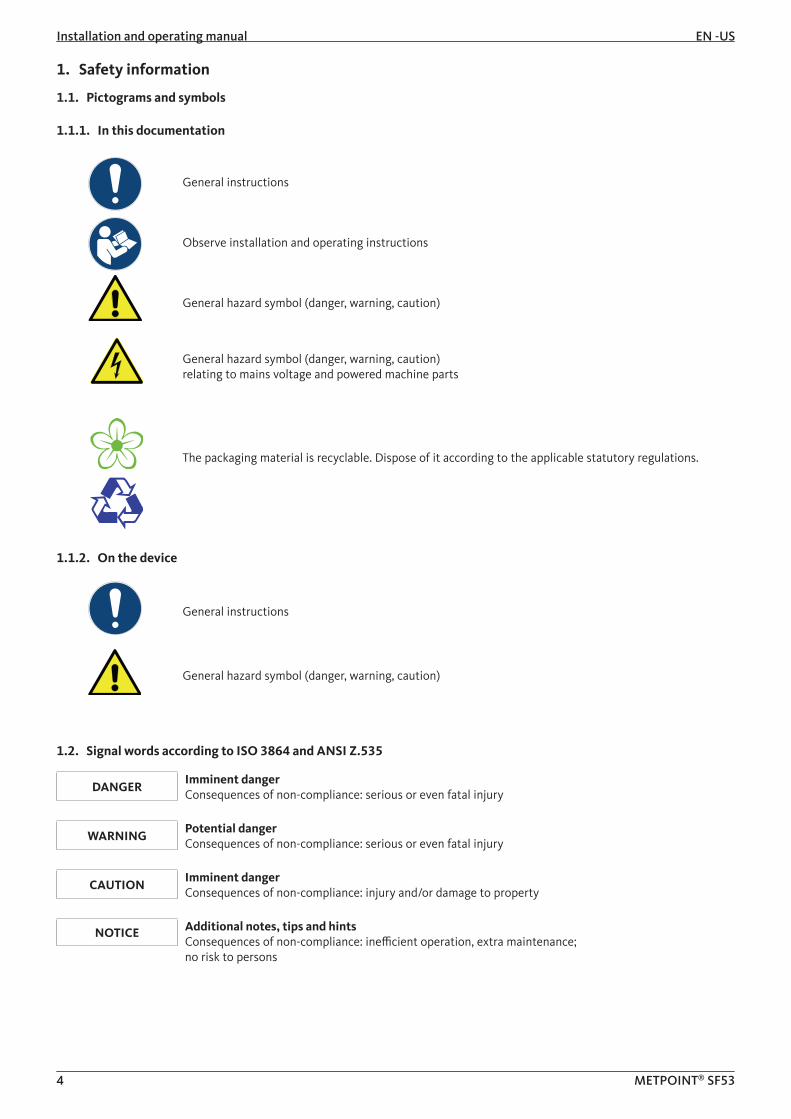
1.1. Pictograms and symbols
1.1.1. In this documentation
General instructions
Observe installation and operating instructions
General hazard symbol (danger, warning, caution)
General hazard symbol (danger, warning, caution) relating to mains voltage and powered machine parts
The packaging material is recyclable. Dispose of it according to the applicable statutory regulations.
1.1.2. On the device
General instructions
General hazard symbol (danger, warning, caution)
1.2. Signal words according to ISO 3864 and ANSI Z.535
DANGERImminent dangerConsequences of non-compliance: serious or even fatal injury
WARNINGPotential dangerConsequences of non-compliance: serious or even fatal injury
CAUTIONImminent dangerConsequences of non-compliance: injury and/or damage to property
NOTICE Additional notes, tips and hintsConsequences of non-compliance: inefficient operation, extra maintenance; no risk to persons
EN-US Installation and operating manual
5 METPOINT® SF53
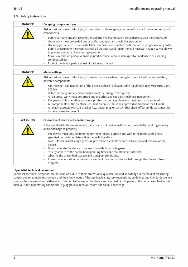
1.3. Safety instructions
DANGER Escaping compressed gas
Risk of serious or even fatal injury from contact with escaping compressed gas or from unsecured plant components.
• Before carrying out any assembly, installation or maintenance work, depressurize the system. All above work must be carried out by authorized specialist technical personnel1.
• Use only pressure-resistant installation materials and suitable tools that are in proper working order.• Before pressurizing the system, check all unit parts and repair them, if necessary. Open valves slowly
to prevent pressure blows during operation. • Make sure that no persons can be injured or objects can be damaged by condensate or escaping
compressed gas.• Protect the device parts against vibration and impact.
DANGER Mains voltage
Risk of serious or even fatal injury from electric shock when coming into contact with non-insulated, powered components.
• For the electrical installation of the device, adhere to all applicable regulations (e.g. VDE 0100 / IEC 60364).
• Before carrying out any maintenance work, de-energize the system. • All electrical work must be carried out by authorized specialist technical personnel1.• The permissible operating voltage is printed on the type plate and must be strictly adhered to.• All components of the electrical installation on site must be approved and/or bear the CE mark.• A reliably accessible circuit breaker (e.g. power plug or switch) that shuts off all conductors must be
installed close to the unit.
WARNING Operation of device outside limit range
If the specified limits are exceeded, there is a risk of device malfunction, potentially resulting in injury and/or damage to property.
• The device must only be operated for the intended purpose and within the permissible limits specified on the type plate and in the technical data.
• From 145 psi, install a high-pressure protection element for safe installation and removal of the device.
• Do not operate the device in connection with flammable gases.• Strictly adhere to the prescribed operating times and maintenance intervals.• Observe the prescribed storage and transport conditions.• Prevent condensation on the sensor element. Ensure that the air fed through the device is free of
droplets.
1 Specialist technical personnelSpecialist technical personnel are persons who, due to their professional qualification and knowledge in the field of measuring, control and pneumatic technology, and their knowledge of the applicable statutory regulations, guidelines and standards are in a position to foresee potential dangers in relation to the use of the device and are qualified to perform the tasks described in this manual. Special operating conditions (e.g. aggressive media) require additional knowledge.
Installation and operating manual EN -US
6 METPOINT® SF53
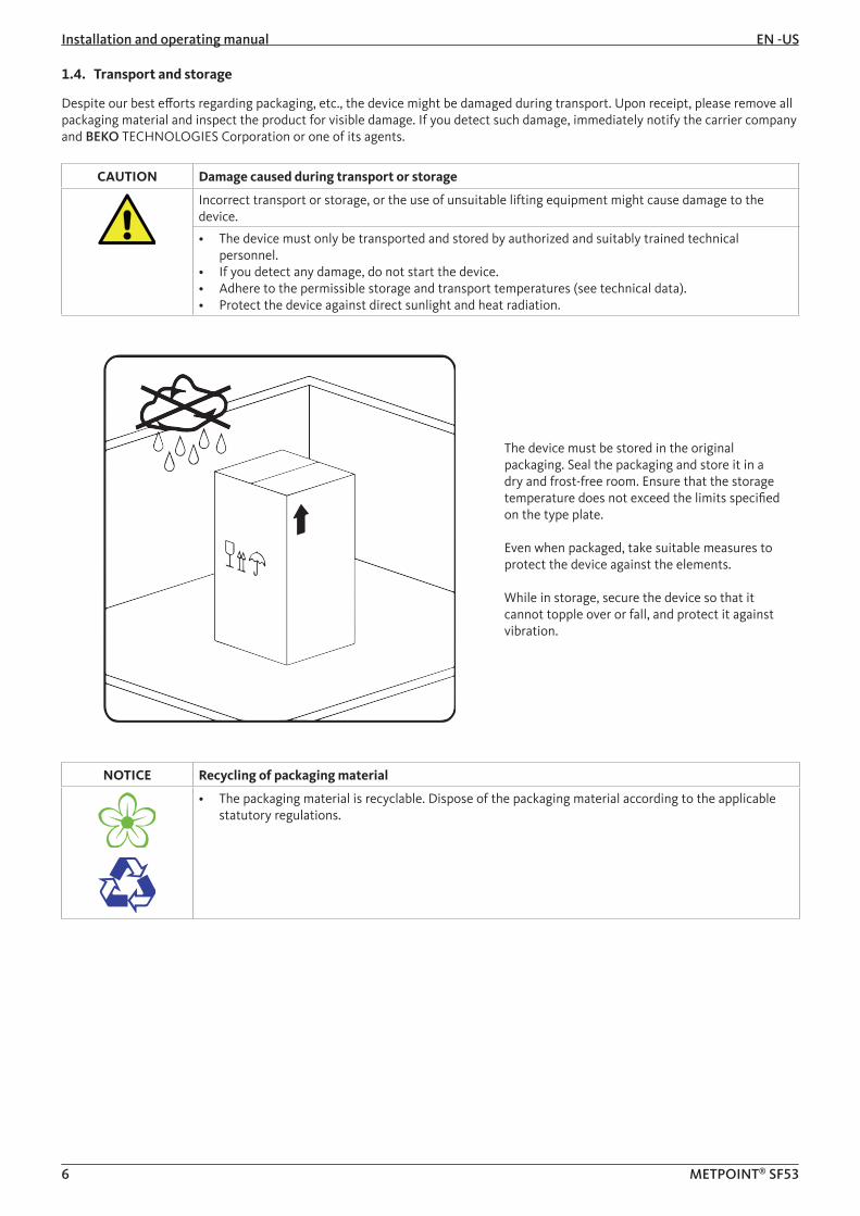
1.4. Transport and storage
Despite our best efforts regarding packaging, etc., the device might be damaged during transport. Upon receipt, please remove all packaging material and inspect the product for visible damage. If you detect such damage, immediately notify the carrier company and BEKO TECHNOLOGIES Corporation or one of its agents.
CAUTION Damage caused during transport or storage
Incorrect transport or storage, or the use of unsuitable lifting equipment might cause damage to the device.
• The device must only be transported and stored by authorized and suitably trained technical personnel.
• If you detect any damage, do not start the device.• Adhere to the permissible storage and transport temperatures (see technical data).• Protect the device against direct sunlight and heat radiation.
The device must be stored in the original packaging. Seal the packaging and store it in a dry and frost-free room. Ensure that the storage temperature does not exceed the limits specified on the type plate.
Even when packaged, take suitable measures to protect the device against the elements.
While in storage, secure the device so that it cannot topple over or fall, and protect it against vibration.
NOTICE Recycling of packaging material
• The packaging material is recyclable. Dispose of the packaging material according to the applicable statutory regulations.
EN-US Installation and operating manual
7 METPOINT® SF53
1.5. Intended use
The METPOINT® FLM is a thermal flow meter for the measurement of volume flow, consumption and flow velocity. By default, the device is configured for the measurement of volume flow in m³/h, consumption in m³ and velocity in m/s.• The METPOINT® FLM is primarily used in compressed air systems. On request, the sensor can be programmed by BEKO
TECHNOLOGIES Corporation for the measurement of other gases: nitrogen, argon, helium, carbon dioxide • The device is not suitable for operation in potentially explosive or aggressive atmospheres.• Protect the device against direct sunlight and heat radiation.
Operate the METPOINT® FLM only for the intended purpose and within the limit range specified in the technical data. Do not operate the device with any media (fluids, gas/vapor mixtures) other than those listed above. Any other use of the device is deemed improper and poses a risk to persons, property and the environment.
1.6. Warranty and liability
All warranty shall be voided, if the METPOINT® FLM is used improperly, for a purpose other than the intended or is operated outside the limits specified in the technical data. In such cases, the manufacturer shall also reject any liability for damages. Improper operation includes:
• Incorrect installation, commissioning or operation; insufficient maintenance• Operation with defective components• Non-compliance with the instructions in this document, in particular the safety instructions• Modification of the device• Non-compliance with the prescribed maintenance intervals• Use of third-party spare parts that have not been approved by the manufacturer

Installation and operating manual EN -US
8 METPOINT® SF53
2. Product information
2.1. Scope of delivery
The table below shows the scope of delivery of the METPOINT® FLM.
Designation Picture
Calibration certificate
Connecting cable (5-wire)
Aligning aid
2.2. Type plate
The type plate is attached to the device housing. It contains all relevant technical data of the METPOINT® FLM. Please have these details to hand when contacting the manufacturer or supplier:
Designation Description
METPOINT® FLM SF53 Type designation
S/N: 12579143 Serial number
P/N: 4036460 Product number
Gas: air Medium
Supply: 18 ... 36 V DC Power supply rating
0.1 ... 53 scfm Min./max. measuring range
4 ... 20 mA Min./max. analog output current
Length: 8.646 inch Length of sensor tube
Pmax: 232 psi Max. permissible operating pressure
NOTICE Handling of type plate
Do not remove or cover the type plate, and protect it against damage.For more information regarding the symbols printed on the type plate, see „Pictograms and symbols“ on page 4.
EN-US Installation and operating manual
9 METPOINT® SF53
2.3. Product overview and description
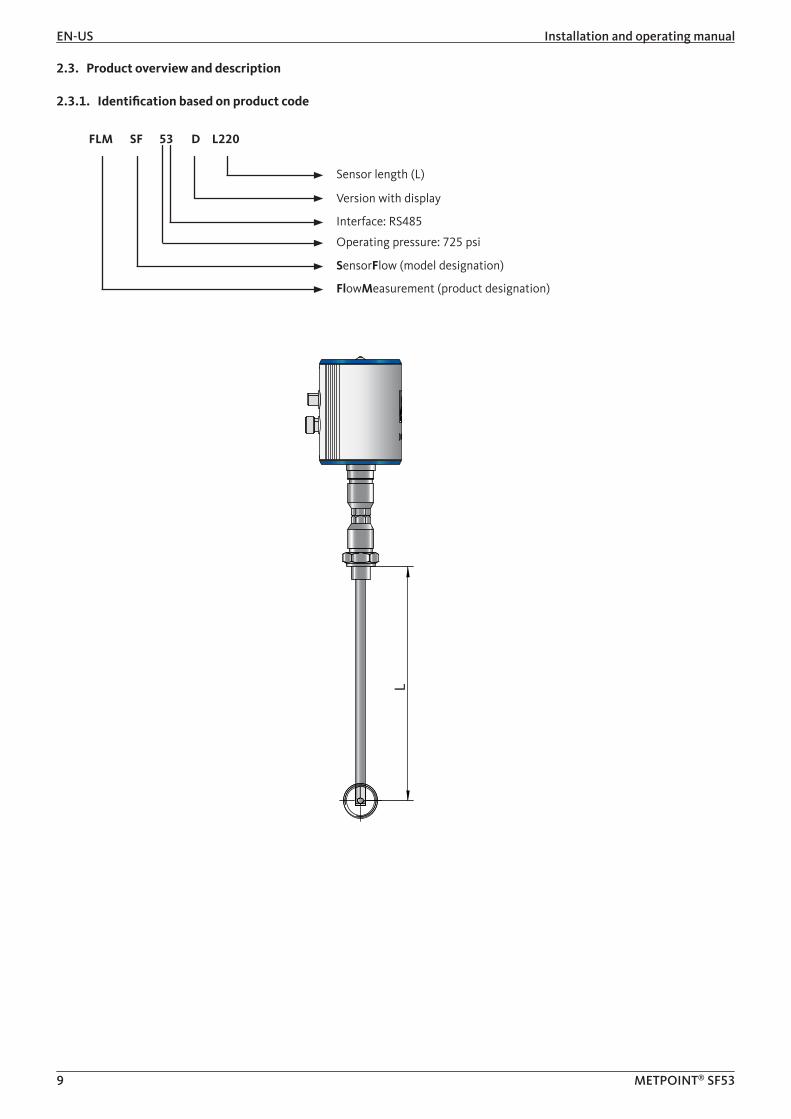
2.3.1. Identification based on product code
FLM
Sensor length (L)
Version with display
Interface: RS485
Operating pressure: 725 psi
SensorFlow (model designation)
FlowMeasurement (product designation)
SF 53 D L220
L

Installation and operating manual EN -US
10 METPOINT® SF53
2.3.2. Product description
The METPOINT® FLM thermal flow meter measures the volume flow, which forms the basis for intelligent energy management. It can be used to identify potential savings, overloads and weak points in a system to improve its efficiency. By measuring the actual flow to the various production units, operators are in a position to make decisions based on facts. The METPOINT® FLM also indicates whether there are any leaks in their system. The METPOINT® FLM thus provides all the information operators need to correctly dimension and configure their system and system components for improved efficiency. The device is equipped with a Modbus RTU(RS485) interface, a 4 ... 20 mA current output, a galvanically isolated pulse output and an optional MBus interface.
2.3.3. Operating principle
Two temperature sensors are installed in series in the direction of flow. The first temperature sensor measures the current process temperature, while the second sensor is electrically heated to a temperature that is exactly 40 K above the temperature measured by the first sensor. As the volume flow increases, the sensors would normally cool, but the electric heater of the second sensor prevents such a temperature drop.
The electric energy required to maintain the temperature difference is directly proportional to the volume flow. This energy consumption of the heater is converted into the relevant flow measurements. Taking into account the inside diameter of the pipe, the METPOINT® FLM determines the exact mass flow.
EN-US Installation and operating manual
11 METPOINT® SF53
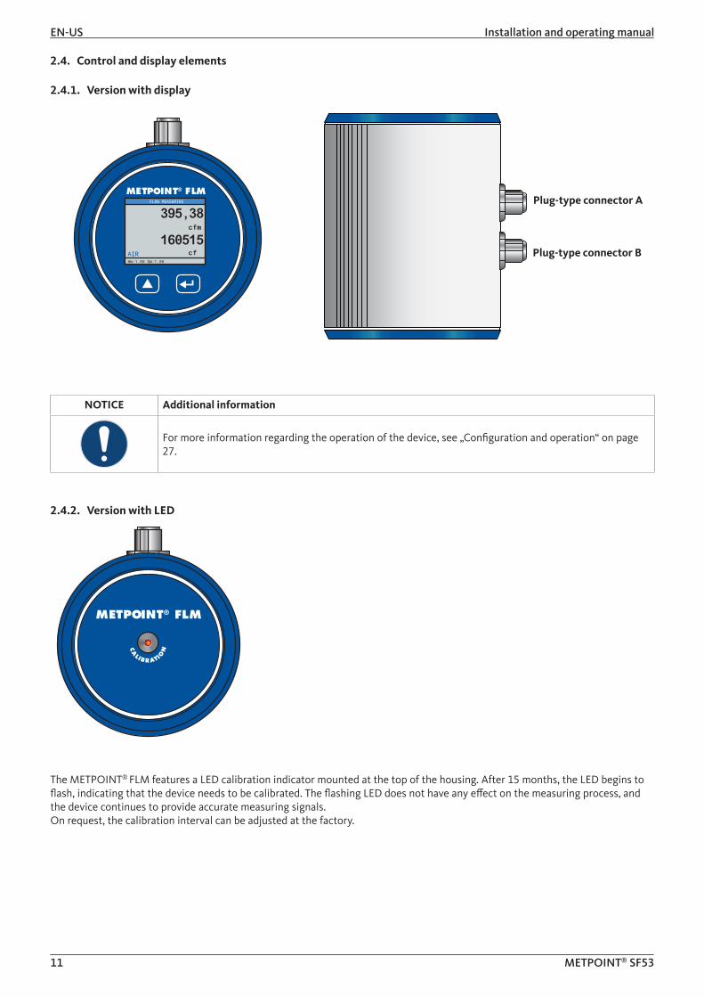
2.4. Control and display elements
2.4.1. Version with display
NOTICE Additional information
For more information regarding the operation of the device, see „Configuration and operation“ on page 27.
2.4.2. Version with LED
The METPOINT® FLM features a LED calibration indicator mounted at the top of the housing. After 15 months, the LED begins to flash, indicating that the device needs to be calibrated. The flashing LED does not have any effect on the measuring process, and the device continues to provide accurate measuring signals.On request, the calibration interval can be adjusted at the factory.
METPOINT® FLMFLOW MEASURING
HW:1.00 SW:1.00
AIR
395,38
160515cfm
cf
Plug-type connector A
Plug-type connector B
METPOINT® FLM
CA
LIB R ATION

Installation and operating manual EN -US
12 METPOINT® SF53
2.4.3. Direction of flow
The direction of flow is indicated by the arrows (1) on the housing of the METPOINT® FLM and on the sensor tube.
1
NOTICE Additional information
If necessary, turn the housing (e.g. to change the direction of flow through the device). For more information, see „Turning housing“ on page 18.

EN-US Installation and operating manual
13 METPOINT® SF53
2.5. Dimensions
Dimensions
Version with display Version with LED
A G½“ (ISO 228/1)
B (inch) 16.34 (Standard) 16.48 (Standard)
C (inch) 3.15
D (inch) Ø 0.46
E (inch) 8.66 (standard), optional: 15.75
F (inch) 3.70
G (inch) 4.02 4.15
F
F
E
D
E
D
C
A
B
G
A
B
G
C
F
F
E
D
E
D
C
A
B
G
A
B
G
C

Installation and operating manual EN -US
14 METPOINT® SF53
2.6. Technical data
Technical data
SF53
Max. operating pressure 232 psig, optional 725 psig
Measuring technique Calorimetric
Operating temperature Sensor tube and fittings: -30 ... +140 °C (-22 ... 284 °F) Housing: -30 ... +80 °C (-22 ... 176 °F)
Measured parameters m³/h (factory settings)On the display version, the following units can be chosen:
m³/min, l/min, l/s, ft/min, cfm, m/s, kg/min, kg/s
Sensor Pt45, Pt1000
Medium nitrogen, argon, helium, carbon dioxide
Humidity of medium max. 90 % rH (no droplets)
Power supply 18 ... 36 VAC
Power consumption max. 5 W
Digital output RS485 (Modbus RTU)
Analog output 4 ... 20 mA (max. load < 500 Ω)
Pulse output Floating switch contactPassive: max. 48 VDC 150 mA
1 pulse per m³ or per literUnit adjustable at display
Accuracy ± 1.5 % of measured value± 0.3 % of final value
Display/indicator Display: TFT 1.8" (resolution: 220 x 167) or service LED
Screw fitting G½“ (ISO 228/1)
Material Sensor tube and fittings: 1.4301 stainless steelHousing: Powder-coated aluminum
Flange: 1.4404 (DIN EN 1092-1)

EN-US Installation and operating manual
15 METPOINT® SF53
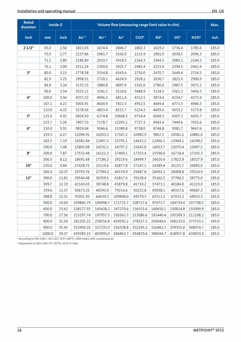
2.7. Measuring ranges
The METPOINT® FLM volume flow sensor can measure flow speeds up to 185.0 m/s and is factory-set to an inside pipe diameter of 53.1 mm. At the analog output of 4 ... 20 mA, this corresponds to:
Rated diameter
Inside Ø Volume flow (measuring range limit value in cfm) Max.
Inch mm inch Air ² Air ³ Ar³ CO2³ N2³ O2³ N2O³ m/s
1/4" 6.0 0.24 9.42 8.7 14.7 9.3 8.4 9.0 9.2 185.0
10.0 0.39 30.08 27.7 47.0 29.8 26.7 28.7 29.5 185.0
15.0 0.59 77.68 71.4 121.4 76.9 69.1 74.1 76.2 185.0
1/2" 16.1 0.63 90.98 83.7 142.2 90.0 80.9 86.7 89.2 185.0
3/4" 21.7 0.85 177.84 163.5 278.0 176.0 158.1 169.6 174.4 185.0
1" 25.0 0.98 243.88 224.2 381.2 241.4 216.9 232.5 239.1 185.0
26.0 1.02 265.20 243.8 414.6 262.5 235.8 252.9 260.0 185.0
27.3 1.07 294.72 271.0 460.7 291.7 262.1 281.0 289.0 185.0
28.5 1.12 323.32 297.3 505.4 320.0 287.5 308.3 317.0 185.0
30.0 1.18 361.08 332.0 564.5 357.4 321.1 344.3 354.1 185.0
1 1/4" 32.8 1.29 436.69 401.5 682.7 432.2 388.3 416.4 428.2 185.0
36.0 1.42 531.48 488.7 830.8 526.0 472.6 506.8 521.1 185.0
36.3 1.43 541.06 497.5 845.8 535.5 481.1 515.9 530.5 185.0
1 1/2" 39.3 1.55 639.84 588.3 1000.2 633.3 568.9 610.1 627.4 185.0
40.0 1.57 663.68 610.2 1037.5 656.9 590.1 632.8 650.8 185.0
41.9 1.65 728.41 669.7 1138.7 720.9 647.7 694.5 714.2 185.0
43.1 1.70 777.34 714.7 1215.2 769.4 691.2 741.2 762.2 185.0
45.8 1.80 882.17 811.1 1379.0 873.1 784.4 841.2 865.0 185.0
2" 50.0 1.97 1059.23 973.9 1655.8 1048.3 941.9 1010.0 1038.6 185.0
51.2 2.02 1112.05 1022.5 1738.4 1100.6 988.8 1060.4 1090.4 185.0
53.1 2.09 1197.59 1101.1 1872.1 1185.3 1064.9 1141.9 1174.3 185.0
54.5 2.15 1263.13 1161.4 1974.6 1250.2 1123.2 1204.4 1238.5 185.0
57.5 2.26 1489.43 1369.5 2328.3 1474.1 1324.4 1420.2 1460.5 185.0
60.0 2.36 1544.12 1419.8 2413.8 1528.3 1373.0 1472.3 1514.1 185.0
64.2 2.53 1774.33 1631.4 2773.7 1756.1 1577.7 1691.8 1739.8 185.0² According to DIN 1945 / ISO 1217 (20°C (68°F), 1000 mbar), with compressed air.
³ Adjustment to DIN 1343: 0°C (32°F), 1013.25 mbar
Installation and operating manual EN -US
16 METPOINT® SF53
Rated diameter
Inside Ø Volume flow (measuring range limit value in cfm) Max.
Inch mm inch Air ² Air ³ Ar³ CO2³ N2³ O2³ N2O³ m/s
2 1/2" 65.0 2.56 1821.03 1674.4 2846.7 1802.3 1619.2 1736.4 1785.6 185.0
70.3 2.77 2137.86 1965.7 3342.0 2115.9 1901.0 2038.5 2096.3 185.0
71.1 2.80 2186.80 2010.7 3418.5 2164.3 1944.5 2085.1 2144.2 185.0
76.1 3.00 2511.24 2309.0 3925.7 2485.4 2233.0 2394.5 2462.4 185.0
3" 80.0 3.15 2778.58 2554.8 4343.6 2750.0 2470.7 2649.4 2724.5 185.0
82.5 3.25 2958.51 2720.2 4624.9 2928.1 2630.7 2821.0 2900.9 185.0
84.9 3.34 3133.15 2880.8 4897.9 3101.0 2786.0 2987.5 3072.2 185.0
90.0 3.54 3525.11 3241.2 5510.6 3488.9 3134.5 3361.2 3456.5 185.0
4" 100.0 3.94 4357.22 4006.3 6811.4 4312.5 3874.4 4154.7 4272.4 185.0
107.1 4.22 5003.91 4600.9 7822.3 4952.5 4449.4 4771.3 4906.5 185.0
110.0 4.33 5278.56 4853.4 8251.7 5224.3 4693.6 5033.2 5175.8 185.0
5" 125.0 4.92 6824.50 6274.8 10668.3 6754.4 6068.3 6507.2 6691.7 185.0
133.7 5.26 7807.53 7178.7 12205.1 7727.3 6942.4 7444.6 7655.6 185.0
6" 150.0 5.91 9839.04 9046.6 15380.8 9738.0 8748.8 9381.7 9647.6 185.0
159.3 6.27 11096.91 10203.2 17347.2 10982.9 9867.2 10581.1 10881.0 185.0
182.5 7.19 14581.94 13407.5 22795.1 14432.2 12966.1 13904.1 14298.2 185.0
190.0 7.48 15805.08 14532.1 24707.2 15642.8 14053.7 15070.4 15497.5 185.0
8" 200.0 7.87 17533.48 16121.3 27409.1 17353.4 15590.6 16718.4 17192.3 185.0
206.5 8.12 18691.68 17186.2 29219.6 18499.7 16620.4 17822.8 18327.9 185.0
10" 250.0 9.84 27428.75 25219.6 42877.8 27147.1 24389.4 26153.7 26895.0 185.0
260.4 10.25 29793.76 27394.2 46574.9 29487.8 26492.3 28408.8 29214.0 185.0
12" 300.0 11.81 39544.48 36359.5 61817.6 39138.4 35162.5 37706.2 38775.0 185.0
309.7 12.19 42143.03 38748.8 65879.8 41710.2 37473.1 40184.0 41323.0 185.0
339.6 13.37 50673.25 46592.0 79214.6 50152.8 45058.1 48317.6 49687.2 185.0
388.8 15.31 70301.30 64639.2 109898.0 69579.3 62511.2 67033.2 68933.3 185.0
500.0 19.69 109845.79 100998.7 171715.7 108717.6 97673.7 104739.4 107708.2 185.0
600.0 23.62 158177.93 145438.2 247270.6 156553.4 140650.1 150824.8 155099.9 185.0
700.0 27.56 215297.74 197957.5 336562.7 213086.6 191440.4 205289.3 211108.2 185.0
800.0 31.50 281205.22 258556.8 439592.2 278317.2 250044.6 268133.0 275733.1 185.0
900.0 35.43 355900.35 327235.9 556358.8 352245.2 316462.7 339355.8 348974.7 185.0
1000.0 39.37 439383.15 403995.0 686862.7 434870.6 390694.7 418957.8 430833.0 185.0² According to DIN 1945 / ISO 1217 (20°C (68°F), 1000 mbar), with compressed air.
³ Adjustment to DIN 1343: 0°C (32°F), 1013.25 mbar
EN-US Installation and operating manual
17 METPOINT® SF53
3. Installation
3.1. Warning
DANGER Escaping compressed gas
Risk of serious or even fatal injury from contact with escaping compressed gas or from unsecured plant components.
• Before carrying out any assembly, installation or maintenance work, depressurize the system. Such work must be carried out by authorized specialist technical personnel only (see „Safety instructions“ on page 5).
• From 145 psig, install a high-pressure protection element for safe installation and removal of the device.• Tighten the slotted spring pin with a torque of 177-265 inch lbs.• Use only pressure-resistant installation materials and suitable tools that are in proper working order.• Before pressurizing the system, check all unit parts and repair them, if necessary. Open valves slowly
to prevent pressure blows during operation.
3.1.1. Requirements for piping
• Correctly dimensioned gaskets.• Correctly installed and aligned flanges and gaskets.• Differences in pipe diameters at joints should not exceed 0.0393 inch. For more information, see ISO 14511.• Clean, properly installed pipes.
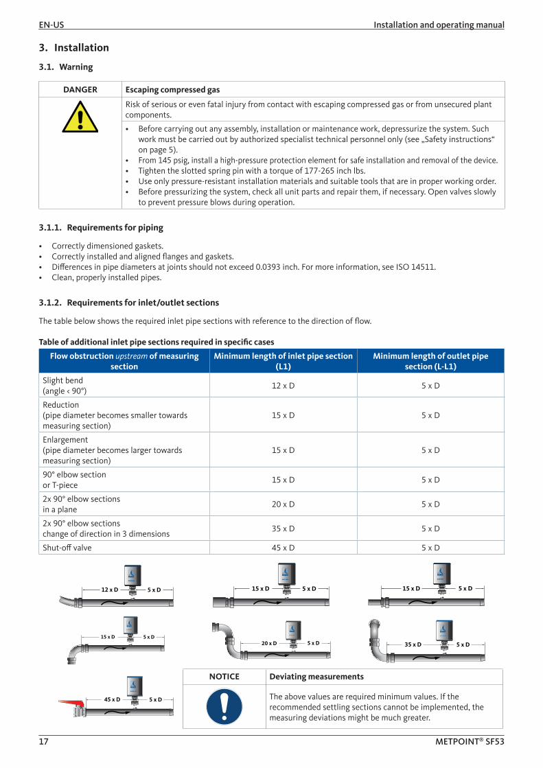
3.1.2. Requirements for inlet/outlet sections
The table below shows the required inlet pipe sections with reference to the direction of flow.
Table of additional inlet pipe sections required in specific cases
Flow obstruction upstream of measuring section
Minimum length of inlet pipe section (L1)
Minimum length of outlet pipe section (L-L1)
Slight bend(angle < 90°)
12 x D 5 x D
Reduction(pipe diameter becomes smaller towards measuring section)
15 x D 5 x D
Enlargement(pipe diameter becomes larger towards measuring section)
15 x D 5 x D
90° elbow section or T-piece
15 x D 5 x D
2x 90° elbow sectionsin a plane
20 x D 5 x D
2x 90° elbow sections change of direction in 3 dimensions
35 x D 5 x D
Shut-off valve 45 x D 5 x D
5 x D12 x D 5 x D15 x D 5 x D15 x D
5 x D15 x D5 x D20 x D 5 x D35 x D
5 x D45 x D
NOTICE Deviating measurements
The above values are required minimum values. If the recommended settling sections cannot be implemented, the measuring deviations might be much greater.
Installation and operating manual EN -US
18 METPOINT® SF53
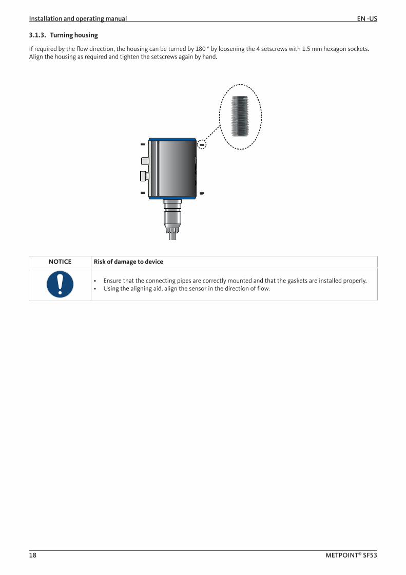
3.1.3. Turning housing
If required by the flow direction, the housing can be turned by 180 ° by loosening the 4 setscrews with 1.5 mm hexagon sockets. Align the housing as required and tighten the setscrews again by hand.
NOTICE Risk of damage to device
• Ensure that the connecting pipes are correctly mounted and that the gaskets are installed properly.• Using the aligning aid, align the sensor in the direction of flow.

EN-US Installation and operating manual
19 METPOINT® SF53
3.2. Installation
The sensor is installed by means of a ½, DN 15 ball valve (min. Ø 15 mm). Install the straight fitting with the O-ring (G ½ thread, WS 32) in the connecting nozzle. Ensure that the assembly is pressure-tight.
Position the sensor head at the center of the pipe and align it to the flow direction. To do this, the sensor tube is equipped with a depth scale, arrows indicating the direction of flow and an aligning aid. After the sensor is correctly positioned and aligned, tighten the slotted spring pin with a torque of 177-265 inch lbs.
When tightening the straight fitting and the slotted spring pin, take care not to change the alignment of the sensor. Otherwise, you might need to correct the sensor position and alignment.The angle of the sensor should not deviate by more than ± 2° from the ideal position. Larger angles might result in inaccurate measurement.
From an operating pressure of >10 bar, install a high-pressure protection element (prod. no. 4025892).This allows for the installation of the sensor while the system is pressurized, and ensures that the sensor is safely secured at the measuring point.
NOTICE Additional information
For more information about the installation of the high pressure protection element, refer to the installation and operating manual shipped with the element.
y
160
170
180
xdA Securing ring
Engraved depth scalefor precision installationInstallation depth = x + y
dA = outside diameterx = dA 2
Installation and operating manual EN -US
20 METPOINT® SF53
4. Electrical installation
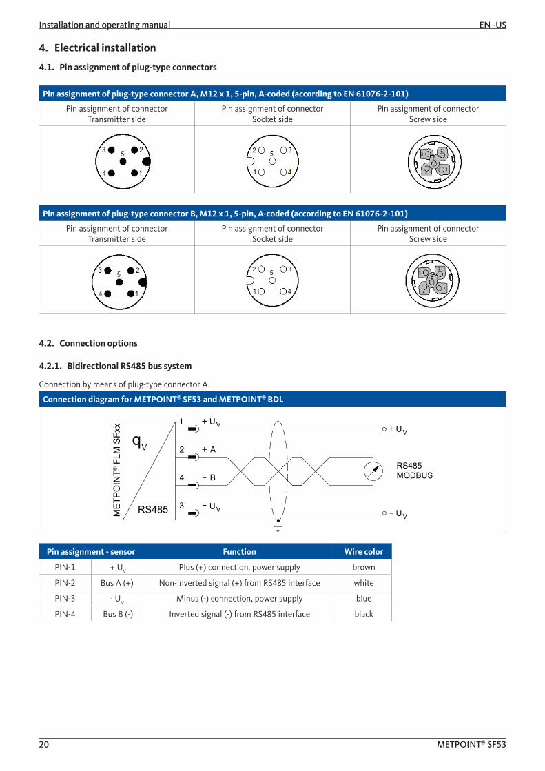
4.1. Pin assignment of plug-type connectors
Pin assignment of plug-type connector A, M12 x 1, 5-pin, A-coded (according to EN 61076-2-101)
Pin assignment of connectorTransmitter side
Pin assignment of connectorSocket side
Pin assignment of connectorScrew side
Pin assignment of plug-type connector B, M12 x 1, 5-pin, A-coded (according to EN 61076-2-101)
Pin assignment of connectorTransmitter side
Pin assignment of connectorSocket side
Pin assignment of connectorScrew side
4.2. Connection options
4.2.1. Bidirectional RS485 bus system
Connection by means of plug-type connector A.
Connection diagram for METPOINT® SF53 and METPOINT® BDL
q
MET
POIN
T® F
LM S
Fxx 1
2
4
3RS485
A
B
VU+VU+
VU-V- U
RS485 MODBUS
+
-
V
Pin assignment - sensor Function Wire color
PIN-1 + UV Plus (+) connection, power supply brown
PIN-2 Bus A (+) Non-inverted signal (+) from RS485 interface white
PIN-3 - UV Minus (-) connection, power supply blue
PIN-4 Bus B (-) Inverted signal (-) from RS485 interface black

EN-US Installation and operating manual
21 METPOINT® SF53
4.2.2. Current output 4 ... 20 mA, 3-wire
Connection by means of plug-type connector A.
Connection diagram for METPOINT® SF53 and METPOINT® BDL
RLqM
ETPO
INT®
FLM
SFx
x
+ - -
+
4 ... 20 mA
I4 ... 20 mA
1
5
3
2
V- U
V
V+ U
VUOUT+ I
Pin assignment - sensor Function Wire color
PIN-1 + UV Plus (+) connection, power supply brown
PIN-2 not assigned white
PIN-3 - UV Minus (-) connection, power supply blue
PIN-4 not assigned black
PIN-5 + IOUT Current output grey
4.2.3. MBus
Connection by means of plug-type connector B.
Connection diagram for METPOINT® SF53 and METPOINT® BDL
q
MET
POIN
T® F
LM S
Fxx
1
4
5
3MBus
VU+VU+
VU-V- U
MBus
V
Pin assignment - sensor Function Wire color
PIN-1 not assigned brown
PIN-2 not assigned white
PIN-3 not assigned blue
PIN-4 MBus MBus black
PIN-5 MBus MBus grey

Installation and operating manual EN -US
22 METPOINT® SF53
4.2.4. Galvanically isolated pulse output
Connection by means of plug-type connector B.
Connection diagram for METPOINT® SF53 and METPOINT® BDL
qM
ETPO
INT®
FLM
SFx
x
1
4
5
3Impuls
VU+VU+
VU-V- U
Impuls
V
Pin assignment - sensor Function Wire color
PIN-1 not assigned brown
PIN-2 not assigned white
PIN-3 not assigned blue
PIN-4 Pulse Galvanically isolated pulse black
PIN-5 Pulse Galvanically isolated pulse grey
EN-US Installation and operating manual
23 METPOINT® SF53
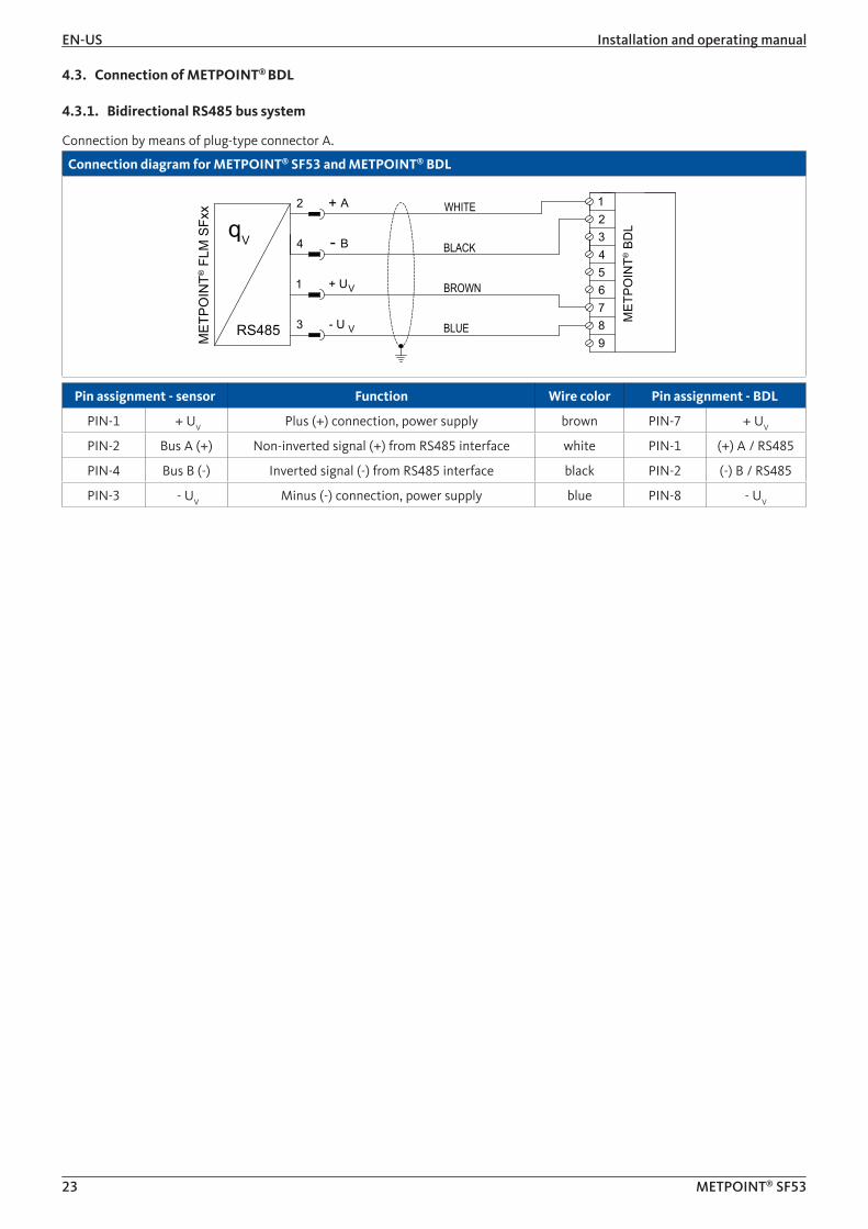
4.3. Connection of METPOINT® BDL
4.3.1. Bidirectional RS485 bus system
Connection by means of plug-type connector A.
Connection diagram for METPOINT® SF53 and METPOINT® BDL
MET
POIN
T® F
LM S
Fxx
MET
POIN
T® B
DL
BROWN
WHITE
q
BLUE
BLACK
1
3
2
4
123456789
V- U
V
A
B
+
-
RS485
V+ U
Pin assignment - sensor Function Wire color Pin assignment - BDL
PIN-1 + UV Plus (+) connection, power supply brown PIN-7 + UV
PIN-2 Bus A (+) Non-inverted signal (+) from RS485 interface white PIN-1 (+) A / RS485
PIN-4 Bus B (-) Inverted signal (-) from RS485 interface black PIN-2 (-) B / RS485
PIN-3 - UV Minus (-) connection, power supply blue PIN-8 - UV

Installation and operating manual EN -US
24 METPOINT® SF53
4.3.2. Current output 4 ... 20 mA, 3-wire
Connection by means of plug-type connector A.
Connection diagram for METPOINT® SF53 and METPOINT® BDL
MET
POIN
T® F
LM S
Fxx
MET
POIN
T® B
DL
BROWN
GREYq
BLUE
I4 ... 20 mA
3
2
1
5
123456789
V- U
V
V+ U
OUT+ I
Pin assignment - sensor Function Wire color Pin assignment - BDL
PIN-1 + UV Plus (+) connection, power supply brown PIN-7 + UV
PIN-5 + IOUT Current output grey PIN-4 Analog IN (+)
PIN-3 - UV Minus (-) connection, power supply blue PIN-8 - UV
PIN-2 not assigned white
PIN-4 not assigned black
4.3.3. Galvanically isolated pulse output
Connection by means of plug-type connector B.
Connection diagram for METPOINT® SF53 and METPOINT® BDL
MET
POIN
T® F
LM S
Fxx
MET
POIN
T® B
DL q
R = 4,7kΩ
BROWN
BLACK
GREY
BLUE
1
4
5
3Impuls
VU+VU+
VU-V- U
V
123456789
R
Pin assignment - sensor Function Wire color Pin assignment - BDL
PIN-1 + UV Plus (+) connection, power supply brown
PIN-4 Pulse Pulse black PIN-4 Analog IN (+)
PIN-5 Pulse Pulse grey PIN-7 + UV
PIN-3 - UV Minus (-) connection, power supply blue
PIN-2 not assigned white
EN-US Installation and operating manual
25 METPOINT® SF53
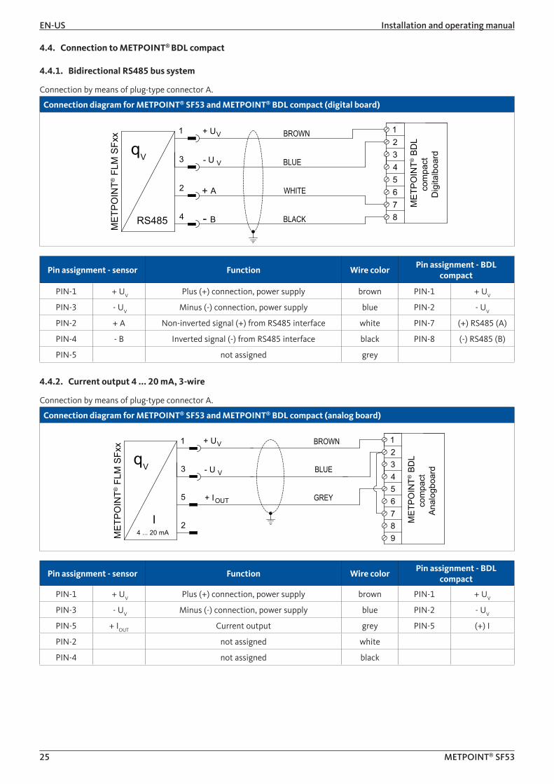
4.4. Connection to METPOINT® BDL compact
4.4.1. Bidirectional RS485 bus system
Connection by means of plug-type connector A.
Connection diagram for METPOINT® SF53 and METPOINT® BDL compact (digital board)M
ETPO
INT®
FLM
SFx
x
MET
POIN
T® B
DL
com
pact
D
igita
lboa
rd
WHITE
BROWN
q
BLACK
BLUE
2
4
1
3 V- UV
A
B
+
-RS485
12345678
V+ U
Pin assignment - sensor Function Wire colorPin assignment - BDL
compact
PIN-1 + UV Plus (+) connection, power supply brown PIN-1 + UV
PIN-3 - UV Minus (-) connection, power supply blue PIN-2 - UV
PIN-2 + A Non-inverted signal (+) from RS485 interface white PIN-7 (+) RS485 (A)
PIN-4 - B Inverted signal (-) from RS485 interface black PIN-8 (-) RS485 (B)
PIN-5 not assigned grey
4.4.2. Current output 4 ... 20 mA, 3-wire
Connection by means of plug-type connector A.
Connection diagram for METPOINT® SF53 and METPOINT® BDL compact (analog board)
MET
POIN
T® F
LM S
Fxx
MET
POIN
T® B
DL
com
pact
An
alog
boar
d BROWN
BLUEq
GREY
I4 ... 20 mA
5
2
1
3
123456789
V- UV
V+ U
OUT+ I
Pin assignment - sensor Function Wire colorPin assignment - BDL
compact
PIN-1 + UV Plus (+) connection, power supply brown PIN-1 + UV
PIN-3 - UV Minus (-) connection, power supply blue PIN-2 - UV
PIN-5 + IOUT Current output grey PIN-5 (+) I
PIN-2 not assigned white
PIN-4 not assigned black

Installation and operating manual EN -US
26 METPOINT® SF53
4.4.3. Galvanically isolated pulse output
Connection by means of plug-type connector B.
Connection diagram for METPOINT® SF53 and METPOINT® BDL compact (analog)
MET
POIN
T® F
LM S
Fxx
MET
POIN
T® B
DL
com
pact
An
alog
boar
d
BROWN
qBLACK
GREY
BLUE
1
4
5
3Impuls
VU+VU+
VU-V- U
V
123456789
R
Pin assignment - sensor Function Wire colorPin assignment - BDL
compact
PIN-1 + UV Plus (+) connection, power supply brown
PIN-4 Pulse Pulse black PIN-1 + UV
PIN-5 Pulse Pulse grey PIN-8 (+) V - PT
PIN-3 - UV Minus (-) connection, power supply blue
PIN-2 not assigned white
4.5. Modbus termination
If the METPOINT® FLM is the last device in the Modbus system, it must be terminated. The sensor is equipped with a built-in terminator. To terminate the device, loosen the 2 top setscrews at the housing. lift off the lid and set the DIP switch (1) to ON. When closing the sensor housing, ensure that the housing gasket is correctly installed.
1
EN-US Installation and operating manual
27 METPOINT® SF53
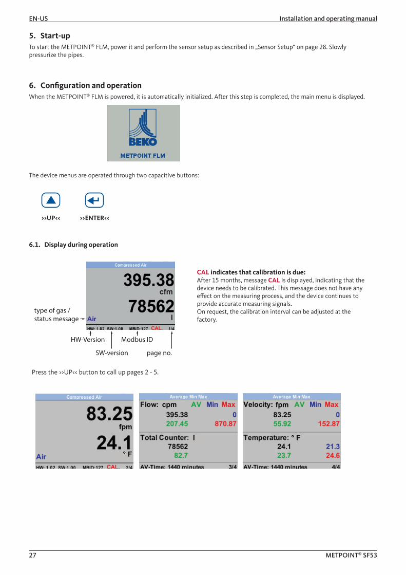
5. Start-upTo start the METPOINT® FLM, power it and perform the sensor setup as described in „Sensor Setup“ on page 28. Slowly pressurize the pipes.
6. Configuration and operationWhen the METPOINT® FLM is powered, it is automatically initialized. After this step is completed, the main menu is displayed.
The device menus are operated through two capacitive buttons:
>>UP<< >>ENTER<<
6.1. Display during operation
CAL indicates that calibration is due:After 15 months, message CAL is displayed, indicating that the device needs to be calibrated. This message does not have any effect on the measuring process, and the device continues to provide accurate measuring signals.On request, the calibration interval can be adjusted at the factory.
Press the >>UP<< button to call up pages 2 - 5.
type of gas / status message
HW-Version
SW-version
Modbus ID
page no.
cfm
l
fpm
° F
cpm
l
fpm
° F
Installation and operating manual EN -US
28 METPOINT® SF53
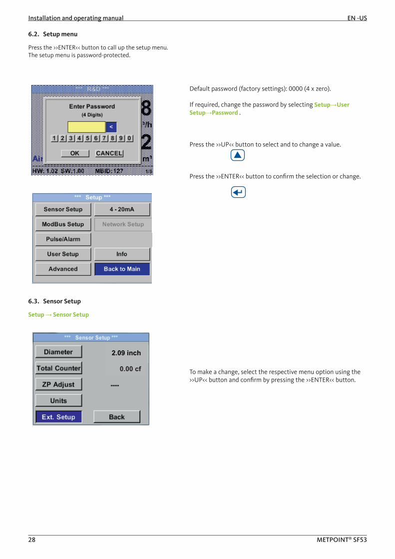
6.2. Setup menu
Press the >>ENTER<< button to call up the setup menu.The setup menu is password-protected.
Default password (factory settings): 0000 (4 x zero).
If required, change the password by selecting Setup→User Setup→Password .
Press the >>UP<< button to select and to change a value.
Press the >>ENTER<< button to confirm the selection or change.
6.3. Sensor Setup
Setup → Sensor Setup
2.09 inch
0.00 cf To make a change, select the respective menu option using the >>UP<< button and confirm by pressing the >>ENTER<< button.

EN-US Installation and operating manual
29 METPOINT® SF53
6.3.1. Entering pipe inside diameter
Setup → Sensor Setup → Diameter
inchTo change the unit, press the >>UP<< button to select the "Unit" field and confirm by pressing the >>ENTER<< button.
Press the >>UP<< button to select the desired unit and confirm by pressing the >>ENTER<< button 2x.
Press the >>UP<< button to select the value to be changed and confirm by pressing the >>ENTER<< button.
Press the >>UP<< button to enter the new value and confirm by pressing the >>ENTER<< button.
inch2
6.3.2. Entering / changing consumption counter value
Setup → Sensor Setup → Total Counter
cfTo change the unit, press the >>UP<< button to select the "Unit" field and confirm by pressing the >>ENTER<< button.
Press the >>UP<< button to select the desired unit and confirm by pressing the >>ENTER<< button 2x.
Press the >>UP<< button to select the value to be changed and confirm by pressing the >>ENTER<< button.
Press the >>UP<< button to enter the new value and confirm by pressing the >>ENTER<< button.
cf
NOTICE Consumption counter value
When the consumption counter reaches 1,000,000,000 cf, it is automatically reset to 0.
Installation and operating manual EN -US
30 METPOINT® SF53
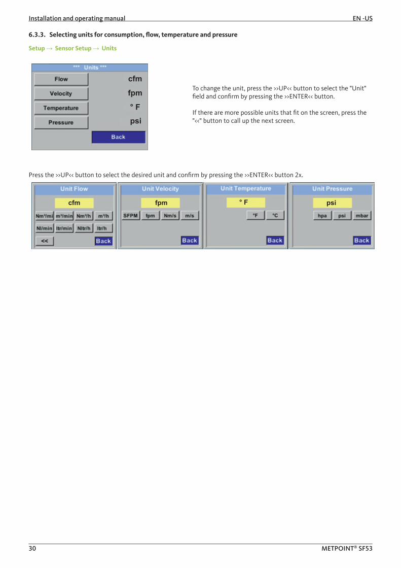
6.3.3. Selecting units for consumption, flow, temperature and pressure
Setup → Sensor Setup → Units
cfm
fpm
° Fpsi
To change the unit, press the >>UP<< button to select the "Unit" field and confirm by pressing the >>ENTER<< button.
If there are more possible units that fit on the screen, press the "<<" button to call up the next screen.
Press the >>UP<< button to select the desired unit and confirm by pressing the >>ENTER<< button 2x.
cfm fpm ° F psi

EN-US Installation and operating manual
31 METPOINT® SF53
6.3.4. Entering reference conditions
Setup → Sensor Setup → Ext. Setup
Filtertime
° F
psi
Enter the reference parameter values.
Setup → Sensor Setup → Ext. Setup → Ref. Pres
psiTo change the reference pressure, press the >>UP<< button to select the "Unit" field and confirm by pressing the >>ENTER<< button.
Press the >>UP<< button to select the desired unit and confirm by pressing the >>ENTER<< button 2x.
Setup → Sensor Setup → Ext. Setup → Ref. Temp
° F
Enter the reference temperature.
Setup → Sensor Setup → Ext. Setup → Filtertime
Under "Filtertime", you can enter an attenuation, provided that a "Filtergrade" is entered.Possible values: 0 -10000 in [ms].
Installation and operating manual EN -US
32 METPOINT® SF53
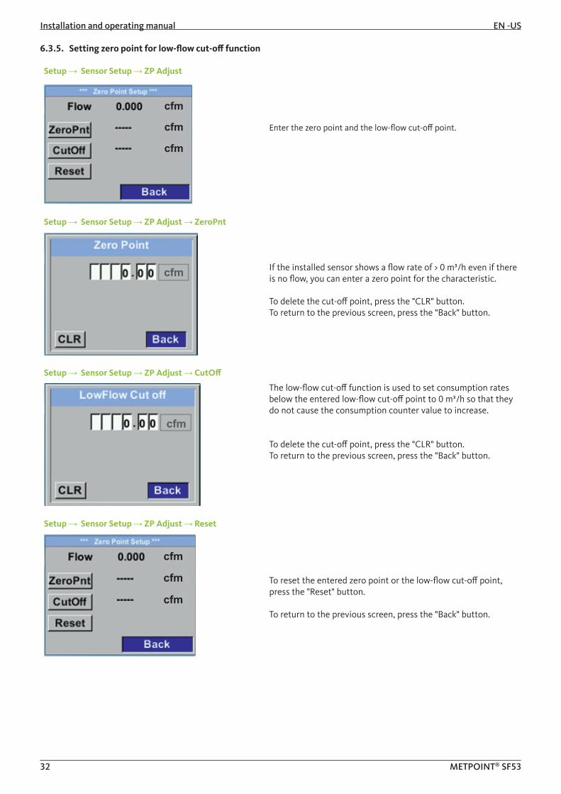
6.3.5. Setting zero point for low-flow cut-off function
Setup → Sensor Setup → ZP Adjust
cfm
cfm
cfm
Enter the zero point and the low-flow cut-off point.
Setup → Sensor Setup → ZP Adjust → ZeroPnt
cfm If the installed sensor shows a flow rate of > 0 m³/h even if there is no flow, you can enter a zero point for the characteristic.
To delete the cut-off point, press the "CLR" button.To return to the previous screen, press the "Back" button.
Setup → Sensor Setup → ZP Adjust → CutOff
cfm
The low-flow cut-off function is used to set consumption rates below the entered low-flow cut-off point to 0 m³/h so that they do not cause the consumption counter value to increase.
To delete the cut-off point, press the "CLR" button.To return to the previous screen, press the "Back" button.
Setup → Sensor Setup → ZP Adjust → Reset
cfm
cfm
cfm
To reset the entered zero point or the low-flow cut-off point, press the "Reset" button.
To return to the previous screen, press the "Back" button.
EN-US Installation and operating manual
33 METPOINT® SF53
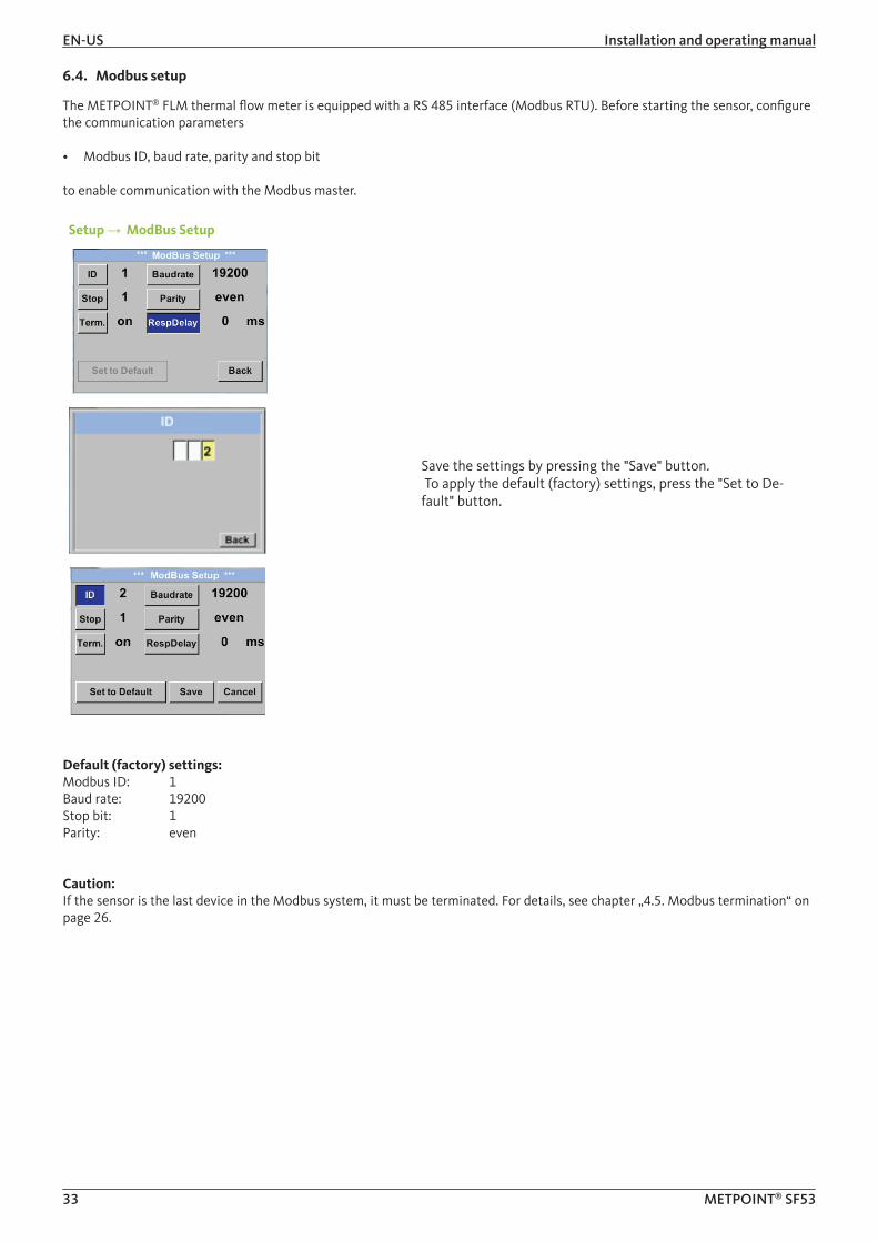
6.4. Modbus setup
The METPOINT® FLM thermal flow meter is equipped with a RS 485 interface (Modbus RTU). Before starting the sensor, configure the communication parameters
• Modbus ID, baud rate, parity and stop bit
to enable communication with the Modbus master.
Setup → ModBus Setup
Save the settings by pressing the "Save" button. To apply the default (factory) settings, press the "Set to De-fault" button.
Default (factory) settings: Modbus ID: 1Baud rate: 19200Stop bit: 1Parity: even
Caution: If the sensor is the last device in the Modbus system, it must be terminated. For details, see chapter „4.5. Modbus termination“ on page 26.

Installation and operating manual EN -US
34 METPOINT® SF53
6.4.1. Modbus settings (2001 ... 2005)
Modbus register
Register address
Byte Data type Description DefaultRead/ write
Unit/comment
2001 2000 2 UInt16 Modbus ID 1 R/W Modbus ID 1…247
2002 2001 2 UInt16 Baud rate 4 R/W
0 = 12001 = 24002 = 48003 = 9600
4 = 192005 = 38400
2003 2002 2 UInt16 Parity 1 R/W0 = none1 = even2 = odd
2004 2003 2 UInt16Number of stop bits
R/W0 = 1 stop bits1 = 2 stop bits
2005 2004 2 UInt16 Word order 0xABCD R/W0xABCD = big endian
0xCDAB = middle endian
6.4.2. Values register (1001 …1500)
Modbus register
Register address
Byte Data type DescriptionDefault Read/
write
1101 1100 4 Float Flow in m³/h R
1109 1108 4 Float Flow in Nm³/h R
1117 1116 4 Float Flow in m³/min R
1125 1124 4 Float Flow in Nm³/min R
1133 1132 4 Float Flow in ltr/h R
1141 1140 4 Float Flow in Nltr/h R
1149 1148 4 Float Flow in ltr/min R
1157 1156 4 Float Flow in Nltr/min R
1165 1164 4 Float Flow in ltr/s R
1173 1172 4 Float Flow in Nltr/s R
1181 1180 4 Float Flow in cfm R
1189 1188 4 Float Flow in Ncfm R
1197 1196 4 Float Flow in kg/h R
1205 1204 4 Float Flow in kg/min R
1213 1212 4 Float Flow in kg/s R
1221 1220 4 Float Flow in kW R
1269 1268 4 UInt32 Consumption m³ before decimal point x R
1275 1274 4 UInt32 Consumption Nm³ before decimal point x R
1281 1280 4 UInt32 Consumption ltr before decimal point x R
1287 1286 4 UInt32 Consumption Nltr before decimal point x R
1293 1292 4 UInt32 Consumption cf before decimal point x R
1299 1298 4 UInt32 Consumption Ncf before decimal point x R
1305 1304 4 UInt32 Consumption kg before decimal point x R
1311 1310 4 UInt32Consumption kWh before decimal point
x R
1347 1346 4 Float Velocity m/s
1355 1354 4 Float Velocity Nm/s
1363 1362 4 Float Velocity Ft/min
1371 1370 4 Float Velocity NFt/min
1419 1418 4 Float GasTemp °C
1427 1426 4 Float GasTemp °F
EN-US Installation and operating manual
35 METPOINT® SF53
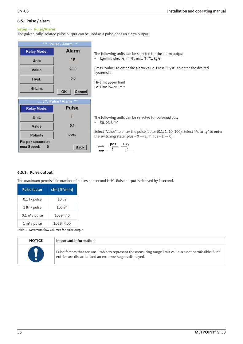
6.5. Pulse / alarm
Setup → Pulse/AlarmThe galvanically isolated pulse output can be used as a pulse or as an alarm output.
° FThe following units can be selected for the alarm output:• kg/min, cfm, l/s, m³/h, m/s, °F, °C, kg/s
Press "Value" to enter the alarm value. Press "Hyst". to enter the desired hysteresis.
Hi-Lim: upper limitLo-Lim: lower limit
l The following units can be selected for pulse output:• kg, cd, l, m³
Select "Value" to enter the pulse factor (0.1, 1, 10, 100). Select "Polarity" to enter the switching state (plus = 0 → 1, minus = 1 → 0).
6.5.1. Pulse output
The maximum permissible number of pulses per second is 50. Pulse output is delayed by 1 second.
Pulse factor cfm [ft³/min]
0.1 l / pulse 10.59
1 ltr / pulse 105.94
0.1m³ / pulse 10594.40
1 m³ / pulse 105944.00
Table 1: Maximum flow volumes for pulse output
NOTICE Important information
Pulse factors that are unsuitable to represent the measuring range limit value are not permissible. Such entries are discarded and an error message is displayed.

Installation and operating manual EN -US
36 METPOINT® SF53
6.6. User Setup
Setup → User Setup
On the user setup screen, you can change the password, rotate the display and adjust its brightness.
To change the password, you must enter the new password twice.
6.7. Advanced
Setup → Advanced
Press the "Factory Reset" button to reset the METPOINT® FLM to its default (factory) settings.

EN-US Installation and operating manual
37 METPOINT® SF53
6.8. 4 ... 20 mA
Setup → 4 - 20 mA
On this screen, you can adjust the settings for the 4 ... 20 mA analog output.
Setup → 4 - 20 mA → Channel 1
0.000 cfm
646.25 cfm
646.25 cfm33425.2 fpm
The following measurements can be configured:• Flow• Velocity• Temperature• unused = deactivate channel
cfm
The screenshot to the left shows the available units for flow. Press the "<<" button to call up the next screen.
0.000 cfm
646.25 cfm
646.25 cfm33425.2 fpm
The scaling of the 4 ... 20 mA analog output can be set to automatic ("AutoRange = on") or manual ("AutoRange = off").
With "AutoRange = on", the sensor automatically calculates the valid measuring range and associated reference conditions, based on the set pipe diameter.
Select "Scale 4mA" and "Scale 20mA" to manually configure the scaling of the output (precondition: "AutoRange = off").
cfm cfmEnter the scale for 4 mA and 20 mA respectively.

Installation and operating manual EN -US
38 METPOINT® SF53
Setup → 4 - 20 mA → Error Current
On this screen, you can enter the error signal to be sent by the analog output in the event of a fault.• 2 mA = sensor fault / system error• 22 mA = sensor fault / system error• None = output according to Namur (3.8 mA ... 20.5 mA)
< 4mA to 3.8 mA = value below measuring range > 20 mA to 20.5 mA = value above measuring range
Confirm your entry by pressing the >>ENTER<< button.
6.9. Info
Setup → Info
cfmfpm°F This screen shows device information.
° Fpsi
psi° F
2.09 inch Press "Details" to view the calibration conditions.
6.10. MBus
6.10.1. Default communication settings
Primary address*: 1ID: Serial number of sensorBaud rate*: 2400Medium*: Gas
6.10.2. Transferred values
Value 1 with [Unit]*: Flow [cfm]Value 2 with [Unit]*: Consumption [cf]Value 3 with [Unit]*: Velocity [fpm]Value 4 with [Unit]*: Gas temperature [°F]
* these values can be factory-set or changed on request.

EN-US Installation and operating manual
39 METPOINT® SF53
7. Spare parts and accessoriesThe accessories available for the METPOINT® FLM are listed in the table below.
Designation Picture
Power supply with plug-type connector APart. no. 4032115
8. Maintenance and servicingRegularly check the sensor head for dirt and clean it, if necessary. Dirt, dust or oil deposits on the sensor element cause incorrect measurements.We recommend checking the sensor element at least once a year. If the compressed air is heavily contaminated, choose a shorter inspection interval.
9. Cleaning sensor headTo clean the sensor head, immerse it in warm water with a little detergent. Do not clean the sensor with a cloth, sponge, brush or other implement, as any mechanical impact can destroy the sensor. In the event of persistent deposits, return the sensor to the manufacturer for inspection and cleaning.
10. CalibrationIf the device is not custom-configured, we recommend having it calibrated every 12 months. For calibration, send the METPOINT® FLM to BEKO TECHNOLOGIES Corporation.
11. LED indicatorThe METPOINT® FLM features a LED calibration indicator mounted at the top of the housing. After 15 months, the LED begins to flash, indicating that the device needs to be calibrated. The flashing LED does not have any effect on the measuring process, and the device continues to provide accurate measuring signals.On request, the calibration interval can be adjusted at the factory.
Installation and operating manual EN -US
40 METPOINT® SF53
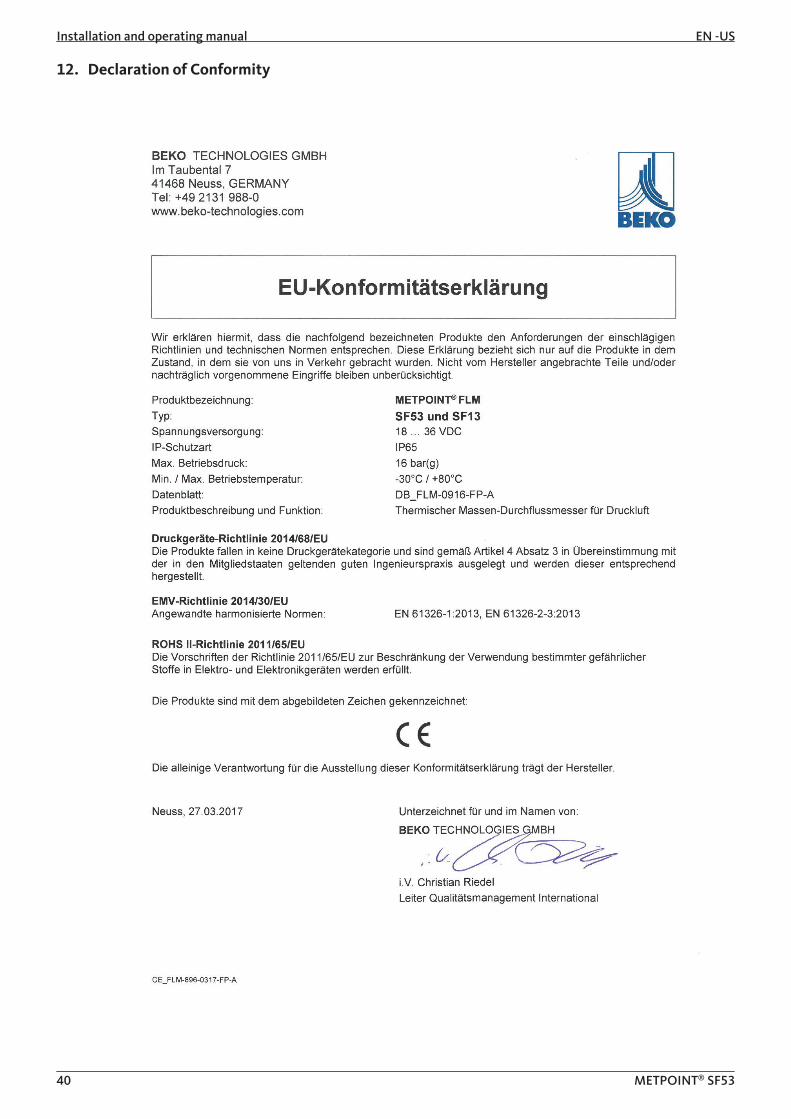
12. Declaration of Conformity
EN-US Installation and operating manual
41 METPOINT® SF53
BEKO TECHNOLOGIES GMBH Im Taubental 7 41468 Neuss, GERMANY Phone: +49 2131 988-0 www.beko-technologies.com
CE_FLM-896-0916-FP-A
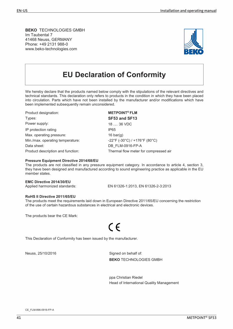
EU Declaration of Conformity We hereby declare that the products named below comply with the stipulations of the relevant directives and technical standards. This declaration only refers to products in the condition in which they have been placed into circulation. Parts which have not been installed by the manufacturer and/or modifications which have been implemented subsequently remain unconsidered.
Product designation: METPOINT® FLM Types: SF53 and SF13 Power supply: 18 … 36 VDC IP protection rating IP65 Max. operating pressure: 16 bar(g)
Min./max. operating temperature: -22°F (-30°C) / +176°F (80°C) Data sheet: DB_FLM-0916-FP-A Product description and function: Thermal flow meter for compressed air Pressure Equipment Directive 2014/68/EU The products are not classified in any pressure equipment category. In accordance to article 4, section 3, they have been designed and manufactured according to sound engineering practice as applicable in the EU member states. EMC Directive 2014/30/EU Applied harmonized standards: EN 61326-1:2013, EN 61326-2-3:2013 RoHS II Directive 2011/65/EU The products meet the requirements laid down in European Directive 2011/65/EU concerning the restriction of the use of certain hazardous substances in electrical and electronic devices. The products bear the CE Mark:
This Declaration of Conformity has been issued by the manufacturer.
Neuss, 25/10/2016 Signed on behalf of:
BEKO TECHNOLOGIES GMBH
ppa Christian Riedel Head of International Quality Management

Installation and operating manual EN -US
42 METPOINT® SF53

EN-US Installation and operating manual
43 METPOINT® SF53
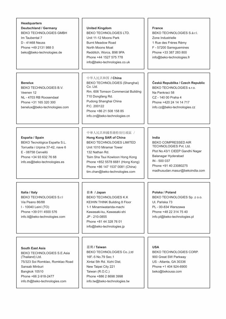
HeadquartersDeutschland / GermanyBEKO TECHNOLOGIES GMBHIm Taubental 7 D - 41468 NeussPhone +49 2131 988 0 [email protected]
United KingdomBEKO TECHNOLOGIES LTD.Unit 11-12 Moons ParkBurnt Meadow RoadNorth Moons MoatRedditch, Worcs, B98 9PAPhone +44 1527 575 [email protected]
FranceBEKO TECHNOLOGIES S.à.r.l.Zone Industrielle1 Rue des Frères Rémy F - 57200 SarregueminesPhone +33 387 283 [email protected]
BeneluxBEKO TECHNOLOGIES B.V.Veenen 12NL - 4703 RB RoosendaalPhone +31 165 320 [email protected]
中华人民共和国 / ChinaBEKO TECHNOLOGIES (Shanghai) Co. Ltd. Rm. 606 Tomson Commercial Building710 Dongfang Rd.Pudong Shanghai ChinaP.C. 200122Phone +86 21 508 158 [email protected]
Česká Republika / Czech RepublicBEKO TECHNOLOGIES s.r.o. Na Pankraci 58CZ - 140 00 Praha 4Phone +420 24 14 14 717 [email protected]
España / SpainBEKO Tecnológica España S.L. Torruella i Urpina 37-42, nave 6E - 08758 CervellóPhone +34 93 632 76 [email protected]
中華人民共和國香港特別行政區 /
Hong Kong SAR of ChinaBEKO TECHNOLOGIES LIMITED Unit 1010 Miramar Tower 132 Nathan Rd.Tsim Sha Tsui Kowloon Hong KongPhone +852 5578 6681 (Hong Kong)Phone +86 147 1537 0081 (China)[email protected]
IndiaBEKO COMPRESSED AIR TECHNOLOGIES Pvt. Ltd.Plot No.43/1 CIEEP Gandhi NagarBalanagar Hyderabad IN - 500 037Phone +91 40 [email protected]
Italia / ItalyBEKO TECHNOLOGIES S.r.lVia Peano 86/88I - 10040 Leinì (TO)Phone +39 011 4500 [email protected]
日本 / JapanBEKO TECHNOLOGIES K.KKEIHIN THINK Building 8 Floor1-1 Minamiwatarida-machiKawasaki-ku, Kawasaki-shiJP - 210-0855 Phone +81 44 328 76 01 [email protected]
Polska / PolandBEKO TECHNOLOGIES Sp. z o.o.Ul. Pańska 73PL - 00-834 WarszawaPhone +48 22 314 75 [email protected]
South East AsiaBEKO TECHNOLOGIES S.E.Asia (Thailand) Ltd.75/323 Soi Romklao, Romklao RoadSansab MinburiBangkok 10510Phone +66 [email protected]
臺灣 / TaiwanBEKO TECHNOLOGIES Co.,Ltd16F.-5 No.79 Sec.1 Xintai 5th Rd. Xizhi Dist.New Taipei City 221Taiwan (R.O.C.)Phone +886 2 8698 [email protected]
USABEKO TECHNOLOGIES CORP. 900 Great SW ParkwayUS - Atlanta, GA 30336Phone +1 404 924-6900 [email protected]
Related Documents