Methodologies for Combined Loads Tests Using a Multi-Actuator Test Machine Marshall Rouse NASA Langley Research Center, Mail Stop 190, Hampton, VA 23681-2199 E-mail: [email protected] Structures Testing Branch ABSTRACT The NASA Langley COmbined Loads Test System (COLTS) Facility was designed to accommodate a range of fuselage structures and wing sections and subject them to both quasistatic and cyclic loading conditions. Structural tests have been conducted in COLTS that address structural integrity issues of metallic and fiber reinforced composite aerospace structures in support of NASA Programs (i.e. the Aircraft Structural Integrity (ASIP) Program, High-Speed-Research program and the Supersonic Project, NASA Engineering and Safety Center (NESC) Composite Crew Module Project, and the Environmentally Responsible Aviation Program),. This paper presents experimental results for curved panels subjected to mechanical and internal pressure loads using a D-box test fixture. Also, results are presented that describe use of a checkout beam for development of testing procedures for a combined mechanical and pressure loading test of a Multi-bay box. The Multi-bay box test will be used to experimentally verify the structural performance of the Multi-bay box in support of the Environmentally Responsible Aviation Project at NASA Langley. INTRODUCTION The ability to subject aerospace structures to combined loads representative of actual operating conditions is an important aspect of aerospace structural design. The standard aerospace industry practice is to design a structure that supports the various loading conditions and to verify the design by structural testing. A test fixture is usually designed to subject the structure to a subset of the loading conditions. The test fixture is often limited to a particular design or single configuration. However, the development of structures technology to be used for future aerospace design requires that full-scale and sub- scale structural concepts be tested with combinations of mechanical and internal pressure loads. Combined-loads testing requires a combined loads test machine with the flexibility to accommodate these structures. The NASA Langley Research Center developed the COmbined Loads Test System (COLTS), which consists of a multi-actuator test machine capable of applying combined loads and internal pressure loading to validate structures technology [1]. Structural tests have been conducted using COLTS to support airframe and space structures technology development. Tests have been conducted for the NASA Aircraft Structural Integrity Program, NASA High-Speed Research program, NASA Engineering and Safety Center (NESC) Composite Crew Module (CCM) Program and Environmentally Responsible Aviation (ERA) Project [2-7]. Three of the tests that were conducted using COLTS are presented in this paper. Experimental results are presented for curved fuselage panels that were tested using a D-box test fixture. Experimental results are presented for a 30-foot checkout beam specimen that is currently being used to develop and verify testing methodology for an ERA composite Multi-bay box test currently being planned for COLTS. FACILITY DESCRIPTION Combined Loads Test System COLTS was designed to accommodate a range of fuselage structures and wing sections and subject them to both quasistatic and cyclic loading conditions. COLTS is capable of testing fuselage barrels up to 4.6 m diameter and 13.7 m long with combined mechanical, internal pressure, and thermal loads. A schematic of COLTS configured with a cylindrical shell mounted between the test machine platens is illustrated in Figure 1a, and a photograph of the facility is shown in Figure 1b. The loading platen is suspended from a gantry that can traverse forward or backward to accommodate test articles of different lengths. Compression and bending loads are applied to the test articles by six 2,001.7-kN hydraulic actuators located perpendicular to and between the loading and reacting platens along the x (longitudinal) axis. Torsion loads are applied to the test articles by two 1,334.5-kN hydraulic actuators located vertically and spaced 7.0 m apart. Shear loads are applied to the test articles by two 1,334.5-kN hydraulic actuators located horizontally and spaced 5.5 m apart. The test machine is located in a steel reinforced concrete pit that is approximately 9.8 m deep, 14.3 m wide, and 22.0 m long. This arrangement is to ensure that pressurized structural testing can be performed safely. The length of the axial actuators is extended by https://ntrs.nasa.gov/search.jsp?R=20130014926 2018-05-21T15:23:03+00:00Z

Welcome message from author
This document is posted to help you gain knowledge. Please leave a comment to let me know what you think about it! Share it to your friends and learn new things together.
Transcript
Methodologies for Combined Loads Tests Using a Multi-Actuator Test Machine
Marshall RouseNASA Langley Research Center, Mail Stop 190, Hampton, VA 23681-2199
E-mail: [email protected] Testing Branch
ABSTRACT
The NASA Langley COmbined Loads Test System (COLTS) Facility was designed to accommodate a range of fuselage structures and wing sections and subject them to both quasistatic and cyclic loading conditions. Structural tests have been conducted in COLTS that address structural integrity issues of metallic and fiber reinforced composite aerospace structures in support of NASA Programs (i.e. the Aircraft Structural Integrity (ASIP) Program, High-Speed-Research program and the Supersonic Project, NASA Engineering and Safety Center (NESC) Composite Crew Module Project, and the Environmentally Responsible Aviation Program),. This paper presents experimental results for curved panels subjected to mechanical and internal pressure loads using a D-box test fixture. Also, results are presented that describe use of a checkout beam for development of testing procedures for a combined mechanical and pressure loading test of a Multi-bay box. The Multi-bay box test will be used to experimentally verify the structural performance of the Multi-bay box in support of the Environmentally Responsible Aviation Project at NASA Langley.
INTRODUCTION
The ability to subject aerospace structures to combined loads representative of actual operating conditions is an importantaspect of aerospace structural design. The standard aerospace industry practice is to design a structure that supports the various loading conditions and to verify the design by structural testing. A test fixture is usually designed to subject the structure to a subset of the loading conditions. The test fixture is often limited to a particular design or single configuration. However, the development of structures technology to be used for future aerospace design requires that full-scale and sub-scale structural concepts be tested with combinations of mechanical and internal pressure loads. Combined-loads testing requires a combined loads test machine with the flexibility to accommodate these structures. The NASA Langley Research Center developed the COmbined Loads Test System (COLTS), which consists of a multi-actuator test machine capable of applying combined loads and internal pressure loading to validate structures technology [1]. Structural tests have been conducted using COLTS to support airframe and space structures technology development. Tests have been conducted for the NASA Aircraft Structural Integrity Program, NASA High-Speed Research program, NASA Engineering and Safety Center (NESC) Composite Crew Module (CCM) Program and Environmentally Responsible Aviation (ERA) Project [2-7].
Three of the tests that were conducted using COLTS are presented in this paper. Experimental results are presented for curved fuselage panels that were tested using a D-box test fixture. Experimental results are presented for a 30-foot checkout beam specimen that is currently being used to develop and verify testing methodology for an ERA composite Multi-bay box test currently being planned for COLTS.
FACILITY DESCRIPTION
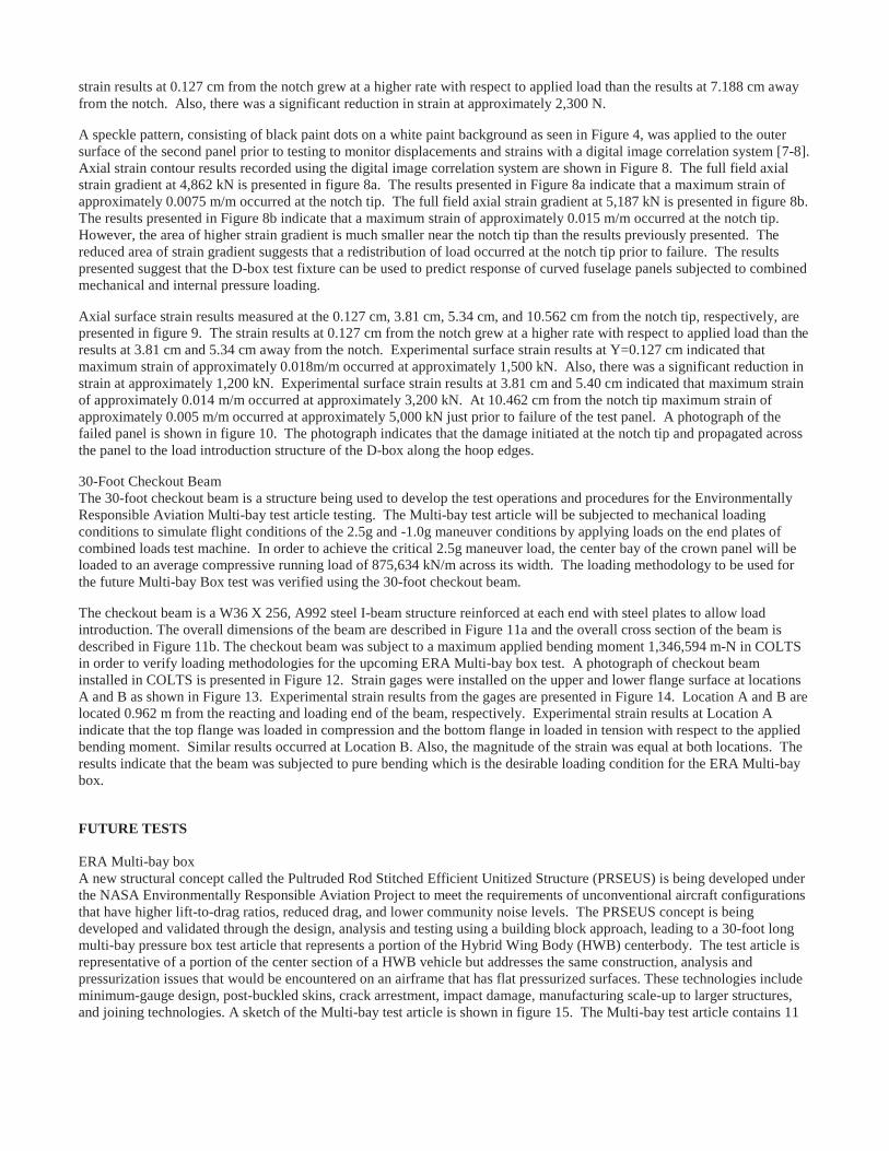
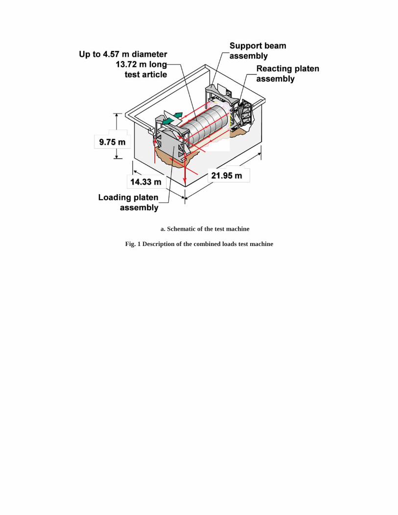
Combined Loads Test SystemCOLTS was designed to accommodate a range of fuselage structures and wing sections and subject them to both quasistatic and cyclic loading conditions. COLTS is capable of testing fuselage barrels up to 4.6 m diameter and 13.7 m long with combined mechanical, internal pressure, and thermal loads. A schematic of COLTS configured with a cylindrical shell mounted between the test machine platens is illustrated in Figure 1a, and a photograph of the facility is shown in Figure 1b.The loading platen is suspended from a gantry that can traverse forward or backward to accommodate test articles of different lengths. Compression and bending loads are applied to the test articles by six 2,001.7-kN hydraulic actuators located perpendicular to and between the loading and reacting platens along the x (longitudinal) axis. Torsion loads are applied to the test articles by two 1,334.5-kN hydraulic actuators located vertically and spaced 7.0 m apart. Shear loads are applied to the test articles by two 1,334.5-kN hydraulic actuators located horizontally and spaced 5.5 m apart. The test machine is located in a steel reinforced concrete pit that is approximately 9.8 m deep, 14.3 m wide, and 22.0 m long. This arrangement is to ensure that pressurized structural testing can be performed safely. The length of the axial actuators is extended by
https://ntrs.nasa.gov/search.jsp?R=20130014926 2018-05-21T15:23:03+00:00Z

means of tubular extensions to connect the loading platen with the load reacting platen so that test specimens that are longerthan 3.05 m can be accommodated.
Mini-COLTSFor development of tests to be conducted in COLTS, an approximately 10%-scale model of COLTS, called Mini-COLTS, is utilized. Compression and bending, shear, and torsion loads are applied to subscale test models by six 8,896-N hydraulic actuators located perpendicular to and between the loading and reacting platens along the x (longitudinal) axis. Torsion loads are applied to the test articles by two 8,896-N hydraulic actuators located vertically and spaced 81.6 cm inches apart. Shear loads are applied to the test articles by two 8,896-N hydraulic actuators located horizontally and spaced 57.15 cm apart. The length of the axial actuators is fixed with respect to the load reacting platen so that test models that are 139.7 cm can be accommodated. A photograph of the Mini-COLTS is shown in Figure 2. Using the COLTS control system, Mini-COLTS can be used to do operational checkout of the mechanical loading parameters before loading the actual test article. Once theMini-COLTS loading has been verified, the controls are switched back to the COLTS facility.
D-box Test FixtureA cross section drawing of the D-box test fixture is shown in Figure 3. The fixture is used to apply mechanical and internal pressure loads to curved panels. The axial stiffness of the D-box test fixture allows a test panel to experience most of the applied axial load and minimizes the shift in the center-of-pressure of the assembly if the test panel buckles. The low axial stiffness of the D-box test fixture is the result of an assembly of curved I-beams with the cross section shown in the inset of Figure 3. The I-beam sections are 20.32 cm deep and 15 of these sections are used to make the D-box test fixture. This D-box test fixture is designed to test curved panels with 152.4- to 330.2-cm radii and 50.8- to 55.9-cm frame spacing. Anoverhead photo of a panel in the D-box mounted in COLTS and a cabinet view drawing of the D-box test fixture arepresented in Figure 4. The drawing shows the hinge fittings attaching the panel to the D-box. Thirteen of these hinge fittings are provided between the I-beams for this purpose. When the D-box assembly is internally pressurized, the assembly expands in a manner that causes the hinge supports to move inward. This deformation would cause the test panel to bend in a way that is not representative of the response of an internally pressurized shell. To prevent this undesirable deformation, cross braces are mounted between the hinge points as shown in Figure 3 such that the distance between the hinge points can be held constant or adjusted as needed to induce the appropriate stress state in the test panel. The D-box test fixture is capable of applying combined axial, shear, and internal pressure loads: 1,751,268 N/m axial load, 525,380.1 N/m shear load, and 137.89 kPa internal pressure.
TESTS PERFORMED
Curved Fuselage PanelsTest result for two curved fuselage graphite-epoxy panels are presented in this paper. Both of the panels were 3.05 m long, 1.83 m arc width and 1.90 m outer mold radius. The test panels were also tested with a 22.86 cm length circumferential notch to simulate discrete source damage. The first panel was a honeycomb sandwiched panel with two frames. The facesheets were fabricated using 28 plies of IM7/PETI-5 graphite-epoxy material titanium honeycomb core. It had two frames mechanically fastened to the skin and spaced 1.02 m apart. The notch was machined into the panel mid-way between the two frames and centered on the longitudinal centerline at the mid-length of the panel. The frames were fabricated from triaxially braided stitched preform and fiber preforms using a resin film infusion process. The second panel was a stiffened graphite-epoxy fuselage side panel design. This panel had eight stringers and four frames. The stringers were spaced equally 17.8 cm apart. The second panel had four frames mechanically fastened to the skin and spaced 0.51 m apart. The notch was machined into this panel mid-way between the two frames and severed an interior stringer. A photograph of the second panel is shown in Figure 5. The skin was fabricated from 34 plies of IM7/PETI-5 graphite-epoxy material. The stringers were fabricated from IM7/PETI-5 graphite-epoxy material and the frames were fabricated from triaxially braided stitched preform and fiber preforms using a resin film infusion process. A detailed description of the curved fuselage panel is given in Reference [3].
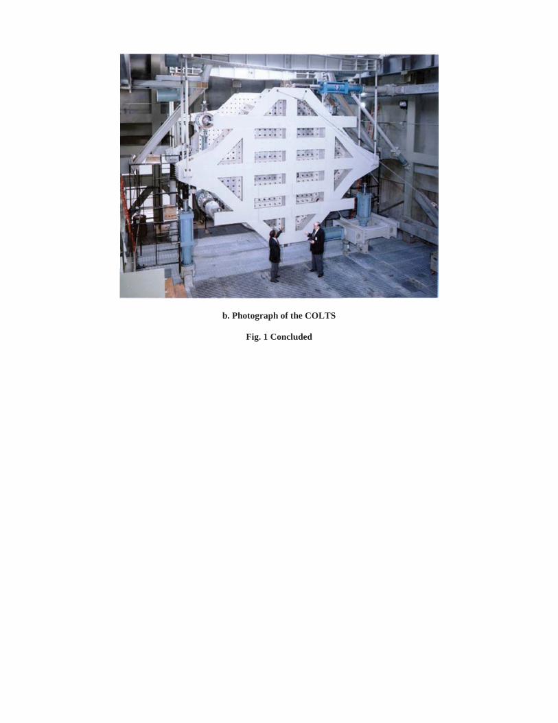
The fuselage panels were loaded to 49.12 kPa internal pressure and then axial tension load was applied until failure occurred. A summary of the failure is presented. The experimental axial strain results along a circumferential line located at the mid-length of the first panel are presented in Figure 6. The results indicate that the strain results are uniform across circumference of the panel except at the notch tips. The strains were a maximum of 0.014 m/m near the notch tip and decrease to approximately 0.002 m/m away from the notch tip at a 2,688.8 N axial load and 49.12 kPa internal pressure loading. However, the maximum value of strain at the notch tip varied from 0.008 m/m to 0.012 m/m at the notch tip at an axial load of 4571.6N and 49.12kPa. The lower measured strain value with respect to the previous load condition present in the figure at the notch tip suggests that damage has initiated at the notch tip resulting in a redistribution of loading at the tip. Axial surface strain results measured at the 0.127 cm and 7.188 cm from the notch tip, respectively, are presented in figure 7. The
strain results at 0.127 cm from the notch grew at a higher rate with respect to applied load than the results at 7.188 cm awayfrom the notch. Also, there was a significant reduction in strain at approximately 2,300 N.
A speckle pattern, consisting of black paint dots on a white paint background as seen in Figure 4, was applied to the outer surface of the second panel prior to testing to monitor displacements and strains with a digital image correlation system [7-8]. Axial strain contour results recorded using the digital image correlation system are shown in Figure 8. The full field axial strain gradient at 4,862 kN is presented in figure 8a. The results presented in Figure 8a indicate that a maximum strain of approximately 0.0075 m/m occurred at the notch tip. The full field axial strain gradient at 5,187 kN is presented in figure 8b. The results presented in Figure 8b indicate that a maximum strain of approximately 0.015 m/m occurred at the notch tip. However, the area of higher strain gradient is much smaller near the notch tip than the results previously presented. The reduced area of strain gradient suggests that a redistribution of load occurred at the notch tip prior to failure. The results presented suggest that the D-box test fixture can be used to predict response of curved fuselage panels subjected to combined mechanical and internal pressure loading.
Axial surface strain results measured at the 0.127 cm, 3.81 cm, 5.34 cm, and 10.562 cm from the notch tip, respectively, are presented in figure 9. The strain results at 0.127 cm from the notch grew at a higher rate with respect to applied load than the results at 3.81 cm and 5.34 cm away from the notch. Experimental surface strain results at Y=0.127 cm indicated that maximum strain of approximately 0.018m/m occurred at approximately 1,500 kN. Also, there was a significant reduction in strain at approximately 1,200 kN. Experimental surface strain results at 3.81 cm and 5.40 cm indicated that maximum strain of approximately 0.014 m/m occurred at approximately 3,200 kN. At 10.462 cm from the notch tip maximum strain of approximately 0.005 m/m occurred at approximately 5,000 kN just prior to failure of the test panel. A photograph of the failed panel is shown in figure 10. The photograph indicates that the damage initiated at the notch tip and propagated across the panel to the load introduction structure of the D-box along the hoop edges.
30-Foot Checkout BeamThe 30-foot checkout beam is a structure being used to develop the test operations and procedures for the Environmentally Responsible Aviation Multi-bay test article testing. The Multi-bay test article will be subjected to mechanical loading conditions to simulate flight conditions of the 2.5g and -1.0g maneuver conditions by applying loads on the end plates of combined loads test machine. In order to achieve the critical 2.5g maneuver load, the center bay of the crown panel will be loaded to an average compressive running load of 875,634 kN/m across its width. The loading methodology to be used for the future Multi-bay Box test was verified using the 30-foot checkout beam.
The checkout beam is a W36 X 256, A992 steel I-beam structure reinforced at each end with steel plates to allow load introduction. The overall dimensions of the beam are described in Figure 11a and the overall cross section of the beam is described in Figure 11b. The checkout beam was subject to a maximum applied bending moment 1,346,594 m-N in COLTS in order to verify loading methodologies for the upcoming ERA Multi-bay box test. A photograph of checkout beam installed in COLTS is presented in Figure 12. Strain gages were installed on the upper and lower flange surface at locations A and B as shown in Figure 13. Experimental strain results from the gages are presented in Figure 14. Location A and B are located 0.962 m from the reacting and loading end of the beam, respectively. Experimental strain results at Location A indicate that the top flange was loaded in compression and the bottom flange in loaded in tension with respect to the applied bending moment. Similar results occurred at Location B. Also, the magnitude of the strain was equal at both locations. The results indicate that the beam was subjected to pure bending which is the desirable loading condition for the ERA Multi-bay box.
FUTURE TESTS
ERA Multi-bay boxA new structural concept called the Pultruded Rod Stitched Efficient Unitized Structure (PRSEUS) is being developed under the NASA Environmentally Responsible Aviation Project to meet the requirements of unconventional aircraft configurations that have higher lift-to-drag ratios, reduced drag, and lower community noise levels. The PRSEUS concept is being developed and validated through the design, analysis and testing using a building block approach, leading to a 30-foot long multi-bay pressure box test article that represents a portion of the Hybrid Wing Body (HWB) centerbody. The test article is representative of a portion of the center section of a HWB vehicle but addresses the same construction, analysis and pressurization issues that would be encountered on an airframe that has flat pressurized surfaces. These technologies include minimum-gauge design, post-buckled skins, crack arrestment, impact damage, manufacturing scale-up to larger structures, and joining technologies. A sketch of the Multi-bay test article is shown in figure 15. The Multi-bay test article contains 11

PRSEUS panels (crown, floor, two upper bulkheads, two lower bulkheads, two side rib, two side keels, lower keel), four honeycomb center rib panels, aluminum fittings, access doors, and titanium bolts.
As defined in the 30-foot checkout beam section above, the Multi-bay test article will be subjected to mechanical loads, but it will also be subjected to internal pressure loads. Mechanical and internal pressure loads will be applied simultaneously. The loading conditions will simulate the critical load cases: 2.5g, 2.5g plus 63.431 kPa, -1.0g, and -1.0g plus 63.431 kPamaneuver conditions, as well as the static 126.863 kPa ground condition that was used to size the overall test article structure. The Multi-bay test article will be subjected to internal pressure loads of 126.863 kPa to simulate a twice static proof condition.
CONCLUDING REMARKSA combined loads test machine has been demonstrated that is capable of applying combined mechanical, internal pressure loading to various structures. Curved fuselage panel were subjected to axial tension and internal pressure loading with simulated damage. Experimental results from COLTS for a check out beam have been used to verify that the combined loads test machine is capably of applying the proper pure bending loading condition to for the upcoming NASA ERA Multi-bay test article.
REFERENCES
[1] Ambur, D. R., Rouse, M., Starnes, J.H., and Shuart, M. J., “Facilities for Combined Loads Testing of Aircraft Structures to Satisfy Structural Technology Development Requirements,” presented at the 5th Annual Advanced Composites Technology Conference, Seattle, WA, August 22-36, 1994.
[2] Ambur, D. R., Rouse, M., Young, R. D., and Perez-Ramos, C., “Evaluation of an Aluminum Fuselage Panel with Discrete-Source Damage and Subjected to Combined Loading Conditions,” AIAA-99-1382, April 1999.
[3] High Speed Research Program Summary Report for Task 16 Material and Structures Damage Tolerances and 25 Fuselage Structures, NAA Contract NAS1-2020, September 1999.
[4] Ambur Damodar R., and Rouse, M., “Design and Evaluation of Composite Fuselage Panels Subjected to CombinedLoading Conditions”, AIAA Journal of Aircraft; Vol. 42, No. 4, August 2005.
[5] Rouse, M. Young, Richard D., and Gehrki, Ralph E., “Structural Stability of a Stiffened Aluminum Fuselage Panel Subjected to Combined Mechanical and Internal Pressure Loads,” presented at the 44th AIAA/ASME/ASCE/AHS Structures, Structural Dynamics, and Materials Conference, Norfolk, Virginia, April 7-10, 2003.
[6] Composite Crew Module Test NESC-RP-06-019, NASA/TM-211-217190, 2011.
[7] Jegley, Dawn C. “Status of Advanced Stitched Unitized Composite Aircraft Structures,” presented at the 51th AIAA Aerospace Sciences Meeting including the New Horizons Forum and Aerospace Exposition , Grapevine, TX, January 2013.
a. Schematic of the test machine
Fig. 1 Description of the combined loads test machine
b. Photograph of the COLTS
Fig. 1 Concluded

Fig. 2 Photograph of the Mini-COLTS combined loads test machine
Fig. 3 Cross section of D-box test fixture for testing curved panels

Fig. 4 Overhead photograph and cabinet view of drawing of D-box test fixture
Fig. 5 Fuselage curved panel B
Fig. 6 Experimental axial surface strain results from strain gages across the circumference of the panel and near the notch

Fig. 7 Experimental axial surface strain results near notch tip as a function of applied load
a 4,862 kN applied axial load b 5,187 kN applied axial load
Fig. 8 Full-field axial strain gradients

Fig. 9 Experimental surface strain results near the tip of the notch

Fig. 10 Experimental surface strain results near the tip of the notch.

a. Dimensions
Fig. 11 Checkout beam geometry
b. Cross-section
Fig. 11 Concluded

Fig. 12 Photograph of 30’ checkout beam

Fig. 13 Location of strain gages on checkout beam

Fig. 14 Typical strains on the top and upper and lower flange of the checkout beam
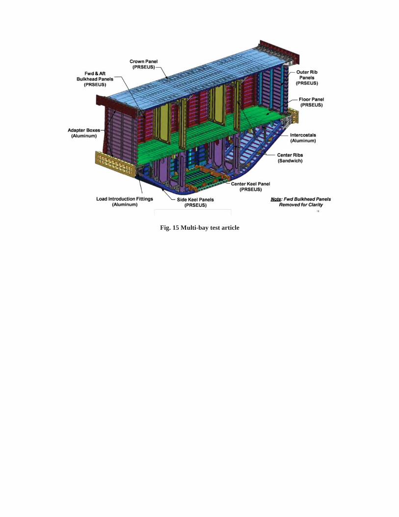
Fig. 15 Multi-bay test article
Related Documents