Method of Virtual Work Beam Deflection Example Steven Vukazich San Jose State University

Welcome message from author
This document is posted to help you gain knowledge. Please leave a comment to let me know what you think about it! Share it to your friends and learn new things together.
Transcript

Method of Virtual Work Beam Deflection Example
StevenVukazichSanJoseStateUniversity
Summary of Procedure for Finding Bending Deformation Using Virtual Work
We want to find the deflection at point A and the slope at point B due to the applied loads
PMw
x
y
𝜃"
Modulus of Elasticity = EMoment of Inertia = I
AB
ab
L
𝛿$
Step 1 – Remove all loads and apply a virtual force (or moment) to measure the deformation at the point of interest
Qx
y
Aa
L
From an equilibrium analysis, find the internal bending moment function for the virtual system: MQ(x)
Convenient to set Q = 1
PMw
x
y
L
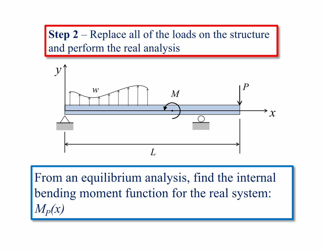
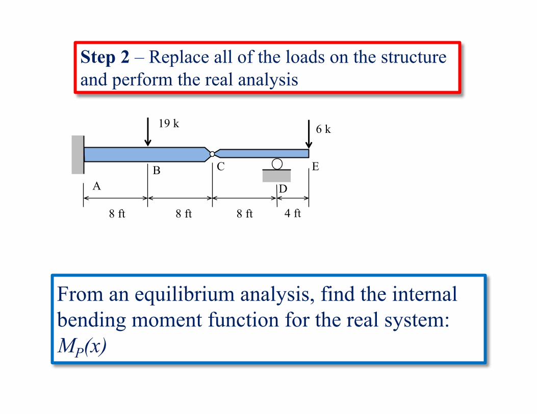
Step 2 – Replace all of the loads on the structure and perform the real analysis
From an equilibrium analysis, find the internal bending moment function for the real system: MP(x)
𝑄𝛿$ = ' 𝑀)
*
+
𝑀,
𝐸𝐼𝑑𝑥
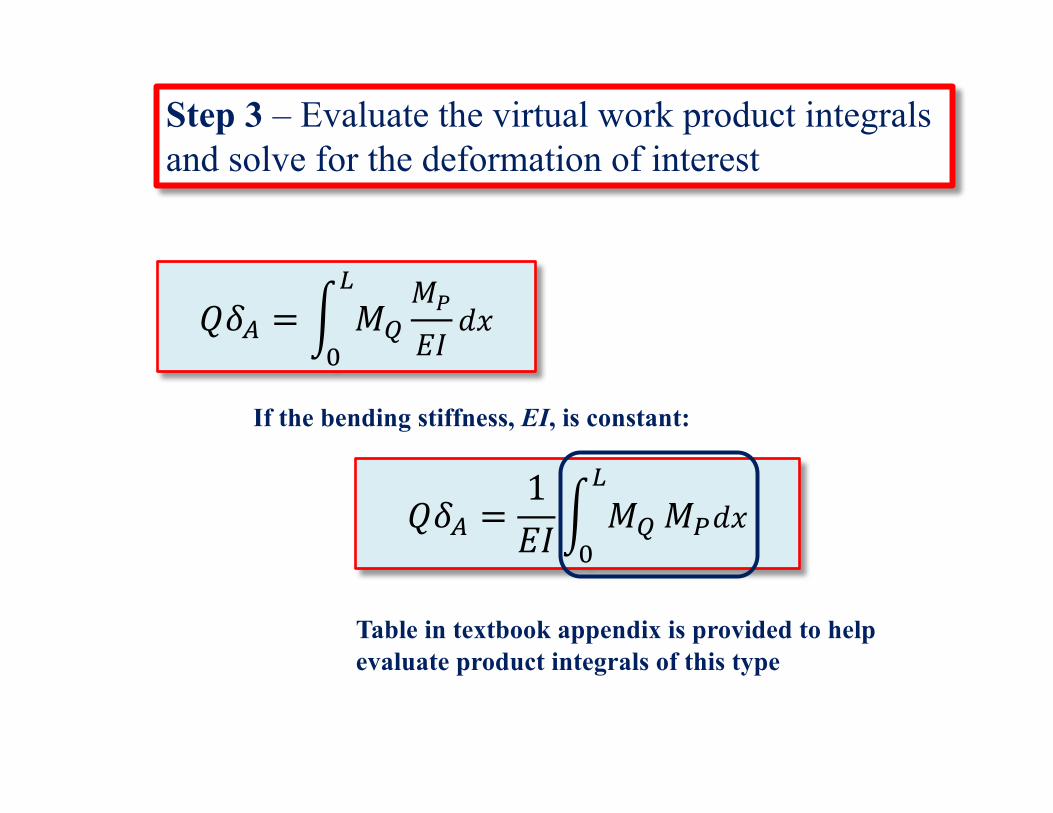
If the bending stiffness, EI, is constant:
𝑄𝛿$ =1𝐸𝐼' 𝑀)
*
+𝑀,𝑑𝑥
Table in textbook appendix is provided to help evaluate product integrals of this type
Step 3 – Evaluate the virtual work product integrals and solve for the deformation of interest
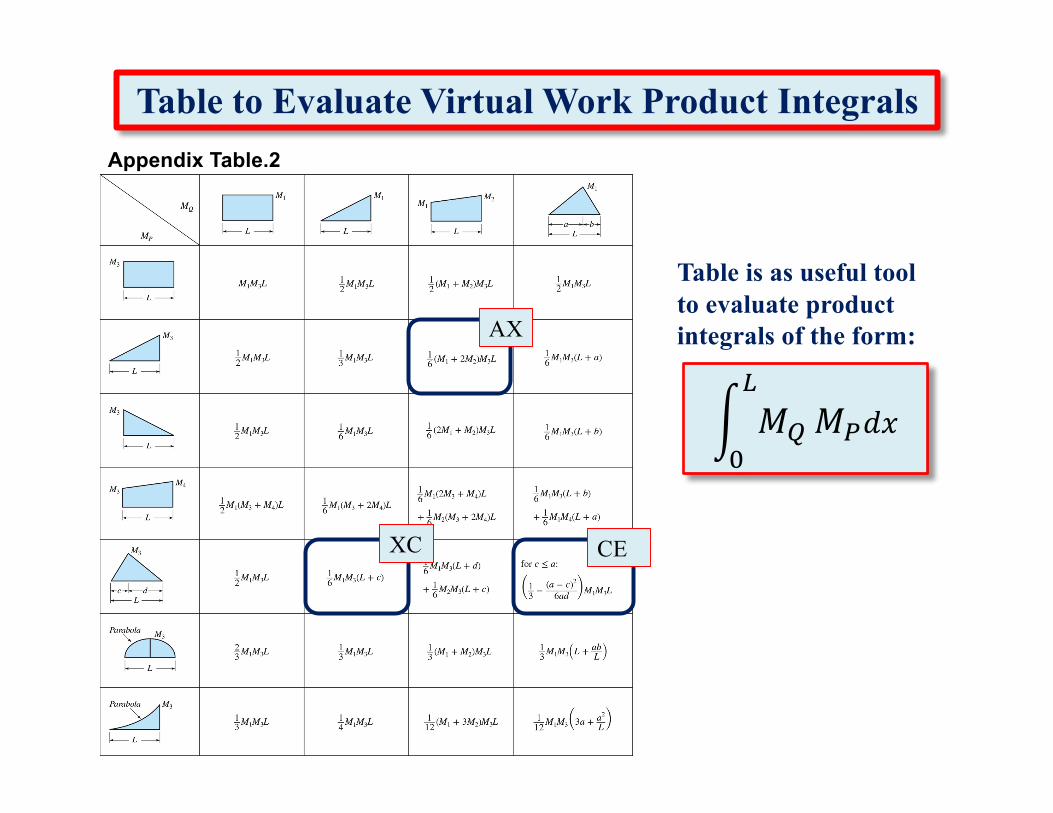
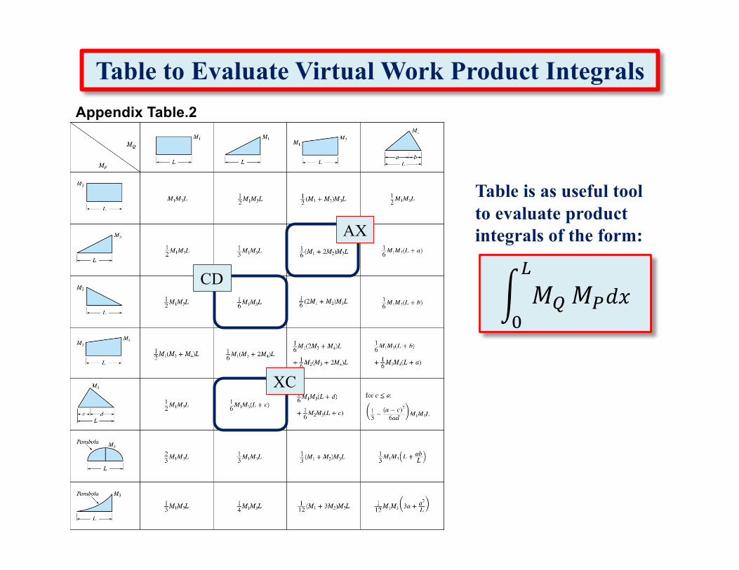
Appendix Table.2
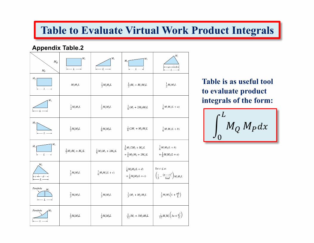
Table to Evaluate Virtual Work Product Integrals
' 𝑀)
*
+𝑀,𝑑𝑥
Table is as useful tool to evaluate product integrals of the form:
Beam Deflection Example
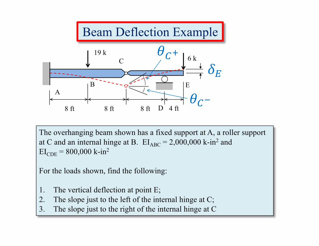
The overhanging beam shown has a fixed support at A, a roller support at C and an internal hinge at B. EIABC = 2,000,000 k-in2 and EICDE = 800,000 k-in2
For the loads shown, find the following:
1. The vertical deflection at point E;2. The slope just to the left of the internal hinge at C;3. The slope just to the right of the internal hinge at C
8 ft 4 ftD
C
BA
E
8 ft8 ft
6 k19 k
𝛿2
𝜃34
𝜃35
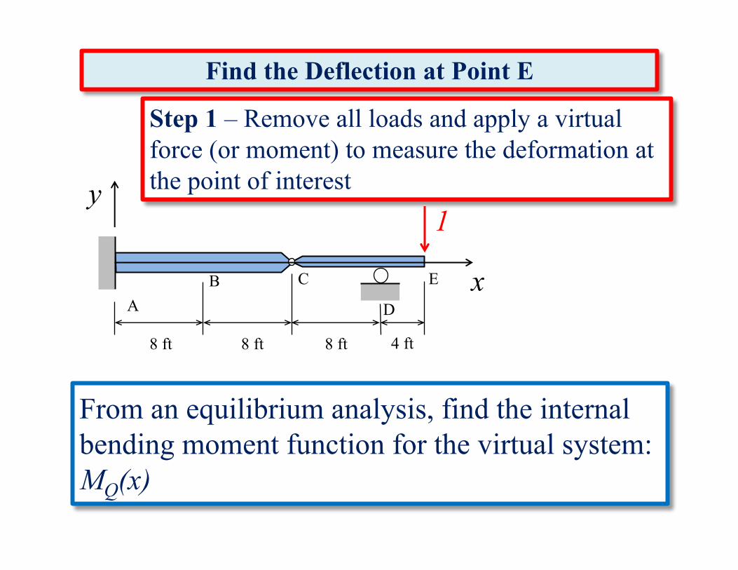
Step 1 – Remove all loads and apply a virtual force (or moment) to measure the deformation at the point of interest
1
x
y
From an equilibrium analysis, find the internal bending moment function for the virtual system: MQ(x)
8 ft 4 ft
D
CBA
E
8 ft8 ft
Find the Deflection at Point E
1y
8 ft 4 ft
CBA E
8 ft8 ft
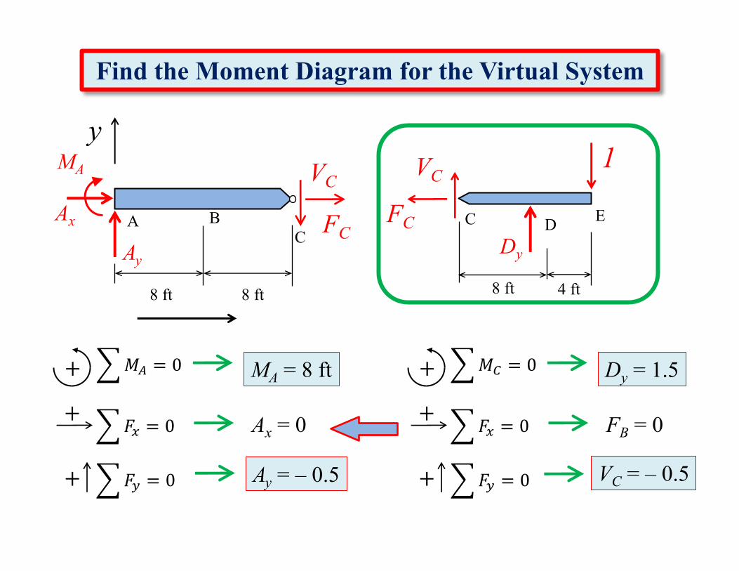
Find the Moment Diagram for the Virtual System
CAx
AyDy
MA VCVC
FCFC D
6𝑀3
�
�
= 0+
6𝐹;
�
�
= 0+
6𝐹<
�
�
= 0+
Dy = 1.5
FB = 0
VC = – 0.5
6𝑀$
�
�
= 0+
6𝐹;
�
�
= 0+
6𝐹<
�
�
= 0+
MA = 8 ft
Ax = 0
Ay = – 0.5
1
8 ft 4 ft
CB
A
E
8 ft8 ft
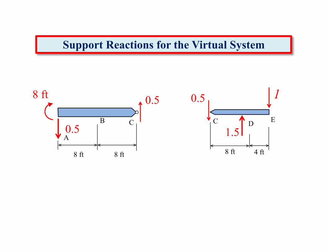
Support Reactions for the Virtual System
C1.5
8 ft 0.5
D
0.5
0.5
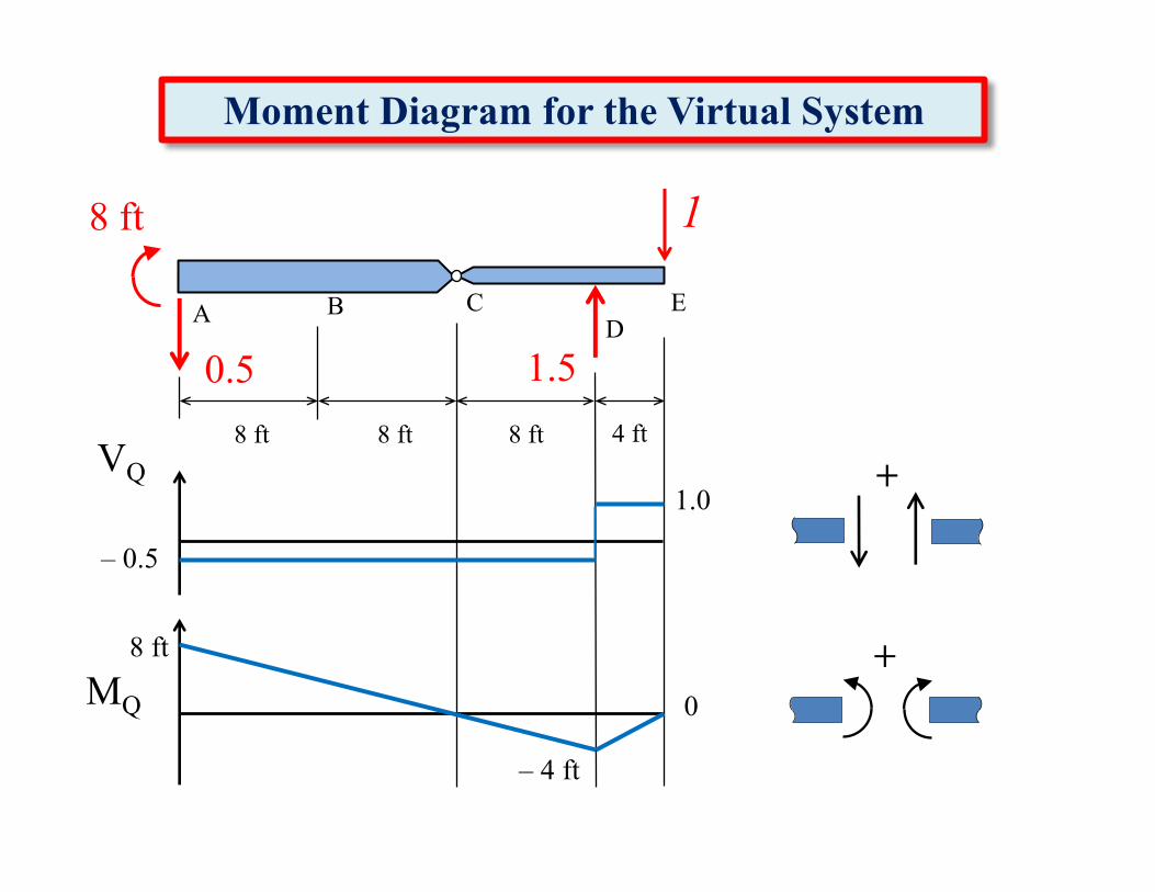
Moment Diagram for the Virtual System
1.5
8 ft
0.5
1
8 ft 4 ft
DCBA E
8 ft8 ft
+
+VQ
MQ
– 0.5
– 4 ft
8 ft
1.0
0
Step 2 – Replace all of the loads on the structure and perform the real analysis
From an equilibrium analysis, find the internal bending moment function for the real system: MP(x)
8 ft 4 ft
D
CBA
E
8 ft8 ft
6 k19 k
6 ky
8 ft 4 ft
CBA E
8 ft8 ft
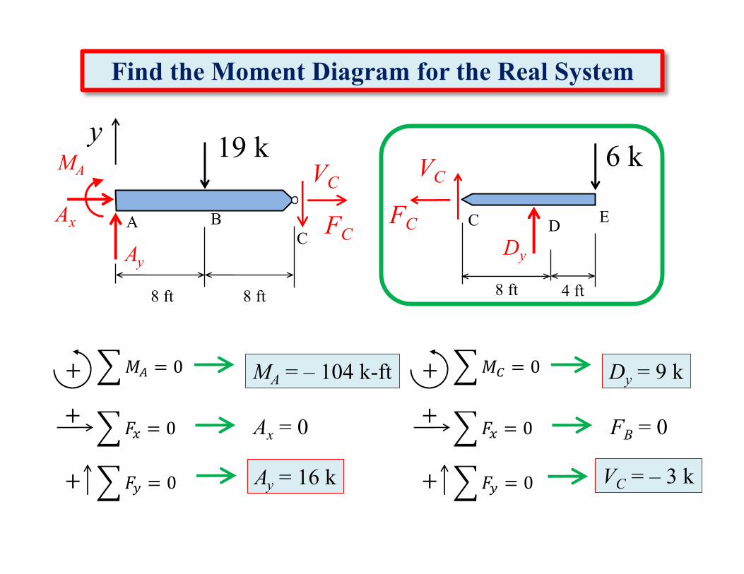
Find the Moment Diagram for the Real System
CAx
AyDy
MA VCVC
FCFC D
6𝑀3
�
�
= 0+
6𝐹;
�
�
= 0+
6𝐹<
�
�
= 0+
Dy = 9 k
FB = 0
VC = – 3 k
6𝑀$
�
�
= 0+
6𝐹;
�
�
= 0+
6𝐹<
�
�
= 0+
MA = – 104 k-ft
Ax = 0
Ay = 16 k
19 k
8 ft 4 ft
CBA
E
8 ft8 ft
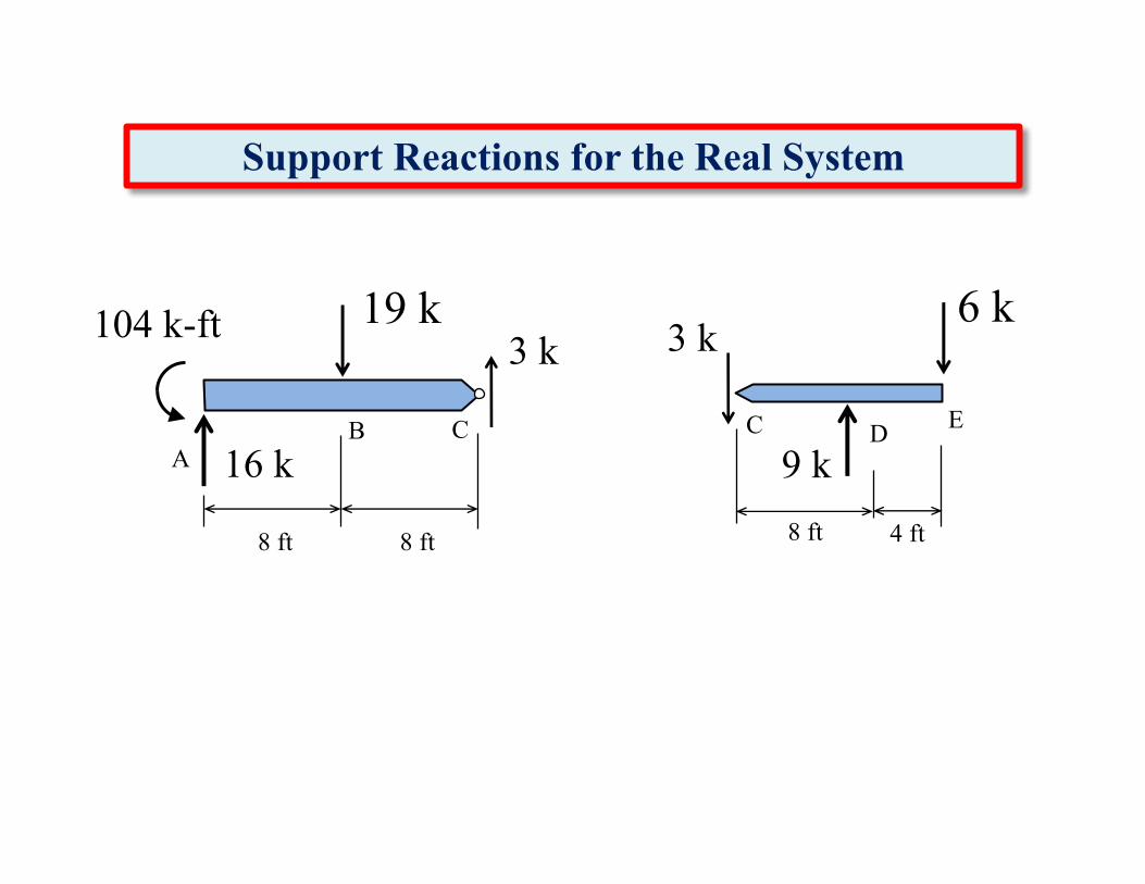
Support Reactions for the Real System
C9 k
104 k-ft 3 k
D
3 k
16 k
6 k19 k
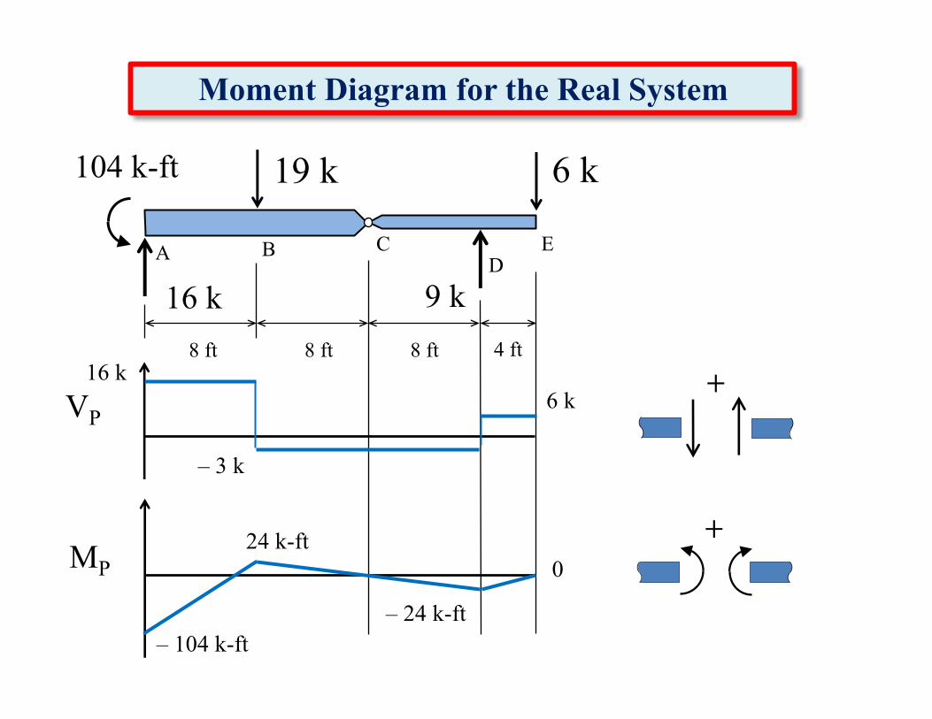
Moment Diagram for the Real System
9 k16 k
6 k
8 ft 4 ft
DCBA E
8 ft8 ft
+
+VP
MP
16 k
– 24 k-ft– 104 k-ft
0
19 k104 k-ft
6 k
– 3 k
24 k-ft
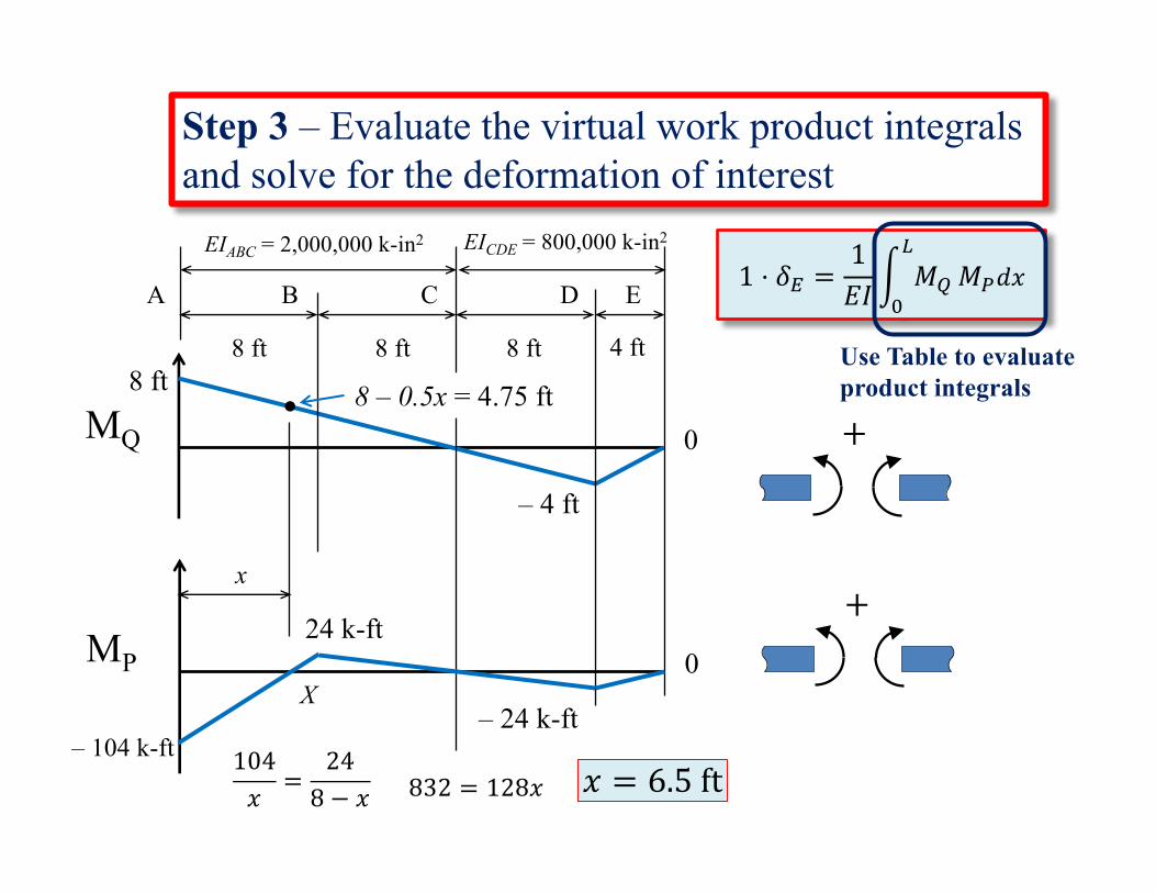
1 ⋅ 𝛿2 =1𝐸𝐼' 𝑀)
*
+𝑀,𝑑𝑥
Use Table to evaluate product integrals
Step 3 – Evaluate the virtual work product integrals and solve for the deformation of interest
+MQ
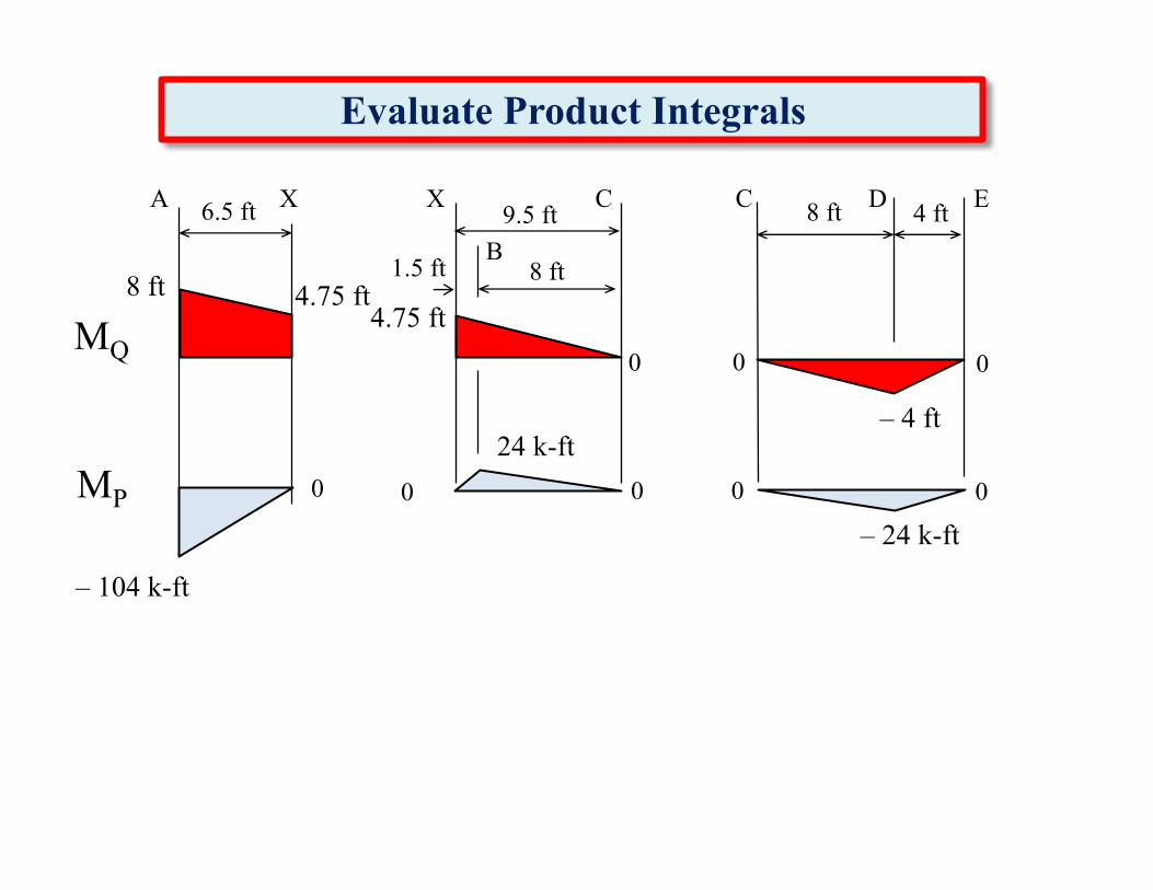
– 4 ft
8 ft
0
+
8 ft 4 ft8 ft8 ft
DCBA E
EIABC = 2,000,000 k-in2 EICDE = 800,000 k-in2
x
X
104𝑥
=248 − 𝑥 832 = 128𝑥 𝑥 = 6.5ft
MP
– 24 k-ft– 104 k-ft
024 k-ft
8 – 0.5x = 4.75 ft
MQ
– 4 ft
8 ft
MP– 24 k-ft
– 104 k-ft
24 k-ft
1.5 ft
4 ft8 ft
8 ft
DCXA E6.5 ft
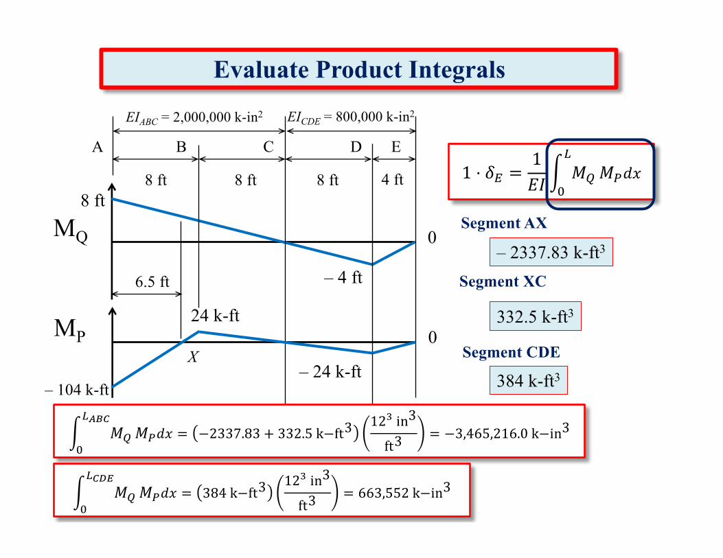
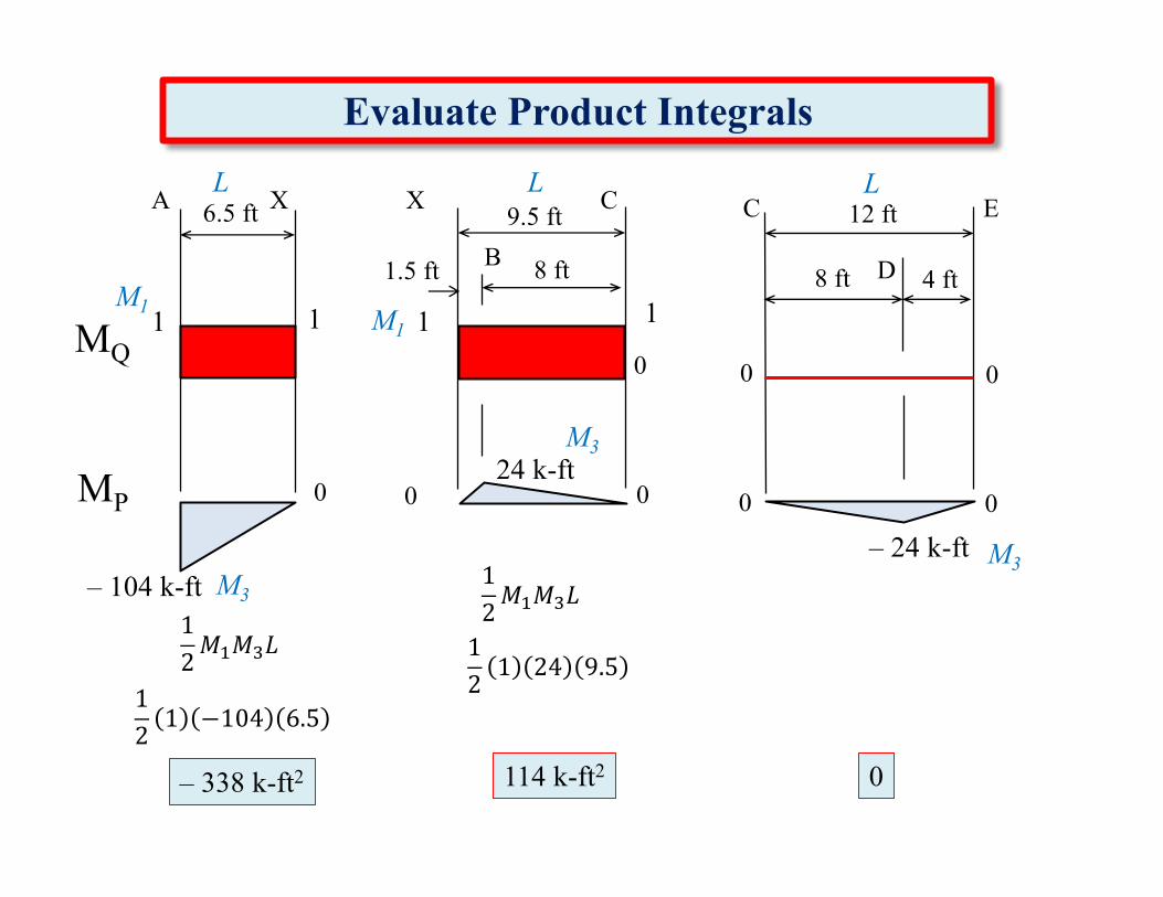
Evaluate Product Integrals
9.5 ftX
B
00 0
00 0 0 0
C
4.75 ft4.75 ft
Appendix Table.2
Table to Evaluate Virtual Work Product Integrals
' 𝑀)
*
+𝑀,𝑑𝑥
Table is as useful tool to evaluate product integrals of the form:AX
XC CE
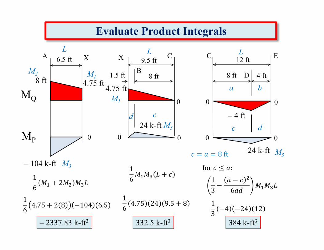
Evaluate Product Integrals
M3 for𝑐 ≤ 𝑎:
13−
𝑎 − 𝑐 O
6𝑎𝑑𝑀P𝑀Q𝐿
16𝑀P𝑀Q 𝐿 + 𝑐1
6𝑀P + 2𝑀O 𝑀Q𝐿
164.75 + 2 8 −104 6.5
– 2337.83 k-ft3
164.75 24 9.5 + 8
332.5 k-ft3 384 k-ft3
13−4 −24 12
MQ
– 4 ft
8 ft
MP– 24 k-ft
– 104 k-ft
24 k-ft
1.5 ft 4 ft8 ft8 ft D
CXA E6.5 ft 9.5 ftX
B
00 0
00 0 0 0
C
4.75 ft4.75 ft
M2 M1
L L
M1
cd
ba
dcM3
M3
L
𝑐 = 𝑎 = 8ft
12 ft
Evaluate Product Integrals
– 2337.83 k-ft3
332.5 k-ft3
384 k-ft3
1 ⋅ 𝛿2 =1𝐸𝐼' 𝑀)
*
+𝑀,𝑑𝑥
MQ
– 4 ft
8 ft
0
8 ft 4 ft8 ft8 ft
DCBA E
6.5 ft
XMP
– 24 k-ft– 104 k-ft
024 k-ft
EIABC = 2,000,000 k-in2 EICDE = 800,000 k-in2
Segment XC
Segment CDE
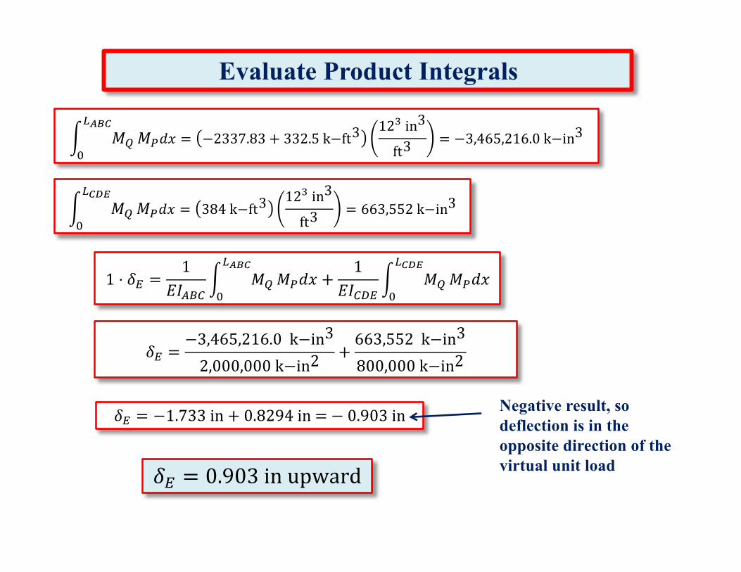
' 𝑀)
*UVW
+𝑀,𝑑𝑥 = −2337.83 + 332.5k−ft3
12Qin3
ft3= −3,465,216.0k−in3
' 𝑀)
*W\]
+𝑀,𝑑𝑥 = 384k−ft3
12Qin3
ft3= 663,552k−in3
Segment AX
Evaluate Product Integrals
𝛿2 =−3,465,216.0k−in3
2,000,000k−in2+663,552k−in3
800,000k−in2
' 𝑀)
*W\]
+𝑀,𝑑𝑥 = 384k−ft3
12Qin3
ft3= 663,552k−in3
1 ⋅ 𝛿2 =1
𝐸𝐼$"3' 𝑀)
*UVW
+𝑀,𝑑𝑥 +
1𝐸𝐼3^2
' 𝑀)
*W\]
+𝑀,𝑑𝑥
𝛿2 = −1.733in + 0.8294in= − 0.903in Negative result, so deflection is in the opposite direction of the virtual unit load𝛿2 = 0.903inupward
' 𝑀)
*UVW
+𝑀,𝑑𝑥 = −2337.83 + 332.5k−ft3
12Qin3
ft3= −3,465,216.0k−in3
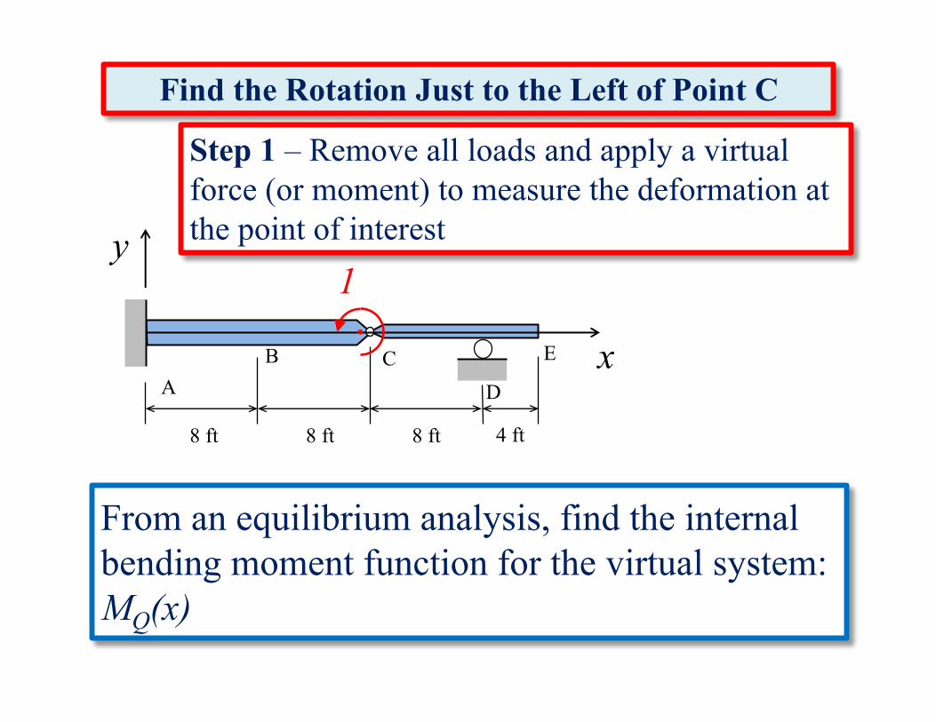
Step 1 – Remove all loads and apply a virtual force (or moment) to measure the deformation at the point of interest
1
x
y
From an equilibrium analysis, find the internal bending moment function for the virtual system: MQ(x)
8 ft 4 ft
DCB
AE
8 ft8 ft
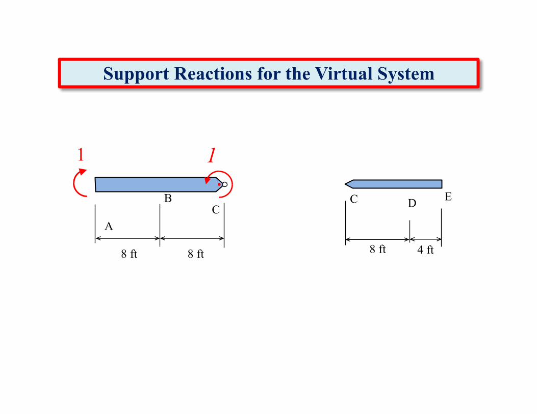
Find the Rotation Just to the Left of Point C
y
8 ft 4 ft
CBA E
8 ft8 ft
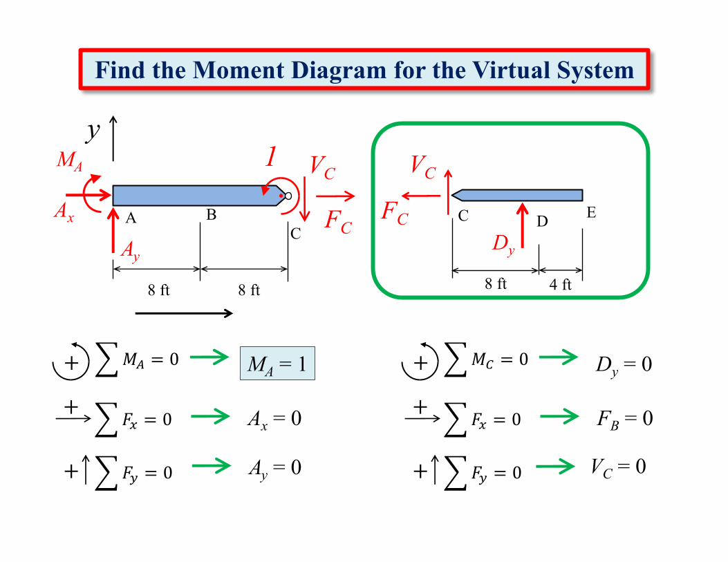
Find the Moment Diagram for the Virtual System
CAx
AyDy
MA VC VC
FCFC D
6𝑀3
�
�
= 0+
6𝐹;
�
�
= 0+
6𝐹<
�
�
= 0+
Dy = 0
FB = 0
VC = 0
6𝑀$
�
�
= 0+
6𝐹;
�
�
= 0+
6𝐹<
�
�
= 0+
MA = 1
Ax = 0
Ay = 0
1
8 ft 4 ft
CB
A
E
8 ft8 ft
Support Reactions for the Virtual System
C
1
D
1
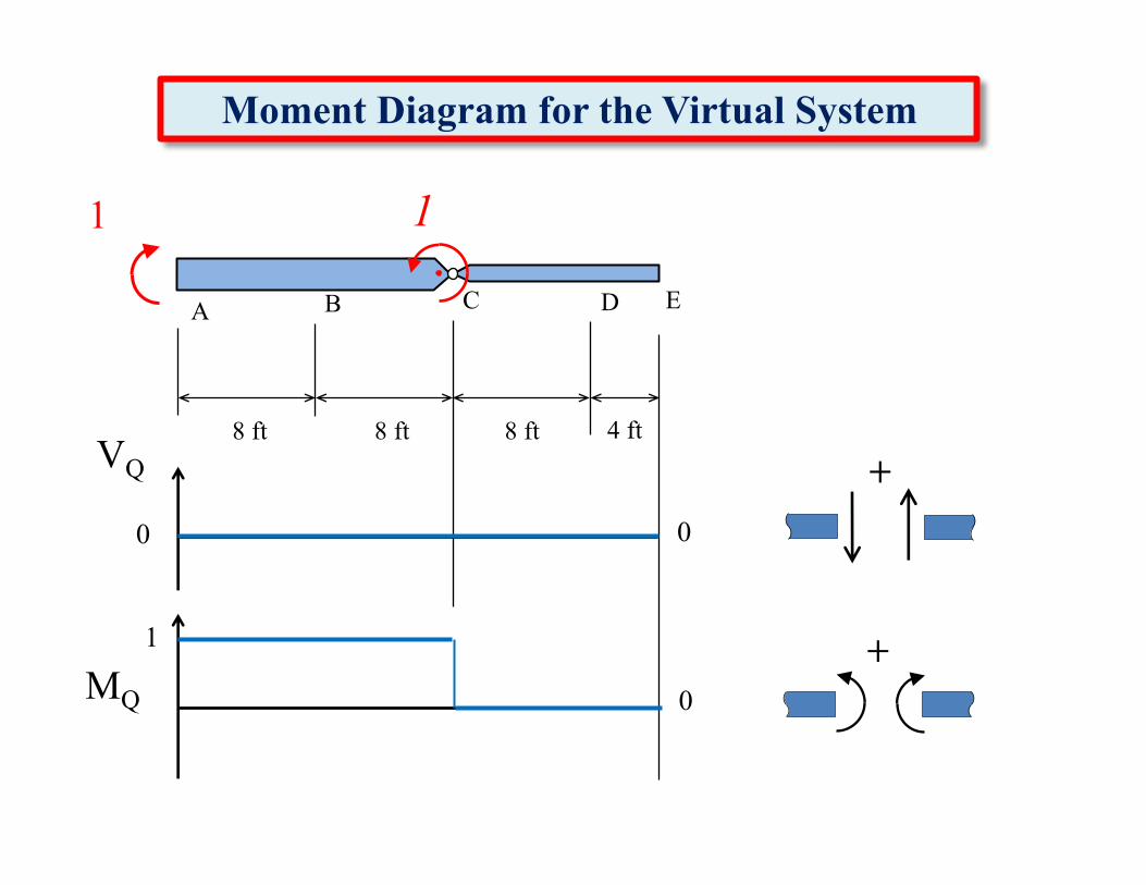
Moment Diagram for the Virtual System
1
8 ft 4 ft
DCBA E
8 ft8 ft
+
+VQ
MQ
0
1
0
0
1

Moment Diagram for the Real System
9 k16 k
6 k
8 ft 4 ft
DCBA E
8 ft8 ft
+
+VP
MP
16 k
– 24 k-ft– 104 k-ft
0
19 k104 k-ft
6 k
– 3 k
24 k-ft
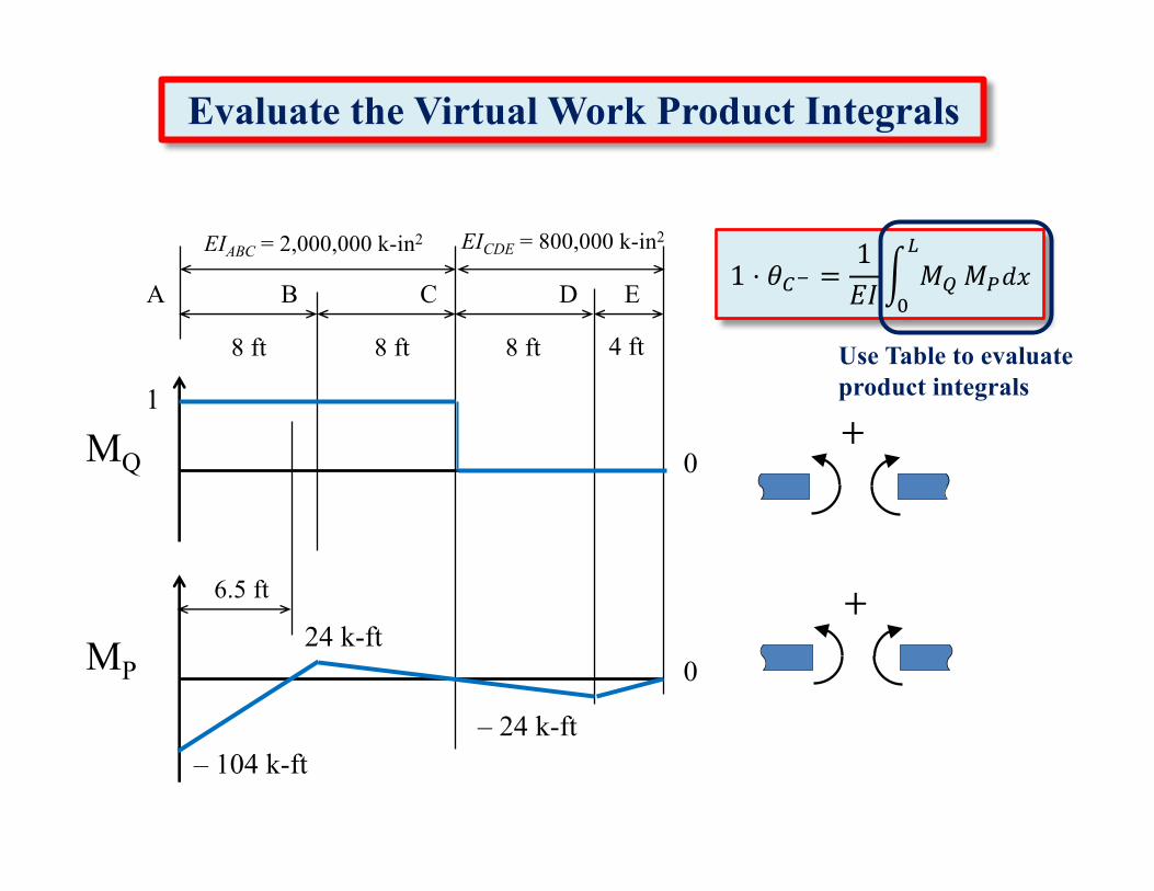
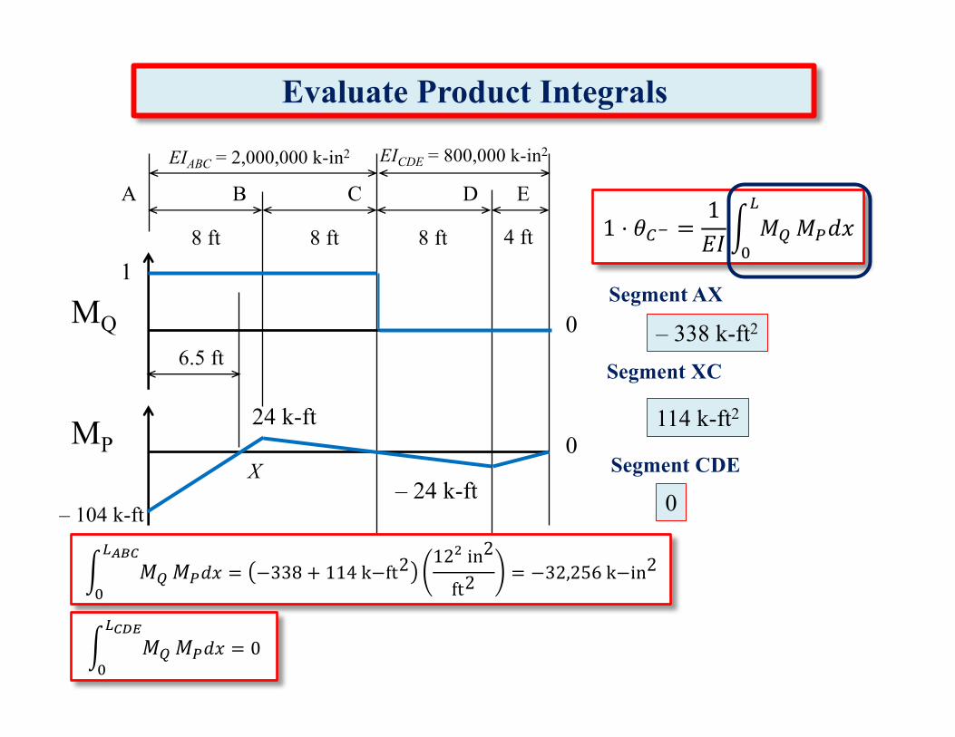
1 ⋅ 𝜃34 =1𝐸𝐼' 𝑀)
*
+𝑀,𝑑𝑥
Use Table to evaluate product integrals
+
+
8 ft 4 ft8 ft8 ft
DCBA E
Evaluate the Virtual Work Product Integrals
MQ
1
0
MP
– 24 k-ft– 104 k-ft
024 k-ft
6.5 ft
EIABC = 2,000,000 k-in2 EICDE = 800,000 k-in2
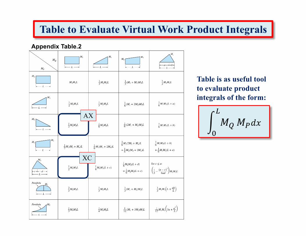
Appendix Table.2
Table to Evaluate Virtual Work Product Integrals
' 𝑀)
*
+𝑀,𝑑𝑥
Table is as useful tool to evaluate product integrals of the form:
AX
XC
MQ1
1.5 ft 8 ft
CXA 6.5 ft
Evaluate Product Integrals
9.5 ftX
B
0
M1
L L
M1
M3
L
121 −104 6.5
– 338 k-ft2
121 24 9.5
1
114 k-ft2 0
M3
MP
– 104 k-ft
24 k-ft00 0
12𝑀P𝑀Q𝐿
1 1
– 24 k-ft
4 ft8 ft D
E
0 0
0 0
C
M3
12 ft
12𝑀P𝑀Q𝐿
Evaluate Product Integrals
– 338 k-ft2
114 k-ft2
0
1 ⋅ 𝜃34 =1𝐸𝐼' 𝑀)
*
+𝑀,𝑑𝑥8 ft 4 ft8 ft8 ft
DCBA E
6.5 ft
XMP
– 24 k-ft– 104 k-ft
024 k-ft
EIABC = 2,000,000 k-in2 EICDE = 800,000 k-in2
Segment XC
Segment CDE
' 𝑀)
*UVW
+𝑀,𝑑𝑥 = −338 + 114k−ft2
12Oin2
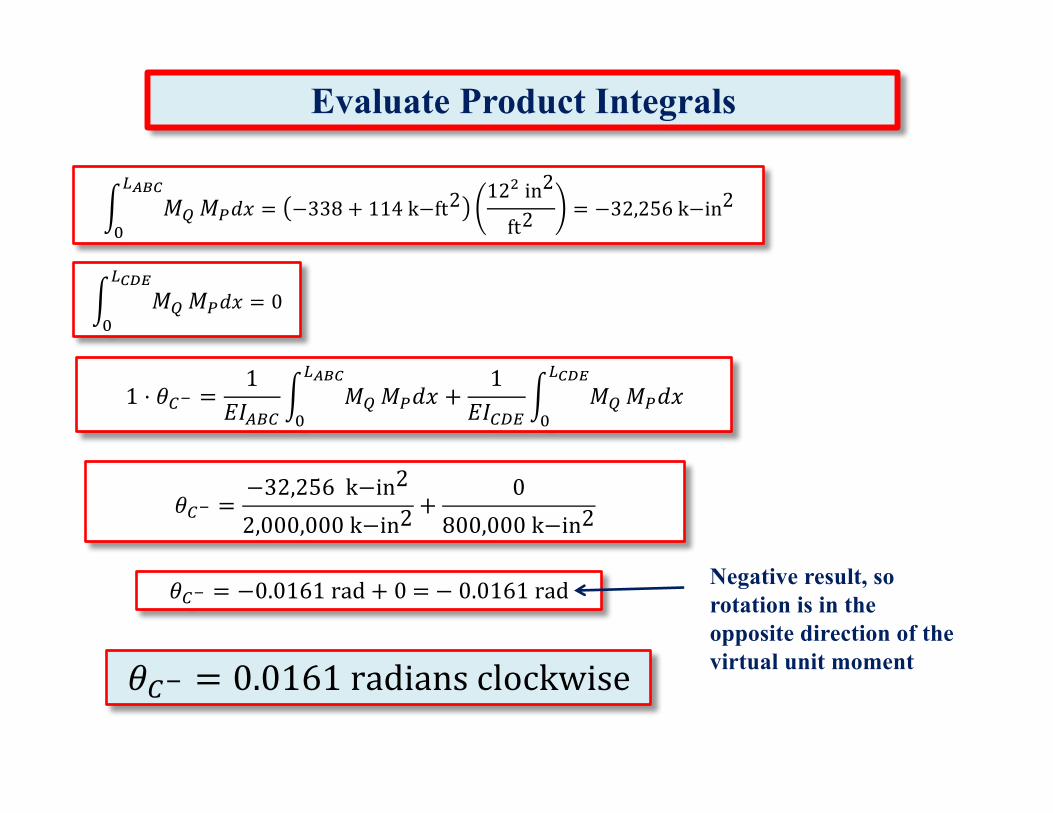
ft2= −32,256k−in2
' 𝑀)
*W\]
+𝑀,𝑑𝑥 = 0
Segment AXMQ
1
0
Evaluate Product Integrals
𝜃34 =−32,256k−in2
2,000,000k−in2+
0800,000k−in2
1 ⋅ 𝜃34 =1
𝐸𝐼$"3' 𝑀)
*UVW
+𝑀,𝑑𝑥 +
1𝐸𝐼3^2
' 𝑀)
*W\]
+𝑀,𝑑𝑥
𝜃34 = −0.0161rad + 0= − 0.0161rad Negative result, so rotation is in the opposite direction of the virtual unit moment𝜃34 = 0.0161radiansclockwise
' 𝑀)
*UVW
+𝑀,𝑑𝑥 = −338 + 114k−ft2
12Oin2
ft2= −32,256k−in2
' 𝑀)
*W\]
+𝑀,𝑑𝑥 = 0
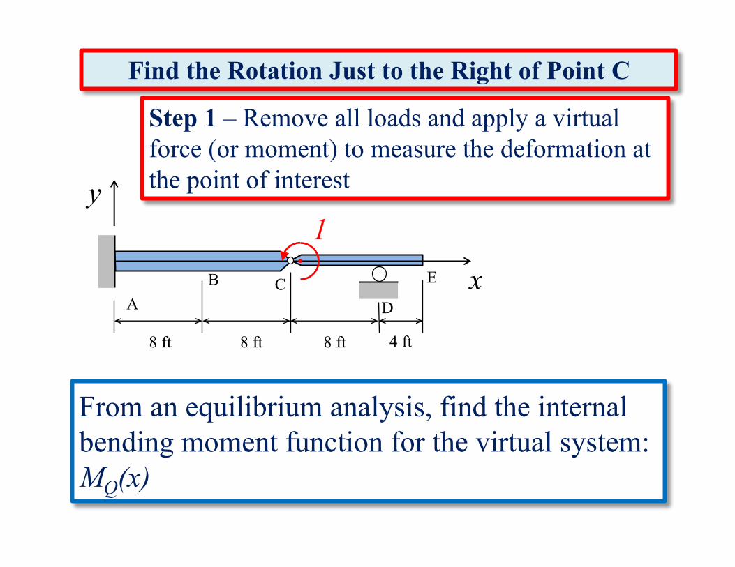
Step 1 – Remove all loads and apply a virtual force (or moment) to measure the deformation at the point of interest
1
x
y
From an equilibrium analysis, find the internal bending moment function for the virtual system: MQ(x)
8 ft 4 ft
DCB
AE
8 ft8 ft
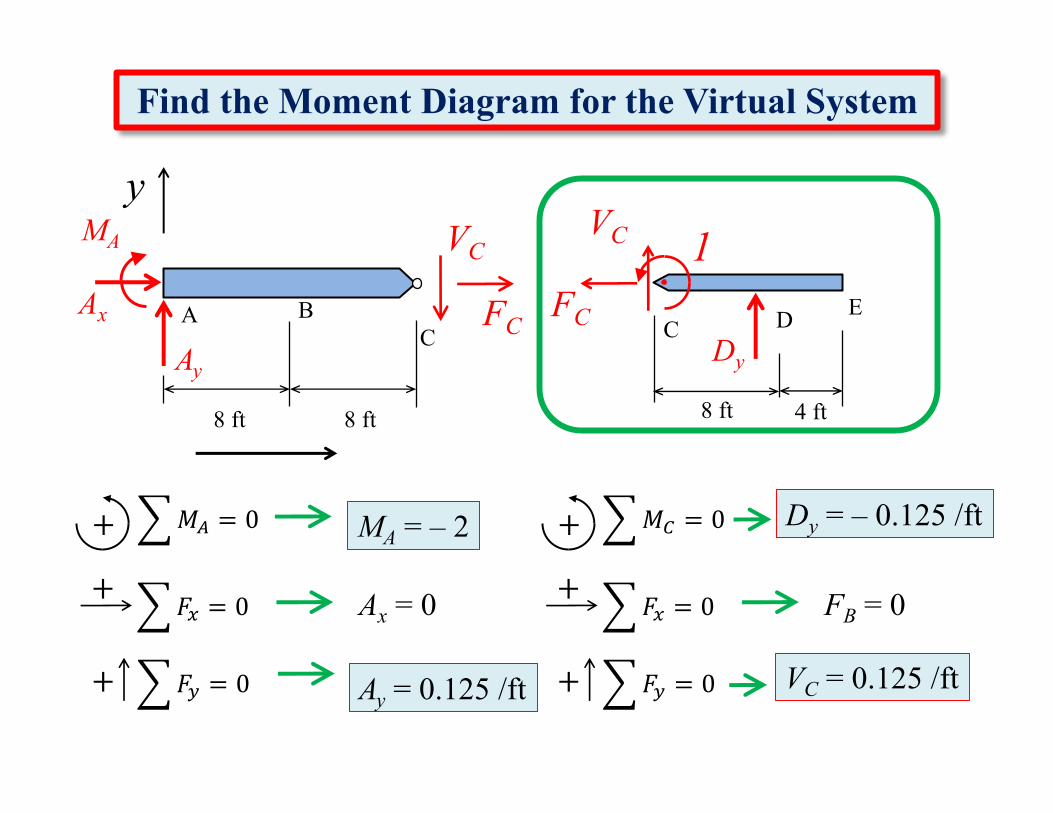
Find the Rotation Just to the Right of Point C
y
8 ft 4 ft
CBA E
8 ft8 ft
Find the Moment Diagram for the Virtual System
CAx
AyDy
MA VCVC
FCFC D
6𝑀3
�
�
= 0+
6𝐹;
�
�
= 0+
6𝐹<
�
�
= 0+
Dy = – 0.125 /ft
FB = 0
6𝑀$
�
�
= 0+
6𝐹;
�
�
= 0+
6𝐹<
�
�
= 0+
MA = – 2
Ax = 0
1
VC = 0.125 /ftAy = 0.125 /ft
8 ft 4 ft
CBAE
8 ft8 ft
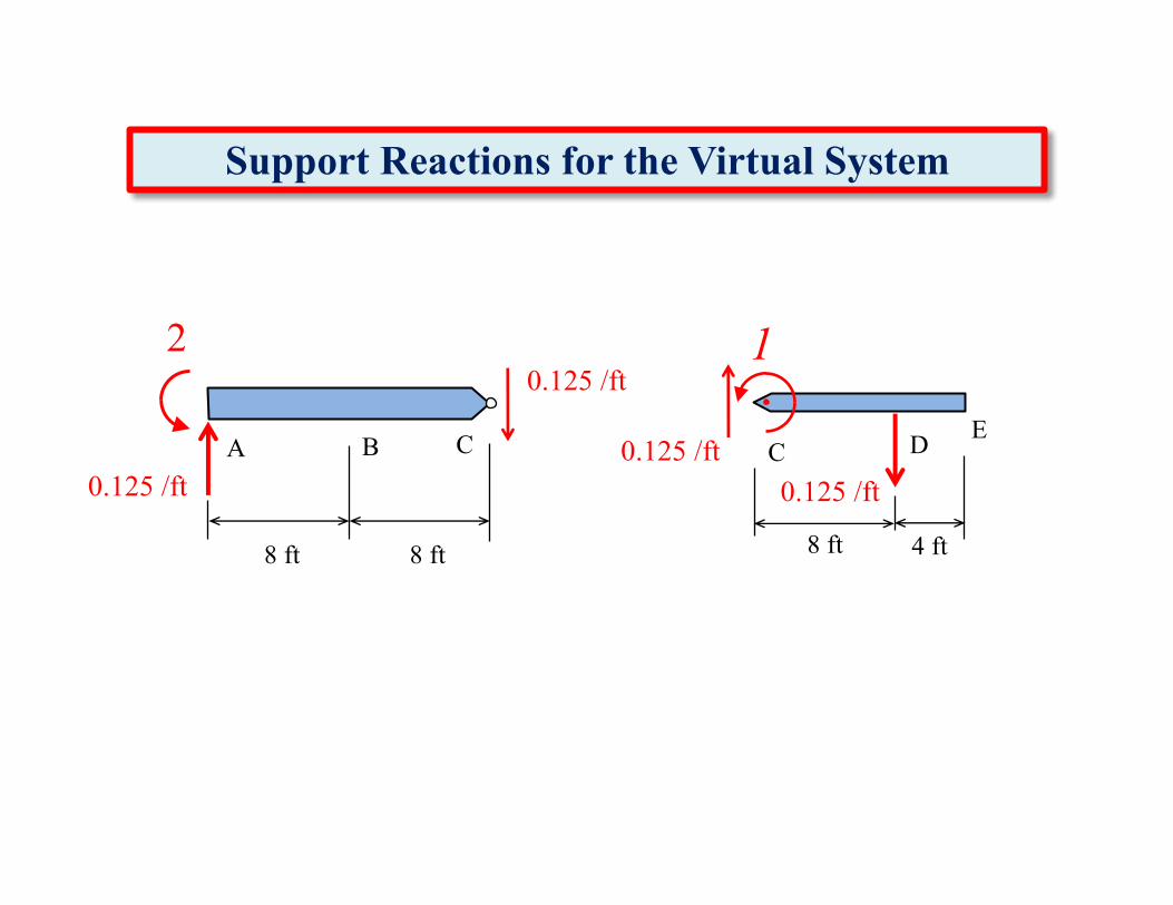
Support Reactions for the Virtual System
C
2
D
10.125 /ft
0.125 /ft0.125 /ft0.125 /ft
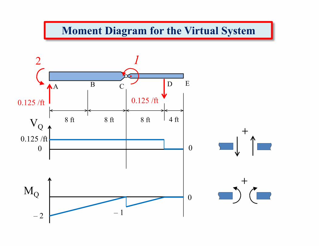
Moment Diagram for the Virtual System
2
8 ft 4 ft
DCBA E
8 ft8 ft
+
+VQ
MQ
0
– 2
0
0
1
0.125 /ft0.125 /ft
– 1
0.125 /ft

Moment Diagram for the Real System
9 k16 k
6 k
8 ft 4 ft
DCBA E
8 ft8 ft
+
+VP
MP
16 k
– 24 k-ft– 104 k-ft
0
19 k104 k-ft
6 k
– 3 k
24 k-ft
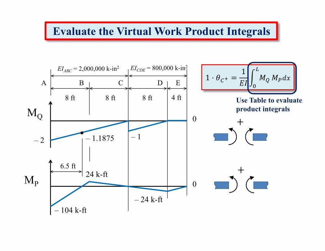
1 ⋅ 𝜃35 =1𝐸𝐼' 𝑀)
*
+𝑀,𝑑𝑥
Use Table to evaluate product integrals
+
+
8 ft 4 ft8 ft8 ft
DCBA E
Evaluate the Virtual Work Product Integrals
MQ
– 2
0
– 1– 1.1875
MP
– 24 k-ft– 104 k-ft
024 k-ft
6.5 ft
EIABC = 2,000,000 k-in2 EICDE = 800,000 k-in2
Appendix Table.2
Table to Evaluate Virtual Work Product Integrals
' 𝑀)
*
+𝑀,𝑑𝑥
Table is as useful tool to evaluate product integrals of the form:AX
XC
CD
MQ– 2
– 24 k-ft
1.5 ft
8 ft
8 ft
DCXA E6.5 ft
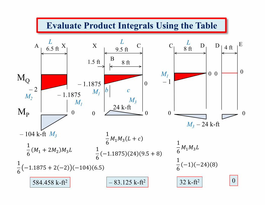
Evaluate Product Integrals Using the Table
9.5 ftX
B
0
0
0 0
C
M2 M1
L L
M1M3
M3
4 ftL
16𝑀P + 2𝑀O 𝑀Q𝐿
16−1.1875 + 2 −2 −104 6.5
584.458 k-ft2
16−1.1875 24 9.5 + 8
– 1.1875
0 0– 1
– 83.125 k-ft2
16𝑀P𝑀Q𝐿
16−1 −24 8
32 k-ft2
M1
0
D
M3
MP
– 104 k-ft
24 k-ft00 0
– 1.1875
16𝑀P𝑀Q 𝐿 + 𝑐
cb
1 ⋅ 𝜃35 =1𝐸𝐼' 𝑀)
*
+𝑀,𝑑𝑥
8 ft 4 ft8 ft8 ft
DCBA E
Evaluate the Virtual Work Product Integrals
MQ
– 2
0
– 1– 1.1875
MP
– 24 k-ft– 104 k-ft
024 k-ft
6.5 ft
EIABC = 2,000,000 k-in2 EICDE = 800,000 k-in2
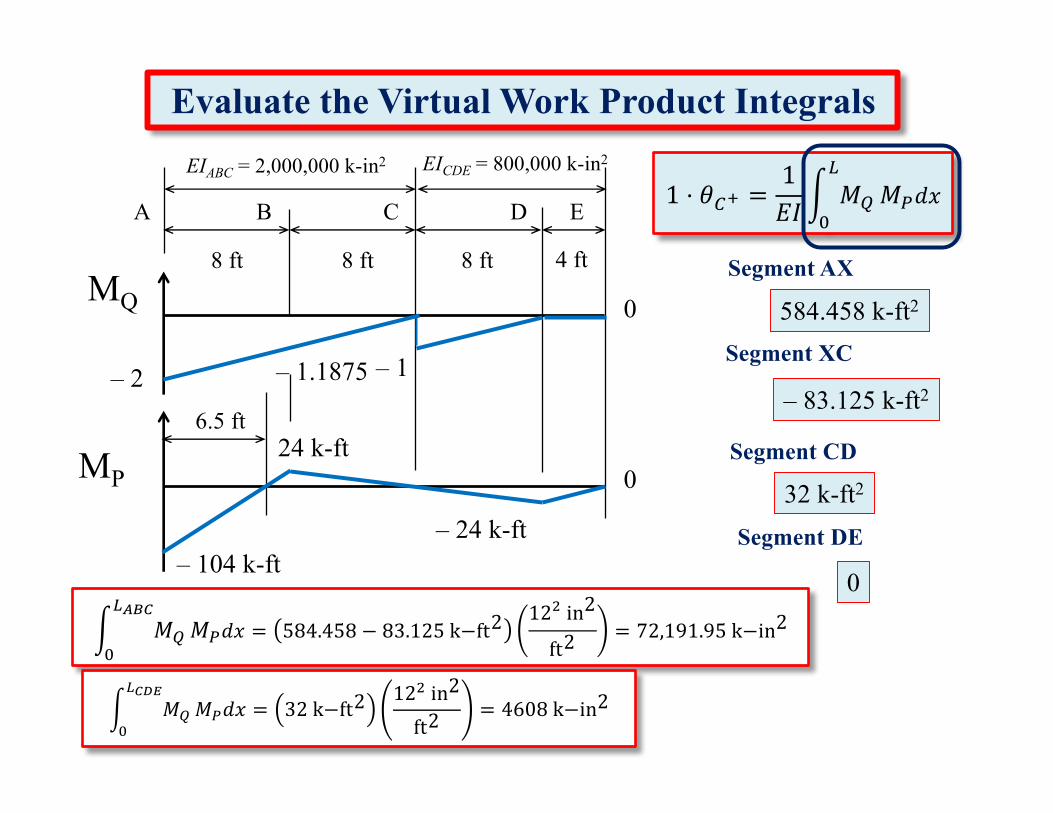
584.458 k-ft2
– 83.125 k-ft2
0
Segment XC
Segment CD
' 𝑀)
*UVW
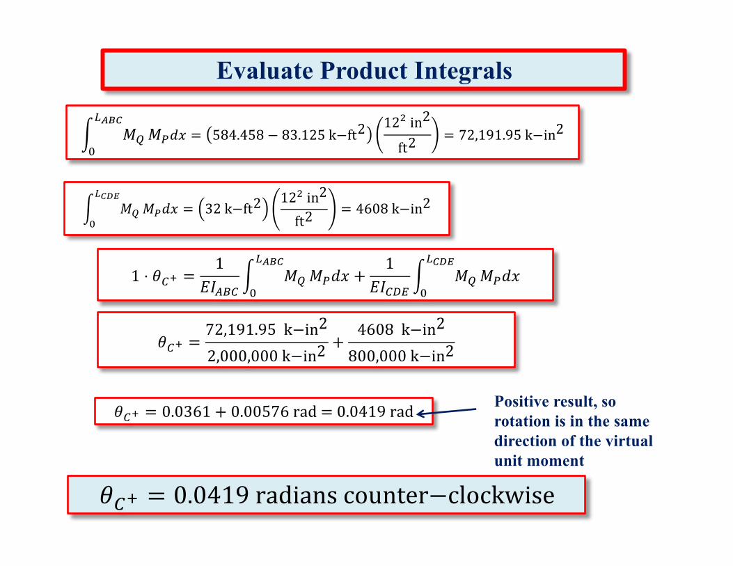
+𝑀,𝑑𝑥 = 584.458 − 83.125k−ft2
12Oin2
ft2= 72,191.95k−in2
' 𝑀)
*W\]
+𝑀,𝑑𝑥 = 32k−ft2
12Oin2
ft2= 4608k−in2
Segment AX
32 k-ft2
Segment DE
Evaluate Product Integrals
𝜃35 =72,191.95k−in2
2,000,000k−in2+
4608k−in2
800,000k−in2
1 ⋅ 𝜃35 =1
𝐸𝐼$"3' 𝑀)
*UVW
+𝑀,𝑑𝑥 +
1𝐸𝐼3^2
' 𝑀)
*W\]
+𝑀,𝑑𝑥
𝜃35 = 0.0361 + 0.00576rad=0.0419rad Positive result, so rotation is in the same direction of the virtual unit moment
𝜃35 = 0.0419radianscounter−clockwise
' 𝑀)
*W\]
+𝑀,𝑑𝑥 = 32k−ft2
12Oin2
ft2= 4608k−in2
' 𝑀)
*UVW
+𝑀,𝑑𝑥 = 584.458 − 83.125k−ft2
12Oin2
ft2= 72,191.95k−in2
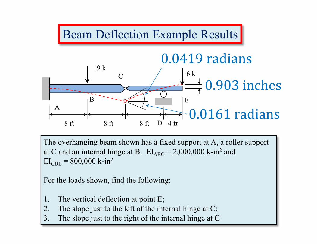
Beam Deflection Example Results
The overhanging beam shown has a fixed support at A, a roller support at C and an internal hinge at B. EIABC = 2,000,000 k-in2 and EICDE = 800,000 k-in2
For the loads shown, find the following:
1. The vertical deflection at point E;2. The slope just to the left of the internal hinge at C;3. The slope just to the right of the internal hinge at C
8 ft 4 ftD
C
BA
E
8 ft8 ft
6 k19 k
0.0161radians
0.0419radians
0.903inches
Related Documents