Institute of Structural Engineering Page 1 Method of Finite Elements I Chapter 2b The Direct Stiffness Method: 2 nd Order and Stability Analysis Method of Finite Elements I

Welcome message from author
This document is posted to help you gain knowledge. Please leave a comment to let me know what you think about it! Share it to your friends and learn new things together.
Transcript

Institute of Structural Engineering Page 1
Method of Finite Elements I
Chapter 2b
The Direct Stiffness Method:
2nd Order and Stability Analysis
Method of Finite Elements I

Institute of Structural Engineering Page 2
Method of Finite Elements I
2nd Order Effectsor the influence of the axial normal force
Normal forces change the stiffness of the structure !
Institute of Structural Engineering Page 3
Method of Finite Elements I
Types of Linear Analysis
Analysis type 1st Order 2nd Order 3rd Order
Deformations small small large
Strains small small small
Equilibrum
formulation
undeformed
shape
deformed
shape
deformed
shape
Usage Floor slab Column
Cable bridge
Form finding
(Cable-nets)
Institute of Structural Engineering Page 4
Method of Finite Elements I
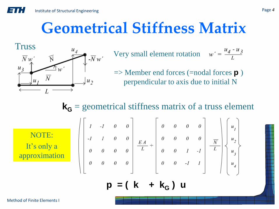
Geometrical Stiffness Matrix
kG = geometrical stiffness matrix of a truss element
p = ( k + kG ) u
Very small element rotation
=> Member end forces (=nodal forces p )
perpendicular to axis due to initial N
Truss
NOTE:
It’s only a
approximation
Institute of Structural Engineering Page 5
Method of Finite Elements I
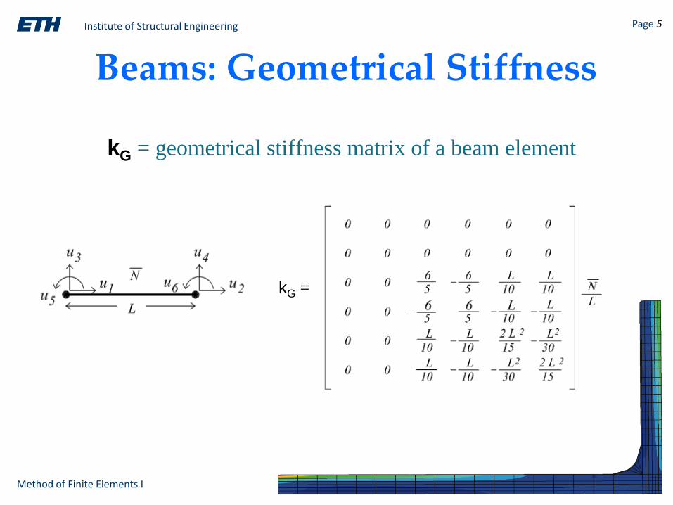
Beams: Geometrical Stiffness
kG = geometrical stiffness matrix of a beam element
kG =
Institute of Structural Engineering Page 6
Method of Finite Elements I
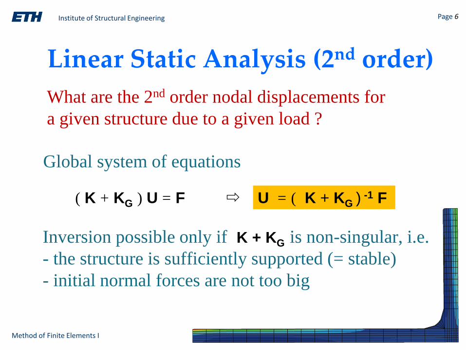
Linear Static Analysis (2nd order)
Global system of equations
( K + KG ) U = F U = ( K + KG )-1 F
Inversion possible only if K + KG is non-singular, i.e.
- the structure is sufficiently supported (= stable)
- initial normal forces are not too big
What are the 2nd order nodal displacements for
a given structure due to a given load ?

Institute of Structural Engineering Page 7
Method of Finite Elements I
Linear Static Analysis (2nd order)
Workflow of computer program
1. Perform 1st order analysis
2. Calculate resulting axial forces in elements (=Ne)
3. Build element geometrical stiffness matrices due to Ne
4. Add geometrical stiffness to global stiffness matrix
5. Solve global system of equations (=> displacements)
6. Calculate element results
NOTE: Only approximate solution !

Institute of Structural Engineering Page 8
Method of Finite Elements I
Stability Analysis
How much can a given load be increased until a
given structure becomes unstable ?
(K + λmax KG0) U = F
Nmax = λmax N0
KGmax = f(Nmax)KGmax(Nmax) = λmax KG(N0) = λmax KG0
2nd order analysis No additional load possible
(K + λmax KG0) ΔU = ΔF = 0
linear algebra
(A - λ B) x = 0 Eigenvalue problem
Institute of Structural Engineering Page 9
Method of Finite Elements I
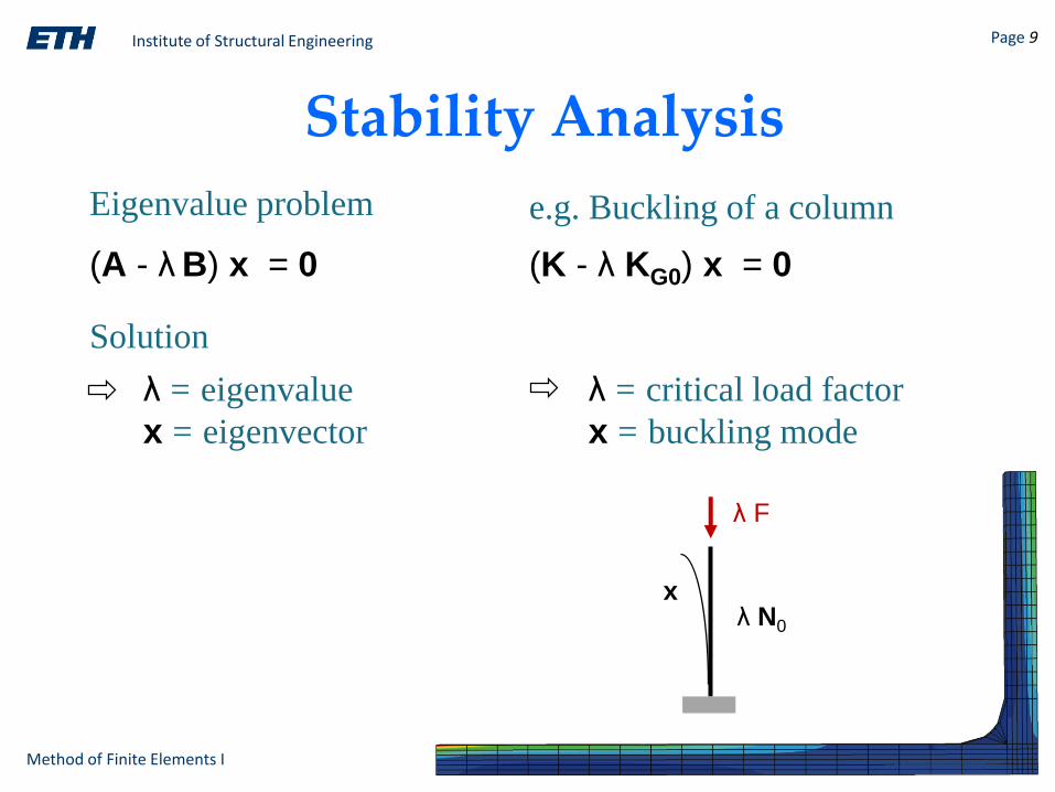
Stability Analysis
Eigenvalue problem
(A - λ B) x = 0
λ = eigenvalue
x = eigenvector
(K - λ KG0) x = 0
λ = critical load factor
x = buckling mode
e.g. Buckling of a column
λ N0
λ F
x
Solution
Institute of Structural Engineering Page 10
Method of Finite Elements I
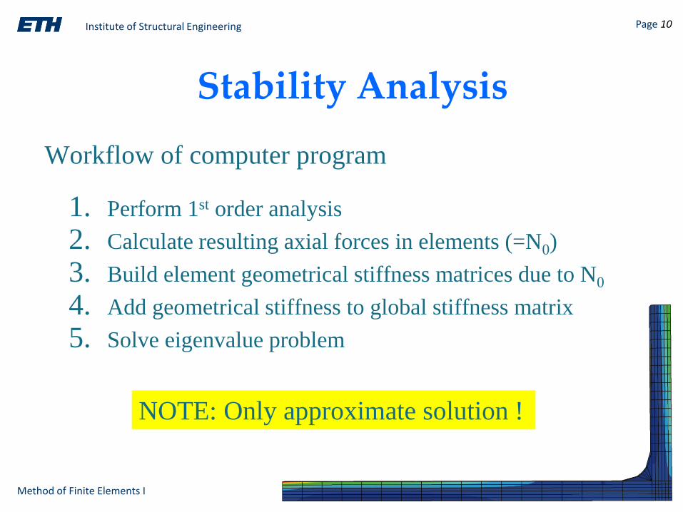
Stability Analysis
Workflow of computer program
1. Perform 1st order analysis
2. Calculate resulting axial forces in elements (=N0)
3. Build element geometrical stiffness matrices due to N0
4. Add geometrical stiffness to global stiffness matrix
5. Solve eigenvalue problem
NOTE: Only approximate solution !

Institute of Structural Engineering Page 11
Method of Finite Elements I

Institute of Structural Engineering Page 12
Method of Finite Elements I
Chapter 2c
Structural Dynamics:
Modal Analysis with the DSM
Method of Finite Elements I
Institute of Structural Engineering Page 13
Method of Finite Elements I
Goals of this Chapter
• Review of structural dynamics
• Dynamic analysis with the DSM
• DSM software workflow for …
• Modal analysis
Institute of Structural Engineering Page 14
Method of Finite Elements I
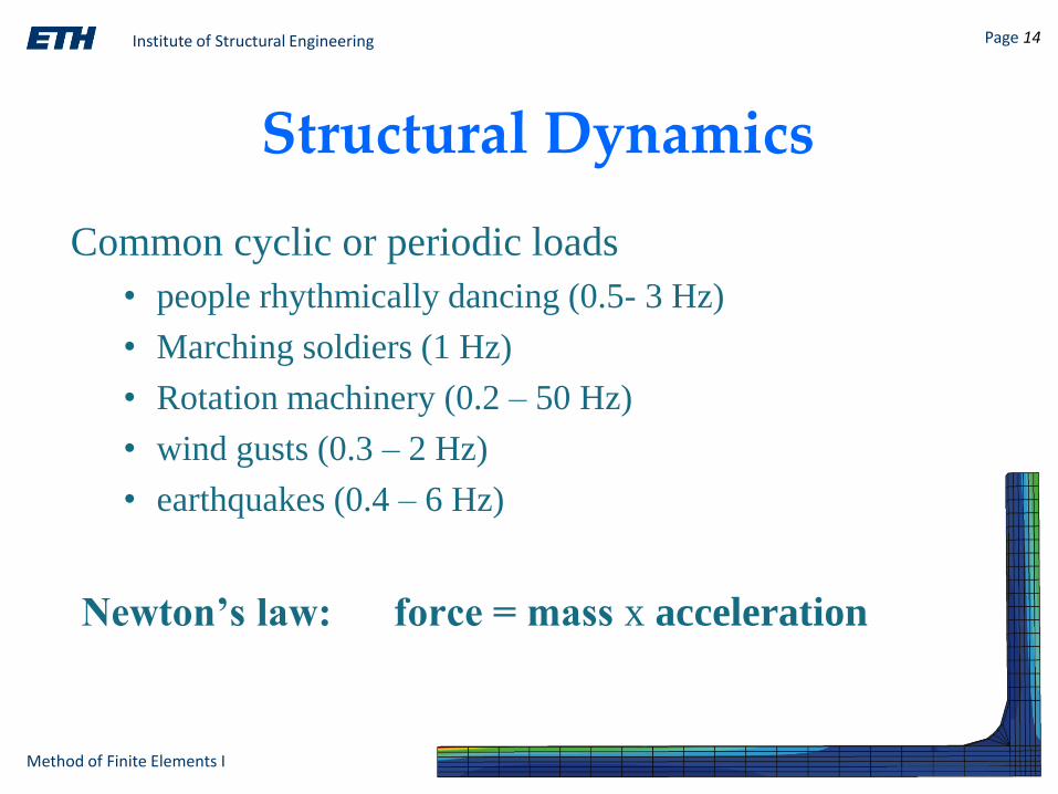
Newton’s law: force = mass x acceleration
Common cyclic or periodic loads
• people rhythmically dancing (0.5- 3 Hz)
• Marching soldiers (1 Hz)
• Rotation machinery (0.2 – 50 Hz)
• wind gusts (0.3 – 2 Hz)
• earthquakes (0.4 – 6 Hz)
Structural Dynamics
Institute of Structural Engineering Page 15
Method of Finite Elements I
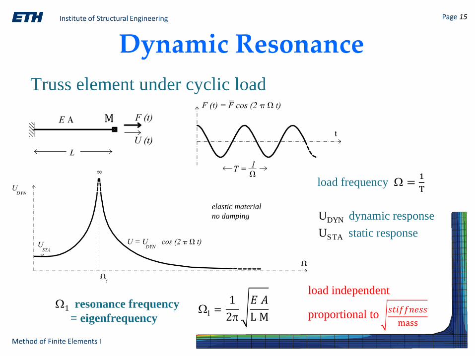
Dynamic Resonance
Truss element under cyclic load
load frequency W =1
T
UDYN dynamic response
USTA static response
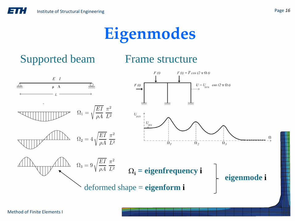
W1 resonance frequency
= eigenfrequencyW1 =
1
2p
𝐸 𝐴
L M
load independent
elastic material
no damping
M
𝑠𝑡𝑖𝑓𝑓𝑛𝑒𝑠𝑠
massproportional to
Institute of Structural Engineering Page 16
Method of Finite Elements I
Eigenmodes
Frame structureSupported beam
deformed shape = eigenform i
Wi = eigenfrequency ieigenmode i
Institute of Structural Engineering Page 17
Method of Finite Elements I
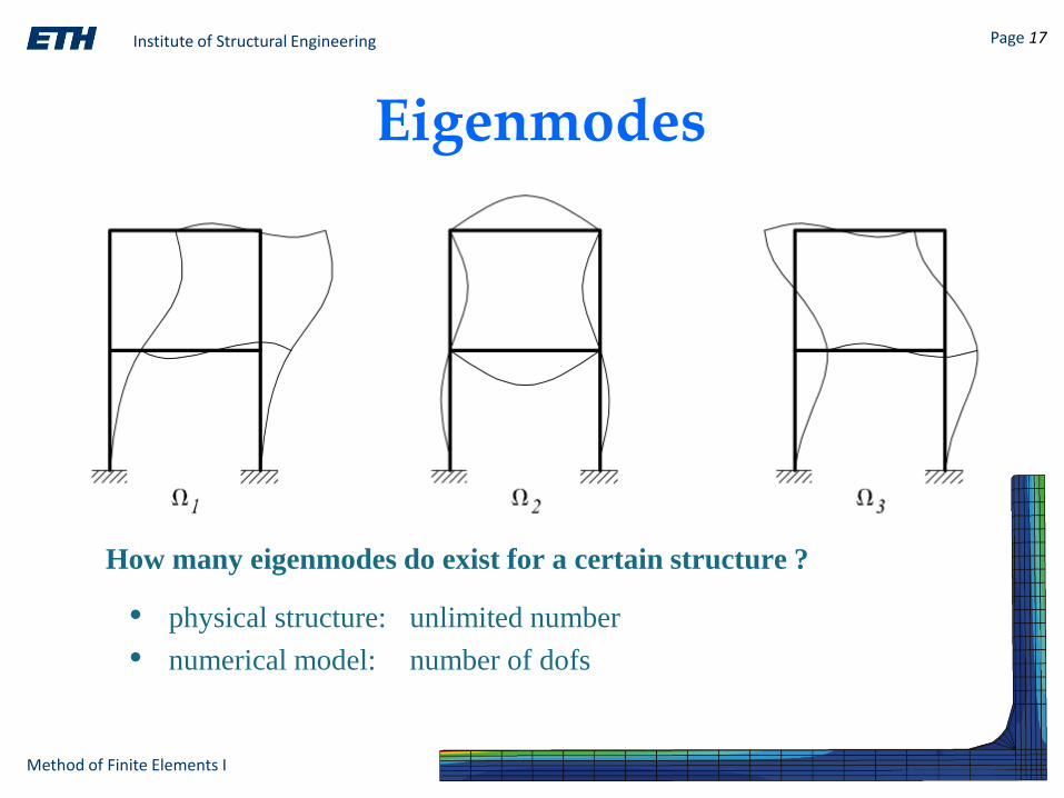
Eigenmodes
• physical structure: unlimited number
• numerical model: number of dofs
How many eigenmodes do exist for a certain structure ?
Institute of Structural Engineering Page 18
Method of Finite Elements I
Modal Analysis
Goal of structural design for dynamic effects:
load frequencies ≠ eigenfrequencies
Find the dynamic eigenmodes (frequency/form)
this process is known as
modal analysis
Institute of Structural Engineering Page 19
Method of Finite Elements I
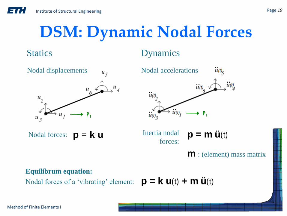
DSM: Dynamic Nodal Forces
P1P1
p = k u p = m ሷu(t)
Statics Dynamics
Inertia nodal
forces:
Nodal displacements Nodal accelerations
p = k u(t) + m ሷu(t)
Equilibrum equation:
Nodal forces of a ‘vibrating’ element:
m : (element) mass matrix
Nodal forces:
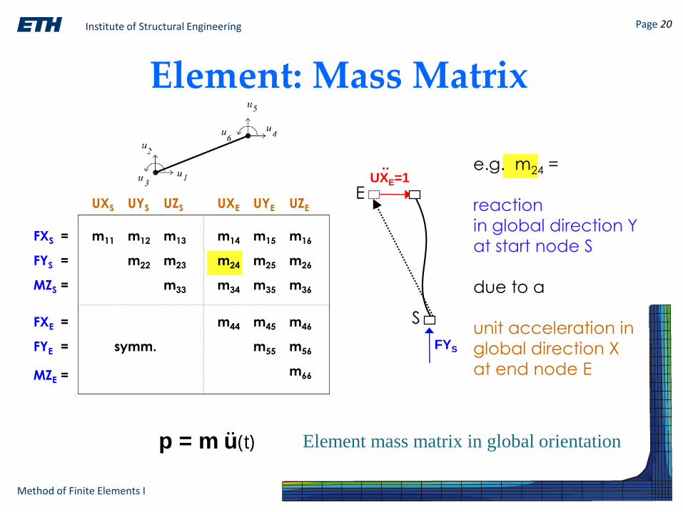
Institute of Structural Engineering Page 20
Method of Finite Elements I
UXE=1
FYS
S
E
..
FXS =
FYS =
MZS =
FXE =
FYE =
MZE =
UXS UYS UZS UXE UYE UZE
m14 m15 m16
m24 m25 m26
m34 m35 m36
m44 m45 m46
m55 m56
m66
m11 m12 m13
m22 m23
m33
symm.
e.g. m24 =
reaction
in global direction Y
at start node S
due to a
unit acceleration in
global direction X
at end node E
Element: Mass Matrix
p = m ሷu(t) Element mass matrix in global orientation
Institute of Structural Engineering Page 21
Method of Finite Elements I
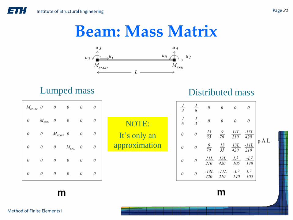
Beam: Mass Matrix
m m
Lumped mass Distributed mass
NOTE:
It’s only an
approximation

Institute of Structural Engineering Page 22
Method of Finite Elements I
K = global stiffness matrix = Assembly of all ke
F(t) = K U(t) + M ሷU(t)
Global System of Equations
Equilibrium at every node of the structure:
F(t) = global load vector = Assembly of all fe
U(t) = global displacement vector
M = global mass matrix = Assembly of all me
ሷU(t) = global acceleration vector

Institute of Structural Engineering Page 23
Method of Finite Elements I
Modal AnalysisWhat are the eigenmodes of a given structure ?
Global system of equations K U(t) + M ሷU(t) = F(t)
Harmonic displacements
for eigenmode i (Ei ,Wi)Ui(t) = Ei cos(2p Wi t)
( K – (2p Wi t)2 M ) Ei cos(2p Wi t) = 0
valid at any time ( K – (2p Wi)2 M ) Ei = 0
Solution of eigenvalue problem:Wi = (dynamic) eigenfrequency
Ei = (dynamic) eigenform
load independent!
Institute of Structural Engineering Page 24
Method of Finite Elements I
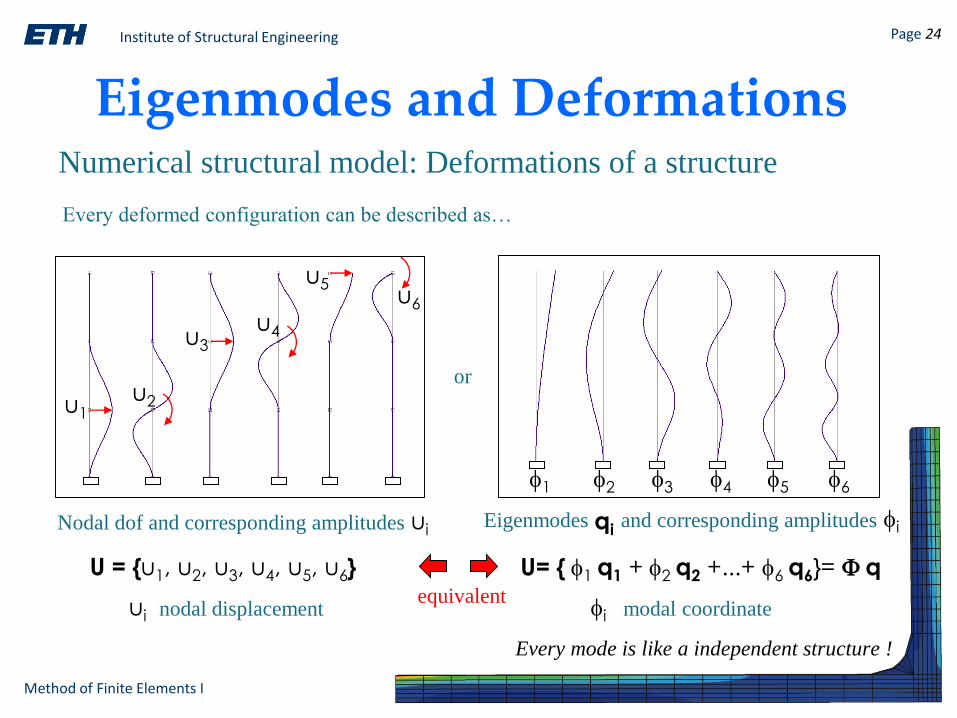
Eigenmodes and DeformationsNumerical structural model: Deformations of a structure
U = {u1, u2, u3, u4, u5, u6}
u1u2
u3
u4
u5u6
1 2 3 4 5 6
Every deformed configuration can be described as…
Nodal dof and corresponding amplitudes Eigenmodes and corresponding amplitudes
U= { 1 q1 + 2 q2 +...+ 6 q6}= q
or
ui nodal displacement
uii
i modal coordinateequivalent
Every mode is like a independent structure !
qi

Institute of Structural Engineering Page 25
Method of Finite Elements I
Types of Modal Analysis
Response spectra analysis Time history analysis
load-time
function
T1 Ti Tj
response spectrum
Institute of Structural Engineering Page 26
Method of Finite Elements I
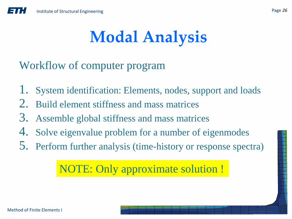
Modal Analysis
Workflow of computer program
1. System identification: Elements, nodes, support and loads
2. Build element stiffness and mass matrices
3. Assemble global stiffness and mass matrices
4. Solve eigenvalue problem for a number of eigenmodes
5. Perform further analysis (time-history or response spectra)
NOTE: Only approximate solution !
Institute of Structural Engineering Page 27
Method of Finite Elements I
Difference betweenDSM and FEM
How to find the local matrices k , kG and m
and local load vectors f?for a specific finite element ?
Chapters 3 and 4
Related Documents