0010 1 CD-ROM Revision 0 Date September 1986 METHOD 0010 MODIFIED METHOD 5 SAMPLING TRAIN 1.0 SCOPE AND APPLICATION 1.1 This method is applicable to the determination of Destruction and Removal Efficiency (DRE) of semivolatile Principal Organic Hazardous Compounds (POHCs) from incineration systems (PHS, 1967). This method also may be used to determine particulate emission rates from stationary sources as per EPA Method 5 (see References at end of this method). 2.0 SUMMARY OF METHOD 2.1 Gaseous and particulate pollutants are withdrawn from an emission source at an isokinetic sampling rate and are collected in a multicomponent sampling train. Principal components of the train include a high-efficiency glass- or quartz-fiber filter and a packed bed of porous polymeric adsorbent resin. The filter is used to collect organic-laden particulate materials and the porous polymeric resin to adsorb semivolatile organic species. Semivolatile species are defined as compounds with boiling points >100EC. 2.2 Comprehensive chemical analyses of the collected sample are conducted to determine the concentration and identity of the organic materials. 3.0 INTERFERENCES 3.1 Oxides of nitrogen (NO ) are possible interferents in the determination x of certain water-soluble compounds such as dioxane, phenol, and urethane; reaction of these compounds with NO in the presence of moisture will reduce x their concentration. Other possibilities that could result in positive or negative bias are (1) stability of the compounds in methylene chloride, (2) the formation of water-soluble organic salts on the resin in the presence of moisture, and (3) the solvent extraction efficiency of water-soluble compounds from aqueous media. Use of two or more ions per compound for qualitative and quantitative analysis can overcome interference at one mass. These concerns should be addressed on a compound-by-compound basis before using this method. 4.0 APPARATUS AND MATERIALS 4.1 Sampling train : 4.1.1 A schematic of the sampling train used in this method is shown in Figure 1. This sampling train configuration is adapted from EPA Method 5 procedures, and, as such, the majority of the required equipment

Welcome message from author
This document is posted to help you gain knowledge. Please leave a comment to let me know what you think about it! Share it to your friends and learn new things together.
Transcript

0010 1CD-ROM Revision 0
Date September 1986
METHOD 0010
MODIFIED METHOD 5 SAMPLING TRAIN
1.0 SCOPE AND APPLICATION
1.1 This method is applicable to the determination of Destruction andRemoval Efficiency (DRE) of semivolatile Principal Organic Hazardous Compounds(POHCs) from incineration systems (PHS, 1967). This method also may be used todetermine particulate emission rates from stationary sources as per EPA Method5 (see References at end of this method). 2.0 SUMMARY OF METHOD
2.1 Gaseous and particulate pollutants are withdrawn from an emissionsource at an isokinetic sampling rate and are collected in a multicomponentsampling train. Principal components of the train include a high-efficiencyglass- or quartz-fiber filter and a packed bed of porous polymeric adsorbentresin. The filter is used to collect organic-laden particulate materials and theporous polymeric resin to adsorb semivolatile organic species. Semivolatilespecies are defined as compounds with boiling points >100EC.
2.2 Comprehensive chemical analyses of the collected sample are conductedto determine the concentration and identity of the organic materials.
3.0 INTERFERENCES
3.1 Oxides of nitrogen (NO ) are possible interferents in the determinationx
of certain water-soluble compounds such as dioxane, phenol, and urethane;reaction of these compounds with NO in the presence of moisture will reducex
their concentration. Other possibilities that could result in positive ornegative bias are (1) stability of the compounds in methylene chloride, (2) theformation of water-soluble organic salts on the resin in the presence ofmoisture, and (3) the solvent extraction efficiency of water-soluble compoundsfrom aqueous media. Use of two or more ions per compound for qualitative andquantitative analysis can overcome interference at one mass. These concernsshould be addressed on a compound-by-compound basis before using this method.
4.0 APPARATUS AND MATERIALS
4.1 Sampling train:
4.1.1 A schematic of the sampling train used in this method is shownin Figure 1. This sampling train configuration is adapted from EPAMethod 5 procedures, and, as such, the majority of the required equipment

0010 2CD-ROM Revision 0
Date September 1986
0010 3CD-ROM Revision 0
Date September 1986
is identical to that used in EPA Method 5 determinations. The newcomponents required are a condenser coil and a sorbent module, which areused to collect semivolatile organic materials that pass through the glass-or quartz-fiber filter in the gas phase.
4.1.2 Construction details for the basic train components are givenin APTD-0581 (see Martin, 1971, in Section 13.0, References); commercialmodels of this equipment are also available. Specifications for the sorbentmodule are provided in the following subsections. Additionally, thefollowing subsections list changes to APTD-0581 and identify allowable trainconfiguration modifications.
4.1.3 Basic operating and maintenance procedures for the samplingtrain are described in APTD-0576 (see Rom, 1972, in Section 13.0,References). As correct usage is important in obtaining valid results, allusers should refer to APTD-0576 and adopt the operating and maintenanceprocedures outlined therein unless otherwise specified. The sampling trainconsists of the components detailed below.
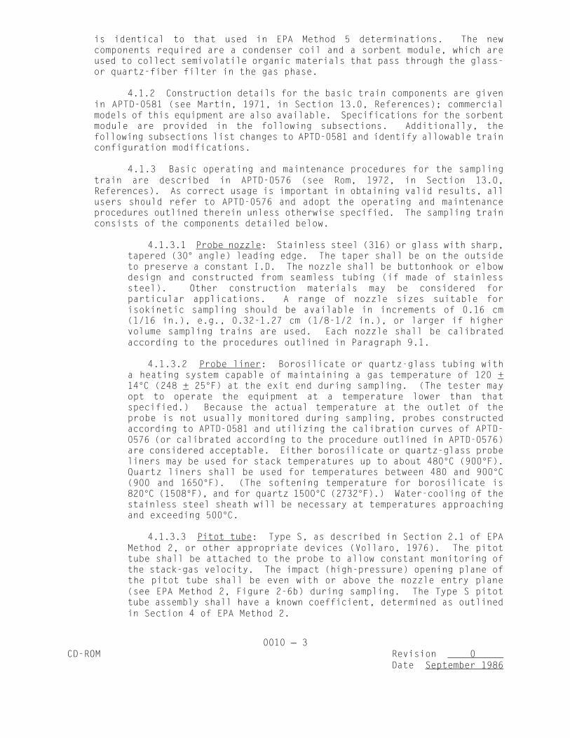
4.1.3.1 Probe nozzle: Stainless steel (316) or glass with sharp,tapered (30E angle) leading edge. The taper shall be on the outsideto preserve a constant I.D. The nozzle shall be buttonhook or elbowdesign and constructed from seamless tubing (if made of stainlesssteel). Other construction materials may be considered forparticular applications. A range of nozzle sizes suitable forisokinetic sampling should be available in increments of 0.16 cm(1/16 in.), e.g., 0.32-1.27 cm (1/8-1/2 in.), or larger if highervolume sampling trains are used. Each nozzle shall be calibratedaccording to the procedures outlined in Paragraph 9.1.
4.1.3.2 Probe liner: Borosilicate or quartz-glass tubing witha heating system capable of maintaining a gas temperature of 120 +14EC (248 + 25EF) at the exit end during sampling. (The tester mayopt to operate the equipment at a temperature lower than thatspecified.) Because the actual temperature at the outlet of theprobe is not usually monitored during sampling, probes constructedaccording to APTD-0581 and utilizing the calibration curves of APTD-0576 (or calibrated according to the procedure outlined in APTD-0576)are considered acceptable. Either borosilicate or quartz-glass probeliners may be used for stack temperatures up to about 480EC (900EF).Quartz liners shall be used for temperatures between 480 and 900EC(900 and 1650EF). (The softening temperature for borosilicate is820EC (1508EF), and for quartz 1500EC (2732EF).) Water-cooling of thestainless steel sheath will be necessary at temperatures approachingand exceeding 500EC.
4.1.3.3 Pitot tube: Type S, as described in Section 2.1 of EPAMethod 2, or other appropriate devices (Vollaro, 1976). The pitottube shall be attached to the probe to allow constant monitoring ofthe stack-gas velocity. The impact (high-pressure) opening plane ofthe pitot tube shall be even with or above the nozzle entry plane(see EPA Method 2, Figure 2-6b) during sampling. The Type S pitottube assembly shall have a known coefficient, determined as outlinedin Section 4 of EPA Method 2.

0010 4CD-ROM Revision 0
Date September 1986
4.1.3.4 Differential pressure gauge: Inclined manometer orequivalent device as described in Section 2.2 of EPA Method 2. Onemanometer shall be used for velocity-head ( P) readings and the otherfor orifice differential pressure ( H) readings.
4.1.3.5 Filter holder: Borosilicate glass, with a glass fritfilter support and a sealing gasket. The sealing gasket should bemade of materials that will not introduce organic material into thegas stream at the temperature at which the filter holder will bemaintained. The gasket shall be constructed of Teflon or materialsof equal or better characteristics. The holder design shall providea positive seal against leakage at any point along the filtercircumference. The holder shall be attached immediately to theoutlet of the cyclone or cyclone bypass.
4.1.3.6 Filter heating system: Any heating system capable ofmaintaining a temperature of 120 + 14EC (248 + 25EF) around the filterholder during sampling. Other temperatures may be appropriate forparticular applications. Alternatively, the tester may opt tooperate the equipment at temperatures other than that specified. Atemperature gauge capable of measuring temperature to within 3EC(5.4EF) shall be installed so that the temperature around the filterholder can be regulated and monitored during sampling. Heatingsystems other than the one shown in APTD-0581 may be used.
4.1.3.7 Organic sampling module: This unit consists of threesections, including a gas-conditioning section, a sorbent trap, anda condensate knockout trap. The gas-conditioning system shall becapable of conditioning the gas leaving the back half of the filterholder to a temperature not exceeding 20EC (68EF). The sorbent trapshall be sized to contain approximately 20 g of porous polymericresin (Rohm and Haas XAD-2 or equivalent) and shall be jacketed tomaintain the internal gas temperature at 17 + 3EC (62.5 + 5.4EF). Themost commonly used coolant is ice water from the impinger ice-waterbath, constantly circulated through the outer jacket, using rubber orplastic tubing and a peristaltic pump. The sorbent trap should beoutfitted with a glass well or depression, appropriately sized toaccommodate a small thermocouple in the trap for monitoring the gasentry temperature. The condensate knockout trap shall be ofsufficient size to collect the condensate following gasconditioning. The organic module components shall be oriented todirect the flow of condensate formed vertically downward from theconditioning section, through the adsorbent media, and into thecondensate knockout trap. The knockout trap is usually similar inappearance to an empty impinger directly underneath the sorbentmodule; it may be oversized but should have a shortened center stem(at a minimum, one-half the length of the normal impinger stems) tocollect a large volume of condensate without bubbling andoverflowing into the impinger train. All surfaces of the organicmodule wetted by the gas sample shall be fabricated of borosilicateglass, Teflon, or other inert materials. Commercial versions of the

0010 5CD-ROM Revision 0
Date September 1986
complete organic module are not currently available, but may beassembled from commercially available laboratory glassware and acustom-fabricated sorbent trap. Details of two acceptable designsare shown in Figures 2 and 3 (the thermocouple well is shown inFigure 2).
4.1.3.8 Impinger train: To determine the stack-gas moisturecontent, four 500-mL impingers, connected in series with leak-freeground-glass joints, follow the knockout trap. The first, third, andfourth impingers shall be of the Greenburg-Smith design, modified byreplacing the tip with a 1.3-cm (1/2-in.) I.D. glass tube extendingabout 1.3 cm (1/2 in.) from the bottom of the outer cylinder. Thesecond impinger shall be of the Greenburg-Smith design with thestandard tip. The first and second impingers shall contain knownquantities of water or appropriate trapping solution. The thirdshall be empty or charged with a caustic solution, should the stackgas contain hydrochloric acid (HCl). The fourth shall contain aknown weight of silica gel or equivalent desiccant.
4.1.3.9 Metering system: The necessary components are a vacuumgauge, leak-free pump, thermometers capable of measuring temperatureto within 3EC (5.4EF), dry-gas meter capable of measuring volume towithin 1%, and related equipment, as shown in Figure 1. At aminimum, the pump should be capable of 4 cfm free flow, and the dry-gas meter should have a recording capacity of 0-999.9 cu ft with a resolution of 0.005 cu ft. Other meteringsystems capable of maintaining sampling rates within 10% ofisokineticity and of determining sample volumes to within 2% may beused. The metering system must be used in conjunction with a pitottube to enable checks of isokinetic sampling rates. Sampling trainsusing metering systems designed for flow rates higher than thosedescribed in APTD-0581 and APTD-0576 may be used, provided that thespecifications of this method are met.
4.1.3.10 Barometer: Mercury, aneroid, or other barometer capableof measuring atmospheric pressure to within 2.5 mm Hg (0.1 in. Hg).In many cases the barometric reading may be obtained from a nearbyNational Weather Service station, in which case the station value(which is the absolute barometric pressure) is requested and anadjustment for elevation differences between the weather station andsampling point is applied at a rate of minus 2.5 mm Hg (0.1 in. Hg)per 30-m (100 ft) elevation increase (vice versa for elevationdecrease).
4.1.3.11 Gas density determination equipment: Temperature sensorand pressure gauge (as described in Sections 2.3 and 2.4 of EPAMethod 2), and gas analyzer, if necessary (as described in EPA Method3). The temperature sensor ideally should be permanently attached tothe pitot tube or sampling probe in a fixed configuration such thatthe tip of the sensor extends beyond the leading edge of the probesheath and does not touch any metal.

0010 6CD-ROM Revision 0
Date September 1986

0010 7CD-ROM Revision 0
Date September 1986
0010 8CD-ROM Revision 0
Date September 1986
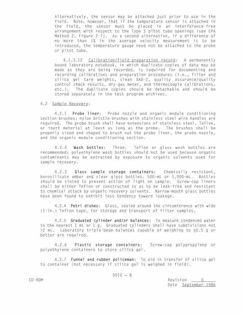
Alternatively, the sensor may be attached just prior to use in thefield. Note, however, that if the temperature sensor is attached inthe field, the sensor must be placed in an interference-freearrangement with respect to the Type S pitot tube openings (see EPAMethod 2, Figure 2-7). As a second alternative, if a difference ofno more than 1% in the average velocity measurement is to beintroduced, the temperature gauge need not be attached to the probeor pitot tube.
4.1.3.12 Calibration/field-preparation record: A permanentlybound laboratory notebook, in which duplicate copies of data may bemade as they are being recorded, is required for documenting andrecording calibrations and preparation procedures (i.e., filter andsilica gel tare weights, clean XAD-2, quality assurance/qualitycontrol check results, dry-gas meter, and thermocouple calibrations,etc.). The duplicate copies should be detachable and should bestored separately in the test program archives.
4.2 Sample Recovery:
4.2.1 Probe liner: Probe nozzle and organic module conditioningsection brushes; nylon bristle brushes with stainless steel wire handles arerequired. The probe brush shall have extensions of stainless steel, Teflon,or inert material at least as long as the probe. The brushes shall beproperly sized and shaped to brush out the probe liner, the probe nozzle,and the organic module conditioning section.
4.2.2 Wash bottles: Three. Teflon or glass wash bottles arerecommended; polyethylene wash bottles should not be used because organiccontaminants may be extracted by exposure to organic solvents used forsample recovery.
4.2.3 Glass sample storage containers: Chemically resistant,borosilicate amber and clear glass bottles, 500-mL or 1,000-mL. Bottlesshould be tinted to prevent action of light on sample. Screw-cap linersshall be either Teflon or constructed so as to be leak-free and resistantto chemical attack by organic recovery solvents. Narrow-mouth glass bottleshave been found to exhibit less tendency toward leakage.
4.2.4 Petri dishes: Glass, sealed around the circumference with wide(1-in.) Teflon tape, for storage and transport of filter samples.
4.2.5 Graduated cylinder and/or balances: To measure condensed waterto the nearest 1 mL or 1 g. Graduated cylinders shall have subdivisions not>2 mL. Laboratory triple-beam balances capable of weighing to +0.5 g orbetter are required.
4.2.6 Plastic storage containers: Screw-cap polypropylene orpolyethylene containers to store silica gel.
4.2.7 Funnel and rubber policeman: To aid in transfer of silica gelto container (not necessary if silica gel is weighed in field).

0010 9CD-ROM Revision 0
Date September 1986
4.2.8 Funnels: Glass, to aid in sample recovery.
4.3 Filters: Glass- or quartz-fiber filters, without organic binder,exhibiting at least 99.95% efficiency (<0.05% penetration) on 0.3-um dioctylphthalate smoke particles. The filter efficiency test shall be conducted inaccordance with ASTM standard method D2986-71. Test data from the supplier'squality control program are sufficient for this purpose. In sources containingSO or SO , the filter material must be of a type that is unreactive to SO or2 3 2
SO . Reeve Angel 934 AH or Schleicher and Schwell #3 filters work well under3
these conditions.
4.4 Crushed ice: Quantities ranging from 10-50 lb may be necessary duringa sampling run, depending on ambient air temperature.
4.5 Stopcock grease: Solvent-insoluble, heat-stable silicone grease. Useof silicone grease upstream of the module is not permitted, and amounts used oncomponents located downstream of the organic module shall be minimized. Siliconegrease usage is not necessary if screw-on connectors and Teflon sleeves orground-glass joints are used.
4.6 Glass wool: Used to plug the unfritted end of the sorbent module. Theglass-wool fiber should be solvent-extracted with methylene chloride in a Soxhletextractor for 12 hr and air-dried prior to use.
5.0 REAGENTS
5.1 Adsorbent resin: Porous polymeric resin (XAD-2 or equivalent) isrecommended. These resins shall be cleaned prior to their use for samplecollection. Appendix A of this method should be consulted to determineappropriate precleaning procedure. For best results, resin used should notexhibit a blank of higher than 4 mg/kg of total chromatographable organics (TCO)(see Appendix B) prior to use. Once cleaned, resin should be stored in anairtight, wide-mouth amber glass container with a Teflon-lined cap or placed inone of the glass sorbent modules tightly sealed with Teflon film and elasticbands. The resin should be used within 4 wk of the preparation.
5.2 Silica gel: Indicating type, 6-16 mesh. If previously used, dry at175EC (350EF) for 2 hr before using. New silica gel may be used as received.Alternatively, other types of desiccants (equivalent or better) may be used,subject to the approval of the Administrator.
5.3 Impinger solutions: Distilled organic-free water (Type II) shall beused, unless sampling is intended to quantify a particular inorganic gaseousspecies. If sampling is intended to quantify the concentration of additionalspecies, the impinger solution of choice shall be subject to Administratorapproval. This water should be prescreened for any compounds of interest. Onehundred mL will be added to the specified impinger; the third impinger in thetrain may be charged with a basic solution (1 N sodium hydroxide or sodiumacetate) to protect the sampling pump from acidic gases. Sodium acetate shouldbe used when large sample volumes are anticipated because sodium hydroxide willreact with carbon dioxide in aqueous media to form sodium carbonate, which maypossibly plug the impinger.

0010 10CD-ROM Revision 0
Date September 1986
5.4 Sample recovery reagents:
5.4.1 Methylene chloride: Distilled-in-glass grade is required forsample recovery and cleanup (see Note to 5.4.2 below).
5.4.2 Methyl alcohol: Distilled-in-glass grade is required forsample recovery and cleanup.NOTE: Organic solvents from metal containers may have a high residue blank
and should not be used. Sometimes suppliers transfer solvents frommetal to glass bottles; thus blanks shall be run prior to field useand only solvents with low blank value (<0.001%) shall be used.
5.4.3 Water: Water (Type II) shall be used for rinsing the organicmodule and condenser component.
6.0 SAMPLE COLLECTION, PRESERVATION, AND HANDLING
6.1 Because of complexity of this method, field personnel should be trainedin and experienced with the test procedures in order to obtain reliable results.
6.2 Laboratory preparation:
6.2.1 All the components shall be maintained and calibrated accordingto the procedure described in APTD-0576, unless otherwise specified.
6.2.2 Weigh several 200- to 300-g portions of silica gel in airtightcontainers to the nearest 0.5 g. Record on each container the total weightof the silica gel plus containers. As an alternative to preweighing thesilica gel, it may instead be weighed directly in the impinger or samplingholder just prior to train assembly.
6.2.3 Check filters visually against light for irregularities andflaws or pinhole leaks. Label the shipping containers (glass Petri dishes)and keep the filters in these containers at all times except during samplingand weighing.
6.2.4 Desiccate the filters at 20 + 5.6EC (68 + 10EF) and ambientpressure for at least 24 hr, and weigh at intervals of at least 6 hr to aconstant weight (i.e., <0.5-mg change from previous weighing), recordingresults to the nearest 0.1 mg. During each weighing the filter must not beexposed for more than a 2-min period to the laboratory atmosphere andrelative humidity above 50%. Alternatively (unless otherwise specified bythe Administrator), the filters may be oven-dried at 105EC (220EF) for 2-3hr, desiccated for 2 hr, and weighed.

0010 11CD-ROM Revision 0
Date September 1986
6.3 Preliminary field determinations:
6.3.1 Select the sampling site and the minimum number of samplingpoints according to EPA Method 1 or as specified by the Administrator.Determine the stack pressure, temperature, and range of velocity heads usingEPA Method 2. It is recommended that a leak-check of the pitot lines (seeEPA Method 2, Section 3.1) be performed. Determine the stack-gas moisturecontent using EPA Approximation Method 4 or its alternatives to establishestimates of isokinetic sampling-rate settings. Determine the stack-gas drymolecular weight, as described in EPA Method 2, Section 3.6. If integratedEPA Method 3 sampling is used for molecular weight determination, theintegrated bag sample shall be taken simultaneously with, and for the sametotal length of time as, the sample run.
6.3.2 Select a nozzle size based on the range of velocity heads sothat it is not necessary to change the nozzle size in order to maintainisokinetic sampling rates. During the run, do not change the nozzle.Ensure that the proper differential pressure gauge is chosen for the rangeof velocity heads encountered (see Section 2.2 of EPA Method 2).
6.3.3 Select a suitable probe liner and probe length so that alltraverse points can be sampled. For large stacks, to reduce the length ofthe probe, consider sampling from opposite sides of the stack.
6.3.4 A minimum of 3 dscm (105.9 dscf) of sample volume is requiredfor the determination of the Destruction and Removal Efficiency (DRE) ofPOHCs from incineration systems. Additional sample volume shall becollected as necessitated by analytical detection limit constraints. Todetermine the minimum sample volume required, refer to sample calculationsin Section 10.0.
6.3.5 Determine the total length of sampling time needed to obtainthe identified minimum volume by comparing the anticipated average samplingrate with the volume requirement. Allocate the same time to all traversepoints defined by EPA Method 1. To avoid timekeeping errors, the length oftime sampled at each traverse point should be an integer or an integer plusone-half min.
6.3.6 In some circumstances (e.g., batch cycles) it may be necessaryto sample for shorter times at the traverse points and to obtain smallergas-sample volumes. In these cases, the Administrator's approval must firstbe obtained.
6.4 Preparation of collection train:
6.4.1 During preparation and assembly of the sampling train, keep allopenings where contamination can occur covered with Teflon film or aluminumfoil until just prior to assembly or until sampling is about to begin.
0010 12CD-ROM Revision 0
Date September 1986
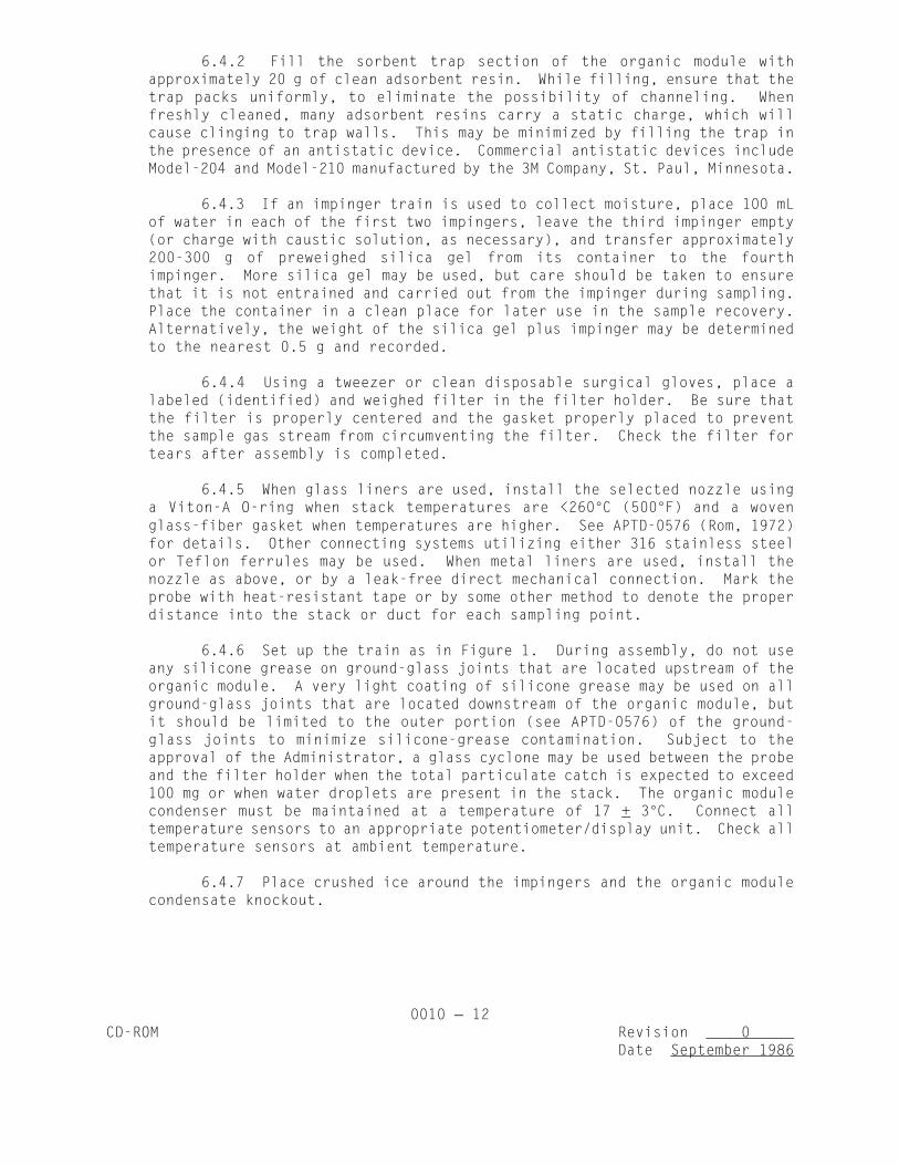
6.4.2 Fill the sorbent trap section of the organic module withapproximately 20 g of clean adsorbent resin. While filling, ensure that thetrap packs uniformly, to eliminate the possibility of channeling. Whenfreshly cleaned, many adsorbent resins carry a static charge, which willcause clinging to trap walls. This may be minimized by filling the trap inthe presence of an antistatic device. Commercial antistatic devices includeModel-204 and Model-210 manufactured by the 3M Company, St. Paul, Minnesota.
6.4.3 If an impinger train is used to collect moisture, place 100 mLof water in each of the first two impingers, leave the third impinger empty(or charge with caustic solution, as necessary), and transfer approximately200-300 g of preweighed silica gel from its container to the fourthimpinger. More silica gel may be used, but care should be taken to ensurethat it is not entrained and carried out from the impinger during sampling.Place the container in a clean place for later use in the sample recovery.Alternatively, the weight of the silica gel plus impinger may be determinedto the nearest 0.5 g and recorded.
6.4.4 Using a tweezer or clean disposable surgical gloves, place alabeled (identified) and weighed filter in the filter holder. Be sure thatthe filter is properly centered and the gasket properly placed to preventthe sample gas stream from circumventing the filter. Check the filter fortears after assembly is completed.
6.4.5 When glass liners are used, install the selected nozzle usinga Viton-A O-ring when stack temperatures are <260EC (500EF) and a wovenglass-fiber gasket when temperatures are higher. See APTD-0576 (Rom, 1972)for details. Other connecting systems utilizing either 316 stainless steelor Teflon ferrules may be used. When metal liners are used, install thenozzle as above, or by a leak-free direct mechanical connection. Mark theprobe with heat-resistant tape or by some other method to denote the properdistance into the stack or duct for each sampling point.
6.4.6 Set up the train as in Figure 1. During assembly, do not useany silicone grease on ground-glass joints that are located upstream of theorganic module. A very light coating of silicone grease may be used on allground-glass joints that are located downstream of the organic module, butit should be limited to the outer portion (see APTD-0576) of the ground-glass joints to minimize silicone-grease contamination. Subject to theapproval of the Administrator, a glass cyclone may be used between the probeand the filter holder when the total particulate catch is expected to exceed100 mg or when water droplets are present in the stack. The organic modulecondenser must be maintained at a temperature of 17 + 3EC. Connect alltemperature sensors to an appropriate potentiometer/display unit. Check alltemperature sensors at ambient temperature.
6.4.7 Place crushed ice around the impingers and the organic modulecondensate knockout.

0010 13CD-ROM Revision 0
Date September 1986
6.4.8 Turn on the sorbent module and condenser coil coolantrecirculating pump and begin monitoring the sorbent module gas entrytemperature. Ensure proper sorbent module gas entry temperature beforeproceeding and again before any sampling is initiated. It is extremelyimportant that the XAD-2 resin temperature never exceed 50EC (122EF),because thermal decomposition will occur. During testing, the XAD-2temperature must not exceed 20EC (68EF) for efficient capture of thesemivolatile species of interest.
6.4.9 Turn on and set the filter and probe heating systems at thedesired operating temperatures. Allow time for the temperatures tostabilize.
6.5 Leak-check procedures
6.5.1 Pre-test leak-check:
6.5.1.1 Because the number of additional intercomponentconnections in the Semi-VOST train (over the M5 Train) increases thepossibility of leakage, a pre-test leak-check is required.
6.5.1.2 After the sampling train has been assembled, turn on andset the filter and probe heating systems at the desired operatingtemperatures. Allow time for the temperatures to stabilize. If aViton A O-ring or other leak-free connection is used in assemblingthe probe nozzle to the probe liner, leak-check the train at thesampling site by plugging the nozzle and pulling a 381-mm Hg (15-in.Hg) vacuum.(NOTE: A lower vacuum may be used, provided that it is not exceeded
during the test.)
6.5.1.3 If an asbestos string is used, do not connect the probeto the train during the leak-check. Instead, leak-check the train byfirst attaching a carbon-filled leak-check impinger (shown in Figure4) to the inlet of the filter holder (cyclone, if applicable) andthen plugging the inlet and pulling a 381-mm Hg (15-in. Hg) vacuum.(Again, a lower vacuum may be used, provided that it is not exceededduring the test.) Then, connect the probe to the train and leak-check at about 25-mm Hg (1-in. Hg) vacuum; alternatively, leak-checkthe probe with the rest of the sampling train in one step at 381-mmHg (15-in. Hg) vacuum. Leakage rates in excess of 4% of the averagesampling rate or >0.00057 m /min (0.02 cfm), whichever is less, are3
unacceptable.
6.5.1.4 The following leak-check instructions for the samplingtrain described in APTD-0576 and APTD-0581 may be helpful. Start thepump with fine-adjust valve fully open and coarse-adjust valvecompletely closed. Partially open the coarse-adjust valve and slowlyclose the fine-adjust valve until the desired vacuum is reached. Donot reverse direction of the fine-adjust valve; this will cause waterto back up into the organic module. If the desired vacuum isexceeded, either leak-check at this higher vacuum or end the leak-check, as shown below, and start over.

0010 14CD-ROM Revision 0
Date September 1986
Figure 4. Leak-check Impinger
0010 15CD-ROM Revision 0
Date September 1986
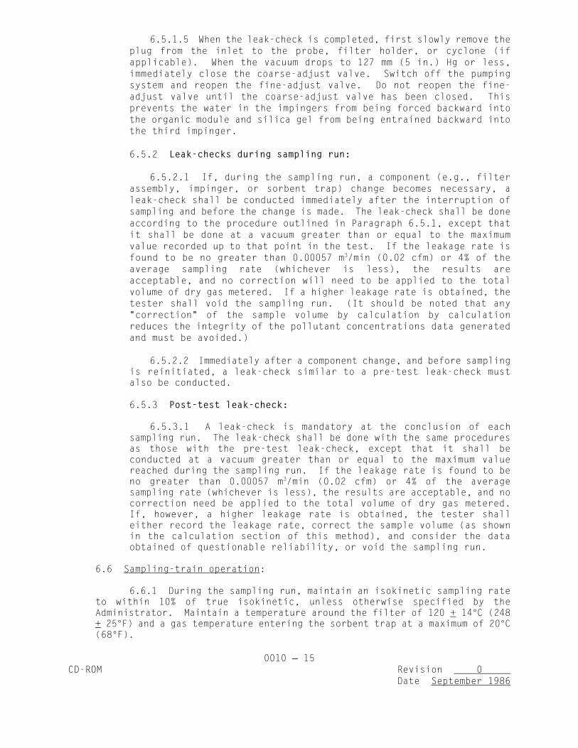
6.5.1.5 When the leak-check is completed, first slowly remove theplug from the inlet to the probe, filter holder, or cyclone (ifapplicable). When the vacuum drops to 127 mm (5 in.) Hg or less,immediately close the coarse-adjust valve. Switch off the pumpingsystem and reopen the fine-adjust valve. Do not reopen the fine-adjust valve until the coarse-adjust valve has been closed. Thisprevents the water in the impingers from being forced backward intothe organic module and silica gel from being entrained backward intothe third impinger.
6.5.2 Leak-checks during sampling run:
6.5.2.1 If, during the sampling run, a component (e.g., filterassembly, impinger, or sorbent trap) change becomes necessary, aleak-check shall be conducted immediately after the interruption ofsampling and before the change is made. The leak-check shall be doneaccording to the procedure outlined in Paragraph 6.5.1, except thatit shall be done at a vacuum greater than or equal to the maximumvalue recorded up to that point in the test. If the leakage rate isfound to be no greater than 0.00057 m /min (0.02 cfm) or 4% of the3
average sampling rate (whichever is less), the results areacceptable, and no correction will need to be applied to the totalvolume of dry gas metered. If a higher leakage rate is obtained, thetester shall void the sampling run. (It should be noted that any"correction" of the sample volume by calculation by calculationreduces the integrity of the pollutant concentrations data generatedand must be avoided.)
6.5.2.2 Immediately after a component change, and before samplingis reinitiated, a leak-check similar to a pre-test leak-check mustalso be conducted.
6.5.3 Post-test leak-check:
6.5.3.1 A leak-check is mandatory at the conclusion of eachsampling run. The leak-check shall be done with the same proceduresas those with the pre-test leak-check, except that it shall beconducted at a vacuum greater than or equal to the maximum valuereached during the sampling run. If the leakage rate is found to beno greater than 0.00057 m /min (0.02 cfm) or 4% of the average3
sampling rate (whichever is less), the results are acceptable, and nocorrection need be applied to the total volume of dry gas metered.If, however, a higher leakage rate is obtained, the tester shalleither record the leakage rate, correct the sample volume (as shownin the calculation section of this method), and consider the dataobtained of questionable reliability, or void the sampling run.
6.6 Sampling-train operation:
6.6.1 During the sampling run, maintain an isokinetic sampling rateto within 10% of true isokinetic, unless otherwise specified by theAdministrator. Maintain a temperature around the filter of 120 + 14EC (248+ 25EF) and a gas temperature entering the sorbent trap at a maximum of 20EC(68EF).

0010 16CD-ROM Revision 0
Date September 1986
6.6.2 For each run, record the data required on a data sheet such asthe one shown in Figure 5. Be sure to record the initial dry-gas meterreading. Record the dry-gas meter readings at the beginning and end of eachsampling time increment, when changes in flow rates are made before andafter each leak-check, and when sampling is halted. Take other readingsrequired by Figure 5 at least once at each sample point during each timeincrement and additional readings when significant changes (20% variationin velocity-head readings) necessitate additional adjustments in flow rate.Level and zero the manometer. Because the manometer level and zero maydrift due to vibrations and temperature changes, make periodic checks duringthe traverse.
6.6.3 Clean the stack access ports prior to the test run to eliminatethe chance of sampling deposited material. To begin sampling, remove thenozzle cap, verify that the filter and probe heating systems are at thespecified temperature, and verify that the pitot tube and probe are properlypositioned. Position the nozzle at the first traverse point, with the tippointing directly into the gas stream. Immediately start the pump andadjust the flow to isokinetic conditions. Nomographs, which aid in therapid adjustment of the isokinetic sampling rate without excessivecomputations, are available. These nomographs are designed for use when theType S pitot-tube coefficient is 0.84 + 0.02 and the stack-gas equivalentdensity (dry molecular weight) is equal to 29 + 4. APTD-0576 details theprocedure for using the nomographs. If the stack-gas molecular weight andthe pitot-tube coefficient are outside the above ranges, do not use thenomographs unless appropriate steps (Shigehara, 1974) are taken tocompensate for the deviations.
6.6.4 When the stack is under significant negative pressure(equivalent to the height of the impinger stem), take care to close thecoarse-adjust valve before inserting the probe into the stack, to preventwater from backing into the organic module. If necessary, the pump may beturned on with the coarse-adjust valve closed.
6.6.5 When the probe is in position, block off the openings aroundthe probe and stack access port to prevent unrepresentative dilution of thegas stream.
6.6.6 Traverse the stack cross section, as required by EPA Method 1or as specified by the Administrator, being careful not to bump the probenozzle into the stack walls when sampling near the walls or when removingor inserting the probe through the access port, in order to minimize thechance of extracting deposited material.
6.6.7 During the test run, make periodic adjustments to keep thetemperature around the filter holder and the organic module at the properlevels; add more ice and, if necessary, salt to maintain a temperature of<20EC (68EF) at the condenser/silica gel outlet. Also, periodically checkthe level and zero of the manometer.

0010 17CD-ROM Revision 0
Date September 1986

0010 18CD-ROM Revision 0
Date September 1986
6.6.8 If the pressure drop across the filter or sorbent trap becomestoo high, making isokinetic sampling difficult to maintain, thefilter/sorbent trap may be replaced in the midst of a sample run. Usinganother complete filter holder/sorbent trap assembly is recommended, ratherthan attempting to change the filter and resin themselves. After a newfilter/sorbent trap assembly is installed, conduct a leak-check. The totalparticulate weight shall include the summation of all filter assemblycatches.
6.6.9 A single train shall be used for the entire sample run, exceptin cases where simultaneous sampling is required in two or more separateducts or at two or more different locations within the same duct, or incases where equipment failure necessitates a change of trains. In all othersituations, the use of two or more trains will be subject to the approvalof the Administrator.
6.6.10 Note that when two or more trains are used, separate analysisof the front-half (if applicable) organic-module and impinger (ifapplicable) catches from each train shall be performed, unless identicalnozzle sizes were used on all trains. In that case, the front-half catchesfrom the individual trains may be combined (as may the impinger catches),and one analysis of front-half catch and one analysis of impinger catch maybe performed.
6.6.11 At the end of the sample run, turn off the coarse-adjustvalve, remove the probe and nozzle from the stack, turn off the pump, recordthe final dry-gas meter reading, and conduct a post-test leak-check. Also,leak-check the pitot lines as described in EPA Method 2. The lines mustpass this leak-check in order to validate the velocity-head data.
6.6.12 Calculate percent isokineticity (see Section 10.8) todetermine whether the run was valid or another test run should be made.
7.0 SAMPLE RECOVERY
7.1 Preparation:
7.1.1 Proper cleanup procedure begins as soon as the probe is removedfrom the stack at the end of the sampling period. Allow the probe to cool.When the probe can be safely handled, wipe off all external particulatematter near the tip of the probe nozzle and place a cap over the tip toprevent losing or gaining particulate matter. Do not cap the probe tiptightly while the sampling train is cooling down because this will createa vacuum in the filter holder, drawing water from the impingers into thesorbent module.
7.1.2 Before moving the sample train to the cleanup site, removethe probe from the sample train and cap the open outlet, being carefulnot to lose any condensate that might be present. Cap the filter inlet.

0010 19CD-ROM Revision 0
Date September 1986
Remove the umbilical cord from the last impinger and cap the impinger. Ifa flexible line is used between the organic module and the filter holder,disconnect the line at the filter holder and let any condensed water orliquid drain into the organic module.
7.1.3 Cap the filter-holder outlet and the inlet to the organicmodule. Separate the sorbent trap section of the organic module from thecondensate knockout trap and the gas-conditioning section. Cap all organicmodule openings. Disconnect the organic-module knockout trap from theimpinger train inlet and cap both of these openings. Ground-glass stoppers,Teflon caps, or caps of other inert materials may be used to seal allopenings.
7.1.4 Transfer the probe, the filter, the organic-module components,and the impinger/condenser assembly to the cleanup area. This area shouldbe clean and protected from the weather to minimize sample contamination orloss.
7.1.5 Save a portion of all washing solutions (methanol/methylenechloride, Type II water) used for cleanup as a blank. Transfer 200 mL ofeach solution directly from the wash bottle being used and place each in aseparate, prelabeled glass sample container.
7.1.6 Inspect the train prior to and during disassembly and note anyabnormal conditions.
7.2 Sample containers:
7.2.1 Container no. 1: Carefully remove the filter from the filterholder and place it in its identified Petri dish container. Use a pair orpairs of tweezers to handle the filter. If it is necessary to fold thefilter, ensure that the particulate cake is inside the fold. Carefullytransfer to the Petri dish any particulate matter or filter fibers thatadhere to the filter-holder gasket, using a dry nylon bristle brush orsharp-edged blade, or both. Label the container and seal with 1-in.-wideTeflon tape around the circumference of the lid.
7.2.2 Container no. 2: Taking care that dust on the outside of theprobe or other exterior surfaces does not get into the sample,quantitatively recover particulate matter or any condensate from the probenozzle, probe fitting, probe liner, and front half of the filter holder bywashing these components first with methanol/methylene chloride (1:1 v/v)into a glass container. Distilled water may also be used. Retain a waterand solvent blank and analyze in the same manner as with the samples.Perform rinses as follows:
7.2.2.1 Carefully remove the probe nozzle and clean the insidesurface by rinsing with the solvent mixture (1:1 v/v methanol/-methylene chloride) from a wash bottle and brushing with a nylonbristle brush. Brush until the rinse shows no visible particles;then make a final rinse of the inside surface with the solvent mix.Brush and rinse the inside parts of the Swagelok fitting with thesolvent mix in a similar way until no visible particles remain.

0010 20CD-ROM Revision 0
Date September 1986
7.2.2.2 Have two people rinse the probe liner with the solventmix by tilting and rotating the probe while squirting solvent intoits upper end so that all inside surfaces will be wetted withsolvent. Let the solvent drain from the lower end into the samplecontainer. A glass funnel may be used to aid in transferring liquidwashes to the container.
7.2.2.3 Follow the solvent rinse with a probe brush. Hold theprobe in an inclined position and squirt solvent into the upper endwhile pushing the probe brush through the probe with a twistingaction; place a sample container underneath the lower end of theprobe and catch any solvent and particulate matter that is brushedfrom the probe. Run the brush through the probe three times or moreuntil no visible particulate matter is carried out with the solventor until none remains in the probe liner on visual inspection. Withstainless steel or other metal probes, run the brush through in theabove-prescribed manner at least six times (metal probes have smallcrevices in which particulate matter can be entrapped). Rinse thebrush with solvent and quantitatively collect these washings in thesample container. After the brushing, make a final solvent rinse ofthe probe as described above.
7.2.2.4 It is recommended that two people work together to cleanthe probe to minimize sample losses. Between sampling runs, keepbrushes clean and protected from contamination.
7.2.2.5 Clean the inside of the front half of the filter holderand cyclone/cyclone flask, if used, by rubbing the surfaces with anylon bristle brush and rinsing with methanol/methylene chloride (1:1v/v) mixture. Rinse each surface three times or more if needed toremove visible particulate. Make a final rinse of the brush andfilter holder. Carefully rinse out the glass cyclone and cycloneflask (if applicable). Brush and rinse any particulate materialadhering to the inner surfaces of these components into the front-half rinse sample. After all solvent washings and particulate matterhave been collected in the sample container, tighten the lid on thesample container so that solvent will not leak out when it is shippedto the laboratory. Mark the height of the fluid level to determinewhether leakage occurs during transport. Label the container toidentify its contents.
7.2.3 Container no. 3: The sorbent trap section of the organicmodule may be used as a sample transport container, or the spent resin maybe transferred to a separate glass bottle for shipment. If the sorbent trapitself is used as the transport container, both ends should be sealed withtightly fitting caps or plugs. Ground-glass stoppers or Teflon caps may beused. The sorbent trap should then be labeled, covered with aluminum foil,and packaged on ice for transport to the laboratory. If a separate bottleis used, the spent resin should be quantitatively transferred from the trapinto the clean bottle. Resin that adheres to the walls of the trap shouldbe recovered using a rubber policeman or spatula and added to this bottle.

0010 21CD-ROM Revision 0
Date September 1986
7.2.4 Container no. 4: Measure the volume of condensate collectedin the condensate knockout section of the organic module to within +1 mL byusing a graduated cylinder or by weighing to within +0.5 g using a triple-beam balance. Record the volume or weight of liquid present and note anydiscoloration or film in the liquid catch. Transfer this liquid to aprelabeled glass sample container. Inspect the back half of the filterhousing and the gas-conditioning section of the organic module. Ifcondensate is observed, transfer it to a graduated or weighing bottle andmeasure the volume, as described above. Add this material to the condensateknockout-trap catch.
7.2.5 Container no. 5: All sampling train components located betweenthe high-efficiency glass- or quartz-fiber filter and the first wet impingeror the final condenser system (including the heated Teflon line connectingthe filter outlet to the condenser) should be thoroughly rinsed withmethanol/methylene chloride (1:1 v/v) and the rinsings combined. This rinseshall be separated from the condensate. If the spent resin is transferredfrom the sorbent trap to a separate sample container for transport, thesorbent trap shall be thoroughly rinsed until all sample-wetted surfacesappear clean. Visible films should be removed by brushing. Whenever traincomponents are brushed, the brush should be subsequently rinsed with solventmixture and the rinsings added to this container.
7.2.6 Container no. 6: Note the color of the indicating silica gelto determine if it has been completely spent and make a notation of itscondition. Transfer the silica gel from the fourth impinger to its originalcontainer and seal. A funnel may make it easier to pour the silica gelwithout spilling. A rubber policeman may be used as an aid in removing thesilica gel from the impinger. It is not necessary to remove the smallamount of dust particles that may adhere strongly to the impinger wall.Because the gain in weight is to be used for moisture calculations, do notuse any water or other liquids to transfer the silica gel. If a balance isavailable in the field, weigh the container and its contents to 0.5 g orbetter.
7.3 Impinger water:
7.3.1 Make a notation of any color or film in the liquid catch.Measure the liquid in the first three impingers to within +1 mL by using agraduated cylinder or by weighing it to within +0.5 g by using a balance (ifone is available). Record the volume or weight of liquid present. Thisinformation is required to calculate the moisture content of the effluentgas.
7.3.2 Discard the liquid after measuring and recording the volume orweight, unless analysis of the impinger catch is required (see Paragraph4.1.3.7). Amber glass containers should be used for storage of impingercatch, if required.
7.3.3 If a different type of condenser is used, measure the amountof moisture condensed either volumetrically or gravimetrically.

0010 22CD-ROM Revision 0
Date September 1986
7.4 Sample preparation for shipment: Prior to shipment, recheck all samplecontainers to ensure that the caps are well secured. Seal the lids of allcontainers around the circumference with Teflon tape. Ship all liquid samplesupright on ice and all particulate filters with the particulate catch facingupward. The particulate filters should be shipped unrefrigerated.
8.0 ANALYSIS
8.1 Sample preparation:
8.1.1 General: The preparation steps for all samples will result ina finite volume of concentrated solvent. The final sample volume (usuallyin the 1- to 10-mL range) is then subjected to analysis by GC/MS. Allsamples should be inspected and the appearance documented. All samples areto be spiked with surrogate standards as received from the field prior toany sample manipulations. The spike should be at a level equivalent to 10times the MDL when the solvent is reduced in volume to the desired level(i.e., 10 mL). The spiking compounds should be the stable isotopicallylabeled analog of the compounds of interest or a compound that would exhibitproperties similar to the compounds of interest, be easily chromatographed,and not interfere with the analysis of the compounds of interest. Suggestedsurrogate spiking compounds are: deuterated naphthalene, chrysene, phenol,nitrobenzene, chlorobenzene, toluene, and carbon-13-labeledpentachlorophenol.
8.1.2 Condensate: The "condensate" is the moisture collected in thefirst impinger following the XAD-2 module. Spike the condensate with thesurrogate standards. The volume is measured and recorded and thentransferred to a separatory funnel. The pH is to be adjusted to pH 2 with6 N sulfuric acid, if necessary. The sample container and graduatedcylinder are sequentially rinsed with three successive 10-mL aliquots of theextraction solvent and added to the separatory funnel. The ratio of solventto aqueous sample should be maintained at 1:3. Extract the sample byvigorously shaking the separatory funnel for 5 min. After completeseparation of the phases, remove the solvent and transfer to a Kuderna-Danish concentrator (K-D), filtering through a bed of precleaned, dry sodiumsulfate. Repeat the extraction step two additional times. Adjust the pHto 11 with 6 N sodium hydroxide and reextract combining the acid and baseextracts. Rinse the sodium sulfate into the K-D with fresh solvent anddiscard the desiccant. Add Teflon boiling chips and concentrate to 10 mLby reducing the volume to slightly less than 10 mL and then bringing tovolume with fresh solvent. In order to achieve the necessary detectionlimit, the sample volume can be further reduced to 1 mL by using a microcolumn K-D or nitrogen blow-down. Should the sample start to exhibitprecipitation, the concentration step should be stopped and the sampleredissolved with fresh solvent taking the volume to some finite amount.After adding a standard (for the purpose of quantitation by GC/MS), thesample is ready for analysis, as discussed in Paragraph 8.2.
0010 23CD-ROM Revision 0
Date September 1986
8.1.3 Impinger: Spike the sample with the surrogate standards;measure and record the volume and transfer to a separatory funnel. Proceedas described in Paragraph 8.1.2.
8.1.4 XAD-2: Spike the resin directly with the surrogate standards.Transfer the resin to the all-glass thimbles by the following procedure(care should be taken so as not to contaminate the thimble by touching itwith anything other than tweezers or other solvent-rinsed mechanical holdingdevices). Suspend the XAD-2 module directly over the thimble. The glassfrit of the module (see Figure 2) should be in the up position. The thimbleis contained in a clean beaker, which will serve to catch the solventrinses. Using a Teflon squeeze bottle, flush the XAD-2 into the thimble.Thoroughly rinse the glass module with solvent into the beaker containingthe thimble. Add the XAD-2 glass-wool plug to the thimble. Cover the XAD-2in the thimble with a precleaned glass-wool plug sufficient to prevent theresin from floating into the solvent reservoir of the extractor. If theresin is wet, effective extraction can be accomplished by loosely packingthe resin in the thimble. If a question arises concerning the completenessof the extraction, a second extraction, without a spike, is advised. Thethimble is placed in the extractor and the rinse solvent contained in thebeaker is added to the solvent reservoir. Additional solvent is added tomake the reservoir approximately two-thirds full. Add Teflon boiling chipsand assemble the apparatus. Adjust the heat source to cause the extractorto cycle 5-6 times per hr. Extract the resin for 16 hr. Transfer thesolvent and three 10-mL rinses of the reservoir to a K-D and concentrate asdescribed in Paragraph 8.1.2.
8.1.5 Particulate filter (and cyclone catch): If particulate loadingis to be determined, weigh the filter (and cyclone catch, if applicable).The particulate filter (and cyclone catch, if applicable) is transferred tothe glass thimble and extracted simultaneously with the XAD-2 resin.
8.1.6 Train solvent rinses: All train rinses (i.e., probe, impinger,filter housing) using the extraction solvent and methanol are returned tothe laboratory as a single sample. If the rinses are contained in more thanone container, the intended spike is divided equally among the containersproportioned from a single syringe volume. Transfer the rinse to aseparatory funnel and add a sufficient amount of organic-free water so thatthe methylene chloride becomes immiscible and its volume no longer increaseswith the addition of more water. The extraction and concentration steps arethen performed as described in Paragraph 8.1.2.
8.2 Sample analysis:
8.2.1 The primary analytical tool for the measurement of emissionsfrom hazardous waste incinerators is GC/MS using fused-silica capillary GCcolumns, as described in Method 8270 in Chapter Four of this manual.Because of the nature of GC/MS instrumentation and the cost associated

0010 24CD-ROM Revision 0
Date September 1986
with sample analysis, prescreening of the sample extracts by gaschromatography/flame ionization detection (GC/FID) or with electron capture(GC/ECD) is encouraged. Information regarding the complexity andconcentration level of a sample prior to GC/MS analysis can be of enormoushelp. This information can be obtained by using either capillary columnsor less expensive packed columns. However, the FID screen should beperformed with a column similar to that used with the GC/MS. Keep in mindthat GC/FID has a slightly lower detection limit than GC/MS and, therefore,that the concentration of the sample can be adjusted either up or down priorto analysis by GC/MS.
8.2.2 The mass spectrometer will be operated in a full scan (40-450)mode for most of the analyses. The range for which data are acquired in aGC/MS run will be sufficiently broad to encompass the major ions, as listedin Chapter Four, Method 8270, for each of the designated POHCs in anincinerator effluent analysis.
8.2.3 For most purposes, electron ionization (EI) spectra will becollected because a majority of the POHCs give reasonable EI spectra. Also,EI spectra are compatible with the NBS Library of Mass Spectra and othermass spectral references, which aid in the identification process for othercomponents in the incinerator process streams.
8.2.4 To clarify some identifications, chemical ionization (CI)spectra using either positive ions or negative ions will be used toelucidate molecular-weight information and simplify the fragmentationpatterns of some compounds. In no case, however, should CI spectra alonebe used for compound identification. Refer to Chapter Four, Method 8270,for complete descriptions of GC conditions, MS conditions, and quantitativeand quantitative identification.
9.0 CALIBRATION
9.1 Probe nozzle: Probe nozzles shall be calibrated before their initialuse in the field. Using a micrometer, measure the inside diameter of the nozzleto the nearest 0.025 mm (0.001 in.). Make measurements at three separate placesacross the diameter and obtain the average of the measurements. The differencebetween the high and low numbers shall not exceed 0.1 mm (0.004 in.). Whennozzles become nicked, dented, or corroded, they shall be reshaped, sharpened,and recalibrated before use. Each nozzle shall be permanently and uniquelyidentified.
9.2 Pitot tube: The Type S pitot tube assembly shall be calibratedaccording to the procedure outlined in Section 4 of EPA Method 2, or assigned anominal coefficient of 0.84 if it is not visibly nicked, dented, or corroded andif it meets design and intercomponent spacing specifications.

0010 25CD-ROM Revision 0
Date September 1986
9.3 Metering system:
9.3.1 Before its initial use in the field, the metering system shallbe calibrated according to the procedure outlined in APTD-0576. Instead ofphysically adjusting the dry-gas meter dial readings to correspond to thewet-test meter readings, calibration factors may be used to correct the gasmeter dial readings mathematically to the proper values. Before calibratingthe metering system, it is suggested that a leak-check be conducted. Formetering systems having diaphragm pumps, the normal leak-check procedurewill not detect leakages within the pump. For these cases the followingleak-check procedure is suggested: Make a 10-min calibration run at 0.00057m /min (0.02 cfm); at the end of the run, take the difference of the3
measured wet-test and dry-gas meter volumes and divide the difference by 10to get the leak rate. The leak rate should not exceed 0.00057 m /min (0.023
cfm).
9.3.2 After each field use, the calibration of the metering systemshall be checked by performing three calibration runs at a singleintermediate orifice setting (based on the previous field test). The vacuumshall be set at the maximum value reached during the test series. To adjustthe vacuum, insert a valve between the wet-test meter and the inlet of themetering system. Calculate the average value of the calibration factor.If the calibration has changed by more than 5%, recalibrate the meter overthe full range of orifice settings, as outlined in APTD-0576.
9.3.3 Leak-check of metering system: That portion of the samplingtrain from the pump to the orifice meter (see Figure 1) should be leak-checked prior to initial use and after each shipment. Leakage after thepump will result in less volume being recorded than is actually sampled.The following procedure is suggested (see Figure 6): Close the main valveon the meter box. Insert a one-hole rubber stopper with rubber tubingattached into the orifice exhaust pipe. Disconnect and vent the low sideof the orifice manometer. Close off the low side orifice tap. Pressurizethe system to 13-18 cm (5-7 in.) water column by blowing into the rubbertubing. Pinch off the tubing and observe the manometer for 1 min. A lossof pressure on the manometer indicates a leak in the meter box. Leaks, ifpresent, must be corrected.NOTE: If the dry-gas-meter coefficient values obtained before and after a
test series differ by >5%, either the test series shall be voided orcalculations for test series shall be performed using whichever metercoefficient value (i.e., before or after) gives the lower value oftotal sample volume.
9.4 Probe heater: The probe-heating system shall be calibrated before itsinitial use in the field according to the procedure outlined in APTD-0576.Probes constructed according to APTD-0581 need not be calibrated if thecalibration curves in APTD-0576 are used.

0010 26CD-ROM Revision 0
Date September 1986

0010 27CD-ROM Revision 0
Date September 1986
9.5 Temperature gauges: Each thermocouple must be permanently and uniquelymarked on the casting; all mercury-in-glass reference thermometers must conformto ASTM E-1 63C or 63F specifications. Thermocouples should be calibrated in thelaboratory with and without the use of extension leads. If extension leads areused in the field, the thermocouple readings at ambient air temperatures, withand without the extension lead, must be noted and recorded. Correction isnecessary if the use of an extension lead produces a change >1.5%.
9.5.1 Impinger, organic module, and dry-gas meter thermocouples: Forthe thermocouples used to measure the temperature of the gas leaving theimpinger train and the XAD-2 resin bed, three-point calibration at ice-water, room-air, and boiling-water temperatures is necessary. Accept thethermocouples only if the readings at all three temperatures agree to +2EC(3.6EF) with those of the absolute value of the reference thermometer.
9.5.2 Probe and stack thermocouple: For the thermocouples used toindicate the probe and stack temperatures, a three-point calibration at ice-water, boiling-water, and hot-oil-bath temperatures must be performed; itis recommended that room-air temperature be added, and that the thermometerand the thermocouple agree to within 1.5% at each of the calibration points.A calibration curve (equation) may be constructed (calculated) and the dataextrapolated to cover the entire temperature range suggested by themanufacturer.
9.6 Barometer: Adjust the barometer initially and before each test seriesto agree to within +25 mm Hg (0.1 in. Hg) of the mercury barometer or thecorrected barometric pressure value reported by a nearby National Weather ServiceStation (same altitude above sea level).
9.7 Triple-beam balance: Calibrate the triple-beam balance before eachtest series, using Class-S standard weights; the weights must be within +0.5% ofthe standards, or the balance must be adjusted to meet these limits.
10.0 CALCULATIONS
10.1 Carry out calculations. Round off figures after the final calculationto the correct number of significant figures.
10.2 Nomenclature:
A = Cross-sectional area of nozzle, m (ft ).n2 2
B = Water vapor in the gas stream, proportion by volume.ws C = Type S pitot tube coefficient (nominally 0.84 + 0.02),d
dimensionless.
I = Percent of isokinetic sampling.

0010 28CD-ROM Revision 0
Date September 1986
L = Maximum acceptable leakage rate for a leak-check, either pre-testaor following a component change; equal to 0.00057 m /min (0.023
cfm) or 4% of the average sampling rate, whichever is less.
L = Individual leakage rate observed during the leak-check conductediprior to the "i " component change (i = 1, 2, 3...n) m /minth 3
(cfm). L = Leakage rate observed during the post-test leak-check, m /minp
3
(cfm). M = Stack-gas dry molecular weight, g/g-mole (lb/lb-mole).d
M = Molecular weight of water, 18.0 g/g-mole (18.0 lb/lb-mole).w
P = Barometric pressure at the sampling site, mm Hg (in. Hg).bar
Ps = Absolute stack-gas pressure, mm Hg (in. Hg).
P = Standard absolute pressure, 760 mm Hg (29.92 in. Hg).std R = Ideal gas constant, 0.06236 mm Hg-m /K-g-mole (21.85 in. Hg-ft /ER-3 3
lb-mole). T = Absolute average dry-gas meter temperature (see Figure 6), K (ER).m
T = Absolute average stack-gas temperature (see Figure 6), K (ER).s
T = Standard absolute temperature, 293K (528ER).std V = Total volume of liquid collected in the organic module condensatelc
knockout trap, the impingers, and silica gel, mL.
V = Volume of gas sample as measured by dry-gas meter, dscm (dscf).m V = Volume of gas sample measured by the dry-gas meter, corrected tom(std)
standard conditions, dscm (dscf).
V = Volume of water vapor in the gas sample, corrected to standardw(std)conditions, scm (scf).
V = Stack-gas velocity, calculated by Method 2, Equation 2-9, usingsdata obtained from Method 5, m/sec (ft/sec).
W = Weight of residue in acetone wash, mg.a
= Dry-gas-meter calibration factor, dimensionless. H = Average pressure differential across the orifice meter (see Figure
2), mm H O (in. H O).2 2

0010 29CD-ROM Revision 0
Date September 1986
= Density of water, 0.9982 g/mL (0.002201 lb/mL).w
= Total sampling time, min. = Sampling time interval from the beginning of a run until the first1
component change, min.
= Sampling time interval between two successive component changes,ibeginning with the interval between the first and second changes,min.
= Sampling time interval from the final (n ) component change untilpth
the end of the sampling run, min.
13.6 = Specific gravity of mercury.
60 = sec/min.
100 = Conversion to percent.
10.3 Average dry-gas-meter temperature and average orifice pressure drop:See data sheet (Figure 5, above).
10.4 Dry-gas volume: Correct the sample measured by the dry-gas meter tostandard conditions (20EC, 760 mm Hg [68EF, 29.92 in. Hg]) by using Equation 1:
T P + H/13.6 P + H/13.6 std bar bar _____ _______________ ______________ V = V = K V (1)1 m m(std) m T P Tm std m
where:
K = 0.3858 K/mm Hg for metric units, or1
K = 17.64ER/in. Hg for English units.1
It should be noted that Equation 1 can be used as written, unless the leakagerate observed during any of the mandatory leak-checks (i.e., the post-test leak-check or leak-checks conducted prior to component changes) exceeds L . If L ora p
L exceeds L , Equation 1 must be modified as follows:i a
a. Case I (no component changes made during sampling run): Replace Vm
in Equation 1 with the expression:
V - (L - L ) m p a

0010 30CD-ROM Revision 0
Date September 1986
b. Case II (one or more component changes made during the sampling run):Replace V in Equation 1 by the expression: m
n
V - (L - L ) - j (L - L ) - (L - L ) m 1 a 1 i a 1 p a p i=2
and substitute only for those leakage rates (L or L ) that exceed L .1 p a
10.5 Volume of water vapor:
P RT w std __ _____ V = V = K V (2)2 1c w(std) lc M P w std where:
K = 0.001333 m /mL for metric units, or23
K = 0.04707 ft /mL for English units.23
10.6 Moisture content:
V w(std) _________________ B = (3) ws V + V m(std) w(std)
NOTE: In saturated or water-droplet-laden gas streams, two calculations ofthe moisture content of the stack gas shall be made, one from theimpinger analysis (Equation 3) and a second from the assumption ofsaturated conditions. The lower of the two values of B shall bew
considered correct. The procedure for determining the moisturecontent based upon assumption of saturated conditions is given in theNote to Section 1.2 of Method 4. For the purposes of this method,the average stack-gas temperature from Figure 6 may be used to makethis determination, provided that the accuracy of the in-stacktemperature sensor is +1EC (2EF).
10.7 Conversion factors:
From To Multiply byscf m 0.028323
g/ft gr/ft 15.433 3
g/ft lb/ft 2.205 x 10³ 3 -3
g/ft g/m 35.313 3

0010 31CD-ROM Revision 0
Date September 1986
10.8 Isokinetic variation:
10.8.1 Calculation from raw data:
100 T [K F + (V /T ) (P + H/13.6)] s 3 lc m m bar _________________________________________ I = (4) 60 V P A s s nwhere:
K = 0.003454 mm Hg-m /mL-K for metric units, or33
K = 0.002669 in. Hg-ft /mL-ER for English units.33
10.8.2 Calculation for intermediate values:
T V P 100 s m(std) std I = T V A P 60(1-B ) std s n s ws (5) T V s m(std) = K 4 P V A (1-B ) s s n ws
where:
K = 4.320 for metric units, or4
K = 0.09450 for English units.4
10.8.3 Acceptable results: If 90% < I < ll0%, the results areacceptable. If the results are low in comparison with the standard and Iis beyond the acceptable range, or if I is less than 90%, the Administratormay opt to accept the results.
10.9 To determine the minimum sample volume that shall be collected, thefollowing sequence of calculations shall be used.
10.9.1 From prior analysis of the waste feed, the concentration ofPOHCs introduced into the combustion system can be calculated. The degreeof destruction and removal efficiency that is required is used to determinethe maximum amount of POHC allowed to be present in the effluent. This maybe expressed as:
(WF) (POHC conc) (l00-%DRE) i _________________ _________ = Max POHC Mass (6) i 100 100
where:
WF = mass flow rate of waste feed per hr, g/hr (lb/hr).
POHC = concentration of Principal Organic Hazardous Compound (wti
%) introduced into the combustion process.

0010 32CD-ROM Revision 0
Date September 1986
DRE = percent Destruction and Removal Efficiency required.
Max POHC = mass flow rate (g/hr [lb/hr]) of POHC emitted from thecombustion source.
10.9.2 The average discharge concentration of the POHC in theeffluent gas is determined by comparing the Max POHC with the volumetricflow rate being exhausted from the source. Volumetric flow rate data areavailable as a result of preliminary Method 1-4 determinations:
Max POHC Mass i ______________ = Max POHC conc (7) i DV eff(std)
where:
DV = volumetric flow rate of exhaust gas, dscm (dscf).eff(std)
POHC conc = anticipated concentration of the POHC in thei
exhaust gas stream, g/dscm (lb/dscf).
10.9.3 In making this calculation, it is recommended that a safetymargin of at least ten be included:
LDL x 10 POHC ____________ = V (8) TBC POHC i conc
where:
LDL = detectable amount of POHC in entire sampling train.POHC
NOTE: The whole extract from an XAD-2 cartridge is seldom ifever, injected at once. Therefore, if aliquoting factorsare involved, the LDL is not the same as thePOHCanalytical (or column) detection limit.
V = minimum dry standard volume to be collected at dry-gasTBC meter.
10.10 Concentration of any given POHC in the gaseous emissions of acombustion process:
1) Multiply the concentration of the POHC as determined in Method 8270 bythe final concentration volume, typically 10 mL.
C (ug/mL) x sample volume (mL) = amount (ug) of POHC in sample (9)POHC

0010 33CD-ROM Revision 0
Date September 1986
where:
C = concentration of POHC as analyzed by Method 8270.POHC
2) Sum the amount of POHC found in all samples associated with a singletrain.
Total (ug) = XAD-2 (ug) + condensate (ug) + rinses (ug) + impinger (ug) (10)
3) Divide the total ug found by the volume of stack gas sampled (m ).3
(Total ug)/(train sample volume) = concentration of POHC (ug/m ) (11)3
11.0 QUALITY CONTROL
11.1 Sampling: See EPA Manual 600/4-77-027b for Method 5 quality control.
11.2 Analysis: The quality assurance program required for this studyincludes the analysis of field and method blanks, procedure validations,incorporation of stable labeled surrogate compounds, quantitation versus stablelabeled internal standards, capillary column performance checks, and externalperformance tests. The surrogate spiking compounds selected for a particularanalysis are used as primary indicators of the quality of the analytical data fora wide range of compounds and a variety of sample matrices. The assessment ofcombustion data, positive identification, and quantitation of the selectedcompounds are dependent on the integrity of the samples received and theprecision and accuracy of the analytical methods employed. The quality assuranceprocedures for this method are designed to monitor the performance of theanalytical method and to provide the required information to take correctiveaction if problems are observed in laboratory operations or in field samplingactivities.
11.2.1 Field Blanks: Field blanks must be submitted with the samplescollected at each sampling site. The field blanks include the samplebottles containing aliquots of sample recovery solvents, unused filters, andresin cartridges. At a minimum, one complete sampling train will beassembled in the field staging area, taken to the sampling area, and leak-checked at the beginning and end of the testing (or for the same totalnumber of times as the actual test train). The filter housing and probe ofthe blank train will be heated during the sample test. The train will berecovered as if it were an actual test sample. No gaseous sample will bepassed through the sampling train.
11.2.2 Method blanks: A method blank must be prepared for each setof analytical operations, to evaluate contamination and artifacts that canbe derived from glassware, reagents, and sample handling in the laboratory.
11.2.3 Refer to Method 8270 for additional quality controlconsiderations.

0010 34CD-ROM Revision 0
Date September 1986
12.0 METHOD PERFORMANCE
12.1 Method performance evaluation: Evaluation of analytical proceduresfor a selected series of compounds must include the sample-preparation proceduresand each associated analytical determination. The analytical procedures shouldbe challenged by the test compounds spiked at appropriate levels and carriedthrough the procedures.
12.2 Method detection limit: The overall method detection limits (lowerand upper) must be determined on a compound-by-compound basis because differentcompounds may exhibit different collection, retention, and extractionefficiencies as well as instrumental minimum detection limit (MDL). The methoddetection limit must be quoted relative to a given sample volume. The upperlimits for the method must be determined relative to compound retention volumes(breakthrough).
12.3 Method precision and bias: The overall method precision and bias mustbe determined on a compound-by-compound basis at a given concentration level.The method precision value would include a combined variability due to sampling,sample preparation, and instrumental analysis. The method bias would bedependent upon the collection, retention, and extraction efficiency of the traincomponents. From evaluation studies to date using a dynamic spiking system,method biases of -13% and -16% have been determined for toluene and 1,1,2,2-tetrachloroethane, respectively. A precision of 19.9% was calculated from afield test data set representing seven degrees of freedom which resulted from aseries of paired, unspiked Semivolatile Organic Sampling trains (Semi-VOST)sampling emissions from a hazardous waste incinerator.
13.0 REFERENCES
1. Addendum to Specifications for Incinerator Testing at Federal Facilities,PHS, NCAPC, December 6, 1967.
2. Bursey, J., Homolya, J., McAllister, R., and McGangley, J., Laboratory andField Evaluation of the Semi-VOST Method, Vols. 1 and 2, U.S. EnvironmentalProtection Agency, EPA/600/4-851/075A, 075B (1985).
3. Martin, R.M., Construction Details of Isokinetic Source-Sampling Equipment,Research Triangle Park, NC, U.S. Environmental Protection Agency, April 1971, PB-203 060/BE, APTD-0581, 35 pp.
4. Rom, J.J., Maintenance, Calibration, and Operation of Isokinetic Source-Sampling Equipment, Research Triangle Park, NC, U.S. Environmental ProtectionAgency, March 1972, PB-209 022/BE, APTD-0576, 39 pp.
5. Schlickenrieder, L.M., Adams, J.W., and Thrun, K.E., Modified Method 5 Trainand Source Assessment Sampling System: Operator's Manual, U.S. EnvironmentalProtection Agency, EPA/600/8-85/003, (1985).

0010 35CD-ROM Revision 0
Date September 1986
6. Shigehara, R.T., Adjustments in the EPA Nomography for Different Pitot TubeCoefficients and Dry Molecular Weights, Stack Sampling News, 2:4-11 (October1974).
7. U.S. Environmental Protection Agency, CFR 40 Part 60, Appendix A, Methods1-5.
8. Vollaro, R.F., A Survey of Commercially Available Instrumentation for theMeasurement of Low-Range Gas Velocities, Research Triangle Park, NC, U.S.Environmental Protection Agency, Emissions Measurement Branch, November 1976(unpublished paper).

METHOD 0010, APPENDIX A
PREPARATION OF XAD-2 SORBENT RESIN
1.0 SCOPE AND APPLICATION
1.1 XAD-2 resin as supplied by the manufacturer is impregnated with abicarbonate solution to inhibit microbial growth during storage. Both the saltsolution and any residual extractable monomer and polymer species must be removedbefore use. The resin is prepared by a series of water and organic extractions,followed by careful drying.
2.0 EXTRACTION
2.1 Method 1: The procedure may be carried out in a giant Soxhletextractor. An all-glass thimble containing an extra-coarse frit is used forextraction of XAD-2. The frit is recessed 10-15 mm above a crenellated ring atthe bottom of the thimble to facilitate drainage. The resin must be carefullyretained in the extractor cup with a glass-wool plug and stainless steel screenbecause it floats on methylene chloride. This process involves sequentialextraction in the following order.
Solvent Procedure
Water Initial rinse: Place resin in a beaker, rinseonce with Type II water, and discard. Fill with water a second time, let standovernight, and discard.
Water Extract with H O for 8 hr.2
Methyl alcohol Extract for 22 hr.
Methylene chloride Extract for 22 hr.
Methylene chloride (fresh) Extract for 22 hr.
2.2 Method 2:
2.2.1 As an alternative to Soxhlet extraction, a continuous extractorhas been fabricated for the extraction sequence. This extractor has been foundto be acceptable. The particular canister used for the apparatus shown in FigureA-1 contains about 500 g of finished XAD-2. Any size may be constructed; thechoice is dependent on the needs of the sampling programs. The XAD-2 is heldunder light spring tension between a pair of coarse and fine screens. Spacersunder the bottom screen allow for even distribution of clean solvent. The three-necked flask should be of sufficient size (3-liter in this case) to hold solvent
0010 A 1CD-ROM Revision 0
Date September 1986

0010 A 2CD-ROM Revision 0
Date September 1986
Figure A-1. XAD-2 cleanup extraction apparatus.

0010 A 3CD-ROM Revision 0
Date September 1986
equal to twice the dead volume of the XAD-2 canister. Solvent is refluxedthrough the Snyder column, and the distillate is continuously cycled up throughthe XAD-2 for extraction and returned to the flask. The flow is maintainedupward through the XAD-2 to allow maximum solvent contact and prevent channeling.A valve at the bottom of the canister allows removal of solvent from the canisterbetween changes.
2.2.2 Experience has shown that it is very difficult to cyclesufficient water in this mode. Therefore the aqueous rinse is accomplished bysimply flushing the canister with about 20 liters of distilled water. A smallpump may be useful for pumping the water through the canister. The waterextraction should be carried out at the rate of about 20-40 mL/min.
2.2.3 After draining the water, subsequent methyl alcohol andmethylene chloride extractions are carried out using the refluxing apparatus.An overnight or 10- to 20-hr period is normally sufficient for each extraction.
2.2.4 All materials of construction are glass, Teflon, or stainlesssteel. Pumps, if used, should not contain extractable materials. Pumps are notused with methanol and methylene chloride.
3.0 DRYING
3.1 After evaluation of several methods of removing residual solvent, afluidized-bed technique has proved to be the fastest and most reliable dryingmethod.
3.2 A simple column with suitable retainers, as shown in Figure A-2, willserve as a satisfactory column. A 10.2-cm (4-in.) Pyrex pipe 0.6 m (2 ft) longwill hold all of the XAD-2 from the extractor shown in Figure A-1 or the Soxhletextractor, with sufficient space for fluidizing the bed while generating aminimum resin load at the exit of the column.
3.3 Method 1: The gas used to remove the solvent is the key to preservingthe cleanliness of the XAD-2. Liquid nitrogen from a standard commercial liquidnitrogen cylinder has routinely proved to be a reliable source of large volumesof gas free from organic contaminants. The liquid nitrogen cylinder is connectedto the column by a length of precleaned 0.95-cm (3/8-in.) copper tubing, coiledto pass through a heat source. As nitrogen is bled from the cylinder, it isvaporized in the heat source and passes through the column. A convenient heatsource is a water bath heated from a steam line. The final nitrogen temperatureshould only be warm to the touch and not over 40EC. Experience has shown thatabout 500 g of XAD-2 may be dried overnight by consuming a full 160-litercylinder of liquid nitrogen.
3.4 Method 2: As a second choice, high-purity tank nitrogen may be usedto dry the XAD-2. The high-purity nitrogen must first be passed through a bed
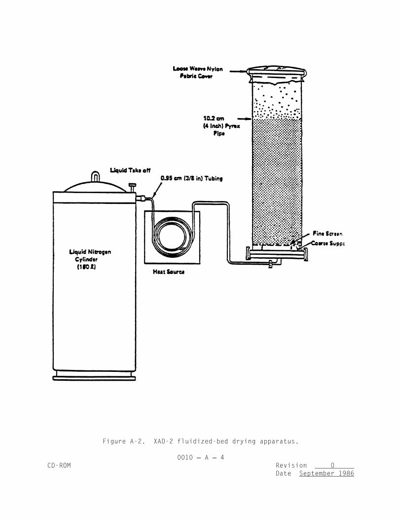
0010 A 4CD-ROM Revision 0
Date September 1986
Figure A-2. XAD-2 fluidized-bed drying apparatus.

0010 A 5CD-ROM Revision 0
Date September 1986
of activated charcoal approximately 150 mL in volume. With either type of dryingmethod, the rate of flow should gently agitate the bed. Excessive fluidizationmay cause the particles to break up.
4.0 QUALITY CONTROL PROCEDURES
4.1 For both Methods 1 and 2, the quality control results must be reportedfor the batch. The batch must be reextracted if the residual extractableorganics are >20 ug/mL by TCO analysis or the gravimetric residue is >0.5 mg/20g XAD-2 extracted. (See also section 5.1, Method 0010.)
4.2 Four control procedures are used with the final XAD-2 to check for (1)residual methylene chloride, (2) extractable organics (TCO), (3) specificcompounds of interest as determined by GC/MS, as described in Section 4.5 below,and (4) residue (GRAV).
4.3 Procedure for residual methylene chloride:
4.3.1 Description: A 1+0.1-g sample of dried resin is weighed intoa small vial, 3 mL of toluene are added, and the vial is capped and well shaken.Five uL of toluene (now containing extracted methylene chloride) are injectedinto a gas chromatograph, and the resulting integrated area is compared with areference standard. The reference solution consists of 2.5 uL of methylenechloride in 100 mL of toluene, simulating 100 ug of residual methylene chlorideon the resin. The acceptable maximum content is 1,000 ug/g resin.
4.3.2 Experimental: The gas chromatograph conditions are as follows:
6-ft x 1/8-in. stainless steel column containing 10% OV-101 on100/120 Supelcoport;
Helium carrier at 30 mL/min;
FID operated on 4 x 10 A/mV;-11
Injection port temperature: 250EC;
Detector temperature: 305EC;
Program: 30EC(4 min) 40EC/min 250EC (hold); and
Program terminated at 1,000 sec.
4.4 Procedure for residual extractable organics:
4.4.1 Description: A 20+0.1-g sample of cleaned, dried resin isweighed into a precleaned alundum or cellulose thimble which is plugged withcleaned glass wool. (Note that 20 g of resin will fill a thimble, and the

0010 A 6CD-ROM Revision 0
Date September 1986
resin will float out unless well plugged.) The thimble containing the resin isextracted for 24 hr with 200-mL of pesticide- grade methylene chloride (Burdickand Jackson pesticide-grade or equivalent purity). The 200-mL extract is reducedin volume to 10-mL using a Kuderna-Danish concentrator and/or a nitrogenevaporation stream. Five uL of that solution are analyzed by gas chromatographyusing the TCO analysis procedure. The concentrated solution should not contain>20 ug/mL of TCO extracted from the XAD-2. This is equivalent to 10 ug/g of TCOin the XAD-2 and would correspond to 1.3 mg of TCO in the extract of the 130-gXAD-2 module. Care should be taken to correct the TCO data for a solvent blankprepared (200 mL reduced to 10 mL) in a similar manner.
4.4.2 Experimental: Use the TCO analysis conditions described in therevised Level 1 manual (EPA 600/7-78-201).
4.5 GC/MS Screen: The extract, as prepared in paragraph 4.4.1, issubjected to GC/MS analysis for each of the individual compounds of interest.The GC/MS procedure is described in Chapter Four, Method 8270. The extract isscreened at the MDL of each compound. The presence of any compound at aconcentration >25 ug/mL in the concentrated extract will require the XAD-2 to berecleaned by repeating the methylene chloride step.
4.6 Methodology for residual gravimetric determination: After the TCOvalue and GC/MS data are obtained for the resin batch by the above procedures,dry the remainder of the extract in a tared vessel. There must be <0.5 mgresidue registered or the batch of resin will have to be extracted with freshmethylene chloride again until it meets this criterion. This level correspondsto 25 ug/g in the XAD-2, or about 3.25 mg in a resin charge of 130 g.

0010 B 1CD-ROM Revision 0
Date September 1986
METHOD 0010, APPENDIX B
TOTAL CHROMATOGRAPHABLE ORGANIC MATERIAL ANALYSIS
1.0 SCOPE AND APPLICATION
1.1 In this procedure, gas chromatography is used to determine the quantityof lower boiling hydrocarbons (boiling points between 90E and 300EC) in theconcentrates of all organic solvent rinses, XAD-2 resin and LC fractions - whenMethod 1 is used (see References, Method 0010) - encountered in Level 1environmental sample analyses. Data obtained using this procedure serve atwofold purpose. First, the total quantity of the lower boiling hydrocarbons inthe sample is determined. Then whenever the hydrocarbon concentrations in theoriginal concentrates exceed 75 ug/m , the chromatography results are reexamined3
to determine the amounts of individual species.
The extent of compound identification is limited to representing allmaterials as normal alkanes based upon comparison of boiling points. Thus themethod is not qualitative. In a similar manner, the analysis issemiquantitative; calibrations are prepared using only one hydrocarbon. They arereplicated but samples routinely are not.
1.2 Application: This procedure applies solely to the Level 1 C7-C16 gaschromatographic analysis of concentrates of organic extracts, neat liquids, andof LC fractions. Throughout the procedure, it is assumed the analyst has beengiven a properly prepared sample.
1.3 Sensitivity: The sensitivity of this procedure, defined as the slopeof a plot of response versus concentration, is dependent on the instrument andmust be verified regularly. TRW experience indicates the nominal range is of theorder of 77 uV@V@sec@uL/ng of n-heptane and 79 uV@sec@ul/ng of n-hexadecane. Theinstrument is capable of perhaps one hundredfold greater sensitivity. The levelspecified here is sufficient for Level 1 analysis.
1.4 Detection limit: The detection limit of this procedure as written is1.3 ng/uL for a 1 uL injection of n-decane. This limit is arbitrarily based ondefining the minimum detectable response as 100 uv@sec. This is an easieroperational definition than defining the minimum detection limit to be thatamount of material which yields a signal twice the noise level.
1.5 Range: The range of the procedure will be concentrations of 1.3 ng/uLand greater.
1.6 Limitations
1.6.1 Reporting limitations: It should be noted that a typicalenvironmental sample will contain compounds which: (a) will not elute inthe specified boiling ranges and thus will not be reported, and/or (b)
0010 B 2CD-ROM Revision 0
Date September 1986
will not elute from the column at all and thus will not be reported.Consequently, the organic content of the sample as reported is a lower boundand should be regarded as such.
1.6.2 Calibration limitations: Quantitation is based on calibrationwith n-decane. Data should therefore be reported as, e.g., mg C8/m as n-3
decane. Since response varies linearly with carbon number (over a widerange the assumption may involve a 20% error), it is clear that heptane (C7)detected in a sample and quantitated as decane will be overestimated.Likewise, hexadecane (C16) quantitated as decane will be underestimated.From previous data, it is estimated the error involved is on the order of6-7%.
1.6.3 Detection limitations: The sensitivity of the flame ionizationdetector varies from compound to compound. However, n-alkanes have agreater response than other classes. Consequently, using an n-alkane as acalibrant and assuming equal responses of all other compounds tends to givelow reported values.
2.0 SUMMARY OF METHOD
2.1 A mL aliquot of all 10-mL concentrates is disbursed for GC-TCOanalysis. With boiling point-retention time and response-amount calibrationcurves, the data (peak retention times and peak areas) are interpreted by firstsumming peak areas in the ranges obtained from the boiling point-retention timecalibration. Then, with the response-amount calibration curve, the area sums areconverted to amounts of material in the reported boiling point ranges.
2.2 After the instrument is set up, the boiling point-retention timecalibration is effected by injecting a mixture of n-C7 through n-C16 hydrocarbonsand operating the standard temperature program. Response-quantity calibrationsare accomplished by injecting n-decane in n-pentane standards and performing thestandard temperature program.
2.3 Definitions2.3.1 GC: Gas chromatography or gas chromatograph.
2.3.2 C7-C16 n-alkanes: Heptane through hexadecane.
2.3.3 GCA temperature program: 4 min isothermal at 60EC, 10EC/minfrom 60E to 220EC.
2.3.4 TRW temperature program: 5 min isothermal at room temperature,then program from 30EC to 250EC at 15EC/min.
3.0 INTERFERENCES
Not applicable.

0010 B 3CD-ROM Revision 0
Date September 1986
4.0 APPARATUS AND MATERIALS
4.1 Gas chromatograph: This procedure is intended for use on a Varian 1860gas chromatograph, equipped with dual flame ionization detectors and a lineartemperature programmer. Any equivalent instrument can be used provided thatelectrometer settings, etc., be changed appropriately.
4.2 Gases:
4.2.1 Helium: Minimum quality is reactor grade. A 4A or 13Xmolecular sieve drying tube is required. A filter must be placed betweenthe trap and the instrument. The trap should be recharged after every thirdtank of helium.
4.2.2 Air: Zero grade is satisfactory.
4.2.3 Hydrogen: Zero grade.
4.3 Syringe: Syringes are Hamilton 701N, 10 uL, or equivalent.
4.4 Septa: Septa will be of such quality as to produce very low bleedduring the temperature program. An appropriate septum is Supelco Microsep 138,which is Teflon-backed. If septum bleed cannot be reduced to a negligible level,it will be necessary to install septum swingers on the instrument.
4.5 Recorder: The recorder of this procedure must be capable of not lessthan 1 mV full-scale display, a 1-sec time constant and 0.5 in. per min chartrate.
4.6 Integrator: An integrator is required. Peak area measurement by handis satisfactory but too time-consuming. If manual integration is required, themethod of "height times width at half height" is used.
4.7 Columns:
4.7.1 Preferred column: 6 ft x 1/8 in. O.D. stainless steel column of10% OV-101 on 100/120 mesh Supelcoport.
4.7.2 Alternate column: 6 ft x 1/8 in. O.D. stainless steel columnof 10% OV-1 (or other silicon phase) on 100/120 mesh Supelcoport.
4.8 Syringe cleaner: Hamilton syringe cleaner or equivalent connected toa suitable vacuum source.
5.0 REAGENTS
5.1 Pentane: "Distilled-in-Glass" (reg. trademark) or "Nanograde" (reg.trademark) for standards and for syringe cleaning.

0010 B 4CD-ROM Revision 0
Date September 1986
5.2 Methylene chloride: "Distilled-in-Glass" (reg. trademark) or"Nanograde" (reg. trademark) for syringe cleaning.
6.0 SAMPLING HANDLING AND PRESERVATION
6.1 The extracts are concentrated in a Kuderna-Danish evaporator to avolume less than 10 mL. The concentrate is then quantitatively transferred toa 10-mL volumetric flask and diluted to volume. A 1-mL aliquot is taken for boththis analysis and possible subsequent GC/MS analysis and set aside in the samplebank. For each GC-TCO analysis, obtain the sample sufficiently in advance toallow it to warm to room temperature. For example, after one analysis isstarted, return that sample to the sample bank and take the next sample.
7.0 PROCEDURES
7.1 Setup and checkout: Each day, the operator will verify the following:
7.1.1 That supplies of carrier gas, air and hydrogen are sufficient,i.e., that each tank contains > 100 psig.
7.1.2 That, after replacement of any gas cylinder, all connectionsleading to the chromatograph have been leak-checked.
7.1.3 That the carrier gas flow rate is 30 + 2 mL/min, the hydrogenflow rate is 30 + 2 mL/min, and the air flow rate is 300 + 20 mL/min.
7.1.4 That the electrometer is functioning properly.
7.1.5 That the recorder and integrator are functioning properly.
7.1.6 That the septa have been leak-checked (leak-checking is effectedby placing the soap bubble flow meter inlet tube over the injection portadaptors), and that no septum will be used for more than 20 injections.
7.1.7 That the list of samples to be run is ready.
7.2 Retention time calibration:
7.2.1 To obtain the temperature ranges for reporting the results ofthe analyses, the chromatograph is given a normal boiling point-retentiontime calibration. The n-alkanes, their boiling points, and data reportingranges are given in the table below:

0010 B 5CD-ROM Revision 0
Date September 1986
NBP, EC Reporting Range, EC Report As
n-heptane 98 90-110 C7n-octane 126 110-140 C8n-nonane 151 140-160 C9n-decane 174 160-180 C10n-undecane 194 180-200 C11n-dodecane 214 200-220 C12n-tridecane 234 220-240 C13n-tetradecane 252 240-260 C14n-pentadecane 270 260-280 C15n-hexadecane 288 280-300 C16
7.2.2 Preparation of standards: Preparing a mixture of the C7-C16alkanes is required. There are two approaches: (1) use of a standards kit(e.g., Polyscience Kit) containing bottles of mixtures of selected n-alkaneswhich may be combined to produce a C7-C16 standard; or (2) use of bottlesof the individual C7-C16 alkanes from which accurately known volumes may betaken and combined to give a C7-C16 mixture.
7.2.3 Procedure for retention time calibration: This calibration isperformed at the start of an analytical program; the mixture ischromatographed at the start of each day. To attain the required retentiontime precision, both the carrier gas flow rate and the temperature programspecifications must be observed. Details of the procedure depend on theinstrument being used. The general procedure is as follows:
7.2.3.1 Set the programmer upper limit at 250EC. If this settingdoes not produce a column temperature of 250EC, find the correctsetting.
7.2.3.2 Set the programmer lower limit at 30EC.
7.2.3.3 Verify that the instrument and samples are at roomtemperature.
7.2.3.4 Inject 1 uL of the n-alkane mixture.
7.2.3.5 Start the integrator and recorder.
7.2.3.6 Allow the instrument to run isothermally at roomtemperature for five min.
7.2.3.7 Shut the oven door.
7.2.3.8 Change the mode to Automatic and start the temperatureprogram.
7.2.3.9 Repeat Steps 1-9 a sufficient number of times so that therelative standard deviation of the retention times for each peak is <5%.

0010 B 6CD-ROM Revision 0
Date September 1986
7.3 Response calibration:
7.3.1 For the purposes of a Level 1 analysis, response-quantitycalibration with n-decane is adequate. A 10-uL volume of n-decane isinjected into a tared 10 mL volumetric flask. The weight injected isobtained and the flask is diluted to the mark with n-pentane. This standardcontains about 730 ng n-decane per uL n-pentane. The exact concentrationdepends on temperature, so that a weight is required. Two serial tenfolddilutions are made from this standard, giving standards at about 730, 73,and 7.3 ng n-decane per uL n-pentane, respectively.
7.3.2 Procedure for response calibration: This calibration isperformed at the start of an analytical program and monthly thereafter. Themost concentrated standard is injected once each day. Any change incalibration necessitates a full calibration with new standards. Standardsare stored in the refrigerator locker and are made up monthly.
7.3.2.1 Verify that the instrument is set up properly.
7.3.2.2 Set electrometer at 1 x 10 A/mV.-10
7.3.2.3 Inject 1 uL of the highest concentration standard.
7.3.2.4 Run standard temperature program as specified above.
7.3.2.5 Clean syringe.
7.3.2.6 Make repeated injections of all three standards until therelative standard deviations of the areas of each standard are #5%.
7.4 Sample analysis procedure:
7.4.1 The following apparatus is required:
7.4.1.1 Gas chromatograph set up and working.
7.4.1.2 Recorder, integrator working.
7.4.1.3 Syringe and syringe cleaning apparatus.
7.4.1.4 Parameters: Electrometer setting is 1 x 10 A/mV;-10
recorder is set at 0.5 in./min and 1 mV full-scale.
7.4.2 Steps in the procedure are:
7.4.2.1 Label chromatogram with the data, sample number, etc.

0010 B 7CD-ROM Revision 0
Date September 1986
7.4.2.2 Inject sample.
7.4.2.3 Start integrator and recorder.
7.4.2.4 After isothermal operation for 5 min, begin temperatureprogram.
7.4.2.5 Clean syringe.
7.4.2.6 Return sample; obtain new sample.
7.4.2.7 When analysis is finished, allow instrument to cool.Turn chromatogram and integrator output and data sheet over to dataanalyst.
7.5 Syringe cleaning procedure:
7.5.1 Remove plunger from syringe.
7.5.2 Insert syringe into cleaner; turn on aspirator.
7.5.3 Fill pipet with pentane; run pentane through syringe.
7.5.4 Repeat with methylene chloride from a separate pipet.
7.5.5 Flush plunger with pentane followed by methylene chloride.
7.5.6 Repeat with methylene chloride.
7.6 Sample analysis decision criterion: The data from the TCO analyses oforganic extract and rinse concentrates are first used to calculate the totalconcentration of C7-C16 hydrocarbon-equivalents (Paragraph 7.7.3) in the samplewith respect to the volume of air actually sampled, i.e., ug/m . On this basis,3
a decision is made both on whether to calculate the quantity of each n-alkaneequivalent present and on which analytical procedural pathway will be followed.If the total organic content is great enough to warrant continuing the analysis-- >500 ug/m -- a TCO of less than 75 ug/m will require only LC fractionation3 3
and gravimetric determinations and IR spectra to be obtained on each fraction.If the TCO is greater than 75 ug/m , then the first seven LC fractions of each3
sample will be reanalyzed using this same gas chromatographic technique.
7.7 Calculations:
7.7.1 Boiling Point - Retention Time Calibration: The required datafor this calibration are on the chromatogram and on the data sheet. Thedata reduction is performed as follows:
7.7.1.1 Average the retention times and calculate relativestandard deviations for each n-hydrocarbon.

0010 B 8CD-ROM Revision 0
Date September 1986
7.7.1.2 Plot average retention times as abscissae versus normalboiling points as ordinates.
7.7.1.3 Draw in calibration curve.
7.7.1.4 Locate and record retention times corresonding to boilingranges 90-100, 110-140, 140-160, 160-180, 180-200, 200-220, 220-240,240-260, 260-280, 280-300EC.
7.7.2 Response-amount calibration: The required data for thiscalibration are on the chromatogram and on the data sheet. The datareduction is performed as follows:
7.7.2.1 Average the area responses of each standard and calculaterelative standard deviations.
7.7.2.2 Plot response (uv@sec) as ordinate versus ng/uL asabscissa.
7.7.2.3 Draw in the curve. Perform least squares regression andobtain slope (uV@sec@uL/ng).
7.7.3 Total C7-C16 hydrocarbons analysis: The required data for thiscalculation are on the chromatogram and on the data sheet. The datareduction is performed as follows:
7.7.3.1 Sum the areas of all peaks within the retention timerange of interest.
7.7.3.2 Convert this area (uV@sec) to ng/uL by dividing by theweight response for n-decane ([email protected]/ng).
7.7.3.3 Multiply this weight by the total concentrate volume (10mL) to get the weight of the C7-C16 hydrocarbons in the sample.
7.7.3.4 Using the volume of gas sampled or the total weight ofsample acquired, convert the result of Step 7.7.3.3 above to ug/m .3
7.7.3.5 If the value of total C7-C16 hydrocarbons from Step7.7.3.4 above exceeds 75 ug/m , calculate individual hydrocarbon3
concentrations in accordance with the instructions in Paragraph 7.7.5.5below.
7.7.4 Individual C7-C16 n-Alkane Equivalent Analysis: The requireddata from the analyses are on the chromatogram and on the data sheet. Thedata reduction is performed as follows:
7.7.4.1 Sum the areas of peaks in the proper retention timeranges.
0010 B 9CD-ROM Revision 0
Date September 1986
7.7.4.2 Convert areas (uV@sec) to ng/uL by dividing by the properweight response (uV@sec@uL/ng).
7.7.4.3 Multiply each weight by total concentrate volume (10 mL)to get weight of species in each range of the sample.
7.7.4.4 Using the volume of gas sampled on the total weight ofsample acquired, convert the result of Step 7.7.4.3 above to ug/m .3
8.0 QUALITY CONTROL
8.1 Appropriate QC is found in the pertinent procedures throughout themethod.
9.0 METHOD PERFORMANCE
9.1 Even relatively comprehensive error propagation analysis is beyond thescope of this procedure. With reasonable care, peak area reproducibility of astandard should be of the order of 1% RSD. The relative standard deviation ofthe sum of all peaks in a fairly complex waste might be of the order of 5-10%.Accuracy is more difficult to assess. With good analytical technique, accuracyand precision should be of the order of 10-20%.
10.0 REFERENCES
1. Emissions Assessment of Conventional Stationary Combustion Systems: Methodsand Procedure Manual for Sampling and Analysis, Interagency Energy/EnvironmentalR&D Program, Industrial Environmental Research Laboratory, Research TrianglePark, NC 27711, EPA-600/7-79-029a, January 1979.
Related Documents


