METERING STANDARD ENMAX POWER CORPORATION (EPC) ENMAX Power Corporation 8820 52 Street SE Calgary, Alberta T2C 4E7 Phone 403.514.2807 Fax 403.720.3780 NOTE: THE CONTENTS OF THIS DOCUMENT MAY CHANGE, AND AS SUCH, IT IS THE RESPONSIBILITY OF THE READER TO ENSURE THEY ARE ACCESSING THE MOST RECENT VERSION. Rev # Date Description Originator Approved 0 2016-09-01 Issued for Implementation N. Duerksen T. Nguyen 1 2017-11-08 Revision C. Chan T. Nguyen

Welcome message from author
This document is posted to help you gain knowledge. Please leave a comment to let me know what you think about it! Share it to your friends and learn new things together.
Transcript

METERINGSTANDARD
ENMAXPOWERCORPORATION(EPC)
ENMAX Power Corporation 8820 52 Street SE Calgary, Alberta T2C 4E7 Phone 403.514.2807 Fax 403.720.3780
NOTE: THE CONTENTS OF THIS DOCUMENT MAY CHANGE, AND AS SUCH, IT IS THE RESPONSIBILITY OF THE READER TO ENSURE THEY ARE ACCESSING THE MOST RECENT VERSION.
Rev # Date Description Originator Approved 0 2016-09-01 Issued for Implementation N. Duerksen T. Nguyen 1 2017-11-08 Revision C. Chan T. Nguyen
- 2 -
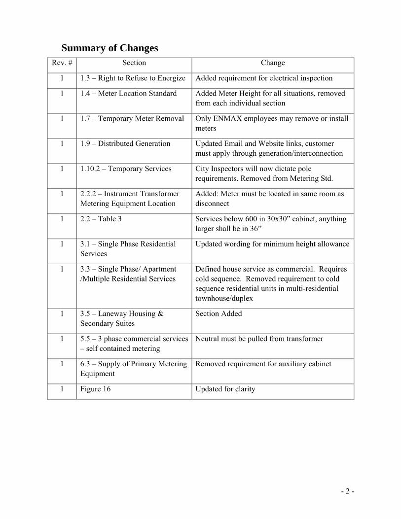
Summary of Changes Rev. # Section Change
1 1.3 – Right to Refuse to Energize Added requirement for electrical inspection
1 1.4 – Meter Location Standard Added Meter Height for all situations, removed from each individual section
1 1.7 – Temporary Meter Removal Only ENMAX employees may remove or install meters
1 1.9 – Distributed Generation Updated Email and Website links, customer must apply through generation/interconnection
1 1.10.2 – Temporary Services City Inspectors will now dictate pole requirements. Removed from Metering Std.
1 2.2.2 – Instrument Transformer Metering Equipment Location
Added: Meter must be located in same room as disconnect
1 2.2 – Table 3 Services below 600 in 30x30” cabinet, anything larger shall be in 36”
1 3.1 – Single Phase Residential Services
Updated wording for minimum height allowance
1 3.3 – Single Phase/ Apartment /Multiple Residential Services
Defined house service as commercial. Requires cold sequence. Removed requirement to cold sequence residential units in multi-residential townhouse/duplex
1 3.5 – Laneway Housing & Secondary Suites
Section Added
1 5.5 – 3 phase commercial services – self contained metering
Neutral must be pulled from transformer
1 6.3 – Supply of Primary Metering Equipment
Removed requirement for auxiliary cabinet
1 Figure 16 Updated for clarity
- 3 -
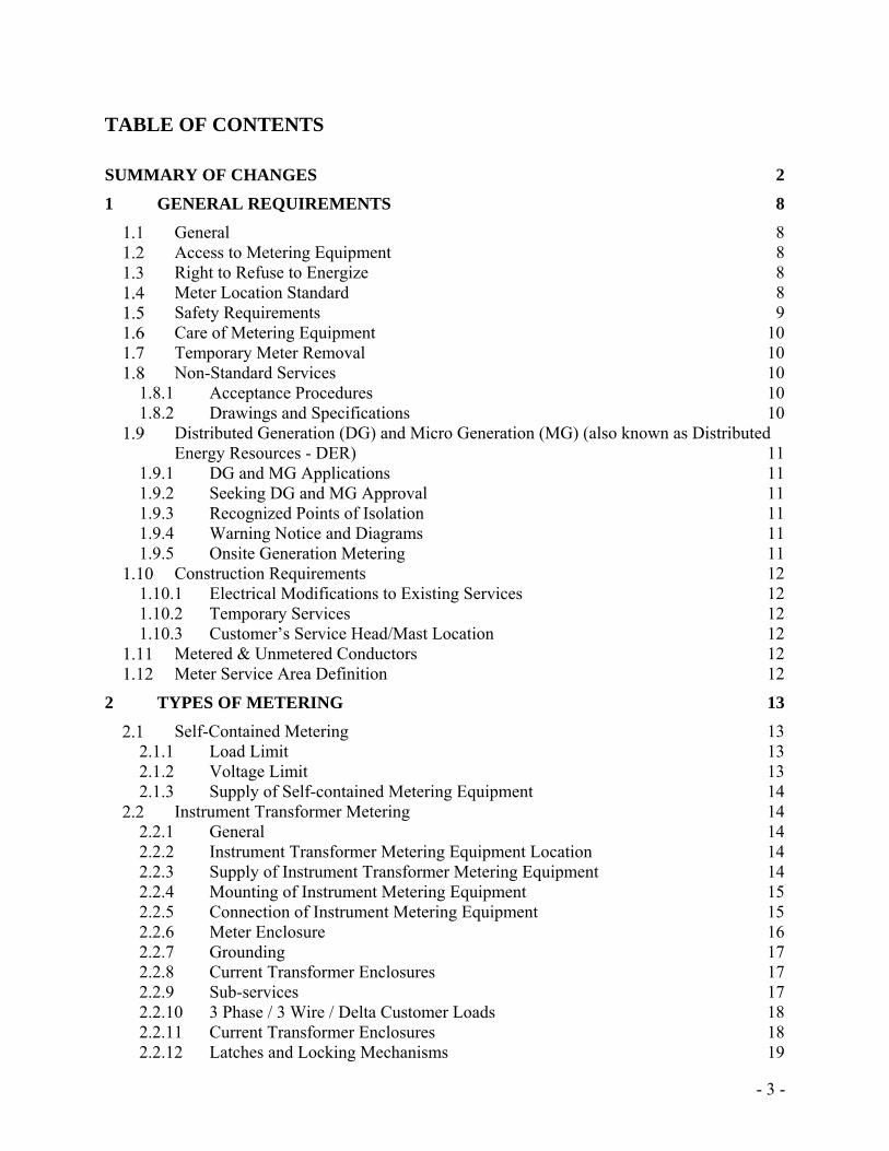
TABLE OF CONTENTS
SUMMARY OF CHANGES 2
1 GENERAL REQUIREMENTS 8
General 8 Access to Metering Equipment 8 Right to Refuse to Energize 8 Meter Location Standard 8 Safety Requirements 9 Care of Metering Equipment 10 Temporary Meter Removal 10 Non-Standard Services 10
1.8.1 Acceptance Procedures 10 1.8.2 Drawings and Specifications 10 Distributed Generation (DG) and Micro Generation (MG) (also known as Distributed
Energy Resources - DER) 11 1.9.1 DG and MG Applications 11 1.9.2 Seeking DG and MG Approval 11 1.9.3 Recognized Points of Isolation 11 1.9.4 Warning Notice and Diagrams 11 1.9.5 Onsite Generation Metering 11 Construction Requirements 12
1.10.1 Electrical Modifications to Existing Services 12 1.10.2 Temporary Services 12 1.10.3 Customer’s Service Head/Mast Location 12 Metered & Unmetered Conductors 12 Meter Service Area Definition 12
2 TYPES OF METERING 13
Self-Contained Metering 13 2.1.1 Load Limit 13 2.1.2 Voltage Limit 13 2.1.3 Supply of Self-contained Metering Equipment 14 Instrument Transformer Metering 14
2.2.1 General 14 2.2.2 Instrument Transformer Metering Equipment Location 14 2.2.3 Supply of Instrument Transformer Metering Equipment 14 2.2.4 Mounting of Instrument Metering Equipment 15 2.2.5 Connection of Instrument Metering Equipment 15 2.2.6 Meter Enclosure 16 2.2.7 Grounding 17 2.2.8 Current Transformer Enclosures 17 2.2.9 Sub-services 17 2.2.10 3 Phase / 3 Wire / Delta Customer Loads 18 2.2.11 Current Transformer Enclosures 18 2.2.12 Latches and Locking Mechanisms 19
- 4 -
2.2.13 Conduit Requirements 19 2.2.14 Splitter Trough Applications 19
3 RESIDENTIAL SERVICES 20
Single Phase Residential Services - Single Meter Installations 20 3.1.1 Installation 20 Single Phase Residential Services - Instrument Transformer Metering 20
3.2.1 Installation 20 Single phase / Multiple Residential Services – Multiple Meter Installations
(Duplexes/Townhouses) 21 3.3.1 Installation 21 Single phase /Apartment/ Commercial/Retailing/Residential Services - Multiple Meter
Installations (Apartments) 22 3.4.1 Installation 22 Laneway Housing & Secondary Suites 22
4 FARM SERVICES 23
5 COMMERCIAL SERVICES 23
General 23 Single-phase/ Comm. Services - Self-contained Metering (Single Meter) 23 Single-phase/ Comm. Services - Self-contained Metering (Multi-Meter) 24 Single-phase Comm. Services - Instrument Transformer Metering 24 Three-phase Commercial Services - Self-contained Metering 25 Three-phase Commercial Services - Instrument Transformer Metering 25 Shopping Malls 26
6 COMMERCIAL OR INDUSTRIAL PRIMARY METERED SERVICE 27
Service Application and Acceptance 27 Primary Switchgear Specifications (Figure 8) 27 Supply of Primary Metering Equipment 28 Mounting of Primary Metering Equipment 29 Connection of Instrument Transformers 29 Meter Enclosure Requirements 29 Outdoor Primary Metering Requirements 30 Conduit Requirements 31 Meter Communication Requirements (Figures 9 & 11) 31
7 INTERVAL METERING REQUIREMENTS 31
Existing Site 31 New Site 31
8 USE OF METERING SIGNALS FOR CUSTOMER LOAD MANAGEMENT SYSTEM 32
9 CONNECTIVITY 33
10 APPENDICES 34
Figure 1: Multiple Meter Installation 34 Figure 2: Single Phase Transformer Rated CT Connection 35 Figure 3A: Single meter, Instrument Transformer Layout Commercial Three phase service 36
- 5 -
Figure 3B: Multiple meter with Instrument Transformer Layout Three phase service 37 Figure 4: Three Phase CT Layout 38 Figure 5: Self-Contained, Single-phase, Three Wire Circuit 120/240 volts 39 Figure 6: Three Wire circuit, Apartment circuit 120/208 volts 40 Figure 7: Three phase four wire circuit, multiple voltages 41 Figure 8: Primary Metering Wiring Diagram 42 Figure 9: Primary metering Arrangement (One Meter) 43 Figure 10: Outdoor Mounted Metering Enclosure 44 Figure 11: Preferred & Alternate Metering Assembly 45 Figure 12: Transformer Rated, Single-Phase, Three Wire Circuit, 120/240V 46 Figure 13: Layout of Metering Requirements - Distributed Generation (DG) sites 47 Figure 14: Single Residential Dwellings (rate code D100) 48 Figure 15: Small/Medium Commercial Services <150KVA (rate code D200 & D300) 49 Figure 16: Large Commercial/Retailing/Residential Services (rate code D310) 50 Figure 17: Shopping Malls (rate code D310) 51 Figure 18: Primary Metered Services (rate code D410) 52 Figure 19: Primary Metered Services prefer & alternate feed (rate code D410) 53
11 FREQUENTLY ASKED QUESTIONS 54
- 6 -
Glossary Electrical terms used in this manual are based on accepted electrical industry practice and the company’s “Terms & Conditions”. AECUC - Alberta Electrical and Communications Utility Code.
AMR - Automatic Metering Reading.
AWG - American Wire Gauge: a wire sizing standard.
Bulk-Metering - Where a single utility revenue meter is used to measure the consumption of more than one clearly defined area. CEC - Canadian Electrical Code, Part 1 and Amendments. Clearly Defined Area - is defined as an individual building, unit, bay, or apartment. CSA - Canadian Standards Association. Cold Sequence Metering - A disconnect is located immediately on the line side of each ENMAX meter, and only isolates that meter. Disconnecting Device- Breaker, fused-disconnect switch CT - Current Transformer. Demand - The average value of power over a specified interval of time. The most common unit of measures are kilowatt (kW) and kilovolt Amperes (kVA) demand. Double Metering - Where more than one utility revenue meter is used to measure the consumption of only one clearly defined area.
EMT - Electrical Metal Tubing.
Energy - The integral of active power over time. E.g. kilowatt-hours (kWh).
Ground - The connection to earth obtained by a grounding electrode, not to be used as neutral connection. Harmonics - Distortions to the voltage and current waveforms from their normal sinusoidal shape. Hot Sequence Metering - Utility supply is connected directly to meter / metering installation.
Apartment - Three-wire service obtained from two-phase wires and a neutral of a three-phase four-wire wye system (120/208volts).
- 7 -
Instrument Transformer Enclosure - The enclosure supplied and installed by the customer for the housing of instrument transformers. Instrument Transformer Metering - Using a transformer in a metering circuit to step down the current and/or the voltage to a level that can be accommodated safely by the meter. Interval Metering - Energy values are recorded for a specific time period on a continual basis. Typically 1minute, 5 minute, 15 minute, or 1 hour intervals. LB’s - An “L” shaped fitting which is a part of the conduit run that has a removable access cover.
Meter Enclosure - The enclosure supplied and installed by the customer for the housing of a meter. Meter Socket - A meter mounting device for the purpose of installing a self-contained meter. Meter Socket and Test Switch Enclosure - Meter socket combined with a Test switch for use with current and/or voltage transformers enclosed in metal housing. Multiple Service - A service to a building, such as an apartment building or shopping center, that has two or more units and a common service entrance in which each unit is served and metered separately. Network ring- The distribution system is fed by multiple primary circuits whose secondaries are tied together to form a power grid or “network”. Neutral - The conductor from the transformer Star point that carries the imbalanced load current and provides a reference point for the metering potentials. Polarity Mark - Marked indicators on a transformer to show the instantaneous direction of current flow through the windings. Current flow into the primary marker causes current flow out of the secondary marker.
PT – Potential transformer+
Primary Metered Service - A metered site with service voltage over 750 Volts.
SAW Meter - Temporary electrical meter only used for construction purposes that is removed after building is complete.
Secondary Metered Service - A metered site with service voltage less than 750 Volts. Self-contained Meter - A meter designed to accommodate the full line current and voltage of the circuit. Single Phase - A service comprised of a 120/240 volt three wire circuit. Time of Use Metering - Energy and demand registrations are segregated into time blocks during each day. Each time block is assigned a rate period. These rate periods are scheduled by time, day of the week, holidays, and/or season.
- 8 -
Three Phase - A service with three phase conductors and a neutral. SCA - Alberta Safety Codes Act.
1 GENERAL REQUIREMENTS General
The purpose of this Standard is to assist customers requiring information regarding ENMAX Metering standards. This section describes general requirements and is applicable to all subsequent sections within this Standard. If you have any questions about this Standard, please contact ENMAX Metering at 403-514-2807 or email [email protected]. A copy of this Standard can be found at: https://www.ENMAX.com/ForYourBusinessSite/Documents/Revenue_Metering.pdf Note: Services above 3000 Amps must notify Revenue Metering a minimum of 16 weeks in advance of installation requirement.
Access to Metering Equipment ENMAX employees, or agents, must have reasonable and unhindered access to all ENMAX equipment for the purpose of reading, testing, and changing that equipment. Where ready access to the metering equipment is not given due to locked doors, ENMAX may request a key for its use. ENMAX may install a lock-box for the purpose of keeping the key on site.
Right to Refuse to Energize An electrical inspection and approval by the local authority having jurisdiction must have taken place prior to ENMAX meter installation. ENMAX reserves the right to refuse energizing any service or meter installation within its service territory at its discretion. Some of the potential causes for refusal may include: unsafe installation conditions, identification of any hazardous conditions at a work site, or the service entrance equipment—more specifically, its location and application.
Meter Location Standard ENMAX meters must be located on the load side of the customer’s breaker / fused-disconnect (Cold Sequenced Metering). The only Hot Sequence installations allowed by ENMAX are single phase, residential meters that are self-contained and not serviced by the ENMAX network ring bus. All new residential meters serviced by the ENMAX network ring bus, must be Cold Sequenced. Customer transformers are not permitted to be installed on the line side of an ENMAX meter unless the transformer has a nameplate efficiency rating of 98% or greater. A meter may not be enclosed inside a box, closet, or any construct deemed by ENMAX to restrict utility employee access.
1
1
- 9 -
Meter sockets may be recessed providing that 25 mm (2”) clear space around the circumference of the socket is provided for every 25 mm (1”); or, fraction thereof that the rear face of the socket extends into the recess. When the building finish is meant to come flush around the circumference of meter sockets, the back of the ring shoulder of the socket shall protrude at least 6 mm (1/4”) from the building finish. The meter socket must be mounted so that the jaws are plumb through all vertical planes and the socket cleaned of all foreign matter before the connection will be made. The minimum allowable installation height of the bottom of the meter base is 1.5m (4.9ft) above finished grade F The maximum allowable installation height of the top of the meter base is 1.8m (5.9ft) above finished grade. (Preferred height is 1.5m above finished grade)
Safety Requirements There shall be provided, above and beside each meter distribution center, a clear space in width no less than 15 cm (6”) extending from the floor to a point above the highest unit of the distribution center. In front of each meter distribution center, a clear space no less than 75 cm (30”) from the outmost protruding surface of the grouped equipment. A minimum working space of 1 m wide by 2.2 m high is required in front of all electrical equipment, and to the sides and back, where access is required. A minimum passageway of 1 m wide by 2.2 m high must be maintained as an entrance or exit from all electrical areas. If 1200 amps or more, or rated over 750V (CEC Part I, 2-310 (2)), there shall be two points of exit, or a minimum of 1.5 meters, of unobstructed working space. Metering equipment cannot be located in areas that are hazardous to anyone working on that equipment, or to the metering equipment itself. Hazardous locations are defined as any area involving moving machinery, dust, vibration, fumes, water and/or moisture. No meter shall be located in an environment that is considered dangerous due to H2S gas, or where H2S gas may be present and hazardous. No meter shall be located in a biologically hazardous location, for example, livestock and poultry facilities. This requirement is in place to protect ENMAX staff from the danger of contracting or spreading any disease or virus. It is not permissible to mount water, sewer, gas, equipment, or other pipes foreign to the electrical metering installation directly above electrical metering equipment; or, to encroach on minimum working space around electrical metering equipment. The areas where electrical metering equipment is installed, must have adequate illumination and ventilation to carry out all work safely. ENMAX will not install meters:
In areas where the meter is less than 1 meter from moving equipment.
1
- 10 -
In the path of water from eaves or rainspouts. Where the meter may be subject to steam or corrosive hazardous vapors. Where the metering equipment is less than 1 meter from any property line, fence,
adjacent structure, or vegetation. In areas that are difficult to access such as open pits, near moving machinery, hatchways,
closets, stairways, or where there are noticeable vibrations.
Care of Metering Equipment The customer is required to exercise reasonable care for the protection of the ENMAX equipment installed on the customer’s premises. Should any damage occur, or the metering equipment is lost or stolen after installation, the said customer may be liable for the cost of repair or replacement. The customer may not tamper with ENMAX owned equipment in any manner.
Temporary Meter Removal The Customer must call ENMAX Trouble (403-514-6100) to request for the removal of a meter from an energized, metered service. Meters shall only be disconnected or re-installed by qualified ENMAX employees or agents.
Non-Standard Services
1.8.1 Acceptance Procedures
The Customer must follow this Standard, however, some situations may require a deviation from this Standard. If the customer feels the requirements of this Standard cannot be met, a letter requesting a Non-Standard Service, along with drawings, must be submitted to ENMAX Metering for approval. The required drawings should be submitted as early as possible, before the ordering and installation of service entrance equipment or other associated equipment. Approval may, or may not, be granted. Please note that any approval granted applies only to the service in question and is not a general approval for future services.
1.8.2 Drawings and Specifications
Equipment drawings, specifications, and site plans are required by ENMAX for non-standard services. In some cases, a hand drawn sketch that clearly shows the layout and dimensions are all that is needed. Drawings submitted, must clearly show all equipment related to the metering, including service entrance equipment and revenue metering enclosures. These drawings should show elevations and enclosures sizes. Drawings are to be sent to ENMAX Metering at [email protected] In the event of a dispute, only ENMAX APPROVED prints and ENMAX written communications will be considered binding.
1
- 11 -
Distributed Generation (DG) and Micro Generation (MG) (also known as Distributed Energy Resources - DER)
1.9.1 DG and MG Applications
In some cases, the customer may want to install electric power production sources on site. Customers must obtain approval from ENMAX before installing and energizing this type of equipment. See Section 1.10 for more details on obtaining approval from ENMAX. For more information about this, or how to apply, please review this web site: https://www.enmax.com/business/meter-services/distributed-generation. Or you can email your questions to: [email protected].
1.9.2 Seeking DG and MG Approval
Customers must obtain approval from the ENMAX Generation/Interconnection (see above email for contact information) before installing and energizing on site electrical power sources.
1.9.3 Recognized Points of Isolation
ENMAX electrical equipment, which requires maintenance work upon it, shall have a Disconnecting Device to isolate it from all ungrounded conductors of all sources of supply; this includes the utility supply and any on site electrical power production sources. ENMAX does not recognize any type of Transfer Switch as a suitable means of disconnect.
1.9.4 Warning Notice and Diagrams
Sites with on-site electrical power production sources shall install warning notice of an interconnected system at the meter socket and at the Disconnect Mean location.
A permanent, legible, and accurate single line diagram of the interconnected system to be installed in a conspicuous place at the supply authority disconnecting means.
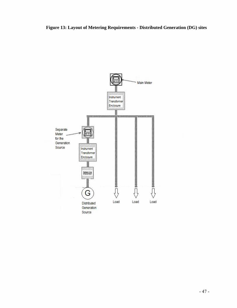
1.9.5 Onsite Generation Metering
For customers with a DG system between 1MW to 5MW, a separate non-revenue metering system may be required to meter the generation output. The generation source is required to be metered separately from the rest of the load sources. Please note that the metering instrument CTs and Pts from the ENMAX Metering system cannot be utilized for the generation non-revenue meter. The customer is required to provide specific data. For more details, please contact [email protected].
1
- 12 -
Construction Requirements
1.10.1 Electrical Modifications to Existing Services
Commercial customers planning any modifications or additions to their electrical system, shall notify ENMAX at (403)514- 2807 or email to [email protected] before modifying an existing service. These additions include: increased load, back-up power supplies, on site power production sources, and transfer switches. Early contact with ENMAX will help ensure that any additions, or changes, are not effecting ENMAX infrastructures and capability to supply the service safely. The customer may be charged or be responsible for, costs associated with any change required to ENMAX equipment due to the service modification. Customers requesting approval, may be required to make upgrades to their existing electrical equipment to meet ENMAX Metering standards. The customer is responsible to make the required changes.
1.10.2 Temporary Services
All temporary construction (SAW) services must be located on the load side of the customers’ HRC fused-disconnect (Cold Sequence Metering). The SAW pole and installation must have approval and proof of inspection by the local jurisdiction having authority.
1.10.3 Customer’s Service Head/Mast Location
The Customer’s service head, or equivalent, must be located at a height no greater than 18 ft. (5.5 m) above finished grade. The service head and attachment point are owned by the Customer.
Metered & Unmetered Conductors All service entrances must be designed and constructed so that metered and unmetered conductors are not run in the same conduit or raceway.
Meter Service Area Definition A meter used for revenue purposes shall not cover more than one clearly defined area. Conversely, more than one revenue meter may not service one clearly defined area (Double-Metering is not allowed). A clearly defined area is constituted of a contained unit, for example:
A site which uses electricity services for domestic purposes in separate and permanently metered single family dwelling units within an apartment building, duplex, or fourplex, or
A bay within a commercial complex. Each clearly defined area must have a unique municipal address. Each clearly defined area must have a unique Site ID. Only one meter per area shall be permitted with the following exceptions:
1
- 13 -
Changes may be made to an area which creates a need for an additional meter to be installed in an existing area.
Changes to the existing service shall not be made without the express consent of ENMAX Metering (refer to section 1.8 Non-Standard Services for further instructions).
The purpose of this regulation is to ensure that ENMAX Metering, meters accurately and measures the customers’ consumption.
2 TYPES OF METERING
Self-Contained Metering
2.1.1 Load Limit
The maximum load for a self-contained meter is 200 Amp per phase.
2.1.2 Voltage Limit
The maximum voltage limit for a self-contained meter is 600-volt phase to phase.
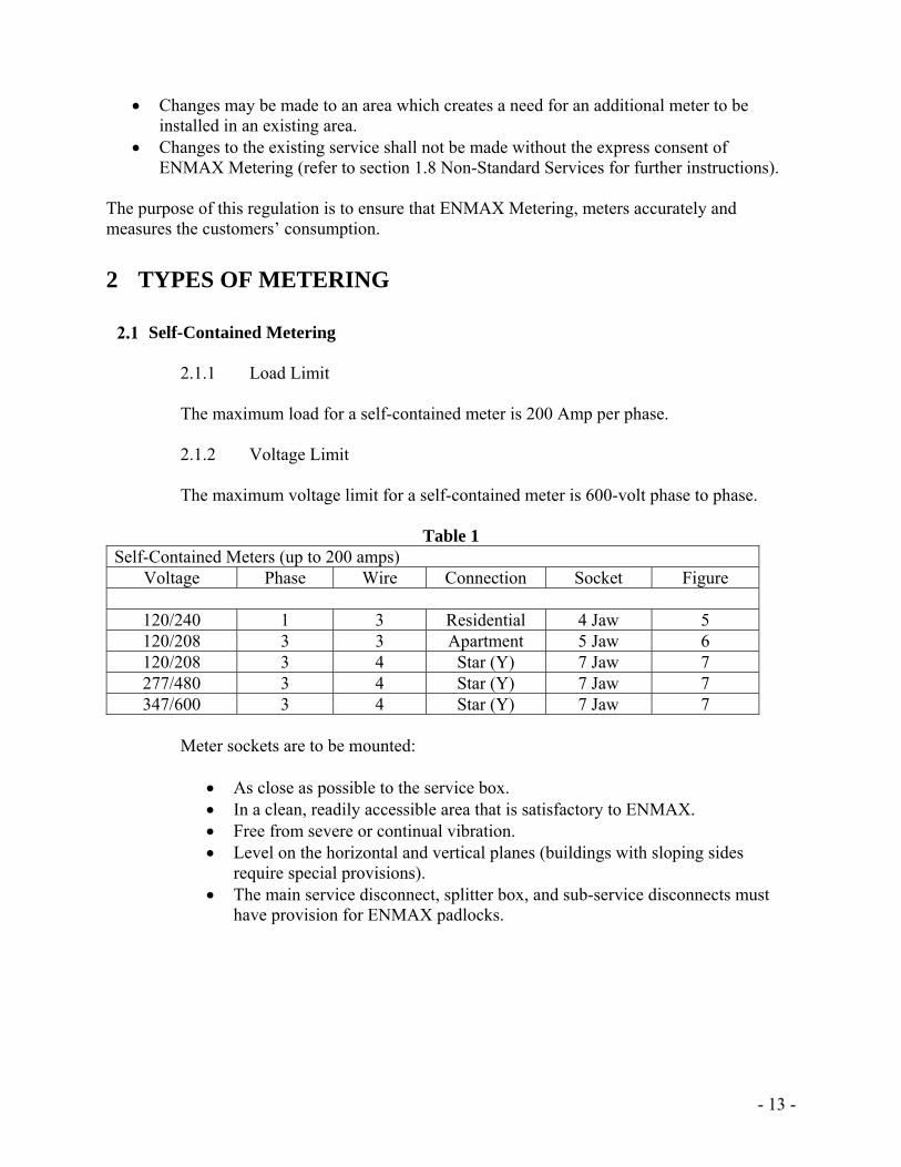
Table 1 Self-Contained Meters (up to 200 amps)
Voltage Phase Wire Connection Socket Figure
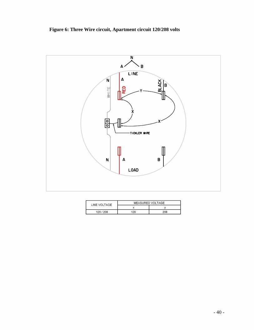
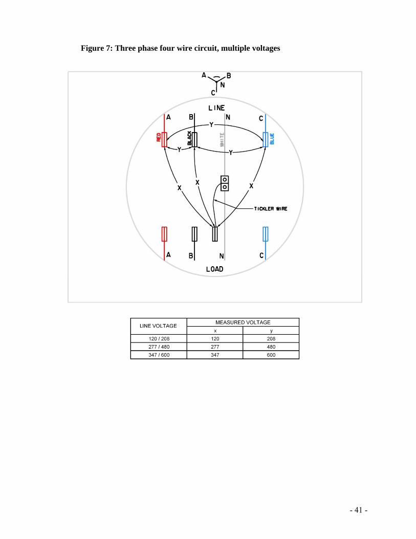
120/240 1 3 Residential 4 Jaw 5 120/208 3 3 Apartment 5 Jaw 6 120/208 3 4 Star (Y) 7 Jaw 7 277/480 3 4 Star (Y) 7 Jaw 7 347/600 3 4 Star (Y) 7 Jaw 7
Meter sockets are to be mounted:
As close as possible to the service box. In a clean, readily accessible area that is satisfactory to ENMAX. Free from severe or continual vibration. Level on the horizontal and vertical planes (buildings with sloping sides
require special provisions). The main service disconnect, splitter box, and sub-service disconnects must
have provision for ENMAX padlocks.
- 14 -
2.1.3 Supply of Self-contained Metering Equipment The Customer shall:
Supply and install an approved meter socket complete with a screw type sealing ring for ENMAX use that conforms to recognized industry standards (CSA, ULC).
Make all connections within the meter socket. ENMAX shall:
Supply the meter and install the meter in the socket. Note: Ringless meter sockets and sockets with current bypass switches (automatic circuit closures) will not be accepted for metering at any installation serviced by ENMAX.
Instrument Transformer Metering
2.2.1 General
Instrument transformer type metering is required on all services exceeding 200 amps per phase. Contact ENMAX Metering if you require instrument transformers for an installation. A Site ID and Electrical permit are require prior to ordering instrument transformers.
2.2.2 Instrument Transformer Metering Equipment Location
For ENMAX owned distribution transformer installations, meter and metering equipment installation shall be connected on the load side of the distribution transformer. For customer owned distribution transformer installations, meter and metering equipment shall be connected on the line side of the distribution transformer. Customer equipment is not allowed within the Instrument Transformer enclosure. The instrument transformer cabinet shall not be used as a splitter box. The instrument transformer enclosure is reserved for ENMAX Metering equipment only. The instrument transformer enclosure and meter base shall be installed in the same room as the main disconnect that feeds the respective meter.
2.2.3 Supply of Instrument Transformer Metering Equipment
The Customer shall:
Supply and install a manufacturer pre-wired meter enclosure according to specifications shown in Table 2.
Supply and install a current transformer enclosure according to specifications shown in Table 3.
1
- 15 -
Supply and install a 31.75 mm (1 1/4”) conduit between the current transformer and the meter enclosure for poly-phase installations, or a 25.4 mm (1”) conduit for single phase installations.
Supply and install all hardware, bus-work, termination and/or cable required to complete the primary connections to the current transformers.
Supply and install a 19 mm (3/4”) plywood sheet behind all enclosures.
ENMAX shall: Supply instrument transformers. Supply and install the secondary wiring. Supply and install the meter.
The instrument transformers are available to the customer for installation upon request from ENMAX Metering. Customer shall provide site ID, service address, and Electrical Permit number to ENMAX when requesting instrument transformers.
ENMAX METERING
8820 52 Street SE Calgary, Alberta, T2C 4E7
Phone: (403) 514-2807
2.2.4 Mounting of Instrument Metering Equipment
The Customer is required to mount: A meter enclosure. A current transformer enclosure. All current transformers. A conduit between current transformer enclosure and meter enclosure.
The customer shall assume the cost of installing the above metering equipment. The current transformers are to be mounted in the following manner:
Fastened to the back panel of the current enclosure and must be removable from the front. All mounting holes on the current transformer must be utilized.
Ensure that the current transformer nameplates are clearly visible when the enclosure is open.
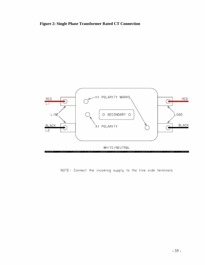
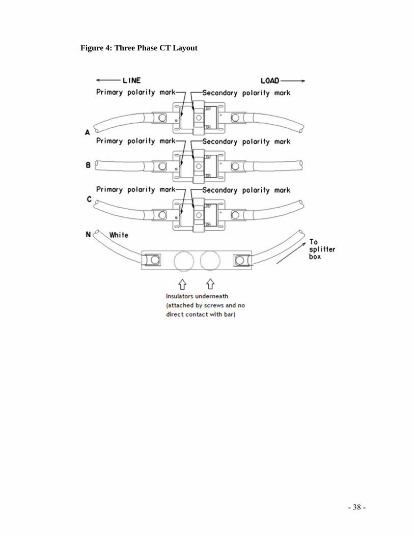
Ensure that the current transformers are positioned with the primary polarity mark toward the source of supply and in an arrangement that will not obstruct access to the secondary terminals (Figure 4).
For single phase 3 wire CT’s, the supply, (line1/line2) shall be connected to the same side of the CT (Figure 2).
2.2.5 Connection of Instrument Metering Equipment
The customer is responsible to make all the connections to the instrument transformer primary. These connections should be properly secured and conductors shall be shaped or formed and supported so that no tension is applied to the current transformers.
- 16 -
The customer is also required to install an isolated neutral bar in line with the supply neutral and that is accessible to ENMAX Metering. Please refer to diagram ‘N’ in figure 4. Damaged current transformers are required to be replaced before energization.
ENMAX Metering will make all the connections to current transformer secondary, testing switch, and the meter.
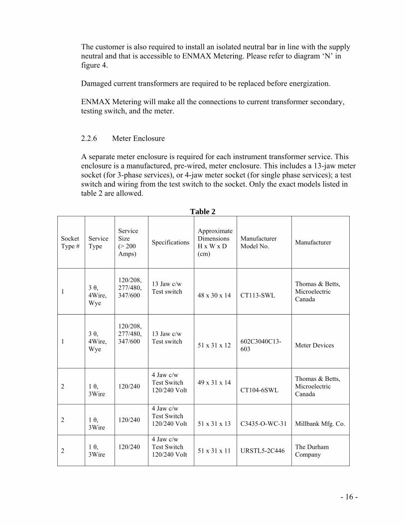
2.2.6 Meter Enclosure
A separate meter enclosure is required for each instrument transformer service. This enclosure is a manufactured, pre-wired, meter enclosure. This includes a 13-jaw meter socket (for 3-phase services), or 4-jaw meter socket (for single phase services); a test switch and wiring from the test switch to the socket. Only the exact models listed in table 2 are allowed.
Table 2
Socket Type #
Service Type
Service Size (> 200 Amps)
Specifications
Approximate Dimensions H x W x D (cm)
Manufacturer Model No.
Manufacturer
1
3 θ, 4Wire, Wye
120/208, 277/480, 347/600
13 Jaw c/w Test switch
48 x 30 x 14
CT113-SWL
Thomas & Betts, Microelectric Canada
1 3 θ, 4Wire, Wye
120/208, 277/480, 347/600
13 Jaw c/w Test switch
51 x 31 x 12
602C3040C13-603
Meter Devices
2 1 θ, 3Wire
120/240
4 Jaw c/w Test Switch 120/240 Volt
49 x 31 x 14
CT104-6SWL
Thomas & Betts, Microelectric Canada
2 1 θ, 3Wire
120/240
4 Jaw c/w Test Switch 120/240 Volt
51 x 31 x 13
C3435-O-WC-31
Millbank Mfg. Co.
2 1 θ, 3Wire
120/240
4 Jaw c/w Test Switch 120/240 Volt
51 x 31 x 11 URSTL5-2C446 The Durham Company
- 17 -
Note: Meter enclosures are available through local distributors. Location
Meter enclosure shall be located: Indoor in a clean readily accessible area that is satisfactory to
ENMAX. In the same room as the current transformer enclosure. Within a maximum of 7 m (23’) conduit run from the current
transformer enclosure. Each meter position shall be “Cold Sequence Metering” equipped
with a circuit breaker / fused disconnect on the line side of the socket meter for each individual unit it supplies.
The circuit breaker / fused disconnect must have provision for an ENMAX padlock.
Mounting
Meter enclosures shall be mounted: With the height of the enclosure no lower than 0.46m and no
higher than 1.8 m above finished grade (as per section 1.4) On ¾” sheet of plywood. Level on both the horizontal and vertical planes. Free of severe or continual vibration.
2.2.7 Grounding
Each meter enclosure must be bonded to system ground.
2.2.8 Current Transformer Enclosures
A separate current transformer enclosure is required for each instrument transformer service according to the specifications shown in Table 3.
2.2.9 Sub-services
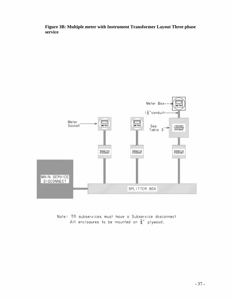
Where a transformer rated service is a sub-service, the meter must be installed on the load side of a sub-service disconnect. The sub-service disconnect must have provision for an ENMAX padlock (Figure 3B).
- 18 -
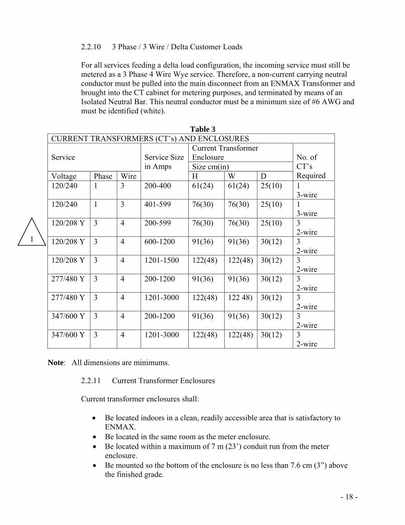
2.2.10 3 Phase / 3 Wire / Delta Customer Loads
For all services feeding a delta load configuration, the incoming service must still be metered as a 3 Phase 4 Wire Wye service. Therefore, a non-current carrying neutral conductor must be pulled into the main disconnect from an ENMAX Transformer and brought into the CT cabinet for metering purposes, and terminated by means of an Isolated Neutral Bar. This neutral conductor must be a minimum size of #6 AWG and must be identified (white).
Table 3
CURRENT TRANSFORMERS (CT’s) AND ENCLOSURES Service
Service Size in Amps
Current Transformer Enclosure
No. of CT’s Required
Size cm(in) Voltage Phase Wire H W D 120/240 1 3 200-400 61(24) 61(24) 25(10) 1
3-wire 120/240 1 3 401-599 76(30) 76(30) 25(10) 1
3-wire 120/208 Y 3 4 200-599 76(30) 76(30) 25(10) 3
2-wire 120/208 Y 3 4 600-1200 91(36) 91(36) 30(12) 3
2-wire 120/208 Y 3 4 1201-1500 122(48) 122(48) 30(12) 3
2-wire 277/480 Y 3 4 200-1200 91(36) 91(36) 30(12) 3
2-wire 277/480 Y 3 4 1201-3000 122(48) 122 48) 30(12) 3
2-wire 347/600 Y 3 4 200-1200 91(36) 91(36) 30(12) 3
2-wire 347/600 Y 3 4 1201-3000 122(48) 122(48) 30(12) 3
2-wire Note: All dimensions are minimums.
2.2.11 Current Transformer Enclosures
Current transformer enclosures shall:
Be located indoors in a clean, readily accessible area that is satisfactory to ENMAX.
Be located in the same room as the meter enclosure. Be located within a maximum of 7 m (23’) conduit run from the meter
enclosure. Be mounted so the bottom of the enclosure is no less than 7.6 cm (3”) above
the finished grade.
1
- 19 -
Be mounted so the bottom of the enclosure is no more than 1.5 m (60”) above the finished grade.
Conform to all other ENMAX Metering Standard requirements.
The current transformer enclosure shall be equipped with vertically hinged doors, which are non-removable, in the closed position. These doors shall be equipped with a latch and have provisions for securing the door with an ENMAX padlock. Cover plates are not acceptable on current transformer enclosures.
2.2.12 Latches and Locking Mechanisms
Provisions for securing the padlock shall be metal. Plastic latches or locking mechanisms are not acceptable.
2.2.13 Conduit Requirements
A conduit, of 31.75 mm (1 1/4”) minimum diameter and a maximum length of 7 m (23’), is required between the current transformer enclosure and meter enclosure. This conduit shall be terminated with lock nuts and bushings except where threaded hubs are supplied. When it is necessary to route Metering secondary wires through compartments other than those reserved for ENMAX use, a metal conduit, or suitable metal raceway, shall be installed through each compartment for the exclusive use of ENMAX. The conduit run shall be continuous, uninterrupted, and it is not permitted to have any fittings with removal covers. It shall be equipped with a continuous length of poly pull string and identified as for use by “ENMAX METERING”. The number of bends shall be kept to a minimum, but in no case shall there be more than three 90 degree bends (or the equivalent of three 90 degree bends). The metering conduit run within the switchgear and between the switchgear and the meter cabinet shall not have fittings with removable covers. If ‘LB’s, or similar conduit fittings must be used, they must be sealable and clearly visible. Permission must be granted by ENMAX Metering for the use of LB’s or similar fittings. 2.2.14 Splitter Trough Applications
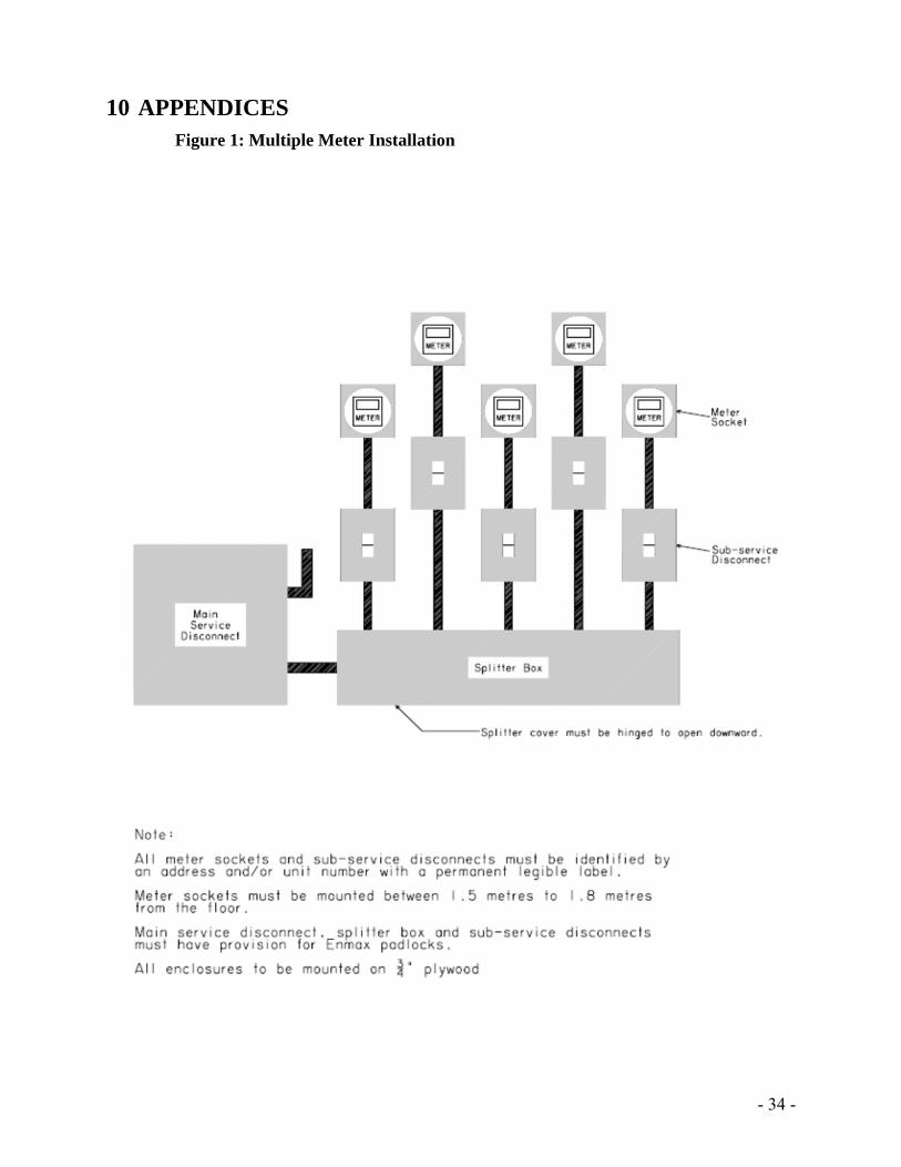
In cases where a splitter is required, a lockable (with large padlock rings), suitably rated splitter trough for the application shall be located immediately after, and on the load side of the main disconnect for the building. Each service coming out of the splitter trough must go directly into a lockable disconnect before proceeding to the individual socket type meter base. (Figure 1).
- 20 -
3 RESIDENTIAL SERVICES
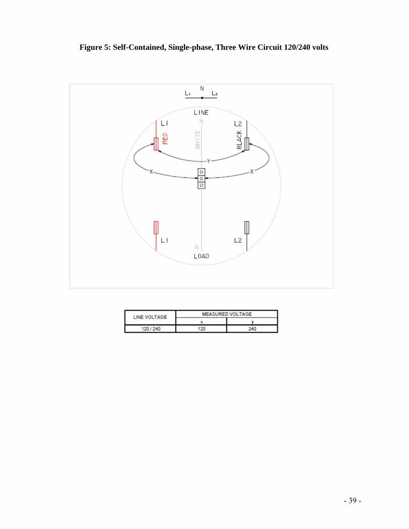
Single Phase Residential Services - Single Meter Installations These services are generally single-phase 120/240 volt (Figure 5) or Apartment 120/208 volt (Figure 6), 200 amp or less, self-contained services supplying residential houses in urban and rural areas. For meter configuration see Figure 14.
3.1.1 Installation
Such meter installation shall be: On the outside wall of the house. Connected on the line side of service disconnect.
If the finished grade is to be completed at a future date, the customer must supply a platform to meet the height requirements. This platform must have proof of meeting building code standards. A minimum height of 1.5 m above finished grade must be maintained when a permanent structure, such as a deck, is built in the clear access area of the meter. A meter whose height above any finished grade becomes greater or less than the specified limits; or, meter that is otherwise rendered inaccessible due to alterations to the building or finished grade level, must be moved and be brought into the limits specified above within 30 days after receipt of notification to move said meter.
The Customer shall:
Supply and install a CSA, ULC approved low voltage, socket type meter base. Supply and install conduit, wire and all service entrance equipment.
ENMAX Shall:
Supply and install the meter.
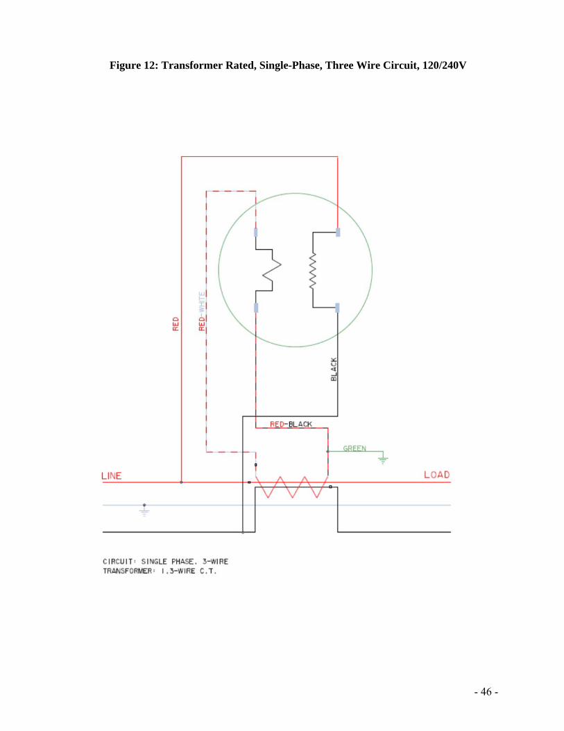
Single Phase Residential Services - Instrument Transformer Metering These services are required where the load will exceed 200 amps (Figure 12).
3.2.1 Installation
Such meter installations shall have: The meter mounted on the outside of the house. Instrument transformer mounted indoors, within an enclosure specified in
Table 3 (Figure 2). The instrument enclosure and meter shall be connected by a 25.4 mm (1”)
conduit. The meter connected on the load side of service disconnect.
1
- 21 -
The Customer shall: Supply and install a 4-jaw meter socket as listed in Table 2-Socket Type #2. Supply and install an instrument transformer enclosure as listed in Table 3.
ENMAX shall:
Supply the required current transformer. Supply and install the secondary wiring. Supply and install the meter.
Single phase / Multiple Residential Services – Multiple Meter Installations
(Duplexes/Townhouses) These services are generally single-phase 120/240 (Figure 5) volt or 120/208 volt (Figure 6) self-contained services supplying a building that has several meters supplied from a single service entrance. For meter configuration see Figure 14.
3.3.1 Installation
Such meter installations shall be: Grouped together in an approved area. Identified by address (or unit number) with a permanent legible label on all
meter sockets, disconnects and unit electrical panels. The main service disconnect, splitter box, and sub-service disconnects must
have provision for ENMAX padlocks. The number of Customer’s services of the same voltage and characteristic
terminating at any one supply service, run to, on, or in any building, shall not exceed six.
Any “house”, “public” or “common” service for the building is considered to be a commercial service, and this service’s meter must be cold sequenced
The customer shall:
Supply and install the meter sockets. Supply and install all the service entrance equipment. Identify all meter sockets, disconnects, and unit electrical panels by address (or
unit number) with a permanent legible label. For a 120/208 service a white neutral conductor must be pulled from the
ENMAX transformer and terminated at the 9 o’clock terminal of the meter socket (Figure 6). The neutral conductor shall be sized at # 12 AWG or greater.
ENMAX shall:
Supply the meters. Perform connectivity test. Install the meters in the sockets.
To request a connectivity test, please contact ENMAX SOC (Service Order Control) at: 403-514-2807. Refer to Section 9 for further details.
1
- 22 -
Single phase /Apartment/ Commercial/Retailing/Residential Services - Multiple Meter Installations (Apartments)
These services are generally single-phase 120/240 volt or 120/208 volt self-contained services supplying a building that has several meters supplied from a single service entrance. For meter configuration see Figures 1&16.
3.4.1 Installation
Such meter installations shall be: Located indoors. Grouped together in an approved area. Connected on the load side of the sub service disconnect. Identified by address (or unit number) with a permanent legible label on all
meter sockets, disconnects, and unit electrical panels. Mounted with the centerline of the meter at a height of 1.5 m to 1.8 m above
the floor level.
The main service disconnect, splitter box, and sub-service disconnects must have provision for ENMAX padlocks.
The customer shall:
Supply and install the meter sockets. Supply and install all the service entrance equipment. Identify all meter sockets, disconnects, and unit electrical panels by address (or
unit number) with a permanent legible label. For a 120/208 service a white neutral conductor must be pulled from the
ENMAX transformer and terminated at the 9 o’clock terminal of the meter socket (Figure 6). The neutral conductor shall be sized at # 12 AWG or greater.
ENMAX shall:
Supply the meters. Perform connectivity test. Install the meters in the sockets.
To request a connectivity test, please contact ENMAX SOC (Service Order Control) at 403-514-2807. Refer to Section 9 for further details.
Laneway Housing & Secondary Suites
This section outlines details for the case where a property owner wishes to create a secondary residence on their property and meter both buildings separately.
The meters must be installed on separate meter bases; ganged meter bases are not
permitted The separate meter bases are allowed to both be installed on the same building (garage
or main unit
1
- 23 -
4 FARM SERVICES Single phase farm services/ Self-contained Metering These services are single-phase 120/240-volt (Figure 5) services supplying farm operations, where the main breaker does not exceed a rating of 200 amps. The centerline of the meter shall be mounted at a height of 1.65m above finished grade. The meter shall be mounted on a customer owned pole. The customer shall:
Supply and install an approved meter socket. Supply and install all the service entrance equipment.
ENMAX shall:
Supply the meter. Install the meter.
5 COMMERCIAL SERVICES
General For commercial services in which the service entrance / metering is not located on the main floor, an approved stairway, elevator, and/or escalator must be installed to facilitate the transfer of equipment to, and from, the electrical room. Ladders do not provide appropriate access and are therefore not acceptable.
Single-phase/ Comm. Services - Self-contained Metering (Single Meter) These are commercial services where the service disconnect rating does not exceed 200 amps. The meter shall be mounted:
The meter shall be located on the load side of the service disconnect. On the outside wall of the building.
The main service disconnect, splitter box, and sub-service disconnects must have provision for ENMAX padlocks. The customer shall:
Supply and install an approved meter socket. Supply and install all the service entrance equipment. For a 120/208 service, a white neutral conductor must be pulled from the ENMAX
transformer and terminated at the 9 o’clock terminal of the meter socket (Figure 6). The neutral conductor shall be sized at #12 AWG or greater.
- 24 -
ENMAX shall: Supply the meter. Install the meter.
Single-phase/ Comm. Services - Self-contained Metering (Multi-Meter)
These are commercial services where the service disconnect rating does not exceed 200 amps and the meter shall be located on the load side of the service disconnect. For meter configuration see Figures 1 & 15. The meters shall be mounted:
Grouped together in an approved area. Identified by address (or unit number) with a permanent, legible label on all meter
sockets, disconnects, and unit electrical panels.
The main service disconnect, splitter box, and sub-service disconnects must have provision for ENMAX padlocks. The customer shall:
Supply and install approved meter sockets. Supply and install all the service entrance equipment. Identify all meter sockets, disconnects, and unit electrical panels by address (or unit
number) with a permanent legible label. For a 120/208 service, a white neutral conductor must be pulled from the ENMAX
transformer and terminated at the 9 o’clock terminal of the meter socket (Figure 6). The neutral conductor shall be sized at # 12 AWG or greater.
ENMAX shall: Supply the meter. Perform connectivity test. Install the meter.
To request a connectivity test, please contact ENMAX SOC (Service Order Control) at 403-514-2807. Refer to Section 9 for further details.
Single-phase Comm. Services - Instrument Transformer Metering These are commercial services where the service disconnect exceeds a rating of 200 amps. The meter shall be mounted in an approved area. The instrument transformer enclosure shall be located indoors. The meter shall be located on the load side of the service disconnect. The main service disconnect, splitter box, and sub-service disconnects must have provision for ENMAX padlocks, and they must all be located in the same room as the meter & CT Cabinet as per section 2.2.1 The customer shall:
Supply and install a four-jaw meter socket as specified in Table 2-Socket Type #2.
- 25 -
Supply and install an instrument transformer enclosure as specified in Table 3. Supply and install all the service entrance equipment. Identify all meter sockets, disconnects, and unit electrical panels by address (or unit
number) with a permanent, legible label. ENMAX shall:
Supply and install secondary wiring. Supply the meter. Install the meter.
Three-phase Commercial Services - Self-contained Metering
These are commercial services where the service disconnect rating does not exceed 200 amps. The meter shall be located on the load side of service disconnect. The main service disconnect, splitter box, and sub-service disconnects must have provision for ENMAX padlocks. The customer shall:
Supply and install an approved meter socket. Supply and install all service entrance equipment. Identify all meter sockets and disconnects by address (or unit number) with a
permanent, legible label (and unit electrical panels if site has more than one electric meter).
A white neutral conductor must be pulled from the ENMAX transformer into and terminated at the 3rd bottom jaw of the meter socket (Figure 7) (from the transformer).
In the case of multiple meters, request a connectivity test by contacting: ENMAX SOC at 403-514-2807. Refer to Section 9 for further details. ENMAX shall:
Supply the meter. Install the meter.
Three-phase Commercial Services - Instrument Transformer Metering
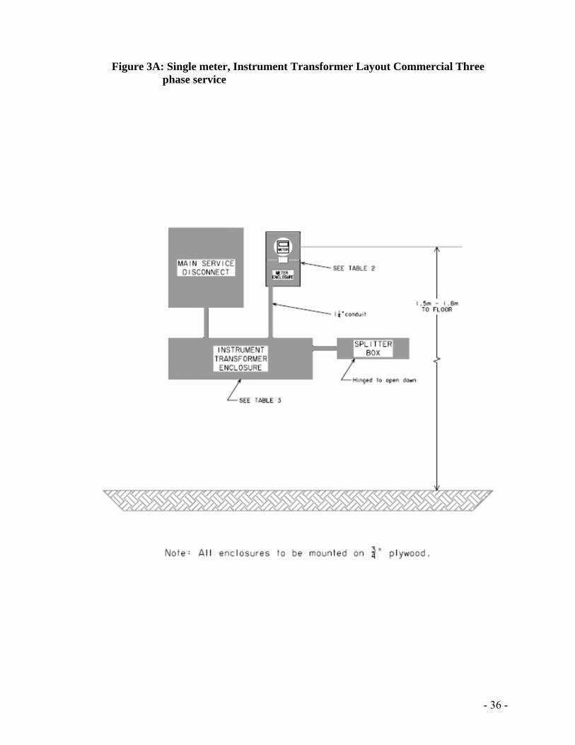
These are services where the service disconnect rating exceeds 200 amps. Metering shall be located on the load side of the customer’s breaker. Meters and instrument transformer enclosures shall be located in the same room as its respective disconnect inside the building (Figure 3A & 3B). The main service disconnect, splitter box, and sub-service disconnects, must have provision for ENMAX padlocks. The customer shall:
Supply and install a 13-jaw meter socket as specified in Table 2-Socket Type #1.
1
- 26 -
Supply and install an instrument transformer enclosure as specified in Table 3. Be responsible to make the primary connections to the instrument transformers. Identify all meter sockets, disconnects, and unit electrical panels by address (or unit
number) with a permanent legible label.
Note: Where the customer’s installed capacity is above 200KVA, refer to section 7.2 for additional requirements. ENMAX shall:
Install the secondary wiring. Make all the secondary connections. Supply the meter. Install the meter.
Resistive Grounded Services
The customer must obtain approval from ENMAX before installing a resistive grounded system. ENMAX must be contacted for service requirements.
Shopping Malls
Metering shall be located on the load side of the customer’s breaker. The meters and instrument transformer enclosures shall be located in the same room as its respective disconnect inside the building (Figure 3A & 3B). For meter configuration see Figure 17. The main service disconnect, splitter box, and sub-service disconnects, must have provision for ENMAX padlocks. The customer shall:
Supply and install a meter socket as specified in Tables 1 & 2. Supply and install an instrument transformer enclosure as specified in Table 3. Be responsible to make the primary connections to the instrument transformers. Identify all meter sockets, disconnects, and unit electrical panels by address (or unit
number) with a permanent, legible label.
Note: Where the customer’s installed capacity is above 200KVA, refer to section 7.2 for additional requirements. ENMAX shall:
Install the metering secondary wiring. Make all the secondary metering connections. Supply the meter. Install the meter.
- 27 -
6 COMMERCIAL OR INDUSTRIAL PRIMARY METERED SERVICE
Service Application and Acceptance
For Primary Metered Services, a kick-off meeting must be arranged prior to project initiation that includes ENMAX Metering, Customer Projects, System Planning and Asset Management. High voltage, main service switchgear shop drawings, and a single line diagram with the metering point clearly marked, must be submitted for acceptance, as soon as completed. This is to ensure ENMAX Metering can order any necessary equipment required to complete metering arrangements without delay. The lead time between the placement of an order of high voltage equipment and delivery can be up to 6 months. Manufacturing of equipment should not start until all final drawings have been reviewed and accepted by ENMAX. This will avoid costly alterations to equipment already built.
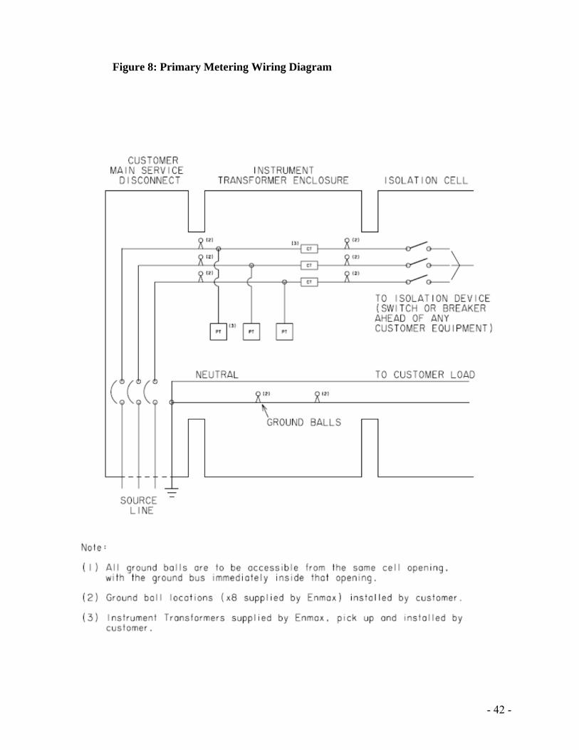
Primary Switchgear Specifications (Figure 8)
A separate metering transformer cell for each service must be provided. The size of the
metering transformer cell must meet CSA standards. The metering transformer cell must have a hinged door, be pad-lockable, and is reserved for utility use only.
The metering transformer cell door must not be electrically, or mechanically, interlocked with any other cells.
Only 1 single point of isolation is permitted on the load side of the metering cell. A protection / isolation cell (i.e. Fused disconnect / breaker) must be provided upstream
of the metering transformer cell and an isolation means (i.e. Visible isolation switch or breaker) must be provided immediately downstream of the metering transformer cell, and ahead of any customer equipment.
High voltage, main service switchgear incorporating metering equipment, must be constructed so that all ENMAX instrument transformers, required for metering, are readily accessible.
Barriers are required between all sections of the equipment, including metered and unmetered conductors, and between sections reserved for the customer and ENMAX.
There shall be no customer energy consuming equipment (e.g. space heater) connected before the metering transformers.
ENMAX Metering will supply eight ground ball studs to be installed by the customer. There will be two ground balls per phase: one ground ball is located on the bus at the entrance to the metering transformer cell, and the other is on the same bus exiting the cell. The Current and Potential Transformer for each phase, are to be installed between these two ground balls. All phase bus ground balls must be accessible from the front door entrance to the cell.
Two ground ball studs shall be mounted on the ground bus. The ground ball studs shall be arranged in a way that all grounding connections are accessible and can be safely installed from the front door of metering transformer cell entrance.
The ground bus shall be located near the bottom, front of the metering transformer cell front door opening.
- 28 -
A working space of 3 m (10’) clearance is required in front of the metering transformer cell in order for ENMAX Metering personnel to safely install the grounds.
Supply of Primary Metering Equipment
The customer is required to supply:
A meter enclosure according to specifications shown in Table 2-Socket Type #1. A section of high-voltage main service switchgear for installation of instrument
transformers that is acceptable to ENMAX (see section 6.2). A conduit between the instrument transformer compartment and the meter enclosure (see
section 6.8). All hardware, bus-work, termination and/or cable, required for primary connections to the
Current and Potential Transformers. A plywood sheet behind the meter enclosure (see section 6.6). Meter communication requirements (see section 6.9).
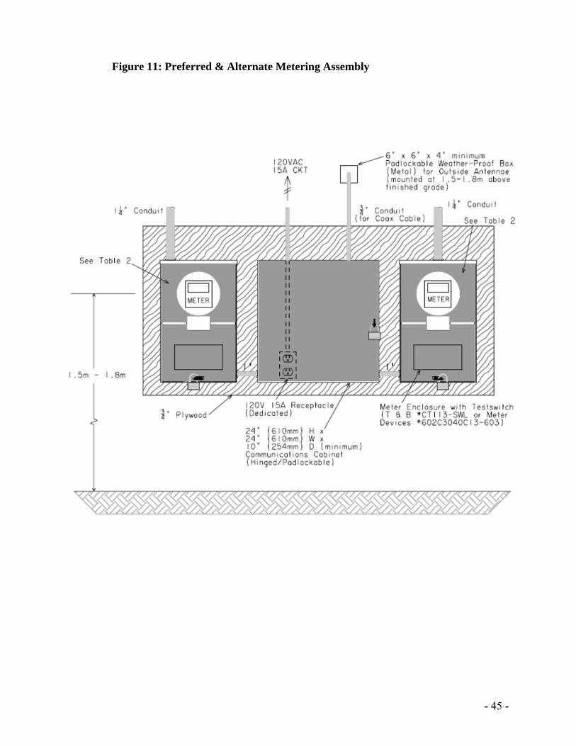
For more details and specifications, please call ENMAX Metering at 403-514-2807 or email to [email protected] In addition, at sites with Preferred/Alternate feeders, the customer is required to supply: (Figure 11)
Separate meter sockets for each meter A conduit, run from each meter socket to the outside of the building. This 19 mm (3/4”)
EMT conduit shall terminate at a 6” x 6”x 4” (minimum size) weatherproof, pad-lockable box, for the external antenna. The box shall be mounted on the outside wall at a height between 1.5 m and 1.8 m above finished grade.
A duplex receptacle (120V, 15A) supplied by a dedicated circuit on the load side of the meter is to be mounted on the plywood where the meter sockets are installed.
For more details and specifications please call ENMAX Metering at 403-514-2807 or email to [email protected]. ENMAX will supply:
Revenue meters. Instrument transformers (current and potential). Metering secondary wiring.
The instrument transformers are available to the customer for installation at ENMAX Metering, located in its South Services Center.
1
- 29 -
Mounting of Primary Metering Equipment
The customer is required to mount:
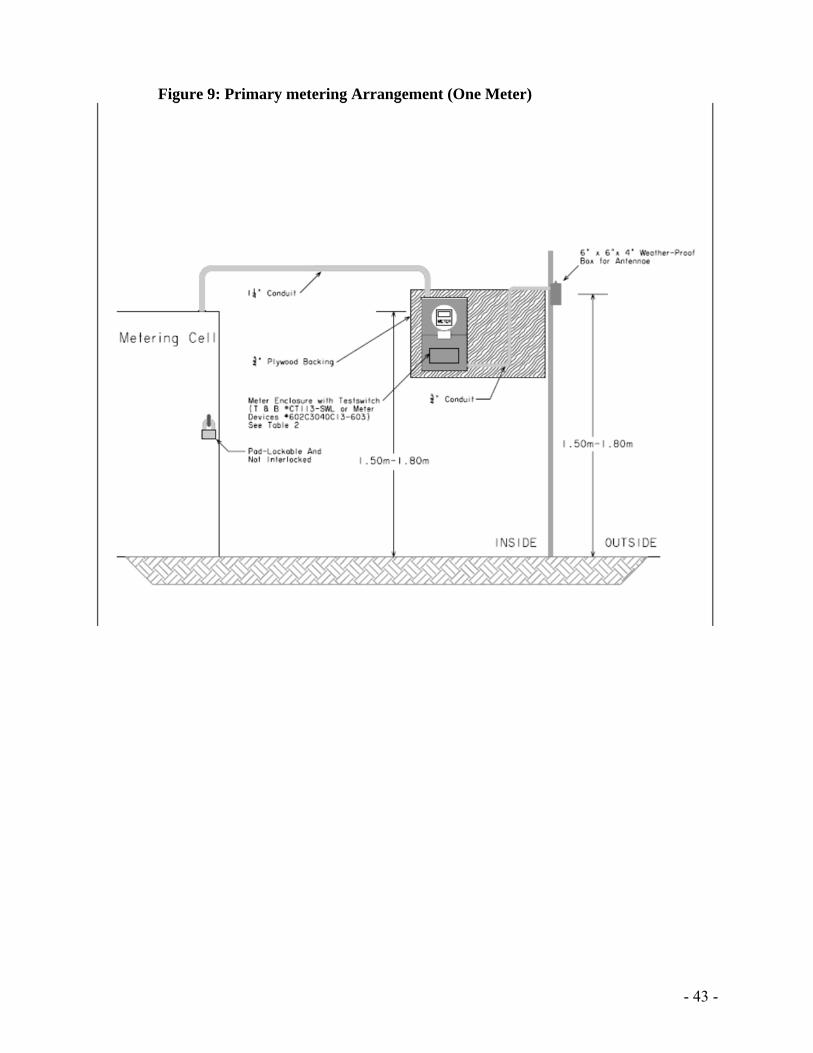
A meter enclosure. All instrument transformers in the instrument transformer compartment (Figure 8). A conduit between instrument transformer and meter enclosure. A conduit between the meter and the antenna box mounted on the buildings external wall,
if it is a single meter installation (Figure 9). If it is a preferred/alternate site, an auxiliary cabinet with conduit running to both
meters and, a conduit running to the antenna box mounted on the buildings external wall (Figure 11).
The ground balls on each phase and the ground bus as described in Section 6.2 (Figure 8).
The customer shall assume the cost of installing the above metering equipment. The instrument transformers, both current and potential, are to be mounted in the following manner:
Securely mounted in the instrument transformer compartment. All mounting holes on the instrument transformers must be utilized.
The Instrument transformer nameplates are clearly visible when the compartment door is open.
Current transformers shall be positioned with the primary polarity mark toward the source of supply, between two ground ball studs, and in an arrangement that will not obstruct access to the secondary terminals.
Potential transformers shall be connected to the bus-work on the line side of the Current transformers, between two ground ball studs, and shall be of a “non-draw out” style.
Potential transformer H2 connections shall be connected to the neutral from the ENMAX supply using white wire.
All utility instrument transformer mounting base-plates shall be bonded to ground.
Connection of Instrument Transformers The customer is responsible to make all of the connections to the instrument transformer primaries. These connections should be properly secured and conductors shall be shaped, or formed, and supported so that no tension is applied to the potential and current transformers. ENMAX Metering will make all the connections to current and potential transformer secondary, testing switch, and the meters.
Meter Enclosure Requirements A separate meter enclosure is required for each instrument transformer service. This enclosure is a manufacturer pre-wired meter enclosure including a 13-jaw meter socket, a test switch and wiring from the test switch to the socket. Meter enclosure specifications are shown in Table 2-Socket Type #1.
- 30 -
Location - Meter enclosures should be located:
In a clean, readily accessible area that is satisfactory to ENMAX. In the same room as the instrument transformer compartment and respective disconnect
that feeds the meter In the high voltage room within a maximum of 7 m (23’) of conduit from the instrument
transformer compartment (Figure 9). To conform to all other requirements. In such an area as to maintain a 1 m clear zone around the Meter enclosure to facilitate
the mounting of any other auxiliary panels that might be required for auxiliary metering equipment, or load management equipment.
If the arrangement specified above is impractical, the following less desirable alternatives may be considered:
In an electrical room adjacent to the high voltage room within a maximum of 7 m (23’) of conduit from instrument transformer compartment; or
In the high voltage room and located on a wall adjacent (within 3 m or 10’) to the entrance door.
Mounting - Meter enclosures shall be mounted:
With the center line of the enclosure 1.5 m to 1.8 m above the floor. Level on both the horizontal and vertical planes. Mounted on 19 mm (3/4”) sheet of plywood. Free of severe or continual vibration.
Grounding - Each meter enclosure must be bonded to the system ground.
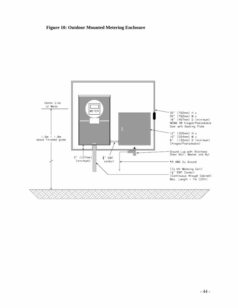
Outdoor Primary Metering Requirements A separate, non-interlocked, compartment of high voltage main service switchgear is required for each instrument transformer service. The size of such switchgear shall meet CSA standards. The switchgear requires hinged doors over all live electrical equipment. The door of the instrument transformer compartment shall be equipped with a latch and have provisions for securing the door with an ENMAX padlock – no other locking mechanism is permitted.
For outdoor high voltage main service switchgear installation, the instrument transformer compartment and meter enclosure must be weather proof (Figure 10).
The instrument transformer compartment shall be equipped with a heater. The heater shall be on the same circuit and control as the adjacent compartments. The power supply feeding the heating elements for the whole outdoor switchgear must come from the load side of the utility metering equipment.
The Meter enclosure shall not be mounted on any part of the outdoor switchgear.
- 31 -
Conduit Requirements
A metal conduit, of 31.75 mm (1 ¼”) minimum diameter and a maximum length of 7 m (23’), is required between the instrument transformer enclosure and the meter enclosure. This conduit shall be terminated with lock nuts and bushings, except where threaded hubs are supplied. The conduit must be a continuous run.
The metering conduit run within the primary switchgear and between the primary switchgear and the meter enclosure, shall not have fittings with removable covers. The conduit is for the exclusive use of ENMAX. When it is necessary to route Metering secondary wires through compartments, other than those reserved for ENMAX use, a metal conduit, or suitable metal raceway, shall be installed through each compartment for the exclusive use of ENMAX.
Meter Communication Requirements (Figures 9 & 11) To allow for remote meter communication, a conduit shall be installed from the meter enclosure to the outside of the building. This 19 mm. (3/4”) EMT conduit, shall terminate at a 150 x 150 x 100 mm (6”x 6” x 4”) (minimum size), weatherproof, pad-lockable box. The box shall be mounted on the outside wall at a height between 1.5 m. and 1.8 m. above finished grade. This box shall be in a location approved by ENMAX.
7 INTERVAL METERING REQUIREMENTS
Existing Site Where a customer’s peak load is above 150 KVA twice in the previous 365 days, or upon a customer’s request, an interval meter, that is capable of remote interrogation, will be installed. At an existing site, where modifications are made to the infrastructure requiring a Demand greater than 150 kVA, an interval meter will be installed. ENMAX will cover the cost of interval metering equipment if the customer’s peak load is above 150 KVA twice in the previous 365 days. Otherwise, ENMAX does not require interval metering and the customer shall assume the cost of interval metering upgrade, communication line, and raceway installation. Please contact ENMAX Metering at 403-514-2807 or email [email protected] for more details.
New Site An interval meter will be installed at all new sites with a planned installed capacity of 200 kVA or greater. See Table 4 below for details. To allow for automatic meter reading, a 19 mm (3/4”) EMT communication conduit shall be installed from the meter enclosure to an antenna box located outside the building. The 19 mm (3/4”) EMT communication conduit shall not exceed 30 m (100’) in length. If junction boxes, or LBs’ are used in this conduit run, they shall not be installed at a height over 2 m (12 ft.) above finished grade. The antenna box shall be a
- 32 -
150x150x100 mm (6” x 6”x 4”), weatherproof, pad-lockable, hinged box. The antenna box shall be mounted on the outside wall at a height between 1.5 m and 1.8 m above finished grade. In some cases, the building exterior construction is not completed at the time the meter and antenna box are to be installed. In this scenario, a temporary box may be installed, outside the building and not fixed to the outside wall. The customer must provide this commitment in writing to ENMAX Metering, stating that the antenna box will be moved to its final location once the building exterior construction is complete. In all cases, the box dimensions and elevation must comply with this Standard. The customer must contact ENMAX Metering to request permission to install the antenna box in a temporary location, and to make arrangements to move the box to its final location. The customer may be required to run a ¾" telephone line conduit from the telephone company demarcation point to the meter cabinet if other suitable communication methods are not available. This requirement will be determined by ENMAX Metering.
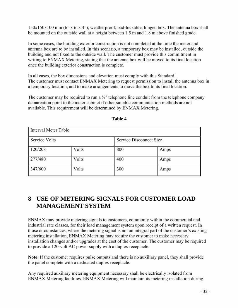
Table 4
Interval Meter Table
Service Volts Service Disconnect Size
120/208 Volts 800 Amps
277/480 Volts 400 Amps
347/600 Volts 300 Amps
8 USE OF METERING SIGNALS FOR CUSTOMER LOAD MANAGEMENT SYSTEM
ENMAX may provide metering signals to customers, commonly within the commercial and industrial rate classes, for their load management system upon receipt of a written request. In those circumstances, where the metering signal is not an integral part of the customer’s existing metering installation, ENMAX Metering may require the customer to make necessary installation changes and/or upgrades at the cost of the customer. The customer may be required to provide a 120-volt AC power supply with a duplex receptacle.
Note: If the customer requires pulse outputs and there is no auxiliary panel, they shall provide the panel complete with a dedicated duplex receptacle. Any required auxiliary metering equipment necessary shall be electrically isolated from ENMAX Metering facilities. ENMAX Metering will maintain its metering installation during
- 33 -
normal working hours. However, it accepts no liability for the operation of customer’s auxiliary metering equipment and continuity of such signals. ENMAX will not supply a time interval pulse under any circumstances. The standard metering signals that may be available from ENMAX metering installations, are watt-hour (Wh), and volt-amperes reactive hour (VARh). The customer shall assume all incremental costs incurred by ENMAX in order for the provision of metering signals and maintenance of such equipment, including auxiliary metering equipment.
9 CONNECTIVITY ENMAX will complete a connectivity test on all sites which meet the following criteria:
Residential buildings with 2 or more units with unique addresses (e.g. townhomes or condominiums with 2 or more units).
Commercial buildings with 2 or more units with unique addresses. The connectivity test must be requested by the customer. The connectivity test must pass before ENMAX meters are installed. If the connectivity test fails, the customer is responsible to make the necessary corrections and request an additional test.
- 34 -
10 APPENDICES Figure 1: Multiple Meter Installation
- 35 -
Figure 2: Single Phase Transformer Rated CT Connection
- 36 -
Figure 3A: Single meter, Instrument Transformer Layout Commercial Three phase service
- 37 -
Figure 3B: Multiple meter with Instrument Transformer Layout Three phase service
- 38 -
Figure 4: Three Phase CT Layout
- 39 -
Figure 5: Self-Contained, Single-phase, Three Wire Circuit 120/240 volts
- 40 -
Figure 6: Three Wire circuit, Apartment circuit 120/208 volts
- 41 -
Figure 7: Three phase four wire circuit, multiple voltages
- 42 -
Figure 8: Primary Metering Wiring Diagram
- 43 -
Figure 9: Primary metering Arrangement (One Meter)
- 44 -
Figure 10: Outdoor Mounted Metering Enclosure
- 45 -
Figure 11: Preferred & Alternate Metering Assembly
- 46 -
Figure 12: Transformer Rated, Single-Phase, Three Wire Circuit, 120/240V
- 47 -
Figure 13: Layout of Metering Requirements - Distributed Generation (DG) sites
- 48 -
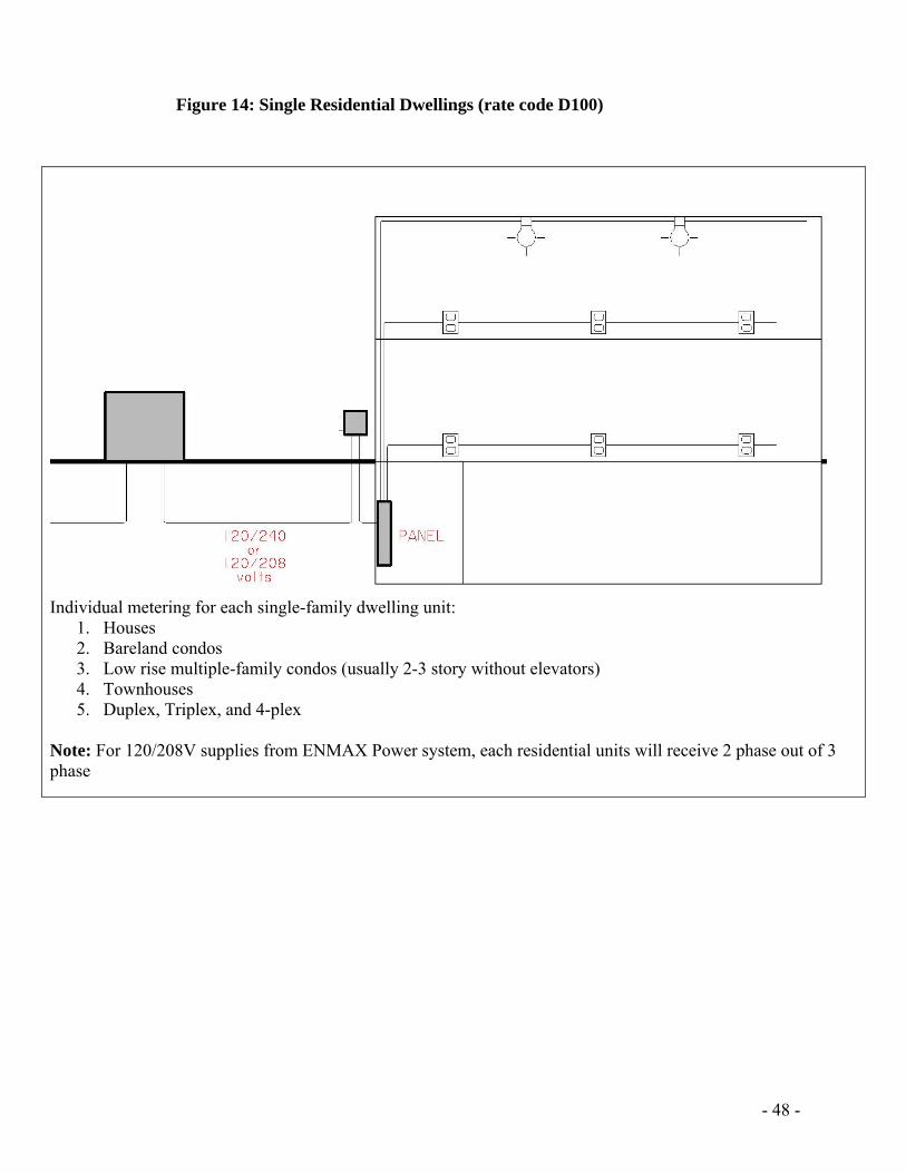
Figure 14: Single Residential Dwellings (rate code D100)
Individual metering for each single-family dwelling unit:
1. Houses 2. Bareland condos 3. Low rise multiple-family condos (usually 2-3 story without elevators) 4. Townhouses 5. Duplex, Triplex, and 4-plex
Note: For 120/208V supplies from ENMAX Power system, each residential units will receive 2 phase out of 3 phase
- 49 -
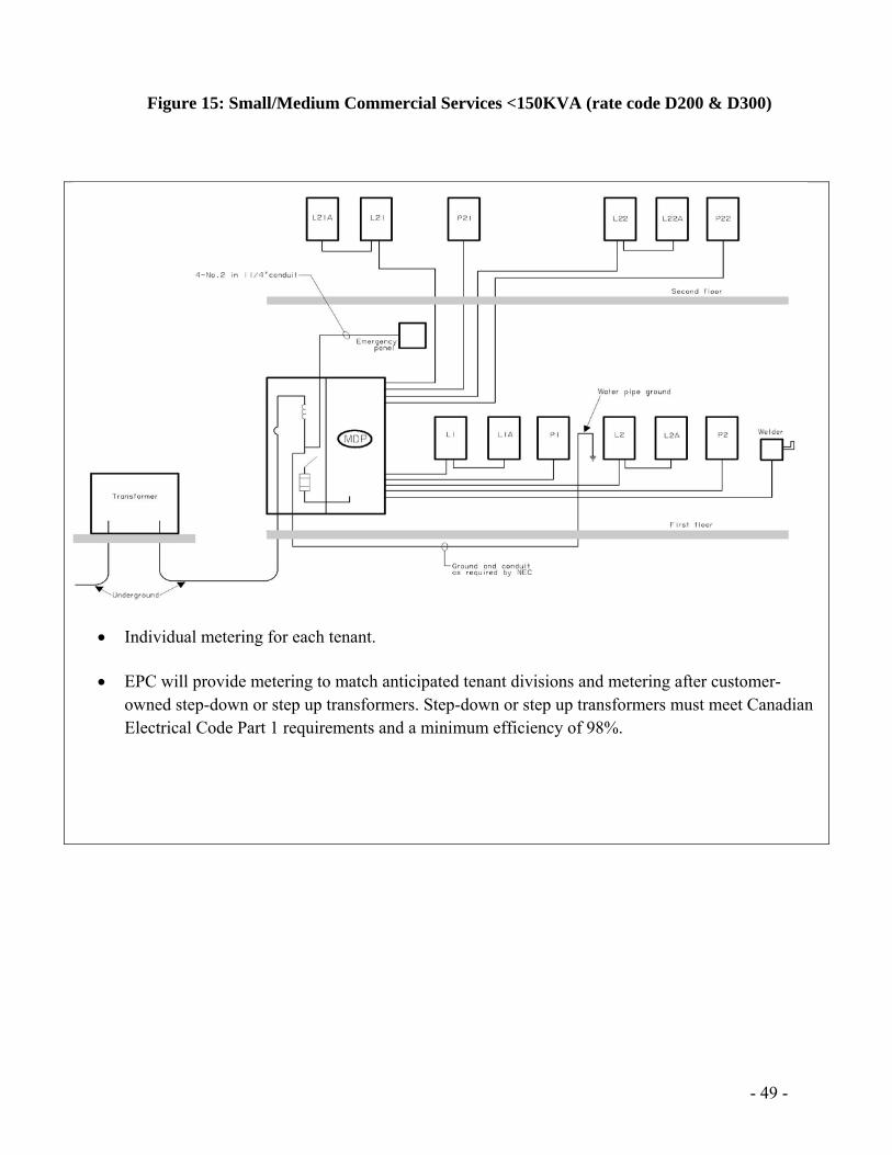
Figure 15: Small/Medium Commercial Services <150KVA (rate code D200 & D300)
Individual metering for each tenant.
EPC will provide metering to match anticipated tenant divisions and metering after customer-owned step-down or step up transformers. Step-down or step up transformers must meet Canadian Electrical Code Part 1 requirements and a minimum efficiency of 98%.
- 50 -
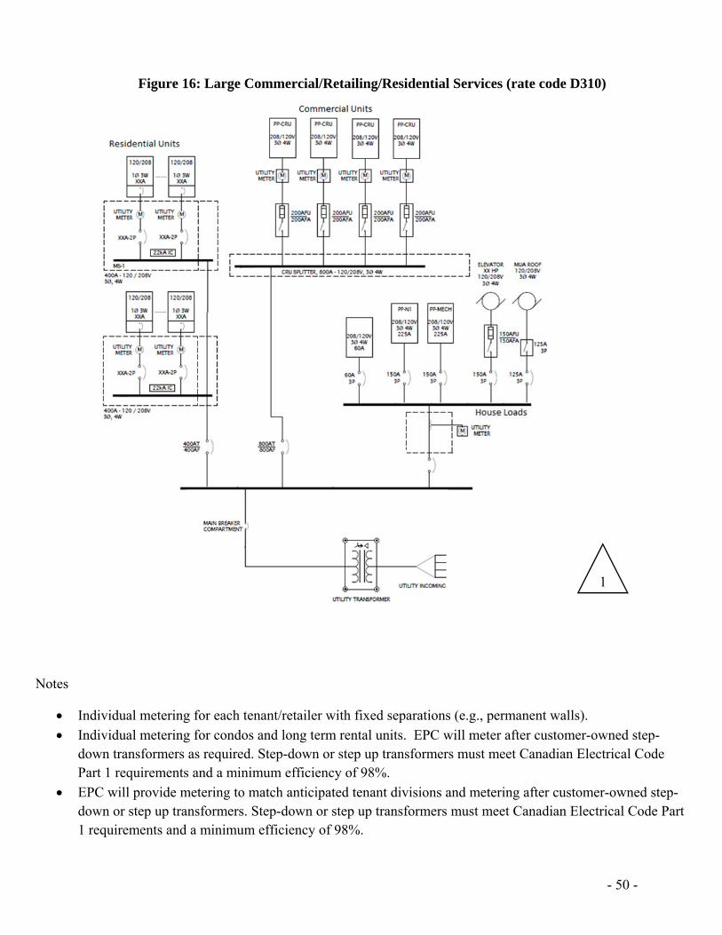
Figure 16: Large Commercial/Retailing/Residential Services (rate code D310)
Notes
Individual metering for each tenant/retailer with fixed separations (e.g., permanent walls).
Individual metering for condos and long term rental units. EPC will meter after customer-owned step-down transformers as required. Step-down or step up transformers must meet Canadian Electrical Code Part 1 requirements and a minimum efficiency of 98%.
EPC will provide metering to match anticipated tenant divisions and metering after customer-owned step-down or step up transformers. Step-down or step up transformers must meet Canadian Electrical Code Part 1 requirements and a minimum efficiency of 98%.
1
- 51 -
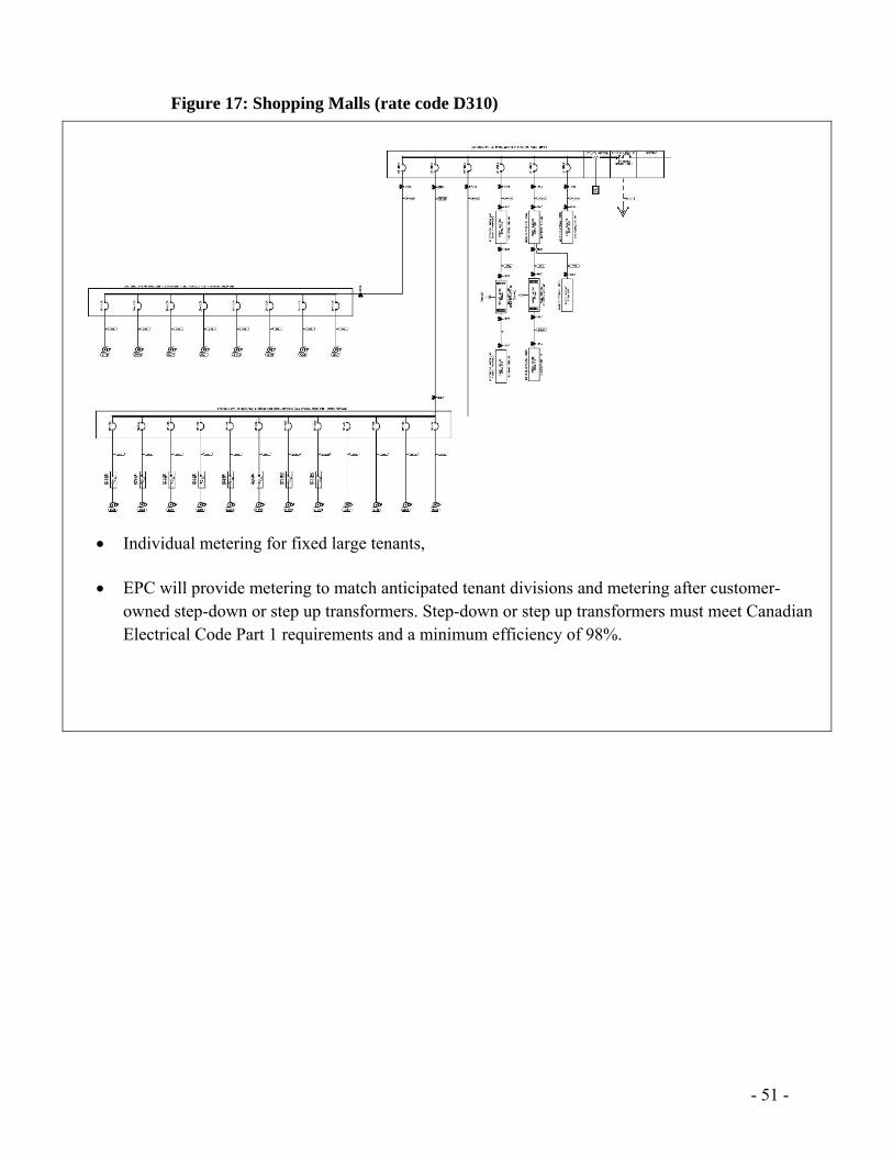
Figure 17: Shopping Malls (rate code D310)
Individual metering for fixed large tenants,
EPC will provide metering to match anticipated tenant divisions and metering after customer-
owned step-down or step up transformers. Step-down or step up transformers must meet Canadian Electrical Code Part 1 requirements and a minimum efficiency of 98%.
- 52 -
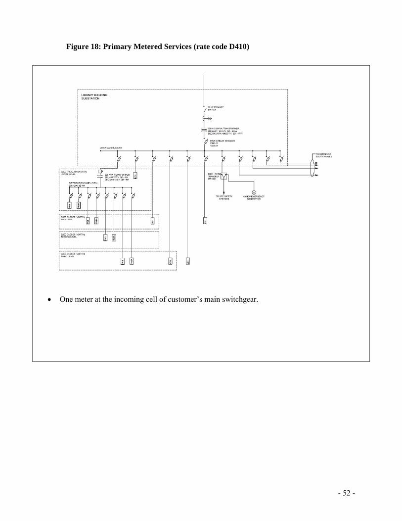
Figure 18: Primary Metered Services (rate code D410)
One meter at the incoming cell of customer’s main switchgear.
- 53 -
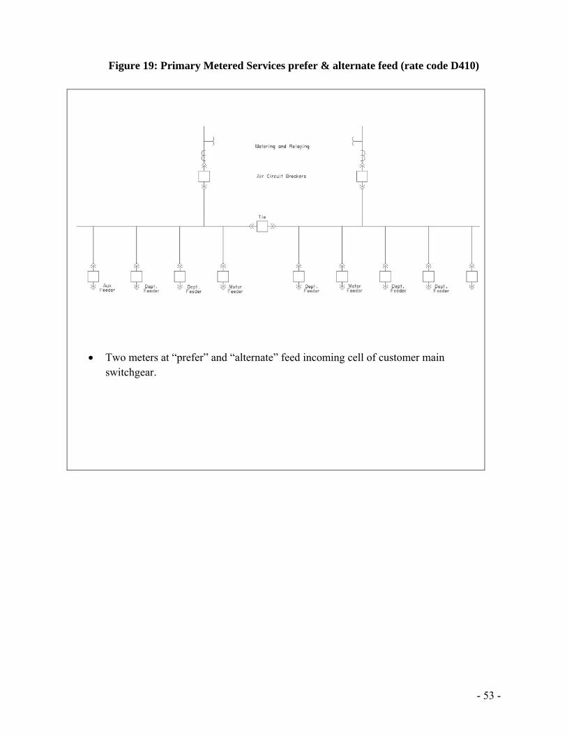
Figure 19: Primary Metered Services prefer & alternate feed (rate code D410)
Two meters at “prefer” and “alternate” feed incoming cell of customer main
switchgear.
- 54 -
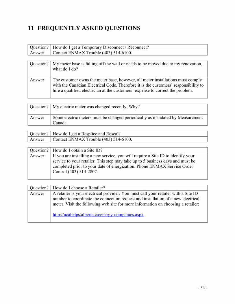
11 FREQUENTLY ASKED QUESTIONS Question? How do I get a Temporary Disconnect / Reconnect? Answer Contact ENMAX Trouble (403) 514-6100.
Question? My meter base is falling off the wall or needs to be moved due to my renovation,
what do I do?
Answer The customer owns the meter base, however, all meter installations must comply with the Canadian Electrical Code. Therefore it is the customers’ responsibility to hire a qualified electrician at the customers’ expense to correct the problem.
Question? My electric meter was changed recently, Why?
Answer Some electric meters must be changed periodically as mandated by Measurement
Canada. Question? How do I get a Resplice and Reseal? Answer Contact ENMAX Trouble (403) 514-6100.
Question? How do I obtain a Site ID? Answer If you are installing a new service, you will require a Site ID to identify your
service to your retailer. This step may take up to 5 business days and must be completed prior to your date of energization. Phone ENMAX Service Order Control (403) 514-2807.
Question? How do I choose a Retailer? Answer A retailer is your electrical provider. You must call your retailer with a Site ID
number to coordinate the connection request and installation of a new electrical meter. Visit the following web site for more information on choosing a retailer: http://ucahelps.alberta.ca/energy-companies.aspx
Related Documents