3A0987M EN Parts PD44 Metering Valves and Feed Systems Meter, mix, and dispense system for precise two-component micro-dispensing of sealants and adhesives. For professional use only. Not approved for use in European explosive atmosphere locations. See page 3 for model information, including maxi- mum working pressure and approvals. See page 4 for product configuration information. Important Safety Instructions Read all warnings and instructions in PD44 Operation-Maintenance manual 313876. Save all instructions. Micrometer shown Micrometer PD44 and LRT PD44 Control Box shown

Welcome message from author
This document is posted to help you gain knowledge. Please leave a comment to let me know what you think about it! Share it to your friends and learn new things together.
Transcript

3A0987MEN
Parts
PD44Metering Valves and Feed Systems
Meter, mix, and dispense system for precise two-component micro-dispensing of sealants and adhesives. For professional use only.
Not approved for use in European explosive atmosphere locations.
See page 3 for model information, including maxi-mum working pressure and approvals. See page 4 for product configuration information.
Important Safety InstructionsRead all warnings and instructions in PD44 Operation-Maintenance manual 313876. Save all instructions.
Micrometer shownMicrometer PD44 and
LRT PD44 Control Box shown

Related Manuals
2 3A0987M
ContentsRelated Manuals . . . . . . . . . . . . . . . . . . . . . . . . . . . 2Models . . . . . . . . . . . . . . . . . . . . . . . . . . . . . . . . . . . 3Product Configurator . . . . . . . . . . . . . . . . . . . . . . . 4Accessories . . . . . . . . . . . . . . . . . . . . . . . . . . . . . . . 9Parts . . . . . . . . . . . . . . . . . . . . . . . . . . . . . . . . . . . . 12
Micrometer Drive, 02/2980-1/25 . . . . . . . . . . . . 12Linear Resistive Transducer Drive . . . . . . . . . . 14Stepper Motor Drive . . . . . . . . . . . . . . . . . . . . . 16Metering Rod and Spool Valve Cross Section . 18High Viscosity Spool Valve Components . . . . . 20Low Viscosity Spool Valve Components . . . . . . 22Spool Air Piston Assembly . . . . . . . . . . . . . . . . 24Material Inlet Blocks . . . . . . . . . . . . . . . . . . . . . 251:1 Luer Nose . . . . . . . . . . . . . . . . . . . . . . . . . . 26Luer Lock Nose with Check Valves . . . . . . . . . 27Standard Nose with 7/8-9 Thread . . . . . . . . . . 28Nose with 7/8-9 Thread and Check Valves . . . 2920 Oz Cartridge Feed System . . . . . . . . . . . . . 30Dyna-Mite Pump . . . . . . . . . . . . . . . . . . . . . . . . 325 Gallon Lid with Diaphragm Pump . . . . . . . . . 335 Gallon Lid with 5:1 Monark Stainless Steel Pump
345 Gallon Lid with Stainless Steel Diaphragm Pump
355 Gallon Tank Assembly with Diaphragm Pump 365 Gallon Tank Assembly with 5:1 Monark Stainless
Steel Pump . . . . . . . . . . . . . . . . . . . . . . . . . 3810 Gallon Tank Assemblies with Diaphragm Pump
4010 Gallon Tank Assemblies with 5:1 Monark
Stainless Steel Pump . . . . . . . . . . . . . . . . . 42Micrometer and LRT Logic . . . . . . . . . . . . . . . . 44Micrometer and LRT Optional Customer Inputs 47Stepper Motor Driven Logic . . . . . . . . . . . . . . . 48
Graco Standard Warranty . . . . . . . . . . . . . . . . . . . 52Graco Information . . . . . . . . . . . . . . . . . . . . . . . . . 52
Related ManualsManuals are available at www.graco.com
Component manuals in U.S. English.
PD44 Manuals
Part Description
313876 PD44 Metering Valves and Feed Systems Operation - Maintenance
313877 PD44 Control Box Setup - Operation
Feed System Manuals
306565 Air-Driven, Stainless Steel Agitators
307043 Monark® Air Motor
308116 Severe-Duty, UHMWPE/PTFE or PTFE Packed Stainless Steel Pumps
308167 Low Volume Air Regulators
308168 High Volume Air Regulators
308169 Air Filters, Lubricators and Kits
309306 Air-Operated Husky™ Diaphragm Pumps
312376 Stainless Steel Agitator Kit
313526 Check-Mate® Pump, Ram Packages
3A1452 Dispensit™ Cartridge Retainer
308302 Dyna-Mite Pump and Ram

Models
3A0987M 3
Models
* If a custom PD44 is ordered, it will not be CE approved unless otherwise noted.
Metering Valve Model
Max Outlet Fluid Working
Pressurepsi (MPa, bar)
Max Air Working Pressure
psi (MPa, bar)
Max Inlet Working Pressurepsi (MPa, bar)
CE Approved*Metal Sleeves Plastic Sleeves
Linear Resistive Transducer (LRT) 2000 (14, 138) 100 (0.7, 7) 1200 (8, 83) 400 (2.8, 28)
Micrometer 2000 (14, 138) 100 (0.7, 7) 1200 (8, 83) 400 (2.8, 28)
Motor Driven 2000 (14, 138) 100 (0.7, 7) 1200 (8, 83) 400 (2.8, 28)

Product Configurator
4 3A0987M
Product ConfiguratorThis system can be ordered with many different options as shown in the configurator below.
The following table applies to the PD44 configurations and indicates all of the options available for each letter shown above.
PD44 C - A -BCD-EFG- H - I - J - K - L - M - NO - P - Q - RS - T - U - V - W - X
Configurator S
eries Level
Base U
nit
High V
olume R
od Material, S
ize
Low V
olume R
od Material, S
ize
High V
olume S
pool
Low V
olume S
pool
Outlet N
ose
Mixer
Controls
Pow
er Cord
High V
olume Feed
High V
olume Feed H
ose
High V
olume Feed O
ptions
Low V
olume Feed
Low V
olume Feed H
ose
Low V
olume Feed O
ptions
Vacuum
Pum
p(s)
Bench S
tand
Seal Lubricant
Code A Part Base UnitA 964000 Micrometer PD44B 964001 Linear Resistive Transducer PD44C 964002 Motor Driven PD44
Code B Part High Volume Rod Material NOTE: See code CD for last two digits of part numberA 9641__ Hardened SteelB 9642__ Stainless Steel, UHMWC 9643__ Tungsten Carbide, UHMW
Code CD Part High Volume Rod Size
NOTE: See code B for first four digits of part number01 ____01 1.25 mm rod diameter02 ____02 1.38 mm rod diameter03 ____03 1.50 mm rod diameter04 ____04 1.63 mm rod diameter05 ____05 1.75 mm rod diameter06 ____06 2.00 mm rod diameter07 ____07 2.13 mm rod diameter08 ____08 2.25 mm rod diameter09 ____09 2.38 mm rod diameter10 ____10 2.50 mm rod diameter11 ____11 2.63 mm rod diameter12 ____12 2.75 mm rod diameter13 ____13 3.00 mm rod diameter14 ____14 3.13 mm rod diameter15 ____15 3.25 mm rod diameter16 ____16 3.38 mm rod diameter17 ____17 3.50 mm rod diameter18 ____18 3.63 mm rod diameter
19 ____19 3.75 mm rod diameter20 ____20 4.00 mm rod diameter21 ____21 4.25 mm rod diameter22 ____22 4.50 mm rod diameter23 ____23 4.63 mm rod diameter24 ____24 4.75 mm rod diameter25 ____25 4.88 mm rod diameter26 ____26 5.00 mm rod diameter27 ____27 5.13 mm rod diameter28 ____28 5.25 mm rod diameter29 ____29 5.50 mm rod diameter30 ____30 5.75 mm rod diameter31 ____31 6.00 mm rod diameter32 ____32 6.13 mm rod diameter33 ____33 6.25 mm rod diameter34 ____34 6.38 mm rod diameter35 ____35 6.50 mm rod diameter36 ____36 6.63 mm rod diameter37 ____37 6.75 mm rod diameter38 ____38 7.00 mm rod diameter39 ____39 7.25 mm rod diameter40 ____40 7.50 mm rod diameter41 ____41 7.63 mm rod diameter42 ____42 7.75 mm rod diameter43 ____43 7.88 mm rod diameter44 ____44 8.00 mm rod diameter
Code E Part Low Volume Rod Material NOTE: See code FG for last two digits of part numberA 9641__ Hardened SteelB 9642__ Stainless Steel, UHMWC 9643__ Tungsten Carbide, UHMW

Product Configurator
3A0987M 5
Code FG Part Low Volume Rod Size NOTE: See code E for first four digits of part number
01 ____01 1.25 mm rod diameter02 ____02 1.38 mm rod diameter03 ____03 1.50 mm rod diameter04 ____04 1.63 mm rod diameter05 ____05 1.75 mm rod diameter06 ____06 2.00 mm rod diameter07 ____07 2.13 mm rod diameter08 ____08 2.25 mm rod diameter09 ____09 2.38 mm rod diameter10 ____10 2.50 mm rod diameter11 ____11 2.63 mm rod diameter12 ____12 2.75 mm rod diameter13 ____13 3.00 mm rod diameter14 ____14 3.13 mm rod diameter15 ____15 3.25 mm rod diameter16 ____16 3.38 mm rod diameter17 ____17 3.50 mm rod diameter18 ____18 3.63 mm rod diameter19 ____19 3.75 mm rod diameter20 ____20 4.00 mm rod diameter21 ____21 4.25 mm rod diameter22 ____22 4.50 mm rod diameter23 ____23 4.63 mm rod diameter24 ____24 4.75 mm rod diameter25 ____25 4.88 mm rod diameter26 ____26 5.00 mm rod diameter27 ____27 5.13 mm rod diameter28 ____28 5.25 mm rod diameter29 ____29 5.50 mm rod diameter30 ____30 5.75 mm rod diameter31 ____31 6.00 mm rod diameter32 ____32 6.13 mm rod diameter33 ____33 6.25 mm rod diameter34 ____34 6.38 mm rod diameter35 ____35 6.50 mm rod diameter36 ____36 6.63 mm rod diameter37 ____37 6.75 mm rod diameter38 ____38 7.00 mm rod diameter39 ____39 7.25 mm rod diameter40 ____40 7.50 mm rod diameter41 ____41 7.63 mm rod diameter42 ____42 7.75 mm rod diameter43 ____43 7.88 mm rod diameter44 ____44 8.00 mm rod diameter
Code H Part High Volume Spool1 964003 High viscosity, HS2 964004 High viscosity, Stainless Steel/UHMWPE3 964005 High viscosity, TC/UHMWPE4 964006 Low viscosity, Stainless Steel
Code I Part Low Volume Spool1 964011 High viscosity, HS2 964012 High viscosity, Stainless Steel/UHMWPE3 964013 High viscosity, TC/UHMWPE4 964014 Low viscosity, Stainless Steel
Code J Part Outlet Nose1 964020 Luer lock, equal ports, no check valves2 964021 Luer lock, equal ports, dual check valves3 964022 Equal ports, 7/8-9, no check valves4 964023 Large and small ports, 7/8-9, no check
valves5 964024 Large and small ports, 7/8-9, single
check valve6 964025 Dual small ports, 7/8-9, no check valves7 964026 Dual small ports, 7/8-9 dual check valves
Code K Part Mixer1 964027 1/8-24 Luer Lock inlet and outlet, 0.5 cc2 964028 3/16-32 bell mouth inlet, luer lock outlet,
2.0 cc3 964029 1/4-24 bell mouth inlet, luer lock outlet,
4.0 cc4 964030 1/4-32 bell mouth inlet, luer lock outlet,
5.5 cc5 964031 1/4-48 bell mouth inlet, luer lock outlet,
8.0 cc6 964032 3/16-32 bell mouth inlet, tapered outlet,
1.5 cc7 964033 1/4-24 bell mouth inlet, tapered outlet,
3.5 cc8 964034 3/16-24 bell mouth inlet, tapered outlet,
1.0 cc

Product Configurator
6 3A0987M
Code L Part Controls1 964035 Pneumatic, micrometer, wire harness
only2 964036 Pneumatic, micrometer, HMI controls,
low level3 964037 Pneumatic, micrometer, HMI controls,
low level, I/O package4 964038 Pneumatic, micrometer, HMI controls,
low level, high level5 964039 Pneumatic, micrometer, HMI controls,
low level, high level, I/O package6 964040 Pneumatic, linear resistive transducer,
wire harness only7 964041 Pneumatic, linear resistive transducer,
HMI controls, low level8 964042 Pneumatic, linear resistive transducer,
HMI controls, low level, I/O package9 964043 Pneumatic, linear resistive transducer,
HMI controls, low level, high levelA 964044 Pneumatic, linear resistive transducer,
HMI controls, low level, high level, I/O package
B 964045 Motor driven, I/O, wire harness onlyC 964046 Stepper motor, HMI control, low level,
high level, I/O packageD -- No Controls - Use only with UniXact
motion tableE 25C687 No Controls with pressure transducer
block. Use only with UniXact motion table
Code M Part Power Cord1 121055 120 VAC, North American cord set2 121054 250 VAC, 1 phase, no plug3 121056 10 amp, 250 volt, continental Europe4 121057 10 amp, 250 volt, United Kingdom and
Ireland5 121058 10 amp, 250 volt, Israel6 124864 10 amp, 250 volt, Australia7 124861 10 amp, 250 volt, Italy8 124863 10 amp, 250 volt, Switzerland9 124862 10 amp, 250 volt, DenmarkA 121060 10 amp, 250 volt, IndiaN -- None
Code NO Part High Volume Feed01 964050 20 oz cartridge feed with mounting post02 964051 1 gallon pail Ram and transfer pump03 964052 5 gallon pail cover with diaphragm pump04 964053 5 gallon pail cover diaphragm pump and
agitator05 964054 5 gallon pail cover and 5:1 transfer pump06 964055 5 gallon pail cover, 1:1 pump with dip
tube for moisture sensitive materials07 964056 5 gallon single post Ram with 11:1 pump,
mild steel08 964057 5 gallon single post Ram with 11:1 pump,
stainless steel09 964058 5 gallon tank, support and diaphragm
pump, mild steel10 964059 5 gallon tank, support, diaphragm pump
and agitator, mild steel11 964060 5 gallon tank, support, diaphragm pump,
agitator and vacuum fill, mild steel12 964061 5 gallon tank, support, diaphragm pump,
stainless steel13 964062 5 gallon tank, support, diaphragm pump,
agitator, stainless steel14 964063 5 gallon tank, support, diaphragm pump,
agitator, vacuum fill, stainless steel15 964064 5 gallon tank, support and 5:1 pump, mild
steel16 964065 5 gallon tank, support, 5:1 pump, agitator,
mild steel17 964066 5 gallon tank, support, 5:1 pump, agitator,
vacuum fill, mild steel18 964067 5 gallon tank, support, 5:1 pump, stain-
less steel

Product Configurator
3A0987M 7
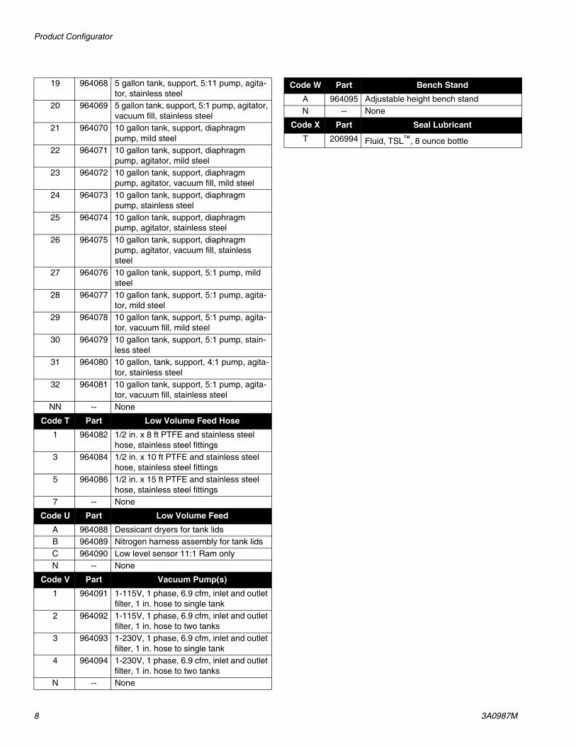
19 964068 5 gallon tank, support, 5:1 pump, agitator, stainless steel
20 964069 5 gallon tank, support, 5:1 pump, agitator, vacuum fill, stainless steel
21 964070 10 gallon tank, support, diaphragm pump, mild steel
22 964071 10 gallon tank, support, diaphragm pump, agitator, mild steel
23 964072 10 gallon tank, support, diaphragm pump, agitator, vacuum fill, mild steel
24 964073 10 gallon tank, support, diaphragm pump, stainless steel
25 964074 10 gallon tank, support, diaphragm pump, agitator, stainless steel
26 964075 10 gallon tank, support, diaphragm pump, agitator, vacuum fill, stainless steel
27 964076 10 gallon tank, support, 5:1 pump, mild steel
28 964077 10 gallon tank, support, 5:1 pump, agita-tor, mild steel
29 964078 10 gallon tank, support, 5:1 pump, agita-tor, vacuum fill, mild steel
30 964079 10 gallon tank, support, 5:1 pump, stain-less steel
31 964080 10 gallon, tank, support, 4:1 pump, agita-tor, stainless steel
32 964081 10 gallon tank, support, 5:1 pump, agita-tor, vacuum fill, stainless steel
NN -- None
Code P Part High Volume Feed Hose1 964082 1/2 in. x 8 ft PTFE and stainless steel
hose, stainless steel fittings3 964084 1/2 in. x 10 ft PTFE and stainless steel
hose, stainless steel fittings5 964086 1/2 in. x 15 ft PTFE and stainless steel
hose, stainless steel fittingsN -- None
Code Q Part High Volume FeedA 964088 Dessicant dryers for tank lidsB 964089 Nitrogen harness assembly for tank lidsC 964090 Low level sensor 11:1 Ram onlyN -- None
Code RS Part Low Volume Feed01 964050 20 oz cartridge feed with mounting post02 964051 1 gallon pail Ram and transfer pump03 964052 5 gallon pail cover with diaphragm pump04 964053 5 gallon pail cover diaphragm pump and
agitator05 964054 5 gallon pail cover and 5:1 transfer pump06 964055 5 gallon pail cover, 1:1 pump with dip
tube for moisture sensitive materials07 964056 5 gallon single post Ram with 11:1 pump,
mild steel08 964057 5 gallon single post Ram with 11:1 pump,
stainless steel09 964058 5 gallon tank, support and diaphragm
pump, mild steel10 964059 5 gallon tank, support, diaphragm pump
and agitator, mild steel11 964060 5 gallon tank, support, diaphragm pump,
agitator and vacuum fill, mild steel12 964061 5 gallon tank, support, diaphragm pump,
stainless steel13 964062 5 gallon tank, support, diaphragm pump,
agitator, stainless steel14 964063 5 gallon tank, support, diaphragm pump,
agitator, vacuum fill, stainless steel15 964064 5 gallon tank, support and 5:1 pump, mild
steel16 964065 5 gallon tank, support, 5:1 pump, agitator,
mild steel17 964066 5 gallon tank, support, 5:1 pump, agitator,
vacuum fill, mild steel18 964067 5 gallon tank, support, 5:1 pump, stain-
less steel
Product Configurator
8 3A0987M
19 964068 5 gallon tank, support, 5:11 pump, agita-tor, stainless steel
20 964069 5 gallon tank, support, 5:1 pump, agitator, vacuum fill, stainless steel
21 964070 10 gallon tank, support, diaphragm pump, mild steel
22 964071 10 gallon tank, support, diaphragm pump, agitator, mild steel
23 964072 10 gallon tank, support, diaphragm pump, agitator, vacuum fill, mild steel
24 964073 10 gallon tank, support, diaphragm pump, stainless steel
25 964074 10 gallon tank, support, diaphragm pump, agitator, stainless steel
26 964075 10 gallon tank, support, diaphragm pump, agitator, vacuum fill, stainless steel
27 964076 10 gallon tank, support, 5:1 pump, mild steel
28 964077 10 gallon tank, support, 5:1 pump, agita-tor, mild steel
29 964078 10 gallon tank, support, 5:1 pump, agita-tor, vacuum fill, mild steel
30 964079 10 gallon tank, support, 5:1 pump, stain-less steel
31 964080 10 gallon, tank, support, 4:1 pump, agita-tor, stainless steel
32 964081 10 gallon tank, support, 5:1 pump, agita-tor, vacuum fill, stainless steel
NN -- None
Code T Part Low Volume Feed Hose1 964082 1/2 in. x 8 ft PTFE and stainless steel
hose, stainless steel fittings3 964084 1/2 in. x 10 ft PTFE and stainless steel
hose, stainless steel fittings5 964086 1/2 in. x 15 ft PTFE and stainless steel
hose, stainless steel fittings7 -- None
Code U Part Low Volume FeedA 964088 Dessicant dryers for tank lidsB 964089 Nitrogen harness assembly for tank lidsC 964090 Low level sensor 11:1 Ram onlyN -- None
Code V Part Vacuum Pump(s)1 964091 1-115V, 1 phase, 6.9 cfm, inlet and outlet
filter, 1 in. hose to single tank2 964092 1-115V, 1 phase, 6.9 cfm, inlet and outlet
filter, 1 in. hose to two tanks3 964093 1-230V, 1 phase, 6.9 cfm, inlet and outlet
filter, 1 in. hose to single tank4 964094 1-230V, 1 phase, 6.9 cfm, inlet and outlet
filter, 1 in. hose to two tanksN -- None
Code W Part Bench StandA 964095 Adjustable height bench standN -- None
Code X Part Seal LubricantT 206994 Fluid, TSL™, 8 ounce bottle

Accessories
3A0987M 9
AccessoriesMixer Kits with Shroud
Mixer Packs
Part Description
964034 Mixer, Kit, 3/16 in. (4.8mm) x 24, 10 taper tip mixers with shroud
964032 Mixer, Kit, 3/16 in. (4.8mm) x 32, 10 taper tip mixers with shroud
964028 Mixer, Kit, 3/16 in. (4.8mm) x 32, 10 Luer Lock tip mixers with shroud/sleeve
964033 Mixer, Kit, 1/4 in. (6.5mm) x 24, 10 taper tip mixers with shroud
964029 Mixer, Kit, 1/4 in. (6.5mm) x 24, 10 Luer Lock tip mixers with shroud/sleeve
964030 Mixer, Kit, 1/4 in. (6.5mm) x 32, 10 Luer Lock tip mixers with shroud/sleeve
964031 Mixer, Kit, 1/4 in. (6.5mm) x 48, 10 Luer Lock tip mixers with shroud/sleeve
Part Description
964027 Mixer, 1/8 in. (3.2mm) x 24 Luer Lock inlet/tip, 10 Pack
16D962 Mixer, 1/8 in. (3.2mm) x 24 Luer Lock inlet/tip, 50 Pack
16D963 Mixer, 1/8 in. (3.2mm) x 24 Luer Lock inlet/tip, 250 Pack
16D978 Mixer, 3/16 in. (4.8mm) x 24 taper tip, 50 Pack
16D979 Mixer, 3/16 in. (4.8mm) x 24 taper tip, 250 Pack
LC0077 Mixer, 3/16 in. (4.8mm) x 32 taper tip, 50 Pack
LC0084 Mixer, 3/16 in. (4.8mm) x 32 taper tip, 250 Pack
LC0082 Mixer, 3/16 in. (4.8mm) x 32 Luer Lock tip, 50 Pack
LC0090 Mixer, 3/16 in. (4.8mm) x 32 Luer Lock tip, 250 Pack
LC0078 Mixer, 1/4 in. (6.5mm) x 24 taper tip mixer, 50 Pack
LC0085 Mixer, 1/4 in. (6.5mm) x 24 taper tip mixer, 250 Pack
LC0083 Mixer, 1/4 in. (6.5mm) x 24 Luer Lock tip, 50 Pack
LC0089 Mixer, 1/4 in. (6.5mm) x 24 Luer Lock tip, 250 Pack
16D968 Mixer, 1/4 in. (6.5mm) x 32 Luer Lock tip, 50 Pack
16D969 Mixer, 1/4 in. (6.5mm) x 32 Luer Lock tip, 250 Pack
16D970 Mixer, 1/4 in. (6.5mm) x 48 Luer Lock tip, 50 Pack
16D973 Mixer, 1/4 in. (6.5mm) x 48 Luer Lock tip, 250 Pack
Part Description

Accessories
10 3A0987M
O-Rings and SealsFor o-ring and seal locations, see the following sections:
• Metering Rod and Spool Valve Cross Section, beginning on page 18
• High Viscosity Spool Valve Components, page 20
• Low Viscosity Spool Valve Components, page 22
Part Description
24E247 Kit, O-ring, chemical resistant, PD4424E248 Kit, Seal, Spool, H.V., PD4424E249 Kit, Seal, Spool, L.V., PD4416B265 Seal, Posipack, 1.25, ZAP16B266 Seal, Posipack, 1.38, ZAP16B267 Seal, Posipack, 1.50, ZAP16B268 Seal, Posipack, 1.63, ZAP16B269 Seal, Posipack, 1.75, ZAP16B270 Seal, Posipack, 2.00, ZAP16B271 Seal, Posipack, 2.13, ZAP16B272 Seal, Posipack, 2.25, ZAP16B273 Seal, Posipack, 2.38, ZAP16B274 Seal, Posipack, 2.50, ZAP16B275 Seal, Posipack, 2.63, ZAP16B276 Seal, Posipack, 2.75, ZAP16B277 Seal, Posipack, 3.00, ZAP16B278 Seal, Posipack, 3.13, ZAP16B279 Seal, Posipack, 3.25, ZAP16B280 Seal, Posipack, 3.38, ZAP16B281 Seal, Posipack, 3.50, ZAP16B282 Seal, Posipack, 3.63, ZAP16B283 Seal, Posipack, 3.75, ZAP16B284 Seal, Posipack, 4.00, ZAP16B285 Seal, Posipack, 4.25, ZAP16B286 Seal, Posipack, 4.50, ZAP16B287 Seal, Posipack, 4.63, ZAP16B288 Seal, Posipack, 4.75, ZAP16B289 Seal, Posipack, 4.88, ZAP16B290 Seal, Posipack, 5.00, ZAP16B291 Seal, Posipack, 5.13, ZAP16B292 Seal, Posipack, 5.25, ZAP16B293 Seal, Posipack, 5.50, ZAP16B294 Seal, Posipack, 5.75, ZAP16B295 Seal, Posipack, 6.00, ZAP
16B296 Seal, Posipack, 6.13, ZAP16B297 Seal, Posipack, 6.25, ZAP16B298 Seal, Posipack, 6.38, ZAP16B299 Seal, Posipack, 6.50, ZAP16B300 Seal, Posipack, 6.63, ZAP16B301 Seal, Posipack, 6.75, ZAP16B302 Seal, Posipack, 7.00, ZAP16B303 Seal, Posipack, 7.25, ZAP16B304 Seal, Posipack, 7.50, ZAP16B305 Seal, Posipack, 7.63, ZAP16B306 Seal, Posipack, 7.75, ZAP16B307 Seal, Posipack, 7.88, ZAP16B450 Seal, Posipack, 8.00, ZAP
Part Description

Accessories
3A0987M 11
Needles
Part Description
E4000025-50 Needle, Luer Lock, Sampler Package (10 each 14 ga x 1/2 in., 16 ga x 1/2 in., 18 ga x 1/2 in., 20 ga x 1/2 in., 22 ga x 1/2 in.)
E4000001-50 Needle, Luer Lock, 14 Gauge x 1/2 in., 50 Pack
E4000004-50 Needle, Luer Lock, 15 Gauge x 1/2 in., 50 Pack
E4000005-50 Needle, Luer Lock, 16 Gauge x 1 in., 50 Pack
E4000006-50 Needle, Luer Lock, 18 Gauge x 1 in., 50 Pack
E4000011-50 Needle, Luer Lock, 22 Gauge x 1/2 in., 50 Pack
E4000014-50 Needle, Luer Lock, 14 Gauge x 1 in., 50 Pack
E4000024-50 Needle, Luer Lock, 23 Gauge x 1/2 in., 50 Pack
E4000088-50 Needle, Luer Lock, 16 Gauge x 1/2 in., 50 Pack

Parts
12 3A0987M
Parts
Micrometer Drive, 02/2980-1/25 0
43
21
87
21
09
65
98
73
56
4
51
23
40
69
07
8
124
122
121
117
115114113112111
110
105
101
102
106
104
103
1
1 3
5
6
1 3
116 1
118 1
119 1
112
123
124 125
126127
128
131
132 132
131
129
130
111
116
108 610945
1074
1207
3
4
Use Krytox 203gpl on all air cylinder seals and surfaces.
Align micrometer number line with needle valve port center.
Note direction of seals on air cylinder piston and on piston rod seal.
Mount piston rod (116) to connecting block (107). Use removable thread locker Loctite #242 blue or equivalent.
Torque fastener to 67-70 in-lb (7.6-7.9 N•m).
Install spring plunger (106) and retaining plate (108) onto connecting block.
Torque fastener to 4-8 in-lb (0.45-0.90 N•m).
1
2
3
4
5
6
7
2

Parts
3A0987M 13
* Parts included in Kit 95/2980-1/25 (purchase separately).
† Parts included in assembly 24K620 (purchase sepa-rately).
--- Parts not available for individual sale.
Ref Part Description Qty101 01/2984-2/97 BLOCK, retainer, oil cup 1102 01/2983/97 PLATE, tie, front, 2 in. 1103 01/2982-1/97 PLATE, plate, tie, back 1104 96/0305/99 SCREW, socket head cap, 10-24 x 2.00,
mild steel4
105 01/2706-2.0/99 ROD, rod, guide, 1.5b x 2.0s 2106 84/0263/11 PLUNGER, 10-32 1107 01/2980/97 BLOCK 1108 01/2981/99 RETAINER, rod, metering 1109 96/0458/99 SCREW, fhsc, 10-32 x 0.50, mild steel 1110 96/2955/98 SCREW, socket head cap, 10-24 x 0.18,
stainless steel8
111 01/2985/97 BLOCK, air cylinder 1112* 95/0504/01 O-RING, buna, 028, 70a 2113* 95/0849/11 SEAL, posipak, 3/8 ID x 5/8 OD 1114 01/2704/98 WASHER, air cylinder 1115 96/0425/99 RING, 0.625, mild steel 1116 01/2979/97 ROD, air cylinder 1117* 95/0601/01 SEAL, u-cup, 1-3/16 ID x 1-1/2 OD 2118 01/2702/97 PISTON, air cylinder, rod, 1.5b x 2.0s 1119 01/2701-2.0/97 TUBE, air cylinder, aluminum 1120 96/0608/99 SCREW, shs, 6-32 x 0.31, cup point,
mild steel2
121* 95/0900/00 O-RING, fluoroelastomer, 009, 75a 1122† 01/2969/97 CAP, top, air cylinder, rod 1123† --- TOOL, micrometer, 0-2 in. 1124 96/0098-45/99 SCREW, shc, 10-24 x 4.50, mild steel 4125† 96/0523/99 SCREW, shs, 1/4-20 x 0.38, cone point,
mild steel2
126 94/0525/96 FITTING, nipple, hex, 1/8 npt, brass 1127 94/0767/96 COUPLING, hex, 1/8 npt, brass 1128 123541 VALVE, needle, 1/8 npt x 1/4 t,
press-to-fit2
129 123540 BUTTON, snap-on, 1/4 tube, red 1130 123539 BUTTON, snap-on, 1/4 tube, blue 1131 01/2995/11 GUARD, guard, side 2132 96/0271/99 FASTENER, bhcs, 8-32 x 0.31, mild
steel6

Parts
14 3A0987M
Linear Resistive Transducer Drive
LEFT SIDE VIEW FRONT VIEW
PG-7
3 WHT
2 RED
LOOKING FROM SOLDER SIDE
1 BLK
MALE
PG-7
M
RIGHT SIDE VIEW
204
3207
213 1
203
212
211
206
202 205202
201
2
21021209 3
208
2214
222
214215
216
217
219
220 220
219
220
218
Use removable thread locker Loctite #242 blue or equal on fastener (210) and cylinder (213).
Torque fastener to 67-70 in-lb (7.6-7.9 N•m).
Install spring plunger (207) and retaining plate (209) onto connecting block.
Torque fastener to 4-8 in-lb (0.45-0.90 N•m).
1
2
3
4

Parts
3A0987M 15
Ref Part Description Qty201 01/2984-2/97 BLOCK, retainer, oil cup 1202 01/2983/97 PLATE, tie, front, 2 in. 2203 81/0360-3M/11 CONNECTOR, plug, male, 3-pin, RTD 1204 61/0086/11 JACKET, shrink, 1/8, black, semi-rigid 0.5205 96/0305/99 SCREW, shc, 10-24 x 2.00, mild steel 4206 01/2706-2.0/99 ROD, rod, guide, 1.5b x 2.0s 2207 84/0263/11 PLUNGER, 10-32 1208 01/2980/97 BLOCK 1209 01/2981/99 RETAINER, rod, metering 1210 96/0458/99 SCREW, fhsc, 10-32 x 0.50, mild steel 1211 96/2955/98 SCREW, shc, shdr, 0.25, 10-24 x 0.18,
stainless steel8
212 01/2985-1/97 BLOCK, air cylinder, lvdt 1213 83/0070-2PD/11 CYLINDER, 1.5b x 2.0s, special tip 1214 94/0499/96 ADAPTER, hex, 1/4 npt x 1/8 npt, male x
male, brass1
215 94/0767/96 COUPLING, hex, 1/8 npt, brass 1216 123541 VALVE, needle, 1/8 npt x 1/4 t, press-to-fit 2217 123540 BUTTON, snap-on, 1/4 tube, red 1218 123539 BUTTON, snap-on, 1/4 tube, blue 1219 01/2995/11 GUARD, guard, side 2220 96/0271/99 FASTENER, bhcs, 8-32 x 0.31, mild steel 6221 96/0608/99 SCREW, shs, 6-32x0.31, cup pt, mild steel 2222 94/0598/96 BUSHING, 1/4npt x 1/8npt, brass 1

Parts
16 3A0987M
Stepper Motor Drive
3131
3141
316
318
320
322
317
321
319
315
312311
310
323
327
306 4
304 3
303305
302
301
325
312
325
312
324
309 308
307
32
5
4
Press bearing (314) onto lead screw drive nut (315). Secure with retaining ring (313).
Use removable thread locker Loctite #242 blue or equal on fastener (309).
Torque fastener to 67-70 in-lb (7.6-7.9 N•m).
Install spring plunger (306) and retaining plate (308) onto connecting block.
Torque fastener to 4-8 in-lb (0.45-0.90 N•m).
1
2
3
4
5

Parts
3A0987M 17
Ref Part Description Qty301 01/2984-2/97 BLOCK, retainer, oil cup, 1.5b 1302 01/2983/97 PLATE, tie, front, 2 in. 1303 01/2982-1/97 PLATE, plate, tie, back 1304 96/0305/99 SCREW, shc, 10-24 x 2.00, mild steel 4305 01/2706-2.0/99 ROD, rod, guide, 1.5b x 2.0s 2306 84/0263/11 PLUNGER, 10-32 1307 01/2980/97 BLOCK 1308 01/2981/99 RETAINER, rod, metering, pd3 1309 96/0458/99 SCREW, fhsc, 10-32 x 0.50, mild steel 1310 96/2955/98 SCREW, shc, 0.25, 10-24 x 0.18,
stainless steel8
311 01/2990/97 HOUSING, lead screw 1312 96/0271/99 FASTENER, bhcs, 8-32 x 0.31, mild
steel8
313 96/0209/99 RING, 0.625, mild steel 1314 84/0129/11 BALL, 0.62ID x 1.375 OD 1315 01/2993/25 NUT, lead screw, drive 1316 01/2994/25 SCREW, lead screw, drive 1317 96/0323/99 SCREW, shc, 10-32 x 0.50, mild steel 4318 01/2991-1/97 COUPLER, lead screw, 1/4 1319 96/0363/99 SCREW, shc, 6-32 x 0.38, mild steel 2320 01/2992/97 RETAINER, bearing, leadscrew 1321 01/2890/97 PLATE 1322 96/0187/98 SCREW, shc, 8-32 x 0.38, stainless
steel4
323 01/2993-S/89 SPACER, drive nut 1324 96/0608/99 SCREW, shs, 6-32 x 0.31, cup point,
mild steel2
325 01/2995/11 GUARD, guard, side 2327 B3000061 SCREW, shs, 6-32 x 0.25, nylon point,
stainless steel1

Parts
18 3A0987M
Metering Rod and Spool Valve Cross Section
402a
†404a
402b
404d
402c
404c
†404b
NOTE: Other parts of valve that are not included in this assembly are shown for reference only.
NOTE: See the rebuild procedure in the PD44 Metering Valves and Feed Sys-tems Operation and Maintenance manual. See Related Manuals on page 2.
“A” Side
Front
High Viscosity Shown
Slide Plate
Connecting Plate
Set Screw
“A” Side
† O-ring
PTFE Gasket

Parts
3A0987M 19
Rod Assembly Kits
† Seals are available separately. See O-Rings and Seals section on page 10.
One kit is required for each side of the valve A and B.
Reference402 † 404
DescriptionHardened Steel
Rod Assembly KitStainless Steel
Rod Assembly KitTungsten CarbideRod Assembly Kit Description Part
KIT, rod, 1.25 964101 964201 964301
KIT, o-ring 24E247
KIT, rod, 1.38 964102 964202 964302KIT, rod, 1.50 964103 964203 964303KIT, rod, 1.63 964104 964204 964304KIT, rod, 1.75 964105 964205 964305KIT, rod, 2.00 964106 964206 964306KIT, rod, 2.13 964107 964207 964307KIT, rod, 2.25 964108 964208 964308KIT, rod, 2.38 964109 964209 964309KIT, rod, 2.50 964110 964210 964310KIT, rod, 2.63 964111 964211 964311KIT, rod, 2.75 964112 964212 964312KIT, rod, 3.00 964113 964213 964313KIT, rod, 3.13 964114 964214 964314KIT, rod, 3.25 964115 964215 964315KIT, rod, 3.38 964116 964216 964316KIT, rod, 3.50 964117 964217 964317KIT, rod, 3.63 964118 964218 964318KIT, rod, 3.75 964119 964219 964319KIT, rod, 4.00 964120 964220 964320KIT, rod, 4.25 964121 964221 964321KIT, rod, 4.50 964122 964222 964322KIT, rod, 4.63 964123 964223 964323KIT, rod, 4.75 964124 964224 964324KIT, rod, 4.88 964125 964225 964325KIT, rod, 5.00 964126 964226 964326KIT, rod, 5.13 964127 964227 964327KIT, rod, 5.25 964128 964228 964328KIT, rod, 5.50 964129 964229 964329KIT, rod, 5.75 964130 964230 964330KIT, rod, 6.00 964131 964231 964331KIT, rod, 6.13 964132 964232 964332KIT, rod, 6.25 964133 964233 964333KIT, rod, 6.38 964134 964234 964334KIT, rod, 6.50 964135 964235 964335KIT, rod, 6.63 964136 964236 964336KIT, rod, 6.75 964137 964237 964337KIT, rod, 7.00 964138 964238 964338KIT, rod, 7.25 964139 964239 964339KIT, rod, 7.50 964140 964240 964340KIT, rod, 7.63 964141 964241 964341KIT, rod, 7.75 964142 964242 964342KIT, rod, 7.88 964143 964243 964343KIT, rod, 8.00 964144 964244 964344

Parts
20 3A0987M
High Viscosity Spool Valve Components
A
A
BA
MAX FLUID WPRXXXX Mpa XXXX bar XXXX PSI
MAX AIR WPR0.7 Mpa 7 bar 100 PSISERIAL SERIES
MODEL NUMBERPD44C-ABCDEFGHIJKLMNOPQRSTUVWX
UA1234 NF09A
502510
514
502507 503 501
505
514
505
510
503 507
502
502506
NOTE: See the rebuild procedure in the PD44 Metering Valves and Feed Sys-tems Operation and Maintenance manual. See Related Manuals on page 2.

Parts
3A0987M 21
† Quantities listed are for one side of the valve.
O-rings and seals are contained in kit 24E248. 1 kit is required for each side of the valve.
HS = hardened steel, SS = stainless steel, TC = Tungsten Carbide/UHMW. Spools are handed: A-Side, B-Side.
Ref Part Description
Quantity †Spool Valve, A Side, HS
Spool Valve, A Side, SS
Spool Valve, A Side, TC
Spool Valve, B Side, HS
Spool Valve, B Side, SS
Spool Valve, B Side, TC
501 RING, quad 4 4 4 4 4 4502 O-RING 4 4 4 4 4 4503 O-RING 6 6 6 6 6 6505 SEAL 2 2 2 2 2 2506 U50205 VALVE, spool, HS, A Side 1
24E565 VALVE, spool, SS, A Side 1
24E579 VALVE, spool, TC, A Side 1
U50206 VALVE, spool, HS, B Side 1
24E566 VALVE, spool, SS, B Side 1
24E567 VALVE, spool, TC, B Side 1
507 01/2975-4/98 WASHER, seal, high viscosity 2 2 2 2 2 2510 01/2974-5/70 CARTRIDGE, high viscosity, 1.5b 2 2 2 2 2 2514 01/2989/98 RETAINER, seal, spool, high viscosity 2 2 2 2 2 2

Parts
22 3A0987M
Low Viscosity Spool Valve Components
A
A B
A
MAX FLUID WPRXXXX Mpa XXXX bar XXXX PSI
MAX AIR WPR0.7 Mpa 7 bar 100 PSISERIAL SERIES
MODEL NUMBERPD44C-ABCDEFGHIJKLMNOPQRSTUVWX
UA1234 NF09A
609610 611
601602 603 606
608 612
605 606
603
611
603
611609611608
602
610
NOTE: See the rebuild procedure in the PD44 Metering Valves and Feed Sys-tems Operation and Maintenance manual. See Related Manuals on page 2.

Parts
3A0987M 23
† Quantities listed are for one side of the valve.
O-rings and seals are contained in kit 24E249. 1 kit is required for each side of the valve.
Sleeves are handed: A-Side, B-Side.
Ref Part Description
Quantity †Spool Valve,
Low Viscosity, A Side
Spool Valve,Low Viscosity,
B Side601 RING, quad 4 4602 O-RING 2 2603 O-RING 4 4605 SEAL 6 6606 O-RING 2 2608 01/2960/98 SPOOL, low viscosity 1 1609 01/2961/98 SLEEVE, low viscosity, A side,
stainless steel, quad1
01/2962/98 SLEEVE, low viscosity, B side, stainless steel, quad
1
610 01/2975-3/98 WASHER, seal, low viscosity 2 2611 01/2977/70 CAP, end, seal, low viscosity 2 2612 01/2963/98 SPACER, seal, low viscosity 3 3

Parts
24 3A0987M
Spool Air Piston Assembly
701 702 703 704 705 706 707
708
Apply thin coat of krytox 203GPL to inner diameter of cylinder wall (704).
Use krytox 203GPL on all o-ring and seal surfaces.
1
2
709
Ref Part Description Qty701 123453 FITTING, 1/4 tube x 1/8 npt, male 1702 16A565 CAP, end, air cylinder, spool 1703 95/0504/01 O-RING, buna, 028, 70a 1704 01/2973/97 CYLINDER, cylinder, air, spool, 1.5 1705 01/2976/97 PISTON, air cylinder, spool, 1.5b 1706 95/0601/01 SEAL, u-cup, 1-3/16 ID x 1-1/2 OD, nitrile 1707 01/2971-1/97 BLOCK, seal, air cylinder, spool 1708 96/0305/99 SCREW, shc, 10-24 x 2.00, mild steel 2709 104702 SCREW, cap, socket head 1

Parts
3A0987M 25
Material Inlet Blocks
Kit includes additional o-rings. See Metering Rod and Spool Valve Cross Section beginning on page 18, item 404.
Ref Part Description Qty2102 02/2995-S/25 KIT, inlet, PD44, top, 1/4 NPT, LH, SS 1.2102a 16A570 BLOCK, PD44, top inlet, 1/4 NPT, SS 1.2102b 96/0097/99 SCREW, socket head, #10-24x1.25, MS 4
2103 24E247 KIT, o-ring, FX75, PD44 12104 02/2996-S/25 KIT, inlet, PD44, top, 1/4 NPT, RH, SS 1.2104a 16A571 BLOCK, PD44, top inlet, 1/4 NPT, SS 1.2104b 96/0097/99 SCREW, socket head, #10-24x1.25, MS 4
2103
2102a
2102b
2103
2104a
2104b
Torque fasteners to 67-70 in-lb (7.6-7.9 N•m).1
1
1

Parts
26 3A0987M
1:1 Luer Nose
A B
803
805
802
808
804 807 806 806 807
Ref Part Description Qty802 01/2725/98 BLOCK, nose, body, 1.5b x 1:1 1805 96/0125/99 SCREW, shc, 10-24 x 0.50, mild steel 2806 94/3108/70 BALL, ball, 0.094 dia, acetal 2807 96/0510/99 SCREW, shs, 6-32 x 0.13, flat point, mild
steel2
808 94/0645/89 RING, lock, nylon 1

Parts
3A0987M 27
Luer Lock Nose with Check Valves
O-rings are available in kit 24E247. See Metering Rod and Spool Valve Cross Section beginning on page 18.
A B
906
907
903
907904
905
902
912
909
908
908
907 908
904
905
911 910
Ref Part Description Qty902 01/2734/98 BLOCK, 1.5b, 1:1, a/b 1903 01/2728/98 PLATE, retaining, nose, 1.5b, 1:1,
stainless steel1
904 94/3110/70 BALL, ball, 0.125 dia, acetal 2905 97/0203/98 SPRING, compression, 0.120 OD x
0.3125l, 7.41l2
906 96/0119/99 SCREW, fhsc, 6-32 x 0.50, mild steel 2907 O-RING 2908 O-RING 2909 96/0307-1/99 SCREW, shc, 10-24 x 1.00, mild steel 2910 94/3108/70 BALL, ball, 0.094 dia, acetal 2911 96/0510/99 SCREW, shs, 6-32 x 0.13, flat point, mild
steel2
912 94/0645/89 RING, lock, nylon 1

Parts
28 3A0987M
Standard Nose with 7/8-9 Thread
O-rings are available in kit 24E247. See Metering Rod and Spool Valve Cross Section beginning on page 18.
Ref Part Description
QuantityLarge Port A, Large Port B
Large Port A,Small Port B
1002 01/2726/98 BLOCK, nose 1
01/2723/98 BLOCK, nose 1
1003 O-RING 2 21005 96/0125/99 SCREW, shc, 10-24 x 0.50, mild steel 2 21006 60/0137/89 NUT, retaining, 3/16”, 1/4”, & 3/8” 1 11007 01/2828/87 NOZZLE, ratio check, PD, 1.5, plug 1 11008 01/2825-2/87 NOZZLE, ratio check, PD, 1.5B, H1/Low 1
01/2825/87 NOZZLE, ratio check, PD, 1.5B notes 1
A B
1005
1002
1003
7/8-9 Thread
1006
1007 1008

Parts
3A0987M 29
Nose with 7/8-9 Thread and Check Valves
O-rings are available in kit 24E247. See Metering Rod and Spool Valve Cross Section beginning on page 18.
Ref Part Description
QuantitySmall Ports,Dual Check
Small Ports,No Check
1102 01/2728/98 PLATE, retaining, nose, 1.5b, 1:1, stainless steel
1
1103 94/3110/70 BALL, ball, 0.125 dia, acetal 2
1104 97/0203/98 SPRING, compression, 0.120 od x 0.3125l, 7.41l
2
1105 96/0119/99 SCREW, fhsc, 6-32 x 0.50, mild steel 2
1106 O-RING 2 21107 O-RING 2 21108 96/0125/99 SCREW, shc, 10-24 x 0.50, mild steel 2 21109 01/2727/98 NOSE 1 11110 60/0137/89 NUT, retaining, 3/16”, 1/4”, & 3/8” 1 11111 01/2828/87 NOZZLE, ratio check, PD, 1.5, plug 1 11112 01/2825-1/87 NOZZLE, ratio check, PD, 1.53, low 1 1
A B
1102
1105
1107
11071106
1103
1104
1109
1108
Check Ball Assembly Detail
7/8-9 Thread
11121111
1110

Parts
30 3A0987M
20 Oz Cartridge Feed System
DO NOT SERVICE WITHOUTREMOVING AIR PRESSURE ANDWEARING SAFETY GLASSES.
WARNING
1201
1207 1209
1210
1205
1206
1202
1208
1203
1209
12041211
1212

Parts
3A0987M 31
Ref Part Description Qty1201 24H683 CARTRIDGE, 20 oz retainer 11202 A8000004 POST, mounting, 1/2 x 24 11203 A8000006 CLAMP, 8040, bracket 11204 G0100091 VALVE, ball, 3w, 1/4 npt, female, plastic 11205 A8000088 BASE, base, round, for 1/2 rod 11206 96/0031/99 FASTENER, shc, 1/4-20 x 1.00, mild
steel2
1207 V-5384K565 TUBE, 0.375 ID x 0.500 OD, polyethylene
2
1208 96/0030/99 SCREW, shc, 1/4-20 x 0.75, mild steel 11209 94/0661/85 CONNECTOR, 1/2 tube x 1/4 npt, male 21210 94/0300-1/98 FITTING, elbow, straight, 90, 1/4 npt,
male/female, stainless steel2
1211 94/0320-1/98 FITTING, nipple, hex, 1/4 npt, male/male, stainless steel, 5k, 3
1
1212 94/0553-2/85 FITTING, nozzle, 1/4 npt, male, x 1/8 ID x 2 in.
1

Parts
32 3A0987M
Dyna-Mite Pump
1301
1302
1303
1304
1306
1305
Ref Part Description Qty1301 94/0385/98 FITTING, reducer, 1/2 npt x 1/4
npt, female/male, stainless steel1
1302 94/0900-R2/98 VALVE, ball, 2w, 1/4 npt, female, 2000 psi
1
1303 94/0898-R2/98 HANDLE, butterfly, 1/4 thru 1/2 11304 94/0073/98 FITTING, nipple, 1/4 npt x 5.00,
male/male, stainless steel1
1305 94/0300-1/98A FITTING, elbow, straight, 90, 1/4 npt, male/female
1
1306 82/0237-GL/25 RAM, 2-post, 8.5:1, stainless steel, 1 gallon
1

Parts
3A0987M 33
5 Gallon Lid with Diaphragm Pump
1401 1402
1403
1404
Material out to priming container
Material out to dis-pense valve
Air in
Ref Part Description
QuantitySUPPLY UNIT,
no agitatorSUPPLY UNIT, with agitator
1401 U50184 PUMP, 1:1, 5 gallon, with dip tube, stainless steel, no agitator
1
U50185 PUMP, 1:1, 5 gallon, with dip tube, stainless steel, agitator
1
1402 94/0301-1/98 FITTING, elbow, straight, 90, 1/2 npt, stainless steel
1 1
1403 94/0791/98 VALVE, ball, 3w, 1/2 in. female, 800 psi, stainless steel
1 1
1404 94/0562/98 FITTING, nipple, hex, 3/4 npt x 1/2 npt, male/male
1 1

Parts
34 3A0987M
5 Gallon Lid with 5:1 Monark Stainless Steel Pump
200psi
0
1501
15021503 1504 1505
Ref Part Description Qty1501 82/0771-SP/25 PUMP, 5:1, stainless steel, PTFE 11502 94/0301-1/98 FITTING, elbow, straight, 90, 1/2 npt,
stainless steel1
1503 94/0791/98 VALVE, ball, 3w, 1/2 in. female, 800 psi, stainless steel
1
1504 94/0520/98 FITTING, nipple, hex, 1/2 npt, male/male, stainless steel
1
1505 94/0380/98 COUPLING, hex, 1/2npt, female/female, stainless steel
1

Parts
3A0987M 35
5 Gallon Lid with Stainless Steel Diaphragm Pump
1601
16021603
16041605
16071606
16081609
1610
1611,1612,16131614
1615 1616 1617 1618 1607 1619
Material out to priming container
Material out to dis-pense valve
Air in
Ref Part Description Qty1601 01/3917/98 PAIL, 10 gallon, ring-belt, lid 11602 94/0464-100/25 FITTING, bulkhead, 1 in. nptf,
polyethylene, fluoroelastomer1
1603 94/0615/98 BUSHING, 1 npt x 1/4 npt, male/female, stainless steel, 3k, 304
1
1604 82/0169/25 DRYER, disposable, w/ adapter 11605 94/0464-200/25 FITTING, bulkhead, 2 in. nptf,
polyethylene, fluoroelastomer1
1606 01/3915/98 PLUG, 2 in. nptm x 1/2 nptf, stain-less steel
1
1607 94/0301-1/98 FITTING, elbow, straight, 90, 1/2 npt, stainless steel
2
1608 16C398 FITTING, adapter, 1/2 npt x 08 JIC, 6k, stainless steel
1
1609 16C530 HOSE, assembly, stainless steel braid, 1/2 x 36, stainless steel
1
1610 01/3916/98 TUBE, dip, 1/2 npt, 16 in. long, stainless steel
1
1611 109058 SCREW, cap, hex head 41612 104123 WASHER, lock, spring 41613 84/0400/11 BUMPER, rubber, 1-1/2 x 3/4, 1/4
dia, t4
1614 94/1040/98 ADAPTER, JIC 08 x 3/4 npt, male/male, stainless steel, 2.5k, 3
1
1615 257447 PUMP, Husky, stainless steel 11616 94/0562/98 FITTING, nipple, hex, 3/4 npt x
1/2 npt, male/male1
1617 94/0791/98 VALVE, ball, 3w, 1/2 in. female, 800 psi, stainless steel
1
1618 02/0023/50 KIT, connection, air, 1/4 npt 11619 94/0506/96 FITTING, elbow, straight, 1/4 npt,
90, brass1
Ref Part Description Qty

Parts
36 3A0987M
5 Gallon Tank Assembly with Diaphragm Pump
0
12
84
psi 30
22
1915
26
R
WORCESTER
1702
1701
1703
1704

Parts
3A0987M 37
Ref Part Description
Quantity
Mild
Ste
el T
ank
Mild
Ste
el T
ank,
P
neum
atic
Agi
tato
r
Mild
Ste
el,
Vac
uum
Fill
Sta
inle
ss S
teel
Tan
k
Sta
inle
ss S
teel
Tan
k,P
neum
atic
Agi
tato
r
Sta
inle
ss S
teel
, V
acuu
m F
ill
1701 02/1030-18/25 LID, 5 gallon, stainless steel, relief, vent
1 1
02/1030-15/25 LID, 5 gallon, mild steel, pneumatic agitator
1
02/1030-13/25 LID, 5 gallon, mild steel, pneumatic agitator, vacuum, fill
1
02/1030-14/25 LID, 5 gallon, stainless steel, pneumatic agitator
1
02/1030-12/25 LID, 5 gallon, stainless steel, pneumatic agitator, vacuum, fill
1
1702 02/1030-22/25 TANK, 5 gallon, mild steel, low sensor
1 1
02/1030-9/25 TANK, 5 gallon, mild steel, low/high sensors
1
02/1030-21/25 TANK, 5 gallon, stainless steel, low sensor
1 1
02/1030-6/25 TANK, 5 gallon, stainless steel, low/high sensor
1
1703 02/1030-3/25 PUMP, diaphragm, stainless steel, 1/2 npt
1 1 1 1 1 1
1704 02/1030-23/25 SUPPORT, tank 1 1 1 1 1 1

Parts
38 3A0987M
5 Gallon Tank Assembly with 5:1 Monark Stainless Steel Pump
R
0
12
84
psi 30
22
1915
26
WORCESTER
R
1801
1802
1803
1804

Parts
3A0987M 39
Ref Part Description
Quantity
Mild
Ste
el T
ank
Mild
Ste
el T
ank,
P
neum
atic
Agi
tato
r
Mild
Ste
el,
Vac
uum
Fill
Sta
inle
ss S
teel
Tan
k
Sta
inle
ss S
teel
Tan
k,P
neum
atic
Agi
tato
r
Sta
inle
ss S
teel
, V
acuu
m F
ill
1801 02/1030-18/25 LID, 5 gallon, stainless steel, relief, vent 1 1
02/1030-15/25 LID, 5 gallon, mild steel, pneumatic agitator
1
02/1030-13/25 LID, 5 gallon, mild steel, pneumatic agitator, vacuum, fill
1
02/1030-14/25 LID, 5 gallon, stainless steel, pneumatic agitator
1
02/1030-12/25 LID, 5 gallon, stainless steel, pneumatic agitator, vacuum, fill
1
1802 02/1030-22/25 TANK, 5 gallon, mild steel, low sensor 1 1
02/1030-9/25 TANK, 5 gallon, mild steel, low/high sensors
1
02/1030-21/25 TANK, 5 gallon, stainless steel, low sensor
1 1
02/1030-6/25 TANK, 5 gallon, stainless steel, low/high sensor
1
1803 02/1030-4/25 PUMP, 5:1, stainless steel, PTFE/polyethylene
1 1 1 1 1 1
1804 02/1030-23/25 SUPPORT, tank 1 1 1 1 1 1

Parts
40 3A0987M
10 Gallon Tank Assemblies with Diaphragm Pump
R
0
12
84
psi 30
22
1915
26
WORCESTER
1901
1902
19031904

Parts
3A0987M 41
Ref Part Description
Quantity
Mild
Ste
el T
ank
Mild
Ste
el T
ank,
P
neum
atic
Agi
tato
r
Mild
Ste
el T
ank,
P
neum
atic
Agi
tato
r,V
acuu
m F
ill
Sta
inle
ss S
teel
Tan
k
Sta
inle
ss S
teel
Tan
k,
Pne
umat
ic A
gita
tor
Sta
inle
ss S
teel
Tan
k,
Pne
umat
ic A
gita
tor,
Vac
uum
Fill
1901 02/1030-19/25 LID, tank, 10 gallon, mild steel, relief, vent
1
02/1030-11/25 LID, 10 gallon, mild steel, pneumatic agitator
1
02/1030-10/25 LID, 10 gallon, mild steel, pneumatic agitator, vacuum, fill
1
02/1030-20/25 LID, tank, 10 gallon, stainless steel, relief, vent
1
02/1030-7/25 LID, 10 gallon, stainless steel, pneumatic agitator
1
02/1030-8/25 LID, 10 gallon, stainless steel, pneumatic agitator, vacuum, fill
1
1902 02/1030-24/25 TANK, 10 gallon, mild steel, low sensor 1
02/1030-2/25 TANK, 10 gallon, mild steel, low/high sensors
1
02/1030-32/25 TANK, 10 gallon, mild steel, low/high sensors, vacuum
1
02/1030-25/25 TANK, 10 gallon, stainless steel, low sensor
1
02/1030-5/25 TANK, 10 gallon, stainless steel, low/high sensors
1
02/1030-33/25 TANK, 10 gallon, stainless steel, low/high sensors, vacuum
1
1903 02/1030-3/25 PUMP, diaphragm, stainless steel, 1/2 npt
1 1 1 1 1 1
1904 02/1030-23/25 SUPPORT, tank 1 1 1 1 1 1

Parts
42 3A0987M
10 Gallon Tank Assemblies with 5:1 Monark Stainless Steel Pump
R
0
12
84
psi 30
22
1915
26
WORCESTER
R
2001
2003
2002
2004

Parts
3A0987M 43
Ref Part Description
Quantity
Mild
Ste
el T
ank
Mild
Ste
el T
ank,
P
neum
atic
Agi
tato
r
Mild
Ste
el T
ank,
P
neum
atic
Agi
tato
r,V
acuu
m F
ill
Sta
inle
ss S
teel
Tan
k
Sta
inle
ss S
teel
Tan
k,
Pne
umat
ic A
gita
tor
Sta
inle
ss S
teel
Tan
k,
Pne
umat
ic A
gita
tor,
Vac
uum
Fill
2001 02/1030-19/25 LID, tank, 10 gallon, mild steel, relief, vent
1
02/1030-11/25 LID, 10 gallon, mild steel, pneumatic agitator
1
02/1030-10/25 LID, 10 gallon, mild steel, pneumatic agitator, vacuum, fill
1
02/1030-20/25 LID, tank, 10 gallon, stainless steel, relief, vent
1
02/1030-7/25 LID, 10 gallon, stainless steel, pneumatic agitator
1
02/1030-8/25 LID, 10 gallon, stainless steel, pneumatic agitator, vacuum, fill
1
2002 02/1030-24/25 TANK, 10 gallon, mild steel, lo 1
02/1030-2/25 TANK, 10 gallon, mild steel, lo, hi 1
02/1030-32/25 TANK, 10 gallon, mild steel, lo, hi, vacuum
1
02/1030-25/25 TANK, 10 gallon, stainless steel, lo 1
02/1030-5/25 TANK, 10 gallon, stainless steel, lo, hi 1
02/1030-33/25 TANK, 10 gallon, stainless steel, lo, hi, vacuum
1
2003 02/1030-4/25 PUMP, 5:1, stainless steel, PTFE/polyethylene
1 1 1 1 1 1
2004 02/1030-23/25 SUPPORT, tank 1 1 1 1 1 1

Parts
44 3A0987M
Micrometer and LRT Logic
F0300012
F0300011
PS-1
CR-CS2
PLC-1 EXP-1
CR-CS1
EXP-2
CRM
BATTERY
116GND
GND
GND
1L1 2L1L1 1L2 2L2L2 666 6 6 6 6 88 8 8 8 8
SPARE
SPARE
SPARE
SPARE
STOP
BLOC
K
25 26 242927
SPARE
7
253 4
6
1
7
253 4
6
1
7
253 4
6
1LN
1 2
5 6
3
7
12
9
13
10
14
118
4
SIGNAL CONNECTION
PG-3
A TANKLEVEL CONTROLS
PG-4
B TANKLEVEL CONTROLS
PG-2
CUSTOMER I/O100V TO 250V AC
PG-8
START
MACHINE I/O
PG-1
14
12
11
A1+
A2-
14
12
11
A1+
A2-
1
3
4
2
INTPUTS0 1 2 3
CONNEC
T EX
PANSION
THIS
END
0 1 2 30UTPUTS
CONNEC
T EX
PANSION
THIS
END
INPUTS0 1 2 3 4 5 6 7
0 1 2 3 4 50UTPUTS
CONNEC
T EX
PANSION
THIS
END

Parts
3A0987M 45
86
8
CRM
1413
START
FS-1
6
6
SOL-EX
T
SOL-ODV
SOL-RE
T
86
6
6 6
W
321
371
G
336
340
338
339
337
335
334
333
332
331
330
329
328
327
326
325
324
323
322
2L1
L1
PLC-
1
L+
CAB-
1
GM
CAB-2
386
Q0.4
390
388
389
387
Q0.5
32
FASTEN
CABL
ES TO
PLC
AND
HMI
USING
#4 SC
REWS,
LIGH
TLY SN
UG
,---DO
NO
T OVE
R TIGH
TEN---
N2L2
2L
385
384
383
8
382
381
380
379
31
Q0.3
29
Q0.2
27
Q0.
126
1L
PLC OU
TPU
TS
378
377
8
376
375
373
374
372
Q0.0
25
306
320
319
318
8
315
317
316
314
88
+24V
HMI
0V
7
(BLK
)
312
313
311
310
88
2L1
309
308
307
1L1
5
100V
TO
240
AC
(BLK
)
FU-L
303
305
304
1L1
L
300
302
301
N G
AC-CONN
50/60 H
Z
356
PL-1
POWER
ON
88
666
24V DC
56
PS-1 L
+V-V
N
62L2
(BLK
)1L2
10
8
370
369
368
PG-44
367
366
8
365
364
8
PG-34
PG-1
362
363
361
360
8
PG-19
358
359
357
8
PG-18
1L1
1L2
(BLK
)L
L1
PB-2
XO
(BLK
)L2
N
STOP
XO
EMER
GEN
CY
(BLK
)
PG-8
355
8
353
354
8
PG-111
PG-2
352
351
8
350
1
PG-8
PG-82
4
2
PG-2
PG-4
421
6
435
434
433
432
431
430
429
428
427
426
425
424
423
422
66666
I0.7
406
420
419
412
415
418
417
416
414
413
409
411
410
408
407
6
66
21
PG-4
I0.6
5
766
PG-3
I0.4
20
PG-35
I0.5
15
PG-1
PG-1 613
66
2M
14
PG-15
I0.3
PG-1
66612
I0.2
PG-1
133
PG-1
6611
PG-1
403
405
404
402
401
400
12
PG-12
I0.1
11I0.0
766
INPU
TSPLC-
1
1M6
PX-AL
PX-BL
8
PG-4
PX-BH
1
PG-3
81
PX-AH
19
I .3
PG-4
I .2I .11M
2
PG-3
182
I .0
PG-4
PG-3
INPU
TSEX
P-1
663
663
66
1MQ .3
66
36
Q .2Q .1
35
EXP-
1 OU
TPU
TS
1L Q .0
6666
8
ASSEM
BLIES 80
/245
1-A
/50B
AND
80/24
53-A4/50
ONLY
PG-14
PX-CSV
PX-O
SV
PX-RET
PX-EXT
START
SIGNAL
PROX SW
ITCH
SPOOL RE
LOAD
POSI
TION
PROX SW
ITCH
SPOOL DISPE
NSE
POSI
TION
PROX SW
ITCH
EXTEND
POSI
TION
PROX SW
ITCH
RETR
ACT
POSI
TION
PROX SW
ITCH
A TA
NK LO
W
PROX SW
ITCH
B TA
NK LO
W
SPARE
EXTEND
AIR
CYL
INDER
RETR
ACT
AIR
CYL
INDER
OPE
N (SPO
OL)
DISPE
NSE
VALVE
AUDIBLE
ALA
RM
CUSTOMER
SIGNAL
READY
TO DISPE
NSE
CUSTOMER
SIGNAL
DISPE
NSE
(CYC
LE) C
OMPL
ETE
A TA
NK
AUTO
FILL
B TA
NK
AUTO
FILL
SPARE
SPARE
PROX SW
ITCH
A TA
NK HIGH
PROX SW
ITCH
B TA
NK HIGH
SPARE
SPARE
VALVE BO
DY
CR-CS1
A1+
A2-
CR-CS2
A1+
A2-
CUSTOMER
I/O
START
CONNEC
TION
+ 1- 2
SOL-FILA
+ 1- 2
SOL-FILB
SEE
TANK OR FEED
ASSEM
BLY FO
R PA
RT ID
ENTIFICA
TION
XO
PB-10
CRM
950X
I
PB-1A
CRM
117
CRM
106
SEE
TANK OR FEED
ASSEM
BLY FO
R PA
RT ID
ENTIFICA
TION
SEE HARN
ESS ASSEM
BLY
FOR PA
RT ID
ENTIFICA
TION
SEE 80
/245
0-CS
/50
FOR PA
RT ID
ENTIFICA
TION
SEE 80
/245
0-CS
/50
FOR PA
RT ID
ENTIFICA
TION
SEE AU
TO FILL
FOR PA
RT ID
ENTIFICA
TION
8
AA-1
68
6
WHER
E USED
IN CIRCU
ITLINE,
LOAD
AND
CON
TROL CO
NDUC
TORS
AT LINE VO
LTAG
E
INTR
INSICA
LLY SA
FE W
IRING
VOLTAG
E FR
OM
OTH
ER SOURC
ES (C
USTOMER
SIGNAL)
AC GRO
UNDED
NEU
TRAL LESS
THAN
150
VOLTS
AC CON
TROL CO
NDUC
TORS
AT LESS
THAN
150
VOLTS
DC CO
NTR
OL CO
NDUC
TORS
LIGH
T BLUE
WHITE/BLUE
WIRE CO
LOR
GRE
EN/YELLO
W
BLAC
K
GRO
UND
DC CO
MMON
ORA
NGE
WHITE
BLUE
RED
BLAC
K
BLUE
BROWN
BLAC
K
BLUE
BROWN
BLAC
K
BLUE
BROWN
BLAC
K
BLUE
BROWN
BLAC
K
BLUE
BROWN
BLAC
K
BLUE
BROWN
BLAC
K
BLUE
BROWN
BLAC
K
BLUE
BROWN
Parts
46 3A0987M
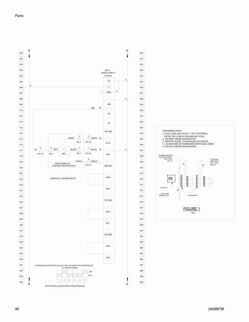
8 6
556
590
588
589
587
585
586
584
582
583
581
580
579
578
577
576
575
574
573
572
571
570
569
562
565
568
567
566
564
563
559
561
560
558
557
550
553
555
554
552
551
8
ANALOG INPUT/EXP-2
RA COM
IN B-
GND
RD COM
IN D+
IN D-
6
L+
M
RC COM
IN C+
IN C-
IN A-
RB COM
IN B+
22
6
IN A+
24
OUTPUT
PG-7
1
PG-7
2
PG-7
3
PG-7A
1
PG-7A
3
PG-7A
242
MO
VO
IO
6
6
23
CONFIGURE DIP SWITCHES ON EXP-2 FOR 10V SUPPLY AS SHOWN BELOW
DIP SWITCHES LOCATED INSIDE ANALOG MODULE
1 2 43 5 6
ON
OFF
2 & 6 ON AS SHOWN
STAR WASHERENCLOSURE
GROUND STUD
FIGURE 1NTS
TO GROUNDTERM. BLOCKMIN 14 AWGGRN/YEL
GROUNDING NOTES:1. PLACE LABEL 84/0130-26/11 "PE" AT EXTERNAL PROTECTIVE CONDUCTOR (GROUND STUD).2. NO PAINT UNDER GROUND STUD.3. REFER TO FIGURE 1 FOR GROUND STUD DETAIL..11. DO NOT WIRE TIE POWER WIRES WITH SIGNAL WIRES.12. DO NOT JUMPER GROUND WIRES.
SEE NOTE 1
PE
INCOMING GROUNDPROTECTIVE EARTH
MIN 14 AWGGEL/YEL
506
540
538
539
537
535
536
534
532
533
531
530
529
528
527
526
525
524
523
522
521
520
519
512
515
518
517
516
514
513
509
511
510
508
507
500
503
505
504
502
501
PG-7A
4
SEE 02/2980-4/25FOR PART IDENTIFICATION
8 6
LRT-1
BLACK
WHITE
RED BLACK
WHITE
RED
SHIELDSHIELD
JUMPER ALL UNUSED INPUTS

Parts
3A0987M 47
Micrometer and LRT Optional Customer Inputs
CUST START
CR-CS1
CR-CS2 CYCLE COMPLETE (CR-CS2): IN PUMP MODE-SHOT & DV MODE-AUTO, CHANGES STATE FOR "1" SECONDS AFTER THE RETRACT SWITCH IS TRIPPED.
(STANDARD CUSTOMER SIGNAL OUTPUTS DESCRIBED; CUSTOM PROGRAMMING AVAILABLE)
8
CUSTOMER START: IN ANY MODE, OPERATES IN PARALELL TO THE FOOTSWITCH.STARTPROVIDE A DRY CONTACT CLOSURE BETWEEN BLACK & WHITE WIRES ON THECUSTOMER SIGNAL CABLE TO ACTUATE MACHINE
Q0.4
Q0.532
31
6
6
READY TO DISPENSE SIGNAL (CR-CS1): IN PUMP MODE-SHOT & DV MODE-AUTO, CHANGES STATE WHEN PUMP IS RETRACTED AND LS-EXT IS TRIPPED.
CUSTOMER SIGNAL OUTPUT 1
28 30
33 34
CUSTOMER I/O CONNECTION CABLE (10FT LG)
81/1060-CS/25
BLU
ORG
RED
GRN
WHTBLKSTARTINPUT
PG-2
81 2
PG-2
11I0.0
8 11
CR-CS1
11 12
CR-CS1
11 14
CR-CS2
11 12
CR-CS2
11 14
CR-CS1
A1+ A2-
CR-CS2
A1+ A2-
2L8
Q0.329
Q0.227
Q0.126
PLC OUTPUTS
1L8
Q0.025
6
6
6
6
68
SOL
SOL
SOL
AA-1
3
PG-2
6
PG-2
4
PG-2
7
PG-2
2
PG-2
1
PG-2
PG-8
81
PG-8
PG-8
2
4
14I0.3
I0.213
12I0.1
INPUTSPLC-1
1M
6
6START
FS-1

Parts
48 3A0987M
Stepper Motor Driven Logic
BLU/W
HT
BLK/
WH
T
NO
TE: U
SE W
IRE
FERR
ULE
S O
N D
RIVE
CO
NN
ECTI
ON
S
ON8
SW-1
LO
CATE
D U
ND
ER D
RIVE
HO
USI
NG
C
LOSE
ST T
O D
RIVE
FAC
E
NO
TE: S
ET D
IP S
WIT
CHES
BEF
ORE
WIR
ING
DRI
VE
TRA
NS-
1 51
RED/B
LK
86
6PG
-2
DC
CON
TRO
L CO
ND
UC
TORS
WH
ERE
USE
D IN
CIR
CUIT
LIN
E, L
OA
D A
ND
CO
NTR
OL
CON
DU
CTO
RS A
T LI
NE
VOLT
AGE
AC C
ON
TRO
L CO
ND
UC
TORS
AT
LESS
TH
AN
150
VO
LTS
AC G
ROU
ND
ED N
EUTR
AL
LESS
TH
AN
150
VO
LTS
VOLT
AGE
FRO
M O
THER
SO
URC
ES (C
UST
OM
ER S
IGN
AL)
INTR
INSI
CALL
Y SA
FE W
IRIN
G
WIR
E CO
LOR
WH
ITE/
BLU
E
ORA
NG
E O
R YE
LLO
W
GRE
EN/Y
ELLO
W
LIG
HT
BLU
E
824
VDC
140
139
138
137
BLAC
K
DC
COM
MO
NG
ROU
ND
WH
ITE
BLU
E
RED
133
136
135
134
131
132
130
BLU
129
128
127
126
4
125
124
123
122
PLC-
1
8L+EX
P-1
52
34
1
67
89
L1PO
RT-1
+24V CA
B-1
IF1B
IF1AG
IF2
0V
24VD
C
179
178
177
VDC
COM
6
176
175
174
173
OFF
86 CO
MVD
C
OFF
ON
OFF
ON
1
ON
23
OFF
ON
OFF
65
47
169
172
171
170
WH
T/BL
U
167
168
166
PRO
GRA
MM
ING
GM
PORT
-0
52
34
1
67
89
GN
NO
TE: S
ET S
WIT
CHES
PRO
GRA
MM
ING
FO
R D
P/M
PI
6
2
165
164
163
162
161
160
159
158
PG-2
GRN
/BLK
6
8BL
U
PG-2
4
5BL
K
BLU
PX-U
P
BRN
PG-27
115V
XO
PB-2
STO
PEM
ERG
ENCY
CRM
34
118
121
120
119
116
117
115
CRM
1314
HM
I-1
8
XO
PB-10
0X
I
PB-1
A
810
11
14 A
WG
114
113
112
111
110
109
108
107
1L1
BLK
120V
TO
250
VAC
, 50-
60 HZ
NO
TE: V
OLT
AGE
TO B
E FA
CTO
RY S
ETAC
CORD
ING
TO
NA
MEP
LATE
AC-C
ON
N
N10
3
106
105
104
101
102
100
GL
(10
AM
P)L
FU-N
(10
AM
P)
FU-L
N
(4 AMP)
CB-1
6
CRM
56
W CRM
A1
A2
PL-1
12
POW
ERCO
NTRO
L
8
6
154
6
157
156
155
6
152
153
151
BLK
L+
120V
23
0V
PS-1
L1
24V
DC
M
N(L
2)
1L1
1L1
1L2
1L2
150
149
148
147
14 A
WG
1L2
146
145
144
143
6
GRN
/BLK
8
6BLU
6
5
PG-2
4
WH
T/BL
K
66
8W
HT
PG-2
PG-22
1
BLK
PX-D
NBL
U
BRN
6
PG-2
BLK
BLU
PX-H
OM
E
BRN
PG-23
(5 A
MP)
50
CB-2
RED
53
24VD
C
L2
L1
BD
L2
CBA5 7L1
230V
BLK
14 A
WG
142
141
120V
AC
8CO
MVD
C
L2
X4X2
H1
H3
X3
X1
H2
H4
7
L15
4M
GRE
EN
28
USE
81/
0056
-MC1
0S/1
1CO
NN
ECT
SHIE
LD T
O G
ROU
ND
SW-2
LO
CATE
D U
ND
ER D
RIVE
HO
USI
NG
C
LOSE
ST T
O D
RIVE
MO
UN
TIN
G F
ACE
ON
OFF
OFFON
12
OFF
ON
OFF
ON
34
56
T1
ON
ON
78
25-
LAST
USE
DW
IRE
TUBE
107
55
RED
ORA
NG
E
WH
ITE
BLAC
K
BLU
E
CLR
DISP1P0P1+
P1-
PO+
2726
P0-MM
+5V
LMT-
20
212522
FAU
LT - (E)
DIR
ECTI
ON
-
SHU
TDO
WN
+
SHU
TDO
WN
-
RESE
T -
23 24-
22-
20 21
-
19-
27 282625
17 18-
16
STEP
-14 1513
-
PG-D
RIVE
2120 242322 25
10 12 1311987
FAU
LT +
(C)
DIR
ECTI
ON
+
7 10
RESE
T +
12-
11
-
98--
22
4 6-
5-
3
--
2
16 1714 15 19185 64321
PIN
OU
T
AT D
RIVE
LOO
KIN
G
LED
S
AC P
OW
ER A
PPLI
EDN
O A
C PO
WER
SU
PPLI
ED
FAU
LT C
ON
DIT
ION
* D
RIVE
OVE
RTEM
PERA
TURE
* SH
ORT
CIR
CUIT
GRE
ENLE
D C
OLO
R: OFF
OFF
ON
RED
ON
ON
OFF
RED
50%
RED
UC
TIO
NEN
ABL
ED
2.60
AM
PS<3
2mH
S57-
102-
MO
-4%
3rd
HA
RMO
NIC
SERI
ES50
00
AN
TI-R
ESO
NA
NCE
:
CURR
ENT:
GA
IN:
AUTO
STA
ND
BY:
WIR
ING
CO
NFI
G:
RESO
LUTI
ON:
WAV
E FO
RM:
MO
TOR:
NO
TE:
1. U
SE 8
1/00
56-M
C10S
/11
MA
KE 1
0 FT
. 2
. CO
NN
ECT
SHIE
LD T
O G
ROU
ND
3. J
UM
PER
PIN
S 1
AN
D 2
ON
PA
NEL
SID
E O
F CO
NN
ECTO
R 4
. JU
MPE
R PI
NS
8 A
ND
9 O
N P
AN
EL S
IDE
OF
CON
NEC
TOR.
5. C
ABL
E FR
OM
PA
NEL
TO
PG
-5 T
O B
E 10
FEE
T. 6
. STR
IP M
OTO
R CA
BLE
TO S
HIE
LD A
ND
CLA
MP
TO
BA
CK P
AN
EL A
S SH
OW
N:
FIL-
1
GRA
Y
ZP
LMT+
3M
6196
RPS
2M
17616
1M
EXP-
1EM
-253
POSI
TIO
N
MO
DU
LE
STP
15 6
54
CRM
12
WH
T
LIN
E
55L
LOA
DN52
DRI
VE I/
O
B+ B-A+
A-
GN
D
21ST
EP +
1
GN
D5255
GN
D
CN-4
NL1
MO
TOR
DRI
VEPA
RKER
E-AC
DRI
VE-1
BRO
WN
ORA
NG
E
GRE
EN
BLAC
K
YELL
OW
5 PG-5
98
GRE
EN7
BLAC
K
WH
ITE
6W
HIT
E
2
RED
4
BARE
31
BLU
E
RED
BARE
M1

Parts
3A0987M 49
GRN
NO
TE:
OU
TPU
TS F
OR
CUST
OM
ER U
SE M
UST
BE
ISO
LATE
D W
ITH
REL
AYS
8+2
4VD
C
240
239
238
237
229
236
235
234
233
232
231
230
228
227
226
225
224
223
222
6CO
MVD
C
+24V
DC
280
279
278
8
I1.7
I1.6
I1.5
I1.4
I1.3
I1.2
I1.1
I1.0
270
277
276
275
274
273
272
271
Q0.
7
Q1.
0
Q0.
5
Q0.
6
269
268
267
266
265
264
263
Q0.
3
Q0.
42L
8
49
Q0.
1
Q0.
250
DIS
PEN
SE
PX-O
SV
PX-C
SVPG
-2
214
221
220
219
218
217
216
215
213
212
211
210
209
208
207
BRN
RELO
AD
RED/W
HT
CUST
STA
RT
206
205
204
203
88
PG-11
200
202
201
200
8
8
+24V
DC
PG-1
STA
RT
FS-1 8
8PG
-1BR
N
2
4
PG-2
I0.4 2MI0.7
I0.6
6
I0.5
ORG
/BLK
10W
HT
PG-2
31
I0.3
I0.2
255
262
261
260
259
258
257
256
Q0.
0
PLC
OU
TPU
TS
81LCU
ST S
S/FR
BIT
38
254
253
252
251
250
249
248
CUST
SS/
FR B
IT 1
CUST
SS/
FR B
IT 2
88
CUST
REL
OA
D8
STA
RT S
IGN
AL
SPO
OL
RELO
AD
POSI
TIO
N
BLU/B
LKW
HT
93029
I0.1
I0.01M
INPU
TSPL
C-1
6 6VDC
COM
+24V
DC
247
246
245
244
243
242
241
8
CUST
PU
RGE
STA
RT8
302
COM
VDC
6
15 PG-2
AUD
IO A
LARM
SOL-
OSV
14
PG-2
RED
BLK
AA
-1
6
ORG
6VA
LVE
SPO
OL
315
314
313
312
311
310
309
308
307
306
304
305
303
Q1.
328
7
I2.6
I2.7
37
I2.3
I2.5
I2.4
36353423
301
300
299
298
297
296
295
44
Q1.
741
42
294
293
292
291
289
290
288
24 40Q
1.6
Q1.
5
Q1.
448
I2.0
I2.1
I2.2
46
COM
VDC 6
PLC
OU
TPU
TS
286
285
284
+24V
DC 8
8
283
282
281
47
Q1.
2
Q1.
13L
SIG
NA
L
CR-2
A1
A2
CUST
OM
ER
CR-2
1114
45
CR-1
1114
43
6D
ISPE
NSE
REA
DY
SIG
NA
L
CR-1
A1
A2
6CU
STO
MER
DIS
PEN
SED
ON
E
SIG
NA
L
TIM
E TO
PURG
E
VDC
COM
6
CUST
OM
ER
29
POSI
TIO
NSP
OO
L D
ISPE
NSE
FLO
W R
ATE (M
M/S
EC) /
SH
OT
SIZE
(%)
CUST
OM
ER S
ELEC
T (0
=0FF, 1
=0N)
TABL
E 1
TOU
CH S
CREE
N C
ON
TRO
LLED
SHO
T SIZE
/ SP
EED
1SH
OT
SIZE
/ SP
EED
2SH
OT
SIZE
/ SP
EED
3SH
OT
SIZE
/ SP
EED
4SH
OT
SIZE
/ SP
EED
5SH
OT
SIZE
/ SP
EED
6SH
OT
SIZE
/ SP
EED
7
1 1 110 000
12.7
00 0 1 1
0 11
0 110
12.6
1 100
12.5
DIG
ITA
L IN
PUTS
ORG
ORG
ORG
ORG
SEE
TABL
E 1
SEE
TABL
E 1
SEE
TABL
E 1
OPE
N
CLO
SE
SPO
OL
VALV
ERE
D56
13 PG-2
SOL-
CSV
11
PG-2
RED
BLK
BLK
6
NO
NE
NO
NE
"A" L
OW
8 8"B
" LO
W
Z-LI
FTCO
NN
ECTE
D
"A" H
I
"B" H
I
NO
NE
NO
NE
NO
NE
NO
NE
NO
NE
NO
NE
NO
NE
NO
NE
NO
NE
STA
RT P
URG
E
RELO
AD
AA
NO
NE
NO
NE
NO
NE
NO
NE
NO
NE
FILL
"A" S
IDE
FILL
"B" S
IDE
NO
NE
OPE
N D
V
NO
NE
1053
ON
LY!
LEVE
L CO
NTR
OL
SWIT
CHES
A
RE N
OT
INCL
UD
ED W
ITH
TH
IS C
ON
TRO
L PA
CKAG
E.
SEE
TAN
K O
R FE
ED
ASS
EMBL
Y FO
R PA
RT ID
ENTI
FICA
TIO
N
PX-A
L4
PG-6
5
PG-6
BLK
BRN
6
326
PG-6
BLU
PX-B
L4
PG-7
BRN
5
PG-7
BLUBL
K33
7
PG-7
6
3
PG-7
6
3
PG-6
6
3938
PX-B
H
PX-A
H
1
PG-7
BRN
1
PG-6
BRN
2
PG-7
BLK
BLU
2
PG-6
BLUBL
K
88
B B B B
WIT
H L
EVEL
1053
VA
LVE
AD
D JU
MPE
RW
ITH
LEV
EL10
53 V
ALV
E
AD
D JU
MPE
RW
ITH
LEV
EL10
53 V
ALV
E
WIT
H L
EVEL
1053
VA
LVE
RED
WH
T
BLK
C
RED
WH
T
BLK
C CBL
K
WH
TRE
D
C
WH
TRE
D
BLK
C C

Parts
50 3A0987M
HO
USI
NG
CON
NEC
TOR
+ 24
VD
C5
8BL
U
LS-O
SV
SOL-
OSV
SOL-
CSV-
COM
MO
N
GRO
UN
D
SOL-
CSV-
SIG
NA
L
VDC
COM
MO
N
+ 24
VD
C
PX-D
N
PX-U
P
LS-C
SV
151412 1311
8
10
976
6GN
D
5631 65730819 20
GRN
/WH
T
ORG
GRN
BLK
RED
BLK/
WH
T
BLU
/WH
T
RED
/WH
T
BLU
/BLK
ORG
/BLK
PX-H
OM
E
VDC
COM
MO
N
VDC
COM
MO
N
+ 24
VD
C
USE
LCC
# 81
/009
5-15
/11
CABL
E A
ND
TH
E FO
LLO
WIN
G
COLO
R CO
DE
ON
TH
E SO
LDER
D-S
UB
CON
NEC
TOR
USA
GE
PG-2
2 43
PIN
# 1
Ø1/
16 X
3/8
"LG
HEA
T SH
RIN
KTU
BIN
G C
OVE
RIN
G A
LL S
OLD
ERJO
INTS
AS
SHO
WN
16 686
WIR
E #
WH
T/BL
K
RED
/BLK
GRN
/BLK
WIR
E CO
LOR
WH
T
F
GRO
UN
DIN
G N
OTE
S:1.
PLA
CE L
ABE
L 84
/013
0-26
/11
"PE"
AT
EXTE
RNA
L PR
OTE
CTI
VE.
CON
DU
CTO
R (G
ROU
ND
STU
D).
2. N
O P
AIN
T U
ND
ER G
ROU
ND
STU
D.
3. R
EFER
TO
FIG
URE
1 F
OR
GRO
UN
D S
TUD
DET
AIL
..9.
GRO
UN
D A
LL D
OO
RS10
. SH
IELD
CA
BLE
TO B
E CO
NN
ECTE
D A
T O
NE
EN
D T
O T
ERM
INA
L G
ROU
ND
.11
. DO
NO
T W
IRE
TIE
POW
ER W
IRES
WIT
H S
IGN
AL
WIR
ES.
12. D
O N
OT
JUM
PER
GRO
UN
D W
IRES
. SE
E FI
GU
RE 2
FIG
URE
1
STA
R W
ASH
ER
INCO
MIN
G G
ROU
ND
PRO
TEC
TIVE
EA
RTH
MIN
14
AWG
GEL
/YEL
STA
R W
ASH
ER
TO G
ROU
ND
STU
D O
N D
OO
RM
IN 1
4 AW
GG
RN/Y
EL
PE
SEE
NO
TE 1
TO G
ROU
ND
DIS
T. B
AR
SEE
FIG
URE
2M
IN 1
4 AW
GG
RN/Y
EL
NTS
FIG
URE
2
PLAC
E N
EAR
GRO
UN
D D
IST
BAR
84/0
130-
23/1
1
PE GROUND STUD GRN/YEL
GRO
UN
D D
IST.
BA
R
HMI GR/YEL
PLC-1 GRN/YEL
EXP-1 GRN/YEL
FIL-1 GRN/YEL
DRIVE-1 GRN/YEL
DRIVE-1 I/O SHLD
M1 SHLD
FS-1
ENCL
OSU
REG
ROU
ND
STU
D
NTS
VALVE
COLO
R
81/0
723/
1112
AWG
WIR
EPA
RT N
UM
BER
REFE
REN
CE W
IRE
FERR
ULE
CH
ART
SIZE
GRA
Y
14AW
G81
/072
2/11
BLU
E
16AW
G81
/072
4/11
BLAC
K
18AW
G81
/072
1/11
RED
20-2
2AW
G81
/072
0/11
WH
ITE
24AW
G81
/072
5/11
LT. B
LUE
NO
TE: U
SE L
EAD
FRE
E SO
LDER
125
78
13
1514
6
23
4
9
1110
1
1414106
107
1 53
42
12
SOL-
OSV
SOL-
CSV
(B)
(A)
(B)
(A)
FL-1
1/2"
DIA
80 P
SIG
PLA
NT
AIR
100
YEL
GRN
SPO
OL
VALV
E
MF-
1
MF-
2
NO
TE: F
ILTE
R SU
PPLI
ED B
Y CU
STO
MER
SOL-
OSV
100EA EBP
A B 106
107
GRN
YEL
DV-
1
CLO
SE
VALV
ESP
OO
L
OPE
N
1053
PD
NO
TE: F
ILTE
R SU
PPLI
ED B
Y CU
STO
MER
FL-1
1/2"
DIA
80 P
SIG
PLA
NT
AIR 10
0
MF-
2
MF-
1
7
NU
MBE
RPI
N U
SAG
E
4 5 62 3PIN 1
PG-6
'A' T
AN
K LE
VEL1
2
34
5
6K
8 38 6 8 32 6KE
Y
FREE
HA
NG
ORG
10 1412 131197 85 64
NU
MBE
R
2 31PIN
PIN
USA
GE
PG-5
MO
TOR1
23
45
67
89
1011
1213
14
JUM
PER1
JUM
PER1
BARE
RED
BLAC
KW
HIT
EG
REEN
JUM
PER2
JUM
PER2
---
---
---
---
---
BLU
RED
WH
T
---BL
K
BRN
COLO
R
BRO
WN
BLU
E
GRN
/YEL
---
COLO
RPI
N U
SAG
E
4
NU
MBE
R
2 31PIN
PG-1
STA
RT O
PTIO
NS
1
2K
4
8 29 KEY
GN
D
IN B
OX
FREE
HA
NG
7
NU
MBE
RPI
N U
SAG
E
4 5 62 3PIN 1
PG-7
'B' T
AN
K LE
VEL1
2
34
5
K6
8 39 6 8 33 KEY 6
FREE
HA
NG
---W
HT
RED
BLU
ORG
BRN
COLO
R
BLK
15
8
1310
41 9
32
1112
6 14
75
TRANS-1 NEUTRAL GND
(DIS
PEN
SE)
(REL
OA
D)
(DIS
PEN
SE)
OPE
N
(REL
OA
D)
CLO
SE

Parts
3A0987M 51

All written and visual data contained in this document reflects the latest product information available at the time of publication. Graco reserves the right to make changes at any time without notice.
Original instructions. This manual contains English. MM 3A0987
Graco Headquarters: MinneapolisInternational Offices: Belgium, China, Japan, Korea
GRACO INC. AND SUBSIDIARIES • P.O. BOX 1441 • MINNEAPOLIS MN 55440-1441 • USA
Copyright 2011, Graco Inc. All Graco manufacturing locations are registered to ISO 9001.www.graco.com
Revision M, January 2017
Graco Standard WarrantyGraco warrants all equipment referenced in this document which is manufactured by Graco and bearing its name to be free from defects in material and workmanship on the date of sale to the original purchaser for use. With the exception of any special, extended, or limited warranty published by Graco, Graco will, for a period of twelve months from the date of sale, repair or replace any part of the equipment determined by Graco to be defective. This warranty applies only when the equipment is installed, operated and maintained in accordance with Graco’s written recommendations.
This warranty does not cover, and Graco shall not be liable for general wear and tear, or any malfunction, damage or wear caused by faulty installation, misapplication, abrasion, corrosion, inadequate or improper maintenance, negligence, accident, tampering, or substitution of non-Graco component parts. Nor shall Graco be liable for malfunction, damage or wear caused by the incompatibility of Graco equipment with structures, accessories, equipment or materials not supplied by Graco, or the improper design, manufacture, installation, operation or maintenance of structures, accessories, equipment or materials not supplied by Graco.
This warranty is conditioned upon the prepaid return of the equipment claimed to be defective to an authorized Graco distributor for verification of the claimed defect. If the claimed defect is verified, Graco will repair or replace free of charge any defective parts. The equipment will be returned to the original purchaser transportation prepaid. If inspection of the equipment does not disclose any defect in material or workmanship, repairs will be made at a reasonable charge, which charges may include the costs of parts, labor, and transportation.
THIS WARRANTY IS EXCLUSIVE, AND IS IN LIEU OF ANY OTHER WARRANTIES, EXPRESS OR IMPLIED, INCLUDING BUT NOT LIMITED TO WARRANTY OF MERCHANTABILITY OR WARRANTY OF FITNESS FOR A PARTICULAR PURPOSE.
Graco’s sole obligation and buyer’s sole remedy for any breach of warranty shall be as set forth above. The buyer agrees that no other remedy (including, but not limited to, incidental or consequential damages for lost profits, lost sales, injury to person or property, or any other incidental or consequential loss) shall be available. Any action for breach of warranty must be brought within two (2) years of the date of sale.
GRACO MAKES NO WARRANTY, AND DISCLAIMS ALL IMPLIED WARRANTIES OF MERCHANTABILITY AND FITNESS FOR A PARTICULAR PURPOSE, IN CONNECTION WITH ACCESSORIES, EQUIPMENT, MATERIALS OR COMPONENTS SOLD BUT NOT MANUFACTURED BY GRACO. These items sold, but not manufactured by Graco (such as electric motors, switches, hose, etc.), are subject to the warranty, if any, of their manufacturer. Graco will provide purchaser with reasonable assistance in making any claim for breach of these warranties.
In no event will Graco be liable for indirect, incidental, special or consequential damages resulting from Graco supplying equipment hereunder, or the furnishing, performance, or use of any products or other goods sold hereto, whether due to a breach of contract, breach of warranty, the negligence of Graco, or otherwise.
FOR GRACO CANADA CUSTOMERSThe Parties acknowledge that they have required that the present document, as well as all documents, notices and legal proceedings entered into, given or instituted pursuant hereto or relating directly or indirectly hereto, be drawn up in English. Les parties reconnaissent avoir convenu que la rédaction du présente document sera en Anglais, ainsi que tous documents, avis et procédures judiciaires exécutés, donnés ou intentés, à la suite de ou en rapport, directement ou indirectement, avec les procédures concernées.
Graco InformationSealant and Adhesive Dispensing Equipment
For the latest information about Graco products, visit www.graco.com.For patent information, see www.graco.com/patents.
TO PLACE AN ORDER, contact your Graco distributor, go to www.graco.com and select “Where to Buy” in the top blue bar, or call to find the nearest distributor.
If calling from the US: 800-746-1334If calling from outside the US: 0-1-330-966-3000
Related Documents


