Meta Imaging Series ® MetaMorph Basic Commands Version 7.0 for Microsoft Windows XP ® User’s Guide 1020 2101-03

Welcome message from author
This document is posted to help you gain knowledge. Please leave a comment to let me know what you think about it! Share it to your friends and learn new things together.
Transcript

Meta Imaging Series®
MetaMorphBasic Commands
Version 7.0 for Microsoft Windows XP®
User’s Guide
1020 2101-03

ii

iii
Copyrights, Notices, and Trademarks
© 2004 – 2006 Molecular Devices Corporation. All rights reserved. Printed in the U.S.A. Information in this document is subject to change without notice and does not represent a commitment on the part of Molecular Devices Corporation. The software described in this document, including information contained in any databases, is furnished under a license agreement and may be used or copied only in accordance with the terms of the agreement. It is illegal to copy the software, except as specifically allowed in the license agreement. No part of this manual may be reproduced or transmitted in any form or by any means, electronic or mechanical, including photocopying and recording, for any purpose, without the express written permission of Molecular Devices Corporation. MetaMorph and ImageXpress are registered trademarks and Discovery-1, MetaXpress, MDCStore and ImageXpress Micro are trademarks of Molecular Devices Corporation. All other trademarks are the property of their respective owners. Disclaimer Molecular Devices Corporation reserves the right to change its products and services at any time to incorporate technological developments. This user guide is subject to change without notice. Although this user guide has been prepared with every precaution to ensure accuracy, Molecular Devices Corporation assumes no liability for any errors or omissions, nor for any damages resulting from the application or use of this information.

iv

MetaMorph 1 Version 7.0
Table of Contents
Navigating the MetaMorph Online Help System 13
Help Menu Overview 13
Updates History (Help Menu) 14
About MetaMorph (Help Menu) 14 Creating a System Report – Use these procedures to generate the System Report as a text file or to print the System Report…………………..16
Using the Window Menu (Window Menu) 17
Toolbars (Window Menu) 19
History Window (Window Menu) 19
Using the History Window 20
Dialog Boxes 21
Working With Graphs 23
Graphs - Print Settings 24
Graphs - Copy Graphs to Image 25
Graphs - Save Graph as Bitmap 26
Graphs - Show Graph Data 27
Graphs - Point Statistics 28
Graphs – Zoom In/Out 28
Image Selectors 30
Image Selector Structure for Single Commands 31
Image Selector Structure for Journals 31 How Source Images Are Represented ................................................ 32 How Destination Images Are Represented ........................................ 32 How Images Are Represented During Journal Editing ..................... 34 How Images Are Represented During Playback................................ 34

Basic Commands
MetaMorph 2 Version 7.0
Keyboard Shortcuts 36
Menu Shortcuts 36
Window Menu Toolbars 37
Standard Toolbar 38
Region Tools 40
Overlay Toolbar 41
Stack Toolbar 41
Display Toolbar 42
Devices Toolbar 43
File Toolbar 44
Basic Acquisition Toolbar 45
Living Cell Toolbar 46
Fluorescence Toolbar 47
Color Photography Toolbar 48
Process Toolbar 48
Binary Toolbar 49
Arithmetic and Stack Arithmetic Toolbars 50
Transmitted Light Toolbar 50
Color Toolbar 50
Measure Toolbars 51
Journal Control Toolbar 52
Apps Toolbar 53
Journal Toolbar 54
Taskbar Toolbar 54
Variables Toolbar 55
Device Control Toolbar 55
Region Toolbar 56

Basic Commands
MetaMorph 3 Version 7.0
Image Window Tools 57 Image Window............................................................................................... 57 Image Tools Descriptions .............................................................................. 58
Stack Player (Image Window Tools) 59
Play Preferences 60
Zoom Tool (Image Window Tools) 61
Histogram Tool 62
Color Histogram Tool (Image Window Tools) 63
Drawing Graph Using LUT Colors 65 Color Space Models ......................................................................................69

Basic Commands
MetaMorph 4 Version 7.0
Display Mode Tool (Image Window Tools) 71
Visible Spectrum 72
Contrast Tool and Slider (Image Window Tools) 75
Threshold Tool and Slider (Image Window Tools) 76
Scale Tool and Scale Slider (Image Window Tools) 79
Using the Scale Tool 80
Selecting a Range 80
Scaling Within an Active Region 80
Using the Scale Slider 81
Histogram Bar (Image Window Tools) 81
Color Channel Toggles (Image Window Tools) 81
Color Channel Selector (Image Window Tools) 81
Plane Slider Error! Bookmark not defined.
ReverseReverse one plane Error! Bookmark not defined.
Image Browser (File Menu) 83
Using the Image Browser 84
Navigating and Opening Images 84
Moving and Resizing the Image Browser 85
Viewing Playback of Stack Thumbnails 86
Directory Path 86
Directory Tree 86
Thumbnail Window 86
Thumbnail Stack Player 87
Build Catalog 87
Build Catalog - Dialog Box Options 87

Basic Commands
MetaMorph 5 Version 7.0
Overlay Tool (Image Window Tools) 88
New (File Menu) 89
Open (File Menu) 90
Build Stack (File Menu) 92
Open Previous (File Menu) 97
Open Next (File Menu) 97
Browse Disk Images (File Menu) 98
Import (File Menu) 99
Open Multi Dimensional 101
Build Multi Dimensional 102
Close (File Menu) 108
Close All (File Menu) 109
Save (File Menu) 110
Save As (File Menu) 111 Saving a JPEG File: ............................................................................112
Basic Commands
MetaMorph 6 Version 7.0
Save Partial As (File Menu) 113
Revert to Saved (File Menu) 114
Setup Sequential File Names (File Menu) 115
Save Using Sequential File Name (File Menu) 117
Transfer Image 117
Find Images (File Menu) 119
Rename Image (Edit Menu) 138
Annotate Image (Edit Menu) 139
Image Info (Edit Menu) 140
Print (File Menu) 143
Print Stack (File Menu) 147
Run Program (File Menu) 147
Exit (File Menu) 149
Recent Files List (1...6) (File Menu) 151
Undo (Edit Menu) 151
Redo (Edit Menu) 152
Copy (Edit Menu) 153
Paste (Edit Menu) 153
Duplicate Image (Edit Menu) 154
Duplicate Plane (Edit Menu) 155
Duplicate Stack (Edit Menu) 155
Duplicate Image with Zoom (Edit Menu) 156
Duplicate Stack with Zoom (Edit Menu) 157
Region Tools (Regions Menu) 158
Load Regions (Regions Menu) 158
Save Regions (Regions Menu) 159
Clear Regions (Regions Menu) 160

Basic Commands
MetaMorph 7 Version 7.0
Transfer Regions (Regions Menu) 161
Move All Regions (Regions Menu) 162
Preferences (Edit Menu) 164
Configure Default Paths (Edit Menu) 171
Region Tool Properties 172
Locator Tool (Region Toolbar) 175
Rectangular Region Tool (Region Toolbar) 178
Ellipse Region Tool (Region Toolbar) 179
Trace Region Tool (Region Toolbar) 180
Single Line Tool (Region Toolbar) 182
Multi-Line Tool (Region Toolbar) 183
Traced Line Tool (Region Toolbar) 184
Auto-Trace Region Tool (Region Toolbar) 186
Join Drawing Tool 188
Cut Drawing Tool (Overlay Tools) 188
Color Threshold Mapping Tool 189
Color Threshold Unmapping Tool (Region Tools) 190
Clear Overlay Tool (Region Tools) 191
Overlay Properties 192
Create Region (Region Menu) 194
Select Plane (Stack Menu) 196
Add Plane (Stack Menu) 197

Basic Commands
MetaMorph 8 Version 7.0
Remove Plane (Stack Menu) 199
Play Images from Disk (File Menu) 200
Montage (Stack Menu) 205
Align Stack (Stack Menu) 208
Movie (Stack Menu) 211
Set Acquisition Channel 213
Device Control (Devices Menu) 214
Device Control - Dialog Box Options 214
Device Control - Control Dialog Box Options 214
Device Control - Configure Dialog Box Options 215
Using the Device Control Command 216
Configure Magnification 217
Configure Magnification - Dialog Box Options 217
Configuring Magnification 218
Creating Magnification Settings 218
Deleting Magnification Settings 220
Configure Illumination 220
Deleting Illumination Settings 221
Focus (Devices Menu) 223
Configure Laser Autofocus 231
Stage (Devices Menu) 237
Move Stage to Absolute Position (Devices Menu) 243
Move Stage to Relative Position (Devices Menu) 246
Move Stage to Position of Image (Devices Menu) 248
Scan Stage (Devices Menu) 250
Scan Multi-Well Plate (Devices Menu) 252
Basic Commands
MetaMorph 9 Version 7.0
Database Connection 255 Drop-in: HTDB_PLAYER................................................................................................256
Laser Control (MicroPoint™ Laser) 258
Calibration Bar (Display Menu) 265
Date/Time (Display Menu) 268
Clear Measurement Stamps (Measure Menu) 270
Color Combine (Display Menu) 271
Color Separate (Display Menu) 274
Intensity Profile (Display Menu) 275
Deinterlace (Display Menu) 277
Rotate (Display Menu) 279
Paint Region (Display Menu) 280
Log Data (F9) (Log Menu) 282
Annotate Log File (Log Menu) 283
Label Logged Data (Log Menu) 285
View Log File (Log Menu) 286
Set Logging Row and Column (Log Menu) 288
Configure Logging Timestamp (Log Menu) 297
Open Data Log (Log Menu) 299 Additional Information about DDE ...............................................................299
Additional Information About DDE: ..............................................................................300 Using a New Microsoft Excel Worksheet .................................................... 300 Using a Microsoft Excel Worksheet Other Than the Default....................... 300 Creating a DDE Link to Lotus 1-2-3, Borland Quattro Pro, or MicroCal Origin301 Linking to Another Application..................................................................... 301

Basic Commands
MetaMorph 10 Version 7.0
Close Data Log (Log Menu) 303
Pause Data Logging (Log Menu) 303
Resume Data Logging (Log Menu) 303
View Current Data Log (Log Menu) 304
Configure Log 304
An Introduction to Automatic Object Analysis 306
Calibrate Distances (Measure Menu) 307 Calibrating Distances - Menu ......................................................................307
Calibrate Gray Levels (Measure Menu) 313 Calibrate Gray Levels - Dialog Box Options................................................ 315
Assign Time Reference (Measure Menu) 317
Configure Object Standards (Measure Menu) 318 Drop-in: AUTOMEAS or IMA..........................................................................................318
Show Region Statistics (Measure Menu) 320
Region Measurements (Measure Menu) 323
Measure Pixel (Measure Menu) 331
Measure Distance 332
Linescan (Measure Menu) 333
Segmented Histogram (Measure Menu) 336
Manually Count Objects (Measure Menu) 342 Measure List ................................................................................................344

Basic Commands
MetaMorph 11 Version 7.0
Area Measurement Terms 345
Dimension Measurement Terms 347
Shape, Position, and Orientation Measurement Terms 349
Circular Measurement Terms 351
Elliptical Fourier Analysis Measurement Terms 355
Intensity Measurement Terms 355
Gray Level Texture Measurement Terms 357
Optical Density Measurement Terms 358
Adjust Digital Contrast (Display Menu) 362
Scale Image (Display Menu) 368
Contrast Shortcuts (Display Menu) 372
Threshold Image (Measure Menu) 373
Sharpen (Legacy) 381
Low Pass (Legacy) 383
Detect Edges (Process Menu) 385
Unsharp Mask (Legacy) 388
Median Filter (Legacy) 391
Edit Kernel (Process Menu) 393
Binary Operations (Process Menu) 396
Binary - Dialog Box Options 409
Arithmetic (Process Menu) 410
Stack Arithmetic (Process Menu) 414
Flatten Background (Legacy) 416
Correct Shading (Legacy) 418
Background and Shading Correction (Process Menu) 420
Background and Shading Correction Procedure - Subtract Background 421
Basic Filters (Process Menu) 426

Basic Commands
MetaMorph 12 Version 7.0
Basic Filters - Low Pass 426
Basic Filters - Median 428
Basic Filters - Rank 428
Basic Filters - Remove Haze 430
Basic Filters - Sharpen 433
Basic Filters - Unsharp Mask 434
Stopwatches (Journal Menu) 443
Define Stopwatch Sequences (Journal Menu) 445
Index of Journal Functions 447
.....................................................................................................................447 Statistical Measurement Terms 500
Data Graph Types Used in MetaMorph 503
Glossary of Terms Error! Bookmark not defined.
Error! Bookmark not defined.

Basic Commands
MetaMorph 13 Version 7.0
Navigating the MetaMorph Online Help System If you have used a Windows-based online Help system before, you will find the MetaMorph online Help familiar and easy to use. If you have never used a Windows Online Help system, from the Help menu, click Help on Help to review Microsoft’s instructions, How to use Help. Then, read the following paragraphs about using MetaMorph Help.
Using MetaMorph Help Most commands listed in MetaMorph's online Help have three types of Help pages--a Summary page, a Procedure page, and a Dialog Box Options page.
F1 and
Press the F1 key to see context sensitive help for the active dialog box. After you press F1 to view the topic introduction on the Summary page, click the See Also button at the top of the Help window. A drop-down list will open from which you can see a list of all topic pages for your selected topic. Choose either the appropriate Dialog Box Options topic or the Procedure topic for your currently active dialog box. Each time a different dialog box becomes active, you can press F1 and click See Also for new topic information.
Use the other buttons in the button bar to navigate MetaMorph Online Help.
• Click the Browse buttons (<< and >>) to page through topics that are on the same level in the Online Help.
• Click the Help Topics button to alternately activate or deactivate the Help Topics window, which contains the complete MetaMorph Help Table of Contents organized in a hierarchal structure.
• Click Back button to navigate backwards through the topics that you have visited in the current Help session.
• Click Print to print the current Help topic page.
Help Menu Overview The Help menu provides access to MetaMorph’s online Help program, as well as support options and information about your version of MetaMorph. The following choices are available:
Help Topics – Opens the MetaMorph Help program.
Help on Current Function – Provides help on the active dialog box.
Help on Help – Contains instructions on using online help.
Molecular Devices Support Online – Opens your default web browser to the Molecular Devices Online Support homepage. Use the Support page to access the latest technical documents and hardware information.
Meta Series Updates - Online – Opens your default web browser to the Molecular Devices Meta Series Updates login page. Use your System ID to login to the Meta Series Updates web site and download the latest update to the current shipping version of Meta Imaging Series software.

Basic Commands
MetaMorph 14 Version 7.0
Note: You must have a valid Maintenance Plan to login to the Meta Series Updates web site.
Updates History – Displays a history of all of the updates that have been downloaded to your imaging system.
About MetaMorph – Opens the About MetaMorph dialog box.
Updates History (Help Menu) Displays a history of all of the updates that have been downloaded to your imaging system.
Use this command to read a list of the updates and program "patches" that have been downloaded to the imaging program. The Updates History dialog box displays a table listing the update or patch ID code, the date it was created, and the date it was installed on the computer.
EXAMPLE: "T10148,01/01/98,03/05/98" indicates that a patch with the code "T10148" and having a creation date of January 1, 1998, was installed on March 5, 1998.
Reading Your Updates History To read a list of the updates and patches that you have downloaded to your imaging system, use the following procedure:
Step Action
1 From the Help menu, choose Updates History. The Updates History dialog box will appear.
2 The dialog box displays a table that lists all updates and patches that have been installed.
EXAMPLE: "T10148,01/01/98,03/05/98" indicates that a patch with the code "T10148" and having a creation date of January 1, 1998, was installed on March 5, 1998.
3 When you have finished reading the list, choose OK to close the dialog box.
Updates History - Dialog Box Options
History Table Displays a list of all updates and patches that have been installed.
OK Closes the dialog box.
About MetaMorph (Help Menu) Contains version and license information about your copy of MetaMorph.
Use this command to view version and license information about your copy of MetaMorph, including dates and version numbers of various system components. This information can be printed to a System Report that can be sent to Molecular Devices Technical Support to assist in diagnosing your system.

Basic Commands
MetaMorph 15 Version 7.0
The System Report can be printed on a printer connected to your system or a network printer, or it can be "printed" to an ASCII text file. You can send this report to appropriate MDC support personnel as an E-mail attachment, or fax the printed document to MDC support personnel.
The following information is included in the System Report:
System User Name – The name of your company or organization.
System ID – Your assigned system ID number.
MetaMorph version number and date – The current version number of MetaMorph/MetaXpress that you have installed.
System Components – This information includes the name of the .dll file that creates a specific installed component, the version number of the component, and the date that the .dll file was generated.
MMADMIN.INI file – This file contains the Meta Imaging Series Administrator settings for groups, users, and hardware configurations that you have defined.
UICSHELL.INI file – This file contains user license information and other setting information.
UICDrvr.INI file – This file contains all the device settings for Illumination, Wavelength, Intensity (Neutral Density), Stage, Z-motor (focus), and Shutter, as well as specific settings for HCS/MetaXpress including objective offsets and Z-motor parameters.
DEFAULTS.INI file – This file contains the MetaMorph default paths and file locations.
DROPINS.INI file – This file contains a list of all the currently selected Drop-in modules.
LOG.INI file – This file contains settings needed to enable MetaMorph to transfer log file data to external applications such as Microsoft Excel, Lotus 123, and Quattro Pro.
UICTOOLS.INI file – This file contains the initial setting information that MetaMorph transfers to Microsoft Windows for cursor and video preferences.
About MetaMorph - Dialog Box Options
Main field Contains the version number of MetaMorph, as well as copyright and patent information.
Licensed to Lists user information and System ID. This is the information you entered when you installed MetaMorph.
Component Tables Contains version numbers and dates of various system components.
More>>/Less<< Expands (maximizes) or reduces (minimizes) the dialog box.
Help Opens the MetaMorph Online Help program.
License Opens the MetaMorph software license agreement

Basic Commands
MetaMorph 16 Version 7.0
Close
Closes the dialog box.
Your Name Type the name to be used in the From field of the printed report cover sheet.
Your Phone Type the phone number to be used in the From field of the printed report cover sheet.
Your Fax Number Type the fax number to be used in the From field of the printed report cover sheet.
Print Report Prints a report containing your system information. The cover sheet contains the phone and fax numbers of MDC Technical Support and the contact information you entered above.
System Report Procedures Use the following procedures to create a System Report to send to MDC Technical Support:
Configuring a Generic Text, Print-to-file Printer Driver – Complete this procedure if you want to send a ASCII text file of the report as an E-mail attachment and do not have a generic text, print-to-file printer driver installed on your system. Creating a System Report – Use these procedures to generate the System Report as a text file or to print the System Report.
Configuring a Generic Text Print-to-file Printer Driver Use the following procedure to configure a generic text, print-to-file printer driver on your system:
Step Action
1 To define a printer, from the Windows Start button, select Settings > Printers, then select Add Printer. The wizard will guide you through the process.
2 In the Add Printer Wizard on the Local or Network Printer page, select Local Printer and uncheck Automatically detect and install my Plug and Play printer. Click Next.
3 On the Select the Printer Port page, click Use the following port and select FILE: Print to File from the list of available ports. Click Next.
4 On the Add Printer Wizard page, select Generic as the Manufacturer and select Generic/Text Only. Click Next.
5 On the Name Your Printer page, use Generic/Text Only as the printer name, and do not select it as the default printer. Click Next.
6 On the Printer Sharing page, select Do not share this printer. Click Next.
7 On the Print Test Page, select No for Do

Basic Commands
MetaMorph 17 Version 7.0
you want to print a test page? Click Next.
8 On the final page of the wizard, the complete configuration that you specified for your printer is shown. Click Finish if the configuration is correct.
Creating a System Report Complete the following steps to generate a MetaMorph System Report to a text file:
Step Action
1 From MetaMorph, click Help>About MetaMorph. The About MetaMorph dialog box opens.
2 Click on the More button. The dialog box expands.
3 In the fields provided, type your name, phone number, and fax number, then click Print Report. The Print Setup dialog box opens.
4 In the Printer Name box, select Generic/Text Only, and click OK. The Print to File dialog box opens.
5 Type the complete path and file name for the text file to which you want to record your system log. For example:
C:\Documents\MM Reports\ Systemreport_061202.txt
Then click OK.
Note: You must include the .txt extension to the end of the file name in order to view it in a text browser.
6 Using Windows Explorer, locate the file and double click on the file name to open it.
Complete the following steps to print the MetaMorph System Report: Step Action
1 From MetaMorph, click Help>About MetaMorph. The About MetaMorph dialog box opens.
2 Click on the More button. The dialog box expands.
3 In the fields provided, type your name, phone number, and fax number, then click Print Report. The Print Setup dialog box opens.
4 In the Printer Name box, select the printer you want to print to and click OK.
Using the Window Menu (Window Menu) The Window menu provides a list of images and dialog boxes that are currently open on

Basic Commands
MetaMorph 18 Version 7.0
the MetaMorph desktop, either as windows or minimized as icons. As a window management tool, the Window menu enables you to switch between images or dialog boxes quickly or to determine which image is active.
The Window menu marks the active image and dialog box in its list with check marks. The active taskbar will also be displayed. If you want to change the desktop "focus" to a different image or dialog box, or bring the active taskbar to the "front," select its name from the Window menu. MetaMorph will bring the image, dialog box, or taskbar to the front, changing its title bar to the color used to designate the active window. If an image, dialog box, or taskbar is an icon (minimized), it will be restored to a full-sized window first. MetaMorph will then place a check mark next to the entry for that image or dialog box in the Window menu.
The status of the command icon Toolbar is also indicated in the Window menu. The Toolbar can be hidden and unhidden by successively clicking its entry in the Window menu.
Note: Some dialog boxes are "modal"; that us, they must be closed before you can invoke any other program functions. This will prevent you from being able to use the Window menu, or any other, while that dialog box is open.
The number of images that appear in the Window menu is determined by the number of images currently open, which depends in turn on the amount of working memory (RAM) in your computer.
How Images Are Named
These images: Are named…
Result images from commands
Using a combination of the command and the original image name.
EXAMPLE: Sharpen Low BEADS
Result images from duplicating commands
As copies.
EXAMPLE: Copy of BEADS
Images with the same name as existing open images
Using the original file name and a number.
EXAMPLE: BEADS-2
Arranging Image Windows
Image placement is controlled through the Preferences dialog box (Windows tab page). Overlay at Top Left Corner places the new or opened images on top of each other, starting at the top left corner of the screen. Cascade from Top Left Corner cascades the images starting at the top left corner of the screen. Cascade from Current Image cascades the images starting from the current image.
Newly loaded or created images will not be placed outside of the viewing area when MetaMorph cascades images from previous images. MetaMorph senses the edge of the screen and shifts the next image opened to another part of the desktop.
Determining How Many Images Can Be Loaded into MetaMorph
The number of image files that can be loaded at one time depends on your computer's available memory. The Get Info command (File menu) will display a dialog box that lists how much memory an image uses. The status bar at the bottom of the MetaMorph workspace lists the remaining amount of memory which can be used to store images.

Basic Commands
MetaMorph 19 Version 7.0
Toolbars (Window Menu) Displays or hides MetaMorph Toolbars.
Use this command to display or hide toolbars. After you have hidden a toolbar using this command, you can display it again by rechoosing the Toolbar command. A check mark next to the toolbar name indicates that the toolbar has been enabled. When you hide the toolbar, the check mark will disappear.
The MetaMorph Toolbars provide quick access to frequently used menu commands. You can also access these commands directly from their associated menus.
Displaying and Hiding MetaMorph Toolbars To toggle the display of MetaMorph Toolbars, use the following procedure:
Step Action
1 Select the Window menu.
2 Click Toolbars. A sub-menu containing a list of available toolbars opens.
3 Click the toolbar that you want to use. The toolbar opens, and a check appears next to the name of the tool bar that you opened.
4 To close a toolbar, click on the name of the tool bar on the Toolbar sub-menu, or if the toolbar is not docked, click on the close icon in the toolbar title area.
History Window (Window Menu) Records history of commands issued in current session of MetaMorph.
Use the History Window to log a sequential list of commands run in MetaMorph, as illustrated below:

Basic Commands
MetaMorph 20 Version 7.0
The History Window logs any command that can be recorded in a Journal. The results can then be saved to a text file that is a useful reference of commands for a given session. For example, you can use this information to help create a journal based on the commands of a prior session. Recording history ensures that your past work in MetaMorph can be recreated. History files are also helpful when calling for technical support.
The History Window is cleared when you exit MetaMorph — history does not carry over to the next session. Use the Save As command if you need to save the history of the active session.
Note: If history recording is enabled and MetaMorph closes unexpectedly, you will have the option of saving the command history file the next time you start MetaMorph.
Using the History Window The following procedures are used with the History Window:
Step Action
1 From the Window menu, click Show History Window. The History Window opens.
2 Select Start Recording History to begin recording
Or
Click Start Recording History from the Window menu to begin recording.
Note: The History window does not have to be open to start recording.
3 Select Stop Recording History to stop recording
Or
Click Stop Recording History from the Window menu to stop recording.
4 To clear the History Window, click Clear.
5 To save the history to a text file, click Save As. The Save Command History File dialog box opens. Type or select the name to which you want to save the history file and click Save.
6 To close the History Window, Click Close
Or
Click Hide History Window from the Window menu.
Note: If Start Recording History is selected, closing the History Window will not stop recording history of the active session.

Basic Commands
MetaMorph 21 Version 7.0
Dialog Boxes Dialog boxes are displayed in MetaMorph whenever it is necessary to request information about a command or task to be performed or to supply you with information.
Commands which display a dialog box are marked with an ellipsis (". . .") in their respective MetaMorph menus. An ellipsis is also used on command buttons in dialog boxes that open secondary dialog boxes.
Most MetaMorph dialog boxes use options and command buttons that are similar to those used in most Windows-based programs. An option can be selected by positioning the pointer over it and clicking the left mouse button. If you want to use the keyboard, you can press the [TAB] key to move forward (left to right, top to bottom) to the next area within the dialog box. The cursor (arrow) keys can be used to move between options inside a group box.
Typical Dialog Box Options
Dialog boxes often have an OK button, a Close button, or another command button that closes the dialog box while completing the command. Some, however, use the Close button found in the dialog box's upper right corner. Clicking the Close button automatically closes the dialog box. To cancel a command, choose Cancel from the dialog box or press the [ESC] key.
Selecting Files from Standard Dialog Boxes That Open and Save Files
Many MetaMorph dialog boxes that open and save files share a design common to most Windows-based applications. Once you have learned how to use these options for one dialog box, such as the one used by the Open command, you will have learned how use the options for many dialog boxes.
Selecting the Drive
Click the Look In list at the top of the dialog box to open its drop-down list. If you don't see the desired drive letter and name, drag the scroll box until you see it in the drop-down list. Click anywhere on the drive name so that it is highlighted.
Selecting the File's Directory
If you don't see the icon for the desired file in the currently displayed folder, click the Up One Level icon button, which has the icon of a manila folder with a superimposed arrow pointing up. This will bring you up one level in the directory structure. You can repeat this step, if necessary, and can even use it to select a different drive. If you need to go down a level, find the icon for the pertinent subdirectory in the collection of currently displayed icons, and then choose Open. The DOS single period (" . ") and double period (" .. ") can be typed in the File Name text box to specify directories that are secondary to the currently selected folder or that are secondary to the current folder's parent folder, respectively. If you need to create a new folder (directory), choose the Create New Folder icon button, which looks like a manila folder with rays of light emanating from it. Then type a name for the new folder in the text box that appears next to the new folder's icon.
Selecting the File Type

Basic Commands
MetaMorph 22 Version 7.0
If there many files in the folder, you may want to limit the display of files in the file table to one particular type. Click the Down Arrow for the Files of Type list to open its drop-down list. If you don't see the desired file type, drag the scroll box until you see it in the drop-down list. Click anywhere on the file type name so that it is highlighted.
When you are saving images, you will need to select a file type. However, for many types of files in MetaMorph, the default file type associated with that kind of file is already selected for you.
Selecting the File
Click once on the icon for the desired file to display its name in the File Name text box.
When you are saving files, you should type a new name in the File Name text box, unless you want to select an existing name from the list box and overwrite that file.
Typical Dialog Box Options
Type of option:
Purpose: Selection procedure:
Command buttons
Initiate an immediate action. Dimmed buttons indicate commands that are currently unavailable.
Choose command button.

Basic Commands
MetaMorph 23 Version 7.0
Command buttons with ellipsis (. . .)
Open a secondary dialog box.
Choose command to open next dialog box.
More >> buttons
Expand dialog box. Choose command button to select from additional options.
<< Less buttons
Condense dialog box to original size.
Choose command button to hide extra options.
Text boxes Allow user to supply information or choice.
Type requested text at flashing insertion point. Use the [BACKSPACE] or [DEL] key to delete text.
List boxes Display a list of choices that do not fit into a dialog box.
Click scroll bars with mouse until desired item appears in list. Click item to highlight it. You can use cursor (Arrow) keys to advance list until the item is highlighted.
Drop-down lists
Display only the current selection available in a list. If there are many choices, a scroll bar will be displayed.
Click the arrow at the right of the box to open the list. Select the option in the same manner as a list box.
Radio buttons
Display mutually exclusive options.
Select the desired option. The circle will fill once it is selected. Selecting a new option clears the previous selection.
Check boxes
Displayed next to options that are not mutually exclusive.
Select or clear the desired boxes or associated text. Options that are selected contain a check mark inside the check box.
Working With Graphs Many commands in MetaMorph create highly configurable graphs from the data you collect. These graphs share a common set of tools and features that can be accessed using the graph drop-down arrow.
Most graphs options can be changed using the Graph Settings command. You can configure appearance, titles, axes, tick marks, trace lines, and other features using this command. Other options available in the graph drop-down menu include the following:
Print Settings
Copy Graph to Clipboard
Copy Graph to Image
Save Graph as Bitmap

Basic Commands
MetaMorph 24 Version 7.0
Show Graph Data
Point Statistics
Zoom In/Out
Graphs - Print Settings Configures the position and size of printed graphs.
Use the Print Settings command to change print settings for graphs. You can change the background color, line thickness, size, and position of printed graphs with this command.
Note: The area of the graph that prints is the same as the current graph view onscreen — if your graph is zoomed to a specific area, only that area will print.
Printing a Graph MetaMorph can print a copy of a standard graph to the default printer selected in the Windows Control Panel's Printer group. To print a copy of a graph, use the following procedure:
Step Action
1 Click the Down Arrow button in the lower left corner of the graph window to open the pop-up menu.
2 Choose Print from the menu. The Print dialog box will appear.
3 Click Print to print the graph.
Note: To configure the print settings before printing, select Print Settings from the graph drop-down menu.
Graph Print Settings - Dialog Box Options
Use white background and black foreground Prints the graph with a white background and black foreground.
Use black for trace colors Prints all traces in black.
Graph position and size on page
Fill page Uses the entire page to print the graph, regardless of the onscreen size. When this option is selected, the rest of the size and position fields are disabled.
Page Displays the current size and orientation of the paper. This information is taken from your printer settings.
Top position Position of the top of the graph from the top of the page (in inches).

Basic Commands
MetaMorph 25 Version 7.0
Left position Position of the left edge of the graph from the left edge of the page (in inches).
Graph height Height in inches.
Graph width Width in inches.
Use height and width of graph window Prints the graph the same size as the onscreen display.
Line widths
Use displayed line thickness Prints the graph with the same line thickness as onscreen.
Use thin lines Prints the graph using thin lines. Use this option if you want to have very thin lines on your printed graph.
OK Applies your changes and closes the dialog box.
Cancel Closes the dialog box and disregards any changes.
Graphs - Copy Graphs to Image Combines the graph with another image.
Use the Copy Graphs to Image command to combine the graph with an existing image or create a new image from the graph. This is a useful way to associate the graph with the image that provided its data. You can also combine the graph with all the planes in a stack.
Copy Graphs to Image - Dialog Box Options
Destination image Selects the destination for the graph image. You can overwrite the existing image or place the results in a new image window.
Combine with image Enables you to choose an image to combine with the graph and position the graph within the new image.
Image to combine Selects the image to combine with the graph. If it is a stack image, you can choose to add the graph to the current plane or to all the planes in the stack.
Position of graph Selects the location of the graph in the image. You can place the graph above, below, to the left, or to the right of the image.
Copy Copies the image base on the selections you made.
Close Closes the dialog box.

Basic Commands
MetaMorph 26 Version 7.0
Graphs - Save Graph as Bitmap Save the graph as in the bitmap file format.
Use this command to save the graph as a bitmap file. You can alter the bitmap resolution to produce a high-quality image when printing.
Saving a Graph as a Bitmap MetaMorph can save a graph as a bitmap for use in other applications. The bit-depth of the saved .bmp image will depend on the depth of your video display.
To save a graph as a bitmap, use the following procedure:
Step Action
1 Click the Down Arrow button in the lower left corner of the graph window to open the pop-up menu.
2 Choose Save Graph as Bitmap from the menu. The Choose Save Graph as Bitmap dialog box will appear.
3 Type the desired file name in the Bitmap File text box. If necessary, use the Browse button to change the location for the file.
4 To use a white background and black foreground in the bitmap check that box.
5 To use black for trace colors, check that box.
6 To further configure the bitmap before saving, check Save high resolution bitmap suitable for printing. Resolution, size, and line widths configuration options are enabled.
7 When you complete configuring the bitmap, click OK to save the graph.
Save Graph as Bitmap - Dialog Box Options
Bitmap file Contains the path and name of the bitmap file. Edit this path to point to the directory where you want to save the bitmap, or use the browse button to change the location. You must replace the * with a valid file name to save the graph as a bitmap.
Browse Enables you to browse your file system to locate a bitmap file to write to.
Use white background and black foreground Saves the graph with a white background and black foreground.
Use black for trace colors Saves all traces in black.
Save high resolution bitmap suitable for printing Check this box to change the resolution and size of the bitmap image.

Basic Commands
MetaMorph 27 Version 7.0
Bitmap resolution Selects the DPI resolution of the bitmap image. The highest valid setting is 2000 DPI. This setting is only available when the Save high resolution bitmap suitable for printing box is checked.
Bitmap height Height in inches. This setting is only available when the Save high resolution bitmap suitable for printing box is checked.
Bitmap width Width in inches. This setting is only available when the Save high resolution bitmap suitable for printing box is checked.
Use height and width of graph window Saves the graph with the same size as the onscreen display. This setting is only available when the Save high resolution bitmap suitable for printing box is checked.
Line widths
Use displayed line thickness Saves the graph with the same line thickness as onscreen. This setting is only available when the Save high resolution bitmap suitable for printing box is checked.
Use thin lines Saves the graph using thin lines. This setting is only available when the Save high resolution bitmap suitable for printing box is checked.
OK Saves the graph to the location and name specified in the Bitmap file field and closes the dialog box.
Cancel Closes the dialog box without saving a bitmap.
Graphs - Show Graph Data Displays the X and Y values of each point for each trace in the graph.
Use the Show Graph Data command to view a table that contains the X and Y values of each point. Selecting a data cell in the table turns the corresponding data in the graph to an active point. You can log the data and select all or part of the table to print.
Show Graph Data - Dialog Box Options
Table Displays the point-by-point measurement data for individual traces. Data for each trace will be represented down X and Y columns. The first row of the table contains a key with the line style of each trace, as defined in the Graph Settings dialog box. Click a data cell in the table to highlight the corresponding data point on the graph.
Open Log/Log Data Opens a data log for storing the graph data. After you open the data log, the text on this button will change to "Log Data." Choosing this button will then save the data set to the data log.
Configure Log Selects what data is included or excluded from data logging. Also allows a choice of whether column titles are to be included and if data are to be listed on a single line.
Print Opens the Print Setup dialog box to print the selected portion of the table.

Basic Commands
MetaMorph 28 Version 7.0
Note: You must select all or part of a table before you can print it. To select the entire table, place the cursor in the top left cell of the table and click to highlight. To select a portion of the table, click and drag the cursor to highlight the portion.
Close Closes the dialog box.
Graphs - Point Statistics Enables you to view statistics for selected points on a graph.
Use the Points Statistics command to select two points from the same trace on a graph and view slope and difference statistics for them. You can also select a single point to view the X and Y coordinates of the point.
Note: You must select two points from the same trace to view point statistics about them.
Point Statistics - Dialog Box Options
Active point Displays the X and Y coordinates of the first point selected. To create an active point, place your cursor over a point on a trace, click to create the active point and drag to move the active point along the trace.
Second point Displays the X and Y coordinates of the second point. To create the second point, click the active point — a line with a second point is displayed. Move the second point to another point on the same trace and click.
Difference Displays the difference between the X and Y coordinates of the active point and second point.
Slope Displays the slope of the line created between the active and second points.
Open Log/Log Data Opens a data log for storing the point statistics. After you open the data log, the text on this button will change to "Log Data." Choosing this button will then save the data set to the data log.
Configure Log Selects what data is included or excluded from data logging. Also allows a choice of whether column titles are to be included and if data are to be listed on a single line
Close Closes the dialog box.
Graphs – Zoom In/Out Zooms in and out of a graph and provides X- and Y-axes scroll bars to view the entire zoomed graph.
Use the Zoom In/Out command to increase or decrease the magnification of graphs. Selecting Zoom In/Out from the graph drop-down menu turns your cursor into a magnifying glass icon. Click inside the graph to zoom in and open the graph zoom tools, as shown below:
Click the tools on the example to read a brief description of the associated tool.

Basic Commands
MetaMorph 29 Version 7.0
Copies the graph to the Windows clipboard as a bitmap. The graph can then be pasted into any application capable of displaying bitmap images.
Show All Y-Axis Data
Expands the zoom of the graph to display the whole range of Y-axis data.
Zoom out (Y-axis)
Zoom out of the graph along its Y-axis.
Zoom in (Y-axis)
Zoom into the graph along its Y-axis.
Y-axis Scroll Bar
X-axis Scroll Bar
Graph Drop-down Menu
Opens the graph drop-down menu, which has the following options:
• Graph Settings
• Print Settings
• Copy Graph to Clipboard

Basic Commands
MetaMorph 30 Version 7.0
• Copy Graph to Image
• Save Graph as Bitmap
• Show Graph Data
• Point Statistics
• Zoom In/Out
Toggle Between Zoomed Views
Changes the current zoomed view to the previously zoomed view.
Zoom In on Click and Drag
Turns your cursor into a magnifying glass icon. Click within the graph or mini-graph to zoom, or right-click to zoom out. You can also click and drag the cursor to zoom into the selected area.
Zoom In (X-axis)
Zoom into the graph along its X-axis.
Zoom Out (X-Axis)
Zoom out of the graph along its X-axis.
Show all X-Axis data
Expands the zoom of the graph to display the entire X-Axis.
Mini-graph
Displays the entire graph when the main graph is resized. The white rectangle represents the area shown in the main graph and can be moved to change the view of the main graph.
Status Area Displays the X and Y coordinates of the cursor while in the graph. Click anywhere in the graph to view the coordinates of the nearest point in the status area.
Image Selectors Image selectors are a series of drop-down lists that specify the available images that a command can use.
These drop-down lists provide you with the flexibility to select the desired image for enhancement or analysis. You can select an image, a whole stack, or the current plane for a single command or for a journal.
Almost every command that acts upon an image has a dialog box that includes a source image selector, and if applicable, a destination image selector. A source image selector is used to specify the source image and, if it is a stack, the plane(s) to be used as the source. A destination image selector is used to create a new image, append the result to an existing image, or overwrite an existing image or plane in a stack.

Basic Commands
MetaMorph 31 Version 7.0
Just as there are different options in the drop-down lists for source and destination images, there are additional image selector components needed for journals. A simple set of options appears in the image selector when you are selecting images for a single command. However, additional options are added to both source and destination image selectors when working with journals. These options give you the flexibility to select the current image at start, the results of a previous command in the journal, or an image specified during playback rather than a particular image.
Additional options are added to image selectors once a stack has been selected. These options enable you to specify a desired plane. A simple set of options--Current or All Planes--appears in the image selector when you are selecting planes for a single command. However, additional options are added to both source and destination image selectors when working with journals. These add the ability to select a specific plane or a relative plane position.
Note: You can use variables in image selectors to use user-defined images during normal use and within a journal. If you set an image selector to Specified Name, you can enter a variable as %varname%, and MetaMorph will attempt to use the string in the variable 'varname' as the image name. You can use this feature in Destination image selectors when not journaling; you can use it in Destination image selectors and Image source selectors within the journal editor.
Since some commands operate only on certain types of images, MetaMorph lists applicable images in the image selector drop-down lists. For example, an 8-bit image is not an appropriate source image for the Scale 16-Bit Image command and therefore will not appear in its image selector. If a command can not be applied to any of the available images, the image selector will display "[No Applicable Images]." If no images are available, the image selector will display "[No Images]." If all of the images on the desktop are binary or 8-bit, clicking the image selector in the Scale 16-Bit Image dialog box will display "Need 16-Bit Images."
Image Selector Structure for Single Commands A typical image selector used when selecting images for a single command is presented in the illustration below. The image selector structure presented in this section is that of a "typical" image selector. Because of the requirements of specific commands, the options available in a particular image selector may vary slightly to accommodate these needs.
Click on the following illustration to view descriptions of each drop-down list in the source and destination image selectors.
Image Selector Structure for Journals Knowing how to use image selectors is essential to creating effective journals. The image selectors are used during the recording of the journal to select the specific images or type of images that will be used when playing back the journal. For example, you can record an image selection based on a specific image name, the result image from the second recorded command in the journal, or a relative reference to an image such as the last result image.
The illustration that follows shows a typical image selector that is used to select images while recording a journal.
Click on the following illustration to view descriptions of each drop-down list in the source and destination image selectors used when recording journals.

Basic Commands
MetaMorph 32 Version 7.0
How Source Images Are Represented If you look at a source image selector drop-down list when recording a journal, you will note that some image names are marked with numbers, and that there are other options in the selector that do not ordinarily appear.
This option: Example Represents…
Image name with a number before it
0 Tblood A resulting image from a previous command during the recording of the journal.
Last Result The last resulting image. Will not be displayed if a resulting image has not been created by the journal.
Specified(name) Specified(TBlood) A specific image as noted inside the parenthesis.
Select on Playback Selects the source image from a dialog box during playback of the journal.
Note: This dialog box will also appear any time a specific image is recorded as part of a journal but is not present on the desktop during playback.
How Destination Images Are Represented If you look at a destination image selector drop-down list when recording a journal, you will note that some image names are marked with numbers, and that there are other options in the selector that do not ordinarily appear.
This option: Example Represents…
Image name with a number before it
0 Tblood A resulting image from a previous command during the recording of the journal. "0" indicates the current image when the recording was started; "1" is the result image from the first command.
Image name without a number
Untitled An image that was on the desktop prior to the start of the journal. This image does not need to be open during playback because MetaMorph will create a new image with this name.
Source The source image.
Last Result The last resulting image. Will not be displayed if a resulting image

Basic Commands
MetaMorph 33 Version 7.0
has not been created by the journal.
Specified(name) Specified(TBlood) A specific image as noted inside the parenthesis.
Note: When you are working with New Images, a new image usually named after the command is specified but you can change the name.
Select on Playback Selects the destination image from a dialog box during the playback of the journal.
Note: This dialog box will also appear anytime a specific image is recorded as part of a journal but is not present on the desktop during playback.
How Planes Are Represented
There are additional options for selecting planes when recording a journal that do not ordinarily appear. These apply to both source and destination image selectors.
This option: Example Represents…
Current Plane Current The current plane. The image will be overwritten or will be added below this plane if this option is selected from a destination image selector.
Specific Specific(1) A specific image indicated in the parenthesis. The image will be overwritten or will be added below this plane if this option is selected from a destination image selector.
Relative Relative (+1)
Relative (-1)
A plane position relative to the current plane position. Depending on the current plane's position in the stack, you can select a position that is -3 to +3 planes from the current plane.
The image will be overwritten or will be added below this plane if this option is selected from a destination image selector.
Top The top plane in the stack (Plane 1).
Bottom The bottom plane in the stack (the highest numbered

Basic Commands
MetaMorph 34 Version 7.0
plane).
How Images Are Represented During Journal Editing When you edit a journal entry, the image selectors in the dialog box will be similar to the ones that appeared when you recorded the journal. Resulting images are numbered ("1 Nerve") just as they were during recording. However, image names for images that were on the desktop prior to recording will not appear in the image selectors. The current image at the start of the journal (shown as "Image Name" during recording) will be listed as "Current at Start."
How Images Are Represented During Playback If Toggle Interactive is selected for a command when recording or editing a journal, the command's dialog box will appear during playback. The image selectors will only include the image name. General terms for images, such as "Last Result" and resulting numbers, will not appear with the image names.
All source image selectors consist of at least this drop-down list, which contains the names of all of the applicable images and stacks open on the desktop.
.This drop-down list appears only if a stack has been selected using the first drop-down list. You can select the current plane or all planes as the source image for the command. This drop-down list will not appear if a stack is chosen for a command that does not permit a choice between all planes and the current plane.
This drop-down list specifies the type of destination image. You can overwrite an existing image, add to an existing image, or create a new image. If you want to create a new image stack, click add to. The program will then create a new image, and then add all susequent images to it to create a stack.

Basic Commands
MetaMorph 35 Version 7.0
This drop-down list selects the particular image to use when overwriting or adding to an existing image. If you want to overwrite the source image, you can select [Source] from this list. If you are creating a new image, a new image (usually named after the command) is specified here. You can change the image name if you wish.
All source image selectors consist of at least this drop-down list. This list contains the names of all of the applicable images and stacks open on the desktop.
This drop-down list, which is used to select the plane(s) appear, appears only if a stack has been selected using the first drop-down list.
This drop-down list specifies the type of destination image. You can overwrite an existing image, add to an existing image, or create a new image.

Basic Commands
MetaMorph 36 Version 7.0
This drop-down list selects the particular image to use when overwriting or adding to an existing image. If you are creating a new image, a new image (usually named after the command) is specified in this drop-down list. You can change the image named if you wish.
This drop-down list, which is used to select the plane(s), usually appears if a single stack plane or image has been selected as the source image.
Keyboard Shortcuts Frequently used commands in MetaMorph have keyboard combination shortcuts which activate the command without the need to open its menu. Keyboard shortcuts are listed on the menu to the right of the command. The keyboard shortcuts are also listed with command descriptions throughout the online Help.
To use a keyboard shortcut, press and hold the first key and then press the second key listed. If it is just one key, simply press the key listed.
EXAMPLE: The shortcut for opening a stored image with the File menu's Open command is CTRL + O. Press and hold the [CTRL] key and then press the letter [O] on your keyboard.
Menu Shortcuts Underlined letters in a menu command name represent a keyboard alternative to accessing that menu item with a mouse. To open the menu and choose a command without using your mouse, type in sequence:
[ALT] key, menu letter, and command letter
EXAMPLE: To exit MetaMorph, you would type:
[ALT], [F], [X]
If a menu has two or more commands with the same letter underlined, MetaMorph will select the first command that uses that keyboard letter. Subsequent presses of the same key will select other commands in the menu using that letter. Commands are selected by MetaMorph in the order they are listed on the menu.
Down Arrow

Basic Commands
MetaMorph 37 Version 7.0
Click the Down Arrow to open a pop-up configuration menu that allows you to select an item to configure: default colors, sizes, or positions for regions, or default behavior for the Locator Tool.
Status Bar
This area on the Region Tools window displays the Region Tool that is currently in use.
Window Menu Toolbars MetaMorph includes 25 toolbars that enable fast access to many commands and features. You can place any of these tool bars adjacent to or below the Standard Toolbar or you can place them in other locations on your display. The toolbars can be configured to appear in one of four different formats: Small Icons, Small Icons with text, Large Icons, or Large Icons with text.
The MetaMorph toolbars give you easier access to the more commonly used tools and dialog boxes. Not all menu functions are associated with a toolbar. Also, the tools work differently with certain functions. Some toolbars contain tools that are used to display several of the dialog boxes from a specific menu. Some toolbars combine commands or functions from different menus into a single, task-oriented toolbar. Other toolbars are dedicated to a specific dialog box and the tool selections are used to display the same dialog box but with different preselected settings. By using these tools, you need to complete fewer steps after the tool selection has opened the associated dialog box.
Toolbars can be docked in one of four locations in the MetaMorph window. When you select and activate a toolbar, it first appears in the toolbar area just below the menu bar. Once the toolbar is open you can move it to and dock it in one of the other three border areas of the MetaMorph window, or you can drag it to any position within the MetaMorph window. Tools bars that are freestanding and not docked will contain a title bar indicating the toolbar name. You can also activate the text display feature to identify the name and function of each tool.
Technical Note PDF — Creating custom toolbars, menu and icons
Note: When pointing to and using tools on MetaMorph toolbars, if you momentarily rest the mouse pointer on a tool, a "ToolTip" appears that indicates to name of the tool.
Window Menu Toolbars Index The following default toolbars are available in MetaMorph:
Note: You can also use the Drop-ins/Toolbar command in the Meta Imaging Series Administrator to create custom toolbars. Region Tools Journal
Overlay Tools Journal Control
Apps Living Cell Tools
Arithmetic Measure
Basic Acquisition Process
Binary Region
Color Stack
Color Photography Tools
Stack Arithmetic

Basic Commands
MetaMorph 38 Version 7.0
Device Control Standard Tools
Devices Taskbar
Display Transmitted Light Tools
File Variables
Fluorescence Tools
Using Window Menu Toolbars To access a toolbar, use the following steps: Step Action
1 Open the Window menu and select Toolbars or right-click anywhere on the Standard toolbar or on any open toolbar.
2 Select the toolbar that you want to open. The Windows menu closes and the toolbar opens.
3 To change the look of the toolbar icons, right-click on any open toolbar and select Show Large Icons if you want full-size buttons or select Show Button Text if you want the toolbar to display the name of each tool.
4 Move the toolbar to the desired location.
Standard Toolbar The Standard toolbar contains often used commands in MetaMorph, as well as many common to Windows based applications.
The following tools are available on the Standard toolbar:
Click each tool icon to view the associated Help topic, when applicable. Tool Description
Open Opens a previously saved image file or stack file
into an image window on the desktop.
Save Resets, fixes, or auto enhances the contrast of a
grayscale image.
Image Info Displays a summary of information about a
selected image or stack.
Print Prints the active image or plane to the selected
printer.
Close All Opens the Close Images Dialog box.
Shutter Open/Shutter Closed
Opens or closes the installed shutter device. Toggles the current shutter state to the opposite setting.

Basic Commands
MetaMorph 39 Version 7.0
Snap Acquires an image using the current settings
specified in the Acquire main dialog box. This is the same command as Acquire in the Acquire main dialog box.
Note: If you use the Acquire from Spot or Acquire from Digital Camera commands to acquire images, Snap uses the settings from those dialog boxes.
Configure Acquisition
Configures image acquisition for and acquires images from a variety of digital cameras.
Live Rapidly acquires new image data in to the
"Acquired" window, in effect, showing a live image. Pressing F2 or this button again stops updating the image. This is the same command as Show Live in the Acquire main dialog box.
Auto Expose Calculates and sets the autoexposure time for
individually acquired images and for the Live image window. This is the same command as Auto Expose in the Acquire main dialog box.
Multi Dimensional Acquisition
Acquisition of images from a series of times, stage positions, wavelengths, and/or Z-positions. This function is used to acquire large and complex data sets without requiring the use of journals.
Review Multi Dimensional Data
Enables you to view, filter, organize, and analyze MetaMorph images in a Multi Dimensional Data Set (*.nd) and generate new images based on your viewing criteria.
Undo Redo
Reverses the last operation performed on an image that did not create a new result image. Reverses the last addition of an image to a stack or the last removal of an image from a stack. Reverses the last Undo command.
Scale Image Enables you to Increases the contrast of a
displayed 16-bit image or stack by scaling a selected range of its gray levels to another range.
Find Images Finds images on your hard disk, based on image
characteristics that you select. Browses, opens, or deletes selected image files.
Histogram Displays the distribution of grayscale values.
Duplicate as Displayed
Creates 24-bit images from binary, 8-bit, or 16-bit images.

Basic Commands
MetaMorph 40 Version 7.0
Log Data Sends data measurements either to an open data
log or object log. This command can be used for logging any measurement data that are not otherwise logged automatically from a specific dialog box (such as the Integrated Morphometry Analysis dialog box).
Open Data Log
Opens an existing or new data log for storing measurements other than morphometric measurements.
Open Object Log
Opens an existing or new object log for storing morphometric measurement data.
Open Summary Log
Opens an existing or new summary log for storing summaries of morphometry statistics.
Show Images Brings all images on the MetaMorph desktop to the
front.
Show Dialog Brings all dialog boxes on the MetaMorph desktop
to the front.
Close Dialog Closes all open dialog boxes.
Region Tools The Region Tools toolbar consists of tools used to create and manipulate regions of interest in an image. MetaMorph defines a region of interest with a region outline which, when selected, is a dotted, blinking boundary.
Note: Regions drawn with a two-dimensional Region Tool (Rectangular, Ellipse, Trace, or Auto-Trace) must be at least 2x2 in size to be valid in MetaMorph.
Changing the Color of a Region's Outline
Copying a Region Outline
Shrinking a Region Outline to Fit an Object
Shrinking a Region Outline Using a Three-Button Mouse
The following tools are available on the Region toolbar:
Click each tool icon to view the associated Help topic. Tool Description
Locator Selects, moves, resizes, edits, and deletes regions.
When you select the Locator Tool, the pointer will look like an arrow.
Rectangular Region
Creates and manipulate rectangular regions.
Ellipse Region Creates and manipulate elliptical regions.

Basic Commands
MetaMorph 41 Version 7.0
Trace Region Creates and manipulate hand-traced regions of
interest.
Single Line Creates single line regions.
Multi-Line Creates lines consisting of more than two or more
straight-line segments.
Traced Line Creates freehand lines.
Auto-Trace Region
Creates regions by automatically tracing objects.
Region Properties
Opens the Region Properties dialog box.
Overlay Toolbar The Overlay toolbar consists of tools used to create and edit overlay tools in MetaMorph.
The following tools are available on the Overlay toolbar: Click each tool icon to view the associated Help topic.
Tool Description
Join Drawing Joins together two or more objects in an image
window, so that MetaMorph will treat them as a single object.
Cut Drawing Separates two or more overlapping objects in an
image window.
Threshold Mapping
Sets threshold levels in a 24-bit color image.
Threshold Unmapping
Removes selected color values from the thresholding range.
Clear Overlay Removes the colored segmentation overlays in both
grayscale and color images, and to remove the red thresholding overlays in 24-bit color images.
Overlay Properties
Selects the size and sensitivity of the Join Drawing tool.
Stack Toolbar The Stack toolbar consists of tools used to create stack images and movies in MetaMorph.
The following tools are available on the Stack toolbar: Click each tool icon to view the associated Help topic.
Tool Description
Select Plane Selects a specific plane in one or two selected
stacks; plays forward or backward through the planes in one or two selected stacks.

Basic Commands
MetaMorph 42 Version 7.0
Add Plane Adds an image, the current plane of a stack, or an
entire stack to the selected stack or image.
Remove Planes
Removes the selected plane from a stack, either placing it in a separate image window or discarding it.
Keep Planes Selects planes in an image stack to keep and
discards the rest.
Align Stack Shifts each plane in the selected stack horizontally
and/or vertically to aid in aligning of objects within the stack.
Movie Builds an on-screen movie that can be played from
the currently selected stack. Builds an on-screen single-frame movie that can be displayed from a single-plane image.
Make Movie Creates multimedia .avi video or QuickTime movie
files from a stack of image planes.
Montage Creates a montage in a new image window
comprising all of the planes from the selected stack.
Montage Stacks
Uses two to four stacks to create a two- or four-pane montaged stack that consists of one image from each original stack in each plane of the montaged stack.
3D Reconstruction
Creates a volumetric 3D reconstruction, consisting of rotated views, from a stack of through-focus images.
View Orthogonal Planes
Creates a single plane XZ view and a single plane YZ view of a selected point in a stack or a stack of cross-section images.
Display Toolbar The Display toolbar contains tools used to manipulate the active image on the MetaMorph desktop.
The following tools are available on the Display toolbar: Click each tool icon to view the associated Help topic, if applicable.
Tool Description
Adjust Digital Contrast
Adjusts image brightness, contrast, and gamma, selects and configures the look-up table model, and adjusts the number of grayscale levels or colors used to display an image.
Scale Image Increases the contrast of a displayed 16-bit image or
stack by scaling a selected range of its gray levels to

Basic Commands
MetaMorph 43 Version 7.0
another range.
Rotate Image Rotates the selected image 90, 180, or 270 degrees
clockwise, and places the resulting image in a new image window.
Show/Hide Full Screen
Centers the selected single-plane image and displays it against a black background.
Set Zoom Applies a selected magnification level to an image
that is between 1 and 800 percent of the original. Zooms a region of the image so that it fills the image window.
Text Draws text of a specified gray value on the selected
image.
Paint Region Paints a region in a specified grayscale level or color
in an image, or paints an outline of the region, using the active region to define the size, shape, and location.
Paint Arrow Draws an arrow symbol onto the selected image.
Horizontal Flips the image horizontally.
Vertical Flips the image vertically.
Stretch and Mirror
Resizes an image by rescaling it in the X- and Y- axis directions. Creates a mirror image by flipping the image horizontally or vertically.
Overlay Images
Overlays up to seven images, assigning a different color to each. Typically, one of the images is a grayscale transmitted-light image, and the other overlay images are fluorescence images.
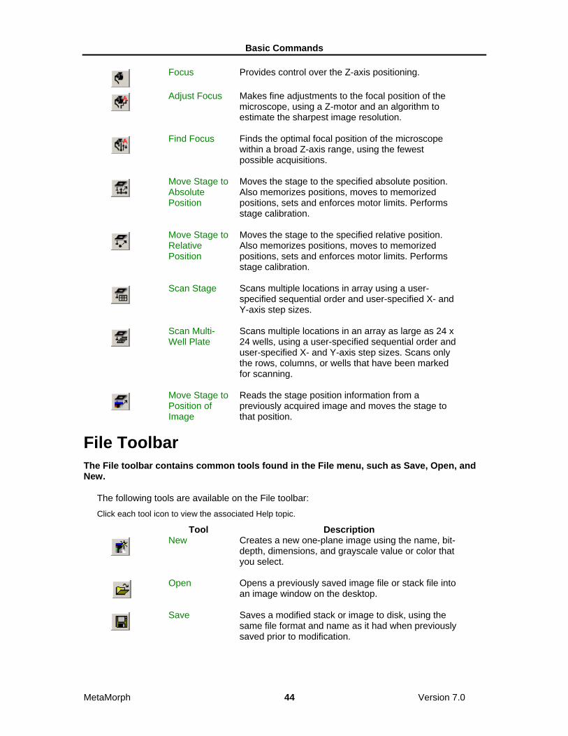
Devices Toolbar The Devices toolbar contains tools used to configure and adjust illumination, shutter, focus, and stage devices.
The following tools are available on the Devices toolbar: Click each tool icon to view the associated Help topic.
Tool Description
Illumination The Configure Illumination command enables you to
create unique settings for the hardware devices used to control illumination in MetaMorph.
Shutter Open/Shutter Closed
Opens or closes the installed shutter device. Toggles the current shutter state to the opposite setting.
Basic Commands
MetaMorph 44 Version 7.0
Focus Provides control over the Z-axis positioning.
Adjust Focus Makes fine adjustments to the focal position of the
microscope, using a Z-motor and an algorithm to estimate the sharpest image resolution.
Find Focus Finds the optimal focal position of the microscope
within a broad Z-axis range, using the fewest possible acquisitions.
Move Stage to Absolute Position
Moves the stage to the specified absolute position. Also memorizes positions, moves to memorized positions, sets and enforces motor limits. Performs stage calibration.
Move Stage to Relative Position
Moves the stage to the specified relative position. Also memorizes positions, moves to memorized positions, sets and enforces motor limits. Performs stage calibration.
Scan Stage Scans multiple locations in array using a user-
specified sequential order and user-specified X- and Y-axis step sizes.
Scan Multi-Well Plate
Scans multiple locations in an array as large as 24 x 24 wells, using a user-specified sequential order and user-specified X- and Y-axis step sizes. Scans only the rows, columns, or wells that have been marked for scanning.
Move Stage to Position of Image
Reads the stage position information from a previously acquired image and moves the stage to that position.
File Toolbar The File toolbar contains common tools found in the File menu, such as Save, Open, and New.
The following tools are available on the File toolbar: Click each tool icon to view the associated Help topic.
Tool Description
New Creates a new one-plane image using the name, bit-
depth, dimensions, and grayscale value or color that you select.
Open Opens a previously saved image file or stack file into
an image window on the desktop.
Save Saves a modified stack or image to disk, using the
same file format and name as it had when previously saved prior to modification.

Basic Commands
MetaMorph 45 Version 7.0
Save As Saves a modified image or stack to disk using a
different file name and/or file format than its original file name.
Save Partial As
Saves the area of the active image or stack that is marked by the active region of interest, using your choice of file name and file format.
Revert to Saved
Restores a modified image to its last saved condition. If the image is a plane in a stack, the active plane or the entire stack may be restored.
Set Up Sequential File Names
Configures the sequential file name series to be used for saving images with the Save Using Sequential File Name command.
Save Using Sequential File Names
Saves the active image using the sequential file name series that was configured with the Set Up Sequential File Names command.
Close Closes the image in the current image window so
that it is no longer displayed in the MetaMorph application workspace.
Close All Closes all open images on the desktop and, if
specified, saves the selected new or modified images.
Image Info Displays a summary of information about a selected
image or stack.
Find Images Finds images on your hard disk, based on image
characteristics that you select. Browses, opens, or deletes selected image files.
Basic Acquisition Toolbar The Basic Acquisition toolbar contains tools used to quickly acquire images in MetaMorph.
The following tools are available on the Basic Acquisition toolbar: Click each tool icon to view the associated Help topic.
Tool Description
Shutter Open/Shutter Closed
Opens or closes the installed shutter device. Toggles the current shutter state to the opposite setting.
Snap Acquires an image using the current settings
specified in the Acquire main dialog box. This is the same command as Acquire in the Acquire main dialog box.
Note: If you use the Acquire from Spot or

Basic Commands
MetaMorph 46 Version 7.0
Acquire from Digital Camera commands to acquire images, Snap uses the settings from those dialog boxes.
Configure Acquisition
Configures image acquisition for and acquires images from a variety of digital cameras.
Live Rapidly acquires new image data in to the "Acquired"
window, in effect, showing a live image. Pressing F2 or this button again stops updating the image. This is the same command as Show Live in the Acquire main dialog box.
Auto Expose Calculates and sets the autoexposure time for
individually acquired images and for the Live image window. This is the same command as Auto Expose in the Acquire main dialog box.
Save As Saves a modified image or stack to disk using a
different file name and/or file format than its original file name.
Close All Closes all open images on the desktop and, if
specified, saves the selected new or modified images.
Living Cell Toolbar The Living Cell toolbar contains tools used to create and analyze images and stacks of live cells experiments in MetaMorph.
The following tools are available on the Living Cell toolbar: Click each tool icon to view the associated Help topic.
Tool Description
Multi Dimensional Acquisition
Acquisition of images from a series of times, stage positions, wavelengths, and/or Z-positions. This function is used to acquire large and complex data sets without requiring the use of journals.
Review Multi Dimensional Data
Enables you to view, filter, organize, and analyze MetaMorph images in a Multi Dimensional Data Set (*.nd) and generate new images based on your viewing criteria.
Montage Creates a montage in a new image window
comprising all of the planes from the selected stack.
Movie Builds an on-screen movie that can be played from
the currently selected stack. Builds an on-screen single-frame movie that can be displayed from a single-plane image.
Stack Creates a new image by performing a selected

Basic Commands
MetaMorph 47 Version 7.0
Arithmetic arithmetic or Boolean logic operation on the planes in a stack.
Make Movie Creates multimedia .avi video or QuickTime movie
files from a stack of image planes.
Track Objects Tracks one or more selected objects through each
image in an image stack or a sequential series of single images.
Track Points The Track Points command allows you to track one
or more selected points through each frame in a series of images and to derive measurements of the paths, positions, and velocities of the points.
Fluorescence Toolbar The Fluorescence toolbar contains tools used to create and analyze images of fluorescence experiments in MetaMorph.
The following tools are available on the Fluorescence toolbar: Click each tool icon to view the associated Help topic.
Tool Description
Basic Digital Acquire
Acquires an image from a digital camera. Can be configured to calibrate the exposure time automatically.
Multi Dimensional Acquisition
Acquisition of images from a series of times, stage positions, wavelengths, and/or Z-positions. This function is used to acquire large and complex data sets without requiring the use of journals.
Review Multi Dimensional Data
Enables you to view, filter, organize, and analyze MetaMorph images in a Multi Dimensional Data Set (*.nd) and generate new images based on your viewing criteria.
Adjust Digital Contrast
Adjusts image brightness, contrast, and gamma, selects and configures the look-up table model, and adjusts the number of grayscale levels or colors used to display an image.
Color Align Shifts the red, green, and blue planes of an image
independently to bring them into alignment.
Measure Colocalization
Provides quantitative data regarding regions of overlap of two fluorescent probes in an image.
Overlay Images
Overlays up to seven images, assigning a different color to each. Typically, one of the images is a grayscale transmitted-light image, and the other overlay images are fluorescence images.

Basic Commands
MetaMorph 48 Version 7.0
Color Photography Toolbar The Color Photography toolbar contains tools used to configure and manipulate color images in MetaMorph.
The following tools are available on the Color Photography toolbar: Click each tool icon to view the associated Help topic.
Tool Description
Threshold Image
Applies segmentation to an image, differentiating between objects of interest and other parts of the image based on the image's grayscale levels or colors. You Can also create a binary mask image or a clipped image with this command.
Adjust Digital Contrast
Adjusts image brightness, contrast, and gamma, selects and configures the look-up table model, and adjusts the number of grayscale levels or colors used to display an image.
Show Region Statistics
Displays the dimensional and pixel intensity statistics of the selected region of interest or of the entire image, and logs the data to a data log, if needed.
Set Color Threshold
Selects a threshold range for 24-bit color images.
Integrated Morphometry Analysis
Opens the Integrated Morphometry Analysis (IMA) interface for the measurement, display, and logging of morphometric data.
Process Toolbar The Process toolbar contains tools used to sharpen, filter, and manipulate images in MetaMorph.
The following tools are available on the Process toolbar: Click each tool icon to view the associated Help topic.
Tool Description
Sharpen Accentuates the edges within an image or region of
interest using a convolution kernel.
Low Pass Blurs the edges within an image or region of interest
using a convolution kernel to average the values within the image data.
Detect Edges Isolates and enhances the edges in an image by
using a selected edge-detection convolution.
Unsharp Mask Sharpens an image and brings out details in
shadows and highlights. When an Unsharp Mask filter is applied, the contrast will be reduced so that fine details have a middle gray level.

Basic Commands
MetaMorph 49 Version 7.0
Median Filter Reduces the effects of noise in an image by
removing pixels whose grayscale values are substantially different from those of neighboring pixels.
Correct Shading
Shading correction is used to eliminate non-uniformities in illumination that can adversely affect thresholding or intensity measurements.
Flatten Background
Equalizes image background intensity across an entire image or in a selected region.
FFT Performs fast Fourier transform filtering of images in
the frequency domain, rather than in the spatial domain.
Binary Toolbar The Binary toolbar contains tools used to create binary mask images from 8-bit, 16-bit, or 24-bit images.
The following tools are available on the Binary toolbar: Click the Binary tool icon to view the Binary Image Operations dialog box. All the commands in this toolbar are available as options in the Binary Image Operations dialog box.
Tool Description
Binary Creates a binary mask image from the selected 8-bit,
16-bit, or 24-bit image based on the current thresholding, and applies a selected geometric convolution operation to this or other binary images.
Erode Image Shrinks objects in the binarized image.
Dilate Image Expands objects in the binarized image.
Skeltonize Image
Reduces objects in the binarized image down to their center lines with a one-pixel width.
Outline Image Creates outlines of all of the white objects in the
binarized image.
Distance Map Creates an 8-bit image from the binarized image
where the intensity value of a pixel in an object indicates the distance to the edge of the object.
Segment Performs a "watershed" segmentation on a binarized
image to create boundaries between objects that are touching. MetaMorph uses an 8-bit distance map to determine how to separate objects.
Remove Single Pixels
Removes all single pixels (that is, white pixels which are not touching any other white pixels) from a binarized image.
Invert Converts all black pixels to white and all white pixels
to black in a binarized image.

Basic Commands
MetaMorph 50 Version 7.0
Arithmetic and Stack Arithmetic Toolbars The Arithmetic and Stack Arithmetic tools contains commands used to perform arithmetic or Boolean logic operations to images and planes in a stack.
The following tools are available on the Process toolbar: Click each tool icon to view the associated Help topic.
Tool Description
Arithmetic Applies an arithmetic or Boolean logic operation
(Add, Subtract, Multiply, Divide, Logical AND, Logical OR, Logical XOR, Minimum, Maximum or Average) to the specified image.
Stack Arithmetic
Creates a new image by performing a selected arithmetic or Boolean logic operation on the planes in a stack.
Transmitted Light Toolbar The Transmitted Light toolbar contains commands used to assist in transmitted light experiments such as brightfield, darkfield, and phase experiments.
The following tools are available on the Transmitted Light toolbar: Click each tool icon to view the associated Help topic.
Tool Description
Arithmetic Applies an arithmetic or Boolean logic operation
(Add, Subtract, Multiply, Divide, Logical AND, Logical OR, Logical XOR, Minimum, Maximum or Average) to the specified image.
Correct Shading
Shading correction is used to eliminate non-uniformities in illumination that can adversely affect thresholding or intensity measurements.
Show Region Statistics
Displays the dimensional and pixel intensity statistics of the selected region of interest or of the entire image, and logs the data to a data log, if needed.
Color Toolbar The Color toolbar contains commands used to combine, separate, or align color images.
The following tools are available on the Color toolbar: Click each tool icon to view the associated Help topic.
Tool Description
Color Combine
Creates one of the following: 8-bit color image with a custom look-up
table. 24-bit color image, using the red, green, and
blue components from up to three specified

Basic Commands
MetaMorph 51 Version 7.0
8-bit or 16-bit images. 8-bit image with a custom look-up table from
a two- or three-plane stack, using its planes as the red, green, and blue components.
24-bit image from a binary, 8-bit, or 16-bit image, using a custom look-up table.
Color Separate
Converts a 24-bit color image or stack of images into three component 8-bit images. Depending on the color model you select, the destination images will consist of one of the following:
A red image, a green image, and a blue image.
A hue image, a saturation image, and an intensity image.
A hue image, a saturation image, and a luminosity image.
The color decoding process is essentially a reversal of the process used in the Color Combine command.
Color Align Shifts the red, green, and blue planes of an image
independently to bring them into alignment.
Measure Toolbars The Measure toolbar contains commands used to perform, distance, statistical, and morphometric measurements.
The following tools are available on the Color toolbar: Click each tool icon to view the associated Help topic.
Tool Description
Calibrate Distances
Calibrates distance in the image window or video device, setting a specific number of image pixels to equal a specified distance.
Calibrate Gray Levels
Calibrates specified gray values in the image by setting them to equal known values, such as ion concentration. The active gray level calibration will affect all images on the MetaMorph desktop.
Threshold Image
Applies segmentation to an image, differentiating between objects of interest and other parts of the image based on the image's grayscale levels or colors. You Can also create a binary mask image or a clipped image with this command.
Show Region Statistics
Displays the dimensional and pixel intensity statistics of the selected region of interest or of the entire image, and logs the data to a data log, if needed.
Region Measurements
Collects selected image statistics based on the Region Measurements dialog box configuration, enables interactive viewing of the data, interactively sorts the data according to your specified criteria,

Basic Commands
MetaMorph 52 Version 7.0
and stores the collected data in a log file.
Linescan Graphs the intensity values along a selected line in
an image or stack. 24-Bit color image data will be graphed with separate traces for the red, green, and blue components.
Manually Count Objects
Counts different classes of objects manually when the use of automatic object analysis is not possible and/or not desired.
Set Color Threshold
Selects a threshold range for 24-bit color images.
Integrated Morphometry Analysis
Opens the Integrated Morphometry Analysis (IMA) interface for the measurement, display, and logging of morphometric data.
Auto Threshold for Light Objects
Uses an algorithm to select an inclusive threshold range at the lighter end of the grayscale histogram. This state is best applied to brightfield images, such as transmitted light images.
Auto Threshold for Dark Objects
Uses an algorithm to select an inclusive threshold range at the darker end of the grayscale histogram. This state is best applied to images with a dark background, such as fluorescence images.
Internally Threshold Objects
Thresholds objects so that pixels below a selected percentage of the maximum intensity in each object are removed, and then measures the processed objects.
Journal Control Toolbar The Journal Control toolbar contains commands used to configure the playback of journals for images and directories in MetaMorph.
The following tools are available on the Journal Control toolbar: Click each tool icon to view the associated Help topic.
Tool Description
Define Stopwatch Sequences
Defines a set of journals, which can each be run at different times for one stopwatch.
Loop a Journal
Repeats a journal a specified number of times at the specified interval.
Loop for all Planes
Repeats a journal for each plane of the selected stack.
Loop for all Regions
Repeats a journal for each region on the selected image.
Loop for all Repeats a journal for each image in a selected

Basic Commands
MetaMorph 53 Version 7.0
Images in Directory
directory.
Toggle Interactive
Enables the display of the next command’s dialog box during playback, allowing you to make changes to the dialog box settings.
Apps Toolbar The Apps toolbar contains widely used Drop-ins found in the Apps menu of MetaMorph.
The following tools are available on the Apps toolbar: Click each tool icon to view the associated Help topic.
Tool Description
Multi Dimensional Acquisition
Acquisition of images from a series of times, stage positions, wavelengths, and/or Z-positions. This function is used to acquire large and complex data sets without requiring the use of journals.
Review Multi Dimensional Data
Enables you to view, filter, organize, and analyze MetaMorph images in a Multi Dimensional Data Set (*.nd) and generate new images based on your viewing criteria.
Multi Dimensional Set Utilities
Enables you to do the following: Select data sets for viewing Run a journal in conjunction with selected
data sets Perform file system functions on your data
set including appending two or more data sets into a single data set
Copy and delete data sets Move data sets to different directories Build Multi Dimensional Data Sets
Track Objects Tracks one or more selected objects through each
image in an image stack or a sequential series of single images.
Track Points The Track Points command allows you to track one
or more selected points through each frame in a series of images and to derive measurements of the paths, positions, and velocities of the points.
Measure Colocalization
Provides quantitative data regarding regions of overlap of two fluorescent probes in an image.
Measure Grid Creates a user-configurable measurement grid on an
image and performs measurements, or runs a journal to process and/or measure the image regions, within each element in the grid.
Measure XYZ Measures the spatial distance between pairs of

Basic Commands
MetaMorph 54 Version 7.0
Distance points in different image planes in a stack. Plays back three-dimensional wireframe rotations of the track lines. Distance measurements are displayed in the dialog box, and can be saved in a data log.
Measure Volume
Measures the volume of a thresholded object through all of the planes in a stack.
Graph Intensities
Measures and logs intensity data from selected regions in an image stack, or in a series of live video images.
Journal Toolbar The Journal toolbar contains commands used create and edit journals.
The following tools are available on the Journal toolbar: Tool Description
Start Recording
Starts recording a new journal.
Stop Recording
Opens the Save Journal As dialog box.
Pause Recording
Pauses the recording of the journal.
Resume Recording
Resumes the recording of the journal.
Run Journal Opens the Run Journal dialog box.
Edit Journal Opens the Select a Journal to Edit dialog box.
Taskbar Toolbar The Taskbar toolbar contains commands used to create, edit, and load taskbars.
The following tools are available on the Taskbar toolbar: Click each tool icon to view the associated Help topic, if applicable.
Tool Description
Create Taskbar
Opens the Taskbar Editor and creates an empty taskbar. Assigns journals to empty buttons, replaces existing journals assigned to buttons with new journals, and clears journals from the selected taskbar. Adds new rows or columns of buttons to the selected taskbar.
Edit Taskbar Opens the Taskbar Editor and creates an empty
taskbar.
Load Taskbar Opens the Select a Taskbar dialog box.

Basic Commands
MetaMorph 55 Version 7.0
Show Taskbar Toggles the currently loaded taskbar on.
Hide Taskbar Toggles the currently loaded taskbar off.
Variables Toolbar The Variables toolbar contains commands used to assign, remove, log, and loop variables used by journals in MetaMorph.
The following tools are available on the Variables toolbar: Click each tool icon to view the associated Help topic.
Tool Description
Assign Variable
Creates custom variables from selected MetaMorph measurement parameters, other variables, and number/string literals; assigns values to variables, and performs arithmetic and logical operations.
Enter Variable Provides a dialog box for assigning values to
variables during playback of a journal.
Delete Variable
Removes a user-defined variable from use by MetaMorph.
Log Variable Opens an existing or new data log for storing
calculated data from a user-defined variable.
Branch on Variable
Runs a specified journal if a selected variable's value meets a specific criterion. Runs a different specified journal if the condition is not met.
Loop Variable Repeats a journal a specified number of times or for
as long as the value of a selected variable fulfills a specified condition.
Device Control Toolbar The Device Control toolbar contains commands used to manually change the x, y, and z positions of a stage using MetaMorph.
The following tools are available on the Device Control toolbar: Tool Description
Device Control Opens the Device Control dialog box.
Illumination
Setting
Opens the Configure Illumination dialog box.
Shutter Open/Shutter Closed
Opens or closes the installed shutter device. Toggles the current shutter state to the opposite setting.
Magnification Setting
Opens the Configure Magnification dialog box.

Basic Commands
MetaMorph 56 Version 7.0
Step Stage Left Moves the stage one unit to the left.
Step Stage Right
Moves the stage one unit to the right.
Step Stage Back
Moves the stage one unit back.
Step Stage Forward
Moves the stage one unit forward.
Step Focus Up Uses the Z-motor to move the stage one unit up.
Step Focus Down
Uses the Z-motor to move the stage one unit down.
Region Toolbar The Region toolbar contains commands used to configure regions of interest created with the Region Tools toolbar.
The following tools are available on the Device Control toolbar: Tool Description
Load Region Loads the region locations and dimensions
from a region file (*.rgn) of your choice and applies them to the current image or stack.
Save Region
Saves the locations and dimensions of all regions of interest in the active window to a region file (*.rgn).
Transfer Region Transfers all of the regions in an open image
to another open image. The transferred region(s) will be placed in the same relative location as in the original image.
Clear Region Clears all of the regions of interest in the
active image window.
Shrink Region to Fit
Shrinks a region to fit an object contained inside the region within a thresholded image.
Delete Active Region
Deletes the Active Region.
Convert Region to Lines
Automatically develops line regions from binary skeletonized images in order to use the line regions for line scans or kymographs.
Create Segment Regions
Creates rectangular regions of a selected length and width along a line region.

Basic Commands
MetaMorph 57 Version 7.0
Create Regions Around Objects
Draws regions around objects in the currently active image or plane in a stack. You must first threshold the image or apply the Measure Objects or Integrated Morphometry Analysis commands.
Image Window Tools Each image window has its own set of Image Window Tools located in a panel on the left side of the image window. These tools can be hidden or redisplayed by choosing Hide Image Window Toolbar or Show Image Window Toolbar from the pop-up context menu that appears when you right-click an image.
Image Window The number and type of Image Window Tools available vary based on the type of image you open. The following examples illustrate two possible image windows:
Click the tools on either example to read a brief description of the associated tool.
24-bit image with 75% zoom.

Basic Commands
MetaMorph 58 Version 7.0
16-bit image stack with overlays and 100% zoom.
Note: The image window that is the source image of the active dialog box has a green border around it to distinguish it from other images on the MetaMorph desktop.
Image Tools Descriptions The following Image Window Tools are available:
Tool Description Available with
Title Bar Displays the image name,
as well as controls to minimize, maximize, and close the image window.
Note: An asterisk (*) preceding an image name indicates that the image has been modified and/or has not been saved.
All images
Stack Toolbar
Controls playback of stack images.
Stack images
Zoom Increases or decrease
the zoom level for the current image.
All images
Overlay Displays the distributions
of grayscale, RGB, or HSI 8-bit, 16-bit, and 24-bit

Basic Commands
MetaMorph 59 Version 7.0
values. images
Display Enables you to select a
monochrome, pseudocolor, or user-defined display mode look-up table (LUT) for a grayscale image.
8-bit and 16-bit images
Contrast Resets, fixes, or auto
enhances the contrast of a grayscale image.
8-bit, 16-bit, and 24-bit images
Threshold Creates a boundary
between the objects being measured and other parts of an image based on the image's grayscale or color levels.
8-bit, 16-bit, and 24-bit images
Scale Enables you to change
the scale range or autoscale setting of the image.
16-bit images
Color Channel
Turns each color (Red, Blue, and Green) channel on or off.
24-bit images
Color Channel Selector
Specifies the current color channel controlled by the Contrast Slider when working with 24-bit color images.
24-bit images
Scale Slider
The Scale Slider allows you to manually change the range of gray levels in a 16-bit image.
16-bit images
Histogram and Threshold Slider
The Threshold Slider displays image and background data. The Histogram displays the number of pixels at each intensity level.
8-bit and 16-bit images
Stack Player (Image Window Tools) The Stack Player controls an on-screen movie that can be played forward, backward, or plane-by-plane from the currently selected stack.
Click each Stack Player control to read a brief description of the associated control.

Basic Commands
MetaMorph 60 Version 7.0
Use the Stack Player to control playback of individual planes in a stack.
Using the Stack Player The following tools control playback of stack images:
Tool Description
Click and drag the Plane Slider to manually
adjust the plane displayed. A ToolTip is displayed showing the active plane number.
Plays stack backward.
Steps stack backward one plane.
Stops stack.
Steps stack forward one plane.
Plays stack.
Use the Play Preferences and Select Plane commands for additional playback options.
Play Preferences
The Play Preferences dialog box enables you to loop, reverse, or change the frames-per-second speed of stack image playback. To use the Play Preferences dialog box:
Step Action
1 Right-click in the image window and choose Play Preference from the pop-up menu.
OR
Click Play Preferences from the Stack menu.
The Play Preferences dialog box opens.

Basic Commands
MetaMorph 61 Version 7.0
2 Choose Loop to continuously replay the stack in either direction (forward or reverse) when played.
OR
Choose Reverse to continuously replay the stack in both directions (forward then reverse) when played. Loop must be selected for Reverse to work.
3 Use the slider or edit box to adjust the frames-per-second if needed.
4 Click Close.
Zoom Tool (Image Window Tools) The Zoom Tool provides 14 different levels of magnification from 5 to 800 percent.
Use the Zoom Tool to increase or decrease the magnification for the current image. You can select 5, 10, 15, 25, 33, 50, 75, 100, 150, 200, 300, 400, 600, or 800 percent magnification. The Zoom Tool’s "magnifying glass" cursor can also be used to select and zoom directly into a specific area of interest.
You can also change the magnification of an image without using the Zoom Tool:
• Right-click in the image window, click Zoom, and choose one of the magnification levels from the pop-up menu that appears.
• Use the keyboard shortcuts to increase or decrease the magnification level of the active image window. Press the appropriate shortcut key listed below until you reach the desired magnification level.
• Resize an image window while pressing the [Shift] key to zoom in and out of the image while it resizes. The image will maintain its proportion in relation to the changing size of the window.
Shortcut:
Increase magnification = [Page Up]
Decrease magnification = [Page Down]
Using the Zoom Tool To increase or decrease the magnification in an image, use the following procedure:
Step Action
1 Click the Zoom Tool. The pointer will change to a "magnifying glass" cursor when placed over the image.
2 Move the cursor to the area of the image you want to magnify and click.
The image will be centered in the area you chose and the new magnification level will display in the window’s title bar.
OR
Right-click to decrease the magnification level of the image.

Basic Commands
MetaMorph 62 Version 7.0
Note: To adjust the size of the window to accommodate the new image size, press the [Shift] key while increasing an area’s image size, or double-click the window's title bar after zooming.
To zoom into a specific area, use the following procedure: Step Action
1 Click the Zoom Tool. The pointer will change to a "magnifying glass" cursor when placed over the image.
2 Click and drag the cursor to select a rectangular area to zoom into.
The image will zoom to the area selected.
Histogram Tool The Histogram Tool displays the distribution of grayscale values.
Use the Histogram Tool to see a graphical representation of the distribution of an image's grayscale levels. This tool is available for both 8-bit and 16-bit images. You can open the histogram tool by right-clicking on an appropriate image and selecting Show Histogram from the list.
Note: The Color Histogram Tool is used with 24-bit color images. A typical histogram is shown below:
Click the numeric labels and the graph bars in this sample histogram to read a brief description about each item's function:
Configuring the Histogram Settings:
Hiding the Histogram Labels
Hiding the Highlight Bars
Highlighting Under Bars
Highlighting Between Bars
Drawing Graph Using LUT Colors
Turning On Area as Percentage
Turning On Apply LUT to Graph

Basic Commands
MetaMorph 63 Version 7.0
Scaling Between Bars
Using the Histogram Commands:
Stretching an Image's LUT (8-bit only)
Scaling an Image (16-bit only)
Setting the Histogram's X-Axis
Resetting the Histogram's X-Axis
Using the Histogram Tool To open and use a histogram, use the following procedure:
Step Action
1 Right-click on an appropriate image and selecting Show Histogram from the list or click the Histogram Tool on the Standard Toolbar. The histogram for the current image opens.
2 Move the left and right Highlight Bars (located at the edges of the histogram) to display the grayscale value for the bin currently below the selected bar. The number of pixels in the image with that grayscale value will also be displayed.
You can move each bar separately by dragging them using the left mouse button. To move the bars simultaneously, hold down the [SHIFT] key while dragging them with the pointer.
Color Histogram Tool (Image Window Tools) The Color Histogram Tool displays the distributions of RGB, HSI, or HSL color values.
Use this tool when you want to see a graphical representation of the distributions of the color space elements in a 24-bit color image. A typical color histogram is shown below. You can choose a color space model (RGB, HSI, or HSL) and perform thresholding manipulations through each color component, or "channel," of that color model. The histogram can be used to set the image threshold. The Highlight Bars at the left and right of the histogram allow you to set the low and high threshold levels, respectively, and "add" the selected range to the threshold.
Note: The grayscale Histogram Tool is used with 8-bit and 16-bit images.
Click the items in this sample color histogram to read a brief description about each item's function:

Basic Commands
MetaMorph 64 Version 7.0
Configuring the Histogram Settings:
Hiding the Color Histogram Legend
Hiding the Color Histogram Labels
Hiding the Highlight Bars
Scaling Between Bars
Using the Histogram Commands:
Setting the Histogram's X-Axis
Resetting the Histogram's X-Axis
Configuring a Log File
Logging Data
Configuring Color Channel Settings:
Choosing a Color Space Model and Channel
Adding a Range to the Threshold
Deleting a Range from the Threshold
Hiding the Histogram Labels To hide the X- and Y- axis value labels displayed in the histogram,

Basic Commands
MetaMorph 65 Version 7.0
use the following procedure: Step Action
1 Select the Settings menu from the Histogram menu bar.
2 Choose Labels from the menu so that its check mark is cleared. The histogram labeling will also disappear.
Hiding the Highlight Bars Highlight bars are shown by default; however, they need to be hidden when working with binary images. To hide the Highlight Bars, use the following procedure:
Step Action
1 Select the Settings menu from the Histogram menu bar.
2 Choose Show Highlight Bars from the menu so that its check mark is cleared. The left and right Highlight Bars will become hidden.
Highlighting Under Bars Highlight Under Bars highlights the pixels in a grayscale image which have the same grayscale values as the values selected by the bar in the histogram. For example, if grayscale level 50 is selected by the blue Highlight Bar, all pixels in the image that have grayscale value 50 will be displayed with a blue overlay.
To enable Highlight Under Bars so that you can see the overlays, use the following procedure:
Step Action
1 Select the Settings menu from the Histogram menu bar.
2 Choose Highlight Under Bars from the menu. A check mark will appear next to its entry, indicating that it is active.
3 As you slide the red or blue Highlight Bar, the overlay will change to reflect the value selected in the histogram. Red and blue lines will appear in the Contrast Slider to indicate the value that you have selected in the histogram.
Note: If you do not have the palette set to 236 entries, the overlay may "disappear." This is because the limited palette does not include the gray level you have selected in the histogram.
Drawing Graph Using LUT Colors Draw Graph Using LUT Colors uses the image look-up table (LUT) colors when graphing the histogram. This option displays the image’s grayscale range in the histogram and is enabled by default. If this option is disabled, the data in the histogram will be

Basic Commands
MetaMorph 66 Version 7.0
displayed as green.
To enable Draw Graph Using LUT Colors, use the following procedure: Step Action
1 Select the Settings menu from the Histogram menu bar.
2 Choose Draw Graph Using LUT Colors from the menu. A check mark will appear next to its entry, indicating that it is active.
Highlighting Between Bars Highlight Between Bars places a purple overlay over all pixels in an image that have a grayscale level value that falls between the two values selected by the blue and red Highlight Bars. The overlay will extend to those pixels marked by the Highlight Bars if Highlight Under Bars is not enabled. Otherwise, it will not highlight those pixels marked with a histogram overlay.
To enable Highlight Between Bars, use the following procedure:
Step Action
1 Select the Settings menu from the Histogram menu bar.
2 Choose Highlight Between Bars from the menu. A check mark will appear next its entry, indicating that it is active.
3 As you slide the red and blue Highlight Bars, the overlay will change to reflect the values selected in the histogram. A purple line will appear in the Contrast Slider to indicate the values that you have selected in the histogram.
Turning On Area as a Percentage MetaMorph will display the area between the Highlight Bars as either a percentage or as total pixels. To activate Area as Percentage, use the following procedure:
Step Action
1 Select the Settings menu from the Histogram menu bar.
2 Choose Area as Percentage from the menu. A check mark will appear next to its entry, indicating that it is active.
Turning On Apply LUT to Graph Apply LUT to Graph applies the image's LUT (look-up table) when graphing the histogram. This means that commands that change the LUT (such as Stretch LUT or contrast adjustment) will be reflected accurately in the histogram. Apply LUT to Graph should be enabled whenever you

Basic Commands
MetaMorph 67 Version 7.0
adjust the contrast.
Note: This command is meant for use with monochrome images. The grayscale levels from the green channel of the LUT will be graphed using this feature. Because the three channels are identical in a monochrome image, all grayscale levels will be represented in the histogram.
Step Action
1 Select the Settings menu from the Histogram menu bar.
2 Choose Apply LUT to Graph from the menu. A check mark will appear next to its entry, indicating that it is active.
Scaling Between Bars Sometimes a histogram's scaling is not ideal for your purposes. For example, an image may contain a large number of pixels at a particular value, causing a tall "spike" in the histogram at that point on the X-axis, while the values you really want to study are not well represented. Scale Between Bars rescales the histogram graph so that the value with the most pixels between the bars becomes the peak value.
To enable Scale Between Bars, use the following procedure: Step Action
1 Move the Highlight Bars to bracket the grayscale values of interest.
2 Select the Settings menu from the Histogram menu bar.
3 Choose Scale Between Bars from the menu. A check mark will appear next to its entry, indicating that it is active.
Note: Rescaling is only active when Scale Between Bars is active. If you move the bars while Scale Between Bars is active, the scale of the graph will be updated to reflect the new peak value. (The Peak Value label at the top of the Y-axis will reflect this change.)
Stretching an Image's LUT Some images do not have a brightness range that extends through the full range of gray levels available in the histogram display. Stretch LUT allows you to expand the brightness range of the image by selecting a range of gray level values and stretching these gray levels to cover the entire histogram display.
The same number of grayscale levels that were missing before the stretch will still be missing, but the grayscale values are spread evenly through the entire histogram. Because this changes the look-up table values but not the actual grayscale values, a pixel that is gray level 100 will still be gray level 100 after this command is applied.

Basic Commands
MetaMorph 68 Version 7.0
Step Action
1 Move the red and blue Highlight Bars to bracket the grayscale values of interest.
2 From the Histogram menu bar, select the Commands menu.
3 Choose Stretch LUT from the Commands menu.
4 To revert back to the original LUT values, select the Contrast Tool and select Reset Contrast.
Scaling 16-Bit Images The Scale Image command is the same as the Scale 16-Bit Image command. A 16-bit image consists of 65536 possible gray levels, but, due to experimental conditions, much of your important data may reside within a narrow range at the dark end of the scale. The Scale 16-Bit Images command allows you to scale a 16-bit image to a selected range of 256 gray scale levels, thereby increasing the apparent contrast in the display. This command does not affect measurements. Its purpose is to give you the option of deciding which grayscale levels will be used to display 16-bit images on your screen.
To scale a range of grayscale values in a 16-bit image to an 8-bit display, use the following procedure:
Step Action
1 Adjust the blue (left) Highlight Bar in the histogram to the darkest gray level you want to use for the images (the same as using the Low Scale text box or slider in the Scale 16-Bit Image dialog box).
2 Adjust the red (right) Highlight Bar in the histogram to the brightest gray level you want to use for the images (the same as using the High Scale text box or slider in the Scale 16-Bit Image dialog box).
3 Select the Commands menu from the Histogram menu bar.
4 Choose Scale Image. The displayed image will be scaled to 8 bits.
Setting the Histogram's X-Axis Set X Axis sets the X-axis data range of the histogram graph to the range defined by the Highlight Bars. To set the X-axis data range, use the following procedure:
Step Action
1 Move the blue (left) Highlight Bar to the location in the graph that you want to use as the left edge of the histogram.
2 Move the red (right) Highlight Bar to the location in the graph that you want to use as the right edge of the histogram.
3 From the Histogram menu bar, select the Commands menu.

Basic Commands
MetaMorph 69 Version 7.0
4 Choose Set X Axis. The graph will change to show only the area between the Highlight bars.
Resetting the Histogram's X-Axis Reset X Axis restores the X-axis scaling of the histogram graph to the original range. To reset the X-axis data range, use the following procedure:
Step Action
1 From the Histogram menu bar, select the Commands menu.
2 Choose Reset X Axis. The graph's X-axis data range will be restored.
Color Space Models A commonly used model used for dealing with color images is the RGB model, which proposes that each color can be described in terms of the relative contributions of the colors red, green, and blue to that final color. Each color can accordingly be described by its position in a hypothetical three-dimensional color cube, or "color space," which plots increasing intensities of red, green, and blue along the three major axes.
Each color axis is divisible into 256 possible values. Thus, the color of any pixel in a 24-bit image can be encoded by three 8-bit color intensity values, one for each of the three color values.
Other working color space models are derived from the RGB model, the most common being the HSI (hue, saturation, and intensity) and HSL (hue, saturation, and luminosity) models. Both models use an algorithm to convert the red, green, and blue intensity values into corresponding hue, saturation, and intensity or luminosity values. Intensity is simply a measure of the amount of light radiating from or incident on a surface. Luminosity (sometimes called luminance or brightness) is similar to intensity, but takes into account the eye's differential sensitivity to light of different wavelengths.
MetaMorph allows you to take advantage of the differences between color space models by choosing which model you want to use.
Hiding the Color Histogram Legend To hide the histogram legend, use the following procedure:
Step Action
1 From the Histogram menu bar, select the Settings menu. By default, Show Legend will be enabled, and a check mark will be displayed next to its entry.
2 Choose Show Legend. The check mark will disappear from next to its entry, and the legend will disappear from the histogram window.
Hiding the Color Histogram Labels To hide the histogram labels, use the following procedure:
Step Action
1 From the Histogram menu bar, select the Settings menu. By default, the Show Labels will be enabled, and a check mark will be
Basic Commands
MetaMorph 70 Version 7.0
seen next to its entry.
2 Choose Show Labels. The check mark will disappear from next to the Show Labels entry, and the labels will disappear from around the histogram.
Choosing a Color Space Model and Channel To select a color space model and channel, use the following procedure:
Step Action
1 From the Histogram menu bar, select the Channel menu.
2 From the top section of the Channel menu list, choose which color model you want to use: RGB, HSI, or HSL. A check mark will appear next to the entry, and the entries in the next section of the Channel menu will reflect the choice of color model.
3 Choose which channel in which to perform your manipulations:
• If you chose the RGB model, choose between the Red, Green, or Blue channels.
• If you chose the HSI model, choose between the Hue, Saturation, or Intensity channels.
• If you chose the HSL model, choose between the Hue, Saturation, or Luminosity channels.
A check mark will appear next to your selection.
Adding a Range to the Threshold To add a selected range of color values to the thresholding, use the following procedure:
Step Action
1 Use the left and right Highlight Bars to set the lower and upper limits of the range of color values that you want to add to the thresholding range.
2 From the Histogram menu bar, select the Channel menu.
3 Choose Add Range to Threshold. A colored overlay will appear in the image window over those pixels with color values in the range defined by the Highlight Bars.
Deleting a Range from the Threshold This command uses the image window Color Histogram Tool to remove a specified range of color values from a previously defined threshold range. To remove a range of color values from thresholding, use the following procedure:

Basic Commands
MetaMorph 71 Version 7.0
Step Action
1 Use the left and right Highlight Bars to set the lower and upper limits of the range of color values that you want to remove from the thresholding range.
2 From the Histogram menu bar, select the Channel menu.
3 Choose Delete Range from Threshold. Those pixels with color values in the range defined by the Highlight Bars will disappear from the overlay.
Using the Color Histogram Tool To open and use an image's color histogram, use the following procedure:
Step Action
1 Click the Color Histogram Tool. The image's histogram opens.
2 Move the left and right Highlight Bars (located at the edges of the histogram) to display the color value for the bin currently below the selected bar. The number of pixels in the image with that color value will also be displayed.
You can move each bar separately by dragging the desired bar using the left mouse button. To move them simultaneously, hold down the [SHIFT] key while dragging.
Display Mode Tool (Image Window Tools) The Display Mode Tool provides a predefined or user-defined display mode look-up table (LUT) for a grayscale image.
Use the Display Mode Tool to change the currently assigned LUT to one of the following predefined LUTs:
Monochrome Black and white grayscale display mode
Pseudocolor Arbitrarily assigned color display mode
Red Predefined red LUT color display mode
Green Predefined green LUT color display mode
Blue Predefined blue LUT color display mode
Yellow Predefined yellow LUT color display mode

Basic Commands
MetaMorph 72 Version 7.0
Magenta Predefined magenta LUT color display mode
Cyan Predefined cyan LUT color display mode
Set by Wavelength Determines display mode based on the images wavelength value
Note: If the wavelength value of the image is not in the visible range of the electromagnetic spectrum (� 380-780 nm), the image will display as monochrome.
You can also configure, save, and apply your own look-up table for use with the image.
Note The Display Mode Tool is not available for color images.
Visible Spectrum
Using the Display Mode Tool Selecting a Display Mode
Loading an Existing LUT
Configuring the Display Mode
Defining a User LUT
Selecting a Display Mode To select a display mode, use the following procedure:
Step Action
1 Click the Display Mode Tool. A pop-up menu opens. Choose Monochrome, Pseudocolor, Red, Green, Blue, Yellow, Magenta, or Cyan from the pop-up menu to use one of the predefined MetaMorph display modes. The check mark indicates the active display mode.
Or
Choose Set By Wavelength to set the display to correspond with the image wavelength.
Or
Select a previously loaded user-defined look-up table from the pop-up menu.

Basic Commands
MetaMorph 73 Version 7.0
2 MetaMorph will switch to the selected display mode.
Loading an Existing LUT To load an existing look-up table (LUT), such as one of the sample LUTs provided with MetaMorph, use the following procedure:
Step Action
1 Select the Display Mode Tool by clicking it using the left mouse button. A pop-up menu opens.
2 Choose Configure LUT from the pop-up menu. The Define User LUT dialog box opens.
3 Choose Load. The Load LUT File dialog box opens.
4 Select the icon for the desired file. If necessary, use the Look In drop-down list box or Up One Level icon button to select the correct drive and folder.
5 Choose Open. The Load LUT File dialog box will close.
6 The newly loaded LUT opens in the Look-Up Table Mode List Box on the left side of the Define User LUT dialog box. (It will also appear in the Display Mode Tool drop-down menu as a menu item.)
Refer to Selecting a Display Mode for more information about selecting the active look-up table.
Configuring the Display Mode To configure the display mode using the Configure LUT option, use the following procedure:
Step Action
1 Click the Display Mode Tool. A pop-up menu opens.
2 Choose Configure LUT from the pop-up menu. The Define User LUT dialog box opens.
3 Select the look-up table that you want to configure from the Look-Up Table Mode List Box on the left side of the dialog box.
4 If you want to change the quantization of the image, type the desired value in the Quantization Level text box.
5 If you want to invert a look-up table, select Invert.
6 When you have finished configuring the look-up table, you can choose Save to save it. The Save LUT File dialog box opens. Type a file name in the File Name text box and

Basic Commands
MetaMorph 74 Version 7.0
choose Save.
Quantization is a measure of the number of distinct grayscale values contained in the image. The default setting is 256.
Defining a User LUT To define a new user-defined look-up table, use the following procedure:
Step Action
1 Click the Display Mode Tool. A pop-up menu opens.
2 Choose Configure LUT from the pop-up menu. The Define User LUT dialog box opens.
3 Choose Create. A new LUT named "User0" opens in the Look-Up Table Mode List Box. The Red, Green, Blue, Upper, and Lower editing options will be enabled.
4 Choose the < command button on the right side of the dialog box to open the LUT graph. The X-axis values of the graph represent the LUT input while the Y-axis values represent the output.
If the user LUT is based on the Monochrome LUT, only one of the three scan lines will be visible.
5 Select the desired starting and ending look-up table addresses to be modified using the Lower and Upper options.
You can select the entire range or you can select smaller ranges, leaving existing values for other parts of the look-up table intact.
6 The intensity for the red, green, and blue components for the selected range of addresses can be editing by first selecting the color component(s) that you want to edit using the Red, Green, and Blue check boxes. You can disable any component that you do not want to edit.
AND
For each of the selected components, select a starting value and an ending value using the text boxes next to Red, Green, and Blue (If you know the color for the range rather than the values, select the desired color from the Color Fill drop-down list box; the appropriate values opens in the starting and ending value text boxes).
7 Choose Apply to apply the edited look-up table to the image.
(You can repeat Steps 4 - 6 as needed.)
8 If you want to save the custom look-up table on disk for future use, choose Save. Type the desired file name in the File Name text

Basic Commands
MetaMorph 75 Version 7.0
box. Then choose Save.
Contrast Tool and Slider (Image Window Tools) The Contrast Tool allows you to auto enhance, reset, or fix the contrast of a grayscale image. The Contrast Slider allows you to adjust the overall brightness of an image and expand the range of grayscale levels displayed for an image.
Use the Contrast Tool when you want to perform one of the three tasks in its pop-up menu: Auto Enhance, Reset Contrast, or Fix Contrast.
Auto Enhance adjusts the contrast by performing a "stretch" on only those grayscale levels that are contained in the image's histogram.
Reset Contrast resets the contrast to the default settings of Contour = OFF, Invert = OFF, Quantization = 255, Brightness = 50, and Contrast = 50.
Fix Contrast changes the pixel gray values in the image based the image's LUT values.
Note: The Contrast Tool is available with 8-bit and 24-bit images. The Scale Tool is used for 16-bit images.
The Contrast Slider in the Image Window toolbar is used to adjust brightness and contrast. Dragging the slider with the left mouse button adjusts the overall brightness of the image. Dragging the slider with the right mouse button rescales the range of grayscale levels that is displayed, thereby increasing contrast. Changing image brightness and contrast in this manner affect only the display, not the actual intensity values in the image data. To make the changes of brightness or contrast permanent, choose Fix Contrast from the Contrast Tool's pop-up menu.
Using the Contrast Tool To use the Contrast Tool, use the following procedure:
Step Action
1 Click the Contrast Tool. A pop-up menu opens.
2 Choose one of the following options from the pop-up menu: Auto Enhance, Reset Contrast, or Fix Contrast.
3 If you chose Fix Contrast for a stack, a dialog box opens, asking of you want to apply the command to all planes in the stack:
If you want to fix the contrast for all planes, choose Yes.
Or If you only want to fix the contrast for the current plane, choose No.
Auto Enhance allows MetaMorph to adjust the contrast by performing a "stretch" on only those grayscale levels that are contained in the image's histogram.
Reset Contrast resets the contrast to the default settings of Contour = OFF, Invert = OFF, Quantization = 255, Brightness = 50, and Contrast = 50.
Fix Contrast changes the pixel gray vales in the image to the values on the LUT. Resets the LUT.

Basic Commands
MetaMorph 76 Version 7.0
Using the Contrast Slider To adjust the brightness and contrast of an image with the Contrast Slider, use the following procedure:
Step Action
1 Position the pointer over the Contrast Slider so that it changes from the arrow cursor to the Contrast Pointer.
2 To adjust the brightness of the image, drag the mouse up or down using the LEFT mouse button until you have found the desired brightness level.
Note: This will only affect an image's LUT. You must choose Fix Contrast if you want to alter the image data permanently.
3 To expand the contrast range, drag the mouse up using the RIGHT mouse button until you have found the desired contrast setting.
You will only be able to increase contrast; you cannot decrease an image's contrast from baseline. Expanding the contrast reduces the number of grayscale levels that you will see in the image at one time (the number of grayscale levels actually available stays the same) while increasing the perceived intensity differences in the image.
Note: This too will only affect an image's LUT. You must choose Fix Contrast if you want to alter the image data permanently.
Threshold Tool and Slider (Image Window Tools) The Threshold Tool Creates a boundary between the objects being measured and other parts of an image on the basis of the image's grayscale or color levels.
Use the Threshold Tool and Slider to create a boundary on the basis of the image's gray or color levels. Some measurement commands require that a distinction be made between the objects being measured and other ("background") parts of an image. Areas of the image that are marked with the thresholding overlay will be included in the measurement and processing. (This differs from the method by which MetaFluor handles thresholding.)
The Threshold Tool displays a menu that provides the following choices:
(1) Threshold Off
(2) Inclusive Threshold, with gray values between the upper and lower threshold limits highlighted by a red overlay.
(3) Exclusive Threshold, with the gray values equal to or above the upper threshold limit, and those equal to or below the lower threshold limit, highlighted by the red overlay.
(4) Auto Threshold for Light Objects, which applies an inclusive threshold to what MetaMorph perceives to be the objects in the image. This uses a sophisticated algorithm for analysis of a grayscale histogram, measuring the "peaks" at the brighter end of the histogram to select the threshold range. Autothresholding of 24-bit color images uses the Intensity channel. This state is best applied to brightfield images, such as transmitted light images. Autothresholding can be

Basic Commands
MetaMorph 77 Version 7.0
recorded in journals.
Note: The Auto Threshold range selection for color images is interactive with the settings in the Set Color Threshold drop-in command (Process menu), but does not interact with the settings of the Region Tools window's Color Mapping or Unmapping Tools, the Histogram Tool, or the Threshold Image command. Autothresholding of grayscale images is interactive with the settings in the Threshold Image command (Measure menu).
(5) Auto Threshold for Dark Objects, which uses the algorithm to select an inclusive threshold range at the darker end of the grayscale histogram. This state is best applied to images with a dark background, such as fluorescence images.
(6) Threshold Image , which opens the Threshold Image dialog box located in the Measure menu.
When thresholding is enabled in grayscale images, the Histogram Bar will act as the Threshold Slider, and will contain a Low Threshold Arrow and High Threshold Arrow that can be dragged. The Threshold Tool button will indicate the current thresholding status. The button displays three bars representing the three states of the Threshold Slider, with a small wedge-shaped arrow under the bar that corresponds to the current state.
Color images do not have the Histogram Bar. To configure the threshold for color images, use the Set Color Threshold drop-in command, or the Color Threshold Mapping and Unmapping Tools, which are located in the Region Tools window.
See Drop-In Help Topic:
Set Color Threshold
Using the Threshold Tool and Slider When the Threshold Tool is active, the Histogram Bar in the Image Window Toolbar will contain low and high threshold arrows that can be dragged, allowing you to quickly set the threshold range.
Note: Press [Shift] while dragging either arrow to move both arrows at once. Step Action
1 Click the Threshold Tool. A pop-up menu opens, providing you with the following six choices:
• Threshold Off
• Inclusive Threshold
• Exclusive Threshold
• Auto Threshold for Light Objects
• Auto Threshold for Dark Objects
• Threshold Image
2 Choose one of the options, as appropriate to your needs.
For color images, it is best to use one of the autothresholding states, rather than the Inclusive or Exclusive state.
3 If you chose Inclusive Threshold in Step 2, the Threshold Tool button will be displayed

Basic Commands
MetaMorph 78 Version 7.0
with the wedge-shaped arrow pointing to the middle bar, and the red thresholding overlay will cover the entire image, because the gray level range has not yet been selected.
Drag the top arrow in the slider down to select an upper threshold gray value limit so that most of the desired objects are marked with the red thresholding overlay.
AND Drag the bottom arrow in the slider to select a lower threshold gray value limit that removes the majority of the remaining red thresholding overlay from the background areas.
Readjust the upper threshold setting if necessary.
4 If you choose Exclusive Threshold in Step 2, the Threshold Tool button will be displayed with the wedge-shaped arrow pointing to the rightmost bar, and the image will not show any red thresholding overlay because the gray level range has not yet been selected.
Drag the top arrow in the slider down to select an upper threshold gray value limit so that most of the desired objects are marked with the red thresholding overlay.
AND Drag the bottom arrow in the slider to select a lower threshold gray value limit as needed.
5 If you chose either Auto Threshold for Light Objects or Auto Threshold for Dark Objects in Step 2, MetaMorph will perform an analysis of the intensity values in the image and then select a threshold range automatically.
Note: You should examine the image carefully to determine how well the objects have been "captured" by the thresholding range. You may need to adjust the thresholding (see Step 7).
6 If you need to adjust the threshold range for a grayscale image, you can use the upper and lower arrows on the slider, or you can use the Threshold Image command.
OR If you need to adjust the threshold range for a 24-bit color image, you will need to use the Set Color Threshold drop-in command. Note: The Region Tools window's Color Threshold Mapping and Unmapping Tools will not be interactive with the Threshold Tool's range selection. Neither will the Threshold Image command nor the Histogram Tool's Add Range to Threshold and Delete Range from Threshold commands (Channel menu).

Basic Commands
MetaMorph 79 Version 7.0
Note: Trying to move a threshold arrow past the second threshold arrow will cause the arrow to stop and cause both arrows to have the same value.
Scale Tool and Scale Slider (Image Window Tools) Changes the contrast of a displayed 16-bit image by scaling a selected range of its gray levels to a different range.
Use the Scale Tool and Slider to narrow the display range of a 16-bit image. A 16-bit image consists of 65536 possible gray levels. However, important image information may be contained within a narrow range towards the lower end of the grayscale. This is particularly the case for low light level experiments. The Scale Tool effectively rescales the intensities in the original image, allowing you to see differences of grayscale values that might otherwise be impossible to view.
When a 16-bit image is opened, the Scale Slider is displayed next to the Histogram Bar in the Image Window Toolbar. It contains low and high grayscale range arrows that can be dragged, allowing you to quickly change the scale of the image.
A ToolTip will display the changing scale as you drag the arrows. If Auto Scale is enabled, the current range percentage will also be shown, as shown below:
Note: Using the Scale Tool and Slider changes the scaling parameters in the image file header – you will be prompted to save when you close the image. This does not change your actual image data. To maintain the original scaling parameters in an image file, save the modified image to a different file name.
The Scale Tool displays a menu with the following choices:
Best Fit Range Automatically selects the best range given the intensity values of the image. When using the Acquire command, Best Fit Range is enabled for all acquired images.
8-Bit Range (0-255) Gray level range of 0-255.
10-Bit Range (0-1023) Gray level range of 0-1023.
12-Bit Range (0-4095) Gray level range of 0-4095.
14-Bit Range (0-16383) Gray level range of 0-16383.

Basic Commands
MetaMorph 80 Version 7.0
16-Bit Range (0-65535) Gray level range of 0-65535.
Auto Scale Scales the image based on the percentage of the total number of pixel values from the lowest to highest pixel value.
Scale Within Active Region Uses the maximum and minimum intensity values in the active region of interest when Auto Scale is selected. The entire image will then be displayed using the values determined from the active region of interest. This can be particularly useful when working with a stack because Auto Scale recalculates within the active region for each plane in a stack.
Scale Image Opens the Scale Image dialog box.
Using the Scale Tool Selecting a Range
Scaling Within an Active Region
Using the Scale Slider Selecting a Range To change the scaling range of an image, use the following procedure:
Step Action
1 Click the Scale Tool. A pop-up menu opens.
2 Choose 8-Bit Range, 10-Bit Range, 12-Bit Range, 14-Bit Range, or 16-Bit Range from the pop-up menu to change the gray level range of the image.
Or
Choose Auto Scale from the pop-up menu if you want image scaled based on the percentage of the total number of pixel values from the lowest to highest pixel value.
The current range selected will display on the Scale button. If auto scaling is on, an A will also display.
Scaling Within an Active Region To scale an image based on the grayscale values of an active region, use the following procedure:
Step Action
1 Create or load a region using the Region Tools.
2 Click the Scale Tool. A pop-up menu opens.
3 Select Auto Scale from the pop-up menu.
Note: Auto Scale must be active to use this feature.
4 Select Scaling Within Active Region from the pop-up menu.

Basic Commands
MetaMorph 81 Version 7.0
5 Click within the region to activate it. The entire image will be scaled based on the grayscale values of the region.
Using the Scale Slider
When a 16-bit image is opened, the Scale Slider is displayed next to the Histogram Bar. It contains low and high grayscale range arrows that can be dragged, allowing you to quickly change the scale of the image. The position of the arrows on the slider corresponds with the bit-range selected with the Scale Tool.
Note: Press [Shift] while dragging either arrow to move both arrows at once.
Use the following procedure to adjust the image scale: Step Action
1 Position the pointer over the Scale Slider so that it changes from the arrow cursor to the Scale Pointer.
2 Drag the top arrow in the slider to select the high scale value of the image.
AND Drag the bottom arrow in the slider to select the low scale value of the image.
Histogram Bar (Image Window Tools) The Histogram Bar displays the range of data in an image.
The Histogram Bar is a graphical representation of the range and intensity of image data. Image data is displayed as white and background is displayed as deep gray. The bar is useful when scaling 16-bit images.
The Histogram Bar is also used as a Threshold Slider when thresholding is enabled in the Threshold Tool pop-up menu.
Note: This tool is not available for 24-bit images.
Color Channel Toggles (Image Window Tools) The Color Channel Toggles turn on or off individual color channels.
Uses these buttons to turn on or off each color channel separately. Three buttons are located directly above the Color Channel Selector button, one for each primary color (Red, Blue, and Green). Click the appropriate button to turn on or turn off an individual color channel.
Note: This tool is available only for 24-bit images.
Color Channel Selector (Image Window Tools) The Color Channel Selector specifies the current color channel controlled by the Contrast Slider when working with 24-bit color images.
Use this tool to toggle through the selections for the Red, Green, Blue, or Intensity channels when you want to adjust the brightness and contrast of a particular channel using the Contrast Slider. The Red, Green, and Blue channel selectors each allow you to adjust the selected channel independently,

Basic Commands
MetaMorph 82 Version 7.0
whereas the Intensity channel selector allows you to adjust the brightness and contrast for the overall image. When you select the Intensity channel, the red, green, and blue channels will be adjusted relative to each other.
Note: This tool is available only for 24-bit images.
Using the Color Channel Selector To choose a color channel, use the following procedure.
Step Action
1 By default, the active channel will be the Intensity channel. To change channels, choose the Color Channel Selector by clicking it with the left mouse button.
2 The next active channel, the Red Channel, will be selected. Successively clicking the Color Channel Selector will cycle through the Green Channel, the Blue Channel, and then back to the Intensity Channel. The color of the Contrast Slider will change to match the selected channel as you toggle through the choices.
3 When you have selected the desired channel, you can use the Contrast Tool and Contrast Slider to adjust the contrast and brightness for the selected channel (or the entire image, if the Intensity Channel is selected).

Basic Commands
MetaMorph 83 Version 7.0
Image Browser (File Menu) Browse image thumbnails in your file system to quickly find and open images.
Use the Image Browser to navigate your file system and locate images to view in MetaMorph. This provides an effective way to find the images you want without having to open full images. Other features of the Image Browser include:
• View image data within the Thumbnail Window without opening the image.
• View thumbnails of images on removable media (e.g. CD-ROM).
• Build Thumbnail Catalogs from images on removable media (e.g. CD-ROM), then view the thumbnails without the media.
• Perform basic file maintenance functions, such as renaming or deleting an image.
• View thumbnail movies of image stacks.
• Create image stacks from selected thumbnail images.
Note: Selecting Images with the same depth and size will produce better quality stack images.
The following options are available from the Image browser sub-menu:
Show/Hide Toggles the Image Browser on and off.
Refresh Rescans files in the current folder displayed in the Thumbnail Window and updates them to reflect changes to the image files.
Build Catalog Builds a catalog of image thumbnails on your system. This command can target local and removable drives when building the catalog.
Note: You do not need to use the Build Catalog command to view images on removable media. Images on removable media can be accessed directly through the Image Browser.
Clear Removes all Thumbnails from the Image Browser.
The following example illustrates the Image Browser:
Click each section to read a brief description.

Basic Commands
MetaMorph 84 Version 7.0
Using the Image Browser
Navigating and Opening Images with the Image Browser
Moving/Resizing the Image Browser
Viewing Playback of Stack Thumbnails Navigating and Opening Images
Use the following procedures to find and open images with the Image Browser: Step Action
1 From the File menu, click Image Browser>Show/Hide. The Image Browser opens. The Directory Path box shows the path of the default image directory. You can edit the path or use the Directory Tree to locate images.
Note: You can change the path of the default image directory using the Configure Default Paths command.
2 To locate images using the Directory Path,
Basic Commands
MetaMorph 85 Version 7.0
type the path to the directory you want to view and press [Enter]. The Thumbnail Window opens thumbnails for all images in the directory.
3 To locate images using the Directory Tree, navigate to the directory you want to view and expand it to view a list of all images in the folder. The Thumbnail Window opens thumbnails for all images in the directory.
4 To open an image, select it from the Thumbnail Window and double-click. The image opens on the MetaMorph desktop.
OR
To open multiple images at once, hold down the [Ctrl] key while selecting each image, right-click on a selected image and select Open Image(s). You can also select multiple images by clicking and dragging an area around the images you want to select.
Note: To view information about an image, place your cursor over the thumbnail image. A ToolTip opens containing image data, such as creation time, size, and bit depth.
5 To open multiple images as a stack, hold down the [Ctrl] key while selecting each image, right-click on a selected image and select Open as Stack.
Moving and Resizing the Image Browser The Image Browser is docked to the left side of the MetaMorph desktop by default. It can be undocked and moved anywhere on your Windows desktop, both inside and outside of MetaMorph. The Directory Tree and Thumbnail Window can be resized with the splitter bar separating them, and the Image Browser can be resized within MetaMorph.
Use the following procedures to move or resize the Image Browser: Step Action
1 To undock the Image Browser, move your pointer above the Directory Path box and double-click. The Image Browser will undock. Click and drag the title bar to move.
2 To dock the Image Browser, double-click the title bar or Click and drag the title bar to either side of the MetaMorph desktop.
3 To resize the Directory Tree and Thumbnail Window, Position the pointer between the two panes so that it changes from the arrow cursor to the pane slider and click and drag the edge of the pane up or down.
4 To resize the Image Browser within the MetaMorph desktop, Position the pointer along the right or left edge of the Image Browser so that it changes from the arrow

Basic Commands
MetaMorph 86 Version 7.0
cursor to a double arrow cursor and click and drag the edge of the browser right or left.
Viewing Playback of Stack Thumbnails
The Thumbnail Stack Player on the bottom of the Image Browser offers the same functionality for thumbnails as the Image Window Stack Player has for images. Use it for playback of one or more thumbnails of stack images in the Thumbnail Window.
To use the Thumbnail Stack Player, use the following procedure: Step Action
1 Click a stack thumbnail to select it.
To select multiple stacks for simultaneous playback, hold down the [Ctrl] key while selecting each stack.
2 Use the Stack Thumbnail tools as described below.
The following tools control playback of stack images: Tool Description
Click and drag the Plane Slider to manually adjust the plane displayed. A ToolTip is displayed showing the active plane number.
Plays stack backward.
Steps stack backward one plane.
Stops stack.
Steps stack forward one plane.
Plays stack.
Use the Play Preferences command for additional playback options.
Directory Path Shows the location of the default image directory as defined in the Configure Default Paths command. You can edit the path or use the Directory tree to locate images. Directory Tree Use the Directory Tree to navigate a tree-view of your file system and locate images. Click a folder to open thumbnails of the images it contains in the Thumbnail Window. Double-click an image name to open the full-size image on the MetaMorph desktop. Thumbnail Window View thumbnails from selected folder. Double-click a thumbnail to open the full-size image on the MetaMorph desktop. You can also right-click the thumbnail to view additional options such as Rename, Delete, and Open as Stack.

Basic Commands
MetaMorph 87 Version 7.0
Thumbnail Stack Player Use the Thumbnail Stack Player to play stacks within the Thumbnail Window without opening the stacks on the MetaMorph desktop. You can select and playback multiple stacks from the Thumbnail Window.
Build Catalog Builds a catalog of the image thumbnails on your system. This command can target local and removable drives when building the catalog.
Use the Build Catalog command to scan local, network, and removable drives for images to display in the Image Browser.
Note: Network drives must be mounted through Windows Explorer before they can be scanned with the Build Catalog command.
Images stored on removable media such as CD-ROMs or Zip disks can be cataloged and their thumbnails saved. After images from removable media are scanned using the Build Catalog command, their thumbnails are available in the Directory Tree. The names of these folders are based on the label of the original media, as shown below:
You still have access to the thumbnails even if you remove the original media. This enables you to catalog images from removable media one time, then view thumbnails and information about the images at any time without loading the original media.
Note: You will not be able to open full images from thumbnails created from removable media if the media is not present.
Build Catalog - Dialog Box Options Select the Drive(s) to Add to the Thumbnail Catalog Enables you to select folders and drives on your system to scan for images.
Apply Starts scanning selected drives and building the Thumbnail Catalog.

Basic Commands
MetaMorph 88 Version 7.0
Close Closes the dialog box.
Building and Accessing a Thumbnail Catalog Use the following procedure to build a Thumbnail Catalog:
Step Action
1 From the File menu, select Image Browser>Build Catalog. The Build Catalog dialog box opens with a tree-view of available drives on your system.
2 Navigate the tree-view using the expand and collapse buttons.
3 Select the folder or drive you want to add to the Thumbnail Catalog. All subfolders of the selected drive/folder will also be included.
4 Click Apply to build the Thumbnail Catalog. A progress bar indicates the progress.
Note: Press [Esc] to cancel building the Thumbnail catalog.
5 Click Close. If you created a catalog from a drive containing removable media, the thumbnails will be listed on the bottom of the Directory Tree. The name will be the same as the label of the media.
Overlay Tool (Image Window Tools) The Overlay tool toggles the overlay of an image.
Use the Overlay tool to toggle the overlay of an image on and off. Overlays are created with the following commands:
Integrated Morphometry Analysis (IMA)
Overlay Images
MetaXpress Application Modules (exclusive to MetaXpress)
Notes: Overlays created by the MetaXpress Application Modules are written to the source image and
are saved with the image. If the image contained previous overlays, they will be overwritten if the image is saved.
Additional Overlay tools are available in the Overlay Toolbar.
Thresholds are not overlays and are not affected by the Overlay tool.

Basic Commands
MetaMorph 89 Version 7.0
New (File Menu) Creates a new one-plane image using the name, bit-depth, dimensions, and grayscale value or color that you select.
Use the New command when you want to create an image with a specified image bit-depth, dimensions, and grayscale value. You can also use the New command to create 24- or 48-bit color mages. The grayscale range from which you can select the image's grayscale value depends on the image depth you select:
Image Bit-Depth: Grayscale Range:
1-Bit 0 or 1
8-Bit 0 through 255
16-Bit 0 through 65,535
Shortcut: CTRL + N
Creating a New Image To create a new image, use the following procedure:
Step Action
1 From the File menu, choose New. The New dialog box will appear.
2 Type the desired name for new image in the Name of Image text box.
Skip this step if you want to use the default name of "Untitled."
3 Select the desired image depth for the new image from the Image Depth group.
4 Select the pixel width and height of the image using Width and Height.
5 Select the desired gray value for the entire image using Gray.
OR
If you are creating a 24-bit color image, choose Color and select the desired color for the entire image from the Color dialog box that appears. Then choose OK.
OR
If you are creating a 48-bit color image, choose the red, green, and blue levels in the Red, Green, and Blue fields.
6 Choose Create to create the new image.
New - Dialog Box Options
Name of Image Your choice of an image name for the new image. The default name is "Untitled."
Image Depth

Basic Commands
MetaMorph 90 Version 7.0
The image depth for the new image. Select 1-Bit to create a binary image, select 8-Bit to create an 8-bit image, select 16-Bit to create a 16-bit image, or select 24-Bit or 48-bit to create a color image.
Width The pixel width of the new image. The default setting for width is 512.
Height The pixel height of the new image. The default setting for width is 480.
Gray The gray value for the new 1-, 8-, or 16-bit images. The grayscale range available depends on the image depth. For a binary image, you may select 0 or 1. For an 8-bit image, you may select a value from 0 through 255. For a 16-bit image, you may select a value from 0 through 65,535.
Color Opens the Color dialog box, which allows you to select a color for a new 24-bit color image. This option is only available when 24-bit is selected in the Image Depth section.
Red The red level of the new 48-bit image. The valid range of values is 0 through 65,535. This option is only available when 48-bit is selected in the Image Depth section.
Green The green level of the new 48-bit image. The valid range of values is 0 through 65,535. This option is only available when 48-bit is selected in the Image Depth section.
Blue The blue level of the new 48-bit image. The valid range of values is 0 through 65,535. This option is only available when 48-bit is selected in the Image Depth section.
Create Creates the new image based on the options selected.
Cancel Cancels the command.
Open (File Menu) Opens a previously saved image file or stack file into an image window on the desktop for viewing, processing, or analysis.
Use the Open command when you want to open an image file or stack file from an experiment that has been saved using one of the following file types:
File Type File Extension Type of Image
TIFF *.tif Tagged Image File Format bitmap
Stack *.stk MetaMorph stack
JPEG .jpg Joint Photographic Experts Group bitmap
Bitmap *.bmp Windows bitmap
LSM *.lsm Zeiss LSM-510 image format
ND .nd MetaMorph N Dimensional data set.

Basic Commands
MetaMorph 91 Version 7.0
ICS .ics Nikon ICS format.
INF .inf MetaFluor file format.
SEQ .seq N Dimensional data set created from sequential image files.
The STACK file format (.stk) places a stack of images into a single image file. Since images saved using the .stk file format are treated as a single image file when saved, you can open the entire stack together using the Open command rather than opening it with the Build Stack command. This also applies to stacks saved using the MRC-500 format and WinView format.
Note: You can also open image files in MetaMorph by dragging the files from your Windows desktop or Windows Explorer onto the MetaMorph desktop. To drag an image onto the MetaMorph desktop, select it with a single left mouse click and drag it onto the desktop. You can select multiple files to drag onto the desktop by holding down the [Ctrl] key while selecting each image, or by holding down the [Shift] key while selecting a range of images.
Shortcut: CTRL + O
Opening an Image To open an image, use the following procedure:
Step Action
1 From the File menu, choose Open. The Open dialog box will appear.
2 Select the icon for the desired image file. If necessary, use the Look In list or Up One Level icon button to select the appropriate drive and folder.
3 Choose Open to open the image.
Open - Dialog Box Options
Look In Displays the currently selected folder. Click the icon for the desired folder to display its files. Click the Up One Level button to go up one level in the directory structure.
File Name Lists the currently selected file. The table above the list displays all of the files in the currently selected folder that match the file type selection in the Files of Type drop down list box.
Files of Type Determines the file format of the files displayed in the file table. Select All Images (*.*) to display all file names.
Image Size Displays the selected image’s size.
Annotation Displays the selected image’s annotation. This text box cannot be edited.
Open Opens the image.

Basic Commands
MetaMorph 92 Version 7.0
Cancel Cancels the command.
Help Opens this Help document.
Build Stack (File Menu) Builds a stack from a collection of individual images, so that each image is a plane in the stack.
Use Build Stack to build a stack from a collection of images that have (1) sequentially numbered extensions, (2) sequentially numbered file names, or (3) different file names or extensions as a user-defined stack. Images in a user-defined stack must be of the same width, height, and bit-depth. An image stack is not merely a storage mechanism, but rather a very powerful tool for viewing and manipulating images.
Use Build Stack: Quick as a shortcut for building a stack from images with sequentially numbered file names.
The STACK file format (*.stk) places a stack of images into a single image file. Since images saved using the STK file format are treated as a single image file, you can open the entire stack of images using the Open command rather than the Build Stack command. This also applies to stacks saved using the MRC-500 format and WinView format.
Shortcut: Build Stack--Quick = CTRL + Q
Building a Stack Quick Building a Stack
Building by Numbered Name
Building by Numbered Extension
Building a User-Defined Stack
Quick Building a Stack To quickly build a stack from sequentially numbered image files, use the following procedure:
Step Action
1 From the File menu, choose Build Stack. A secondary menu will appear.
2 Choose Quick. The Build Stack: Quick dialog box will appear.
3 Select the first image in the stack. If the image file is not visible, select its file type from the Files of Type list. If necessary, use the Look In list or Up One Level button to select the appropriate drive and folder.
4 Choose Open to build the stack. MetaMorph will open the remaining files in the sequentially numbered series.
Building a Stack by Numbered Name To build a stack from images with sequentially numbered file names, use the following procedure:
Step Action

Basic Commands
MetaMorph 93 Version 7.0
1 From the File menu, choose Build Stack. A secondary menu will appear.
2 Choose Numbered Names. The Build Stack: Numbered Names dialog box will appear.
3 If you want to change the nominal Z-axis distance between the stack's planes, select a value for Z Dist. Between Planes.
4 Select a value for Increment Name By if you want to load only one out of every x number of images. (This can be useful for conserving memory.)
5 Choose First Image. The Select First Sequential Image dialog box will appear.
6 Select the first image in the stack. If the desired image file is not visible, select its file type from the Files of Type list. If necessary, use the Look In list or Up One Level button to select the appropriate drive and folder. Then choose Open.
EXAMPLE: Image201.tif is selected as the first image in a stack consisting of Image201.tif through Image205.tif.
7 From the Select Last Image dialog box, select the last image with the same sequentially numbered file name that you want to load. To automatically select the last image in the list, click Select Last, then click OK.
8 Choose OK. The Build Stack: Numbered Names dialog box will reappear, with the file names for First Image and Last Image selected.
Choose OK to build the stack.
Building a Stack by Numbered Extensions To build a stack from images with sequentially numbered file extensions, use the following procedure:
Step Action
1 From the File menu, choose Build Stack. A secondary menu will appear.
2 Choose Numbered Extensions. The Build Stack: Numbered Extensions dialog box will appear.
3 If you want to change the nominal Z-axis distance between the stack's planes, select a value for Z Dist. Between Planes.
4 Select a value for Increment Extension By if you want to load only one out of every x number of images. (This can be useful for conserving memory.)
5 Choose First Image. The Select First

Basic Commands
MetaMorph 94 Version 7.0
Sequential Image dialog box will appear.
6 Select the first image in the stack. If the desired image file is not visible, select its file type from the Files of Type list. If necessary, use the Look in list or Up One Level button to select the appropriate drive and folder. Then choose Open.
EXAMPLE: Cell.001 is selected as the first image in a stack consisting of Cell.001 through Cell.003.
7 From the Select Last Image dialog box, select the last image with the same sequentially numbered extension that you want to load. To automatically select the last image in the list, click Select Last, then click OK.
8 Choose OK. The Build Stack: Numbered Extensions dialog box will reappear, with the file names for First Image and Last Image selected.
Choose OK to build the stack.
Building a User-Defined Stack To build a stack from images with sequentially numbered file extensions, use the following procedure:
Step Action
1 From the File menu, choose Build Stack. A secondary menu will appear.
2 Choose User Defined. The Build Stack: User Defined dialog box will appear.
The list box on the left side is a list of the names of images in the current folder. The Stack list on the right side displays the selected image names for the custom stack.
3 If the desired folder is not displayed, choose Select Directory. After you have selected a folder, choose OK to return to the Open User Defined Stack dialog box.
4 Select the first image for the custom stack from the list of image files in the list box on the left.
Choose Append -> to transfer the image name to the Stack list.
5 Repeat Step 4 for each image you want to add to the custom stack.
Choose <- Remove if you want to remove an image from the Stack list.
6 If you want to change the nominal Z-axis distance between the stack's planes, select a value for Z Dist. Between Planes.
7 Choose OK to open the stack.

Basic Commands
MetaMorph 95 Version 7.0
Build Stack - Dialog Box Options
Quick Building a Stack
Building by Numbered Name
Building by Numbered Extension
Building a User-Defined Stack
Build Stack: Quick - Dialog Box Options
File Name Lists the currently selected file. The table above the list displays all of the files in the currently selected folder that match the file type selection in the Files of Type drop down list.
Files of Type Determines the file format of the files displayed in the file table. Select All Images (*.*) to display all file names.
Look In Displays the currently selected folder. Click the icon for the desired folder to display its files. Click the Up One Level button to go up one level in the directory structure.
Image Size Displays the selected image stack's size.
Annotation Displays the selected image's annotation. This text box cannot be edited.
Open Opens the stack.
Cancel Cancels the command.
Build Stack: Numbered Names - Dialog Box Options
First Image Opens the Select First Sequential Image dialog box, which is used for selecting the first image in a stack. The Select First Sequential Image dialog box has options similar to those found in Build Stack: Quick.
Last Image Opens the Select Last Image dialog box, which lists images that sequentially follow the selected First Image. Use this option to select the last image in the sequentially numbered series or the last image you want to load. To automatically select the last image in the list, click Select Last, then click OK to return to the Open by Numbered Name dialog box.
Z Dist. Between Planes Selects the Z-axis distance (such as "1 micron") to be used between the planes in the stack. This option operates on the stack as a whole, not on individual planes.
Increment Name By Selects the increment of the file name for the image files to be loaded. The maximum value that can be used is 32000.
Pad number with leading 0s Adds zeros to the to the beginning of the numbered name to ensure they are loaded in the correct order.

Basic Commands
MetaMorph 96 Version 7.0
This option is enabled by default.
OK Opens the stack.
Cancel Cancels the command.
Build Stack: Numbered Extensions - Dialog Box Options
First Image Opens the Select First Sequential Image dialog box used for selecting the first image in a stack. The Select First Sequential Image dialog box has options similar to those found in Build Stack: Quick.
Last Image Opens the Select Last Image dialog box, which is a list of images which sequentially follow the selected First Image. Use this option to select the last image in the sequentially numbered series or the last image you want to load. To automatically select the last image in the list, click Select Last, then click OK to return to the Open by Numbered Name dialog box.
Z Dist. Between Planes Selects the Z-axis distance (such as "1 micron") to be used between the planes in the stack. This option operates on the stack as a whole, not on individual planes.
Increment Extension By Selects the increment of the file name for the image files to be loaded. The maximum value that can be used is 32000.
OK Opens the stack.
Cancel Cancels the command.
Build Stack: User Defined - Dialog Box Options
Select Directory Opens the Select Directory dialog box used for selecting the current folder. The path of the current folder is shown to the right of the Select Directory button.
Current Directory Files Lists the names of the files in the currently selected folder in a list box on the left side of the dialog box.
Stack Displays the names of the image files selected for the custom stack.
Append -> Adds the selected file to the end of the custom stack.
<-Remove Removes the selected file from the custom stack.
Z Dist. Between Planes Selects the Z-axis distance (such as "1 micron") to be used between the planes in the stack. This option operates on the stack as a whole, not on individual planes.
OK

Basic Commands
MetaMorph 97 Version 7.0
Opens the stack.
Cancel Cancels the command.
Open Previous (File Menu) Opens the image that is listed in the current directory as preceding the last image opened.
Use Open Previous and Open Next to open images quickly. If Open Previous/Next To in the Preferences dialog box (Windows tab page) is set to New Window, the previously opened image will be placed in a new image window. If Open Previous/Next To is set to Same Window, the opened image will overwrite the contents of the active image window.
Your computer will beep as it opens the first image in the directory to indicate that are no more images in the directory that can be opened using the Open Previous command.
Shortcut: [CTRL] + [Left Arrow]
Opening the Previous Image To open the previous image, use the following procedure:
Step Action
1 From the File menu, choose Open Previous.
2 The preceding image listed in the directory of the most recently opened image will be opened either (1) in a new image window or (2) in the current image window (depending on the Open Previous/Next To option selected in the Preferences dialog box's Windows tab page).
3 You may continue to choose Open Previous until you find the desired image or until you have opened the first image in the directory (the Open Previous command will become unavailable).
Open Next (File Menu) Opens the image that is listed in the current directory as following the previously opened image (or the first image in the last directory if images haven't yet been opened during the current work session).
Use Open Previous and Open Next to open images quickly. If the Open Previous/Next To option in the Preferences dialog box's Windows tab page is set to New Window, the previously opened image will be placed in a new image window. If Open Previous/Next To is set to Same Window, the opened image will overwrite the contents of the active image window. When MetaMorph has displayed the last image in the current directory, the Open Next command will become unavailable (your computer will emit a "beep" as it opens the last image in the folder to indicate that it is the final image that can be opened using the Open Next command).
Shortcut: [CTRL] + [Right Arrow]
Opening the Next Image To open the previous image, use the following procedure:

Basic Commands
MetaMorph 98 Version 7.0
Step Action
1 From the File menu, choose Open Next.
2 The next image in the same directory as the most recently opened image will be opened either (1) in a new image window or (2) in the current image window (depending on the Open Previous/Next To option selected in the Preferences dialog box's Windows tab page).
3 You may continue to choose Open Next until you find the desired images or until you have opened the last image in the directory (the Open Next command will be unavailable).
Browse Disk Images (File Menu) Displays images from a selected directory, one at a time, in a preview window, and opens a selected image.
Use this command when you are unsure of an image name or the contents of the image or stack. This command allows you select the directory for browsing. You may move forward or backwards in the directory or you may skip images. If the image is a stack, you may preview each plane. If there is an annotation for the image, it will also be displayed in the Browse Disk Images dialog box. When you have found the image or stack you want, you can open it from the Browse Disk Images dialog box.
Browsing Disk Images To browse disk image, use the following procedure:
Step Action
1 From the File menu, choose Browse Disk Images. The Browse Disk Images dialog box and a preview image window will appear.
2 Choose Select Start File. The Select Start File dialog box will appear.
3 Select the icon for the first image to browse. Use the Files of Type drop-down list box and the Look In list or Up One Level icon button select the correct file type, drive, and folder, if necessary.
Choose Open to return to the Browse Disk Images dialog box. The selected starting file will be displayed in the preview image window.
4 Choose Next > or Skip > to start browsing images.
To browse through the images in the selected directory, use the Next >, Skip >, < Prev, or < Skip command buttons.
The status text above the browsing buttons will list the previous, current, and next image.
5 If the image is a stack, you may use Plane # to browse through its planes.
6 When you have found the image you want to

Basic Commands
MetaMorph 99 Version 7.0
open, choose OK to open it.
Browse Disk Images - Dialog Box Options
Select Start File Opens the Select Start File dialog box used for selecting the current directory and starting file for browsing. The Select Start File dialog box has options similar to those found in the Open command's dialog box.
< Skip Skips backward one image selection at a time without displaying that image in the preview image window.
< Prev Displays the previous image in the preview image window.
Skip > Skips forward one image selection at a time without displaying that image in the preview image window.
Next > Displays the next image in the preview image window.
Plane # Displays the selected plane number if the previewed image is a stack. This option will be unavailable and will appear dimmed if the image is not a stack. If the previewed image is an .stk image stack, the center plane number will be displayed in this option.
Annotation Text Box Displays the selected image's annotation. This text box cannot be edited.
OK Opens the current image in the browse preview image and closes the Browse Disk dialog box.
Cancel Cancels the command.
Import (File Menu) Imports 8-bit or 16-bit images into MetaMorph.
You may use this command to import 8-bit or 16-bit digital images, either data or text files, provided that you supply MetaMorph with the following information: (1) Width, (2) Height, (3) Offset (the starting byte number of the image data in the file to be imported), (4) Number of planes in the image, and (5) Bit-depth. If you are importing a 16-bit image across platforms, you will also need to know the byte order used by the file's native platform. If it is different from the little-endian byte order used by your MetaMorph system, you will need to select Swap Bytes.
Note: The Import command does not support 24-bit color images.
The starting byte number of the image data in the file to be imported.
Byte-oriented data is read sequentially in the order that the bytes were stored. 16-Bit and 32-bit CPUs organize data and character strings into 16-bit cells and 32-bit cells, rather than organizing this information into a series of individual bytes of data like an 8-bit image. However, the byte order within 16-bit and 32-bit data depends on the system that created it. Your MetaMorph system (a system based on the Intel 80x86 series of CPUs) uses a byte order referred to as little-endian; it stores the least significant byte at the lowest address in the word. A big-endian machine stores the most significant byte at the lowest address in a word. Examples of such systems include the Commodore Amiga and the Apple Macintosh. When you import files from a big-endian system to little-endian system, the position of the bytes

Basic Commands
MetaMorph 100 Version 7.0
in the data are flipped during the file-reading because of the difference in the byte order methods--causing the data to be read incorrectly. MetaMorph’s Swap Bytes option corrects this so that the file is imported properly.
Importing an 8-Bit or 16-Bit Digital Image To import an 8-bit or 16-bit digital image into MetaMorph, use the following procedure:
Step Action
1 From the File menu, choose Import. The Import dialog box will appear.
2 If the desired destination image is not displayed in the image selector next to Destination, select it using the image selector. You can overwrite or add to the existing image or you can place the results in a new image window.
3 Choose Select File to specify the file to be imported. The Select Image to Import dialog box will appear.
AND
Select the icon for the desired file. If necessary, use the Look In list or Up One Level icon button to locate the correct drive and folder. Then choose Open.
4 Select Data or Text from the File Type group.
4 Type the image’s width and height in the Width and Height text boxes.
5 Type the byte number where the image data starts in the file to be imported in the Offset text box.
6 Type the number of planes in the image in the Planes text box.
7 Select 8-bit or 16-bit from the Depth group.
AND
If you selected 16-bit to import an image from a system that does not use the little-endian byte order, select Swap Bytes.
8 Choose OK to import the file.
Import - Dialog Box Options
Destination Specifies the destination for the imported file.
Select File Selects the file to be imported.
File Type Specifies Data (binary) or Text as the type of file that will be imported.
Depth Specifies 8-bit or 16-bit as the depth of the file that will be imported.

Basic Commands
MetaMorph 101 Version 7.0
Swap Bytes If the file to be imported is a 16-bit file from a system that uses the big-endian byte ordering method of organizing data, this option must be enabled so that file can be imported properly. This option will become unavailable if you select an 8-bit depth.
Width Specifies the width, in pixels, of the file that will be imported.
Height Specifies the height, in pixels, of the file that will be imported.
Offset Specifies the starting byte number of the image data in the file that will be imported. This is useful if you need to exclude the header of a binary or text file when importing the image.
Planes Specifies the number of planes in the file that will be imported.
OK Imports the selected file.
Cancel Cancels the command.
Open Multi Dimensional Opens a previously saved multi dimensional file in the optional 4D Viewer application for viewing or analysis.
Use the Open Multi Dimensional command to open two- and three-dimensional images in the 4D Viewer. You can view 1-, 8-, 16-, 24-, and 48-bit images. It supports viewing single images, series of sequential images, and multidimensional data. You can also use the 4D viewer to view and log 3D measurements such as voxels and centroid x, y, and z.
Note: The Open Multi Dimensional command opens the selected image in the 4D viewer. For more information about the 4D Viewer, refer to the 4D Viewer Help File.
Opening a Multi Dimensional Image To open a multi dimensional image in the optional 4D Viewer, complete the following procedure:
Step Action
1 From the File menu, choose Open Multi Dimensional. The Open Multi Dimensional dialog box will appear.
2 Select the icon for the desired file. If necessary, use the Look In list or Up One Level icon button to select the appropriate drive and folder.
3 Click Open to open the image in the 4D Viewer.
Open Multi Dimensional Image - Dialog Box Options
Look In

Basic Commands
MetaMorph 102 Version 7.0
Displays the currently selected folder. Click the icon for the desired folder to display its files. Click the Up One Level button to go up one level in the directory structure.
File Name Lists the currently selected file. The table above the list displays all of the files in the currently selected folder that match the file type selection in the Files of Type drop down list box.
Files of Type Determines the file format of the files displayed in the file table. Select All Images (*.*) to display all file names.
Image Size Displays the selected image’s size.
Annotation Displays the selected image’s annotation. This text box cannot be edited.
Open Opens the image.
Cancel Cancels the command.
Help Opens this help document.
Build Multi Dimensional Opens a sequence of previously saved multi dimensional files in the optional 4D Viewer application for viewing or analysis.
Use the Build Multi Dimensional command to open a sequence of two- and/or three-dimensional images in the 4D Viewer. You can open either a simple or complex sequence of images:
Simple Image — The number in a simple sequence image name indicates the order of the image in the sequence and not any particular dimension.
Complex Image — The image names in a complex sequence have a separate number (or label) for each dimension. For example, in an image named file_w1_s1_t1.stk, w1 could indicate the wavelength dimension, s1 the stage position and t1 the time point.
Opening a Series of Simple Sequential Images
Opening a Complex Series of Images
Dialog Box Options
Opening a Series of Simple Sequential Images The number in a simple sequence image name indicates the order of the image in the sequence and not any particular dimension. Use the following procedure to open a series of simple sequential images like those created using the Save Using Sequential File Name command in MetaMorph:
Notes:
• You must know the number of each relevant dimension in the image set you are opening. You also must know the order of the dimensions in the image set.
Basic Commands
MetaMorph 103 Version 7.0
• If you are opening a series of images with a separate number (or label) for each dimension, refer to Opening a Complex Series of Images.
Step Action
1 From the File menu, select Build Multi Dimensional, the Build ND From Sequential Images Open dialog box opens.
2 Navigate to the directory containing the series of images to open, select any image in the series and click Open. The Build Multi Dimensional Image From Sequential Images dialog box opens.
3 Select Simple Sequence from the File Name Convention field.
4 In the Dimension Info field, uncheck any dimension that is not used in your data set, then enter the number of each relevant dimension in the Dimension Sizes fields.
5 Select the order of the dimensions in the Order of dimensions in the selected file drop-down list.
6 Enter the number of the first image in the series that you want to load in the First Image Number field.
For example, If you have the set of sequential files Nerve001.tif to Nerve100.tif, and you enter 05 in the First Image Number field, Nerve005.tif will be the first image in the data set.
7 Enter the number of the last image in the series that you want to load in the Last Image Number field.
For example, If you have the set of sequential files Nerve001.tif to Nerve100.tif, and you enter 50 in the Last Image Number field, Nerve050.tif will be the last image in the data set.
8 In the Image Name field, highlight the number within the image name used to determine the sequence of the image in the dataset.
Note: Selecting non-numeric characters changes the color of the selection to red, indicating an error.
9 To only load an increment of the total number of images set to open, enter a value other than 1 in the Increment the sequence number by field.
For example, if your dataset contains 10 images and First Image Number is set to 1, entering 2 in the Increment the sequence number by field results in images 1, 3, 5, 7,

Basic Commands
MetaMorph 104 Version 7.0
and 9 opening in the new dataset.
10 If the number in the file name is padded, enter the padding character in the Pad the sequence with character field.
For example, in the file Nerve001.tif, 001 is actually padded with two zeros. In this case, you would enter 0 to account for the padding character. That is because If there are two identical padding characters (for instance, 00 or AA) you only have to enter the character once in this field.
11 To save your settings to use again, select Save settings in a .seq file and enter a name for the settings.
12 To open a table showing the status of the images as currently configured, click Preview. If the dialog box is not configured correctly, a warning opens stating the error.
13 To assign the current values to the dataset and open the file in the viewer, click OK. If the dialog box is not configured correctly, a warning opens stating the error.
Opening a Complex Series of Images
The image names in a complex sequence have a separate number (or label) for each dimension. For example, in an image named file_w1_s1_t1.stk, w1 could indicate the wavelength dimension, s1 the stage position, and t1 the time point.
Use the following procedure to open a series of complex sequential images:
Step Action
1 From the File menu, select Build Multi Dimensional, the Build ND From Sequential Images Open dialog box opens.
2 Navigate to the directory containing the series of images to open, select any image in the series and click Open. The Build Multi Dimensional Image From Sequential Images dialog box opens.
3 Select Complex Sequence from the File Name Convention field.
4 In the Dimension Info field, uncheck any dimension that is not used in your image set.
5 In the Increment By fields, select how each dimension is incremented — by Image or by Plane.
For any dimension where the sequence is determined by a value in the filename, select Image. For example, if you have an image named multi2_w1DIC_s1_t1.STK, where w1 indicates wavelength, s1 the stage, and

Basic Commands
MetaMorph 105 Version 7.0
t1 time, you should set these dimensions to Image.
Select Plane for the Z Planes increment when loading a stack (.STK) image.
6 In each of the Name fields, highlight the number within the image name used to determine the sequence of the selected dimension.
For example, in an image named multi2_w1DIC_s3_t9.STK, you would highlight the 9 in the Time Planes Name field because t9 refers to the time plane.
Note: Only wavelength and stage dimensions can have non-numeric characters selected. No two dimensions can have the same number/label highlighted. These errors are indicated by the highlight color changing to red.
7 If the number in the file name is padded, enter the padding character in the Padding Char field.
For example, in the file Nerve001.tif, 001 is actually padded with two zeros. In this case, you would enter 0 to account for the padding character. That is because If there are two identical padding characters (for instance, 00 or AA) you only have to enter the character once in this field.
8 If you selected Plane in the Increment By field for any of your dimensions, and you want to change the plane number increment, enter a value in the relevant Changes Every field.
9 Click Auto Calculate Dimension Sizes to automatically fill in the relevant Dimension Sizes fields in the Dimension Info area.
Note: You must complete steps 3-8 before you can use the Auto Calculate Dimension Sizes command.
10 To save your settings to use again, select Save settings in a .seq file and enter a name for the settings. The settings are saved in the current directory.
11 To open a table showing the status of the images as currently configured, click Preview. If the dialog box is not configured correctly, a warning opens stating the error.
12 To assign the current values to the dataset and opens the file in the viewer, click OK. If the dialog box is not configured correctly, a

Basic Commands
MetaMorph 106 Version 7.0
warning opens stating the error.
Build Multi Dimensional - Dialog Box Options
File Name Convention
Simple Sequence Enables the simple sequence options. The number in a simple sequence image name indicates the order of the image in the sequence and not any particular dimension.
Complex Sequence Enables complex sequence options. The image names in a complex sequence have a separate number (or label) for each dimension. For example, in an image named file_w1_s1_t1.stk, w1 could indicate the wavelength dimension, s1 the stage position and t1 the time point.
Dimension Info
Z Planes (Z) Specifies the total number of Z planes for the multi dimensional image.
Wavelength (W) Specifies the total number of wavelength planes for the multi dimensional image.
Stage Position (S) Specifies the total number of stage positions for the multi dimensional image.
Time Points (T) Specifies the total number of time points for the multi dimensional image.
Set Z Distance Enables you to select the inter-plane distance for the image set.
Set Wavelength Enables you to set a name and LUT for each wavelength.
Set Stage Labels Enables you to set a name for each stage position.
Simple Sequence Options These options are available if you select the Simple Sequence file name convention.
Order of dimensions in the selected file Selects the order of the dimensions in the file.
First Image Number Sets the first image in the sequence to be loaded in the data set. For example, if you have the set of sequential files Nerve001.tif to Nerve100.tif, and you enter 05 in the First Image Number field, Nerve005.tif will be the first image in the data set.
Last Image Number Sets the last image in the sequence to be loaded in the data set. For example, if you have the set of sequential files Nerve001.tif to Nerve100.tif, and you enter 50 in the Last Image Number field, Nerve050.tif will be the last image in the data set.
Image Name Highlight the number within the image name used to determine the sequence of the image in the

Basic Commands
MetaMorph 107 Version 7.0
dataset. Selecting non numeric characters changes the color of the selection to red, indicating an error.
Increment the sequence number by Determines if any images in a series are skipped when creating a data set. The series is defined by the values in the First Image Number and Last Image Number fields. If a value of 2 (or above) is entered, every second (or x) image in the series is used.
Pad the sequence with character Enables you to enter a value if the number in the file name is padded. For example, in the file Nerve001.tif, 001 is actually padded with two zeros. In this case, you would enter 0 to account for the padding character. That is because if there are two identical padding characters (for instance, 00 or AA) you only have to enter the character once in this field.
Complex Sequence Options These options are available if you select the Complex Sequence file name convention. The image names in a complex sequence have a separate number (or label) for each dimension. For example, in an image named file_w1_s1_t1.stk, w1 indicates the wavelength dimension, s1 the stage position and t1 the time point.
Image Info These fields enable you to enter information about the following dimensions: Z Plane, Wavelength Stage Position, and Time Planes.
Increment By Selects how the dimension is incremented — by image or by plane. For example, if you have an image named multi2_w1DIC_s1_t1.STK, where w1 indicates wavelength, s1 the stage, and t1 time, these dimensions should be set to Image because the sequence of each dimension is determined by the values in the image name. Select Plane for the Z Planes increment when loading a stack (.STK) image.
Name Highlight the number in the image name that represents the dimension sequence in the dataset. Only wavelength and stage dimensions can have non-numeric characters selected. No two dimensions should have the same number/label highlighted. These errors are indicated by the highlight color changing to red.
Padding Char Enables you to enter a value if the number that represents the dimension in the file name is padded. For example, in the file multi2_w1DIC_s1_t001.STK, t001 is actually padded with two zeros. In this case, you would enter 0 (why not 00?) to account for the padding character.
Changes Every
Enable you to enter the plane number increments for the selected dimension. This field is only enabled if Plane is selected in the Increment Type drop-down box.
Notes: • If you have more than one dimension incrementing by plane, there must be at least
one dimension with a value of 1 for the Changes Every field.
• No two dimensions can have the same value for the Changes Every field.
• The Changes Every value of a dimension must be a multiple of the Dimension Size value of a dimension with a lesser Change Every value.
For example, An image set contains 3 Z Planes and 2 Time Point dimensions, set to Increment By Plane. If the Z Planes Changes Every value is set to 1, then the Time Points Change Every Value must be a multiple of 3 (the number of Z planes).

Basic Commands
MetaMorph 108 Version 7.0
Auto Calculate Dimension Sizes Calculates and fills in the Dimension Sizes values based on the settings in the Image Info fields.
Save settings in a seq. file Enables you to save the current settings as a .seq file. This file can then be loaded from the Build Multi Dimensional Images dialog box.
OK Assigns the current values to the dataset and opens the file in the viewer. If the dialog box is not configured correctly, a warning opens stating the error.
Preview Opens a table showing status of the images as currently configured. If the dialog box is not configured correctly, a warning opens stating the error.
Cancel
Cancels the operations and closes the dialog box.
Close (File Menu) Closes the image in the current image window so that it is no longer displayed in the MetaMorph application workspace. If the image is a new or modified image, the command will prompt you to save the image.
Use the Close command to close an image after you have finished using it. Closing images when you have finished working with them will minimize desktop clutter and free up memory for images that you are still using.
Shortcut: CTRL + W
Closing an Image To close an image, use the following procedure:
Step Action
1 From the File menu, choose Close.
2 If the image has been modified or is new, the Image Has Been Modified dialog box will appear. Continue to Step 3.
OR If the image was not modified, skip to Step 4.
3 Choose Yes from the Image Has Been Modified dialog box to save changes to the new or modified image. If the image is a new image, the Save As dialog box will appear, which you can use to specify a file name for the new image.
OR
Choose No to close the image without saving.
4 The arrow pointer will change to the "busy" pointer while MetaMorph closes the image.

Basic Commands
MetaMorph 109 Version 7.0
Close All (File Menu) Closes all open images on the desktop and, if specified, saves the selected new or modified images.
Use the Close All command to close all of the images on the desktop when you want to start a new experiment or to clear the desktop of all images. The Close All dialog box contains three different options for saving and closing the new or modified images on the desktop:
(1) Close without saving open images,
(2) Close and query for each image for saving, or
(3) Query for all images at once and then close all images.
MetaMorph's default behavior to is display these three options in the Close All dialog box whenever you choose Close All. However, you can change this behavior using the Preferences command (Edit menu) so that the Close All dialog box does not appear. The images will then be closed according to the Close All option specified in the Saving tab page of the Preferences dialog box.
Closing All Images To close all images, use the following procedure:
Step Action
1 From the File menu, choose Close All.
If the Preferences option, Query for Close Options on Close All, has been selected, the Close All Images dialog box will appear. If this Preferences option has not been selected, skip to Step 4.
2 If you do not want to save any open images, select Close Without Saving Open Images.
OR
If you want to be prompted to save each new or modified image separately while closing, select Close and Query Each Image for Saving.
OR
If you want to select the images to be saved from a list of all open images prior to closing, select Query All Images at Once, Then Close All.
3 Choose Close All from the Close All Images dialog box.
4 If you selected Close Without Saving Open Images in the Close All Images dialog or in the Preferences dialog box, MetaMorph will close all of the open images.
If you selected either Close and Query Each Image for Saving or Query All Images at Once, Then Close All, MetaMorph will close all images after prompting you to select images for saving. (You will be prompted for a file name for new images.)
Close All - Dialog Box Options

Basic Commands
MetaMorph 110 Version 7.0
Close All Options Close Without Saving Open Images closes all images without prompting you to save any of the open images. Close and Query Each Image for Saving prompts you to save before closing each new or modified image. No prompts for saving will appear for images that are not modified. Query All Images at Once, Then Close All allows you to select images for saving from a list box of all open images prior to closing the images.
Close All Closes all images according to the selected option in the Close All Options group box.
Cancel Cancels the command.
Save (File Menu) Saves a modified stack or image to disk, using the same file format and name as it had when previously saved prior to modification. The data previously stored in the image file will be overwritten by the modified data. Saves a newly created image or stack to disk using your choice of file name and file format. This command saves the entire image.
Use the Save command if you want to save changes to an image file and no longer need the previously saved data. If you need to save the original file, use the Save As command to save the modified image using a new file name.
You can use the Save command to save newly created images or stacks. MetaMorph will recognize that the image or stack is new and will open the Save As dialog box for you to specify the name and file format of your choice.
Saving a Stack:
Stacks can be saved using the Stack (*.stk) file format, which saves all of the image planes in a single image file. Use of this format has several advantages over stacks created from individually saved images: (1) the need to allocate part of the file name for numerical numbering is eliminated because all planes will be saved in the same file, and (2) the entire set of planes will be loaded for you automatically when you choose the Open command. In general, you should select this format unless you plan to use the images in other applications.
Note: When saving a stack file, the Save command will open the Save As dialog box, rather than saving the file immediately. This is a precaution to prevent the inadvertent overwriting of a stack file, which has the potential of deleting hundreds of valuable images.
WARNING: If you find that it is necessary to save modified images individually that are grouped together using either the Build Stack or Add Plane(s) command, you should first remove the desired images from the stack using the Remove Plane command (remember to set the dialog box options so that the removed images are not closed when removed from the stack). If you try to use the Save or the Save As command without removing these planes, you may accidentally overwrite another file which has the same numbered name as that plane number assigned to the plane in the stack.
Shortcut: CTRL + S
Saving an Image To save an image, use the following procedure:
Step Action
1 From the File menu, choose Save.
2 If the image is new or is a stack file, the Save As dialog box will appear.

Basic Commands
MetaMorph 111 Version 7.0
OR If the image is an existing image that has been modified, rather than a new one, skip to Step 6.
3 If necessary, select the destination drive and folder for the new image using the Save In list or Up One Level icon button.
Note: Choose the New Folder icon button to create a new subfolder under the current folder. Type the name of the new folder in the text box next to the its icon.
4 Select the desired file type from the Files of Type list. If you want to save a stack, select *.STK from this list.
5 Type the desired file name in the File Name text box.
6 Choose Save.
Save As (File Menu) Saves a modified image or stack to disk using a different file name and/or file format than its original file name. Saves a newly created image or stack to disk using your choice of file name and file format.
Use the Save As command when you want to save an image or stack without overwriting the data in the original file or when you want to save the file using a different file format than its original file format. You can use the Save As command or the Save command to save newly created images or stacks to disk. Files can be saved in any of the following formats:
File Type File Extension Type of Image
TIFF *.tif Tagged Image File Format bitmap
Stack *.stk MetaMorph stack
JPEG .jpg Joint Photographic Experts Group bitmap
RGB TIFF *.tif Red-Green-Blue (RGB) Tagged Image Format File (TIFF)
Image-1 *.img MDC proprietary format
MRC-500 *.pic Bio-Rad proprietary format
CC200 *.cc2 Format created by Photometrics CC200 camera
Hamamatsu *.ham Hamamatsu proprietary format
Argus *.ima Format for Hamamatsu Argus systems
WinView *.spe WinView Stack
Bitmap *.bmp Windows bitmap
WARNING:

Basic Commands
MetaMorph 112 Version 7.0
Caution should be exercised when saving files of one type of file format to a different file format. Some file formats do not save certain types of data with the image. For example, a TIFF image saved using MDC file format will not retain its gray calibration values, spatial calibration values, threshold state, or annotation text. We suggest that you select Notify User If Some Information Will Be Lost During the Save on the Saving tab page of the Preferences dialog box. This option will display a warning dialog box before saving to a file format that will not retain all of the original data.
Saving a Stack:
Stacks should be saved using the Stack (.stk) file format, which saves all of the image planes in a single image file. Using this format has the advantage of being able to load the entire set of planes automatically when you use the Open command. In general, you should select this format unless you plan to use the images in other applications.
WARNING: If you find that it is necessary to save modified images individually that are grouped together using either the Build Stack or Add Plane(s) command, you should first remove the desired images from the stack using the Remove Plane command (remember to set the dialog box options so that the removed images are not closed when removed from the stack). If you try to use the Save or the Save As command without removing these planes, you may accidentally overwrite another file which has the same numbered name as that plane number assigned to the plane in the stack.
Saving a JPEG File: The JPEG image format is a bitmap storage standard which is commonly used in web-based documents, as well as in graphic arts and desktop publishing. This is a comparatively "lossy" format, capable of giving up some image quality in favor of greater file compression. MetaMorph provides an option in the Preferences dialog box's Saving tab page that allows you to select the tradeoff between image quality and file compression. The higher settings will save your image with higher image quality but less file compression.
Note: In MetaMorph, 48-bit images saved as JPEG format are saved as 24-bit images. Compressing 48-bit images to 24-bit JPEG images can cause some data loss to occur.
Saving an Image As To save a new image or modified image under a different name, use the following procedure:
Step Action
1 From the File menu, choose Save As. The Save As dialog box will appear.
2 If necessary, select the destination drive and folder for the new image using the Save In list or Up One Level button.
Note: Choose the New Folder button to create a new subfolder under the current folder. Type the name of the new folder in the text box next to the its icon.
3 Select the desired file type from the Files of Type list. If you want to save a stack, select *.STK from this list.
4 Type the desired file name in the File Name text box.
5 Choose Save.
Save As - Dialog Box Options
File Name

Basic Commands
MetaMorph 113 Version 7.0
Lists the currently selected name for the file to be saved. Type an alternative name in this box to specify a name for a new file. The table above the list displays all of the files in the current folder that match the file type selection in the Files of Type list.
Files of Type Specifies the file format used for the saved image. Also determines the file format of the files displayed in the files table. Select All Files (*.*) to display all file names.
Save In Displays the currently selected folder. Click the icon for the desired folder to display its files. Click the Up One Level icon button to go up one level in the directory structure.
Save Saves the image.
Cancel Cancels the command.
Save Partial As (File Menu) Saves that area of the active image or stack which is marked by the active region of interest, using your choice of file name and file format. When the active image does not contain an active region of interest, this command will save the entire image.
Use the Save Partial As command when you want to save only part of an image or stack. You will be prompted to provide a file name for the partial image. If you select the same file name as the original image, you will be asked whether you want to overwrite the data in the original file.
WARNING: Caution should be exercised when saving files of one type of file format to a different file format. Some file formats do not save certain types of data with the image. For example, a TIFF image saved using MDC file format will not retain its gray calibration values, spatial calibration values, threshold state, or annotation text. We suggest that you select Notify User If Some Information Will Be Lost During the Save in the Saving tab page of the Preferences dialog box. This option will display a warning dialog box before saving to a file format that will not retain all of the original data.
Saving a Partial Image To save a partial image, use the following procedure:
Step Action
1 Create an active region of interest that marks the area of the image that you want to save.
2 From the File menu, choose Save Partial As. The Save Partial As dialog box will appear.
3 If necessary, select the destination drive and folder for the new image using the Save In drop-down list or Up One Level button.
Note: Choose the New Folder button to create a new subdirectory under the current directory. Type the name of the new directory in the text box next to the new folder's icon
4 Select the desired file type from the Files of Type drop-down list. If you want to save a stack, select *.STK from this list.
5 Type the desired file name in the File Name text box.

Basic Commands
MetaMorph 114 Version 7.0
6 Choose Save.
If you select a previously used file name, MetaMorph will display a reminder dialog box asking if you want to replace the existing file with the new image. Choose Yes to replace the image or choose No to return to the Save Partial As dialog box to pick a new file name.
Save Partial As - Dialog Box Options
File Name Lists the currently selected name for the file to be saved. Type an alternative name in this box to specify a name for a new file. The table above the list displays all of the files in the current folder that match the file type selection in the Files of Type list.
Files of Type Specifies the file format used for the saved image. Also determines the file format of the files displayed in the files table. Select All Files (*.*) to display all file names.
Save In Displays the currently selected folder. Click the icon for the desired folder to display its files. Click the Up One Level icon button to go up one level in the directory structure.
Save Saves the image.
Cancel Cancels the command.
Revert to Saved (File Menu) Restores a modified image to its last saved condition. If the image is a plane in a stack, the active plane or the entire stack may be restored.
Use Revert to Saved if you want to restore an image to its last saved state. All changes applied to the image since it was last saved will be discarded. This command can not be used with images that have not previously been saved to disk.
Note: If you want to undo the last processing command, use the Undo command in the Edit menu.
Shortcut: ALT + R
Reverting to a Previous Version of an Image To revert to a saved image, use the following procedure:
Step Action
1 From the File menu, choose Revert to Saved. The Revert to Saved dialog box will appear.
2 If the selected image is a single-plane image, skip to Step 3.
OR If the image is a stack, select Current to revert the active plane or select All Planes to revert the entire stack.

Basic Commands
MetaMorph 115 Version 7.0
3 Choose OK. The pointer will change to the "busy" cursor while MetaMorph restores the image to the state it was in when its file was last saved.
Revert to Saved - Dialog Box Options
Image Selects the image to be reverted back to its previously saved state.
OK Reverts the image.
Cancel Cancels the command.
Setup Sequential File Names (File Menu) Configures the sequential file name series to be used for saving images with the Save Using Sequential File Name command.
Use this command to specify the location, base name, and starting image number for a series of images saved with the Save Using Sequential File Name command. The base name can be any length up to 32 characters, and the image number can be up to nine digits in length.
This command also allows you to specify how you want MetaMorph to handle image saving if an image with the same name exists. Your choices are
(1) Confirm Before Overwriting,
(2) Overwrite Automatically, and
(3) Skip to the End of Sequence.
Setting Up Sequential File Names To set up sequential file names, use the following procedure:
Step Action
1 From the File menu, choose Setup Sequential File Names. The Setup Sequential File Names dialog box will appear.
2 Type the desired base file name in the Base Name text box. This can be any length up to 32 characters.
3 Type the starting image number in the Image Number text box.
4 From the Number Width spin box, select the number of digits (places) you want to use in the image number.
5 From the Save As Type drop-down box, select the file format to use when saving the file.
5 From the If Image Already Exists group, select one of the following options to specify how you want MetaMorph to handle the selection of an existing file name:

Basic Commands
MetaMorph 116 Version 7.0
(1) Confirm Before Overwriting,
(2) Overwrite Automatically, or
(3) Skip to End of Sequence .
6 Choose Select Directory to select the desired folder for storing the sequential images when saved.
7 In the Select Directory dialog box, select the desired destination drive and folder for the sequential images.
Choose OK to return to the Setup Sequential File Names dialog box.
8 The unique file name and the folder for the sequential file names will be displayed in the dialog box. Choose OK to complete the configuration.
Setup Sequential File Names - Dialog Box Options
Base Name The base name of the sequential file name series. This can be any length up to 32 characters.
Image Number The sequential number appended to the base name for the next image.
Number Width Selects the number of digits that you want for the image number. This can be any length up to nine digits. The default is a three-digit length.
Save As Type Selects the file format to use when saving the files. All supported MetaMorph file types are available.
Unique File Name Displays the current base name and image number for the next image.
If Image Already Exists Select the method you want MetaMorph to use if the selected image name is already used by another image:
Confirm Before Overwriting will display a message box if the file name already exists.
Overwrite Automatically overwrite the image without warning you that the image will be overwritten.
Skip to End of Sequence will use a sequence number that falls at the end of the existing saved images with the same name.
Select Directory Opens the Select Directory dialog box so you can select the destination folder in which the sequential images will be saved.
OK Sets the sequential file names.
Cancel Cancels the command.

Basic Commands
MetaMorph 117 Version 7.0
Save Using Sequential File Name (File Menu) Saves the active image using the sequential file name series that was configured with the Setup Sequential File Names command. If the Setup Sequential File Names is not used first, this command will use the default path (set by the Configure Default Paths command).
Use this command when you want to save an image as part of a sequential set of images. Use the Setup Sequential File Names command prior to using this command to designate the location, name, and starting number, and method for handling images with the same name as existing images for the sequential set of images. This command is ideal for journals.
The Save Using Sequential File Name command changes the image window name to just the file name (without the extension). If a journal using this command requires the specified name elsewhere, you may use the Rename command after this command to change the image window back to the specified name.
Shortcut: CTRL + U
Note: A journal using Save using Sequential file names may cause the size of the disk cache to increase. If you are using Windows 95 or 98 you can edit your SYSTEM>INI file to avoid this. Please call Molecular Devices Technical Support before you edit this file:
Step Action
1 Edit your c:\windows\SYSTEM.INI and find [VCache]. After it add the line:
2 MaxFileCache=32768
3 This is the max K that the cache can size to. 32768K is 32 MB.
Saving Using Sequential File Name To save the active image using the designated sequential file name, use the following procedure:
Step Action
1 From the File menu, choose Save Using Sequential File Name.
2 The image will be saved using the sequence designated with the Setup Sequential File Names command.
Transfer Image Transfers an image from the MetaMorph desktop to the AutoQuant AutoDeblur application.
Use this command to transfer an image to the desktop of AutoQuant’s AutoDeblur application. If AutoDeblur is already running, the image will open on its desktop. If AutoDeblur is not running, the command will start AutoDeblur then open the image.
Note: This command is only available if you have the AutoQuant AutoDeblur application installed on your system.
Note: This command will only transfer images supported by the AutoQuant AutoDeblur application. Refer to that application’s documentation for detail about supported image types.

Basic Commands
MetaMorph 118 Version 7.0
Transfer Image - Dialog Box Options
Image to Transfer Specifies the image to transfer. If there is more than one valid image on the MetaMorph desktop, click the Image to Transfer box to select the image want to transfer.
Note: This command will only transfer images supported by the AutoQuant AutoDeblur application. Refer to that application’s documentation for detail about supported image types.
Application Name Selects the application that will open the image.
Note: Currently, AQI AutoDeblur is the only application available.
Close Image After Transfer Closes the image on the MetaMorph desktop after the image has been transferred.
Apply Transfers the selected image to the AQI AutoDeblur desktop.
Close Closes the Transfer Image dialog box.
Transferring Images To transfer an image from the MetaMorph desktop to another application, use the following procedure:
Step Action
1 Use the Open command to open the image you want to transfer.
2 From the File menu, choose Transfer Image. The Transfer Image dialog box opens.
3 Ensure that the image to transfer is listed in the Image to Transfer field. If it is not, click the Image to Transfer field and select the image name from the drop-down list.
4 Select the Application where the image is transferred from the Application Name drop-down list.
Note: AQI AutoDeblur is currently the only application available.
5 If you want the image to close on the MetaMorph desktop after it has been transferred, select Close Image After Transfer.
6 Click Apply to transfer the selected image to the AQI AutoDeblur desktop.
7 Click Close to close the Transfer Image dialog box.

Basic Commands
MetaMorph 119 Version 7.0
Find Images (File Menu) Finds images on your hard disk, based on image characteristics that you select. Browses, opens, or deletes selected image files.
Use this command to determine the location of images that meet your selected set of specifications. You can specify images' names, locations, date of creation or modification, dimensions, bit-depth, annotation text strings, illumination wavelength settings, stage position (X, Y), Z position or distance, stage label, digital camera settings used during acquisition, or any combination of Image Properties annotations. Images that have the specified characteristics will be listed in a table, and a "thumbnail" view will be displayed for any image you highlight in the table. The Find Image Files command is also useful for obtaining information quickly regarding groups of images.
The Find Image Files command dialog box is organized into a set of tabbed pages. You can select image characteristics for the file search from any or all of the tabbed pages. The page groupings are as follows:
(1) Name & Location--Specifies images by name and/or folder. You can make multiple file specifications by separating them with a semicolon, comma, or a space, for example, " *.img;*.tif ". (Note: If a given file passes more than one of the file specifications, it may show up several times in the table of found images. E.g., if you specify " *.*; *.tif ", all TIFF files will be displayed twice.) Be sure to select the Include Subfolder check box to instruct MetaMorph to look in subdirectories. The Name drop-down list will store the last ten file specifications that have been used.
(2) Date Modified--Specifies images by date of last modification or of creation (if never modified). You can select a span of time by the number of days or months before the present, or by specifying a starting and ending date.
(3) Image--Specifies images by their width, height, bit-depth, or by a word or phrase contained in their annotations. The annotation phrase search is not case-sensitive: you can use either uppercase or lowercase letters.
(4) Wavelength--Specifies images by their illumination wavelength setting. You can stipulate that the illumination wavelength be within a specified span of wavelengths, or that it be greater or less than a specified wavelength.
(5, 6) Stage X and Stage Y--Specifies images by their stage position settings. These two separate tabbed pages allow you to stipulate that the X and Y positions be within a specified range of values, or that they be greater or less than a specified value.
(7) Stage Label--Specifies images by a specific string of characters in its stage label. This is a "tag" associated with an image that indicates the position of the stage at the time of acquisition. (See Move Stage to Absolute Position for details.)
(8) Z--Specifies images by their Z value. The Z value may represent a distance or an absolute position. You can specify that the Z values be within a specified range, or that they be greater or less than a specified value.
(9) Digital--Specifies images by the digital camera settings used during their acquisition. You can stipulate a specific exposure time, region size, gain, camera speed, or camera bit-depth.
(10) Properties--Specifies images by their Image Properties entries. These are user-defined annotations or values that are attached to each image automatically at the time of acquisition. The Find Image Files command allows you to apply up to five "filters" to search for images that have the characteristics you want. (Note: Only .tif and .stk files are capable of storing image properties.)
(11) Options--Selects which image characteristics will be displayed in the "files found" table.

Basic Commands
MetaMorph 120 Version 7.0
Note: If you want to use a restricted set of image characteristics for your search, be sure to adjust the options on the other pages of the dialog box to their most general settings. For example, if you are searching for all images with a specific arrangement of letters in their names, you will need to make sure that the All Files options have been selected on the Date Modified, Wavelength, Stage X, Stage Y, and Z pages. This can be done quickly by choosing New Search.
After MetaMorph has located the image files having the selected characteristics, they will be displayed in a table in the lower half of the dialog box. You can configure the information to be displayed by making selections from the Options tab page. You can view a "thumbnail" display of the image by single-clicking its entry in the table. To open the image, double-click the table entry. To delete an image, single-click its entry in the table and then press the [DEL] key.
Shortcut: CTRL + F
Finding Images
By Name or Location
By Date
By Dimensions, Bit-depth, or Annotation Text
By Illumination Wavelength Setting
By Stage X and Y Position
By Stage Label
By Z Value
By Digital Camera Settings
By User-Defined Image Properties
Selecting Image Table Information To Be Displayed
Finding Images by Name or Location To find image files based on their names or locations, use the following procedure:
Step Action
1 From the File menu, choose Find Image Files. The Find Image Files dialog box will appear.
2 If you are performing a new search in which there are no restrictions based on image characteristics, click the New Search button.
3 To search for image files based of their file names, type a name or use wildcards (* and ?) in the Name drop-down list.
You can make multiple file specifications by separating them with a semicolon, comma, or a space, for example, " *.img;*.tif ".
4 If necessary, use the Look In list to select the drive in which to search.
OR Choose the Browse button and use the Browse for Folder dialog box that appears to locate the drive and folder in which to search for images.
Basic Commands
MetaMorph 121 Version 7.0
5 To include subfolders (subdirectories) under the selected folder in your search, select the Include Subfolder check box.
6 To specify the file type of the image, select it in the Image Type list box.
7 If you want to restrict the search based on image characteristics in any of the other tabbed pages, select the tab for the page you want and make your selection(s). Click the Procedure button at the top of this Help page to select from a list of the other procedure pages.
OR If you want to use just the image characteristics on the Name & Location page, be sure to adjust the options on the other pages of the dialog box to their most general settings. For example, you will need to select the All Files option on the Date Modified, Wavelength, Stage X, Stage Y, Z, and Properties pages, and clear the settings for any other options on the other pages.
8 When you are ready to begin the search, choose Find Now.
If you need to stop the search before it is complete, choose Stop.
When the search starts, the Find Image Files dialog box will expand, and a table will be displayed in the lower part of the dialog box. This table will list information for each image: its name, folder in which it resides, amount of memory used, image type, dimensions, bit-depth, annotation, etc. The table will list all image files that meet your specifications, and is updated as new files are found.
9 If you want to view a "thumbnail" display of any of the images, select it from the table by clicking its entry in the Name column.
To delete an image, select its entry from the table and press the [DEL] key on your keyboard. MetaMorph will move the image file to the Windows Recycle Bin.
10 To conduct a new search, repeat Steps 2 - 8, as needed.
When you have finished, close the Find Image Files dialog box by clicking the Close button in the upper right corner.
Finding Images by Date To find image files based on their dates, use the following procedure:
Step Action
1 From the File menu, choose Find Image Files. The Find Image Files dialog box will

Basic Commands
MetaMorph 122 Version 7.0
appear.
2 Select the tab for the Date Modified page.
3 If you are performing a new search in which there are no restrictions based on image characteristics, click the New Search button.
4 Select Find All Files Created or Modified.
5 To specify a period of time during which the images were created or were last modified, select the option button for Between… and….
AND Type the starting date in the first text box and the ending date in the second text box. Use the date format for which your computer is configured (in the Regional Settings dialog box from the Windows Control Panel group).
6 If you want to specify a particular period of time before the present, select During the Previous… Month(s), and select the number of months from its spin box.
OR Select During the Previous… Day(s), and select the number of days from its spin box.
7 If you want to restrict the search based on image characteristics in any of the other tabbed pages, select the tab for the page you want and make your selection(s). Click the Procedure button at the top of this Help page to select from a list of the other procedure pages.
OR If you want to use just the image characteristics on the Date Modified page, be sure to adjust the options on the other pages of the dialog box to their most general settings. For example, you will need to select the All Files option on the Wavelength, Stage X, Stage Y, Z, and Properties pages, and clear the settings for any other options on the other pages.
8 When you are ready to begin the search, choose Find Now.
If you need to stop the search before it is complete, choose Stop.
When the search starts, the Find Image Files dialog box will expand, and a table will be displayed in the lower part of the dialog box. This table will list information for each image: its name, folder in which it resides, amount of memory used, image type, dimensions, bit-depth, annotation, etc. The table will list all image files that meet your specifications, and is updated as new files are found.
9 If you want to view a "thumbnail" display of any of the images, select it from the table by

Basic Commands
MetaMorph 123 Version 7.0
clicking its entry in the Name column.
To delete an image, select its entry from the table and press the [DEL] key on your keyboard. MetaMorph will move the image file to the Windows Recycle Bin.
10 To conduct a new search, repeat Steps 3 - 9, as needed.
When you have finished, close the Find Image Files dialog box by clicking the Close button in the upper right corner.
Finding Images by Dimensions, Bit-Depth, or Annotation Text To find image files based on their dimensions, bit-depth, or annotation text, use the following procedure:
Step Action
1 From the File menu, choose Find Image Files. The Find Image Files dialog box will appear.
2 Select the tab for the Image page.
3 If you are performing a new search in which there are no restrictions based on image characteristics, click the New Search button.
4 If you do not want to restrict the search to images of a specific size, select Any Width from the Width Is… Pixels drop-down list and/or select Any Height from the Height Is… Pixels drop-down list.
OR If you do want to specify a particular image width and/or height, select Greater Than, Less Than, or Equal To from the Width Is… Pixels drop-down list and/or the Height Is… Pixels drop-down list, and type a value in the corresponding text box(es).
5 If you do not want to restrict the search to images of a particular bit-depth, select Any Depth from the Depth Is… Bits per Pixel drop-down list.
OR To restrict the search to images of a particular bit-depth, select the desired bit-depth from the Depth Is… Bits per Pixel drop-down list: 1-Bit, 8-Bit, 16-Bit, or 24-Bit.
6 If you would like to select a certain plane from a stack of images, you can do so in the Plane # list boxes.
7 If you want to perform the search based on a word or phrase contained in the image annotation, type the word or phrase in the Annotation Text Contains text box.
8 If you want to restrict the search based on image characteristics in any of the other tabbed pages, select the tab for the page you

Basic Commands
MetaMorph 124 Version 7.0
want and make your selection(s). Click the Procedure button at the top of this Help page to select from a list of the other procedure pages.
OR If you want to use just the image characteristics on the Image page, be sure to adjust the options on the other pages of the dialog box to their most general settings. For example, you will need to select the All Files option on the Wavelength, Date Modified, Stage X, Stage Y, Z, and Properties pages, and clear the settings for any other options on the other pages.
9 When you are ready to begin the search, choose Find Now.
If you need to stop the search before it is complete, choose Stop.
When the search starts, the Find Image Files dialog box will expand, and a table will be displayed in the lower part of the dialog box. This table will list information for each image: its name, folder in which it resides, amount of memory used, image type, dimensions, bit-depth, annotation, etc. The table will list all image files that meet your specifications, and is updated as new files are found.
10 If you want to view a "thumbnail" display of any of the images, select it from the table by clicking its entry in the Name column.
To delete an image, select its entry from the table and press the [DEL] key on your keyboard. MetaMorph will move the image file to the Windows Recycle Bin.
11 To conduct a new search, repeat Steps 3 - 9, as needed.
When you have finished, close the Find Image Files dialog box by clicking the Close button in the upper right corner.
Finding Images by Illumination Wavelength Setting To find image files based on their illumination wavelength settings, use the following procedure:
Step Action
1 From the File menu, choose Find Image Files. The Find Image Files dialog box will appear.
2 Select the tab for the Wavelength page.
3 If you are performing a new search in which there are no restrictions based on image characteristics, click the New Search button.
4 Select Find All Files Containing Wavelength Setting.
5 To specify a span of wavelengths within

Basic Commands
MetaMorph 125 Version 7.0
which the illumination wavelength for the desired images may reside, select the option button for Between… and….
AND Type the lower wavelength value in the first text box and the upper wavelength value in the second text box. Now skip to Step 8.
6 To search for images with an illumination wavelength above a specific value, select the Greater Than… nm option button, and type a value in the accompanying text box. Then skip to Step 8.
7 To search for images with an illumination wavelength below a specific value, select the Less Than… nm option button, and type a value in the accompanying text box.
8 If you want to restrict the search based on image characteristics in any of the other tabbed pages, select the tab for the page you want and make your selection(s). Click the Procedure button at the top of this Help page to select from a list of the other procedure pages.
OR If you want to use just the image characteristics on the Wavelength page, be sure to adjust the options on the other pages of the dialog box to their most general settings. For example, you will need to select the All Files option on the Date Modified, Stage X, Stage Y, Z, and Properties pages, and clear the settings for any other options on the other pages.
9 When you are ready to begin the search, choose Find Now.
If you need to stop the search before it is complete, choose Stop.
When the search starts, the Find Image Files dialog box will expand, and a table will be displayed in the lower part of the dialog box. This table will list information for each image: its name, folder in which it resides, amount of memory used, image type, dimensions, bit-depth, annotation, etc. The table will list all image files that meet your specifications, and is updated as new files are found.
10 If you want to view a "thumbnail" display of any of the images, select it from the table by clicking its entry in the Name column.
To delete an image, select its entry from the table and press the [DEL] key on your keyboard. MetaMorph will move the image file to the Windows Recycle Bin.
11 To conduct a new search, repeat Steps 3 - 10, as needed.

Basic Commands
MetaMorph 126 Version 7.0
When you have finished, close the Find Image Files dialog box by clicking the Close button in the upper right corner.
Finding Images by Stage X and Y Position To find image files based on their stage X or Y position, use the following procedure:
Step Action
1 From the File menu, choose Find Image Files. The Find Image Files dialog box will appear.
2 If you are performing a new search in which there are no restrictions based on image characteristics, click the New Search button.
3 Select the tab for the Stage X page.
4 Select Find All Files Containing Stage X Setting.
5 To specify a range of X-axis stage positions within which the desired images were acquired, select the option button for Between… and….
AND Type the lower X-coordinate value for the stage in the first text box and the upper value in the second text box. Now skip to Step 8.
6 To search for images with a stage X-axis position above a specific value, select the Greater Than… Unit(s) option button, and type a value in the accompanying text box. Then skip to Step 8.
7 To search for images with a stage X-axis position below a specific value, select the Less Than… Unit(s) option button, and type a value in the accompanying text box.
8 If you want to restrict your search to images with a particular stage Y-axis value (or range of values), repeat Steps 3 - 7 for the Stage Y pages of the Find Image Files dialog box.
When you have finished selecting stage positions, continue to Step 9.
9 If you want to restrict the search based on image characteristics in any of the other tabbed pages, select the tab for the page you want and make your selection(s). Click the Procedure button at the top of this Help page to select from a list of the other procedure pages.
OR If you want to use just the stage coordinates to define the search, be sure to adjust the options on the other pages of the dialog box to their most general settings. For example, you will need to select the All Files option on the Date Modified, Wavelength, Z, and

Basic Commands
MetaMorph 127 Version 7.0
Properties pages, and clear the settings for any other options on the other pages.
10 When you are ready to begin the search, choose Find Now.
If you need to stop the search before it is complete, choose Stop.
When the search starts, the Find Image Files dialog box will expand, and a table will be displayed in the lower part of the dialog box. This table will list information for each image: its name, folder in which it resides, amount of memory used, image type, dimensions, bit-depth, annotation, etc. The table will list all image files that meet your specifications, and is updated as new files are found.
11 If you want to view a "thumbnail" display of any of the images, select it from the table by clicking its entry in the Name column.
To delete an image, select its entry from the table and press the [DEL] key on your keyboard. MetaMorph will move the image file to the Windows Recycle Bin.
12 To conduct a new search, repeat Steps 2 - 11, as needed.
When you have finished, close the Find Image Files dialog box by clicking the Close button in the upper right corner.
Finding Images by Stage Label To find image files based on their stage label, use the following procedure:
Step Action
1 From the File menu, choose Find Image Files. The Find Image Files dialog box will appear.
2 If you are performing a new search in which there are no restrictions based on image characteristics, click the New Search button.
3 Select the tab for the Stage Label page.
4 In the Label Contains Text box, type a string of characters that is in the stage label of the image(s) you are trying to find (EXAMPLE: "Well A1").
5 If you want to restrict the search based on image characteristics in any of the other tabbed pages, select the tab for the page you want and make your selection(s). Click the Procedure button at the top of this Help page to select from a list of the other procedure pages.
OR If you want to use just the stage label to define the search, be sure to adjust the options on the other pages of the dialog box

Basic Commands
MetaMorph 128 Version 7.0
to their most general settings. For example, you will need to select the All Files option on the Date Modified, Wavelength, Stage X, Stage Y, and Properties pages, and clear the settings for any other options on the other pages.
6 When you are ready to begin the search, choose Find Now.
If you need to stop the search before it is complete, choose Stop.
When the search starts, the Find Image Files dialog box will expand, and a table will be displayed in the lower part of the dialog box. This table will list information for each image: its name, folder in which it resides, amount of memory used, image type, dimensions, bit-depth, annotation, etc. The table will list all image files that meet your specifications, and is updated as new files are found.
7 If you want to view a "thumbnail" display of any of the images, select it from the table by clicking its entry in the Name column.
To delete an image, select its entry from the table and press the [DEL] key on your keyboard. MetaMorph will move the image file to the Windows Recycle Bin.
8 To conduct a new search, repeat Steps 2 - 7, as needed.
When you have finished, close the Find Image Files dialog box by clicking the Close button in the upper right corner.
Finding Images by Z Value To find image files based on their Z value, use the following procedure. (Note: Z value can refer to a Z-motor distance or to an absolute Z-motor position).
Step Action
1 From the File menu, choose Find Image Files. The Find Image Files dialog box will appear.
2 If you are performing a new search in which there are no restrictions based on image characteristics, click the New Search button.
3 Select the tab for the Z page.
4 Select Find All Files Containing Z Setting.
5 To specify a range of Z-axis positions within which the desired images were acquired, select the option button for Between… and….
AND Type the lower Z-coordinate value (shallowest depth position) in the first text box and the upper value (lowest depth position) in the second text box. Now skip to
Basic Commands
MetaMorph 129 Version 7.0
Step 8.
6 To search for images with a Z-axis position above a specific value (i.e., below a particular depth), select the Greater Than… Unit(s) option button, and type a value in the accompanying text box. Then skip to Step 8.
7 To search for images with a Z-axis position below a specific value (i.e., above a particular depth), select the Less Than… Unit(s) option button, and type a value in the accompanying text box.
8 If you want to restrict the search based on image characteristics in any of the other tabbed pages, select the tab for the page you want and make your selection(s). Click the Procedure button at the top of this Help page to select from a list of the other procedure pages.
OR If you want to use just the stage coordinates to define the search, be sure to adjust the options on the other pages of the dialog box to their most general settings. For example, you will need to select the All Files option on the Date Modified, Wavelength, Stage X, Stage Y, and Properties pages, and clear the settings for any other options on the other pages.
9 When you are ready to begin the search, choose Find Now.
If you need to stop the search before it is complete, choose Stop.
When the search starts, the Find Image Files dialog box will expand, and a table will be displayed in the lower part of the dialog box. This table will list information for each image: its name, folder in which it resides, amount of memory used, image type, dimensions, bit-depth, annotation, etc. The table will list all image files that meet your specifications, and is updated as new files are found.
10 If you want to view a "thumbnail" display of any of the images, select it from the table by clicking its entry in the Name column.
To delete an image, select its entry from the table and press the [DEL] key on your keyboard. MetaMorph will move the image file to the Windows Recycle Bin.
11 To conduct a new search, repeat Steps 2 - 10, as needed.
When you have finished, close the Find Image Files dialog box by clicking the Close button in the upper right corner.
Finding Images by Digital Camera Settings

Basic Commands
MetaMorph 130 Version 7.0
To find image files based on the digital camera settings used during their acquisition, use the following procedure:
Step Action
1 From the File menu, choose Find Image Files. The Find Image Files dialog box will appear.
2 If you are performing a new search in which there are no restrictions based on image characteristics, click the New Search button.
3 If necessary, select the tab for the Digital page.
4 To search for images based on their exposure times, select a filter mode (Greater Than, Less Than, or Equal To) from the Exposure Is… ms drop-down list.
AND Type an exposure time value in the accompanying text box.
5 To search for images based on their digital camera acquisition region settings, type the Region Name in the Region Is text box.
6 To search for images based on their camera speed (Slow or Fast), type the appropriate speed setting in the Speed Is text box.
7 To search for images based on their camera bit-depth, select the value from the Bit Depth Is… Bits per Pixel drop-down list: 10-Bit, 12-Bit, 14-Bit, or 16-Bit.
8 If you want to restrict the search based on image characteristics in any of the other tabbed pages, select the tab for the page you want and make your selection(s). Click the Procedure button at the top of this Help page to select from a list of the other procedure pages.
OR If you want to use just the stage coordinates to define the search, be sure to adjust the options on the other pages of the dialog box to their most general settings. For example, you will need to select the All Files option on the Date Modified, Wavelength, Stage X, Stage Y, Z, and Properties pages, and clear the settings for any other options on the other pages.
9 When you are ready to begin the search, choose Find Now.
If you need to stop the search before it is complete, choose Stop.
When the search starts, the Find Image Files dialog box will expand, and a table will be displayed in the lower part of the dialog box. This table will list information for each image: its name, folder in which it resides, amount of

Basic Commands
MetaMorph 131 Version 7.0
memory used, image type, dimensions, bit-depth, annotation, etc. The table will list all image files that meet your specifications, and is updated as new files are found.
10 If you want to view a "thumbnail" display of any of the images, select it from the table by clicking its entry in the Name column.
To delete an image, select its entry from the table and press the [DEL] key on your keyboard. MetaMorph will move the image file to the Windows Recycle Bin.
11 To conduct a new search, repeat Steps 2 - 10, as needed.
When you have finished, close the Find Image Files dialog box by clicking the Close button in the upper right corner.
Finding Images by User-Defined Image Properties To find image files based on the image properties settings, use the following procedure:
Step Action
1 From the File menu, choose Find Image Files. The Find Image Files dialog box will appear.
2 If you are performing a new search in which there are no restrictions based on image characteristics, click the New Search button.
3 If necessary, select the tab for the Properties page.
4 Select option button 1 from the Settings group.
5 Select the Find All Files Containing Property button.
6 In the Name text box, type the name of the property you want to use in the search.
7 From the Filter drop-down list, select the appropriate filtering mode that you want to apply.
If the image property is a numeric value, select Any Value, Between, Greater Than, Less Than, or Equal To.
If the property is character-based text, select Any Value or Containing Text.
8 If you selected any other Filter than Any Value in Step 7, type the number or text you want to use in the Value text box. If you selected Between in Step 7, type the starting value in the left Value text box and the ending value in the right text box that appears.
9 If you want to restrict the search further by simultaneously applying other image property search filters, select the next option

Basic Commands
MetaMorph 132 Version 7.0
button from the Settings group and repeat Steps 5 - 8.
10 If you want to restrict the search based on image characteristics in any of the other tabbed pages, select the tab for the page you want and make your selection(s). Click the Procedure button at the top of this Help page to select from a list of the other procedure pages.
OR If you want to use just the image properties filters to define the search, be sure to adjust the options on the other pages of the dialog box to their most general settings. For example, you will need to select the All Files option on the Date Modified, Wavelength, Stage X, Stage Y, and Z pages, and clear the settings for any other options on the other pages.
11 When you are ready to begin the search, choose Find Now.
If you need to stop the search before it is complete, choose Stop.
When the search starts, the Find Image Files dialog box will expand, and a table will be displayed in the lower part of the dialog box. This table will list information for each image: its name, folder in which it resides, amount of memory used, image type, dimensions, bit-depth, annotation, etc. The table will list all image files that meet your specifications, and is updated as new files are found.
12 If you want to view a "thumbnail" display of any of the images, select it from the table by clicking its entry in the Name column.
To delete an image, select its entry from the table and press the [DEL] key on your keyboard. MetaMorph will move the image file to the Windows Recycle Bin.
13 To conduct a new search, repeat Steps 2 - 12, as needed.
When you have finished, close the Find Image Files dialog box by clicking the Close button in the upper right corner.
Selecting Image Table Information To Be Displayed To select the information to be displayed in the columns of the "image files found" table, use the following procedure:
Step Action
1 From the Edit menu, choose Find Image Files. The Find Image Files dialog box will appear.
2 If necessary, select the tab for the Options page.

Basic Commands
MetaMorph 133 Version 7.0
3 In the list table on the Options tab page, select the information you want displayed in the "files found" table by clicking them so that an "X" appears next to their entry, and clear the entries for items you do not want displayed.
4 If you want to conduct a search now, select the tab for the page you want and make your selection(s). Click the Procedure button at the top of this Help page to select from a list of the other procedure pages.
5 When you have finished, close the Find Image Files dialog box by clicking the Close button in the upper right corner.
Find Images - Dialog Box Options
Name & Location
Date
Image
Wavelength
Stage X
Stage Y
Stage Label
Z (Z-Distance Setting)
Digital
Properties
Find Images (Name & Location) - Dialog Box Options
Name Use this text/drop-down list box to specify a file name, file extension, or character string within a file name for the search. You can use wildcards (* and ?) and can make multiple file specifications by separating entries with a semicolon, comma, or space. EXAMPLE: " Rhod?1.*; *.tif ".
Look In Selects a drive in which to conduct the search.
Browse Opens the Browse for Folder dialog box, from which you can select a drive and folder in which to search. The path for the selected folder will be displayed in the Look In box.
Include Subfolder Prompts MetaMorph to search within subfolders (subdirectories) under the currently selected folder.
Image Type Selects the image format to search for.
Find Now Starts the search for images with the characteristics selected from the Find Image Files dialog box pages.

Basic Commands
MetaMorph 134 Version 7.0
Stop Stops the search currently in progress.
New Search Clears the currently selected image characteristics from the Find Image Files dialog box and prepares the system for a new image file search.
Find Images (Date Modified) - Dialog Box Options
All Files Prompts MetaMorph to search for images with any date of creation/last modification.
Find All Files Created or Modified Prompts MetaMorph to search for images with specific dates of creation or time of last modification, as specified by one of the next three options (Between… and…, During the Previous… Month[s], or During the Previous… Day[s]).
Between… and… Specifies a period of time within which images must have a date of creation or last modification. The two text boxes specify the starting and ending dates for the time period.
During the Previous… Month(s) Specifies a search for image(s) with a date of creation or last modification that falls within a period of time up to a specified number of months before the present.
During the Previous… Day(s) Specifies a search for image(s) with a date of creation or last modification that falls within a period of time up to a specified number of days before the present.
Find Now Starts the search for images with the characteristics selected from the Find Image Files dialog box pages.
Stop Stops the search currently in progress.
New Search Clears the currently selected image characteristics from the Find Image Files dialog box and prepares the system for a new image file search.
Find Images (Image) - Dialog Box Options
Width Is Specifies a search for image(s) of a particular width. The drop-down list selects a filter mode: Any Width, Greater Than, Less Than, Equal To. The text box specifies the width, in pixels.
Height Is Specifies a search for image(s) of a particular height. The drop-down list selects a filter mode: Any Height, Greater Than, Less Than, Equal To. The text box specifies the height, in pixels.
Depth Is Specifies a search for image(s) of a particular bit-depth: Any Depth, 1-Bit, 8-Bit, 16-Bit, or 24-Bit.
Plane Number
Specify the plane(s) you want to search for with these boxes. Use the list box to specify a range and the text box to specify a limit. You can also choose to search all planes.
Annotation Text Contains

Basic Commands
MetaMorph 135 Version 7.0
Use this text box to specify a word or phrase that must be in the image(s) annotation. The annotation phrase search is not case-sensitive: you can use either uppercase or lowercase text in this text box.
Find Now Starts the search for images with the characteristics selected from the Find Image Files dialog box pages.
Stop Stops the search currently in progress.
New Search Clears the currently selected image characteristics from the Find Image Files dialog box and prepares the system for a new image file search.
Find Images (Wavelength) - Dialog Box Options
All Files Prompts MetaMorph to search for images acquired with any illumination wavelength.
Find All Files Containing Wavelength Setting Prompts MetaMorph to search for images with specific illumination wavelengths, as specified by one of the next three options (Between… and…, Greater Than… nm, or Less Than… nm).
Between… and… Specifies a range of wavelengths within which images must have an illumination wavelength during acquisition. The two text boxes specify the lower and upper wavelength value, in nanometers, for the range.
Greater Than… nm Specifies a search for image(s) with illumination wavelengths greater than the specified wavelength value.
Less Than… nm Specifies a search for image(s) with illumination wavelengths less than the specified wavelength value.
Find Now Starts the search for images with the characteristics selected from the Find Image Files dialog box pages.
Stop Stops the search currently in progress.
New Search Clears the currently selected image characteristics from the Find Image Files dialog box and prepares the system for a new image file search.
Find Images (Stage X) - Dialog Box Options
All Files Prompts MetaMorph to search for images with any stage X-coordinate setting.
Find All Files Containing Stage X Setting Prompts MetaMorph to search for images with specific stage X-coordinate settings, as specified by one of the next three options (Between… and…, Greater Than… Unit[s], or Less Than… Unit[s]).
Between… and… Specifies a range of stage X-coordinate positions within which images must have been acquired. The two text boxes specify the lower value (left limit) and upper value (right limit) for the range.
Greater Than… Unit(s) Specifies a search for image(s) with stage X-coordinate values greater than the specified value.

Basic Commands
MetaMorph 136 Version 7.0
Less Than… Unit(s) Specifies a search for image(s) with stage X-coordinate values less than the specified value.
Find Now Starts the search for images with the characteristics selected from the Find Image Files dialog box pages.
Stop Stops the search currently in progress.
New Search Clears the currently selected image characteristics from the Find Image Files dialog box and prepares the system for a new image file search.
Find Images (Stage Y) - Dialog Box Options
All Files Prompts MetaMorph to search for images with any stage Y-coordinate setting.
Find All Files Containing Stage X Setting Prompts MetaMorph to search for images with specific stage Y-coordinate settings, as specified by one of the next three options (Between… and…, Greater Than… Unit[s], or Less Than… Unit[s]).
Between… and… Specifies a range of stage Y-coordinate positions within which images must have been acquired. The two text boxes specify the lower value (lower limit) and upper value (upper limit) for the range.
Greater Than… Unit(s) Specifies a search for image(s) with stage Y-coordinate values greater than the specified value.
Less Than… Unit(s) Specifies a search for image(s) with stage Y-coordinate values less than the specified value.
Find Now Starts the search for images with the characteristics selected from the Find Image Files dialog box pages.
Stop Stops the search currently in progress.
New Search Clears the currently selected image characteristics from the Find Image Files dialog box and prepares the system for a new image file search.
Find Images (Stage Label) - Dialog Box Options
Label Contains Text Specifies a string of characters that in the stage label of the image(s) you are trying to find (EXAMPLE: "Well A1").
Find Now Starts the search for images with the characteristics selected from the Find Image Files dialog box pages.
Stop Stops the search currently in progress.
New Search Clears the currently selected image characteristics from the Find Image Files dialog box and prepares the system for a new image file search.

Basic Commands
MetaMorph 137 Version 7.0
Find Images (Z) - Dialog Box Options
All Files Prompts MetaMorph to search for images with any Z value.
Find All Files Containing Stage X Setting Prompts MetaMorph to search for images with specific Z values, as specified by one of the next three options (Between… and…, Greater Than… Unit[s], or Less Than… Unit[s]).
Between… and… Specifies a range of Z values within which images must have been acquired. The two text boxes specify the lower value (highest position) and upper value (lowest position) for the range.
Greater Than… Unit(s) Specifies a search for image(s) with Z values greater than (i.e., at a greater depth than) the specified value.
Less Than… Unit(s) Specifies a search for image(s) with Z values less than (i.e., at a shallower depth than) the specified value.
Find Now Starts the search for images with the characteristics selected from the Find Image Files dialog box pages.
Stop Stops the search currently in progress.
New Search Clears the currently selected image characteristics from the Find Image Files dialog box and prepares the system for a new image file search.
Find Images (Digital) - Dialog Box Options
Exposure Is… ms Specifies a search for image(s) acquired with a particular exposure time. The drop-down list selects a filter mode: Any Exposure, Greater Than, Less Than, Equal To. The text box specifies the exposure time, in milliseconds.
Region Is Specifies a search for image(s) with a particular acquisition region setting. Type the name of the region setting in this text box, as configured in the Configure Regions dialog box (Basic Digital Acquire or Acquire from Digital Camera commands). The region-based search is not case-sensitive: you can use either uppercase or lowercase text in this text box.
Gain Is Specifies a search for image(s) acquired with a particular digital camera gain setting (Low, High, or Super High), as configured in the Define Acquisition Settings dialog box (Basic Digital Acquire or Acquire from Digital Camera commands). The gain-based search is not case-sensitive: you can use either uppercase or lowercase text in this text box.
Speed Is Specifies a search for image(s) acquired with a particular digital camera speed setting (Slow or Fast), as configured in the Define Acquisition Settings dialog box (Basic Digital Acquire or Acquire from Digital Camera commands). The camera speed-based search is not case-sensitive: you can use either uppercase or lowercase text in this text box.
Bit Depth Is… Bits per Pixel Specifies a search for image(s) acquired with a particular digital camera bit-depth: Any Depth, 10-Bit, 12-Bit, 14-Bit, or 16-Bit.
Basic Commands
MetaMorph 138 Version 7.0
Find Now Starts the search for images with the characteristics selected from the Find Image Files dialog box pages.
Stop Stops the search currently in progress.
New Search Clears the currently selected image characteristics from the Find Image Files dialog box and prepares the system for a new image file search.
Find Images (Properties) - Dialog Box Options
Setting You can configure up to five image properties filters. This option button group selects which filter is currently being configured. All configured sets of filters will be in effect for the search. If you only want to apply one image properties filter, be sure to select All Files for the other four filters.
All Files Deactivates the currently selected image properties filter. If all five filters are set to All Files, MetaMorph will use only the image file characteristics selected on the other tabbed pages of the Find Image Files dialog box, and will not use image properties to restrict its search.
Find All Files Containing Property Prompts MetaMorph to search for images with specific image properties defined for the filter currently selected by the Setting button group. The image properties to be searched for will be those defined by the next three options (Name, Filter, and Value).
Name Use this text box to type the name of the image property you want to use in the current search filter.
Filter Selects the mode for the image property filter: Any Value, Containing Text, Between, Greater Than, Less Than, or Equal To. You can use Any Value for either text-based or numeric image property values. MetaMorph will search for all images that have the image property type specified in the Name text box (Note: This is not the same as setting the current filter to All Files; images must have the image property type to pass the filter). Containing Text should be used only to search for text-based properties, such as a name. For all other filter types, the entries you type in the value fields must be numeric. If you select Between, the Value text box will change to a pair of text boxes.
Value Use this box to type the value to be used by the current image properties filter. If you selected Greater Than, Less Than, or Equal To from the Filter list, the entry you type must be a number. If you selected Between from the Filter list, the Value text box will change to a pair of text boxes, which you can use to define the lower and upper value for the filter range.
Find Now Starts the search for images with the characteristics selected from the Find Image Files dialog box pages.
Stop Stops the search currently in progress.
New Search Clears the currently selected image characteristics from the Find Image Files dialog box and prepares the system for a new image file search.
Rename Image (Edit Menu) Changes the name of the current image window to a new name of your choice.

Basic Commands
MetaMorph 139 Version 7.0
Use the Rename command when you want to change an image's title to a more descriptive title consisting of multiple words and spaces, to a shorter title, or to match a specified image name when recording or editing a journal.
Note: The Rename command alters only the name displayed on the image window; it does not affect the original file name stored on disk. If you want to change the name of the file, you should use the Save As command.
Note: You can use a variable to override a filename when using the Rename Image command in a journal. Select Rename Image from the Functions tab of the Journal Editor and use the Select Settings To Override command to override the New Name settings, then uncheck the Use current value box and type in or select a variable in the Select variable field.
Renaming an Image To rename an image window, use the following procedure:
Step Action
1 From the Edit menu, choose Rename. The Rename dialog box opens.
2 If the desired image is not displayed in the image selector next to Current Name, select it using the image selector.
3 Type the desired name in the New Name text box.
4 Choose Apply.
Rename - Dialog Box Options
Current Name Selects the image to be renamed.
New Name Specifies the new name for the selected image.
Apply Renames the image.
Close Closes the dialog box.
Annotate Image (Edit Menu) Stores text of your choice with an image or plane. This text can be viewed using the Image Info command.
Use the Annotate Image command when you want to store notes with an image, such as its subject matter, how it was acquired, or any processing that might have been applied to it after acquisition, which you might want to know when reviewing Get Info later. Separate annotations can be stored with each plane in a stack.
Note: The pop-up context menu that appears when you right-click in the Annotate Image dialog box contains commands that allow you to cut, copy, paste, or delete text, as well as to undo any changes you make.
WARNING: After you annotate an image or stack, you must save the modified image or stack using the Save or Save As command if you want to save the annotations for use during future work sessions.

Basic Commands
MetaMorph 140 Version 7.0
Annotating an Image To annotate an image, use the following procedure:
Step Action
1 From the Edit menu, choose Annotate Image. The Annotate Image dialog box opens.
2 If the desired image is not displayed in the image selector next to Image, select it using the image selector.
AND If the image is a stack, use the second drop-down list to select whether you are annotating just the Current plane or All planes in the stack.
3 Type the text you want to store with the image or plane into the text box in the dialog box.
If you need to restore the newly typed text to its original condition, choose Undo. (If you are working with a stack, you must choose Undo prior to changing planes.)
4 If you are working with a stack, the current plane will be annotated. Use the Select Plane command to advance to the next plane to store additional annotations.
5 Choose Close to close the dialog box.
6 Save the modified image and its annotation(s) using the Save or Save As command.
Annotate Image - Dialog Box Options
Image Selects an image or stack to annotate.
Annotate Image Text Box Use this text box to type your annotation for the image or plane. Press [CTRL] + [ENTER] to advance to the next line.
Undo/Redo Undoes or redoes a newly typed or edited annotation to its original state. An annotation cannot be undone after you choose Close or if the stack is advanced to another plane.
Close Closes the dialog box.
Image Info (Edit Menu) Displays a summary of information about a selected image or stack.
Use the Get Info command when you want to view an image's or a stack's annotation(s) and/or statistics. The statistics that will be displayed include the image's location, file type, creation timestamp, last saved
Basic Commands
MetaMorph 141 Version 7.0
timestamp, look-up table model, storage volume requirements, dimensions, bit-depth, number of planes, interplane Z-axis distance, and plane wavelength.
Shortcut: ALT + I
Getting Image Info To get more information about a selected image or stack, use the following procedure:
Step Action
1 From the Edit menu, choose Image Info. The Image Info dialog box opens.
2 Select the desired image using the Image selector.
3 The image's data will be displayed in the dialog box.
4 If you want to read the annotation for the selected image, use the scroll bar on the Annotation text box to scroll the annotation.
To view the annotation for a particular plane in a stack, use the Plane option to select the number of the desired plane.
5 Choose Close when you have finished reviewing the image's information.
Image Info - Dialog Box Options
Image Selects the image or stack to show information for.
Annotation If the image has been annotated the annotation is displayed in this text box.
Location on Disk Shows the path of the active image.
File Type The format of the active image file.
Creation Timestamp Displays the time and date of the image's creation.
Last Saved Timestamp Displays the most recent date and time the image was saved.
Lookup Table Model Specifies whether the image is based on a monochrome, pseudocolor, or user-defined look-up table.
Storage Requirement The amount of disk space required to store the image.
Image Width Displays the width of the active image in pixels.

Basic Commands
MetaMorph 142 Version 7.0
Image Height Displays the height of the active image in pixels.
Image Depth Specifies the range of grayscale or color values in the active image.
Image X Calibration Current X-axis calibrations of the selected image. If the image has not been calibrated, this will read "1 pixel/pixel."
Image Y Calibration Current Y-axis calibrations of the selected image. If the image has not been calibrated, this will read "1 pixel/pixel."
Number of Planes Displays the number of planes in the active image. If the image is not a stack (.stk) there will only be one plane.
Plane Stage Label The label that stores stage position information at the time a specific image was acquired. Often used with the Scan Multi-Well Plate command.
Plane Stage Position The x and y coordinates of the stage device at the time the active image was acquired.
Plane Camera Offset The x and y coordinates of the upper left corner of the active image at the time of acquisition.
Plane Camera Bins The x and y settings for binning at the time the active image was acquired.
Plane Z Distance The difference in Z position between the previous plane and the current plane. This applies to stacks of images acquired using the Acquire Z Series command.
Plane Z Position The exact position of the Z motor at the time a specific plane in the active image was acquired. If no Z motor was used during acquisition this field defaults to "not recorded".
Plane Illum Setting Illumination setting used to acquire the image as defined in the Configure Illumination command.
Plane Wavelength The value of the wavelength setting at the time the active image was acquired.
Plane Magnification Magnification setting used to acquire the image as defined in the Configure Magnification command.
Plane Numerical Aperture Numerical aperture used to acquire the image as defined in the Configure Magnification command.
Plane Refractive Index Refractive Index used to acquire the image as defined in the Configure Magnification command.
Plane Use this list box to select which plane you wish to view information for. This works only if the active image is part of a stack file (.stk).

Basic Commands
MetaMorph 143 Version 7.0
Close Closes the Get Info dialog box.
Print (File Menu) Prints the active image or plane to the selected printer.
Use the Print Image command to print images if a printer is available. You may select the exact size and position of the image on the printed page. You can also choose whether or not to print the name of the image (which you can change) at the top of the page, and whether or not to include the overlay information (thresholding overlays, object overlays, labeling, and so on).
The image will be printed as displayed. Thus, if the Scale 16-Bit Image command has been applied to a 16-bit image prior to printing, the scaled 8-bit view of the image will be printed.
Note: All images that are printed with their object overlays will be rendered using 24-bit pixel encoding, even if the underlying image is an 8-bit or scaled 16-bit image. Because this requires a considerable amount of printer memory, and because a temporary buffer will be used to render the image, you must ensure that your printer has sufficient memory.
Shortcut: CTRL + P
Printing an Image
Printing an Image
Selecting Printing Options
Printing an Image To print the active image, use the following procedure:
Step Action
1 From the File menu, choose Print. The Print dialog box will appear.
2 The currently selected printer will be listed in the Printer Name field. If you do not want to use this printer, use the drop-down arrow to select a different printer in Name field.
3 To print the image to a file select Print to file. You will be prompted to supply the output file name during the printing process.
4 Edit the Number of copies field to select the number of copies you want to print.
5 To collate multiple pages, check Collate.
6 If you want to specify an image size and position that differs from the default (full page, centered), or select other printing options, click Options to open the Print Options dialog box.
7 Choose OK to start the print command.
8 MetaMorph will display a status box while printing the image.
You may choose Cancel from the status box to stop the printing.
Note: If Windows has started downloading

Basic Commands
MetaMorph 144 Version 7.0
the print job to the printer when you choose Cancel, you may need to wait for the printer to finish or reset the printer manually.
Selecting Printing Options To change the Print Options settings for the image to be printed, use the following procedure:
Step Action
1 From the Print dialog box, choose Options. The Print Options dialog box will appear.
2 If you want to include the image title with the printed image, select Yes from the Print Title button group. If necessary, you can type a different title in the accompanying text box.
OR If you want to omit the image title, select No.
3 Use the Left and Top text boxes in the Position group to specify the distance, in inches, between the upper left corner of the paper and the left and top edges, respectively, of the printed image. Alternatively, you can drag the box-in-box, displayed at the left of the Print Options dialog box, to manipulate the placement of the image on the printed page.
OR
If you want to center the image on the printed page, choose Center.
4 Use the Width and Height text boxes in the Size group to specify the horizontal and vertical size, in inches, of the image on the printed page.
OR
If you want the image to be as large as the paper size (and printer) permits, choose Fill Page.
5 If there are any regions of interest defined on the image, select a setting for the Region Outline Color. You can select either a White or Black outline, or, if you do not want to have the regions drawn on the printed image, select None.
6 If you want to print the image overlays (segmentation and thresholding overlays, object measurement overlays, etc.), select Print Image Overlay Information.
7 If the lines and edges of objects in your image are "jaggy" (i.e., appear "boxy") and you want to use an algorithm to smooth the edges, select the Interpolate Image to Smooth Pixel Edges check box.
Note: This algorithm works by increasing the number of pixels and interpolating where the newer, intervening pixels should be. Image

Basic Commands
MetaMorph 145 Version 7.0
overlays can not be expanded in this manner. Consequently, the Interpolate Image to Smooth Pixel Edges option and the Print Image Overlay Information option are mutually exclusive.
8 Choose OK to accept the Print Options settings and return to the Print dialog box.
Print - Dialog Box Options
Print Options
Print - Dialog Box Options
Printer
Name Lists the current printer.
Properties Opens the Properties dialog box for the selected printer.
Status Lists the status for the selected printer.
Type Lists the name of the selected printer.
Where Lists the location of the selected printer.
Comment Displays additional information about the selected printer.
Print to file Use this option to print an image to file. When you select this option, you will be asked to supply the Output File Name during the printing process.
Print Range
All Prints the entire image. This is the only option available in the Print Range fields.
Copies
Number of copies Use this field to enter the number of copies to print.
Collate When more than one copy of a multiple page selection is being printed, selecting this check box will direct the printer to print all pages in a copy of the selection before starting any of the pages for the next copy. When this box is cleared, all copies of a page in the selection will be printed before starting on the next page in the selection.
Help Opens the Print Help file.
Basic Commands
MetaMorph 146 Version 7.0
Options Displays the Print Options dialog box, which allows you to specify the size and placement of the image on the printed page.
OK Starts the printing process and displays a Printing status dialog box while the image is printing.
Cancel Cancels the command.
Print Options - Dialog Box Options
Print Title Specifies whether the image title is to be printed with the image. Select Yes to print the title, which you can change by typing a new name in the accompanying text box. Select No to omit the title.
Position
Left Specifies the distance, in inches, from the image to the left edge of the printed page.
Top Specifies the distance, in inches, from the image to the top edge of the printed page.
Center Choosing this command will print the image directly in the center of the printed page. This is the default state for image position.
Size
Width Specifies the horizontal size, in inches, of the printed image.
Height Specifies the vertical size, in inches, of the printed image.
Fill Page Choosing this command will print the image as large as the paper size will permit. This is the default state for image size.
Region Outline Color This option allows you to select whether the outlines of regions of interest are to be left off of the printed image (None), to be drawn in White, or drawn in Black. The default selection is None.
Print Image Overlay Information When selected, this option allows you to print all image overlays (except region outlines, which can be printed using the Region Outline Color option) that are on the image when the image is printed.
Interpolate Image to Smooth Pixel Edges Applies an algorithm to smooth the lines and the edges of objects in the image. Note: This algorithm works by increasing the number of pixels and interpolating where the newer, intervening pixels should be. Image overlays can not be expanded in this manner. Consequently, the Interpolate Image to Smooth Pixel Edges option and the Print Image Overlay Information option are mutually exclusive.
OK Accepts the Print Options settings.
Cancel

Basic Commands
MetaMorph 147 Version 7.0
Cancels any changes to the dialog box settings.
Help
Opens this Help file.
Print Stack (File Menu) Prints the active stack of images to the selected printer so that each plane is printed on a separate page. The stack title will be printed at the top of each page.
Use the Print Stack command to print a stack of images if a printer is available. When printed, the images will be expanded to fill the paper size used while maintaining the image's aspect ratio. Any type of image that is supported by MetaMorph can be printed. When printing 16-bit images, the images will be printed as displayed. Thus, if the Scale 16-Bit Image command has been applied prior to printing, the scaled 8-bit view of the images will be printed.
If you want to print all of the planes from a stack on a single page, use the Montage command to place the image planes in one image. Then use the Print command to print the montage.
To use the Print Stack command, your hard disk must have enough free memory for Windows to store a temporary file of the images until the printer finishes printing the images, and your printer must have enough memory to print full-page graphics.
Printing a Stack To print the active stack, use the following procedure:
Step Action
1 From the File menu, choose Print Stack.
2 MetaMorph will display a status box while printing the image.
You may choose Cancel from the status box to stop the printing.
Note: If Windows has started downloading the print job to the printer when you choose Cancel, you may need to wait for the printer to finish or reset the printer manually.
Run Program (File Menu) Runs the selected Windows or DOS program using any specified parameters (if required or used).
Use this command to run a Windows or DOS program while in MetaMorph. This command is useful for running your own custom Windows or DOS applications. You may specify the initial state of the window for the Windows or DOS program to Normal, Maximized, or Minimized. You may also instruct MetaMorph to wait until the other program finishes (the default setting).
Note: You can use both built-in and custom MetaMorph variables in your command. MetaMorph variables must be enclosed with "%" characters when used in the Run Program dialog box. For example, %Image.FileName% is the valid way to express the Image.FileName variable on the run program command line.
Running a Program To run a Windows or DOS program from MetaMorph, use the following procedure:
Step Action

Basic Commands
MetaMorph 148 Version 7.0
1 From the File menu, choose Run Program. The Run Program dialog box will appear.
2 Type the program's complete path and file name and the desired parameters in the Command Line text box.
EXAMPLE: To start the Windows Notepad program and open a log file called Data.log which resides in the C:\MM\Log\ directory, type
C:\WINDOWS\NOTEPAD.EXE C:\MM\LOG\DATA.LOG
Note: You can use both built-in and custom MetaMorph variables in your command. MetaMorph variables must be enclosed with "%" characters when used in the Run Program dialog box. For example, %Image.FileName% is the valid way to express the Image.FileName variable on the run program command line.
3 From the Initial State group, select Normal, Maximized, or Minimized as the state of the program's window.
4 If you want MetaMorph to wait for the program to finish before continuing, select Wait for Program to Finish.
5 Choose OK to run the program.
6 When you have finished using the program, you may need to choose its Exit or Close command to close the program and return to MetaMorph.
Run Program - Dialog Box Options
Command Line Use this text box to type the Windows or DOS program's directory path, name and any desired parameters.
Initial State The initial state of the program's window. Can be Normal, Maximized, or Minimized.
Wait for Program to Finish Instructs MetaMorph to wait until the program is finished or closed before continuing. Generally, this option should be selected.
OK Runs the program.
Cancel Cancels the command.

Basic Commands
MetaMorph 149 Version 7.0
Exit (File Menu) Closes all open images on the desktop and, if specified, saves selected new or modified images and then quits MetaMorph.
Use the Exit command to end the current work session and to quit MetaMorph. The Exit MetaMorph dialog box contains three different options for saving the new or modified images on the desktop before exiting:
(1) Exit Without Saving Open Images,
(2) Exit and Query Each Image for Saving, or
(3) Query All Images at Once, Then Exit.
MetaMorph's default behavior to is display these three options in the Exit MetaMorph dialog box whenever you choose Exit. However, you can change this behavior using the Edit menu's Preferences command (Saving tab page) so that the Exit MetaMorph dialog box does not appear. The Exit will then proceed according to the Exit option specified in the Preferences dialog box.
Note: If you press and hold both the [CTRL] and [SHIFT] keys while choosing the Exit command in the File menu, all of your MetaMorph settings will be saved without quitting MetaMorph.
WARNING: If you change the options for exiting MetaMorph in the Preferences dialog box so that Query for Exit Options on Exit is deselected and the Exit Without Saving Open Images is selected, all new or modified images will be discarded when you exit MetaMorph.
Exiting MetaMorph Exiting Without Saving Images
Exiting After Being Queried for Each Image
Exiting After Being Queried for All Images at Once
Exiting MetaMorph Without Saving To exit MetaMorph without saving any of the open images, use the following procedure:
Note: For the following procedure, the Preferences option for Query for Exit Options on Exit has been selected (the default setting).
Step Action
1 From the File menu, choose Exit.
2 A dialog box will appear, asking if you are sure you want to exit. Choose Yes to exit.
3 If there are any open images, the Exit MetaMorph dialog box will appear.
If there are no images, skip to Step 6.
4 Select Exit Without Saving Open Images from the Exit Options group.
5 Choose Exit.
6 While exiting, MetaMorph will change the pointer to a clock symbol and display a message box indicating that it is saving its settings.
Exiting MetaMorph After Querying for Each Image

Basic Commands
MetaMorph 150 Version 7.0
To exit MetaMorph after being queried to save each image, use the following procedure:
Note: For the following procedure, the Preferences option for Query for Exit Options on Exit has been selected (the default setting).
Step Action
1 From the File menu, choose Exit.
2 A dialog box will appear, asking if you are sure you want to exit. Choose Yes to exit.
3 If there are any open images, the Exit MetaMorph dialog box will appear.
If there are no images, skip to Step 9.
4 Select Exit and Query Each Image for Saving from the Exit Options group.
5 Choose Exit. The Image Has Been Modified dialog box will appear for each image that has been changed.
6 Choose Yes to save the changes to the image.
OR
Choose No to close the image without saving it.
7 If you selected Yes in the previous step, MetaMorph will save the image. If the image has not been saved before, the Save As dialog box will appear.
Type the desired file name for the image in the File Name text box and select the desired file type for the image from the Files of Type list. If necessary, use the Save In list or Up One Level icon button to select the correct location. Choose Save to save the image.
8 Repeat Steps 6 and 7 for each image.
9 While you are exiting, the pointer will change to the "busy" cursor (a clock symbol) and display a message box indicating that it is saving its settings.
Exiting MetaMorph After Querying for All Images To exit MetaMorph after being queried to save all images at once, use the following procedure:
Note: For the following procedure, the Preferences option for Query for Exit Options on Exit has been selected (the default setting).
Step Action
1 From the File menu, choose Exit.
2 A dialog box will appear, asking if you are sure you want to exit. Choose Yes to exit.
3 If there are any open images, the Exit MetaMorph dialog box will appear.
If there are no images, skip to Step 8.

Basic Commands
MetaMorph 151 Version 7.0
4 Select Query All Images at Once, Then Exit from the Exit Options group.
5 Choose Exit. The Close Images and Exit MetaMorph dialog box will appear.
6 Select the images you want to save by double-clicking the desired image names in the list. Images selected for saving will be marked with an "X".
AND
Choose Save and Exit.
7 If you selected an image for saving in the previous step, MetaMorph will save the image. If the image has not been saved before, the Save As dialog box will appear.
Type the desired file name for the image in the File Name text box and select the desired file type for the image from the Files of Type list. If the desired location for the file is not displayed, use the Save In list or Up One Level icon button to select the correct location. Choose Save to save the image.
8 While you are exiting, the pointer will change to the "busy" cursor (a clock symbol) and display a message box indicating that it is saving its settings.
Recent Files List (1...6) (File Menu) Opens your choice of one of the last six images or stacks used during a MetaMorph work session.
Use this list of most recently accessed files as a shortcut for the Open or Build Stack command. This list is a time-saver because you do not need to remember which drive or directory you stored the desired image. 1 represents the most recently accessed file while 6 represents the least recently accessed file in the list. The list is updated each time an image is opened or saved.
Opening a File in the Recent Files List To open a file in the Recent Files List, use the following procedure:
Step Action
1 Select the File menu.
2 Choose the desired image or stack name by clicking its entry with the pointer.
OR
Choose the desired image or stack name by typing the number listed before the image name (1, 2, 3, 4, 5, or 6).
Undo (Edit Menu) Reverses the last operation performed on an image that did not create a new result image. Reverses the last addition of an image to a stack or the last removal of an image from a

Basic Commands
MetaMorph 152 Version 7.0
stack.
Use the Undo command to reverse an unintended command that has been applied to a single-plane image, or to undo the addition or removal of an image from a stack. Commands which process an original image have an Undo/Redo command button in their dialog boxes which is the same as the Undo/Redo commands in the Edit menu. The command that that will be undone (or redone) is listed next to the Undo (or Redo) command in the Edit menu.
Prior to applying a command to a single-plane image, MetaMorph stores a copy of the image window contents. Undo swaps that copy with the results of the command; Redo swaps them back. Redoing an operation should take less time than the operation itself.
Note: MetaMorph cannot undo commands that affect more than one plane of a stack. If you need to undo and redo such operations, use Duplicate Stack or Save As to save a copy of a stack before processing the stack.
WARNING: When you are using the Undo/Redo command button in a dialog box, keep in mind that it is the same command as the Undo/Redo command in the Edit menu. It is available in all of the applicable dialog boxes to undo/redo the last applicable command, and not merely the last application of that dialog box’s particular command.
Shortcut: CTRL + Z
Undoing a Command To reverse an applicable command, use the following procedure:
Step Action
1 From the Edit menu, choose Undo (command).
OR
Choose the Undo button in the command's dialog box.
2 The command will be undone.
Redo (Edit Menu) Reverses the last applicable Undo command applied to a processing command that did not create a new image.
Use the Redo command to reapply an operation that was used to modify a single-plane image. Many commands which process images have an Undo/Redo command button in their dialog boxes which is the same as the Undo/Redo commands in the Edit menu. The command that that will be reapplied is listed next to the Redo command in the Edit menu.
Prior to applying a command to a single-plane image, MetaMorph stores a copy of the image window contents. Undo swaps that copy with the results of the command; Redo swaps them back. Redoing an operation should take less time than the processing operation itself.
WARNING: When you are using the Undo/Redo command button in a dialog box, keep in mind that it is the same command as the Undo/Redo command in the Edit menu. It is available in all of the applicable dialog boxes to undo/redo the last applicable command, not the last application of that dialog box’s particular command.
Shortcut: CTRL + Z

Basic Commands
MetaMorph 153 Version 7.0
Redoing a Command To reapply a command that has been undone, use the following procedure:
Step Action
1 From the Edit menu, choose Redo (command).
OR
Choose the Redo button in the command's dialog box.
2 The command's action will be restored.
Copy (Edit Menu) Copies the image area inside the active region (or the entire image if there is no active region) to the Clipboard for pasting.
Use the Copy command when you want to copy a selected part of an image and paste it into another image or to another application.
Shortcut: CTRL + C
Copying an Image or Part of an Image To copy an image or part of an image, use the following procedure:
Step Action
1 If you want to copy part of the image, use a Region Tool to mark the desired area with an active region of interest.
2 From the Edit menu, choose Copy. The image or the image area inside the selected region will be copied to the Clipboard.
3 Paste the copied image into the active image window using the Paste command or paste it into another application using that application's paste command. Most Windows-based programs support the use of the keyboard shortcut, CTRL + V.
Paste (Edit Menu) Pastes a copied image stored in the Clipboard to a selected image window or region.
Use the Paste command to paste an image stored in the Clipboard into a new image window or into a selected region. MetaMorph will paste the image data into the upper left corner of the window when an active region is not available.

Basic Commands
MetaMorph 154 Version 7.0
MetaMorph retains both the size of the data to be pasted and the region of interest--but it uses whichever is smaller. Thus, if an area that is 40 x 20 pixels is pasted into a region that is 30 x 30 pixels, the length will be clipped to fit into the region but the bottom of the region will remain empty. The region used for pasting does not need to be a rectangular region; MetaMorph uses the irregularly shaped region’s bounding rectangle to determine the upper left corner but does not paste outside of the irregularly shaped region.
Shortcut: CTRL + V
Pasting an Image To paste a copied image or part of an image, use the following procedure:
Step Action
1 If you want to paste the copied image to a selected area in the destination image, use a Region Tool to mark the desired location with an active region of interest.
Note: Verify that the region is big enough to hold the copied image data; otherwise it will be clipped to fit inside the region when pasted.
2 From the Edit menu, choose Paste.
3 The copied image will be pasted inside the active region of the active image or in the upper left corner if there is no active region.
Duplicate Image (Edit Menu) Copies the current image or active plane of a stack and places the copy in a new image window named as a copy of the original image. If a region of interest is active, only the contents of the region will be copied to the new image window.
Use Duplicate Image when you want to copy the entire current image or plane of a stack. Define an
Basic Commands
MetaMorph 155 Version 7.0
active region of interest on the image if you only need to copy part of the image.
Images created by Duplicate Image are named as copies, for example: Copy of IMAGE.
Shortcut: CTRL + D
Duplicating an Image To duplicate the current image or active region of interest, use the following procedure:
Step Action
1 From the Edit menu, choose Duplicate Image.
2 The current image or the part of the image inside the active region of interest will be copied into a new image window and named as a copy of the original image.
Duplicate Plane (Edit Menu) Copies the current plane and places the copy in a new image window named as a copy of the original stack. If a region of interest is active, only the contents of the region will be copied to the new image window.
Use Duplicate Plane when you want to copy the entire current plane. Define an active region of interest on the plane if you only need to copy part of the image. Use Duplicate Stack if you want to copy a complete stack.
Copies of planes created by Duplicate Plane are named like copies of images, for example: Copy of IMAGE.
Shortcut: CTRL + D
Duplicating a Plane To duplicate the current plane or active region of interest, use the following procedure:
Step Action
1 From the Edit menu, choose Duplicate Plane.
2 The current plane or the part of the plane inside the active region of interest will be copied into a new image window and named as a copy of the original image.
Duplicate Stack (Edit Menu) Copies all planes in the current stack and places the copy in a new image window named as a copy of the original stack. If a region of interest is active, only the contents of the region will be copied to the new image window.
Use Duplicate Stack when you want to copy the entire stack. Define an active region of interest on the active plane if you only need to copy part of each plane. Use Duplicate Plane if you want to copy just the active plane.
Stacks created by Duplicate Stack are named as copies of the original stack, for example: Copy of IMAGE.

Basic Commands
MetaMorph 156 Version 7.0
Shortcut: CTRL + SHIFT + D
Duplicating a Stack To duplicate the current stack or active region of interest on the stack, use the following procedure:
Step Action
1 From the Edit menu, choose Duplicate Stack.
2 The current stack or the part of the plane inside the active region of interest will be copied into a new image window and named as a copy of the original stack.
Duplicate Image with Zoom (Edit Menu) Copies the current image at the current zoom level and places the zoomed pixels into an image window that has a zoom factor of 100 percent. If a region of interest is active, only the contents of the region will be copied to the new image window.
Use Duplicate Image with Zoom when you want a copy of an image that retains the zoom level of the original image. (If you use Duplicate Image on a zoomed image, the pixels will return back to the state they were in at 100% zoom.) The result image from a Duplicate Image with Zoom operation performed on an image zoomed to 50% will be the same size as the zoomed original but actually occupies 1/4 the memory. Thus, Duplicate Image with Zoom is useful when you do not have a lot of storage space. However, if the Zoom level is higher than the original (such as 200%), the result image will occupy more memory. The table below illustrates the storage requirements for a sample 8-bit image at various Zoom levels. This command will also work with binary, 16-bit, and 24-bit images.
Zoom Width Height Storage Requirements
25% 128 120 15,360 bytes
50% 256 240 61,440 bytes
100% 512 480 245,760 bytes
200% 1024 960 983,040 bytes
When you duplicate an image that has a zoom factor larger than 100%, you should consider using the

Basic Commands
MetaMorph 157 Version 7.0
Interpolate when Duplicating with Zoom option in the Preferences dialog box. Interpolation computes what the pixel intensity values between the original values should be in the zoomed image. Normally, when a zoom of 400% is applied to an image, sixteen times as many pixels are used to represent each pixel’s value. When duplicated, this results in a chunky, pixelated image that is not as smooth as the original image. Rather than applying the same value uniformly to a larger block of pixels, interpolation computes the values for each new pixel based on the original values surrounding it. Use of this option makes duplication with zoom perform more slowly.
Shortcut: ALT + Z
Duplicating an Image with Zoom To duplicate the current image at the current zoom level, use the following procedure:
Step Action
1 Zoom the image to the desired level with the Zoom Tool.
2 From the Edit menu, choose Duplicate Image with Zoom.
3 The current image or the part of the image inside the active region of interest will be copied. The zoomed pixels will be placed into a new image window.
Duplicate Stack with Zoom (Edit Menu) Copies the current stack at the current zoom level and places the zoomed pixels into an image window that has a zoom factor of 100 percent. If a region of interest is active, only the contents of the region will be copied to the new image window.
Use Duplicate Stack with Zoom when you want a copy of a stack that retains the zoom level of the original stack. (If you use the Duplicate Stack on a zoomed stack, the pixels will return back to the state they were in at 100% zoom.) The result image from a Duplicate Stack with Zoom operation performed on an image zoomed to 50% looks the same size as the zoomed original, but actually occupies 1/4 the memory. Thus, Duplicate Stack with Zoom is useful when you do not have a lot of storage space. However, if the Zoom level is higher than the original (such as 200%), the result image will occupy more memory.
When you duplicate an image that has a zoom factor larger than 100%, you should consider using the Interpolate when Duplicating with Zoom option in the Preferences dialog box. Interpolation computes what the pixel intensity values between the original values should be in the zoomed image. Normally, when a zoom of 400% is applied to an image, sixteen times as many pixels will be used to represent each pixel’s value. When duplicated, this results in a chunky, pixelated image that is not as smooth as the original image. Rather than applying the same value to a larger block of pixels, interpolation computes the values for each new pixel based on the original values surrounding it. Use of this option makes duplication with zoom perform more slowly.
Shortcut: ALT + SHIFT + D
Duplicating a Stack with Zoom To duplicate the current stack at the current zoom level, use the following procedure:
Step Action
1 Zoom the stack to the desired level with the Zoom Tool.

Basic Commands
MetaMorph 158 Version 7.0
2 From the Edit menu, choose Duplicate Stack with Zoom.
3 The current stack or the part of the stack inside the active region of interest will be copied. The zoomed pixels will be placed into a new image window.
Region Tools (Regions Menu) Opens the Region Tools window and places it in the last location it was used.
Use the Region Tools command to open the Region Tools window if it was closed during the last work session or during the current session. If the Region Tools window is closed prior to quitting MetaMorph, it will be closed when MetaMorph is next started.
During a work session, you may reduce the Region Tools window to an icon, move it to another location, or close it.
Opening, Closing, and Moving the Region Tools Window To open the Region Tools window, use the following procedure:
Step Action
1 From the Regions menu, choose Region Tools.
2 The Region Tools window will open.
To close the Region Tools window, use the following procedure: Step Action
1 Click the Region Tools window's Close button.
2 The Region Tools window will close.
To move the Region Tools window, use the following procedure: Step Action
1 Position the pointer over the Region Tools window's title bar.
2 Click and hold the left mouse button while dragging the Region Tools window to the new location.
3 Release the mouse button when the Region Tools window is at the desired location.
Load Regions (Regions Menu) Loads the region locations and dimensions from a region file (*.rgn) of your choice and applies them to the current image or stack.
Use the Load Regions command when you want to use previously saved regions for gathering measurements or other tasks rather than creating new regions of interest on the current image or stack. Use the Transfer Regions command if the desired regions already exist on an open image. Regions can be saved for future work sessions using the Save Regions command.

Basic Commands
MetaMorph 159 Version 7.0
Loading Regions To apply a saved set of regions to the active image, use the following procedure:
Step Action
1 From the Regions menu, choose Load Regions. The Open Region File dialog box opens.
2 Select the desired region file. Use the Look In list or Up One Level button to locate the correct drive or folder, if necessary. (Region files use the extension ".rgn".)
3 Choose Open to open the region file.
4 The region(s) that were saved in the region file will appear in the active image window.
Load Regions - Dialog Box Options
File Name Lists the currently selected region file. The table above this list displays all of the files in the currently selected folder that match the file type specified in the Files of Type list.
Files of Type Determines the file format of the files displayed in the table. The default is *.RGN. Select All Files (*.* ) to display all file names.
Look In Selects a drive or folder. Click the Up One Level icon to go up one level in the directory structure.
Open Opens the region file.
Cancel Cancels the command.
Save Regions (Regions Menu) Saves the locations and dimensions of all regions of interest in the active window to a region file (*.rgn).
Use the Save Regions command when you want to save regions of interest from the current work session for future use. Use the Open Regions command to open the saved region file later. The .rgn file format is ASCII text and can be edited with the Windows WordPad. It is recommended that you make a backup copy of the .rgn file before editing it because, if it is edited incorrectly, MetaMorph will not be able to read it.
Saving Regions To save region(s) in the active image window, use the following procedure:
Step Action
1 From the Regions menu, choose Save Regions. The Save Regions dialog box opens.
2 If necessary, select the destination drive and

Basic Commands
MetaMorph 160 Version 7.0
folder for the new region file using the Save In list or Up One Level button.
3 Select the destination directory for the new region file from the Directories list.
Note: Choose the New Folder button to create a new subdirectory under the current directory. Type the name of the new directory in the text box that appears next to the new folder's icon and choose Open.
4 Type the desired file name in the File Name text box.
5 Choose Save.
MetaMorph will save the region file.
Note: If you selected a previously used file name in the previous step, MetaMorph will display a reminder dialog box asking if you want to replace the existing file with the new region(s). Choose Yes to replace the file or choose No to return to the Save Regions dialog box to pick a new file name.
Save Regions - Dialog Box Options File Name Lists the currently selected region file. The table above this list displays all of the files in the currently selected folder that match the file type specified in the Files of Type list.
Files of Type Determines the file format of the files displayed in the table. The default is *.RGN. Select All Files (*.* ) to display all file names.
Save In Selects the drive or folder. Click the Up One Level icon to go up one level in the directory structure.
Save Saves the region file.
Cancel Cancels the command.
Clear Regions (Regions Menu) Clears all of the regions of interest in the active image window.
Use the Clear Regions command to remove all regions from the active image window. This command does not affect previously saved region files.
Note: To delete just the active region from an image, simply click the right mouse button while the region is active.
Clearing Regions To clear the region(s) from the active image window, use the following procedure:
Step Action

Basic Commands
MetaMorph 161 Version 7.0
1 From the Regions menu, choose Clear Regions. The Clear Regions dialog box opens.
2 Choose Yes to clear the regions from the active image window and then return to the active image window.
OR
Choose No to return to the active image window without clearing the regions.
Clear Regions - Dialog Box Options Yes Clears the regions from the active image.
No Closes the dialog box without clearing the regions.
Transfer Regions (Regions Menu) Transfers all of the regions in an open image to another open image. The transferred region(s) will be placed in the same relative location as in the original image.
Use the Transfer Regions command when you want to regions already in use in another image. You can have MetaMorph clear existing regions in the destination image before transferring and/or clear the regions from the source image after the transfer.
Transferring Regions
To transfer region(s) from an image window, use the following procedure:
Step Action
1 From the Regions menu, choose Transfer Regions. The Transfer Regions dialog box opens.
2 Select the desired source image with the Source Image selector.
3 Select the desired destination image with the Destination Image selector.
If you want to transfer just the active region, select Active Region.
OR
If you want to transfer all regions, select All Regions.
4 If you want to have existing regions cleared from the destination image before the transfer, select Clear Regions from Destination Before Transfer.
5 If you want to have the originals of the transferred regions cleared from the source image after being transferred to the destination image, select Clear Regions from

Basic Commands
MetaMorph 162 Version 7.0
Source After Transfer.
6 Choose OK.
Transfer Regions - Dialog Box Options
Source Image Selects the source image of the region(s) to be transferred.
Destination Image Selects the destination image of the region(s) to be transferred.
Region Selection
Active Region When selected, only the active region will be transferred.
All Regions When selected, all regions will be transferred.
Clear Regions from
Destination Before Transfer Clears all regions from the destination image prior to transferring the regions from the source image.
Source After Transfer Clears all regions from the source image after transferring the regions to the destination image.
OK Transfers the regions.
Close Closes the dialog box.
Move All Regions (Regions Menu) Moves all regions of interest simultaneously up, down, left, or right.
Use this command to move regions at any time during an experiment (including during image acquisition). The Move All Regions command is ideal for situations in which all of the objects that you are measuring have moved simultaneously and in the same direction. For example, if you add a solution to a dish, the influx of solution may shift the field of view by a number of pixels. Move All Regions allows you to shift all of the regions of interest to follow the objects you were measuring.
Note: You can move all user-defined regions simultaneously with the Locator Tool (Region Tools window) by holding down the [SHIFT] key and dragging any region. However, the Move All Regions dialog box has additional options and preference settings that you may want to take advantage of.
Note: MetaMorph does not record region moves in log files. If you need to know when you moved regions, you should create an event mark and log that whenever you move regions.
Moving All Regions Simultaneously To move all regions in an image window simultaneously, use the following procedure:
Step Action
1 From the Regions menu, choose Move All

Basic Commands
MetaMorph 163 Version 7.0
Regions. The Move All Regions dialog box opens.
2 If necessary, select the desired image with the Image selector.
3 If you want to be able to move the regions "past" the border of the image window, select the Regions Can Be Moved Off of the Image check box.
AND If you want to remove regions that are moved completely past the image borders, select the Regions That Are Moved Off of the Image Will Be Deleted check box.
4 To move the regions, use the up and down arrows in the Left and Top spin boxes. Alternatively, you can enter a value directly into the text fields. Increasing the value of the Left spin box will move the regions to the right. Increasing the value of the Top spin box will move the regions toward the lower edge of the image.
OR Move the inner box in the Region Area box-in-box display to the desired location either by dragging the box with your pointer or by dragging the sliders at the right and lower edges of the display.
5 Choose Close to close the dialog box.
Note: You may find it useful to keep the dialog box open during the experiment in case the field of view shifts again.
Move All Regions - Dialog Box Options
Image Selects the image containing the regions of interest that you want to move.
Region Area Allows you to click on the smaller box with the left mouse button and then drag the mouse pointer to move the region box, as with an actual region of interest. The inner box represents an outline that defines an area (bounding rectangle) containing all of the existing regions of interest in the selected image.
Left Selects an X-coordinate for the upper, left corner of the bounding rectangle that surrounds the regions. Increasing this value will move the regions to the right.
Top Selects a Y-coordinate for the upper, left corner of the bounding rectangle that surrounds the regions. Increasing this value will move the regions toward the lower edge.
Regions Can Be Moved Off of the Image When selected, this option allows regions to be moved "past" the border of the image. When cleared, this check box will only allow regions to be moved to the edge of the image.
Regions That Are Moved Off of the Image Will Be Deleted When selected, this option will delete any regions that are moved entirely past the edge of the image, even if

Basic Commands
MetaMorph 164 Version 7.0
you immediately move the bounding rectangle back into the image. The Regions Can Be Moved Off of the Image check box must be selected to use the Regions That Are Moved Off of the Image Will Be Deleted option.
Close Closes the Move All Regions dialog box.
Preferences (Edit Menu) Changes the default settings for one or more actions that occur In the MetaMorph environment to the user's preferred choice among the available settings.
Use the Preferences command to change settings for options that fall in one of following Preference topics:
• Region Labels
• Stack Buffering
• Windows
• Processing
• Open
• Save
• New Classifier
• Measure Objects
• Object Logging
• Journals Changes that are made to Preferences settings will affect the remainder of the current work session and all subsequent sessions unless you change the settings later.
Note: The New Classifier and Object Logging tab pages of the Preference dialog box require that you install the AUTOMEAS drop-in. The Measure Objects tab page will be available only if you have loaded either the AUTOMEAS or IMA drop-in.
Configuring Preferences To configure default preferences, use the following procedure:
Step Action
1 From the Edit menu, choose Preferences. The Preferences dialog box will appear.
Note: MetaMorph remembers the last tab page selected and will display it when you next open the Preferences dialog box.
2 Select the desired tab page: Windows, Processing, Saving, New Classifier, Measure Objects, Object Logging, Journals, Region Labels, or Stack Buffering.
3 Select the options you want to use. (Refer to the description for each option in the Preferences dialog box options section.)
4 Choose OK to set the selected preferences.

Basic Commands
MetaMorph 165 Version 7.0
Preferences - Dialog Box Options
Windows Preferences
Processing Preferences
Opening Preferences
Saving Preferences
New Classifier Preferences
Measure Objects Preferences
Object Logging Preferences
Journal Preferences
Region Label Preferences
Stack Buffering
Windows Preferences - Dialog Box Options
Image Placement Determines where an image will be placed on the MetaMorph workspace when it is first loaded or created.
Overlay at Top Left Corner places the new or opened images on top of each other starting at the top left corner of the screen.
Cascade from Top Left Corner cascades the images starting at the top left corner of the screen.
Cascade from Current Image cascades the images starting from the current image.
Set Anchor Uses the current position of the active image to set the anchor point for cascading images. When you choose Set Anchor, MetaMorph will confirm with a message dialog box that it has set the anchor point. Choose OK to close the dialog box.
Copy Annotation When Duplicating Instructs MetaMorph to copy the annotation from the original image when using one of the duplicate commands.
Start recording command history when MetaMorph starts Instructs MetaMorph to run the History command at start-up.
Default Image Zoom Selects the default zoom to be used when an image is first opened during a MetaMorph work session. You can select 50% of normal size, 75% of normal size, normal size (100%), 150% of normal size, or 200% of normal size. When the image is open, you can change the zoom using the Zoom Tool found in the Image Window Tools.
Note: You can use the Normal Size option to create custom zoom setting for images. If you change the zoom of an image, and then save it, the next time the image is opened it will zoom to the custom level.
Default Palette Size Selects the default palette size to be used with any image that is opened after you close the Preferences dialog box. If you stretch the contrast of a very low contract image using Auto Enhance (Contrast Tool), you may not obtain the desired results if the default palette size is set to 64 entries. You can select from the following number of palette entries: 2, 4, 8, 16, 32, 64, 128, or 236.

Basic Commands
MetaMorph 166 Version 7.0
Default LUT Selects the default look-up table (LUT) used with any image that is opened after you close the Preferences dialog box. Select Set By Wavelength (default), Monochrome, Pseudocolor, Red, Green, Blue, Yellow, Magenta, or Cyan from the drop-down menu to use one of the predefined MetaMorph display modes. Use the Display Mode Tool found in the Image Window Tools to modify existing or create new LUTs.
Processing Preferences - Dialog Box Options
Enable Automatic Annotations Enables automatic annotations so that annotations are added whenever the image data for an image is modified.
Redraw During Iterations Enables image redrawing while a processing command is being performed.
Interpolate when Duplicating with Zoom Interpolates the pixel intensity values in the zoomed image to smooth out the image when one of the Duplicate with Zoom commands is applied.
Movie Preference Selects the method for building frames when the Movie command is carried out.
Plays Movie Slower but Uses Less Memory will cause the movie to be displayed without the need to build temporary bitmaps, and will accordingly use less memory. However, it may run considerably slower. This may not be a consideration if your image or region of interest is small.
Plays Movie Faster but Uses More Memory uses temporary images, thereby using more memory. However, the build sequence will run much faster. This is the method used by older versions of MetaMorph (previous to version 3.0).
Color Model used to display pixel values Changes the default color model used in MetaMorph. Choose from RGB (red-green-blue), HSI (hue-saturation-intensity), or HSL (hue-saturation-luminosity).
Save Preferences - Dialog Box Options
Query for Close Options on Close All Displays a dialog box for selecting a Close All option for closing and saving images whenever the Close All command is used. If this Preferences option is deselected, images will be closed and saved according to the preference that have been set in the Close All Options group without displaying the Close All options when closing all images.
Close All Options Selects a global preference for closing and saving images when closing all images.
Close Without Saving Open Images will allow images to be closed without prompting you to save them.
Close and Query Each Image for Saving will prompt you to save each modified or new image as it is closed.
Query All Images at Once, Then Close All allows you to select the images to be saved from a list before the images are closed.
Query for Exit Options on Exit Displays a dialog box for selecting an Exit option for saving images when exiting MetaMorph. If this Preferences option is deselected, images will be closed and saved according to the preference already set in the Exit Options group without displaying Exit options when exiting.
Exit Options

Basic Commands
MetaMorph 167 Version 7.0
Selects a global preference for saving images when exiting.
Exit Without Saving Open Images quits MetaMorph without prompting you to save open images.
Exit and Query Each Image for Saving prompts you to save each modified or new image as it is closed.
Query All Images at Once, Then Exit All allows you to select the images to be saved from a list before quitting MetaMorph.
Save TIFF/STK Files Using LZW Compression Uses Lempel Ziff compression to store .tif and .stk file images. This is a lossless compression (i.e., with no loss of image data) that can save storage space, particularly with images that have less pixel-to-pixel variability of gray values.
Notify User If Some Information Will Be Lost During the Save Some image file formats (for example, TIFF) save the image data and other information such as annotations. Other image file formats can save only image data. Selecting this option ensures that you will be warned by MetaMorph if you have selected an image file format that can only save data. You will be given the opportunity to save the image in the selected file format or as a TIFF file.
Save Thumbnails for Multi-Dimensional Applications Enabled by default. Saves thumbnail files of acquisitions created using the Multi-Dimensional Acquisition command.
JPEG Quality Factor (1… 100) Specifies the tradeoff between .jpg image file compression and quality. Settings closer to 100 will save JPEG images with a higher image quality, but less file compression.
TIFF/STK DPI Value Specifies the DPI (dots per inch) value to write into any saved TIFF files. The default value is 72, but you may enter in your own value. This will assist people who want to print images from Photoshop, which uses a TIFF file's DPI value to determine the size of the printed image.
New Classifier Preferences - Dialog Box Options
Auto Classifier Definition The New Classifier preferences allow you to select which classifier parameters you want used in the "point to object" mode of the Create New Classifier (Configure Object Classifiers) command. Any parameter that you select (by double-clicking on the parameter name so that a check mark appears next to it) from the Auto Classifier Definition list will be used to define a new classifier when using the "point to object" mode.
Show Deviations All displays all available classifier parameters.
Active displays only those classifiers that you have selected in the Auto Classifier Definition list.
Percent Deviation Sets the range of deviation from the object's parameter value to use as the Filter Range in the Configure Object Classifiers dialog box. For example, if you select a Percent Deviation of 5%, MetaMorph will set the deviation range as the object's value plus or minus 2.5% (for a total range of 5%).
Measure Objects Preferences - Dialog Box Options
Enable Elliptical Fourier Parameters Adds elliptical Fourier parameters to the list of parameters for configuration of object log files and object data logging.
Measure All Regions Selecting this check box prompts MetaMorph to measure the objects in all regions of interest that have been

Basic Commands
MetaMorph 168 Version 7.0
defined in an image when a measurement command is carried out. Leaving the check box cleared will prompt MetaMorph to measure within just the active region. Note: If you leave the check box cleared and have regions of interest defined in the image, but none of the regions is active, all objects will be measured, as if no regions had been defined.
Draw Object Borders Draws a one pixel-wide border around measured objects. (This does not affect measurements.)
Color (Draw Object Borders) Specifies the color for the borders of measured objects. The values of 0 to 255 that you type in this text box correspond to the colors in the Pseudocolor look-up table, starting at black, progressing through blue, green, yellow, red, and finally white.
Object Number Overlay Changes the default color of the selected object's number used by Show Individual Object Data. Select the desired color from the drop-down list box.
Draw Centroid Mark Marks the centroid of each object with a one-pixel marker.
Color (Draw Centroid Mark) Specifies the color for the centroid marker pixel. The values of 0 to 255 that you type in this text box correspond to the colors in the Pseudocolor look-up table, starting at black, progressing through blue, green, yellow, red, and finally white.
Fill Text Background Places a background "fill" behind the object number overlay, so that the numbers can be read more easily.
Log Summary Data on a Single Line Select this option if you want summary data to be logged on one line in the log file, rather than on multiple lines.
Redraw Image During Measurements Select this option if you want the pseudocolor display to be redrawn after every 64th object. If this option is not selected, the entire image will be measured first and then the pseudocolor display will be drawn for all objects at the same time.
Draw Failed Classifier Objects Select this option if you want the borders of all objects that fail a given classifier to be drawn when that classifier set is displayed in the Show Classifiers Statistics dialog box. If this option is not selected, failed objects will not appear in the Show Classifiers Statistics dialog box.
Fill Holes in Objects The centers of some objects have intensity values similar to the image's background, and do not threshold well. Select this option to instruct MetaMorph to fill in any holes in objects so that they can be accounted for in the measurement data.
Warn User when Measurement Data Will Be Erased Displays the Reset Object Measurements prompt each time you perform an automatic measurement command that will erase current measurements.
Exclude Objects If Centroid Is Not in the Current Region Excludes any object from measurement and logging if its centroid is not inside the current region. If this option is deselected, Measure Objects will only binarize in the active region.
Exclude Objects That Touch Edge of the Image Excludes any object that touches the edge of the image when measuring and logging using Measure Objects or Integrated Morphometry Analysis.

Basic Commands
MetaMorph 169 Version 7.0
Object Logging Preferences - Dialog Box Options
Log Object ID Logs the object ID number, starting with the topmost, leftmost object.
Log Image Name Logs the image name.
Log Image Time Logs the image's creation time.
Log Image Plane Logs the current image plane number.
Log Elapsed Time Logs the time that has elapsed between acquisition of the current image and acquisition of the reference image.
Log Region Name Logs the labels of regions of interest.
Log Stage Label Logs the stage Position or SubPosition label associated with the current image.
Log Wavelength Logs the excitation illumination wavelength associated with the current image.
Log Z Position Logs the Z-motor position associated with the current image.
Journal Preferences - Dialog Box Options
Display Missing/Extra Data Messages on Journal Playback Displays messages during journal playback if there is missing or extra data in the journal.
Load Old Digital4 Journal Acquisition Settings into Settings List Allows you to add the old Digital4 journal acquisition settings into the current version of the journal acquisition settings list.
Select MetaMorph Version Date for Old Journals Allows you to attach the appropriate MetaMorph version date when updating older journals. You may either enter the correct date by choosing a Predetermined Date from the drop-down list of previous MetaMorph version dates or by entering your interim version's date from the Enter Date in the Form MM/DD/YYYY text box.
Region Label Preferences - Dialog Box Options
Draw Labels Next to Regions Draws a numeric label next to regions of interest.
Label Location Selects a position for the numeric label. Select a check box to specify where you want the label to be drawn, relative to the region: Top, Left, Right, Center, or Bottom. Center will be unavailable unless you select the Draw Label Inside Region Boundary check box.
Draw Label Inside of Region Boundary

Basic Commands
MetaMorph 170 Version 7.0
Specifies that the numeric label be drawn within the borders of the region. You can select any of the positions available in the Label Location group: Top, Left, Right, Center, or Bottom.
Draw Labels with Respect to the Image Zoom When selected, this option sizes region labels in accordance with the zoom factor. When image magnification is increased and the regions appear larger, the region labels will also appear larger. When image magnification is decreased, the label size will also decrease. If you leave this check box cleared, image labels will remain the same size regardless of image magnification.
Label Color Specifies whether each numeric label is drawn in the same color as the region outline (Same as Region) or if all labels are to be drawn in the color selected from the accompanying Color list (Custom Color).
Color (Label Color) Selects a color that will be used for all region labels. This option will be unavailable unless you select Custom Color from the Label Color group.
Fill Label Background When selected, this check box specifies that the area behind the numeric label be filled with a background color that you selected from the accompanying Color list.
Color (Label Background) Selects a color that will be used to fill the area behind all labels. This option will be unavailable unless you selected the Fill Label Background check box.
Open Preferences - Dialog Box Options
Open Olympus Fluoview images as This feature determines how Olympus Fluoview images are opened in MetaMorph.
16-bit monochrome stacks (separate planes for each color) opens a 16-bit monochrome stack containing a separate frame for each color of the original image.
48-bit color images opens the image as a 48-bit color image.
Open Select Plane dialog after opening a stack Check this box to automatically open the Select Plane dialog box when a stack is opened.
Open Previous/Next to Determines how to display an image opened using the Open Previous and Open Next Commands.
Same Window replaces the current active image with the previous/next image in your default image directory.
New Window opens the previous/next image in a new window on your desktop.
Stack Buffering Preferences - Dialog Box Options
Enable disk swapping Check this box to enable disk swapping. This reserves a specified amount of system RAM for image buffers and temporally writes it to the hard drive (Swap Location) for storage when that amount is exceeded. This memory is then available to be used by MetaMorph for image buffers.
Browse Opens the Browse for Folder dialog box. Use this to select a location other than the default to use as the swap location. The path for the selected folder will be displayed in the Swap Location box.
Swap Location Displays the location of the swap file.

Basic Commands
MetaMorph 171 Version 7.0
Maximum amount of RAM allowed for image buffers Specifies the amount of system RAM that can be used for image buffers when disk swapping is enabled.
Enable quick file loading Check this box to enable images to load faster at initial load time by delaying the reading of image pixel data until the program needs it.
Note: Files saved with LZW compression will not load faster with this feature enabled.
Minimum file size required to activate quick loading Specifies the minimum file size required to activate quick loading. Files below this size have all of their image pixel data read at initial load time. The reading of image pixel data for files above this size will be delayed until the program needs it.
Configure Default Paths (Edit Menu) Configures the default directory paths displayed for each type of dialog box that opens or saves files in MetaMorph.
Use this command to specify the default paths for file types that are frequently saved in the same directory location. For example, if you always save images to a directory called C:\Images, you can use this command to configure the Image Save and Image Load default paths so that whenever you use the Save As, Open, or Build Stack commands, "C:\Images\" will appear in the respective dialog boxes.
For those items for which you do not want to select a path manually, you may choose Last Dir. to use the last directory modified by this command. The Last Dir. option is useful when you have selected a path for one file type and want to use the same path for other file types.
Configuring Default Paths To configure default paths, use the following procedure:
Step Action
1 From the Edit menu, choose Configure Default Paths. The Configure Default Paths dialog box will appear.
2 Select the entry in the Paths list that you want to change and choose Modify.
The Select Path dialog box will appear.
3 If necessary, select the desired drive and folder using the Look In list or Up One Level
icon button.
Note: Choose the New Folder icon button to create a new subfolder under the current folder. Type the name of the new folder in the text box next to its icon. Then choose Open.
4 Choose Open to return to the Configure Default Paths dialog box.
5 Repeat Steps 2 - 4 for each entry that you want to configure.
6 Choose OK.
Configure Default Paths - Dialog Box Options

Basic Commands
MetaMorph 172 Version 7.0
File Types Lists the currently selected path for each type of MetaMorph file. Allows you select a file type so that you can modify its default path.
Modify Opens the Select Path dialog box and allows you to select the desired directory for the file type.
Last Dir. Use this option when you do not want to manually select a path. It uses the last directory modified by this command for the currently selected file type.
OK Configures the default paths.
Cancel Cancels the command.
Region Tool Properties The Region Tool Properties dialog box enables you to change the properties of regions of interest (ROIs) in MetaMorph.
Use this tool to change the color, size, and position of ROIs.
Region Tool Properties Dialog Box Options
Region Tool Properties - Dialog Box Options
Region Color
Use same color for new regions Check this box and select a color from the list below to make the color the default color for all future regions of interest. The color selected will also be applied to all regions loaded from a saved region file.The default behavior of MetaMorph is to change colors for each region of interest in an image.
Region Size
Default region width Specifies the default width, in pixels, of new regions. This is the width of the region before it is resized. The valid range of pixels is 2-30000.
Default region height Specifies the default height , in pixels, of new regions. This is the height of the region before it is resized. The valid range of pixels is 2-30000.
Lock region sizes Check this box to lock region sizes to the selected width and height. When this option is enabled, new regions cannot be resized. However, they can be moved.
Region Position
Lock region positions Check this box to lock region positions to where they were created. When this option is enabled, new regions cannot be moved. However, they can be resized.

Basic Commands
MetaMorph 173 Version 7.0
Note: The Lock region position command does not apply to resizing or moving a region using a journal.
Revert to Locator Tool after creating a region Check this box to automatically change to the Locator Tool after creating a region.
OK Accepts the setting and closes the dialog box.
Cancel Closes the dialog box without making any changes.
Changing the Color of a Region's Outline MetaMorph assigns the color a region's outline automatically unless the Use Same Color for New Regions option is selected in the Region Tool window's configuration menu (Down Arrow button). However, you can change the color after the region has been created.
Step Action
1 Position the pointer over the desired region (or within five pixels of it, if it is a line region).
2 Press the right mouse button. A pop-up context menu will appear.
3 Point to the Change Color command. A secondary color palette menu will appear.
4 Choose the desired color from the palette menu. The current color will be indicated with a check mark.
5 When you release the mouse button, the region outline will change to the new color.
Copying a Region Outline You can copy a region outline so that you may use a duplicate outline in another image. MetaMorph remembers the X and Y coordinates of the region so that it will be pasted in the same location as the region in the original image. You can use this command to make a duplicate outline for the same image but you will need to move it to the desired location.
Step Action
1 Position the pointer over the desired region (or within five pixels of it, if it is a line).
2 Press the right mouse button. A pop-up context menu will appear.
3 Choose Copy Region from the menu.
4 Select the destination image window for the outline copy by clicking its title bar.
5 Press the right mouse button again. The context menu will appear.

Basic Commands
MetaMorph 174 Version 7.0
6 Choose Paste Region from the menu. The copy of the outline will appear in the same position in the destination image as it had in the source image.
Shrinking a Region Outline to Fit an Object You can shrink a region created by the Rectangular, Ellipse, or Trace Region Tools (which create closed regions) to fit an object contained inside the region within a thresholded image. Sections of the region outline that are over background will shrink to find the edge of the object. However, the position for sections of the region outline that are over thresholded pixels will not change. If there is no object inside the region, the region outline will not change. On a binary image, this command assumes that any non-zero pixel is object data.
Note: Regions drawn with a two-dimensional Region Tool (Rectangular, Ellipse, Trace, or Auto-Trace) must be at least 2x2 in size to be valid in MetaMorph. Shrink to Fit does not work with line or polyline regions.
Step Action
1 Threshold the image if it is an 8-bit, 16-bit, or 24-bit image.
2 Select or create a region containing the entire object. Avoid including parts of other objects in the region. The region must be created using the Rectangular, Ellipse, or Trace Region Tool.
3 Position the pointer over the center of the region.
4 Press the right mouse button. A pop-up context menu will appear.
5 From the context menu, choose Shrink to Fit.
Note: This option will not be available if no region is selected.
6 The region outline will shrink to form an outline around the object.
Shrinking a Region Outline Using a Three-Button Mouse You can also shrink a new region created by the Rectangular, Ellipse, or Trace Region Tools to fit an object contained inside the region using a three-button mouse shortcut. This shortcut works just like the Shrink to Fit command and requires a thresholded image. However, the shortcut applies only to newly created regions.
Note: Regions drawn with a two-dimensional Region Tool (Rectangular, Ellipse, Trace, or Auto-Trace) must be at least 2x2 in size to be valid in MetaMorph.
Step Action
1 Threshold the image.

Basic Commands
MetaMorph 175 Version 7.0
2 Create a region containing the entire object. Avoid including parts of other objects in the region. The region must be created using the Rectangular, Ellipse, or Trace Region Tool.
3 Position the pointer over the center of the region.
4 Press the middle mouse button. (The active region tool must be the Rectangular, Ellipse, or Trace Region Tool.)
5 The region outline will shrink to form an outline around the object.
Locator Tool (Region Toolbar) The Locator Tool is the default tool in the Region Toolbar.
Use this tool to select, move, resize, edit, and delete regions. When you select the Locator Tool, the pointer will look like an arrow.
Note: Regions drawn with a two-dimensional Region Tool (Rectangular, Ellipse, Trace, or Auto-Trace) must be at least 2x2 in size to be valid in MetaMorph.
Using the Locator Tool
Selecting a Region as the Active Region
Deselecting the Active Region
Editing the Shape of a Region
Deleting a Region
Moving the Pointer Using Keystrokes
Moving a Closed Region
Moving a Line Region
Displaying a Region's X and Y Coordinates, Width, and Height
Resizing a Rectangular or Elliptical Region
Resizing or Reshaping a Line Region
Selecting a Region as the Active Region To select a region as the active region, use the following procedure:
Step Action
1 Place the pointer inside the desired region.
If you are selecting a line region, "inside" the region is within five pixels or less from any point on the line.
2 Press the left mouse button.
The region's outline will change from a solid line to a dotted line to indicate that it is the active region.

Basic Commands
MetaMorph 176 Version 7.0
Deselecting the Active Region To deselect the active region, use the following procedure:
Step Action
1 Place the pointer outside the active region.
2 Press the left mouse button.
The region's outline will change from a dotted line to a solid line to indicate that it is no longer active.
Editing the Shape of a Region To edit the shape of a region, use the following procedure:
Step Action
1 Place the pointer inside the desired region.
2 Double-click the left mouse button.
Round region handles will appear.
3 To edit the region, drag the individual round handles to the desired locations.
Deleting a Region To delete a region, use the following procedure:
Step Action
1 Place the pointer inside the desired region.
2 Press the right mouse button and choose Delete Region from the pop-up context menu that appears.
OR Hold down the [SHIFT] key and press the right mouse button.
3 The region will be deleted.
Moving the Pointer Using Keystrokes To move the pointer using keystrokes, press the arrow keys on the keyboard to move the pointer in the desired direction.
Moving a Closed Region To move a closed region, use the following procedure:
Step Action
1 Place the pointer inside the desired region.
2 Drag the pointer using the left mouse button.
3 Release the mouse button when the pointer is at the new location. The region outline will move to the location.
Moving a Line Region To move a line region drawn with any of the line region tools, use the following procedure:
Basic Commands
MetaMorph 177 Version 7.0
Step Action
1 With the Locator Tool, click the line region once to make it the active region.
2 Place the pointer over the line.
3 Hold down the left button of your mouse and drag the line to the desired position. Then release the mouse button.
Displaying a Region's X and Y Coordinates, Width, and Height To display a region's location, use the following procedure:
Step Action
1 Place the pointer inside the desired region.
2 Press the left mouse button.
The Region Toolbar status line will display "Region: (left, top)" to indicate the location of the region's top left corner. If the region is elliptical, the coordinates of its central point will be displayed. If the region has an irregular shape, its top left corner will be determined by bounding the object with a rectangular box.
Resizing a Rectangular or Elliptical Region To resize a rectangular or elliptical region, use the following procedure:
Step Action
1 Place the pointer above the edge or corner of region's outline.
2 When the pointer changes to a double-headed arrow cursor, drag the region outline. Regions drawn with a two-dimensional Region Tool (Rectangular, Ellipse, Trace, or Auto-Trace) must be at least 2x2 in size to be valid in MetaMorph.
Note: You will be able to resize the region only in the direction indicated by the double arrows. To stretch the region horizontally and vertically simultaneously, the pointer must be over the corner of the region outline so that the double arrows are pointing diagonally.
3 Release the mouse button when the region is the desired size.
Note: While you are resizing a region, you can determine its size and location by looking at the status line in the Region Toolbar; it will display "Region: (left, top), (width, height)."
Resizing or Reshaping a Line Region To resize a line region drawn with any of the line region tools, use the following procedure:
Step Action
1 With the Locator Tool, click the line region

Basic Commands
MetaMorph 178 Version 7.0
once to make it the active region.
2 Place the pointer over the line.
3 Double-click the line. Round handles will appear at the ends of the line region. If the line region consists of more than one segment, nodes will appear at each vertex.
4 Place the pointer over the handle or node that you want to move.
5 Hold down the left button of your mouse and drag the handle or node to the desired position. Then release the mouse button.
6 Repeat Steps 4 and 5 for each handle or node that you wish to move.
Rectangular Region Tool (Region Toolbar) The Rectangular Region Tool is used to create and manipulate rectangular regions.
Use this tool to create closed regions in which all of the pixels within the boundaries of the region outline are measured. When you select the Rectangular Region Tool, the pointer will change to an arrow cursor with an attached "rectangle."
Note: Regions drawn with a two-dimensional Region Tool (Rectangular, Ellipse, Trace, or Auto-Trace) must be at least 2x2 in size to be valid in MetaMorph.
Creating a Rectangular Region Creating a Rectangular Region
Creating and Resizing a Rectangular Region
Deleting Any Region, Made by Any Tool
Using the Locator Tool Without Switching Tools
Resizing a Rectangular or Elliptical Region Using the Locator Tool
Creating a Rectangular Region To create a rectangular region, use the following procedure:
Step Action
1 Select the image window so that it is active, and place the pointer at the desired location.
3 Press the left mouse button.
OR Press [Insert].
A rectangular region will appear.
Creating and Resizing a Rectangular Region To create and resize a rectangular region, use the following procedure:
Step Action
1 Place the pointer at the desired location in the active image window.
2 If you want to "lock" the Rectangular Region

Basic Commands
MetaMorph 179 Version 7.0
Tool so as to create a perfectly square region (i.e., X = Y), hold down the [ALT] key.
3 Drag the pointer downward and toward the right using the left mouse button.
4 Release the mouse button when the region is the desired size. A rectangular region will appear.
Note: Regions drawn with a two-dimensional Region Tool (Rectangular, Ellipse, Trace, or Auto-Trace) must be at least 2x2 in size to be valid in MetaMorph.
Deleting Any Region, Made by Any Tool To delete a region, use the following procedure:
Step Action
1 Place the pointer inside the region's outline.
2 Press the right mouse button and choose Delete Region from the pop-up context menu that appears.
OR Hold down the [SHIFT] key and press the right mouse button.
3 The region will be deleted.
Using the Locator Tool Without Switching Tools To use the Locator Tool without switching tools, use the following procedure:
Step Action
1 Press and hold the [CTRL] key down while performing the desired Locator Tool task.
The pointer will change to the arrow pointer used by the Locator Tool to indicate the change in tool status.
Ellipse Region Tool (Region Toolbar) The Ellipse Region Tool is used to create and manipulate elliptical regions.
Use this tool to create closed regions in which all of the pixels within the boundaries of the region outline are measured. When you select the Ellipse Region Tool, the pointer will change to an arrow cursor with an attached "ellipse."
Click the See Also button above to select from a list of Ellipse Region Tool procedures.
Note: Regions drawn with a two-dimensional Region Tool (Rectangular, Ellipse, Trace, or Auto-Trace) must be at least 2x2 in size to be valid in MetaMorph.
Creating an Elliptical Region
Creating an Ellipse Region
Creating and Resizing an Ellipse Region
Resizing a Rectangular or Elliptical Region Using the Locator Tool

Basic Commands
MetaMorph 180 Version 7.0
Creating an Elliptical Region To create an elliptical region, use the following procedure:
Step Action
1 Select the image window so that it is active and place the pointer at the center of the desired location (ellipses are initially drawn from their center point, rather than the top left corner).
2 Press the left mouse button.
OR Press [Insert].
An elliptical region will appear.
Note: Regions drawn with a two-dimensional Region Tool (Rectangular, Ellipse, Trace, or Auto-Trace) must be at least 2x2 in size to be valid in MetaMorph.
Creating and Resizing an Elliptical Region To create and resize an elliptical region, use the following procedure:
Step Action
1 Place the pointer at the desired location in the active image window.
2 If you want to "lock" the Ellipse Region Tool so as to create a perfectly circular region (i.e., X = Y), hold down the [ALT] key.
3 Drag the pointer downward and toward the right using the left mouse button.
4 Release the mouse button when the region is the desired size. An elliptical region will appear.
Note: Regions drawn with a two-dimensional Region Tool (Rectangular, Ellipse, Trace, or Auto-Trace) must be at least 2x2 in size to be valid in MetaMorph.
Trace Region Tool (Region Toolbar) The Trace Region Tool is used to create and manipulate hand-traced regions of interest.
Use this tool to create hand-traced closed regions in which all of the pixels within the boundaries of the region outline are measured. When you select the Trace Region Tool, the pointer will change to an arrow cursor with an attached "hand-traced region."
Click the See Also button above and click Tracing a Region to select from a list of Trace Region Tool procedures.
Note: Regions drawn with a two-dimensional Region Tool (Rectangular, Ellipse, Trace, or Auto-Trace) must be at least 2x2 in size to be valid in MetaMorph.
Tracing a Region
Starting a Hand-Traced Region

Basic Commands
MetaMorph 181 Version 7.0
Adding a Point Using a Straight Line
Adding Points Using a Freehand Curve
Deleting the Last Added Point
Closing the Hand-Traced Region
Moving a Line Region
Resizing or Reshaping a Line Region
Deleting Any Region, Made by Any Tool
Using the Locator Tool Without Switching Tools
Starting a Hand-Traced Region To start a hand-traced region with the Trace Region Tool, use the following procedure:
Step Action
1 Select the image window so that it is active, and place the pointer at the desired location.
2 Press the left mouse button.
OR Press [Insert].
The region's outline starting point will appear, with a rubber band line stretched between the starting point and the current pointer position.
Adding a Point Using a Straight Line To draw a straight line to the next point in a hand-traced region with the Trace Region Tool, use the following procedure:
Step Action
1 Move the pointer and attached rubber band line to the next point. (Do NOT hold down the mouse button yet.)
2 Press (and RELEASE) the left mouse button.
The rubber band will freely follow the pointer to its new location. A fixed line will appear when you press the mouse button.
Adding Points Using a Freehand Curve To draw freehand curves with the Trace Region Tool, use the following procedure:
Step Action
1 After starting the hand-traced region, drag the pointer around the object you want to trace (using the left mouse button).
2 MetaMorph will add a point wherever you drag the pointer while holding down the mouse button.
Deleting the Last Added Point

Basic Commands
MetaMorph 182 Version 7.0
To delete the last point that was added to a hand-traced region drawn with the Trace Region Tool, use the following procedure:
Step Action
1 Press the right mouse button.
OR Press the [BACKSPACE] or [DEL] key.
2 MetaMorph will delete the last added point.
Closing the Hand-Traced Region To close a hand-traced region drawn with the Trace Region Tool, use the following procedure:
Step Action
1 Double-click the left mouse button.
OR Press the [SPACEBAR] key.
2 MetaMorph will close the region automatically so that the last point and the first point are joined.
Note: Regions drawn with a two-dimensional Region Tool (Rectangular, Ellipse, Trace, or Auto-Trace) must be at least 2x2 in size to be valid in MetaMorph.
Single Line Tool (Region Toolbar) This tool is used to create single line regions.
Use this tool to create line regions that are of a one-pixel width and of any desired length. All measurements will be made on only those pixels that are under the line. When you select the Single Line Tool, the pointer will change to an arrow cursor with an attached line.
Note: Regions drawn with a one-dimensional Region Tool (Single Line, Multi-Line, or Traced Line) must be at least 2 pixels in length to be valid in MetaMorph.
Click the See Also button above and click Single Line Tool to select from a list of Single Line Tool procedures.
Using the Single Line Tool
Starting a Single Line
Ending the Single Line
Moving a Line Region
Resizing or Reshaping a Line Region
Deleting Any Region, Made by Any Tool
Using the Locator Tool Without Switching Tools
Starting the Single Line To start a straight line with the Single Line Tool, use the following procedure:
Step Action

Basic Commands
MetaMorph 183 Version 7.0
1 Position the pointer at the desired location.
2 Press the left mouse button.
The line's starting point will appear, with a rubber band line stretched between the starting point and the current pointer position.
Ending the Single Line To end the straight line you are drawing with the Single Line Tool, use the following procedure:
Step Action
1 Move the pointer to the desired ending location.
2 Press the left mouse button.
A solid, fixed line will appear.
Multi-Line Tool (Region Toolbar) This tool is used to create lines consisting of more than two or more straight-line segments.
Use this tool to create multiple-point lines that are of a one-pixel width. All measurements will be made on only those pixels that are under the line. When you select the Multi-Line Tool, the pointer will change to an arrow cursor with an attached "multi-point line."
Note: Regions drawn with a one-dimensional Region Tool (Single Line, Multi-Line, or Traced Line) must be at least 2 pixels in length to be valid in MetaMorph.
Click the See Also button above and click Using the Multi-Line Tool to select from a list of Multi-Line Tool procedures.
Using the Multi-Line Tool
Starting a Multi-Line Region
Completing the First Segment of the Multi-Line
Adding Additional Segments
Ending the Last Line Segment
Moving a Line Region
Resizing or Reshaping a Line Region
Deleting Any Region, Made by Any Tool
Using the Locator Tool Without Switching Tools
Starting a Multi-Line Region To start a line consisting of more than two or more straight-line segments, use the following procedure:
Step Action
1 Select the image window so that it is active, and place the pointer at the desired location.
2 Press the left mouse button.

Basic Commands
MetaMorph 184 Version 7.0
The line's starting point will appear with a rubber band line stretched between the starting point and the current pointer position.
Completing the First Segment of the Multi-Line To complete the first segment of a multi-line region, use the following procedure:
Step Action
1 Move the pointer and attached rubber band line to the next point. (Do NOT hold down the mouse button yet.)
2 Press (and RELEASE) the left mouse button.
The rubber band will freely follow the pointer to its new location. A fixed line will appear when the mouse button is clicked.
Adding Additional Segments To add more segments to the multi-line region, use the following procedure:
Step Action
1 Move the pointer and attached rubber band line to the next point. (Do NOT hold down the mouse button yet.)
2 Press (and RELEASE) the left mouse button.
The rubber band line will freely follow the pointer to its new location. A fixed line attached to the previous segment will appear for each segment you add.
3 Repeat Steps 1 and 2 for each segment you want to add. A fixed line attached to the previous segment will appear for each segment you add.
Ending the Last Line Segment To end the last segment of the multi-line region, use the following procedure:
Step Action
1 Move the pointer to the desired location.
2 Double-click the left mouse button.
3 MetaMorph will close the region automatically so that the last point and the first point are joined.
Traced Line Tool (Region Toolbar) This tool is used to create freehand lines.
Use this tool to make freehand line regions of a one-pixel width. All measurements will be made on only those pixels that are under the line. When you select the Traced Line Tool, the pointer will change to an arrow cursor with an attached "free-hand line."
Note: Regions drawn with a one-dimensional Region Tool (Single Line, Multi-Line, or Traced Line) must be at least 2 pixels in length to be valid in MetaMorph.

Basic Commands
MetaMorph 185 Version 7.0
Click the See Also button above and click Using the Trace Line Tool to select from a list of Trace Line Tool procedures.
Using the Traced Line Tool
Starting a Hand-Traced Line
Adding a Point Using a Straight Line
Adding Points Using a Freehand Curve
Deleting the Last Added Point
Ending the Hand-Traced Region
Moving a Line Region
Resizing or Reshaping a Line Region
Deleting Any Region, Made by Any Tool
Using the Locator Tool Without Switching Tools
Starting a Hand-Traced Line To start a hand-traced line with the Traced Line Tool, use the following procedure:
Step Action
1 Select the image window so that it is active, and place the pointer at the desired location.
2 Press the left mouse button.
OR Press [INS].
The region's outline starting point will appear, with a rubber band line stretched between the starting point and the current pointer position.
Adding a Point Using a Straight Line To add a straight-line segment to a hand-traced line, use the following procedure:
Step Action
1 Move the pointer and attached rubber band line to the next point. (Do NOT hold down the mouse button yet.)
2 Press (and RELEASE) the left mouse button.
The rubber band line will follow the pointer to its new location. A fixed line will appear when you press the mouse button.
Adding Points Using a Freehand Curve To continue a hand-traced line with a freehand curve, use the following procedure:
Step Action
1 After starting the hand-traced line, drag the pointer around the object that you want to trace (using the left mouse button).

Basic Commands
MetaMorph 186 Version 7.0
2 MetaMorph will add a point wherever you drag the pointer.
Deleting the Last Added Point To delete the last point added to a hand-traced line, use the following procedure:
Step Action
1 Press the right mouse button.
OR Press the [BACKSPACE] or [DEL] key.
2 MetaMorph will delete the last added point.
Ending the Hand-Traced Line To end the hand traced line, use the following procedure:
Step Action
1 Double-click the left mouse button.
2 MetaMorph will end the line.
Auto-Trace Region Tool (Region Toolbar) The Auto-Trace Region Tool is used to create regions by automatically tracing objects.
Use this tool to create closed regions that delineate objects with well-defined edges. When you select the Auto-Trace Region Tool, the pointer will change to an arrow cursor with an attached "traced region."
Select Auto-Trace Regions from the See Also list above to select from a list of Auto-Trace Region Tool procedures.
Note: Regions drawn with a two-dimensional Region Tool (Rectangular, Ellipse, Trace, or Auto-Trace) must be at least 2x2 in size to be valid in MetaMorph.
For best results, you should first configure this tool using the options in its dialog box.
Auto-Trace Regions
Configuring the Auto-Trace Region Tool
Tracing an Object
Moving the Auto-Traced Region
Resizing or Reshaping the Auto-Traced Line
Deleting Any Region, Made by Any Tool
Using the Locator Tool Without Switching Tools
Auto-Trace Regions - Dialog Box Options To configure the Auto-Trace Region Tool, use the procedure presented in the following table:
Step Action
1 Select the Auto-Trace Region Tool. The Auto-Trace dialog box will appear.
2 From the Edge Detection group, select Dark to Bright if your object is dark and your

Basic Commands
MetaMorph 187 Version 7.0
background is bright.
OR Select Bright to Dark if your object is bright and your background is dark.
3 Select the desired type of edge smoothing from the Edge Smoothing group:
None = no edge smoothing
Average = based on an average of the edge vertices found by MetaMorph
Median = based on a median of the edge vertices found by MetaMorph.
Intelligent = based on determining if a point’s value is radically different from those of neighboring vertices, and, if so, replacing that value with one that is close to those of its neighbors.
4 Select a value for Length that is greater than the radius of the object (or one-half of the length if it is of rectangular shape).
Note: It is important that you set the Length value correctly. If the value is too large, MetaMorph will include pixels that are not part of the object in its search for edge vertices. If the value is too small, MetaMorph will trace only part of the object, or none of the object if it cannot find edge vertices within the limits of the length value.
5 Select the value for Angle to represent the degrees between edge vertices. Select a smaller number for small objects or highly irregular objects.
6 Select a value for Threshold that will instruct MetaMorph to consider a difference in gray level of neighboring pixels that is greater than the Threshold value to be an edge.
7 Select a value for the Width that will instruct MetaMorph to consider only gray level shifts no wider than this value to be an edge.
8 Select Use Threshold if you want MetaMorph to use the threshold, set with the Threshold Tool in the Image Window Toolbar, to assist it in finding the edge.
9 Once you have selected the necessary options for the individual object, you can use the Auto-Trace Tool.
10 To close the dialog box, click the Close button in its upper right corner.
Tracing an Object To trace an object with the Auto-Trace Region Tool, use the procedure presented in the following table:
Step Action
Basic Commands
MetaMorph 188 Version 7.0
1 Select the image window so that it is the active window, and place the pointer over the center of the object.
2 Press the left mouse button.
OR Press [INS].
A region will appear which closely matches what MetaMorph perceives as the edge of the object.
Note: Regions drawn with a two-dimensional Region Tool (Rectangular, Ellipse, Trace, or Auto-Trace) must be at least 2x2 in size to be valid in MetaMorph.
Join Drawing Tool The Join Drawing Tool is used to join together two or more objects in an image window, so that MetaMorph will treat them as a single object.
Use this tool to combine objects which should be analyzed and processed as a single unit. This tool is also used to join together different parts of the same object which appear to be separated from one another due to optical or morphological conditions. When you select the Join Drawing Tool, the pointer will change to a pencil cursor, point downward, with crosshairs attached at the tip.
Using the Join Drawing Tool To use the Join Drawing Tool, use the following procedure:
Step Action
1 In the active image window, place the pointer over the first object in the pair of objects to be joined.
2 Using the left mouse button, drag the pointer to the second object in the pair of objects to be joined.
3 Release the mouse button. A red "join" line will appear, connecting the two objects. MetaMorph will now treat the two (or more) objects as one.
Note: The red "join" line can be removed only by using the Clear Overlay Tool in the Region Tools toolbar. The size of the Join Drawing Tool's line can be changed in the Overlay Tools Properties dialog box.
Cut Drawing Tool (Overlay Tools) The Cut Drawing Tool is used to separate two or more overlapping objects in an image window.
Use this tool to differentiate between two or more overlapping objects, so that MetaMorph will be able to discriminate between them, rather than treating them collectively as a single object. When you select the Cut Drawing Tool, the pointer will change to a pencil cursor, eraser end downward, with crosshairs attached at the tip.

Basic Commands
MetaMorph 189 Version 7.0
Using the Cut Drawing Tool To use the Cut Drawing Tool, use the following procedure:
Step Action
1 In the active image window, place the pointer at one end of an imaginary line that divides the two regions to be separated.
2 Using the left mouse button, drag the mouse pointer to the other end of the desired dividing line.
3 Release the mouse button. A black "cut" line will appear between the two regions that you want to differentiate. MetaMorph will now treat the two regions as two separate objects.
Note: The "cut" line can be removed only by using the Clear Overlay Tool in the Region Tools toolbar. The size of the Cut Drawing Tool's line can be changed in the Overlay Tools Properties dialog box.
Color Threshold Mapping Tool The Color Threshold Mapping Tool is used for setting threshold levels in a 24-bit color image.
Use this tool to add to the range of thresholded color values by selecting pixels with the pointer. When you select the Color Threshold Mapping Tool, the pointer will change to an arrow cursor with an attached paint spraycan. When the Threshold Tool is in Inclusive mode, the Color Threshold Mapping Tool selects pixels whose values are to be included in the threshold range, and selected pixels will be covered with a red thresholding overlay. The Color Threshold Unmapping Tool removes pixels from the threshold range. Conversely, when thresholding is in Exclusive mode, the entire image will initially be covered with the thresholding overlay, and the Color Threshold Mapping Tool will select pixels whose values are to be excluded from thresholding, whereas the Unmapping Tool selects pixels to be added back to the threshold range.
Note: The Color Threshold Mapping Tool and Unmapping tool are independent of the Set Color Threshold dialog box. The Threshold Unmapping tool only unmaps thresholded areas that have been mapped by the Threshold Mapping tool.
Note: This tool is active only in 24-bit color image windows.
See Dropin Help Topic:
Set Color Threshold
Using the Color Threshold Mapping Tool To use the Color Threshold Mapping Tool, use the following procedure:
Step Action
1 Select the Color Threshold Mapping Tool, which has a button with an icon that looks like a paint spraycan.
2 With the Threshold Tool in Inclusive mode (the default), use the left mouse button to drag the pointer over all pixels with color

Basic Commands
MetaMorph 190 Version 7.0
values you want to add to the thresholding range. A red thresholding overlay will appear over all pixels in the image window that have color values in the selected threshold range.
OR With the Threshold Tool in Exclusive mode, a red thresholding overlay will initially appear over the entire image window. Use the left mouse button to drag the pointer over all pixels with color values you want to remove from the thresholding range.
Color Threshold Unmapping Tool (Region Tools) The Color Threshold Unmapping Tool is used to remove selected color values from the thresholding range.
Use this tool to the remove color values from the threshold range by selecting pixels with the pointer. When the Threshold Tool is in Inclusive mode, the Color Threshold Mapping Tool selects pixels whose values are to be included in the threshold range, and selected pixels will be covered with a red thresholding overlay. The Color Threshold Unmapping Tool removes pixels from the threshold range. Conversely, when thresholding is in Exclusive mode, the entire image will initially be covered with the thresholding overlay, and the Color Threshold Mapping Tool will select pixels whose values are to be excluded from thresholding, whereas the Unmapping Tool selects pixels to be added back to the threshold range.
Note: The Color Threshold Mapping Tool and Unmapping tool are independent of the Set Color Threshold dialog box. The Threshold Unmapping tool only unmaps thresholded areas that have been mapped by the Threshold Mapping tool.
Note: This tool is active only in 24-bit color image windows.
Using the Color Threshold Unmapping Tool To use the Color Threshold Unmapping Tool, use the following procedure:
Step Action
1 After selecting a threshold range with the Color Threshold Mapping Tool, select the Color Threshold Unmapping Tool, which has a button with an icon that looks like a bucket and mop.
2 With the Threshold Tool in Inclusive mode (the default), use the left mouse button to drag the pointer over all pixels with the color values that you want to remove from the thresholding range. The red thresholding overlay will disappear from all pixels in the image window that have the color values of the pixels selected by the Color Threshold Unmapping Tool.
OR With the Threshold Tool in Exclusive mode, drag the pointer over all pixels with the color values that you want to add back to the thresholding range.

Basic Commands
MetaMorph 191 Version 7.0
Clear Overlay Tool (Region Tools) The Clear Overlay Tool is used to remove the colored segmentation overlays in both grayscale and color images, and to remove the red thresholding overlays in 24-bit color images.
Use this tool to remove overlays created with the Cut Drawing Tool, the Join Drawing Tool, or the Integrated Morphometry Analysis command. In color images only, the Clear Overlay Tool also allows removal of the red thresholding overlay that was set using the Color Threshold Mapping Tool from the Region Tools window or the Color Threshold Histogram Tool from the Image Window Tools.
Click the See Also button above to select from a list of Clear Overlay Tool procedures.
Using the Clear Overlay Tool Clearing the Cut Overlay
Clearing the Join Overlay
Clearing the Object Overlay
Clearing the Threshold
Clearing the Cut Overlay To remove the black "cut" overlay drawn with the Cut Drawing Tool, use the following procedure:
Step Action
1 Select the Clear Overlay Tool from the Region Tools window.
2 From the Clear Overlay Tool secondary menu, choose Clear Cut Overlay. The black "cut" overlay will disappear from the image window.
Clearing the Join Overlay To remove the red "join" overlay drawn with the Join Drawing Tool, use the following procedure:
Step Action
1 Select the Clear Overlay Tool from the Region Tools window.
2 From the Clear Overlay Tool secondary menu, choose Clear Join Overlay. The red "join" overlay will disappear from the image window.
Clearing the Object Overlay To remove object overlays drawn with the Integrated Morphometry Analysis interface, use the following procedure:
Step Action
1 Select the Clear Overlay Tool from the Region Tools window.
2 From the Clear Overlay Tool secondary menu, choose Clear Object Overlay. The

Basic Commands
MetaMorph 192 Version 7.0
green and/or blue object overlay will disappear from the image window.
Clearing the Threshold To remove the red overlay associated with thresholding with either the Color Threshold Mapping Tool from the Region Tools window or the Color Histogram Tool from the Image Window Tools, use the following procedure.
Note: This command is available only for 24-bit color images. Step Action
1 Select the Clear Overlay Tool from the Region Tools window.
2 From the Clear Overlay Tool secondary menu, choose Clear Threshold. The red thresholding overlay will disappear from the image window.
Overlay Properties The Overlay Properties dialog box is used to select the size and sensitivity of the Join Drawing tool.
Use this command to change the width (in pixels) of the line created with the Join Drawing tool, as well as its sensitivity.
In dealing with color image processing, the convention is to classify each colored pixel in terms of its position in a three-dimensional cube, or "color space," with each of the three major axes, or "channels," encoding a particular color component (the RGB color space model encodes each color by the intensities of its component red, green, and blue colors).
With 24-bit color images, each of the three channels has 2**8 (i.e., 256) possible gradations, yielding approximately 16.7 million possible colors. To get around the difficulties of handling this many colors, MetaMorph must "bin" each color channel by dividing the 256 possible colors in each channel by 6, 8, 16, 24, or 32.
The actual binning value used in MetaMorph is determined by the Sensitivity setting. Sensitivity 1 divides each axis by 6, while Sensitivity 5 divides each axis by 32. Thus, for example, Sensitivity setting 1 results in (256/6)**3, or 77,673, possible colors, while Sensitivity setting 5 results in (256/32)**3, or 512, possible colors.
Overlay Properties dialog box options
Overlay Properties - Dialog Box Options
Default pen size Select the width (in pixels) of the line created with the Join Drawing tool. The available range is 1-10 pixels.
Sensitivity Select the binning sensitivity. The available range is 1-5. Sensitivity 1 divides each axis by 6, while Sensitivity 5 divides each axis by 32. Thus, for example, Sensitivity setting 1 results in (256/6)**3, or 77,673, possible colors, while Sensitivity setting 5 results in (256/32)**3, or 512, possible colors.
Note: This command is active only in 24-bit color images.

Basic Commands
MetaMorph 193 Version 7.0
Locator Tool
This is the default tool in the Region Tools window. It is used to select, move, resize, edit, and delete regions.
Rectangular Region Tool
This tool is used to create and manipulate rectangular regions. Unlike a Line Region Tool, the regions that this tool creates will be closed regions in which all of the pixels within the boundaries of the region outline are measured. When you select the Rectangular Region Tool, the pointer will change to an arrow cursor with an attached rectangle.
Ellipse Region Tool
This tool is used to create and manipulate elliptical regions. Unlike a Line Region Tool, the regions that this tool creates will be closed regions in which all of the pixels within the boundaries of the region outline are measured. When you select the Ellipse Region Tool, the pointer will change to an arrow cursor with an attached ellipse.
Trace Region Tool
This tool is used to create and manipulate hand-traced regions of interest. Unlike a Line Region Tool, the regions that this tool creates will be closed regions in which all of the pixels within the boundaries of the region outline are measured. When you select the Trace Region Tool, the pointer will change to an arrow cursor with an attached hand-traced region.
Single Line Tool
This tool is used to create single lines. The regions that this tool creates are of a one-pixel width, and all measurements that are made will only be of those pixels under the line. When you select the Single Line Tool, the pointer will change to an arrow cursor with an attached line.
Multi-Line Tool
This tool is used to create multiple-point lines. The regions that this tool creates are of a one-pixel width, and all measurements that are made will only be of those pixels under the line. When you select the Multi-Line Tool, the pointer will change to an arrow cursor with an attached multi-point line.
Traced Line Tool
This tool is used to create freehand lines. The regions that this tool creates are of a one-pixel width, and all measurements that are made will only be of those pixels under the line. When you select the Traced Line Tool, the pointer will change to an arrow cursor with an attached free-hand line.
Auto-Trace Region Tool
This tool is used to create regions by automatically tracing objects. It works best on objects that are clearly singular objects with well-defined edges. When you select the Auto-Trace Region Tool, the pointer will change to an arrow cursor with an attached traced region.

Basic Commands
MetaMorph 194 Version 7.0
Join Drawing Tool
This tool is used to combine objects that should be analyzed and processed as a single unit. This tool is also used to join together different parts of the same object that appear to be separated from one another due to optical or morphological conditions. When you select the Join Drawing Tool, the pointer will change to a pencil cursor, point downward, with crosshairs attached at the tip.
Cut Drawing Tool
This tool is used to differentiate between two or more overlapping objects, so that MetaMorph will be able to discriminate between them, rather than treating them collectively as a single object. When you select the Cut Drawing Tool, the pointer will change to a pencil cursor, eraser end downward, with crosshairs attached at the tip.
Color Threshold Mapping Tool
This tool is used to add to the range of thresholded color values by selecting pixels with the pointer. When you select the Color Threshold Mapping Tool, the pointer will change to an arrow cursor with an attached paint spraycan.
Color Threshold Unmapping Tool
This tool is used to remove color values from the threshold range by selecting pixels with the pointer. When you select the Color Threshold Unmapping Tool, the pointer will change to an arrow cursor with an attached mop.
Clear Overlay Tool
This tool is used to remove overlays created with the Cut Drawing Tool, the Join Drawing Tool, or the Integrated Morphometry Analysis command. In color images only, the Clear Overlay Tool can also be used to remove the red thresholding overlay that was set using the Color Threshold Mapping Tool from the Region Tools window or the Color Threshold Histogram from the Image Window Tools.
A section of an image designated for image operations. All such operations occur within a region when it is selected. Also referred to as an ROI.
Create Region (Region Menu) The Create Region dialog box enables you to create regions of interest (ROIs) in the active image. MetaMorph defines a region of interest with a region outline which, when selected, is a dotted, blinking boundary.
Use the Create Region command to add rectangular, elliptical, or line ROIs to an image. This command is fully journalizable and is useful for creating regions of interest on images within a journal. To interactively work with ROIs on an active image on the desktop, use the Region and Region Tools toolbars.
Create Regions - Dialog Box Options
Type Selects one of the following shapes for the region of interest: Rectangle, Ellipse, or Line.

Basic Commands
MetaMorph 195 Version 7.0
Position
X Selects the X position for the new ROI. If the ROI is a rectangle, the left side of the rectangle will be in this position. This field can be edited and is only available when Rectangle or Ellipse is selected in the Position field.
Y Selects the Y position for the new ROI. If the ROI is a rectangle, the top of the rectangle will be in this position. If the ROI is an ellipse, the center of the ellipse region will be in this position. This field can be edited and is only available when Rectangle or Ellipse is selected in the Position field.
Width Sets the width of the new ROI. This field can be edited and is only available when Rectangle or Ellipse is selected in the Position field.
Height Sets the height of the new ROI. This field can be edited and is only available when Rectangle or Ellipse is selected in the Position field.
From
X Selects the starting X position for the new Line ROI. This field can be edited and is only available when Line is selected in the Position field.
Y Selects the starting Y position for the new Line ROI. This field can be edited and is only available when Line is selected in the Position field.
To
X Selects the ending X position for the new Line ROI. This field can be edited and is only available when Line is selected in the Position field.
Y Selects the ending Y position for the new Line ROI. This field can be edited and is only available when Line is selected in the Position field.
Create Creates the region of interest on the active image.
Close Closes the dialog box.
Creating Regions Use the following procedure to create a ROI:
Step Action
1 On the MetaMorph Desktop, Select the image you want to create a ROI on.
2 From the Region menu, select Create Region. The Create Region dialog box opens.
3 To create a rectangular or elliptical ROI,
Basic Commands
MetaMorph 196 Version 7.0
select Rectangle or Ellipse from the Type field.
4 Use the Position X and Y fields to enter the X and Y locations of the new region.
5 Use the Width and Height fields to enter the width and height of the new region.
6 To create a ROI line, select Line from the Type field.
7 Use the From and To X and Y fields to select the start and end X and Y points for the line.
8 Click Create to place the ROI on the active image on the MetaMorph desktop.
9 Click Close to close the dialog box.
Select Plane (Stack Menu) Selects a specific plane in one or two selected stacks; plays forward or backward through the planes in one or two selected stacks.
Use this command when you want to select a specific plane from a stack or play that stack forward or backwards automatically. You can also use the Select Plane command to select the same plane from two stacks or play them forwards or backwards concurrently to compare the planes in each stack.
Shortcut: [ + ] and [ - ]
Selecting a Plane To select a plane, use the following procedure:
Step Action
1 From the Stack menu, choose Select Plane. The Select Plane dialog box will appear.
2 If the desired stack is not displayed in the image selector next to Stack 1, select it using the image selector.
If you want to play two stacks concurrently, select the second stack using the image selector next to Stack 2. You can choose None Selected from this image selector at any time if you want to select planes from a single stack.
3 Choose Update Image While Scrolling to instruct MetaMorph to update the image window with the currently selected plane while scrolling through images with the scroll bar box.
4 To play the image stack, choose Forward or Reverse to view planes quickly in one direction. Choose Stop to stop at a particular plane.

Basic Commands
MetaMorph 197 Version 7.0
5 To view a specific plane, type the plane number in the text box next to the slider or use the slider's scroll box or arrows to move to that plane.
6 To close the Select Plane dialog box, click the Close button in the upper right corner of the dialog box.
Select Plane - Dialog Box Options
Stack 1 Selects the stack from which you want to select planes.
Stack 2 Selects a second stack if you want to view the same plane concurrently from two stacks.
Slider and Text Box Selects a plane for viewing. Type a number into the text box and press the [TAB] key to display the selected plane. Use the scroll box arrows on the slider to move to a particular plane.
Update Image While Scrolling Updates the image window with the currently selected plane while scrolling through planes using the box on the scroll bar. (Has no effect on scrolling done with the scroll bar arrows.)
Reverse Quickly plays backward through the planes until you choose Stop or until the first plane is displayed.
Stop Stops at the current plane during Reverse or Forward.
Forward Quickly plays through the planes until you choose Stop or until the last plane is displayed.
Add Plane (Stack Menu) Adds an image, the current plane of a stack, or an entire stack to the selected stack or image.
Use this command whenever you want to add a single image, a plane from another image, or an entire stack to another selected stack. You can also use this command to create a new stack by adding a single-plane image to another single-plane image.
When adding an image or plane, you will be able to choose the location of the new addition as
(1) After the current plane,
(2) At an absolute location,
(3) At a relative location,
(4) At the top of the stack, or
(5) At the bottom of the stack.
The Add Plane dialog box includes an option to close the original image or stack window after adding the image.
Note: Adding images of a different size will clip those images to the same size as the original image plane in the stack.
Note: Adding images of a different bit-depth will scale those images to the same bit-depth as the original image plane in the stack (for example, 8-bit and 24-bit images will be rescaled when added to a 16-bit

Basic Commands
MetaMorph 198 Version 7.0
stack).
See Dropin Help Topic:
Keep Planes
Adding a Plane to a Stack To add a plane to a stack, use the following procedure:
Step Action
1 From the Stack menu, choose Add Plane. The Add Plane dialog box will appear.
2 Using the Source image selector, select the desired plane or stack that you want to add to the existing stack (or image).
If you selected a stack, the Source image selector will change to two selectors. The second one allows you to select whether you want to add All Planes or the Current plane to the existing stack (or image).
3 Using the Resultant Stack image selector, select the destination stack name and the location where the new plane should be added.
You can add the plane to a specific location, a relative location, the bottom, the top, or as the current plane.
4 Select Close Image After Adding if you do not want a copy of the added image (or stack) to remain open after adding.
5 Choose Add.
6 Choose Close to close the dialog box.
Add Plane - Dialog Box Options
Source Selects the image or stack you want to add. If you select a stack, use the second selector to select the planes to be added--All Planes or Current.
Resultant Stack Selects the destination stack name and the location where the new plane should be added. You can select either an existing stack or an single image. You can add the plane to a specific location, a relative location, the bottom, the top, or as the current plane.
Close Image After Adding Closes the source image or stack after adding to the destination stack.
Add Adds the selected source image or stack to the selected destination stack.
Undo/Redo If Add Plane was the last command applied, this command button undoes and redoes the addition of the last plane or stack. The Undo and Redo buttons will undo or redo any preceding command that did not result in the creation of a new image, regardless of the dialog box from which the button was chosen.

Basic Commands
MetaMorph 199 Version 7.0
Close Closes the dialog box.
Remove Plane (Stack Menu) Removes the selected plane from a stack, either placing it in a separate image window or discarding it.
Use this command when you want to remove an image from a stack that you are viewing. The Remove Plane dialog box includes an option to keep the original image on the desktop after removing; otherwise, the removed image will be discarded.
WARNING: Double-clicking the plane number in the scrolling list of plane numbers will remove that plane from the currently selected stack.
See Dropin Help Topic:
Keep Planes
Removing a Plane from a Stack To remove a plane from a stack, use the following procedure:
Step Action
1 From the Stack menu, choose Remove Plane. The Remove Plane dialog box will appear.
2 Using the Image Stack image selector, select the desired stack from which you want to remove a plane.
3 If you want the removed plane to remain open as a single image on the desktop, select Keep Image After Removing.
4 Select the desired plane number from the Plane spin control or list box.
5 Choose Remove to remove the selected plane from the stack.
WARNING:
Double-clicking the plane number in the Plane list will also remove the plane.
6 Repeat Steps 4 and 5 for each plane in the stack that you want to remove.
7 Choose Close when you have finished.
Remove Plane - Dialog Box Options
Image Stack Selects the stack from which plane(s) will be removed.
Plane Selects the plane(s) to be removed. Double-clicking a plane number in the list box will select and remove the plane.
Keep Image After Removing

Basic Commands
MetaMorph 200 Version 7.0
Places the removed plane in a separate image window on the desktop.
Remove Removes the selected plane from the stack.
Undo/Redo Undoes/redoes the removal of the last plane (if Remove Plane was the last command).
Close Closes the dialog box.
Play Images from Disk (File Menu) Opens a selected group of images from disk, one image at a time, so that only one image will consume computer memory (RAM) at any given time.
Use this command when you want to view a group of images, but, due to memory limitations, are unable to open the entire group of images at once.
You can play groups of images from disk that have
(1) Sequentially numbered file names with the same file type extension,
(2) The same file name but sequentially numbered extensions, or
(3) Different names or extensions, as a user-defined group of images.
These options are available on the command's secondary menu from the File menu. Or you can choose Quick Play which plays all subsequent images that share the same sequentially numbered file name as the selected image.
Playing Images from Disk
Quick Playing a Stack
Playing by Numbered Name
Playing by Numbered Extension
Playing a User Defined Stack
Quick Playing a Stack To "quick play" sequentially numbered files as a stack, use the following procedure:
Step Action
1 From the File menu, choose Play Images from Disk. A secondary menu will appear.
2 Choose Quick Play. The Quick Play Stack by Numbered Name dialog box will appear.
3 Select the stack file's drive and folder, as needed, with the Look In list or Up One Level icon button.
4 If the file name for the first image in the stack is not visible in the File Name list, select its icon from the table for the current folder. If necessary, select the appropriate file type from the Files of Type list. Then choose Open.
5 Choose OK to play the stack.

Basic Commands
MetaMorph 201 Version 7.0
6 MetaMorph will open the Play Images from Disk dialog box and an image window that displays the first image.
Choose
Forward to play the selected images from disk,
Stop to stop at a particular image, or
Reverse to play the images in the reverse order.
You can also use the slider or text box to advance to a desired image.
7 Click the dialog box's Close button in the upper right corner to close it.
Playing a Stack by Numbered Name To play images with sequentially numbered file names as a stack, use the following procedure:
Step Action
1 From the File menu, choose Play Images from Disk. A secondary menu will appear.
2 Choose Numbered Names. The Play by Numbered Name dialog box will appear.
3 Choose First Image. The Select First Sequential Image dialog box will appear.
4 Select the stack file's drive and folder, as needed, with the Look In list or Up One Level icon button.
5 If the file name for the first image in the stack is not visible in the File Name list, select its icon from the table for the current folder. If necessary, select the appropriate file type from the Files of Type list. Then choose Open.
6 From the Select Last Image dialog box that appears, select the last image with the same sequentially numbered file name that you want to load.
7 Choose OK. The Play by Numbered Name dialog box reappears with the file names for First Image and Last Image selected.
Choose OK to open the stack.
8 MetaMorph will open the Play Images from Disk dialog box and an image window displaying the first image.
Choose
Forward to play the selected images from disk,
Stop to stop at a particular image, or
Reverse to play the images in the reverse order.

Basic Commands
MetaMorph 202 Version 7.0
You can also use the slider or text box to advance to a desired image.
9 Click the dialog box's Close button in the upper right corner to close it.
Playing a Stack by Numbered Extensions To play images with sequentially numbered file extensions as a stack, use the following procedure:
Step Action
1 From the File menu, choose Play Images from Disk and pull open its secondary menu.
2 Choose Numbered Extensions. The Play by Numbered Extensions dialog box will appear.
3 Choose First Image. The Select First Sequential Image dialog box will appear.
4 If the file name for the first image in the stack is not visible in the File Name list, select its file type from the Files of Type list. If necessary, select the stack's drive and folder with the Look In list or Up One Level icon button. Then choose Open.
EXAMPLE: Cell.001 is selected as the first image in a stack consisting of Cell.001 through Cell.003.
5 From the Select Last Image dialog box that appears, select the last image with the same sequentially numbered extension that you want to load.
6 Choose OK. The Play by Numbered Extensions dialog box will reappear with the file names for First Image and Last Image selected.
Choose OK to open the stack.
7 MetaMorph will open the Play Images from Disk dialog box and an image window displaying the first image.
Choose
Forward to play the selected images from disk,
Stop to stop at a particular image, or
Reverse to play the images in the reverse order.
You can also use the slider or text box to advance to a desired image.
8 Click the dialog box's Close button in the upper right corner to close it.
Playing a User-Defined Stack To load images with sequentially numbered file extensions into a stack and "play" them, use the

Basic Commands
MetaMorph 203 Version 7.0
following procedure: Step Action
1 From the File menu, choose Play Images from Disk. A secondary menu will appear.
2 Choose User Defined. The Play User Defined dialog box will appear.
The list box on the left side contains a list of image names in the current directory. The Group list on the right side displays the names of images selected for the custom stack.
3 If the desired directory is not displayed, choose Select Directory to open a directory selection dialog box. After you have selected a directory (folder), choose OK to return to the Play User Defined dialog box.
4 Select the first image for the custom stack from the list of image files in the list box on the left.
Choose Append -> to transfer the image name to the Group list.
5 Repeat Step 4 for each image you want to add.
Choose <- Remove if you want to remove an image from the Group list.
6 Choose OK to open the stack.
7 MetaMorph will open the Play Images from Disk dialog box and an image window containing the first image.
Choose
Forward to play the selected images from disk,
Stop to stop at a particular image, or
Reverse to quickly play the images in the reverse order.
You can also use the slider or text box to advance to a desired image.
8 Click the dialog box's Close button in the upper right corner to close it.
Play Images from Disk - Dialog Box Options
Quick Play Stack by Numbered Name
Play by Numbered Name
Play by Numbered Extension
Play User-Defined
Quick Play Stack by Numbered Name - Dialog Box Options
Basic Commands
MetaMorph 204 Version 7.0
File Name Lists the name of the currently selected file. The table above the list displays all of the files in the current folder that match the file type selection in the Files of Type list.
Files of Type Determines the file format of the files displayed in the file table. Select All Files (*.*) to display all files.
Look In Displays the currently selected folder. Click the list box's arrow to change folders or drives.
Open "Quick plays" the selected images from disk.
Cancel Cancels the command.
Annotation Displays the selected image's annotation. This text box cannot be edited.
Play by Numbered Name - Dialog Box Options
First Image Opens the Select First Sequential Image dialog box used for selecting the first image. The Select First Sequential Image dialog box has options similar to those found in Quick Play Stack by Numbered Name.
Last Image Opens the Select Last Image dialog box, which is a list of images that sequentially follow the selected First Image. Use this option to select the last image in the sequentially numbered series or the last image you want to load. Then choose OK to return to the Quick Play by Numbered Name dialog box.
OK Plays the selected images from disk.
Cancel Cancels the command.
Play by Numbered Extensions - Dialog Box Options
First Image Opens the Select First Sequential Image dialog box used for selecting the first image. The Select First Sequential Image dialog box has options similar to those found in Quick Play Stack by Numbered Name.
Last Image Opens the Select Last Image dialog box, which is a list of images which sequentially follow the selected First Image. Use this option to select the last image in the sequentially numbered series or the last image you want to load. Then choose OK to return to the Play by Numbered Extensions dialog box.
OK Plays the selected images from disk.
Cancel Cancels the command.
Play User Defined - Dialog Box Options
Select Directory

Basic Commands
MetaMorph 205 Version 7.0
Opens the Select Directory dialog box, which is used for selecting an active directory (folder). The Select Directory dialog box has options similar to those found in Quick Play Stack by Numbered Name.
Current Directory Files Lists the names of the files in the current folder in a list box on the left side of the dialog box.
Group Displays the names of the image files selected for the custom group of images to play from disk.
Append -> Adds the selected file name to the end of the custom group.
<- Remove Removes the selected file name from inclusion in the custom group.
OK Opens selected group of images from disk.
Cancel Cancels the command.
Montage (Stack Menu) Creates a montage in a new image window comprising all of the planes from the selected stack. Also creates a stitched montage for a seamless contiguous image.
Use this command when you want to view stack images side-by-side in a single image, rather than stacked on top of each other. This command allows you to define the shape of the montage, the separator lines between the montaged images, the sequence number type, and the position. The montage image can be viewed at magnifications greater or less than 100 percent using the Zoom feature. A montaged image can be printed like any other image. If your image stack is comprised of images acquired from adjacent sites at the same z-position, you can choose the Stitch images option to create a single, contiguous image of all the images in the stack.
Image-1/AT: The equivalent command in the Image-1/AT acquisition and analysis system was called "Kymograph."
See Dropin Help Topic:
Montage Stacks
Creating a Montage To create a montage from a stack, use the following procedure:
Step Action
1 From the Stack menu, choose Montage. The Montage dialog box will appear.
2 Select the desired stack using the Stack image selector.
3 Select the desired destination montage image using the Dest image selector. You can Overwrite or Add to the existing stack, or you can place the results in a New image window.
4 Select Horizontal, Vertical, Zigzag- Horizontal, or Zigzag- Vertical from the Fill Order group to select the direction
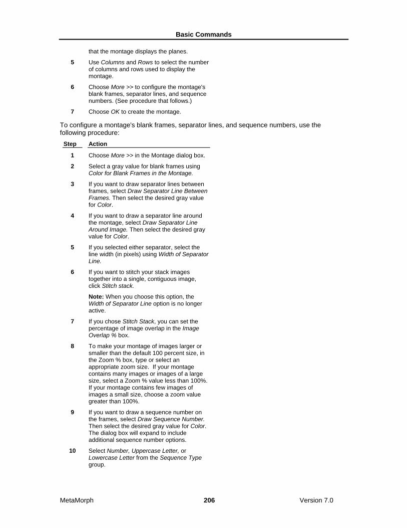
Basic Commands
MetaMorph 206 Version 7.0
that the montage displays the planes.
5 Use Columns and Rows to select the number of columns and rows used to display the montage.
6 Choose More >> to configure the montage's blank frames, separator lines, and sequence numbers. (See procedure that follows.)
7 Choose OK to create the montage.
To configure a montage's blank frames, separator lines, and sequence numbers, use the following procedure:
Step Action
1 Choose More >> in the Montage dialog box.
2 Select a gray value for blank frames using Color for Blank Frames in the Montage.
3 If you want to draw separator lines between frames, select Draw Separator Line Between Frames. Then select the desired gray value for Color.
4 If you want to draw a separator line around the montage, select Draw Separator Line Around Image. Then select the desired gray value for Color.
5 If you selected either separator, select the line width (in pixels) using Width of Separator Line.
6 If you want to stitch your stack images together into a single, contiguous image, click Stitch stack.
Note: When you choose this option, the Width of Separator Line option is no longer active.
7 If you chose Stitch Stack, you can set the percentage of image overlap in the Image Overlap % box.
8 To make your montage of images larger or smaller than the default 100 percent size, in the Zoom % box, type or select an appropriate zoom size. If your montage contains many images or images of a large size, select a Zoom % value less than 100%. If your montage contains few images of images a small size, choose a zoom value greater than 100%.
9 If you want to draw a sequence number on the frames, select Draw Sequence Number. Then select the desired gray value for Color. The dialog box will expand to include additional sequence number options.
10 Select Number, Uppercase Letter, or Lowercase Letter from the Sequence Type group.

Basic Commands
MetaMorph 207 Version 7.0
11 To place the number in the desired location on each frame, select Top Left, Top Right, Bottom Left, or Bottom Right from the Sequence Number Position group.
12 If you want a background fill behind the sequence number, select Erase Image Behind Sequence Number. Then select the desired value using the Background Color text box.
Montage - Dialog Box Options
Stack Selects the stack for the montage.
Dest Specifies a destination for the montage result image. You can Overwrite or Add to the existing stack, or you can place the results in a New image window.
Planes, Width, Height, Montage Width, Montage Height Status text that displays data for the selected stack and the montage that will be created from it.
Fill Order Selects the direction (Horizontal, Vertical, Zigzag-Horizontal, or Zigzag- Vertical) to be used to display the planes in the montage.
Columns Selects the number of columns in the montage.
Rows Selects the number of rows in the montage.
More >> Expands the dialog box to include configuration options for blank frames, separator numbers, and sequence numbers.
Less << Condenses the dialog box.
Zoom% Establishes the size of the montage window and the individual images. Use this setting to ensure that you create a suitable image size. When making a montage from a large stack, you can change the Zoom percentage to a value less than 100% to ensure that all images are displayed on your screen. You can also set the Zoom value higher than 100 percent to view smaller montages or small areas of larger montages. This zoom value is applied in the montage image creation process, and is separate from the zoom tool in the image window.
Stitch images Activates the Stitch images option. When this option is selected, image information in the adjacent or overlapped areas is compared. Coincidental image data is merged in the overlap area to create a single, contiguous image from all images in the stack.
Note: When Stitch images is selected the Width of separator line option is not active.
Image Overlap % Specifies the area of overlap between two image edges as a percentage of a single image area.
Width of Separator Line
Basic Commands
MetaMorph 208 Version 7.0
Selects the width (in pixels) used for either type of separator line.
Color for Blank Frames in the Montage Selects the grayscale value used for blank frames in the montage if there is not an even number of frames to complete the montage.
Draw Separator Line Between Frames Draws separator lines between frames using the specified Color value.
Draw Separator Line Around Image Draws separator lines around the image using the specified Color value.
Draw Sequence Number Draws the frame's sequence number using the specified Color value. When this option is selected, the dialog box will expand to include additional sequence number options.
Sequence Type Specifies the type of sequence number to be used: Number, Uppercase Letter, or Lowercase Letter. This option is available only when Draw Sequence Number has been selected.
Sequence Number Position Specifies the location of the sequence number for each plane: Top Left, Top Right, Bottom Left, or Bottom Right. This option is available only when Draw Sequence Number has been selected.
Erase Image Behind Sequence Number Places a background fill behind the sequence number using the specified Background Color value. This option is available only when Draw Sequence Number has been selected.
OK Creates the montage.
Cancel Cancels the command.
Align Stack (Stack Menu) Shifts each plane in the selected stack horizontally and/or vertically to aid in aligning of objects within the stack.
Use this command to adjust the alignment of acquired images when the object(s) in the stack need to be lined up for use of commands such as Color Encode, Arithmetic, Stack Arithmetic, and Red/Green Overlay.

Basic Commands
MetaMorph 209 Version 7.0
You can align the current plane to the adjacent plane or to the top plane.
Aligning a Stack
Reference Plane
Shifting Plane
Reference Plane
Shifting Plane
1. A horizontal shift of ten pixels to the left is selected and applied to the middle plane, using the top plane as a reference.
2. A horizontal shift of ten pixels to the left is selected and applied to the bottom plane, using the middle plane as a reference.
CAUTION: If you select the Color mode of alignment Display, you should avoid applying a zoom factor of either 25% or 50% for the Alignment image window. Because of the way in which the images are interlaced, these zoom factors will cause the green alignment image component to disappear, making it impossible to monitor your plane alignment.
Aligning a Stack To align a stack of images, use the following procedure:
Step Action
1 From the Stack menu, choose Align Stack. The Align Stack dialog box will appear.
2 Select the desired image from the Stack image selector.
3 Select an alignment display from the Display group:
Subtract uses subtraction to show the difference between the reference plane and the shifting plane.
Average uses averaging to display this difference.
Color uses red and green to mark the differences between the reference and shifting planes.
4 Specify the location of the reference plane for the alignment using Reference. You can select either the Top plane in the stack or the

Basic Commands
MetaMorph 210 Version 7.0
plane Adjacent to the current plane.
5 Choose More >> to select any of the configuration options described in Align Stack - Dialog Box Options.
6 Use the Horizontal Shift and Vertical Shift text boxes or sliders to adjust the alignment of the plane displayed in the alignment image window. The plane will be moved in one-pixel increments.
If you are using the Subtract display, the plane will be aligned when there is a nearly uniform grayscale level throughout the entire image.
If you are using Average, the aligned plane should look like the original plane with as little blurring as possible.
If you are using the Color display, the plane will be aligned when the plane is uniformly yellow with no red or green areas.
7 Choose Apply when you are satisfied with the alignment of the plane.
OR
Choose Zero Shift to reset the sliders to zero.
8 If you did not select Auto Next, choose the Next or the Previous command button to advance to the next or the preceding plane (depending on whether you are starting with the first or last plane).
9 Repeat Steps 6 - 8 until you have aligned each plane in the stack.
10 Choose Close when you have finished.
Align Stack - Dialog Box Options
Stack Selects the stack that will be aligned.
Display Selects the method to be used to display differences between the reference plane and the shifting plane:
Subtract uses subtraction to show the difference between the reference plane and the shifting plane. The planes will be aligned when there is a nearly uniform grayscale level throughout the entire image.
The Average display uses averaging to display the offset between the two planes. The aligned plane should look like the original plane with as little blurring as possible.
The Color display uses red and green to mark the differences between the reference and shifting planes. The planes will be aligned when the image is uniformly yellow with no red or green areas.
Reference Plane Specifies whether the current plane will be aligned to the Top plane or the Adjacent (N - 1) plane (the plane below the current one).
Horizontal Shift (text box and slider)

Basic Commands
MetaMorph 211 Version 7.0
Adjusts the horizontal alignment of the plane in one-pixel increments.
Vertical Shift (text box and slider) Adjusts the vertical alignment of the plane in one-pixel increments.
Previous Places the previous plane in the alignment image window. This option is not journalizable.
Next Places the next plane in the alignment image window. Use this option to align the next plane if you do not have the Auto Next command enabled. This option is not journalizable.
More >> Expands the dialog box to include the align stack configuration options.
Less << Condenses the dialog box.
Zero Shift Resets the Horizontal Shift and Vertical Shift to zero.
Auto Update Updates the alignment image as the horizontal and vertical shift of the plane are changed.
Auto Next Places the next plane in the alignment image window after you choose Apply.
Auto Zero Resets the horizontal and vertical shift to zero after you choose Apply.
Keep Alignment Image Keeps the alignment image window open after the Align Stack dialog box is closed.
Gray Level Fill Selects a grayscale level to fill in the empty areas on the edges of the image after the plane has been shifted. The default value is 0 (black).
Max Shear Selects maximum values for the horizontal and vertical shift that falls outside the default range of -10 to +10 pixels.
Apply Applies the alignment.
Close Closes the dialog box.
Movie (Stack Menu) Builds an on-screen movie that can be played forward, backward, frame-by-frame, or in a loop, from the currently selected stack. Builds an on-screen single-frame movie that can be displayed from a single-plane image.
Use this command when you want to create a movie that can be played at a user-specified speed. You can specify the direction (forward, backward, or frame-by-frame), the looping, the speed, and the movie window size. The size of the movie is limited to the amount of memory (RAM) in your computer.
If a stack is zoomed prior to building the movie, the movie will use the same zoom factor. If an active

Basic Commands
MetaMorph 212 Version 7.0
region of interest is defined on the stack, the movie image will be limited to the image inside of the region of interest.
The speed of the movie can be set from one to 30 frames per second (fps). While the movie is playing, the current speed in frames per second (fps) is displayed in the movie window. The speed achieved will depend on the size of the image. For example, while a stack that is 256 x 240 pixels can run at 30 frames per second, a stack that is 512 x 480 pixels may run slower than the selected 30 frames per second speed.
You have the option of selecting the way in which your computer's random-access memory (RAM) is used when you play back a movie. This in turn will affect the speed of playback. To configure your use of RAM during playback of a movie, select between Plays Movies Slower but Uses Less Memory and Plays Movies Faster but Uses More Memory from the Preferences dialog box's Movie Preference group (Processing tab page). If you select Plays Movie Faster…, MetaMorph will need to use enough additional RAM to create a duplicate of the stack so as to play it back as rapidly as possible. If you select Plays Movie Slower…, MetaMorph will simply play back the stack that is already in memory.
EXAMPLE: Consider the case in which you have a movie consisting of 80 eight-bit planes, each of which is 512x480 pixels in size. Each plane contains approximately 245,000 pixels, each of which consumes a byte of memory. This stack will require approximately 19.5 MB of RAM. With Plays Movie Faster… selected in the Processing tab page of the Preferences dialog box, nearly 40 MB of RAM will be required to play the movie.
Shortcuts for Movie Controls:
[B] Play movie backward.
<- Play movie one frame backward.
[SPACEBAR] Stop the movie.
-> Play movie one frame forward.
[F] Play movie forward.
[S] Maximize the movie.
[ESC] Return the movie to standard movie size
See Dropin Help Topic:
Make AVI
Building a Movie To build a movie from a stack or an image, use the following procedure:
Step Action
1 Open the stack or image and select it as the active window.
2 From the Stack menu, choose Movie and wait while MetaMorph builds the movie.
3 When MetaMorph has finished building the movie, it will display the movie in a separate window with controls at the bottom of the image.

Basic Commands
MetaMorph 213 Version 7.0
(Click each movie control in this illustration to learn more. Press [CTRL] + [TAB] to see the "hotspots.")
4 If you want to play the movie forward continuously, select Loop. If you want to loop the movie continuously forward and then backward, select both Loop and Reverse.
5 Use the movie controls or their keyboard shortcuts to play the movie.
6 To close the movie, click its Close button in the upper right corner.
Saturation Markers
This color… Indicates that the marked area is…
Dark Blue Grayscale value 0 or "less": undersaturated (too dark and will be clipped to zero).
Cyan Grayscale value 1 - 10: approaching undersaturation (underflow).
Yellow Grayscale value 245 - 254 (8-bit): approaching oversaturation (overflow).
Red Grayscale value 255 or "greater" (8-bit): oversaturated (too bright and will be clipped to 255).
Set Acquisition Channel Sets the live video channel from the list of available live video channels, if you are using a video driver that supports multiple video channels.
Use this command when you want to set the video channel prior to using a command that acquires an image in a journal (such as Live Video or Acquire Image).
This command can only be used if you are currently using a video driver that supports multiple acquisition channels. Video drivers that support multiple acquisition channels include the Matrox Image Series driver, the Matrox MVP-AT driver, the Matrox Meteor/RGB driver, the Flashbus driver, and the ITI driver. If you are using the ITI driver, you can use this command only when using a video-rate camera, but not a CCD.
Some commands, such as Acquire Image, do not have their own Video Channel option. When you include these commands in a journal that acquires an image, you should use the Set Acquisition Channel command to set the video channel.
If you are recording a journal that includes the Live Video command, you can select No Change for the Video Channel option in the Live Video dialog box during recording. Before you run the journal, you can use the Set Acquisition Channel command to select the desired channel. This eliminates the need to edit the acquisition journal each time you want to change video channels.

Basic Commands
MetaMorph 214 Version 7.0
The Matrox Meteor/RGB board has six channels. You can select 24-bit or monochrome versions of the following channels: RGB, RCA, and S-Video. The S-Video channel may not be available on all boards.
The Flashbus MV board provides a selection of four channels which vary depending on whether you selected the NTSC or PAL format when you configured the Flashbus driver. If you selected the NTSC format, you can select from RS-170, RGB, Composite, or S-Video input. If you selected the PAL format, you can select from CCIR, RGB, Composite, or S-Video inputs.
Setting the Acquisition Channel To set the live acquisition channel, use the following procedure:
Step Action
1 From the Acquire menu, choose Set Acquisition Channel. The Set Acquisition Channel dialog box opens.
2 Select the desired video channel from the Video Channel list.
3 Choose OK.
Set Acquisition Channel - Dialog Box Options
Video Channel Selects the video channel. This command can set the live video channel only if you are using a video driver that supports multiple video channels.
OK Sets the live video channel.
Cancel Cancels the command.
Device Control (Devices Menu) Controls and configures illumination, magnification, and stage settings.
Use the Device Control command to select preconfigured settings for illumination, magnification, stage, and focus position. These settings are considered the current system settings and can be selected to acquire images. You can also use this command to access the dialog boxes used to configure these settings.
Device Control - Dialog Box Options Control Tab Selects the dialog box tab that enables you to choose illumination, magnification, stage, and focus settings.
Configure Tab Selects the dialog box tab that enables you to configure illumination, magnification, stage, and focus settings.
Close Closes the dialog box.
Device Control - Control Dialog Box Options Illumination Selects a predefined illumination setting. The color box reflects the LUT for the wavelength assigned to the

Basic Commands
MetaMorph 215 Version 7.0
setting you choose.
Open/Close Shutter
Opens and closes shutters as defined by the active illumination setting.
Magnification Selects a magnification setting defined in the Magnification dialog box.
Stage X Displays the current position for the X-axis. Select another position by typing a new location in the text field or use the spin controls to move to another location.
Go To Position Select a stage position setting defined in the Memorize Position dialog box.
Stage Y Displays the current position for the X-axis. Select another position by typing a new location in the text field or use the spin controls to move to another location.
Go To Origin Moves to the Origin location.
Memorize Opens the Memorize Position dialog box. Memorizes the current position and adds it to the Memory List for future use. You are not required to provide a description for the memorized position. Positions without descriptive text are assigned descriptions (for example, Position 1, Position 2). The Memorize command allows you to assign categories to positions as they are memorized if you have set up categories using the Edit command in the Stage Memory List dialog box.
Z Motor Displays the current position for the Z Motor. Select another position by entering a new location in the text field or use the Home, Top, and Bottom buttons to move to each location.
Home Moves the Z Motor to the home focus position as defined in the Focus dialog box.
Top Moves the Z Motor to the top focus position as defined in the Focus dialog box.
Bottom Moves the Z Motor to the bottom focus position as defined in the Focus dialog box.
Close Closes the dialog box.
Device Control - Configure Dialog Box Options Configure Illumination Opens the Configure Illumination dialog box.
Configure Magnification Opens the Configure Magnification dialog box.
Configure Stage Opens the Move Stage to Absolute Position dialog box.
Configure Z

Basic Commands
MetaMorph 216 Version 7.0
Opens the Focus dialog box.
Select Z Device This option is available if more than one Z motor is available.
Select Stage Device This option is available if more than one stage is available.
Close Closes the dialog box.
Using the Device Control Command To change current device settings, use the following procedure:
Step Action
1 From the Devices menu, click Device Control. The Device Control dialog box opens.
2 Click the Control tab. The Control tab moves to the front.
3 To change the illumination setting, click the Illumination drop-down box and select from the list. The list is populated with settings created with the Configure Illumination command. The color box reflects the LUT for the wavelength assigned to the setting you choose.
4 To open or close the shutters assigned to the illumination setting, click the Open/Close Shutter icon.
5 To change the magnification setting, click the Magnification drop-down box and select from the list. The list is populated with settings created with the Configure Magnification command.
6 To change the X position of the stage, type a new location in the Stage Y field or use the spin controls to move to another location.
7 To change the Y position of the stage, type a new location in the Stage X field or use the spin controls to move to another location.
8 To select a stage position setting, click the Go To Position drop-down box and select from the list. The list is populated with settings created in the Move Stage to Absolute Position dialog box.
9 To go to the origin position defined in the Move Stage to Absolute Position, click Go to Origin.
10 To save a setting made with the Stage X and Stage Y fields, click Memorize. The Memorize Position dialog box opens. Type a name for the settings in the Description field (e.g. Setting2) and click Memorize. Your new

Basic Commands
MetaMorph 217 Version 7.0
setting is now available in the Go To Position drop-down box.
11 To change the position of the Z motor, type a new position in the Z Motor field or click Home, Top, or Bottom to go to those positions as defined in the Focus dialog box.
12 Click Close.
Configure Magnification The Configure Magnification command enables you to create unique settings for each hardware device used to control magnification in MetaMorph.
Use the Configure Magnification command to create settings for the positions of one or more hardware devices that affect magnification. Once created, these groups of settings are saved as one magnification setting that can be automatically applied in MetaMorph. This tool gives you the option of creating and reusing different magnification settings to use in various experimental conditions and hardware configurations. You can also save groups of magnification settings and load them as needed.
This command is used in conjunction with the Calibrate Distances command to determine distance calibrations applied to newly acquired images.
The following settings can be modified and saved using the Configure Magnification command:
• Objective position
• Numerical aperture
• Refraction index
• Z offset
• X, Y offset
• Z escape distance
Note: The number of settings available will vary according to the hardware attached to your computer.
Configure Magnification - Dialog Box Options Name Specifies a new magnification setting name when you add a setting with Add/Replace.
Change magnification manually Enables you to manually configure the NA and refraction Index of a new magnification setting. Use this when there is no automated objective changer detected and hardware positions cannot be set automatically. Checking this box will enable the Setting options.
Defined Settings Lists currently defined magnification settings that can be selected.
Setting Lists available configurable settings:
Note: The type and number of settings will vary based on your hardware configuration. Numerical Aperture – Specifies the numerical aperture for a manually defined magnification setting. This option is only displayed when Change magnification manually is selected.
Refraction Index – Select the following refraction indices for a manually defined magnification setting:
Air – Refraction index of 1.0. This value cannot be edited.

Basic Commands
MetaMorph 218 Version 7.0
Water – Refraction index of 1.33. This value cannot be edited.
Oil – Refraction index of 1.515. This value can be edited.
This option will not be displayed unless Change magnification manually is selected.
Z Offset (um) – Specifies the Z-offset value for the setting. When this setting is selected, MetaMorph will adjust the Z position so that the sample will stay in focus. This option is only displayed when Change magnification manually is selected.
X, Y Offset (um) –Specifies the X- and Y-offset values of the objective when changing magnification levels. When the magnification setting is selected, MetaMorph will adjust the X, Y position by the specified distance.
Objective – Selects the active objective from the motorized turret.
Magnifier – Selects the position of the magnifier.
Z Escape Distance (um) – Specifies distance to move the Z motor before changing the objective. The Z motor will return to its original position after the objective has changed.
Z Motor – Specifies which Z motor to use for the escape distance. This option is only available if more than one Z motor is connected to the system.
Display message to manually switch objective when setting is selected Check this box to be prompted to manually switch the objective to the setting specified in the chosen magnification setting. You will be prompted after the objective has been moved out of the way based on the Z Escape Distance setting. This option is only displayed when Change magnification manually is selected.
Show message when selecting setting if calibration is not assigned Check this box to be warned if a calibration is not assigned to the magnification setting selected in the Defined Settings box. Calibrations are assigned with the Calibrate Distances command.
Add/Replace Adds new or edits existing defined settings.
Remove Deletes selected defined settings.
Backup Opens the Backup All Magnification Settings dialog box, enabling you to save the active magnification settings to file. The file extension for magnification settings is .MGS.
Restore Opens the Restore Magnification Settings dialog box, enabling you to load a saved magnification settings file. The file extension for magnification settings is .MGS.
Close Closes the dialog box.
Configuring Magnification Creating Magnification Settings
Deleting Magnification Settings Creating Magnification Settings To create a new magnification setting, use the following procedure:
Step Action
1 From the Devices menu, click Configure Magnification. The Configure Magnification

Basic Commands
MetaMorph 219 Version 7.0
dialog box opens.
2 Type a name for the new setting in the Name field.
3 If you want to specify settings for hardware that cannot be changed automatically, click the Change magnification manually checkbox.
4 If you want to change the numerical aperture, select the desired value from Numerical Aperture.
5 If you want to change the refraction index, select the desired setting from Refraction Index. Only the Oil setting can be modified.
6 If you want to change the Z Offset of the objective, select the desired value from Z Offset (um).
7 To change the objective’s X and Y Offset values, select the desired values from X, Y Offset (um).
8 Click Display message to manually switch objective when setting is selected to be reminded to manually switch the objective for manual settings.
9 To select the active objective, click the Objective check box and select the magnification with the slider.
10 To select the magnifier position, click the Magnifier check box and select In or Out.
11 To select the distance the Z motor moves before the objective changes position, edit the Z Escape Distance (um) field.
12 If you have more than one Z motor attached to you system, select one from the Z Motor drop-down box.
13 Click Add/Replace when your setting is complete. The new setting name is displayed in the Defined Settings field and the setting is saved.
14 To save the active magnification settings, click Backup. The Backup All Magnification Settings dialog box opens. Type a name for the magnification settings (*.MGS) file in the File Name text box, then click Save.
15 To load a saved magnification setting, click Restore. The Restore Magnification Settings dialog box opens. Select the icon for the desired magnification file, then click Open. If the desired folder is not currently displayed, use the Look In list or Up One Level icon button to change the current folder.
16 Click Close.

Basic Commands
MetaMorph 220 Version 7.0
Deleting Magnification Settings To delete an existing magnification setting, use the following procedure:
Step Action
1 From the Devices menu, click Configure Magnification. The Configuring Magnification dialog box opens.
2 Click the name of the setting you want to delete in the Defined Settings field.
3 Click Remove.
4 Click Close.
Configure Illumination The Configure Illumination command enables you to create unique settings for the hardware devices used to control illumination in MetaMorph.
Use the Configure Illumination command to create settings for multiple hardware devices that affect illumination. Once created, the positions of these devices are saved as one illumination setting that can be automatically applied in MetaMorph. You can also save groups of Illumination settings and load them as needed.
The following aspects can be modified and saved using the Configure Illumination command:
• Open and close shutters
• Set the wavelength and intensity of the illumination by controlling the appropriate window.
• Set the wavelength value for images.
Note: The number of device controls available will vary according to your hardware configuration.
Before you use the Illumination command, you will need to install and configure the appropriate hardware device driver(s) using the Meta Imaging Series Administrator.
WARNING: Turn off all electronics, including computers, before powering up your arc lamp light source. The electromagnetic pulse (EMP) generated by arc lamp (mercury or xenon) starters can damage any electronics near the power supply, lamp house, or cables that connect the power supply and lamp.
WARNING: You must run all mechanical shutters at a cycle time greater than 25 ms. Uniblitz, Lambda 10, Metaltek, Ludl, and cooled CCD shutters are driven by a high voltage which takes time to dissipate. Running these shutters at a cycle length shorter than 25 ms will cause a build-up of heat, leading to eventual jamming. Neither Molecular Devices nor any manufacturers of the aforementioned shutters will honor warranties on equipment that has been damaged by improper use. Operation of these shutters at a cycle length shorter than 25 ms will be considered improper use.
Creating Illumination Settings The options that appear in the Configure Illumination dialog box vary based on your installed hardware. To create a new illumination setting, use the following procedure:

Basic Commands
MetaMorph 221 Version 7.0
Step Action
1 From the Devices menu, click Configure Illumination. The Configure Illumination dialog box opens.
2 Type a name for the new setting in the Name field.
3 To specify a wavelength value for images acquired using this setting, type or select a value from the Wavelength field. The color box displays the LUT for the wavelength value you enter.
4 To select the active filter for a filter wheel, click the check box next to the filter wheel name and select the filter with the slider.
5 If you have a monochromater, click the check box next to the monochrometer name and use the slider or edit box to select the wavelength to be used during acquisitions.
6 To change the state of a shutter, click the checkbox next to the shutter name and select Always Closed or Active.
7 To manually check the shutter positions for a setting, click the Open/Close Shutter icon.
8 To open the shutter when the setting is active, click Open shutters when setting is selected. This is done primarily when you are using transmitted light and bleaching and photo damage is not a concern. When this option is selected the shutters will not open or close for acquisitions because they will be in their proper state as soon as a setting becomes active.
9 Click Add/Replace when your setting is complete. The new setting name is displayed in the Defined Settings field and the setting is saved.
10 To save the active illumination settings, click Backup. The Backup All Illumination Settings dialog box opens. Type a name for the illumination settings (*.ILS) file in the File Name text box, then click Save.
11 To load a saved illumination setting, click Restore. The Restore Illumination Settings dialog box opens. Select the icon for the desired illumination file, then click Open. If the desired folder is not currently displayed, use the Look In list or Up One Level icon button to change the current folder.
12 Click Close.
Deleting Illumination Settings To delete an existing illumination setting, use the following procedure:
Step Action

Basic Commands
MetaMorph 222 Version 7.0
1 From the Devices menu, click Configure Illumination. The Configuring Illumination dialog box opens.
2 Click the name of the setting you want to delete in the Defined Settings field.
3 Click Remove.
4 Click Close.
Configure Illumination - Dialog Box Options
Name Specifies a new illumination setting name when you add a setting with Add/Replace.
Wavelength Specifies wavelength value for the illumination setting. This value is stored in images created using this illumination setting. The color box shows the LUT that corresponds with the wavelength. If you set the wavelength outside the visible range (380-780), the color box turns white.
Defined Settings Lists currently available defined illumination settings. Double click a setting to make it active. The settings in the dialog box will change to reflect the new setting.
Open shutters when setting is selected Determines if shutters set to open for each illumination setting do so when you select a setting. If not selected, shutters will open only during acquisition. Leave this box unchecked to use the Open/Close Shutter icon to verify your shutter settings.
Open/Close Shutter
Opens and closes shutters as defined by the active illumination setting. This command is useful if you want to verify the correct shutters are responding for a setting.
Device Positions Lists configurable settings:
Note: The type and number of settings will vary based on your hardware configuration.
Filter Wheel – Select the active filter for each filter wheel. If you have a monochromatic device you can enter the number in the box.
Shutter – Select Closed or Open for each shutter. This is the state you want the shutter to be in during acquisition. If the Open shutters when setting is selected box is checked, then this will be the state the shutter will be in when the setting is selected.
Monochromater – Click the check box next to the Monochromater name and use the slider or edit box to select the wavelength to be used during acquisitions.
Add/Replace Adds new or edits existing defined settings.
Remove Deletes the setting selected in the Defined Settings list.
Backup Opens the Backup All Illumination Settings dialog box, enabling you to save the active illumination settings to file. The file extension for illumination settings is .ILS.

Basic Commands
MetaMorph 223 Version 7.0
Restore Opens the Restore Illumination Settings dialog box, enabling you to load a saved illumination settings file. The file extension for illumination settings is .ILS.
Close Closes the dialog box.
Focus (Devices Menu) Provides control over the Z-axis positioning. This command sets limits on motor motion. It also allows you to alter the current position, and save positions for future use.
Use this command to configure focus limits and to memorize focus positions (100 positions per memory list) before using commands that rely on Z-axis positioning, such as Acquire Z Series.
Before you use the Focus command, you must install and configure the appropriate hardware device driver(s) for your Z motor using the Meta Imaging Series Administrator. You will also need to calibrate the focus in the Meta Imaging Series Administrator program before using the Focus command.
WARNING: Be aware of the distance between the microscope objective and your slide. Specifying a large Z-axis move may result in damage to your specimen and microscope.
Using the Focus Command Configuring Focus Limits
Changing the Focus Position
Setting Top, Bottom, and Home Positions
Using Memorized Positions
Configuring Focus Limits To set the focus limits, use the following procedure:
Step Action
1 From the Devices menu, choose Focus. The Focus dialog box will appear.
If the dialog box is compressed, choose More >>.
2 Using the focus control knob, carefully adjust the focus until you find the position you want to use as the bottom limit on the Z-axis distance range.
CAUTION: This will typically be a very small distance below the bottom of your specimen. Use very small distances to protect short working distance objectives and condensers from damage.
3 Choose Set Bottom Limit. The Current Position value should appear in the text box next to Set Bottom Limit.
4 Using the focus control knob, carefully adjust the focus until you find the position you want to use as the top limit on the Z-axis distance

Basic Commands
MetaMorph 224 Version 7.0
range (see CAUTION in Step 2.)
AND
Choose Set Top Limit. The Current Position value should appear in the text box next to Set Top Limit.
5 Select Enforce Motor Limits if you want MetaMorph to abide by the selected Top and Bottom Limits.
Note: MetaMorph will abide by these limits when this option is selected. You should use this option whenever you are acquiring images. This will protect your equipment from possible damage if you acquire too many images (the extra images will be acquired at the location of the limit).
6 Move the focus knob manually to the previous Origin reference point.
AND
Choose Set Origin.
Note: The Origin value serves as MetaMorph's reference point for its limits and memorized positions. Whenever you turn on the focus controller after it has been shut off, you will need to reestablish the Origin. Because limits and bookmarks are based on the Origin, it is very important that you use the same value each time.
Understanding Focus Limits
MetaMorph provides a Top Limit and Bottom Limit on the range of distance that MetaMorph will move the focus motor. These limits function in addition to any hardware limits the Z-axis device provides, and will help prevent damage to your equipment when used properly.
The Origin value serves as MetaMorph's reference point for its limits and memorized positions. Whenever you switch on the focus controller after it has been shut off, you will need to reestablish the Origin using Set Origin. The Origin is set to 0 when you first calibrate the focus device (and until you switch the device off). While you can change the Origin to some other position using Set Origin, the most precise positioning of the focus will be achieved if you start at the bottom (Origin) and focus upwards against gravity. This is because the teeth of the gears of the focus motor are consistently engaged when resisting gravity, but can slip slightly (tens of nanometers) when moving with gravity.

Basic Commands
MetaMorph 225 Version 7.0
Note: These limits control only the MetaMorph commands (such as those in the Focus and Acquire Z Series dialog boxes), not the manual focus control knob that is part of some Z-axis devices.
Changing the Focus Position To change the focus position manually, use the following procedure:
Step Action
1 From the Devices menu, choose Focus. The Focus dialog box will appear.
2 Select the desired increment between each move (each use of the Current Position spin box) by selecting one of the preset values in the Move Increment group.
EXAMPLE: To move one micron each time you select the Current Position spin box, select 1.0.
OR
Select Custom from the Move Increment group and type the desired increment in the Custom Increment text box.
3 Use the Current Position spin box to change the focus position in the desired direction using the increment selected in Step 2.
OR
Press the [Up Arrow] or [Down Arrow] key to change the focus position.
Setting Customized Top, Bottom, and Home Positions To define and use customized top, bottom, and home positions, use the following procedure:
Step Action

Basic Commands
MetaMorph 226 Version 7.0
1 From the Devices menu, choose Focus. The Focus dialog box will appear.
2 Change the focus position so that the desired focus position for Bottom is displayed in the Current Position text box.
3 Choose Set Bottom.
The command button next to Set Bottom should display Go to "Value" instead of Go to 0.
4 Repeat Step 2 for the desired Home focus position.
AND
Choose Set Home. The command button next to Set Home should display Go to "Value" instead of Go to 0.
5 Repeat Step 2 for the desired Top focus position.
AND
Choose Set Top. The command button next to Set Home should display Go to "Value" instead of Go to 0.
6 To change the focus position to the Bottom, Home, or Top custom position, choose the appropriate Go to "Value" command button.
Understanding Custom Top, Bottom, and Home Positions MetaMorph provides three custom positions in the Focus dialog box. These three positions are called Top, Bottom, and Home, for their positions in the stack.
When you first configure the Focus command, these custom positions are set to 0. Thus, the Go To command buttons next to the Set Top, Set Home, and Set Bottom command buttons display Go to 0. The text on these buttons will change to display values of your choice once you have selected values for each.
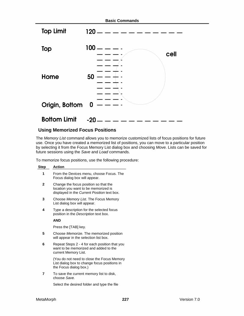
Basic Commands
MetaMorph 227 Version 7.0
Using Memorized Focus Positions The Memory List command allows you to memorize customized lists of focus positions for future use. Once you have created a memorized list of positions, you can move to a particular position by selecting it from the Focus Memory List dialog box and choosing Move. Lists can be saved for future sessions using the Save and Load commands.
To memorize focus positions, use the following procedure: Step Action
1 From the Devices menu, choose Focus. The Focus dialog box will appear.
2 Change the focus position so that the location you want to be memorized is displayed in the Current Position text box.
3 Choose Memory List. The Focus Memory List dialog box will appear.
4 Type a description for the selected focus position in the Description text box.
AND
Press the [TAB] key.
5 Choose Memorize. The memorized position will appear in the selection list box.
6 Repeat Steps 2 - 4 for each position that you want to be memorized and added to the current Memory List.
(You do not need to close the Focus Memory List dialog box to change focus positions in the Focus dialog box.)
7 To save the current memory list to disk, choose Save.
Select the desired folder and type the file

Basic Commands
MetaMorph 228 Version 7.0
name in the File Name text box. Then choose Save.
8 Click the dialog box's Close button in the upper right corner to close it.
Focus - Dialog Box Options
Focus - Main Dialog Box Options
• Focus Tab
• Configure Tab
• Limits Tab
• Special Tab
• Auto Focus Memory List
Focus - Main Dialog Box Options
Current Position Displays the current position. The next current position can be selected by typing the desired location in its text box or by using the spin box to move to another location using the increments specified by Move Increments.
Focus Tab Moves the Focus tab to the front. Use this tab to set the size of the individual focus increment, and to move the focus position to the home or origin positions, or to the position of its previously set upper or lower limit.
Configure Tab Moves the Configure tab to the front. Use this tab to set the default Z positions for Top, Bottom, Home, and Origin.
Limits Tab Moves the Limits tab to the front. Use this tab to set the upper and lower Z-motor limits, and to activate or deactivate the enforcement of the motor limits that you have set.
Special Tab Moves the Special tab to the front. Use this tab to configure the sensitivity of your focus knob.
Note: This tab is not available for all focus devices.
Auto Focus Tab Moves the Auto Focus tab to the front. Use this tab to configure laser auto focus options.
Note: The Autofocus tab is only available if the system has a recognized laser auto focus (LAF) component present. Some microscopes have optional LAF support. The following MDC hardware supports LAF:
• ImageXpress 5000a • ImageXpress MICRO
• Discovery-1
Memory List

Basic Commands
MetaMorph 229 Version 7.0
Opens the Focus Memory List dialog box. Use this dialog box to memorize customized lists of focus positions for future use. Once you have created a memorized list of positions, you can move to a particular position by selecting it from the Focus Memory List dialog box and choosing Move. Lists can be saved for future sessions using the Save and Load commands. You can memorize 100 positions per memory list.
Close Closes the Focus dialog box.
Focus Tab - Dialog Box Options
Move Increments Specifies the increments that the Current Position spin box moves using a preset value or the Custom increment.
Custom Increment Specifies the custom increment used if Custom is selected in the Move Increments group.
Go To Top Moves to the Top location as defined in the Configure tab.
Go To Home Moves to the Home location as defined in the Configure tab.
Go To Bottom Moves to the Bottom location as defined in the Configure tab.
Go To Origin Moves to the Origin location as defined in the Configure tab.
Configure Tab - Dialog Box Options
Set Top Specifies the location displayed in the Current Position text box as the Top focus position. This is a customized focus position which you can go to by choosing the Go To command next to Set Top.
Set Home Specifies the location displayed in the Current Position text box as the Home focus position. This is a customized focus position which you can go to by choosing the Go To command next to Set Home.
Set Bottom Specifies the location displayed in the Current Position text box as the Bottom focus position. This is a customized focus position which you can go to by choosing the Go To command next to Set Bottom.
Set Origin Sets the Origin to the location displayed in the Current Position text box. This value serves as MetaMorph's reference point for the Top and Bottom Limits and the memorized positions. The Origin must be reset to its previous value anytime that you use MetaMorph after turning off the focus controller.
Limits Tab - Dialog Box Options
Enforce Motor Limits Enforces the Top and Bottom Limits as the range of distance that MetaMorph will move the focus motor.
Set Top Limit Sets the Top Limit to the location displayed in the Current Position text box. Top Limit and Bottom Limit are used with Enforce Motor Limits to force MetaMorph to stay within these limits to help prevent damage to your equipment.

Basic Commands
MetaMorph 230 Version 7.0
Set Bottom Limit Sets the Bottom Limit to the location displayed in the Current Position text box. Top Limit and Bottom Limit are used with Enforce Motor Limits to force MetaMorph to stay within these limits to help prevent damage to your equipment.
Special Tab - Dialog Box Options
Note: This tab is not available for all focus devices.
Jog Sensitivity Selects the number of micrometers per rotation for the focus knob.
Record Jog Sensitivity Records the setting to a journal. This option is only enabled when recording a journal.
Encoder mode Enables the device to read back its position as it is being moved and allows it to move more accurately. Note: When this mode is active, it takes more time to complete a move.
Servo mode Enables the device to continually monitor its position and to automatically adjust the motor when it detects that the position has changed. Note: This mode requires encoders to be enabled.
Focus: Auto Focus Tab - Dialog Box Options
Note: The Autofocus tab is only available if the system has a recognized laser auto focus (LAF) component present. Some microscopes have optional LAF support. The options available in this dialog box vary depending on the hardware platform. The following MDC hardware supports LAF:
• ImageXpress MICRO
• ImageXpress 5000a
• Discovery-1
Note: If you are running MetaXpress, you can also configure LAF from the Configure Laser Sensor dialog box, which is accessed in the Autofocus tab of the Plate Acquisition Setup dialog box.
Configure Laser Opens the Configure Laser Autofocus dialog box.
Snap Image Acquires an image to the desktop using the current exposure settings (which can be changed from the Configure Laser Autofocus dialog box).
Preview Pass
Note: Preview Pass is only available for the ImageXpress MICRO hardware platform.
Runs the Z-motor through a range determined by the values in the Start position and Full range fields of the Configure Laser Autofocus dialog box. Opens a graph that charts the focus values of each Z position. The parameters used for the preview pass are set in the Configure Laser Autofocus dialog box.
Use the Preview Pass function to help determine the optimal exposure settings to use during autofocus. Ideally, the graph will show two sharp peaks that represent the focus values at the bottom of the plate and the bottom of the well.
Basic Commands
MetaMorph 231 Version 7.0
Show Laser Live
Note: This option is only available for the ImageXpress 5000A and/or Discovery-1
hardware platforms. Displays a live image of the laser using the current exposure and laser power settings from the Configure Laser Autofocus dialog box. The Plateacquire dropin must be loaded to see this option.
Autofocus
Performs laser auto focus at the current stage position using the current settings in the Configure Laser Autofocus dialog box. If applicable, the results of the autofocus are displayed in the right side of the tab.
Focus Memory List - Dialog Box Options
Memorize Memorizes the current focus position. A Description must be provided before this button is enabled.
Description Specifies the name for the current position to be memorized. Lists all memorized positions and values of the positions in the current Memory List in a list box. Each position must have unique name.
Selection List Box Allows you to select a memorized focus position before moving to it or deleting it.
Close Closes the dialog box.
Move Moves the focus to the selected memorized position.
Load Loads a previously saved focus memory list saved to disk, overwriting the current memory list displayed in the Focus Memory List dialog box.
Save Saves the active Memory List to disk for future use. The current Memory List must be saved before loading another one if you want to use the active list again.
Delete
Deletes the currently selected focus position from the active Memory List.
Configure Laser Autofocus Configures Laser Autofocus (LAF) settings used during acquisition.
Use this dialog box, along with the Auto Focus tab of the Focus dialog box, to fine tune the LAF settings used during acquisition. The options enable you to determine the number of surfaces to search for, the start position of the search, and other parameters.
Note: The Autofocus tab is only available if the system has a recognized laser auto focus (LAF) component present. Some microscopes have optional LAF support. The following MDC hardware supports LAF:
• ImageXpress 5000a

Basic Commands
MetaMorph 232 Version 7.0
• ImageXpress MICRO
• Discovery-1
Note: If you are running MetaXpress, you can also configure LAF from the Configure Laser Sensor dialog box, which is accessed in the Autofocus tab of the Plate Acquisition Setup dialog box.
Configuring Laser Autofocus
Configure Laser Autofocus - Dialog Box Options
Configure Laser Autofocus - Dialog Box Options
ImageXpress MICRO
ImageXpress 5000A
Discovery-1
Configure Laser Autofocus: ImageXpress Micro - Dialog Box Options
Action
Sets the type of autofocus used when the Autofocus command is called from the Auto Focus tab of the Focus dialog box. The following options are available:
Autofocus – Full Search – Performs a search across the full focus range, looking for either one or two peaks as specified in the Search Options field.
Autofocus – Incremental – Performs a search across an incremental range, ranging around a previously found position.
Preview Pass – Performs a preview pass across the full focus range and displays a graph of the results.
Search options
Find 2 surfaces
Attempts to find a second peak from the start position. For example, if you are using MetaXpress to perform plate acquisition, this would search for both the bottom of plate and bottom of well focus values.
Find 1 surface
Attempts to find a single peak from the start position.
Perform iterative search
The search is broken up into increments based on the Thickness value, covering up to the Full Range value. The search ends when the desired peak is found within the last range searched. If not selected, the entire Full range is traversed and the desired peak is selected from within the entire search range.
Start position
Start from current z-position
Starts the search from the current z-motor position.
Start from (um)
Basic Commands
MetaMorph 233 Version 7.0
Enables you to enter a specific z-motor position (in um) to use when starting the search.
Search parameters
Full range (um)
Specifies the full range to cover for a Full Search. If Perform iterative search is selected, this represents the maximum range to cover.
Incremental range (um)
Specifies the range to cover for an incremental search.
Thickness offset (um)
Specifies the distance to move after finding the first peak and before starting the search for the second peak. If Perform iterative search is selected, this also represents the range of each individual search.
Exposure 1st surface (us)
Specifies the exposure to use when searching for the first surface.
Exposure 2nd surface (us)
Specifies the exposure to use when searching for the second surface. This option is only enabled when Find 2 surfaces is enabled.
Coarse step (um)
Z-motor step size used during the initial stage of autofocusing. The default value varies for each objective.
Fine step (um)
Z-motor step size used during the second stage of autofocusing. The default value varies for each objective.
Laser intensity (%)
Sets the laser intensity. This option is not available for all LAF hardware platforms.
Post-focus offset (um) Specifies the z-offset to apply after finding the target peak in a search. This is the offset from the laser focus z-position to the image focus z-position. The default value varies for each objective and wavelength
OK
Accepts the current values and closes the dialog box.
Cancel
Closes the dialog box without changing any settings.
Configure Laser Autofocus: ImageXpress 5000A - Dialog Box Options
Action
Sets the type of autofocus used when the Autofocus command is called from the Auto Focus tab of the Focus dialog box. The following options are available:

Basic Commands
MetaMorph 234 Version 7.0
Autofocus –Performs a search across the full focus range, looking for either one or two peaks as specified in the Search Options field.
Show Live – Opens a live image of the laser using the current Exposure and Laser intensity settings.
Search options
Find 2 surfaces
Attempts to find a second peak from the start position. For example, if you are using MetaXpress to perform plate acquisition, this would search for both the bottom of plate and bottom of well focus values.
Find 1 surface
Attempts to find a single peak from the start position.
Start position
Start from current z-position
Starts the search from the current z-motor position.
Start from (um)
Enables you to enter a specific z-motor position (in um) to use when starting the search.
Reflectivity
Dim Sets an illumination setting used during laser auto focus suited for wells with little reflectivity, such as those with plastic plates or those using media.
Bright Sets an illumination setting used during laser auto focus suited for wells with higher reflectivity This is useful when using some types of glass plates, or wells without any media, that are highly reflective. This setting uses a filter in the emission path to reduce the intensity.
Range (um) Specifies the maximum range to cover for a search.
Thickness offset (um) Specifies the distance to move after finding the first peak and before starting the search for the second peak.
Post-focus offset (um) Specifies the z-offset to apply after finding the target peak in a search. This is the offset from the laser focus z-position to the image focus z-position. The default value varies for each objective and wavelength.
Search parameters — 1st surface
Max step (um) Z-motor step size used when searching for the first surface. The default value varies for each objective.
Exposure (ms) Specifies the exposure to use when searching for the first surface.
Laser intensity Sets the laser intensity to use when searching for the first surface.
Search parameters – 2nd surface
Basic Commands
MetaMorph 235 Version 7.0
Max step (um) Z-motor step size used when searching for the second surface. The default value varies for each objective. This option is only enabled when Find 2 surfaces is enabled.
Exposure (ms) Specifies the exposure to use when searching for the second surface. This option is only enabled when Find 2 surfaces is enabled.
Laser intensity Sets the laser intensity to use when searching for the second surface. This option is only enabled when Find 2 surfaces is enabled.
OK Accepts the current values and closes the dialog box.
Cancel Closes the dialog box without changing any settings.
Configure Laser Autofocus Discovery-1 - Dialog Box Options
Action
Sets the type of autofocus used when the Autofocus command is called from the Auto Focus tab of the Focus dialog box. The following options are available:
Autofocus –Performs a search across the full focus range, looking for either one or two peaks as specified in the Search Options field.
Show Live – Opens a live image of the laser using the current Exposure setting.
Search options
Find 2 surfaces
Attempts to find a second peak from the start position. For example, if you are using MetaXpress to perform plate acquisition, this would search for both the bottom of plate and bottom of well focus values.
Find 1 surface
Attempts to find a single peak from the start position.
Start position
Start from current z-position
Starts the search from the current z-motor position.
Start from (um)
Enables you to enter a specific z-motor position (in um) to use when starting the search.
Reflectivity
Dim Sets an illumination setting used during laser auto focus suited for wells with little reflectivity, such as those with plastic plates or those using media.
Bright Sets an illumination setting used during laser auto focus suited for wells with higher reflectivity This is useful when using some types of glass plates, or wells without any media, that are highly

Basic Commands
MetaMorph 236 Version 7.0
reflective. This setting uses a filter in the emission path to reduce the intensity.
Search parameters
Range (um) Specifies the maximum range to cover for a search.
Max step (um) Z-motor step size used when searching for the first surface. The default value varies for each objective.
Exposure 1st surface (ms) Specifies the exposure to use when searching for the first surface.
Exposure 2nd surface (ms) Specifies the exposure to use when searching for the second surface. This option is only enabled when Find 2 surfaces is enabled.
Thickness offset (um) Specifies the distance to move after finding the first peak and before starting the search for the second peak.
Post-focus offset (um) Specifies the z-offset to apply after finding the target peak in a search. This is the offset from the laser focus z-position to the image focus z-position. The default value varies for each objective and wavelength.
OK Accepts the current values and closes the dialog box.
Cancel Closes the dialog box without changing any settings.
Configuring Laser Autofocus To configure laser autofocus parameters from the Focus dialog, complete the following procedure:
Note: For more information about the fields in the Configure Laser Autofocus dialog box, refer to Configure Laser Autofocus - Dialog Box Options.
Step Action
1 From the Auto Focus tab of the Focus dialog box, Click Configure Laser. The Configure Laser Autofocus dialog box opens.
2 Select the type of autofocus action to perform from the Action drop-down list. Valid options vary depending on the hardware platform used:
Autofocus – Full Search – Performs search across full focus range, looking for either one or two peaks as specified in the Search Options field.
Autofocus – Incremental – Performs search across incremental range, ranging

Basic Commands
MetaMorph 237 Version 7.0
around the previously found focus position.
Autofocus – Performs search across full focus range, looking for either one or two peaks as specified in the Search Options field. Search stops when desired peak is found.
Preview Pass – Performs a preview pass across the full focus range and displays graph of the results.
Show Live – Opens a live image of the laser.
3 To start the autofocus from the current z-motor position, select Start from current z-position.
OR
Select Start from (um) to enter the z-motor starting position in ums.
4 Edit the values in the Search parameters field as needed. Refer to Configure Laser Autofocus - Dialog Box Options for more information.
5 Click OK to exit the Configure Laser Autofocus dialog and return to the Autofocus tab of the Focus dialog box.
Stage (Devices Menu) Provides control over the X and Y axis positioning of a stage, moves the stage, and stores position settings for future use.
Use this command to scan multiple positions using a motorized stage. Before you can use the Stage commands, you must install and configure the appropriate hardware device driver for your stage using the Meta Imaging Series Administrator. You also must calibrate the stage in the Meta Imaging Series Administrator program before using the Stage commands in MetaMorph.
If you want to control the Z-axis positioning of the stage with a focus motor, you will need to install and configure the appropriate hardware device driver for your focus controller and calibrate the focus in the Meta Imaging Series Administrator.
The five stage commands are:
Move Stage to Absolute Position
Move Stage to Relative Position
Move Stage to Position of Image
Scan Stage
Scan Multi-Well Plate
The Scan Stage and Scan Multi-Well Plate commands both scan multiple locations in an array in sequential order. For both commands, you can specify the scanning method, the X and Y axis step sizes, the number of rows and columns to scan, and the journal to be executed at each well. However, Scan Multi-Well Plate is set up to allow specific positions, rows, or columns to be enabled or disabled for scanning. An array of up to 12 x 12 wells (the size of a typical plate is 12 x 8 wells) can be visited using the Scan Multi-Well Plate command. Scan Stage, on the other hand, scans all wells in the specified

Basic Commands
MetaMorph 238 Version 7.0
array. However, it does not limit the size of the array that can be scanned.
WARNING: You need to be aware of the position of the stage relative to both the objective and the condenser of the microscope. There is always a danger that a motorized stage may collide into either of these microscope components.
Configuring the Stage
Setting the Motor Limits and Origin for the Stage
Using the Stage Memory List to Move to a Position
Editing the Stage Memory List
Moving the Stage to an Absolute Position
Moving the Stage to a Relative Position
Moving the Stage to the Position of an Image
Setting the Motor Limits and Origin for the Stage To set the motor limits and origin for the stage, use the following procedure:
Step Action
1 Install and configure the appropriate hardware device driver for your stage using the Meta Imaging Series Administrator.
2 If you have more than one stage device installed, select the correct device on the Configure tab of the Device Control dialog box.
3 From the Devices menu, choose Stage.
AND Choose Move Stage to Absolute Position or Move Stage to Relative Position from the

Basic Commands
MetaMorph 239 Version 7.0
secondary menu that appears. The selected command's dialog box will appear.
4 If the dialog box is compressed, choose More >> so that you can see the motor limits and origin commands.
5 Using the Y Current Position, adjust the stage position until you find the position you want to use as the top limit on the Y-axis distance range.
AND
Choose Top. The new limit value will appear in parentheses on the Top command button.
6 Using the Y Current Position, adjust the stage position until you find the position you want to use as the bottom limit on the Y-axis distance range.
AND
Choose Bottom. The new limit value will appear in parentheses on the Bottom command button.
7 Using the X Current Position, adjust the stage position until you find the position you want to use as the left limit on the X-axis distance range.
AND
Choose Left. The new limit value will appear in parentheses on the Left command button.
8 Using the X Current Position, adjust the stage position until you find the position you want to use as the right limit on the X-axis distance range.
AND
Choose Right. The new limit value will appear in parentheses on the Right command button.
9 Select Enforce Motor Limits if you want MetaMorph to abide by the selected limits.
Note: MetaMorph will abide by these limits when this option is selected. You should use this option whenever you are acquiring images. This will protect your equipment from possible damage if you acquire too many images (the extra images will be acquired at the location of the limit).
10 Move the stage manually to the previous Origin reference point using the motor controls.
AND
Choose Set Origin.
Note: The Origin value serves as MetaMorph's reference point for its limits and

Basic Commands
MetaMorph 240 Version 7.0
memorized positions. Whenever you turn on the stage controller after it has been shut off, you will need to reestablish the Origin. Because limits and bookmarks are based on the Origin, it is very important that you use the same value each time.
Using the Stage Memory List to Move to a Position To use the Memory List to move to a position, use the following procedure:
Step Action
1 Install and configure the appropriate hardware device driver for your stage using the Meta Imaging Series Administrator.
2 If you have more than one stage device installed, select the correct device on the Configure tab of the Device Control dialog box.
3 From the Devices menu, choose Stage.
AND Choose Move Stage to Absolute Position or Move Stage to Relative Position from the secondary menu that appears. The selected command's dialog box will appear.
4 If the dialog box is compressed, choose More >> so that you can see the motor limits and origin commands.
Choose Memory List. The Stage Memory List dialog box will appear.
5 If you have set up categories, select the desired category from the Category drop-down list box. You can select All to view the positions from all categories in the list.
6 To move to a position, select it from the Memorized Stage Position List so that it is highlighted. Then choose Move.
If you want to move to the position before the current position in the list, choose Move to Prev. If you want to move to the position after the current position, choose Move to Next.
OR
If you know the description of the position you want to move to, you can choose Move to Des. Type the description in the Description text box and choose OK.
Note: The position must be in the category that is currently selected.
7 If you want to move to multiple positions, you can double-click each of the desired position names so that each is marked with a check mark.
AND
Choose Move to Selected Positions. The
Basic Commands
MetaMorph 241 Version 7.0
Move to Selected Positions dialog box will appear. Select the Movement Order.
You can also choose Set Journal to Execute if you want a journal to be run at each position. Select the icon for the desired journal. Then choose Open.
Choose Move. MetaMorph will move the stage to all of the selected positions.
8 You can also edit the stage Memory List as needed.
9 To save the current Memory List to disk, choose Save.
Select the desired directory and then type the file name in the File Name text box. Choose Save.
Editing the Stage Memory List To use the Memory List to move to a position, use the following procedure:
Step Action
1 Choose Edit from the Stage Memory List dialog box. The Edit Stage Memory List dialog box will appear.
2 You can add categories for the list by choosing Add Category. Type the desired name in the Category text box and choose OK.
Once you have set up categories, you can select the desired category from the Category list.
3 To change the order of the position entries in the list, highlight the position entry to be moved and choose Move Up or Move Down until the entry is in the desired location.
4 You can use the Cut Position, Copy Position, and Paste Position commands to cut, copy, and paste position entries in the list.
5 To edit the values for a particular position, choose Edit Position. The Edit Stage Position dialog box will appear.
You can edit the position's description, X, Y, and Z axis values, and its selection. You can also change its X, Y, and Z axis values to the current motor position by choosing Use Motor Position. Choose OK when you are done.
6 Choose Close when you have finished.
Stage - Dialog Box Options
Stage Memory List
Edit Stage Memory List

Basic Commands
MetaMorph 242 Version 7.0
Move Stage to Absolute Position
Move Stage to Relative Position
Move Stage to Position of Image
Stage Memory List - Dialog Box Options
List of Memorized Stage Positions Displays the memorized stage positions in the current stage position list. Check marks indicate selected positions that will be moved to if you choose Move to Selected Positions. Positions can be selected or deselected by double-clicking them.
Category Specifies the category of positions that will be displayed in the list. You can select All to see all categories.
Move to Selected Positions Moves to the positions that are marked with a check mark. You can select List Order or Shortest Distance as the Movement Order. You can also select a journal to be executed at each location if needed.
Load Loads a previously saved position list for use during a session.
Close Closes the dialog box.
Move Moves to the position that is currently highlighted in the list.
Move to Prev Moves to the position prior to the current (highlighted) position in the list.
Move to Next Moves to the position after to the current (highlighted) position in the list.
Move to Des Moves to the position that has the specified description. You must provide the complete description text to move to a position using this command.
Edit Edits the order of position entries in the list, cuts, copies and pastes position entries, adds and deletes categories. You can use the keyboard shortcuts for the Cut command (CTRL + X), Copy command (CTRL + C), and Paste command (CTRL + V) to move position entries from one list category to another.
Show Allows you to specify whether the list will display all positions or just the selected positions (those marked with check marks).
Save Saves the current position list to disk for future use. You must save before quitting MetaMorph if you want to use the current list again.
Edit Stage Memory List - Dialog Box Options
Position List Displays the memorized stage positions in the current stage position list. Check marks indicate selected positions that will be moved to if you choose Move to Selected Positions in the Stage Memory List dialog box. Positions can be selected or deselected by double-clicking them.

Basic Commands
MetaMorph 243 Version 7.0
Category Specifies the category of positions that will be displayed in the list. You can select All to see all categories.
Move to Position Moves to the position that is currently highlighted in the list.
Move Up Moves the highlighted position entry up one place in the list.
Move Down Moves the highlighted position entry down one place in the list.
Edit Position Allows you to change the description and X, Y, and Z axis values for a position. You can also select or deselect the position. You can also change the X, Y, and Z axis values to the current motor position by choosing Use Motor Position.
Cut Position Cuts the highlighted position entry from the list.
Copy Position Copies the highlighted position entry.
Paste Position Pastes the last cut or copied position entry into the currently highlighted location.
Select All Turns on the selection check marks for all of the position entries in the current category.
Unselect All Turns off the selection check marks for all of the position entries in the current category.
Close Closes the dialog box.
Move Stage to Absolute Position (Devices Menu) Moves the stage to the specified absolute position. Also memorizes positions, moves to memorized positions, and sets and enforces motor limits.
This command moves the stage to the specified absolute position. It also performs some tasks which are shared by this command and the Move Stage to Relative Position command. As you work with these two commands, it is important to remember that the Configure, Set Origin, Go to Origin, Top, Bottom, Left, Right, Enforce Motor Limits, Memory List, and Memorize commands are shared by both commands. Thus, when you change the motor limits in this command's dialog box, they will be updated in the Move to Relative Position dialog box.
MetaMorph automatically generates a "label" that stores stage position information when a .tif or .stk image is acquired. This label consists of two parts which can be thought of as a position and a subposition. A move to an absolute position, and moves generated by scanning a multi-well plate, will affect the "position" portion of the label, whereas a move to a relative position, and moves generated by the Scan Stage command, will affect the "subposition" portion of the label. The position value is drawn from the Description text box entry in the Memorize Position secondary dialog box, accessed by either the Move Stage to Absolute Position or Move Stage to Relative Position commands. The subposition value will then be generated based on the most recent movement, relative to the absolute position (EXAMPLE: "Well A1:Top", "Well A1:Right", etc.). The label will be updated whenever the stage is moved. Label information is available in the Get Info image information, and can be used to search for images with the Find Image Files command. Stage label information can also be logged when you perform logging of data during measurement procedures.

Basic Commands
MetaMorph 244 Version 7.0
Moving the Stage to an Absolute Position To move the stage to an absolute position, use the following procedure:
Step Action
1 Install and configure the appropriate hardware device driver for your stage using the Meta Imaging Series Administrator.
2 If you have more than one stage device installed, select the correct device on the Configure tab of the Device Control dialog box.
3 From the Devices menu, choose Stage.
AND Choose Move Stage to Absolute Position from the secondary menu that appears. The Move Stage to Absolute Position dialog box will appear.
4 If you want to log the stage positions, open a data log using the Open Data Log command.
5 To configure the data log for logging, choose Configure Log. The Configure Log dialog box will appear.
AND
Select the parameters you want to log from the Configuration list so that each is marked by a check mark next to its entry. (You can choose Enable All or Disable All if you want to select or deselect all of the parameters listed.)
Then choose OK to return to the Move Stage to Absolute Position dialog box. You can now choose Log Position any time that you want to log the current position.
6 Use the X and Y options to move the stage to a particular position. If you are using the spin boxes, the stage will move as you click them. If you are using the text boxes, the stage will not move until you press the [TAB] key.
Note: If you have a Z-Motor Device installed, you will also be able to adjust the focus. The limits for the Z-axis are controlled in the Focus dialog box.
7 To add the current position to the Memory List, choose Memorize. The Memorize Position dialog box will appear.
Type the desired description for the position in the Description text box. If you have set up categories for positions (see Editing the Memory List), you can select a Category. Choose Memorize.
8 Choose Go to Origin whenever you want to

Basic Commands
MetaMorph 245 Version 7.0
move the stage to the origin point.
9 Choose Close when you have finished.
Move Stage to Absolute Position - Dialog Box Options
Current Position Displays the current position for the X-axis and Y-axis. The next current position can be selected by typing the desired location in the text boxes or by using the spin controls to move to another location. If a Z-Motor Device is installed, the Z spin box will also appear.
Go to Origin Moves to the Origin location.
Log Position Logs the current position in the data log file. This option is only available if a data log or DDE link has been opened.
Memorize Memorizes the current position and adds it to the Memory List for future use. You are not required to provide a description for the memorized position. Positions without descriptive text are assigned descriptions (for example, Position 1, Position 2). The Memorize command allows you to assign categories to positions as they are memorized if you have set up categories using the Edit command in the Stage Memory List dialog box.
Memory List Memorizes customized lists of stage positions for future use. Once you have created a memorized list of positions, you can move to a particular position by selecting it from the Stage Memory List dialog box and choosing Move. Lists can be saved for future sessions using the Save and Load commands. You can also edit points using the Edit command.
More >> Expands the dialog box.
Less << Condenses the dialog box.
Enforce Motor Limits Enforces the Top, Bottom, Left, and Right limits as the range of distance that MetaMorph will move the stage for the X-axis and Y-axis.
Top and Bottom Specifies the motor limits for Y-axis range of distance.
Left and Right Specifies the motor limits for the X-axis range of distance.
Configure Log Opens the Configure Log dialog box so that you can select the parameters to be logged to the data log. Parameters marked with a check mark will be logged for subsequent measurements. If Log Column Titles is selected, a line listing the measurement titles will be logged (1) the first time the configure measurement is used, (2) whenever measurement parameters are enabled or disabled, or (3) whenever the logged measurement is different from the previous measurement in the log file. If Place Log Data on Current Line is selected, subsequently logged data will be appended to the current line in the log file, rather than on a new line. The Log Column Titles option will be unavailable when you select this option.
Set Origin Sets the Origin to the location displayed in the Current Position text boxes. This value serves as MetaMorph's reference point for the motor motion limits and the memorized positions. The Origin must be

Basic Commands
MetaMorph 246 Version 7.0
reset to its previous value anytime that you use MetaMorph after turning off the stage controller.
Move Increment Sets the distance to move the stage when using the spin controls in the Current Position X, Y, and Z fields. The unit of measurement is defined when you calibrate the stage in the Meta Imaging Series Administrator.
Custom Increment Sets a custom distance to move the stage when using the spin controls in the Current Position X, Y, and Z fields. Select Custom in the Move Increment field to use this setting.
Encoder mode Enables the device to read back its position as it is being moved and allows it to move more accurately. Note: When this mode is active, it takes more time to complete a move.
Servo mode Enables the device to continually monitor its position and to automatically adjust the motor when it detects that the position has changed. Note: This mode requires encoders to be enabled.
Close Closes the dialog box.
Move Stage to Relative Position (Devices Menu) Moves the stage to the specified relative position. Also memorizes positions, moves to memorized positions, sets and enforces motor limits.
This command moves the stage to the specified relative position. It also performs some tasks which are shared by this command and the Move Stage to Absolute Position command. As you work with these two commands, it is important to remember that the Configure, Set Origin, Go to Origin, Top, Bottom, Left, Right, Enforce Motor Limits, Memory List, and Memorize commands are shared by both commands. Thus, when you change the motor limits in this command's dialog box, they will be updated in the Move to Absolute Position dialog box.
MetaMorph automatically generates a "label" that stores stage position information when a .tif or .stk image is acquired. This label consists of two parts which can be thought of as a position and a subposition. A move to an absolute position, and moves generated by scanning a multi-well plate, will affect the "position" portion of the label, whereas a move to a relative position, and moves generated by the Scan Stage command, will affect the "subposition" portion of the label. The position value is drawn from the Description text box entry in the Memorize Position secondary dialog box, accessed by either the Move Stage to Absolute Position or Move Stage to Relative Position commands. The subposition value will then be generated based on the most recent movement, relative to the absolute position (EXAMPLE: "Well A1:Top", "Well A1:Right", etc.). The label will be updated whenever the stage is moved. Label information is available in the Get Info image information, and can be used to search for images with the Find Image Files command. Stage label information can also be logged when you perform logging of data during measurement procedures.
Moving the Stage to a Relative Position To move the stage to a relative position, use the following procedure:
Step Action
1 Install and configure the appropriate hardware device driver for your stage using the Meta Imaging Series Administrator.
2 If you have more than one stage device installed, select the correct device on the Configure tab of the Device Control dialog box.
3 From the Devices menu, choose Stage.

Basic Commands
MetaMorph 247 Version 7.0
AND Choose Move Stage to Relative Position from the secondary menu that appears. The Move Stage to Relative Position dialog box will appear.
4 If you want to log stage positions, open a data log using the Open Data Log command.
5 To configure the data log for logging, choose Configure Log. The Configure Log dialog box will appear.
AND
Select the parameters you want to log from the Configuration list so that each is marked by a check mark next to its entry. (You can choose Enable All or Disable All if you want to select or deselect all of the parameters listed.)
Choose OK to return to the Move Stage to Relative Position dialog box. You can now choose Log Position any time that you want to log the current position.
6 Use the X and Y options to specify the Relative Offset for the move. Choose Move and the new current position is displayed in the Current Position text next to the Relative Offset.
Note: If you have a Z-Motor Device installed, you will also be able to adjust the focus. The limits for the Z-axis are controlled in the Focus dialog box.
7 To add the current position to the memory list, choose Memorize. The Memorize Position dialog box will appear.
Type the desired description for the position in the Description text box. If you have set up categories for positions (see Editing the Memory List), you can select a Category. Choose Memorize.
8 If you want to go to the Origin point, choose More >> to expand the dialog box. Then choose Go to Origin.
9 Choose Close when you have finished.
Move Stage to Relative Position - Dialog Box Options
Relative Offset Selects the relative offset for the Move command for the X-axis and Y-axis. To move forward relative to the current position, select a positive number. To move backward relative to the current position, select a negative number. If a Z-Motor device is installed, the Z spin box will also appear.
Current Position Displays the current position for the X-axis and Y-axis. If a Z-Motor device is installed, the position for the Z-axis will also appear.

Basic Commands
MetaMorph 248 Version 7.0
Close Closes the dialog box.
Move Moves the stage to position indicated by the relative offset.
Memorize Memorizes the current position and adds it to the Memory List for future use. This option allows you to assign categories to positions as they are memorized if you have set up categories using the Edit command in the Stage Memory List dialog box.
Log Position Logs the current position in the data log file. This option is only available if a data log is open or a DDE link to an open spreadsheet has been established.
Memory List Memorizes customized lists of stage positions for future use. Once you have created a memorized list of positions, you can move to a particular position by selecting it from the Stage Memory List dialog box and choosing Move. Lists can be saved for future sessions using the Save and Load commands. You can also edit points using the Edit command.
More >> Expands the dialog box.
Less << Condenses the dialog box.
Enforce Motor Limits Enforces the Top, Bottom, Left, and Right limits as the range of distance that MetaMorph will move the stage for the X-axis and Y-axis.
Top and Bottom Specifies the motor limits for Y-axis range of distance.
Left and Right Specifies the motor limits for the X-axis range of distance.
Configure Log Opens the Configure Log dialog box so that you can select the parameters to be logged to the Data Log. Parameters marked with a check mark will be logged for subsequent measurements. If you select Log Column Titles, a line listing the measurement titles will be logged (1) the first time you use the configured measurement, (2) whenever you enable or disable measurement parameters, or (3) whenever the logged measurement is different from the previous measurement in the log file. If you select Place Log Data on Current Line, subsequently logged data will be appended to the current line in the log file, rather than on a new line. The Log Column Titles option will be unavailable when you select this option.
Go to Origin Moves to the Origin location.
Set Origin Sets the Origin to the location displayed in the Current Position text boxes. This value serves as MetaMorph's reference point for the limits and the memorized positions. The Origin must be reset to its previous value anytime that you use MetaMorph after turning off the stage controller.
Move Stage to Position of Image (Devices Menu) Reads the stage position information from a previously acquired image and moves the stage to that position.

Basic Commands
MetaMorph 249 Version 7.0
MetaMorph automatically generates a "label" that stores stage position information when a .tif or .stk image is acquired. This label consists of two parts which can be thought of as a position and a subposition. Label information is available in the Get Info image information, and can be used to search for images with the Find Image Files command. The Move Stage to Position of Image command uses the position information from a selected image of interest to direct the placement of the stage.
Note: This command can not be used to move the stage to the Z-axis position of the image, even if the stage or other device has Z-motor capabilities. This is because absolute Z-positions can not be recorded in an image.
WARNING: If the stage has not maintained its origin, it will not be moved to the correct position. The origin might become changed if the stage is moved when MetaMorph is not running or if the stage is switched off. The origin can be changed with the Set Origin command button located in either the Move Stage to Absolute Position or Move Stage to Relative Position dialog boxes.
Moving the Stage to the Position of an Image To move the stage to the position at which an image was acquired, use the following procedure:
Step Action
1 Install and configure the appropriate hardware device driver for your stage using the Meta Imaging Series Administrator.
2 If you have more than one stage device installed, select the correct device on the Configure tab of the Device Control dialog box.
3 From the Devices menu, choose Stage.
AND Choose Move Stage to Position of Image from the secondary menu that appears. The Move to Image Position dialog box will appear.
4 Use the Image selector to select the image whose stage position information you want to use to move the stage.
The X, Y Position of Image status line will indicate the stage coordinates of the image, and the Label status line will display the position label (position:subposition).
5 When you are ready, choose OK. The stage will move to the position at which the image was acquired.
WARNING: If the stage has not maintained its origin, it will not be moved to the correct position. The origin might become changed if the stage is moved when MetaMorph is not running or if the stage is switched off
6 When you have finished, choose Close.
Move Stage to Position of Image - Dialog Box Options Image Selects the image whose stage position you want to use to reposition the stage.

Basic Commands
MetaMorph 250 Version 7.0
X, Y Position of Image Indicates the X and Y coordinates at which the selected image was acquired.
Label Indicates the stage position label (position:subposition).
OK Moves the stage to the position at which the selected image was acquired.
Close Closes the dialog box.
Scan Stage (Devices Menu) Scans multiple locations in array using a user-specified sequential order and user-specified X and Y axis step sizes.
Use this command when you want to scan a complete array that is larger than the 24 x 24 well limit that can be scanned using the Scan Multi-Well Plate command. Scan Stage scans all wells in the specified array. You can specify a journal to be run at each well, if you wish.
The Scan Stage and Scan Multi-Well Plate commands both scan multiple locations in an array in sequential order. For both commands, you can specify the scanning method, the X and Y axis step sizes, the number of rows and columns to scan, and the journal to be executed at each well. However, Scan Multi-Well Plate is set up to allow specific positions, rows, or columns to be enabled or disabled for scanning. An array of up to 24 x 24 wells (the size of a typical plate is 12 x 8 wells) can be visited using the Scan Multi-Well Plate command. Scan Stage, on the other hand, scans all wells in the specified array. However, it does not limit the size of the array that can be scanned.
Note: This command assumes that you have already moved the stage to the desired starting point for the scan.
MetaMorph automatically generates a "label" that stores stage position information when a .tif or .stk image is acquired. This label consists of two parts which can be thought of as a position and a subposition. A move to an absolute position, and moves generated by scanning a multi-well plate, will affect the "position" portion of the label, whereas a move to a relative position, and moves generated by the Scan Stage command, will affect the "subposition" portion of the label. The position value is drawn from the Description text box entry in the Memorize Position secondary dialog box, accessed by either the Move Stage to Absolute Position or Move Stage to Relative Position commands. The subposition
Basic Commands
MetaMorph 251 Version 7.0
value will then be generated based on the most recent movement, relative to the absolute position (EXAMPLE: "Well A1:Top", "Well A1:Right", etc.). The label will be updated whenever the stage is moved. Label information is available in the Get Info image information, and can be used to search for images with the Find Image Files command. Stage label information can also be logged when you perform logging of data during measurement procedures.
Scanning the Stage To scan a stage, use the following procedure. (Note: This command assumes that you are already at the desired starting point for the scan.)
Step Action
1 Install and configure the appropriate hardware device driver for your stage using the Meta Imaging Series Administrator.
2 If you have more than one stage device installed, select the correct device on the Configure tab of the Device Control dialog box.
3 From the Devices menu, choose Stage.
AND Choose Scan Stage from the secondary menu that appears. The Scan Stage dialog box will appear.
4 Select the desired order for the scanning from the Scan Mode group.
5 Specify the appropriate X and Y axis step distances for your stage using the X and Y Step Size options.
6 Specify the size of the array to be scanned using Columns and Rows.
7 If you want a journal to be executed each time a cell is visited, choose Set Journal to Execute. The Select a Journal to Run dialog box will appear.
AND
Select the icon for the desired journal and choose Open to return to the Scan Stage dialog box. The journal name will be listed at the bottom of the dialog box.
8 Choose Scan. The Scanning Stage dialog box will appear.
This dialog box lists the status of the scan. Information such as the current location, number of wells done, and number of wells not completed will be listed in this dialog box. You can choose Cancel if you want to cancel a scan.
Scan Stage - Dialog Box Options
Scan Mode Specifies the sequential order used to visit each well. Left to Right scans from left to right, while Zig Zag (Horizontal) scans every other row left to right, and right to left for the intervening rows. Top to Bottom scans

Basic Commands
MetaMorph 252 Version 7.0
top to bottom, while Zig Zag (Vertical) scans every other column top to bottom, and bottom to top for the intervening columns.
Step Size Specifies the X and Y axis step size between cells for the scan.
Columns Specifies the number of columns in the array to be scanned.
Rows Specifies the number of rows in the array to be scanned.
Set Journal to Execute Specifies the journal to be run at each well, if applicable. If one is selected, it will be listed below this command button.
Scan Scans the specified array and runs the selected journal. Displays its progress in the Scanning Stage dialog box.
Close Closes the dialog box.
Scan Multi-Well Plate (Devices Menu) Scans multiple locations in an array as large as 24 x 24 wells, using a user-specified sequential order and user-specified X and Y axis step sizes. Scans only the rows, columns, or wells that have been marked for scanning.
Use this command when you want to scan some locations in an array that can be up to 24 columns by 24 rows. This command is typically used to scan multiple-well plates. You can use its Configure Wells command to mark which rows, columns, or specific cell locations are to be scanned. You can specify a journal to run at each well, if needed.
The Scan Stage and Scan Multi-Well Plate commands both scan multiple locations in an array in sequential order. For both commands, you can specify the scanning method, the X and Y axis step sizes, the number of rows and columns to scan, and the journal to be run at each well. However, Scan Multi-Well Plate is set up to allow specific positions, rows, or columns to be enabled or disabled for scanning. An array of up to 24 x 24 wells can be visited using the Scan Multi-Well Plate command. Scan Stage, on the other hand, scans all wells in the specified array. However, it does not limit the size of the array that can be scanned.

Basic Commands
MetaMorph 253 Version 7.0
Note: This command assumes that you have already moved the stage to the desired starting point for the scan.
Note: If you are using this command while recording a journal, you will have the option of recording the scan to the journal without performing the scan. A dialog box opens when you click Scan that asks if you want to record the scan without actually performing the scan.
MetaMorph automatically generates a "label" that stores stage position information when a .tif or .stk image is acquired. This label consists of two parts which can be thought of as a position and a subposition. A move to an absolute position, and moves generated by scanning a multi-well plate, will affect the "position" portion of the label, whereas a move to a relative position, and moves generated by the Scan Stage command, will affect the "subposition" portion of the label. The position value is drawn from the Description text box entry in the Memorize Position secondary dialog box, accessed by either the Move Stage to Absolute Position or Move Stage to Relative Position commands. The subposition value will then be generated based on the most recent movement, relative to the absolute position (EXAMPLE: "Well A1:Top", "Well A1:Right", etc.). The label will be updated whenever the stage is moved. Label information is available in the Get Info image information, and can be used to search for images with the Find Image Files command. Stage label information can also be logged when you perform logging of data during measurement procedures.
Scanning a Multi-Well Plate To scan a multiple-well plate, use the following procedure.
Note: This command assumes that you are already at the desired starting point for the scan.
Step Action
1 Install and configure the appropriate hardware device driver for your stage using the Meta Imaging Series Administrator.
2 If you have more than one stage device installed, select the correct device on the Configure tab of the Device Control dialog box.
3 From the Devices menu, choose Stage. A secondary menu will appear.

Basic Commands
MetaMorph 254 Version 7.0
AND From the secondary menu, choose Scan Multi-Well Plate. The Scan Multi-Well Plate dialog box will appear.
4 Select the desired order for the scanning from the Scan Mode group.
5 Specify the appropriate X and Y axis step distances for your stage using the X and Y Step Size options.
6 Specify the size of the array to be scanned using Columns and Rows.
7 To specify the well positions to be scanned, choose Configure Wells. The Configure Wells dialog box will appear. This dialog box consists of check boxes representing the wells in the selected array size. Only those wells whose check boxes are selected will be visited during the scan.
The square button next to each row number and below each column label allows you to select or clear all of the check boxes representing that row or column's wells. You can use the All button to select or deselect the entire array. You can also select or clear individual check boxes by clicking them.
8 To specify whether the rows are to be labeled with letters and the columns with numbers, or vice versa, select your desired configuration, either Letters for Columns or Letters for Rows, from the Well Labeling option button group.
9 When you have finished, choose Close to return to the Scan Multi-Well Plate dialog box.
10 If you want a journal to be run each time a cell is visited, choose Set Journal to Execute. The Select a Journal to Run dialog box will appear.
AND
Select the file for the desired journal and choose Open to return to the Scan Multi-Well Plate dialog box. The journal name will be listed at the bottom of the dialog box.
11 Choose Scan. The Scanning Stage status window will appear.
This dialog box lists the status of the scan. The current location, number of wells completed, the number of wells remaining, and the current well being scanned will be listed in this status window. You can choose Cancel if you want to cancel a scan.
Scan Multi-Well Plate - Dialog Box Options
Scan Multi-Well Plate

Basic Commands
MetaMorph 255 Version 7.0
Configure Wells
Scanning Wells
Scan Multi-Well Plate - Dialog Box Options
Scan Mode Specifies the sequential order used to visit each well. Left to Right scans left to right, while Zig Zag (Horizontal) scans every other row left to right, and right to left for the intervening rows. Top to Bottom scans top to bottom, while Zig Zag (Vertical) scans every other column top to bottom, and bottom to top for the intervening columns.
Step Size Specifies the X and Y axis step size between cells for the scan.
Columns Specifies the number of columns in the array to be scanned. A maximum of 24 columns can be selected.
Rows Specifies the number of rows in the array to be scanned. A maximum of 24 rows can be selected.
Configure Wells Opens the Configure Wells dialog box so that you can select the specific wells to be scanned. This dialog box consists of check boxes representing the wells in the selected array size. Only those wells whose check boxes are selected will be visited during the scan. Note: When you first open the Scan Multi-Well Plate dialog box, the default setting is for one row and one column (i.e., a single well). If you choose the Configure Wells command button without changing the Columns and Rows settings, a message box will appear, informing you that the command is configured for a single well. Regardless of whether you want to keep the single well configuration or want to reconfigure for more wells, select the check box in the message window if you want to measure that uppermost, leftmost well. Clear the check box if you want to skip that well. If necessary, you can then reconfigure the Columns and Rows settings in the Scan Multi-Well Plate dialog box and rechoose Configure Wells to make your final selection of which wells to measure.
Set Journal to Execute Specifies the journal to be run at each well, if applicable. If one is selected, it will be listed below this command button.
Random Scan Enables a random scan of the plate. The number of wells that are randomly scanned are determined in the Wells to visit field. The Columns and Rows fields are disabled if Random Scan is selected.
Wells to visit Determines the number of well to randomly scan when Random Scan is selected.
Scan Scans the specified array (or random wells) and executes the selected journal. Displays its progress in the Scanning Stage dialog box.
Close Closes the dialog box.
Database Connection Enables you login to the MetaXpress image database when opening the MetaXpress application.
Availability: Exclusive to MetaXpress Database Version

Basic Commands
MetaMorph 256 Version 7.0
Drop-in: HTDB_PLAYER Use the Database Connection Dialog box to log in to the MetaXpress image database when opening the MetaXpress application.
Note: If you do not know the information needed to connect to the database and start MetaXpress, contact your System Administrator.
Database Connection - Connecting to the Database To connect to the MetaXpress database and start the MetaXpress application, complete the following procedure:
Note: If you do not know the information needed to connect to the database and start MetaXpress, contact your System Administrator.
Step Action
1 Start the MetaXpress application.
2 When the Database Connection dialog box opens, select either Oracle or SQL Server as the Database Type.
3 Enter the server name in the Server field. If you are using a locally installed copy of the MSDE or SQL Server software, you can use a "." (full stop or period) in place of the server name
4 Enter the database name in the Database field.
5 Enter your username and password into the next two fields.
6 Click Set Network Type button, select Named Pipes for a locally installed server or TCP/IP for a remote server (unless instructed otherwise by your network administrator).
Note: If something has changed with the network setup of your operating system, the Named Pipes and TCP/IP options may not work. If there is an error connecting to the database with these options, try selecting the System’s Default option and trying to connect again.
7 Click OK to close the Set Network Type dialog box
8 Click Connect to connect to the database.
If the connection succeeds, the MetaXpress menus will display. If there is an error connecting to the database, a dialog box will open. Please note the exact text displayed in the dialog when contacting Molecular Devices Corporation Technical Support for assistance.
Database Connection - Dialog Box Options

Basic Commands
MetaMorph 257 Version 7.0
Note: Ensure that you have the database and server information needed before attempting to log in to the database. If you do not have this information, contact you System Administrator.
Database Type Selects the database program to login to. Valid choices are Oracle or SQL Server
Server Specifies the name of the server to connect to. If you are using a locally installed copy of the MSDE or SQL Server software, you can use a "." (full stop or period) in place of the server name.
Database Specifies the name of the database to connect to.
User Specifies the user account name to use when logging in to the database.
Password Specifies the user account password to use when logging in to the database.
Set Network Type Opens the Set Network Type dialog box. Select Named Pipes for a locally installed server or TCP/IP for a remote server (unless instructed otherwise by your network administrator).
Connect Attempts to connect to the selected database based on your current settings.
Cancel Cancels the command and closes MetaXpress.
Configure Wells (Scan Multi-Well Plate) - Dialog Box Options
All Selects and deselects all wells. Wells that have been selected will be indicated in the grid by a check mark.
Well Labeling Selects a labeling configuration for the rows and columns in the grid: Letters for Columns labels the columns with letters (A, B, C, …, etc.) and the rows with numbers (1, 2, 3, …, etc.), whereas Letters for Rows labels the columns with numbers and the rows with letters.
A, B, C, …, etc. Selecting the button at the top of the column or to the left of the row (depending on your selection from the Well Labeling option button group) selects and deselects the entire column or row. Clicking an individual check box in the grid selects and deselects the corresponding well.
1, 2, 3, …, etc. Selecting the button to the left of the row or at the top of the column (depending on your selection from the Well Labeling option button group) selects and deselects the entire row or column. Clicking an individual check box in the grid selects and deselects the corresponding well.
Close Accepts the current selection of wells to be scanned and closes the Configure Wells dialog box.
Scanning Wells (Scan Multi-Well Plate) - Dialog Box Options
Scanning… of… Indicates numerically which well is currently being scanned, out of the total number of wells.

Basic Commands
MetaMorph 258 Version 7.0
X Indicates the row of the well currently being scanned.
Y Indicates the column of the well currently being scanned
Wells Done Indicates the number of wells that have already been scanned.
Wells to Do Indicates the number of wells remaining to be scanned
Well Indicates the well currently being scanned, in terms of its row/column (e.g., "F11").
Cancel Cancels the scanning operation and closes the Scanning Wells status window.
Laser Control (MicroPoint™ Laser) Provides control of the Photonic Instruments MicroPoint™ Laser system.
Use this dialog box to control the MicroPoint™ Laser system when running applications such as photobleaching, photoablation, uncaging and photoactivation. This dialog box provides settings for the MicroPoint™ laser system that control the laser position, intensity, and number of pulses. You can either designate a region which directs the laser to the center of the region, or specify the X and Y coordinates of the location where you want to direct the laser. You can use two different settings to control the laser intensity. The Attenuation plate setting moves a plate of varying density that interrupts the laser. Use the dialog box Attenuation Plate slider control or settings box to vary the setting continuously from 0 percent to 100 percent. You can also specify the number of pulses that you want to occur at the selected target location. Increasing the number of pulses over time has an effect similar to increasing the percentage of transmission. Therefore, if you cannot attain sufficient intensity using only the Attenuation Plate setting, you can increase the number of laser pulses that will be applied to the selected location.
Notes: • Each laser pulse requires about 67 milliseconds, limiting the maximum number of pulses
per second to 15. The actual laser pulse duration from the Nitrogen gas laser is about four nanoseconds, but the charging circuit requires the additional time for complete recycle.
• Your experiment’s photobleaching characteristics, such as anticipated rate of recovery might limit the number of laser pulses that can effectively be applied to a single location on your sample without invalidating your experiment data.
You can also automate your experiment by incorporating laser control settings into a MetaMorph journal. Using a journal, you can target multiple locations on your sample that are either adjoining within a single region or are in separate non-adjoining locations.
Note: If you are interested in reviewing publications about the use of the MicroPoint™ Laser for photobleaching applications, contact Molecular Devices support.
MicroPoint™ is a trademark of Photonic Instruments, Inc.
General Procedures
Creating a Coordinate System
Pulsing the Laser at your Sample
Laser Control - Dialog Box Options
Basic Commands
MetaMorph 259 Version 7.0
General Procedures The following are the general steps for using the Laser Control. For specific procedures for using the Laser Control, refer to Pulsing the laser at your sample, which follows.
Note: Before beginning to use the Laser Control, be sure to read these general procedures to familiarize yourself with the overall process of preparing and using the Laser Control software.
Step Action
1 Ensure that all MicroPoint™ Laser physical and mechanical configurations are set up correctly. Refer to the MicroPoint™ documentation included with your laser system.
Note: Ensure that your MicroPoint™ laser is correctly focused. If the laser is not properly focused, the Laser Control software will not be able to configure the coordinate system.
2 Establish and set up an illumination specifically for acquisitions made in conjunction with the MicroPoint™ laser system.
3 In the Configure Magnification dialog box, create a magnification setting for each objective that you intend to use.
4 Complete the Coordinate system setting.
Refer to Creating a Coordinate System
Note: To properly complete the coordinate system setting, you must set up a magnification setting for each objective that you intend to use for your experiment.
5 Determine whether you will specify the exact coordinates for applying the laser to your sample or use the center of the active region as the laser application point.
6 Determine the intensity of laser that you want to apply. Laser intensity is typically set using the Attenuation plate control. You can set an intensity level ranging from 0 to 100 percent. You can achieve higher levels of intensity by increasing the number of pulses.
7 Ensure that you familiarize yourself with and follow all safety procedures for using the MicroPoint™ Laser before turning on the laser and initiating laser pulses. Refer to the safety warnings that follow.
Warning The MicroPoint™ Laser is a Class III B laser system. This laser produces coherent light of extreme high intensity. Looking at the laser, particularly through the microscope

Basic Commands
MetaMorph 260 Version 7.0
optics, can cause permanent eye damage. Whenever the laser is on, you should be sure to strictly adhere to the following rules:
• Always keep the laser safety key lock in the off position during all times when you are not specifically performing photobleaching or other laser procedures.
• Always set the light path control to the camera position before turning on the laser.
• Never look into the microscope eyepieces when the laser is on.
• Avoid looking at the sample area on the stage when the laser is on.
• Never look directly down into the objective of an inverted microscope. Laser Control (MicroPoint)
Creating a Coordinate System
Pulsing the Laser at your Sample
Laser Control - Dialog Box Options
Creating a Coordinate System To create a coordinate system that defines the area of your sample at which the laser can pulse, complete the following procedure:
Note: The coordinate system setting defines the relationship between image pixel units and laser units. A five point calibration method is used.
Step Action
1 From the Devices menu, click Configure Illumination. The Configure Illumination dialog box opens.
2 Verify that the appropriate illumination settings are correct. To use the laser control, you must have at least one illumination setting. If your MicroPoint™ laser requires a specific illumination configuration, you should create the appropriate settings in the Configure Illumination dialog box.
3 From the Devices menu, click Configure Magnification. The Configure Magnification dialog box opens.
4 Verify that your magnification settings are correct. You should have a magnification setting for each objective that you will use. Correct magnification settings are needed to create the Coordinate system setting. .
5 If you have a manual microscope, in the Configure Magnification dialog box, click both Change magnification manually and Display message to manually switch objective when setting is selected.
Note: Because manual microscopes cannot communicate with MetaMorph, when you change your objective, you must also

Basic Commands
MetaMorph 261 Version 7.0
change your magnification setting in MetaMorph or image information stored with the image will be incorrect
6 From the Devices menu, click Laser Control. The Laser Control dialog box opens.
7 From the list of available settings in the Illumination setting box, choose the illumination setting that you want to use when the laser is pulsed.
8 From either the Device Control dialog box or the Device Control tool bar, choose your initial magnification setting, then ensure that you have selected the matching objective on your microscope.
9 Place a sample slide on the stage, and focus the microscope; then, remove the sample slide and place a yellow fluorescence laser calibration slide on the stage.
10 On the MicroPoint™ Laser control box, turn the key to the on position to turn on the laser power supply. The laser will be used in the following step to create a Coordinate System.
Warning
Before pulsing the laser, be sure that the light path is set to the camera position, and that no one is looking through the microscope eyepieces or directly at the stage or into the objective, or serious, permanent eye damage can result.
11 In the Coordinate System Setting Box, create a new setting by clicking Create Setting. You can also update an existing setting by clicking Update Setting. Click Delete Setting to remove settings that are no longer valid. When you click Create Setting or Update Setting, the system will pulse the laser at five different locations to create the Coordinate System. Appropriate messages are displayed indicating success or problems in creating the coordinate system.
12 Repeat the preceding step to create a separate coordinate system for each objective that you will use in your experiment. The coordinate system setting name will be the magnification name followed by the date that you created the coordinate system for that objective.
13 Your coordinate system has been created, proceed to Pulsing the Laser at your Sample.
Laser Control (MicroPoint)

Basic Commands
MetaMorph 262 Version 7.0
General Procedures
Pulsing the Laser at your Sample
Laser Control - Dialog Box Options
Pulsing the Laser at your Sample To pulse the laser at portion of a sample, complete the following procedure: Step Action
1 From the Devices menu, click Laser Control. The Laser Control dialog box opens.
2 From the list of available settings in the Illumination setting box, choose the illumination setting that you want to use when the laser is pulsed.
3 From either the Device Control dialog box or the Device Control tool bar, choose your magnification setting, then ensure that you have selected the matching objective on your microscope.
4 In the Coordinate System Setting Box, select the coordinate system setting that corresponds to your selected magnification and objective. If no coordinate system setting exists or if you need to create a new setting for a different objective, refer to the preceding procedure for Creating a Coordinate System.
5 Place a valid sample slide on the microscope stage.
6 In the Position box, choose either Image coordinates or Center of active region. Image coordinates define the location of the laser target to the pixel location; Center of active region defines the target location as the center point within the active region.
7 If you chose Image coordinates, click Preview Image. An image window opens with two regions on the image. One region defines the boundaries in which the laser can pulse. The position of this region cannot be adjusted. The image window will also contain a rectangle that you can move. Drag this rectangle to a location in the image where you want to pulse the laser. The X/Y coordinates of the laser target is the center of the rectangle. You can also type or select the target location in the X and Y Image coordinates boxes.
8 If you chose Center of active region, in the Live image window or in an acquired image, use an appropriate region tool to place a region around the target area. The center of

Basic Commands
MetaMorph 263 Version 7.0
the region will be the target.
Hint: To have a visual indication of the boundary limits when you are placing a region in the live window (or in an acquired image), complete the following steps:
• Before selecting Center of active region, while Image coordinates is selected, click Preview.
• In the Preview window make the region that represents the image coordinate boundaries active.
• Open the Acquire dialog box and click Live.
• Open the Transfer Regions dialog box, and transfer only the Active Region to the Live window or acquired image.
Note: Be sure not to move this region after it has been transferred, or the boundary reference will no longer be valid.
9 In the Intensity box, set the intensity level that you want to use. First set the percentage of intensity using the Attenuation plate control. Type or select a value from 1 to 100 percent or move the slider control to change the percentage value. The sum of the total cumulative time to pulse the laser is shown to the right of the Number of pulses field.
Note: 100 percent indicates the maximum amount of laser intensity.
10 If the Attenuation plate transmission percentage is 100, and you still need more intensity on a single target, use the Number of pulses setting to increase the number of pulses. Type or select the number of pulses that you want the laser to emit. The laser can emit a maximum of 15 pulses in one second. The duration and spacing between pulses are fixed values.
11 To pulse the laser for the selected number of pulses at the selected intensity (percentage of transmission), turn on the laser safety key switch on the MicroPoint™ Laser control unit, then click Pulse Laser. After you are finished, turn off the laser safety key switch.
Warning
Before pulsing the laser, be sure that the light path is set to the camera position, and that no one is looking through the microscope eyepieces or directly at the stage or into the objective, or serious, permanent eye damage can result.
12 To close the Laser Control dialog box, click the close button. Any settings that you

Basic Commands
MetaMorph 264 Version 7.0
made in the dialog box are stored for future use, and will be present the next time you open the dialog box.
Laser Control (MicroPoint)
General Procedures
Creating a Coordinate System
Laser Control - Dialog Box Options
Laser Control - Dialog Box Options
Illumination setting Selects a preconfigured illumination setting containing the illumination settings values to be used when the laser is active.
Coordinate system setting Selects and assigns a coordinate system based on a magnification setting. You can create and store multiple settings, and then choose the setting that is most appropriate for your experiment. The coordinate system setting defines the relationship between image pixel units and laser units. A five point calibration method is used. Refer to the procedure for Creating a Coordinate System.
Create Setting Creates the coordinate system settings. When you click Create Settings, the program instructs you to place a fluorescent calibration slide on the stage. After you click OK, the program automatically calibrates the laser to the current magnification. A new setting is displayed in the Coordinate system setting box, indicating the magnification used and the date it was created.
Update Setting Applies a new set of Coordinate system setting values to replace the currently displayed setting values.
Delete Setting Deletes the currently selected laser coordinate system.
Position Chooses between using coordinates that you specify or the center of the current active region as the laser target area.
Image Coordinates Specifies the X and Y coordinates of the laser target position when you have chosen Image coordinates as the laser position selection. Note: the Images coordinates settings boxes are inactive until a coordinate system has been established and selected. It is also inactive whenever Center of Active region is selected.
X and Y position Specifies the X and Y coordinate values that determine the location where the laser will be focused.
Center of Active Region Designates the center of the active region as the laser target. The laser will pulse only at the center of the active region. The X and Y image coordinate boxes are inactive when Center of Active Region is selected. The Preview Image is not available when you are using Center of Active Region to designate your laser target. Open the Acquire dialog box and use Live or acquire an image on which to place an active region.
Hint: To have the boundary region available for reference, transfer the region from the Preview Image window to either the live window or the acquired window.
Note: Center of active region is the recommended target selection method to use in a journal.

Basic Commands
MetaMorph 265 Version 7.0
Using this method enables more than one target region to be pulsed when looping a journal for all regions.
Preview Image Opens a preview image to enable you to see and move the region whose center is the target when Image Coordinates is selected . It also shows a region that indicates the boundary of the area in which the laser can pulse. Drag the target region inside the boundary region to update the image coordinates. The laser will pulse the center of the region.
Note: The Preview Image window is a static image using settings from the Acquire dialog box.
Intensity Provides controls for setting the laser pulse intensity.
Number of pulses Specifies the number of times the laser will pulse the selected location Each pulse lasts about four nanoseconds with 67 milliseconds between pulses.
Attenuation plate Selects the attenuation plate position that corresponds to the desired percentage of power for the laser.
Pulse Laser Initiates the specified number of laser pulses. To pulse the laser for the selected number of pulses at the selected intensity (percentage of transmission), turn on the laser safety key switch on the MicroPoint™ Laser control unit, then click Pulse Laser. After you are finished, turn off the laser safety key switch.
Warning:
Before pulsing the laser, be sure that the light path is set to the camera position, and that no one is looking through the microscope eyepieces or directly at the stage or into the objective, or serious, permanent eye damage can result.
Close Closes the Laser Control dialog box. Any settings that you made in the dialog box are stored for future use, and will be present the next time you open the dialog box.
Laser Control (MicroPoint)
General Procedures
Creating a Coordinate System
Pulsing the Laser at your Sample
Calibration Bar (Display Menu) Stamps a distance calibration bar on the selected image, based on its calibration settings. You can specify the use of a label (number of units and unit name) and the bar's size, orientation, color, font, and border.
Use this command with an image that you have calibrated using the Calibrate Distances command to display a calibration bar for publication purposes.
The default position is the lower right corner of the image, but you can place the bar anywhere on the image prior to stamping. This command creates an active region to mark the location and size of the bar so that you can see where the stamp will be applied. You can use the options in the dialog box to change the size and position of the bar, or you can move and adjust the region like a rectangular region (the region defines the space for the bar, the border for the bar, and its label). When you choose Stamp,

Basic Commands
MetaMorph 266 Version 7.0
the calibration bar will become part of the image, overwriting any underlying image data.
The Bar Size option in the Stamp Calibration Bar dialog box will list the calibration units used for the calibration bar. If the word "units" is listed after Bar Size rather than "um" or some such unit name, the image has not been calibrated with the Calibrate Distances command.
This command can be applied to 1-bit, 8-bit, 16-bit, or 24-bit images. You can also stamp individual planes in a stack. You can use Undo in the dialog box to undo the calibration stamp, or you can use the Undo command in the Edit menu.
Note: When creating a journal in the Journal Editor that includes a step to include a calibration bar, you can override the X and Y position values of the bar using variables. This can be used, for example, to set the position of the calibration bar based on a calculation.
QUICK TIP: Calibration bar outlines can be copied to the Clipboard and pasted into successive images in precisely the same location as in the original image. When you right-click the calibration bar region in the source image, a pop-up context menu will appear, from which you can choose Copy Region. You can then right-click in the destination image and choose Paste Region from the context menu. The region outline will be pasted into the destination image, and you can then apply the Stamp Calibration Bar command by selecting the destination image from the image selector and choosing Stamp.
WARNING: When you stamp an image with a calibration bar, the bar will become a part of the image itself. If you later try to perform a densitometric or morphometric measurement on the entire image, the grayscale values and morphometric characteristics of the bar and its labeling will be measured along with the objects in the image. Be sure to perform your measurements before you apply any graphics to the image. If there is any chance that you will need to reanalyze the original image, you should make a copy of the original and apply the calibration bar to the copy.
WARNING: If you are stamping a calibration bar on a 16-bit image that has already been scaled using the Scale 16-Bit Image command’s Auto Scale option, you should select grayscale values for the bar and background colors that do not differ greatly from the high and low intensity values in the image itself. Because the bar and its labeling become part of the image, the image intensities will be rescaled when an excessively bright or dark bar or text is applied to an autoscaled image. This can have the undesirable effect of severely reducing the apparent contrast in the image and making it too dark or too bright.
Stamping a Calibration Bar To stamp a calibration bar on an image, use the following procedure:
Step Action
1 Use the Calibrate Distances command to calibrate the image, if you have not already done so.
2 From the Display menu, choose Graphics> Calibration Bar. The Calibration Bar dialog box opens.
3 Select the desired image using the Image selector. If the selected image is a stack, select All (planes) or the Current plane from the image selector.
4 Select the desired size of the calibration bar using the Bar Size and Thickness options.
OR
Click the calibration bar region and drag the region outline to the desired size. The values in the Bar Size and Thickness text boxes will change accordingly.

Basic Commands
MetaMorph 267 Version 7.0
5 Choose Horizontal or Vertical from the Bar Orientation group.
6 Select the X and Y coordinates of the desired location for the calibration bar using the X and Y options.
OR
Click in the middle of the calibration bar region and drag the region outline to the desired location. The values in the X and Y options will change accordingly.
7 If you want to configure the calibration bar stamp, choose More >> for additional options. Otherwise, skip to Step10.
8 Select the desired grayscale or color value for the calibration bar border color using Bar Border Color.
9 To configure the calibration bar interior and label, use the following options. Select
Fill Interior Area of Bar if you want to fill in the bar with the selected grayscale or color value,
Draw Label Onto Image if you want to draw a label next to the bar, using the selected grayscale or color value, or
Erase Image Behind Label if you want the image area behind the label to be replaced with the selected grayscale or color value.
AND
Select the desired grayscale or color value for each using its Color option.
10 Choose Stamp.
11 Choose Close.
Calibration Bar - Dialog Box Options
Image Specifies the image that will be stamped with the calibration bar.
Label Indicates the current size, in pixels, of the calibration bar.
Bar Size (units) Specifies the size of the bar in calibrated units.
Bar Thickness (pixels) Specifies the thickness of the bar, in pixels.
Bar Orientation Specifies the Horizontal or Vertical orientation of the calibration bar.
X Specifies X-coordinate on the image for the location of the bar.

Basic Commands
MetaMorph 268 Version 7.0
Y Specifies Y-coordinate on the image for the location of the bar.
Bar Border Color Specifies the grayscale or color value used for the border surrounding the calibration bar.
Fill Interior Area of Bar Fills the interior area of the bar with the selected grayscale or color value.
Draw Label on Image Draws a calibration bar label, using the selected grayscale or color value, next to the bar indicating the number of calibrated units and the unit name in the bar.
Erase Image Behind Label Replaces the image area behind the label with the specified grayscale or color value.
Font Selects a font for the calibration bar label.
Stamp Stamps the calibration bar on the image.
More >> Expands the dialog box to display additional options.
<< Less Condenses the dialog box.
Undo / Redo Undoes/redoes the last applicable command that did not create a new result image.
Close Closes the dialog box.
Date/Time (Display Menu) Stamps your choice of the current date and time, the acquisition date and time, between-plane elapsed time, or stopwatch elapsed times on the selected image or plane.
Use this command when you want to label an image with the date and time. You may select the color of the text and background (if a background is desired). The format of the date and time stamp can also be configured. This command may be applied to 1-bit, 8-bit, 16-bit, or 24-bit images. You may also stamp individual planes in a stack. You may use the Undo option in the dialog box or the Undo command in the Edit menu to undo the command.
The default position is in the lower right corner of the image, but you may place the timestamp anywhere on the image prior to stamping. This command creates an active region to mark the location of the timestamp so that you can see where the stamp will be applied. You can reposition the timestamp as you would a rectangular region. Once you choose Stamp, the timestamp becomes part of the image.
WARNING: When you apply a timestamp to an image, the stamp will become a part of the image itself. If you later try to perform a densitometric or morphometric measurement on the entire image, the grayscale values and morphometric characteristics of the stamp will be measured along with the objects in the image. Be sure to perform your measurements before you apply any graphics to the image. If there is any chance that you will need to reanalyze the original image, you should make a copy of the original and apply the stamp to the copy.
WARNING: If you are placing a timestamp on a 16-bit image that has already been scaled using the Scale 16-Bit

Basic Commands
MetaMorph 269 Version 7.0
Image command’s Auto Scale option, you should select grayscale values for the timestamp and background colors that do not differ greatly from the high and low intensity values in the image itself. Because the stamp becomes part of the image, the image intensities will be rescaled when an excessively bright or dark stamp is applied to an autoscaled image. This can have the undesirable effect of severely reducing the apparent contrast in the image and making it too dark or too bright.
Stamping the Date/Time on an Image
To stamp the time and date on image, use the following procedure: Step Action
1 From the Display menu, choose Graphics> Date/Time. The Date/Time dialog box opens.
2 Select the desired source image using the Image selector. If the selected image is a stack, select All (planes) or the Current plane from the image selector.
3 Select the desired grayscale or color value for the text color using Text Color.
4 Select Fill Background if you want to place a background behind the date/time stamp.
5 Select the desired grayscale or color value for the background color using Background Color.
Note: Fill Background must be selected first.
6 If the image is a 16-bit image, you may select Restrict Colors to Min/Max to restrict the available colors for the date/time stamp to those within the range between the image's minimum and maximum brightness values.
7 From the Time/Date Source group, select Time Image Was Created, Current Time, Elapsed Time, or Stopwatch 1, 2, or 3 as the source of the date/time stamp.
8 To change the format of the timestamp, choose Format. Select the desired date and time elements from the dialog box and choose OK to return to the Stamp Date/Time dialog box.
9 If the region for the time/date stamp is not in the desired location on the image, drag it to the desired position using the pointer.
10 Choose Stamp.
11 Choose Close.
Date/Time - Dialog Box Options
Image Selects the image or plane that will be given a date/time stamp.
Date/Time Specifies source used for the stamp. Choices are Time Image Was Created, Current Time, Elapsed Time,

Basic Commands
MetaMorph 270 Version 7.0
Stopwatch 1, Stopwatch 2, and Stopwatch 3.
X Specifies the X-coordinate on the image for the location of the date/time stamp.
Y Specifies the Y-coordinate on the image for the location of the date/time stamp.
Text Color Specifies the grayscale or color value for the text of the date/time stamp.
Background Color Specifies the grayscale or color value for the background color behind the date/time stamp if you selected Fill Background.
Make Colors Image Min/Max Restricts the available colors for the date/time stamp to those in the range between the image's minimum and maximum gray or color values.
Fill Background Places the selected background color behind the date/time stamp.
Stamp Stamps the timestamp at the location selected by the date/time stamp region of interest.
Undo / Redo Undoes/redoes the last applicable command that did not create a new result image.
Format Specifies the format used for the stamp using the various date and time elements provided in the dialog box (Day, Hour, Seconds, etc.).
Font Selects a font for the date/time stamp.
Close Closes the dialog box.
Clear Measurement Stamps (Measure Menu) Clears (erases) all of the Measure Pixel and Manually Count Objects measurement stamps from the graphics overlay on the current image.
Use this command when you want to clear measurement stamps created by the Measure Pixel or Manually Count Objects commands.
Shortcut: ALT + C
Clearing Measurement Stamps To clear measurement stamps from an image, use the following procedure:
Step Action
1 From the Measure menu, choose Clear Measurement Stamps.
2 The stamps will be cleared from the image.

Basic Commands
MetaMorph 271 Version 7.0
Color Combine (Display Menu) Creates an 8-bit color image with a custom look-up table, or a 24- or 48 bit color image, using the red, green, and blue components from up to three specified 8-bit or 16-bit images. Creates an 8-bit image with a custom look-up table from a two- or three-plane stack, using its planes as the red, green, and blue components. Creates a 24- or 48-bit image from a binary, 8-bit, or 16-bit image, using a custom look-up table.
To create an 8-bit color-encoded image, MetaMorph takes advantage of the fact that most color images do not use the full spectrum of colors available. It builds a custom look-up table consisting of the 256 most frequent colors in specified images. Encoded pixels that do not match the colors in the look-up table are converted to the most closely matched representative color. This is referred to as the "optimal color matching" model for color-encoding.
You may specify one image each for the Red, Green, and Blue components if you are using the One Image per Color option. If you do not want to specify an image for a particular component, you may select None from its image selector. The three images do not have to be the same bit-depth: a combination of 8-bit and 16-bit images can be used. However, binary source images are not supported.
Use the Hue rendering option to improve the resulting image when combining red, green, and blue images. The Hue rendering option passes the red, green, and blue components through a matrix that has custom color merge coefficients. The Coefficients option opens a dialog box that enables you to create, save, or load custom coefficient sets. You can also use Hue rendering to color combine a stack of three planes where each plane is the red, green, and blue data of an image.
Color Combine also has a Stack option for color-encoding stacks with two or three planes. The Stack option can be particularly useful for working with stacks that have planes acquired separately with red, green, and blue filters.
Note: Images with broad ranges of colors will be noticeably degraded when converted to eight bits. Artificially constructed images and noisy images frequently have too many colors to convert well to an 8-bit image. Look for quantization effects or false-contouring in the resultant 8-bit images. To avoid this, use a low pass filter or a similar processing filter on the noisy image to create a smoother image more suitable for color-encoding.
For best results when using fluorescence images, you should use background subtraction to make the background as uniformly dark as possible. Ideally, all background pixels will be gray level zero. If the background is not uniformly gray level zero, you may want to use Clip to Gray Level in the Threshold Image dialog box to set all background pixels (for example, those in the range of 0 to 20) to zero. An alternative method is to subtract a constant gray value from the image (using the Subtract operation in the Arithmetic dialog box with Constant selected as the Second Source). Before color-encoding brightfield images, you should perform similar actions to make the background uniformly bright (for example, gray level 255 for 8-bit images).
Note: When the Components option is selected, the Color Combine command will use the calibration settings from the first component image selected. If images are selected for the Red, Green, and Blue Components, then the calibration settings from the Red Component image are used in the color combined image. If no red component is selected, the calibration settings from the green component image are used. If only a blue component image is selected, then its calibration setting is used.
Combining Colors To create a color-encoded image, use the following procedure:
Step Action
1 From the Display menu, choose Color Combine. The Color Combine dialog box

Basic Commands
MetaMorph 272 Version 7.0
opens.
2 Select the desired source from the Source Type group. You can select
Components if you want to specify the source images for each component separately,
Stack if the source is a stack with two or more planes, or
Single Image if you want to color-encode a binary, 8-bit, or 16-bit image to create a 24-bit result image.
3 Select the desired result depth from the Result Depth group.
Note: You must select 24-Bit for this option if you selected Single Image as the Source Type in Step 2.
4 If you selected Components in Step 2, select the desired image for each component that you want to use from the Red Component, Green Component, and Blue Component image selectors.
OR If you selected Stack in Step 2, select the desired stack from the Stack image selector.
OR If you selected Single Image in Step 2, select the desired image from the Source image selector.
5 Select the desired destination using the Destination image selector.
6 To use the Hue rendering option, click Enable hue rendering, then click Coefficients to open the Coefficients dialog box and load or create a coefficient set to use when processing the images.
Note: This option is not available when Single Image is selected in the Source Type field.
6 Choose Color Combine.
Color Combine - Dialog Box Options
Source Type Specifies the source used for the Color Encode command. Select
Components if you want to specify the source images for each component separately,
Stack if you want to use a stack with two or more planes as the source, or
Single Image if you want to color-encode a binary, 8-bit, or 16-bit image to create a resulting 24-bit image.
Result Depth

Basic Commands
MetaMorph 273 Version 7.0
Specifies the bit-depth of the resulting color-encoded image. You may select either 8-Bit, 24-Bit or 48-bit if the Source Type is Components or Stack. If the Source Type is Single Image, you must select 24-Bit as the Result Depth.
Red Component Specifies the image to use for the red component, if separate images are to be used for each component.
Green Component Specifies the image to use for the green component, if separate images are to be used for each component.
Blue Component Specifies the image to use for the blue component, if separate images are to be used for each component.
Stack Specifies the stack to use if you selected Stack as the Source Type.
Source Specifies the 8-bit image to use if you selected Single Image as the Source Type.
Destination Specifies the destination to use for the color-encoded image.
Hue Rendering Use the Hue rendering option to improve the resulting image when combining red, green, and blue images. The Hue rendering option passes the red, green, and blue components through a matrix that has custom color merge coefficients. You can also use Hue rendering to color combine a stack of three planes where each plane is the red, green, and blue data of an image.
Enable hue rendering Enables hue rendering when the Color Combine command is used. This option is not available when Single Image is selected as the Source Type
Coefficients Opens the Coefficients dialog box that enables you to create, save, or load custom coefficient sets. This option is only available when Hue rendering is enabled.
Color Combine Color-encodes the selected image(s) or stack.
Cancel Cancels the command.
Coefficients - Dialog Box Options
Color merge coefficients Specifies the values of each coefficient in the 3 x 3 matrix. Each column represents a color channel in RGB order; that is, the column on the left contains red values, the middle column green values, and the right column blue values. The sum of each row must always add up to 255.
Load Set Opens the Load State File dialog box. This enables you to load an existing coefficient set to be used when color combining.
Save Set Opens the Save coefficient dialog box. Enables you to save the current coefficient settings to a file (*.clr) for subsequent re-use using the Load Set command.
OK Accepts any changes you made to the settings in the Coefficients dialog box and closes the dialog box.

Basic Commands
MetaMorph 274 Version 7.0
Cancel Cancels any changes you made to the settings in the Coefficients dialog box and closes the dialog box.
Color Separate (Display Menu) Converts a 24- or 48-bit color image or stack of images into three component 8-bit images. Depending on the color model you select, the destination images will consist of (1) a red image, a green image, and a blue image, (2) a hue image, a saturation image, and an intensity image, or (3) a hue image, a saturation image, and a luminosity image. The color decoding process is essentially a reversal of the process used in the Color Combine command.
Use this command when you want to separate a color image or stack of color images into component elements. You can select a color space model in which to work: RGB (red-green-blue), HSI (hue-saturation-intensity), or HSL (hue-saturation-luminosity). After you select a color model, you can separate the color source image into the three components that constitute the image, based on the color model.
Separating Colors in an Image To color-decode a 24- or 48-bit color image into its three component 8-bit images, use the following procedure:
Step Action
1 From the Display menu, choose Color Separate. The Color Separate dialog box opens.
2 From the Color Image selector, select the image you want to decode.
3 From the Color Model list, select a color model with which to work.
4 If you want to change the names of the result images from the default titles, enter your desired names in the three image selectors. You can overwrite or add to an existing image, or you can place the results in a new image window.
5 Choose Separate.
6 When you have finished, choose Close.
Color Separate - Dialog Box Options
Color Image Selects the color source image or stack of images that you want to decode into three 8-bit images or image stacks.
Color Model Selects a color space model in which to work: RGB (red-green-blue), HSI (hue-saturation-intensity), or HSL (hue-saturation-luminosity). The model you select will determine the components into which the source image will be decoded.
Red Image / Hue Image Selects the destination for the 8-bit red image (RGB model) or hue image (HSI or HSL models).
Green Image / Saturation Image Selects the destination for the 8-bit green image (RGB model) or saturation image (HSI or HSL models).

Basic Commands
MetaMorph 275 Version 7.0
Blue Image / Intensity Image / Luminosity Image Selects the destination for the8-bit blue image (RGB model), intensity image (HSI model) or luminosity image (HSL model).
Separate Carries out the command.
Close Closes the dialog box.
Intensity Profile (Display Menu) Creates a topographical profile of an image's intensity levels in which "heights" represent brightness in the source image.
Use this command to represent an image's intensity distributions as "heights" in a 3-D topographical display. The maximum height will be used for the brightest possible pixels in the source image, for example, pixels with grayscale value 255 in an 8-bit image. Less bright pixels will accordingly be scaled to a smaller height.
You can configure the height of the "3-D" profile to suit your needs by selecting a Scaling mode. The overall height of the resulting destination image will be scaled accordingly. If you select Pixels as your Scaling mode, you can specify a maximum height for the profile of anywhere from 2 to 256 pixels. The height of the resulting destination image will be the selected number of pixels plus one-half the height of the original source image. For example, if you select a Scaling value of 80 pixels and your original image is 120 pixels in height, the resulting overall image height will be ( 80 + [ 120 / 2 ] ), or 140 pixels.
If you select Percentage as your Scaling mode, you can specify a maximum height for the profile that is between 2.5 and 50 percent of the original source image. The 5 - 100 percent range indicated by this option is stated as a percentage of one-half the height of the original source image. The height of the resulting destination image will thus be one-half the selected Percentage of the original source image (which is variable, depending on your Percentage selection) plus one-half the actual height of the source image (which is constant). For example, if you select a Scaling value of 50 percent and your original image is 120 pixels in height, the resulting overall image height will be ( [ { 50% / 2 } X 120 pixels ] + [ 120 pixels / 2 ] ), or 90 pixels.
In addition to creating profiles from images, you can also create a profile from all planes in a stack. Intensity Profile includes a Preview option which displays a preview of the profile for the selected image or current plane to help you select parameters.
By default, the Pseudocolor look-up table is assigned to the profile image window. This command will work with either 8-bit or 16-bit grayscale images, and will retain the source image grayscale values. This command does not support 24-bit color images.
There are three intensity profile modes available.
Points produces a profile in which each point in the profile represents the intensity of the corresponding point in the source image.
Lines, Equal Intensity produces a profile in which lines extend from the point (X, Y, 0) to the point (X, Y, intensity). Each line in the profile uses the intensity or color of the corresponding point the source image.
Lines, Shaded produces a profile in which lines extend from the point (X, Y, 0) to the point (X, Y, intensity). The intensity or color of each line in the profile reflects the Y-axis position of the corresponding point in the source image. The further a pixel is toward the back of the profile, the more faded it appears.

Basic Commands
MetaMorph 276 Version 7.0
Creating an Intensity Profile To create an intensity profile from an image or stack, use the following procedure:
Step Action
1 From the Graphics menu, choose Intensity Profile. The Intensity Profile dialog box will appear.
2 Select the desired source image using the Source image selector. If the selected image is a stack, select All (planes) or the Current plane from the image selector.
3 Select the desired destination and name for the intensity profile using the Dest. image selector.
4 From the Profile Mode group, select
(1) Points,
(2) Lines, Equal Intensity, or
(3) Lines, Shaded.
5 Select a Skew value to set the distance to shift the profile display, if necessary. The default value is 30.
6 Select a Scaling mode to determine the height of the profile. Select
Pixels to specify a maximum height for the profile that is expressed in terms of actual numbers of pixels, or
Percentage to specify a maximum height that is expressed as a percentage of the height of the original source image. (Note: The percentage is actually expressed in terms of half the height of the source image. Thus, "100" percent equates to 50% of the overall source image.)
7 Use the Scale text box or slider to specify the maximum height of the profile. This will be expressed as either pixels or as a percentage of the height of the original source image, depending on the selection you made in Step 6.
8 Choose Preview if you want to see a preview of the intensity profile using the options selected. A preview of the image's or current plane's profile will be created.
9 Choose OK.
Intensity Profile - Dialog Box Options
Source Specifies the source image or stack for the intensity profile.
Dest

Basic Commands
MetaMorph 277 Version 7.0
Specifies the destination and name used for the intensity profile.
Profile Mode Specifies the profile mode used to create the intensity profile:
Points produces a profile in which each point in the profile represents the intensity of the corresponding point in the source image.
Lines, Equal Intensity produces a profile in which lines extend from the point (X, Y, 0) to the point (X, Y, intensity). Each line in the profile uses the intensity or color of the corresponding point the source image.
Lines, Shaded produces a profile in which lines extend from the point (X, Y, 0) to the point (X, Y, intensity). The intensity or color of each line in the profile reflects the y position of the corresponding point in the source image. The further a pixel is toward the back of the profile, the more faded it appears.
Skew Specifies the distance to shift the profile display. The default value is 30. The X-axis offset is based on an equation calculated for each row (Y) of the image:
[ ]( )Offset X
Image Height=
− Y Skew*128
Scaling Selects the mode by which the maximum height of the profile is determined. Select:
Pixels to specify a maximum height for the profile that is expressed in terms of actual numbers of pixels, or
Percentage to specify a maximum height that is expressed as a percentage of the height of the original source image. (Note: The percentage is actually expressed in terms of half the height of the source image. Thus, "100" percent equates to 50% of the overall source image.)
Scale Specifies the maximum height of the profile. This will be expressed as either pixels (2 - 256) or as a percentage of the height (actually, half the height) of the original source image (5 - 100), depending on whether you selected Pixels or Percentage as the Scaling mode.
Preview Creates a preview of the intensity profile that will be created. For stacks, a preview of the current plane will be displayed.
OK Creates the intensity profile of the selected image or stack and places it in the new image window specified by Dest.
Cancel Cancels the command.
Deinterlace (Display Menu) Creates one image composed of the even-field scan lines from a video source image and another image composed of the video source image's odd-field scan lines. Each scan line in the two resulting images will be duplicated to maintain the appropriate aspect ratio.
Use the Deinterlace command to separate interlaced video images created with Image-1/FL. Image-1/FL stores images in such a way that the first wavelength is saved in the even-field scan lines and the second wavelength is saved in the odd-field scan lines of the saved image. Deinterlace may be applied to stacks. Two stacks will be created.
Basic Commands
MetaMorph 278 Version 7.0
The U.S. broadcast standard video format (RS-170) specifies that a single video frame duration be 1/30th of a second. The frame is actually composed of two interlaced video fields, an "odd" scan line field and an "even" scan line field, each 1/60th of a second in duration. If you are acquiring single frames (from either a camera or an optical memory disk recorder), you can improve your time resolution from 1/30th to 1/60th of a second by deinterlacing the fields. There is no guarantee as to whether an odd field or an even field will be acquired first.
Note: Digital cameras do not use interlacing. Accordingly, this command only applies to images captured with a video rate camera.
Note: This command does not support 24-bit color images.
Deinterlacing an Image or Stack To deinterlace an image or stack, use the following procedure:
Note: If there is an active region of interest on the source image, Deinterlace will use that region to set the size of the Odd and Even images when New is selected in the Odd or Even image selectors.
Step Action
1 From the Display menu, choose Deinterlace. The Deinterlace dialog box opens.
2 Select the desired source image using the Source image selector. If the selected image is a stack, select All (planes) or the Current plane from the image selector.
3 Select the desired destination and name for the odd-field scan lines using the Odd image selector.
4 Select the desired destination and name for the even-field scan lines using the Even image selector.
5 Choose Apply.
6 Choose Close when you have finished.
Deinterlace - Dialog Box Options
Source Specifies the source image or stack that will be deinterlaced.
Odd Specifies the destination and name to use for the resulting odd-field scan lines.
Even Specifies the destination and name to use for the resulting even-field scan lines.
Apply Deinterlaces the selected image or stack.
Close Closes the dialog box.

Basic Commands
MetaMorph 279 Version 7.0
Rotate (Display Menu) Rotates the selected image in integer increments from -360 to ~359 degrees and places the resulting image in a new image window.
Use this command when you want to rotate an image clockwise from -360 to ~359 degrees. If a region of interest is active, the command will rotate the area in the region of interest and place it a new image window.
You can select from the following interpolation algorithms to use when rotating the image:
Nearest Neighbors — Uses the intensity values from the closest neighboring pixels to determine intensity values for rotated pixels. This option is the fastest but least accurate.
Linear Interpolation — Uses a weighted average of the intensity values of pixels (using the best least-squares fit plane to the 4 four nearest rotated pixel intensities) around the rotated pixels to determine the new intensity value.
Cubic Interpolation — Uses a weighted average of the intensity values of pixels (using a third degree polynomial model of the 16 nearest rotated pixel intensities) around the rotated pixels to determine the new intensity value. The option is the slowest but the most accurate.
See Dropin Help File:
Stretch and Mirror
Rotating an Image To rotate an image, use the following procedure:
Step Action
1 From the Display menu, choose Rotate. The Rotate dialog box opens.
2 Select the desired image for rotating from the Image selector.
3 Select the desired angle from the Rotate by list.
4 If desired, select a rotation algorithm to use. Nearest Neighbors is selected by default.
4 Choose Rotate. MetaMorph will create a clockwise-rotated copy of the image in a new image window.
5 Choose Close when you have finished.
Rotate - Dialog Box Options
Image Selects the image to be rotated.
Dest Selects the destination for the rotated image. You can overwrite the existing image or place the results in a new image window. Or you can add the rotated image as a plane to an existing image or stack.
Rotate by Selects the angle of rotation for the image. The valid range is -360 to ~359 degrees.

Basic Commands
MetaMorph 280 Version 7.0
Rotation Algorithm Nearest Neighbors — Uses the intensity values from the closest neighboring pixels to
determine intensity values for rotated pixels. This option is the fastest but least accurate.
Linear Interpolation — Uses a weighted average of the intensity values of pixels (using the best least-squares fit plane to the 4 four nearest rotated pixel intensities) around the rotated pixels to determine the new intensity value.
Cubic Interpolation — Uses a weighted average of the intensity values of pixels (using a third degree polynomial model of the 16 nearest rotated pixel intensities) around the rotated pixels to determine the new intensity value. The option is the slowest but the most accurate.
Rotate Rotates the specified image or region of interest and places the resulting image in a new image window.
Close Closes the dialog box.
Paint Region (Display Menu) Paints a region in a specified grayscale level or color in an image, or paints an outline of the region, using the active region to define the size, shape, and location. If region label drawing has been enabled in the Region Label tab page of the Preferences dialog box, the numeric region labels will be stamped into the image.
Use this command when you want to paint over unneeded areas of the selected image. For example, you can paint the edges of an image that has been processed with the low pass filter using an active rectangular region. (Only pixels surrounded by other pixels can be filtered. Therefore, pixels on the edges of the image will not have been filtered.)
You can also use this command to add regions to the thresholding range when single objects need to be treated as a single unit for analysis and processing. Alternatively, this command can be used to remove regions from thresholding when two or more overlapping thresholded objects need to be differentiated.
This function is also useful for inserting "title" boxes over images for presentations. (This command is particularly suited for use in journals, allowing you to create uniform "title" boxes in a series of images.)
QUICK TIP: Region outlines can be copied to the Clipboard and pasted into successive images in precisely the same location as in the original image. When you right-click the region in the source image, a pop-up context menu will appear, from which you can choose Copy Region. You can then right-click in the destination image and choose Paste Region from the context menu. The region outline will be pasted into the destination image, and you can then apply the Paint Region command by selecting the destination image from the image selector and choosing Paint.
You can also use Paint Region to draw lines of a one pixel-width on the image using one of the line Region Tools (Single Line, Multi-Line, and Traced Line Tools). To create thicker lines, use the Rectangular Region Tool or Trace Region Tool.
The Undo option in the Paint Region dialog box undoes the last application of the Paint Region command.
See Dropin Help File::
Draw Text

Basic Commands
MetaMorph 281 Version 7.0
Painting a Region To paint a region on an image or stack, use the following procedure:
Step Action
1 From the Display menu, choose Graphics>Paint Region. The Paint Region dialog box opens.
2 Select the desired source image using the Image selector. If the selected image is a stack, select All (planes) or the Current plane from the image selector.
3 From the Paint Mode group, select between Region Outline Only, Inside region area, or Outside region area.
4 If you want to paint the region or outline in a specific grayscale intensity value (binary, 8-bit, or 16-bit images) or color (24-bit images only), select Gray Value from the Paint Color group.
AND
Type a grayscale level in the Gray Value spin box (binary, 8-bit, or 16-bit), or choose Color and select a color from the Color dialog box that appears (24-bit images only).
OR
To use the gray value from an existing User-defined or Program variable, select Value from variable and type the name of the variable in the Variable Name field.
5 If you need to add regions to a thresholding range when they would otherwise be excluded (8-bit or 16-bit only), you can paint the region with a thresholding overlay by first thresholding the image with the Threshold Tool or with the Threshold Image command (Process menu), and then selecting Inside Threshold from the Paint Color group.
6 If you need to exclude regions from a thresholding range when they would otherwise be included (8-bit or 16-bit only), you can paint the region in a value that is outside the thresholding range by first thresholding the image with the Threshold Tool or with the Threshold Image command (Process menu), and then selecting Outside Threshold from the Paint Color group. If grayscale value 0 is in the threshold range, the area will be painted with grayscale value 255. Otherwise, the region will be painted in grayscale value 0.
7 Define an active region on the source image using a Region Tool.
8 Choose Paint. The region or outline will be

Basic Commands
MetaMorph 282 Version 7.0
painted.
9 Choose Close when you have finished.
Paint Region - Dialog Box Options Image Selects the image for the painted region.
Paint Mode Specifies which part of the image will be painted. The following chooses are available: Region Outline Only, Inside Region only, or Outside Region only.
Paint Color Selects the paint fill. The following chooses are available:
Gray value Uses the grayscale value entered in the Gray Value (8-bit or 16-bit images) field or the color chosen from the Color field (24-bit images only).
Value from variable Uses the gray value from the User-defined or Program variable entered into the Variable Name field. This option is used when recording journals.
Inside threshold Applies a thresholding overlay to a region in an 8-bit or 16-bit image. This is useful for adding an object or region to thresholding which otherwise would not have been included in the threshold range (equivalent to the Join Drawing Tool).
Outside threshold Applies a grayscale value to a region in an 8-bit or 16-bit image (for example, grayscale value 0 or 255 in 8-bit images) that is outside the currently selected threshold range.
Gray Value Specifies the grayscale value for the painted region.
Color Opens the Color dialog box, from which colors can be selected for painting a region in a 24-bit image.
Value from Variable Enter the name of the variable containing the gray value to use for the region.
Paint Region Labels Paints the region label (if applicable) as well as the region when selected.
Paint Paints the active region the grayscale value specified by the Gray Value option. This command will be grayed out until there is an active region on the selected image.
Undo/Redo Undoes/redoes the last applicable command that did not create a new result image.
Close Closes the dialog box.
Log Data (F9) (Log Menu) Sends data measurements either to an open data log or object log. This command can be

Basic Commands
MetaMorph 283 Version 7.0
used for logging any measurement data that are not otherwise logged automatically from a specific dialog box (such as the Integrated Morphometry Analysis dialog box).
Use the Log Data command to send data measured by the Annotate Log File, Measure Angle, Measure Distance, Linescan, Show Region Statistics, Measure Distance with Annotation, Measure Object Distance, Log Pixels in Region, and Gray Level Statistics commands to an open data log. Or use this command to send data measured by the Show Individual Object Data command to an open object log and/or edgelist log. Or use this command to send data measured by Show Classifier Statistics command to an open summary log. The log file can be in the form of a text file or DDE link to an open spreadsheet program such as Microsoft Excel or Lotus 1-2-3.
After you have used the Open Data Log or the Open Object Log command to open the log file, you can log data from a particular measurement using the Log Data command or its keyboard shortcut, the [F9] function key. In each of the dialog boxes for the measurements mentioned above, a data log status text will report when the log file is open and ready to log data. For example, if you have opened a text file for logging data, the status text will report
Data Log: DATA.LOG
or that it has just logged the measured data:
Logged to DATA.LOG
Each measurement command that logs data has a Configure Log option in its dialog box to configure data logging, so as to log only the information that is necessary for you. If the data you expect to appear in the log file are not there when you view the log file, check the Configure Log option to make sure that some or all of the logging parameters for that measurement command have not been disabled.
Shortcut: [F9]
See Dropin Help Topic:
Open Object Log
Logging Data To log data from an image to a data log or object log, use the following procedure:
Step Action
1 To log data from a variety of commands and drop-in interfaces, open a data log using the Open Data Log command.
OR
Open an object log using the Open Object Log command to log data from the Show Individual Object Data command.
2 Use the desired measurement command to measure data from the image.
3 From the Log menu, choose Log Data.
OR
Press [F9] to log the data using the keyboard shortcut.
4 The measured data will be logged.
Annotate Log File (Log Menu) Adds a separate annotation, which will appear on its own line, to the log file of your

Basic Commands
MetaMorph 284 Version 7.0
choice.
Use this command to add general comments to a log file for later reference.
The desired log file must be open for you to log an annotation. For example, if you select Object Log from the Log File drop-down list, but there is no object log open, the status text above the Open Log command button will report "Object Log Not Open."
See Dropin Help Topics:
Open Object Log
Open Summary Log
Open EdgeList Log
Annotating a Log File To annotate a log file, use the following procedure:
Step Action
1 From the Log menu, choose Annotate Log File. The Annotate Log File dialog box will appear.
2 Select the desired log file type (Data Log, Object Log, Summary Log, or EdgeList Log) from the Log File list.
If the selected log file is open, the status line below Log File will display the type and name of the log file. If the selected log file is not open, you can use the Open Log command to open a log file.
3 Type the desired annotation in the Annotation text box.
4 If you want the annotation to be logged in more than one column in the log file, type a comma after the text for each column.
AND
Select Separate Annotation into Comma Delimited Fields.
5 To insert the annotation into the log file, choose F9: Log Data, or press the [F9] function key.
6 Choose Close when you have finished.
Annotate Log File - Dialog Box Options
Log File Selects the log file to be annotated.
Annotation Type the annotation in this text box. The text will be logged in one column unless you select Separate Annotation into Comma Delimited Fields and place a comma between the text for each column.
Separate Annotation into Comma Delimited Fields Separates the annotation into multiple fields that are logged into separate columns in the log file, based on

Basic Commands
MetaMorph 285 Version 7.0
the commas in the annotation. Thus, "1,2,3" would be placed into three columns if this option is selected, rather than in one column.
Open Log Opens the selected log file. This command changes to F9: Log Data when a log file is open.
F9: Log Data Logs the annotation to the log file selected using the Log File option. To assist you in logging the correct data when several measurement dialog boxes are open, "F9" is added to the name of this option in the active dialog box to indicate which data will be logged when you press [F9].
Close Closes the dialog box.
Label Logged Data (Log Menu) Adds up to three text labels to each measurement line in the open log file as data are logged.
Use the Label Logged Data command to add your own labels to measurements while you log data. You can add, change, enable, or disable labels between measurements. For further ease of use, you may want to keep the Label Logged Data dialog box open while you perform the desired actions.
Note: Below the text boxes for each text label is a history list of the last five entries used for that text field. If you want to switch between several text entries for a label, selecting entries from this history list will eliminate the need to retype the entries.
Labeling Logged Data To add up to three labels for each measurement line while logging data, use the following procedure:
Step Action
1 Open the desired log file from the Log menu.
2 From the Log menu, choose Label Logged Data. The Label Logged Data dialog box will appear.
3 Select Log Label 1 to enable logging of the first Log Text label.
AND
Type the desired text in the text box below the Log Label 1 check box and then press [TAB].
4 Select Log Label 2 to enable logging of the first Log Text label.
AND
Type the desired text in the text box below the Log Label 2 check box and then press [TAB].
5 Select Log Label 3 to enable logging of the first Log Text label.
AND
Type the desired text in the text box below

Basic Commands
MetaMorph 286 Version 7.0
the Log Label 3 check box and then press [TAB].
6 Perform the desired measurements as usual. The Log Text will be logged when the data are logged.
7 You can select and deselect any of the three Log Text labels as you make measurements. To select all three Log Text labels quickly, choose All Text Fields in Use. To deselect all three labels, choose No Text Fields in Use.
8 The drop-down list below each text box is a history list of the last five entries used for that text field. To use a history list, select the desired entry from the list and then press [TAB] to activate your selection.
Label Logged Data - Dialog Box Options
Log Label 1, 2, and 3 Check Boxes Activates logging for the first, second, and third text labels, respectively. Clear the check boxes to disable logging.
Text Boxes Use the text boxes below each Log Label check box to type the text for each log label. Press the [TAB] key after you have finished typing.
History Lists The drop-down lists below each Log Label text box contain history lists of the last entries used for the associated text field. If you want to switch between several text entries for a label, selecting entries from this history list will eliminate the need to retype the entries. Press the [TAB] key to activate your selection.
All Text Fields in Use Enables all three of the text fields.
No Text Fields in Use Disables all three of the text fields.
Close Closes the dialog box.
View Log File (Log Menu) Displays the contents of a text-based log file in table format using the Viewer window.
Use this command to view a text log file within MetaMorph. You can view more than one log file at a time. Although you can use this command to view a log file that is already open, its primary use is to select and view a log file that is not the current data, object, summary, or edgelist log.
If you select a log file that contains no data, a message dialog box will appear, stating "The file Filename.log could not be viewed because it has no columns or rows." Empty log files can occur if you open and overwrite an existing log file and then close it without actually logging any data, or if you log to a new log file with all of the logging parameters disabled.
The Viewer window has adjustable column widths so that you can resize the columns to best fit on your screen. (Drag the vertical cell borders between the column labels.) The maximum width of a column is about 1/4 the width of the screen. As with any other window, you can also adjust the Viewer's size using its borders.
If you want to print a table in the Viewer, there is a Print Table command in the Viewer's Control Menu

Basic Commands
MetaMorph 287 Version 7.0
(click the icon in the window's upper left corner). This command will print the text that is visible within the each column's width. Thus, you should adjust the columns (as mentioned above) before printing. The size of the window and the position of the scroll bars will have no effect on what is printed; if the data can fit in the column width, it will be printed.
You can also view a log file by using a spreadsheet program or a text editor, such as the Windows WordPad program.
See Dropin Help Topics:
View Current Object Log
View Current Summary Log
View Current EdgeList Log
Viewing a Log File To view a log file, use the following procedure:
Step Action
1 From the Log menu, choose View Log File. The Select Log File dialog box will appear.
2 Select the icon for the desired log file If necessary, select the correct drive and folder using the Look In list or Up One Level icon button. Then choose Open. The Viewer window will open, with the selected log file displayed.
3 The Viewer window can be resized by dragging its borders, as with other windows.
If the labels or data are not entirely visible, you can adjust the width of the columns in the table by dragging the vertical cell border between the labels until the columns are desired width. The maximum width of a column is 1/4 of the width of the screen.
4 To print the log file data, click the Control Menu Button in the upper left corner on the title bar and choose Print Table from the pop-up menu that appears.
5 To close the Viewer window, click its Close button, in the upper right corner.
View Log File - Dialog Box Options
File Name Lists the name of the currently selected log file.
Files of Type Determines the file format of the files displayed in the current file table and File Name list. For viewing log files, the default is *.LOG. Select All Files (*.*) to display all files.
Look In Displays the currently selected folder. Click the icon for the desired folder to display its files. Click the Up One Level icon button to go up one level in the directory structure.
Open

Basic Commands
MetaMorph 288 Version 7.0
Opens the log file.
Cancel Cancels the command.
Set Logging Row and Column (Log Menu) Specifies the row and column into which the next measured data are to be logged in an application linked by dynamic data exchange (DDE).
Use this command to specify either absolute or relative row and column locations when logging data to a particular type of log file (data, object, summary, or edgelist). The default behavior of logging when this command is not used is to log all new data on a new line, starting at the first column.
If an absolute location is specified, the data is placed at that location and will overwrite any existing data at the location. If a relative location is specified, the data is placed at the location that is X number of rows or columns after either the last line or the last logged position. This command can be used with any open, DDE-linked spreadsheet application.
Note: The actual location of new data is also effected by the Place log data on current line option selected in the Configure Log dialog box. (available within a number of different measurement commands in MetaMorph). When you use the Configure Log command, the current line in Place log data on current line refers to the position set in the Set Logging Row and Column command. The default logging behavior in MetaMorph is to log new data in the next row, anchor column (first column by default). Therefore, if you do not have Place log data on current line selected, new data is logged on the next line, anchor column from the position set in the Set Logging Row and Column dialog box. See the examples for more information.
The following examples show how to use the Set Logging Row and Column command to log data in three common scenarios.
Example 1 — Logging Blocks of IMA Data Example 2 — Inserting a Blank Row between Two Sets of Data Example 3 — Inserting an Empty Column between Two Sets of Data
Set Logging Row and Column - Example 1
Example 1 — Logging Blocks of IMA Data This example shows how to log blocks of Integrated Morphometry Analysis (IMA) data in adjacent columns. This technique is useful when logging the output of commands that provide several rows of data at one time, such as Integrated Morphometry Analysis (IMA) or Track Objects.
This example shows a set of the same IMA data logged twice. Use the following procedure to log blocks of data that start on the first row:
Note: This procedure assumes that you are familiar with logging data. If you need more information on opening and configuring a log file, refer to the Logging Data section in the Contents tab of this helpfile.
Step Action
1 Open an image on the MetaMorph desktop and threshold it using the Threshold command on the image window toolbar.
2 Open the Integrated Morphometry Analysis command from the Measure menu, configure it to measure two parameters, then click Measure to display the measured data, as shown in Figure 1:

Basic Commands
MetaMorph 289 Version 7.0
Figure 1 Example 1 IMA Screen
3 Click Configure Log, ensure that Image Name is selected in the Parameter Configuration field and both Log column titles and Place log data on current line are unchecked in the Logging Options field, then click OK. Unchecking Place log data on current line ensures that each object is logged on a separate row.
4 Click Open Log, open a DDE-linked spreadsheet, then click F9: Log data. The measured parameters are logged to your spreadsheet, as shown in Figure 2:
Figure 2 Example 1 First Log
5 Open the Set Logging Row and Column command from the Log menu and set the following parameters, as shown in Figure 3:
Figure 3 Example 1 Set Logging Row and Column Dialog Box

Basic Commands
MetaMorph 290 Version 7.0
The follow options are set in this example:
Option Setting Comment
Log File Object Log
Row Move Type / Row
Absolute / 1 Starts the next block of data logged on the first row.
Column Move Type / Column Offset
Relative / 0 This does not shift the next column of data to be logged. This results in the next block of data being placed to the right of the data most recently logged.
Set Anchor Column Selected New data is logged at the specific anchor column rather than the default column (A).
Position reference for relative move
Last log position
The move type in this example is relative to the last location where data was written, rather than relative to the next line, first column.
6 Click OK, then Click Close to close the Set Logging Row and Column dialog box.
7 Click F9: Log data to log the data to your spreadsheet for the second time. The new block of data is placed next to the first block, as shown in Figure 4:
Figure 4 Example 1 Second Log
8 If you want to continue logging several columns of data across the top row, repeat Steps 5-7 for each block of data. Make sure

Basic Commands
MetaMorph 291 Version 7.0
that you return the values to those shown in Figure 3 each time.
Note: Notice that after the Set Anchor Column option is set, subsequent loggings keep the same column but still advances the row. This is convenient for positioning data when logging multiple lines. In the above example, if you do not repeat steps 5-7, then the next logged data will be logged starting at the anchor column, column D.
Set Logging Row and Column - Example 2
Example 2 — Inserting a Blank Row between Two Sets of Data
The second example shows how to insert a blank row after logging a row of data. The first row in this example contains labels for each column of data. Use the following procedure to insert a blank row between sets of data:
Note: This procedure assumes that you are familiar with logging data. If you need more information on opening and configuring a log file, refer to the Logging Data section in the Contents tab of this helpfile.
Step Action
1 Open an image on the MetaMorph desktop.
2 Open the Show Region Statistics command from the Measure menu and ensure that Entire Image is selected.
3 Click Configure Log, and configure the log to display three parameters. Ensure that Log column titles is checked and Place log data on current line is unchecked, then click OK.
Note: The setting for Log column titles is used to illustrate this example. It is not required to insert a blank row between two sets of data.
4 Click Open Log, open a DDE-linked spreadsheet, then click F9: Log data. The parameters you selected in Step 3 are logged to your spreadsheet, as shown in Figure 1:
Figure 1 Example 2 First Log
5 Open the Set Logging Row and Column command from the Log menu and set the following parameters, as shown in Figure 2:
Figure 2 Example 2 Set Logging Row and Column

Basic Commands
MetaMorph 292 Version 7.0
The follow options are set in this example:
Option Setting Comment
Log File Data Log
Row Move Type / Row Offset
Relative / 1 Advances the next data logged one row.
Column Move Type / Column Offset
Relative / 0 These settings do not move the column for the next data logged.
Set Anchor Column Not Selected Keeps Column A as the anchor column.
Position reference for relative move
Last log position
The move type in this example is relative to the last location where data was written, rather than relative to the next line, first column.
6 Click OK, then Click Close to close the Set Logging Row and Column dialog box.
7 Click F9: Log data to log the data to your spreadsheet for the second time. The new row of data inserted after skipping a row, as shown in Figure 3:
Figure 3 Example 2 Second Log
8 If you want to continue skipping a row each time you log data, repeat Steps 5-7 for each block of data. Make sure that you return the values to those shown in Figure 2 each time.
Set Logging Row and Column - Example 3

Basic Commands
MetaMorph 293 Version 7.0
Example 3 — Inserting an Empty Column between Two Sets of Data
The third example shows how to insert a blank column after logging data. This technique is useful if you are inserting data into a formatted spreadsheet that requires the data to be placed in specific cells. Use the following procedure to insert an empty column between sets of data:
Note: This procedure assumes that you are familiar with logging data. If you need more information on opening and configuring a log file, refer to the Logging Data section in the Contents tab of this helpfile.
Step Action
1 Open an image on the MetaMorph desktop.
2 Open the Show Region Statistics command from the Measure menu and ensure that Entire Image is selected.
3 Click Configure Log, and configure the log to display only one parameter (for example, Average. Ensure that Log column titles and Place log data on current line are both unchecked, then click OK.
4 Click Open Log, open a DDE-linked spreadsheet, then click F9: Log data. The parameter you selected in Step 3 is logged to your spreadsheet, as shown in Figure 1:
Figure 1 Example 3 First Log
5 Open the Set Logging Row and Column command from the Log menu and set the following parameters, as shown in Figure 2:
Figure 2 Example 3 Set Logging Row and Column

Basic Commands
MetaMorph 294 Version 7.0
The follow options are set in this example:
Option Setting Comment
Log File Data Log
Row Move Type / Row Offset
Relative / 0 Keeps the next piece of logged data on the same row as the first piece.
Column Move Type / Column Offset
Relative / 1 Moves the next piece of logged data one column.
Set Anchor Column Not Selected Keeps Column A as the anchor column.
Position reference for relative move
Last log position
Ensures that the relative column move is from the current position and not from the next line.
6 Click OK, then Click Close to close the Set Logging Row and Column dialog box.
7 Click Configure Log, and disable the one parameter selected (for example Average) and enable another parameter (for example, Area). Ensure that Log column titles is not selected and Place log data on current line is selected, then click OK.
Note: Enabling Place log data on current line ensures that the second parameter logged will stay on the same line as the first parameter logged. The current line refers to the position set in Set Logging Row and Column. If Place log data on current line is not selected, data would be logged on the next row, anchor column.
8 Click F9: Log data to log the new data to your spreadsheet. The new data is inserted on the same row after skipping a column, as shown in Figure 3:
Figure 3 Example 3 Second Log
9 If you want to continue this pattern of logging columns of similar data with an empty column between the data, repeat Steps 3-7 for each piece of data. The results of repeating steps 3-7 with new data are shown in Figure 4:
Figure 4 Example 3 Third Log

Basic Commands
MetaMorph 295 Version 7.0
Setting the Logging Row and Column To set the logging row and column for an open worksheet in a DDE-linked spreadsheet program, use the following procedure:
Note: The actual location of new data is also effected by the Place log data on current line option selected in the Configure Log dialog box. (available within a number of different measurement commands in MetaMorph). When you use the Configure Log command, the current line in Place log data on current line refers to the position set in the Set Logging Row and Column command. The default logging behavior in MetaMorph is to log new data in the next row, anchor column (first column by default). Therefore, if you do not have Place log data on current line selected, new data is logged on the next line, anchor column from the position set in the Set Logging Row and Column dialog box. See the examples for more information.
Step Action
1 From the Log menu, choose Set Logging Row and Column. The Set Logging Row and Column dialog box will appear.
2 Select the desired log file type (Data Log, Object Log, Summary Log, or Edge List Log) from the Log File list.
3 To set the logging row, select Absolute or Relative from the Row Move Type group.
AND
Select a value for the absolute Row location or the Row Offset relative to either the next line or the last log position.
4 To set the logging column, select Absolute or Relative from the Column Move Type group.
AND
Select a value for the absolute Column location or the Column Offset relative to either the next line or the last log position.
5 To set the current column position as the default column position for future logging, select Set anchor column.
6 To select a reference point if Relative is selected in the Row or Column Move Type, (this option is not valid if absolute is selected), select Next line to make the reference point the next row
OR
Select Last log position to make the reference point the position where data would next be logged (if Place log data on current line is selected in the Configure Log dialog box).

Basic Commands
MetaMorph 296 Version 7.0
Note: The actual location of new data is also effected by the Place log data on current line option selected in the Configure Log dialog box. See the examples for more information.
7 Choose OK to set the select logging row and columns.
8 If you want to set the logging row and column for more than one type of open log file, repeat Steps 2 - 5 for each type.
9 Choose Close to close the dialog box.
Set Logging Row and Column - Dialog Box Options
Note: Refer to the Set Logging Row and Column examples to view the results of different options available in this dialog box.
Log File Specifies the type of DDE-linked log file that is affected by the changes in this dialog box. If you have more than one type of log file open, be sure to select the one that you want to configure.
Row Move Type
Absolute Enables you to select the row number of the next logged line using the Row field.
Relative Enables you to select how many rows to skip when logging the next line of data using the Row Offset field. The exact location of the next line of data depends on the option selected in the Position reference for relative move field.
Row When Absolute is selected, specifies the row number for logging the next row of data.
Row Offset When Relative is selected, specifies a location for the next row that is relative to either the next line or the location of the last logged row (depending on what is selected in the Position reference for relative move field).
Column Move Type
Absolute Enables you to select the column number of the next logged line using the Column field.
Relative Enables you to select how many columns to skip when logging the next line of data using the Column Offset field. The exact location of the next line of data depends on the option selected in the Position reference for relative move field.
Column ( ) When Absolute is selected, specifies a particular column number for logging the next column of data. The value in the parentheses indicates the column letter in the spreadsheet.
Column Offset When Relative is selected, specifies a location for the next column that is relative to either the next line or the location of the last logged column (depending on what is selected in the Position reference for relative

Basic Commands
MetaMorph 297 Version 7.0
move field).
Set anchor column Sets the current column position as the default column position for all future logging. Once the anchor position is set, data logged to a new line will start at the anchor column instead of column 1. This option is not selected by default. The default column when MetaMorph starts is 1.
Position reference for relative move These options determine how logging is affected when Relative is selected in the Row Move Type and/or Column Move Type fields.
Next line When you select Relative in the Row Move Type and/or Column Move Type, this option sets the reference points, used by the Row Offset and Column Offset commands, to the next row. The next row is the default location for new data if Place Log Data on Current Line is not selected in the Configure Log dialog box.
Last log position When you select Relative in the Row Move Type and/or Column Move Type, this option sets the reference points, used by the Row Offset and Column Offset commands, to the position of the next row or column from where data was last logged. Last log position is the position where data would next be logged if Place Log Data on Current Line was checked.
Position This text indicates the unadjusted and new position for logging. The "from:" value displayed reflects the position from which a relative move will be calculated. This value will differ depending on the "Position reference for relative moves" field. The "to:" value indicates the absolute position resulting from the move.
OK Sets the logging row and column for the selected log file. If you continue to click this command, the values in the Position From field will continue to update based on the current settings, reflecting where the new data will be logged.
Close Closes the dialog box.
Configure Logging Timestamp (Log Menu) Specifies the time units to be included in the image timestamp.
Use this command to specify which time units to include in an image timestamp. You can choose whether to include or exclude the year, month, date, day of the week, hour, minute, second, and millisecond.
You can also configure what time units to include in an elapsed time timestamp. To include elapsed time, select it using the Configure Log command.
Configuring the Logging Timestamp To specify which time units you want to be included in the image timestamp, use the following procedure:
Step Action
1 From the Log menu, choose Configure Logging Timestamp. The Configure Logging Timestamp dialog box will open to the Image Date/Time tab.
2 Determine which time units you want to include in the timestamp. You can select

Basic Commands
MetaMorph 298 Version 7.0
Weekday, Month, Day (that is, the date), Year, Hours, Minutes, Seconds, and milliseconds.
3 To determine which time units to include in an elapsed timestamp, click the Elapsed tab and select the time units to include.
3 Choose OK.
Configure Logging Timestamp - Dialog Box Options
Image Date/Time Tab
Weekday Includes the day of the week in the timestamp.
Month Includes the month in the timestamp.
Day Includes the day within the month (that is, the date) in the timestamp.
Year Includes the year in the timestamp.
Hours Includes the hour (in 24-hour notation) in the timestamp.
Minutes Includes the minute in the timestamp.
Seconds Includes the second in the timestamp.
Milliseconds Includes the time in milliseconds in the timestamp.
Sample Displays a sample timestamp based on your current selections.
Elapsed Tab
Days Includes the day in the elapsed timestamp.
Hours Includes the hour (in 24-hour notation) in the elapsed timestamp.
Minutes Includes the minute in the elapsed timestamp.
Seconds Includes the second in the elapsed timestamp.
Milliseconds Includes the time in milliseconds in the elapsed timestamp.

Basic Commands
MetaMorph 299 Version 7.0
OK Applies the selected timestamp configuration.
Cancel Cancels the command.
Open Data Log (Log Menu) Opens an existing or new data log for storing measurements other than morphometric measurements.
Use this command to open a data log for logging measurements other than morphometric measurements. Measure Brightness, Measure Pixel, Measure Angle, Measure Distance, Linescan, Manually Count Objects, Show Region Statistics, and Segmented Histogram are some of the commands whose measurements are logged to a data log. You can log the data to a text file, by Dynamic Data Exchange (DDE) to an open worksheet in a spreadsheet program, or to both.
For MetaMorph to log measurement data, it must know where you want the data stored, that is, which text file or open, DDE-linked spreadsheet to use. This information is supplied by the Open Data Log command. What is logged will be based on the parameters selected with each measurement command’s Configure Log option. However, even if a log file is open and configured, nothing will be logged until you choose Log Data from the Log menu. This command allows you to log measurement data selectively when you need it.
You can view the logged data by
(1) Opening the current text-based data log using View Current Data Log,
(2) Opening a comma-delimited text file in a text editor, or
(3) Switching to an external DDE-linked spreadsheet application.
Note: When creating a journal in the Journal Editor that includes a step to open any type of log, you can use a variable as a file name for the log file. This can be used to ensure that the log file for an experiment matches the name of the experiment. Double-click Open Log File (Variable) from the Builtin Functions Tab of the Journal Editor to enter a variable name for the log file.
Additional Information about DDE Using a New Microsoft Excel Sheet
Using a Microsoft Excel Sheet Other Than the Default
Creating a DDE Link to Lotus 1-2-3, Borland Quattro Pro, or MicroCal Origin
Linking to Another Application
Opening a Data Log To open a data log, use the following procedure:
Step Action
1 From the Log menu, choose Open Data Log. The Open Data Log dialog box will appear.
2 Select Dynamic Data Exchange (DDE) to log directly to an open spreadsheet program. Select A Text File to log the data to a text

Basic Commands
MetaMorph 300 Version 7.0
file.
Note: You can select both options.
3 If you selected A Text File in the previous step, the Open Data Log File dialog box will appear.
Select an icon for an existing log file or type a new file name in the File Name text box. (If necessary, use the Look In list or Up One Level icon button to change the current drive and folder to the correct location.)
AND
Choose Open.
4 If you selected an existing log's file name in Step 3, the Log File Exists dialog box will appear. You can Overwrite the contents of the file, Append new data, or Cancel.
5 If you selected Dynamic Data Exchange (DDE) in Step 2, the Export Log Data dialog box will appear.
Select the desired application from the Application list. Choose Default to use the default settings for the selected application.
Choose OK to launch the external application. Once the application is opened, MetaMorph will reappear.
Additional Information About DDE: Using a New Microsoft Excel Sheet
Using a Microsoft Excel Sheet Other Than the Default
Creating a DDE Link to Lotus 1-2-3, Borland Quattro Pro, or MicroCal Origin
Linking to Another Application
Using a New Microsoft Excel Worksheet If you already have data in an open worksheet, you can request that MetaMorph link to a new Microsoft Excel worksheet. After you select Excel in the Export Log Data dialog box, type "<NEW>" in the Sheet Name text box (be sure to include the angle brackets surrounding the word "New"). This will open the next new worksheet--Book2[Sheet1] (or Sheet2 in Microsoft Excel 4.0).
Using a Microsoft Excel Worksheet Other Than the Default
If you want to use a previously saved worksheet, you must open Microsoft Excel and the worksheet prior to using the desired Open Log File command in MetaMorph.
When you have opened the desired worksheet, type the path and file name of the worksheet in the Sheet Name text box in the Export Log Data dialog box (for example, type: C:\MSOFFICE\EXCEL\TEST.XLS).
Then carefully select the starting row and column for the new data so that you do not use rows and columns that already contain data.

Basic Commands
MetaMorph 301 Version 7.0
If you select the wrong name, the Connect to Application dialog box will appear. Select the correct name from the list at the bottom of the dialog box and choose Connect. You can also create a new worksheet here.
Creating a DDE Link to Lotus 1-2-3, Borland Quattro Pro, or MicroCal Origin
Creating a DDE link to the default worksheet in Lotus 1-2-3 for Windows, MicroCal Origin, or Borland Quattro Pro is similar to the procedure for Microsoft Excel, except that you will select the appropriate spreadsheet application name from the Application list. In this case, the default Sheet Name is Untitled.
If you want to use a previously saved sheet, you must open both the spreadsheet application and the worksheet prior to using the desired Open Log File command in MetaMorph. Type the path and file name of the worksheet in the Sheet Name text box in the Export Log Data dialog box (for example, type: C:\123R4W\DATA.WK4).
Then carefully select the starting row and column for the new data so that you do not use rows and columns that already contain data.
If you select the wrong name, the Connect to Application dialog box will appear. Select the correct name from the list at the bottom of the dialog box and choose Connect. The <New> option for creating a new worksheet is not available for Lotus 1-2-3.
Linking to Another Application If you select Other Application from the Export Log Data dialog box's Application list, you will need to supply the Application Name, Topic Name, Item Name, Starting Row, and Starting Column. You will need to consult the application's manual to determine the first three options, or contact its technical support department. You will need to determine the numbers to be used for the Starting Row and Starting Column.
Option Description Example
Application Name
Defined by application receiving the data. Typically, it is a single word that refers to the software.
EXCEL
Topic Name Defined by the application receiving the data. For spreadsheets, it is the name of the worksheet that will receive the data.
Sheet1 [Book]Sheet1
Item Name Defined by the application receiving the data. Specifies where the data is to be sent.
MetaMorph recognizes two special symbols in this text string: "<r>" which is replaced by the current row number/letter, and "<c>" which is replaced by the current column number/letter.
Application's Format:
R1C1 RAC1
Enter in MetaMorph:
R<r>C<c>
Open Data Log File - Dialog Box Options
File Name Lists the name of the currently selected file.

Basic Commands
MetaMorph 302 Version 7.0
Files of Type Determines the file format of the files displayed in the File Name list. For opening log files, the default is *.LOG. Select All Files (*.*) to display all file names.
Save In Displays the currently selected folder. Click the icon for the desired folder to display its files. Click the Up One Level icon button to go up one level in the directory structure.
Save Opens the log file.
Cancel Cancels the command.
Export Log Data - Dialog Box Options
Application Selects the Dynamic Data Exchange (DDE) application for exporting log data. Select the desired application from the supplied applications or select Other Application.
Sheet Name Specifies the worksheet name for the DDE-linked spreadsheet application.
Starting Row Specifies the first row for the exported data. Must match the numerical or alphabetical format used by the application.
Starting Column Specifies the first column for the exported data. Must match the numerical or alphabetical format used by the application.
Application Name A DDE definition that is required to set up a DDE link if you select Other Application from the Application list. Defined by the application receiving the data, this definition is typically a single word that refers to the software. Consult the application's manual or technical support department to obtain this definition. EXAMPLE: Excel.
Topic Name A DDE definition that is required to set up a DDE link if you select Other Application from the Application list. Defined by the application receiving the data, this definition is the name of the worksheet that will receive the data. Consult the application's manual or technical support department to obtain this definition. EXAMPLE: Sheet1.
Item Name A DDE definition that is required to set up a DDE link if you select Other Application from the Application list. Defined by the application receiving the data, this definition specifies where the data are to be sent. MetaMorph recognizes two special symbols in this text string: "<r>" which is replaced by the current row number/letter, and "<c>" which is replaced by the current column number/letter. Consult the application's manual or technical support department to obtain this definition. EXAMPLE: For the application format of R1C1 or RAC1, enter R<r>C<c> in the Item Name text box.
Default Resets the default values for the selected application.
OK Opens the DDE link.
Cancel

Basic Commands
MetaMorph 303 Version 7.0
Cancels the command.
Dialog Box Options
Close Data Log (Log Menu) Closes the current data log (text file), or closes the dynamic data exchange (DDE) link to a running spreadsheet program.
Use this command to close the current data log when you have finished logging data or before you open a new data log. All log files will be closed automatically by MetaMorph upon exiting.
Note: This command closes the DDE link to the spreadsheet program--it does not close or save worksheet files. You must switch to the spreadsheet program to perform these tasks.
Closing a Data Log To close a data log, use the following procedure:
Step Action
1 Select the Log menu.
2 Choose Close Data Log.
Pause Data Logging (Log Menu) Pauses logging of data to the current data log.
Use this command before you make measurements that you do not want to log. Use the Resume Data Logging command when you want to continue logging data to the current log file.
Pausing Data Logging To pause data logging, use the following procedure:
Step Action
1 Select the Log menu.
2 Choose Pause Data Logging. After you have performed your measurements, you can continue with data logging by choosing Resume Data Logging.
Resume Data Logging (Log Menu) Resumes logging of data to the current data log.
Use this command when you want to continue logging data to a data log after using the Pause Data Logging command.
Resuming Data Logging To resume data logging, use the following procedure:
Step Action
1 Select the Log menu.
Basic Commands
MetaMorph 304 Version 7.0
2 Choose Resume Data Logging.
View Current Data Log (Log Menu) Displays the contents of the current data log (text file) in tabular format using the Viewer window.
Use this command to view the current data log within MetaMorph. If the current data log contains no data, a message dialog box will appear, stating "The file Filename.log could not be viewed because it has no columns or rows." Empty log files can occur if you open an existing log file and then close it without actually logging any data or if you log to a new log file with all of the logging parameters disabled.
The Viewer window has adjustable column widths so that you can resize the columns to best fit on your screen. (Drag the vertical cell borders between the column labels.) The maximum width of a column is about 1/4 the width of the screen. As with any other window, you can also adjust the Viewer window's size using its borders.
If you want to print a table in the Viewer, there is a Print Table command in the Viewer's Control Menu (click the icon in the window's upper left corner). This command will print the text that is visible within the each column's width. Thus, you should adjust the columns before printing. The size of the window and the position of the scroll bars will have no effect on what is printed; if the data can fit in the column width, it will be printed.
You can also view a log file by using a spreadsheet program or a text editor, such as the Windows WordPad program.
Note: If you are currently logging to a DDE-linked spreadsheet application, you will need to switch to that application to view the data. View Current Data Log displays text files only.
Viewing the Current Data Log To view the current data log, use the following procedure:
Step Action
1 From the Log menu, choose View Current Data Log. The Viewer window will open, displaying the current log file.
2 The Viewer window can be resized by dragging its borders, as with other windows.
If the labels or data are not entirely visible, you can adjust the width of the columns in the table by dragging the vertical cell border between the labels until the columns are the desired width. The maximum width of a column is 1/4 of the width of the screen.
3 To close the Viewer window, click the Close button in its upper right corner.
Configure Log Selects the data to be logged to an open log file or spreadsheet application.
This dialog box is associated with a number of different measurement commands in MetaMorph, and is typically accessed by choosing a Configure command button in the dialog box. Use this command to select which measurement data to send to the log file.

Basic Commands
MetaMorph 305 Version 7.0
Configuring a Log File To configure a log file for a particular dialog box, use the following procedure:
Step Action
1 Choose Configure Log. The Configure Log dialog box will appear.
2 Select the parameters you want to log from the Configuration list by double-clicking the entries, so that each is marked by a check mark next to its name.
3 You can choose Enable All or Disable All if you want to select or clear all of the parameters listed.
4 Choose OK to return to the original dialog box.
Configure Log - Dialog Box Options
Configuration Specifies the parameters to be logged. Parameters marked with a check mark will be logged in subsequent measurements. Double-click the desired parameter to mark it with a check mark.
Enable All Enables all parameters in the Configuration list.
Disable All Disables all parameters in the Configuration list.
Log Column Titles If Log Column Titles is selected, a line listing the measurement titles will be logged (1) the first time you use the configured measurement, (2) whenever you are enable/disable measurement parameters, or (3) whenever the logged measurement is different from the previous measurement in the log file.
Place Log Data on Current Line When you select this option, subsequently logged data will be appended to the current line in the log file, rather than to a new line. The Log Column Titles option will become unavailable when you select this option.
OK Reconfigures the log file.
Cancel Cancels the Configure Log command.

Basic Commands
MetaMorph 306 Version 7.0
An Introduction to Automatic Object Analysis Importance of Threshold Selection
To use MetaMorph's automatic analysis capabilities effectively, you must bear in mind that most computerized image analysis algorithms need to make very strong assumptions about the image to obtain reasonable performance. For example, MetaMorph assumes that edges of objects are indicated by large changes of grayscale level over a very short distance. Thus, one of the most critical steps in performing morphometric analysis is the accurate selection of a thresholding range.
Suitability of Images
Before MetaMorph can perform automatic object analysis, the image must be thresholded to separate the objects from their background (segmentation). Because this method requires that the intensity values of pixels in an image object fall within a discrete range, certain types of images do not lend themselves well to automatic object analysis, such as those acquired using polarized light or taken under phase-contrast (the phase-halo expands the outlines of the objects, resulting in inaccurate measurements).
Objects in these images nevertheless can often be analyzed if you perform one or more image processing procedures, such as applying the Detect Edges command. You may find that acquiring brightfield images with carefully selected analog contrast settings, and with background subtraction and shading correction enabled, can yield optimal images for automated measurement of low-contrast objects, such as living cells.
WARNING: Because objects are separated based on differences of gray level, the location of the outline of an object may vary depending on the threshold levels that are set. It is very important that you select the upper and lower limits carefully for the threshold range. The human eye often has difficulty in determining the edges of rounded objects. You may need to enable and disable thresholding with successive clicks of the Threshold Tool, or switch back and forth between a monochrome and pseudocolor palette, to check the accuracy of your threshold range settings.
Counting Overlapping Objects
The mammalian visual system uses context clues and assumptions in everyday life which help us distinguish between overlapping objects. Computers, however, can make virtually no assumptions, and context clues are significantly beyond current technology. As a result, objects that are clumped together often will be counted as a single object.
To gain a more accurate count of overlapping objects, you can make use of the assumption that the objects being measured are fairly uniform in size. Using the Standard Area option, you can direct MetaMorph to consider all object areas over a specified value to contain multiple objects.
An alternative to the use of Standard Area measurements is to use the Cut Drawing Tool, located in the Region Tools window. This tool can be used to draw a "cut" line between each pair of overlapping objects. When the image is subsequently measured, MetaMorph will treat each object as separate.
Counting Fragmented Objects
A corollary to the problem of overlapping objects is the situation in which a single object appears fragmented. This is often due to discontinuities in the range of grayscale values in the object. Because image segmentation is based on the grayscale values in the thresholding range, this can lead to subregions of an object being counted and measured as separate objects.
To avoid this problem, MetaMorph provides another Region Tool, the Join Drawing Tool, which can be used to draw a "join" line between fragmented subregions in an object. When the image is measured, MetaMorph will treat all subregions as belonging to a single object.
Counting Small Objects

Basic Commands
MetaMorph 307 Version 7.0
Because there are a finite number of pixels in the image, each one will have a finite area. If the objects you are measuring are quite small (close to the size of a pixel), an error of one pixel can translate into a significant error in the measured data. Larger objects will give rise far less error because the error of a single pixel or a few pixels will represent only a small percentage of the overall size of the object.
See Dropin Help Topic:
Measure Objects
Calibrate Distances (Measure Menu) Calibrates distance in the image window or video device, setting a specific number of image pixels to equal a specified distance.
Use this command to calibrate images or devices to a specific unit of measure. Uncalibrated distance measurements are expressed in pixels.
A calibration setting can be applied to a single image, all images open on the MetaMorph desktop, or to a unique camera/magnification/video channel setting combination. When you create a calibration setting unique to a camera/magnification/ video channel setting combination, this calibration will be applied to all images acquired with that combination.
Calibration sets in the Calibrate Distances dialog box are persistent and will remain there with their current values until edited, removed, or overwritten by loading a calibration file. Calibrations sets can be saved in calibration (*.cal) files, and applied to other images. Also, if you need to temporarily modify a calibration set, you can save the currently loaded calibration set(s) to a calibration file before making changes. Then, reload the original saved data from the file to restore the original values.
Calibrated images that are saved in the *.tif or *.stk file formats will retain their calibration information when reopened. To change calibration values applied to a file, all files, or a device, just define and apply new values.
The display of the X and Y axis calibration, in # units/pixel, will help you in choosing a Z-axis spacing for through-focus series in the Acquire Z Series dialog box. The ratio of X:Y to Z can then be used in the 3-D Reconstruction and View Orthogonal Planes commands. However, the Z-axis resolution of a microscope is usually only one-third to one-fifth as good as the lateral resolution, so using a 1:1:1 X:Y:Z spacing will result in an unnecessary oversampling in the Z-axis by a factor of three to five.
You can record a selected calibration in a journal by clicking Apply. However, editing a calibration cannot be recorded.
Application Note — Spatially calibrating images in MetaMorph
Calibrating Distances - Menu Calibrating Distances
Applying a Distance Calibration
Saving Distance Calibrations
Loading and Applying a Distance Calibration
Calibrating Distances To calibrate distances for an image, use the following procedure:
Step Action
1 From the Measure menu, choose Calibrate Distances. The Calibrate Distances dialog

Basic Commands
MetaMorph 308 Version 7.0
box opens.
2 Ensure that the image that you want to use to make your calibration settings is open.
3 Click the Setup tab. The Setup tab dialog moves to the front.
4 If more than one image is open, click the image selector to select the image you want to use to make your calibration settings.
5 Click New. A new default calibration name appears in the Calibrations box. The current name will be highlighted. Type a new name to replace the existing name.
6 To edit a new or existing calibration set, highlight the name of the calibration set that you want to edit, then click Edit The settings boxes on the setup tab will activate.
7 In the Define Calibrations By area, click the method that you want to use to make your calibration settings. Click either Rectangle Rgn, Line Rgn, or Editing Units/Pixel.
8 If you selected either Rectangle Rgn or Line Rgn, you can move and resize the active region to align with the reference object in your image.
Using the mouse pointer, position and resize the region over the part of the image you want to use for calibrating (for example, a grid with a known width and height). To minimize error, you should use the largest grid spacing available in the image.
As you adjust the size of the active region, the values in Region Size text boxes will change, displaying the region's width and height. You can use these settings boxes to fine-tune the region's size.
9 In the Calibrated Size X and Y text boxes, type the actual distance of the known X-axis and Y-axis sizes of the object used for calibration.
10 If you selected Editing Units/Pix by which to define your calibration, type or select appropriate X and Y values for the number of Units per Pixel as your calibration values.
11 In the Units box, select one of the standard unit names (pixels, nm, um, mm, cm, or m).
OR
Select Custom and then type a custom unit name in the Custom Unit box.
12 To create a calibration setting that is applied to images acquired with unique hardware conditions, select a magnification setting (if applicable), a camera, and a video channel (if applicable) from the Magnification,

Basic Commands
MetaMorph 309 Version 7.0
Camera, and Channel boxes.
13 To acquire a test image using the hardware and calibration settings you defined, click Snap.
Click Done to save the calibration setting.
To save an entire set of calibration settings, see Saving Distance Calibrations.
14 To create additional calibration sets, repeat these steps beginning with step 5.
15 Click Close to close the calibrate Distances dialog box.
Applying a Distance Calibration To assign a calibration from the Calibrations list in the Calibrate Distances dialog box, use the following procedure:
Step Action
1 In the Calibrate Distances dialog box, click the Apply tab. The apply tab dialog moves to the front.
2 If more than one image is open, click the Destination box and select the image you want to apply the calibration setting to.
3 From the Calibrations list, click the calibration set that you want to apply. The calibration values to be applied are displayed in the Image Calibration and Selected Calibration status text.
4 If the calibration set that you want to use is not listed in the calibrations box, click Load from File to load the calibrations file containing the calibrations set you need. The Load Spatial Calibrations dialog box opens.
5 Select the calibration file that you want to use, then click Open. The calibration sets contained in the file will appear in the Calibrations box.
6 Complete the procedure in Step 3 to select the calibration set that you want.
7 Click Apply Calibration to apply the displayed calibration values to the selected image.
OR
Click Apply To All Open Images to apply the displayed calibration values to all images open on the MetaMorph desktop.
8 Click Close to close the calibrate Distances dialog box.
Saving Distance Calibrations MetaMorph enables you to save multiple calibrations together in a calibration (*.cal) file that you can use later. You can then load the file that contains the calibrations for use with any image or
Basic Commands
MetaMorph 310 Version 7.0
device.
To save one or more calibration sets to a single calibration file, use the following procedure: Step Action
1 On the Setup tab, complete the procedure for creating a calibration set to calibrate the first distance.
2 Repeat this procedure for each calibration set you want to include in the calibration file.
To remove a calibration set from the list, highlight the calibration set that you want to delete, then click Remove.
3 Click Save to File to save all of the listed calibration sets to a single calibration file. The Save Calibrations dialog box opens.
4 In the File Name box, type a file name and click Save.
OR
If you are overwriting an existing calibration file, click Save. The contents of the file are replaced with any new or revised calibration sets.
5 Click Close to close the Calibrate Distances dialog box.
Loading a Saved Distance Calibration To load a calibration file (*.cal) and apply its calibration sets, use the following procedure:
Step Action
1 Click Save to File to save the current calibration file.
WARNING: MetaMorph displays only one calibration file and its associated sets at any given time. Before loading another file, use the Save to File command to save the current file and any new calibrations (or changes to existing calibrations) so that you do not lose any calibrations.
2 Choose Load from File from the Calibrate Distances dialog box. The Load Calibrations dialog box opens.
3 Select the calibration file that you want and click Open. MetaMorph loads the calibration file.
4 Select the desired calibration from the Calibrations list. MetaMorph displays the correct region size in the image window and the calibrated distance in the Calibrate Distance dialog box.
5 Click Apply to apply the selected calibration.
6 Click Close to close the calibrate Distances

Basic Commands
MetaMorph 311 Version 7.0
dialog box.
When you are resizing and positioning the region over a grid, you may want to use the Zoom Tool to check the positioning of the region on the grid. The width of the region is one pixel, but the grid lines can be larger than one pixel. For example, if the grid lines are the width of three pixels, one common way to position the region is to place the region outline over the outside pixel in the top left corner of the region. The lower right corner of the region is then placed over the inside pixel of that corner. The Zoom Tool will help you see the width of the grid lines.
Calibrate Distances - Dialog Box Options
Apply (tab) Specifies the selected destination for your calibration file(s).
Destination Specifies which image window the selected calibration will be applied to.
Apply To All Open Images Applies the selected calibration to all open images on the MetaMorph desktop. This is useful for batch calibration correction of image sets.
Apply Applies the selected calibration to the specified destination.
Image Calibration Gives the current X and Y axis calibrations of the selected image or acquisition device. If it has not been calibrated, this will read "1 pixel/pixel."
Selected Calibration Gives the X and Y axis calibrations, in distance units per pixel, of the calibration selected in the Calibrations list.
Calibrations Lists the calibration sets in the current calibration file. Once a calibration is applied to video, all images acquired will use this calibration. To change the calibration, select the Pixel calibration to use pixel units or to apply a different calibration.
Load from File Loads an existing file of one or more calibration sets to the Calibrate Distances dialog box.
Setup (tab) Contains the controls used to specify the calibration settings to apply to your selected destination.
(Image Selector) Selects the image for calibrating distances.
Summary Opens a table containing the following information about each calibration setting: Camera, Channel, Magnification, Calibration, X, Y, and Units.
Calibrations Lists the calibration sets in the current calibration file. Calibration Names can be edited and renamed in this box.

Basic Commands
MetaMorph 312 Version 7.0
New Creates a new calibration set, assigning a default name in the format: "Calibration #?."
Edit/Done Activates or deactivates the editable areas on the Setup tab.
Remove Removes the selected calibration set from the Calibrations list.
Cancel Edit Cancels the editing session, restoring the previously set values.
Define Calibrations By: Selects the type of region to be used for calibration. Line is used for calibrating a linear distance. Rectangle is used for calibrating in both the X and Y axis directions.
Rectangle Rgn – Indicates that you will use a resizable rectangular region to align with the calibration reference in your image.
Line Rgn – Indicates that you will use a resizable line region to align with the calibration reference in your image.
Editing Units/Pix – Indicates that you will enter a number-of-units-per-pixel value for both the X and Y dimensions to specify your calibration value.
Calibrated Size Specifies the actual X and Y axis distances of the object being used for calibrating distances.
Region Size Specifies the X and Y axis distances, in pixels, of the region used for calibrating distances.
Units/Pixel Selects and indicates the number of units per pixel as a calibration value. Specify values for both X and Y dimensions.
Units Specifies the unit of measure that you want to assign.
Custom Unit When custom is selected as the unit of measure in the Units box, specifies a custom unit of measure.
Magnification Selects the magnification setting used to apply the calibration to acquired images (if applicable).
Camera Selects the video device used to apply the calibration to acquired images (if applicable).
Channel Selects the video channel used to apply the calibration to acquired images (if applicable). This field will only be available if your camera supports more than one channel.
Snap Acquires an image using the currently selected camera. The image will contain the region you defined above.

Basic Commands
MetaMorph 313 Version 7.0
Note: The camera used to acquire the image is determined in the Select Camera/Board command under the Devices menu. Selecting a camera from the Camera drop-down box will not make it the active camera in MetaMorph.
Load from File Loads a selected calibration (*.cal) file.
(File Name) Gives the name of the currently loaded calibration (*.cal) file.
Save to File Saves the current calibration file, overwriting the existing contents of the calibration file listed in the File status text.
Close Closes the dialog box.
Calibrate Gray Levels (Measure Menu) Calibrates specified gray values in the image by setting them to equal known values, such as ion concentration. The active gray level calibration will affect all images on the MetaMorph desktop.
Use this command when your gray values indicate more than mere object reflectance. For example, in fluorescence work, the gray values in the image will be determined by the light emitted by an indicator dye. If the dye emission is proportional to the concentration of an ion such as calcium, the gray values in the image will be directly related to the concentration of calcium in the image. This command will express your intensity measurements in terms of calcium concentration.
To calibrate gray values, one typically acquires an image from a microscope slide with samples of known concentrations. You would then create a region over the first concentration sample and choose Add Entry. (Note: Regions drawn with a two-dimensional Region Tool [Rectangular, Ellipse, Trace, or Auto-Trace] must be at least 2x2 in size to be valid in MetaMorph.) The corresponding known concentration value is then entered as the region's gray value (either average or total) that is displayed in the table. This process should be repeated for each of the known concentration samples. From these samples, the Calibrate Gray Levels command is able to build a calibration curve in which all concentration values between the known values are calculated according to the selected Curve Fit Algorithm. After the calibration has been applied and then enabled with the Use Calibration option, all gray level measurements (such as Show Region Statistics and Measure Objects) will display the calculated concentration value.
Shortcut: [F8]
Note: To add an entry when the Calibrate Gray Values dialog box is open, press the [F8] key again.
See Dropin Help Topic:
Optical Density (Scaled)
Calibrating Gray Levels To calibrate gray levels, use the following procedure.
Note: Select an image acquired from a slide with known concentration samples as the active image for this command.
Step Action
1 From the Measure menu, choose Calibrate Gray Levels. The Calibrate Gray Levels

Basic Commands
MetaMorph 314 Version 7.0
dialog box will appear.
2 Select the desired calibration method from the Calibrate dialog box:
Average Gray Value calibrates using an average of all pixel gray values in the selected region.
Total Gray Value calibrates using the integrated sum of all gray values in the selected region. (If you use this method, you must use regions of identical size for every concentration sample.)
3 Select the desired image depth for calibration from the Image Depth group.
4 Type the desired calibration value unit name in the Unit Name text box.
5 Draw a region inside the first known concentration sample and select it so that it is the active region. Make sure that your region is drawn completely inside the sample.
6 Choose Add Entry. A new row will be added to the calibration table.
Type the known concentration value in the Calibration Value table cell.
7 Repeat Steps 5 and 6 for each known concentration sample, adding them in the order they should be appear in the curve.
If you need to delete an entry from the table, select the entry and choose Delete. To edit an entry in the table, click on the entry and type the desired text.
Note: Any changes you make (deletions/additions) are not committed until you click the Apply button.
8 Select the desired algorithm to plot the calibration curve from the Curve Fit Algorithm list.
AND
If you want to use extrapolation for the curve, select Yes from the Extrapolation group. When you use extrapolation, you can to enforce a Minimum Limit and a Maximum Limit so that values used by extrapolation are within an acceptable range.
9 Choose Graph to see a graph of the calibration curve.
10 Choose Apply to apply the calibration curve.
AND
Select Use Calibration so that calibrated units are used for all gray level measurements. This option can be disabled at any time if you want to use gray level

Basic Commands
MetaMorph 315 Version 7.0
values.
Calibrate Gray Levels - Dialog Box Options Calibrate Gray Levels
Graph Statistics
Calibrate Gray Levels - Dialog Box Options
Calibrate Specifies the calibration method used for calibrating gray levels:
Average Gray Value applies a calibration by using an average of all pixels in the selected region.
Total Gray Value applies a calibration by using the sum of all gray values in the selected region.
Image Depth Specifies the image bit-depth used for the calibration.
Calibration Value Lists the known calibration values you assigned to the gray values from each concentration sample.
Total Gray Lists the gray value found for the concentration sample based on the Calibrate option selection.
Curve Fit Algorithm Specifies the algorithm used to plot the calibration curve. You can choose:
Linear Interpolation, Polynomial Interpolation, Line of Best Fit, Line of Best Log, 3rd Degree Polynomial, or 4th Degree Polynomial.
Extrapolate Enables extrapolation for the calibration curve.
Enforce Minimum Limit and Enforce Maximum Limit Selects and enables minimum and maximum limits for the calibrated values. Setting and enabling limits is recommended when Extrapolate is used.
Use Calibration Enables the calibration table so that calibrated units are used for all gray level measurements. This option can be disabled at any time if you want to use gray level values
Apply Applies the calibration curve so that calibrated units will be used for all gray level measurements whenever Use Calibration is selected.
Unit Name Specifies the unit name for the calibrated values (this name appears in place of Gray Level where applicable).
Load Loads a saved calibration table.
Save

Basic Commands
MetaMorph 316 Version 7.0
Saves the current calibration table for future use.
Add Entry Adds an entry to the calibration table of known concentration samples based on the gray values in the active region. Entries should added in the order they are to appear in the curve.
Delete Entry Deletes the selected entry from the calibration table.
Graph Graphs the calibration curve based on the selected Curve Fit Algorithm.
Graph Stats Opens the Graph Statistics dialog box. This will give the slope and Y-intercept of the calibration curve, and allows you to open, configure, and send data to a data log. This option is unavailable for linear or polynomial interpolations.
Close Closes the dialog box.
Graph Statistics - Dialog Box Options
Statistics Data Region Displays the statistics on the currently applied calibration. The type of curve fit algorithm and the equation are displayed. Slope and Y-intercept information is supplied for Line of Best Fit and Line of Best Log. Coefficients (A0, A1, A2, A3, and A4 for fourth degree) and standard deviation values are supplied for 3rd Degree Polynomial and 4th Degree Polynomial. Statistics are not available for linear or polynomial interpolations.
Open Log Opens a summary log file and/or a DDE link to an open spreadsheet application for logging data. This command changes to F9: Log Data once a log file is open.
F9: Log Data Logs the currently displayed data from the dialog box to an open summary log file or to another application via a DDE link. To assist you in logging the proper data when several measurement dialog boxes are open, "F9" will be added to the name of this option in the active dialog box to indicate which data will be logged when you press [F9].
Configure Log Opens the Configure Log dialog box so that you can select the parameters to be logged to the log file.
Close Closes the dialog box.
This method draws a line between adjacent known value points. Any unknown value that falls between two known values will be converted to a known value by interpolation. If extrapolation is enabled and if the unknown has a value greater than that of the largest known value, the system will extrapolate a value for that point. The extrapolation is performed by extending the line from the final point using the slope connecting the final and penultimate point.
This method draws a curve between adjacent known value points. Like the Linear Interpolation method, the calibration curve will pass through known points. Unlike Linear Interpolation, however, the calibration curve will tend to be smoother because each interpolated point is calculated by using an equation that considers the entire set of known calibration points. This method should not be used with extrapolation enabled.

Basic Commands
MetaMorph 317 Version 7.0
This method attempts to draw a straight line between all of the known value points. In this way, if one of the points is actually a little off, that error can be minimized. If extrapolation is enabled, this line is extended as far as necessary, so that if a value falls above or below the largest or smallest known value, a value can be found.
This method attempts to draw a logarithmic curve through all of the known points. If extrapolation is enabled, this curve will be extended to allow value measurements to be made for points falling above or below the largest or smallest known value.
This method draws a curve using a third-degree polynomial equation that best fits the set of known calibration points.
This method draws a curve using a fourth-degree polynomial equation that best fits the set of known calibration points.
Assign Time Reference (Measure Menu) Specifies the reference image used for elapsed time measurements. You can select a specific image or the first plane of the current stack.
Use this command to define the reference image that is the starting point for elapsed time measurements, which are based on image creation timestamps. Measurement commands which log the image name, plane, and date/time will include an Elapsed Time option in their Configure Log dialog boxes. Before selecting the Elapsed Time option in one of these Configure Log dialog boxes, you should select the reference image with the Assign Time Reference command. If you do not define a reference image, the default will be the first plane of the current stack.
When selecting the reference image, MetaMorph uses the following calculation for the elapsed time:
(Image Date&Time) - (Reference Image Date&Time) = Elapsed Time
The default setting for the elapsed time calculation is "off" so that the existing setups and journals are not affected.
Assigning a Time Reference To assign a reference image for elapsed time measurements, use the following procedure:
Step Action
1 From the Measure menu, choose Assign Time Reference. The Assign Time Reference dialog box opens.
2 Select Image, Plane 1 if you want to use the first plane from the current stack as the reference image.
OR
Select Specified Image if you want to select a specific image rather than use the current stack.
3 If you selected Specified Image, select the desired image and plane, if applicable, using the Specified Image selector.
4 To configure data logging, choose Configure Log.
5 If you want to log the reference image's name, plane number, and date/time, open a data log using the Open Log command.

Basic Commands
MetaMorph 318 Version 7.0
When the data log is open, the text on the Open Log button will change to F9: Log Data, and you can then log the reference image information.
6 Choose OK.
Assign Time Reference - Dialog Box Options
Image, Plane 1 Specifies the reference image for elapsed time measurements as the first plane of the current stack.
Specified Image Enables the Specified Image selector so that a specific image and plane can be used as the reference image.
Open Log Opens a data log and/or a DDE link to an open spreadsheet application for logging data. This command will change to F9: Log Data when a log file is open.
F9: Log Data Logs the currently displayed data from the dialog box to an open data log or to an open spreadsheet application via a DDE link. To assist you in logging the appropriate data when several measurement dialog boxes are open, "F9" will be added to the name of this option in the active dialog box to indicate which data will be logged when you press [F9].
Configure Log Opens the Configure Log dialog box so that you can select the parameters to be logged to the log file.
OK Assigns the reference image based on the image selected.
Cancel Cancels the command.
Configure Object Standards (Measure Menu) Configures the size of a Standard Area, and sets the boundaries between low and medium optical densities and between medium and high optical densities.
Drop-in: AUTOMEAS or IMA Use this command to set the size of the Standard Area for measurement of groups of objects, and to set the grayscale values that represent the division between low, medium, and high optical density regions.
Note: Regions drawn with a two-dimensional Region Tool (Rectangular, Ellipse, Trace, or Auto-Trace) must be at least 2x2 in size to be valid in MetaMorph.
Counting objects is often complicated by the fact that objects overlap or clump together when thresholded, resulting in counts that are lower than the actual number of objects present. The Configure Object Standards command allows you to choose a value that you believe represents the area of a standard object, based on the assumption that the objects being measured are of fairly uniform size (area). The clumps of objects are counted by dividing the area measured for a clump by the area of a standard object and this value will be listed in the Show Classifier Statistics dialog box as the Standard Area Count.
Many measurements that are based on optical density (OD) make use of the concept of "low," "medium," and "high" density regions. Examples include such measures as the area of a high-density region or the radial dispersion of a low-density region. These measurements require that the low-to-medium and medium-to-high density boundaries be defined. This is done by specifying grayscale values that

Basic Commands
MetaMorph 319 Version 7.0
approximate the midpoints between the three densities.
An Introduction to Automatic Object Analysis
Measurement Term Definitions
Configuring Object Standards Standard Area
Optical Density Boundaries
Configuring Standard Area To configure a Standard Area, use the following procedure:
Step Action
1 Using the Rectangular Region Tool, select a small region in your image that contains a known number of representative objects.
2 Measure the region using either the Integrated Morphometry Analysis or Measure Objects command.
3 Using either the Integrated Morphometry Analysis or Show Classifier Statistics command, determine the average of area of the objects by dividing the Total Area by the number of objects.
4 From the Measure menu, choose Configure Object Standards. The Configure Object Standards dialog box opens.
5 In the Standard Area box, enter the average area that you calculated.
6 Click OK when you have finished.
Configuring Optical Density Boundaries To configure optical density boundaries, use the following procedure:
Step Action
1 From the Measure menu, choose Configure Object Standards. The Configure Object Standards dialog box will appear.
2 In the Optical Density Low Boundary spin box, enter a grayscale value that represents the midpoint for the transition between low and medium optical density in your images.
3 In the Optical Density High Boundary spin box, enter a grayscale value that represents the midpoint for the transition between medium and high optical density.
4 When you have finished, choose OK.
Configure Object Standards - Dialog Box Options
Standard Area Specifies the size of the Standard Area.

Basic Commands
MetaMorph 320 Version 7.0
Optical Density Low Boundary Specifies the grayscale value representing the midpoint between low and medium optical density.
Optical Density High Boundary Specifies the grayscale value representing the midpoint between medium and high optical density.
OK Accepts the configured standards.
Cancel Cancels the command.
Show Region Statistics (Measure Menu) Displays the dimensional and pixel intensity statistics of the selected region of interest or of the entire image, and logs the data to a data log, if needed.
Use this command when you want to view or log data about a selected region or image including data about the size, area, thresholded area, and intensity values for that region. The column on the left in the Show Region Statistics dialog box lists the dimension statistics for the region. These will be expressed in terms of pixels unless you use the Calibrate Distances command. The column on the right lists the intensity statistics for the region. These will be expressed in terms of grayscale or color channel intensity levels. You can use the Calibrate Gray Levels command to convert intensity levels for grayscale images to "real world" units, such as molarity or pH. If you are measuring a color image, you can display and log the data for the individual red, green, blue, or intensity channels. (The intensity "channel" is the arithmetic mean of the three color channels.) You can also select the numeric format for both types of data. This format is used for data displayed in the dialog box and saved in the log files.
This command displays data for the active region of interest unless Entire Image is selected. When there is no active region, no data will be displayed in the dialog box unless you select Entire Image. For a complete listing of the statistics that are displayed, click the "Dialog" button at the top of this window.
Note: The data log must be opened before you can log data from this command.
Showing Region Statistics To show dimensional and intensity statistics for an image or active region of interest, use the following procedure:
Step Action
1 From the Measure menu, choose Show Region Statistics. The Show Region Statistics dialog box will appear.
2 Select the desired image using the Image selector.
3 If you want to log measurement data, open a data log using the Open Data Log command.
4 To configure the data log for logging, choose Configure Log. Select the parameters you want to log by double-clicking their entries in the Configuration list and choose OK to return to the Show Region Statistics dialog box.
5 You can change the numeric format used for displaying the dialog box's data. Each column has its own Format option to do this.

Basic Commands
MetaMorph 321 Version 7.0
Use the number symbol ( # ) and period ( . ) to represent the desired numeric format in the Format text boxes. Press the [TAB] key so that selected format will take effect.
Note: The format will also be used to record region data to the data log when logging.
6 If you want to measure only those pixels that fall within the threshold settings, select Use Threshold for Intensity Measurements. When selected, all of the intensity measurements on the right side of the dialog box will be updated based on the current threshold settings.
7 If you are working with a 24-bit color image, select the color channel for the data you want to view from the Channel radio button group: R (red), G (green), B (blue), or I (intensity).
8 The values displayed in the dialog box are for the active region. The statistics will be updated whenever you change the focus to another region or select a different image.
If you want to view the statistics for the entire image, select Entire Image. These statistics will be displayed. To view the active region statistics, deselect Entire Image.
9 If you want to log the region statistics, choose F9: Log Data.
10 If you are measuring a color image and wish to measure a different color channel, repeat Steps 7 - 9, as needed.
11 Choose Close when you have finished.
Show Region Statistics - Dialog Box Options
Image Selects the image and plane, if applicable, for showing region statistics.
REGION Next to this table column header is the spatial unit (pixels, um, etc.) used by the remaining entries in the column.
Left The X-coordinate of the leftmost pixel in the region.
Top The Y-coordinate of the uppermost pixel in the region.
Width The distance between the leftmost and rightmost pixels in the region.
Height The distance between the uppermost and lowermost pixels in the region.
Area

Basic Commands
MetaMorph 322 Version 7.0
The area of the region.
Perimeter The distance around the border of the region.
Th Area The area of the region with pixels that have intensities falling within the thresholding range.
%Th Area The area of the thresholded portion of the region as a percentage of the entire area of the region.
INTENSITY Next to this column header is the intensity unit (grayscale level or a calibrated unit, such as concentration) used by the remaining entries in the column.
Average The average intensity value (grayscale value or concentration unit) of the entire region.
Std. Dev The standard deviation around the mean of the average intensity value for the entire region.
Sig / Noise A measure of the inherent "noisiness" of the region, calculated by dividing the average intensity value by the standard deviation.
Integrated The sum of all intensity values for all pixels in the region.
Minimum The lowest intensity value in the region.
Maximum The highest intensity value in the region.
Format Selects the numeric format used to display the data in the dialog box. There are separate Format options for dimension statistics and intensity statistics. The number symbol ( # ) and the period ( . ) are used to represent the desired numeric format.
Use Threshold for Intensity Measurements Specifies that only pixels whose gray values fall within the threshold settings will be included in the intensity measurements of the Show Region Statistics command. Using this option, you can limit the measurements to those which fall in the specified range. For example, if you want view the average gray value of all non-zero pixels, set the image's threshold range from 1 - 255 (or 1 - 65535) and select this option.
Channel Selects a color channel for which measurement data in a 24-bit color image are to be displayed: R (red), G (green), B (blue), or I (intensity).
Open Log Opens a data log or DDE link to an open spreadsheet.
Configure Log Opens the Configure Log dialog box so that you can select the parameters to be logged to the log file.
Entire Image

Basic Commands
MetaMorph 323 Version 7.0
Displays the statistics for the entire image rather than the active region of interest. Once this command has been deselected, the statistics displayed will change to those belonging to the active region of interest. When there is no active region, no data will be displayed in the dialog box unless you select Entire Image.
Close Closes the dialog box.
Region Measurements (Measure Menu) Collects selected image measurements based on the Region Measurements dialog box configuration, enables interactive viewing of the data, interactively sorts the data according to your specified criteria, and stores the collected data in a log file, and displays the data in one of several different graph formats.
Use the Region Measurements dialog box to collect image measurement data from a MetaMorph image or image stack, and to store the data into a designated log file. Image data can be collected from the active region of an image, all regions in the image, or the entire image.
This command enables you to measure multiple regions of an entire stack without using a Journal that executes Loop for All Regions inside Loop for All Planes to acquire measurement data for all regions and all planes in an image stack.
The Region Measurements dialog box contains controls to select the image from an image selector, a control to select the part of the image from which you want to collect data, a control to open a log file and to transfer data to the log, and a control to close the dialog box. In addition, this dialog box contains three tabbed window areas.
The Measurements tab displays the collected data for the active region, all regions, or the entire image, depending on the selection you made in the Include box. The data is displayed in table format. Each region is assigned to a separate line in the table. The data in the table is displayed in the same layout as the log file. However, unlike the log file, the data columns in this table update interactively as the data from the collection point changes.
Data in columns in the interactive Region Measurements table can be sorted according to the measurement on which you want to base the sort results. Click the column label button at the top of the column for the measurement on which the sort is to be based. Click once for an ascending sort, click again for a descending sort. Because this is an interactive sort, you can view the table sorted for each different measurements in the table both in ascending and descending order.
Sorted data can be transferred to a log file. Thus, for one table of data, you can create many different log files, each with a different sort criteria applied. When you click Log Data or press the F9 key, all data as it is displayed in the table is transferred to the log file, producing a static record of your data.
In addition to the data being collected interactively from your image, the Measurements table in Region Measurements enables you to interactively link from a specific line of data in the table back to the region and/or plane in your image from where the data was collected. If you click on any line of data, your associated image display changes to the selected plane in a stack and highlights the selected region in the image.
The Graph tab contains a graph area with settings and controls used to specify the graph characteristics and to view the graph. You can choose from three basic types of graphs, Series, Scatter Plot, and Histogram. Settings for the X and Y axes enable you to choose the measurement to be assigned to each axis. The Histogram graph type includes a # of Bins setting to enable you to specify the data sampling "level of granularity."
The Configure tab contains controls to specify the measurements that you want to collect, the criteria for collecting the data including the color channel that you want to use, and the data table and logging controls.
Except for the last six selections on the configure tab, each of the parameters in the list corresponds to a column in both the measurements table and the summary table. Click in the checkbox or double-click on a measurement name to enable or disable a column. The last six measurements are summary data for

Basic Commands
MetaMorph 324 Version 7.0
the measurements table, and correspond to rows in the summary table.
The Labels tab contains settings to modify region labels. In addition to the default label, you can use the Region Type as the label, or use a combination of Measurements as the label.
Region Measurements – Procedures To collect region measurement data, complete the following procedures: Step Action
1 From the Measure menu, choose Region Measurements. The Region Measurements dialog box opens.
2 If no images are open, from the File menu choose Open and open one or more images. The image name of the selected image appears on the "Source" button.
Note: When no images are open, this button indicates [No Images].
3 If two or more images are open, click the "Source" button to select a different image to measure. Select All Planes or Current Plane if your image is a stack.
4 In the Include box, choose the area of your image or image stack that you want to include in your measurements.
Choose
All Regions to include all regions in your image or stack.
Active Region to include only the active region.
Entire Image to include all pixels in the image or stack.
5 Click the Configure tab.
6 In the Configure scroll box, click on the items and/or measurements that you want to include in your measurement results. You can select or deselect any item or measurement at any time. The table on the Measurements tab instantly updates to reflect any changes. To include all items and measurements in the configure scroll box, click Enable All. To deactivate all items and measurements, click Disable All.
7 Click Use Threshold for Intensity Measurements if you want to include only those thresholded objects with gray value intensities within the specified thresholded range. When checked, as you change the threshold sensitivity, the Average Intensity value changes.
8 If your image is a 24-bit color image, click one of the color channels for which measurement data in a 24-bit color image
Basic Commands
MetaMorph 325 Version 7.0
are to be displayed.
9 In the Display and Log area, click Region Measurements Only to include only the measurement data and exclude the summary data. Click Summary Only to include only the summary data, and exclude all specific measurement data. Click Region Measurements and Summary to include both types of data in the measurements table.
10 Click the Labels tab.
11 On the Labels tab, choose the Region Labels criteria that you want to apply to your image.
Choose
Labels Off If you do not want to apply labels to any region.
Display Numbers in Sequence If you want to label each region with its associated region number.
Display Region Type/Text If you want to label each region with the region type in addition to the sequence number.
Display Measurements If you want to label each region with the measurement types that you checked.
12 Click Preferences to change the position or colors of your region labels.
13 Click the Measurements tab to view the measurements table on the measurements tab. To increase your viewing area, click the maximize button, or resize the window to the dimension that you want.
14 If you have multiple regions in your image, you can identify the region in the image by clicking on the entry in the table. The corresponding region highlight will become a flashing broken-line outline.
15 To edit a region label in the table, double-click the region label that you want to edit. An edit box will surround the current label. Type a new label in the box and press Enter.
16 To interactively sort the table data based on a specific measurement, click the column label button of the measurement on which you want to base the sort. Sorts can be ascending or descending. Click once for an ascending sort, click again for a descending sort. Sorted data can be transferred to a log file in its sorted order.
17 Click the Graph tab to create a graph from your data. Refer to Graphing your Region Measurements, which follows.

Basic Commands
MetaMorph 326 Version 7.0
18 Click Open Log to open a log file. The Open Data Log dialog box opens.
19 In the Open Data Log dialog box, click Dynamic Data Exchange to log your measurements to a DDE file.
OR
Click A text file to log your data to a text file. Click OK. The Open Data Log File dialog box opens.
20 In the Open Data Log File dialog box, select the log file that you want to use, or type a file name in the File Name field to start a new log file.
21 Each time that you want to log data, click F9:Log Data. A snapshot of the data on the measurements tab is copied to your log file.
22 To close the Region Measurements dialog box, click Close.
Graphing your Region Measurements To create a graph from your region measurement data, complete the following procedure:
Note: This procedure assumes that you have already opened an appropriate image, selected one or more regions in your image, and chosen the measurements that you want to make.
Step Action
1 From the Region Measurements dialog box, click the Graph tab.
2 In the Type box, select the type of graph that you want to construct.
3 In the X Axis box select the measurement that you want to use for the X-Axis.
4 In the Y Axis box select the measurement that you want to use for the Y-Axis.
5 If you selected Series as the graph type, and Elapsed Time as the X-axis measurement, in the Units box select the appropriate elapsed time unit-of-measure.
6 If you select Histogram as your graph Type, the # of Bins box will be shown instead of the Y-axis box. In the # of Bins box, type or select a value that specifies an appropriate number of bins for your histogram. To determine the appropriate number of bins to use, determine the number of data points within your image.
Note: Typically, the number of bins should not be more than the number data points.
7 Click Copy Graph to create a separate, duplicate copy of the graph in a new window

Basic Commands
MetaMorph 327 Version 7.0
that has all of the same control buttons as the original window.
Note: This function can be included in a journal.
8 Double-click on the graph to open the Graph Settings dialog box. Use the settings in this box to change the appearance of and type of graph that you are using and to change other various graph characteristics. For additional information, refer to the online help for the Graph Settings dialog box.
9 Right-click on the graph to open the graph menu. From the graph menu you can-Open the Graph Settings dialog box to modify your graph’s physical characteristics.
• Print your Graph.-Open the Print Settings dialog box to change the appearance of your printed graph.
• Copy your graph to the clipboard to paste it into another application or document.
• Open the Copy Graph to Image dialog box to copy your graph to the image from which the data was obtained.
• Open the Save Graph as Bitmap dialog box to specify the attributes that you want to apply to the bitmapped graph and the location where you want to save it.
• Open the (Show) Graph Data dialog box to view your graph data and open and configure a data log.
• Open the Point Statistics dialog box to view and log specific statistics for selected data points in the graph.
10 Use the Zoom controls on the graph perimeter to control the graph’s zoom settings.
Region Measurements - Dialog Box Options
(Image Name) Selects and displays the name of the image or stack from which you want to collect measurements. If the image is a stack, a stack button is displayed. Click this button to select either all planes in the stack or the current plane.
Include Selects and displays the area of the image or stack from which to collect the image data.
Entire Image evaluates the data in all areas of the image.
All Regions evaluates the data in all regions in the image.
Active Region evaluates all data in the active region.

Basic Commands
MetaMorph 328 Version 7.0
Note: If no regions are identified in your image, and Entire Image is not selected, no data will be displayed in the Measurements table.
Open Log/F9:Log Data Opens the Open Log dialog box if a log is not currently open, or makes a new data entry in the log file from the current data in the Measurements table (on the Measurements tab). You can choose to log your data to a text file, or to a DDE link to an open spreadsheet.
Close Closes the Region Measurements dialog box.
Configure Tab – Displays the configuration settings for the Region Measurements dialog box.
Graph Tab – Displays a graph of your selected measurement data based on the settings you select on this tab and in the Graph Settings dialog box.
Labels Tab – Displays settings that you can apply to region labels to enhance the content and appearance of the labels for easier identification and better visual separation.
Measurements Tab – Displays a table based on the measurement configuration selected on the Configure tab.
Region Measurements - Configure Tab - Dialog Box Options
Configure Tab Displays the configuration settings for the Region Measurements dialog box.
(Configure Options) Selectively enables or disables data columns in the Measurements table, and indicates the columns that are enabled or disabled.
Enable All Enables all columns in the Measurements table.
Disable All Disables all columns in the Measurements table.
Use Threshold for Intensity Measurement Specifies that only pixels whose gray values fall within the threshold settings will be included in the intensity measurements of the Region Measurements command. Using this option, you can limit the measurements to those which fall in the specified range. For example, if you want view the average gray value of all non-zero pixels, set the image's threshold range from 1 - 255 (or 1 - 65535) and select this option.
Color Channel Selects a color channel for which measurement data in a 24-bit color image are to be displayed: R (red), G (green), B (blue), or I (intensity).
Intensity Indicates that the Intensity option is selected and that data will be collected based on this setting. Intensity s the average of all color channels – Red, Green, and Blue.
Red Indicates that the Red color channel is selected and that data will be collected from information on that channel.
Green Indicates that the Green color channel is selected and that data will be collected from information on that channel.
Blue Indicates that the Blue color channel is selected and that data will be collected from information on that channel.
Display and Log Specifies the type of data that will be displayed in the Measurements table and transferred to the log file.

Basic Commands
MetaMorph 329 Version 7.0
Region Measurements Only Displays data columns based on the configuration settings that you checked in the Configure Options box.
Summary Only Displays summary information that summarizes your selected data columns. The summary measurements displayed depend on the contents of your image and your configuration settings.
Region Measurements and Summary Displays both the Region Measurements information and the Summary information in a split window.
Region Measurements - Labels Tab - Dialog Box Options
Labels Tab Displays settings that you can apply to region labels to enhance the content and appearance of the labels for easier identification and better visual separation.
Region Labels Enables you to apply different label criteria to region labels.
Labels Off Turns off the region labels (Default).
Display Region Number in Sequence Applies each region's number as the region label.
Display Region Type/Text Applies the region type as the region label.
Display Measurements Applies the measurement selection(s) as the region label.
(Measurement Label Selections) Indicates the types of measurement values selected as region labels. Check one or more measurements whose values will be applied as the region label.
Preferences Opens the Region Label Preferences Dialog box. Use this dialog box to customize the color and position of region labels relative to the region location.
Region Measurements - Measurements Tab - Dialog Box Options
Measurements Tab Displays a table based on the measurement configuration selected on the Configure tab. If Region Measurements Only was selected in the Display and Log area, only data columns based on the configuration settings that you checked in the Configure Options box are displayed. If Summary Only was selected in the Display and Log area, only Displays summary information that summarizes your selected data columns is displayed. If Region Measurements and Summary was selected in the Display and Log area, both the Region Measurements information and the Summary information is displayed in a split window.
Note: You can edit region labels in the table. Double-click the label that you want to edit, then type the new label and press Enter. The new label replaces the previous label both in the table and in the image.
(Measurements Tab Sort Feature) Measurements displayed on the Measurements tab can be sorted according the measurement on which you want to base the sort. Click the column label button to sort the table data based on the measurement in that column. Sorts can be ascending or descending. Click once for an ascending sort, click again for a descending sort. Data can be sorted interactively and can be transferred to a log file in its sorted order. For each sort you perform, you can make a separate entry in the log file, or log different sorts into different log files. To separate individual entries in a single log file, use one of the following log commands from the log menu. Label Logged Data will include column headers for each log entry, Set Logging Row and Column enables you to specify one or more rows of vertical separation, and Configure Logging Timestamp will time stamp individual log entries.

Basic Commands
MetaMorph 330 Version 7.0
Note: Numerical columns are sorted in numerical order. The Region Label column is an alpha column. Numerical values in this or any alpha column are not sorted numerically.
Region Measurements - Graph Tab - Dialog Box Options Specifies the setting needed to construct the type of graph that you want to create from your data. The Region Measurements Graph feature uses the standard Metamorph Graph Preferences settings for choosing and configuring the type of graph that you want to use.
Type Specifies the type of graph to be constructed. Open the drop-down list to choose the layout format for your data. The format choices are Series, Scatter Plot, and Histogram. Choose the format that best fits the type of data that you want to graph. For any of these graph types, to change the specific graph setting and graph format, double-click on the graph, and the Graph Settings dialog box opens. Make and save changes to your graph settings, then click Close in the Graph Settings dialog box to return to your graph. Refer to the Online Help information for the Graph Settings dialog box for information about using this dialog box to change your graph settings.
Series Choose the Series format when graphing your measurements, based on the following:
• Elapsed time
• Plane Number
• Z-Distance
• Wavelength
Scatter Plot Choose the Scatter Plot format when graphing any of the measurements listed on the Configure tab beginning with Area through Maximum Intensity. The Scatter Plot graph is derived from the correlation between two measurements.
Histogram Choose the Histogram format when graphing any of the measurements listed on the Configure tab beginning with Area through Maximum Intensity.
X-Axis Specifies the data that will be used for the X-axis of the graph. Open the drop-down list to choose the data to apply to the X-axis. The measurements available on the drop-down list depend on the type of layout format that you selected in the Type drop-down list.
This box is displayed for all graph types and will contain the following options when the Graph Type is Series:
• Elapsed Time
• Plane Number
• Z Distance
• Wavelength
These values are extracted from the measurements from the plane information that is included in the Image Information. When the Graph Type is Histogram or Scatter Plot, the X Axis will contain measurements that are checked on the Configure tab, beginning with Area through Maximum Intensity.
Y-Axis Specifies the measurement that will be used for the Y-axis of the graph. Open the drop-down list to choose the measurement to apply to the Y-axis. The measurements available on the drop-down list depend on the

Basic Commands
MetaMorph 331 Version 7.0
type of layout format that you selected in the Type drop-down list.
This box is displayed for the Series and Scatter Plot Graph Types and includes measurements from the Configure tab. Only the measurements that are enabled are included. Summary measurements are not included. When the Graph Type is Histogram, the Y-Axis box is not displayed and the # of Bins box is displayed instead.
Units When the Graph Type is Series and the X-axis measurement is Elapsed Time, the units box is available for you to specify the time unit-of-measure.
# of Bins Specifies the number of graph elements in a histogram that will be assigned to the image data. Thus, the higher the number of bins, the finer the level of data depiction that will be shown. However, if you specify a # of Bins that exceeds the number of available data points, your data might not show an accurate graphical representation of values.
Copy Graph Creates an exact copy as a snapshot of your graph data in a separate window. The new window contains all of the same graph controls and features present on the Graph tab. The graph is automatically labeled as the file name and image plane from which the image data was extracted. This button is journal-accessible.
Measure Pixel (Measure Menu) Displays the grayscale or color intensity values, Z-axis distance, and the X and Y coordinates of the selected pixel in an image. Stamps the intensity values on the selected pixel if needed.
Use this command when you want to view or log data about individual pixels in an image or stack.
Note: The MetaMorph application window's Status Bar always lets you see the coordinates and intensity values of the pixel currently under the pointer.
Use the Clear Measurement Stamps command to clear the gray value stamps from the image when you are done.
You can log each measurement to an open data log if needed. Use the Open Data Log command to open a data log first. When you measure a pixel by clicking it with the mouse, the measurement will be logged.
Measuring Pixel Intensities and Coordinates To measure a pixel's intensity values and location coordinates, use the following procedure:
Step Action
1 From the Measure menu, choose Measure Pixel. The Measure Pixel dialog box will appear.
2 Select the desired image using the Image selector.
3 If you want to log measurement data, open a data log using the Open Data Log command (Log menu).
4 To configure the data log for logging, choose Configure Log.

Basic Commands
MetaMorph 332 Version 7.0
5 If you want to change the numeric format displayed in the dialog box, type the desired format in the Numeric Format text box.
6 Select Stamp Measurement if you want to stamp the grayscale values of the pixels on the image window as you select them.
AND
Select the color for the measurement stamp using the Color Used for Measurement Stamp list.
7 Select the pixels you want to measure by clicking them in the image window. The status text at the top of the window will update to reflect the current pixel's data.
If logging is enabled, data will be logged each time a pixel is measured.
8 Choose Close when you have finished.
Measure Pixel - Dialog Box Options
Image Selects the image and plane, if applicable, for measuring pixels.
X, Y, Z Distance, Gray Value Displays the data from the current measurement.
Status Displays the data from the current measurement.
Numeric Format Changes the numeric format used for displaying the measurement data.
Color Used for Measurement Stamp Selects the color used for the measurement stamp if you selected Stamp Measurement.
Stamp Measurement Stamps the gray value on the image window of any subsequently measured pixel.
Configure Log Opens the Configure Log dialog box so that you can select the parameters to be logged to the log file.
Close Closes the dialog box.
Measure Distance Journal Function that Logs the distance of a line drawn with the Single Line Tool or Multi-Line Tool.
Note: This command is only available as a journal function using the Journal Editor. To measure the distance of a line without using a journal, use the Show Region Statistics and Region Measurements commands.
Use this command in conjunction with a line region drawn with a Region Tool to determine the distance

Basic Commands
MetaMorph 333 Version 7.0
of an object or area of interest within an image. An option in the dialog box labels the line region with the distance measurement.
The distance measurement will be displayed in calibrated units, which can be configured using the Calibrate Distances command. If the units have not been calibrated, MetaMorph will display the distance in pixels.
You can log each measurement to an open data log if needed. Use the Open Data Log command to open a data log first. You can use the Log Data command or its keyboard shortcut, the [F9] function key, to log the data. Before you do so, however, you should disable region labeling. If labeling is left enabled, the region name in the log file will be entered as the "Distance = xxx pixels" label, rather than the region's number, which can lead to confusion.
Linescan (Measure Menu) Graphs the intensity values along a selected line in an image or stack. 24-Bit color image data will be graphed with separate traces for the red, green, and blue components.
Use this command when you want view the intensity values along a given line ("transept") in graphical format or want to log the intensity data to a data log. Use this command in conjunction with a line region drawn with a Region Tool. You can graph averaged or maximum intensity values from lines wider than the one pixel-width of the original line region by selecting the desired width using Scan Width.
This command will display and log data in calibrated gray values if a calibration table has been created and enabled using the Calibrate Gray Levels command.
You can log each measurement to an open data log if needed. Use the Open Data Log command to open a data log first. You can use the Log Data command or its keyboard shortcut, the [F9] function key, to log the data.
Graphing the Intensity Along a Line with Linescan To graph the intensity along a transept line, use the following procedure:
Step Action
1 From the Measure menu, choose Linescan. The Linescan dialog box will appear.
2 Select the desired image using the Image selector.
3 If you want to log measurement data, open a data log using the Open Data Log command (Log menu).
4 To configure the headings that will be logged to the data log, choose Configure Hdr and select the header items that you want to be logged from the Configuration list in the Configure Log dialog box that appears. Then choose OK.
AND
To configure data that will be logged to the data log, choose Configure Log and select the data items that you want to be logged from the Configuration list in the Configure Log dialog box that appears. Then choose OK.
5 To graph intensity values from an area wider

Basic Commands
MetaMorph 334 Version 7.0
than the one pixel-width of a region line, select the desired width, up to a maximum of 200 pixels, using Scan Width.
AND From the Y Value drop-down list in the lower right corner of the dialog box, select
Average to graph the average intensity for the width of the scale line at each "point" along the line, or
Maximum to graph the highest intensity value for the width at each "point."
6 Draw a line for the linescan using a Line Region Tool and select the line so that it is the active region. The length of the line can be edited by double-clicking it in the image window. To resize the line, drag the handles that appear. The square handle indicates the start of the line. This is always the starting point for the linescan, no matter how the line is edited.
MetaMorph will graph the line's intensity using the trace line in the graph window. (You can configure the graph by following the steps in the next table.)
7 To display an individual pixel's intensity value, click and hold the pointer on or within five pixels of the trace line using the left mouse button. The status bar at the bottom of the graph window will display that pixel's intensity in the format
Nearest value: (location, intensity)
MetaMorph will update the status bar display with the current pixel's location and intensity as you drag the mouse pointer.
8 If you want to log the measured distance, choose F9: Log Data.
9 To zoom in or out of the graph, click the Down Arrow and choose Zoom In/Out (Ctrl+Click) from the pop-up menu that appears. The Zoom toolbars open.
OR
Place the cusor within the graph, press Ctrl and Click to open the Zoom toolbars.
10 If you want to print the linescan graph, click the Down Arrow and choose Print from the pop-up menu that appears.
11 Choose Close when you have finished measuring distances.
To configure the X- and Y-axes of the linescan graph, use the following procedure:
Note: For more information about configuring and using graphs in MetaMorph, refer to Working with Graphs.

Basic Commands
MetaMorph 335 Version 7.0
Step Action
1 To configure the Y-axis from within the Linescan dialog box, select a predefined range from the Y Scale list that contains intensity ranges suitable for 8-bit, 10-bit, 12-bit, 14-bit, and 16-bit images.
2 If the Y-axis ranges available from the Y Scale list are not suitable, you can configure the axis by clicking the graph's Down Arrow, choosing Graph Settings, and selecting the Y-Axis tab.
3 The X-axis values depend on the current location of the linescan line. You can select Lock X Axis if you want the X-axis values of the graph being displayed to remain at the current values.
Note: To compare several lines, create the longest line first. Then select Lock X Axis. Otherwise, values outside those selected when the X-axis was locked will not be displayed in the graph.
Linescan - Dialog Box Options
Down Arrow Configuration Menu The Down Arrow button opens the Graphs drop-down configuration menu, which you can use to configure, save, or print graphs. Refer to Working with Graphs for more information.
Image Selects the image and plane, if applicable, for graphing the intensity along a line.
Scan Width Graphs the averaged intensity values from an area wider than the one-pixel width of a single region line, up to a maximum width of 200 pixels.
Open Log Opens a data log and/or a DDE link to an open spreadsheet application for logging data. This command will change to F9: Log Data when a log file is open.
F9: Log Data Logs the currently displayed data from the dialog box to an open data log or to an open spreadsheet application by way of a DDE link. To assist you in logging the appropriate data when several measurement dialog boxes are open, "F9" will be added to the name of this option in the active dialog box to indicate which data will be logged when you press [F9].
Configure Hdr Opens the Configure Log dialog box so that you can select the header information to be logged to the log file.
Configure Log Opens the Configure Log dialog box so that you can select the data parameters to be logged to the log file.
More >> Expands the dialog box.

Basic Commands
MetaMorph 336 Version 7.0
<< Less Condenses the dialog box.
Annotation Use this text box to edit or review the currently selected image's annotation.
Lock X Axis Locks the values used to graph the X-axis in the currently displayed graph to the current X-axis values. If you want to compare several lines, create the longest line first. Then lock the X-axis. All of the values will fit on the graph.
Y Scale Selects the Y-axis values from a series of predefined intensity ranges suitable for 8-bit, 10-bit, 12-bit, 14-bit, or 16-bit images.
Y Value Selects the intensity value (Average or Maximum) to be displayed for each "point" along a scan line wider than one pixel.
Segmented Histogram (Measure Menu) Divides an 8-bit or 16-bit image's grayscale values into histogram bins and creates a custom pseudocolored look-up table so that the intensity range in each bin is displayed in a distinct color.
Use this command when you want to easily see and measure multiple intensity groups. A typical application is to measure bins of low to high intensity from a fluorescent image, with the lowest intensity bin set to background.
Note: This command does not support the use of binary or 24-bit color images.
The histogram bins can be created by MetaMorph using the Auto-Configure Bins command button to create equal or nearly equal ranges of grayscale values, or by the user who edits existing bins (from Auto-Configure Bins) or creates new bins.
After the bins have been created, they can be measured and logged using the Measure Bins command button. If a data log is opened when segmented histogram data is measured, the data will be logged to that log file. Use the Open Data Log command to open a data log prior to measuring.
This command creates a custom look-up table (LUT) that can be saved using the Configure LUT command.
Segmented Histogram Procedure Auto-configuring Segmented Histogram Bins
Creating and Editing Bins
Selecting Bin Preferences
Loading and Saving Bin Configurations
Measuring Bins
Auto-configuring Segmented Histogram Bins The quickest way to configure segmented histogram bins to use Auto-Configure, which creates equal or nearly equal ranges of grayscale values based on the number of bins you request.
To auto-configure bins, use the following procedure:

Basic Commands
MetaMorph 337 Version 7.0
Step Action
1 From the Measure menu, choose Segmented Histogram. The Segmented Histogram dialog box will appear.
2 Select the desired image using the Image selector.
3 From the Bin Count spin box, select the number of bins you want to be created.
4 Choose Bin Preferences to set your preferences for creating bins. Select your preferences for bin names and labeling background bins. (Refer to Selecting Bin Preferences.)
5 Choose Auto-Configure.
6 If the selected image is a 16-bit image, the Set 16-Bit Image Depth dialog box will appear.
Select the image bit-depth (10-bit, 12-bit, 14-bit, or 16-bit) that is appropriate for your image.
7 Based on the bin preferences you selected, MetaMorph will create the selected number of bins and list them in order of intensity in the Histogram Bins list on the left side.
On the right side, the Bin Information of the currently selected bin in the Histogram Bins list will be displayed. The name of the bin is based on your preference selection. The Low and High values specify its grayscale value range. The Color list has 16 possible color selections, including Transparent.
As MetaMorph autoconfigures the bins in your image, it also creates one background bin from the lowest gray value range. If you select the first bin from the Histogram Bin list, you will notice that the Background check box below Color is selected for this bin.
While MetaMorph assigns the background bin a Transparent "color," so that you can distinguish it from the other bins, the most important difference between the background bin and the other bins is that its data are excluded from the Cell Area measurement when you use Measure Bins.
Creating and Editing Bins To create and edit the Segmented Histogram bins, use the following procedure:
Step Action
1 If you are editing an existing bin, select the desired bin from the Histogram Bins list. Its name will appear in the Text box. You can edit the name if necessary.
OR
If you are creating a new bin, type the desired name for the bin in the Text box.

Basic Commands
MetaMorph 338 Version 7.0
2 Select the grayscale range for the bin using Low and High.
The ranges selected for bins should not overlap. If they do, MetaMorph will count pixels falling within the ranges of two or more bins as belonging to the first bin when it measures the bins. (This prevents the total area or cell area measurements from reporting a value larger than the number of pixels in the image.)
3 Select the color for the bin's display from the Color list. There are sixteen colors available, including Transparent (no color).
4 Select Background if you want to designate the bin as the background bin so that its data are not included in the Cell Area measurement when measured.
5 Choose Add to add the newly defined bin (or a copy of an existing bin) to the Histogram Bins list.
OR
Choose Modify to modify the existing bin.
Note: Refer to Selecting Bin Preferences for more information about preferences that change the behavior of the Modify command.
6 Double-click the new or modified bin to select it as an active bin in the image window. (Active bins will be marked with an "X" in the Histogram Bins list.)
7 Repeat Steps 1 - 6 for all of the bins you want to add or edit.
You can choose Remove to remove a selected bin from the Histogram Bins list if necessary.
Selecting Bin Preferences The Bin Preferences command button allows you to indicate your preferences for bin naming, background bin naming, and modification of bins.
Note: Bin preferences that are used by Auto-Configure will not take effect until Auto-Configure is chosen again.
To select bin preferences, use the following procedure: Step Action
1 Choose Bin Preferences from the Segmented Histogram dialog. The Bin Preferences dialog box will appear.
2 From the Bin Name group, select which method you want Auto-Configure to use when naming bins:
Use Color as Bin Name uses the bin's color as the name (for example, Transparent, Red,

Basic Commands
MetaMorph 339 Version 7.0
Green).
Use Low-High Range as Bin Name uses the bin's grayscale range (for example, 0 - 26, 27 - 51, 51 - 77).
Use an Increasing Number as Bin Name numbers the bins (for example, 1, 2, 3).
3 Select Label Background Bins as "Background" if you want the background bins that are created by Auto-Configure to be named "Background." (In the examples in the previous step, Transparent, 0 - 26, and 1 would be named Background.)
4 If you want the bin edits to occur only after you have chosen Modify, select Only Change When Modify Button Is Pushed from the Bin Modifications group.
OR
If you want bin edits to occur whenever you select a new bin, select Modify Automatically When Bin Is Changed.
5 Select Warn If Bin Modifications Will Be Lost if you want a dialog box to warn you to save modifications that would be lost as you switch to a new bin.
6 Choose OK.
Loading and Saving Bin Configurations To load a bin configuration that you have already saved, use the following procedure:
Step Action
1 Save the current configuration using the Save command. Otherwise, Load will overwrite any bin modifications or additions you have made.
2 Choose Load from the Segmented Histogram dialog box. The Load Histogram Bin Configuration dialog box will appear.
3 Select the icon for the desired configuration file. Use the Look In drop-down list box or Up One Level icon button to select the correct location of the configuration file if necessary.
4 Choose Open to load the configuration file.
To save a histogram bin configuration so that you can use it again by loading it, use the following procedure:
Step Action
1 Choose Save from the Segmented Histogram dialog box. The Save Histogram Bin Configuration dialog box will appear.
2 Type the desired file name in the File Name text box. MetaMorph will assign the extension ".hbc" to the name.

Basic Commands
MetaMorph 340 Version 7.0
3 Use the Save In list or Up One Level icon button to select the correct location of the configuration file if necessary.
4 Choose Save to save the histogram bin configuration file.
Measuring Bins The status lines at the bottom of the Segmented Histogram dialog box display measurement data about the current bin and the image in general. When you have configured the bins to your liking, you can measure and log data from the bins.
Note: If you wish, you can measure segmented histogram data using only the active region. However, if you move or resize the region, remember to choose Measure Bins again to maintain accurate measurement data in the dialog box.
Step Action
1 If you want to log measurement data, open a data log using the Open Data Log command (Log menu).
Data from the bins will be logged automatically when you measure the bins.
2 To configure data logging, choose Configure Log.
3 If you have not already done so, double-click the bins that you want to measure to activate them. Only active bins can measured. (They will be marked with an "X" in the Histogram Bins list.)
4 Choose Measure Bins.
MetaMorph will measure the bins and display the selected bin's measurement data for Total Pixels, Cell Area, Bin Area, and %Cell Area at the bottom of the dialog box.
5 To see the measurement data for each bin, select it from the Histogram Bins list, and its data will be displayed.
The number of pixels in the image.
The total of all pixels in the measured bins except those which are part of the background bins.
The number of pixels in the selected bin in the Histogram Bins list.
Lists the selected bin's percentage of the Cell Area measurement.
Segmented Histogram - Dialog Box Options
Image Selects the image and plane, if applicable, for segmented histogram.
Auto-Configure Bins Automatically configures histogram bins of equal or nearly equal ranges of grayscale values for the selected image. The bins will be named according to the preferences selected using Bin Preferences.

Basic Commands
MetaMorph 341 Version 7.0
Bin Count Specifies the number of bins to be created using the Auto-Configure command.
Histogram Bins Lists the bins in the current bin configuration. Information about the selected bin (highlighted) will be displayed in the Bin Information options on the right side of the dialog box. Bins that are marked with an "X" are active bins which will be used when the bins are measured with the Measure Bins command. Once measured, a bin can be selected from this list box to display its measurement data at the bottom of the dialog box.
<- Add Adds a newly named bin to the Histogram Bin list. A bin name must be entered in the Name text box before it can be added to the current bin configuration.
Remove Removes the selected bin from the Histogram Bin list.
Modify Modifies an existing bin's values. This must be chosen before editing a different bin. Otherwise, all changes to the existing bin will be lost.
Save Saves the current bin configuration to disk.
Load Loads a previously saved bin configuration.
Name Specifies the name of the bin. If you are creating a new bin, you must specify this prior to adding the new bin. For auto-configured bins, the names of the bins are based on the preferences selected using Bin Preferences.
Low and High Specifies the grayscale range of the selected bin. If ranges for bins overlap, MetaMorph will count pixels that fall within the ranges of two or more bins as belonging to the first bin when measuring the bins.
Color Specifies the color displayed in the image window to signify the selected bin in the image when measured.
Background Designates the selected bin as a background bin so that its data will not be included in the Cell Area measurement when measured.
Bin Preferences Opens the Bin Preferences dialog box, which allows you to configure the bin names and label backgrounds.
Measure Bins Measures the active bins and displays the Total Pixels, Cell Area, Bin Area, and %Cell Area measurements for the selected bin at the bottom of the dialog box. Also logs the measurement data to an open data log, if applicable.
Configure Log Opens the Configure Log dialog box so that you can select the parameters to be logged to the log file.
Close Closes the dialog box.

Basic Commands
MetaMorph 342 Version 7.0
Manually Count Objects (Measure Menu) Counts different classes of objects manually when the use of automatic object analysis is not possible and/or not desired.
Use this command when you want to count objects manually in the selected image. This command allows you to keep count tallies for up to six classes of objects of your choice. As you indicate objects under the positioned pointer by clicking them with the left mouse button, the count for the selected object class will increase. When all of the objects for the first class have been counted, a new object class and color can be selected. Objects that meet your standards for this class can then be selected and counted.
When an object is counted, an object class stamp will be used to mark the image. The object class stamp can be written to the overlay or can be written permanently to the image.
The count tallies for each class are displayed in the Manually Count Objects dialog box next to its object class name. If a data log is open when an object is counted, the count data will be logged to that log file. Use the Open Data Log command to open a data log prior to counting. You can also log count data at any time if the data log is open.
Note: To log the individual object count data, you must select the Log Manual Count Data When Selecting Object check box before counting objects. If you do not see the check box in the dialog box, choose More >> to expand the dialog box.
Use the Clear Measurement Stamps command to clear the stamps from the image when you have finished.
Manually Counting Objects To manually count objects in an image, use the following procedure:
Step Action
1 From the Measure menu, choose Manually Count Objects. The Manually Count Objects dialog box will appear.
2 Select the desired image using the Image selector.
3 If you want to log measurement data and/or summary data, open a data log using the Open Data Log command.
If you select the Log Manual Count Data When Selecting Object check box, data from each object that you count will be logged automatically as long as the data log is open. If you want to log a summary of the count tallies, choose Log Counts whenever needed.
Note: To log the individual object count data, you must select the Log Manual Count Data When Selecting Object check box before counting objects. If you do not see the check box in the dialog box, choose More >> to expand the dialog box.
4 To configure logging of the individual object count data, choose Configure Manual Count Data. To configure logging of the summed count data, choose Configure Object Counts Data.

Basic Commands
MetaMorph 343 Version 7.0
The Configure Log dialog box will appear.
5 Select the desired option from the Make Measurements On group:
Overlay marks an object class stamp over the measured object in an overlay which can be erased.
Image writes the object class stamp permanently on the image.
6 If you selected Overlay in Step 5, use Overlay Color to select its color. (You can change the overlay color for each Object Class counted.)
OR
If Image was selected in the previous step, select the desired grayscale value for the object class stamp using Foreground. If you select Fill Background, you can specify a grayscale value behind the stamp using Background.
7 From the Object Class group, select a class number for the first class of objects that you want to measure.
To name the class, double-click its name and type the desired name in the Object Class Name text box.
8 Position the pointer over each object that meets your standards for the selected class and press the left mouse button. MetaMorph will increase the counter for the selected class and mark the object with the appropriate object class number.
9 Repeat Steps 6 - 8 for each class of objects that you see in the image, selecting a unique class number for each class.
10 Choose Close when you have finished.
Manually Count Objects - Dialog Box Options
Image Selects the image and plane (if applicable) for manually counting objects.
Object Class Specifies the object class number to be used for subsequently counted objects. After an object class has been selected, MetaMorph will add to its counter whenever you click on an object. When you have counted all objects that match your standards for that object class, you can select a different object class number to count the next group of objects. You can name an object class by double-clicking its name and typing the desired name in the Enter Object Class Name text box in the secondary Manually Count Objects dialog box that appears.
Make Measurements On Specifies the item used to mark the object class stamp on the image when counting the objects.
Overlay marks an object class stamp over measured object on an overlay which can be erased.
Image writes the object class number stamp permanently on the image.

Basic Commands
MetaMorph 344 Version 7.0
Overlay Color Selects the overlay color used for the object class stamp when Overlay is selected from the Make Measurements On group.
Foreground Specifies the grayscale value used to stamp the object class number on the image if Image is selected from the Make Measurements On group.
Fill Background Enables the use of a background color behind the object class number if Image is selected from the Make Measurements On group.
Background Specifies the grayscale value used to stamp a background fill behind the object class number if you selected Fill Background.
Undo Last Click Erases the last count made. If the Log manual count data when selecting object checkbox is selected, the count will still be logged even if the Undo Last Click command is used.
Log Counts Logs a summary of the current count tallies for each object class. If the data log is open while counting objects, data for each object will be logged as it is counted if you have selected the Log Manual Count Data When Selecting Object check box, but the summed count data will not be logged until you choose Log Counts.
Reset Measurements Resets the count tallies of all object classes, clearing the current counts displayed under Count. If a data log is open, the Reset command will be logged to that file.
More >> Expands the dialog box.
Less << Condenses the dialog box.
Configure Manual Count Data Opens the Configure Log dialog box so that you can select the individual object count parameters to be logged to the data log file.
Configure Object Counts Data Opens the Configure Log dialog box so that you can select the summed count data parameters to be logged to the data log file.
Log Manual Count Data When Selecting Object Enables/disables individual logging of each object as it is counted. You must select this check box before counting objects to log the individual object count data.
Close Closes the dialog box.
Measure List Please make a selection:

Basic Commands
MetaMorph 345 Version 7.0
Area Measurements
Dimension Measurements
Shape, Position, and Orientation Measurements
Circular Measurements
Elliptical Fourier Analysis Measurements
Intensity Measurements
Gray Level Texture Measurements
Optical Density Measurements
Area Measurement Terms Area measurement terms are used to describe and quantify the two-dimensional space occupied by objects in the image.
Click a term to see a description and an explanatory figure or equation:
Total Area
The area of the entire object, including any holes present, regardless of hole-filling.
Pixel Area
The number of pixels in the object.
(Pixels inside holes are not included unless hole-filling is enabled in the Measure Objects Preferences dialog box.)

Basic Commands
MetaMorph 346 Version 7.0
Area
The area of the object in calibrated units.
(The area inside holes is not included unless hole-filling is enabled in the Measure Objects Preferences dialog box.)
Hole Area
The area of the holes in the object.
If hole-filling has been enabled in the Measure Objects Preferences dialog box, this area should be equal to 0.
Relative Hole Area
The ratio of the hole area to the total area of the object.
A relative hole area of 0 indicates that the object has no holes, whereas a relative hole area near

Basic Commands
MetaMorph 347 Version 7.0
1 indicates that the object consists mostly of holes.
Standard Area Count
The number of times larger that the object is than the value defined as the standard area.
If an object has a standard area count less than 1.0, it will count as a single object.
Total
When used in the Integrated Morphometry Analysis command summary display, this term refers to the total area of all objects measured.
Dimension Measurement Terms Dimensional measurement terms are used to describe and quantify the cross-sectional sizes of objects in an image.
Click a term to see a description and an explanatory figure or equation:
Width
The horizontal dimension of the object.

Basic Commands
MetaMorph 348 Version 7.0
Height
The vertical dimension of the object.
Length
The span of the longest chord through the object.
Breadth
The caliper width of the object, perpendicular to the longest chord. (See also Length.)
Fiber Length

Basic Commands
MetaMorph 349 Version 7.0
The length of an object, assuming that it is a fiber.
Fiber Breadth
The width of an object, assuming that it is a fiber.
Shape, Position, and Orientation Measurement Terms These measurement terms are used to describe and quantify morphometric characteristics regarding an object's boundaries and location in space.
Perimeter
The distance around the edge of the object, measuring from the mid-points of each pixel that

Basic Commands
MetaMorph 350 Version 7.0
defines its border.
Centroid
The point that represents the center of mass of the object.
Centroid X and Y
The X and Y coordinates of the centroid of the object.
Orientation

Basic Commands
MetaMorph 351 Version 7.0
The angle between (1) the longest chord through the object and (2) the horizontal axis. The orientation will range from -90 to +90 degrees.
Shape Factor
A value from 0 to 1 representing how closely the object represents a circle.
A value near 0 indicates a flattened object, whereas a value of 1.0 indicates a perfect circle.
Elliptical Form Factor
The ratio of the object's breadth to its length.
Circular Measurement Terms Circular measurement terms are used to describe and quantify the dimensions of an object's boundaries with respect to its centroid.

Basic Commands
MetaMorph 352 Version 7.0
Inner Radius
The distance from the centroid to the nearest point along the object's edge.
Outer Radius
The distance from the centroid to the farthest point along the object's edge.

Basic Commands
MetaMorph 353 Version 7.0
Mean Radius
The average distance from the centroid to all points along the object's edge.
Equivalent Radius
The radius of a circle that would contain an area equal to that of the object.
Equivalent Sphere Volume

Basic Commands
MetaMorph 354 Version 7.0
The volume of a sphere that would have an equatorial cross-sectional area equal to that of the object.
Equivalent Prolate Volume
The volume of a prolate spheroid (cigar-shaped object) with a major axis matching that of the object.
A prolate spheroid is produced by revolving an ellipse around its major axis.
Equivalent Oblate Volume
The volume of an oblate spheroid (squashed sphere or disk) with a minor axis matching that of the object.
An oblate spheroid is produced by revolving an ellipse around its minor axis.
Equivalent Sphere Surface Area

Basic Commands
MetaMorph 355 Version 7.0
The surface area of a sphere with a cross-sectional area equal to that of the object.
Elliptical Fourier Analysis Measurement Terms Elliptical Fourier analysis measurement terms are used to describe and quantify an object's shape, using a "Fourier series" of ellipses to approximate the object's outline.
Elliptical Fourier analysis (EFA) is a method of shape analysis that uses MetaMorph's Measure Objects edgelist data (object outline vertex information) for each image object, calculating a set of harmonic coefficients in what is referred to mathematically as Fourier space. The output of this analysis is a series of ellipses that collectively approximate the outline of the object.
For simple shapes, the harmonic number will represent the number of vertices in an object's outline. Circles and ellipses will have a large Harmonic 2 Ellipse Area, triangles will have a large Harmonic 3, and so on.
The following table gives a description of each EFA term used by MetaMorph, and the equivalent conventional morphometric term used by the Configure Object Measurements and Integrated Morphometry Analysis (IMA) commands.
EFA Measurement Description/Equation Equivalent Morphometric Parameter
EFA Harmonic 1, A0 X-Coordinate of the center of mass Centroid X
EFA Harmonic 1, C0 Y-Coordinate of the center of mass Centroid Y
EFA Harmonic 2, Semi-Major Axis
Length of long axis (radius for a circle) Outer Radius, or Length divided by 2
EFA Harmonic 2, Semi-Minor Axis
Length of short axis (radius for a circle) Inner Radius, or Breadth divided by 2
EFA Harmonic 2, Semi-Major Axis Angle
Angle of the long axis with respect to the X-axis
Orientation
EFA Harmonic 2, Ellipse Area
Area of the ellipse = (~3.1416)*(Semi-Major Axis)*(Semi-Minor Axis)
Object Area
EFA Harmonic 2, Axial Ratio
(Semi-Minor Axis) / (Semi-Major Axis) (no equivalent)
EFA Harmonic 2, (Semi-Major Axis) / (Semi-Minor Axis)
Inverse of Axial Ratio, (Outer Radius) / (Inner Radius)
Elliptical Form Factor
Average of Semi-Major and Semi-Minor Axes
--- Mean Radius (approximately)
Intensity Measurement Terms Intensity measurement terms are used to describe and quantify grayscale intensity (i.e. pixel brightness) values and their distribution.
Average Gray Value

Basic Commands
MetaMorph 356 Version 7.0
The average of the pixel grayscale values contained in the object.
Total Gray Value
The sum of the grayscale values for all pixels contained in the object. Also referred to as Integrated Gray Value.
Intensity Center X and Y
The X and Y coordinates of the intensity-weighted centroid of the object.
Radial Dispersion

Basic Commands
MetaMorph 357 Version 7.0
A measure of the distribution of intensity (typically fluorescence) around the centroid.
Radial dispersion is an intensity-weighted "equivalent radius" of a disk whose total integrated intensity is equal to the total integrated intensity of the object.
Gray Level Texture Measurement Terms Texture measurement parameters are used to describe and quantify the regional variation of gray levels in an object.
The Markov texture parameters (Pressman, J. Histochem. Cytochem. 24:138,1976) in MetaMorph are calculated as the sum of the elements of a weighted conditional gray level transition probability matrix. Larger weights are assigned to elements far from the matrix diagonal. PL(i/j) is the conditional probability of gray level I occurring L pixels away after gray level j occurs, where L is defined as the step size. N is the number of gray levels in the object. In MetaMorph, N = 8 because the object gray levels are reassigned by histogram equalization into 8 bins.
Texture Difference Moment
A measure of the uniformity of the gray levels in an object.
Objects with uniform gray level will have a texture difference moment (TDM) close to 0. Objects with greater variation of gray level will have a larger TDM value.
Texture Inverse Difference Moment
The inverse of the Texture Difference Moment (q.v.).
Objects with uniform gray level will have an inverse texture difference moment (iTDM) close to 1. Objects with greater variation of gray level

Basic Commands
MetaMorph 358 Version 7.0
will have an iTDM value nearer to 0.
Optical Density Measurement Terms Optical density (OD) measurement terms are used to describe and quantify the opacity of objects when exposed to transmitted light. This can be thought of as analogous to the inverse of the grayscale values, which pertain to the amount of spectral, or reflected, light.
For our purposes, optical density is calculated as the inverse logarithm of the grayscale transmittance, where the transmittance at a given pixel is considered to be its grayscale value divided by the maximum possible number of grayscale levels (256 for an 8-bit image, etc.).
The low-medium and medium-high density boundaries are those specified in the Configure Object Standards dialog box (Measure menu). For more on OD measurements, see Doudkine et al., Pathologica 87:286, 1995.
Optical Density (OD)
The inverse logarithm of the grayscale transmittance, where the transmittance at a given pixel is considered to be its grayscale value divided by the maximum possible number of grayscale levels (e.g. 256 for an 8-bit image)
Integrated Optical Density (IOD)
The sum of the optical densities of all pixels that make up the object.

Basic Commands
MetaMorph 359 Version 7.0
OD Variance
A measure of the OD distribution in an object.
For objects of very uniform density, the variance approaches 0. The variance approaches a maximal value of 1.0 for objects with greater contrast.
OD Relative Low Area
The ratio of the pixel area of the low OD region to the total pixel area of the object.
OD Relative Medium Area
The ratio of the pixel area of the medium OD region to the total pixel area of the object.
OD Relative High Area

Basic Commands
MetaMorph 360 Version 7.0
The ratio of the pixel area of the high OD region to the total pixel area of the object.
OD Relative Low Amount
The ratio of the integrated OD (IOD) of the low density region to the total IOD of the object.
OD Relative Medium Amount
The ratio of the integrated OD (IOD) of the medium density region to the total IOD of the object.
OD Relative High Amount
The ratio of the integrated OD (IOD) of the high density region to the total IOD of the object.
OD Relative Low Distance
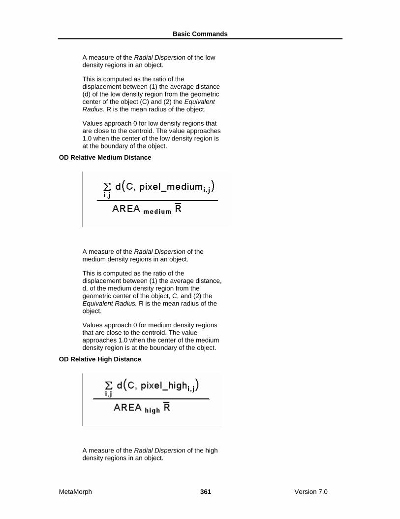
Basic Commands
MetaMorph 361 Version 7.0
A measure of the Radial Dispersion of the low density regions in an object.
This is computed as the ratio of the displacement between (1) the average distance (d) of the low density region from the geometric center of the object (C) and (2) the Equivalent Radius. R is the mean radius of the object.
Values approach 0 for low density regions that are close to the centroid. The value approaches 1.0 when the center of the low density region is at the boundary of the object.
OD Relative Medium Distance
A measure of the Radial Dispersion of the medium density regions in an object.
This is computed as the ratio of the displacement between (1) the average distance, d, of the medium density region from the geometric center of the object, C, and (2) the Equivalent Radius. R is the mean radius of the object.
Values approach 0 for medium density regions that are close to the centroid. The value approaches 1.0 when the center of the medium density region is at the boundary of the object.
OD Relative High Distance
A measure of the Radial Dispersion of the high density regions in an object.

Basic Commands
MetaMorph 362 Version 7.0
This is computed as the ratio of the displacement between (1) the average distance, d, of the high density region from the geometric center of the object, C, and (2) the Equivalent Radius. R is the mean radius of the object.
Values approach 0 for high density regions that are close to the centroid. The value approaches 1.0 when the center of the high density region is at the boundary of the object.
Adjust Digital Contrast (Display Menu) Adjusts image brightness, contrast, and gamma, selects and configures the look-up table model, and adjusts the number of grayscale levels or colors used to display an image.
Use this command when you want to adjust the brightness, contrast, or gamma of an 8-bit grayscale, or 24-bit color image.
If you are acquiring 16-bit images and wish to adjust the contrast and brightness, you should use the Scale 16-Bit Image command (Process menu) to do so. Because of the far greater number of intensity levels in a 16-bit image, the effects of merely adjusting the contrast settings from the Adjust Digital Contrast dialog box controls may have little visible effect on the image display. In addition to adjusting image contrast and brightness, the Scale 16-Bit Image command allows you to scale a selected range of 16-bit intensity levels to a 256-level intensity display, thereby greatly increasing the effect of the contrast adjustments. Adjust Digital Contrast is not available for binary (1-bit depth) images because these images only exist as two gray levels: black and white.
All of the digital contrast options EXCEPT Fix Contrast affect only the display of the image (the intensity values shown in the image window), not the image data. Reset Contrast resets the Brightness, Contrast, Quantization, and Invert settings applied to the image window display to their default settings.
Contrast reduces the number of grayscale levels or colors that you will see in the image at one time (the number of grayscale levels or colors actually available stays the same), but increases the perceived contrast of the image.
Gamma adjusts the linearity of the relationship between the actual image intensity values and the brightness of the image display on your monitor. Values will range from 0.2 to 5.0. An unmodified image will have a gamma of 1.0, which indicates that the relationship is perfectly linear. Increasing the gamma will result in a brighter image in which pixel intensity values in the middle of the grayscale are proportionally increased relative to the intensity values at the ends of the grayscale range. The graph that is displayed in the right half of the expanded Adjust Digital Contrast dialog box will show this as an upward deflection of the Display Intensity vs. Image Intensity curve. Conversely, decreasing the gamma will result in a darker image, and this will be reflected in the Intensity graph as a downward deflection. If you are working with a 24-bit color image, you can adjust the gamma levels of each color channel (red, green, or blue) or of all three channels simultaneously.
WARNING:
Fix Contrast permanently applies all of the digital contrast changes that have been applied to the image window display to the image data itself.
Adjusting the Digital Contrast To adjust the digital contrast of an image, use the following procedure:
Step Action

Basic Commands
MetaMorph 363 Version 7.0
1 From the Display menu, choose Adjust Digital Contrast. The Adjust Digital Contrast dialog box opens.
2 Select the Source image using the Source image selector.
3 If you are working with a 24-bit color image, select which Color Channel you want for your contrast changes to affect: Red, Green, Blue, or All. Otherwise skip to Step 4.
4 Adjust the contrast of the image using the Contrast slider or text box. Increasing the value raises the contrast of the image.
Note: If you are working with an 8-bit grayscale image, you can also adjust the contrast by dragging the Contrast Slider (Image Window Tool) with the right mouse button.
5 Adjust the brightness of the image using the Brightness slider or text box. You may need to adjust the contrast and brightness together until you have enhanced the image to suit your viewing needs.
You can restore the default values by choosing Reset (as long as you have not applied the Fix Contrast command to the image.)
Note: You can also adjust the brightness by dragging the Contrast Slider (Image Window Tool) with the left mouse button.
6 Adjust the midrange brightness of the image using the Gamma slider or text box. Dragging the slider handle to the right will result in a brighter display of pixels with intensity values in the middle of the grayscale, relative to those with values at the ends of the grayscale range.
Note: To see a graph of Display Intensity vs. Image Intensity, you may need to expand the dialog box first by choosing More >>.
7 If you want to adjust the contrast by applying the Stretch LUT command, choose Auto (performs a stretch on only those grayscale levels that are in the image's histogram).
Note: Auto will be available only for 8-bit images.
8 If you want to invert the image's look-up table, select the Invert Contrast check box.
Note: Invert will be available only for 8-bit images.
9 Select the desired look-up table from the Look-up Table Model list.
OR
Define a custom look-up table by choosing

Basic Commands
MetaMorph 364 Version 7.0
Define User LUT.
Note: These options will be available only for 8-bit images.
10 If you are working with a single channel of a 24-bit color image and wish to adjust another channel, repeat Steps 3 - 9 for the next color channel.
11 If you want to permanently change the pixel gray or color values in the image according the values in the look-up table, choose Fix Contrast.
WARNING: Fix Contrast permanently changes the image data.
This command is designed to be used on a monochrome LUT. When used on a color LUT (such as Pseudocolor), only the values in the look-up table's green channel will be fixed.
12 Choose Close when you have finished.
Defining a User LUT To define a custom look-up table (LUT) for an image, use the following procedure:
Step Action
1 Choose Define User LUT from the Adjust Digital Contrast dialog box.
OR
Select Configure LUT from the Display Mode Tool's pop-up menu.
The Define LUT dialog box will appear.
2 Choose Create. A new LUT named "User0" will appear in the Look-up Table Mode list. The Red, Green, Blue, Upper, and Lower editing options will be enabled.
3 Choose the < command button on the right side of the dialog box to open the LUT graph. The X-axis values of the graph will be the input while the Y-axis values will be the output.
If the user LUT is based on Monochrome LUT, only one of the three scan lines will be visible.
4 Select the desired starting and ending look-up table addresses to be modified using Lower and Upper.
You can select the entire range or you can select smaller ranges, leaving existing values for other parts of the look-up table intact.
5 The intensity for the red, green, and blue components for the selected range of addresses can be editing by enabling the

Basic Commands
MetaMorph 365 Version 7.0
color component(s) you want to edit using the Red, Green, and Blue check boxes. You can disable any component you do not want to edit.
AND
For each of the selected components, select a starting value and an ending value using the text boxes next to Red, Green, and Blue. (If you know the color for the range rather than the values, you can select the desired color from the Color list, and the appropriate values will appear in the starting and ending value text boxes.)
6 Choose Apply to apply the edited look-up table to the image.
(You can repeat Steps 4 - 6, as needed.)
7 If you want to save the custom look-up table on disk for future use, choose Save. Type the desired file name in the File Name text box and choose Save.
Inverting a Look-up Table
Inverting a look-up table remaps the addresses in the table so that the lowest and highest gray values are switched, as shown in the following table.
When you invert the look-up table of an image with a dark background and bright objects, the background becomes bright and the objects become dark.
Original Value
Inverted Value
0 255
1 254
2 253
3 252
4 251
... ...
251 4
252 3
253 2
254 1
255 0
Adjust Digital Contrast - Dialog Box Options
Source Selects the Source image for which you want to adjust the contrast.

Basic Commands
MetaMorph 366 Version 7.0
Color Channel (24-bit images only) Selects the color channel to be affected by your contrast changes: Red, Green, Blue, or All.
Brightness Specifies the overall brightness of the image. Affects only the display of the image, not the image data, unless you then choose Fix Contrast.
Contrast Expands the range of grayscale levels or colors displayed in the image. Increasing contrast reduces the number of levels that will be displayed in the image at one time (the number of grayscale levels or colors in the image data actually stays the same).
Gamma Adjusts the linearity of the relationship between the actual image intensity values and the brightness of the image display on your monitor. Values will range from 0.2 to 5.0. Increasing the gamma will result in a brighter display of pixels with intensity values in the middle of the grayscale, relative to those with values at the ends of the grayscale range. Conversely, decreasing the gamma results in a darker image.
Use display settings for activated images Check this box to apply the current Brightness, Contrast, and Gamma settings to any 8-bit and 16-bit images that are active.
Note: These settings will also apply to any future 8-bit or 16-bit images opened while this box is checked.
Reset Restores the contrast to the default settings of Contour = Off, Invert = Off, Quantization = 255, Brightness = 50, and Contrast = 50.
Undo/Redo Undoes or redoes the last applicable command that did not create a new Result image. (For this command, it undoes the results of the Fix Contrast command button). Undo/Redo buttons in MetaMorph apply to any previously applied command that did not create a new Result image, not just the last use of the command in the dialog box from which the button was chosen.
Auto Adjusts the contrast by performing a "stretch" on those grayscale levels or colors that are in the image's histogram. This command is the same as the Auto Enhance command in the Contrast Tool's pop-up menu.
More >> Expands the dialog box to include additional options such as those used for configuring LUTs.
<< Less Condenses the dialog box.
Quantization Specifies the number of distinct gray level values contained in an 8-bit image. The default setting is 256.
Lookup Table Model Specifies the look-up table used for the image. The default look-up tables, Monochrome and Pseudocolor cannot be edited. You can edit user-defined look-up tables.
Invert Contrast Remaps a look-up table so that the lowest and highest grayscale values are switched. See invert Illustration.
Fix Contrast Permanently changes the pixel gray values in the image according the values in the look-up table. MetaMorph ignores this command if the selected image is a 16-bit image. This command is designed to be used on a monochrome LUT. When used on a color LUT (except for the Red or Blue LUT), only the values

Basic Commands
MetaMorph 367 Version 7.0
in the look-up table's green channel will be fixed.
Define User LUT Creates and defines custom look-up tables using the image's Define User LUT dialog box. You can save and load the user-defined look-up tables using this command. Because this dialog box is associated with the Image Window Tools, it will close when its image is closed. This command is not available with 24-bit images.
Display Intensity vs. Image Intensity Graph Displays a curve representing the relationship between actual image pixel intensity values and the intensity at which they are displayed on your monitor. Increasing the Gamma will result in a brighter display of pixels with intensity values in the middle of the grayscale, and this will be reflected as an upward deflection of the curve. Conversely, decreasing the gamma results in a darker image, and the curve will show a downward deflection. If you are adjusting the gamma for the individual color channels of a 24-bit color image, the graph will display the curves for the red, green, and blue channels as red, green, and blue curves, respectively.
Close Closes the dialog box.
Define User LUT - Dialog Box Options
Look-up Table Model List Box Specifies the look-up table to be used for the image. The default look-up tables, Monochrome and Pseudocolor, cannot be edited. You can edit user-defined look-up tables.
Load Loads a previously saved custom look-up table.
Save Saves a custom look-up table.
Create Creates a new custom look-up table for editing.
Delete Deletes a custom look-up table. You cannot delete the default look-up tables.
Quantization Specifies the number of distinct gray level values contained in the image. The default setting is 256.
Invert Contrast Remaps a look-up table so that the lowest and highest grayscale values are switched. See invert Illustration.
Contour Applies a "sawtooth" grayscale to the image which varies from low intensity to high and back to low. MetaMorph uses a number of ranges of gray vales, centered on the peak of the contour. To increase or decrease the number of contours, increase or decrease the Contrast setting in the Adjust Digital Contrast dialog box.
Subtract Determines how MetaMorph displays pixels when the Adjust Digital Contrast command causes them to display the value for intensities "less" than zero. When Subtract is deselected, values less than zero will be clipped to zero. When Subtract is selected, the value will be wrapped around.
Reset Restores the contrast to the default settings of Contour = Off, Invert = Off, Quantization = 255, Brightness = 50, and Contrast = 50.
Red

Basic Commands
MetaMorph 368 Version 7.0
Enables or disables editing for the red component of the look-up table. The text boxes next to the check box specify the starting and ending values for the intensity. (A starting value can be larger than an ending value.)
Green Enables or disables editing for the green component of the look-up table. The text boxes next to the check box specify the starting and ending values for the intensity. (A starting value can be larger than an ending value.)
Blue Enables or disables editing for the blue component of the look-up table. The text boxes next to the check box specify the starting and ending values for the intensity. (A starting value can be larger than an ending value.)
Lower and Upper Specifies the starting and ending look-up table addresses to be modified. You can select the entire range or you can select smaller ranges, leaving existing values for other parts of the look-up table intact.
> button Opens the LUT graph. The X-axis values of the graph are the input while the Y-axis values are the output. If the user LUT is based on Monochrome LUT, only one of the three scan lines will be visible.
Apply Applies the edited look-up table to the image.
Close Closes the dialog box.
Scale Image (Display Menu) Increases the contrast of a displayed 16-bit image or stack by scaling a selected range of its gray levels to another range.
A 16-bit image consists of 65536 possible gray levels. However, due to experimental conditions, much of the important image information may be contained within a narrow range towards the lower end of the grayscale. This is particularly the case for low light level experiments. The Scale 16-Bit Image command allows you to select a range of gray values in a 16-bit image which can then either be displayed in the same image window or copied as a new 8-bit image. This will effectively rescale the intensities in the original image, allowing you more easily to see differences of grayscale values that might otherwise be impossible to discriminate visually.
Note: This command does not affect your image data. It only affects the display of the data on your monitor.
WARNING:
If you use the Copy command button while Transfer Filename When Copying is enabled, and then save the image, you will overwrite the original 16-bit Source image because the copied 8-bit image will have been given the same name as the original image file. As a result, your 16-bit data may be irretrievably lost. You should also note that the image's file name is not necessarily the same as the name displayed in the title bar of the image window.
The initial default range of gray levels will be those between the image's lowest gray level and highest gray level (the Image Min/Max option in the Range drop-down list). Thus, you cannot set the Image Min/Max slider to a value below the image's minimum value or above its maximum value. However, if you select one of the other Range options (10-bit, 12-bit, 14-bit, or 16-bit depth), you can change the initial default range to include all of the gray levels available in an image's depth type. You can then set the range for the scaling manually to a range of your preference.
If you do not want to scale the image manually, you can use Auto-Scale. MetaMorph will base the scaling range on the image's lowest and highest gray levels. If your image contains outlying "hot" pixels (either oversaturated or undersaturated), you can exclude a selected percentage of the pixels in the

Basic Commands
MetaMorph 369 Version 7.0
image (not the gray levels in its histogram!) at the lower and upper end of the image's grayscale range by adjusting the Low % and High % spin boxes in the Scale Image dialog box. For example, you could exclude the bright nucleus of a cell in a fluorescence image by setting the low spin box to 1% and the high spin box to 10%. (You can specify a fractional value, such as 0.1%, if necessary. Click here for a depiction of a sample histogram with the lowest and highest 0.1% of pixels selected for exclusion.) Scaling will then be based on the lowest and highest remaining grayscale values. If you enable Scale Within Active Region, autoscaling will work within an active region of interest. This will allow you to place a small active region of interest over the object(s) you want to see, and the image will be scaled based on the grayscale values of that region. This can be particularly useful when working with a stack because Auto-Scale recalculates within the active region for each plane in the stack.
Scaling a 16-Bit Image
Histogram of Scaled 16-Bit Image
The darkest and brightest 0.1% of the pixels in the image are excluded, and the scaling will be based on the values of the lowest and highest remaining grayscale values.

Basic Commands
MetaMorph 370 Version 7.0
Scaling a 16-Bit Image To scale a 16-bit image, use the following procedure:
Step Action
1 From the Display menu, choose Scale Image. The Scale Image dialog box opens.
2 Select the desired 16-bit image using the Image selector.
3 If you want to specify gray levels that are outside of the default range of the image's lowest and highest gray levels (Image Min/Max), select 8-Bits, 10-Bits, 12-Bits, 14-Bits, or 16-Bits from the Range list.
This will change the range to include all of the gray values available in the specified image depth type.
4 To specify the high and low scale values manually, click and drag the Low and High Scale Sliders on the Scale Bar, or use the Low Scale and High Scale edit boxes.
OR
If you want to scale the image based on a percent of pixels to exclude, select Auto Scale. If desired, specify a percentage of pixels (not gray values) to be excluded from the lower and upper ends of the scaling ranges with the Low % and High % edit boxes.
5 To apply the maximum and minimum intensity values of an active region of interest to the entire image, select Scale within the active region.
Note: This option is only available when Auto Scale is enabled.
6 To copy the altered image to an 8-bit image,
click the destination icon , choose to overwrite, add to, or create a new file for the resulting image, then click Copy.
Note: If New is selected as the destination, the default file name of the new image will be in the format 8-Bit Copy of Original File Name. If you want to select a different name for the 8-bit copy, Click 8-Bit Copy and select Specified to open the Specify Image name dialog box.
OR
To copy all planes in a stack to an 8-bit stack, select Copy entire stack. Click the

Basic Commands
MetaMorph 371 Version 7.0
destination icon, choose to overwrite, add to, or create a new file for the resulting image, then click Copy.
7 Choose Close when you have finished.
Scale Image - Dialog Box Options
Image Selects the 16-bit Source image that you want to scale.
Close Closes the dialog box.
Range Selects the range of gray levels available for scaling. The default setting of Image Min/Max sets the range between the image's minimum and maximum gray levels. You can also specify gray levels that are outside of the default range to include all of the levels available in the following image types:
• 8-Bits (0-255)
• 10-Bits (0-1023)
• 12-Bits (0-4095)
• 14-Bits (0-16383)
• 16-Bits (0-65535)
Settings
Auto Scale Allows MetaMorph to scale the image based on its lowest and highest gray levels. You can exclude a specific percentage of pixels from the lower and upper end of the scaling range with the Low % and High % spin boxes. When you select the Auto Scale check box, the Low Scale and High Scale options are disabled.
Low% Excludes the lowest selected percentage of pixels in the image (not the percentage of gray levels in the histogram) from the range of values being autoscaled. This option is available only when the Auto Scale check box is selected.
High% Excludes the highest selected percentage of pixels in the image (not the percentage of gray levels in the histogram) from the range of values being autoscaled. This option is available only when the Auto Scale check box is selected.
Low Scale Selects the darkest gray level for the scaled image. This option is available only when the Auto Scale check box is not selected.
High Scale Selects the brightest gray level for the scaled image. This option is available only when the Auto Scale check box is not selected.
Scale Within the Active Region Directs MetaMorph to use the maximum and minimum intensity values in the active region of interest when Auto Scale is selected. The entire image will then be displayed using the values determined from the active region of interest.
Calculation
Basic Commands
MetaMorph 372 Version 7.0
Gray Level Minimum and Maximum Values Displays the minimum and maximum gray level values for the current plane and the entire stack.
Calculate Stack Min/Max Calculates new minimum and maximum gray level values for a stack after changes have been made to the image and displays the results. This option is only available when a stack is selected.
Copy to 8-bit Image
Destination Choose to overwrite, add to, or create a new file for the resulting image of the Copy command.
Copy Copies the scaled image to a new 8-bit image. If your 16-bit image was thresholded, the 8-bit image will be saved with the 16-bit thresholding state scaled to an 8-bit thresholding state.
Copy entire stack Copies all planes in a stack to a new 8-bit stack. If your 16-bit stack was thresholded, the 8-bit stack will be saved with the 16-bit thresholding state scaled to an 8-bit thresholding state.
Transfer filename when copying Transfers the file name of the original 16-bit image to the new 8-bit image when you use the Copy command button.
WARNING: If you use the Copy command button while Transfer filename when copying is enabled, and then save the image, you will overwrite the original 16-bit Source image because the copied 8-bit image will have been given the same name as the original image file. As a result, your 16-bit data may be irretrievably lost. You should also note that the image's file name is not necessarily the same as the name displayed in the title bar of the image window.
NOTE: This option causes the Filename for the original 16-bit image to be transferred as the file name for the new 8-bit image, not the Image Title.
Contrast Shortcuts (Display Menu) Provides easily accessible shortcuts for four common contrast tasks: Auto Enhance, Invert Contrast, Reset Contrast, and Fix Contrast. Applies the selected contrast command to the currently selected image.
Use the shortcuts listed below whenever you want to apply one of these four contrast commands to an image. These shortcuts are for the Auto, Invert Contrast, Reset, and Fix Contrast options found in the Adjust Digital Contrast dialog box. The Auto Enhance, Reset Contrast, and Fix Contrast tasks also can be accomplished using the Contrast Tool's pop-up menu (found among the Image Window Tools).
Shortcuts:
Auto Enhance = CTRL + A
Invert Contrast = CTRL + I
Reset Contrast = CTRL + R
Using a Contrast Shortcut To use a contrast shortcut on the active image, use the following procedure:
Step Action

Basic Commands
MetaMorph 373 Version 7.0
1 From the Display menu, choose Contrast Shortcuts. A secondary menu opens.
The menu displays each of the four contrast operations (Auto-Enhance, Invert Contrast, Reset Contrast, and Fix Contrast) and their respective keyboard shortcuts.
2 To use a particular contrast command, choose it from the secondary menu.
OR
Use the keyboard shortcut listed next to the command's name: press and hold the [CTRL] key and then press the assigned letter.
Threshold Image (Measure Menu) Applies segmentation to an image, differentiating between objects of interest and other parts of the image based on the image's grayscale levels or colors. Can also create a binary mask image or a clipped image. You can log threshold settings, save them in a file, and load previously saved settings from disk.
Use the Threshold Image command prior to applying a measurement command that requires that a distinction be made between the objects being measured and the other parts of the image. Thresholding defines a range of grayscale values that are found in the pixels of objects which are of interest. You can set values below the defined low threshold and values above the defined high threshold to zero, or you can invert the thresholding such that intensity values within the defined threshold range are set to zero. Thresholding is not available for binary images because they are already implicitly thresholded (1 = on, 0 = off).
MetaMorph will place a red thresholding overlay on the image as a visual indicator of the thresholded areas. As you adjust the thresholding, the red overlay will disappear from the background areas. You can also use the Threshold Tool and Slider, found among the Image Window Tools, to adjust the thresholding of grayscale images. The Threshold Tool will also allow you to turn thresholding on or off, reverse the thresholding so that pixels with gray values below the lower threshold and above the upper threshold are marked with the overlay for measurement, and can perform automatic thresholding based on the presence of light or dark objects in the image. When you enable thresholding, the slider in the Image Window Tools will set the low and high values for the threshold range. However, the options for applying masks are available only in the Threshold Image dialog box and its associated journal functions (Threshold Image and Clip). Thresholds for 24-bit images can also be saved and loaded with the Threshold Image command.
There are three thresholding states: (1) Inclusive, with gray values between the upper and lower threshold limits highlighted by a red overlay, (2) Exclusive, with the gray values equal to or above the upper threshold limit, and those equal to or below the lower threshold limit, highlighted by the red overlay, and (3) Off.
Shortcut: CTRL + T
Thresholding an Image Grayscale Images
24-Bit Color Images
Thresholding an Image - Grayscale Images To threshold a grayscale image, use the following procedure:

Basic Commands
MetaMorph 374 Version 7.0
Step Action
1 From the Measure menu, choose Threshold Image. The Threshold Image dialog box opens with the Threshold tab active.
The red thresholding overlay should appear over the active image.
2 Select the desired image using the Src. image selector.
3 If you have previously saved a set of threshold settings and want to use them, choose Load and select the desired .gth file from the Load Threshold dialog box that appears. Then choose Open. Now skip to Step 6.
4 Select a high threshold value using the High option so that most of the desired objects are marked with the red thresholding overlay. Some red overlay may still be visible in the background areas.
Note: Selecting a gray value for High that is lower than the current Low value will cause the Low value to be reset to the same value as High.
5 Select a low threshold value using the Low option that removes the majority of the remaining red overlay from the background areas. Adjust the High gray value if necessary.
Note: Selecting a gray value for Low that is higher than the current High value will cause the High value to be reset to the same value as Low.
6 If you want to change the range of available grey levels in the High and Low sliders, select the appropriate range from the Range box. The default selection of Image Min/Max sets the range to the image’s minimum and maximum gray levels.
Note: This option is only available for 16-bit images.
7 Select a thresholding state from the State radio button group. Inclusive if you want to threshold pixels with gray values between the upper and lower threshold limits, or
Exclusive if you want to threshold pixels with gray values equal to or outside of the upper and lower threshold limits.
8 If you want to log the threshold settings as data in a log file, open the log file using the Open Log command. Once the data log is open, the text on the Open Log button will change to F9: Log Data, and you can then log the settings whenever you desire.

Basic Commands
MetaMorph 375 Version 7.0
AND If you want to save the threshold settings for future use in another image, choose Save. The Save Threshold dialog box will appear. Type a name for the .thr file in the File Name text box. Then choose Save to return to the Threshold Image dialog box.
9 If all of the objects are clearly defined by the red thresholding overlay, the image is ready for further processing. Now you can skip to Step 13.
OR
If you want to create a binary or mask image from the image or active region of interest, continue to Step 9.
10 Click the Clip tab to make it active. From the Mode group, select the operation you want to perform: Create Binary Mask or Clip to Gray Level.
The Dest. image selector will select a destination for you automatically. You can change the destination, but New must be selected for Create Binary Mask if the Source image is not binary.
11 If you selected Create Binary Mask, select the bit depth of the binary image from the Bit Depth of Binary Mask section.
12 If you selected Clip to Gray Level, select a gray level value using the Gray slider or text box.
13 Choose Apply to apply the selected binary or mask image operation.
14 Choose Close to close the dialog box.
Thresholding an Image - 24-Bit Color Images To threshold a 24-bit color image, use the following procedure:
Step Action
1 From the Measure menu, choose Threshold Image. The Threshold Image dialog opens.
2 Select the desired image using the Src. image selector.
3 If you have previously saved a set of threshold settings and want to use them, choose Load Threshold and select the desired .thr file from the Load 24-Bit Threshold dialog box that appears. Then choose Open. Now skip to Step 9.
4 If the Region Tools window is not currently visible, select the Region menu. Then choose Region Tools.
5 If necessary, use the Sensitivity spin box to specify the threshold binning sensitivity.

Basic Commands
MetaMorph 376 Version 7.0
6 With one of the Region Tools, draw a region of interest around an area in the image that contains the color values you want to include in the threshold range.
7 Choose Add to Threshold. A red overlay will appear over all pixels in the entire image window that are in the selected threshold range.
8 If necessary, repeat Steps 6 and 7 to include all of the desired color values in the threshold range.
If you make a mistake and want to remove values from the threshold range, draw a region of interest around pixels with the unwanted values and choose Delete from Threshold. Alternatively, you can choose Clear Threshold to remove all thresholding and start over again.
9 Select a thresholding state from the State radio button group. Select
Inclusive if you want the currently selected colors to define the areas that are thresholded, or
Exclusive if you want the currently selected colors to define areas that are excluded from thresholding.
10 If you want to log the threshold settings as data in a log file, open the log file using the Open Log command. Once the data log is open, the text on the Open Log button will change to F9: Log Data, and you can then log measurement parameter data whenever you desire.
AND If you want to save the threshold settings for future use in another image, choose Save Threshold. The Save 24-Bit Threshold dialog box will appear. Type a name for the .thr file in the File Name text box. Then choose Save to return to the Threshold Image dialog box.
11 If all of the objects are clearly defined by the red thresholding overlay, the image is ready for further processing. Skip to Step 16.
OR
If you want to create a binary or mask image from the image or active region of interest, continue to Step 12.
12 Click the Clip tab to make it active. From the Mode group, select the operation you want to perform: Create Binary Mask or Clip to Color Value.
The Dest. image selector will select a destination for you automatically. You can change the destination, but New must be

Basic Commands
MetaMorph 377 Version 7.0
selected for Create Binary Mask if the Source image is not binary.
13 If you selected Create Binary Mask, select the bit depth of the binary image from the Bit Depth of Binary Mask section.
14 If you selected Clip to Color Value, choose Color and select a color from the Color dialog box that appears. Then choose OK.
15 Choose Apply to apply the selected binary or mask image operation.
16 Choose Close to close the dialog box.
Threshold Image - Dialog Box Options
Grayscale Images
Threshold Tab
Clip Tab
Overlay Tab
24-Bit Color Images
Threshold Tab
Clip Tab
Overlay Tab
Threshold Sensitivity In dealing with color image processing, the convention is to classify each colored pixel in terms of its position in a three-dimensional cube, or "color space," with each of the three major axes, or "channels," encoding a particular color component (for example, the RGB color space model encodes each color by the intensities of its component red, green, and blue colors). With 24-bit color images, each of the three channels has 2**8 (that is, 256) possible gradations, yielding approximately 16.7 million possible colors. To get around the difficulties of handling this many colors, MetaMorph must "bin" each color channel by dividing the 256 possible colors by 6, 8, 16, 24, or 32. The actual binning value used in MetaMorph is determined by the Sensitivity setting. Sensitivity 1 divides each axis by 6, while Sensitivity 5 divides each axis by 32. Thus, for example, Sensitivity setting 1 results in (256/6)**3, or 77,673, possible colors, while Sensitivity setting 5 results in (256/32)**3, or 512, possible colors.
Threshold Image, Grayscale - Dialog Box Options, Threshold Tab
Src Selects the Source image that you want to threshold.
Close Closes the dialog box.
Low Defines the lowest gray value in the range of gray values shared by the objects or areas of interest.
High Defines the highest gray value in the range of gray values shared by the objects or areas of interest.
Range
Selects the range of gray levels available for thresholding. The default setting of Image Min/Max sets the

Basic Commands
MetaMorph 378 Version 7.0
range between the image's minimum and maximum gray levels. Other choices include gray-level ranges for 10-, 12-, 14-, or 16-bit images.
Note: This option is only available for 16-bit images. State Selects a thresholding state for the image:
Inclusive thresholds pixels with gray values between the upper and lower threshold limits,
Exclusive thresholds pixels with gray values equal to or outside of the upper and lower threshold limits, and
Off disables thresholding.
Open Log
Opens a data log or a DDE connection to an open spreadsheet program for logging the threshold settings as data. Changes to "F9: Log Data" when the log file is open.
F9: Log Data
Logs the threshold settings to the open data log or worksheet. You can also press the [F9] function key to log the settings. After the data are logged, the command button will become unavailable until you select another set of threshold settings.
Configure Log
Opens the Configure Log dialog box, so that you can select the parameters to be logged to the log file.
Load Opens the Load Threshold dialog box, from which you can select a previously saved .gth file containing threshold range settings.
Save Opens the Save Threshold dialog box, from which you can specify a name and location for saving threshold settings in a .gth file.
Threshold Image, Grayscale - Dialog Box Options, Clip Tab
Src Selects the Source image that you want to threshold.
Close Closes the dialog box.
Dest Selects the destination of binary or mask image. Create Mask requires a new binary image as the destination if the source is not binary.
Mode Selects the binary or mask image operation that will be applied when you choose Apply:
Create Binary Mask creates a binary image where all pixels in the thresholded range are assigned a grayscale value for white based on the setting in the Bit depth of binary mask field. All other pixels are assigned gray level 0 (black).
Clip to Gray Level creates or modifies an image in which all pixels in the thresholded rang are assigned to the selected Gray value and all other pixels are left unchanged.
These operations work on the active region of interest, if one has been defined, rather than on the entire image.
Bit depth of binary mask Selects the bit depth of the binary image created with Create Binary Mask. Valid choices are: 1-bit, 8-bit, 16-

Basic Commands
MetaMorph 379 Version 7.0
bit, 24-bit, or 48-bit.
Gray Specifies the gray level value to be used with Clip to Gray Level.
Apply Applies the selected binary or mask image operation.
Undo/Redo Undoes/redoes the last applicable command that did not create a new Result image.
Threshold Image - Dialog Box Options, Overlay Tab
Src Selects the Source image that you want to threshold.
Close Closes the dialog box.
Threshold Color Displays the current overlay color
Color Opens the Color dialog box, allowing you to choose a color to be applied to threshold overlays.
Threshold Display Mode
Draw threshold over the thresholded area Displays the threshold overlays on the area thresholded area.
Draw threshold over the non-thresholded area Displays the threshold overlays on the non-thresholded area.
Draw so you can see image beneath threshold Creates a transparent threshold overlay.
Threshold Image, Color - Dialog Box Options, Threshold Tab
Src Selects the Source image that you want to threshold.
Close Closes the dialog box.
Sensitivity In dealing with color image processing, the convention is to classify each colored pixel in terms of its position in a three-dimensional cube, or "color space," with each of the three major axes, or "channels," encoding a particular color component (for example, the RGB color space model encodes each color by the intensities of its component red, green, and blue colors). With 24-bit color images, each of the three channels has 2**8 (that is, 256) possible gradations, yielding approximately 16.7 million possible colors. To get around the difficulties of handling this many colors, MetaMorph must "bin" each color channel by dividing the 256 possible colors by 6, 8, 16, 24, or 32. The actual binning value used in MetaMorph is determined by the Sensitivity setting. Sensitivity 1 divides each axis by 6, while Sensitivity 5 divides each axis by 32. Thus, for example, Sensitivity setting 1 results in (256/6)**3, or 77,673, possible colors, while Sensitivity setting 5 results in (256/32)**3, or 512, possible colors.
Add to Threshold Adds color values within a region of interest (delineated with a Region Tool) to the threshold range.

Basic Commands
MetaMorph 380 Version 7.0
Clear Threshold Clears all threshold settings and removes the red thresholding overlay from the image window.
Delete from Threshold Adds color values within a region of interest to the threshold range.
Save Threshold Saves the current threshold setting to a .thr file.
Load Threshold Loads a threshold setting from a .thr file.
State Selects a thresholding state for the image:
Inclusive uses the currently selected colors to define the areas that are thresholded,
Exclusive uses the currently selected colors to define the areas that are excluded from thresholding, and
Off disables thresholding
Threshold Image, Color - Dialog Box Options, Clip Tab
Src Selects the Source image that you want to threshold.
Close Closes the dialog box.
Dest Selects the destination of binary or mask image. Create Mask requires a new binary image as the destination if the source is not binary.
Mode Selects the binary or mask image operation that will be applied when you choose Apply:
Create Binary Mask creates a binary image where all pixels in the thresholded range are assigned a grayscale value for white based on the setting in the Bit depth of binary mask field. All other pixels are assigned gray level 0 (black).
Clip to Color Value creates or modifies an image in which all pixels in the thresholded rang are assigned to the selected Gray value and all other pixels are left unchanged.
These operations work on the active region of interest, if one has been defined, rather than on the entire image.
Bit depth of binary mask Selects the bit depth of the binary image created with Create Binary Mask. Valid choices are: 1-bit, 8-bit, 16-bit, 24-bit, or 48-bit.
Color Selects the color of the threshold overlay created with Clip to Color Value.
Apply Applies the selected image operation.
Undo/Redo Undoes/redoes the last applicable command that did not create a new Result image.

Basic Commands
MetaMorph 381 Version 7.0
Sharpen (Legacy) Note: The Sharpen filter is now available through the Basic Filters command in the Process menu. The stand alone Sharpen command is no longer available from the MetaMorph desktop and can only be accessed through the Journal Editor.
Accentuates the edges within an image or region of interest using a convolution kernel.
Use the Sharpen command when you want to enhance the fine details in an image or region without altering the average gray value. The following images show the effect on an image of the High setting of the Sharpen filter:
The effect of the Sharpen filter is to accentuate changes of grayscale values that occur over a short distance. This is done by increasing the intensity of pixels that are considerably brighter than their neighbors. The following figure illustrates the enhancing effects of the Sharpen filter on an "edge" in an image:
Applying a Sharpening Filter to an Edge
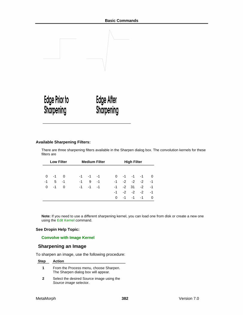
Basic Commands
MetaMorph 382 Version 7.0
Available Sharpening Filters:
There are three sharpening filters available in the Sharpen dialog box. The convolution kernels for these filters are
Low Filter Medium Filter High Filter
0 -1 0 -1 -1 -1 0 -1 -1 -1 0 -1 5 -1 -1 9 -1 -1 -2 -2 -2 -1 0 -1 0 -1 -1 -1 -1 -2 31 -2 -1 -1 -2 -2 -2 -1 0 -1 -1 -1 0
Note: If you need to use a different sharpening kernel, you can load one from disk or create a new one using the Edit Kernel command.
See Dropin Help Topic:
Convolve with Image Kernel
Sharpening an Image To sharpen an image, use the following procedure:
Step Action
1 From the Process menu, choose Sharpen. The Sharpen dialog box will appear.
2 Select the desired Source image using the Source image selector.

Basic Commands
MetaMorph 383 Version 7.0
3 Select the desired destination image using the Dest image selector. You can overwrite or add to the existing image, or you can place the results in a new image window.
4 Select the Low, Medium, or High filter from the Filter group. The selected kernel will be displayed in the dialog box.
5 Choose Apply.
6 Choose Close when you have finished.
Sharpen - Dialog Box Options
Source Selects the Source image that you want to sharpen.
Dest Selects the destination for the sharpened image. You can overwrite the existing image or place the results in a new image window. Or you can add the sharpened image as a plane to an existing image or stack.
Filter Specifies the "strength" of the convolution used to sharpen the image (Low, Medium, or High). The selected kernel will be displayed next to the Filter radio button group.
Apply Applies the selected filter to the Source image.
Undo/Redo Undoes/redoes the last applicable command that did not create a new Result image.
Close Closes the dialog box.
Low Pass (Legacy) Note: The Low Pass filter is now available through the Basic Filters command in the Process menu. The stand alone Low Pass command is no longer available from the MetaMorph desktop and can only be accessed through the Journal Editor.
Blurs the edges within an image or region of interest using a convolution kernel to average the values within the image data.
Use the Low Pass command when you want to smooth out noise and other areas containing high spatial frequency data. This spatial convolution blurs the edges within an image or region of interest by using an averaging convolution kernel to create a "moving average" of regional intensity values within the image data. The numerical average is calculated for the intensity of pixels in a region of a user-specified size and centered on the pixel being processed. This is done for each pixel in the image. The following images show the effect on an image of the Low Pass filter:

Basic Commands
MetaMorph 384 Version 7.0
The Low Pass filter reduces the differences in intensity in an image by smoothing the transitions between grayscale values. The following figure illustrates the smoothing effect of the Low Pass filter on an "edge" in an image:
Applying a Low Pass Filter to an Edge
Horizontal Size and Vertical Size set the pixel size of the low pass filter. These can not be larger than half the width or height, respectively, of the image itself.
To blur a stack using information in the Z-axis, use the Average option in the Stack Arithmetic dialog box (Process menu).
Applying a Low Pass Filter

Basic Commands
MetaMorph 385 Version 7.0
To apply a low pass filter to an image, use the following procedure: Step Action
1 From the Process menu, choose Low Pass. The Low Pass dialog box will appear.
2 Select the desired Source image using the Source image selector.
3 Select the desired destination image using the Dest image selector. You can overwrite or add to the existing image or you can place the results in a new image window.
4 Use Horizontal Size and Vertical Size to select the size of the low pass filter kernel, in pixels. These can not exceed half the height or width of the image.
If the image is very wide and the selected kernel size is too large, MetaMorph will display a message dialog box requesting that you try a smaller kernel size.
5 Choose Apply.
6 Choose Close when you have finished.
Low Pass - Dialog Box Options
Source Selects the Source image to which you want to apply the low pass convolution.
Dest Selects the destination for the low pass-convolved image. You can overwrite the existing image or place the results in a new image window. Or you can add the low passed image as a plane to an existing image or stack.
Horizontal Size Specifies the horizontal size of the convolution kernel that will be applied the image. This can not exceed half the width of the image.
Vertical Size Specifies the vertical size of the convolution kernel that will be applied the image. This can not exceed half the height of the image.
Apply Applies the Low Pass convolution to the Source image.
Undo/Redo If your destination image is configured to overwrite the original image, choosing this command button will undo the effects of the low pass filter. The button text will change to "Redo," and choosing it again will reapply the filter. (Undo/Redo buttons in MetaMorph apply to any previously applied command that did not create a new Result image, not just the last use of the command in the dialog box from which the button was chosen.)
Close Closes the dialog box.
Detect Edges (Process Menu) Isolates and enhances the edges in an image by using a selected edge-detection

Basic Commands
MetaMorph 386 Version 7.0
convolution(s). The convolution kernel detects edges in the image by comparing brightness changes in neighboring pixels.
MetaMorph provides a number of edge-detection convolutions that enhance the visibility of the edges of objects in an image. The following images show the effect of the Sobel convolution:
There are seven filters available in the Detect Edges dialog box. The kernels for each are displayed in the dialog box. These filters apply up to four convolutions to an image. When using the Sobel, Prewitt, and Kirsch filters, the results of the individual convolutions are added together.
Filter One Convolution
Two Convolutions
Three Convolutions
Four Convolutions
Laplace 1 0 -1 0 -1 4 -1 0 -1 0
Laplace 2 -1 -1 -1 -1 8 -1 -1 -1 -1
Horizontal -1 -1 -1 0 0 0 1 1 1
Vertical -1 0 1 -1 0 1 -1 0 1
Sobel 1 2 1 -1 0 1 0 0 0 + -2 0 2 -1 -2 -1 -1 0 1

Basic Commands
MetaMorph 387 Version 7.0
Prewitt 1 1 1 -1 0 1 0 0 0 + -1 0 1 -1 -1 -1 -1 0 1
Kirsch 5 5 5 5 5 -3 5 -3 -3 -3 -3 -3 -3 0 -3 + 5 0 -3 + 5 0 -3 + 5 0 -3 -3 -3 -3 -3 -3 -3 5 -3 -3 5 5 -3
See Dropin Help Topic:
Convolve with Image Kernel
Detecting Edges in an Image To detect edges in an image, use the following procedure:
Step Action
1 From the Process menu, choose Detect Edges. The Detect Edges dialog box will appear.
2 Select the desired Source image using the Source image selector.
3 Select the desired destination image using the Result image selector. You can overwrite or add to the existing image or you can place the results in a new image window.
4 Select the desired edge-detection filter from the Filter group. The selected kernel will be displayed in the dialog box.
5 If you want to compensate for gray level underflow when the filter is applied, select a Result Gray Scale Offset value.
6 Choose Apply.
7 Choose Close when you have finished.
Detect Edges - Dialog Box Options
Source image Selects the Source image to which you want to apply an edge-detection convolution.
Result image Selects the destination for the convolved image. You can overwrite the existing image or place the results in a new image window. Or you can add the filtered image as a plane to an existing image or stack.
Filter Specifies the edge-detection filter. The kernel for the selected filter will be displayed next to the Filter group.
Apply Applies the selected edge-detection convolution(s) to the Source image.
Result Gray Scale Offset Compensates for gray level underflow when a filter is applied by adding a selected value to the pixel intensities in the convolved image.

Basic Commands
MetaMorph 388 Version 7.0
Undo/Redo Undoes/redoes the last applicable command that did not create a new Result image.
Close Closes the dialog box.
Unsharp Mask (Legacy) Note: The Unsharp mask filter is now available through the Basic Filters command in the Process menu. The stand alone Unsharp mask command is no longer available from the MetaMorph desktop and can only be accessed through the Journal Editor.
Sharpens an image and brings out details in shadows and highlights. When an Unsharp Mask filter is applied, the contrast will be reduced so that fine details have a middle gray level.
Use Unsharp Mask when you want to highlight the fine details in the image without increasing the overall contrast. Unsharp Mask works by subtracting a blurred (low pass-filtered) version of the image from the Source image itself. The blurred image will retain the overall brightness patterns of the original. Subtracting this from the original will result in an image composed only of the original image’s finest details. Unlike edge-detection, unsharp masking does not remove all of the overall brightness patterns; it merely reduces them. The following images show the effect of the Unsharp Mask, using a Scaling Factor of 0.9 and a Result Scale of 10 (see description which follows):
The following illustration shows the steps MetaMorph performs when it applies Unsharp Mask to an image. In this example, default options are used (Low Pass Filter Size of 3, Scaling Factor of 0.75, Result Scale of 4, Auto Result Scale enabled, and Create New Result image selected.)
Applying an Unsharp Mask Filter

Basic Commands
MetaMorph 389 Version 7.0

Basic Commands
MetaMorph 390 Version 7.0
MetaMorph allows you to configure the Low Pass filter kernel which will be used to blur the image, and the scaling factor that will be applied to the blurred image. For best results, experiment to see which values work best for a given specimen. As a general rule, the greater the scaling factor, the less brightness information from the original that will be retained. If the Auto Result Scale option is selected, MetaMorph will pick a result scale that matches the selected scaling factor, so that the contrast will be roughly the same as in the original image.
Applying an Unsharp Mask Filter To apply an Unsharp Mask filter to an image, use the following procedure:
Step Action
1 From the Process menu, choose Unsharp Mask. The Unsharp Mask dialog box will appear.
2 Select the desired Source image using the Source image selector.
3 Select the desired destination image using the Dest image selector. You can overwrite or add to the existing image or you can place the results in a new image window.
4 If you want MetaMorph to select a Result Scale that matches the Scaling Factor you select, enable Auto Result Scale.
5 Use Low Pass Kernel Size to select the size of the low pass convolution kernel, in pixels. Smaller kernel sizes will lead to the retention of less fine detail.
If the image is very wide and the selected kernel size is too large, MetaMorph will display a message dialog box requesting that you try a smaller kernel size.
6 Select a Scaling Factor. If set to 1, only the edges will be left after unsharp masking. Smaller numbers allow more of the image features to be present in the Result image.
7 Use Result Scale to increase the contrast lost during the subtraction of the blurred copy

Basic Commands
MetaMorph 391 Version 7.0
from the original image.
Note: Skip this step if you selected Auto Result Scale in Step 4. Changing the Result Scale setting will deselect Auto Result Scale.
8 Choose Apply.
9 Choose Close when you have finished.
Unsharp Mask - Dialog Box Options
Source Selects the Source image to which you want to apply the Unsharp Mask filter.
Dest Selects the destination for the filtered image. You can overwrite the existing image or place the results in a new image window. Or you can add the filtered image as a plane to an existing image or stack.
Low Pass Kernel Size Specifies the pixel size of the low pass filter that will be used to create the blurred subtraction image from the original Source image. Use of larger low pass kernel sizes will lead to the retention of more fine detail.
Scaling Factor Specifies the scaling factor to apply to the image after the low pass filter is applied. If set to 1, only the edges will be left after unsharp masking. Numbers smaller than 1.0 allow more of the image features to be present in the Result image.
Result Scale Restores the contrast lost during the subtraction of the blurred copy from the original image. The minimum value is 1.
Auto Result Scale Allows MetaMorph to select the Result Scale value for you that matches the selected scaling factor.
Apply Applies the selected filter to the Source image.
Undo/Redo Undoes/redoes the last applicable command that did not create a new Result image.
Close Closes the dialog box.
Median Filter (Legacy) Note: The Median filter is now available through the Basic Filters command in the Process menu. The stand alone Median Filter command is no longer available from the MetaMorph desktop and can only be accessed through the Journal Editor.
Reduces the effects of noise in an image by removing pixels whose grayscale values are substantially different from those of neighboring pixels. This retains the details in the image while reducing image "noise."
This filter works by selecting the median pixel value of the pixels in an NxM pixel area and replacing the center pixel with this value. This process is repeated for every pixel in the image. The result of applying a median filter to an image is a suppression of localized anomalies (such as "dark noise" or "read-out noise") in the image. The following images show the effect of the Median Filter, using a kernel size of 3 x 3:

Basic Commands
MetaMorph 392 Version 7.0
This command produces results similar to that of the Low Pass filter. In comparing the two commands, Median Filter offers two advantages:
(1) Median Filter can completely remove certain types of noise (such as "hot" pixels) while the Low Pass filter simply redistributes such noise to the neighboring pixels, and
(2) Median Filter reduces the noise in the image while retaining most of the sharpness in the details. The Low Pass filter blurs both the noise and the details indiscriminately.
Applying a Median Filter To apply a median filter to an image, use the following procedure:
Step Action
1 From the Process menu, choose Median Filter. The Median Filter dialog box will appear.
2 Select the desired Source image using the Source image selector.
3 Select the desired destination image using the Dest image selector. You can overwrite or add to the existing image or you can place the results in a new image window.
4 Use Horizontal Size and Vertical Size to select the size of the median filter convolution kernel.
5 If you want to speed up processing by using a sub-sample, select the desired value using

Basic Commands
MetaMorph 393 Version 7.0
Sub-Sample Ratio.
6 Choose Apply.
7 Choose Close when you have finished.
Median Filter - Dialog Box Options
Source Selects the Source image to which the median filter will be applied.
Dest Selects the destination for the convolved image. You can overwrite the existing image or place the results in a new image window. Or you can add the filtered image as a plane to an existing image or stack.
Horizontal Size Specifies the horizontal size of the median filter convolution kernel. Largest possible value is 128.
Vertical Size Specifies the vertical size of the median filter convolution kernel. Largest possible value is 128.
Sub-Sample Ratio Speeds up the processing of large kernels by limiting the calculations to a sub-sample, rather than every pixel. For example, if 2 is selected as the sub-sample, the pixels in columns/rows 1, 3, 5, 7, etc. will be used (1/4th the pixels). If 3 is selected, the pixels in columns/rows 1, 4, 7, 10, etc. will be used (1/9th). Likewise, if 8 is selected, the pixels in columns/rows 1, 9, 17, etc. will be used (1/64th). The maximum sub-sample value is 16 (samples 1 in 256 pixels).
Apply Applies the median filter to the Source image.
Undo/Redo Undoes/redoes the last applicable command that did not create a new Result image.
Close Closes the dialog box.
Edit Kernel (Process Menu) Enables you to load, edit, save, and apply a user-defined convolution kernel.
Use this command when you want to define values for or use a custom convolution kernel for processing images, rather than using the kernels supplied by the Process menu commands. You can also use this command to load and apply kernels created with Image-1/AT software.
The convolution kernel can range in size from 3x3 to 16x16 elements. Each element can be individually set to any value between -128 and 127. The Edit Kernel dialog box includes a table of the kernel values which can be edited by clicking on the desired cell in the table.
When a custom convolution kernel is applied to a selected image, the resultant image is formed by convolving the image with the kernel divided by the Element scale. The resultant image is then divided by the Result Scale factor and the absolute value of the image is taken. In some cases, you may want to specify an Offset value to be added to all pixel gray values after the convolution is completed so that all gray values remain within the image's gray range (for example, 0 to 255 for 8-bit images).
Once the kernel has been edited, you can apply it to the selected image and save it for future use. You can also print out a copy of the values in the kernel.
See Dropin Help Topic:
Convolve with Image Kernel

Basic Commands
MetaMorph 394 Version 7.0
Editing a Kernel To edit a spatial convolution kernel and apply it to an image, use the following procedure:
Step Action
1 From the Process menu, choose Edit Kernel. The Edit Kernel dialog box will appear.
2 Select the desired Source image using the Source image selector.
3 Select the desired destination image using the Result image selector. You can overwrite or add to the existing image or you can place the results in a new image window.
4 To load an existing kernel for editing, choose Load Kernel. The Load Kernel dialog box will appear.
Select the icon for the desired kernel file (*.krn). Use the Look In list or Up One Level icon button to select the correct location if necessary. Then choose Open. The Edit Kernel dialog box will reappear with the selected kernel loaded.
5 To change the size (pixels) of the kernel, type the desired dimensions in the Width and Height text boxes.
The kernel must be at least 3x3 elements, but can not be larger than 16x16 elements.
6 Edit the kernel elements by using the pointer to select table cells on the right side of the dialog box. Each element can be set individually to any value between 1 and 255. (The sum of the elements should equal 1.0 to avoid drastically increasing or decreasing the overall brightness in the Result image.)
AND
Press [ENTER] to store each value. You can press [TAB] to advance to the next cell, located to the right of the current cell.
7 If you want to change the element scaling from the default value of 1, use Element.
The result of the kernel element divided by the Element scale should not be much less than 1.0. Otherwise significant numerical inaccuracies can occur.
8 If you want to change the result scaling from the default value of 1, use Result.
The result of the convolution will be divided by this value. The value of the Result scale must be set so that the sum of the elements becomes as close to 1.0 as possible; otherwise, image values will overflow the frame buffer and an overly bright and "washed out" image will result. For example, if the sum of the elements is 8, set Result to

Basic Commands
MetaMorph 395 Version 7.0
8 so that the value of sum of the elements becomes 1.
9 If you want an offset value to be added to the final pixel intensity values after the convolution, select the desired value using Offset.
10 Select Yes in the Absolute Value group to use the absolute value of each resulting pixel. Select No to clip any negative values to zero.
11 Choose Apply to apply the edited kernel.
Edit Kernel - Dialog Box Options
Source image Selects the Source image to which you want to apply the convolution kernel.
Result image Selects the name of the processed image. You can create a new image file or stack, overwrite the existing image file or stack, or add images to an existing image stack.
Load Kernel Loads a previously saved kernel so that you can edit it or apply it to the selected image.
Save Kernel Saves the current kernel to disk so that you can use it during future sessions.
Print Kernel Prints a copy of the kernel table to the default printer.
Kernel Table Displays the elements for the current kernel. You can edit these values by clicking the desired table cell. Each element can be set individually to any value between -128 and 127. The size of the kernel is governed by the Width and Height options.
Width Specifies the width of the kernel. The width can range from 3 to 16 elements.
Height Specifies the height of the kernel. The height can range from 3 to 16 elements.
Element Specifies the number by which each kernel element should be divided before the convolution is performed. The result of the kernel element divided by the Element scale should not vary greatly from 1.0. Otherwise, significant numerical inaccuracies can occur.
Result The result of the convolution is divided by this value. The value of the Result scale must be set so that the sum of the elements becomes as close to 1.0 as possible; otherwise, the image values will underflow or overflow the frame buffer. For example, if the sum of the elements is 8, set Result to 8 so that the value of the sum of the elements becomes 1.
Offset Specifies the offset value that is added to the final pixel intensity values in the image when the convolution is completed, so that all gray values will remain within the image's bit-depth (for example, 0 - 255 for 8-bit images).
Absolute Value

Basic Commands
MetaMorph 396 Version 7.0
Specifies whether absolute values of each resulting pixel will be used or if negative values will be clipped to zero. Select No to clip the negative values to zero.
Apply Applies the current convolution kernel to the specified image.
Undo/Redo Undoes/redoes the last applicable command that did not create a new Result image.
Close Closes the dialog box.
Binary Operations (Process Menu) Creates a binary mask image from the selected 8-bit, 16-bit, or 24-bit image based on the current thresholding, and applies a selected geometric convolution operation to this or other binary images.
Use this command when you want to create a binary mask image from an 8-bit, 16-bit, or 24-bit image for use in one of the following binary operations. Click an entry to see a "before and after" view of the effect of the operation on a sample image:
Erode
Ultimate Erode
Dilate
Ultimate Dilate
Skeletonize
Outline
8-Bit Distance Map
Segment (watershed)
Remove Single Pixels
Invert
Euclidean Distance
Note: To binarize an image, you must first threshold it.
Shortcut: CTRL + B
The Erode Operation

Basic Commands
MetaMorph 397 Version 7.0
The Ultimate Erode Operation
The Dilate Operation

Basic Commands
MetaMorph 398 Version 7.0
The Ultimate Dilate Operation
The Skeletonize Operation

Basic Commands
MetaMorph 399 Version 7.0
The Outline Operation
The 8-Bit Distance Map Operation

Basic Commands
MetaMorph 400 Version 7.0
The Segment (Watershed) Operation
The Remove Single Pixels Operation

Basic Commands
MetaMorph 401 Version 7.0
The Invert Operation
The Euclidean Distance Map Operation

Basic Commands
MetaMorph 402 Version 7.0
Binarizing an Image
Binarize
Erode
Ultimate Erode
Dilate
Ultimate Dilate
Skeletonize
Outline
8-Bit Distance Map
Segment
Remove Single Pixels
Invert
Euclidean Distance
Binarizing an Image Before applying a binary operation, create a binary image mask with the Binarize operation using the following procedure:
Step Action
1 From the Process menu, choose Binary. The Binary Image Operations dialog box will appear.

Basic Commands
MetaMorph 403 Version 7.0
2 Select the desired Source image from the Source image selector.
3 Select New as the destination image from the Dest. image selector.
OR
Select Overwrite or Add To if you want to use an existing binary image as the destination.
4 Select Binarize from the Operation button group.
5 If you have not already thresholded the image, use the Low and High sliders in the Threshold Settings group to set threshold values for the binary mask.
6 Choose Apply. The binary mask will be created.
Applying Erode Erode is used to shrink objects. This is often used to separate objects that touch or overlap. Using the binary mask, Erode converts white pixels to 0 (black) if the number of surrounding background pixels is less than or equal to the selected Neighborhood value.
Note: Because erosion shrinks objects, measurements made using an eroded image may lead to erroneous calculations.
To apply Erode to an image, use the following procedure: Step Action
1 Open the Binary Image Operations dialog box and Binarize the image if it is not a binary image.
2 Select the desired binary image from the Source image selector.
3 Select the destination image using the Result image selector. You can overwrite or add to the existing image or place the results in a new image window.
4 Select Erode from the Operation group.
5 Select a value for Neighborhood to specify the number of neighboring black pixels a pixel in the binary mask image must have for it too to be changed to black in the eroded image.
6 Specify the number of erosions to perform on the binary image using the Repeat Count option.
7 Select Erode Last Pixel to erode the last remaining single white pixel in an area if the neighboring white pixels have been eroded.
8 Choose Apply.
Applying Ultimate Erode
Basic Commands
MetaMorph 404 Version 7.0
Ultimate Erode is similar to Erode in that it converts white pixels to 0 (black) if the number of surrounding background pixels is less than or equal to the selected Neighborhood value. However, Ultimate Erode keeps performing the erode operation until no more areas match the Neighborhood criteria, or until there are only single pixels left.
To apply Ultimate Erode to an image, use the following procedure: Step Action
1 Open the Binary Image Operations dialog and Binarize the image if it is not a binary image.
2 Select the desired binary image from the Source image selector.
3 Select the destination image using the Result image selector. You can overwrite or add to the existing image or place the results in a new image window.
4 Select Ultimate Erode from the Operation group.
5 Select a value for Neighborhood that specifies the number of neighboring black pixels a pixel of the binary mask image must have for it too to be changed to black in the eroded image.
6 Choose Apply.
Note: Ultimate Erode can be a time-intensive operation.
Applying Dilate Dilate is used to connect objects which are discontinuous, or to fill "holes" in objects. Using the binary mask image, Dilate converts black (0) pixels to white if the number of surrounding white pixels is greater than or equal to the selected Neighborhood value.
Note: Since dilation enlarges objects, measurements made using an eroded image may lead to erroneous calculations.
To apply Dilate to an image, use the following procedure: Step Action
1 Open the Binary Image Operations dialog and Binarize the image if it is not a binary image.
2 Select the desired binary image from the Source image selector.
3 Select the destination image using the Result image selector. You can overwrite or add to the existing image or place the results in a new image window.
4 Select Dilate from the Operation group.
5 Select a value for Neighborhood that specifies the number of neighboring white pixels that must surround a black pixel in the binary image to produce a white pixel in the black pixel's place in the dilated image.

Basic Commands
MetaMorph 405 Version 7.0
6 Specify the number of dilations to perform on the binary image using the Repeat Count option.
7 Select Dilate Without Closing if you want to skip converting a pixel if doing so would close or merge two objects together.
8 Choose Apply.
Applying Ultimate Dilate Ultimate Dilate is similar to Dilate in that it converts black (0) pixels to white if the number of surrounding white pixels is less than or equal to the selected Neighborhood value. However, Ultimate Dilate keeps performing the Dilate operation until no more areas match the neighborhood criteria or until there are no more pixels to be converted.
To apply Ultimate Dilate to an image, use the following procedure: Step Action
1 Open the Binary Image Operations dialog and Binarize the image if it is not a binary image.
2 Select the desired binary image from the Source image selector.
3 Select the destination image using the Result image selector. You can overwrite or add to the existing image or place the results in a new image window.
4 Select Ultimate Dilate from the Operation group.
5 Select a value for Neighborhood that specifies the number of neighboring white pixels that must surround a black pixel in the binary image to produce a white pixel in the black pixel's place in the dilated image.
6 Choose Apply.
Note: Ultimate Dilate can be a time-intensive operation.
Applying Skeletonize Skeletonize reduces an object down to its center line(s) with a one-pixel width. It is useful for long, thin objects, such as neuronal branches or microtubules.
To apply Skeletonize to an image, use the following procedure: Step Action
1 Open the Binary Image Operations dialog and Binarize the image if it is not a binary image.
2 Select the desired binary image from the Source image selector.
3 Select the destination image using the Result image selector. You can overwrite or add to the existing image or place the results in a new image window.

Basic Commands
MetaMorph 406 Version 7.0
4 Select Skeletonize from the Operation group.
5 Choose Apply.
Applying Outline Outline uses the binary image mask to create outlines from all of the white objects.
To apply Outline to an image, use the following procedure: Step Action
1 Open the Binary Image Operations dialog and Binarize the image if it is not a binary image.
2 Select the desired binary image from the Source image selector.
3 Select the destination image using the Result image selector. You can overwrite or add to the existing image or place the results in a new image window.
4 Select Outline from the Operation group.
5 Choose Apply.
Creating an 8-Bit Distance Map 8-Bit Distance Map creates an 8-bit image in which pixel intensity values indicate the distance to the edge in an object. Unless the objects in the image are large, the pixel intensity values will be very close to zero (black). You may find Multiply Result by 10 helpful in visualizing the distance map if you create a monochrome distance map.
To apply 8-Bit Distance Map to an image, use the following procedure: Step Action
1 Open the Binary Image Operations dialog and Binarize the image if it is not a binary image.
2 Select the desired binary image from the Source image selector.
3 Select the destination image using the Result image selector. You can overwrite or add to the existing 8-bit image or place the results in a new image window.
4 Select 8-Bit Distance Map from the Operation group.
5 If you want the intensity values in the resulting distance map to be multiplied by 10, select Multiply Result by 10.
6 If you selected Multiply Result by 10, you can select Use Colored LUT. This will display the resulting distance map using a custom pseudocolored look-up table that greatly enhances visual discrimination of objects.
7 Choose Apply.
Applying a Watershed Segmentation

Basic Commands
MetaMorph 407 Version 7.0
Segment separates touching objects so that each object has completely distinct boundaries. Watershed segmentation works best on images with round objects that are touching each other. MetaMorph uses an 8-bit distance map during the segmentation operation to determine how to separate objects.
Note: You will probably want to use erosion and dilation on the image first to smooth the edges of objects. This may decrease the number of tiny fragments produced by Segment.
To apply Segment to an image, use the following procedure: Step Action
1 Open the Binary Image Operations dialog and Binarize the image if it is not a binary image.
2 Select the desired binary image from the Source image selector.
3 Select the destination image using the Result image selector. You can overwrite or add to the existing image or place the results in a new image window.
4 Select Segment from the Operation group.
5 Choose Apply.
Removing Single Pixels Remove Single Pixels erodes single white pixels from a binary image. When applying Remove Single Pixel, MetaMorph uses the Erode operation with the Neighborhood option set to 8 to remove single pixels in the image.
To apply Remove Single Pixels to an image, use the following procedure: Step Action
1 Open the Binary Image Operations dialog and Binarize the image if it is not a binary image.
2 Select the desired binary image from the Source image selector.
3 Select the destination image using the Result image selector. You can overwrite or add to the existing image or place the results in a new image window.
4 Select Remove Single Pixels from the Operation group.
5 Choose Apply.
Inverting a Binary Image Invert converts all black pixels to white and all white pixels to black in the binary mask image.
To apply Invert to an image, use the following procedure: Step Action
1 Open the Binary Image Operations dialog and Binarize the image if it is not a binary

Basic Commands
MetaMorph 408 Version 7.0
image.
2 Select the desired binary image from the Source image selector.
3 Select the destination image using the Result image selector. You can overwrite or add to the existing image or place the results in a new image window.
4 Select Invert from the Operation group.
5 Choose Apply.
Creating a Euclidean Distance Map Euclidean Distance creates a new 16-bit image from the binarized image where the intensity value indicates the Euclidean distance, measured in pixels, to the nearest white pixel in the original binary image. The new image is displayed with a pseudocolor LUT that illustrates the change in intensity values within the image.
To apply Invert to an image, use the following procedure: Step Action
1 Open the Binary Image Operations dialog and Binarize the image if it is not a binary image.
2 Select the desired binary image from the Source image selector.
3 Select the destination image using the Result image selector. You can overwrite or add to the existing 16-bit image or place the results in a new image window.
4 Select Euclidean Distance from the Operation group.
5 Click Apply.
Binary - Dialog Box Help
Binary Operations
Binary Dialog Box Options
Binary Operations
Binarize Creates a binary image based on the thresholding range. Thresholded pixels in the Source image will be converted to binary value 1 (white), while unthresholded pixels will be converted to value 0 (black).
Erode Shrinks objects in the binarized image. This is often used to separate touching objects. Erode will convert white pixels to value 0 (black) if the number of surrounding black pixels is greater than or equal to the selected Neighborhood value. The number of successive erosions is specified by the Repeat Count setting.
Basic Commands
MetaMorph 409 Version 7.0
Ultimate Erode Similar to Erode in that it converts white pixels to value 0 (black) if the number of surrounding black pixels is greater than or equal to the selected Neighborhood value. However, Ultimate Erode will continue performing the erosion process until no more areas match the neighborhood criteria, or until there are only single pixels left.
Dilate Expands objects in the binarized image. This is often used to connect objects which are discontinuous or to fill "holes." Dilate will convert black pixels to value 1 (white) if the number of surrounding white pixels is greater than or equal to the selected Neighborhood value. The number of successive dilations is specified by the Repeat Count setting.
Ultimate Dilate Similar to Dilate in that it converts black pixels to value 1 (white) if the number of surrounding white pixels greater than or equal to the selected Neighborhood value. However, Ultimate Dilate will continue performing the dilation process until no more areas match the neighborhood criteria, or until there are no more pixels left to convert.
Skeletonize Reduces objects in the binarized image down to their center lines with a one-pixel width. This is particularly useful for long, thin objects, such as nerve fibers or microtubules.
Outline Creates outlines of all of the white objects in the binarized image.
8-Bit Distance Map Creates an 8-bit image from the binarized image where the intensity value of a pixel in an object indicates the distance to the edge of the object. Unless the objects in the image are large, the pixel intensity values will be close to zero, and the Multiply Result by 10 option should be used. (Note: MetaMorph creates an 8-bit distance map when applying Segment to an image.
Segment Performs a "watershed" segmentation on a binarized image to create boundaries between objects that are touching. MetaMorph uses an 8-bit distance map to determine how to separate objects. (Note: You may want to use erosion and dilation on the image first to smooth the edges of the objects. This may decrease the number of tiny fragments that are produced by Segment.)
Remove Single Pixels Removes all single pixels (that is, white pixels which are not touching any other white pixels) from a binarized image. When applying Remove Single Pixels, MetaMorph uses the Erode operation with Neighborhood set to 8.
Invert Converts all black pixels to white and all white pixels to black in a binarized image.
Euclidean Distance Creates a new 16-bit image from the binarized image where the intensity value indicates the Euclidean distance, measured in pixels, to the nearest white pixel in the original binary image. The new image is displayed with a pseudocolor LUT that illustrates the change in intensity values within the image. Binary - Dialog Box Options Source image Selects the Source image for the binary operation.
Result image Selects the destination image for the binary operation.
Operation Specifies the binary operation. If the selected Source image is not binary, the only operation available will be Binarize. Once a binary mask image has been created, you can use any of the other options in the group

Basic Commands
MetaMorph 410 Version 7.0
box.
Threshold Defines the range of gray values shared by the objects or areas of interest. Low defines the lowest gray value in the range and High defines the highest gray value in the range. These values are limited by the range of gray values in 16 bit images.
Neighborhood For Erode and Ultimate Erode this value specifies the number of neighboring black pixels a pixel of the binary mask image must have to produce a black pixel in the eroded image. For Dilate and Ultimate Dilate, this value specifies the number of neighboring white pixels that must surround a black pixel in the binary image to produce a white pixel in the black pixel's place in the dilated image.
Multiple Result by 10 Available when creating an 8-bit distance map, this option multiplies the values in the distance map by 10 and enables the availability of the Use Colored LUT option.
Use Colored LUT Available when creating an 8-bit distance map, this option displays the resulting 8-bit distance map using a custom pseudocolor look-up table that is easier to see than a monochrome image.
Show Descriptive Text Displays a description of the currently selected binary operation.
Apply Applies the selected binary operation.
Undo Undoes the last applicable command that did not create a new Result image.
Close Closes the dialog box.
Arithmetic (Process Menu) Applies an arithmetic or Boolean logic operation to a specified image
Use this command to apply an arithmetic or logical operation to an image or between two images. Arithmetic operations involve two Source images or one Source image and a constant value. The following operations are available:
• Add • Logical OR
• Subtract • Logical XOR
• Multiply • Minimum
• Divide • Maximum
• Logical AND • Average You can perform arithmetic operations using binary, 8-bit, 16-bit, or 24-bit images. When performing arithmetic operations, be aware that the minimum and maximum intensity values of the image type affect the Result image. Overflow or underflow can occur when the results of an arithmetic operation can not be represented due to a result bit-depth that is set too small.
Since the gray level value for images is zero-based, any arithmetic operation resulting in negative numbers will create an underflow. MetaMorph clips negative numbers to zero to avoid display anomalies. Overflow occurs when the result value from an operation is greater than the maximum value that can be represented in an image's bit-depth. The maximum values for each bit-depth are:
Bit-depth Maximum Values

Basic Commands
MetaMorph 411 Version 7.0
1 (binary) 1
8-bit 255
16-bit 65535
24-bit 255 (for each channel)
There are several ways to prevent overflow and underflow. For example:
• When adding an 8-bit image to another 8-bit image, select a new destination image that is 16-bit if the combined intensity values will be higher than 255.
• When subtracting a second Source image from the first, use the Value option to add back in a specified value to prevent underflow.
• Use the Denominator and Numerator options to scale images so that underflow and overflow do not occur when multiplying and dividing (ratioing) images.
CAUTION: To convert a 16-bit image to eight bits, do NOT simply specifying an 8-bit result and divide the Source image by 256. MetaMorph autoscales the 16-bit Source image before performing the Divide function. This can result in an image consisting entirely of 0's and 1's, even if the Source image is not configured for autoscaling. To create an 8-bit image that faithfully represents the intensity range of the unscaled 16-bit Source image, specify a 16-bit result for the Arithmetic command's Divide function. Then use the Scale 16-Bit Image command's Copy 16-Bit Image to 8-Bit Image option with the scaling range set manually to 0 - 255.
Performing Arithmetic Operations
Arithmetic - Dialog Box Options
Shortcut: ALT + A
Performing Arithmetic Operations To perform an arithmetic operation, use the following procedure:
Step Action
1 From the Process menu, choose Arithmetic. The Arithmetic dialog box opens.
2 Select the first Source image from the Source image 1 image selector.
3 Select Image from the Source 2 group. Then select the second Source image from the Source 2 image selector.
OR
Select Constant value from the Source 2 group if you want to use a constant value (selected using the Value/Numerator option later) instead of a second Source image. This will disable the Source 2 image selector. (If None is selected in the Source 2 image selector, Constant will be selected from the Second Source group.)
4 Select the Result image using the Result image. selector. You can overwrite or add to the existing image or place the results in a new image window.

Basic Commands
MetaMorph 412 Version 7.0
5 If you selected New as the Result image , select the desired bit depth from the Bit depth group.
You should select 8 for operations on an 8-bit image which will result in values that are less than 255, and 16 for operations which will result in values that exceed 255. For information about binary images, see Working with Binary Images.
6 Select the desired arithmetic operation from the Operation list.
Note: You must enter whole integers into all of the Constant values fields. Decimal values will be ignored.
7 If you are performing a Multiply or Divide operation, select the desired Denominator and Numerator (for Divide) for the operation in the Constant values fields.
OR
If you selected Constant value for any other operation, the Value option will appear. Use this option to select the Constant value for the selected operation.
OR
If you selected Image for the Subtract operation, you can use Value to add back in an offset value to prevent underflow.
8 Choose Apply to perform the selected operation.
Arithmetic - Dialog Box Options Source image 1 Specifies the first Source image for the arithmetic operation.
Source 2 Specifies whether the second source for the operation will be an image or a constant value. If Constant value is selected, the Source 2 image selector is unavailable.
Image When selected, this enables you to select the second Source image for the arithmetic operation.
Constant value Enables the Constant values fields, where you can select values based on what Operation is selected.
Result
Image Selects the destination for the new image. You can overwrite the existing image or place the results in a new image window. Or you can add the resulting image as a plane to an existing image or stack.

Basic Commands
MetaMorph 413 Version 7.0
Bit Depth
If you select a new Result image you can select the bit depth (binary, 8-bit, 16-bit, or 24-bit) of the image. If you select Overwrite or Add To, this option is unavailable. For information about binary images, see Working with Binary Images.
Operation
Specifies the arithmetic operation to be performed. The following choices are available: Add - For each corresponding pixel position, this operation adds the intensity of the pixel in the Source 1 image to that of the pixel in the Source 2 image (or to the Constant value), and outputs that value to the new image. This operation is useful for combining two images.
Subtract - For each corresponding pixel position, this operation subtracts the intensity of the pixel in the Source 2 image (or the Constant value) from that of the pixel in the Source 1 image, and outputs that value to the new image. You may need to add back in a Value to the pixel intensities to prevent intensity value underflow. This operation is useful for analyzing differences between two images.
Multiply - For each corresponding pixel position, this operation multiplies the intensity of the pixel in the Source 1 image by that of the pixel in the Source 2 image (or by the Constant value), and outputs that value to the new image. You may need to divide the pixel intensities by a Denominator value to prevent intensity value overflow. This operation is useful for accentuating the areas of overlap between two images.
Divide - For each corresponding pixel position, this operation divides the intensity of the pixel in the Source 1 image by that of the pixel in the Source 2 image (or by the Constant value), and outputs that value to the new image. You may need to factor in a Numerator and/or Denominator value with the pixel intensities to prevent intensity value underflow or overflow. This operation is useful for ratioing two images.
Logical AND - Best used for binary images. For each corresponding pixel position, this operation determines the pixels in the two binary images are both "turned on" (white). If so, the result pixel also will be "on." Otherwise, the result pixel will be "off" (black). For images of higher bit-depth, the intensity levels of the two pixels, expressed in binary, will be compared, bit register by bit register. Where there is a "1" in the corresponding column of both intensity values, a "1" will be output. Similarly, where there is a "0" in the corresponding column of both intensity values, a "1" will be output. For all other results, a "0" will be output. For example, value 10101100 (grayscale 172) compared with value 10100011 (gray value 163) will yield 11110000 (gray value 240). The Result image typically will be brighter than either of the Source images.
Logical OR - Best used for binary images. For each corresponding pixel position, this operation determines if either of the pixels in the two binary images is "turned on" (white). If so, the result pixel also will be "on." Otherwise, the result pixel will be "off" (black). For images of higher bit-depth, the intensity levels of the two pixels, expressed in binary, will be compared, bit register by bit register. Where there is a "1" in the corresponding column of either intensity value, a "1" will be output. For all other results, a "0" will be output. For example, value 10101100 (grayscale 172) compared with value 10100011 (gray value 163) will yield 10101111 (gray value 175).
Logical XOR - Best used for binary images. For each corresponding pixel position, this operation determines if only one or the other of the pixels in the two binary images are "turned on" (white). If so, the result pixel also will be "on." Otherwise, the result pixel will be "off" (black). For images of higher bit-depth, the intensity levels of the two pixels, expressed in binary, will be compared, bit register by bit register. Where there is a "1" in the corresponding column of only one or the other of the intensity values, a "1" will be output. For all other results, a "0" will be output. For example, value 10101100 (grayscale 172) compared with value 10100011 (gray value 163) will yield 00001111(gray value 15). The Result image typically will be darker than either of the Source images.
Minimum - For each corresponding pixel position in the two images, this operation finds the pixel which has the lower intensity value, and outputs that value to the new image.
Maximum - For each corresponding pixel position in the two images, this operation finds the pixel which has the higher intensity value, and outputs that value to the new image.

Basic Commands
MetaMorph 414 Version 7.0
Average - For each corresponding pixel position in the two images, this operation finds the average of the intensities for the two pixels at that position, and outputs that value to the new image.
Constant values
Note: You must enter whole integers into all of the Constant values fields. Decimal values will be ignored.
Numerator/Value Specifies the first operand value used for Multiply and Divide. If you selected Constant value for any operation other than Multiply or Divide, the Value option will appear instead. Use this option to select the Constant value for the operation. If you selected Image for the Subtract operation, you can use the Value option to add back in an offset value to prevent underflow.
Denominator Specifies the second operand for Multiply and Divide. This option is unavailable if any other Operation is selected.
Formula Displays the operation to be performed based on the current settings.
Apply Applies the selected arithmetic operation.
Undo/Redo Undoes/redoes the last applicable command that did not create a new Result image.
Close Closes the dialog box.
Working with Binary Images When Performing Arithmetic Operations
When Arithmetic produces an 8-bit or 16-bit Result image, it does not use the value 1 when it finds that value in a binary Source image. It substitutes it with the maximum intensity allowed by the Result image (255 or 65535). Arithmetic assumes that binary images are masks used with its logical functions, Measure Objects with Mask, or other MetaMorph functions. The substitution allows it to use binary images as 8-bit mask images (as created by Threshold Image) and 16-bit mask images. The rationale for the substitution is simple. The value 1 is the greatest value a 1-bit pixel can have. Arithmetic is substituting the greatest values possible for a pixel of the depth required for the Result image.
Stack Arithmetic (Process Menu) Creates a new image by performing a selected arithmetic or Boolean logic operation on the planes in a stack.
Use this command when you want to create a new image using one of the following commands: Sum Of, Minimum, Maximum, Average, Logical AND, Logical OR, or Logical XOR. (Click the Dialog button at the top of this window to see a description of each.) If there is an active region of interest in the stack, Stack Arithmetic will operate on that region of interest.
New Result images for Sum Of: MetaMorph uses a 16-bit buffer to perform the Sum Of stack arithmetic operation. When MetaMorph places the results in a new image window, it will use the following guidelines to minimize overflow by placing operation results from (1) a 24-bit stack into a 24-bit image, (2) a 16-bit stack into a 16-bit image, (3) an 8-bit stack into a 16-bit image, and (4) a 1-bit stack into an 8-bit or 16-bit image, depending on the number of images in the stack (see Note below).
Note: The Sum Of command treats white pixels in binary images as "1"s. Thus, if there are more than 256 images, the results must be stored in a 16-bit image. This interpretation of white pixels as "1"s differs from the Arithmetic dialog box.

Basic Commands
MetaMorph 415 Version 7.0
WARNING: It is still possible to create an overflow using the Sum Of command if the sum of the gray values for a given pixel in a 16-bit or lower stack exceeds 65535, or if the sum for a 24-bit stack exceeds the ~16.7 million limit. If an overflow occurs, you will be prompted with a warning message noting than an overflow occurred.
New Result images for Other Operations: MetaMorph will use the same depth image as the Source image when performing Minimum, Maximum, XOR, AND, and OR operations, and will never exceed the starting depth.
For Average, it performs the calculations using more bits than the Source image to prevent overflow, but displays the results in the same depth image with no loss of data.
Performing Stack Arithmetic To perform stack arithmetic, use the following procedure:
Step Action
1 From the Process menu, choose Stack Arithmetic. The Stack Arithmetic dialog box will appear.
2 Select the desired image stack from the Source image selector.
3 Select the destination image using the Result image selector. You can overwrite or add to the existing image or place the results in a new image window.
4 Select the desired stack arithmetic operation from the Operation group.
5 Choose Apply to apply the operation to the stack.
6 Choose Close when you have finished.
Stack Arithmetic - Dialog Box Options
Source image Selects the stack to which you want to apply an arithmetic operation.
Result image Selects the destination for the Result image. You can add to the existing stack or place the results in a new image window.
Operation Specifies the arithmetic operation used. You can select from
Sum Of – For each corresponding pixel position, this operation adds the intensities of the pixels in the stack planes, and outputs that value to the new image. This operation is useful for combining images.
Minimum – For each corresponding pixel position in the images, this operation finds the pixel which has the lowest intensity value out of all of the planes, and outputs that value to the new image.
Maximum – For each corresponding pixel position in the images, this operation finds the pixel which has the highest intensity value out of all of the planes, and outputs that value to the new image.
Average – For each corresponding pixel position in the images, this operation finds the average of the all of the intensities for the pixels at that position, and outputs that value to the new image.
Logical AND – Best used for stacks of binary images. For each corresponding pixel position, this operation determines if the pixels in the first two binary planes are both "turned on" (white). If so, the

Basic Commands
MetaMorph 416 Version 7.0
result pixel also will be "on." Otherwise, the result pixel will be "off" (black). The result of this comparison is then compared to the next plane. The operation proceeds in this manner until all planes have been compared. For images of higher bit-depth, the intensity levels of the two pixels, expressed in binary, will be compared, bit register by bit register. Where there is a "1" in the corresponding column of both intensity values, a "1" will be output. Similarly, where there is a "0" in the corresponding column of both intensity values, a "1" will be output. For all other results, a "0" will be output. For example, value 10101100 (grayscale 172) compared with value 10100011 (gray value 163) will yield 11110000 (gray value 240).
Logical OR – Best used for stacks of binary images. For each corresponding pixel position, this operation determines if either of the pixels in the first two binary planes are "turned on" (white). If so, the result pixel also will be "on." Otherwise, the result pixel will be "off" (black). The result of this comparison is then compared to the next plane. The operation proceeds in this manner until all planes have been compared. For images of higher bit-depth, the intensity levels of the two pixels, expressed in binary, will be compared, bit register by bit register. Where there is a "1" in the corresponding column of either intensity value, a "1" will be output. For all other results, a "0" will be output. For example, value 10101100 (grayscale 172) compared with value 10100011 (gray value 163) will yield 10101111 (gray value 175).
Logical XOR – Best used for binary images. For each corresponding pixel position, this operation determines if only one or the other of the pixels in the first two binary planes are "turned on" (white). If so, the result pixel also will be "on." Otherwise, the result pixel will be "off" (black). The result of this comparison is then compared to the next plane. The operation proceeds in this manner until all planes have been compared. For images of higher bit-depth, the intensity levels of the two pixels, expressed in binary, will be compared, bit register by bit register. Where there is a "1" in the corresponding column of only one or the other of the intensity values, a "1" will be output. For all other results, a "0" will be output. For example, value 10101100 (grayscale 172) compared with value 10100011 (gray value 163) will yield 00001111(gray value 15).
Best Focus – Estimates the regions of best focus in an image stack to within one-tenth pixel accuracy along Z. Two resolution grid sizes are employed to enhance the criterion of focus through the stack.
Apply Applies the arithmetic operation to the source stack.
Close Closes the dialog box.
Flatten Background (Legacy) Note: The Flatten Background command is now available through the Background and Shading Correction command in the Process menu. The stand alone Flatten Background command is no longer available from the MetaMorph desktop and can only be accessed through the Journal Editor.
Equalizes image background intensity across an entire image or in a selected region.
Use the Flatten Background command to correct for gradated or uneven image background regions. Background unevenness can be corrected within an entire image or a specified image region. Depending on the illumination option you select, Flatten Background can either darken or lighten areas to compensate for an uneven image background without affecting the objects in the image.
If your illumination is a fluorescent light source in which the image has a light object on a dark background, select Fluorescence as the source of illumination. If your illumination is a transmitted light source in which the image is a dark object on a light background, select Transmission as the source of illumination.
You can apply the Flatten Background command to individual images or to image stacks. You can also overwrite individual images or images stacks. In addition you can add new images as additional images to an existing stack or you can build a new image stack from the modified images. If you overwrite an image or a stack, you can click Undo to reverse the change and compare the appearance of the modified image to the original image.

Basic Commands
MetaMorph 417 Version 7.0
Flatten Background - Dialog Box Options
Source: Specifies or selects the image or image stack to be processed. If more that one image is open, you can select the image that you want to process.
Dest: Specifies or selects the name of the processed image. You can create a new image file or stack, overwrite the existing image file or stack, or add images to an existing image stack.
Object Size: Specifies or selects the size in pixels of the largest object in the image area or selected region. This enables Flatten Background to exclude objects in the image equal to or less than the specified size from the background flattening process.
Illumination Indicates the illumination source for the image or image stack.
Fluorescence Specifies fluorescence illumination images or images with bright objects against a dark background. Select this option if the majority of the background area is dark, and you want uneven or gradated light areas to be made uniformly dark.
Transmission Specifies transmitted illumination images or images with dark objects against a bright background. Select this option if the majority of the background area is light, and you want uneven or gradated dark areas to be made uniformly light.
Apply Copies the original image and modifies the new image based the settings you selected for object size and illumination.
Undo Reverses the saved image or image stack to its previous state.
Close Closes the Flatten Background dialog box.
Flattening Backgrounds To correct image background unevenness, complete the following procedure: Step Action
1 Open one or more images. These can be individual images or stacks.
2 From the Process menu, select Flatten Background. The Flatten Background dialog box opens.
3 If more than one image is open, click Source and select the image that you want to process.
4 In the Object Size box, type or select the size in pixels of the largest object in the image.
5 Choose the type of illumination. If your

Basic Commands
MetaMorph 418 Version 7.0
image is light object against a dark background, click Fluorescence. If your image is a dark image against a light background, click Transmission.
6 Click Apply. The new, processed image opens.
7 Click Dest: to save your new image.
• Click Overwrite to replace the existing image or stack.
• Click New to make a new image file or stack.
• Click Add To for inserting the new image into an existing stack or to add an image to an existing individual image and convert it to a stack.
8 Click Close when you are finished using the Flatten Background command.
Correct Shading (Legacy) Note: The Correct Shading command is now available through the Background and Shading Correction command in the Process menu. The stand alone Correct Shading command is no longer available from the MetaMorph desktop and can only be accessed through the Journal Editor.
Shading correction is used to eliminate non-uniformities in illumination that can adversely affect thresholding or intensity measurements (quantitative densitometry and quantitative fluorescence measurement).
Shading correction should only be necessary if you plan to measure intensity values (for example, quantitative densitometry and quantitative fluorescence microscopy) or want to apply thresholding to an image which has been degraded by problems from non-uniform illumination. However, shading correction may not always be required in such situations. A non-uniform illumination pattern can be the result of many factors, such as the specific characteristics of the light source, stray light, or dirt in the optical path.
This command allows you to perform shading correction on images after they have been acquired (thus allowing you to preserve the original acquired images). You can specify the bit-depth of the correction image as 8-bit, 16-bit, or 24-bit.
Prior to using the Correct Shading command, you will need to acquire the images you want to use for the correction. You can select images for the Foreground Image, Background Image, and Shading Image, if necessary. Shading images should be acquired with background subtraction enabled.
The Correct Shading command allows you to specify the scaling factor that is used in the shading correction equation. The value you select should be based on the bit-depth of the Source image. Alternatively, you can select Scale Using Max Pixel Value in Shading Image, which uses the maximum gray value of the image or the maximum gray value of the denominator. The Correct Shading equation allows you to set an Offset value if there are pixels in the Foreground Image that have a lower gray value than the pixels in the Background Image. This condition indicates an improper use of this command as the background image should never be brighter than the foreground image.
Correcting Shading To correct shading in an image, use the following procedure:
Basic Commands
MetaMorph 419 Version 7.0
Step Action
1 From the Process menu, choose Correct Shading. The Correct Shading dialog box will appear.
2 If the desired destination image is not displayed in the image selector below Destination Image, select it using the image selector.
3 Select the desired bit-depth for the destination image using Result Depth.
4 Select the image that you want to correct using the Foreground Image selector.
5 Select the image that you want to use as the background reference image using the Background Image selector.
6 If you want to use an offset value other than default setting of zero, select that value using Offset.
7 If you want to use the maximum gray value of the image or the maximum gray value of the denominator, select Scale Using Max Pixel Value in Shading Image so that its check box is filled.
OR
If you want to specify the scaling factor used in the Correct Shading equation, deselect Scale Using Max Pixel Value in Shading Image. Then select the desired scaling factor using Scaling Factor. The value you select should be based on the bit-depth of your camera.
8 Select the image that you want to use as the shading reference image using the Shading Image selector.
Note: You must perform a background subtraction on the intended shading image before selecting it as the Shading Image.
9 Click Apply.
Correct Shading - Dialog Box Options
Destination Image Selects the destination for the shading-corrected image. You can create a new image or you can overwrite or add to an existing image. If you overwrite or add to an existing image, you should select an image that has the same bit-depth as that selected in Result Depth.
Foreground Image Selects the image to be corrected. Background Image Selects the background reference image. If you do not want to use a background image, you can select None Selected from this image selector.
Shading Image
Basic Commands
MetaMorph 420 Version 7.0
Selects the shading reference image. If you do not want to use a shading image, you can select None Selected from this image selector.
Note: You must perform a background subtraction on the intended shading image before selecting it as the shading image.
Offset Specifies an offset value for the equation if there are pixels in the Foreground Image that have a lower gray value than the pixels in the Background Image.
Scaling Factor Specifies the scaling factor that will be used by the Correct Shading equation. The value you select should be based on the bit-depth of your camera. This option will be unavailable if Scale Using Max Pixel Value in Shading Image is selected.
Result Depth Specifies the bit-depth of the corrected image.
Scale Using Max Pixel Value in Shading Image Uses the maximum gray value of the image or of the denominator for scaling, rather than a user-defined scaling factor.
Apply Performs the shading correction.
Close Closes the dialog box.
Background and Shading Correction (Process Menu) Contains four separate image-processing operations used for background and shading correction.
The following operations are available:
Subtract background – This operation subtracts the intensity of a corresponding pixel position in a background image from that of the pixel in the Source image. The result is outputted to a new image. You can also subtract a constant value from each pixel of the Source image instead of using a background image.
Correct shading – Shading correction is used to eliminate non-uniformities in illumination that can adversely affect thresholding or intensity measurements. It should only be necessary if you plan to measure intensity values (for example, quantitative densitometry and quantitative fluorescence microscopy) or want to apply thresholding to an image which has been degraded by problems from non-uniform illumination. However, shading correction may not always be required in such situations. A non-uniform illumination pattern can be the result of many factors, such as the specific characteristics of the light source, stray light, or dirt in the optical path.
Prior to using the Correct Shading command, you need to acquire the images you want to use for the correction. You can select images for the background Image and shading Image, if necessary. Shading images should be acquired with background subtraction enabled.
Statistical correction – Use this command to perform background subtraction based on the intensity levels in a selected region of interest. Once you have selected a region, you can subtract the maximum, minimum, or average intensity value in that region from each pixel in the image. If you have defined several regions of interest in the image, you can determine the one that gives the best results by selecting from among them and observing the Result images. You can add to or replace the existing

Basic Commands
MetaMorph 421 Version 7.0
image or stack of images, or you can place the results in a new image window.
Note: The Statistical correction operation replaces the Use Region for Background command found in previous versions of MetaMorph.
Note: If your Source image is a stack and you choose All Planes, the calculated background value from this current plane will be subtracted from all of the planes of the stack. To calculate a different background value for each plane, record this command into a journal using the current plane in the image selector. Then run the journal using the Loop for All Planes command.
Flatten background – Use the Flatten Background command to correct for gradated or uneven image background regions. Background unevenness can be corrected within an entire image or a specified image region. Depending on the illumination option you select, Flatten Background can either darken or lighten areas to compensate for an uneven image background without affecting the objects in the image.
Background and Shading Correction Procedures
Background and Shading Correction - Dialog Box Options
Background and Shading Correction Procedures
Subtract background
Correct shading
Statistical correction
Flatten background Background and Shading Correction Procedure - Subtract Background Complete the following procedure to use the Subtract background operation:
Step Action
1 Open the image(s) you want to correct, as well a background image(s) to use, if applicable.
2 From the Process menu, select Background and Shading Correction. The Background and Shading Correction dialog box opens.
3 In the Operation field, select Subtract background.
4 Select the image that you want to correct using the Source image selector.
5 To use a background image, select Background image, then choose the background image to use.
OR
To subtract a constant value from each pixel in the Source image, select Constant value, then enter the value to subtract.
6 If you selected Background image and you

Basic Commands
MetaMorph 422 Version 7.0
want to use an offset value other than default setting of zero, enter that value in the Offset field.
7 Click Apply to process the image.
8 Click Close to exit the dialog box.
Background and Shading Correction Procedure - Correct Shading To correct shading in an image, use the following procedure:
Step Action
1 Open the image you want to correct, as well as the background image and shading image, if applicable.
2 From the Process menu, select Background and Shading Correction. The Background and Shading Correction dialog box opens.
3 In the Operation field, select Correct shading.
4 Select the image that you want to correct using the Source image selector.
5 Select the image that you want to use as the background reference image using the Background Image selector.
6 If needed, select the shading image using Shading image selector.
Note: You must perform a background subtraction on the intended shading image before selecting it as the Shading Image.
7 If you want to use an offset value other than default setting of zero, select that value using Offset.
8 Select the desired bit-depth for the destination image using Result Depth.
9 If you want to use the maximum gray value of the image or the maximum gray value of the denominator, select Scale Using Max Pixel Value in Shading Image.
OR
If you want to specify the scaling factor used in the Correct Shading equation, deselect Scale Using Max Pixel Value in Shading Image. Then select the desired scaling factor using Scaling Factor. The value you select should be based on the bit-depth of your camera.
10 Click Apply to process the image.
11 Click Close to exit the dialog box.
Background and Shading Correction Procedure - Statistical Correction

Basic Commands
MetaMorph 423 Version 7.0
Complete the following procedure to use the Statistical correction operation: Step Action
1 Open the image(s) you want to correct.
2 From the Process menu, select Background and Shading Correction. The Background and Shading Correction dialog box opens.
3 In the Operation field, select Statistical correction.
4 Select the desired image from the Source image selector. If the Source image is a stack of image planes, select either the Current plane or All Planes.
5 Select a destination for the processed image with the Result image selector. By default, a new image is created. You can also overwrite the existing image, or appended an existing stack.
6 Use the region tools to create or load a region on the selected image.
7 If there is more than one region of interest defined in the image, select the desired region with the Region to Be Used as Background selector.
8 Select which intensity value in the region that you want to subtract: Average, Minimum, or Maximum.
9 Click Apply to process the image.
10 Click Close to exit the dialog box.
Background and Shading Correction Procedure - Flatten Background
Complete the following procedure to use the Flatten background operation: Step Action
1 Open the image(s) you want to correct.
2 From the Process menu, select Background and Shading Correction. The Background and Shading Correction dialog box opens.
3 In the Operation field, select Flatten background.
4 If more than one image is open, click Source image and select the image that you want to process.
5 Select a destination for the processed image with the Result image selector. By default, a new image is created. You can also overwrite the existing image, or appended an existing stack.

Basic Commands
MetaMorph 424 Version 7.0
6 Choose the type of illumination. If your image is light object against a dark background, click Fluorescence. If your image is a dark image against a light background, click Transmission.
7 In the Object Size box, type or select the size in pixels of the largest object in the image.
8 Click Apply to process the image.
9 Click Close to exit the dialog box.
Background and Shading Correction - Dialog Box Options
Source image Selects the image or image stack to be processed. If more that one image is open, you can select the image that you want to process.
Result image Selects the name of the processed. You can create a new image file or stack, overwrite the existing image file or stack, or add images to an existing image stack.
Operation
Subtract background This operation subtracts the intensity of a corresponding pixel position in a background image from that of the pixel in the Source image. The result is outputted to a new image. You can also subtract a constant value instead of a background image.
Correct shading Eliminates non-uniformities in illumination that can adversely affect thresholding or intensity measurements.
Statistical correction Takes the maximum, minimum, or average intensity value of a selected region of interest and subtracts it from each pixel in the current image plane or in an entire stack of images.
Flatten background Equalizes image background intensity across an entire image or in a selected region.
Parameters Parameters vary depending on the selected operation.
Subtract background parameters
Background image Selects the image or image stack used as the background image. If Background image is selected, you will be able to select an offset to use for the process.
Constant Value Use this option to select a constant value to be subtracted from each pixel of the Source image.
Offset Available only if Background image is selected. Specifies an offset value for the equation if there are pixels in the Source image that have a lower gray value than the pixels in the Background image.
Result bit depth

Basic Commands
MetaMorph 425 Version 7.0
If you select a new Result image you can select the bit depth (binary, 8-bit, 16-bit, or 24-bit) of the image. If you select Overwrite or Add To, this option is unavailable. For information about binary images, see Working with Binary Images.
Correct shading parameters
Background image Selects the background reference image. If you do not want to use a background image, you can select None Selected from this image selector.
Shading image Selects the shading reference image. If you do not want to use a shading image, you can select None Selected from this image selector.
Note: You must perform a background subtraction on the intended shading image before selecting it as the shading image.
Offset Specifies an offset value for the equation if there are pixels in the Source image that have a lower gray value than the pixels in the Background image.
Scaling factor Specifies the scaling factor that will be used by the Correct Shading equation. The value you select should be based on the bit-depth of your camera. This option will be unavailable if Scale Using Max Pixel Value in Shading Image is selected.
Result bit depth Specifies the bit-depth of the corrected image.
Scale using max pixel value in shading image Uses the maximum gray value of the image or of the denominator for scaling, rather than a user-defined scaling factor.
Statistical correction parameters
Region Statistics Select which intensity value in the selected region that you want to subtract: Average, Minimum, or Maximum.
Region Number Selects the region of interest to use for determining the intensity value to be subtracted.
Flatten background parameters
Illumination Indicates the illumination source for the image or image stack.
Fluorescence Use this option for fluorescence illumination images or images with bright objects against a dark background. This option is best if the majority of the background area is dark, and you want uneven or gradated light areas to be made uniformly dark.
Transmission Use this option for transmitted illumination images or images with dark objects against a bright background. This option is best if the majority of the background area is light, and you want uneven or gradated dark areas to be made uniformly light.
Object size Selects the size in pixels of the largest object in the image area or selected region. This enables

Basic Commands
MetaMorph 426 Version 7.0
Flatten Background to exclude objects in the image equal to or less than the specified size from the background flattening process.
Description Displays a definition, and a formula if applicable, of the currently selected operation.
Apply Applies the selected arithmetic operation.
Undo Undoes/redoes the last command that did not create a new Result image.
Close Closes the dialog box.
Basic Filters (Process Menu) Contains six separate image-processing filters used to improve image quality.
The following filters are available. Click the links for more information:
Low Pass
Smoothes the image and suppresses high frequencies by replacing each pixel intensity with the local average intensity.
Median
Smoothes the image and removes noise by replacing each pixel intensity with the local median intensity.
Rank
Smoothes the image and removes noise by replacing each pixel intensity with a local rank statistic intensity such as minimum, maximum or median.
Remove haze
Subtracts out of focus blur estimated from neighboring planes.
Sharpen
Enhances detail by applying a high pass filter.
Unsharp mask
Subtracts out of focus blur estimated by applying a low pass filter.
Basic Filters Procedures
Basic Filters - Dialog Box Options
Basic Filters - Low Pass Smoothes the image and suppresses high frequencies by replacing each pixel intensity with the local average intensity.
Use the Low Pass filter when you want to smooth out noise and other areas containing high spatial frequency data. This spatial convolution blurs the edges within an image or region of interest by using an averaging convolution kernel to create a "moving average" of regional intensity values within the image data. The numerical average is calculated for the intensity of pixels in a region of a user-specified size

Basic Commands
MetaMorph 427 Version 7.0
and centered on the pixel being processed. This is done for each pixel in the image. The following images show the effect on an image of the Low Pass filter:
The Low Pass filter reduces the differences in intensity in an image by smoothing the transitions between grayscale values. The following figure illustrates the smoothing effect of the Low Pass filter on an "edge" in an image:
Applying a Low Pass Filter to an Edge
Horizontal Size and Vertical Size set the pixel size of the low pass filter. These can not be larger than half the width or height, respectively, of the image itself.
To blur a stack using information in the Z-axis, use the Average option in the Stack Arithmetic dialog box

Basic Commands
MetaMorph 428 Version 7.0
(Process menu).
Basic Filters - Median Smoothes the image and removes noise by replacing each pixel intensity with the local median intensity.
This filter works by selecting the median pixel value of the pixels in an NxM pixel area and replacing the center pixel with this value. This process is repeated for every pixel in the image. This results in a suppression of localized anomalies such as dark noise or read-out noise in the image. The following images show the effect of the Median Filter, using a kernel size of 3 x 3:
This command produces results similar to that of the Low Pass filter. In comparing the two commands, Median Filter offers two advantages:
• The Median filter can completely remove certain types of noise (such as "hot" pixels) while the Low Pass filter simply redistributes such noise to the neighboring pixels
• The Median filter reduces the noise in the image while retaining most of the sharpness in the details. The Low Pass filter blurs both the noise and the details indiscriminately.
Basic Filters - Rank Smoothes the image and removes noise by replacing each pixel intensity with a local rank statistic intensity such as minimum, maximum or median.
Note: The rank filter replaces the Produce Background Correction Image command found in previous versions of MetaMorph.
The Rank filter is similar to the Median Filter in that it works by selecting the median pixel value of the pixels in an NxM pixel area and replacing the center pixel with this value. This process is repeated for every pixel in the image unless the user specifies a sub-set ratio. The resulting background image is

Basic Commands
MetaMorph 429 Version 7.0
then subtracted from the Source image to produce a new image with less background noise and unwanted fluorescence. While the Median filter uses only the true median pixel at the 50% mark, the Rank filter can use any percentage set by the user.
The filter works to 12-bit accuracy. If the original image is a true 16 bits deep, the least significant 4 bits will be ignored. The function lets the user specify that the operation be performed on a lower bit range to accommodate cameras that use only 12 or 14 bits.
Note: This function operates exclusively on the full image, ignoring any active region on the Source image.
The following images show the effects of producing a background image and subtracting it from a Source image, using a kernel size of 3 x 3:
Original Image
Correction Image

Basic Commands
MetaMorph 430 Version 7.0
Image after Subtraction
Basic Filters - Remove Haze Reduces the effects of out-of-focus haze from a plane in a stack of images.
Use this filter to reduce the effects of out-of-focus haze from a stack with three or more planes. Because this command is based on nearest-neighbor deblurring, it can only be applied to stacks with at least three planes. This command can be applied to 8-bit or 16-bit images.
The Remove Haze command depends on an estimation of the three-dimensional Point Spread Function (PSF) to compute the contributions from out-of-focus planes, and uses this to generate an image in which the effects of the out-of-focus haze are greatly reduced.
This command requires that the planes in the stack be acquired very closely together (typically, one micron or less), so that the planes above and below contribute to the out-of-focus haze in the target plane. If the planes are too far apart, the Unsharp Mask filter should be used instead, as it will be difficult to compute accurately the contribution from distant planes.
You can change the size of the low pass filter kernel, which approximates the point spread function and is used to determine the contribution to blurring from the out-of-focus planes. For best results, experiment to see which values work best for a given specimen. As a general rule, the greater the scaling factor, the greater the amount of haze that is removed from the original. If you select Auto Result Scale, MetaMorph will select a Result Scale that matches the selecting Scaling Factor so that the brightness of the resultant pixels will be roughly the same as in the original image.
Notes:
• Results obtained from the Remove Haze command are not suitable for use in quantitative gray level analysis.
• You cannot use 24-bit image stacks or stacks with less than four planes with the Remove haze filter.
For best results, we strongly recommend scaling 8-bit image stacks to 16-bits by multiplying them by 100 prior to applying the remove haze operation. This will greatly improve the resultant image's quality.
The Process of Removing Haze:
The process that MetaMorph uses to remove haze from a plane can be broken down into five steps.
Step 1: The out-of-focus haze in the desired plane is computed by convolving the adjacent planes by the

Basic Commands
MetaMorph 431 Version 7.0
point spread function. To speed up computations, MetaMorph first averages the planes adjacent to the target plane to create an approximation of the haze in the desired plane.
Step 2: After the plane above and below are averaged together, MetaMorph applies a low pass filter to the averaged image. The low pass filter blurs the image to simulate the effects of looking at those planes from the target plane. The low pass filter is a simple and fast substitute for a kernel derived from the PSF. A PSF kernel would have to be derived for each sample, and is computationally expensive.
Step 3: Before MetaMorph subtracts the low pass image from the target plane, it first decreases the intensity range of the low pass image so that the result of the subtraction operation will be greater than zero (if the result was zero, the image would be uniformly black). Thus, rather than:
100% - 100% = 0 intensity range,
the subtraction operations will look similar to the following if a Scaling Factor of 0.75 is applied:
100% -75% = 25% intensity range (approximately).
The Scaling Factor should be determined empirically, taking into consideration how much out-of-focus

Basic Commands
MetaMorph 432 Version 7.0
haze should be removed from the image and how much brightness range can be lost. The figure below uses the default Scaling Factor of 0.75 to illustrate this step.
Step 4: Next, MetaMorph subtracts the scaled low pass image to remove the out-of-focus haze, creating a resultant image with the haze reduced.
Step 5: After the out-of-focus haze has been subtracted, the contrast of the result plane can be "stretched" to restore about 100% of the contrast range. This will not restore the number of gray levels to that of the original image, but the range will be restored.

Basic Commands
MetaMorph 433 Version 7.0
Basic Filters - Sharpen Enhances detail by applying a high pass filter.
Use the Sharpen filter to enhance the fine details in an image or region without altering the average gray value. The following images show the effect of the Medium setting on an image
The effect of the Sharpen filter is to accentuate changes of grayscale values that occur over a short distance. This is done by increasing the intensity of pixels that are considerably brighter than their neighbors. The following figure illustrates the enhancing effects of the Sharpen filter on an "edge" in an image:
Applying a Sharpening Filter to an Edge

Basic Commands
MetaMorph 434 Version 7.0
Available Sharpening Filters:
There are three sharpening filters available. The convolution kernels for these filters are:
Low Filter Medium Filter High Filter
0 -1 0 -1 -1 -1 0 -1 -1 -1 0 -1 5 -1 -1 9 -1 -1 -2 -2 -2 -1 0 -1 0 -1 -1 -1 -1 -2 31 -2 -1 -1 -2 -2 -2 -1 0 -1 -1 -1 0
Note: If you need to use a different sharpening kernel, you can load one from disk or create a new one using the Edit Kernel command.
See Dropin Help Topic:
Convolve with Image Kernel
Basic Filters - Unsharp Mask Subtracts out of focus blur estimated by applying a low pass filter.
Use the Unsharp Mask filter to highlight the fine details in the image without increasing the overall contrast. Unsharp Mask works by subtracting a blurred (low pass-filtered) version of the image from the Source image itself. The blurred image will retain the overall brightness patterns of the original. Subtracting this from the original will result in an image composed only of the original image’s finest details. Unlike edge-detection, unsharp masking does not remove all of the overall brightness patterns; it merely reduces them. The following images show the effect of the Unsharp Mask, using a Scaling Factor of 0.9 and a Result Scale of 10 (see description which follows):

Basic Commands
MetaMorph 435 Version 7.0
The following illustration shows the steps MetaMorph performs when it applies Unsharp Mask to an image. In this example, default options are used (Low Pass Filter Size of 3, Scaling Factor of 0.75, Result Scale of 4, Auto Result Scale enabled, and Create New Result image selected.)
Applying an Unsharp Mask Filter

Basic Commands
MetaMorph 436 Version 7.0
You can configure the Low Pass filter used to blur the image, and the scaling applied to the blurred image. For best results, experiment to see which values work best for a given specimen. As a general rule, the greater the scaling factor, the less brightness information from the original that will be retained. If the Auto Result Scale option is selected, MetaMorph will pick a result scale that matches the selected scaling factor, so that the contrast will be roughly the same as in the original image.

Basic Commands
MetaMorph 437 Version 7.0
Basic Filters Procedures Low Pass
Median
Rank
Remove haze
Sharpen
Unsharp Mask
Basic Filters Procedure - Low Pass Complete the following procedure to use the Low pass operation:
Step Action
1 Open the image(s) you want to correct.
2 From the Process menu, select Basic Filters. The Basic Filters dialog box opens.
3 In the Operation field, select Low pass.
4 If more than one image is open, click Source image and select the image that you want to process.
5 Select a destination for the processed image with the Result image selector. By default, a new image is created. You can also overwrite the existing image, or appended an existing stack.
6 Use the Filter width and Filter height selectors to enter the size of the low pass filter kernel, in pixels. These can not exceed half the height or width of the image.
If the image is very wide and the selected kernel size is too large, a message opens requesting that you try a smaller kernel size.
7 Click Apply to process the image.
8 Click Close to exit the dialog box.
Basic Filters Procedure - Median Complete the following procedure to use the Median operation:
Step Action
1 Open the image(s) you want to correct.
2 From the Process menu, select Basic Filters. The Basic Filters dialog box opens.
3 In the Operation field, select Median.
4 If more than one image is open, click Source image and select the image that you want to process.
5 Select a destination for the processed image with the Result image selector. By default, a

Basic Commands
MetaMorph 438 Version 7.0
new image is created. You can also overwrite the existing image, or appended an existing stack.
6 Use the Filter width and Filter height selectors to enter the size of the Median filter convolution kernel, in pixels. 128 is the maximum value for each.
7 If you want to speed up processing by using a sub-sample, enter the desired value in the Sub-sample ratio field. The maximum sub-sample value is 16.
8 Click Apply to process the image.
9 Click Close to exit the dialog box.
Basic Filters Procedure - Rank Complete the following procedure to use the Rank operation:
Step Action
1 Open the image(s) you want to correct.
2 From the Process menu, select Basic Filters. The Basic Filters dialog box opens.
3 In the Operation field, select Rank.
4 If more than one image is open, click Source image and select the image that you want to process.
5 Select a destination for the processed image with the Result image selector. By default, a new image is created. You can also overwrite the existing image, or appended an existing stack.
6 Use the Filter Width selector to enter the size of the convolution kernel, in pixels.
7 Use the Intensity rank selector to enter the pixel intensity percentage used in creating the background. A percentage of 100 will produce a background of maximum intensity, while a percentage of 0 will produce a background based on minimum intensity.
8 If you want to speed up processing by using a sub-sample, enter the desired value in the Sub-sample ratio field. The maximum sub-sample value is 16.
9 Under True Depth of 16 it Image select which bits of the image will be used to determine the median (or p%) pixel.
10 Click Apply to process the image.
11 Click Close to exit the dialog box.
Basic Filters Procedure - Remove Haze Complete the following procedure to use the Remove haze operation:

Basic Commands
MetaMorph 439 Version 7.0
Note: You cannot use 24-bit image stacks or stacks with less than four planes with the Remove haze filter.
Step Action
1 Open the stack image(s) you want to correct.
2 From the Process menu, select Basic Filters. The Basic Filters dialog box opens.
3 In the Operation field, select Remove haze.
4 If more than one stack is open, click Source image and select the stack that you want to process.
Note: The source stack must contain at least three planes.
5 Select a destination for the processed image with the Result image selector. By default, a new image is created. You can also overwrite the existing image, or appended an existing stack.
6 Use the Filter Width selector to enter the pixel size of the low pass filter. Larger filter widths lead to the detection of larger areas. The Filter width must be an odd number.
If the image is very wide and the selected filter width is too large, MetaMorph opens a message requesting that you try a smaller number.
If the horizontal size of the images are too large AND are much greater than their vertical size, you can use the Rotate command in the Graphics menu to rotate the images by 90 degrees, thereby creating a new stack that can then be processed by Remove Haze.
7 Select a Scaling factor. If set to 1, only the edges are left after processing. Smaller numbers allow more of the image features to be present in the Result image.
8 Use the Result scale option to increase the contrast lost during the subtraction of the blurred copy from the original image.
Note: Changing the Result scale setting will disable Auto result scale.
9 Select Auto result scale if you have MetaMorph select a result scale that matches the scaling factor you select.
10 Click Apply to process the image.
11 Click Close to exit the dialog box.
Basic Filters Procedure - Sharpen Complete the following procedure to use the Sharpen operation:

Basic Commands
MetaMorph 440 Version 7.0
Step Action
1 Open the image(s) you want to correct.
2 From the Process menu, select Basic Filters. The Basic Filters dialog box opens.
3 In the Operation field, select Sharpen.
4 If more than one image is open, click Source image and select the image that you want to process.
5 Select a destination for the processed image with the Result image selector. By default, a new image is created. You can also overwrite the existing image, or appended an existing stack.
6 Select the Low, Medium, or High filter from the Filter group. The selected kernel will be displayed in the dialog box.
7 Click Apply to process the image.
8 Click Close to exit the dialog box.
Basic Filters Procedure - Unsharp Mask Complete the following procedure to use the Unsharp mask operation:
Step Action
1 Open the stack image(s) you want to correct.
2 From the Process menu, select Basic Filters. The Basic Filters dialog box opens.
3 In the Operation field, select Unsharp mask.
4 If more than one stack is open, click Source image and select the stack that you want to process.
Note: The source stack must contain at least three planes.
5 Select a destination for the processed image with the Result image selector. By default, a new image is created. You can also overwrite the existing image, or appended an existing stack.
6 Use the Filter Width selector to enter the pixel size of the low pass filter. Smaller filter widths lead to the retention of less fine detail.
If the image is very wide and the selected filter width is too large, MetaMorph opens a message requesting that you try a smaller filter width.
7 Select a Scaling factor. If set to 1, only the edges are left after unsharp masking. Smaller numbers allow more of the image features to be present in the Result image.
8 Use the Result scale option to increase the contrast lost during the subtraction of the
Basic Commands
MetaMorph 441 Version 7.0
blurred copy from the original image.
Note: Changing the Result scale setting will disable Auto result scale.
9 Select Auto result scale if you have MetaMorph select a result scale that matches the scaling factor you select.
10 Click Apply to process the image.
11 Click Close to exit the dialog box.
Basic Filters - Dialog Box Options
Source image Selects the image or image stack to be processed. If more that one image is open, you can select the image that you want to process.
Result image Selects the name of the processed image. You can create a new image file or stack, overwrite the existing image file or stack, or add images to an existing image stack.
Operation
Low Pass Smoothes the image and suppresses high frequencies by replacing each pixel intensity with the local average intensity.
Median Smoothes the image and removes noise by replacing each pixel intensity with the local median intensity.
Rank Smoothes the image and removes noise by replacing each pixel intensity with a local rank statistic intensity such as minimum, maximum or median.
Remove haze Subtracts out of focus blur estimated from neighboring planes.
Sharpen Enhances detail by applying a high pass filter.
Unsharp mask Subtracts out of focus blur estimated by applying a low pass filter.
Parameters Parameters vary depending on the selected operation.
Low pass parameters
Filter width Specifies the horizontal size of the convolution kernel that will be applied the image. This can not exceed half the width of the image.
Filter height Specifies the vertical size of the convolution kernel that will be applied the image. This can not

Basic Commands
MetaMorph 442 Version 7.0
exceed half the height of the image.
Median parameters
Filter width Specifies the horizontal size of the median filter convolution kernel. Largest possible value is 128.
Filter height Specifies the vertical size of the median filter convolution kernel. Largest possible value is 128.
Sub-sample ratio Speeds up the processing of large kernels by limiting the calculations to a sub-sample, rather than every pixel. For example, if 2 is selected as the sub-sample, the pixels in columns/rows 1, 3, 5, 7, etc. will be used (1/4th the pixels). If 3 is selected, the pixels in columns/rows 1, 4, 7, 10, etc. will be used (1/9th). Likewise, if 8 is selected, the pixels in columns/rows 1, 9, 17, etc. will be used (1/64th). The maximum sub-sample value is 16 (samples 1 in 256 pixels).
Rank parameters
Filter width [N by N]
Specifies the size (in pixels) of the regions (kernels) used to determine each median pixel.
Sub-sample ratio Speeds up the processing of large kernels by limiting the calculations to a sub-sample, rather than every pixel. For example, if 2 is selected as the sub-sample, the pixels in columns/rows 1, 3, 5, 7, etc. will be used (1/4th the pixels). If 3 is selected, the pixels in columns/rows 1, 4, 7, 10, etc. will be used (1/9th). Likewise, if 8 is selected, the pixels in columns/rows 1, 9, 17, etc. will be used (1/64th). The maximum sub-sample value is 16 (samples 1 in 256 pixels).
Intensity rank Determines which pixel's intensity value will be used in each kernel to create the background. A value of 50 indicates the median pixel will be used. Other values indicate that the pixel at the given percentage in the list will be used.
True depth of 16-bit image Lets you select which bits of the image will be used for determining the median (or p%) pixel. The calculations are only done to 12-bit precision, so it is preferable to perform the calculations on the most significant bits in the image. Since some cameras use only the lowest 12 or 14 bits for the data, which can not be determined by MetaMorph, the user can direct the procedure to operate on the proper set of 12 bits.
Remove haze parameters
Note: You cannot use 24-bit image stacks or stacks with less than four planes with the Remove haze filter.
Filter width Specifies the pixel size of the low pass filter applied the stack. Larger filter width values lead to the detection of larger areas. The filter width must be an odd number to maintain symmetry in the kernel.
Scaling factor Specifies the scaling factor applied to the stack after the low pass filter is applied. If set to 1, only the edges will be left after unsharp masking. Numbers smaller than 1 allow more of the image features to be present in the Result image.
Result scale Restores the contrast lost during the subtraction of the blurred copy from the original image.

Basic Commands
MetaMorph 443 Version 7.0
Auto result scale Allows MetaMorph to select a Result Scale value that matches the selected Scaling Factor.
Sharpen parameters
Filter Specifies the "strength" of the convolution used to sharpen the image (Low, Medium, or High). The selected kernel will be displayed next to the Filter radio button group.
Unsharp mask parameters
Filter width Specifies the pixel size of the low pass filter that will be used to create the blurred subtraction image from the original Source image. Use of larger filter width values leads to the retention of more fine detail.
Scaling factor Specifies the scaling factor to apply to the image after the low pass filter is applied. If set to 1, only the edges will be left after unsharp masking. Numbers smaller than 1.0 allow more of the image features to be present in the Result image.
Result scale Restores the contrast lost during the subtraction of the blurred copy from the original image. The minimum value is 1.
Auto result scale Allows MetaMorph to select the Result Scale value for you that matches the selected scaling factor.
Description Displays a definition, and a formula if applicable, of the currently selected operation.
Apply Applies the selected filter.
Undo Undoes/redoes the last command that did not create a new Result image.
Close Closes the dialog box
The Point Spread Function (PSF) describes a three-dimensional
diffraction pattern of a point below the resolution level of the microscope
source. When the three-dimensional diffraction pattern is sectioned in the
focal plane, it appears as a two-dimensional diffraction pattern--the Airy disk.
Stopwatches (Journal Menu) Displays three independent stopwatches, allowing you to make and log elapsed time measurements.
Use the Stopwatches command to make elapsed time measurements. The data you obtain can be logged to a data log file. You can also use this command in conjunction with a sequence defined in the Define Stopwatch Sequence dialog box to control timed events in MetaMorph. You can create journals that operate the stopwatches, and then operate them from a taskbar.
The three stopwatches act independently of one another. Thus, if you select Stopwatch 1 in the Stopwatch group and then choose Start, this command will only start Stopwatch 1. Similarly, if you start Stopwatch 2, you can pause either stopwatch at any time by selecting it in the Stopwatch group and then

Basic Commands
MetaMorph 444 Version 7.0
choosing Pause. Only the selected stopwatch will be paused. You can reset the timer for the selected stopwatch by choosing the Reset command. If the stopwatch was in use when you chose Reset, it will continue to increment time after it has reset to zero. If you chose Reset after pausing the stopwatch, the Pause button will revert back to Start.
Note: If you perform other tasks while a stopwatch is running, the stopwatch may not increment on the screen, or may appear to jump numbers. However, this is no cause for concern because the stopwatches are linked to the system clock, and will always update to the correct elapsed time when system resources permit.
Using Stopwatches To use stopwatches for making elapsed time measurements, use the following procedure:
Step Action
1 From the Journal menu, choose Stopwatches. The Stopwatches dialog box will appear.
2 If you want to log measurement data, open a data log file using the Open Data Log command.
3 To configure logging to the data log, choose Configure Log.
4 Select the first stopwatch you want to use from the Stopwatch group.
5 When you are ready to start measuring elapsed time, choose Start. The selected stopwatch will start incrementing the elapsed time displayed in the Stopwatches group. The time will be displayed in the format of HHH:MM:SS.
6 Choose Pause whenever you want to pause the stopwatch's counter. You can choose Resume whenever you want to start the stopwatch again.
OR
Choose Toggle to toggle the state of the stopwatch. Thus, if the stopwatch is running, choosing Toggle will pause it and change the Start/Pause/Resume button to Resume.
7 Choose Reset to reset the time displayed for the selected stopwatch. If the stopwatch was running at the time, it will continue to do so.
8 Repeat Steps 5 - 7 as needed for each stopwatch you want to use.
9 Choose the Close button in the dialog box's upper right corner to close the dialog box when you have finished.
Stopwatches - Dialog Box Options
Stopwatch Selects the Stopwatch that is currently controlled by the Start/Pause/Resume, Toggle, and Reset buttons. Displays the total elapsed time next to the stopwatch number.
Basic Commands
MetaMorph 445 Version 7.0
Toggle Toggles the selected stopwatch to the next state (Start/Pause/Resume). If the selected stopwatch has not been started, this command will start the stopwatch. If the stopwatch is started, this command will pause the stopwatch. If the stopwatch is paused, this command will resume the stopwatch. This command also changes the text on the Start/Pause/Resume button accordingly to match the stopwatch's actions.
Start/Pause/Resume If you choose this command while the text displays Start, the selected stopwatch will start incrementing the elapsed time. After the stopwatch has started, the button text will change to Pause. To stop incrementing the stopwatch, choose Pause. The button text will change to Resume. To start counting elapsed time again, choose Resume.
Reset Changes the elapsed time for the selected stopwatch to zero and continues incrementing elapsed time if the stopwatch is active. If the stopwatch is paused, it will change the text for the Start/Pause/Resume button back to Start.
Open Log Opens a data log and/or a DDE link to an open spreadsheet application for logging data. This command will change to F9: Log Data when a log file is open.
F9: Log Data Logs the elapsed time to an open data log or to an open spreadsheet application through a DDE link.
Configure Log Opens the Configure Log dialog box so that you can select the parameters to be logged to the log file.
Define Stopwatch Sequences (Journal Menu) Defines a set of journals which can each be run at different times for one stopwatch.
Use this command to configure a sequence of timed events. Each event includes a journal, stopwatch, time, and condition. This command uses the Stopwatch command as the timer mechanism to determine whether the specified elapsed time and condition are met for an event. When that happens, the journal associated with that event will be run. You can define sequences of multiple journals for each of the three stopwatches.
When you have defined the desired sequence(s), a status dialog box will display the current status of each sequence. When you are ready to start a sequence of events for a particular stopwatch, start (or toggle its state) the stopwatch in the Stopwatch dialog box. The status of each sequence will be displayed in a status dialog box. This dialog box also allows you to stop the sequences at any time.
Defining Stopwatch Sequences To define stopwatch sequences, use the following procedure:
Step Action
1 From the Journal menu, choose Define Stopwatch Sequences. The Define Stopwatch Sequences dialog box will appear.
2 Double-click "<New>" in the Event List Box to add a new event (or highlight it and choose Add).
3 Select the desired stopwatch for this event from the Stopwatch group.
4 Select the elapsed time using the Time option. You can select Seconds, Minutes, or

Basic Commands
MetaMorph 446 Version 7.0
Hours as the units of time.
5 Use the Condition list to select the condition that must occur for the event to be carried out. You can specify that the elapsed time be
(1) Equal to the event time,
(2) Greater than the event time,
(3) Less than the event time, or
(4) A multiple of the event time.
6 Choose Journal to select the journal to be run.
AND Select the icon for the desired journal. If necessary, use the Look In list or Up One Level icon button to locate the appropriate drive and folder. Then choose Open.
7 Repeat Steps 2 - 6 for each event you want to add.
8 If the events that you want to use for a sequence are not marked with a check mark, double-click the desired event to select it. You can use Enable All and Disable All to display or clear the check marks. Only those events marked with a check mark will be carried out.
9 Choose Begin to display a status dialog box. You can start the stopwatches from the Stopwatch dialog box whenever you wish.
Define Stopwatch Sequences - Dialog Box Options
Event List Box Displays defined events. The journal name, time, condition, and stopwatch associated with the event are displayed here. You can add new events by double-clicking on the "<New>" item in the Event List Box. Events which are marked with a check mark will be carried out when its stopwatch is in use.
Stopwatch Specifies the stopwatch to associate with the event that is currently selected in the Event List Box.
Time Specifies the elapsed time. You can select Seconds, Minutes, or Hours as the units of time.
Condition Specifies the condition that must occur before the journal can run. The condition can that the elapsed time equals the event time, that it is greater than the event time, less than the event time, or a multiple of the event time.
Journal Specifies the journal to be run for the event.
Begin Runs the sequences and displays the Sequence Status dialog box.
Close Closes the dialog box without running the sequences.

Basic Commands
MetaMorph 447 Version 7.0
Add/Duplicate Adds a new event when "<New>" is the selected item in the Event List Box. Otherwise, this command duplicates the selected event.
Remove Removes the selected event from the Event List Box.
Remove All Removes all events from the Event List Box.
Enable All Enables all events in the Event List Box so that check marks appear for all events. Only those events that are selected will be carried out for a particular sequence.
Disable All Disables all events in the Event List Box.
Save Saves all of the sequences to disk for future use.
Load Loads a previously saved sequence into the Event List Box.
Sequence Status Dialog Box Displays the name of the next event journal that will be run and the time remaining until the event for each stopwatch sequence.
Stop Closes the Sequence Status dialog box and stops running the events in the sequence.
Index of Journal Functions
Note: For more information about a Journal Function, open the function’s dialog box and then press the <F1> key to open the online help for that topic. - Numbers and Special Characters - 3D Reconstruction Drop-in: 3D Menu: Stack Command: 3D Reconstruction Description: Creates a 3-dimensional reconstruction of a Z-series stack. - A - Acquire Background Basic MetaMorph Function Menu: Devices Command: Acquire Image, Live Video (option in dialog boxes) Description: Acquires an image for background subtraction.

Basic Commands
MetaMorph 448 Version 7.0
Acquire from Flashbus Drop-in: FLASHBUS Menu: Devices Command: Acquire from Flashbus Description: Acquires images from a video camera or VCR and the Flashbus MV frame grabber board. Acquire from Flashbus--Start Focusing Drop-in: FLASHBUS Menu: Devices Command: Acquire from Flashbus Description: Initiates continuous image acquisition from a video camera or VCR and the Flashbus MV frame grabber board. Acquire from Flashbus--Stop Focusing Drop-in: FLASHBUS Menu: Devices Command: Acquire from Flashbus Description: Terminates continuous image acquisition from a video camera or VCR and the Flashbus MV frame grabber board. Acquire from Flashbus--Video Adjustments Drop-in: FLASHBUS Menu: Devices Command: Acquire from Flashbus (option in dialog box) Description: Configures the contrast, brightness, hue, saturation, sharpness, and gain of the display for images acquired from a video camera or VCR and the Flashbus MV frame grabber board. Acquire from Integrating Camera Drop-in: INTGRATE Menu: Devices Command: Acquire from Integrating Camera Description: Acquires images with an integrating camera. Acquire from RGB Camera Drop-in: RGB Menu: Devices Command: Acquire from RGB Camera (LC) Description: Acquires images from camera RGB channels. Encodes them into a color image. Acquire Image Basic MetaMorph Function Menu: Devices Command: Acquire Image Description: Acquires an image. Acquire Photon Events Drop-in: PHOTCNT Menu: Devices Command: Acquire Photon Events Description: Opens Acquire Photon Events dialog box for acquisition of a photon-counting image. Acquire Shading Basic MetaMorph Function Menu: Devices Command: Acquire Image (option in dialog box) Description: Acquires an image for shading correction. Acquire Specific Wavelength Drop-in: MULTIWAC Menu: Devices Command: Acquire Multiple Wavelengths

Basic Commands
MetaMorph 449 Version 7.0
Description: Acquires a single image at the currently configured wavelength. Acquire Spectral Scan Drop-in: SPECTRAL Menu: Stack Command: Acquire Spectral Scan Description: Acquires a series of images in a range of wavelengths. Requirements: Monochromator, Illumination device. Acquire Timelapse Drop-in: TLAPSE Menu: Stack Command: Acquire Timelapse Description: Acquires a series of frames at a specified interval and duration. Acquire with Frame Transfer Camera Drop-in: FRAME Menu: Devices Command: Acquire with Frame Transfer Camera Description: Acquires images with a frame transfer camera. Acquire Z Series Drop-in: 3D Menu: Stack Command: Acquire Z Series Description: Acquires a series of images at varying focal depths. Requirements: Z-axis motor and Z-Motor Device. ADC: Acquire from Digital Camera Drop-in: DIGITAL4 Menu: Devices Command: Acquire from Digital Camera Description: Acquires images with a digital camera. ADC: Activate Digital Camera Setting Drop-in: DIGITAL4 Menu: Devices Command: Acquire from Digital Camera Description: Selects a set of digital camera settings without having to acquire an image. This can be particularly useful for switching between different settings for focusing and acquisition. ADC: Calibrate Digital Camera Obsolete command. Functions have been added to Calibrate Distances (Measure menu). Description: Applies the calibration from an image calibrated with the Calibrate Distances command to the digital camera. ADC: Clear Frame Buffer Drop-in: DIGITAL4 Menu: Devices Command: Acquire from Digital Camera (option in dialog box) Description: Clears the contents of the video board's memory. ADC: Define Acquisition Settings Drop-in: DIGITAL4 Menu: Devices Command: Acquire from Digital Camera (Define Acquisition Settings dialog box) Description: Configures the digital camera acquisition settings. ADC: Focus Drop-in: DIGITAL4 Menu: Devices Command: Acquire from Digital Camera (option in dialog box)

Basic Commands
MetaMorph 450 Version 7.0
Description: Acquires images into a Focus window. A subsequent call to this function or a press of the [F2] key will terminate acquisition. ADC: Load Acquisition Settings Drop-in: DIGITAL4 Menu: Devices Command: Acquire from Digital Camera (option in dialog box) Description: Loads a stored set of digital camera settings. ADC: Use Active Region Defined on Image Drop-in: DIGITAL4 Menu: Devices Command: Acquire from Digital Camera (option in dialog box) Description: Uses the active region in an image window as that image's acquisition region. Add Plane Basic MetaMorph Function Menu: Stack Command: Add Plane Description: Adds a specified image to a stack. Adjust Digital Contrast Basic MetaMorph Function Menu: Process Command: Adjust Digital Contrast Description: Adjusts image brightness and contrast. Align Stack Basic MetaMorph Function Menu: Stack Command: Align Stack Description: Adjusts the registration between images in a stack. AMW - Acquire Multiple Wavelengths Drop-in: MULTIWAC Menu: Devices Command: Acquire Multiple Wavelengths Description: Acquires images using up to five sets of illumination settings. AMW - Acquire Specific Wavelength Drop-in: MULTIWAC Menu: Devices Command: Acquire Multiple Wavelengths Description: Acquires an image using the currently active set of illumination settings. AMW - Load File Drop-in: MULTIWAC Menu: Devices Command: Acquire Multiple Wavelengths Description: Loads an .amw state file that stores dialog box settings for acquisition of multiple-wavelength images. AMW - Save State Drop-in: MULTIWAC Menu: Devices Command: Acquire Multiple Wavelengths Description: Saves the dialog box acquisition settings (exposure times, balances, illumination settings, etc.) in a state file (*.amw). Analog Auto Adjust Basic MetaMorph Function Menu: Devices

Basic Commands
MetaMorph 451 Version 7.0
Command: Acquire Image, Live Video (option in Analog Contrast dialog box) Description: Adjusts White Level and Black Level automatically. Analog Contrast Basic MetaMorph Function Menu: Devices Commands: Acquire Image, Live Video (option in dialog boxes) Description: Opens Analog Contrast dialog box for adjusting White Level and Black Level. Analog Contrast (RGB) Drop-in: MTLIVE Menu: Devices Commands: Analog Contrast (RGB) Description: Adjusts the contrast of color video images acquired with a Mutech MV-1000 board and an analog RGB camera. Annotate Image Basic MetaMorph Function Menu: File Command: Annotate Image Description: Stores text with an image. Annotate Log File Basic MetaMorph Function Menu: Log Command: Annotate Log File Description: Adds text to a log file. Annotate Measured Image Drop-in: ANMEAS Menu: Measure Command: Annotate Measured Image Description: Stores text with a measured image. Arithmetic Basic MetaMorph Function Menu: Process Command: Arithmetic Description: Applies an arithmetic or logic operation to a specified image. Assign Reference Image Basic MetaMorph Function Menu: Measure Command: Assign Reference Image Description: Specifies a reference image as the starting point for elapsed time measurements. Assign Reference Image (Configure Data) Basic MetaMorph Function Menu: Measure Command: Assign Reference Image (option in dialog box) Description: Configures a data log for elapsed time measurements. Assign Reference Image (Log Data) Basic MetaMorph Function Menu: Measure Command: Assign Reference Image (option in dialog box) Description: Logs data from an elapsed time measurement. Assign Variable Drop-in: MMVAR Menu: Journal Command: Assign Variable

Basic Commands
MetaMorph 452 Version 7.0
Description: Creates custom variables from selected MetaMorph measurement parameters, other variables, and number/string literals; assigns values to variables, and performs arithmetic and logical operations. ASTM Grain Size Drop-in: ASTM Menu: Apps Command: ASTM Grain Size Description: Performs ASTM measurements of grain size. Auto-Configure Segmented Histogram Bins Basic MetaMorph Function Menu: Measure Command: Segmented Histogram Option in Segmented Histogram dialog box. Description: Automatically configures Segmented Histogram bins of equal ranges of grayscale values for the selected image. Auto Enhance Basic MetaMorph Function Menu: Process Command: Adjust Digital Contrast (option in dialog box) Description: Automatically increases image contrast. Auto Enhance (Shortcut) Basic MetaMorph Function Menu: Process Command: Contrast Shortcuts--Auto Enhance Description: Automatically increases image contrast. Auto-Focus Drop-in: AUTOFCUS Menu: Devices Command: Auto-Focus Description: Triggers Ludl auto-focus motor. Requirements: Z-axis motor and Z-Motor Device. Auto-Focus via Software - Adjust Focus Drop-in: AUTOFO_S Menu: Devices Command: Auto-Focus via Software: Adjust Focus Description: Makes fine adjustments to the focal position of the microscope using an intensity measurement algorithm. Requirements: Z-axis motor and Z-Motor Device. Auto-Focus via Software - Find Focus Drop-in: AUTOFO_S Menu: Devices Command: Auto-Focus via Software: Find Focus Description: Finds the optimal focal position of the microscope within a broad Z-axis range using an intensity measurement algorithm. Requirements: Z-axis motor and Z-Motor Device. - B - Basic Digital Acquire Drop-in: DIGITAL4 Menu: Devices Command: Basic Digital Acquire Description: Acquires an image from a digital camera. Similar to Acquire from Digital Camera, but uses a streamlined interface.

Basic Commands
MetaMorph 453 Version 7.0
BDA: Configure Auto Expose Drop-in: DIGITAL4 Menu: Devices Command: Basic Digital Acquire (option in dialog box) Description: Configures logging of digital camera acquisition settings (image name, time, exposure duration, etc.) to a log file. Beep Drop-in: JOURNAL Menu: Journal Command: Beep Description: Triggers a computer "beep" tone. Binarize Image Basic MetaMorph Function Menu: Process Command: Binary (option in Binary Image Operations dialog box) Description: Converts an image to a 1-bit pixel-depth image (Black & White) based on a user-specified threshold. Branch on User Input Drop-in: JNLYESNO Menu: Journal Command: Branch on User Input Description: Creates a user-configured dialog box that runs one of two specified journals, depending on whether you click a Yes or No command button in the dialog box. Note: This command will appear in the Journal menu only while you are in "journal recording" mode. Branch on Object Measurement Drop-in: MBRANCH Menu: Journal Command: Branch on Object Measurement Description: Runs one or the other of two selected journals, depending on whether or not a specified measurement criterion has been met. Branch on Variable Drop-in: MMVAR Menu: Journal Command: Branch on Variable Description: Runs a specified journal if a selected variable's value meets a specific criterion. Runs a different specified journal if the condition is not met. Browse Disk Images Basic MetaMorph Function Menu: File Command: Browse Disk Images Description: Displays images from a directory, one at a time. Opens a selected image. Build Stack (Numbered Extensions) Basic MetaMorph Function Menu: File Command: Build Stack--Numbered Extensions Description: Opens a series of images as a stack by choosing the first and last plane from images with the same name and sequentially numbered file extensions. Build Stack (Numbered Names) Basic MetaMorph Function Menu: File Command: Build Stack--Numbered Names Description: Opens a series of images as a stack by choosing the first and last plane from images with sequentially numbered file names (not extensions).

Basic Commands
MetaMorph 454 Version 7.0
Build Stack (Quick) Basic MetaMorph Function Menu: File Command: Build Stack--Quick Description: Opens a series of images as a stack by choosing the first plane and automatically adding all other planes with subsequent sequentially numbered names or extensions. Build Stack (User Defined) Basic MetaMorph Function Menu: File Command: Build Stack--User Defined Description: Opens a series of user-selected images as a stack. (Note: All images selected must be of the same dimensions.) - C - Calibrate Distances Basic MetaMorph Function Menu: Measure Command: Calibrate Distances Description: Calibrates linear and spatial distance in an image. Calipers Drop-in: CALIPERS Menu: Measure Command: Calipers Description: Measures the distance between a pair of movable "caliper" lines. Change Plane Basic MetaMorph Function Change Plane Tool (Image Window Tool). Description: Selects a different plane in the currently active image stack. Clear Frame Buffer Drop-in: FRAME Menu: Devices Command: Acquire with Frame Transfer Camera Description: Clears the current image from a frame transfer image buffer. Clear Measurement Stamps Basic MetaMorph Function Menu: Graphics Command: Clear Measurement Stamps Description: Clears calibration bar or date/time stamps from image window. Clear Regions Basic MetaMorph Function Menu: Edit Command: Clear Regions Description: Removes regions of interest from an image. Clear Threshold Basic MetaMorph Function Threshold Tool (Image Window Tool). Description: Removes color thresholding from a 24-bit image. Clear Video Image Buffer Basic MetaMorph Function Menu: Devices Command: Transfer Image to Video (option in dialog box)

Basic Commands
MetaMorph 455 Version 7.0
Description: Clears an image or stack from the video monitor's image buffer. Clip Basic MetaMorph Function Menu: Process Command: Threshold Image Option in Threshold Image dialog box. Description: Assigns a selected gray level to all image pixels in the thresholded range. Close Basic MetaMorph Function Menu: File Command: Close Description: Closes the currently active image window. Close All Basic MetaMorph Function Menu: File Command: Close All Description: Closes all currently open image windows. Close Data Log Basic MetaMorph Function Menu: Log Command: Close Data Log Description: Closes a currently open data log file. Close Edge List Log Drop-in: AUTOMEAS or IMA Menu: Log Command: Close EdgeList Log Description: Closes a currently open edgelist log file. Close Object Log Drop-in: AUTOMEAS or IMA Menu: Log Command: Close Object Log Description: Closes a currently open object log file. Close Summary Log Drop-in: AUTOMEAS or IMA Menu: Log Command: Close Summary Log Description: Closes a currently open summary log file. Color Align Drop-in: CALIGN Menu: Graphics Command: Color Align Description: Shifts the red, green, and blue planes of an image independently to bring them into alignment. Color Decode Basic MetaMorph Function Menu: Graphics Command: Color Decode Description: Converts a single 24-bit color image into red, green, and blue 8-bit images. Color Encode Basic MetaMorph Function Menu: Graphics Command: Color Encode

Basic Commands
MetaMorph 456 Version 7.0
Description: Creates a single 8-bit color image from the red, green, and blue components of up to three 8-bit or 16-bit source images. Color Mosaic Drop-in: MOSAIC Menu: Graphics Command: Color Mosaic Description: Converts Sony Color Mosaic images to 24-bit color images. Color Threshold (Load and Set) Drop-in: CLRTHRSH Menu: Process Command: Set Color Threshold Description: Loads a set of color thresholds from disk. Color Threshold (Set) Drop-in: CLRTHRSH Menu: Process Command: Set Color Threshold Description: Sets the selected color threshold. Combine into B&W + Color Drop-in: COMB_BWC Menu: Process Command: Combine into BW+Color Description: Combines Black&White and color source images into a single image. Configure Auto-Focus Drop-in: AUTOFCUS Menu: Devices Command: Configure Auto-Focus Description: Configures the focus range for the Prior stage Z-motor. Configure Background Basic MetaMorph Function Menu: Devices Command: Acquire Image (option in dialog box) Description: Configures acquisition of a background image. Configure Calipers Log Drop-in: CALIPERS Menu: Measure Command: Calipers Description: Configures logging of caliper distance measurement data. Configure Correlation Log Drop-in: CORRPLOT Menu: Measure Command: Correlation Plot (option in dialog box) Description: Configures logging of correlation measurement data. Configure Count 2 Types of Cell Log Drop-in: CELLCNT Menu: Measure Command: Count 2 Types of Cells Description: Configures logging of two cell-type count data. Configure Count Cells Log Drop-in: CELLCNT Menu: Measure Command: Count Cells Description: Configures logging of single-cell count data.

Basic Commands
MetaMorph 457 Version 7.0
Configure Date/Time Stamp Basic MetaMorph Function Menu: Graphics Command: Stamp Date/Time Description: Configures font and time units of the time/date stamp. Configure Default Paths Basic MetaMorph Function Menu: Edit Command: Configure Default Paths Description: Instructs MetaMorph where to find directories for loading/saving files. Configure Digital Camera Drop-in: CFGCCD Menu: Devices Command: Configure Digital Camera Description: Configures a digital CCD camera. Configure Email Settings Drop-in: EMAIL Menu: File Command: Configure Email Settings Description: Configures the SPIMail settings for sending images as email attachments. Configure Export 24-Bit Threshold Log Drop-in: EXTHRESH Menu: Process Command: Export 24-bit Threshold (option in dialog box) Description: Configures logging of 24-bit threshold data as text. Configure Linescan Log Basic MetaMorph Function Menu: Measure Command: Linescan (option in dialog box) Description: Configures logging of linescan data. Configure Linescan Log (24-bit) Basic MetaMorph Function Menu: Measure Command: Linescan (option in dialog box) Description: Configures logging of 24-bit linescan data. Configure Linescan Log Header Basic MetaMorph Function Menu: Measure Command: Linescan (option in dialog box) Description: Configures logging of linescan header data (plane #, region name, etc.). Configure Log Image Annotation Drop-in: LOGAN Menu: Log Command: Log Image Annotation (option in dialog box) Description: Configures logging of image annotation information. Configure Log Image Histogram Drop-in: LOGHISTO Menu: Log Command: Log Image Histogram (option in dialog box) Description: Configures logging of image pixel grayscale or color value information on a bin-by-bin basis.

Basic Commands
MetaMorph 458 Version 7.0
Configure Log Pixels Log Drop-in: LOGPIX Menu: Measure Command: Log Pixels in Region (option in dialog box) Description: Configures logging of pixel data. Configure Logging Timestamp Basic MetaMorph Function Menu: Log Command: Configure Logging Timestamp Description: Configures logging of timestamp data. Configure Manually Count Objects Log Basic MetaMorph Function Menu: Measure Command: Manually Count Objects (option in dialog box) Description: Configures logging of Manually Count Objects individual object count data. Configure Manually Count Objects Log (24-bit) Basic MetaMorph Function Menu: Measure Command: Manually Count Objects (option in dialog box) Description: Configures logging of 24-bit Manually Count Objects individual object count data. Configure Manually Count Objects Counts Log Basic MetaMorph Function Menu: Measure Command: Manually Count Objects (option in dialog box) Description: Configures logging of Manually Count Objects summed object counts data. Configure Measure Angle Log Basic MetaMorph Function Menu: Measure Command: Measure Angle (option in dialog box) Description: Configures logging of angle measurement data. Configure Measure Colocalization Log Drop-in: COLOCAL Menu: Measure Command: Measure Colocalization (option in dialog box) Description: Configures logging of colocalization measurement data. Configure Measure Distance Log Basic MetaMorph Function Menu: Measure Command: Measure Distance (option in dialog box) Description: Configures logging of distance measurement data. Configure Measure Distance with Annotation Log Drop-in: ANMEAS Menu: Measure Command: Measure Distance with Annotation (option in dialog box) Description: Configures logging of distance measurement and annotation data. Configure Measure Grid Log Drop-in: MEASGRID Menu: Measure Command: Measure Grid (option in dialog box) Description: Configures logging of grid distance measurement data. Configure Measure Object Distance Log Drop-in: OBJDIST
Basic Commands
MetaMorph 459 Version 7.0
Menu: Measure Command: Measure Object Distance (option in dialog box) Description: Configures logging of object width measurement data. Configure Measure Pixel Log Basic MetaMorph Function Menu: Measure Command: Measure Pixel (option in dialog box) Description: Configures logging of pixel intensity data. Configure Measure Pixel Log (24-bit) Basic MetaMorph Function Menu: Measure Command: Measure Pixel (option in dialog box) Description: Configures logging of 24-bit pixel color value data. Configure Measure Regions Log Drop-in: BTIME Menu: Measure Command: Measure Regions (option in dialog box) Description: Configures logging of intensity measurement data across image frames. Configure Measure Volume Log Drop-in: MVOLUME Menu: Measure Command: Measure Volume (option in dialog box) Description: Configures logging of volume measurement data. Configure Measure XYZ Distance Log Drop-in: MEASXYZD Menu: Measure Command: Measure XYZ Distance Description: Configures logging of distance between points in different stack planes. Configure Region Statistics Log Basic MetaMorph Function Menu: Measure Command: Show Region Statistics (option in dialog box) Description: Configures logging of region statistics data. Configure Segmented Histogram Log Basic MetaMorph Function Menu: Measure Command: Segmented Histogram (option in dialog box) Description: Enables/disables logging of Segmented Histogram parameters. Configure Serial Device Drop-in: CUSTOMIO Menu: Devices Command: Custom I/O Control--Send Serial Data (option in dialog box) Description: Configures control of serial data stream, sent from the computer to another device. Configure Track Objects Log Drop-in: TRACKOBJ Menu: Measure Command: Track Objects Description: Configures logging of Track Objects point-by-point measurement data. Configure Track Objects Statistics Log Drop-in: TRACKOBJ Menu: Measure Command: Track Objects

Basic Commands
MetaMorph 460 Version 7.0
Description: Configures logging of Track Objects track measurement data. Configure Track Points Log Drop-in: TRACKPTS Menu: Measure Command: Track Points Description: Configures logging of Track Points data. Configure Zeiss Info Log Drop-in: ZEISSINF Menu: Measure Command: Show Zeiss Info (option in dialog box) Description: Configures logging of information from a Zeiss confocal microscope image. Convolve with Image Kernel Drop-in: KERNEL Menu: Process Command: Convolve with Image Kernel Description: Creates and convolves large image kernels. CoolSNAP - Acquire Image Drop-in: COOLSNAP Menu: Devices Command: Acquire from CoolSNAP Description: Acquires an image with the Photometrics CoolSNAP camera. CoolSNAP - Load Settings Drop-in: COOLSNAP Menu: Devices Command: Acquire from CoolSNAP (option on Acquire tab page) Description: Loads a CoolSNAP acquisition settings (*.csn) file. CoolSNAP - Start Focusing Drop-in: COOLSNAP Menu: Devices Command: Acquire from CoolSNAP Description: Initiates continuous live acquisition of images with the CoolSNAP camera for the purposes of focusing the microscope or adjusting color balance and brightness. CoolSNAP - Stop Focusing Drop-in: COOLSNAP Menu: Devices Command: Acquire from CoolSNAP Description: Terminates continuous acquisition of images with the CoolSNAP camera. CoolSNAP - Use Active Region Drop-in: COOLSNAP Menu: Devices Command: Acquire from CoolSNAP (option on Region tab page) Description: Sets the CoolSNAP acquisition region to the currently active region on the image selected by the Region tab page's Image selector. Count 2 Types of Cells Drop-in: CELLCNT Menu: Measure Command: Count 2 Types of Cells Description: Counts two types of cells in an image. Count 2 Types of Cells - Log Data Drop-in: CELLCNT Menu: Measure Command: Count 2 Types of Cells (option in dialog box)

Basic Commands
MetaMorph 461 Version 7.0
Description: Logs data from measurements of the numbers of two types of cells in an image. Count 2 Types of Cells (Set Threshold) Drop-in: CELLCNT Menu: Measure Command: Count 2 Types of Cells (option in dialog box) Description: Selects a threshold range for an image in which two types of cells are being counted. Count Cells Drop-in: CELLCNT Menu: Measure Command: Count Cells Description: Measures the number of cells with a particular staining in an image. Count Cells - Log Data Drop-in: CELLCNT Menu: Measure Command: Count Cells (option in dialog box) Description: Logs data from measurements of the number of cells with a particular staining in an image. Count Cells (Set Threshold) Drop-in: CELLCNT Menu: Measure Command: Count Cells (option in dialog box) Description: Selects a threshold range for an image in which cells with a particular staining are being counted. Copy Basic MetaMorph Function Menu: Edit Command: Copy Description: Copies an image, or the image area in an active region, to the Clipboard. Copy Background to Image Window Basic MetaMorph Function Menu: Devices Command: Acquire Image, Live Video (option in Configure Background dialog box) Description: Copies an acquired background image to the image window. Copy Image Name Basic MetaMorph Function Menu: Edit Command: Rename Description: Applies the name from one image to another, either renaming the source image or closing and overwriting it. Copy Region to Kernel Editor Drop-in: KERNEL Menu: Process Command: Convolve with Image Kernel Description: Copies the values in the region created by Convolve with Image Kernel to the kernel table. Copy to 8-Bit Image Basic MetaMorph Function Menu: Process Command: Scale 16-Bit Image (option in dialog box) Description: Copies a scaled 16-bit image to 8-bit format. Correct Shading Basic MetaMorph Function
Basic Commands
MetaMorph 462 Version 7.0
Menu: Process Command: Correct Shading Description: Performs shading correction to rectify non-uniform illumination of an image field. Correlation Plot Drop-in: CORRPLOT Menu: Measure Command: Correlation Plot Description: Measures and displays the correlation between the intensities of corresponding pixels in two images. Count 2 Types of Cells - Log Data Drop-in: CELLCNT Menu: Measure Command: Count 2 Types of Cells Description: Sends two cell-type count data to an open data log. Count Cells - Log Data Drop-in: CELLCNT Menu: Measure Command: Count Cells Description: Sends single-cell count data to an open data log. Count 2 Types of Cells (Set Threshold) Drop-in: CELLCNT Menu: Measure Command: Count 2 Types of Cells Description: Selects a threshold range for an image in which two types of cells are being counted. Count Cells (Set Threshold) Drop-in: CELLCNT Menu: Measure Command: Count Cells Description: Selects a threshold range for an image in which single cells are being counted. Create 24-Bit Presentation Image Drop-in: CREATETC Menu: Graphics Command: Create 24-Bit Presentation Image Description: Creates 24-bit images from binary, 8-bit, 16-bit, or other 24-bit images. Create 8-Bit Distance Map Basic MetaMorph Function Menu: Process Command: Binary (option in Binary Image Operations dialog box) Description: Creates an 8-bit image where pixel intensities indicate distance to the edge of an object. Create Regions Around Objects Drop-in: TRACEOBJ Menu: Measure Command: Create Regions Around Objects Description: Draws regions around objects in the currently active image or plane in a stack. Create Segment Regions from Line Drop-in: SEGMENTS Menu: Edit Command: Create Segment Regions Description: Creates rectangular regions of a selected length and width along a line region. Cut Objects Drop-in: CUTJOIN

Basic Commands
MetaMorph 463 Version 7.0
Menu: Measure Command: Cut Objects Description: Cuts an area of an image thresholded as a single object into two or more objects. - D - Dage/MTI CCD-C72 Drop-in: CCDC72 Menu: Devices Command: Dage/MTI CCD-C72 Description: Controls acquisition with a Dage/MTI CCD-C72 camera. Define Image Property Drop-in: PROPMGR Menu: Edit Command: Image Properties Description: Creates and attaches custom, user-defined properties to an image or a stack of images. Define Stopwatch Sequences (Load) Basic MetaMorph Function Menu: Journal Command: Define Stopwatch Sequences Description: Loads a Stopwatch Sequences Set file. Define Stopwatch Sequences (Save) Basic MetaMorph Function Menu: Journal Command: Define Stopwatch Sequences Description: Saves a Stopwatch Sequences Set file. Deinterlace Basic MetaMorph Function Menu: Graphics Command: Deinterlace Description: Separates an image into odd-field and even-field video scan line images. Delay Drop-in: JOURNAL Menu: Journal Command: Delay Description: Adds a delay of the specified length to the journal being recorded. Delete Variable Drop-in: MMVAR Menu: Journal Command: Delete Variable Description: Removes a user-defined variable from use by MetaMorph. Detect Edges Basic MetaMorph Function Menu: Process Command: Detect Edges Description: Enhances the edges in an image with an edge-detection image convolution. Digital Camera Video Control: Focus Drop-in: DCAMVID Menu: devices Command: Digital Camera Video Control (option in dialog box) Description: Triggers focusing of a digital camera.

Basic Commands
MetaMorph 464 Version 7.0
Digital Camera Video Control: Stop Focus Menu: DCAMVID Command: Digital Camera Video Control (option in dialog box) Description: Switches off the focusing of a digital camera. Digital I/O: Set Digital I/O Drop-in: CUSTOMIO Menu: Devices Command: Digital I/O--Set Digital I/O Description: Controls transmission of TTL signals sent to a digital I/O device board. Digital I/O: Wait for Digital I/O Drop-in: CUSTOMIO Menu: Devices Command: Digital I/O--Wait for Digital I/O Description: Controls reception of TTL signals sent from a digital I/O device board. Dilate Image Basic MetaMorph Function Menu: Process Command: Binary (option in Binary Image Operations dialog box) Description: Uniformly increases the size of bright objects with a series of image convolutions. Fills small "holes" in an image. Display EdgeList Log as Image Drop-in: EDGELIST Menu: Log Command: View EdgeList File as Image Description: Creates a binary stack of the edgelists and an 8-bit image of the centroids stored in the selected edgelist log file. Requirements: The edgelist log file must first be closed. Draw Boxes on Binary Image Drop-in: GRIDBIN Menu: Graphics Command: Draw Boxes on Binary Image Description: Draws grid/boxes on a binary image. Draw Gray Wedge Drop-in: WEDGE Menu: Graphics Command: Draw Gray Wedge Description: Draws a grayscale "wedge" in an image. Draw Grid Drop-in: GRID Menu: Graphics Command: Draw Grid Description: Draws a grid on an image window or live video monitor. Draw Text Drop-in: TEXT Menu: Graphics Command: Draw Text Description: Draws text on an image. Duplicate Plane/Image Basic MetaMorph Function Menu: Edit Command: Duplicate Plane Description: Copies the currently active image into a new image window.

Basic Commands
MetaMorph 465 Version 7.0
Duplicate Plane/Image with Zoom Basic MetaMorph Function Menu: Edit Command: Duplicate with Zoom Description: Copies an image at its current zoom level to an image window, treating the new zoom level as 100%. Duplicate Stack Basic MetaMorph Function Menu: Edit Command: Duplicate Stack Description: Copies all planes in a stack to a new stack. Duplicate Stack with Zoom Basic MetaMorph Function Menu: Edit Command: Duplicate Stack with Zoom Description: Copies all planes in a stack at their current zoom level to a new stack, treating the new zoom level as 100%. - E - Edit Kernel Basic MetaMorph Function Menu: Process Command: Edit Kernel Description: Loads, saves, edits, and applies a user-defined image convolution kernel. Equalize Light Drop-in: EQUALIZE Menu: Stack Command: Equalize Light Description: Equalizes the average, minimum, or maximum light levels of all planes in a stack. Erase Background Basic MetaMorph Function Menu: Devices Command: Acquire Image (option in Configure Background dialog box) Description: Clears the current background image from the background subtraction image buffer. Erode Image Basic MetaMorph Function Menu: Process Command: Binary (option in Binary Image Operations dialog box) Description: Uniformly reduces the size of bright objects with a series of image convolutions. Removes small speckles from an image. Export 24 bit Threshold Drop-in: EXTHRESH Menu: Process Command: Export 24 bit Threshold Description: Exports 24-bit image threshold as text. - F - FFT Drop-in: FFT Menu: Process Command: FFT Description: Applies a selected fast Fourier transform filter to an image.

Basic Commands
MetaMorph 466 Version 7.0
Find Image Files Basic MetaMorph Function Menu: File Command: Find Image Files Description: Finds images on your hard disk, based on image characteristics or defined properties that you select. Fix Contrast Basic MetaMorph Function Menu: Process Command: Adjust Digital Contrast Description: Permanently applies image contrast changes to the image data. Fix Contrast (Shortcut) Basic MetaMorph Function Menu: Process Command: Contrast Shortcuts--Fix Contrast Description: Permanently applies image contrast changes to the image data. Flip Horizontal Basic MetaMorph Function Menu: Graphics Command: Flip--Horizontal Description: Flips an image around from left to right. Flip Vertical Basic MetaMorph Function Menu: Graphics Command: Flip--Vertical Description: Flips an image around from top to bottom. Focus (Goto Bottom) Basic MetaMorph Function Menu: Devices Command: Focus Option in Focus dialog box. Description: Triggers a focus motor to extend to its user-defined bottom focus limit. Requirements: Z-axis motor. Focus (Goto Home) Basic MetaMorph Function Menu: Devices Command: Focus Option in Focus dialog box. Description: Triggers a focus motor to return to its user-defined central focusing position. Requirements: Z-axis motor. Focus (Goto Origin) Basic MetaMorph Function Menu: Devices Command: Focus (option in dialog box) Description: Triggers a focus motor to extend to its reference focus position. Requirements: Z-axis motor. Focus (Goto Top) Basic MetaMorph Function Menu: Devices Command: Focus (option in dialog box) Description: Triggers a focus motor to retract to its user-defined upper focus position. Requirements: Z-axis motor.

Basic Commands
MetaMorph 467 Version 7.0
Focus (Load Memorized Positions File) Basic MetaMorph Function Menu: Devices Command: Focus (option in Focus Memory List dialog box) Description: Loads a file of settings for the top, bottom, and home positions of a focus motor. Requirements: Z-axis motor. Focus (Move to a Relative Position) Basic MetaMorph Function Menu: Devices Command: Focus Independent command--journal only. Description: Triggers a focus motor to move to a specified distance up or down from the current position. Requirements: Z-axis motor. Focus (Move to an Absolute Position) Basic MetaMorph Function Menu: Devices Command: Focus Independent command--journal only. Description: Triggers a focus motor to move to a specified absolute focal position. Requirements: Z-axis motor. Focus (Move to Memorized Position) Basic MetaMorph Function Menu: Devices Command: Focus (option in Focus Memory List dialog box) Description: Triggers a focus motor to move to a stored focal position. Requirements: Z-axis motor. Focus (Reset Origin) Basic MetaMorph Function Menu: Devices Command: Focus (option in dialog box) Description: Resets the origin reference point to the location displayed in the Current Position text box. Requirements: Z-axis motor. Focus (Set Bottom) Basic MetaMorph Function Menu: Devices Command: Focus (option in dialog box) Description: Sets the bottom focus position of a focus motor to the location displayed in the Current Position text box. Requirements: Z-axis motor. Focus (Set Home) Basic MetaMorph Function Menu: Devices Command: Focus (option in dialog box) Description: Sets the central focus position of a focus motor to the location displayed in the Current Position text box. Requirements: Z-axis motor. Focus (Set Top) Basic MetaMorph Function Menu: Devices Command: Focus (option in dialog box) Description: Sets the top focus position of a focus motor to the location displayed in the Current Position text box. Requirements: Z-axis motor.

Basic Commands
MetaMorph 468 Version 7.0
- G - Get Info Basic MetaMorph Function Menu: File Command: Get Info Description: Displays an image's annotation and statistics (dimensions, bit-depth, etc.). Gray (Apply Gray Calibration) Basic MetaMorph Function Menu: Measure Command: Calibrate Gray Levels (option in dialog box) Description: Applies a grayscale calibration to the currently active image. Gray (Configure Log for 3rd Degree Equation) Basic MetaMorph Function Menu: Measure Command: Calibrate Gray Levels (option in Graph Statistics dialog box) Description: Allows logging of third-degree equation variables from the curve-fitting of a grayscale calibration. Gray (Configure Log for 4th Degree Equation) Basic MetaMorph Function Menu: Measure Command: Calibrate Gray Levels (option in Graph Statistics dialog box) Description: Allows logging of fourth-degree equation variables from the curve-fitting of a grayscale calibration. Gray (Configure Log for Best Line Equation) Basic MetaMorph Function Menu: Measure Command: Calibrate Gray Levels (option in Graph Statistics dialog box) Description: Allows logging of linear equation variables (slope and intercept) from a linear curve-fit of a grayscale calibration. Gray (Configure Log for Best Log Equation) Basic MetaMorph Function Menu: Measure Command: Calibrate Gray Levels (option in Graph Statistics dialog box) Description: Allows logging of linear equation variables (slope and intercept) from a logarithmic curve-fit of a grayscale calibration. Gray (Load Gray Calibration Table) Basic MetaMorph Function Menu: Measure Command: Calibrate Gray Levels (option in dialog box) Description: Loads a grayscale calibration table. Gray (Log 3rd Degree Equation) Basic MetaMorph Function Menu: Measure Command: Calibrate Gray Levels (Curve Fit Algorithm option in dialog box) Description: Specifies a third-degree polynomial curve-fit algorithm for a grayscale calibration. Gray (Log 4th Degree Equation) Basic MetaMorph Function Menu: Measure Command: Calibrate Gray Levels (Curve Fit Algorithm option in dialog box) Description: Specifies a fourth-degree polynomial curve-fit algorithm for a grayscale calibration.

Basic Commands
MetaMorph 469 Version 7.0
Gray (Log Line Equation) Basic MetaMorph Function Menu: Measure Command: Calibrate Gray Levels (Curve Fit Algorithm option in dialog box) Description: Specifies a Line of Best Fit curve-fit algorithm for a grayscale calibration. Gray (Log Best Log Equation) Basic MetaMorph Function Menu: Measure Command: Calibrate Gray Levels (Curve Fit Algorithm option in dialog box) Description: Specifies a Line of Best Log curve-fit algorithm for a grayscale calibration. Gray (Turn Off Gray Calibration) Basic MetaMorph Function Menu: Measure Command: Calibrate Gray Levels (option in dialog box) Description: Disables application of a grayscale calibration table to the image. Gray (Turn On Gray Calibration) Basic MetaMorph Function Menu: Measure Command: Calibrate Gray Levels (option in dialog box) Description: Enables application of a grayscale calibration table to the image. - H - Hamamatsu C2400-60 Drop-in: C240060 Menu: Devices Command: Hamamatsu C2400-60 Description: Allows control of a Hamamatsu C2400-60 camera controller. Hamamatsu C5985: Acquire Drop-in: C5985 Menu: Devices Command: Acquire from Hamamatsu C5985 Description: Configures acquisition and acquires images with the Hamamatsu C5985 chilled CCD. Hamamatsu C5985: Acquire Background Drop-in: C5985 Menu: Devices Command: Acquire from Hamamatsu C5985 Description: Acquires a background reference image with the Hamamatsu C5985 chilled CCD. Hamamatsu C5985: Copy Background Drop-in: C5985 Menu: Devices Command: Acquire from Hamamatsu C5985 Description: Copies the image currently in the background frame buffer, or the image you selected with the Background Reference image selector, to an image window. Hamamatsu C5985: Load Settings Drop-in: C5985 Menu: Devices Command: Acquire from Hamamatsu C5985 Description: Loads a set of acquisition settings for use by the Hamamatsu C5985 chilled CCD. Hide Classifier Statistics Drop-in: AUTOMEAS Menu: Measure Command: Show Classifier Statistics

Basic Commands
MetaMorph 470 Version 7.0
Independent command--journal only. Description: Closes the dialog box. Hide Individual Object Data Drop-in: AUTOMEAS Menu: Measure Command: Show Individual Object Data Independent command--journal only. Description: Closes the dialog box. - I - ICCD: Configure Intensifier Gain Drop-in: SETICCD Menu: Devices Command: Configure Intensifier Gain Control Description: Configures the control of the intensifier CCD camera settings when using computer-controlled gain. ICCD: Set Camera Black Level Drop-in: SETICCD Menu: Devices Command: Set Camera Level and Gain Description: Sets the intensified CCD camera's black level. ICCD: Set Camera Video Gain Drop-in: SETICCD Menu: Devices Command: Set Camera Level and Gain Description: Sets the intensified CCD camera's video gain. ICCD: Set Intensifier Gain Drop-in: SETICCD Menu: Devices Command: Set Intensifier Gain Description: Sets the intensifier gain for use with an intensified CCD camera. Illumination Basic MetaMorph Function Menu: Devices Command: Illumination Description: Controls the functions of filter wheels, monochromators, and other illumination devices. Image Toolbar: Auto Enhance Basic MetaMorph Function Contrast Tool (Image Window Tool). Description: Automatically increases image contrast. Image Toolbar: Fix Contrast Basic MetaMorph Function Contrast Tool (Image Window Tool). Description: Permanently applies image contrast changes to the image data. Image Toolbar: Load Image Look-up Table Basic MetaMorph Function Palette Tool (Image Window Tool). Option in Define User LUT dialog box. Description: Loads a stored look-up table. Image Toolbar: Reset Contrast Basic MetaMorph Function

Basic Commands
MetaMorph 471 Version 7.0
Contrast Tool (Image Window Tool). Description: Reverts the contrast settings to the factory defaults (Contour = OFF, Invert = OFF, Quantization = 255, Brightness = 50, Contrast = 50). Import Basic MetaMorph Function Menu: File Command: Import Description: Imports an 8-bit or 16-bit image into MetaMorph. Integrated Morphometry: Load State Drop-in: IMA Menu: Measure Command: Integrated Morphometry Analysis (option in dialog box) Description: Loads a state file that specifies IMA dialog box settings. Integrated Morphometry: Log Data Drop-in: IMA Menu: Measure Command: Integrated Morphometry Analysis (option in dialog box) Description: Logs morphometric measurement data of thresholded objects. Integrated Morphometry: Measure Drop-in: IMA Menu: Measure Command: Integrated Morphometry Analysis (option in dialog box) Description: Measures thresholded objects and displays the measurement data in a table or histogram. Integrated Morphometry: Reset Accumulated Drop-in: IMA Menu: Measure Command: Integrated Morphometry Analysis (option in dialog box) Description: Discards all IMA measurements anc clears the data display. Integrated Morphometry: Reset Current Drop-in: IMA Menu: Measure Command: Integrated Morphometry Analysis (option in dialog box) Description: Discards the most recent set of IMA measurements. Intensity Profile Basic MetaMorph Function Menu: Graphics Command: Intensity Profile Description: Creates an image that represents a source image's intensity levels as heights in a "3-D" topographic display. Interlace Images Drop-in: ILACE Menu: Graphics Command: Interlace Images Description: Creates a single image from the even-field scan lines from one source image and the odd-field scan lines from a second source image. Interleave Stacks Drop-in: INTLEAVE Menu: Stack Command: Interleave Stacks Description: Interleaves planes from two stacks into a single stack. Internally Threshold Objects

Basic Commands
MetaMorph 472 Version 7.0
Drop-in: THRESHOB Menu: Measure Command: Internally Threshold Objects Description: Thresholds objects so that pixels below a selected percentage of the maximum intensity in each object are removed, and then measures the processed objects. Invert Contrast Basic MetaMorph Function Menu: Process Command: Adjust Digital Contrast (option in dialog box) Description: Switches the lowest and highest gray values in the look-up table. Invert Contrast (Shortcut) Basic MetaMorph Function Menu: Process Command: Contrast Shortcuts Description: Switches the lowest and highest gray values in the look-up table. Invert Image Basic MetaMorph Function Menu: Process Command: Binary (option in Binary Image Operations dialog box) Description: Converts all black pixels to white and all white pixels to black in a binary image. - J - Join Objects Drop-in: CUTJOIN Menu: Measure Command: Join Objects Description: Joins areas of an image thresholded as multiple objects, so they will be treated as a single object. Journal Preferences Drop-in: JOURNAL Menu: Journal Command: Journal Preferences Description: Opens the Journal Preferences dialog box. - K - Keep Planes Drop-in: KEEPPLN Menu: Stack Command: Keep Planes Description: Chooses which planes in a stack to keep/discard. Kodak: Acquire Drop-in: KODAK Menu: Devices Command: Kodak MotionCorder Description: Transfers the current image frame in the Kodak MotionCorder to MetaMorph. Kodak: Go to Frame Drop-in: KODAK Menu: Devices Command: Kodak MotionCorder Description: Moves to the selected image frame during playback from the Kodak MotionCorder. Kodak: Set Acquisition Rate

Basic Commands
MetaMorph 473 Version 7.0
Drop-in: KODAK Menu: Devices Command: Kodak MotionCorder Description: Configures the acquisition rate for timelapse recording with the Kodak MotionCorder. Kodak: Set Acquisition Region Drop-in: KODAK Menu: Devices Command: Kodak MotionCorder Description: Configures an acquisition subregion for recordings made with the Kodak MotionCorder. Kodak: Set Acquisition Size Drop-in: KODAK Menu: Devices Command: Kodak MotionCorder Description: Configures the frame size for acquisition with the Kodak MotionCorder. Kodak: Set Display Rate Drop-in: KODAK Menu: Devices Command: Kodak MotionCorder Description: Selects the playback rate for display of image frames from the Kodak MotionCorder. Kodak: Set Gamma Drop-in: KODAK Menu: Devices Command: Kodak MotionCorder Description: Adjusts the linearity of the relationship between video signal amplitude and pixel intensity. Lower gamma values will result in a darker image. Kodak: Step Forward Drop-in: KODAK Menu: Devices Command: Kodak MotionCorder Description: Steps the Kodak MotionCorder to the next image frame. - L - Label Logged Data Basic MetaMorph Function Menu: Log Command: Label Logged Data Description: Adds up to three text labels per line in the log file as data are logged. Linescan Basic MetaMorph Function Menu: Measure Command: Linescan Description: Creates a linescan graph of intensity values along a selected line in an image. Live Video Basic MetaMorph Function Menu: Devices Command: Live Video Description: Displays live video on the monitor. Adjusts contrast. Acquires/subtracts background images. Requirements: RS-170 or CCIR camera and appropriate video board. Load 24 Bit Threshold Basic MetaMorph Function

Basic Commands
MetaMorph 474 Version 7.0
Menu: Process Command: Threshold Image (option in dialog box--for 24-bit images only) Description: Loads a stored set of threshold settings. Load Image Kernel Drop-in: KERNEL Menu: Process Command: Convolve with Image Kernel Description: Loads a stored image convolution kernel. Load Journal Taskbar Drop-in: JOURNAL Menu: Journal Command: Load Taskbar Description: Loads a selected journal taskbar. Load Kernel Basic MetaMorph Function Menu: Process Command: Edit Kernel (option in dialog box) Description: Loads a stored image convolution kernel. Load Object Classifier Set Drop-in: AUTOMEAS Menu: Measure Command: Configure Object Classifiers (option in dialog box) Description: Loads a stored object measurement classifier (mathematical filter) set. Load Segmented Histogram Bin Configuration Basic MetaMorph Function Menu: Measure Command: Segmented Histogram (option in dialog box) Description: Loads a stored file that specifies the bin configuration for a Segmented Histogram. Load Spatial Calibrations Basic MetaMorph Function Menu: Measure Command: Calibrate Distances (option in dialog box) Description: Loads a selected distance calibration. Log All Object Data Drop-in: AUTOMEAS or IMA Menu: Log Command: Log All Object Data Description: Logs all object measurement data to the open object log file. Log All Object Edge Lists Drop-in: AUTOMEAS or IMA Menu: Measure Independent command--journal only. Description: Logs all objects' edge coordinates to the open edgelist log file. Log Image Annotation Drop-in: LOGAN Menu: Log Command: Log Image Annotation Description: Saves an annotation to a data log, along with the data from the current image. Log Image Histogram Drop-in: LOGHISTO Menu: Log Command: Log Image Histogram

Basic Commands
MetaMorph 475 Version 7.0
Description: Saves image pixel grayscale or color value information to a data log. Log Manual Object Counts Basic MetaMorph Function Menu: Measure Command: Manually Count Objects (option in dialog box) Description: Logs Manually Count Objects summed counts data to the open data log file. Log Object Edge List Drop-in: AUTOMEAS Menu: Measure Command: Show Individual Object Data (option in dialog box) Description: Logs edge coordinate data to the open edgelist log file from the object currently selected in the Show Individual Object Data dialog box. Log Pixels in Region Drop-in: LOGPIX Menu: Measure Command: Log Pixels in Region Description: Logs pixel coordinate data to a data log file. Log Stopwatch Data Basic MetaMorph Function Menu: Journal Command: Stopwatches (option in dialog box) Description: Logs stopwatch event timer data. Log Variable Drop-in: MMVAR Menu: Journal Command: Log Variable Description: Opens an existing or new data log for storing calculated data from a user-defined variable. Loop a Journal Drop-in: JOURNAL Menu: Journal Command: Loop a Journal Description: Repeats a journal for a specified number of times. Loop for All Images in Directory Drop-in: LPALLDIR Menu: Journal Command: Loop for All Images in Directory Description: Repeats a journal for each image in a selected directory. Loop for All Planes Drop-in: JOURNAL Menu: Journal Command: Loop for All Planes Description: Repeats a journal for each plane in a selected image stack. Loop for All Regions Drop-in: JOURNAL Menu: Journal Command: Loop for All Regions Description: Repeats a journal for each region on a selected image. Loop Variable Drop-in: MMVAR Menu: Journal Command: Loop Variable

Basic Commands
MetaMorph 476 Version 7.0
Description: Repeats a journal a specified number of times or for as long as the value of a selected variable fulfills a specified condition. Low Pass Basic MetaMorph Function Menu: Process Command: Low Pass Description: Applies a low-pass convolution filter to smooth out noise, other high-frequency spatial image data. - M - Make AVI Drop-in: MAKEAVI Menu: Stack Command: Make AVI Description: Creates .avi video files from image stacks. Manually Count Objects Basic MetaMorph Function Menu: Measure Command: Manually Count Objects Description: Counts different classes of objects as you click on them with the mouse cursor. MCU Driver Parameters Drop-in: MCU Menu: Devices Command: MCU Driver Parameters Description: Sets the motion parameters for the Zeiss MCU series motorized microscope's stage and Z-motor. Measure Angle Basic MetaMorph Function Menu: N/A Command: Measure Angle Description: Displays an angle measurement in degrees between two segments of a line, or between a line and the X-axis. Measure Colocalization Drop-in: COLOCAL Menu: Measure Command: Measure Colocalization Description: Measures, displays, and logs the area, average grayscale value, and integrated grayscale value for regions of overlap of two fluorescent probes. Measure Distance Basic MetaMorph Function Menu: N/A Command: Measure Distance Description: Displays the distance of a line drawn with the Single Line Region Tool. If Calibrate Distances has not been used, displays distance in pixels. Measure Distance with Annotation Drop-in: ANDIST Menu: Measure Command: Measure Distance with Annotation Description: Measures the distance of a line drawn with the Single Line Region Tool. Logs data with annotation to a data log. Measure Grid Drop-in: MEASGRID

Basic Commands
MetaMorph 477 Version 7.0
Menu: Measure Command: Measure Grid Description: Creates a user-configurable measurement grid on an image and performs measurements, or runs a journal to process and/or measure the image regions, within each element in the grid. Measure Object Distance Drop-in: OBJDIST Menu: Measure Command: Measure Object Distance Description: Displays the distance of that portion of a drawn line which is within the boundaries of a binary or thresholded image. Measure Objects Drop-in: AUTOMEAS Menu: Measure Command: Measure Objects Description: Compiles selected measurements of thresholded objects; displays them in a new image with each measurement class indicated by a unique color. Requirements: Prior use of Configure Object Classifiers (Measure menu). Measure Objects with Mask Drop-in: AUTOMEAS Menu: Measure Command: Measure Objects with Mask Description: Measures objects using a 1-bit mask, or an 8-bit mask consisting only of gray values 0 and 255, to distinguish objects from background (gray value 0). Displays the objects in a new 8-bit pseudocolor image. Measure Pixel Menu: Measure Command: Measure Pixel Description: Displays and logs the gray value and coordinates of a selected pixel. Measure Regions Drop-in: BTIME Menu: Measure Command: Measure Regions Description: Measures and graphs various intensity statistics of selected regions in a stack or a live video image. Measure Segmented Histogram Bins Basic MetaMorph Function Menu: Measure Command: Segmented Histogram (option in dialog box) Description: Measures the active bins of a Segmented Histogram, displaying Total pixels, Cell Area, Bin Area and %Cell Area measurements. Measure Single Object Drop-in: AUTOMEAS Menu: Measure Command: Measure Single Objects Description: Measures a thresholded object in an active region or image. Marks the objects with the same pseudocolor in a new image and displays the measurements in the dialog box. Requirements: Prior use of Measure Single Objects. Not interactive. Measure Single Objects Drop-in: AUTOMEAS Menu: Measure Command: Measure Single Objects Description: Compiles measurements about a single object selected with the Locator Tool in a binary image or thresholded 8-bit or 16-bit image.

Basic Commands
MetaMorph 478 Version 7.0
Measure Volume Drop-in: MVOLUME Menu: Measure Command: Measure Volume Description: Measures the volume of a thresholded object through a stack. Measure XYZ Distance Drop-in: MEASXYZD Menu: Measure Command: Measure XYZ Distance Description: Opens the Measure XYZ Distance dialog box with your selection of option settings. Used for measuring distance between points in different planes in a stack. Interactive Mode only. Median Filter Basic MetaMorph Function Menu: Process Command: Median Filter Description: Reduces image noise by removing pixels with a value very different from those of its neighbors. Microscope: Send Command Drop-in: SCOPE Menu: Devices Command: Send Commands to Microscope Description: Sends the command string you enter to the Leica DM or Zeiss Axio series motorized microscope. Microscope: Set Fluor Filter Drop-in: SCOPE Menu: Devices Command: Microscope Control Description: Rotates the Leica DM or Zeiss Axio motorized microscope's filter cube to the selected filter. Microscope: Set Fluor Shutter Drop-in: SCOPE Menu: Devices Command: Microscope Control Description: Toggles the Leica DM or Zeiss Axio motorized microscope's shutter to the selected position. Microscope: Set Objective Drop-in: SCOPE Menu: Devices Command: Microscope Control Description: Rotates the Leica DM or Zeiss Axio motorized microscope nosepiece to the selected objective. Microscope: Set Prism 1 Drop-in: SCOPE Menu: Devices Command: Microscope Control Description: Moves the lower prism in the Leica DM or Zeiss Axio motorized microscope system to the selected position. Microscope: Set Prism 2 Drop-in: SCOPE Menu: Devices Command: Microscope Control Description: Moves the upper prism in the Leica DM or Zeiss Axio motorized microscope system to the selected position.

Basic Commands
MetaMorph 479 Version 7.0
Microscope: Set Trans Shutter Drop-in: SCOPE Menu: Devices Command: Microscope Control Description: Toggles the Leica DM or Zeiss Axio motorized microscope's lamp to the on or off position. Montage Basic MetaMorph Function Menu: Stack Command: Montage Description: Converts a stack of images into a side-by-side display of all image planes. Montage Stacks Basic MetaMorph Function Menu: Stack Command: Montage Stacks Description: Converts images from up to four different sources into a side-by-side display of the image planes. Morphometry Histogram (Configure Log) Drop-in: AUTOMEAS Menu: Measure Command: Morphometry Histogram (option in dialog box) Description: Configures logging of Morphometry Histogram data. Requirements: Prior use of Measure Objects command. Morphometry Histogram (Log Data) Drop-in: AUTOMEAS Menu: Measure Command: Morphometry Histogram (option in dialog box) Description: Logs Morphometry Histogram data. Move All Regions Basic MetaMorph Function Menu: Edit Command: Move All Regions Description: Performs controlled moves of all regions simultaneously. Movie Basic MetaMorph Function Menu: Stack Command: Movie Description: Builds an on-screen movie of the images in a stack. Multi-Journal Timelapse Drop-in: TLAPSE2 Menu: Stack Command: Multi-Journal Timelapse Description: Runs multiple journals simultaneously. - N - New Basic MetaMorph Function Menu: File Command: New Description: Creates a new one-plane image with a user-specified name, size, bit-depth, and grayscale value.

Basic Commands
MetaMorph 480 Version 7.0
- O - Object Measurement: Activate All Drop-in: AUTOMEAS Menu: Measure Command: Configure Object Measurements (option in dialog box) Description: Enables logging of all object measurements. Object Measurement: Configure Summary Data Drop-in: AUTOMEAS Menu: Measure Command: Configure Object Measurements (accessed from Configure Summary Log option in dialog box) Description: Configures object measurement summary data. Object Measurement: Inactivate All Drop-in: AUTOMEAS Menu: Measure Command: Configure Object Measurements (option in dialog box) Description: Disables logging of all object measurements. Object Measurement: Load Set Drop-in: AUTOMEAS Menu: Measure Command: Configure Object Measurements (option in dialog box) Description: Loads a stored measurement set. Object Measurement: Reset Set Drop-in: AUTOMEAS Menu: Measure Command: Configure Object Measurements (option in dialog box) Description: Resets the Measurements to Log selections to the factory defaults. Object Measurement: Set Format String Drop-in: AUTOMEAS Menu: Measure Command: Configure Object Measurements (option in dialog box) Description: Sets the numeric format (decimal places) of object measurement data. Object Measurement: Set to Active Drop-in: AUTOMEAS Menu: Measure Command: Configure Object Measurements (option in dialog box) Description: Interactively enables logging of a selected object measurement. Object Measurement: Set to Inactive Drop-in: AUTOMEAS Menu: Measure Command: Configure Object Measurements (option in dialog box) Description: Interactively disables logging of a selected object measurement. Object Standards: Set Area Drop-in: AUTOMEAS or IMA Menu: Measure Command: Configure Object Standards Description: Specifies a standard area by which clumps of objects are divided to determine the number of objects in a measurement region. Object Standards: Set Standard OD Boundaries Drop-in: AUTOMEAS or IMA Menu: Measure

Basic Commands
MetaMorph 481 Version 7.0
Command: Configure Object Standards Description: Specifies the boundary between low- and medium-density regions and between medium- and high-density regions for object measurements involving optical density. Object Standards: Set Standards Drop-in: AUTOMEAS or IMA Menu: Measure Command: Configure Object Standards Description: Specifies a standard area by which clumps of objects are divided to determine the number of objects in a measurement region; specifies the low-medium and medium-high optical density boundaries of objects to be measured. Open Basic MetaMorph Function Menu: File Command: Open Description: Opens an image or stack of images. Open 4D Series into Single Stack Drop-in: OPEN4D Menu: File Command: Open 4D Series Into Stack Description: Creates a single stack of images from a "4-dimensional" grid of images loaded from disk. Open Data Log Basic MetaMorph Function Menu: Log Command: Open Data Log Description: Opens a text file or DDE link to an open spreadsheet for logging of data. Open Edge List Log Drop-in: AUTOMEAS or IMA Menu: Log Command: Open Edge List Log Description: Opens a text file or DDE link to an open spreadsheet for logging of edgelist data. Open Next Basic MetaMorph Function Menu: File Command: Open Next Description: Opens the next image listed in the current directory after the most recently opened image. If images have not yet been opened in the current work session, opens the first image in the directory of the most recently opened image. Open Object Log Drop-in: AUTOMEAS or IMA Menu: Log Command: Open Object Log Description: Opens a text file or DDE link to an open spreadsheet for logging of object measurement data. Open Previous Basic MetaMorph Function Menu: File Command: Open Previous Description: Opens the immediately preceding image in the current directory of the image that was last opened. Open Regions Basic MetaMorph Function Menu: Edit

Basic Commands
MetaMorph 482 Version 7.0
Command: Open Regions Description: Loads a stored set of region settings and applies them to the current image or stack. Open Summary Log Drop-in: AUTOMEAS or IMA Menu: Log Command: Open Summary Log Description: Opens a text file or DDE link to an open spreadsheet for logging of summary data. Optical Density (Scaled) Drop-in: ODSCALE Menu: Process Command: Optical Density (Scaled) Description: Performs scaled optical density measurements. Outline Image Basic MetaMorph Function Menu: Process Command: Binary (option in Binary Image Operations dialog box) Description: Creates outlines of all white objects in a binary or binarized image. Overlay Images Drop-in: OVERFLUO Menu: Process Command: Overlay Images Description: Creates an image by overlaying up to six fluorescent images over a transmitted light image. - P - Paint Arrow Drop-in: ARROW Menu: Graphics Command: Paint Arrow Description: Draws an arrow symbol onto the selected image. Paint Region Basic MetaMorph Function Menu: Graphics Command: Paint Region Description: Fills a region, defined with a Region Tool, with a user-specified gray level (1-bit, 8-bit or 16-bit images) or color (24-bit images). Paste Basic MetaMorph Function Menu: Edit Command: Paste Description: Pastes a copied image from the Clipboard to a selected image window or region. Pause Data Logging Basic MetaMorph Function Menu: Log Command: Pause Data Logging Description: Pauses logging to the current data log file. Pause Edge List Logging Drop-in: AUTOMEAS or IMA Menu: Log Command: Pause Edge List Logging Description: Pauses logging to the current edgelist log file.

Basic Commands
MetaMorph 483 Version 7.0
Pause Object Logging Drop-in: AUTOMEAS or IMA Menu: Log Command: Pause Object Logging Description: Pauses logging to the current object log file. Pause Summary Logging Drop-in: AUTOMEAS or IMA Menu: Log Command: Pause Summary Logging Description: Pauses logging to the current summary log file. Play Images from Disk - Numbered Extensions Basic MetaMorph Function Menu: Stack Command: Play Images from Disk--Numbered Extensions Description: Opens images, one at a time, from a group of images with sequentially numbered file extensions. Play Images from Disk Numbered Names Basic MetaMorph Function Menu: Stack Command: Play Images from Disk Numbered Names Description: Opens images, one at a time, from a group of images with sequentially numbered file names (not extensions). Play Images from Disk - Quick Play Basic MetaMorph Function Menu: Stack Command: Play Images from Disk--Quick Play Description: Opens images automatically, one at a time, from a group of images with the same sequentially numbered file name or extension. Play Images from Disk - User Defined Basic MetaMorph Function Menu: Stack Command: Play Images from Disk--User Defined Description: Opens images, one at a time, from a user-selected group of images. Preferences Basic MetaMorph Function Menu: Edit Command: Preferences Description: Opens the Preferences dialog box. Print Basic MetaMorph Function Menu: File Command: Print Description: Prints the active image or stack plane. Print Stack Basic MetaMorph Function Menu: File Command: Print Stack Description: Prints all planes in the active stack. - Q - - R -

Basic Commands
MetaMorph 484 Version 7.0
Ratio Images Drop-in: RATIO Menu: Process Command: Ratio Images Description: Builds a ratio image from two source images. Recalculate Morph Measurements Drop-in: AUTOMEAS Menu: Measure Equivalent to Recalculate Object Parameters. Description: Updates the measurements in an accumulated object log. Record Image State Drop-in: JOURNAL Menu: Journal Command: Record Image State Description: Records the current image state (placement, magnification, display of Image Window Toolbar, etc.) at the time that this command is executed in a journal. Region Tools Basic MetaMorph Function Menu: Edit Command: Toolbar Description: Opens the Region Tools window and places it in the location it was last used. Remember Serial Device Drop-in: CUSTOMIO Menu: Devices Command: Custom I/O--Send Serial Data (option in dialog box) Description: Records the selected serial device. Remove Haze Drop-in: 3D Menu: Process Command: Remove Haze Description: Uses a 3-dimensional Point Spread Function and subtraction process to reduce the effects of haze from a plane in a stack of images. Remove Image Property Drop-in: PROPMGR Menu: Edit Command: Image Properties Description: Removes custom, user-defined properties that have been attached to an image or a stack of images. Remove Plane Basic MetaMorph Function Menu: Stack Command: Remove Plane Description: Deletes a plane from an image stack. Remove Single Pixels Basic MetaMorph Function Menu: Process Command: Binary (option in Binary Arithmetic Operations dialog box) Description: Erodes single white pixels from a binary or binarized image. Rename Basic MetaMorph Function Menu: File Command: Rename

Basic Commands
MetaMorph 485 Version 7.0
Description: Changes the name of the current image window; does not affect the original file name. Re-Save Stacks as TIFFs Drop-in: STK2TIFF Menu: Stack Command: Re-Save Stacks as TIFFs Description: Converts each stack image file in a source directory to TIFF files with sequentially numbered file names or extensions. Reset Accumulated Summary Drop-in: AUTOMEAS Menu: Measure Command: Show Classifier Statistics Description: Resets accumulated measurement summary data. Reset Analog Contrast Basic MetaMorph Function Menu: Devices Command: Live Video (option in dialog box) Description: Reverts the contrast settings to the factory defaults (White Level = 50, Black Level = 50). Reset Contrast Basic MetaMorph Function Menu: Process Command: Adjust Digital Contrast (option in dialog box) Description: Reverts the contrast settings to the factory defaults (Contour = OFF, Invert = OFF, Quantization = 255, Brightness = 50, Contrast = 50). Reset Contrast (Shortcut) Basic MetaMorph Function Menu: Process Command: Contrast Shortcuts Description: Reverts the contrast settings to the factory defaults (Contour = OFF, Invert = OFF, Quantization = 255, Brightness = 50, Contrast = 50). Reset Manual Object Counts Basic MetaMorph Function Menu: Measure Command: Manually Count Objects (option in dialog box) Description: Resets object count measurements. Reset Object Classifiers Drop-in: AUTOMEAS Menu: Measure Command: Configure Object Measurements (option in dialog box) Description: Resets the Measurements to Log selections to the factory default settings. Reset Object Measurements Drop-in: AUTOMEAS Menu: Measure Command: Reset Object Measurements Description: Resets classifier statistics summaries derived from the last measured image to zero. Resume Data Logging Basic MetaMorph Function Menu: Log Command: Resume Data Logging Description: Resumes logging to the current data log after using the Pause Data Logging command. Resume EdgeList Logging

Basic Commands
MetaMorph 486 Version 7.0
Drop-in: AUTOMEAS or IMA Menu: Log Command: Resume EdgeList Logging Description: Resumes logging to the current edgelist log after using the Pause EdgeList Logging command. Resume Object Logging Drop-in: AUTOMEAS or IMA Menu: Log Command: Resume Object Logging Description: Resumes logging to the current object log after using the Pause Object Logging command. Resume Summary Logging Drop-in: AUTOMEAS or IMA Menu: Log Command: Resume Summary Logging Description: Resumes logging to the current summary log after using the Pause Summary Logging command. Resync Focus for Olympus Microscope Drop-in: OLAXRF Menu: Devices Command: Resync Focus Dialog with Olympus Z-Motor Description: Updates the Focus command's dialog box to reflect the current Z-distance setting on the Olympus microscope Z-motor. Revert to Saved Basic MetaMorph Function Menu: File Command: Revert to Saved Description: Restores a modified image or stack to its last stored condition. Rotate Basic MetaMorph Function Menu: Graphics Command: Rotate Description: Rotates a selected image 90, 180, or 270 degrees clockwise, placing the resulting image in a new window. Run Journal Drop-in: JOURNAL Menu: Journal Command: Run Journal Description: Executes the selected journal. Run Journal for Each Grid Position Drop-in: MEASGRID Menu: Measure Command: Measure Grid (option in dialog box). Description: Runs the selected journal for each measurement region in a "grid" placed over an image. Run Program Basic MetaMorph Function Menu: File Command: Run Program Description: Runs a selected Windows or DOS program from within MetaMorph. Run User Program Drop-in: RUNUSER Menu: File

Basic Commands
MetaMorph 487 Version 7.0
Command: Run User Program Description: Runs a user-created Visual Basic OLE program from within MetaMorph. - S - Save Basic MetaMorph Function Menu: File Command: Save Description: Saves a new or modified image or stack to disk. Save 24 Bit Threshold Basic MetaMorph Function Menu: Process Command: Threshold Image (option in dialog box--24-bit images only) Description: Saves the threshold settings of 24-bit images. Save As Basic MetaMorph Function Menu: File Command: Save As Description: Saves a new or modified image or stack under a new, user-specified file name. Save Original and Result Loop Drop-in: SAVELOOP Menu: Process Command: Save Original and Result Loop Description: Applies a selected journal to each image in a selected directory, saving a copy of both the original and result images in a separate directory. Save Partial As Basic MetaMorph Function Menu: File Command: Save Partial As Description: Saves an active region of interest to a new image file. Save Regions Basic MetaMorph Function Menu: Edit Command: Save Regions Description: Saves the locations and dimensions of all regions of interest in the active window to a region file. Save Settings Basic MetaMorph Function Menu: File Command: Exit Independent command--journal only. Description: Saves the MetaMorph shell settings. Save Using Sequential File Name Basic MetaMorph Function Menu: File Command: Save Using Sequential File Name Description: Saves the active image using the sequential file name series configured with the Set Up Sequential File Names command. Scale 16 Bit Image Basic MetaMorph Function Menu: Process Command: Scale 16-Bit Image

Basic Commands
MetaMorph 488 Version 7.0
Description: Scales the gray level display for a 16-bit image to a user-specified range that fits within the monitor's 256 gray level limit. Scan Several Multi-Well Plates Custom application. Drop-in: MULPLATE Menu: Devices Command: Scan Several Multi-Well Plates Description: Scans multiple locations in several multiple-well plates. Allows a journal to be run at each location. Segment Image Basic MetaMorph Function Menu: Process Command: Binary (option in Binary Arithmetic Operations dialog box) Description: Separates overlapping objects in a binary or binarized image using a Watershed segmentation algorithm. Select Image Basic MetaMorph Function Independent command--journal only. Description: Selects an image as the current image. Equivalent to clicking on an image with the mouse cursor. Select Plane Basic MetaMorph Function Menu: Stack Command: Select Plane Description: Selects a specific plane in a stack or the same plane from two stacks. Plays forwards or backwards through the planes in one or two selected stacks. Select Serial Device Drop-in: CUSTOMIO Menu: Devices Commands: Custom I/O Control--Send Serial Data, Wait for Serial Data (option in dialog boxes) Description: Selects and opens a Data Stream device for transmission of serial data. Select Video Device Drop-in: VIDEVICE Menu: Devices Command: Select Video Device Description: Selects a video device. Switches between cameras. Send Image as Email Attachment Drop-in: EMAIL
Menu: File Command: Send Image as Email Attachment Description: Opens an email message and attaches the active image.
Send Serial Data Drop-in: CUSTOMIO Menu: Devices Command: Custom I/O Control--Send Serial Data Description: Sends a stream of data from the computer to another device via the serial port. Sequence Region Labels Drop-in: RGNSEQ Menu: Edit Command: Sequence Region Labels Description: Renumbers regions in an image, eliminating "gaps" in the sequence left after removing one or more regions.

Basic Commands
MetaMorph 489 Version 7.0
Set BNC Output Trigger Drop-in: PIBNC Menu: Devices
Command: Set BNC Output Trigger Description: Configures the signal state for the BNC output from a Princeton Instruments PentaMax camera. Set Filter Max Limit Drop-in: AUTOMEAS Menu: Measure Command: Configure Object Classifiers (option in dialog box) Description: Sets and stores the upper limit value of a classifier filter range. Set Filter Min Limit Drop-in: AUTOMEAS Menu: Measure Command: Configure Object Classifiers (option in dialog box) Description: Sets and stores the lower limit value of a classifier filter range. Set Filter Range to Exclusive Drop-in: AUTOMEAS Menu: Measure Command: Configure Object Classifiers (option in dialog box) Description: Excludes recording of data from all objects whose measurements fall within the selected classifier filter range. Set Filter Range to Inclusive Drop-in: AUTOMEAS Menu: Measure Command: Configure Object Classifiers (option in dialog box) Description: Excludes recording of data from all objects whose measurements fall outside of the selected classifier filter range. Set Filter to Active Drop-in: AUTOMEAS Menu: Measure Command: Configure Object Classifiers (option in dialog box) Description: Enables a selected classifier filter. Set Filter to Inactive Drop-in: AUTOMEAS Menu: Measure Command: Configure Object Classifiers (option in dialog box) Description: Disables a selected classifier filter. Set Image Zoom Drop-in: SETZOOM Menu: Process Command: Set Image Zoom Description: Applies a selected zoom level of between 1% and 800% to an image. Set Live Basic MetaMorph Function Menu: Devices Command: Live Video Description: Updates the Live Video image window with a representation of the image stored in the video board frame buffer. Requirements: RS-170 or CCIR camera and appropriate video board. Set Live Video Channel

Basic Commands
MetaMorph 490 Version 7.0
Basic MetaMorph Function Menu: Devices Command: Set Live Video Channel Description: Selects the live video channel from a list of available live video channels. Set Live Video Region (Active Region) Basic MetaMorph Function Menu: Devices Command: Set Live Video Region--Use Active Region Description: Reverts to image acquisition from the entire video image window after using the Use Active Region command. Set Live Video Region (Reset to Full Image) Basic MetaMorph Function Menu: Devices Command: Set Live Video Region--Reset to Full Image Description: Designates an active region of interest in the video image window as the image acquisition area. Set Logging Row and Column Basic MetaMorph Function Menu: Log Command: Set Logging Row and Column Description: Specifies the next row and column of a log file for logging of the next data measurement. Set Object Classifier Color Drop-in: AUTOMEAS Menu: Measure Command: Configure Object Classifiers (option in dialog box) Description: Changes the color for a selected classifier set from the default setting of Random. Set Object Classifier to Active Drop-in: AUTOMEAS Menu: Measure Command: Configure Object Classifiers (option in dialog box) Description: Enables the selected object classifier set. Set Object Classifier to Inactive Drop-in: AUTOMEAS Menu: Measure Command: Configure Object Classifiers (option in dialog box) Description: Disables the selected object classifier set. Set Plane Z Distance Drop-in: 3D Menu: Stack Command: Set Plane Z Distance Description: Specifies a between-plane Z-distance to a selected image stack. Set Threshold Sensitivity Basic MetaMorph Function Menu: Process Command: Threshold Image (option in dialog box--24-bit images only) Description: Sets the binning sensitivity for 24-bit color images. MetaMorph must bin ~16.7 million colors into groups of 6, 8, 16, 24, or 32 color levels, corresponding to sensitivity settings of 1 through 5. Set Up Sequential File Names Basic MetaMorph Function Menu: File Command: Set Up Sequential File Names

Basic Commands
MetaMorph 491 Version 7.0
Description: Configures the sequential file name series used for saving images with the Save Using Sequential File Name command. Sharpen Basic MetaMorph Function Menu: Process Command: Sharpen Description: Accentuates edges within an image using a low, medium, or high sharpening convolution filter. Show Classifier Statistics Drop-in: AUTOMEAS Menu: Measure Command: Show Classifier Statistics Description: Displays measurement statistics of objects that pass a selected object classifier filter. Can be used non-interactively. Show Classifier Statistics Interactive Drop-in: AUTOMEAS Menu: Measure Command: Show Classifier Statistics Description: Displays measurement statistics of objects that pass a selected object classifier filter. Interactive Mode only. Show Image at Full Screen Drop-in: FULLSCR Menu: Graphics Command: Show Image at Full Screen Description: Displays the selected image centered against a black background. Show Indiv. Obj. Data Interactive Drop-in: AUTOMEAS Menu: Measure Command: Show Individual Object Data Description: Displays Measure Objects data from the last measured image. Interactive Mode only. Show Individual Object Data Drop-in: AUTOMEAS Menu: Measure Command: Show Individual Object Data Description: Displays Measure Objects data from the last measured image. Can be used non-interactively. Show Message and Wait Drop-in: JOURNAL Menu: Journal Command: Show Message and Wait Description: Records a message for display during journal execution and pauses for user input. Show Region Statistics Basic MetaMorph Function Menu: Measure Command: Show Region Statistics Description: Displays statistics for the selected region or image and logs the data if needed. Can be used non-interactively. Show Region Statistics (Interactive) Basic MetaMorph Function Menu: Measure Command: Show Region Statistics Description: Displays statistics for the selected region or image and logs the data if needed. Interactive Mode only.

Basic Commands
MetaMorph 492 Version 7.0
Show Zeiss Info Drop-in: ZEISSINF Menu: Measure Command: Show Zeiss Info Description: Displays information for images acquired with a Zeiss confocal microscope. Shutter: Close Drop-in: SHUTTER Menu: Devices Command: Set Shutter State Description: Switches the shutter to a closed state. This function is non-interactive. Shutter: Open Drop-in: SHUTTER Menu: Devices Command: Set Shutter State Description: Switches the shutter to an open state. This function is non-interactive. Shutter: Set State Drop-in: SHUTTER Menu: Devices Command: Set Shutter State Description: Selects a state (Open, Close, or Toggle) for the shutter. Shutter: Toggle Drop-in: SHUTTER Menu: Devices Command: Set Shutter State Description: Switches the shutter to the opposite state (from Closed to Open or from Open to Closed). This function is non-interactive. Skeletonize Image Basic MetaMorph Function Menu: Process Command: Binary (option in Binary Arithmetic Operations) Description: Reduces an object in a binary or binarized image down to its center line with a one-pixel width. Spatial Calibration Off Basic MetaMorph Function Menu: Measure Command: Calibrate Distance Independent command--journal only. Description: Disables application of a distance calibration to measured object. Spatial Calibration On Basic MetaMorph Function Menu: Measure Command: Calibrate Distance Independent command--journal only. Description: Enables application of a distance calibration to measured object. Spot Camera: Acquire Drop-in: SPOTCAM Menu: Devices Command: Acquire from Spot Camera Description: Acquires images with the Spot camera. Both 24-bit image acquisition and 12-bit stack acquisition will use the values set with the Exposure Settings options. SPT: Log Object Data Drop-in: MOTION

Basic Commands
MetaMorph 493 Version 7.0
Menu: Apps Command: Single Particle Tracking (option in dialog box) Description: Logs object tracking object data to an open object log file. SPT: Log Summary Data Drop-in: MOTION Menu: Apps Command: Single Particle Tracking (option in dialog box) Description: Logs object tracking statistical summary data to an open summary log file. SPT: Configure Log Drop-in: MOTION Menu: Apps Command: Single Particle Tracking (option in secondary Track Objects [Stack] dialog box, accessed after using Configure Tracking Parameters, selecting regions, and configuring the primary Track Objects [Stack] dialog box) Description: Configures logging of object tracking image data. Stack Arithmetic Basic MetaMorph Function Menu: Process Command: Stack Arithmetic Description: Creates a new image by performing a selected arithmetic or logical operation (e.g., Sum, Average, Logical OR, etc.) on the planes in a stack. Stage (Configure Log) Basic MetaMorph Function Menu: Devices Commands: Stage--Move Stage to Absolute Position, Move Stage to Relative Position (options in dialog boxes) Description: Enables/disables logging of stage position coordinates and distance units. Requirements: X,Y-axis stage motor. Stage (Go to Origin) Basic MetaMorph Function Menu: Devices Commands: Stage--Move Stage to Absolute Position, Move Stage to Relative Position (option in dialog boxes) Description: Moves the stage to the user-defined origin position. Requirements: X,Y-axis stage motor. Stage (Load Memory List) Basic MetaMorph Function Menu: Devices Commands: Stage--Move Stage to Absolute Position, Move Stage to Relative Position (option in Stage Memory List dialog box) Description: Loads a stage position memory list file. Requirements: X,Y-axis stage motor. Stage (Log Position) Basic MetaMorph Function Menu: Devices Commands: Stage--Move Stage to Absolute Position, Move Stage to Relative Position (option in dialog boxes) Description: Logs the current stage position in a data log file. Requirements: X,Y-axis stage motor. Stage (Memorize Absolute Position) Basic MetaMorph Function Menu: Devices Command: Stage--Move Stage to Absolute Position (option in dialog box)

Basic Commands
MetaMorph 494 Version 7.0
Description: Memorizes the current absolute stage position and adds it to the Memory List for future use. Requirements: X,Y-axis stage motor. Stage (Memorize Relative Position) Basic MetaMorph Function Menu: Devices Command: Stage--Move Stage to Relative Position (option in dialog box) Description: Memorizes the current relative stage position and adds it to the Memory List for future use. Requirements: X,Y-axis stage motor. Stage (Move to Absolute Position) Basic MetaMorph Function Menu: Devices Command: Stage--Move Stage to Absolute Position Description: Moves the stage to a specified absolute position. Requirements: X,Y-axis stage motor. Stage (Move to Description) Basic MetaMorph Function Menu: Devices Commands: Stage--Move Stage to Absolute Position, Move Stage to Relative Position (Move option in Stage Memory List dialog box) Description: Moves the stage to a position associated with a previously stored text description. Requirements: X,Y-axis stage motor. Stage (Move to Position of Image) Basic MetaMorph Function Menu: Devices Command: Stage--Move Stage to Position of Image Description: Moves the stage to the position at which a selected image was acquired. Requirements: X,Y-axis stage motor. Stage (Move to Relative Position) Basic MetaMorph Function Menu: Devices Command: Stage--Move Stage to Relative Position Description: Moves the stage to a specified relative position. Requirements: X,Y-axis stage motor. Stage (Move to Selected Position) Basic MetaMorph Function Menu: Devices Commands: Stage--Move Stage to Absolute Position, Move Stage to Relative Position (option in Stage Memory List dialog box) Description: Moves the stage to the positions in the Stage Memory List that have been marked with a check mark. Requirements: X,Y-axis stage motor. Stage (Reset Origin) Basic MetaMorph Function Menu: Devices Commands: Stage--Move Stage to Absolute Position, Move Stage to Relative Position (option in dialog boxes) Description: Resets the origin to the position displayed in the Current Position text group. Requirements: X,Y-axis stage motor. Stage (Save Memory List) Basic MetaMorph Function Menu: Devices

Basic Commands
MetaMorph 495 Version 7.0
Commands: Stage--Move Stage to Absolute Position, Move Stage to Relative Position (option in Stage Memory List dialog box) Description: Saves the current stage position list for future use. Requirements: X,Y-axis stage motor. Stage (Scan) Basic MetaMorph Function Menu: Devices Command: Stage--Scan Stage Description: Scans multiple locations in an array using a user-specified sequential order and step sizes. Requirements: X,Y-axis stage motor. Stage (Scan Wells) Basic MetaMorph Function Menu: Devices Command: Stage--Scan Multi-Well Plate Description: Scans multiple locations in an array not larger than 12 x 12 cells, using a user-specified sequential order and step sizes. Requirements: X,Y-axis stage motor. Stage (Set Calibration) Basic MetaMorph Function Menu: Devices Commands: Stage--Move Stage to Absolute Position, Move Stage to Relative Position (option in dialog boxes) Description: Calibrates the step sizes used in moving the stage. Requirements: X,Y-axis stage motor. Stage (Set Limits) Basic MetaMorph Function Menu: Devices Commands: Stage--Move Stage to Absolute Position, Move Stage to Relative Position (option in dialog boxes) Description: Sets the top, left, right, and bottom limits for the stage motor. Requirements: X,Y-axis stage motor. Stage (Show Memory List) Basic MetaMorph Function Menu: Devices Commands: Stage--Move Stage to Absolute Position, Move Stage to Relative Position (option in dialog boxes) Description: Displays the currently loaded stage memory list. Requirements: X,Y-axis stage motor. Stamp Calibration Bar Basic MetaMorph Function Menu: Graphics Command: Stamp Calibration Bar Description: Stamps a calibration bar on the selected image, based on its calibration settings. Requirements: Prior use of Calibrate Distances (Measure menu). Stamp Date/Time Basic MetaMorph Function Menu: Graphics Command: Stamp Date/Time Description: Places a user-configured date/time stamp on the selected image. Stereographic Views Drop-in: STEREO Menu: Stack Command: Stereographic Views

Basic Commands
MetaMorph 496 Version 7.0
Description: Creates a stereographic image pair from a Z-series stack. Stopwatches: Configure Log Basic MetaMorph Function Menu: Journal Command: Stopwatches (option in dialog box) Description: Enables/disables logging of stopwatch event timer data. Stopwatches: Pause Basic MetaMorph Function Menu: Journal Command: Stopwatches (option in dialog box) Description: Pauses incrementation of the selected stopwatch's elapsed time. Stopwatches: Reset Basic MetaMorph Function Menu: Journal Command: Stopwatches (option in dialog box) Description: Zeroes the elapsed time for the selected stopwatch. Stopwatches: Resume Basic MetaMorph Function Menu: Journal Command: Stopwatches (option in dialog box) Description: Restarts the elapsed time for a selected paused stopwatch. Stopwatches: Start Basic MetaMorph Function Menu: Journal Command: Stopwatches (option in dialog box) Description: Starts the timer for a selected stopwatch. Stopwatches: Toggle Basic MetaMorph Function Menu: Journal Command: Stopwatches (option in dialog box) Description: Toggles the state for a selected stopwatch. Starts or resumes a stopped or paused stopwatch, or pauses a stopwatch that is running. Stream Acquisition Drop-in: STREAM Menu: Devices Command: Configure Stream Acquisition Description: Configures high-speed stream acquisition. Stream Acquisition (Acquire Only) Drop-in: STREAM Menu: Devices Command: Acquire Stream Description: Acquires a high-speed data stream. Requirements: Data Stream device. Stretch and Mirror Drop-in: STRETCH Menu: Graphics Command: Stretch and Mirror Description: Stretches and/or mirrors an image. Sub-Pixel Shift Drop-in: SUBSHIFT Menu: Process Command: Sub-Pixel Shift

Basic Commands
MetaMorph 497 Version 7.0
Description: Shifts an image by a selected sub-pixel distance in the horizontal and/or vertical direction. Sum 16 Bit Image Drop-in: SUM16 Menu: Devices Command: Sum 16-Bit Image Description: Sums RS-170 video into a 16-bit image. Useful for >256-frame exposures. - T - Threshold Image Basic MetaMorph Function Menu: Process Command: Threshold Image Description: Differentiates between objects and other parts of an image based on the image's grayscale or color values. Places a colored overlay over pixels within the thresholded range of values. Toolbar: Snap Basic MetaMorph Function Acquire Tool (Command Icon Toolbar) Description: Acquires a single image. Toolbar: Toggle Shutter Basic MetaMorph Function Toggle Shutter Tool (Command Icon Toolbar) Description: Toggles the external shutter to the opposite state to the one it is currently in (Closed -> Open; Open -> Closed). Topographic Surface Drop-in: 3D Menu: Stack Command: Topographic Surface Description: Builds a "3-D" surface map from an image stack, displaying the Z-axis position of the surface of an object, relative to the first plane, by the brightness of the pixels. Track Objects Drop-in: TRACKOBJ Menu: Measure Command: Track Objects Description: Tracks one or more objects through an image stack or a sequential series of single images. Transfer Image to Video Basic MetaMorph Function Menu: Devices Command: Transfer Image to Video Description: Displays the selected image or stack (one plane at a time) on the video monitor. Transfer Regions Basic MetaMorph Function Menu: Edit Command: Transfer Regions Description: Transfers all of the regions in one open image to another open image, in the same relative location. Turn Auto Scaling On or Off Basic MetaMorph Function Menu: Process Command: Scale 16-Bit Image

Basic Commands
MetaMorph 498 Version 7.0
Description: Specifies whether or not to increase the contrast in a 16-bit image by automatically scaling its range of grayscale values to an 8-bit display. Twain Configure Drop-in: TWAINCFG Menu: Devices Command: Twain Configure Description: Selects a Twain-compliant device for image acquisition and specifies whether to use the device's user interface. - U - Ultimate Dilate Image Basic MetaMorph Function Menu: Process Command: Binary (option in Binary Arithmetic Operations dialog box) Description: Converts black pixels in a binary or binarized image to white if the number of surrounding white pixels is less than or equal to the selected Neighborhood value, as with Dilate, but performs the operation until no more areas match the Neighborhood criteria. Ultimate Erode Image Basic MetaMorph Function Menu: Process Command: Binary (option in Binary Arithmetic Operations dialog box) Description: Converts white pixels in a binary or binarized image to black if the number of surrounding black pixels is less than or equal to the selected Neighborhood value, as with Erode, but performs the operation until no more areas match the Neighborhood criteria. Undo Add Plane Basic MetaMorph Function Menu: Stack Command: Add Plane (option in dialog box) Description: Undoes the most recent addition of a plane to a stack. Undo Remove Plane Basic MetaMorph Function Menu: Stack Command: Remove Plane (option in dialog box) Description: Undoes the removal of the last plane. Undo/Redo Basic MetaMorph Function Menu: Edit Command: Undo Also an option in various dialog boxes. Description: Reverses the last operation performed on an image that did not create a new result image. Redo reapplies the operation after undoing it. Unselect Serial Device Drop-in: CUSTOMIO Menu: Devices Commands: Custom I/O Control--Send Serial Data, Wait for Serial Data (options in dialog boxes) Description: Cancels the selection of a serial device. Unsharp Mask Basic MetaMorph Function Menu: Process Command: Unsharp Mask Description: Sharpens an image by subtracting a blurred version of the original. The overall dynamic range of gray values will be reduced.

Basic Commands
MetaMorph 499 Version 7.0
Use Region for Background Drop-in: SUBRGN Menu: Process Command: Use Region for Background Description: Subtracts a grayscale value (minimum, maximum, or average) in a selected region from each pixel in an image. - V - Video Adjustments Drop-in: FLASHBUS Menu: Devices Command: Acquire from Flashbus Description: Adjusts the display of images captured by way of the Flashbus MV frame grabber board. View Current Data Log Basic MetaMorph Function Menu: Log Command: View Current Data Log Description: Displays the contents of a current data log file in tabular format. View Current Edge List Log Drop-in: AUTOMEAS or IMA Menu: Log Command: View Current EdgeList Log Description: Displays the contents of a current edgelist log file in tabular format. View Current Object Log Drop-in: AUTOMEAS or IMA Menu: Log Command: View Current Object Log Description: Displays the contents of a current object log file in tabular format. View Current Summary Log Drop-in: AUTOMEAS or IMA Menu: Log Command: View Current Summary Log Description: Displays the contents of a current summary log file in tabular format. View Log File Basic MetaMorph Function Menu: Log Command: View Data Log Description: Displays the contents of a text log file in tabular format; will prompt user for file name. View Orthogonal Planes Drop-in: 3D Menu: Stack Command: View Orthogonal Planes Description: Creates a single-plane X-Z view and a single plane Y-Z view of a selected point in a stack or a stack of cross-section images. - W - Wait for Serial Data Drop-in: CUSTOMIO Menu: Devices Command: Custom I/O Control--Wait for Serial Data Description: Waits for a sequential stream of data from a serial port.

Basic Commands
MetaMorph 500 Version 7.0
- X - - Y - - Z - Zoom, Pan and Scroll Video Drop-in: ZOOMPAN Menu: Devices Command: Zoom, Pan and Scroll Video Description: Zooms, pans, and scrolls video monitor display. Zoom to Fit Drop-in: SETZOOM Menu: Process Command: Set Image Zoom (option in dialog box) Description: Fills the image window with the selected image region.
Statistical Terms
Please make a selection:
Statistical Measurement Terms
Data Graph Types Used in MetaMorph
Statistical Measurement Terms Statistical measurement terms are used in MetaMorph to describe and quantify
Average
Synonymous with mean, this refers to the sum of all measures divided by the number of measures. The average, or mean, is calculated by the formula:
where
n = number of measures
Correlation Coefficient
More formally called the coefficient of linear correlation, this is a measure of the strength of the relationship between two variables x and y. Given n pairs of observations (xI , yi), the correlation coefficient is calculated as:

Basic Commands
MetaMorph 501 Version 7.0
where
,
,
and
The correlation coefficient is used by the Correlation Plot drop-in command.
Mean
Commonly called the average, this refers to the sum of all measures divided by the number of measures. The mean is calculated by the formula:
where
n = number of measures
Median
Popularly defined as the middle measurement in a ranked collection of measures. If there is an odd number of measurements, the value of the median is simply the

Basic Commands
MetaMorph 502 Version 7.0
middle measurement. If there is an even number of measurements, the median is typically chosen as the mean of the two middle scores.
Standard Deviation (SD)
A measure of the variability of a set of measurements around their mean. The standard deviation is defined as the positive square root of the variance.
See also: Mean, Variance
Standard Error of the Mean (SE)
When taking repeated measurement samples from a population, the sampling distribution will produce a roughly bell-shaped histogram with a mean equal to that of the population. The standard deviation of the sampling distribution is referred to as the standard error of the mean. This can be calculated as:
where
SD = the standard deviation of the entire population,
and
n = the number of samples
See also: Standard Deviation
Variance
A measure of the deviation of the values in a measurement set from their arithmetic mean. The variance is calculated as:
See also: Standard Deviation, Standard Error of the Mean
Count

Basic Commands
MetaMorph 503 Version 7.0
When used in the Integrated Morphometry Analysis (IMA) summary display, this term refers to the total number of objects measured. When used in the Region Measurements summary display, this term refers to the total number of measurements, which is usually interpreted as the number of regions, the number of planes, or a combination of the regions times planes (depending on the image selector and Include settings).
Total
When used in the Integrated Morphometry Analysis (IMA) summary display, this term refers to the sum of the measurements for a specific parameter selected to be measured. For example, if you select Width from the Parameters List Box, the Total value in the summary display area (and the value that is logged) is the sum of Width measurements for all objects measured.
Data Graph Types Used in MetaMorph MetaMorph uses a number of different types of graph to display measurement data.
Bar Graph
A data graph that represents the frequency or value of a measurement by the length of a rectangular bar. Bar graphs can represent either quantitative or qualitative data as the independent variable. An example of a bar graph is shown in the following figure:

Basic Commands
MetaMorph 504 Version 7.0
See also: Histogram
Histogram
A type of bar graph that specifically represents quantitative data as the independent variable. An example of a histogram is shown in the following figure:
Scatterplot
A graph that plots data as individual points. This type of graph is used in the analysis of linear correlation by such commands as Integrated Morphometry Analysis and Correlation Plot. An example of a scatterplot is shown in the following figure:

Basic Commands
MetaMorph Version 7.0
Related Documents


![Show Commands IGMP Commands - Nokia...Multicast 7950 XRS Routing Protocols Guide Page 167 Show Commands IGMP Commands group Syntax group [grp-ip-address]group summary Context show>router>igmp](https://static.cupdf.com/doc/110x72/613e856969193359046d2c3b/show-commands-igmp-commands-nokia-multicast-7950-xrs-routing-protocols-guide.jpg)