Metal s Part 1 Manufacturing Processes, MET 1311 Dr Simin Nasseri Southern Polytechnic State University (© Fundamentals of Modern Manufacturing; Materials, Processes and Systems, by M. P. Groover) 1

Metals Part 1 Manufacturing Processes, MET 1311 Dr Simin Nasseri Southern Polytechnic State University (© Fundamentals of Modern Manufacturing; Materials,
Dec 22, 2015
Welcome message from author
This document is posted to help you gain knowledge. Please leave a comment to let me know what you think about it! Share it to your friends and learn new things together.
Transcript
Metals Part 1
Manufacturing Processes, MET 1311Dr Simin Nasseri
Southern Polytechnic State University(© Fundamentals of Modern Manufacturing; Materials, Processes and Systems,
by M. P. Groover)
1
Manufacturing Processes, Prof Simin Nasseri
Four Types of Engineering Materials
1. Metals
2. Ceramics
3. Polymers
4. Composites
2
Three basic ones
Manufacturing Processes, Prof Simin Nasseri
METALS
1. Alloys
2. Ferrous Metals
3. Nonferrous Metals
4. Superalloys
5. Guide to the Processing of Metals
3
Manufacturing Processes, Prof Simin Nasseri
Why Metals Are Important
High stiffness and strength ‑ can be alloyed for high
rigidity, strength, and hardness
Toughness ‑ capacity to absorb energy better than other
classes of materials
Good electrical conductivity ‑ Metals are conductors
Good thermal conductivity ‑ conduct heat better than ceramics or polymers
Cost – the price of steel is very competitive with other engineering materials
4
Manufacturing Processes, Prof Simin Nasseri
Classification of Metals
Ferrous ‑ those based on iron Steels Cast irons
Nonferrous ‑ all other metals Aluminum, magnesium, copper, nickel, titanium,
zinc, lead, tin, molybdenum, tungsten, gold, silver, platinum, and others
Superalloys
5
Manufacturing Processes, Prof Simin Nasseri
Metals and Alloys
An Alloy = A metal composed of two or more elements At least one element is metallic
Enhanced properties versus pure metals Strength Hardness Corrosion resistance
Two main categories Solid Solutions Intermediate Phases
6
Manufacturing Processes, Prof Simin Nasseri
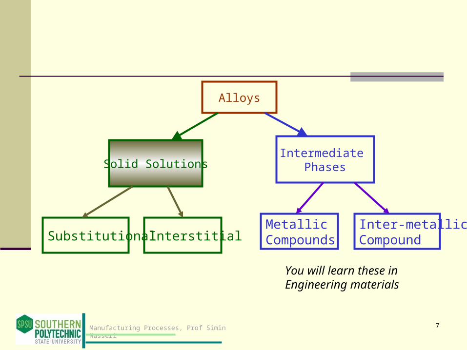
Alloys
Solid SolutionsIntermediate
Phases
Substitutional InterstitialMetallic Compounds
Inter-metallicCompound
7
You will learn these in Engineering materials

Manufacturing Processes, Prof Simin Nasseri
An alloy in which one element is dissolved in another to form a single‑phase structure
Base element is metallic (Solvent) Dissolved element, metallic or non-metal
Solid Solutions
A phase = any homogeneous mass of material, such as a metal, in which the grains all have the same crystal lattice structure!
What is a phase (in a material structure)?
8

Manufacturing Processes, Prof Simin Nasseri
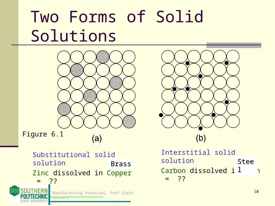
Two Forms of Solid Solutions
Substitutional solid solution - atoms of solvent element are replaced in its unit cell by dissolved element
Interstitial solid solution - atoms of dissolving element fit into vacant spaces between base metal atoms in the lattice structure
In both forms, the alloy structure is generally stronger and harder than either of the component elements
Figure 6.1
Atomic radii must be similar
Atoms of dissolving elements must be small :Hydrogen, Carbon, Nitrogen, Boron
9
Manufacturing Processes, Prof Simin Nasseri
Two Forms of Solid Solutions
Substitutional solid solution
Zinc dissolved in Copper = ??
Interstitial solid solution
Carbon dissolved in Iron = ??
Figure 6.1
BrassBrass SteelSteel
10

Phase Diagrams
11

Manufacturing Processes, Prof Simin Nasseri
Phase Diagrams
A graphical picture showing the phases of a metal alloy system as a function of composition and temperature
A phase diagram for an alloy system consisting of two elements at atmospheric pressure is called a binary phase diagram
Composition is plotted on the horizontal axis and temperature on the vertical axis
Any point in the diagram indicates the overall composition and the phase or phases present at the given temperature under equilibrium conditions
12

Manufacturing Processes, Prof Simin Nasseri
Copper-Nickel (Cu- Ni) Phase Diagram
Figure 6.2 Phase diagram for the copper‑nickel alloy system.
solid + liq
uid
Consider point A:Composition: 60% Ni, 40% CuAt 11000 C (or 2000o F) the alloy is still at solid stage.
Consider point B:About 35% Ni and 65% Cu,At 1250oC, it is a mixture of liquid and solid.
13
The overall composition of the alloy is given by its position along the horizontal axis

Manufacturing Processes, Prof Simin Nasseri
Tin-Lead Phase Diagram
Figure 6.3 Phase diagram for the tin‑lead alloy system.
Widely used in soldering for making electrical connections
Molten Tin and lead
Solid Tin and
Solid Tin and molten mixture
Soli lead and molten mixture
Solid solution of Tin in Lead Solid
solution of Lead in Tin
Pure tin melts at 232C (449F), Pure lead melts at 327C (621F)14
Just for your information:
Manufacturing Processes, Prof Simin Nasseri 15
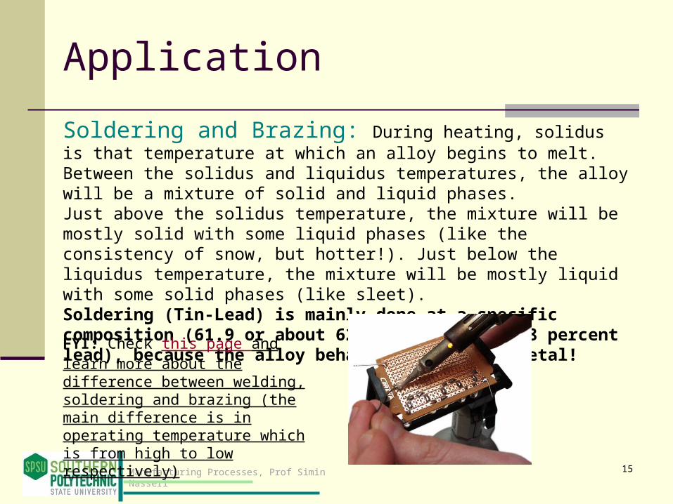
Application
Soldering and Brazing: During heating, solidus is that temperature at which an alloy begins to melt. Between the solidus and liquidus temperatures, the alloy will be a mixture of solid and liquid phases. Just above the solidus temperature, the mixture will be mostly solid with some liquid phases (like the consistency of snow, but hotter!). Just below the liquidus temperature, the mixture will be mostly liquid with some solid phases (like sleet).Soldering (Tin-Lead) is mainly done at a specific composition (61.9 or about 62 percent Tin in 38 percent lead), because the alloy behaves like a pure metal!
FYI: Check this page and learn more about the difference between welding, soldering and brazing (the main difference is in operating temperature which is from high to low respectively)

Ferrous Metals
16

Manufacturing Processes, Prof Simin Nasseri
Ferrous Metals
Based on iron, one of the oldest metals known to man
Ferrous metals of engineering importance are alloys of iron and carbon
These alloys divide into two major groups: Steel Cast iron
Together, they constitute approximately 85% of the metal tonnage in the United States
17
Manufacturing Processes, Prof Simin Nasseri
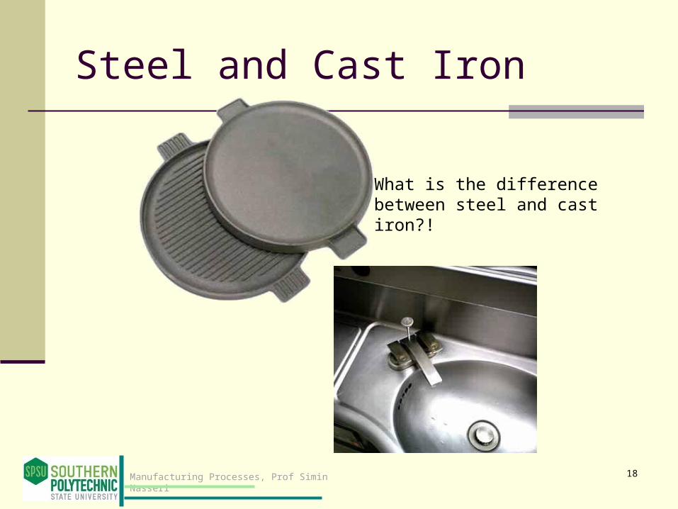
Steel and Cast Iron
What is the difference between steel and cast iron?!
18

Manufacturing Processes, Prof Simin Nasseri
Steel and Cast Iron Defined
Steel = an iron‑carbon alloy containing from 0.02% to 2.1% carbon
Cast iron = an iron‑carbon alloy containing from 2.1% to about 4% or 5% carbon
Steels and cast irons can also contain other alloying elements besides carbon
19

Manufacturing Processes, Prof Simin Nasseri
Iron-Carbon Phase Diagram
Figure 6.4 Phase diagram for iron‑carbon system, up to about 6% carbon.
FYI: Watch the DVD of the book:Choose Additional Processes, then Heat treating.
20
Just for your information:
Steel
21

Manufacturing Processes, Prof Simin Nasseri
Steel
An alloy of iron containing from 0.02% and 2.11% carbon by weight
Often includes other alloying elements: nickel, manganese, chromium, and molybdenum
Steel alloys can be grouped into four categories: 1. Plain carbon steels2. Low alloy steels3. Stainless steels4. Tool steels
22

Manufacturing Processes, Prof Simin Nasseri
Plain Carbon Steels
Carbon is the principal alloying element, with only small amounts of other elements (about 0.5% manganese is normal)
Strength of plain carbon steels increases with carbon content, but ductility is reduced
High carbon steels can be heat treated to form martensite, making the steel very hard and strong
Carbon Strength Carbon Ductility
23

Manufacturing Processes, Prof Simin Nasseri
Figure 6.12 Tensile strength and hardness as a function of carbon content in plain carbon steel (hot rolled).
Hardness is the characteristic of a solid material expressing its resistance to permanent deformation.
24

Manufacturing Processes, Prof Simin Nasseri
AISI-SAE Designation Scheme
Specified by a 4‑digit number system: 10XX, where 10 indicates plain carbon steel, and XX indicates carbon % in hundredths of percentage points
For example, 1020 steel contains 0.20% C Developed by American Iron and Steel Institute (AISI) and
Society of Automotive Engineers (SAE), so designation often expressed as AISI 1020 or SAE 1020
25
Manufacturing Processes, Prof Simin Nasseri
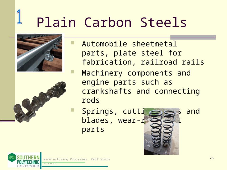
Plain Carbon Steels Automobile sheetmetal parts, plate
steel for fabrication, railroad rails Machinery components and engine
parts such as crankshafts and connecting rods
Springs, cutting tools and blades, wear-resistant parts
26

Manufacturing Processes, Prof Simin Nasseri
Low Alloy SteelsIron‑carbon alloys that contain additional
alloying elements in amounts totaling less than 5% by weight
Mechanical properties superior to plain carbon steels for given applications
Higher strength, hardness, wear resistance, toughness, and more desirable combinations of these properties
Heat treatment is often required to achieve these improved properties
Large diameter pipeline
27
Manufacturing Processes, Prof Simin Nasseri
Stainless Steel (SS)
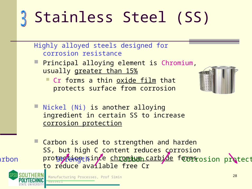
Highly alloyed steels designed for corrosion resistance
Principal alloying element is Chromium, usually greater than 15% Cr forms a thin oxide film that protects surface
from corrosion
Nickel (Ni) is another alloying ingredient in certain SS to increase corrosion protection
Carbon is used to strengthen and harden SS, but high C content reduces corrosion protection since chromium carbide forms to reduce available free Cr Carbon Strength Carbon Corrosion protection
28
Manufacturing Processes, Prof Simin Nasseri
Properties of Stainless Steels
In addition to corrosion resistance, stainless steels are noted for their combination of strength and ductility While desirable in many applications, these
properties generally make stainless steel difficult to work in manufacturing
Significantly more expensive than plain C or low alloy steels
29

Manufacturing Processes, Prof Simin Nasseri
Tool Steels
A class of (usually) highly alloyed steels designed for use as industrial cutting tools, dies, and molds
To perform in these applications, they must possess high strength, hardness, wear resistance, and toughness under impact
Tool steels are heat treated
30

Cast Iron
31

Manufacturing Processes, Prof Simin Nasseri
Cast Irons
Iron alloys containing from 2.1% to about 4% carbon and from 1% to 3% silicon.
This composition makes them highly suitable as casting metals.
32
Tonnage of cast iron castings is several times that of all other cast metal parts combined, excluding cast ingots in steel-making that are subsequently rolled into bars, plates, and similar stock.
Overall tonnage of cast iron is second only to steel among metals

Manufacturing Processes, Prof Simin Nasseri
Question
What do you think this is?
Cross-section of a gray cast iron using an optical microscopy (up to 1000 times magnification)
33
Related Documents