Metalloporphyrin-catalysed epoxidation using hydrogen peroxide A thesis submitted to the University of Surrey in partial fulfilment of the requirements for the degree of Doctor of Philosophy in the Faculty of Science Presented by Suthahari Gunathilagan, BSc. (Hons.) 2001 The Joseph Kenyon Research Laboratories, Department of Chemistry, University of Surrey, GuHdford, Surrey GU2 5XH

Welcome message from author
This document is posted to help you gain knowledge. Please leave a comment to let me know what you think about it! Share it to your friends and learn new things together.
Transcript

Metalloporphyrin-catalysed epoxidation
using hydrogen peroxide
A thesis submitted to the University of Surrey in partial fulfilment of the requirements for the degree of Doctor of
Philosophy in the Faculty of Science
Presented by
Suthahari Gunathilagan, BSc. (Hons.)
2001
The Joseph Kenyon Research Laboratories, Department of Chemistry,
University of Surrey, GuHdford,
Surrey GU2 5XH

Acknowledgement
Many thanks to my supervisors, Dr. Ian Cunningham, Prof. John Hay, Dr. Tim Danks
and Dr. Ian Hamerton at the University of Surrey, and Prof. Brian Cox at Zeneca. I
would also like to thank my friends and colleagues at the University of Surrey for
their kind help and encouragement. I am grateful to Zeneca for financial support.
11

Abstract
The catalysis by S, 1 0, IS,20-tetrakis(pentafluorophenyl)-21H,23H-porphyrin iron(III)
chloride (F20 TPPFeCl) of alkene epoxidation by H20 2 has been investigated.
Extensive catalyst decomposition was observed during the reaction. A kinetics and
product yield analysis has shown that this decomposition does not occur via either the
oxoperferryl intermediate (F 20 TPP·+)F eIV =0 or the oxoferryl intermediate
(F20 TPP)FeIV =0, but appears to involve direct oxidation of the porphyrin in parallel
with the catalytic epoxidation cycle. The catalytic epoxidation cycle involves
formation of an oxoperferryl intermediate which reacts with cyclooctene to give
epoxide and regenerate F20 TPPFeIlI. However, this reaction of the oxoperferryl
intermediate with cyclooctene is in competition with reaction of the oxoperferryl
intermediate with H20 2, which also regenerates F20 TPPFeIII probably via the oxoferryl
intermediate. In the absence of organic substrate, the decomposition by hydrogen
peroxide is probably via the oxoperferryl and oxoferryl species.
In order to investigate the effect of catalyst structure on epoxidation efficiency and
catalyst stability, metalloporphyrins (S, 1 0, IS,20-tetrakis(p-hydroxyphenyl)-21H,23H
porphyrin iron(III) chloride (THPPFeCl), S,10,IS,20-tetraphenyl-21H,23H-porphyrin
iron(III) chloride (TPPF eCl), S, 1 0, IS ,20-tetrakis(p-sulfonatophenyl)-21 H,23 H
porphyrin manganese(III) chloride (TSPPMnCl), S,10,IS,20-tetraphenyl-21H, 23H
porphyrin manganese(III) chloride (TPPMnCl), S, 1 0, IS,20-tetrakis(p-hydroxyphenyl)
-21H,23H-porphyrin manganese(III) chloride (THPPMnCl) and S, 1 0, IS,20-tetrakis
(pentafluorophenyl)-21H,23H-porphyrin iron(III) chloride (F20 TPPFeCl)) catalysed
epoxidation reactions have been studied. Of these, THPPFeCl was synthesised from
pyrrole and p- hydroxybenzaldehyde (via p-acetylbenzaldehyde), with the metal being
inserted using refluxing FeCbAH20 in DMF. THPPMnCl was prepared by
III
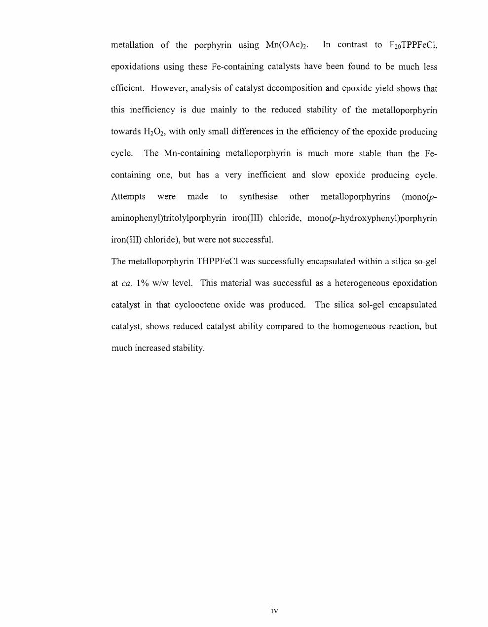
metallation of the porphyrin usmg Mn(OAc )2. In contrast to F 20 TPPF eCI,
epoxidations using these Fe-containing catalysts have been found to be much less
efficient. However, analysis of catalyst decomposition and epoxide yield shows that
this inefficiency is due mainly to the reduced stability of the metalloporphyrin
towards H20 2, with only small differences in the efficiency of the epoxide producing
cycle. The Mn-containing metalloporphyrin is much more stable than the Fe
containing one, but has a very inefficient and slow epoxide producing cycle.
Attempts were made to synthesise other metalloporphyrins (mono(p
aminophenyl)tritolylporphyrin iron(III) chloride, mono(p-hydroxyphenyl)porphyrin
iron(III) chloride), but were not successful.
The metalloporphyrin THPPFeCI was successfully encapsulated within a silica so-gel
at ca. 1% w/w level. This material was successful as a heterogeneous epoxidation
catalyst in that cyclooctene oxide was produced. The silica sol-gel encapsulated
catalyst, shows reduced catalyst ability compared to the homogeneous reaction, but
much increased stability.
IV

EDX
THPPFeCl
TPPFeCl
TSPPMnCl
TPPMnCl
THPPMnCl
F20TPPFeCl
Glossary
energy dispersive X-ray analysis
5, 10, 15,20-tetrakis(p-hydroxyphenyl)-21H,23H
- porphyrin iron(III) chloride,
5,10,15,20-tetraphenyl-21H,23H-porphyrin
-iron(III) chloride
5,10, l5,20-tetrakis(p-sulfonatophenyl)-21H,23H
-porphyrin manganese(III) chloride
5,10, l5,20-tetraphenyl-21H, 23H- porphyrin
-manganese(III) chloride
5,10, 15,20-tetrakis(p-hydroxyphenyl) -21H,23H
-porphyrin manganese(III) chloride
5,1 0,15,20-tetrakis (pentafluorophenyl)-21H,23H
-porphyrin iron(III) chloride

Llwpter one -lnlroaUCllon ana llterature review
Table of Contents
Chapter One
Introduction and literature review ........................................................................ 1
1.1 Introduction ........................................................................................................ 1
1.2 Cytochrome P450 enzymes ............................................................................... 1
1.3 Metalloporphyrins as oxidation catalysts .......................................................... 5
1.3.1 Porphyrins ................................................................................................... 6
1.3.2 Oxygenation and oxidation reactions ......................................................... 9
1.3.3 Oxidants .................................................................................................... 12
1.3.4 Catalysts .................................................................................................... 17
1.3.5 Mechanism of the metalloporphyrin catalysed oxygenation reaction ...... 18
1.3.5.1 Formation of high-valent intermediate .............................................. 18
1.3.5.2 Reactions of high-valent iron species with alkene ............................. 20
1.3.6 Catalytic efficiency / Catalyst stability ..................................................... 23
1.4 Syntheses of porphyrins .................................................................................. 25
1.4.1 "1 + 1 + 1 + 1" synthetic methods .................................................................. 25
1.4.2 "2+2" Porphyrin synthesis ........................................................................ 30
1.4.3 "3+ 1" Porphyrin synthesis ........................................................................ 32
1.4.4 Insoluble support methodology ................................................................ 33
1.4.5 Miscellaneous ........................................................................................... 35
1.4.6 Metalloporphyrins ..................................................................................... 35
1.4.7 Supported metalloporphyrins .................................................................... 36
1.4.8 Encapsulation of metalloporphyrin in a sol-gel matrix ............................ 36
VI

cnapcer one - 1nlroaUClion ana IIceracure review
1.5 Sol-Gels .......................................................................................................... 36
1.5.1 Sol-Gel Processing .................................................................................... 37
1.5.2 Gel. ............................................................................................................ 40
1.5.3 Drying ...................................................................................................... 41
1.5.4 Surface Area and porosity ........................................................................ .42
1.6 Aims / objectives ...................................................................... 42
1.7 References ........................................................................................................ 45
.. \'11
~ two-BxploratlOn O[ OXlaallVe Vs. tlestrllctlve pathways
Chapter Two
2.1. Introduction ..................................................................................................... 50
2.2.Results .............................................................................................................. 52
2.2.1. Epoxidation of alkenes - General conditions ........................................... 52
2.2.2 Preliminary Findings ................................................................................. 53
2.2.3 Epoxide Yields .......................................................................................... 61
2.2.4 Combined yield / Kinetic study of the iron porphyrin catalysed
epoxidation of cyc100ctene by hydrogen peroxide ............................................. 64
2.2.5 Use of2,4-dimethoxyphenol as substrate ................................................. 65
2.2.6 Test for F2oTPPFe1v=O .............................................................................. 68
2.2.7 Fate ofH20 2 .............................................................................................. 69
2.3. Discussion ....................................................................................................... 70
2.3.1 Summary of Results .................................................................................. 70
2.3.2 The catalytic cycle ..................................................................................... 72
2.3.3 Catalyst decomposition ............................................................................. 74
2.3.4 Competition for the oxoperferryl. .............................................................. 75
2.3.5 Overall scheme .......................................................................................... 76
2.4 Conclusion ....................................................................................................... 78
2.5. Experimental Section ...................................................................................... 78
2.5.1 Materials .................................................................................................... 78
2.5.2 Standardisation of the concentration ofH20 2 ..•...........•.....•...••.•.....•......... 79
2.5.3 Protocol. ..................................................................................................... 80
2.5.4 Instrumentation .......................................................................................... 80
2.5.5 Analysis of epoxide yield by gas chromatography .................................... 81
viii

~r two-hxptoratlOn o[ oxzaatzve vs. uestructlve patilwarS
2.5.6 Kinetic analysis by Uv-vis spectroscopy and product analysis by GC ..... 82
2.5.7 Experimental methods ............................................................................... 83
2.5.7.1. Epoxidation reaction of cyclooctene with H20 2 in the presence of
tetrakis (pentafluorophenyl)porphyrin iron(III) chloride as a catalyst ........... 83
2.5.7.2 Uv/vis repscans of destruction oftetrakis(pentafluorophenyl) -
porphyrin iron(III) chloride in the epoxidation reaction of cyclooctene ......... 84
2.5.7.3 Fixed wavelength Uv/vis monitoring of catalyst destruction in the
epoxidation reaction with different concentrations of cyclooctene ................ 84
2.5.7.4 Fixed wavelength Uv/vis monitoring of catalyst destruction in the
epoxidation reaction with different concentrations of styrene ........................ 85
2.5.7.5 Fixed wavelength Uv/vis monitoring of catalyst destruction in the
epoxidation reaction with different concentrations of cyclohexene ............... 86
2.5.7.6 Fixed wavelength Uv/vis monitoring of catalyst destruction in the
epoxidation reaction with different substrates ................................................ 87
2.5.7.7 Fixed wavelength Uv/vis monitoring of catalyst destruction in the
epoxidation reaction with different concentrations ofH20 2 ..•..•........••.•...••.... 87
2.5.7.8 Fixed wavelength Uv-vis monitoring of destruction of different
concentration of tetrakis(pentafluorophenyl )porphyrin iron(III) chloride in the
epoxidation reaction of cyc1ooctene ................................................................ 88
2.5.7.9 Product analysis (GC) of the tetrakis(pentafluorophenyl)porphyrin
iron(III) chloride catalysed H20 r epoxidation of cyclooctene ........................ 89
2.5.7.10 Determination of rate constants for catalyst decay, and epoxide yields
for the epoxidation reaction at different concentration of cyclooctene ........... 90
2.5.7.11 Epoxidation with 2,4-dimethoxyphenol as substrate ........................ 92
ix

or two-bxploratlOll o( oxtaatlve vs. destrucflve patllwars
2.5.7.12 Product analysis of the epoxidation reaction of cyc100ctene \\-ith high
levels of catalyst .............................................................................................. 93
2.5.8 Synthesis of2,4-dimethoxyphenol ............................................................ 9.+
2.6 References ........................................................................................................ 96
x

Chapter Three - Synthesis of metal/oporphyrills
Chapter Three
Synthesis ofmetalloporphyrins ................................................................................... 98
3.1 Introduction ....................................................................................................... 98
3.1.1 Porphyrin synthesis ....................................................................................... 100
3.1.2 Objectives (target metalloporphyrins) ........................................................... 101
3.1.3 Sol-Gel chemistry .......................................................................................... 104
3.2 Results and Discussion ........................................................................................ 106
3.2.1 Synthesis ofmono(p-nitrophenyl)tritolylporphyrin ...................................... 106
3.2.2 Solid phase route to prepare a mono-substituted porphyrin -
monohydroxyphenyltritolylporphyrin .................................................................... 108
3.2.2.1 Preparation of® -C02H ........................................................................ 108
3.2.2.2 Conversion to®-COCI ......................................................................... 109
3.2.2.3 Preparation of® -COOC6H4CHO ......................................................... 110
3.2.2.4 Synthesis of 5-(p-benzoylphenyl)-1 0, 15,20-tritolylporphyrin on solid
phase ................................................................................................................... III
3.2.3 Synthesis of 5,10, 15,20-tetrakis(p-hydroxyphenyl)porphyrin ...................... III
3.2.3.1 Preparation ofp-acetylbenzaldehyde ...................................................... 112
3.2.3.2 Preparation of 5,1 0, 15,20-tetrakis(p-acetylphenyl)porphyrin ............... 114
3.2.3.3 Preparation of 5,10,15,20-tetrakis(p-hydroxyphenyl)porphyrin ............ 116
3.2.3.4 Insertion of metal into the tetrakis(p-hydroxyphenyl)porphyrin ........... 119
3.2.4 Sol-Gel chemistry .......................................................................................... 123
3.2.4.1 Preparation of immobilised metalloporphyrin ........................................ 123
3.2.4.2 Surface / Porosity analysis ...................................................................... 123
Xl
Chapter Three - Synthesis of metalloporphyrins
3.2.4.3 Analysis of the gel by IR spectroscopy ................................................... 124
3.2.4.4 EDX results ............................................................................................. 126
3.3 Conclusion ........................................................................................................... 128
3.4. Experimental. ...................................................................................................... 129
3.4.1 Materials ........................................................................................................ 129
3.4.2. Instrumentation ............................................................................................. 129
3.4.3 Method .......................................................................................................... 130
3.4.3.1. Synthesis of5-(p-nitrophenyl)-10,15,20-tritolylporphyrin .................... 130
3.4.3.2 Synthesis of 5-(p-hydroxyphenyl)-1 0, 15,20-tritolylporphyrin on solid-
phase ................................................................................................................... 131
3.4.3.2.1 Preparation of ® -COOH ............................................................... 131
3.4.3.2.2 Preparation of ® -COCl. ................................................................. 132
3.4.3.2.3- Preparation ofCR) -COOC6H4CHO ................................................. 132
3.4.3.2.4 Synthesis of 5-(p-benzoylphenyl)-1 0, 15,20-tritolylporphyrin on solid
phase ................................................................................................................ 132
3.4.3.3. Synthesis of5,10,15,20-tetrakis(p-hydroxyphenyl)porphyrin ............... 133
3.4.3.3.1 Preparation of p-Acetylbenzaldehyde .............................................. 133
3.4.3.3.2. Synthesis of5,10,15,20-tetrakis(p-acetylphenyl)porphyrin ............ 134
3.4.3.3.3 Synthesis of 5, 10, 15,20-tetrakis(p-hydroxyphenyl)porphyrin ......... 134
3.4.3.4 Insertion of metal [Pe(H)] into tetrakis(p-hydroxyphenyl)porphyrin ..... 135
3.4.3.5 Insertion of metal [Mn(H)] into tetrakis(p-hydroxyphenyl)porphyrin .... 135
3.4.3.6 Synthesis of metalloporphyrin-TEOS organic-inorganic polymerhybrid
............................................................................................................................. 136
.. Xll

Chapter Three - Synthesis of metalloporphyrills
3.4.3.6.1 Full analysis of the sample ................................................................... 137
3.4.3.7 Synthesis ofporphyrin-TEOS organic-inorganic polymer hybrid ......... 137
3.5 References ........................................................................................................ 138
Xlll

ter Four- epoxidation reaction with different catalysts
Chapter Four
Epoxidation of alkene in the presence of different metalloporphyrins ................ 139
4.1 Introduction .................................................................................................... 139
4.2.Results ............................................................................................................ 143
4.2.1 Fe-catalysts ............................................................................................. 143
4.2.2 Mn-catalysts ............................................................................................ 146
4.2.3 Encapsulated catalyst .............................................................................. 149
4.3 Discussion ...................................................................................................... 150
4.3.1 Fe-catalysts ............................................................................................. 150
4.3.2 Mn-Catalysts ........................................................................................... 158
4.3.3 Epoxidation reaction with encapsulated 5,10, 15,20-tetrakis
-(p-hydroxyphenyl)-21H,23H-porphyrin iron(III) chloride ................... 160
4.4 Conclusion ..................................................................................................... 162
4.5 Experimental Section ..................................................................................... 163
4.5.1 Materials ................................................................................................. 163
4.5.2 Instrumentation ....................................................................................... 164
4.5.3 Method .................................................................................................... 165
4.5.3.1 Epoxidation reaction of cyclooctene in the presence of different
catalysts and hydrogen peroxide as the oxidant.. ......................................... 165
4.5.3.2 Epoxidation reaction of cyclooctene in the presence of encapsulated
[5,10, 15,20-tetrakis(p-hydroxyphenyl)-21H,23H-porphyrin iron(III)
chloride] and hydrogen peroxide as the oxidant.. ........................................ 166
4.5.3.3 Calculation of percentage of porphyrin in the Si02 network. ......... 166
4.6 References ...................................................................................................... 169
XIV

Appendix 1 ............................................................................... 170
Appendix 2 ............................................................................... 1 73
xv
Chapter one - Introduction and literature review
Chapter One
Introduction and literature review
1.1 Introduction
The work presented in this thesis is a study of metalloporphyrin catalysed alkene
epoxidation reactions. While the ability of metaUoporphyrins to act as a catalyst
for the epoxidation of alkenes has been extensively studied, in this work the effect
of metalloporphyrin decomposition on the catalysis of epoxidation is emphasised.
1.2 Cytochrome P450 enzymes
Cytochrome P-450 is the name of a wide family of mono-oxygenase enzymes that
catalyse the transfer of one oxygen atom, from dioxygen, to a substrate. 1,2
The cytochrome P-450 family is widely distributed in the animal (including
human beings), plant and microbial kingdoms and participates as a mono-
1

Chapter one - Introduction and literature review
oxygenase in various detoxification and biosynthetic pathways, some of which are
particularly important for regulation ofhonnone activity.
The active site of cytochrome P-450 has long been known to contain a single iron
protoporphyrin IX prosthetic group (figure 1.1). Dioxygen is bound, reduced, and
activated at this site.
o
Figure 1.1: Structure of iron protoporphyrin IX
Cytochromes P-450 are postulated to catalyse hydroxylation of alkanes and the
epoxidation of alkenes through high-valent iron porphyrin intennediates?
The catalytic cycle is shown in scheme 1.1, where S is substrate.

Chapter one - Introduction and literature review
so @9-P-450
s
~-P-450 S
02
2-
@-P-45 2H+ S
Scheme 1.1: Catalytic cycle of cytochrome P-450
It can be divided into stages:
1 and 2 - binding of the substrate and one-electron reduction of the FeIII to the
Fe" state,
3 and 4 - binding of dioxygen and one-electron reduction,
5 - fonnal heterolysis of the 0-0 bond with concomitant generation of the
reactive oxidant [Fe v =0] and a molecule of water,
6 - a two-electron oxidation of the substrate to produce SO and regenerate the
ferric (FeIII) resting state of the enzyme.
As described in scheme 1.1, substrate binding to native ferric P-450 is followed
by reduction to the ferrous state, thereby allowing oxygen binding. Reaction 5
results in splitting of the oxygen-oxygen bond, one atom being lost as water. The
other oxygen atom, now an "activated oxygen", is inserted into a carbon-hydrogen
bond of the substrate to produce the corresponding alcohol (or C=C to produce
3

Chapter one - Introduction and literature review
epoxide), which is then released with regeneration of the resting state of the
enzyme (ferric state). The overall process is a reductive molecular oxygen
activation in which one oxygen atom is transferred to a substrate whereas the
second one is eliminated as water (scheme 1.2). Scheme 1.2 also includes the
'peroxide shunt' using H20 2 (equation 2).
Scheme 1.2. Oxidation of substrate
The exact nature of the active oxidant, written as [Fe v =0] above, remams
uncertain. The possible forms of active oxidant are (Fe v =0), (pore+FeIV =0) * and
(FeIV_Oe).t Evidence has accumulated that suggests that the active oxidant
derived via the peroxide shunt pathway is similar to that formed by the reduction
of dioxygen. 2
Simplified mechanisms, which are generally accepted, for the subsequent reaction
to give hydroxylation and epoxidation, are shown in scheme 1.3.4
• Por- porphyrin t In this thesis Fe v is generally used to indicate the high valent intermediate, except where the different forms are discussed explicitly.

Chapter one - Introduction and literature review
Hydroxylation
FeY=O I + ,?C-H
FeN-O·
Epoxidation
Felli
/ \ N-U
Scheme 1.3: Mechanisms for alkane hydroxylation and alkene epoxidation catalysed by cytochrome P-450
Because of the high molecular mass and protein structure of cytochromes P-450,
it is still difficult to determine the detailed mechanism of substrate oxidations and
the nature of the iron intermediates involved in these processes.4 A possible way
to avoid these problems is to use biomimetic chemical systems containing a
metalloporphyrin.
1.3 Metalloporpbyrins as oxidation catalysts
For a long time, metalloporphyrins were only considered as relatives of
haemoprotein active sites and not as potential catalysts.
5

Chapter one - Illtroductioll and literature review
The wide range of oxidative transformations catalysed by the heme-containing
monooxygenase cytochrome P-450 suggests that simple metalloporphyrin
complexes should also catalyse such reactions under appropriate conditions. I ,5
1.3.1 Porphyrins
Porphyrins are derivatives of a simple purple compound called 'porphin'. The
naturally occurring derivatives of porphin are known as p01plzyrills. The basic
structure of porphyrin consists of four pyrrole molecules linked by four methine
bridges (-CH=), while at the centre of the molecule is a 'hole'. Porphyrin is an
aromatic compound containing twenty-two 1C electrons of which eighteen are
involved in a delocalisation pathway.
Pyrrole unit ~H
Figure 1.2: Structure of porphin
H I H
H
H
H
Any porphyrin derivative in which at least one of the central nitrogen atoms of a
porphyrin H2 (P) forms a bond to a metal atom is called a metalloporphyrin.
The porphyrin is a tetradentate ligand, in which the space available for a
coordinated n1etal has a maximum diameter of approximately 3.7 A.6 When
coordination occurs, two protons are lost from the pyrrole nitrogen atoms, leaving
two negative charges that are distributed equally about the whole irmer ring.
6
Chapter one - Introduction and literature review
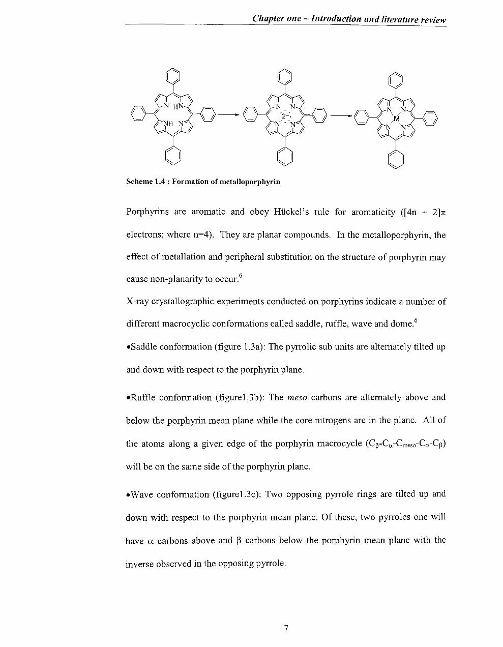
Scheme 1.4 : Formation of metalloporphyrin
Porphyrins are aromatic and obey Ruckel's rule for aromaticity ([ 4n + 2]1t
electrons; where n=4). They are planar compounds. In the metalloporphyrin, the
effect of metallation and peripheral substitution on the structure of porphyrin may
cause non-planarity to occur.6
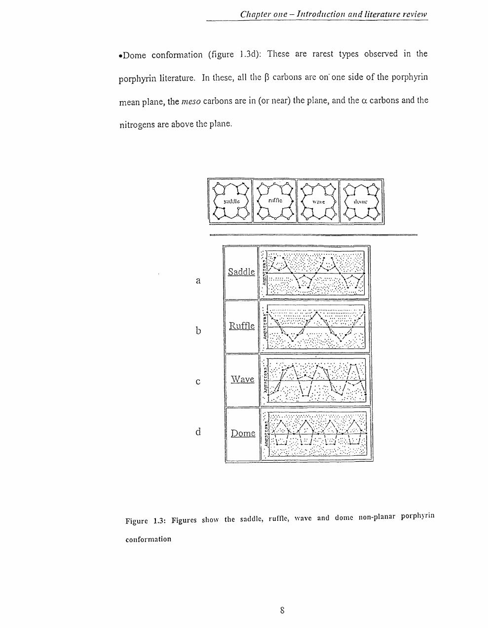
X-ray crystallographic experiments conducted on porphyrins indicate a number of
different macrocyc1ic conformations called saddle, ruffle, wave and dome.6
eSaddle conformation (figure 1.3a): The pyrrolic sub units are alternately tilted up
and down with respect to the porphyrin plane.
eRuffle conformation (figure1.3b): The meso carbons are alternately above and
below the porphyrin mean plane while the core nitro gens are in the plane. All of
the atoms along a given edge of the porphyrin macrocyc1e (Cp-Ca-Cmeso-Ca-Cp)
will be on the same side of the porphyrin plane .
• Wave conformation (figure1.3c): Two opposing pyrrole rings are tilted up and
down with respect to the porphyrin mean plane. Of these, two pyrroles one will
have a carbons above and ~ carbons below the porphyrin mean plane with the
inverse observed in the opposing pyrrole.
7
Chapter Ol1e -Introduction and literature review
-Dome confom1ation (figure I.3d): These are rarest types observed in the
porphyrin literature. In these, all the B carbons are on' one side of the porphyrin
mean plane, the meso carbons are in (or near) the plane, and the CJ. carbons and the
nitrogens are above the plane.
a
b Ruffle
c 'Nave
d I I Dome
I i
Figure 1.3: Figures show the saddle, rufi1e, wave and dome non-planar porphyrin
conformation
s

Chapter one - Introduction and literature review
Physical properties, such as light absorption of the porphyrin, are controlled by
various chemical groups and arrangements of bonds in the ring. Different metals
determine the porphyrin's biological role by modifying its chemical properties.
Porphyrins hold an important position in oxidative mechanisms of metabolism,
ranging from the oxygen-carrying capacity of haemoglobins to the oxidative
reactions of cytochrome P450 and peroxidase enzymes*.l, 2
1.3.2 Oxygenation and Oxidation reactions
Metalloporphyrin, as an oxidative catalyst which mimics cytochrome P-450 mono
oxygenase, can show unique substrate specificity, chemoselectivity and high
catalytic activity under mild conditions. 1,2
There are two reasons for studying metalloporphyrins as oxidation catalysts:7
(i) they are capable of effecting the oxidation of organic substrates behaving
as a chemical, rather than biochemical catalyst at ambient temperature.
The oxidation of organic substrates leads to the production of many
functionalised molecules, which are of great commercial and synthetic
importance.
(ii) the study provides understanding, from simple chemical models, of the
essential steps of the catalytic cycle of a metalloenzyme capable of
achieving the same reaction in a living organism.
• Peroxidases are a class of iron(III) porphyrin containing proteins that catalyse the oxidation (electron removal) of substrates by hydrogen peroxide.
9
Chapter one - Introduction and literature review
Groves and co-workers were the first to demonstrate the ability of iron tetraphenyl
porphyrin as a catalyst in the hydroxylation and epoxidation reaction of alkanes
and alkenes. 8
Catalytic oxidation by metalloporphyrins now plays an important role in the
conversion of both saturated and unsaturated hydrocarbons into valuable fine
chemicals.7
Although the generic term 'oxidation' has been used so far, from here on the
terms oxygenation (addition of '0') and oxidation (electron removal) will be used.
The mechanism of hydroxylation of hydrocarbons by vanous synthetic
metallporphyrin catalysts was first investigated by Groves et ai.8
Hydroxylation of C-H bonds is believed to occur in two steps:9
(i) abstraction of a hydrogen atom by the high-valent iron-oxo intermediate
(Fe v =0, pore+FeI v =0, FeIV _Oe) having a free-radical-like reactivity, and
(ii) the oxygen rebound mechanism-oxidation of the intermediate free radical
by the FeIV -OH species with transfer of its OH ligand, leading to the
hydroxylated substrate (Scheme 1.5). 9
Examples of hydroxylation reactions are shown in scheme 1.6.
10

Chapter one - Introduction and literature review
"-..........- C-H /
"./ H 0 -Fe IV
/".
Abstraction , --------' .. ~ C·
..........-/
Rebound 'C 0 -~;....;:;.....;:c...:.:....:.:""=:---l"~ ..........-/ - H
Scheme l.5.Mechanism proposed for alkane hydroxylation
OR 0
0 PhIO • +
Fe(TPP)CI
15 1
OH OR
0 Mn(TPP)CI .- + °2 / NaBH4
4 1
Scheme 1.6: Hydroxylation reactions catalysed by metalloporphyrin
Fe(TPP)CI - Tetraphenylporphyrin iron chloride, Mn(TPP)FeCI-iron chloride
". / H 0 -Fe!\'
/".
Tetraphenylporphyrin
Oxygenation where '0' is inserted in to C=C bond is tenned epoxidation.
Epoxidation of olefins, which is featured in this work, is an important reaction
greatly used in organic synthesis.
The successful epoxidation reactions reqUIre stable catalysts, absence of
interfering by-products, and oxidants that are soluble and highly reactive towards
catalyst.
1 1

Chapter one - Introduction and literature review
1.3.3 Oxidants
Oxidants in these systems have included dioxygen or other oxygen atom donors
such as hydroperoxides,lO hypochlorites,7, 11 peracidsll or iodosylbenzenes.I2, 13
Oxygen atom donors - The use of one oxygen atom of molecular oxygen in a
mono-oxygenation reactions is always very difficult. The mono-oxygenases of
cytochrome P-450 type avoid this problem by only using a single oxygen atom of
O2 in reactions which they catalyse, while the second oxygen atom is eliminated
as water following reductive dioxygen activation. 1 1
For metalloporphyrins the use of single oxygen atom donors such as
iodosylbenzenes (C6HsIO),I2,13 potassium hydrogen persulphate
(2KHSOs.KHS04.K2S04),7 sodium hypochlorite (NaOCl),7,II peracids
(RC03H),II hydroperoxides (ROOH)4,7,1O, hydrogenperoxide (H20 2)4,7,11 etc.
easily affords the metallo-oxo species avoiding the problems involved in the
reductive dioxygen activation.
elodosylbenzene13 - The use of one-oxygen atom donors such as iodosylbenzene
in the oxygenation reactions is still common. Iodosylbenzene is much more
reactive towards the catalysts than towards alkene. The mechanism is outlined in
scheme 1.7.
12
Chapter one - Introduction and literature review
~+ Cl
6 t-o~ I -
----~ ~ -----~ Cl
R R \--1
~ -Porphyrin ring
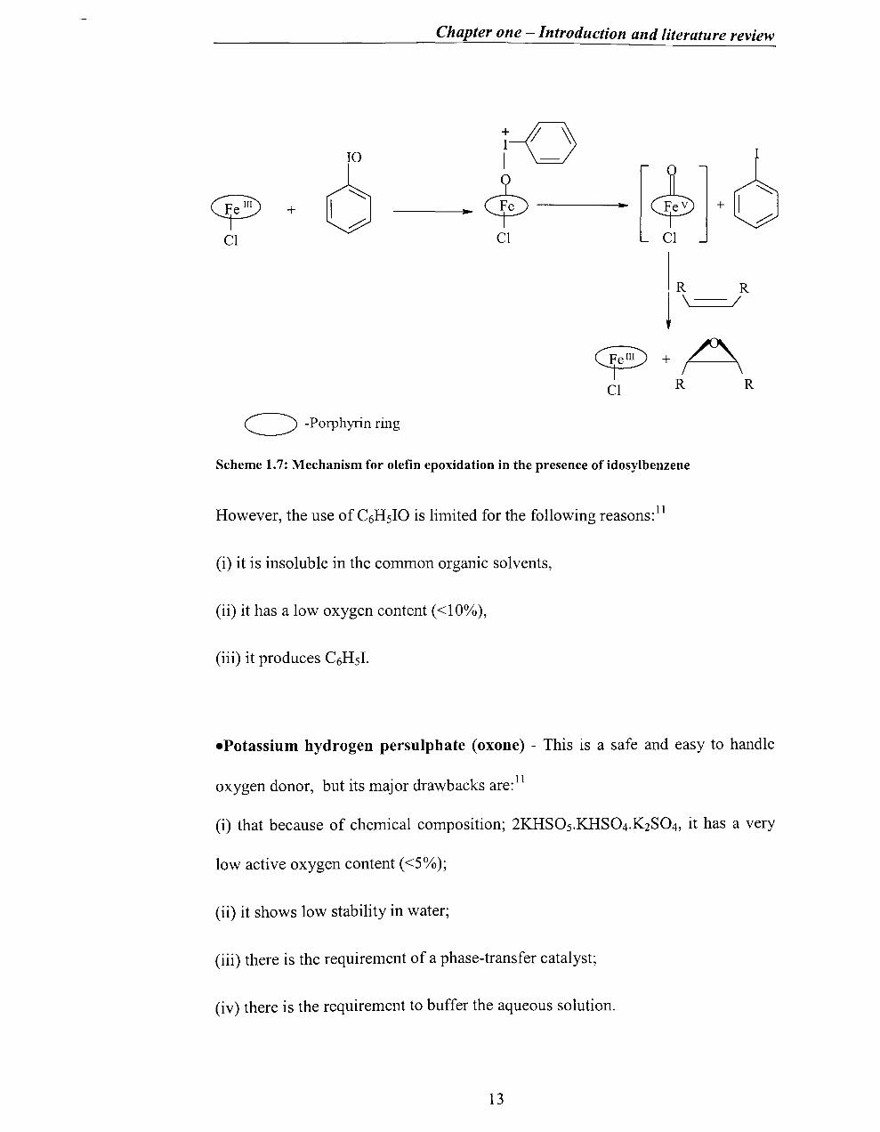
Scheme 1.7: Mechanism for olefin epoxidation in the presence of idosylbenzene
However, the use of C6HsIO is limited for the following reasons: 11
(i) it is insoluble in the common organic solvents,
(ii) it has a low oxygen content «10%),
(iii) it produces C6HsI.
.Potassium hydrogen persulphate (oxone) - This is a safe and easy to handle
oxygen donor, but its major drawbacks are: 11
(i) that because of chemical composition; 2KHSOs.KHS04.K2S04, it has a very
low active oxygen content «5%);
(ii) it shows low stability in water;
(iii) there is the requirement of a phase-transfer catalyst;
(iv) there is the requirement to buffer the aqueous solution.
13

Chapter one - Introduction and literature review
O Mn(TFPP)Cl / KHSOs 0 ---'--~. ° CH2C12 / aqueous buffer pH8
Scheme 1.8. Epoxidation with Potassium hydrogen persulphate as an oxidant.ll
Mn(TFPP)CI - Tetrafluorophenyl porphyrin manganese chloride
.Peroxyacids and Alkylhydroperoxides - When alkylhydroperoxides are used
as oxidants in reactions catalysed by metalloporphyrins, the major difficulty is to
avoid the homolytic cleavage of the peroxide bond which leads to the formation
of the RO· radical (scheme 1.9).7 Mansuy showed that the interaction with the
alkylperoxides can be modified by the presence of a strong donor ligand, such as
imidazole. 10
Heterolytic pathway
+
+[Cf>F 0
ROOH .. $ + ROH
L
M- metal L = imidazole
Homolytic pathway OH
ROOH + ~ ----~ $> + RO
CI CI
Scheme 1.9: Schematic diagram of homolytic and heterolytic cleavage.
14

Chapter one - Introduction and literature review
• Hypochlorites - Hypochlorites are cheap, safe, easily available and can be
easy to use.
Metalloporphyrin catalysed epoxidation of alkenes was investigated by, among
others, Meunier and coworkers. 13,14 They found that the addition of small
amounts of pyridine strongly increased the stereo-selectivity, reaction rate and
overall turnover.
Ph Ph \-/ + NaOel
cis-stilbene
Without pyridine
With pyridine
(0.15 equiv.lolefin)
Mn(TPP)OAc Ph Ph Ph '\ / '\ • \ I +
0 cis-epoxide
Cis-epoxide trans-epoxide Overall yield
35% 65%
78% 22%
(time in hours)
70-80% (7h)
80-85% (2-3h)
\ 1"'-0 Ph
trans-epoxide
Scheme 1.10 :Epoxidation reaction of stilbene with NaOel as oxidant; Mn(TPP)OAcTetraphenylporphyrin manganese acetate
Montanari and coworkers found that by lowering the pH of the NaOel aqueous
solution from >12.7 to 9.5-10.5, a very strong enhancement of the epoxidation
rate was observed. I4
-H20 2 - Mansuy and co-workers first reported that oxygenation of unsaturated
hydrocarbons can be carried out with 30% H20 2 and a Mn-porphyrin catalyst.IS
15
Chapter one - Introduction and literature review
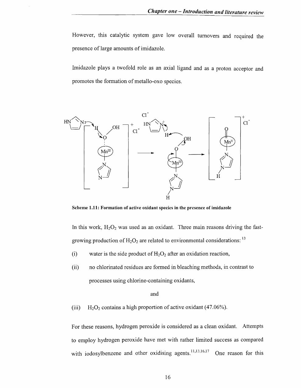
However, this catalytic system gave low overall turnovers and required the
presence of large amounts of imidazole.
Imidazole plays a twofold role as an axial ligand and as a proton acceptor and
promotes the formation of metallo-oxo species.
HN~ Cl + HN~+ Cl \ r'=\~ /OH
+
Cl \ fv
c!v ~o H~
/JH
~ ~ ~
~ N
f] N
f] N /
N H N f] N
/ H
Scheme 1.11: Formation of active oxidant species in the presence of imidazole
In this work, H20 2 was used as an oxidant. Three main reasons driving the fast-
growing production ofH20 2 are related to environmental considerations: 13
(i) water is the side product ofH20 2 after an oxidation reaction,
(ii) no chlorinated residues are formed in bleaching methods, in contrast to
processes using chlorine-containing oxidants,
and
(iii) H20 2 contains a high proportion of active oxidant (47.06%).
For these reasons, hydrogen peroxide is considered as a clean oxidant. Attempts
to employ hydrogen peroxide have met with rather limited success as compared
with iodosylbenzene and other oxidising agents. ll ,13,16,17 One reason for this
16
Chapter one - Introduction and literature review
failure is interference by radical-producing side reactions. 16,18 A chain
decomposition of the hydroperoxide occurs along with the free-radical processes
associated with the substrate. 19 In the view of Traylor et al., this problem arises
from side reactions after the metal oxidation rather than from a fundamental flaw
in the first step and also they found that simple iron porphyrins could react with
hydrogen peroxide to give high-yield epoxidation, if subsequent side reactions
could be avoided. 19
1.3.4 Catalysts
Metallo-tetraphenylporphyrins are commonly used as catalysts for oxygenation
reactions and catalytic destruction is the main drawback in their use.
The yields and product distributions in the oxidation of hydrocarbons or
epoxidation of alkenes using substituted porphyrins are shown to be markedly
affected by the nature and location of phenyl ring substituents, metal atoms and
h b · . h h" 41218192021 t e su stItuents m t e porp ynn nng.' , , , ,
Iron and manganese derivatives are commonly used as catalysts in the epoxidation
reactions of olefins, when the central metal of a metalloporphyrin is able to fonn a
strong M=O species at room temperature, no oxygen transfer reaction is
observed.13 Therefore vanadium, chromium (as the M=O bonds are very strong)
and nickel (as high-valent species have not been identified) derivatives are
. . 13 mactIve.
Earlier studies indicate that the prevention of the fonnation of J-l-oxo dimers (by
steric hindrance) or the introduction of electron-withdrawing substituents
17
Chapter one - Introduction and literature review
increases catalytic capability by decreasing the rate of oxidative destruction of
h . 22 emm.
1.3.5 Mechanism of the metalloporphyrin catalysed oxygenation reaction
The more general mechanism of oxygen activation and transfer by heme
compounds has been widely investigated.18,19 Several mechanisms have been
proposed for the epoxidation of alkenes by cytochrome P-450 or relevant model
h . d 16-24 b h" I' .c: fr emm compoun s, ut a mec amsm mvo vmg an oxygen tranSler om a
reactive iron(V)-oxo intermediate23 is generally accepted.
1.3.5.1 Formation of high-valent intermediate
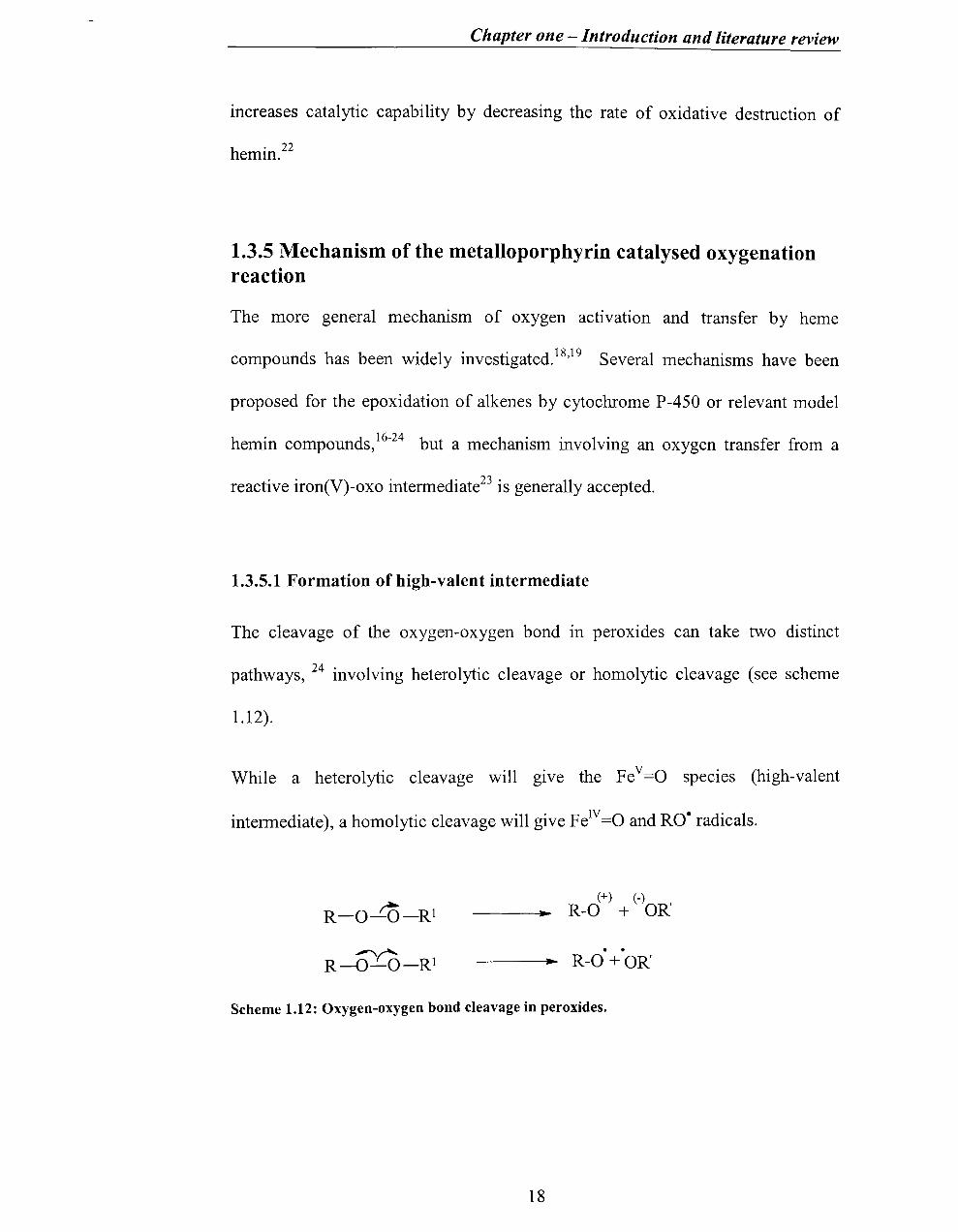
The cleavage of the oxygen-oxygen bond in peroxides can take two distinct
pathways, 24 involving heterolytic cleavage or homolytic cleavage (see scheme
1.12).
While a heterolytic cleavage will gIVe the Fe v =0 specIes (high-valent
intermediate), a homolytic cleavage will give FeIV=O and RO· radicals.
~ R-O-O-Rl (+) (-)
---.. R-O + OR'
---...... R-O + OR'
Scheme 1.12: Oxygen-oxygen bond cleavage in peroxides.
18

Chapter one - Introduction and literature review
A similar mechanism can be envisaged in the reactions of iron (III) porphyrins
(PFe +) with hydroperoxides (scheme 1.13; X= RO where R is an alkyl group). 19
Heterolytic pathway
FeIII + XOH ~.==.~ H+ + FeIIIOX ---l"'~ Fev=O + HX + B I I I
Homolytic pathway
I FeIII + XOH .... H+ + FeIIIOX ..... E---
I ----i .... ~ FeN=O + X •
I I I
Scheme 1.13: Reactions of iron(III) porphyrin with hydroperoxide
In cases where X is a good leaving group (PhIO, RC03H, HOCl or HOOS03 -),
the epoxidation reaction proceeds smoothly. In cases where X = HO- or RO-, low
to zero yields of epoxide have been reported. 19 Therefore, the failure to obtain
epoxide has been taken as evidence for homolytic cleavage (scheme 1.13) for
H20 2 and R02H oxidants, since the oxo-perferryl species (Fe v = 0) epoxidises
alkenes but the ox 0 ferryl (FeN = 0) does not. Traylor and his co-workers
demonstrated that, by avoiding competitive side reactions of the oxo-perferryl
species (Fe v = 0), a high yield of epoxidation can be achieved. 19
In other words, the mechanism for the reaction involving H20 2, the clean and
efficient oxidant that is the keynote of this project; is the most uncertain.
19

Chapter one - Introduction and literature review
Furthermore, this powerful oxidant has a degree of 'notoriety' as one which
readily causes catalyst bleaching. The desired activation route when using
synthetic metalloporphyrins is the heterolytic mode, which leads to the generation
of a high-valent, metal-oxo porphyrin complex and a water molecule. 18,19
1.3.5.2 Reactions of high-valent iron species with alkene
Even where evidence implicates the high-valent iron(IV) porphyrin cation radical
(pore+ _FeIV =0) as the oxidising species, different pathways are possible for its
reaction with an olefin (scheme 1.14).23
20

Chapter one - Introduction and literature review
"-.. ./'
(FeY={)) + C = C / """ R
(1)
"'-/ c
FeY={) -----11
/C", R
I I F eIV -O-C-C •
I I
R
1 (Sa)
(5) ,,+ . / .. FeN={) C= C
/ "-R
1 (5b)
I I R
o /\
-c-c-R
+
R I /
/c-c~ /
+
Scheme 1.14: Reactions of a high-valent iron-oxo porphyrin intermediate with an olefin
The epoxidation reaction of olefin with high-valent iron-oxo porphyrin
intennediate can be take place through different pathways: (1) Direct oxygen
transfer, (2) Free radical addition followed by fast ring closure, (3) Electrophilic
addition followed by fast ring closure, (4) Reversible electrocyclic metallooxetane
fonnation followed by dissociation to epoxide or other products, (5a) Electron
transfer followed by collapse to radical and (5b) Electron transfer followed by
carbocation metalloporphyrin- catalysed oxidation/oxygenation.
21
Chapter one - Introduction and literature review
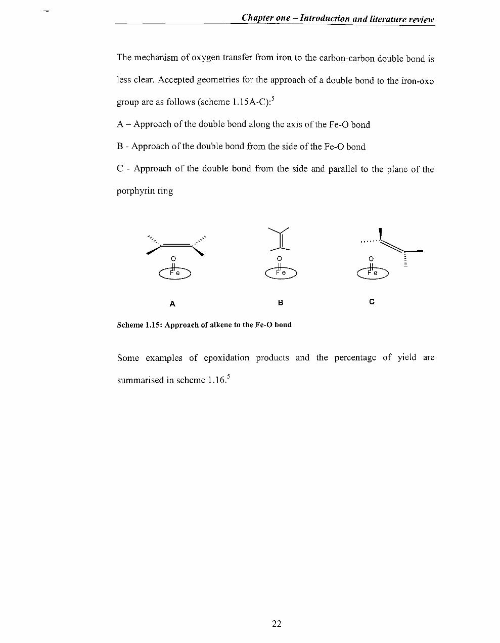
The mechanism of oxygen transfer from iron to the carbon-carbon double bond is
less clear. Accepted geometries for the approach of a double bond to the iron-oxo
group are as follows (scheme 1.15A-C):5
A - Approach of the double bond along the axis of the Fe-O bond
B - Approach of the double bond from the side of the Fe-O bond
C - Approach of the double bond from the side and parallel to the plane of the
porphyrin ring
...... ~ ~.
o o
db db -
A B c
Scheme 1.15: Approach of alkene to the Fe-O bond
Some examples of epoxidation products and the percentage of yield are
summarised in scheme 1.16.5
22

Chapter one - Introduction and literature review
o 93%
84%
cb tfyo ~ 67%, 3% 0
0 0
0 (Yo 0%
OH
0 0 0 0 55% 15%
H H
A 77%
Scheme 1.16 -Epoxidation catalysed by Fe(TPP)CI and Fe(TTP)CI using iodosylbenzene.
Yields are based on oxidant consumed
1.3.6 Catalytic efficiency / Catalyst stability
In comparison with the oxygenase enzymest (e.g. cyctochrome P-450) the models
are less efficient (lower yields) and less robust.
Catalytic ability depends on the following factors:
(i) the rate of the formation of high-valent intermediate:
MIll --.Mv=O
tOxygenase enzymes catalyse the transfer of one oxygen atom, from dioxygen, into an enzyme bonded structure.
23

Chapter one - Introduction and literature review
(ii) the rate of the reaction between the substrate and the high-valent
intennediate:
(iii) side reactions:
M=O + [0] -+ O2
(iv) inhibition
(v) degradation
MIll -+ bleach.
The fonnation of the high-valent intennediate and its reactions with the substrate
have been major areas of study in the analysis of oxygenation reactions17,18,19,22,24
But now, studies have been widened.4-24 In particular the importance of catalyst
degradation has not been emphasised yet and this is the theme of this thesis.
The introduction of bulky and electronegative substituents on the phenyl rings has
been shown to greatly to reduce catalytic destruction. 18,19,22 In fact, besides their
electron-withdrawing effects, these substituents are thought to provide a steric
protection of the porphyrin ring and so decrease the oxidative degradation of the
complex during both the thennal and photochemical catalytic process.21
Therefore, the 2,6-dichloro- and pentafluoro- derivatives (Fs) have been much
used.
Supported metalloporphyrins are known to have marked influence in the chemical
reactions.26 The support provides the local environment for the reaction and can
lead to a successful catalyst site isolation.
24

Chapter one - Introduction and literature review
1.4 Synthesis of porphyrin
1.4.1 "1+1+1+1" synthetic methods
The synthesis of a desired porphyrin can be approached by two ways: (1) by
modification of a naturally occurring porphyrin (for example, heme); or (2) by
total synthesis. Although convenient, modification of naturally occurring
porphyrins poses great limitations on the choice of peripheral substituents because
certain substituents cannot be modified easily. In most cases, such limitations can
be overcome by total synthesis, which involves the syntheses of the pyrrole sub
units having the required substituents.
Although it has been more than seventy years since the first porphyrin syntheses
were published, new methodologies for the preparation of porphyrinoid systems
continue to be developed. This is due to the unparalleled significance of
porphyrins in diverse areas, including biochemistry, material science and
catalysis.
Stepwise condensation of monopyrroles with aliphatic aldehydes was initiated and
d 27 developed 60 years ago by Rothemun . The yields obtained by this method
were very low and the conditions were severe. Alder and Longo modified the
Rothemund reaction in 1967 by using refluxing propionic acid as solvent28
and
these comparatively milder reaction conditions are amenable to large-scale
syntheses. This method is still used widely when large quantities of porphyrin are
needed and where the aldehydes are capable of withstanding acidic conditions.
The harsh reaction conditions result in complete failure with benzaldehydes
25
Chapter one - Introduction and literature review
bearing sensitive functional groups (and the high level of tar produced presents
purification problems).
The Alder-Longo method is often used to obtain unsymmetrically substituted
tetraphenylporphyrins with groups suitable for further modification. Lavalle et
al. 29 have used the Alder-Longo method to synthesise cationic porphyrins which
could be used for DNA binding studies.
Many of the problems associated with the rather harsh conditions of the Adler
Longo method can be overcome using methodology developed by Lindsey et al. 30
This method relies on formation of a porphyrinogen as an intermediate in
porphyrin synthesis. The advantage of this method is that it allows the formation
of porphyrins from sensitive aldehydes, in higher yields, with more facile
purification. A drawback, however, is the need for higher dilution conditions
(typically 10-2 M), which means that the reaction is not amenable to scale-up. In
addition, isolation of the porphyrin usually requires two chromatographic
procedures?l The methodology relies on the fact that pyrrole and benzaldehyde
under acid catalysis will establish an equilibrium with tetraphenyl-porphyrinogen
(scheme 1.17).
26

Chapter one - Introduction and literature review
1. Porphyrinogen Self-Assembly
40 N I
H
acid + 4R-CHO ::;;;_==~
2. Porphyrinogen Oxidation
R
H
n H R C1~CN
3 I I Cl CN Cl
0
H R
•
OH
CN
CN
H
R
Scheme 1.17: Two-step Room-temperature synthesis of meso-Porphyrins
R
0
R
The Lindsey conditions were later modified to allow the formation of 0-
substituted tetraphenylporphyrins, which, owing to their sterically hindered
nature, are difficult to prepare.32
Another method for tetra-arylporphyrin synthesis involves the use of transition
metal salts. Llama et at. 33 have used vanadium(V), titanium(IV) and
manganese(III) salts to synthesise a variety of porphyrins in good yields and at
higher concentrations than the Lindsey method.
During the synthesis of porphyrin, condensation of an aldehyde! and pyrrole gives
the tetrapyrromethane2 which can cyclise to the porphyrinogen3 or continue
polymerisation to give higher molecular weight polypyrromethanes4. Formation
of dipyrrins (dipyrromethenes)5 can occur at any site in the polypyrromethane
27

Chapter one - Introduction and literature review
chain. The addition of an oxidant converts the porphyrinogen to the porphyrin6
and the polypyrromethanes to polypyrromethenes (scheme l.18).32
R
RI 5
ArCHO+ 0 1 N
H
/
I
H
H
2
Ar H
HAr 3
3 H
H H
4
oxidation ~ A
Scheme 1.18 : Schematic diagram of porphyrin formation
H n
Ar
Ar 6
Ar
Therefore, the conversion of aldehyde and pyrrole into porphyrin is a multi-step
process involving condensation (polymerisation and cyc1isation) followed by
·d· 32 OXl atlOn.
28

Chapter one - Introduction and literature review
Condensation
Reaction process
Polymerisation
{ Cyclisation
Oxidation
Scheme 1.19: Multi-step process in porphyrin synthesis
Components
pyrrole + aldehyde
~
tetrapyrromethane
~ porphyrinogen
~ porphyrin
The efficient execution of a one-flask porphyrin reaction requires optimisation of
numerous reaction parameters. In addition, the intrinsic structure of the reactants
must be compatible with each step of the overall process.
In this synthesis each aldehyde is expected to have an individualised reactivity
pattern, especially since reactivity differences can be amplified in a multi-step
reaction. Indeed, slight variations in catalysis, temperature, acidity and oxidant
will give 2-4-fold changes in yield with aldehydes.
Badger et al. 34 suggested that the porphyrinogen is capable of eliminating two
molecules of water to give the dihydroporphyrin; oxidation would then give a
porphyrin. Dolphin35 studied the reaction and found that formation of a mole of
TPP, from four moles ofpyrrole and four of benzaldehyde, requires six oxidising
equivalents and also found the yield of porphyrin increased from 10 to 40%, when
the reaction was carried out in refluxing acetic acid, rather than under the
anaerobic conditions of the sealed tube. He analysed the reactions of both
porphyrinogen and the metal-porphyrinogen (Zincporphodimethene). The
oxidation of the metal-porphodimethene was catalysed by light but not acid. This
29

Chapter one - Introduction and literature review
suggested that the acid catalysis was associated with a protonation on nitrogen. It
has now been found that porphyrinogens isomerise readily in hot acid. 36
Bigey and co-workers37 have reported an improved preparation of unsymmetrical
porphyrin with starting materials protected by a propanoyl moiety.
Micelles can promote porphyrin synthesis in aqueous solution38 by:
(i) collecting and concentrating the reactants;
(ii) biasing the condensation equilibria in favour of porphyrinogen by binding
successive intermediates increasingly tightly. As the aldehyde-pyrrole
chain grows, water molecules are eliminated and the hydrophobicity of the
chain increases, pulling it further into the nonpolar interior of the micelle.
The major practical limitation is that relatively large quantities of
surfactant are required.
1.4.2 "2+2" Porphyrin synthesis
Porphyrins can also be prepared from dipyrromethanes using what are commonly
called "2+2" syntheses. The "2+2" synthesis consists of the condensation of two
dipyrromethanes or dipyrromethenes units. This method as a historical value
since it was initially introduced by Fisher in 192639, and was later developed by
MacDonald and Woodward.40 They independently demonstrated that 5,5'
unsubstituted dipyrrylmethane(7a) or the related dicarboxylic acids(7b)
condensed with diformyldipyrrylmethanes(8) in the presence of an acid catalyst
30
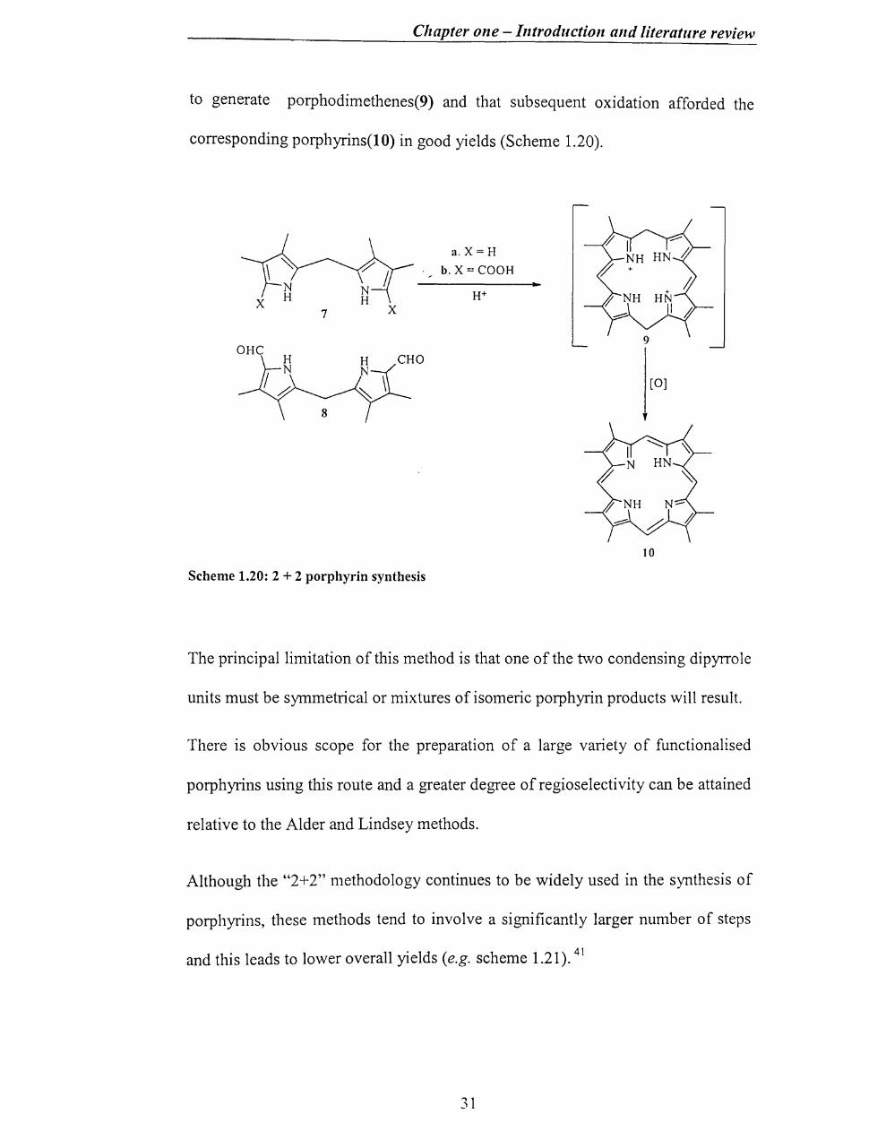
Chapter one - Introduction and literature review
to generate porphodimethenes(9) and that subsequent oxidation afforded the
corresponding porphyrins(lO) in good yields (Scheme 1.20).
7 X
Scheme 1.20: 2 + 2 porphyrin synthesis
a. X=H
b.X=COOH
10
The principal limitation of this method is that one of the two condensing dipyrrole
units must be symmetrical or mixtures of isomeric porphyrin products will result.
There is obvious scope for the preparation of a large variety of functionalised
porphyrins using this route and a greater degree of regioselectivity can be attained
relative to the Alder and Lindsey methods.
Although the "2+2" methodology continues to be widely used in the synthesis of
porphyrins, these methods tend to involve a significantly larger number of steps
and this leads to lower overall yields (e.g. scheme 1.21).41
31

Chapter one Introduction alld literature revieh'
M tEOP H H cO~Ft
KOH reflux 'tj5j
H H ElOH-HP
"" 1. o-Chlct'anil 2. SnClzHCI
Scheme 1.21 "2+2" synthesis of substituted porphyrin
1.4.3 "3+1" Porphyrin synthesis
6~~o P-TsOH
H H
o
H H
The general path of "3+ 1" method consists of a condensation of a tripyrrane with
a pyrrole-2,5-carbaldehyde in the presence of an acidic catalyst.42 This
methodology was very successfully employed in the synthesis of porphyrin.
During the 1960's and 1970's, many alternative routes for porphyrins syntheses
were reported and the "3+ 1" approach was not then pursued.
However, in the last two years this situation has changed and some authors ha\'e
claimed this approach to be a new type of the porphyrin synthesis43
-47. The
original disinterest in the "3+ 1" methodology was due to the difficulties involved
in obtaining the required tripyrrane intermediates. However, direct routes to
tripyrranes have now been developed.48 Now the "3+1" approach has been
32
Chapter olle - Introductioll and literature review
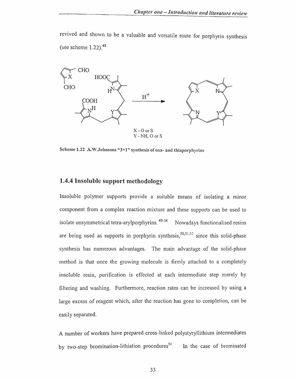
revived and shown to be a valuable and versatile route for porphyrin synthesis
(see scheme 1.22).48
VCHO CHO
x -0 or S Y - NH, 0 or S
Scheme 1.22 A."\V.Johnsons "3+1" synthesis of oxa- and thiaporphyrins
1.4.4 Insoluble support methodology
Insoluble polymer supports provide a suitable means of isolating a mmor
component from a complex reaction mixture and these supports can be used to
isolate unsymmetrical tetra-arylporphyrins. 49-54 Nowadays fllnctionalised resins
are being used as supports in porphyrin synthesis,50,51,52 since this solid-phase
synthesis has numerous advantages. The main advantage of the solid-phase
method is that once the growing molecule is firmly attached to a completely
insoluble resin, purification is effected at each intermediate step merely by
filtering and washing. Furthermore, reaction rates can be increased by using a
large excess of reagent which, after the reaction has gone to completion, can be
easily separated.
A number of workers have prepared cross-linked polystyryllithium intermediates
by two-step bromination-lithiation procedures51. In the case of brominated
33

Chapter one - Introduction and literature review
polymers containing approximately 1-1.5mequiv of bromine per gram, Farrall and
Frechet51 obtained almost complete removal of the bromine in one reaction with
n-butyllithium, while more highly substituted polymers required several
successive treatments with the reagent. They found that, in contrast to the above
mentioned behaviour, a single treatment with n-butyllithium in benzene was
sufficient to effect complete removal of the bromine from the polymer. The
results of their study, indicate that the lithiation reaction is incomplete in
tetrahydrofuran or cyc10hexane but occurs quantitatively in benzene or toluene.
The reason for this behaviour is believed to be due to the swelling properties of
these solvents. In benzene or toluene the resin is fully swollen, while in
cyc10hexane the resin is only partially swollen. This does not explain the
incomplete lithiation reaction in tetrahydrofuran since it has excellent swelling
properties. It is more likely that in the more polar solvent, tetrahydrofuran, ionic
repulsion limits the accessibility of the reagent thus causing the reaction to stop
once a fraction of the functional groups have reacted with n-butyllithium.
Generally, reactions with the macroreticular resins were slower than the reactions
on the swellable resins and require more drastic reaction conditions.51,52 This was
probably due to the more difficult penetration and diffusion of solvents and
reagents into the pores of the macroreticular resins. The resin, as 200-400 mesh
beads, possesses a porous gel structure that allows ready penetration of reagents,
especially in the presence of swelling solvents.
34

Chapter one - Introduction and literature review
1.4.5 Miscellaneous
Recently, a new method for synthesis of meso substituted porphyrins was
published by Drain and Gong55a. By this method, meso-tetraphenylporphyrins
were synthesised in air from pyrrole and aryl aldehydes in one step without
solvents or catalysts. Gas phase or high temperature is essential for this synthesis.
The great advantages of this method are its simplicity and minimal waste
products. However, very low yields and insoluble polymeric by-products are the
drawbacks of this method.
Recently Lindsey and co-workers55b published modified methods for the
substituted porphyrins. Those methods employ minimal chromatography, and
afford up to gram quantities of regioisomerically pure porphyrins bearing
predesignated patterns or up to four different meso substituents.
1.4.6 Metalloporphyrins Generally, there are two possible mechanisms for the metal incorporation
. 56 reactlOn.
(i)A dissociation reaction - the protons first dissociate from the
pyrrole nitro gens to give the dianion, which then reacts with the
metal ion.
or
(ii)A displacement reaction - the metal ion first forms an activated
complex with the porphyrin and the protons are then displaced, by
the metal, from the nitrogen atom.
35

Chapter one - Introduction and literature review
Basic solvents can be used to remove electrons from the centre of the nucleus to
increase the degree of dissociation of the acidic protons and so enhance the rate of
a dissociation-type reaction.57
As most metalloporphyrins represent a rather nonpolar and large moiety that is
therefore soluble only in organic solvents, they will tend to associate strongly with
ions of negative charge, if the metal has a positive charge Z>2.57
1.4.7 Supported metalloporphyrins
Supported metalloporphyrins have been widely studied as models for haem
protein oxygen carriers (haemoglobin and myoglobin) and oxidation catalysts
(peroxidases, catalases and cytochrome P_450).58 The obvious advantages of such
systems can include ease of separation from products and improved catalyst
b 'l' d 58 sta 1 Ity, recovery an re-use.
1.4.8 Encapsulation of metalloporphyrin in a sol-gel matrix
Recently, there has been much interest in the immobilisation of porphyrins and
their metallo derivatives on inorganic supports for use as catalysts. These
materials have shown interesting properties especially in heterogeneous catalysis
for oxygenation reactions of hydrocarbons.
1.5 Sol-Gels
The sol-gel method has become a widespread research technique to insert an
organic molecule into inorganic or hybrid (organic/inorganic) matrices.59,60,61
Inorganic ceramics prepared by the sol-gel process are transparent, chemically
36
Chapter one - Introduction and literature review
inert, photostable and thennally stable. Doped glasses as well as thin films can be
easily prepared.
1.5.1 Sol-Gel Processing
Basically, the sol-gel process involves the synthesis of an inorganic network by a
chemical reaction between metal alkoxide precursors in the presence of acid or
base or P- as a catalyst at room temperature or low temperature.59
Metal alkoxides are most widely used as precursors in sol-gel research (scheme
1.23). These are metallo-organic compounds, which have an organic ligand
attached to a metal or metalloid atom (metal-oxygen-carbon linkage). The most
common tetra-alkoxysilanes used in the sol-gel process are tetra-ethoxysilane
[Si(OC2H5)4] and tetra-methoxysilane [Si(OCH3)4].
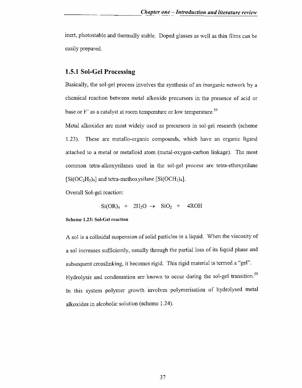
Overall Sol-gel reaction:
Si(OR)4 + 2H20 ~ Si02 + 4ROH
Scheme 1.23: Sol-Gel reaction
A sol is a colloidal suspension of solid particles in a liquid. When the viscosity of
a sol increases sufficiently, usually through the partial loss of its liquid phase and
subsequent crosslinking, it becomes rigid. This rigid material is tenned a "gel".
Hydrolysis and condensation are known to occur during the sol-gel transition.59
In this system polymer growth involves polymerisation of hydrolysed metal
alkoxides in alcoholic solution (scheme 1.24).
37

Chapter one - Introduction and literature review
Hydrolytic Sol-Gel Reaction
Step 1: Hydrolysis
(RO)3Si-OR + H20 organoalkoxide water
Step 2: Condensation
(I) Alcohol condensation
--~'\ (ROhSi-OH " 'ft' 'I 1 reesten IcatlOn Sl ann
+
monomeric hydroxide
ROH alcohol
(RO)3Si-OR + (RO)3Si-OH silanol
polycondensation '\
~ (RO)3Si-O-Si(OR)3 + ROH alcoholysis (alkoxy) siloxane
(II) Water condensation
(RO)3Si-OH + HO-Si(RO)3 silanol silanol
Scheme 1.24: Hydrolytic Sol-Gel Reaction
This polymerisation process is generally initiated by adding water to a solution of
alkoxide. Silanol is made in the hydrolysis by the replacement of alkoxy group
with hydroxyl groups (-OH). Siloxane bridges (=Si-O-Si=) with by-products
(alcohol or water) are formed by condensation reactions involving hydrolysed
species (=Si-OH). Alcohol is normally used as a homogenising agent and in this
project ethanol was used as a solvent as well as homogenising agent. Careful
solvent selection is necessary to avoid side reactions such as trans-esterification,
depolymerisation and re-esterification. The H20: Si molar ratio (r) should not be
less than four for complete hydrolysis (in step 1). Because water is produced as a
by-product of the condensation reaction, an r-value of two is theoretically
sufficient for complete hydrolysis. Generally when r is much less than 2, alcohol-
38

Chapter one - Introduction and literature review
producing condensation is favoured and when r is much greater than 2, the water
producing condensation is favoured.
Hydrolysis is most rapid and complete when catalysts such as acids, bases,
amines, HF and oxides are employed. The presence of H30+ in the solution
-increases the rate of hydrolysis reaction, whereas OH ions increase the
polycondensation reaction. In general, acid-catalysed conditions tend to be
preferred for organically modifying alkoxysilanes.
Acid-catalysed hydrolysis In the presence of an acid catalyst, an alkoxide group
is protonated in a rapid first step.59 The electron density of silicon is decreased,
making it more susceptible to attack by water (scheme 1.25).
Base-catalysed hydrolysis In the presence of base nucleophilic hydroxide anions
are formed in a rapid step by the dissociation of water. 59 Then the silicon atom is
attacked by the hydroxide anion (scheme 1.25).
Finally the gelation occurs by the aggregation of small-organised units. Normally
the gelation time is long (days or weeks), variable and can be affected by the
reaction conditions.
39

High rate o[ondens.tion
Rapid gelation-growth rate determining process
SRE HE Low porosity High porosity
Moderate specific surface area
SRE: Slow Rate Evacuation
HE: Hypercritical Evacuation
Chapter one - Introduction and literature review
Si(OR)4 Raw Material
Hydrolysis
polycondensation
High rate of hydrolysis
1 slow gelation-
nucleation rate determining process
SRE HE Low porosity High porosity
High specific surface area
Drying
Dried gel
Scheme 1.25: Metal alkoxide processing routes to form dried gels.
1.5.2 Gel
Gelation involves the growth and linkage together of polymeric units to fonn a
continuous network that extends through a liquid. In the gelation the first step is a
room temperature polymerisation resulting in a porous and amorphous material
and the second step is the closure of pores at room temperature to fonn the
59 transparent glass.
Depending on pH and water content, the hydrolysis of tetraethoxysilane (TEOS)
can result in the fonnation of polymeric species ranging from polysiloxane chains
40
Chapter one - Introduction and literature review
to colloidal particles of essentially pure Si02.59 Gelation conditions employed in
the preparation of glasses nonnally consist of the hydrolysis of alkoxide
precursors with a small to large excess of water (r>2) at low to intennediate pH
(-1-9). These conditions can result in structures that are intennediate between
linear chains and colloidal particles. These differences in structure occur for the
same addition of H20 because, at low pH, hydrolysis occurs by a mechanism
involving electrophilic attack on an alkoxide oxygen and at intennediate to high
pH, hydrolysis and polymerisation occur by a mechanism involving nucleophilic
attack on silicon.
1.5.3 Drying Drying connects the particles of the gel to fonn a 3D-network. After
conventional drying in air at 20-60oC, the gels tum into porous materials known
as xerogels exhibiting poor chemical and mechanical properties. 59 Nonnally
drying times are often long (weeks, months or years). In this project work a long
period of ageing was used to avoid fracture during drying.
Better homogeneity and better purity of raw materials, lower temperature of
preparation, ability to produce better glass products and special products such as
films are among the advantages of the sol-gel method. In the meantime, the high
cost of raw materials, large shrinkage during processing, residual fine pores,
residual hydroxyl, residual carbon, health hazards of organic solutions and long
processing times are the drawbacks of this method.
41

Chapter one - Introduction and literature review
1.5.4 Surface Area and Porosity.
Surface area, pore size and size distribution have significant effects on a wide
range of phenomena from the absorbency of fine powders in chemical catalysis to
the frost resistance of bricks. Because pore size affects both selectivity and
sensitivity, it is essential to control the pore size. Small pores can restrict
translational freedom of the guest molecule. Gas adsorption is widely used for
pore size distribution analysis.
1.6 Aims / objectives - The aim is to explore the effect of catalyst
stability 011 metalloporphyrin-catalysed alkene epoxidation reactions
Hydrogen peroxide can be used as an efficient oxidant in the epoxidation reaction
but the degradation of the catalyst is a major draw back 16,23 In this work, the
main interest is to quantify the effects of H20 2 on the catalyst and map out the
competing pathways for various metalloporphyrins.
Encapsulation may offer 'protection' to the catalyst from the degradation, so a
part of this work is to prepare metalloporphyrin in a sol-gel and assess its
efficiency. More specifically, therefore the objectives are:
• Identification and quantification of oxidation vs. degradation pathways for
tetrakis(pentafluoro )porphyrin iron chloride (F2oTPPFeCI) using hydrogen
peroxide as an oxidant.
• Synthesis of a metalloporphyrin [5,1 0,1 5,20-tetrakis(p-hydroxyphenyl)-
21H,23H-porphyrin iron(III) chloride (THPPFeCI)] for encapsulation into
sol-gel material (Si02).
42

Chapter one - Introduction and literature review
• Comparision of epoxidation vs. stability for following metalloporphyrins-
5,10, 15,20-tetrakis(p-hydroxyphenyl)-21H,23H-porphyrin iron(III) chloride-
(THPPFeCI), 5,10, 15,20-tetraphenyl-21H,23H-porphyrin iron(III) chloride-
(TPPFeCI), 5,10,15,20-tetrakis(p-sulfonatophenyl)-21H,23H-porphyrin
manganese(III) chloride (TSPPMnCI), 5,10,15,20-tetraphenyl-21H,23H-
porphyrin manganese (III) chloride (TPPMnCl), 5,10,15,20-tetrakis(p-
hydroxyphenyl)-21H,23H-porphyrin manganese(III) chloride (THPPMnCI).
The rationale behind these aims/objectives is briefly discussed.
Firstly, tetrakis(pentafluoro)porphyrin iron chloride (F2oTPPFeCI) was chosen to
explore oxidation vs. degradation for the following reasons,
(i) it has been found to be an efficient and reliable catalyst for epoxidation of
f · . h H 0 1819 range 0 orgamc groups WIt 2 2 ' ,
(ii) The kinetic data for epoxidation (although not for decomposition) using
this catalyst are available from previous work within this and other
groups19
(iii) Despite the efficiency of epoxidation, there is evidence that the catalysis of
epoxidation is accompanied by significant decomposition when using
(iv) The catalyst is commercially available in fairly high purity at a reasonable
cost.
Secondly, it was expected that immobilisation of the metalloporphyrin within the
sol-gel matrix would reduce the intennolecular catalyst interaction implicated in
decomposition58, and alter the selectivity of approach to the metalloporphyrin of
43

Chapter one - Introduction and literature review
oxidant and substrate. In addition, it would reduce the 'leaching' into solvent that
is seen with 'surface-bound supported catalysts,.58 The metalloporphyrin for
incorporation into the sol-gel should possess effective hydrogen-bonding groups
in positions remote from the metal centre; THPPFeCI fulfils this criterion. In
addition, being symmetrically tetra-substituted synthesis will be facilitated.
Furthermore, as it bears electron-donating, rather than electron-withdrawing
substituents, its decomposition will be significant under non-immobilised (i.e.
non-sol-gel) conditions allowing any improvement III stability upon
immobilisation to be readily apparent.
Thirdly, the metalloporphyrins within the range for expansion of the epoxidation
vs. stability study were chosen partly because they are commercially available
(either as porphyrin or metalloporphyrin), but also for the following reasons. The
TPPFeCI and THPPFeCI bear electron-neutral and electron-donating (weakly)
substituents, respectively, and will complement the F20TPPFeCI with its electron
withdrawing group. In many studies, the metal manganese is used instead of iron,
therefore, manganese-containing TSPPMnCI, TPPMnCI and THPPMnCI catalysts
were chosen.
44
Chapter one - Introduction and literature review
1.7 References
1) Paul R.Ortiz de Montellano, Cytochrome P-450, Plenium Press, New York and
London, 1986.
2) a) P.R.Ortiz de Montellano, Acc. Chem. Res., 1987, 20, 289. b) M.C.Feiters,
A.E.Rowan and R.J.M.Nolte, Chem. Soc. Rev., 2000, 29. 375.
3) R.E.White and MJ.Coon, Annu. Rev. Biochem., 1980,49,315
4) D.Mansuy, P.Battioni and lP.Battioni, Eur. J Biochem., 1989, 184,267.
5) J.T.Groves and T.E.Nemo, JAm. Chem. Soc., 1983, 105, 5786.
6) K.M. Smith- http://www-chem. ucdavis. edu/groups/smith/index. html
7) B.Meunier, Bulletin De La Societe Chimique De France, 1986,4,578.
8) a) J.T.Groves and T.E.Nemo and R.S.Myers, JAm. Chem. Soc., 1979, 101,
1032, b) J.T.Groves, W.J.Kruper and R.C.Haushalter, JAm. Chem. Soc.,
1980,102,6375.
9) V.W.Bowry and K.U.Ingold, JAm. Chem. Soc., 1991,113,5699.
10) D.Mansuy, P.Battioni and J.Prenaud, J Chem.Soc. Chem. commun., 1984,
1255.
11) S.Quici, S.Banzi and G.Pozzi, Gazzetta Chimica Italiana, 1993, 123, 597-
612.
12) Harden G, J Chem. Soc., Perkin Trans. 2, 1995, 1883.
13) B.Meunier, Chem. Rev., 1992,92, 141l.
14) a) B.Meunier, E.Guilmet, M.De Carvalho and R.Poilblane, JAm. Chem. Soc.,
1984,106,6668. b) F.Montanari, M.Penso, S.Quici and P.Vigano,
JOrg.Chem., 1985,50,4889.
45

=0;;;;;;= .~
Chapter one - Introduction and literature review
15) P.Battioni, J.-P.Ranaud, J.F.Barto1i, D.Mansuy, M.R.Arti1es and P.Fort, J. Arn.
Chern. Soc., 1988,110,8462.
16) T.G.Tray1or, W.-P.Fann and D.Bandyopadhyay, J. Arn. Chern. Soc.,
1989,111,8009.
17) T.G.Traylor, lC.Marsters, Jr., T.Nakanno and B.E.Dunlap, J. Arn. Chern. Soc.,
1985, 107, 5537.
18) a) T.G.Traylor, C.Kim, J.L.Richards, F.Xu and C.L.Perrin, J. Arn. Chern.
Soc., 1995, 117, 3468. b) J.P.Collman, A.S.Chien, T.A.Eberspacher and
J.LBrauman, J. Arn. Chern. Soc., 2000, 122, 11098.
19) T.G.Traylor, S.Tsuchiya, Y.Byun and C.Kim, J. Arn. Chern. Soc., 1993,115,
2775.
20) M.J.Nappa and C.A.Tolman, Inorg. Chern., 1985,24,4711-4719.
21) A.Maldotti, C.Bartocci, G.Varani, A.Mo1inari, P.Battioni and D.Mansuy, i ,,,
Inorg. Chern., 1996,35,1126. .. '. ;1 I'
22) S.Traylor, D.Dolphin and T.G.Traylor, Chern. Cornrnun., 1984, 279.
23) T.G.Traylor, T.Nakanno and B.E.Dunlap, J. Arn. Chern. Soc., 1986, 108,
2782.
24) T.G.Tray1or and J.P.Ciccone, J. Arn. Chern. Soc., 1989, 111, 8413.
25) J.Chisem, LC.Chisem, J.S.Rafelt, D.J.Macquarrie and J.B.Clark, Chern.
Cornrnun., 1997, 2204.
26) P.R.Cook, C.Gilmartin, G.W.Gray and J.R.Lindsay Smith, J. Chern. Soc.
Perkin Trans. 2, 1995, 1574.
27) P.Rothemund, J. Arn. Chern. Soc., 1936,58,625;
28) A.D.Adler, F.R.Longo, J.D.Finarlli, J.Goldmacher, J.Assour and L.Korsakoff,
46

Chapter one - Introduction and literature review
J. Org. Chern., 1967,32,476.
29) D.K.Lavallee, Z.Xu and R.Pina, J. Org. Chern. 1993, 58, 6000.
30) J.S.Lindsey, H.C.Hsu, LC.Schreiman, P.C.Kearney and A.M.Marguerettaz,
J. Org. Chern., 1987,52, 827.
31) J.S.Lindsey, K.A.MacCrum, J.S.Tyhonas and Y.Y.Chang, J. Org. Chern.,
1994, 59, 579.
32) J.S.Lindsey and R.W.Wagner, J. Arn. Chern. Soc., 1989,54, 828.
33) A.Gradillas, C.Del Campo, J.V.Sinisterra and E.F.Llama, J. Arn. Chern. Soc.,
Perkin Trans. 1, 1995, 261l.
34) G.M.Badger, R.A.Jones and R.L.Laslett, Aust. J. Chern., 1964, 17, 1028.
35) D.Dolphin, J. Heterocyclic Chern., 1970, 7, 275.
36) D.Mauzerall, J. Arn. Chern. Soc., 1960,82, 260l.
37) P.Bigey, S.Frau, C.Loup, C.Claparols, J.Bernadou and B.Meunier, Bull. Soc.
Chirn. Fr., 1996, 133, 679-689
38) R.P.Bonar-Law, J. Org. Chern., 1996,61,3623.
39) H.Fischer and B.Walach, Justus Liebigs Ann. Chern., 1926,450, 164.
40) a) G.P.Arsenault, E.Bullock and S.F.MacDonald, J. Arn. Chern. Soc., 1960,82,
4384, b) R.B.Woodward, W.A.Ayer, J.M.Betaton, F.Bickelhaupt,
R.Bonnett, P.Buchschacher, G.L.Closs, H.Dutler, J.Hannah, F.P.Hauck,
S.Ito, A.Langemann, E.LeGoff. W.Leimgruber, W.Lwowski, J.Sauer,
Z.Valenta and H.Volz, J. Arn. Chern. Soc., 1960, 82, 3800; Tetrahedron,
1990,46, 7599.
41) M.J.Gunter and L.N.Mander, J. Org. Chern., 1981,46,4792,
42) T.D.Lash, Chem. Eur. J., 1996,2,1197.
47
'I
~ 'I iI , I
"
,I

--,;r ~ . .-~ -. ~;,._/ Chapter one - Introduction and literature review
43) A.Boudifand M.Momenteau, J Chem. Commun., 1994,2069 ; J Chem. Soc.
Perkin Trans. 1, 1996, 1235.
44) Y.Lin and T.D.Lash, Tetrahedron Lett., 1995,36, 9441.
45) P.Chandrasekar and T.D.Lash, Tetrahedron Lett., 1996,37,487.
46) T.D.Lash and S.T.Chaney, Chem. Eur. J, 1996, 2, 944.
47) T.D.Lash, Angew. Chem., 1995, 107, 2703.
48) a) J.L.Sessler, M.R.Johnson, V.Lynch, J Org. Chem., 1987, 52, 4394, b)
M.J.Broadhurst, R.Grigg and A.W.Johnson, JChem.Soc. C, 1971,3481.
49) C.C.LeznoffandP.I.Svirskaya, Angew. Chem. Int. Edn., 1978,17,947.
50) J.M.Frechet and C.Schuerch, JAm. Chem. Soc., 1971,93,493.
51) M.J.FarraH and J.M.J.Frechet, J Org. Chem., 1976,41,3877.
52) J.M.J.Frechet and K.E.Haque, Macromolecules, 1975, 8, 130.
53) F.Camps, J.CasteHs, M.J.Femando and J.Font, Tetrahedron Lett., 1971, 1713.
54) a) N.M.Weinshenker, G.A.Crosby and J.Y.Wong, J Org. Chem., 1975, 40,
1966, b) G.A.Crosby, N.M.Weishenker and H.S.Uh, JAm. Chem. Soc.,
1975, 97, 2232.
55) a) C.M.Drain and X.Gong, Chem. Commun., 1997,2117.
b) P.D.Rao, S.D.Benjamin, J.Littler and J.S.Lindsey, J Org. Chem., 2000,
65,7323.
56) J.E.Falk, 'Porphyrins and Metalloporphyrins', Elsevier, Amsterdam, 1964.
57) K.M.Smith, 'Porphyrins and Metalloporphyrins', Elsevier, Amsterdam,
1975.
58) P.R.Cooke, C.Gilmartin, G.W.Gray and J.R.Lindsay Smith, J Chem. Soc.
Perkin Trans. 2, 1995, 1573.
48
./
Chapter one - Introduction and literature review
59) C.J.Brinker and G.W.Scherer, The Physics and Chemistry of Sol-Gel
Processing, Academic Press, San Diego,1990.
60) L.L.Hench and D.R.U1rich, Ultrastructure Processing of Ceramics, Glasses
and Composites, John Wiley & Sons, New York, 1984.
61) S.G.Kulikov, A.V.Veret-Lemarinier, J.P.Galaup, F.Chaput and J.P.Boilot,
Chemical Physics, 1997,216, 147-161.
49

~ ... --=--_/ '-.-hapter two-Exploration of oxidative vs. destructive pathwavs
Chapter Two
Exploration of oxidative vs. destructive pathways
2.1. Introduction
The importance of iron(III) porphyrins in biological oxidations and their use as
catalysts for epoxidation reactions have been discussed in chapter 1.
In epoxidation the oxidising agent creates a reactive high-valent intermeidate
(Fe v =0, Por·+FeIV =0, or FeIV -0·) that rapidly oxidises the substrate (scheme 2.1).
XOH + FeIlI -----i~. high-valent iron substrate ~ product
Scheme 2.1: Epoxidation of substrate; X = alkyl-O- or HO-.
Although the epoxidation reaction with metalloporphyrin complexes has been
extensively studied with the purpose of understanding the nature and structure of
intermediate, the catalyst decay and the catalytic reaction pathways are not clear.
For example, Traylor and co-workers have studied the structure and the formation
of high valent intermediate,1,2 but have not always emphasised catalyst decay.
However, Traylor has noted that in the oxygenation reactions, rapid
50

Chapter -two-Exploration of oxidative vs. destructive pathwavs
metalloporphyrin destruction attenuates catalytic activity with such destruction
being especially rapid in the absence of oxidisable substrates.3
In this chapter, the catalyst decay is analysed with different substrates
(cyc1ooctene, cyc10hexene and styrene) and different concentration of reactants
such as oxidant, substrate and catalyst.
Successful epoxidation reactions require stable catalysts, absence of interfering
by-products, and oxidants that are soluble and highly reactive toward the catalyst
rather than the alkene?,4,5 Although iron(III) tetraphenylporphyrin itself is rapidly
destroyed during catalytic epoxidation by peracids or iodosylbenzenes, the
introduction of bulky and electronegative substituents on the phenyl rings has
been shown to greatly reduce this catalyst destruction.2 Furthermore,
electronegatively-substituted iron(III) porphyrin chlorides react with oxidants and
form high-valent intermediate capable of carrying out further oxidations. 1 The
readily available tetrakis(pentafluorophenyl)porphyrin iron(III) chloride
(F2oTPPFeCI) catalyst is therefore a popular one (Figure 2.1).
F
Figure 2.1: tetrakis(pentafluorophenyl)porphyrin iron(III) chloride (F 20 TPPFeCI)
51
~hapter f(Vo-Exploration of oxidative vs. destructive pat/zwars
It is commercially available, soluble in organic solvents, relatively stable and is an
efficient catalyst for use in a range of organic transformations, for example the
oxidation of dimethoxyarenes,6 and the epoxidation ofhydroxynaphthoquinones.7
In this chapter, the epoxidation reaction of cyclooctene (and cyclohexene, styrene)
using hydrogen peroxide as the oxidant, in conjunction with 5,10,15,20-
tetrakis(pentafluorophenyl)porphyrin iron(III) chloride (F2oTPPFeCI) as the
catalyst was investigated. The aim of the experiments was to study the alkene
epoxidation reaction and catalyst decomposition pathways.
2.2.Results
2.2.1. Epoxidation of alkenes - General conditions
Experiments to probe the F20 TPPFeCI catalysed H202 oxidation of alkene were
carried out. The destruction of the catalyst was followed by monitoring the
disappearance of the Soret peak ca.400 nm, while epoxidation yields were
determined by gas chromatography.
In general, the alkene was stirred at 25 °c in the presence of the catalyst
tetrakis(pentafluorophenyl)porphyrin iron(III) chloride (F2oTPPFeCI) in methanol
/ dichloromethane (3:1) and hydrogen peroxide as oxidant. The alkene was
typically at 'molar' levels (0.5-l.5 M), oxidant (always deficiency) at 102
mM
levels and catalyst at J.lM-mM levels to allow Uv-vis monitoring. Epoxide yields
were assessed by gas chromatography, comparing the epoxide peak (identified by
52

-elmp/et two-Exploration of oxidative vs. destructive patlzwal's
comparison with an authentic sample) with an added reference (dodecane at mM
levels). The specific conditions are fully described in the text and in Tables 1, 2
& 3 and the experimental section. As the alkene, cyclooctene was used
predominantly, but also cyclohexene and styrene. Oxygenations usmg
cyclooctene gave the oxide, as the only product by GC analysis.
o ______ H_20 __ 2_/F_2_oT_p_p_F_e_C_I __ .~ ~O MeOH / CH2CI2 ~
Scheme 2.2: Epoxidation of cyclohexene
2.2.2 Preliminary Findings
F20TPPFeCI-catalysed H20 2-oxidation of cyclooctene at 25 °c gave 84% yield
(GC, relative to standard dodecane) of epoxide based on oxidant, under similar
conditions ([ cyclooctene]o = 1.5 M, [H20 2]0 = 0.12 M, [F20 TPPFeCI]o = 0.001 M,
in 1:3 CH2Cb / MeOH) to those of Traylor4 (see experimental section 2.5.7.1).
The reaction was completed after 20 minutes (no further epoxide). However,
addition of more H20 2 (an additional 0.12 M) after the first cycle gave (after 2
min.), a further increase to 73% of the total* suggesting;
(i) that the first run had terminated, due to consumption of the H202,
and
(ii) that the second run was less efficient than the 'first'.
• i,e. the first run produced O.1M oxide from 0.12M H20 2 (84%) while the second yielded a further
O.074M oxide from the second batch ofO.12M H20 2·
53

, uaptz'r two-bxploratioll of oxidative vs. destructive patlnvars
The second one can be attributed to decomposition of ca.50% of the catalyst
during the original run; as shown by Uv-vis analysis of diluted reaction samples.
Under conditions similar to those above, but with [F2oTPPFeCl]o reduced to15 ~M
(see experimental section 2.5.7.2), the Uv-vis spectrum showed a rapid « ca.30
s), but small, shift of the Soret band at 398 run to 405 run on addition of the H202
followed by almost complete 'bleaching' of the catalyst spectrum over a few
minutes. Importantly, despite the apparent shift in the Soret peak on addition of
the H20 2, the smaller peaks of F20TPPFeCl at 500 and 580 run were not
noticeably shifted, apart from a slight increase in the 550 run region, and they
decayed in concert with the Soret peak (see figure 2.2).
3
5' 2 «
o -~--~ ~
200 300 400 500
Wavelength (nm)
600 700
Figure 2.2. Uy-yis spectra of F2oTPPFeCI-decay during the epoxidation reaction.
The reaction was scanned eyery 30 seconds.
54
800
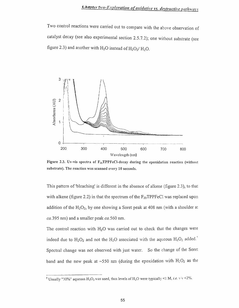
hlt('tl'teltH'o-Exploratioll of oxidative vs. destructive patlzH'a}'S
Two control reactions were carried out to compare with the above observation of
catalyst decay (see also experimental section 2.5.7.2); one without substrate (see
figure 2.3) and another with H20 instead ofH20 2/ H20.
200 300 400 500
Wavelength (nrn)
600 700 800
Figure 2.3. Uv-vis spectra of F2oTPPFeCI-decay during the epoxidation reaction (without
substrate). The reaction was scanned every 10 seconds.
This pattern of 'bleaching' is different in the absence of alkene (figure 2.3), to that
with alkene (figure 2.2) in that the spectrum of the F20TPPFeCl was replaced upon
addition of the H20 2, by one showing a Soret peak at 408 nm (with a shoulder at
ca.395 run) and a smaller peak ca.560 11m.
The control reaction with H20 was carried out to check that the changes were
indeed due to H20 2 and not the H20 associated with the aqueous H20 2 added.'
Spectral change was not observed with just water. So the change of the Soret
band and the new peak at ~550 11m (during the epoxidation with H202 as the
t Usually "30%" aqueous H20 2 was used, thus levels of H20 were typically <1 M, i.e. \:v <2%.
55
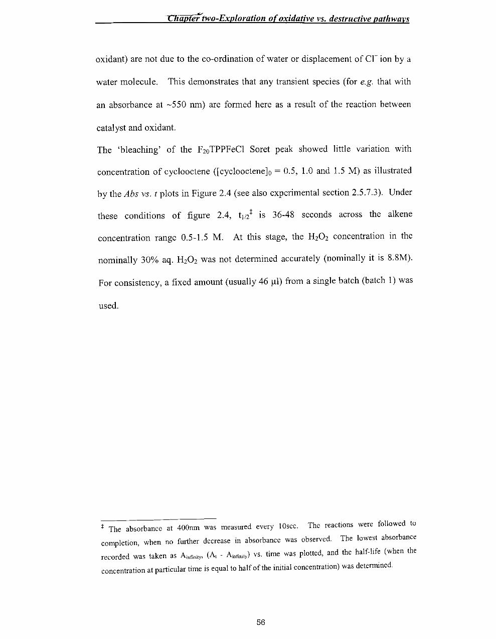
Chapter two-Exploration of oxidative vs. destructive pathways
oxidant) are not due to the co-ordination of water or displacement of cr ion by a
water molecule. This demonstrates that any transient species (for e.g. that with
an absorbance at ~550 nm) are formed here as a result of the reaction between
catalyst and oxidant.
The 'bleaching' of the F20 TPPFeCI Soret peak showed little variation with
concentration of cyc100ctene ([cyc1oocteneJo = 0.5, l.0 and l.5 M) as illustrated
by the Abs vs. t plots in Figure 2.4 (see also experimental section 2.5.7.3). Under
these conditions of figure 2.4, tIl} is 36-48 seconds across the alkene
concentration range 0.5-l.5 M. At this stage, the H20 2 concentration in the
nominally 30% aq. H20 2 was not determined accurately (nominally it is 8.8M).
For consistency, a fixed amount (usually 46 ~l) from a single batch (batch 1) was
used.
:t: The absorbance at 400nm was measured every 10sec. The reactions were followed to
completion, when no further decrease in absorbance was observed. The lowest absorbance
recorded was taken as Ainfinity, (At - Ainfmity) vs. time was plotted, and the half-life (when the
concentration at particular time is equal to half of the initial concentration) was determined.
56

Cliapter/ two-Exploration of oxidative vs. destructive path wars
2.5 ---------.--.--.--------.
o 100 200 300 400 500 600
[CO] = ____ 1.5 M ........ 1 M ........... 0.5 M
Figure 2.4. Plots of Abs vs. t for decay of the F20TPPFeCI peak at 400 nm in the presence of
H20 2 and cyclooctene in 1:3 CH2Ch - MeOH at 25 °c. [F2oTPPFeCI]o=30 IlM, amount of
H20 2 = 46 III of batch 1 (30% w/v), [cyclooctene]o = 0.5,1.0 and 1.5 M.
Similar results, i.e. lack of significant variation with alkene concentration and a
t1/2 of the order of a minute were found for styrene (see also experimental section
2.5.7.4 and figure 2.5). A similar lack of decay rate variation with concentration
was found for cyclohexene (see figure 2.6 and experimental section 2.5.7.5)
although t1/2 was now ca.120 s (The result is complicated by the apparently
different 'starting points', but the t1/2 values are in all cases ca.120 s!). Later
results for cyclohexene indicate a t1l2 closer to 60 s. This variability is commented
upon in 2.5.3.
57

0 « +' «
2.2 ~
2 ,
1.8 -I " ,
1 6 ,
• I
\~ 1.4 - ~ 1.2 \\
, \
0.8 -
0.6
0.4
0.2
o
Chaptertwo-Exploration of oxidative vs. destructive path wars
------------~~--- --
100 200 300 400 500 600 700 800 1000
t
[styrere] = • 1.5 M • 1.0M ..... 0.5M
Figure 2.5. Plots of Abs vs. t for decay of the F20TPPFeCI peak at 400 nm in the presence of H20 2 and styrene in 1:3 CH2CI2_ MeOH at 25 °C. [F20TPPFeCl]0=30 J.lM, amount ofH20 2 = 46 J.ll of batch 1(30% w/v), [styrene]o = 0.5,1.0 and 1.5 M.
10
_ ... __ ._ ... -... _----_ ........ - ........ ----.----.. -... -....... -... ----.-.~-.---.~-----.. ~-.. ----.-.-----.... --.-.-.-.... - -.
110 210 310
[cyclohexenel = __ 0.5 M
410 510
t __ 1.0 M
610
__ 1.5 M
Figure 2.6. Plots of Abs vs. t for decay of the F 20 TPPFeCI peak at 400 nm in the presence of H
20
2 and cyclohexene in 1:3 CH2CI2_ MeOH at 25 0c. [F20TPPFeCl]0=30 J.lM, amount of
H20 2 = 46 J.ll of batch 1(30% w/v), (cyclohexene]o = 0.5, 1.0 and 1.5 M.
58

Chapter/two-Exploration of oxidative vs. destructive patlnvars
Thus, the rate of catalyst 'bleaching' does not appear to vary significantly with
the amount or the nature of substrate alkene.
The t1/2 does appear to be shorter (ca. 20-36 s compared to ca. 40-48 s) at the
lowest (0.5 M) value for all the alkenes, but it is likely that the runs at 1.0 and 1.5
M slow down more in the later stages due to greater H20 2 depletion. This is
presumably due to the greater yield of epoxide product present (vide infra). The
key finding is that three different alkenes (especially cyc100ctene vs. styrene) still
result in decay t1/2 values that differ very little (see also experimental section
2.5.7.6 and figure 2.7).
2.5 ---.-.. - .. -...... -.. -.--............................................................... .
o 50 100 150 200 250 300
__ cyclohexene --0.- styrene -<>- cyclooctene
Figure 2.7. Plots of Abs vs. t for decay of the F20TPPFeCI peak at 400 nm in the preseonce of H
20 2 and alkene (cyclooctene, styrene and cyclohexene) in 1:3 CH2Ch. MeOH at 25 C.
[F2o
TPPFeCllo=30 IJ.M, amount of H20 2 = 46 IJ.I of batch 1(30% w/v), [alkenelo = 1.5 M.
In contrast, a 3-fold variation in H202 concentration (addition of 23, 46 and 69 III
of batch 1 "300/0" [H202]O, [cyc1ooctene]o = 1.5 M,) gave catalyst 'bleaching' with
an approximate 3-fold decrease in t1/2 (see also experimental section 2.5.7.7 and
figure 2.8).
59
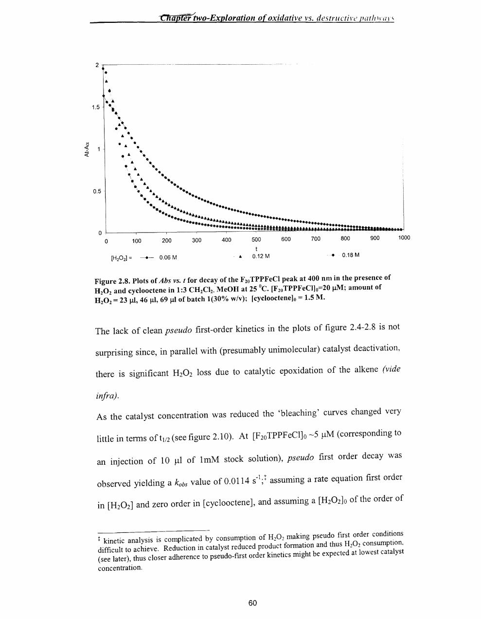
C'1iaplili'two-Exp[oration of oxidative vs. destrllctir~ par/PIal"
•
• 1.5
1 .
0.5
100 200 300 400 500 600 700 800 900
.. 0.12 M • 0.18 M
Figure 2.8. Plots of Abs vs. t for decay of the F 20 TPPFeCI peak at 400 nm in the presence of H20 2 and cyclooctene in 1:3 CH2CI2_ MeOH at 25 °c. [F20TPPFeCl]0=20 IlM; amount of H 20 2 = 23 Ill, 46 Ill, 69 III of batch 1(30% w/v); [cyclooctene]o = 1.5 M.
1000
The lack of clean pseudo first-order kinetics in the plots of figure 2.4-2.8 is not
surprising since, in parallel with (presumably unimolecular) catalyst deactivation,
there is significant H20 2 loss due to catalytic epoxidation of the alkene (vide
infra).
As the catalyst concentration was reduced the 'bleaching' curves changed very
little in terms oft1/2 (see figure 2.10). At [F2oTPPFeCl]o ~5 ).1M (corresponding to
an injection of 10 ).11 of 1mM stock solution), pseudo first order decay was
observed yielding a kobs value of 0.0114 S-l;t assuming a rate equation first order
in [H20 2] and zero order in [cyclooctene], and assuming a [H202]O of the order of
t kinetic analysis is complicated by consumption of H20 2 making pseudo first order conditions difficult to achieve. Reduction in catalyst reduced product formation and thus H20 2 consumption, (see later), thus closer adherence to pseudo-first order kinetics might be expected at lowest catalyst
concentration.
60

Chapter two-Exploration of oxidative vs. destructive patlnvars
0.1 - 0.2 M this gives a second order rate constant of the order of 10-1 dm3 mor l S-I
at 25°C (see figure 2.9 and experimental section 2.5.7.8).
2 iii
III
\ 1.5 . •
• "-
.Ii ~\ ill . \ . \
.Ii ..
~ .Ii ...
~ .. .. 0.5 ••• A.. ........ . .. . .. ...
-......:::: .. _...... . ..... .• ". .. ... ... ............ ...... '
............ l> .. 1~.tu,. .................. i
o. I •• •• ~.:u'-~atu ............ u ............. :::=ml ..... I ................. ••• !
10 110 210 310 410 510 610 710 810 910
[F20 TPPFeCI] = -- •.. 5 11M • •
Figure 2.9. Plots of Abs vs. t for decay of the F20TPPFeCI peak at 400 nm in the presence of H20 2 and cycIooctene in 1:3 CH2CI2_ MeOH at 25 °c. [F2oTPPFeCl]o= 5 ~M, 10 ~M, 15 ~M and 30 ~M of an approximately 1 mM stock solution; amount of H20 2= 46 ~l of batch 1(30%
w/v); [cycIooctene]o = 1.5 M.
2.2.3 Epoxide Yields
The effect of changes in the various components on the catalytic cycle rather than
the catalyst 'bleaching' was studied by GC analysis (see the experimental section
2.5.7.9) of the product yields under the conditions of Table 1.
61

Chapter two-Exploration of oxidative vs. destructive patlnvars
entry [CO]Ol [F20 TPPFeCI]o2 [H20 2]Oj [oxidet M J.lM mM mM
1 1.5 0 173 0
2 1.5 25 173 82±125,6
3 1 25 173 98±8
4 0.5 25 173 73±12
5 0.25 25 173 38±13
6 1.5 15 173 73±4
7 1 15 173 57±1
8 0.5 15 173 43±3
9 0.25 15 173 31±5
10 1.5 7.5 173 38±7
11 1 7.5 173 29±3
12 0.5 7.5 173 24±1
13 0.25 7.5 173 16±4
14 1.5 7.5 86 45±3
15 1.5 7.5 173 42±37
16 1.5 7.5 259 34±5
Table 1. F2oTPPFeCI-catalysed H20 r epoxidation of alkene in 3:1 MeOH-CH2CI28 at 25 °C.
t CO =cyclooctene 2 Determined by Uv-vis analysis assuming E = 1.2 X 10⁵ M-1 cm-t
•
3 Batch 2. Concentration was determined by Uv-analysis. 4 Determined by GC after 20 min. S The yield was ca. 63 mM at 2 min. 6 Addition of a further 25 IlM catalyst gave an increase in [oxide] to ca. 110 mM after a further 20 min (with Uv-vis evidence of unbleached catalyst). 7 Addition of 2,4-dimethoxyphenol at 0.74 mM reduced yield of oxide to ca. 22mM 8The solvent contained 59 mM dodecane as GC standard, giving typically 44 mM dodecane in the reaction
It should be noted that only cyclooctene oxide product was detected and that, in
all cases, the yield of cyclooctene oxide was well below quantitative based on the
amount ofH202 used (at best 57% yield). The termination of the reaction prior to
complete consumption of the H202 was also confirmed by the observation, (i)
that, in all cases, the final Uv-vis spectrum of the reaction was bleached in the
region of the F20TPPFeCI soret band, and (ii) that addition of further F20TPPFeCl
62

Chapter two-Exploration of oxidative vs. destructive pat!zwars
to a 'terminated' reaction, resulted in further oxide product (Table 1, entry 2). It
is clear that the reaction terminates due to destruction of the catalyst.
Examining the results of Table 1, the following can be further noted
(i) There is an increase in yield of cyclooctene oxide with mcrease III
[cyclooctene ]0, (ii) there is an increase in yield of cyclooctene oxide with increase
in [F20 TPPFeCl]o, and (iii) there is a small decrease in yield of cyclooctene oxide
with increase in [H20 2]0. The variation of oxide yield with H20 2 is less clear than
that with cyclooctene, but appears to mirror the trend. The variation of yield with
[cyclooctene]o is illustrated in Figure 2.10.
C')
's 100 ""CJ ..-0 a 80
'"';l 0 60 ..........
:>< r---1 40 Il)
""CJ ..... :><
20 0
~ 2 0 u 0
..-0
~ U
L..-..J
0
• • AX
•
• AX
0.5 1 1.5 2
[cyclooctene]o x mol dn13
• 25 ~ catalyst • 15 ~catalyst A- 7.5 ~catalyst X 3.8 ~catalyst
Figure 2.10: Plots of [cyclooctene oxide] vs. [cyclooctene]o for the F2oTPPFeCI-catalysed H20 2 oxidation of cyclooctene in 3:1 MeOH-CH2CI2 at 25 0c.
To ensure that the catalyst decomposition data and the product yield data were
compatible, several reactions were run where the kinetics of catalyst decay and the
product analysis were carefully determined in the same run.
63
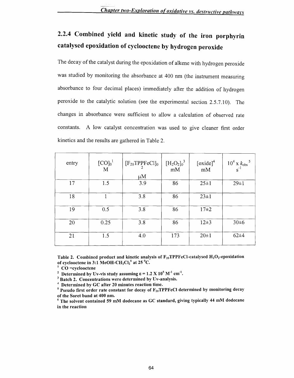
Chapter two-Exploration of oxidative vs. destructive path wars
2.2.4 Combined yield and kinetic study of the iron porphyrin
catalysed epoxidation of cyclooctene by hydrogen peroxide
The decay of the catalyst during the epoxidation of alkene with hydrogen peroxide
was studied by monitoring the absorbance at 400 nm (the instrument measuring
absorbance to four decimal places) immediately after the addition of hydrogen
peroxide to the catalytic solution (see the experimental section 2.5.7.10). The
changes in absorbance were sufficient to allow a calculation of observed rate
constants. A low catalyst concentration was used to give cleaner first order
kinetics and the results are gathered in Table 2.
[CO]Ol [F2o TPPFeCl]o [H20 2]03 [oxidet 104 x kobs entry M 2 mM mM -1 s
~M 17 1.5 3.9 86 25±1 29±1
18 1 3.8 86 23±1
19 0.5 3.8 86 17±2
20 0.25 3.8 86 12±3 30±6
21 1.5 4.0 173 20±1 62±4
Table 2. Combined product and kinetic analysis of FzoTPPFeCI-catalysed HzOz-epoxidation of cyclooctene in 3:1 MeOH-CHzCl/ at 25 °C. I CO =cyclooctene 2 Determined by Uv-vis study assuming E = 1.2 X 10⁵ M-I cm-I
•
3 Batch 2. Concentrations were determined by Uv-analysis. 4 Determined by GC after 20 minutes reaction time. 5 Pseudo first order rate constant for decay of Fzo TPPFeCI determined by monitoring decay of the Soret band at 400 nm. 6 The solvent contained 59 ruM dodecane as GC standard, giving typically 44 ruM dodecane in the reaction
64
5

Chapter two-Exploration of oxidative vs. destructive pathways
The data of Table 2 help to illustrate more succinctly the key general finding of
this work, i.e. that the amount (and nature) of the alkene influences epoxide yield,
but not catalyst decomposition.
2.2.5 Use of 2,4-dimethoxyphenol as substrate
OH
MeO
OMe Figure 2.11: Stucture of 2,4-dimethoxyphenol
2,4-dimethoxyphenol was prepared 8 (see experimental section 2.5.8) to use as the
substrate and the product was identified by NMR studies. Two singlets at 3.7 and
3.9 ppm indicate the presence of two methoxy groups and one double-doublet at
6.4 ppm and two doublets at 6.5 and 6.85 ppm are due to the H-6, H-3 and H-5
phenyl hydrogens, respectively. The singlet at 7.25 ppm suggests the presence of
hydroxy group.
Oxidation of 2,4-dimethoxyphenol (100 /-lM) was carried out with excess H202
(2.5 mM) in the presence ofF2oTPPFeCl (15 /-lM) as a catalyst, and monitored by
Uv-vis analysis (see figure 2.12a). The reaction takes place within ca.1 minute
and the changes (408, 550nm) in the Uv-vis spectrum indicate the appearance of
. III IV 0) new speCIes (Fe ~ Fe = .
Addition of more 2,4-dimethoxyphenol (100 /-lM) gave regeneration of the Uv-vis
III . . h spectrum of the original F20 TPPFe (see figure 2.12b) over ca. 1-2 mIll. WIt a
65
Chapter two-Exploration of oxidative vs. destructive pathways
second-order rate constant of ca. 1 00 M-1 s-1. § It was clear from the stability of
the regenerated catalyst over time that no H20 2 remained and this indicates the
"catalase cycle". Addition of further H20 2 regenerated the F20 TPPFeN =0
spectrum (see figure 2.12c).
§ dFelIl / dt = k2 [FeIV] [phenol] where k2 is the second-order rate constant for reaction ofFelV=O
with the phenol.
66

vo-Exploration of oxidative vs. destrllctive patlnvars
3
25
S 2 < '-" ()
~ 1.5 .e o
~ 1
0..5
'b
). ' .. . . . . / : . .
a~----,----,~---,-----,----~-----,
2JJ ax
a: generation of Fe1v=O after the addition of H 20 l
into the reaction mixture (catalyst, 2,4-dimethoxy
-phenol in solvent)
before the addition of HlOl
a - immediately after the addition of HlOl b - 2 minutes after the addition of H 20 l
S 2 < '-' ()
~ 1.5 ..8 .... o
1: <
0.5
. ..... .....
..... .....
a . ----r-------,------,------ ,-----,-------,
c: after further addition of H 20 l
from figure b (to compare) further addition of HlO l
8JJ
25
S 2 < '-" u
~ 1.5 .2 >o
13 < 1
0..5
ar---~--~--~----~ __ ~--_. an 3Xl
b: regeneration of Fe III after further
addition of dimethoxyphenol
--- b from figure a (to compare) .. further addition of dimethoxy
-phenol
Figure 2.12: l'y-yis analysis of epoxidation with 2A-dimethoxyphenol as substrate in presence of tetrakis(pentafluorophenyl)porphyrin iron(III) chloride as catalyst and H 20! as
oxidant in l\IeOH/CII 1CI1(3:1).
67

-~--~~~-~ ~~--~---'--
Chapter two-Exploration of oxidative vs. destructive pathwars
2.2.6 Test for F 20 TPPFeIV =0
Given that the Uv-vis changes accompanying the oxidation of catalyst in the
presence of alkene are so different from those seen when the catalyst is oxidised
to F10TPP FeIV=O 9 in the absence of alkene (see earlier), a test was devised for
the presence of F10TPPFeIV=O on the decomposition route during the alkene
oxidation reaction.
Since reaction of F10TPPFeIV=O with H101 (to give bleaching) has a second order
rate constant of ca. 0.074 M-1 S-I,9 but reaction of F10TPPFeIV=O with phenol has a
second order rate constant of ca. 100 M-1 S-l, addition of 0.74 mM 2,4-
dimethoxyphenol to any reaction in which decomposition via F10TPPFeIV=O (at
micromolar levels) is involved, should allow regeneration of the F10TPPFelII
, in
preference to destruction by H101 (see calculated pseudo first order constants in
scheme 2.3).
o II
F20TPP -FeIV
MeO
= 0.74mM
k. [phenol] = 0.074 5- 1
bleached
material
Scheme 2.3: Competition for the F20TPPFe1v=O between H20 2 and dimethoxyphenol
68
Chapter two-Exploration of oxidative vs. destructive pathways
In effect, the 2,4-dimethoxyphenol would 'rescue' the catalyst at this point and
allow the catalyst a 'second chance'; the net effect would be to increase
significantly the yield of epoxide. It should be noted that, at sub-millimolar levels
the effect of the 2,4-dimethoxyphenol on consumption ofH20 2 or epoxide product
yield (typically at least 12 millimolar) in any stoichiometric reaction as opposed to
its effect on the catalyst decomposition would be negligible. Reaction at [H20 2]O
= 173 mM, [F2oTPPFeCI]o = 4 /-lM.1 [cyclooctene]o = l.5 M and [2,4-
dimethoxyphenol]o = 0.74 mM gave an epoxide yield of 12 mM somewhat lower
than that in the absence of the phenol (see table 2, entry 21). The Uv-vis spectrum
after 30 min. showed some absorbance (ca. 0.5) in the 350 nm region
characteristic of the oxidised phenol raising the possibility of stoichiometric
oxidation.8 While this would not significantly affect the yield directly, it might
indicate oxidation of all of the phenol, perhaps by the pore+ _FeIV =0 intermediate,
before the phenol could react with any F20TPPFeIV=0 present. However, the
absorbance in this region continued to climb over several hours (to ca.2.0),
probably due to oxidation of the phenol by H20 2 in the absence of catalyst
(bleached after 30 min.), suggesting that much of the 2,4-dimethoxyphenol had
remained unoxidised during the period of the epoxidation.
2.2.7 Fate of H20 2
It is clear from the results of Tables 1 and 2 that the yield of epoxide was less than
quantitative, based on H202. Certainly, some H202 remained unused as shown by
the complete bleaching of the catalyst at the end of the reaction. The question
arises as to the fate of the H202 that was not converted to epoxide; did it all
69

Chapter two-Exploration of oxidative vs. destructive pathwa}'s
remain unreacted or was some lost in side reactions such as 'catalase' activity
(dismutation of H20 2 to H20 and 02)? Runs were carried out at much higher
catalyst concentration so that the appearance of unbleached catalyst at the end of
the reaction could be taken to indicate that no unreacted H20 2 remained (see the
experimental section 2.5.7.12). The results in Table 3 show that a proportion of
the H20 2 is 'lost' in non-epoxide producing side reactions.
entry [COlo 1 [F20 TPPFeCI]o Z [H20 2]O j [oxidef % yieldO
M 11M mM mM
22 1.5 250 86 68 79 23 0.25 250 86 48 56
Table 3. Product analysis of the FzoTPPFeCI-catalysed HzOz-epoxidation of cyclooctene in 3:1 MeOH-CHzCl/ at high catalyst concentration at 2Soc.6 1 CO =cyclooctene 2 Calculated from stock concentration. Uv-vis showed significant unbleached catalyst at end of reaction. 3 Batch 2. Concentrations were determined by Uv- analysis. 4 Determined by GC. 5 Based on HzOz 6 The solvent contained S9mM dodecane as GC standard.
2.3. Discussion
2.3.1 Summary of Results
It is worthwhile summarising the mechanistic evidence concemmg catalysed
H20 2-oxidation for F20TPPFeCl and related catalysts from this work (points (iii)-
(ix)) and from the literature.
(i) Epoxide formation is evidence for reaction of alkene with the oxo-
1 . (F TPP+·)F IV 0 1,4,5,10,11 perferry specIes, 20 e = .
70

----- ----------
Chapter two-Exploration of oxidative vs. destructive pat!zwars
(ii) Reaction of F20 TPPFeCl with H20 2 in the absence of oxidisable substrate
leads to the oxo-ferryl species F2oTPPFeIV=0 via the oxo-perferryl species
(followed by slower bleaching).9
(iii) Reaction of F20 TPPFeCl with H20 2 in the presence of alkene results in
deactivation (bleaching) of the catalyst without significant build up of
F20 TPPFe IV =0.
(iv) Trapping evidence suggests that F20TPPFeIV=0 IS not the mam
'decomposition' intermediate.
(v) The rate of deactivation (bleaching) of F20TPPFeCl in the presence of
alkene is independent on the amount and nature of the alkene.
(vi) The rate of deactivation (bleaching) of F20 TPPFeCl in the presence of
alkene is dependent on the amount of H20 2 added.
(vii) The yield of epoxide is, with H20 2 as limiting reagent, dependent on the
amount of the alkene present.
(viii) A significant proportion of the H20 2 consumed does not yield epoxide.
(ix) The yield of epoxide appears to be inversely dependent on the amount of
Lindsay Smith in 1991 12 outlined various possible pathways (see Scheme 2.4).
Those pathways show the formation of the (F2o Tpp+e)FeIV =0 intermediate and
also illustrate the additional routes and various possible pathways for its reaction
(at this point nothing is implied about the detail of how it is formed). Pathway a
is the accepted electrophilic oxygenation of an alkene that regenerates the catalyst
in the FellI oxidation state, while pathway b represents reaction with solvent (most
71

I ~ _ 0 5 :<f:: jJ~<~~G~ I
- r
Chapter two-Exploration of oxidative vs. destructive patlzH'ars
likely MeOH in this case) to return the catalyst to Fe III. Pathway c invol\-es
reaction with the oxidant (H20 2 in this case) to give the oxo-ferryl F:2oTPPFerv=O
species, which in tum is reduced by further oxidant back to FellI, 1.4.5,13,I .. U5 or
bleached by H20 2. 9,16 Pathways d and e involve oxidation of the porphyrin part
of the catalyst. The exact mechanisms are often poorly specified, but include
'self oxidation' (intramolecular), and bleaching of unoxidised catalyst F 20 TPPFeIII
by the oxo-perferryl intermediate (intermolecular).I,]7
F TPP -FelIlel 20
F TPPFe IlI + epoxide 20
! intramolecular degradation
a
alk ne
o -+- II
F TPP -FeIV 20
d
intermolecular degradation
+')F IV 0 Scheme 2.4: Fate of (F20TPP e =
2.3.2 The catalytic cycle
F TPPFelIl 20
F TPPFe Ill 20
The result of this work shows the epoxidation is relatively efficient and that
appreciable H202 can be converted to epoxide given sufficient catalyst (e .. g. see
72
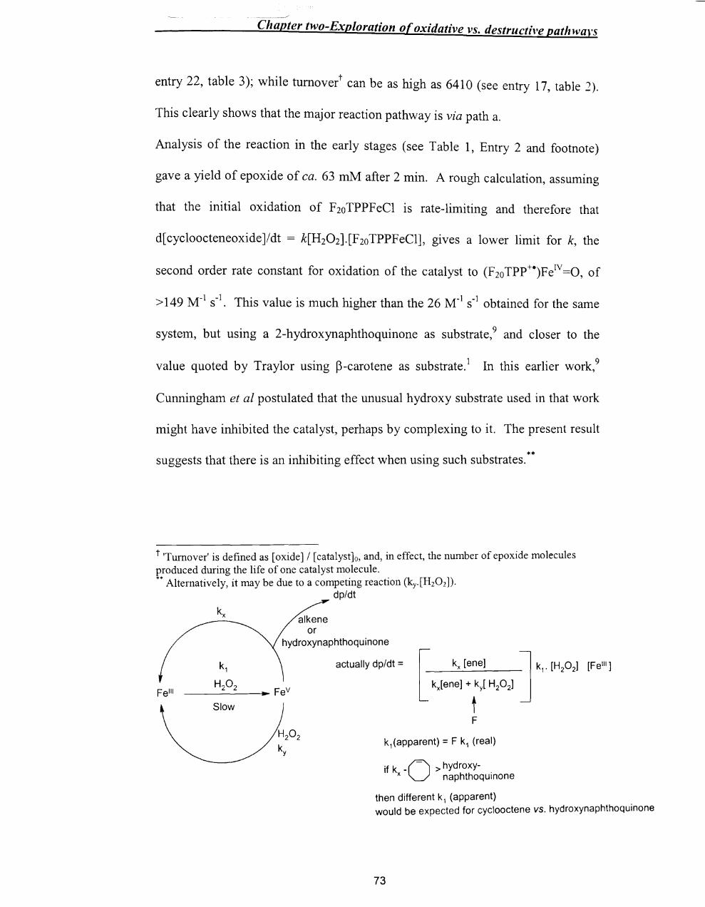
/
Chapter two-Exploration of oxidative vs. destructive patlnvars
entry 22, table 3); while tumovert can be as high as 6410 (see entry 17, table 1).
This clearly shows that the major reaction pathway is via path a.
Analysis of the reaction in the early stages (see Table 1, Entry 2 and footnote)
gave a yield of epoxide of ca. 63 mM after 2 min. A rough calculation, assuming
that the initial oxidation of F 20 TPPF eCl is rate-limiting and therefore that
d[cycloocteneoxide]/dt = k[H20 2]. [F20TPPFeCl], gives a lower limit for k, the
second order rate constant for oxidation of the catalyst to (F20Tpp+e)FeIV=O, of
> 149 M-1 S-1. This value is much higher than the 26 M-1
S-1 obtained for the same
system, but using a 2-hydroxynaphthoquinone as substrate,9 and closer to the
value quoted by Traylor using p-carotene as substrate. 1 In this earlier work,9
Cunningham et al postulated that the unusual hydroxy substrate used in that work
might have inhibited the catalyst, perhaps by complexing to it. The present result
suggests that there is an inhibiting effect when using such substrates. **
t 'Turnover' is defined as [oxide] / [catalyst]o, and, in effect, the number of epoxide molecules produced during the life of one catalyst molecule . •• Alternatively, it may be due to a competing reaction (ky.[H20 2]).
dp/dt
Felli
alkene or
hydroxynaphthoquinone
k1
H20 2 ______ ~ Fev
Slow
actually dp/dt =
k1(apparent) = F k1 (real)
if k -0 > hydroxy- . x naphthoquinone
then different k1 (apparent) would be expected for cyclooctene vs. hydroxynaphthoquinone
73

------:.........--/
Chapter two-Exploration of oxidative vs. destructive path wars
2.3.3 Catalyst decomposition
The most important finding in this work is that an increase in concentration of
substrate alkene, despite increasing the yield of epoxide, does not hm'e any effect
on the rate of catalyst decomposition (see Figure 1 and Table 2), While it is clear
that, path a is the dominant route, this finding means that the decomposition
routes d, e or the combined c ~ F20TPPFeIV=O ~ 'decomposition' (Scheme 2.4)
are not significant here and do not compete with the (F20Tpp+e)FeIV=O + alkene
pathway.
However, since decomposition is observed, there must be, a 'new' decomposition
pathway in parallel with the 'epoxidation cycle' as shown in Scheme 2.5; it does
not compete with the alkene / F20Tpp+eFeIV=O reaction.
F TPPFe I1I 20
alkene
o -+- II
F TPP -FeIY 20
intermolecular degradation
Scheme 2.5: Decomposition pathway in parallel with epoxidation cycle
Parallel heterolytic and homolytic pathways in metalloporphyrin-catalysed
epoxidation,I8 have recently been reported. Given this, is the new parallcl
74
- --
Chapter two-Exploration of oxidative vs. destructive path wars
d . . IV ecomposlhon route via F20TPPFe =0 (as distinct from vza
C.ormed through (F20Tpp+e)FeIV =O)? Th dd" f 2 d' 1. e a lhon 0 ,4- Imethoxyphenol,
known to regenerate F20TPPFeIII from F2oTPPFeIV=0, does not increase epoxide
yield as might be expected if decaying catalyst was regenerated. In this work, the
addition of 2,4-dimethoxyphenol actually reduces the yield of epoxide; this may
be due to complexation of the phenol to the F20 TPPFeIII altering, slightly, the
proportion of catalyst that follows the 'epoxidation' relative to the
'decomposition' route. It seems most likely that this 'direct' decomposition results
from direct oxidation of the porphyrin ring of the catalyst, perhaps by hydroxyl
radical, while epoxidation activity results from oxidation at the metal.
2.3.4 Competition for the oxoperferryl species
If this were the actual reaction scheme (scheme 2.5), the epoxide yield should
depend on the concentration of [F20 TPPFeCI], but not on the substrate
concentration. But the results of this work (Tables 1-3 and Figures 2.5, 2.6, 2.7,
2.10) show that this is not the case.
The following reasons indicate one or more additional pathways from
(i). there is a clear trend of increasing epoxide yield as the alkene
concentration is increased;
(ii). as discussed earlier during the epoxidation reaction a significant amount of
the H202 is consumed without yielding epoxide.
75

_._-------/
Chapter two-Exploration of oxidative vs. destructive patlzwars
The limited 'yield' studies where H20 2 concentration was varied (Table 1. entries
14-16) suggest that the competing route involves H20 2, although oxidation of
solvent MeOH by the oxoperferryl species cannot be ruled out.
The possibility of reaction of H20 2 with (F2oTpp+e)FeN=0 is surprising because
Traylor and his co-workers noted that the competition between peroxide and
alkene for (Por+e)FeIV=O is very dependent upon the hemin structure. More
specifically, (Por+e)FeN=O species where the porphyrin ring is substituted by
electron-withdrawing substituents were thought not to react significantly with
peroxides in competition with alkene.4,13 The consensus is that regeneration of
III b 0 fr +e) IV . IV IV por-Fe y H2 2 om (Por Fe =0 goes vza Por-Fe =0 or Por-Fe -
OH.1,4,5,12,14 The reaction of Por-FeIV =0 (or Por-FeN -OH) itself back to por-FeIIl
does not appear to have been investigated in detail, although it is often presumed
to again involve H20 2.14 The literature9 quotes a degradation pathway (k = 0.074
M-1 S-I) involving (F20TPP)FeIV=0 and H202, so regeneration and destruction may
be in competition at this stage. Whatever the F20TPPFeIV
=0 reductant is, the rate
of the F2oTPPFeN=0 ~ F20TPPFeIII 'regeneration' must, under our reaction
conditions, be much faster than degradation of F20TPPFeIV
=0 to be consistent
with the kinetic findings above.
2.3.5 Overall scheme
The above findings are summarised in scheme 2.6. Approximate values, from this
and others4,9 works, are given for some second order rate constants, k1
(ref. -+). k4
(ref. 9) , k6 (this work); the accompanying pseudo first order rate constants are
calculated for a "typical" [H202] of 0.1 M. 1\'
For step k5 (F2oTPPFe =0 ~
76
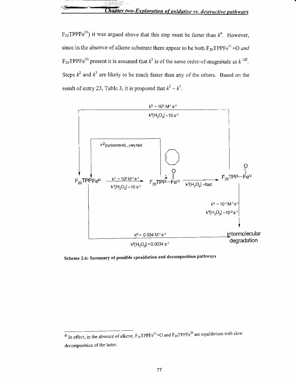
II ~>!k'( < -"'
I;!. )<",
t:7lapIer two-Exploration of oxidative vs. destructive patlnval's
F20TPPFelIl) it was argued above that this step must be faster than k4. However,
since in the absence of alkene substrate there appear to be both F20 TPPFe[\=O and
F20TPPFelIl present it is assumed that k5 is of the same order-of-magnitude as k 10.
Steps k2 and k3 are likely to be much faster than any of the others. Based on the
result of entry 23, Table 3, it is proposed that ~ - k3•
k2 [cydooctene] _very fast
o F20TPPFelli k1 - 1 ()2 M-1 S-1 ..
k4 - 10-1 M-1 S-1
k4[ H20 2] -10-2 S-1
k6 = 0.034 M1 S-1 . ntermolecular L-----~~:..:..:::=-..:....:..:..:.--=---------------:degradation
k6[H20 2] =0.0034 S-1
Scheme 2.6: Summary of possible epoxidation and decomposition pathways
I2J . b f lk F TPPFeIY=O and F20TPPFelll are equilibrium with slow In effect, III the a sence 0 a ene, 20
decomposition of the latter.
77
•

• -------==--/
Chapter two-Exploration of oxidative vs. destructive pathwars
2.4 Conclusion
It has been shown that the amount and nature of the alkene influences epoxide
yield, but not catalyst decomposition and the F2oTPPFeCl-catalysed H20 2-
epoxidation of alkene is via an oxoperferryl species in a catalytic cycle in parallel
with decomposition which probably involves direct oxidation of the porphyrin
rather than the metal. There is no significant decomposition of catalyst via the
oxoperferryl or oxoferryl species. The alkene reacts with the high-valent
oxoperferryl species in competition, probably with further H20 2, both routes
leading back (ultimately) to the FeIII species.
2.S. Experimental Section
2.5.1 Materials
Cyclohexene (Janssen Chimica), cyclooctene (Aldrich), dichloromethane (Fisons),
2,4-dimethoxybenzaldehyde (Acros), dodecane (KOCH-Light Laboratories, Ltd.),
ethyl acetate (Acros), hydrogen peroxide (Fisher), meta-chloroperbenzoic acid,
methanol (Fisher), potassium hydroxide, sodium carbonate, sodium sulphate,
styrene, 5,10, 15,20-tetrakis(pentafluorophenyl)porphyrin iron(III) chloride
(Aldrich) were all used as received.
Two different bottles of 30% aqueous H202 (batch 1 and batch 2) were used in
this work and standardised by Uv-vis spectroscopy.
78

Chapter two-Exploration of oxidative vs. destructive path wars
2.5.2 Standardisation of the concentration of H20 2
Batch 2:
'30% aqueous H20 2' (l ml) was placed in a volumetric flask (250 ml) by a pipette
and water was added up to the mark. The absorbance of this diluted solution was
taken at 242 nm and the concentration of the solution was calculated by the Beer-
Lambert law as follows:
At A =242 nm;
Abswater = 0.339 (reference)
Abssolution = 1.521
~Abs242 (Abssolution- Abswater ) = 1.182
According to the Beer-Lambert law
A= E c 1
A = Absorbance
E = Molar extinction coefficient
c = concentration
1 = length of the cell
A= 39.4 x [H20 2]
[H202] = 1.182/39.4 = 0.03 M
Therefore, the number of moles ofH202 in the 250 ml solution = 7.5 x 10⁻³
mol.
Number of moles ofH202 in lml original solution = 7.5 x 10⁻³
mol
Actual concentration of the original solution = 7.5 M
79
•

Chapter two-Exploration of oxidative vs. destructive pat/zwars
2.5.3 Protocol
At first the reactions were carried out using an older batch (batch 1) of H20 2 and
there were some difficulties in reproducibility for decay rates and yield.
Therefore, to ensure that the results were comparable, the following 'protocol' was
adopted even with the 'standardised' batch 2. Firstly, stock solutions were
prepared and! or tested on a weekly basis. A 'new' bottle (batch 2) of aqueous
30% H20 2 (7.5 M) was used over ca. six weeks. Furthermore, where trends were
to be determined, e.g. the variation in epoxide yield with [cyclooctene] (Table 1,
entries 2-5) the same stocks were used and reactions were carried out within 1-2
days. However, duplicate runs were, as far as possible, carried out on different
stocks and several days apart (e.g. the duplicated runs giving the data of Table 2,
entries 17-21) to ensure that no deterioration had occurred.
In general all runs were carried out in at least duplicate, and the uncertainties
quoted in the tables refer to standard deviations.
2.5.4 Instrumentation
A PYE UNICAM PU4550 gas chromatograph, a PU 8700 UV spectrophotometer
and a Hewlett Packard 8452A diode array spectrometer (Uv-vis analysis) were
used in this work.
PYE UN/CAM PU4550 gas chromatograph:
Typical instrumental set-up:
Column - Metal Clad (12 x 0.22 mm),
Film thickness - 0.25 11M,
80
•

Chapter two-Exploration of oxidative vs. destructive pathwal's
Column temperature - 50°C; injector temperature - 250°C; detector temperature _
250 °C.
For temperature programming:
initial time- 2 min.; rate - 10 °C/min.; upper temperature - 150°C.
PU 8700 UV Spectrophotometer:
Wave length range: 200 nm-800 nm,
Temperature: 25°C
Hewlett Packard 8452A Diode Array spectrometer:
Temperature: Room temperature.
2.5.5 Analysis of epoxide yield by gas chromatography
The reaction mixture (see details of amounts later) was placed in the cuvette by
using micro-syringe and the reaction was initiated by the addition of hydrogen
peroxide. It was allowed to stand at 25°C for 20 min. (for all runs, the Uv-vis
spectrum after 20 min. was checked for bleaching of the catalyst) and the yield
was analysed by direct injection into the GC. The peaks were identified by
comparison of retention times with those of authentic samples. The amount of
product was quantified by comparison of peak area with that of the dodecane
standard (the relative response factor having been established by calibration
~ Series of different concentrations of cyclooctene oxide solutions (3/1 methanoVdichloromethane
with known amount of dodecane) were prepared and the gas chromatograms were obtained. Area
of cyclooctene oxide peakJArea of dodecane peak \'s. concentration of cyclooctene oxide/
concentration of dodecane were plotted and used as calibration graph for the yield calculation.
81
•

Chapter two-Exploration of oxidative vs. destructive pathwavs
2.5.6 Kinetic analysis by Uv-vis spectroscopy and product analysis
byGC
A typical procedure is as follows. Solvent (3:1 MeOH / CH2Ch containing 59 mM
dodecane as GC standard) neat cyclooctene (390 /-11) and F20TPPFeCI in 3:1
MeOH / CH2Ch stock solution (8 /-11, 1 mM) were taken in a cuvette in order by
micro-syringe (cell concentrations are in Table 4). The exact concentration of the
F20 TPPFeCl was determined by Uv-vis spectroscopy assuming E = 1.2 x 10⁵ M-1
cm-1 at 400 nm. After allowing the solution to equilibrate to 25 °c for ca. 5 min.
in a thermostatted Uv-vis spectrometer, the reaction was initiated by the injection
of23 /-11 of30% aqueous H20 2 (batch 2, 7.5M).
Component Concentration
Cyclooctene 1.5 M
F20TPPFeCI 3.8 /-1M
H20 2 86mM
dodecane 47mM
Table 4: Reaction conditions (concentrations in the reaction vessel) for epoxidation reaction of cyclooctene with H20 2 in the presence of tetrakis(pentafluorophenyl)porphyrin iron(III) chloride as a catalyst in MeOH-CH2Ch (3:1) at 25°C.
For kinetic analysis the decay of the F20 TPPFeCI peak at 400 nm was monitored
every 10 s for ca. 20 min. For all runs, the Uv-vis spectrum after 20 min. was
checked for bleaching of the catalyst. After 20 min. the reaction mixture was
analysed by direct injection into the GC and the peaks were identified by
comparison of retention times with those of authentic samples. The amount of
cyclooctene oxide was quantified by comparison of peak area with that of the
dodecane standard (the relative response factor having been established by
calibration runs). The Abs. vs. t data from the kinetics experiments was analysed
82
•
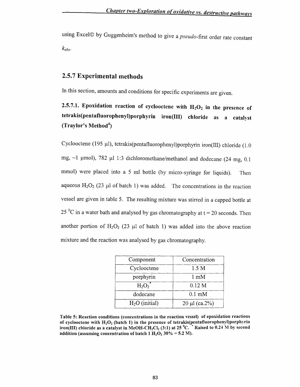
Chapter two-Exploration of oxidative vs. destructive pathwavs
using Excel© by Guggenheim's method to give a pseudo-first order rate constant
kobs.
2.5.7 Experimental methods
In this section, amounts and conditions for specific experiments are given.
2.5.7.1. Epoxidation reaction of cyclooctene with H20 2 in the presence of
tetrakis(pentafluorophenyl)porphyrin iron(III) chloride as a catalyst
(Traylor's Method4)
Cyc100ctene (195 ~l), tetrakis(pentafluorophenyl)porphyrin iron(III) chloride (1.0
mg, ~ 1 ~mol), 782 ~l 1:3 dichloromethane/methanol and dodecane (24 mg, 0.1
mmol) were placed into a 5 ml bottle (by micro-syringe for liquids). Then
aqueous H20 2 (23 ~l of batch 1) was added. The concentrations in the reaction
vessel are given in table 5. The resulting mixture was stirred in a capped bottle at
25°C in a water bath and analysed by gas chromatography at t = 20 seconds. Then
another portion of H20 2 (23 ~l of batch 1) was added into the above reaction
mixture and the reaction was analysed by gas chromatography.
Component Concentration
Cyclooctene 1.5 M
porphyrin ImM
H20 2 * 0.12M
dodecane O.lmM
H20 (initial) 20 ~l (ca.2%)
Table 5: Reaction conditions (concentrations in the reaction vessel) of epoxidation reactio~s of cyclooctene with HzOz (batch 1) in the presence of tetrakis(pentafluorophenyl)porphyrm iron(III) chloride as a catalyst in MeOH-CHzCIz (3:1) at 25°C. * Raised to 0.24 l\I by second addition (assuming concentration of batch 1 H z0 2 30% = 5.2 M).
83
•
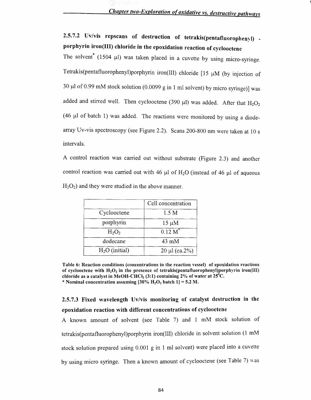
Chapter two-Exploration of oxidative vs. destructive pathways
2.5.7.2 Uv/vis repscans of destruction of tetrakis(pentafluorophenyl) _
porphyrin iron(III) chloride in the epoxidation reaction of cyclooctene
* The solvent (1504 /-ll) was taken placed in a cuvette by using micro-syringe.
Tetrakis(pentafluorophenyl)porphyrin iron(III) chloride [15 /-lM (by injection of
30 /-ll of 0.99 mM stock solution (0.0099 gin 1 ml solvent) by micro syringe)] was
added and stirred well. Then cyc100ctene (390 /-ll) was added. After that HzOz
(46 /-ll of batch 1) was added. The reactions were monitored by using a diode-
array Uv-vis spectroscopy (see Figure 2.2). Scans 200-800 nm were taken at 10 s
intervals.
A control reaction was carried out without substrate (Figure 2.3) and another
control reaction was carried out with 46 /-ll of H20 (instead of 46 /-ll of aqueous
H20 2) and they were studied in the above manner.
Cell concentration
Cyc100ctene 1.5 M
porphyrin 15 /-lM
H20 2 0.12M"
dodecane 43mM
H20 (initial) 20 /-ll (ca.2%)
Table 6: Reaction conditions (concentrations in the reaction vessel) of epoxidation reactions of cyclooctene with H20 2 in the presence of tetrakis(pentafluorophenyl)porphyrin iron(III) chloride as a catalyst in MeOH-CHCI2 (3:1) containing 2% of water at 25°C. * Nominal concentration assuming [30% H20 2 batch 1] = 5.2 M.
2.5.7.3 Fixed wavelength Uv/vis monitoring of catalyst destruction in the
epoxidation reaction with different concentrations of cyclooctene
A known amount of solvent (see Table 7) and 1 mM stock solution of
tetrakis(pentafluorophenyl)porphyrin iron(III) chloride in solvent solution (1 mM
stock solution prepared using 0.001 g in 1 ml solvent) were placed into a cuvette
by using micro syringe. Then a known amount of cyc100ctene (see Table 7) was
84
•
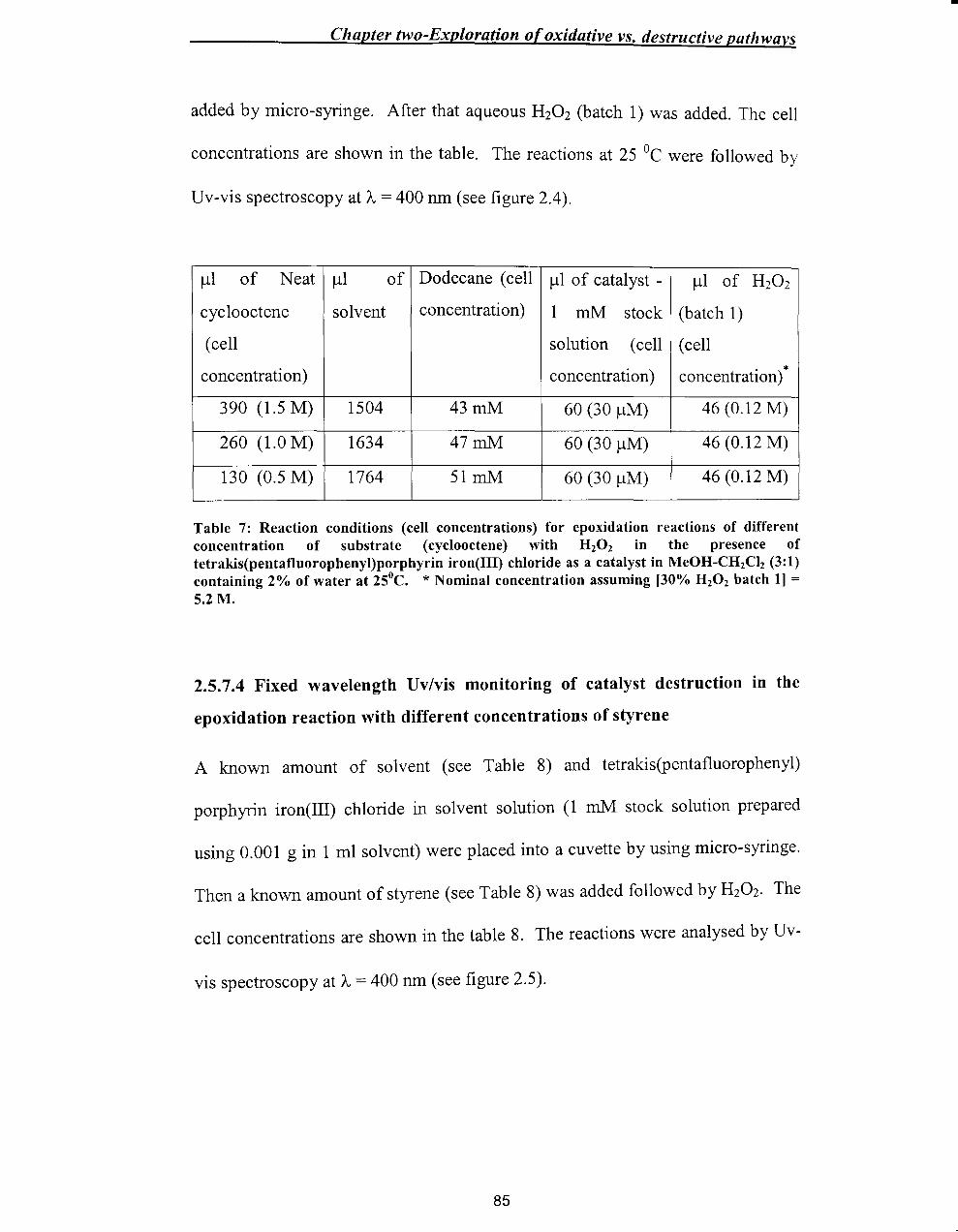
Chapter two-Exploration of oxidative vs. destructive pathwavs
added by micro-syringe. After that aqueous H20 2 (batch 1) was added. The cell
concentrations are shown in the table. The reactions at 25°C were followed by
Uv-vis spectroscopy at A = 400 nm (see figure 2.4).
/-11 of Neat /-11 of Dodecane (cell /-11 0 f catalyst - /-11 of H20 2
cyclooctene solvent concentration) 1 mM stock (batch 1)
(cell solution (cell (cell
concentration) concentration) concentration) *
390 (1.5 M) 1504 43mM 60 (30 /-1M) 46 (0.12 M)
260 (1.0 M) 1634 47mM 60 (30 /-1M) 46 (0.12 M)
130 (0.5 M) 1764 51 mM 60 (30 /-1M) 46 (0.12 M)
Table 7: Reaction conditions (cell concentrations) for epoxidation reactions of different concentration of substrate (cyclooctene) with HzOz in the presence of tetrakis(pentafluorophenyl)porphyrin iron(III) chloride as a catalyst in MeOH-CHzClz (3:1) containing 2% of water at 25°C. * Nominal concentration assuming [30% HzOz batch 1] = S.2M.
2.5.7.4 Fixed wavelength Uv/vis monitoring of catalyst destruction in the
epoxidation reaction with different concentrations of styrene
A known amount of solvent (see Table 8) and tetrakis(pentafluorophenyl)
porphyrin iron(III) chloride in solvent solution (1 mM stock solution prepared
using 0.001 gin 1 ml solvent) were placed into a cuvette by using micro-syringe.
Then a known amount of styrene (see Table 8) was added followed by H20 2. The
cell concentrations are shown in the table 8. The reactions were analysed by Uv-
vis spectroscopy at A = 400 nm (see figure 2.5).
85
-

Chapter two-Exploration of oxidative vs. destructive pathways
/-ll of styrene, /-ll of /-ll of catalyst - 1 /-ll of H20 2
(cell solvent ruM stock (batch 1), (cell concentration) solution, (cell concentration) *
concentration) 344 (1.5 M) 1550 60 (30 /-lM) 46 (0.12 M)
229 (1.0 M) 1665 60 (30 /-lM) 46 (0.12 M)
115 (0.5 M) 1779 60 (30 /-lM) 46 (0.12 M)
Table 8: Reaction conditions of epoxidation reactions of different concentrations of substrate (styrene) with H20 2 in the presence of tetrakis(pentafluorophenyl)porphyrin iron(lll) chloride as a catalyst in MeOH-CHCI2 (3:1) containing 2% of water at 25°C. * Nominal concentration assuming [30% H20 2 batch 1] = 5.2 M.
2.5.7.5 Fixed wavelength Uv/vis monitoring of catalyst destruction in the
epoxidation reaction with different concentrations of cyclohexene
The above epoxidation procedure 2.5.3.4 was carried out with different
concentration of cycIohexene (see table 9) and the reactions were studied by Uv-
vis spectroscopy at A = 400 run (see figure 2.6).
/-llof /-ll /-ll of catalyst -1 /-ll of H20 2
cycIohexene ruM stock (batch 1), (cell
(cell of solvent solution, (cell concentration) * concentration) concentration)
304 (1.5 M) 1590 60 (30 /-lM) 46 (0.12 M)
202 (1.0 M) 1692 60 (30 /-lM) 46 (0.12 M)
101 (0.5 M) 1793 60 (30 /-lM) 46 (0.12 M)
Table 9: Reaction conditions of epoxidation reactions of different concentration of substrate (cyclohexene) with H
20
2 in the presence of tetrakis(pentafluorophenyl)porphyrin iron(!II)
chloride as a catalyst in MeOH-CH2CIz (3:1) containing 2% of water at 25°C. * Nonunal concentration assuming [30% H20 2 batch 1] = 5.2 M.

Chapter two-Exploration of oxidative vs. destructive pathwavs
2.5.7.6 Fixed wavelength Uv/vis monitoring of catalyst destruction III the
epoxidation reaction with different substrates
Solvent [dichloromethane/methanol (25175 v/v) with dodecane as standard] was
placed by micro-syringe and the substrate (1.5 M, see Table 10),
tetrakis(pentafluorophenyl)porphyrin iron(III) chloride [1 mM stock solution was
prepared by using 0.0011 g in 1 ml solvent] were placed in a cuvette. Then 30%
aqueous H20 2 was added by micro-syringe. The cell concentrations are shown in
the table 10. The catalytic decay was studied by Uv-vis spectroscopy at A = 400
nm (figure 2.7). This procedure was carried out at 25°C.
substrate III of III of solvent III of catalyst - III of H20 2 substrate, ImM stock (batch 1) (cell solution, (cell (cell concentration) concentration) concentration)*
cyclooctene 390 (1.5 M) 1504 60 (30 IlM) 46 (0.12M)
cyclohexene 304 (1.5 M) 1590 60 (30 IlM) 46 (0.12 M)
styrene 344 (1.5 M) 1550 60 (30 IlM) 46 (0.12 M)
Table 10: Reaction conditions of epoxidation reactions of different substrates with H20 2 in the presence of tetrakis(pentafluorophenyl)porphyrin iron(III) chloride as a catalyst in MeOH-CHCh (3:1) containing 2% of water at 25°C. * Nominal concentration assuming [30% H 20 Z batch 1] = 5.2 M.
2.5.7.7 Fixed wavelength Uv/vis monitoring of catalyst destruction in the
epoxidation reaction with different concentrations of H 20 2
The procedure 2.5.3.6 was carried out with different amount of 30% aqueous
H20 2 (see table 11) and analysed by Uv-vis spectroscopy A = 400 nm (see figure
2.8).
87

Chapter two-Exploration of oxidative vs. destructive pathwavs
III of H 20 2 (batch 1), III of neat cyc1ooctene, III of III of catalyst -
(cell concentration)* (cell concentration) solvent ImM stock
solution , (cell
concentration)
23 (0.06 M) (1 % water) 390 (1.5 M) 1547 40 (20 /l~1)
46 (0.12 M) (2% water) 390 (1.5 M) 1524 40 (20 /lM)
69 (0.18 M) (3% water) 390 (1.5 M) 1501 40 (20 /lM)
Table 11: Reaction conditions (cell concentrations) of epoxidation reaction of cyclooctene with different amount of H20 2 (batch 1) in the presence of tetrakis(pentafluorophenyl) porphyrin iron(III) chloride as a catalyst in MeOH-CHCI2 (3:1) containing 1-3% of water at 25°C. * Nominal concentration assuming [30% H 20 2 batch 1] = 5.2 M.
2.5.7.8 Fixed wavelength Uv-vis monitoring of destruction of different
concentration of tetrakis(pentafluorophenyl)porphyrin iron(III) chloride in
the epoxidation reaction of cyclooctene
. . The solvent was placed m a cuvette usmg a micro-synnge.
Tetrakis(pentafluorophenyl)porphyrin iron(III) chloride from a single stock
solution (1 mM stock solution prepared using 0.0011 gin Iml solvent) was added
and stirred well. Then cyc100ctene was added. After allowing equilibration to 25
°c the aqueous H202 (batch 1) was added. The reactions with different
concentrations of catalyst were monitored by Uv-vis spectroscopy (Figure 2.9) at
A = 400 nm. Absorbance readings were taken ca. lOs for 1000 s. Runs were
made in at least duplicate (see table 12).
RR
I
i
I I

Chapter two-Exploration of oxidative vs. destructive patltwal's
~l of neat ~l of ~l of catalyst - 1 mM ~l of H20 2
cyclooctene, solvent stock solution, (batch 1 ), (cell
(cell (cell concentration) concentration)*
concentrati on)
390 [1.5 M] 1504 60 [30 ~M] 46 [0.12 M]
390 [1.5 M] 1534 30 [15 ~M] 46 [0.12 M]
390 [1.5 M] 1549 15 [10 ~M] 46 [0.12 M]
390 [1.5 M] 1554 10 [5 ~M] 46 [0.12 M]
Table 12: Reaction conditions for kinetic behaviour of catalytic destruction in the epoxidation reaction with different amount of catalyst in the presence of cyclooctene as the substrate and H20 2 as the oxidant in MeOH-CHCh (3:1) containing 2% of water at 25°C. * Nominal concentration assuming [30% H20 2 batch 1] = 5.2 M.
2.5.7.9 Product analysis (GC) of the tetrakis(pentafluorophenyl)porphyrin
iron(III) chloride catalysed H20repoxidation of cyclooctene
The procedure was carried out according to the general method (see 2.5.6) with
different concentration of oxidant, catalyst and substrate (see the table 12). After
the addition of 30% hydrogen peroxide (batch 2, 7.5 M) the reaction mixture was
allowed to stand at 25°C for 20 min. and the yield was analysed by direct
injection into the GC and the peaks were identified by comparison of retention
times with those of authentic samples. The amount of cyclooctene oxide was
quantified by comparison of peak area with that of the dodecane standard (the
relative response factor having been established by calibration runs).
The Abs vs. t data from the kinetics experiments were analysed using Excel by
Guggenheim's method to give a pseudo-first order rate constant kobs.
89
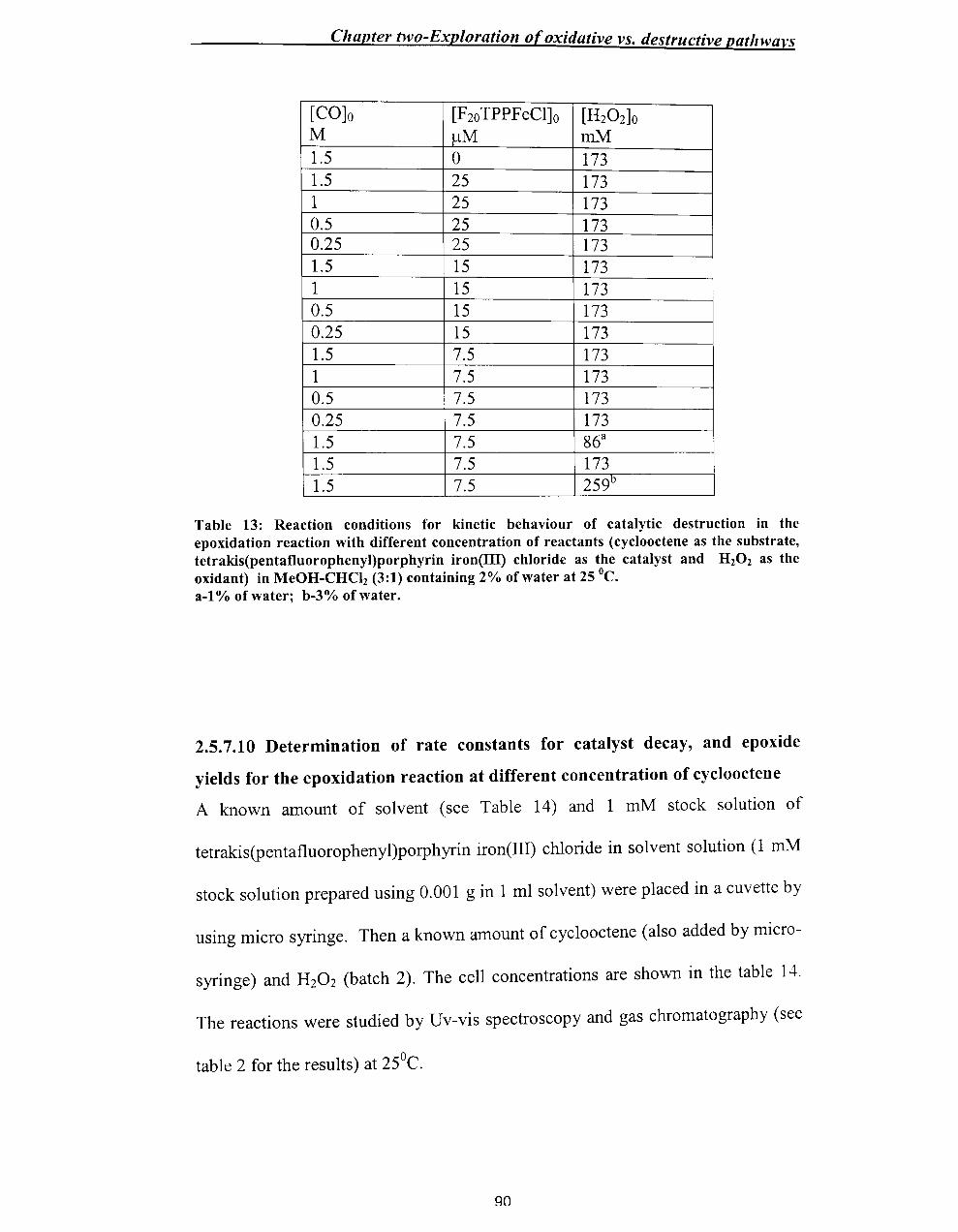
Chapter two-Exploration of oxidative vs. destructive pathwa}'s
[CO]o [F2o TPPFeCl]o [H20 2]O M 11M mM 1.5 0 173 1.5 25 173 1 25 173 0.5 25 173 0.25 25 173 1.5 15 173 1 15 173 0.5 15 173 0.25 15 173 1.5 7.5 173 1 7.5 173 0.5 7.5 173 0.25 7.5 173 1.5 7.5 86a
1.5 7.5 173 1.5 7.5 259D
Table 13: Reaction conditions for kinetic behaviour of catalytic destruction in the epoxidation reaction with different concentration of reactants (cyclooctene as the substrate, tetrakis(pentafluorophenyl)porphyrin iron(UI) chloride as the catalyst and H20 2 as the oxidant) in MeOH-CHCh (3:1) containing 2% of water at 25°C. a-I % of water; b-3% of water.
2.5.7.10 Determination of rate constants for catalyst decay, and epoxide
yields for the epoxidation reaction at different concentration of cyclooctene
A known amount of solvent (see Table 14) and 1 mM stock solution of
tetrakis(pentafluorophenyl)porphyrin iron(III) chloride in solvent solution (1 mM
stock solution prepared using 0.001 gin 1 ml solvent) were placed in a cuvette by
using micro syringe. Then a known amount of cyclooctene (also added by micro-
syringe) and H20 2 (batch 2). The cell concentrations are shown in the table 14.
The reactions were studied by Uv-vis spectroscopy and gas chromatography (see
table 2 for the results) at 25°C.
90

Chapter two-Exploration of oxidative vs. destructive pa/.
[CO]o [F2o TPPFeCI]o [H20 2]O M /-LM mM 1.5 3.9 86
1 3.8 86
0.5 3.8 86
0.25 3.8 86
1.5 4.0 173
Table 14: Reaction conditions for kinetic behaviour of catalytic destruction in the epoxidation reaction with different concentration of reactants (cyclooctene as the substrate and H20 2 as the oxidant) in MeOH-CHCI2 (3:1) containing 1-2% of water at 25 0c.
The absorbance at 400 run was measured every 10 s. The reactions were followed
to completion, i. e. when no further decrease in absorbance (AD was observed.
The lowest absorbance recorded was taken as Ainfinity, In (At - Ainfinity) VS. time was
plotted, and the values of kobs were measured by a first order method. One
example is shown with equation 1, Table 15 and figure 2.13.
In (Ae Aoo) = -kobst + C ............................... (1)
q1

Chapter two-Exploration of oxidative vs. destructive pathways
Time (t) In( At- Aoo ) 30 1.25527 40 1.29098 50 1.32051 60 l.34707 70 l.37437 80 1.39837 90 1.41882 100 l.44817 110 1.46534 120 1.49165 130 l.51413 140 l.54178 150 1.56542
Table 15: Calculated In(At-Aoo) values against time for the reaction of F20 TPPFeCI with hydrogen peroxi~e in methanolldichloromethane (3/1) solution at 25 °C; [cat]o=-3.9 x 10⁻⁶ M; [CO]o = 1.5 x 10- M; [H20 2]O = 86 x 10-3 M monitored at 400 nm.
t o -r---------~------~--------~ _ -0.5
J. <i: -1 ......... c
-1.5
...
50 100 1 pO
y= -0.0025x-1.1926
R2= 0.9972
--2 _L-__________________________ ~
Figure 2.13: Plot of In(At-Aoo) values against time for the reaction of F20TPPFeCI with hydrogen peroxide in methanolldichloromethane (3/1) solution at 25 °C; [cat]o=3.9 x 10-
6 M;
[CO]o = 1.5 X 10⁻³ M; [H20 2]O = 86 x 10-3 M monitored at 400 nm. kobs = 26( ±6) S-I (mean of this and duplicate run).After 20 min. reaction time the reaction mixture was analysed by gas chromatography and the yield was calculated.
2.5.7.11 Epoxidation with 2,4-dimethoxyphenol as substrate
2,4-Dimethoxyphenol (0.0075 g) was taken into a 5 ml volumetric flask and
solvent [MeOH / CHCh (3:1)] was added up to the mark to yield a -0.01 M stock
solution.
92
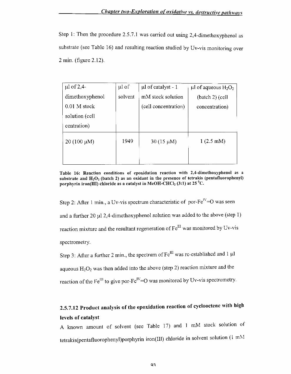
Chapter two-Exploration of oxidative vs. destructive patlnvars
Step 1: Then the procedure 2.5.7.1 was carried out using 2,4-dimethoxyphenol as
substrate (see Table 16) and resulting reaction studied by Uv-vis monitoring over
2 min. (figure 2.12).
).11 of 2,4- ).11 of ).11 of catalyst - 1 ).11 of aqueous H20 2
dimethoxyphenol solvent mM stock solution (batch 2) (cell
0.01 M stock (cell concentration) concentration)
solution (cell
centration)
20 (100 ).1M) 1949 30 (15 ).1M) 1 (2.5 mM)
Table 16: Reaction conditions of epoxidation reaction with 2,4-dimethoxyphenol as a substrate and H 20 2 (batch 2) as an oxidant in the presence of tetrakis (pentafluorophenyl) porphyrin iron(III) chloride as a catalyst in MeOH-CHCI2 (3:1) at 25°C.
Step 2: After 1 min., a Uv-vis spectrum characteristic of por-FelV=O was seen
and a further 20 ).1l2,4-dimethoxyphenol solution was added to the above (step 1)
reaction mixture and the resultant regeneration of Fe III was monitored by Uv-vis
spectrometry.
Step 3: After a further 2 min., the spectrum of Fe III was re-established and 1 ).11
aqueous H20 2 was then added into the above (step 2) reaction mixture and the
reaction of the FeIlI to give por-FeIV=O was monitored by Uv-vis spectrometry.
2.5.7.12 Product analysis of the epoxidation reaction of cyclooctene with high
levels of catalyst
A known amount of solvent (see Table 17) and 1 mM stock solution of
tetrakis(pentafluorophenyl)porphyrin iron(III) chloride in solvent solution (1 ml\l

Chapter two-Exploration of oxidative vs. destructive pathwavs
stock solution prepared using 0.001 gin 1 ml solvent) were placed in a cuyette by
using micro syringe. Then a known amount of cyclooctene was added by micro
syringe followed by 30% H20 2 (batch 2, 7.5M). The cell concentrations are shown
in the table 17. The reactions were analysed by gas chromatography (see table 3
for the results) at 25 °c after 20 minutes.
[CO]O [F2o TPPFeCI]o [H20 2]O M ~M mM 1.5 250 86
0.25 250 86
Table 17: Reaction conditions for the epoxidation reaction (cyclooctene as the substrate and HzOz as the oxidant) in MeOH-CHClz (3:1) at containing 1 % of water 25°C.
2.5.8 Synthesis of 2,4-dimethoxyphenol
(I) Preparation of 2,4-dimethoxyphenyl formate
Meta-chloroperbenzoic acid (18.5 g, 0.075 mol) was dissolved in fresh CH2Ch
(125 ml) and the solution was dried using fresh Na2S04 (9.1 g) over 1 hr. It was
then filtered into a flask containing 2,4-dimethoxybenzaldehyde (10 g, 0.06
moles) and the clear yellow solution was refluxed for 40 h.
The reaction mixture was then concentrated in vacuum and the resultant orange
solid was dissolved in ethyl acetate (125 mI). This was washed with a saturated
solution of aqueous Na2C03 (10 g, O.lmol in 100 ml) in two portions, and with
two portions of brine (50 ml saturated solution). The organic layer was left to dry
94

Chapter two-Exploration of oxidative vs. destructive path wars
over Na2S04, then filtered and concentrated in vacuum to yield a brown oil (8.8 g,
800/0).
(II) Preparation of 2,4-dimethoxyphenol
To the above crude product MeOH (3 ml) and KOH in water (50 ml, 0.17 mol)
were added and warmed. After 16h the solution was acidified (to litmus paper) by
concentrated hydrochloric acid and extracted with CH2Ch (3 x 40 ml). The
organic layer was washed with H20 (35 ml) and brine (2 x 35 ml) and dried over
Na2S04. Then it was filtered and concentrated by vacuum to leave a dark oil
(6.1 g, 66%) homogeneous by IH NMR.
OH
OMe
H
OMe
Figure 2.14: 2,4-dimethoxyphenol
IH NMR :8H (300MHz; CDCh): 3.7 (3H, s), 3.9 (3H, s), 6.4 (lH, dd, 3-H, J =
8.6 and 3.0 Hz), 6.5 (lH, d, 5-H, J = 3 Hz), 6.85 (lH, d, 6-H, J = 8.7 Hz), 7.25
(lH, s, -OH)
95
Chapter two-Exploration of oxidative l'S. destructive pat/m'an
2.6 References
1. T.G.Traylor, C.Kim, J.L. Richards, F.Xu, C.L. Perrin, J. Am. Chem. Soc.
1995,117, 3468.
2. S.Traylor, D.Dolphin, and T.G.Traylor, Chem. Soc., Chem. Commun., 1984,
279.
3. T.G.Traylor, C.J.Marsters, TJ.Nakano and E.B.Dunlap, J. Am. Chem. Soc.
1985, 107, 5537.
4. T.G.Traylor, S.Tsuchiya, Y.-S.Byun, C.Kim, J. Am. Chem. Soc., 1993, 115,
2775.
5. T.G.Traylor, C.Kim, W-P.Fann, C.L.Perrin, Tetrahedron, 1998,54,7977.
6. I.Artaud, K.Ben-Aziza, D.C.Mansuy, J. Org. Chem .. 1993,58,3373.
7. I.D.Cunningham, T.N.Danks, K.T.A.O'Connell, P.W.Scott, J. Org. Chem ..
1999,64,7330.
8. I.D.Cunningham, G.R.Snare, J Chem. Soc., Perkin Trans. 2,1992,2019.
9. I.D.Cunningham, T.N.Danks, K.T.A.O'Connell, P.W.Scott, J. Chem. Soc.,
Perkin Trans. 2, 1999,2133.
10. G.Harden, J Chem. Soc., Perkin Trans. 2, 1995, 1883.
11. K.Murata, R.Panicucci, E.Gopinath, T.C.Bruice, J. Am. Chem. Soc., 1990,
112,6072
12. D.R.Leanord, J.R.Lindsay Smith, J Chem. Soc. Perkin Trans. 2, 1991,25.
13. Y. M.Goh, W.Nam, Inorg. Chern. 1999,38, 914.
14. T.G.Traylor. et ai, JAm. Chem. Soc., 1987, 109, 6201.
15. K.A.Lee, W.Nam, Bull. Korean Chem. Soc. 1996,17,669.
16. R.Panicucci, T.C.Bruice, JAm. Chem. Soc., 1990,112,6063.
96

Chapter two-Exploration o(oxidative vs. destructive pathwal's
17. MJ.Nappa, C.A.Tolman, Inorg. Chern. 1985,24,4711.
18. W.Nam, HJ.Choi, HJ.Han, S.H.Cho, H.J.Lee, S.-Y.Han, Chern. Cornrnun ..
1999,387.
q7

Chapter Three - Synthesis of metal/oporphyrins
Chapter Three
Synthesis of metalloporphyrins
3.1 Introduction
Studies on the H20 2-oxidation of cyclooctene demonstrated that tetrakis
(pentafluorophenyl)porphyrin iron(III) chloride is an effective catalyst for the
epoxidation of alkene, but that there is extensive competition from catalyst
decomposition and H20 2 dismutation (chapter 2). It was planned to extend the study
to different catalysts such as 5, 10, 15,20-tetrakis(p-hydroxyphenyl)-21H,23H
porphyrin iron(III) chloride (1), 5,10,15,20-tetraphenyl-21H,23H-porphyrin iron(III)
chloride (2), 5,10, 15,20-tetrakis(p-sulfonatophenyl)-21H,23H-porphyrin manganese
(III) chloride (3), 5,10,15,20-tetraphenyl-21H,23H-porphyrin manganese (III)
chloride (4), 5,10, 15,20-tetrakis(p-hydroxyphenyl)-21H,23H-porphyrin manganese
(III) chloride (5), 5,10, 15,20-tetrakis(pentafluorophenyl)-21 H,23H-porphyrin iron(III)
98

Chapter Three - Synthesis of metal/oporphyrins
chloride (6), mono(p-aminophenyl)tritolylporphyrin iron(III) chloride (7), mono(p-
hydroxyphenyl)porphyrin iron(III) chloride (8) and its polymer-bound derivative (9)
along with some silica sol-gel immobilised derivatives.
Of these, S,lO,lS,20-tetrakis(p-hydroxyphenyl)porphyrin iron(III) chloride (1),
S,lO,lS,20-tetrakis(p-hydroxyphenyl)-21H,23H-porphyrin manganese(III) chloride
(5), mono(p-aminophenyl)tritolylporphyrin Iron chloride (7), mono(p-
hydroxyphenyl)porphyrin iron(III) chloride (8), the polymer-bound metalloporphyrin
(9), and the sol-gel derivatives needed to be synthesised and these syntheses are
discussed in this chapter.
R2
R2 R2 (I ~ ~ R2 R2
I CI N N "'[/ R3 R1 M
/ '" (I N N°--
R2 R2 ---=::; ~
R2 R2
R2 R2 R3
1: RI-OH; R3 -OH; R2_H; M-Fe
2: RI_H; R3 -H; R2 -H; M-Fe
3: RI_ S03-; R3 - S03-; R2 - H; M-Mn
4: RI_ H- R3 -H; R2 - H; M-Mn ,
5: RI-OH; R3 -OH; R2 - H; M-Mn
6: RI_F; R3 -F; R2 - F; M-Fe
7: RI_ N02; R3 -CH3; R2 - R M-Fe
8: RI-OH; R3 -CH3; R2 -H; M-Fe
9: R I_O-COW ; R3 -CH3; R2 - H; M-Fe
Figure 3.1: Substituted metalloporphyrin, ® -polymer
99

Chapter Three - Synthesis o/metal/oporphyrins
3.1.1 Porphyrin synthesis
Synthesis of a desired porphyrin can be approached by two ways: (1) by modification
ofa naturally occurring porphyrin (for example, heme), or (2) by total synthesis; only
the latter approach will be discussed here. The strategies commonly used in
porphyrin total synthesis are tetramerization of monopyrroles, "2+ 2"synthesis,
cyclisation of open-chain tetrapyrroles and "3+ 1" synthesis (see chapter 1).
Stepwise condensation of monopyrroles with aliphatic aldehydes was initiated and
developed 60 years ago by Rothemund. 1 The yields by this method were very low
and the conditions were severe.
Alder and Long02 modified the Rothemund reaction in 1967 by using refluxing
propionic acid as solvent. These comparatively milder reaction conditions are
amenable to large-scale syntheses. Consequently, this method is still used widely
when large quantities of porphyrin are needed and where the aldehydes are capable of
withstanding acidic conditions, since the harsh reaction conditions result in complete
failure with benzaldehydes bearing sensitive functional groups and the high level of
tar produced presents purification problems. The Alder-Longo method is often used
to obtain unsymmetrically substituted tetraphenylporphyrins with groups suitable for
further modification.
The aim of the work described in this chapter was to synthesise metalloporphyrins to
expand the study of chapter 2, and attempt to stabilise the catalyst by encapsulating
the metalloporphyrin in a silica sol gel.
100

Chapter Three - Synthesis of metalloporphyrins
3.1.2 Objectives (target metalloporphyrins)
Any porphyrin derivative in which at least one of the central nitrogen atoms of a
porphyrin H2 (P) forms a bond to a metal atom is called metalloporphyrin and can be
easily prepared by metal insertion into a porphyrin (for example, scheme 3.1).
~
I", C v
'1 ~ ~ cmeso~Y\\
N . ,\;/ ,,/N~\
~ l' ~ '-!J-r_~ / 0 ~ - -, '!J- ~ _, M
"'-I ~~
~I ---:: /: "/ I /
I
6 .. I :1 c ~
Scheme 3.1: Formation of metalloporphyrin.
Lindsey and co-workers3 developed a room temperature synthesis of meso porphyrins
that is complementary to the Alder method. The gentle conditions of this two-step
one-flask synthesis are compatible with a diverse array of sensitive, highly
functionalised aldehydes. One drawback of this method is that optimal yields are
obtained with O.OlM pyrrole and aldehyde concentrations requiring large solvent
volumes for gramme-scale preparations of porphyrins. In addition, isolation of the
porphyrin usually requires two chromatographic procedures.
This "3+ 1" approach is used to prepare mono(p-nitrophenyl)tritolylporphyrin (10) in
this work (scheme 3.2).4 It is required for reduction of the N02 to the NH2 group.
The idea is that the NH2 of the porphyrin (illustrated in scheme 3.2) or of the
metalloporphyrin will H-bond to the weakly acidic silica. Alternatively, it might be
101
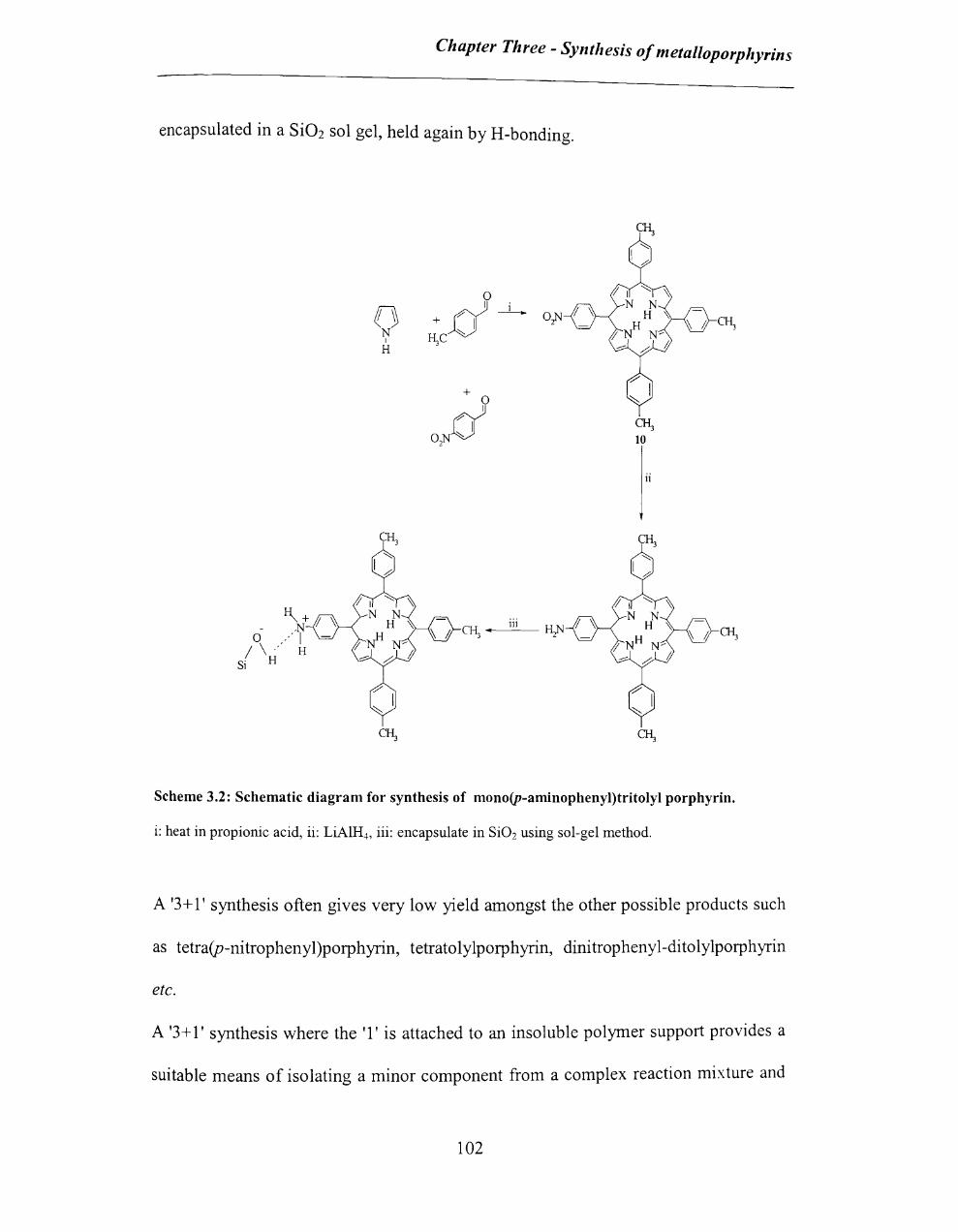
Chapter Three - Synthesis of metal/oporphyrins
encapsulated in a Si02 sol gel, held again by H-bonding.
o N
I
H d
? . 1
7 -+ I f\C ~
o~
ii
I-\+Ij~ - .N
o .0'1 / \ .. ' H
Si H
111 CI~--"--~
Scheme 3.2: Schematic diagram for synthesis of mono(p-aminophenyl)tritolyl porphyrin.
i: heat in propionic acid, ii: LiAIH..), iii: encapsulate in Si02 using sol-gel method.
A '3+ l' synthesis often gives very low yield amongst the other possible products such
as tetra(p-nitrophenyl)porphyrin, tetratolylporphyrin, dinitrophenyl-ditolylporphyrin
etc.
A '3+ l' synthesis where the '1' is attached to an insoluble polymer support provides a
suitable means of isolating a minor component from a complex reaction mixture and
102

Chapter Three - Synthesis of metalloporphyrins
these supports can be used to isolate an unsymmetrical tetraarylporphyrin 5-7 such as
mono(p-hydroxyphenyl)porphyrin (11) (see scheme 3.3).
H3C
OH 11
Br Li
CH .. viii
3
iii -
H3C
~
COOH
o I c=o
6
COCI C=O I 0
9 CHO
CH3
J~;
Scheme 3.3: Schematic diagram for synthesis of 5.10,15,20-tetrakis(p-hydroxyphenyl) porphyrin by using solid support. i: 1.6M BuLi in dry toluene. ii: reflux at 60°C for 3 hours, iii: powdered solid CO:. iv: SOCh in 5: 1 toluenelDMF, \': reflux at 75 11C for 3 hours, vi: p-hydroxybenzaldehyde in THF, \'ii: tolylaldehyde, pYlTole, propionic acid, reflux at 90°C for 1 hour, \'iii: K:C03 in methanol.
The tetraarylporphyrin 5,10, 15,20-tetrakis(p-hydroxyphenyl)porphyrin \\'as to be
synthesised and used as a catalyst in this work because of the likely ease of
preparation. This synthesis involves the condensation of four moles of pyrrole with
four moles of aldehyde (scheme 3.4).
103

Chapter Three - Synthesis of metalloporphyrins
OH
o N I
+ ~ --L... HO HO~ OH
H
OH
ii
OH
HO OH
OH
Scheme 3.4: Schematic diagram for synthesis of 5,lO,15,20-tetrakis(p-hydroxyphenyl) porphyrin iron(III) chlorid. i: heat in propionic acid, ii: FeCb
3.1.3 Sol-Gel chemistry
Studies on the epoxidation reaction demonstrated that catalytic decay is the major
limiting factor of the complete reaction (chapter 2). Therefore, it was hoped to
encapsulate metalloporphyrins 1, 5, 7 and 8 in a silica sol-gel matrix.
The formation of a type of hydrogen bonding between the hydroxyl groups of
[SiOx(OHh_x] (either on the surface or within the sol-gel - see scheme 3.58
) and the
hydroxy or amino groups of the metalloporphyrin (for example - see figure 3.2) is
expected and this will allow immobilisation of the iron complex \\'ithin the
104

mesoporous matrix.
Chapter Three - Synthesis o!metalloporphyrills
Si(OR)4 H) 0
, H+ > [Si(OH)4] + ROH
6l-H20 [SiOx(OH)2_x] li > Si02
(At low-temp.) (At high-temp.)
Scheme 3.5: Possible sol-gel pathway
In practice, despite scheme 3.5 showing Si02 as product, much SiOx(OH)2-x is formed
at low-temperature providing acidic sites for H-bonding as in Figure 3.2.8
The encapsulation mechanism is different from the coulombic forces and covalent
bonding interaction involved in the conventional supported system. It can effectively
prevent leaching of the porphyrin and facilitates continuous usage of the
heterogeneous catalyst system and well defined spacious mesoporous channels further
allow for free diffusion of reactants and products.
105
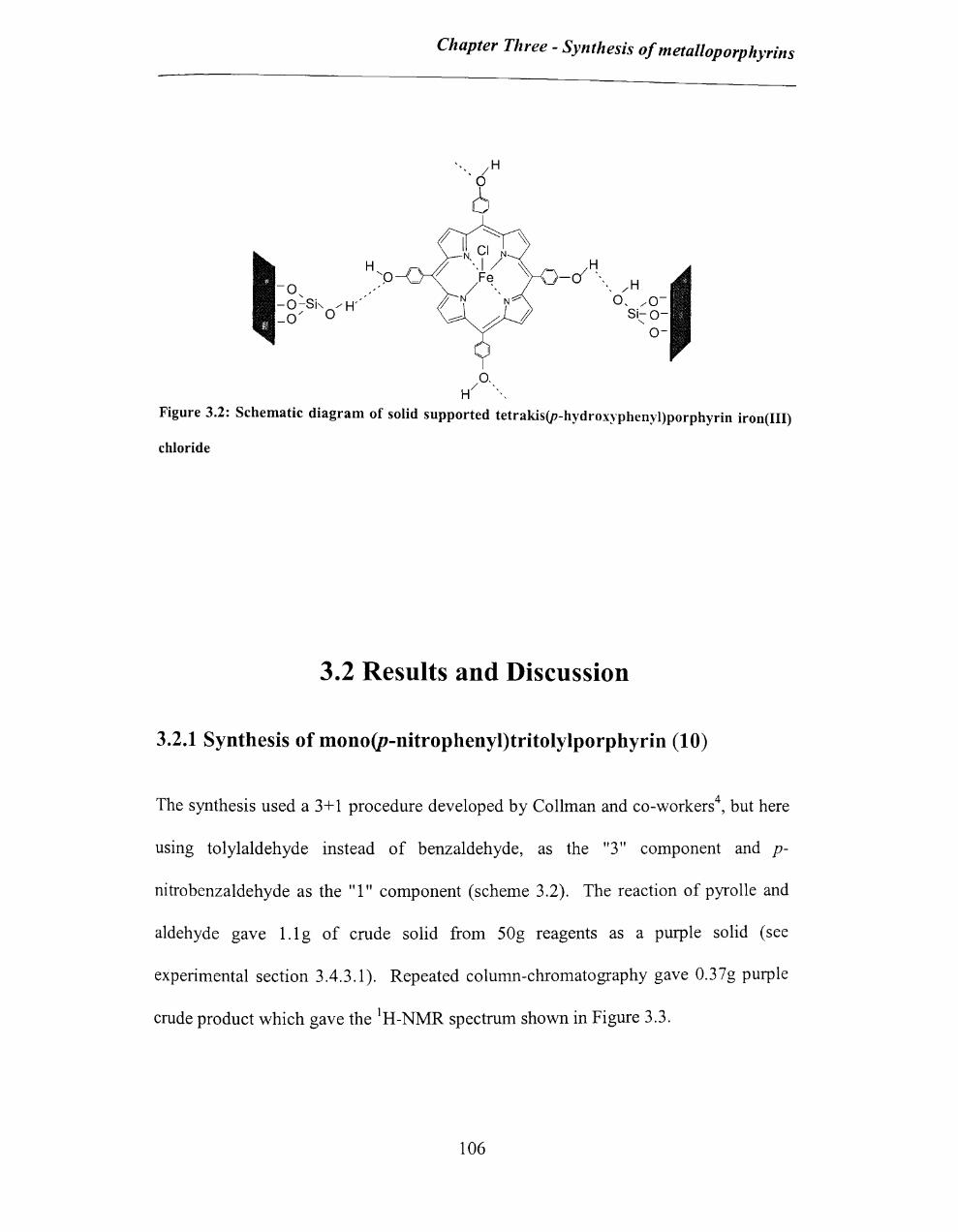
Chapter Three - Synthesis of metalloporphyrins
/H
° (,
H ~p f_
f' I ~ '\;
N CI N
'-.1/ , Fe
/ ",
H --a ", f N N'"
...-:::: ~
j
'" I 0,
H/ ""
Figure 3.2: Schematic diagram of solid supported tetrakis(p-hydroxyphenyl)porphyrin iron(III)
chloride
3.2 Results and Discussion
3.2.1 Synthesis of mono(p-nitrophenyl)tritolylporphyrin (10)
The synthesis used a 3+ 1 procedure developed by Collman and co-workers4, but here
using tolylaldehyde instead of benzaldehyde, as the "3" component and p-
nitrobenzaldehyde as the "1" component (scheme 3.2). The reaction of pyrolle and
aldehyde gave l.1 g of crude solid from SOg reagents as a purple solid (see
experimental section 3.4.3.1). Repeated column-chromatography gave 0.37g purple
crude product which gave the IH-NMR spectrum shown in Figure 3.3.
106

Chapter Three - Synthesis of metal/oporphyrins
Me
Me
,,~.J_::::::--_-,,=~~::=::~;::::::::::;:=:::::::=:;:::~,:::;:=:::::::=:=~~~~~~==:::;:::::-~-:-::~ 8 6 4 2 0 -2 PPM
Figure 3.3: IH-NMR spectrum of the mono(p-nitrophenyl)tritolylporphyrin in CDCI3 •
Although crude, the 1 H -NMR spectrum of the product can be identified from figure
3.3. It shows an -NH proton typical of a pyrrole at -2.77ppm and a -CH proton typical
of a pyrrole at 8.84ppm and 8.91 ppm (the complexity of this portion of the spectrum
makes it difficult to assign the peaks). Peaks in the 2-3ppm region are typical oftolyl
group peaks and the peaks in the 7 -9ppm region are typical of substituted phenyl
hydrogens (see experimental section 3.4.3.1). Peaks in the 0-2ppm region may be
due to the solvent and impurities.
Owing to the 80% of loss of this compound in the purification process, the final yield
107

Chapter Three - Synthesis of metalloporphyrills
is very low and the synthesis to the amino-metalloporphyrin 7 was not continued.
3.2.2 Solid phase route to prepare a mono-substituted porphyrin -
monohydroxyphenyltritolylporphyrin
The process of sequential synthesis on a solid support has many attractive features for
the preparation of mono-substituted porphyrins and should be applicable to the
preparation of porphyrins.
The planned solid phase synthesis used in this work is shown in scheme 3.3.6,7
The method of porphyrin synthesis is similar to those carried out on soluble materials,
but is more difficult to control and evaluate, due to the insolubility of the resins,
which makes the reaction heterogeneous and often prevents the simple
characterisation of the product by the usual methods of analysis.
3.2.2.1 Preparation of® -C02H, ® -polystyrene
Treatment of bromopolystyrene with n-BuLi followed by CO2 gave a solid in good
yield. The solid was examined by IR spectroscopy (see 3.4.3.2.1 and figure 3.4).
108

Q) II c g "E (j)
c C1l L..
f-
Q) (.) c £1 E (J)
c C\j ..... I-
110
105
100
95
90
85
80 1688cm-1 ~
75 -C=O St:etching frequency
2000 1900 1800 1700
110 105 100 95 90 85 80 75 70 65
Chapter Three - Synthesis of metalloporphyrills
~
1263cm1
-C:O Stretc~ing frequency
1600 1500 1400 1300 1200 1100 1000
Wavenumber [cm-1j
(1)
1688cm-1
-C=O Stretching
3600 3400 3200 3000 2800 2600 2400 2200 2000 1800 1600
Wavenumber [cm-1]
(2)
Figure 3.4: (1) and (2) -Partial IR spectra of ®-COOH
In the IR spectra of the product, the broad band at 3000-2400cm-1
and the peak at
1688 cm-1 are both indicative of some C02H present, although it is not possible to say
how much bromine remains. The crude material was used in the next stage.
3.2.2.2 Conversion into(g) -CaCI
After treatment with SOCh the product gave the IR spectrum below, but the
broadness in the C=O region makes analysis difficult (see 3.4.3.2.2 and figure 3.5).
109
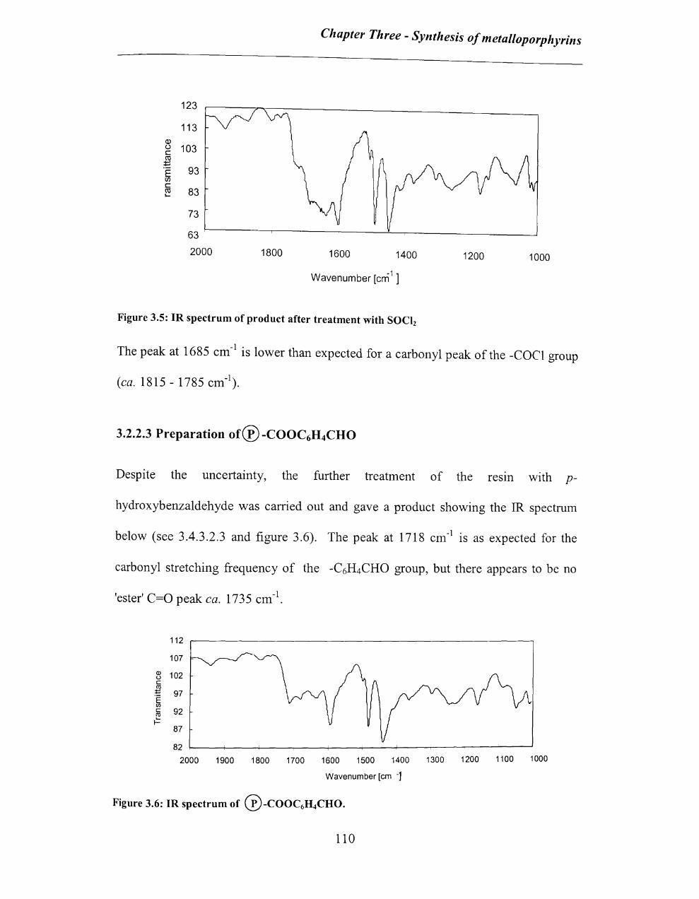
123
113 Q) u 103 c :§ E 93 (/)
c C'O 83 ....
73
63
2000 1800
Chapter Three - Synthesis of metalloporphyrins
1600 1400
-1 ] Wavenumber [em
1200 1000
Figure 3.5: IR spectrum of product after treatment with SOCI!
The peak at 1685 cm-I
is lower than expected for a carbonyl peak of the -COel group
(ca. 1815 - 1785 cm- I).
3.2.2.3 Preparation of® -COOC6H4CHO
Despite the uncertainty, the further treatment of the resm with p-
hydroxybenzaldehyde was carried out and gave a product showing the IR spectrum
below (see 3.4.3.2.3 and figure 3.6). The peak at 1718 cm- I is as expected for the
carbonyl stretching frequency of the -C6H4CHO group, but there appears to be no
'ester' C=O peak ca. 1735 cm- I.
112
107
Q) 102 u c ro t::: 97 "E III c 92 ro .... I-
87
82
2000 1900 1800 1700 1600 1500 1400 1300 1200 1100 1000
Wavenumber [em -1
Figure 3.6: IR spectrum of ®-COOC6H4CHO.
110
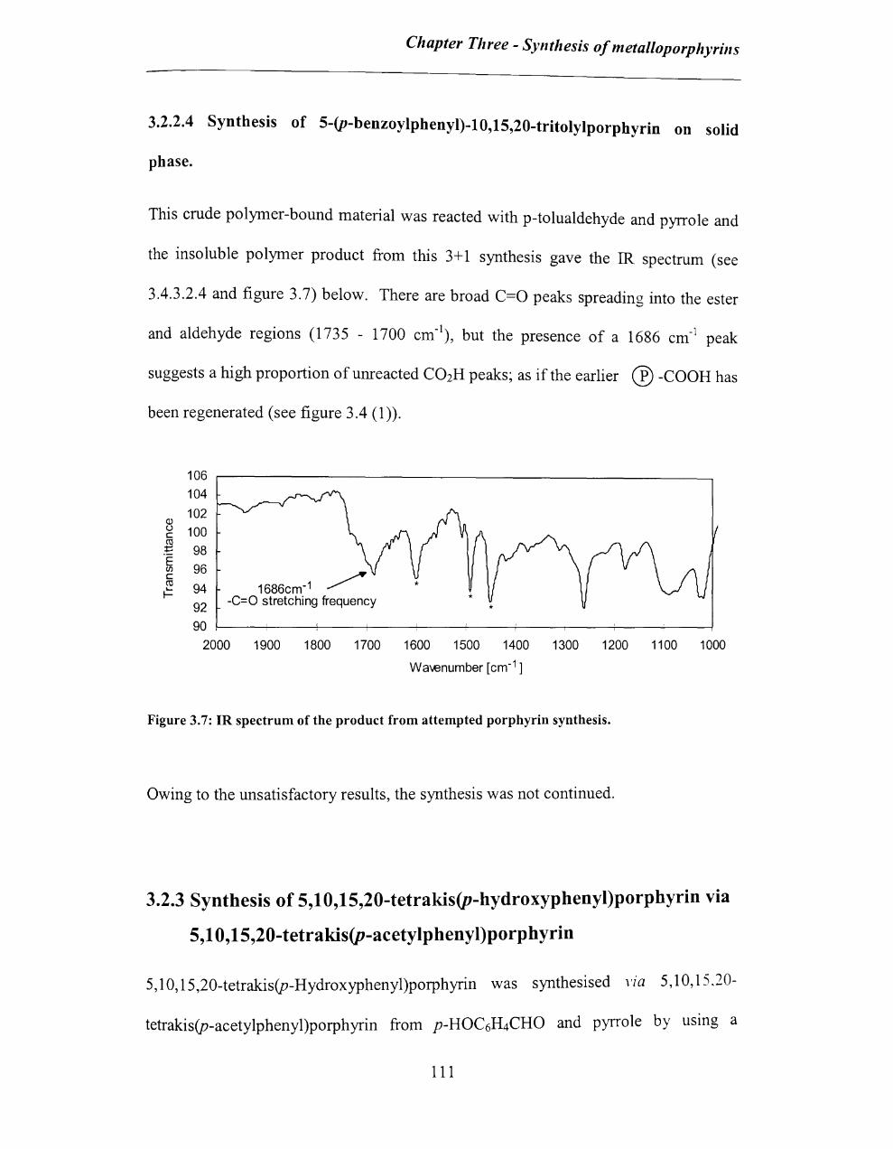
Chapter Three - Synthesis of metalloporphyrins
3.2.2.4 Synthesis of 5-(p-benzoylphenyl)-lO,15,20-tritolylporphyrin on solid
phase.
This crude polymer-bound material was reacted with p-tolualdehyde and pyrrole and
the insoluble polymer product from this 3+1 synthesis gave the IR spectrum (see
3.4.3.2.4 and figure 3.7) below. There are broad C=O peaks spreading into the ester
and aldehyde regions (1735 - 1700 cm-\ but the presence of a 1686 cm-1 peak
suggests a high proportion of unreacted C02H peaks; as if the earlier 0 -COOH has
been regenerated (see figure 3.4 (1 )).
106
104
102 (!) u 100 c :§ 98 E
96 CI)
~ c cu 94 1686cm-1 .... I- -C=O stretching frequency *
92
90 ~---r----+----+----+----+----~--~----~--~--~ 2000 1900 1800 1700 1600 1500 1400 1300 1200 1100 1000
Wa\€number [cm-1 ]
Figure 3.7: IR spectrum of the product from attempted porphyrin synthesis.
Owing to the unsatisfactory results, the synthesis was not continued.
3.2.3 Synthesis of 5,10,15,20-tetrakis(p-hydroxyphenyl)porphyrin via
5,10,15,20-tetrakis(p-acetylphenyl)porphyrin
5, I 0, 15,20-tetrakis(p-Hydroxyphenyl)porphyrin was synthesised vza 5,10,15.20-
tetrakis(p-acetylphenyl)porphyrin from p-HOC6H4CHO and pyrrole by using a
III

Chapter Three - Synthesis of metal/oporphyrins
procedure (see 3.4.3.3 and scheme 3.6) developed by Little and co-workers.9
In each step, the product was conformed by comparing its IH_NMR spectrum with
literature. 9
H
OR
14
OR
OH-------'-v_ CH3 - Wo
ii, iii, i \'
I O-rr-CH3
13 0
Scheme 3.6: Schematic diagram for synthesis of 5,lO,15,20-tetrakis(p-hydroxyphenyl) porphyrin.
i: in NaOH solution, ii: pyrrole, iii: propionic acid, iv: reflux at 80°C for 1 hour, v: KOH.
The route and the results are examined in detail below.
3.2.3.1 Preparation of p-acetylbenzaldebyde (12)
Treatment of p-hydroxybenzaldehyde (see experimental section 3.4.3.3.1) with
sodium hydroxide and acetic anhydride gave an oily product in good yield (50%) and
the product was examined by IR and IH-NMR spectroscopy (figure 3.8 and 3.9).
112

Chapter Three - Synthesis of metal/oporphyrins
80,------------------------------------------------------
70
60
.. 30
20
1794cm -1
~ 3062cm-1 C=O stretching of CAe group
aromatic methine stretching frequency 1702cm-1
C=O stretching of arofl1<ltlC aldehyde
10
I~ ,
1'1
1/
o 1598cm-1
aromatic C=C stretching -1-~
~ ~ 859cm :
_10L-------~----------~----------~----------~
3600 3100 2600 2100 -1
Wavenumber [em 1
Figure 3.8: IR spectrum of p-acetylbenzaldehyde
- _ _ -1 para -disubstituted C-H I 1196cm bending frequency !
C-O-C asymmetric stretching i
1600 1100 600
The presence of a 1794 cm-1 peak suggests an acetyl group and the 1702 cm-1 peak
suggests an aldehyde group in the product.
'D 'D '" r-- "'''' '" '" 00
'" r'r---:
\ V
'Dr--
~~ r-..:r....:
V
,r--... I
/_,1
OCOCH3 Ha*Ha Hb Hb
CHO
Figure 3.9: lH-NMR spectrum of p-acetylbenzaldehyde
113
E
~--

Chapter Three - Synthesis of metalloporphyrills
The lR-NMR spectrum of the product shows -CRO proton typical of an aldehyde at
9.98 ppm and -CH3 protons typical of an acetyl group at 2.33 ppm. Peaks in the 7-8
ppm region are typical of l,4-disubstituted phenyl hydrogens. The small peaks
probably represent unreacted HO-Ph-CHO. From the lH-NMR a purity of ca.90%
was determined.
3.2.3.2 Preparation of 5,10,15,20-tetrakis(p-acetylphenyl)porphyrin (13)
Reaction of the crude p-acetylbenzaldehyde (see section 3.4.3.3.2) with pyrrole
yielded 17.8% of product as a purple powder where the IR spectrum is shown in
Figure 3.10 and lH-NMR spectrum in Figure 3.11.
160~---
140
120
100
8 c fl E 80 (f)
c CIl
~ 60
40
20
- ~
1748cm-1 797cm-1
C=O stretching of -OAC group 1.601cni1 . vPara-diSUbstituted C-H aromatic C=C stretching bending frequecy
frequency
1191cm-1 ~ C-O-C asymmetric stretching
of -OAC group
I
o~--~-----r----+---~------r-------+----~ 3600 3100 2600 2100
Wavenumber [cm-1]
1600
Figure 3.10: IR spectrum of 5,10,15,20-tetrakis(p-acetylphenyl)porphyrin
114
1100 600

Chapter Three - SY1lthesis of metalloporphyri1ls
w r- UJ ." .'" I,JI ,... N 0) N O'l Lt)
'" ~ ..- Lt) ~ N ~ r; ,... ,... r- N ~
\ \/ ~! \
/
______ ~~~v~ __________ ~ ____ ~ 'I.. I
10 I
8 I 6
I 4
("'} \,u "'J e' '" on M 0
0
9
\V \
~ I , , I 2 0
Figure 3.11: IH-NMR spectrum of 5,lO,15,20-tetrakis(p-acetylphenyl)porphyrin
w N <Xl
~
\
/
11
I -2
Comparison of the IR and lR-NMR spectra of this compound with those of the
starting material (p-acetylbenzaldehyde) provides supporting evidence for the reaction
since the -eRO group of the starting material (1702 cm- I) is not present in this
product. Additionally, the IR-NMR spectrum of the product shows -NH and aromatic
115
I , -4 PPM

Chapter Three - Synthesis of metalloporphyrins
protons typical of a pyrrole at -2.82 ppm * and 8.88 ppm and acetyl protons at 2.49
ppm. Furthermore typical peaks of a 1,4-disubstituted phenyl groups are present at
7.51 and 8.21 ppm.
3.2.3.3 Preparation of 5,1 O,15,20-tetrakis(p-hydroxyphenyl)porphyrin (14)
The above product (see 3.4.3.3.2 and 3.4.3.3.3) was treated with potassium hydroxide
and gave a solid in good yield.
It was analysed by visible absorption spectroscopy (figure 3.12), IR (figure 3.13) and
1H-NMR (figure 3.14) spectroscopy.
Porphyrin absorption spectra show an intense absorption (E> 300,000) in the
neighbourhood of 400 nm. This band is referred to as the 'So ret band. There are also
four weaker absorption bands at longer wavelengths (450-700 nm). These bands are
referred as 'Q bands' 10 (figure 3.12 and table 1) .
... In the NMR spectrum, owing to the anisotropic effect from the porphyrin ring current, signals for the
de-shielded pyrrole-protons show up at low field (8 to lOppm) , whereas the signals for the shielded
protons on the inner nitrogen atoms show up at ven gigh field (-2 to-4ppm).

Chapter Three - Synthesis o/metal/oporplzyrills
3 --_ .. _ ................................................... .
2.5
0.5
o~----~----~----~------~----~----~--__ ~ ____ ~ 400 450 500 550 600
Wavelength [nm]
650 700 750 800
Figure 3.12: Uv-vis spectrum of the product (see 5.3.2.3) in ethanol (concentration=7.37x lO"sM)
Anm 405.6 517.3 554.7 593.7 650.9
Absorbance >3 l.174 0.899 0.381 0.450
E >30,0000 15919 12190 5166 6102
Table 1: Uv-visible absorption spectral data of the product (see 3.4.3.3.3)
Upon further purification (washed several times by chloroform - see experimental
section 3.4.3.3.3) the spectra below were obtained. The C=O at 1748 cm-I
in the IR
of the starting material (see figure 3.10) is replaced by a broad OR at ~3301 em-I.
117

Chapter Three - Synthesis of metalloporphyrins
140
120
100
OJ () 80 0::
g E en 0::
~ 60
40
20
0
3301cm-' O-H stretching frequency
3600 3100 2600
1607cm-1
aromatic C=C stretching frequency
1171em-'
2100
c-o stretching frequency of phenolic group
1600
Wavenumber [em-' J
Figure 3.13:IR spectrum of 5,10,15,20-tetrakis(p-hydroxyphenyl)porphyrin
I 10
., :;g .,;
\
~~ om cO"":
Y
J
8
~~ NN ,...:,...:
Y
I 6
OH
0 .... .,,, OH ~ "' _0
~ 00 oj - 00
\ \
, 2 o
eOOcm-' pBra-disubslituted C-H
bending frequency
1100
'" "' ., <:'
J
-2 PPM
Figure 3.14: IH-NMR spectrum of 5,10,15,20-tetrakis(p-hydroxyphenyl)porphyrin
118
600
Chapter Three - Synthesis of metalloporphyrills
In the lH-NMR spectrum, the peak at 8.9 ppm is due to the pyrrole C-H protons and
the peak at -2.85 is of the -NH porphyrin ofpyrrole. Peaks in the 7-8 ppm region are
typical of 1,4-disubstituted phenyl hydrogens. The product could not be
chromatographed effectively and also it was not very soluble in many of the solyents
(chloroform, ethanol, etc.).
3.2.3.4 Insertion of metal into the tetrakis(p-hydroxyphenyl)porphyrin
The metalloporphyrin was successfully prepared by introducing the Fe into the
5,10,15,20-tetrakis(p-hydroxyphenyl)porphyrin (50% of yield) by heating with
FeCh.4H20 in dimethylformamide (see figure 3.15 and experimental section 3.4.3.4).
On metallation, the four-banded spectrum of H2(TTP) is altered to give a spectrum
showing two bands in the visible region; the Soret band is retained. The end of the
reaction is indicated by disappearance of the porphyrin Q band I that is located at
about 650 nm in tetrakis(p-hydroxyphenyl)porphyrin. These two visible bands are
labelled as a and~. The position of the a-band varies within the range 590-630 nm
for the M(TPP)Xn series, the position of the ~-band varies accordingly.
119
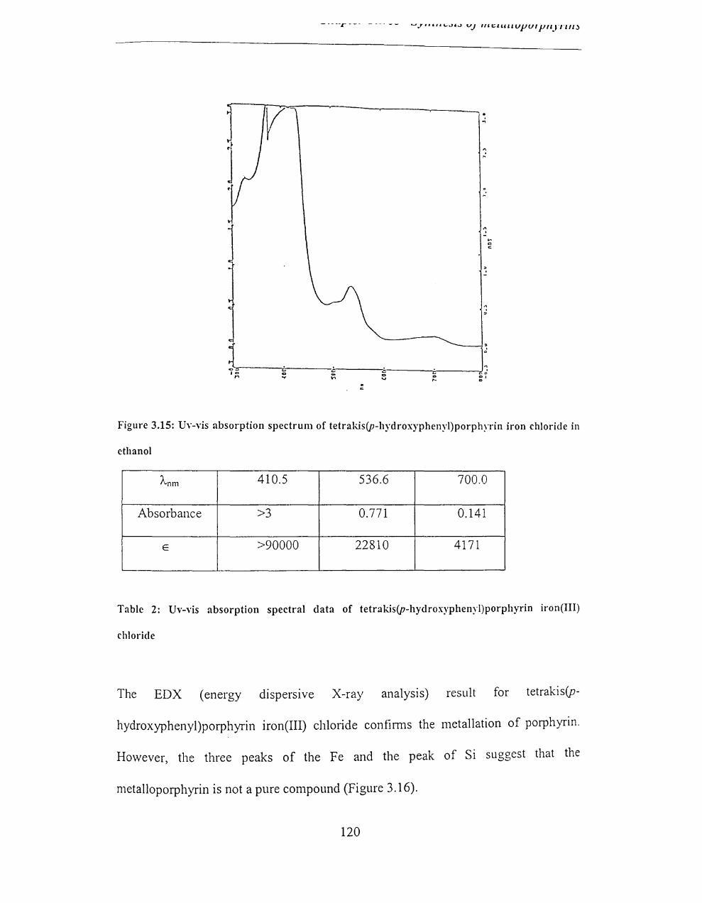
v . .,
" .~
" . .... c c
Figure 3.15: Uv-vis absorption spectrum of tetrakis(p-hydroxyphenyl)porphyrin iron chloride in
ethanol
Anm 410.5 536.6 700.0
Absorbance >3 0.771 0.141
E >90000 22810 4171
Table 2: Uv-vis absorption spectral data of tetrakis(p-hydroxyphenyl)porphyrin iron(III)
chloride
The EDX (energy dispersive X-ray analysis) result for tetrakis(p-
hydroxyphenyl)porphyrin iron(III) chloride confirms the metallation of porphyrin.
However, the three peaks of the Fe and the peak of Si suggest that the
metalloporphyrin is not a pure compound (Figure 3.16).
120
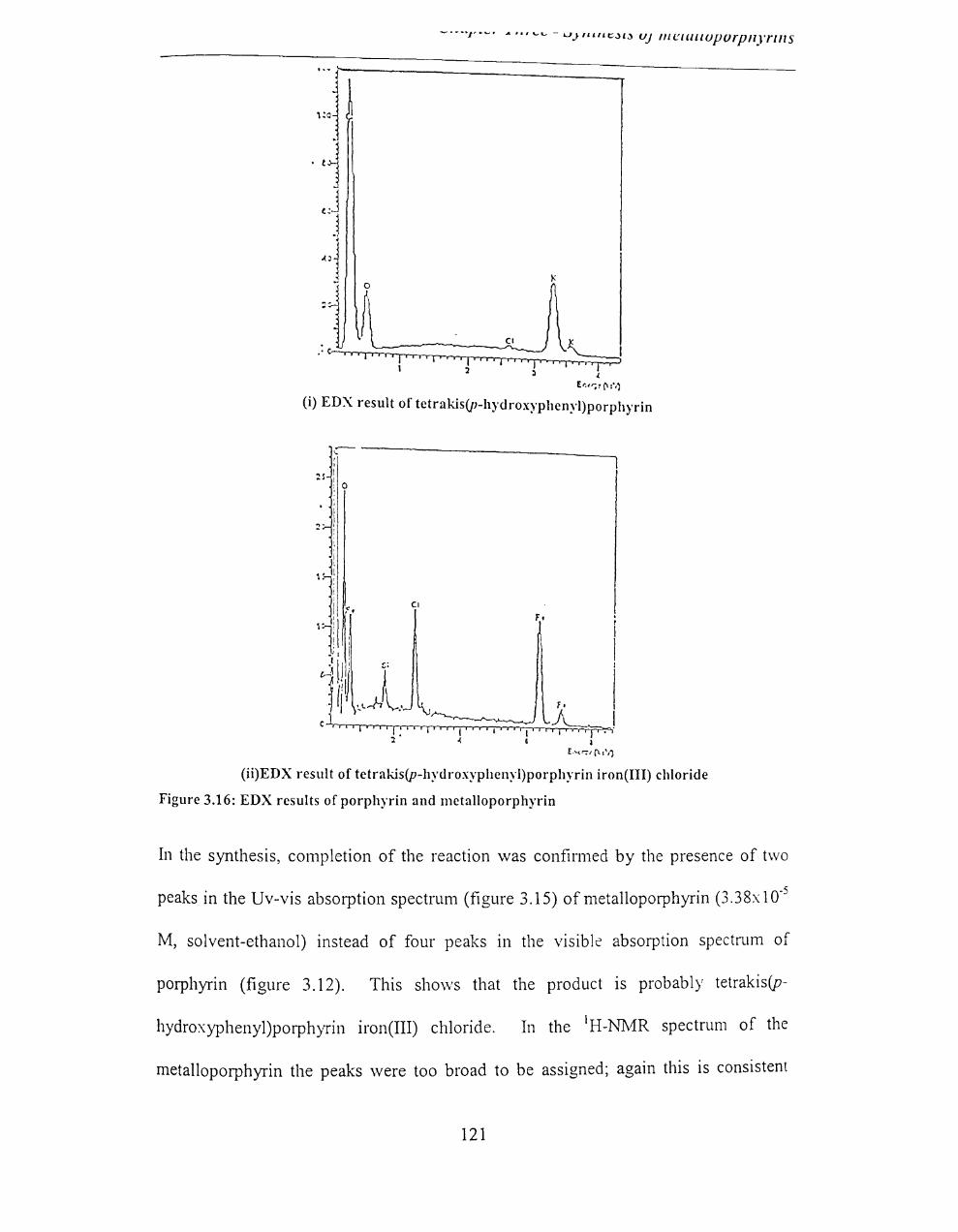
-'--T'~' A ......... - U,}"lltt::;}l;} UJ 1I1C:IClllUpurp"yrlllS
o
r . ~
CI
.·C "" ~: ~: " , .. " .... 1' I :z l "i~
~
(i) EDX result of tetrakis(p-hydroxyphenyl)porphyrin
~----------------------------, ~s :
;0
. ; I
.,. I - : ,
(ii)EDX result of tetrakis(p-hydroxyphenyl)porphyrin iron(III) chloride
Figure 3.16: EDX results of porphyrin and metalloporphyrin
In the synthesis, completion of the reaction was confirmed by the presence of two
peaks in the Uv-vis absorption spectrum (figure 3.15) of metalloporphyrin (3.38x10·5
M, solvent-ethanol) instead of four peaks in the visible absorption spectrum of
porphyrin (figure 3.12). This shows that the product is probably tetrakis(p-
hydroxyphenyl)porphyrin iron(III) chloride. In the IH-N1vfR spectrum of the
metalloporphyrin the peaks were too broad to be assigned; again this is consistent
121

- -- --I' -_. - ••• -- LI,Y'''''LJ'J VJ "'t::.tLlHUl'Uf l'"yrllD
.. . fF III wIth InsertIon 0 e.
Treatment of an ethanolic solution of the product with acetic acid resulted in an
immediate colour change from green to maroon which is characteristic of the
demetallation reaction. lo This further indicates that the product is a metalloporphyrin.
Insertion of metal [Mn(II)] into tetrakis(p-hydroxyphenyl)porphyrin (see 3.4.3.5) was
carried out using manganese(II) acetate tetrahydrate and analysed by Uv-vis
spectroscopy (see figure 3.1 7)
3 \~\ './ \: , I ~
I . I '''\ 5' 11\ -< 2 i : i '-' I \ \ \
~ i 11.\ /~ !
~J~./ ~l ~ 1 i \'-----___ . ~_. _~, __ '_ ---- ~ ~'--~'~-~-====-------
i o -; ---.----;---.-----, 200 300 400 500
Wavelength (n111)
~--- - -------------,
600 700 800
Figure 3.17: Uv-vis absorption spectrum of tetrakis(p-hydroxyphenyl)porphyrin 1V1n chloride in
ethanol
122
Chapter Three - Synthesis of metalloporphyrills
3.2.4 Sol-Gel chemistry
3.2.4.1 Preparation of immobilised metalloporphyrin
Treatment of tetrakis(p-hydroxyphenyl)porphyrin iron(III) chloride (0.0094 mmol)
with water, acetic acid and tetraethoxysilane (8.08 mmol) in ethanol followed by
seven days gelation time gave a wet transparent gel which was then dried at 80°C for
72 hours and 120°C for 96 hours (see the experimental section 3.4.3.6) to give the
encapsulated metalloporphyrin.
If all the metalloporphyrin is incorporated, this will give 1 :900 ratio (mole:mole) of
metalloporphyrin to Si02. This is equal to 0.11 % (moles), 1.25% (w/w).
3.2.4.2 Surface / Porosity analysis
The following results were obtained from the surface area and porosity analysis of the
silica gel (method 3.4.3.6.l) by Coulter SA3100 analyser:
Surface area
BET Surface area
Correlation Coefficient
Total Pore Volume
Pore size Distribution-
737 sq.mlg
0.99993
0.41 cc/g
Under 6 nm diameter 83%
t-Plot surface area 492 sq.mlg
These results suggest that the gel (which contains the metalloporphyrin) has a large
surface area. A large surface area is an advantage for use as a catalyst.
123
Chapter Three - Synthesis of metalloporphyrills
In this analysis the t-plot shows a downward deviation. The downward deviation in
the t-plot can be used for the detennination of the pore volume and pore surface
distribution of micropores. In these results the t-plot surface area is 492 sq.mJg.
Thus, a group of narrow pores has become filled with adsorbed nitrogen, and the
surface area of these pores is 737 (BET surface area) - 492 = 245 sq.mJg (micropore
surface area).
The gel is chemically stable and could not be analysed by Uv-vis spectroscopy
(insoluble in solvents). In the diffuse reflectance analysis, the gel proved to be very
problematic, with minimal reflectance in the Uv- vis region. This may be partially
due to the low amount of sample, which was insufficient to cover the optical aperture.
3.2.4.3 Analysis of the gel by IR spectroscopy
Infrared investigations are complementary in nature, providing infonnation about the
xerogel framework. IR (400-4000 cm- I) spectroscopy has been used extensively to
investigate the dehydroxylation of silica gel surfaces.
Hydroxyl groups are evident in the IR spectra of silica xerogels from bands at 966
cm- I (assigned to Si-OH stretching) and broad bands centred near 3400 cm-I
(assigned
to various isolated and hydrogen-bonded SiO-H stretching vibrations and hydrogen
bonded water).8
One drawback of IR spectroscopy is that bulk silicates prepared from single-step acid
hydrolysis are totally absorbing for wave numbers below about 2400 cm-I, so IR
analyses require dilution in infrared transparent media such as KBr or Nujol.
124

Chapter Three - Synthesis of metalloporphyrins
Therefore, water may be introduced by this procedure and studies of hydroxyl content
or adsorbed water in Nujol-prepared samples are unreliable. In this spectral analysis
of the yield (see experimental section 3.4.3.6.1), continued condensation with
increasing temperature is a major event from the reduction in the relative intensity of
the ~970 cm-1 band assigned to Si-OH stretching along with an increase in the
frequency of the -790 cm-1 band of the Si-O stretching vibration (see figure 3.18-
3.20). Progressive increase in the frequency of the -790 cm-1 has been observed in
many silicate gels and is interpreted as resulting from a strengthening of the network
through cross-linking. 8
65
55
45 Cl) () 35 c co ..... ...... E 25 CI)
c
• 1716 cm-1/
deformation mode of adsorbed water
co 15 L...
I-
5
3441cm -1 hydrogen bonded
SiO-H stretching or hydrogen bonded water 1076cm-1& 1154cm -1Si-O-Si *
* asymmetric stretching frequency
* 966cm -1
Si-OH stretching
-5
4500 4000 3500 3000 2500 -1
Wavenumber [cm ]
2000 1500 1000
Figure 3.18: IR spectrum of metalloporphyrin containing xerogel dried at 80°C for 2 days (see
experimental section 3.4.3.6). *- Nujol peaks
125
500

Chapter Three - Synthesis of metalloporphyrills
45 --------- --.-.--------- -. ---
40 -
35
30
25
20
15
10 3441cm-1
5 - h)'drogen-bonded
*
1634cm -1 deformation mode
of adsorbed molecular water
-1 798cm
Si-O symmetric \etching
\
o _ SiO-H stretching or hydrogen-bonded water 1078cm-1 Si-O-Si * *
-5 ~ ______ r-______ +-______ +-~a=s~ym~m+e~tn~·c~s~t~re~t~ch+.i~ng~~rreq~u~e~n~c~y~ __ ~~~~ __
4500 4000 3500 3000 2500 2000 1500 1000
wavenumber [cm-1]
Figure 3.19: IR spectrum of metalloporphyrin containing xerogel dried at 160°C for 1 day.
*- Nujol peaks
45
40
35
30
Q) 25
u 20 c ro :::: 15 'E (J) 10 c ro 5 t=
0
3441cm -1~" hydrogen-bonded
SiO-H stretching or
1634cm -1 deformation mode
of adsorbed molecular water
798cm- 1
Si-O symmetric stretching
* 1078cm-1
Si-O-Si *' asymmetric stretching frequency -5 ~ ____ ~ ______ +-____ ~ __ ~ __ ~ ____ ~~~ __ r-----~~~~ hydrogen-bonde water
4500 4000 3500 3000 2500 2000 1500 1000 500
wa\€number [cm -1]
Figure 3.20: IR spectrum of metalloporphyrin containing xerogel dried at 200°C for 1 day.
*- Nujol peaks
3.2.4.4 EDX results
500
Fe signal in the EDX result suggests the encapsulation of metalloporphyrin in the gel
(Figure 3.21).
126

eco
€Co-
.
400 o
200-
o I 1 1
I
Si
I 2
I • I
~
Er.e:.y (,eV)
(i) Gel with porphyrin (THPP-see experimental section 3.4.3.7)
600-
':00-
.
200-
o
I
i I
Si
cU ~I o-LJ-r-r-r I I I I I 1 I I I I I I I • 1 2 ..:
Fe I" "I' "'''. 'I"
S 8 Er.e:;( r<eV)
(ii) Gel with metalloporphyrin (THPPFeCl)
Figure 3.21: EDX of silica-gel
Aluminium may be in the TEOS as an impurity.
127

Chapter Three - SYllthesis of metal/oporphyrills
3.3 Conclusion
The metalloporphyrin can be successfully prepared by introducing the metal into a
porphyrin, but purification is the major problem.
Attempted synthesis of mono(p-nitrophenyl)tritolylporphyrin usmg the procedure
developed by Collman et al. 4 with some changes was successful. However, the yield
was very low due to the unexpected difficulties in the preparation and purification
methods.
The planned solid phase route to mono(p-hydroxyphenyl)tritolylporphyrin was not
successful in this work and the insolubility of the resins made the reaction
heterogeneous and prevented the characterisation of the product.
Attempted synthesis of tetrakis(p-hydroxyphenyl)porphyrin usmg the procedure
developed by Little and co-workers was successful even though the tar formation
caused difficulties m the purification step. Recrystallisation or column
chromatographic methods were not efficient for the purification of the product. The
product (tetrakis(p-hydroxyphenyl)porphyrin) and the metalloporphyrin (tetrakis(p
hydroxyphenyl)porphyrin iron(III) chloride) which was prepared by insertion of Fe3+
into the tetrakis(p-hydroxyphenyl)porphyrin were confirmed by Uv-vis, IR, NMR
studies. tetrakis(p-hydroxyphenyl)porphyrin manganese(II) acetate was prepared by
using manganese(II) acetate and characterised as above.
The glass, which was obtained by the sol-gel process, was partly characterised by IR,
128

Chapter Three - Synthesis of metalloporphyrills
Uv-vis, EDX and surface area analysis. The results indicate the sample is partially
ffilcroporous.
Different substituents on the porphyrin ring often cause minor changes to the intensity
and wavelength of these absorptions. Protonation of two of the inner nitrogen atoms
also changes the visible absorption spectrum.
3.4. Experimental
3.4.1 Materials
Acetic acid (Acros), acetic anhydride (Fisons), benzaldehyde (Aldrich),
bromopolystyrene (Lancaster), n-butyllithium (Lancaster), p-carboxybenzaldehyde
(Aldrich), chloroform (Fisher), dichloromethane (Fisher), N,N-dimethylformamide
(Fisons), 1,4-dioxane (BDH), ethanol (Fisons), hydrochloric acid (Fisher), p
hydroxybenzaldehyde (Acros), methanol (Fisons), potassium carbonate (Fisher),
potassium hydroxide (Fisher), propionic acid (Acros), pyrrole (Aldrich), sodium
ethoxide (Lancaster), sodium hydroxide (Fisons), sodium sulphate (Fisher),
tetrahydrofuran (Fisher), thionyl chloride (Aldrich), p-tolua1dehyde (Aldrich) and
toluene (Fisons) were all used as received. Tetraethoxysilane (Lancaster) was
purified by treated with sodium ethoxide followed by distillation.
3.4.2. Instrumentation
Infrared spectra were recorded on a Perkin-Elmer 2000 FT-IR spectrometer. The
129

Chapter Three - Synthesis of 11letalloporphyrins
samples were run as KBr disks or Nujol mulls.
IH-NMR spectra were obtained in deuteriochloroform or deuteriated dimethyl
sulfoxide and recorded at room temperature by means of an EM-300 spectrometer.
Chemical shift values are expressed in ppm relative to TMS and the coupling
constants are in Hz.
Uv-vis spectra were obtained by a PU 8740 Uv-vis scanning spectrometer.
3.4.3 Method
3.4.3.1. Synthesis of 5-(p-nitropbenyl)-1 O,15,20-tritolylporpbyrin
p-tolylaldehyde (14.02 ml, 0.132 mol) and p-nitrobenzaldehyde (10 g, 0.066 mol)
were dissolved in hot glacial acetic acid (400 ml). The mixture was brought to reflux
and pyrrole (27.8 ml, 0.4005 mol) was added as rapidly as possible. The resulting
black solution was heated by a 60°C water bath at reflux for 20 min., then cooled in
ice to 35 °C. Distillation at 60°C under vacuum gave 1.1 g purple crystals.
The crude product which was obtained by the above procedure was stirred with
toluene (50 ml). The resulting solution was diluted with cyclohexane (50 ml), and
loaded onto a column of silica (75 g), then eluted with 1: 1 toluene/cyclohexane under
pressure to give two fractions. The first fraction (A) seemed to be the actual product
and showed two spots on tIc (thin layer chromatography) using .+:1
toluene/cyclohexane as the solvent. The fraction A was loaded on to a column of 30 g
130

Chapter Three - Synthesis of metalloporphyrins
of silica and the chromatographic procedure was repeated twice. Finally, the soh'ent
was removed by rotary evaporator and the purple product (0.1 mg) was analysed by
IH-NMR spectroscopy (see figure 3.3). Because of the non-sufficient amount of the
product, it was not purified further.
Selected IH-NMR data are given below:
IH NMR (CDCh): 88.91 (d, 6H, pyrrole-H), 8.84 (d, 2H, pyrrole-H, 8.71 (d, 2H,
pN02-phenyl-H-ortho to N02), 8.3 (d, 2H, pN02-phenyl-H- meta to N02), 8.07(d,
6H, p-tolyl-H-meta to Me), 7.51(d, 6H, p-tolyl-H-ortho to Me), 2,71 (s, 6H, -CH3 of
10 and 20 p-tolyl), 2.35 (s, 3H, -CH3 of 15 p-tolyl), -2.77 (s, 2H, -pyrrole-NH).
Peaks in the 0-2 region may be due to the solvent.and impurities.
3.4.3.2 Synthesis of 5-(p-hydroxyphenyl)-10,15,20-tritolylporphyrin on solid
phase
The synthesis was carried out using a procedure developed by Svirskaya and Co
workers (see scheme 3.3).11
3.4.3.2.1 Preparation of ® -COOH6
A mixture of brominated resin (2.04 g), dry toluene (26.01 g) and 1.6 M n-BuLi
(1.025 g, 0.016 mol) was stirred and refluxed at 60°C for 3 h under nitrogen gas,
then the mixture was quenched with powdered carbon dioxide. After filtration, the
polymer was washed with THF, methanol, THF-water (2:1), water, THF-water (2:1),
THF and finally methanol. After drying under vacuum 1.8 g of polymer was obtained
and this was analysed by IR spectroscopy (see Figure 3.4).
131

Chapter Three - Synthesis of metalloporphyrills
IR (KBr): v/cm-1
1688 (-C=O stretching of -COOH), 1263 (-C-O stretching of _
COOH), 3000-2400 (broad band, -COOH)
3.4.3.2.2 Preparation of ®-COCI7
To a suspension of® -COOH (0.5 g) in a mixture of dry toluene (4.16 ml) and dry
dimethylformamide (0.83 ml) [5:1 v/v], thionyl chloride (0.2 ml) was slowly added.
The reaction mixture was stirred and refluxed at 75°C for 3 h. After cooling, the
resin was collected and washed repeatedly with dry dimethylformamide, dry toluene,
dry dioxane and finally methylene chloride. After drying under vacuum 0.7 g of
polymer was obtained and an IR spectrum was taken (see Figure 3.5).
IR (KBr): v/cm-1 1685 (this is lower for the -c=o stretching of -COCI group).
3.4.3.2.3- Preparation of ®-COOC6H 4CHO 7
A mixture of ®-COCI (0.4 g), p-hydroxybenzaldehyde (1.17 g, 0.009 mol ), and
THF (5 ml) was stirred and refluxed at 60°C for 3 h, After filtration the resin was
washed with THF. After drying under vacuum 0.3 g of polymer was obtained and an
IR spectrum was taken (see Figure 3.6).
IR (KBr): v/cm-1 1640 (seems to be low for -C=O stretching of -PhCHO), 1718
(seems to be low for -C=O stretching of -benzoyl group).
3.4.3.2.4 Synthesis of 5_(p_benzoylphenyl)-lO,15,20-tritolylporphyrin on solid
phasell
The product ®-COOC6H4CHO from 3.4.3.2.3 (0.2 g), p-tolualdehyde (0.47 g, 0.004
132
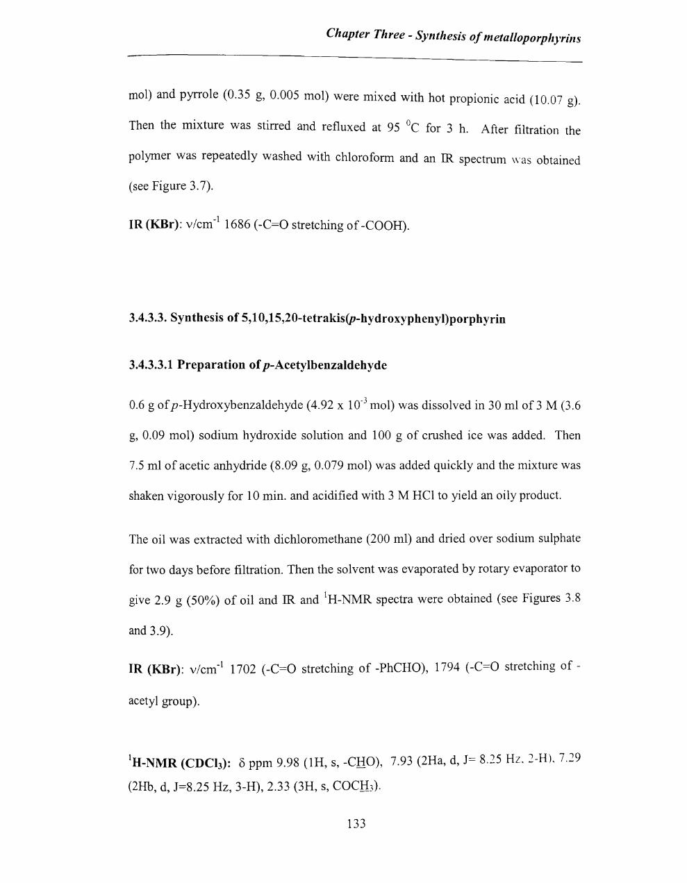
Chapter Three - Synthesis of metal/oporphyrills
mol) and pyrrole (0.35 g, 0.005 mol) were mixed with hot propionic acid (10.07 g).
Then the mixture was stirred and refluxed at 95°C for 3 h. After filtration the
polymer was repeatedly washed with chloroform and an IR spectrum was obtained
(see Figure 3.7).
IR (KBr): v/cm-1 1686 (-C=O stretching of -COOH).
3.4.3.3. Syntbesis of 5,1 O,15,20-tetrakis(p-bydroxypbenyl)porpbyrin
3.4.3.3.1 Preparation of p-Acetylbenzaldebyde
0.6 g ofp-Hydroxybenzaldehyde (4.92 x 10⁻³ mol) was dissolved in 30 ml of 3 M (3.6
g, 0.09 mol) sodium hydroxide solution and 100 g of crushed ice was added. Then
7.5 ml of acetic anhydride (8.09 g, 0.079 mol) was added quickly and the mixture was
shaken vigorously for 10 min. and acidified with 3 M HCI to yield an oily product.
The oil was extracted with dichloromethane (200 ml) and dried over sodium sulphate
for two days before filtration. Then the solvent was evaporated by rotary evaporator to
give 2.9 g (50%) of oil and IR and IH-NMR spectra were obtained (see Figures 3.8
and 3.9).
IR (KBr): v/cm-1 1702 (-C=O stretching of -PhCHO), 1794 (-C=O stretching of -
acetyl group).
IH-NMR (CDCh): 8 ppm 9.98 (lH, s, -CHO), 7.93 (2Ha, d, J= 8.25 Hz, 2-H). 7.29
(2Hb, d, J=8.25 Hz, 3-H), 2.33 (3H, S, COCH3).
133

Chapter Three - Synthesis of metalloporphyrins
3.4.3.3.2. Synthesis of 5,1 O,15,20-tetrakis(p-acetylphenyl)porphyrin
The synthesis was carried out using the procedure developed by Little and co-
19 workers .
p-Acetylbenzaldehyde (2.5 g, 0.0152 mol) was mixed with pyrrole (1.03 g. 0.0154
mol) in propionic acid (25 ml). The reaction mixture was refluxed for one hour and
then cooled overnight at -5°C. The crude material was stirred overnight with absolute
ethanol, then filtered to give a purple amorphous powder (0.29 g, -21 %) and analysed
by IR and 1 H -NMR spectroscopy (see figure 3.10 and 3.11).
IR (KBr): v/cm-1 1748 (-C=O stretching of -acetylgroup).
IH-NMR(CDCh): 8 ppm 8.875 (8H, s, pyrrole), 8.22 (8Hb, d, J = 8.87 Hz, phenyl
H), 7.52 (8Ha, d, J=8.87 Hz, phenyl-H), 2.49 (12H, s, COCH3), -2.82 (2H, s, NH).
3.4.3.3.3 Synthesis of 5,1 O,15,20-tetrakis(p-hydroxyphenyI)porphyrin
The crude material from 3.4.3.3.2 (1.2 g) was refluxed for several hours in 96%
ethanol containing potassium hydroxide (0.86 g, 0.015 mol). The resulting dark green
solution was filtered and acidified with acetic acid; it turned maroon,
The resulting maroon colour solution was evaporated to dryness and a crude green
solid (0.5 g, ~ 75%) was obtained. The crude material was repeatedly washed by
chloroform.
The solid was maroon colour in neutral ethanol and green colour in both acidic and
basic ethanol.
1 F' ~ P The product was analysed by Uv-vis, IR and H-NMR spectroscopy (see Igures -~, -.
134

Chapter Three - Synthesis of 111 eta l/oporphyrills
3.13 and 3.14).
IR (KBr): v/cm-1
3301 (broad band, O-H stretching of phenolic group,) 1171 (C-O
stretching of phenolic group).
tH-NMR (DMSO): 8 ppm 8.86 (8H, s, pyrrole), 7.96(8Hb, d, J = 8.34 Hz, phenyl-H),
7.23 (8Ha, d, J=8.34 Hz, phenyl-H), -2.84 (2H, s, NH).
3.4.3.4 Insertion of metal [Fe(II)] into tetrakis(p-hydroxyphenyl)porphyrin
Tetrakis(p-hydroxyphenyl)porphyrin (0.05 g, 7.37xl0-5 mol) and FeCbAH20 (0.053
g, 2.66xl0-4 mol) were dissolved in dimethylfonnamide (30 ml). The mixture was
brought to reflux for 2 hours. Then the dimethylfonnamide was removed by using a
rotary evaporator. After that H20 (30 ml) was added to the crude product and it was
allowed to cool in an ice bath. 0.03 g of black solid was obtained in 60% yield.
tetrakis(p-Hydroxyphenyl)porphyrin (7.37 x 10⁻⁵ M, solvent-ethanol) and the product
were analysed by Uv-vis spectroscopy (see Figure 3.15 in the Results and Discussion
section) and EDX (Figure 3.16 in the Results and Discussion section).
Uv-vis (ethanol): 410 (>90000), 537 (22810), 700 (4171)
3.4.3.5 Insertion of metal [Mn(II)] into tetrakis(p-hydroxyphenyl)porphyrin
Tetrakis(p-hydroxyphenyl)porphyrin (0.05 g, 7.37xl0-5 mol) and manganese(II)
acetate tetrahydrate (0.064 g, 2.61xl0-4 mol) were dissolved in dimethylformamide
135

Chapter Three - Synthesis of metal/oporphyrills
(30 ml). The mixture was brought to reflux for 2 hours. Then the dimethylformamide
was removed by using a rotary evaporator. After that H20 (30 ml) was added to the
crude product and it was allowed to cool in an ice bath. 0.038 g of black product was
obtained.
The product was characterised by Uv-vis spectroscopy (figure 3.17)
3.4.3.6 Synthesis of metalloporphyrin-TEOS organic-inorganic polymerhybrid
Tetrakis(p-Hydroxyphenyl)porphyrin iron(III) chloride (0.0064 g, 9.44 x 10⁻⁶ mol)
was dissolved in ethanol (l.61 g, absolute alcohol 100%) and a maroon colour
solution was obtained. To this solution H20 (2 g) was added and the colour of the
solution changed from maroon to green. Then the mixture was stirred for 15 minutes
to get a clear solution. Glacial acetic acid (l.21 g) and TEOS (l.684 g, 8.08 x 10⁻³
mol) were added and a green turbid mixture was obtained (see Table 3). On standing,
the mixture separated into two layers. The mixture was stirred vigorously for 12 h to
get a homogeneous mixture and at this point the pH was measured to be 2.65. The
sample bottle was covered with perforated foil to allow solvent evaporation. After a
gelation time of 7 days at room temperature a dark green (black), transparent gel was
obtained. The wet gel was then dried at 80°C for 72 h and then dried at 120°C for 96
h. A dark green, transparent glassy material (0.49 g) was obtained. Then it was
washed with ethanol.
136

Chapter Three - Synthesis of l1letal/oporphyrins
Molar ratios
Hybrid H20 : alkoxide Solvent: alkoxide Acetic acid: alkoxide
Si021P 13.75 4.331 2.49
Table 3: Reaction conditions for synthesis of silica-metalloporphyrin hybrids
P = 5,lO,15,20-tetrakis(p-Hydroxyphenyl)porphyrin iron(III) chloride
3.4.3.6.1 Full analysis of the sample
pH
2.65
The surface area and porous structure of the gel were analysed by a Coulter SA 3100
analyser. The sample (0.4552 g) was taken in to a 9 cc Vacjak sample tube and
outgassed for 360 min at 120°C. The gel was also analysed by IR spectroscopy
(figure 3.17-3.l9) and EDX (energy dispersive X-ray) analysis (figure 3.20).
3.4.3.7 Synthesis of porphyrin-TEOS organic-inorganic polymer hybrid
The procedure 3.4.3.6 was used to prepare encapsulated porphyrin and the product
was analysed by EDX to compare with the EDX of metalloporphyrin to confirm the
metallation.
137

Chapter Three - Synthesis of metal/oporphyrins
3.5 References
1. P.Rothemund, J Am. Chern. Soc., 1939,61,2912.
2. A.D.Alder, F.R.Longo, J.D.Finarelle, J.Goldmacher, J.Assour and
LKorsakaff, J Org. Chern., 1967,6,927.
3. J.S.Lindsey, H.C.Hsu, I.C.Schreiman, P.C.Kearney and A.M.Marguerettaz,
J Org. Chern., 1987,52, 827.
4. J.P.Collman, J.I.Brauman, K.M.Doxsee, T.R.Halbert, E.Bunnenberg, R.E.Linder,
G.N.Lamar, J.D.Gaudio, G.Lang and K.Spartalian, J Am. Chern. Soc., 1980,102,
4189.
5. J.M.Frechet and C.Schuerch, J Am. Chern. Soc., 1971,93,493.
6. M.J.Farrall and J.MJ.Frechet, J Org. Chern., 1976,41,3877.
7. J.M.J.Frechet and K.E.Haque, Macromolecules, 1975,8, 130.
8. CJ.Brinker and G.W.Scherer, The Physics and Chemistry of Sol-Gel
Processing, Academic Press, San Diego, 1990.
9. R.G.Little, J.A.Anton, P .A.Loach and J.A.Thers, Heterocyclic Chemistry. 1975,
12,343.
10. J.E.Falk, 'Porphyrins and Metalloporphyrins', Elsevier, Amsterdam. 1964.
11. C.C.LeznoffandP.I.Svirskaya,Angew. Chern. Int. Edn., 1978,17,947.
138
Chapter Four- epoxidation reaction with different catalysts
Chapter Four
Epoxidation of alkene in the presence of different metalloporphyrins
4.1 Introduction
It has been demonstrated that tetrakis(pentafluorophenyl)-21H,23H-porphyrin
iron(III) chloride (6) is an effective catalyst for the epoxidation of alkenes by
hydrogen peroxide, but that instability of the porphyrin is a significant factor (see
chapter 2). This is a general observation in the epoxidation reactions with
porphyrins as catalysts. 1-9
However, even though catalyst decay is an important factor in the oxygenation
reaction of alkenes with metalloporphyrins as catalysts, for many years, there has
been only sporadic interest in obtaining a detailed understanding of porphyrin
decay.
mesa-Tetra-arylporphyrins with artha or para substituents on the aryl groups are a
popular class of tetra-arylporphyrins and the introduction of electron-deficient
139
Chapter Four- epoxidation reaction with different catalysts
substituents in the metalloporphyrin is a generally accepted method to protect the
metalloporphyrin from the decay of the porphyrin ring and to increase the yield of
epoxidation.1-9
There have been number of reports from Mansuy, l Traylor,2 Nam,3 and others4-9
dealing with metalloporphyrins bearing electron deficient groups as the
substituents. These reports clearly indicate that they favour the epoxidation
reaction and increase the epoxidation yield. Even though those reports did not
give detailed explanations for the effect of substituents on the metalloporphyrin
decay, there are some clues provided which are relevant to this thesis and
discussed in the results and discussion of this chapter.
The reported evidencel-9 also suggests that the metals of metalloporphyrins also
drastically change the chemical stability of porphyrin as well as epoxidation yield.
Vanadium and chromium M=O bonds are very strong and nickel high-valent
species have not been identified, so porphyrin containing these are inactive, but
iron and manganese derivatives are commonly used as catalysts in the epoxidation
reactions of olefin. 4
Traylor2 has suggested that the electron deficient substituents on the
metalloporphyrins increase the yield of epoxidation by favouring the two electron
reduction of the oxo-perferryl complex pore+Fe1V=O (see the discussion of this
chapter and see Chapter 2).
In addition the steric effect of bulky aryl substituents is also known to increase the
stability of the metalloporphyrin, probably by preventing dimerisation and
bimolecular self oxidation reactions. Therefore, separating the molecules from one
1.+0

Chapter Four- epoxidation reaction with different cata(rsts
another by immobilisation of the catalyst in a solid matrix might reduce the
decay. *
Mesoporous materials with a well-defined pore structure have recently attracted a
great deal of research attention in catalytic recovery, stability and catalytic
applications. 10 The encapsulated catalyst has been found to be survived longer
than the free catalyst in several reactions. ll The surrounding solid matrix may
protect the catalyst molecules from the intermolecular reactions and also protect
the molecules from the other foreign molecules or substances, possibly even
hydrogen peroxide. The obvious advantages of solid supports can include ease of
separation from products, recovery and re-use. 12
In this chapter, the epoxidation reaction of cyclooctene by H20 2 is studied with
different catalysts (1-6) containing different metal atom or different substituents
(figure 4.1) and with an encapsulated catalyst. The catalysts are:
1. 5,10, 15,20-tetrakis(p-hydroxyphenyl)-21H,23H-porphyrin iron(III) chloride
(THPPFeCI),
2. 5,10, 15,20-tetraphenyl-21H,23H-porphyrin iron(III) chloride (TPPFeCI),
3. 5,10,15,20-tetrakis(p-sulfonatophenyl)-21H,23H porphyrin manganese(III)
chloride (TSPPMnCI),
4. 5,1 0,15,20-tetraphenyl-21H,23H-porphyrin
(TPPMnCI),
manganese(II I) chloride
5. 5, I 0, 15,20-tetrakis(p-hydroxyphenyl)-21H,23H-porphyrin
chloride (THPPMnCI),
manganese(III)
"d" d tru u"" pathway in parallel with the • Earlier results of this study (chapter 2) show an OXl atlVe es c \ e " epoxidation cycle and also suggests that the decay is possibly due to the destructIOn of the
porphyrin ring not the metal.
141
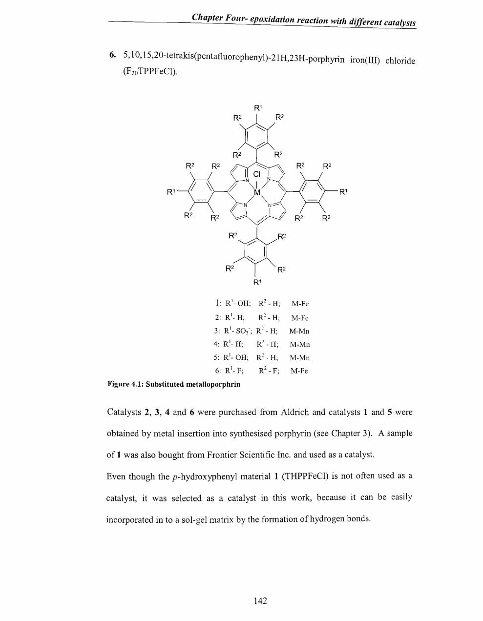
Chapter Four- epoxidation reaction with different catalysts
6. 5,10, 15,20-tetrakis(pentafluorophenyl)-21H,23H_porphyrin iron(III) chloride
(F2o TPPFeCl).
1: Rl_ OH; R2 - H; M-Fe
2: Rl_ H; R2 - H; M-Fe
3: Rl_ S03-; R2 - H; M-Mn
4: Rl_ H; R2 - H; M-Mn
5: Rl_ OH; R2 - H; M-Mn
6: Rl_ F;
Figure 4.1: Substituted metalloporphrin
Catalysts 2, 3, 4 and 6 were purchased from Aldrich and catalysts 1 and 5 were
obtained by metal insertion into synthesised porphyrin (see Chapter 3). A sample
of 1 was also bought from Frontier Scientific Inc. and used as a catalyst.
Even though the p-hydroxyphenyl material 1 (THPPFeCl) is not often used as a
catalyst, it was selected as a catalyst in this work, because it can be easily
incorporated in to a sol-gel matrix by the formation of hydrogen bonds.
142

Chapter Four- epoxidation reaction with different catalysts
4.2.Results
4.2.1 Fe-catalysts
The epoxidation of cyclooctene was carried out in the presence of different
catalysts and hydrogen peroxide in dichloromethane/methanol (v/v = 1/3)
(conditions are fully described in the experiment section 4.5.3.1, but levels are
typically; catalyst- -40 /-tM; substrate - 1.5 M; H20 2 - 0.12 M).
Compared to the
iron(III) chloride
5,10, 15,20-tetrakis(pentafluorophenyl)-21 H,23H-porphyrin
(6), the 5,10, 15,20-tetrakis(p-hydroxyphenyl)-21H,23H-
porphyrin iron(III) chloride (1) and 5,10,15,20-tetraphenyl-21H,23H-porphyrin
iron(III) chloride (2) show a similar pattern of decay of the Soret band (see Figure
4.2), but their decay is much faster (Figure 4.3). The half life for decay of the
Soret peak and the yield of epoxidation product for 5,10,15,20-
tetrakis(pentafluorophenyl)-21H,23H-porphyrin iron (III) chloride (6) are much
greater than that for 5,10, 15,20-tetrakis(p-hydroxyphenyl)-21H,23H-porphyrin
iron(III) chloride (1) and 5,10,15,20-tetraphenyl-21H,23H-porphyrin iron(III)
chloride (2) [see figure 4.3, Table 1 and experimental section 4.5.3.1].
143

,..,. :> 2.8 c::
~ 1 fl. Gi o
-- --",. ,r ... , • ..... JJ IL.-. t...., .... ""' ............. J J'J
~ ul' _· .. r o _.' .. ••••• ... ···-·1·-·1····'-- .• _ ..... _, __ ,,---._~,~~ __ ...,-~~_
380 403 ~r;>t;> 6:":;> --'---"--'~'--r-~ _~\:J \:J~ 7C8 80a
V.I. a vel eng t h ( n m )
a: decay of 5,1 0,15,20-tetrakis(penta n uorophenyl)- 21H,23H-porphyrin iron{III) chloride
f\ c:. o·
8.8
38;; I:",t:)c sr:':8 i·lave 1 eno th (nr.1) .. .
c: decay of 5,10,15,20- tetraphenyl-21H,23H-porphyrin iron(III) chloride
Figure 4.2: Uv-vis analysis (every 10 seconds for 70 seconds) of catalyst decay of Fe-catalysts (40 ~l\l) during the epoxidation of cyclooctene (1.51\1) by H 20 2 (0.12 M) in l\leOH/CH,C1 2
(3: 1).
144

Chapter F our- epoxidation reaction with different catalysts
On close examination of the decay spectra of 1 and 2 (figure 4.2 and 4.3), there is
no evidence of the 550 nm peak, which possibly corresponds to the FeI\=O
intermediate, that is apparent in the Uv-vis spectrum of 6 under similar conditions
(see Chapter 2).
1.8"'---
1.6 -
1.4
1.2 -
1 - '\' J. ;J: 0.8
0.6
10 60 110160210260310360410460510560610 660710760810860910960 t
___ F20TPPFeCI (6) __ TPPFeCI (2) __ TPPHFeCI (1)
Figure 4.3: Plot of Abs vs. t at 410 nm for decay of Fe-catalysts 1, 2 and 6 during the epoxidation of cyclooctene by H20 2 in MeOH/CH2CI2(3:1) at 25°C. catalyst- -40 ).lM; cyclooctene - 1.5 Mj H20 2 - 0.12 M.
Considering the electron density of metalloporphyrins, F 20 TPPF eCI (6) is a more
electron-deficient complex, whereas TPPRFeCI (1) is an electron-rich compound
because of its electron donating substituent (-OR). The most electron deficient
and stable catalyst, F20 TPPFeCI (6) also gives a high yield in the epoxidation
reaction (see Table 1).
145
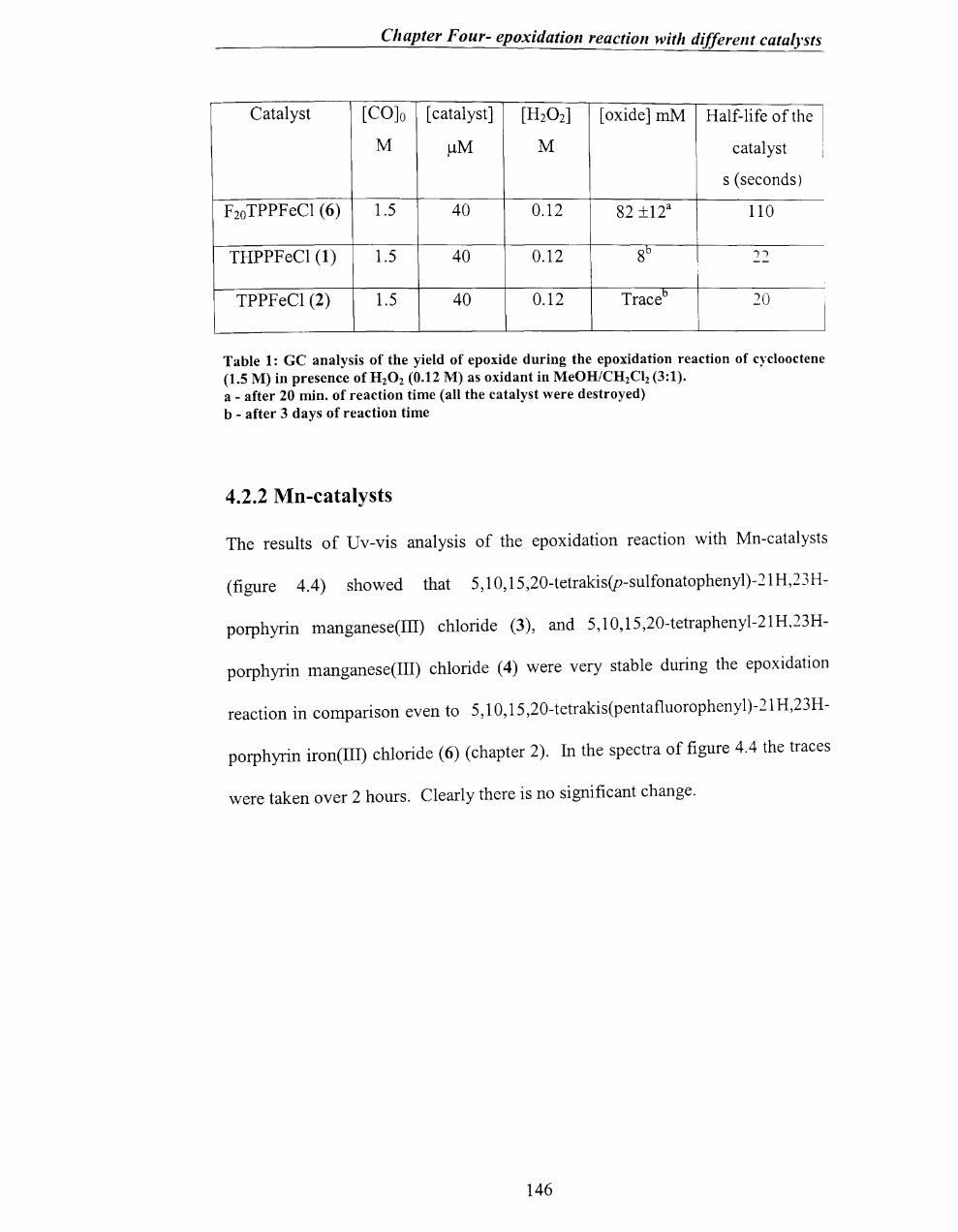
Chapter Four- epoxidation reaction with different catalysts
Catalyst [CO]o [catalyst] [H20 2] [oxide] mM Half-life of the
M ~M M catalyst
s (seconds)
F20TPPFeCl (6) 1.5 40 0.12 82 ±12a 110
THPPFeCl (1) 1.5 40 0.12 8b II --
TPPFeCl (2) 1.5 40 0.12 Traceb 20
I
Table 1: GC analysis of the yield of epoxide during the epoxidation reaction of cyclooctene (1.5 M) in presence of H 20 2 (0.12 M) as oxidant in MeOH/CH2Cl2 (3:1). . a - after 20 min. of reaction time (all the catalyst were destroyed) b - after 3 days of reaction time
4.2.2 Mn-catalysts
The results of Uv-vis analysis of the epoxidation reaction with Mn-catalysts
(figure 4.4) showed that 5,1 0,15,20-tetrakis(p-sulfonatophenyl)-21H,23H-
porphyrin manganese(III) chloride (3), and 5,10, 15,20-tetraphenyl-21H,23H-
porphyrin manganese(III) chloride (4) were very stable during the epoxidation
reaction in comparison even to 5,10,15,20-tetrakis(pentafl uorophen y 1)-21 H,23 H-
porphyrin iron(III) chloride (6) (chapter 2). In the spectra of figure 4.4 the traces
were taken over 2 hours. Clearly there is no significant change.
146
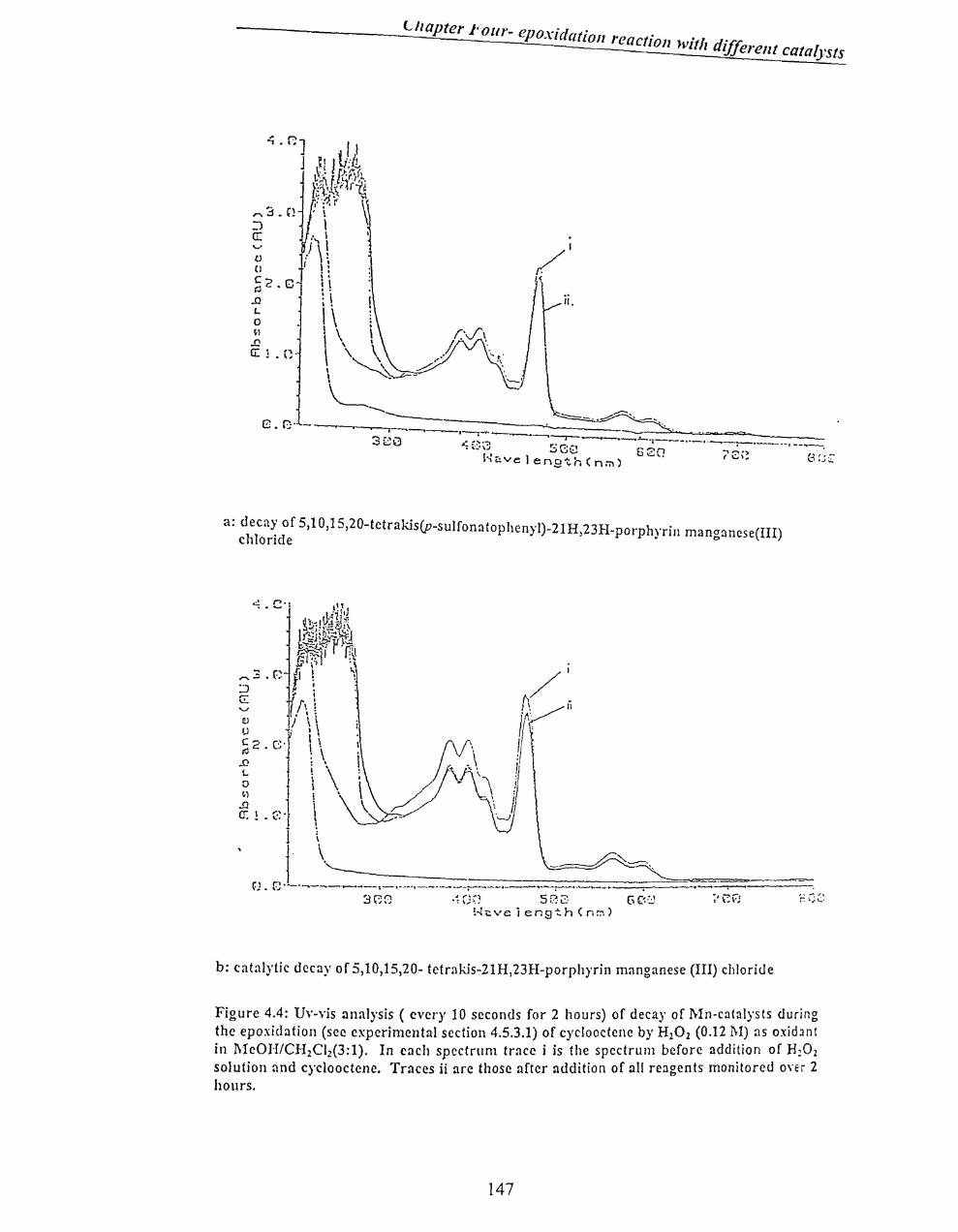
Chapter FOlir- eno ·'d . r Xl atLOn reaction with diffi .
I el ent catalysts
~.r::J /1 J ~I I ~)i
L~" 1 p:r-/~ tt~~\,~i~ ,:lJ. ~ \1
,... 3.0 '! \ :J \ a: ...... I
/ \ \ v (J
~2.C .n L o ~1
..Q a: ! . (;,
t ! 1 i i : i
i \ I \ I' \ h \ \ \ . \ ,\ h'" \ -...:..~-
"------------
. ==--- .. ~~"" 8.G' - ------------_ ---.-.~-,----,--.--.... -------==;.;.-___ ...... -~-=>oo""'_ ___ __ 3 eG ... :.~ ----.---,---.--,. __ >--_1 __ •• _ •. ___.-,..... - __ a_, __ .....--..
~~~ see 620 ~ t~1r:.velen9tr.(n:i\) . 18,~ Be;:
a: deca~ of 5,lO,15,20-tetrakis(p-sulfonatophcnyl)-21H,23H_porphnin mancrancse(III) chlonde . b
.:! ~ •• . . ........ .
·H,F~ 58;::) Ge0 !~ <:. ve j eng'!:. h ( n ~ )
b: catalytic decay of 5,10,15,20- tctralJs-21H,23H-porphyrin manganese (III) chloride
Figure 4.4: Uv-vis analysis ( every 10 seconds for 2 hours) of decay of Mn-catalysts during the epoxidation (see experimental scction 4.5.3.1) of cycJooctcne by H20 Z (0.12 l\I) as oxidant in I\leOI-I1CH2Ciz(3:1). In each spectrum trace i is the spectrum before addition of H~02 solution and cyclooctenc. Traces ii are those after addition of all reagents monitored oYer 2 hours.
147

Chapter Four- epoxidation reaction with different cata(rsts
Peaks corresponding to Mn-porphyrins 3 and 4 seem to be very stable during the
reaction, but even though Mn-catalysts were very stable (compared to 6, 1 and 2).
the epoxidation reaction was much less efficient and the epoxidation yield (for 3)
was very low compared to the Fe-catalysts (see Table 2) even over an extended
period.
Catalyst [CO]o [ catalyst] [H20 2] [ oxide]
M /-lM M mM
F 20 TPPF eCl (6) 1.5 40 0.12 82 ±12
TSPPMnCl (3) 1.5 40 0.12 6
Table 2: GC analysis of the yield of epoxide (after 3 days of reaction time) during the epoxidation reaction of cyclooctene (1.5 M) with HzOz (0.12 1\I) (experimental section 4.5.3.1) in MeOH/CHzClz (3:1).
The epoxidation reaction with 5,10,15,20-tetrakis(p-hydroxyphenyl)-21H,23H-
porphyrin manganese(III) chloride (5) gave only trace amount of epoxide product
(see experimental section 4.5.3.1 and Table 3), but the catalyst was very stable
towards decomposition in stark contrast to its Fe analogue. The reaction was tried
under various different conditions to try to increase the yield (or provoke
decomposition), but with little success.
(i) An increased concentration of H 202 gave a reaction mixture that was
heterogeneous because of too much of water.
(ii) When the reaction was carried out with different solvent (such as
methanol), even the cyclooctene was insoluble.
(iii) With 2,4-dimethoxyphenol as the substrate and analysis by UV-\'is
spectroscopy, there is a slight bathochromic shift in the dimethoxyphenol
1.+8
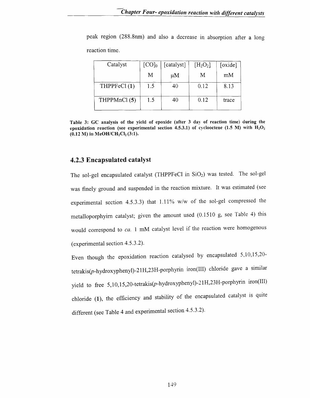
Chapter Four- epoxidation reaction with different catalysts
peak region (288.8nm) and also a decrease m absorption after a long
reaction time.
Catalyst [CO]o [ catalyst] [H20 2] [ oxide]
M ~M M mM
THPPFeCl (1) l.5 40 0.12 8.13
THPPMnCl (5) l.5 40 0.12 trace
Table 3: GC analysis of the yield of epoxide (after 3 day of reaction time) during the epoxidation reaction (see experimental section 4.5.3.1) of cyclooctene (1.5 M) with H20 2
(0.12 M) in MeOH/CH2Cl2 (3:1).
4.2.3 Encapsulated catalyst
The sol-gel encapsulated catalyst (THPPFeCl in Si02) was tested. The sol-gel
was finely ground and suspended in the reaction mixture. It was estimated (see
experimental section 4.5.3.3) that 1.11% w/w of the sol-gel compressed the
metalloporphyim catalyst; given the amount used (0.1510 g, see Table 4) this
would correspond to ca. 1 mM catalyst level if the reaction were homogenous
(experimental section 4.5.3.2).
Even though the epoxidation reaction catalysed by encapsulated 5,10,15,20-
tetrakis(p-hydroxyphenyl)-21H,23H-porphyrin iron(III) chloride gave a similar
yield to free 5,10,15,20-tetrakis(p-hydroxyphenyl)-21H,23H-porphyrin iron(III)
chloride (1), the efficiency and stability of the encapsulated catalyst is quite
different (see Table 4 and experimental section 4.5.3.2).
1.+9
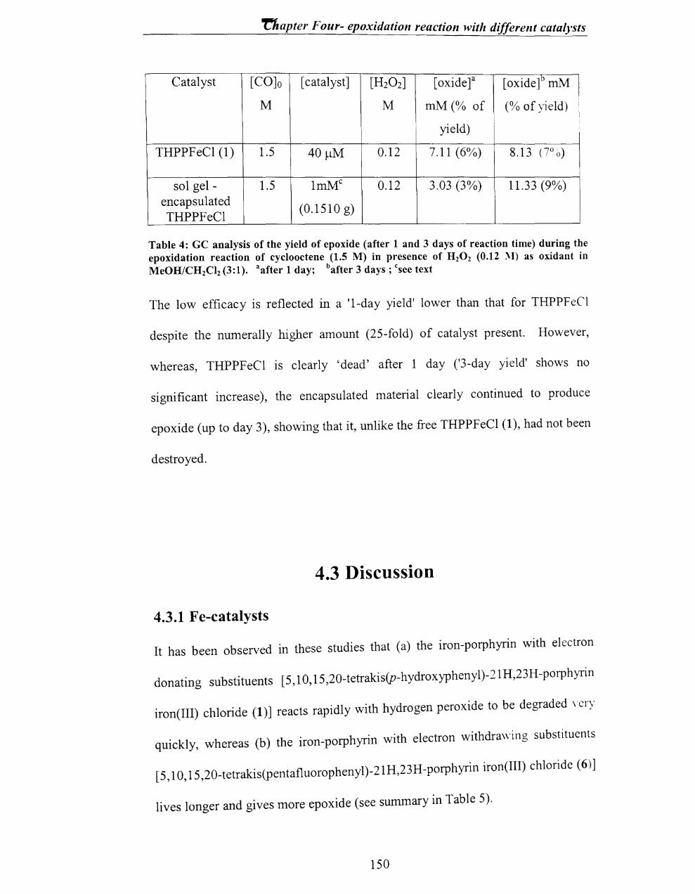
napter Four- epoxidation reaction with different catalysts
Catalyst [CO]o [ catalyst] [H20 2] [oxidet [oxide]b mM l M M mM (% of (% of yield) i
,
yield)
THPPFeCl (1) 1.5 40/-lM 0.12 7.11 (6%) 8.13 (700)
sol gel - 1.5 1mMc 0.12 3.03 (3%) 11.33 (9%) encapsulated
(0.1510 g) THPPFeCl
Table 4: GC analysis of the yield of epoxide (after 1 and 3 days of reaction time) during the epoxidation reaction of cyclooctene (1.5 M) in presence of H20 2 (0.12 :\1) as oxidant in MeOH/CH2Cl2 (3:1). aafter 1 day; bafter 3 days; csee text
The low efficacy is reflected in a 'I-day yield' lower than that for THPPFeCl
despite the numerally higher amount (25-fold) of catalyst present. However,
whereas, THPPFeCI is clearly 'dead' after 1 day ('3-day yield' shows no
significant increase), the encapsulated material clearly continued to produce
epoxide (up to day 3), showing that it, unlike the free THPPFeCl (1), had not been
destroyed.
4.3 Discussion
4.3.1 Fe-catalysts
It has been observed in these studies that (a) the iron-porphyrin with electron
donating substituents [5,10,15 ,20-tetrakis(p-hydroxyphenyl)-21 H,23H -porphyrin
iron(III) chloride (1)] reacts rapidly with hydrogen peroxide to be degraded \'Cry
quickly, whereas (b) the iron-porphyrin with electron withdrawing substituents
[5,10, 15,20_tetrakis(pentafluorophenyl)-21H,23H-porphyrin iron(III) chloride (6)]
lives longer and gives more epoxide (see summary in Table 5).
150

-/
Chapter Four- epoxidation reaction with different catalysts
Catalyst Half-life % of product
(seconds) (based on
H20 2)
5,10,15,20-tetrakis(p-hydroxyphenyl)- 22 7%a ,
21H,23H-porphyrin iron(III) chloride (1) !
5,10,15,20-tetrakis(pentafluorophenyl)- 110 82%b
21H,23H-porphyrin iron (III) chloride (6)
5,10,15,20-tetraphenyl-21H,23H- 20 Trace amount
porphyrin iron(III) chloride (2)
Without catalyst ------- 0%
Table 5: Effect of meso aryl substitution on stability and yield during the H20 2- epoxidation of cyclooctene with different Fe- catalysts (see Table 1 for conditions).
In Table 5, the low epoxidation yield for TPPFeCI seems to show that substituents
(whether electron-donating groups or electron withdrawing groups) on the
porphyrin facilitate the epoxidation reaction. This seems at varience with the idea
of a smooth trend in reactivity often assumed in chemistry.
However on closer anaysis the data reported in the literature concerning chemical
stability of metalloporphyrins are often contradictory. For example, Nam3
,5
prepared a series of metalloporphyrins containing electron-donating and electron-
withdrawing substituents on phenyl groups and studied the effects of the
peripheral sutstituents on the yield of the epoxidation reaction. It was concluded
that the electronic nature of the porphyrin ligands drastically changes the
reactivities of the metalloporphyrins.
In one of those studies, was carried out a stilbene epoxidation with 2-methyl-1-
phenylpropan-2-yl hydroperoxide (PhCH2CMe200H) as oxidant and the iron
porphyrins (shown in figure 4.5) as catalysts.3
151
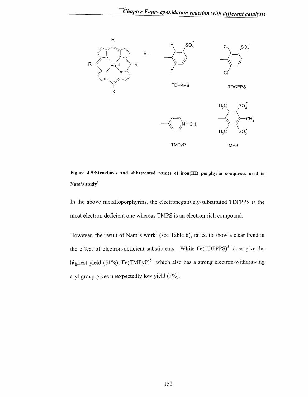
------'"
Chapter Four- epoxidation reaction with different catalysts
Figure 4.5:Structures and abbreviated names of iron(III) porphyrin complexes used in
Nam's study3
In the above metalloporphyrins, the electronegatively-substituted TDFPPS is the
most electron deficient one whereas TMPS is an electron rich compound.
However, the result of Nam's work3 (see Table 6), failed to show a clear trend in
the effect of electron-deficient substituents. While Fe(TDFPPS)3- does gi\'e the
highest yield (51 %), Fe(TMPyP)s+ which also has a strong electron-withdrawing
aryl group gives unexpectedly low yield (2%).
152
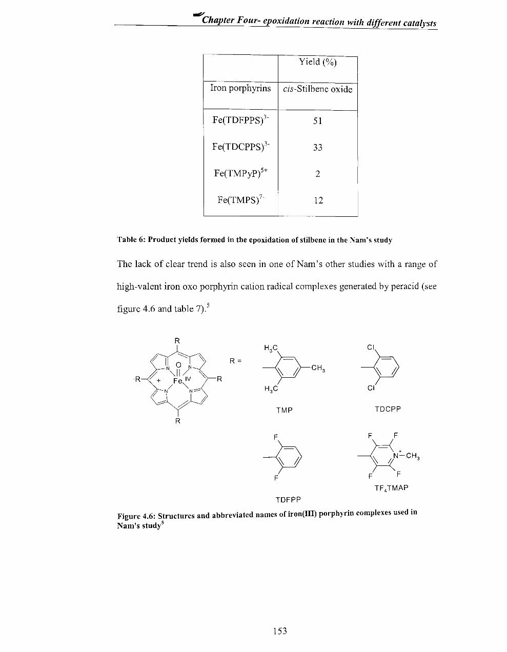
.v Chapter Four- epoxidatioll reactioll with differellt catalysts
Yield (%)
Iron porphyrins cis-Stilbene oxide
Fe(TDFPPS)3- 51
Fe(TDCPPS)3- 33
Fe(TMpyp)5+ 2
Fe(TMPS)7- 12
Table 6: Product yields formed in the epoxidation of stilbene in the Nam's study
The lack of clear trend is also seen in one ofNam's other studies with a range of
high-valent iron oxo porphyrin cation radical complexes generated by peracid (see
figure 4.6 and table 7).5
R H3C
R= -9-CH3
R ~ R
CI~ > H3C CI
.--0;
~ TMP TDCPP
R
F
-9 F
F F
~ iN~CH3 F F
TF 4TMAP
TDFPP
Figure 4.6: Structures and abbreviated names of iron(III) porphyrin complexes used in Nam's studyS
153

Chapter Four- epoxidation reaction with different catalysts
Iron porphyrins yield (% of cyclohexene oxide)
Fe(TMP)(CF3S03) 0
Fe(TDCPP)(CF3S03) 2
Fe(TDFPP)(CF3S03) 0.7
Fe(TF4 TMAP)(CF3S03)S 18
Table 7: Product yields formed in the epoxidation of cyclohexene with H20 2 in Nam's study5
Even here, the Fe(TDFPP)(CF3S03) which is more electron deficient than
Fe(TDCPP)(CF3S03) gives only 0.7% of cyclohexene oxide where as
Fe(TDCPP)(CF3S03) gives 2% of cyclohexene.
This suggests that other factors such as steric factors or overall charge of the
porphyrin may be as, or more important. A recent study has also identified the
nature of the axial ligand as an important factor.13
Even though there is no clear reported explanation for the effect of substituents in
the stability of metalloporphyrin, it might be explained by considering the effect
on the yield which is reported by Traylor6, and the result of earlier part of this
study (chapter 2). Traylor proposed that the reactions of iron porphyrins with
ROOR initially proceed by heterolytic 0-0 bond cleavages (scheme 4.1, path A).
It was further suggested that the electronic nature of iron porphyrin plays
important role in the ratio of the rate of epoxidation process (scheme 4.1, path C)
to that of ROOR disproportionation (scheme 4.1, path B). Iron porphyrin
complexes with electron-withdrawing substituents on the porphyrin ring favour
oxygen atom transfer from pore+FeIV =0 (scheme 4.1) to olefin (scheme -+.1, path
C); perhaps because C corresponds to a two-electron reduction and B only a one-
electron reduction of the oxene; therefore, a high yield of epoxide can be achieved
154

- Chapter Four- epoxidation reaction with different catalysts
with the ROOR such as R20 2. In contrast, iron porphyrin complexes containing
electron-donating substituents, where the pore+FeIV =0 is slightly less electron
deficient, have the tendency to react fast with ROOR (scheme 4.1 5,6,
path B) resulting in either less amount of epoxide or no formation of epoxide.
III -Fe -Porp + ROOH
A heterolysis
o II
ROH +-Fel~porp+·
olefin
C
epoxide
OH
B I __ --==---_. - Fe I~ Porp + RO •
~ ROOH ROO·
~ !
III - Fe - Porp -------------~
Scheme 4.1 5,6: Competition between olefin and ROOH for oxy-perferryl intermediate.
155

-Chapter Four- epoxidation reaction with differellt catalysts
In the specific case of F20 TPPFeIII Traylor's theorY suggests the electronegative
substituents increase the apparent stability of porphyrin and the epoxidation yield
by favouring the reaction route P (formation ofF2oTPPFeIII) which corresponds to
a two electron reduction, whereas reaction route Q (formation of F20 TPP-Fe[\'=O)
corresponds only to a one electron reduction, This explains the relatively high
epoxidation yield in competition (for pore+FeIV =0) with H20 2 reaction to give
FeIV=O (see scheme 4,2),
p
I Felli I
'" ~'" / 'c=c /. '"
'" / c=c / '"
I v Fe= 0 I
Q I IV
Fe= 0 I
L ___________________ intennolicular degradation
Scheme 4. 2: Catalytic activity vs. destruction of oxo-perferryl species.
, , "b t alkene (cyclohexene) and H20 2 has been studied A SImIlar competItIOn e ween
fi 46) b Nam) Nam's results show that the for a range of compounds (see Igure, Y ,
I'ntermedI'ates from iron porphyrins with electron-deficient aryl oxo-perferryl
, 'th lkene but that those electron-donating groups react groups prefer reactIOn WI a ,
, ' 0 ( d t-B OOR) in competition with alkene, This is somewhat readIly WIth R2 2 an u
156

~
Chapter Four- epoxidation reaction with different catalysts
contradictory to our results, which showed significant (non-negligible)
competition between cyclooctene and H20 2 for the electron-deficient
(F20TPP·+)FeIV=O, although these are slight differences in reaction conditions
(e.g. different solvent).
The catalytic activity vs. ease of degradation was analysed earlier in this thesis
(chapter 2 and the scheme 4.2), where the catalyst Fe(F2oTPP)Cl was shown to
undergo direct oxidative destruction from the resting state FeIIl.
It is clear from the results of this work that the increased epoxide yield for
F20TPPFeCI (6) is due, in part at least, to its greater stability; in other words, it
lasts longer allowing more catalytic cycles. However, the question remains, as to
whether the oxidation cycle is more or less, efficient for this catalyst compared to
others,l and 2. A semiquantitative assessment can be made as follows. The half-
life for decay of the THPPFeCl (1) is ca. 22 s, while that for F20TPPFeCl (6) is
ca. 110 s. Therefore, the latter is some 5 times more stable (under similar
conditions -Table 1), so if one allows for the fact that this stability allows the
F20TPPFeCI to continue to oxidise cyclooctene 5-times longer than THPPFeCl,
yields of 82% vs. 7% (Table 5) suggest that the intrinsic epoxidation efficiencies
(i.e. the comparative ability to epoxidise assuming no degradation) are not really
very different for F20TPPFeCI and THPPFeCI, just over 2-fold. In, summary, the
apparently greater epoxidation efficiency of F20 TPPFeCI compared to THPPFeCl
is due in large part to the increased stability of the former. There are a few
previous studies on the effect of meso-aryl substituent on epoxidation and
hydroxylation catalysis rate (as opposed to epoxidation yield), but results are
rather confusing. Traylor7 found that when using pentafluoroiodosylbenzene as
157

-----' Chapter Four- epoxidation reaction with different catalysts
oxidant, electron donating aryl groups increased the rate of epoxidation, but using
hydroperoxide they decreased the rate. In Traylor's 7 work, it seems clear that the
rate-limiting step is the oxidation of the metalloporphyrin to the oxo-perferryl
intermediate. Given this, the 'iodosylbenzene' result seems reasonable, in that
electron donating aryl substituents favour the oxidation of the porPeIII to the
pore+PeIV =0. In contrast the 'hydroperoxide' result is harder to explain; it may be
due to a multiple oxidation step with formation of the co-ordinated ROO- as the
rate-limiting step.
The results of the epoxidation with different catalysts (Table 5) clearly shows that
the THPPFeCI is slightly better epoxidation catalyst than the 'electron neutral'
TPPFeCI 2 (7% vs. trace). Both these catalysts seem to decay at about the same
rate (half-life ca.20 s), so it suggests that, of the two, the electron-rich THPPPeCI
has the slightly more efficient epoxidation cycle. This is not quite consistent, of
course, with the higher efficiency (in the epoxidation cycle) noted for the
F20
TPPFeCI above. However, HO and H are similar in electronic terms when
compared to pentafluoro, and the differences are probably not significant.
4.3.2 Mn-Catalysts
The Uv-vis analysis of the epoxidation reaction with Mn-Porphyrin as catalyst
clearly shows that the Mn catalysts are very stable and remain unchanged even
after days. However, the epoxidation efficiency is also low since, only a trace
amount of epoxide was obtained.
The very low yield of epoxide in the epoxidation reaction with stable Mn-catalysts
might be due to the slow, or lack of, formation ofMn-oxo complex.
158

-Chapter Four- epoxidation reaction with different catalysts
Here is briefly discussed Mansuy' s 1 study of the epoxidation reaction using H20 2
with Mn-porphyrins (see Table 8). The yield of epoxide, while highest for
Mn(TDCPP), is lower for Mn(TPP) than Mn(TMP), despite the former having the
more electron deficient meso-aryl group.
catalyst Styrene epoxide Final state ofMn-catalyst
yield (%)
Mn(TPP)(Cl) 58 Destroyed
Mn(TMP)(Cl) 83 50% destroyed
Mn(TDCPP)( Cl) 100 Intact
Table 8: Epoxidation of styrene in the presence of imidazole used in Mansuy's study (TPP)-tetraphenylporphyrin; (TMP)-tetramesitylporphyrin; (TDCPP)-tetrakis-(2,6-dichlorophenyl)porphyrin.
There is an important clue that can be clearly noticed in the report, in that the
epoxide yield trend follows that of catalyst destruction during the reaction, i.e.
Mn(TPP), giving the lowest epoxide yield, is the most easily destroyed. There is
another complicating factor observed in Mansuy'sl report, in that the same
catalysts in the absence of imidazole give little or no epoxide, but are stable to
degradation.
In this thesis, epoxidation reactions were carried out with 5,10,15 ,20-tetrakis(p-
hydroxyphenyl)-21H,23H-porphyrin manganese(III) chloride (5) for comparison,
5, I 0, 15,20-tetrakis(p-hydroxyphenyl)-21H,23H-porphyrin iron(III) chloride (1)
[see Table 3]. 5,10, 15,20-tetrakis(p-hydroxyphenyl)-21 H,23H-porphyrin
manganese(III) chloride (5) gave only a trace amount of epoxide product, but the
catalyst was very stable towards decomposition. Comparison of these two
159
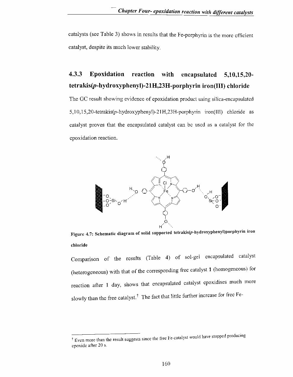
Chapter Four- epoxidation reaction with different catalysts
catalysts (see Table 3) shows in results that the Fe-porphyrin is the more efficient
catalyst, despite its much lower stability.
4.3.3 Epoxidation reactlOon wIOth encapsulated 5 10 15 20 , , , -tetrakis(p-hydroxyphenyl)-21H,23H-porphyrin iron(III) chloride
The GC result showing evidence of epoxidation product using silica-encapsulated
5,10,15,20-tetrakis(p-h ydroxyphenyl)-21 H,23 H -porph yrin iron(III) chloride as
catalyst proves that the encapsulated catalyst can be used as a catalyst for the
epoxidation reaction.
"" I 0-
/ " H "
H --0 ", H /
0, /0-Si-O-
" 0-
Figure 4.7: Schematic diagram of solid supported tetrakis(p-hydroxyphenyl)porphyrin iron
chloride
Comparison of the results (Table 4) of sol-gel encapsulated catalyst
(heterogeneous) with that of the corresponding free catalyst 1 (homogeneous) for
reaction after 1 day, shows that encapsulated catalyst epoxidises much more
slowly than the free catalyst.t The fact that little further increase for free Fe-
F It uld have stopped producing t Even more than the result suggests since the free e-cata ys wo
epoxide after 20 s.
160

Chapter Four- epoxidation reaction with different catalysts
catalyst is seen after 3 days confinns that reaction was completed after 1 day
(indeed earlier results show that the catalyst is destroyed within minutes). In
contrast, the observation that encapsulated catalyst continued to produce epoxide
after 3 days shows that reaction was still on-going at t = 1 day, but much slower
than for "free" catalyst.
The same trend was observed by Lindsay Smithll and others in the study of
supported-metalloporphyrin in alkene epoxidation (Table 9). They studied the
epoxidation of styrene by iodosylbenzene catalysed by iron(III) 5,10.15,20-
tetrakis(2,6-dichlorophenyl)porphyrin (FeIlITDCPP) co-ordinated to pyridine-
modified silica (SiPy-FeIIITDCPP).
FelllTDCPP SiPy-FeJl1TDCPP
Epoxide yielda (%) Epoxide yielda (%)
Reaction Styrene Me-Styrene Styrene Me-Styrene
time / min
5 10 23 l.1 2.7
10 23 51 2.1 5.3
35 27 63 4.7 11.8
1440 29 64 29.0 59.0
Table 911• Time dependence of epoxide yields in the competitive oxidation of styrene and -t
methylst;rene by PhIO in CH2Clz catalysed by FeIllTDCPP and Sipy-Felll~DCPP; Catalyst-2 x 10⁻⁷ mol; PhIO - 1.3 x 10⁻⁴ mol; Styrene = 4-methylstyrene - 2.3 x 10 mol; CH2Clz - 3 cm3
• a-Based on PhIO.
mIn., Here also, the epoxidation with the free catalyst is complete after 35
whereas the yield with supported catalyst although lower initialy, continued to
increase long after 35 min. reaction time.
161

Chapter Four- epoxidation reaction with different catalysts
The very slow reaction might be due to the following reasons:
(i) the limited contact between the reagents and catalyst.
(ii) the pore size being too small to allow the cyclooctene to access the
catalyst.
The catalyst stability (of encapsulated catalyst) may be due to the
(i) inhibition of intermolecular catalyst-catalyst interactions,
(ii) the protection of the porphyrin part of the catalyst.
The latter point (ii) reflects the apparent reduction of the proposed 'direct'
oxidative decay from FeIII, identified for F20 TPPFeCl. This may be steric or
because ofR-bonding of the HO- groups to silica makes the metalloporphyrin less
electron-donating.
4.4 Conclusion
The results obtained from this work and examination of literature work suggests
that
1. strongly electron-withdrawing substituents do appear to favour more efficient
epoxidation, but there is no clear trend extending through neutral substituents
to electron-donating substituents.
2. the efficiency of electron- withdrawing vs. donating catalysts is due mainly to
stability rather than the ability to form oxo-perferryl complex.
3. the increased stability is readily rationalised if, as in chapter 2, direct
decomposition from FeIIl is the main decomposition route.
162

---'
Chapter F our- epoxidation reaction with different catalysts
4. The Mn catalysts are less active but more stable.
5. the encapsulated Fe-catalyst does have catalytic ability, but it is much reduced
(pore size). However, it is much more stable.
4.5 Experimental Section
4.5.1 Materials
Cyc100ctene (Aldrich), dichloromethane (Fisons), dodecane (KOCH-Light
Laboratories Ltd.), 30% hydrogen peroxide (Fisher), methanol (Fisher),
5,10, 15,20-tetrakis(p-hydroxyphenyl)-21H,23H-porphyrin iron(III) chloride
(frontier scientific Inc.), 5,10, 15,20-tetrakis(pentafluorophenyl)-21H,23H-
porphyrin iron(III) chloride (Aldrich), 5,10, 15,20-tetrakis(p-sulfonatophenyl)-
21H,23H-porphyrin manganese(III) chloride (Aldrich), 5,10, 15,20-tetraphenyl-
21H,23H-porphyrin iron(III) chloride (Aldrich) and 5,10, 15,20-tetraphenyl-
21H,23H-porphyrin manganese (III) chloride (Aldrich) were all used as received.
5,10, 15,20-tetrakis(p-Hydroxyphenyl)-21H,23H-porphyrin iron(III) chloride was
synthesised (see Chapter 3) and characterised by IH-NMR and IR.
H20 2 was standardised by Uv-vis spectroscopic determination of a diluted sample.
Throughout this chapter concentrations were based on the stock being 5.22 M
(17.9%). However, given the cautionary note of chapter 2, the same batch was
used throughout.
163

Chapter Four- epoxidation reaction with different catalysts
4.5.2 Instrumentation
A PYE UNICAM PU4550 gas chromatograph, PU 8700 UV spectrophotometer
and Hewlett Packard 8452A diode array spectrometer (UV analysis) were used in
this work.
PYE UNICAM PU4550 gas chromatograph:
Instrumental set-up
Column - Metal Clad (12 x 0.22 mm, 12AQZIBP 0.25),
Film thickness - 0.25 )lm,
Column temperature - 50°C; injector temperature - 250°C; detector temperature
- 250 DC.
For temperature programming:
initial time- 2 min.; rate - 10°C/min.; upper temperature -150°C.
PU 8700 UV Spectrophotometer:
Wavelength range: 200 nm-800 nm,
Temperature: 25°C
Hewlett Packard 8452A Diode Arrav spectrometer:
Temperature: Room temperature
164

Chapter Four- epoxidation reaction with different catalysts
4.5.3 Method
4.5.3.1 Epoxidation reaction of cyclooctene in the presence of
different catalysts and hydrogen peroxide as the oxidant
A known amount of solvent* and 1 mM stock solution of metalloporphyrin in
solvent solution were placed into a cuvette by using micro syringe. Then a known
amount of cyc100ctene was added by micro-syringe. After that aqueous H20 2
(determined as 5.22 M) was added. The cell concentrations are shown in the table
10.
The reactions were carried out at 25°C and analysed by Uv-vis spectroscopy (see
figure 4.2 - 4.4) and by gas chromatography (see Table 1 - 3).
Catalysta (J.1M) Solvent cyc100ctene (M) H 20 2 (M) (J.1l)
40 1524 1.5 0.12
Table 10: Reaction conditions of epoxidation reaction of cycloocteneo
(1.5 M) with 0.12 1\1 H20 2 in the presence of different catalysts in MeOH-CHCh (3:1) at 25 C.
a5,10,15,20-tetrakis(p-hydroxyphenyl)-21H,23H-porphyrin iron(III) chloride, 5,10,1~,20-
tetrakis(pentafluorophenyl)-21H,23H-porphyrin iron(III) ch~oride, 5,10,15,20-tetrakis(psulfonatophenyl)-21H,23H-porphyrin manganese(III) chlonde, 5,10,15,20-tetraphen~l-21H,23H-porphyrin iron(III) chloride, 5,10,15,20-tetraphenyl-21H,23H-porphyr~n manganese (III) chloride and 5,10,15,20-tetrakis(p-hydroxyphenyl)-21H,23H-porphynn iron(llI) chloride were used as catalysts.
• For the methods 4.5.3.1 and 4.5.3.2, the solvent was prepared by mixing 3: 1(~ \.~ methanolldichloromethane and dodecane (0.0029 mol) in a 50 rn1 volumetriC as.
165

4.5.3.2 Epoxidation reaction of cyclooctene in the presence of
encapsulated [5,lO,15,20-tetrakis(p-hydroxyphenyl)-21H,23H_
porphyrin iron(III) chloride 1 and hydrogen peroxide as the
oxidant
A known amount of solvent and a known amount of encapsulated catalyst \\'ere
placed into a cuvette (see Table 11). Then a known amount of cycIooctene (see
Table 11) was added by micro-syringe. After that aqueous H20 2 (determined as
5.22 M) was added and the reaction was allowed to proceed at room temperature
with constant stirring. Then it was analysed by gas chromatography after 1 and 3
days (Table 4).
Catalyst (g) Solvent /-11 of substrate (final /-1l ofH20 2
(/-11) concentration) (final
concentration)
0.1510 (lmM) 1524 390 (1.5 M) 46 (0.12 M)
Table 11: Reaction conditions of epoxidation reaction of cyclooctene (1.5 M) with 0.12 M H 20 2 in the presence of encapsulated metalloporphyrin as catalyst in MeOH-CHCI2 (3:1) at 25°C.
4.5.3.3 Calculation of percentage of porphyrin in the Si02
network.
The silica sol-gel encapsulated THPPFeCl (0.5639 g) which was synthesised in
this work (see chapter 3) was stirred in 7.08 ml absolute ethanol for 2 days. After
this time, the ethanol was changed from colourless to a green colour. Then it was
analysed by Uv-vis spectroscopy and the absorbance of Soret peak (porphyrin
peak) was determined.
166
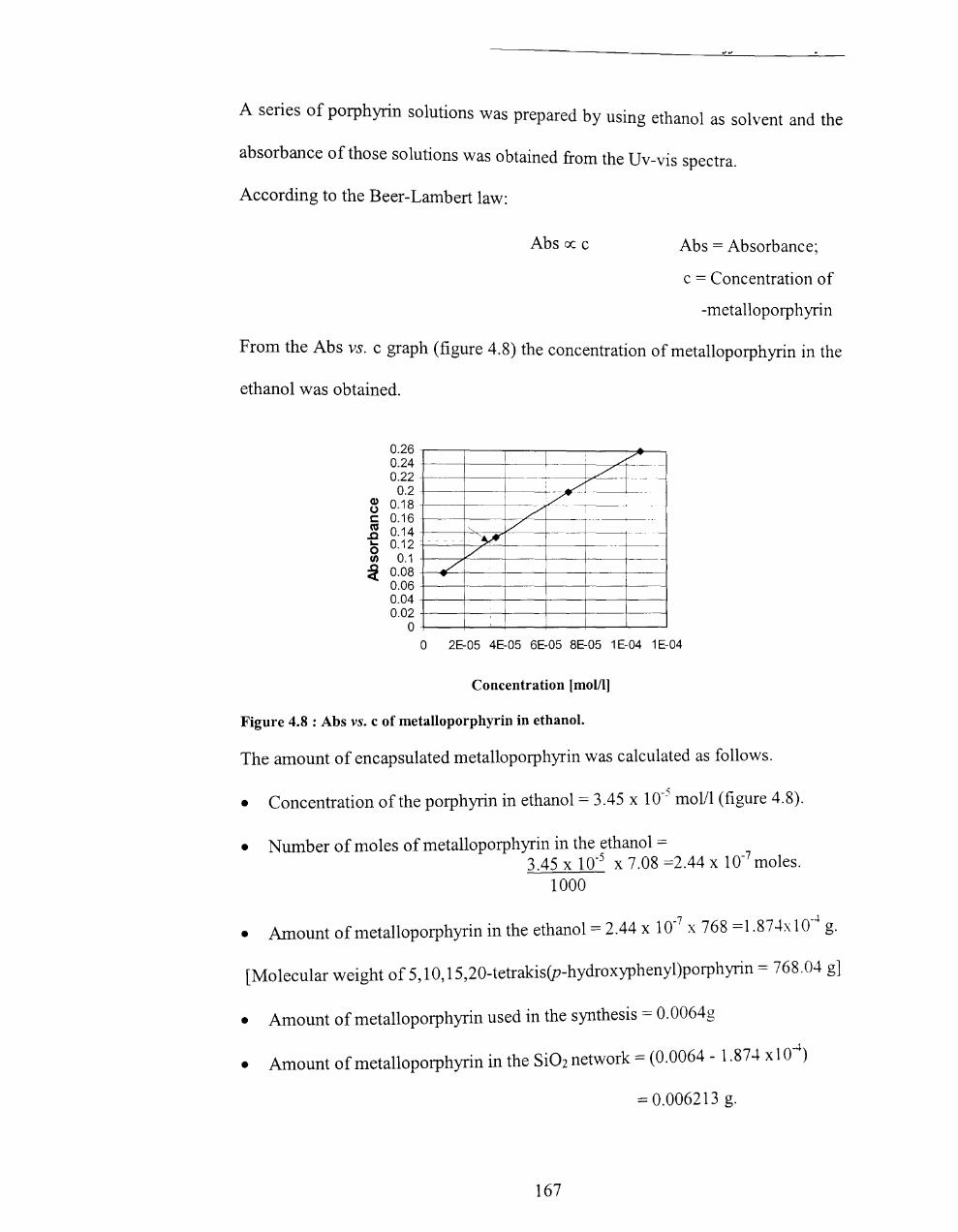
A series of porphyrin solutions was prepared by using ethanol as solvent and the
absorbance of those solutions was obtained from th U . e V-VIS spectra.
According to the Beer-Lambert law:
Abs IX c Abs = Absorbance;
c = Concentration of
-metalloporphyrin
From the Abs vs. c graph (figure 4.8) the concentration of metalloporphyrin in the
ethanol was obtained.
0.26 -r---,-----r----,-----,-----,~-0.24 +---+---1------+ .,/' 0.22 - -~.,,/
B O~·~ 7~· ~ g:~~ - I" !/ -~-~ ... 0.12 - - - ~ ~ 0.1 _ V :i O.OB +-..... ./'=---r---+---f---f------j--
0.06 +---+-~+_--+---+---+-----1 0.04 +---+--+_--+--_+_--+-----1 O. 02 -t----t___~t___-t___----1-----1-----1 0~-+-~4_-4--_+_--L-~
o 2E-05 4E-05 6E-05 BE-05 1 E-04 1 E-04
Concentration [mol/l]
Figure 4.8 : Abs vs. c of metalloporphyrin in ethanol.
The amount of encapsulated metalloporphyrin was calculated as follows.
• Concentration of the porphyrin in ethanol = 3.45 x 10⁻⁵
molll (figure 4.8).
• Number of moles of metalloporphyrin in the ethanol = 3.45 x 10-5 x 7.08 =2.44 x 10⁻⁷ moles.
1000
• Amount of metalloporphyrin in the ethanol = 2.44 x 10-7
x 768 =1.87.fx 10-4
g.
[Molecular weight of 5,10, 15,20-tetrakis(p-hydroxyphenyl)porphyrin = 768.04 g]
• Amount of metalloporphyrin used in the synthesis = 0.0064g
-4 • Amount of metalloporphyrin in the Si 02 network = (0.0064 - 1.87--+ xl 0 )
= 0.006213 g.
167
• Percentage of metalloporphyrin incorporated into silica net work=
0.006213 x 100 = 97%. 0.0064
Weight percentage of metalloporphyrin in the glass = 0.006213 x 100 = 1.11 %. 0.5639
168
4.6 References
l. D.Mansuy, P.Battioni, I.-P.Renaud and IF.Bartoli J Chern. Soc. Chern. Commun,
1985, 888.
2. T.G.Traylor, C.Kim, lL.Richards, F.Xu and C.L.Perrin. J Arn. Chern. Soc., 1995,
117,3468.
3. W.Nam, H.J.Choi, H.I.Han, S.H.Cho, H.J.Lee and S.-Y.Han, Chern. Cornrnull.,
1999, 387.
4. B.Meunier, Chern. Rev., 1992, 92, 141l.
5. Y.M.Goh and W.Nam, In 0 rg. Chern., 1999, 38, 914.
6. T.G.Traylor and F.Xu, J Am. Chern. Soc.,1987, 109, 620l.
7. T.G. Traylor, S. Tsuchiya, Y.-S. Byun and C. Kim, J Arn. Chern. Soc., 1993,115,
2775.
8. S.Quici, S.Banzi and G.Pozzi, Gazzetta Chirnica Italiana, 1993,123,597-612.
9. T.G.Traylor, I.C.Marsters, Jr., T.Nakanno and B.E.Dunlap, J Arn. Chern. Soc.,
1985,107, 5537.
10. L.Zhang, T.Sun and I.Y.Ying, Abstract of 3rd World Congress on Oxidation
Catalysis-Elsevier Science B. V, 1997, 1029.
11 C G·l rt· G W G d I R L Sml·th J Chern. Soc. Perkin Trans. 2, 1995, . . I rna In, . . ray an ... ,.
243.
12. A.W.Van Der Made, R.I.M.Nolte and W. Drenth, Reel. Trav. Chirn, 1990,109.
13. W.Nam, Angew. Chern. Int. Edn., 2000, 39, 3646.
169

Appendix 1
Determination of rate constant for catalyst decay, and epoxide yield for a typical
epoxidation reaction
1554 /-l1 of solvent [dichloromethane/methanol (25/75 v/v)] was placed in a cuvette
using a micro-syringe. 10 /-ll of tetrakis(pentafluorophenyl)porphyrin iron(III) chloride
from a single stock solution (1 mM stock solution prepared using 0.0011 g in 1ml
solvent) was added and stirred well. Then cyclooctene (390 /-ll ) was added. After
allowing equilibration to 25 °c the aqueous H20 2 (46 /-ll of nominally 30%, found to
be 7.5 M) was added and shaken for -30 seconds. The cell concentrations are shown
in Table A.
The reaction was monitored immediately by Uv-vis spectroscopy at A = 400 nm.
Absorbance readings were taken every lOs for 1000 s and are shown in Figure A.
[cyclooctene ]0 [F 20 TPPF eCl] [H20 2]0
M 0 mM
/-lM 1.5 4.0 173
Table A: Reaction conditions for kinetic behaviour of catalytic destruction in the epoxidation reaction (cyclooctene as the substrate and H20 2 ~s the oxidant) in MeOH-CHCI2 (3:1) containing 2% of water (from the aqueous H20 2) at 25 C.
170
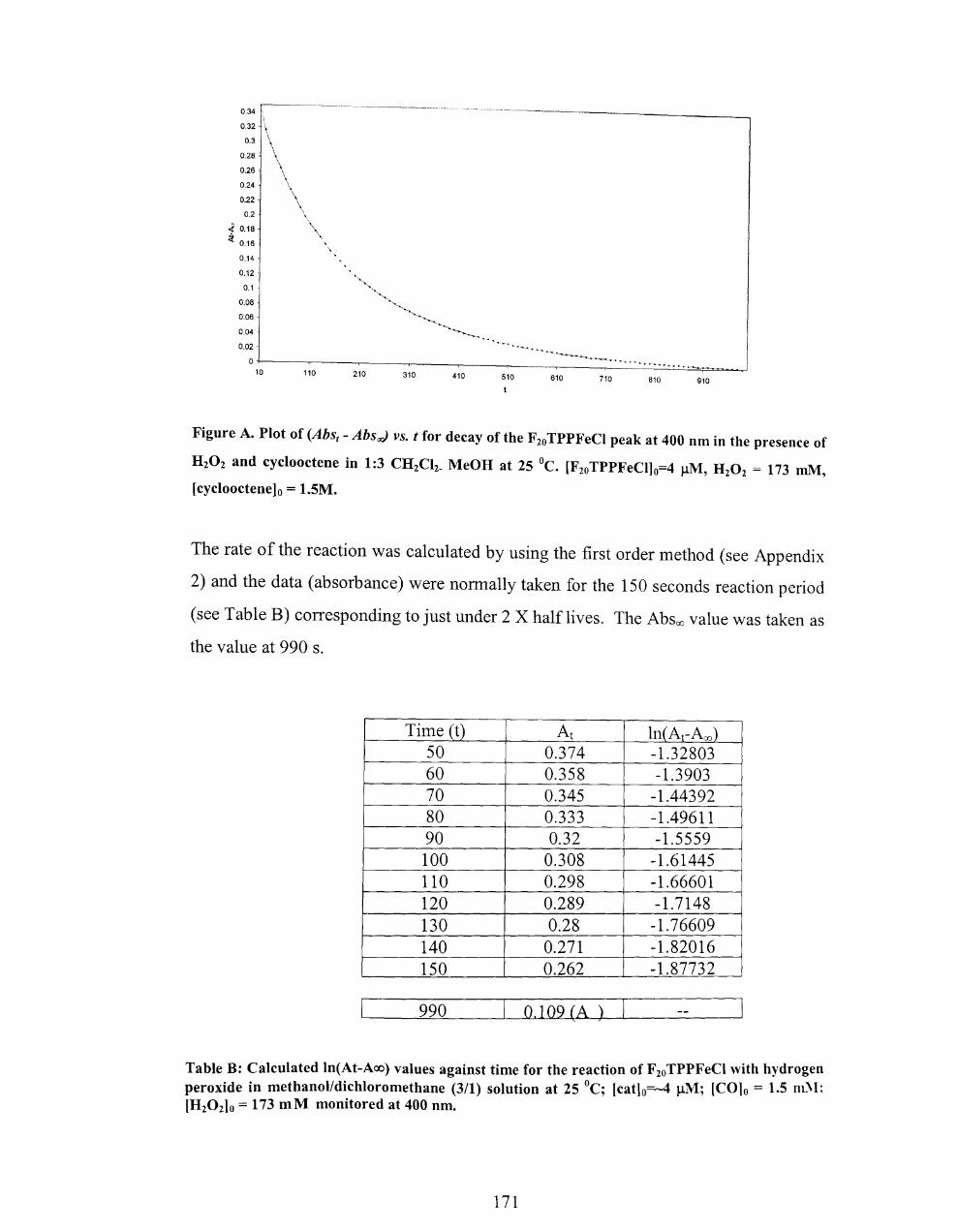
0.34
0.32
0.3 -
0.28
0.26
0.24
0.22
0.2
J. 0.18 ;:l
0.16
0.14
0.12
0.1
0.08
0.06
0.04
0.02·
0 10 110
, \
210 310 410 510 610 710 810 910
Figure A. Plot of (Abst - Absod vs. t for decay of the F 20 TPPFeCI peak at 400 nm in the presence of
H20 2 and cyclooctene in 1:3 CH2Ch_ MeOH at 25 °C. [F20TPPFeCI1o=4 J..lM, H20
2 = 173 mM,
[cyclooctenelo = 1.5M.
The rate of the reaction was calculated by using the first order method (see Appendix
2) and the data (absorbance) were normally taken for the 150 seconds reaction period
(see Table B) corresponding to just under 2 X half lives. The Absoo value was taken as
the value at 990 s.
Time (t) At In(At-Aoo) 50 0.374 -1.32803 60 0.358 -1.3903 70 0.345 -1.44392 80 0.333 -1.49611 90 0.32 -1.5559 100 0.308 -1.61445 110 0.298 -1.66601 120 0.289 -1.7148 130 0.28 -1.76609 140 0.271 -1.82016 150 0.262 -1.87732
990 0.109 (A )
Table B: Calculated In(At-Aoo) values against time for the reaction of F 20TPPFeCI with hydrogen peroxide in methanolldichloromethane (3/1) solution at 25 °C; [catlo=-4 J..lM; (COlo = 1.5 m.'l; [H20 210 = 173 mM monitored at 400 nm.
171

The In(At-ACXl) VS. t was plotted and the kobs was calculated from the slope (see Table
B and Figure B).
-1 -.r-------~------~------~--------------, 70 90
:i ;i -1.5--r::::
-2 ..1-.. __
110
t
130
y = -0.0054x - 1.063
R2 = 0.9994
1 0
Figure B: Plot of In(At-Aoo) values against time for the reaction of F20TPPFeCI with hydrogen
peroxide in methanolldichloromethane (3/1) solution at 25 °C; [cat]o=4 J.1M; [CO]o = 1.5 mM;
[H20 2]O = 173 mM was monitored at 400 nm. kobs = 54 S-1.
172

Appendix 2
For the first order reaction-
X-7P x- reactant and P- product
-d [X]t/dt = k [X]t k-first-order rate constant
[X]t = [X]o.e-kt
In[X]t = In[X]o - kt .................. (1)
Absorption of the reaction mixture at time = t;
At = Ax + Ap ..................... (2) Ax - absorption of reactant X; Ap - absorption
of the product P
According to Beer-Lambert's law
A=ECI E-m01ar extinction coefficient
C - concentration of the absorbant
1- path length
In equation 2;
At = Ex [X]t + Ep [P]t ............... (3)
[P]t = [X]o - [X]t
In equation 3;
At = EX [X]t + Ep {[X]o - [X]t} ..... ( 4)
Absorbace at t = 00 ;
Aoo = Ep [P]oo ..................................... (5)
At the end of the reaction [X] = 0 and [P]oo = [X]o
In the equation 5;
Aoo = Ep [X]o
Equation (5) - (4);
At - Aoo = Ex [X]t + Ep {[X]o - [X]t} - Ep [X]o
= EX [X]t - Ep[X]t
In (At - Aoo) = In[X]t + In(Ex - Ep) ............... (6)
173

According to the equation 1
In[X]t = In[X]o - kt
In equation 6;
In (At - ~) = In[X]o - kt + In(Ex - Ep)
In (At - Aoo) = C - kt .......................... " .(7) C = In( Ex - Ep) + In[X]o
In the y = mx + C graph; slope will give the value ofk (rate constant)
174
Related Documents