Materials Characterization 1ecliniques-Principle s and Applications Eds : G. Sridliar; S. Ghosh Chowdhurv & N. G. Goswanri NML. Janislredpur-83100711999) pp. 163-176 Metallographic Sample Preparation Techniques SAMAR DAS National Metallurgical Laboratory, Jamshedpur-831007 E-mail : [email protected] ABS'T'RACT Microstructure plays an important role in controlling the properties in metals and allcrvs. Hence i nicrostructu•al study called metallographv has been extensively used for materials selection, failure investigation and materials development. The microstructure of metals are com- monly observed under optical and/or electron microscopes, though other types of microscopes have been developed for specific uses. For any microscopic observation, the preparation of proper sample, which reveals the true microstructure is of prima ti, importance. Numerous and diverse techniques have been developed not only to suit the ma- terial but also for the type of microscope to be used. The techniques also vary with the details to be observed. It is difficult to prepare a comprehensive survey of the techniques developed and practised to- day. An attempt has been made here, to briefly discuss the most corn- monly used specimen preparation techniques for optical, scanning electron and transmission electron microscopy together with their merits and demerits. Any specimen preparation method involves several steps. Proper care in each step is essential to avoid difficulty in the subse- quent steps and to reveal the true microstructure. The choice of a technique depends mainly on the materials, the detail required to be observed and the type of microscope to be used. INTRODUCTION The study of microstructural details of metals and alloys is termed as metal- lography. The microstructure of steel was first observed by H.C. Sorby in 1864 z at a very low magnification. Presently several types of microscopes such as transmission electron microscope, scanning electron microscope, Field ion microscope, Auger Microscope, Scanning Tunneling Microscope, Ultrasonic Microscope, Acoustic Microscope etc, are available for micro-structural, mi- cro-chemical and crystallographic characterisation of metals and materials. The type microscope used for characterisation depends upon the fineness and type of details required to he observed. For micro-structural characterisation of 163

Welcome message from author
This document is posted to help you gain knowledge. Please leave a comment to let me know what you think about it! Share it to your friends and learn new things together.
Transcript
Materials Characterization 1ecliniques-Principle s and Applications
Eds : G. Sridliar; S. Ghosh Chowdhurv & N. G. Goswanri
NML. Janislredpur-83100711999) pp. 163-176
Metallographic Sample Preparation Techniques
SAMAR DASNational Metallurgical Laboratory, Jamshedpur-831007
E-mail : [email protected]
ABS'T'RACT
Microstructure plays an important role in controlling the properties in
metals and allcrvs. Hence i nicrostructu•al study called metallographv
has been extensively used for materials selection, failure investigation
and materials development. The microstructure of metals are com-
monly observed under optical and/or electron microscopes, though
other types of microscopes have been developed for specific uses. For
any microscopic observation, the preparation of proper sample, which
reveals the true microstructure is of prima ti, importance. Numerous
and diverse techniques have been developed not only to suit the ma-
terial but also for the type of microscope to be used. The techniques
also vary with the details to be observed. It is difficult to prepare a
comprehensive survey of the techniques developed and practised to-
day. An attempt has been made here, to briefly discuss the most corn-
monly used specimen preparation techniques for optical, scanning
electron and transmission electron microscopy together with their merits
and demerits. Any specimen preparation method involves several steps.
Proper care in each step is essential to avoid difficulty in the subse-
quent steps and to reveal the true microstructure. The choice of a
technique depends mainly on the materials, the detail required to be
observed and the type of microscope to be used.
INTRODUCTION
The study of microstructural details of metals and alloys is termed as metal-
lography. The microstructure of steel was first observed by H.C. Sorby in 1864zat a very low magnification. Presently several types of microscopes such as
transmission electron microscope, scanning electron microscope, Field ion
microscope, Auger Microscope, Scanning Tunneling Microscope, Ultrasonic
Microscope, Acoustic Microscope etc, are available for micro-structural, mi-
cro-chemical and crystallographic characterisation of metals and materials.
The type microscope used for characterisation depends upon the fineness and
type of details required to he observed. For micro-structural characterisation of
163
5ttf.4k /).%S
metals and alloys Optical. Transmission and scanning electron microscopes
are mostly used.
Modern optical microscopes with resolution limit of 200 nm and magnifica-
tion upto 2000 x are used to observe details like grain shape and size, mor-
phology of inclusions and precipitates, micro-seggregation, micro-cracks, sur-
face coating thickness and structure, weld defects etc. in metals.
Scanning electron microscope with resolution upto 5nm and magnification
nearly 2.00,W times are used for observing much finer details. Due its high
depth of field, the scanning electron microscopes are extensively used in frac-
ture study called fractography.
Transmission Electron microscopes with resolution limit upto 0.2nm and mag-
nification upto 9,W.000 times are used for observing crystal defects such
as grain boundary, dislocations, stacking faults, twining etc. The capability of
transmission electron microscope in producing selected area diffraction pattern
helps in characterising such crystal defects.
Whatever may he the microscope used, the success of any metallographic
study' is primarily dependent on proper sample preparation. There are different
types of sample preparation techniques for different types of microscopes.
These techniques may vary with the sample material. Some common tech-
niques used for sample preparation for optical metallography. scanning elec-
tron microscopy and transmission electron microscopy are discussed here.
Sl'l'Cl)IE N PREPARATION FOR OPTICAL N1FT.A,1A,0(_-RALP11N,
The primary requirement of an optical metallographic sample is a representa-
tive smooth and flat surface etched to reveal the micro-structural details. The
size of the sample should he compatible with the mciroscope stage.
The steps involved in preparing such sample are (i) Cutting (ii) Mounting (iii)
Grinding (iv) Polishing and (v) Etching.
Cutting : A sample of site nearly 20nnt x 20mm x 20mm is cut from a
representaive area of bulk material. Such a size facilitate the handling during
grinding and polishing operations. Care is taken not to alter the microstructure
due to generation of excess heat or. application of high stress. Hand sawing.
abrasive cutting with proper cooling and chemical or. electro chemical section-
ing are preferred to faster cutting processes such as flame cutting, lasser cut-
ting. electro discharge machining etc.
Mounting : Embedding of sample in either hot or cold setting resin is called
mounting . Mounting is necessary when (a) sample size is too small for sub-
sequent preparation steps (h) Preservation of sample edge is must (c) A par-
164
SAMAR DAS
ticular face of sample is to be observed (d) Multiple number of samples areto be prepared and observed in a single mount (e) Oblique mounting is re-quired to magnify thin coatings. In hot mounting. the sample along with the
resin powder is subjected to pressure (-30MPa) and temperature (-150°C).
Thermosetting phenolic resins cures and hardens with time, where as thermo-
plastic resins solidifies when cooled to room temperature.
In cold mounting a homogeneous liquid mixture of resin ( monomar) and cata-
lyst is poured into a metallic or. phenolic ring placed surrounding the sample
on a glass slide. The two chemicals react at room temperature and solidify
embedding the sample.
Cold mounting is used when the sample is porous or contains cracks. In
vacuum impregation the pores and cracks are filled without any air bubble.
Hot mounting is preferred because it is faster and economically cheaper, pro-
vided the applied pressure and temperature does not alter the structure.
The mounting materials should be chemically inert to the sample, etchant or,
other materials used during Bringing and polishing. It should have low shrink-
age. moderate viscosity and form bubble free solid to provide good bonding
strength to the sample.
Grinding : The purpose of grinding is to remove the deformed mateials and
reduce the surface roughness caused by cutting operation. Successive grinding
with coarse to fine abrasive particles results in a flat surface with fine
scratches. Rotating wheels with adhesive backed emery papers, vibratory plat-
ens with emery powders or. hand grinding emery papers fixed on glass plates
are conventionally used in grinding. Emery papers of grit sizes 60, 120, 220.
320, 400 and 600 are used successively in six steps. A 90° change in direction
of abrasive cutting and cleaning of the surface, in between each step, produces
better result in less time. Use of moderate pressure is preferred to minimize
the deformed metal layer. The use of lubricant reduces the chance of embed-
ding abrasive particles to soft metal (such as Al. Cu etc.) surfaces.
Polishing : Either manual or, electrolytic polishing is carried out to produce
a perfectly flat mirror like smooth surface by removing the fine scratches
produced during Grinding.
Manual polishing is done by holding the flat ground surface on a cloth covered
rotating wheels smeared with abrasive (AI,O,) suspension. 20µm and 104m
Al,O, particle suspension and 5µm diamond paste is used in three successive
polishing steps. Use of proper polishing cloth, appropriate speed of rotation
and rotation of sample in it direction opposite to the rotation of wheel. pro-
duces a defect free perfectly smooth surface with minimum smeared metal due
to plastic flow.
165
S,AM.1R OA.c
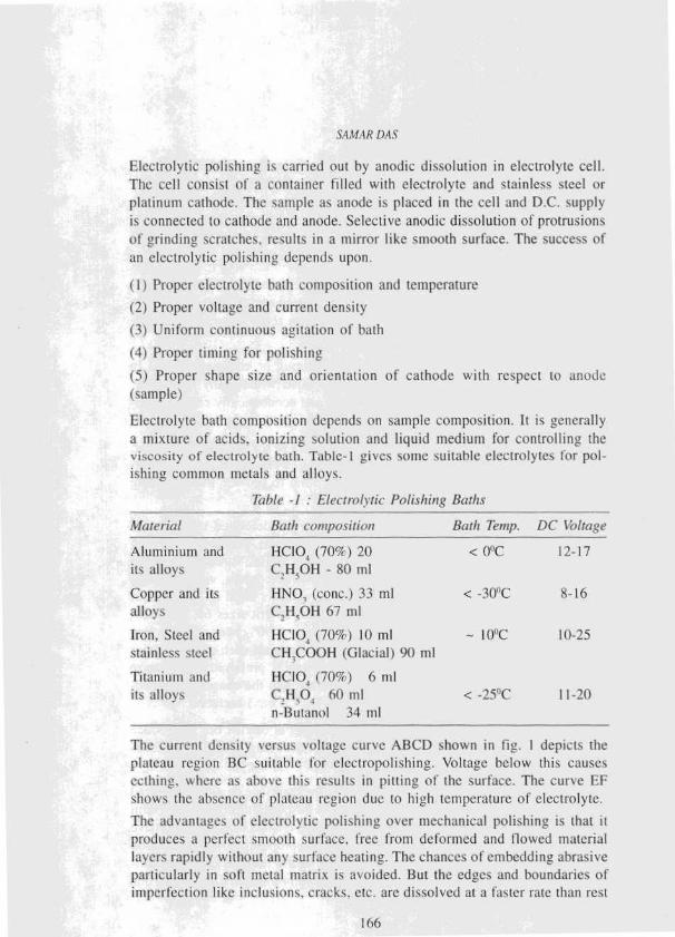
Electrolytic polishing is carried out by anodic dissolution in electrolyte cell.
The cell consist of it container filled with electrolyte and stainless steel or
platinum cathode. The sample as anode is placed in the cell and D.C. supply
is connected to cathode and anode. Selective anodic dissolution of protrusions
of urindin2 scratches. results in a mirror like smooth surface. The success of
an electrolytic polishing depends upon.
(I) Proper electrolyte bath composition and temperature
(2) Proper voltage and current density
(3) Uniform continuous agitation of bath
(4) Proper timing for polishing
(5) Proper shape size and orientation of cathode with respect to anode
(sample)
Electrolyte bath composition depends on sample composition . It is generally
a mixture of acids, ionizing solution and liquid medium for controlling the
viscosity of elccuolyte bath . Table- I gives some suitable electrolytes f or pol-
ishing common metals and alloys.
Table -/ : Electrolytic Polishing Baths
Material
Aluminium and
its alloys
Copper and its
alloys
Iron. Steel and
stainless steel
Titanium and
its alloys
Bath composition Bath Temp. DC Voltage
HCIO4 (70%) 20
(', H.OH - 80 nil
< 0°C 12-17
HNO1 (cone.) 33 ml < -30°C 8-16
C,1-1.01-1 67 nil
IICIO, (70%) 10 ml
C'H.0OOH (Glacial) 9t) nil
HCIO, (70%) 6 nil
- I0°C 10-25
C,H,O1 60 nil
n-Butanol 34 nil
< -25"C 11-20
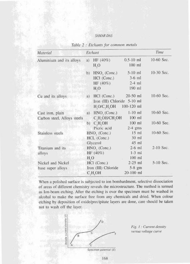
The current density versus voltage curve ABCD shown in fig. I depicts the
plateau region BC suitable for elect ropolishing . Voltage below this causes
ecthing, where as above this results in pitting of the surface . The curve EF
shows the absence of plateau region due to high temperature of electrolyte.
The advantages of electrolytic polishing over mechanical polishing is that it
produces it perfect smooth surface, free from deformed and flowed material
lavers rapidly without any surface heating . The chances of embedding abrasive
particularly in soft metal matrix is avoided . But the edges and boundaries of
imperfection like inclusions . cracks. etc. are dissolved at a faster rate than rest
106
SA;tMAR DAS
of the matrix causing artefacts . The reaction products sometimes adhere to thesurface which are difficult to remove by washing . Immediate washing the
surface in running water and drying with alcohal is necessary to avoid further
chemical attack and to produce a spotless reflectin g surface.
Etching : Features, such as, pores. pits . cracks , inclusions and relief formation
due to difference in hardness are visible in optical microscope in the as polished
sample. But other microstructural details, such as. grain boundary. precipitate,
etc., are revealed on the polished surface by a technique called etching. For
metals and alloys three different types of etching employed are ( i) Optical etch-
ing (ii) ChemicalfElectrochemical etching and (iii) Physical etching.
Optical etching : Special optical techniques , such as, Dark field illumination,
Phase contrast microscopy . Polarization microscopy and Interferrence micros-
copy are employed to make the microstructural features visible under a micro-
scope . Further treatment of polished surface are not generally required, but the
microscope must have the capability to adopt the special illumination and
compension techniques.
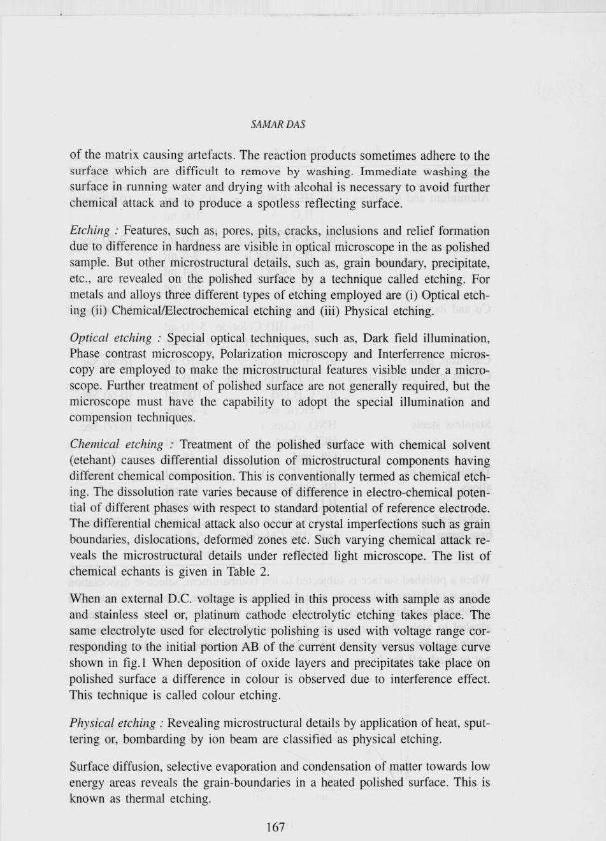
Chemical etching : Treatment of the polished surface with chemical solvent
(etehant) causes differential dissolution of microstructural components having
different chemical composition. This is conventionally termed as chemical etch-
ing. The dissolution rate varies because of difference in electro-chemical poten-
tial of different phases with respect to standard potential of reference electrode.
The differential chemical attack also occur at crystal imperfections such as grain
boundaries, dislocations, deformed zones etc. Such varying chemical attack re-
veals the microstructural details under reflected light microscope. The list of
chemical echants is given in Table 2.
When an external D.C. voltage is applied in this process with sample as anode
and stainless steel or, platinum cathode electrolytic etching takes place. The
same electrolyte used for electrolytic polishing is used with voltage range cor-
responding to the initial portion AB of the current density versus voltage curve
shown in fig.l When deposition of oxide layers and precipitates take place on
polished surface a difference in colour is observed due to interference effect.
This technique is called colour etching.
Plivsical etching : Revealing microstructural details by application of heat, sput-
tering or, bombarding by ion beam are classified as physical etching.
Surface diffusion, selective evaporation and condensation of matter towards low
energy areas reveals the grain-boundaries in a heated polished surface. This is
known as thermal etching.
167
S,Lt/AK DAS
7nble 2 : Ftcl ►onts for common metals
Material Etcl►a ► t Time
Aluminium and its alloys a) HF (40`7)
H,O
0.5-10 nil
1(X) ml
10-60 Sec.
h) HNO, (Conc.) 5-10 nil I0-30 Sec.
HCI (Conc.) 3-6 mlHF (409() 2-4 nil
H,O 190 nil
Cu and its alloys a) HCl (Conc.) 20-50 ml
Iron (III) Chloride 5-10 nil
10-60 Sec.
H,O/C.H4OH 100-120 nil
Cast iron. plain a) HNO. (Conc.) 1-10 ml 10-60 Sec.
Carbon steel. Alloys steels CH,OH/CH, )H 100 nil
h) C,H,OHPicric acid
I(X) ml
2-4 gals
10-60 Sec.
Stainless steels IINO_ (Conc.)
HCL (Conc.)
15 nil
3(1 nil
10-60 Sec.
Glycerol 45 ml
Titanium and its
alloys
HNO, (Conc.)
[if: (40c%)
H,O
2-6 ml
1-3 nil
1(X) nil
2-10 Sec.
Nickel and Nickel
base super alloys
HCI (Conc.)
Iron (III) Chloride
2-25 ml
5-8 gnu
5-10 Sec.
C,H_OH 20-100 ml
When a polished surface is subjected to ion bombardment, selective dissociation
of areas of different chemistry reveals the microstructure . The method is termed
as Ion - beam etching . After the etching is over the specimen must he washed in
alcohol to make the surface free from any chemicals and dried . When colour
etching by deposition of oxide/precipitate layers are done, care should be taken
not to wash off the layer.
Fig. / : (Brunt density
versus 1'ol!Ut;e cu; t'e
a
108
S MAR DA.S
SAMPLE PREPARATION FOR SCANNING ELECTRONMICROSCOPY (SEM)
Scanning electron microscopes are extensively used for
i) Fracture Study
ii) Microstructural study
iii) Study of shape and size of powder particles and
iv) Study of replicas
For fractography the sample is cut to suit the specimen holder. Care must be
taken not to alter the fractured surface during cutting. It is then cleaned with
some solvents e.g., alcohal, etc. to remove dust, oil, greaae or, any extraneous
material. Use of ultrasonic cleaner gives a better cleaning. If the sample is a
non-conductor , it is made conductive by coating the surface with carbon or
gold using vacuum /sputter coater. It is then screwed to the sample holder
without touching the fractured surface. if necessary elecrical conductivity be-
tween coating surface and holder is made by applying conductive carbon or
silver paste.
For microstructural study . if the sample size is large a smaller representative
sample is cut by some suitable method . In case of very small samples conduc-
tive mount can he made using resins with metal fillers. The sample is then
ground and polished to obtain a flat polished surfaces are. Details like, pores,
microcracks, cavities and inclusions can be observed in the as polished
sample . As polished surface can also examined in SEM backscattcred mode to
get a compositional variation contrast.
The methods described in optical specimen preparation for mounting . grinding
and polishing are also applied for SEM specimen preparation. Since an
electropolished surface is free from deformed and flowed material layer, this
method is preferred to manual polishing methods.
For microstructural examination using SEM secondary emission mode , the pol-
ished surface is a etched either chemically or electrolytically in a similar manner as
in case of optical microscopy. A deeper or stronger etch gives a better contrast.
If in-situ replicas are to he observed in scanning electron microscop, the replica is
cut to a suitable size by sharp scissors or scalpel blades and fixed onto a SEM stub,
with the replicated surface upwards . A thin uniform conductive coating on the sur-
face is necessary to avoid charging during observaton in SEM.
Powder particle specimens are made by dispersing a small quantity of powder in an
unreactive solvent using an ultrasonic vibrator. One or. two drops of suspension is
dropped on a clean glass slide and the solvent is allowed to evaporate. A piece of
169
S.I t 1 I R D..S
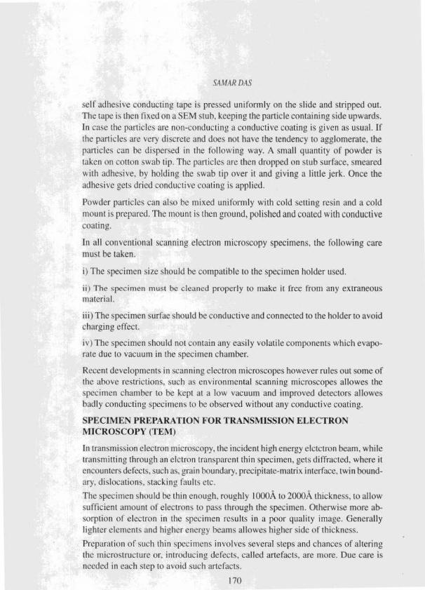
self adhesive conducting tape is pressed uniformly on the slide and stripped out.
The tape is then fixed on a SEM stub, keeping the particle containing side upwards.
In case the particles are non-conducting a conductive coating is given as usual. If
the particles are very discrete and does not have the tendency to agglomerate, the
particles can he dispersed in the following way. A small quantity of powder is
taken on cotton swab tip. The particles are then dropped on stub surface , smeared
with adhesive, by holding the swab tip over it and giving a little jerk. Once the
adhesive gets dried conductive coating is applied.
Powder particles can also be mixed uniformly with cold setting resin and a coldmount is prepared . The mount is then ground, polished and coated with conductivecoating.
In all conventional scanning electron microscopy specimens , the following caremust he taken.
i) The specimen size should he compatible to the specimen holder used.
ii) The specimen must he cleaned properly to make it free from any extraneousmaterial.
iii) The specimen surfac should he conductive and connected to the holder to avoid
charging effect.
iv) The specimen should not contain any easily volatile components which evapo-
rate due to vacuum in the specimen chamber.
Recent developments in scanning electron microscopes however rules out some of
the above restrictions , such as environmental scanning microscopes allowes the
specimen chamber to he kept at a low vacuum and improved detectors allowes
badly conducting specimens to be observed without any conductive coating.
SPECIMEN PREPARATION FORTRANSMISSION ELECTRON
MICROSCOPY (TE\I)
In transmission electron microscopy , the incident high energy elctctron beam, whiletransmitting through an elctron transparent thin specimen , gets diffracted , where it
encounters defects, such as, grain boundary. precipitate-matrix interface, twin bound-
ary, dislocations, stacking faults etc.
The specimen should he thin enough. roughly I000A to 2000A thickness, to allow
sufficient amount of electrons to pass through the specimen. Otherwise more ab-
sorption of electron in the specimen results in a poor quality image. Generally
lighter elements and higher energy beams allowes higher side of thickness.
Preparation of such thin specimens involves several steps and chances of altering
the microstructure or. introducing defects, called artefacts . are store . Due care is
needed in each step to avoid such artefacts.
170
SA,tMAR 1).4S
Among the three types , namely, thin film, thin foil and replica, of transmissionelectron microscopy specimens . thin foils and replicas arc widely used for metal-lographic study.
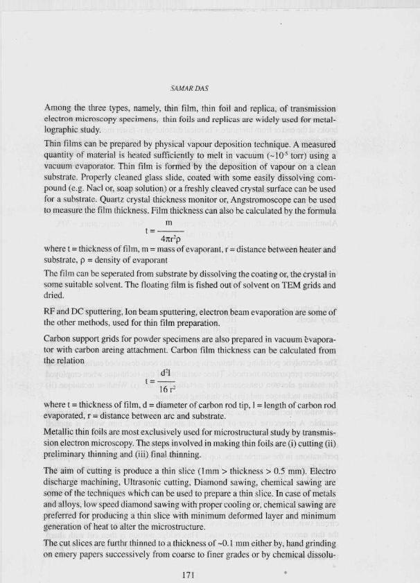
Thin films can he prepared by physical vapour deposition technique. A measured
quantity of material is heated sufficiently to melt in vacuum (- 10` torr ) using avacuum evaporator . Thin film is formed by the deposition of vapour on a cleansubstrate . Properly cleaned glass slide, coated with some easily dissolving com-pound (e.g. lsiacl or, soap solution ) or a freshly cleaved crystal surface can he usedfor a substrate . Quartz crystal thickness monitor or, Angstromoscope can be used
to measure the film thickness. Film thickness can also he calculated by the formula
mt=
4nr'pwhere t = thickness of film, m = mass of evaporant, r = distance between heater and
substrate, p = density of evaporant
The film can be seperated from substrate by dissolving the coating or, the crystal in
some suitable solvent. The floating film is fished out of solvent on TEM grids and
dried.
RF and DC sputtering, Ion beam sputtering, electron beam evaporation are some of
the other methods , used for thin film preparation.
Carbon support grids for powder specimens are also prepared in vacuum evapora-tor with carbon arcing attachment . Carbon film thickness can he calculated fromthe relation
td'1
16 r'
where t = thickness of film, d = diameter of carbon rod tip, I = length of carbon rod
evaporated, r = distance between arc and substrate.
Metallic thin foils are most exclusively used for microstructural study by transmis-
sion electron microscopy. The steps involved in making thin foils are (i) cutting (ii)
preliminary thinning and (iii) final thinning.
The aim of cutting is produce a thin slice (1 mm > thickness > 0.5 mm). Electro
discharge machining, Ultrasonic cutting, Diamond sawing, chemical sawing are
some of the techniques which can be used to prepare a thin slice. In case of metals
and alloys, low speed diamond sawing with proper cooling or, chemical sawing are
preferred for producing a thin slice with minimum deformed laver and minimum
generation of heat to alter the microstructure.
The cut slices arc furthr thinned to a thickness of -0. I mm either by, hand grinding
on emery papers successively from coarse to finer grades or by chemical dissolu-
171
SA,b/AR DAS
Lion by dipping in suitable chemicals Table 3 gives some chemical solutions for a
few common metals. Other chemical solutions can be found from the reference
hooks at the end or from literature. Chemical dissolution is faster method but chances
of forming pits are more. Alternate use of chemical dissolution and hand grinding
produces better result in less time. Preliminary thinning is carried out till the thick-
ness reaches nearly 0.1 nun. The thin slice is then cleaned properly and subjected
to electrolytic polishing for final thinning.
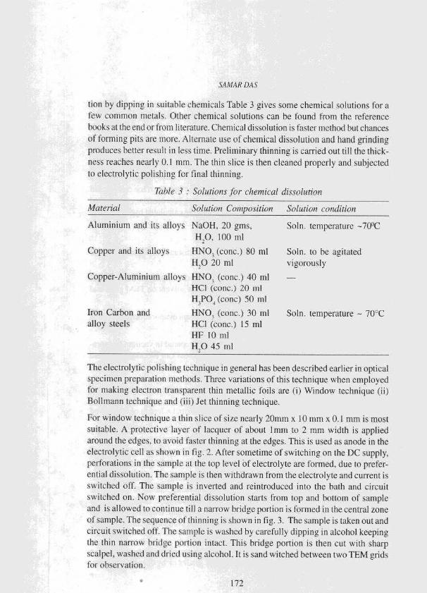
Table 3 : Solutions for chentical dissolution
Material Solution Composition Solution condition
Aluminium and its alloys NaOH, 20 gms, Soln. temperature -70°C
H,O1 100 ml
Copper and its alloys HNO, (conc.) 80 ml Solo. to he agitated
H,O 20 ml vigorously
Copper-Aluminium alloys HNO, (conc.) 40 ml -
HCI (conc.) 20 nil
H,PO, (cone) 50 ml
Iron Carbon and HNO, (conc.) 30 ml Soln. temperature - 70°Calloy steels HCl (conc.) 15 nil
HF 10 nil
11,0 45 ml
The electrolytic polishing technique in general has been described earlier in optical
specimen preparation methods. Three variations of this technique when employed
for making electron transparent thin metallic foils are (i) Window technique (ii)
Bollmann technique and (iii) Jet thinning technique.
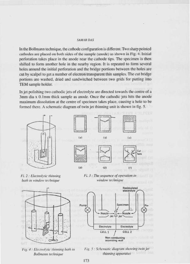
For window technique a thin slice of size nearly 20mm x 10 mm x 0.1 mm is most
suitable. A protective layer of lacquer of about 1mm to 2 mm width is applied
around the edges, to avoid faster thinning at the edges. This is used as anode in the
electrolytic cell as shown in fig. 2. After sometime of switching on the DC supply,
perforations in the sample at the top level of electrolyte are formed, due to prefer-
ential dissolution. The sample is then withdrawn from the electrolyte and current is
switched off. The sample is inverted and reintroduced into the bath and circuit
switched on. Now preferential dissolution starts from top and bottom of sample
and is allowed to continue till a narrow bridge portion is formed in the central zone
of sample. The sequence of thinning is shown in fig. 3. The sample is taken out and
circuit switched oft. The sample is washed by carefully dipping in alcohol keeping
the thin narrow bridge portion intact. This bridge portion is then curt with sharp
scalpel, washed and dried using alcohol. It is sand witched between two TEM grids
for observation.
172
S.4M.4R DA-S
In the Bollmann technique, the cathode configuration is different. Two sharp pointed
cathodes are placed on both sides of the sample (anode) as shown in Fig. 4. Initial
perforation takes place in the anode near the cathode tips. The specimen is then
shifted to form another hole in the nearby region. It is repeated to form several
holes around the initial perforation and the bridge portions between the holes are
cut by scalpel to get a number of electron transparent thin samples. The cut bridge
portions are washed, dried and sandwitched between two grids for putting into
TEM sample holder.
In jet polishing two cathodic jets of electrolyte are directed towards the centre of a
3mm dia x 0.1 mm thick sample as anode. Once the cathodic jets hits the anode
maximum dissolution at the centre of specimen takes place, causing a hole to be
formed there. A schematic diagram of twin jet thinning unit is shown in fig. 5.
+i
Fi. 2 : LYectrohvic thinningbath in window technique
(al
(J!
(b)
ic)
(c)
Fi. 3: The sequence of operation in
window tecluligc«'
Recirculatedelectrolyte r\
I-i,c. 4 : LIec n ,hrie thinning bath tit
Pump
4N to zzzze-.Jet
Electrolyte
CELL 1 I CELL 2
Non-conductingseparating wall
Specimen
rNozzle
'Jett
Elecuolyte 1
1-ig. 5 :.Sclreiuaic diagram Showin g twirl jet
Rolhnann technique thinning apparatus
173
£4 ti,4k DAS
A 3 mm disc punched out of preliminary thinned slice is cleaned and put into the
anode holder. The anode holder is then slid into the jet chamber and electrolyte is
pumped into the side chambers. The electrolyte passes through the small holes
with cathodic connections. as jets and hit the sample centre from both side. Either
a light source and photocell detector or Infra red source and IR detector placed on
both sides of the samppy detects any small perforation in the anode and automati-
cally switches off the circuit and gives alarm to the operator. After repeated clean-
ing in ethanol and drying. the sample can he directly put in the TEM holder without
any support grid.
Due to action of both jets a double concave type contour is formed in the central
zone of anode disc and ultimately forms the perforation. The areas around the edges
of this central perforation contain electron transparent thin areas.
REPLICA PREPARATION METHODS
Replicas are used generally for
i) In-situ mctallography, where the specimen is not allowed to cut for sonicreason.
ii) Characterisation of precipitates by energy-dispersive X-ray analysis and elec-tron diffraction without the matrix interference.
iii) Very high resolution surface study.
iv) Studying electron beam sensitive materials
Replicas can he of mainly three types
i) Single stage or positive replica
ii) Double stage or. negative replica
iii) Extraction replica
Single stage replicas are conveniently prepared by pressing uniformly a cellulose
acetate tape, moistened with solvent (acetone/chloroform) on the fractured or
polished and etched surface. After drying the tape is peeled off from the surface.
To avoid deformation of the replica during peeling, chemical or, electrolytic
dissolution of the material surface can also he applied. The contrast of replica is
enhanced by depositing gold or heavy metal on the replica surface, containing
the details, at a shallow angle. This is known as shadowing. These replicas are
termed as negative replicas because the object details such as hills and valleys
appears as valleys and hills respectively.
In double stage replicating, the replica surface is coated with carbon using vacuum
evaporator and then the cellulose acetate tape is dissolved in a solvent. The
carbon replica floating on the solvent is washed carefully in some fresh solvent
and fished out on TEM support grids.
174
.S,4;t1.4 R DAS
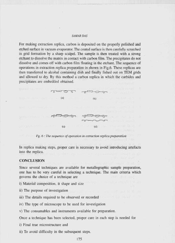
For making extraction replica, carbon is deposited on the properly polished and
etched surface in vacuum evaporator. The coated surface is then carefully scratched
in grid formation by a sharp scalpel. The sample is then treated with a strong
etchant to dissolve the matrix in contact with carbon film. The precipitates do not
dissolve and comes off with carbon film floating in the etchant. The sequence of
operations in extraction replica preparation in shown in Fig.6. These replicas are
then transferred to alcohal containing dish and finally fished out on TEM grids
and allowed to dry. By this method a carbon replica in which the carbides and
precipitates are embedded obtained.
-o-= -<:::-Z'^
Fg. 6 : The sequence of operation in extraction replica preparation
In replica making steps, proper care is necessary to avoid introducing artefacts
into the replica.
CONCLUSION
Since several techniques are available for metallographic sample preparation,
one has to he very careful in selecting a technique. The main criteria which
governs the choice of a technique are
i) Material composition, it shape and size
ii) The purpose of investigation
iii) The details required to he observed or recorded
iv) The type of microscope to be used for investigation
v) The consumables and instruments available for preparation.
Once a technique has been selected, proper care in each step is needed for
i) Final true microstructure and
ii) To avoid difficulty in the subsequent steps.
175
SA MAR DAS
REFERENCES
1. ASTM Standards. Standard Methods of Preparing Metallographic specimens,E-3-86.American Soc. for Metals, Vol. (03.01). 1986.
2. C. F Vander Voort. Metallography principles and Practice, MccGraw Hill BookCompany, 1984.
Gunter Petzow, Metallographic Etching, American Soc. for Metals, 1978.
4. K. C. Thompson, Russel and J. W. Edington, Ed. Practical Electron Microscopy inMaterials Science, Monograph 5. Mac Millan Philips Technical Library. Eindhoven,Netherlands, 1975.
5. Metals Handbook, Metallography, structures and phase Diagrams. American Societyfor Metals. Vol. 8. 8th edition. 1973.
6. J. L. McCall, W. Nl. Mueller. Ed ., Metallographic specimen Preparation , PlenumPress, New York 1971.
7. V. A. Philips. Modern Metallographic Techniques and Their Application, Willey InterScience. New York/London. 1971.
8. L. E. Samuels. Metallographic Polishing by Mechanical Methods. Pitman PublishingCorpn. London and Melbourne, 1971.
9. D. G. Brandon, Modern Techniques in Metallography. Butterworth Publishing Co..London, 1966.
10. ASTM Special Publication. Application of Modern Metallographic Techniques, No.480. Symposium. Philadeiphia, 1966.
11. P. B. Hirsch, A. Howic, R. 13. Nicholson, D. W. Pashley and M. J. Whelan, ElectronMicrosopy of Thin Crystals, Butterworths, London, 1965
12. C. Thomas. Transmission Electron Microscopy of Metals, John WIley and Sons, Inc..New York, 1962.
13. Mc.G. Tegart, The Electrolytic and chemical polishing of metals in Research andIndustry. Pergamon Press, London, 1959.
14. G. L. Kehl, The principles of Metallographic Lab Practice. McGraw Hill Book Co.New York, 1949.
15. P. J. Goodhew. Specimen Preparation in Materials Science, North Holland PublishingCo.
16. D. H. Kay. Techniques for Electron Microscopy. Blackwell
17. V. Valdre, Ed. Electron Microscopy in Materials Science, Academic Precs.
176
Related Documents