©2007 John Wiley & Sons, Inc. M P Groover, Fundamentals of Modern Manufacturing 3/e BULK DEFORMATION PROCESSES IN METALWORKING 1. Rolling 2. Other Deformation Processes Related to Rolling 3. Forging 4. Other Deformation Processes Related to Forging 5. Extrusion 6. Wire and Bar Drawing

Welcome message from author
This document is posted to help you gain knowledge. Please leave a comment to let me know what you think about it! Share it to your friends and learn new things together.
Transcript
©2007 John Wiley & Sons, Inc. M P Groover, Fundamentals of Modern Manufacturing 3/e
BULK DEFORMATION PROCESSES IN METALWORKING
1. Rolling
2. Other Deformation Processes Related to Rolling
3. Forging
4. Other Deformation Processes Related to Forging
5. Extrusion
6. Wire and Bar Drawing
©2007 John Wiley & Sons, Inc. M P Groover, Fundamentals of Modern Manufacturing 3/e
Bulk Deformation
Metal forming operations which cause significant shape change by deforming metal parts whose initial form is bulk rather than sheet
Starting forms: Cylindrical bars and billets, Rectangular billets and slabs, and similar
shapes These processes stress metal sufficiently to
cause plastic flow into desired shape Performed as cold, warm, and hot working
operations
©2007 John Wiley & Sons, Inc. M P Groover, Fundamentals of Modern Manufacturing 3/e
Importance of Bulk Deformation
In hot working, significant shape change can be accomplished
In cold working, strength is increased during shape change
Little or no waste - some operations are near net shape or net shape processes The parts require little or no subsequent
machining
©2007 John Wiley & Sons, Inc. M P Groover, Fundamentals of Modern Manufacturing 3/e
Four Basic Bulk Deformation Processes
1. Rolling – slab or plate is squeezed between opposing rolls
2. Forging – work is squeezed and shaped between opposing dies
3. Extrusion – work is squeezed through a die opening, thereby taking the shape of the opening
4. Wire and bar drawing – diameter of wire or bar is reduced by pulling it through a die opening
©2007 John Wiley & Sons, Inc. M P Groover, Fundamentals of Modern Manufacturing 3/e
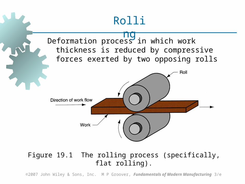
Deformation process in which work thickness is reduced by compressive forces exerted by two opposing rolls
Figure 19.1 The rolling process (specifically, flat rolling).
Rolling
©2007 John Wiley & Sons, Inc. M P Groover, Fundamentals of Modern Manufacturing 3/e
The Rolls
Rotating rolls perform two main functions: Pull the work into the gap between them by
friction between workpart and rolls Simultaneously squeeze the work to reduce its
cross section
©2007 John Wiley & Sons, Inc. M P Groover, Fundamentals of Modern Manufacturing 3/e
Types of Rolling
Based on workpiece geometry : Flat rolling - used to reduce thickness of
a rectangular cross section Shape rolling - square cross section is
formed into a shape such as an I‑beam Based on work temperature :
Hot Rolling – most common due to the large amount of deformation required
Cold rolling – produces finished sheet and plate stock
©2007 John Wiley & Sons, Inc. M P Groover, Fundamentals of Modern Manufacturing 3/e
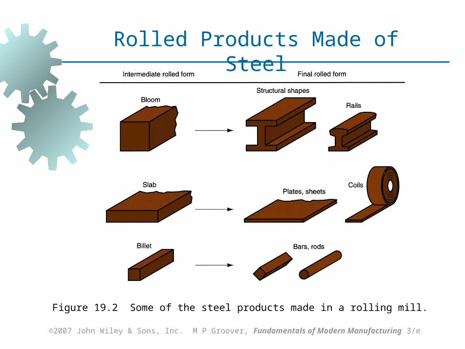
Figure 19.2 Some of the steel products made in a rolling mill.
Rolled Products Made of Steel
©2007 John Wiley & Sons, Inc. M P Groover, Fundamentals of Modern Manufacturing 3/e
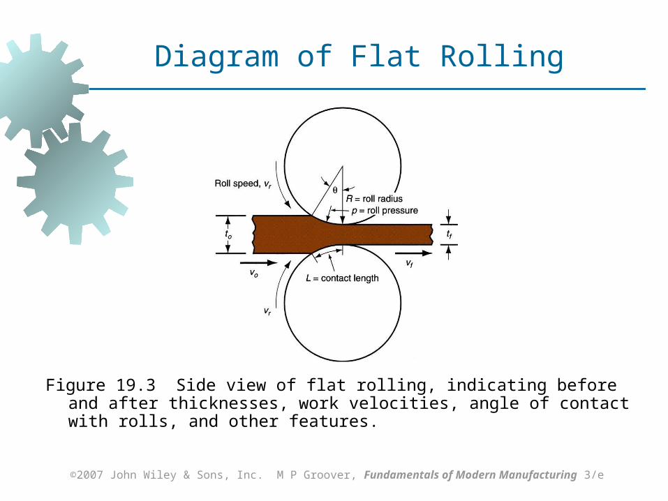
Figure 19.3 Side view of flat rolling, indicating before and after thicknesses, work velocities, angle of contact with rolls, and other features.
Diagram of Flat Rolling
©2007 John Wiley & Sons, Inc. M P Groover, Fundamentals of Modern Manufacturing 3/e
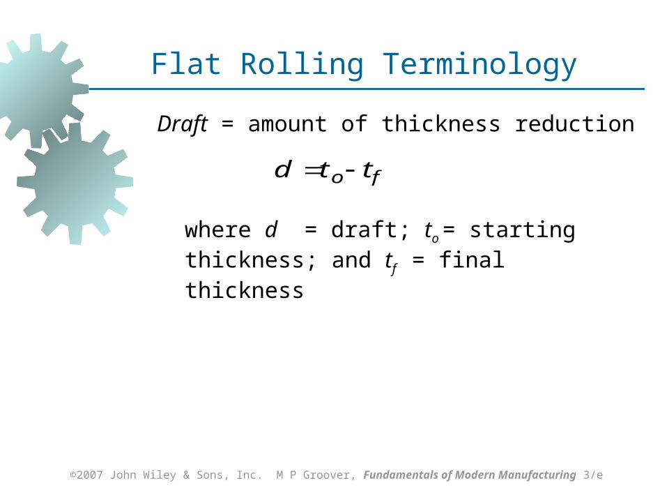
Flat Rolling Terminology
Draft = amount of thickness reduction
fo ttd
where d = draft; to = starting thickness; and tf = final thickness
©2007 John Wiley & Sons, Inc. M P Groover, Fundamentals of Modern Manufacturing 3/e
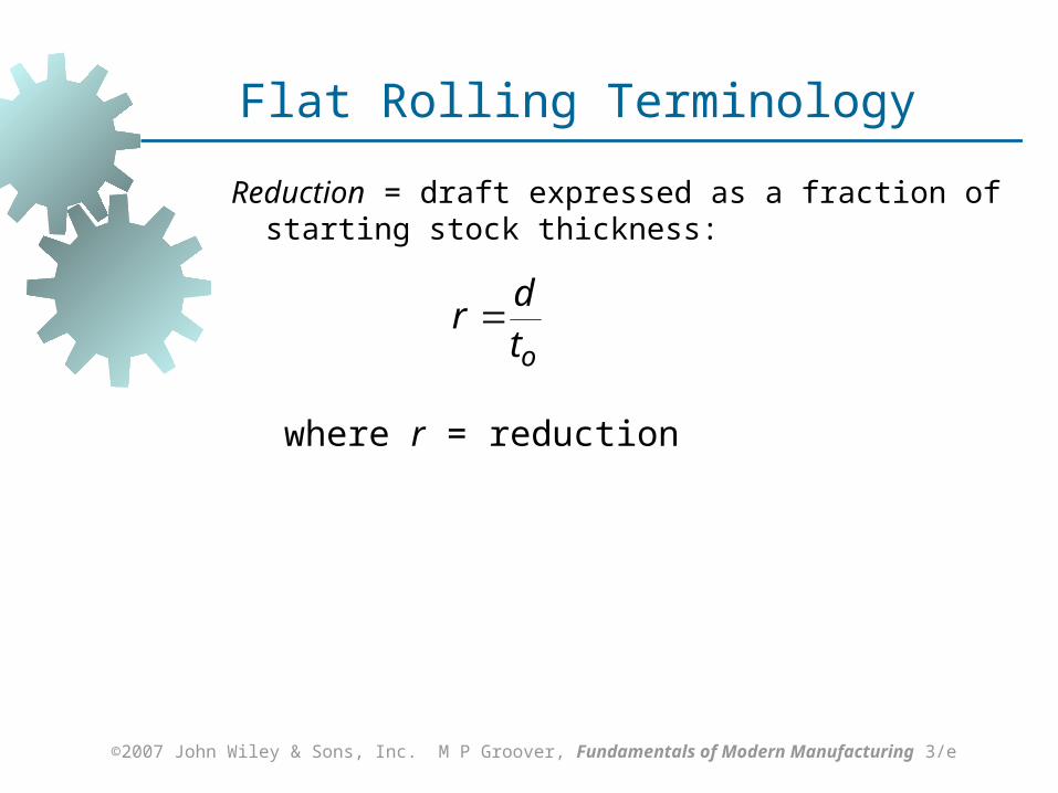
Flat Rolling Terminology
Reduction = draft expressed as a fraction of starting stock thickness:
otd
r
where r = reduction
©2007 John Wiley & Sons, Inc. M P Groover, Fundamentals of Modern Manufacturing 3/e
Shape Rolling
Work is deformed into a contoured cross section rather than flat (rectangular)
Accomplished by passing work through rolls that have the reverse of desired shape
Products include: Construction shapes such as I‑beams,
L‑beams, and U‑channels Rails for railroad tracks Round and square bars and rods
©2007 John Wiley & Sons, Inc. M P Groover, Fundamentals of Modern Manufacturing 3/e
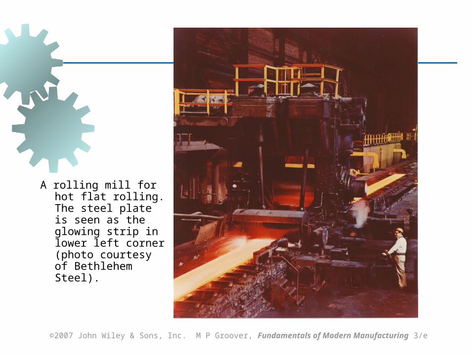
A rolling mill for hot flat rolling. The steel plate is seen as the glowing strip in lower left corner (photo courtesy of Bethlehem Steel).
©2007 John Wiley & Sons, Inc. M P Groover, Fundamentals of Modern Manufacturing 3/e
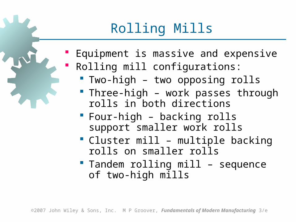
Rolling Mills
Equipment is massive and expensive Rolling mill configurations:
Two-high – two opposing rolls Three-high – work passes through rolls in
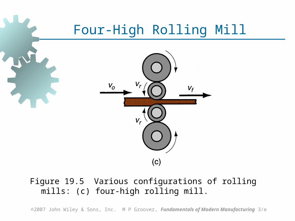
both directions Four-high – backing rolls support smaller
work rolls Cluster mill – multiple backing rolls on
smaller rolls Tandem rolling mill – sequence of two-high
mills
©2007 John Wiley & Sons, Inc. M P Groover, Fundamentals of Modern Manufacturing 3/e
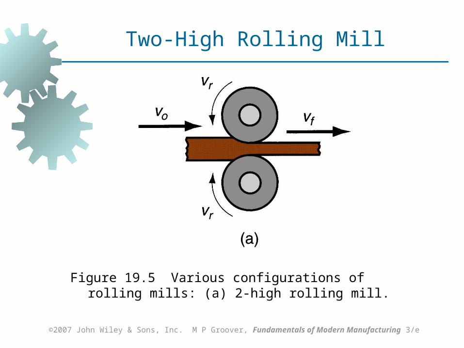
Figure 19.5 Various configurations of rolling mills: (a) 2‑high rolling mill.
Two-High Rolling Mill
©2007 John Wiley & Sons, Inc. M P Groover, Fundamentals of Modern Manufacturing 3/e
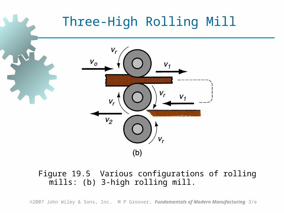
Figure 19.5 Various configurations of rolling mills: (b) 3‑high rolling mill.
Three-High Rolling Mill
©2007 John Wiley & Sons, Inc. M P Groover, Fundamentals of Modern Manufacturing 3/e
Figure 19.5 Various configurations of rolling mills: (c) four‑high rolling mill.
Four-High Rolling Mill

©2007 John Wiley & Sons, Inc. M P Groover, Fundamentals of Modern Manufacturing 3/e
Multiple backing rolls allow even smaller roll diameters
Figure 19.5 Various configurations of rolling mills: (d) cluster mill
Cluster Mill
©2007 John Wiley & Sons, Inc. M P Groover, Fundamentals of Modern Manufacturing 3/e
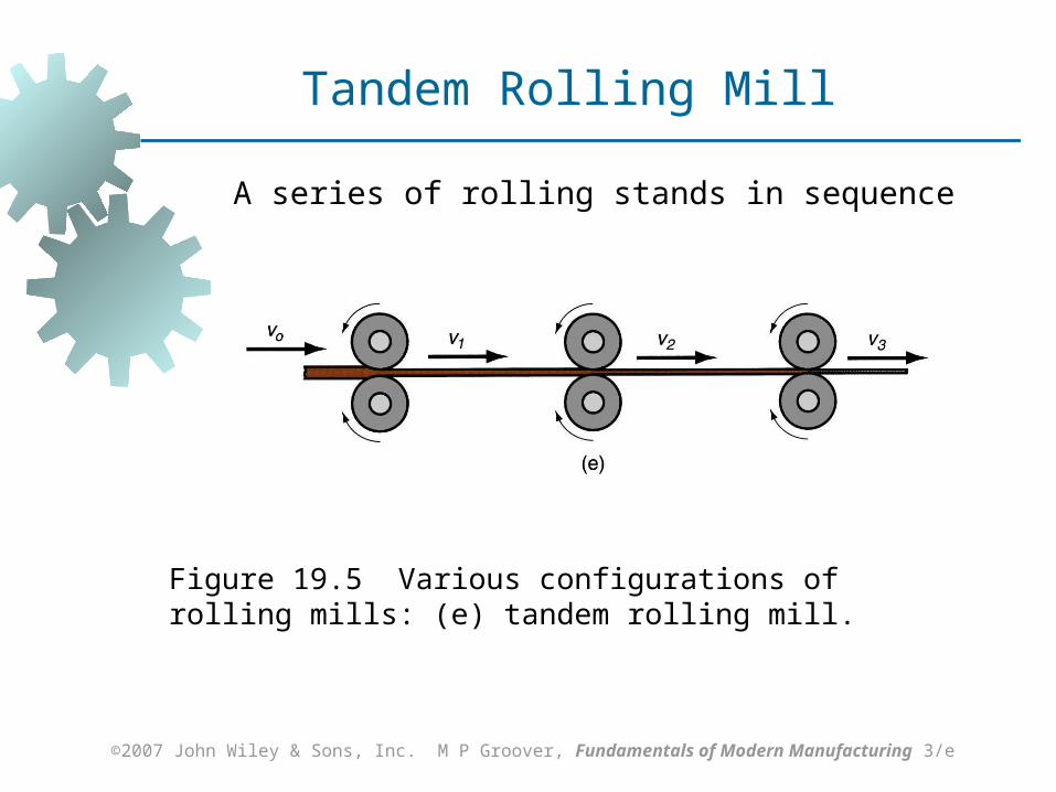
A series of rolling stands in sequence
Figure 19.5 Various configurations of rolling mills: (e) tandem rolling mill.
Tandem Rolling Mill
©2007 John Wiley & Sons, Inc. M P Groover, Fundamentals of Modern Manufacturing 3/e
Thread Rolling
Bulk deformation process used to form threads on cylindrical parts by rolling them between two dies
Important commercial process for mass producing bolts and screws
Performed by cold working in thread rolling machines
Advantages over thread cutting (machining): Higher production rates Better material utilization Stronger threads and better fatigue
resistance due to work hardening
©2007 John Wiley & Sons, Inc. M P Groover, Fundamentals of Modern Manufacturing 3/e
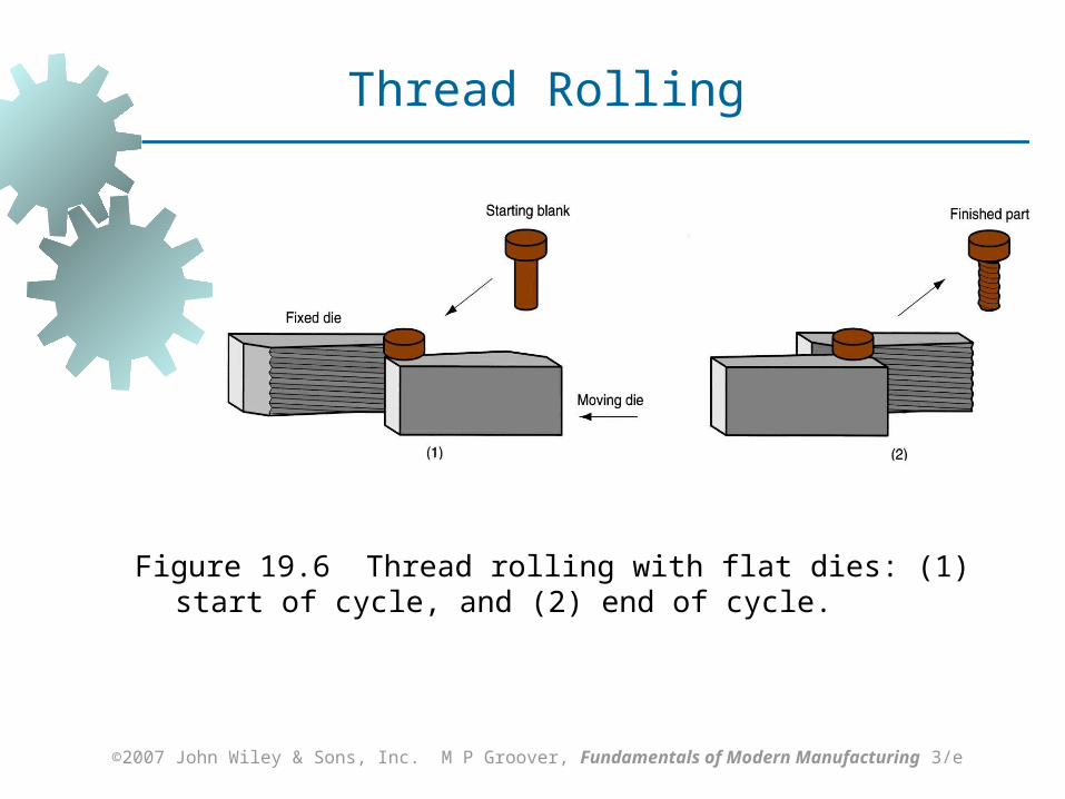
Figure 19.6 Thread rolling with flat dies: (1) start of cycle, and (2) end of cycle.
Thread Rolling
©2007 John Wiley & Sons, Inc. M P Groover, Fundamentals of Modern Manufacturing 3/e
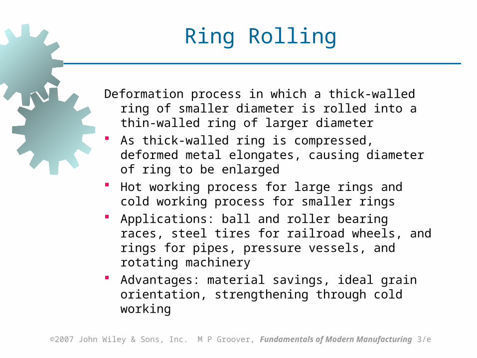
Ring Rolling
Deformation process in which a thick‑walled ring of smaller diameter is rolled into a thin‑walled ring of larger diameter
As thick‑walled ring is compressed, deformed metal elongates, causing diameter of ring to be enlarged
Hot working process for large rings and cold working process for smaller rings
Applications: ball and roller bearing races, steel tires for railroad wheels, and rings for pipes, pressure vessels, and rotating machinery
Advantages: material savings, ideal grain orientation, strengthening through cold working
©2007 John Wiley & Sons, Inc. M P Groover, Fundamentals of Modern Manufacturing 3/e
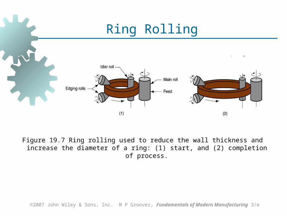
Figure 19.7 Ring rolling used to reduce the wall thickness and increase the diameter of a ring: (1) start, and (2) completion of process.
Ring Rolling
©2007 John Wiley & Sons, Inc. M P Groover, Fundamentals of Modern Manufacturing 3/e
Forging
Deformation process in which work is compressed between two dies
Oldest of the metal forming operations, dating from about 5000 B C
Components: engine crankshafts, connecting rods, gears, aircraft structural components, jet engine turbine parts
Also, basic metals industries use forging to establish basic form of large parts that are subsequently machined to final shape and size
©2007 John Wiley & Sons, Inc. M P Groover, Fundamentals of Modern Manufacturing 3/e
Classification of Forging Operations
Cold vs. hot forging: Hot or warm forging – most common, due
to the significant deformation and the need to reduce strength and increase ductility of work metal
Cold forging – advantage: increased strength that results from strain hardening
Impact vs. press forging: Forge hammer - applies an impact load Forge press - applies gradual pressure
©2007 John Wiley & Sons, Inc. M P Groover, Fundamentals of Modern Manufacturing 3/e
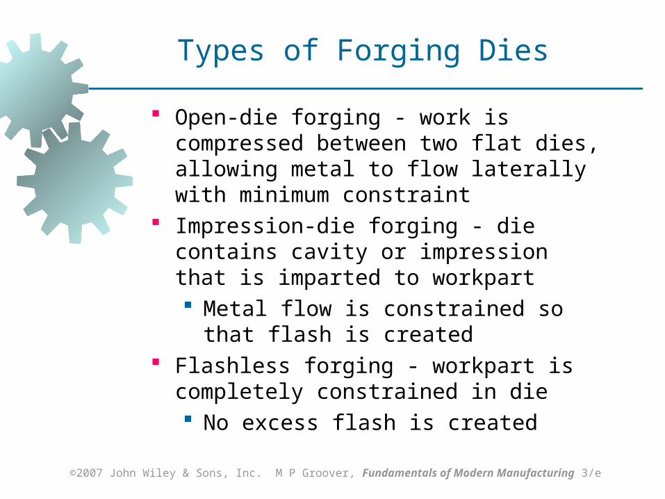
Types of Forging Dies
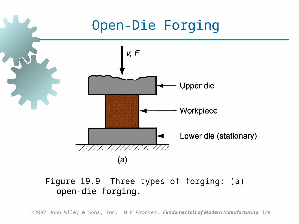
Open‑die forging - work is compressed between two flat dies, allowing metal to flow laterally with minimum constraint
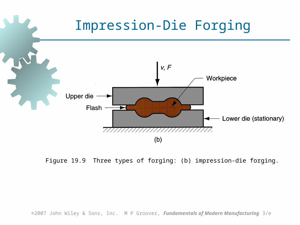
Impression‑die forging - die contains cavity or impression that is imparted to workpart Metal flow is constrained so that flash is
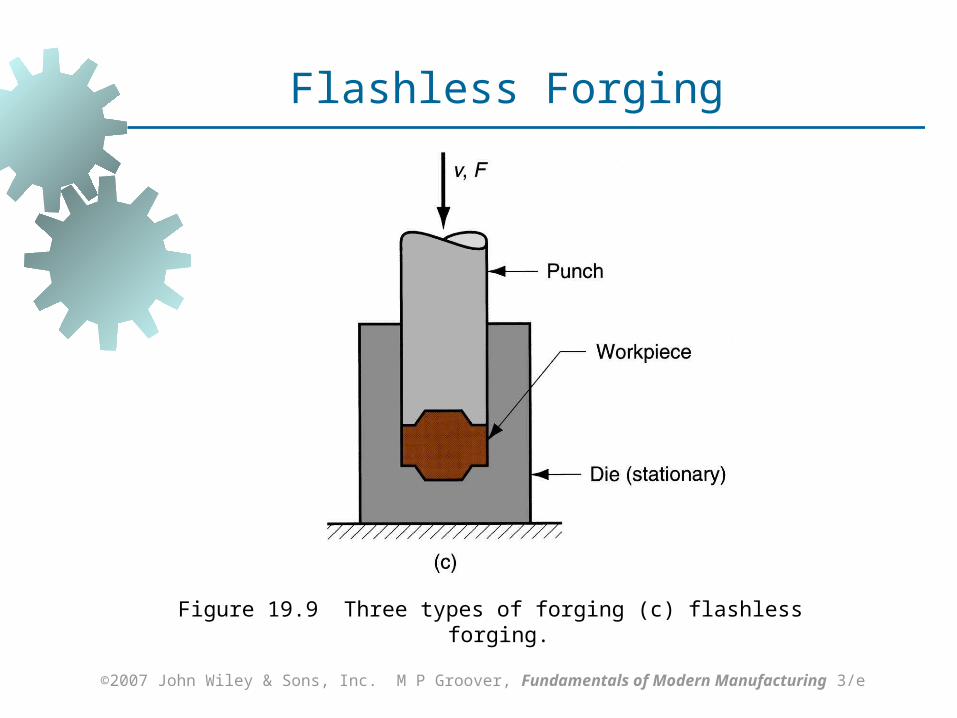
created Flashless forging - workpart is completely
constrained in die No excess flash is created
©2007 John Wiley & Sons, Inc. M P Groover, Fundamentals of Modern Manufacturing 3/e
Figure 19.9 Three types of forging: (a) open‑die forging.
Open-Die Forging
©2007 John Wiley & Sons, Inc. M P Groover, Fundamentals of Modern Manufacturing 3/e
Figure 19.9 Three types of forging: (b) impression‑die forging.
Impression-Die Forging
©2007 John Wiley & Sons, Inc. M P Groover, Fundamentals of Modern Manufacturing 3/e
Figure 19.9 Three types of forging (c) flashless forging.
Flashless Forging
©2007 John Wiley & Sons, Inc. M P Groover, Fundamentals of Modern Manufacturing 3/e
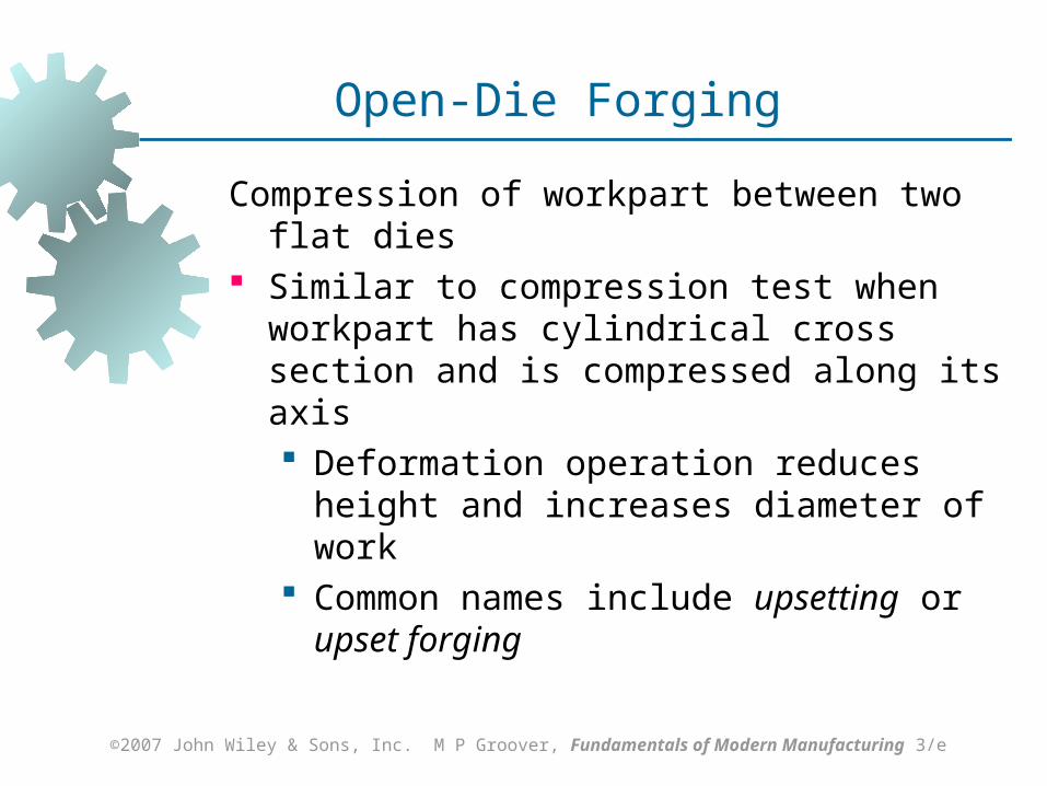
Open‑Die Forging
Compression of workpart between two flat dies Similar to compression test when workpart has
cylindrical cross section and is compressed along its axis Deformation operation reduces height and
increases diameter of work Common names include upsetting or upset
forging
©2007 John Wiley & Sons, Inc. M P Groover, Fundamentals of Modern Manufacturing 3/e
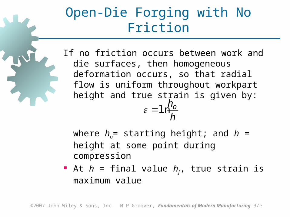
Open‑Die Forging with No Friction
If no friction occurs between work and die surfaces, then homogeneous deformation occurs, so that radial flow is uniform throughout workpart height and true strain is given by:
where ho= starting height; and h = height at some point during compression
At h = final value hf, true strain is maximum value
hholn

©2007 John Wiley & Sons, Inc. M P Groover, Fundamentals of Modern Manufacturing 3/e
Figure 19.10 Homogeneous deformation of a cylindrical workpart under ideal conditions in an open‑die forging operation: (1) start of process with workpiece at its original length and diameter, (2) partial compression, and (3) final size.
Open-Die Forging with No Friction
©2007 John Wiley & Sons, Inc. M P Groover, Fundamentals of Modern Manufacturing 3/e
Open-Die Forging with Friction
Friction between work and die surfaces constrains lateral flow of work, resulting in barreling effect
In hot open-die forging, effect is even more pronounced due to heat transfer at and near die surfaces, which cools the metal and increases its resistance to deformation
©2007 John Wiley & Sons, Inc. M P Groover, Fundamentals of Modern Manufacturing 3/e
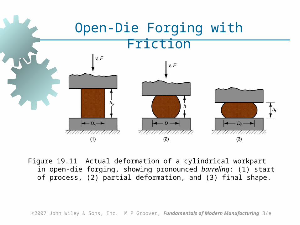
Figure 19.11 Actual deformation of a cylindrical workpart in open‑die forging, showing pronounced barreling: (1) start of process, (2) partial deformation, and (3) final shape.
Open-Die Forging with Friction
©2007 John Wiley & Sons, Inc. M P Groover, Fundamentals of Modern Manufacturing 3/e
Impression‑Die Forging
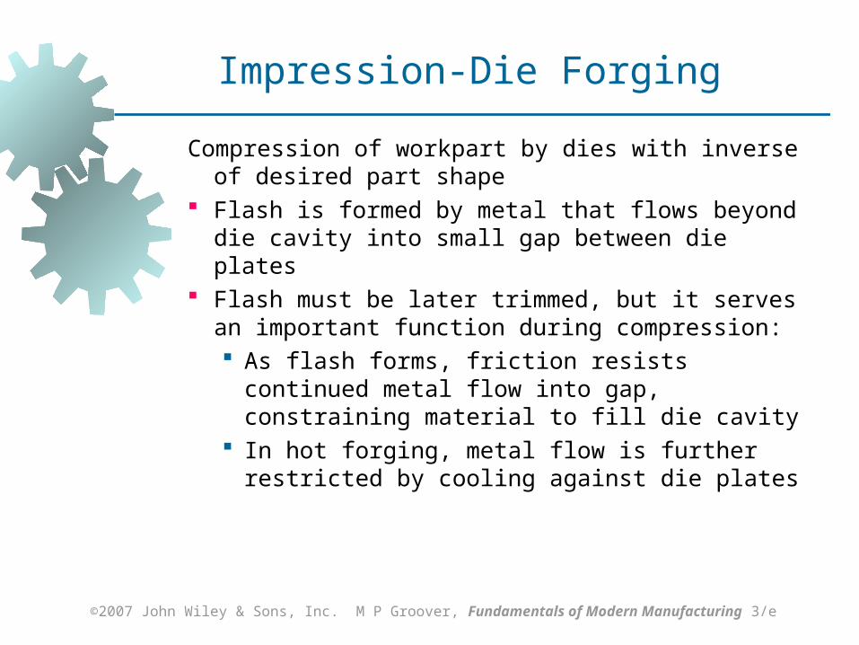
Compression of workpart by dies with inverse of desired part shape
Flash is formed by metal that flows beyond die cavity into small gap between die plates
Flash must be later trimmed, but it serves an important function during compression: As flash forms, friction resists continued
metal flow into gap, constraining material to fill die cavity
In hot forging, metal flow is further restricted by cooling against die plates
©2007 John Wiley & Sons, Inc. M P Groover, Fundamentals of Modern Manufacturing 3/e
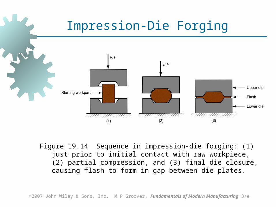
Figure 19.14 Sequence in impression‑die forging: (1) just prior to initial contact with raw workpiece, (2) partial compression, and (3) final die closure, causing flash to form in gap between die plates.
Impression-Die Forging
©2007 John Wiley & Sons, Inc. M P Groover, Fundamentals of Modern Manufacturing 3/e
Impression‑Die Forging Practice
Several forming steps often required, with separate die cavities for each step Beginning steps redistribute metal for more
uniform deformation and desired metallurgical structure in subsequent steps
Final steps bring the part to final geometry Impression-die forging is often performed
manually by skilled operator under adverse conditions
©2007 John Wiley & Sons, Inc. M P Groover, Fundamentals of Modern Manufacturing 3/e
Advantages and Limitations
Advantages of impression-die forging compared to machining from solid stock: Higher production rates Less waste of metal Greater strength Favorable grain orientation in the metal
Limitations: Not capable of close tolerances Machining often required to achieve
accuracies and features needed
©2007 John Wiley & Sons, Inc. M P Groover, Fundamentals of Modern Manufacturing 3/e
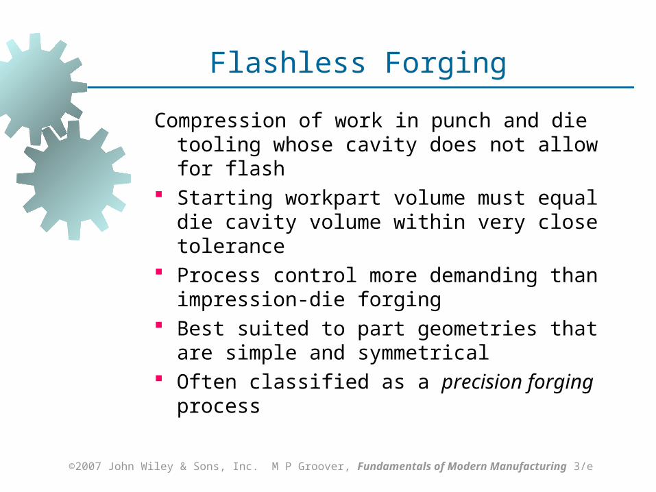
Flashless Forging
Compression of work in punch and die tooling whose cavity does not allow for flash
Starting workpart volume must equal die cavity volume within very close tolerance
Process control more demanding than impression‑die forging
Best suited to part geometries that are simple and symmetrical
Often classified as a precision forging process
©2007 John Wiley & Sons, Inc. M P Groover, Fundamentals of Modern Manufacturing 3/e
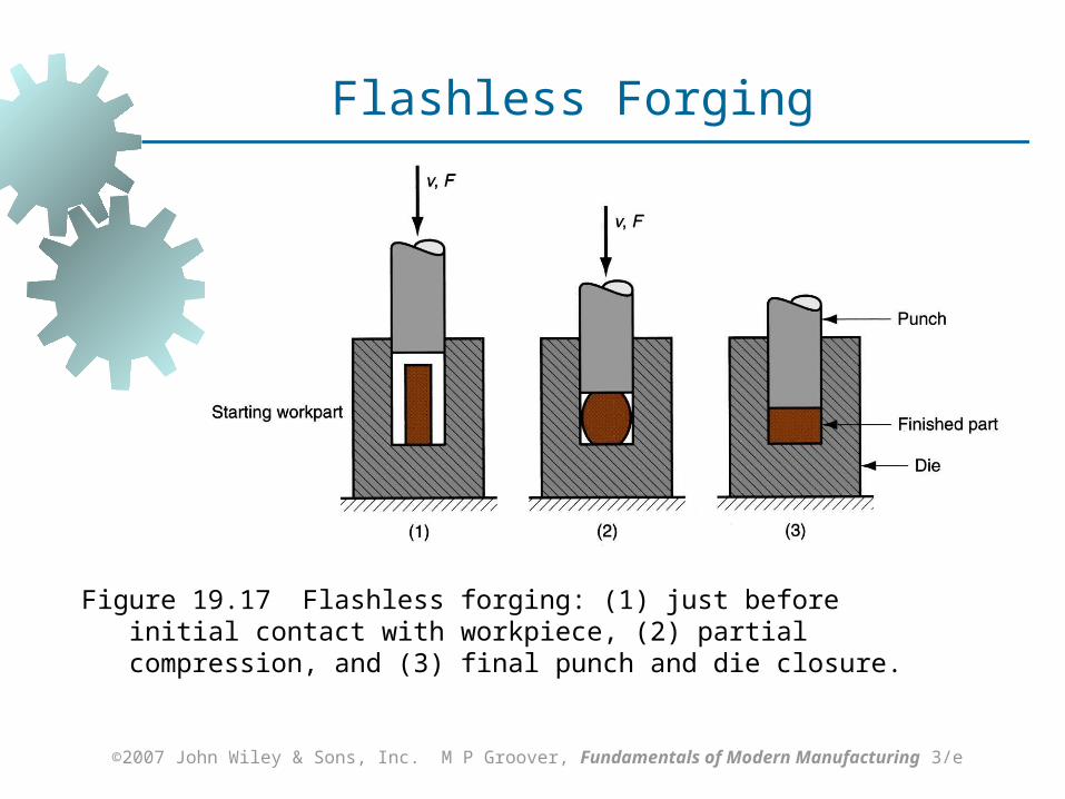
Figure 19.17 Flashless forging: (1) just before initial contact with workpiece, (2) partial compression, and (3) final punch and die closure.
Flashless Forging
©2007 John Wiley & Sons, Inc. M P Groover, Fundamentals of Modern Manufacturing 3/e
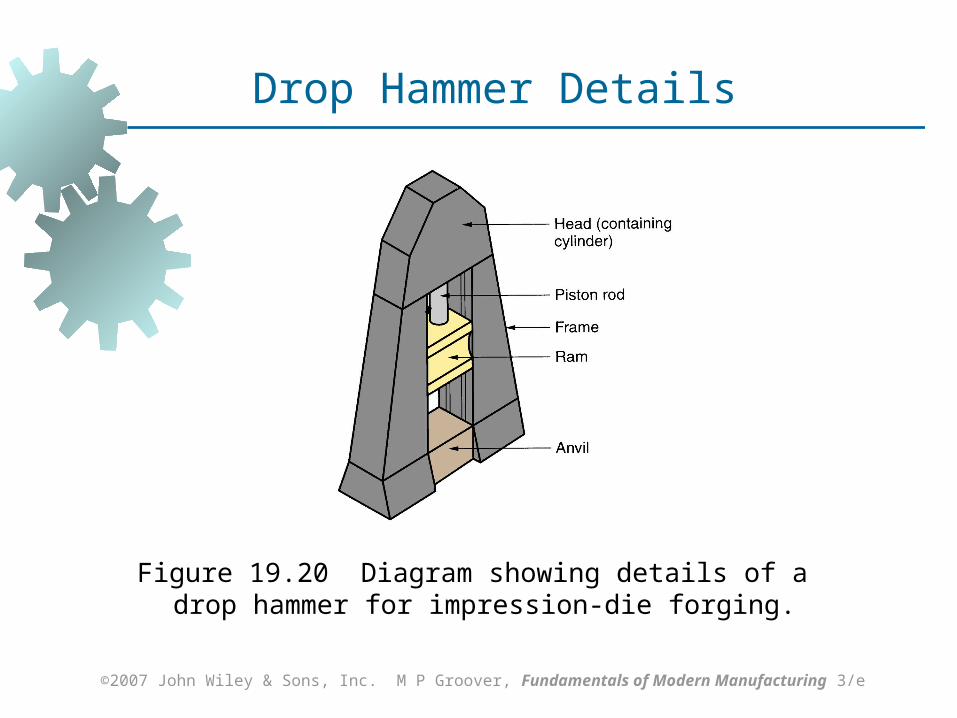
Forging Hammers (Drop Hammers)
Apply impact load against workpart Two types:
Gravity drop hammers - impact energy from falling weight of a heavy ram
Power drop hammers - accelerate the ram by pressurized air or steam
Disadvantage: impact energy transmitted through anvil into floor of building
Commonly used for impression-die forging
©2007 John Wiley & Sons, Inc. M P Groover, Fundamentals of Modern Manufacturing 3/e
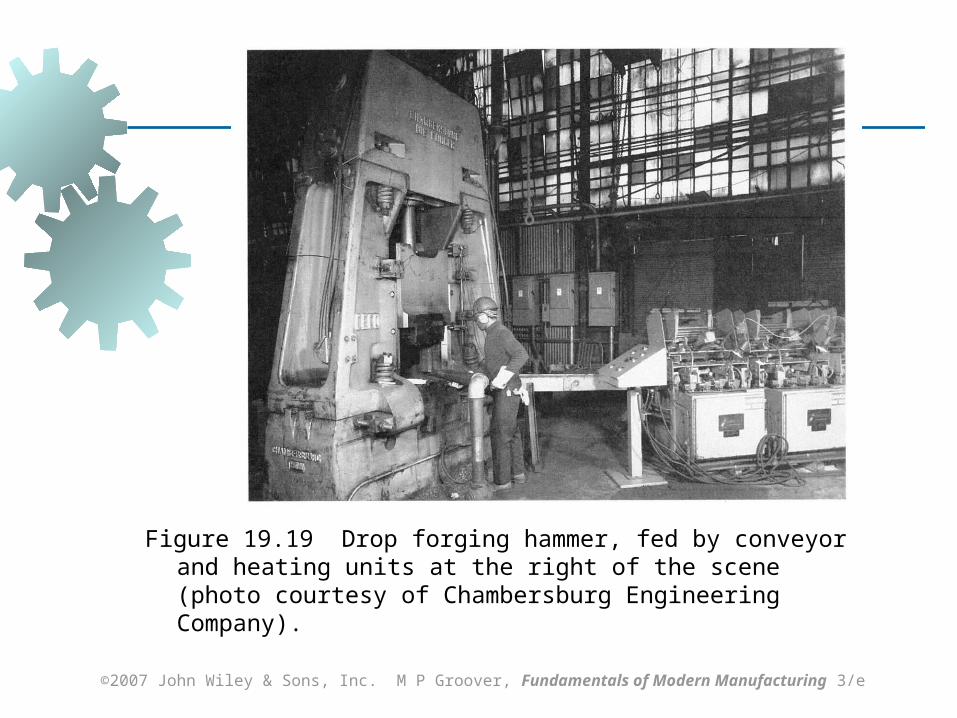
Figure 19.19 Drop forging hammer, fed by conveyor and heating units at the right of the scene (photo courtesy of Chambersburg Engineering Company).
©2007 John Wiley & Sons, Inc. M P Groover, Fundamentals of Modern Manufacturing 3/e
Figure 19.20 Diagram showing details of a drop hammer for impression‑die forging.
Drop Hammer Details
©2007 John Wiley & Sons, Inc. M P Groover, Fundamentals of Modern Manufacturing 3/e
Forging Presses
Apply gradual pressure to accomplish compression operation
Types: Mechanical press - converts rotation of drive
motor into linear motion of ram Hydraulic press - hydraulic piston actuates
ram Screw press - screw mechanism drives ram
©2007 John Wiley & Sons, Inc. M P Groover, Fundamentals of Modern Manufacturing 3/e
Upsetting and Heading
Forging process used to form heads on nails, bolts, and similar hardware products
More parts produced by upsetting than any other forging operation
Performed cold, warm, or hot on machines called headers or formers
Wire or bar stock is fed into machine, end is headed, then piece is cut to length
For bolts and screws, thread rolling is then used to form threads
©2007 John Wiley & Sons, Inc. M P Groover, Fundamentals of Modern Manufacturing 3/e
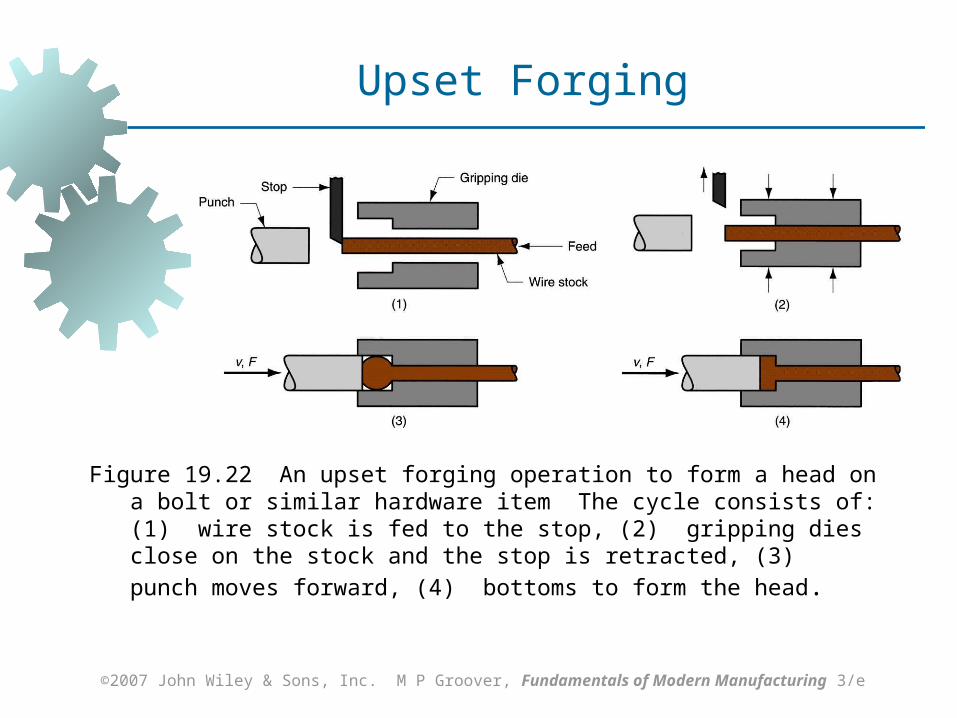
Figure 19.22 An upset forging operation to form a head on a bolt or similar hardware item The cycle consists of: (1) wire stock is fed to the stop, (2) gripping dies close on the stock and the stop is retracted, (3) punch moves forward, (4) bottoms to
form the head.
Upset Forging
©2007 John Wiley & Sons, Inc. M P Groover, Fundamentals of Modern Manufacturing 3/e
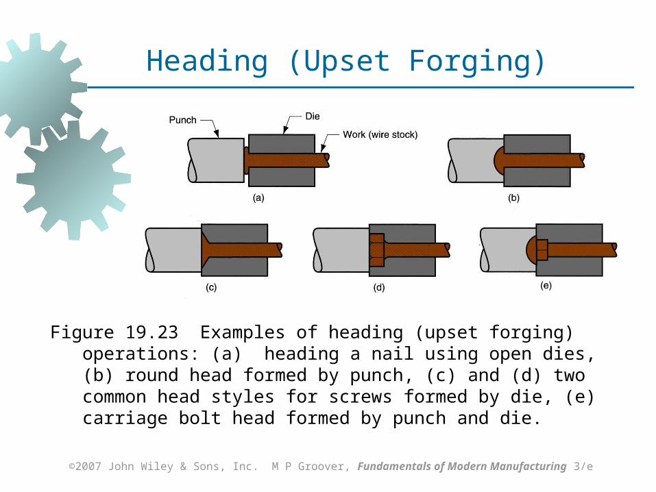
Figure 19.23 Examples of heading (upset forging) operations: (a) heading a nail using open dies, (b) round head formed by punch, (c) and (d) two common head styles for screws formed by die, (e) carriage bolt head formed by punch and die.
Heading (Upset Forging)
©2007 John Wiley & Sons, Inc. M P Groover, Fundamentals of Modern Manufacturing 3/e
Swaging
Accomplished by rotating dies that hammer a workpiece radially inward to taper it as the piece is fed into the dies
Used to reduce diameter of tube or solid rod stock
Mandrel sometimes required to control shape and size of internal diameter of tubular parts
©2007 John Wiley & Sons, Inc. M P Groover, Fundamentals of Modern Manufacturing 3/e
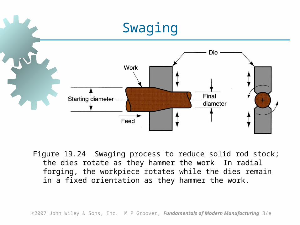
Figure 19.24 Swaging process to reduce solid rod stock; the dies rotate as they hammer the work In radial forging, the workpiece rotates while the dies remain in a fixed orientation as they hammer the work.
Swaging
©2007 John Wiley & Sons, Inc. M P Groover, Fundamentals of Modern Manufacturing 3/e
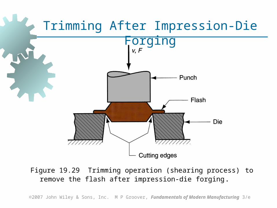
Trimming
Cutting operation to remove flash from workpart in impression‑die forging
Usually done while work is still hot, so a separate trimming press is included at the forging station
Trimming can also be done by alternative methods, such as grinding or sawing
©2007 John Wiley & Sons, Inc. M P Groover, Fundamentals of Modern Manufacturing 3/e
Figure 19.29 Trimming operation (shearing process) to remove the flash after impression‑die forging.
Trimming After Impression-Die Forging

©2007 John Wiley & Sons, Inc. M P Groover, Fundamentals of Modern Manufacturing 3/e
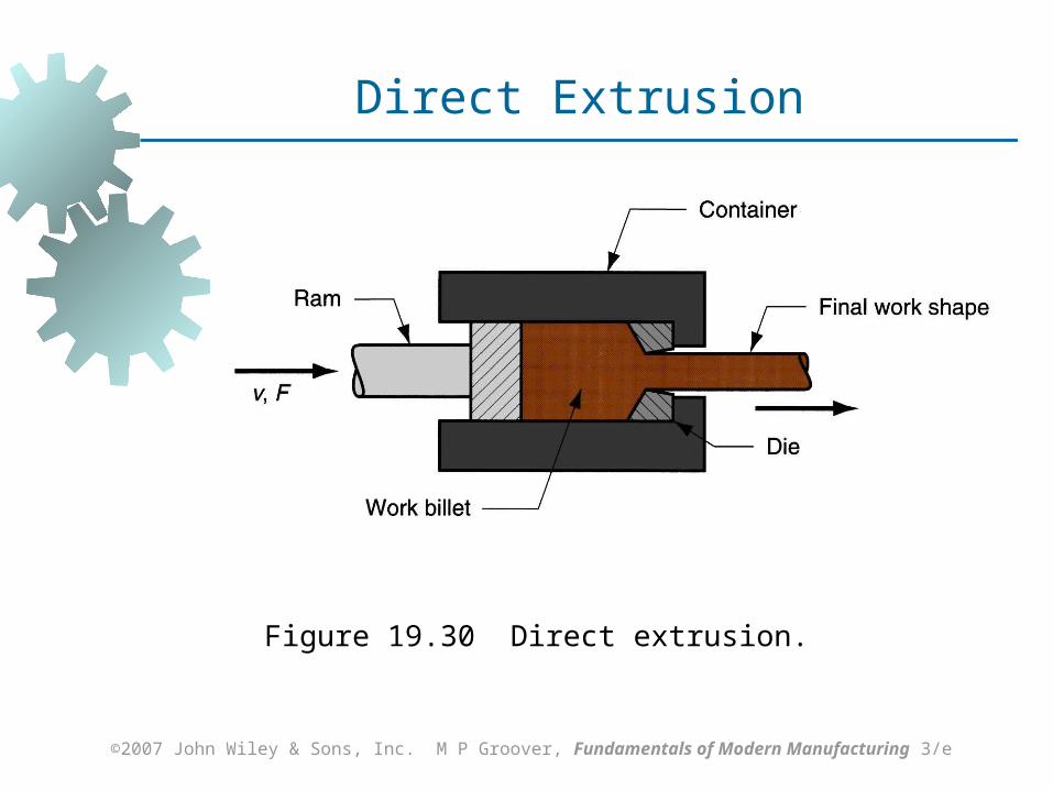
Extrusion
Compression forming process in which work metal is forced to flow through a die opening to produce a desired cross‑sectional shape
Process is similar to squeezing toothpaste out of a toothpaste tube
In general, extrusion is used to produce long parts of uniform cross sections
Two basic types: Direct extrusion Indirect extrusion
©2007 John Wiley & Sons, Inc. M P Groover, Fundamentals of Modern Manufacturing 3/e
Figure 19.30 Direct extrusion.
Direct Extrusion
©2007 John Wiley & Sons, Inc. M P Groover, Fundamentals of Modern Manufacturing 3/e
Comments on Direct Extrusion
Also called forward extrusion As ram approaches die opening, a small
portion of billet remains that cannot be forced through die opening
This extra portion, called the butt, must be separated from extrudate by cutting it just beyond the die exit
Starting billet cross section usually round Final shape of extrudate is determined by die
opening
©2007 John Wiley & Sons, Inc. M P Groover, Fundamentals of Modern Manufacturing 3/e
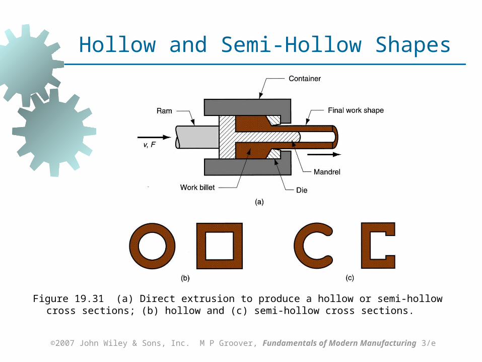
Figure 19.31 (a) Direct extrusion to produce a hollow or semi‑hollow cross sections; (b) hollow and (c) semi‑hollow cross sections.
Hollow and Semi-Hollow Shapes
©2007 John Wiley & Sons, Inc. M P Groover, Fundamentals of Modern Manufacturing 3/e
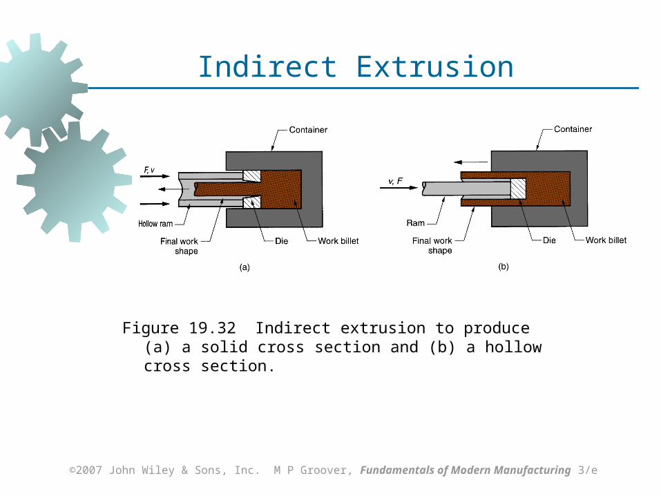
Figure 19.32 Indirect extrusion to produce (a) a solid cross section and (b) a hollow cross section.
Indirect Extrusion
©2007 John Wiley & Sons, Inc. M P Groover, Fundamentals of Modern Manufacturing 3/e
Comments on Indirect Extrusion
Also called backward extrusion and reverse extrusion
Limitations of indirect extrusion are imposed by Lower rigidity of hollow ram Difficulty in supporting extruded product as it
exits die
©2007 John Wiley & Sons, Inc. M P Groover, Fundamentals of Modern Manufacturing 3/e
Advantages of Extrusion
Variety of shapes possible, especially in hot extrusion Limitation: part cross section must be
uniform throughout length Grain structure and strength enhanced in cold
and warm extrusion Close tolerances possible, especially in cold
extrusion In some operations, little or no waste of material
©2007 John Wiley & Sons, Inc. M P Groover, Fundamentals of Modern Manufacturing 3/e
Hot vs. Cold Extrusion
Hot extrusion - prior heating of billet to above its recrystallization temperature Reduces strength and increases ductility of
the metal, permitting more size reductions and more complex shapes
Cold extrusion - generally used to produce discrete parts The term impact extrusion is used to
indicate high speed cold extrusion
©2007 John Wiley & Sons, Inc. M P Groover, Fundamentals of Modern Manufacturing 3/e
Extrusion Ratio
Also called the reduction ratio, it is defined as
where rx = extrusion ratio; Ao = cross-sectional area of the starting billet; and Af = final cross-sectional area of the extruded section
Applies to both direct and indirect extrusion
f
ox A
Ar
©2007 John Wiley & Sons, Inc. M P Groover, Fundamentals of Modern Manufacturing 3/e
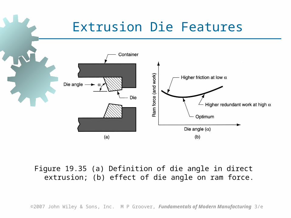
Figure 19.35 (a) Definition of die angle in direct extrusion; (b) effect of die angle on ram force.
Extrusion Die Features
©2007 John Wiley & Sons, Inc. M P Groover, Fundamentals of Modern Manufacturing 3/e
Comments on Die Angle
Low die angle - surface area is large, which increases friction at die‑billet interface Higher friction results in larger ram force
Large die angle - more turbulence in metal flow during reduction Turbulence increases ram force required
Optimum angle depends on work material, billet temperature, and lubrication
©2007 John Wiley & Sons, Inc. M P Groover, Fundamentals of Modern Manufacturing 3/e
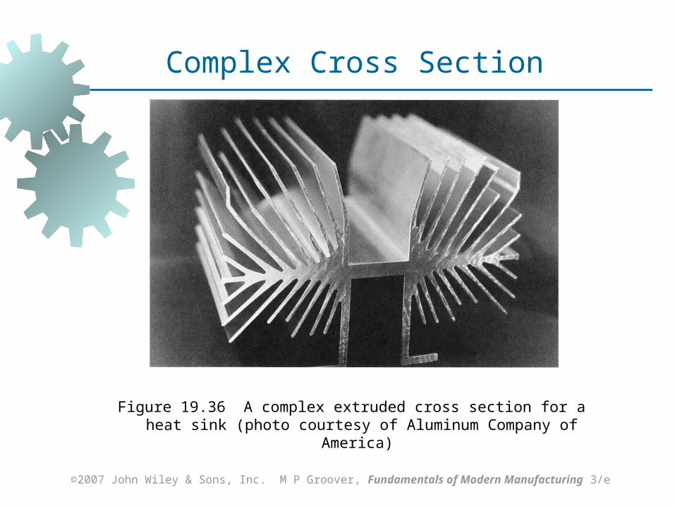
Orifice Shape of Extrusion Die
Simplest cross section shape is circular die orifice
Shape of die orifice affects ram pressure As cross section becomes more complex,
higher pressure and greater force are required Effect of cross-sectional shape on pressure
can be assessed by means the die shape factor Kx
©2007 John Wiley & Sons, Inc. M P Groover, Fundamentals of Modern Manufacturing 3/e
Figure 19.36 A complex extruded cross section for a heat sink (photo courtesy of Aluminum Company of America)
Complex Cross Section
©2007 John Wiley & Sons, Inc. M P Groover, Fundamentals of Modern Manufacturing 3/e
Extrusion Presses
Either horizontal or vertical Horizontal more common
Extrusion presses - usually hydraulically driven, which is especially suited to semi‑continuous direct extrusion of long sections
Mechanical drives - often used for cold extrusion of individual parts
©2007 John Wiley & Sons, Inc. M P Groover, Fundamentals of Modern Manufacturing 3/e
Wire and Bar Drawing
Cross‑section of a bar, rod, or wire is reduced by pulling it through a die opening
Similar to extrusion except work is pulled through die in drawing (it is pushed through in extrusion)
Although drawing applies tensile stress, compression also plays a significant role since metal is squeezed as it passes through die opening
©2007 John Wiley & Sons, Inc. M P Groover, Fundamentals of Modern Manufacturing 3/e
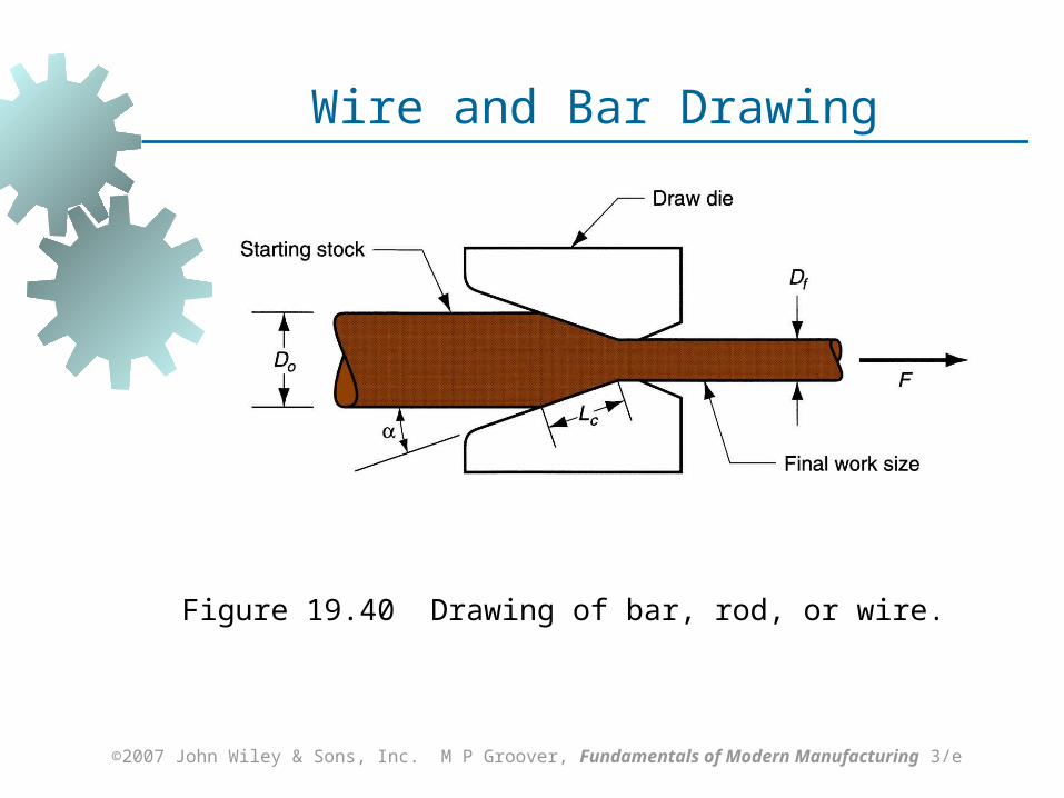
Figure 19.40 Drawing of bar, rod, or wire.
Wire and Bar Drawing
©2007 John Wiley & Sons, Inc. M P Groover, Fundamentals of Modern Manufacturing 3/e
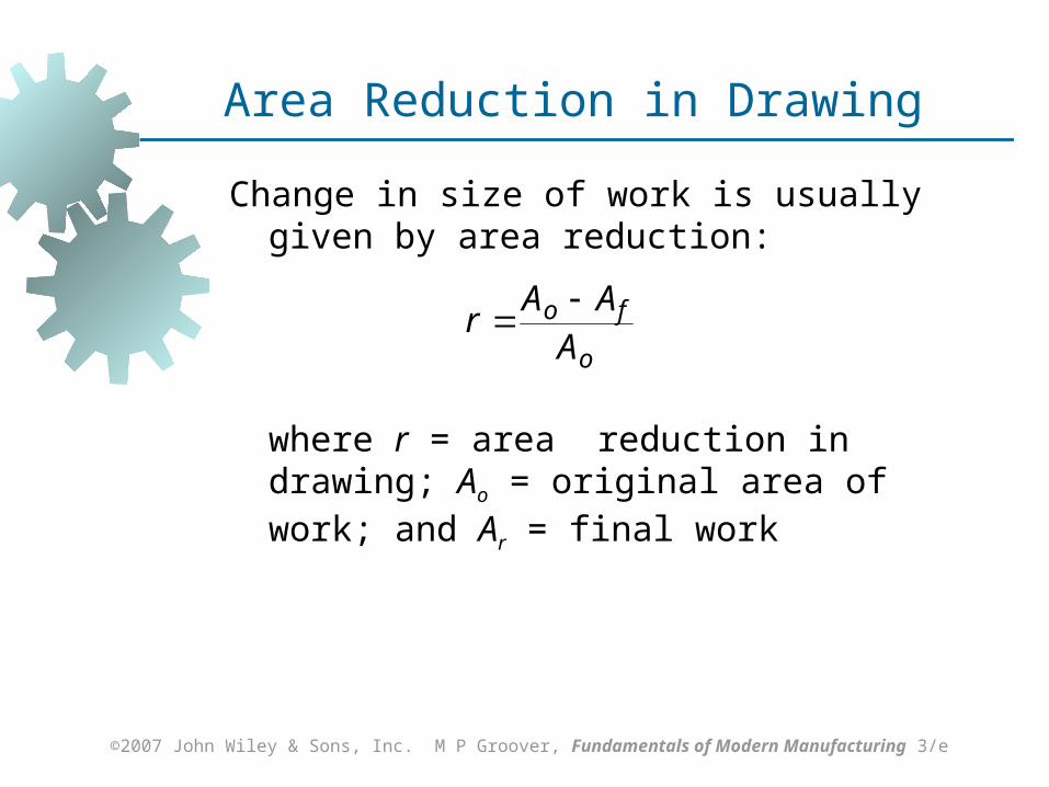
Area Reduction in Drawing
Change in size of work is usually given by area reduction:
where r = area reduction in drawing; Ao = original area of work; and Ar = final work
o
fo
AAA
r
©2007 John Wiley & Sons, Inc. M P Groover, Fundamentals of Modern Manufacturing 3/e
Wire Drawing vs. Bar Drawing
Difference between bar drawing and wire drawing is stock size Bar drawing - large diameter bar and rod
stock Wire drawing - small diameter stock - wire
sizes down to 0.03 mm (0.001 in.) are possible
Although the mechanics are the same, the methods, equipment, and even terminology are different
©2007 John Wiley & Sons, Inc. M P Groover, Fundamentals of Modern Manufacturing 3/e
Drawing Practice and Products
Drawing practice: Usually performed as cold working Most frequently used for round cross
sections Products:
Wire: electrical wire; wire stock for fences, coat hangers, and shopping carts
Rod stock for nails, screws, rivets, and springs
Bar stock: metal bars for machining, forging, and other processes
©2007 John Wiley & Sons, Inc. M P Groover, Fundamentals of Modern Manufacturing 3/e
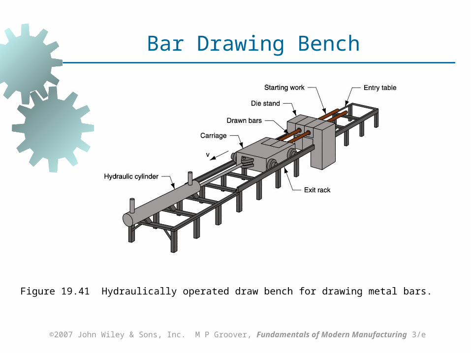
Bar Drawing
Accomplished as a single‑draft operation ‑ the stock is pulled through one die opening
Beginning stock has large diameter and is a straight cylinder
Requires a batch type operation
©2007 John Wiley & Sons, Inc. M P Groover, Fundamentals of Modern Manufacturing 3/e
Figure 19.41 Hydraulically operated draw bench for drawing metal bars.
Bar Drawing Bench
©2007 John Wiley & Sons, Inc. M P Groover, Fundamentals of Modern Manufacturing 3/e
Wire Drawing
Continuous drawing machines consisting of multiple draw dies (typically 4 to 12) separated by accumulating drums Each drum (capstan) provides proper force
to draw wire stock through upstream die Each die provides a small reduction, so
desired total reduction is achieved by the series
Annealing sometimes required between dies to relieve work hardening
©2007 John Wiley & Sons, Inc. M P Groover, Fundamentals of Modern Manufacturing 3/e
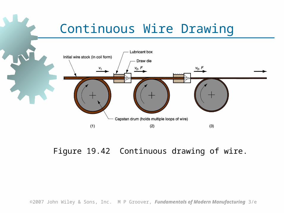
Figure 19.42 Continuous drawing of wire.
Continuous Wire Drawing
©2007 John Wiley & Sons, Inc. M P Groover, Fundamentals of Modern Manufacturing 3/e
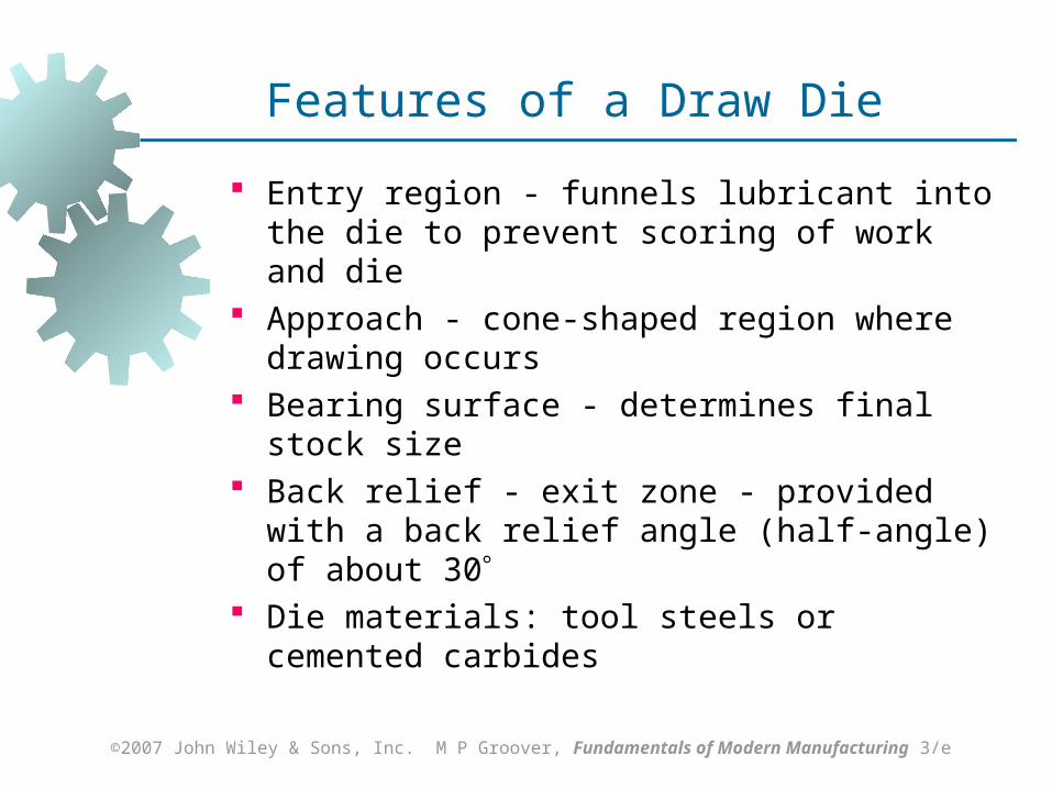
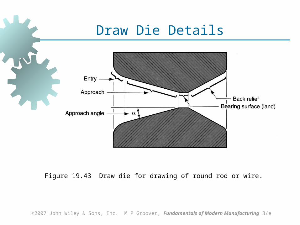
Features of a Draw Die
Entry region - funnels lubricant into the die to prevent scoring of work and die
Approach - cone‑shaped region where drawing occurs
Bearing surface - determines final stock size Back relief - exit zone - provided with a back
relief angle (half‑angle) of about 30 Die materials: tool steels or cemented carbides
©2007 John Wiley & Sons, Inc. M P Groover, Fundamentals of Modern Manufacturing 3/e
Figure 19.43 Draw die for drawing of round rod or wire.
Draw Die Details
©2007 John Wiley & Sons, Inc. M P Groover, Fundamentals of Modern Manufacturing 3/e
Preparation of Work for Drawing
Annealing – to increase ductility of stock Cleaning - to prevent damage to work surface
and draw die Pointing – to reduce diameter of starting end to
allow insertion through draw die
Related Documents