Metadata of the chapter that will be visualized online Series Title Chapter Title MPEG Video Compression Future Chapter SubTitle Copyright Year 2012 Copyright Holder Springer Science+Business Media, LLC Family Name Ostermann Particle Given Name Jörn Corresponding Author Suffix Division Organization Address Hannover, Germany Email [email protected] Family Name Tanimoto Particle Given Name Masayuki Author Suffix Division Organization Address Hannover, Germany Email [email protected] Abstract Looking into the future, more and more of regular and 3D video material will be distributed with increased resolution and quality demand. MPEG foresees further proliferation of high definition video content with resolutions beyond today’s HDTV resolutions of 1980 × 1080 pel. While storage of such video content on solid-state discs or hard discs will not pose a very challenging problem in the future, the distribution of these signals over the Internet, Blu-Ray discs or broadcast channels will, since the expansion of the infrastructure is always an expensive and slow process.

Welcome message from author
This document is posted to help you gain knowledge. Please leave a comment to let me know what you think about it! Share it to your friends and learn new things together.
Transcript

Metadata of the chapter thatwill be visualized online
Series Title
Chapter Title MPEG Video Compression Future
Chapter SubTitle
Copyright Year 2012
Copyright Holder Springer Science+Business Media, LLC
Family Name OstermannParticleGiven Name Jörn
Corresponding Author
SuffixDivisionOrganizationAddress Hannover, GermanyEmail [email protected]
Family Name TanimotoParticleGiven Name Masayuki
Author
SuffixDivisionOrganizationAddress Hannover, GermanyEmail [email protected]
Abstract Looking into the future, more and more of regular and 3D video material will be distributed with increasedresolution and quality demand. MPEG foresees further proliferation of high definition video content withresolutions beyond today’s HDTV resolutions of 1980 × 1080 pel. While storage of such video contenton solid-state discs or hard discs will not pose a very challenging problem in the future, the distributionof these signals over the Internet, Blu-Ray discs or broadcast channels will, since the expansion of theinfrastructure is always an expensive and slow process.
Ostermann
Schreibmaschinentext
Nagoya University
Ostermann
Schreibmaschinentext
Leibniz Universität Hannover
Ostermann
Schreibmaschinentext
Ostermann
Schreibmaschinentext
Nagoya, Japan
Ostermann
Schreibmaschinentext
Ostermann
Schreibmaschinentext
Ostermann
Schreibmaschinentext
Ostermann
Hervorheben

Uncor
recte
d Pro
of
L. Chiariglione (ed.), The MPEG Representation of Digital Media, DOI 10.1007/978-1-4419-6184-6_4, © Springer Science+Business Media, LLC 2011
4.1 Introduction
Looking into the future, more and more of regular and 3D video material will be distributed with increased resolution and quality demand. MPEG foresees further proliferation of high definition video content with resolutions beyond today’s HDTV resolutions of 1980 × 1080 pel. While storage of such video content on solid-state discs or hard discs will not pose a very challenging problem in the future, the distri-bution of these signals over the Internet, Blu-Ray discs or broadcast channels will, since the expansion of the infrastructure is always an expensive and slow process.
Furthermore, the natural extension of 3D movies is Free Viewpoint Movies where the view changes depending on the position of the viewer and his head orientation.
Based on these predictions, MPEG started two new standardization projects: High Efficiency Video Coding (HEVC) is targeted at increased compression effi-ciency compared to AVC, with a focus on video sequences with resolutions of HDTV and beyond. In addition to broadcasting applications, HEVC will also cater towards the mobile market.
The second new project 3D video (3DV) supports new types of audio-visual systems that allow users to view videos of the real 3D space from different user viewpoints. In an advanced application of 3DV, denoted as Free-viewpoint Television (FTV), a user can set the viewpoint to an almost arbitrary location and direction, which can be static, change abruptly, or vary continuously, within the limits that are given by the available camera setup. Similarly, the audio listening point is changed accordingly.
J. Osternmann () e-mail: [email protected]
Chapter 4MPEG Video Compression Future
Jörn Ostermann and Masayuki Tanimoto[AU1]
1
2
3
4
5
6
7
8
9
10
11
12
13
14
15
16
17
18
19
20
21
22
23
24
25

Uncor
recte
d Pro
of
J. Ostermann and M. Tanimoto
4.2 HEVC (High Efficiency Video Coding)
Technology evolution will soon make it possible to capture and display video material with a quantum leap in quality in economic fashion. Here quality is measured in temporal and spatial resolution, color fidelity, and amplitude resolu-tion. Modern TV sets postprocess incoming video to display it at a rate of at least 100 Hz. Camera and display manufactures are showing devices with a spatial reso-lutions of 4,000 pels/line with 2,000 lines. Each pel can record or display 1024 brightness levels compared to 256 brightness levels today. Use of modern displays enables the display of a wider color gamut than what is used today (Fig. 4.1).
It is difficult in today’s transmission networks to carry HDTV resolution with data rates appropriate for high quality to the end user. These higher quality videos will put additional pressure on networks. Future wireless networks like LTE or 4G promise higher bandwidth. However, this bandwidth needs to be shared by a larger number of users making more and more use of their video capabilities. Hence a new video coding standard is required that outperforms AVC at least by 50% and is more suitable for transport over the Internet.
Fig. 4.1 The colored area marks the visible colors, the triangle sRGB marks the colors that can typically be displayed on a TV monitor. The larger Wide Color Gamut triangle shows the color space of future displays that will be able to display deeper, more saturated yellows and greens
[AU2]
this
fig
ure
will
be
prin
ted
in b
/w
26
27
28
29
30
31
32
33
34
35
36
37
38
39
40
41

Uncor
recte
d Pro
of
4 MPEG Video Compression Future
The goal of a 50% gain in coding efficiency will be made possible due to modern video cameras that have different statistical properties compared to cameras pro-duced in the last millennium (Fig. 4.2).
The HEVC video compression standard is currently under joint development by the ISO/IEC Moving Picture Experts Group (MPEG) and ITU-T Video Coding Experts Group (VCEG). MPEG and VCEG have established a Joint Collaborative Team on Video Coding (JCT) to develop the proposed HEVC. Sometimes, this group is referred to as JCT-VC.
4.2.1 Application Scenarios
MPEG envisions HEVC to be potentially used in the following applications: Home and public cinema, surveillance, broadcast, real-time communications including video chat and video conferencing, mobile streaming, personal and professional storage, video on demand, Internet streaming and progressive download, 3D video,
Fig. 4.2 Power spectral density of video sequences with different spatial resolutions showing that high resolution cameras produce less energy at high frequencies compared to low resolution cameras
this
fig
ure
will
be
prin
ted
in b
/w42
43
44
45
46
47
48
49
50
51
52
53
54
Ostermann
Notiz
Given that the fig. is printed b/w, reorder the legend: Tempete CIF City 720ü Traffic (2560x1600) People (2560x1600) ShuttleStart 720p
Ostermann
Notiz
letters on horizontal and vertical axis are not sharp!
Ostermann
Schreibmaschinentext
. The legend is valid at f/T = 0.2 from top to bottom.

Uncor
recte
d Pro
of
J. Ostermann and M. Tanimoto
content production and distribution as well as medical imaging. Looking at this list of applications, the differentiation to AVC and MPEG-2 will be the higher quality of the recorded and delivered video at lower bitrates as well as the better performing streaming services for the Internet enabling real-time communications, video on demand, and Internet streaming. Given these performance improvements, the fol-lowing applications will be the main applications driving the use of HEVC:
Broadcast of video services is constantly suffering from bandwidth limitations. The •number of programs delivered over the air is severely restricted. Due to the limited bandwidth, HDTV broadcast is not available in many markets. Introduction of HEVC will enable broadcast over the air in these markets. Satellite and cable will follow such that customers can make the most out of their ultra-high definition displays.Home theater is a dream of many home owners. New residential buildings often •have a room for home theater which will enable the new screen sizes and viewing distances possible with ultra high definition TV (Fig. 4.3). The owners of these rooms tend to spend money on buying the latest and best devices and contents.IPTV of video services today requires special networks where only the owner of •the network is able to provide IPTV services or IPTV services are offered at lower quality by service providers that do not own the network. Verizon and German Telekom are network owners offering HDTV IPTV at high quality, Netflix as an example for a content owner delivers HDTV at less than 4Mbit/s resulting in limited quality. Reducing the data rate of coded content or increasing quality at today’s bitrates will create another competitive market for delivery of TV and Video on Demand services.
Terrestrial broadcast of HDTV, delivery of UHDTV as well as IPTV will be the driving force for pushing HEVC into the market. The consumer strives for the best
Fig. 4.3 Home theater: Assuming a screen height of 1 m, the viewing distance is 3 m for HDTV and 0.75 m for UHDTV
this
fig
ure
will
be
prin
ted
in b
/w
55
56
57
58
59
60
61
62
63
64
65
66
67
68
69
70
71
72
73
74
75
76
77
78
79
Ostermann
Notiz
Letters in fig need to be crisp.

Uncor
recte
d Pro
of
4 MPEG Video Compression Future
equipment and content quality. The network owners are short of capital to increase the available speed of the network. This is the ideal environment for a new video coding standard to prosper.
4.2.2 Requirements
The requirements that the new standard will fulfill are various. In the following we focus on those metrics that go beyond AVC.
Compression performance: HEVC will enable a substantially greater bitrate •reduction over AVC High Profile. Past experience shows that the success of a new coding standard depends on a substantial differentiation from alternative standards. Therefore, HEVC will have to outperform AVC by 50%, i.e. the same quality will be delivered using half the bitrate.Picture formats: HEVC shall support rectangular progressively scanned picture •formats of arbitrary size ranging at least from QVGA to 8000 × 4000 pel. In terms of color, popular color spaces like YCbCr and RGB as well as a wide color gamut will be supported. The bit depth will be limited to 14 bits/component.
The support for interlaced material is not foreseen. While interlace was impor-tant in the past, modern screens always convert interlaced material into progres-sive picture formats. The artifacts of this conversion as well as the compute power can be avoided when using progressively scanned material.Complexity: There are no measurable requirements on complexity. Obviously, •the standard has to be implementable at an attractive cost in order to be success-ful in the market.Video bit stream segmentation and packetization methods for the target networks •will be developed allowing for efficient use of relevant error resilience measures for networks requiring error recovery, e.g. networks subject to burst errors.
At the end of the standards development process, MPEG will perform verifica-tion tests in order to evaluate the performance of HEVC.
4.2.3 Evaluation of Technologies
At the start of the HEVC development process, MPEG and ITU issued a Call for Proposals which invited interested parties to demonstrate the performance of their video codecs on a predefined set of test sequences and bitrates between 256 kbit/s and 14 Mbit/s. The progressively scanned test sequences were recorded using mod-ern video cameras at resolutions including 416 × 240 pels, 1920 × 1080 pels, and 4096 × 2048 pels. Twenty-seven proposals were evaluated by subjective tests. It turned out that for all test sequences at least one codec provided a rate reduction of 50% compared to AVC High Profile. Therefore, JCT-VC is confident that the rate
80
81
82
83
84
85
86
87
88
89
90
91
92
93
94
95
96
97
98
99
100
101
102
103
104
105
106
107
108
109
110
111
112
113
114
115
Uncor
recte
d Pro
of
J. Ostermann and M. Tanimoto
reduction goal will be reached in the time frame of the standards development. The current plan foresees the final approval of the standard by January 2013.
All 27 proposals were based on block-based hybrid coding with motion compensa-tion. Wavelet technology was not proposed. Based on the first evaluation of the available technologies, technologies likely to be part of the new standard were identified. To a large extend, the technologies were components of the five best per-forming proposals. They were evaluated in an experimental software Test Model Under Consideration (TMUC) until October 2010. In October 2010, the relevant tech-nologies of TMUC were consolidated into TM-H1, which became the common soft-ware that is used as the reference for core experiments in the further development of the HEVC standard. TM-H performs about 40% better than the AVC High Profile.
HEVC will provide more flexibility in terms of larger block sizes, more efficient motion compensation and motion vector prediction as well as more efficient entropy coding. To that extend, HEVC will be a further evolutionary step that started with the standard H.261 issued in 1990.
4.3 3DV (3D Video)
A new 3D Video (3DV) initiative is underway in MPEG. 3DV is a standard that targets serving a variety of 3D displays. 3DV develops a new 3DV format that goes beyond the capabilities of existing standards to enable both advanced stereoscopic display processing and improved support for auto-stereoscopic multiview displays.
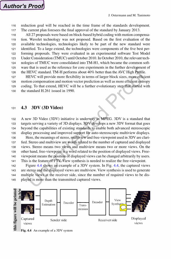
Here, the meanings of stereo, multiview and free-viewpoint used in 3DV are clari-fied. Stereo and multiview are words related to the number of captured and displayed views. Stereo means two views and multiview means two or more views. On the other hand, free-viewpoint is a word related to the position of displayed views. Free-viewpoint means the position of displayed views can be changed arbitrarily by users. This is the feature of FTV. View synthesis is needed to realize the free-viewpoint.
Figure 4.4 shows an example of a 3DV system. In Fig. 4.4, the captured views are stereo and the displayed views are multiview. View synthesis is used to generate multiple views at the receiver side, since the number of required views to be dis-played is more than the transmitted captured views.
Fig. 4.4 An example of a 3DV systemthis
fig
ure
will
be
prin
ted
in b
/w
116
117
118
119
120
121
122
123
124
125
126
127
128
129
130
131
132
133
134
135
136
137
138
139
140
141
142
143
144
145
Ostermann
Notiz

Uncor
recte
d Pro
of
4 MPEG Video Compression Future
4.3.1 Background and Motivation
Figure 4.5 shows the progress of 3D capture and display capabilities. In this figure, the ability of 3D capture and display is expressed as a factor of the pixel-view product, defined as “number of pixels” times “number of views”. It is seen that the pixel-view product has been increasing rapidly year after year in both capture and display. This rapid progress indicates that not only two-view stereoscopic 3D but also advanced multi-view 3D technologies are maturing.
Taking into account such development of 3D technologies, MPEG has been con-ducting 3D standardization activities as shown in Fig. 4.6. MPEG-2 MVP (Multi-View Profile) was standardized to transmit two video signals for stereoscopic TV in November 1996. After intensive study on 3DAV (3D Audio Visual), the standard-ization of MVC that enables efficient coding of multi-view video started in March 2007. It was completed in May 2009. MVC was the first phase of FTV (Free-viewpoint Television). Before completing MVC, 3DV started in April 2007. It uses the view generation function of FTV for 3D display applications. 3DV is the second phase of FTV. The primary goals are the high-quality reconstruction of an arbitrary number of views for advanced stereoscopic processing functionality and to support auto-stereoscopic displays.
1996 1998 2010200820062004200220001
10
100
1000
Year
Space-multiplexing display
Time-multiplexing display
Integral Photography
Multi camera (100 views)
Multi camera (48 views)
Multi camera (128 views)
Rotating cylinder
( 106)
Mirror scan
Directional image display(64 directions)
(128 directions)
Capture
Moore’s law
(400 directions)
(400 directions)
(45 views) (360 views)
(360 views)Mirror scan (33 views)50
5
500
HoloVizio (64 directions)
(72 directions)(300 directions)
Rotating screen (288 directions)
Pix
el-V
iew
Pro
duct
(Num
ber
of p
ixel
s)
(Num
ber
of v
iew
s)
Fig. 4.5 Progress of 3D capture and display capabilities
this
fig
ure
will
be
prin
ted
in b
/w
146
147
148
149
150
151
152
153
154
155
156
157
158
159
160
161
162
163

Uncor
recte
d Pro
of
J. Ostermann and M. Tanimoto
Fig. 4.6 3D standardization activities in MPEG
Fig. 4.7 3DV reference model with items considered for standardization
4.3.2 Application Scenarios
The 3DV targets two specific application scenarios.
1. Enabling stereo devices to cope with varying display types and sizes, and differ-ent viewing preferences. This includes the ability to vary the baseline distance for stereo video to adjust the depth perception, which could help to avoid fatigue and other viewing discomforts.
2. Support for high-quality auto-stereoscopic displays, such that the new format enables the generation of many high-quality views from a limited amount of input data, e.g. stereo and depth.
4.3.3 Requirements
The 3DV reference model is shown in Fig. 4.7. The input is M views captured by cameras, and the output is N views to be displayed. N can be different from M.
this
fig
ure
will
be
prin
ted
in b
/w
164
165
166
167
168
169
170
171
172
173
174
175
Ostermann
Notiz
Letters in fig need to be crisp.

Uncor
recte
d Pro
of
4 MPEG Video Compression Future
At the sender side, a 3D scene is captured by M multiple cameras. The captured views contain the misalignment and luminance differences of the cameras. They are corrected, and depth for each view is estimated from the corrected views. The 3DV encoder compresses both the corrected multiview and depth, for transmission and storage.
At the receiver side, the 3DV decoder reconstructs the multiview and depth. Then, N views are synthesized from the reconstructed M views with the help of the depth information, and displayed on an N-view 3D display.
Multiview test sequences, depth estimation reference software, and view synthesis reference software are developed in the 3DV standardization activity. They are described in Sect. 4.3.4. Candidate items for standardization are illustrated as blue boxes. Major requirements for each item are shown below.
4.3.3.1 Requirements for Data Format
1. Video data The uncompressed data format shall support stereo video, including samples from left and right views as input and output. The source video data should be rectified to avoid misalignment of camera geometry and colors. Other input and output configurations beyond stereo should also be supported.
2. Supplementary data Supplementary data shall be supported in the data format to facilitate high-quality intermediate view generation. Examples of supplementary data include depth maps, segmentation information, transparency or specular reflection, occlusion data, etc. Supplementary data can be obtained by any means from a predeter-mined set of input videos.
3. Metadata Metadata shall be supported in the data format. Examples of metadata include extrinsic and intrinsic camera parameters, scene data, such as near and far plane, and others.
4.3.3.2 Requirements for Compression
1. Compression efficiency Video and supplementary data should not exceed twice the bit rate of state-of-the-art compressed single video. It should also be more efficient than state-of-the-art coding of multiple views with comparable level of rendering capability and quality.
2. Synthesis accuracy The impact of compressing the data format should introduce minimal visual dis-tortion on the visual quality of synthesized views. The compression shall support mechanisms to control overall bitrate with proportional changes in synthesis accuracy.
176
177
178
179
180
181
182
183
184
185
186
187
188
189
190
191
192
193
194
195
196
197
198
199
200
201
202
203
204
205
206
207
208
209
210
211
212
213
214

Uncor
recte
d Pro
of
J. Ostermann and M. Tanimoto
3. Backward compatibility The compressed data format shall include a mode which is backwards compatible with existing MPEG coding standards that support stereo and mono video. In particular, it should be backwards compatible with MVC.
4. Stereo/mono compatibility The compressed data format shall enable the simple extraction of bit streams for stereo and mono output, and support high-fidelity reconstruction of samples from the left and right views of the stereo video.
4.3.3.3 Requirements for Rendering
1. Rendering capability The data format should support improved rendering capability and quality com-pared to existing state-of-the-art representations. The rendering range should be adjustable.
2. Low complexityThe data format shall allow real-time synthesis of views.
3. Display types The data format shall be display-independent. Various types and sizes of displays, e.g. stereo and auto-stereoscopic N-view displays of different sizes with different number of views shall be supported.
4. Variable baseline The data format shall support rendering of stereo views with a variable baseline.
5. Depth rangeThe data format should support an appropriate depth range.
6. Adjustable depth location The data format should support display-specific shift of depth location, i.e., whether the perceived 3D scene (or parts of it) are behind or in front of the screen.
4.3.4 Available Technologies
4.3.4.1 Multiview Test Sequences
Excellent sets of multiview test sequences are available. Several organizations captured various indoor and outdoor scenes with stationary and moving multiview cameras. The multiview cameras are placed on a straight line and face front in parallel . This camera setting is denoted by 1D parallel in the following. The misalignment and color difference of the cameras are corrected. The corrected mul-tiview test sequences with avail-able depth map data are listed below. Contact each organization and follow the conditions to use them.
1. Nagoya University Data Set (three indoor, two moving camera) Pantomime (indoor, 80 views, large depth range, colorful), Champagne_tower (indoor, 80 views, reflections, thin objects, transparency), Dog (in-door, 80 views),
215
216
217
218
219
220
221
222
223
224
225
226
227
228
229
230
231
232
233
234
235
236
237
238
239
240
241
242
243
244
245
246
247
248
249
250
251
252

Uncor
recte
d Pro
of
4 MPEG Video Compression Future
Kendo (moving camera, seven views, colorful, fast object motion, camera motion), Balloons (moving camera, seven views, fast object motion, camera motion, smoke)
2. HHI Data Set (three indoor, one outdoor) Book_arrival (indoor, 16 views, textured background, moving narrow objects), Leaving_laptop (indoor, 16 views, textured background, moving narrow objects), Doorflowers (indoor, 16 views, textured background, moving narrow objects), Alt-Moabit (outdoor, 16 views, traffic scene)
3. Poznan University of Technology Data Set (two moving camera, two outdoor) Poznan_Hall1 (moving camera, nine views, large depth range, camera motion), Poznan_Hall2 (moving camera, nine views, large depth range, camera motion, thin objects), Poznan_Street (outdoor, nine views, traffic scene, large depth range, reflections and transparency), Poznan_CarPark (outdoor, nine views, large depth range, reflections and transparency)
4. GIST Data Set (two indoor) Newspaper (indoor, nine views, rich in texture, large depth range), Cafe (indoor, five views, rich in texture, large depth range, low-res depth captured by five depth-cameras)
5. ETRI/MPEG Korea Forum Data Set (two outdoor) Lovebird1 (outdoor, 12 views, colorful, large depth range), Lovebird2 (outdoor, 12 views, colorful, large depth range)
6. Philips Data Set (one CG, one indoor) Mobile (CG, five views, combination of a moving computer-graphics object with captured images, ground truth depth), Beer Garden (indoor, two views, colorful, depth obtained through stereo-matching combined with blue-screen technology)
4.3.4.2 Depth Estimation Reference Software
The Depth Estimation Reference Software (DERS) has been developed collabora-tively by experts participating in the activity. Although stereo matching is used to estimate depth, two views are not enough to handle occlusion. Therefore, the soft-ware uses three camera views to generate a depth map for the center view. DERS requires the intrinsic and extrinsic camera parameters and can support 1D parallel and non-parallel camera setups.
When a 3D scene is captured by multiple parallel cameras, a point in the 3D scene will appear at a different horizontal location in each camera image. This gives horizontal disparity. The depth is inversely proportional to the disparity. The dispar-ity is estimated by determining the correspondence between pixels in the multiple images. The correspondence is expressed by matching cost energy. Generally, this energy consists of a similarity term and a smoothing term. The smoothing term stimulates disparity to change smoothly within objects. The most likely disparity for every pixel can be obtained by minimizing this matching cost energy. DERS uses Graph Cuts as a global optimization method to obtain the global minimum rather than a local minimum. To handle occlusions, the similarity term is calculated by matching between the center and left views, and the center and right views, and then the smallest term is selected.
253
254
255
256
257
258
259
260
261
262
263
264
265
266
267
268
269
270
271
272
273
274
275
276
277
278
279
280
281
282
283
284
285
286
287
288
289
290
291
292
293
294
295

Uncor
recte
d Pro
of
J. Ostermann and M. Tanimoto
Temporal regularization is applied to the matching cost energy for static pixels to improve the temporal consistency. Furthermore, the reference software supports segmentation and soft-segmentation based depth estimation.
We have also developed a semi-automatic mode of the depth estimation. In this mode, manually created supplementary data is input to help the automatic depth estimation to obtain more accurate depth and clear object boundaries.
4.3.4.3 View Synthesis Reference Software
The View Synthesis Reference Software (VSRS) has been developed collabora-tively by experts participating in the activity.
Since a virtual view between two neighboring camera views is generated, VSRS takes two views, i.e. reference views, two depth-maps, configuration parameters, and camera-parameters as inputs, and synthesizes a virtual view between the refer-ence views. VSRS requires the intrinsic and extrinsic cam-era parameters and can support 1D parallel, and non-parallel camera setups in 1D-mode and General-mode, respectively.
In General-mode, the left and right depth-maps are warped to the virtual view, and both virtual depths are filtered. These depth maps are used to warp the left and right reference views to the virtual view. Holes caused by occlusion in each warped view are filled by pixels from the other view. The warped images are blended and any remaining holes are filled by inpainting.
In 1D-mode the left and right reference views are warped to the virtual view using image shifting. Several modes of view blending and hole filling are supported which consist of different combinations of z-buffering and pixel splatting.
To reduce visible artifacts around object edges, a boundary noise removal method is implemented.
4.4 Summary
With the upcoming standards HEVC and 3DV, MPEG and JCT-VC will provide the codecs to deliver highest quality video content in 2D and 3D. Due to the limitation of bandwidth and stereo TV, markets for the new standards will develop quickly.
296
297
298
299
300
301
302
303
304
305
306
307
308
309
310
311
312
313
314
315
316
317
318
319
320
321
322
323
324

Uncor
recte
d Pro
of
Author QueryChapter No.: 4 0001307709
Query Details Required Author’s Response
AU1 Please provide complete affiliation details for the authors “Jörn Ostermann and Masayuki Tanimoto” and also specify the corresponding author details.
Ostermann
Schreibmaschinentext
Ostermann
Schreibmaschinentext
Ostermann
Schreibmaschinentext
Ostermann
Schreibmaschinentext
Prof. Dr.-Ing. Jörn Ostermann Institut fuer Informationsverarbeitung Leibniz Universität Hannover, Appelstr. 9A, 30167 Hannover, Germany Prof. Masayuki Tanimoto Tanimoto Laboratory Dept. of Information Electonics Nagoya University, Furo-cho, Chikusa-ku, Nagoya 464-8603 JAPAN
Related Documents