701076 MET ONE 237AB Particle Detector USER MANUAL June 2008, Edition 5

Welcome message from author
This document is posted to help you gain knowledge. Please leave a comment to let me know what you think about it! Share it to your friends and learn new things together.
Transcript
701076
MET ONE 237AB Particle Detector
USER MANUAL
June 2008, Edition 5
701076
MET ONE 237AB Particle Detector
USER MANUAL
June 2008, Edition 5
© Hach Ultra Analytics, Inc., 2008. All rights reserved. Printed in the U.S.A.

Table of Contents
Section 1 Specifications.................................................................................................................... 3Section 2 General Information ......................................................................................................... 5
2.1 Safety information ........................................................................................................................ 52.1.1 Use of hazard information................................................................................................... 52.1.2 Precautionary labels ........................................................................................................... 52.1.3 Laser safety information...................................................................................................... 62.1.4 Electrostatic discharge (ESD) considerations..................................................................... 62.1.5 Battery safety information ................................................................................................... 6
2.2 General product information ........................................................................................................ 72.3 Theory of operation...................................................................................................................... 8
Section 3 Installation.......................................................................................................................... 93.1 Unpack the instrument ................................................................................................................. 93.2 Mechanical installation............................................................................................................... 10
3.2.1 Install the isokinetic probe................................................................................................. 103.2.2 Install the purge filter......................................................................................................... 113.2.3 Load printer paper............................................................................................................. 113.2.4 Connect the AC adapter ................................................................................................... 123.2.5 Install the RH/T probe ....................................................................................................... 12
3.3 Rear panel connections ............................................................................................................. 12Section 4 System Start Up .............................................................................................................. 13
4.1 Power up.................................................................................................................................... 13Section 5 Operation.......................................................................................................................... 15
5.1 Front panel overview.................................................................................................................. 155.2 Setup.......................................................................................................................................... 165.3 Counting modes......................................................................................................................... 16
5.3.1 Manual mode .................................................................................................................... 165.3.2 Automatic mode ................................................................................................................ 195.3.3 Concentration mode.......................................................................................................... 215.3.4 Beep mode........................................................................................................................ 23
5.4 Program the relative humidity and temperature probe (RH/T)................................................... 235.4.1 Environmental alarms ....................................................................................................... 24
Section 6 Maintenance .................................................................................................................... 256.1 Maintenance guidelines ............................................................................................................. 256.2 Clean the sensor........................................................................................................................ 25
6.2.1 Battery replacement.......................................................................................................... 266.3 Printer maintenance................................................................................................................... 26
6.3.1 Clean the print head.......................................................................................................... 266.3.2 Correct light print............................................................................................................... 266.3.3 Replace the printer ribbon................................................................................................. 27
Section 7 Troubleshooting Procedures....................................................................................... 297.1 Common problems..................................................................................................................... 297.2 Reset the counter....................................................................................................................... 297.3 Pump troubleshooting ................................................................................................................ 30
7.3.1 Disassembly and cleaning of the pump ............................................................................ 307.3.2 Pump optimization ............................................................................................................ 32
Section 8 Replacement Parts and Accessories......................................................................... 338.1 Accessories................................................................................................................................ 33
Section 9 Service Contact Information ........................................................................................ 35Section 10 Limited Warranty .......................................................................................................... 37
1
Table of Contents
Section 11 Certification....................................................................................................................39Appendix A Optional Accessories ................................................................................................41
A.1 Relative humidity/Temperature (RH/T) probe ............................................................................41A.2 High-pressure diffuser................................................................................................................41A.3 RS485 converter ........................................................................................................................41A.4 External printer...........................................................................................................................42A.5 PortAll software..........................................................................................................................42A.6 Carrying case.............................................................................................................................42
Appendix B Computer Interface Operations ..............................................................................43B.1 Data analysis for ISO 14644 ......................................................................................................43
B.1.1 Computer communications ...............................................................................................43Appendix C PortAll Software ..........................................................................................................47
C.1 Connections...............................................................................................................................47C.2 Operation ...................................................................................................................................47
Appendix D DPU–414 Printer..........................................................................................................49D.1 Printer setup ..............................................................................................................................49D.2 Counter setup for the printer......................................................................................................50
2
Section 1 Specifications
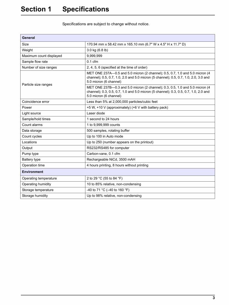
Specifications are subject to change without notice.
General
Size 170.94 mm x 58.42 mm x 165.10 mm (6.7" W x 4.5" H x 11.7" D)
Weight 3.0 kg (6.8 lb)
Maximum count displayed 9,999,999
Sample flow rate 0.1 cfm
Number of size ranges 2, 4, 5, 6 (specified at the time of order)
Particle size ranges
MET ONE 237A—0.5 and 5.0 micron (2 channel); 0.5, 0.7, 1.0 and 5.0 micron (4 channel); 0.5, 0.7, 1.0, 2.0 and 5.0 micron (5 channel); 0.5, 0.7, 1.0, 2.0, 3.0 and 5.0 micron (6 channel)
MET ONE 237B—0.3 and 5.0 micron (2 channel); 0.3, 0.5, 1.0 and 5.0 micron (4 channel); 0.3, 0.5, 0.7, 1.0 and 5.0 micron (5 channel); 0.3, 0.5, 0.7, 1.0, 2.0 and 5.0 micron (6 channel)
Coincidence error Less than 5% at 2,000,000 particles/cubic feet
Power +5 W, +10 V (approximately) (+6 V with battery pack)
Light source Laser diode
Sample/hold times 1 second to 24 hours
Count alarms 1 to 9,999,999 counts
Data storage 500 samples, rotating buffer
Count cycles Up to 100 in Auto mode
Locations Up to 250 (number appears on the printout)
Output RS232/RS485 for computer
Pump type Carbon-vane, 0.1 cfm
Battery type Rechargeable NiCd, 3500 mAH
Operation time 4 hours printing, 8 hours without printing
Environment
Operating temperature 2 to 29 °C (55 to 84 °F)
Operating humidity 10 to 85% relative, non-condensing
Storage temperature -40 to 71 °C (–40 to 160 °F)
Storage humidity Up to 98% relative, non-condensing
3

Specifications
4
Section 2 General Information
2.1 Safety informationRead this entire manual before unpacking, setting up or operating this equipment. Pay attention to all danger and caution statements. Failure to do so could result in serious injury to the operator or damage to the equipment.
To make sure that the protection provided by this equipment is not impaired, do not use or install this equipment in any manner other than that specified in this manual.
2.1.1 Use of hazard information
DANGERIndicates a potentially or imminently hazardous situation which, if not avoided, will result in death or serious injury.
WARNINGIndicates a potentially or imminently hazardous situation which, if not avoided, could result in death or serious injury.
CAUTIONIndicates a potentially hazardous situation that can result in minor or moderate injury.
Important Note: Indicates a situation which, if not avoided, can cause damage to the instrument. Information that requires special emphasis.
Note: Information that supplements points in the main text.
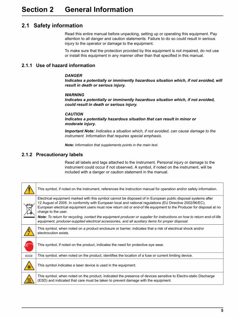
2.1.2 Precautionary labelsRead all labels and tags attached to the instrument. Personal injury or damage to the instrument could occur if not observed. A symbol, if noted on the instrument, will be included with a danger or caution statement in the manual.
This symbol, if noted on the instrument, references the instruction manual for operation and/or safety information.
Electrical equipment marked with this symbol cannot be disposed of in European public disposal systems after 12 August of 2005. In conformity with European local and national regulations (EU Directive 2002/96/EC), European electrical equipment users must now return old or end-of life equipment to the Producer for disposal at no charge to the user. Note: To return for recycling, contact the equipment producer or supplier for instructions on how to return end-of-life equipment, producer-supplied electrical accessories, and all auxiliary items for proper disposal.
This symbol, when noted on a product enclosure or barrier, indicates that a risk of electrical shock and/or electrocution exists.
This symbol, if noted on the product, indicates the need for protective eye wear.
This symbol, when noted on the product, identifies the location of a fuse or current limiting device.
This symbol indicates a laser device is used in the equipment.
This symbol, when noted on the product, indicated the presence of devices sensitive to Electro-static Discharge (ESD) and indicated that care must be taken to prevent damage with the equipment.
5
General Information
2.1.3 Laser safety informationThis particle counter contains a laser-based sensor that is a Class 1 product (as defined by 21 CFR, Subchapter J, of the Health and Safety Act of 1968) when used under normal operation and maintenance. The manual contains no procedures for service of internal parts within this unit. Service should be performed only by factory-authorized personnel.
The particle counter has been evaluated and tested in accordance with EN 61010-1:1993, "Safety Requirements For Electrical Equipment For Measurement, Control, and Laboratory Use" and IEC 825—1:1993, "Safety of Laser Products".
2.1.4 Electrostatic discharge (ESD) considerations Important Note: To minimize hazards and ESD risks, maintenance procedures not requiring power to the analyzer should be performed with power removed.
Delicate internal electronic components can be damaged by static electricity, resulting in degraded instrument performance or eventual failure.
The manufacturer recommends taking the following steps to prevent ESD damage to the instrument:
• Before touching any instrument electronic components (such as printed circuit cards and the components on them) discharge static electricity. This can be accomplished by touching an earth-grounded metal surface such as the chassis of an instrument or a metal conduit or pipe.
• To reduce static build-up, avoid excessive movement. Transport static-sensitive components in anti-static containers or packaging.
• To discharge static electricity and keep it discharged, wear a wrist strap connected by a wire to earth ground.
Handle all static-sensitive components in a static-safe area. If possible, use anti-static floor pads and work bench pads.
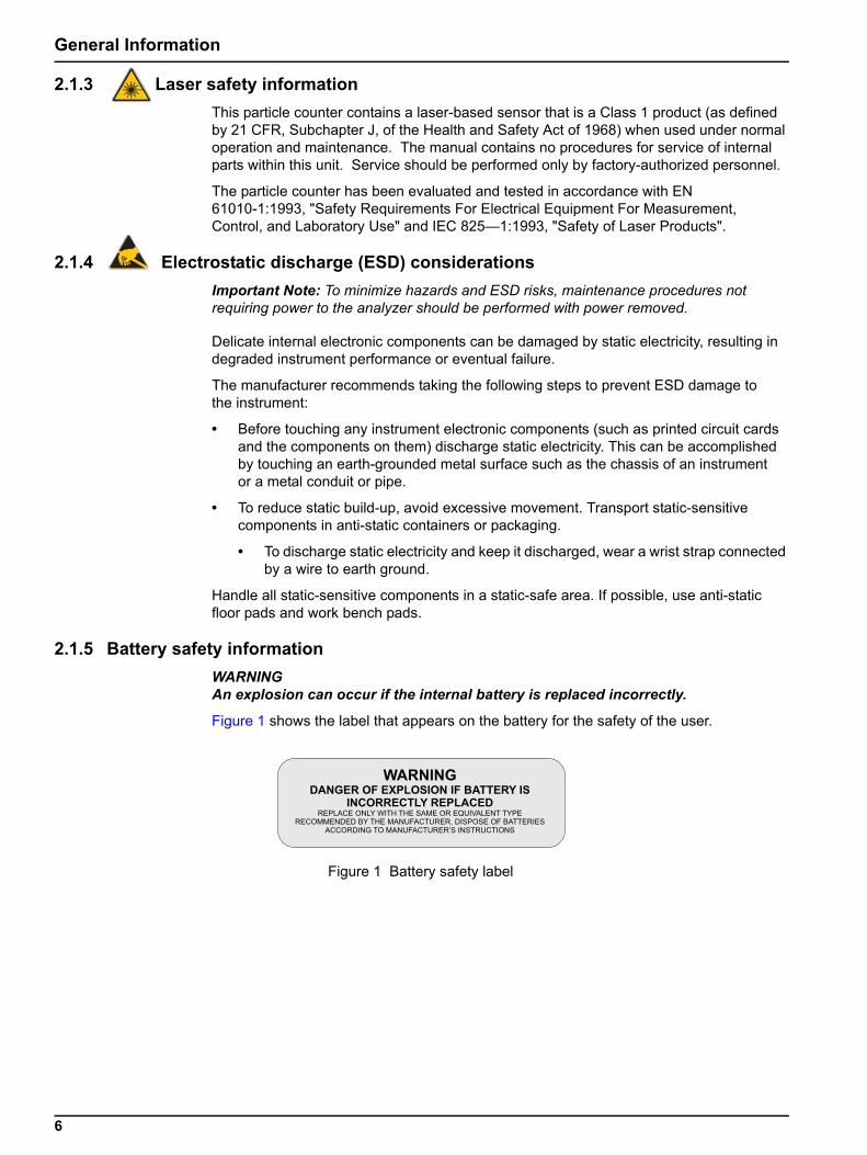
2.1.5 Battery safety informationWARNINGAn explosion can occur if the internal battery is replaced incorrectly.
Figure 1 shows the label that appears on the battery for the safety of the user.
Figure 1 Battery safety label
6
General Information
2.2 General product informationThe MET ONE 237 particle counter is a battery operated, laser based particle counter that is used in a walk-around sampling routine. The counter can store up to 500 records for each sample with a different location label on the record. The data records may later be printed or downloaded to a computer for analysis. The MET ONE 237 particle counter is used in environments where the particulate contamination does not exceed two million particles per cubic foot of air, such as clean-rooms, medical instrument assembly, computer rooms. The Concentration mode in the MET ONE 227 particle counter is used to take a brief sample and estimate the probable cleanliness for areas with unknown particulate levels. This is based on built-in calculations performed in the microprocessor of the counter. Long term use in uncontrolled environments such as open air office spaces or outdoor air will require frequent user maintenance.The MET ONE 237 particle counter operates at a flow rate of 0.1 cubic feet per minute (cfm). The flow rate is required to set the sampling parameters. It takes 10 minutes to sample one cubic foot of air while the results of a one minute sample is multiplied by ten to obtain counts per cubic foot. All counts are reported as cumulative counts; that is, all the reported 0.3 µm particles are 0.3 µm and larger in size.
7
General Information
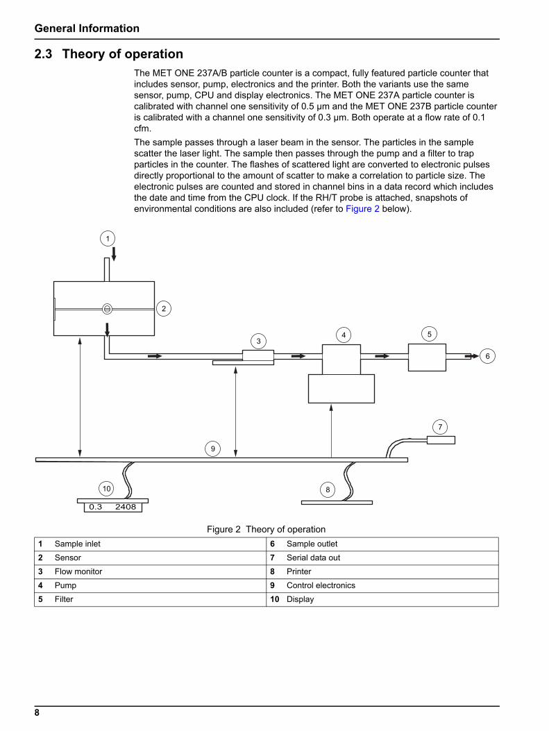
2.3 Theory of operationThe MET ONE 237A/B particle counter is a compact, fully featured particle counter that includes sensor, pump, electronics and the printer. Both the variants use the same sensor, pump, CPU and display electronics. The MET ONE 237A particle counter is calibrated with channel one sensitivity of 0.5 µm and the MET ONE 237B particle counter is calibrated with a channel one sensitivity of 0.3 µm. Both operate at a flow rate of 0.1 cfm.The sample passes through a laser beam in the sensor. The particles in the sample scatter the laser light. The sample then passes through the pump and a filter to trap particles in the counter. The flashes of scattered light are converted to electronic pulses directly proportional to the amount of scatter to make a correlation to particle size. The electronic pulses are counted and stored in channel bins in a data record which includes the date and time from the CPU clock. If the RH/T probe is attached, snapshots of environmental conditions are also included (refer to Figure 2 below).
Figure 2 Theory of operation1 Sample inlet 6 Sample outlet
2 Sensor 7 Serial data out
3 Flow monitor 8 Printer
4 Pump 9 Control electronics
5 Filter 10 Display
8
Section 3 Installation
DANGEROnly qualified personnel should conduct the tasks described in this section of the manual.
This section describes the setup of the MET ONE 237 particle counter and connections to the equipment. If necessary, contact the Technical Support Department with questions regarding the compatibility or suitability of this product for a specific application.
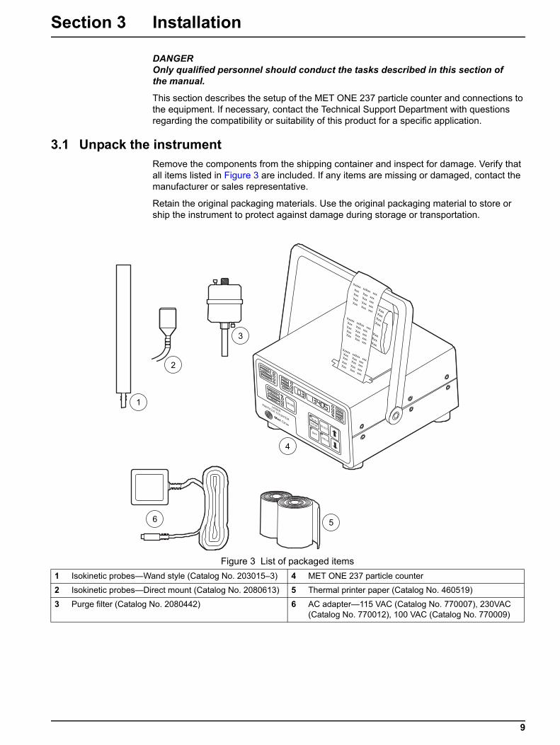
3.1 Unpack the instrumentRemove the components from the shipping container and inspect for damage. Verify that all items listed in Figure 3 are included. If any items are missing or damaged, contact the manufacturer or sales representative.
Retain the original packaging materials. Use the original packaging material to store or ship the instrument to protect against damage during storage or transportation.
Figure 3 List of packaged items1 Isokinetic probes—Wand style (Catalog No. 203015–3) 4 MET ONE 237 particle counter
2 Isokinetic probes—Direct mount (Catalog No. 2080613) 5 Thermal printer paper (Catalog No. 460519)
3 Purge filter (Catalog No. 2080442) 6 AC adapter—115 VAC (Catalog No. 770007), 230VAC (Catalog No. 770012), 100 VAC (Catalog No. 770009)
9
Installation
3.2 Mechanical installationThe MET ONE 237 particle counter is ready to use when unpacked. Check for all the connections to the equipement.
3.2.1 Install the isokinetic probeThe isokinetic sample probes are used for accurate air sampling in particle counting applications. The isokinetic probe (refer to Figure 3 on page 9, item1 or item 2) is used in the laminar air flow for a flow rate of up to 100 feet per minute.
Isokinetic sample probes can be:
• Mounted directly on machines
• Suspended from the ceiling
• Mounted on the wall or through the wall.
Note: Make sure the the isokinetic probes are attached before sampling.
To install the isokinetic probe:
1. Remove the red sensor inlet cap from the MET ONE 237 particle counter.
Note: The isokinetic probes are protected with plastic caps on the openings and should remain in place till they are used in order to minimize contamination.
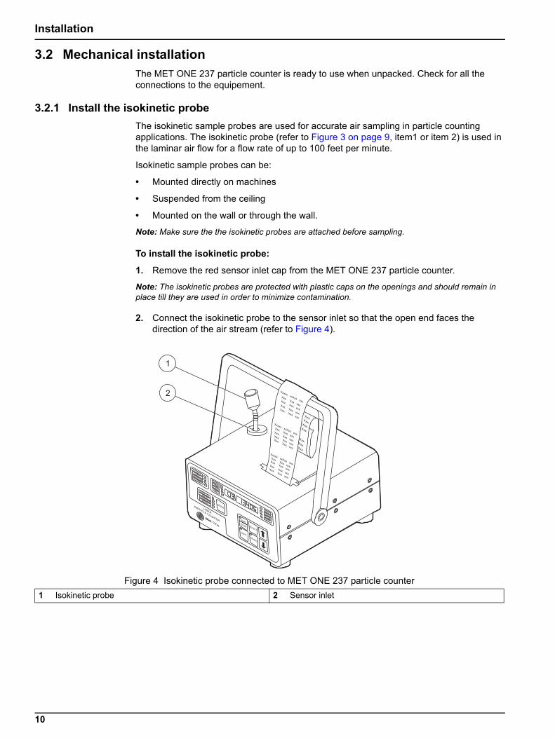
2. Connect the isokinetic probe to the sensor inlet so that the open end faces the direction of the air stream (refer to Figure 4).
Figure 4 Isokinetic probe connected to MET ONE 237 particle counter1 Isokinetic probe 2 Sensor inlet
10
Installation
3.2.2 Install the purge filterThe purge filter (refer to Figure 3 on page 9, item 3) is used for maintenance (purge and zero count) of the MET ONE 237 particle counter. The purge filter permits direct sampling of pressurized air at pressures ranging from 30 to 150 psi.
Note: It is recommended that the purge filter be applied to the counter before moving the MET ONE 237 particle counter to avoid cross contamination.
Note: Verify the zero counts before moving the MET ONE 237 particle counter.
To install the purge filter:
1. Remove the red sensor inlet cap or the isokinetic probe from the MET ONE 237 particle counter.
2. Connect the purge filter to the sensor inlet.
3.2.3 Load printer paper
To load the printer paper:
1. Open the paper tray cover.
2. Remove any remaining paper from the last roll. Snip the paper at the spool and press PAPER FEED until the paper tray is empty.
3. Trim the end of the new paper roll:
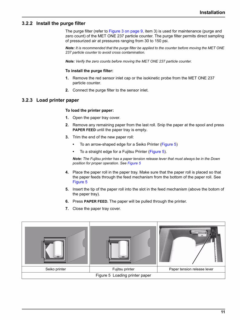
• To an arrow-shaped edge for a Seiko Printer (Figure 5)
• To a straight edge for a Fujitsu Printer (Figure 5).
Note: The Fujitsu printer has a paper tension release lever that must always be in the Down position for proper operation. See Figure 5
4. Place the paper roll in the paper tray. Make sure that the paper roll is placed so that the paper feeds through the feed mechanism from the bottom of the paper roll. See Figure 5
5. Insert the tip of the paper roll into the slot in the feed mechanism (above the botom of the paper tray).
6. Press PAPER FEED. The paper will be pulled through the printer.
7. Close the paper tray cover.
Seiko printer Fujitsu printer Paper tension release lever
Figure 5 Loading printer paper
11
Installation
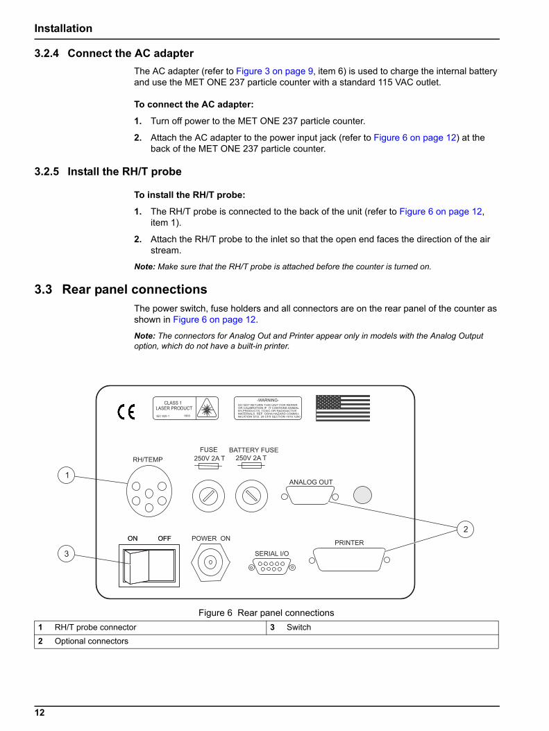
3.2.4 Connect the AC adapterThe AC adapter (refer to Figure 3 on page 9, item 6) is used to charge the internal battery and use the MET ONE 237 particle counter with a standard 115 VAC outlet.
To connect the AC adapter:
1. Turn off power to the MET ONE 237 particle counter.
2. Attach the AC adapter to the power input jack (refer to Figure 6 on page 12) at the back of the MET ONE 237 particle counter.
3.2.5 Install the RH/T probe
To install the RH/T probe:
1. The RH/T probe is connected to the back of the unit (refer to Figure 6 on page 12, item 1).
2. Attach the RH/T probe to the inlet so that the open end faces the direction of the air stream.
Note: Make sure that the RH/T probe is attached before the counter is turned on.
3.3 Rear panel connectionsThe power switch, fuse holders and all connectors are on the rear panel of the counter as shown in Figure 6 on page 12.
Note: The connectors for Analog Out and Printer appear only in models with the Analog Output option, which do not have a built-in printer.
Figure 6 Rear panel connections1 RH/T probe connector 3 Switch
2 Optional connectors
12
Section 4 System Start Up
4.1 Power upTurn on the switch at the back of the MET ONE 237 particle counter (refer to Figure 6 on page 12). The counter will display the main screen when turned on (Figure 7 on page 15). If the LO BATT indicator is lit, plug in the AC adaptor to charge the battery. The counter may be operated during the charging of the battery.
Note: Use the AC adapter provided by the manufacturer to charge the battery or operate the counter. Other off-the-shelf power modules may have different power, current or polarity which could damage the counter.
13

System Start Up
14
Section 5 Operation
The MET ONE 237 particle counter must be configured before operation for parameters such as sample time and count alarm thresholds.
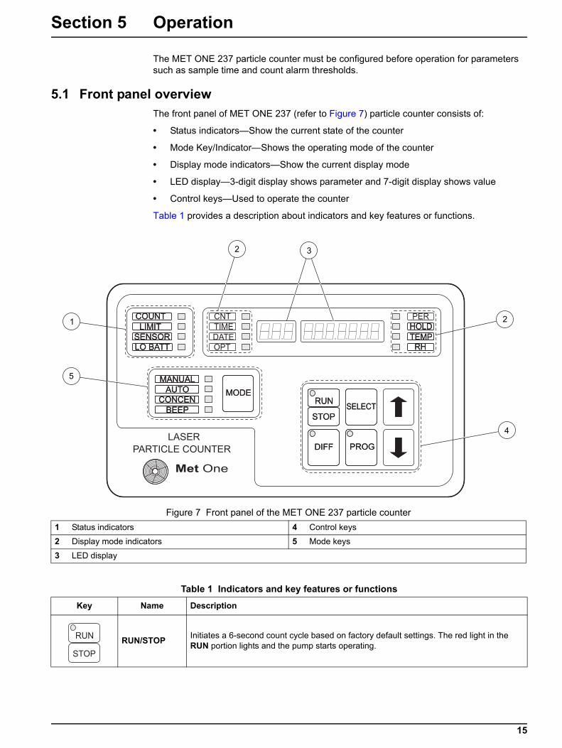
5.1 Front panel overviewThe front panel of MET ONE 237 (refer to Figure 7) particle counter consists of:
• Status indicators—Show the current state of the counter
• Mode Key/Indicator—Shows the operating mode of the counter
• Display mode indicators—Show the current display mode
• LED display—3-digit display shows parameter and 7-digit display shows value
• Control keys—Used to operate the counter
Table 1 provides a description about indicators and key features or functions.
Figure 7 Front panel of the MET ONE 237 particle counter1 Status indicators 4 Control keys
2 Display mode indicators 5 Mode keys
3 LED display
Table 1 Indicators and key features or functions
Key Name Description
RUN/STOP Initiates a 6-second count cycle based on factory default settings. The red light in the RUN portion lights and the pump starts operating.
15
Operation
5.2 SetupThe MET ONE 237 particle counter is ready to use when unpacked, but make sure that the red sensor inlet cap is removed and the isokinetic probe is attached prior to sampling (refer to section 3.2.1 on page 10). If the RH/T probe is used, attach it before the counter is turned on.
5.3 Counting modesThe MET ONE 237 particle counter exhibits various counting modes—Manual mode, Automatic mode, Concentration mode and Beep mode.
5.3.1 Manual modeNote: The factory default setting for the counting mode is the Manual mode.
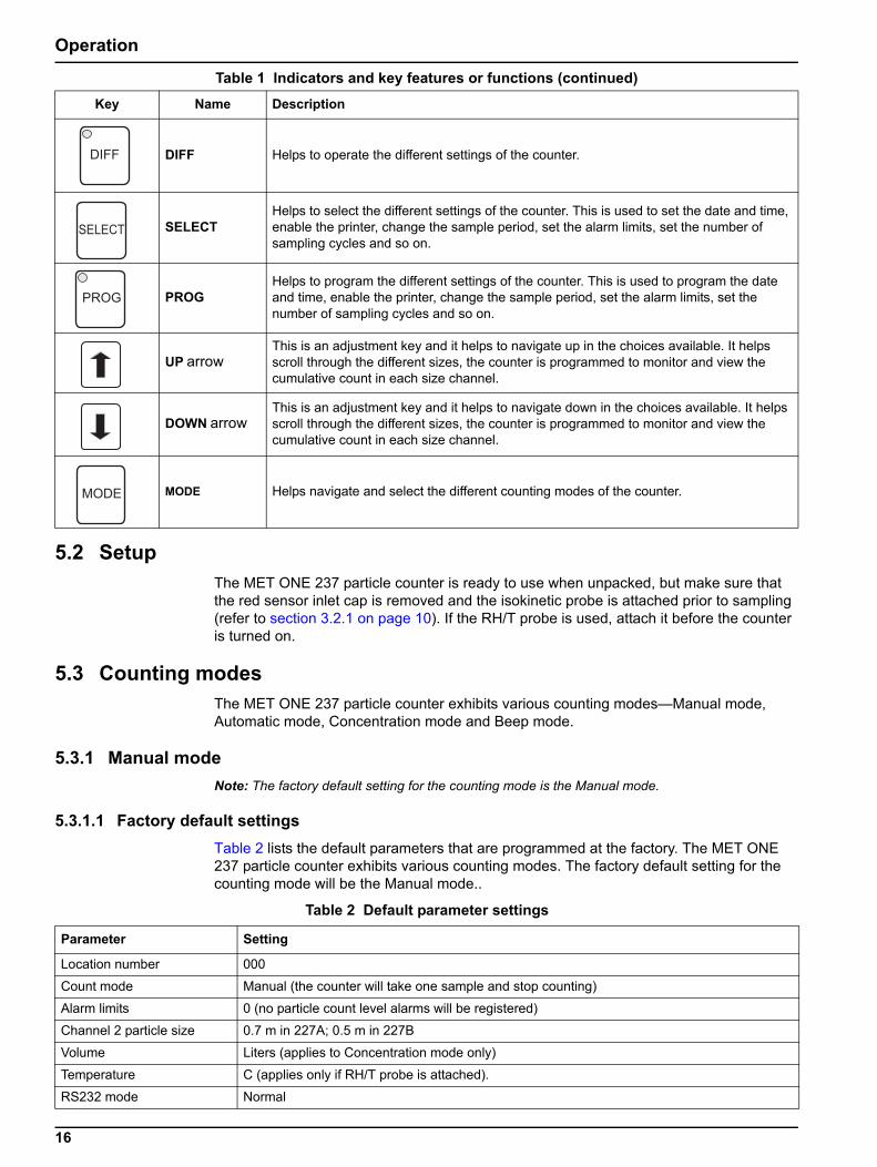
5.3.1.1 Factory default settingsTable 2 lists the default parameters that are programmed at the factory. The MET ONE 237 particle counter exhibits various counting modes. The factory default setting for the counting mode will be the Manual mode..
DIFF Helps to operate the different settings of the counter.
SELECTHelps to select the different settings of the counter. This is used to set the date and time, enable the printer, change the sample period, set the alarm limits, set the number of sampling cycles and so on.
PROGHelps to program the different settings of the counter. This is used to program the date and time, enable the printer, change the sample period, set the alarm limits, set the number of sampling cycles and so on.
UP arrowThis is an adjustment key and it helps to navigate up in the choices available. It helps scroll through the different sizes, the counter is programmed to monitor and view the cumulative count in each size channel.
DOWN arrowThis is an adjustment key and it helps to navigate down in the choices available. It helps scroll through the different sizes, the counter is programmed to monitor and view the cumulative count in each size channel.
MODE Helps navigate and select the different counting modes of the counter.
Table 1 Indicators and key features or functions (continued)
Key Name Description
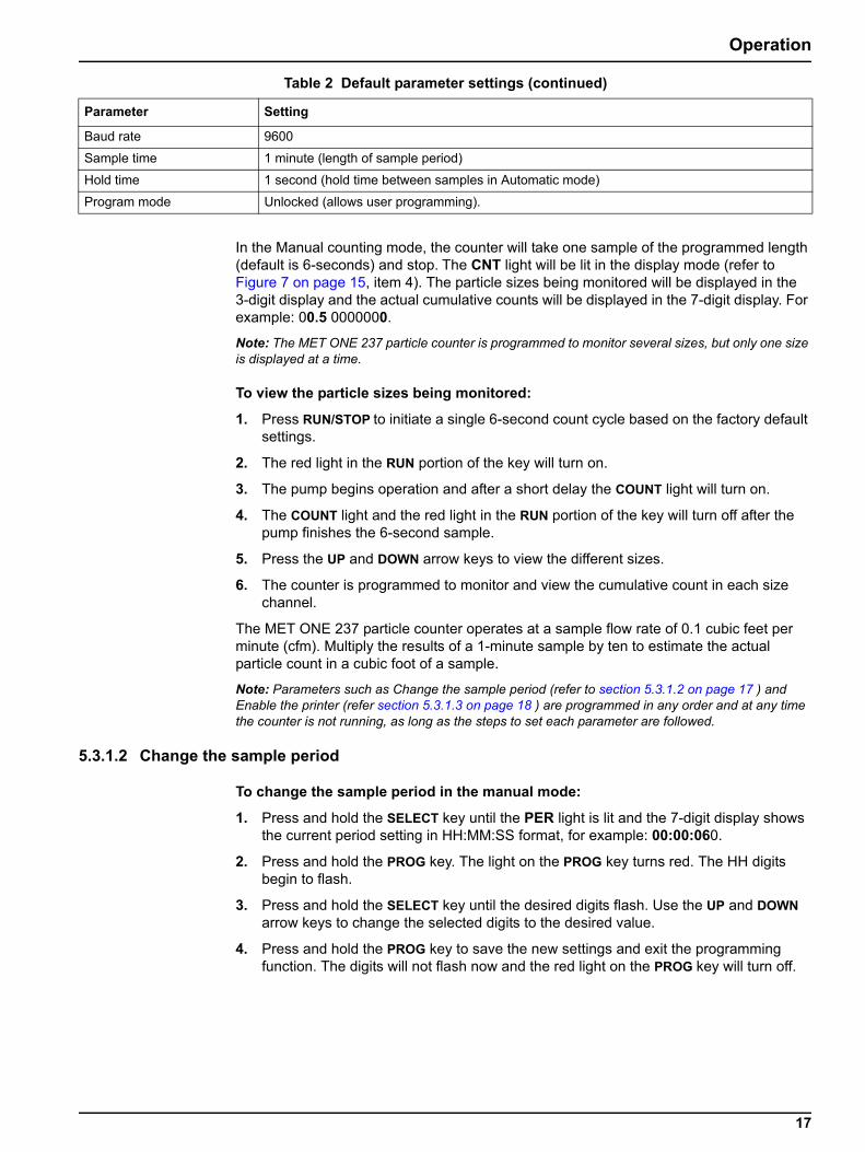
Table 2 Default parameter settings
Parameter Setting
Location number 000
Count mode Manual (the counter will take one sample and stop counting)
Alarm limits 0 (no particle count level alarms will be registered)
Channel 2 particle size 0.7 m in 227A; 0.5 m in 227B
Volume Liters (applies to Concentration mode only)
Temperature C (applies only if RH/T probe is attached).
RS232 mode Normal
16
Operation
In the Manual counting mode, the counter will take one sample of the programmed length (default is 6-seconds) and stop. The CNT light will be lit in the display mode (refer to Figure 7 on page 15, item 4). The particle sizes being monitored will be displayed in the 3-digit display and the actual cumulative counts will be displayed in the 7-digit display. For example: 00.5 0000000.
Note: The MET ONE 237 particle counter is programmed to monitor several sizes, but only one size is displayed at a time.
To view the particle sizes being monitored:
1. Press RUN/STOP to initiate a single 6-second count cycle based on the factory default settings.
2. The red light in the RUN portion of the key will turn on.
3. The pump begins operation and after a short delay the COUNT light will turn on.
4. The COUNT light and the red light in the RUN portion of the key will turn off after the pump finishes the 6-second sample.
5. Press the UP and DOWN arrow keys to view the different sizes.
6. The counter is programmed to monitor and view the cumulative count in each size channel.
The MET ONE 237 particle counter operates at a sample flow rate of 0.1 cubic feet per minute (cfm). Multiply the results of a 1-minute sample by ten to estimate the actual particle count in a cubic foot of a sample.
Note: Parameters such as Change the sample period (refer to section 5.3.1.2 on page 17 ) and Enable the printer (refer section 5.3.1.3 on page 18 ) are programmed in any order and at any time the counter is not running, as long as the steps to set each parameter are followed.
5.3.1.2 Change the sample period
To change the sample period in the manual mode:
1. Press and hold the SELECT key until the PER light is lit and the 7-digit display shows the current period setting in HH:MM:SS format, for example: 00:00:060.
2. Press and hold the PROG key. The light on the PROG key turns red. The HH digits begin to flash.
3. Press and hold the SELECT key until the desired digits flash. Use the UP and DOWN arrow keys to change the selected digits to the desired value.
4. Press and hold the PROG key to save the new settings and exit the programming function. The digits will not flash now and the red light on the PROG key will turn off.
Baud rate 9600
Sample time 1 minute (length of sample period)
Hold time 1 second (hold time between samples in Automatic mode)
Program mode Unlocked (allows user programming).
Table 2 Default parameter settings (continued)
Parameter Setting
17
Operation
5.3.1.3 Enable the printer
To enable the printer in the manual mode:
1. Press and hold the SELECT key until the OPT light is lit.
2. Press the UP or DOWN arrow key until the 3-digit display shows Prn and the 7-digit display shows the status of the printer.
3. Press and hold the PROG key so the red light on the PROG key turns red and the printer status flashes.
4. Press UP or DOWN arrow key until the word All is displayed.
5. Press and hold the PROG key to save the settings. The light in the key will turn off and the printer status will not flash now. When a sample is complete, the printer will print the results.
Other printer options are:
• Alr—Prints only if an alarm condition exists
• ALL buF—Prints all the contents in the memory buffer
• Alr buF—Prints those records in the memory buffer in which an alarm condition was recorded
• OFF—No printing activity
5.3.1.4 Set the date and timeThe date and time are a part of each sample record stored in the memory and may be programmed as follows:
1. Press and hold the SELECT key until the TIME light is lit and the 7-digit display shows the current time setting in the HH:MM:SS format, for example: 08:26:470. The Counting is visible in the seconds field.
2. Press and hold the PROG key. The light on the PROG key turns red and the HH digits flashes.
3. Press and hold the SELECT key until the desired digits flash. Use the UP and DOWN arrow keys to change the selected digits to the required value.
4. Press and hold the PROG key to save the new settings and exit the programming function. The digits will not flash now and the red light in the key will turn off.
5. Press and hold the SELECT key until the DATE light is lit and repeat steps 2 through 4 to set the date.
5.3.1.5 Set alarm limits
To change the alarm limits in the manual mode:
1. Press and hold the SELECT key until the CNT light is lit. The 3-digit display will show the particle size channel and the 7-digit display will show the count for that size.
2. Press and hold the PROG key. The light on the PROG key turns red and the 7-digit display shows the current alarm limit and the left digit flashes.
3. Press and hold the SELECT key till the required digit flashes.
4. Use the UP and DOWN arrow keys to change the digit to the required value.
5. Press and hold the PROG key to save the new settings and exit the programming function. The digits will not flash now and the red light in the PROG key will turn off.
18

Operation
5.3.2 Automatic modeIn the automatic mode, the MET ONE 237 particle counter automatically takes a specified number of samples and stops, allowing unattended operation. The automatic mode covers the typical programming requirements for the common functions associated with the MET ONE 237 particle counter.
Note: The MET ONE 237 particle counter need not be programmed in any order but maybe programmed anytime without affecting others.
To start the Automatic mode :
1. Press and hold the MODE key until the AUTO light is lit.
5.3.2.1 Set location numbers
To set location numbers in the automatic mode:
1. Press and hold the SELECT key until the OPT light is lit.
2. Press the UP or DOWN arrow key until the 3-digit display shows Loc. The 7-digit display will show a number (Default number seen is 32).
3. Press and hold the PROG key. The light on the PROG key will turn red and the digits on the 7-digit display flashes.
4. Press the DOWN arrow to change the location number to 1.
5. Press and hold the PROG key. The red light on the PROG key will turn off and the digits in the 7-digit display will not flash now.
5.3.2.2 Set the number of cyclesThe number of cycles indicates the number of times the counter will repeat the sampling cycle determined by the programmed Period time and Hold time (three cycles is typical for a routine verification check).
Programming a number of cycles greater than one automatically causes the MET ONE 237 particle counter to enter the ‘Average’ mode. An Average mode shows the average count cycles and generates a report for the printer and the memory buffer. For example, if the number of cycles is set to three, the counter will take three samples of the programmed Period length with the hold period being of programmed Hold length. The printer will print the results of each of the three sample periods when they are completed. The fourth report indicating the average count in each size range over the three samples is printed next. If the records are printed from the Memory Buffer at a later time, the printout will be identical.
To set the number of cycles:
1. Press and hold the SELECT key until the OPT light is lit.
2. Press the UP or DOWN arrow key until the 3-digit display shows CYC. The 7-digit display will show a number on the right.
3. Press and hold the PROG key. The light on the PROG key will turn red and the digits in the 7-digit display will begins to flash.
4. Press and hold the SELECT KEY till the required digits begin to flash. Use the UP and DOWN arrow keys to change the selected digits to the required value.
5. Press and hold the PROG key to save the new settings and exit the programming function. The digits will not flash now and the red light in the PROG key will turn off.
19
Operation
5.3.2.3 Set the sample period and hold timeNote: Set the HOLD time to a minimum of 10 seconds when the printer is enabled. A sample record will be overlooked when calculating the average counts, because of printer operation during the calculations. All the samples will be stored in the Memory buffer and will print the average report if printed at a later period.
To set the sample period to 1-minute and hold time to 10-seconds in automatic mode:
1. Press and hold the SELECT key until the PER light is lit and the 7-digit display shows the current period setting in HH:MM:SS format, for example: 00:00:060.
2. Press and hold the PROG key. The light on the PROG key turns red and the HH digits begin to flash.
3. Press and hold the SELECT key until the required digits begin to flash. Use the UP and DOWN arrow keys to change the selected digits to the required value.
4. Press and hold the PROG key to save the new settings and exit the programming function. The digits will not flash now and the red light on the PROG key will turn off.
5. Press and hold the SELECT key until the HOLD light is lit and repeat steps 2 through 4 to set the HOLD time.
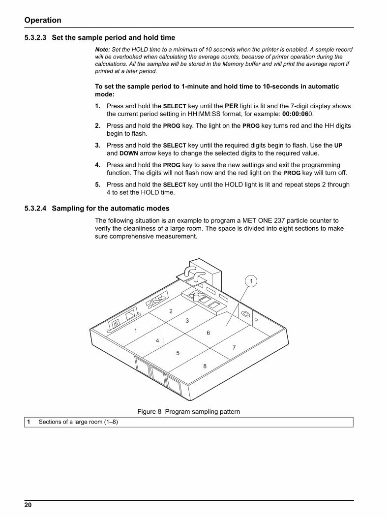
5.3.2.4 Sampling for the automatic modesThe following situation is an example to program a MET ONE 237 particle counter to verify the cleanliness of a large room. The space is divided into eight sections to make sure comprehensive measurement.
Figure 8 Program sampling pattern1 Sections of a large room (1–8)
20
Operation
To sample the room in the automatic mode:
1. Carry the MET ONE 237 particle counter to the center of the first area of the large room to be tested.
2. Place or hold the counter about 4 feet off the floor.
3. Make sure that the opening of the isokinetic probe faces directly into the laminar flow.
4. Press RUN/STOP to initiate counting. The display shows three 1-minute samples being taken, separated by a 10-second hold time.
5. The printer will print the results after each count period. When all three cycles are complete, the counter will print an additional record showing the average of all the three samples.
6. Move to the next location to be tested and program the Location Number as described above.
When the sampling is complete, the count results can be downloaded to a computer and analyzed to verify the condition of the room. Refer to Appendix B on page 43 for download procedures and data string descriptions.
5.3.3 Concentration modeThe concentration mode in the MET ONE 237 particle counter is useful for taking a quick snapshot of airborne particulate contamination levels. Note: The Concentration mode is not a substitute for full sampling.
The concentration mode is appropriate for areas where the particulate levels are unknown and may exceed the operating limits of the counter. The concentration counting mode does not store/write the data records in the memory buffer. The concentration mode gives a continuously updated approximation of the number of particles per cubic foot or per liter. The approximation is based on a user-selectable sample period of one to ten seconds.
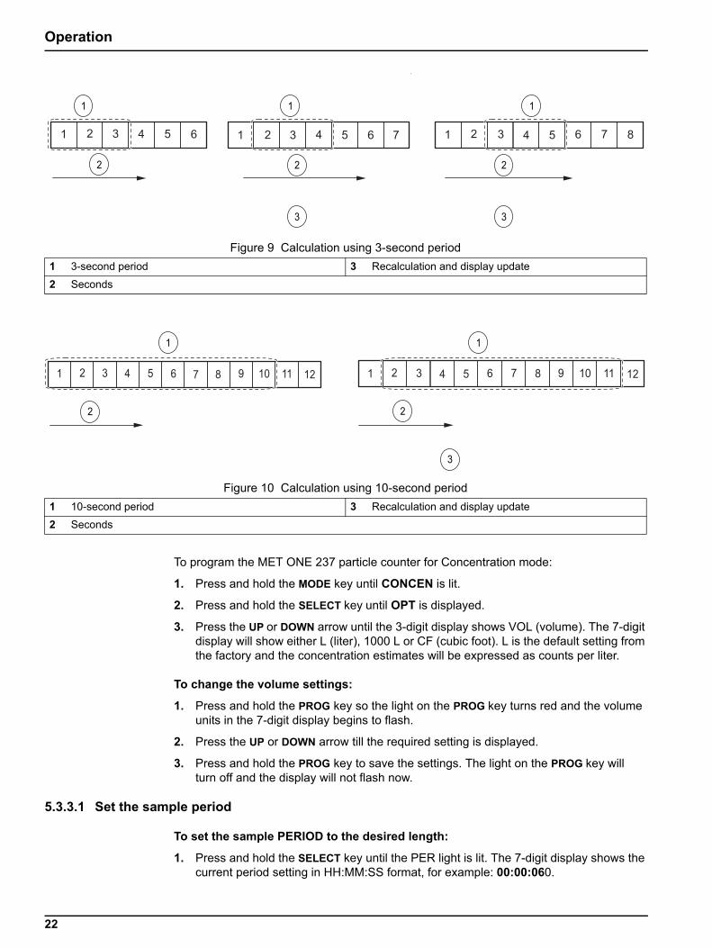
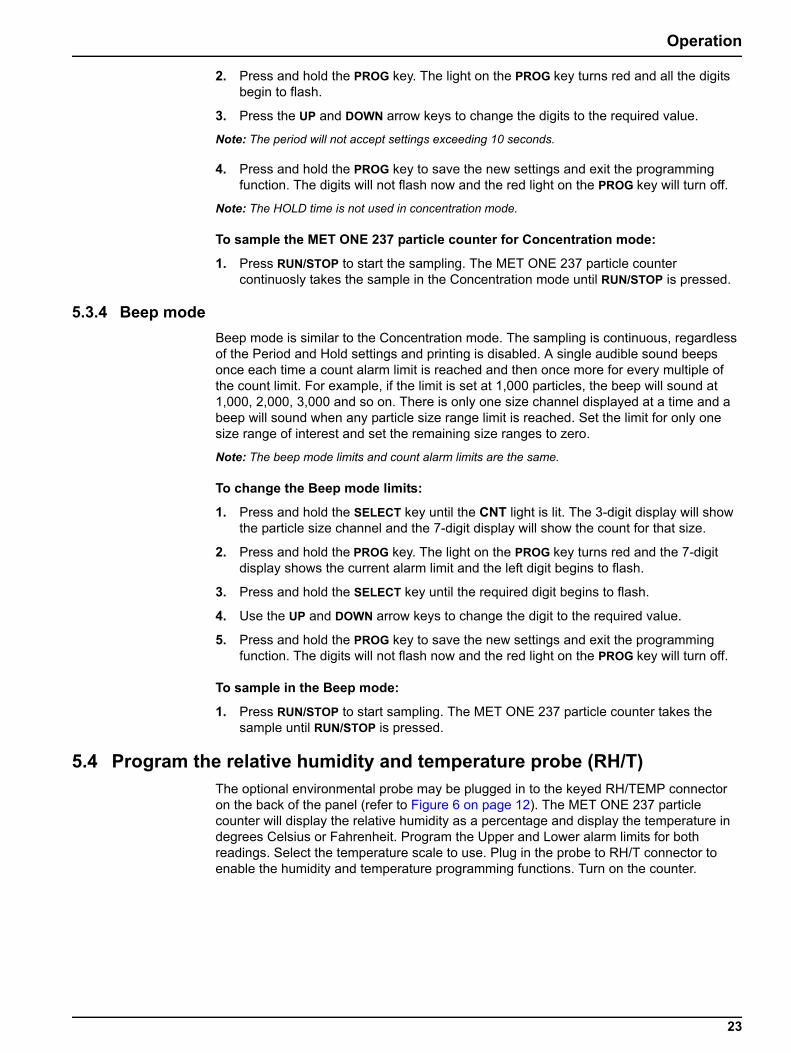
In concentration mode, the counter begins sampling and estimates the counts per cubic foot or per liter based on a programmable period of time. The MET ONE 237 particle counter updates the calculation results on the display at 1-second intervals. The programmable period sets the size of a moving calculation ‘window’ which is moved each second to incorporate a new second of sample data and discard the oldest second of sample data in the ‘window’ of calculations. The MET ONE particle counter uses a 3-second period to calculate the concentration based on a 3-second window (refer to Figure 9). The counter calculates the concentration based on a 10-second window that moves every second (refer to Figure 10). A 10-second period provides a good representation of actual concentration because it covers a longer period.Note: Longer periods also allow high particulate levels to contaminate the sensor. Use a shorter period to calculate the Concentration for unknown environments
21
Operation
.
To program the MET ONE 237 particle counter for Concentration mode:
1. Press and hold the MODE key until CONCEN is lit.
2. Press and hold the SELECT key until OPT is displayed.
3. Press the UP or DOWN arrow until the 3-digit display shows VOL (volume). The 7-digit display will show either L (liter), 1000 L or CF (cubic foot). L is the default setting from the factory and the concentration estimates will be expressed as counts per liter.
To change the volume settings:
1. Press and hold the PROG key so the light on the PROG key turns red and the volume units in the 7-digit display begins to flash.
2. Press the UP or DOWN arrow till the required setting is displayed.
3. Press and hold the PROG key to save the settings. The light on the PROG key will turn off and the display will not flash now.
5.3.3.1 Set the sample period
To set the sample PERIOD to the desired length:
1. Press and hold the SELECT key until the PER light is lit. The 7-digit display shows the current period setting in HH:MM:SS format, for example: 00:00:060.
Figure 9 Calculation using 3-second period1 3-second period 3 Recalculation and display update
2 Seconds
Figure 10 Calculation using 10-second period1 10-second period 3 Recalculation and display update
2 Seconds
22
Operation
2. Press and hold the PROG key. The light on the PROG key turns red and all the digits begin to flash.
3. Press the UP and DOWN arrow keys to change the digits to the required value.
Note: The period will not accept settings exceeding 10 seconds.
4. Press and hold the PROG key to save the new settings and exit the programming function. The digits will not flash now and the red light on the PROG key will turn off.
Note: The HOLD time is not used in concentration mode.
To sample the MET ONE 237 particle counter for Concentration mode:
1. Press RUN/STOP to start the sampling. The MET ONE 237 particle counter continuosly takes the sample in the Concentration mode until RUN/STOP is pressed.
5.3.4 Beep modeBeep mode is similar to the Concentration mode. The sampling is continuous, regardless of the Period and Hold settings and printing is disabled. A single audible sound beeps once each time a count alarm limit is reached and then once more for every multiple of the count limit. For example, if the limit is set at 1,000 particles, the beep will sound at 1,000, 2,000, 3,000 and so on. There is only one size channel displayed at a time and a beep will sound when any particle size range limit is reached. Set the limit for only one size range of interest and set the remaining size ranges to zero.
Note: The beep mode limits and count alarm limits are the same.
To change the Beep mode limits:
1. Press and hold the SELECT key until the CNT light is lit. The 3-digit display will show the particle size channel and the 7-digit display will show the count for that size.
2. Press and hold the PROG key. The light on the PROG key turns red and the 7-digit display shows the current alarm limit and the left digit begins to flash.
3. Press and hold the SELECT key until the required digit begins to flash.
4. Use the UP and DOWN arrow keys to change the digit to the required value.
5. Press and hold the PROG key to save the new settings and exit the programming function. The digits will not flash now and the red light on the PROG key will turn off.
To sample in the Beep mode:
1. Press RUN/STOP to start sampling. The MET ONE 237 particle counter takes the sample until RUN/STOP is pressed.
5.4 Program the relative humidity and temperature probe (RH/T)The optional environmental probe may be plugged in to the keyed RH/TEMP connector on the back of the panel (refer to Figure 6 on page 12). The MET ONE 237 particle counter will display the relative humidity as a percentage and display the temperature in degrees Celsius or Fahrenheit. Program the Upper and Lower alarm limits for both readings. Select the temperature scale to use. Plug in the probe to RH/T connector to enable the humidity and temperature programming functions. Turn on the counter.
23
Operation
To program the settings for relative humidity/temperature:
1. To change the alarm limits, press and hold the SELECT key until the TEMP light is lit. The 7-digit display will show the temperature reading and the scale being used.
2. Press and hold the PROG key. The light on the PROG key turns red. The 3-digit display will show HI (HI indicates that the upper alarm limit is currently being programmed). The 7-digit display shows the current alarm limit and the scale being used and the left digit begins to flash .
3. Press and hold the SELECT key until the required digit begin to flash.
4. Press the UP and DOWN arrow keys to change the flashing digit to the required value.
5. Press and hold the SELECT key until the 3-digit display shows LO (LO indicates that the low temp level is currently being programmed). The 7-digit display shows the current alarm limit and the left digit begins to flash and the scale being used.
6. Press and hold the SELECT key until the desired digit flashes.
Note: The temperature scale is only programmable with the HI temperature alarm limit.
7. Press the UP and DOWN arrow keys to change the digit to the required value.
8. Press and hold the PROG key to save the new settings and exit the programming function. The digits will not flash now and the red light on the PROG key will turn off.
Note: Programming the HI and LO Relative Humidity alarm limits is similar.
5.4.1 Environmental alarmsWhen a programmed environmental alarm limit is exceeded, an audible alarm will sound and the LIMIT light will light red. Press and hold any of the front panel keys to turn off the audible alarm. If the alarm occurs when the RH or TEMP reading is not being displayed, the appropriate TEMP or RH light will flash.
24
Section 6 Maintenance
DANGEROnly qualified personnel should conduct the tasks described in this section of the manual.
DANGERElectrocution hazard. Always disconnect the power to the instrument before making any electrical connections.
WARNINGHarmful radiation exposure. Do not use the controls or adjustments or performance of procedures other than those specified.
CAUTIONElectrostatic discharge (ESD) can damage or destroy electronic components. All work inside the particle counter should be done at a static-safe workstation.
6.1 Maintenance guidelinesA static-safe workstation can be created by doing the following:
• Use a grounded conductive table mat and resistor-isolated wrist-strap combination.
• Earth-ground all test instruments to prevent a buildup of static discharge.
Important Note: The laser diode in this device is extremely sensitive to static charges and out-of-tolerance voltage variations.
Important Note: Never connect or disconnect the sensor cable from the counter when the counter is on.
6.2 Clean the sensor
To clean the sensor:
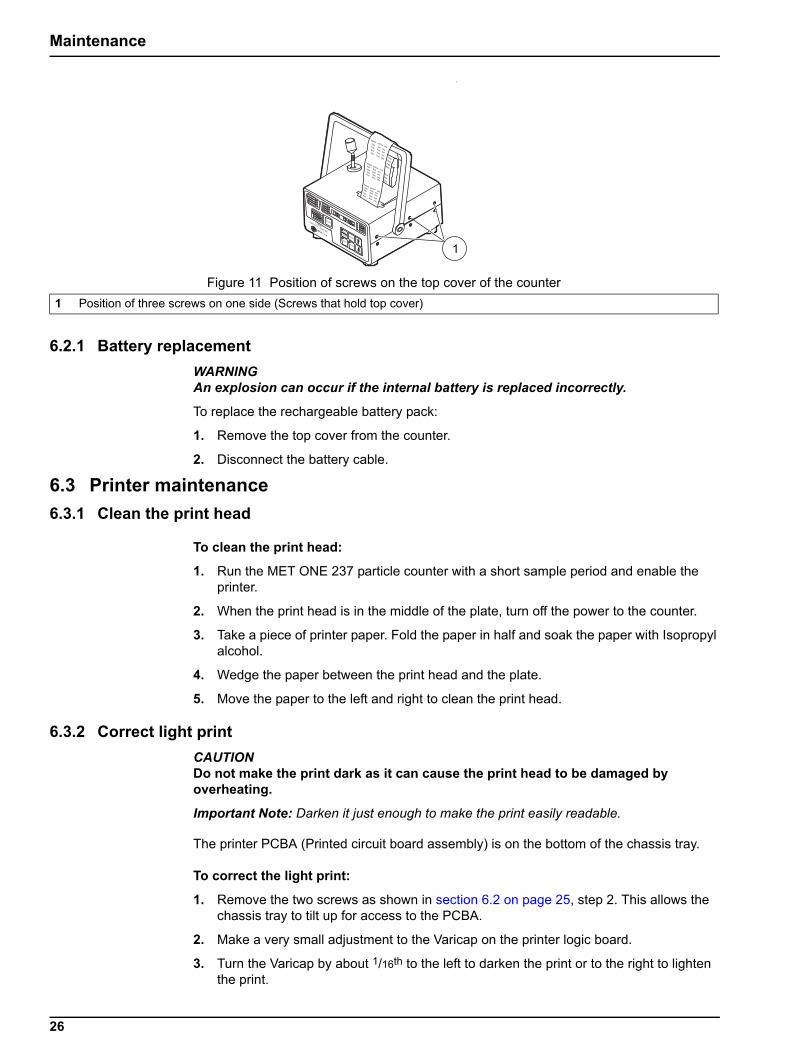
1. Remove the six screws (three screws on each side) that hold the top cover on the counter (refer to Figure 11 on page 26).
2. Remove the two screws from the sides allowing the chassis tray to pivot for sensor access.
3. Disconnect the clear tubing from the sensor outlet fitting.
4. Remove the four nylon screws holding the sensor to the chassis tray.
5. Disconnect the sensor cable from the sensor circuit board. Make note of the position for later steps. Remove the connector from the counter.
6. Insert two #2-56 machine screws in the two threaded holes on the reflector. Use these screws as a handle to remove the reflector with a pulling and twisting motion.
7. Clean the reflector and photo detector with cotton swabs saturated with a small amount of reagent grade Acetone. Wipe the optical surfaces with a dry swab after cleaning. Blow the dust /particles from the interior surfaces with clean dry air.
8. Perform steps 1 to 8 in reverse order to assemble the unit.
25
Maintenance
.
6.2.1 Battery replacementWARNINGAn explosion can occur if the internal battery is replaced incorrectly.
To replace the rechargeable battery pack:
1. Remove the top cover from the counter.
2. Disconnect the battery cable.
6.3 Printer maintenance6.3.1 Clean the print head
To clean the print head:
1. Run the MET ONE 237 particle counter with a short sample period and enable the printer.
2. When the print head is in the middle of the plate, turn off the power to the counter.
3. Take a piece of printer paper. Fold the paper in half and soak the paper with Isopropyl alcohol.
4. Wedge the paper between the print head and the plate.
5. Move the paper to the left and right to clean the print head.
6.3.2 Correct light printCAUTIONDo not make the print dark as it can cause the print head to be damaged by overheating.
Important Note: Darken it just enough to make the print easily readable.
The printer PCBA (Printed circuit board assembly) is on the bottom of the chassis tray.
To correct the light print:
1. Remove the two screws as shown in section 6.2 on page 25, step 2. This allows the chassis tray to tilt up for access to the PCBA.
2. Make a very small adjustment to the Varicap on the printer logic board.
3. Turn the Varicap by about 1/16th to the left to darken the print or to the right to lighten the print.
Figure 11 Position of screws on the top cover of the counter1 Position of three screws on one side (Screws that hold top cover)
26

Maintenance
6.3.3 Replace the printer ribbon
To replace the printer ribbon:
1. Remove the two screws that hold the printer bar and remove the printer bar.
2. Remove the four ¼” nuts that hold the print head assembly.
3. Tilt the chassis tray up as in section 6.3 on page 26, step 1. Locate the printer ribbon cable connector.
Note: The connector must be unlocked by pulling the edges of the connector away from the PCBA before attempting to remove the cable from the connector.
4. Carefully remove the cable from the connector.
5. Replace the printer ribbon and follow steps 4 to 1 to assemble the printer ribbon.
27

Maintenance
28
Section 7 Troubleshooting Procedures
7.1 Common problems
7.2 Reset the counterThe counter is reset to correct any intermittent fault conditions in the microprocessor controller functions. It is similar to restarting the computer and all the settings return to factory defaults clearing the Memory buffer. If the particle counter does not function properly (for example, incorrect date and time), clear the counter memory and restart the microprocessor.
To reset the counter:
1. Turn off the Power to the counter.
2. Press and hold the MODE key while turning on the power. Release the MODE keys when the counter beeps once.
3. The 3-digit display shows dEF and the 7-digit display shows 270-ic, the number and revision level of EPROM.
4. The display may show a different revision level depending on the EPROM.
5. Press the DOWN arrow key to restore normal operation and program the counter operating parameters as required.
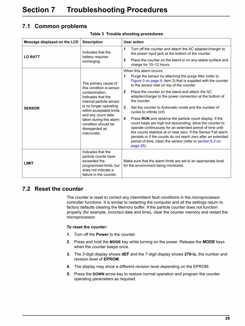
Table 3 Trouble shooting procedures
Message displayed on the LCD Description User action
LO BATTIndicates that the battery requires recharging.
1 Turn off the counter and attach the AC adapter/charger to the power input jack at the bottom of the counter.
2 Place the counter on the stand or on any stable surface and charge for 10–12 hours.
SENSOR
The primary cause of this condition is sensor contamination. Indicates that the internal particle sensor is no longer operating within acceptable limits and any count data taken during this alarm condition should be disregarded as inaccurate.
When this alarm occurs:1 Purge the sensor by attaching the purge filter (refer to
Figure 3 on page 9, item 3) that is supplied with the counter to the sensor inlet on top of the counter.
2 Place the counter on the stand and attach the AC adapter/charger to the power connection at the bottom of the counter.
3 Set the counter to Automatic mode and the number of cycles to infinite (inf).
4 Press RUN and observe the particle count display. If the count totals are high but descending, allow the counter to operate continuously for an extended period of time until the counts stabilize at or near zero. If the Sensor Fail alarm persists or if the counts do not reach zero after an extended period of time, clean the sensor (refer to section 6.2 on page 25).
LIMIT
Indicates that the particle counts have exceeded the programmed limits, but does not indicate a failure in the counter.
Make sure that the alarm limits are set to an appropriate level for the environment being monitored.
29
Troubleshooting Procedures
7.3 Pump troubleshootingIf the vacuum pump does not operate, or exhibits any questionable symptoms such as unusual sound or vibration, it may be removed for maintenance to restore it to optimum operation.
7.3.1 Disassembly and cleaning of the pump
Prerequisites:
• 1.27 mm or 1.5 mm Allen wrench
To disassemble and clean the pump:
1. Open the counter as described in section 6.2 on page 25, step 1 to step 3.
2. Remove the pump from the chassis clip.
3. Remove the pump electrical connection.
4. Disconnect the tubing from the pump.
Note: Make sure to note the attachments to the Vacuum (V) fitting and the Pressure (P) fitting.
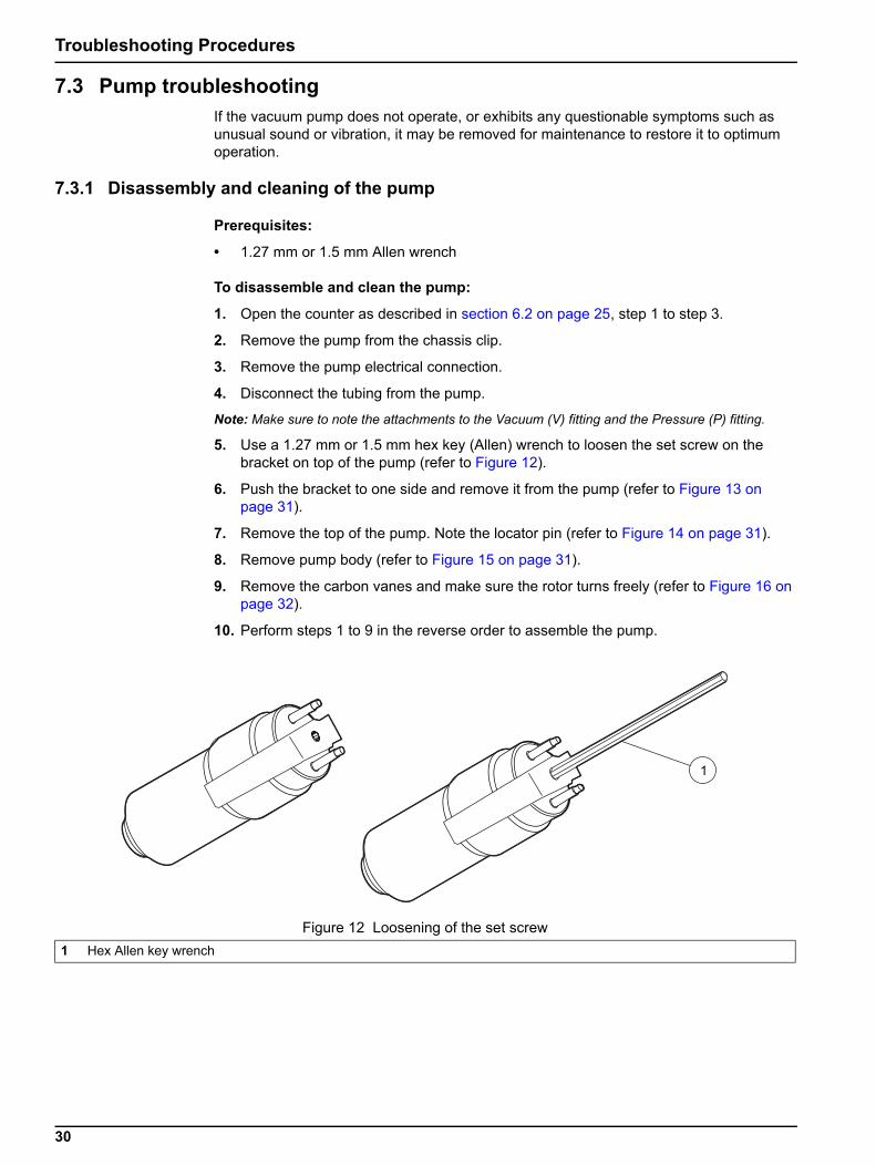
5. Use a 1.27 mm or 1.5 mm hex key (Allen) wrench to loosen the set screw on the bracket on top of the pump (refer to Figure 12).
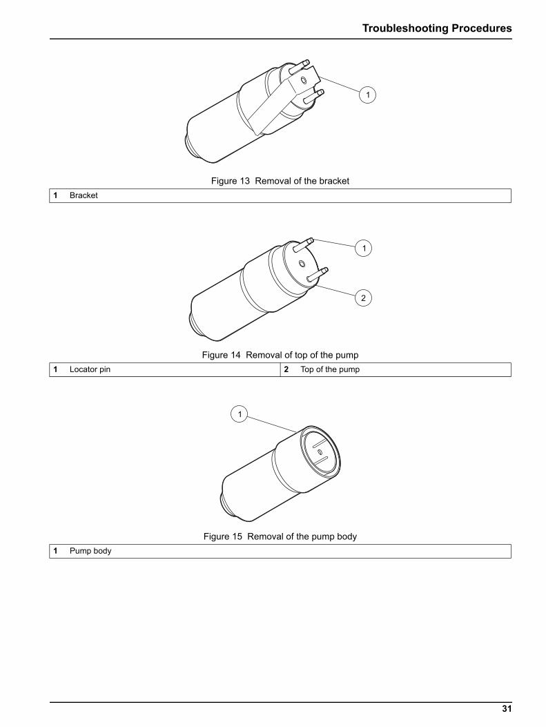
6. Push the bracket to one side and remove it from the pump (refer to Figure 13 on page 31).
7. Remove the top of the pump. Note the locator pin (refer to Figure 14 on page 31).
8. Remove pump body (refer to Figure 15 on page 31).
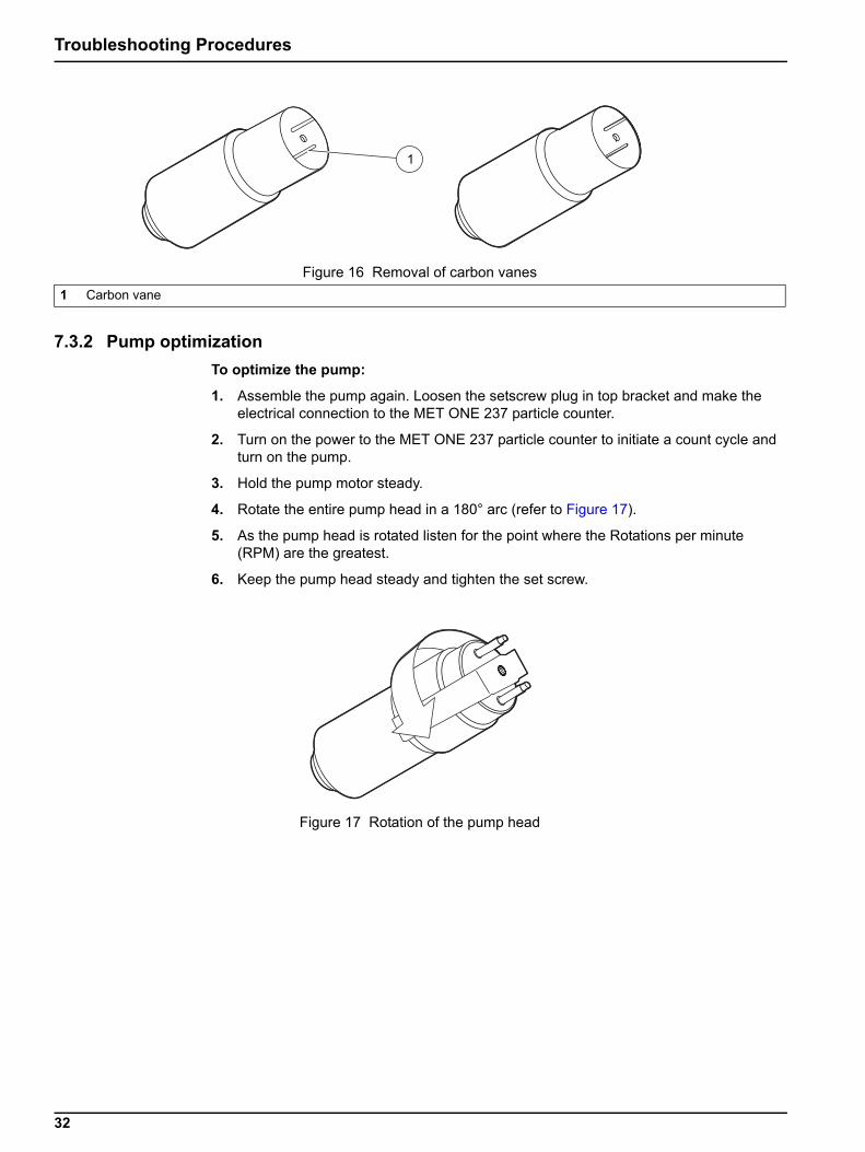
9. Remove the carbon vanes and make sure the rotor turns freely (refer to Figure 16 on page 32).
10. Perform steps 1 to 9 in the reverse order to assemble the pump.
Figure 12 Loosening of the set screw1 Hex Allen key wrench
30
Troubleshooting Procedures
Figure 13 Removal of the bracket1 Bracket
Figure 14 Removal of top of the pump1 Locator pin 2 Top of the pump
Figure 15 Removal of the pump body1 Pump body
31
Troubleshooting Procedures
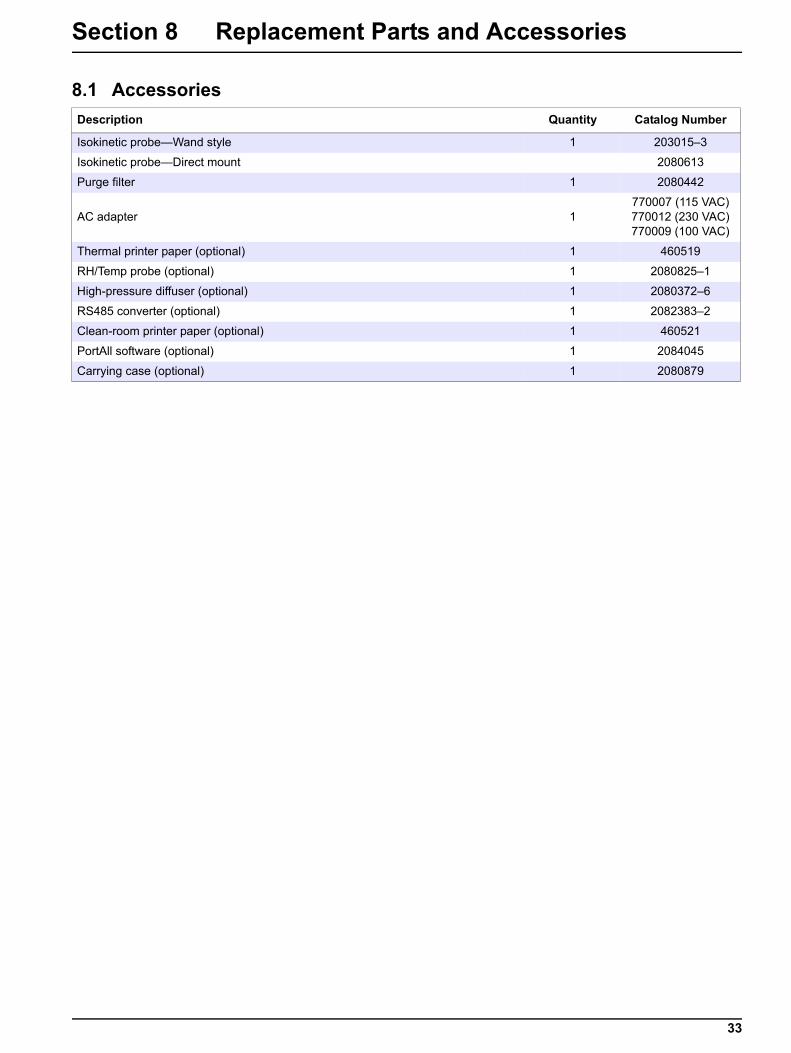
7.3.2 Pump optimizationTo optimize the pump:
1. Assemble the pump again. Loosen the setscrew plug in top bracket and make the electrical connection to the MET ONE 237 particle counter.
2. Turn on the power to the MET ONE 237 particle counter to initiate a count cycle and turn on the pump.
3. Hold the pump motor steady.
4. Rotate the entire pump head in a 180° arc (refer to Figure 17).
5. As the pump head is rotated listen for the point where the Rotations per minute (RPM) are the greatest.
6. Keep the pump head steady and tighten the set screw.
Figure 16 Removal of carbon vanes1 Carbon vane
Figure 17 Rotation of the pump head
32
Section 8 Replacement Parts and Accessories
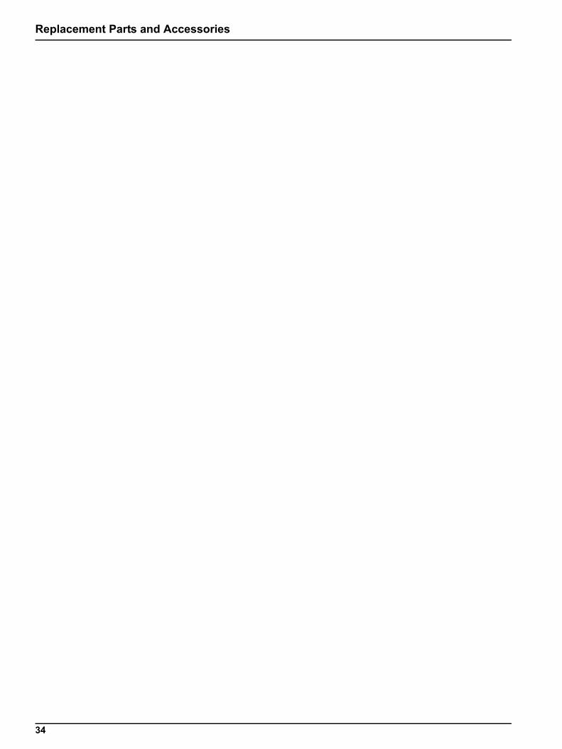
8.1 AccessoriesDescription Quantity Catalog Number
Isokinetic probe—Wand style 1 203015–3
Isokinetic probe—Direct mount 2080613
Purge filter 1 2080442
AC adapter 1770007 (115 VAC)770012 (230 VAC)770009 (100 VAC)
Thermal printer paper (optional) 1 460519
RH/Temp probe (optional) 1 2080825–1
High-pressure diffuser (optional) 1 2080372–6
RS485 converter (optional) 1 2082383–2
Clean-room printer paper (optional) 1 460521
PortAll software (optional) 1 2084045
Carrying case (optional) 1 2080879
33
Replacement Parts and Accessories
34

36
Section 10 Limited WarrantyHach Ultra warrants this instrument to be free of defects in materials and workmanship for a period of one year from the shipping date. If any instrument covered under this warranty proves defective during this period, Hach Ultra will, at its option either repair the defective part without charge for extra parts and labor or provide an equivalent replacement in exchange for the defective product.
If any diode covered under this warranty proves defective during this period, Hach Ultra will, at its option, either repair the defective diode without charge for parts and labor or provide an equivalent replacement in exchange for the defective product.
To obtain service under this warranty, the customer must notify the nearest Hach Ultra service support center on or before the expiration of the warranty period and follow their instructions for return of the defective instrument. The customer is responsible for all costs associated with packaging and transporting the defective unit to the service support center, and must prepay all shipping charges. Hach Ultra will pay for return shipping if the shipment is to a location within the same country as the service support center.
This warranty shall not apply to any defect, failure, or damage caused by improper use or maintenance or by inadequate maintenance or care. This warranty shall not apply to damage resulting from attempts by personnel other than Hach Ultra representatives, or factory authorized and trained personnel, to install, repair or service the instrument; to damage resulting from improper use or connection to incompatible equipment; or to instruments that have been modified or integrated with other products when the effect of such modification or integration materially increases the time or difficulty of servicing the instrument.
THIS WARRANTY IS GIVEN BY HACH ULTRA ANALYTICS WITH RESPECT TO THIS INSTRUMENT IN LIEU OF ANY OTHER WARRANTIES, EXPRESSED OR IMPLIED. HACH ULTRA ANALYTICS AND ITS VENDORS DISCLAIM ANY IMPLIED WARRANTIES OF MERCHANTABILITY OR FITNESS FOR A PARTICULAR NON-CONTRACTUAL PURPOSE. HACH ULTRA ANALYTICS’ RESPONSIBILITY TO REPAIR OR REPLACE DEFECTIVE PRODUCTS IS THE SOLE AND EXCLUSIVE REMEDY PROVIDED TO THE CUSTOMER FOR BREACH OF THIS WARRANTY. HACH ULTRA ANALYTICS AND ITS VENDORS WILL NOT BE LIABLE FOR ANY INDIRECT, SPECIAL, INCIDENTAL, OR CONSEQUENTIAL DAMAGES EVEN IF HACH ULTRA ANALYTICS OR ITS VENDORS HAS BEEN GIVEN ADVANCED NOTICE OF THE POSSIBILITY OF SUCH DAMAGES.
37

38
Section 11 Certification
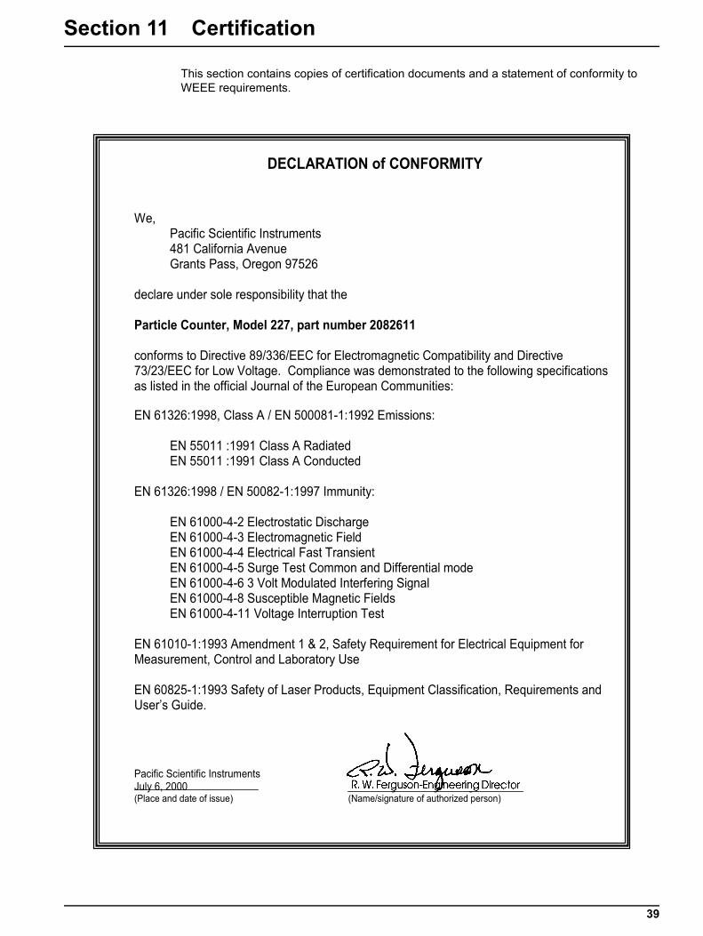
This section contains copies of certification documents and a statement of conformity to WEEE requirements.
DECLARATION of CONFORMITY
We, Pacific Scientific Instruments 481 California Avenue Grants Pass, Oregon 97526
declare under sole responsibility that the
Particle Counter, Model 227, part number 2082611
conforms to Directive 89/336/EEC for Electromagnetic Compatibility and Directive 73/23/EEC for Low Voltage. Compliance was demonstrated to the following specifications as listed in the official Journal of the European Communities:
EN 61326:1998, Class A / EN 500081-1:1992 Emissions:
EN 55011 :1991 Class A Radiated EN 55011 :1991 Class A Conducted
EN 61326:1998 / EN 50082-1:1997 Immunity:
EN 61000-4-2 Electrostatic Discharge EN 61000-4-3 Electromagnetic Field EN 61000-4-4 Electrical Fast Transient EN 61000-4-5 Surge Test Common and Differential mode EN 61000-4-6 3 Volt Modulated Interfering Signal EN 61000-4-8 Susceptible Magnetic Fields EN 61000-4-11 Voltage Interruption Test
EN 61010-1:1993 Amendment 1 & 2, Safety Requirement for Electrical Equipment for Measurement, Control and Laboratory Use
EN 60825-1:1993 Safety of Laser Products, Equipment Classification, Requirements and User’s Guide.
Pacific Scientific Instruments July 6, 2000 R. W. Ferguson-Engineering Director (Place and date of issue) (Name/signature of authorized person)
39
Certification
31
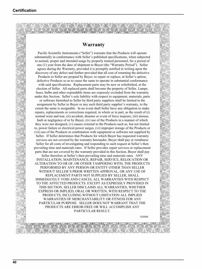
Warranty Pacific Scientific Instruments (“Seller”) warrants that the Products will operate
substantially in conformance with Seller’s published specifications, when subjected to normal, proper and intended usage by properly trained personnel, for a period of
one (1) year from the date of shipment to Buyer (the “Warranty Period”). Seller agrees during the Warranty, provided it is promptly notified in writing upon the
discovery of any defect and further provided that all cost of returning the defective Products to Seller are prepaid by Buyer, to repair or replace, at Seller’s option,
defective Products so as to cause the same to operate in substantial conformance with said specifications. Replacement parts may be new or refurbished, at the
election of Seller. All replaced parts shall become the property of Seller. Lamps, fuses, bulbs and other expendable items are expressly excluded from the warranty
under this Section. Seller’s sole liability with respect to equipment, materials, parts or software furnished to Seller by third party suppliers shall be limited to the
assignment by Seller to Buyer or any such third party supplier’s warranty, to the extent the same is assignable. In no event shall Seller have any obligation to make repairs, replacements or corrections required, in whole or in part, as the result of (i) normal wear and tear, (ii) accident, disaster or event of force majeure, (iii) misuse, fault or negligence of or by Buyer, (iv) use of the Products in a manner of which
they were not designed, (v) causes external to the Products such as, but not limited to, power failure or electrical power surges, (vi) improper storage of the Products or (vii) use of the Products in combination with equipment or software not supplied by Seller. If Seller determines that Products for which Buyer has requested warranty services are not covered by the warranty hereunder, Buyer shall pay or reimburse Seller for all costs of investigating and responding to such request at Seller’s then
prevailing time and materials rates. If Seller provides repair services or replacement parts that are not covered by the warranty provided in this Section, Buyer shall pay
Seller therefore at Seller’s then prevailing time and materials rates. ANY INSTALLATION, MAINTENANCE, REPAIR, SERVICE, RELOCATION OR
ALTERATION TO OR OF, OR OTHER TAMPERING WITH, THE PRODUCTS PERFORMED BY ANY PERSON OR ENTITY OTHER THAN SELLER
WITHOUT SELLER’S PRIOR WRITTEN APPROVAL, OR ANY USE OF REPLACEMENT PARTS NOT SUPPLIED BY SELLER, SHALL
IMMEDIATELY VOID AND CANCEL ALL WARRANTIES WITH RESPECT TO THE AFFECTED PRODUCTS. EXCEPT AS EXPRESSLY PROVIDED IN
THIS SECTION, SELLER DISCLAIMS ALL WARRANTIES, WHETHER EXPRESS OR IMPLIED, ORAL OR WRITTEN, WITH RESPECT TO THE
PRODUCTS, INCLUDING WITHOUT LIMITATION ALL IMPLIED WARRANTIES OF MERCHANTABILITY OR FITNESS FOR ANY
PARTICULAR PURPOSE. SELLER DOES NOT WARRANT THAT THE PRODUCTS ARE ERROR-FREE OR WILL ACCOMPLISH ANY
PARTICULAR RESULT. 12/2000
40
Appendix A Optional Accessories
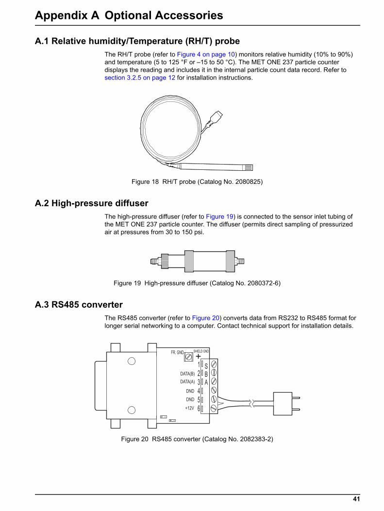
A.1 Relative humidity/Temperature (RH/T) probeThe RH/T probe (refer to Figure 4 on page 10) monitors relative humidity (10% to 90%) and temperature (5 to 125 °F or –15 to 50 °C). The MET ONE 237 particle counter displays the reading and includes it in the internal particle count data record. Refer to section 3.2.5 on page 12 for installation instructions.
A.2 High-pressure diffuserThe high-pressure diffuser (refer to Figure 19) is connected to the sensor inlet tubing of the MET ONE 237 particle counter. The diffuser (permits direct sampling of pressurized air at pressures from 30 to 150 psi.
A.3 RS485 converter The RS485 converter (refer to Figure 20) converts data from RS232 to RS485 format for longer serial networking to a computer. Contact technical support for installation details.
Figure 18 RH/T probe (Catalog No. 2080825)
Figure 19 High-pressure diffuser (Catalog No. 2080372-6)
Figure 20 RS485 converter (Catalog No. 2082383-2)
41
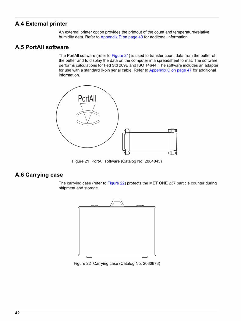
A.4 External printer An external printer option provides the printout of the count and temperature/relative humidity data. Refer to Appendix D on page 49 for additonal information.
A.5 PortAll softwareThe PortAll software (refer to Figure 21) is used to transfer count data from the buffer of the buffer and to display the data on the computer in a spreadsheet format. The software performs calculations for Fed Std 209E and ISO 14644. The software includes an adapter for use with a standard 9-pin serial cable. Refer to Appendix C on page 47 for additional information.
A.6 Carrying caseThe carrying case (refer to Figure 22) protects the MET ONE 237 particle counter during shipment and storage.
Figure 21 PortAll software (Catalog No. 2084045)
Figure 22 Carrying case (Catalog No. 2080878)
42
Appendix B Computer Interface Operations
B.1 Data analysis for ISO 14644The primary reason for a computer interface with the MET ONE 237 particle counter is to download the count data for analysis.
ISO 14644 is the governing standard for clean-rooms. The MET ONE 237 particle counter cannot perform the calculations internally. Use the PortAll software package offered by the manufacturer to download data from the counter. Perform all the necessary functions to make sure that there is compliance to the ISO standard. Refer to Appendix C on page 47 for instructions to setup and operate the MET ONE 227 particle counter with the PortAll software. A standard 9-pin to 9-pin serial cable is available instead of the special cable required for simple serial interface when PortAll software is purchased.
B.1.1 Computer communicationsThe MET ONE 237 particle counter is setup for RS232 and RS485 serial data communications capabilities:
• RS232 serial interface circuitry—Provides asynchronous communications between the counter and computer.
• RS485 serial network circuitry—Provides asynchronous communications between up to 64 counters and a controlling computer.
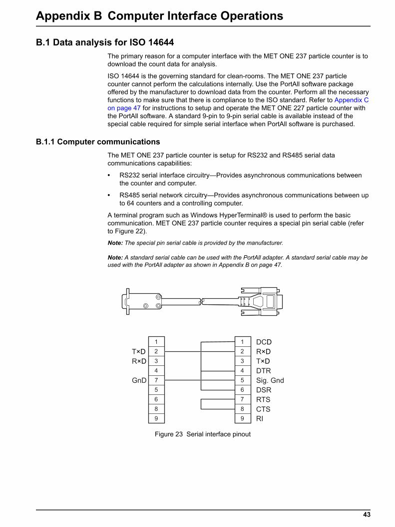
A terminal program such as Windows HyperTerminal® is used to perform the basic communication. MET ONE 237 particle counter requires a special pin serial cable (refer to Figure 22).
Note: The special pin serial cable is provided by the manufacturer.
Note: A standard serial cable can be used with the PortAll adapter. A standard serial cable may be used with the PortAll adapter as shown in Appendix B on page 47.
Figure 23 Serial interface pinout
1 1
2 2
3 3
4 4
7 5
5 6
6 7
8 8
9 9
DCD
R×D
T×D
DTR
Sig. Gnd
DSR
RTS
CTS
RI
T×D
R×D
GnD
43
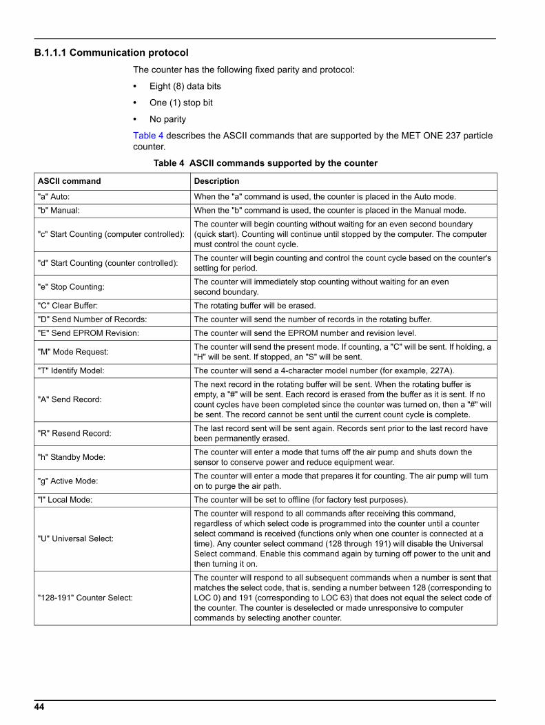
B.1.1.1 Communication protocolThe counter has the following fixed parity and protocol:
• Eight (8) data bits
• One (1) stop bit
• No parity
Table 4 describes the ASCII commands that are supported by the MET ONE 237 particle counter.
Table 4 ASCII commands supported by the counter
ASCII command Description
"a" Auto: When the "a" command is used, the counter is placed in the Auto mode.
"b" Manual: When the "b" command is used, the counter is placed in the Manual mode.
"c" Start Counting (computer controlled):The counter will begin counting without waiting for an even second boundary (quick start). Counting will continue until stopped by the computer. The computer must control the count cycle.
"d" Start Counting (counter controlled): The counter will begin counting and control the count cycle based on the counter's setting for period.
"e" Stop Counting: The counter will immediately stop counting without waiting for an even second boundary.
"C" Clear Buffer: The rotating buffer will be erased.
"D" Send Number of Records: The counter will send the number of records in the rotating buffer.
"E" Send EPROM Revision: The counter will send the EPROM number and revision level.
"M" Mode Request: The counter will send the present mode. If counting, a "C" will be sent. If holding, a "H" will be sent. If stopped, an "S" will be sent.
"T" Identify Model: The counter will send a 4-character model number (for example, 227A).
"A" Send Record:
The next record in the rotating buffer will be sent. When the rotating buffer is empty, a "#" will be sent. Each record is erased from the buffer as it is sent. If no count cycles have been completed since the counter was turned on, then a "#" will be sent. The record cannot be sent until the current count cycle is complete.
"R" Resend Record: The last record sent will be sent again. Records sent prior to the last record have been permanently erased.
"h" Standby Mode: The counter will enter a mode that turns off the air pump and shuts down the sensor to conserve power and reduce equipment wear.
"g" Active Mode: The counter will enter a mode that prepares it for counting. The air pump will turn on to purge the air path.
"l" Local Mode: The counter will be set to offline (for factory test purposes).
"U" Universal Select:
The counter will respond to all commands after receiving this command, regardless of which select code is programmed into the counter until a counter select command is received (functions only when one counter is connected at a time). Any counter select command (128 through 191) will disable the Universal Select command. Enable this command again by turning off power to the unit and then turning it on.
"128-191" Counter Select:
The counter will respond to all subsequent commands when a number is sent that matches the select code, that is, sending a number between 128 (corresponding to LOC 0) and 191 (corresponding to LOC 63) that does not equal the select code of the counter. The counter is deselected or made unresponsive to computer commands by selecting another counter.
44
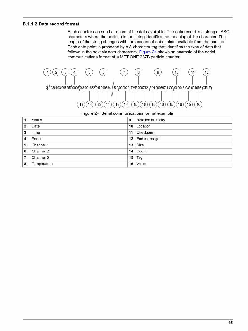
B.1.1.2 Data record formatEach counter can send a record of the data available. The data record is a string of ASCII characters where the position in the string identifies the meaning of the character. The length of the string changes with the amount of data points available from the counter. Each data point is preceded by a 3-character tag that identifies the type of data that follows in the next six data characters. Figure 24 shows an example of the serial communications format of a MET ONE 237B particle counter.
Figure 24 Serial communications format example1 Status 9 Relative humidity
2 Date 10 Location
3 Time 11 Checksum
4 Period 12 End message
5 Channel 1 13 Size
6 Channel 2 14 Count
7 Channel 6 15 Tag
8 Temperature 16 Value
45

46
Appendix C PortAll Software
The clean-room classification standards FS 209E and ISO 14644–1 require specific particle count measurements and calculations to verify the cleanliness level of a clean-room or clean area. The PortAll software automatically generates clean-room verification results from the measurement data from the MET ONE 237 particle counter.
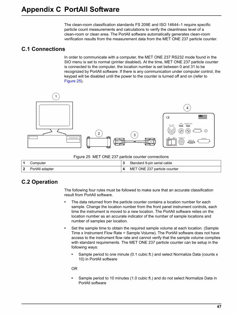
C.1 ConnectionsIn order to communicate with a computer, the MET ONE 237 RS232 mode found in the SIO menu is set to normal (printer disabled). At the time, MET ONE 237 particle counter is connected to the computer, the location number is set between 0 and 31 to be recognized by PortAll software. If there is any communication under computer control, the keypad will be disabled until the power to the counter is turned off and on (refer to Figure 25).
C.2 OperationThe following four rules must be followed to make sure that an accurate classification result from PortAll software.
• The data returned from the particle counter contains a location number for each sample. Change the location number from the front panel instrument controls, each time the instrument is moved to a new location. The PortAll software relies on the location number as an accurate indicator of the number of sample locations and number of samples per location.
• Set the sample time to obtain the required sample volume at each location. (Sample Time x Instrument Flow Rate = Sample Volume). The PortAll software does not have access to the instrument flow rate and cannot verify that the sample volume complies with standard requirements. The MET ONE 237 particle counter can be setup in the following ways:
• Sample period to one minute (0.1 cubic ft.) and select Normalize Data (counts x 10) in PortAll software
OR
• Sample period to 10 minutes (1.0 cubic ft.) and do not select Normalize Data in PortAll software
Figure 25 MET ONE 237 particle counter connections1 Computer 3 Standard 9-pin serial cable
2 PortAll adapter 4 MET ONE 237 particle counter
47
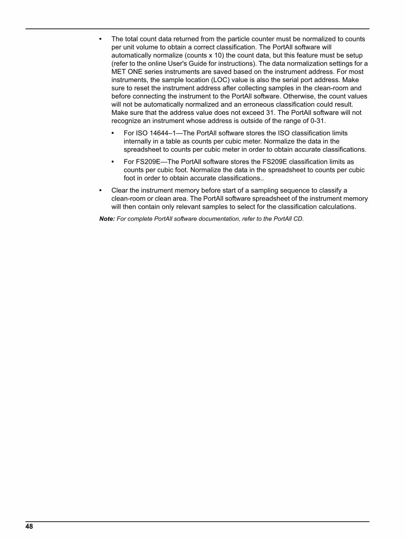
• The total count data returned from the particle counter must be normalized to counts per unit volume to obtain a correct classification. The PortAll software will automatically normalize (counts x 10) the count data, but this feature must be setup (refer to the online User's Guide for instructions). The data normalization settings for a MET ONE series instruments are saved based on the instrument address. For most instruments, the sample location (LOC) value is also the serial port address. Make sure to reset the instrument address after collecting samples in the clean-room and before connecting the instrument to the PortAll software. Otherwise, the count values will not be automatically normalized and an erroneous classification could result. Make sure that the address value does not exceed 31. The PortAll software will not recognize an instrument whose address is outside of the range of 0-31.
• For ISO 14644–1—The PortAll software stores the ISO classification limits internally in a table as counts per cubic meter. Normalize the data in the spreadsheet to counts per cubic meter in order to obtain accurate classifications.
• For FS209E—The PortAll software stores the FS209E classification limits as counts per cubic foot. Normalize the data in the spreadsheet to counts per cubic foot in order to obtain accurate classifications..
• Clear the instrument memory before start of a sampling sequence to classify a clean-room or clean area. The PortAll software spreadsheet of the instrument memory will then contain only relevant samples to select for the classification calculations.
Note: For complete PortAll software documentation, refer to the PortAll CD.
48
Appendix D DPU–414 Printer
The clean-room classification standards FS 209E and ISO 14644–1 require specific particle count measurements and calculations to verify the cleanliness level of a clean-room or clean area.
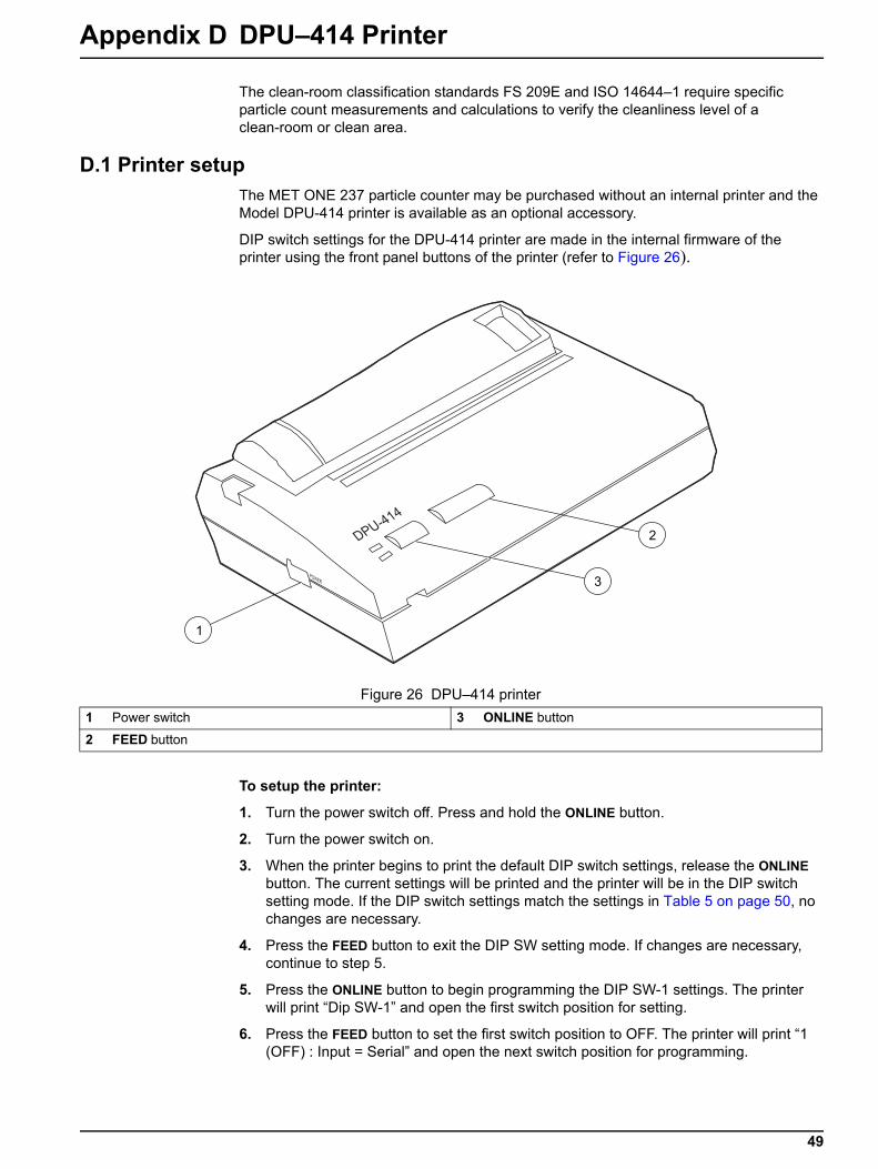
D.1 Printer setupThe MET ONE 237 particle counter may be purchased without an internal printer and the Model DPU-414 printer is available as an optional accessory.
DIP switch settings for the DPU-414 printer are made in the internal firmware of the printer using the front panel buttons of the printer (refer to Figure 26).
To setup the printer:
1. Turn the power switch off. Press and hold the ONLINE button.
2. Turn the power switch on.
3. When the printer begins to print the default DIP switch settings, release the ONLINE button. The current settings will be printed and the printer will be in the DIP switch setting mode. If the DIP switch settings match the settings in Table 5 on page 50, no changes are necessary.
4. Press the FEED button to exit the DIP SW setting mode. If changes are necessary, continue to step 5.
5. Press the ONLINE button to begin programming the DIP SW-1 settings. The printer will print “Dip SW-1” and open the first switch position for setting.
6. Press the FEED button to set the first switch position to OFF. The printer will print “1 (OFF) : Input = Serial” and open the next switch position for programming.
Figure 26 DPU–414 printer1 Power switch 3 ONLINE button
2 FEED button
49
7. Press the ONLINE button to set the second switch position to ON. The printer will print “2 (ON): Printing speed = High” and open the next switch position for programming.
8. Continue programming the remaining positions using the ONLINE button to set ON conditions and the FEED button to set OFF conditions.
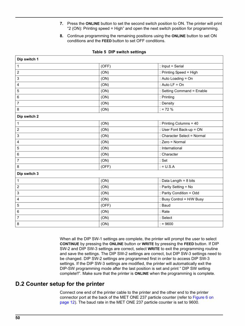
When all the DIP SW-1 settings are complete, the printer will prompt the user to select CONTINUE by pressing the ONLINE button or WRITE by pressing the FEED button. If DIP SW-2 and DIP SW-3 settings are correct, select WRITE to exit the programming routine and save the settings. The DIP SW-2 settings are correct, but DIP SW-3 settings need to be changed. DIP SW-2 settings are programmed first in order to access DIP SW-3 settings. If the DIP SW-3 settings are modified, the printer will automatically exit the DIP-SW programming mode after the last position is set and print “ DIP SW setting complete!!”. Make sure that the printer is ONLINE when the programming is complete.
D.2 Counter setup for the printerConnect one end of the printer cable to the printer and the other end to the printer connector port at the back of the MET ONE 237 particle counter (refer to Figure 6 on page 12). The baud rate in the MET ONE 237 particle counter is set to 9600.
Table 5 DIP switch settings
Dip switch 1
1 (OFF) : Input = Serial
2 (ON) : Printing Speed = High
3 (ON) : Auto Loading = On
4 (ON) : Auto LF = On
5 (ON) : Setting Command = Enable
6 (ON) : Printing
7 (ON) : Density
8 (ON) : = 72 %
Dip switch 2
1 (ON) : Printing Columns = 40
2 (ON) : User Font Back-up = ON
3 (ON) : Character Select = Normal
4 (ON) : Zero = Normal
5 (ON) : International
6 (ON) : Character
7 (ON) : Set
8 (OFF) : = U.S.A
Dip switch 3
1 (ON) : Data Length = 8 bits
2 (ON) : Parity Setting = No
3 (ON) : Parity Condition = Odd
4 (ON) : Busy Control = H/W Busy
5 (OFF) : Baud
6 (ON) : Rate
7 (ON) : Select
8 (ON) : = 9600
50
Index
AASCII commands ..................................................... 44Automatic mode ....................................................... 19
BBattery replacement ................................................. 26Battery safety information .......................................... 6Beep ........................................................................ 23bracket ..................................................................... 30
CCertification .............................................................. 39Class 1 product .......................................................... 6connections, adjustments ........................................ 16Control keys ............................................................. 15CPU clock .................................................................. 8
Ddata analysis ............................................................ 43Display mode indicators ........................................... 15
EElectrostatic discharge (ESD) considerations ............ 6Environmental alarms .............................................. 24
HHigh-pressure diffuser ............................................. 41
LLaser safety information ............................................ 6LED display .............................................................. 15
MMaintenance guidelines ........................................... 25Manual mode ........................................................... 16Mode Key ................................................................. 15
Ooperation, principle ..................................................... 8
PPortAll software ........................................................ 42Power up .................................................................. 13Precautionary labels .................................................. 5protocol, communication .......................................... 44
RRelative Humidity/Temperature (RH/T) probe ......... 41Replacement Parts .................................................. 33RS485 converter ...................................................... 41
SSafety information ...................................................... 5statement of conformity ............................................ 39Status indicators ...................................................... 15
UUnpack the instrument ............................................... 9
WWarranty .................................................................. 37WEEE requirements ................................................ 39
51

52
Index
Electrical equipment marked with this symbol may not be disposed of in European public disposal systems after 12 August of 2005. In conformity with European local and national regulations (EU Directive 2002/96/EC), European electrical equipment users must now return old or end-of life equipment to the Producer for disposal at no charge to the user. Note: For return for recycling, please contact the equipment producer or supplier for instructions on how to return end-of-life equipment for proper disposal. Important document. Retain with product records.
GERMAN Elektrogeräte, die mit diesem Symbol gekennzeichnet sind, dürfen in Europa nach dem 12. August 2005 nicht mehr über die öffentliche Abfallentsorgung entsorgt werden. In Übereinstimmung mit lokalen und nationalen europäischen Bestimmungen (EU-Richtlinie 2002/96/EC), müssen Benutzer von Elektrogeräten in Europa ab diesem Zeitpunkt alte bzw. zu verschrottende Geräte zur Entsorgung kostenfrei an den Hersteller zurückgeben. Hinweis: Bitte wenden Sie sich an den Hersteller bzw. an den Händler, von dem Sie das Gerät bezogen haben, um Informationen zur Rückgabe des Altgeräts zur ordnungsgemäßen Entsorgung zu erhalten. Wichtige Informationen. Bitte zusammen mit den Produktinformationen aufbewahren.
FRENCH A partir du 12 août 2005, il est interdit de mettre au rebut le matériel électrique marqué de ce symbole par les voies habituelles de déchetterie publique. Conformément à la réglementation européenne (directive UE 2002/96/EC), les utilisateurs de matériel électrique en Europe doivent désormais retourner le matériel usé ou périmé au fabricant pour élimination, sans frais pour l’utilisateur. Remarque : Veuillez vous adresser au fabricant ou au fournisseur du matériel pour les instructions de retour du matériel usé ou périmé aux fins d’élimination conforme. Ce document est important. Conservez-le dans le dossier du produit.
ITALIAN Le apparecchiature elettriche con apposto questo simbolo non possono essere smaltite nelle discariche pubbliche europee successivamente al 12 agosto 2005. In conformità alle normative europee locali e nazionali (Direttiva UE 2002/96/EC), gli utilizzatori europei di apparecchiature elettriche devono restituire al produttore le apparecchiature vecchie o a fine vita per lo smaltimento senza alcun costo a carico dell’utilizzatore. Nota: Per conoscere le modalità di restituzione delle apparecchiature a fine vita da riciclare, contattare il produttore o il fornitore dell’apparecchiatura per un corretto smaltimento. Documento importante. Conservare con la documentazione del prodotto.
DANISH Elektriske apparater, der er mærket med dette symbol, må ikke bortskaffes i europæiske offentlige affaldssystemer efter den 12. august 2005. I henhold til europæiske lokale og nationale regler (EU-direktiv 2002/96/EF) skal europæiske brugere af elektriske apparater nu returnere gamle eller udtjente apparater til producenten med henblik på bortskaffelse uden omkostninger for brugeren. Bemærk: I forbindelse med returnering til genbrug skal du kontakte producenten eller leverandøren af apparatet for at få instruktioner om, hvordan udtjente apparater bortskaffes korrekt. Vigtigt dokument. Opbevares sammen med produktdokumenterne.
Form No 011229

Trademarks are property of their respective owners. Specifications subject to change without notice.

Thank you for reading this data sheet.
For pricing or for further information, please contact us at our UK Office, using the details below.
UK OfficeKeison Products,
P.O. Box 2124, Chelmsford, Essex, CM1 3UP, England.Tel: +44 (0)330 088 0560Fax: +44 (0)1245 808399
Email: [email protected]
Please note - Product designs and specifications are subject to change without notice. The user is responsible for determining the suitability of this product.
Related Documents


