Mesoscopic model for dynamic simulations of carbon nanotubes Leonid V. Zhigilei* University of Virginia, Department of Materials Science and Engineering, 116 Engineer’s Way, Charlottesville, Virginia 22904-4745 USA Chenyu Wei ² and Deepak Srivastava ‡ Computational Nanotechnology, NASA Ames Research Center, Mail Stop 229-1, Moffett Field, California 94035-1000 USA sReceived 21 August 2004; revised manuscript received 5 November 2004; published 14 April 2005d A mesoscopic model is developed for static and dynamic simulations of nanomechanics of carbon nanotubes sCNTsd. The model is based on a coarse-grained representation of CNTs as “breathing flexible cylinders” consisting of a variable number of segments. Internal interactions within a CNT are described by a mesoscopic force field designed and parameterized based on the results of atomic-level molecular dynamics simulations. The radial size of the CNTs and external interactions among multiple CNTs and molecular matrix are intro- duced through a computationally efficient “virtual surface” method that does not require explicit representation of the CNT’s surfaces. The mesoscopic model is shown to reproduce well the dynamic behavior of individual CNTs predicted in atomistic simulations at a minor fraction of the computational cost. DOI: 10.1103/PhysRevB.71.165417 PACS numberssd: 61.46.1w, 62.30.1d, 02.70.Ns I. INTRODUCTION Since their discovery in 1991, 1 both single- and multi- walled carbon nanotubes sCNTsd have been investigated rig- orously for their excellent mechanical and physical proper- ties at a very low density. Recent reviews summarize theoretical and experimental results on the nanomechanics, and on the chemical and electronic properties of CNTs. 2–7 From the mechanical characteristics viewpoint, the high as- pect ratio, high stiffness, flexibility, and strength of CNTs suggest that they can be considered as ideal reinforcing nanofibers in nanotube-matrix composites. 8 Despite the great interest in the mechanical and physical properties of CNTs and CNT-based nanocomposites, there have been no computational studies addressing the dynamic behavior of multiple CNTs in a matrix. Computational efforts have been largely limited to quasistatic molecular dynamics sMDd simulations of individual nanotubes, either isolated 9–11 or surrounded by polymer molecules. 12–15 Although investi- gation of the mechanical properties of individual nanotubes and adhesion between nanotubes and polymer matrix are necessary elements in the analysis of the mechanical behav- ior of nanocomposites, the processes of plastic deformation and fracture of nanocomposite materials can have complex collective character that cannot be derived directly from the properties of individual components and can only be ad- dressed in simulations performed at the length scales charac- teristic of multiple interacting nanotubes; i.e., at a mesos- copic level. Dynamic simulations of the nanomechanics of multi- walled nanotubes, bundles of single-walled nanotubes, single-walled nanotubes in continuously spun fibers, and nanotubes in polymer composites have been hindered by the absence of appropriate mesoscopic models. For CNTs, the descriptions originating from continuum mechanics, e.g., elastic shell or beam models have been proposed, 16–20 and critically reviewed in Ref. 21. While the analogy with mac- roscopic beams and shells can provide a convenient tool for analysis and description of the mechanical properties of CNTs, the continuum models are hardly applicable for direct dynamic simulations at a mesoscopic level. A fully three- dimensional dynamic simulation of a nanotube represented by the finite element method 22 can be computationally as expensive as an atomistic MD simulation. In this paper we present a mesoscopic model capable of simulating systems containing multiple interacting CNTs with modest computing requirements. The model provides a coarse-grained description of the dynamic behavior of CNTs and, at the same time, incorporates the essential physics from the finer satomicd level. The conceptual description of the model that includes coarse-grained descriptions of both CNTs and molecular matrix, is given in Sec. II. Parametriza- tion of the model representation of individual CNTs, based on the results of atomistic MD simulations, is described in Sec. III. The results of mesoscopic dynamic simulations of free motion of individual nanotubes are presented and com- pared to the predictions of the atomistic simulations in Sec. IV. The capabilities, limitations, and the potential areas of application of the model are briefly outlined in Sec. V. II. MESOSCOPIC FORCE FIELD (MFF) MODEL FOR CNTs In this section we provide a general description of a me- soscopic model designed to describe the dynamic behavior of individual CNTs, the collective dynamics of multiple CNTs, and interaction of CNTs with an organic matrix. The combination of the mesoscopic representation of CNTs with existing coarse-grained models for molecular systems and polymers 23–26 provides a general computational framework for the dynamic simulations of CNT-polymer nanocompos- ites at time and length scales that are not accessible to either atomistic or continuum computational methods. Practical ap- plication of the model to nanocomposites, though, has to be preceded by a careful parametrization of CNT-polymer inter- action performed for particular polymer matrixes. In the mesoscopic model, each single CNT is modeled as a “breathing flexible cylinder” represented by a variable PHYSICAL REVIEW B 71, 165417 s2005d 1098-0121/2005/71s16d/165417s12d/$23.00 ©2005 The American Physical Society 165417-1

Welcome message from author
This document is posted to help you gain knowledge. Please leave a comment to let me know what you think about it! Share it to your friends and learn new things together.
Transcript
Mesoscopic model for dynamic simulations of carbon nanotubes
Leonid V. Zhigilei*University of Virginia, Department of Materials Science and Engineering, 116 Engineer’s Way, Charlottesville, Virginia 22904-4745 USA
Chenyu Wei† and Deepak Srivastava‡
Computational Nanotechnology, NASA Ames Research Center, Mail Stop 229-1, Moffett Field, California 94035-1000 USAsReceived 21 August 2004; revised manuscript received 5 November 2004; published 14 April 2005d
A mesoscopic model is developed for static and dynamic simulations of nanomechanics of carbon nanotubessCNTsd. The model is based on a coarse-grained representation of CNTs as “breathing flexible cylinders”consisting of a variable number of segments. Internal interactions within a CNT are described by a mesoscopicforce field designed and parameterized based on the results of atomic-level molecular dynamics simulations.The radial size of the CNTs and external interactions among multiple CNTs and molecular matrix are intro-duced through a computationally efficient “virtual surface” method that does not require explicit representationof the CNT’s surfaces. The mesoscopic model is shown to reproduce well the dynamic behavior of individualCNTs predicted in atomistic simulations at a minor fraction of the computational cost.
DOI: 10.1103/PhysRevB.71.165417 PACS numberssd: 61.46.1w, 62.30.1d, 02.70.Ns
I. INTRODUCTION
Since their discovery in 1991,1 both single- and multi-walled carbon nanotubessCNTsd have been investigated rig-orously for their excellent mechanical and physical proper-ties at a very low density. Recent reviews summarizetheoretical and experimental results on the nanomechanics,and on the chemical and electronic properties of CNTs.2–7
From the mechanical characteristics viewpoint, the high as-pect ratio, high stiffness, flexibility, and strength of CNTssuggest that they can be considered as ideal reinforcingnanofibers in nanotube-matrix composites.8
Despite the great interest in the mechanical and physicalproperties of CNTs and CNT-based nanocomposites, therehave been no computational studies addressing the dynamicbehavior of multiple CNTs in a matrix. Computational effortshave been largely limited to quasistatic molecular dynamicssMDd simulations of individual nanotubes, either isolated9–11
or surrounded by polymer molecules.12–15Although investi-gation of the mechanical properties of individual nanotubesand adhesion between nanotubes and polymer matrix arenecessary elements in the analysis of the mechanical behav-ior of nanocomposites, the processes of plastic deformationand fracture of nanocomposite materials can have complexcollective character that cannot be derived directly from theproperties of individual components and can only be ad-dressed in simulations performed at the length scales charac-teristic of multiple interacting nanotubes; i.e., at a mesos-copic level.
Dynamic simulations of the nanomechanics of multi-walled nanotubes, bundles of single-walled nanotubes,single-walled nanotubes in continuously spun fibers, andnanotubes in polymer composites have been hindered by theabsence of appropriate mesoscopic models. For CNTs, thedescriptions originating from continuum mechanics, e.g.,elastic shell or beam models have been proposed,16–20 andcritically reviewed in Ref. 21. While the analogy with mac-roscopic beams and shells can provide a convenient tool foranalysis and description of the mechanical properties of
CNTs, the continuum models are hardly applicable for directdynamic simulations at a mesoscopic level. A fully three-dimensional dynamic simulation of a nanotube representedby the finite element method22 can be computationally asexpensive as an atomistic MD simulation.
In this paper we present a mesoscopic model capable ofsimulating systems containing multiple interacting CNTswith modest computing requirements. The model provides acoarse-grained description of the dynamic behavior of CNTsand, at the same time, incorporates the essential physics fromthe finer satomicd level. The conceptual description of themodel that includes coarse-grained descriptions of bothCNTs and molecular matrix, is given in Sec. II. Parametriza-tion of the model representation of individual CNTs, basedon the results of atomistic MD simulations, is described inSec. III. The results of mesoscopic dynamic simulations offree motion of individual nanotubes are presented and com-pared to the predictions of the atomistic simulations in Sec.IV. The capabilities, limitations, and the potential areas ofapplication of the model are briefly outlined in Sec. V.
II. MESOSCOPIC FORCE FIELD (MFF) MODELFOR CNTs
In this section we provide a general description of a me-soscopic model designed to describe the dynamic behaviorof individual CNTs, the collective dynamics of multipleCNTs, and interaction of CNTs with an organic matrix. Thecombination of the mesoscopic representation of CNTs withexisting coarse-grained models for molecular systems andpolymers23–26 provides a general computational frameworkfor the dynamic simulations of CNT-polymer nanocompos-ites at time and length scales that are not accessible to eitheratomistic or continuum computational methods. Practical ap-plication of the model to nanocomposites, though, has to bepreceded by a careful parametrization of CNT-polymer inter-action performed for particular polymer matrixes.
In the mesoscopic model, each single CNT is modeled asa “breathing flexible cylinder” represented by a variable
PHYSICAL REVIEW B 71, 165417s2005d
1098-0121/2005/71s16d/165417s12d/$23.00 ©2005 The American Physical Society165417-1
number of segments, as shown schematically in Fig. 1sad.The segments are defined by a set of nodes that are locatedalong the nanotube axis, with the length of each segmentdefined as the length of the nanotube section between twoadjacent nodes. The segment length can vary along the nano-tube depending on the local transverse curvature. The de-grees of freedom, for which equations of motion are solvedin dynamic simulations, are the nodes defining the segments,the local radii of the cylinder at the cross sections throughthe nodes, and the torsion angles at the nodes. The internalinteractions within the nanotube are described through aMFF consisting of terms for stretching, bending, torsion, ra-dial breathing, and the coupled stretching-bending,stretching-torsion, and stretching-breathing interactions. Thisdescription allows one to reproduce deformation of nano-tubes under complex loading conditions that can be realizedin a nanocomposite material during processing or under dy-namic or static loading conditions.
A general formulation of the model for CNT-polymernanocomposites can be based on the following LagrangianL,which describes the system of interacting CNTs and matrixmolecules/polymer units:
L =1
2oi
mitSdri
t
dtD2
+1
2ok
mkmSdrk
m
dtD2
+1
2oi
MitSdRi
t
dtD2
+1
2ok
MkmSdRk
m
dtD2
+1
2oi
MiuSdui
t
dtD2
− oi
Uistr − o
i
Uibnd
− oi
UiRt
− oi
Uiu − o
i
Uistr-Rt
− oi
Uistr-bnd− o
i
Uistr-u
− oi,k
Uikt-m − o
i,kUik
t-msbondd − oi j
Uijt-t − o
kl
Uklm-m
− okl
Uklm-msbondd − o
k
UkRm
, s1d
wherer it is the position ofith node in a nanotube,rk
m is theposition of kth unit of the matrix,Ri
t is the radius of thenanotube at nodei, Rk
m is the radius of matrix unitk, ui is thetorsion angle at nodei, mi
t=smi−1,i +mi,i+1d /2 is the mass of apart of the nanotube, represented by the nodei, mi,i+1 is themass of the segmenthi , i +1j of the nanotube located be-tween nodesi and i +1, mk
m is the mass of thekth unit of thematrix,Mi
t andMkm are the inertia parameters25 of the internal
breathing motion of the nanotube at nodei and matrix unitk,respectively,Mi
u is the inertia parameter for the twisting mo-tion of the nanotube. The potential energy of the system iscomposed of terms describing the internal energy of nano-tubes sUstr,Ubnd,URt,Uu ,Ustr-R,Ustr-bnd,Ustr-ud, bondedsUm-msbonddd and nonbondedsUm-md interaction among thematrix units, bonded and nonbonded interaction among thenanotubes and matrix unitssUt-t ,Ut-m,Ut-msbonddd, and inter-nal breathing motion of the matrix unitssURmd. In particular,Ustr is the internal stretching potential defined as a functionof the axial deformation of the nanotube segments;Ubnd isthe bending potential defined as a function of the local cur-vature of the nantotube segments;URt is the internal breath-ing potential defined as a function of the local radiiRi
t at eachnodei along the nanotube;Uu is the torsion term defined asa function of the torsional deformation of nanotube;Ustr-R
andUstr-bnd are the potential energy terms that describe cou-pling between stretching of two segments adjacent to a node,radial contraction at the node and local curvature at the node;Ut-m is the potential for nonbonded van der Waals interactionbetween matrix molecules and nanotubes;Ut-msbondd de-scribes the bonded interaction between matrix molecules andnanotubes due to the formation of chemical bonds;Um-m andUm-msbondd describe the nonbonded and bonded interactionsamong the matrix units; andURm is the internal breathingpotential25 for the matrix units.
The functional forms of the potentials can be chosenbased on the results of experimental investigations and/oratomic-level simulations. In particular, data on the vibra-tional dynamics of the low-frequency modes of the nano-tubes slongitudinal stretching, radial breathing, transverseflexion, and torsional twistd2,5,20,27as well as available dataon the mechanical response of an individual CNT to externalloading, such as stress-strain dependence for stretching,bending, and twisting of nanotubes,2,5,9,10,16,27–30can be usedto find the force constants in the corresponding terms of theinternal force field that controls the dynamics of the nano-tube. Analytical functions can be used at small deformations,whereas tabulated values of energies and forces can be usedto describe complex behavior at large deformations.
The nonbonding interaction among the nanotubes and ma-trix units, Ut-m andUt-t, is described by a corrugated poten-tial field, as schematically shown in Fig. 1sad, whereas stron-ger chemical crosslinks between polymer groups and CNTsare included explicitly into the force field. The corrugatedpotential does not allow the dynamic elements of the modelto roll over one another without slipping. Parametrization ofthe corrugated potential based on the results of atomisticsimulations is currently pursued. The equilibrium distancesin the interaction potentialsUm-m,Ut-m,Ut-t, andUt-msbondd aredefined in terms of the distances between the edges/surfaces
FIG. 1. Schematic representation of a section of nanotube rep-resented by four segments and five nodessad. The position ofithnode in the nanotubesrW i
td, the radius of the nanotube at nodei sRi
td, and the torsion angle at nodei su itd, are the independent
variables that describe the behavior of the nanotube. The sizes ofthe nanotube, matrix molecule, and the amplitude/period of the cor-rugated potential are not shown to scale. The model can be used inmesoscopic simulations of collective dynamics of nanotubes in amatrix sbd.
LEONID V. ZHIGILEI, CHENYU WEI, AND DEEPAK SRIVASTAVA PHYSICAL REVIEW B 71, 165417s2005d
165417-2
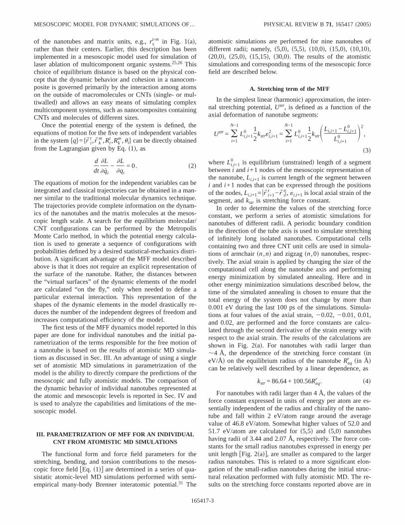
of the nanotubes and matrix units, e.g.,rst-m in Fig. 1sad,
rather than their centers. Earlier, this description has beenimplemented in a mesoscopic model used for simulation oflaser ablation of multicomponent organic systems.25,26 Thischoice of equilibrium distance is based on the physical con-cept that the dynamic behavior and cohesion in a nanocom-posite is governed primarily by the interaction among atomson the outside of macromolecules or CNTsssingle- or mul-tiwalledd and allows an easy means of simulating complexmulticomponent systems, such as nanocomposites containingCNTs and molecules of different sizes.
Once the potential energy of the system is defined, theequations of motion for the five sets of independent variablesin the systemhqj=hrW i
t ,rW km,Ri
t ,Rkm,uij can be directly obtained
from the Lagrangian given by Eq.s1d, as
d
dt
]L
]q̇i
−]L
]qi= 0. s2d
The equations of motion for the independent variables can beintegrated and classical trajectories can be obtained in a man-ner similar to the traditional molecular dynamics technique.The trajectories provide complete information on the dynam-ics of the nanotubes and the matrix molecules at the mesos-copic length scale. A search for the equilibrium molecular/CNT configurations can be performed by the MetropolisMonte Carlo method, in which the potential energy calcula-tion is used to generate a sequence of configurations withprobabilities defined by a desired statistical-mechanics distri-bution. A significant advantage of the MFF model describedabove is that it does not require an explicit representation ofthe surface of the nanotube. Rather, the distances betweenthe “virtual surfaces” of the dynamic elements of the modelare calculated “on the fly,” only when needed to define aparticular external interaction. This representation of theshapes of the dynamic elements in the model drastically re-duces the number of the independent degrees of freedom andincreases computational efficiency of the model.
The first tests of the MFF dynamics model reported in thispaper are done for individual nanotubes and the initial pa-rametrization of the terms responsible for the free motion ofa nanotube is based on the results of atomistic MD simula-tions as discussed in Sec. III. An advantage of using a singleset of atomistic MD simulations in parametrization of themodel is the ability to directly compare the predictions of themesoscopic and fully atomistic models. The comparison ofthe dynamic behavior of individual nanotubes represented atthe atomic and mesoscopic levels is reported in Sec. IV andis used to analyze the capabilities and limitations of the me-soscopic model.
III. PARAMETRIZATION OF MFF FOR AN INDIVIDUALCNT FROM ATOMISTIC MD SIMULATIONS
The functional form and force field parameters for thestretching, bending, and torsion contributions to the mesos-copic force fieldfEq. s1dg are determined in a series of qua-sistatic atomic-level MD simulations performed with semi-empirical many-body Brenner interatomic potential.31 The
atomistic simulations are performed for nine nanotubes ofdifferent radii; namely,s5,0d, s5,5d, s10,0d, s15,0d, s10,10d,s20,0d, s25,0d, s15,15d, s30,0d. The results of the atomisticsimulations and corresponding terms of the mesoscopic forcefield are described below.
A. Stretching term of the MFF
In the simplest linearsharmonicd approximation, the inter-nal stretching potential,Ustr, is defined as a function of theaxial deformation of nanotube segments:
Ustr = oi=1
N−1
Li,i+10 1
2kstr«i,i+1
2 = oi=1
N−1
Li,i+10 1
2kstrSLi,i+1 − Li,i+1
0
Li,i+10 D2
,
s3d
whereLi,i+10 is equilibrium sunstrainedd length of a segment
betweeni andi +1 nodes of the mesoscopic representation ofthe nanotube,Li,i+1 is current length of the segment betweeni and i +1 nodes that can be expressed through the positionsof the nodes,Li,i+1= urW i+1
t −rW itu, «i,i+1 is local axial strain of the
segment, andkstr is stretching force constant.In order to determine the values of the stretching force
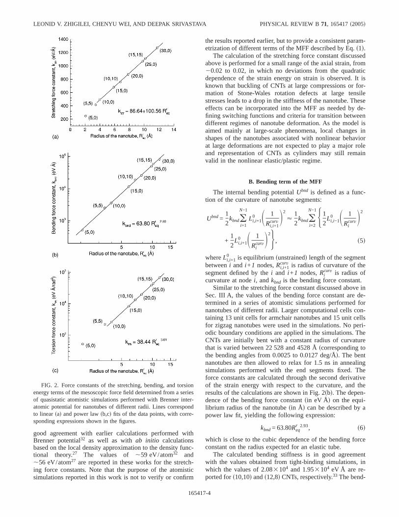
constant, we perform a series of atomistic simulations fornanotubes of different radii. A periodic boundary conditionin the direction of the tube axis is used to simulate stretchingof infinitely long isolated nanotubes. Computational cellscontaining two and three CNT unit cells are used in simula-tions of armchairsn,nd and zigzagsn,0d nanotubes, respec-tively. The axial strain is applied by changing the size of thecomputational cell along the nanotube axis and performingenergy minimization by simulated annealing. Here and inother energy minimization simulations described below, thetime of the simulated annealing is chosen to ensure that thetotal energy of the system does not change by more than0.001 eV during the last 100 ps of the simulations. Simula-tions at four values of the axial strain,20.02, 20.01, 0.01,and 0.02, are performed and the force constants are calcu-lated through the second derivative of the strain energy withrespect to the axial strain. The results of the calculations areshown in Fig. 2sad. For nanotubes with radii larger than,4 Å, the dependence of the stretching force constantsineV/Åd on the equilibrium radius of the nanotubeReq
r sin Ådcan be relatively well described by a linear dependence, as
kstr = 86.64 + 100.56Reqr . s4d
For nanotubes with radii larger than 4 Å, the values of theforce constant expressed in units of energy per atom are es-sentially independent of the radius and chirality of the nano-tube and fall within 2 eV/atom range around the averagevalue of 46.8 eV/atom. Somewhat higher values of 52.0 and51.7 eV/atom are calculated fors5,5d and s5,0d nanotubeshaving radii of 3.44 and 2.07 Å, respectively. The force con-stants for the small radius nanotubes expressed in energy perunit lengthfFig. 2sadg, are smaller as compared to the largerradius nanotubes. This is related to a more significant elon-gation of the small-radius nanotubes during the initial struc-tural relaxation performed with fully atomistic MD. The re-sults on the stretching force constants reported above are in
MESOSCOPIC MODEL FOR DYNAMIC SIMULATIONS OF… PHYSICAL REVIEW B 71, 165417s2005d
165417-3
good agreement with earlier calculations performed withBrenner potential32 as well as withab initio calculationsbased on the local density approximation to the density func-tional theory.27 The values of ,59 eV/atom32 and,56 eV/atom27 are reported in these works for the stretch-ing force constants. Note that the purpose of the atomisticsimulations reported in this work is not to verify or confirm
the results reported earlier, but to provide a consistent param-etrization of different terms of the MFF described by Eq.s1d.
The calculation of the stretching force constant discussedabove is performed for a small range of the axial strain, from20.02 to 0.02, in which no deviations from the quadraticdependence of the strain energy on strain is observed. It isknown that buckling of CNTs at large compressions or for-mation of Stone-Wales rotation defects at large tensilestresses leads to a drop in the stiffness of the nanotube. Theseeffects can be incorporated into the MFF as needed by de-fining switching functions and criteria for transition betweendifferent regimes of nanotube deformation. As the model isaimed mainly at large-scale phenomena, local changes inshapes of the nanotubes associated with nonlinear behaviorat large deformations are not expected to play a major roleand representation of CNTs as cylinders may still remainvalid in the nonlinear elastic/plastic regime.
B. Bending term of the MFF
The internal bending potentialUbnd is defined as a func-tion of the curvature of nanotube segments:
Ubnd=1
2kbndo
i=1
N−1
Li,i+10 S 1
Ri,i+1curv D2
<1
2kbndo
i=2
N−1H1
2Li,i−1
0 S 1
RicurvD2
+1
2Li,i+1
0 S 1
RicurvD2J , s5d
whereLi,i+10 is equilibriumsunstrainedd length of the segment
betweeni and i +1 nodes,Ri,i+1curv is radius of curvature of the
segment defined by thei and i +1 nodes,Ricurv is radius of
curvature at nodei, andkbnd is the bending force constant.Similar to the stretching force constant discussed above in
Sec. III A, the values of the bending force constant are de-termined in a series of atomistic simulations performed fornanotubes of different radii. Larger computational cells con-taining 13 unit cells for armchair nanotubes and 15 unit cellsfor zigzag nanotubes were used in the simulations. No peri-odic boundary conditions are applied in the simulations. TheCNTs are initially bent with a constant radius of curvaturethat is varied between 22 528 and 4528 Åscorresponding tothe bending angles from 0.0025 to 0.0127 deg/Åd. The bentnanotubes are then allowed to relax for 1.5 ns in annealingsimulations performed with the end segments fixed. Theforce constants are calculated through the second derivativeof the strain energy with respect to the curvature, and theresults of the calculations are shown in Fig. 2sbd. The depen-dence of the bending force constantsin eV Åd on the equi-librium radius of the nanotubesin Åd can be described by apower law fit, yielding the following expression:
kbnd= 63.80Reqr 2.93, s6d
which is close to the cubic dependence of the bending forceconstant on the radius expected for an elastic tube.
The calculated bending stiffness is in good agreementwith the values obtained from tight-binding simulations, inwhich the values of 2.083104 and 1.953104 eV Å are re-ported fors10,10d ands12,8d CNTs, respectively.33 The bend-
FIG. 2. Force constants of the stretching, bending, and torsionenergy terms of the mesoscopic force field determined from a seriesof quasistatic atomistic simulations performed with Brenner inter-atomic potential for nanotubes of different radii. Lines correspondto linearsad and power lawsb,cd fits of the data points, with corre-sponding expressions shown in the figures.
LEONID V. ZHIGILEI, CHENYU WEI, AND DEEPAK SRIVASTAVA PHYSICAL REVIEW B 71, 165417s2005d
165417-4
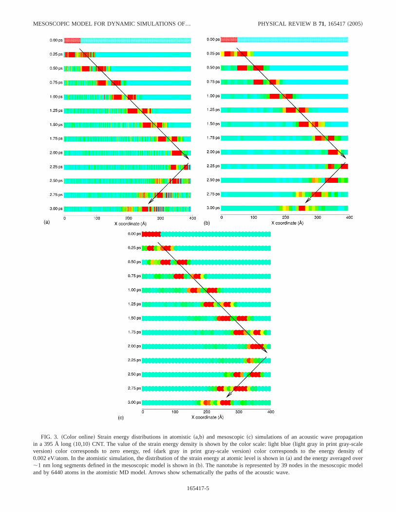
FIG. 3. sColor onlined Strain energy distributions in atomisticsa,bd and mesoscopicscd simulations of an acoustic wave propagationin a 395 Å longs10,10d CNT. The value of the strain energy density is shown by the color scale: light blueslight gray in print gray-scaleversiond color corresponds to zero energy, redsdark gray in print gray-scale versiond color corresponds to the energy density of0.002 eV/atom. In the atomistic simulation, the distribution of the strain energy at atomic level is shown insad and the energy averaged over,1 nm long segments defined in the mesoscopic model is shown insbd. The nanotube is represented by 39 nodes in the mesoscopic modeland by 6440 atoms in the atomistic MD model. Arrows show schematically the paths of the acoustic wave.
MESOSCOPIC MODEL FOR DYNAMIC SIMULATIONS OF… PHYSICAL REVIEW B 71, 165417s2005d
165417-5
ing force constant of 1.903104 eV Å is measured fors10,10d CNT in our MD simulations performed with empiri-cal Brenner potential.
Nonlinear elastic phenomena, such as rippling34,35 orbuckling16,29 of CNTs at large bending angles, can substan-tially reduce the effective bending stiffness of the nanotube.The effect of nonlinear bending deformation can be incorpo-rated into the MFF as needed by defining switching functionsand criteria for transition between different regimes of nano-tube deformation. The calculation of the bending force con-stant discussed above was performed for a small range ofbending angles for which no deviation from the quadraticdependence of the strain energy on curvature is observed.
C. Torsion term of the MFF
The torsion term in the MFFsUud is defined as a functionof the torsional deformation of nanotube segments:
Uu = oi=1
N−1
Li,i+10 1
2ktSui − ui+1
Li,i+10 D2
, s7d
where ui is torsion angle at nodei and kt is torsion forceconstant.
The values of the torsion force constant are determined ina series of atomistic simulations performed for nanotubes ofdifferent radii. Computational cells of the same size as inbending simulations described above are used in the simula-tions. The CNTs are initially twisted with a constant torsionaldeformation along the nanotube, which was varied between0.0025 to 0.0127 deg/ Å. The twisted nanotubes are thenallowed to relax for 1 ns in annealing simulations performedwith the end segments fixed. The force constant calculatedthrough the second derivative of the strain energy with re-spect to the torsional deformation is shown in Fig. 2scd. Fornanotubes with radii larger than,4 Å, the dependence ofthe torsion force constantsin eV Å/rad2d on the equilibriumradius of the nanotubesin Åd can be described by a powerlaw fit, yielding the following expression:
ktrs = 38.44Reqr 3.01, s8d
which is close to the cubic dependence on the radius ex-pected for a twisted hollow cylinder.
The torsion force constant of 1.33104 eV Å/rad2 calcu-lated in this work fors10,10d CNT is in a reasonable agree-ment with values obtained in tight-binding simulations,1.733104 eV Å/rad2 for a s10,10d CNT, and 1.463104 and1.633104 eV Å/rad2 for left and right twists of as12,8dCNT, respectively.33
Large torsional deformations of CNTs can lead to devia-tions from the linear elastic response, e.g., buckling of atwisted s10,10d CNT has been reported in a computationalstudy34 at a shear strain of 5%. Similar to the nonlinear be-havior in stretching and bending deformations, the effect ofnonlinear torsional deformation can be incorporated into theMFF if large deformations are expected to take place in thesimulations.
IV. FREE VIBRATIONS OF INDIVIDUAL CNTs:MESOSCOPIC AND ATOMISTIC SIMULATIONS
As a first test of the mesoscopic model and the parametri-zation described above, we perform a series of simulations ofa free motion of a single-walled CNT with both the mesos-copic and fully atomistic MD models. The initial conditionsin the simulations are chosen to provide targeted testing ofthe two terms of the MFF discussed above; stretching andbending. The torsion angle in the mesoscopic model is onlyweakly coupled to other independent variables through thetorsion-stretching coupling term. As a result, torsional mo-tion of an isolated nanotube is trivial and is not discussed inthis paper. The role of the radial breathing term and the cou-pling terms in the LagrangianfEq. s1dg is to provide a higherorder of accuracy in the description of the dynamic behaviorof CNTs and to facilitate the energy transfer between differ-ent modes during motion. A direct comparison between theresults of the mesoscopic and atomistic simulations de-scribed below suggests that the omission of these terms has arelatively minor effect on the dynamic behavior of the me-soscopic representation of an individual CNT. For some ofthe potential applications of the model, however, high accu-racy in the dynamic behavior of the model may be essential,and fine tuning of the mesoscopic force field through the
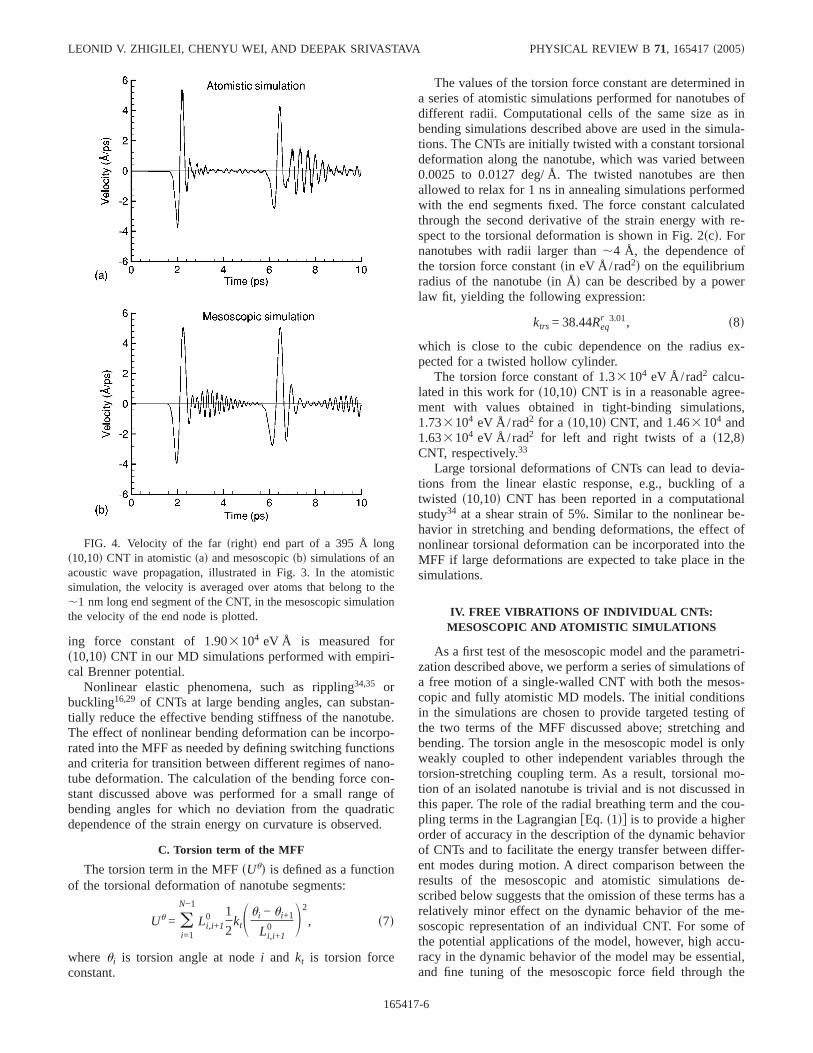
FIG. 4. Velocity of the farsrightd end part of a 395 Å longs10,10d CNT in atomisticsad and mesoscopicsbd simulations of anacoustic wave propagation, illustrated in Fig. 3. In the atomisticsimulation, the velocity is averaged over atoms that belong to the,1 nm long end segment of the CNT, in the mesoscopic simulationthe velocity of the end node is plotted.
LEONID V. ZHIGILEI, CHENYU WEI, AND DEEPAK SRIVASTAVA PHYSICAL REVIEW B 71, 165417s2005d
165417-6
coupling terms may be required. Therefore, we retain thecoupling terms in the general formulation of the model,given in Eq.s1d.
A. Acoustic wave propagation
Acoustic wave propagation is simulated in a 395 Å longs10,10d CNT represented with MFF and atomistic models.The wave is generated by creating a local tensile strain of 2%in a ,50 Å end part of the CNTsleft end in Fig. 3d at thebeginning of the simulations and allowing the systems toevolve freely at later times. In the atomistic MD simulationthes10,10d CNT is represented by 6400 carbon atoms and 40hydrogen atoms. The hydrogen atoms are used at the ends ofthe nanotubes20 atoms at each endd to terminate danglingbonds and to ensure stability of the nanotube. The inter-atomic interaction is described by the Brenner potential forhydrocarbons, which is the potential used to deduce the MFFas described in Sec. III. In the MFF model, the CNT is rep-resented by 38 segments connecting 39 nodes, with eachsegment having equilibrium lengthLi,i+1
0 of ,10.4 Å and amassmi,i+1 of 2022 amu,i =1, … , 38.
A visual picture of the acoustic wave propagation is givenin Fig. 3, where the evolution of the strain energy is shownfor different times during the simulations. The strain energydistributions in the atomistic MD simulations are shown withatomic-level resolution in Fig. 3sad. It can be seen that ini-tially there is a uniform local strain energy distribution in thestrained left end of the CNT. As time progresses, the relax-
ation of the initial tensile stresses in the left part of the nano-tube leads to the formation of a bimodal stress wave thatpropagates through the nanotube. The wave consists of atensile component that propagates first and a compressioncomponent that follows. The bimodal structure of the wave isa result of the interaction of the initial tensile stresses withthe free surface. Both the tensile and compression compo-nents of the wave show up in Fig. 3 as red regions of highstrain energy separated by a light blue/green band that cor-responds to the transition from expansion to compression. By,2 ps, the acoustic wave reaches the farsrightd end of thenanotube and reflects back. Upon reflection, the stress wavechanges signsthe compression component now leads and thetensile component followsd. While one can notice from thefigure that there is some dissipation of the energy of thewave with time, the wave packet still contains the largestfraction of the initial strain energy and can be clearly identi-fied at all times during the simulation.
A mesoscopic simulation performed for the same initialconditions as the atomistic one is illustrated in Fig. 3scd. Inorder to quantitatively compare the results of the mesoscopicand atomistic simulations, the same color scale is used toshow the energy density in both simulations, from light bluecolor corresponding to zero energy, to red color correspond-ing to 0.002 eV/atom. Moreover, an alternative representa-tion of the potential energy distribution in the atomisticsimulation, in which the potential energy is averaged overatoms that belong to segments of the nanotube of the samesize as in the mesoscopic model, is shown in Fig. 3sbd. Finedetails at the atomic level that can be observed in Fig. 3sad
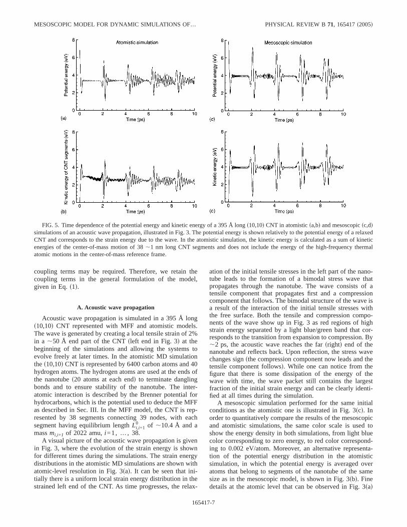
FIG. 5. Time dependence of the potential energy and kinetic energy of a 395 Å longs10,10d CNT in atomisticsa,bd and mesoscopicsc,ddsimulations of an acoustic wave propagation, illustrated in Fig. 3. The potential energy is shown relatively to the potential energy of a relaxedCNT and corresponds to the strain energy due to the wave. In the atomistic simulation, the kinetic energy is calculated as a sum of kineticenergies of the center-of-mass motion of 38,1 nm long CNT segments and does not include the energy of the high-frequency thermalatomic motions in the center-of-mass reference frame.
MESOSCOPIC MODEL FOR DYNAMIC SIMULATIONS OF… PHYSICAL REVIEW B 71, 165417s2005d
165417-7
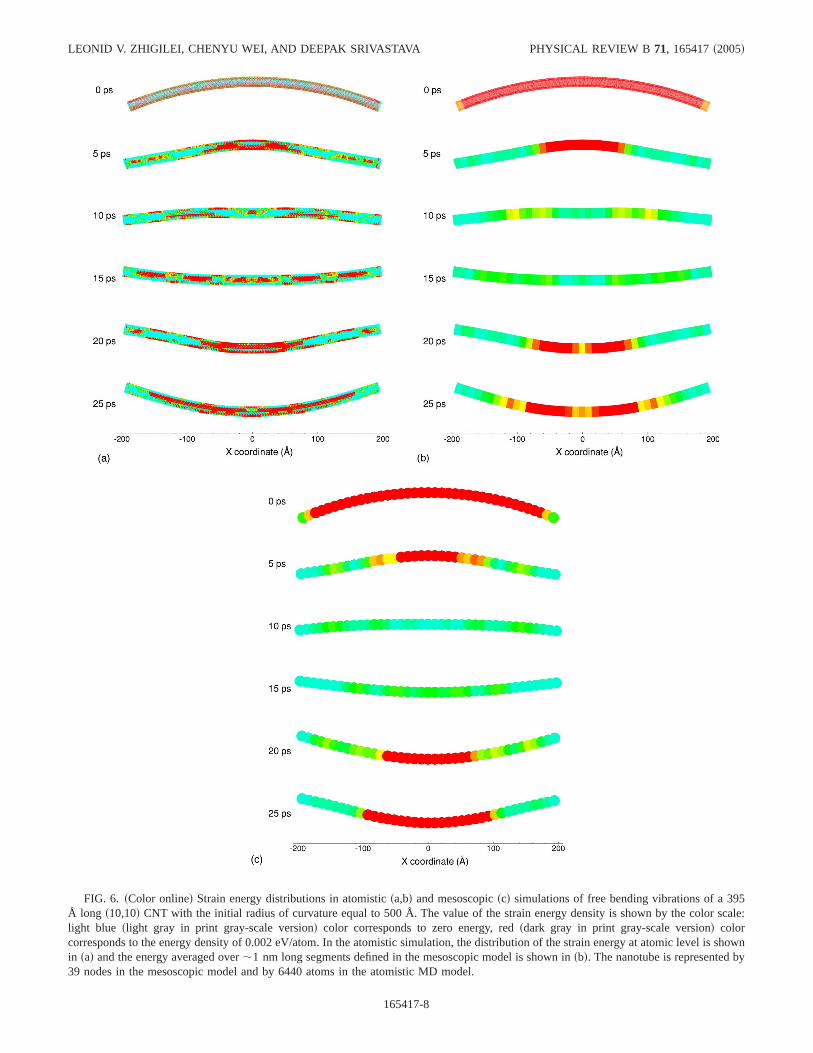
FIG. 6. sColor onlined Strain energy distributions in atomisticsa,bd and mesoscopicscd simulations of free bending vibrations of a 395Å long s10,10d CNT with the initial radius of curvature equal to 500 Å. The value of the strain energy density is shown by the color scale:light blue slight gray in print gray-scale versiond color corresponds to zero energy, redsdark gray in print gray-scale versiond colorcorresponds to the energy density of 0.002 eV/atom. In the atomistic simulation, the distribution of the strain energy at atomic level is shownin sad and the energy averaged over,1 nm long segments defined in the mesoscopic model is shown insbd. The nanotube is represented by39 nodes in the mesoscopic model and by 6440 atoms in the atomistic MD model.
LEONID V. ZHIGILEI, CHENYU WEI, AND DEEPAK SRIVASTAVA PHYSICAL REVIEW B 71, 165417s2005d
165417-8
are smeared out in Fig. 3sbd, making the comparison betweenthe atomistic and mesoscopic simulations easier. Both thevelocity of the wave and characteristic features of the strainenergy distributions in Figs. 3sbd and 3scd show good agree-ment.
Plots of the velocities of the farsrightd ends of the nano-tubes, given in Fig. 4, allow for a more detailed quantitativecomparison between the atomistic and mesoscopic simula-tion results. There is a good match in the overall shape of theplots and in the amplitudes of the velocity spikes that corre-spond to the reflections of the wave packet from the far endof the nanotube. The structure of the velocity spike agreeswith the notion of the bimodal wave interacting with a freesurface: the tensile component of the wave arrives first, pull-ing the end part of the nanotube in the negative directionsnegative part of the velocity spiked; the compressive com-ponent follows, pushing the end part of the nanotube backspositive part of the velocity spiked.
The time evolution of the total potential and kinetic ener-gies of the nanotube during the simulations is shown in Fig.5. In both atomistic and mesoscopic simulations all energy isinitially stored in the potential energy of the stretched part ofthe nanotube. As the acoustic wave develops, the energy par-
tition about evenly between the potential and kinetic energyof the wave. To make a comparison to the mesoscopic simu-lation, the kinetic energy shown in Fig. 4sbd is defined as thekinetic energy of the collective center-of-mass motion of theCNT segments equivalent to the ones in the mesoscopicmodel. This kinetic energy does not include the energy of theradial breathing mode as well as the thermal energy of thehigh-frequency atomic motions in the center-of-mass refer-ence frame. The spikes in the plots of the potential and ki-netic energies correspond to the reflections of the wave fromthe ends of the nanotube and the time between the spikes canbe used to estimate the speed of the wave:,18 000 m/s. Inboth atomistic and mesoscopic simulations, the wave gradu-ally dissipates upon multiple reflections, although the dissi-pation is more pronounced in the atomistic simulation, wherea larger number of vibrational modes and anharmonicity ofinteratomic interaction potential result in a faster energy dis-sipation. Apart from the thermal energy that is not includedin the mesoscopic model, a quantitative difference in thelevels of the potentialfFigs. 5sad and 5scdg and kinetic ener-gies fFigs. 5sbd and 5sddg is related to the difference in theinitial energy of the stretched configurationssstarting pointsin the potential energy plots att=0d. The total energy of thethree segmentsstotal length of ,52 Åd stretched by 2%in the mesoscopic simulation is 7.87 eV, whereas theinitial energy in the atomistic simulation is somewhat lower:6.3 eV.
Overall, we can conclude that the mesoscopic model re-produces well most of the characteristics of the acousticwave propagating in a CNT. A major advantage of the me-soscopic description of the nanotube dynamics is the lowcomputational cost of the simulations. The atomistic simula-tion of 10 ps trajectory of the CNT shown in Fig. 3 took 21h on a dedicated SGI Origin 3800 workstation, whereas themesoscopic simulation took less than a tenth of a second ona desktop PC.
B. Free bending vibrations
To additionally test the mesoscopic model, a simulation offree vibrations of a bents10,10d CNT has been simulated andcompared to the results of atomistic simulations. The samesystem as in the study of the acoustic wave propagation, a395 Å long s10,10d CNT, is used in the simulations. TheCNT is initially bent with a constant radius of curvature,Rcurv=500 Å, along the whole length of the CNT and then,starting at a time of 0 ps, is allowed to evolve freely in theatomistic and mesoscopic simulations.
Snapshots from the simulations of free motion of the CNTare shown in Fig. 6. The color distribution corresponds to thelocal potential energy density at various times. The strainenergy is shown with atomic-level resolution in Fig. 6sad andis averaged over nanotube segments in Fig. 6sbd. It can beseen that initially there is a uniform strain energy distributionin the CNT. The relaxation of the CNT can be described aspropagation of two unloading waves that start from the endparts of the CNT and propagate towards the center. The CNTthen undergoes free bending vibrations with characteristicfrequency of 21 GHz in the atomistic simulation and 20 GHz
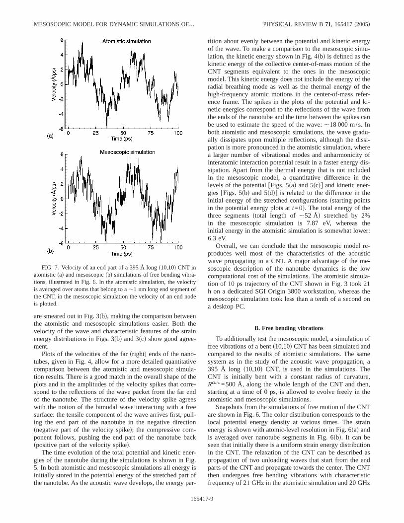
FIG. 7. Velocity of an end part of a 395 Å longs10,10d CNT inatomisticsad and mesoscopicsbd simulations of free bending vibra-tions, illustrated in Fig. 6. In the atomistic simulation, the velocityis averaged over atoms that belong to a,1 nm long end segment ofthe CNT, in the mesoscopic simulation the velocity of an end nodeis plotted.
MESOSCOPIC MODEL FOR DYNAMIC SIMULATIONS OF… PHYSICAL REVIEW B 71, 165417s2005d
165417-9
in the mesoscopic simulation. The discrepancy in the fre-quency of the bending vibrations can be attributed to thedeviation from the linear regimesquadratic dependence ofthe strain energy on curvature, assumed in the parametriza-tion of the bending force constant, Sec. III Bd at high bend-ing angles realized in the simulations shown in Fig. 6. In-deed, the bending angles up to 0.0025 deg/Å were used inparametrization of the MFF, much below the bending angleof 0.1146 deg/Å that corresponds toRcurv=500 Å. This mi-nor discrepancy can be fixed by adapting an anharmonic po-tential fitted to the data from atomistic simulations in a widerrange of bending angles.
In order to perform a more detailed quantitative compari-son of the dynamics of the bending vibrations predicted bythe atomistic and mesoscopic models, velocities of the endparts of the CNTs are plotted in Fig. 7. Apart from a slightlyhigher vibrational frequency in the mesoscopic simulation,the agreement between the two simulations is remarkable.The velocity plots show a very good match not only in theoverall shapes but also in the detailed vibrational structure ofthe trajectories.
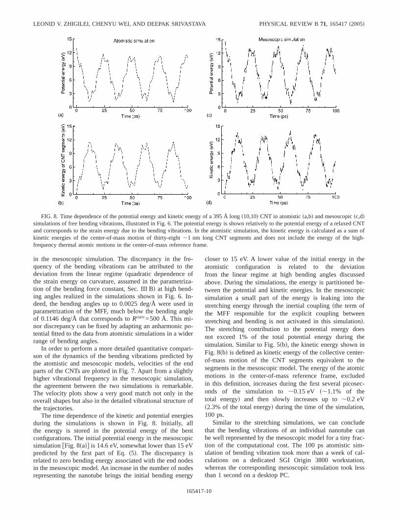
The time dependence of the kinetic and potential energiesduring the simulations is shown in Fig. 8. Initially, allthe energy is stored in the potential energy of the bentconfigurations. The initial potential energy in the mesoscopicsimulationfFig. 8sadg is 14.6 eV, somewhat lower than 15 eVpredicted by the first part of Eq.s5d. The discrepancy isrelated to zero bending energy associated with the end nodesin the mesoscopic model. An increase in the number of nodesrepresenting the nanotube brings the initial bending energy
closer to 15 eV. A lower value of the initial energy in theatomistic configuration is related to the deviationfrom the linear regime at high bending angles discussedabove. During the simulations, the energy is partitioned be-tween the potential and kinetic energies. In the mesoscopicsimulation a small part of the energy is leaking into thestretching energy through the inertial couplingsthe term ofthe MFF responsible for the explicit coupling betweenstretching and bending is not activated in this simulationd.The stretching contribution to the potential energy doesnot exceed 1% of the total potential energy during thesimulation. Similar to Fig. 5sbd, the kinetic energy shown inFig. 8sbd is defined as kinetic energy of the collective center-of-mass motion of the CNT segments equivalent to thesegments in the mesoscopic model. The energy of the atomicmotions in the center-of-mass reference frame, excludedin this definition, increases during the first several picosec-onds of the simulation to,0.15 eV s,1.1% of thetotal energyd and then slowly increases up to,0.2 eVs2.3% of the total energyd during the time of the simulation,100 ps.
Similar to the stretching simulations, we can concludethat the bending vibrations of an individual nanotube canbe well represented by the mesoscopic model for a tiny frac-tion of the computational cost. The 100 ps atomistic sim-ulation of bending vibration took more than a week of cal-culations on a dedicated SGI Origin 3800 workstation,whereas the corresponding mesoscopic simulation took lessthan 1 second on a desktop PC.
FIG. 8. Time dependence of the potential energy and kinetic energy of a 395 Å longs10,10d CNT in atomisticsa,bd and mesoscopicsc,ddsimulations of free bending vibrations, illustrated in Fig. 6. The potential energy is shown relatively to the potential energy of a relaxed CNTand corresponds to the strain energy due to the bending vibrations. In the atomistic simulation, the kinetic energy is calculated as a sum ofkinetic energies of the center-of-mass motion of thirty-eight,1 nm long CNT segments and does not include the energy of the high-frequency thermal atomic motions in the center-of-mass reference frame.
LEONID V. ZHIGILEI, CHENYU WEI, AND DEEPAK SRIVASTAVA PHYSICAL REVIEW B 71, 165417s2005d
165417-10
V. DISCUSSION AND SUMMARY
The principal challenge in the computational modeling ofnanostructures and nanocomposites based on carbon nano-tubes is presented by the gap between the atomistic descrip-tion of individual nanotubes and the collective behavior andproperties of large groups of CNTs in nanocomposite mate-rials or nanostructures. While atomistic simulations can pro-vide detailed information on the behavior of individualCNTs, the calculations are computationally expensive anddifficult to extend to systems containing multiple CNTs. Inthis paper we present a coarse-grained force-field model forCNTs that provides a computationally efficient description ofCNTs and can help to close the gap between the atomisticand continuum descriptions of CNT-based materials andstructures. The coarse-grainedsor mesoscopicd model incor-porates the essential information from the atomic-level simu-lations and represents the dynamic behavior of a CNT with adrastically reduced number of degrees of freedom. Specifi-cally, a CNT is represented as a “breathing flexible cylinder”consisting of a variable number of segments. The surface ofthe nanotube is not represented explicitly in the model but iscalculated from a limited set of dynamic variables only whenneeded to define a particular external interaction. This repre-sentation drastically reduces the number of the independentdegrees of freedom and makes the model much more effi-cient as compared to conventional representations based oncontinuum mechanics concepts.
First test simulations performed for the acoustic wavepropagation and free bending vibrations of the nanotubedemonstrate that the mesoscopic model reproduces well theshort-term dynamic behavior of individual CNTs as pre-dicted in atomistic simulations. If required for a particularapplication, a quantitative agreement between the results ofmesoscopic and atomistic simulations can be further im-proved by fine tuning the parameters of the MFF and inclu-sion of additional terms responsible for coupling betweendifferent dynamic degrees of freedom in the model. More-over, the high-frequency vibrational modes that are not in-
cluded in the mesoscopic model explicitly can be accountedfor by connecting the long-wavelength internal elastic modeswith a “heat bath” that represents the remaining degrees offreedom of the CNT. Although the initial parametrization andtesting of the mesoscopic model discussed in this paper hasbeen performed for single-walled CNTs, the MFF given byEq. s1d can be easily applied to multiwalled CNTs, which areoften used in polymer-matrix nanocomposites. Similarly tosingle-walled CNTs, parametrization of the model for multi-walled CNTs can be performed based on the results of ato-mistic simulations or experimental data on the behavior andproperties of multiwalled CNTs.
The main advantage of the mesoscopic model is its highcomputational efficiency. Simulation of the dynamics of a395 Å long s10,10d CNT for several periods of bending vi-brations took less than a second on a desktop PC, suggestingthat mesoscopic simulations of much larger systems contain-ing multiple CNTs and other constituents represented at amesoscale levelse.g., coarse-grained representation of mo-lecular systems23–26d is possible. The length scale of a dy-namic simulation is defined by the size of the dynamic ele-ments for which the equations of motion are solved. Thedynamic elements in the model are significantly larger thanthe atoms and the size of the computational cell can also bemuch larger than the one used in atomistic simulations. Thetime scale of the simulations is defined by the time step inthe numerical integration. Since explicit atomic vibrationsare not followed in the model, the time step of integrationcan be increased by up to several orders of magnitude. Pa-rametrization of the external interactions for CNTs embed-ded in a polymer matrix and simulation of the CNT-basedpolymer nanocomposite systems, such as the one shownschematically in Fig. 1sbd, is the subject of our current work.
ACKNOWLEDGMENTS
One authorsL. V. Z.d gratefully acknowledges financialsupport provided by the National Science FoundationsDMII-0422632 and NIRT-0403876d.
*Corresponding author. Email address: [email protected]†Email address: [email protected]‡Email address: [email protected]. Iijima, NaturesLondond 56, 354 s1991d.2T. Ebbesen,Carbon Nanotubes: Preparation and Properties
sCRC Press, Boca Raton, 1997d.3E. T. Thostenson, Z. Ren, and T. W. Chou, Compos. Sci. Technol.
61, 1899s2001d.4S. B. Sinnott and R. Andrews, CRC Crit. Rev. Solid State Mater.
Sci. 26, 145 s2001d.5B. I. Yakobson and P. Avouris, Top. Appl. Phys.80, 287 s2001d.6O. A. Shenderova, V. V. Zhirnov, and D. W. Brenner, CRC Crit.
Rev. Solid State Mater. Sci.27, 227 s2002d.7D. Srivastava, inScience and Technology of Carbon Nanotubes:
Applications Perspective, edited by M. MeyyappansCRC Press,Boca Raton, FL, 2004d, Chap. 2.
8Polymer nanocomposites, edited by R. A. Vaia and R. Krish-namoortisAmerican Chemical Society, Washington, DC, 2001d.
9D. Srivastava, M. Menon, and K. Cho, Phys. Rev. Lett.83, 2973s1999d.
10J. W. Che, T. Cagin, and W. A. Goddard, Nanotechnology10,263 s1999d.
11C. Wei, D. Srivastava, and K. Cho, Phys. Rev. B67, 115407s2003d.
12D. Srivastava, D. W. Brenner, J. D. Schall, K. D. Ausman, M. F.Yu, and R. S. Ruoff, J. Phys. Chem. B103, 4330s1999d.
13S. J. V. Frankland, A. Caglar, D. W. Brenner, and M. Griebel, J.Phys. Chem. B106, 3046s2002d.
14V. Lordi and N. Yao, J. Mater. Res.15, 2770s2000d.15C. Wei, D. Srivastava, and K. Cho, Nano Lett.2, 647 s2002d.16B. I. Yakobson, C. J. Brabec, and J. Bernholc, Phys. Rev. Lett.
76, 2511s1996d.
MESOSCOPIC MODEL FOR DYNAMIC SIMULATIONS OF… PHYSICAL REVIEW B 71, 165417s2005d
165417-11
17S. Govindjee and J. L. Sackman, Solid State Commun.110, 227s1999d.
18C. Q. Ru, Phys. Rev. B62, 9973s2000d.19G. M. Odegard, T. S. Gates, L. M. Nicholson, and K. E. Wise,
Compos. Sci. Technol.62, 1869s2002d.20K. Sohlberg, B. G. Sumpter, R. E. Tuzun, and D. W. Noid,
Nanotechnology9, 30 s1998d.21V. M. Harik, Comput. Mater. Sci.24, 312 s2002d.22P. S. Das and L. T. Wille, Comput. Mater. Sci.24, 159 s2002d.23Computer Simulation of Polymers, edited by E. A. Colbourn
sLongman Scientific and Technical, New York, 1994d.24K. Kremer and F. Müller-Plathe, MRS Bull.26, 205 s2001d.25L. V. Zhigilei, P. B. S. Kodali, and B. J. Garrison, J. Phys. Chem.
B 102, 2845s1998d.26L. V. Zhigilei, E. Leveugle, B. J. Garrison, Y. G. Yingling, and M.
I. Zeifman, Chem. Rev.sWashington, D.C.d 103, 321 s2003d.27D. Sánchez-Portal, E. Artacho, J. M. Soler, A. Rubio, and P.
Ordejón, Phys. Rev. B59, 12678s1999d.28M. R. Falvo, G. J. Clary, R. M. Taylor, V. Chi, F. P. Brooks, S.
Washburn, and R. Superfine, NaturesLondond 389, 582 s1997d.29E. W. Wong, P. E. Sheehan, and C. M. Lieber, Science277, 1971
s1997d.30J.-P. Salvetat, J. M. Bonard, N. H. Thomson, A. J. Kulik, L.
Forro, W. Benoit, and L. Zuppiroli, Appl. Phys. A: Mater. Sci.Process.69, 255 s1999d.
31D. W. Brenner, Phys. Rev. B42, 9458s1990d.32D. H. Robertson, D. W. Brenner, and J. W. Mintmire, Phys. Rev.
B 45, 12592s1992d.33L. Vaccarini, C. Goze, L. Henrard, E. Hernández, P. Bernier, and
A. Rubio, Carbon38, 1681s2000d.34M. Arroyo and T. Belytschko, Phys. Rev. Lett.91, 215505
s2003d.35J. Z. Liu, Q. Zheng, and Q. Jiang, Phys. Rev. Lett.86, 4843
s2001d.
LEONID V. ZHIGILEI, CHENYU WEI, AND DEEPAK SRIVASTAVA PHYSICAL REVIEW B 71, 165417s2005d
165417-12
Related Documents