MESLU CLUTCH SYSTEM TECHNISCHE DATEN / TECHNICAL DATA

Welcome message from author
This document is posted to help you gain knowledge. Please leave a comment to let me know what you think about it! Share it to your friends and learn new things together.
Transcript
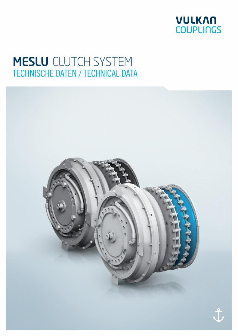
MESLU CLUTCH SYSTEMTECHNISCHE DATEN / TECHNICAL DATA

Das Handsymbol kennzeichnet Seiten, auf denen es eine Veränderung zur Vorgängerversion gibt.The hand symbol appears on pages which differ from the previous catalogue version.09/2014
Bitte benutzen Sie Ihr Smartphone mit der entsprechenden Software, scannen Sie den QR-Code ein.
Please use your smartphone with the relevant software, scan the QR-Code.
Sie erhalten die Information, ob dies die aktuellste Version ist.
You will get the information whether you have got the latest version.
SCAN GET INFO INFO

INHALTSVERZEICHNISCONTENTS
03 INHALTSVERZEICHNIS CONTENTS
04 MESLU SCHALTKUPPLUNGSSYSTEMMESLU CLUTCH SYSTEM
04 EIGENSCHAFTEN MESLU SCHALTKUPPLUNGSSYSTEM CHARACTERISTICS CLUTCH SYSTEM
06 EIGENSCHAFTEN MESLU KUPPLUNGSKOMBINATION CHARACTERISTICS CLUTCH COMBINATION
08 LISTE DER TECHNISCHEN DATEN MESLU CLUTCH LIST OF TECHNICAL DATA MESLU CLUTCH
10 LISTE DER TECHNISCHEN DATEN HOCHELASTISCHE KUPPLUNGEN LIST OF TECHNICAL DATA HIGHLY FLEXIBLE COUPLING
12 ABMESSUNGEN/MASSENTRÄGHEITSMOMENTE/MASSEN DIMENSIONS/MASS-MOMENTS OF INERTIA/MASSES
24 DESIGNVARIANTEN EXAMPLES FOR TAILORED DESIGN
25 SPEZIELLE AUSFÜHRUNG SPECIAL DESIGN
26 EIGENSCHAFTEN PNEUMATISCHE SCHALTEINHEIT CHARACTERISTICS PNEUMATIC CONTROL UNIT
28 EIGENSCHAFTEN LUFTZUFUHR CHARACTERISTICS AIR SUPPLY
29 EIGENSCHAFTEN ÜBERWACHUNGSEINHEIT CHARACTERISTICS MONITORING DEVICE
30 ANLAGENSCHEMA EIN-MOTOREN-ANLAGENBEISPIELEDIAGRAM SINGLE-ENGINE INSTALLATION
32 ERLÄUTERUNGEN DES PRODUKTCODESPRODUCT CODE EXPLANATIONS
09/2014 03MESLU CLUTCH SYSTEM 03

09/2014
TKN: 8.00 kNm – 20.00 kNm
MESLU / VULKARDAN E
MESLU CLUTCH SYSTEM
MESLU Schaltkupplungssystem
Das MESLU Schaltkupplungssystem findet hauptsächlich in Baggerpumpenantrie-ben Anwendung. Es kann allerdings auch in Haupt- und sonstigen Nebenantrieben verwendet werden. Das System besteht aus mechanischen, pneumatischen und elektrischen Komponenten.Die mechanischen Komponenten setzen sich aus der MESLU Schaltkupplungund einer kombinierten hochelastischen (Elastomer-) Kupplung zusammen.In diesem Katalog sind die technischen Daten der jeweiligen Vorzugskombination mit RATO R+ / R / S+ oder VULKARDAN E Kupplung abgebildet.Der pneumatische Teil besteht aus einer Schalteinheit und der zugehörigenaxialen Luftzufuhr.Beispiele verschiedener Anlagenkonfigurationen mit Empfehlung geeigneter Rohrquerschnitte und –längen sowie Angaben zu Luftbehältergrößen und sonstigen Anlagenkomponenten, welche nicht zum Lieferumfang Vulkan gehören, finden Sie auf den Seiten 30 und 31.Der elektrische Teil beinhaltet die Überwachungseinheit, mit der in der Grundaus-stattung der Schlupf in der MESLU sowie der Verdrehwinkel der hochelastischen Kupplung zum Schutz der Anlage überwacht werden kann.
MESLU Clutch System
The MESLU Clutch System is mainly applied in dredge pump applications.Additionally it can be used in main drives as well as in other auxiliary drives.The system consists of mechanical, pneumatic and electrical components.
The mechanical components are the MESLU Clutch in combination with ahighly flexible coupling. The technical data of the recommended combinations with RATO R+ / R / S+ or VULKARDAN E couplings are presented in this catalog.
The pneumatic part of the MESLU Clutch System consists of the Control Unitand the Air Supply.Recommendations such as pipe cross sections, pipe lengths, necessary air container volume and other components of the system (not VULKAN scope of supply) for different examples of single-engine installations can be found on page 30 and 31.The electrical part comprises the Monitoring Device, which in order to protect the drive train detects clutch slippage and is able to monitor the twist angle of the highly flexible coupling as well.
04
EIGENSCHAFTEN MESLU SCHALTKUPPLUNGSSYSTEMCHARACTERISTICS CLUTCH SYSTEM
Weitere Informationen finden Sie auf Seite 06.Further information on page 06.
TKN: 26.50 kNm – 315.00 kNm
MESLU / RATO
Weitere Informationen finden Sie auf Seite 06.Further information on page 06.

09/2014
ÜBERWACHUNGSEINHEIT /MONITORING DEVICE
LUFTZUFUHR /AIR SUPPLY
PNEUMATISCHE SCHALTEINHEIT /PNEUMATIC CONTROL UNIT
Weitere Informationen finden Sie auf Seite 28.Further information on page 28.
Weitere Informationen finden Sie auf Seite 26.Further information on page 26.
Weitere Informationen finden Sie auf Seite 29.Further information on page 29.
05MESLU CLUTCH SYSTEM
EIGENSCHAFTEN MESLU SCHALTKUPPLUNGSSYSTEMCHARACTERISTICS CLUTCH SYSTEM
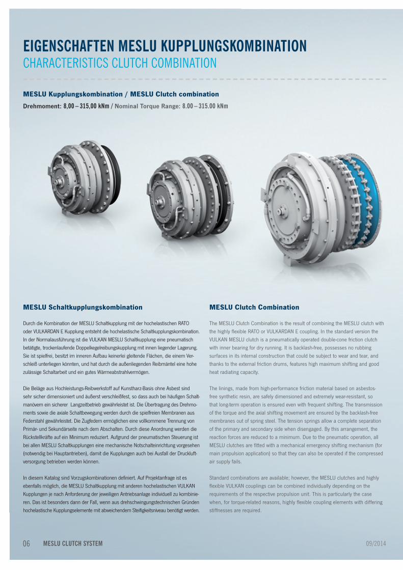
MESLU Kupplungskombination / MESLU Clutch combination
Drehmoment: 8,00 – 315,00 kNm / Nominal Torque Range: 8.00 – 315.00 kNm
EIGENSCHAFTEN MESLU KUPPLUNGSKOMBINATIONCHARACTERISTICS CLUTCH COMBINATION
MESLU Schaltkupplungskombination
Durch die Kombination der MESLU Schaltkupplung mit der hochelastischen RATOoder VULKARDAN E Kupplung entsteht die hochelastische Schaltkupplungskombination. In der Normalausführung ist die VULKAN MESLU Schaltkupplung eine pneumatisch betätigte, trockenlaufende Doppelkegelreibungskupplung mit innen liegender Lagerung. Sie ist spielfrei, besitzt im inneren Aufbau keinerlei gleitende Flächen, die einem Ver-schleiß unterliegen könnten, und hat durch die außenliegenden Reibmäntel eine hohe zulässige Schaltarbeit und ein gutes Wärmeabstrahlvermögen.
Die Beläge aus Hochleistungs-Reibwerkstoff auf Kunstharz-Basis ohne Asbest sind sehr sicher dimensioniert und äußerst verschleißfest, so dass auch bei häufigen Schalt-manövern ein sicherer Langzeitbetrieb gewährleistet ist. Die Übertragung des Drehmo-ments sowie die axiale Schaltbewegung werden durch die spielfreien Membranen aus Federstahl gewährleistet. Die Zugfedern ermöglichen eine vollkommene Trennung von Primär- und Sekundärseite nach dem Abschalten. Durch diese Anordnung werden die Rückstellkräfte auf ein Minimum reduziert. Aufgrund der pneumatischen Steuerung ist bei allen MESLU Schaltkupplungen eine mechanische Notschalteinrichtung vorgesehen (notwendig bei Hauptantrieben), damit die Kupplungen auch bei Ausfall der Druckluft-versorgung betrieben werden können.
In diesem Katalog sind Vorzugskombinationen definiert. Auf Projektanfrage ist es ebenfalls möglich, die MESLU Schaltkupplung mit anderen hochelastischen VULKAN Kupplungen je nach Anforderung der jeweiligen Antriebsanlage individuell zu kombinie-ren. Das ist besonders dann der Fall, wenn aus drehschwingungstechnischen Gründen hochelastische Kupplungselemente mit abweichendem Steifigkeitsniveau benötigt werden.
MESLU Clutch Combination
The MESLU Clutch Combination is the result of combining the MESLU clutch with the highly flexible RATO or VULKARDAN E coupling. In the standard version the VULKAN MESLU clutch is a pneumatically operated double-cone friction clutch with inner bearing for dry running. It is backlash-free, possesses no rubbing surfaces in its internal construction that could be subject to wear and tear, and thanks to the external friction drums, features high maximum shifting and good heat radiating capacity.
The linings, made from high-performance friction material based on asbestos-free synthetic resin, are safely dimensioned and extremely wear-resistant, so that long-term operation is ensured even with frequent shifting. The transmission of the torque and the axial shifting movement are ensured by the backlash-free membranes out of spring steel. The tension springs allow a complete separation of the primary and secondary side when disengaged. By this arrangement, the reaction forces are reduced to a minimum. Due to the pneumatic operation, all MESLU clutches are fitted with a mechanical emergency shifting mechanism (for main propulsion application) so that they can also be operated if the compressed air supply fails.
Standard combinations are available; however, the MESLU clutches and highly flexible VULKAN couplings can be combined individually depending on the requirements of the respective propulsion unit. This is particularly the case when, for torque-related reasons, highly flexible coupling elements with differing stiffnesses are required.
06 09/2014MESLU CLUTCH SYSTEM

EIGENSCHAFTEN MESLU KUPPLUNGSKOMBINATIONCHARACTERISTICS CLUTCH COMBINATION
Alle Bewegungen der Anlage werden von der RATO oder VULKARDAN E Kupplungaufgenommen. Es gelten in dieser Beziehung alle technischen Daten der hoch-elastischen Standardkupplung. Die Schaltkupplung verursacht in dieser Anordnung keinerlei Einschränkung der zulässigen Verlagerungen.
Die Kupplungsfunktionen sind trotz der konstruktiven Einheit klar getrennt. Die Drehschwingungsdämpfung und Minderung von Torsionsschwingungen durch Resonanzverlagerung im System sowie die Aufnahme der radialen und axialen Verlagerungen bei sehr geringen Rückstellkräften wird durch die jeweilige hochelas-tische Kupplung realisiert. Die MESLU Schaltkupplung übernimmt die Schalt- und Schutzfunktion im System.
Der Vorteil der MESLU/RATO, bzw. MESLU/VULKARDAN E Schaltkupplungskombi-nation gegenüber einer elastischen Schaltkupplung mit integrierten elastischenElementen besteht darin, dass das elastische Element von der Wärme, die beim Schalten entsteht, nicht beeinflusst wird.
Verlagerungen aus dem Antriebssystem können das Tragbild und damit den Verschleiß sowie das Schaltverhalten der MESLU Kupplung nicht negativ beeinflussen. Trotz der hintereinanderliegenden Anordnung der beiden getrennten Kupplungssysteme wird eine kompakte Bauweise erreicht.
All movements of the shaft are absorbed by the RATO or VULKARDAN E coupling. In this context all technical data for the standard highly flexible coupling apply. In this arrangement the clutch does not cause any impairment of the permitted displacements.
Despite the integrated construction the coupling functions are clearly separated:The rotational vibration dampening and reduction of torsional vibrations throughshifting the resonance beyond the operating speed range as well as the adsorption of radial and axial displacements at very low restoring forces are realized by the respective highly flexible coupling. The MESLU clutch assumes the engaging and protective function within the system.
The advantage of the MESLU/RATO and MESLU/VULKARDAN E Clutch Com-bination compared to a flexible clutch with integrated elastic elements lies in the fact that the combination is not influenced by the heat that occurs during engaging operations.
The displacement of the propulsion system will not influence the contact pattern of the MESLU and thereby not negatively influence wear and tear and the clutch-ing behavior. Despite the successive arrangement of the MESLU Clutch and the highly flexible coupling a compact design is achieved.
0709/2014 MESLU CLUTCH SYSTEM

Baugröße Nenndrehmoment ZulässigeDrehzahl
Zulässige Drehzahldifferenz
Zulässige Werte Luftverbrauch je Schaltung
Luftbehälter-volumen
Kupplungs-luftdruck
Size Nominal Torque Range Perm. Rotational Speed
Perm. Speed Differenz Perm. Data Reference Air Consumption per Engagement
Air Container Volume
Coupling Air Pressure
Schaltkupplung Hochelastische Kupplung 5) Schaltarbeit Schaltleistung
Clutch Highly Flexible Coupling 5) Engaging Work Engaging Power
TKN1)
[kNm]nKmax
[min-1]∆nKs
2) WKS [kJ]
PKS [kW]
V [dm3]
VB3)
[bar]PKN
4) [bar]
MESLU / VULKARDAN E MESLU VULKARDAN E
MESLU 19
K54128,0 2200
1500 1150 205 8 40 8
K5415K5711
10,02100
K5714K5712
12,5K5715
MESLU 24
K601116,0
1900 1300 1700 280 12 60 8K6014
K601220,0
K6015
MESLU / RATO R+ MESLU RATO R+
MESLU 45G2D2S 26,5
1650 1100 2900 420 14 60 8G2D2M 28,5G2D2H 31,5
MESLU 58G2F2H 40,0
1500 1000 3600 470 19 80 8G2G2M 44,0
MESLU 90G2G2H 51,0
1350 900 4750 595 30 120 8G3B2S 63,0
MESLU 145G3B2H 80,0 1150
800 6950 865 29 120 8G3C1H 100,0 1100
MESLU 147 G3C1H 100,0 1100 800 8370 1050 30 120 8
MESLU 225G4A1S 137,0
900 700 10700 1340 27 120 8G4A1H 160,0
MESLU / RATO R MESLU RATO R
MESLU 330
G471ZR 200,0
750 600 12750 1590 32 120 8
G471TR 250,0
MESLU / RATO S+ MESLU RATO S+
MESLU 420
G5G2M 310,0
700 550 20700 2590 37 120 8
G5G2H 315,0
LISTE DER TECHNISCHEN DATEN MESLU SCHALTKUPPLUNGLIST OF TECHNICAL DATA MESLU CLUTCH
08 09/2014MESLU CLUTCH SYSTEM

Baugröße Nenndrehmoment Zulässige Drehzahl
Zulässige Drehzahldifferenz
Zulässige Werte Luftverbrauch je Schaltung
Luftbehälter- volumen
Kupplungs- luftdruck
Size Nominal Torque Range Perm. Rotational Speed
Perm. Speed Differenz Perm. Data Reference Air Consumption per Engagement
Air Container Volume
Coupling Air Pressure
Schaltkupplung Hochelastische Kupplung 5) Schaltarbeit Schaltleistung
Clutch Highly Flexible Coupling 5) Engaging Work Engaging Power
TKN1)
[kNm]nKmax
[min-1]∆nKs
2) WKS [kJ]
PKS [kW]
V [dm3]
VB3)
[bar]PKN
4) [bar]
MESLU / VULKARDAN E MESLU VULKARDAN E
MESLU 19
K54128,0 2200
1500 1150 205 8 40 8
K5415K5711
10,02100
K5714K5712
12,5K5715
MESLU 24
K601116,0
1900 1300 1700 280 12 60 8K6014
K601220,0
K6015
MESLU / RATO R+ MESLU RATO R+
MESLU 45G2D2S 26,5
1650 1100 2900 420 14 60 8G2D2M 28,5G2D2H 31,5
MESLU 58G2F2H 40,0
1500 1000 3600 470 19 80 8G2G2M 44,0
MESLU 90G2G2H 51,0
1350 900 4750 595 30 120 8G3B2S 63,0
MESLU 145G3B2H 80,0 1150
800 6950 865 29 120 8G3C1H 100,0 1100
MESLU 147 G3C1H 100,0 1100 800 8370 1050 30 120 8
MESLU 225G4A1S 137,0
900 700 10700 1340 27 120 8G4A1H 160,0
MESLU / RATO R MESLU RATO R
MESLU 330
G471ZR 200,0
750 600 12750 1590 32 120 8
G471TR 250,0
MESLU / RATO S+ MESLU RATO S+
MESLU 420
G5G2M 310,0
700 550 20700 2590 37 120 8
G5G2H 315,0
Sondergrößen der MESLU und weitere Kombinationsmöglichkeiten sowie Sonderkonstruktionen wie zum Beispiel Quillschaft-Ausführung auf Anfrage möglich (weitere Informationen finden Sie auf Seite 24/25). Durch den Katalog kann eine Vorauslegung durchgeführt werden. Für die finale Auslegung der Kupplungskombination ist es zwin-gend notwendig eine detaillierte Wärme- und TVC-Berechnung auf Basis der tatsächlich angehangenen Massen und deren Trägheitsmomente durchzuführen.
1) Bei der Auswahl der Kupplungen sind die Dauerleistungen der Motoren zugrundezulegen. Überleistungen, Höchst- und Kurzhöchstleistungen nach DIN 6271 brauchen nicht berücksichtigt zu werden. Das Rutschmoment der MESLU Schaltkupplungen liegt im Bereich von 1.5 - 2 x T
KN. Zur Überprüfung der Wärmebelastung der
Schaltkupplung bitten wir um Bekanntgabe folgender Daten: 1.1 Antriebsdrehzahl vor dem Schalten 1.2 Abtriebsdrehzahl vor dem Schalten 1.3 Drehmoment während des Schaltens antriebsseitig 1.4 Drehmoment während des Schaltens abtriebsseitig 1.5 Massenträgheitsmomente der beim Schalten zu beschleunigenden Massen. 1.6 Schaltfolgezeit
2) ∆nKS = Drehzahldifferenz zwischen den Innen- und Außenteilen = n1 - n2 bzw. n1+n2 bei gegenläufigem Drehsinn der zu kuppelnden Wellen. Die Kupplungen können bis zu der zulässigen Drehzahldifferenz zugeschaltet, jedoch bei voller Drehzahl abgeschaltet werden. Bei höheren Drehzahlen bitten wir um Rückfrage.
3) Der Zwischenbehälter für die Druckluftversorgung der Kupplung soll möglichst nah der Kupplung vorgese-hen werden. Maximale Entfernung 4 m.
4) Für die Betätigung der Kupplung muss Druckluft von 9±0,5 bar zur Verfügung stehen.5) Technische Daten zu den RATO und VULKARDAN Kupplungen siehe Seite 10/11.
A number of sizes of MESLU and other combinations are available, including special designs, for example quill shaft versions (further information on page 24/25). Standard designs are shown in our catalogue which can be tailored to suit your requirements of a clutch coupling. It is necessary, during the design process, to carry out a detailed analysis, by calculation, of the Heat and Torsional Vibration characteristics based on the actual masses and their moments of inertia. 1) When selecting the couplings the permanent outputs of the engines are to be taken as a basis. Overloads,
peak and short peak outputs acc. to DIN 6271 need not to be take into consideration. The slip torque of the MESLU clutches lies in the range of 1.5–2 x T
KN. For checking the thermal load on the clutch coupling,
the following data is requested: 1.1 driving speed prior to engagement. 1.2 driven speed prior to engagement. 1.3 torque during engagement driving side. 1.4 torque during engagement driven side. 1.5 mass moments of inertia of the masses to be accelerated during engagement. 1.6 engagement sequence
2) ∆nKS = speed difference between inner and outer parts = n1 - n2 resp. n1+n2 with opposite rotational direction of the shafts to be coupled to each other. The couplings can be engaged up to the permissible speed difference, they can be disengaged, however, at full speed. For high speeds, please consult VULKAN.
3) The intermediate container for the pneumatic air supply should be installed as near as possible to the coupling. Max. distance 4 m.
4) Pneumatic air of 9±0,5 bar must be available for the actuation of the coupling.5) Technical data RATO and VULKARDAN couplings see Page 10/11.
0909/2014 MESLU CLUTCH SYSTEM

LISTE DER TECHNISCHEN DATEN HOCHELASTISCHE KUPPLUNGENLIST OF TECHNICAL DATA HIGHLY FLEXIBLE COUPLING
09/2014
Baugröße Baugruppe Max. Drehmoment1 Max. Drehmoment2 Max. Drehmomentbereich Zul. Wechsel drehmoment Zul. Verlustleistung Dynamische Drehfe-dersteife
Verhältnismäßige Dämpfung
Size Dimension Group Max. Torque1 Max. Torque2 Max. Torqe Range Perm. Vibratory Torque Perm. Power Loss Dynamic Torsional Stiffness
Relative Damping
TKmax1 kNm
TKmax2 kNm
∆ Tmax kNm
TKW
kNmPKV50
kWCtdyn 1) 2)
kNm/radψ 1) 3)
VULKARDAN EK 5415
K 541012,00 28,80 11,93
2,50 0,5074)60,00 1,13
K 5412 12,00 28,80 14,83 83,00 1,13K 5714
K 5710
15,00 36,00 9,44
4,00 0,5204)
34,50 0,75K 5711 15,00 36,00 14,35 46,00 1,00K 5715 18,75 45,00 19,00 93,00 1,13K 5712 18,75 45,00 23,62 128,00 1,13
K 6014
K 6010
24,00 57,50 14,96
6,40 0,7134)
62,00 0,75
K 6011 24,00 57,50 22,72 85,00 1,00
K 6015 30,00 72,00 30,10 149,00 1,13
K 6012 30,00 72,00 37,40 206,00 1,13
RATO R+G 2D2S
G 2D2040,00 120,00 29,50 6,60 0,900 72,00 0,75
G 2D2M 43,00 128,00 33,50 7,00 0,900 102,00 0,90G 2D2H 47,00 142,00 40,00 8,00 0,900 131,00 1,13G 2F2H G 2F20 60,00 180,00 50,50 10,00 0,980 150,00 1,13G 2G2M G 2G20 66,00 198,00 53,50 11,00 1,050 150,00 0,90G 2G2H G 2G20 76,50 230,00 64,00 13,00 1,050 195,00 1,13G 3B2S G 3B20 100,00 300,00 75,00 17,00 1,200 180,00 0,75G 3B2H G 3B20 120,00 360,00 100,50 20,00 1,200 329,00 1,13
G 3C1H G 3C10 150,00 450,00 116,50 25,00 0,620 810,00 1,13
G 3C1H G 3C10 150,00 450,00 116,50 25,00 0,620 810,00 1,13
G 4A1SG 4A10
205,00 616,00 190,00 34,00 0,800 800,00 0,75
G 4A1H 264,00 792,00 247,00 44,00 0,800 1500,00 1,13
RATO R
G 471Z
G 4710
250,00 900,00 300,00 50,00 0,900 1300,00 0,90
G 471T 320,00 1125,00 375,00 64,00 0,900 2700,00 1,13
RATO S+
G 5G2M
G 5G20
415,00 1395,00 500,00 85,00 3,440 1400,00 0,90
G 5G2H 465,00 1552,50 555,00 85,00 3,440 1732,00 0,90
MESLU CLUTCH SYSTEM10

Siehe Erläuterungen der Technischen Daten.Andere Steifigkeiten auf Anfrage.
1) VULKAN empfiehlt die zusätzliche Berücksichtigung von CTdyn warm (0,7), CTdyn la (1,35) und
ψwarm (0,7) für die Berechnung der Drehschwingungen in der Anlage.
2) Der Betriebszustand der Anlage kann eine Korrektur der gegebenen Werte notwendig machen. Siehe Erläuterung der Technischen Daten. Bei mehrreihigen Kupplungen müssen bei der Drurchführung einer Drehschwingungsanalyse der Anlage die individuellen Massenträgheitsmomente der Kupplung und die dynamischen Drehfedersteifen der einzelnen Elemente berücksichtigt werden. Durch die Eigenschaften des Werkstoffs Naturkautschuk sind folgende Toleranzen der aufgeführten Daten für CTdyn möglich: VULKARDAN E: CTdyn +30% bis 0% für die 4er Elemente bzw. +10% bis -20% für die 1er Elemente bzw. +20% bis -10% für die 5/2er Elemente RATO R / RATO R+ / RATO S+: CTdyn ±15%
3) Bedingt durch die physikalischen Eigenschaften der elastischen Elemente sind folgende Toleranzen der aufgeführten Daten für ψ möglich: VULKARDAN E: +10% bis -20% RATO R: 0% bis -30% für die T Elemente, bzw. 0% bis -45% für die Z Elemente RATO R+: 0% bis -30% für die M, H Elemente, bzw. 0% bis -45% für die S Elemente RATO S+: +10%/-20%
4) PKV50,1h
5) Sonstige Technischen Daten der hochelastischen Kupplungen siehe jeweiligen Katalog.
09/2014
Baugröße Baugruppe Max. Drehmoment1 Max. Drehmoment2 Max. Drehmomentbereich Zul. Wechsel drehmoment Zul. Verlustleistung Dynamische Drehfe-dersteife
Verhältnismäßige Dämpfung
Size Dimension Group Max. Torque1 Max. Torque2 Max. Torqe Range Perm. Vibratory Torque Perm. Power Loss Dynamic Torsional Stiffness
Relative Damping
TKmax1 kNm
TKmax2 kNm
∆ Tmax kNm
TKW
kNmPKV50
kWCtdyn 1) 2)
kNm/radψ 1) 3)
VULKARDAN EK 5415
K 541012,00 28,80 11,93
2,50 0,5074)60,00 1,13
K 5412 12,00 28,80 14,83 83,00 1,13K 5714
K 5710
15,00 36,00 9,44
4,00 0,5204)
34,50 0,75K 5711 15,00 36,00 14,35 46,00 1,00K 5715 18,75 45,00 19,00 93,00 1,13K 5712 18,75 45,00 23,62 128,00 1,13
K 6014
K 6010
24,00 57,50 14,96
6,40 0,7134)
62,00 0,75
K 6011 24,00 57,50 22,72 85,00 1,00
K 6015 30,00 72,00 30,10 149,00 1,13
K 6012 30,00 72,00 37,40 206,00 1,13
RATO R+G 2D2S
G 2D2040,00 120,00 29,50 6,60 0,900 72,00 0,75
G 2D2M 43,00 128,00 33,50 7,00 0,900 102,00 0,90G 2D2H 47,00 142,00 40,00 8,00 0,900 131,00 1,13G 2F2H G 2F20 60,00 180,00 50,50 10,00 0,980 150,00 1,13G 2G2M G 2G20 66,00 198,00 53,50 11,00 1,050 150,00 0,90G 2G2H G 2G20 76,50 230,00 64,00 13,00 1,050 195,00 1,13G 3B2S G 3B20 100,00 300,00 75,00 17,00 1,200 180,00 0,75G 3B2H G 3B20 120,00 360,00 100,50 20,00 1,200 329,00 1,13
G 3C1H G 3C10 150,00 450,00 116,50 25,00 0,620 810,00 1,13
G 3C1H G 3C10 150,00 450,00 116,50 25,00 0,620 810,00 1,13
G 4A1SG 4A10
205,00 616,00 190,00 34,00 0,800 800,00 0,75
G 4A1H 264,00 792,00 247,00 44,00 0,800 1500,00 1,13
RATO R
G 471Z
G 4710
250,00 900,00 300,00 50,00 0,900 1300,00 0,90
G 471T 320,00 1125,00 375,00 64,00 0,900 2700,00 1,13
RATO S+
G 5G2M
G 5G20
415,00 1395,00 500,00 85,00 3,440 1400,00 0,90
G 5G2H 465,00 1552,50 555,00 85,00 3,440 1732,00 0,90
MESLU CLUTCH SYSTEM
See Explanation of Technical Data.Different stiffnesses on request.
1) VULKAN recommend that the values CTdyn warm (0.7), CTdyn la (1.35) and ψwarm (0.7) be additionally used when the installations of torsional vibrations are calculated.
2) The operating stand of the system can make it necessary to correct the values given. See the technical data notes. With multi-row couplings, the individual moments of inertia of the coupling and the dynamic torsional stiffnesses of the individual elements must be taken into account during the torsional vibration analysis of the system. The properties of the natural rubber mean that the following tolerances with respect to the data given for CTdyn are possible: VULKARDAN E: CTdyn +30% to 0% for the 4 elements and +10% to -20% for the 1 elements and +20% to -10% for the 5/2 elements RATO R / RATO R+ / RATO S+: CTdyn ±15%
3) Because of the physical properties of the elastic elements, the following tolerances with respect to the data given for ψ are possible: VULKARDAN E: +10% to -20% RATO R: 0% to -30% for the T elements and 0% to -45% for the Z elements RATO R+: 0% to -30% for the M, H elements and 0% to -45% for the S elements RATO S+: +10%/-20%
4) PKV50,1h
5) Other technical data of the highly flexible couplings see the respective catalogue.
11

ABMESSUNGEN/MASSENTRÄGHEITSMOMENTE/MASSENDIMENSIONS/MASS-MOMENTS OF INERTIA/MASSES
Baugruppe Abmessungen Abmessungen Winkel Massenträgheitsmomente Masse Schwerpunktsabstand
Dimension Group Dimensions Dimensions Angle Mass moments of inertia Mass Distance to center of gravity
TKN B2 D1 D2 D3 D4 D5 D6 D7 D8 GEW1 GEW2 Lkr1 Lkr2 T1 Z1 Z2 L1 L2 L3 L5 L6 L7 L8 L10 L111) L12 L13 V W1 W2 W3 W4 W5 J1 J2 J3 J4 J5 m1 m2 m3 m4 m5 s1 s2 s3 s4 s5
[kNm] [mm] [mm] [mm] [mm] [mm] [mm] [mm] [mm] [mm] [mm] [mm] [mm] [mm] [mm] [mm] [mm] [mm] [mm] [mm] [mm] [mm] [mm] [mm] [mm] [mm] [mm] [mm] [mm] [ °] [ °] [ °] [ °] [ °] [kg] [kg] [kg] [kg] [kg] [kg] [kg] [kg] [kg] [kg] [mm] [mm] [mm] [mm] [mm]
MESLU 19
K54128,0
19,0 625,0 604,7 590,0 – 24,0 50,0 298,0 110,0 M22 M16 285,0 264,0 16,0 235,0 234,0 481,2 250,0 231,1 38,9 51,0 25,0 56,0 40,0 6,0 30,0 35,0 8,0 45,0 90,0 22,5 45,0 –
1,1 7,9 4,6 12,5 – 40,0 173,0 160,0 333,0 – 46,0 234,0 122,0 100,0 –K5415K5711
10,01,4 8,1 4,6 12,7 – 45,0 175,0 161,0 336,0 – 48,0 235,0 122,0 181,0 –
K5714K5712
12,5K5715
Bei mehrreihigen Kupplungen müssen bei der Durchführung einer Drehschwingungsanalyse
der Anlage die individuellen Massenträgheitsmomente der Kupplung und die dynamischen
Drehfedersteifen der einzelnen Elemente berücksichtigt werden.
1) Toleranz 0/-5
In case of multi-row couplings the individual mass-moments of inertia and dynamic torsional
stiffnesses of the coupling must be taken into consideration when making the torsional vibra-
tion analysis of the installation.
1) Tolerance 0/-5
09/2014
MESLU VULKARDAN E19 54 / 57
MESLU CLUTCH SYSTEM12

Baugruppe Abmessungen Abmessungen Winkel Massenträgheitsmomente Masse Schwerpunktsabstand
Dimension Group Dimensions Dimensions Angle Mass moments of inertia Mass Distance to center of gravity
TKN B2 D1 D2 D3 D4 D5 D6 D7 D8 GEW1 GEW2 Lkr1 Lkr2 T1 Z1 Z2 L1 L2 L3 L5 L6 L7 L8 L10 L111) L12 L13 V W1 W2 W3 W4 W5 J1 J2 J3 J4 J5 m1 m2 m3 m4 m5 s1 s2 s3 s4 s5
[kNm] [mm] [mm] [mm] [mm] [mm] [mm] [mm] [mm] [mm] [mm] [mm] [mm] [mm] [mm] [mm] [mm] [mm] [mm] [mm] [mm] [mm] [mm] [mm] [mm] [mm] [mm] [mm] [mm] [ °] [ °] [ °] [ °] [ °] [kg] [kg] [kg] [kg] [kg] [kg] [kg] [kg] [kg] [kg] [mm] [mm] [mm] [mm] [mm]
MESLU 19
K54128,0
19,0 625,0 604,7 590,0 – 24,0 50,0 298,0 110,0 M22 M16 285,0 264,0 16,0 235,0 234,0 481,2 250,0 231,1 38,9 51,0 25,0 56,0 40,0 6,0 30,0 35,0 8,0 45,0 90,0 22,5 45,0 –
1,1 7,9 4,6 12,5 – 40,0 173,0 160,0 333,0 – 46,0 234,0 122,0 100,0 –K5415K5711
10,01,4 8,1 4,6 12,7 – 45,0 175,0 161,0 336,0 – 48,0 235,0 122,0 181,0 –
K5714K5712
12,5K5715
S1
M1
S2
M2
S3
M3
S4
M4
L6
L5
L1
L2 L3
D1
D7
LKR2
Z2 H
7
D6
a9
W3W1
W2
D5
LKR1
T1-
Teilu
ng/h
oles
D2
D3
GEW
2
GEW
1
L7
L8
Z1
H7
L10
L11
B2 H
7
L12
VxW4
L13
D8
C
1
4
Kupplung eingeschaltetCoupling engaged
C
3 1
2
Kupplung ausgeschaltetCoupling disengaged
09/2014
MESLU VULKARDAN E19 54 / 57
MESLU CLUTCH SYSTEM 13

ABMESSUNGEN/MASSENTRÄGHEITSMOMENTE/MASSENDIMENSIONS/MASS-MOMENTS OF INERTIA/MASSES
Baugruppe Abmessungen Abmessungen Winkel Massenträgheitsmomente Masse Schwerpunktsabstand
Dimension Group Dimensions Dimensions Angle Mass moments of inertia Mass Distance to center of gravity
TKN B2 D1 D2 D3 D4 D5 D6 D7 D8 GEW1 GEW2 Lkr1 Lkr2 T1 Z1 Z2 L1 L2 L3 L5 L6 L7 L8 L10 L111) L12 L13 V W1 W2 W3 W4 W5 J1 J2 J3 J4 J5 m1 m2 m3 m4 m5 s1 s2 s3 s4 s5
[kNm] [mm] [mm] [mm] [mm] [mm] [mm] [mm] [mm] [mm] [mm] [mm] [mm] [mm] [mm] [mm] [mm] [mm] [mm] [mm] [mm] [mm] [mm] [mm] [mm] [mm] [mm] [mm] [mm] [ °] [ °] [ °] [ °] [ °] [kg] [kg] [kg] [kg] [kg] [kg] [kg] [kg] [kg] [kg] [mm] [mm] [mm] [mm] [mm]
MESLU 24
K601116,0
23,0 684,0 676,3 670,0 – 24,0 50,0 358,0 110,0 M20 M16 308,0 322,0 24,0 259,0 287,0 533,7 279,0 254,7 38,9 57,0 32,3 20,0 50,0 11,0 50,0 40,0 8,0 45,0 90,0 22,5 45,0 – 4,8 12,9 9,9 22,8 – 81,0 218,0 253,0 471,0 – 48,0 257,0 133,0 191,0 –K6014K6012
20,0K6015
Bei mehrreihigen Kupplungen müssen bei der Durchführung einer Drehschwingungsanalyse
der Anlage die individuellen Massenträgheitsmomente der Kupplung und die dynamischen
Drehfedersteifen der einzelnen Elemente berücksichtigt werden.
1) Toleranz 0/-5
In case of multi-row couplings the individual mass-moments of inertia and dynamic torsional
stiffnesses of the coupling must be taken into consideration when making the torsional vibra-
tion analysis of the installation.
1) Tolerance 0/-5
09/2014
MESLU VULKARDAN E24 60
MESLU CLUTCH SYSTEM14

Baugruppe Abmessungen Abmessungen Winkel Massenträgheitsmomente Masse Schwerpunktsabstand
Dimension Group Dimensions Dimensions Angle Mass moments of inertia Mass Distance to center of gravity
TKN B2 D1 D2 D3 D4 D5 D6 D7 D8 GEW1 GEW2 Lkr1 Lkr2 T1 Z1 Z2 L1 L2 L3 L5 L6 L7 L8 L10 L111) L12 L13 V W1 W2 W3 W4 W5 J1 J2 J3 J4 J5 m1 m2 m3 m4 m5 s1 s2 s3 s4 s5
[kNm] [mm] [mm] [mm] [mm] [mm] [mm] [mm] [mm] [mm] [mm] [mm] [mm] [mm] [mm] [mm] [mm] [mm] [mm] [mm] [mm] [mm] [mm] [mm] [mm] [mm] [mm] [mm] [mm] [ °] [ °] [ °] [ °] [ °] [kg] [kg] [kg] [kg] [kg] [kg] [kg] [kg] [kg] [kg] [mm] [mm] [mm] [mm] [mm]
MESLU 24
K601116,0
23,0 684,0 676,3 670,0 – 24,0 50,0 358,0 110,0 M20 M16 308,0 322,0 24,0 259,0 287,0 533,7 279,0 254,7 38,9 57,0 32,3 20,0 50,0 11,0 50,0 40,0 8,0 45,0 90,0 22,5 45,0 – 4,8 12,9 9,9 22,8 – 81,0 218,0 253,0 471,0 – 48,0 257,0 133,0 191,0 –K6014K6012
20,0K6015
09/2014
MESLU VULKARDAN E24 60
MESLU CLUTCH SYSTEM
S1
M1S2
M2
S3
M3
S4
M4
L1
L2 L3
LKR1
T1-
Teilu
ng/h
oles
Z1 H
7L7
L8
D1
D2
D3
L11
D7
LKR2
Z2 H
7
D6
a9
D5
L6L5
L12
W1
W2
W3
VxW4GEW
1
GEW
2
D8
L10
B2 H
7
L13
C
3 1
2
Kupplung ausgeschaltetCoupling disengaged
C
1
4
Kupplung eingeschaltetCoupling engaged
15

ABMESSUNGEN/MASSENTRÄGHEITSMOMENTE/MASSENDIMENSIONS/MASS-MOMENTS OF INERTIA/MASSES
Baugruppe Abmessungen Abmessungen Winkel Massenträgheitsmomente Masse Schwerpunktsabstand
Dimension Group Dimensions Dimensions Angle Mass moments of inertia Mass Distance to center of gravity
TKN B2 D1 D2 D3 D4 D5 D6 D7 D8 GEW1 GEW2 Lkr1 Lkr2 T1 Z1 Z2 L1 L2 L3 L5 L6 L7 L8 L10 L111) L12 L13 V W1 W2 W3 W4 W5 J1 J2 J3 J4 J5 m1 m2 m3 m4 m5 s1 s2 s3 s4 s5
[kNm] [mm] [mm] [mm] [mm] [mm] [mm] [mm] [mm] [mm] [mm] [mm] [mm] [mm] [mm] [mm] [mm] [mm] [mm] [mm] [mm] [mm] [mm] [mm] [mm] [mm] [mm] [mm] [mm] [ °] [ °] [ °] [ °] [ °] [kg] [kg] [kg] [kg] [kg] [kg] [kg] [kg] [kg] [kg] [mm] [mm] [mm] [mm] [mm]
MESLU 45G2D2S 26,5
– 685,0 792,6 785,0 15,5 24,0 50,0 442,0 110,0 – M24 392,0 650,0 32,0 680,0 340,0 610,5 318,5 292,0 38,9 57,0 – 10,0 60,0 11,0 – 40,0 – 15 30 – – – 2,0 2,5 23,0 20,0 43,0 33,0 38,0 323,0 381,0 704,0 25,0 94,0 277,0 145,0 206,0G2D2M 28,5G2D2H 31,5
MESLU 58G2F2H 40,0 – 735,0 873,9 850,0 15,5 24,0 50,0 500,0 110,0 – M27 700,0 448,0 32,0 730,0 397,0 646,0 282,0 319,0 38,9 51,0 – 10,0 56,0 11,0 – 45,0 – 15 30 – – – 2,8 3,4 31,5 31,0 62,5 40,0 46,0 383,0 477,0 860,0 27,0 103,0 287,0 146,0 200,0G2G2M 44,0 – 793,0 873,9 850,0 17,5 24,0 50,0 500,0 110,0 – M27 755,0 448,0 32,0 790,0 397,0 662,0 282,0 335,0 38,9 51,0 – 10,0 56,0 11,0 – 45,0 – 15 30 – – – 3,9 4,9 35,0 31,0 66,0 47,4 55,7 428,0 477,0 905,0 28,0 110,0 297,0 146,0 218,0
MESLU 90G2G2H 51,0 28,0 793,0 955,4 840,0 17,5 24,0 50,0 500,0 110,0 – M24 755,0 448,0 32,0 790,0 397,0 698,0 355,0 343,0 38,9 51,0 – 10,0 63,0 6,0 45,0 45,0 – 60 – 15 30 – 3,9 4,9 56,0 50,0 106,0 47,4 55,7 535,0 608,0 1143,0 28,0 110,0 305,0 163,0 230,0G3B2S 63,0 28,0 925,0 955,4 840,0 20,0 24,0 50,0 500,0 110,0 – M24 880,0 448,0 32,0 920,0 397,0 747,0 355,0 392,0 38,9 51,0 – 12,0 63,0 6,0 45,0 45,0 – 60 – 15 30 – 8,4 10,7 65,5 49,5 115,0 76,0 91,4 606,0 607,0 1213,0 33,5 132,0 326,0 163,0 244,0
MESLU 145 G3B2H 80,0 32,0 925,0 1080,2 970,0 20,0 24,0 50,0 610,0 110,0 – M30 880,0 545,0 32,0 920,0 481,0 806,0 410,0 396,0 39,7 51,0 – 12,0 80,0 6,0 45,0 45,0 – 60 – 15 30 – 8,5 10,7 120,0 111,0 231,0 77,0 91,4 869,0 988,0 1857,0 34,0 132,0 346,0 184,0 260,0
Bei mehrreihigen Kupplungen müssen bei der Durchführung einer Drehschwingungsanalyse
der Anlage die individuellen Massenträgheitsmomente der Kupplung und die dynamischen
Drehfedersteifen der einzelnen Elemente berücksichtigt werden.
1) Toleranz 0/-5
In case of multi-row couplings the individual mass-moments of inertia and dynamic torsional
stiffnesses of the coupling must be taken into consideration when making the torsional vibra-
tion analysis of the installation.
1) Tolerance 0/-5
09/2014
MESLU RATO R+45 / 58 / 90 / 145 2D / 2F / 2G / 3B
MESLU CLUTCH SYSTEM16

Baugruppe Abmessungen Abmessungen Winkel Massenträgheitsmomente Masse Schwerpunktsabstand
Dimension Group Dimensions Dimensions Angle Mass moments of inertia Mass Distance to center of gravity
TKN B2 D1 D2 D3 D4 D5 D6 D7 D8 GEW1 GEW2 Lkr1 Lkr2 T1 Z1 Z2 L1 L2 L3 L5 L6 L7 L8 L10 L111) L12 L13 V W1 W2 W3 W4 W5 J1 J2 J3 J4 J5 m1 m2 m3 m4 m5 s1 s2 s3 s4 s5
[kNm] [mm] [mm] [mm] [mm] [mm] [mm] [mm] [mm] [mm] [mm] [mm] [mm] [mm] [mm] [mm] [mm] [mm] [mm] [mm] [mm] [mm] [mm] [mm] [mm] [mm] [mm] [mm] [mm] [ °] [ °] [ °] [ °] [ °] [kg] [kg] [kg] [kg] [kg] [kg] [kg] [kg] [kg] [kg] [mm] [mm] [mm] [mm] [mm]
MESLU 45G2D2S 26,5
– 685,0 792,6 785,0 15,5 24,0 50,0 442,0 110,0 – M24 392,0 650,0 32,0 680,0 340,0 610,5 318,5 292,0 38,9 57,0 – 10,0 60,0 11,0 – 40,0 – 15 30 – – – 2,0 2,5 23,0 20,0 43,0 33,0 38,0 323,0 381,0 704,0 25,0 94,0 277,0 145,0 206,0G2D2M 28,5G2D2H 31,5
MESLU 58G2F2H 40,0 – 735,0 873,9 850,0 15,5 24,0 50,0 500,0 110,0 – M27 700,0 448,0 32,0 730,0 397,0 646,0 282,0 319,0 38,9 51,0 – 10,0 56,0 11,0 – 45,0 – 15 30 – – – 2,8 3,4 31,5 31,0 62,5 40,0 46,0 383,0 477,0 860,0 27,0 103,0 287,0 146,0 200,0G2G2M 44,0 – 793,0 873,9 850,0 17,5 24,0 50,0 500,0 110,0 – M27 755,0 448,0 32,0 790,0 397,0 662,0 282,0 335,0 38,9 51,0 – 10,0 56,0 11,0 – 45,0 – 15 30 – – – 3,9 4,9 35,0 31,0 66,0 47,4 55,7 428,0 477,0 905,0 28,0 110,0 297,0 146,0 218,0
MESLU 90G2G2H 51,0 28,0 793,0 955,4 840,0 17,5 24,0 50,0 500,0 110,0 – M24 755,0 448,0 32,0 790,0 397,0 698,0 355,0 343,0 38,9 51,0 – 10,0 63,0 6,0 45,0 45,0 – 60 – 15 30 – 3,9 4,9 56,0 50,0 106,0 47,4 55,7 535,0 608,0 1143,0 28,0 110,0 305,0 163,0 230,0G3B2S 63,0 28,0 925,0 955,4 840,0 20,0 24,0 50,0 500,0 110,0 – M24 880,0 448,0 32,0 920,0 397,0 747,0 355,0 392,0 38,9 51,0 – 12,0 63,0 6,0 45,0 45,0 – 60 – 15 30 – 8,4 10,7 65,5 49,5 115,0 76,0 91,4 606,0 607,0 1213,0 33,5 132,0 326,0 163,0 244,0
MESLU 145 G3B2H 80,0 32,0 925,0 1080,2 970,0 20,0 24,0 50,0 610,0 110,0 – M30 880,0 545,0 32,0 920,0 481,0 806,0 410,0 396,0 39,7 51,0 – 12,0 80,0 6,0 45,0 45,0 – 60 – 15 30 – 8,5 10,7 120,0 111,0 231,0 77,0 91,4 869,0 988,0 1857,0 34,0 132,0 346,0 184,0 260,0
09/2014
MESLU RATO R+45 / 58 / 90 / 145 2D / 2F / 2G / 3B
MESLU CLUTCH SYSTEM
D5
D6
a9
L6
Z2 H
7
D7
D3
L1
L8
L3L2
S1
M1
S2
M2S4
M4
S3
M3
S5
M5
Z1 h
6
D4
LKR1
T1-
Teilu
ng/h
oles
D2
GEW
2
L5
L11 W1
W2
L10
D8
L13
LKR2 D1
C C
2 1
5
Kupplung eingeschaltetCoupling engaged
C C
4 2 1
3
Kupplung ausgeschaltetCoupling disengaged
B2 H
7
17

ABMESSUNGEN/MASSENTRÄGHEITSMOMENTE/MASSENDIMENSIONS/MASS-MOMENTS OF INERTIA/MASSES
Baugruppe Abmessungen Abmessungen Winkel Massenträgheitsmomente Masse Schwerpunktsabstand
Dimension Group Dimensions Dimensions Angle Mass moments of inertia Mass Distance to center of gravity
TKN B2 D1 D2 D3 D4 D5 D6 D7 D8 GEW1 GEW2 Lkr1 Lkr2 T1 Z1 Z2 L1 L2 L3 L5 L6 L7 L8 L10 L111) L12 L13 V W1 W2 W3 W4 W5 J1 J2 J3 J4 J5 m1 m2 m3 m4 m5 s1 s2 s3 s4 s5
[kNm] [mm] [mm] [mm] [mm] [mm] [mm] [mm] [mm] [mm] [mm] [mm] [mm] [mm] [mm] [mm] [mm] [mm] [mm] [mm] [mm] [mm] [mm] [mm] [mm] [mm] [mm] [mm] [mm] [ °] [ °] [ °] [ °] [ °] [kg] [kg] [kg] [kg] [kg] [kg] [kg] [kg] [kg] [kg] [mm] [mm] [mm] [mm] [mm]
MESLU 145 G3C1H 100,0 32,0 1000,0 1080,2 970,0 22,0 24,0 50,0 610,0 110,0 – M30 950,0 545,0 32,0 995,0 481,0 701,5 410,0 291,5 39,7 51,0 – 12,5 80,0 6,0 45,0 45,0 – 60 – 15 30 – 12,9 126,0 111,0 237,0 – 96,0 886,0 988,0 1874,0 – 30,0 354,0 183,0 264,0 –
MESLU 147 G3C1H 100,0 – 1000,0 1060,3 1150,0 22,0 24,0 50,0 610,0 110,0 – M30 950,0 545,0 32,0 995,0 481,0 729,5 438,0 291,5 38,9 51,0 – 12,5 80,0 6,0 – 45,0 – 15 – – – – 12,9 134,0 124,0 258,0 – 96,0 880,0 1071,0 1951,0 – 30,0 369,0 196,0 274,0 –
MESLU 225G4A1S 125,0 – 1250,0 1204,5 1090,0 26,0 24,0 50,0 680,0 110,0 – M36 1190,0 612,0 32,0 1240,0 540,0 862,0 515,0 347,0 38,9 51,0 – 14,0 90,0 6,0 – 45,0 – 15 30 – – – 35,1 283,0 230,0 513,0 – 171,0 1415,0 1523,0 2938,0 – 37,0 437,0 232,0 331,0 –
G4A1H 160,0 – 1250,0 1204,5 1090,0 26,0 24,0 50,0 680,0 110,0 – M36 1190,0 612,0 32,0 1240,0 540,0 862,0 515,0 347,0 38,9 51,0 – 14,0 90,0 6,0 – 45,0 – 15 30 – – – 35,1 283,0 230,0 513,0 – 171,0 1415,0 1523,0 2938,0 – 37,0 437,0 232,0 331,0 –
Bei mehrreihigen Kupplungen müssen bei der Durchführung einer Drehschwingungsanalyse
der Anlage die individuellen Massenträgheitsmomente der Kupplung und die dynamischen
Drehfedersteifen der einzelnen Elemente berücksichtigt werden.
1) Toleranz 0/-5
In case of multi-row couplings the individual mass-moments of inertia and dynamic torsional
stiffnesses of the coupling must be taken into consideration when making the torsional vibra-
tion analysis of the installation.
1) Tolerance 0/-5
09/2014
MESLU RATO R+145 / 147 / 225 3C / 4A
MESLU CLUTCH SYSTEM18

Baugruppe Abmessungen Abmessungen Winkel Massenträgheitsmomente Masse Schwerpunktsabstand
Dimension Group Dimensions Dimensions Angle Mass moments of inertia Mass Distance to center of gravity
TKN B2 D1 D2 D3 D4 D5 D6 D7 D8 GEW1 GEW2 Lkr1 Lkr2 T1 Z1 Z2 L1 L2 L3 L5 L6 L7 L8 L10 L111) L12 L13 V W1 W2 W3 W4 W5 J1 J2 J3 J4 J5 m1 m2 m3 m4 m5 s1 s2 s3 s4 s5
[kNm] [mm] [mm] [mm] [mm] [mm] [mm] [mm] [mm] [mm] [mm] [mm] [mm] [mm] [mm] [mm] [mm] [mm] [mm] [mm] [mm] [mm] [mm] [mm] [mm] [mm] [mm] [mm] [mm] [ °] [ °] [ °] [ °] [ °] [kg] [kg] [kg] [kg] [kg] [kg] [kg] [kg] [kg] [kg] [mm] [mm] [mm] [mm] [mm]
MESLU 145 G3C1H 100,0 32,0 1000,0 1080,2 970,0 22,0 24,0 50,0 610,0 110,0 – M30 950,0 545,0 32,0 995,0 481,0 701,5 410,0 291,5 39,7 51,0 – 12,5 80,0 6,0 45,0 45,0 – 60 – 15 30 – 12,9 126,0 111,0 237,0 – 96,0 886,0 988,0 1874,0 – 30,0 354,0 183,0 264,0 –
MESLU 147 G3C1H 100,0 – 1000,0 1060,3 1150,0 22,0 24,0 50,0 610,0 110,0 – M30 950,0 545,0 32,0 995,0 481,0 729,5 438,0 291,5 38,9 51,0 – 12,5 80,0 6,0 – 45,0 – 15 – – – – 12,9 134,0 124,0 258,0 – 96,0 880,0 1071,0 1951,0 – 30,0 369,0 196,0 274,0 –
MESLU 225G4A1S 125,0 – 1250,0 1204,5 1090,0 26,0 24,0 50,0 680,0 110,0 – M36 1190,0 612,0 32,0 1240,0 540,0 862,0 515,0 347,0 38,9 51,0 – 14,0 90,0 6,0 – 45,0 – 15 30 – – – 35,1 283,0 230,0 513,0 – 171,0 1415,0 1523,0 2938,0 – 37,0 437,0 232,0 331,0 –
G4A1H 160,0 – 1250,0 1204,5 1090,0 26,0 24,0 50,0 680,0 110,0 – M36 1190,0 612,0 32,0 1240,0 540,0 862,0 515,0 347,0 38,9 51,0 – 14,0 90,0 6,0 – 45,0 – 15 30 – – – 35,1 283,0 230,0 513,0 – 171,0 1415,0 1523,0 2938,0 – 37,0 437,0 232,0 331,0 –
09/2014
MESLU RATO R+145 / 147 / 225 3C / 4A
MESLU CLUTCH SYSTEM
GEW
2
L8
L3L2
L1
D7
L6
D6
a9
D5
D4
LKR1
T1-
Tei
lung
/ ho
les
Z1 h
6L5
L11
D3
Z2 H
7
LKR2
S1
M1
S3
M3
S4
M4
S2
M2
D2
W2
W1
D8
L10
L13
D1
C
1
4
Kupplung eingeschaltetCoupling engaged
C
3 1
2
Kupplung ausgeschaltetCoupling disengaged
B2 H
7
19

ABMESSUNGEN/MASSENTRÄGHEITSMOMENTE/MASSENDIMENSIONS/MASS-MOMENTS OF INERTIA/MASSES
Baugruppe Abmessungen Abmessungen Winkel Massenträgheitsmomente Masse Schwerpunktsabstand
Dimension Group Dimensions Dimensions Angle Mass moments of inertia Mass Distance to center of gravity
TKN B2 D1 D2 D3 D4 D5 D6 D7 D8 GEW1 GEW2 Lkr1 Lkr2 T1 Z1 Z2 L1 L2 L3 L5 L6 L7 L8 L10 L111) L12 L13 V W1 W2 W3 W4 W5 J1 J2 J3 J4 J5 m1 m2 m3 m4 m5 s1 s2 s3 s4 s5
[kNm] [mm] [mm] [mm] [mm] [mm] [mm] [mm] [mm] [mm] [mm] [mm] [mm] [mm] [mm] [mm] [mm] [mm] [mm] [mm] [mm] [mm] [mm] [mm] [mm] [mm] [mm] [mm] [mm] [ °] [ °] [ °] [ °] [ °] [kg] [kg] [kg] [kg] [kg] [kg] [kg] [kg] [kg] [kg] [mm] [mm] [mm] [mm] [mm]
MESLU 330G471ZR 200,0 – 1465,0 1396,5 1260,0 33,0 24,0 50,0 850,0 110,0 – M36 1395,0 750,0 32,0 1460,0 650,0 920,6 530,0 390,6 38,9 51,0 – 14,0 90,0 6,0 – 60,0 – 15° 30° – – – 69,6 541,0 431,0 972,0 – 246,0 2026,0 2237,0 4263,0 – 40,0 474,0 233,0 347,0 –
G471TR 250,0 – 1465,0 1396,5 1260,0 33,0 24,0 50,0 850,0 110,0 – M36 1395,0 750,0 32,0 1460,0 650,0 920,6 530,0 390,6 38,9 51,0 – 14,0 90,0 6,0 – 60,0 – 15° 30° – – – 69,6 541,0 431,0 972,0 – 246,0 2026,0 2237,0 4263,0 – 40,0 474,0 233,0 347,0 –
Bei mehrreihigen Kupplungen müssen bei der Durchführung einer Drehschwingungsanalyse
der Anlage die individuellen Massenträgheitsmomente der Kupplung und die dynamischen
Drehfedersteifen der einzelnen Elemente berücksichtigt werden.
1) Toleranz 0/-5
In case of multi-row couplings the individual mass-moments of inertia and dynamic torsional
stiffnesses of the coupling must be taken into consideration when making the torsional vibra-
tion analysis of the installation.
1) Tolerance 0/-5
09/2014
MESLU RATO R330 47
MESLU CLUTCH SYSTEM20

Baugruppe Abmessungen Abmessungen Winkel Massenträgheitsmomente Masse Schwerpunktsabstand
Dimension Group Dimensions Dimensions Angle Mass moments of inertia Mass Distance to center of gravity
TKN B2 D1 D2 D3 D4 D5 D6 D7 D8 GEW1 GEW2 Lkr1 Lkr2 T1 Z1 Z2 L1 L2 L3 L5 L6 L7 L8 L10 L111) L12 L13 V W1 W2 W3 W4 W5 J1 J2 J3 J4 J5 m1 m2 m3 m4 m5 s1 s2 s3 s4 s5
[kNm] [mm] [mm] [mm] [mm] [mm] [mm] [mm] [mm] [mm] [mm] [mm] [mm] [mm] [mm] [mm] [mm] [mm] [mm] [mm] [mm] [mm] [mm] [mm] [mm] [mm] [mm] [mm] [mm] [ °] [ °] [ °] [ °] [ °] [kg] [kg] [kg] [kg] [kg] [kg] [kg] [kg] [kg] [kg] [mm] [mm] [mm] [mm] [mm]
MESLU 330G471ZR 200,0 – 1465,0 1396,5 1260,0 33,0 24,0 50,0 850,0 110,0 – M36 1395,0 750,0 32,0 1460,0 650,0 920,6 530,0 390,6 38,9 51,0 – 14,0 90,0 6,0 – 60,0 – 15° 30° – – – 69,6 541,0 431,0 972,0 – 246,0 2026,0 2237,0 4263,0 – 40,0 474,0 233,0 347,0 –
G471TR 250,0 – 1465,0 1396,5 1260,0 33,0 24,0 50,0 850,0 110,0 – M36 1395,0 750,0 32,0 1460,0 650,0 920,6 530,0 390,6 38,9 51,0 – 14,0 90,0 6,0 – 60,0 – 15° 30° – – – 69,6 541,0 431,0 972,0 – 246,0 2026,0 2237,0 4263,0 – 40,0 474,0 233,0 347,0 –
GEW
2
L8
L3L2
L1
D7
L6
D6
a9
D5
D4
LKR1
T1-
Tei
lung
/ ho
les
Z1 h
6L5
L11
D3
Z2 H
7
LKR2
S1
M1
S3
M3
S4
M4
S2
M2
D2
W2
W1
D8
L10
L13
D1
C
1
4
Kupplung eingeschaltetCoupling engaged
C
3 1
2
Kupplung ausgeschaltetCoupling disengaged
09/2014
MESLU RATO R330 47
MESLU CLUTCH SYSTEM 21

ABMESSUNGEN/MASSENTRÄGHEITSMOMENTE/MASSENDIMENSIONS/MASS-MOMENTS OF INERTIA/MASSES
Baugruppe Abmessungen Abmessungen Winkel Massenträgheitsmomente Masse Schwerpunktsabstand
Dimension Group Dimensions Dimensions Angle Mass moments of inertia Mass Distance to center of gravity
TKN B2 D1 D2 D3 D4 D5 D6 D7 D8 GEW1 GEW2 Lkr1 Lkr2 T1 Z1 Z2 L1 L2 L3 L5 L6 L7 L8 L10 L111) L12 L13 V W1 W2 W3 W4 W5 J1 J2 J3 J4 J5 m1 m2 m3 m4 m5 s1 s2 s3 s4 s5
[kNm] [mm] [mm] [mm] [mm] [mm] [mm] [mm] [mm] [mm] [mm] [mm] [mm] [mm] [mm] [mm] [mm] [mm] [mm] [mm] [mm] [mm] [mm] [mm] [mm] [mm] [mm] [mm] [mm] [ °] [ °] [ °] [ °] [ °] [kg] [kg] [kg] [kg] [kg] [kg] [kg] [kg] [kg] [kg] [mm] [mm] [mm] [mm] [mm]
MESLU 420G5G2M 310,0 50,0 1710,0 1494,0 1386,0 36,0 24,0 50,0 850,0 110,0 – M36 1615,0 750,0 32,0 1685,0 650,0 1314,9 670,0 644,9 38,9 51,0 – 35,0 90,0 6,0 – 60,0 12,0 30 45 15 30 30 190,0 333,0 1199,0 850,0 2049,0 456,0 809,0 3364,0 3060,0 6424,0 65,0 260,0 524,0 258,0 397,0G5G2H 315,0 50,0 1710,0 1494,0 1386,0 36,0 24,0 50,0 850,0 110,0 – M36 1615,0 750,0 32,0 1685,0 650,0 1314,9 670,0 644,9 38,9 51,0 – 35,0 90,0 6,0 – 60,0 12,0 30 45 15 30 30 190,0 333,0 1199,0 850,0 2049,0 456,0 809,0 3364,0 3060,0 6424,0 65,0 260,0 524,0 258,0 397,0
Bei mehrreihigen Kupplungen müssen bei der Durchführung einer Drehschwingungsanalyse
der Anlage die individuellen Massenträgheitsmomente der Kupplung und die dynamischen
Drehfedersteifen der einzelnen Elemente berücksichtigt werden.
1) Toleranz 0/-5
In case of multi-row couplings the individual mass-moments of inertia and dynamic torsional
stiffnesses of the coupling must be taken into consideration when making the torsional vibra-
tion analysis of the installation.
1) Tolerance 0/-5
09/2014
MESLU RATO S+420 5G
MESLU CLUTCH SYSTEM22

Baugruppe Abmessungen Abmessungen Winkel Massenträgheitsmomente Masse Schwerpunktsabstand
Dimension Group Dimensions Dimensions Angle Mass moments of inertia Mass Distance to center of gravity
TKN B2 D1 D2 D3 D4 D5 D6 D7 D8 GEW1 GEW2 Lkr1 Lkr2 T1 Z1 Z2 L1 L2 L3 L5 L6 L7 L8 L10 L111) L12 L13 V W1 W2 W3 W4 W5 J1 J2 J3 J4 J5 m1 m2 m3 m4 m5 s1 s2 s3 s4 s5
[kNm] [mm] [mm] [mm] [mm] [mm] [mm] [mm] [mm] [mm] [mm] [mm] [mm] [mm] [mm] [mm] [mm] [mm] [mm] [mm] [mm] [mm] [mm] [mm] [mm] [mm] [mm] [mm] [mm] [ °] [ °] [ °] [ °] [ °] [kg] [kg] [kg] [kg] [kg] [kg] [kg] [kg] [kg] [kg] [mm] [mm] [mm] [mm] [mm]
MESLU 420G5G2M 310,0 50,0 1710,0 1494,0 1386,0 36,0 24,0 50,0 850,0 110,0 – M36 1615,0 750,0 32,0 1685,0 650,0 1314,9 670,0 644,9 38,9 51,0 – 35,0 90,0 6,0 – 60,0 12,0 30 45 15 30 30 190,0 333,0 1199,0 850,0 2049,0 456,0 809,0 3364,0 3060,0 6424,0 65,0 260,0 524,0 258,0 397,0G5G2H 315,0 50,0 1710,0 1494,0 1386,0 36,0 24,0 50,0 850,0 110,0 – M36 1615,0 750,0 32,0 1685,0 650,0 1314,9 670,0 644,9 38,9 51,0 – 35,0 90,0 6,0 – 60,0 12,0 30 45 15 30 30 190,0 333,0 1199,0 850,0 2049,0 456,0 809,0 3364,0 3060,0 6424,0 65,0 260,0 524,0 258,0 397,0
09/2014
MESLU RATO S+420 5G
MESLU CLUTCH SYSTEM
L1
W3
VxW4
W5
W1
W2
S2
M2
S3
M3S4
M4
S5
M5
D2
D7 LK
R2
Z2 H
7
D6
a9
D5
GEW
2B2
H7
L5
L6
L2 L3
D3
L8
D4
LKR1
T1-
Teilu
ng/h
oles
Z1 h
6
L10
L12
S1
M1
D8
L13
D1
L11C C
2 1
5
Kupplung eingeschaltetCoupling engaged
C C
4 2 1
3
Kupplung ausgeschaltetCoupling disengaged
23
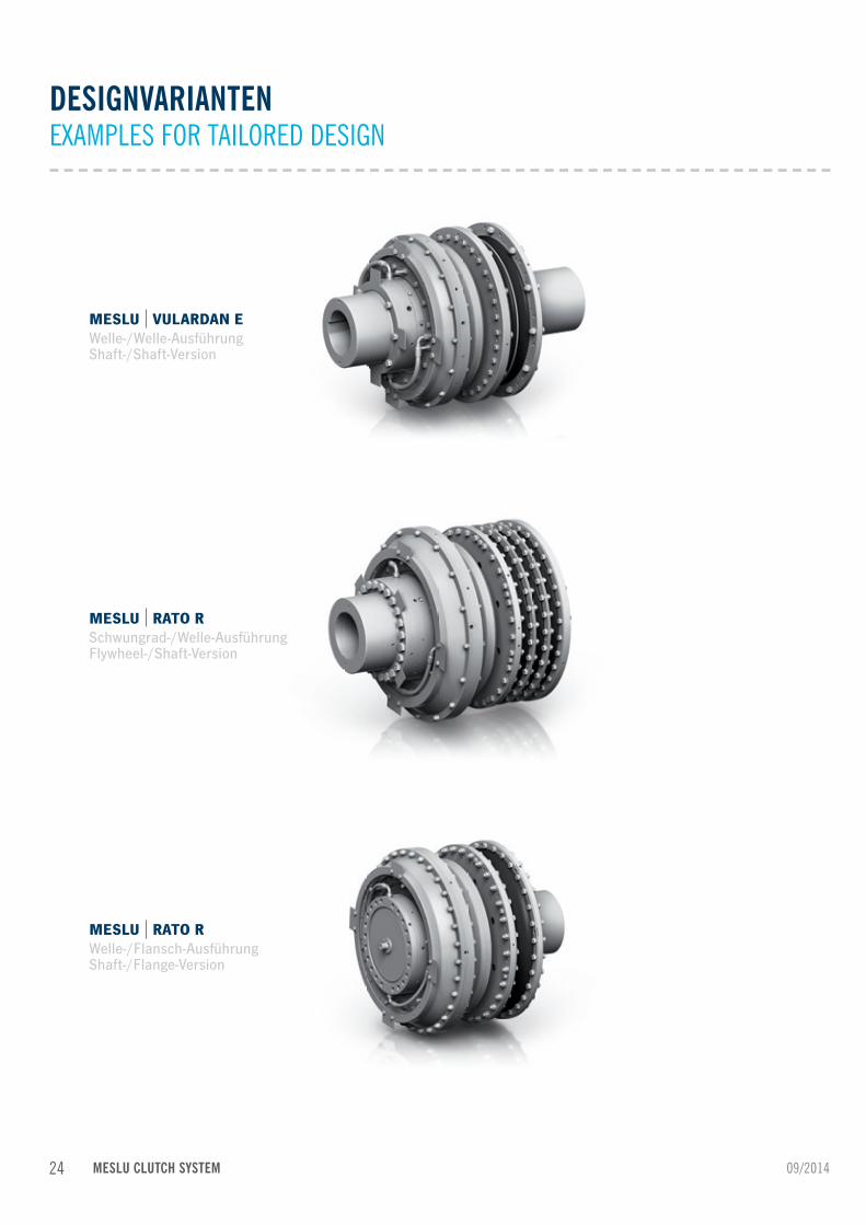
DESIGNVARIANTENEXAMPLES FOR TAILORED DESIGN
MESLU VULARDAN EWelle-/Welle-AusführungShaft-/Shaft-Version
MESLU RATO RSchwungrad-/Welle-AusführungFlywheel-/Shaft-Version
MESLU RATO RWelle-/Flansch-AusführungShaft-/Flange-Version
24 09/2014MESLU CLUTCH SYSTEM

SPEZIELLE AUSFÜHRUNG SPECIAL DESIGN
MESLU Quillschaft-Ausführung MESLU quill shaft versionGröße / Size: 57 – 540TKN: 44.00 kNm – 400.00 kNm
2509/2014 MESLU CLUTCH SYSTEM

In diesem Katalog ist die Standardvariante der Schalteinheit für die Schaltkupplungs-größen 19 bis 58 und für die Größen 90 bis 420 erläutert und beschrieben. Diese komplett auf einen Rahmen montierte Schalteinheit bildet das Kernstück jeder pneu-matischen Steuerung. Sie wird zu jeder VULKAN MESLU Schaltkupplung mitgeliefert und sollte in unmittelbarer Nähe (siehe Anlagenschema Ein-Motoren-Anlage) der Kupp-lung angebracht werden. Sinkt der Luftdruck in der Kupplung unter den Druck, der für die schlupffreie Übertragung des Drehmomentes erforderlich ist, wird die Kupplung durch die Luftdrucküberwachung automatisch abgeschaltet.
In this catalogue, the standard version of the control unit for the MESLU sizes 19 to 58 and for sizes 90 to 420 is explained and described. This control unit, completely mounted on a single frame, is the heart of the pneumatic control system. One will be delivered with each VULKAN MESLU Clutch, and should be installed within easy reach (see system diagram single-engine installation) of the coupling. The clutch will automatically disengage, if the air pressure drops below a pre-set limit.
I = Druckluft - Eingang 9 ± 0,5 bar / I = Compressed Air - Input 9 ± 0,5 barII = zur Schaltkupplung / to the Clutch CouplingC = Anschluss für Fernmanometer (Schaltzustandanzeige) / Connection for remote manometer (indication engagement condition)D, C1 = Messanschlüsse für Einstellmanometer (vom Kunden nicht zu benutzen) / Connections for adjustable manometer (not to be used by the cust.)
Sonderausführungen mit z. B. Druckabsenkung auf Anfrage möglich.Special designs included e.g. pressure reduction on request.
Standard-Schaltschema
5
2
5
3
3
134
111
1
1
1
52 C1
C
D20
3
4
5
ZV6
5
I II
9
122
22
122
R
P
B
Sicherung gegenunbeabsichtigtes Schalten /Protection against unintended engagement
Kupplung „Ein“ /Clutch „in“
Kupplung „Aus“ /Clutch „out“
Fernbedienung /Remote control
Luftversorgung /Air Supply
Messanschluss /Test port
A
31
3 42
3
5
1
2
1 1
4
33 3 3 555
73
72211
141142
100
10
3 NO4 NO1 NC 2 NC
71
1
Standard-SchaltschemaStandard configuration diagram
09/2014MESLU CLUTCH SYSTEM
EIGENSCHAFTEN PNEUMATISCHE SCHALTEINHEITCHARACTERISTICS PNEUMATIC CONTROL UNIT
26

Die Standardvariante kann durch zusätzliche Aggregate auf den jeweiligen Anwen-dungsfall angepasst werden. Außerdem ist es möglich mehrere MESLU Schaltkupp-lungen und deren Steuerungen logisch miteinander zu verknüpfen und über eine entsprechende Verblockung dafür zu sorgen, dass die Schaltkupplungen z.B. nicht gleichzeitig geschaltet werden können, um evtl. Schäden an der Antriebsanlage auszuschließen (z.B. bei Quillschaft-Ausführung in mehrgängigen Getrieben).
The standard version can be adapted, with additional units, to suit any applica-tion. Furthermore, it is possible to link multiple MESLU clutches and their controls by system interlocking via suitable valves to ensure that the clutches cannot be engaged simultaneously, preventing possible damage to the propulsion system (e. g. at quill shaft version in multi-speed gearboxes).
Große pneumatische Schalteinheit mit Geräteanordnung / Large pneumatic control unit with arrangement of equipment.
Kleine pneumatische Schalteinheit mit Geräteanordnung / Small pneumatic control unit with arrangement of equipment.
Technische Daten: Anschlussmaße für I und II: M22 x 1,5 für Rohr 15 x 1,5 / Connection dimension for I and II: M22 x 1,5 for Pipe 15 x 1,5Anschlussmaße für C: M12 x 1,5 für Rohr 6 x 1 / Connection dimension for C: M12 x 1,5 for Pipe 6 x 1Stromversorgung: 24 V / Electrical Power Supply: 24 VAndere Spannungen und weitere Konfigurationen auf Anfrage möglich / Other voltages and configurations available on request.
Technische Daten: Anschlussmaße für I und II: M36 x 2,0 für Rohr 28 x 2,0 / Connection dimension for I and II: M36 x 2,0 für Rohr 28 x 2,0Anschlussmaße für A, A1, B und C: M12 x 1,5 für Rohr 6 x 1 / Connection dimension for A, A1, B und C: M12 x 1,5 for Pipe 6 x 1Stromversorgung: 24 V / Electrical Power Supply: 24 VAndere Spannungen und weitere Konfigurationen auf Anfrage möglich / Other voltages and configurations available on request.
Große pneumatische Schalteinheitmit Geräteanordnung
211 319-2*
73**121-A* 11 VT1 71
100C1/D* 141 20 10
134 142 72
600
59
170
126
31555
70
740
800
870
22
122
121
510
Ø8
Rau
m f
ür G
erät
e un
d V
erro
hrun
g /
Spac
e fo
r pip
ing
6-5*121-B*
Kleine pneumatische Schalteinheitmit Geräteanordnung
390
180
121
22
9
5
12250
606 12
225445
158
75
516
570
645
336
Rau
m f
ür G
erät
e un
d V
erro
hrun
g /
Spac
e fo
r Ins
trum
ents
and
pip
ing
Ø8
6-5*121-B*
9-2*
212
215
211
31
121-A*
11
VT1
71
73
134
142
72
57
C1/D*
141
2
10
100
101
09/2014 MESLU CLUTCH SYSTEM
EIGENSCHAFTEN PNEUMATISCHE SCHALTEINHEITCHARACTERISTICS PNEUMATIC CONTROL UNIT
27

09/2014
Die axiale Luftzufuhr bestehend aus dem Rotor, dem Verbundschlauch und dem Schnellentlüftungsventil sowie eines Adapter flansches, verbindet die pneumatische Schalteinheit mit der MESLU Schaltkupplung. Sie gewährleistet eine kontinuierliche Druckluftversorgung. Um keine Schwingungen zu übertragen, ist das Verbindungsstück zwischen Rotor und Schnellentlüftungsventil als flexibler Verbundschlauch ausgeführt. Das Schnellentlüftungsventil schützt das System vor Überdruck, indem es für eine schnelle Entlüftung im Ausschaltfall bzw. bei Notabschaltung sorgt.
The axial air supply consisting of the rotor, connection hose and quick release valve, connects the pneumatic control unit with the MESLU Clutch. This guaran-tees a continuous supply of compressed air. To prevent transmitted vibration, the connector between the rotor and quick release valve is flexible. The quick release valve protects the system against pressure overload ensuring fast venting in case of emergency shut-down.
MESLUGröße
Rohr Abmessungen
MESLUSize
Pipe Dimensions
D1 D2 h6 D3 h7 D4 D5 e GW (Rotor) L1 L2 L3 L4 L5 L6 L7 L8 +1 L9 L10 L11 TKR SL W1 W2
[mm] [mm] [mm] [mm] [mm] [mm] [mm] [mm] [mm] [mm] [mm] [mm] [mm] [mm] [mm] [mm] [mm] [mm] [mm] [mm] [mm] [°] [°]
19 – 58 15 x 1,5 60,0 52,0 52,0 19,0 100,0 30,0 M22 x 1,5 99,0 104,0 20,0 25,0 48,0 17,0 23,0 22,0 3,0 2,0 5,0 80,0 500,0 15,0 60,090 – 420 28 x 2,0 82,6 52,0 52,0 24,0 125,0 47,0 G 1" 108,5 115,0 21,0 26,5 59,0 17,0 23,0 22,0 3,0 2,5 5,0 80,0 800,0 15,0 60,0
MESLU CLUTCH SYSTEM
EIGENSCHAFTEN LUFTZUFUHRCHARACTERISTICS AIR SUPPLY
L1
L10
L10
e
ØD
1L5
L11
SL
D2
D5
D3
M8
Ø0.
4A
L4A
L2L3
Y
Y
A
L7L6
2:1
0.03
L8
L9Kante riefenfrei gerundet /Edge rounded groove free
Vulkan Lieferumfang /Vulkan scope of delivery
Kundenanschluss /Customer connectionleicht gefettet
slightly greased
Rohr / pipe Halterung gehört nicht zum Vulkan Lieferumfang /Bracket does not belong to Vulkan scope of delivery
0.03
A
A
RA 0.8
RA
3.2
RA
3.2
D4
ØTK
R
W°
W 2
RA 0.8
Ansicht A / View A
28

09/2014
EIGENSCHAFTEN ÜBERWACHUNGSEINHEITCHARACTERISTICS MONITORING DEVICE
Die Überwachungseinheit erkennt den Schlupf innerhalb der MESLU Schaltkupplung, bzw. die Differenzdrehzahl zwischen der Antriebs- und Abtriebsseite über berüh-rungslose Signalgeber und trennt dementsprechend die Kupplung, wenn eine dieser Systemgrößen den tolerierten Bereich über- bzw. unterschreitet.Um die Anlage vor unzulässigen Überlasten zu schützen und somit Beschädigungen zu verhindern, kann neben Schlupf innerhalb der MESLU Schaltkupplung zusätzlich der Drehwinkel bei der hochelastischen RATO oder VULKARDAN E überwacht werden.
The monitoring device detects the slip inside the MESLU clutch i.e. the differential speed between the drive and driven side by means of a non-contacting transducer. The clutch will disengage if the speed differential is outside the pre-set limits, preventing heat overload of the clutch friction pads. In addition, the twist angle of the highly flexible RATO or VULKARDAN E coupling can be monitored, preventing damage to the drive.
Verdrehwinkel–Überwachung /Twist angle monitoring
Schutz vor Überlast an derelastischen Kupplung /Protection against over loadat the flexible coupling
Zustandsüberwachung /Condition monitoring
Schlupf–Überwachung /Slip control
Schutz vor Überlast ander Schaltkupplung /Protection against over loadat the clutch coupling
Verschleiß–Überwachung /Wear monitoring
Drehzahl–Überwachung /Rotational speed monitoring
Optionale Überwachung des Schaltvorgangs /Optional engagement monitoring
Optionale Einschaltsperre beiabnormalem Anlagenzustand /Optional engagement blocking in case ofabnormal drive line conditions
Drehrichtungs–Überwachung /Detection of rotating direction
Optionale Überwachung derDrehrichtung auf der Lastseite /Optional monitoring of therotating direction at the load side
Temperatur–Überwachung /Temperature monitoring
Optionale Überwachungzum Schutz der Schaltkupplung /Optional monitoringto protect the clutch
puls
e se
nsor
puls
e se
nsor
puls
e se
nsor
puls
e se
nsor
pulse sensor
Zusatzfunktionen wie Drehrichtungs-, Drehzahl- und Temperaturüberwachung sowie Verblockung für mehrgängige Getriebe (Quillschaft-Ausführung) auf Anfrage möglich.There are additional functions available on request e.g. as direction sensing, rotational speed and temperature monitoring and system interlocking for multi-speed gearboxes (quill shaft version).
MESLU CLUTCH SYSTEM 29

Anlagenschema mit kleiner Schalteinheit für MESLU Größe 19 – 58 hier beispielhaft im PropellerantriebSystem diagram with small control unit for MESLU size 19-58 here as an example in the propeller drive
ANLAGENSCHEMA EIN-MOTOREN-ANLAGENBEISPIELEDIAGRAM SINGLE-ENGINE INSTALLATION
Rohrleitungen gehören nicht zum Lieferumfang VULKAN / Pipe lines do not belong to the scope of supply VULKAN.Technische Beschreibung: TV02121000 / Technical description: TV02121000.
I II
VIEW_TEMPLATE_2
Anlagenschemakleine Schalteinheit
30 bar von der Startflasche /30 bar from start up container
KleineSchalteinheit
VULKAN
control unit
2V0225...
Absperrhahn /stop cock
Leitungsfilter /line air filter
Druckminderventil /pressure reduction valve
SicherheitsventilAbschaltdruck 10 +1 bar /
safety valvedischarge pressure 10 +1 bar
Entwässerung /
draining
Gehö
rt n
icht
zum
Lie
feru
mfa
ng V
ULK
AN
/
Doe
s no
t be
long
to
the
scop
e of
sup
ply
VU
LKA
N
Luftbehälter /air reservoir
Länge dieser Rohrleitungen max. 4 mBei Rohrleitungen länger als 4 m müssen Rohre mitentsprechend größerer Nennweite verwendet werden /
Length of these pipe lines max. 4 mIf pipe lines are longer than 4 m pipe diametermust be increased accordingly.
Rotor / rotorVerbunbschlauch / connecting hoseSchnellöseventil / quick release valve
VULKAN - MESLU Schaltkupplungskombination /VULKAN - MESLU Clutch Combination
9 ± 0.5 bar15 x 1.5 15
x 1
.5
22 x
1.5
22 x
2.0
22 x
2.0
22 x
2.0
MESLU Größe / Size
Luftbehältervolumen / Air container volume
[dm³]
19 4024 6045 6058 80
09/2014MESLU CLUTCH SYSTEM30

Anlagenschema mit großer Schalteinheit für MESLU Größen 90 – 420 hier beispielhaft im BaggerpumpenantriebSystem diagram with large control unit for MESLU sizes 90-420 here as an example in the dredge pump drive
Rohrleitungen gehören nicht zum Lieferumfang VULKAN / Pipe lines do not belong to the scope of supply VULKAN.Technische Beschreibung: TV02121000 / Technical description: TV02121000.
I II
VIEW_TEMPLATE_2
Anlagenschemagroße Schalteinheit
30 bar von der Startflasche /30 bar from start up container
GroßeSchalteinheit
VULKAN
control unit
2V0226...
Absperrhahn /stop cock
Leitungsfilter /line air filter
Druckminderventil /pressure reduction valve
SicherheitsventilAbschaltdruck 10 +1 bar /
safety valvedischarge pressure 10 +1 bar
Entwässerung /
draining
Gehö
rt n
icht
zum
Lie
feru
mfa
ng V
ULK
AN
/
Doe
s no
t be
long
to
the
scop
e of
sup
ply
VU
LKA
N
Luftbehälter /air reservoir
Länge dieser Rohrleitungen max. 4 mBei Rohrleitungen länger als 4 m müssen Rohre mitentsprechend größerer Nennweite verwendet werden /
Length of these pipe lines max. 4 mIf pipe lines are longer than 4 m pipe diametermust be increased accordingly.
Rotor / rotorVerbunbschlauch / connecting hoseSchnellöseventil / quick release valve
VULKAN - MESLU Schaltkupplungskombination /VULKAN - MESLU Clutch Combination
Pumpe /pump
9 ± 0.5 bar28 x 2.0 28
x 2
.0
28 x
2.0
28 x
3.0
28 x
3.0
28 x
3.0
MESLU Größe / Size
Luftbehältervolumen / Air container volume
[dm³]
90 – 420 120
09/2014 MESLU CLUTCH SYSTEM 31

ERLÄUTERUNGEN DES PRODUKTCODESPRODUCT CODE EXPLANATIONS
MESLU Schaltkupplungssytem
Alle VULKAN Couplings Produkte sind mit einem Produktcode gekennzeichnet. Dieser Code setzt sich aus verschiedenen Parameter-Angaben zusammen und ermöglicht es, unsere Produkte eindeutig zu identifizieren.
MESLU Clutch System
All VULKAN Couplings products are identified by a product code. This code consists of several parameters and it enables the clear identification of all products.
Beispiel eines Produktcodes einerMESLU Schaltkupplungskombination
Hier haben wir den Code am Beispiel einer MESLU Schaltkupplungskombination, mit einer MESLU, Größe 24 und einer RATO R+, Größe 2D, 2-reihig, Elementsteifigkeit S entschlüsselt dargestellt.
Example of a MESLU Clutchcombination product code
We have decoded here the product code of a MESLU Clutch Combination,with a MESLU, Size 24 and a RATO R+, Size 2D, 2 rows, Element stiffness S.
09/2014
Weitere Steifigkeiten auf Anfrage möglich / Further Stiffnesses available on request.
GrößenbezeichnungSize codeMESLU
6 = 190 = 241 = 452 = 583 = 904 = 1454 = 1477 = 2255 = 3309 = 420
ProduktfamilieProduct family
ElementreihenElement rows
1 = 1 Reihe / 1 row2 = 2 Reihen / 2 row
GrößenbezeichnungSize code
RATO / VULKARDAN E
5457602D2F2G3B3C4A475G
N 0 2D 2
Baugröße (Liste der technischen Daten)Size (List of technical data)
KomplettkupplungComplete coupling
SHochelastische
KupplungHighly flexible Coupling
0 = Rato S / S+
R = Rato R / R+
K = Vulkardan E
KennzeichenKey
R0
RATO RZT
RATO S+ / R+SMH
VULKARDAN E1245
ElementsteifigkeitElement stiffness
MESLU CLUTCH SYSTEM32

Auch die VULKAN Couplings Unterbaugruppen / Peripheriekomponenten sind mit einem Produktcode gekennzeichnet. Dieser Code setzt sich aus verschiedenen Parameter-Angaben zusammen und ermöglicht es, unsere Unterbaugruppen / Peripheriekomponenten eindeutig zu identifizieren.
Also the VULKAN Couplings sub-assemblies / Peripheral devices are identified by a product code. This code consists of several parameters and it enables the clear identification of all products.
Beispiel eines Produktcodeseiner großen Schalteinheit
Hier haben wir den Code am Beispiel einer großen Schalteinheit für MESLU Größen90 – 420, als Unterbaugruppe entschlüsselt dargestellt.
Example of a Large Control Unitproduct code
We have decoded here the product code of a Large Control Unit for MESLU sizes 90 – 420 as sub assembly.
09/2014
ProduktkennzeichenProduct key
0226 = Große Schalteinheit / Large Control Unit0225 = Kleine Schalteinheit / Small Control Unit0201 = Luftzufuhr / Air Supply0230 = Schlupfüberwachung / Slip Control0231 = Verdrehwinkel überwachung / Twist Angel Monitoring0500 = Getriebeüberwachung (Sonderausführung) / Gearbox Monitoring (Special Design)
ProduktfamilieProduct family
V 0226
Baugröße (Liste der technischen Daten)Size (List of technical data)
UnterbaugruppeSub assembly
KennzeichenKey
00102
MESLU CLUTCH SYSTEM 33

34 MESLU CLUTCH SYSTEM

35MESLU CLUTCH SYSTEM
VALIDITY CLAUSE
The present catalogue shall replace all previous editions, any previous printings
shall no longer be valid. Based on new developments, VULKAN reserves the right
to amend and change any details contained in this catalogue respectively. The new
data shall only apply with respect to couplings that were ordered after said amend-
ment or change. It shall be the responsibility of the user to ensure that only the
latest catalogue issue will be used. The respective latest issue can be seen on the
website of VULKAN on www.vulkan.com.
The data contained in this catalogue refer to the technical standard as presently
used by VULKAN with defined conditions according to the explanations. It shall be
the sole responsibility and decision of the system administrator for the drive line to
draw conclusions about the system behaviour.
VULKAN torsional vibration analysis usually only consider the pure mechanical
mass-elastic system. Being a component manufacturer exclusively, VULKAN
assumes no system responsibility with the analysis of the torsional vibration system
(stationary, transiently)! The accuracy of the analysis depends on the exactness of
the used data and the data VULKAN is provided with, respectively.
Any changes due to the technological progress are reserved. For questions or
queries please contact VULKAN.
Status: 09/2014
All duplication, reprinting and translation rights are reserved.
We reserve the right to modify dimensions and constructions without prior notice.
GÜLTIGKEITSKLAUSEL
Die vorliegende Broschüre ersetzt alle vorherigen Ausgaben, ältere Drucke verlieren
ihre Gültigkeit. VULKAN ist berechtigt, aufgrund neuerer Entwicklungen die in
dieser Broschüre enthaltenen Daten entsprechend anzupassen und zu verändern.
Die neuen Daten gelten nur für nach der Änderung bestellte Kupplungen. Es liegt
im Verantwortungsbereich des Anwenders dafür zu sorgen, dass ausschließlich
die aktuelle Katalogversion verwendet wird. Der jeweils aktuelle Stand ist auf der
Webseite von VULKAN unter www.vulkan.com jederzeit abrufbar.
Die Angaben in dieser Broschüre beziehen sich auf den technischen Standard
gültig im Hause VULKAN und stehen unter den in den Erläuterungen definierten
Bedingungen. Es liegt allein im Entscheidungs- und Verantwortungsrahmen des
Systemverantwort-lichen für die Antriebslinie, entsprechende Rückschlüsse auf das
Systemverhalten zu ziehen.
VULKAN Drehschwingungsanalysen berücksichtigen in der Regel nur das rein mech-
anische Schwingungsersatzsystem. Als reiner Komponentenhersteller übernimmt
VULKAN mit der Analyse des Drehschwingungssystems (stationär, transient) nicht
die Systemverantwortung! Die Genauigkeit der Analyse hängt von der Genauigkeit
der verwendeten bzw. der VULKAN zur Verfügung gestellten Daten ab.
Änderungen aufgrund des technischen Fortschritts sind vorbehalten. Bei Unklar-
heiten bzw. Rückfragen kontaktieren Sie bitte VULKAN.
Stand 09/2014
Das Recht auf Vervielfältigung, Nachdruck und Übersetzungen behalten wir uns vor.
Maß- und Konstruktionsänderungen vorbehalten.

Head Office: VULKAN Kupplungs- und Getriebebau Bernhard Hackforth GmbH & Co. KG | Heerstraße 66 | 44653 Herne | GermanyPhone + 49 (0) 2325 922-0 | Fax + 49 (0) 2325 71110 | Mail [email protected]
www.vulkan.com
Related Documents