23-24 September, 2006, BULGARIA 1 MERGING ONTOLOGIES AND OBJECT-ORIENTED TECHNOLOGIES FOR SOFTWARE DEVELOPMENT Dencho N. Batanov Frederick Institute of Technology Computer Science Department Nicosia, Cyprus E-mail: [email protected] Abstract: There is now almost unanimous agreement that the object-oriented paradigm, applied to software engineering, is superior to the classical (function-based, procedural) paradigm. On the other hand, the object-oriented software engineering methodologies have been evolved significantly over the last two decades. The advent of Web in general and Semantic Web in particular led, for example, to merging them with the ontologies and appearance of related models and tools. Using ontologies however in the classical object-oriented software development life cycle is still not very well supported by respective research, procedures, techniques and tools. The main idea of this paper is to pay attention to the opportunities for using ontologies in the phase of high-level analysis of object-oriented systems in general and, more specifically, to show how ontologies can be used for converting a problem domain text description into an object model. The object model of a system consists of objects, identified from the text description and structural linkages corresponding to existing or established relationships. The ontologies provide metadata schemas, offering a controlled vocabulary of concepts. At the center of both object models and ontologies are objects within a given problem domain. The difference is that while the object model should contain explicitly shown structural dependencies between objects in a system, including their properties, relationships, events and processes, the ontologies are based on related terms only. On the other hand, the object model refers to the collections of concepts used to describe the generic characteristics of objects in object-oriented languages. Because ontology is accepted as a formal, explicit specification of a shared conceptualization, we can naturally link ontologies with object models, which represent a system-oriented map of related objects, described as Abstract Data Types (ADTs). Keywords: Software Engineering, Ontology, Object-Oriented Analysis, Object identification

Welcome message from author
This document is posted to help you gain knowledge. Please leave a comment to let me know what you think about it! Share it to your friends and learn new things together.
Transcript
23-24 September, 2006, BULGARIA
1
MERGING ONTOLOGIES AND OBJECT-ORIENTED TECHNOLOGIES FOR SOFTWARE DEVELOPMENT
Dencho N. Batanov Frederick Institute of Technology
Computer Science Department Nicosia, Cyprus
E-mail: [email protected]
Abstract: There is now almost unanimous agreement that the object-oriented paradigm, applied to software engineering, is superior to the classical (function-based, procedural) paradigm. On the other hand, the object-oriented software engineering methodologies have been evolved significantly over the last two decades. The advent of Web in general and Semantic Web in particular led, for example, to merging them with the ontologies and appearance of related models and tools. Using ontologies however in the classical object-oriented software development life cycle is still not very well supported by respective research, procedures, techniques and tools. The main idea of this paper is to pay attention to the opportunities for using ontologies in the phase of high-level analysis of object-oriented systems in general and, more specifically, to show how ontologies can be used for converting a problem domain text description into an object model. The object model of a system consists of objects, identified from the text description and structural linkages corresponding to existing or established relationships. The ontologies provide metadata schemas, offering a controlled vocabulary of concepts. At the center of both object models and ontologies are objects within a given problem domain. The difference is that while the object model should contain explicitly shown structural dependencies between objects in a system, including their properties, relationships, events and processes, the ontologies are based on related terms only. On the other hand, the object model refers to the collections of concepts used to describe the generic characteristics of objects in object-oriented languages. Because ontology is accepted as a formal, explicit specification of a shared conceptualization, we can naturally link ontologies with object models, which represent a system-oriented map of related objects, described as Abstract Data Types (ADTs).
Keywords: Software Engineering, Ontology, Object-Oriented Analysis, Object identification
2 PROCEEDINGS of the 20th International Conference SAER-2006
1. INTRODUCTION Ontology is a specification of a representational vocabulary for a shared domain of discourse: definitions of classes, relations, functions, and other objects (Gruber, 1993) or, more generally, a specification of conceptualization (Gruber, 1994). To solve the problem of heterogeneity in developing software applications, there is a need for specific descriptions of all kinds of concepts, for example, classes (general things), the relationships that can exist among them, and their properties (or attributes) (Heflin, Volz, and Dale, 2002). Ontologies described syntactically on the basis of languages such as eXtensible Markup Language (XML), XML Schema (XMLS), Resource Description Framework (RDF), RDF Schema (RDFS) and OWL (Web Ontology Language) can be successfully used for this purpose. Object orientation is a commonly accepted paradigm in software engineering for the last few decades. There is now almost unanimous agreement that it is superior to the classical (function-based, procedural) paradigm. On the other hand, the object-oriented software engineering methodologies have been evolved significantly over the last two decades. The advent of Web in general and Semantic Web in particular led, for example, to merging them with the ontologies and appearance of related models and tools. The foundation of such merging is the domain model. The Semantic Web community has produced in the last couple of years a number of complementary tools, including languages (RDF Schema and OWL), for developing, maintaining, using and sharing domain models for (Object-Oriented) Software Engineering. For example, domain models encoded in OWL can be uploaded on the Web and shared among multiple applications. It’s worth noting here that there are quite substantial differences between the object models used by object-oriented and Semantic Web-oriented programming languages. Merging ontologies however and the classical object-oriented software development, where the classical object model is used, is still not very well supported by respective research, related procedures, techniques and tools. The motto of classical object-oriented software development may be formulated in different ways, but its essence can be stated simply: “Identify and concentrate on objects in the problem domain description first. Think about the system function later.” At the initial analysis phase, however, identifying the right objects, which are vital to the system’s functionality, seems to be the most difficult task in the whole development process, from both theoretical and practical point of view. Object-oriented software development is well supported by a huge number of working methods, techniques, and tools, except for this starting point - object identification and building the related system object model. Converting the text description of system problem domain and respective functional requirement specifications into an object model is usually left to the intuition and experience of developers (system analysts). One commonly accepted rule of thumb is, “If an object fits within the context of the system’s responsibilities, then include it in the system.” However, since the members of a development team are likely to have different views on many points, serious communication problems may occur during the later phases of the software development process. Recently there has been great research interest in applying ontologies for solving this "language ambiguity problem" as either an ontology-driven or ontology-based approach (Deridder, Wouters, 1999). Object-oriented software is actually a process of software implementation of Abstract Data Types (ADTs). Any ADT is a named set of attributes, which show the characteristics of and formalize the relationships between objects, and methods (operations, functions) for putting into effect the behavior of objects, making the
September 22nd, 2006, BULGARIA
3
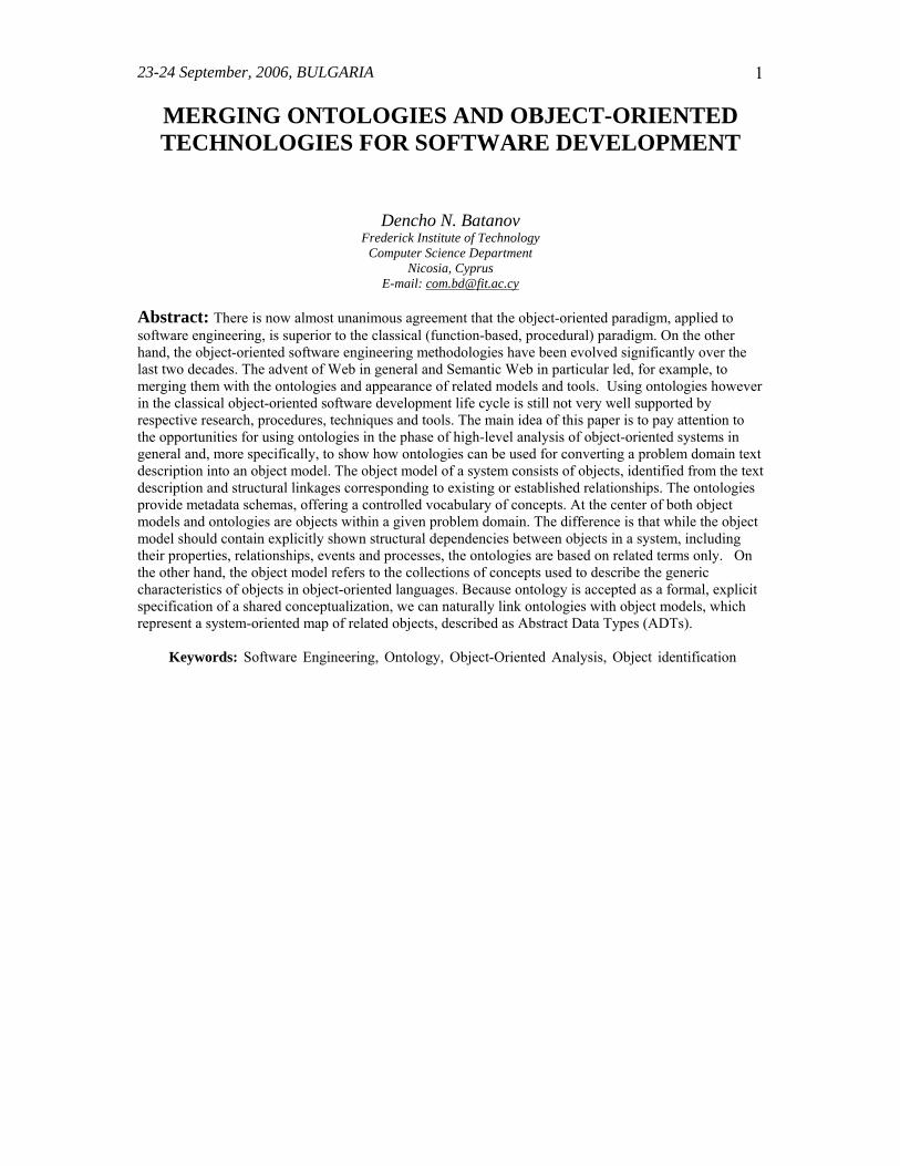
system functional enough to be of practical use. Building an accurate, correct and objectively well-defined object model containing objects, represented as ADTs, is the basis for successful development of an object-oriented software system (Weiss, 1993; Manola, 1999). Objects are transformed during the software development process from “real things” to concepts, and finally to ADTs, as shown in Figure1.
Real Thing Concept Abstract Data Type
STUDENT - Person who is studying in an academic system
STUDENT - Attributes with their types - Behavior (methods, operations, functions)
Figure 1. Conceptualization and ADTs
In this paper, I’ll show a possible procedure for converting a text description of a problem domain into an object model, based on transformation of eight different models. Only two of them, namely the Text description model (T-model) and Class (object) model (C-model), are included in the classical object-oriented software development process. The rest of the models represent specific analysis work, which the developers should do in order to get benefit from using ontologies for semi-formal identification of objects, which are to be responsible for the system functionality. The paper is structured as follows: Section 2 introduces the models in general and describes the overall procedure for their transformation. Section 3 is dedicated to a little bit more detailed description of the models as well as to discussion on the techniques and tools, which can be practically used for model transformation. An illustrative example of a part of the information system for the domain of academic management is used throughout the paper to support the explanations. Finally, section 4 summarizes the proposed procedure and highlights direction for future work. 2. OVERVIEW OF THE PROCEDURE Models are inseparable and one of the most significant parts of any methodology. They help developers to better understand complex tasks and represent in a simpler way the work they should do to solve those tasks. Object-oriented analysis of a system under development is a good example of such a complex task. The complexity stems from the fact that in object-oriented development everything is based on objects but their identification in a given problem domain is completely left to the intuition of the developer. All that he/she has as a starting point is the text description of the problem domain, which is itself an extended model of the usually very general and ambiguous initial user requirements. Following the existing practice we accept this text description model (T-model) as the available model, which serves as a starting point of our transformation process. According to the object-oriented software development methodology the analysis work on the T-model leads to two major deliverables: functional specification of the system, expressed as either text or graphically as Use Case diagrams and the class (object) model (C-model). The ultimate goal of the developer's efforts is actually creating the C-model. This is so because the objects included in the C-model should contain the complete information necessary for the next phases of design and implementation of the
4 PROCEEDINGS of the 20th International Conference SAER-2006
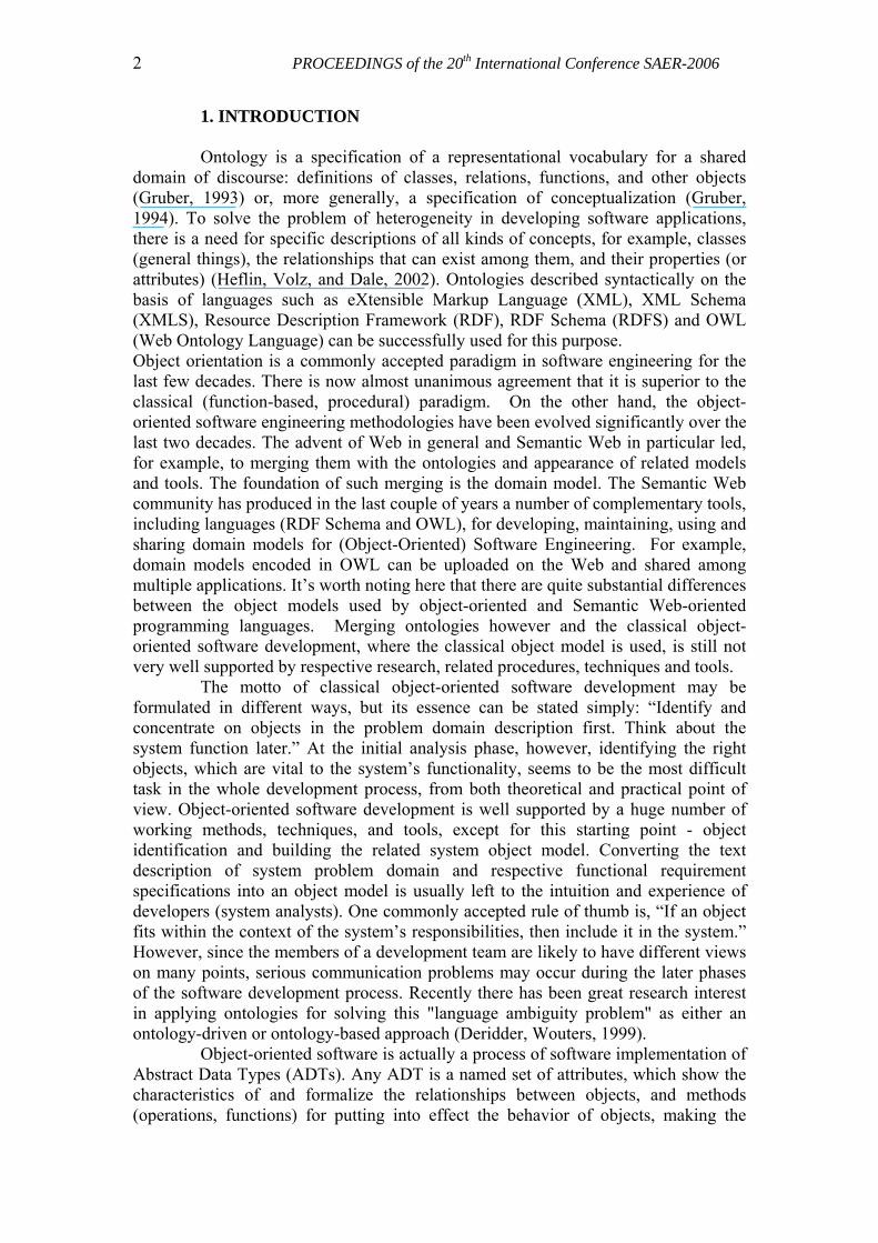
software system. In other words the objects should be represented as ADTs - ready for design and implementation software modules. It is clear now the already mentioned problem with "language ambiguity" - different interpretations of the T-model, without any formal support of the choice of participating objects, would lead to creating C-models, which are quite probably inconsistent, incomplete or inefficient for the further steps of design and implementation. We can believe that using ontology as a tool of conceptualization working on the T-model can make if not fully formal at least semi-formal the process of creating the C-model and in this way to help developers in this complex and imprecise task. Figure 2 shows the basic idea of the procedure, models used and transformation process on them. The starting point of the transformation is the T-model, which represents a concise description of the problem domain, where the software system under development will work, written in a natural language, in this case English. If not available the T-model is a deliverable from a system analyst's work on the general user requirements for the system functionality. The presumption is that this problem domain description contains the main objects, which will participate in ensuring that functionality. Of course, at this level the objects are represented by their natural names only and as such are very far from the form we need to reach - represented as ADTs. To help this process we refer to a tool of conceptualization - an ontological engine, which applied on the T-model generates an ontological model (O-model) of the problem domain at hand.
T-model ................... The doctoral student must normally have ........ Text description model
O-model <rdfs:subClassOf rdf:resource="http://web.mit.edu#Top" />
<rdfs:subClassOf rdf:resource="
Ontological model
MF-model
stu co app the app sup fac staf me dep exa req res deg per ter dea righ pro ow the the doc doc app fac staf sen fullO1 O2 O3 O4 O5 O6 O7 O8 O9O10O11O12O13O14O15O16O17O18O19O20O21O22O23O24O25O26O27O28O29
stude O1commO2approO3thesis O4applicO5super O6facult O7staff O8mem O9deparO10examO11requirO12reseaO13degreO14permO15termO16deanO17right O18propoO19own O20thesiO21thesiO22doct O23doct O24appr O25faculO26staff O27seni O28full O29full_tO30final O31geneO32exa O33intellO34oral_O35doct O36stud O37depaO38
O1 O2 O3 O4 O5 O6 O7 O8 O9 O10O11O12O13O14O15O16O17O18O19O20O21O22O23O24O25O26O27O28O29
Full Matrix model
Mr-model
approval
thesis
applicati
supervi
departm
examin
degree
permis
dean
right thesis p
thesis r
doctoral
s taffme
full_time
finate
o1 o2 o3 o4 o5 o6 o7 o8 o9 o10 o11 o12 o13 o14 o15 o1
approval o1
thesis o2
application o3
supervis or o4
department o5
examination o6
degree o7
permiss ion o8
dean o9
right o10
thesis _proposal o11
thesis _research o12
doctoral_student o13
staff_member o14
full_time_res ident o15
final_term o16
examination_requirement o17
intellec tual_property o18
department_committee o19
5 8 2 3 3 1 4 2 4 3 4 1 10 3 4weight
Reduced matrix model
C-model
Class (object) model
XML-model <>…….<> <…….
……>
DF-model Data and Function model
data
function
UO-model Use Case Ontological model
4
5 6 7 8
3
2
1
Figure 2. Models for converting a text description into an object model
We use the fact that any ontology is a systematic description of concepts (objects) in a given domain of interest along with expressed relationships between all or part of them. The O-model is a straightforward and practically useful source of information for identifying the participating objects. We use this information to build a so-called
September 22nd, 2006, BULGARIA
5
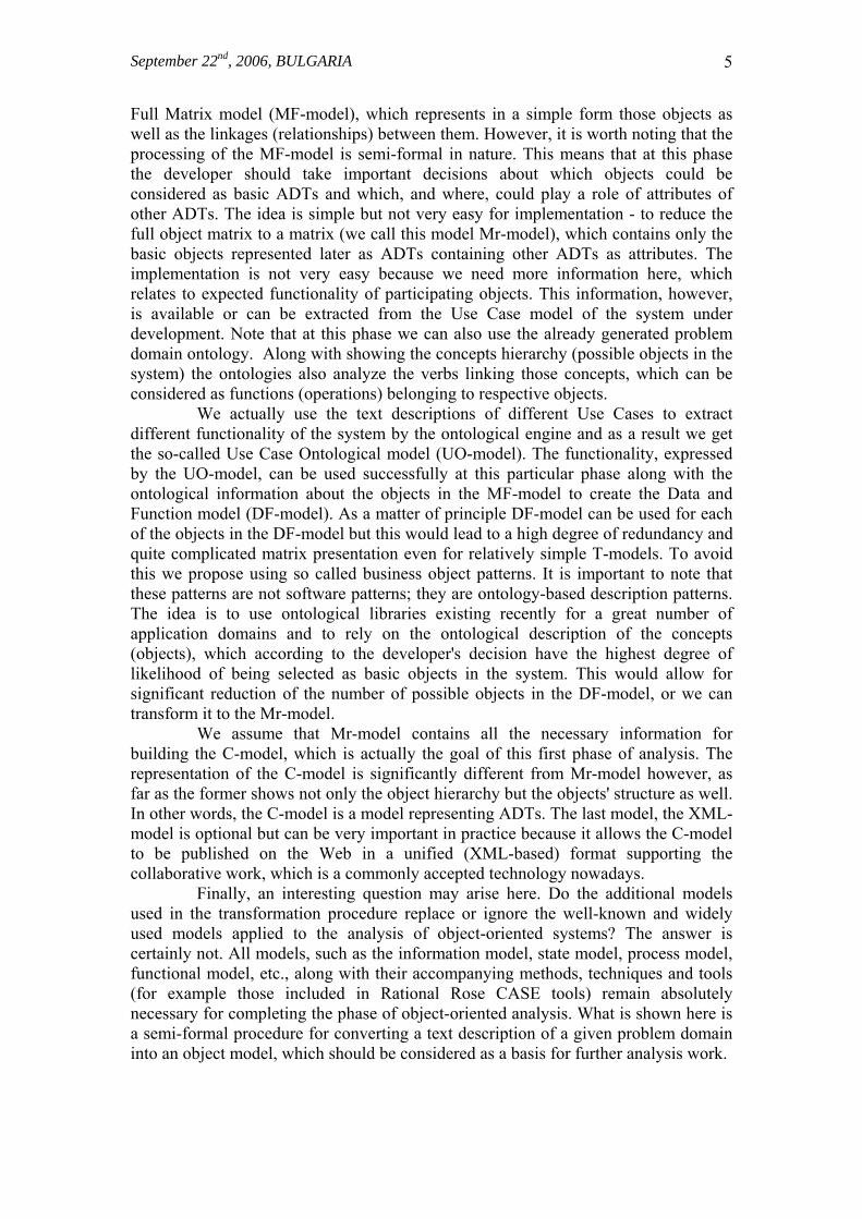
Full Matrix model (MF-model), which represents in a simple form those objects as well as the linkages (relationships) between them. However, it is worth noting that the processing of the MF-model is semi-formal in nature. This means that at this phase the developer should take important decisions about which objects could be considered as basic ADTs and which, and where, could play a role of attributes of other ADTs. The idea is simple but not very easy for implementation - to reduce the full object matrix to a matrix (we call this model Mr-model), which contains only the basic objects represented later as ADTs containing other ADTs as attributes. The implementation is not very easy because we need more information here, which relates to expected functionality of participating objects. This information, however, is available or can be extracted from the Use Case model of the system under development. Note that at this phase we can also use the already generated problem domain ontology. Along with showing the concepts hierarchy (possible objects in the system) the ontologies also analyze the verbs linking those concepts, which can be considered as functions (operations) belonging to respective objects. We actually use the text descriptions of different Use Cases to extract different functionality of the system by the ontological engine and as a result we get the so-called Use Case Ontological model (UO-model). The functionality, expressed by the UO-model, can be used successfully at this particular phase along with the ontological information about the objects in the MF-model to create the Data and Function model (DF-model). As a matter of principle DF-model can be used for each of the objects in the DF-model but this would lead to a high degree of redundancy and quite complicated matrix presentation even for relatively simple T-models. To avoid this we propose using so called business object patterns. It is important to note that these patterns are not software patterns; they are ontology-based description patterns. The idea is to use ontological libraries existing recently for a great number of application domains and to rely on the ontological description of the concepts (objects), which according to the developer's decision have the highest degree of likelihood of being selected as basic objects in the system. This would allow for significant reduction of the number of possible objects in the DF-model, or we can transform it to the Mr-model. We assume that Mr-model contains all the necessary information for building the C-model, which is actually the goal of this first phase of analysis. The representation of the C-model is significantly different from Mr-model however, as far as the former shows not only the object hierarchy but the objects' structure as well. In other words, the C-model is a model representing ADTs. The last model, the XML-model is optional but can be very important in practice because it allows the C-model to be published on the Web in a unified (XML-based) format supporting the collaborative work, which is a commonly accepted technology nowadays. Finally, an interesting question may arise here. Do the additional models used in the transformation procedure replace or ignore the well-known and widely used models applied to the analysis of object-oriented systems? The answer is certainly not. All models, such as the information model, state model, process model, functional model, etc., along with their accompanying methods, techniques and tools (for example those included in Rational Rose CASE tools) remain absolutely necessary for completing the phase of object-oriented analysis. What is shown here is a semi-formal procedure for converting a text description of a given problem domain into an object model, which should be considered as a basis for further analysis work.
6 PROCEEDINGS of the 20th International Conference SAER-2006
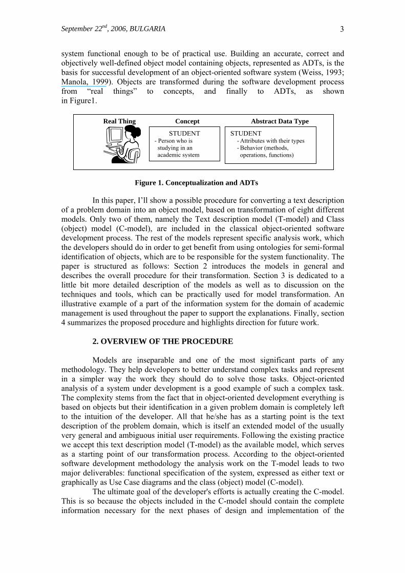
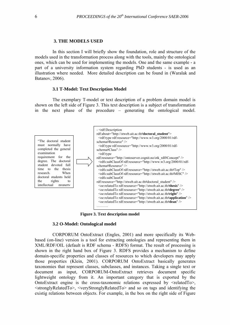
3. THE MODELS USED In this section I will briefly show the foundation, role and structure of the models used in the transformation process along with the tools, mainly the ontological ones, which can be used for implementing the models. One and the same example - a part of a university information system regarding PhD students - is used as an illustration where needed. More detailed description can be found in (Waralak and Batanov, 2006). 3.1 T-Model: Text Description Model The exemplary T-model or text description of a problem domain model is shown on the left side of Figure 3. This text description is a subject of transformation in the next phase of the procedure – generating the ontological model.
- <rdf:Description rdf:about="http://stweb.ait.ac.th#doctoral_student"> <rdf:type rdf:resource="http://www.w3.org/2000/01/rdf-schema#Resource" /> <rdf:type rdf:resource="http://www.w3.org/2000/01/rdf-schema#Class" /> <rdf:type rdf:resource="http://ontoserver.cognit.no/otk_rdf#Concept" /> <rdfs:subClassOf rdf:resource="http://www.w3.org/2000/01/rdf-schema#Resource" /> <rdfs:subClassOf rdf:resource="http://stweb.ait.ac.th#Top" /> <rdfs:subClassOf rdf:resource="http://stweb.ait.ac.th#MISC" /> <rdfs:subClassOf rdf:resource="http://stweb.ait.ac.th#doctoral_student" /> <oe:relatedTo rdf:resource="http://stweb.ait.ac.th#thesis" /> <oe:relatedTo rdf:resource="http://stweb.ait.ac.th#degree" /> <oe:relatedTo rdf:resource="http://stweb.ait.ac.th#right" /> <oe:relatedTo rdf:resource="http://stweb.ait.ac.th#application" /> <oe:relatedTo rdf:resource="http://stweb.ait.ac.th#dean" /> ……….
“The doctoral studentmust normally havecompleted the generalexamination requirement for thedegree. The doctoralstudent devoted fulltime to the thesisresearch. Whendoctoral students heldthe rights tointellectual property
Figure 3. Text description model
3.2 O-Model: Ontological model CORPORUM OntoExtract (Engles, 2001) and more specifically its Web-based (on-line) version is a tool for extracting ontologies and representing them in XML/RDF/OIL (default is RDF schema - RDFS) format. The result of processing is shown in the right hand box of Figure 3. RDFS provides a mechanism to define domain-specific properties and classes of resources to which developers may apply those properties (Klein, 2001). CORPORUM OntoExtract basically generates taxonomies that represent classes, subclasses, and instances. Taking a single text or document as input, CORPORUM-OntoExtract retrieves document specific lightweight ontology from it. An important category that is exported by the OntoExtract engine is the cross-taxonomic relations expressed by <relatedTo>, <stronglyRelatedTo>, <veryStronglyRelatedTo> and so on tags and identifying the existig relations between objects. For example, in the box on the right side of Figure
September 22nd, 2006, BULGARIA
7
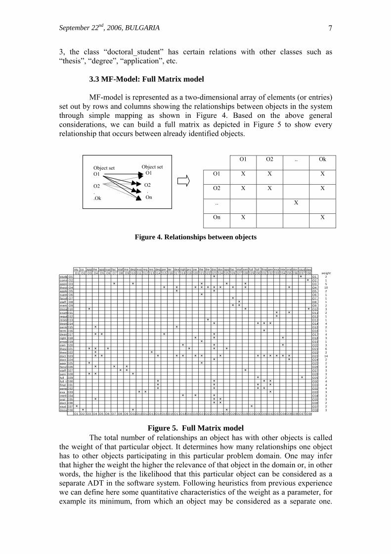
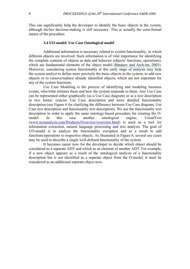
3, the class “doctoral_student” has certain relations with other classes such as “thesis”, “degree”, “application”, etc. 3.3 MF-Model: Full Matrix model MF-model is represented as a two-dimensional array of elements (or entries) set out by rows and columns showing the relationships between objects in the system through simple mapping as shown in Figure 4. Based on the above general considerations, we can build a full matrix as depicted in Figure 5 to show every relationship that occurs between already identified objects.
O1 O2 .. Ok
O1 X X X
O2 X X X
.. X
On X X
Object set O1 O2 . .Ok
Object set O1 O2 . On
Figure 4. Relationships between objects
stu co app the app sup fac staf me dep exa req res deg per ter dea righ pro ow the the doc doc app fac staf sen full full fina gen exa inte oral doc stud depO1 O2 O3 O4 O5 O6 O7 O8 O9O10O11 O12O13O14O15O16 O17O18O19O20O21 O22O23O24O25O26 O27O28O29O30O31O32O33O34 O35O36 O37O38 weight
stude O1com
O1 2mO2
aO2 1
ppro O3 O3 5thes is O4 O4 10applic O5 O5 2super O6 O6 1facult O7 O7 1staff O8 O8 1mem O9 O9 2deparO10 O10 3examO11 O11 2requirO12 O12 1reseaO13 O13 1degreO14 O14 4permO15 O15 2term O16 O16 1deanO17 O17 4right O18 O18 3propoO19 O19 1own O20 O20 3thes iO21 O21 6thes iO22 O22 2doct O23 O23 14doct O24 O24 2appr O25 O25 2faculO26 O26 3staff O27 O27 3seni O28 O28 3full O29 O29 2full_tO30 O30 4final O31 O31 4geneO32 O32 4exa O33 O33 3intell O34 O34 3oral_O35 O35 3doct O36 O36 2stud O37 O37 2depaO38 O38 3
O7 O8 O9 O1O1 O2 O3 O4 O5 O6 0O11O12O13 O14O15O16O17O18 O19O20O21O22O23 O24O25O26 O27O28O29O30O31 O32O33O34O35O36 O37 O38
Figure 5. Full Matrix model The total number of relationships an object has with other objects is called the weight of that particular object. It determines how many relationships one object has to other objects participating in this particular problem domain. One may infer that higher the weight the higher the relevance of that object in the domain or, in other words, the higher is the likelihood that this particular object can be considered as a separate ADT in the software system. Following heuristics from previous experience we can define here some quantitative characteristics of the weight as a parameter, for example its minimum, from which an object may be considered as a separate one.
8 PROCEEDINGS of the 20th International Conference SAER-2006
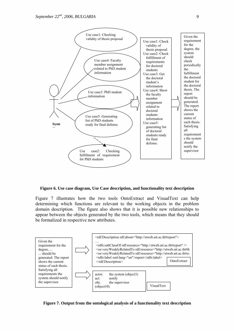
This can significantly help the developer to identify the basic objects in the system, although his/her decision-making is still necessary. This is actually the semi-formal nature of the procedure. 3.4 UO-model: Use Case Ontological model Additional information is necessary related to system functionality, in which different objects are involved. Such information is of vital importance for identifying the complete contents of objects as data and behavior (objects' functions, operations), which are fundamental elements of the object model (Batanov and Arch-int, 2003). Moreover, considering system functionality at this early stage of analysis may help the system analyst to define more precisely the basic objects in the system, to add new objects or to remove/replace already identified objects, which are not important for any of the system functions. Use Case Modeling is the process of identifying and modeling business events, who/what initiates them and how the system responds to them. Any Use Case can be represented either graphically (as a Use Case diagram) or as a text description in two forms: concise Use Case description and more detailed functionality description (see Figure 6 for clarifying the difference between Use Case diagram, Use Case text description and functionality text description). We use the functionality text description in order to apply the same ontology-based procedure for creating the O-model. In this case another ontological engine, VisualText (www.textanalysis.com/Products/Overview/overview.html) is used as a tool for information extraction, natural language processing and text analysis. The goal of UO-model is to analyze the functionality escription and as a result to add functions/operations to respective objects. As illustrated in Figure 6, several use cases may be used to describe a single well-defined functionality of the system. It becomes easier now for the developer to decide which object should be considered as a separate ADT and which as an element of another ADT. For example, if a new object appears as a result of the ontological analysis of a functionality description but is not identified as a separate object from the O-model, it must be considered as an additional separate object now.
September 22nd, 2006, BULGARIA
9
Use case1: Checking validity of thesis proposal Given the
requirement for the degree, the system should check periodically the fulfillment the doctoral student for the doctoral thesis. The report should be generated. The report shows the current status of each thesis. Satisfying all requirements the system should notify the supervisor
Use case1: Check validity of thesis proposal
Use case2: Check fulfillment of requirements for doctoral students
Use case3: Get the doctoral student’s information
Use case4: Show the faculty member assignment related to doctoral students information
Use case5: generating list of doctoral students ready for final defense.
Figure 6. Use case diagram, Use Case description, and functionality text description
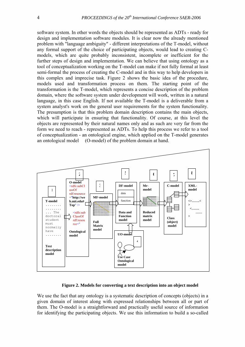
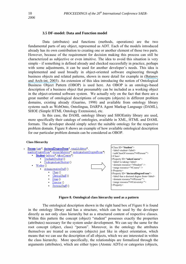
Figure 7 illustrates how the two tools OntoExtract and VisualText can help determining which functions are relevant to the working objects in the problem domain description. The figure also shows that it is possible new relationships to appear between the objects generated by the two tools, which means that they should be formalized in respective new attributes.
Figure 7. Output from the ontological analysis of a functionality text description
Use case5: Generating list of PhD students ready for final defense.
Use case4: Faculty member assignment related to PhD student information
Use case3: PhD student information
System
Use case2: Checkingfulfillment of requirementfor PhD students
<rdf:Description rdf:about="http://stweb.ait.ac.th#report"> … <rdfs:subClassOf rdf:resource="http://stweb.ait.ac.th#report" /> <oe:veryWeaklyRelatedTo rdf:resource="http://stweb.ait.ac.th#th <oe:veryWeaklyRelatedTo rdf:resource="http://stweb.ait.ac.th#cu <rdfs:label xml:lang="en">report</rdfs:label> </rdf:Description> OntoExtract
Given the requirement for the degree, ... ... should be generated. The report shows the current status of each thesis. Satisfying all requirements the system should notify the supervisor
actor: the system (object3) act: notify obj: the supervisor (object10) VisualText
10 PROCEEDINGS of the 20th International Conference SAER-2006
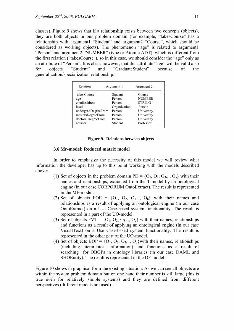
3.5 DF-model: Data and Function model Data (attributes) and functions (methods, operations) are the two fundamental parts of any object, represented as ADT. Each of the models introduced already has its own contribution to creating one or another element of those two parts. However, because of the requirement for decision making this process can still be characterized as subjective or even intuitive. The idea to avoid this situation is very simple - if something is defined already and checked successfully in practice, perhaps with some adjustments, it can be used for another developer’s needs. This idea is implemented and used broadly in object-oriented software engineering through business objects and related patterns, shown in more detail for example in (Batanov and Arch-int, 2003). An extension of this idea introducing the notion of Ontological Business Object Pattern (OBOP) is used here. An OBOP is an ontology-based description of a business object that presumably can be included as a working object in the object-oriented software system. We actually rely on the fact that there are a great number of ontological descriptions of concepts (objects) in different problem domains, existing already (Guarino, 1998) and available from ontology library systems such as WebOnto, Ontolingua, DARPA Agent Markup Language (DAML), SHOE (Simple HTML Ontology Extensions), etc. In this case, the DAML ontology library and SHOEntity library are used, more specifically their catalogs of ontologies, available in XML, HTML and DAML formats. The developer should simply select the suitable ontology for the respective problem domain. Figure 8 shows an example of how available ontological description for our particular problem domain can be considered as OBOP.
Class Hierarchy
<Class ID="Student"> <label>student</label> <subClassOf resource"=#Person/ "> </Class> <Property ID="takesCourse"> <label>is taking</label> <domain resource="#Student" /> <range resource="#Course" /> </Property> <Property ID="doctoralDegreeFrom"> <label>has a doctoral degree from</label> <domain resource"=#Person/ "> <range resource"=#University/ "> </Property>
Figure 8. Ontological class hierarchy used as a pattern
The ontological description shown in the right hand box of Figure 8 is found in the ontology library and has a structure, which can be used by the developer directly as not only class hierarchy but as a structured content of respective classes. Within this pattern the concept (object) “student” possesses exactly the properties (attributes) necessary for the system under development. We can say the same for the root concept (object, class) “person”. Moreover, in the ontology the attributes themselves are treated as concepts (objects) just like in object orientation, which means that we can use the description of all objects, which we are interested in within the class hierarchy. More specifically, the relationships are formalized through the arguments (attributes), which are either types (Atomic ADTs) or categories (objects,
September 22nd, 2006, BULGARIA
11
classes). Figure 9 shows that if a relationship exists between two concepts (objects), they are both objects in our problem domain (for example, “takesCourse” has a relationship with argument1 “Student” and argument2 “Course”, which should be considered as working objects). The phenomenon “age” is related to argument1 “Person” and argument2 ”NUMBER” (type or Atomic ADT), which is different from the first relation ("takesCourse"), so in this case, we should consider the “age” only as an attribute of “Person”. It is clear, however, that this attribute “age” will be valid also for objects “Student” and “GraduateStudent” because of the generalization/specialization relationship.
Relation Argument 1 Argument 2 ========================================== takesCourse Student Course age Person NUMBER emailAddress Person STRING head Organization Person undergradDegreeFrom Person University mastersDegreeFrom Person University doctoralDegreeFrom Person University advisor Student Professor
Figure 9. Relations between objects
3.6 Mr-model: Reduced matrix model In order to emphasize the necessity of this model we will review what information the developer has up to this point working with the models described above:
(1) Set of objects in the problem domain PD = {O1, O2, O3,.., Oa} with their names and relationships, extracted from the T-model by an ontological engine (in our case CORPORUM OntoExtract). The result is represented in the MF-model.
(2) Set of objects FOE = {O1, O2, O3,.., Ob} with their names and relationships as a result of applying an ontological engine (in our case OntoExtract) on a Use Case-based system functionality. The result is represented in a part of the UO-model.
(3) Set of objects FVT = {O1, O2, O3,.., Oc} with their names, relationships and functions as a result of applying an ontological engine (in our case VisualText) on a Use Case-based system functionality. The result is represented in the other part of the UO-model.
(4) Set of objects BOP = {O1, O2, O3,.., Od}with their names, relationships (including hierarchical information) and functions as a result of searching for OBOPs in ontology libraries (in our case DAML and SHOEntity). The result is represented in the DF-model.
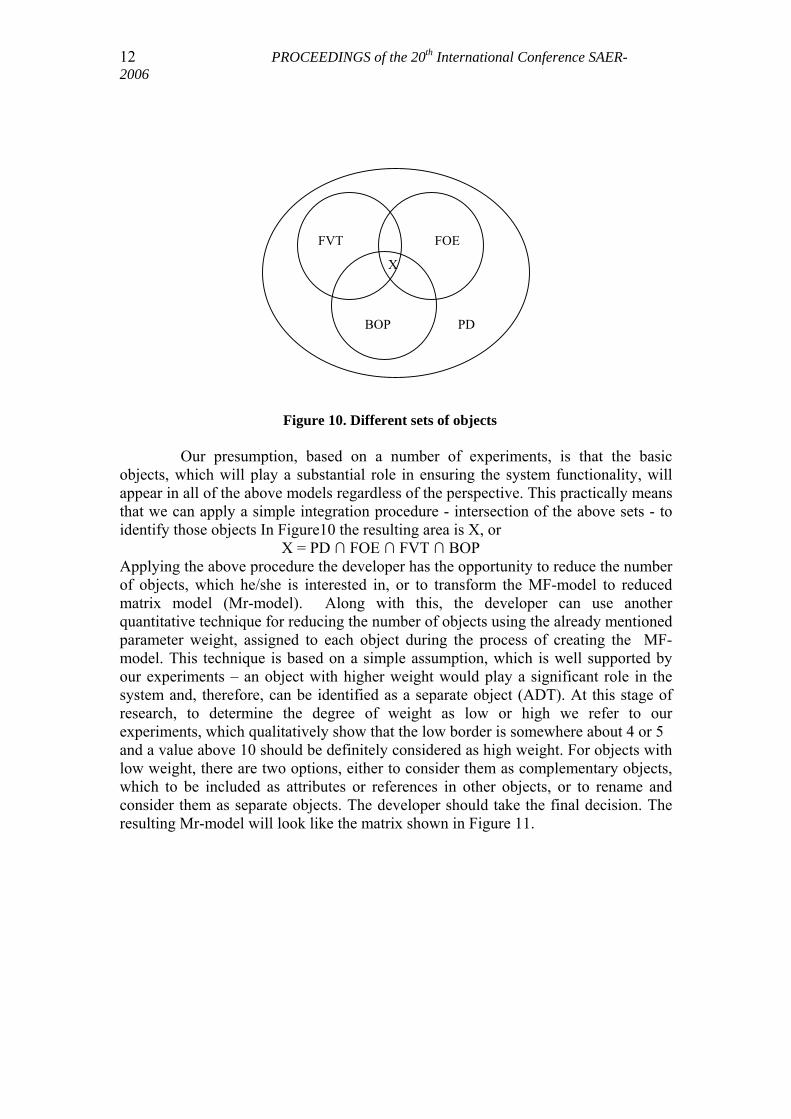
Figure 10 shows in graphical form the existing situation. As we can see all objects are within the system problem domain but on one hand their number is still large (this is true even for relatively simple systems) and they are defined from different perspectives (different models are used).
12 PROCEEDINGS of the 20th International Conference SAER-2006
FVT FOE
BOP
X
PD
Figure 10. Different sets of objects
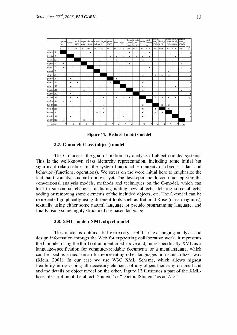
Our presumption, based on a number of experiments, is that the basic objects, which will play a substantial role in ensuring the system functionality, will appear in all of the above models regardless of the perspective. This practically means that we can apply a simple integration procedure - intersection of the above sets - to identify those objects In Figure10 the resulting area is X, or X = PD ∩ FOE ∩ FVT ∩ BOP Applying the above procedure the developer has the opportunity to reduce the number of objects, which he/she is interested in, or to transform the MF-model to reduced matrix model (Mr-model). Along with this, the developer can use another quantitative technique for reducing the number of objects using the already mentioned parameter weight, assigned to each object during the process of creating the MF-model. This technique is based on a simple assumption, which is well supported by our experiments – an object with higher weight would play a significant role in the system and, therefore, can be identified as a separate object (ADT). At this stage of research, to determine the degree of weight as low or high we refer to our experiments, which qualitatively show that the low border is somewhere about 4 or 5 and a value above 10 should be definitely considered as high weight. For objects with low weight, there are two options, either to consider them as complementary objects, which to be included as attributes or references in other objects, or to rename and consider them as separate objects. The developer should take the final decision. The resulting Mr-model will look like the matrix shown in Figure 11.
September 22nd, 2006, BULGARIA
13
approval
thesisapplication
supervisor
department
examination
degree
permission
dean rightthesis_proposal
thesis_research
student
staff_member
full_time_resident
final_term
examination_requireme
intellectual_property
department_committee
o1 o2 o3 o4 o5 o6 o7 o8 o9 o10 o11 o12 o13 o14 o15 o16 o17 o18 o19
approvo1 5
thesis o2 8
applicao3 2
supervo4 3
depart o5 3
examino6 1
degreeo7 4
permis o8 2
dean o9 4
right o10 3
thesis_o11 4
thesis_o12 1
studeno13 10
staff_mo14 3
full_timo15 4
final_teo16 4
examino17 5
intelleco18 3
depart o19 4
5 8 2 3 3 1 4 2 4 3 4 1 10 3 4 4 5 3 4
weight
weight
Figure 11. Reduced matrix model
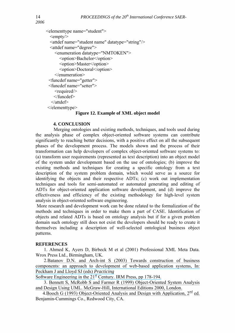
3.7. C-model: Class (object) model The C-model is the goal of preliminary analysis of object-oriented systems. This is the well-known class hierarchy representation, including some initial but significant relationships for the system functionality contents of objects – data and behavior (functions, operations). We stress on the word initial here to emphasize the fact that the analysis is far from over yet. The developer should continue applying the conventional analysis models, methods and techniques on the C-model, which can lead to substantial changes, including adding new objects, deleting some objects, adding or removing some elements of the included objects, etc. The C-model can be represented graphically using different tools such as Rational Rose (class diagrams), textually using either some natural language or pseudo programming language, and finally using some highly structured tag-based language. 3.8. XML-model: XML object model This model is optional but extremely useful for exchanging analysis and design information through the Web for supporting collaborative work. It represents the C-model using the third option mentioned above and, more specifically XML as a language-specification for computer-readable documents or a metalanguage, which can be used as a mechanism for representing other languages in a standardized way (Klein, 2001). In our case we use W3C XML Schema, which allows highest flexibility in describing all necessary elements of any object hierarchy on one hand and the details of object model on the other. Figure 12 illustrates a part of the XML-based description of the object “student” or “DoctoralStudent” as an ADT.
14 PROCEEDINGS of the 20th International Conference SAER-2006
<elementtype name="student"> <empty/> <attdef name="student name" datatype="string"/> <attdef name="degree"> <enumeration datatype="NMTOKEN"> <option>Bachelor</option> <option>Master</option> <option>Doctoral</option> </enumeration> <funcdef name="getter"> <funcdef name="setter"> <required/> </funcdef> </attdef>
</elementtype> Figure 12. Example of XML object model
4. CONCLUSION Merging ontologies and existing methods, techniques, and tools used during the analysis phase of complex object-oriented software systems can contribute significantly to reaching better decisions, with a positive effect on all the subsequent phases of the development process. The models shown and the process of their transformation can help developers of complex object-oriented software systems to: (a) transform user requirements (represented as text description) into an object model of the system under development based on the use of ontologies; (b) improve the existing methods and techniques for creating a specific ontology from a text description of the system problem domain, which would serve as a source for identifying the objects and their respective ADTs; (c) work out implementation techniques and tools for semi-automated or automated generating and editing of ADTs for object-oriented application software development, and (d) improve the effectiveness and efficiency of the existing methodology for high-level system analysis in object-oriented software engineering. More research and development work can be done related to the formalization of the methods and techniques in order to make them a part of CASE. Identification of objects and related ADTs is based on ontology analysis but if for a given problem domain such ontology still does not exist the developers should be ready to create it themselves including a description of well-selected ontological business object patterns. REFERENCES 1. Ahmed K, Ayers D, Birbeck M et al (2001) Professional XML Meta Data. Wrox Press Ltd., Birmingham, UK. 2.Batanov D.N. and Arch-int S (2003) Towards construction of business components: an approach to development of web-based application systems, In: Peckham J and Lloyd SJ (eds) Practicing Software Engineering in the 21st Century. IRM Press, pp 178-194. 3. Bennett S, McRobb S and Farmer R (1999) Object-Oriented System Analysis and Design Using UML. McGraw-Hill, International Editions 2000, London. 4.Booch G (1993) Object-Oriented Analysis and Design with Application, 2nd ed. Benjamin-Cummings Co., Redwood City, CA.
September 22nd, 2006, BULGARIA
15
5.Chandrasekaran B, Josephson JR and Benjamin VR (1999) What are ontologies, and why do we need them? IEEE Intelligent Systems 14(1): 20-26. 6. Coad P, North D and Mayfield M (1995) Object Models: Strategies, Patterns and Applications. Object International Inc., Yourdon Press Computing Series, Prentice Hall, Englewood Cliffs, NJ. 7. Coleman D, Arnold P, Bodoff S et al (1994) Object-Oriented Development: The Fusion Method. Prentice Hall, Englewood Cliffs, NJ. 8. Ellzey KS (1991) Data Structures for Computer Information Systems, 2nd ed. Macmillan Publishing Company, New York. 9. Deridder D, Wouters B (1999) The Use of Ontologies as a Backbone for Software Engineering Tools, Programming Technology Lab, Vrije Universiteit Brussel, Brussels, Belgium. 10. Engles R (2001) Del 6: CORPORUM – OntoExtract ontology extraction tool, On-To-Knowledge: Content-driven knowledge management tools through evolving ontologies. IST project IST-1999-1032, On-To-Knowledge. 11. Engles RHP, Bremdal BA and Jones R (2001) CORPORUM: a workbench for the semantic web. EXML/PKDD workshop, CognIT a.s. 12. Gil Y and Ratnakar V (2002) A comparison of (semantic) markup languages. Proceedings of the 15th International FLAIRS Conference, Special Track on Semantic Web, Pensacola, FL. 13. Gruber TR (1993) A translation approach to portable ontology specifications. Knowledge Acquisition 5: 199-220. 14. Gruber TR (1994) Towards Principles for the Design of Ontologies Use for Knowledge Sharing. In Proceedings of IJHCS-1994, 5 (6): 907-928. 15. Gruninger M and Lee JT (2002) Ontology applications and design. Communications of the ACM 45(2): 40-42. 16. Heflin J, Volz R and Dale J (2002) Requirements for a Web Ontology Language. W3C Working Draft. 17. Johansson I (1998) Pattern as an ontological category, In: Guarino N (ed), Formal Ontology in Information Systems. IOS Press, Amsterdam, Netherlands, pp 86-94. 18. Klein M (2002) Interpreting XML documents via an RDF schema ontology, In: Proceedings of the 13th International Workshop on Database and Expert Systems Applications (DEXA’02), IEEE CS Press. 19. Klein M (2001) XML, RDF and relatives. IEEE Intelligent Systems March/April, pp 26-28. 20. Maedache A and Staab S (2001) Ontology learning for the semantic web. IEEE Intelligent Systems March/April, pp 72-79. 21. Manola F (1999) Technologies for a web object model. IEEE Internet Computing January-February, pp 38-47. 22. Noy NF, Sintek M, Decker S et al (2001) Creating semantic web contents with Protégé-2000. IEEE Intelligent Systems March/April, pp 60-61. 23. Swartout W (1999) Ontologies. IEEE Intelligent Systems January/February, pp 18-25. 24. Weiss MA (1993) Data Structures and Algorithm Analysis in C. Benjamin/Cummings Publishing Company, Florida International University, Redwood City, CA. 25. Waralak Vongdoiwang, Batanov Dencho (2006), An ontology-based procedure for generating object model from text description, in Knowledge and Information Systems, Springer, London.
Related Documents


