Number 14 Printed in U.S.A. 90-818177-3 APRIL 2001 2001, Mercury Marine Sterndrive Units Alpha One Generation II SERVICE MANUAL

Mercruiser Service Manual 14 A
Nov 18, 2014
Welcome message from author
This document is posted to help you gain knowledge. Please leave a comment to let me know what you think about it! Share it to your friends and learn new things together.
Transcript
Number 14
Printed in U.S.A. 90-818177-3 APRIL 2001 2001, Mercury Marine
Sterndrive UnitsAlpha One
Generation II
�������
����
90-
i
MerCruiser #14 Sterndrive Units 90-818177-3
MerCruiser #14 Sterndrive Units90-818177-3
1A
GENERAL INFORMATIONSERVICE MANUAL NUMBER 14
90-818177--3 APRIL 2001 Page 1A-1
IMPORTANT INFORMATIONSection 1A - General Information
Table of Contents
How To Use This Manual 1A-2. . . . . . . . . . . . . Page Numbering 1A-2. . . . . . . . . . . . . . . . .
Introduction 1A-3. . . . . . . . . . . . . . . . . . . . . . . . Special Product Information 1A-3. . . . . . . .
Directional References 1A-3. . . . . . . . . . . . . . . Propeller Rotation 1A-4. . . . . . . . . . . . . . . . . . . Serial Number Locations and Engine Designation Decal 1A-4. . . . . . . . . . .
Sterndrive Unit Serial Number Location 1A-5. . . . . . . . . . . . . . . . . . . . . . . .
Decal Application 1A-5. . . . . . . . . . . . . . . . . . . Decal Removal 1A-5. . . . . . . . . . . . . . . . . . . Instructions for “Wet” Application 1A-5. . .
Painting Procedures 1A-7. . . . . . . . . . . . . . . . . Cleaning & Painting Aluminum Propellers & Gear Housings 1A-7. . . . . . .
GENERAL INFORMATION SERVICE MANUAL NUMBER 14
Page 1A-2 90-818177--3 APRIL 2001
How To Use This Manual
This Manual is divided into sections which represent major components and systems.
Some sections are further divided into parts which more fully describe the component.
Sections and parts are listed at the front of this manual.
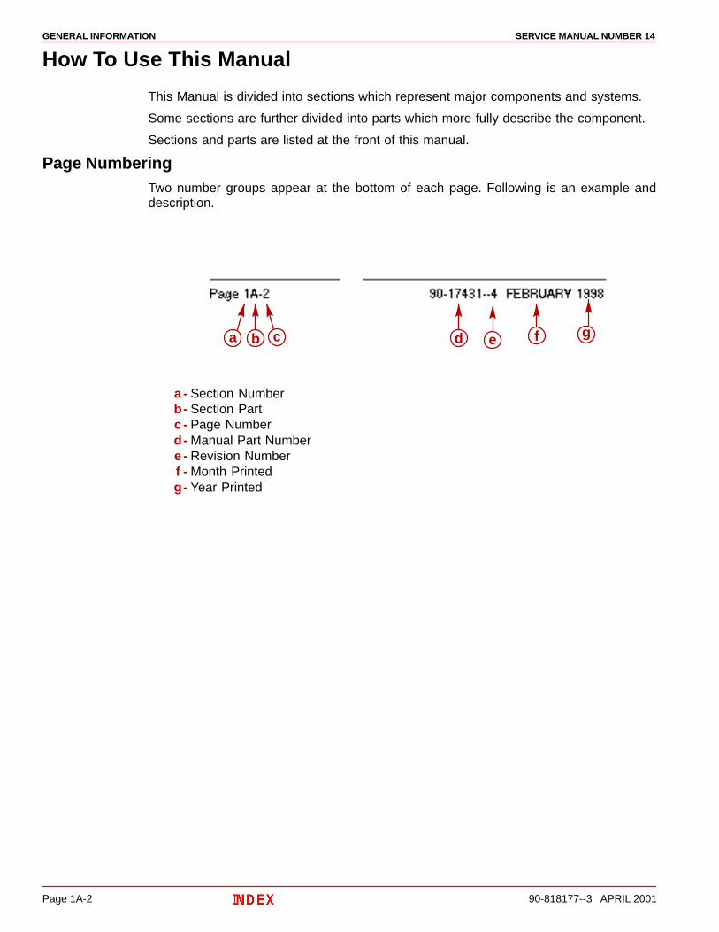
Page NumberingTwo number groups appear at the bottom of each page. Following is an example anddescription.
a b c d e f g
a - Section Numberb- Section Partc - Page Numberd- Manual Part Numbere - Revision Numberf - Month Printedg- Year Printed
GENERAL INFORMATIONSERVICE MANUAL NUMBER 14
90-818177--3 APRIL 2001 Page 1A-3
Introduction
This comprehensive overhaul and repair manual is designed as a service guide for theMercury MerCruiser models previously listed. It provides specific information, includingprocedures for disassembly, inspection, assembly and adjustment, to enable dealers andservice mechanics to repair these products.
Before attempting repairs, it is suggested that the procedure be read to gain knowledge ofthe methods and tools used and the cautions and warnings required for safety.
Special Product InformationDuring production of these models, special product improvements and changes have beenmade to increase product reliability and performance. Such changes to a sterndriveassembly component(s) are covered in the “Special Information” portion of the appropriatesterndrive assembly section. (Refer to the section “Index”.) Serial number breaks areprovided, where applicable, for ease of identification.
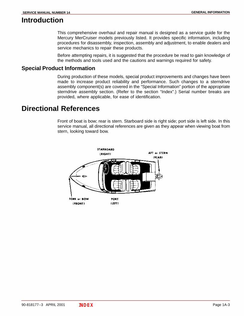
Directional References
Front of boat is bow; rear is stern. Starboard side is right side; port side is left side. In thisservice manual, all directional references are given as they appear when viewing boat fromstern, looking toward bow.

GENERAL INFORMATION SERVICE MANUAL NUMBER 14
Page 1A-4 90-818177--3 APRIL 2001
Propeller Rotation
Propeller rotation for sterndrive can be right hand or left hand rotation as viewed from theaft end of the propeller.
Right Hand Rotation Left Hand Rotation
Serial Number Locations and Engine Designation Decal
22031
a
b
a - Transom Assembly Serial Numberb - Engine Designation Decal
GENERAL INFORMATIONSERVICE MANUAL NUMBER 14
90-818177--3 APRIL 2001 Page 1A-5
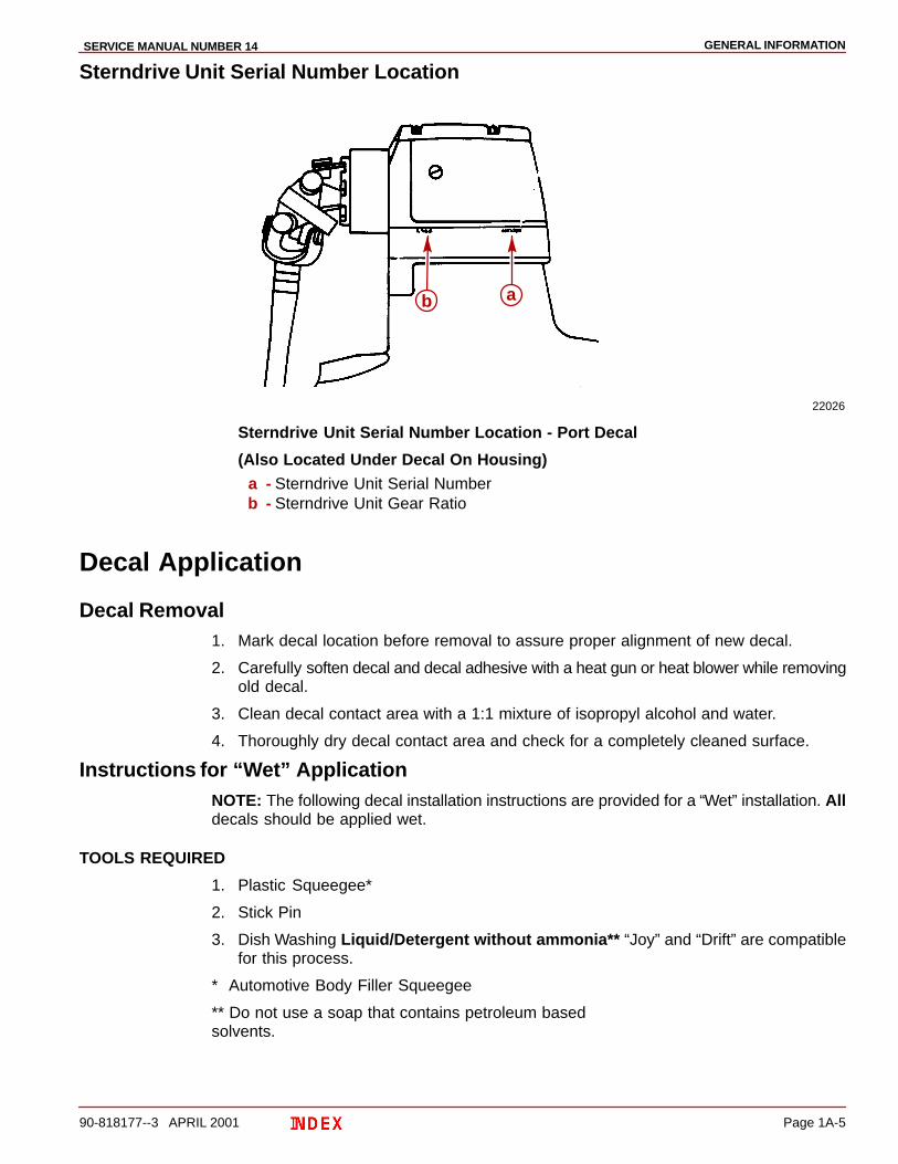
Sterndrive Unit Serial Number Location
22026
b a
Sterndrive Unit Serial Number Location - Port Decal
(Also Located Under Decal On Housing)a - Sterndrive Unit Serial Numberb - Sterndrive Unit Gear Ratio
Decal Application
Decal Removal1. Mark decal location before removal to assure proper alignment of new decal.
2. Carefully soften decal and decal adhesive with a heat gun or heat blower while removingold decal.
3. Clean decal contact area with a 1:1 mixture of isopropyl alcohol and water.
4. Thoroughly dry decal contact area and check for a completely cleaned surface.
Instructions for “Wet” ApplicationNOTE: The following decal installation instructions are provided for a “Wet” installation. Alldecals should be applied wet.
TOOLS REQUIRED
1. Plastic Squeegee*
2. Stick Pin
3. Dish Washing Liquid/Detergent without ammonia** “Joy” and “Drift” are compatiblefor this process.
** Automotive Body Filler Squeegee
** Do not use a soap that contains petroleum based solvents.
GENERAL INFORMATION SERVICE MANUAL NUMBER 14
Page 1A-6 90-818177--3 APRIL 2001
SERVICE TIP: Placement of decals using the “Wet” application will allow time toposition decal. Read entire installation instructions on this technique beforeproceeding.
TEMPERATURE
IMPORTANT: Installation of vinyl decals should not be attempted while in directsunlight. Air and surface temperature should be between 60°F (15°C) and 100°F(38°C) for best application.
SURFACE PREPARATION
IMPORTANT: Do not use a soap or any petroleum based solvents to clean applicationsurface.
Clean entire application surface with mild dish washing liquid and water. Rinse surfacethoroughly with clean water.
DECAL APPLICATION
1. Mix 1/2 ounce (16 ml) of dish washing liquid in one gallon (4 l) of cool water to use aswetting solution.
NOTE: Leave protective masking, if present, on the face of decal until final steps of decalinstallation. This will ensure that the vinyl decal keeps its shape during installation.
2. Place the decal face down on a clean work surface and remove the paper backing from“adhesive side” of decal.
3. Using a spray bottle, flood the entire “adhesive side” of the decal with the pre-mixedwetting solution.
4. Flood area where the decal will be positioned with wetting solution.
5. Position pre-wetted decal on wetted surface and slide into position.
6. Starting at the center of the decal, “lightly” squeegee out the air bubbles and wettingsolution with overlapping strokes to the outer edge of the decal. Continue going over thedecal surface until all wrinkles are gone and adhesive bonds to the cowl surface.
7. Wipe decal surface with soft paper towel or cloth.
8. Wait 10 - 15 minutes.
9. Starting at one corner, “carefully and slowly” pull the masking off the decal surface ata 180° angle.
NOTE: To remove any remaining bubbles, pierce the decal at one end of the bubble withstick pin and press out the entrapped air or wetting solution with your thumb (moving towardthe puncture).
GENERAL INFORMATIONSERVICE MANUAL NUMBER 14
90-818177--3 APRIL 2001 Page 1A-7
Painting Procedures
Cleaning & Painting Aluminum Propellers & Gear Housings
WARNINGAvoid serious injury from flying debris. Avoid serious injury from airborneparticles. Use eye and breathing protection with proper ventilation.
PROPELLERS
1. Sand the entire area to be painted with 3M 120 Regalite Polycut or coarse Scotch-Brite,disc or belts.
2. Feather edges of all broken paint edges. Try not to sand through the primer.
3. Clean the surface to be painted using PPG Industries DX330 Wax and Grease Removeror equivalent (Xylene or M.E.K.).
4. If bare metal has been exposed, use Quicksilver’s Light Gray Primer.
5. Allow a minimum of 1 hour dry time and no more than 1 week before applying the finishcoat.
6. Apply the finish coat using Quicksilver’s EDP Propeller Black.
GEAR HOUSINGS
The following procedure should be used in refinishing gear housings. This procedure willprovide the most durable paint system available in the field. The materials recommendedare of high quality and approximate marine requirements. The following procedure willprovide a repaint job that compares with a properly applied factory paint finish. It isrecommended that the listed materials be purchased from a local Ditzler Automotive FinishSupply Outlet. The minimum package quantity of each material shown is sufficient torefinish several gear housings.
Procedure:
1. Wash gear housing with a muriatic acid base cleaner to remove any type of marinegrowth, and rinse with water, if necessary.
2. Wash gear housing with soap and water, then rinse.
3. Sand blistered area with 3M 180 grit sandpaper or P180 Gold Film Disc to remove paintblisters only. Feather edge all broken paint edges.
4. Clean gear housing thoroughly with (DX-330) wax and grease remover.
5. Spot repair surfaces where bare metal is exposed with (DX-503) alodine treatment.
IMPORTANT: Do not use any type of aerosol spray paints as the paint will not properlyadhere to the surface nor will the coating be sufficiently thick to resist future paintblistering.
6. Mix epoxy chromate primer (DP-40) with equal part catalyst (DP-401) permanufacturers instructions, allowing proper induction period for permeation of theepoxy primer and catalyst.
IMPORTANT: Do not paint sacrificial zinc trim tab or zinc anode.
7. Cut out a cardboard “plug” for trim pump pocket to keep paint off of mating surface tomaintain good continuity circuitry between trim tab and gear housing.
GENERAL INFORMATION SERVICE MANUAL NUMBER 14
Page 1A-8 90-818177--3 APRIL 2001
8. Allow a minimum of one hour drying time and no more than one week before top coatingassemblies.
9. Use Ditzler Urethane DU9000 for Mercury Black and DU33414M for Sea Ray White.Catalyze the colors with Ditzler DU5 catalyst mixed 1:1 ratio. Reduce with solvents perDitzler label.
CAUTIONBe sure to comply with instructions on the label for ventilation and respirators.Using a spray gun, apply one half to one mil even thickness. Let dry, flash off forfive minutes and apply another even coat of one half to one mil film thickness. Thisurethane paint will dry to the touch in a matter of hours, but will remain sensitiveto scratches and abrasions for a few days.
10. The type of spray gun used will determine the proper reduction ratio of the paint.

GENERAL INFORMATIONSERVICE MANUAL NUMBER 14
90-818177--3 APRIL 2001 Page 1A-9
THIS PAGE IS INTENTIONALLY BLANK

GENERAL INFORMATION SERVICE MANUAL NUMBER 14
Page 1A-10 90-818177--3 APRIL 2001
THIS PAGE IS INTENTIONALLY BLANK

1B
MAINTENANCESERVICE MANUAL NUMBER 14
90-818177--3 APRIL 2001 Page 1B-1
IMPORTANT INFORMATIONSection 1B - Maintenance
Table of Contents
Trim Pump Specifications 5A-2. . . . . . . . . . . . Valve Pressure Specifications 5A-2. . . . . .
Maintenance Schedules 1B-2. . . . . . . . . . . . . . Maintenance Intervals 1B-2. . . . . . . . . . . . .
Gas Sterndrive 1B-2. . . . . . . . . . . . . . . . . . . . . . Routine Maintenance * 1B-2. . . . . . . . . . . . Scheduled Maintenance * 1B-3. . . . . . . . . .
Quicksilver Maintenance Products 1B-4. . . . . Lubricating Shift Cable Pivot Points 1B-4. . . . Lubricating Propeller Shaft 1B-4. . . . . . . . . . . Lubricating Steering System 1B-5. . . . . . . . . .
Power Steering Models 1B-5. . . . . . . . . . . . Manual Steering Models 1B-5. . . . . . . . . . .
Lubricating Tie Bar Pivot Points 1B-6. . . . . . . Models With Control Valve Mounted On Starboard Transom Assembly 1B-6. . Models With Control Valve Mounted On Port Transom Assembly 1B-6. . . . . . .
Lubricating Transom and Gimbal Assembly ,Hinge Pins and Gimbal Bearing . . . . 1B-7Checking and Adding Sterndrive Oil 1B-8. . .
Models Without Drive Unit Gear Lube Monitor 1B-8. . . . . . . . . . . . . . . . . . . . Models With Gear Lube Monitor 1B-9. . . .
Checking Lubricant for Water 1B-10. . . . . . . Changing Lubricant 1B-12. . . . . . . . . . . . . . .
General Maintenance 1B-14. . . . . . . . . . . . . . . . Maintaining Power Package Exterior Surfaces 1B-14. . . . . . . . . . . . . . . . Steering Head and Remote Control Maintenance 1B-14. . . . . . . . . . . . . Checking Quicksilver MerCathode System 1B-14. . . . . . . . . . . . . . . . . . . . . . . . . Maintaining Anodic Trim Tab or Plate 1B-14. . . . . . . . . . . . . . . . . . . . . . . . . . . Checking Optional Quicksilver Anti-Corrosion Anode Kit 1B-14. . . . . . . . . . Boat Bottom Care 1B-15. . . . . . . . . . . . . . . . Antifouling Paint 1B-15. . . . . . . . . . . . . . . . . . Maintaining Ground Circuit Continuity 1B-15. . . . . . . . . . . . . . . . . . . . . . .
Power Package Layup (Out of Season Storage) 1B-16. . . . . . . . . . . . . . . . . . .
Engine 1B-16. . . . . . . . . . . . . . . . . . . . . . . . . . Sterndrive 1B-16. . . . . . . . . . . . . . . . . . . . . . .
Power Package Recommissioning 1B-18. . . . . Engine 1B-18. . . . . . . . . . . . . . . . . . . . . . . . . . Sterndrive 1B-18. . . . . . . . . . . . . . . . . . . . . . .
MAINTENANCE SERVICE MANUAL NUMBER
Page 1B-2 90-818177--3 APRIL 2001
Maintenance Schedules
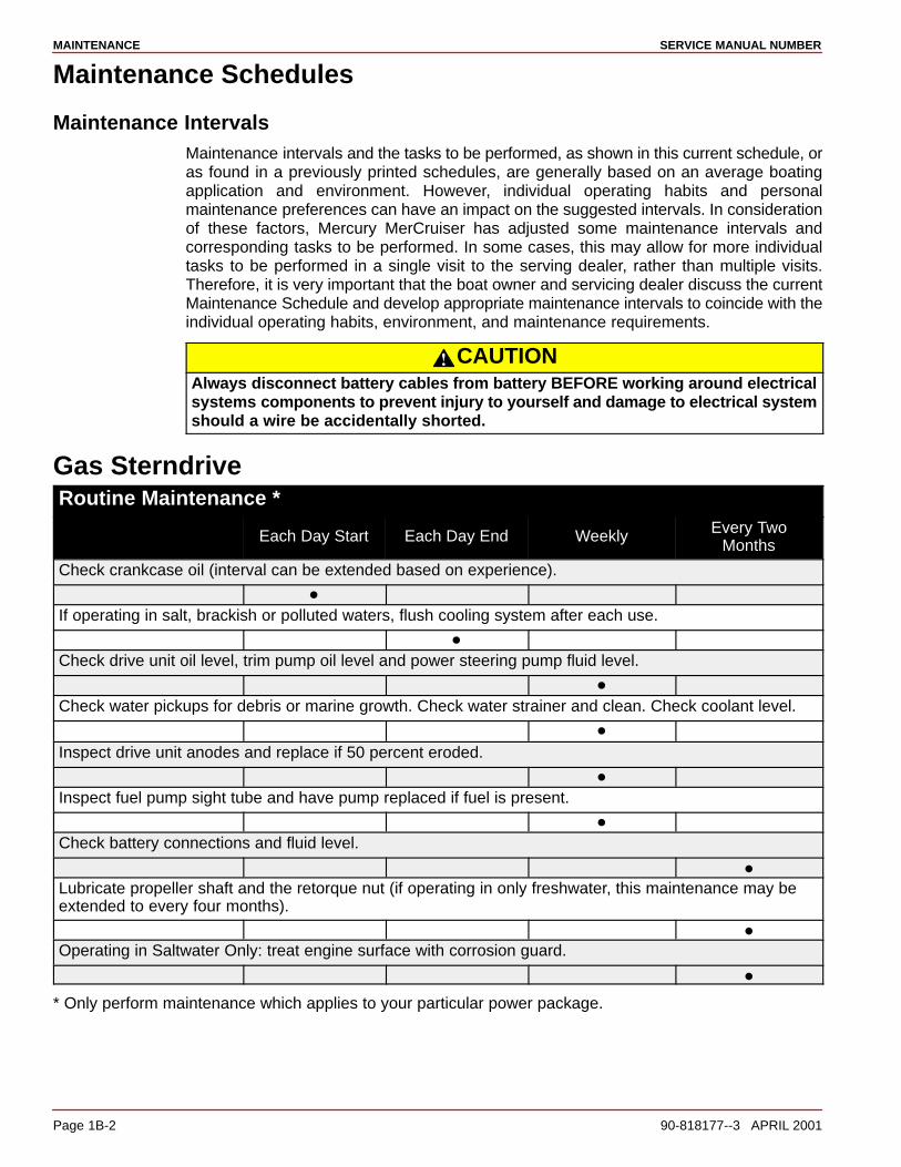
Maintenance IntervalsMaintenance intervals and the tasks to be performed, as shown in this current schedule, oras found in a previously printed schedules, are generally based on an average boatingapplication and environment. However, individual operating habits and personalmaintenance preferences can have an impact on the suggested intervals. In considerationof these factors, Mercury MerCruiser has adjusted some maintenance intervals andcorresponding tasks to be performed. In some cases, this may allow for more individualtasks to be performed in a single visit to the serving dealer, rather than multiple visits.Therefore, it is very important that the boat owner and servicing dealer discuss the currentMaintenance Schedule and develop appropriate maintenance intervals to coincide with theindividual operating habits, environment, and maintenance requirements.
CAUTIONAlways disconnect battery cables from battery BEFORE working around electricalsystems components to prevent injury to yourself and damage to electrical systemshould a wire be accidentally shorted.
Gas SterndriveRoutine Maintenance *
Each Day Start Each Day End Weekly Every TwoMonths
Check crankcase oil (interval can be extended based on experience).
�
If operating in salt, brackish or polluted waters, flush cooling system after each use.
�
Check drive unit oil level, trim pump oil level and power steering pump fluid level.
�
Check water pickups for debris or marine growth. Check water strainer and clean. Check coolant level.
�
Inspect drive unit anodes and replace if 50 percent eroded.
�
Inspect fuel pump sight tube and have pump replaced if fuel is present.
�
Check battery connections and fluid level.
�
Lubricate propeller shaft and the retorque nut (if operating in only freshwater, this maintenance may beextended to every four months).
�
Operating in Saltwater Only: treat engine surface with corrosion guard.
�
* Only perform maintenance which applies to your particular power package.

MAINTENANCESERVICE MANUAL NUMBER 14
90-818177--3 APRIL 2001 Page 1B-3
Gas Sterndrive (Continued)Scheduled Maintenance *
AnnuallyEvery 100
Hours or Annu-ally�
Every 200Hours or 3
Years�
Every 300Hours or 3
Years�
Every 2 Years Every 5 Years
Touch-up paint power package and spray with corrosion guard.
�
Change crankcase oil and filter.
�
Change drive unit oil and retorque connection of gimbal ring to steering shaft.
�
Replace fuel filter.
�
Check steering system and remote control for loose, missing or damaged parts. Lubricate cables andlinkages.
�
Inspect U-joints, splines and bellows. Check clamps. Check engine alignment. Lubricate U-joint splines.
�
Lubricate gimbal bearing and engine coupler.
��
Check continuity circuit for loose or damaged connections. Test MerCathode� unit output on Bravo mod-els.
�
Retorque engine mounts.
�
Check spark plugs, wires, distributor cap and ignition timing. Check and adjust idle speed.
�
Clean flame arrestor and crankcase ventilation hoses. Replace PCV valve.
�
Check electrical system for loose, damaged or corroded fasteners.
�
Inspect condition and tension of belts.
�
Check cooling system and exhaust system hose clamps for tightness. Inspect both systems for damageor leaks.
�
Disassemble and inspect seawater pump and replace worn components.
�
Clean seawater section of closed cooling system. Clean, inspect and test pressure cap.
�
Replace coolant.
� �
* Only perform maintenance which applies to your particular power package.
� Whichever occurs first.� Lubricate engine coupler every 50 hours if operated at idle for prolonged periods of time.� Interval will be reduced if not using extended life coolant.

MAINTENANCE SERVICE MANUAL NUMBER
Page 1B-4 90-818177--3 APRIL 2001
Quicksilver Maintenance Products
We recommend the use of Quicksilver Maintenance Products where specified.
Lubricating Shift Cable Pivot Points
22245
a
a - SAE 20 Or 30 Engine Oil
Lubricating Propeller Shaft
70134
a
a - Special Lubricant 101, 2-4-C Marine Lubricant With Teflon Or Perfect Seal WithTeflon (Listed In Order Of Effectiveness)

MAINTENANCESERVICE MANUAL NUMBER 14
90-818177--3 APRIL 2001 Page 1B-5
Lubricating Steering SystemWARNING
Transom end of steering cable MUST BE fully retracted into cable housing whenlubricating cable. If cable is lubricated while extended, hydraulic lock of cable couldoccur.
Power Steering Models
2202371901
a
b
c
e
d
e
a
c
d
Earlier Style Control Valve Later Style Control Valvea - Steering Cable Grease Fitting - 2-4-C Marine Lubricant With Teflonb - Control Valve Grease Fitting - 2-4-C Marine Lubricant With Teflonc - Steering Cable End - Special Lubricant 101d - Pivot Point - Sae 20 Or 30 Engine Oile - Pivot Bolts - Special Lubricant 101
Manual Steering Models
22055a b
c
d
a - Steering Cable Grease Fitting - 2-4-C Marine Lubricant With Teflonb - Steering - Cable End And Exposed Portion - Special
Lubricant 101c - Pivot Points - SAE 20 Or 30 Engine Oild - Pivot Bolts - Special Lubricant 101
MAINTENANCE SERVICE MANUAL NUMBER
Page 1B-6 90-818177--3 APRIL 2001
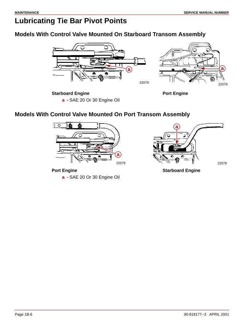
Lubricating Tie Bar Pivot Points
Models With Control Valve Mounted On Starboard Transom Assembly
22079 22079
a a
Starboard Engine Port Enginea - SAE 20 Or 30 Engine Oil
Models With Control Valve Mounted On Port Transom Assembly
22079 22079
a
a
Port Engine Starboard Enginea - SAE 20 Or 30 Engine Oil
MAINTENANCESERVICE MANUAL NUMBER 14
90-818177--3 APRIL 2001 Page 1B-7
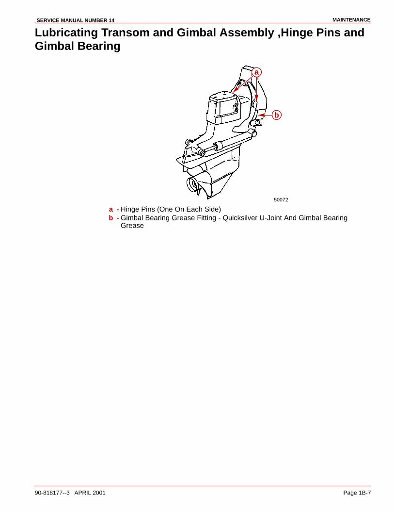
Lubricating Transom and Gimbal Assembly ,Hinge Pins andGimbal Bearing
50072
b
a
a - Hinge Pins (One On Each Side)b - Gimbal Bearing Grease Fitting - Quicksilver U-Joint And Gimbal Bearing
Grease
MAINTENANCE SERVICE MANUAL NUMBER
Page 1B-8 90-818177--3 APRIL 2001
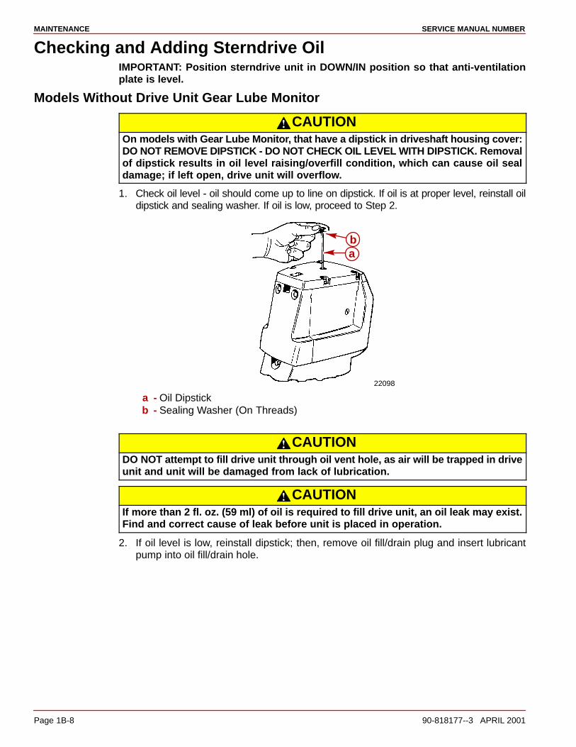
Checking and Adding Sterndrive OilIMPORTANT: Position sterndrive unit in DOWN/IN position so that anti-ventilationplate is level.
Models Without Drive Unit Gear Lube Monitor
CAUTIONOn models with Gear Lube Monitor, that have a dipstick in driveshaft housing cover:DO NOT REMOVE DIPSTICK - DO NOT CHECK OIL LEVEL WITH DIPSTICK. Removalof dipstick results in oil level raising/overfill condition, which can cause oil sealdamage; if left open, drive unit will overflow.
1. Check oil level - oil should come up to line on dipstick. If oil is at proper level, reinstall oildipstick and sealing washer. If oil is low, proceed to Step 2.
22098
ab
a - Oil Dipstickb - Sealing Washer (On Threads)
CAUTIONDO NOT attempt to fill drive unit through oil vent hole, as air will be trapped in driveunit and unit will be damaged from lack of lubrication.
CAUTIONIf more than 2 fl. oz. (59 ml) of oil is required to fill drive unit, an oil leak may exist.Find and correct cause of leak before unit is placed in operation.
2. If oil level is low, reinstall dipstick; then, remove oil fill/drain plug and insert lubricantpump into oil fill/drain hole.

MAINTENANCESERVICE MANUAL NUMBER 14
90-818177--3 APRIL 2001 Page 1B-9
3. Remove oil vent plug; then, fill drive unit (through oil fill/drain unit hole) with oil until anair-free stream of oil flows out of oil vent hole.
22101
22095
2210122103
a
b
cd
a - Oil Vent Plugb - Sealing Washer Or O-ringc - Oil Fill/Drain Plugd - Sealing Washer Or O-ring
4. Without removing lubricant pump from fill/drain hole, reinstall vent plug and sealingwasher (or O-ring if equipped). Torque to 40 lb-in. (4 Nm).
5. Remove lubricant pump and quickly reinstall fill/drain plug and sealing washer (or O-ringif equipped). Torque to 40 lb-in. (4 Nm).
6. Recheck oil level, using dipstick.
Models With Gear Lube MonitorIMPORTANT: Position drive unit in DOWN/IN position, verify that the anti-ventilationplate is level.
NOTE: Drive unit oil level is checked at gear lube monitor.
50323
Gear LubeMonitordecal
IMPORTANT: Oil level in gear lube monitor will rise and fall during drive operation;always check oil level when drive is cool and engine is shut down.
50028 71990
a
b
a - Round Gear Lube Monitorb - Square Gear Lube Monitor
MAINTENANCE SERVICE MANUAL NUMBER
Page 1B-10 90-818177--3 APRIL 2001
1. Fill gear lube monitor to “FULL” line on decal. Lubricate O-ring seal on gear lube monitorneck with sterndrive oil, to ensure ease of installing and removing cap, and install gearlube monitor cap. Do not overtighten cap - 1/4 turn, after cap contacts seal, is sufficient.
CAUTIONOn models with Gear Lube Monitor, that have a dipstick in driveshaft housing cover:DO NOT REMOVE DIPSTICK - DO NOT CHECK OIL LEVEL WITH DIPSTICK. Removalof dipstick results in oil level raising/overfill condition, which can cause oil sealdamage; if left open, drive unit will overflow.
2. Check oil level in gear lube monitor.
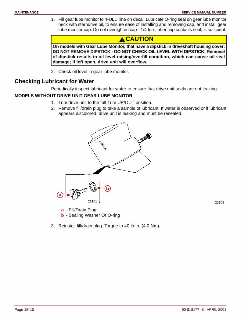
Checking Lubricant for WaterPeriodically inspect lubricant for water to ensure that drive unit seals are not leaking.
MODELS WITHOUT DRIVE UNIT GEAR LUBE MONITOR
1. Trim drive unit to the full Trim UP/OUT position.2. Remove fill/drain plug to take a sample of lubricant. If water is observed or if lubricant
appears discolored, drive unit is leaking and must be resealed.
22101 22103
ab
a - Fill/Drain Plugb - Sealing Washer Or O-ring
3. Reinstall fill/drain plug. Torque to 40 lb-in. (4.0 Nm).

MAINTENANCESERVICE MANUAL NUMBER 14
90-818177--3 APRIL 2001 Page 1B-11
MODELS WITH GEAR LUBE MONITOR
Check for water at bottom of gear lube monitor, and/or if oil appears discolored, a water leakis indicated somewhere in the drive unit, and drive unit must be resealed.
CAUTIONIf more than 2 fl. oz. (59ml) of Quicksilver High Performance Gear Lube is requiredto fill gear lube monitor, a seal may be leaking. Find and correct cause of leak beforeunit is placed in operation.
IMPORTANT: If drive unit has set overnight or longer, check for water in drive unit,as follows:
1. Trim drive unit to full Trim UP/OUT position.
22101 22103a
b
a - Oil Fill/Drain Plugb - Sealing Washer or O-ring
2. Remove fill/drain plug to sample lubricant. If water runs out, and/or if lubricant appearsdiscolored, drive unit is leaking and must be resealed.
3. Reinstall fill/drain plug. Torque to 40 lb-in. (4 Nm).
MAINTENANCE SERVICE MANUAL NUMBER
Page 1B-12 90-818177--3 APRIL 2001
Changing Lubricant
CAUTIONIf any water drains from fill/drain hole, or if oil color appears discolored, a leak indrive unit may exist. Find and correct cause of leak before placing unit back inoperatIon.
CAUTIONDO NOT attempt to fill drive unit through oil vent holes, as air will be trapped in driveunit and unit will be damaged from lack of lubrication.
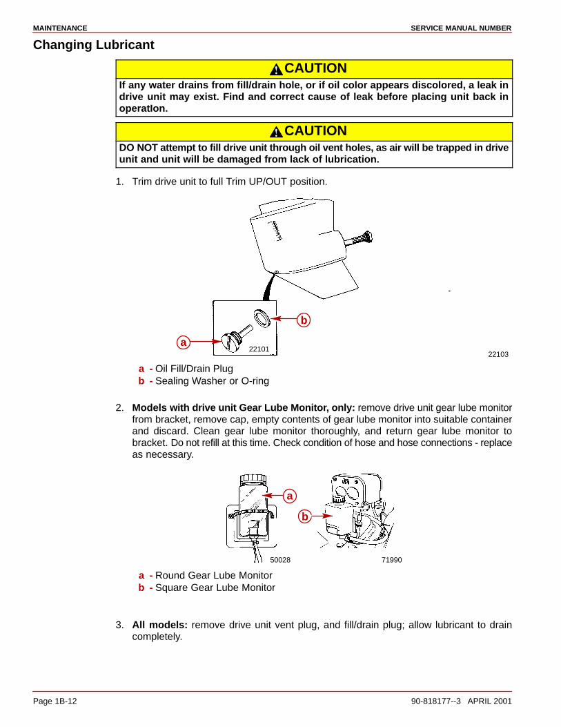
1. Trim drive unit to full Trim UP/OUT position.
2210122103
a
b
a - Oil Fill/Drain Plugb - Sealing Washer or O-ring
2. Models with drive unit Gear Lube Monitor, only: remove drive unit gear lube monitorfrom bracket, remove cap, empty contents of gear lube monitor into suitable containerand discard. Clean gear lube monitor thoroughly, and return gear lube monitor tobracket. Do not refill at this time. Check condition of hose and hose connections - replaceas necessary.
50028 71990
a
b
a - Round Gear Lube Monitorb - Square Gear Lube Monitor
3. All models: remove drive unit vent plug, and fill/drain plug; allow lubricant to draincompletely.

MAINTENANCESERVICE MANUAL NUMBER 14
90-818177--3 APRIL 2001 Page 1B-13
4. Trim drive unit to full DOWN/IN position, with anti-ventilation plate level, to completedraining process.
50072
c
d
b
a
a - Oil Vent Plugb - Sealing Washer Or O-ringc - Vent Holed - Dipstick
5. Using lubricant pump, fill drive unit through fill/drain hole with lubricant until oil is evenwith bottom edge of vent hole.
6. Without removing lubricant pump from fill/drain hole, reinstall oil vent plug and sealingwasher.
a. Non-Gear Lube Monitor Models: torque oil vent plug to 40 lb-in. (4 Nm).
b. Gear Lube Monitor Models: tighten oil vent plug snugly; do not torque at this time.
7. All models: remove lubricant pump and quickly reinstall fill/drain plug and sealingwasher. Torque to 40 lb-in. (4 Nm).
Models with Gear Lube Monitor:
8. Remove oil vent plug and sealing washer (with drive unit in full DOWN/IN position).
9. Fill gear lube monitor bottle with Quicksilver High-Performance Gear Lube. When oilstarts to run out the vent hole (gear lube hose between drive unit and gear lube bottlebecomes filled), reinsert vent plug. Torque to 40 lb-in. (4 Nm).
10. Fill gear lube monitor to “FULL” line on decal. Lubricate O-ring seal on gear lube monitorneck with sterndrive oil, to ensure ease of installing and removing cap. Install gear lubemonitor cap. Do not overtighten.

MAINTENANCE SERVICE MANUAL NUMBER
Page 1B-14 90-818177--3 APRIL 2001
11. All models: recheck oil level after first use.
50072
a
a - Vent Hole
General Maintenance
Maintaining Power Package Exterior SurfacesEntire Power Package should be sprayed at recommended intervals with QuicksilverCorrosion Guard. Follow instructions on can for proper application.
At least once each year, entire Power Package should be cleaned and external surfaces thathave become bare should be repainted with Quicksilver Primer and Spray Paint.
Steering Head and Remote Control MaintenanceLubricate steering head and remote control with 2-4-C Marine Lubricant with Teflon. Inspectsteering head and remote control for ease of operation.
Checking Quicksilver MerCathode SystemIf boat is equipped with a Quicksilver MerCathode System, system should be tested toensure that it is providing adequate output to protect underwater metal parts on boat. Testshould be made where boat is moored, using Quicksilver Reference Electrode and TestMeter.Refer to section 7.
Maintaining Anodic Trim Tab or PlateEach sterndrive unit is equipped with a sacrificial anodic trim tab (or plate on later models)to help protect underwater metal parts from galvanic corrosion. Because of itsself-sacrificing nature, trim tab (or plate) MUST BE replaced if eroded 50% or more. Ananodic plate is the new service replacement for the anodic trim tab. Install the anodic platein place of the anodic trim tab. Refer to Section 7.
Checking Optional Quicksilver Anti-Corrosion Anode KitIf boat is equipped with Quicksilver Anti-Corrosion Anode Kit, inspect anode and replace iferoded to less than 50% of its original size. Carefully follow installation instructions, thataccompany new Anode Kit, to ensure proper installation.
MAINTENANCESERVICE MANUAL NUMBER 14
90-818177--3 APRIL 2001 Page 1B-15
Boat Bottom CareTo achieve maximum performance and fuel economy, boat bottom MUST BE kept clean.Accumulation of marine growth or other foreign matter can greatly reduce boat speed andincrease fuel consumption. To ensure best performance and efficiency, periodically cleanboat bottom in accordance with manufacturer’s recommendations.
In some areas, it may be advisable to paint the bottom to help prevent marine growth. Referto the following information for special notes about the use of antifouling paints.
Antifouling PaintIMPORTANT: Corrosion damage that results from the improper application ofantifouling paint will not be covered by the limited warranty.
Painting Boat Hull or Boat Transom: Antifouling paint may be applied to boat hull and boattransom but you must observe the following precautions:
IMPORTANT: DO NOT paint anodes or MerCathode System reference electrode andanode, as this will render them ineffective as galvanic corrosion inhibitors.
IMPORTANT: If antifouling protection is required for boat hull or boat transom,copper or tin base paints, if not prohibited by law, can be used. If using copper or tinbased antifouling paints, observe the following:
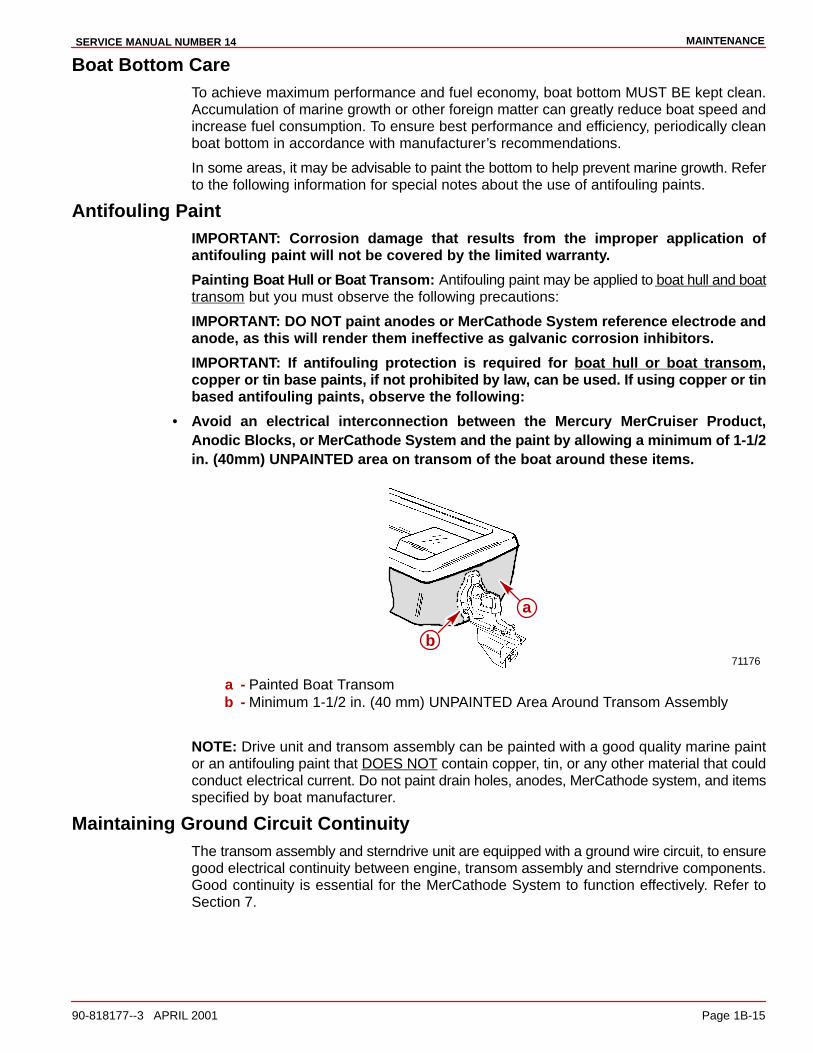
• Avoid an electrical interconnection between the Mercury MerCruiser Product,Anodic Blocks, or MerCathode System and the paint by allowing a minimum of 1-1/2in. (40mm) UNPAINTED area on transom of the boat around these items.
71176
a
b
a - Painted Boat Transomb - Minimum 1-1/2 in. (40 mm) UNPAINTED Area Around Transom Assembly
NOTE: Drive unit and transom assembly can be painted with a good quality marine paintor an antifouling paint that DOES NOT contain copper, tin, or any other material that couldconduct electrical current. Do not paint drain holes, anodes, MerCathode system, and itemsspecified by boat manufacturer.
Maintaining Ground Circuit ContinuityThe transom assembly and sterndrive unit are equipped with a ground wire circuit, to ensuregood electrical continuity between engine, transom assembly and sterndrive components.Good continuity is essential for the MerCathode System to function effectively. Refer toSection 7.

MAINTENANCE SERVICE MANUAL NUMBER
Page 1B-16 90-818177--3 APRIL 2001
Power Package Layup (Out of Season Storage)
EngineRefer to appropriate Engine Service Manual.
Sterndrive1. Lubricate steering system. Refer to Section 6.
2. Lubricate transom gimbal housing assembly swivel shaft, gimbal bearing, and propellershaft. Refer to Section 4 and Section 1-B.
3. Lubricate sterndrive unit U-joint shaft splines and cross bearings. Refer to Section 3-A.
4. Inspect U-joint bellows for cracks or other signs of deterioration. Check bellows clampsfor tightness. Refer to Section 4.
5. Check engine alignment. Refer to Engine Service Manual.
6. Change sterndrive unit oil. Refer to Section 1-B.
MAINTENANCESERVICE MANUAL NUMBER 14
90-818177--3 APRIL 2001 Page 1B-17
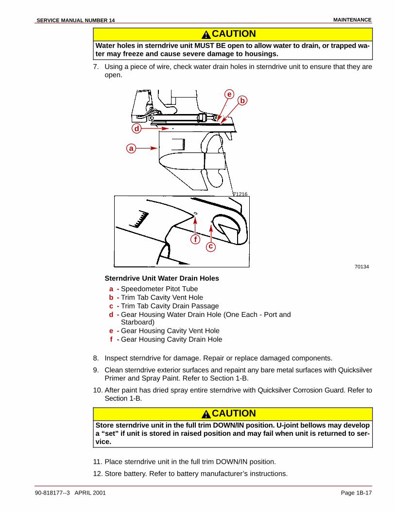
CAUTIONWater holes in sterndrive unit MUST BE open to allow water to drain, or trapped wa-ter may freeze and cause severe damage to housings.
7. Using a piece of wire, check water drain holes in sterndrive unit to ensure that they areopen.
70134
71216
a
be
d
fc
Sterndrive Unit Water Drain Holesa - Speedometer Pitot Tubeb - Trim Tab Cavity Vent Holec - Trim Tab Cavity Drain Passaged - Gear Housing Water Drain Hole (One Each - Port and
Starboard)e - Gear Housing Cavity Vent Holef - Gear Housing Cavity Drain Hole
8. Inspect sterndrive for damage. Repair or replace damaged components.
9. Clean sterndrive exterior surfaces and repaint any bare metal surfaces with QuicksilverPrimer and Spray Paint. Refer to Section 1-B.
10. After paint has dried spray entire sterndrive with Quicksilver Corrosion Guard. Refer toSection 1-B.
CAUTIONStore sterndrive unit in the full trim DOWN/IN position. U-joint bellows may developa “set” if unit is stored in raised position and may fail when unit is returned to ser-vice.
11. Place sterndrive unit in the full trim DOWN/IN position.
12. Store battery. Refer to battery manufacturer’s instructions.
MAINTENANCE SERVICE MANUAL NUMBER
Page 1B-18 90-818177--3 APRIL 2001
Power Package Recommissioning
EngineRefer to appropriate Engine Service Manual.
Sterndrive1. Perform ALL maintenance specified for completion “At Least Once Each Year” in
“Maintenance Chart” (Refer to Section 1-B), except items which were performed at thetime of sterndrive layup.
2. Install fully-charged battery. Clean battery cable clamps and terminals and reconnectcables. Be sure to tighten clamps securely. Apply a thin coat of petroleum based greaseto clamps and terminals to help retard corrosion.
3. After recommissioning and starting engine, check steering system and shift control forproper operation.

MAINTENANCESERVICE MANUAL NUMBER 14
90-818177--3 APRIL 2001 Page 1B-19
THIS PAGE IS INTENTIONALLY BLANK

MAINTENANCE SERVICE MANUAL NUMBER
Page 1B-20 90-818177--3 APRIL 2001
THIS PAGE IS INTENTIONALLY BLANK
1C
TROUBLESHOOTINGSERVICE MANUAL NUMBER 14
90-818177--3 APRIL 2001 Page 1C-1
IMPORTANT INFORMATIONSection 1C - Troubleshooting
Table of Contents
Troubleshooting 1C-3. . . . . . . . . . . . . . . . . . . . . Sterndrive Unit Troubleshooting 1C-3. . . . . . .
Sterndrive Unit Will Not Slide Into Bell Housing 1C-3. . . . . . . . . . . . . . . . . . . . . Drive Unit Does Not Shift Into Gear; Remote Control Shift Handle Moves 1C-3Drive Unit Does Not Shift Into Gear; Remote Control Shift Handle Does Not Move 1C-3. . . . . . . . . . . . . . . . . . . . . . . Drive Unit Shifts Hard 1C-4. . . . . . . . . . . . . Drive Unit In Gear, Will Not Shift Out Of Gear 1C-4. . . . . . . . . . . . . . . . . . . . . . . . . Gear Housing Noise 1C-4. . . . . . . . . . . . . . Drive Shaft Housing Noise 1C-5. . . . . . . . . Drive Shaft Housing Noise (Continued) 1C-6. . . . . . . . . . . . . . . . . . . . . Drive Shaft Housing Noise (Continued) 1C-7. . . . . . . . . . . . . . . . . . . . .
Performance Troubleshooting 1C-8. . . . . . . . . Low WOT Engine Rpm 1C-8. . . . . . . . . . . . High WOT Engine Rpm 1C-8. . . . . . . . . . . . Propeller Ventilating/Cavitating 1C-8. . . . . Poor Boat Performance And/Or Poor Maneuverability-Bow Too Low 1C-8. Poor Boat Performance And/Or Poor Maneuverability-Bow Too High 1C-9
Power Steering 1C-9. . . . . . . . . . . . . . . . . . . . . Hard Steering - Helm And Cable 1C-9. . . . Hard Steering (Engine Running) - Power Steering System 1C-10. . . . . . . . . . Power Steering System External Fluid Leaks 1C-10. . . . . . . . . . . . . . . . . . . . . .
Compact Hydraulic Steering 1C-11. . . . . . . . . . Important Information 1C-11. . . . . . . . . . . . . Helm Becomes Jammed During Filling 1C-11. . . . . . . . . . . . . . . . . . . . System Difficult To Fill 1C-11. . . . . . . . . . . . . Steering Hard To Turn 1C-11. . . . . . . . . . . . . Helm Unit Bumpy - Requires Too Many Turns 1C-11. . . . . . . . . . . . . . . . . .
Power Trim Electrical System 1C-12. . . . . . . . . Power Trim Pump Motor Will Not Run In The OUT/UP Or IN/DOWN Direction 1C-12. . . . . . . . . . . . . . . . . . . . . . . . Power Trim Pump Motor Will Not Run In The OUT/UP Or IN/DOWN Direction 1C-13. . . . . . . . . . . . . . . . . . . . . . . . Power Trim Pump Motor Runs In The OUT/UP Direction, But Not In The IN/DOWN Direction 1C-13. . . . . . . . . . . Power Trim Pump Motor Runs In The OUT/UP Direction, But Not In The IN/DOWN Direction 1C-14. . . . . . . . . . .
Power Trim Pump Motor Runs In The IN/DOWN Direction, But Not In The OUT/UP Direction-Both Trim And Trailer Switches Inoperative- 1C-14. . . . . . . . . . . . . . . . . . . . . Power Trim Pump Motor Runs In The IN/DOWN Direction, But Not In The OUT/UP Direction-Both Trim And Trailer Switches Inoperative 1C-14. . . . . . . . . . . . . . . . . . . . . . Trim Control OUT/UP Trim Switch Inoperative 1C-15. . . . . . . . . . . . . . . . . . . . . . Trim Control Trailer Switch Inoperative 1C-15. . . . . . . . . . . . . . . . . . . . . . Trim System Functions While Unattended 1C-15. . . . . . . . . . . . . . . . . . . . . .
Power Trim System Wiring Diagram 1C-16. . . Power Trim Hydraulic System 1C-17. . . . . . . . .
Drive Unit Cannot Be Trimmed OUT/UP Or Trims Slowly Or With Jerky Movements 1C-17. . . . . . . . . . . . Drive Unit Will Not Stay In Trimmed OUT/UP Position 1C-17. . . . . . . . . . . . . . . . . Sterndrive Unit Trails OUT/UP On Deceleration Or When Shifting Into Reverse 1C-17. . . . . . . . . . . . . . . . . . . . . . . . Oil Foams Out Of Pump Fill/Vent Screw 1C-18. . . . . . . . . . . . . . . . . . . . . . . . . . Sterndrive Unit Cannot Be Lowered From UP Position Or Lowers With Jerky Movements 1C-18. . . . . Sterndrive Unit Will Not Stay In Full UP Position For Extended Periods 1C-18. . . . . . . . . . . . . . . . . . . . . . . . . Sterndrive Will Not Stay In The Trimmed OUT/UP Position When Underway 1C-19. . . . . . . . . . . . . . . . . . . . . . . Sterndrive Unit Trails OUT/UP On Deceleration Or When Shifting Into Reverse 1C-19. . . . . . . . . . . . . . . . . . . . Oil Foams Out Of Pump Fill/Vent Screw 1C-19. . . . . . . . . . . . . . . . . . . . . . . . . . Trim Motor Runs But Does Not Pump Oil 1C-19. . . . . . . . . . . . . . . . . . . . . . . . Trim Pump Runs Slowly In Both Directions 1C-19. . . . . . . . . . . . . . . . . . . . . . . Trim Pump Runs Slowly With A Laboring Sound 1C-19. . . . . . . . . . . . . . . . . .
TROUBLESHOOTING SERVICE MANUAL NUMBER 14
Page 1C-2 90-818177--3 APRIL 2001
Table of Contents (continued)
Power Trim Hydraulic Schematic 1C-20. . . . . . Auto Trim II Electrical System 1C-21. . . . . . . . .
Pump Motor Will Not Run UP Or DOWN In Either Manual Or Auto Mode 1C-21. . . . . . . . . . . . . . . . . . . . . . . . . . . Pump Motor Will Not Stop Running Down In Auto Mode 1C-22. . . . . . . . . . . . . . Pump Motor Will Not Run Up Or Down In Auto Mode 1C-22. . . . . . . . . . . . . . Trim System Completely Inoperative In Manual Mode 1C-23. . . . . . . . . . . . . . . . . Pump Motor Will Run UP, But Not Down In Both Manual And Auto Modes 1C-23. . . . . . . . . . . . . . . . . . . . . . . . . . Pump Motor Runs Down, But Not UP In Both The Manual And Auto Modes 1C-23. . . . . . . . . . . . . . . . . . . . . . . . . . Pump Motor Will Run Down, But Not UP In Auto Mode 1C-24. . . . . . . . . . . . . Pump Motor Will Run UP, But Not DOWN In Auto Mode 1C-24. . . . . . . . . . . . . Trim DOWN/IN Switch Inoperative In Manual Trim Control 1C-24. . . . . . . . . . . . Trim UP/OUT Switch Inoperative In Manual Trim Control 1C-25. . . . . . . . . . . . Trailer Switch In Manual, Trim Control Inoperative 1C-25. . . . . . . . . . . . . . . Boat Is On Plane Well Before Drive Unit Begins To Trim Out 1C-25. . . . . Boat Is Not On Plane Before Drive Unit Begins To Trim Out 1C-25. . . . .
Auto Trim II System Wiring Diagram 1C-26. . . Corrosion Protection 1C-26. . . . . . . . . . . . . . . . .
Corrosion On Underwater Parts, Without MerCathode Or Impressed CurrentProtection 1C-27. . . . . . . . . . . . . . . . . . . . . . . Corrosion On Underwater Parts, With MerCathode Or Impressed Current Protection 1C-28. . . . . . . . . . . . . . . . Corrosion On Underwater Parts, With MerCathode Or Impressed Current Protection 1C-30. . . . . . . . . . . . . . . . Testing Procedure for Corrosion Protection 1C-31. . . . . . . . . . . . . . . . . . . . . . . MerCathode Controller 1C-32. . . . . . . . . . . .
Shift System Troubleshooting 1C-33. . . . . . . . . Troubleshooting Shift Problems 1C-34. . . . . Checking for Excessive Play 1C-36. . . . . . . Isolating Excessive Play 1C-40. . . . . . . . . . . Checking Remote Control Shift Cable Output 1C-42. . . . . . . . . . . . . . . . . . . . Checking Cutout Switch Timing (Models With Roller Type Switch) 1C-43. . Checking Cutout Switch Timing (Models With Plunger Type Switch) 1C-45. Checking Operation 1C-47. . . . . . . . . . . . . . .

TROUBLESHOOTINGSERVICE MANUAL NUMBER 14
90-818177--3 APRIL 2001 Page 1C-3
Troubleshooting
This section is a guide for performance and product troubleshooting. Referrals to specificsections of this manual are made where special tests or repair procedures are to beperformed.
Because of the relationship between Power Package components (engine and sterndrive),it will be necessary in some cases to simultaneously refer to the appropriate Engine ServiceManual for further troubleshooting information.
Effective troubleshooting is best enhanced by:
• Personal product knowledge and experience of the trained mechanic/technician.
• Allowing adequate time for testing and analysis.
• Utilizing these charts as a “guide” - a starting point.
Sterndrive Unit Troubleshooting
Sterndrive Unit Will Not Slide Into Bell Housing
Cause Special Instructions
U-joint shaft splines not aligned withengine coupler splines.
Rotate propeller shaftCOUNTERCLOCKWISE to align splines.
Engine not aligned. Check engine alignment.
Gimbal bearing not properly installed.Check engine alignment to determine ifgimbal bearing is cocked or improperlyinstalled in gimbal housing.
Damaged U-joint shaft splines and/orengine coupler splines.
Inspect and replace if necessary.
Drive Unit Does Not Shift Into Gear; Remote Control Shift Handle MovesNOTE:For additional information on troubleshooting, refer to SECTION 2A and see“Troubleshooting Shift Problems.”
Cause Special Instructions
Shift cables improperly adjusted. Adjust shift cables.
Shift cables not connected. Install and adjust shift cables.
Inner core wire broken or loose. Reconnect or replace inner core wire.
Drive Unit Does Not Shift Into Gear; Remote Control Shift Handle Does NotMove
NOTE:For additional information on troubleshooting, refer to SECTION 2A and see“Troubleshooting Shift Problems.”
Cause Special Instructions
Control box not properly assembled. Properly reassemble control box.
Broken or damaged linkage in control box. Repair linkage.
Controls improperly adjusted-cable endguide hitting brass barrel.
Adjust shift cables.

TROUBLESHOOTING SERVICE MANUAL NUMBER 14
Page 1C-4 90-818177--3 APRIL 2001
Drive Unit Shifts HardNOTE:For additional information on troubleshooting, refer to SECTION 2A and see“Troubleshooting Shift Problems.”
Cause Special Instructions
Shift cables improperly adjusted. Adjust shift cables.
Damaged remote control or drive unit shiftcable.
Replace cable(s) and adjust.
Shift cable too short (sharp bends) or toolong (loops and long bends).
Select and install proper length cable.
Corroded shift cables. Replace, adjust and check for waterleakage.
Internal wear in remote control box. Repair as needed.
Shift cable attaching nuts too tight (endcannot pivot).
Properly install nuts.
Shift cable pivot ends are corroded or notlubricated.
Clean and lubricate.
Drive Unit In Gear, Will Not Shift Out Of GearNOTE:For additional information on troubleshooting, refer to SECTION 2A and see“Troubleshooting Shift Problems.”
Cause Special Instructions
Shift cable broken. Replace cable and adjust.
Cable end not connected in drive unit. Remove and reinstall drive unit.
Remote control damaged. Repair or replace remote control.
Internal shift mechanism damage. Repair or replace as necessary.
Gear Housing Noise
Cause Special Instructions
Metal particles in drive unit lubricant.Disassemble, clean and inspect andreplace necessary components. (Refer toSECTION 3B, 3C or 3D)
Propeller incorrectly installed. Inspect mounting hardware. Installpropeller correctly.
Propeller shaft bent. Inspect and replace if necessary. (Refer toSECTION 3B, 3C or 3D)
Incorrect gear shimming.Check gear housing backlash and piniongear height. (Refer to SECTION 3B, 3C or3D)
Worn or damaged gears and/or bearingscaused by impact, overheating orimproper shimming.
Disassemble, inspect and replace. (Refer to SECTION 3B, 3C or 3D)
TROUBLESHOOTINGSERVICE MANUAL NUMBER 14
90-818177--3 APRIL 2001 Page 1C-5
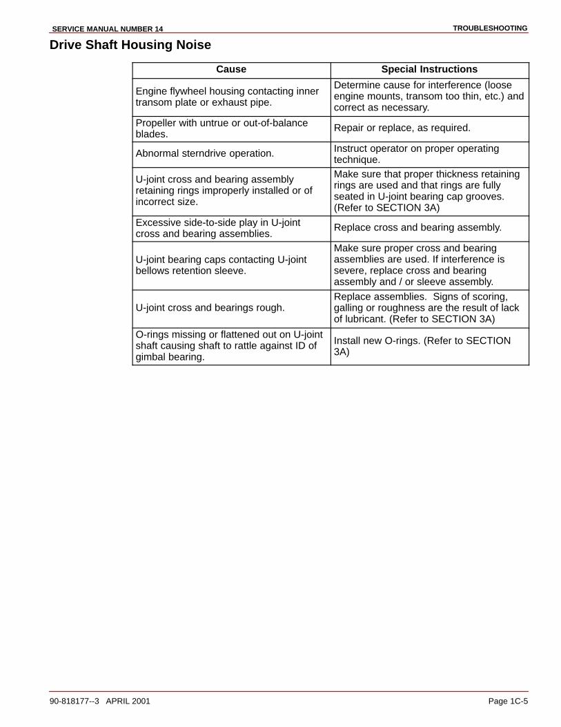
Drive Shaft Housing Noise
Cause Special Instructions
Engine flywheel housing contacting innertransom plate or exhaust pipe.
Determine cause for interference (looseengine mounts, transom too thin, etc.) andcorrect as necessary.
Propeller with untrue or out-of-balanceblades.
Repair or replace, as required.
Abnormal sterndrive operation. Instruct operator on proper operatingtechnique.
U-joint cross and bearing assemblyretaining rings improperly installed or ofincorrect size.
Make sure that proper thickness retainingrings are used and that rings are fullyseated in U-joint bearing cap grooves.(Refer to SECTION 3A)
Excessive side-to-side play in U-jointcross and bearing assemblies.
Replace cross and bearing assembly.
U-joint bearing caps contacting U-jointbellows retention sleeve.
Make sure proper cross and bearingassemblies are used. If interference issevere, replace cross and bearingassembly and / or sleeve assembly.
U-joint cross and bearings rough.Replace assemblies. Signs of scoring,galling or roughness are the result of lackof lubricant. (Refer to SECTION 3A)
O-rings missing or flattened out on U-jointshaft causing shaft to rattle against ID ofgimbal bearing.
Install new O-rings. (Refer to SECTION3A)
TROUBLESHOOTING SERVICE MANUAL NUMBER 14
Page 1C-6 90-818177--3 APRIL 2001
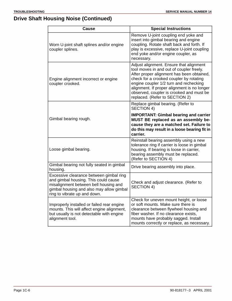
Drive Shaft Housing Noise (Continued)
Cause Special Instructions
Worn U-joint shaft splines and/or enginecoupler splines.
Remove U-joint coupling end yoke andinsert into gimbal bearing and enginecoupling. Rotate shaft back and forth. Ifplay is excessive, replace U-joint couplingend yoke and/or engine coupler, asnecessary.
Engine alignment incorrect or enginecoupler crooked.
Adjust alignment. Ensure that alignmenttool moves in and out of coupler freely.After proper alignment has been obtained,check for a crooked coupler by rotatingengine coupler 1/2 turn and recheckingalignment. If proper alignment is no longerobserved, coupler is crooked and must bereplaced. (Refer to SECTION 2)
Gimbal bearing rough.
Replace gimbal bearing. (Refer toSECTION 4)
IMPORTANT: Gimbal bearing and carrierMUST BE replaced as an assembly be-cause they are a matched set. Failure todo this may result in a loose bearing fit incarrier.
Loose gimbal bearing.
Reinstall bearing assembly using a newtolerance ring if carrier is loose in gimbalhousing. If bearing is loose in carrier,bearing assembly must be replaced.(Refer to SECTION 4)
Gimbal bearing not fully seated in gimbalhousing.
Drive bearing assembly into place.
Excessive clearance between gimbal ringand gimbal housing. This could causemisalignment between bell housing andgimbal housing and also may allow gimbalring to vibrate up and down.
Check and adjust clearance. (Refer to SECTION 4)
Improperly installed or failed rear enginemounts. This will affect engine alignment,but usually is not detectable with enginealignment tool.
Check for uneven mount height, or looseor soft mounts. Make sure there isclearance between flywheel housing andfiber washer. If no clearance exists,mounts have probably sagged. Installmounts correctly or replace, as necessary.

TROUBLESHOOTINGSERVICE MANUAL NUMBER 14
90-818177--3 APRIL 2001 Page 1C-7
Drive Shaft Housing Noise (Continued)
Cause Special Instructions
Boat transom too thin. Thickness: 2 in.(51 mm) minimum, 2-1/4 in. (57 mm)maximum.
Add thickness to transom.
Boat transom thickness uneven. This couldaffect engine to transom assemblyalignment and is usually not detectable withalignment tool. Variation: 1/8 in. (3 mm)maximum.
Repair boat as necessary.
Bell housing contacting gimbal ring. Thiswould cause knocking in the fully trimmedIN position only.
Check for soft or split trim cylinderbushings and loose or worn hinge pin bushings. (Refer to SECTION 5B)
Stringer height uneven or transomassembly installed cocked on boattransom. This will affect engine alignment,but is usually not detectable withalignment tool.
Measure the distance between the engineflywheel housing and the inner transomplate on both sides. If distances areuneven, the problem may be due touneven stringer height or a cockedtransom assembly. Adjust the stringerheight or relocate the transom cutout asrequired.
Weak boat transom or boat bottom thatflexes under power and causes enginemisalignment - this condition will usuallycause engine coupler failure.
This condition can sometimes be detectedby having someone apply force to the topof the drive unit while watching the innertransom plate. If movement can beobserved, the transom is weak and mustbe repaired.
Rear engine mount attaching hardwareimproperly installed or missing.
Reinstall hardware correctly.
Engine mounting holes drilled off-center ininner transom plate engine supports orengine flywheel housing
Make sure the holes are equally spacedfore and aft and are equal distance fromthe centerline.
Misalignment between bell housing,gimbal housing and engine coupler.
Contact your service center and arrangeto have a technical service representativecheck the unit using a special gauge.
TROUBLESHOOTING SERVICE MANUAL NUMBER 14
Page 1C-8 90-818177--3 APRIL 2001
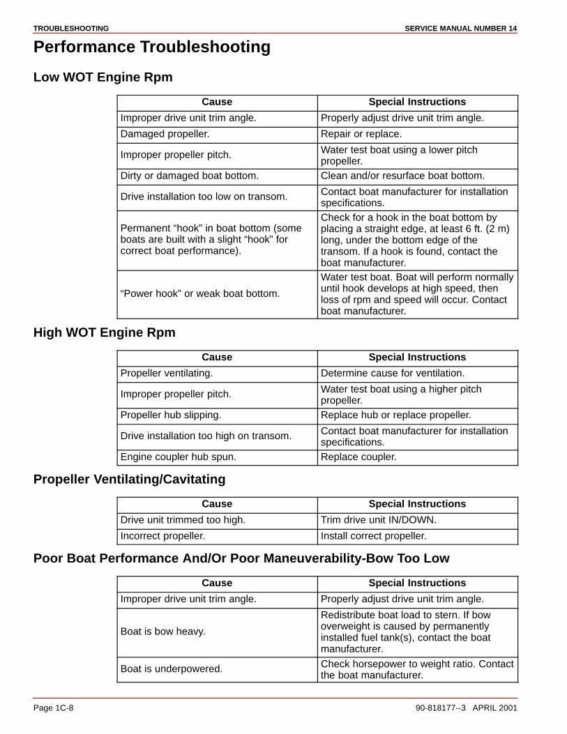
Performance Troubleshooting
Low WOT Engine Rpm
Cause Special Instructions
Improper drive unit trim angle. Properly adjust drive unit trim angle.
Damaged propeller. Repair or replace.
Improper propeller pitch. Water test boat using a lower pitchpropeller.
Dirty or damaged boat bottom. Clean and/or resurface boat bottom.
Drive installation too low on transom. Contact boat manufacturer for installationspecifications.
Permanent “hook” in boat bottom (someboats are built with a slight “hook” forcorrect boat performance).
Check for a hook in the boat bottom byplacing a straight edge, at least 6 ft. (2 m)long, under the bottom edge of thetransom. If a hook is found, contact theboat manufacturer.
“Power hook” or weak boat bottom.
Water test boat. Boat will perform normallyuntil hook develops at high speed, thenloss of rpm and speed will occur. Contactboat manufacturer.
High WOT Engine Rpm
Cause Special Instructions
Propeller ventilating. Determine cause for ventilation.
Improper propeller pitch. Water test boat using a higher pitchpropeller.
Propeller hub slipping. Replace hub or replace propeller.
Drive installation too high on transom. Contact boat manufacturer for installationspecifications.
Engine coupler hub spun. Replace coupler.
Propeller Ventilating/Cavitating
Cause Special Instructions
Drive unit trimmed too high. Trim drive unit IN/DOWN.
Incorrect propeller. Install correct propeller.
Poor Boat Performance And/Or Poor Maneuverability-Bow Too Low
Cause Special Instructions
Improper drive unit trim angle. Properly adjust drive unit trim angle.
Boat is bow heavy.
Redistribute boat load to stern. If bowoverweight is caused by permanentlyinstalled fuel tank(s), contact the boatmanufacturer.
Boat is underpowered. Check horsepower to weight ratio. Contactthe boat manufacturer.
TROUBLESHOOTINGSERVICE MANUAL NUMBER 14
90-818177--3 APRIL 2001 Page 1C-9
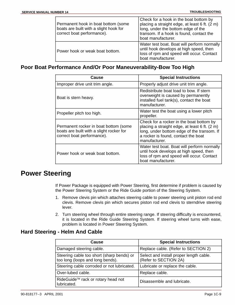
Permanent hook in boat bottom (someboats are built with a slight hook forcorrect boat performance).
Check for a hook in the boat bottom byplacing a straight edge, at least 6 ft. (2 m)long, under the bottom edge of thetransom. If a hook is found, contact theboat manufacturer.
Power hook or weak boat bottom.
Water test boat. Boat will perform normallyuntil hook develops at high speed, thenloss of rpm and speed will occur. Contactboat manufacturer.
Poor Boat Performance And/Or Poor Maneuverability-Bow Too High
Cause Special Instructions
Improper drive unit trim angle. Properly adjust drive unit trim angle.
Boat is stern heavy.
Redistribute boat load to bow. If sternoverweight is caused by permanentlyinstalled fuel tank(s), contact the boatmanufacturer.
Propeller pitch too high. Water test the boat using a lower pitchpropeller.
Permanent rocker in boat bottom (someboats are built with a slight rocker forcorrect boat performance).
Check for a rocker in the boat bottom byplacing a straight edge, at least 6 ft. (2 m)long, under bottom edge of the transom. Ifa rocker is found, contact the boatmanufacturer.
Power hook or weak boat bottom.
Water test boat. Boat will perform normallyuntil hook develops at high speed, thenloss of rpm and speed will occur. Contactboat manufacturer.
Power Steering
If Power Package is equipped with Power Steering, first determine if problem is caused bythe Power Steering System or the Ride Guide portion of the Steering System.
1. Remove clevis pin which attaches steering cable to power steering unit piston rod endclevis. Remove clevis pin which secures piston rod end clevis to sterndrive steeringlever.
2. Turn steering wheel through entire steering range. If steering difficulty is encountered,it is located in the Ride Guide Steering System. If steering wheel turns with ease,problem is located in Power Steering System.
Hard Steering - Helm And Cable
Cause Special Instructions
Damaged steering cable. Replace cable. (Refer to SECTION 2)
Steering cable too short (sharp bends) ortoo long (loops and long bends).
Select and install proper length cable.(Refer to SECTION 2A)
Steering cable corroded or not lubricated. Lubricate or replace the cable.
Over-lubed cable. Replace cable.
RideGuide rack or rotary head notlubricated.
Disassemble and lubricate.

TROUBLESHOOTING SERVICE MANUAL NUMBER 14
Page 1C-10 90-818177--3 APRIL 2001
Hard Steering (Engine Running) - Power Steering System
Cause Special Instructions
Low power steering pump fluid level. Check fluid level. (Refer to SECTION 6A)
Loose power steering pump drive belt. Adjust belt tension. (Refer to SECTION6A)
Air in system. Cycle to remove air. (Refer to SECTION6A)
Fluid leak. Locate and correct source of leak. (Refer to SECTION 6A)
If the above 4 steps do not solve theproblem, test the power steering system.
Test power steering system. (Refer toSECTION 6A)
Power Steering System External Fluid Leaks
Cause Special Instructions
Pump reservoir leaking at fill cap(reservoir too full).
Remove fluid to bring to proper level.
Pump reservoir leaking at fill cap (air orwater in fluid).
Locate source of air or water and correct.Air may enter because of low reservoirfluid level or internal pump leak. Testpump. (Refer to SECTION 6A)
Loose hose connections. Tighten hose connections.
Damaged hose. Replace hose.
Bad cylinder piston rod seal. Replace cylinder.
Damaged or worn control valve seals. Replace cylinder.
Bad power steering pump seals andO-rings.
Repair pump. (Refer to SECTION 6A)
Cracked or porous metal parts. Replace part(s).

TROUBLESHOOTINGSERVICE MANUAL NUMBER 14
90-818177--3 APRIL 2001 Page 1C-11
Compact Hydraulic Steering
Important InformationWhenever a troubleshooting solution calls for removal from vessel and/or dismantling ofsteering system components, such work must be carried out by a qualified marinemechanic. The following is offered as a guide only and neither Mercury MerCruiser nor thehelm manufacturer are responsible for any consequences resulting from incorrect repairs.
Most faults occur when the installation instructions are not followed and usually show upimmediately upon filling the system. The most common faults encountered and their likelycause and solution are provided in the following.
Sometimes when returning the steering wheel from a locked position, a slight resistancemay be felt and a clicking noise may be heard. This should not be mistaken as a fault, asit is a completely normal situation caused by the releasing of the lockspool in the system.
WARNINGAvoid serious injury or death due to FIRE or EXPLOSION. Be sure that engine com-partment is well ventilated and that no gasoline vapors are present to prevent thepossibility of a FIRE or EXPLOSION.
Helm Becomes Jammed During Filling
Cause Special Instructions
Blockage in the line between the helm(s)and the cylinder(s).
Make certain that hoses were not kinkedor pinched during installation. If so, thehose must be removed and replaced.
System Difficult To Fill
Cause Special Instructions
Air in system. Review filling instructions.
Steering Hard To Turn
Cause Special Instructions
Steering cylinder pivot bushings are tootight or trunion is bent, causingmechanical binding.
To test, disconnect clevis from steeringlever and turn the steering wheel. If it nowturns easy, correct cause of mechanicalbinding. Please note that excessivelyloose connections to steering cylinder orsteering lever can also cause mechanicalbinding.
Restrictions in hoses. Find restrictions and correct.
Air in hydraulic fluid. See filling and purging instructions.
Wrong hydraulic fluid has been used to fillsteering system.
Drain system and fill with approvedhydraulic fluid.
Helm Unit Bumpy - Requires Too Many Turns
Cause Special Instructions
Dirt in inlet check of helm pump. Replace helm unit.

TROUBLESHOOTING SERVICE MANUAL NUMBER 14
Page 1C-12 90-818177--3 APRIL 2001
Power Trim Electrical System
NOTE:Refer to “Power Trim System Wiring Diagram.”
Power Trim Pump Motor Will Not Run In The OUT/UP Or IN/DOWN Direction
SOLENOIDS DO NOT CLICK
Cause Special Instructions
Bad electrical connection at the 110 ampfuse or at the battery or the harness cameunplugged from the pump
Check all electrical connection points
20 amp fuse blown.
Determine cause for the blown fuse andcorrect before replacing fuse.
NOTE:If fuse blows while trimming OUT/UPor raising drive unit, problem may be due togrounded trim limit switch leads. To checkfor grounded condition, disconnect trim limitswitch leads at bullet connector 14, 15, 16and 17. If drive unit can now be raised (using“Trailer” switch), trim limit switch or leads aregrounded.
Power trim pump battery cables or wiringharness connections corroded or loose.
Clean and/or tighten connections 1, 2, 4,10, 11, 12 and 18 as necessary.
Trim control wiring harness connectorloose or corroded.
Clean and secure connection 13 asnecessary.
110 amp fuse blown (does not apply tointermittent problem).
Check for voltage at terminal 4. If novoltage indicated, determine cause ofblown fuse.
Open circuit in trim control wiring harness.
Check for battery voltage at terminal 8while trimming OUT/UP and at terminal 6while trimming OUT/UP. If no voltage isindicated, check trim control for a loose orcorroded connection or a damaged powersupply lead in harness.
Thermal circuit breaker in pump motoropen.
Replace commutator end plate assembly.

TROUBLESHOOTINGSERVICE MANUAL NUMBER 14
90-818177--3 APRIL 2001 Page 1C-13
Power Trim Pump Motor Will Not Run In The OUT/UP Or IN/DOWN Direction
BOTH SOLENOIDS CLICK
Cause Special Instructions
Faulty solenoids or loose or corrodedconnections.
Check for battery voltage at terminals 5while trimming OUT/UP. If no voltage isindicated, check connections 2, 3, 4 and 5and/or replace solenoids.
Pump motor brushes stuck, corroded orworn out.
Clean or replace as required.
Armature commutator dirty. Clean or replace armature as required.
Armature faulty. Test for shorted, open or groundedcondition and replace if needed.
Field and frame faulty.Check for open or grounded condition.Replace field and frame assembly ifneeded.
Water or oil in motor. Replace motor assembly.
Pump gears frozen. Replace pump valve body and gearassembly.
Power trim pump harness or trim controlharness shorted between OUT/UP andIN/DOWN circuit (pump trying to run inOUT/UP and IN/DOWN directionsimultaneously).
Disconnect BLU/WHI lead from solenoidterminal 8. If pump motor will now run inthe OUT/UP direction, a short in theharness exists. Repair or replace harnessas needed.
Power Trim Pump Motor Runs In The OUT/UP Direction, But Not In TheIN/DOWN Direction
IN/DOWN SOLENOID DOES NOT CLICK
Cause Special Instructions
Loose or dirty solenoid connections. Check connections 6 and 7 and cleanand/or tighten as required.
Open IN/DOWN circuit in trim control orpump wiring harness.
Check for battery voltage at terminal 6while trimming OUT/UP. If no voltage isindicated, check for a loose or corrodedOUT/UP circuit connection, damagedOUT/UP circuit lead or a faulty OUT/UPtrim switch. Repair or replace as required.
Solenoid faulty. Replace solenoid.

TROUBLESHOOTING SERVICE MANUAL NUMBER 14
Page 1C-14 90-818177--3 APRIL 2001
Power Trim Pump Motor Runs In The OUT/UP Direction, But Not In TheIN/DOWN Direction
IN/DOWN SOLENOID CLICKS
Cause Special Instructions
Loose or dirty solenoid connections. Check connections 4 and 5. Clean and/ortighten as necessary.
Faulty solenoid.Check for battery voltage at terminal 5while trimming IN/DOWN. If no voltage isindicated, replace solenoid.
Faulty IN/DOWN field winding. Replace field and frame assembly.
Power Trim Pump Motor Runs In The IN/DOWN Direction, But Not In TheOUT/UP Direction-Both Trim And Trailer Switches Inoperative-
OUT/UP SOLENOID DOES NOT CLICK
Cause Special Instructions
Loose or dirty solenoid connections. Check connections 8 and 9. Clean and/ortighten as necessary.
Open OUT/UP circuit trim control or pump wiring harness.
Check for battery voltage at terminal 8while trimming OUT/UP. If no voltage isindicated, check for a loose or corrodedOUT/UP circuit connection, blown fuse (iftrim control is equipped), damagedOUT/UP circuit lead or a faulty OUT/UPtrim switch. Repair or replace asnecessary.
Faulty solenoid. Replace solenoid.
Power Trim Pump Motor Runs In The IN/DOWN Direction, But Not In TheOUT/UP Direction-Both Trim And Trailer Switches Inoperative
OUT/UP SOLENOID CLICKS
Cause Special Instructions
Loose or dirty solenoid connections. Check connections 2 and 3. Clean and/ortighten as necessary.
Faulty solenoid.Check for battery voltage at terminal 3while trimming OUT/UP. If no voltage isindicated, replace solenoid.
Faulty OUT/UP field winding. Replace solenoid.
TROUBLESHOOTINGSERVICE MANUAL NUMBER 14
90-818177--3 APRIL 2001 Page 1C-15
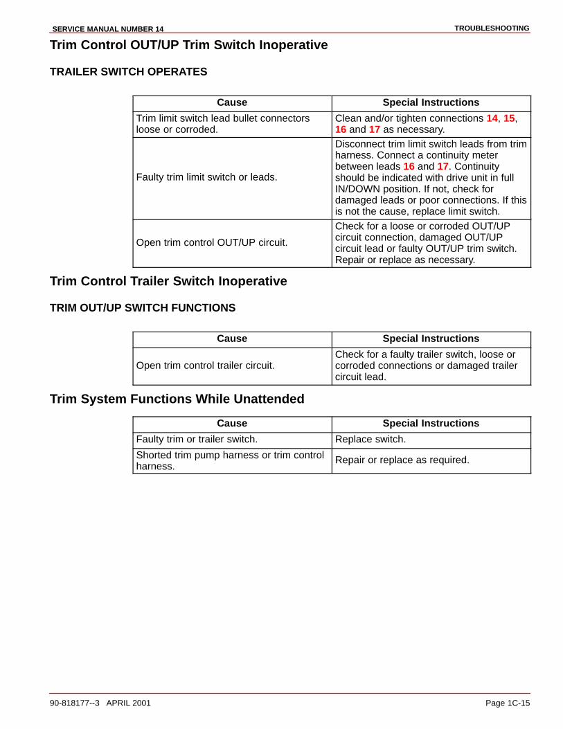
Trim Control OUT/UP Trim Switch Inoperative
TRAILER SWITCH OPERATES
Cause Special Instructions
Trim limit switch lead bullet connectorsloose or corroded.
Clean and/or tighten connections 14, 15,16 and 17 as necessary.
Faulty trim limit switch or leads.
Disconnect trim limit switch leads from trimharness. Connect a continuity meterbetween leads 16 and 17. Continuityshould be indicated with drive unit in fullIN/DOWN position. If not, check fordamaged leads or poor connections. If thisis not the cause, replace limit switch.
Open trim control OUT/UP circuit.
Check for a loose or corroded OUT/UP circuit connection, damaged OUT/UPcircuit lead or faulty OUT/UP trim switch.Repair or replace as necessary.
Trim Control Trailer Switch Inoperative
TRIM OUT/UP SWITCH FUNCTIONS
Cause Special Instructions
Open trim control trailer circuit.Check for a faulty trailer switch, loose orcorroded connections or damaged trailercircuit lead.
Trim System Functions While Unattended
Cause Special Instructions
Faulty trim or trailer switch. Replace switch.
Shorted trim pump harness or trim controlharness.
Repair or replace as required.
TROUBLESHOOTING SERVICE MANUAL NUMBER 14
Page 1C-16 90-818177--3 APRIL 2001
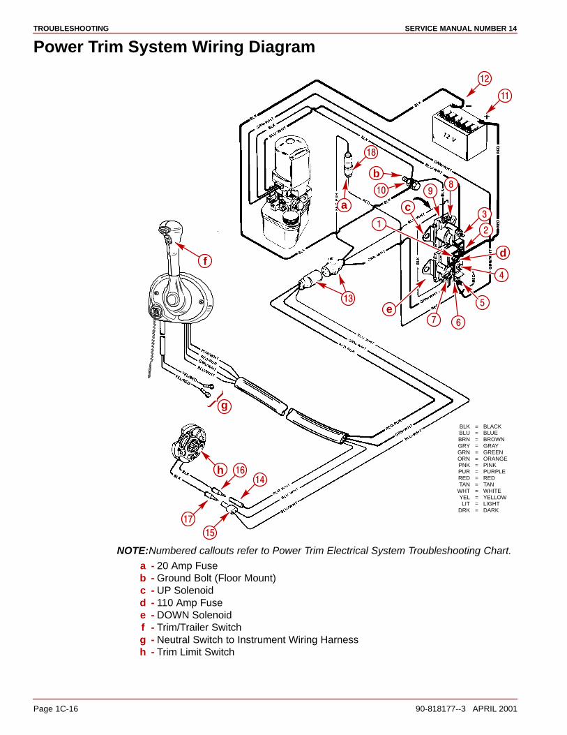
Power Trim System Wiring Diagram
BLK = BLACKBLU = BLUEBRN = BROWNGRY = GRAYGRN = GREENORN = ORANGEPNK = PINKPUR = PURPLERED = REDTAN = TAN
WHT = WHITEYEL = YELLOWLIT = LIGHT
DRK = DARK
b
e
g
�
�
�
h
��
��
��
��
��
��
��
��
�
a
��
d
�
�
�
c
f
NOTE:Numbered callouts refer to Power Trim Electrical System Troubleshooting Chart.
a - 20 Amp Fuseb - Ground Bolt (Floor Mount)c - UP Solenoidd - 110 Amp Fusee - DOWN Solenoidf - Trim/Trailer Switchg - Neutral Switch to Instrument Wiring Harnessh - Trim Limit Switch
TROUBLESHOOTINGSERVICE MANUAL NUMBER 14
90-818177--3 APRIL 2001 Page 1C-17
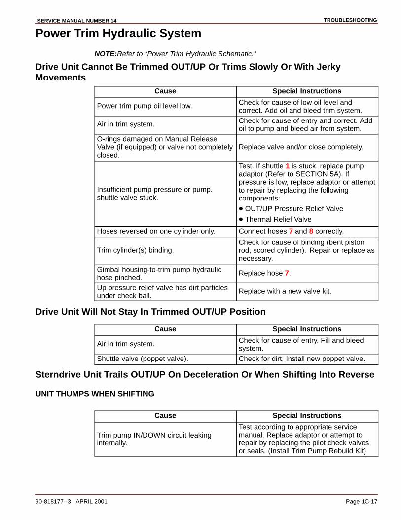
Power Trim Hydraulic System
NOTE:Refer to “Power Trim Hydraulic Schematic.”
Drive Unit Cannot Be Trimmed OUT/UP Or Trims Slowly Or With JerkyMovements
Cause Special Instructions
Power trim pump oil level low. Check for cause of low oil level andcorrect. Add oil and bleed trim system.
Air in trim system. Check for cause of entry and correct. Addoil to pump and bleed air from system.
O-rings damaged on Manual ReleaseValve (if equipped) or valve not completelyclosed.
Replace valve and/or close completely.
Insufficient pump pressure or pump.shuttle valve stuck.
Test. If shuttle 1 is stuck, replace pumpadaptor (Refer to SECTION 5A). Ifpressure is low, replace adaptor or attemptto repair by replacing the followingcomponents:
� OUT/UP Pressure Relief Valve
� Thermal Relief Valve
Hoses reversed on one cylinder only. Connect hoses 7 and 8 correctly.
Trim cylinder(s) binding.Check for cause of binding (bent pistonrod, scored cylinder). Repair or replace asnecessary.
Gimbal housing-to-trim pump hydraulichose pinched.
Replace hose 7.
Up pressure relief valve has dirt particlesunder check ball.
Replace with a new valve kit.
Drive Unit Will Not Stay In Trimmed OUT/UP Position
Cause Special Instructions
Air in trim system. Check for cause of entry. Fill and bleed system.
Shuttle valve (poppet valve). Check for dirt. Install new poppet valve.
Sterndrive Unit Trails OUT/UP On Deceleration Or When Shifting Into Reverse
UNIT THUMPS WHEN SHIFTING
Cause Special Instructions
Trim pump IN/DOWN circuit leakinginternally.
Test according to appropriate service manual. Replace adaptor or attempt torepair by replacing the pilot check valvesor seals. (Install Trim Pump Rebuild Kit)
TROUBLESHOOTING SERVICE MANUAL NUMBER 14
Page 1C-18 90-818177--3 APRIL 2001
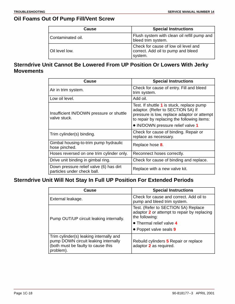
Oil Foams Out Of Pump Fill/Vent Screw
Cause Special Instructions
Contaminated oil. Flush system with clean oil refill pump andbleed trim system.
Oil level low.Check for cause of low oil level andcorrect. Add oil to pump and bleedsystem.
Sterndrive Unit Cannot Be Lowered From UP Position Or Lowers With JerkyMovements
Cause Special Instructions
Air in trim system. Check for cause of entry. Fill and bleedtrim system.
Low oil level. Add oil.
Insufficient IN/DOWN pressure or shuttlevalve stuck.
Test. If shuttle 1 is stuck, replace pumpadaptor. (Refer to SECTION 5A) Ifpressure is low, replace adaptor or attemptto repair by replacing the following items:
� IN/DOWN pressure relief valve 1
Trim cylinder(s) binding. Check for cause of binding. Repair orreplace as necessary.
Gimbal housing-to-trim pump hydraulichose pinched.
Replace hose 8.
Hoses reversed on one trim cylinder only. Reconnect hoses correctly.
Drive unit binding in gimbal ring. Check for cause of binding and replace.
Down pressure relief valve (6) has dirt particles under check ball.
Replace with a new valve kit.
Sterndrive Unit Will Not Stay In Full UP Position For Extended Periods
Cause Special Instructions
External leakage. Check for cause and correct. Add oil topump and bleed trim system.
Pump OUT/UP circuit leaking internally.
Test. (Refer to SECTION 5A) Replace adaptor 2 or attempt to repair by replacingthe following:
� Thermal relief valve 4� Poppet valve seals 9
Trim cylinder(s) leaking internally andpump DOWN circuit leaking internally(both must be faulty to cause thisproblem).
Rebuild cylinders 5 Repair or replaceadaptor 2 as required.
TROUBLESHOOTINGSERVICE MANUAL NUMBER 14
90-818177--3 APRIL 2001 Page 1C-19
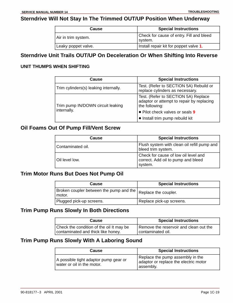
Sterndrive Will Not Stay In The Trimmed OUT/UP Position When Underway
Cause Special Instructions
Air in trim system. Check for cause of entry. Fill and bleed system.
Leaky poppet valve. Install repair kit for poppet valve 1.
Sterndrive Unit Trails OUT/UP On Deceleration Or When Shifting Into Reverse
UNIT THUMPS WHEN SHIFTING
Cause Special Instructions
Trim cylinders(s) leaking internally. Test. (Refer to SECTION 5A) Rebuild or replace cylinders as necessary.
Trim pump IN/DOWN circuit leaking internally.
Test. (Refer to SECTION 5A) Replace adaptor or attempt to repair by replacingthe following:
� Pilot check valves or seals 9� Install trim pump rebuild kit
Oil Foams Out Of Pump Fill/Vent Screw
Cause Special Instructions
Contaminated oil. Flush system with clean oil refill pump andbleed trim system.
Oil level low.Check for cause of low oil level andcorrect. Add oil to pump and bleedsystem.
Trim Motor Runs But Does Not Pump Oil
Cause Special Instructions
Broken coupler between the pump and themotor.
Replace the coupler.
Plugged pick-up screens. Replace pick-up screens.
Trim Pump Runs Slowly In Both Directions
Cause Special Instructions
Check the condition of the oil It may becontaminated and thick like honey.
Remove the reservoir and clean out thecontaminated oil.
Trim Pump Runs Slowly With A Laboring Sound
Cause Special Instructions
A possible tight adaptor pump gear orwater or oil in the motor.
Replace the pump assembly in theadaptor or replace the electric motorassembly.
TROUBLESHOOTING SERVICE MANUAL NUMBER 14
Page 1C-20 90-818177--3 APRIL 2001
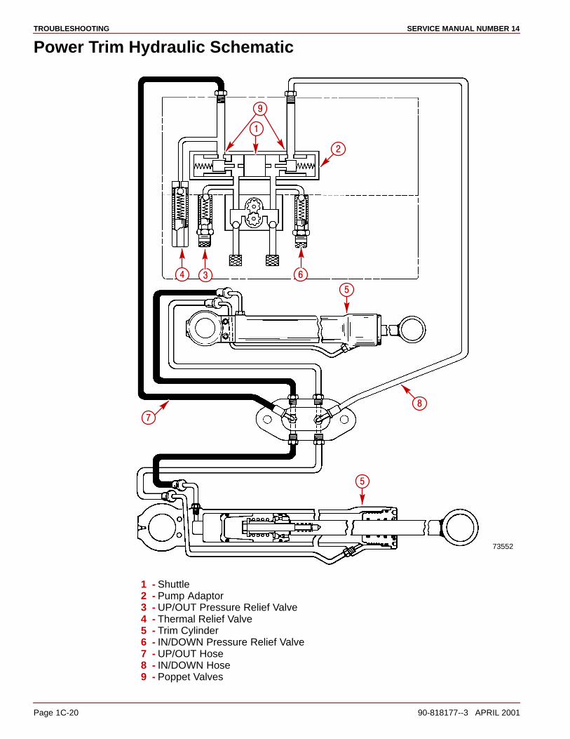
Power Trim Hydraulic Schematic
73552
�
�
�� �
�
�
�
�
1 - Shuttle2 - Pump Adaptor3 - UP/OUT Pressure Relief Valve4 - Thermal Relief Valve5 - Trim Cylinder6 - IN/DOWN Pressure Relief Valve7 - UP/OUT Hose8 - IN/DOWN Hose9 - Poppet Valves

TROUBLESHOOTINGSERVICE MANUAL NUMBER 14
90-818177--3 APRIL 2001 Page 1C-21
Auto Trim II Electrical System
NOTE:Refer to “Auto Trim II System Wiring Diagram.”
Pump Motor Will Not Run UP Or DOWN In Either Manual Or Auto Mode
SOLENOIDS CLICK
Cause Special Instructions
Pump positive battery cable connectionloose or corroded.
Check cable 14.
110 amp fuse blown or loose or corrodedsolenoid connection.
Check for voltage at terminal 5.
Pump motor brushes stuck, corroded orworn out.
Clean or replace.
Armature commutator dirty. Clean or replace.
Armature faulty. Test and replace if bad.
Field and frame faulty. Test and replace if bad.
Pump gears frozen. Replace pump.
Trim harness shorted between UP andDOWN circuit.
Disconnect blue-white lead 2 fromsolenoid terminal. If pump motor will nowrun in the DOWN direction, a short in theharness is indicated.
SOLENOIDS DO NOT CLICK
Cause Special Instructions
Pump negative battery cable loose,corroded or damaged.
Check cable 13 for damage or a loose orcorroded connection.
Mode switch wiring harness connector isloose at pump.
Secure connection 47.
Faulty thermal circuit breaker in pumpmotor.
Connect a jumper wire between terminals1 and 7. If pump now operates, circuitbreaker is faulty and field and frameassembly must be replaced.
Open circuit in mode switch wiringharness.
With ignition switch in RUN position andmode switch in MANUAL mode, check forvoltage at terminal 8 while trimming UPand terminal 12 while rimming DOWN. Ifno voltage is indicated, refer to items 5and 6 immediately following.
No power to mode switch.
Check for voltage at terminal 25 (with ignition switch in RUN position). If novoltage is indicated, check power lead fora poor connection.
Faulty mode switch.
Check for voltage at terminal 24 (withmode switch in AUTO mode) and terminal26 (with switch in the MANUAL mode).Replace switch if no voltage is indicated.
TROUBLESHOOTING SERVICE MANUAL NUMBER 14
Page 1C-22 90-818177--3 APRIL 2001
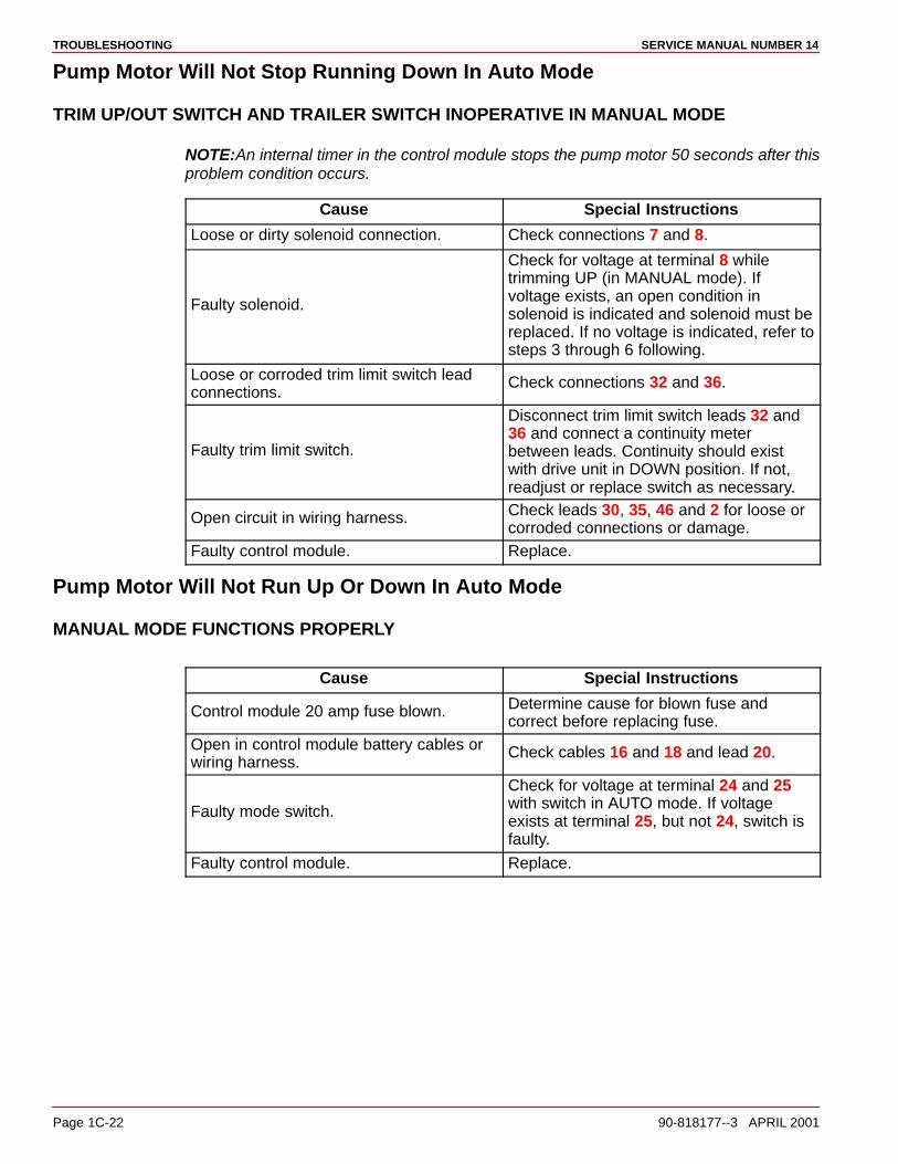
Pump Motor Will Not Stop Running Down In Auto Mode
TRIM UP/OUT SWITCH AND TRAILER SWITCH INOPERATIVE IN MANUAL MODE
NOTE:An internal timer in the control module stops the pump motor 50 seconds after thisproblem condition occurs.
Cause Special Instructions
Loose or dirty solenoid connection. Check connections 7 and 8.
Faulty solenoid.
Check for voltage at terminal 8 whiletrimming UP (in MANUAL mode). Ifvoltage exists, an open condition insolenoid is indicated and solenoid must bereplaced. If no voltage is indicated, refer tosteps 3 through 6 following.
Loose or corroded trim limit switch leadconnections.
Check connections 32 and 36.
Faulty trim limit switch.
Disconnect trim limit switch leads 32 and36 and connect a continuity meterbetween leads. Continuity should existwith drive unit in DOWN position. If not,readjust or replace switch as necessary.
Open circuit in wiring harness. Check leads 30, 35, 46 and 2 for loose orcorroded connections or damage.
Faulty control module. Replace.
Pump Motor Will Not Run Up Or Down In Auto Mode
MANUAL MODE FUNCTIONS PROPERLY
Cause Special Instructions
Control module 20 amp fuse blown. Determine cause for blown fuse andcorrect before replacing fuse.
Open in control module battery cables orwiring harness.
Check cables 16 and 18 and lead 20.
Faulty mode switch.
Check for voltage at terminal 24 and 25with switch in AUTO mode. If voltageexists at terminal 25, but not 24, switch isfaulty.
Faulty control module. Replace.

TROUBLESHOOTINGSERVICE MANUAL NUMBER 14
90-818177--3 APRIL 2001 Page 1C-23
Trim System Completely Inoperative In Manual Mode
AUTO MODE FUNCTIONS PROPERLY
Cause Special Instructions
Faulty mode switch.Check for voltage at terminal 26 withmode switch in MANUAL mode. If novoltage is indicated, replace switch.
Open circuit in wiring harness. Check leads 27 and 33 for loose orcorroded connections or damage.
Pump Motor Will Run UP, But Not DOWN In Both Manual And Auto Modes
DOWN SOLENOID DOES NOT CLICK
Cause Special Instructions
Loose or dirty solenoid connections. Check connections 4, 7 and 12.
Faulty mode switch or open in DOWNcircuit.
Check for voltage at terminal 12 whiletrimming Down (in MANUAL mode). If novoltage is indicated, repeat test at terminal22 and 23. If voltage exists at terminal 23,but not at 22, switch is faulty. If voltage is present at terminal 22, check leads 3 and48 and connector 47 for an opencondition.
Faulty DOWN solenoid. Replace solenoid.
DOWN SOLENOID CLICKS
Cause Special Instructions
Loose or dirty solenoid connections. Check connections 10 and 11.
Faulty solenoid.Check for voltage at terminal 11 whiletrimming Down (in MANUAL mode). If novoltage is indicated, replace solenoid.
Faulty DOWN field winding. Replace field and frame.
Pump Motor Runs DOWN, But Not UP In Both The Manual And Auto Modes
UP SOLENOID CLICKS
Cause Special Instructions
Loose or dirty solenoid connections. Check connections 5 and 6.
Faulty solenoid.Check for voltage at terminal 6 whiletrimming UP. If no voltage is indicated,replace solenoid.
Faulty UP field winding. Replace field and frame.
TROUBLESHOOTING SERVICE MANUAL NUMBER 14
Page 1C-24 90-818177--3 APRIL 2001
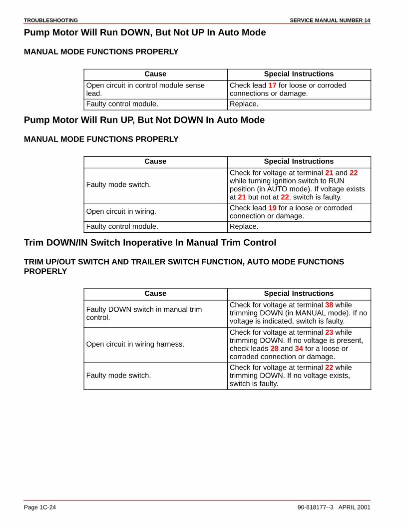
Pump Motor Will Run DOWN, But Not UP In Auto Mode
MANUAL MODE FUNCTIONS PROPERLY
Cause Special Instructions
Open circuit in control module sense lead.
Check lead 17 for loose or corroded connections or damage.
Faulty control module. Replace.
Pump Motor Will Run UP, But Not DOWN In Auto Mode
MANUAL MODE FUNCTIONS PROPERLY
Cause Special Instructions
Faulty mode switch.
Check for voltage at terminal 21 and 22while turning ignition switch to RUNposition (in AUTO mode). If voltage existsat 21 but not at 22, switch is faulty.
Open circuit in wiring. Check lead 19 for a loose or corrodedconnection or damage.
Faulty control module. Replace.
Trim DOWN/IN Switch Inoperative In Manual Trim Control
TRIM UP/OUT SWITCH AND TRAILER SWITCH FUNCTION, AUTO MODE FUNCTIONSPROPERLY
Cause Special Instructions
Faulty DOWN switch in manual trimcontrol.
Check for voltage at terminal 38 whiletrimming DOWN (in MANUAL mode). If novoltage is indicated, switch is faulty.
Open circuit in wiring harness.
Check for voltage at terminal 23 whiletrimming DOWN. If no voltage is present,check leads 28 and 34 for a loose orcorroded connection or damage.
Faulty mode switch.Check for voltage at terminal 22 whiletrimming DOWN. If no voltage exists,switch is faulty.
TROUBLESHOOTINGSERVICE MANUAL NUMBER 14
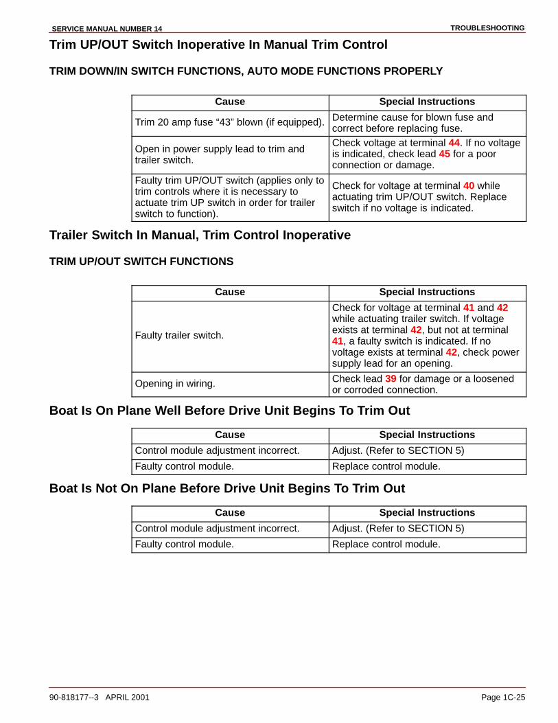
90-818177--3 APRIL 2001 Page 1C-25
Trim UP/OUT Switch Inoperative In Manual Trim Control
TRIM DOWN/IN SWITCH FUNCTIONS, AUTO MODE FUNCTIONS PROPERLY
Cause Special Instructions
Trim 20 amp fuse “43” blown (if equipped). Determine cause for blown fuse andcorrect before replacing fuse.
Open in power supply lead to trim and trailer switch.
Check voltage at terminal 44. If no voltageis indicated, check lead 45 for a poorconnection or damage.
Faulty trim UP/OUT switch (applies only totrim controls where it is necessary toactuate trim UP switch in order for trailerswitch to function).
Check for voltage at terminal 40 whileactuating trim UP/OUT switch. Replaceswitch if no voltage is indicated.
Trailer Switch In Manual, Trim Control Inoperative
TRIM UP/OUT SWITCH FUNCTIONS
Cause Special Instructions
Faulty trailer switch.
Check for voltage at terminal 41 and 42while actuating trailer switch. If voltageexists at terminal 42, but not at terminal41, a faulty switch is indicated. If novoltage exists at terminal 42, check powersupply lead for an opening.
Opening in wiring. Check lead 39 for damage or a loosenedor corroded connection.
Boat Is On Plane Well Before Drive Unit Begins To Trim Out
Cause Special Instructions
Control module adjustment incorrect. Adjust. (Refer to SECTION 5)
Faulty control module. Replace control module.
Boat Is Not On Plane Before Drive Unit Begins To Trim Out
Cause Special Instructions
Control module adjustment incorrect. Adjust. (Refer to SECTION 5)
Faulty control module. Replace control module.

TROUBLESHOOTING SERVICE MANUAL NUMBER 14
Page 1C-26 90-818177--3 APRIL 2001
Auto Trim II System Wiring Diagram
22178
�
��
��
��
��
��
��
��
��
���
��
��
�
�
��
��
��
��
��
����
��
��
��
��
��
��
��
��
��
�
�
�
�
�
� �
��
��
��
��
�
�
����
Corrosion Protection
NOTE:Refer to “MerCathode Controller Wiring Diagram.”
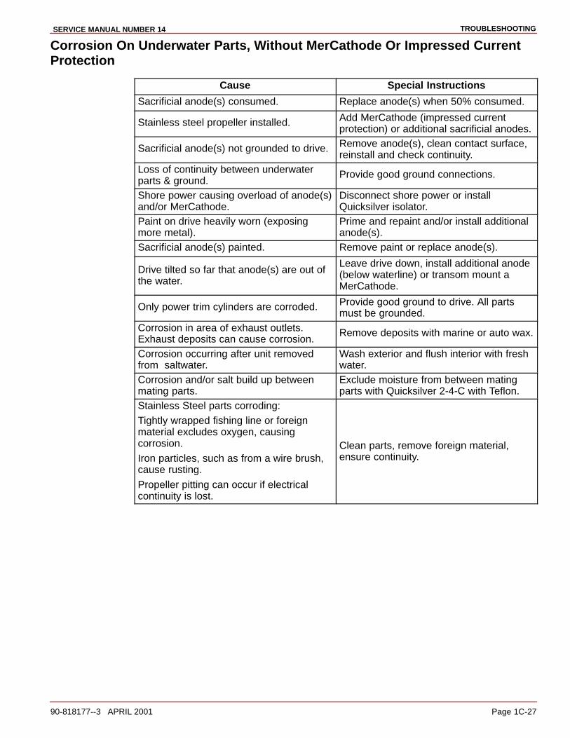
TROUBLESHOOTINGSERVICE MANUAL NUMBER 14
90-818177--3 APRIL 2001 Page 1C-27
Corrosion On Underwater Parts, Without MerCathode Or Impressed CurrentProtection
Cause Special Instructions
Sacrificial anode(s) consumed. Replace anode(s) when 50% consumed.
Stainless steel propeller installed. Add MerCathode (impressed currentprotection) or additional sacrificial anodes.
Sacrificial anode(s) not grounded to drive. Remove anode(s), clean contact surface,reinstall and check continuity.
Loss of continuity between underwaterparts & ground.
Provide good ground connections.
Shore power causing overload of anode(s)and/or MerCathode.
Disconnect shore power or installQuicksilver isolator.
Paint on drive heavily worn (exposingmore metal).
Prime and repaint and/or install additionalanode(s).
Sacrificial anode(s) painted. Remove paint or replace anode(s).
Drive tilted so far that anode(s) are out ofthe water.
Leave drive down, install additional anode(below waterline) or transom mount aMerCathode.
Only power trim cylinders are corroded. Provide good ground to drive. All partsmust be grounded.
Corrosion in area of exhaust outlets.Exhaust deposits can cause corrosion.
Remove deposits with marine or auto wax.
Corrosion occurring after unit removedfrom saltwater.
Wash exterior and flush interior with freshwater.
Corrosion and/or salt build up betweenmating parts.
Exclude moisture from between matingparts with Quicksilver 2-4-C with Teflon.
Stainless Steel parts corroding:
Tightly wrapped fishing line or foreignmaterial excludes oxygen, causingcorrosion.
Iron particles, such as from a wire brush,cause rusting.
Propeller pitting can occur if electricalcontinuity is lost.
Clean parts, remove foreign material,ensure continuity.
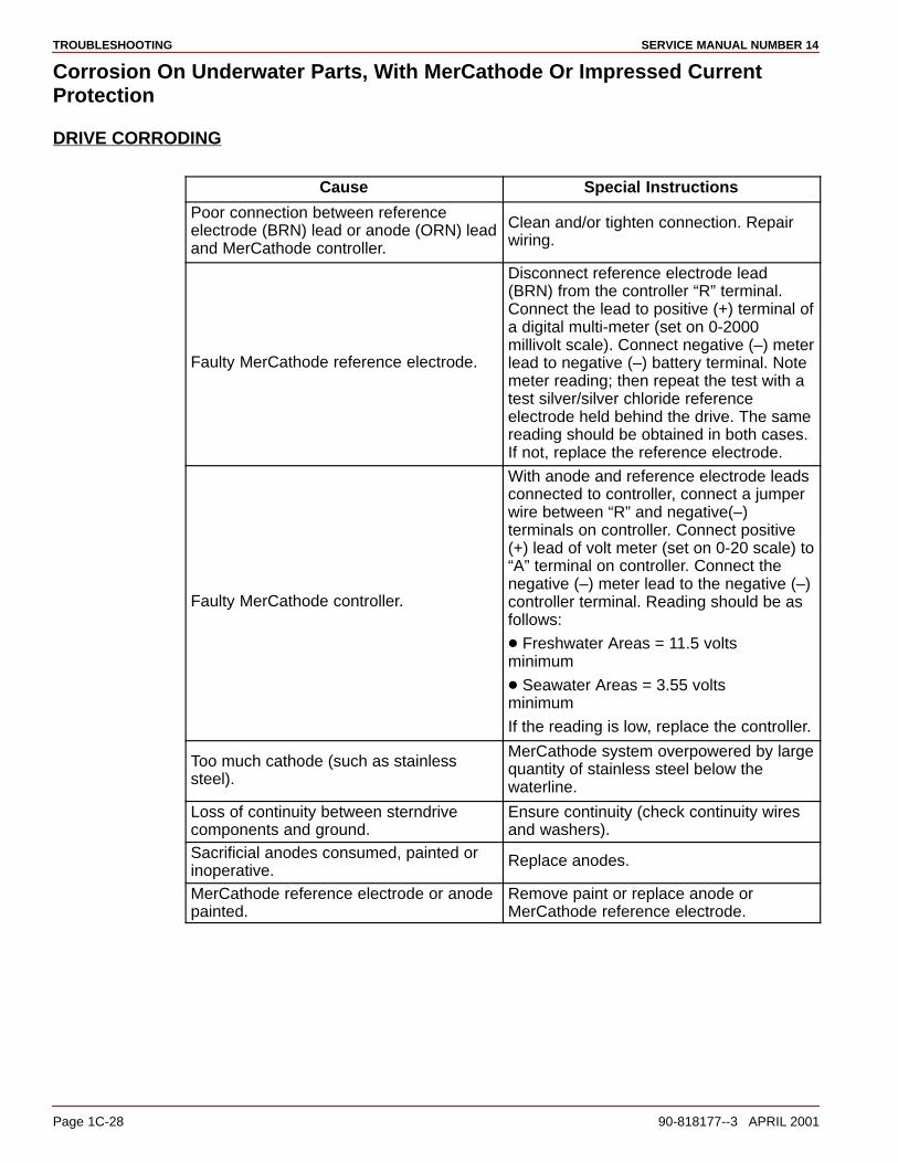
TROUBLESHOOTING SERVICE MANUAL NUMBER 14
Page 1C-28 90-818177--3 APRIL 2001
Corrosion On Underwater Parts, With MerCathode Or Impressed CurrentProtection
DRIVE CORRODING
Cause Special Instructions
Poor connection between referenceelectrode (BRN) lead or anode (ORN) leadand MerCathode controller.
Clean and/or tighten connection. Repairwiring.
Faulty MerCathode reference electrode.
Disconnect reference electrode lead(BRN) from the controller “R” terminal.Connect the lead to positive (+) terminal ofa digital multi-meter (set on 0-2000millivolt scale). Connect negative (–) meterlead to negative (–) battery terminal. Notemeter reading; then repeat the test with atest silver/silver chloride referenceelectrode held behind the drive. The samereading should be obtained in both cases.If not, replace the reference electrode.
Faulty MerCathode controller.
With anode and reference electrode leadsconnected to controller, connect a jumperwire between “R” and negative(–)terminals on controller. Connect positive(+) lead of volt meter (set on 0-20 scale) to“A” terminal on controller. Connect thenegative (–) meter lead to the negative (–)controller terminal. Reading should be asfollows:
� Freshwater Areas = 11.5 volts minimum
� Seawater Areas = 3.55 volts minimum
If the reading is low, replace the controller.
Too much cathode (such as stainlesssteel).
MerCathode system overpowered by largequantity of stainless steel below thewaterline.
Loss of continuity between sterndrivecomponents and ground.
Ensure continuity (check continuity wiresand washers).
Sacrificial anodes consumed, painted orinoperative.
Replace anodes.
MerCathode reference electrode or anodepainted.
Remove paint or replace anode orMerCathode reference electrode.

TROUBLESHOOTINGSERVICE MANUAL NUMBER 14
90-818177--3 APRIL 2001 Page 1C-29
DRIVE CORRODING - CONTINUED
Cause Special Instructions
No power to MerCathode controller.
Connect positive (+) lead of volt meter (seton 0-20 volt scale) to positive (+) terminalon the controller and negative (-) voltmeter lead to negative (-) terminal. Metershould indicate battery voltage. Check forblown fuse (if equipped) on a standardMerCathode system. Clean the connectionor repair wiring as required.
Check the fuse in the hot lead.
Check battery.
MerCathode system not functioning Check for loose connections at controllerand batteryCheck the grounding wire between thedrive and the controller.
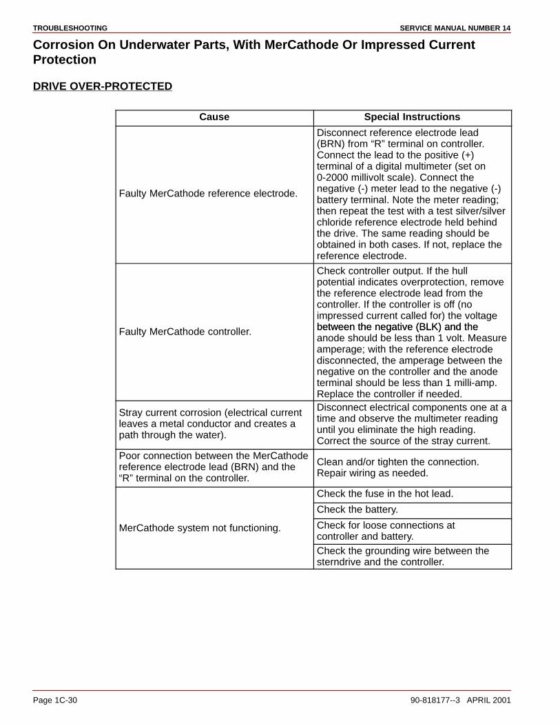
TROUBLESHOOTING SERVICE MANUAL NUMBER 14
Page 1C-30 90-818177--3 APRIL 2001
Corrosion On Underwater Parts, With MerCathode Or Impressed CurrentProtection
DRIVE OVER-PROTECTED
Cause Special Instructions
Faulty MerCathode reference electrode.
Disconnect reference electrode lead(BRN) from “R” terminal on controller.Connect the lead to the positive (+)terminal of a digital multimeter (set on0-2000 millivolt scale). Connect thenegative (-) meter lead to the negative (-)battery terminal. Note the meter reading;then repeat the test with a test silver/silverchloride reference electrode held behindthe drive. The same reading should beobtained in both cases. If not, replace the reference electrode.
Check controller output. If the hullpotential indicates overprotection, removethe reference electrode lead from thecontroller. If the controller is off (noimpressed current called for) the voltage between the negative (BLK) and theFaulty MerCathode controller. between the negative (BLK) and theanode should be less than 1 volt. Measureamperage; with the reference electrodedisconnected, the amperage between thenegative on the controller and the anodeterminal should be less than 1 milli-amp.Replace the controller if needed.
Stray current corrosion (electrical currentleaves a metal conductor and creates apath through the water).
Disconnect electrical components one at atime and observe the multimeter readinguntil you eliminate the high reading.Correct the source of the stray current.
Poor connection between the MerCathodereference electrode lead (BRN) and the“R” terminal on the controller.
Clean and/or tighten the connection.Repair wiring as needed.
Check the fuse in the hot lead.
Check the battery.
MerCathode system not functioning. Check for loose connections at controller and battery.Check the grounding wire between thesterndrive and the controller.
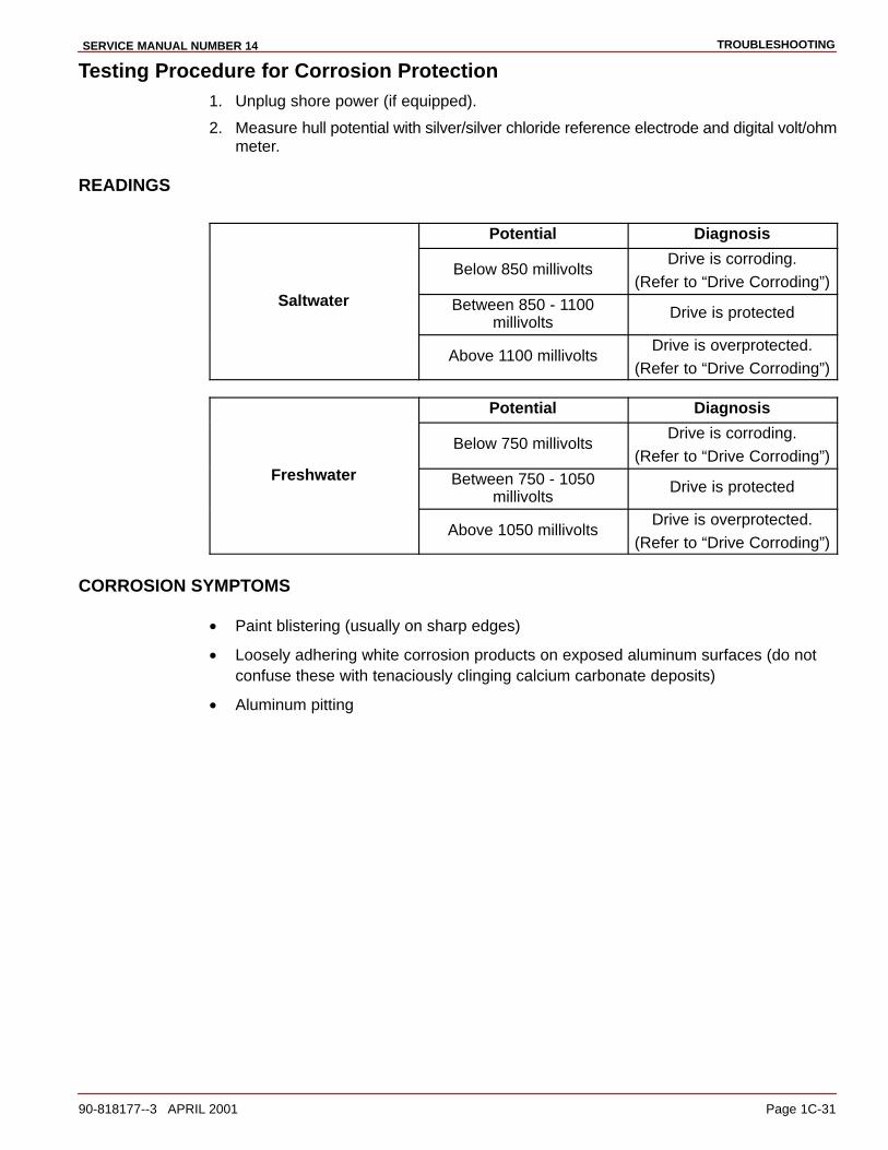
TROUBLESHOOTINGSERVICE MANUAL NUMBER 14
90-818177--3 APRIL 2001 Page 1C-31
Testing Procedure for Corrosion Protection1. Unplug shore power (if equipped).
2. Measure hull potential with silver/silver chloride reference electrode and digital volt/ohmmeter.
READINGS
Potential Diagnosis
Below 850 millivoltsDrive is corroding.
(Refer to “Drive Corroding”)Saltwater Between 850 - 1100
millivoltsDrive is protected
Above 1100 millivoltsDrive is overprotected.
(Refer to “Drive Corroding”)
Potential Diagnosis
Below 750 millivoltsDrive is corroding.
(Refer to “Drive Corroding”)Freshwater Between 750 - 1050
millivoltsDrive is protected
Above 1050 millivoltsDrive is overprotected.
(Refer to “Drive Corroding”)
CORROSION SYMPTOMS
• Paint blistering (usually on sharp edges)
• Loosely adhering white corrosion products on exposed aluminum surfaces (do notconfuse these with tenaciously clinging calcium carbonate deposits)
• Aluminum pitting

TROUBLESHOOTING SERVICE MANUAL NUMBER 14
Page 1C-32 90-818177--3 APRIL 2001
MerCathode Controller
73596
a
b
c
a - Controllerb - 20 Amp Fusec - Electrode
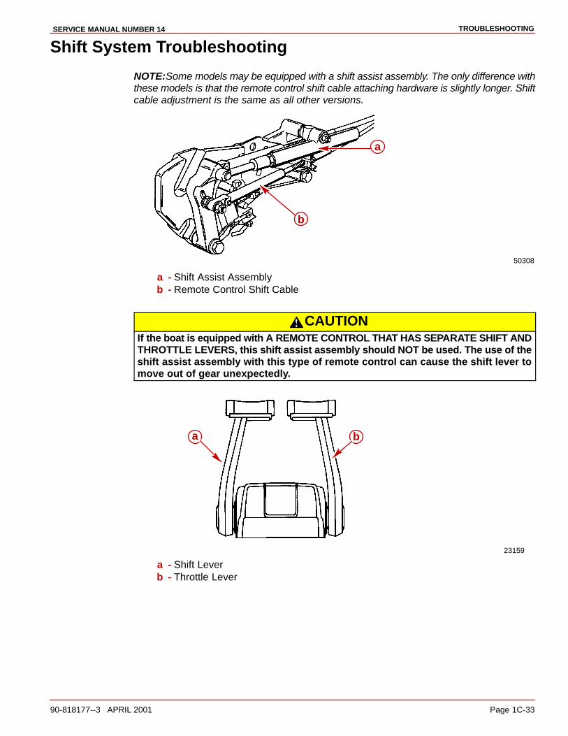
TROUBLESHOOTINGSERVICE MANUAL NUMBER 14
90-818177--3 APRIL 2001 Page 1C-33
Shift System Troubleshooting
NOTE:Some models may be equipped with a shift assist assembly. The only difference withthese models is that the remote control shift cable attaching hardware is slightly longer. Shiftcable adjustment is the same as all other versions.
50308
a
b
a - Shift Assist Assemblyb - Remote Control Shift Cable
CAUTIONIf the boat is equipped with A REMOTE CONTROL THAT HAS SEPARATE SHIFT ANDTHROTTLE LEVERS, this shift assist assembly should NOT be used. The use of theshift assist assembly with this type of remote control can cause the shift lever tomove out of gear unexpectedly.
23159
a b
a - Shift Leverb - Throttle Lever
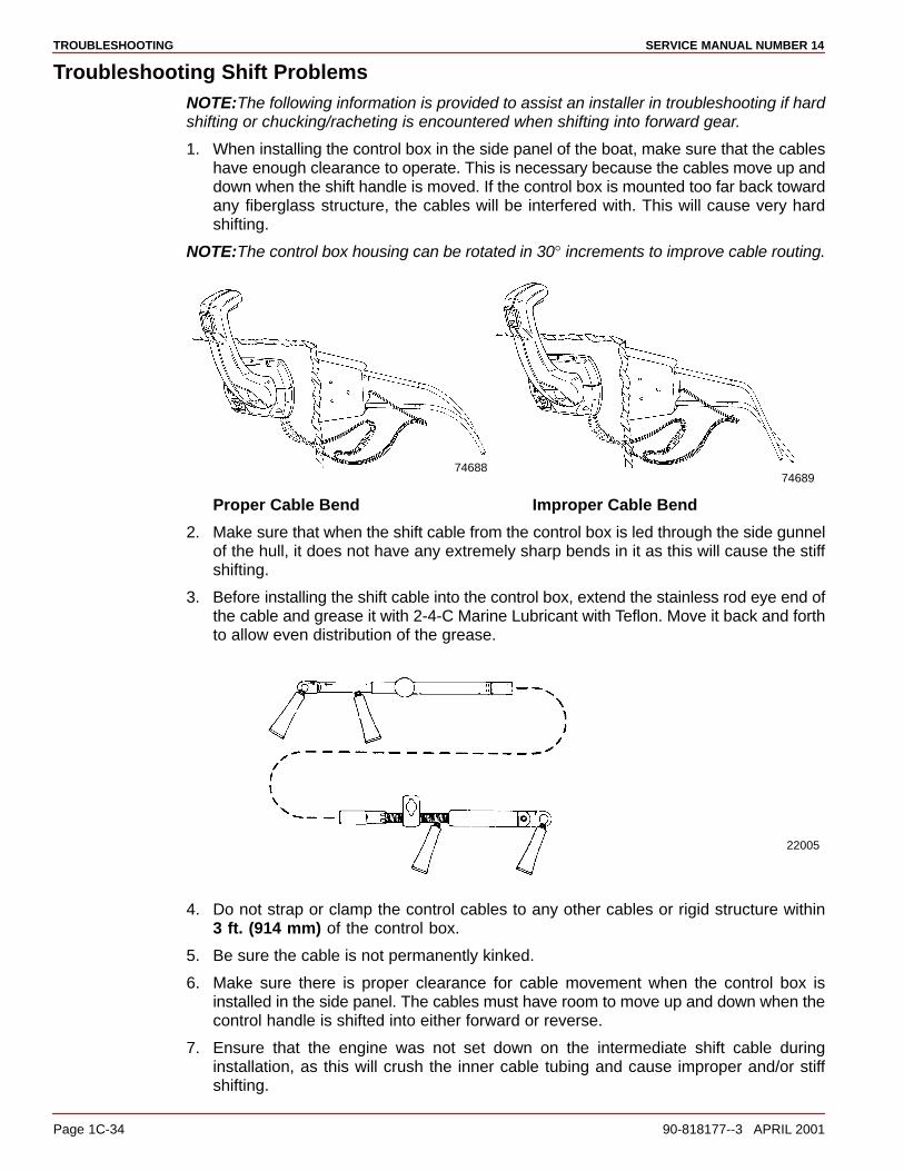
TROUBLESHOOTING SERVICE MANUAL NUMBER 14
Page 1C-34 90-818177--3 APRIL 2001
Troubleshooting Shift ProblemsNOTE:The following information is provided to assist an installer in troubleshooting if hardshifting or chucking/racheting is encountered when shifting into forward gear.
1. When installing the control box in the side panel of the boat, make sure that the cableshave enough clearance to operate. This is necessary because the cables move up anddown when the shift handle is moved. If the control box is mounted too far back towardany fiberglass structure, the cables will be interfered with. This will cause very hardshifting.
NOTE:The control box housing can be rotated in 30° increments to improve cable routing.
7468874689
Proper Cable Bend Improper Cable Bend
2. Make sure that when the shift cable from the control box is led through the side gunnelof the hull, it does not have any extremely sharp bends in it as this will cause the stiffshifting.
3. Before installing the shift cable into the control box, extend the stainless rod eye end ofthe cable and grease it with 2-4-C Marine Lubricant with Teflon. Move it back and forthto allow even distribution of the grease.
22005
4. Do not strap or clamp the control cables to any other cables or rigid structure within3 ft. (914 mm) of the control box.
5. Be sure the cable is not permanently kinked.
6. Make sure there is proper clearance for cable movement when the control box isinstalled in the side panel. The cables must have room to move up and down when thecontrol handle is shifted into either forward or reverse.
7. Ensure that the engine was not set down on the intermediate shift cable duringinstallation, as this will crush the inner cable tubing and cause improper and/or stiffshifting.
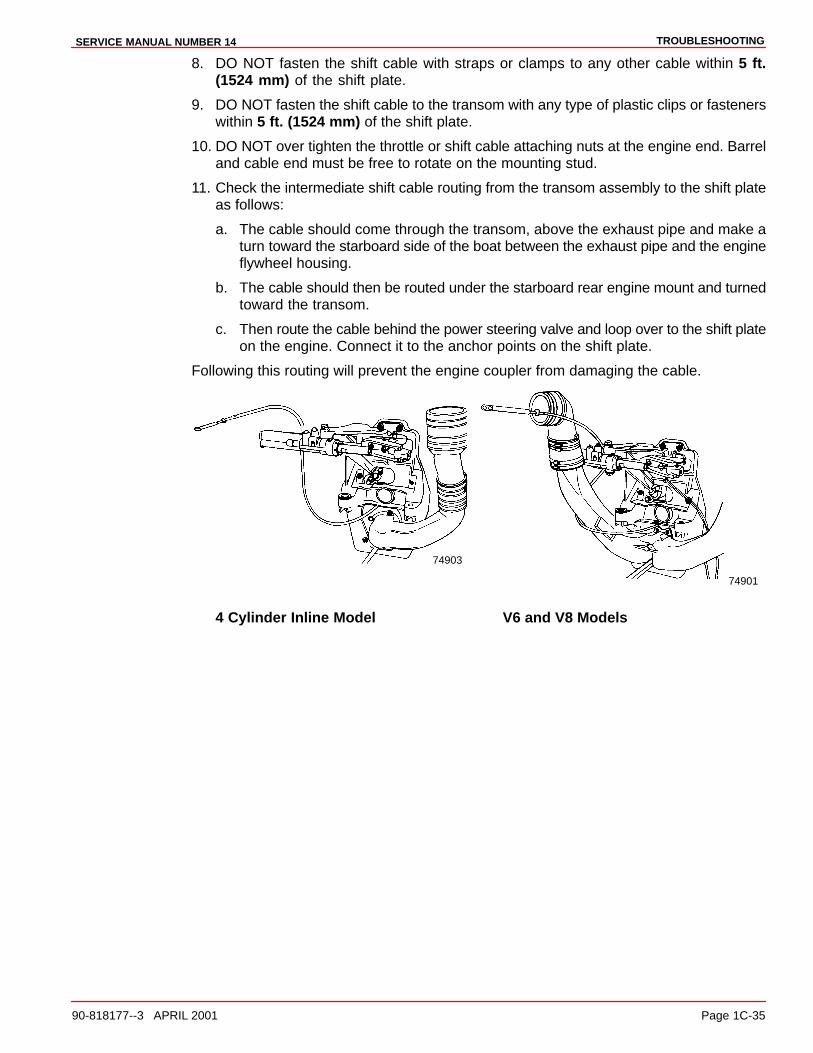
TROUBLESHOOTINGSERVICE MANUAL NUMBER 14
90-818177--3 APRIL 2001 Page 1C-35
8. DO NOT fasten the shift cable with straps or clamps to any other cable within 5 ft.(1524 mm) of the shift plate.
9. DO NOT fasten the shift cable to the transom with any type of plastic clips or fastenerswithin 5 ft. (1524 mm) of the shift plate.
10. DO NOT over tighten the throttle or shift cable attaching nuts at the engine end. Barreland cable end must be free to rotate on the mounting stud.
11. Check the intermediate shift cable routing from the transom assembly to the shift plateas follows:
a. The cable should come through the transom, above the exhaust pipe and make aturn toward the starboard side of the boat between the exhaust pipe and the engineflywheel housing.
b. The cable should then be routed under the starboard rear engine mount and turnedtoward the transom.
c. Then route the cable behind the power steering valve and loop over to the shift plateon the engine. Connect it to the anchor points on the shift plate.
Following this routing will prevent the engine coupler from damaging the cable.
74903
74901
4 Cylinder Inline Model V6 and V8 Models

TROUBLESHOOTING SERVICE MANUAL NUMBER 14
Page 1C-36 90-818177--3 APRIL 2001
Checking for Excessive PlayChecking for excessive play in the drive unit shift system can be done with the boat in thewater or on land. Refer to the appropriate procedure:
BOAT OUT OF WATER (ENGINE OFF)
1. Disconnect remote control shift cable.
22267
ca
db
a - Remote Control Shift Cableb - Plastic Shift Leverc - Clevis Pin and Cotter Pind - Locknut and Washer
IMPORTANT: When pushing or pulling on drive unit shift cable in the following steps,apply just enough pressure so that V-notch starts moving. Then ease up slightly. Usea fine tip marking device to mark threaded tube to obtain an accurate measurement.
22058
a
Roller Type Switcha - V-notch
75225
a
Plunger Type Switcha - V-notch
2. Check for excessive play in drive unit shift system:
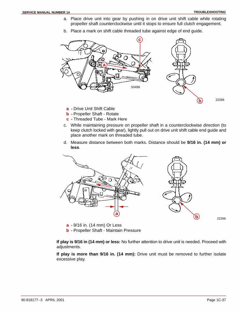
TROUBLESHOOTINGSERVICE MANUAL NUMBER 14
90-818177--3 APRIL 2001 Page 1C-37
a. Place drive unit into gear by pushing in on drive unit shift cable while rotatingpropeller shaft counterclockwise until it stops to ensure full clutch engagement.
b. Place a mark on shift cable threaded tube against edge of end guide.
22266b
a
c
50499
a - Drive Unit Shift Cableb - Propeller Shaft - Rotatec - Threaded Tube - Mark Here
c. While maintaining pressure on propeller shaft in a counterclockwise direction (tokeep clutch locked with gear), lightly pull out on drive unit shift cable end guide andplace another mark on threaded tube.
d. Measure distance between both marks. Distance should be 9/16 in. (14 mm) orless.
22266a
b
a - 9/16 in. (14 mm) Or Lessb - Propeller Shaft - Maintain Pressure
If play is 9/16 in (14 mm) or less: No further attention to drive unit is needed. Proceed withadjustments.
If play is more than 9/16 in. (14 mm): Drive unit must be removed to further isolateexcessive play.

TROUBLESHOOTING SERVICE MANUAL NUMBER 14
Page 1C-38 90-818177--3 APRIL 2001
BOAT IN WATER (ENGINE RUNNING)
WARNINGAt least two people will be needed for the following procedure, one person to checkthe adjustment and one person to stay at the control station of the boat.
WARNINGEnsure boat is secured to dock and precautions have been taken to avoid damageto boat prior to placing drive unit into gear.
1. Start engine and let it warm up to normal operating temperature (Refer to operatingprocedures in Operation and Maintenance Manual).
2. Disconnect throttle cable.
22062
b
a
Carburetor Model Shown (Others Similar)a - Throttle Cable End Guideb - Carburetor Throttle Lever
3. Disconnect Remote Control Shift Cable.
22267
ca
db
a - Remote Control Shift Cableb - Plastic Shift Leverc - Clevis Pin And Cotter Pind - Locknut And Washer
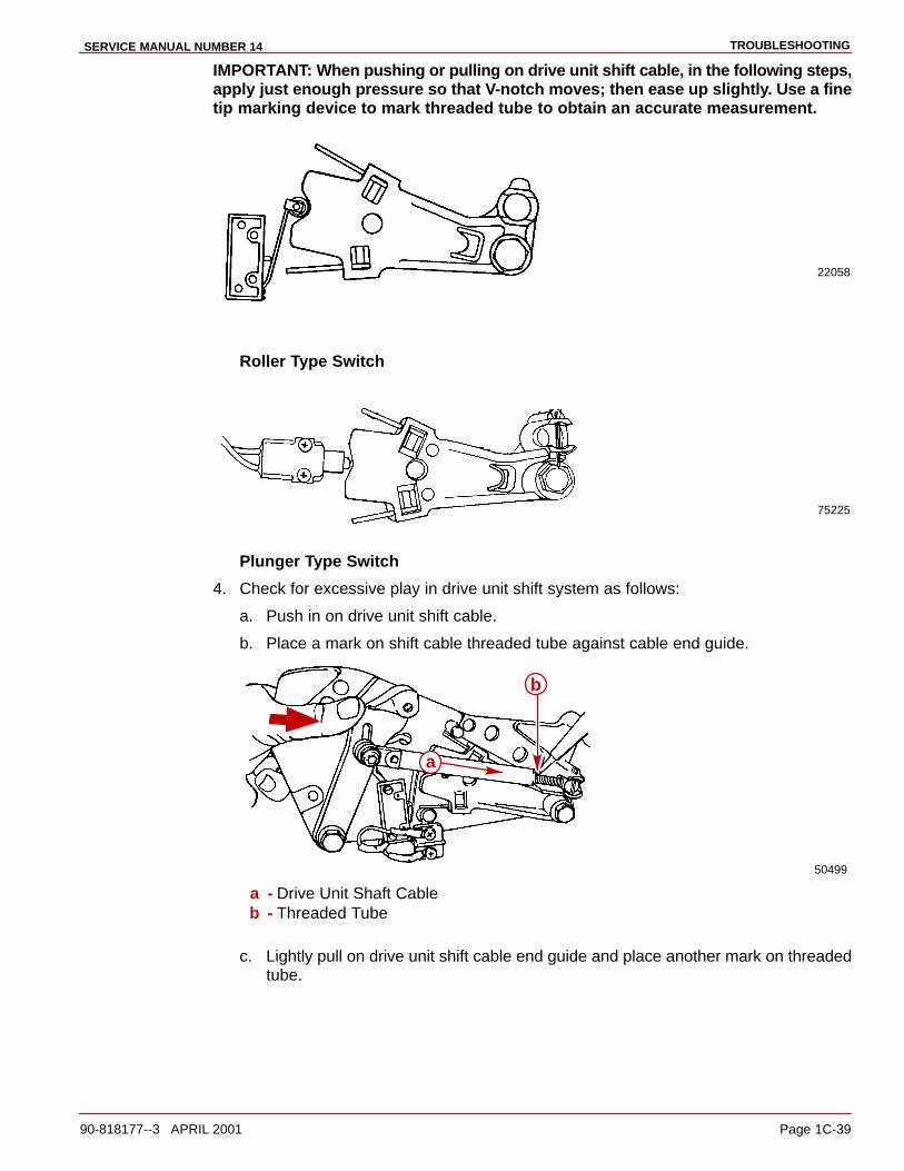
TROUBLESHOOTINGSERVICE MANUAL NUMBER 14
90-818177--3 APRIL 2001 Page 1C-39
IMPORTANT: When pushing or pulling on drive unit shift cable, in the following steps,apply just enough pressure so that V-notch moves; then ease up slightly. Use a finetip marking device to mark threaded tube to obtain an accurate measurement.
22058
Roller Type Switch
75225
Plunger Type Switch
4. Check for excessive play in drive unit shift system as follows:
a. Push in on drive unit shift cable.
b. Place a mark on shift cable threaded tube against cable end guide.
50499
a
b
a - Drive Unit Shaft Cableb - Threaded Tube
c. Lightly pull on drive unit shift cable end guide and place another mark on threadedtube.
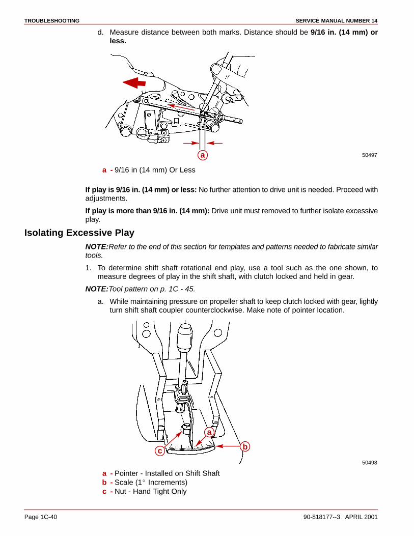
TROUBLESHOOTING SERVICE MANUAL NUMBER 14
Page 1C-40 90-818177--3 APRIL 2001
d. Measure distance between both marks. Distance should be 9/16 in. (14 mm) orless.
50497a
a - 9/16 in (14 mm) Or Less
If play is 9/16 in. (14 mm) or less: No further attention to drive unit is needed. Proceed withadjustments.
If play is more than 9/16 in. (14 mm): Drive unit must removed to further isolate excessiveplay.
Isolating Excessive PlayNOTE:Refer to the end of this section for templates and patterns needed to fabricate similartools.
1. To determine shift shaft rotational end play, use a tool such as the one shown, tomeasure degrees of play in the shift shaft, with clutch locked and held in gear.
NOTE:Tool pattern on p. 1C - 45.
a. While maintaining pressure on propeller shaft to keep clutch locked with gear, lightlyturn shift shaft coupler counterclockwise. Make note of pointer location.
50498
c b
a
a - Pointer - Installed on Shift Shaftb - Scale (1� Increments)c - Nut - Hand Tight Only
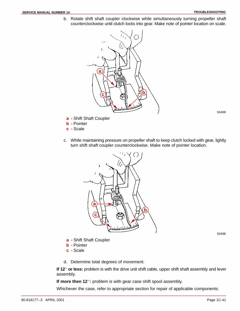
TROUBLESHOOTINGSERVICE MANUAL NUMBER 14
90-818177--3 APRIL 2001 Page 1C-41
b. Rotate shift shaft coupler clockwise while simultaneously turning propeller shaftcounterclockwise until clutch locks into gear. Make note of pointer location on scale.
50498
a
bc
a - Shift Shaft Couplerb - Pointerc - Scale
c. While maintaining pressure on propeller shaft to keep clutch locked with gear, lightlyturn shift shaft coupler counterclockwise. Make note of pointer location.
50498
bc
a
a - Shift Shaft Couplerb - Pointerc - Scale
d. Determine total degrees of movement.
If 12� or less: problem is with the drive unit shift cable, upper shift shaft assembly and leverassembly.
If more then 12�: problem is with gear case shift spool assembly.
Whichever the case, refer to appropriate section for repair of applicable components.
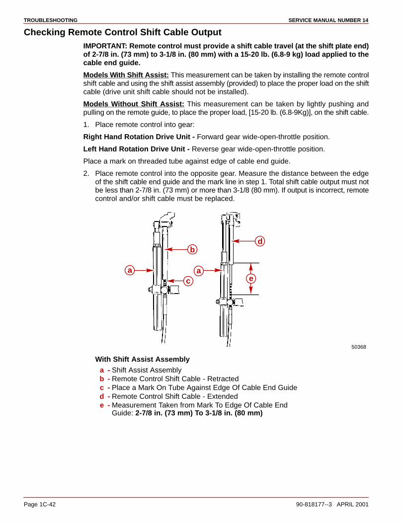
TROUBLESHOOTING SERVICE MANUAL NUMBER 14
Page 1C-42 90-818177--3 APRIL 2001
Checking Remote Control Shift Cable OutputIMPORTANT: Remote control must provide a shift cable travel (at the shift plate end)of 2-7/8 in. (73 mm) to 3-1/8 in. (80 mm) with a 15-20 lb. (6.8-9 kg) load applied to thecable end guide.
Models With Shift Assist: This measurement can be taken by installing the remote controlshift cable and using the shift assist assembly (provided) to place the proper load on the shiftcable (drive unit shift cable should not be installed).
Models Without Shift Assist: This measurement can be taken by lightly pushing andpulling on the remote guide, to place the proper load, [15-20 lb. (6.8-9Kg)], on the shift cable.
1. Place remote control into gear:
Right Hand Rotation Drive Unit - Forward gear wide-open-throttle position.
Left Hand Rotation Drive Unit - Reverse gear wide-open-throttle position.
Place a mark on threaded tube against edge of cable end guide.
2. Place remote control into the opposite gear. Measure the distance between the edgeof the shift cable end guide and the mark line in step 1. Total shift cable output must notbe less than 2-7/8 in. (73 mm) or more than 3-1/8 (80 mm). If output is incorrect, remotecontrol and/or shift cable must be replaced.
d
ac e
b
a
50368
With Shift Assist Assemblya - Shift Assist Assemblyb - Remote Control Shift Cable - Retractedc - Place a Mark On Tube Against Edge Of Cable End Guided - Remote Control Shift Cable - Extendede - Measurement Taken from Mark To Edge Of Cable End
Guide: 2-7/8 in. (73 mm) To 3-1/8 in. (80 mm)
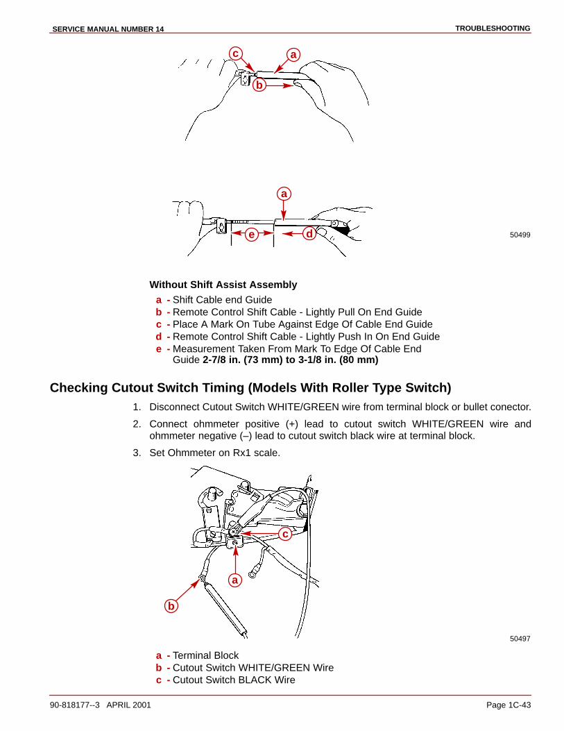
TROUBLESHOOTINGSERVICE MANUAL NUMBER 14
90-818177--3 APRIL 2001 Page 1C-43
50499
b
c a
de
a
Without Shift Assist Assemblya - Shift Cable end Guideb - Remote Control Shift Cable - Lightly Pull On End Guidec - Place A Mark On Tube Against Edge Of Cable End Guided - Remote Control Shift Cable - Lightly Push In On End Guidee - Measurement Taken From Mark To Edge Of Cable End
Guide 2-7/8 in. (73 mm) to 3-1/8 in. (80 mm)
Checking Cutout Switch Timing (Models With Roller Type Switch)1. Disconnect Cutout Switch WHITE/GREEN wire from terminal block or bullet conector.
2. Connect ohmmeter positive (+) lead to cutout switch WHITE/GREEN wire andohmmeter negative (–) lead to cutout switch black wire at terminal block.
3. Set Ohmmeter on Rx1 scale.
50497
b
a
c
a - Terminal Blockb - Cutout Switch WHITE/GREEN Wirec - Cutout Switch BLACK Wire
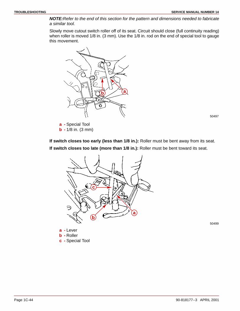
TROUBLESHOOTING SERVICE MANUAL NUMBER 14
Page 1C-44 90-818177--3 APRIL 2001
NOTE:Refer to the end of this section for the pattern and dimensions needed to fabricatea similar tool.
Slowly move cutout switch roller off of its seat. Circuit should close (full continuity reading)when roller is moved 1/8 in. (3 mm). Use the 1/8 in. rod on the end of special tool to gaugethis movement.
50497
b a
a - Special Toolb - 1/8 in. (3 mm)
If switch closes too early (less than 1/8 in.): Roller must be bent away from its seat.
If switch closes too late (more than 1/8 in.): Roller must be bent toward its seat.
50499
c
ba
a - Leverb - Rollerc - Special Tool
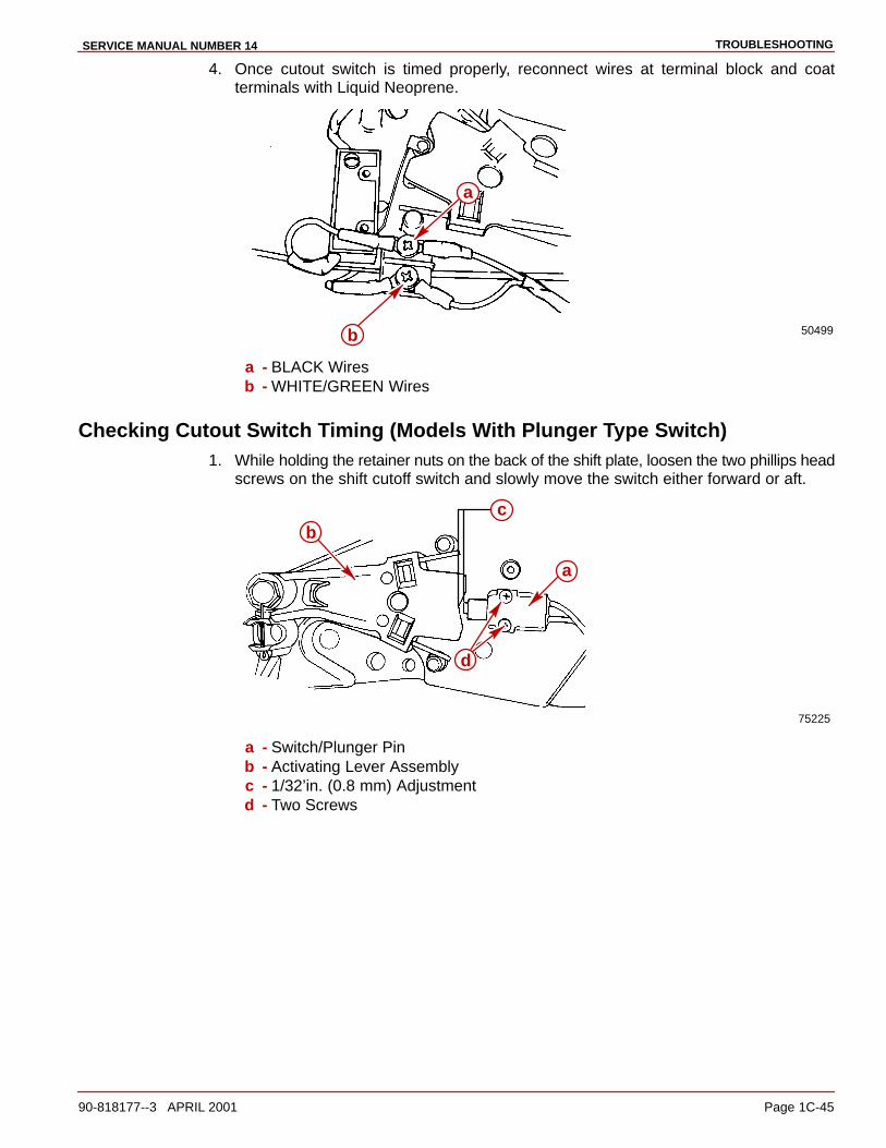
TROUBLESHOOTINGSERVICE MANUAL NUMBER 14
90-818177--3 APRIL 2001 Page 1C-45
4. Once cutout switch is timed properly, reconnect wires at terminal block and coatterminals with Liquid Neoprene.
50499b
a
a - BLACK Wiresb - WHITE/GREEN Wires
Checking Cutout Switch Timing (Models With Plunger Type Switch)1. While holding the retainer nuts on the back of the shift plate, loosen the two phillips head
screws on the shift cutoff switch and slowly move the switch either forward or aft.
75225
c
a
b
d
a - Switch/Plunger Pinb - Activating Lever Assemblyc - 1/32’in. (0.8 mm) Adjustmentd - Two Screws

TROUBLESHOOTING SERVICE MANUAL NUMBER 14
Page 1C-46 90-818177--3 APRIL 2001
2. Adjust switch to locate plunger pin to 1/32 in (0.8 mm). between plunger pin andactivating lever assembly.
75679
3. Slowly move activating lever assembly off until cutout switch opens or closes. Circuitshould open or close when the activating lever assembly is moved 3/16 +/– 1/32 in.(4.8 +/– 0.8 mm).
75225
a
b
b
a - Cutout Switchb - Movement of Activating Lever Assembly
4. After adjustments are made and are within 3/16 +/– 1/32 in. (4.8 +/– 0.8 mm), tightenthe screws on the cutout switch. After tightening screws, recheck the plunger pinposition.
TROUBLESHOOTINGSERVICE MANUAL NUMBER 14
90-818177--3 APRIL 2001 Page 1C-47
Checking Operation1. Reconnect throttle cable.
2. Place boat in water and start engine. Check the following:
a. Shift into forward and reverse gear, verify clutch engages before engine begins toaccelerate.
b. Accelerate engine in forward and reverse gear to ensure engine does not shut down.
c. Check that shift cutout switch roller is centered in notch of shift cutout lever, with driveunit in forward and reverse gear.
d. Shift from IN gear position to neutral, ensure drive unit is in neutral before remotecontrol shift lever comes to neutral detent position.

TROUBLESHOOTING SERVICE MANUAL NUMBER 14
Page 1C-48 90-818177--3 APRIL 2001
THIS PAGE IS INTENTIONALLY BLANK

TROUBLESHOOTINGSERVICE MANUAL NUMBER 14
90-818177--3 APRIL 2001 Page 1C-49
50375
TOP
VIE
W
SID
E V
IEW
BE
ND
AS
SH
OW
N
PO
INT
ER
CU
TO
UT
SW
ITC
HA
DJU
ST
ME
NT
TO
OL
SC
AL
E
1/8
in. D
ia.
(3m
m)
1/16
in.
(1.6
mm
)5
- 1/
2 in
. (14
0mm
)1/
16 in
. (1.
6mm
) D
ia. S
TIF
F W
IRE
PAS
TE
TO
HE
AV
YS
TOC
K P
AP
ER
OR
CA
RD
BO
AR
D

TROUBLESHOOTING SERVICE MANUAL NUMBER 14
Page 1C-50 90-818177--3 APRIL 2001
THIS PAGE IS INTENTIONALLY BLANK
2A
REMOVAL, INSTALLATION AND ADJUSTMENTSSERVICE MANUAL NUMBER 14
90-818177--3 APRIL 2001 Page 2A-1
REMOVAL, INSTALLATION AND ADJUSTMENTSection 2A - All Models
Table of Contents
Sterndrive Unit Removal 2A-2. . . . . . . . . . . . . Sterndrive Unit Installation 2A-6. . . . . . . . . . . . Remote Control Shift Cable Adjustment (Drive Unit Installed) 2A-13. . . . . .
Troubleshooting Shift Problems 2A-22. . . . . Propeller Installation 2A-23. . . . . . . . . . . . . .
Transom Assembly Removal 2A-25. . . . . . . . . Power Steering Models 2A-25. . . . . . . . . . . . Manual Steering Models 2A-26. . . . . . . . . . .
Transom Assembly Installation 2A-31. . . . . . . . Power Steering Models 2A-36. . . . . . . . . . . . Manual Steering Models 2A-38. . . . . . . . . . .

REMOVAL, INSTALLATION AND ADJUSTMENTS SERVICE MANUAL NUMBER 14
Page 2A-2 90-818177--3 APRIL 2001
Sterndrive Unit Removal
1. Move remote control shift lever into the FORWARD gear position on standard rotationgear cases, or REVERSE on counter rotation gear cases.
2. Press trailer button on control handle to raise drive unit to trailer position / full-up position.
3. Raise the drive unit to gain access to area between gimbal housing and sterndriveimmediately atop the transom end of the anti-ventilation plate.
4. Disconnect speedometer fittings following a. or b. as appropriate:
a. Grasp the top half of the plastic fitting, turn counterclockwise and pull up todisengage locking device.
75580
a
b
70025
cc
a
b
1997-1/2 and Earlier Model Speedometer Connectora - Speedometer Connector, Male Endb - Speedometer Connector, Female Endc - Alignment Slots
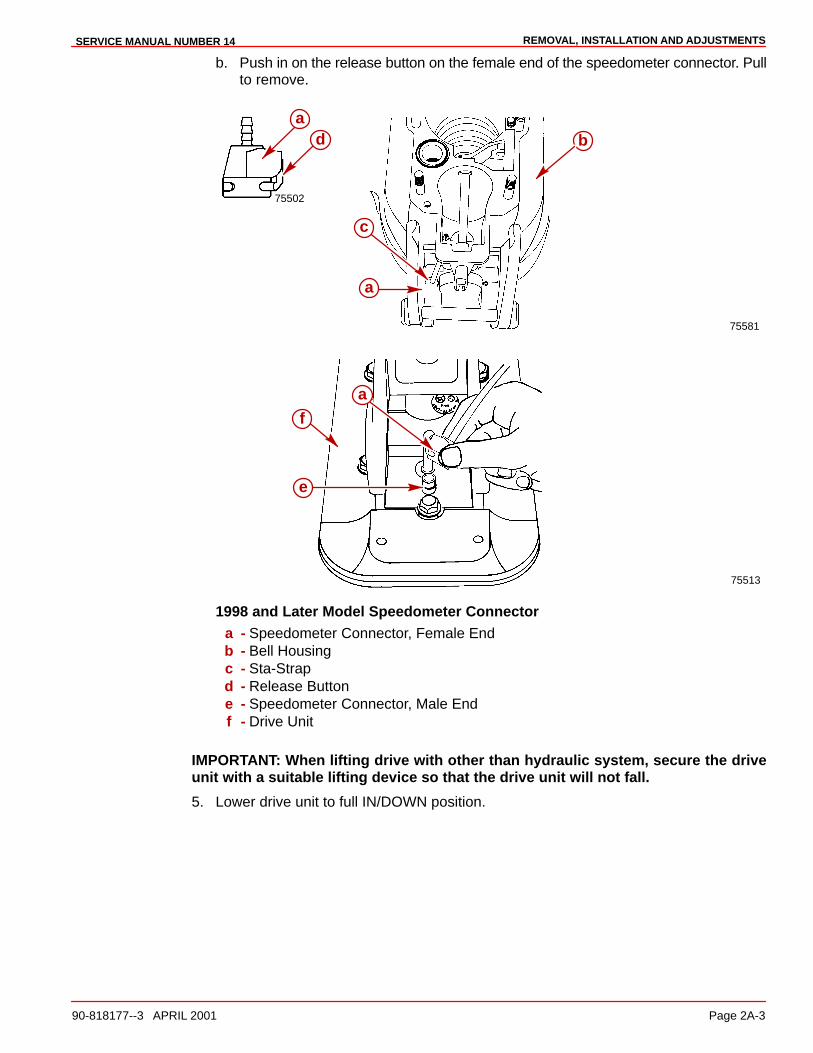
REMOVAL, INSTALLATION AND ADJUSTMENTSSERVICE MANUAL NUMBER 14
90-818177--3 APRIL 2001 Page 2A-3
b. Push in on the release button on the female end of the speedometer connector. Pullto remove.
75581
75502
ba
d
a
c
75513
a
e
f
1998 and Later Model Speedometer Connectora - Speedometer Connector, Female Endb - Bell Housingc - Sta-Strapd - Release Buttone - Speedometer Connector, Male Endf - Drive Unit
IMPORTANT: When lifting drive with other than hydraulic system, secure the driveunit with a suitable lifting device so that the drive unit will not fall.
5. Lower drive unit to full IN/DOWN position.

REMOVAL, INSTALLATION AND ADJUSTMENTS SERVICE MANUAL NUMBER 14
Page 2A-4 90-818177--3 APRIL 2001
6. Remove power trim cylinders (aft end) from drive unit.
70027
b c
ad
e
a - Aft Anchor Pinb - Bushings (4)c - Flat Washers (2)d - E-ring Clips (2)e - Plastic Caps (2)
70026
b
b
a
a - Aft Anchor Pinb - Bushings
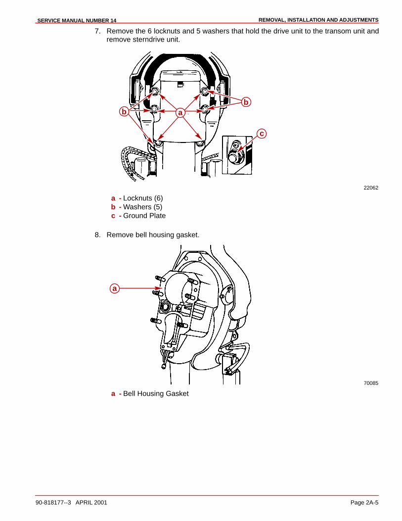
REMOVAL, INSTALLATION AND ADJUSTMENTSSERVICE MANUAL NUMBER 14
90-818177--3 APRIL 2001 Page 2A-5
7. Remove the 6 locknuts and 5 washers that hold the drive unit to the transom unit andremove sterndrive unit.
22062
ab
c
b
a - Locknuts (6)b - Washers (5)c - Ground Plate
8. Remove bell housing gasket.
70085
a
a - Bell Housing Gasket
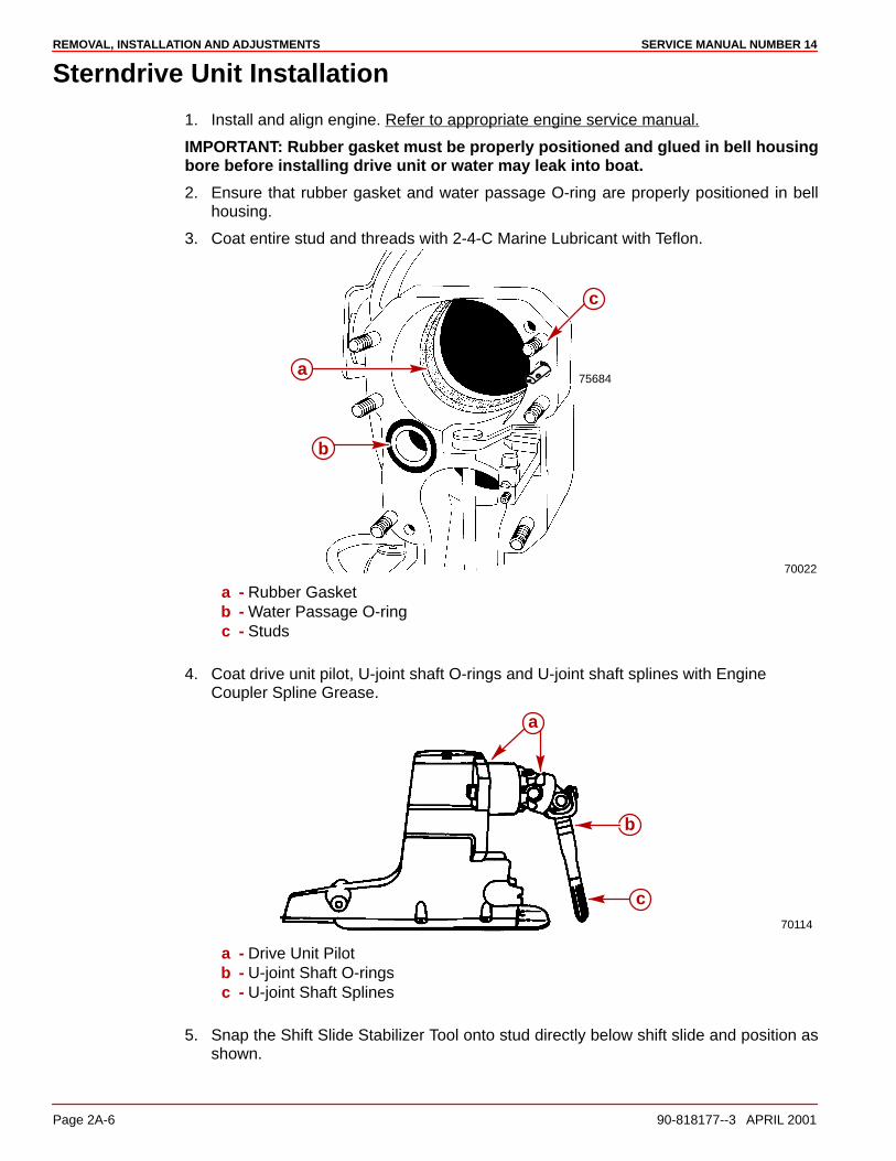
REMOVAL, INSTALLATION AND ADJUSTMENTS SERVICE MANUAL NUMBER 14
Page 2A-6 90-818177--3 APRIL 2001
Sterndrive Unit Installation
1. Install and align engine. Refer to appropriate engine service manual.
IMPORTANT: Rubber gasket must be properly positioned and glued in bell housingbore before installing drive unit or water may leak into boat.
2. Ensure that rubber gasket and water passage O-ring are properly positioned in bellhousing.
3. Coat entire stud and threads with 2-4-C Marine Lubricant with Teflon.
70022
75684a
b
c
a - Rubber Gasketb - Water Passage O-ringc - Studs
4. Coat drive unit pilot, U-joint shaft O-rings and U-joint shaft splines with EngineCoupler Spline Grease.
70114
b
c
a
a - Drive Unit Pilotb - U-joint Shaft O-ringsc - U-joint Shaft Splines
5. Snap the Shift Slide Stabilizer Tool onto stud directly below shift slide and position asshown.
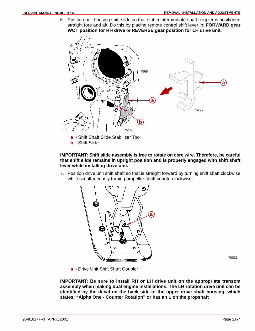
REMOVAL, INSTALLATION AND ADJUSTMENTSSERVICE MANUAL NUMBER 14
90-818177--3 APRIL 2001 Page 2A-7
6. Position bell housing shift slide so that slot in intermediate shaft coupler is positionedstraight fore and aft. Do this by placing remote control shift lever in: FORWARD gearWOT position for RH drive or REVERSE gear position for LH drive unit.
75198
75684
a
b
a
75199
a - Shift Shaft Slide Stabilizer Toolb - Shift Slide
IMPORTANT: Shift slide assembly is free to rotate on core wire. Therefore, be carefulthat shift slide remains in upright position and is properly engaged with shift shaftlever while installing drive unit.
7. Position drive unit shift shaft so that is straight forward by turning shift shaft clockwisewhile simultaneously turning propeller shaft counterclockwise.
70033
a
a - Drive Unit Shift Shaft Coupler
IMPORTANT: Be sure to install RH or LH drive unit on the appropriate transomassembly when making dual engine installations. The LH rotation drive unit can beidentified by the decal on the back side of the upper drive shaft housing, whichstates: “Alpha One - Counter Rotation” or has an L on the propshaft
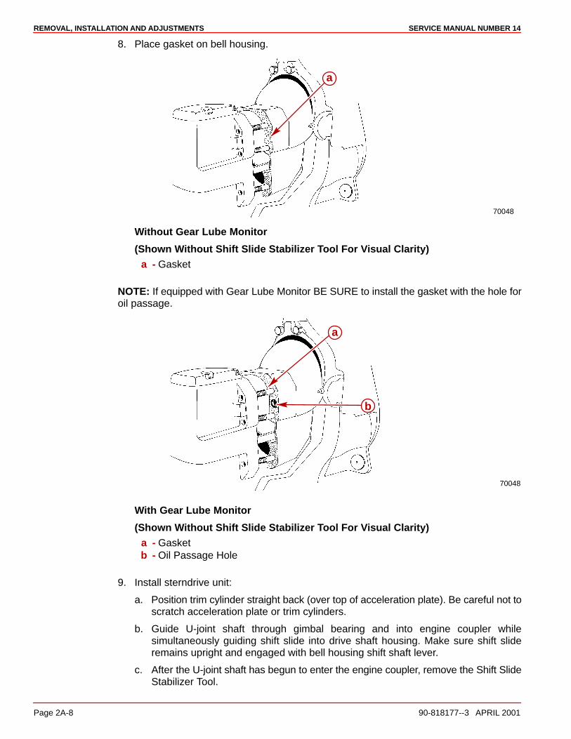
REMOVAL, INSTALLATION AND ADJUSTMENTS SERVICE MANUAL NUMBER 14
Page 2A-8 90-818177--3 APRIL 2001
8. Place gasket on bell housing.
70048
a
Without Gear Lube Monitor
(Shown Without Shift Slide Stabilizer Tool For Visual Clarity)a - Gasket
NOTE: If equipped with Gear Lube Monitor BE SURE to install the gasket with the hole foroil passage.
70048
a
b
With Gear Lube Monitor
(Shown Without Shift Slide Stabilizer Tool For Visual Clarity)a - Gasketb - Oil Passage Hole
9. Install sterndrive unit:
a. Position trim cylinder straight back (over top of acceleration plate). Be careful not toscratch acceleration plate or trim cylinders.
b. Guide U-joint shaft through gimbal bearing and into engine coupler whilesimultaneously guiding shift slide into drive shaft housing. Make sure shift slideremains upright and engaged with bell housing shift shaft lever.
c. After the U-joint shaft has begun to enter the engine coupler, remove the Shift SlideStabilizer Tool.
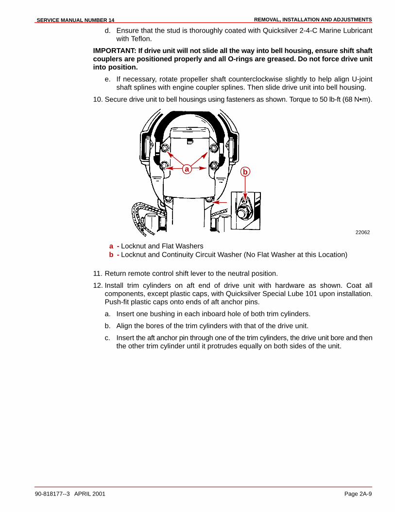
REMOVAL, INSTALLATION AND ADJUSTMENTSSERVICE MANUAL NUMBER 14
90-818177--3 APRIL 2001 Page 2A-9
d. Ensure that the stud is thoroughly coated with Quicksilver 2-4-C Marine Lubricantwith Teflon.
IMPORTANT: If drive unit will not slide all the way into bell housing, ensure shift shaftcouplers are positioned properly and all O-rings are greased. Do not force drive unitinto position.
e. If necessary, rotate propeller shaft counterclockwise slightly to help align U-jointshaft splines with engine coupler splines. Then slide drive unit into bell housing.
10. Secure drive unit to bell housings using fasteners as shown. Torque to 50 lb-ft (68 N�m).
22062
ba
a - Locknut and Flat Washersb - Locknut and Continuity Circuit Washer (No Flat Washer at this Location)
11. Return remote control shift lever to the neutral position.
12. Install trim cylinders on aft end of drive unit with hardware as shown. Coat allcomponents, except plastic caps, with Quicksilver Special Lube 101 upon installation.Push-fit plastic caps onto ends of aft anchor pins.
a. Insert one bushing in each inboard hole of both trim cylinders.
b. Align the bores of the trim cylinders with that of the drive unit.
c. Insert the aft anchor pin through one of the trim cylinders, the drive unit bore and thenthe other trim cylinder until it protrudes equally on both sides of the unit.

REMOVAL, INSTALLATION AND ADJUSTMENTS SERVICE MANUAL NUMBER 14
Page 2A-10 90-818177--3 APRIL 2001
NOTE: Distance between the trim cylinders and the drive unit anchor pin bore isexaggerated for visual clarity.
70026
bb
a
a - Aft Anchor Pinb - Bushings
d. Install the two remaining bushings onto the aft anchor pin ends and fit into bore oftrim cylinders.
e. Install the flat washers.
f. Install the E-ring clips.
NOTE: The inboard grooves of the aft anchor pin are for E-ring clips, and wider, outboardgrooves are for securing plastic caps.
70027
e
d
c
ba
a - Aft Anchor Pinb - Bushingsc - Flat Washers (2)d - E-ring Clips (2)e - Plastic Caps (2)
13. Raise drive to gain access to area between gimbal housing and sterndrive, immediatelyatop the transom end of the anti-ventilation plate.
14. Connect speedometer fittings following a. or b. as appropriate:
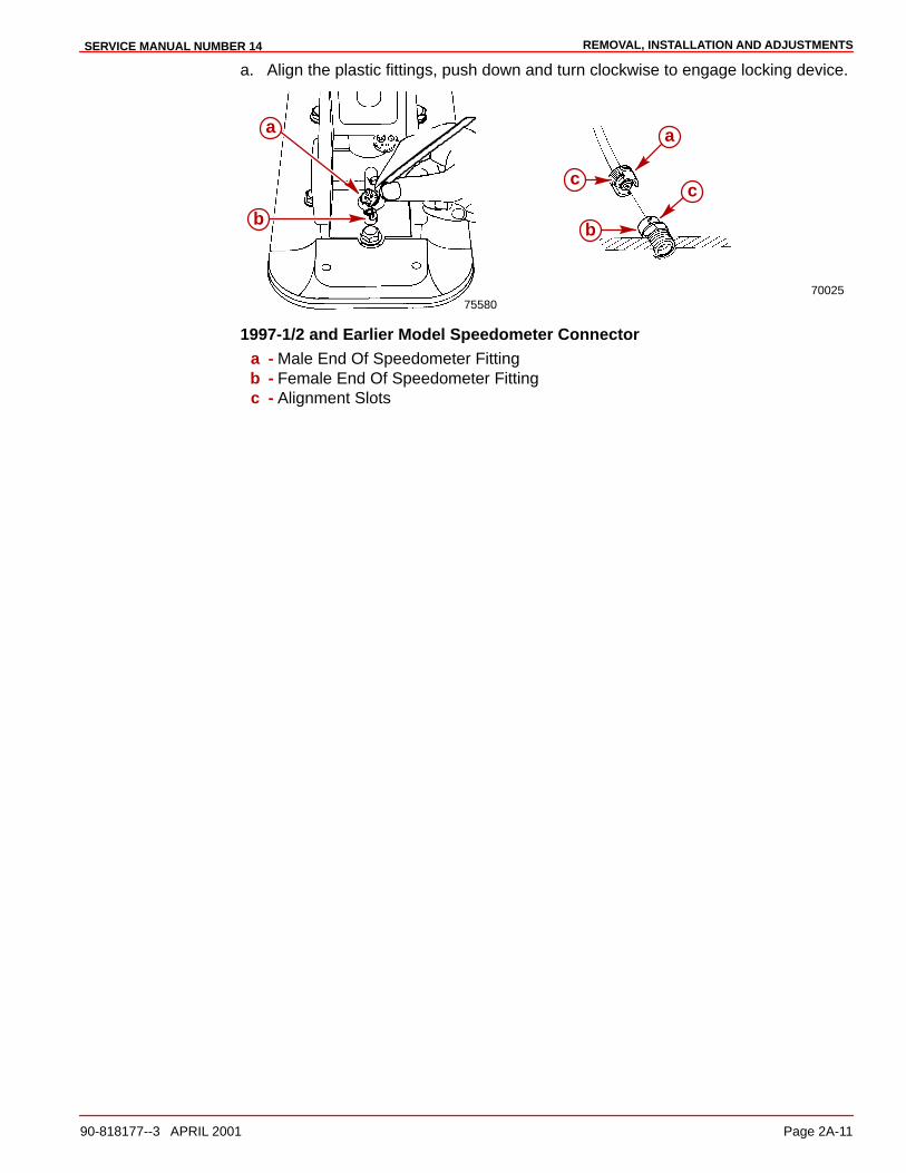
REMOVAL, INSTALLATION AND ADJUSTMENTSSERVICE MANUAL NUMBER 14
90-818177--3 APRIL 2001 Page 2A-11
a. Align the plastic fittings, push down and turn clockwise to engage locking device.
75580
a
b
70025
cc
a
b
1997-1/2 and Earlier Model Speedometer Connectora - Male End Of Speedometer Fittingb - Female End Of Speedometer Fittingc - Alignment Slots
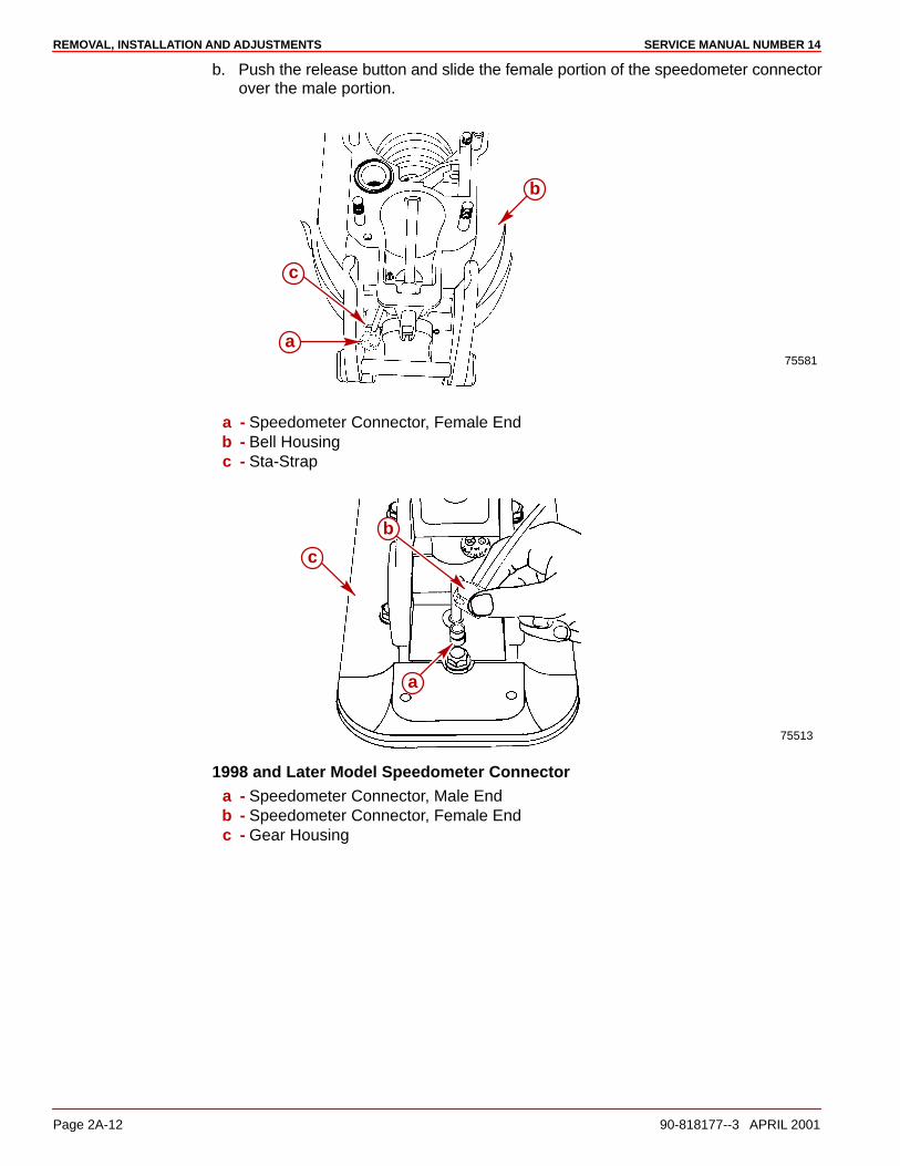
REMOVAL, INSTALLATION AND ADJUSTMENTS SERVICE MANUAL NUMBER 14
Page 2A-12 90-818177--3 APRIL 2001
b. Push the release button and slide the female portion of the speedometer connectorover the male portion.
75581
c
a
b
a - Speedometer Connector, Female Endb - Bell Housingc - Sta-Strap
75513
c
a
b
1998 and Later Model Speedometer Connectora - Speedometer Connector, Male Endb - Speedometer Connector, Female Endc - Gear Housing
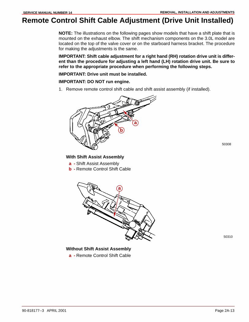
REMOVAL, INSTALLATION AND ADJUSTMENTSSERVICE MANUAL NUMBER 14
90-818177--3 APRIL 2001 Page 2A-13
Remote Control Shift Cable Adjustment (Drive Unit Installed)
NOTE: The illustrations on the following pages show models that have a shift plate that ismounted on the exhaust elbow. The shift mechanism components on the 3.0L model arelocated on the top of the valve cover or on the starboard harness bracket. The procedurefor making the adjustments is the same.
IMPORTANT: Shift cable adjustment for a right hand (RH) rotation drive unit is differ-ent than the procedure for adjusting a left hand (LH) rotation drive unit. Be sure torefer to the appropriate procedure when performing the following steps.
IMPORTANT: Drive unit must be installed.
IMPORTANT: DO NOT run engine.
1. Remove remote control shift cable and shift assist assembly (if installed).
50308
b
a
With Shift Assist Assemblya - Shift Assist Assemblyb - Remote Control Shift Cable
50310
a
Without Shift Assist Assemblya - Remote Control Shift Cable
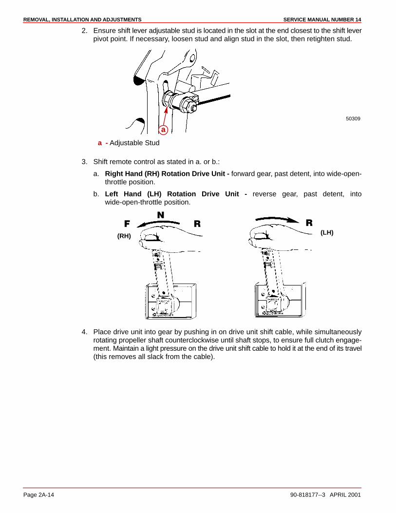
REMOVAL, INSTALLATION AND ADJUSTMENTS SERVICE MANUAL NUMBER 14
Page 2A-14 90-818177--3 APRIL 2001
2. Ensure shift lever adjustable stud is located in the slot at the end closest to the shift leverpivot point. If necessary, loosen stud and align stud in the slot, then retighten stud.
50309
a
a - Adjustable Stud
3. Shift remote control as stated in a. or b.:
a. Right Hand (RH) Rotation Drive Unit - forward gear, past detent, into wide-open-throttle position.
b. Left Hand (LH) Rotation Drive Unit - reverse gear, past detent, intowide-open-throttle position.
(RH)
�
�
�(LH)
�
4. Place drive unit into gear by pushing in on drive unit shift cable, while simultaneouslyrotating propeller shaft counterclockwise until shaft stops, to ensure full clutch engage-ment. Maintain a light pressure on the drive unit shift cable to hold it at the end of its travel(this removes all slack from the cable).

REMOVAL, INSTALLATION AND ADJUSTMENTSSERVICE MANUAL NUMBER 14
90-818177--3 APRIL 2001 Page 2A-15
IMPORTANT: Do not use excessive force when holding pressure on the drive unitshift cable. Excessive force would be indicated by movement of the V-notch of theactuator lever assembly.
22266
a
b
a - Drive Unit Shift Cable - Push Inb - Propeller Shaft - Rotate Counterclockwise
5. Lightly pull on remote control shift cable end guide (to remove slack from remote controland cable) and adjust brass barrel as necessary to align attaching points with shift leverclevis pin hole and stud. Be sure to maintain light pressure on drive unit shift cable.
50309
c
ab
d
a - End Guideb - Brass Barrelc - Shift Lever Clevis Pin Holed - Stud
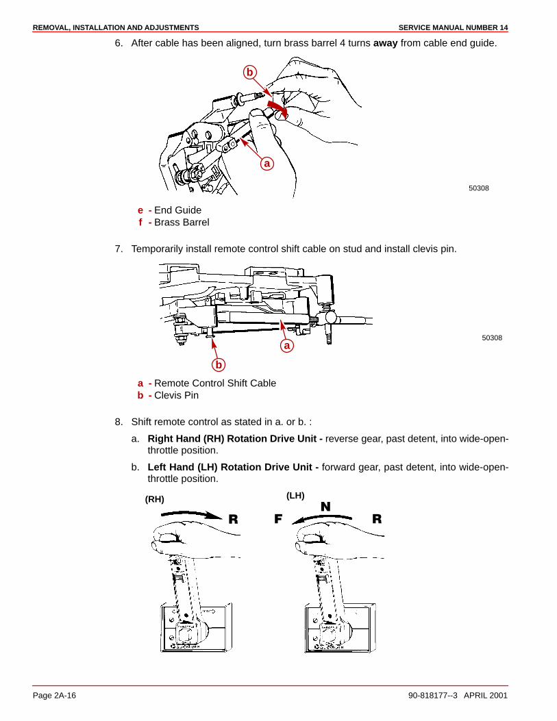
REMOVAL, INSTALLATION AND ADJUSTMENTS SERVICE MANUAL NUMBER 14
Page 2A-16 90-818177--3 APRIL 2001
6. After cable has been aligned, turn brass barrel 4 turns away from cable end guide.
50308
a
b
e - End Guidef - Brass Barrel
7. Temporarily install remote control shift cable on stud and install clevis pin.
50308a
b
a - Remote Control Shift Cableb - Clevis Pin
8. Shift remote control as stated in a. or b. :
a. Right Hand (RH) Rotation Drive Unit - reverse gear, past detent, into wide-open-throttle position.
b. Left Hand (LH) Rotation Drive Unit - forward gear, past detent, into wide-open-throttle position.
(RH)
�
�
�
(LH)
�
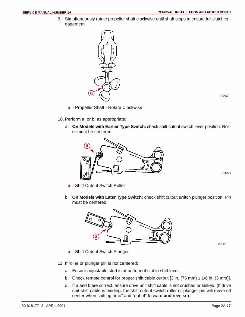
REMOVAL, INSTALLATION AND ADJUSTMENTSSERVICE MANUAL NUMBER 14
90-818177--3 APRIL 2001 Page 2A-17
9. Simultaneously rotate propeller shaft clockwise until shaft stops to ensure full clutch en-gagement.
22267a
a - Propeller Shaft - Rotate Clockwise
10. Perform a. or b. as appropriate:
a. On Models with Earlier Type Switch: check shift cutout switch lever position. Roll-er must be centered.
22058
a
a - Shift Cutout Switch Roller
b. On Models with Later Type Switch: check shift cutout switch plunger position. Pinmust be centered.
75128
a
a - Shift Cutout Switch Plunger
11. If roller or plunger pin is not centered:
a. Ensure adjustable stud is at bottom of slot in shift lever.
b. Check remote control for proper shift cable output [3 in. (76 mm) ± 1/8 in. (3 mm)].
c. If a and b are correct, ensure drive unit shift cable is not crushed or kinked. (If driveunit shift cable is binding, the shift cutout switch roller or plunger pin will move offcenter when shifting “into” and “out of” forward and reverse).
REMOVAL, INSTALLATION AND ADJUSTMENTS SERVICE MANUAL NUMBER 14
Page 2A-18 90-818177--3 APRIL 2001
NOTE: If shift cable was damaged during installation, install new shift cable assembly, thenrepeat shift cable adjustment procedure.
CAUTIONImproper installation of the shift assist assembly could result in damage or mal-function to the shift control box.
For Commander 3000 Controls, if shift assist assembly attaching points do not align, verifycontroller is in the neutral position. Remove the shift cable and reposition the adjustmentbarrel as required to allow the shift assembly to be installed with no effort.
For ALL other controls, if shift assist assembly attaching points do not align, push in orpull out on end of shift assist assembly to install. Do not attempt to readjust shift cable.

REMOVAL, INSTALLATION AND ADJUSTMENTSSERVICE MANUAL NUMBER 14
90-818177--3 APRIL 2001 Page 2A-19
12. After remote control shift cable has been properly adjusted, reinstall cable and shift as-sist assembly (if applicable) and secure with hardware. Tighten locknut completely thenback off 1/2 turn.
50308
a
b
e
f
c
d
g
With Shift Assist Assemblya - Remote Control Shift Cableb - Shift Assist Assemblyc - Clevis Pind - Cotter Pine - Large I.D. Washerf - Small I.D. Washerg - Locknut
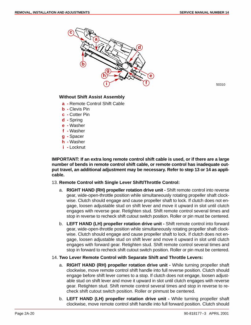
REMOVAL, INSTALLATION AND ADJUSTMENTS SERVICE MANUAL NUMBER 14
Page 2A-20 90-818177--3 APRIL 2001
50310
a
b
c
d
ef
g
i
h
Without Shift Assist Assemblya - Remote Control Shift Cableb - Clevis Pinc - Cotter Pind - Springe - Washerf - Washerg - Spacerh - Washeri - Locknut
IMPORTANT: If an extra long remote control shift cable is used, or if there are a largenumber of bends in remote control shift cable, or remote control has inadequate out-put travel, an additional adjustment may be necessary. Refer to step 13 or 14 as appli-cable.
13. Remote Control with Single Lever Shift/Throttle Control:
a. RIGHT HAND (RH) propeller rotation drive unit - Shift remote control into reversegear, wide-open-throttle position while simultaneously rotating propeller shaft clock-wise. Clutch should engage and cause propeller shaft to lock. If clutch does not en-gage, loosen adjustable stud on shift lever and move it upward in slot until clutchengages with reverse gear. Retighten stud. Shift remote control several times andstop in reverse to recheck shift cutout switch position. Roller or pin must be centered.
b. LEFT HAND (LH) propeller rotation drive unit - Shift remote control into forwardgear, wide-open-throttle position while simultaneously rotating propeller shaft clock-wise. Clutch should engage and cause propeller shaft to lock. If clutch does not en-gage, loosen adjustable stud on shift lever and move it upward in slot until clutchengages with forward gear. Retighten stud. Shift remote control several times andstop in forward to recheck shift cutout switch position. Roller or pin must be centered.
14. Two Lever Remote Control with Separate Shift and Throttle Levers:
a. RIGHT HAND (RH) propeller rotation drive unit - While turning propeller shaftclockwise, move remote control shift handle into full reverse position. Clutch shouldengage before shift lever comes to a stop. If clutch does not engage, loosen adjust-able stud on shift lever and move it upward in slot until clutch engages with reversegear. Retighten stud. Shift remote control several times and stop in reverse to re-check shift cutout switch position. Roller or pinmust be centered.
b. LEFT HAND (LH) propeller rotation drive unit - While turning propeller shaftclockwise, move remote control shift handle into full forward position. Clutch should
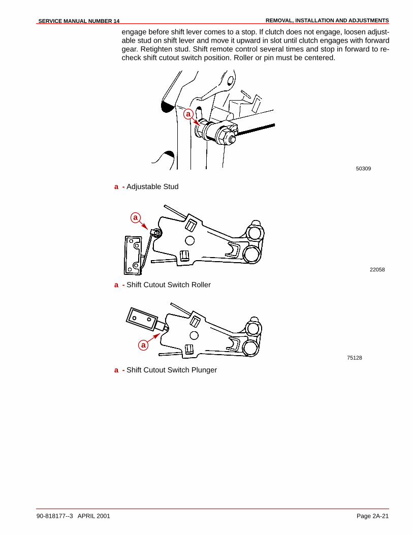
REMOVAL, INSTALLATION AND ADJUSTMENTSSERVICE MANUAL NUMBER 14
90-818177--3 APRIL 2001 Page 2A-21
engage before shift lever comes to a stop. If clutch does not engage, loosen adjust-able stud on shift lever and move it upward in slot until clutch engages with forwardgear. Retighten stud. Shift remote control several times and stop in forward to re-check shift cutout switch position. Roller or pin must be centered.
50309
a
a - Adjustable Stud
22058
a
a - Shift Cutout Switch Roller
75128
a
a - Shift Cutout Switch Plunger
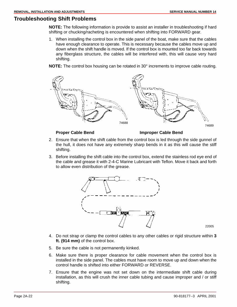
REMOVAL, INSTALLATION AND ADJUSTMENTS SERVICE MANUAL NUMBER 14
Page 2A-22 90-818177--3 APRIL 2001
Troubleshooting Shift ProblemsNOTE: The following information is provide to assist an installer in troubleshooting if hardshifting or chucking/racheting is encountered when shifting into FORWARD gear.
1. When installing the control box in the side panel of the boat, make sure that the cableshave enough clearance to operate. This is necessary because the cables move up anddown when the shift handle is moved. If the control box is mounted too far back towardsany fiberglass structure, the cables will be interfered with, this will cause very hardshifting.
NOTE: The control box housing can be rotated in 30° increments to improve cable routing.
7468874689
Proper Cable Bend Improper Cable Bend
2. Ensure that when the shift cable from the control box is led through the side gunnel ofthe hull, it does not have any extremely sharp bends in it as this will cause the stiffshifting.
3. Before installing the shift cable into the control box, extend the stainless rod eye end ofthe cable and grease it with 2-4-C Marine Lubricant with Teflon. Move it back and forthto allow even distribution of the grease.
22005
4. Do not strap or clamp the control cables to any other cables or rigid structure within 3ft. (914 mm) of the control box.
5. Be sure the cable is not permanently kinked.
6. Make sure there is proper clearance for cable movement when the control box isinstalled in the side panel. The cables must have room to move up and down when thecontrol handle is shifted into either FORWARD or REVERSE.
7. Ensure that the engine was not set down on the intermediate shift cable duringinstallation, as this will crush the inner cable tubing and cause improper and / or stiffshifting.

REMOVAL, INSTALLATION AND ADJUSTMENTSSERVICE MANUAL NUMBER 14
90-818177--3 APRIL 2001 Page 2A-23
8. DO NOT fasten the shift cable with straps or clamps to any other cable within 5 ft. (1524mm) of the shift plate.
9. DO NOT fasten the shift cable to the transom with any type of plastic clips or fastenerswithin 5 ft. (1524 mm) of the shift plate.
10. DO NOT overtighten the throttle or shift cable attaching nuts at the engine end. Barreland cable end must be free to rotate on the mounting stud.
11. Check the intermediate shift cable routing from the transom assembly to the shift plateas follows:
a. The cable should come through the transom, above the exhaust pipe and make aturn towards the starboard side of the boat between the exhaust pipe and the engineflywheel housing.
b. The cable should then be routed under the starboard rear engine mount, and turntowards the transom.
c. Then go up behind the power steering valve and loop over to the shift plate on theengine, where it is connected to the anchor points on the shift plate.
Following this routing will prevent the engine coupler from damaging the cable.
74903
74901
4 Cylinder Inline Model V6 and V8 Models
Propeller Installation
WARNINGBe sure that remote control is in the neutral position and ignition key is removedfrom switch.
WARNINGPlace a block of wood between the antiventilation plate to protect hands from pro-peller blades and to prevent propeller from turning.
1. To aid in future propeller removal, liberally coat the propeller shaft splines with one ofthe following lubricants; then, install propeller.
• Special Lubricant 101
• 2-4-C Marine Lubricant with Teflon
• Perfect Seal
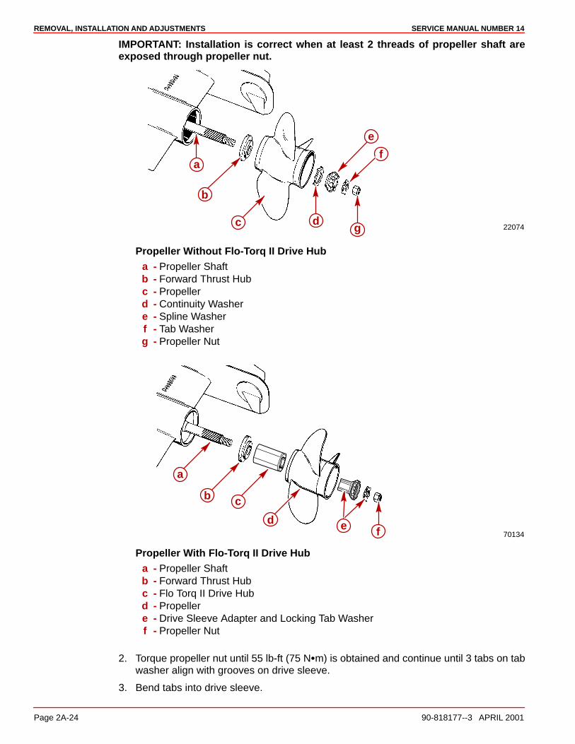
REMOVAL, INSTALLATION AND ADJUSTMENTS SERVICE MANUAL NUMBER 14
Page 2A-24 90-818177--3 APRIL 2001
IMPORTANT: Installation is correct when at least 2 threads of propeller shaft areexposed through propeller nut.
22074
f
g
e
dc
b
a
Propeller Without Flo-Torq II Drive Huba - Propeller Shaftb - Forward Thrust Hubc - Propellerd - Continuity Washere - Spline Washerf - Tab Washerg - Propeller Nut
70134
a
b c
d e f
Propeller With Flo-Torq II Drive Huba - Propeller Shaftb - Forward Thrust Hubc - Flo Torq II Drive Hubd - Propellere - Drive Sleeve Adapter and Locking Tab Washerf - Propeller Nut
2. Torque propeller nut until 55 lb-ft (75 N�m) is obtained and continue until 3 tabs on tabwasher align with grooves on drive sleeve.
3. Bend tabs into drive sleeve.

REMOVAL, INSTALLATION AND ADJUSTMENTSSERVICE MANUAL NUMBER 14
90-818177--3 APRIL 2001 Page 2A-25
Transom Assembly Removal
Power Steering ModelsNOTE: If Tie Bars need to be removed or serviced see section 6A or 6B.
1. Remove the power steering assembly..
a. Disconnect clevis from steering lever.
b. Disconnect steering cable from clevis.
71901
22023
d
b
a
a
g
g
b
c c
d
e
ff
h
i
Earlier Model Control Valve Later Model Control Valve. . . . . . . . . . . a - Cable Endb - Clevisc - Cotter Pind - Clevis Pine - Locking Platef - Cable Retaining Nutg - Steering Leverh - Cotter Pini - Clevis Pin
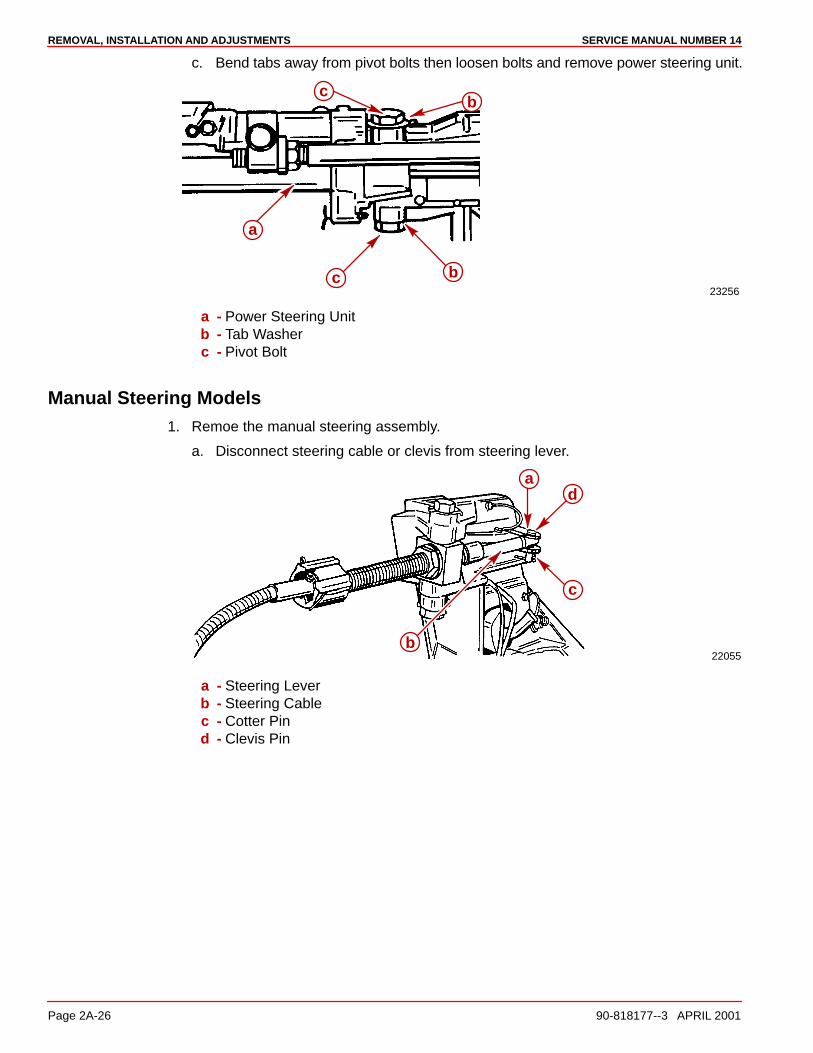
REMOVAL, INSTALLATION AND ADJUSTMENTS SERVICE MANUAL NUMBER 14
Page 2A-26 90-818177--3 APRIL 2001
c. Bend tabs away from pivot bolts then loosen bolts and remove power steering unit.
23256
a
c
c
b
b
a - Power Steering Unitb - Tab Washerc - Pivot Bolt
Manual Steering Models1. Remoe the manual steering assembly.
a. Disconnect steering cable or clevis from steering lever.
22055
ad
c
b
a - Steering Leverb - Steering Cablec - Cotter Pind - Clevis Pin
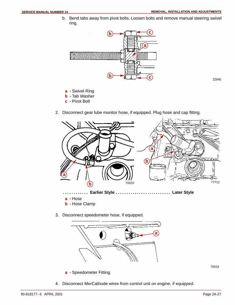
REMOVAL, INSTALLATION AND ADJUSTMENTSSERVICE MANUAL NUMBER 14
90-818177--3 APRIL 2001 Page 2A-27
b. Bend tabs away from pivot bolts. Loosen bolts and remove manual steering swivelring.
22945
b
b
c
c
a
a - Swivel Ringb - Tab Washerc - Pivot Bolt
2. Disconnect gear lube monitor hose, if equipped. Plug hose and cap fitting.
77712
a
b
a
b 70023
Earlier Style Later Style. . . . . . . . . . . . . . . . . . . . . . . . . . . . . . . . . . . . . . a - Hoseb - Hose Clamp
3. Disconnect speedometer hose, if equipped.
70015
a
a - Speedometer Fitting
4. Disconnect MerCathode wires from control unit on engine, if equipped.

REMOVAL, INSTALLATION AND ADJUSTMENTS SERVICE MANUAL NUMBER 14
Page 2A-28 90-818177--3 APRIL 2001
5. Disconnect trim limit switch wires at trim pump and trim position sender wires at engine.
6. For engine removal, refer to appropriate engine service manual.
7. Disconnect power trim hydraulic hoses from trim pump. Cap hoses and plug pump fittingholes.
22031a
b
c
a - Sta-Strapb - Trim Limit Switch Wiresc - Hydraulic Hoses

REMOVAL, INSTALLATION AND ADJUSTMENTSSERVICE MANUAL NUMBER 14
90-818177--3 APRIL 2001 Page 2A-29
8. If installed, remove exhaust pipe.
70068
a
b
In-line 4 Cylinder Models
22057
ab
V6/V8 Modelsa - Exhaust Pipeb - Screws
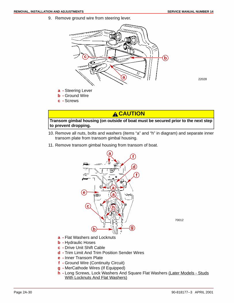
REMOVAL, INSTALLATION AND ADJUSTMENTS SERVICE MANUAL NUMBER 14
Page 2A-30 90-818177--3 APRIL 2001
9. Remove ground wire from steering lever.
22028
b
a
c
a - Steering Leverb - Ground Wirec - Screws
CAUTIONTransom gimbal housing (on outside of boat must be secured prior to the next stepto prevent dropping.
10. Remove all nuts, bolts and washers (items “a” and “h” in diagram) and separate innertransom plate from transom gimbal housing.
11. Remove transom gimbal housing from transom of boat.
70012
g
f
d
f
b
c
a
h
aae
a - Flat Washers and Locknutsb - Hydraulic Hosesc - Drive Unit Shift Cabled - Trim Limit And Trim Position Sender Wirese - Inner Transom Platef - Ground Wire (Continuity Circuit)g - MerCathode Wires (If Equipped)h - Long Screws, Lock Washers And Square Flat Washers (Later Models - Studs
With Locknuts And Flat Washers)
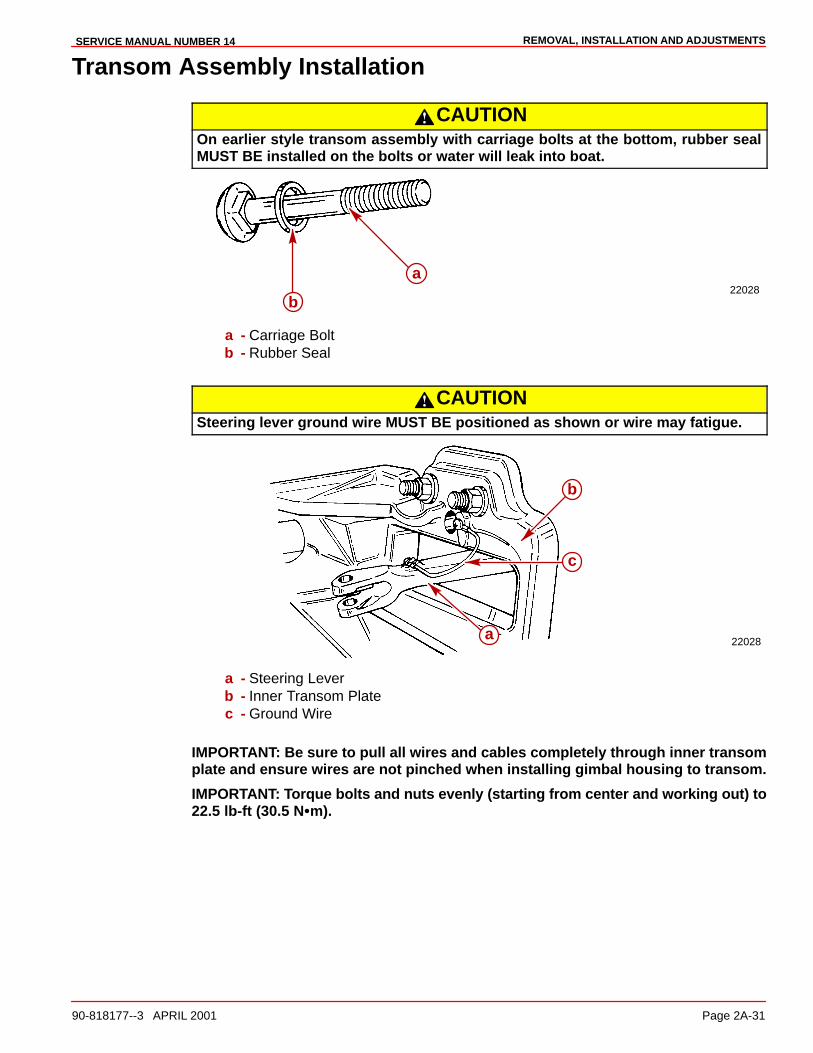
REMOVAL, INSTALLATION AND ADJUSTMENTSSERVICE MANUAL NUMBER 14
90-818177--3 APRIL 2001 Page 2A-31
Transom Assembly Installation
CAUTIONOn earlier style transom assembly with carriage bolts at the bottom, rubber sealMUST BE installed on the bolts or water will leak into boat.
22028b
a
a - Carriage Boltb - Rubber Seal
CAUTIONSteering lever ground wire MUST BE positioned as shown or wire may fatigue.
22028
c
b
a
a - Steering Leverb - Inner Transom Platec - Ground Wire
IMPORTANT: Be sure to pull all wires and cables completely through inner transomplate and ensure wires are not pinched when installing gimbal housing to transom.
IMPORTANT: Torque bolts and nuts evenly (starting from center and working out) to22.5 lb-ft (30.5 N�m).
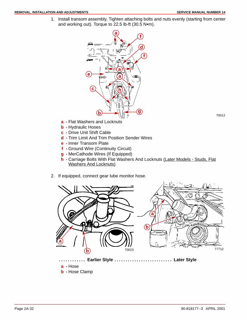
REMOVAL, INSTALLATION AND ADJUSTMENTS SERVICE MANUAL NUMBER 14
Page 2A-32 90-818177--3 APRIL 2001
1. Install transom assembly. Tighten attaching bolts and nuts evenly (starting from centerand working out). Torque to 22.5 lb-ft (30.5 N�m).
70012g
f
d
f
b
c
e
a
h
aa
a - Flat Washers and Locknutsb - Hydraulic Hosesc - Drive Unit Shift Cabled - Trim Limit And Trim Position Sender Wirese - Inner Transom Platef - Ground Wire (Continuity Circuit)g - MerCathode Wires (If Equipped)h - Carriage Bolts With Flat Washers And Locknuts (Later Models - Studs, Flat
Washers And Locknuts)
2. If equipped, connect gear lube monitor hose.
77712
a
b
a
b 70023
Earlier Style Later Style. . . . . . . . . . . . . . . . . . . . . . . . . . . . . . . . . . . . . . a - Hoseb - Hose Clamp
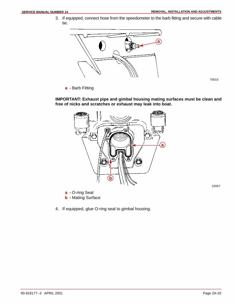
REMOVAL, INSTALLATION AND ADJUSTMENTSSERVICE MANUAL NUMBER 14
90-818177--3 APRIL 2001 Page 2A-33
3. If equipped, connect hose from the speedometer to the barb fitting and secure with cabletie.
70015
a
a - Barb Fitting
IMPORTANT: Exhaust pipe and gimbal housing mating surfaces must be clean andfree of nicks and scratches or exhaust may leak into boat.
22057
a
b
a - O-ring Sealb - Mating Surface
4. If equipped, glue O-ring seal to gimbal housing.

REMOVAL, INSTALLATION AND ADJUSTMENTS SERVICE MANUAL NUMBER 14
Page 2A-34 90-818177--3 APRIL 2001
5. Install exhaust pipe or block off plate on gimbal housing. Torque screws to 22.5 lb-ft(30.5 Nm).
70068
a
b
In-line 4 Cylinder Models
22057
ab
V6/V8 Modelsa - Exhaust Pipeb - Screws
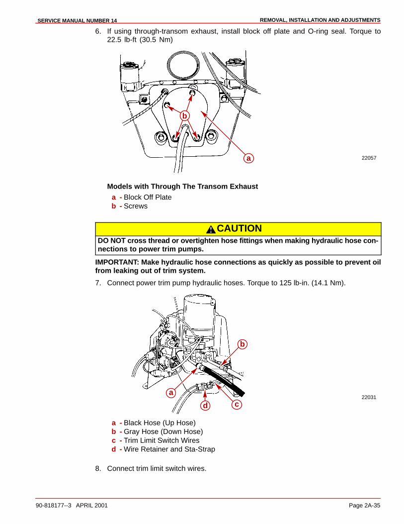
REMOVAL, INSTALLATION AND ADJUSTMENTSSERVICE MANUAL NUMBER 14
90-818177--3 APRIL 2001 Page 2A-35
6. If using through-transom exhaust, install block off plate and O-ring seal. Torque to22.5 lb-ft (30.5 Nm)
22057a
b
Models with Through The Transom Exhausta - Block Off Plateb - Screws
CAUTIONDO NOT cross thread or overtighten hose fittings when making hydraulic hose con-nections to power trim pumps.
IMPORTANT: Make hydraulic hose connections as quickly as possible to prevent oilfrom leaking out of trim system.
7. Connect power trim pump hydraulic hoses. Torque to 125 lb-in. (14.1 Nm).
22031a
b
d c
a - Black Hose (Up Hose)b - Gray Hose (Down Hose)c - Trim Limit Switch Wiresd - Wire Retainer and Sta-Strap
8. Connect trim limit switch wires.
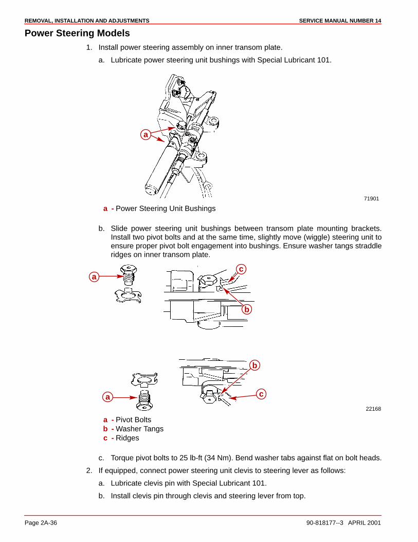
REMOVAL, INSTALLATION AND ADJUSTMENTS SERVICE MANUAL NUMBER 14
Page 2A-36 90-818177--3 APRIL 2001
Power Steering Models1. Install power steering assembly on inner transom plate.
a. Lubricate power steering unit bushings with Special Lubricant 101.
71901
a
a - Power Steering Unit Bushings
b. Slide power steering unit bushings between transom plate mounting brackets.Install two pivot bolts and at the same time, slightly move (wiggle) steering unit toensure proper pivot bolt engagement into bushings. Ensure washer tangs straddleridges on inner transom plate.
22168
a
b
c
a c
b
a - Pivot Boltsb - Washer Tangsc - Ridges
c. Torque pivot bolts to 25 lb-ft (34 Nm). Bend washer tabs against flat on bolt heads.
2. If equipped, connect power steering unit clevis to steering lever as follows:
a. Lubricate clevis pin with Special Lubricant 101.
b. Install clevis pin through clevis and steering lever from top.

REMOVAL, INSTALLATION AND ADJUSTMENTSSERVICE MANUAL NUMBER 14
90-818177--3 APRIL 2001 Page 2A-37
c. Secure clevis pin with cotter pin. Bend both ends of cotter pin.
70019
b
a d
c
a - Clevis Pinb - Clevisc - Steering Leverd - Cotter Pin
WARNINGFailure to use a steering cable locking device could cause a loss of steering, whichcould cause damage to the boat and/or injury.
All current production Quicksilver Ride Guide steering cables have a self-locking couplernut and do not require an external locking device. (Other cable manufacturers also makecables with a self-locking coupler nut.)
3. Install steering cable.
a. Lubricate steering cable end with a liberal amount of Special Lubricant 101 andinstall cable end through guide tube.
b. Later Model Control Valve: Using a suitable wrench, hold the flat surfaces on thecable guide tube in the vertical position.
73901
a
cb
Later Model Control Valvea - Flat (Hold Vertical)b - Suitable Wrenchc - Guide Tube
c. Both Models: Connect cable end to clevis with clevis pin. Secure clevis pin in cleviswith cotter pin. Bend both ends of cotter pin.
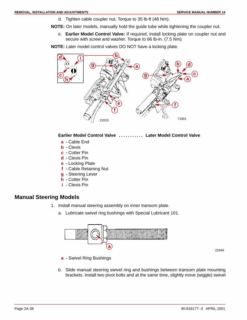
REMOVAL, INSTALLATION AND ADJUSTMENTS SERVICE MANUAL NUMBER 14
Page 2A-38 90-818177--3 APRIL 2001
d. Tighten cable coupler nut. Torque to 35 lb-ft (48 Nm).
NOTE: On later models, manually hold the guide tube while tightening the coupler nut.
e. Earlier Model Control Valve: If required, install locking plate on coupler nut andsecure with screw and washer. Torque to 66 lb-in. (7.5 Nm).
NOTE: Later model control valves DO NOT have a locking plate.
7190122023
d
b
a
a
g
g
b
c c
d
ef
f
h
i
Earlier Model Control Valve Later Model Control Valve. . . . . . . . . . . a - Cable Endb - Clevisc - Cotter Pind - Clevis Pine - Locking Platef - Cable Retaining Nutg - Steering Leverh - Cotter Pini - Clevis Pin
Manual Steering Models1. Install manual steering assembly on inner transom plate.
a. Lubricate swivel ring bushings with Special Lubricant 101.
22946a
a - Swivel Ring Bushings
b. Slide manual steering swivel ring and bushings between transom plate mountingbrackets. Install two pivot bolts and at the same time, slightly move (wiggle) swivel

REMOVAL, INSTALLATION AND ADJUSTMENTSSERVICE MANUAL NUMBER 14
90-818177--3 APRIL 2001 Page 2A-39
ring to ensure proper pivot bolt engagement into swivel ring bushings. Ensurewasher tangs straddle ridges on inner transom plate.
22168
a
b
c
a c
b
a - Pivot Boltsb - Washer Tangsc - Ridges
c. Torque pivot bolts to 25 lb-ft (34 Nm). Bend washer tabs against flat on bolt heads.
2. Install steering cable.
a. Lubricate steering cable end with a liberal amount of Special Lubricant 101 andinstall cable end through guide tube.
b. Connect steering cable to steering lever and secure with clevis pin and cotter pin.Spread both ends of cotter pin.
c. Tighten coupler nut. Torque to 35 lb-ft (48 Nm).
70373
f
g
a
b
c
d e
a - Steering Cableb - Cable Coupler Nutc - Steering Cable Guide Tubed - Steering Cable Ende - Cotter Pinf - Clevis Ping - Steering Lever

REMOVAL, INSTALLATION AND ADJUSTMENTS SERVICE MANUAL NUMBER 14
Page 2A-40 90-818177--3 APRIL 2001
THIS PAGE IS INTENTIONALLY BLANK

3A
DRIVE SHAFT HOUSINGSERVICE MANUAL NUMBER 14
90-818177--3 APRIL 2001 Page 3A-1
STERNDRIVE UNITSection 3A - Drive Shaft Housing
Table of Contents
Specifications 3A-2. . . . . . . . . . . . . . . . . . . . . . . Torque Specifications 3A-2. . . . . . . . . . . . . Upper Drive Shaft Bearing Preload 3A-2. . U-joint Bearing Preload 3A-2. . . . . . . . . . . . Gear Shimming Specifications 3A-2. . . . . . Lubricants/Sealers/Adhesives 3A-3. . . . . . Special Tools 3A-3. . . . . . . . . . . . . . . . . . . . .
Drive Shaft Housing Exploded Parts View 3A-4. . . . . . . . . . . . . . . . . . . . . . . . . . . . . .
U-joint and Driven Gear Components 3A-4. . . . . . . . . . . . . . . . . . . . Drive Shaft Components 3A-6. . . . . . . . . . .
Special Information 3A-7. . . . . . . . . . . . . . . . . . Top Cover Bearing Cup 3A-7. . . . . . . . . . . . Universal Joint Bearing Set 3A-7. . . . . . . .
Drive Shaft Housing/Gear Housing 3A-7. . . . Separation 3A-7. . . . . . . . . . . . . . . . . . . . . . .
Drive Shaft Housing and Component Disassembly 3A-9. . . . . . . . . . . . . . . . . . . . . . .
Drive Unit Gear Ratio Identification 3A-9. . Drive Shaft Housing Cleaning and Inspection 3A-15. . . . . . . . . . . . . . . . . . . . . . . . .
U-joint Assembly - Inspection and Disassembly 3A-15. . . . . . . . . . . . . . . . . . . . Oil Seal Carrier Subassembly 3A-17. . . . . . Pinion Gear Subassembly 3A-18. . . . . . . . . U-joint Subassembly 3A-21. . . . . . . . . . . . . . U-joint Assembly 3A-24. . . . . . . . . . . . . . . . . Top Cover Subassembly 3A-26. . . . . . . . . . . Upper Driven Gear Subassembly 3A-29. . .
Drive Shaft Housing Reassembly 3A-33. . . . . . Drive Shaft Housing Inspection 3A-33. . . . . Installation 3A-33. . . . . . . . . . . . . . . . . . . . . . . Assembly and Checking Driven Gear Location 3A-35. . . . . . . . . . . . . . . . . . . Adjusting Gear Location 3A-38. . . . . . . . . . . Seal Installation 3A-39. . . . . . . . . . . . . . . . . . Checking and Adjusting Drive Gear Location 3A-43. . . . . . . . . . . . . . . . . . .
Final Reassembly 3A-45. . . . . . . . . . . . . . . . . . . Joining Drive Shaft Housing/Gear Housing 3A-47. . . . . . . . . . . . . . . . . . . . . . . . . . .
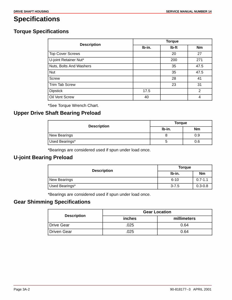
DRIVE SHAFT HOUSING SERVICE MANUAL NUMBER 14
Page 3A-2 90-818177--3 APRIL 2001
Specifications
Torque Specifications
TorqueDescription
lb-in. lb-ft Nm
Top Cover Screws 20 27
U-joint Retainer Nut* 200 271
Nuts, Bolts And Washers 35 47.5
Nut 35 47.5
Screw 28 41
Trim Tab Screw 23 31
Dipstick 17.5 2
Oil Vent Screw 40 4
*See Torque Wrench Chart.
Upper Drive Shaft Bearing Preload
TorqueDescription
lb-in. Nm
New Bearings 8 0.9
Used Bearings* 5 0.6
*Bearings are considered used if spun under load once.
U-joint Bearing Preload
TorqueDescription
lb-in. Nm
New Bearings 6-10 0.7-1.1
Used Bearings* 3-7.5 0.3-0.8
*Bearings are considered used if spun under load once.
Gear Shimming Specifications
Gear LocationDescription
inches millimeters
Drive Gear .025 0.64
Driven Gear .025 0.64

DRIVE SHAFT HOUSINGSERVICE MANUAL NUMBER 14
90-818177--3 APRIL 2001 Page 3A-3
Lubricants/Sealers/Adhesives
Description Part Number
Quicksilver 2-4-C Marine LubricantWithTeflon
92-825407A12
Quicksilver U-jointAnd Gimbal Bearing-Grease
92-828052A2
3M Brand Adhesive 92-86166-1
Quicksilver Needle Bearing AssemblyLubricant
92-825265A1
Quicksilver Perfect Seal 92-34227-1
Permatex Ultra Blue Silicone Sealant Obtain Locally
Quicksilver Special Lubricant 101 92-13872A1
Quicksilver High Performance Gear Lube 92-816026A4
Special Tools
Description Part Number
U-joint Adaptor 91-38756
Bearing Cup Driver 91-38918
Bearing Cup Driver 91-808053
Bearing Cup Driver 91-33493
Bearing Cup Driver 91-36577
Driver Rod 91-37323
Driver Tool 91-90774
Oil Seal Driver 91-817570
Shimming Tool (Driven Gear) 91-60526
Shimming Tool (Driven Gear) 91-854377
Shimming Tool (Drive Gear) 91-60523
Slide Hammer Puller 91-34569A1
Torque Wrench (lb-in.) 91-66274
U-joint Bearing Retainer Wrench 91-17256
Universal Puller Plate 91-37241
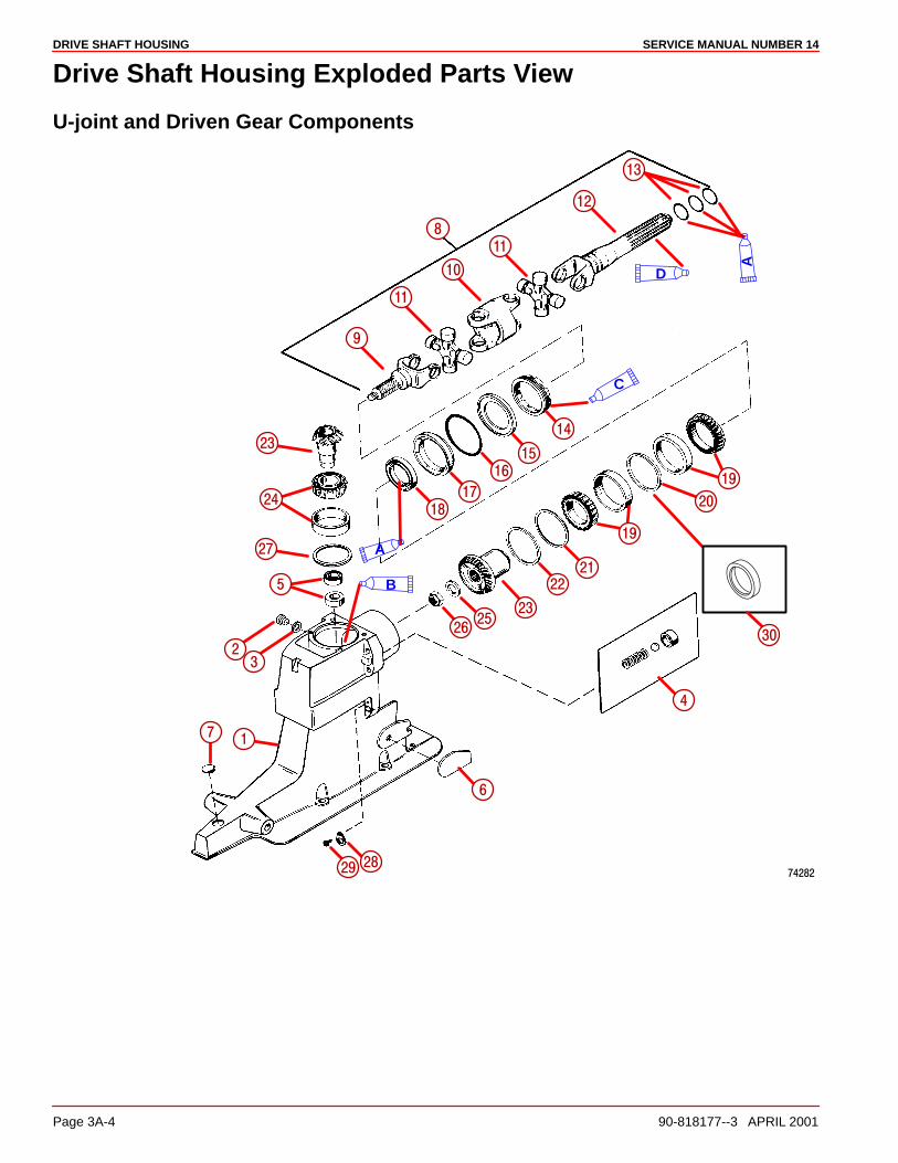
DRIVE SHAFT HOUSING SERVICE MANUAL NUMBER 14
Page 3A-4 90-818177--3 APRIL 2001
Drive Shaft Housing Exploded Parts View
U-joint and Driven Gear Components
�����
�
��
��
��
��
��
��
��
�
��
��
�
��
��
�
�
�
�
��
��
��
��
���
��
���
��
�
��
B
D
A
A
C

DRIVE SHAFT HOUSINGSERVICE MANUAL NUMBER 14
90-818177--3 APRIL 2001 Page 3A-5
1 - Drive Shaft Housing2 - Screw3 - O-ring Or Washer4 - Spring Assembly5 - Oil Seal6 - Wear Pad7 - Plug8 - Universal Joint9 - Yoke, Universal Joint-gear End
10 - Socket, Center-universal Joint11 - Cross And Bearing12 - Yoke Assembly, Universal Joint-cou-
pling End13 - O-ring14 - Retainer15 - Ring
16 - O-ring17 - Carrier Assembly18 - Oil Seal19 - Roller Bearing And Cups20 - Spacer Cup (S/N Prior To 0L100009)21 - Shim22 - Shim23 - Drive Gear Assembly24 - Roller Bearing And Cup25 - Washer26 - Nut27 - Shims28 - Ground Plate29 - Screw30 - Spacer Cup (S/N 0L100009 And
Above)
Lubricants/Sealers/Adhesives
NOTE: Fill Drive With High Performance Gear Lube
A A - 2-4-C Marine Lubricant With Teflon
A B - Quicksilver High Performance Gear Lube
A C- Special Lubricant 101
D - Quicksilver Engine Coupler Spline Grease
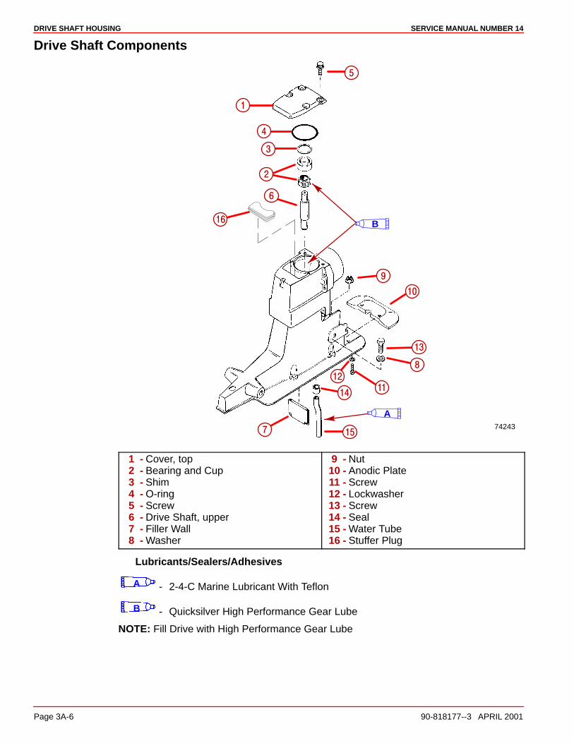
DRIVE SHAFT HOUSING SERVICE MANUAL NUMBER 14
Page 3A-6 90-818177--3 APRIL 2001
Drive Shaft Components
74243
��
��
��
��
��
��
�
�
�
�
�
�
�
�
B
A
1 - Cover, top2 - Bearing and Cup3 - Shim4 - O-ring5 - Screw6 - Drive Shaft, upper7 - Filler Wall8 - Washer
9 - Nut10 - Anodic Plate11 - Screw12 - Lockwasher13 - Screw14 - Seal15 - Water Tube16 - Stuffer Plug
Lubricants/Sealers/Adhesives
A - 2-4-C Marine Lubricant With Teflon
B - Quicksilver High Performance Gear Lube
NOTE: Fill Drive with High Performance Gear Lube
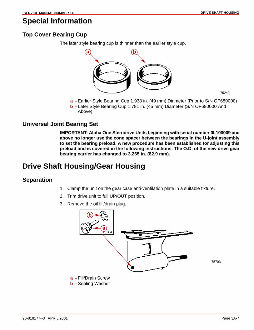
DRIVE SHAFT HOUSINGSERVICE MANUAL NUMBER 14
90-818177--3 APRIL 2001 Page 3A-7
Special Information
Top Cover Bearing CupThe later style bearing cup is thinner than the earlier style cup.
75240
a b
a - Earlier Style Bearing Cup 1.938 in. (49 mm) Diameter (Prior to S/N OF680000)b - Later Style Bearing Cup 1.781 in. (45 mm) Diameter (S/N OF680000 And
Above)
Universal Joint Bearing SetIMPORTANT: Alpha One Sterndrive Units beginning with serial number 0L100009 andabove no longer use the cone spacer between the bearings in the U-joint assemblyto set the bearing preload. A new procedure has been established for adjusting thispreload and is covered in the following instructions. The O.D. of the new drive gearbearing carrier has changed to 3.265 in. (82.9 mm).
Drive Shaft Housing/Gear Housing
Separation1. Clamp the unit on the gear case anti-ventilation plate in a suitable fixture.
2. Trim drive unit to full UP/OUT position.
3. Remove the oil fill/drain plug.
75703
23264a
b
a - Fill/Drain Screwb - Sealing Washer
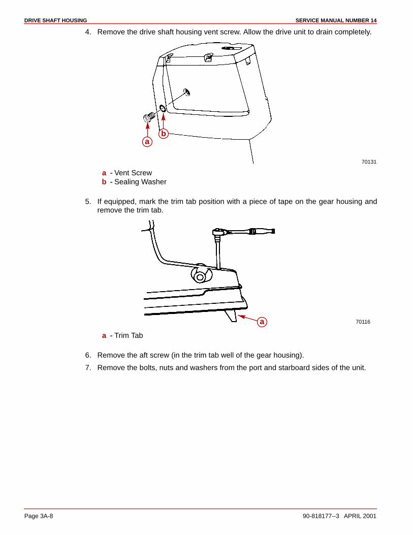
DRIVE SHAFT HOUSING SERVICE MANUAL NUMBER 14
Page 3A-8 90-818177--3 APRIL 2001
4. Remove the drive shaft housing vent screw. Allow the drive unit to drain completely.
70131
ab
a - Vent Screwb - Sealing Washer
5. If equipped, mark the trim tab position with a piece of tape on the gear housing andremove the trim tab.
70116a
a - Trim Tab
6. Remove the aft screw (in the trim tab well of the gear housing).
7. Remove the bolts, nuts and washers from the port and starboard sides of the unit.
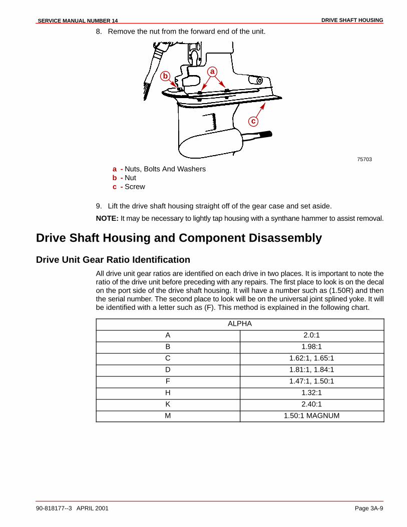
DRIVE SHAFT HOUSINGSERVICE MANUAL NUMBER 14
90-818177--3 APRIL 2001 Page 3A-9
8. Remove the nut from the forward end of the unit.
75703
b a
c
a - Nuts, Bolts And Washersb - Nutc - Screw
9. Lift the drive shaft housing straight off of the gear case and set aside.
NOTE: It may be necessary to lightly tap housing with a synthane hammer to assist removal.
Drive Shaft Housing and Component Disassembly
Drive Unit Gear Ratio IdentificationAll drive unit gear ratios are identified on each drive in two places. It is important to note theratio of the drive unit before preceding with any repairs. The first place to look is on the decalon the port side of the drive shaft housing. It will have a number such as (1.50R) and thenthe serial number. The second place to look will be on the universal joint splined yoke. It willbe identified with a letter such as (F). This method is explained in the following chart.
ALPHA
A 2.0:1
B 1.98:1
C 1.62:1, 1.65:1
D 1.81:1, 1.84:1
F 1.47:1, 1.50:1
H 1.32:1
K 2.40:1
M 1.50:1 MAGNUM
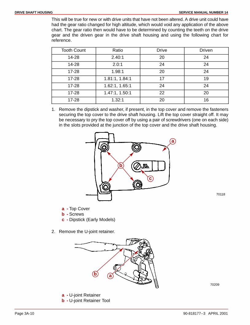
DRIVE SHAFT HOUSING SERVICE MANUAL NUMBER 14
Page 3A-10 90-818177--3 APRIL 2001
This will be true for new or with drive units that have not been altered. A drive unit could havehad the gear ratio changed for high altitude, which would void any application of the abovechart. The gear ratio then would have to be determined by counting the teeth on the drivegear and the driven gear in the drive shaft housing and using the following chart forreference.
Tooth Count Ratio Drive Driven
14-28 2.40:1 20 24
14-28 2.0:1 24 24
17-28 1.98:1 20 24
17-28 1.81:1, 1.84:1 17 19
17-28 1.62:1, 1.65:1 24 24
17-28 1.47:1, 1.50:1 22 20
17-28 1.32:1 20 16
1. Remove the dipstick and washer, if present, in the top cover and remove the fastenerssecuring the top cover to the drive shaft housing. Lift the top cover straight off. It maybe necessary to pry the top cover off by using a pair of screwdrivers (one on each side)in the slots provided at the junction of the top cover and the drive shaft housing.
70118
c
a
b
a - Top Coverb - Screwsc - Dipstick (Early Models)
2. Remove the U-joint retainer.
70209
ab
a - U-joint Retainerb - U-joint Retainer Tool
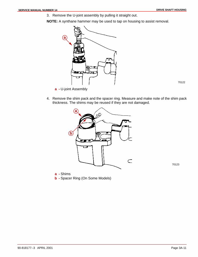
DRIVE SHAFT HOUSINGSERVICE MANUAL NUMBER 14
90-818177--3 APRIL 2001 Page 3A-11
3. Remove the U-joint assembly by pulling it straight out.
NOTE: A synthane hammer may be used to tap on housing to assist removal.
70122
a
a - U-joint Assembly
4. Remove the shim pack and the spacer ring. Measure and make note of the shim packthickness. The shims may be reused if they are not damaged.
70123
a
b
a - Shimsb - Spacer Ring (On Some Models)
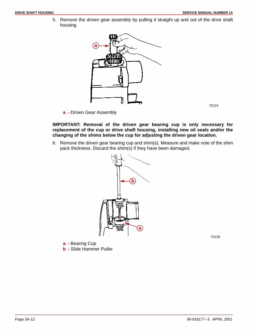
DRIVE SHAFT HOUSING SERVICE MANUAL NUMBER 14
Page 3A-12 90-818177--3 APRIL 2001
5. Remove the driven gear assembly by pulling it straight up and out of the drive shafthousing.
70124
a
a - Driven Gear Assembly
IMPORTANT: Removal of the driven gear bearing cup is only necessary forreplacement of the cup or drive shaft housing, installing new oil seals and/or thechanging of the shims below the cup for adjusting the driven gear location.
6. Remove the driven gear bearing cup and shim(s). Measure and make note of the shimpack thickness. Discard the shim(s) if they have been damaged.
70128
a
b
a - Bearing Cupb - Slide Hammer Puller

DRIVE SHAFT HOUSINGSERVICE MANUAL NUMBER 14
90-818177--3 APRIL 2001 Page 3A-13
7. Remove the water tube from the drive shaft housing.
70126
b
a
a - Water Tubeb - Drive Shaft Housing
8. Remove the rubber seal from the drive shaft housing.
70125
a
b
a - Rubber Sealb - Drive Shaft Housing
CAUTIONEye protection must be worn when performing the following procedure. Failure todo so may cause personal injury.

DRIVE SHAFT HOUSING SERVICE MANUAL NUMBER 14
Page 3A-14 90-818177--3 APRIL 2001
9. Remove the drive shaft housing oil seals as shown in the figure below.
70129
a
b
a - Oil Seals (2)b - Suitable Tool
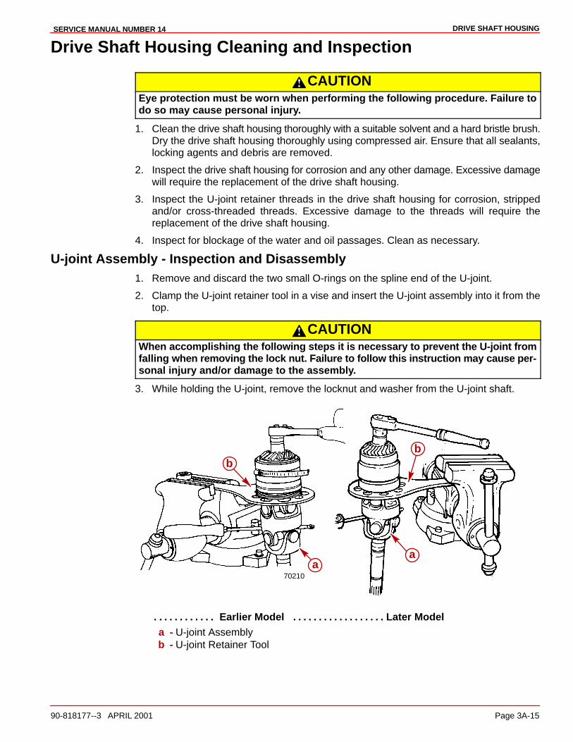
DRIVE SHAFT HOUSINGSERVICE MANUAL NUMBER 14
90-818177--3 APRIL 2001 Page 3A-15
Drive Shaft Housing Cleaning and Inspection
CAUTIONEye protection must be worn when performing the following procedure. Failure todo so may cause personal injury.
1. Clean the drive shaft housing thoroughly with a suitable solvent and a hard bristle brush.Dry the drive shaft housing thoroughly using compressed air. Ensure that all sealants,locking agents and debris are removed.
2. Inspect the drive shaft housing for corrosion and any other damage. Excessive damagewill require the replacement of the drive shaft housing.
3. Inspect the U-joint retainer threads in the drive shaft housing for corrosion, strippedand/or cross-threaded threads. Excessive damage to the threads will require thereplacement of the drive shaft housing.
4. Inspect for blockage of the water and oil passages. Clean as necessary.
U-joint Assembly - Inspection and Disassembly1. Remove and discard the two small O-rings on the spline end of the U-joint.
2. Clamp the U-joint retainer tool in a vise and insert the U-joint assembly into it from thetop.
CAUTIONWhen accomplishing the following steps it is necessary to prevent the U-joint fromfalling when removing the lock nut. Failure to follow this instruction may cause per-sonal injury and/or damage to the assembly.
3. While holding the U-joint, remove the locknut and washer from the U-joint shaft.
70210a
bb
a
Earlier Model Later Model. . . . . . . . . . . . . . . . . . . . . . . . . . . . . . a - U-joint Assemblyb - U-joint Retainer Tool

DRIVE SHAFT HOUSING SERVICE MANUAL NUMBER 14
Page 3A-16 90-818177--3 APRIL 2001
CAUTIONEye protection must be worn when performing the following procedure. Failure todo so may cause personal injury.
4. Remove gear and bearing assembly from shaft.
5. Remove bearings from gear and ensure that the bearing cones and cups remaintogether as a set utilizing a piece of wire to keep them together.
IMPORTANT: After disassembly inspect the bearing cones and cups for damage thatmay have occurred during removal from the gear. If either of the bearing cups orcones have been damaged, it will be necessary to replace both bearing cups and bothbearing cones.
22393
a
b
c
a - Gear/Bearing Assemblyb - Universal Puller Platec - Suitable Mandrel
6. Clean all components with a suitable solvent and dry them thoroughly usingcompressed air.
7. Inspect the pinion gear bearings by rotating them by hand. Rough, uneven movementor a loose condition indicates the need for replacement of the bearings and cups.
8. Inspect the large O-ring around the oil seal carrier for damage or excessivecompression. Replace the O-ring if it is found to be defective.
9. Inspect the gear for pitting, chipped or broken teeth, hairline fractures and excessive oruneven wear. Replace both the drive (pinion) gear and the driven gear if any of theseconditions exist.
10. Inspect the U-joint retainer for damage, cracks and/or broken or corroded threads.Replace it if any of these conditions are found.

DRIVE SHAFT HOUSINGSERVICE MANUAL NUMBER 14
90-818177--3 APRIL 2001 Page 3A-17
11. Inspect the thrust ring for cracks, damage and/or excessive wear. Replace it if any arefound.
23010abcd e
f
a - Retainerb - Thrust Ringc - O-ring, Larged - Oil Seal Carriere - U-jointf - O-rings
Oil Seal Carrier SubassemblyINSPECTION AND DISASSEMBLY
1. Inspect the oil seal carrier and oil seal for damage or excessive wear. If the carrier isfound to be defective, replace the carrier and the oil seal as a unit. If only the oil seal isfound to be defective, replace it as outlined.
a. Remove the U-joint oil seal from the oil seal carrier using a punch and a hammer.
23009
a
b
a - Oil Sealb - Oil Seal Carrier
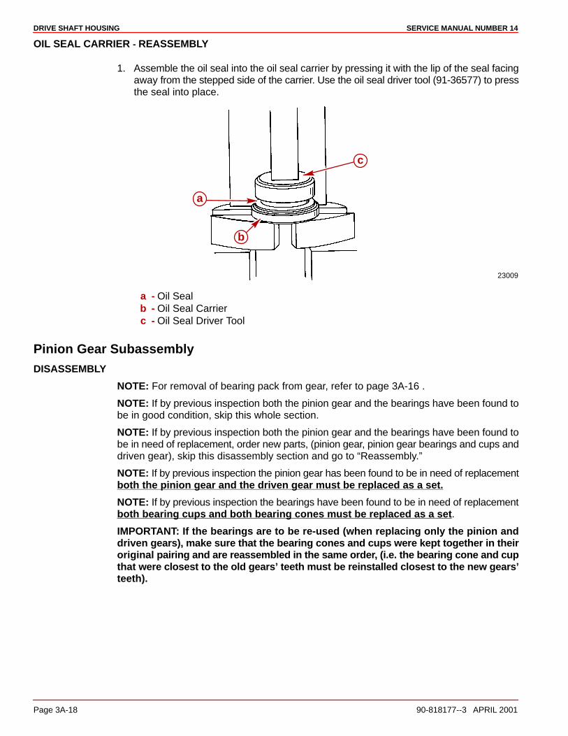
DRIVE SHAFT HOUSING SERVICE MANUAL NUMBER 14
Page 3A-18 90-818177--3 APRIL 2001
OIL SEAL CARRIER - REASSEMBLY
1. Assemble the oil seal into the oil seal carrier by pressing it with the lip of the seal facingaway from the stepped side of the carrier. Use the oil seal driver tool (91-36577) to pressthe seal into place.
23009
a
c
b
a - Oil Sealb - Oil Seal Carrierc - Oil Seal Driver Tool
Pinion Gear SubassemblyDISASSEMBLY
NOTE: For removal of bearing pack from gear, refer to page 3A-16 .
NOTE: If by previous inspection both the pinion gear and the bearings have been found tobe in good condition, skip this whole section.
NOTE: If by previous inspection both the pinion gear and the bearings have been found tobe in need of replacement, order new parts, (pinion gear, pinion gear bearings and cups anddriven gear), skip this disassembly section and go to “Reassembly.”
NOTE: If by previous inspection the pinion gear has been found to be in need of replacementboth the pinion gear and the driven gear must be replaced as a set.
NOTE: If by previous inspection the bearings have been found to be in need of replacementboth bearing cups and both bearing cones must be replaced as a set.
IMPORTANT: If the bearings are to be re-used (when replacing only the pinion anddriven gears), make sure that the bearing cones and cups were kept together in theiroriginal pairing and are reassembled in the same order, (i.e. the bearing cone and cupthat were closest to the old gears’ teeth must be reinstalled closest to the new gears’teeth).

DRIVE SHAFT HOUSINGSERVICE MANUAL NUMBER 14
90-818177--3 APRIL 2001 Page 3A-19
REASSEMBLY
IMPORTANT: Lightly lubricate the gears and bearings with Quicksilver HighPerformance Gear Lube before installing. Bearings and gears must be lubricated toobtain accurate preload readings.
1. Press the bearing cone onto the pinion gear until it seats fully against the back side ofthe gear.
22393
a
b
c
a - Driver Tool (91-90774)b - Bearing Conec - Drive Gear
2. Place the bearing cup onto the bearing cone.
3. Place the large bearing spacer onto the bearing cup.
4. Place the second bearing cup onto the spacer.
IMPORTANT: Do not over-press the second bearing cone, as damage to one or bothof the bearings could occur. If an over-pressed condition occurs (the spacer does notmove freely), completely disassemble the bearings from the gear and start again.

DRIVE SHAFT HOUSING SERVICE MANUAL NUMBER 14
Page 3A-20 90-818177--3 APRIL 2001
5. Press the bearing cone (positioned as shown in the next figures) onto the pinion gearuntil the bearing rollers make light contact with the bearing cup.
22393
ab
c
d
Models With Serial Numbers Prior To 0L100009a - Bearing Coneb - Bearing Cupc - Spacer (Must Move Freely)d - Suitable Mandrel - Must Push On Inner Bearing Race
75631
a
bc
d
Models With Serial Numbers 0L100009 and Latera - Bearing Coneb - Bearing Cupc - Spacer (Must Move Freely)d - Suitable Mandrel – Must Push On Inner Bearing Race
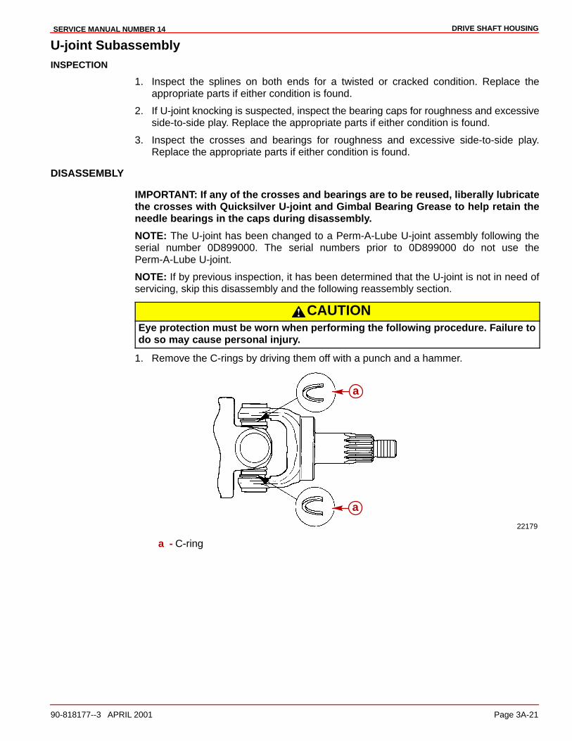
DRIVE SHAFT HOUSINGSERVICE MANUAL NUMBER 14
90-818177--3 APRIL 2001 Page 3A-21
U-joint SubassemblyINSPECTION
1. Inspect the splines on both ends for a twisted or cracked condition. Replace theappropriate parts if either condition is found.
2. If U-joint knocking is suspected, inspect the bearing caps for roughness and excessiveside-to-side play. Replace the appropriate parts if either condition is found.
3. Inspect the crosses and bearings for roughness and excessive side-to-side play.Replace the appropriate parts if either condition is found.
DISASSEMBLY
IMPORTANT: If any of the crosses and bearings are to be reused, liberally lubricatethe crosses with Quicksilver U-joint and Gimbal Bearing Grease to help retain theneedle bearings in the caps during disassembly.
NOTE: The U-joint has been changed to a Perm-A-Lube U-joint assembly following theserial number 0D899000. The serial numbers prior to 0D899000 do not use thePerm-A-Lube U-joint.
NOTE: If by previous inspection, it has been determined that the U-joint is not in need ofservicing, skip this disassembly and the following reassembly section.
CAUTIONEye protection must be worn when performing the following procedure. Failure todo so may cause personal injury.
1. Remove the C-rings by driving them off with a punch and a hammer.
22179
a
a
a - C-ring
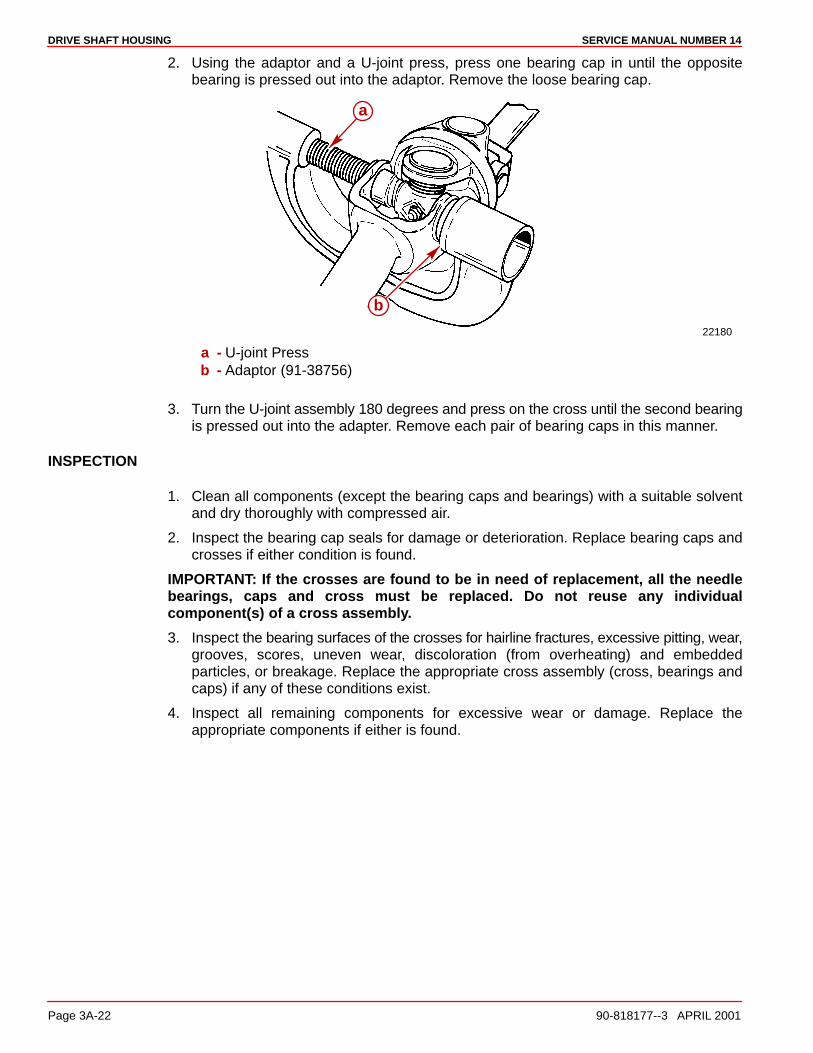
DRIVE SHAFT HOUSING SERVICE MANUAL NUMBER 14
Page 3A-22 90-818177--3 APRIL 2001
2. Using the adaptor and a U-joint press, press one bearing cap in until the oppositebearing is pressed out into the adaptor. Remove the loose bearing cap.
22180
a
b
a - U-joint Pressb - Adaptor (91-38756)
3. Turn the U-joint assembly 180 degrees and press on the cross until the second bearingis pressed out into the adapter. Remove each pair of bearing caps in this manner.
INSPECTION
1. Clean all components (except the bearing caps and bearings) with a suitable solventand dry thoroughly with compressed air.
2. Inspect the bearing cap seals for damage or deterioration. Replace bearing caps andcrosses if either condition is found.
IMPORTANT: If the crosses are found to be in need of replacement, all the needlebearings, caps and cross must be replaced. Do not reuse any individualcomponent(s) of a cross assembly.
3. Inspect the bearing surfaces of the crosses for hairline fractures, excessive pitting, wear,grooves, scores, uneven wear, discoloration (from overheating) and embeddedparticles, or breakage. Replace the appropriate cross assembly (cross, bearings andcaps) if any of these conditions exist.
4. Inspect all remaining components for excessive wear or damage. Replace theappropriate components if either is found.
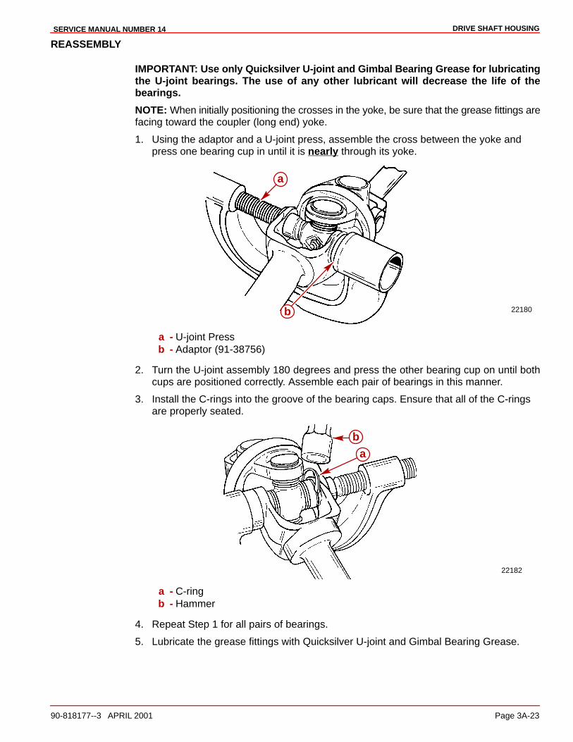
DRIVE SHAFT HOUSINGSERVICE MANUAL NUMBER 14
90-818177--3 APRIL 2001 Page 3A-23
REASSEMBLY
IMPORTANT: Use only Quicksilver U-joint and Gimbal Bearing Grease for lubricatingthe U-joint bearings. The use of any other lubricant will decrease the life of thebearings.
NOTE: When initially positioning the crosses in the yoke, be sure that the grease fittings arefacing toward the coupler (long end) yoke.
1. Using the adaptor and a U-joint press, assemble the cross between the yoke andpress one bearing cup in until it is nearly through its yoke.
22180
a
b
a - U-joint Pressb - Adaptor (91-38756)
2. Turn the U-joint assembly 180 degrees and press the other bearing cup on until bothcups are positioned correctly. Assemble each pair of bearings in this manner.
3. Install the C-rings into the groove of the bearing caps. Ensure that all of the C-ringsare properly seated.
22182
b
a
a - C-ringb - Hammer
4. Repeat Step 1 for all pairs of bearings.
5. Lubricate the grease fittings with Quicksilver U-joint and Gimbal Bearing Grease.

DRIVE SHAFT HOUSING SERVICE MANUAL NUMBER 14
Page 3A-24 90-818177--3 APRIL 2001
U-joint Assembly
REASSEMBLY
1. On Models With Serial Numbers Prior To 0L100009: temporarily install a hose clampon the bearing assembly to keep the bearing cups aligned with the spacer whileaccomplishing the next step.
70092
b
a77709
b
Earlier Style Later Style. . . . . . . . . . . . . . . . . . . . . . . . . . . . . . . . a - Hose Clampb - Bearing Cups
2. Assemble the retainer ring, thrust washer, O-ring and oil seal carrier. Then assemble thegear/bearing assembly, the washer and the nut. Tighten the nut finger tight.
75632
a
b
c
de
fg
h
a - Gear Assemblyb - Washerc - Nutd - Oil Seal Carriere - O-ringf - Thrust Washerg - Retainer Ringh - U-joint Assembly
3. Place the U-joint into the U-joint retainer tool.
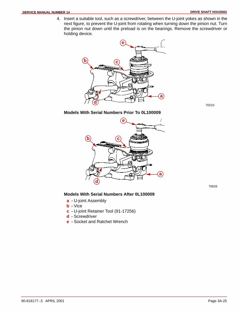
DRIVE SHAFT HOUSINGSERVICE MANUAL NUMBER 14
90-818177--3 APRIL 2001 Page 3A-25
4. Insert a suitable tool, such as a screwdriver, between the U-joint yokes as shown in thenext figure, to prevent the U-joint from rotating when turning down the pinion nut. Turnthe pinion nut down until the preload is on the bearings. Remove the screwdriver orholding device.
70210
a
b
d
c
e
Models With Serial Numbers Prior To 0L100009
75633
a
d
e
cb
Models With Serial Numbers After 0L100009a - U-joint Assemblyb - Vicec - U-joint Retainer Tool (91-17256)d - Screwdrivere - Socket and Ratchet Wrench
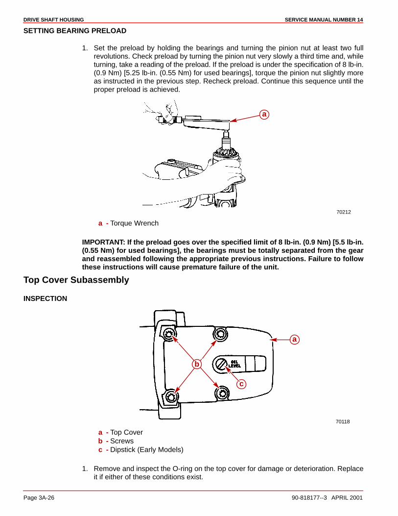
DRIVE SHAFT HOUSING SERVICE MANUAL NUMBER 14
Page 3A-26 90-818177--3 APRIL 2001
SETTING BEARING PRELOAD
1. Set the preload by holding the bearings and turning the pinion nut at least two fullrevolutions. Check preload by turning the pinion nut very slowly a third time and, whileturning, take a reading of the preload. If the preload is under the specification of 8 lb-in.(0.9 Nm) [5.25 lb-in. (0.55 Nm) for used bearings], torque the pinion nut slightly moreas instructed in the previous step. Recheck preload. Continue this sequence until theproper preload is achieved.
70212
a
a - Torque Wrench
IMPORTANT: If the preload goes over the specified limit of 8 lb-in. (0.9 Nm) [5.5 lb-in.(0.55 Nm) for used bearings], the bearings must be totally separated from the gearand reassembled following the appropriate previous instructions. Failure to followthese instructions will cause premature failure of the unit.
Top Cover Subassembly
INSPECTION
70118
a
b
c
a - Top Coverb - Screwsc - Dipstick (Early Models)
1. Remove and inspect the O-ring on the top cover for damage or deterioration. Replaceit if either of these conditions exist.

DRIVE SHAFT HOUSINGSERVICE MANUAL NUMBER 14
90-818177--3 APRIL 2001 Page 3A-27
2. Remove the top cover bearing cup and shim(s). Measure and make a note of thethickness of the shim pack. The shim(s) may be reused if they are not damaged.
3. Clean the top cover with a suitable solvent and a hard bristle brush. Ensure that allsealants and locking agents are removed. Dry the top cover thoroughly usingcompressed air.
4. Inspect the oil passage to ensure that it is clean and free of debris.
5. Inspect the bearing cup in the top cover for pits, grooves, scores, uneven wear,discoloration from overheating, or embedded particles. Replace it and the small bearingon the end of the upper drive shaft if any of these conditions exist.
6. Ensure that the bearing cup is not spinning in the top cover bore. If this condition exists,replace the top cover, the bearing cup and the bearing on the upper drive shaft.
DISASSEMBLY
NOTE: Disassembly of the top cover is for replacement of the bearing cup or changing thethickness of the shim pack for adjusting the upper driven gear bearing preload or gearlocation.
1. Remove the top cover bearing cup and shim(s). Measure and make a note of thethickness of the shim pack. The shim(s) may be reused if they are not damaged.
2. Inspect the top cover bearing cup bore for evidence of the bearing cup spinning in thebore. If this condition exists, replace the top cover, the bearing cup and the small bearingon the upper drive shaft.
70127
a
b
a - Bearing Cupb - Slide Hammer Puller (91-34569A1)

DRIVE SHAFT HOUSING SERVICE MANUAL NUMBER 14
Page 3A-28 90-818177--3 APRIL 2001
REASSEMBLY
NOTE: If installing the top cover bearing race for the first time, use the same thickness ofshims that were removed or a .015 in. (0.38 mm) shim pack if the original shim packthickness is not known.
1. Lubricate the top cover bore with Quicksilver High Performance Gear Lube
2. Place the shims(s) into the top cover bore.
3. Install the bearing cup into the top cover using the tools as shown in the following figure.
4. Reinstall the top cover O-ring.
70701a
b
c
d
e
a - Shimsb - Bearing Cupc - Bearing Cup Driver (91-38918) Used With 31-61100A1 Bearing Or Bearing Cup
Driver (91-808053) Used With 31-32575A1 Bearingd - Driver Rod (91-37323)e - Top Cover
NOTE: The later style bearing cup is thinner than the earlier style cup.
75240
ba
a - Earlier Style Bearing Cup 1.938 in Diameter (Prior To S/N OF680000)b - Later Style Bearing Cup 1.781 in. Diameter (S/N 680000 And Above)
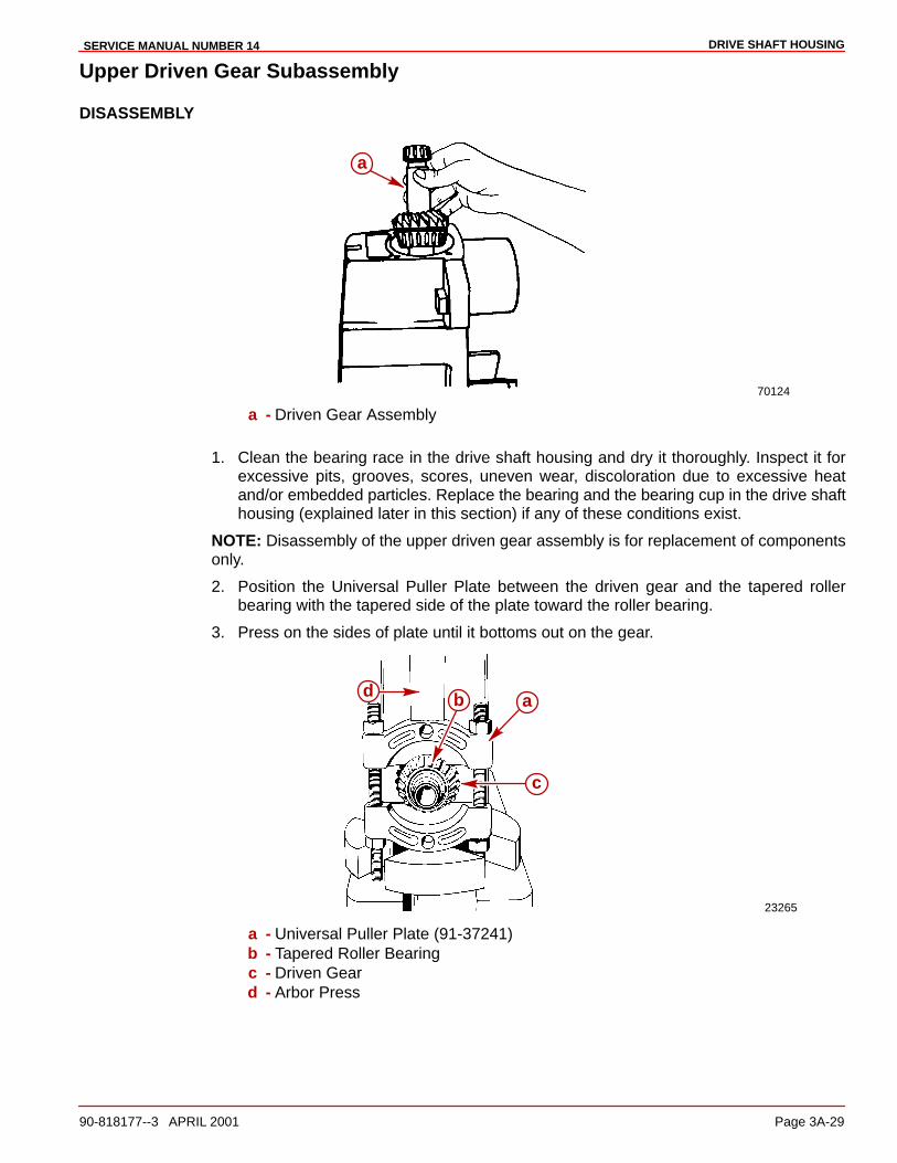
DRIVE SHAFT HOUSINGSERVICE MANUAL NUMBER 14
90-818177--3 APRIL 2001 Page 3A-29
Upper Driven Gear Subassembly
DISASSEMBLY
70124
a
a - Driven Gear Assembly
1. Clean the bearing race in the drive shaft housing and dry it thoroughly. Inspect it forexcessive pits, grooves, scores, uneven wear, discoloration due to excessive heatand/or embedded particles. Replace the bearing and the bearing cup in the drive shafthousing (explained later in this section) if any of these conditions exist.
NOTE: Disassembly of the upper driven gear assembly is for replacement of componentsonly.
2. Position the Universal Puller Plate between the driven gear and the tapered rollerbearing with the tapered side of the plate toward the roller bearing.
3. Press on the sides of plate until it bottoms out on the gear.
23265
a
c
d b
a - Universal Puller Plate (91-37241)b - Tapered Roller Bearingc - Driven Geard - Arbor Press
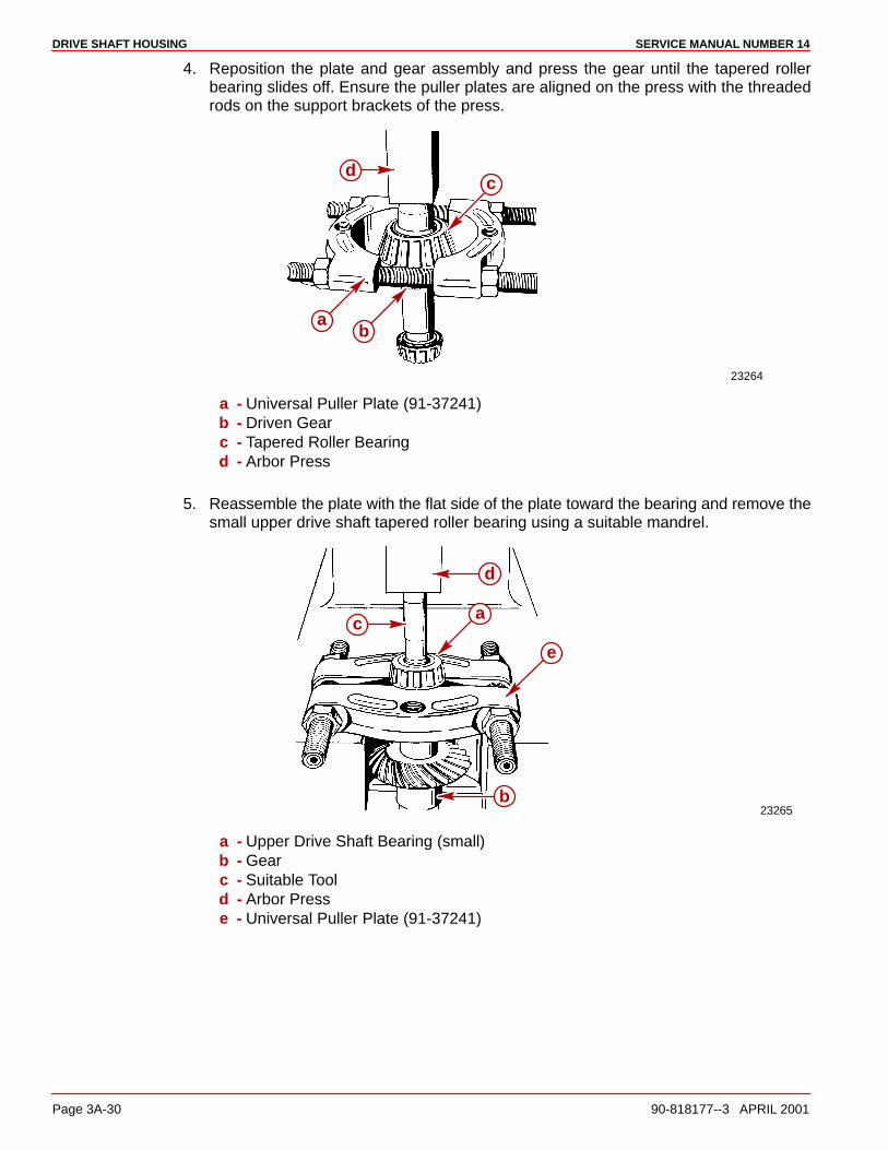
DRIVE SHAFT HOUSING SERVICE MANUAL NUMBER 14
Page 3A-30 90-818177--3 APRIL 2001
4. Reposition the plate and gear assembly and press the gear until the tapered rollerbearing slides off. Ensure the puller plates are aligned on the press with the threadedrods on the support brackets of the press.
23264
a
cd
b
a - Universal Puller Plate (91-37241)b - Driven Gearc - Tapered Roller Bearingd - Arbor Press
5. Reassemble the plate with the flat side of the plate toward the bearing and remove thesmall upper drive shaft tapered roller bearing using a suitable mandrel.
23265
a
b
c
d
e
a - Upper Drive Shaft Bearing (small)b - Gearc - Suitable Toold - Arbor Presse - Universal Puller Plate (91-37241)

DRIVE SHAFT HOUSINGSERVICE MANUAL NUMBER 14
90-818177--3 APRIL 2001 Page 3A-31
6. Press the driven gear from the upper drive shaft.
23266
a
b
c
d
a - Driven Gearb - Upper Drive Shaftc - Suitable Toold - Arbor Press
INSPECTION
1. Clean all parts with a suitable solvent and dry them thoroughly with compressed air. Becareful not to spin the bearing.
2. Inspect the gear for pitting, chipped or broken teeth, hairline fractures and excessive oruneven wear. Replace both the drive (pinion) and the driven gear if any of theseconditions exist.
3. Inspect the gear hub for evidence of the bearing spinning. Replace the tapered rollerbearing, the driven gear and the pinion gear on the U-joint if any evidence of spinningis found.
4. Inspect the upper drive shaft for damage, hairline fractures and evidence of the gearspinning on the shaft. Replace the upper drive shaft, the driven gear and the pinion gearon the U-joint if any of these conditions are found.
5. Inspect the upper drive shaft to ensure that the hole through the center of the shaft isclean and clear. Clean out the hole if it has any debris.
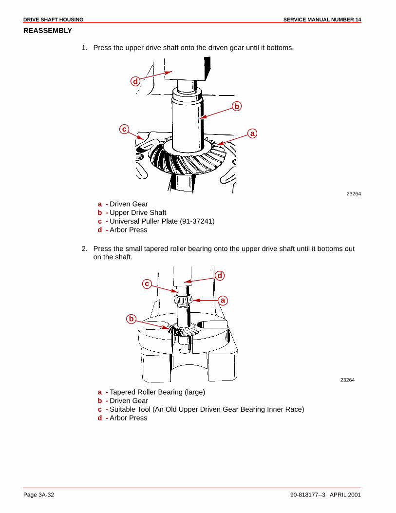
DRIVE SHAFT HOUSING SERVICE MANUAL NUMBER 14
Page 3A-32 90-818177--3 APRIL 2001
REASSEMBLY
1. Press the upper drive shaft onto the driven gear until it bottoms.
23264
ac
d
b
a - Driven Gearb - Upper Drive Shaftc - Universal Puller Plate (91-37241)d - Arbor Press
2. Press the small tapered roller bearing onto the upper drive shaft until it bottoms outon the shaft.
23264
a
cd
b
a - Tapered Roller Bearing (large)b - Driven Gearc - Suitable Tool (An Old Upper Driven Gear Bearing Inner Race)d - Arbor Press

DRIVE SHAFT HOUSINGSERVICE MANUAL NUMBER 14
90-818177--3 APRIL 2001 Page 3A-33
Drive Shaft Housing Reassembly
Drive Shaft Housing Inspection1. Inspect the locating pin holes on the drive shaft housing (at the gear housing mating
surface) to ensure that they are not elongated. Elongation of the holes may cause thedrive shaft to break because the housings may not align properly when assembled.
InstallationNOTE: If installing the upper driven gear bearing cup for the first time use the samethickness of shims that were removed or approximately a .015 in. (0.38mm) shim pack if theoriginal shim pack thickness is not known.
1. Lubricate the bore in the drive shaft housing (into which the upper driven gear bearingcup is to be installed) with Quicksilver High Performance Gear Lube.
2. Place the shim(s) into the bore of the drive shaft housing.
3. Install the upper driven gear bearing cup as shown below.
70445
ab
c
d
a - Shimsb - Bearing Cupc - Bearing Cup Driver (91-33493)d - Driver Rod (An Old Propeller Shaft Shown)
IMPORTANT: Lightly lubricate the gears, bearings, seals and O-rings withQuicksilver High Performance Gear Lube before installing. Bearings and gears mustbe lubricated to obtain accurate preload readings.
IMPORTANT: The top cover screws must be torqued to 20 lb-ft (27 Nm), to properlycheck the upper drive shaft bearing preload.

DRIVE SHAFT HOUSING SERVICE MANUAL NUMBER 14
Page 3A-34 90-818177--3 APRIL 2001
4. Lightly lubricate both of the bearings on the upper driven gear assembly with QuicksilverHigh Performance Gear Lube and install the upper driven gear assembly into the driveshaft housing.
70124
a
a - Upper Driven Gear Assembly
5. Install the top cover and torque the screws 20 lb-ft (27 Nm).
70118
a
b
a - Top Coverb - Screws (4)
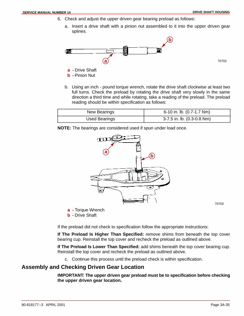
DRIVE SHAFT HOUSINGSERVICE MANUAL NUMBER 14
90-818177--3 APRIL 2001 Page 3A-35
6. Check and adjust the upper driven gear bearing preload as follows:
a. Insert a drive shaft with a pinion nut assembled to it into the upper driven gearsplines.
70702a
b
a - Drive Shaftb - Pinion Nut
b. Using an inch - pound torque wrench, rotate the drive shaft clockwise at least twofull turns. Check the preload by rotating the drive shaft very slowly in the samedirection a third time and while rotating, take a reading of the preload. The preloadreading should be within specification as follows:
New Bearings 6-10 in. lb. (0.7-1.7 Nm)
Used Bearings 3-7.5 in. lb. (0.3-0.8 Nm)
NOTE: The bearings are considered used if spun under load once.
70703
ab
a - Torque Wrenchb - Drive Shaft
If the preload did not check to specification follow the appropriate instructions:
If The Preload Is Higher Than Specified: remove shims from beneath the top coverbearing cup. Reinstall the top cover and recheck the preload as outlined above.
If The Preload Is Lower Than Specified: add shims beneath the top cover bearing cup.Reinstall the top cover and recheck the preload as outlined above.
c. Continue this process until the preload check is within specification.
Assembly and Checking Driven Gear LocationIMPORTANT: The upper driven gear preload must be to specification before checkingthe upper driven gear location.
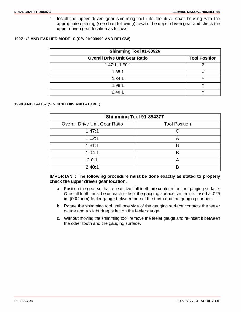
DRIVE SHAFT HOUSING SERVICE MANUAL NUMBER 14
Page 3A-36 90-818177--3 APRIL 2001
1. Install the upper driven gear shimming tool into the drive shaft housing with theappropriate opening (see chart following) toward the upper driven gear and check theupper driven gear location as follows:
1997 1/2 AND EARLIER MODELS (S/N 0K999999 AND BELOW)
Shimming Tool 91-60526
Overall Drive Unit Gear Ratio Tool Position
1.47:1, 1.50:1 Z
1.65:1 X
1.84:1 Y
1.98:1 Y
2.40:1 Y
1998 AND LATER (S/N 0L100009 AND ABOVE)
Shimming Tool 91-854377
Overall Drive Unit Gear Ratio Tool Position
1.47:1 C
1.62:1 A
1.81:1 B
1.94:1 B
2.0:1 A
2.40:1 B
IMPORTANT: The following procedure must be done exactly as stated to properlycheck the upper driven gear location.
a. Position the gear so that at least two full teeth are centered on the gauging surface.One full tooth must be on each side of the gauging surface centerline. Insert a .025in. (0.64 mm) feeler gauge between one of the teeth and the gauging surface.
b. Rotate the shimming tool until one side of the gauging surface contacts the feelergauge and a slight drag is felt on the feeler gauge.
c. Without moving the shimming tool, remove the feeler gauge and re-insert it betweenthe other tooth and the gauging surface.
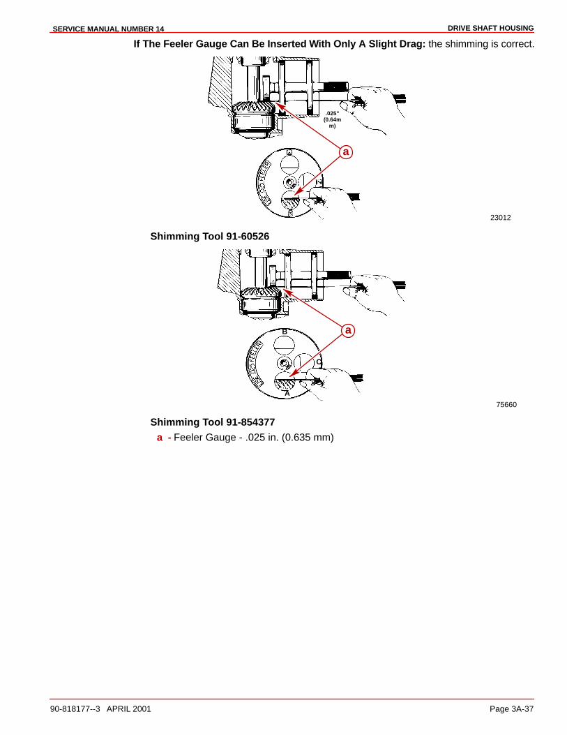
DRIVE SHAFT HOUSINGSERVICE MANUAL NUMBER 14
90-818177--3 APRIL 2001 Page 3A-37
If The Feeler Gauge Can Be Inserted With Only A Slight Drag: the shimming is correct.
23012
.025”(0.64m
m)
a
Shimming Tool 91-60526
75660
B
C
A
a
Shimming Tool 91-854377a - Feeler Gauge - .025 in. (0.635 mm)
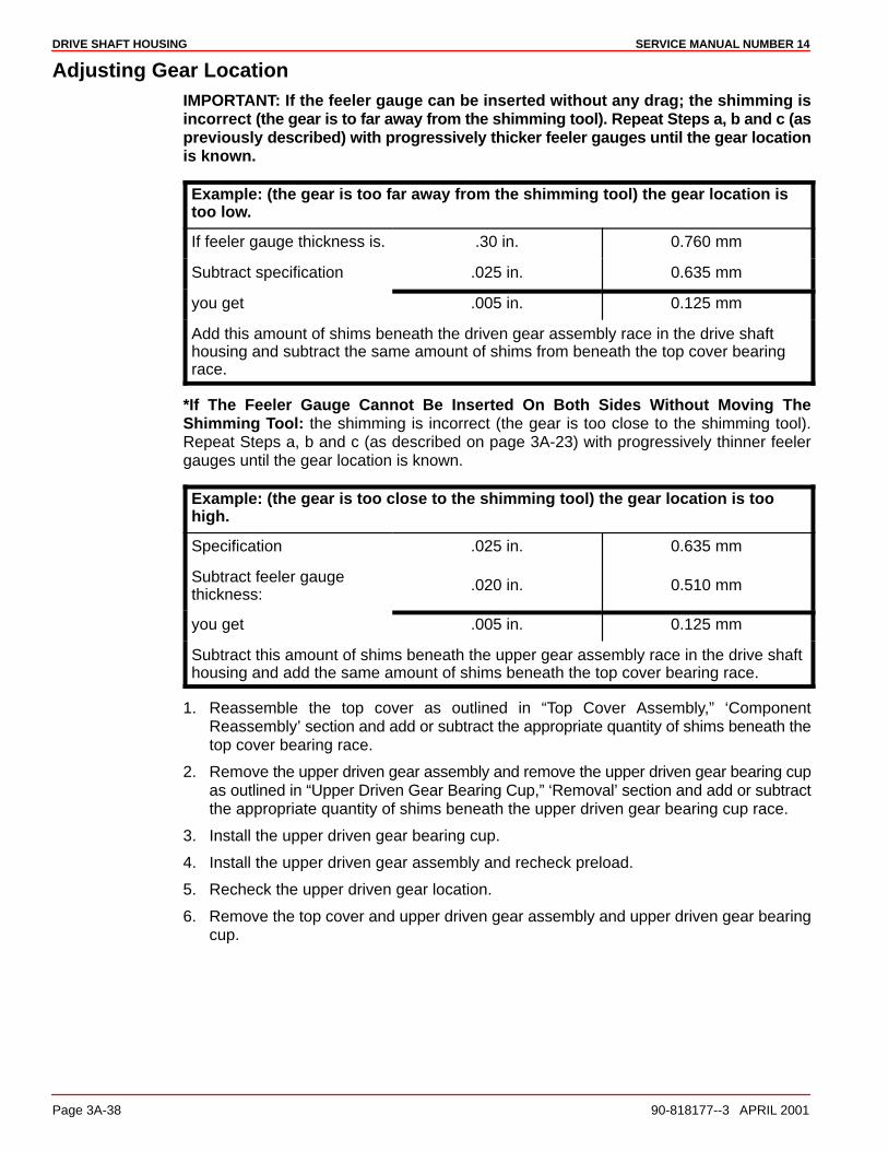
DRIVE SHAFT HOUSING SERVICE MANUAL NUMBER 14
Page 3A-38 90-818177--3 APRIL 2001
Adjusting Gear LocationIMPORTANT: If the feeler gauge can be inserted without any drag; the shimming isincorrect (the gear is to far away from the shimming tool). Repeat Steps a, b and c (aspreviously described) with progressively thicker feeler gauges until the gear locationis known.
Example: (the gear is too far away from the shimming tool) the gear location istoo low.
If feeler gauge thickness is. .30 in. 0.760 mm
Subtract specification .025 in. 0.635 mm
you get .005 in. 0.125 mm
Add this amount of shims beneath the driven gear assembly race in the drive shafthousing and subtract the same amount of shims from beneath the top cover bearingrace.
*If The Feeler Gauge Cannot Be Inserted On Both Sides Without Moving TheShimming Tool: the shimming is incorrect (the gear is too close to the shimming tool).Repeat Steps a, b and c (as described on page 3A-23) with progressively thinner feelergauges until the gear location is known.
Example: (the gear is too close to the shimming tool) the gear location is toohigh.
Specification .025 in. 0.635 mm
Subtract feeler gaugethickness:
.020 in. 0.510 mm
you get .005 in. 0.125 mm
Subtract this amount of shims beneath the upper gear assembly race in the drive shafthousing and add the same amount of shims beneath the top cover bearing race.
1. Reassemble the top cover as outlined in “Top Cover Assembly,” ‘ComponentReassembly’ section and add or subtract the appropriate quantity of shims beneath thetop cover bearing race.
2. Remove the upper driven gear assembly and remove the upper driven gear bearing cupas outlined in “Upper Driven Gear Bearing Cup,” ‘Removal’ section and add or subtractthe appropriate quantity of shims beneath the upper driven gear bearing cup race.
3. Install the upper driven gear bearing cup.
4. Install the upper driven gear assembly and recheck preload.
5. Recheck the upper driven gear location.
6. Remove the top cover and upper driven gear assembly and upper driven gear bearingcup.
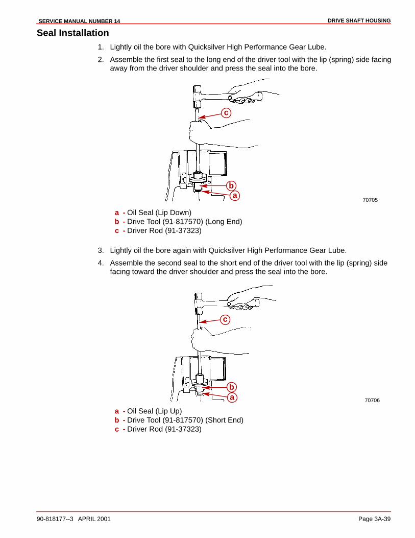
DRIVE SHAFT HOUSINGSERVICE MANUAL NUMBER 14
90-818177--3 APRIL 2001 Page 3A-39
Seal Installation1. Lightly oil the bore with Quicksilver High Performance Gear Lube.
2. Assemble the first seal to the long end of the driver tool with the lip (spring) side facingaway from the driver shoulder and press the seal into the bore.
70705a
b
c
a - Oil Seal (Lip Down)b - Drive Tool (91-817570) (Long End)c - Driver Rod (91-37323)
3. Lightly oil the bore again with Quicksilver High Performance Gear Lube.
4. Assemble the second seal to the short end of the driver tool with the lip (spring) sidefacing toward the driver shoulder and press the seal into the bore.
70706ab
c
a - Oil Seal (Lip Up)b - Drive Tool (91-817570) (Short End)c - Driver Rod (91-37323)
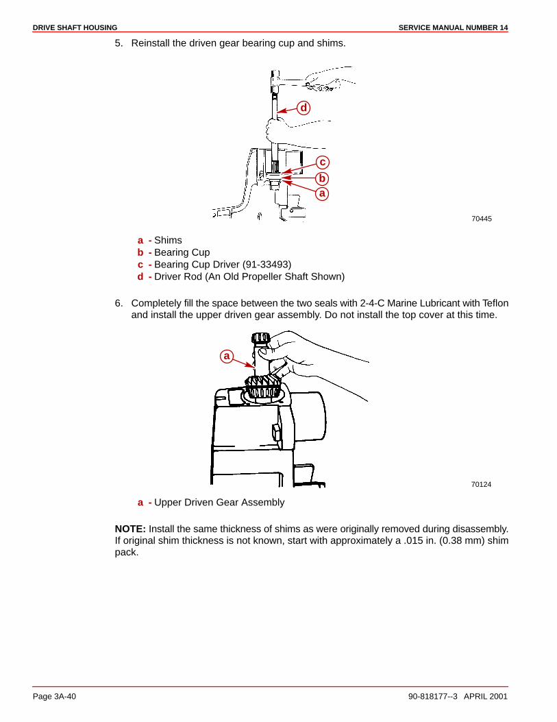
DRIVE SHAFT HOUSING SERVICE MANUAL NUMBER 14
Page 3A-40 90-818177--3 APRIL 2001
5. Reinstall the driven gear bearing cup and shims.
70445
ab
c
d
a - Shimsb - Bearing Cupc - Bearing Cup Driver (91-33493)d - Driver Rod (An Old Propeller Shaft Shown)
6. Completely fill the space between the two seals with 2-4-C Marine Lubricant with Teflonand install the upper driven gear assembly. Do not install the top cover at this time.
70124
a
a - Upper Driven Gear Assembly
NOTE: Install the same thickness of shims as were originally removed during disassembly.If original shim thickness is not known, start with approximately a .015 in. (0.38 mm) shimpack.
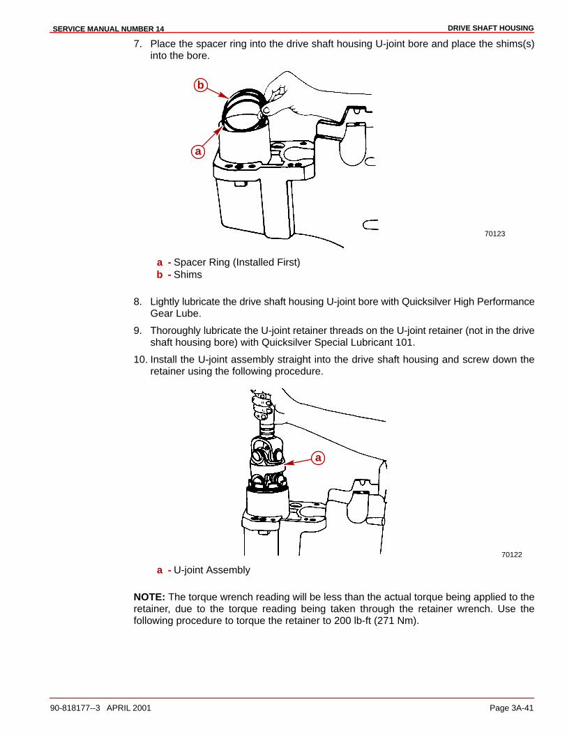
DRIVE SHAFT HOUSINGSERVICE MANUAL NUMBER 14
90-818177--3 APRIL 2001 Page 3A-41
7. Place the spacer ring into the drive shaft housing U-joint bore and place the shims(s)into the bore.
70123
a
b
a - Spacer Ring (Installed First)b - Shims
8. Lightly lubricate the drive shaft housing U-joint bore with Quicksilver High PerformanceGear Lube.
9. Thoroughly lubricate the U-joint retainer threads on the U-joint retainer (not in the driveshaft housing bore) with Quicksilver Special Lubricant 101.
10. Install the U-joint assembly straight into the drive shaft housing and screw down theretainer using the following procedure.
70122
a
a - U-joint Assembly
NOTE: The torque wrench reading will be less than the actual torque being applied to theretainer, due to the torque reading being taken through the retainer wrench. Use thefollowing procedure to torque the retainer to 200 lb-ft (271 Nm).

DRIVE SHAFT HOUSING SERVICE MANUAL NUMBER 14
Page 3A-42 90-818177--3 APRIL 2001
11. Measure the length of the torque wrench as follows:
a. On beam type torque wrenches, measure from the square drive to the fulcrum (pivot)point of the handle.
b. On click-stop or dial type torque wrenches, measure from the square drive to thereference mark on the handle (marked with 2 bands, a line, etc.).
12. Use the following chart to determine the torque wrench reading required to properlytorque the retainer to 200 lb-ft (271 Nm).
Torque Wrench Length In Inches (cm) Torque Wrench Reading, in lb-ft (Nm) toachieve 200 lb-ft (271 Nm) of torque
15 (38) 111 (151)
16 (41) 114 (155)
17 (43) 117 (159)
18 (46) 120 (163)
19 (48) 123 (167)
20 (51) 125 (170)
21 (53) 127 (172)
22 (56) 129 (175)
23 (58) 131 (178)
24 (61) 133 (180)
25 (64) 135 (183)
26 (66) 136 (184)
27 (69) 138 (187)
28 (71) 140 (190)
29 (74) 141 (191)
30 (76) 143 (194)
31 (79) 144 (195)
32 (81) 145 (197)
33 (84) 147 (200)
34 (86) 148 (201)
35 (89) 149 (202)
36 (91) 150 (203)
26363
a b
a - Torque Wrench Lengthb - 12 in. retainer Wrench
a. Torque the retainer until the torque reading for your length of torque wrench isattained.
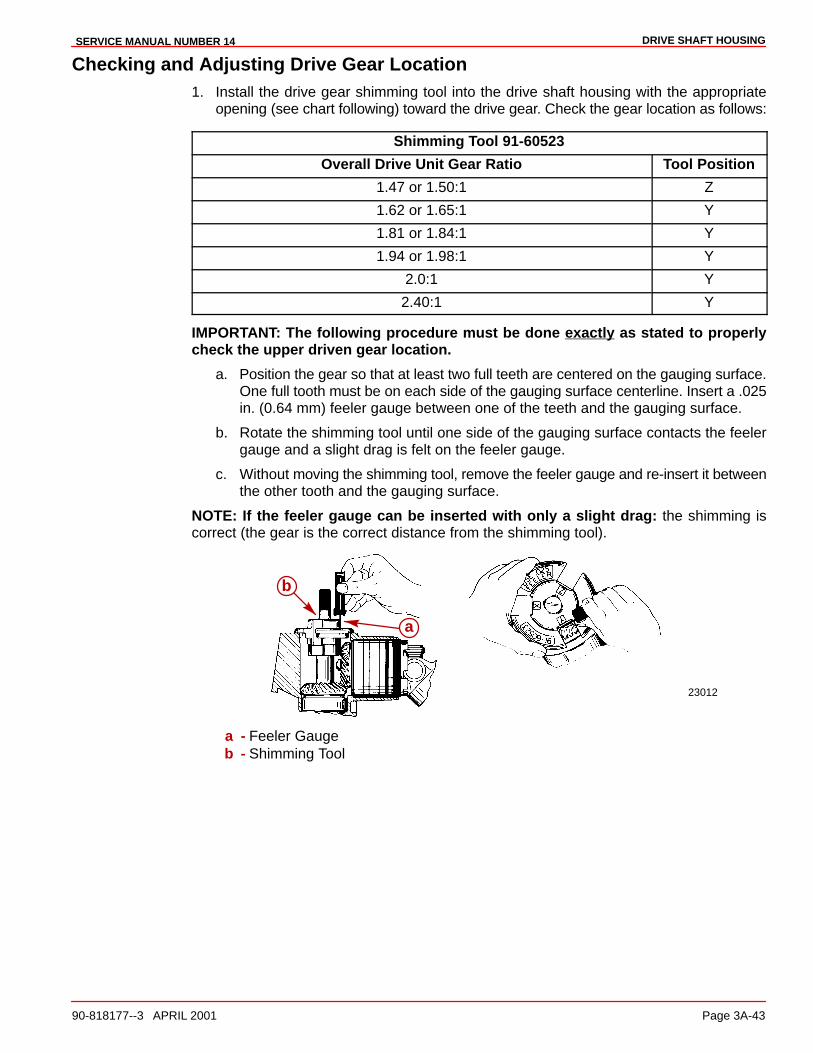
DRIVE SHAFT HOUSINGSERVICE MANUAL NUMBER 14
90-818177--3 APRIL 2001 Page 3A-43
Checking and Adjusting Drive Gear Location1. Install the drive gear shimming tool into the drive shaft housing with the appropriate
opening (see chart following) toward the drive gear. Check the gear location as follows:
Shimming Tool 91-60523
Overall Drive Unit Gear Ratio Tool Position
1.47 or 1.50:1 Z
1.62 or 1.65:1 Y
1.81 or 1.84:1 Y
1.94 or 1.98:1 Y
2.0:1 Y
2.40:1 Y
IMPORTANT: The following procedure must be done exactly as stated to properlycheck the upper driven gear location.
a. Position the gear so that at least two full teeth are centered on the gauging surface.One full tooth must be on each side of the gauging surface centerline. Insert a .025in. (0.64 mm) feeler gauge between one of the teeth and the gauging surface.
b. Rotate the shimming tool until one side of the gauging surface contacts the feelergauge and a slight drag is felt on the feeler gauge.
c. Without moving the shimming tool, remove the feeler gauge and re-insert it betweenthe other tooth and the gauging surface.
NOTE: If the feeler gauge can be inserted with only a slight drag: the shimming iscorrect (the gear is the correct distance from the shimming tool).
23012
a
b
a - Feeler Gaugeb - Shimming Tool

DRIVE SHAFT HOUSING SERVICE MANUAL NUMBER 14
Page 3A-44 90-818177--3 APRIL 2001
ADJUSTING PINION GEAR LOCATION (U-JOINT ASSEMBLY)
NOTE: If the feeler gauge inserts with no drag: the shimming is incorrect (the gear is toofar away from the shimming tool). Repeat Steps a, b and c (as described previously) withprogressively thicker feeler gauges until the gear location is known.
Example: the gear location is too high
(the gear is too far away from the shimming tool),
If feeler gauge thickness is: .030 in. 0.760 mm
Subtract specification .025 in. 0.635mm
you get .005 in. 0.125 mm
Remove the U-joint and subtract this amount of shims, then reinstall the U-joint.
NOTE: If the feeler gauge cannot be inserted on both sides without moving theshimming tool: the shimming is incorrect (the gear is too close to the shimming tool).Repeat Steps a, b and c above with progressively thinner feeler gauges until the gearlocation is known.
Example: the gear location is too low
(the gear is too close to the shimming tool)
Specification .025 In. 0.635 mm
Subtract feeler gauge thickness: .020 In. 0.510mm
you get .005 In. .0125 mm
Add this amount of shims to position gear to its proper location.
2. Recheck the pinion gear location as outlined previously and readjust if necessary.
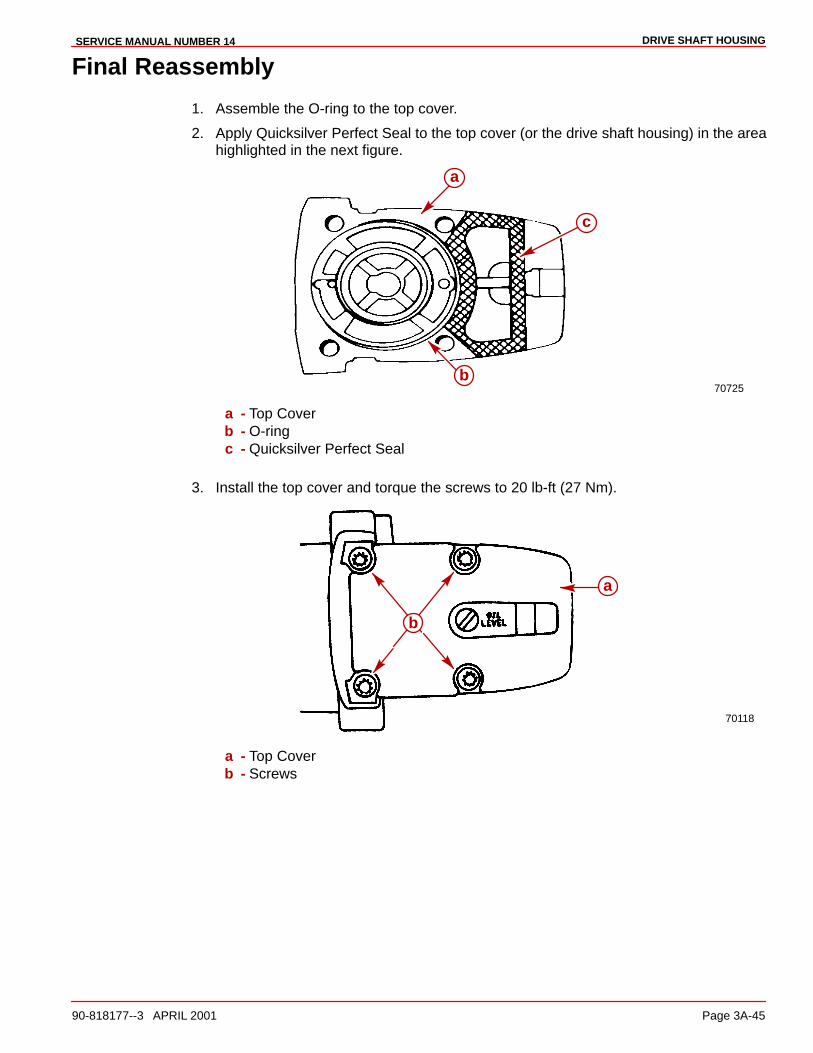
DRIVE SHAFT HOUSINGSERVICE MANUAL NUMBER 14
90-818177--3 APRIL 2001 Page 3A-45
Final Reassembly
1. Assemble the O-ring to the top cover.
2. Apply Quicksilver Perfect Seal to the top cover (or the drive shaft housing) in the areahighlighted in the next figure.
70725
a
b
c
a - Top Coverb - O-ringc - Quicksilver Perfect Seal
3. Install the top cover and torque the screws to 20 lb-ft (27 Nm).
70118
a
b
a - Top Coverb - Screws

DRIVE SHAFT HOUSING SERVICE MANUAL NUMBER 14
Page 3A-46 90-818177--3 APRIL 2001
4. Install the rubber seal into the drive shaft housing.
70125
a
b
a - Rubber Sealb - Drive Shaft Housing
5. Lubricate the end of the water tube (that goes into the drive shaft housing) withQuicksilver 2-4-C Marine Lubricant with Teflon. Install the water tube into the rubber sealin the drive shaft housing. Make sure that the tube is positioned with the bend towardsthe forward end of the unit and the longest straight section toward the gear housingmating surface.
70126
a
b
a - Water Tube (Correctly Positioned)b - Drive Shaft Housing

DRIVE SHAFT HOUSINGSERVICE MANUAL NUMBER 14
90-818177--3 APRIL 2001 Page 3A-47
Joining Drive Shaft Housing/Gear Housing1. Lubricate the end of the water tube (in the drive shaft housing) and the splines of the
drive shaft with Quicksilver 2-4-C Marine Lubricant with Teflon.
NOTE: The aluminum dam in the gear housing has been changed to a rubber filler plug. Ifthe aluminum water pump dam in the gear housing has become corroded or damaged, itcan be replaced with the rubber filler plug.
IMPORTANT: Ensure that the drain hole of the aluminum water pump dam is notclogged with any foreign material. Damage may occur if passage is blocked.
71410 71436
ac
b
a - Aluminum Damb - Rubber Filler Plugc - Drain Hole
2. Units with an aluminum dam require a bead of Permatex Ultra Blue Silicone Sealantalong the top of the dam. If rubber filler plug is present, it is not necessary to use thissealant.
3. To replace the aluminum dam if it has been removed and undamaged, place a bead ofPermatex Ultra Blue Silicone Sealant down both sides of it.
4. Ensure that the water pump dam in the drive shaft housing is present and installedcorrectly. Ensure that all parts are present on the gear housing and the drive shafthousing.
IMPORTANT: Install the Trim Tab (or Anodic plate) bolt into the gear housing.
70710
a
bc
a - Drive Shaft Splinesb - Sealant - Aluminum Dam Onlyc - Trim Tab Bolt
5. Position the drive shaft housing straight above the gear housing. Align the water tubesleeve with the water tube and the drive shaft with the upper drive gear and assemblethe drive shaft housing to the gear housing. It may be necessary to rotate the propellershaft or the U-joint to align the drive shaft splines with the upper drive gear splines.
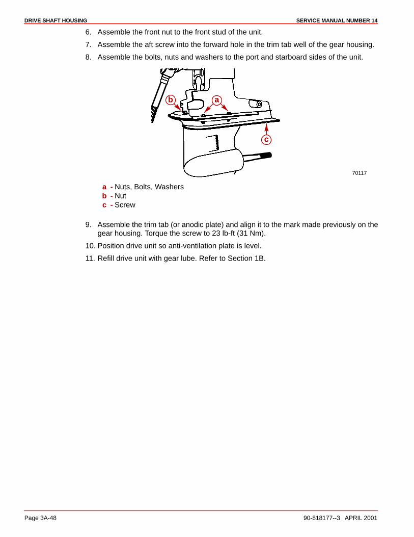
DRIVE SHAFT HOUSING SERVICE MANUAL NUMBER 14
Page 3A-48 90-818177--3 APRIL 2001
6. Assemble the front nut to the front stud of the unit.
7. Assemble the aft screw into the forward hole in the trim tab well of the gear housing.
8. Assemble the bolts, nuts and washers to the port and starboard sides of the unit.
70117
b
c
a
a - Nuts, Bolts, Washersb - Nutc - Screw
9. Assemble the trim tab (or anodic plate) and align it to the mark made previously on thegear housing. Torque the screw to 23 lb-ft (31 Nm).
10. Position drive unit so anti-ventilation plate is level.
11. Refill drive unit with gear lube. Refer to Section 1B.

DRIVE SHAFT HOUSINGSERVICE MANUAL NUMBER 14
90-818177--3 APRIL 2001 Page 3A-49
THIS PAGE IS INTENTIONALLY BLANK

DRIVE SHAFT HOUSING SERVICE MANUAL NUMBER 14
Page 3A-50 90-818177--3 APRIL 2001
THIS PAGE IS INTENTIONALLY BLANK
3B
GEAR HOUSING STANDARD ROTATIONSERVICE MANUAL NUMBER 14
90-818177--3 APRIL 2001 Page 3B-1
STERNDRIVE UNITSection 3B - Gear Housing Standard Rotation
Table of Contents
Standard Rotation Gear Housing Specifications 3B-2. . . . . . . . . . . . . . . . . . . . . .
Torque Specifications 3B-2. . . . . . . . . . . . . Shimming Specifications 3B-2. . . . . . . . . . . Lubricants / Sealers / Adhesives 3B-2. . . . Special Tools 3B-3. . . . . . . . . . . . . . . . . . . . . Special Tools (continued) 3B-4. . . . . . . . . .
Standard Rotation Gear Housing Exploded Parts View 3B-6. . . . . . . . . . . . . . . .
Drive Shaft Components 3B-6. . . . . . . . . . . Propeller Shaft Components 3B-8. . . . . . .
Special Information 3B-10. . . . . . . . . . . . . . . . . . Shift Spool Assembly 3B-10. . . . . . . . . . . . . . Forward Gear Bearing Bore 3B-11. . . . . . . .
Pre-Disassembly Inspection 3B-12. . . . . . . . . . Propeller 3B-12. . . . . . . . . . . . . . . . . . . . . . . . Propeller Shaft 3B-12. . . . . . . . . . . . . . . . . . .
Drive Shaft Housing/Gear Housing 3B-13. . . . Separation 3B-13. . . . . . . . . . . . . . . . . . . . . . .
Gear Housing and Component Disassembly 3B-15. . . . . . . . . . . . . . . . . . . . . . .
Water Pump Subassembly 3B-15. . . . . . . . . Oil Seal Carrier Subassembly 3B-18. . . . . . Bearing Carrier Subassembly 3B-21. . . . . . Drive Shaft Assembly 3B-34. . . . . . . . . . . . . Propeller Shaft Assembly and Forward Gear Bearing Cup 3B-37. . . . . . . . Forward Gear Assembly 3B-41. . . . . . . . . . .
Shift Spool Assembly 3B-44. . . . . . . . . . . . . . Propeller Shaft Assembly 3B-45. . . . . . . . . . Shift Shaft Assembly 3B-47. . . . . . . . . . . . . . Pinion Bearing 3B-50. . . . . . . . . . . . . . . . . . .
Gear Housing Reassembly 3B-51. . . . . . . . . . . Gear Housing Inspection 3B-51. . . . . . . . . . Pinion Bearing 3B-51. . . . . . . . . . . . . . . . . . . Forward Gear Bearing Cup 3B-52. . . . . . . . Shift Shaft Assembly 3B-53. . . . . . . . . . . . . . Propeller Shaft Assembly 3B-55. . . . . . . . . . Drive Shaft and Pinion Gear 3B-57. . . . . . . . Drive Shaft - Bearing Preload Tool 3B-60. . Pinion Gear Location 3B-61. . . . . . . . . . . . . . Bearing Carrier Assembly 3B-62. . . . . . . . . . Forward Gear Backlash 3B-65. . . . . . . . . . . Reverse Gear Backlash 3B-67. . . . . . . . . . . Forward and/or Reverse Gear Backlash Adjustment 3B-69. . . . . . . . . . . . . Drive Shaft - Bearing Preload Tool 3B-69. .
Bearing Carrier Assembly 3B-70. . . . . . . . . . . . Final Installation 3B-70. . . . . . . . . . . . . . . . . .
Oil Seal Carrier Assembly 3B-74. . . . . . . . . . . . Installation 3B-74. . . . . . . . . . . . . . . . . . . . . . .
Water Pump Assembly 3B-75. . . . . . . . . . . . . . . Installation 3B-75. . . . . . . . . . . . . . . . . . . . . . .
Joining Drive Shaft Housing/Gear Housing 3B-78. . . . . . . . . . . . . . . . . . . . . . . . . . .
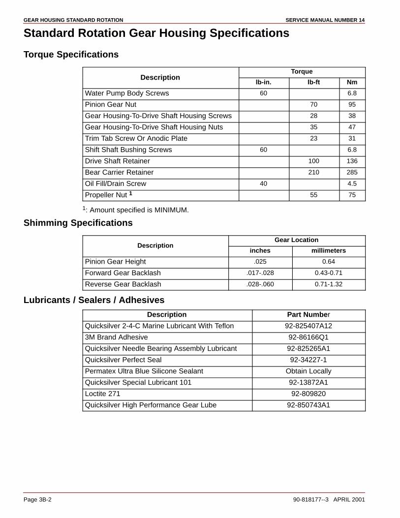
GEAR HOUSING STANDARD ROTATION SERVICE MANUAL NUMBER 14
Page 3B-2 90-818177--3 APRIL 2001
Standard Rotation Gear Housing Specifications
Torque Specifications
TorqueDescription
lb-in. lb-ft Nm
Water Pump Body Screws 60 6.8
Pinion Gear Nut 70 95
Gear Housing-To-Drive Shaft Housing Screws 28 38
Gear Housing-To-Drive Shaft Housing Nuts 35 47
Trim Tab Screw Or Anodic Plate 23 31
Shift Shaft Bushing Screws 60 6.8
Drive Shaft Retainer 100 136
Bear Carrier Retainer 210 285
Oil Fill/Drain Screw 40 4.5
Propeller Nut 1 55 75
1: Amount specified is MINIMUM.
Shimming Specifications
Gear LocationDescription
inches millimeters
Pinion Gear Height .025 0.64
Forward Gear Backlash .017-.028 0.43-0.71
Reverse Gear Backlash .028-.060 0.71-1.32
Lubricants / Sealers / Adhesives
Description Part Number
Quicksilver 2-4-C Marine Lubricant With Teflon 92-825407A12
3M Brand Adhesive 92-86166Q1
Quicksilver Needle Bearing Assembly Lubricant 92-825265A1
Quicksilver Perfect Seal 92-34227-1
Permatex Ultra Blue Silicone Sealant Obtain Locally
Quicksilver Special Lubricant 101 92-13872A1
Loctite 271 92-809820
Quicksilver High Performance Gear Lube 92-850743A1
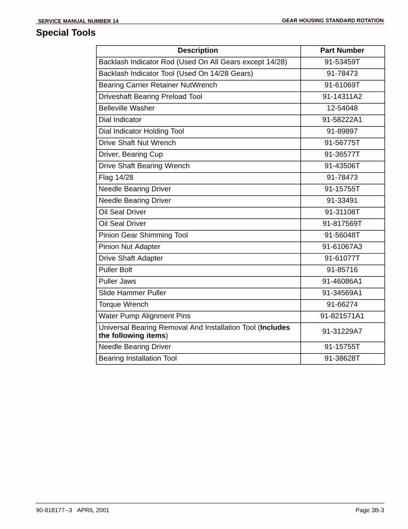
GEAR HOUSING STANDARD ROTATIONSERVICE MANUAL NUMBER 14
90-818177--3 APRIL 2001 Page 3B-3
Special Tools
Description Part Number
Backlash Indicator Rod (Used On All Gears except 14/28) 91-53459T
Backlash Indicator Tool (Used On 14/28 Gears) 91-78473
Bearing Carrier Retainer NutWrench 91-61069T
Driveshaft Bearing Preload Tool 91-14311A2
Belleville Washer 12-54048
Dial Indicator 91-58222A1
Dial Indicator Holding Tool 91-89897
Drive Shaft Nut Wrench 91-56775T
Driver, Bearing Cup 91-36577T
Drive Shaft Bearing Wrench 91-43506T
Flag 14/28 91-78473
Needle Bearing Driver 91-15755T
Needle Bearing Driver 91-33491
Oil Seal Driver 91-31108T
Oil Seal Driver 91-817569T
Pinion Gear Shimming Tool 91-56048T
Pinion Nut Adapter 91-61067A3
Drive Shaft Adapter 91-61077T
Puller Bolt 91-85716
Puller Jaws 91-46086A1
Slide Hammer Puller 91-34569A1
Torque Wrench 91-66274
Water Pump Alignment Pins 91-821571A1
Universal Bearing Removal And Installation Tool (Includesthe following items)
91-31229A7
Needle Bearing Driver 91-15755T
Bearing Installation Tool 91-38628T

GEAR HOUSING STANDARD ROTATION SERVICE MANUAL NUMBER 14
Page 3B-4 90-818177--3 APRIL 2001
Special Tools (continued)
Description Part Number
Collar 91-30366T-1
Needle Bearing Driver 91-32336
Driver Head 91-36569T
Prop Shaft Needle Bearing Driver 91-37311
Driveshaft Needle Bearing Driver 91-37312T
Needle Bearing Driver 91-52393T
Needle Bearing Driver Rod 91-37323
Nut 11-24156
Pilot Washer 91-36571T
Needle Bearing Pilot Washer 91-37324T
Pilot Washer 91-37350T
Puller Plate 91-29310
Gear Puller 91-36379
Puller Head 91-32325T
Bearing Installation Tool 91-38628T
Puller Head 91-52394
Puller Shaft 91-31229
Roller Bearing Removal and Installation Tool 91-37292
Washer 12-34961
*The 91-14311A2 Bearing Preload Tool is also used on Mercury and Mariner V-6 gearcases. Check your inventory before buying.
NOTE: Water Pump Face Seal Tool is not available separately, 26-816575A2 is a kit partnumber which includes the tool and the face seal.

GEAR HOUSING STANDARD ROTATIONSERVICE MANUAL NUMBER 14
90-818177--3 APRIL 2001 Page 3B-5
THIS PAGE IS INTENTIONALLY BLANK
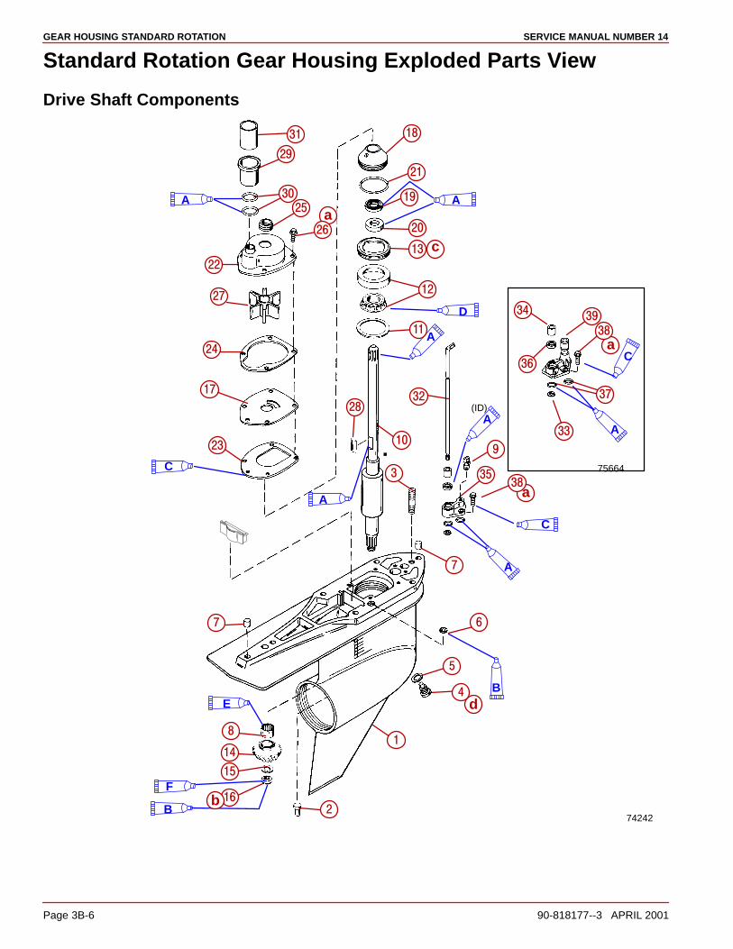
GEAR HOUSING STANDARD ROTATION SERVICE MANUAL NUMBER 14
Page 3B-6 90-818177--3 APRIL 2001
Standard Rotation Gear Housing Exploded Parts View
Drive Shaft Components
74242
A
D
A
A
A(ID)
C
A
B
A
E
C.
B
F
75664
A
C
��
��
��
�
a
b
c
a
a
d
��
��
��
��
��
��
��
��
��
��
��
�
�
�
��
����
��
�
��
��
��
��
�
�
�
�
�
�
�
��
�
����
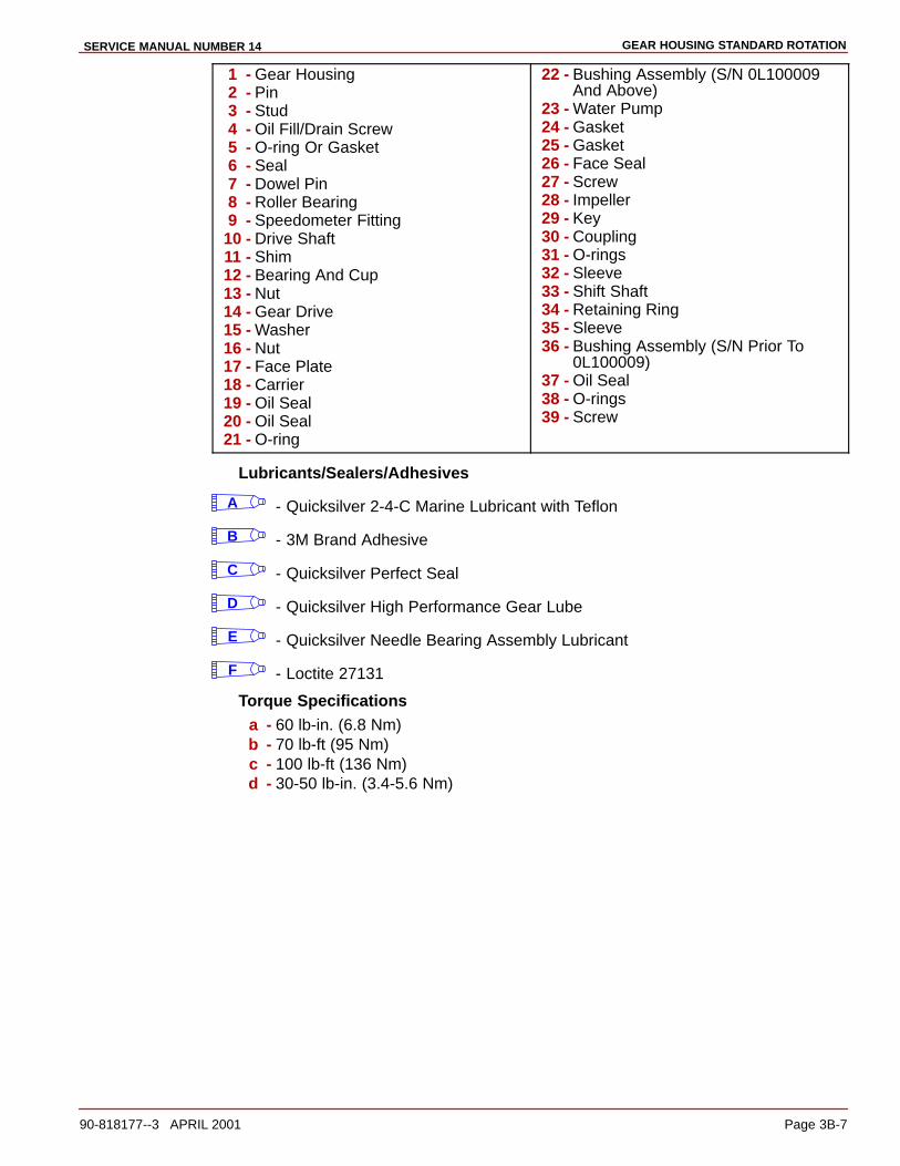
GEAR HOUSING STANDARD ROTATIONSERVICE MANUAL NUMBER 14
90-818177--3 APRIL 2001 Page 3B-7
1 - Gear Housing2 - Pin3 - Stud4 - Oil Fill/Drain Screw5 - O-ring Or Gasket6 - Seal7 - Dowel Pin8 - Roller Bearing9 - Speedometer Fitting
10 - Drive Shaft11 - Shim12 - Bearing And Cup13 - Nut14 - Gear Drive15 - Washer16 - Nut17 - Face Plate18 - Carrier19 - Oil Seal20 - Oil Seal21 - O-ring
22 - Bushing Assembly (S/N 0L100009And Above)
23 - Water Pump24 - Gasket25 - Gasket26 - Face Seal27 - Screw28 - Impeller29 - Key30 - Coupling31 - O-rings32 - Sleeve33 - Shift Shaft34 - Retaining Ring35 - Sleeve36 - Bushing Assembly (S/N Prior To
0L100009)37 - Oil Seal38 - O-rings39 - Screw
Lubricants/Sealers/Adhesives
A - Quicksilver 2-4-C Marine Lubricant with Teflon
B - 3M Brand Adhesive
C - Quicksilver Perfect Seal
D - Quicksilver High Performance Gear Lube
E - Quicksilver Needle Bearing Assembly Lubricant
F - Loctite 27131
Torque Specificationsa - 60 lb-in. (6.8 Nm)b - 70 lb-ft (95 Nm)c - 100 lb-ft (136 Nm)d - 30-50 lb-in. (3.4-5.6 Nm)

GEAR HOUSING STANDARD ROTATION SERVICE MANUAL NUMBER 14
Page 3B-8 90-818177--3 APRIL 2001
Propeller Shaft Components
F(OD)
A(ID)
C
C
CE
D
F
75691
��
a
b
d
e
��
�
��
��
��
�
�
�
�
�
��
�
��
�
��
��
�
��
�
��
��
����
��
��
���
��
�
��
��
��
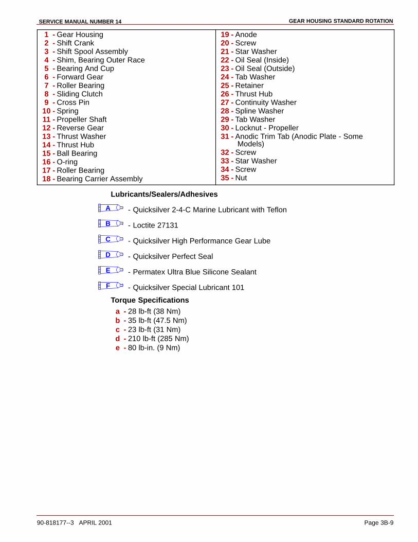
GEAR HOUSING STANDARD ROTATIONSERVICE MANUAL NUMBER 14
90-818177--3 APRIL 2001 Page 3B-9
1 - Gear Housing2 - Shift Crank3 - Shift Spool Assembly4 - Shim, Bearing Outer Race5 - Bearing And Cup6 - Forward Gear7 - Roller Bearing8 - Sliding Clutch9 - Cross Pin
10 - Spring11 - Propeller Shaft12 - Reverse Gear13 - Thrust Washer14 - Thrust Hub15 - Ball Bearing16 - O-ring17 - Roller Bearing18 - Bearing Carrier Assembly
19 - Anode20 - Screw21 - Star Washer22 - Oil Seal (Inside)23 - Oil Seal (Outside)24 - Tab Washer25 - Retainer26 - Thrust Hub27 - Continuity Washer28 - Spline Washer29 - Tab Washer30 - Locknut - Propeller31 - Anodic Trim Tab (Anodic Plate - Some
Models)32 - Screw33 - Star Washer34 - Screw35 - Nut
Lubricants/Sealers/Adhesives
A - Quicksilver 2-4-C Marine Lubricant with Teflon
B - Loctite 27131
C - Quicksilver High Performance Gear Lube
D - Quicksilver Perfect Seal
E - Permatex Ultra Blue Silicone Sealant
F - Quicksilver Special Lubricant 101
Torque Specificationsa - 28 lb-ft (38 Nm)b - 35 lb-ft (47.5 Nm)c - 23 lb-ft (31 Nm)d - 210 lb-ft (285 Nm)e - 80 lb-in. (9 Nm)

GEAR HOUSING STANDARD ROTATION SERVICE MANUAL NUMBER 14
Page 3B-10 90-818177--3 APRIL 2001
Special Information
CAUTIONAvoid damage to sterndrive unit. Drive unit damage will occur if Later Style partsare intermixed with Earlier Style parts
Shift Spool AssemblyThe later style shift spool assembly has a larger gap than the earlier style. This later styleshift spool beginning with serial number 0K041000 is sold as a whole assembly and can beused when replacing the earlier style (Prior to S/N 0K041000). The end play for the spoolwill remain the same as the earlier models (.002-.010 in. .051-.254 mm).
7521974877
cc
ab
a - Earlier Style Shift Spool Assembly (Prior To S/N 0K041000)b - Later Style Shift Spool Assembly (S/N 0K041000 And Above)c - Measure End Play Here At Gap

GEAR HOUSING STANDARD ROTATIONSERVICE MANUAL NUMBER 14
90-818177--3 APRIL 2001 Page 3B-11
Forward Gear Bearing BoreThe later style forward gear bearing bore is smaller (3.2635 to 3.2650 in.) than the earlierstyle (3.4985 to 3.5000 in.) This slightly smaller bearing bore for the forward gear bearingadapter is approximately 1/4 in. (6.3 mm) smaller.
75241
3.4985to3.5000
Earlier Style Forward Gear Bore (Prior to S/N OF680000)
75248
3.2635to3.2650
Later Style Forward Gear Bore (S/N OF680000 and Above)
The later style bearing cup is thinner and has a smaller diameter than the earlier style.
75256b
a
a - Earlier Style Gear Bearing Cup 3.500 in. Diameter (Prior To S/N OF680000)b - Later Style Gear Bearing Cup 3.265 in. Diameter (S/N OF680000 and Above)

GEAR HOUSING STANDARD ROTATION SERVICE MANUAL NUMBER 14
Page 3B-12 90-818177--3 APRIL 2001
Pre-Disassembly Inspection
Propeller
REMOVAL
1. If not already accomplished, remove the propeller and its mounting components.
Propeller Shaft
INSPECTION
1. Inspect the propeller shaft for side to side movement, as follows:
a. Position the dial indicator on the propeller shaft.
b. Push the propeller shaft to one side and zero the dial indicator.
c. Move the propeller shaft to the opposite side while observing the dial indicator.Ashaft deflection of more than .003 in. (0.08 mm) indicates a worn propeller shaftbearing.
2. Check for a bent propeller shaft as follows:
a. Rotate the drive shaft in gear while observing the dial indicator. If the deflection ismore than .007 in. (0.178 mm), a bent propeller shaft is indicated.
22086
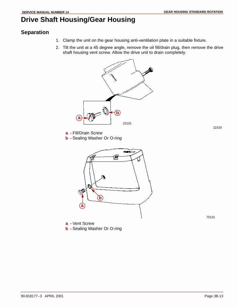
GEAR HOUSING STANDARD ROTATIONSERVICE MANUAL NUMBER 14
90-818177--3 APRIL 2001 Page 3B-13
Drive Shaft Housing/Gear Housing
Separation1. Clamp the unit on the gear housing anti-ventilation plate in a suitable fixture.
2. Tilt the unit at a 45 degree angle, remove the oil fill/drain plug, then remove the driveshaft housing vent screw. Allow the drive unit to drain completely.
2210122103
ab
a - Fill/Drain Screwb - Sealing Washer Or O-ring
70131
a
b
a - Vent Screwb - Sealing Washer Or O-ring
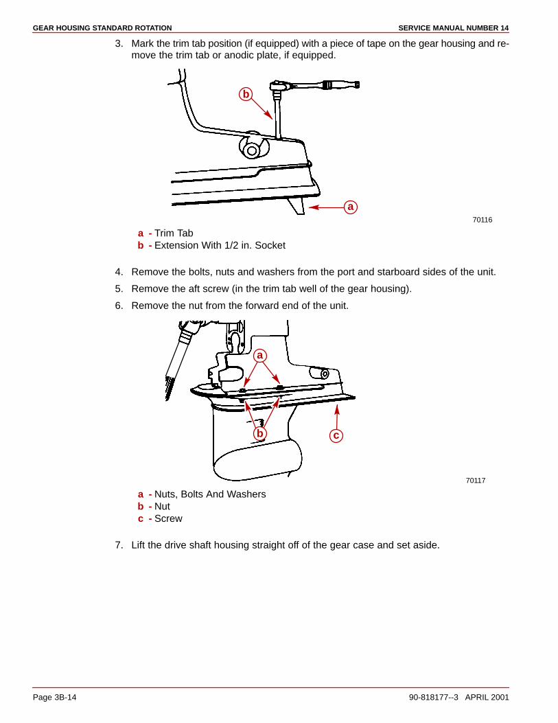
GEAR HOUSING STANDARD ROTATION SERVICE MANUAL NUMBER 14
Page 3B-14 90-818177--3 APRIL 2001
3. Mark the trim tab position (if equipped) with a piece of tape on the gear housing and re-move the trim tab or anodic plate, if equipped.
70116
a
b
a - Trim Tabb - Extension With 1/2 in. Socket
4. Remove the bolts, nuts and washers from the port and starboard sides of the unit.
5. Remove the aft screw (in the trim tab well of the gear housing).
6. Remove the nut from the forward end of the unit.
70117
a
cb
a - Nuts, Bolts And Washersb - Nutc - Screw
7. Lift the drive shaft housing straight off of the gear case and set aside.
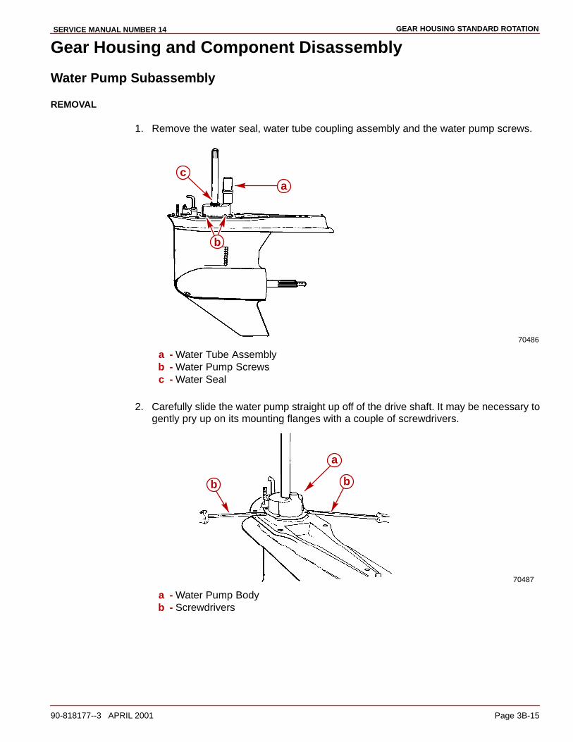
GEAR HOUSING STANDARD ROTATIONSERVICE MANUAL NUMBER 14
90-818177--3 APRIL 2001 Page 3B-15
Gear Housing and Component Disassembly
Water Pump Subassembly
REMOVAL
1. Remove the water seal, water tube coupling assembly and the water pump screws.
70486
ac
b
a - Water Tube Assemblyb - Water Pump Screwsc - Water Seal
2. Carefully slide the water pump straight up off of the drive shaft. It may be necessary togently pry up on its mounting flanges with a couple of screwdrivers.
70487
a
b b
a - Water Pump Bodyb - Screwdrivers
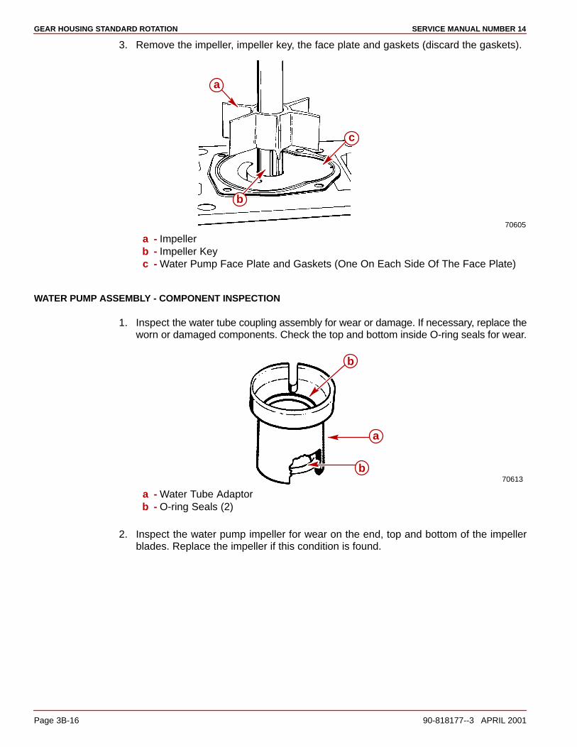
GEAR HOUSING STANDARD ROTATION SERVICE MANUAL NUMBER 14
Page 3B-16 90-818177--3 APRIL 2001
3. Remove the impeller, impeller key, the face plate and gaskets (discard the gaskets).
70605
c
a
b
a - Impellerb - Impeller Keyc - Water Pump Face Plate and Gaskets (One On Each Side Of The Face Plate)
WATER PUMP ASSEMBLY - COMPONENT INSPECTION
1. Inspect the water tube coupling assembly for wear or damage. If necessary, replace theworn or damaged components. Check the top and bottom inside O-ring seals for wear.
70613
b
a
b
a - Water Tube Adaptorb - O-ring Seals (2)
2. Inspect the water pump impeller for wear on the end, top and bottom of the impellerblades. Replace the impeller if this condition is found.

GEAR HOUSING STANDARD ROTATIONSERVICE MANUAL NUMBER 14
90-818177--3 APRIL 2001 Page 3B-17
3. Inspect for proper bonding between the hub and the impeller. Replace the impeller if im-proper bonding is found.
70500
ba
a - Impellerb - Hub
4. Inspect the impeller blades to see if they are hard or deformed. Replace the impeller ifthe blades are in this condition.
5. Inspect the water pump face plate and the water pump interior for roughness and/orgrooves. Replace the appropriate components if any are found.
70609
a b
a - Water Pump Face Plateb - Water Pump Body

GEAR HOUSING STANDARD ROTATION SERVICE MANUAL NUMBER 14
Page 3B-18 90-818177--3 APRIL 2001
Oil Seal Carrier Subassembly
REMOVAL
1. Remove the oil seal carrier from the gear housing. It may be necessary to gently pry upon it with two screwdrivers.
70489
a
b
a - Oil Seal Carrierb - Screwdrivers
OIL SEAL CARRIER - INSPECTION
1. Inspect the oil seal carrier, O-ring and seals for wear and/or damage. If necessary, re-place defective parts as follows.
OIL SEAL CARRIER - DISASSEMBLY
NOTE: Complete the instructions in this section only if the assembly components have beenfound to be defective and are in need of repair or replacement.
1. Remove the O-ring.
70501a
b
a - O-ringb - Oil Seals (2)
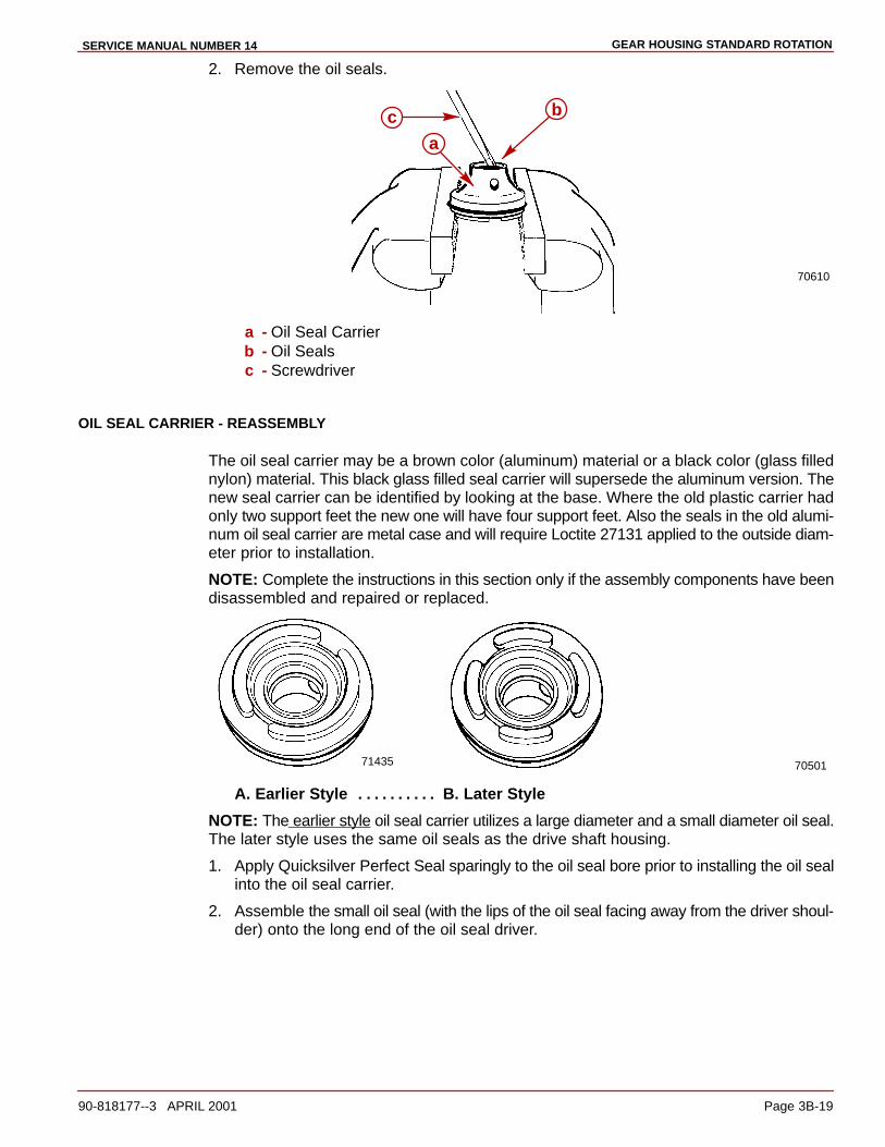
GEAR HOUSING STANDARD ROTATIONSERVICE MANUAL NUMBER 14
90-818177--3 APRIL 2001 Page 3B-19
2. Remove the oil seals.
70610
c b
a
a - Oil Seal Carrierb - Oil Sealsc - Screwdriver
OIL SEAL CARRIER - REASSEMBLY
The oil seal carrier may be a brown color (aluminum) material or a black color (glass fillednylon) material. This black glass filled seal carrier will supersede the aluminum version. Thenew seal carrier can be identified by looking at the base. Where the old plastic carrier hadonly two support feet the new one will have four support feet. Also the seals in the old alumi-num oil seal carrier are metal case and will require Loctite 27131 applied to the outside diam-eter prior to installation.
NOTE: Complete the instructions in this section only if the assembly components have beendisassembled and repaired or replaced.
7050171435
A. Earlier Style B. Later Style. . . . . . . . . .
NOTE: The earlier style oil seal carrier utilizes a large diameter and a small diameter oil seal.The later style uses the same oil seals as the drive shaft housing.
1. Apply Quicksilver Perfect Seal sparingly to the oil seal bore prior to installing the oil sealinto the oil seal carrier.
2. Assemble the small oil seal (with the lips of the oil seal facing away from the driver shoul-der) onto the long end of the oil seal driver.
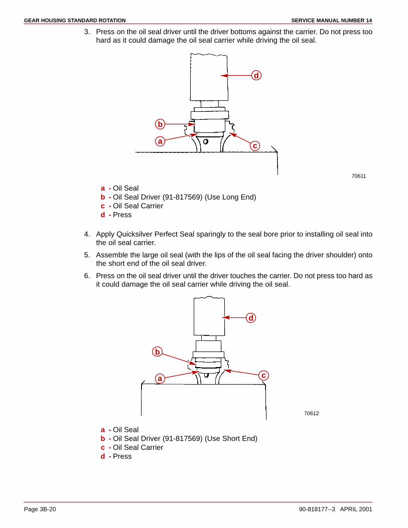
GEAR HOUSING STANDARD ROTATION SERVICE MANUAL NUMBER 14
Page 3B-20 90-818177--3 APRIL 2001
3. Press on the oil seal driver until the driver bottoms against the carrier. Do not press toohard as it could damage the oil seal carrier while driving the oil seal.
70611
d
ca
b
a - Oil Sealb - Oil Seal Driver (91-817569) (Use Long End)c - Oil Seal Carrierd - Press
4. Apply Quicksilver Perfect Seal sparingly to the seal bore prior to installing oil seal intothe oil seal carrier.
5. Assemble the large oil seal (with the lips of the oil seal facing the driver shoulder) ontothe short end of the oil seal driver.
6. Press on the oil seal driver until the driver touches the carrier. Do not press too hard asit could damage the oil seal carrier while driving the oil seal.
70612
a
b
d
c
a - Oil Sealb - Oil Seal Driver (91-817569) (Use Short End)c - Oil Seal Carrierd - Press
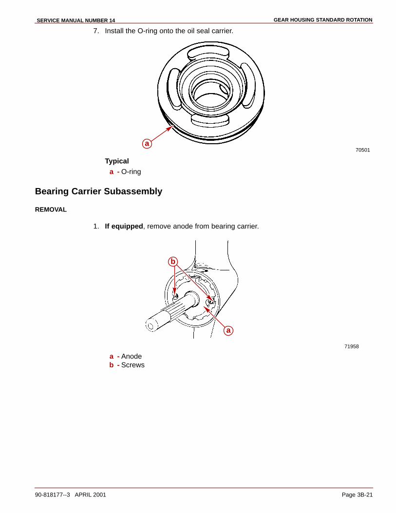
GEAR HOUSING STANDARD ROTATIONSERVICE MANUAL NUMBER 14
90-818177--3 APRIL 2001 Page 3B-21
7. Install the O-ring onto the oil seal carrier.
70501a
Typicala - O-ring
Bearing Carrier Subassembly
REMOVAL
1. If equipped, remove anode from bearing carrier.
71958
a
b
a - Anodeb - Screws
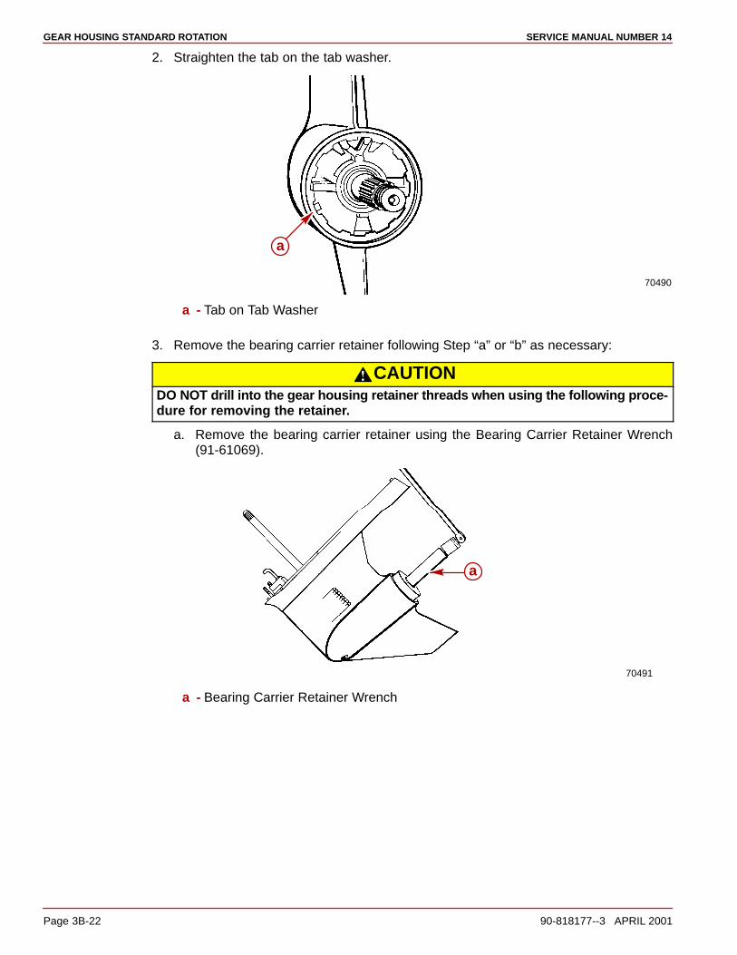
GEAR HOUSING STANDARD ROTATION SERVICE MANUAL NUMBER 14
Page 3B-22 90-818177--3 APRIL 2001
2. Straighten the tab on the tab washer.
70490
a
a - Tab on Tab Washer
3. Remove the bearing carrier retainer following Step “a” or “b” as necessary:
CAUTIONDO NOT drill into the gear housing retainer threads when using the following proce-dure for removing the retainer.
a. Remove the bearing carrier retainer using the Bearing Carrier Retainer Wrench(91-61069).
70491
a
a - Bearing Carrier Retainer Wrench

GEAR HOUSING STANDARD ROTATIONSERVICE MANUAL NUMBER 14
90-818177--3 APRIL 2001 Page 3B-23
b. If the retainer is corroded in place, drill 4 holes in the retainer and fracture the retainerwith a chisel. Pry the remaining segments out.
23356
a
a - Drilled Holes
FOR EARLIER STYLE UNITS:
CAUTIONDO NOT pull on the bearing carrier outer ring, as damage to the carrier will result.
4. Pull the bearing carrier from the gear housing by the inner bosses located on the centerarea by the oil seals.
NOTE: If the bearing carrier is seized in the gear housing, it may be necessary to use heatto loosen the carrier.
70934
a
b
Earlier Style Unitsa - Puller Jaws (91-46086 A1)b - Puller Bolt (91-85716)
FOR LATER STYLE UNITS:
5. Pull the bearing carrier from the gear housing by pulling on the outer ring of the bearingcarrier.

GEAR HOUSING STANDARD ROTATION SERVICE MANUAL NUMBER 14
Page 3B-24 90-818177--3 APRIL 2001
NOTE: If the bearing carrier is seized in the gear housing, it may be necessary to use heatto loosen the carrier.
70492
b
a
Later Style Unitsa - Puller Jaws (91-46086 A1)b - Puller Bolt (91-85716)
NOTE: Puller jaws are oriented differently on the Earlier Style and the Later Style Units.
BEARING CARRIER ASSEMBLY - INSPECTION
1. Clean the assembly with a suitable solvent and dry the parts thoroughly using com-pressed air.
NOTE: If any of the following items are found to be defective complete the appropriate in-struction(s) in “Bearing Carrier Assembly.”
2. Inspect the bearing carrier for signs of excessive corrosion especially in the area wherethe bearing carrier touches the gear housing. If excessive corrosion is evident, replacethe carrier.
50314
a
b
a - Bearing Carrierb - Mating Surfaces
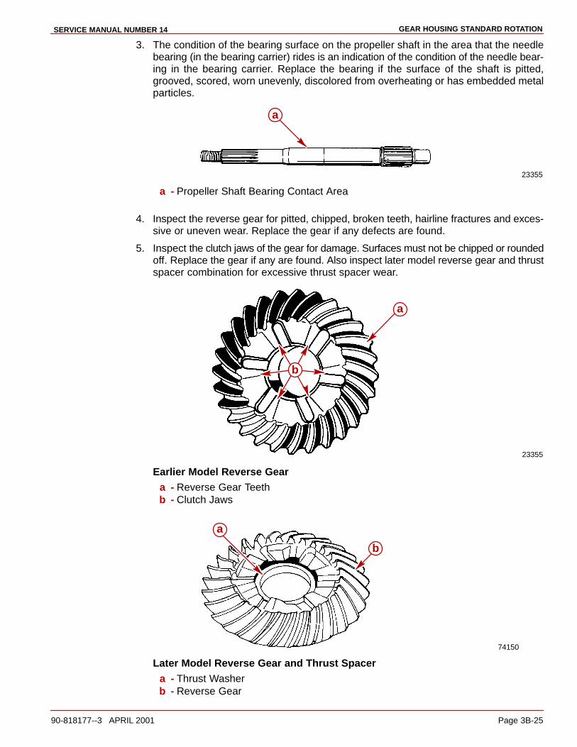
GEAR HOUSING STANDARD ROTATIONSERVICE MANUAL NUMBER 14
90-818177--3 APRIL 2001 Page 3B-25
3. The condition of the bearing surface on the propeller shaft in the area that the needlebearing (in the bearing carrier) rides is an indication of the condition of the needle bear-ing in the bearing carrier. Replace the bearing if the surface of the shaft is pitted,grooved, scored, worn unevenly, discolored from overheating or has embedded metalparticles.
23355
a
a - Propeller Shaft Bearing Contact Area
4. Inspect the reverse gear for pitted, chipped, broken teeth, hairline fractures and exces-sive or uneven wear. Replace the gear if any defects are found.
5. Inspect the clutch jaws of the gear for damage. Surfaces must not be chipped or roundedoff. Replace the gear if any are found. Also inspect later model reverse gear and thrustspacer combination for excessive thrust spacer wear.
23355
a
b
Earlier Model Reverse Geara - Reverse Gear Teethb - Clutch Jaws
74150
a
b
Later Model Reverse Gear and Thrust Spacera - Thrust Washerb - Reverse Gear
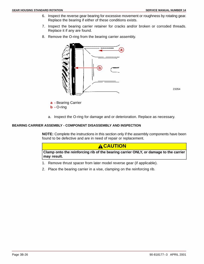
GEAR HOUSING STANDARD ROTATION SERVICE MANUAL NUMBER 14
Page 3B-26 90-818177--3 APRIL 2001
6. Inspect the reverse gear bearing for excessive movement or roughness by rotating gear.Replace the bearing if either of these conditions exists.
7. Inspect the bearing carrier retainer for cracks and/or broken or corroded threads.Replace it if any are found.
8. Remove the O-ring from the bearing carrier assembly.
23354
a
b
a - Bearing Carrierb - O-ring
a. Inspect the O-ring for damage and or deterioration. Replace as necessary.
BEARING CARRIER ASSEMBLY - COMPONENT DISASSEMBLY AND INSPECTION
NOTE: Complete the instructions in this section only if the assembly components have beenfound to be defective and are in need of repair or replacement.
CAUTIONClamp onto the reinforcing rib of the bearing carrier ONLY, or damage to the carriermay result.
1. Remove thrust spacer from later model reverse gear (if applicable).
2. Place the bearing carrier in a vise, clamping on the reinforcing rib.
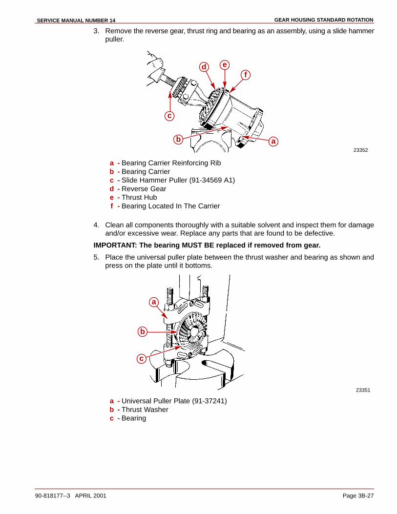
GEAR HOUSING STANDARD ROTATIONSERVICE MANUAL NUMBER 14
90-818177--3 APRIL 2001 Page 3B-27
3. Remove the reverse gear, thrust ring and bearing as an assembly, using a slide hammerpuller.
23352
ab
c
d ef
a - Bearing Carrier Reinforcing Ribb - Bearing Carrierc - Slide Hammer Puller (91-34569 A1)d - Reverse Geare - Thrust Hubf - Bearing Located In The Carrier
4. Clean all components thoroughly with a suitable solvent and inspect them for damageand/or excessive wear. Replace any parts that are found to be defective.
IMPORTANT: The bearing MUST BE replaced if removed from gear.
5. Place the universal puller plate between the thrust washer and bearing as shown andpress on the plate until it bottoms.
23351
a
c
b
a - Universal Puller Plate (91-37241)b - Thrust Washerc - Bearing
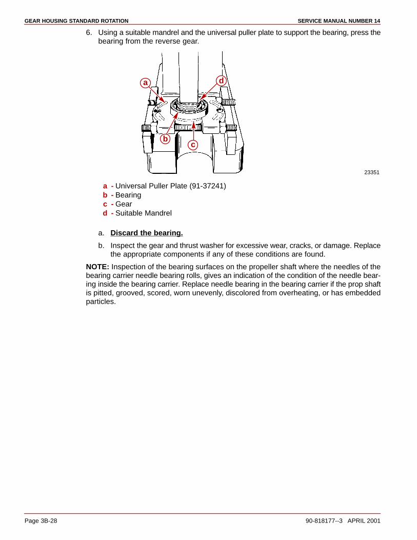
GEAR HOUSING STANDARD ROTATION SERVICE MANUAL NUMBER 14
Page 3B-28 90-818177--3 APRIL 2001
6. Using a suitable mandrel and the universal puller plate to support the bearing, press thebearing from the reverse gear.
23351
a
bc
d
a - Universal Puller Plate (91-37241)b - Bearingc - Geard - Suitable Mandrel
a. Discard the bearing.
b. Inspect the gear and thrust washer for excessive wear, cracks, or damage. Replacethe appropriate components if any of these conditions are found.
NOTE: Inspection of the bearing surfaces on the propeller shaft where the needles of thebearing carrier needle bearing rolls, gives an indication of the condition of the needle bear-ing inside the bearing carrier. Replace needle bearing in the bearing carrier if the prop shaftis pitted, grooved, scored, worn unevenly, discolored from overheating, or has embeddedparticles.

GEAR HOUSING STANDARD ROTATIONSERVICE MANUAL NUMBER 14
90-818177--3 APRIL 2001 Page 3B-29
7. Perform Step “a” or “b” as necessary.
a. If Replacing The Needle Bearing And Seals: Remove the needle bearing andseals with the tools as shown. Discard the needle bearing and both seals.
23140
a
b
c
d
a - Bearing Driver Rod (91-37323)b - Driver Head (91-36569)c - Needle Bearingd - Oil Seals
b. If Replacing The Seal Only: Remove the oil seals with a suitable pry bar, beingcareful not to damage the bore of the bearing carrier. Discard both of the seals.
23140
ba
a - Oil Sealsb - Pry Bar
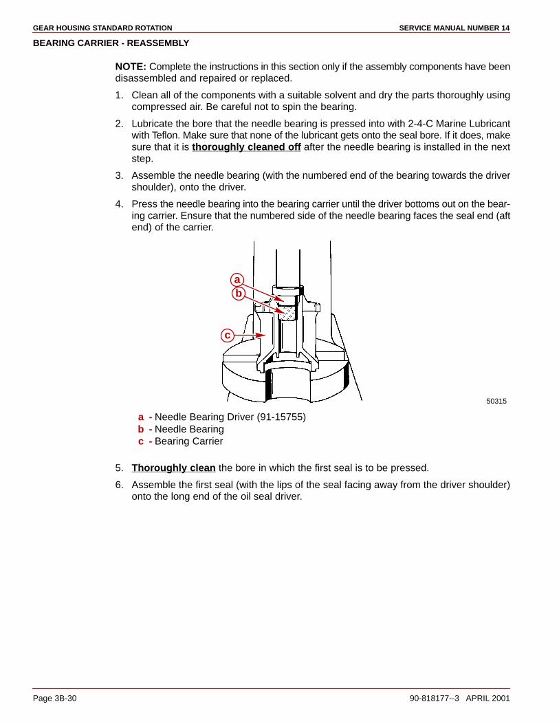
GEAR HOUSING STANDARD ROTATION SERVICE MANUAL NUMBER 14
Page 3B-30 90-818177--3 APRIL 2001
BEARING CARRIER - REASSEMBLY
NOTE: Complete the instructions in this section only if the assembly components have beendisassembled and repaired or replaced.
1. Clean all of the components with a suitable solvent and dry the parts thoroughly usingcompressed air. Be careful not to spin the bearing.
2. Lubricate the bore that the needle bearing is pressed into with 2-4-C Marine Lubricantwith Teflon. Make sure that none of the lubricant gets onto the seal bore. If it does, makesure that it is thoroughly cleaned off after the needle bearing is installed in the nextstep.
3. Assemble the needle bearing (with the numbered end of the bearing towards the drivershoulder), onto the driver.
4. Press the needle bearing into the bearing carrier until the driver bottoms out on the bear-ing carrier. Ensure that the numbered side of the needle bearing faces the seal end (aftend) of the carrier.
50315
c
ba
a - Needle Bearing Driver (91-15755)b - Needle Bearingc - Bearing Carrier
5. Thoroughly clean the bore in which the first seal is to be pressed.
6. Assemble the first seal (with the lips of the seal facing away from the driver shoulder)onto the long end of the oil seal driver.
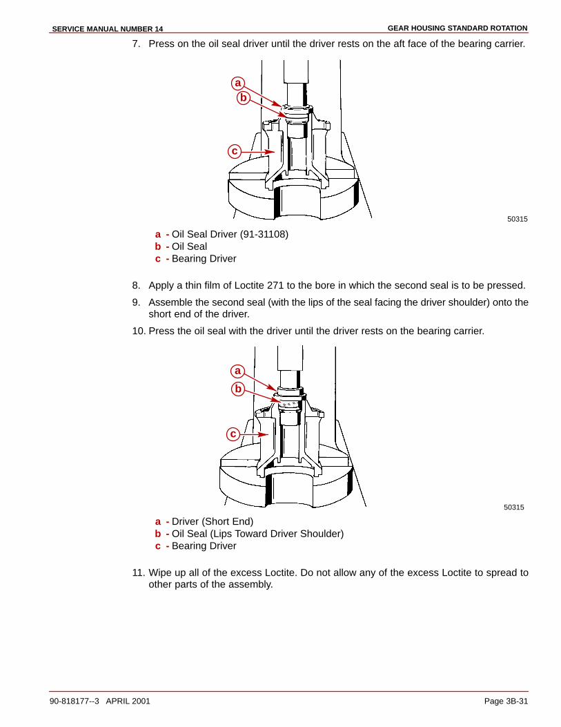
GEAR HOUSING STANDARD ROTATIONSERVICE MANUAL NUMBER 14
90-818177--3 APRIL 2001 Page 3B-31
7. Press on the oil seal driver until the driver rests on the aft face of the bearing carrier.
50315
c
ab
a - Oil Seal Driver (91-31108)b - Oil Sealc - Bearing Driver
8. Apply a thin film of Loctite 271 to the bore in which the second seal is to be pressed.
9. Assemble the second seal (with the lips of the seal facing the driver shoulder) onto theshort end of the driver.
10. Press the oil seal with the driver until the driver rests on the bearing carrier.
50315
a
b
c
a - Driver (Short End)b - Oil Seal (Lips Toward Driver Shoulder)c - Bearing Driver
11. Wipe up all of the excess Loctite. Do not allow any of the excess Loctite to spread toother parts of the assembly.
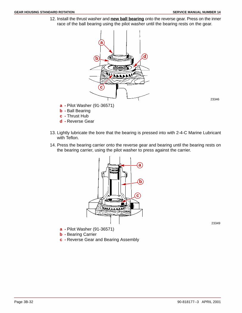
GEAR HOUSING STANDARD ROTATION SERVICE MANUAL NUMBER 14
Page 3B-32 90-818177--3 APRIL 2001
12. Install the thrust washer and new ball bearing onto the reverse gear. Press on the innerrace of the ball bearing using the pilot washer until the bearing rests on the gear.
23346
a
b
c
d
a - Pilot Washer (91-36571)b - Ball Bearingc - Thrust Hubd - Reverse Gear
13. Lightly lubricate the bore that the bearing is pressed into with 2-4-C Marine Lubricantwith Teflon.
14. Press the bearing carrier onto the reverse gear and bearing until the bearing rests onthe bearing carrier, using the pilot washer to press against the carrier.
23349
a
b
c
a - Pilot Washer (91-36571)b - Bearing Carrierc - Reverse Gear and Bearing Assembly

GEAR HOUSING STANDARD ROTATIONSERVICE MANUAL NUMBER 14
90-818177--3 APRIL 2001 Page 3B-33
15. Install the O-ring onto the bearing carrier.
23354
b
a
a - O-ringb - Bearing Carrier
16. If equipped with thrust spacer, install it into gear as shown.
71910
a
b
a - Thrust Spacerb - Reverse Gear
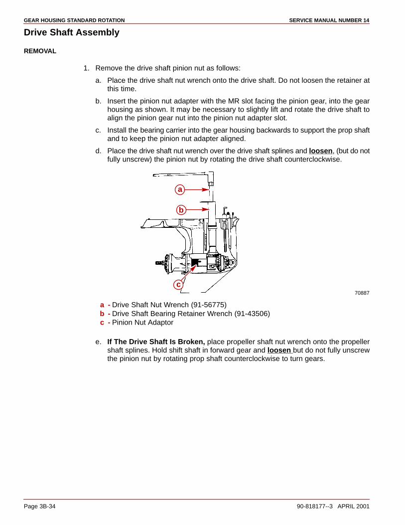
GEAR HOUSING STANDARD ROTATION SERVICE MANUAL NUMBER 14
Page 3B-34 90-818177--3 APRIL 2001
Drive Shaft Assembly
REMOVAL
1. Remove the drive shaft pinion nut as follows:
a. Place the drive shaft nut wrench onto the drive shaft. Do not loosen the retainer atthis time.
b. Insert the pinion nut adapter with the MR slot facing the pinion gear, into the gearhousing as shown. It may be necessary to slightly lift and rotate the drive shaft toalign the pinion gear nut into the pinion nut adapter slot.
c. Install the bearing carrier into the gear housing backwards to support the prop shaftand to keep the pinion nut adapter aligned.
d. Place the drive shaft nut wrench over the drive shaft splines and loosen, (but do notfully unscrew) the pinion nut by rotating the drive shaft counterclockwise.
70887
a
b
c
a - Drive Shaft Nut Wrench (91-56775)b - Drive Shaft Bearing Retainer Wrench (91-43506)c - Pinion Nut Adaptor
e. If The Drive Shaft Is Broken, place propeller shaft nut wrench onto the propellershaft splines. Hold shift shaft in forward gear and loosen but do not fully unscrewthe pinion nut by rotating prop shaft counterclockwise to turn gears.
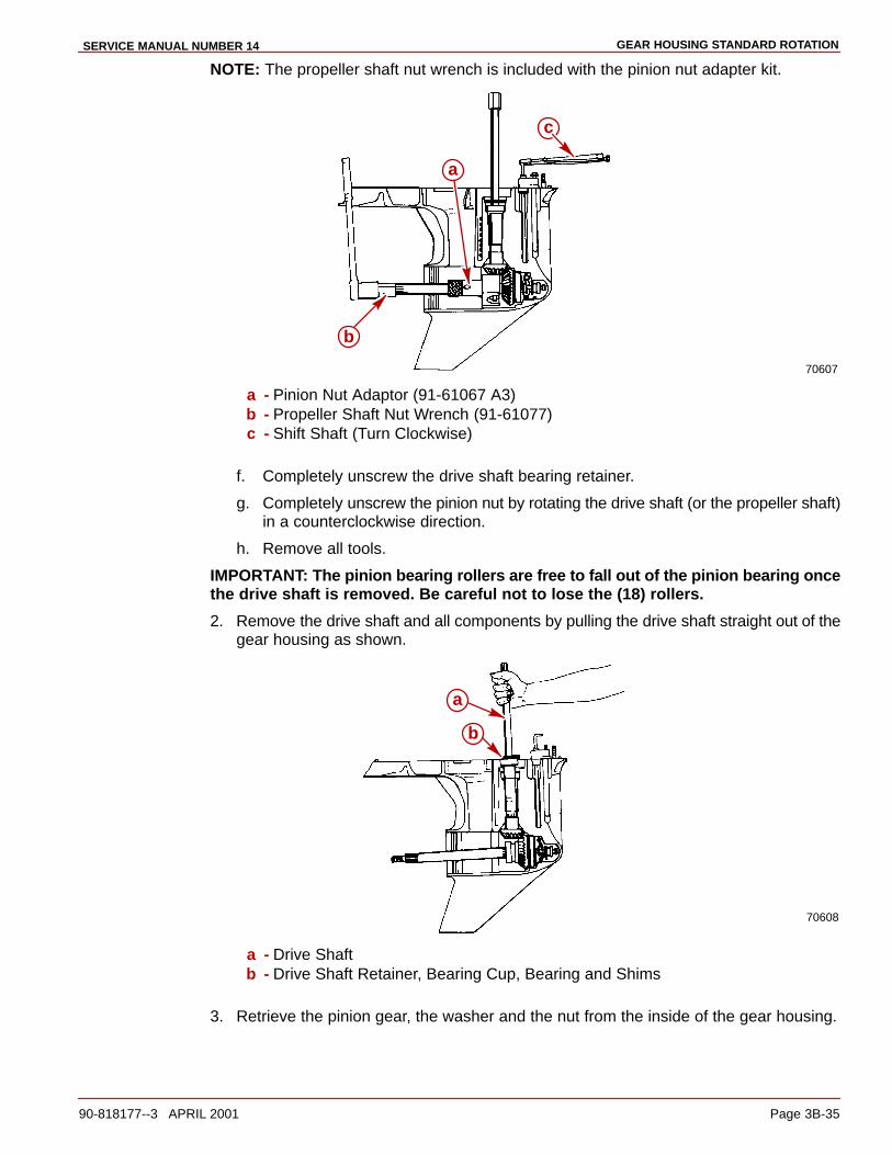
GEAR HOUSING STANDARD ROTATIONSERVICE MANUAL NUMBER 14
90-818177--3 APRIL 2001 Page 3B-35
NOTE: The propeller shaft nut wrench is included with the pinion nut adapter kit.
70607
c
b
a
a - Pinion Nut Adaptor (91-61067 A3)b - Propeller Shaft Nut Wrench (91-61077)c - Shift Shaft (Turn Clockwise)
f. Completely unscrew the drive shaft bearing retainer.
g. Completely unscrew the pinion nut by rotating the drive shaft (or the propeller shaft)in a counterclockwise direction.
h. Remove all tools.
IMPORTANT: The pinion bearing rollers are free to fall out of the pinion bearing oncethe drive shaft is removed. Be careful not to lose the (18) rollers.
2. Remove the drive shaft and all components by pulling the drive shaft straight out of thegear housing as shown.
70608
b
a
a - Drive Shaftb - Drive Shaft Retainer, Bearing Cup, Bearing and Shims
3. Retrieve the pinion gear, the washer and the nut from the inside of the gear housing.
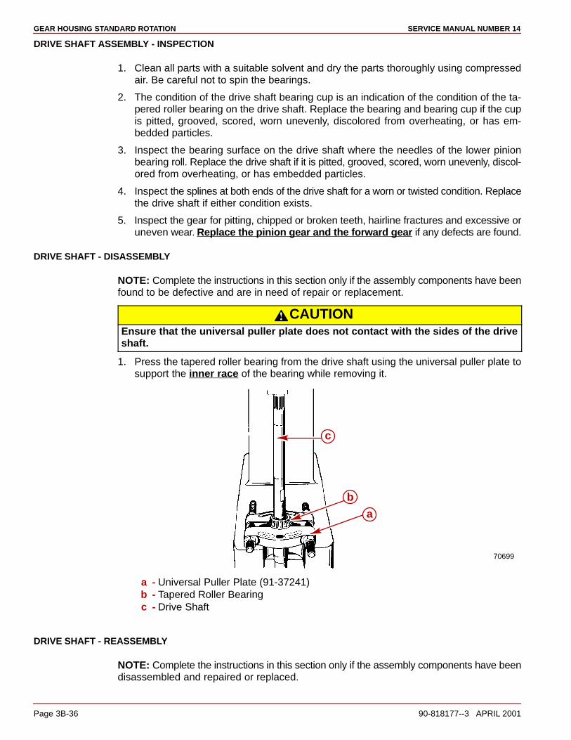
GEAR HOUSING STANDARD ROTATION SERVICE MANUAL NUMBER 14
Page 3B-36 90-818177--3 APRIL 2001
DRIVE SHAFT ASSEMBLY - INSPECTION
1. Clean all parts with a suitable solvent and dry the parts thoroughly using compressedair. Be careful not to spin the bearings.
2. The condition of the drive shaft bearing cup is an indication of the condition of the ta-pered roller bearing on the drive shaft. Replace the bearing and bearing cup if the cupis pitted, grooved, scored, worn unevenly, discolored from overheating, or has em-bedded particles.
3. Inspect the bearing surface on the drive shaft where the needles of the lower pinionbearing roll. Replace the drive shaft if it is pitted, grooved, scored, worn unevenly, discol-ored from overheating, or has embedded particles.
4. Inspect the splines at both ends of the drive shaft for a worn or twisted condition. Replacethe drive shaft if either condition exists.
5. Inspect the gear for pitting, chipped or broken teeth, hairline fractures and excessive oruneven wear. Replace the pinion gear and the forward gear if any defects are found.
DRIVE SHAFT - DISASSEMBLY
NOTE: Complete the instructions in this section only if the assembly components have beenfound to be defective and are in need of repair or replacement.
CAUTIONEnsure that the universal puller plate does not contact with the sides of the driveshaft.
1. Press the tapered roller bearing from the drive shaft using the universal puller plate tosupport the inner race of the bearing while removing it.
70699
c
b
a
a - Universal Puller Plate (91-37241)b - Tapered Roller Bearingc - Drive Shaft
DRIVE SHAFT - REASSEMBLY
NOTE: Complete the instructions in this section only if the assembly components have beendisassembled and repaired or replaced.

GEAR HOUSING STANDARD ROTATIONSERVICE MANUAL NUMBER 14
90-818177--3 APRIL 2001 Page 3B-37
CAUTIONEnsure that the universal puller plate does not make contact with the sides of thedrive shaft.
1. Assemble a new tapered roller bearing on the drive shaft with the large O.D. of the bear-ing facing the pinion gear end of the drive shaft.
2. Press the tapered roller bearing onto the drive shaft using the universal puller plate anda suitable mandrel (an old tapered roller bearing inner race).
77707
bc
a
a - Universal Puller Plate (91-37241)b - Tapered Roller Bearingc - Suitable Mandrel
Propeller Shaft Assembly and Forward Gear Bearing Cup
REMOVAL
1. Tilt the propeller shaft to the port side of the gear housing and remove the shaft by pullingit up and out.
23348
a
bc
a - Propeller Shaft Assemblyb - Shift Spoolc - Shift Crank
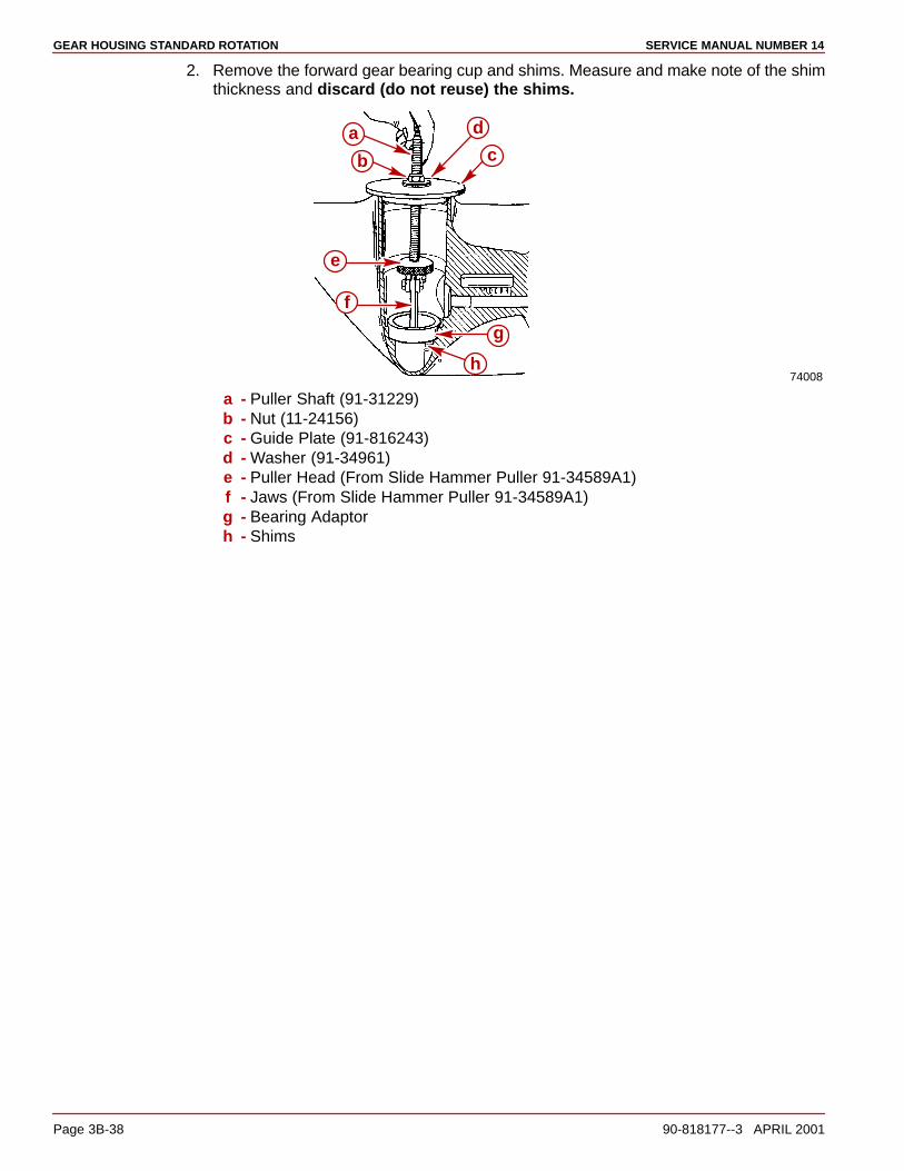
GEAR HOUSING STANDARD ROTATION SERVICE MANUAL NUMBER 14
Page 3B-38 90-818177--3 APRIL 2001
2. Remove the forward gear bearing cup and shims. Measure and make note of the shimthickness and discard (do not reuse) the shims.
74008
a
b
d
c
e
f
g
h
a - Puller Shaft (91-31229)b - Nut (11-24156)c - Guide Plate (91-816243)d - Washer (91-34961)e - Puller Head (From Slide Hammer Puller 91-34589A1)f - Jaws (From Slide Hammer Puller 91-34589A1)g - Bearing Adaptorh - Shims
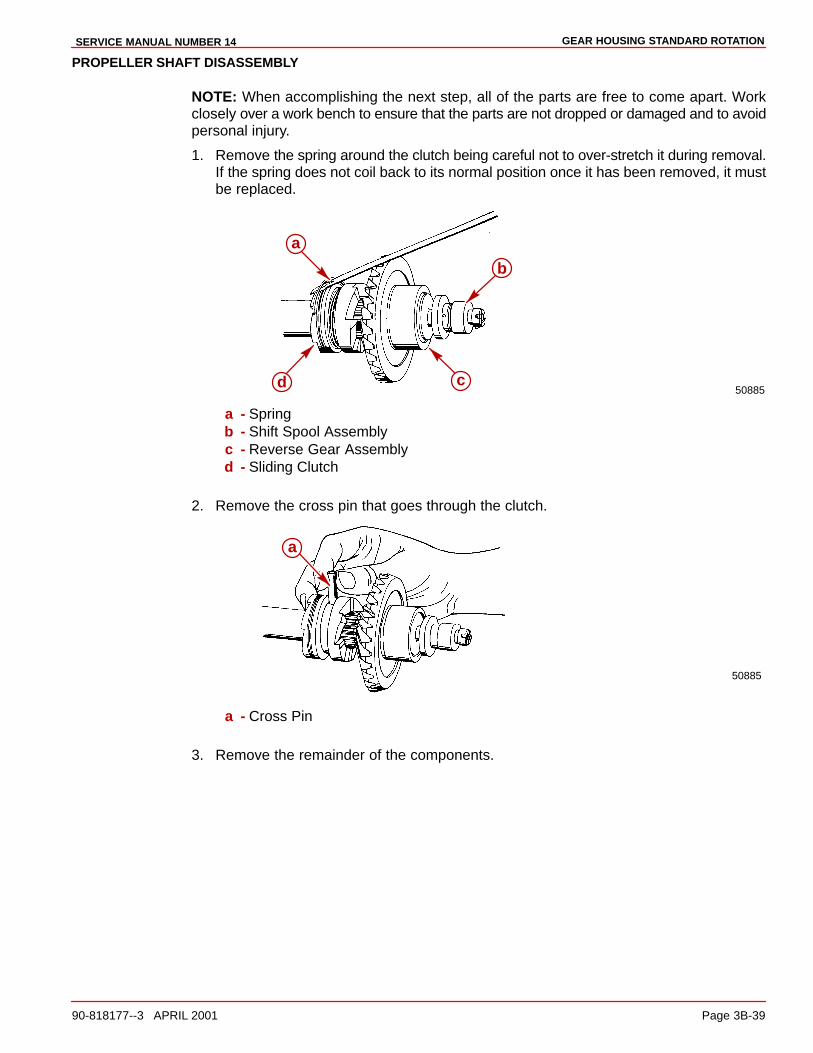
GEAR HOUSING STANDARD ROTATIONSERVICE MANUAL NUMBER 14
90-818177--3 APRIL 2001 Page 3B-39
PROPELLER SHAFT DISASSEMBLY
NOTE: When accomplishing the next step, all of the parts are free to come apart. Workclosely over a work bench to ensure that the parts are not dropped or damaged and to avoidpersonal injury.
1. Remove the spring around the clutch being careful not to over-stretch it during removal.If the spring does not coil back to its normal position once it has been removed, it mustbe replaced.
50885d c
b
a
a - Springb - Shift Spool Assemblyc - Reverse Gear Assemblyd - Sliding Clutch
2. Remove the cross pin that goes through the clutch.
50885
a
a - Cross Pin
3. Remove the remainder of the components.
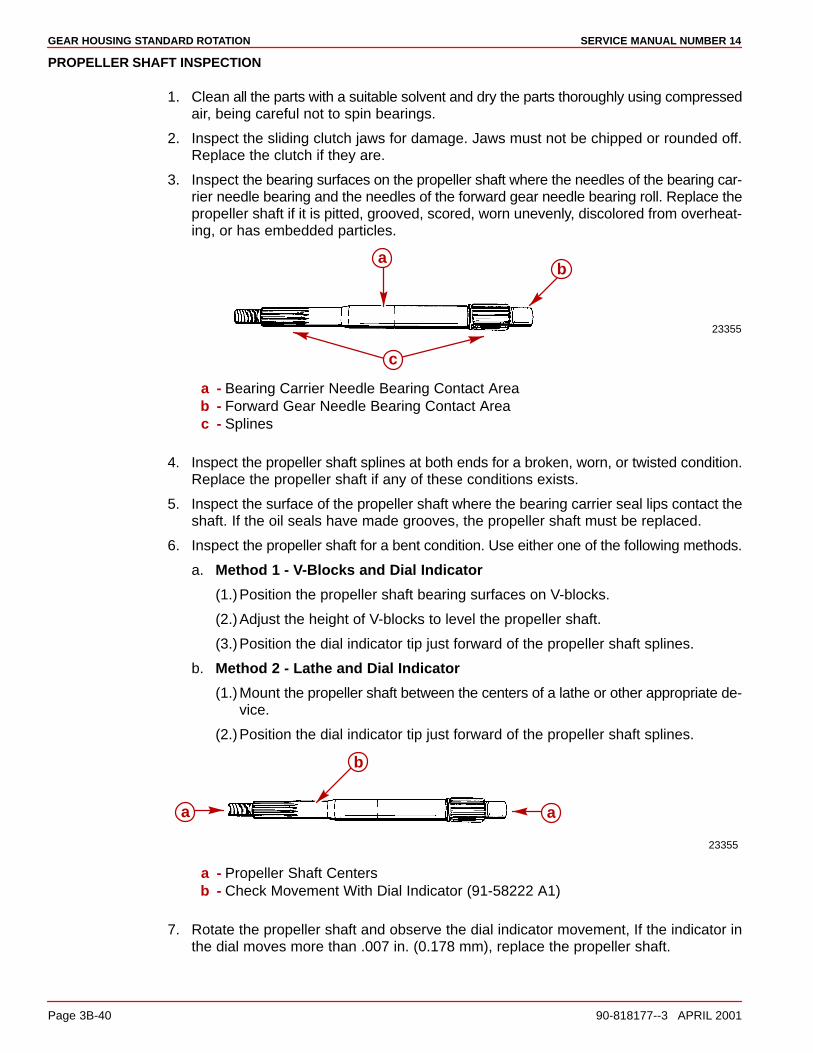
GEAR HOUSING STANDARD ROTATION SERVICE MANUAL NUMBER 14
Page 3B-40 90-818177--3 APRIL 2001
PROPELLER SHAFT INSPECTION
1. Clean all the parts with a suitable solvent and dry the parts thoroughly using compressedair, being careful not to spin bearings.
2. Inspect the sliding clutch jaws for damage. Jaws must not be chipped or rounded off.Replace the clutch if they are.
3. Inspect the bearing surfaces on the propeller shaft where the needles of the bearing car-rier needle bearing and the needles of the forward gear needle bearing roll. Replace thepropeller shaft if it is pitted, grooved, scored, worn unevenly, discolored from overheat-ing, or has embedded particles.
23355
ba
c
a - Bearing Carrier Needle Bearing Contact Areab - Forward Gear Needle Bearing Contact Areac - Splines
4. Inspect the propeller shaft splines at both ends for a broken, worn, or twisted condition.Replace the propeller shaft if any of these conditions exists.
5. Inspect the surface of the propeller shaft where the bearing carrier seal lips contact theshaft. If the oil seals have made grooves, the propeller shaft must be replaced.
6. Inspect the propeller shaft for a bent condition. Use either one of the following methods.
a. Method 1 - V-Blocks and Dial Indicator
(1.)Position the propeller shaft bearing surfaces on V-blocks.
(2.)Adjust the height of V-blocks to level the propeller shaft.
(3.)Position the dial indicator tip just forward of the propeller shaft splines.
b. Method 2 - Lathe and Dial Indicator
(1.)Mount the propeller shaft between the centers of a lathe or other appropriate de-vice.
(2.)Position the dial indicator tip just forward of the propeller shaft splines.
23355
b
aa
a - Propeller Shaft Centersb - Check Movement With Dial Indicator (91-58222 A1)
7. Rotate the propeller shaft and observe the dial indicator movement, If the indicator inthe dial moves more than .007 in. (0.178 mm), replace the propeller shaft.
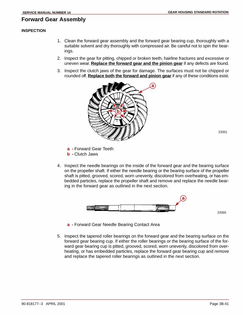
GEAR HOUSING STANDARD ROTATIONSERVICE MANUAL NUMBER 14
90-818177--3 APRIL 2001 Page 3B-41
Forward Gear Assembly
INSPECTION
1. Clean the forward gear assembly and the forward gear bearing cup, thoroughly with asuitable solvent and dry thoroughly with compressed air. Be careful not to spin the bear-ings.
2. Inspect the gear for pitting, chipped or broken teeth, hairline fractures and excessive oruneven wear. Replace the forward gear and the pinion gear if any defects are found.
3. Inspect the clutch jaws of the gear for damage. The surfaces must not be chipped orrounded off. Replace both the forward and pinion gear if any of these conditions exist.
23351
a
b
a - Forward Gear Teethb - Clutch Jaws
4. Inspect the needle bearings on the inside of the forward gear and the bearing surfaceon the propeller shaft. If either the needle bearing or the bearing surface of the propellershaft is pitted, grooved, scored, worn unevenly, discolored from overheating, or has em-bedded particles, replace the propeller shaft and remove and replace the needle bear-ing in the forward gear as outlined in the next section.
23355
a
a - Forward Gear Needle Bearing Contact Area
5. Inspect the tapered roller bearings on the forward gear and the bearing surface on theforward gear bearing cup. If either the roller bearings or the bearing surface of the for-ward gear bearing cup is pitted, grooved, scored, worn unevenly, discolored from over-heating, or has embedded particles, replace the forward gear bearing cup and removeand replace the tapered roller bearings as outlined in the next section.

GEAR HOUSING STANDARD ROTATION SERVICE MANUAL NUMBER 14
Page 3B-42 90-818177--3 APRIL 2001
FORWARD GEAR DISASSEMBLY
NOTE: Complete the instructions in this section only if the assembly components have beenfound to be defective and are in need of repair or replacement.
NOTE: The forward gear needle bearing case is made of a very high tensile steel. Removalof the bearing by conventional methods (e.g. - chisel and hammer or mandrel and press)may be very difficult. A notch in the casing may be made with the use of a high speed grinder.
1. Remove the forward gear needle bearing.
23352
a
a - Forward Gear Needle Bearing
2. If it has been determined by previous inspection that the forward gear or tapered rollerbearing needs to be replaced, remove the tapered roller bearing from the forward gearas follows:
a. Cut off the roller bearing cage and remove rollers.
NOTE: It may be necessary to grind a groove at the top lip of the bearing race to providea lip for the universal puller plate.
b. Press the gear from the bearing race, using a suitable mandrel.
23141
a b
c
a - Universal Puller Plate (91-37241)b - Inner Bearing Racec - Forward Gear
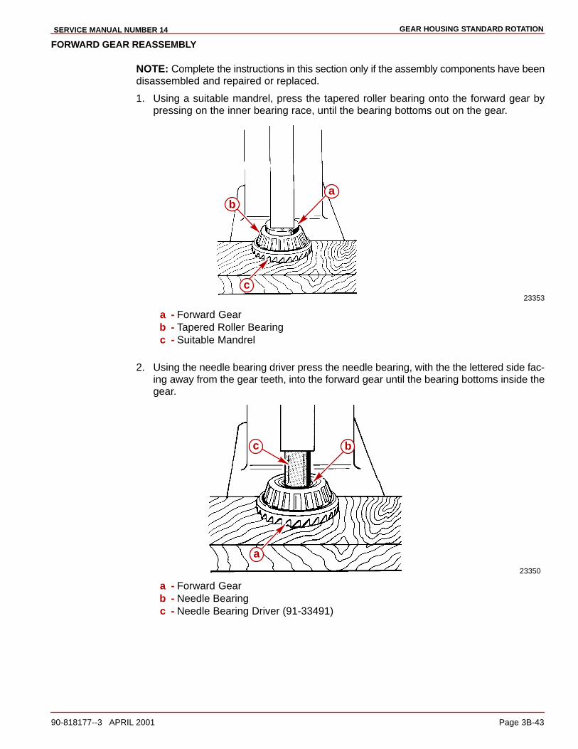
GEAR HOUSING STANDARD ROTATIONSERVICE MANUAL NUMBER 14
90-818177--3 APRIL 2001 Page 3B-43
FORWARD GEAR REASSEMBLY
NOTE: Complete the instructions in this section only if the assembly components have beendisassembled and repaired or replaced.
1. Using a suitable mandrel, press the tapered roller bearing onto the forward gear bypressing on the inner bearing race, until the bearing bottoms out on the gear.
23353
ab
c
a - Forward Gearb - Tapered Roller Bearingc - Suitable Mandrel
2. Using the needle bearing driver press the needle bearing, with the the lettered side fac-ing away from the gear teeth, into the forward gear until the bearing bottoms inside thegear.
23350
a
bc
a - Forward Gearb - Needle Bearingc - Needle Bearing Driver (91-33491)
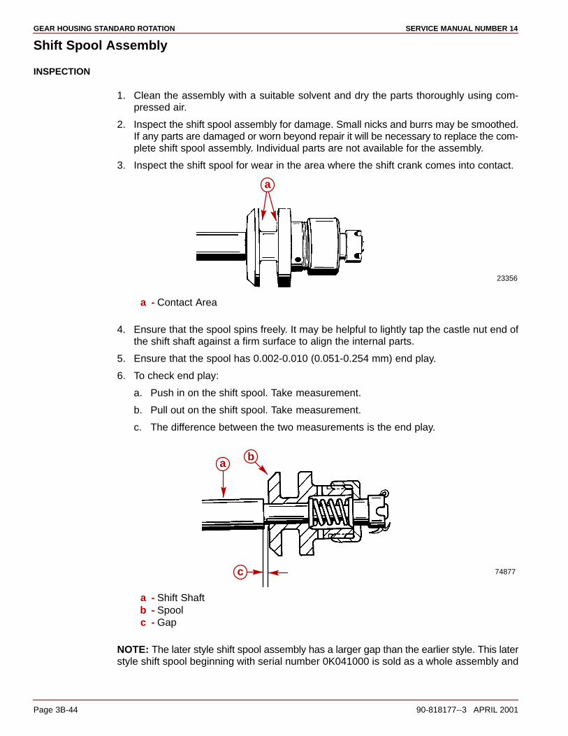
GEAR HOUSING STANDARD ROTATION SERVICE MANUAL NUMBER 14
Page 3B-44 90-818177--3 APRIL 2001
Shift Spool Assembly
INSPECTION
1. Clean the assembly with a suitable solvent and dry the parts thoroughly using com-pressed air.
2. Inspect the shift spool assembly for damage. Small nicks and burrs may be smoothed.If any parts are damaged or worn beyond repair it will be necessary to replace the com-plete shift spool assembly. Individual parts are not available for the assembly.
3. Inspect the shift spool for wear in the area where the shift crank comes into contact.
23356
a
a - Contact Area
4. Ensure that the spool spins freely. It may be helpful to lightly tap the castle nut end ofthe shift shaft against a firm surface to align the internal parts.
5. Ensure that the spool has 0.002-0.010 (0.051-0.254 mm) end play.
6. To check end play:
a. Push in on the shift spool. Take measurement.
b. Pull out on the shift spool. Take measurement.
c. The difference between the two measurements is the end play.
74877
ab
c
a - Shift Shaftb - Spoolc - Gap
NOTE: The later style shift spool assembly has a larger gap than the earlier style. This laterstyle shift spool beginning with serial number 0K041000 is sold as a whole assembly and

GEAR HOUSING STANDARD ROTATIONSERVICE MANUAL NUMBER 14
90-818177--3 APRIL 2001 Page 3B-45
can be used when replacing the earlier style (Prior to S/N 0K041000). The end play for thespool will remain the same as the earlier models .002-.010 in. (.051-.254 mm).
7521974877
a
c c
b
a - Earlier Style Shift Spool Assembly (Prior To S/N 0k041000)b - Later Style Shift Spool Assembly (S/N 0k041000 And Above)c - Measure End Play Here At Gap
Propeller Shaft Assembly
REASSEMBLY
NOTE: Complete the instructions in this section only if the assembly components have beendisassembled and repaired or replaced.
1. Assemble the sliding clutch on the propeller shaft, being sure to align cross pin holesin the clutch with the slot in the propeller shaft. Make sure that the sliding clutch is placedon the propeller shaft with the grooved end of the clutch facing the propeller end of theshaft.
2. Assemble the forward gear assembly to the propeller shaft.
3. Assemble the shift spool assembly to the propeller shaft being sure to align the crosspin hole of the shift spool shaft with the clutch.
4. Assemble the cross pin through the sliding clutch, through the propeller shaft andthrough the shift spool shaft hole.
5. Assemble the cross pin retaining spring over the propeller end of the propeller shaft andwind it around the clutch over the cross pin hole. Be careful not to distort the spring whileassembling it.
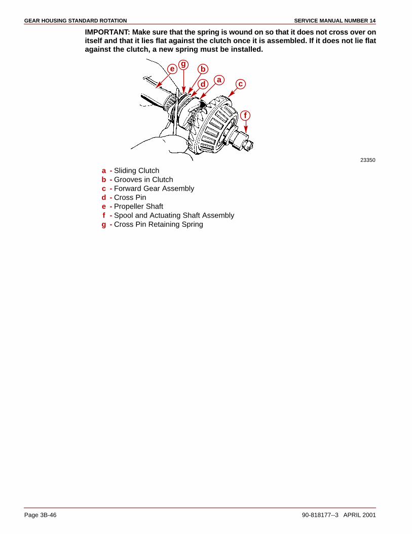
GEAR HOUSING STANDARD ROTATION SERVICE MANUAL NUMBER 14
Page 3B-46 90-818177--3 APRIL 2001
IMPORTANT: Make sure that the spring is wound on so that it does not cross over onitself and that it lies flat against the clutch once it is assembled. If it does not lie flatagainst the clutch, a new spring must be installed.
23350
f
eg
b
d a c
a - Sliding Clutchb - Grooves in Clutchc - Forward Gear Assemblyd - Cross Pine - Propeller Shaftf - Spool and Actuating Shaft Assemblyg - Cross Pin Retaining Spring
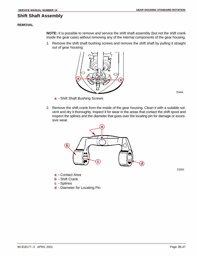
GEAR HOUSING STANDARD ROTATIONSERVICE MANUAL NUMBER 14
90-818177--3 APRIL 2001 Page 3B-47
Shift Shaft Assembly
REMOVAL
NOTE: It is possible to remove and service the shift shaft assembly (but not the shift crankinside the gear case) without removing any of the internal components of the gear housing.
1. Remove the shift shaft bushing screws and remove the shift shaft by pulling it straightout of gear housing.
70494
aa
a - Shift Shaft Bushing Screws
2. Remove the shift crank from the inside of the gear housing. Clean it with a suitable sol-vent and dry it thoroughly. Inspect it for wear in the areas that contact the shift spool andinspect the splines and the diameter that goes over the locating pin for damage or exces-sive wear.
23350
b
c d
a
a - Contact Areab - Shift Crankc - Splinesd - Diameter for Locating Pin
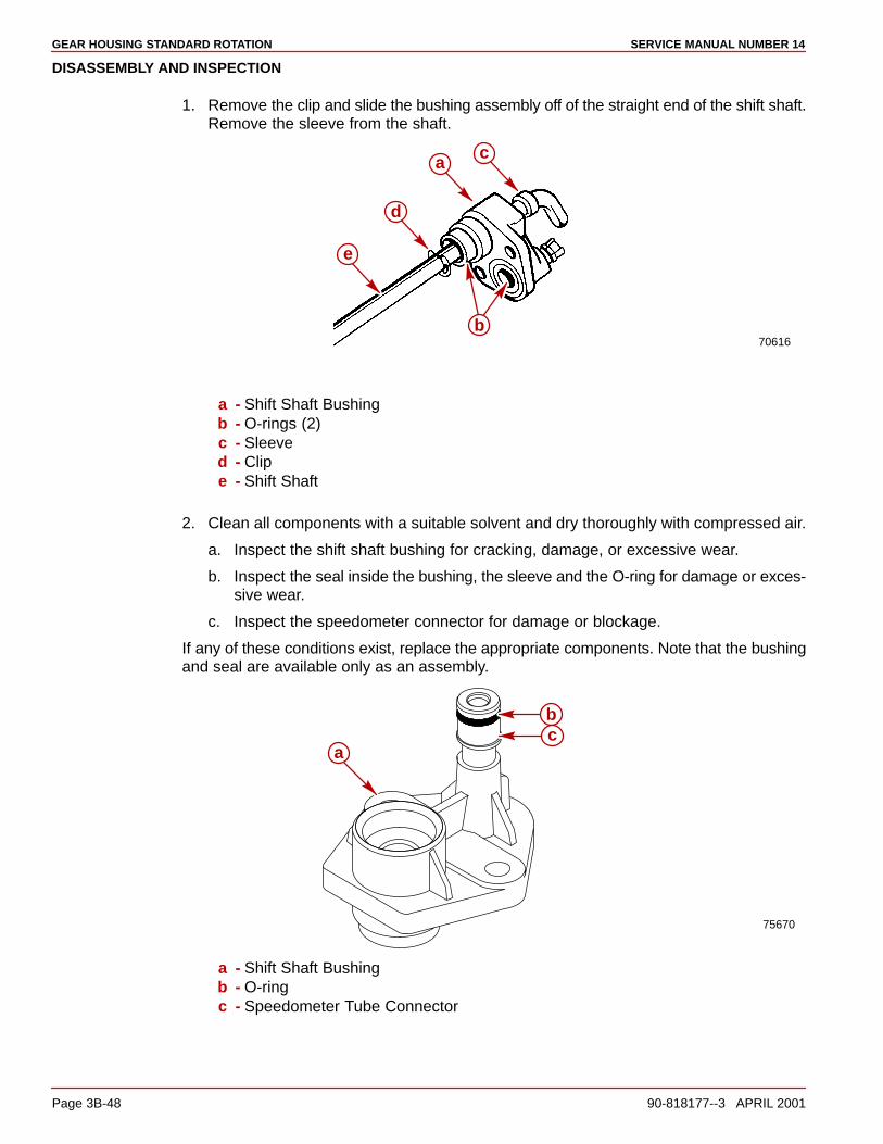
GEAR HOUSING STANDARD ROTATION SERVICE MANUAL NUMBER 14
Page 3B-48 90-818177--3 APRIL 2001
DISASSEMBLY AND INSPECTION
1. Remove the clip and slide the bushing assembly off of the straight end of the shift shaft.Remove the sleeve from the shaft.
70616
c
e
d
a
b
a - Shift Shaft Bushingb - O-rings (2)c - Sleeved - Clipe - Shift Shaft
2. Clean all components with a suitable solvent and dry thoroughly with compressed air.
a. Inspect the shift shaft bushing for cracking, damage, or excessive wear.
b. Inspect the seal inside the bushing, the sleeve and the O-ring for damage or exces-sive wear.
c. Inspect the speedometer connector for damage or blockage.
If any of these conditions exist, replace the appropriate components. Note that the bushingand seal are available only as an assembly.
75670
a
bc
a - Shift Shaft Bushingb - O-ringc - Speedometer Tube Connector
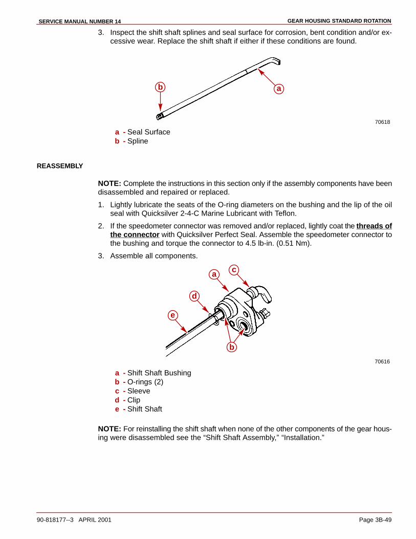
GEAR HOUSING STANDARD ROTATIONSERVICE MANUAL NUMBER 14
90-818177--3 APRIL 2001 Page 3B-49
3. Inspect the shift shaft splines and seal surface for corrosion, bent condition and/or ex-cessive wear. Replace the shift shaft if either if these conditions are found.
70618
b a
a - Seal Surfaceb - Spline
REASSEMBLY
NOTE: Complete the instructions in this section only if the assembly components have beendisassembled and repaired or replaced.
1. Lightly lubricate the seats of the O-ring diameters on the bushing and the lip of the oilseal with Quicksilver 2-4-C Marine Lubricant with Teflon.
2. If the speedometer connector was removed and/or replaced, lightly coat the threads ofthe connector with Quicksilver Perfect Seal. Assemble the speedometer connector tothe bushing and torque the connector to 4.5 lb-in. (0.51 Nm).
3. Assemble all components.
70616
c
e
d
a
b
a - Shift Shaft Bushingb - O-rings (2)c - Sleeved - Clipe - Shift Shaft
NOTE: For reinstalling the shift shaft when none of the other components of the gear hous-ing were disassembled see the “Shift Shaft Assembly,” “Installation.”

GEAR HOUSING STANDARD ROTATION SERVICE MANUAL NUMBER 14
Page 3B-50 90-818177--3 APRIL 2001
Pinion Bearing
REMOVAL
NOTE: Inspect the bearing surface on the drive shaft where the needles of the lower pinionbearing roll. The condition of the drive shaft at this location give an indication of the conditionof the needle bearing. Replace lower pinion bearing (needles and race as a set) if the driveshaft is pitted, grooved scored, worn unevenly, discolored from overheating, or has em-bedded particles.
IMPORTANT: All the needle bearings (18) MUST BE in place inside bearing race whiledriving the pinion bearing from the gear housing.
IMPORTANT: Do not reuse the bearing (race or rollers) once it has been removed.
1. Remove and discard the pinion bearing (race and rollers) using tools as shown.
NOTE: Hold down on the driver rod.
70614
a
b
c
d
a - Pinion Bearingb - Bearing Driver (91-36569)c - Pilot Washer (91-36571)d - Driver Rod (91-37323)

GEAR HOUSING STANDARD ROTATIONSERVICE MANUAL NUMBER 14
90-818177--3 APRIL 2001 Page 3B-51
Gear Housing Reassembly
Gear Housing Inspection1. Clean the gear housing thoroughly with a suitable solvent and a hard bristle brush. Dry
the gear housing thoroughly using compressed air. Ensure that all sealants, lockingagents and debris are removed.
2. Inspect the gear housing for excessive corrosion, impact or any other damage. Exces-sive damage and/or corrosion requires replacement of the gear housing.
3. Inspect the bearing carrier retainer threads in the gear housing for corrosion and/orstripped threads. Excessive damage to the threads requires replacement of the gearhousing.
4. Inspect bearing race/cup contact areas for evidence of bearing cup spinning. Check thatbearing cups are not loose in bearing bores. Any one bearing bore in which the race/cupis loose may require replacement of the gear housing.
5. Inspect for blockage in water inlet holes and the speedometer hole, clean as necessary.Be careful not to enlarge the speedometer hole as this could cause erroneous speedom-eter readings.
6. Make sure that the locating pins are in place in the gear housing and that the correspond-ing holes in the drive shaft housing are not elongated. The drive shaft may break if thehousings are not aligned properly due to missing locating pins or elongated holes.
Pinion Bearing
INSTALLATION
IMPORTANT: Install only a NEW pinion bearing (race and rollers). Do not reinstall apinion bearing that has been previously removed from a gear housing.
1. Lubricate the bore into which the pinion bearing is to be installed with Quicksilver HighPerformance Gear Lube.
2. Position the new pinion bearing (with the cardboard shipping sleeve in place) onto thedriver head, with the lettered and numbered side of the bearing oriented upward.
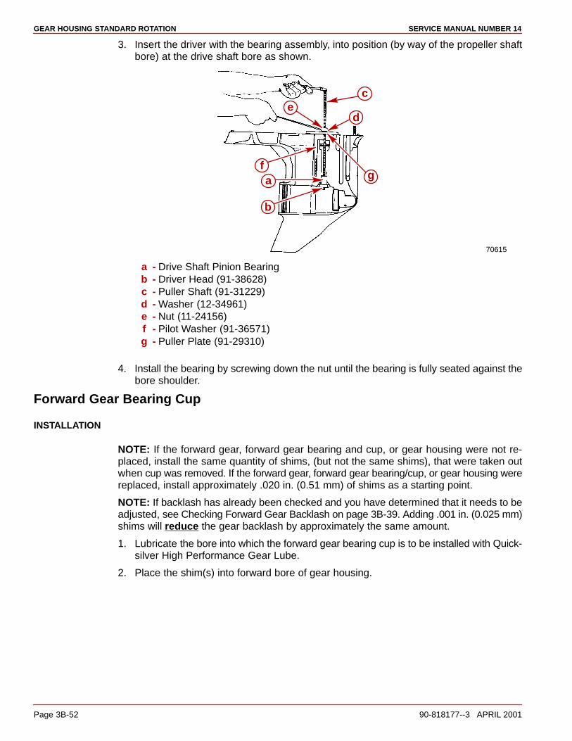
GEAR HOUSING STANDARD ROTATION SERVICE MANUAL NUMBER 14
Page 3B-52 90-818177--3 APRIL 2001
3. Insert the driver with the bearing assembly, into position (by way of the propeller shaftbore) at the drive shaft bore as shown.
70615
b
af
ec
d
g
a - Drive Shaft Pinion Bearingb - Driver Head (91-38628)c - Puller Shaft (91-31229)d - Washer (12-34961)e - Nut (11-24156)f - Pilot Washer (91-36571)g - Puller Plate (91-29310)
4. Install the bearing by screwing down the nut until the bearing is fully seated against thebore shoulder.
Forward Gear Bearing Cup
INSTALLATION
NOTE: If the forward gear, forward gear bearing and cup, or gear housing were not re-placed, install the same quantity of shims, (but not the same shims), that were taken outwhen cup was removed. If the forward gear, forward gear bearing/cup, or gear housing werereplaced, install approximately .020 in. (0.51 mm) of shims as a starting point.
NOTE: If backlash has already been checked and you have determined that it needs to beadjusted, see Checking Forward Gear Backlash on page 3B-39. Adding .001 in. (0.025 mm)shims will reduce the gear backlash by approximately the same amount.
1. Lubricate the bore into which the forward gear bearing cup is to be installed with Quick-silver High Performance Gear Lube.
2. Place the shim(s) into forward bore of gear housing.
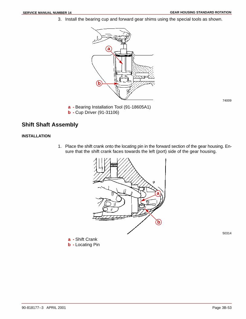
GEAR HOUSING STANDARD ROTATIONSERVICE MANUAL NUMBER 14
90-818177--3 APRIL 2001 Page 3B-53
3. Install the bearing cup and forward gear shims using the special tools as shown.
74009
a
b
a - Bearing Installation Tool (91-18605A1)b - Cup Driver (91-31106)
Shift Shaft Assembly
INSTALLATION
1. Place the shift crank onto the locating pin in the forward section of the gear housing. En-sure that the shift crank faces towards the left (port) side of the gear housing.
50314
a
b
a - Shift Crankb - Locating Pin

GEAR HOUSING STANDARD ROTATION SERVICE MANUAL NUMBER 14
Page 3B-54 90-818177--3 APRIL 2001
2. Install the shift shaft assembly into the gear housing as shown. Position the bent endof the shift shaft forward while installing it and ensure that the splined end of the shiftshaft is engaged with the shift crank. Make sure that the O-rings are present and posi-tioned properly. Install fasteners.
70620
a
a - Shift Shaft Assembly
NOTE: If the pinion bearing needles have fallen out, install 18 needles into needle bearingouter race. Use Quicksilver Needle Bearing Assembly Lubricant, to help hold needles inplace.
23142
a
b
a - Needles (18)b - Roller Bearing Outer Race
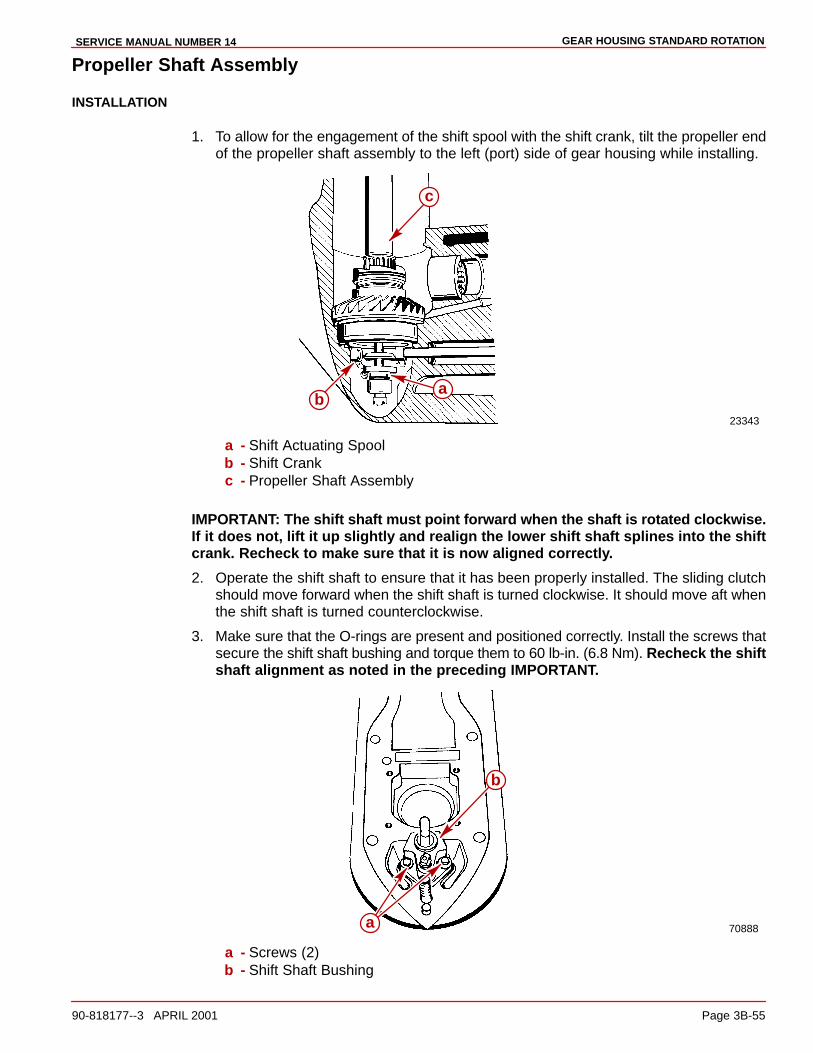
GEAR HOUSING STANDARD ROTATIONSERVICE MANUAL NUMBER 14
90-818177--3 APRIL 2001 Page 3B-55
Propeller Shaft Assembly
INSTALLATION
1. To allow for the engagement of the shift spool with the shift crank, tilt the propeller endof the propeller shaft assembly to the left (port) side of gear housing while installing.
23343
ba
c
a - Shift Actuating Spoolb - Shift Crankc - Propeller Shaft Assembly
IMPORTANT: The shift shaft must point forward when the shaft is rotated clockwise.If it does not, lift it up slightly and realign the lower shift shaft splines into the shiftcrank. Recheck to make sure that it is now aligned correctly.
2. Operate the shift shaft to ensure that it has been properly installed. The sliding clutchshould move forward when the shift shaft is turned clockwise. It should move aft whenthe shift shaft is turned counterclockwise.
3. Make sure that the O-rings are present and positioned correctly. Install the screws thatsecure the shift shaft bushing and torque them to 60 lb-in. (6.8 Nm). Recheck the shiftshaft alignment as noted in the preceding IMPORTANT.
70888
b
a
a - Screws (2)b - Shift Shaft Bushing

GEAR HOUSING STANDARD ROTATION SERVICE MANUAL NUMBER 14
Page 3B-56 90-818177--3 APRIL 2001
4. Slide the rubber sleeve at top end of shift shaft down so that it just touches the oil sealin the bushing.
a
70492d
b
c
a - Shift Shaftb - Rubber Sleevec - Oil Seald - Shift Shaft Bushing

GEAR HOUSING STANDARD ROTATIONSERVICE MANUAL NUMBER 14
90-818177--3 APRIL 2001 Page 3B-57
Drive Shaft and Pinion Gear
INSTALLATION
NOTE: If the original shims were not retained or if pinion gear, drive shaft, drive shaft taperedroller bearing and cup, or gear housing were replaced, start off by installing a .030 in. (0.76mm) shim(s).
NOTE: If the original shims were retained (or measurement known) and none of the abovelisted parts were replaced, reinstall the same shims or same amount of shims.
1. Place the shim(s) into the drive shaft housing bore at the location shown.
70620
a
a - Shim(s)
NOTE: For ease of installation, glue the washer to the pinion gear, using 3M Adhesive(92-86166-1) or equivalent.
2. Apply Loctite 271 to the threads of the pinion gear nut and assemble the pinion gear nutinto the MR slot of the pinion nut adapter. A small amount of heavy grease in the slotof the pinion nut adapter while installing the drive shaft assembly.
3. Place the pinion gear and washer into the gear housing.
4. Insert the pinion nut adapter (with the nut) into the gear housing.
5. Insert the drive shaft into the gear housing drive shaft bore. It may be necessary to rotatethe drive shaft to engage the drive shaft splines into the pinion gear splines.

GEAR HOUSING STANDARD ROTATION SERVICE MANUAL NUMBER 14
Page 3B-58 90-818177--3 APRIL 2001
6. Start the pinion nut onto the drive shaft threads by rotating the drive shaft until the nutis snug.
70891
a c
b
a - Pinion Gear (WIth The Washer Glued To The Tool)b - Pinion Nut Adapter (91-61067 A3)c - Drive Shaft
7. Install the drive shaft tapered roller bearing cup, then the retainer. Hand tighten.
70890
ba
a - Tapered Roller Bearing Cupb - Drive Shaft Retainer
8. Install the bearing carrier into the gear housing backwards to hold the propeller shaft andthe pinion nut adapter in position.
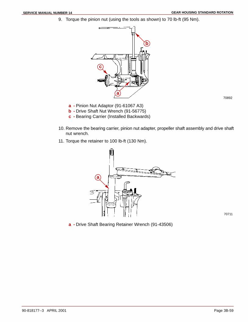
GEAR HOUSING STANDARD ROTATIONSERVICE MANUAL NUMBER 14
90-818177--3 APRIL 2001 Page 3B-59
9. Torque the pinion nut (using the tools as shown) to 70 lb-ft (95 Nm).
70892a
c
b
a - Pinion Nut Adaptor (91-61067 A3)b - Drive Shaft Nut Wrench (91-56775)c - Bearing Carrier (Installed Backwards)
10. Remove the bearing carrier, pinion nut adapter, propeller shaft assembly and drive shaftnut wrench.
11. Torque the retainer to 100 lb-ft (130 Nm).
70711
a
a - Drive Shaft Bearing Retainer Wrench (91-43506)

GEAR HOUSING STANDARD ROTATION SERVICE MANUAL NUMBER 14
Page 3B-60 90-818177--3 APRIL 2001
Drive Shaft - Bearing Preload Tool
INSTALLATION
1. Install the components from the Bearing Preload Tool Kit (91-14311A2) over the driveshaft in the order shown.
73885
ab
c
de
f
g
d
a - Top Nut with Threaded Pipeb - Nutc - Springd - Thrust Washere - Thrust Bearingf - Thrust Washerg - Water Pump Face Plate (From Gear Housing)
NOTE: Place the top two nuts as closely together as possible.
2. Pull up on the drive shaft and tighten the two (2) allen screws in the top nut of the bearingpreload tool.
70716
a
a
a - Allen Screws

GEAR HOUSING STANDARD ROTATIONSERVICE MANUAL NUMBER 14
90-818177--3 APRIL 2001 Page 3B-61
3. Screw the bottom nut of the bearing preload tool down until it is one inch further downthe threaded rod than it was previously.
70893
a
a - Bottom Nut [Screwed Down Approximately 1 in. (25 mm) Further Than It WasPreviously]
4. Rotate the drive shaft at least three full turns in a clockwise direction.
Pinion Gear Location
CHECKING AND ADJUSTING
1. Place the pinion gear shimming tool into the gear housing.
NOTE: Take the following measurements at 3 locations, rotating the drive shaft 120 degreesbetween each reading (always rotate the drive shaft in a clockwise direction).
2. Insert the thickest feeler gauge that fits snugly between one tooth of the pinion gear andhigh point of the shimming tool.
3. Rotate the drive shaft 120 degrees in a clockwise direction and take another reading.
4. Repeat this process until 3 readings have been taken.
5. Add the three readings together and divide the sum by 3 to get the average pinion gearheight. Make note of this average measurement.
NOTE: The average pinion gear height should be .025 in. (0.64 mm).
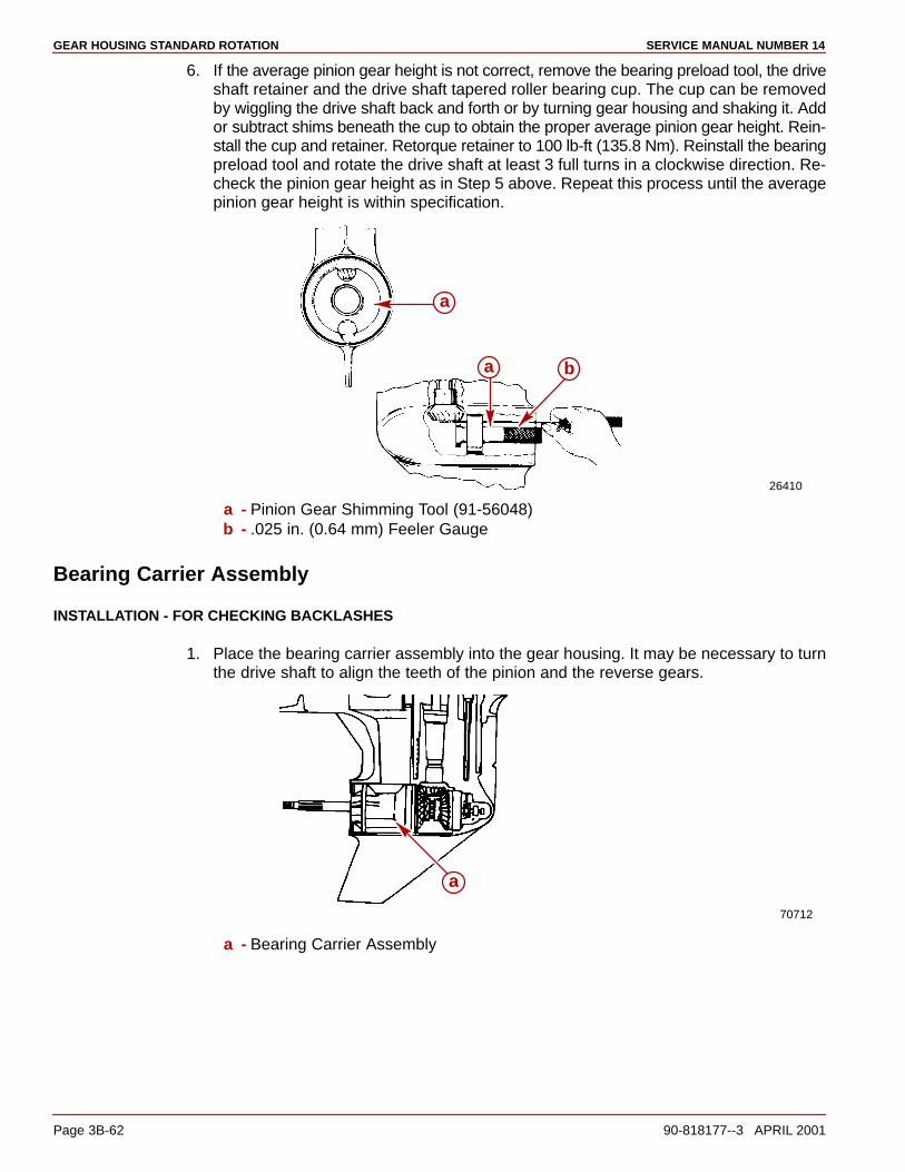
GEAR HOUSING STANDARD ROTATION SERVICE MANUAL NUMBER 14
Page 3B-62 90-818177--3 APRIL 2001
6. If the average pinion gear height is not correct, remove the bearing preload tool, the driveshaft retainer and the drive shaft tapered roller bearing cup. The cup can be removedby wiggling the drive shaft back and forth or by turning gear housing and shaking it. Addor subtract shims beneath the cup to obtain the proper average pinion gear height. Rein-stall the cup and retainer. Retorque retainer to 100 lb-ft (135.8 Nm). Reinstall the bearingpreload tool and rotate the drive shaft at least 3 full turns in a clockwise direction. Re-check the pinion gear height as in Step 5 above. Repeat this process until the averagepinion gear height is within specification.
26410
a b
a
a - Pinion Gear Shimming Tool (91-56048)b - .025 in. (0.64 mm) Feeler Gauge
Bearing Carrier Assembly
INSTALLATION - FOR CHECKING BACKLASHES
1. Place the bearing carrier assembly into the gear housing. It may be necessary to turnthe drive shaft to align the teeth of the pinion and the reverse gears.
70712
a
a - Bearing Carrier Assembly

GEAR HOUSING STANDARD ROTATIONSERVICE MANUAL NUMBER 14
90-818177--3 APRIL 2001 Page 3B-63
2. Align the bearing carrier “V” shaped notch with the alignment hole in the gear housingand then install the tab washer with the external tab inserted into the hole in the gearhousing.
70713
ac
b
a - Gear Case Alignment Holeb - “V” Shaped Notch In Bearing Carrierc - Alignment Tab Of Tab Washer
3. Ensure that the “V” shaped tab aligns with the “V” notch in the bearing carrier.
70714
a
b
a - Tab Washerb - “V” Tab
4. Generously lubricate the bearing carrier retainer threads with Quicksilver Lubricant 101.Start the retainer into the gear housing threads and tighten it down fully by hand.
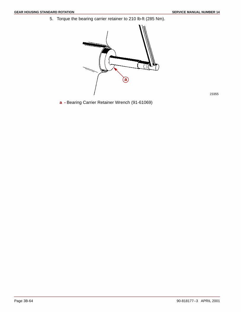
GEAR HOUSING STANDARD ROTATION SERVICE MANUAL NUMBER 14
Page 3B-64 90-818177--3 APRIL 2001
5. Torque the bearing carrier retainer to 210 lb-ft (285 Nm).
23355
a
a - Bearing Carrier Retainer Wrench (91-61069)

GEAR HOUSING STANDARD ROTATIONSERVICE MANUAL NUMBER 14
90-818177--3 APRIL 2001 Page 3B-65
Forward Gear Backlash
CHECKING
1. Apply forward pressure to propeller shaft as follows:
a. Attach puller jaws and puller bolt onto bearing carrier bosses, if equipped, or onbearing carrier outer ring and propeller shaft.
70719
a
b
a - Puller Jawsb - Puller Bolt
2. Torque the puller bolt to 45 lb-in. (5 Nm). Rotate the drive shaft three full turns clockwiseand retorque the bolt to 45 lb-in. (5 Nm).
3. For All Gears Except 14:28: Install backlash indicator (P/N 91-58222 A1) and align theindicator pointer so that it is perpendicular to and touching the “I” mark on the indicatorrod.
4. For 14:28 Gears: Install backlash indicator (91-78473) and align the indicator pointerso that it is perpendicular to and touching the “2” mark on the indicator rod.
5. Tighten the indicator rod onto the drive shaft and rotate the drive shaft so that the needlein the dial makes at least one full revolution and comes to “0” on the indicator scale.

GEAR HOUSING STANDARD ROTATION SERVICE MANUAL NUMBER 14
Page 3B-66 90-818177--3 APRIL 2001
77706
edc
b
a
a - Threaded Rod [3/8 in. (9.5 mm) Obtain Locally]b - Dial Indicator Holding Toolc - Backlash Indicatord - Indicator Pointere - Backlash Indicator Rod
6. Take the backlash readings by lightly turning the drive shaft back and forth, so as to feelthe backlash between the gear. No movement should be noticed at the propeller shaft.
a. Observe the backlash indicator and record the reading.
b. Loosen the indicator rod and rotate the drive shaft 90 degrees in a clockwise direc-tion.
c. Repeat Step 2 above and take and record another reading. Repeat Step 3 until atotal of 4 backlash readings have been taken.
7. Add the four readings together and divide the sum by four. This is your average back-lash, make note of this figure, if it does not meet specifications of .017-.028 in. (0.43-0.71mm) it will be adjusted at a later step.
8. Loosen the backlash indicator rod and remove the puller jaws.
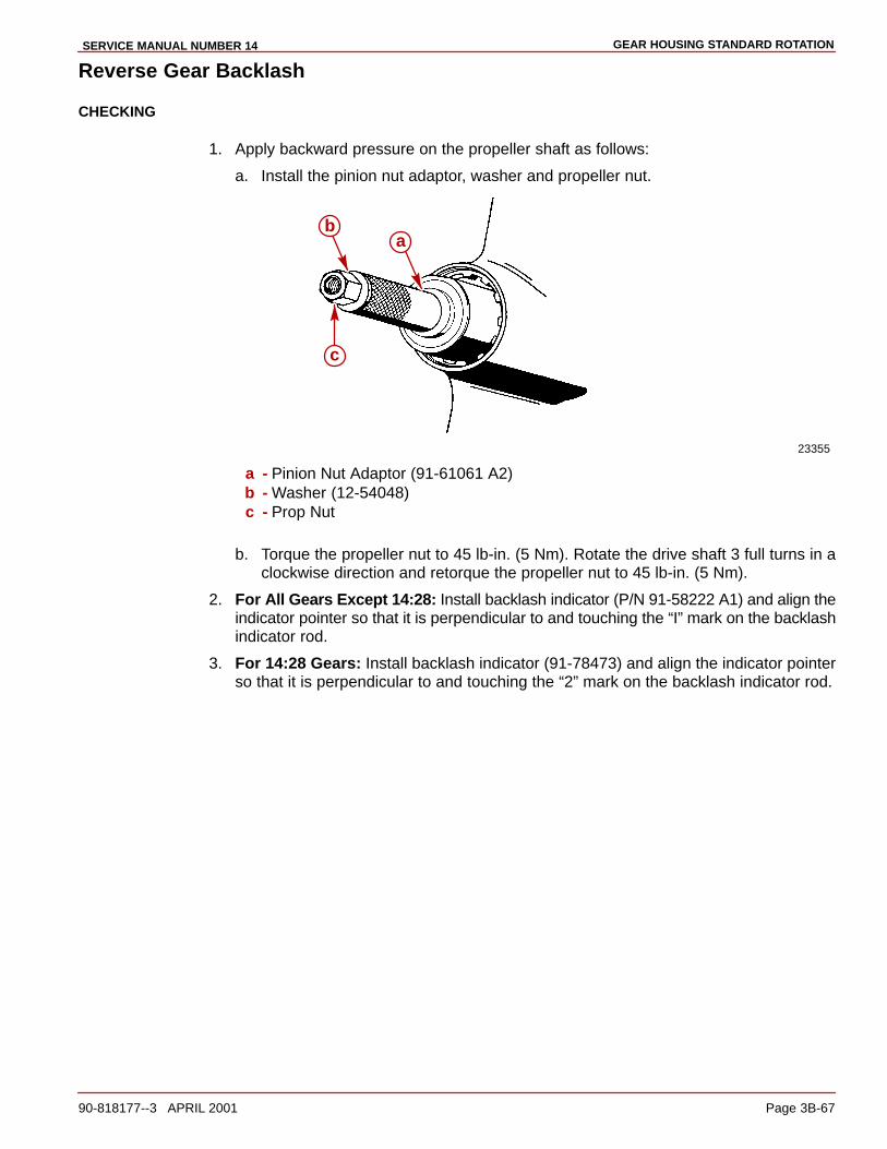
GEAR HOUSING STANDARD ROTATIONSERVICE MANUAL NUMBER 14
90-818177--3 APRIL 2001 Page 3B-67
Reverse Gear Backlash
CHECKING
1. Apply backward pressure on the propeller shaft as follows:
a. Install the pinion nut adaptor, washer and propeller nut.
23355
c
ba
a - Pinion Nut Adaptor (91-61061 A2)b - Washer (12-54048)c - Prop Nut
b. Torque the propeller nut to 45 lb-in. (5 Nm). Rotate the drive shaft 3 full turns in aclockwise direction and retorque the propeller nut to 45 lb-in. (5 Nm).
2. For All Gears Except 14:28: Install backlash indicator (P/N 91-58222 A1) and align theindicator pointer so that it is perpendicular to and touching the “I” mark on the backlashindicator rod.
3. For 14:28 Gears: Install backlash indicator (91-78473) and align the indicator pointerso that it is perpendicular to and touching the “2” mark on the backlash indicator rod.
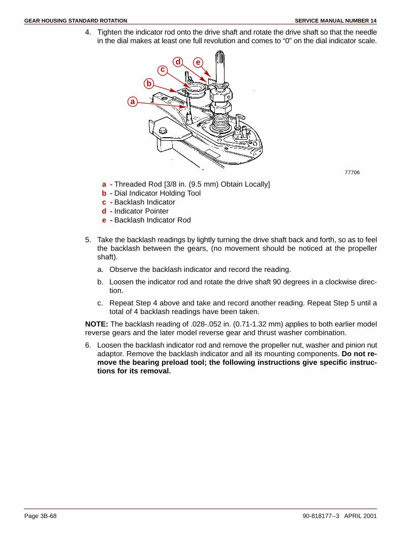
GEAR HOUSING STANDARD ROTATION SERVICE MANUAL NUMBER 14
Page 3B-68 90-818177--3 APRIL 2001
4. Tighten the indicator rod onto the drive shaft and rotate the drive shaft so that the needlein the dial makes at least one full revolution and comes to “0” on the dial indicator scale.
77706
edc
b
a
a - Threaded Rod [3/8 in. (9.5 mm) Obtain Locally]b - Dial Indicator Holding Toolc - Backlash Indicatord - Indicator Pointere - Backlash Indicator Rod
5. Take the backlash readings by lightly turning the drive shaft back and forth, so as to feelthe backlash between the gears, (no movement should be noticed at the propellershaft).
a. Observe the backlash indicator and record the reading.
b. Loosen the indicator rod and rotate the drive shaft 90 degrees in a clockwise direc-tion.
c. Repeat Step 4 above and take and record another reading. Repeat Step 5 until atotal of 4 backlash readings have been taken.
NOTE: The backlash reading of .028-.052 in. (0.71-1.32 mm) applies to both earlier modelreverse gears and the later model reverse gear and thrust washer combination.
6. Loosen the backlash indicator rod and remove the propeller nut, washer and pinion nutadaptor. Remove the backlash indicator and all its mounting components. Do not re-move the bearing preload tool; the following instructions give specific instruc-tions for its removal.
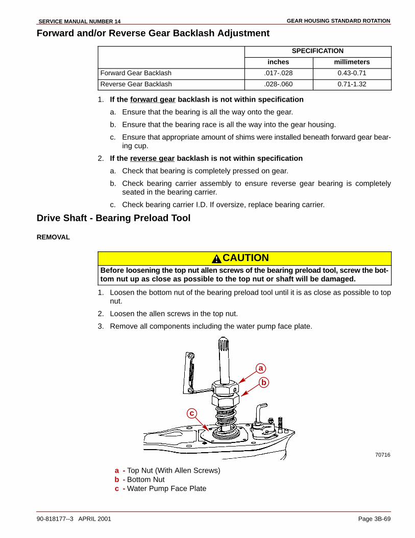
GEAR HOUSING STANDARD ROTATIONSERVICE MANUAL NUMBER 14
90-818177--3 APRIL 2001 Page 3B-69
Forward and/or Reverse Gear Backlash Adjustment
SPECIFICATION
inches millimeters
Forward Gear Backlash .017-.028 0.43-0.71
Reverse Gear Backlash .028-.060 0.71-1.32
1. If the forward gear backlash is not within specification
a. Ensure that the bearing is all the way onto the gear.
b. Ensure that the bearing race is all the way into the gear housing.
c. Ensure that appropriate amount of shims were installed beneath forward gear bear-ing cup.
2. If the reverse gear backlash is not within specification
a. Check that bearing is completely pressed on gear.
b. Check bearing carrier assembly to ensure reverse gear bearing is completelyseated in the bearing carrier.
c. Check bearing carrier I.D. If oversize, replace bearing carrier.
Drive Shaft - Bearing Preload Tool
REMOVAL
CAUTIONBefore loosening the top nut allen screws of the bearing preload tool, screw the bot-tom nut up as close as possible to the top nut or shaft will be damaged.
1. Loosen the bottom nut of the bearing preload tool until it is as close as possible to topnut.
2. Loosen the allen screws in the top nut.
3. Remove all components including the water pump face plate.
70716
c
a
b
a - Top Nut (With Allen Screws)b - Bottom Nutc - Water Pump Face Plate
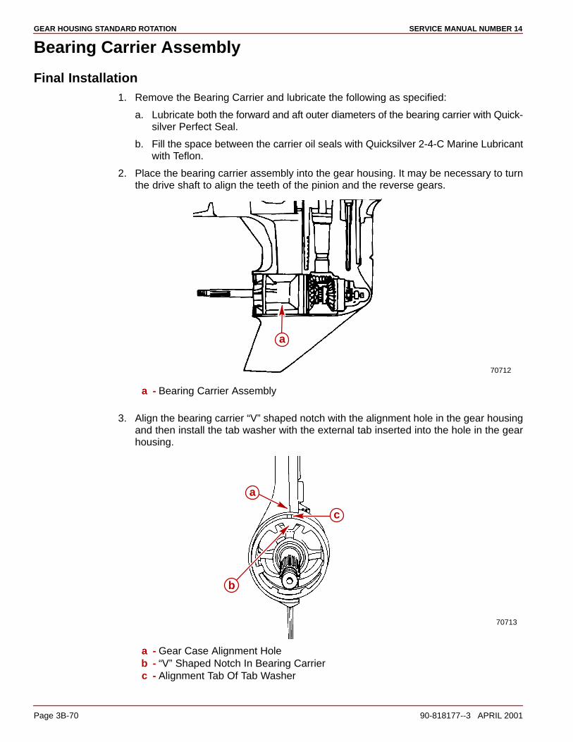
GEAR HOUSING STANDARD ROTATION SERVICE MANUAL NUMBER 14
Page 3B-70 90-818177--3 APRIL 2001
Bearing Carrier Assembly
Final Installation1. Remove the Bearing Carrier and lubricate the following as specified:
a. Lubricate both the forward and aft outer diameters of the bearing carrier with Quick-silver Perfect Seal.
b. Fill the space between the carrier oil seals with Quicksilver 2-4-C Marine Lubricantwith Teflon.
2. Place the bearing carrier assembly into the gear housing. It may be necessary to turnthe drive shaft to align the teeth of the pinion and the reverse gears.
70712
a
a - Bearing Carrier Assembly
3. Align the bearing carrier “V” shaped notch with the alignment hole in the gear housingand then install the tab washer with the external tab inserted into the hole in the gearhousing.
70713
a
c
b
a - Gear Case Alignment Holeb - “V” Shaped Notch In Bearing Carrierc - Alignment Tab Of Tab Washer
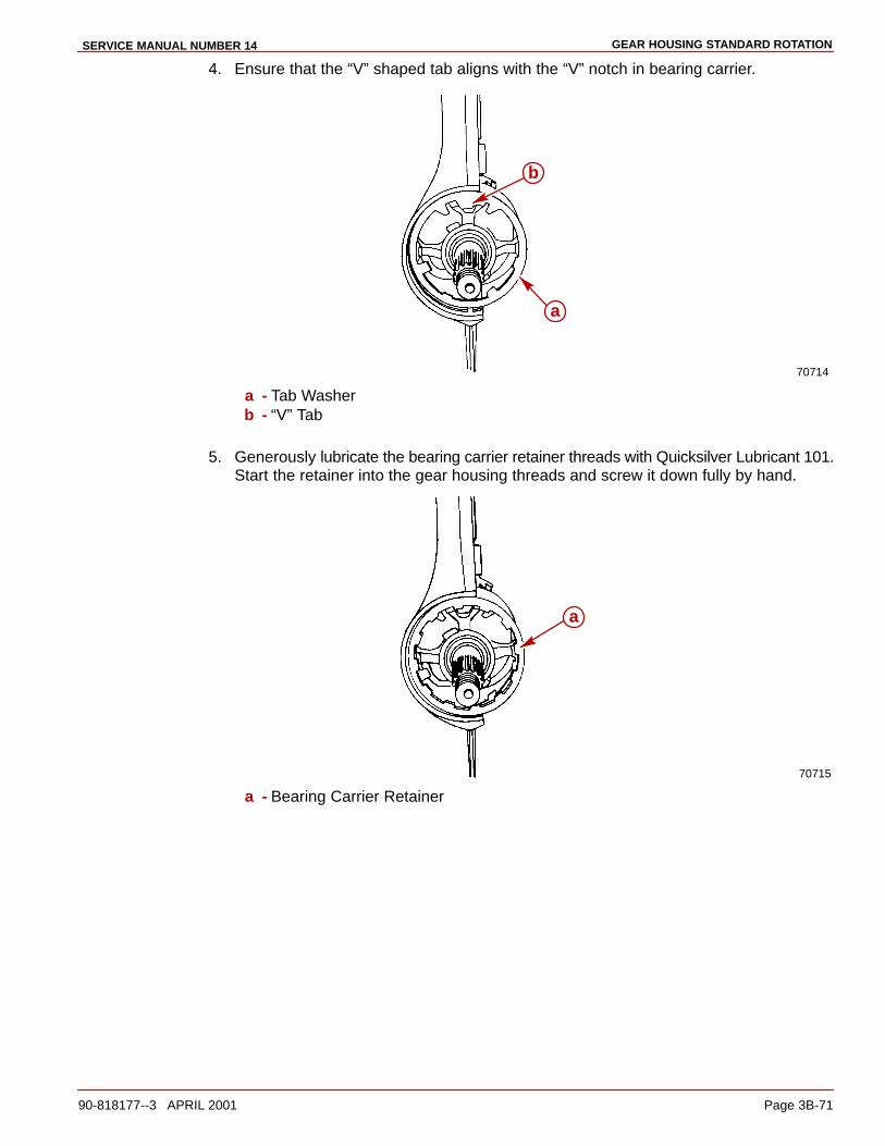
GEAR HOUSING STANDARD ROTATIONSERVICE MANUAL NUMBER 14
90-818177--3 APRIL 2001 Page 3B-71
4. Ensure that the “V” shaped tab aligns with the “V” notch in bearing carrier.
70714
a
b
a - Tab Washerb - “V” Tab
5. Generously lubricate the bearing carrier retainer threads with Quicksilver Lubricant 101.Start the retainer into the gear housing threads and screw it down fully by hand.
70715
a
a - Bearing Carrier Retainer
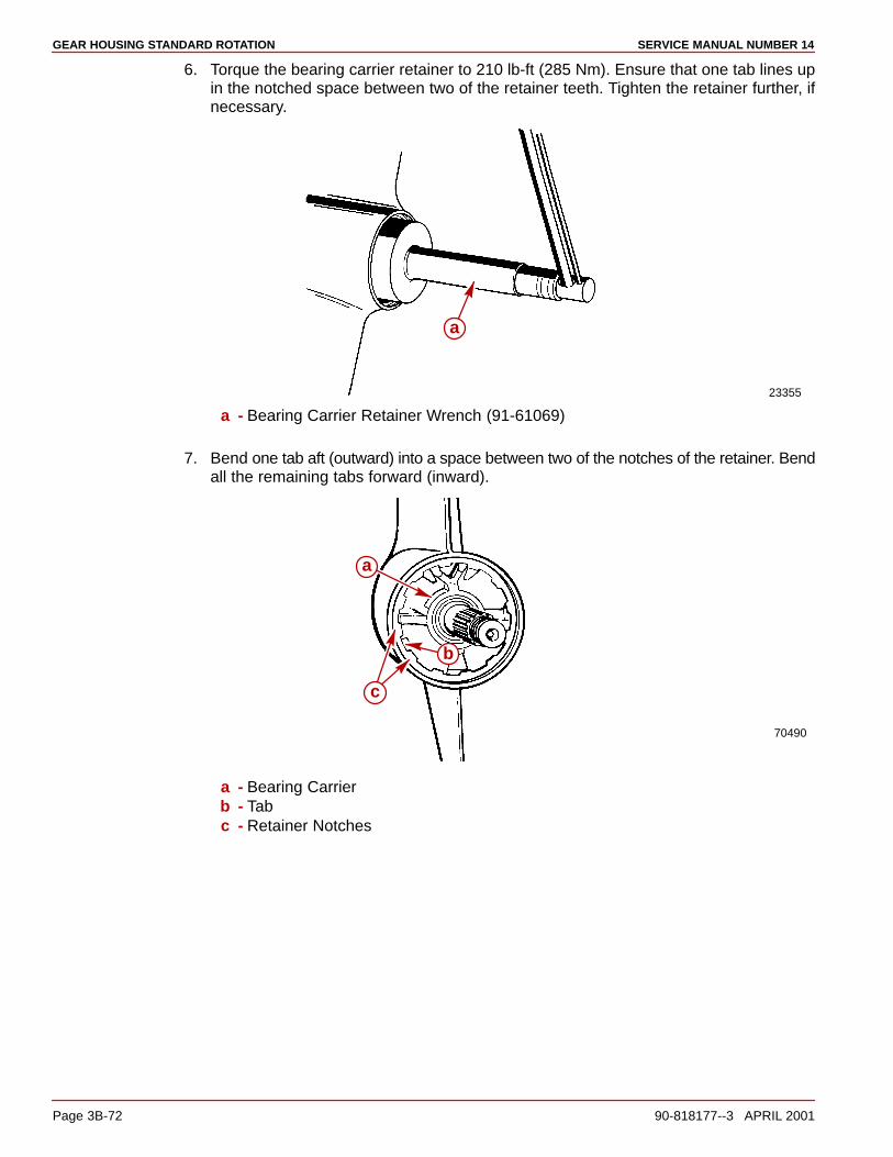
GEAR HOUSING STANDARD ROTATION SERVICE MANUAL NUMBER 14
Page 3B-72 90-818177--3 APRIL 2001
6. Torque the bearing carrier retainer to 210 lb-ft (285 Nm). Ensure that one tab lines upin the notched space between two of the retainer teeth. Tighten the retainer further, ifnecessary.
23355
a
a - Bearing Carrier Retainer Wrench (91-61069)
7. Bend one tab aft (outward) into a space between two of the notches of the retainer. Bendall the remaining tabs forward (inward).
70490
a
b
c
a - Bearing Carrierb - Tabc - Retainer Notches
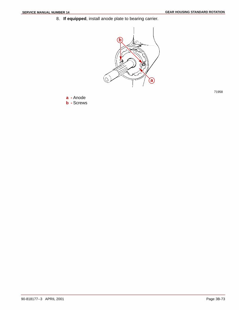
GEAR HOUSING STANDARD ROTATIONSERVICE MANUAL NUMBER 14
90-818177--3 APRIL 2001 Page 3B-73
8. If equipped, install anode plate to bearing carrier.
71958
a
b
a - Anodeb - Screws
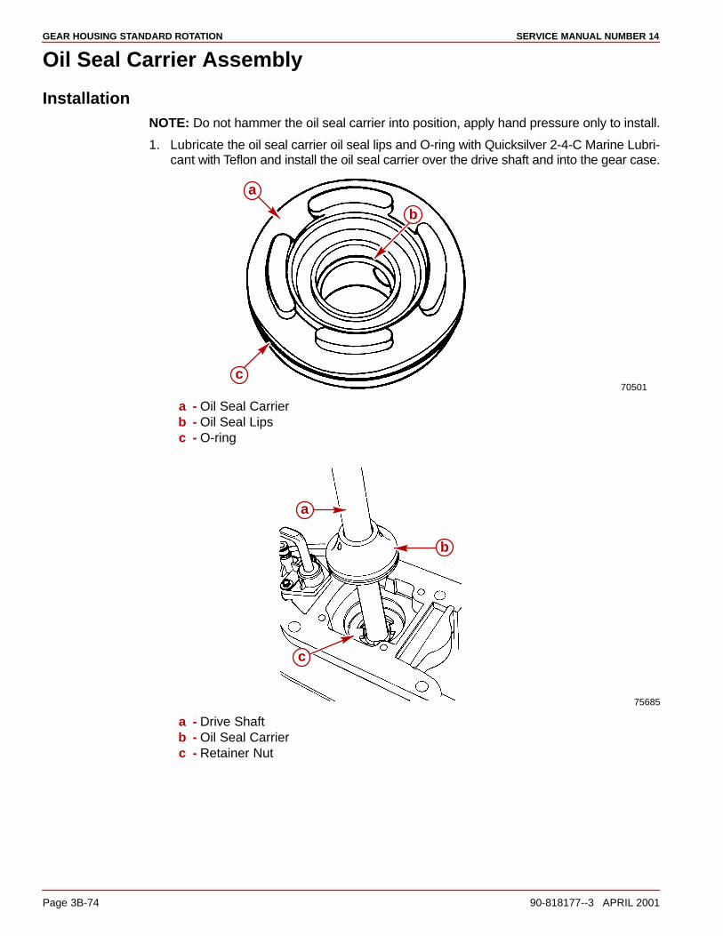
GEAR HOUSING STANDARD ROTATION SERVICE MANUAL NUMBER 14
Page 3B-74 90-818177--3 APRIL 2001
Oil Seal Carrier Assembly
InstallationNOTE: Do not hammer the oil seal carrier into position, apply hand pressure only to install.
1. Lubricate the oil seal carrier oil seal lips and O-ring with Quicksilver 2-4-C Marine Lubri-cant with Teflon and install the oil seal carrier over the drive shaft and into the gear case.
70501
a
b
c
a - Oil Seal Carrierb - Oil Seal Lipsc - O-ring
75685
c
b
a
a - Drive Shaftb - Oil Seal Carrierc - Retainer Nut

GEAR HOUSING STANDARD ROTATIONSERVICE MANUAL NUMBER 14
90-818177--3 APRIL 2001 Page 3B-75
Water Pump Assembly
InstallationNOTE: The aluminum dam has been changed to a rubber filler plug. If the aluminum waterpump dam in the gear housing has become corroded or damaged, it can be replaced withthe rubber filler plug.
IMPORTANT: The gaskets/face plate hole pattern is not symmetrical. If the holes ofthe gaskets/face plate do not align with the screw holes of the gear case and/or eachother, one or more of the parts is upside down. Determine which part(s) is (are) upsidedown and turn the appropriate part(s) over.
1. Apply Quicksilver Perfect Seal to the small hole gasket. Place the small hole gasket, theface plate and the large hole gasket onto the gear case.
NOTE: Add Quicksilver Perfect Seal to the gasket to seal it and prevent water from seepinginto the gear housing.
70720
a
bc
a - Small Hole Gasketb - Face Platec - Large Hole Gasket
2. Place a small amount of Quicksilver 2-4-C Marine Lubricant with Teflon on the flat sur-face of the impeller key and assemble the key onto the drive shaft keyway.
IMPORTANT: When using an impeller whose blades have taken a set, face the curl ofthe blades in a counterclockwise direction. DO NOT install the impeller with itsblades oriented in a reversed direction from original rotation, or premature impellerfailure will occur.
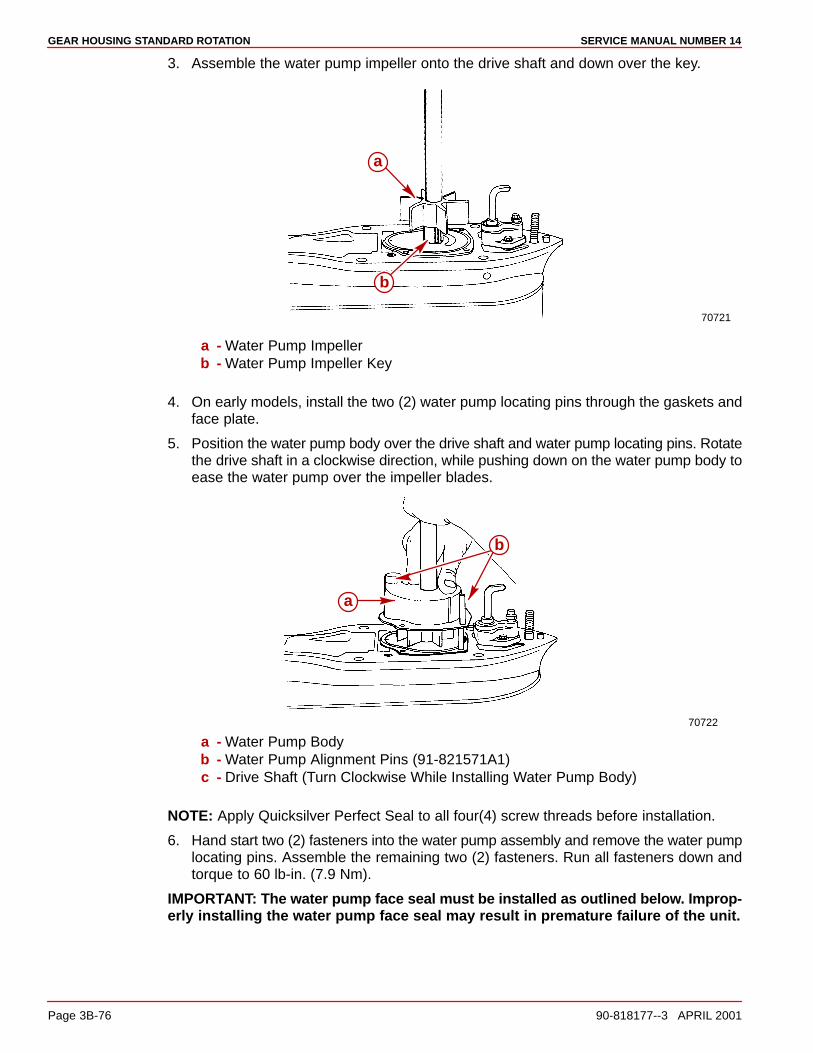
GEAR HOUSING STANDARD ROTATION SERVICE MANUAL NUMBER 14
Page 3B-76 90-818177--3 APRIL 2001
3. Assemble the water pump impeller onto the drive shaft and down over the key.
70721
a
b
a - Water Pump Impellerb - Water Pump Impeller Key
4. On early models, install the two (2) water pump locating pins through the gaskets andface plate.
5. Position the water pump body over the drive shaft and water pump locating pins. Rotatethe drive shaft in a clockwise direction, while pushing down on the water pump body toease the water pump over the impeller blades.
70722
a
b
a - Water Pump Bodyb - Water Pump Alignment Pins (91-821571A1)c - Drive Shaft (Turn Clockwise While Installing Water Pump Body)
NOTE: Apply Quicksilver Perfect Seal to all four(4) screw threads before installation.
6. Hand start two (2) fasteners into the water pump assembly and remove the water pumplocating pins. Assemble the remaining two (2) fasteners. Run all fasteners down andtorque to 60 lb-in. (7.9 Nm).
IMPORTANT: The water pump face seal must be installed as outlined below. Improp-erly installing the water pump face seal may result in premature failure of the unit.
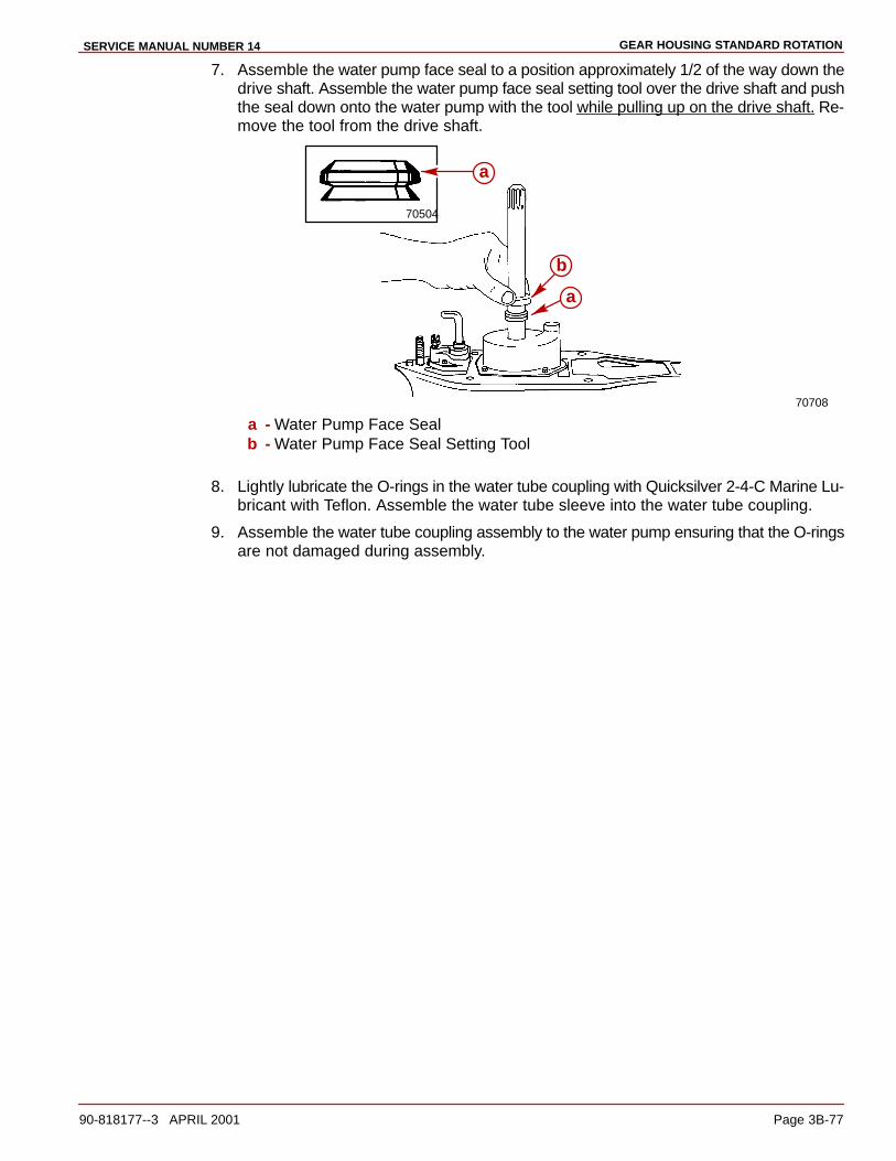
GEAR HOUSING STANDARD ROTATIONSERVICE MANUAL NUMBER 14
90-818177--3 APRIL 2001 Page 3B-77
7. Assemble the water pump face seal to a position approximately 1/2 of the way down thedrive shaft. Assemble the water pump face seal setting tool over the drive shaft and pushthe seal down onto the water pump with the tool while pulling up on the drive shaft. Re-move the tool from the drive shaft.
70708
70504
a
b
a
a - Water Pump Face Sealb - Water Pump Face Seal Setting Tool
8. Lightly lubricate the O-rings in the water tube coupling with Quicksilver 2-4-C Marine Lu-bricant with Teflon. Assemble the water tube sleeve into the water tube coupling.
9. Assemble the water tube coupling assembly to the water pump ensuring that the O-ringsare not damaged during assembly.
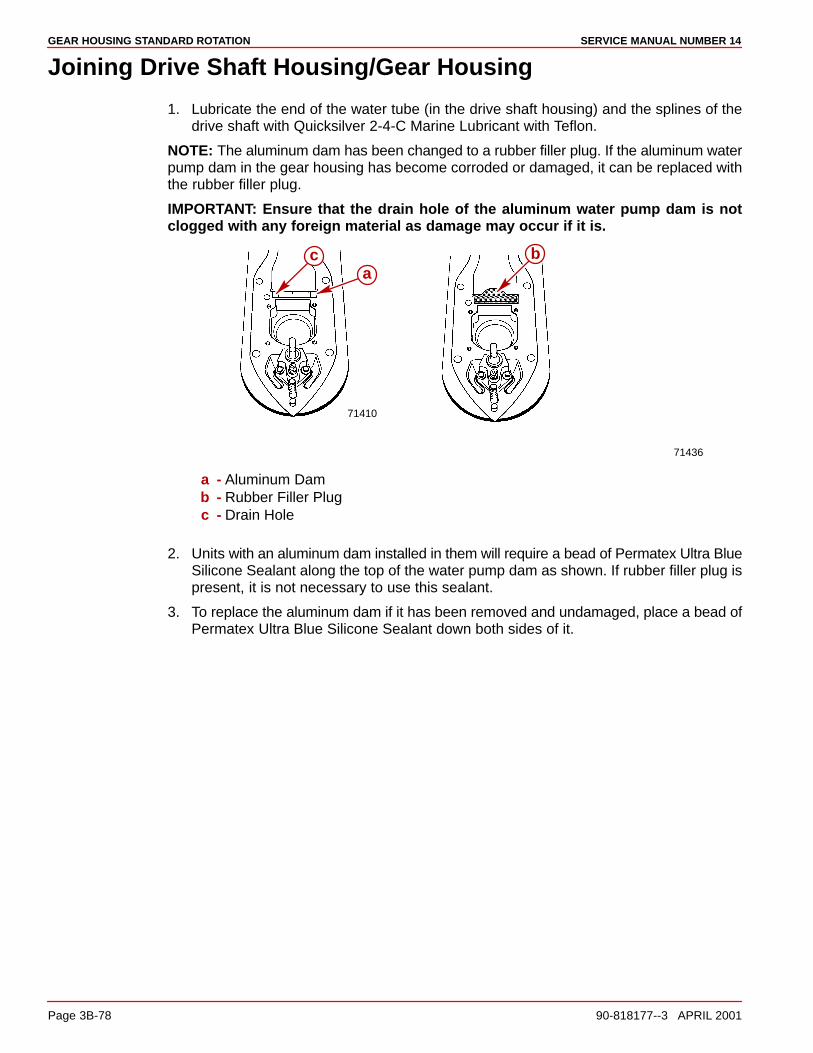
GEAR HOUSING STANDARD ROTATION SERVICE MANUAL NUMBER 14
Page 3B-78 90-818177--3 APRIL 2001
Joining Drive Shaft Housing/Gear Housing
1. Lubricate the end of the water tube (in the drive shaft housing) and the splines of thedrive shaft with Quicksilver 2-4-C Marine Lubricant with Teflon.
NOTE: The aluminum dam has been changed to a rubber filler plug. If the aluminum waterpump dam in the gear housing has become corroded or damaged, it can be replaced withthe rubber filler plug.
IMPORTANT: Ensure that the drain hole of the aluminum water pump dam is notclogged with any foreign material as damage may occur if it is.
71436
71410
ca
b
a - Aluminum Damb - Rubber Filler Plugc - Drain Hole
2. Units with an aluminum dam installed in them will require a bead of Permatex Ultra BlueSilicone Sealant along the top of the water pump dam as shown. If rubber filler plug ispresent, it is not necessary to use this sealant.
3. To replace the aluminum dam if it has been removed and undamaged, place a bead ofPermatex Ultra Blue Silicone Sealant down both sides of it.
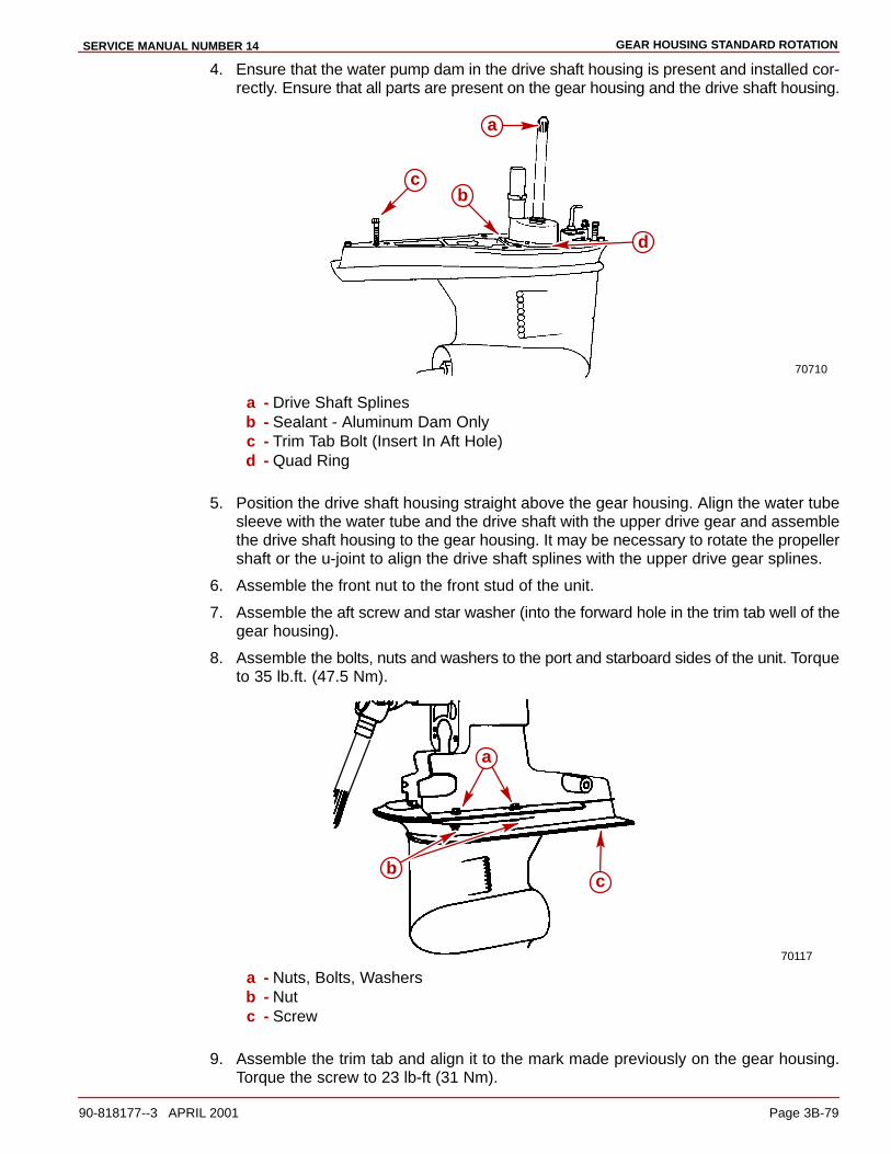
GEAR HOUSING STANDARD ROTATIONSERVICE MANUAL NUMBER 14
90-818177--3 APRIL 2001 Page 3B-79
4. Ensure that the water pump dam in the drive shaft housing is present and installed cor-rectly. Ensure that all parts are present on the gear housing and the drive shaft housing.
70710
a
cb
d
a - Drive Shaft Splinesb - Sealant - Aluminum Dam Onlyc - Trim Tab Bolt (Insert In Aft Hole)d - Quad Ring
5. Position the drive shaft housing straight above the gear housing. Align the water tubesleeve with the water tube and the drive shaft with the upper drive gear and assemblethe drive shaft housing to the gear housing. It may be necessary to rotate the propellershaft or the u-joint to align the drive shaft splines with the upper drive gear splines.
6. Assemble the front nut to the front stud of the unit.
7. Assemble the aft screw and star washer (into the forward hole in the trim tab well of thegear housing).
8. Assemble the bolts, nuts and washers to the port and starboard sides of the unit. Torqueto 35 lb.ft. (47.5 Nm).
70117
a
cb
a - Nuts, Bolts, Washersb - Nutc - Screw
9. Assemble the trim tab and align it to the mark made previously on the gear housing.Torque the screw to 23 lb-ft (31 Nm).

GEAR HOUSING STANDARD ROTATION SERVICE MANUAL NUMBER 14
Page 3B-80 90-818177--3 APRIL 2001
10. Position or lower drive unit so anti-ventilation plate is level.
11. Refill drive unit with gear lube. Refer to section 1B.

GEAR HOUSING STANDARD ROTATIONSERVICE MANUAL NUMBER 14
90-818177--3 APRIL 2001 Page 3B-81
THIS PAGE IS INTENTIONALLY BLANK

GEAR HOUSING STANDARD ROTATION SERVICE MANUAL NUMBER 14
Page 3B-82 90-818177--3 APRIL 2001
THIS PAGE IS INTENTIONALLY BLANK

3C
GEAR HOUSING (COUNTER ROTATION)SERVICE MANUAL NUMBER 14
90-818177--3 APRIL 2001 Page 3C-1
STERNDRIVE UNITSection 3C - Gear Housing (Counter Rotation)
Table of Contents
Specifications 3C-2. . . . . . . . . . . . . . . . . . . . . . . Torque Specifications 3C-2. . . . . . . . . . . . . Shimming Specifications 3C-2. . . . . . . . . . . Lubricants/Sealers/Adhesives 3C-2. . . . . . Special Tools 3C-2. . . . . . . . . . . . . . . . . . . . . Special Tools (continued) 3C-4. . . . . . . . . .
Counter-Rotation Gear Housing Exploded Parts View 3C-6. . . . . . . . . . . . . . . .
Drive Shaft Components 3C-6. . . . . . . . . . . Propeller Shaft Components 3C-8. . . . . . .
Special Information 3C-10. . . . . . . . . . . . . . . . . . Shift Spool Assembly 3C-10. . . . . . . . . . . . . . Propeller Shaft 3C-10. . . . . . . . . . . . . . . . . . . Forward Gear Bearing Bore 3C-11. . . . . . . . Bearing Carrier 3C-11. . . . . . . . . . . . . . . . . . . Thrust Collar 3C-12. . . . . . . . . . . . . . . . . . . . . Reverse Gear Bearing Adaptor 3C-12. . . . . Forward Gear Bearing Adaptor 3C-13. . . . .
Pre-Disassembly Inspection 3C-14. . . . . . . . . . Propeller 3C-14. . . . . . . . . . . . . . . . . . . . . . . . Propeller Shaft 3C-14. . . . . . . . . . . . . . . . . . .
Drive Shaft Housing/Gear Housing 3C-15. . . . Separation 3C-15. . . . . . . . . . . . . . . . . . . . . . .
Gear Housing and Component Disassembly 3C-17. . . . . . . . . . . . . . . . . . . . . . .
Water Pump Assembly 3C-17. . . . . . . . . . . . Oil Seal Carrier Assembly 3C-20. . . . . . . . . . Bearing Carrier Assembly 3C-23. . . . . . . . . . Forward Gear Bearing and Adaptor 3C-27. Bearing Carrier Disassembly And Inspection 3C-35. . . . . . . . . . . . . . . . . . . . . . . Bearing Carrier Reassembly 3C-37. . . . . . . Forward Gear Bearing Adaptor Assembly 3C-39. . . . . . . . . . . . . . . . . . . . . . . Drive Shaft Assembly 3C-42. . . . . . . . . . . . .
Propeller Shaft Assembly 3C-47. . . . . . . . . . Reverse Gear Assembly 3C-52. . . . . . . . . . . Shift Spool Assembly 3C-54. . . . . . . . . . . . . . Reverse Gear Bearing Adaptor Assembly 3C-56. . . . . . . . . . . . . . . . . . . . . . . Shift Shaft Assembly 3C-58. . . . . . . . . . . . . . Pinion Bearing 3C-60. . . . . . . . . . . . . . . . . . .
Gear Housing Reassembly 3C-62. . . . . . . . . . . Gear Housing Inspection 3C-62. . . . . . . . . . Pinion Bearing Installation 3C-62. . . . . . . . . Shift Shaft Assembly Installation 3C-63. . . . Reverse Gear Bearing Adaptor Assembly Installation 3C-65. . . . . . . . . . . . .
Gear Location/Backlashes Checking and Adjustment 3C-69. . . . . . . . . . . . . . . . . . . . .
Reverse Gear 3C-69. . . . . . . . . . . . . . . . . . . . Drive Shaft and Pinion Gear 3C-71. . . . . . . . Drive Shaft - Bearing Preload Tool 3C-74. . Pinion Gear Location 3C-76. . . . . . . . . . . . . . Reverse Gear Backlash 3C-78. . . . . . . . . . . Forward Gear Backlash 3C-80. . . . . . . . . . . Drive Shaft - Bearing Preload Tool 3C-88. .
Propeller Shaft Assembly 3C-88. . . . . . . . . . . . . Component Reassembly 3C-88. . . . . . . . . . . Installation 3C-91. . . . . . . . . . . . . . . . . . . . . . .
Drive Shaft and Pinion Gear 3C-95. . . . . . . . . . Final Installation 3C-95. . . . . . . . . . . . . . . . . .
Bearing Carrier Assembly 3C-98. . . . . . . . . . . . Final Installation 3C-98. . . . . . . . . . . . . . . . . .
Oil Seal Carrier Assembly 3C-110. . . . . . . . . . . . Installation 3C-110. . . . . . . . . . . . . . . . . . . . . . .
Water Pump Assembly 3C-111. . . . . . . . . . . . . . . Installation 3C-111. . . . . . . . . . . . . . . . . . . . . . .
Joining Drive Shaft Housing/Gear Housing 3C-114. . . . . . . . . . . . . . . . . . . . . . . . . . .
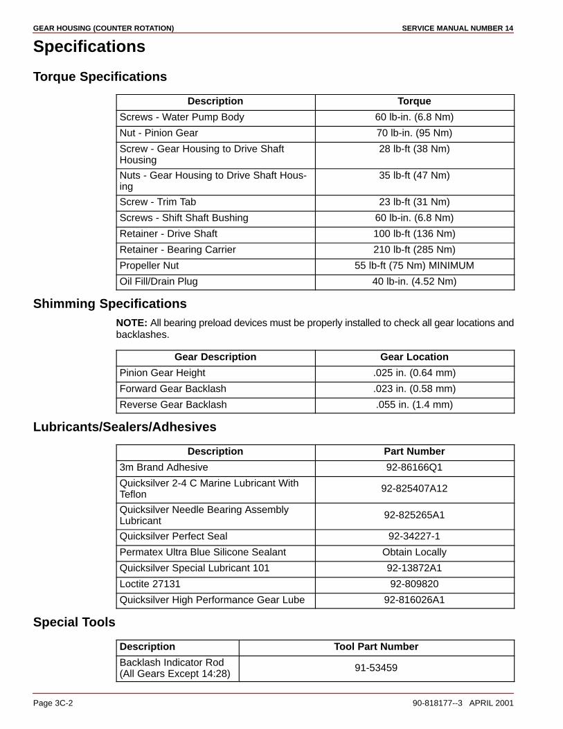
GEAR HOUSING (COUNTER ROTATION) SERVICE MANUAL NUMBER 14
Page 3C-2 90-818177--3 APRIL 2001
Specifications
Torque Specifications
Description Torque
Screws - Water Pump Body 60 lb-in. (6.8 Nm)
Nut - Pinion Gear 70 lb-in. (95 Nm)
Screw - Gear Housing to Drive ShaftHousing
28 lb-ft (38 Nm)
Nuts - Gear Housing to Drive Shaft Hous-ing
35 lb-ft (47 Nm)
Screw - Trim Tab 23 lb-ft (31 Nm)
Screws - Shift Shaft Bushing 60 lb-in. (6.8 Nm)
Retainer - Drive Shaft 100 lb-ft (136 Nm)
Retainer - Bearing Carrier 210 lb-ft (285 Nm)
Propeller Nut 55 lb-ft (75 Nm) MINIMUM
Oil Fill/Drain Plug 40 lb-in. (4.52 Nm)
Shimming SpecificationsNOTE: All bearing preload devices must be properly installed to check all gear locations andbacklashes.
Gear Description Gear Location
Pinion Gear Height .025 in. (0.64 mm)
Forward Gear Backlash .023 in. (0.58 mm)
Reverse Gear Backlash .055 in. (1.4 mm)
Lubricants/Sealers/Adhesives
Description Part Number
3m Brand Adhesive 92-86166Q1
Quicksilver 2-4 C Marine Lubricant WithTeflon
92-825407A12
Quicksilver Needle Bearing AssemblyLubricant
92-825265A1
Quicksilver Perfect Seal 92-34227-1
Permatex Ultra Blue Silicone Sealant Obtain Locally
Quicksilver Special Lubricant 101 92-13872A1
Loctite 27131 92-809820
Quicksilver High Performance Gear Lube 92-816026A1
Special Tools
Description Tool Part Number
Backlash Indicator Rod(All Gears Except 14:28)
91-53459

GEAR HOUSING (COUNTER ROTATION)SERVICE MANUAL NUMBER 14
90-818177--3 APRIL 2001 Page 3C-3
Backlash Indicator Rod(14:28 Gears)
91-78473
Bearing AdaptorInstallation Tool
91-18605 A2
Bearing Carrier RetainerWrench
91-61069T
Bearing Driver 91-816244
Bearing Preload Tool 91-14311 A2
Bearing Removal Tool 91-816245
Belleville Washer 12-54048
Dial Indicator 91-58222 A1
Dial Indicator HoldingTool
91-89897
Drive Shaft Nut Wrench 91-56775T
Drive Shaft BearingRetainer Wrench
91-43506T
Guide Plate 91-816243
Needle Bearing Driver 91-15755T
Oil Seal Driver 91-31108T
Oil Seal Driver 91-817569T
Pinion Gear ShimmingTool
91-56048T
Pinion Nut Adaptor 91-61067 A3

GEAR HOUSING (COUNTER ROTATION) SERVICE MANUAL NUMBER 14
Page 3C-4 90-818177--3 APRIL 2001
Special Tools (continued)
Description Tool Part Number
Drive Shaft Adaptor 91-61077T
Puller Bolt 91-85716
Puller Shaft 91-31229
Puller Jaws 91-46086 A1
Puller Jaws 91-816242
Slide Hammer Puller 91-34569 A1
Forward Gear InstallationTool
91-815850
Torque Wrench (InchPound)
91-66274
Universal Puller Plate 91-37241
Water Pump AlignmentPins
91-821571 A1
Universal BearingRemoval And InstallationTool
91-31229 A7
Driver Head 91-36569T
Driver Head Rod 91-37323
Nut 11-24156
Pilot Washer 91-36571T
Puller Plate 91-29310
Puller/Driver Head 91-38628T
Reverse Gear BearingTool
91-807944T
*The 91-14311A2 Bearing Preload Tool is also used on Mercury and Mariner V-6 gearcases. Check your inventory before buying.
NOTE: Water Pump Face Seal Tool is not available separately, 26-816575A2 is a kit partnumber which includes the tool and the face seal.

GEAR HOUSING (COUNTER ROTATION)SERVICE MANUAL NUMBER 14
90-818177--3 APRIL 2001 Page 3C-5
THIS PAGE IS INTENTIONALLY BLANK

GEAR HOUSING (COUNTER ROTATION) SERVICE MANUAL NUMBER 14
Page 3C-6 90-818177--3 APRIL 2001
Counter-Rotation Gear Housing Exploded Parts View
Drive Shaft Components
74242
��
�
��
��
��
��
�
a
a
b
A
D
A
A
A(ID)
C
A
B
A
E
�
�
�
��
�
�
��
�
�
�
��
��
���
�
��
�
�
��
�
�
��
�
��
��
�
C
75664
�
a��
A
��
��
�
��
C
B
F
d
c
��
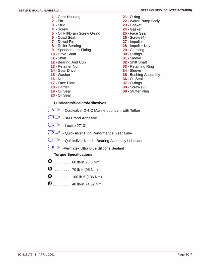
GEAR HOUSING (COUNTER ROTATION)SERVICE MANUAL NUMBER 14
90-818177--3 APRIL 2001 Page 3C-7
1 - Gear Housing2 - Pin3 - Stud4 - Screw5 - Oil Fill/Drain Screw O-ring6 - Quad Seal7 - Dowel Pin8 - Roller Bearing9 - Speedometer Fitting
10 - Drive Shaft11 - Shim12 - Bearing And Cup13 - Retainer Nut14 - Gear Drive15 - Washer16 - Nut17 - Face Plate18 - Carrier19 - Oil Seal20 - Oil Seal
21 - O-ring22 - Water Pump Body23 - Gasket24 - Gasket25 - Face Seal26 - Screw (4)27 - Impeller28 - Impeller Key29 - Coupling30 - O-rings31 - Sleeve32 - Shift Shaft33 - Retaining Ring34 - Sleeve35 - Bushing Assembly36 - Oil Seal37 - O-rings38 - Screw (2)39 - Stuffer Plug
Lubricants/Sealers/Adhesives
A - Quicksilver 2-4-C Marine Lubricant with Teflon
B - 3M Brand Adhesive
C - Loctite 27131
D - Quicksilver High Performance Gear Lube
E - Quicksilver Needle Bearing Assembly Lubricant
F -Permatex Ultra Blue Silicone Sealant
Torque Specifications
a 60 lb-in. (6.8 Nm). . . . . . . . .
b 70 lb-ft (95 Nm). . . . . . . . .
c 100 lb-ft (136 Nm). . . . . . . . . .
d 40 lb-in. (4.52 Nm). . . . . . . . . .

GEAR HOUSING (COUNTER ROTATION) SERVICE MANUAL NUMBER 14
Page 3C-8 90-818177--3 APRIL 2001
Propeller Shaft Components
DF(OD)
D
E
74723
��
�
�
�
�
��
�
��
��
�
��
��
��
��
������
��
��
�
��
�
��
����
��
�
�
�
�
�
�
�
�
�
�
�
�
��
��
�
(ID)A
b
c
d
a
75691
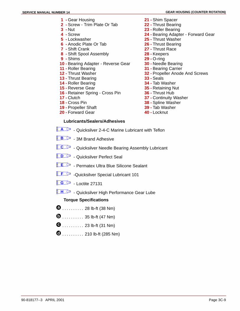
GEAR HOUSING (COUNTER ROTATION)SERVICE MANUAL NUMBER 14
90-818177--3 APRIL 2001 Page 3C-9
1 - Gear Housing2 - Screw - Trim Plate Or Tab3 - Nut4 - Screw5 - Lockwasher6 - Anodic Plate Or Tab7 - Shift Crank8 - Shift Spool Assembly9 - Shims
10 - Bearing Adapter - Reverse Gear11 - Roller Bearing12 - Thrust Washer13 - Thrust Bearing14 - Roller Bearing15 - Reverse Gear16 - Retainer Spring - Cross Pin17 - Clutch18 - Cross Pin19 - Propeller Shaft20 - Forward Gear
21 - Shim Spacer22 - Thrust Bearing23 - Roller Bearing24 - Bearing Adapter - Forward Gear25 - Thrust Washer26 - Thrust Bearing27 - Thrust Race28 - Keepers29 - O-ring30 - Needle Bearing31 - Bearing Carrier32 - Propeller Anode And Screws33 - Seals34 - Tab Washer35 - Retaining Nut36 - Thrust Hub37 - Continuity Washer38 - Spline Washer39 - Tab Washer40 - Locknut
Lubricants/Sealers/Adhesives
A - Quicksilver 2-4-C Marine Lubricant with Teflon
B - 3M Brand Adhesive
C - Quicksilver Needle Bearing Assembly Lubricant
D - Quicksilver Perfect Seal
E - Permatex Ultra Blue Silicone Sealant
F -Quicksilver Special Lubricant 101
G - Loctite 27131
H - Quicksilver High Performance Gear Lube
Torque Specifications
a 28 lb-ft (38 Nm). . . . . . . . . .
b 35 lb-ft (47 Nm). . . . . . . . . .
c 23 lb-ft (31 Nm). . . . . . . . . .
d 210 lb-ft (285 Nm). . . . . . . . . .
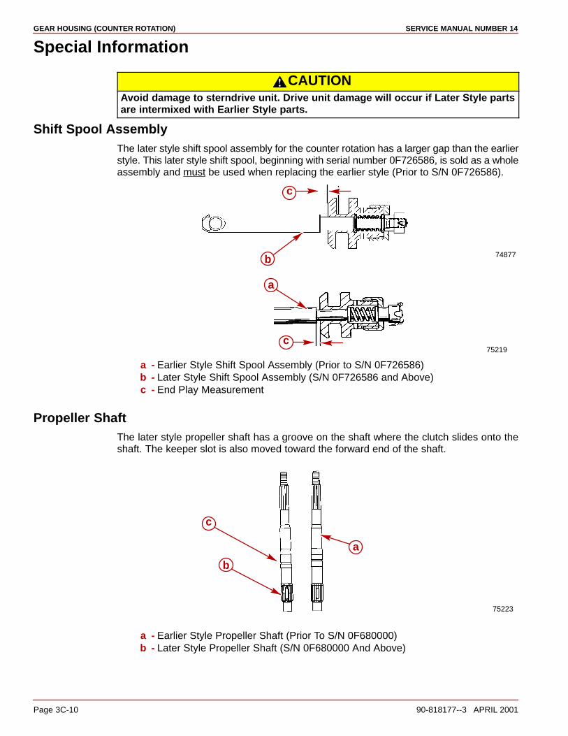
GEAR HOUSING (COUNTER ROTATION) SERVICE MANUAL NUMBER 14
Page 3C-10 90-818177--3 APRIL 2001
Special Information
CAUTIONAvoid damage to sterndrive unit. Drive unit damage will occur if Later Style partsare intermixed with Earlier Style parts.
Shift Spool AssemblyThe later style shift spool assembly for the counter rotation has a larger gap than the earlierstyle. This later style shift spool, beginning with serial number 0F726586, is sold as a wholeassembly and must be used when replacing the earlier style (Prior to S/N 0F726586).
75219
74877
a
b
c
c
a - Earlier Style Shift Spool Assembly (Prior to S/N 0F726586)b - Later Style Shift Spool Assembly (S/N 0F726586 and Above)c - End Play Measurement
Propeller ShaftThe later style propeller shaft has a groove on the shaft where the clutch slides onto theshaft. The keeper slot is also moved toward the forward end of the shaft.
75223
a
b
c
a - Earlier Style Propeller Shaft (Prior To S/N 0F680000)b - Later Style Propeller Shaft (S/N 0F680000 And Above)
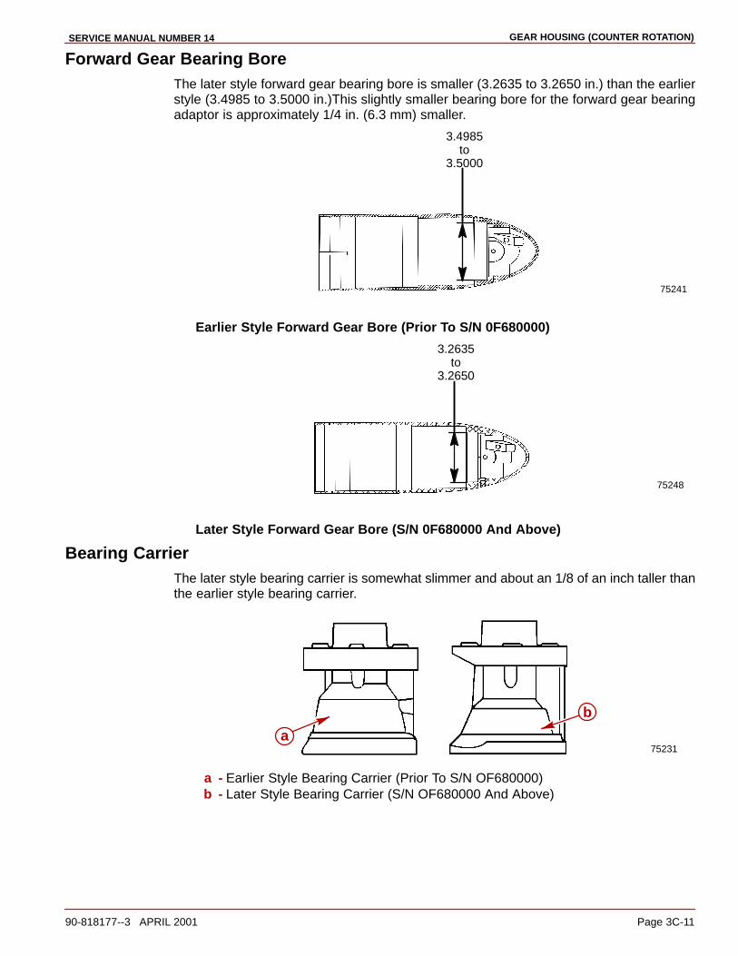
GEAR HOUSING (COUNTER ROTATION)SERVICE MANUAL NUMBER 14
90-818177--3 APRIL 2001 Page 3C-11
Forward Gear Bearing BoreThe later style forward gear bearing bore is smaller (3.2635 to 3.2650 in.) than the earlierstyle (3.4985 to 3.5000 in.)This slightly smaller bearing bore for the forward gear bearingadaptor is approximately 1/4 in. (6.3 mm) smaller.
3.4985 to3.5000
75241
Earlier Style Forward Gear Bore (Prior To S/N 0F680000)
75248
3.2635 to3.2650
Later Style Forward Gear Bore (S/N 0F680000 And Above)
Bearing CarrierThe later style bearing carrier is somewhat slimmer and about an 1/8 of an inch taller thanthe earlier style bearing carrier.
75231a
b
a - Earlier Style Bearing Carrier (Prior To S/N OF680000)b - Later Style Bearing Carrier (S/N OF680000 And Above)
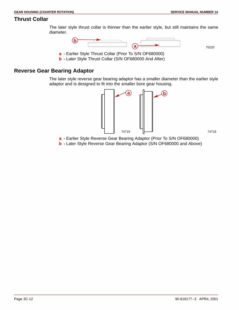
GEAR HOUSING (COUNTER ROTATION) SERVICE MANUAL NUMBER 14
Page 3C-12 90-818177--3 APRIL 2001
Thrust CollarThe later style thrust collar is thinner than the earlier style, but still maintains the samediameter.
75220ab
a - Earlier Style Thrust Collar (Prior To S/N OF680000)b - Later Style Thrust Collar (S/N OF680000 And After)
Reverse Gear Bearing AdaptorThe later style reverse gear bearing adaptor has a smaller diameter than the earlier styleadaptor and is designed to fit into the smaller bore gear housing.
74719 74718
a b
a - Earlier Style Reverse Gear Bearing Adaptor (Prior To S/N OF680000)b - Later Style Reverse Gear Bearing Adaptor (S/N OF680000 and Above)
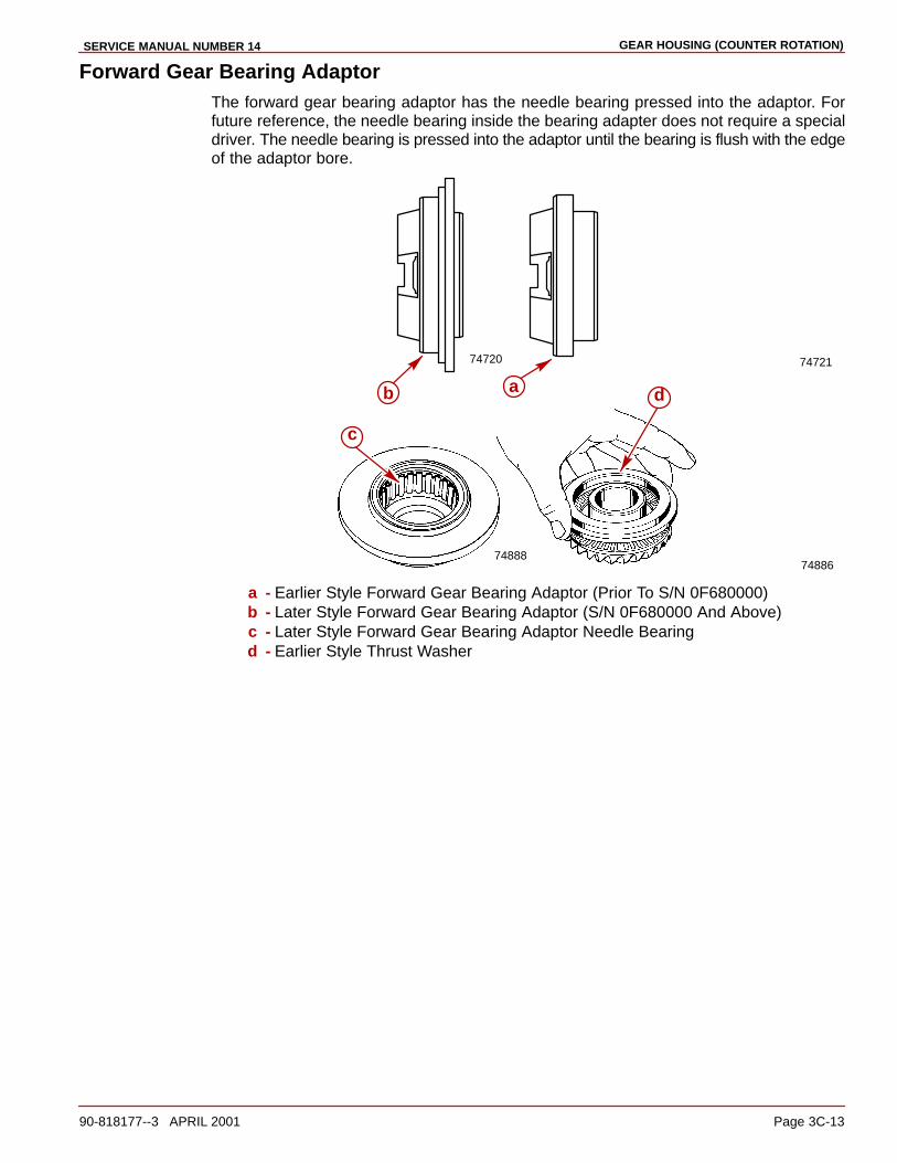
GEAR HOUSING (COUNTER ROTATION)SERVICE MANUAL NUMBER 14
90-818177--3 APRIL 2001 Page 3C-13
Forward Gear Bearing AdaptorThe forward gear bearing adaptor has the needle bearing pressed into the adaptor. Forfuture reference, the needle bearing inside the bearing adapter does not require a specialdriver. The needle bearing is pressed into the adaptor until the bearing is flush with the edgeof the adaptor bore.
74720 74721
7488874886
a db
c
a - Earlier Style Forward Gear Bearing Adaptor (Prior To S/N 0F680000)b - Later Style Forward Gear Bearing Adaptor (S/N 0F680000 And Above)c - Later Style Forward Gear Bearing Adaptor Needle Bearingd - Earlier Style Thrust Washer
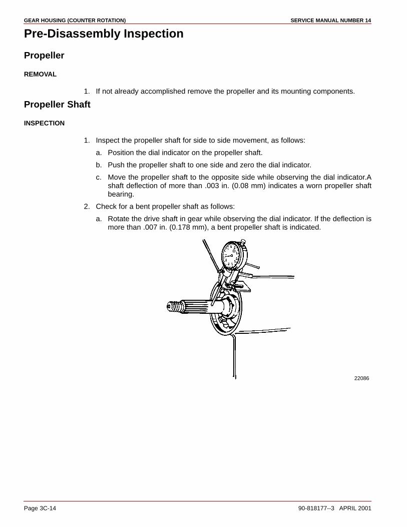
GEAR HOUSING (COUNTER ROTATION) SERVICE MANUAL NUMBER 14
Page 3C-14 90-818177--3 APRIL 2001
Pre-Disassembly Inspection
Propeller
REMOVAL
1. If not already accomplished remove the propeller and its mounting components.
Propeller Shaft
INSPECTION
1. Inspect the propeller shaft for side to side movement, as follows:
a. Position the dial indicator on the propeller shaft.
b. Push the propeller shaft to one side and zero the dial indicator.
c. Move the propeller shaft to the opposite side while observing the dial indicator.Ashaft deflection of more than .003 in. (0.08 mm) indicates a worn propeller shaftbearing.
2. Check for a bent propeller shaft as follows:
a. Rotate the drive shaft in gear while observing the dial indicator. If the deflection ismore than .007 in. (0.178 mm), a bent propeller shaft is indicated.
22086
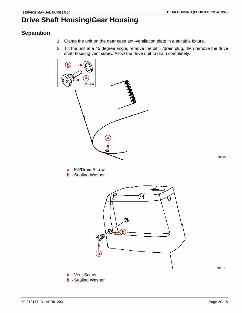
GEAR HOUSING (COUNTER ROTATION)SERVICE MANUAL NUMBER 14
90-818177--3 APRIL 2001 Page 3C-15
Drive Shaft Housing/Gear Housing
Separation1. Clamp the unit on the gear case anti-ventilation plate in a suitable fixture.
2. Tilt the unit at a 45 degree angle, remove the oil fill/drain plug, then remove the driveshaft housing vent screw. Allow the drive unit to drain completely.
70115
23264
a
b
a
a - Fill/Drain Screwb - Sealing Washer
70131
b
a
a - Vent Screwb - Sealing Washer

GEAR HOUSING (COUNTER ROTATION) SERVICE MANUAL NUMBER 14
Page 3C-16 90-818177--3 APRIL 2001
3. Mark the trim tab position with a piece of tape on the gear housing and remove the trimtab.
70116
a
b
a - Trim Tabb - Extension With 1/2 In. Socket
4. Remove the bolts, nuts and washers from the port and starboard sides of the unit.
5. Remove the aft screw (in the trim tab well of the gear housing).
6. Remove the nut from the forward end of the unit.
70117
b c
a
a - Nuts, Bolts and Washersb - Nutc - Screw
7. Lift the drive shaft housing straight off of the gear case and set aside.
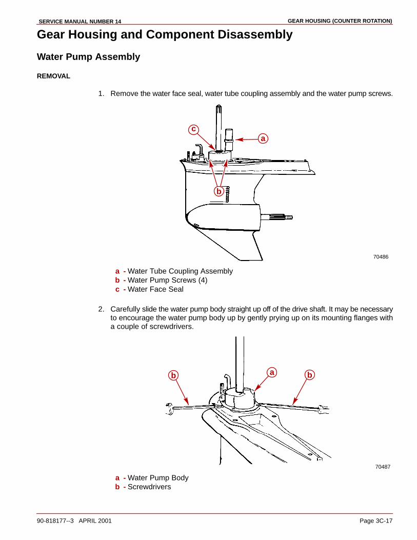
GEAR HOUSING (COUNTER ROTATION)SERVICE MANUAL NUMBER 14
90-818177--3 APRIL 2001 Page 3C-17
Gear Housing and Component Disassembly
Water Pump Assembly
REMOVAL
1. Remove the water face seal, water tube coupling assembly and the water pump screws.
70486
b
ca
a - Water Tube Coupling Assemblyb - Water Pump Screws (4)c - Water Face Seal
2. Carefully slide the water pump body straight up off of the drive shaft. It may be necessaryto encourage the water pump body up by gently prying up on its mounting flanges witha couple of screwdrivers.
70487
bb a
a - Water Pump Bodyb - Screwdrivers

GEAR HOUSING (COUNTER ROTATION) SERVICE MANUAL NUMBER 14
Page 3C-18 90-818177--3 APRIL 2001
3. Remove the impeller, impeller key, the face plate and gaskets. Discard the gaskets.
70605
b
a
c
a - Impellerb - Impeller Keyc - Water Pump Face Plate And Gaskets (One Gasket On Each Side Of The Face
Plate)
WATER PUMP INSPECTION
1. Inspect the water tube coupling assembly for wear or damage. If necessary replace theworn or damaged components especially the two O-ring seals on the inside, one at thetop and one at the bottom.
70613
b
b
a
a - Water Tube Adapterb - O-ring Seals (2)
2. Inspect the water pump impeller for wear on the end, top and bottom of the impellerblades. Replace the impeller if this condition is found.
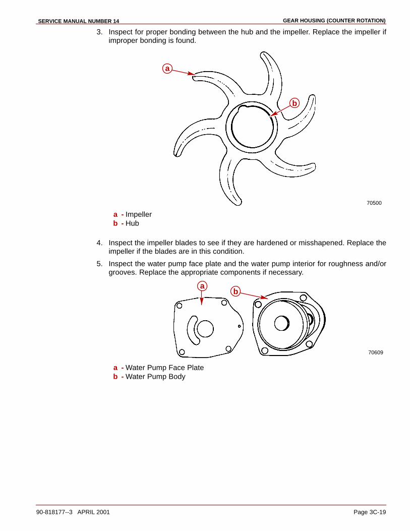
GEAR HOUSING (COUNTER ROTATION)SERVICE MANUAL NUMBER 14
90-818177--3 APRIL 2001 Page 3C-19
3. Inspect for proper bonding between the hub and the impeller. Replace the impeller ifimproper bonding is found.
70500
b
a
a - Impellerb - Hub
4. Inspect the impeller blades to see if they are hardened or misshapened. Replace theimpeller if the blades are in this condition.
5. Inspect the water pump face plate and the water pump interior for roughness and/orgrooves. Replace the appropriate components if necessary.
70609
ab
a - Water Pump Face Plateb - Water Pump Body
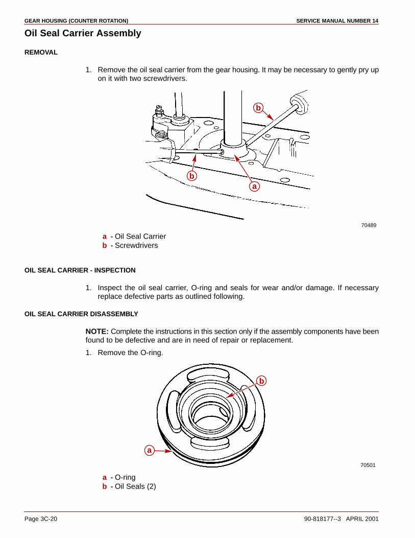
GEAR HOUSING (COUNTER ROTATION) SERVICE MANUAL NUMBER 14
Page 3C-20 90-818177--3 APRIL 2001
Oil Seal Carrier Assembly
REMOVAL
1. Remove the oil seal carrier from the gear housing. It may be necessary to gently pry upon it with two screwdrivers.
70489
b
ab
a - Oil Seal Carrierb - Screwdrivers
OIL SEAL CARRIER - INSPECTION
1. Inspect the oil seal carrier, O-ring and seals for wear and/or damage. If necessaryreplace defective parts as outlined following.
OIL SEAL CARRIER DISASSEMBLY
NOTE: Complete the instructions in this section only if the assembly components have beenfound to be defective and are in need of repair or replacement.
1. Remove the O-ring.
70501
a
b
a - O-ringb - Oil Seals (2)
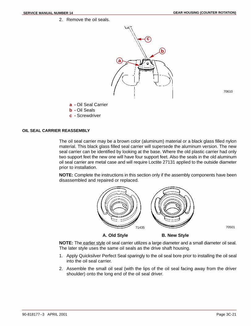
GEAR HOUSING (COUNTER ROTATION)SERVICE MANUAL NUMBER 14
90-818177--3 APRIL 2001 Page 3C-21
2. Remove the oil seals.
70610
c
a
b
a - Oil Seal Carrierb - Oil Sealsc - Screwdriver
OIL SEAL CARRIER REASSEMBLY
The oil seal carrier may be a brown color (aluminum) material or a black glass filled nylonmaterial. This black glass filled seal carrier will supersede the aluminum version. The newseal carrier can be identified by looking at the base. Where the old plastic carrier had onlytwo support feet the new one will have four support feet. Also the seals in the old aluminumoil seal carrier are metal case and will require Loctite 27131 applied to the outside diameterprior to installation.
NOTE: Complete the instructions in this section only if the assembly components have beendisassembled and repaired or replaced.
71435 70501
A. Old Style B. New Style
NOTE: The earlier style oil seal carrier utilizes a large diameter and a small diameter oil seal.The later style uses the same oil seals as the drive shaft housing.
1. Apply Quicksilver Perfect Seal sparingly to the oil seal bore prior to installing the oil sealinto the oil seal carrier.
2. Assemble the small oil seal (with the lips of the oil seal facing away from the drivershoulder) onto the long end of the oil seal driver.
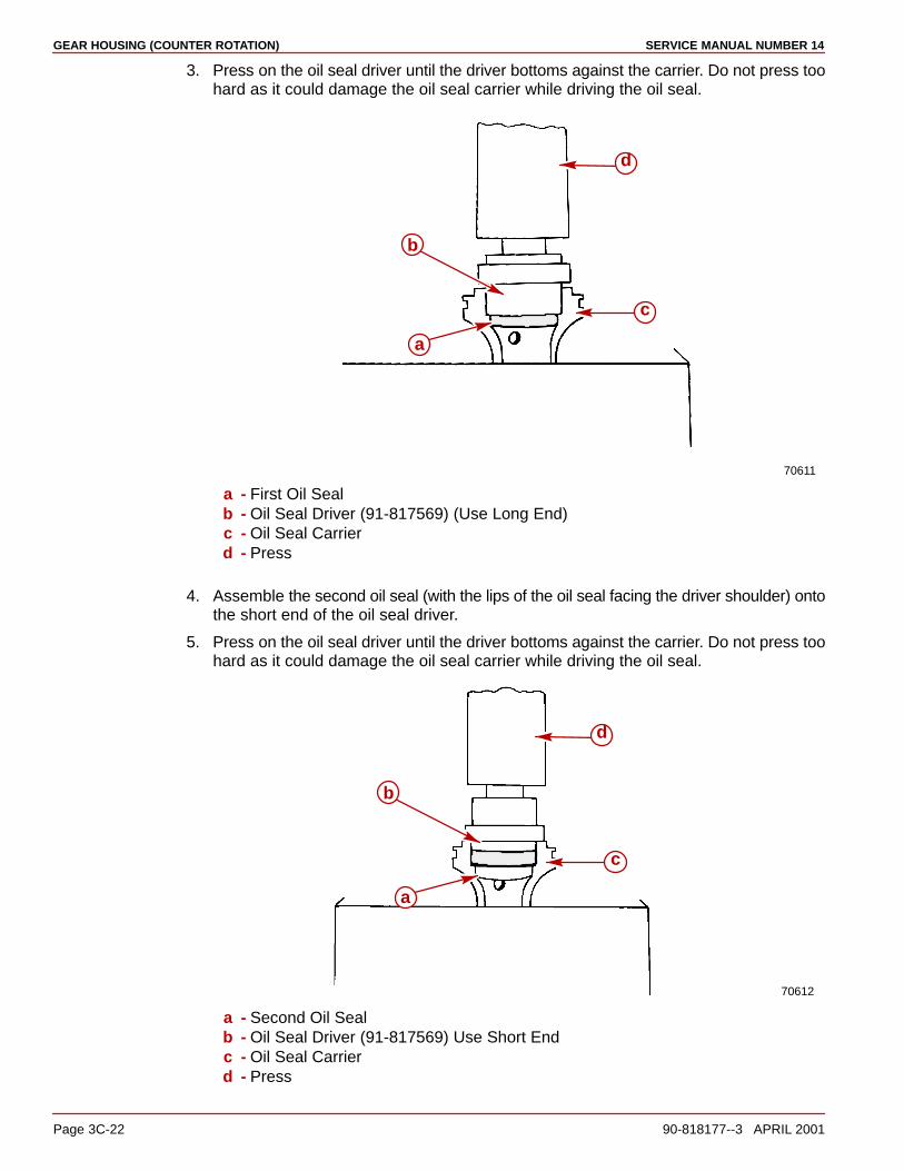
GEAR HOUSING (COUNTER ROTATION) SERVICE MANUAL NUMBER 14
Page 3C-22 90-818177--3 APRIL 2001
3. Press on the oil seal driver until the driver bottoms against the carrier. Do not press toohard as it could damage the oil seal carrier while driving the oil seal.
70611
a
b
c
d
a - First Oil Sealb - Oil Seal Driver (91-817569) (Use Long End)c - Oil Seal Carrierd - Press
4. Assemble the second oil seal (with the lips of the oil seal facing the driver shoulder) ontothe short end of the oil seal driver.
5. Press on the oil seal driver until the driver bottoms against the carrier. Do not press toohard as it could damage the oil seal carrier while driving the oil seal.
70612
a
b
c
d
a - Second Oil Sealb - Oil Seal Driver (91-817569) Use Short Endc - Oil Seal Carrierd - Press
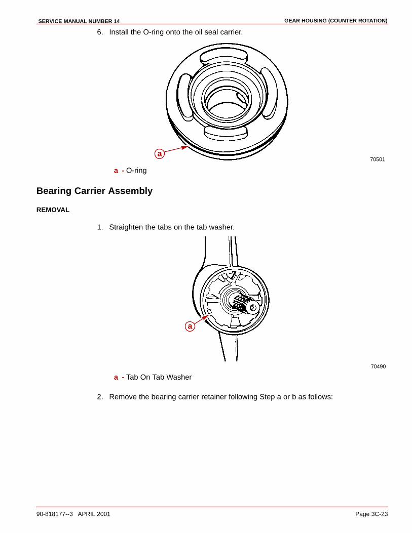
GEAR HOUSING (COUNTER ROTATION)SERVICE MANUAL NUMBER 14
90-818177--3 APRIL 2001 Page 3C-23
6. Install the O-ring onto the oil seal carrier.
70501a
a - O-ring
Bearing Carrier Assembly
REMOVAL
1. Straighten the tabs on the tab washer.
70490
a
a - Tab On Tab Washer
2. Remove the bearing carrier retainer following Step a or b as follows:
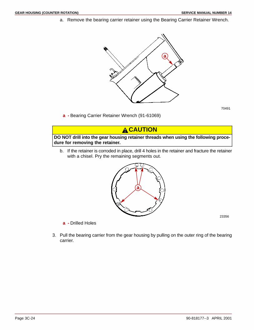
GEAR HOUSING (COUNTER ROTATION) SERVICE MANUAL NUMBER 14
Page 3C-24 90-818177--3 APRIL 2001
a. Remove the bearing carrier retainer using the Bearing Carrier Retainer Wrench.
70491
a
a - Bearing Carrier Retainer Wrench (91-61069)
CAUTIONDO NOT drill into the gear housing retainer threads when using the following proce-dure for removing the retainer.
b. If the retainer is corroded in place, drill 4 holes in the retainer and fracture the retainerwith a chisel. Pry the remaining segments out.
23356
a
a - Drilled Holes
3. Pull the bearing carrier from the gear housing by pulling on the outer ring of the bearingcarrier.
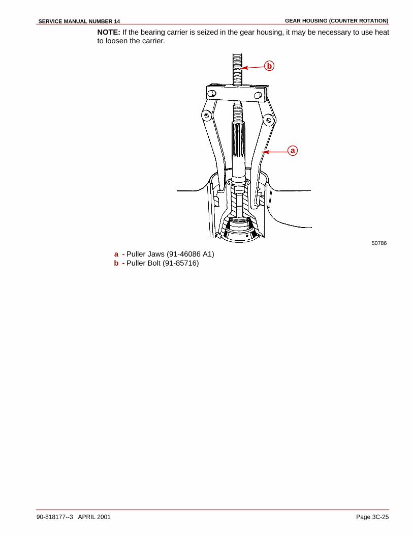
GEAR HOUSING (COUNTER ROTATION)SERVICE MANUAL NUMBER 14
90-818177--3 APRIL 2001 Page 3C-25
NOTE: If the bearing carrier is seized in the gear housing, it may be necessary to use heatto loosen the carrier.
50786
b
a
a - Puller Jaws (91-46086 A1)b - Puller Bolt (91-85716)

GEAR HOUSING (COUNTER ROTATION) SERVICE MANUAL NUMBER 14
Page 3C-26 90-818177--3 APRIL 2001
4. Lift the bearing carrier out of the gear housing. Locate and retain the thrust washer thatmay be stuck to the inside surface of the bearing carrier.
50826
a
50779
a
a - Thrust Washer

GEAR HOUSING (COUNTER ROTATION)SERVICE MANUAL NUMBER 14
90-818177--3 APRIL 2001 Page 3C-27
Forward Gear Bearing and Adaptor
REMOVAL
1. Remove the aft thrust bearing.
50786
a
a - Thrust Bearing
2. Remove the aft thrust collar.
50787
a
a - Thrust Collar
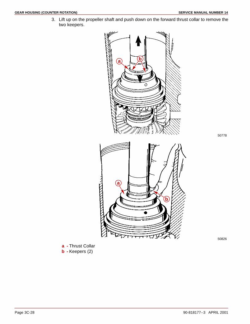
GEAR HOUSING (COUNTER ROTATION) SERVICE MANUAL NUMBER 14
Page 3C-28 90-818177--3 APRIL 2001
3. Lift up on the propeller shaft and push down on the forward thrust collar to remove thetwo keepers.
50778
a b
50826
b
a
a - Thrust Collarb - Keepers (2)
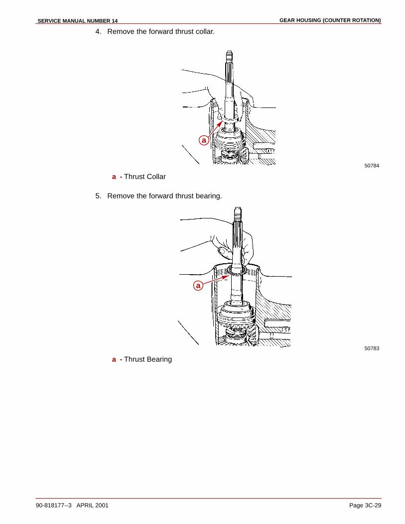
GEAR HOUSING (COUNTER ROTATION)SERVICE MANUAL NUMBER 14
90-818177--3 APRIL 2001 Page 3C-29
4. Remove the forward thrust collar.
50784
a
a - Thrust Collar
5. Remove the forward thrust bearing.
50783
a
a - Thrust Bearing
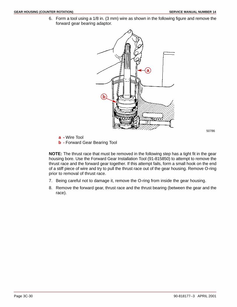
GEAR HOUSING (COUNTER ROTATION) SERVICE MANUAL NUMBER 14
Page 3C-30 90-818177--3 APRIL 2001
6. Form a tool using a 1/8 in. (3 mm) wire as shown in the following figure and remove theforward gear bearing adaptor.
50786
a
b
a - Wire Toolb - Forward Gear Bearing Tool
NOTE: The thrust race that must be removed in the following step has a tight fit in the gearhousing bore. Use the Forward Gear Installation Tool (91-815850) to attempt to remove thethrust race and the forward gear together. If this attempt fails, form a small hook on the endof a stiff piece of wire and try to pull the thrust race out of the gear housing. Remove O-ringprior to removal of thrust race.
7. Being careful not to damage it, remove the O-ring from inside the gear housing.
8. Remove the forward gear, thrust race and the thrust bearing (between the gear and therace).

GEAR HOUSING (COUNTER ROTATION)SERVICE MANUAL NUMBER 14
90-818177--3 APRIL 2001 Page 3C-31
9. Remove the forward gear shim.
50783
d
a
b
c
a - Forward Gear Installation Tool (91-815850)b - Thrust Racec - Forward Geard - Shim

GEAR HOUSING (COUNTER ROTATION) SERVICE MANUAL NUMBER 14
Page 3C-32 90-818177--3 APRIL 2001
COMPONENT - INSPECTION
CAUTIONEye protection must be worn when performing next procedure. Failure to do so maycause personal injury.
1. Clean the assembly and all components with a suitable solvent and dry the partsthoroughly using compressed air.
NOTE: If any of the following items are found to be defective, complete the appropriateinstruction(s).
2. Inspect the bearing carrier for signs of excessive corrosion especially in the area wherethe bearing carrier touches the gear housing. If excessive corrosion is evident, replacethe carrier.
50818
a
b
a - Bearing Carrierb - Mating Surfaces
NOTE: The bearing carrier has changed slightly. The later style bearing carrier is about 1/8of an inch taller and more streamlined than the earlier style. See “Special Information” onpage 3C-8.
a
b
a - Earlier Style Bearing Carrier (Prior To S/N OF680000)b - Later Style Bearing Carrier (S/N OF680000 And Above)
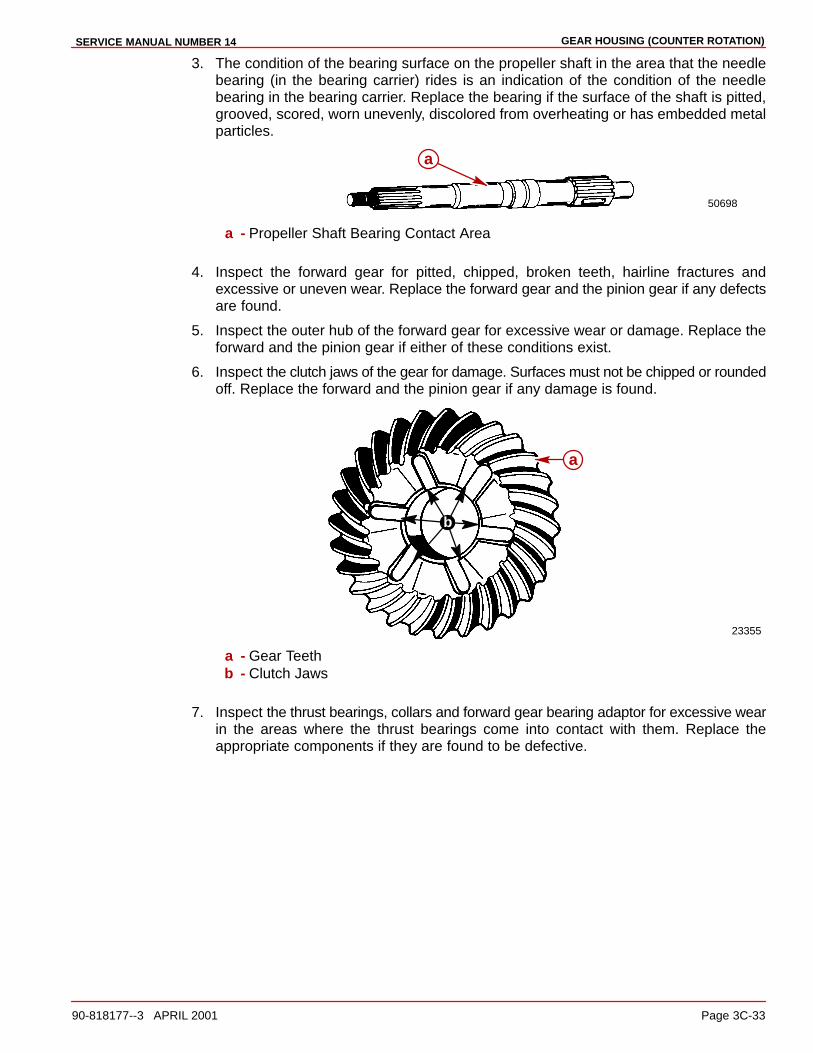
GEAR HOUSING (COUNTER ROTATION)SERVICE MANUAL NUMBER 14
90-818177--3 APRIL 2001 Page 3C-33
3. The condition of the bearing surface on the propeller shaft in the area that the needlebearing (in the bearing carrier) rides is an indication of the condition of the needlebearing in the bearing carrier. Replace the bearing if the surface of the shaft is pitted,grooved, scored, worn unevenly, discolored from overheating or has embedded metalparticles.
50698
a
a - Propeller Shaft Bearing Contact Area
4. Inspect the forward gear for pitted, chipped, broken teeth, hairline fractures andexcessive or uneven wear. Replace the forward gear and the pinion gear if any defectsare found.
5. Inspect the outer hub of the forward gear for excessive wear or damage. Replace theforward and the pinion gear if either of these conditions exist.
6. Inspect the clutch jaws of the gear for damage. Surfaces must not be chipped or roundedoff. Replace the forward and the pinion gear if any damage is found.
23355
b
a
a - Gear Teethb - Clutch Jaws
7. Inspect the thrust bearings, collars and forward gear bearing adaptor for excessive wearin the areas where the thrust bearings come into contact with them. Replace theappropriate components if they are found to be defective.

GEAR HOUSING (COUNTER ROTATION) SERVICE MANUAL NUMBER 14
Page 3C-34 90-818177--3 APRIL 2001
8. Inspect the bearing carrier retainer for cracks and/or broken or corroded threads.Replace it if any are found.
23356
a
b
a - Drilled Holes
9. Inspect the large O-ring for damage and/or deterioration. Replace it if either conditionis found.
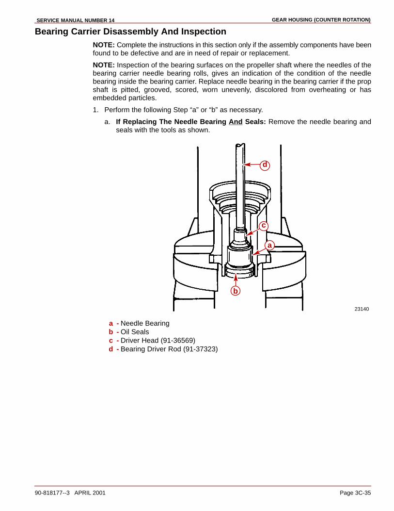
GEAR HOUSING (COUNTER ROTATION)SERVICE MANUAL NUMBER 14
90-818177--3 APRIL 2001 Page 3C-35
Bearing Carrier Disassembly And InspectionNOTE: Complete the instructions in this section only if the assembly components have beenfound to be defective and are in need of repair or replacement.
NOTE: Inspection of the bearing surfaces on the propeller shaft where the needles of thebearing carrier needle bearing rolls, gives an indication of the condition of the needlebearing inside the bearing carrier. Replace needle bearing in the bearing carrier if the propshaft is pitted, grooved, scored, worn unevenly, discolored from overheating or hasembedded particles.
1. Perform the following Step “a” or “b” as necessary.
a. If Replacing The Needle Bearing And Seals: Remove the needle bearing andseals with the tools as shown.
23140
a
b
c
d
a - Needle Bearingb - Oil Sealsc - Driver Head (91-36569)d - Bearing Driver Rod (91-37323)
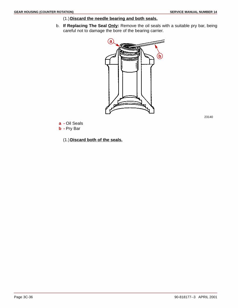
GEAR HOUSING (COUNTER ROTATION) SERVICE MANUAL NUMBER 14
Page 3C-36 90-818177--3 APRIL 2001
(1.)Discard the needle bearing and both seals.
b. If Replacing The Seal Only: Remove the oil seals with a suitable pry bar, beingcareful not to damage the bore of the bearing carrier.
23140
a
b
a - Oil Sealsb - Pry Bar
(1.)Discard both of the seals.
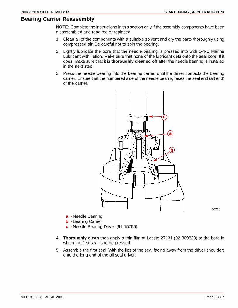
GEAR HOUSING (COUNTER ROTATION)SERVICE MANUAL NUMBER 14
90-818177--3 APRIL 2001 Page 3C-37
Bearing Carrier ReassemblyNOTE: Complete the instructions in this section only if the assembly components have beendisassembled and repaired or replaced.
1. Clean all of the components with a suitable solvent and dry the parts thoroughly usingcompressed air. Be careful not to spin the bearing.
2. Lightly lubricate the bore that the needle bearing is pressed into with 2-4-C MarineLubricant with Teflon. Make sure that none of the lubricant gets onto the seal bore. If itdoes, make sure that it is thoroughly cleaned off after the needle bearing is installedin the next step.
3. Press the needle bearing into the bearing carrier until the driver contacts the bearingcarrier. Ensure that the numbered side of the needle bearing faces the seal end (aft end)of the carrier.
50788
a
b
c
a - Needle Bearingb - Bearing Carrierc - Needle Bearing Driver (91-15755)
4. Thoroughly clean then apply a thin film of Loctite 27131 (92-809820) to the bore inwhich the first seal is to be pressed.
5. Assemble the first seal (with the lips of the seal facing away from the driver shoulder)onto the long end of the oil seal driver.
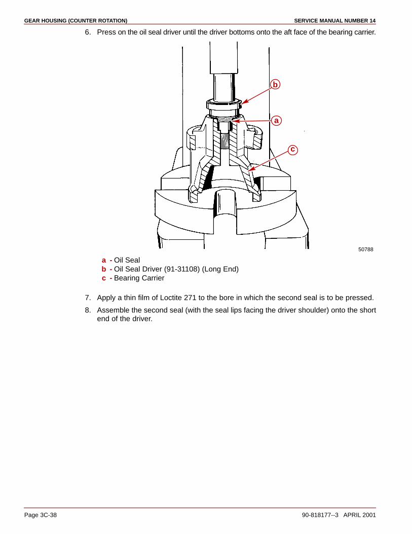
GEAR HOUSING (COUNTER ROTATION) SERVICE MANUAL NUMBER 14
Page 3C-38 90-818177--3 APRIL 2001
6. Press on the oil seal driver until the driver bottoms onto the aft face of the bearing carrier.
50788
a
b
c
a - Oil Sealb - Oil Seal Driver (91-31108) (Long End)c - Bearing Carrier
7. Apply a thin film of Loctite 271 to the bore in which the second seal is to be pressed.
8. Assemble the second seal (with the seal lips facing the driver shoulder) onto the shortend of the driver.

GEAR HOUSING (COUNTER ROTATION)SERVICE MANUAL NUMBER 14
90-818177--3 APRIL 2001 Page 3C-39
9. Press the oil seal with the driver until the driver contacts the bearing carrier.
50788
a
b
c
a - Driver (Short End)b - Oil Seal (Lips Toward Driver Shoulder)c - Bearing Carrier
10. Wipe up all of the excess Loctite. Do not allow any of the excess Loctite to spread toother parts of the assembly.
Forward Gear Bearing Adaptor Assembly
INSPECTION
1. Thoroughly clean the forward gear bearing adaptor with a suitable solvent and dry itthoroughly using compressed air.
NOTE: The condition of the bearing surfaces on the forward gear in the areas that thebearings of the bearing adaptor and the thrust bearing rides is an indication of the conditionof the respective bearings. Replace the bearing(s) if the surface of the gear and/or the thrustwasher is pitted, grooved, scored, worn unevenly, discolored from overheating or hasembedded metal particles.
2. Assemble the forward gear to the bearing adaptor. Inspect them for excessivemovement or roughness by rotating the gear in the adaptor. Replace the bearing in theadaptor if either of these conditions exist.
3. Inspect the adaptor for other signs of excessive wear or damage. Replace the adaptorif any are found.
NOTE: The later model forward gear bearing adapter comes with the needle bearingpressed into the adapter. For future reference, the needle bearing in side the bearing

GEAR HOUSING (COUNTER ROTATION) SERVICE MANUAL NUMBER 14
Page 3C-40 90-818177--3 APRIL 2001
adapter does not require a special driver. The needle bearing is pressed into the adapteruntil the bearing is flush with the edge of the adapter bore.
74888
ab
a - Forward Gear Bearing Adapterb - Needle Bearing
NOTE: A difference exists in the forward gear bearing adaptor. The latest style adaptor hasincorporated the earlier thrust race into the adaptor. Refer to the following illustration foridentification.
7472074721
50785
a b
c
a - Bearing Adaptor - Latest Styleb - Bearing Adaptor - Earlier Stylec - Thrust Race - No Longer Separate
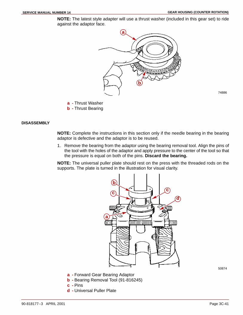
GEAR HOUSING (COUNTER ROTATION)SERVICE MANUAL NUMBER 14
90-818177--3 APRIL 2001 Page 3C-41
NOTE: The latest style adapter will use a thrust washer (included in this gear set) to rideagainst the adaptor face.
74886
a
b
a - Thrust Washerb - Thrust Bearing
DISASSEMBLY
NOTE: Complete the instructions in this section only if the needle bearing in the bearingadaptor is defective and the adaptor is to be reused.
1. Remove the bearing from the adaptor using the bearing removal tool. Align the pins ofthe tool with the holes of the adaptor and apply pressure to the center of the tool so thatthe pressure is equal on both of the pins. Discard the bearing.
NOTE: The universal puller plate should rest on the press with the threaded rods on thesupports. The plate is turned in the illustration for visual clarity.
50874
a
b
cc
d
a - Forward Gear Bearing Adaptorb - Bearing Removal Tool (91-816245)c - Pinsd - Universal Puller Plate

GEAR HOUSING (COUNTER ROTATION) SERVICE MANUAL NUMBER 14
Page 3C-42 90-818177--3 APRIL 2001
REASSEMBLY
1. Lubricate the bore that the needle bearing is pressed into with Quicksilver SpecialLubricant 101.
2. If earlier style, assemble the needle bearing to the adaptor with the numbered end ofthe bearing facing the driver shoulder.
3. If earlier style, press the needle bearing into the bearing adaptor using a suitablemandrel until the bearing bottoms in the adaptor.
Drive Shaft Assembly
REMOVAL
1. Remove the drive shaft pinion nut as follows:
a. Place the drive shaft bearing retainer wrench onto the drive shaft. Do not loosen theretainer at this time.
b. Insert the pinion nut adaptor with the MR slot facing the pinion gear, into the gearhousing as shown. It may be necessary to slightly lift and rotate the drive shaft toalign the pinion gear nut into the pinion nut adapter slot.
c. Install the bearing carrier into the gear housing backwards to support the prop shaftand to keep the pinion nut adapter aligned.
d. Place the drive shaft nut wrench over the drive shaft splines and loosen, (but do notfully unscrew), the pinion nut by rotating the drive shaft counterclockwise.
70887
a
b
c
a - Drive Shaft Nut Wrench (91-56775)b - Drive Shaft Bearing Retainer Wrench (91-43506)c - Pinion Nut Adaptor (91-61067 A1)
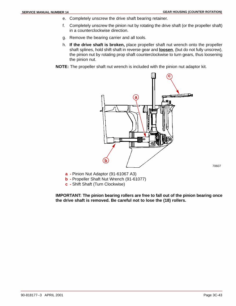
GEAR HOUSING (COUNTER ROTATION)SERVICE MANUAL NUMBER 14
90-818177--3 APRIL 2001 Page 3C-43
e. Completely unscrew the drive shaft bearing retainer.
f. Completely unscrew the pinion nut by rotating the drive shaft (or the propeller shaft)in a counterclockwise direction.
g. Remove the bearing carrier and all tools.
h. If the drive shaft is broken, place propeller shaft nut wrench onto the propellershaft splines, hold shift shaft in reverse gear and loosen, (but do not fully unscrew),the pinion nut by rotating prop shaft counterclockwise to turn gears, thus looseningthe pinion nut.
NOTE: The propeller shaft nut wrench is included with the pinion nut adaptor kit.
70607
a
c
b
a - Pinion Nut Adaptor (91-61067 A3)b - Propeller Shaft Nut Wrench (91-61077)c - Shift Shaft (Turn Clockwise)
IMPORTANT: The pinion bearing rollers are free to fall out of the pinion bearing oncethe drive shaft is removed. Be careful not to lose the (18) rollers.
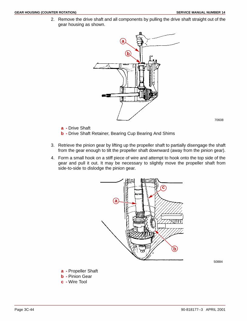
GEAR HOUSING (COUNTER ROTATION) SERVICE MANUAL NUMBER 14
Page 3C-44 90-818177--3 APRIL 2001
2. Remove the drive shaft and all components by pulling the drive shaft straight out of thegear housing as shown.
70608
a
b
a - Drive Shaftb - Drive Shaft Retainer, Bearing Cup Bearing And Shims
3. Retrieve the pinion gear by lifting up the propeller shaft to partially disengage the shaftfrom the gear enough to tilt the propeller shaft downward (away from the pinion gear).
4. Form a small hook on a stiff piece of wire and attempt to hook onto the top side of thegear and pull it out. It may be necessary to slightly move the propeller shaft fromside-to-side to dislodge the pinion gear.
50884
a
b
c
a - Propeller Shaftb - Pinion Gearc - Wire Tool

GEAR HOUSING (COUNTER ROTATION)SERVICE MANUAL NUMBER 14
90-818177--3 APRIL 2001 Page 3C-45
DRIVE SHAFT INSPECTION
1. Clean all parts with a suitable solvent and dry the parts thoroughly using compressedair, being careful not to spin the bearings.
2. The condition of the drive shaft bearing cup is an indication of the condition of thetapered roller bearing on the drive shaft. Replace the bearing and bearing cup if the cupis pitted, grooved, scored, worn unevenly, discolored from overheating or hasembedded particles.
3. Inspect the bearing surface on the drive shaft where the needles of the lower pinionbearing roll. Replace the drive shaft if it is pitted, grooved, scored, worn unevenly,discolored from overheating or has embedded particles.
4. Inspect the splines at both ends of the drive shaft for a worn or twisted condition. Replacethe drive shaft if either condition exists.
5. Inspect the gear for pitting, chipped or broken teeth, hairline fractures and excessive oruneven wear. Replace the pinion gear and the forward gear if any defects are found.
DRIVE SHAFT DISASSEMBLY
NOTE: Complete the instructions in this section only if the assembly components have beenfound to be defective and are in need of repair or replacement.
1. Press the tapered roller bearing from the drive shaft using the universal puller plate tosupport the inner race of the bearing while removing it.
70699
a
b
c
a - Universal Puller Plate (91-37241)b - Tapered Roller Bearingc - Drive Shaft
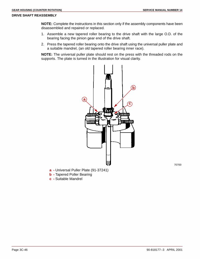
GEAR HOUSING (COUNTER ROTATION) SERVICE MANUAL NUMBER 14
Page 3C-46 90-818177--3 APRIL 2001
DRIVE SHAFT REASSEMBLY
NOTE: Complete the instructions in this section only if the assembly components have beendisassembled and repaired or replaced.
1. Assemble a new tapered roller bearing to the drive shaft with the large O.D. of thebearing facing the pinion gear end of the drive shaft.
2. Press the tapered roller bearing onto the drive shaft using the universal puller plate anda suitable mandrel, (an old tapered roller bearing inner race).
NOTE: The universal puller plate should rest on the press with the threaded rods on thesupports. The plate is turned in the illustration for visual clarity.
70700
a
b
c
a - Universal Puller Plate (91-37241)b - Tapered Poller Bearingc - Suitable Mandrel

GEAR HOUSING (COUNTER ROTATION)SERVICE MANUAL NUMBER 14
90-818177--3 APRIL 2001 Page 3C-47
Propeller Shaft Assembly
REMOVAL
CAUTIONHold onto the propeller shaft assembly in the following step to avoid personal injuryand/or dropping components when turning the gear housing over.
1. While holding onto the propeller shaft, turn the gear housing over so that the boreopening is facing down.
2. While moving the propeller shaft to the left (port) side of the gear housing, to allow theshift spool to disengage from the shift crank, lower the propeller shaft out of the gearhousing.
NOTE: The rollers of the reverse gear bearing adaptor may become dislodged whileremoving the propeller shaft assembly. If this occurs, inspect the bearing cage to see if ithas been damaged. If it has not been damaged simply snap the rollers back into position.If it has been damaged, it will be necessary to remove and replace the bearing.
50887
a
bc
a - Propeller Shaft Assemblyb - Shift Spoolc - Shift Crank

GEAR HOUSING (COUNTER ROTATION) SERVICE MANUAL NUMBER 14
Page 3C-48 90-818177--3 APRIL 2001
3. Locate and retain the thrust race and thrust bearing which could be on top of the reversegear (if not, they may be stuck to the reverse gear bearing adaptor).
50887
a
a - Thrust Bearing And Race
PROPELLER SHAFT DISASSEMBLY
IMPORTANT: When accomplishing the next step all of the parts are free to comeapart. Work closely over a work bench to ensure that the parts are not dropped ordamaged and to avoid personal injury.
1. Remove the spring around the clutch being careful not to stretch it during removal. If thespring does not coil back to its normal position once it has been removed it must bereplaced.
50885d
ab
c
a - Springb - Shift Spool Assemblyc - Reverse Gear Assemblyd - Sliding Clutch

GEAR HOUSING (COUNTER ROTATION)SERVICE MANUAL NUMBER 14
90-818177--3 APRIL 2001 Page 3C-49
2. Remove the cross pin that goes through the clutch.
50885
a
a - Cross Pin
3. Slide the spool assembly out of the propeller shaft, remove the reverse gear and slidethe clutch off of the propeller shaft.
50881
b c d
a - Cross Pinb - Clutchc - Reverse Gear Assemblyd - Spool

GEAR HOUSING (COUNTER ROTATION) SERVICE MANUAL NUMBER 14
Page 3C-50 90-818177--3 APRIL 2001
PROPELLER SHAFT INSPECTION
1. Clean all the parts with a suitable solvent and dry the parts thoroughly using compressedair. Be careful not to spin bearings.
2. Inspect the sliding clutch jaws for damage. Jaws must not be chipped or rounded off.Replace the clutch if they are.
23350
a
a - Sliding Clutch Jaws
3. Inspect the bearing surfaces on the propeller shaft where the needles of the bearingcarrier needle bearing and the needles of the reverse gear needle bearing roll. Replacethe propeller shaft if it is pitted, grooved, scored, worn unevenly, discolored formoverheating or has embedded particles.
50698
a b
c
a - Bearing Carrier Needle Bearing Contact Areab - Reverse Gear Needle Bearing Contact Areac - Splines
4. Inspect the propeller shaft splines at both ends for a broken, worn or twisted condition.Replace the propeller shaft if any of these conditions exists.
5. Inspect the surface of the propeller shaft where the bearing carrier seal lips contact theshaft. If the oil seals have made grooves, the propeller shaft must be replaced.
50698
a
a - Bearing Carrier Seal Contact Area
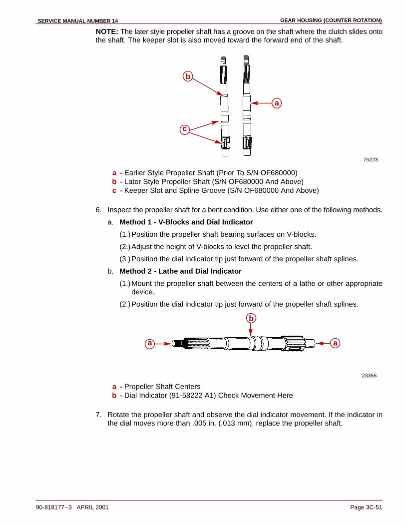
GEAR HOUSING (COUNTER ROTATION)SERVICE MANUAL NUMBER 14
90-818177--3 APRIL 2001 Page 3C-51
NOTE: The later style propeller shaft has a groove on the shaft where the clutch slides ontothe shaft. The keeper slot is also moved toward the forward end of the shaft.
75223
a
b
c
a - Earlier Style Propeller Shaft (Prior To S/N OF680000)b - Later Style Propeller Shaft (S/N OF680000 And Above)c - Keeper Slot and Spline Groove (S/N OF680000 And Above)
6. Inspect the propeller shaft for a bent condition. Use either one of the following methods.
a. Method 1 - V-Blocks and Dial Indicator
(1.)Position the propeller shaft bearing surfaces on V-blocks.
(2.)Adjust the height of V-blocks to level the propeller shaft.
(3.)Position the dial indicator tip just forward of the propeller shaft splines.
b. Method 2 - Lathe and Dial Indicator
(1.)Mount the propeller shaft between the centers of a lathe or other appropriatedevice.
(2.)Position the dial indicator tip just forward of the propeller shaft splines.
23355
a
b
a
a - Propeller Shaft Centersb - Dial Indicator (91-58222 A1) Check Movement Here
7. Rotate the propeller shaft and observe the dial indicator movement. If the indicator inthe dial moves more than .005 in. (.013 mm), replace the propeller shaft.
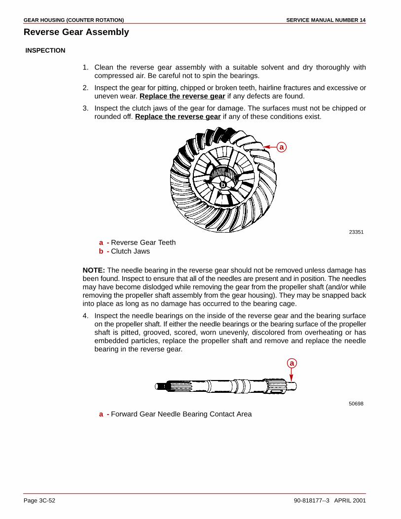
GEAR HOUSING (COUNTER ROTATION) SERVICE MANUAL NUMBER 14
Page 3C-52 90-818177--3 APRIL 2001
Reverse Gear Assembly
INSPECTION
1. Clean the reverse gear assembly with a suitable solvent and dry thoroughly withcompressed air. Be careful not to spin the bearings.
2. Inspect the gear for pitting, chipped or broken teeth, hairline fractures and excessive oruneven wear. Replace the reverse gear if any defects are found.
3. Inspect the clutch jaws of the gear for damage. The surfaces must not be chipped orrounded off. Replace the reverse gear if any of these conditions exist.
23351
b
a
a - Reverse Gear Teethb - Clutch Jaws
NOTE: The needle bearing in the reverse gear should not be removed unless damage hasbeen found. Inspect to ensure that all of the needles are present and in position. The needlesmay have become dislodged while removing the gear from the propeller shaft (and/or whileremoving the propeller shaft assembly from the gear housing). They may be snapped backinto place as long as no damage has occurred to the bearing cage.
4. Inspect the needle bearings on the inside of the reverse gear and the bearing surfaceon the propeller shaft. If either the needle bearings or the bearing surface of the propellershaft is pitted, grooved, scored, worn unevenly, discolored from overheating or hasembedded particles, replace the propeller shaft and remove and replace the needlebearing in the reverse gear.
50698
a
a - Forward Gear Needle Bearing Contact Area
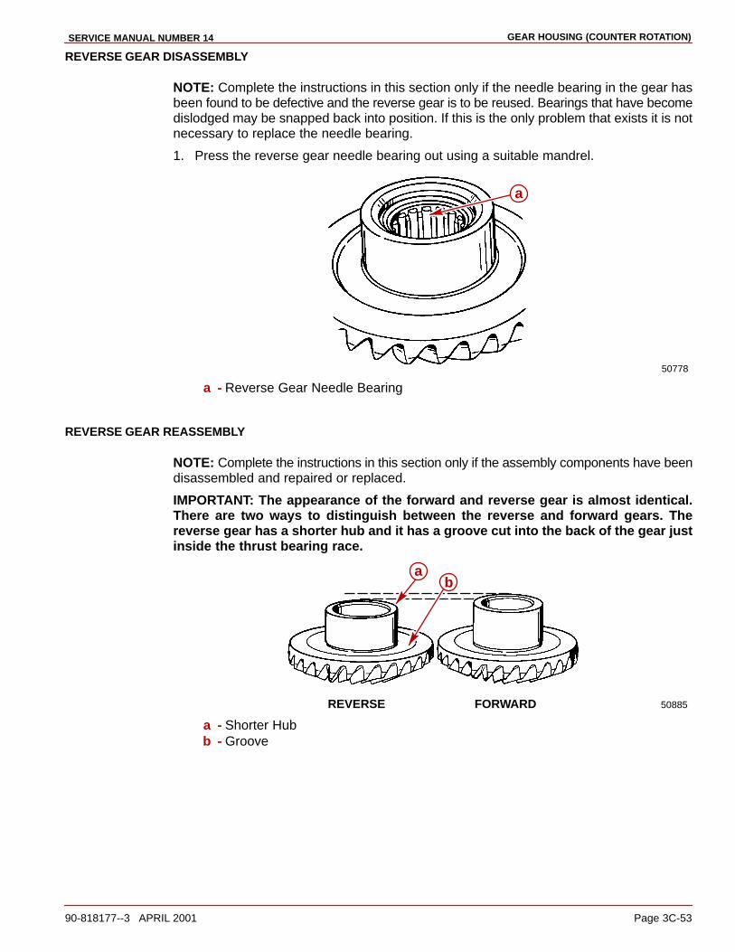
GEAR HOUSING (COUNTER ROTATION)SERVICE MANUAL NUMBER 14
90-818177--3 APRIL 2001 Page 3C-53
REVERSE GEAR DISASSEMBLY
NOTE: Complete the instructions in this section only if the needle bearing in the gear hasbeen found to be defective and the reverse gear is to be reused. Bearings that have becomedislodged may be snapped back into position. If this is the only problem that exists it is notnecessary to replace the needle bearing.
1. Press the reverse gear needle bearing out using a suitable mandrel.
50778
a
a - Reverse Gear Needle Bearing
REVERSE GEAR REASSEMBLY
NOTE: Complete the instructions in this section only if the assembly components have beendisassembled and repaired or replaced.
IMPORTANT: The appearance of the forward and reverse gear is almost identical.There are two ways to distinguish between the reverse and forward gears. Thereverse gear has a shorter hub and it has a groove cut into the back of the gear justinside the thrust bearing race.
50885REVERSE FORWARD
ab
a - Shorter Hubb - Groove
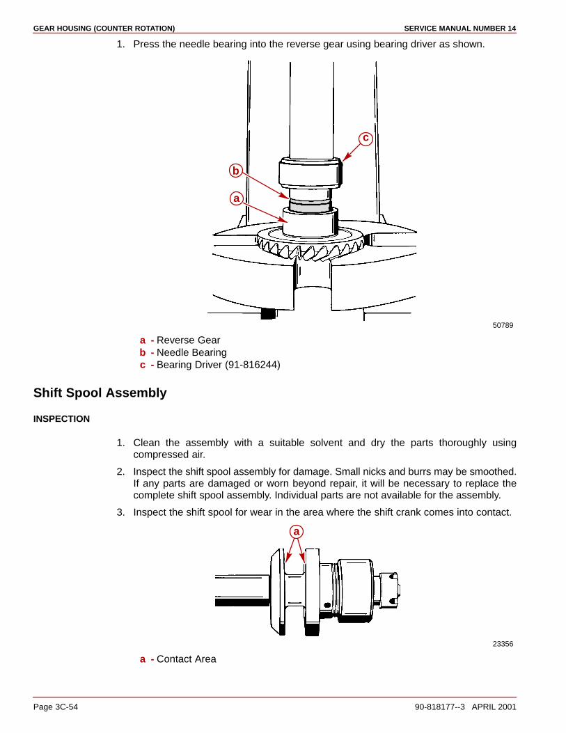
GEAR HOUSING (COUNTER ROTATION) SERVICE MANUAL NUMBER 14
Page 3C-54 90-818177--3 APRIL 2001
1. Press the needle bearing into the reverse gear using bearing driver as shown.
50789
a
b
c
a - Reverse Gearb - Needle Bearingc - Bearing Driver (91-816244)
Shift Spool Assembly
INSPECTION
1. Clean the assembly with a suitable solvent and dry the parts thoroughly usingcompressed air.
2. Inspect the shift spool assembly for damage. Small nicks and burrs may be smoothed.If any parts are damaged or worn beyond repair, it will be necessary to replace thecomplete shift spool assembly. Individual parts are not available for the assembly.
3. Inspect the shift spool for wear in the area where the shift crank comes into contact.
23356
a
a - Contact Area

GEAR HOUSING (COUNTER ROTATION)SERVICE MANUAL NUMBER 14
90-818177--3 APRIL 2001 Page 3C-55
4. Ensure that the spool spins freely (it may be helpful to lightly tap the forward [castle nut]end of the shift spool shaft against a firm surface to align the internal parts).
5. Ensure that the spool has no more than .002-.010 (0.051-0.254 mm) end play.
6. To check end play:
a. Push in on the shift spool. Take measurement.
b. Pull out on the shift spool. Take measurement.
c. The difference between the two measurements is the end play.
74877
ab
c
a - Shift Shaftb - Spoolc - End Play Measurement:
NOTE: The later style shift spool assembly for the counter rotation has a larger gap thanthe earlier style. This later style shift spool, beginning with serial number OF726586, is soldas a whole assembly and must be used when replacing the earlier style (Prior to S/NOF726586).
75219
74877b
c
a
c
a - Earlier Style Shift Spool Assembly (Prior To S/N OF726586)b - Later Style Shift Spool Assembly (S/N OF726586 And Above)c - Measure End Play Here At Gap
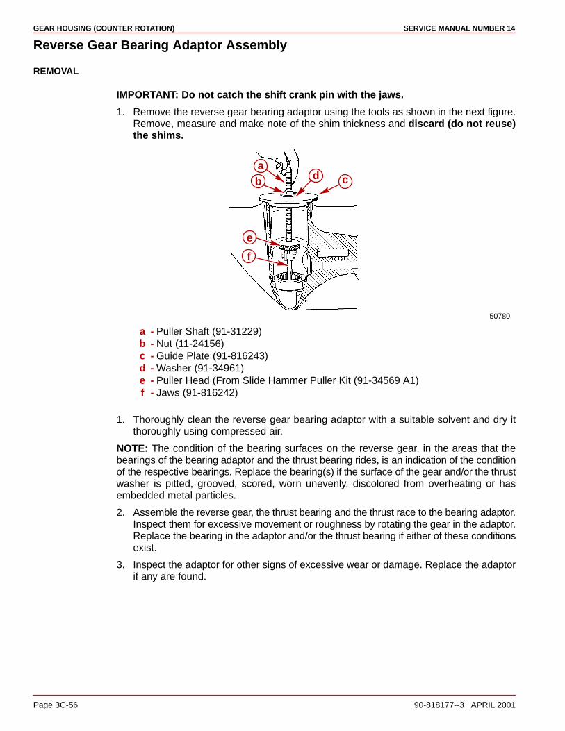
GEAR HOUSING (COUNTER ROTATION) SERVICE MANUAL NUMBER 14
Page 3C-56 90-818177--3 APRIL 2001
Reverse Gear Bearing Adaptor Assembly
REMOVAL
IMPORTANT: Do not catch the shift crank pin with the jaws.
1. Remove the reverse gear bearing adaptor using the tools as shown in the next figure.Remove, measure and make note of the shim thickness and discard (do not reuse)the shims.
50780
d
e
f
ab c
a - Puller Shaft (91-31229)b - Nut (11-24156)c - Guide Plate (91-816243)d - Washer (91-34961)e - Puller Head (From Slide Hammer Puller Kit (91-34569 A1)f - Jaws (91-816242)
1. Thoroughly clean the reverse gear bearing adaptor with a suitable solvent and dry itthoroughly using compressed air.
NOTE: The condition of the bearing surfaces on the reverse gear, in the areas that thebearings of the bearing adaptor and the thrust bearing rides, is an indication of the conditionof the respective bearings. Replace the bearing(s) if the surface of the gear and/or the thrustwasher is pitted, grooved, scored, worn unevenly, discolored from overheating or hasembedded metal particles.
2. Assemble the reverse gear, the thrust bearing and the thrust race to the bearing adaptor.Inspect them for excessive movement or roughness by rotating the gear in the adaptor.Replace the bearing in the adaptor and/or the thrust bearing if either of these conditionsexist.
3. Inspect the adaptor for other signs of excessive wear or damage. Replace the adaptorif any are found.
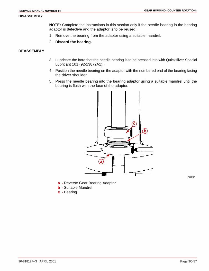
GEAR HOUSING (COUNTER ROTATION)SERVICE MANUAL NUMBER 14
90-818177--3 APRIL 2001 Page 3C-57
DISASSEMBLY
NOTE: Complete the instructions in this section only if the needle bearing in the bearingadaptor is defective and the adaptor is to be reused.
1. Remove the bearing from the adaptor using a suitable mandrel.
2. Discard the bearing.
REASSEMBLY
3. Lubricate the bore that the needle bearing is to be pressed into with Quicksilver SpecialLubricant 101 (92-13872A1).
4. Position the needle bearing on the adaptor with the numbered end of the bearing facingthe driver shoulder.
5. Press the needle bearing into the bearing adaptor using a suitable mandrel until thebearing is flush with the face of the adaptor.
50790
a
b
c
a - Reverse Gear Bearing Adaptorb - Suitable Mandrelc - Bearing
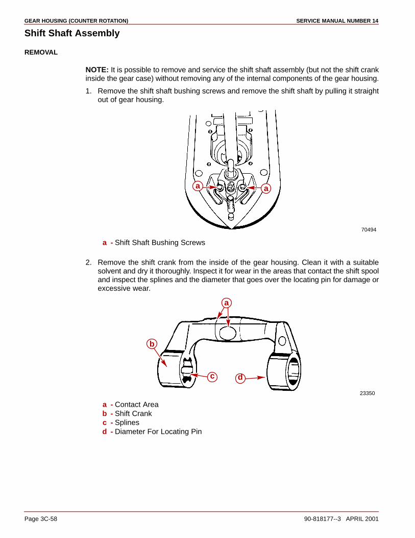
GEAR HOUSING (COUNTER ROTATION) SERVICE MANUAL NUMBER 14
Page 3C-58 90-818177--3 APRIL 2001
Shift Shaft Assembly
REMOVAL
NOTE: It is possible to remove and service the shift shaft assembly (but not the shift crankinside the gear case) without removing any of the internal components of the gear housing.
1. Remove the shift shaft bushing screws and remove the shift shaft by pulling it straightout of gear housing.
70494
a a
a - Shift Shaft Bushing Screws
2. Remove the shift crank from the inside of the gear housing. Clean it with a suitablesolvent and dry it thoroughly. Inspect it for wear in the areas that contact the shift spooland inspect the splines and the diameter that goes over the locating pin for damage orexcessive wear.
23350
a
b
c d
a - Contact Areab - Shift Crankc - Splinesd - Diameter For Locating Pin

GEAR HOUSING (COUNTER ROTATION)SERVICE MANUAL NUMBER 14
90-818177--3 APRIL 2001 Page 3C-59
SHIFT SHAFT DISASSEMBLY
1. Remove the clip and slide the bushing assembly off of the straight end of the shift shaft.Remove the rubber sleeve from the shaft.
70616
a
b
c
d
e
a - Shift Shaft Bushingb - O-rings (2)c - Sleeved - Clipe - Shift Shaft
CLEANING AND INSPECTION
1. Clean all components with a suitable solvent and dry thoroughly with compressed air.
2. Inspect the shift shaft bushing for cracking, damage or excessive wear.
3. Inspect the seal inside the bushing, the sleeve and the O-rings on the outside of thebushing for damage or excessive wear.
4. Inspect the speedometer connector for damage or blockage.
If any of these conditions exist replace the appropriate components. Note that the bushingand seal are available only as an assembly.
70617 75670
c
a
b ad
c
Earlier and Later Models Showna - Shift Shaft Bushingb - Sealc - Speedometer Tube Connectord - O-ring
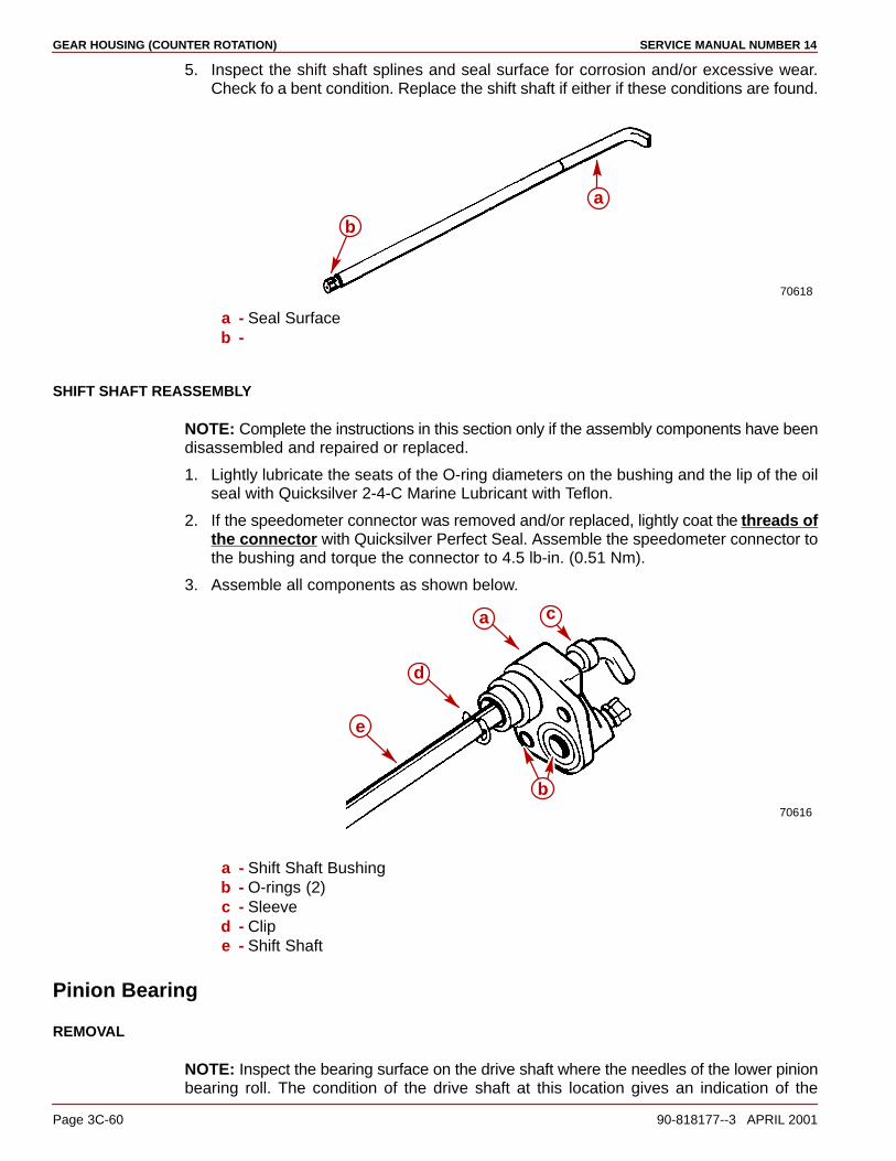
GEAR HOUSING (COUNTER ROTATION) SERVICE MANUAL NUMBER 14
Page 3C-60 90-818177--3 APRIL 2001
5. Inspect the shift shaft splines and seal surface for corrosion and/or excessive wear.Check fo a bent condition. Replace the shift shaft if either if these conditions are found.
70618
a
b
a - Seal Surfaceb -
SHIFT SHAFT REASSEMBLY
NOTE: Complete the instructions in this section only if the assembly components have beendisassembled and repaired or replaced.
1. Lightly lubricate the seats of the O-ring diameters on the bushing and the lip of the oilseal with Quicksilver 2-4-C Marine Lubricant with Teflon.
2. If the speedometer connector was removed and/or replaced, lightly coat the threads ofthe connector with Quicksilver Perfect Seal. Assemble the speedometer connector tothe bushing and torque the connector to 4.5 lb-in. (0.51 Nm).
3. Assemble all components as shown below.
70616
a
b
c
d
e
a - Shift Shaft Bushingb - O-rings (2)c - Sleeved - Clipe - Shift Shaft
Pinion Bearing
REMOVAL
NOTE: Inspect the bearing surface on the drive shaft where the needles of the lower pinionbearing roll. The condition of the drive shaft at this location gives an indication of the
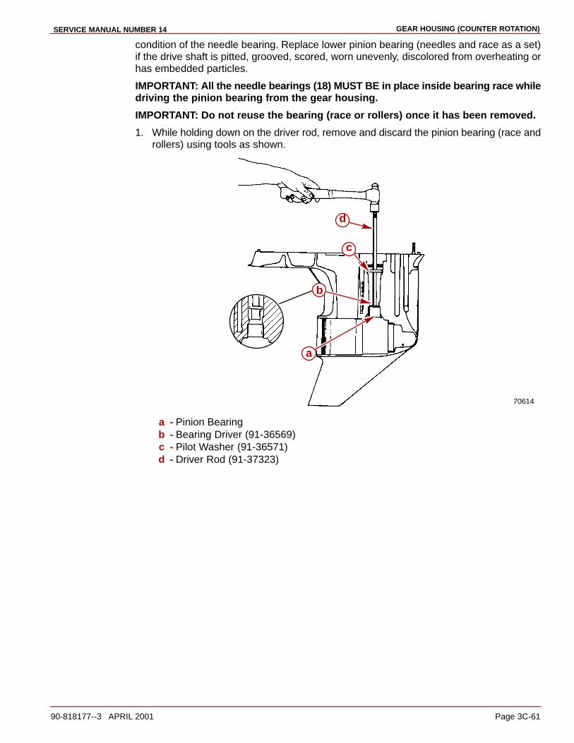
GEAR HOUSING (COUNTER ROTATION)SERVICE MANUAL NUMBER 14
90-818177--3 APRIL 2001 Page 3C-61
condition of the needle bearing. Replace lower pinion bearing (needles and race as a set)if the drive shaft is pitted, grooved, scored, worn unevenly, discolored from overheating orhas embedded particles.
IMPORTANT: All the needle bearings (18) MUST BE in place inside bearing race whiledriving the pinion bearing from the gear housing.
IMPORTANT: Do not reuse the bearing (race or rollers) once it has been removed.
1. While holding down on the driver rod, remove and discard the pinion bearing (race androllers) using tools as shown.
70614
a
b
c
d
a - Pinion Bearingb - Bearing Driver (91-36569)c - Pilot Washer (91-36571)d - Driver Rod (91-37323)
GEAR HOUSING (COUNTER ROTATION) SERVICE MANUAL NUMBER 14
Page 3C-62 90-818177--3 APRIL 2001
Gear Housing Reassembly
Gear Housing Inspection1. Clean the gear housing thoroughly with a suitable solvent and a hard bristle brush. Dry
the gear housing thoroughly using compressed air. Ensure that all sealants, lockingagents and debris are removed.
2. Inspect the gear housing for excessive corrosion, impact or any other damage.Excessive damage and/or corrosion requires replacement of the gear housing.
3. Inspect the bearing carrier retainer threads in the gear housing for corrosion and/orstripped threads. Excessive damage to the threads requires replacement of the gearhousing.
4. Inspect bearing race/cup contact areas for evidence of bearing cup spinning. Check thatbearing cups are not loose in bearing bores. Any one bearing bore in which the race/cupis loose may require replacement of the gear housing.
5. Inspect for blockage in water inlet holes and the speedometer hole. Clean as necessary.Be careful not to enlarge the speedometer hole as this could cause erroneousspeedometer readings.
6. Make sure that the locating pins are in place in the gear housing and that thecorresponding holes in the drive shaft housing are not elongated. The drive shaft maybreak if the housings are not aligned properly due to missing locating pins or elongatedholes.
Pinion Bearing InstallationIMPORTANT: Install only a NEW pinion bearing (race and rollers). Do not reinstall apinion bearing that has been previously removed from a gear housing.
1. Lubricate the bore into which the pinion bearing is to be installed with Quicksilver HighPerformance Gear Lube.
2. Position the new pinion bearing onto the driver head, with the lettered and numberedside of the bearing positioned upward.
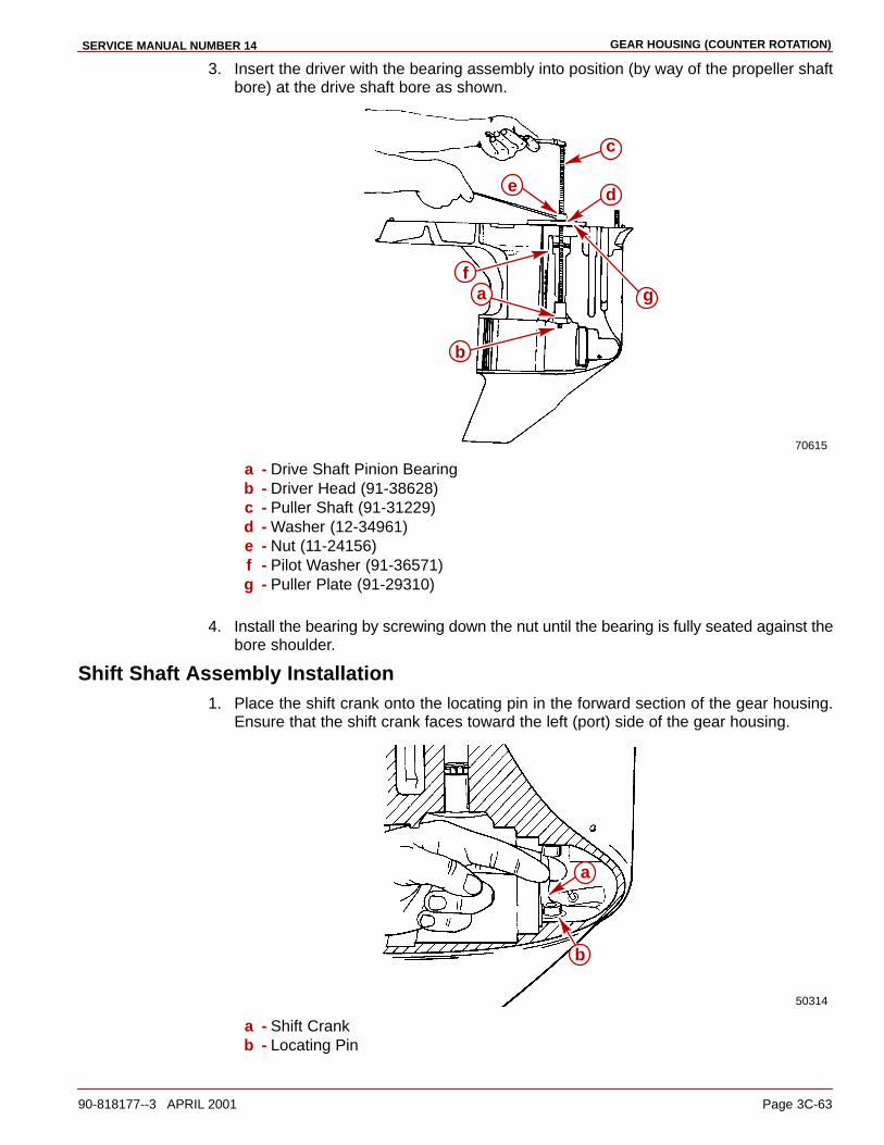
GEAR HOUSING (COUNTER ROTATION)SERVICE MANUAL NUMBER 14
90-818177--3 APRIL 2001 Page 3C-63
3. Insert the driver with the bearing assembly into position (by way of the propeller shaftbore) at the drive shaft bore as shown.
70615
a
b
c
de
fg
a - Drive Shaft Pinion Bearingb - Driver Head (91-38628)c - Puller Shaft (91-31229)d - Washer (12-34961)e - Nut (11-24156)f - Pilot Washer (91-36571)g - Puller Plate (91-29310)
4. Install the bearing by screwing down the nut until the bearing is fully seated against thebore shoulder.
Shift Shaft Assembly Installation1. Place the shift crank onto the locating pin in the forward section of the gear housing.
Ensure that the shift crank faces toward the left (port) side of the gear housing.
50314
b
a
a - Shift Crankb - Locating Pin

GEAR HOUSING (COUNTER ROTATION) SERVICE MANUAL NUMBER 14
Page 3C-64 90-818177--3 APRIL 2001
2. Install the shift shaft and bushing assembly into the gear housing as shown. Position thebent end of the shift shaft forward while installing it and ensure that the splined end ofthe shift shaft is engaged with the shift crank. Make sure that the O-rings are presentand positioned properly. Install the screws and tighten to hold the shift shaft into the shiftcrank.
70620
a
a - Shift Shaft Assembly
NOTE: If the pinion bearing needle bearings have fallen out, install 18 needles into needlebearing outer race. Use Quicksilver Needle Bearing Assembly Lubricant to help holdneedles in place.
23142
a
b
a - Needles (18)b - Roller Bearing Outer Race
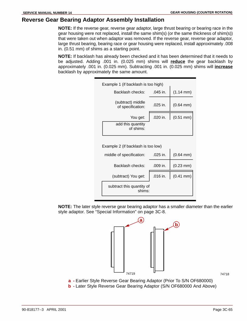
GEAR HOUSING (COUNTER ROTATION)SERVICE MANUAL NUMBER 14
90-818177--3 APRIL 2001 Page 3C-65
Reverse Gear Bearing Adaptor Assembly InstallationNOTE: If the reverse gear, reverse gear adaptor, large thrust bearing or bearing race in thegear housing were not replaced, install the same shim(s) (or the same thickness of shim(s))that were taken out when adaptor was removed. If the reverse gear, reverse gear adaptor,large thrust bearing, bearing race or gear housing were replaced, install approximately .008in. (0.51 mm) of shims as a starting point.
NOTE: If backlash has already been checked and it has been determined that it needs tobe adjusted. Adding .001 in. (0.025 mm) shims will reduce the gear backlash byapproximately .001 in. (0.025 mm). Subtracting .001 in. (0.025 mm) shims will increasebacklash by approximately the same amount.
Example 1 (if backlash is too high)
Backlash checks:
(subtract) middleof specification:
You get:
add this quantityof shims:
.045 in.
.025 in.
.020 in.
(1.14 mm)
(0.64 mm)
(0.51 mm)
Example 2 (if backlash is too low)
Backlash checks:
middle of specification:
(subtract) You get:
subtract this quantity ofshims:
.025 in.
.009 in.
.016 in.
(0.64 mm)
(0.23 mm)
(0.41 mm)
NOTE: The later style reverse gear bearing adaptor has a smaller diameter than the earlierstyle adaptor. See “Special Information” on page 3C-8.
74719 74718
ab
a - Earlier Style Reverse Gear Bearing Adaptor (Prior To S/N OF680000)b - Later Style Reverse Gear Bearing Adaptor (S/N OF680000 And Above)
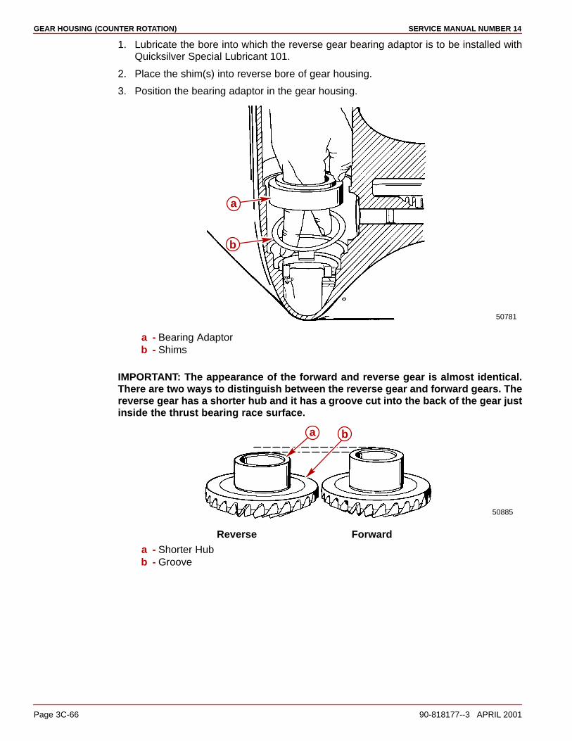
GEAR HOUSING (COUNTER ROTATION) SERVICE MANUAL NUMBER 14
Page 3C-66 90-818177--3 APRIL 2001
1. Lubricate the bore into which the reverse gear bearing adaptor is to be installed withQuicksilver Special Lubricant 101.
2. Place the shim(s) into reverse bore of gear housing.
3. Position the bearing adaptor in the gear housing.
50781
a
b
a - Bearing Adaptorb - Shims
IMPORTANT: The appearance of the forward and reverse gear is almost identical.There are two ways to distinguish between the reverse gear and forward gears. Thereverse gear has a shorter hub and it has a groove cut into the back of the gear justinside the thrust bearing race surface.
50885
a b
Reverse Forwarda - Shorter Hubb - Groove
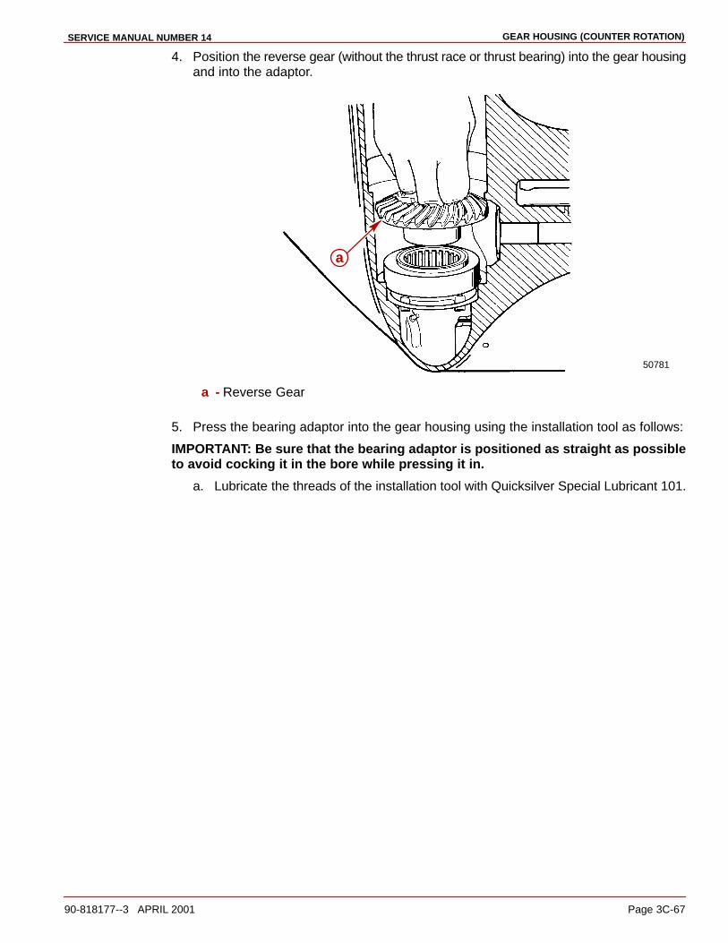
GEAR HOUSING (COUNTER ROTATION)SERVICE MANUAL NUMBER 14
90-818177--3 APRIL 2001 Page 3C-67
4. Position the reverse gear (without the thrust race or thrust bearing) into the gear housingand into the adaptor.
50781
a
a - Reverse Gear
5. Press the bearing adaptor into the gear housing using the installation tool as follows:
IMPORTANT: Be sure that the bearing adaptor is positioned as straight as possibleto avoid cocking it in the bore while pressing it in.
a. Lubricate the threads of the installation tool with Quicksilver Special Lubricant 101.
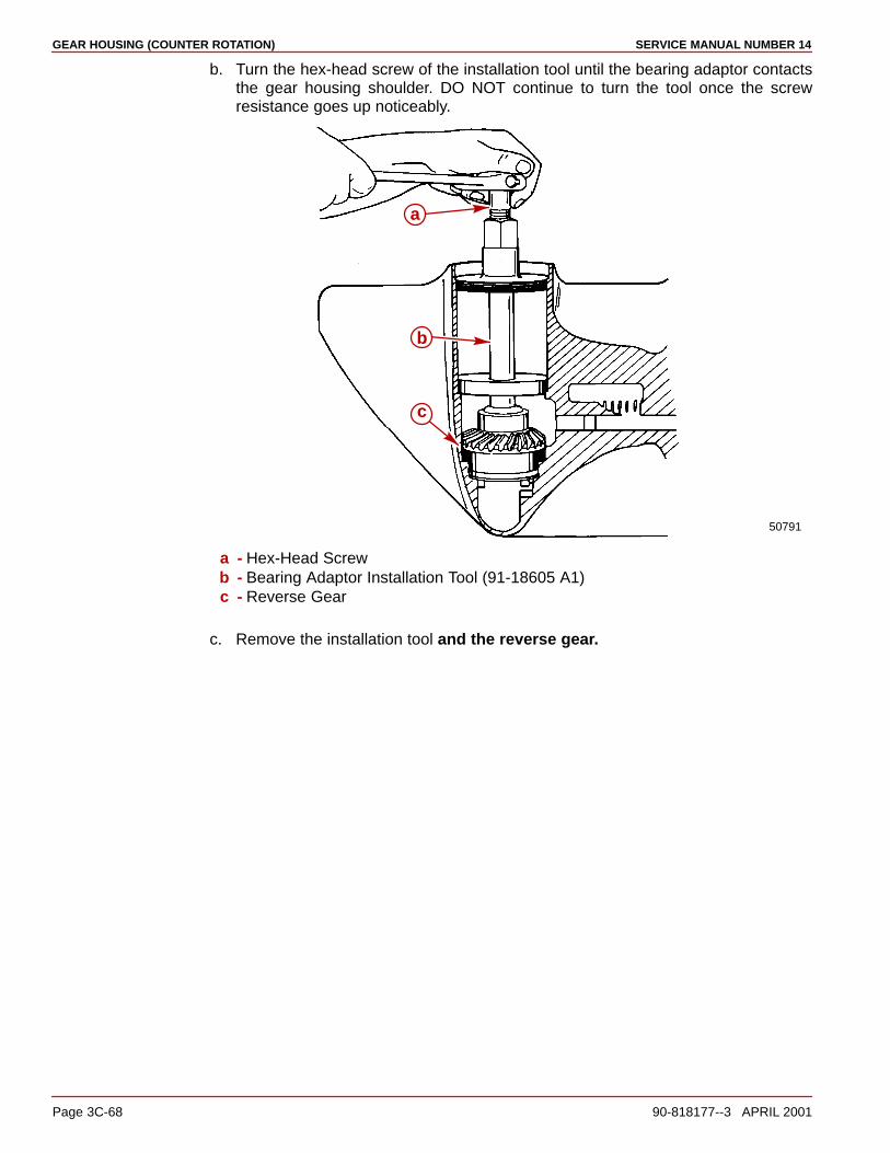
GEAR HOUSING (COUNTER ROTATION) SERVICE MANUAL NUMBER 14
Page 3C-68 90-818177--3 APRIL 2001
b. Turn the hex-head screw of the installation tool until the bearing adaptor contactsthe gear housing shoulder. DO NOT continue to turn the tool once the screwresistance goes up noticeably.
50791
a
b
c
a - Hex-Head Screwb - Bearing Adaptor Installation Tool (91-18605 A1)c - Reverse Gear
c. Remove the installation tool and the reverse gear.

GEAR HOUSING (COUNTER ROTATION)SERVICE MANUAL NUMBER 14
90-818177--3 APRIL 2001 Page 3C-69
Gear Location/Backlashes Checking and Adjustment
Reverse Gear
INSTALLATION (FOR CHECKING BACKLASH ONLY)
1. Lubricate the large reverse gear thrust bearing with Quicksilver High Performance GearLube. First position the thrust race and then the bearing into the gear housing and ontothe reverse gear bearing adaptor as shown below.
50882
a
b
c
a - Thrust Bearingb - Thrust Racec - Reverse Gear Bearing Adaptor
IMPORTANT: The appearance of the forward and reverse gear is almost identical.There are two ways to distinguish between the reverse and forward gears. Thereverse gear has a shorter hub and a groove cut into the back of the gear just insidethe thrust bearing race surface.
50885
a
b
Reverse Forwarda - Shorter Hubb - Groove

GEAR HOUSING (COUNTER ROTATION) SERVICE MANUAL NUMBER 14
Page 3C-70 90-818177--3 APRIL 2001
2. Assemble the reverse gear into the gear housing and into the reverse gear bearingadaptor.
50884
a
b
c
d
a - Reverse Gearb - Thrust Bearingc - Thrust Race (Under Bearing)d - Reverse Gear Bearing Adaptor

GEAR HOUSING (COUNTER ROTATION)SERVICE MANUAL NUMBER 14
90-818177--3 APRIL 2001 Page 3C-71
Drive Shaft and Pinion Gear
INSTALLATION (FOR CHECKING GEAR LOCATION AND BACKLASHES ONLY)
NOTE: If the original shims were not retained or if pinion gear, drive shaft, drive shaft taperedroller bearing and cup or gear housing were replaced start off by installing .038 in. (0.96 mm)shim(s).
NOTE: If the original shims were retained (or measurement known) and none of the abovelisted parts were replaced, reinstall the original shims (or an amount of shims equal to theoriginal shims).
1. Place the shim(s) into the drive shaft housing bore at the location shown.
70620
a
a - Shim(s)
NOTE: For ease of installation, glue the washer to the tool using 3M Adhesive or equivalent.
2. Assemble the pinion gear nut into the MR slot of the pinion nut adaptor. A small dab ofheavy grease in the slot of the pinion nut adaptor will help hold the nut in the adaptorwhile installing the drive shaft assembly.
3. Place the pinion gear (with the washer glued to it) into the gear housing.
4. Insert the pinion nut adaptor (with the nut) into the gear housing.
5. Insert the drive shaft into the gear housing drive shaft bore. It may be necessary to rotatethe drive shaft to engage the drive shaft splines into the pinion gear splines.
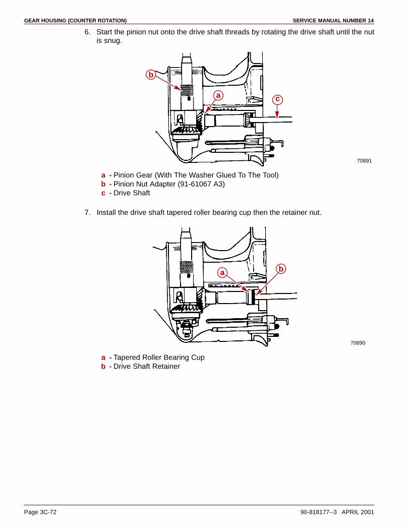
GEAR HOUSING (COUNTER ROTATION) SERVICE MANUAL NUMBER 14
Page 3C-72 90-818177--3 APRIL 2001
6. Start the pinion nut onto the drive shaft threads by rotating the drive shaft until the nutis snug.
70891
a
b
c
a - Pinion Gear (With The Washer Glued To The Tool)b - Pinion Nut Adapter (91-61067 A3)c - Drive Shaft
7. Install the drive shaft tapered roller bearing cup then the retainer nut.
70890
a b
a - Tapered Roller Bearing Cupb - Drive Shaft Retainer
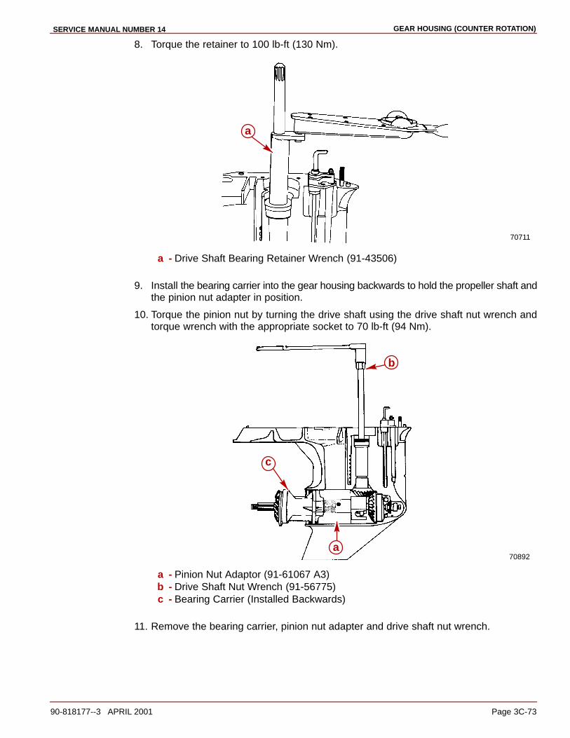
GEAR HOUSING (COUNTER ROTATION)SERVICE MANUAL NUMBER 14
90-818177--3 APRIL 2001 Page 3C-73
8. Torque the retainer to 100 lb-ft (130 Nm).
70711
a
a - Drive Shaft Bearing Retainer Wrench (91-43506)
9. Install the bearing carrier into the gear housing backwards to hold the propeller shaft andthe pinion nut adapter in position.
10. Torque the pinion nut by turning the drive shaft using the drive shaft nut wrench andtorque wrench with the appropriate socket to 70 lb-ft (94 Nm).
70892a
b
c
a - Pinion Nut Adaptor (91-61067 A3)b - Drive Shaft Nut Wrench (91-56775)c - Bearing Carrier (Installed Backwards)
11. Remove the bearing carrier, pinion nut adapter and drive shaft nut wrench.
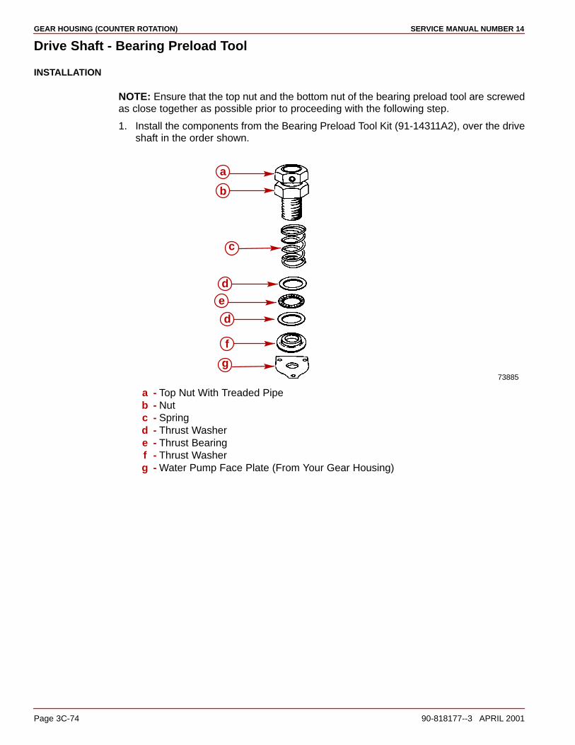
GEAR HOUSING (COUNTER ROTATION) SERVICE MANUAL NUMBER 14
Page 3C-74 90-818177--3 APRIL 2001
Drive Shaft - Bearing Preload Tool
INSTALLATION
NOTE: Ensure that the top nut and the bottom nut of the bearing preload tool are screwedas close together as possible prior to proceeding with the following step.
1. Install the components from the Bearing Preload Tool Kit (91-14311A2), over the driveshaft in the order shown.
73885
a
b
c
e
f
g
d
d
a - Top Nut With Treaded Pipeb - Nutc - Springd - Thrust Washere - Thrust Bearingf - Thrust Washerg - Water Pump Face Plate (From Your Gear Housing)

GEAR HOUSING (COUNTER ROTATION)SERVICE MANUAL NUMBER 14
90-818177--3 APRIL 2001 Page 3C-75
2. Pull up on the drive shaft and tighten the two (2) allen screws in the top nut of the bearingpreload tool.
70716
a
a
a - Allen Screws
3. Screw the bottom nut of the bearing preload tool down until it is one inch further downthe threaded rod than it was previously.
70893
a
a - Bottom Nut (Screwed Down Approximately 1 in. (25 mm) Further Than It WasPreviously)
4. Rotate the drive shaft at least three full turns in a clockwise direction to seat the needlebearing.
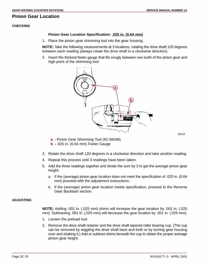
GEAR HOUSING (COUNTER ROTATION) SERVICE MANUAL NUMBER 14
Page 3C-76 90-818177--3 APRIL 2001
Pinion Gear Location
CHECKING
Pinion Gear Location Specification: .025 in. (0.64 mm)
1. Place the pinion gear shimming tool into the gear housing.
NOTE: Take the following measurements at 3 locations, rotating the drive shaft 120 degreesbetween each reading (always rotate the drive shaft in a clockwise direction).
2. Insert the thickest feeler gauge that fits snugly between one tooth of the pinion gear andhigh point of the shimming tool.
26410
a
b
a - Pinion Gear Shimming Tool (91-56048)b - .025 in. (0.64 mm) Feeler Gauge
3. Rotate the drive shaft 120 degrees in a clockwise direction and take another reading.
4. Repeat this process until 3 readings have been taken.
5. Add the three readings together and divide the sum by 3 to get the average pinion gearheight.
a. If the (average) pinion gear location does not meet the specification of .025 in. (0.64mm) proceed with the adjustment instructions .
b. If the (average) pinion gear location meets specification, proceed to the ReverseGear Backlash section.
ADJUSTING
NOTE: Adding .001 in. (.025 mm) shims will increase the gear location by .001 in. (.025mm). Subtracting .001 in. (.025 mm) will decrease the gear location by .001 in. (.025 mm).
1. Loosen the preload tool.
2. Remove the drive shaft retainer and the drive shaft tapered roller bearing cup. (The cupcan be removed by wiggling the drive shaft back and forth or by turning gear housingover and shaking it.) Add or subtract shims beneath the cup to obtain the proper averagepinion gear height.
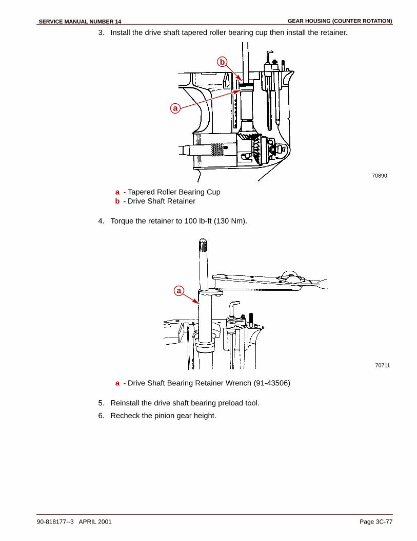
GEAR HOUSING (COUNTER ROTATION)SERVICE MANUAL NUMBER 14
90-818177--3 APRIL 2001 Page 3C-77
3. Install the drive shaft tapered roller bearing cup then install the retainer.
70890
a
b
a - Tapered Roller Bearing Cupb - Drive Shaft Retainer
4. Torque the retainer to 100 lb-ft (130 Nm).
70711
a
a - Drive Shaft Bearing Retainer Wrench (91-43506)
5. Reinstall the drive shaft bearing preload tool.
6. Recheck the pinion gear height.
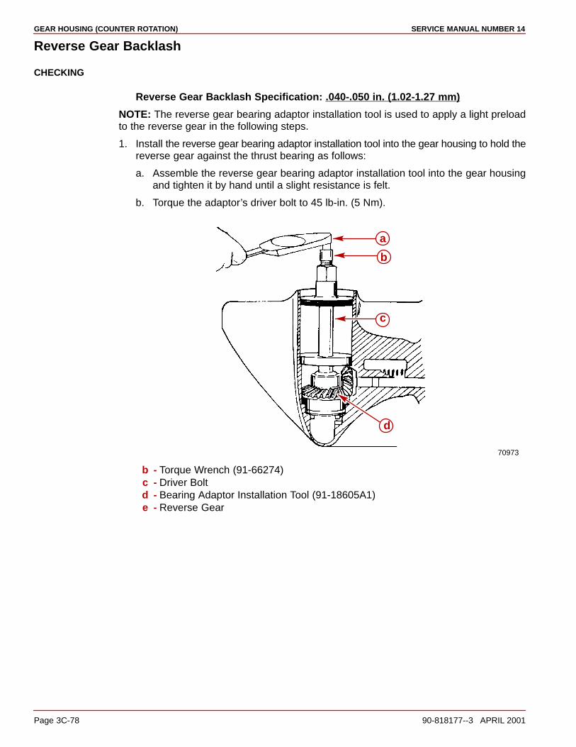
GEAR HOUSING (COUNTER ROTATION) SERVICE MANUAL NUMBER 14
Page 3C-78 90-818177--3 APRIL 2001
Reverse Gear Backlash
CHECKING
Reverse Gear Backlash Specification: .040-.050 in. (1.02-1.27 mm)
NOTE: The reverse gear bearing adaptor installation tool is used to apply a light preloadto the reverse gear in the following steps.
1. Install the reverse gear bearing adaptor installation tool into the gear housing to hold thereverse gear against the thrust bearing as follows:
a. Assemble the reverse gear bearing adaptor installation tool into the gear housingand tighten it by hand until a slight resistance is felt.
b. Torque the adaptor’s driver bolt to 45 lb-in. (5 Nm).
70973
d
a
b
c
b - Torque Wrench (91-66274)c - Driver Boltd - Bearing Adaptor Installation Tool (91-18605A1)e - Reverse Gear
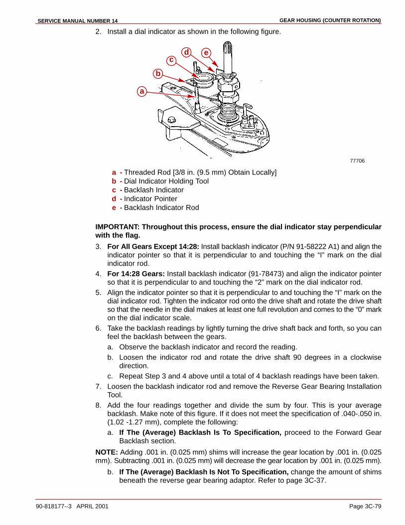
GEAR HOUSING (COUNTER ROTATION)SERVICE MANUAL NUMBER 14
90-818177--3 APRIL 2001 Page 3C-79
2. Install a dial indicator as shown in the following figure.
77706
edc
b
a
a - Threaded Rod [3/8 in. (9.5 mm) Obtain Locally]b - Dial Indicator Holding Toolc - Backlash Indicatord - Indicator Pointere - Backlash Indicator Rod
IMPORTANT: Throughout this process, ensure the dial indicator stay perpendicularwith the flag.
3. For All Gears Except 14:28: Install backlash indicator (P/N 91-58222 A1) and align theindicator pointer so that it is perpendicular to and touching the “I” mark on the dialindicator rod.
4. For 14:28 Gears: Install backlash indicator (91-78473) and align the indicator pointerso that it is perpendicular to and touching the “2” mark on the dial indicator rod.
5. Align the indicator pointer so that it is perpendicular to and touching the “I” mark on thedial indicator rod. Tighten the indicator rod onto the drive shaft and rotate the drive shaftso that the needle in the dial makes at least one full revolution and comes to the “0” markon the dial indicator scale.
6. Take the backlash readings by lightly turning the drive shaft back and forth, so you canfeel the backlash between the gears.a. Observe the backlash indicator and record the reading.b. Loosen the indicator rod and rotate the drive shaft 90 degrees in a clockwise
direction.c. Repeat Step 3 and 4 above until a total of 4 backlash readings have been taken.
7. Loosen the backlash indicator rod and remove the Reverse Gear Bearing InstallationTool.
8. Add the four readings together and divide the sum by four. This is your averagebacklash. Make note of this figure. If it does not meet the specification of .040-.050 in.(1.02 -1.27 mm), complete the following:a. If The (Average) Backlash Is To Specification, proceed to the Forward Gear
Backlash section.
NOTE: Adding .001 in. (0.025 mm) shims will increase the gear location by .001 in. (0.025mm). Subtracting .001 in. (0.025 mm) will decrease the gear location by .001 in. (0.025 mm).
b. If The (Average) Backlash Is Not To Specification, change the amount of shimsbeneath the reverse gear bearing adaptor. Refer to page 3C-37.
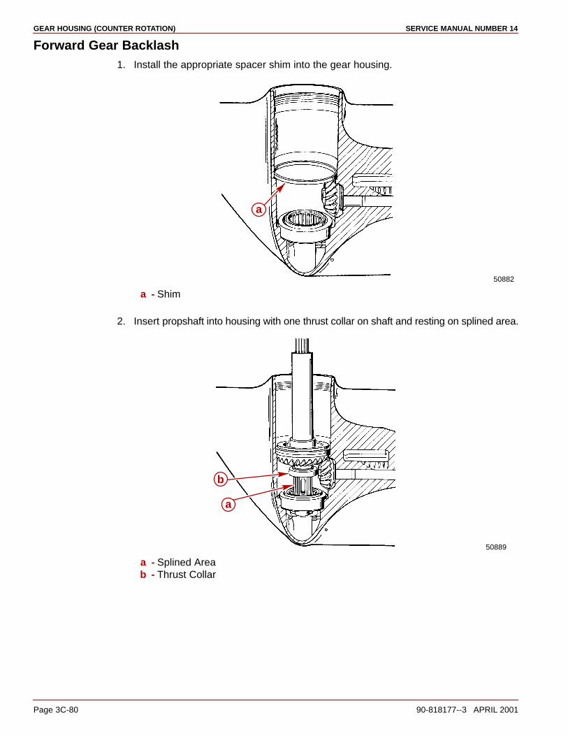
GEAR HOUSING (COUNTER ROTATION) SERVICE MANUAL NUMBER 14
Page 3C-80 90-818177--3 APRIL 2001
Forward Gear Backlash1. Install the appropriate spacer shim into the gear housing.
50882
a
a - Shim
2. Insert propshaft into housing with one thrust collar on shaft and resting on splined area.
50889
a
b
a - Splined Areab - Thrust Collar

GEAR HOUSING (COUNTER ROTATION)SERVICE MANUAL NUMBER 14
90-818177--3 APRIL 2001 Page 3C-81
3. If equipped, place the thrust race or washer on top of the thrust bearing with the steppedside up as shown in the following figure.
50785
a
a - Thrust Race
NOTE: The thrust race has been replaced with a thrust washer on S/N OF680000 andabove models.
74886
a
b
a - Thrust Washerb - Thrust Bearing

GEAR HOUSING (COUNTER ROTATION) SERVICE MANUAL NUMBER 14
Page 3C-82 90-818177--3 APRIL 2001
4. Assemble the forward gear installation tool to the forward gear. Then place it (with theforward gear, thrust bearing and thrust race, if applicable) down over the propeller shaft.Ensure that the thrust race seats evenly onto the shim. Tap the thrust race down lightlywith a soft tool; do not damage the thrust race surface.
50889
a
b
c
d
a - Forward Gear Installation Tool (91-815850)b - Forward Gearc - Spacer Shimd - Thrust Race
5. Install the forward gear bearing adaptor using a hook tool (which was fashioned whenthe adaptor was removed) as shown. Ensure that the adaptor seats evenly against thethrust race.
50889
a
b
c
d
a - Hook Toolb - Forward Gear Installation Tool (91-815850)c - Forward Gear Bearing Adaptord - Thrust Race

GEAR HOUSING (COUNTER ROTATION)SERVICE MANUAL NUMBER 14
90-818177--3 APRIL 2001 Page 3C-83
6. Remove the hook tool and, while holding down on the forward gear, remove the forwardgear installation tool.
50889
a
b
c
a - Forward Gear Installation Tool (91-815850)b - Forward Gear Bearing Adaptorc - Forward Gear
7. Lower the bearing carrier down over the propeller shaft until it is fully seated.
50888
a
b
a - Propeller Shaftb - Bearing Carrier

GEAR HOUSING (COUNTER ROTATION) SERVICE MANUAL NUMBER 14
Page 3C-84 90-818177--3 APRIL 2001
8. Align the bearing carrier “V” shaped notch with the alignment hole in the gear housingand then install the tab washer with the external tab inserted into the hole in the gearhousing.
50779
c
a
b
a - Gear Housing Tab Washer Alignment Holeb - “v” Shaped Notch In Bearing Carrierc - Alignment Tab Of Tab Washer
9. Ensure that the “V” shaped tab aligns with the “V” notch in bearing carrier.
70714
a
b
a - Tab Washerb - “V”-Tab
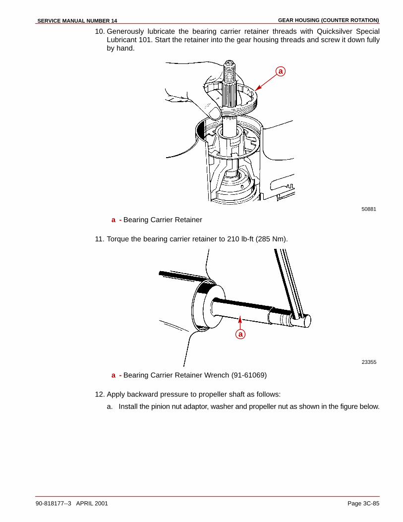
GEAR HOUSING (COUNTER ROTATION)SERVICE MANUAL NUMBER 14
90-818177--3 APRIL 2001 Page 3C-85
10. Generously lubricate the bearing carrier retainer threads with Quicksilver SpecialLubricant 101. Start the retainer into the gear housing threads and screw it down fullyby hand.
50881
a
a - Bearing Carrier Retainer
11. Torque the bearing carrier retainer to 210 lb-ft (285 Nm).
23355
a
a - Bearing Carrier Retainer Wrench (91-61069)
12. Apply backward pressure to propeller shaft as follows:
a. Install the pinion nut adaptor, washer and propeller nut as shown in the figure below.
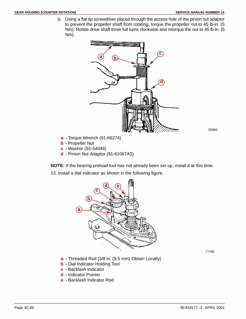
GEAR HOUSING (COUNTER ROTATION) SERVICE MANUAL NUMBER 14
Page 3C-86 90-818177--3 APRIL 2001
b. Using a flat tip screwdriver placed through the access hole of the pinion nut adaptorto prevent the propeller shaft from rotating, torque the propeller nut to 45 lb-in. (5Nm). Rotate drive shaft three full turns clockwise and retorque the nut to 45 lb-in. (5Nm).
50880
a bc
d
a - Torque Wrench (91-66274)b - Propeller Nutc - Washer (91-54048)d - Pinion Nut Adaptor (91-61067A3)
NOTE: If the bearing preload tool has not already been set up, install it at this time.
13. Install a dial indicator as shown in the following figure.
77706
edc
b
a
a - Threaded Rod [3/8 in. (9.5 mm) Obtain Locally]b - Dial Indicator Holding Toolc - Backlash Indicatord - Indicator Pointere - Backlash Indicator Rod
GEAR HOUSING (COUNTER ROTATION)SERVICE MANUAL NUMBER 14
90-818177--3 APRIL 2001 Page 3C-87
14. Align the backlash indicator pointer so that it is perpendicular to and touching the “I” markon the dial indicator rod. Tighten the indicator rod onto the drive shaft and rotate the driveshaft so that the needle in the dial makes at least one full revolution and comes to “0”on the dial indicator scale.
15. Take the backlash readings by lightly turning the drive shaft back and forth, so you canfeel the backlash between the gears.
a. Observe the backlash indicator and record the reading.
b. Loosen the indicator rod and rotate the drive shaft 90 degrees in a clockwisedirection.
c. Repeat step “a” and “b” above until a total of 4 backlash readings have been taken.
d. Add the four readings together and divide the sum by four. This is your averagebacklash. Make note of this figure. If it does not meet specifications of .017-.028 in.(0.43-0.71 mm), it will be adjusted at a later step.
16. Loosen the backlash indicator rod and remove the dial indicator and its supportingtooling.
17. Remove the propeller nut, washer and the pinion nut adaptor.
a. If The Backlash Is To Specification, skip the next step (17b) and go on to step 18following.
NOTE: Installing a .002 in. (.051 mm) thinner spacer shim will decrease the gear backlashby .002 in. (.051 mm). Installing a .002 in. (.051 mm) thicker shim will increase the gearbacklash by .002 in. (.051 mm).
b. If The Backlash Is Not To Specification, complete the following instructions toinstall a different size spacer shim under the forward gear thrust race.
(1.)Remove the bearing carrier retainer, tab washer and the bearing carrier.
(2.)Using the hook tool, remove the forward gear bearing adaptor.
(3.) Insert the forward gear installation tool into the forward gear and remove theforward gear, thrust bearing and thrust race.
(4.)Remove the spacer shim.
18. Remove the items as outlined following:
a. Remove the bearing carrier retainer, tab washer and the bearing carrier.
b. Using the hook tool remove the forward gear bearing adaptor.
c. Insert the forward gear installation tool into the forward gear and remove the forwardgear, thrust bearing and thrust race.
d. Remove the spacer shim.
e. Remove drive shaft preload tool.
f. Remove drive shaft assembly.
g. Remove the reverse gear.
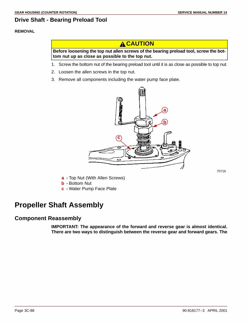
GEAR HOUSING (COUNTER ROTATION) SERVICE MANUAL NUMBER 14
Page 3C-88 90-818177--3 APRIL 2001
Drive Shaft - Bearing Preload Tool
REMOVAL
CAUTIONBefore loosening the top nut allen screws of the bearing preload tool, screw the bot-tom nut up as close as possible to the top nut.
1. Screw the bottom nut of the bearing preload tool until it is as close as possible to top nut.
2. Loosen the allen screws in the top nut.
3. Remove all components including the water pump face plate.
70716
a
b
c
a - Top Nut (With Allen Screws)b - Bottom Nutc - Water Pump Face Plate
Propeller Shaft Assembly
Component ReassemblyIMPORTANT: The appearance of the forward and reverse gear is almost identical.There are two ways to distinguish between the reverse gear and forward gears. The
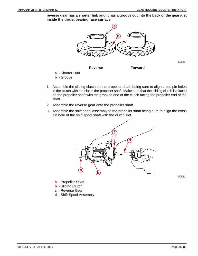
GEAR HOUSING (COUNTER ROTATION)SERVICE MANUAL NUMBER 14
90-818177--3 APRIL 2001 Page 3C-89
reverse gear has a shorter hub and it has a groove cut into the back of the gear justinside the thrust bearing race surface.
50885
b
a
Reverse Forwarda - Shorter Hubb - Groove
1. Assemble the sliding clutch on the propeller shaft, being sure to align cross pin holesin the clutch with the slot in the propeller shaft. Make sure that the sliding clutch is placedon the propeller shaft with the grooved end of the clutch facing the propeller end of theshaft.
2. Assemble the reverse gear onto the propeller shaft.
3. Assemble the shift spool assembly to the propeller shaft being sure to align the crosspin hole of the shift spool shaft with the clutch slot.
50881
d
c
ab
a - Propeller Shaftb - Sliding Clutchc - Reverse Geard - Shift Spool Assembly

GEAR HOUSING (COUNTER ROTATION) SERVICE MANUAL NUMBER 14
Page 3C-90 90-818177--3 APRIL 2001
4. Assemble the cross pin through the sliding clutch, propeller shaft and shift spool shafthole.
50885
d
e
c
ab
a - Propeller Shaftb - Sliding Clutchc - Cross Pind - Reverse Geare - Shift Spool Assembly
5. Assemble the cross pin retaining spring over the propeller shaft and wind it around theclutch over the cross pin hole. Be careful not to distort the spring while assembling it.
IMPORTANT: Make sure that the spring is wound on so that it does not cross over onitself and that it lies flat against the clutch once it is assembled. If it does not lie flatagainst the clutch a new spring must be installed.
50885
ab
c
a - Sliding Clutchb - Propeller Shaftc - Cross Pin Retaining Spring

GEAR HOUSING (COUNTER ROTATION)SERVICE MANUAL NUMBER 14
90-818177--3 APRIL 2001 Page 3C-91
Installation1. Lubricate the large thrust bearing with Quicksilver High Performance Gear Lube.
Position the thrust race and then the bearing into the gear housing onto the reverse gearbearing adaptor as shown following.
50882
a
b
c
a - Thrust Raceb - Thrust Bearingc - Reverse Gear Bearing Adaptor
2. Rotate the shift crank toward the aft end of the gear housing until it touches against thebearing adaptor. Hold it in this position.
50885b
a
a - Shift Crankb - Bearing Adaptor
IMPORTANT: Be careful when inserting the propeller shaft assembly into the gearhousing as the needle bearings in the reverse gear bearing adaptor can becomedislodged when installing it. If it is suspected that a needle has become dislodged,remove the propeller shaft assembly. Inspect the needle bearing cages for damage.If the cages have not been damaged and a needle bearing is positioned wrong, it canbe snapped back into place.
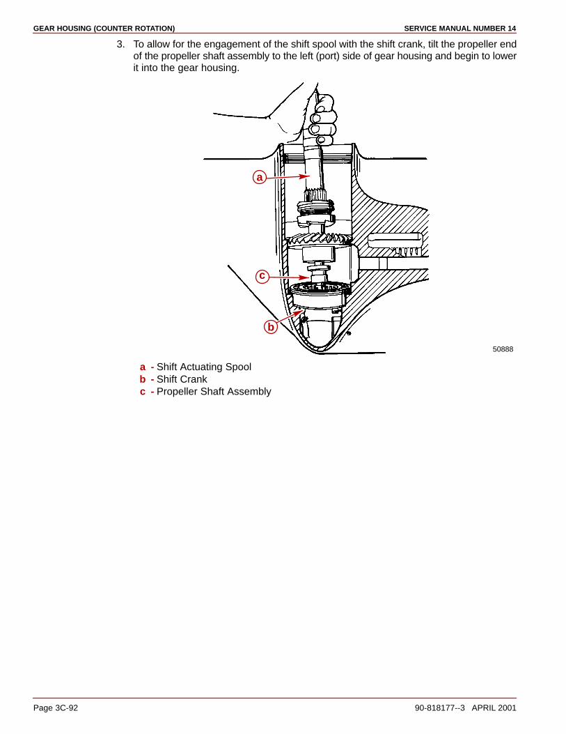
GEAR HOUSING (COUNTER ROTATION) SERVICE MANUAL NUMBER 14
Page 3C-92 90-818177--3 APRIL 2001
3. To allow for the engagement of the shift spool with the shift crank, tilt the propeller endof the propeller shaft assembly to the left (port) side of gear housing and begin to lowerit into the gear housing.
50888
a
b
c
a - Shift Actuating Spoolb - Shift Crankc - Propeller Shaft Assembly
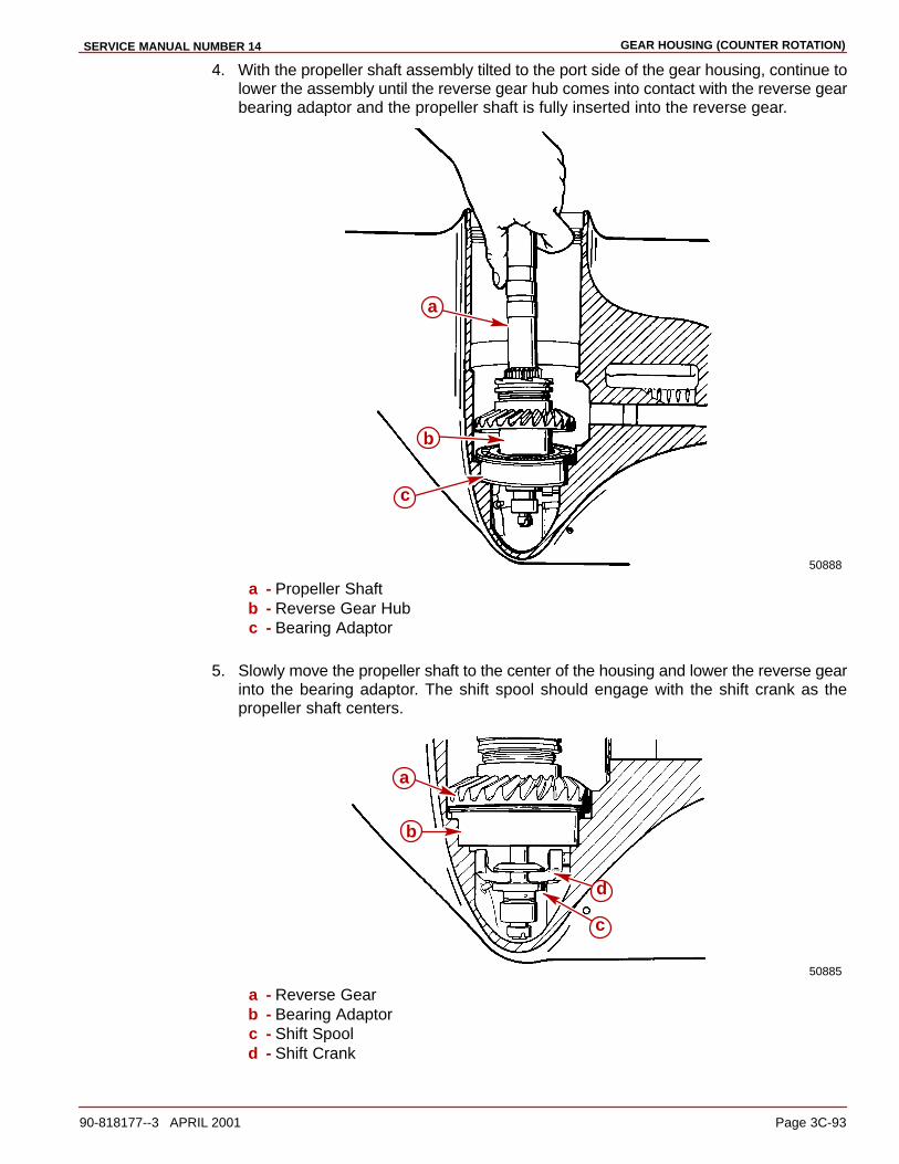
GEAR HOUSING (COUNTER ROTATION)SERVICE MANUAL NUMBER 14
90-818177--3 APRIL 2001 Page 3C-93
4. With the propeller shaft assembly tilted to the port side of the gear housing, continue tolower the assembly until the reverse gear hub comes into contact with the reverse gearbearing adaptor and the propeller shaft is fully inserted into the reverse gear.
50888
a
b
c
a - Propeller Shaftb - Reverse Gear Hubc - Bearing Adaptor
5. Slowly move the propeller shaft to the center of the housing and lower the reverse gearinto the bearing adaptor. The shift spool should engage with the shift crank as thepropeller shaft centers.
50885
c
d
a
b
a - Reverse Gearb - Bearing Adaptorc - Shift Spoold - Shift Crank

GEAR HOUSING (COUNTER ROTATION) SERVICE MANUAL NUMBER 14
Page 3C-94 90-818177--3 APRIL 2001
IMPORTANT: The shift shaft must point forward when the shaft is rotated clockwise.If it does not lift it up slightly and realign the lower shift shaft splines into the shiftcrank. Recheck to make sure that it is now aligned correctly.
6. Operate the shift shaft to ensure that it has been properly installed. The sliding clutchshould move forward when the shift shaft is turned clockwise and should move aft whenthe shift shaft is turned counterclockwise.
7. Torque the screws that secure the shift shaft bushing to 60 lb-in. (6.8 Nm). Recheck theshift shaft alignment as noted in the preceding IMPORTANT statement.
70888
a
b
a - Screws (2)b - Shift Shaft Bushing
8. Slide the rubber sleeve at top end of shift shaft down so that it just touches the oil sealin the bushing.
70492
bc
a
d
a - Shift Shaftb - Rubber Sleevec - Oil Seald - Shift Shaft Bushing
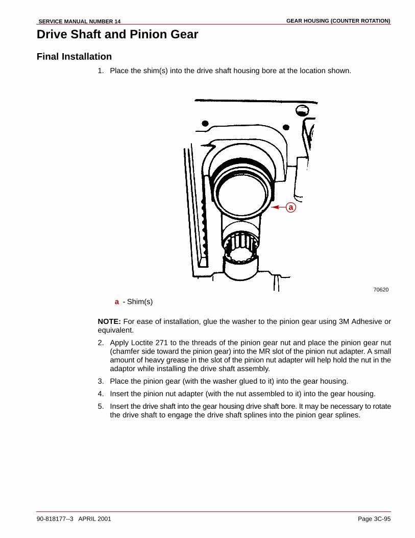
GEAR HOUSING (COUNTER ROTATION)SERVICE MANUAL NUMBER 14
90-818177--3 APRIL 2001 Page 3C-95
Drive Shaft and Pinion Gear
Final Installation1. Place the shim(s) into the drive shaft housing bore at the location shown.
70620
a
a - Shim(s)
NOTE: For ease of installation, glue the washer to the pinion gear using 3M Adhesive orequivalent.
2. Apply Loctite 271 to the threads of the pinion gear nut and place the pinion gear nut(chamfer side toward the pinion gear) into the MR slot of the pinion nut adapter. A smallamount of heavy grease in the slot of the pinion nut adapter will help hold the nut in theadaptor while installing the drive shaft assembly.
3. Place the pinion gear (with the washer glued to it) into the gear housing.
4. Insert the pinion nut adapter (with the nut assembled to it) into the gear housing.
5. Insert the drive shaft into the gear housing drive shaft bore. It may be necessary to rotatethe drive shaft to engage the drive shaft splines into the pinion gear splines.

GEAR HOUSING (COUNTER ROTATION) SERVICE MANUAL NUMBER 14
Page 3C-96 90-818177--3 APRIL 2001
6. Start the pinion nut onto the drive shaft threads by rotating the drive shaft until the nutis snug.
70891
a
b
c
a - Pinion Gear (With The Washer Glued To It)b - Pinion Nut Adaptor (91-61067A3)c - Drive Shaft
7. Install the drive shaft tapered roller bearing cup then the retainer.
70890
ab
a - Tapered Roller Bearing Cupb - Drive Shaft Retainer
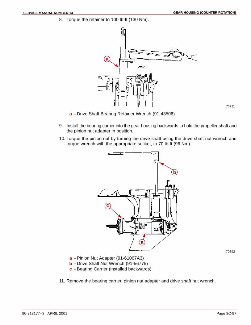
GEAR HOUSING (COUNTER ROTATION)SERVICE MANUAL NUMBER 14
90-818177--3 APRIL 2001 Page 3C-97
8. Torque the retainer to 100 lb-ft (130 Nm).
70711
a
a - Drive Shaft Bearing Retainer Wrench (91-43506)
9. Install the bearing carrier into the gear housing backwards to hold the propeller shaft andthe pinion nut adapter in position.
10. Torque the pinion nut by turning the drive shaft using the drive shaft nut wrench andtorque wrench with the appropriate socket, to 70 lb-ft (96 Nm).
70892
a
b
c
a - Pinion Nut Adapter (91-61067A3)b - Drive Shaft Nut Wrench (91-56775)c - Bearing Carrier (installed backwards)
11. Remove the bearing carrier, pinion nut adapter and drive shaft nut wrench.

GEAR HOUSING (COUNTER ROTATION) SERVICE MANUAL NUMBER 14
Page 3C-98 90-818177--3 APRIL 2001
Bearing Carrier Assembly
Final Installation1. Install the appropriate spacer shim into the gear housing.
50782
a
a - Shim
2. Lubricate the thrust bearing with Quicksilver High Performance Gear Lube and placeit onto the forward gear.
50785
a
a - Thrust Bearingb - Forward Gear
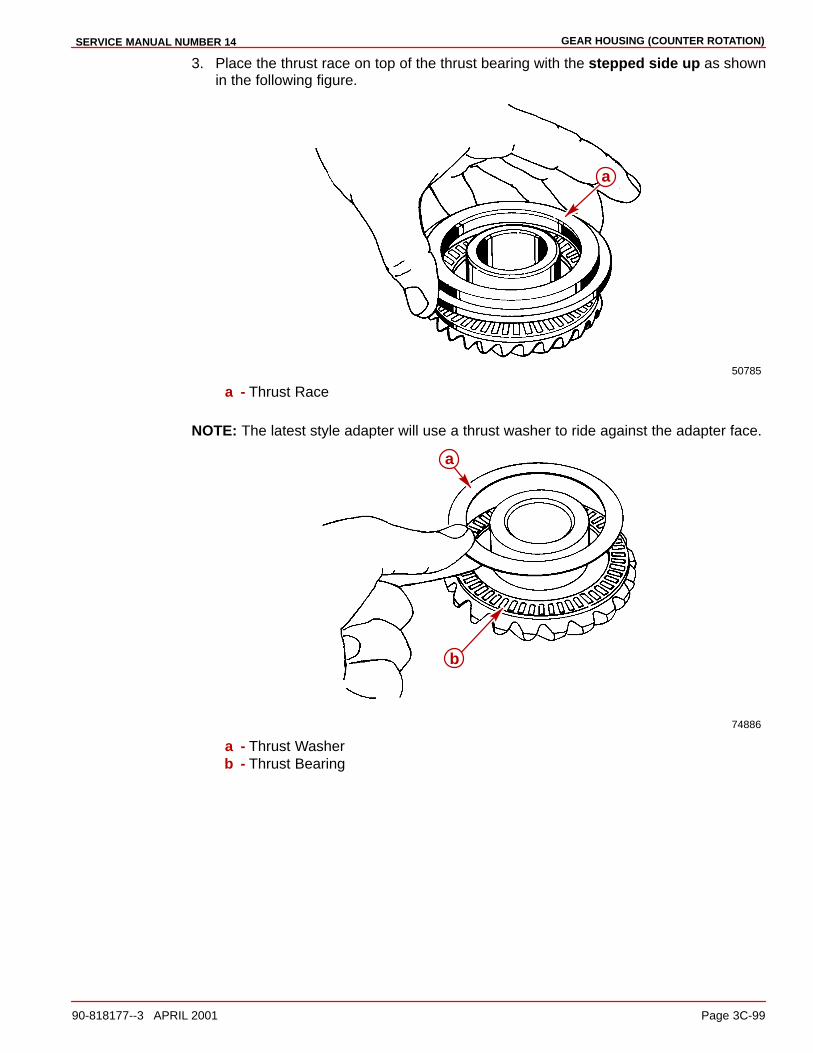
GEAR HOUSING (COUNTER ROTATION)SERVICE MANUAL NUMBER 14
90-818177--3 APRIL 2001 Page 3C-99
3. Place the thrust race on top of the thrust bearing with the stepped side up as shownin the following figure.
50785
a
a - Thrust Race
NOTE: The latest style adapter will use a thrust washer to ride against the adapter face.
74886
a
b
a - Thrust Washerb - Thrust Bearing
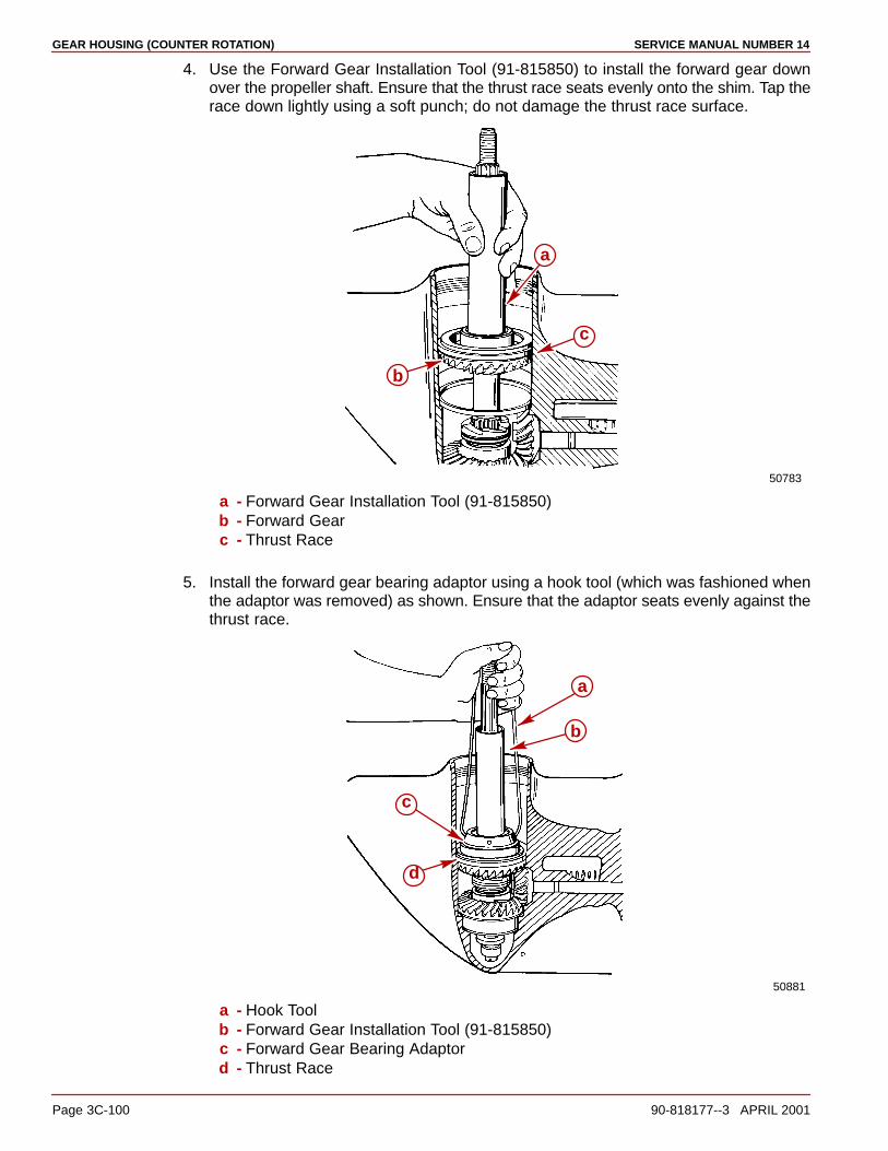
GEAR HOUSING (COUNTER ROTATION) SERVICE MANUAL NUMBER 14
Page 3C-100 90-818177--3 APRIL 2001
4. Use the Forward Gear Installation Tool (91-815850) to install the forward gear downover the propeller shaft. Ensure that the thrust race seats evenly onto the shim. Tap therace down lightly using a soft punch; do not damage the thrust race surface.
50783
b
a
c
a - Forward Gear Installation Tool (91-815850)b - Forward Gearc - Thrust Race
5. Install the forward gear bearing adaptor using a hook tool (which was fashioned whenthe adaptor was removed) as shown. Ensure that the adaptor seats evenly against thethrust race.
50881
a
b
c
d
a - Hook Toolb - Forward Gear Installation Tool (91-815850)c - Forward Gear Bearing Adaptord - Thrust Race

GEAR HOUSING (COUNTER ROTATION)SERVICE MANUAL NUMBER 14
90-818177--3 APRIL 2001 Page 3C-101
6. Remove the hook tool and, while holding down on the forward gear, remove the forwardgear installation tool by holding the bearing adaptor down with a large screwdriver.
50889
a
b
c
a - Forward Gear Installation Tool (91-815850)b - Forward Gear Bearing Adaptorc - Forward Gear
7. Ensure that the top of the bearing adaptor is clean and install the small thrust race ontop of the bearing adaptor.
50880
a
b
c
a - Thrust Raceb - Forward Gear Bearing Adaptorc - Forward Gear
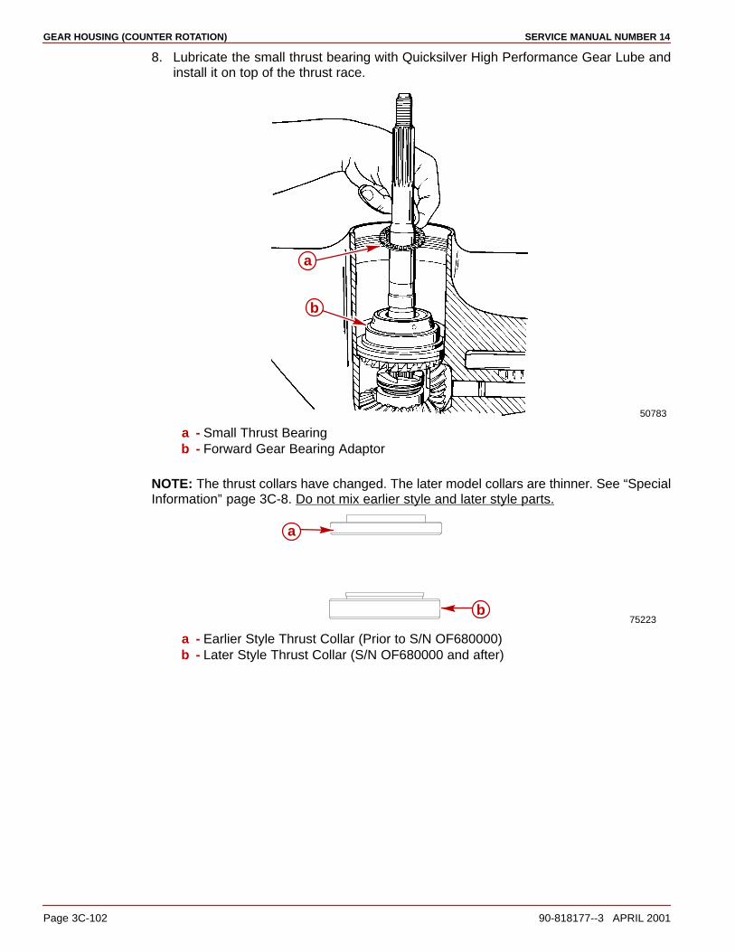
GEAR HOUSING (COUNTER ROTATION) SERVICE MANUAL NUMBER 14
Page 3C-102 90-818177--3 APRIL 2001
8. Lubricate the small thrust bearing with Quicksilver High Performance Gear Lube andinstall it on top of the thrust race.
50783
a
b
a - Small Thrust Bearingb - Forward Gear Bearing Adaptor
NOTE: The thrust collars have changed. The later model collars are thinner. See “SpecialInformation” page 3C-8. Do not mix earlier style and later style parts.
75223
a
b
a - Earlier Style Thrust Collar (Prior to S/N OF680000)b - Later Style Thrust Collar (S/N OF680000 and after)
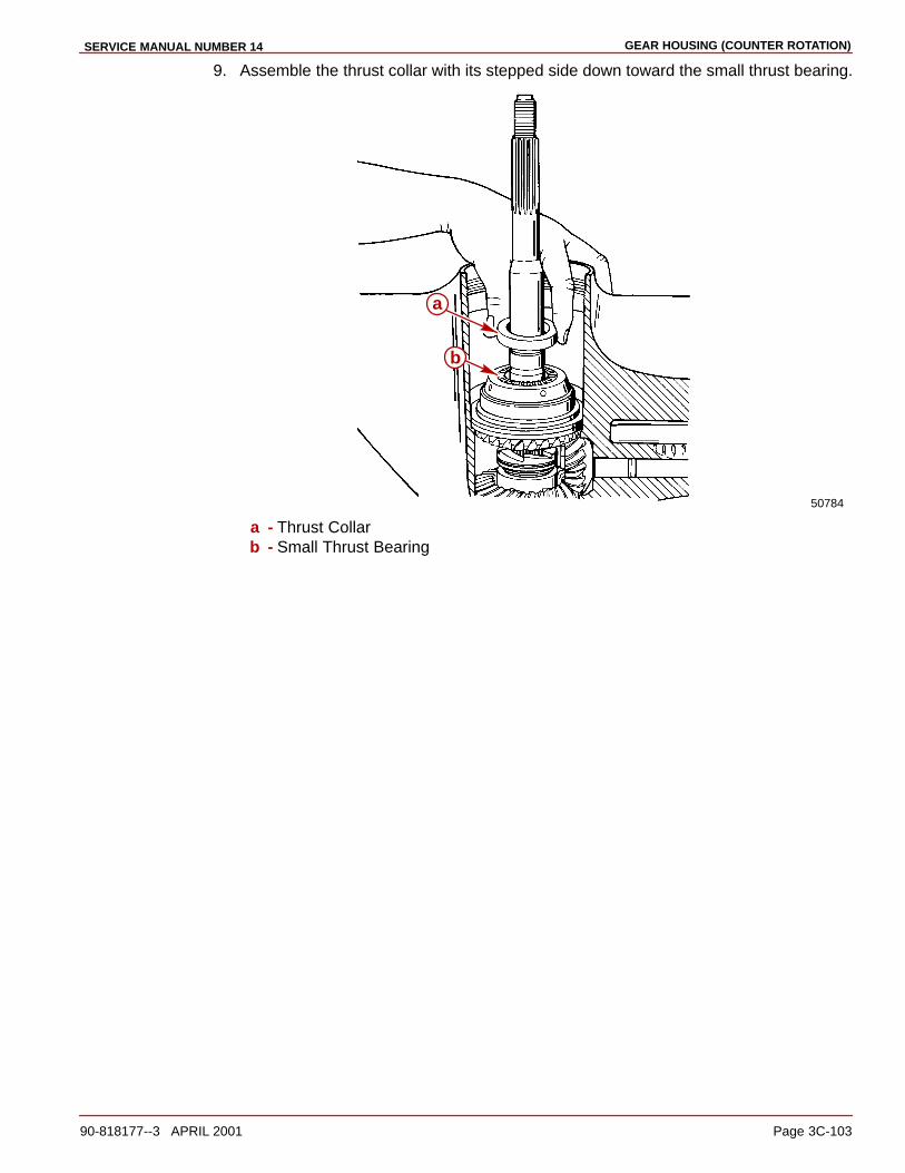
GEAR HOUSING (COUNTER ROTATION)SERVICE MANUAL NUMBER 14
90-818177--3 APRIL 2001 Page 3C-103
9. Assemble the thrust collar with its stepped side down toward the small thrust bearing.
50784
b
a
a - Thrust Collarb - Small Thrust Bearing

GEAR HOUSING (COUNTER ROTATION) SERVICE MANUAL NUMBER 14
Page 3C-104 90-818177--3 APRIL 2001
10. Pull up slightly on the propeller shaft to gain access to the groove on the shaft for thekeepers. Assemble the two keepers into the groove and lower the propeller shaft.
50826
a
b
c
a - Propeller Shaft (Slightly Lifted)b - Keepers (2)c - Thrust Collar
50778
a
c b
a - Propeller Shaft (Lowered Into Position)b - Keepersc - Thrust Collar

GEAR HOUSING (COUNTER ROTATION)SERVICE MANUAL NUMBER 14
90-818177--3 APRIL 2001 Page 3C-105
11. Install the second thrust collar with its stepped side up.
50787
b
a
a - Propeller Shaftb - Thrust Collar
12. Lubricate the second thrust bearing with Quicksilver High Performance Gear Lube andinstall it to the top of the thrust collar.
50786
a
b
a - Thrust Bearingb - Thrust Collar
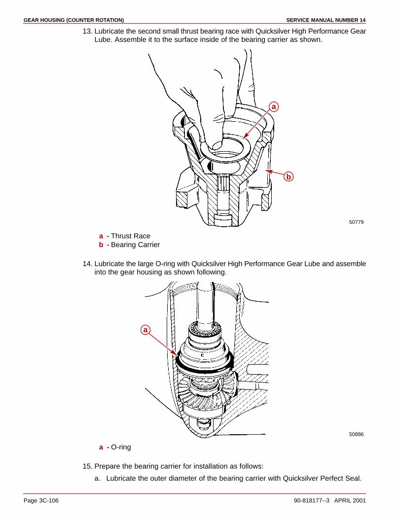
GEAR HOUSING (COUNTER ROTATION) SERVICE MANUAL NUMBER 14
Page 3C-106 90-818177--3 APRIL 2001
13. Lubricate the second small thrust bearing race with Quicksilver High Performance GearLube. Assemble it to the surface inside of the bearing carrier as shown.
50779
b
a
a - Thrust Raceb - Bearing Carrier
14. Lubricate the large O-ring with Quicksilver High Performance Gear Lube and assembleinto the gear housing as shown following.
50886
a
a - O-ring
15. Prepare the bearing carrier for installation as follows:
a. Lubricate the outer diameter of the bearing carrier with Quicksilver Perfect Seal.

GEAR HOUSING (COUNTER ROTATION)SERVICE MANUAL NUMBER 14
90-818177--3 APRIL 2001 Page 3C-107
b. Fill the space between the carrier oil seals with Quicksilver 2-4-C Marine Lubricantwith Teflon.
c. Lubricate the needle bearing with Quicksilver High Performance Gear Lube.
16. Install the bearing carrier assembly into the gear housing.
50826
a
a - Bearing Carrier Assembly
17. Align the bearing carrier “V” shaped notch with the alignment hole in the gear housing.
18. Install the tab washer with the external tab inserted into the hole in the gear housing.
70713
b
ca
a - Gear Case Alignment Holeb - “V” Shaped Notch in Bearing Carrierc - Alignment Tab of Tab Washer
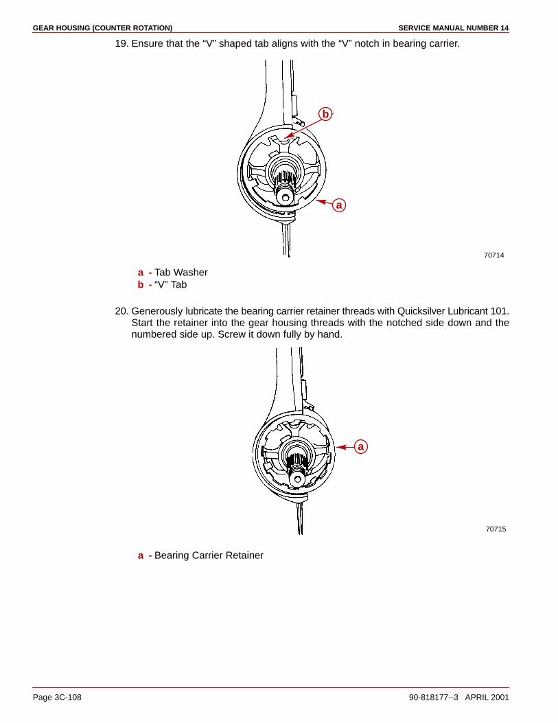
GEAR HOUSING (COUNTER ROTATION) SERVICE MANUAL NUMBER 14
Page 3C-108 90-818177--3 APRIL 2001
19. Ensure that the “V” shaped tab aligns with the “V” notch in bearing carrier.
70714
a
b
a - Tab Washerb - “V” Tab
20. Generously lubricate the bearing carrier retainer threads with Quicksilver Lubricant 101.Start the retainer into the gear housing threads with the notched side down and thenumbered side up. Screw it down fully by hand.
70715
a
a - Bearing Carrier Retainer
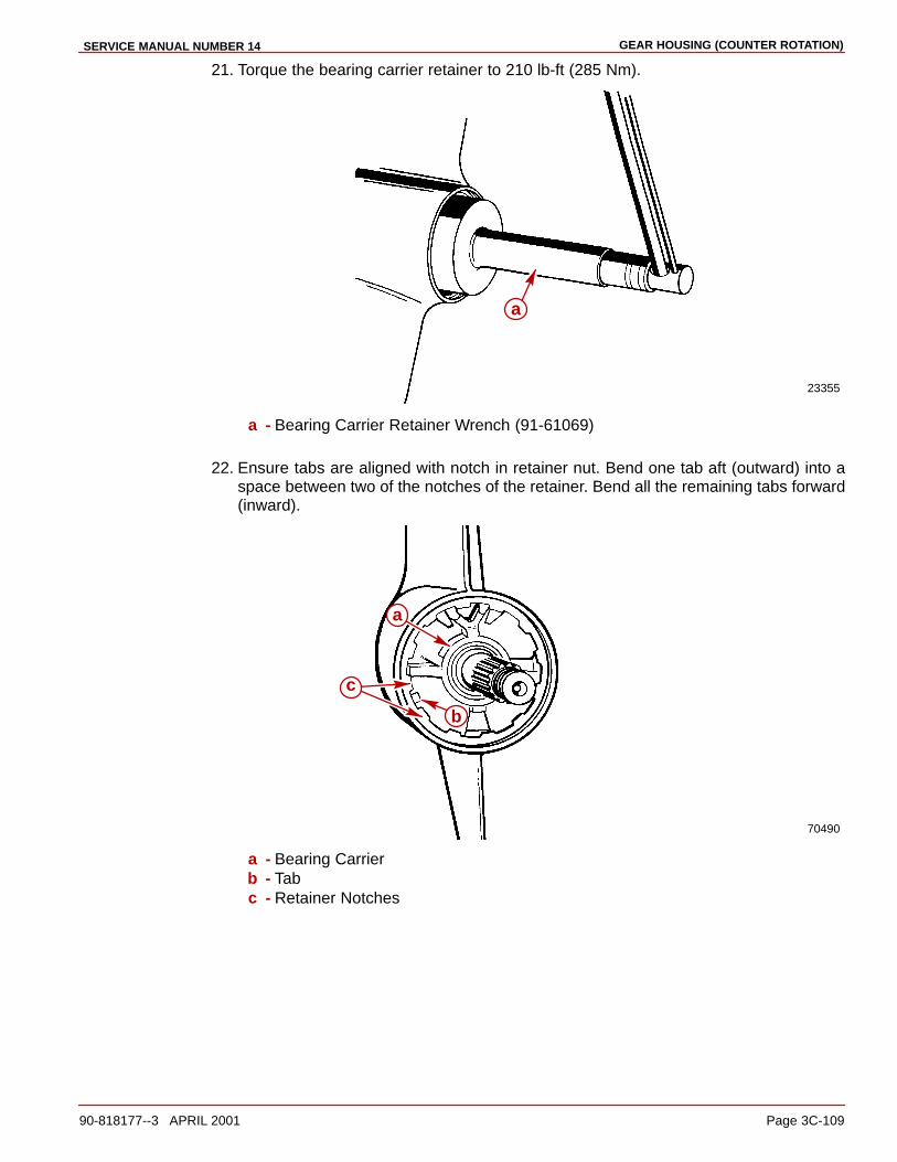
GEAR HOUSING (COUNTER ROTATION)SERVICE MANUAL NUMBER 14
90-818177--3 APRIL 2001 Page 3C-109
21. Torque the bearing carrier retainer to 210 lb-ft (285 Nm).
23355
a
a - Bearing Carrier Retainer Wrench (91-61069)
22. Ensure tabs are aligned with notch in retainer nut. Bend one tab aft (outward) into aspace between two of the notches of the retainer. Bend all the remaining tabs forward(inward).
70490
a
b
c
a - Bearing Carrierb - Tabc - Retainer Notches

GEAR HOUSING (COUNTER ROTATION) SERVICE MANUAL NUMBER 14
Page 3C-110 90-818177--3 APRIL 2001
Oil Seal Carrier Assembly
InstallationNOTE: Apply hand pressure only to install the oil seal carrier into position. Do not hammerit into position.
1. Lubricate the oil seal carrier oil seal lips and O-ring with Quicksilver 2-4-C MarineLubricant with Teflon and install the oil seal carrier over the drive shaft and into the gearcase.
70501
ab
c
a - Oil Seal Carrier (Bottom View)b - Oil Seal Lipsc - O-ring
75685
a
b
c
a - Drive Shaftb - Oil Seal Carrierc - Retainer Nut

GEAR HOUSING (COUNTER ROTATION)SERVICE MANUAL NUMBER 14
90-818177--3 APRIL 2001 Page 3C-111
Water Pump Assembly
InstallationNOTE: The aluminum dam has been changed to a rubber filler plug. If the aluminum waterpump dam in the gear housing has become corroded or damaged, it can be replaced withthe rubber filler plug.
1. Install the rubber filler plug or aluminum dam in the gear housing. Earlier models willhave an aluminum dam, later models will have a rubber filler plug. To replace thealuminum dam if it has been removed and undamaged, place a bead of Permatex UltraBlue Silicone Sealant down both sides of it.
71410 71436
ba
a - Aluminum Damb - Rubber Filler Plug
IMPORTANT: The gaskets/face plate hole pattern is not symmetrical. If the holes ofthe gaskets/face plate do not align with the screw holes of the gear case and/or eachother, one or more of the parts is upside down. Determine which part(s) is (are) upsidedown and turn the appropriate part(s) over.
2. Assemble the small hole gasket then the face plate followed by the large hole gasketonto the gear case.
70720
ab
c
a - Small Hole Gasketb - Face Platec - Large Hole Gasket
3. Place a small amount of Quicksilver 2-4-C Marine Lubricant with Teflon on the flatsurface of the impeller key and assemble the key onto the drive shaft keyway.
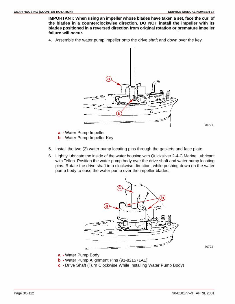
GEAR HOUSING (COUNTER ROTATION) SERVICE MANUAL NUMBER 14
Page 3C-112 90-818177--3 APRIL 2001
IMPORTANT: When using an impeller whose blades have taken a set, face the curl ofthe blades in a counterclockwise direction. DO NOT install the impeller with itsblades positioned in a reversed direction from original rotation or premature impellerfailure will occur.
4. Assemble the water pump impeller onto the drive shaft and down over the key.
70721
a
b
a - Water Pump Impellerb - Water Pump Impeller Key
5. Install the two (2) water pump locating pins through the gaskets and face plate.
6. Lightly lubricate the inside of the water housing with Quicksilver 2-4-C Marine Lubricantwith Teflon. Position the water pump body over the drive shaft and water pump locatingpins. Rotate the drive shaft in a clockwise direction, while pushing down on the waterpump body to ease the water pump over the impeller blades.
70722
a
b
c
a - Water Pump Bodyb - Water Pump Alignment Pins (91-821571A1)c - Drive Shaft (Turn Clockwise While Installing Water Pump Body)

GEAR HOUSING (COUNTER ROTATION)SERVICE MANUAL NUMBER 14
90-818177--3 APRIL 2001 Page 3C-113
7. Hand start two (2) fasteners into the water pump assembly and remove the water pumplocating pins. Assemble the remaining two (2) fasteners. Run all fasteners down andtorque to 60 lb-in. (7.9 Nm).
IMPORTANT: The water pump face seal must be installed as outlined below.Improperly installing the water pump face seal may result in premature failure of theunit.
8. Lightly lubricate the drive shaft with Quicksilver 2-4-C Marine Lubricant with Teflon.Assemble the water pump face seal to a position approximately 1/2 of the way down thedrive shaft. Assemble the water pump face seal setting tool over the drive shaft and pushthe seal down onto the water pump with the tool while pulling up on the drive shaft.Remove the tool from the drive shaft.
70708
70504a
b
a
a - Water Pump Face Sealb - Water Pump Face Seal Setting Tool
9. Assemble the water tube sleeve into the water tube coupling.
10. Assemble the water tube coupling assembly to the water pump ensuring that the O-ringsare not damaged during assembly.
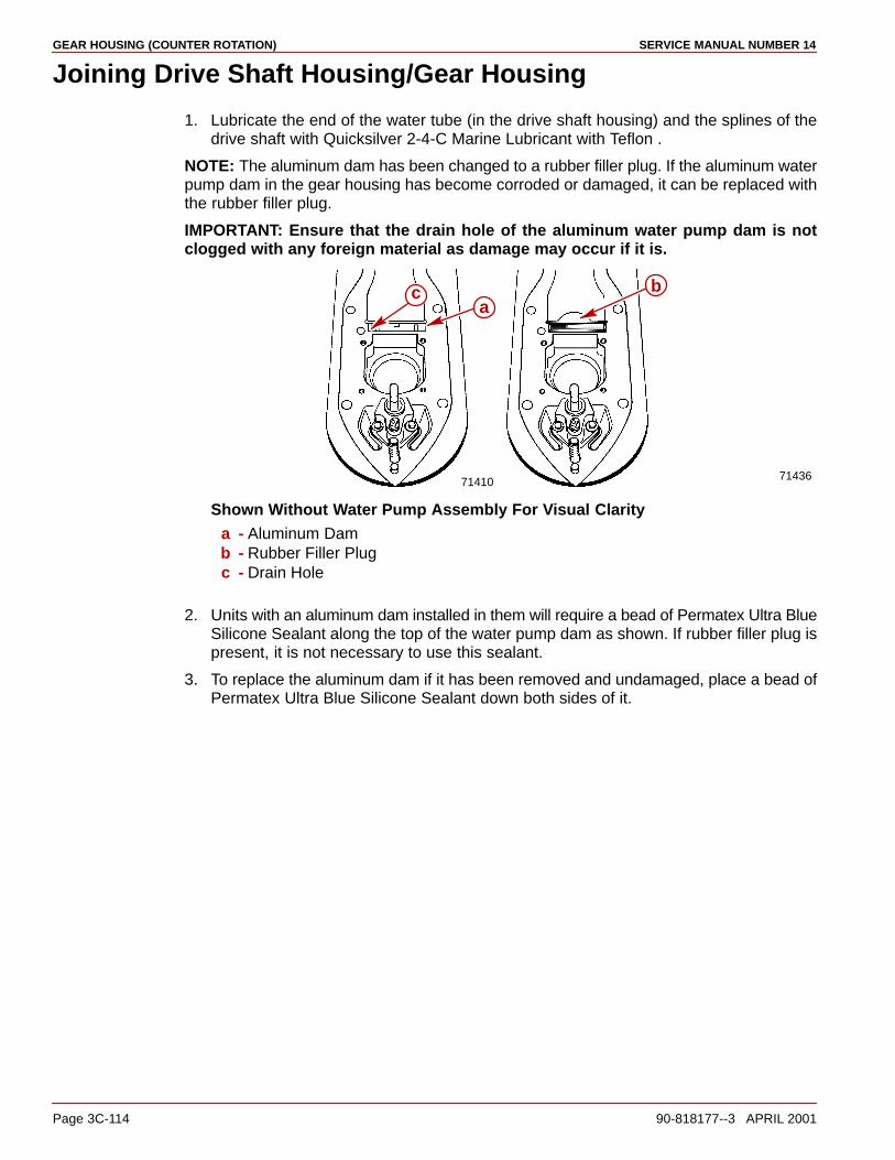
GEAR HOUSING (COUNTER ROTATION) SERVICE MANUAL NUMBER 14
Page 3C-114 90-818177--3 APRIL 2001
Joining Drive Shaft Housing/Gear Housing
1. Lubricate the end of the water tube (in the drive shaft housing) and the splines of thedrive shaft with Quicksilver 2-4-C Marine Lubricant with Teflon .
NOTE: The aluminum dam has been changed to a rubber filler plug. If the aluminum waterpump dam in the gear housing has become corroded or damaged, it can be replaced withthe rubber filler plug.
IMPORTANT: Ensure that the drain hole of the aluminum water pump dam is notclogged with any foreign material as damage may occur if it is.
71410 71436
abc
Shown Without Water Pump Assembly For Visual Claritya - Aluminum Damb - Rubber Filler Plugc - Drain Hole
2. Units with an aluminum dam installed in them will require a bead of Permatex Ultra BlueSilicone Sealant along the top of the water pump dam as shown. If rubber filler plug ispresent, it is not necessary to use this sealant.
3. To replace the aluminum dam if it has been removed and undamaged, place a bead ofPermatex Ultra Blue Silicone Sealant down both sides of it.
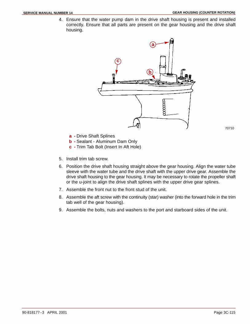
GEAR HOUSING (COUNTER ROTATION)SERVICE MANUAL NUMBER 14
90-818177--3 APRIL 2001 Page 3C-115
4. Ensure that the water pump dam in the drive shaft housing is present and installedcorrectly. Ensure that all parts are present on the gear housing and the drive shafthousing.
70710
a
b
c
a - Drive Shaft Splinesb - Sealant - Aluminum Dam Onlyc - Trim Tab Bolt (Insert In Aft Hole)
5. Install trim tab screw.
6. Position the drive shaft housing straight above the gear housing. Align the water tubesleeve with the water tube and the drive shaft with the upper drive gear. Assemble thedrive shaft housing to the gear housing. It may be necessary to rotate the propeller shaftor the u-joint to align the drive shaft splines with the upper drive gear splines.
7. Assemble the front nut to the front stud of the unit.
8. Assemble the aft screw with the continuity (star) washer (into the forward hole in the trimtab well of the gear housing).
9. Assemble the bolts, nuts and washers to the port and starboard sides of the unit.

GEAR HOUSING (COUNTER ROTATION) SERVICE MANUAL NUMBER 14
Page 3C-116 90-818177--3 APRIL 2001
NOTE: Torque all fasteners as listed in the following figure.
70117
a
b
c
a - Nuts, Bolts, Washers [Torque To 35 lb-ft [47.5 Nm)]b - Nut [Torque To 35 lb-ft [47.5 Nm)]c - Screw [Torque To 28 lb-ft [41 Nm)]
10. Assemble the trim tab and align it to the mark made previously on the gear housing.Torque the screw to 23 lb-ft (31 Nm).
11. Position or lower drive unit so anti-ventilation plate is level.
12. Refill drive unit with gear lube. Refer to Section 1B.

GEAR HOUSING (COUNTER ROTATION)SERVICE MANUAL NUMBER 14
90-818177--3 APRIL 2001 Page 3C-117
THIS PAGE IS INTENTIONALLY BLANK

GEAR HOUSING (COUNTER ROTATION) SERVICE MANUAL NUMBER 14
Page 3C-118 90-818177--3 APRIL 2001
THIS PAGE IS INTENTIONALLY BLANK

4A
SERVICE PROCEDURES REQUIRING MINOR DISASSEMBLYSERVICE MANUAL NUMBER 14
90-818177--3 APRIL 2001 Page 4A-1
TRANSOM ASSEMBLYSection 4A - Service Procedures Requiring Minor Disassembly
Table of Contents
Specifications 4A-2. . . . . . . . . . . . . . . . . . . . . . . Torque Specifications 4A-2. . . . . . . . . . . . . Lubricants/Sealers/Adhesives 4A-2. . . . . . Special Tools 4A-2. . . . . . . . . . . . . . . . . . . . .
Special Information 4A-3. . . . . . . . . . . . . . . . . . Trim Limit Switch 4A-3. . . . . . . . . . . . . . . . . Trim Position Sender 4A-3. . . . . . . . . . . . . .
Trim Limit Switch and Trim Position Sender 4A-4. . . . . . . . . . . .
Removal 4A-4. . . . . . . . . . . . . . . . . . . . . . . . . Installation 4A-7. . . . . . . . . . . . . . . . . . . . . . . Trim Position Sender Adjustment 4A-12. . . Trim Limit Switch Adjustment 4A-13. . . . . . .
Gimbal Bearing 4A-15. . . . . . . . . . . . . . . . . . . . . Inspection 4A-15. . . . . . . . . . . . . . . . . . . . . . . Removal 4A-15. . . . . . . . . . . . . . . . . . . . . . . . . Installation 4A-17. . . . . . . . . . . . . . . . . . . . . . .
Shift Cable 4A-19. . . . . . . . . . . . . . . . . . . . . . . . . Removal 4A-19. . . . . . . . . . . . . . . . . . . . . . . . . Inspection 4A-22. . . . . . . . . . . . . . . . . . . . . . . Installation 4A-23. . . . . . . . . . . . . . . . . . . . . . . Remote Control Shift Cable Adjustment (Drive Unit Installed) 4A-28. . . . . . . . . . . . . .
Exhaust Bellows 4A-38. . . . . . . . . . . . . . . . . . . . Removal 4A-38. . . . . . . . . . . . . . . . . . . . . . . . . Cleaning And Inspection 4A-39. . . . . . . . . . . Installation 4A-39. . . . . . . . . . . . . . . . . . . . . . .
Gear Lube Monitor Kit System Components - Replacement 4A-42. .
Monitor To Thru-Bulkhead Fitting Hose: 4A-42. . . . . . . . . . . . . . . . . . . . . Thru-bulkhead To Bell Housing Gear Lube Monitor Hose 4A-46. . . . . . . . . . Bell Housing To Driveshaft Housing Anti-Dribble Valves 4A-48. . . . . . .
Crimp Clamp Tool 4A-50. . . . . . . . . . . . . . . . . . .

sERVICE PROCEDURES REQUIRING MINOR DISASSEMBLY SERVICE MANUAL NUMBER 14
Page 4A-2 90-818177--3 APRIL 2001
Specifications
Torque Specifications
TorqueDescription
lb-in. lb-ft Nm
Shift Cable Core Wire Anchor Screws 20 2.3
Bellows Hose Clamps 35 4
Hinge Pins 102 143
Lubricants/Sealers/Adhesives
Description Part Number
3M Brand Adhesive 92-86166Q1
Quicksilver 2-4-C Marine Lubricant with Teflon 92-825407A12
Special Tools
Description Part Number
Bearing Removal and Installation Tool 91-31229A7
Bellows Expander Tool 91-45497A1
Slide Hammer Puller 91-34569A1
Shift Cable Removal and Installation Tool 91-12037
Hinge Pin Tool 91-78310
Sleeve Removal Tool (U-joint Bellows) 91-818169T
Sleeve Installation Tool (U-joint Bellows) 91-818162
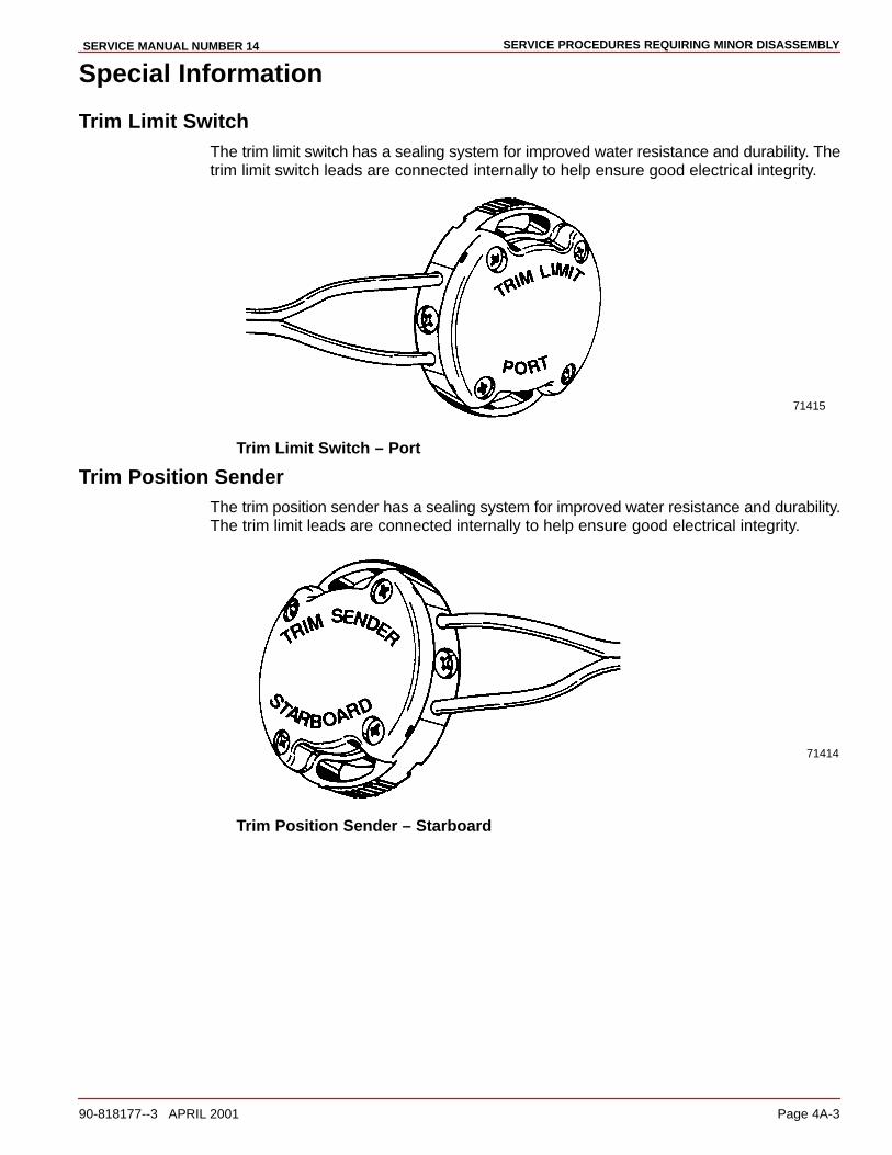
SERVICE PROCEDURES REQUIRING MINOR DISASSEMBLYSERVICE MANUAL NUMBER 14
90-818177--3 APRIL 2001 Page 4A-3
Special Information
Trim Limit SwitchThe trim limit switch has a sealing system for improved water resistance and durability. Thetrim limit switch leads are connected internally to help ensure good electrical integrity.
71415
Trim Limit Switch – Port
Trim Position SenderThe trim position sender has a sealing system for improved water resistance and durability.The trim limit leads are connected internally to help ensure good electrical integrity.
71414
Trim Position Sender – Starboard

sERVICE PROCEDURES REQUIRING MINOR DISASSEMBLY SERVICE MANUAL NUMBER 14
Page 4A-4 90-818177--3 APRIL 2001
Trim Limit Switch and Trim Position Sender
RemovalNOTE: Disconnect both the trim limit and trim sender leads before removing.
1. Remove sterndrive unit.
2. Remove trim limit switch.
71221
a
a - Screws, Washers And Retainers
3. Remove trim position sender.
71220
a
a - Screws, Washers and Retainers
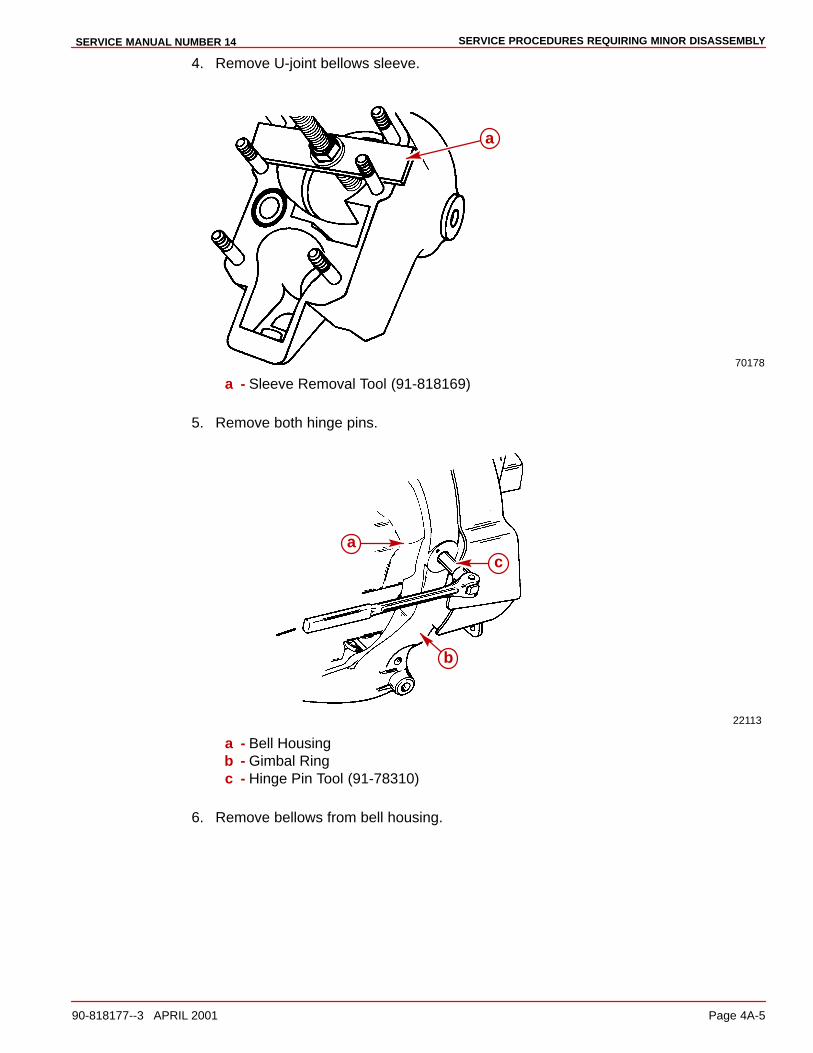
SERVICE PROCEDURES REQUIRING MINOR DISASSEMBLYSERVICE MANUAL NUMBER 14
90-818177--3 APRIL 2001 Page 4A-5
4. Remove U-joint bellows sleeve.
70178
a
a - Sleeve Removal Tool (91-818169)
5. Remove both hinge pins.
22113
a
b
c
a - Bell Housingb - Gimbal Ringc - Hinge Pin Tool (91-78310)
6. Remove bellows from bell housing.
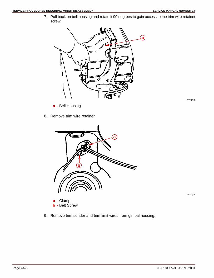
sERVICE PROCEDURES REQUIRING MINOR DISASSEMBLY SERVICE MANUAL NUMBER 14
Page 4A-6 90-818177--3 APRIL 2001
7. Pull back on bell housing and rotate it 90 degrees to gain access to the trim wire retainerscrew.
23363
a
a - Bell Housing
8. Remove trim wire retainer.
70197
a
b
a - Clampb - Belt Screw
9. Remove trim sender and trim limit wires from gimbal housing.
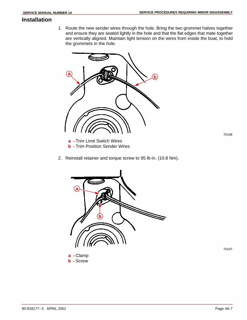
SERVICE PROCEDURES REQUIRING MINOR DISASSEMBLYSERVICE MANUAL NUMBER 14
90-818177--3 APRIL 2001 Page 4A-7
Installation1. Route the new sender wires through the hole. Bring the two grommet halves together
and ensure they are seated lightly in the hole and that the flat edges that mate togetherare vertically aligned. Maintain light tension on the wires from inside the boat, to holdthe grommets in the hole.
70198
ab
a - Trim Limit Switch Wiresb - Trim Position Sender Wires
2. Reinstall retainer and torque screw to 95 lb-in. (10.8 Nm).
70197
a
b
a - Clampb - Screw

sERVICE PROCEDURES REQUIRING MINOR DISASSEMBLY SERVICE MANUAL NUMBER 14
Page 4A-8 90-818177--3 APRIL 2001
3. Connect U-joint bellows to bell housing as follows:
a. Position U-joint bellows on bell housing. Ensure that the bell housing flange restsin the groove at the end of bellows.
75268
a
b
c
b
a - Bell Housing Flangeb - Bellowsc - Groove
b. Lubricate sleeve O.D. with engine cleaner (Quicksilver Power Tune works well andit evaporates quickly) and install sleeve with tool and suitable driving rod.
70207
a
b
c
a - Sleeveb - Installation Tool (91-818162)c - Suitable Driving Rod
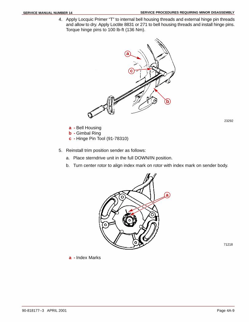
SERVICE PROCEDURES REQUIRING MINOR DISASSEMBLYSERVICE MANUAL NUMBER 14
90-818177--3 APRIL 2001 Page 4A-9
4. Apply Locquic Primer “T” to internal bell housing threads and external hinge pin threadsand allow to dry. Apply Loctite 8831 or 271 to bell housing threads and install hinge pins.Torque hinge pins to 100 lb-ft (136 Nm).
23292
a
b
c
a - Bell Housingb - Gimbal Ringc - Hinge Pin Tool (91-78310)
5. Reinstall trim position sender as follows:
a. Place sterndrive unit in the full DOWN/IN position.
b. Turn center rotor to align index mark on rotor with index mark on sender body.
71218
a
a - Index Marks
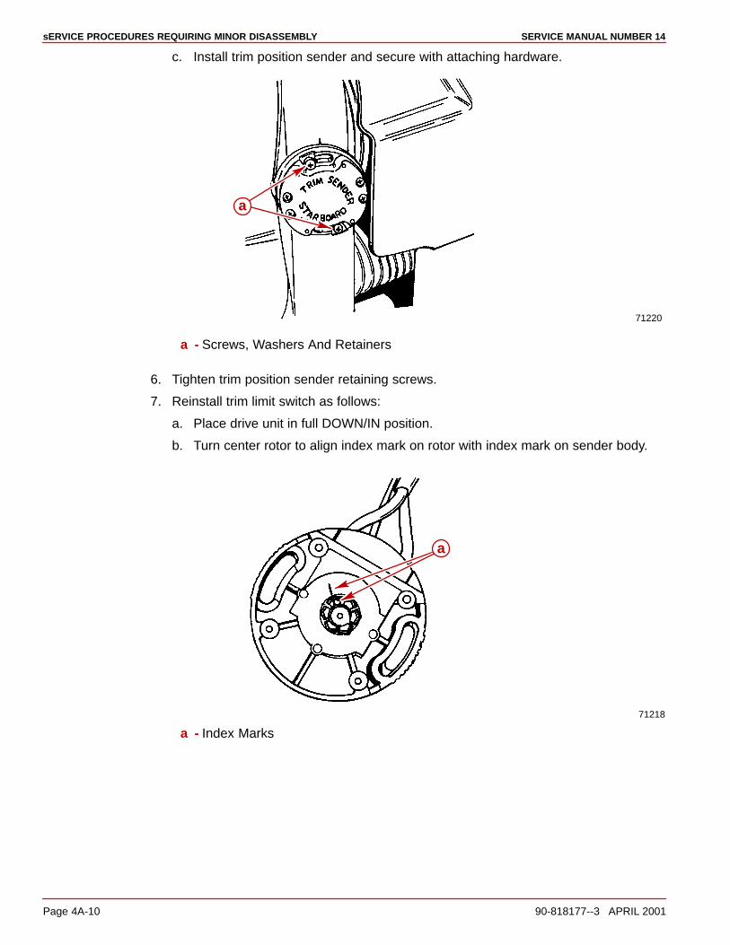
sERVICE PROCEDURES REQUIRING MINOR DISASSEMBLY SERVICE MANUAL NUMBER 14
Page 4A-10 90-818177--3 APRIL 2001
c. Install trim position sender and secure with attaching hardware.
71220
a
a - Screws, Washers And Retainers
6. Tighten trim position sender retaining screws.
7. Reinstall trim limit switch as follows:
a. Place drive unit in full DOWN/IN position.
b. Turn center rotor to align index mark on rotor with index mark on sender body.
71218
a
a - Index Marks
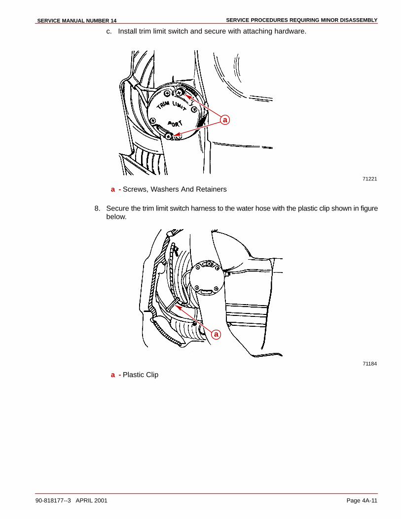
SERVICE PROCEDURES REQUIRING MINOR DISASSEMBLYSERVICE MANUAL NUMBER 14
90-818177--3 APRIL 2001 Page 4A-11
c. Install trim limit switch and secure with attaching hardware.
71221
a
a - Screws, Washers And Retainers
8. Secure the trim limit switch harness to the water hose with the plastic clip shown in figurebelow.
71184
a
a - Plastic Clip
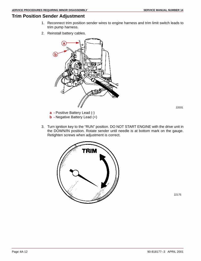
sERVICE PROCEDURES REQUIRING MINOR DISASSEMBLY SERVICE MANUAL NUMBER 14
Page 4A-12 90-818177--3 APRIL 2001
Trim Position Sender Adjustment1. Reconnect trim position sender wires to engine harness and trim limit switch leads to
trim pump harness.
2. Reinstall battery cables.
22031
a
b
a - Positive Battery Lead (-)b - Negative Battery Lead (+)
3. Turn ignition key to the “RUN” position. DO NOT START ENGINE with the drive unit inthe DOWN/IN position. Rotate sender until needle is at bottom mark on the gauge.Retighten screws when adjustment is correct.
22175

SERVICE PROCEDURES REQUIRING MINOR DISASSEMBLYSERVICE MANUAL NUMBER 14
90-818177--3 APRIL 2001 Page 4A-13
Trim Limit Switch Adjustment
WARNINGWhen adjusting trim limit switch, use extreme care that the engine is not started andkeep clear of the area near the propeller. Use care to prevent placing hands in anarea where injury could occur because of drive unit movement.
CAUTIONTrim limit switch MUST BE adjusted exactly as outlined. If switch is adjusted incor-rectly, drive unit could move out beyond the gimbal ring support flanges and causedamage to sterndrive unit.
1. Adjust trim limit switch as follows:
a. Loosen screws and turn trim limit switch clockwise to end of slots.
71221
a b
b
a - Screwsb - Slots
b. Ensure drive unit is in the full DOWN/IN position.
c. Using the Trim button on the control, trim drive unit UP/OUT. DO NOT USE TRAILERBUTTON.
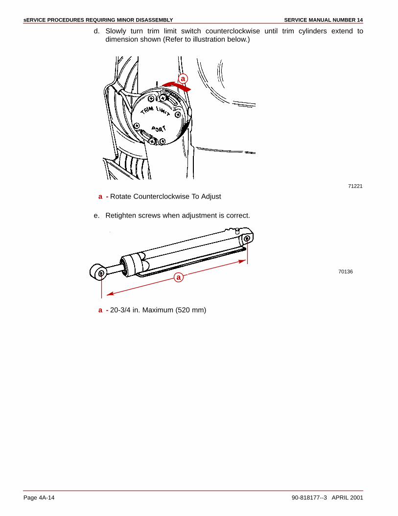
sERVICE PROCEDURES REQUIRING MINOR DISASSEMBLY SERVICE MANUAL NUMBER 14
Page 4A-14 90-818177--3 APRIL 2001
d. Slowly turn trim limit switch counterclockwise until trim cylinders extend todimension shown (Refer to illustration below.)
71221
a
a - Rotate Counterclockwise To Adjust
e. Retighten screws when adjustment is correct.
70136a
a - 20-3/4 in. Maximum (520 mm)

SERVICE PROCEDURES REQUIRING MINOR DISASSEMBLYSERVICE MANUAL NUMBER 14
90-818177--3 APRIL 2001 Page 4A-15
Gimbal Bearing
IMPORTANT: Gimbal bearing and carrier are a matched set and must be replaced asan assembly. Tolerance ring must be replaced anytime gimbal bearing is removed.
Inspection1. Remove sterndrive unit.
2. Reach through bell housing and rotate gimbal bearing to check for rough spots. Pushand pull on inner race to check for side wear. Any excessive movement or roughnessis cause for replacement.
Removal
CAUTIONDo not remove gimbal bearing unless replacement is necessary, as damage to bear-ing may result during removal.
1. Remove gimbal bearing assembly using tools as shown.
23151
a
c
db
e
f
g
a - Puller Shaft (91-31229)*
b - Nut (11-24156)*
c - Washer (12-34961)*
d - Plates (2) (91-29310)*
e - Slide Hammer Pullerf - Gimbal Bearing Inner Raceg - Gimbal Bearing Carrier
* From Bearing Removal and Installation Tool 91-31229A5

sERVICE PROCEDURES REQUIRING MINOR DISASSEMBLY SERVICE MANUAL NUMBER 14
Page 4A-16 90-818177--3 APRIL 2001
2. Remove tolerance ring.
75214
a
b
a - Gimbal Bearing Carrierb - Tolerance Ring
3. Remove grease seal.
22171
a
b
a - Gimbal Housingb - Grease Seal
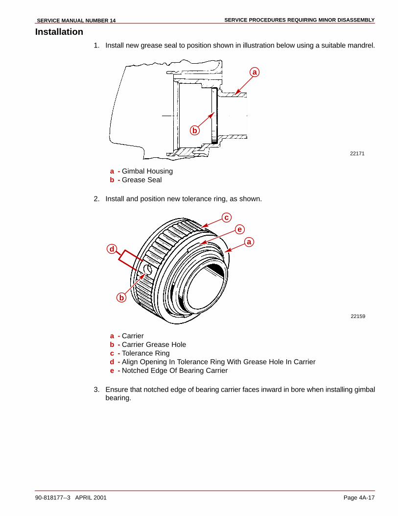
SERVICE PROCEDURES REQUIRING MINOR DISASSEMBLYSERVICE MANUAL NUMBER 14
90-818177--3 APRIL 2001 Page 4A-17
Installation1. Install new grease seal to position shown in illustration below using a suitable mandrel.
22171
a
b
a - Gimbal Housingb - Grease Seal
2. Install and position new tolerance ring, as shown.
22159
a
b
e
c
d
a - Carrierb - Carrier Grease Holec - Tolerance Ringd - Align Opening In Tolerance Ring With Grease Hole In Carriere - Notched Edge Of Bearing Carrier
3. Ensure that notched edge of bearing carrier faces inward in bore when installing gimbalbearing.

sERVICE PROCEDURES REQUIRING MINOR DISASSEMBLY SERVICE MANUAL NUMBER 14
Page 4A-18 90-818177--3 APRIL 2001
4. Align gimbal bearing carrier grease hole and tolerance ring opening with grease cavityhole in gimbal housing.
b
77020
c
a
a - Gimbal Bearing Carrier Grease Holeb - Tolerance Ring Openingc - Bearing Carrier Notch - Face Inward
5. Install gimbal bearing with tools, as shown. Tap in with a lead hammer until carrier restson the gimbal housing. Approximately 1/8 in. of the bore will show when the bearing isbottomed out.
22118
e
cd
a b
a - Driver Rod (91-37323)*
b - Plate (91-29310)*
c - Driver Head (91-32325)*
d - Mandrel (91-30366-1)*
e - Gimbal Bearing Assembly
* From Bearing Removal and Installation Tool 91-31229A7

SERVICE PROCEDURES REQUIRING MINOR DISASSEMBLYSERVICE MANUAL NUMBER 14
90-818177--3 APRIL 2001 Page 4A-19
Shift Cable
Removal1. Remove sterndrive unit.
2. Disconnect shift cable from shift plate and remove end guide.
22183
22183
b a
a - Anchor Screws (2)b - End Guide
3. Remove threaded tube.
22183
a b
a - Jam Nutb - Threaded Tube
4. Cut safety wire and remove set screw from shift slide.
70138
a
b
c
a - Set Screwb - Shift Slidec - Safety Wire
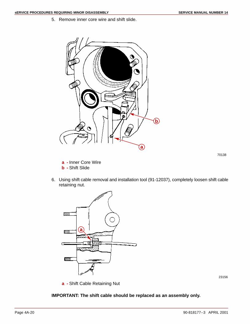
sERVICE PROCEDURES REQUIRING MINOR DISASSEMBLY SERVICE MANUAL NUMBER 14
Page 4A-20 90-818177--3 APRIL 2001
5. Remove inner core wire and shift slide.
70138
a
b
a - Inner Core Wireb - Shift Slide
6. Using shift cable removal and installation tool (91-12037), completely loosen shift cableretaining nut.
23156
a
a - Shift Cable Retaining Nut
IMPORTANT: The shift cable should be replaced as an assembly only.
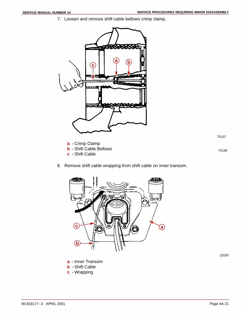
SERVICE PROCEDURES REQUIRING MINOR DISASSEMBLYSERVICE MANUAL NUMBER 14
90-818177--3 APRIL 2001 Page 4A-21
7. Loosen and remove shift cable bellows crimp clamp.
70138
70137
ca b
a - Crimp Clampb - Shift Cable Bellowsc - Shift Cable
8. Remove shift cable wrapping from shift cable on inner transom.
22030
a
b
c
a - Inner Transomb - Shift Cablec - Wrapping
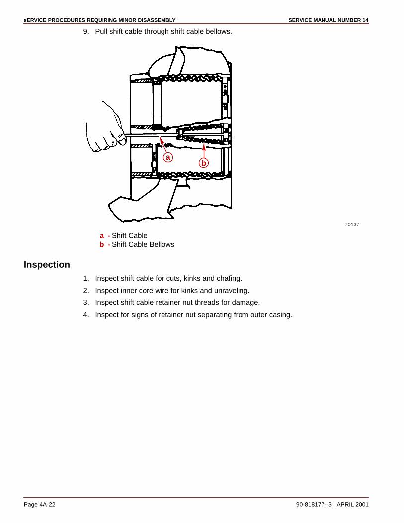
sERVICE PROCEDURES REQUIRING MINOR DISASSEMBLY SERVICE MANUAL NUMBER 14
Page 4A-22 90-818177--3 APRIL 2001
9. Pull shift cable through shift cable bellows.
70137
ab
a - Shift Cableb - Shift Cable Bellows
Inspection1. Inspect shift cable for cuts, kinks and chafing.
2. Inspect inner core wire for kinks and unraveling.
3. Inspect shift cable retainer nut threads for damage.
4. Inspect for signs of retainer nut separating from outer casing.
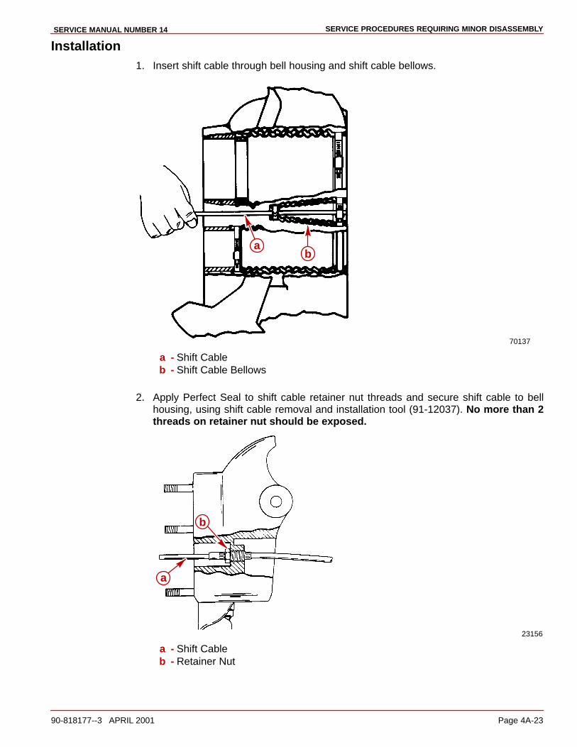
SERVICE PROCEDURES REQUIRING MINOR DISASSEMBLYSERVICE MANUAL NUMBER 14
90-818177--3 APRIL 2001 Page 4A-23
Installation1. Insert shift cable through bell housing and shift cable bellows.
70137
ab
a - Shift Cableb - Shift Cable Bellows
2. Apply Perfect Seal to shift cable retainer nut threads and secure shift cable to bellhousing, using shift cable removal and installation tool (91-12037). No more than 2threads on retainer nut should be exposed.
23156
b
a
a - Shift Cableb - Retainer Nut
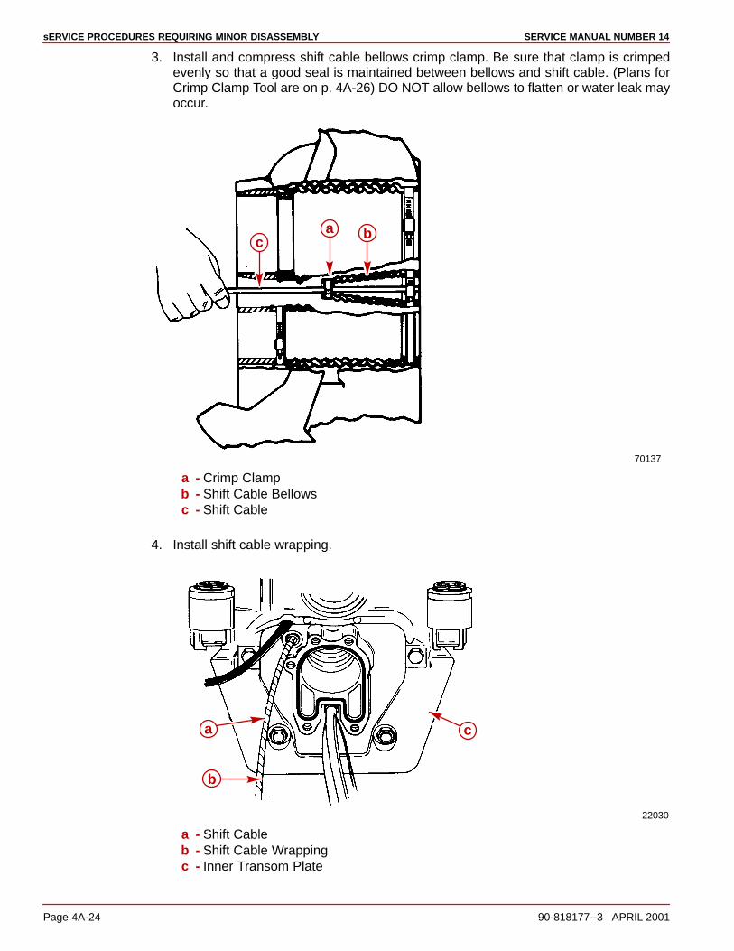
sERVICE PROCEDURES REQUIRING MINOR DISASSEMBLY SERVICE MANUAL NUMBER 14
Page 4A-24 90-818177--3 APRIL 2001
3. Install and compress shift cable bellows crimp clamp. Be sure that clamp is crimpedevenly so that a good seal is maintained between bellows and shift cable. (Plans forCrimp Clamp Tool are on p. 4A-26) DO NOT allow bellows to flatten or water leak mayoccur.
70137
ca b
a - Crimp Clampb - Shift Cable Bellowsc - Shift Cable
4. Install shift cable wrapping.
22030
a
b
c
a - Shift Cableb - Shift Cable Wrappingc - Inner Transom Plate
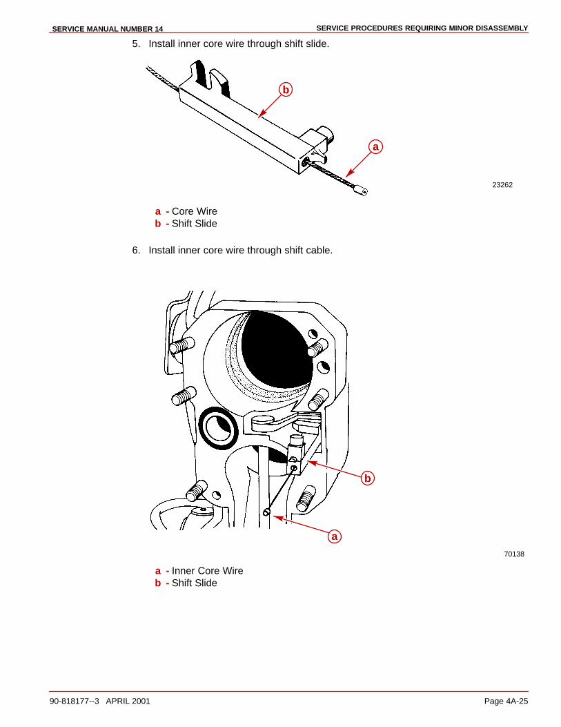
SERVICE PROCEDURES REQUIRING MINOR DISASSEMBLYSERVICE MANUAL NUMBER 14
90-818177--3 APRIL 2001 Page 4A-25
5. Install inner core wire through shift slide.
23262
a
b
a - Core Wireb - Shift Slide
6. Install inner core wire through shift cable.
70138
a
b
a - Inner Core Wireb - Shift Slide
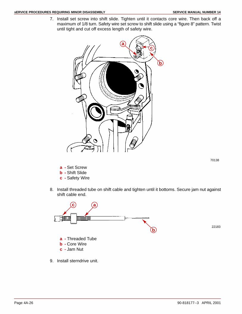
sERVICE PROCEDURES REQUIRING MINOR DISASSEMBLY SERVICE MANUAL NUMBER 14
Page 4A-26 90-818177--3 APRIL 2001
7. Install set screw into shift slide. Tighten until it contacts core wire. Then back off amaximum of 1/8 turn. Safety wire set screw to shift slide using a “figure 8” pattern. Twistuntil tight and cut off excess length of safety wire.
70138
a
b
c
a - Set Screwb - Shift Slidec - Safety Wire
8. Install threaded tube on shift cable and tighten until it bottoms. Secure jam nut againstshift cable end.
22183
a
b
c
a - Threaded Tubeb - Core Wirec - Jam Nut
9. Install sterndrive unit.
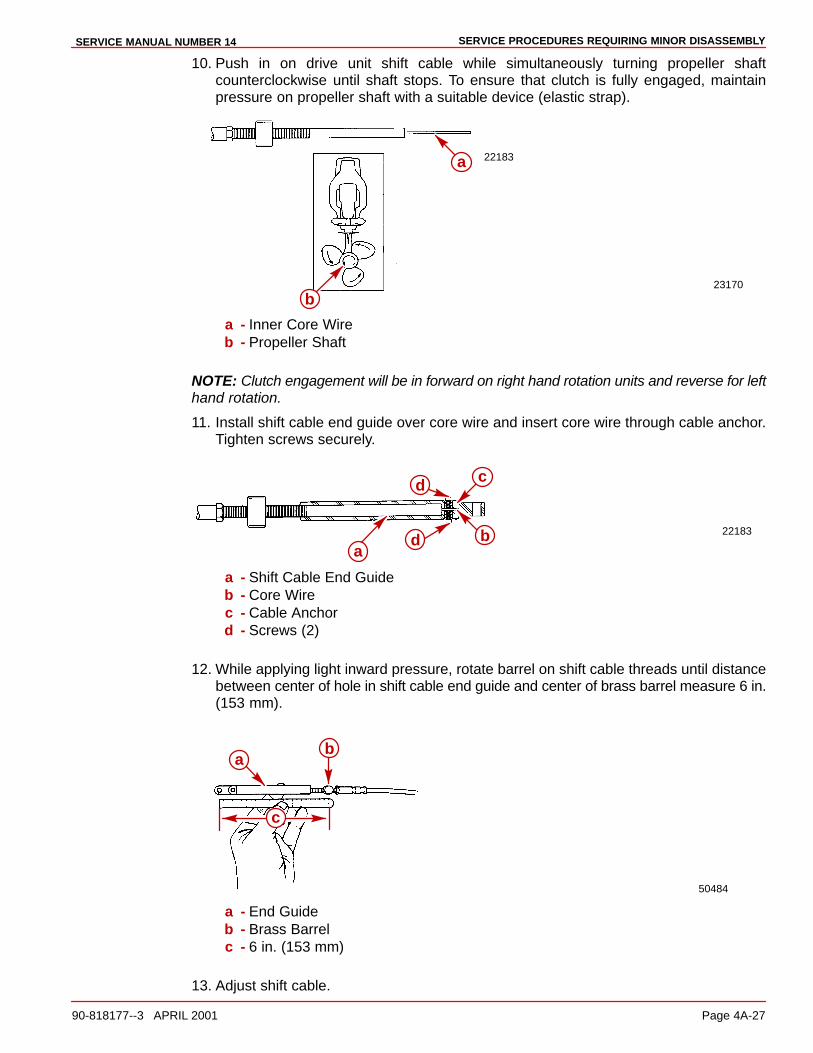
SERVICE PROCEDURES REQUIRING MINOR DISASSEMBLYSERVICE MANUAL NUMBER 14
90-818177--3 APRIL 2001 Page 4A-27
10. Push in on drive unit shift cable while simultaneously turning propeller shaftcounterclockwise until shaft stops. To ensure that clutch is fully engaged, maintainpressure on propeller shaft with a suitable device (elastic strap).
23170
22183a
b
a - Inner Core Wireb - Propeller Shaft
NOTE: Clutch engagement will be in forward on right hand rotation units and reverse for lefthand rotation.
11. Install shift cable end guide over core wire and insert core wire through cable anchor.Tighten screws securely.
22183
ab
c
d
d
a - Shift Cable End Guideb - Core Wirec - Cable Anchord - Screws (2)
12. While applying light inward pressure, rotate barrel on shift cable threads until distancebetween center of hole in shift cable end guide and center of brass barrel measure 6 in.(153 mm).
50484
ab
c
a - End Guideb - Brass Barrelc - 6 in. (153 mm)
13. Adjust shift cable.
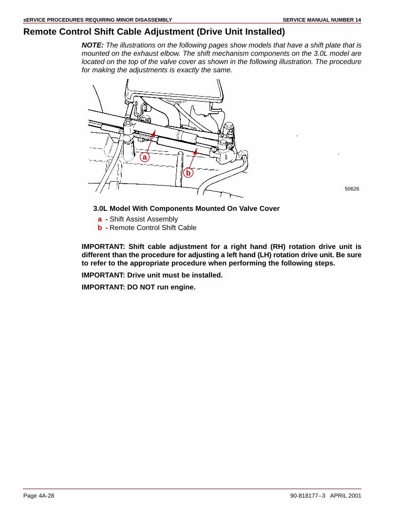
sERVICE PROCEDURES REQUIRING MINOR DISASSEMBLY SERVICE MANUAL NUMBER 14
Page 4A-28 90-818177--3 APRIL 2001
Remote Control Shift Cable Adjustment (Drive Unit Installed)NOTE: The illustrations on the following pages show models that have a shift plate that ismounted on the exhaust elbow. The shift mechanism components on the 3.0L model arelocated on the top of the valve cover as shown in the following illustration. The procedurefor making the adjustments is exactly the same.
50626
a
b
3.0L Model With Components Mounted On Valve Covera - Shift Assist Assemblyb - Remote Control Shift Cable
IMPORTANT: Shift cable adjustment for a right hand (RH) rotation drive unit isdifferent than the procedure for adjusting a left hand (LH) rotation drive unit. Be sureto refer to the appropriate procedure when performing the following steps.
IMPORTANT: Drive unit must be installed.
IMPORTANT: DO NOT run engine.

SERVICE PROCEDURES REQUIRING MINOR DISASSEMBLYSERVICE MANUAL NUMBER 14
90-818177--3 APRIL 2001 Page 4A-29
1. Remove remote control shift cable and shift assist assembly (if installed).
50308
b
a
With Shift Assist Assemblya - Shift Assist Assemblyb - Remote Control Shift Cable
50310
a
Without Shift Assist Assemblya - Remote Control Shift Cable

sERVICE PROCEDURES REQUIRING MINOR DISASSEMBLY SERVICE MANUAL NUMBER 14
Page 4A-30 90-818177--3 APRIL 2001
2. Ensure shift lever adjustable stud is at bottom of slot. If necessary, loosen stud and moveit to bottom of slot toward the pivot bolt, then retighten stud.
50309
a
b
a - Adjustable Studb - Toward pivot bolt
3. Shift remote control as stated in “a” or “b” following:
a. Right Hand (RH) Rotation Drive Unit - forward gear, past detent, intowide-open-throttle position.
(RH)
�
�
�

SERVICE PROCEDURES REQUIRING MINOR DISASSEMBLYSERVICE MANUAL NUMBER 14
90-818177--3 APRIL 2001 Page 4A-31
b. Left Hand (LH) Rotation Drive Unit - reverse gear, past detent, intowide-open-throttle position.
(LH)�
4. Place drive unit into gear by pushing in on drive unit shift cable, while simultaneouslyrotating propeller shaft counterclockwise until shaft stops, to ensure full clutchengagement. Maintain a light pressure on the drive unit shift cable to hold it at the endof its travel (this removes all slack from the cable).
IMPORTANT: Do not use excessive force when holding pressure on the drive unitshift cable. Excessive force would be indicated by movement of the v-notch on theshift cutout switch.
22266
a
b
a - Drive Unit Shift Cable - Push Inb - Propeller Shaft - Rotate Counterclockwise

sERVICE PROCEDURES REQUIRING MINOR DISASSEMBLY SERVICE MANUAL NUMBER 14
Page 4A-32 90-818177--3 APRIL 2001
5. Lightly pull on remote control shift cable end guide (to remove slack from remote controland cable) and adjust brass barrel as necessary to align attaching points with shift leverclevis pin hole and stud. Be sure to maintain light pressure on drive unit shift cable.
50309
c
ab
d
a - End Guideb - Brass Barrelc - Shift Lever Clevis Pin Holed - Stud
6. After cable has been aligned, turn brass barrel 4 turns away from cable end guide.
50308
a
b
e - End Guidef - Brass Barrel
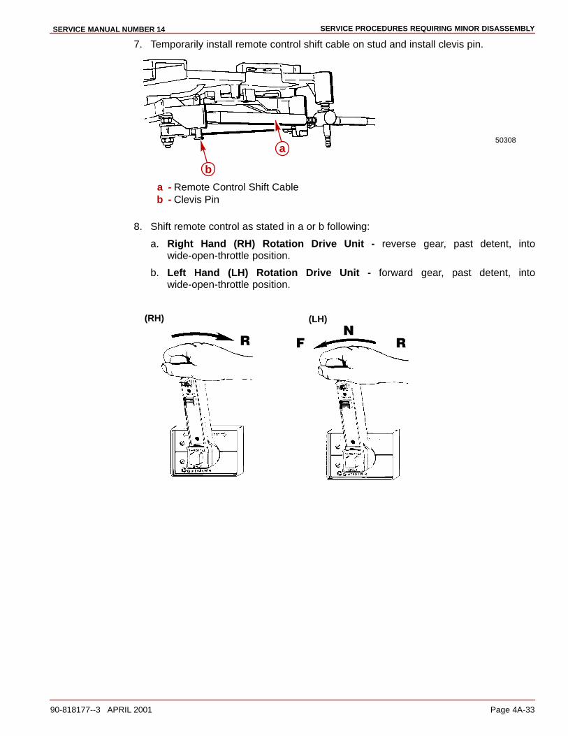
SERVICE PROCEDURES REQUIRING MINOR DISASSEMBLYSERVICE MANUAL NUMBER 14
90-818177--3 APRIL 2001 Page 4A-33
7. Temporarily install remote control shift cable on stud and install clevis pin.
50308a
b
a - Remote Control Shift Cableb - Clevis Pin
8. Shift remote control as stated in a or b following:
a. Right Hand (RH) Rotation Drive Unit - reverse gear, past detent, intowide-open-throttle position.
b. Left Hand (LH) Rotation Drive Unit - forward gear, past detent, intowide-open-throttle position.
(RH)
�
�
�
(LH)
�

sERVICE PROCEDURES REQUIRING MINOR DISASSEMBLY SERVICE MANUAL NUMBER 14
Page 4A-34 90-818177--3 APRIL 2001
9. Simultaneously rotate propeller shaft clockwise until shaft stops to ensure full clutchengagement.
22267
a
a - Propeller Shaft - Rotate Clockwise
10. Perform a or b as appropriate:
a. On Models with Earlier Type Switch: check shift cutout switch lever position.Roller must be centered.
22058
a
a - Shift Cutout Switch Roller
b. On Models with Later Type Switch: check shift cutout switch plunger position. Pinmust be centered.
75128
a
a - Shift Cutout Switch Roller
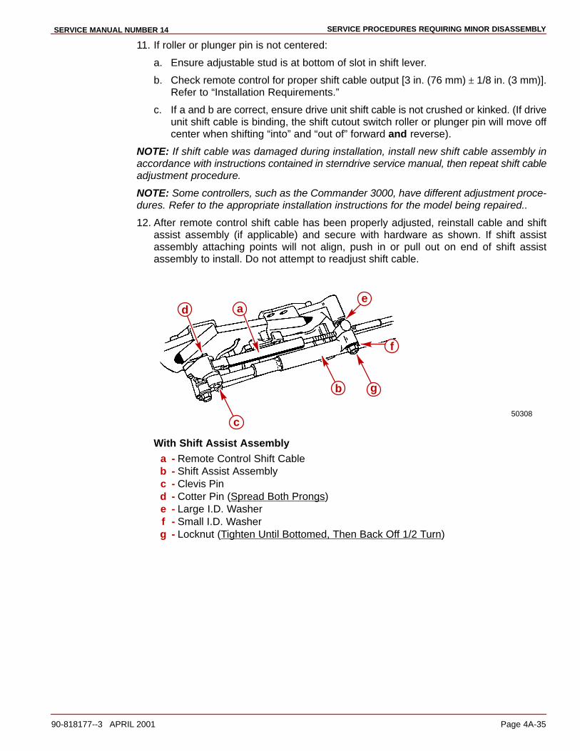
SERVICE PROCEDURES REQUIRING MINOR DISASSEMBLYSERVICE MANUAL NUMBER 14
90-818177--3 APRIL 2001 Page 4A-35
11. If roller or plunger pin is not centered:
a. Ensure adjustable stud is at bottom of slot in shift lever.
b. Check remote control for proper shift cable output [3 in. (76 mm) ± 1/8 in. (3 mm)].Refer to “Installation Requirements.”
c. If a and b are correct, ensure drive unit shift cable is not crushed or kinked. (If driveunit shift cable is binding, the shift cutout switch roller or plunger pin will move offcenter when shifting “into” and “out of” forward and reverse).
NOTE: If shift cable was damaged during installation, install new shift cable assembly inaccordance with instructions contained in sterndrive service manual, then repeat shift cableadjustment procedure.
NOTE: Some controllers, such as the Commander 3000, have different adjustment proce-dures. Refer to the appropriate installation instructions for the model being repaired..
12. After remote control shift cable has been properly adjusted, reinstall cable and shiftassist assembly (if applicable) and secure with hardware as shown. If shift assistassembly attaching points will not align, push in or pull out on end of shift assistassembly to install. Do not attempt to readjust shift cable.
50308
a
b
e
f
c
d
g
With Shift Assist Assemblya - Remote Control Shift Cableb - Shift Assist Assemblyc - Clevis Pind - Cotter Pin (Spread Both Prongs)e - Large I.D. Washerf - Small I.D. Washerg - Locknut (Tighten Until Bottomed, Then Back Off 1/2 Turn)
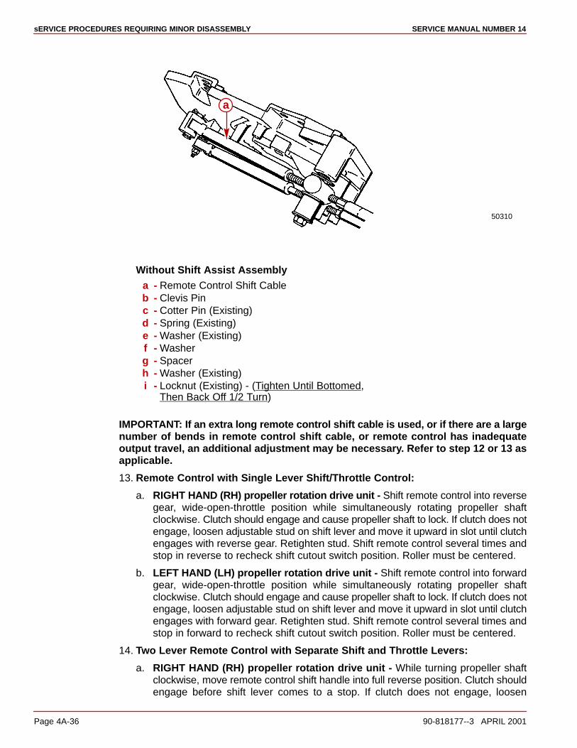
sERVICE PROCEDURES REQUIRING MINOR DISASSEMBLY SERVICE MANUAL NUMBER 14
Page 4A-36 90-818177--3 APRIL 2001
50310
a
Without Shift Assist Assemblya - Remote Control Shift Cableb - Clevis Pinc - Cotter Pin (Existing)d - Spring (Existing)e - Washer (Existing)f - Washerg - Spacerh - Washer (Existing)i - Locknut (Existing) - (Tighten Until Bottomed,
Then Back Off 1/2 Turn)
IMPORTANT: If an extra long remote control shift cable is used, or if there are a largenumber of bends in remote control shift cable, or remote control has inadequateoutput travel, an additional adjustment may be necessary. Refer to step 12 or 13 asapplicable.
13. Remote Control with Single Lever Shift/Throttle Control:
a. RIGHT HAND (RH) propeller rotation drive unit - Shift remote control into reversegear, wide-open-throttle position while simultaneously rotating propeller shaftclockwise. Clutch should engage and cause propeller shaft to lock. If clutch does notengage, loosen adjustable stud on shift lever and move it upward in slot until clutchengages with reverse gear. Retighten stud. Shift remote control several times andstop in reverse to recheck shift cutout switch position. Roller must be centered.
b. LEFT HAND (LH) propeller rotation drive unit - Shift remote control into forwardgear, wide-open-throttle position while simultaneously rotating propeller shaftclockwise. Clutch should engage and cause propeller shaft to lock. If clutch does notengage, loosen adjustable stud on shift lever and move it upward in slot until clutchengages with forward gear. Retighten stud. Shift remote control several times andstop in forward to recheck shift cutout switch position. Roller must be centered.
14. Two Lever Remote Control with Separate Shift and Throttle Levers:
a. RIGHT HAND (RH) propeller rotation drive unit - While turning propeller shaftclockwise, move remote control shift handle into full reverse position. Clutch shouldengage before shift lever comes to a stop. If clutch does not engage, loosen
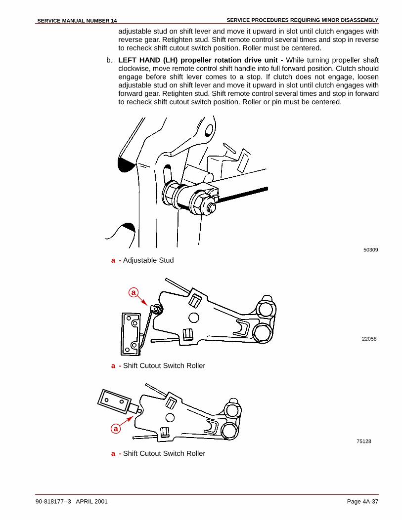
SERVICE PROCEDURES REQUIRING MINOR DISASSEMBLYSERVICE MANUAL NUMBER 14
90-818177--3 APRIL 2001 Page 4A-37
adjustable stud on shift lever and move it upward in slot until clutch engages withreverse gear. Retighten stud. Shift remote control several times and stop in reverseto recheck shift cutout switch position. Roller must be centered.
b. LEFT HAND (LH) propeller rotation drive unit - While turning propeller shaftclockwise, move remote control shift handle into full forward position. Clutch shouldengage before shift lever comes to a stop. If clutch does not engage, loosenadjustable stud on shift lever and move it upward in slot until clutch engages withforward gear. Retighten stud. Shift remote control several times and stop in forwardto recheck shift cutout switch position. Roller or pin must be centered.
50309
a - Adjustable Stud
22058
a
a - Shift Cutout Switch Roller
75128
a
a - Shift Cutout Switch Roller

sERVICE PROCEDURES REQUIRING MINOR DISASSEMBLY SERVICE MANUAL NUMBER 14
Page 4A-38 90-818177--3 APRIL 2001
Exhaust Bellows
Removal1. Remove sterndrive unit.
2. Loosen hose clamps and remove exhaust bellows.
75269
a - Exhaust Bellowsb - Hose Clamps
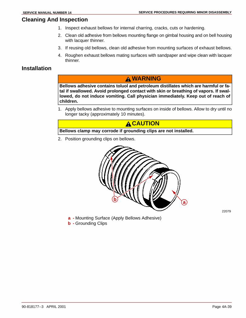
SERVICE PROCEDURES REQUIRING MINOR DISASSEMBLYSERVICE MANUAL NUMBER 14
90-818177--3 APRIL 2001 Page 4A-39
Cleaning And Inspection1. Inspect exhaust bellows for internal charring, cracks, cuts or hardening.
2. Clean old adhesive from bellows mounting flange on gimbal housing and on bell housingwith lacquer thinner.
3. If reusing old bellows, clean old adhesive from mounting surfaces of exhaust bellows.
4. Roughen exhaust bellows mating surfaces with sandpaper and wipe clean with lacquerthinner.
Installation
WARNINGBellows adhesive contains toluol and petroleum distillates which are harmful or fa-tal if swallowed. Avoid prolonged contact with skin or breathing of vapors. If swal-lowed, do not induce vomiting. Call physician immediately. Keep out of reach ofchildren.
1. Apply bellows adhesive to mounting surfaces on inside of bellows. Allow to dry until nolonger tacky (approximately 10 minutes).
CAUTIONBellows clamp may corrode if grounding clips are not installed.
2. Position grounding clips on bellows.
22079
ab
a - Mounting Surface (Apply Bellows Adhesive)b - Grounding Clips

sERVICE PROCEDURES REQUIRING MINOR DISASSEMBLY SERVICE MANUAL NUMBER 14
Page 4A-40 90-818177--3 APRIL 2001
3. Install exhaust bellows on gimbal housing. Position hose clamp as shown. Tighten hoseclamp screw to 35 lb-in. (8-10 Nm) using a screwdriver through access holes in gimbalhousing.
70199
c
ab
a - Exhaust Bellowsb - Hose Clampc - Gimbal Housing Access Hole
4. Install exhaust bellows on bell housing as follows:
a. Place hose clamp over bellows end.
b. Place expander tool (91-45497A1) through bell housing into first bellowsconvolution.
22161

SERVICE PROCEDURES REQUIRING MINOR DISASSEMBLYSERVICE MANUAL NUMBER 14
90-818177--3 APRIL 2001 Page 4A-41
c. Pull tool until tool touches the flange on bell housing (bellows starts to slip ontoflange); then release tool.
75270
a - Expander Tool (91-45497A1)b - Bell Housing Flange
d. Reposition tool into the third bellows convolution.
e. Pull bellows onto bell housing flange.
f. Torque hose clamp to 35 lb-in. (4 Nm).
75269
a - Exhaust Bellowsb - Hose Clamp

sERVICE PROCEDURES REQUIRING MINOR DISASSEMBLY SERVICE MANUAL NUMBER 14
Page 4A-42 90-818177--3 APRIL 2001
Gear Lube Monitor Kit System Components - Replacement
Monitor To Thru-Bulkhead Fitting Hose:EARLIER STYLE
Check hose periodically for condition, including cracks, hardening, etc.; replace asnecessary.
1. To replace hose, remove hose clamps and clip, then remove hose.
2. Install new hose of sufficient length to allow reservoir to be removed from topside orbottom-side of bracket. Secure hose with hose clamps.
3. If thru-bulkhead fitting was taken out to remove gimbal housing. The following stepsmust be completed.
4. Install gimbal housing fitting through housing. Ensure the hex on fitting lines up withformed cavity in housing, which prevents fitting from rotating.
5. Install washer and secure assembly with locknut. Torque to 12 lb-ft (16.5 Nm).
IMPORTANT: To ensure that fitting is seated securely in cavity there should be 1/2 in.(12.7 mm) of threads protruding through the top of the nut to the end of the gimbalhousing fitting.
6. Install 90 degree swivel fitting and position as shown while torquing to 80 lb-in. (9 Nm).
70006
a b c d e
a - Swivel Fittingb - Locknutc - Washerd - O-ringe - Gimbal Housing Fitting
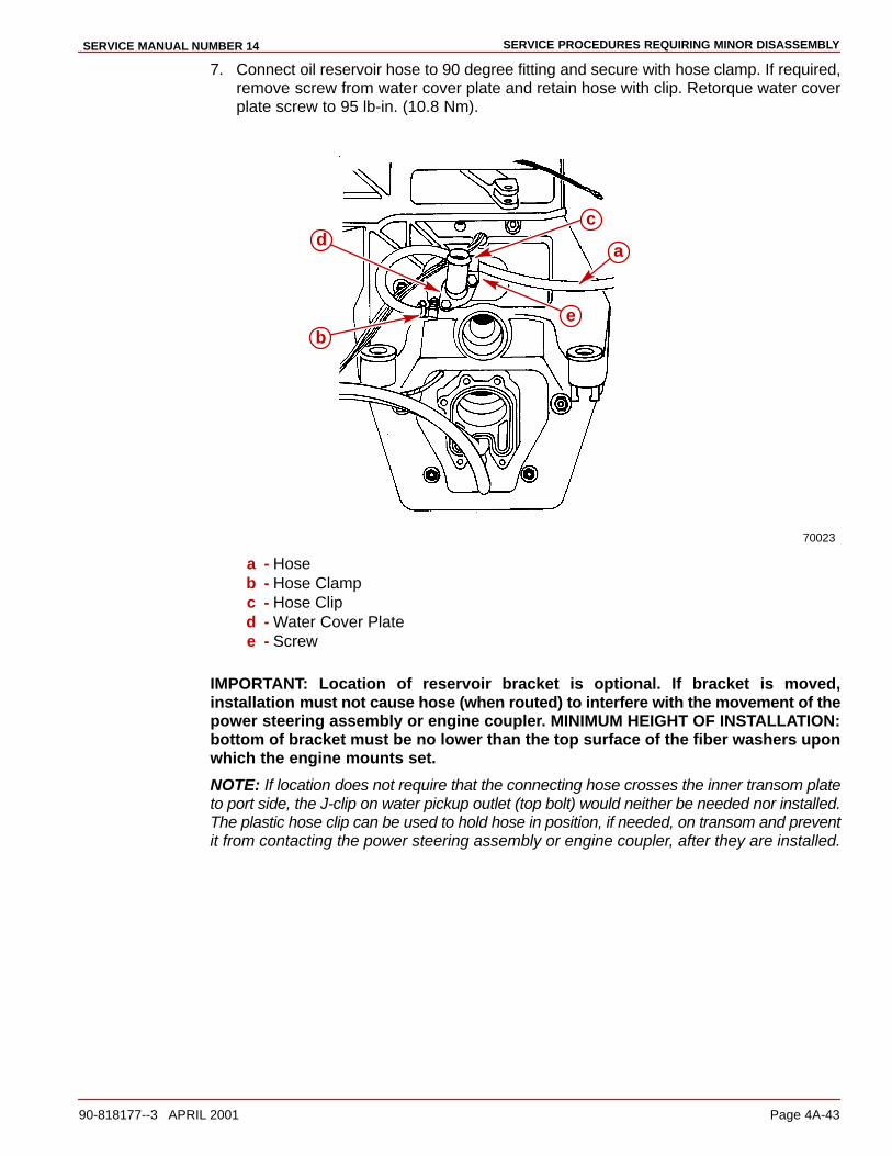
SERVICE PROCEDURES REQUIRING MINOR DISASSEMBLYSERVICE MANUAL NUMBER 14
90-818177--3 APRIL 2001 Page 4A-43
7. Connect oil reservoir hose to 90 degree fitting and secure with hose clamp. If required,remove screw from water cover plate and retain hose with clip. Retorque water coverplate screw to 95 lb-in. (10.8 Nm).
70023
a
b
cd
e
a - Hoseb - Hose Clampc - Hose Clipd - Water Cover Platee - Screw
IMPORTANT: Location of reservoir bracket is optional. If bracket is moved,installation must not cause hose (when routed) to interfere with the movement of thepower steering assembly or engine coupler. MINIMUM HEIGHT OF INSTALLATION:bottom of bracket must be no lower than the top surface of the fiber washers uponwhich the engine mounts set.
NOTE: If location does not require that the connecting hose crosses the inner transom plateto port side, the J-clip on water pickup outlet (top bolt) would neither be needed nor installed.The plastic hose clip can be used to hold hose in position, if needed, on transom and preventit from contacting the power steering assembly or engine coupler, after they are installed.
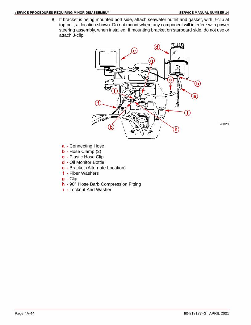
sERVICE PROCEDURES REQUIRING MINOR DISASSEMBLY SERVICE MANUAL NUMBER 14
Page 4A-44 90-818177--3 APRIL 2001
8. If bracket is being mounted port side, attach seawater outlet and gasket, with J-clip attop bolt, at location shown. Do not mount where any component will interfere with powersteering assembly, when installed. If mounting bracket on starboard side, do not use orattach J-clip.
70023
h
bc
f
g
a
de
i
b
f
a - Connecting Hoseb - Hose Clamp (2)c - Plastic Hose Clipd - Oil Monitor Bottlee - Bracket (Alternate Location)f - Fiber Washersg - Cliph - 90� Hose Barb Compression Fittingi - Locknut And Washer
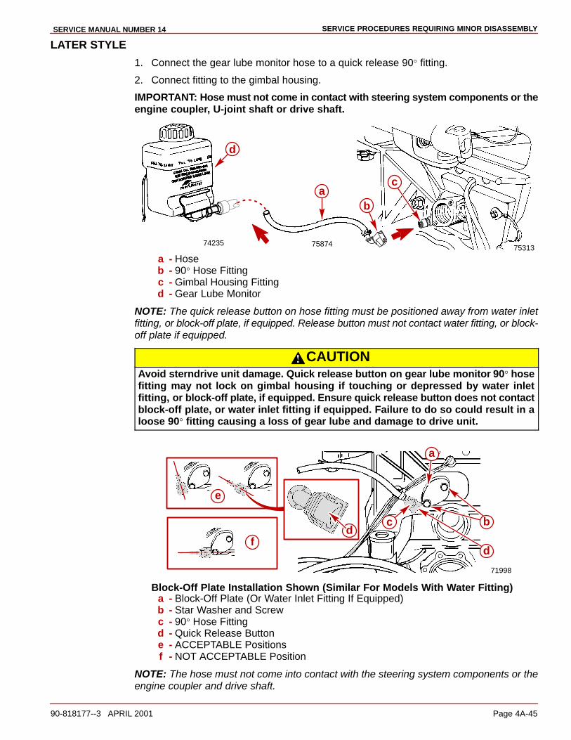
SERVICE PROCEDURES REQUIRING MINOR DISASSEMBLYSERVICE MANUAL NUMBER 14
90-818177--3 APRIL 2001 Page 4A-45
LATER STYLE
1. Connect the gear lube monitor hose to a quick release 90° fitting.
2. Connect fitting to the gimbal housing.
IMPORTANT: Hose must not come in contact with steering system components or theengine coupler, U-joint shaft or drive shaft.
7531374235 75874
a
d
c
b
a - Hoseb - 90° Hose Fittingc - Gimbal Housing Fittingd - Gear Lube Monitor
NOTE: The quick release button on hose fitting must be positioned away from water inletfitting, or block-off plate, if equipped. Release button must not contact water fitting, or block-off plate if equipped.
CAUTIONAvoid sterndrive unit damage. Quick release button on gear lube monitor 90° hosefitting may not lock on gimbal housing if touching or depressed by water inletfitting, or block-off plate, if equipped. Ensure quick release button does not contactblock-off plate, or water inlet fitting if equipped. Failure to do so could result in aloose 90° fitting causing a loss of gear lube and damage to drive unit.
71998
db
d
a
c
e
f
Block-Off Plate Installation Shown (Similar For Models With Water Fitting)a - Block-Off Plate (Or Water Inlet Fitting If Equipped)b - Star Washer and Screwc - 90° Hose Fittingd - Quick Release Buttone - ACCEPTABLE Positionsf - NOT ACCEPTABLE Position
NOTE: The hose must not come into contact with the steering system components or theengine coupler and drive shaft.
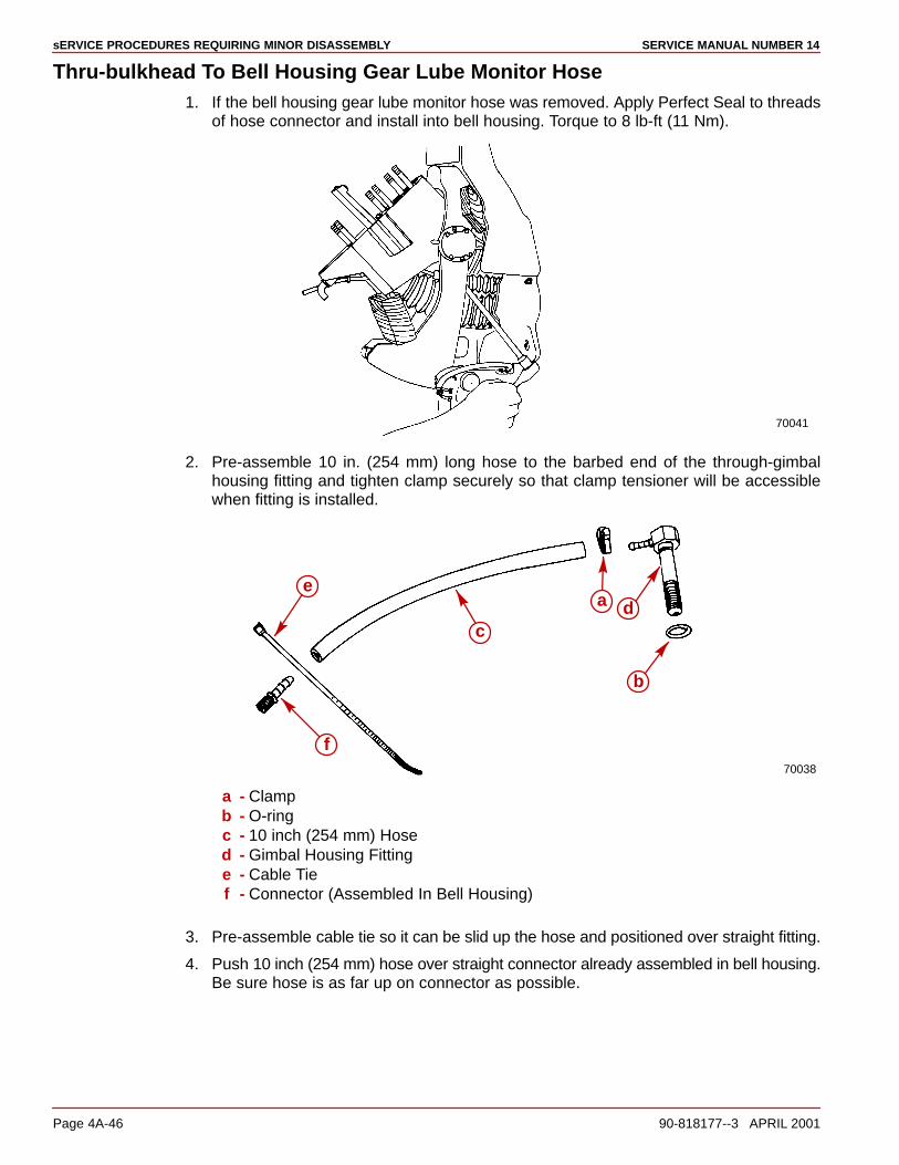
sERVICE PROCEDURES REQUIRING MINOR DISASSEMBLY SERVICE MANUAL NUMBER 14
Page 4A-46 90-818177--3 APRIL 2001
Thru-bulkhead To Bell Housing Gear Lube Monitor Hose1. If the bell housing gear lube monitor hose was removed. Apply Perfect Seal to threads
of hose connector and install into bell housing. Torque to 8 lb-ft (11 Nm).
70041
2. Pre-assemble 10 in. (254 mm) long hose to the barbed end of the through-gimbalhousing fitting and tighten clamp securely so that clamp tensioner will be accessiblewhen fitting is installed.
70038
b
c
a de
f
a - Clampb - O-ringc - 10 inch (254 mm) Hosed - Gimbal Housing Fittinge - Cable Tief - Connector (Assembled In Bell Housing)
3. Pre-assemble cable tie so it can be slid up the hose and positioned over straight fitting.
4. Push 10 inch (254 mm) hose over straight connector already assembled in bell housing.Be sure hose is as far up on connector as possible.
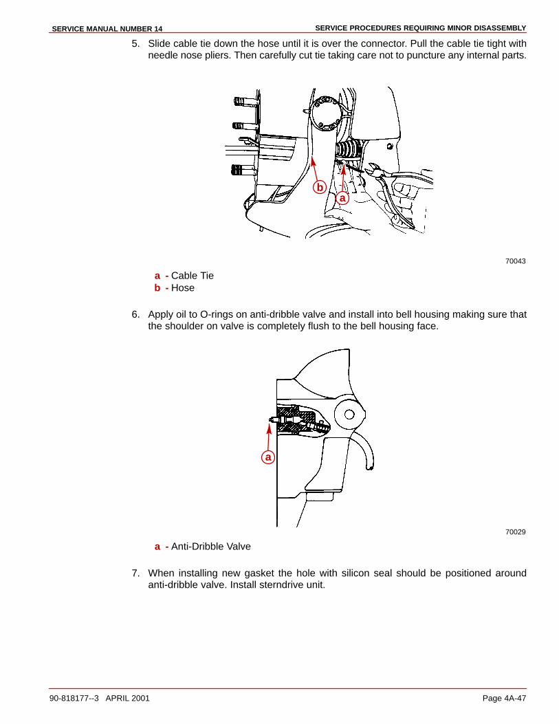
SERVICE PROCEDURES REQUIRING MINOR DISASSEMBLYSERVICE MANUAL NUMBER 14
90-818177--3 APRIL 2001 Page 4A-47
5. Slide cable tie down the hose until it is over the connector. Pull the cable tie tight withneedle nose pliers. Then carefully cut tie taking care not to puncture any internal parts.
70043
ba
a - Cable Tieb - Hose
6. Apply oil to O-rings on anti-dribble valve and install into bell housing making sure thatthe shoulder on valve is completely flush to the bell housing face.
70029
a
a - Anti-Dribble Valve
7. When installing new gasket the hole with silicon seal should be positioned aroundanti-dribble valve. Install sterndrive unit.
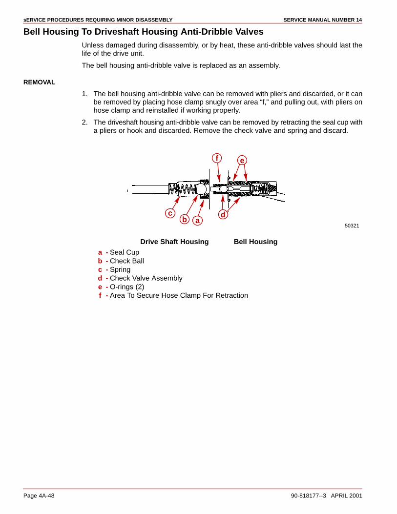
sERVICE PROCEDURES REQUIRING MINOR DISASSEMBLY SERVICE MANUAL NUMBER 14
Page 4A-48 90-818177--3 APRIL 2001
Bell Housing To Driveshaft Housing Anti-Dribble ValvesUnless damaged during disassembly, or by heat, these anti-dribble valves should last thelife of the drive unit.
The bell housing anti-dribble valve is replaced as an assembly.
REMOVAL
1. The bell housing anti-dribble valve can be removed with pliers and discarded, or it canbe removed by placing hose clamp snugly over area “f,” and pulling out, with pliers onhose clamp and reinstalled if working properly.
2. The driveshaft housing anti-dribble valve can be removed by retracting the seal cup witha pliers or hook and discarded. Remove the check valve and spring and discard.
50321b
d
ef
ac
Drive Shaft Housing Bell Housinga - Seal Cupb - Check Ballc - Springd - Check Valve Assemblye - O-rings (2)f - Area To Secure Hose Clamp For Retraction
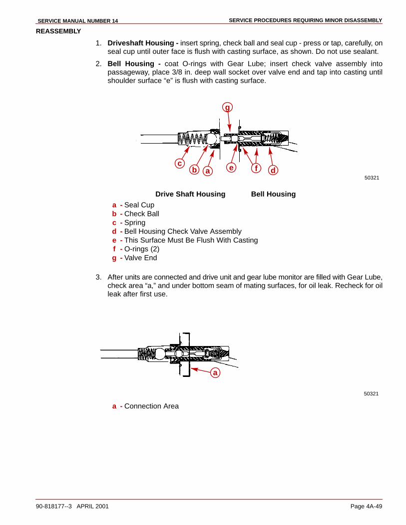
SERVICE PROCEDURES REQUIRING MINOR DISASSEMBLYSERVICE MANUAL NUMBER 14
90-818177--3 APRIL 2001 Page 4A-49
REASSEMBLY
1. Driveshaft Housing - insert spring, check ball and seal cup - press or tap, carefully, onseal cup until outer face is flush with casting surface, as shown. Do not use sealant.
2. Bell Housing - coat O-rings with Gear Lube; insert check valve assembly intopassageway, place 3/8 in. deep wall socket over valve end and tap into casting untilshoulder surface “e” is flush with casting surface.
50321b d
g
ac e f
Drive Shaft Housing Bell Housinga - Seal Cupb - Check Ballc - Springd - Bell Housing Check Valve Assemblye - This Surface Must Be Flush With Castingf - O-rings (2)g - Valve End
3. After units are connected and drive unit and gear lube monitor are filled with Gear Lube,check area “a,” and under bottom seam of mating surfaces, for oil leak. Recheck for oilleak after first use.
50321
a
a - Connection Area
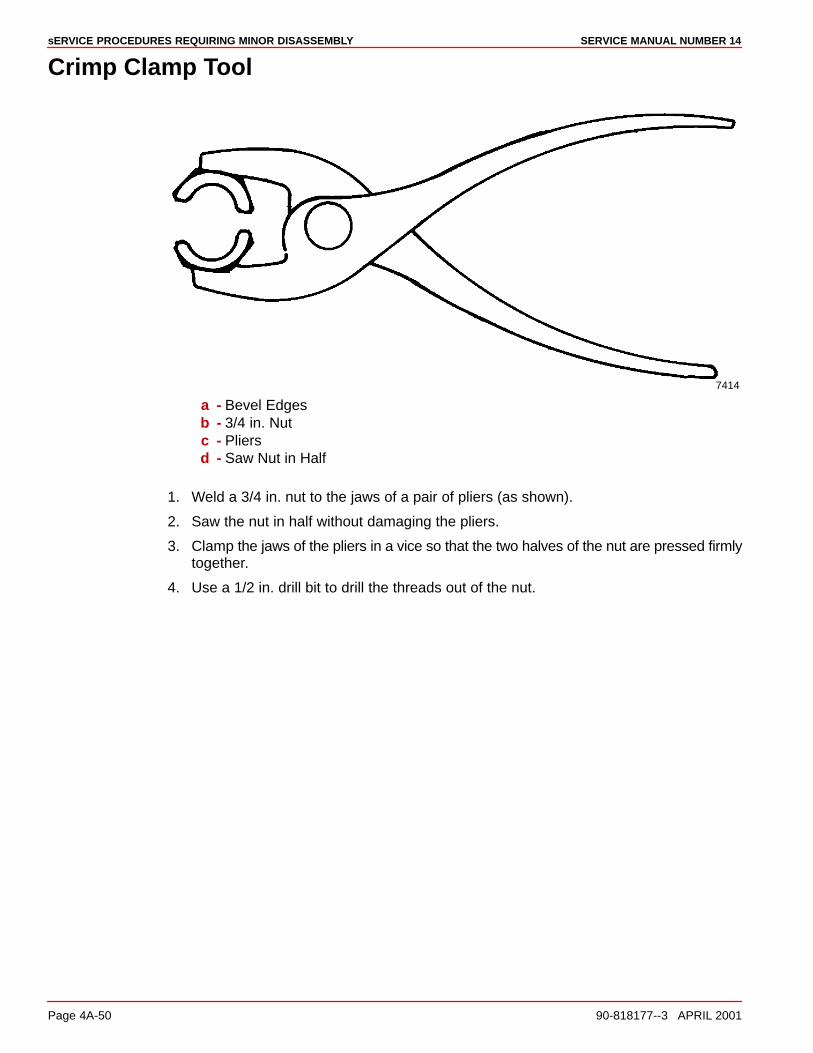
sERVICE PROCEDURES REQUIRING MINOR DISASSEMBLY SERVICE MANUAL NUMBER 14
Page 4A-50 90-818177--3 APRIL 2001
Crimp Clamp Tool
7414
a - Bevel Edgesb - 3/4 in. Nutc - Pliersd - Saw Nut in Half
1. Weld a 3/4 in. nut to the jaws of a pair of pliers (as shown).
2. Saw the nut in half without damaging the pliers.
3. Clamp the jaws of the pliers in a vice so that the two halves of the nut are pressed firmlytogether.
4. Use a 1/2 in. drill bit to drill the threads out of the nut.

SERVICE PROCEDURES REQUIRING MINOR DISASSEMBLYSERVICE MANUAL NUMBER 14
90-818177--3 APRIL 2001 Page 4A-51
THIS PAGE IS INTENTIONALLY BLANK

sERVICE PROCEDURES REQUIRING MINOR DISASSEMBLY SERVICE MANUAL NUMBER 14
Page 4A-52 90-818177--3 APRIL 2001
THIS PAGE IS INTENTIONALLY BLANK
4B
SERVICE PROCEDURES REQUIRING MAJOR DISASSEMBLYSERVICE MANUAL NUMBER 14
90-818177--3 APRIL 2001 Page 4B-1
TRANSOM ASSEMBLYSection 4B - Service Procedures Requiring Major Disassembly
Table of Contents
Transom Assembly Specifications 4B-2. . . . . Torque Specifications 4B-2. . . . . . . . . . . . . Special Tools 4B-2. . . . . . . . . . . . . . . . . . . . . Lubricants / Sealers / Adhesives 4B-3. . . .
Special Information 4B-4. . . . . . . . . . . . . . . . . . Trim Limit Switch 4B-4. . . . . . . . . . . . . . . . . Trim Position Sender 4B-4. . . . . . . . . . . . . . Shift Cable 4B-4. . . . . . . . . . . . . . . . . . . . . . . Gear Lube Monitor Kit Access Plug Locations 4B-5. . . . . . . . . . . . . . . . . . .
Alpha One Transom Assembly Exploded View 4B-7. . . . . . . . . . . . . . . . . . . . .
Bell Housing Components 4B-7. . . . . . . . . Gimbal Housing Components 4B-9. . . . . . Inner Transom Plate Components 4B-11. . Gimbal Ring and Steering Lever Components 4B-13. . . . . . . . . . . . . . . . . . . . .
Component Disassembly 4B-15. . . . . . . . . . . . . Bell Housing Removal 4B-15. . . . . . . . . . . . . Trim Position Sender and Trim Limit Switch Wire Removal 4B-21. . . . . . . . Gimbal Ring, Swivel Shaft and Steering Lever Removal 4B-21. . . . . . . . . .
Gimbal Housing Servicing 4B-28. . . . . . . . . . . . U-Joint Bellows Removal 4B-28. . . . . . . . . .
Shift Cable Bellows Removal 4B-29. . . . . . . Bushings And Upper Seal Removal 4B-30.
Component Servicing 4B-32. . . . . . . . . . . . . . . . Bell Housing Disassembly 4B-32. . . . . . . . . Bell Housing Reassembly 4B-37. . . . . . . . . . Gasket And O-Ring 4B-41. . . . . . . . . . . . . . . Speedometer Tubing And Water Hose 4B-42. . . . . . . . . . . . . . . . . . . . . . . . . . .
Reassembly 4B-45. . . . . . . . . . . . . . . . . . . . . . . . Gimbal Ring Bushing Installation 4B-45. . . . Oil Seal Installation 4B-47. . . . . . . . . . . . . . . Exhaust Bellows Installation 4B-49. . . . . . . . Trim Position Sender and Trim Limit Switch Wire Installation 4B-50. . . . . . . . . . . Gimbal Ring, Swivel Shaft and Steering Lever Installation 4B-51. . . . . . . . . Shift Cable Bellows Installation 4B-59. . . . . Bell Housing Installation 4B-61. . . . . . . . . . . Trim Limit Switch Installation 4B-69. . . . . . . Trim Position Sender Installation 4B-70. . . . ALPHA ONE (GENERATION II) ACCESS PLUG 4B-71. . . . . . . . . . . . . . . . . . – DRILLING TEMPLATE – 4B-71. . . . . . . . .
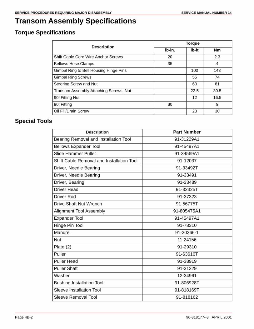
SERVICE PROCEDURES REQUIRING MAJOR DISASSEMBLY SERVICE MANUAL NUMBER 14
Page 4B-2 90-818177--3 APRIL 2001
Transom Assembly SpecificationsTorque Specifications
TorqueDescription
lb-in. lb-ft Nm
Shift Cable Core Wire Anchor Screws 20 2.3
Bellows Hose Clamps 35 4
Gimbal Ring to Bell Housing Hinge Pins 100 143
Gimbal Ring Screws 55 74
Steering Screw and Nut 60 81
Transom Assembly Attaching Screws, Nut 22.5 30.5
90�Fitting Nut 12 16.5
90�Fitting 80 9
Oil Fill/Drain Screw 23 30
Special Tools
Description Part Number
Bearing Removal and Installation Tool 91-31229A1
Bellows Expander Tool 91-45497A1
Slide Hammer Puller 91-34569A1
Shift Cable Removal and Installation Tool 91-12037
Driver, Needle Bearing 91-33492T
Driver, Needle Bearing 91-33491
Driver, Bearing 91-33489
Driver Head 91-32325T
Driver Rod 91-37323
Drive Shaft Nut Wrench 91-56775T
Alignment Tool Assembly 91-805475A1
Expander Tool 91-45497A1
Hinge Pin Tool 91-78310
Mandrel 91-30366-1
Nut 11-24156
Plate (2) 91-29310
Puller 91-63616T
Puller Head 91-38919
Puller Shaft 91-31229
Washer 12-34961
Bushing Installation Tool 91-806928T
Sleeve Installation Tool 91-818169T
Sleeve Removal Tool 91-818162

SERVICE PROCEDURES REQUIRING MAJOR DISASSEMBLYSERVICE MANUAL NUMBER 14
90-818177--3 APRIL 2001 Page 4B-3
Lubricants / Sealers / Adhesives
Description Part Number
3M Brand Adhesive 92-86166Q1
Quicksilver 2-4-C Marine Lubricant WithTeflon
92-825407A12
Quicksilver U-Joint AndGimbal BearingGrease
92-828052A2
Perfect Seal 92-34227-1
Anti-Corrosion Grease 92-78376A6
Locquic Primer “T” 92-809824
Loctite 27131 92-809820
Quicksilver Special Lubricant 101 92-13872A1

SERVICE PROCEDURES REQUIRING MAJOR DISASSEMBLY SERVICE MANUAL NUMBER 14
Page 4B-4 90-818177--3 APRIL 2001
Special Information
Trim Limit SwitchThe trim limit switch has a sealing system for improved water resistance and durability. Thetrim limit switch leads are connected internally to help ensure good electrical integrity.
71415
Trim Limit Switch - Port
Trim Position SenderThe trim position sender has a sealing system for improved water resistance and durability.The trim limit leads are connected internally to help ensure good electrical integrity.
71414
Trim Position Sender - Starboard
Shift CableA Drive Unit Shift Cable Removal and Installation Tool 91-12037 is required for cable remov-al and installation.
23156
a
a - Shift Cable Retaining Nut
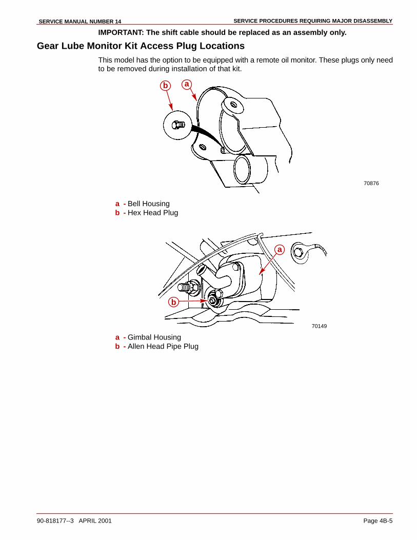
SERVICE PROCEDURES REQUIRING MAJOR DISASSEMBLYSERVICE MANUAL NUMBER 14
90-818177--3 APRIL 2001 Page 4B-5
IMPORTANT: The shift cable should be replaced as an assembly only.
Gear Lube Monitor Kit Access Plug LocationsThis model has the option to be equipped with a remote oil monitor. These plugs only needto be removed during installation of that kit.
70876
ab
a - Bell Housingb - Hex Head Plug
70149
a
b
a - Gimbal Housingb - Allen Head Pipe Plug
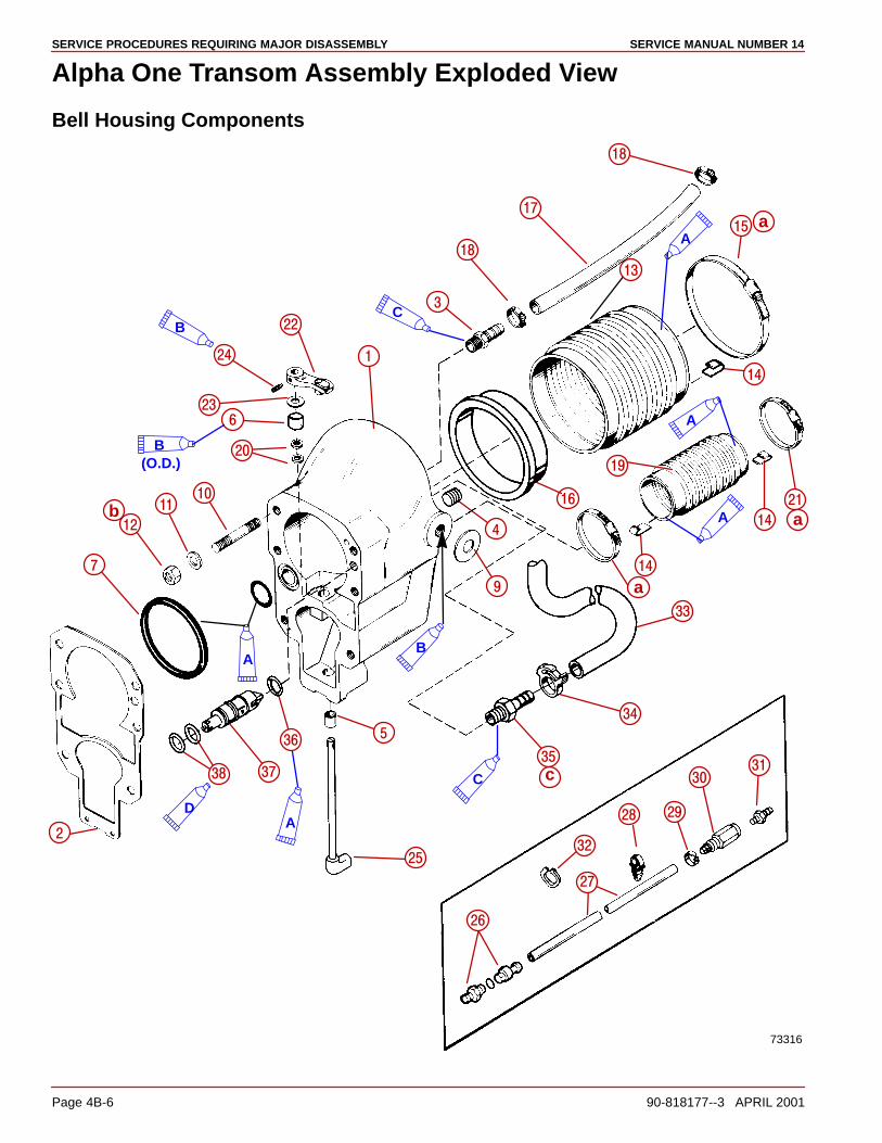
SERVICE PROCEDURES REQUIRING MAJOR DISASSEMBLY SERVICE MANUAL NUMBER 14
Page 4B-6 90-818177--3 APRIL 2001
Alpha One Transom Assembly Exploded View
Bell Housing Components
A
�
��
A
A
73316
��
��
�
��
��
��
��
��
��
�
A
��
��
��
��
�
��
��
��
�
��
�
��
��
����
���
��
��
�
�
��
B
A
��
�
C
CB
B(O.D.)
D
�
ab
c
a
��
a
SERVICE PROCEDURES REQUIRING MAJOR DISASSEMBLYSERVICE MANUAL NUMBER 14
90-818177--3 APRIL 2001 Page 4B-7
1 - Bell Housing Assembly2 - Gasket3 - Connector4 - Pipe Plug5 - Bushing6 - Bushing7 - Gasket (Rubber)8 - O-Ring9 - Washer (Synthane)
10 - Stud11 - Washer12 - Nut13 - Universal Joint Bellows14 - Ground Clip15 - Clamp16 - Sleeve17 - Hose18 - Clamp19 - Exhaust Bellows
20 - Seals21 - Clamp22 - Lever Assembly23 - Washer24 - Screw25 - Shift Shaft (Upper)26 - Coupling Assembly27 - Tubing28 - Clip29 - Clamp30 - Fitting Assembly31 - Connector32 - Clamp33 - Hose34 - Clamp35 - Connector36 - O-Ring37 - Valve Assembly38 - O-rIng
Lubricants/Sealers/Adhesives
A - 3M Brand Adhesive
B - Loctite 27131
C - Quicksilver Perfect Seal
D - Quicksilver High Performance Gear Lube
Torque Specificationsa - Tighten Securely Approximately 35 lb-in. (4 Nm)b - 50 lb-ft (68 Nm)c - 8 lb-ft (11 Nm)

SERVICE PROCEDURES REQUIRING MAJOR DISASSEMBLY SERVICE MANUAL NUMBER 14
Page 4B-8 90-818177--3 APRIL 2001
Gimbal Housing Components
��
��
��
��
�
�
74861
��
��
A
��
�
��
B
C
D
�
��
����
��
��
��
��
�
��
��
�
��
��
��
�
�
��
��
��
��
��
��
�
���
�
�
��
�
��
��
��
a
� c
b
d

SERVICE PROCEDURES REQUIRING MAJOR DISASSEMBLYSERVICE MANUAL NUMBER 14
90-818177--3 APRIL 2001 Page 4B-9
1 - Gimbal Housing2 - Stud3 - Lower Bushing4 - Oil Seal5 - Upper Bushing6 - Grease Fitting7 - Lubricap8 - Grease Seal9 - Bearing Assembly
10 - Tolerance Ring11 - O-Ring12 - Stud13 - Seal14 - Pipe Plug15 - Water Tube16 - Bushing17 - Cover18 - Screw19 - Lower Swivel Pin20 - Cotter PIn21 - Washer22 - Bolt23 - Washer24 - Washer25 - Nut
26 - Bellows27 - Clamp28 - Clamp29 - Washer30 - Nut31 - Gasket32 - Connector33 - Lock Washer34 - Nut35 - Anodic Plate36 - Seal37 - Gasket38 - Screw39 - Lock Washer40 - Hose41 - Clamp42 - 90� Fitting43 - Nut44 - Washer45 - O-Ring46 - Connector47 - Continuity Wire48 - Continuity Wire Connection49 - Hose Clamp
Lubricants/Sealers/Adhesives
A - 3M Brand Adhesive
B - Quicksilver Perfect Seal
C - Loctite 27131
D - Quicksilver U-Joint And Gimbal Bearing Grease
Torque Specificationsa - 80 lb-in. (9 Nm)b - 12 lb-ft (16.5 Nm)c - Approximately 35 lb-in. (3.96 Nm)d - 25 lb-ft (34 Nm)
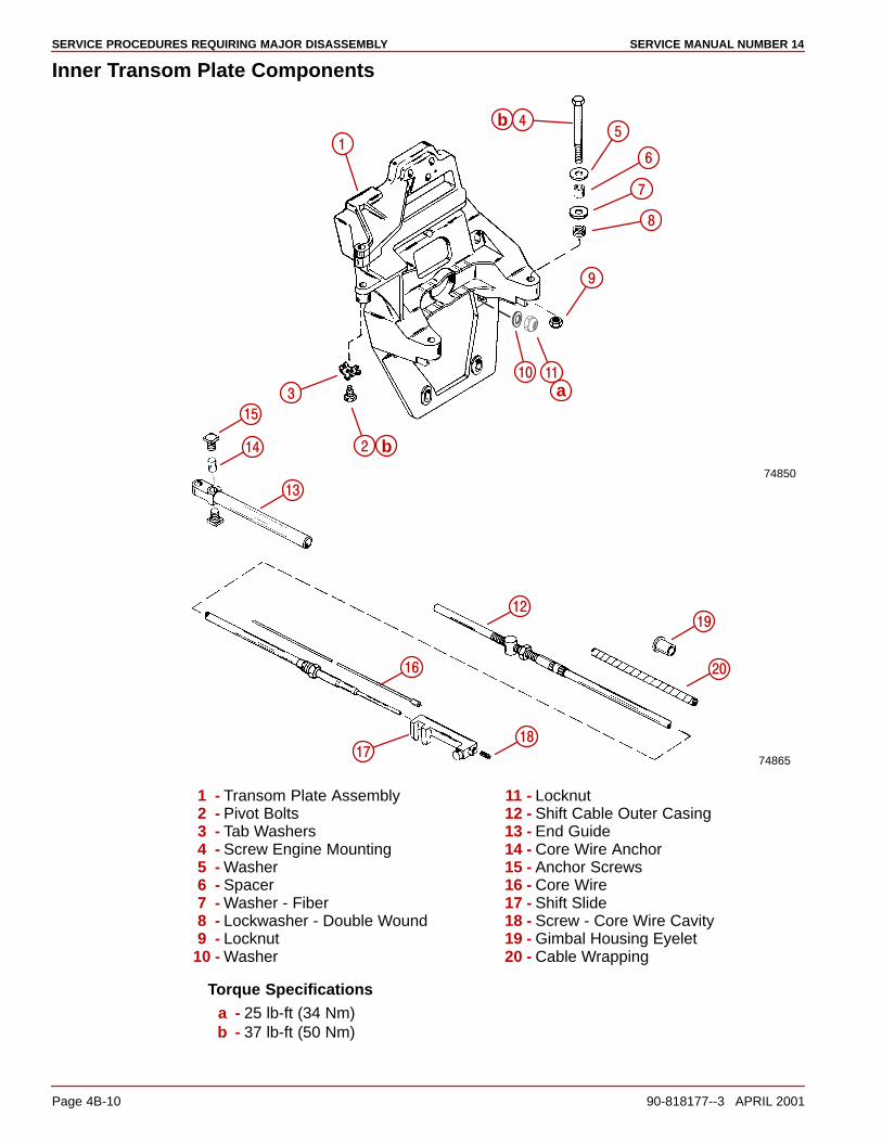
SERVICE PROCEDURES REQUIRING MAJOR DISASSEMBLY SERVICE MANUAL NUMBER 14
Page 4B-10 90-818177--3 APRIL 2001
Inner Transom Plate Components
�
�
�
�
74850
��
a��
�
�
�
74865
��
��
�
��
��
��
��
��
�
a
b
b
1 - Transom Plate Assembly2 - Pivot Bolts3 - Tab Washers4 - Screw Engine Mounting5 - Washer6 - Spacer7 - Washer - Fiber8 - Lockwasher - Double Wound9 - Locknut
10 - Washer
11 - Locknut12 - Shift Cable Outer Casing13 - End Guide14 - Core Wire Anchor15 - Anchor Screws16 - Core Wire17 - Shift Slide18 - Screw - Core Wire Cavity19 - Gimbal Housing Eyelet20 - Cable Wrapping
Torque Specificationsa - 25 lb-ft (34 Nm)b - 37 lb-ft (50 Nm)

SERVICE PROCEDURES REQUIRING MAJOR DISASSEMBLYSERVICE MANUAL NUMBER 14
90-818177--3 APRIL 2001 Page 4B-11
THIS PAGE IS INTENTIONALLY BLANK
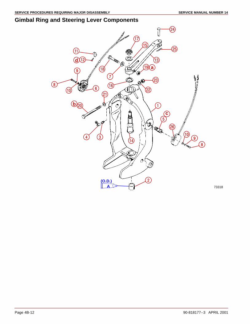
SERVICE PROCEDURES REQUIRING MAJOR DISASSEMBLY SERVICE MANUAL NUMBER 14
Page 4B-12 90-818177--3 APRIL 2001
Gimbal Ring and Steering Lever Components
��
�
��
�
��
��
��
�
�
��
��
�
��
��
�
��
�
��
�
73318
��
A
��
��
��
�
��
a
b
c
d
(O.D.)
SERVICE PROCEDURES REQUIRING MAJOR DISASSEMBLYSERVICE MANUAL NUMBER 14
90-818177--3 APRIL 2001 Page 4B-13
1 - Gimbal Ring2 - Bushing3 - Grease Fitting4 - Lubricap5 - Hinge Pin6 - Trim Limit Switch7 - Washer8 - Screw9 - Lockwasher
10 - Retainer11 - Trim Wire Clamp12 - Screw13 - Steering Lever
14 - Swivel Shaft15 - Washer16 - Washer17 - Nut18 - Screw19 - Nut20 - Screw21 - Washer22 - Washer23 - Locknut24 - Clevis Pin25 - Cotter Pin26 - Trim Position Sender
Lubricants/Sealers/Adhesives
A - Resiweld Sealer
Torque Specificationsc - 60 lb-ft (81 Nm)d - 55 lb-ft (74 Nm)e - 110 lb-ft (148 Nm)f - 95 lb-in. (10.5 Nm)

SERVICE PROCEDURES REQUIRING MAJOR DISASSEMBLY SERVICE MANUAL NUMBER 14
Page 4B-14 90-818177--3 APRIL 2001
THIS PAGE IS INTENTIONALLY BLANK
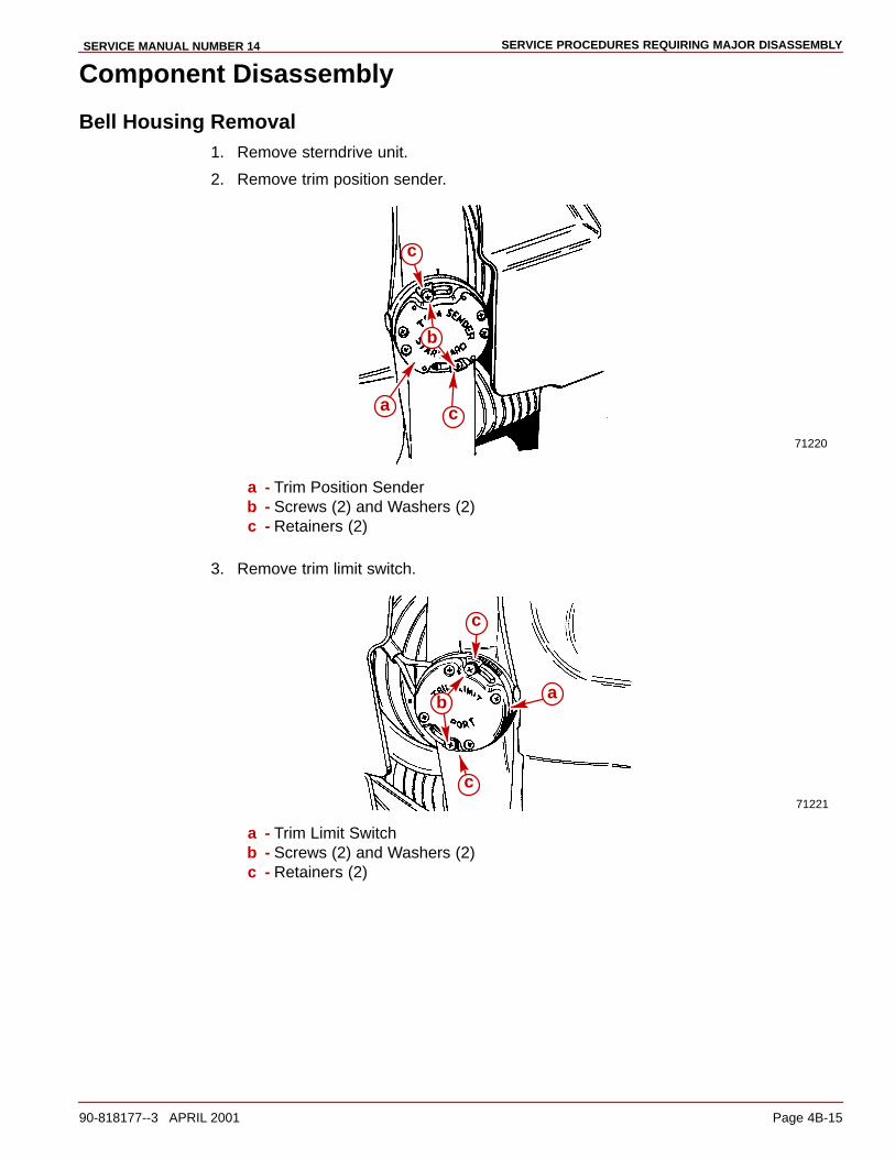
SERVICE PROCEDURES REQUIRING MAJOR DISASSEMBLYSERVICE MANUAL NUMBER 14
90-818177--3 APRIL 2001 Page 4B-15
Component Disassembly
Bell Housing Removal1. Remove sterndrive unit.
2. Remove trim position sender.
71220
a
c
c
b
a - Trim Position Senderb - Screws (2) and Washers (2)c - Retainers (2)
3. Remove trim limit switch.
71221
b
c
c
a
a - Trim Limit Switchb - Screws (2) and Washers (2)c - Retainers (2)

SERVICE PROCEDURES REQUIRING MAJOR DISASSEMBLY SERVICE MANUAL NUMBER 14
Page 4B-16 90-818177--3 APRIL 2001
4. Disconnect shift cable from shift plate and remove cable end guide (b) by loosening an-chor screws (a).
22183
a
b
a
a - Anchor Screws (2)b - End Guide
5. Remove threaded tube (b) by loosening locking nut (a).
22183
ab
a - Jam Nutb - Threaded Tube
6. Remove lock wire and set screw from shift slide.
70139
a
b
c
a - Set Screwb - Shift Slidec - Safety Wire
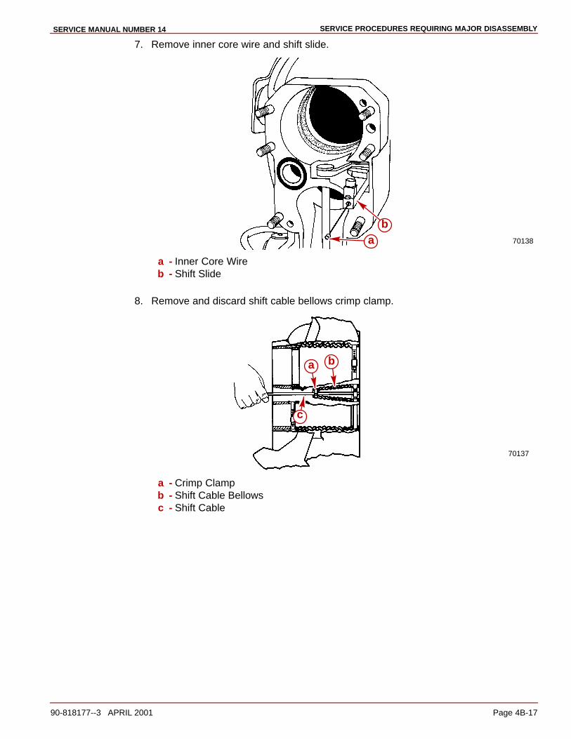
SERVICE PROCEDURES REQUIRING MAJOR DISASSEMBLYSERVICE MANUAL NUMBER 14
90-818177--3 APRIL 2001 Page 4B-17
7. Remove inner core wire and shift slide.
70138ab
a - Inner Core Wireb - Shift Slide
8. Remove and discard shift cable bellows crimp clamp.
70137
a b
c
a - Crimp Clampb - Shift Cable Bellowsc - Shift Cable
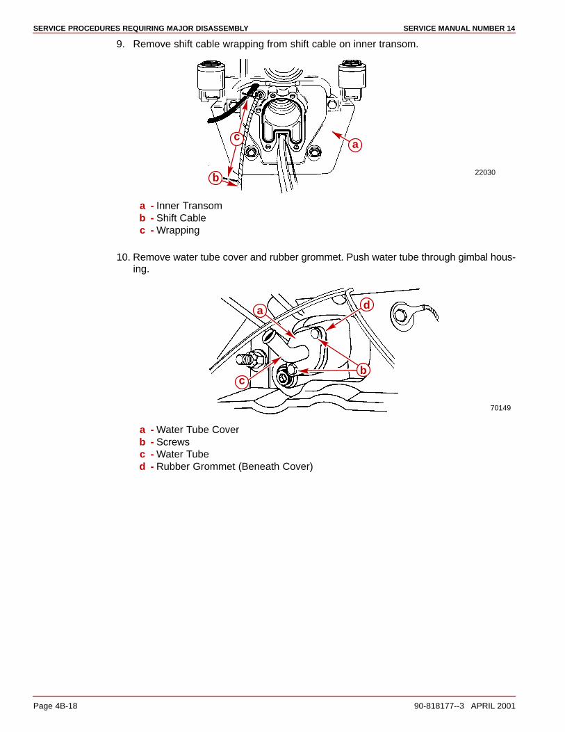
SERVICE PROCEDURES REQUIRING MAJOR DISASSEMBLY SERVICE MANUAL NUMBER 14
Page 4B-18 90-818177--3 APRIL 2001
9. Remove shift cable wrapping from shift cable on inner transom.
22030
a
b
c
a - Inner Transomb - Shift Cablec - Wrapping
10. Remove water tube cover and rubber grommet. Push water tube through gimbal hous-ing.
70149
a
c
d
b
a - Water Tube Coverb - Screwsc - Water Tubed - Rubber Grommet (Beneath Cover)
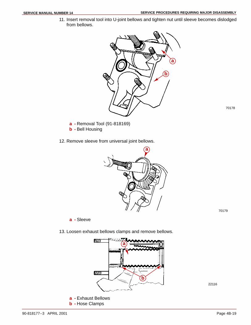
SERVICE PROCEDURES REQUIRING MAJOR DISASSEMBLYSERVICE MANUAL NUMBER 14
90-818177--3 APRIL 2001 Page 4B-19
11. Insert removal tool into U-joint bellows and tighten nut until sleeve becomes dislodgedfrom bellows.
70178
a
b
a - Removal Tool (91-818169)b - Bell Housing
12. Remove sleeve from universal joint bellows.
70179
a
a - Sleeve
13. Loosen exhaust bellows clamps and remove bellows.
22116
a
b
a - Exhaust Bellowsb - Hose Clamps
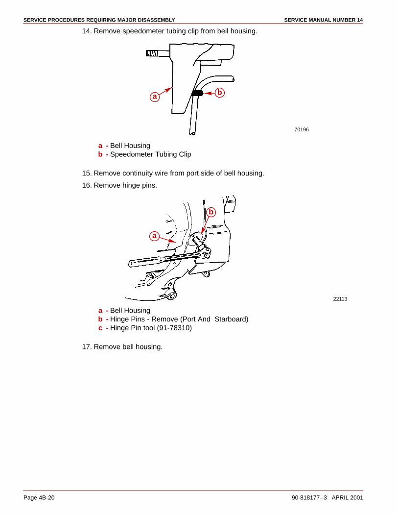
SERVICE PROCEDURES REQUIRING MAJOR DISASSEMBLY SERVICE MANUAL NUMBER 14
Page 4B-20 90-818177--3 APRIL 2001
14. Remove speedometer tubing clip from bell housing.
70196
a b
a - Bell Housingb - Speedometer Tubing Clip
15. Remove continuity wire from port side of bell housing.
16. Remove hinge pins.
22113
a
b
a - Bell Housingb - Hinge Pins - Remove (Port And Starboard)c - Hinge Pin tool (91-78310)
17. Remove bell housing.
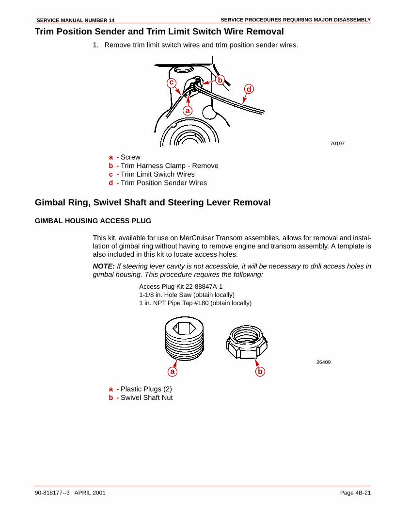
SERVICE PROCEDURES REQUIRING MAJOR DISASSEMBLYSERVICE MANUAL NUMBER 14
90-818177--3 APRIL 2001 Page 4B-21
Trim Position Sender and Trim Limit Switch Wire Removal1. Remove trim limit switch wires and trim position sender wires.
70197
a
bcd
a - Screwb - Trim Harness Clamp - Removec - Trim Limit Switch Wiresd - Trim Position Sender Wires
Gimbal Ring, Swivel Shaft and Steering Lever Removal
GIMBAL HOUSING ACCESS PLUG
This kit, available for use on MerCruiser Transom assemblies, allows for removal and instal-lation of gimbal ring without having to remove engine and transom assembly. A template isalso included in this kit to locate access holes.
NOTE: If steering lever cavity is not accessible, it will be necessary to drill access holes ingimbal housing. This procedure requires the following:
Access Plug Kit 22-88847A-11-1/8 in. Hole Saw (obtain locally)1 in. NPT Pipe Tap #180 (obtain locally)
26409
a b
a - Plastic Plugs (2)b - Swivel Shaft Nut
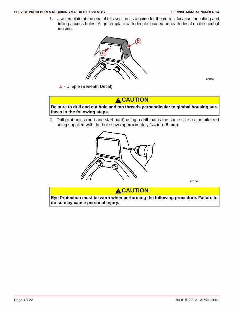
SERVICE PROCEDURES REQUIRING MAJOR DISASSEMBLY SERVICE MANUAL NUMBER 14
Page 4B-22 90-818177--3 APRIL 2001
1. Use template at the end of this section as a guide for the correct location for cutting anddrilling access holes. Align template with dimple located beneath decal on the gimbalhousing.
70862
a
b
a - Dimple (Beneath Decal)
CAUTIONBe sure to drill and cut hole and tap threads perpendicular to gimbal housing sur-faces in the following steps.
2. Drill pilot holes (port and starboard) using a drill that is the same size as the pilot rodbeing supplied with the hole saw (approximately 1/4 in.) (6 mm).
70152
CAUTIONEye Protection must be worn when performing the following procedure. Failure todo so may cause personal injury.

SERVICE PROCEDURES REQUIRING MAJOR DISASSEMBLYSERVICE MANUAL NUMBER 14
90-818177--3 APRIL 2001 Page 4B-23
3. Cut holes in gimbal housing (port and starboard) using 1-1/8 in. hole saw and pilot rod.Remove metal chips with compressed air.
70153 22652
a
a - Drill Pilot Hole
REMOVAL
1. Loosen screws and nuts (not necessary to remove).
70150
c
d
a
b
a - Screws (2)b - Nuts (2)c - Washers (4)d - Gimbal Ring
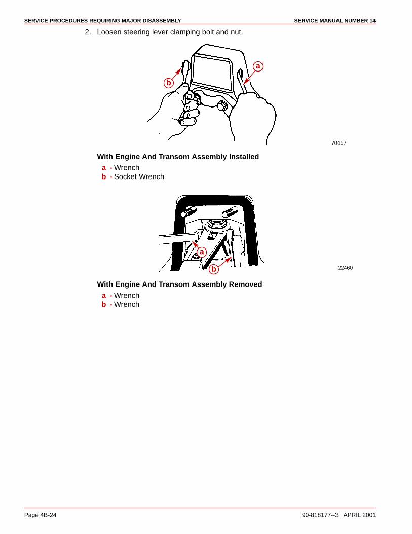
SERVICE PROCEDURES REQUIRING MAJOR DISASSEMBLY SERVICE MANUAL NUMBER 14
Page 4B-24 90-818177--3 APRIL 2001
2. Loosen steering lever clamping bolt and nut.
70157
a
b
With Engine And Transom Assembly Installeda - Wrenchb - Socket Wrench
22460
a
b
With Engine And Transom Assembly Removeda - Wrenchb - Wrench
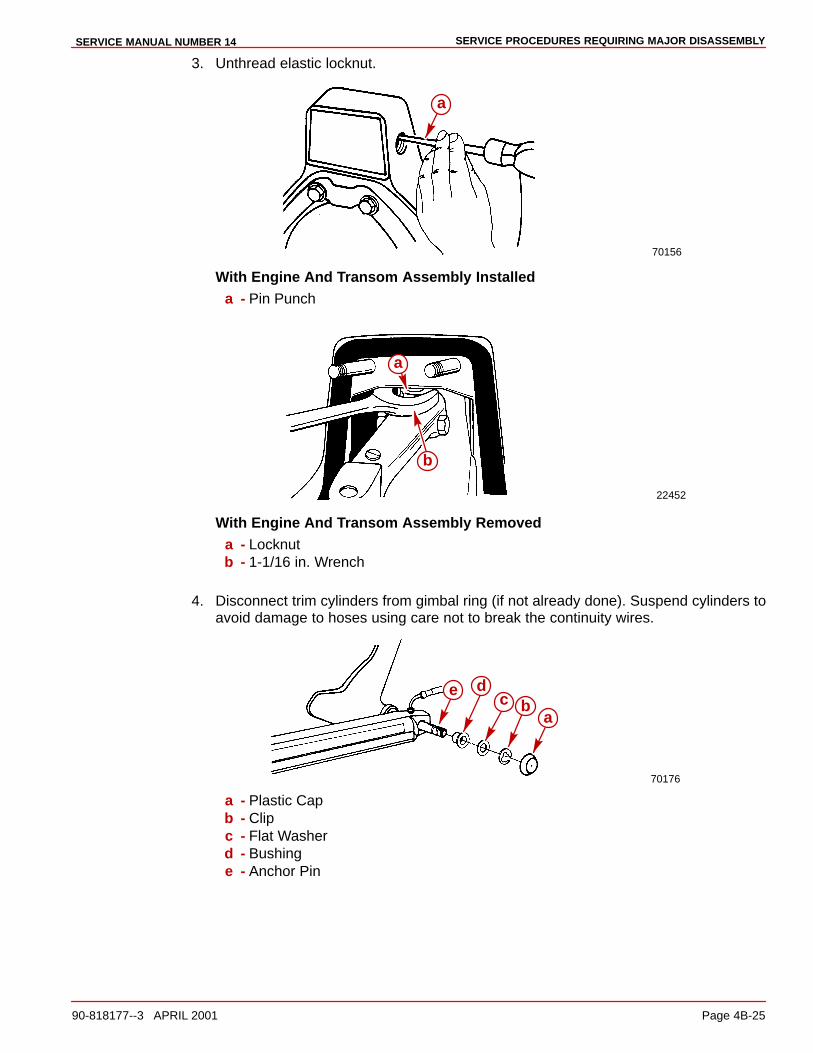
SERVICE PROCEDURES REQUIRING MAJOR DISASSEMBLYSERVICE MANUAL NUMBER 14
90-818177--3 APRIL 2001 Page 4B-25
3. Unthread elastic locknut.
70156
a
With Engine And Transom Assembly Installeda - Pin Punch
22452
a
b
With Engine And Transom Assembly Removeda - Locknutb - 1-1/16 in. Wrench
4. Disconnect trim cylinders from gimbal ring (if not already done). Suspend cylinders toavoid damage to hoses using care not to break the continuity wires.
70176
abc
e d
a - Plastic Capb - Clipc - Flat Washerd - Bushinge - Anchor Pin
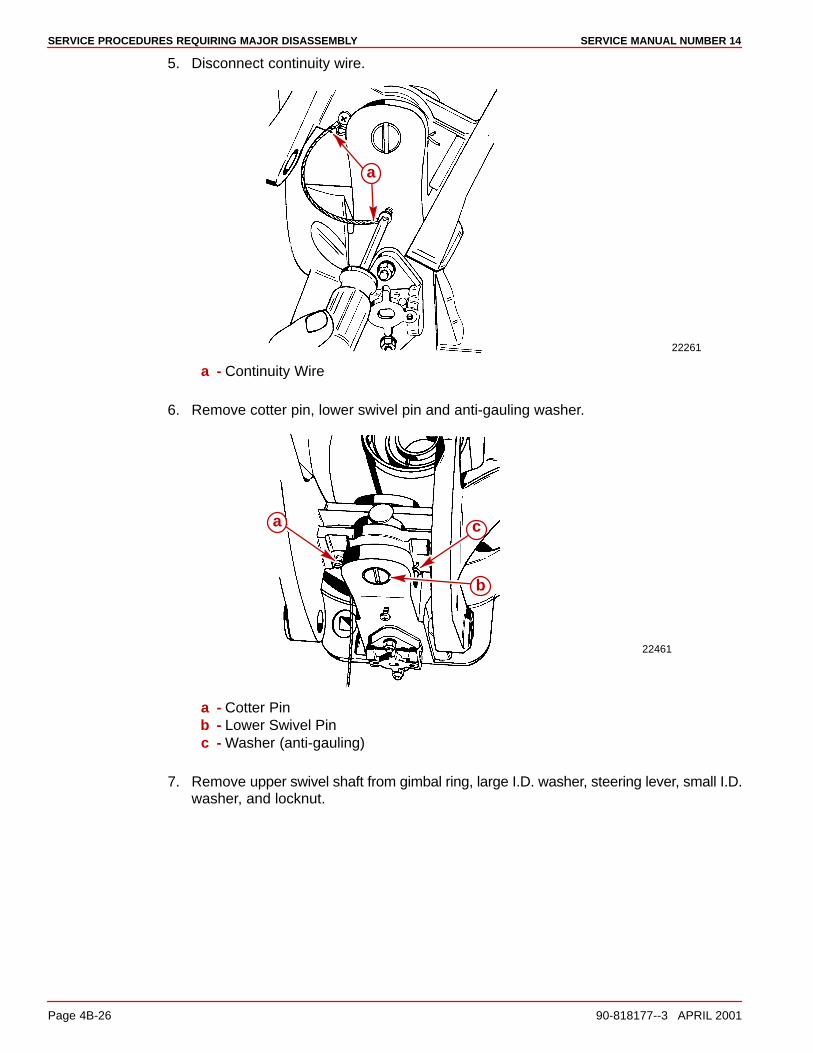
SERVICE PROCEDURES REQUIRING MAJOR DISASSEMBLY SERVICE MANUAL NUMBER 14
Page 4B-26 90-818177--3 APRIL 2001
5. Disconnect continuity wire.
22261
a
a - Continuity Wire
6. Remove cotter pin, lower swivel pin and anti-gauling washer.
22461
a
b
c
a - Cotter Pinb - Lower Swivel Pinc - Washer (anti-gauling)
7. Remove upper swivel shaft from gimbal ring, large I.D. washer, steering lever, small I.D.washer, and locknut.
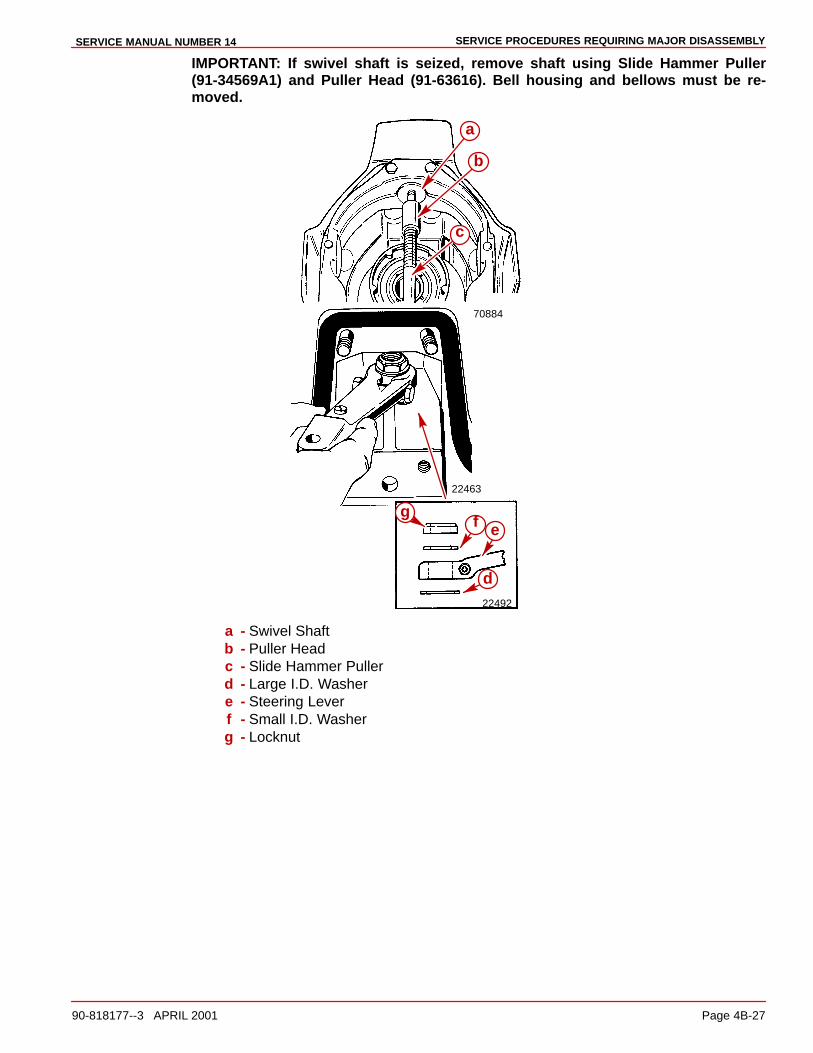
SERVICE PROCEDURES REQUIRING MAJOR DISASSEMBLYSERVICE MANUAL NUMBER 14
90-818177--3 APRIL 2001 Page 4B-27
IMPORTANT: If swivel shaft is seized, remove shaft using Slide Hammer Puller(91-34569A1) and Puller Head (91-63616). Bell housing and bellows must be re-moved.
70884
22463
22492
a
b
c
d
efg
a - Swivel Shaftb - Puller Headc - Slide Hammer Pullerd - Large I.D. Washere - Steering Leverf - Small I.D. Washerg - Locknut
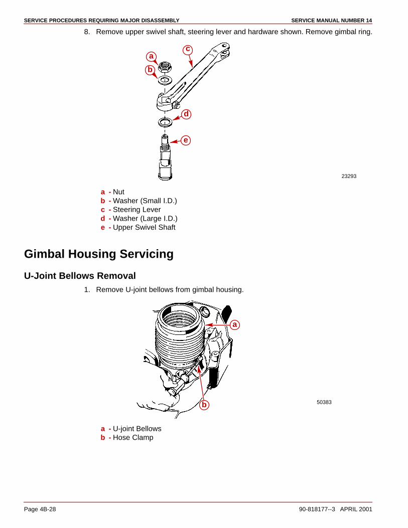
SERVICE PROCEDURES REQUIRING MAJOR DISASSEMBLY SERVICE MANUAL NUMBER 14
Page 4B-28 90-818177--3 APRIL 2001
8. Remove upper swivel shaft, steering lever and hardware shown. Remove gimbal ring.
23293
a
b
c
d
e
a - Nutb - Washer (Small I.D.)c - Steering Leverd - Washer (Large I.D.)e - Upper Swivel Shaft
Gimbal Housing Servicing
U-Joint Bellows Removal1. Remove U-joint bellows from gimbal housing.
50383
a
b
a - U-joint Bellowsb - Hose Clamp

SERVICE PROCEDURES REQUIRING MAJOR DISASSEMBLYSERVICE MANUAL NUMBER 14
90-818177--3 APRIL 2001 Page 4B-29
2. If reusing bellows, remove old adhesive from inside diameter of U-joint bellows end us-ing lacquer thinner, and inspect for possible damage.
50383a
a - Bellows
3. Clean bellows mounting flange on gimbal housing with sandpaper and wipe clean withlacquer thinner.
70184
a
a - Mounting Flange
Shift Cable Bellows Removal1. Loosen hose clamp and remove shift cable bellows.
50542
a
b
a - Shift Cable Bellowsb - Hose Clamp
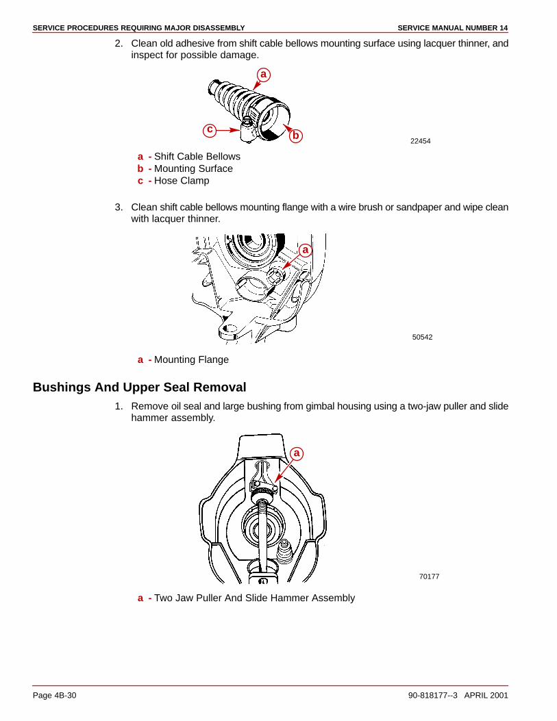
SERVICE PROCEDURES REQUIRING MAJOR DISASSEMBLY SERVICE MANUAL NUMBER 14
Page 4B-30 90-818177--3 APRIL 2001
2. Clean old adhesive from shift cable bellows mounting surface using lacquer thinner, andinspect for possible damage.
22454
a
bc
a - Shift Cable Bellowsb - Mounting Surfacec - Hose Clamp
3. Clean shift cable bellows mounting flange with a wire brush or sandpaper and wipe cleanwith lacquer thinner.
50542
a
a - Mounting Flange
Bushings And Upper Seal Removal1. Remove oil seal and large bushing from gimbal housing using a two-jaw puller and slide
hammer assembly.
70177
a
a - Two Jaw Puller And Slide Hammer Assembly
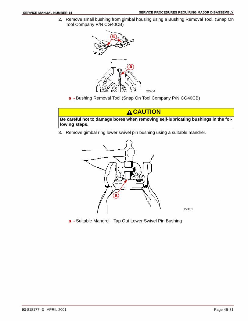
SERVICE PROCEDURES REQUIRING MAJOR DISASSEMBLYSERVICE MANUAL NUMBER 14
90-818177--3 APRIL 2001 Page 4B-31
2. Remove small bushing from gimbal housing using a Bushing Removal Tool. (Snap OnTool Company P/N CG40CB)
22454
22438
a
a
a - Bushing Removal Tool (Snap On Tool Company P/N CG40CB)
CAUTIONBe careful not to damage bores when removing self-lubricating bushings in the fol-lowing steps.
3. Remove gimbal ring lower swivel pin bushing using a suitable mandrel.
22451
a
a - Suitable Mandrel - Tap Out Lower Swivel Pin Bushing
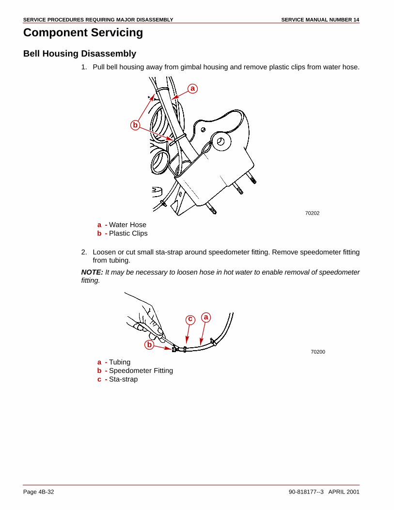
SERVICE PROCEDURES REQUIRING MAJOR DISASSEMBLY SERVICE MANUAL NUMBER 14
Page 4B-32 90-818177--3 APRIL 2001
Component Servicing
Bell Housing Disassembly1. Pull bell housing away from gimbal housing and remove plastic clips from water hose.
70202
a
b
a - Water Hoseb - Plastic Clips
2. Loosen or cut small sta-strap around speedometer fitting. Remove speedometer fittingfrom tubing.
NOTE: It may be necessary to loosen hose in hot water to enable removal of speedometerfitting.
70200
a
b
c
a - Tubingb - Speedometer Fittingc - Sta-strap

SERVICE PROCEDURES REQUIRING MAJOR DISASSEMBLYSERVICE MANUAL NUMBER 14
90-818177--3 APRIL 2001 Page 4B-33
3. Disconnect speedometer hose at transom and remove fitting and hose from unit.
70203
a
b
a - Fittingb - Gimbal Housing
4. Remove clamp and fitting from tubing.
NOTE: It may be necessary to loosen hose in hot water to enable removal of fitting.
70201
ab
c
a - Tubingb - Fittingc - Clamp
5. Remove water inlet hose from bell housing.
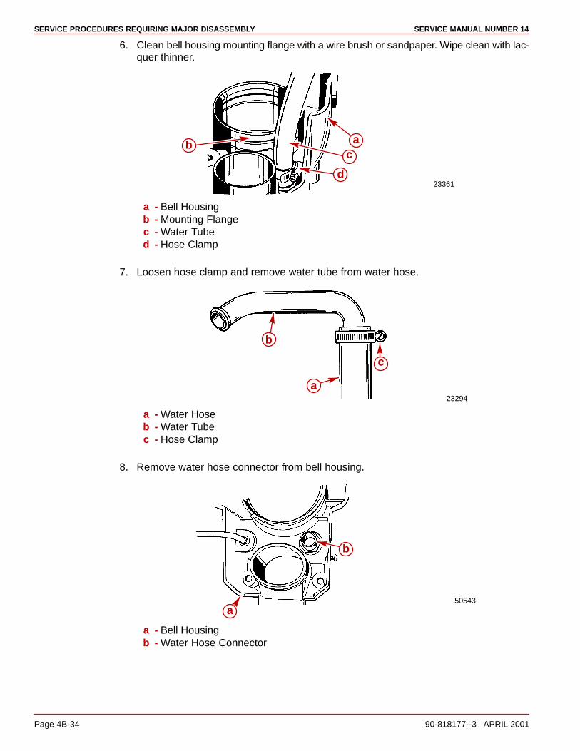
SERVICE PROCEDURES REQUIRING MAJOR DISASSEMBLY SERVICE MANUAL NUMBER 14
Page 4B-34 90-818177--3 APRIL 2001
6. Clean bell housing mounting flange with a wire brush or sandpaper. Wipe clean with lac-quer thinner.
23361
abc
d
a - Bell Housingb - Mounting Flangec - Water Tubed - Hose Clamp
7. Loosen hose clamp and remove water tube from water hose.
23294
a
b
c
a - Water Hoseb - Water Tubec - Hose Clamp
8. Remove water hose connector from bell housing.
50543a
b
a - Bell Housingb - Water Hose Connector
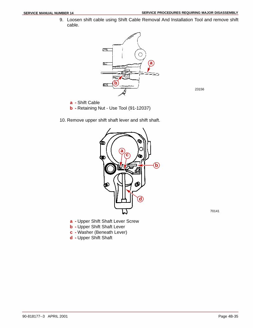
SERVICE PROCEDURES REQUIRING MAJOR DISASSEMBLYSERVICE MANUAL NUMBER 14
90-818177--3 APRIL 2001 Page 4B-35
9. Loosen shift cable using Shift Cable Removal And Installation Tool and remove shiftcable.
23156
a
b
a - Shift Cableb - Retaining Nut - Use Tool (91-12037)
10. Remove upper shift shaft lever and shift shaft.
70141
a
b
c
d
a - Upper Shift Shaft Lever Screwb - Upper Shift Shaft Leverc - Washer (Beneath Lever)d - Upper Shift Shaft
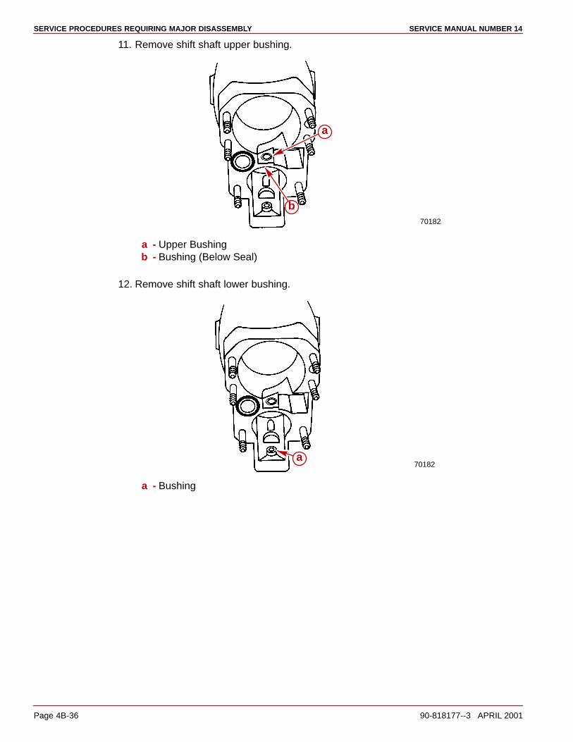
SERVICE PROCEDURES REQUIRING MAJOR DISASSEMBLY SERVICE MANUAL NUMBER 14
Page 4B-36 90-818177--3 APRIL 2001
11. Remove shift shaft upper bushing.
70182
a
b
a - Upper Bushingb - Bushing (Below Seal)
12. Remove shift shaft lower bushing.
70182a
a - Bushing
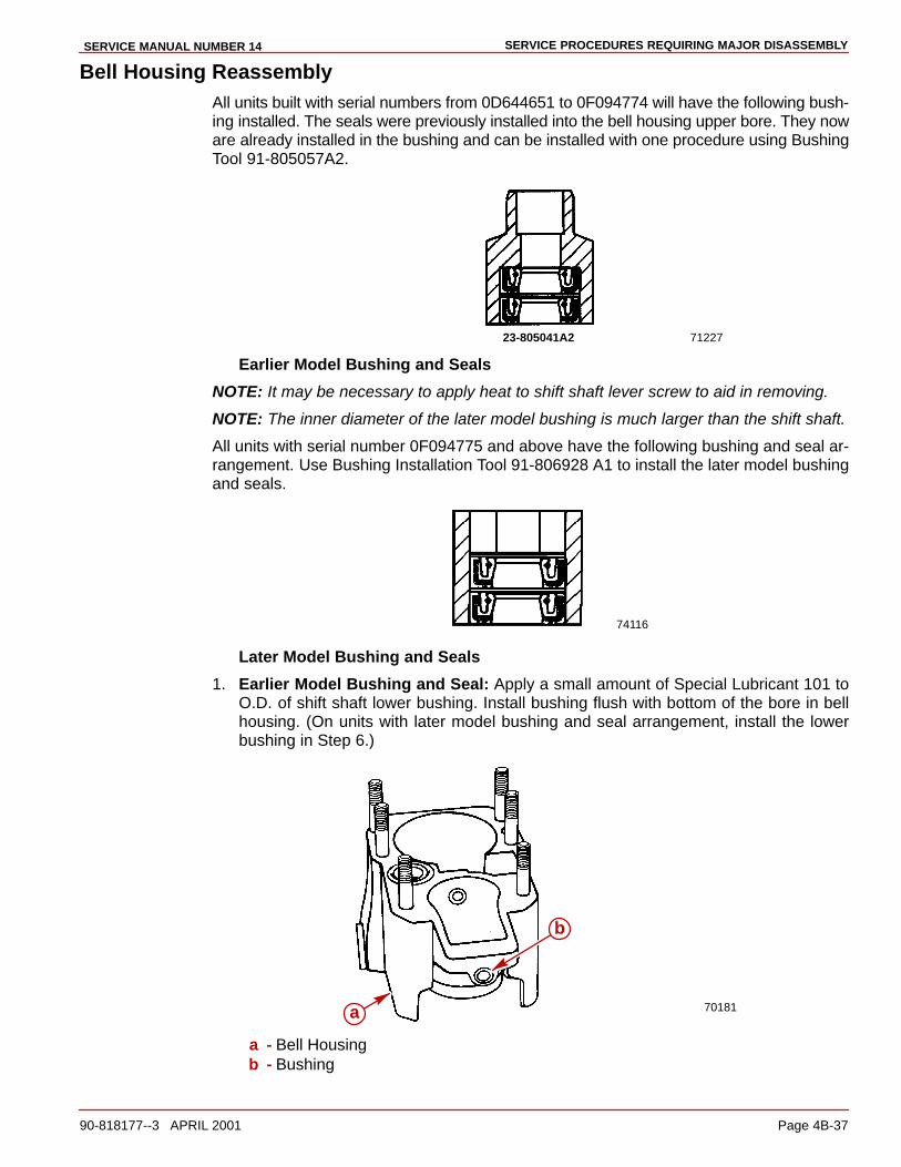
SERVICE PROCEDURES REQUIRING MAJOR DISASSEMBLYSERVICE MANUAL NUMBER 14
90-818177--3 APRIL 2001 Page 4B-37
Bell Housing ReassemblyAll units built with serial numbers from 0D644651 to 0F094774 will have the following bush-ing installed. The seals were previously installed into the bell housing upper bore. They noware already installed in the bushing and can be installed with one procedure using BushingTool 91-805057A2.
7122723-805041A2
Earlier Model Bushing and Seals
NOTE: It may be necessary to apply heat to shift shaft lever screw to aid in removing.
NOTE: The inner diameter of the later model bushing is much larger than the shift shaft.
All units with serial number 0F094775 and above have the following bushing and seal ar-rangement. Use Bushing Installation Tool 91-806928 A1 to install the later model bushingand seals.
74116
Later Model Bushing and Seals
1. Earlier Model Bushing and Seal: Apply a small amount of Special Lubricant 101 toO.D. of shift shaft lower bushing. Install bushing flush with bottom of the bore in bellhousing. (On units with later model bushing and seal arrangement, install the lowerbushing in Step 6.)
70181a
b
a - Bell Housingb - Bushing
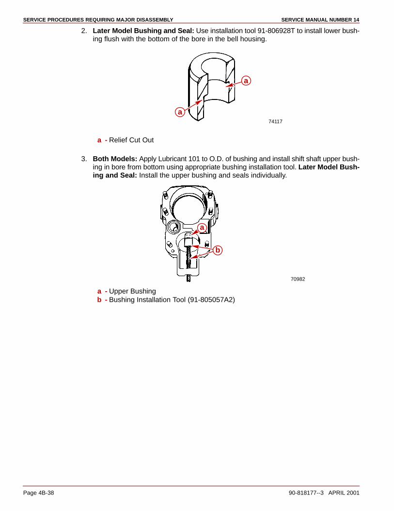
SERVICE PROCEDURES REQUIRING MAJOR DISASSEMBLY SERVICE MANUAL NUMBER 14
Page 4B-38 90-818177--3 APRIL 2001
2. Later Model Bushing and Seal: Use installation tool 91-806928T to install lower bush-ing flush with the bottom of the bore in the bell housing.
74117
a
a
a - Relief Cut Out
3. Both Models: Apply Lubricant 101 to O.D. of bushing and install shift shaft upper bush-ing in bore from bottom using appropriate bushing installation tool. Later Model Bush-ing and Seal: Install the upper bushing and seals individually.
70982
a
b
a - Upper Bushingb - Bushing Installation Tool (91-805057A2)

SERVICE PROCEDURES REQUIRING MAJOR DISASSEMBLYSERVICE MANUAL NUMBER 14
90-818177--3 APRIL 2001 Page 4B-39
4. Install upper shift shaft lever and shift shaft. Apply Loctite 27131 or Type “A” to screwthreads. Tighten securely.
70141
a
b
c
d
a - Upper Shift Shaft Lever Screwb - Upper Shift Shaft Leverc - Washer (Beneath Lever)d - Upper Shift Shaft
5. Apply Perfect Seal to threads of shift cable retainer and install shift cable. Tighten retain-er securely using shift cable removal and installation tool (until no more than two threadsof retainer are showing).
23156
a
b
a - Shift Cableb - Retaining Nut - Use Tool (91-12037)
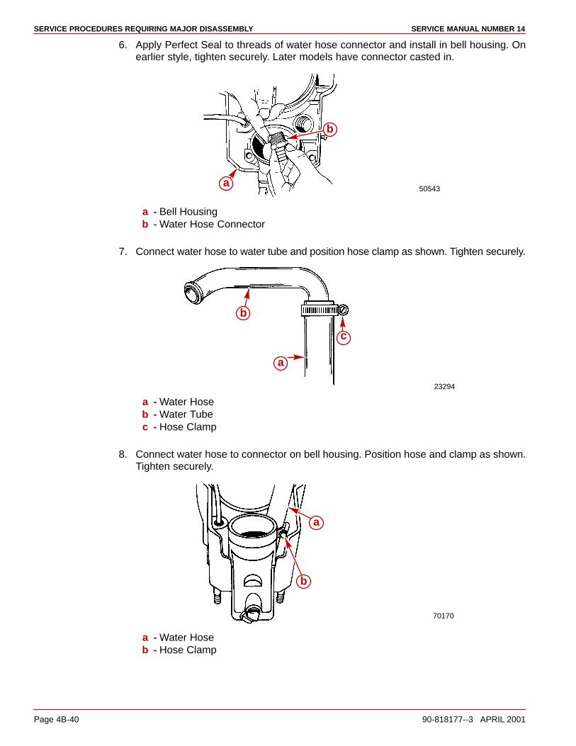
SERVICE PROCEDURES REQUIRING MAJOR DISASSEMBLY SERVICE MANUAL NUMBER 14
Page 4B-40 90-818177--3 APRIL 2001
6. Apply Perfect Seal to threads of water hose connector and install in bell housing. Onearlier style, tighten securely. Later models have connector casted in.
50543a
b
a - Bell Housingb - Water Hose Connector
7. Connect water hose to water tube and position hose clamp as shown. Tighten securely.
23294
a
b
c
a - Water Hoseb - Water Tubec - Hose Clamp
8. Connect water hose to connector on bell housing. Position hose and clamp as shown.Tighten securely.
70170
a
b
a - Water Hoseb - Hose Clamp
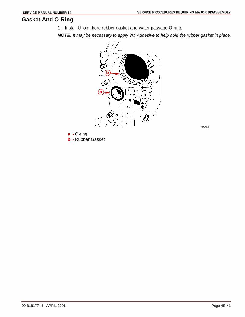
SERVICE PROCEDURES REQUIRING MAJOR DISASSEMBLYSERVICE MANUAL NUMBER 14
90-818177--3 APRIL 2001 Page 4B-41
Gasket And O-Ring1. Install U-joint bore rubber gasket and water passage O-ring.
NOTE: It may be necessary to apply 3M Adhesive to help hold the rubber gasket in place.
70022
a
b
a - O-ringb - Rubber Gasket
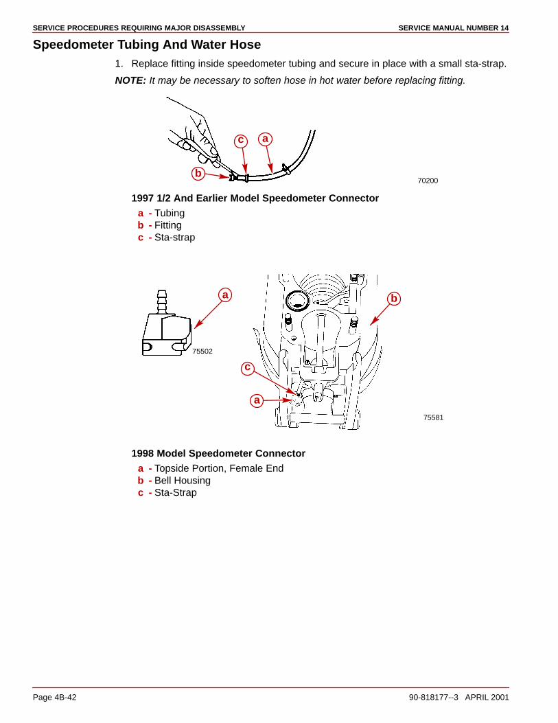
SERVICE PROCEDURES REQUIRING MAJOR DISASSEMBLY SERVICE MANUAL NUMBER 14
Page 4B-42 90-818177--3 APRIL 2001
Speedometer Tubing And Water Hose1. Replace fitting inside speedometer tubing and secure in place with a small sta-strap.
NOTE: It may be necessary to soften hose in hot water before replacing fitting.
70200
a
b
c
1997 1/2 And Earlier Model Speedometer Connectora - Tubingb - Fittingc - Sta-strap
75581
a
b
c
75502
a
1998 Model Speedometer Connectora - Topside Portion, Female Endb - Bell Housingc - Sta-Strap
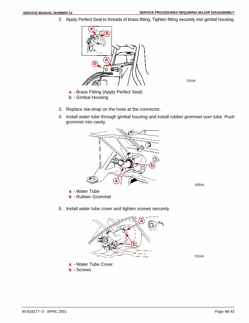
SERVICE PROCEDURES REQUIRING MAJOR DISASSEMBLYSERVICE MANUAL NUMBER 14
90-818177--3 APRIL 2001 Page 4B-43
2. Apply Perfect Seal to threads of brass fitting. Tighten fitting securely into gimbal housing.
70204
ab
ab
a - Brass Fitting (Apply Perfect Seal)b - Gimbal Housing
3. Replace sta-strap on the hose at the connector.
4. Install water tube through gimbal housing and install rubber grommet over tube. Pushgrommet into cavity.
50544a
b
a - Water Tubeb - Rubber Grommet
5. Install water tube cover and tighten screws securely.
70149
a
b
a - Water Tube Coverb - Screws
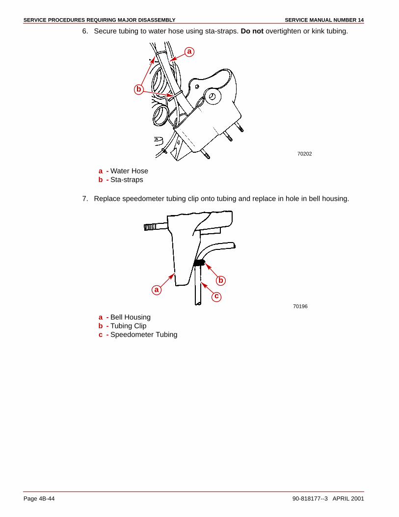
SERVICE PROCEDURES REQUIRING MAJOR DISASSEMBLY SERVICE MANUAL NUMBER 14
Page 4B-44 90-818177--3 APRIL 2001
6. Secure tubing to water hose using sta-straps. Do not overtighten or kink tubing.
70202
a
b
a - Water Hoseb - Sta-straps
7. Replace speedometer tubing clip onto tubing and replace in hole in bell housing.
70196
ab
c
a - Bell Housingb - Tubing Clipc - Speedometer Tubing
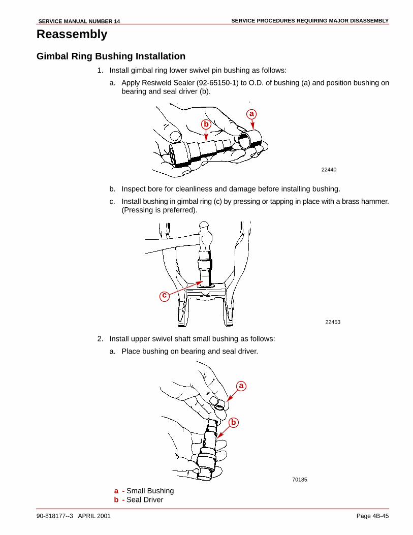
SERVICE PROCEDURES REQUIRING MAJOR DISASSEMBLYSERVICE MANUAL NUMBER 14
90-818177--3 APRIL 2001 Page 4B-45
Reassembly
Gimbal Ring Bushing Installation1. Install gimbal ring lower swivel pin bushing as follows:
a. Apply Resiweld Sealer (92-65150-1) to O.D. of bushing (a) and position bushing onbearing and seal driver (b).
22440
ab
b. Inspect bore for cleanliness and damage before installing bushing.
c. Install bushing in gimbal ring (c) by pressing or tapping in place with a brass hammer.(Pressing is preferred).
22453
c
2. Install upper swivel shaft small bushing as follows:
a. Place bushing on bearing and seal driver.
70185
a
b
a - Small Bushingb - Seal Driver
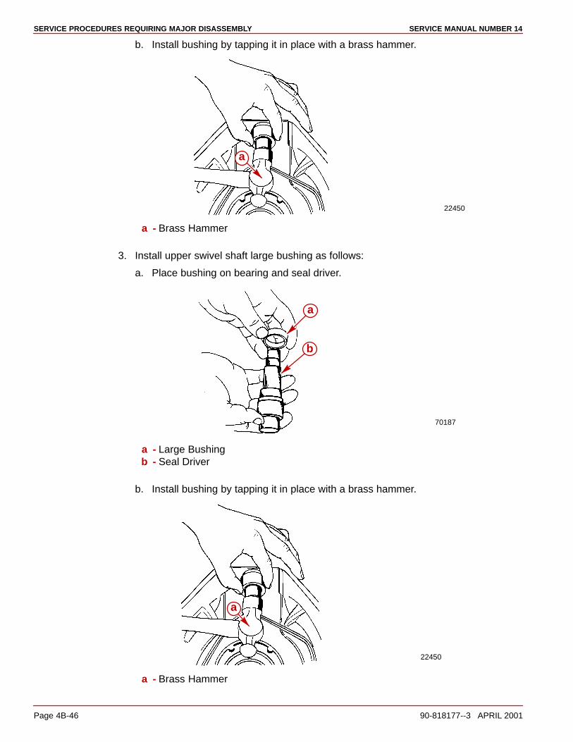
SERVICE PROCEDURES REQUIRING MAJOR DISASSEMBLY SERVICE MANUAL NUMBER 14
Page 4B-46 90-818177--3 APRIL 2001
b. Install bushing by tapping it in place with a brass hammer.
22450
a
a - Brass Hammer
3. Install upper swivel shaft large bushing as follows:
a. Place bushing on bearing and seal driver.
70187
a
b
a - Large Bushingb - Seal Driver
b. Install bushing by tapping it in place with a brass hammer.
22450
a
a - Brass Hammer
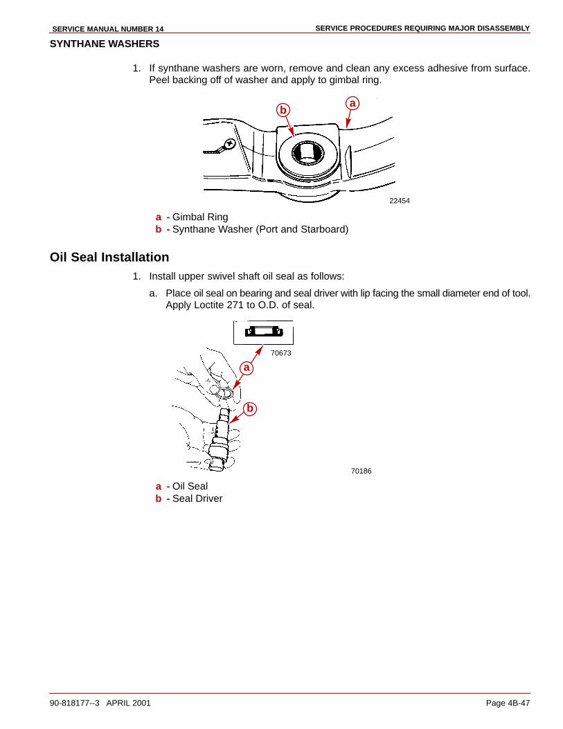
SERVICE PROCEDURES REQUIRING MAJOR DISASSEMBLYSERVICE MANUAL NUMBER 14
90-818177--3 APRIL 2001 Page 4B-47
SYNTHANE WASHERS
1. If synthane washers are worn, remove and clean any excess adhesive from surface.Peel backing off of washer and apply to gimbal ring.
22454
ab
a - Gimbal Ringb - Synthane Washer (Port and Starboard)
Oil Seal Installation1. Install upper swivel shaft oil seal as follows:
a. Place oil seal on bearing and seal driver with lip facing the small diameter end of tool.Apply Loctite 271 to O.D. of seal.
70673
70186
a
b
a - Oil Sealb - Seal Driver
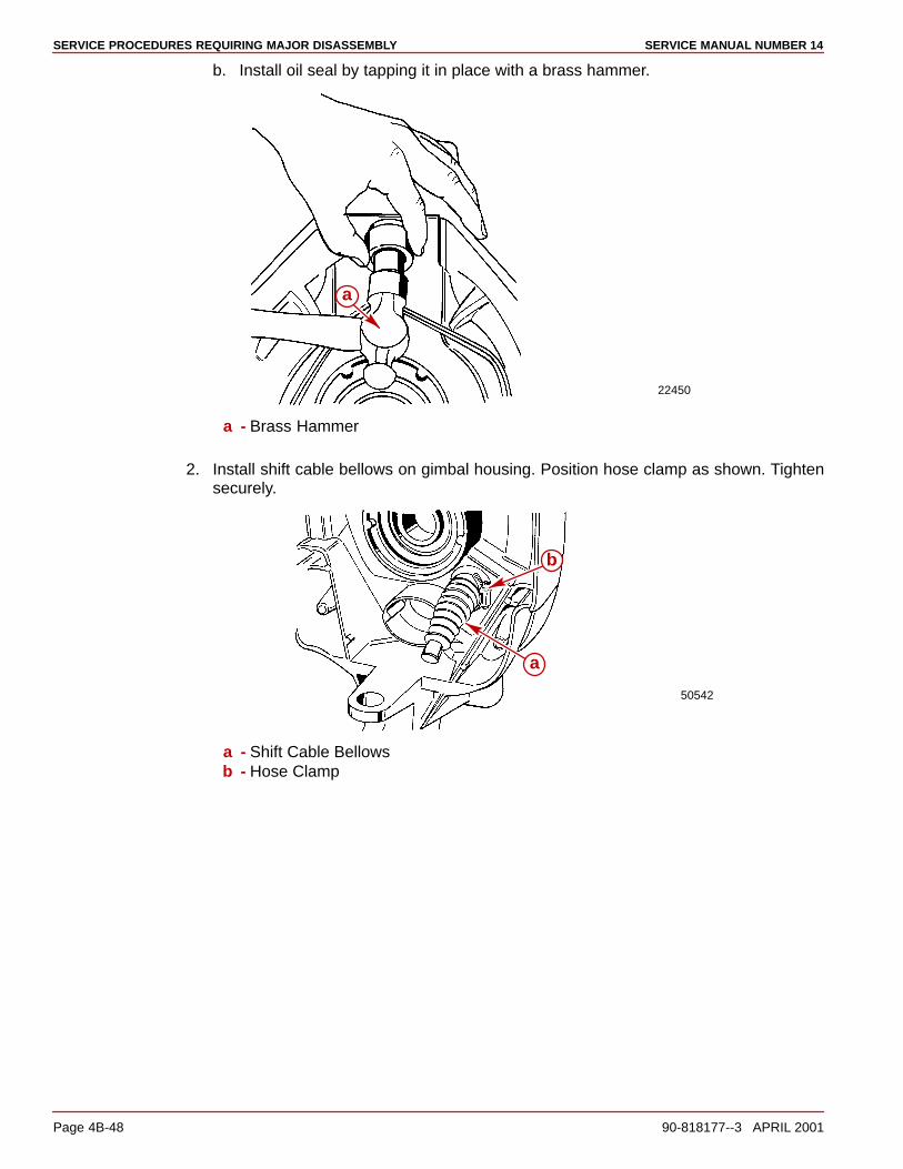
SERVICE PROCEDURES REQUIRING MAJOR DISASSEMBLY SERVICE MANUAL NUMBER 14
Page 4B-48 90-818177--3 APRIL 2001
b. Install oil seal by tapping it in place with a brass hammer.
22450
a
a - Brass Hammer
2. Install shift cable bellows on gimbal housing. Position hose clamp as shown. Tightensecurely.
50542
a
b
a - Shift Cable Bellowsb - Hose Clamp
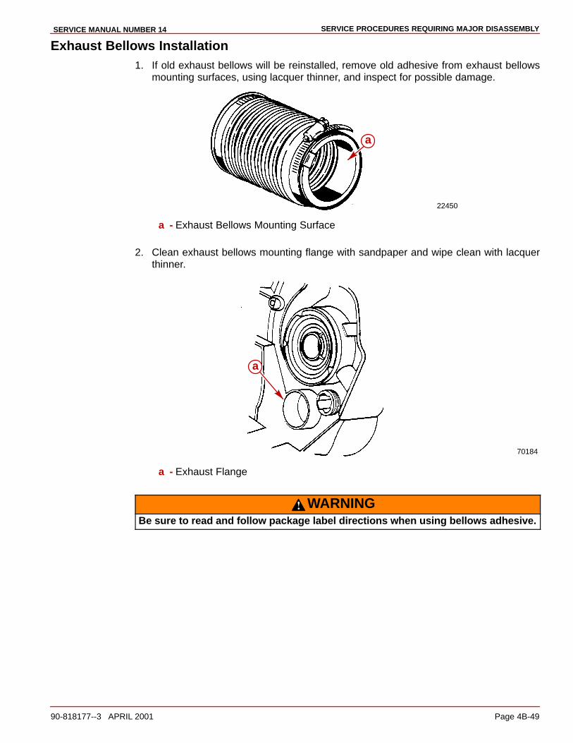
SERVICE PROCEDURES REQUIRING MAJOR DISASSEMBLYSERVICE MANUAL NUMBER 14
90-818177--3 APRIL 2001 Page 4B-49
Exhaust Bellows Installation1. If old exhaust bellows will be reinstalled, remove old adhesive from exhaust bellows
mounting surfaces, using lacquer thinner, and inspect for possible damage.
22450
a
a - Exhaust Bellows Mounting Surface
2. Clean exhaust bellows mounting flange with sandpaper and wipe clean with lacquerthinner.
70184
a
a - Exhaust Flange
WARNINGBe sure to read and follow package label directions when using bellows adhesive.

SERVICE PROCEDURES REQUIRING MAJOR DISASSEMBLY SERVICE MANUAL NUMBER 14
Page 4B-50 90-818177--3 APRIL 2001
3. Position grounding clips on bellows. Use bellows P/N 18654 only.
22079
b
c
b
a
a
a - Apply 3M Brand Adhesiveb - Grounding Clipsc - Bellows Part Number
4. Apply bellows adhesive to exhaust bellows mounting surface. Allow to dry (approxi-mately 10 minutes), before installing.
22450
a
a - Exhaust Bellows Mounting Surface
5. Install exhaust bellows on gimbal housing flange. Position hose clamp as shown. Torqueto 30-40 lb-in. (3.3-4.5 Nm).
70199a
b
a - Gimbal Housing Flangeb - Hose Clamp
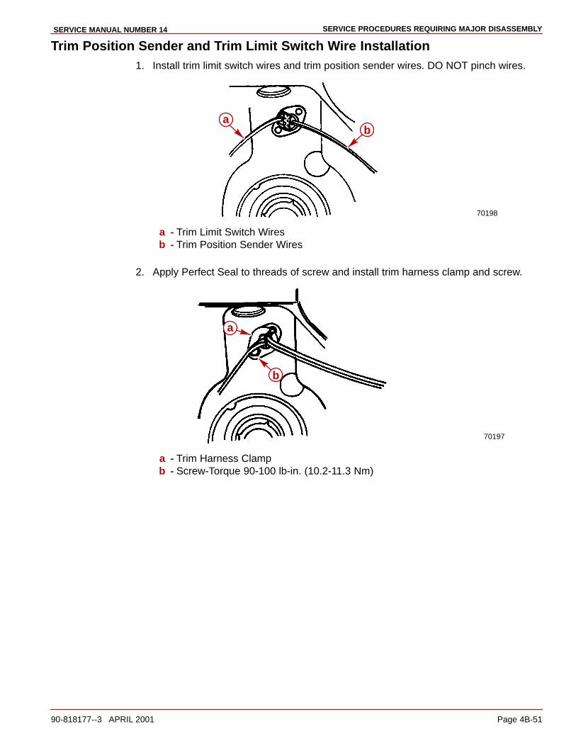
SERVICE PROCEDURES REQUIRING MAJOR DISASSEMBLYSERVICE MANUAL NUMBER 14
90-818177--3 APRIL 2001 Page 4B-51
Trim Position Sender and Trim Limit Switch Wire Installation1. Install trim limit switch wires and trim position sender wires. DO NOT pinch wires.
70198
ab
a - Trim Limit Switch Wiresb - Trim Position Sender Wires
2. Apply Perfect Seal to threads of screw and install trim harness clamp and screw.
70197
a
b
a - Trim Harness Clampb - Screw-Torque 90-100 lb-in. (10.2-11.3 Nm)
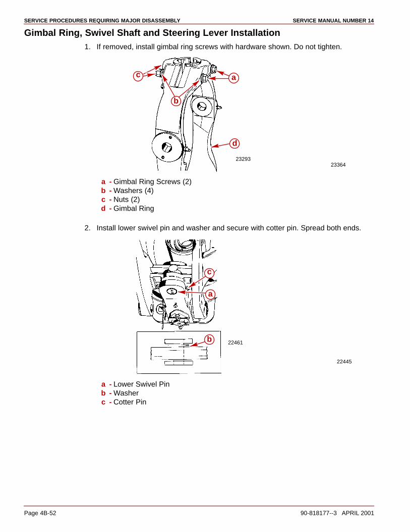
SERVICE PROCEDURES REQUIRING MAJOR DISASSEMBLY SERVICE MANUAL NUMBER 14
Page 4B-52 90-818177--3 APRIL 2001
Gimbal Ring, Swivel Shaft and Steering Lever Installation1. If removed, install gimbal ring screws with hardware shown. Do not tighten.
2329323364
d
a
b
c
a - Gimbal Ring Screws (2)b - Washers (4)c - Nuts (2)d - Gimbal Ring
2. Install lower swivel pin and washer and secure with cotter pin. Spread both ends.
22445
22461
a
b
c
a - Lower Swivel Pinb - Washerc - Cotter Pin
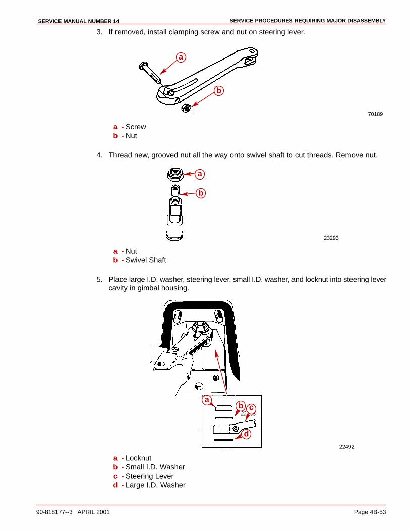
SERVICE PROCEDURES REQUIRING MAJOR DISASSEMBLYSERVICE MANUAL NUMBER 14
90-818177--3 APRIL 2001 Page 4B-53
3. If removed, install clamping screw and nut on steering lever.
70189
a
b
a - Screwb - Nut
4. Thread new, grooved nut all the way onto swivel shaft to cut threads. Remove nut.
23293
a
b
a - Nutb - Swivel Shaft
5. Place large I.D. washer, steering lever, small I.D. washer, and locknut into steering levercavity in gimbal housing.
22463
22492
ab c
d
a - Locknutb - Small I.D. Washerc - Steering Leverd - Large I.D. Washer
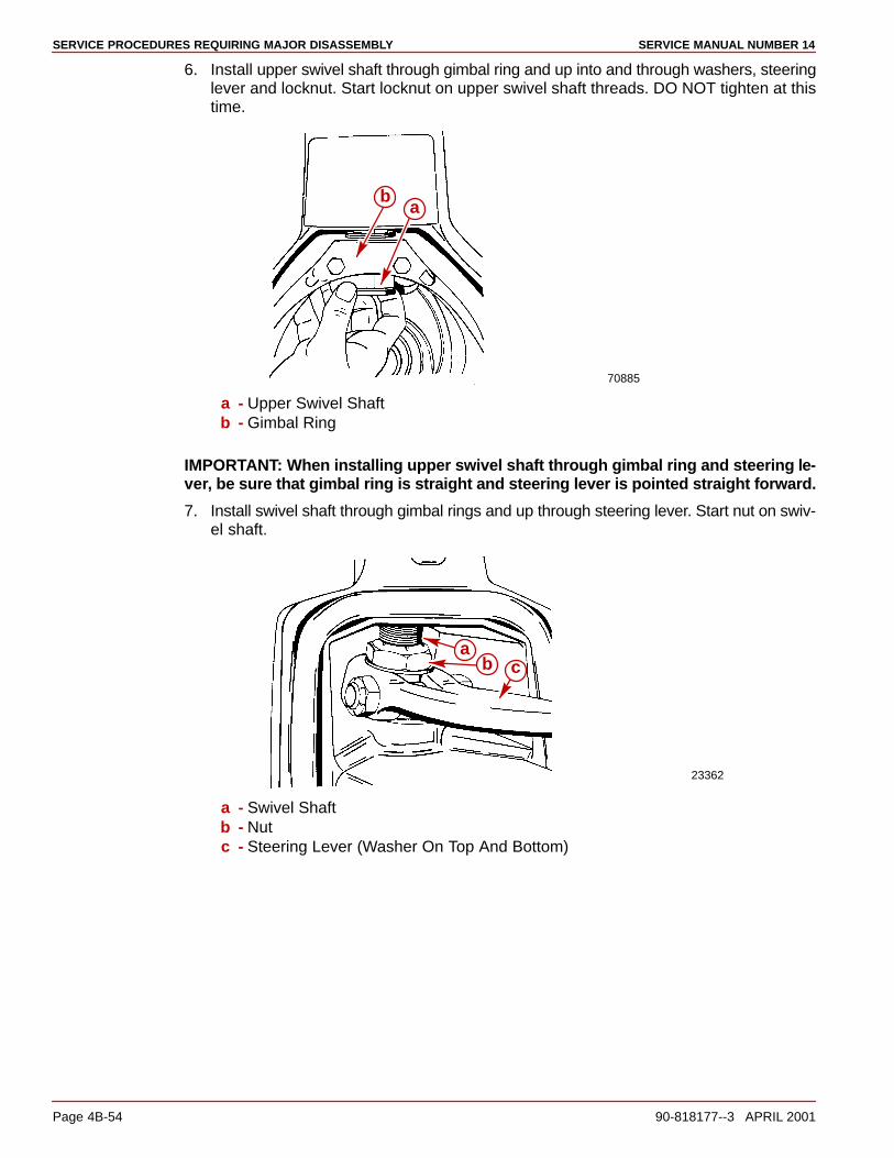
SERVICE PROCEDURES REQUIRING MAJOR DISASSEMBLY SERVICE MANUAL NUMBER 14
Page 4B-54 90-818177--3 APRIL 2001
6. Install upper swivel shaft through gimbal ring and up into and through washers, steeringlever and locknut. Start locknut on upper swivel shaft threads. DO NOT tighten at thistime.
70885
ab
a - Upper Swivel Shaftb - Gimbal Ring
IMPORTANT: When installing upper swivel shaft through gimbal ring and steering le-ver, be sure that gimbal ring is straight and steering lever is pointed straight forward.
7. Install swivel shaft through gimbal rings and up through steering lever. Start nut on swiv-el shaft.
23362
ab c
a - Swivel Shaftb - Nutc - Steering Lever (Washer On Top And Bottom)
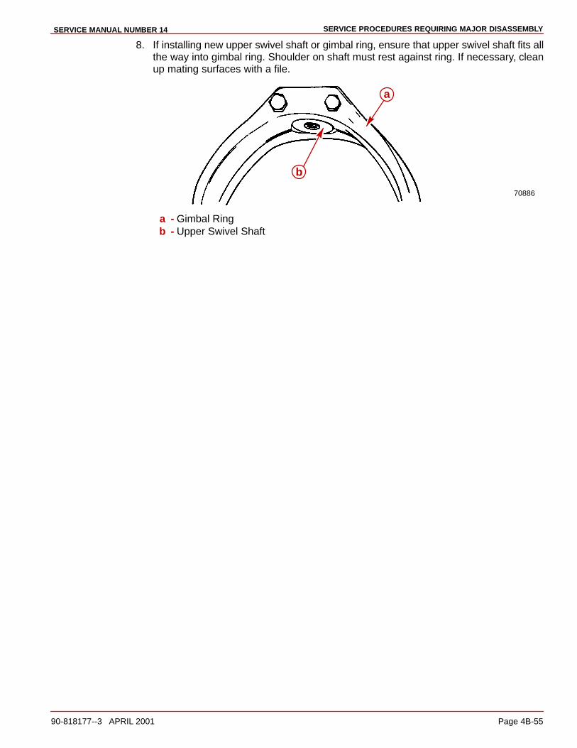
SERVICE PROCEDURES REQUIRING MAJOR DISASSEMBLYSERVICE MANUAL NUMBER 14
90-818177--3 APRIL 2001 Page 4B-55
8. If installing new upper swivel shaft or gimbal ring, ensure that upper swivel shaft fits allthe way into gimbal ring. Shoulder on shaft must rest against ring. If necessary, cleanup mating surfaces with a file.
70886
a
b
a - Gimbal Ringb - Upper Swivel Shaft

SERVICE PROCEDURES REQUIRING MAJOR DISASSEMBLY SERVICE MANUAL NUMBER 14
Page 4B-56 90-818177--3 APRIL 2001
9. Tighten nut until a clearance of .002 - .010 in. (0.05 - 0.25 mm) exists between lowerswivel pin washer and gimbal housing mount.
70156
a
b
Engine And Transom Assembly Installeda - Pin Punchb - Nut
50541
ab
Engine And Transom Assembly Removeda - Nutb - Wrench (1-1/16in.)
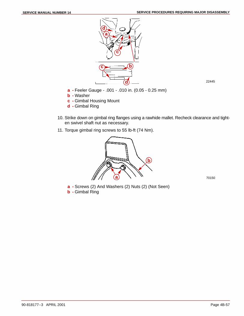
SERVICE PROCEDURES REQUIRING MAJOR DISASSEMBLYSERVICE MANUAL NUMBER 14
90-818177--3 APRIL 2001 Page 4B-57
22445
a
b
c
d
c
d
a - Feeler Gauge - .001 - .010 in. (0.05 - 0.25 mm)b - Washerc - Gimbal Housing Mountd - Gimbal Ring
10. Strike down on gimbal ring flanges using a rawhide mallet. Recheck clearance and tight-en swivel shaft nut as necessary.
11. Torque gimbal ring screws to 55 lb-ft (74 Nm).
70150a
b
a - Screws (2) And Washers (2) Nuts (2) (Not Seen)b - Gimbal Ring
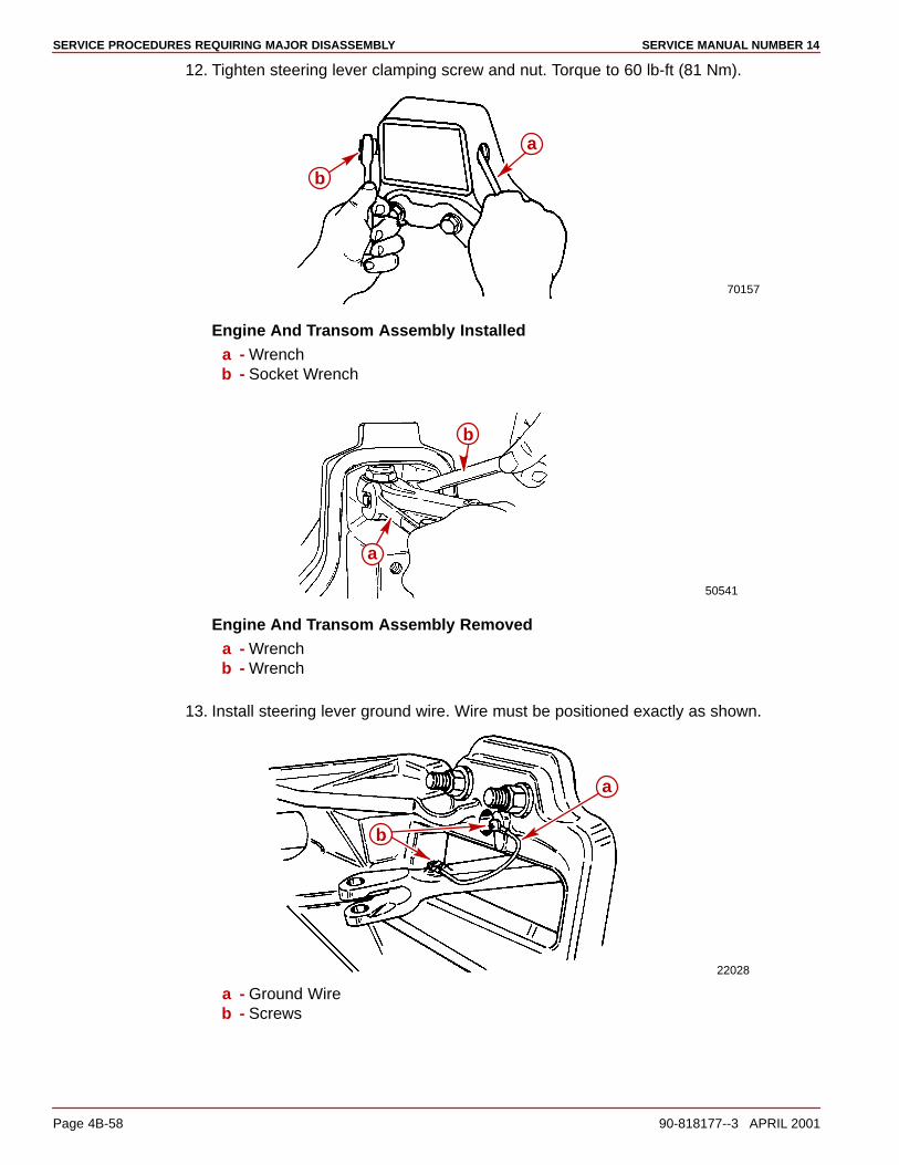
SERVICE PROCEDURES REQUIRING MAJOR DISASSEMBLY SERVICE MANUAL NUMBER 14
Page 4B-58 90-818177--3 APRIL 2001
12. Tighten steering lever clamping screw and nut. Torque to 60 lb-ft (81 Nm).
70157
a
b
Engine And Transom Assembly Installeda - Wrenchb - Socket Wrench
50541
a
b
Engine And Transom Assembly Removeda - Wrenchb - Wrench
13. Install steering lever ground wire. Wire must be positioned exactly as shown.
22028
a
b
a - Ground Wireb - Screws
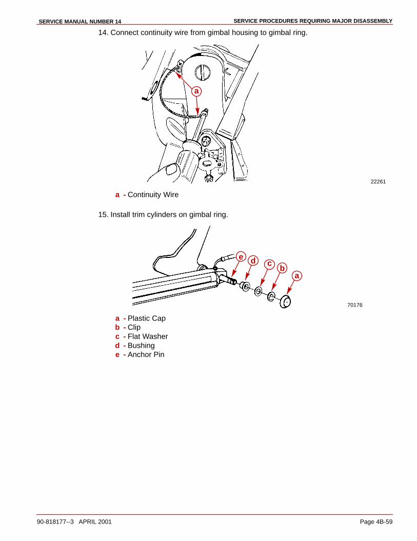
SERVICE PROCEDURES REQUIRING MAJOR DISASSEMBLYSERVICE MANUAL NUMBER 14
90-818177--3 APRIL 2001 Page 4B-59
14. Connect continuity wire from gimbal housing to gimbal ring.
22261
a
a - Continuity Wire
15. Install trim cylinders on gimbal ring.
70176
ab
cde
a - Plastic Capb - Clipc - Flat Washerd - Bushinge - Anchor Pin
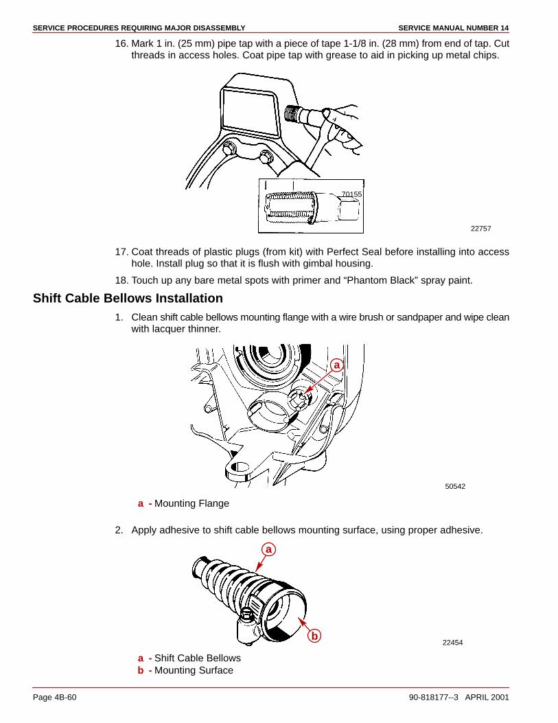
SERVICE PROCEDURES REQUIRING MAJOR DISASSEMBLY SERVICE MANUAL NUMBER 14
Page 4B-60 90-818177--3 APRIL 2001
16. Mark 1 in. (25 mm) pipe tap with a piece of tape 1-1/8 in. (28 mm) from end of tap. Cutthreads in access holes. Coat pipe tap with grease to aid in picking up metal chips.
70155
22757
17. Coat threads of plastic plugs (from kit) with Perfect Seal before installing into accesshole. Install plug so that it is flush with gimbal housing.
18. Touch up any bare metal spots with primer and “Phantom Black” spray paint.
Shift Cable Bellows Installation1. Clean shift cable bellows mounting flange with a wire brush or sandpaper and wipe clean
with lacquer thinner.
50542
a
a - Mounting Flange
2. Apply adhesive to shift cable bellows mounting surface, using proper adhesive.
22454
a
b
a - Shift Cable Bellowsb - Mounting Surface
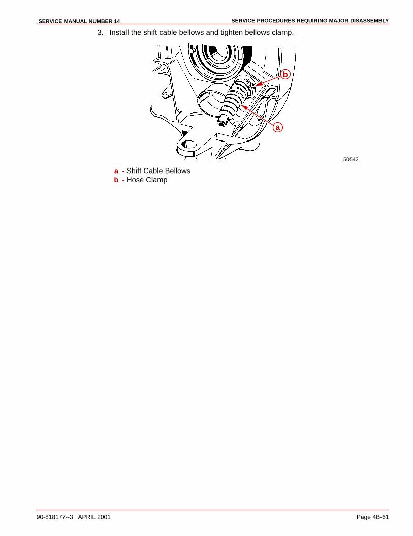
SERVICE PROCEDURES REQUIRING MAJOR DISASSEMBLYSERVICE MANUAL NUMBER 14
90-818177--3 APRIL 2001 Page 4B-61
3. Install the shift cable bellows and tighten bellows clamp.
50542
a
b
a - Shift Cable Bellowsb - Hose Clamp

SERVICE PROCEDURES REQUIRING MAJOR DISASSEMBLY SERVICE MANUAL NUMBER 14
Page 4B-62 90-818177--3 APRIL 2001
Bell Housing Installation1. Prepare U-joint bellows for installation as follows:
a. Clean gimbal housing mounting flange with sandpaper and wipe clean with lacquerthinner.
b. Apply bellows adhesive to mounting surface on inside of bellows.
c. Position grounding clip and hose clamp over bellows end.
2. Lubricate the end of the shift cable with Quicksilver 2-4-C Marine Lubricant with Teflon.
3. Carefully insert the cable through the small opening in the bellows and through the gim-bal housing.
4. Then insert the cable into the engine compartment. Route the cable as shown in the fol-lowing illustrations.
74903
3.0L Model
74901
V6 and V8 Models
WARNINGBe sure to read and follow package label directions when using bellows adhesive.
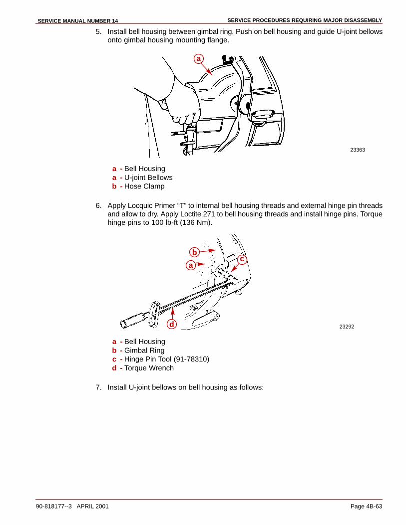
SERVICE PROCEDURES REQUIRING MAJOR DISASSEMBLYSERVICE MANUAL NUMBER 14
90-818177--3 APRIL 2001 Page 4B-63
5. Install bell housing between gimbal ring. Push on bell housing and guide U-joint bellowsonto gimbal housing mounting flange.
23363
a
a - Bell Housinga - U-joint Bellowsb - Hose Clamp
6. Apply Locquic Primer “T” to internal bell housing threads and external hinge pin threadsand allow to dry. Apply Loctite 271 to bell housing threads and install hinge pins. Torquehinge pins to 100 lb-ft (136 Nm).
23292
a
bc
d
a - Bell Housingb - Gimbal Ringc - Hinge Pin Tool (91-78310)d - Torque Wrench
7. Install U-joint bellows on bell housing as follows:
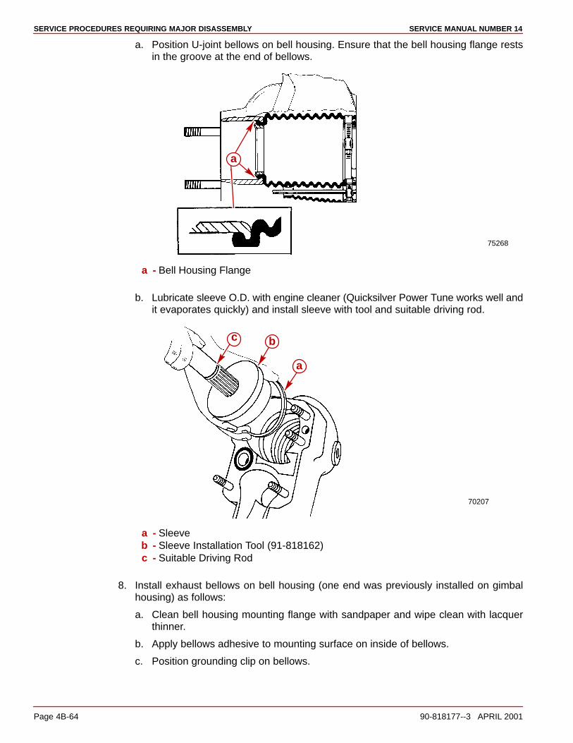
SERVICE PROCEDURES REQUIRING MAJOR DISASSEMBLY SERVICE MANUAL NUMBER 14
Page 4B-64 90-818177--3 APRIL 2001
a. Position U-joint bellows on bell housing. Ensure that the bell housing flange restsin the groove at the end of bellows.
75268
a
a - Bell Housing Flange
b. Lubricate sleeve O.D. with engine cleaner (Quicksilver Power Tune works well andit evaporates quickly) and install sleeve with tool and suitable driving rod.
70207
a
bc
a - Sleeveb - Sleeve Installation Tool (91-818162)c - Suitable Driving Rod
8. Install exhaust bellows on bell housing (one end was previously installed on gimbalhousing) as follows:
a. Clean bell housing mounting flange with sandpaper and wipe clean with lacquerthinner.
b. Apply bellows adhesive to mounting surface on inside of bellows.
c. Position grounding clip on bellows.
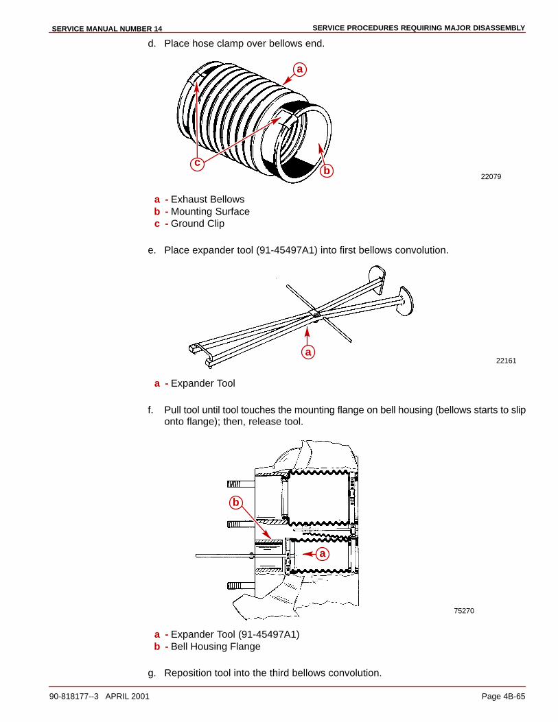
SERVICE PROCEDURES REQUIRING MAJOR DISASSEMBLYSERVICE MANUAL NUMBER 14
90-818177--3 APRIL 2001 Page 4B-65
d. Place hose clamp over bellows end.
22079
a
bc
a - Exhaust Bellowsb - Mounting Surfacec - Ground Clip
e. Place expander tool (91-45497A1) into first bellows convolution.
22161a
a - Expander Tool
f. Pull tool until tool touches the mounting flange on bell housing (bellows starts to sliponto flange); then, release tool.
75270
a
b
a - Expander Tool (91-45497A1)b - Bell Housing Flange
g. Reposition tool into the third bellows convolution.

SERVICE PROCEDURES REQUIRING MAJOR DISASSEMBLY SERVICE MANUAL NUMBER 14
Page 4B-66 90-818177--3 APRIL 2001
h. Pull bellows onto bell housing flange.
i. Position hose clamp as shown and tighten securely. Remove tool.
75269
a
b
a - Exhaust Bellowsb - Hose Clamp
IMPORTANT: Ensure shift cable bellows crimp clamp is not flattened out when com-pressing in the following step. Crimp clamp must be compressed evenly around bel-lows and shift cable to prevent water leakage.
9. Insert shift cable through shift cable bellows.
NOTE: After inserting shift cable through shift bellows be sure that bellows is in relaxed posi-tion [2 1/2 in (63 mm) from bell housing] before crimping clamp.
10. Compress crimp clamp.
70137
abc
a
a - Shift Cableb - Shift Cable Bellowsc - Crimp Clamp

SERVICE PROCEDURES REQUIRING MAJOR DISASSEMBLYSERVICE MANUAL NUMBER 14
90-818177--3 APRIL 2001 Page 4B-67
11. Install shift cable wrapping on shift cable from inner transom. Position approximately 2inches from gimbal housing.
22030a
a - Shift Cable Wrapping
12. Install core wire through shift slide.
23262
a
b
a - Shift Slideb - Core Wire
13. Install inner core wire through shift cable. Be sure and position shift lever roller betweenslot on shift slide.
23262
a
b
c
d
a - Inner Core Wireb - Shift Cablec - Shift Slided - Shift Lever
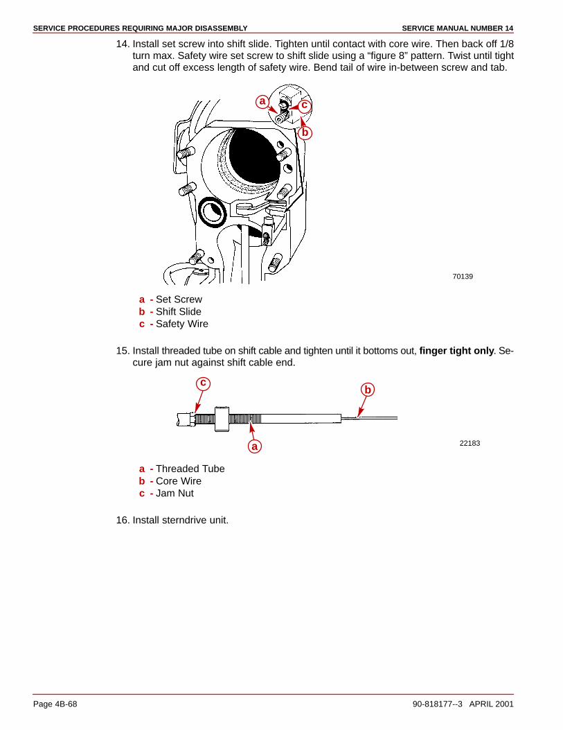
SERVICE PROCEDURES REQUIRING MAJOR DISASSEMBLY SERVICE MANUAL NUMBER 14
Page 4B-68 90-818177--3 APRIL 2001
14. Install set screw into shift slide. Tighten until contact with core wire. Then back off 1/8turn max. Safety wire set screw to shift slide using a “figure 8” pattern. Twist until tightand cut off excess length of safety wire. Bend tail of wire in-between screw and tab.
70139
a
b
c
a - Set Screwb - Shift Slidec - Safety Wire
15. Install threaded tube on shift cable and tighten until it bottoms out, finger tight only. Se-cure jam nut against shift cable end.
22183a
bc
a - Threaded Tubeb - Core Wirec - Jam Nut
16. Install sterndrive unit.

SERVICE PROCEDURES REQUIRING MAJOR DISASSEMBLYSERVICE MANUAL NUMBER 14
90-818177--3 APRIL 2001 Page 4B-69
17. Push in on drive unit shift cable core wire while simultaneously turning propeller shaftcounterclockwise until shaft stops. To ensure that clutch is fully engaged maintain pres-sure on propeller shaft with a suitable device (elastic strap).
23170
22183
a
b
a - Inner Core Wireb - Propeller Shaft
NOTE: Clutch engagement will be in forward on standard rotation units and reverse forcounter rotation.
18. Install shift cable end guide over core wire and insert core wire through cable anchor.Tighten screws securely.
22183
a b
cd
d
a - Shift Cable End Guideb - Core Wirec - Cable Anchord - Screws (2)
19. While applying light pressure, measure distance between center of hole in shift cableend guide and center of brass barrel. Measurement should be 6 in. (153 mm).
50484
a b
c
a - End Guideb - Brass Barrelc - 6 in. (153 mm)
20. Connect shift cable to shift plate and adjust.
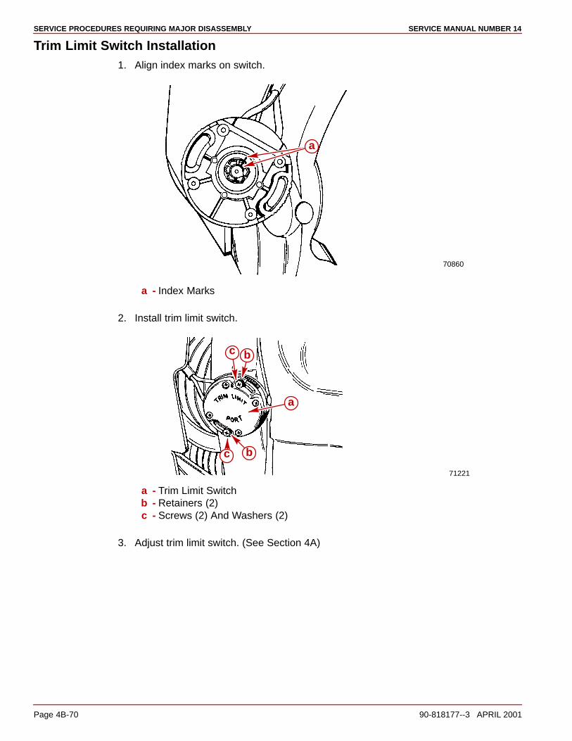
SERVICE PROCEDURES REQUIRING MAJOR DISASSEMBLY SERVICE MANUAL NUMBER 14
Page 4B-70 90-818177--3 APRIL 2001
Trim Limit Switch Installation1. Align index marks on switch.
70860
a
a - Index Marks
2. Install trim limit switch.
71221
a
bc
c b
a - Trim Limit Switchb - Retainers (2)c - Screws (2) And Washers (2)
3. Adjust trim limit switch. (See Section 4A)
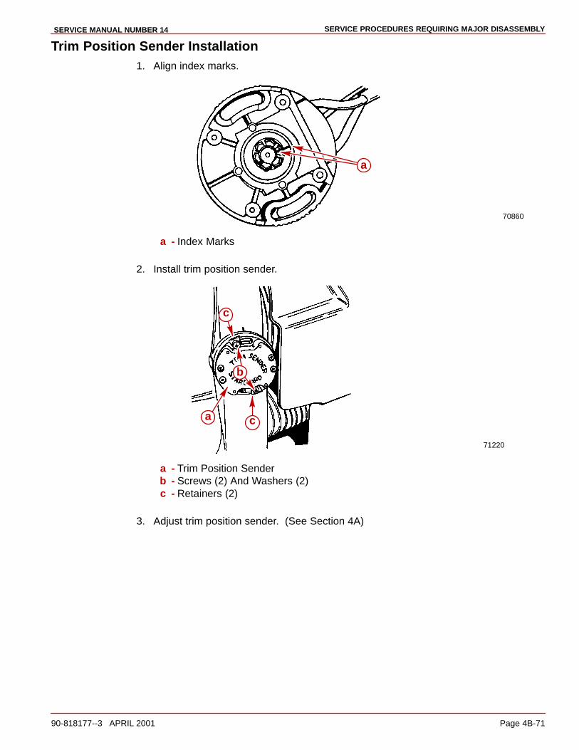
SERVICE PROCEDURES REQUIRING MAJOR DISASSEMBLYSERVICE MANUAL NUMBER 14
90-818177--3 APRIL 2001 Page 4B-71
Trim Position Sender Installation1. Align index marks.
70860
a
a - Index Marks
2. Install trim position sender.
71220
a
b
c
c
a - Trim Position Senderb - Screws (2) And Washers (2)c - Retainers (2)
3. Adjust trim position sender. (See Section 4A)

SERVICE PROCEDURES REQUIRING MAJOR DISASSEMBLY SERVICE MANUAL NUMBER 14
Page 4B-72 90-818177--3 APRIL 2001
ALPHA ONE (GENERATION II) ACCESS PLUG– DRILLING TEMPLATE –
IMPORTANT: CAREFULLY CUT OUT TEMPLATE -USE STRAIGHTEDGE TO MAKE ACCURATE FOLDS. ALIGN CENTERLINEWITH CENTER LINE OF DIMPLE. WITH TEMPLATE ACCURATELYALIGNED, TAPE TEMPLATE TO GIMBAL HOUSING SECURELYSO THAT IT CANNOT MOVE OR SHIFT.
70862

SERVICE PROCEDURES REQUIRING MAJOR DISASSEMBLYSERVICE MANUAL NUMBER 14
90-818177--3 APRIL 2001 Page 4B-73
THIS PAGE IS INTENTIONALLY BLANK
5A
OILDYNE TRIM PUMPSERVICE MANUAL NUMBER 14
90-818177--3 APRIL 2001 Page 5A-1
POWER TRIMSection 5A - Olidyne Trim Pump
Table of Contents
Trim Pump Specifications 5A-2. . . . . . . . . . . . Valve Pressure Specifications 5A-2. . . . . . Electrical Specification 5A-2. . . . . . . . . . . . Torque Specification 5A-2. . . . . . . . . . . . . . Special Tools 5A-2. . . . . . . . . . . . . . . . . . . . . Lubricants/Adhesives/Sealers 5A-2. . . . . .
Trim Pump Exploded View 5A-4. . . . . . . . . . . . Oildyne Trim Pump 5A-4. . . . . . . . . . . . . . .
Maintaining Power Trim Pump Oil Level 5A-6. . . . . . . . . . . . . . . . . . . . . . . . . . . . . . Air Bleeding Power Trim System 5A-7. . . . . .
Bleeding OUT/UP Trim Circuit 5A-7. . . . . . Bleeding IN/DOWN Trim Circuit 5A-8. . . .
Testing Power Trim Pump 5A-9. . . . . . . . . . . . Test Gauge 5A-9. . . . . . . . . . . . . . . . . . . . . . Internal Restriction Test 5A-10. . . . . . . . . . . OUT/UP Pressure Test 5A-10. . . . . . . . . . . . IN/DOWN Pressure Test 5A-12. . . . . . . . . . . Trim Pump Hydraulic System 5A-13. . . . . . .
Trim Cylinder Internal Leak Test 5A-14. . . . . . . Trim Cylinder Shock Piston Test 5A-15. . . .
Motor and Electrical Bench Tests 5A-16. . . . . . 110 Amp Fuse Test (Pump in Boat) 5A-16. 110 Amp Fuse Test (Pump Out of Boat) 5A-17. . . . . . . . . . . . . . . 20 Amp Fuse Test 5A-17. . . . . . . . . . . . . . . . Trim Pump Motor Test (In Boat) 5A-18. . . . Trim Pump Motor Test (Out of Boat) 5A-20. . . . . . . . . . . . . . . . . . . . Solenoid Test (Pump In Boat) 5A-22. . . . . . Solenoid Test (Pump Out of Boat) 5A-24. . .
Trim Pump Removal 5A-25. . . . . . . . . . . . . . . . . Hydraulic Repair 5A-27. . . . . . . . . . . . . . . . . . . .
Disassembly 5A-27. . . . . . . . . . . . . . . . . . . . . Filter Replacement 5A-29. . . . . . . . . . . . . . . . UP Pressure Relief Valve Replacement 5A-30. . . . . . . . . . . . . . . . . . . . DOWN Pressure Relief Valve Replacement 5A-32. . . . . . . . . . . . . . . . . . . . Thermal Relief Valve Replacement 5A-34. . Pump Replacement 5A-34. . . . . . . . . . . . . . . Adapter Replacement 5A-36. . . . . . . . . . . . . Adapter Repair 5A-38. . . . . . . . . . . . . . . . . . . Pump Shaft Oil Seal Replacement 5A-41. .
Motor Repair 5A-43. . . . . . . . . . . . . . . . . . . . . . . Disassembly 5A-43. . . . . . . . . . . . . . . . . . . . .
Armature Tests 5A-46. . . . . . . . . . . . . . . . . . . . . . Continuity Test 5A-46. . . . . . . . . . . . . . . . . . . Test for Shorts 5A-47. . . . . . . . . . . . . . . . . . . Cleaning Commutator 5A-47. . . . . . . . . . . . .
Field Tests 5A-47. . . . . . . . . . . . . . . . . . . . . . . . . Test for Open Circuit 5A-47. . . . . . . . . . . . . . Test for Short in Field 5A-48. . . . . . . . . . . . . Thermal Switch Continuity Test 5A-49. . . . . Brush Replacement 5A-50. . . . . . . . . . . . . . .
Reassembly 5A-53. . . . . . . . . . . . . . . . . . . . . . . . Trim Pump Installation 5A-59. . . . . . . . . . . . . . . Trim Pump Wiring Diagrams 5A-60. . . . . . . . . .
Model With Three-Button Trim/Trailer Panel 5A-60. . . . . . . . . . . . . . . . Model With Trim In Handle and Trailer Switch Separate 5A-61. . . . . . . . . . .
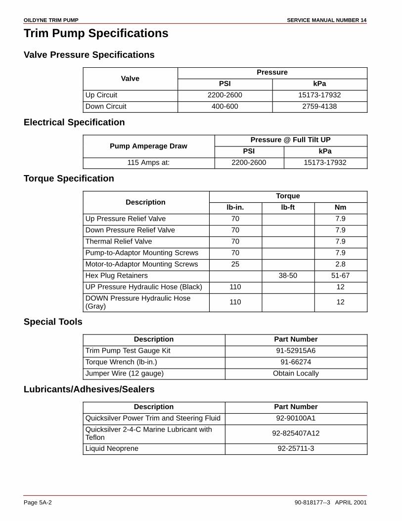
OILDYNE TRIM PUMP SERVICE MANUAL NUMBER 14
Page 5A-2 90-818177--3 APRIL 2001
Trim Pump Specifications
Valve Pressure Specifications
PressureValve
PSI kPa
Up Circuit 2200-2600 15173-17932
Down Circuit 400-600 2759-4138
Electrical Specification
Pressure @ Full Tilt UPPump Amperage Draw
PSI kPa
115 Amps at: 2200-2600 15173-17932
Torque Specification
TorqueDescription
lb-in. lb-ft Nm
Up Pressure Relief Valve 70 7.9
Down Pressure Relief Valve 70 7.9
Thermal Relief Valve 70 7.9
Pump-to-Adaptor Mounting Screws 70 7.9
Motor-to-Adaptor Mounting Screws 25 2.8
Hex Plug Retainers 38-50 51-67
UP Pressure Hydraulic Hose (Black) 110 12
DOWN Pressure Hydraulic Hose(Gray)
110 12
Special Tools
Description Part Number
Trim Pump Test Gauge Kit 91-52915A6
Torque Wrench (lb-in.) 91-66274
Jumper Wire (12 gauge) Obtain Locally
Lubricants/Adhesives/Sealers
Description Part Number
Quicksilver Power Trim and Steering Fluid 92-90100A1
Quicksilver 2-4-C Marine Lubricant withTeflon
92-825407A12
Liquid Neoprene 92-25711-3

OILDYNE TRIM PUMPSERVICE MANUAL NUMBER 14
90-818177--3 APRIL 2001 Page 5A-3
THIS PAGE IS INTENTIONALLY BLANK
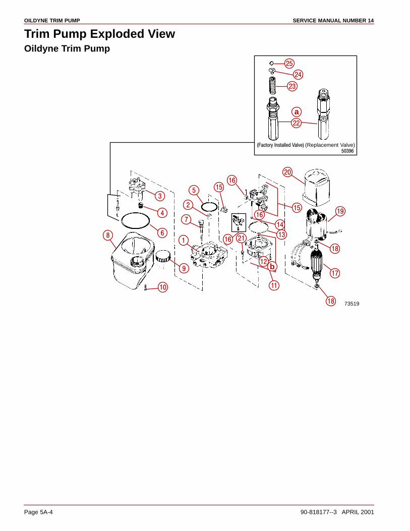
OILDYNE TRIM PUMP SERVICE MANUAL NUMBER 14
Page 5A-4 90-818177--3 APRIL 2001
Trim Pump Exploded ViewOildyne Trim Pump
73519
���������� ���������������� (Replacement Valve)
�
�
�
�
�
�
�
�
�
�� ��
��
��
��
��
����
��
��
��
��
��
��
��
��
��
��
��
��
a
b
OILDYNE TRIM PUMPSERVICE MANUAL NUMBER 14
90-818177--3 APRIL 2001 Page 5A-5
1 - Adaptor2 - Coupling3 - Pump4 - Filter5 - O-ring-Motor End6 - O-ring, Reservoir End7 - Dipstick8 - Reservoir9 - Cap (With Vent Hole)
10 - Screw (Includes O-ring)11 - End Cap w/Bearing12 - Screw13 - O-ring
14 - Screw15 - Brush Holder Kit16 - Brush set17 - Armature18 - Thrust Washer19 - Field and Frame20 - Housing21 - Screw22 - Relief Valve With:23 - Spring24 - Eyelet25 - Check Ball
Replacement Relief Valve Color Code:Down Pressure: Green
Up Pressure: Blue
Thermal: Gold
Torque Specificationsa - 75 lb-in. (8 Nm)b - 25 lb-in. (2.8 Nm)
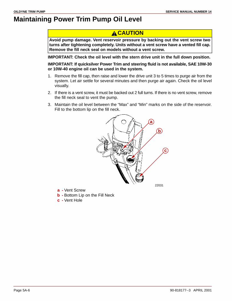
OILDYNE TRIM PUMP SERVICE MANUAL NUMBER 14
Page 5A-6 90-818177--3 APRIL 2001
Maintaining Power Trim Pump Oil Level
CAUTIONAvoid pump damage. Vent reservoir pressure by backing out the vent screw twoturns after tightening completely. Units without a vent screw have a vented fill cap.Remove the fill neck seal on models without a vent screw.
IMPORTANT: Check the oil level with the stern drive unit in the full down position.
IMPORTANT: If quicksilver Power Trim and steering fluid is not available, SAE 10W-30or 10W-40 engine oil can be used in the system.
1. Remove the fill cap, then raise and lower the drive unit 3 to 5 times to purge air from thesystem. Let air settle for several minutes and then purge air again. Check the oil levelvisually.
2. If there is a vent screw, it must be backed out 2 full turns. If there is no vent screw, removethe fill neck seal to vent the pump.
3. Maintain the oil level between the “Max” and “Min” marks on the side of the reservoir.Fill to the bottom lip on the fill neck.
22031
a
c
b
a - Vent Screwb - Bottom Lip on the Fill Neckc - Vent Hole
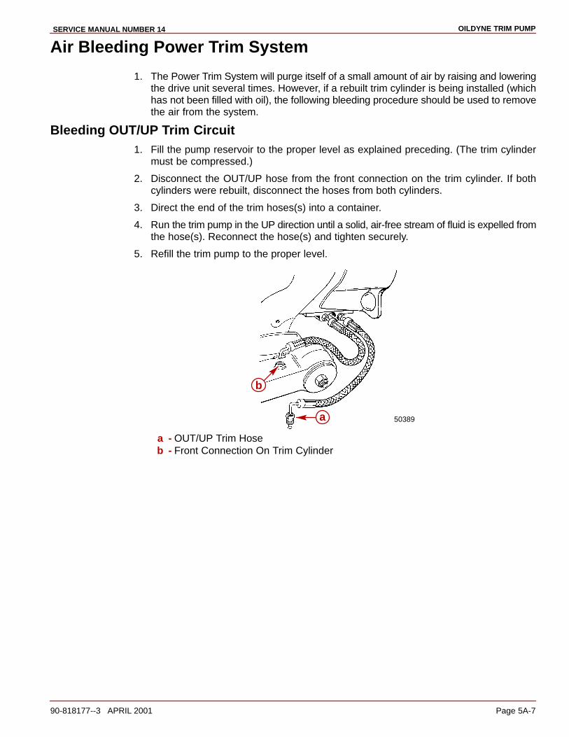
OILDYNE TRIM PUMPSERVICE MANUAL NUMBER 14
90-818177--3 APRIL 2001 Page 5A-7
Air Bleeding Power Trim System
1. The Power Trim System will purge itself of a small amount of air by raising and loweringthe drive unit several times. However, if a rebuilt trim cylinder is being installed (whichhas not been filled with oil), the following bleeding procedure should be used to removethe air from the system.
Bleeding OUT/UP Trim Circuit1. Fill the pump reservoir to the proper level as explained preceding. (The trim cylinder
must be compressed.)
2. Disconnect the OUT/UP hose from the front connection on the trim cylinder. If bothcylinders were rebuilt, disconnect the hoses from both cylinders.
3. Direct the end of the trim hoses(s) into a container.
4. Run the trim pump in the UP direction until a solid, air-free stream of fluid is expelled fromthe hose(s). Reconnect the hose(s) and tighten securely.
5. Refill the trim pump to the proper level.
50389a
b
a - OUT/UP Trim Hoseb - Front Connection On Trim Cylinder
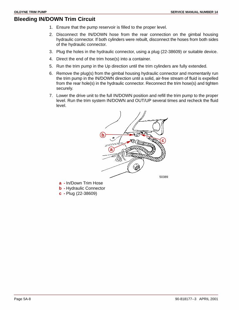
OILDYNE TRIM PUMP SERVICE MANUAL NUMBER 14
Page 5A-8 90-818177--3 APRIL 2001
Bleeding IN/DOWN Trim Circuit1. Ensure that the pump reservoir is filled to the proper level.
2. Disconnect the IN/DOWN hose from the rear connection on the gimbal housinghydraulic connector. If both cylinders were rebuilt, disconnect the hoses from both sidesof the hydraulic connector.
3. Plug the holes in the hydraulic connector, using a plug (22-38609) or suitable device.
4. Direct the end of the trim hose(s) into a container.
5. Run the trim pump in the Up direction until the trim cylinders are fully extended.
6. Remove the plug(s) from the gimbal housing hydraulic connector and momentarily runthe trim pump in the IN/DOWN direction until a solid, air-free stream of fluid is expelledfrom the rear hole(s) in the hydraulic connector. Reconnect the trim hose(s) and tightensecurely.
7. Lower the drive unit to the full IN/DOWN position and refill the trim pump to the properlevel. Run the trim system IN/DOWN and OUT/UP several times and recheck the fluidlevel.
50389
a
bc
a - In/Down Trim Hoseb - Hydraulic Connectorc - Plug (22-38609)
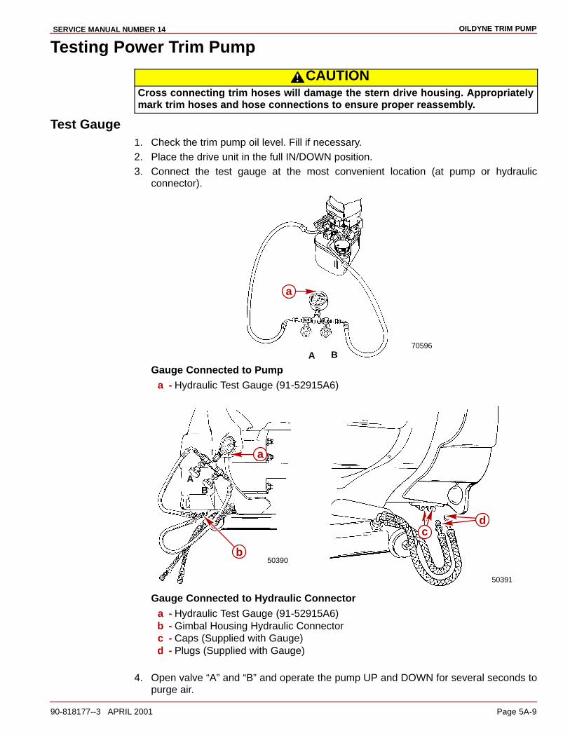
OILDYNE TRIM PUMPSERVICE MANUAL NUMBER 14
90-818177--3 APRIL 2001 Page 5A-9
Testing Power Trim Pump
CAUTIONCross connecting trim hoses will damage the stern drive housing. Appropriatelymark trim hoses and hose connections to ensure proper reassembly.
Test Gauge1. Check the trim pump oil level. Fill if necessary.2. Place the drive unit in the full IN/DOWN position.3. Connect the test gauge at the most convenient location (at pump or hydraulic
connector).
70596A B
a
Gauge Connected to Pumpa - Hydraulic Test Gauge (91-52915A6)
50390
AB
50391
a
b
cd
Gauge Connected to Hydraulic Connectora - Hydraulic Test Gauge (91-52915A6)b - Gimbal Housing Hydraulic Connectorc - Caps (Supplied with Gauge)d - Plugs (Supplied with Gauge)
4. Open valve “A” and “B” and operate the pump UP and DOWN for several seconds topurge air.

OILDYNE TRIM PUMP SERVICE MANUAL NUMBER 14
Page 5A-10 90-818177--3 APRIL 2001
Internal Restriction Test1. Open valves “A” and “B”.
2. Operate pump OUT/UP and IN/DOWN while observing gauge.
3. Replace adapter if pressure is in excess of 200 psi (1379 kPa).
OUT/UP Pressure TestNOTE: The numbers in parenthesis, e.g. (3), refer to the trim pump hydraulic systemdiagram on page 5A-11.
1. Leave valve “A” open and close valve “B.”
2. Run pump OUT/UP while observing the gauge. The reading should be 2200-2600 psi.(15173-17932 kPa).
If Gauge reading is within specifications, proceed to step 3.
If Gauge reading is not within specifications, perform the following:
Replace UP Pressure Release Valve Proceed toReplace UP Pressure Release Valve(3) and Retest
Reading OK Proceed toStep 3
Reading NOT OK
Replace Thermal Relief Valve (4) and Proceed toReplace Thermal Relief Valve (4) andRetest
Reading OK Proceed toStep 3
Reading NOT OK
Replace Adaptor (2)

OILDYNE TRIM PUMPSERVICE MANUAL NUMBER 14
90-818177--3 APRIL 2001 Page 5A-11
3. Run the pump OUT/UP until the gauge reading reaches 2200-2600 psi (15173-17932kPa). Stop pumping OUT/UP The pressure should not fall below 1900 psi (13104 kPa).If Gauge reading is 1900 psi (13104 kPa) or above, UP pressure test completed. IfGauge reading is below 1900 psi (13104 kPa) perform the following:
NOTE: A small leak will cause a pressure drop to be seen.
Check for External Oil Leaks, Up PressureCheck for External Oil Leaks,Correct and Retest
Reading OK Up PressureTest Completed
Reading NOT OK
Replace Thermal Relief Valve (4) Up PressureReplace Thermal Relief Valve (4)and Retest
Reading OK Up PressureTest Completed
Reading NOT OK
Install Trim Pump Rebuild Kit and Up PressureInstall Trim Pump Rebuild Kit andRetest
Reading OK Up PressureTest Completed
Reading NOT OK
Replace Adaptor (2)

OILDYNE TRIM PUMP SERVICE MANUAL NUMBER 14
Page 5A-12 90-818177--3 APRIL 2001
IN/DOWN Pressure TestNOTE: The numbers in parenthesis, e.g. (3), refer to the trim pump hydraulic systemdiagram.
1. Close valve “A” and open valve “B.”
2. Run the pump IN/DOWN while observing the gauge. The reading should be 400-600psi (2759-4138 kPa). If Gauge reading is within specifications, proceed to step 3. Gaugereading is NOT within specifications, perform the following.
Replace DOWN Pressure Release Proceed toReplace DOWN Pressure ReleaseValve (6) and Retest
Reading OK Proceed toStep 3
Reading NOT OK
Proceed toInstall Trim Pump Rebuild Kit Reading OK Proceed toStep 3
Reading NOT OK
Replace Adaptor (2)
3. Run pump IN/DOWN until gauge reading reaches 400 - 600 psi (2759 - 4138 kPa). Stoppumping IN/DOWN. Pressure should not fall below 350 psi (2414 kPa).
NOTE: A small leak will cause a pressure drop to be seen.
• Gauge reading above 350 psi (2414 kPa), DOWN Pressure Test completed.
• Gauge reading below 350 psi (2414 kPa), perform the following:
Check for External OilLeaks; Correct and Retest(5)*
ReadingOK
Reading NOT OK
Install Pump Rebuild Kit andRetest (1)*
Reading NOT OK
Down PressureTest Completed
Replace Adaptor (2)*
ReadingOK
Down PressureTest Completed
* The callout numbers refer to the Trim Pump Hydraulic System drawing on p. 5A-8.
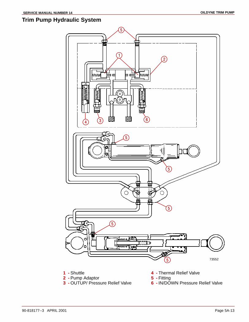
OILDYNE TRIM PUMPSERVICE MANUAL NUMBER 14
90-818177--3 APRIL 2001 Page 5A-13
Trim Pump Hydraulic System
73552
��
�
���
�
�
�
�
�
1 - Shuttle2 - Pump Adaptor3 - OUTUP/ Pressure Relief Valve
4 - Thermal Relief Valve5 - Fitting6 - IN/DOWN Pressure Relief Valve
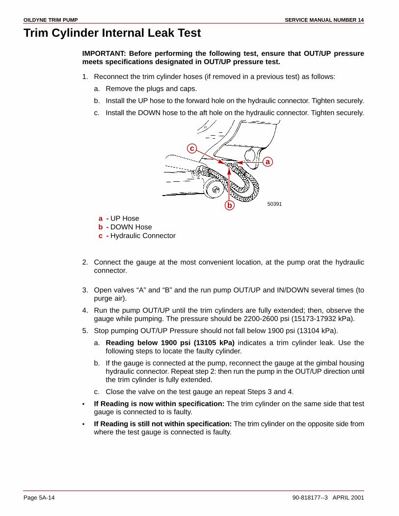
OILDYNE TRIM PUMP SERVICE MANUAL NUMBER 14
Page 5A-14 90-818177--3 APRIL 2001
Trim Cylinder Internal Leak Test
IMPORTANT: Before performing the following test, ensure that OUT/UP pressuremeets specifications designated in OUT/UP pressure test.
1. Reconnect the trim cylinder hoses (if removed in a previous test) as follows:
a. Remove the plugs and caps.
b. Install the UP hose to the forward hole on the hydraulic connector. Tighten securely.
c. Install the DOWN hose to the aft hole on the hydraulic connector. Tighten securely.
50391
a
b
c
a - UP Hoseb - DOWN Hosec - Hydraulic Connector
2. Connect the gauge at the most convenient location, at the pump orat the hydraulicconnector.
3. Open valves “A” and “B” and the run pump OUT/UP and IN/DOWN several times (topurge air).
4. Run the pump OUT/UP until the trim cylinders are fully extended; then, observe thegauge while pumping. The pressure should be 2200-2600 psi (15173-17932 kPa).
5. Stop pumping OUT/UP Pressure should not fall below 1900 psi (13104 kPa).
a. Reading below 1900 psi (13105 kPa) indicates a trim cylinder leak. Use thefollowing steps to locate the faulty cylinder.
b. If the gauge is connected at the pump, reconnect the gauge at the gimbal housinghydraulic connector. Repeat step 2: then run the pump in the OUT/UP direction untilthe trim cylinder is fully extended.
c. Close the valve on the test gauge an repeat Steps 3 and 4.
• If Reading is now within specification: The trim cylinder on the same side that testgauge is connected to is faulty.
• If Reading is still not within specification: The trim cylinder on the opposite side fromwhere the test gauge is connected is faulty.

OILDYNE TRIM PUMPSERVICE MANUAL NUMBER 14
90-818177--3 APRIL 2001 Page 5A-15
Trim Cylinder Shock Piston TestIf all previous trim system test results meet specifications, but drive unit will not trimIN/DOWN, the problem may be a leaky trim cylinder shock piston. Use the followingtest to check for this condition. No test gauge required.
1. Run the pump in the OUT/UP direction until the trim cylinders are fully extended.
2. Use a suitable devise to keep trim cylinder piston rods from retracting. The QuicksilverTrailering Kit works well for this purpose.
22562
a
a - Trailering Clip
3. Disconnect the UP trim hose from a trim cylinder.
50389
b
a
a - UP Trim Hoseb - Front Connection
4. Run the pump in the IN/DOWN direction. If oil flows from the UP port on the trim cylinder,the shock piston is leaking and must be replaced.

OILDYNE TRIM PUMP SERVICE MANUAL NUMBER 14
Page 5A-16 90-818177--3 APRIL 2001
Motor and Electrical Bench Tests
110 Amp Fuse Test (Pump in Boat)
WARNINGDO NOT perform this test near flammables (or explosives) as a spark may occurwhen making connections.
1. Check for voltage at terminal “d” using a volt meter. Voltage MUST BE indicated beforeproceeding with the next check.
22495
a
b
c
d
a - Volt Meter Negative (-) Leadb - Volt Meter Positive (+) Leadc - Fuse (RED in Color)d - Check for Voltage Here
2. Check for voltage at terminal “d” using a volt meter.
a. Voltage Indicated: Fuse O.K.
b. Voltage Not Indicated: Replace the fuse.
22493
a
b
c
d
a - Volt Meter Negative (-) Leadb - Volt Meter Positive (+) Leadc - Fuse (RED in Color)d - Check for Voltage Here

OILDYNE TRIM PUMPSERVICE MANUAL NUMBER 14
90-818177--3 APRIL 2001 Page 5A-17
110 Amp Fuse Test (Pump Out of Boat)1. Connect the ohmmeter leads between the terminals on the fuse.
22493
b
a
a - 110 Amp Fuse (Red)b - Ohmmeter Leads
Zero Ohms Reading (Full Continuity)-Fuse OK.High Ohms Reading (No Continuity)-Replace fuse.
20 Amp Fuse Test1. Remove the fuse from the fuse holder.
22496
a
a - Fuse Holder
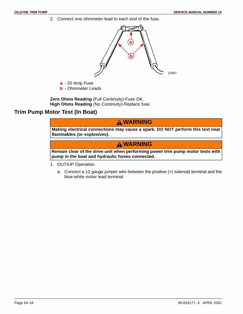
OILDYNE TRIM PUMP SERVICE MANUAL NUMBER 14
Page 5A-18 90-818177--3 APRIL 2001
2. Connect one ohmmeter lead to each end of the fuse.
22497
a
b
a - 20 Amp Fuseb - Ohmmeter Leads
Zero Ohms Reading (Full Continuity)-Fuse OK.High Ohms Reading (No Continuity)-Replace fuse.
Trim Pump Motor Test (In Boat)
WARNINGMaking electrical connections may cause a spark. DO NOT perform this test nearflammables (or explosives).
WARNINGRemain clear of the drive unit when performing power trim pump motor tests withpump in the boat and hydraulic hoses connected.
1. OUT/UP Operation.
a. Connect a 12 gauge jumper wire between the positive (+) solenoid terminal and theblue-white motor lead terminal.

OILDYNE TRIM PUMPSERVICE MANUAL NUMBER 14
90-818177--3 APRIL 2001 Page 5A-19
b. The motor should run.
22494
c
d
a
b
IN/DOWN Positiona - OUT/UP Solenoidb - Positive Terminal (+)c - BLUE-WHITE Motor Lead Terminald - Jumper Wire
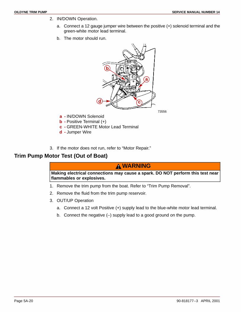
OILDYNE TRIM PUMP SERVICE MANUAL NUMBER 14
Page 5A-20 90-818177--3 APRIL 2001
2. IN/DOWN Operation.
a. Connect a 12 gauge jumper wire between the positive (+) solenoid terminal and thegreen-white motor lead terminal.
b. The motor should run.
73556
a
cd
b
a - IN/DOWN Solenoidb - Positive Terminal (+)c - GREEN-WHITE Motor Lead Terminald - Jumper Wire
3. If the motor does not run, refer to “Motor Repair.”
Trim Pump Motor Test (Out of Boat)
WARNINGMaking electrical connections may cause a spark. DO NOT perform this test nearflammables or explosives.
1. Remove the trim pump from the boat. Refer to “Trim Pump Removal”.
2. Remove the fluid from the trim pump reservoir.
3. OUT/UP Operation
a. Connect a 12 volt Positive (+) supply lead to the blue-white motor lead terminal.
b. Connect the negative (–) supply lead to a good ground on the pump.
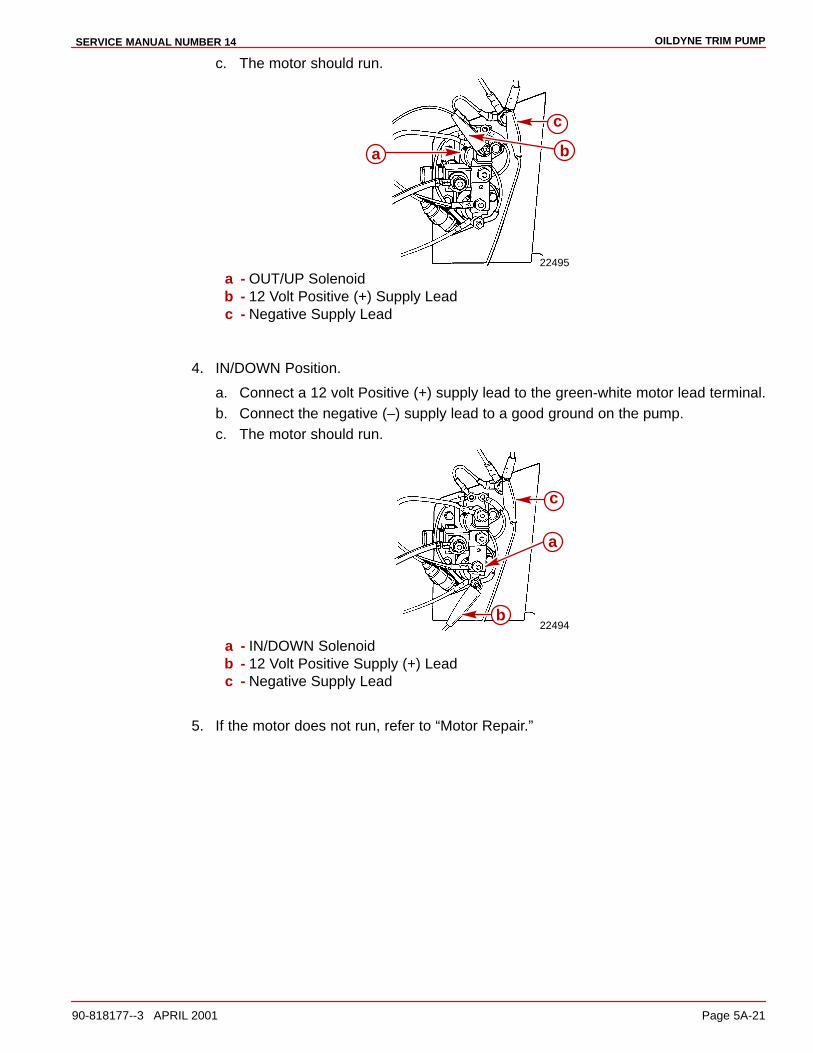
OILDYNE TRIM PUMPSERVICE MANUAL NUMBER 14
90-818177--3 APRIL 2001 Page 5A-21
c. The motor should run.
22495
ba
c
a - OUT/UP Solenoidb - 12 Volt Positive (+) Supply Leadc - Negative Supply Lead
4. IN/DOWN Position.
a. Connect a 12 volt Positive (+) supply lead to the green-white motor lead terminal.b. Connect the negative (–) supply lead to a good ground on the pump.c. The motor should run.
22494
a
b
c
a - IN/DOWN Solenoidb - 12 Volt Positive Supply (+) Leadc - Negative Supply Lead
5. If the motor does not run, refer to “Motor Repair.”
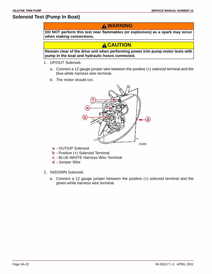
OILDYNE TRIM PUMP SERVICE MANUAL NUMBER 14
Page 5A-22 90-818177--3 APRIL 2001
Solenoid Test (Pump In Boat)
WARNINGDO NOT perform this test near flammables (or explosives) as a spark may occurwhen making connections.
CAUTIONRemain clear of the drive unit when performing power trim pump motor tests withpump in the boat and hydraulic hoses connected.
1. UP/OUT Solenoid.
a. Connect a 12 gauge jumper wire between the positive (+) solenoid terminal and theblue-white harness wire terminal.
b. The motor should run.
22495
d
a
b
c
a - OUT/UP Solenoidb - Positive (+) Solenoid Terminalc - BLUE-WHITE Harness Wire Terminald - Jumper Wire
2. IN/DOWN Solenoid.
a. Connect a 12 gauge jumper between the positive (+) solenoid terminal and thegreen-white harness wire terminal.
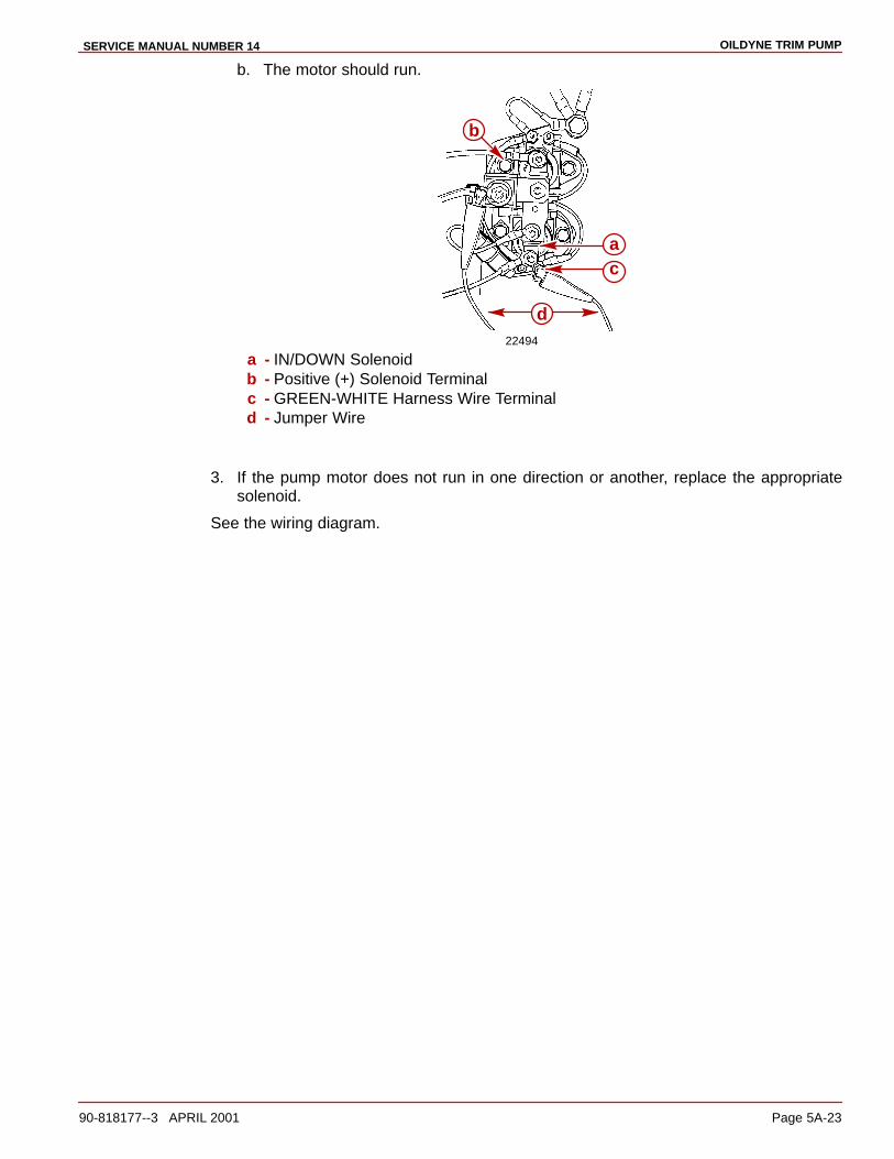
OILDYNE TRIM PUMPSERVICE MANUAL NUMBER 14
90-818177--3 APRIL 2001 Page 5A-23
b. The motor should run.
22494
b
ac
d
a - IN/DOWN Solenoidb - Positive (+) Solenoid Terminalc - GREEN-WHITE Harness Wire Terminald - Jumper Wire
3. If the pump motor does not run in one direction or another, replace the appropriatesolenoid.
See the wiring diagram.

OILDYNE TRIM PUMP SERVICE MANUAL NUMBER 14
Page 5A-24 90-818177--3 APRIL 2001
Solenoid Test (Pump Out of Boat)
WARNINGDO NOT perform this test near flammables (or explosives) as a spark may occurwhen making connections.
1. Remove the trim pump from the boat. Refer to “Trim Pump Removal”.
2. Remove the fluid from the trim pump reservoir.
3. OUT/UP Solenoid.
a. Connect a 12 volt Positive (+) supply lead to blue-white harness terminal wire.
b. Connect the negative (–) supply lead to the solenoid ground terminal as shown.
c. Connect the ohmmeter leads to the large terminals on the solenoid.
22493
a
b
d
e
fc
a - OUT/UP Solenoidb - 12 volt Positive (+) Supply Leadc - Negative (–) Supply Leadd - Ohmmeter Leadse - BLUE-WHITE Harness Wire Terminalf - Solenoid Ground Terminal
4. Zero Ohms Reading (Full Continuity)-Solenoid is OK.High Ohms Reading (No Continuity)-Replace solenoid.
5. IN/DOWN Solenoid.
a. Connect a 12 volt positive (+) supply lead to the green-white harness wire terminal.
b. Connect the negative (–) supply lead to the solenoid ground terminal.
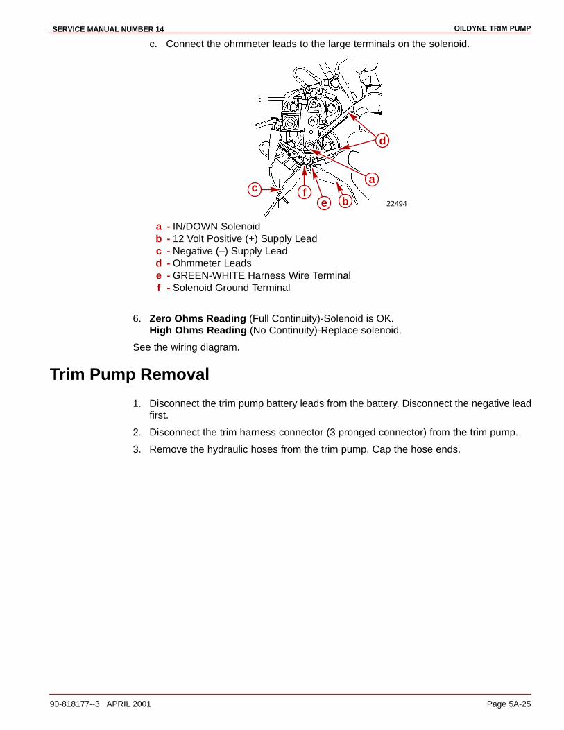
OILDYNE TRIM PUMPSERVICE MANUAL NUMBER 14
90-818177--3 APRIL 2001 Page 5A-25
c. Connect the ohmmeter leads to the large terminals on the solenoid.
22494
c
d
b
a
ef
a - IN/DOWN Solenoidb - 12 Volt Positive (+) Supply Leadc - Negative (–) Supply Leadd - Ohmmeter Leadse - GREEN-WHITE Harness Wire Terminalf - Solenoid Ground Terminal
6. Zero Ohms Reading (Full Continuity)-Solenoid is OK.High Ohms Reading (No Continuity)-Replace solenoid.
See the wiring diagram.
Trim Pump Removal
1. Disconnect the trim pump battery leads from the battery. Disconnect the negative leadfirst.
2. Disconnect the trim harness connector (3 pronged connector) from the trim pump.
3. Remove the hydraulic hoses from the trim pump. Cap the hose ends.
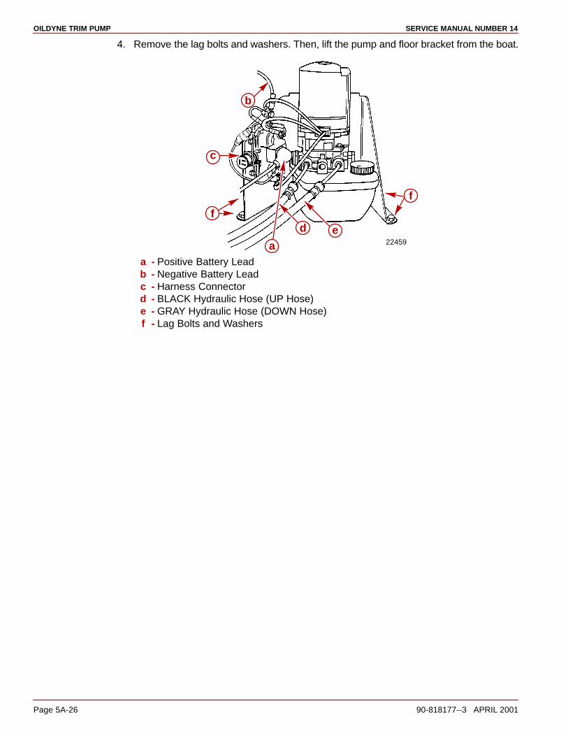
OILDYNE TRIM PUMP SERVICE MANUAL NUMBER 14
Page 5A-26 90-818177--3 APRIL 2001
4. Remove the lag bolts and washers. Then, lift the pump and floor bracket from the boat.
22459
f
ed
a
f
c
b
a - Positive Battery Leadb - Negative Battery Leadc - Harness Connectord - BLACK Hydraulic Hose (UP Hose)e - GRAY Hydraulic Hose (DOWN Hose)f - Lag Bolts and Washers
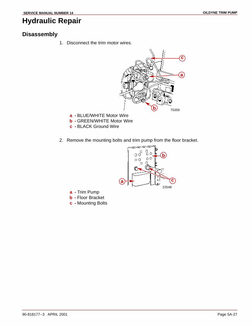
OILDYNE TRIM PUMPSERVICE MANUAL NUMBER 14
90-818177--3 APRIL 2001 Page 5A-27
Hydraulic Repair
Disassembly1. Disconnect the trim motor wires.
70359
c
a
ba - BLUE/WHITE Motor Wireb - GREEN/WHITE Motor Wirec - BLACK Ground Wire
2. Remove the mounting bolts and trim pump from the floor bracket.
22548
b
ca
a - Trim Pumpb - Floor Bracketc - Mounting Bolts
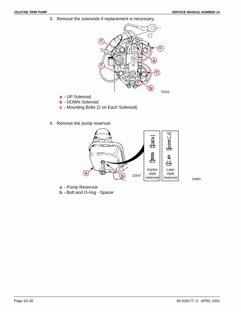
OILDYNE TRIM PUMP SERVICE MANUAL NUMBER 14
Page 5A-28 90-818177--3 APRIL 2001
3. Remove the solenoids if replacement is necessary.
70232
c
c
b
a
c
c
a - UP Solenoidb - DOWN Solenoidc - Mounting Bolts (2 on Each Solenoid)
4. Remove the pump reservoir.
2254723860
Earlierstyle
reservoir
Laterstyle
reservoirba
a - Pump Reservoirb - Bolt and O-ring - Spacer

OILDYNE TRIM PUMPSERVICE MANUAL NUMBER 14
90-818177--3 APRIL 2001 Page 5A-29
Filter Replacement1. Remove the filter by twisting while pulling upward.
70932
a
a - Filter
2. Install a new filter.
22547
b
a
a - Filterb - 5/8 in. Socket

OILDYNE TRIM PUMP SERVICE MANUAL NUMBER 14
Page 5A-30 90-818177--3 APRIL 2001
UP Pressure Relief Valve ReplacementNOTE: The UP pressure relief valve in the kit is color coded blue for easy identification.
IMPORTANT: A difference exists between the factory installed and the replacementpressure relief valves. Once the jam nut is loosened on a factory installed relief valve,the valve is out of adjustment.
IMPORTANT: When installing a replacement pressure relief valve, DO NOT loosen orattempt to remove the hex “jam” nut. This valve is preset at the factory for proper UPpressure relief.
70872
a
a - Factory Installed UP Pressure Relief Valve
NOTE: Original factory installed pressure relief valves will be a natural steel finish - they willNOT be color coded.
1. Replace the UP pressure relief valve. Ensure that the threaded hole is free of dirt.Lubricate the O-ring at the base of the new valve with Power Trim and Steering Fluidand install. Torque to 70 lb-in. (7.9 Nm).
50396
ba
Current Replacement Pressure Relief Valvea - Replacement UP Pressure Relief Valveb - Color Coded Blue Area

OILDYNE TRIM PUMPSERVICE MANUAL NUMBER 14
90-818177--3 APRIL 2001 Page 5A-31
50396 70872 50396
c d
e
fb
a
Original Factory Installed Pressure Relief Valvea - Original Factory Installed UP Pressure Relief Valveb - Jam Nut - Loosen Before Removing the Valvec - Be Sure to Remove the Pump Body Components (Spring, eyelet, Check Ball) -
Discardd - Replacement UP Pressure Relief Valve (Blue) - Use the Base of the valve for
tighteninge - Jam Nut - DO NOT TURN or Attempt to Loosenf - O-ring

OILDYNE TRIM PUMP SERVICE MANUAL NUMBER 14
Page 5A-32 90-818177--3 APRIL 2001
DOWN Pressure Relief Valve ReplacementNOTE: The DOWN pressure relief valve in the kit is color coded green for easy identification.
IMPORTANT: A difference exists between the factory installed and the replacementpressure relief valves. Once the jam nut is loosened on a factory installed relief valve,the valve is out of adjustment.
IMPORTANT: When installing a replacement pressure relief valve, DO NOT loosen orattempt to remove the hex “jam” nut. This valve is preset at the factory for properDOWN pressure relief.
70872
a
a - Factory Installed DOWN Pressure Relief Valve
50396
ba
a - Replacement DOWN Pressure Relief Valveb - Color Coded Green Area

OILDYNE TRIM PUMPSERVICE MANUAL NUMBER 14
90-818177--3 APRIL 2001 Page 5A-33
1. Replace the DOWN pressure relief valve. Remove the pump body components anddiscard. Ensure that the threaded hole is free of dirt. Lubricate the O-ring at the baseof the new valve with Power Trim and Steering Fluid and install. Torque to 70 lb-in. (7.9Nm). Use the base of the valve for tightening; DO NOT TURN or attempt to loosen thejam nut.
50396 70872 50396
a
b
c d
e
f
Original Factory Installed Pressure Relief Valvea - Original Factory Installed DOWN Pressure Relief Valveb - Jam Nut - Loosen Before Removing the Valvec - Pump Body Components (Spring, Eyelet, Check Ball)d - Replacement DOWN Pressure Relief Valve (GREEN)e - Jam Nutf - O-ring
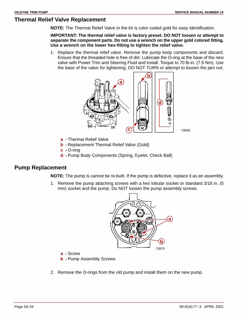
OILDYNE TRIM PUMP SERVICE MANUAL NUMBER 14
Page 5A-34 90-818177--3 APRIL 2001
Thermal Relief Valve ReplacementNOTE: The Thermal Relief Valve in the kit is color coded gold for easy identification.
IMPORTANT: The thermal relief valve is factory preset. DO NOT loosen or attempt toseparate the component parts. Do not use a wrench on the upper gold colored fitting.Use a wrench on the lower hex-fitting to tighten the relief valve.
1. Replace the thermal relief valve. Remove the pump body components and discard.Ensure that the threaded hole is free of dirt. Lubricate the O-ring at the base of the newvalve with Power Trim and Steering Fluid and install. Torque to 70 lb-in. (7.9 Nm). Usethe base of the valve for tightening; DO NOT TURN or attempt to loosen the jam nut.
70836
d
b
c
a
a - Thermal Relief Valveb - Replacement Thermal Relief Valve (Gold)c - O-ringd - Pump Body Components (Spring, Eyelet, Check Ball)
Pump ReplacementNOTE: The pump is cannot be re-built. If the pump is defective, replace it as an assembly.
1. Remove the pump attaching screws with a hex lobular socket or standard 3/16 in. (5mm) socket and the pump. Do NOT loosen the pump assembly screws.
70870
a
b
a - Screwb - Pump Assembly Screws
2. Remove the O-rings from the old pump and install them on the new pump.
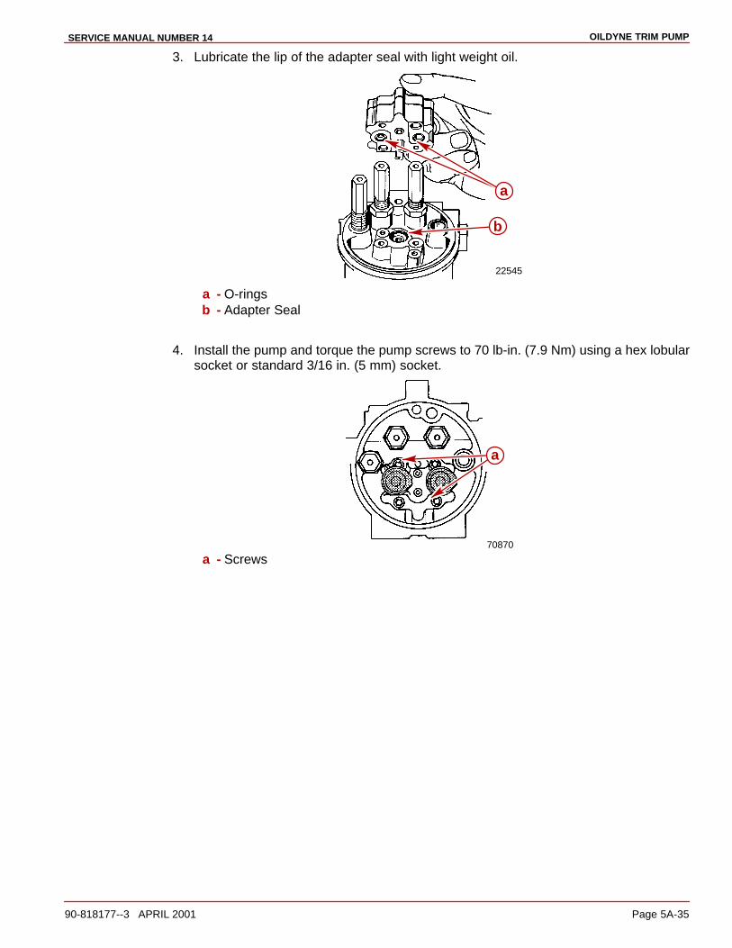
OILDYNE TRIM PUMPSERVICE MANUAL NUMBER 14
90-818177--3 APRIL 2001 Page 5A-35
3. Lubricate the lip of the adapter seal with light weight oil.
22545
a
b
a - O-ringsb - Adapter Seal
4. Install the pump and torque the pump screws to 70 lb-in. (7.9 Nm) using a hex lobularsocket or standard 3/16 in. (5 mm) socket.
70870
a
a - Screws
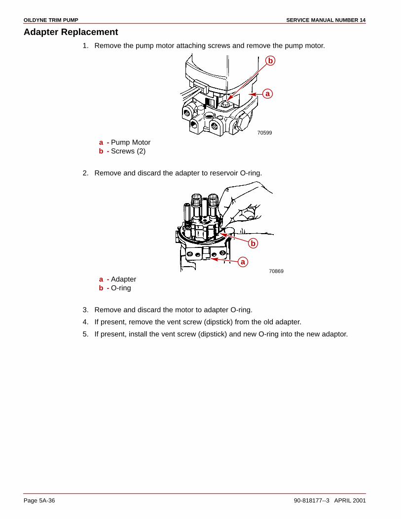
OILDYNE TRIM PUMP SERVICE MANUAL NUMBER 14
Page 5A-36 90-818177--3 APRIL 2001
Adapter Replacement1. Remove the pump motor attaching screws and remove the pump motor.
70599
a
b
a - Pump Motorb - Screws (2)
2. Remove and discard the adapter to reservoir O-ring.
70869
b
a
a - Adapterb - O-ring
3. Remove and discard the motor to adapter O-ring.
4. If present, remove the vent screw (dipstick) from the old adapter.
5. If present, install the vent screw (dipstick) and new O-ring into the new adaptor.
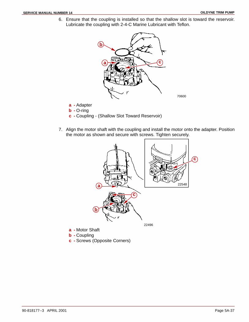
OILDYNE TRIM PUMPSERVICE MANUAL NUMBER 14
90-818177--3 APRIL 2001 Page 5A-37
6. Ensure that the coupling is installed so that the shallow slot is toward the reservoir.Lubricate the coupling with 2-4-C Marine Lubricant with Teflon.
70600
ca
b
a - Adapterb - O-ringc - Coupling - (Shallow Slot Toward Reservoir)
7. Align the motor shaft with the coupling and install the motor onto the adapter. Positionthe motor as shown and secure with screws. Tighten securely.
22548
22496
c
b
c
a
a - Motor Shaftb - Couplingc - Screws (Opposite Corners)
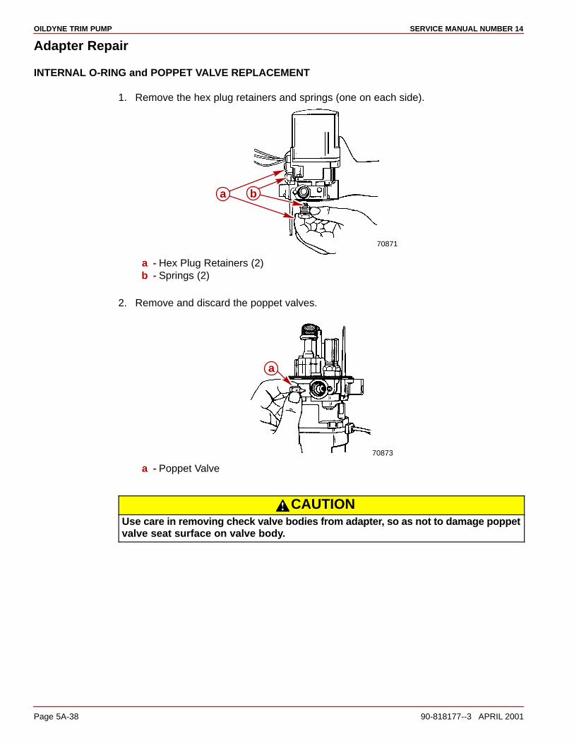
OILDYNE TRIM PUMP SERVICE MANUAL NUMBER 14
Page 5A-38 90-818177--3 APRIL 2001
Adapter Repair
INTERNAL O-RING and POPPET VALVE REPLACEMENT
1. Remove the hex plug retainers and springs (one on each side).
70871
a b
a - Hex Plug Retainers (2)b - Springs (2)
2. Remove and discard the poppet valves.
70873
a
a - Poppet Valve
CAUTIONUse care in removing check valve bodies from adapter, so as not to damage poppetvalve seat surface on valve body.

OILDYNE TRIM PUMPSERVICE MANUAL NUMBER 14
90-818177--3 APRIL 2001 Page 5A-39
3. Remove the check valve bodies and spool, using 1/4 in. (6.35 mm) metal rod or punch.Ensure contact point on the valve bodies is NOT the sealing surface.
70868
a bc
a - Check Valve Bodyb - Spoolc - Small Punch
4. Remove and discard the O-rings on the hex plug retainers.
5. Discard the check valve bodies.
6. Clean the hex plug retainers and spool.
70867d
b e f e bc
ada
c
a - O-ringsb - Hex Plug Retainersc - Springsd - Poppet Valvese - Check Valve Bodiesf - Spool
7. Lubricate the check valve body O-rings with Power Trim and Steering Fluid, or with10W-30 or 10W-40 motor oil.
CAUTIONDO NOT force check valve bodies into adapter as damage to O-rings may result.
8. Place the spool and check valve bodies into the adapter.
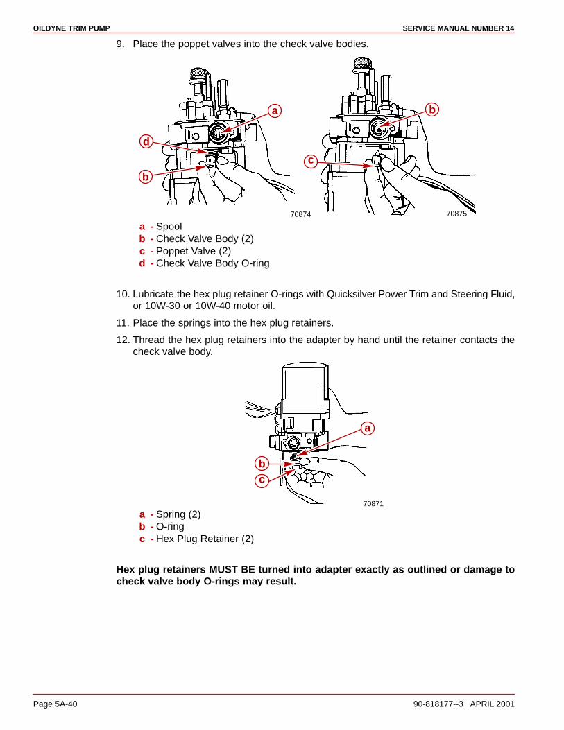
OILDYNE TRIM PUMP SERVICE MANUAL NUMBER 14
Page 5A-40 90-818177--3 APRIL 2001
9. Place the poppet valves into the check valve bodies.
70874 70875
a
d
b
b
c
a - Spoolb - Check Valve Body (2)c - Poppet Valve (2)d - Check Valve Body O-ring
10. Lubricate the hex plug retainer O-rings with Quicksilver Power Trim and Steering Fluid,or 10W-30 or 10W-40 motor oil.
11. Place the springs into the hex plug retainers.
12. Thread the hex plug retainers into the adapter by hand until the retainer contacts thecheck valve body.
70871
a
bc
a - Spring (2)b - O-ringc - Hex Plug Retainer (2)
Hex plug retainers MUST BE turned into adapter exactly as outlined or damage tocheck valve body O-rings may result.
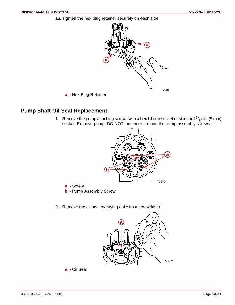
OILDYNE TRIM PUMPSERVICE MANUAL NUMBER 14
90-818177--3 APRIL 2001 Page 5A-41
13. Tighten the hex plug retainer securely on each side.
70866
a
a
a - Hex Plug Retainer
Pump Shaft Oil Seal Replacement1. Remove the pump attaching screws with a hex lobular socket or standard 3/16 in. (5 mm)
socket. Remove pump. DO NOT loosen or remove the pump assembly screws.
70870
a
b
a - Screwb - Pump Assembly Screw
2. Remove the oil seal by prying out with a screwdriver.
50371
a
a - Oil Seal
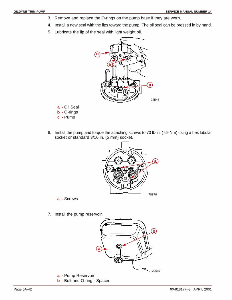
OILDYNE TRIM PUMP SERVICE MANUAL NUMBER 14
Page 5A-42 90-818177--3 APRIL 2001
3. Remove and replace the O-rings on the pump base if they are worn.
4. Install a new seal with the lips toward the pump. The oil seal can be pressed in by hand.
5. Lubricate the lip of the seal with light weight oil.
22545
c
b
a
a - Oil Sealb - O-ringsc - Pump
6. Install the pump and torque the attaching screws to 70 lb-in. (7.9 Nm) using a hex lobularsocket or standard 3/16 in. (5 mm) socket.
70870
a
a - Screws
7. Install the pump reservoir.
22547
b
a
a - Pump Reservoirb - Bolt and O-ring - Spacer
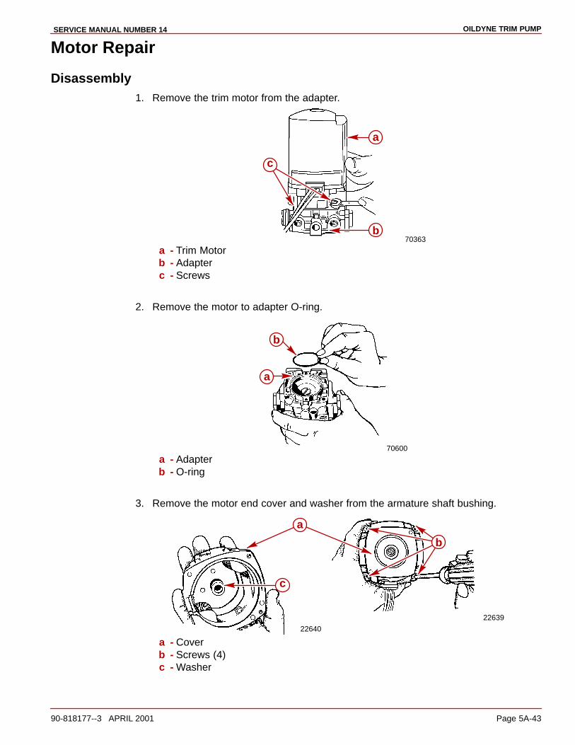
OILDYNE TRIM PUMPSERVICE MANUAL NUMBER 14
90-818177--3 APRIL 2001 Page 5A-43
Motor Repair
Disassembly1. Remove the trim motor from the adapter.
70363
a
b
c
a - Trim Motorb - Adapterc - Screws
2. Remove the motor to adapter O-ring.
70600
b
a
a - Adapterb - O-ring
3. Remove the motor end cover and washer from the armature shaft bushing.
22639
22640
c
a
b
a - Coverb - Screws (4)c - Washer

OILDYNE TRIM PUMP SERVICE MANUAL NUMBER 14
Page 5A-44 90-818177--3 APRIL 2001
4. Loosen the brush hold down arms.
22648
a
b
b
a
a - Brush Hold Down Armsb - Screws
IMPORTANT: Use care in removing brush holders so as not to lose springs.
5. Remove the brush holders and springs.
22638
b
a
a - Brush Holderb - Spring
6. Remove the thermal switch and brush assembly.
22637
ab
a - Thermal Switch and Brushb - Screw

OILDYNE TRIM PUMPSERVICE MANUAL NUMBER 14
90-818177--3 APRIL 2001 Page 5A-45
7. Remove the brush assembly mounting bracket.
22636
a
a
b
a - Brush Assembly Bracketb - Screws
8. Remove the armature and thrust washer from the motor housing.
22499
a
b
c
a - Armatureb - Thrust Washerc - Motor Housing
9. Remove the field assembly from the motor housing.
22501
a
b
a - Field Assemblyb - Motor Housing

OILDYNE TRIM PUMP SERVICE MANUAL NUMBER 14
Page 5A-46 90-818177--3 APRIL 2001
10. Remove the motor housing O-ring.
22645
a
b
a - O-ringb - Motor Housing
Armature Tests
Continuity Test1. Set the ohmmeter on the Rx1 scale.
2. Place the alligator clip meter lead on the armature shaft.
3. Touch the meter lead probe to each commutator bar one at a time.
Continuity Indicated - Armature grounded (replace armature).Continuity Not Indicated - Armature not grounded.
22646
a
c
b
a - Ohmmeter - Set on Rx1 Scaleb - Meter Lead - Place on Armaturec - Meter Lead - Place on All Commutator Bars (One at a time)
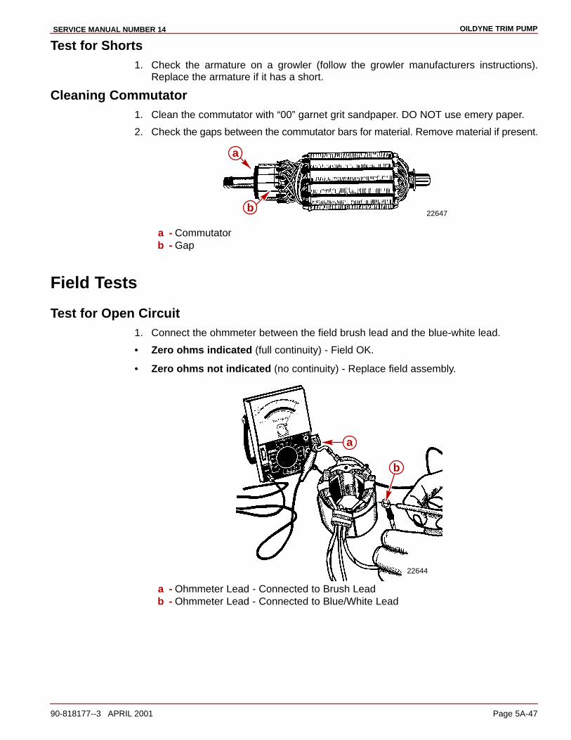
OILDYNE TRIM PUMPSERVICE MANUAL NUMBER 14
90-818177--3 APRIL 2001 Page 5A-47
Test for Shorts1. Check the armature on a growler (follow the growler manufacturers instructions).
Replace the armature if it has a short.
Cleaning Commutator1. Clean the commutator with “00” garnet grit sandpaper. DO NOT use emery paper.
2. Check the gaps between the commutator bars for material. Remove material if present.
22647b
a
a - Commutatorb - Gap
Field Tests
Test for Open Circuit1. Connect the ohmmeter between the field brush lead and the blue-white lead.
• Zero ohms indicated (full continuity) - Field OK.
• Zero ohms not indicated (no continuity) - Replace field assembly.
22644
a
b
a - Ohmmeter Lead - Connected to Brush Leadb - Ohmmeter Lead - Connected to Blue/White Lead
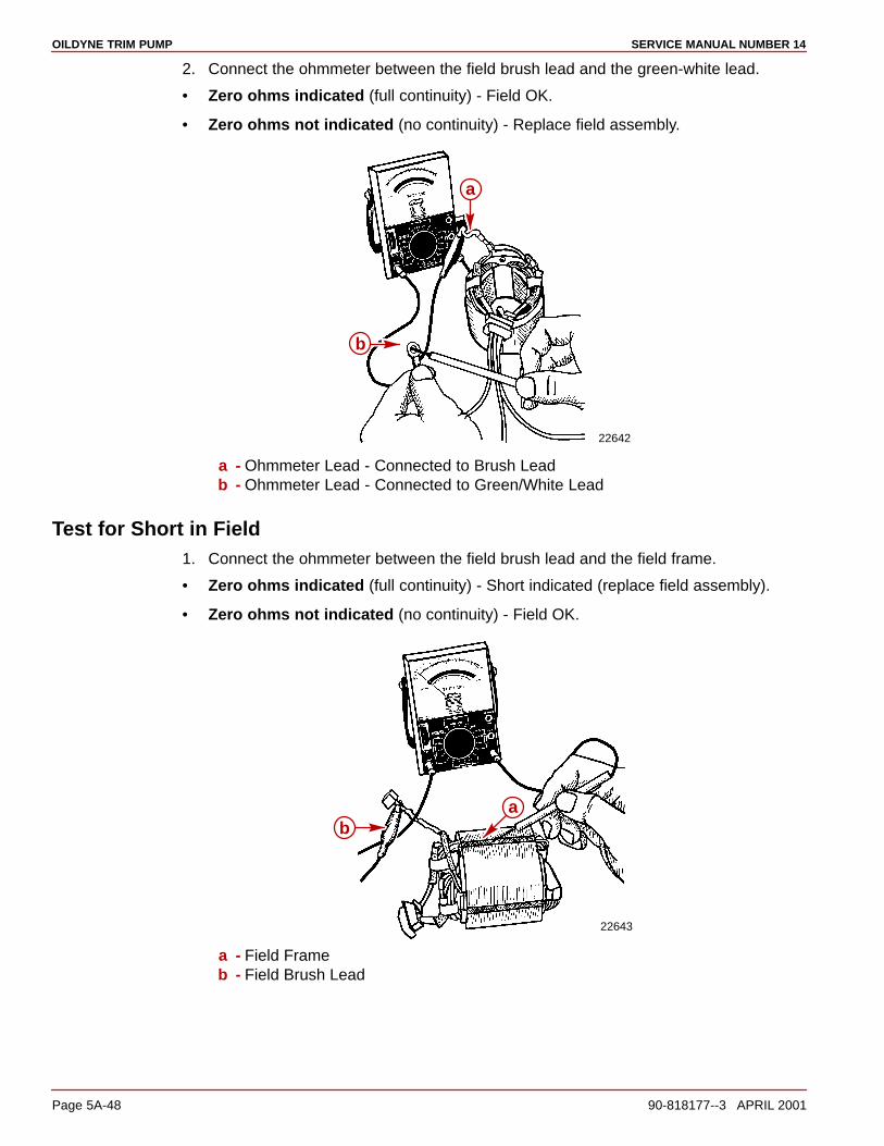
OILDYNE TRIM PUMP SERVICE MANUAL NUMBER 14
Page 5A-48 90-818177--3 APRIL 2001
2. Connect the ohmmeter between the field brush lead and the green-white lead.
• Zero ohms indicated (full continuity) - Field OK.
• Zero ohms not indicated (no continuity) - Replace field assembly.
22642
a
b
a - Ohmmeter Lead - Connected to Brush Leadb - Ohmmeter Lead - Connected to Green/White Lead
Test for Short in Field1. Connect the ohmmeter between the field brush lead and the field frame.
• Zero ohms indicated (full continuity) - Short indicated (replace field assembly).
• Zero ohms not indicated (no continuity) - Field OK.
22643
ab
a - Field Frameb - Field Brush Lead
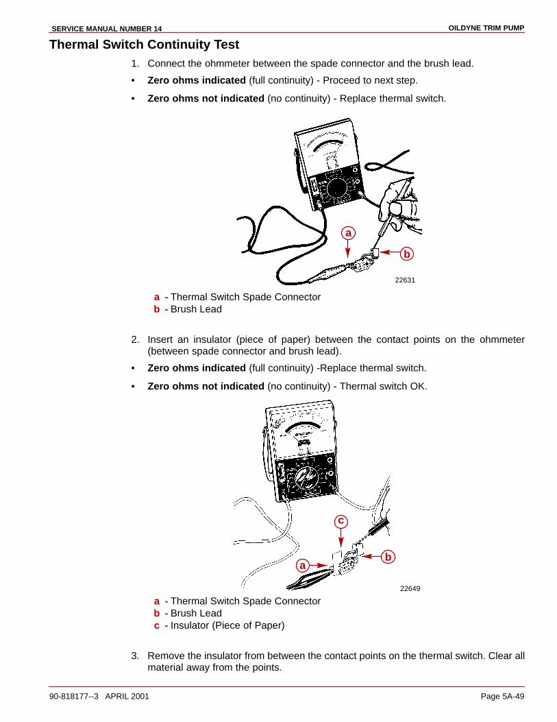
OILDYNE TRIM PUMPSERVICE MANUAL NUMBER 14
90-818177--3 APRIL 2001 Page 5A-49
Thermal Switch Continuity Test1. Connect the ohmmeter between the spade connector and the brush lead.
• Zero ohms indicated (full continuity) - Proceed to next step.
• Zero ohms not indicated (no continuity) - Replace thermal switch.
22631
b
a
a - Thermal Switch Spade Connectorb - Brush Lead
2. Insert an insulator (piece of paper) between the contact points on the ohmmeter(between spade connector and brush lead).
• Zero ohms indicated (full continuity) -Replace thermal switch.
• Zero ohms not indicated (no continuity) - Thermal switch OK.
22649
b
c
a
a - Thermal Switch Spade Connectorb - Brush Leadc - Insulator (Piece of Paper)
3. Remove the insulator from between the contact points on the thermal switch. Clear allmaterial away from the points.

OILDYNE TRIM PUMP SERVICE MANUAL NUMBER 14
Page 5A-50 90-818177--3 APRIL 2001
Brush Replacement1. Loosen the brush hold down arms.
22648
a
ba
b
a - Brush Hold Down Armsb - Screws
IMPORTANT: Use care in removing brush holders so as not to lose springs.
2. Remove the brush holders and springs.
22638
b
a
a - Brush Holderb - Spring
3. Remove the thermal switch and brush assembly.
22637
a
bc
a - Thermal Switch and Brushb - Screwc - Connector
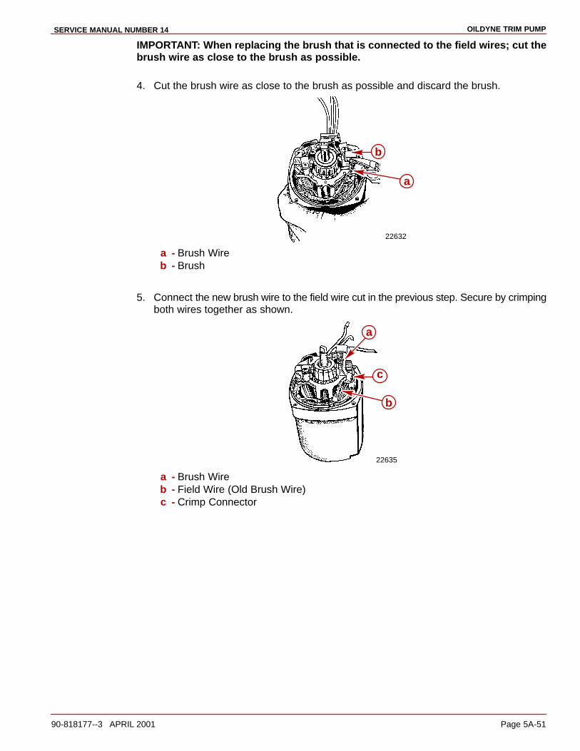
OILDYNE TRIM PUMPSERVICE MANUAL NUMBER 14
90-818177--3 APRIL 2001 Page 5A-51
IMPORTANT: When replacing the brush that is connected to the field wires; cut thebrush wire as close to the brush as possible.
4. Cut the brush wire as close to the brush as possible and discard the brush.
22632
b
a
a - Brush Wireb - Brush
5. Connect the new brush wire to the field wire cut in the previous step. Secure by crimpingboth wires together as shown.
22635
a
c
b
a - Brush Wireb - Field Wire (Old Brush Wire)c - Crimp Connector

OILDYNE TRIM PUMP SERVICE MANUAL NUMBER 14
Page 5A-52 90-818177--3 APRIL 2001
6. Reinstall the spring and brush in the brush holder.
22638
b
ac
a - Brush Holderb - Springc - Brush
7. Position the brush hold down arms and tighten them securely. DO NOTOVERTIGHTEN.
22648
a
ba
b
a - Brush Hold Down Armsb - Screws
8. Position the brush wire as shown before reassembly.
22634
a
a - Brush Wire

OILDYNE TRIM PUMPSERVICE MANUAL NUMBER 14
90-818177--3 APRIL 2001 Page 5A-53
Reassembly
1. Install the motor housing O-ring.
22645
a
b
a - O-ringb - Motor Housing
IMPORTANT: The field assembly wires must face the front of the motor housing. Usethe notched area in the housing as a reference in determining the front.
22633
c
b
a
a - Motor Housingb - Frontc - Notched Area
2. Install the field assembly into the motor housing.
22501
a
b
a - Field Assemblyb - Motor Housing

OILDYNE TRIM PUMP SERVICE MANUAL NUMBER 14
Page 5A-54 90-818177--3 APRIL 2001
3. Install the thrust washer on the armature and install the armature into the motor housing.
22499
c
a
b
a - Armatureb - Thrust Washerc - Motor Housing
4. Install the brush assembly mounting. Tighten the screws securely.
22636
a
a
b
a - Brush Assembly Mounting Bracketb - Screws
5. Install the thermal switch and connect the black wire. DO NOT overtighten the screw.
22637
ab
c
a - Thermal Switchb - Screwc - Black Wire Connector

OILDYNE TRIM PUMPSERVICE MANUAL NUMBER 14
90-818177--3 APRIL 2001 Page 5A-55
6. Install the springs and brushes in the brush holders.
22638
b
a
c
a - Brush Holdersb - Springsc - Brushes
7. Position the brush holders and secure them with the brush hold down arms. DO NOTovertighten the screws.
22648
a
b
a
b
a - Brush Hold Down Armsb - Screws

OILDYNE TRIM PUMP SERVICE MANUAL NUMBER 14
Page 5A-56 90-818177--3 APRIL 2001
8. Install the motor end cover. Apply Loctite 27131 to the screws and tighten securely. DONOT overtighten.
22639
a
b
a - Motor End Coverb - Screws
9. Install the motor to adapter O-ring.
70600
b
a
a - Adapterb - O-ring
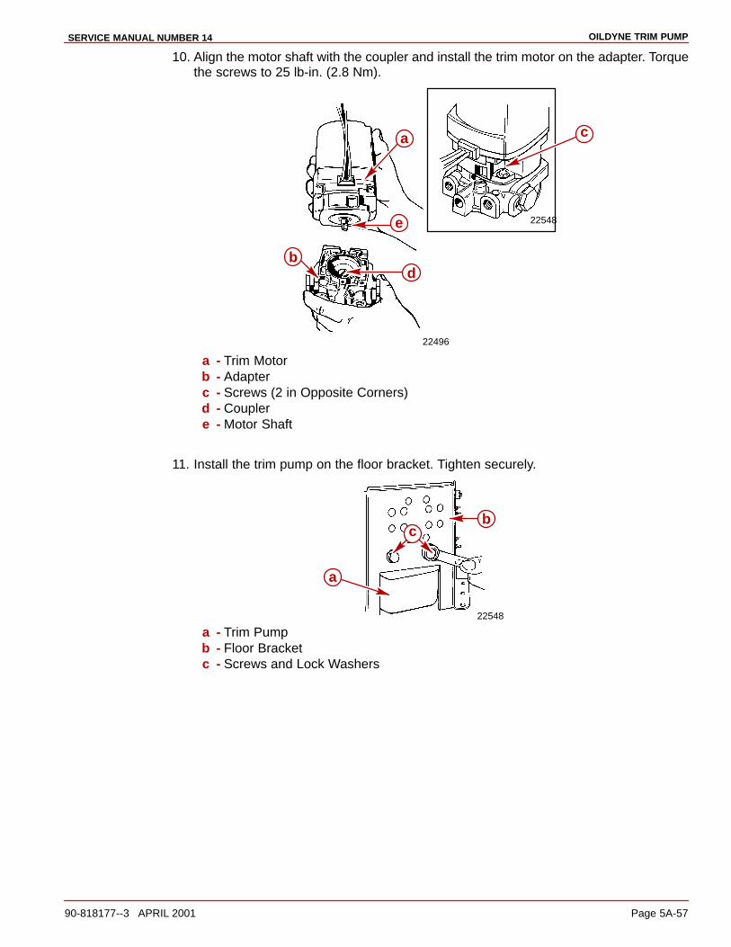
OILDYNE TRIM PUMPSERVICE MANUAL NUMBER 14
90-818177--3 APRIL 2001 Page 5A-57
10. Align the motor shaft with the coupler and install the trim motor on the adapter. Torquethe screws to 25 lb-in. (2.8 Nm).
22548
22496
ca
e
db
a - Trim Motorb - Adapterc - Screws (2 in Opposite Corners)d - Couplere - Motor Shaft
11. Install the trim pump on the floor bracket. Tighten securely.
22548
bc
a
a - Trim Pumpb - Floor Bracketc - Screws and Lock Washers

OILDYNE TRIM PUMP SERVICE MANUAL NUMBER 14
Page 5A-58 90-818177--3 APRIL 2001
12. Connect the trim motor wires to solenoids as shown.
70359
a
b
c
a - Blue/White Motor Wireb - Green/White Motor Wirec - Black Ground Wire
CAUTIONSolenoid terminal cover screw is attached to 12 volt positive source. DO NOTGROUND the screw driver when installing cover.
13. Install the solenoid terminal cover. Tighten the screw securely.
70360
a
b
a - Solenoid Terminal Coverb - Screw
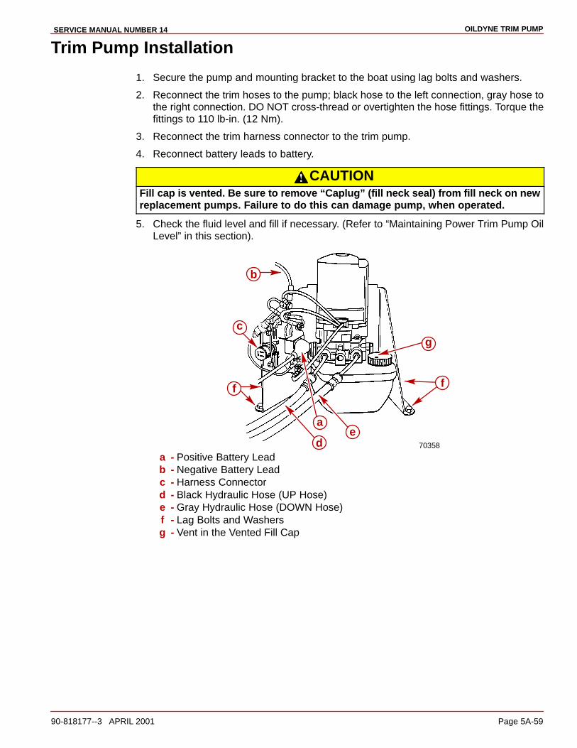
OILDYNE TRIM PUMPSERVICE MANUAL NUMBER 14
90-818177--3 APRIL 2001 Page 5A-59
Trim Pump Installation
1. Secure the pump and mounting bracket to the boat using lag bolts and washers.
2. Reconnect the trim hoses to the pump; black hose to the left connection, gray hose tothe right connection. DO NOT cross-thread or overtighten the hose fittings. Torque thefittings to 110 lb-in. (12 Nm).
3. Reconnect the trim harness connector to the trim pump.
4. Reconnect battery leads to battery.
CAUTIONFill cap is vented. Be sure to remove “Caplug” (fill neck seal) from fill neck on newreplacement pumps. Failure to do this can damage pump, when operated.
5. Check the fluid level and fill if necessary. (Refer to “Maintaining Power Trim Pump OilLevel” in this section).
70358
g
f
ed
b
a
c
f
a - Positive Battery Leadb - Negative Battery Leadc - Harness Connectord - Black Hydraulic Hose (UP Hose)e - Gray Hydraulic Hose (DOWN Hose)f - Lag Bolts and Washersg - Vent in the Vented Fill Cap
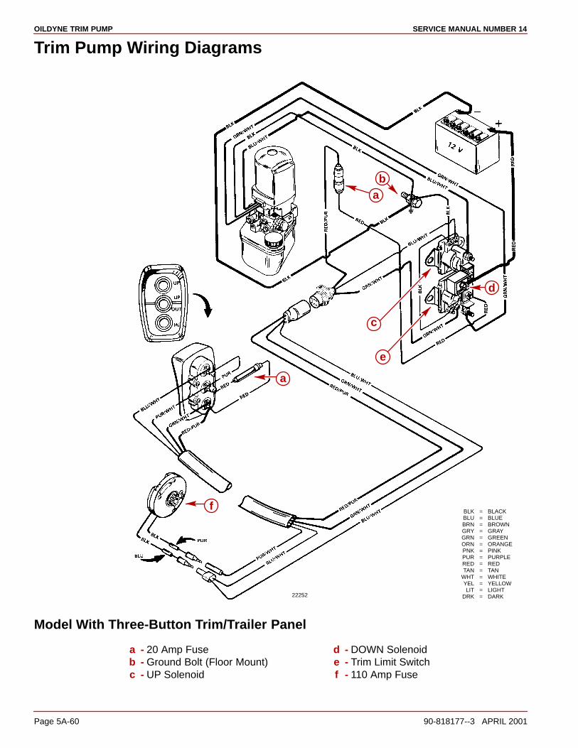
OILDYNE TRIM PUMP SERVICE MANUAL NUMBER 14
Page 5A-60 90-818177--3 APRIL 2001
Trim Pump Wiring Diagrams
22252
BLK = BLACKBLU = BLUEBRN = BROWNGRY = GRAYGRN = GREENORN = ORANGEPNK = PINKPUR = PURPLERED = REDTAN = TAN
WHT = WHITEYEL = YELLOWLIT = LIGHT
DRK = DARK
d
e
c
ba
a
f
Model With Three-Button Trim/Trailer Panel
a - 20 Amp Fuseb - Ground Bolt (Floor Mount)c - UP Solenoid
d - DOWN Solenoide - Trim Limit Switchf - 110 Amp Fuse
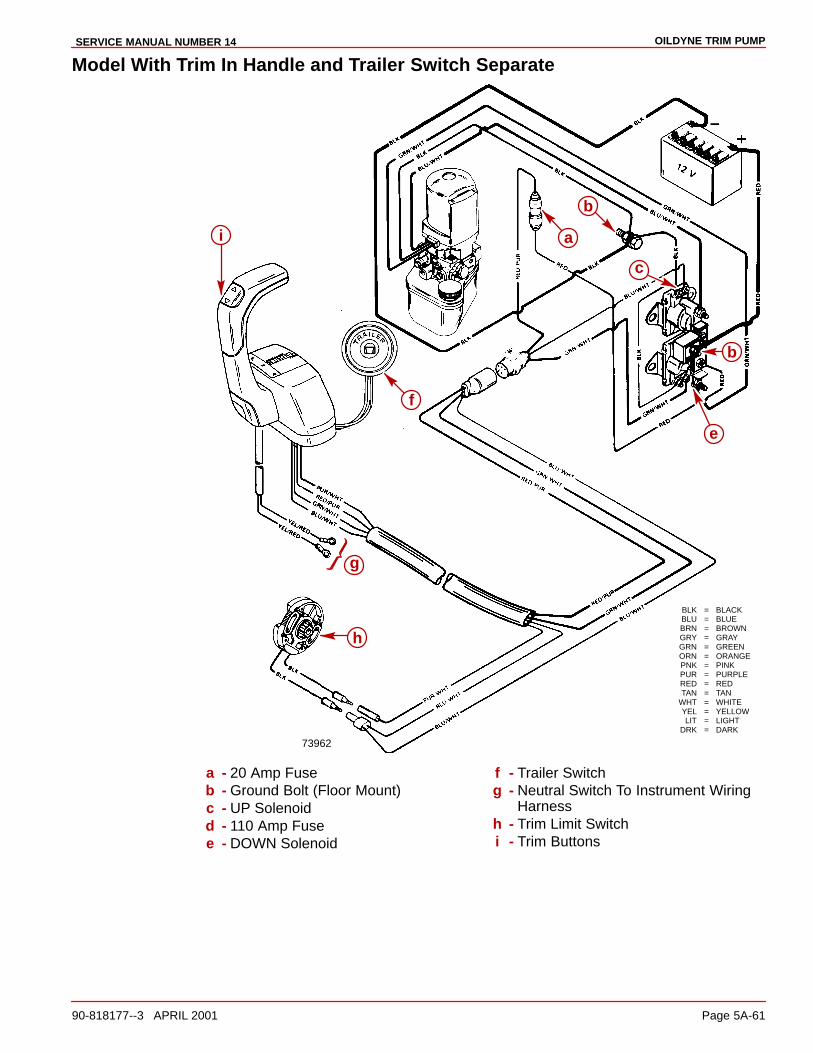
OILDYNE TRIM PUMPSERVICE MANUAL NUMBER 14
90-818177--3 APRIL 2001 Page 5A-61
Model With Trim In Handle and Trailer Switch Separate
73962
BLK = BLACKBLU = BLUEBRN = BROWNGRY = GRAYGRN = GREENORN = ORANGEPNK = PINKPUR = PURPLERED = REDTAN = TAN
WHT = WHITEYEL = YELLOWLIT = LIGHT
DRK = DARK
b
a
c
b
e
f
g
h
i
a - 20 Amp Fuseb - Ground Bolt (Floor Mount)c - UP Solenoidd - 110 Amp Fusee - DOWN Solenoid
f - Trailer Switchg - Neutral Switch To Instrument Wiring
Harnessh - Trim Limit Switchi - Trim Buttons

OILDYNE TRIM PUMP SERVICE MANUAL NUMBER 14
Page 5A-62 90-818177--3 APRIL 2001
THIS PAGE IS INTENTIONALLY BLANK
5B
TRIM CYLINDERSSERVICE MANUAL NUMBER 14
90-818177--3 APRIL 2001 Page 5B-1
POWER TRIMSection 5B - Trim Cylinders
Table of Contents
Specifications 5B-2. . . . . . . . . . . . . . . . . . . . . . . Torque Specifications 5B-2. . . . . . . . . . . . . Special Tools 5B-2. . . . . . . . . . . . . . . . . . . . . Lubricants/Sealers/Adhesives 5B-2. . . . . .
Trim Cylinder Repair 5B-3. . . . . . . . . . . . . . . . . Removal 5B-3. . . . . . . . . . . . . . . . . . . . . . . . . Disassembly 5B-5. . . . . . . . . . . . . . . . . . . . . Reassembly 5B-9. . . . . . . . . . . . . . . . . . . . . Installation 5B-15. . . . . . . . . . . . . . . . . . . . . . .

TRIM CYLINDERS SERVICE MANUAL NUMBER 14
Page 5B-2 90-818177--3 APRIL 2001
Specifications
Torque Specifications
TorqueDescription
lb-in. lb-ft Nm
Piston Rod Bolt 17.5 23.7
End Cap 45 61
Anode Screw 30 3.4
Special Tools
Description Part Number
Spanner Nut Wrench 91-821709T
Large Pin Set 91-811907
Medium Pin Set 91-811908
Small Pin Set 91-811909
Lubricants/Sealers/AdhesivesNOTE: Prior to reassembly of trim cylinder(s), lubricate all internal parts with QuicksilverPower Trim and Steering Fluid or (if not available) 10W-30 or 10W-40 motor oil.
Description Part Number
Loctite 27131 92-809820
Quicksilver 2-4-C Marine Lubricant with Teflon 92-825407A12
Quicksilver Perfect Seal 92-34227--1
Quicksilver Power Trim and Steering Fluid 92-90100A12
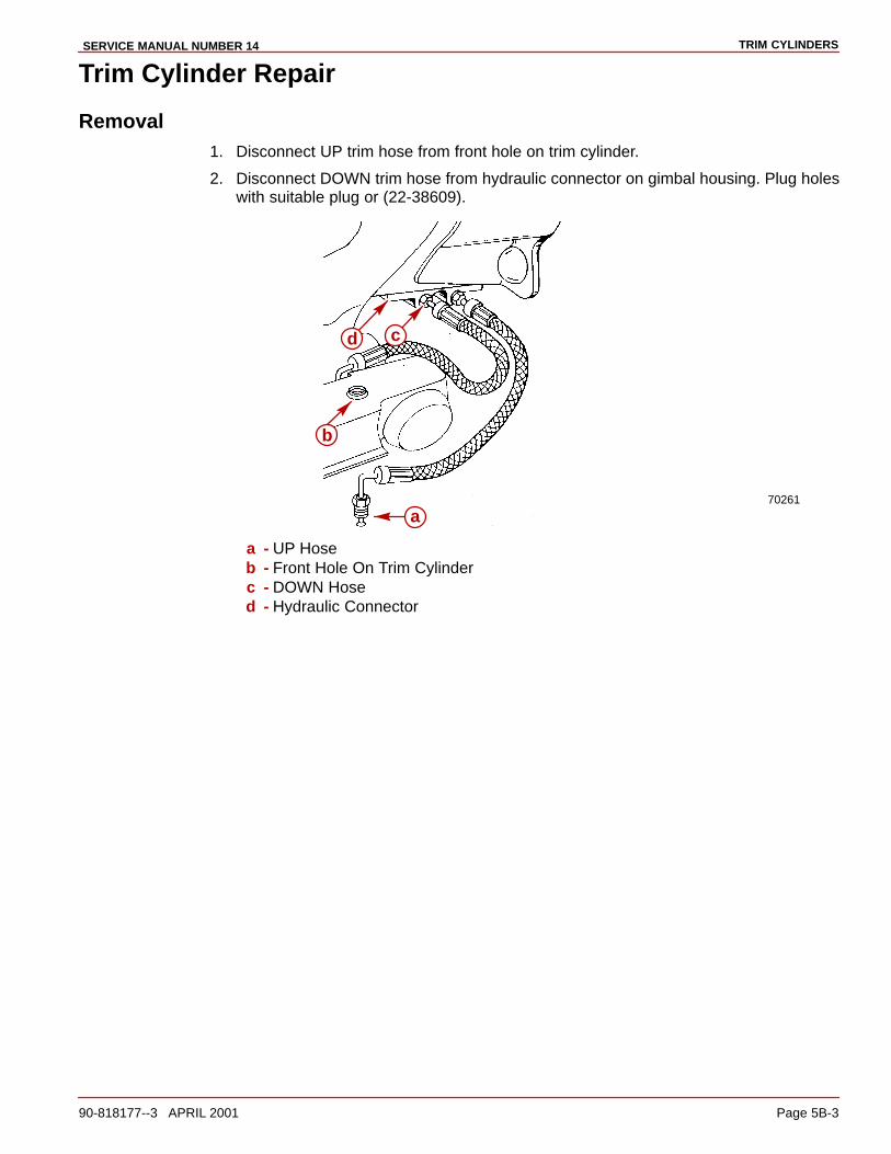
TRIM CYLINDERSSERVICE MANUAL NUMBER 14
90-818177--3 APRIL 2001 Page 5B-3
Trim Cylinder Repair
Removal1. Disconnect UP trim hose from front hole on trim cylinder.
2. Disconnect DOWN trim hose from hydraulic connector on gimbal housing. Plug holeswith suitable plug or (22-38609).
70261
a
b
d c
a - UP Hoseb - Front Hole On Trim Cylinderc - DOWN Hosed - Hydraulic Connector
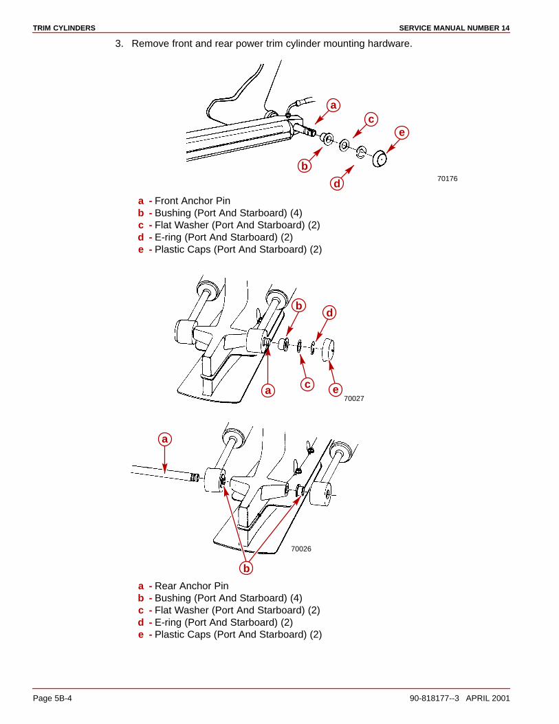
TRIM CYLINDERS SERVICE MANUAL NUMBER 14
Page 5B-4 90-818177--3 APRIL 2001
3. Remove front and rear power trim cylinder mounting hardware.
70176
a
b
c
d
e
a - Front Anchor Pinb - Bushing (Port And Starboard) (4)c - Flat Washer (Port And Starboard) (2)d - E-ring (Port And Starboard) (2)e - Plastic Caps (Port And Starboard) (2)
70027a
b
c
d
e
70026
a
b
a - Rear Anchor Pinb - Bushing (Port And Starboard) (4)c - Flat Washer (Port And Starboard) (2)d - E-ring (Port And Starboard) (2)e - Plastic Caps (Port And Starboard) (2)
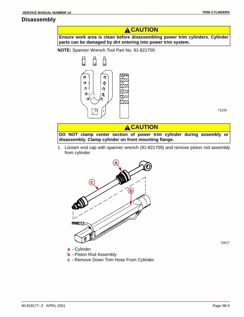
TRIM CYLINDERSSERVICE MANUAL NUMBER 14
90-818177--3 APRIL 2001 Page 5B-5
Disassembly
CAUTIONEnsure work area is clean before disassembling power trim cylinders. Cylinderparts can be damaged by dirt entering into power trim system.
NOTE: Spanner Wrench Tool Part No. 91-821709.
71233
CAUTIONDO NOT clamp center section of power trim cylinder during assembly ordisassembly. Clamp cylinder on front mounting flange.
1. Loosen end cap with spanner wrench (91-821709) and remove piston rod assemblyfrom cylinder.
70677
b
c
a
a - Cylinderb - Piston Rod Assemblyc - Remove Down Trim Hose From Cylinder.
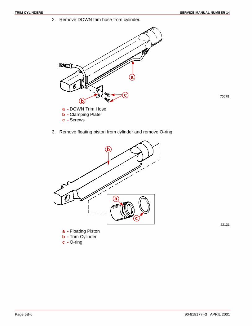
TRIM CYLINDERS SERVICE MANUAL NUMBER 14
Page 5B-6 90-818177--3 APRIL 2001
2. Remove DOWN trim hose from cylinder.
70678
b
a
c
a - DOWN Trim Hoseb - Clamping Platec - Screws
3. Remove floating piston from cylinder and remove O-ring.
22131
a
b
c
a - Floating Pistonb - Trim Cylinderc - O-ring

TRIM CYLINDERSSERVICE MANUAL NUMBER 14
90-818177--3 APRIL 2001 Page 5B-7
4. Remove trim cylinder end caps (Use special tool 91-821709).
71677
a
b
c
a - Special Tool 91-821709b - Trim Cylinderc - Trim Cylinder End Cap
5. Remove and disassemble shock piston assembly. Be careful not to lose check balls.Refer to Reassembly section for explanation if spacer is missing from cylinder.
22132
70682
a
dg
h
b
c
fe
a - Boltb - Spacerc - Washerd - Springs (3)e - Spring Pins (3)f - Check Balls (3)g - Shock Piston Assemblyh - O-ring
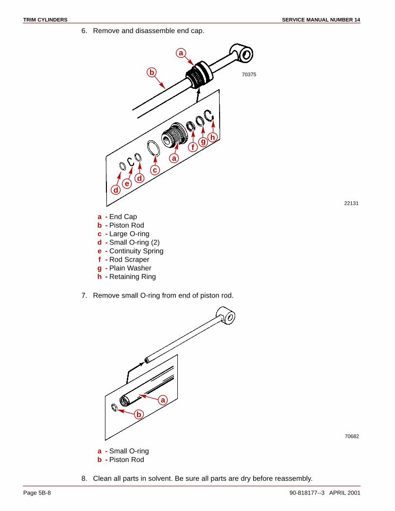
TRIM CYLINDERS SERVICE MANUAL NUMBER 14
Page 5B-8 90-818177--3 APRIL 2001
6. Remove and disassemble end cap.
22131
70375b
de
dc
a
af
g h
a - End Capb - Piston Rodc - Large O-ringd - Small O-ring (2)e - Continuity Springf - Rod Scraperg - Plain Washerh - Retaining Ring
7. Remove small O-ring from end of piston rod.
70682
a
b
a - Small O-ringb - Piston Rod
8. Clean all parts in solvent. Be sure all parts are dry before reassembly.

TRIM CYLINDERSSERVICE MANUAL NUMBER 14
90-818177--3 APRIL 2001 Page 5B-9
ReassemblyIMPORTANT: DO NOT attempt to substitute trim cylinders from different models ordamage to drive unit and/or transom could result.
CAUTIONEnsure work area and all components are clean before reassembling trim cylinders.Power Trim components can become damaged if dirt gets into system.
NOTE: Before reassembly, lubricate all internal parts with Quicksilver Power Trim andSteering Fluid or SAE 10W-30 or 10W-40 Motor Oil.
1. Install small O-ring into end of piston rod.
70682
a
b
a - O-ringb - Piston Rod
2. Install small O-rings and continuity spring into end cap.
3. Install rod scraper, plain washer and retaining ring into end cap.
4. Install large O-ring onto outside diameter of end cap.

TRIM CYLINDERS SERVICE MANUAL NUMBER 14
Page 5B-10 90-818177--3 APRIL 2001
5. Install end cap onto piston rod.
22131
70375b
de
dc
a
af
g h
a - End Capb - Piston Rodc - Large O-ringd - Small O-ring (2)e - Continuity Springf - Rod Scraperg - Plain Washerh - Retaining Ring
6. Install large O-ring on shock piston.
7. Install check ball, check ball eyelet, spring and spring pin into shock piston.
IMPORTANT: The new trim cylinders provide the capability for an increased Trim-inrange. Spacer (u) can be removed from the trim cylinders to increase the Trim-inrange by approximately 1-1/2 degrees. This will improve the acceleration on someboats by forcing the bow down more quickly. If spacers are to be removed, the boatmust be tested to ensure the increased Trim-in range does not cause any undesiredboat handling characteristics (bow-steer, chine-walk, etc.) if the drive is trimmed-inwhile the boat is operated at higher speeds. The boat should be tested under allconceivable load conditions and maneuvers to ensure that the additional Trim-indoes not pose a problem. The final decision and responsibility for use of theadditional Trim-in range is left up to the boat manufacturer.
WARNINGIt is recommended that only qualified personnel perform the adjustment to the trimcylinders. Boat must be water tested after removing the spacers from the trim cylin-ders to ensure that the increased trim range does not cause the boat to exhibit anundesirable boat handling characteristic if the drive is trimmed in at higher speeds.The increased trim-in range may cause handling problems on some boats whichcould result in personal injury.
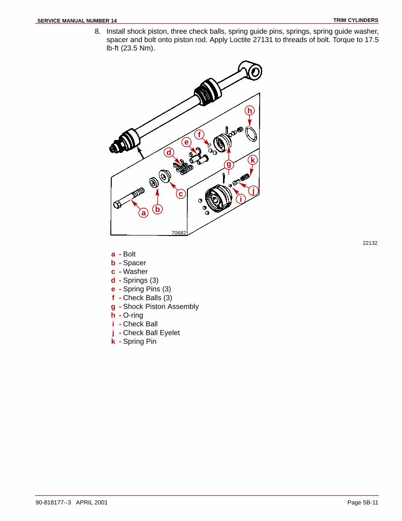
TRIM CYLINDERSSERVICE MANUAL NUMBER 14
90-818177--3 APRIL 2001 Page 5B-11
8. Install shock piston, three check balls, spring guide pins, springs, spring guide washer,spacer and bolt onto piston rod. Apply Loctite 27131 to threads of bolt. Torque to 17.5lb-ft (23.5 Nm).
22132
70682
a
dg
h
b
c
ef
ij
k
a - Boltb - Spacerc - Washerd - Springs (3)e - Spring Pins (3)f - Check Balls (3)g - Shock Piston Assemblyh - O-ringi - Check Ballj - Check Ball Eyeletk - Spring Pin

TRIM CYLINDERS SERVICE MANUAL NUMBER 14
Page 5B-12 90-818177--3 APRIL 2001
9. Apply oil to parts. Install O-ring onto floating piston and insert floating piston into cylinder.
22131
a
b
70682
a - O-ringb - Pistonc - Cylinder
IMPORTANT: Some boat configurations may require tilt-limit spacers to limit the totalupward travel of the drive unit. Be sure to install the same number of spacers thatwere originally removed. There must be an equal number in each cylinder.
10. If required, install tilt-limit spacers.
71679
71678
a
a - Tilt Limit Spacers
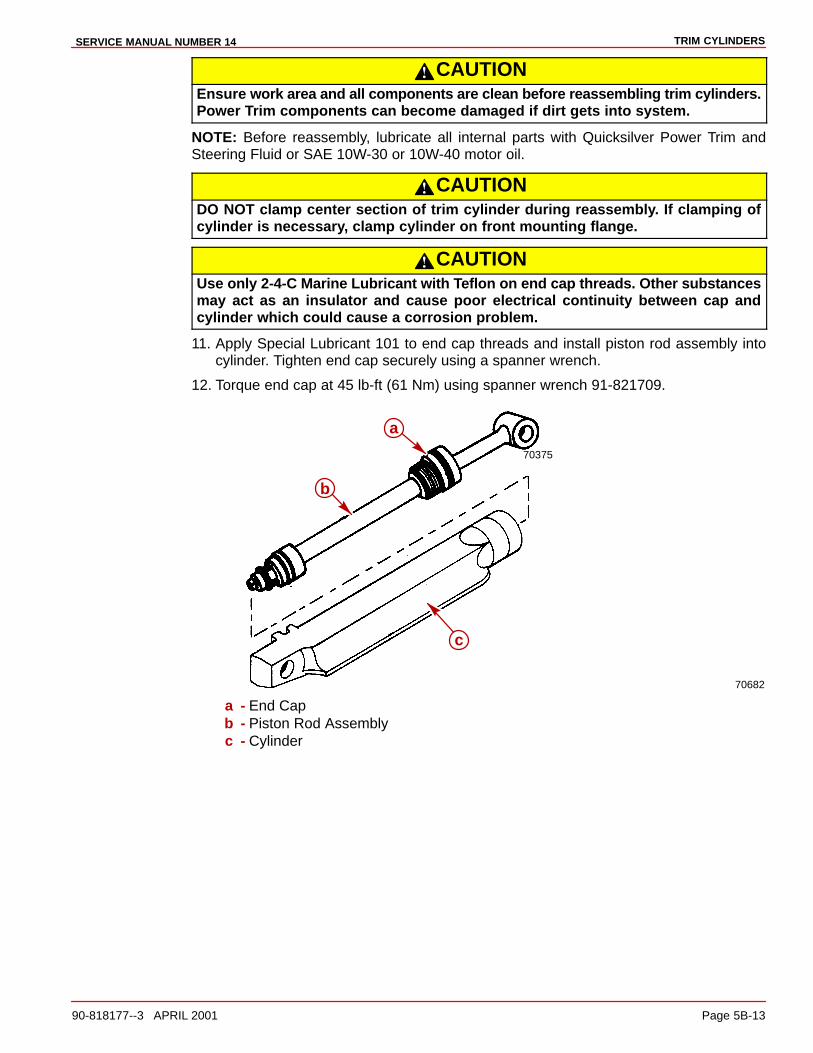
TRIM CYLINDERSSERVICE MANUAL NUMBER 14
90-818177--3 APRIL 2001 Page 5B-13
CAUTIONEnsure work area and all components are clean before reassembling trim cylinders.Power Trim components can become damaged if dirt gets into system.
NOTE: Before reassembly, lubricate all internal parts with Quicksilver Power Trim andSteering Fluid or SAE 10W-30 or 10W-40 motor oil.
CAUTIONDO NOT clamp center section of trim cylinder during reassembly. If clamping ofcylinder is necessary, clamp cylinder on front mounting flange.
CAUTIONUse only 2-4-C Marine Lubricant with Teflon on end cap threads. Other substancesmay act as an insulator and cause poor electrical continuity between cap andcylinder which could cause a corrosion problem.
11. Apply Special Lubricant 101 to end cap threads and install piston rod assembly intocylinder. Tighten end cap securely using a spanner wrench.
12. Torque end cap at 45 lb-ft (61 Nm) using spanner wrench 91-821709.
70682
70375
a
b
c
a - End Capb - Piston Rod Assemblyc - Cylinder
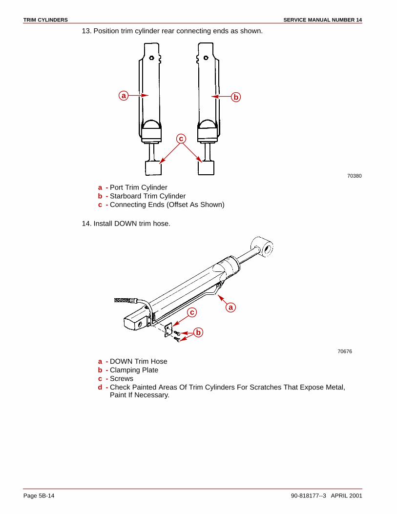
TRIM CYLINDERS SERVICE MANUAL NUMBER 14
Page 5B-14 90-818177--3 APRIL 2001
13. Position trim cylinder rear connecting ends as shown.
70380
a b
c
a - Port Trim Cylinderb - Starboard Trim Cylinderc - Connecting Ends (Offset As Shown)
14. Install DOWN trim hose.
70676
ac
b
a - DOWN Trim Hoseb - Clamping Platec - Screwsd - Check Painted Areas Of Trim Cylinders For Scratches That Expose Metal,
Paint If Necessary.
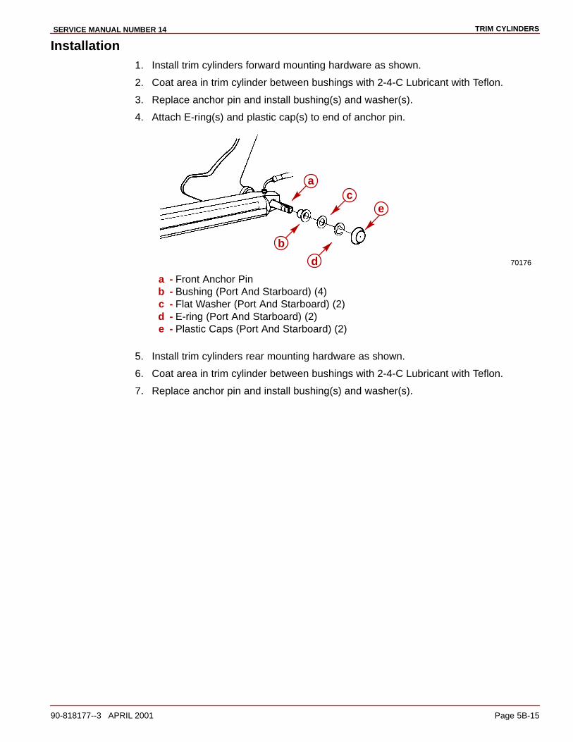
TRIM CYLINDERSSERVICE MANUAL NUMBER 14
90-818177--3 APRIL 2001 Page 5B-15
Installation1. Install trim cylinders forward mounting hardware as shown.
2. Coat area in trim cylinder between bushings with 2-4-C Lubricant with Teflon.
3. Replace anchor pin and install bushing(s) and washer(s).
4. Attach E-ring(s) and plastic cap(s) to end of anchor pin.
70176
a
b
c
d
e
a - Front Anchor Pinb - Bushing (Port And Starboard) (4)c - Flat Washer (Port And Starboard) (2)d - E-ring (Port And Starboard) (2)e - Plastic Caps (Port And Starboard) (2)
5. Install trim cylinders rear mounting hardware as shown.
6. Coat area in trim cylinder between bushings with 2-4-C Lubricant with Teflon.
7. Replace anchor pin and install bushing(s) and washer(s).
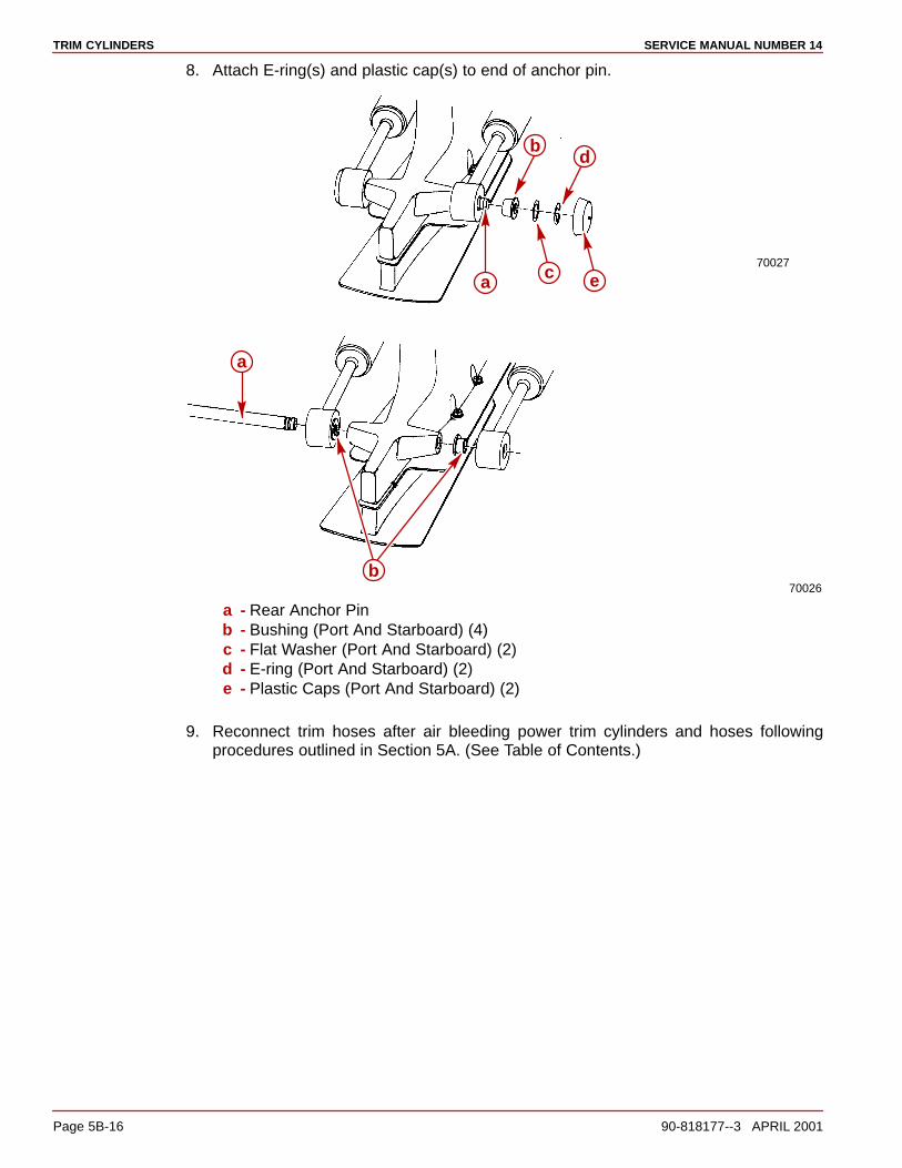
TRIM CYLINDERS SERVICE MANUAL NUMBER 14
Page 5B-16 90-818177--3 APRIL 2001
8. Attach E-ring(s) and plastic cap(s) to end of anchor pin.
70027
b
c
d
ea
70026
a
b
a - Rear Anchor Pinb - Bushing (Port And Starboard) (4)c - Flat Washer (Port And Starboard) (2)d - E-ring (Port And Starboard) (2)e - Plastic Caps (Port And Starboard) (2)
9. Reconnect trim hoses after air bleeding power trim cylinders and hoses followingprocedures outlined in Section 5A. (See Table of Contents.)

TRIM CYLINDERSSERVICE MANUAL NUMBER 14
90-818177--3 APRIL 2001 Page 5B-17
THIS PAGE IS INTENTIONALLY BLANK

TRIM CYLINDERS SERVICE MANUAL NUMBER 14
Page 5B-18 90-818177--3 APRIL 2001
THIS PAGE IS INTENTIONALLY BLANK
5C
DUAL POWER TRIM SYSTEMSERVICE MANUAL NUMBER 14
90-818177--3 APRIL 2001 Page 5C-1
POWER TRIMSection 5C - Dual Power Trim System
Table of Contents
Important Information 5C-2. . . . . . . . . . . . . . . . Testing Dual Power Trim System 5C-2. . . . . .
Relay Test 5C-3. . . . . . . . . . . . . . . . . . . . . . . Diode Module Test 5C-3. . . . . . . . . . . . . . . . Trailer Switch Test 5C-4. . . . . . . . . . . . . . . . Starboard Trim Switch Test 5C-4. . . . . . . . Port Trim Switch Test 5C-4. . . . . . . . . . . . . .
Dual Power Trim System Component Repair 5C-5. . . . . . . . . . . . . . . . . . . . . . . . . . . . .
Important Information 5C-5. . . . . . . . . . . . . Relay Replacement 5C-5. . . . . . . . . . . . . . .
Diode Module Replacement 5C-7. . . . . . . . . . Removal 5C-7. . . . . . . . . . . . . . . . . . . . . . . . . Installation 5C-7. . . . . . . . . . . . . . . . . . . . . . .
Trim Control Panel Switch(es) Replacement 5C-8. . . . . . . . . . . . . . . . . . . . . . .
Removal 5C-8. . . . . . . . . . . . . . . . . . . . . . . . . Installation 5C-9. . . . . . . . . . . . . . . . . . . . . . .
Wiring Diagrams 5C-10. . . . . . . . . . . . . . . . . . . . Dual Trim Harnesses 5C-10. . . . . . . . . . . . . . Electrical Box Wiring 5C-11. . . . . . . . . . . . . .
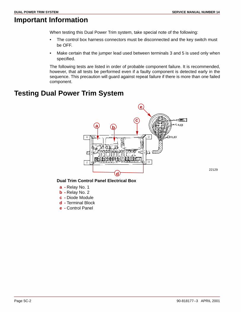
DUAL POWER TRIM SYSTEM SERVICE MANUAL NUMBER 14
Page 5C-2 90-818177--3 APRIL 2001
Important Information
When testing this Dual Power Trim system, take special note of the following:
• The control box harness connectors must be disconnected and the key switch mustbe OFF.
• Make certain that the jumper lead used between terminals 3 and 5 is used only whenspecified.
The following tests are listed in order of probable component failure. It is recommended,however, that all tests be performed even if a faulty component is detected early in thesequence. This precaution will guard against repeat failure if there is more than one failedcomponent.
Testing Dual Power Trim System
22129
e
ca b
dDual Trim Control Panel Electrical Box
a - Relay No. 1b - Relay No. 2c - Diode Moduled - Terminal Blocke - Control Panel

DUAL POWER TRIM SYSTEMSERVICE MANUAL NUMBER 14
90-818177--3 APRIL 2001 Page 5C-3
Relay Test
TESTING RELAY NO. 1
1. Test for 12 volts at terminal 2, using only terminal 4 as a ground.
• Voltage indicated, proceed to “2.”
• No voltage indicated, replace relay.
2. Connect a jumper wire between terminals 3 and 5. Test for 12 volts at terminal 2, usingonly terminal 4 as a ground.
• No voltage indicated, relay OK.
• Voltage indicated, replace the relay.
TESTING RELAY NO. 2
1. Test for continuity between terminals 13 and 9.
• Continuity indicated, proceed to “2.”
• No continuity indicated, replace the relay.
2. Connect a jumper wire between terminals 3 and 5. Test for continuity between terminals13 and 9.
• No continuity indicated, relay OK.
• Continuity indicated, replace relay.
Diode Module TestPerform the following diode tests using an ohmmeter set on the Rx1 scale. When testingdiodes, take 2 readings. Note the first reading; then, reverse the meter leads and, again,note the reading.
If the diode is good, the meter should indicate a high or infinite resistance (no metermovement) when connected one way and a low reading (below 60 ohms) when connectedthe other way.
If both readings are high or infinite, the diode is open. Replace the diode module.
1. Diode No. 1
a. Connect a jumper wire between terminals 3 and 5. Test the diode between terminals9 and 10.
2. Diode No. 2
a. Connect a jumper between terminals 3 and 5. Test diode between terminals 10 and13.
CAUTIONBefore proceeding with further diode testing, remove fuse from red/purple harnesslead so that it will not be possible to short either control box or VOA meter.
3. Diode No. 3
a. Test the diode between terminals 6 and 12.
4. Diode No. 4
a. Test the diode between terminals 12 and 7.

DUAL POWER TRIM SYSTEM SERVICE MANUAL NUMBER 14
Page 5C-4 90-818177--3 APRIL 2001
5. Diode No. 5
a. Test the diode between terminals 8 and 11.
6. Diode No. 6
a. Test the diode between terminals 14 and 15.
7. Diode No. 7
a. Test the diode between terminals 8 and 5.
8. Diode No. 8
a. Test the diode between terminals 5 and 15.
Trailer Switch Test
CAUTIONRemove fuse from RED/PURPLE harness lead before proceeding with test.
1. Set the ohmmeter on the Rx1 scale.
2. Push down on the “Trailer” switch and check for continuity between terminals 10 and 3.
• Continuity indicated, proceed to step 3.
• No continuity indicated, replace the switch.
3. Push up on the trailer switch and check for continuity between terminals 2 and 12.
• Continuity indicated, switch OK.
• No continuity indicated, replace the switch.
Starboard Trim Switch Test1. Set ohmmeter on Rx1 scale.
2. Push down on STARBOARD TRIM switch and check for continuity between terminals1 and 9.
• Continuity indicated, proceed to step 3.
• No continuity indicated, replace switch.
3. Push up on STARBOARD TRIM switch and check for continuity between terminals 11and 6.
• Continuity indicated, switch OK.
• No continuity indicated, replace switch.
Port Trim Switch Test1. Set ohmmeter on Rx1 scale.
2. Push down on PORT TRIM switch and check for continuity between terminals 2 and 13.
• Continuity indicated, proceed to step 3.
• No continuity indicted, replace switch.
3. Push up on PORT TRIM switch and check for continuity between terminals 14 and 7.
• Continuity indicated, switch OK.
• No continuity indicated, replace switch.

DUAL POWER TRIM SYSTEMSERVICE MANUAL NUMBER 14
90-818177--3 APRIL 2001 Page 5C-5
Dual Power Trim System Component Repair
Important InformationUse care when removing and installing components. Do not force or pull wiring duringreplacement. Use care to prevent wiring from stretching, pinching or chafing. Coat allterminal connections with Quicksilver Liquid Neoprene.
Relay Replacement
REMOVAL
1. Remove control box cover.
22086
a
ba - Screwsb - Cover
2. Unsolder wires from relay to be replaced.
3. Remove relay.
22086
a
b
a - Relay Assemblies (1 and 2)b - Fasteners

DUAL POWER TRIM SYSTEM SERVICE MANUAL NUMBER 14
Page 5C-6 90-818177--3 APRIL 2001
INSTALLATION
1. Install new relay.
IMPORTANT: Use 63/67 (Tin/Lead) alloy solder. DO NOT use acid core solder asdamage to relay can result. Coat terminal connections with Quicksilver LiquidNeoprene.
2. Resolder wires from terminal block to relay as shown.
3. Coat terminal connections with Quicksilver Liquid Neoprene.
22216
a
c
b
a - Relay No. 1b - Relay No. 2c - Terminal Block
4. Install control box cover.
22086b
a
a - Screwsb - Cover
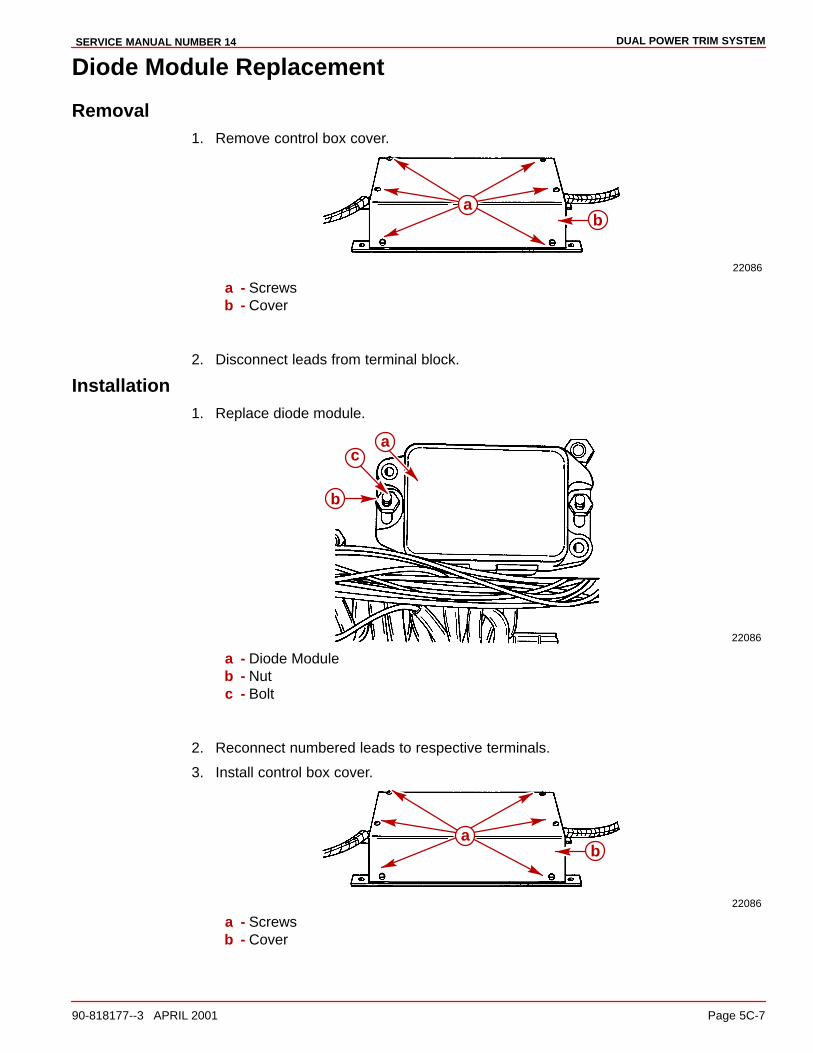
DUAL POWER TRIM SYSTEMSERVICE MANUAL NUMBER 14
90-818177--3 APRIL 2001 Page 5C-7
Diode Module Replacement
Removal1. Remove control box cover.
22086
ba
a - Screwsb - Cover
2. Disconnect leads from terminal block.
Installation1. Replace diode module.
22086
a
b
c
a - Diode Moduleb - Nutc - Bolt
2. Reconnect numbered leads to respective terminals.
3. Install control box cover.
22086
ba
a - Screwsb - Cover
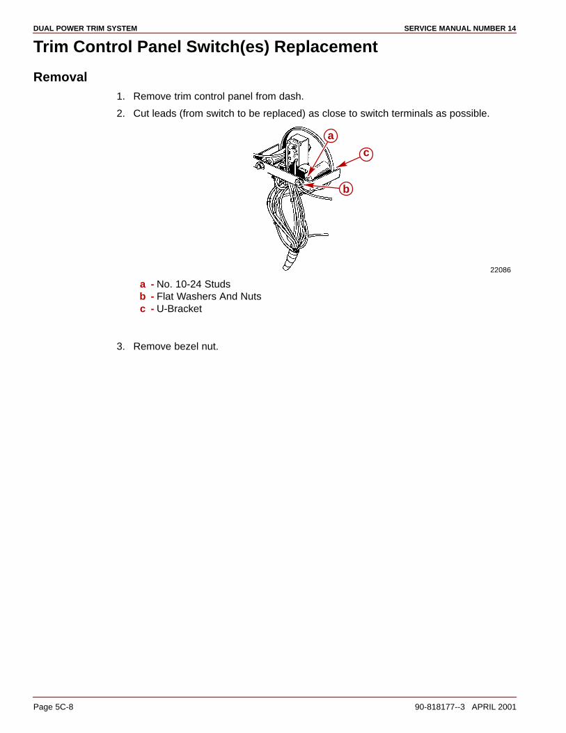
DUAL POWER TRIM SYSTEM SERVICE MANUAL NUMBER 14
Page 5C-8 90-818177--3 APRIL 2001
Trim Control Panel Switch(es) Replacement
Removal1. Remove trim control panel from dash.
2. Cut leads (from switch to be replaced) as close to switch terminals as possible.
22086
a
c
b
a - No. 10-24 Studsb - Flat Washers And Nutsc - U-Bracket
3. Remove bezel nut.

DUAL POWER TRIM SYSTEMSERVICE MANUAL NUMBER 14
90-818177--3 APRIL 2001 Page 5C-9
Installation1. Replace switch.
22086
b
a
a - Bezel Nutb - Switch
2. With new switch properly positioned in control panel, loop leads through their respectiveterminal eyelets. Refer to Wiring Diagram.
3. Using 60/40 (tin/lead) alloy rosin core solder, solder leads to terminals.
4. Secure trim control panel to dash.
22086
ac
b
a - No. 10-24 Studsb - Flat Washers And Nutsc - U-Bracket
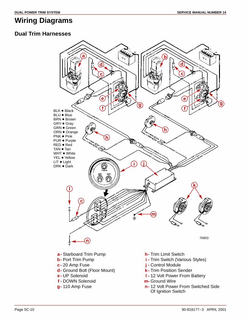
DUAL POWER TRIM SYSTEM SERVICE MANUAL NUMBER 14
Page 5C-10 90-818177--3 APRIL 2001
Wiring Diagrams
Dual Trim Harnesses
BLK � BlackBLU � BlueBRN � BrownGRY � GrayGRN � GreenORN � OrangePNK � PinkPUR � PurpleRED � RedTAN � TanWHT � WhiteYEL � YellowLIT � LightDRK � Dark
e
a b
c
d
c
d
fg
e
fg
h
h
k
j
n
m
l
c
i
76903
a- Starboard Trim Pumpb- Port Trim Pumpc- 20 Amp Fused- Ground Bolt (Floor Mount)e- UP Solenoidf - DOWN Solenoidg- 110 Amp Fuse
h- Trim Limit Switchi - Trim Switch (Various Styles)j - Control Modulek- Trim Position Senderl - 12 Volt Power From Battery
m- Ground Wiren- 12 Volt Power From Switched Side
Of Ignition Switch
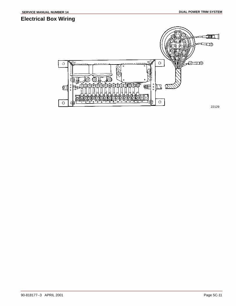
DUAL POWER TRIM SYSTEMSERVICE MANUAL NUMBER 14
90-818177--3 APRIL 2001 Page 5C-11
Electrical Box Wiring
22129

DUAL POWER TRIM SYSTEM SERVICE MANUAL NUMBER 14
Page 5C-12 90-818177--3 APRIL 2001
THIS PAGE IS INTENTIONALLY BLANK

6A
POWER STEERINGSERVICE MANUAL NUMBER 14
90-818177--3 APRIL 2001 Page 6A-1
STEERING SYSTEMSSection 6A - Power Steering
Table of Contents
Trim Pump Specifications 5A-2. . . . . . . . . . . . Valve Pressure Specifications 5A-2. . . . . .
Specifications 6A-2. . . . . . . . . . . . . . . . . . . . . . . Special Tools 6A-2. . . . . . . . . . . . . . . . . . . . . Lubricants/Adhesives/Sealers 6A-2. . . . . .
Description 6A-3. . . . . . . . . . . . . . . . . . . . . . . . . Earlier Style Control Valve 6A-3. . . . . . . . . Later Style Control Valve 6A-3. . . . . . . . . .
Earlier Model Power Steering System 6A-4. . Right Turn 6A-4. . . . . . . . . . . . . . . . . . . . . . .
Earlier Model Power Steering System 6A-5. . Left Turn 6A-5. . . . . . . . . . . . . . . . . . . . . . . .
Earlier Model Power Steering System 6A-6. . Neutral 6A-6. . . . . . . . . . . . . . . . . . . . . . . . . .
Later Model Power Steering System 6A-7. . . Right Turn 6A-7. . . . . . . . . . . . . . . . . . . . . . .
Later Model Power Steering System 6A-8. . . Left Turn 6A-8. . . . . . . . . . . . . . . . . . . . . . . .
Later Model Power Steering System 6A-9. . . Neutral 6A-9. . . . . . . . . . . . . . . . . . . . . . . . . .
Steering Helm and Cable 6A-10. . . . . . . . . . . . . Steering Cable Specifications 6A-11. . . . . .
Filling and Air Bleeding Power Steering System 6A-12. . . . . . . . . . . . . . . . . . . . Balancing Power Steering Control Valve 6A-13. . . . . . . . . . . . . . . . . . . . . . . . . . . . . . Steering Cable Selection, Removal and Installation 6A-17. . . . . . . . . . . . . . . . . . . . .
Selection 6A-17. . . . . . . . . . . . . . . . . . . . . . . . Removal 6A-18. . . . . . . . . . . . . . . . . . . . . . . . . Installation 6A-18. . . . . . . . . . . . . . . . . . . . . . . Installation 6A-20. . . . . . . . . . . . . . . . . . . . . . . Power Steering Pump Lugging Test 6A-21. Power Steering System Pressure Test 6A-23. . . . . . . . . . . . . . . . . . . . . . . . . . . . Pump Pressure Test 6A-25. . . . . . . . . . . . . . Booster Cylinder Test 6A-27. . . . . . . . . . . . .
Power Steering Component Repair 6A-29. . . . Power Steering Unit 6A-29. . . . . . . . . . . . . . . Cable Guide Tube (Early Style Only) 6A-33Control Valve (Early Style Only) 6A-37. . . . Booster Cylinder (Early Style Only) 6A-50. .
Power Steering Pump 6A-55. . . . . . . . . . . . . . . . Removal 6A-55. . . . . . . . . . . . . . . . . . . . . . . . . Flow Control Valve Servicing 6A-55. . . . . . . Pump Shaft Oil Seal Replacement 6A-56. . Disassembly 6A-58. . . . . . . . . . . . . . . . . . . . . Cleaning And Inspection 6A-61. . . . . . . . . . . Reassembly 6A-61. . . . . . . . . . . . . . . . . . . . . Multiple Sterndrive Steering Tie Bar Arrangements 6A-67. . . . . . . . . . . . . . . . . . . Determining Tie Bar Length 6A-67. . . . . . . . Selection 6A-68. . . . . . . . . . . . . . . . . . . . . . . . Installation 6A-69. . . . . . . . . . . . . . . . . . . . . . .
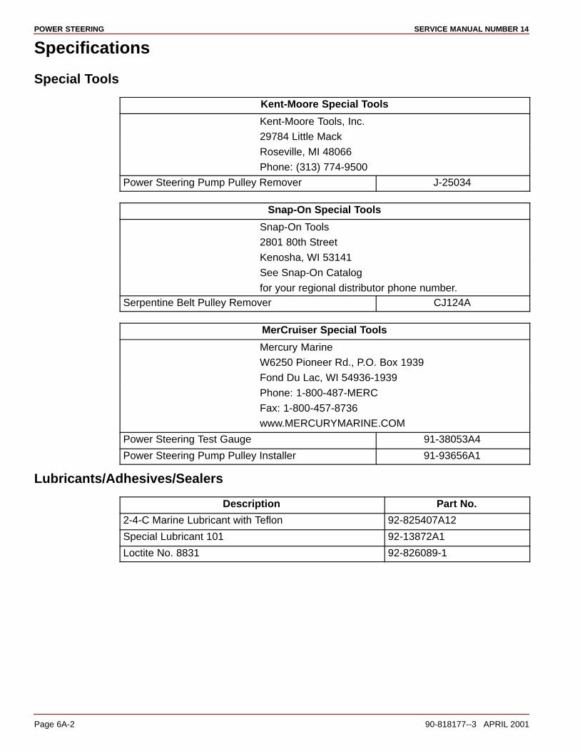
POWER STEERING SERVICE MANUAL NUMBER 14
Page 6A-2 90-818177--3 APRIL 2001
Specifications
Special Tools
Kent-Moore Special Tools
Kent-Moore Tools, Inc.
29784 Little Mack
Roseville, MI 48066
Phone: (313) 774-9500
Power Steering Pump Pulley Remover J-25034
Snap-On Special Tools
Snap-On Tools
2801 80th Street
Kenosha, WI 53141
See Snap-On Catalog
for your regional distributor phone number.Serpentine Belt Pulley Remover CJ124A
MerCruiser Special Tools
Mercury Marine
W6250 Pioneer Rd., P.O. Box 1939
Fond Du Lac, WI 54936-1939
Phone: 1-800-487-MERC
Fax: 1-800-457-8736
www.MERCURYMARINE.COM
Power Steering Test Gauge 91-38053A4
Power Steering Pump Pulley Installer 91-93656A1
Lubricants/Adhesives/Sealers
Description Part No.
2-4-C Marine Lubricant with Teflon 92-825407A12
Special Lubricant 101 92-13872A1
Loctite No. 8831 92-826089-1
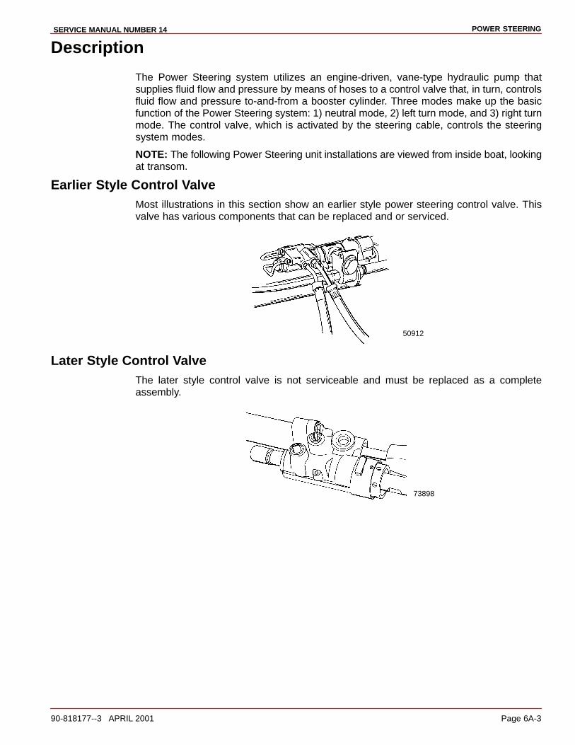
POWER STEERINGSERVICE MANUAL NUMBER 14
90-818177--3 APRIL 2001 Page 6A-3
Description
The Power Steering system utilizes an engine-driven, vane-type hydraulic pump thatsupplies fluid flow and pressure by means of hoses to a control valve that, in turn, controlsfluid flow and pressure to-and-from a booster cylinder. Three modes make up the basicfunction of the Power Steering system: 1) neutral mode, 2) left turn mode, and 3) right turnmode. The control valve, which is activated by the steering cable, controls the steeringsystem modes.
NOTE: The following Power Steering unit installations are viewed from inside boat, lookingat transom.
Earlier Style Control ValveMost illustrations in this section show an earlier style power steering control valve. Thisvalve has various components that can be replaced and or serviced.
50912
Later Style Control ValveThe later style control valve is not serviceable and must be replaced as a completeassembly.
73898
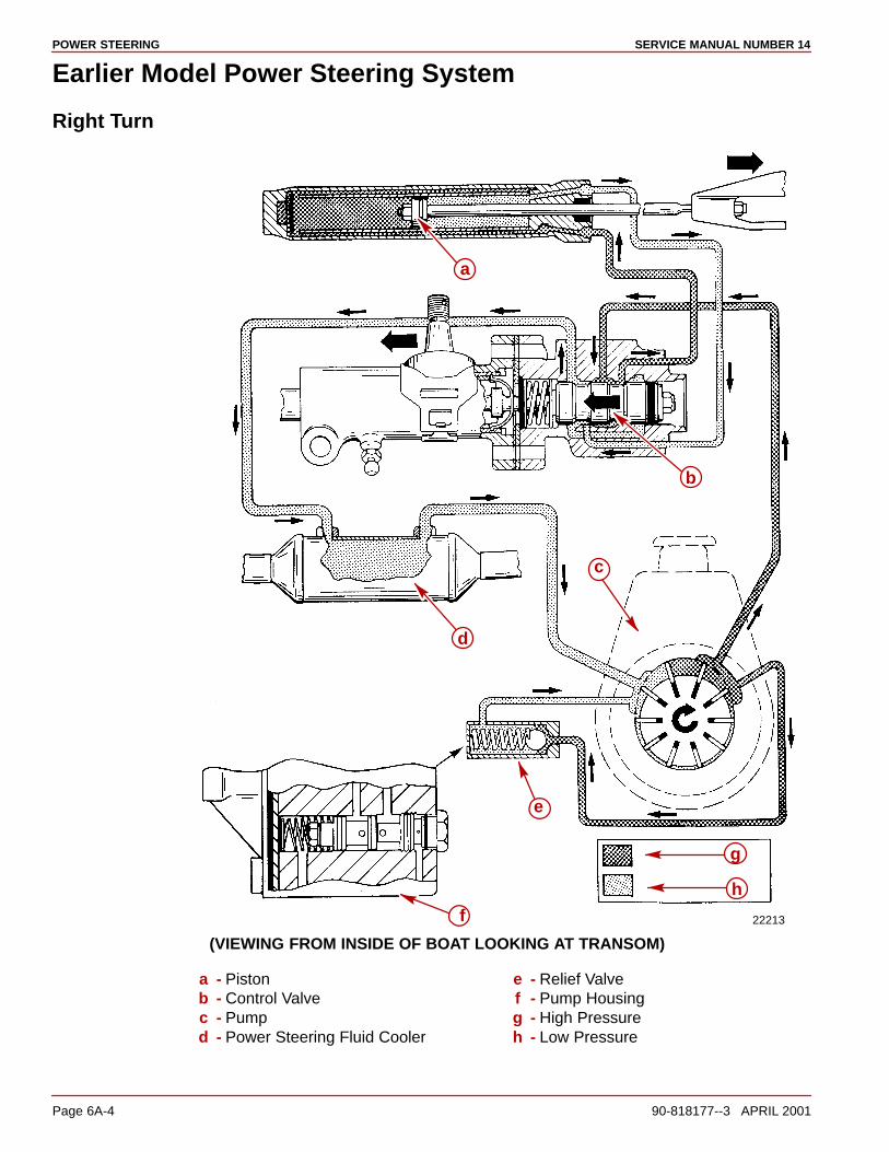
POWER STEERING SERVICE MANUAL NUMBER 14
Page 6A-4 90-818177--3 APRIL 2001
Earlier Model Power Steering System
Right Turn
22213
c
d
a
b
e
f
h
g
(VIEWING FROM INSIDE OF BOAT LOOKING AT TRANSOM)
a - Pistonb - Control Valvec - Pumpd - Power Steering Fluid Cooler
e - Relief Valvef - Pump Housingg - High Pressureh - Low Pressure
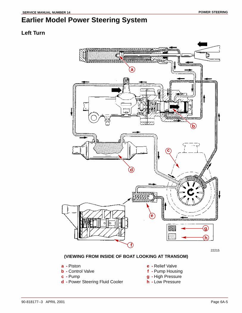
POWER STEERINGSERVICE MANUAL NUMBER 14
90-818177--3 APRIL 2001 Page 6A-5
Earlier Model Power Steering System
Left Turn
22215
c
d
a
b
e
f
h
g
(VIEWING FROM INSIDE OF BOAT LOOKING AT TRANSOM)
a - Pistonb - Control Valvec - Pumpd - Power Steering Fluid Cooler
e - Relief Valvef - Pump Housingg - High Pressureh - Low Pressure
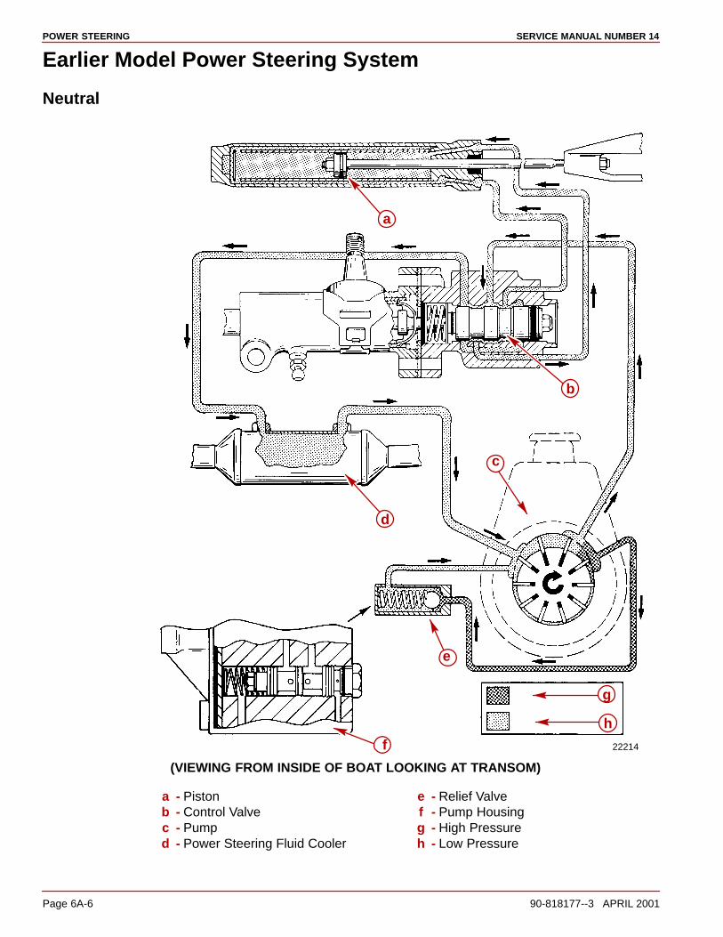
POWER STEERING SERVICE MANUAL NUMBER 14
Page 6A-6 90-818177--3 APRIL 2001
Earlier Model Power Steering System
Neutral
22214
c
d
a
b
e
f
h
g
(VIEWING FROM INSIDE OF BOAT LOOKING AT TRANSOM)
a - Pistonb - Control Valvec - Pumpd - Power Steering Fluid Cooler
e - Relief Valvef - Pump Housingg - High Pressureh - Low Pressure
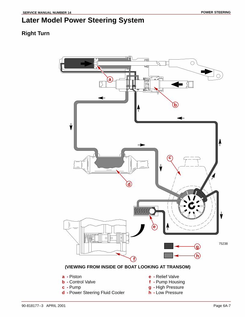
POWER STEERINGSERVICE MANUAL NUMBER 14
90-818177--3 APRIL 2001 Page 6A-7
Later Model Power Steering System
Right Turn
75238
c
d
a
b
e
fh
g
(VIEWING FROM INSIDE OF BOAT LOOKING AT TRANSOM)
a - Pistonb - Control Valvec - Pumpd - Power Steering Fluid Cooler
e - Relief Valvef - Pump Housingg - High Pressureh - Low Pressure

POWER STEERING SERVICE MANUAL NUMBER 14
Page 6A-8 90-818177--3 APRIL 2001
Later Model Power Steering System
Left Turn
75239
c
d
a
b
e
fh
g
(VIEWING FROM INSIDE OF BOAT LOOKING AT TRANSOM)
a - Pistonb - Control Valvec - Pumpd - Power Steering Fluid Cooler
e - Relief Valvef - Pump Housingg - High Pressureh - Low Pressure

POWER STEERINGSERVICE MANUAL NUMBER 14
90-818177--3 APRIL 2001 Page 6A-9
Later Model Power Steering System
Neutral
75237
c
d
a
b
e
f h
g
(VIEWING FROM INSIDE OF BOAT LOOKING AT TRANSOM)
a - Pistonb - Control Valvec - Pumpd - Power Steering Fluid Cooler
e - Relief Valvef - Pump Housingg - High Pressureh - Low Pressure
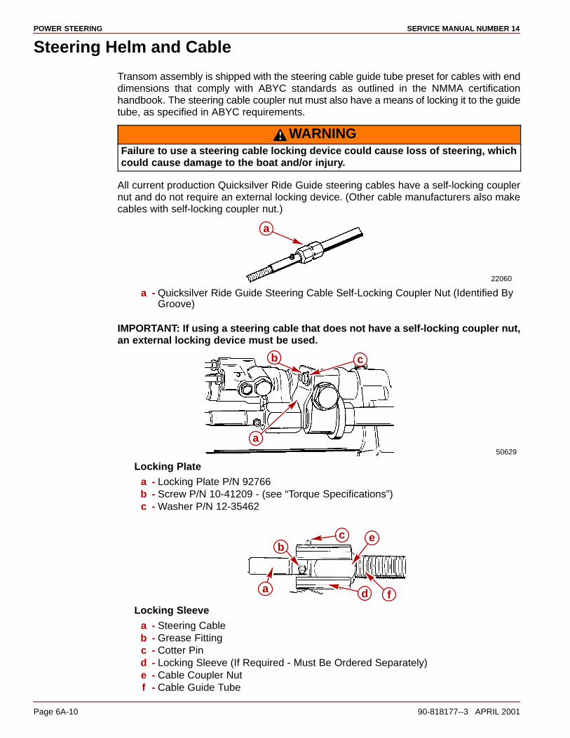
POWER STEERING SERVICE MANUAL NUMBER 14
Page 6A-10 90-818177--3 APRIL 2001
Steering Helm and Cable
Transom assembly is shipped with the steering cable guide tube preset for cables with enddimensions that comply with ABYC standards as outlined in the NMMA certificationhandbook. The steering cable coupler nut must also have a means of locking it to the guidetube, as specified in ABYC requirements.
WARNINGFailure to use a steering cable locking device could cause loss of steering, whichcould cause damage to the boat and/or injury.
All current production Quicksilver Ride Guide steering cables have a self-locking couplernut and do not require an external locking device. (Other cable manufacturers also makecables with self-locking coupler nut.)
22060
a
a - Quicksilver Ride Guide Steering Cable Self-Locking Coupler Nut (Identified ByGroove)
IMPORTANT: If using a steering cable that does not have a self-locking coupler nut,an external locking device must be used.
50629
b c
a
Locking Platea - Locking Plate P/N 92766b - Screw P/N 10-41209 - (see “Torque Specifications”)c - Washer P/N 12-35462
a
bc
f
e
dLocking Sleeve
a - Steering Cableb - Grease Fittingc - Cotter Pind - Locking Sleeve (If Required - Must Be Ordered Separately)e - Cable Coupler Nutf - Cable Guide Tube
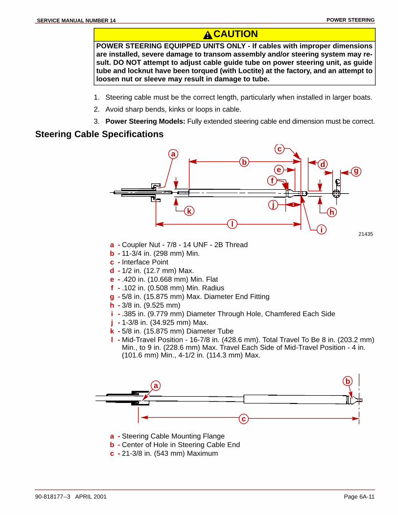
POWER STEERINGSERVICE MANUAL NUMBER 14
90-818177--3 APRIL 2001 Page 6A-11
CAUTIONPOWER STEERING EQUIPPED UNITS ONLY - If cables with improper dimensionsare installed, severe damage to transom assembly and/or steering system may re-sult. DO NOT attempt to adjust cable guide tube on power steering unit, as guidetube and locknut have been torqued (with Loctite) at the factory, and an attempt toloosen nut or sleeve may result in damage to tube.
1. Steering cable must be the correct length, particularly when installed in larger boats.
2. Avoid sharp bends, kinks or loops in cable.
3. Power Steering Models: Fully extended steering cable end dimension must be correct.
Steering Cable Specifications
21435
CL
ab
c
de
fg
h
i
jk
l
a - Coupler Nut - 7/8 - 14 UNF - 2B Threadb - 11-3/4 in. (298 mm) Min.c - Interface Pointd - 1/2 in. (12.7 mm) Max.e - .420 in. (10.668 mm) Min. Flatf - .102 in. (0.508 mm) Min. Radiusg - 5/8 in. (15.875 mm) Max. Diameter End Fittingh - 3/8 in. (9.525 mm)i - .385 in. (9.779 mm) Diameter Through Hole, Chamfered Each Sidej - 1-3/8 in. (34.925 mm) Max.k - 5/8 in. (15.875 mm) Diameter Tubel - Mid-Travel Position - 16-7/8 in. (428.6 mm). Total Travel To Be 8 in. (203.2 mm)
Min., to 9 in. (228.6 mm) Max. Travel Each Side of Mid-Travel Position - 4 in.(101.6 mm) Min., 4-1/2 in. (114.3 mm) Max.
b
c
a
a - Steering Cable Mounting Flangeb - Center of Hole in Steering Cable Endc - 21-3/8 in. (543 mm) Maximum
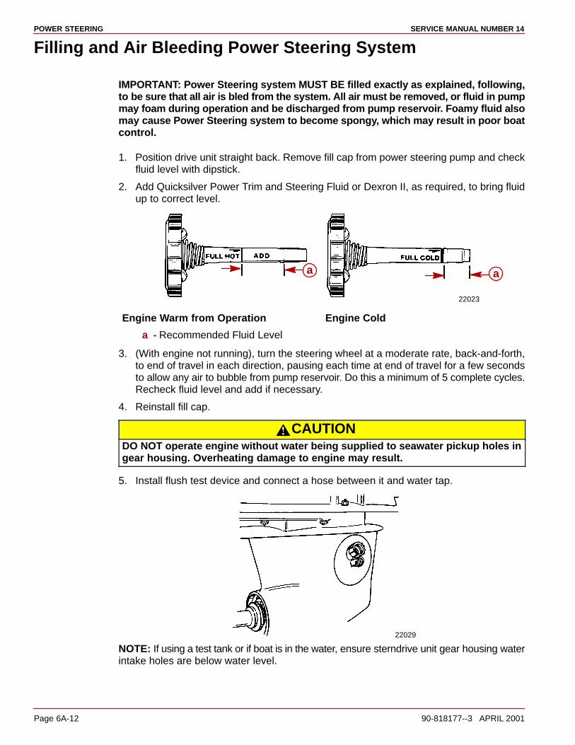
POWER STEERING SERVICE MANUAL NUMBER 14
Page 6A-12 90-818177--3 APRIL 2001
Filling and Air Bleeding Power Steering System
IMPORTANT: Power Steering system MUST BE filled exactly as explained, following,to be sure that all air is bled from the system. All air must be removed, or fluid in pumpmay foam during operation and be discharged from pump reservoir. Foamy fluid alsomay cause Power Steering system to become spongy, which may result in poor boatcontrol.
1. Position drive unit straight back. Remove fill cap from power steering pump and checkfluid level with dipstick.
2. Add Quicksilver Power Trim and Steering Fluid or Dexron II, as required, to bring fluidup to correct level.
22023
aa
Engine Warm from Operation Engine Cold
a - Recommended Fluid Level
3. (With engine not running), turn the steering wheel at a moderate rate, back-and-forth,to end of travel in each direction, pausing each time at end of travel for a few secondsto allow any air to bubble from pump reservoir. Do this a minimum of 5 complete cycles.Recheck fluid level and add if necessary.
4. Reinstall fill cap.
CAUTIONDO NOT operate engine without water being supplied to seawater pickup holes ingear housing. Overheating damage to engine may result.
5. Install flush test device and connect a hose between it and water tap.
22029
NOTE: If using a test tank or if boat is in the water, ensure sterndrive unit gear housing waterintake holes are below water level.

POWER STEERINGSERVICE MANUAL NUMBER 14
90-818177--3 APRIL 2001 Page 6A-13
6. Partially open water tap (approximately 1/2 max.) and allow water to enter coolingsystem. DO NOT use full water tap pressure.
7. Start engine and run at idle. During this time, turn steering wheel back-and-forth to endof travel in each direction several times.
8. Position drive unit so that it is straight back and then stop engine. Remove fill cap frompump. Allow any foam in pump reservoir to disperse, then check fluid level and add fluid,if needed. DO NOT OVERFILL. Reinstall fill cap and tighten securely.
9. If fluid was foamy in previous step, repeat steps 7 and 8 until fluid does not foam andlevel remains constant.
Balancing Power Steering Control Valve
IMPORTANT: Control valve is balanced by the manufacturer and should not requirefurther adjustment. However, if drive unit tends to creep in one direction or the other(with engine running, drive unit in neutral, and hands off the steering wheel), thecontrol valve MUST BE balanced as explained following.
1. Ensure engine is off.
2. Disconnect steering cable from power steering control valve clevis.
22023
a
c
d
b
a - Steering Cableb - Clevisc - Pind - Cotter Pin
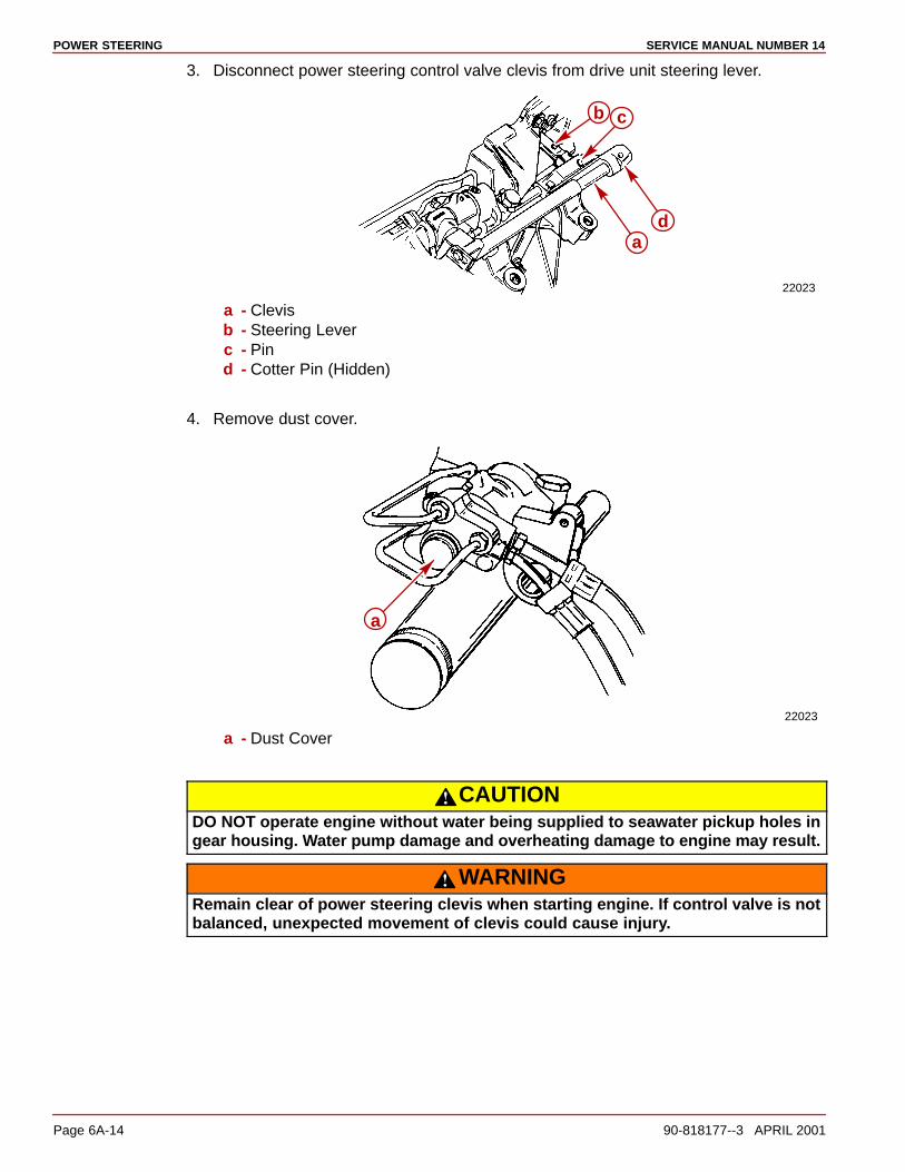
POWER STEERING SERVICE MANUAL NUMBER 14
Page 6A-14 90-818177--3 APRIL 2001
3. Disconnect power steering control valve clevis from drive unit steering lever.
22023
d
cb
a
a - Clevisb - Steering Leverc - Pind - Cotter Pin (Hidden)
4. Remove dust cover.
22023
a
a - Dust Cover
CAUTIONDO NOT operate engine without water being supplied to seawater pickup holes ingear housing. Water pump damage and overheating damage to engine may result.
WARNINGRemain clear of power steering clevis when starting engine. If control valve is notbalanced, unexpected movement of clevis could cause injury.

POWER STEERINGSERVICE MANUAL NUMBER 14
90-818177--3 APRIL 2001 Page 6A-15
5. Connect a flush test device to drive unit. Partially open water tap (approximately 1/2max.) and allow water to enter cooling system. DO NOT use full water tap pressure.
22029
6. Start engine and adjust control valve by turning adjustment nut as follows:
22023
a
a - Adjustment Nut
a. If power steering piston rod end clevis moves toward right (starboard), turn nutclockwise until clevis just begins to move toward left (port), then turn nutcounterclockwise until clevis just begins to move toward right (starboard). Turn nutclockwise to exactly 1/2 the rotation necessary to change direction of rod end clevismovement.
b. If power steering piston rod end clevis moves toward left (port), turn nutcounterclockwise until clevis just begins to move toward right (starboard), then turnnut clockwise until clevis just begins to move toward left (port). Turn nutcounterclockwise to exactly 1/2 the rotation necessary to change direction of rod endclevis movement.
7. Turn off engine.
8. Apply a liberal amount of Special Lubricant 101 to end of steering cable and install cableend in clevis. Secure with pin and cotter pin.
9. Torque self-locking coupler nut to 35 lb-ft (48 Nm).
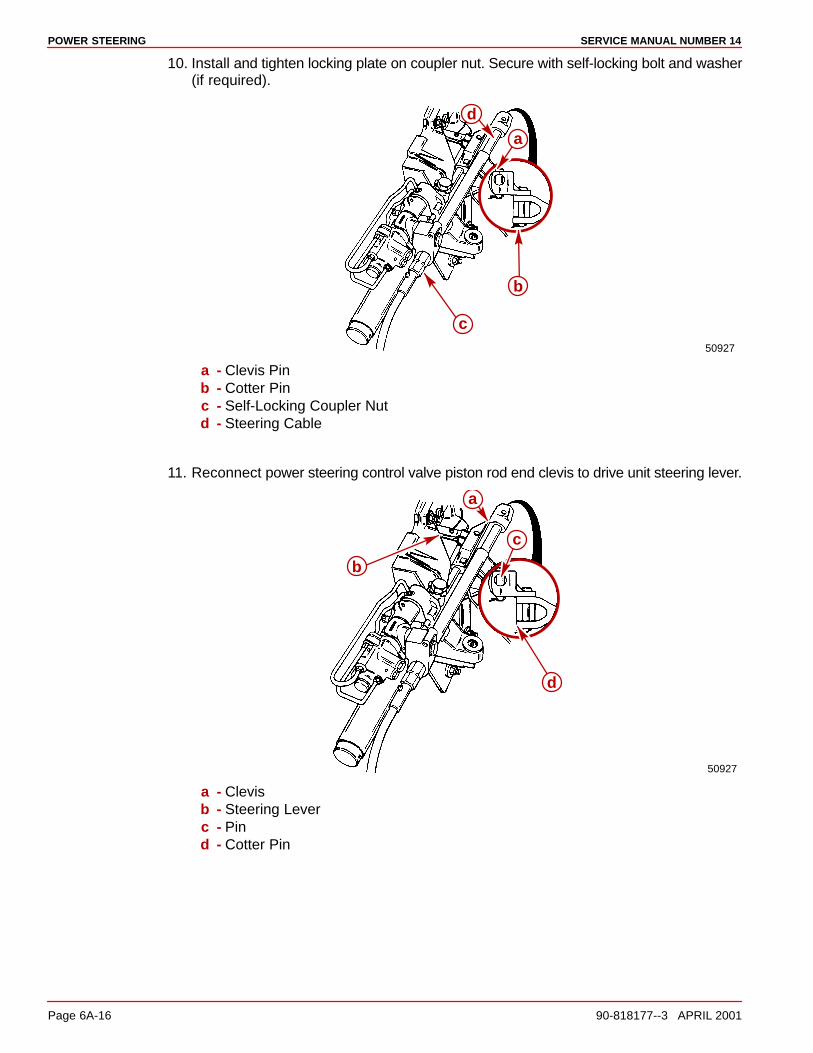
POWER STEERING SERVICE MANUAL NUMBER 14
Page 6A-16 90-818177--3 APRIL 2001
10. Install and tighten locking plate on coupler nut. Secure with self-locking bolt and washer(if required).
50927
a
b
c
d
a - Clevis Pinb - Cotter Pinc - Self-Locking Coupler Nutd - Steering Cable
11. Reconnect power steering control valve piston rod end clevis to drive unit steering lever.
50927
a
b
c
d
a - Clevisb - Steering Leverc - Pind - Cotter Pin
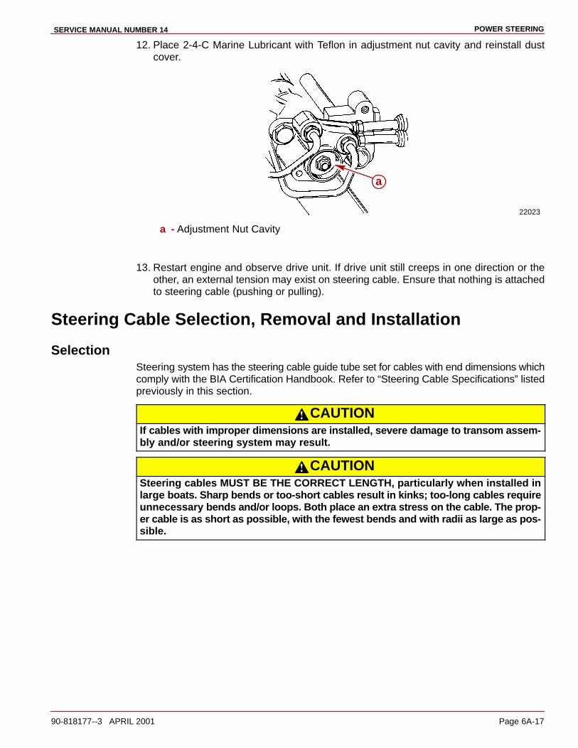
POWER STEERINGSERVICE MANUAL NUMBER 14
90-818177--3 APRIL 2001 Page 6A-17
12. Place 2-4-C Marine Lubricant with Teflon in adjustment nut cavity and reinstall dustcover.
22023
a
a - Adjustment Nut Cavity
13. Restart engine and observe drive unit. If drive unit still creeps in one direction or theother, an external tension may exist on steering cable. Ensure that nothing is attachedto steering cable (pushing or pulling).
Steering Cable Selection, Removal and Installation
SelectionSteering system has the steering cable guide tube set for cables with end dimensions whichcomply with the BIA Certification Handbook. Refer to “Steering Cable Specifications” listedpreviously in this section.
CAUTIONIf cables with improper dimensions are installed, severe damage to transom assem-bly and/or steering system may result.
CAUTIONSteering cables MUST BE THE CORRECT LENGTH, particularly when installed inlarge boats. Sharp bends or too-short cables result in kinks; too-long cables requireunnecessary bends and/or loops. Both place an extra stress on the cable. The prop-er cable is as short as possible, with the fewest bends and with radii as large as pos-sible.
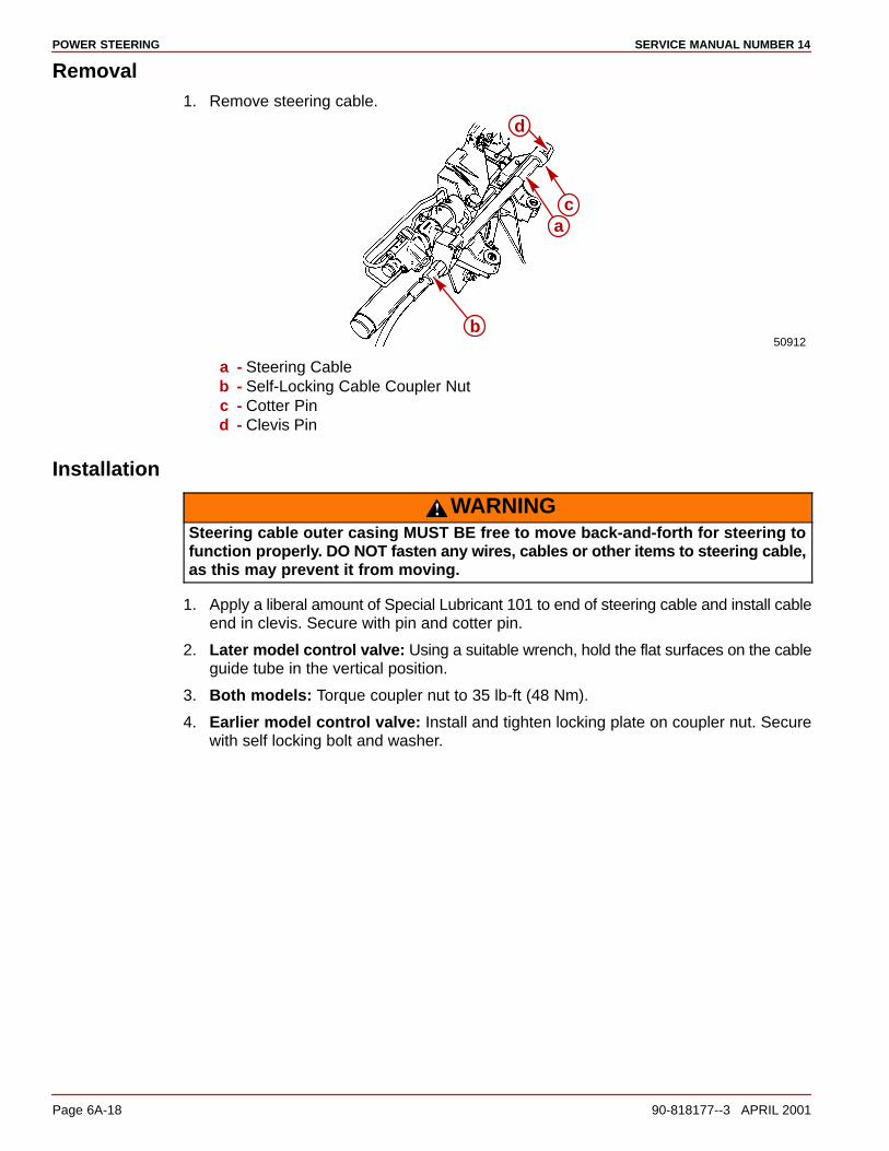
POWER STEERING SERVICE MANUAL NUMBER 14
Page 6A-18 90-818177--3 APRIL 2001
Removal1. Remove steering cable.
50912
a
b
c
d
a - Steering Cableb - Self-Locking Cable Coupler Nutc - Cotter Pind - Clevis Pin
Installation
WARNINGSteering cable outer casing MUST BE free to move back-and-forth for steering tofunction properly. DO NOT fasten any wires, cables or other items to steering cable,as this may prevent it from moving.
1. Apply a liberal amount of Special Lubricant 101 to end of steering cable and install cableend in clevis. Secure with pin and cotter pin.
2. Later model control valve: Using a suitable wrench, hold the flat surfaces on the cableguide tube in the vertical position.
3. Both models: Torque coupler nut to 35 lb-ft (48 Nm).
4. Earlier model control valve: Install and tighten locking plate on coupler nut. Securewith self locking bolt and washer.
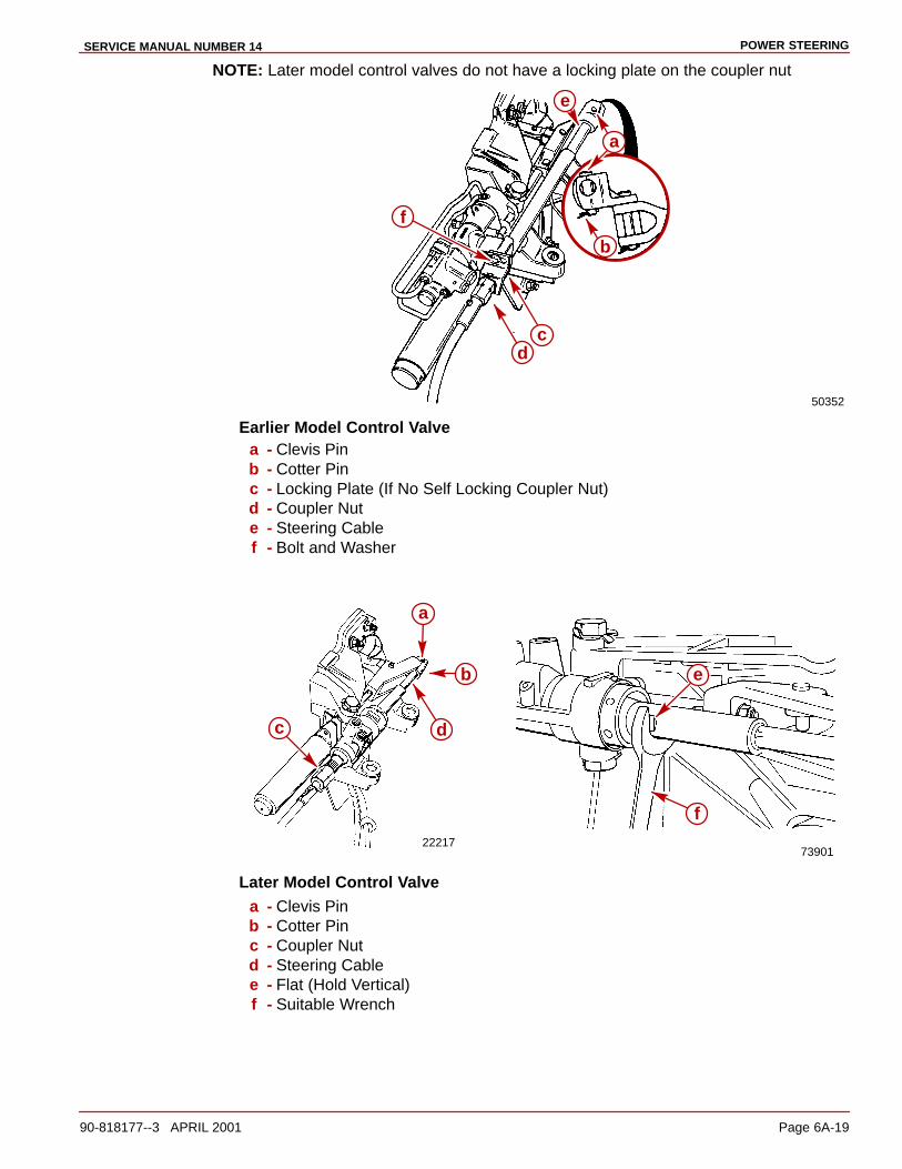
POWER STEERINGSERVICE MANUAL NUMBER 14
90-818177--3 APRIL 2001 Page 6A-19
NOTE: Later model control valves do not have a locking plate on the coupler nut
50352
f
a
b
cd
e
Earlier Model Control Valvea - Clevis Pinb - Cotter Pinc - Locking Plate (If No Self Locking Coupler Nut)d - Coupler Nute - Steering Cablef - Bolt and Washer
2221773901
a
b
c d
e
f
Later Model Control Valvea - Clevis Pinb - Cotter Pinc - Coupler Nutd - Steering Cablee - Flat (Hold Vertical)f - Suitable Wrench
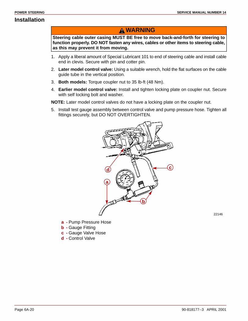
POWER STEERING SERVICE MANUAL NUMBER 14
Page 6A-20 90-818177--3 APRIL 2001
Installation
WARNINGSteering cable outer casing MUST BE free to move back-and-forth for steering tofunction properly. DO NOT fasten any wires, cables or other items to steering cable,as this may prevent it from moving.
1. Apply a liberal amount of Special Lubricant 101 to end of steering cable and install cableend in clevis. Secure with pin and cotter pin.
2. Later model control valve: Using a suitable wrench, hold the flat surfaces on the cableguide tube in the vertical position.
3. Both models: Torque coupler nut to 35 lb-ft (48 Nm).
4. Earlier model control valve: Install and tighten locking plate on coupler nut. Securewith self locking bolt and washer.
NOTE: Later model control valves do not have a locking plate on the coupler nut.
5. Install test gauge assembly between control valve and pump pressure hose. Tighten allfittings securely, but DO NOT OVERTIGHTEN.
22146
a
b
d c
a - Pump Pressure Hoseb - Gauge Fittingc - Gauge Valve Hosed - Control Valve
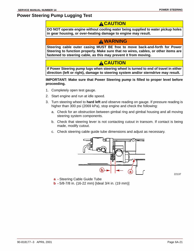
POWER STEERINGSERVICE MANUAL NUMBER 14
90-818177--3 APRIL 2001 Page 6A-21
Power Steering Pump Lugging Test
CAUTIONDO NOT operate engine without cooling water being supplied to water pickup holesin gear housing, or over-heating damage to engine may result.
WARNINGSteering cable outer casing MUST BE free to move back-and-forth for PowerSteering to function properly. Make sure that no wires, cables, or other items arefastened to steering cable, as this may prevent it from moving.
CAUTIONIf Power Steering pump lugs when steering wheel is turned to end of travel in eitherdirection (left or right), damage to steering system and/or sterndrive may result.
IMPORTANT: Make sure that Power Steering pump is filled to proper level beforeproceeding.
1. Completely open test gauge.
2. Start engine and run at idle speed.
3. Turn steering wheel to hard left and observe reading on gauge. If pressure reading ishigher than 300 psi (2069 kPa), stop engine and check the following:
a. Check for an obstruction between gimbal ring and gimbal housing and all movingsteering system components.
b. Check that steering lever is not contacting cutout in transom. If contact is beingmade, modify cutout.
c. Check steering cable guide tube dimensions and adjust as necessary.
22137b a
a - Steering Cable Guide Tubeb - 5/8-7/8 in. (16-22 mm) [Ideal 3/4 in. (19 mm)]
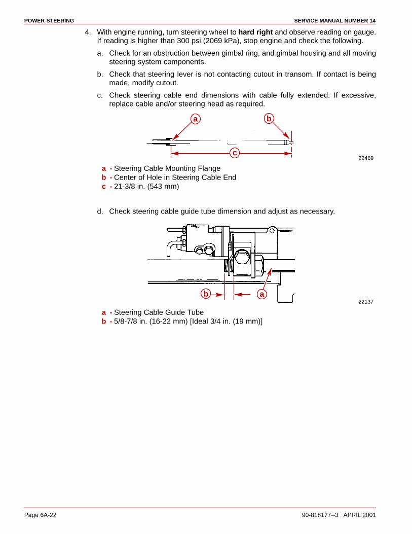
POWER STEERING SERVICE MANUAL NUMBER 14
Page 6A-22 90-818177--3 APRIL 2001
4. With engine running, turn steering wheel to hard right and observe reading on gauge.If reading is higher than 300 psi (2069 kPa), stop engine and check the following.
a. Check for an obstruction between gimbal ring, and gimbal housing and all movingsteering system components.
b. Check that steering lever is not contacting cutout in transom. If contact is beingmade, modify cutout.
c. Check steering cable end dimensions with cable fully extended. If excessive,replace cable and/or steering head as required.
22469
a b
c
a - Steering Cable Mounting Flangeb - Center of Hole in Steering Cable Endc - 21-3/8 in. (543 mm)
d. Check steering cable guide tube dimension and adjust as necessary.
22137b a
a - Steering Cable Guide Tubeb - 5/8-7/8 in. (16-22 mm) [Ideal 3/4 in. (19 mm)]
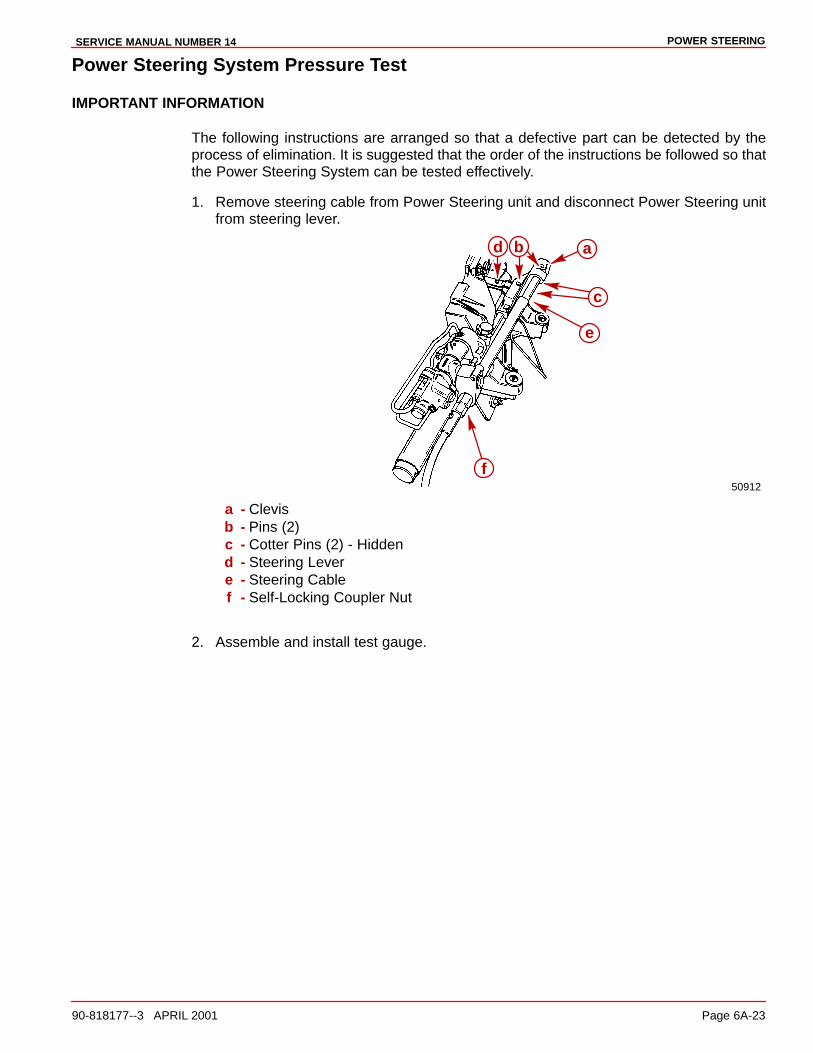
POWER STEERINGSERVICE MANUAL NUMBER 14
90-818177--3 APRIL 2001 Page 6A-23
Power Steering System Pressure Test
IMPORTANT INFORMATION
The following instructions are arranged so that a defective part can be detected by theprocess of elimination. It is suggested that the order of the instructions be followed so thatthe Power Steering System can be tested effectively.
1. Remove steering cable from Power Steering unit and disconnect Power Steering unitfrom steering lever.
50912
d a
c
e
f
b
a - Clevisb - Pins (2)c - Cotter Pins (2) - Hiddend - Steering Levere - Steering Cablef - Self-Locking Coupler Nut
2. Assemble and install test gauge.
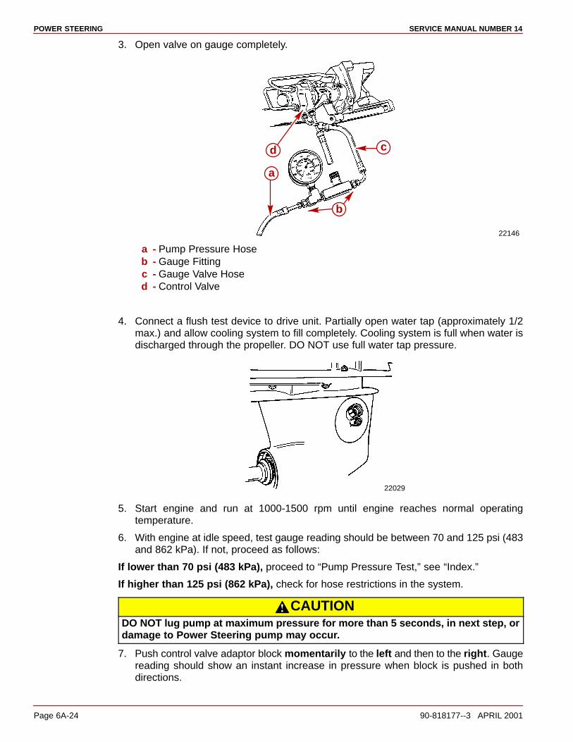
POWER STEERING SERVICE MANUAL NUMBER 14
Page 6A-24 90-818177--3 APRIL 2001
3. Open valve on gauge completely.
22146
c
b
a
d
a - Pump Pressure Hoseb - Gauge Fittingc - Gauge Valve Hosed - Control Valve
4. Connect a flush test device to drive unit. Partially open water tap (approximately 1/2max.) and allow cooling system to fill completely. Cooling system is full when water isdischarged through the propeller. DO NOT use full water tap pressure.
22029
5. Start engine and run at 1000-1500 rpm until engine reaches normal operatingtemperature.
6. With engine at idle speed, test gauge reading should be between 70 and 125 psi (483and 862 kPa). If not, proceed as follows:
If lower than 70 psi (483 kPa), proceed to “Pump Pressure Test,” see “Index.”
If higher than 125 psi (862 kPa), check for hose restrictions in the system.
CAUTIONDO NOT lug pump at maximum pressure for more than 5 seconds, in next step, ordamage to Power Steering pump may occur.
7. Push control valve adaptor block momentarily to the left and then to the right. Gaugereading should show an instant increase in pressure when block is pushed in bothdirections.
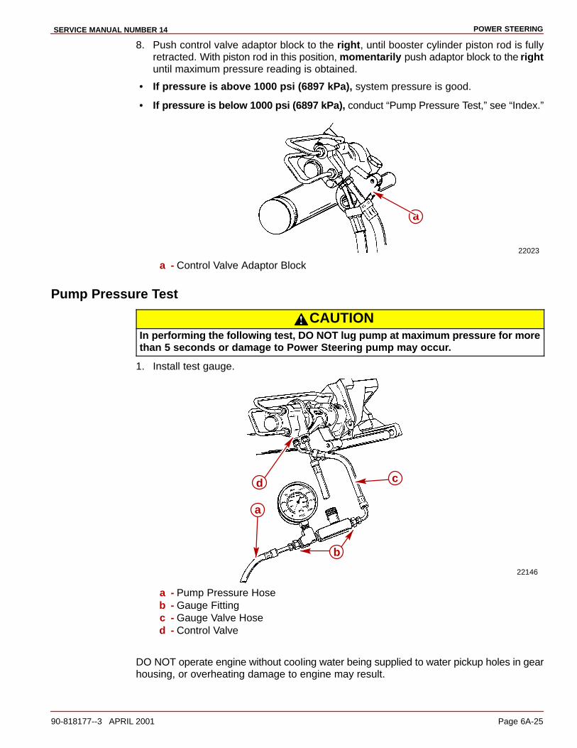
POWER STEERINGSERVICE MANUAL NUMBER 14
90-818177--3 APRIL 2001 Page 6A-25
8. Push control valve adaptor block to the right, until booster cylinder piston rod is fullyretracted. With piston rod in this position, momentarily push adaptor block to the rightuntil maximum pressure reading is obtained.
• If pressure is above 1000 psi (6897 kPa), system pressure is good.
• If pressure is below 1000 psi (6897 kPa), conduct “Pump Pressure Test,” see “Index.”
22023
a
a - Control Valve Adaptor Block
Pump Pressure Test
CAUTIONIn performing the following test, DO NOT lug pump at maximum pressure for morethan 5 seconds or damage to Power Steering pump may occur.
1. Install test gauge.
22146
b
a
d c
a - Pump Pressure Hoseb - Gauge Fittingc - Gauge Valve Hosed - Control Valve
DO NOT operate engine without cooIing water being supplied to water pickup holes in gearhousing, or overheating damage to engine may result.

POWER STEERING SERVICE MANUAL NUMBER 14
Page 6A-26 90-818177--3 APRIL 2001
2. Connect a flush test device to drive unit. Partially open water tap (approximately 1/2max.) and allow water to enter cooling system. DO NOT use full water tap pressure.
22029
3. Start engine and run at 1000-1500 rpm until engine reaches normal operatingtemperature.
4. Close test gauge valve just long enough to obtain maximum pressure reading.
5. Close and open valve 3 times. Record highest pressure reading attained each time.
a. If pressure readings are between 1150 and 1250 psi (7932-8621 kPa) and arewithin a range of 50 psi (345 kPa), the pump is within specifications. If the pumptests OK, but system pressure was low (as tested under “Power Steering SystemPressure Test,” see “Index”), proceed to “Booster Cylinder Test,” see “Index.”
b. If pressure readings are between 1150-1250 psi (7932-8621 kPa), but are notwithin a 50 psi (345 kPa) range, the Power Steering pump flow control valve issticking or pump hydraulic system is dirty.
c. If pressure readings are constant, but below 1000 psi (6897 kPa), replace PowerSteering pump.

POWER STEERINGSERVICE MANUAL NUMBER 14
90-818177--3 APRIL 2001 Page 6A-27
Booster Cylinder Test
CAUTIONDO NOT operate engine without cooling water being supplied to water pickup holesin gear housing, or over-heating damage to engine may result.
1. Connect a flush test device to drive unit. Partially open water tap (approximately 1/2max.) and allow water to enter cooling system. DO NOT use full water tap pressure.
22029
2. Start engine.
3. Push control valve adaptor block to the right until booster cylinder rod is fully retracted.
4. Stop engine.
5. Remove top metal hydraulic line from control valve.
6. Plug port in control valve and cap end of metal line with cap and plug supplied in testgauge kit.
22023
a
b
a - Adaptor Block - Push To Rightb - Top Metal Line
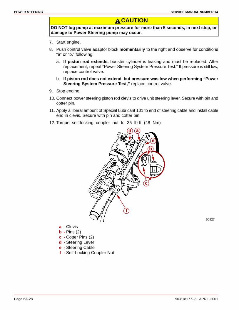
POWER STEERING SERVICE MANUAL NUMBER 14
Page 6A-28 90-818177--3 APRIL 2001
CAUTIONDO NOT lug pump at maximum pressure for more than 5 seconds, in next step, ordamage to Power Steering pump may occur.
7. Start engine.
8. Push control valve adaptor block momentarily to the right and observe for conditions“a” or “b,” following:
a. If piston rod extends, booster cylinder is leaking and must be replaced. Afterreplacement, repeat “Power Steering System Pressure Test.” If pressure is still low,replace control valve.
b. If piston rod does not extend, but pressure was low when performing “PowerSteering System Pressure Test,” replace control valve.
9. Stop engine.
10. Connect power steering piston rod clevis to drive unit steering lever. Secure with pin andcotter pin.
11. Apply a liberal amount of Special Lubricant 101 to end of steering cable and install cableend in clevis. Secure with pin and cotter pin.
12. Torque self-locking coupler nut to 35 lb-ft (48 Nm).
50927
a
b
c
e
d
f
a - Clevisb - Pins (2)c - Cotter Pins (2)d - Steering Levere - Steering Cablef - Self-Locking Coupler Nut
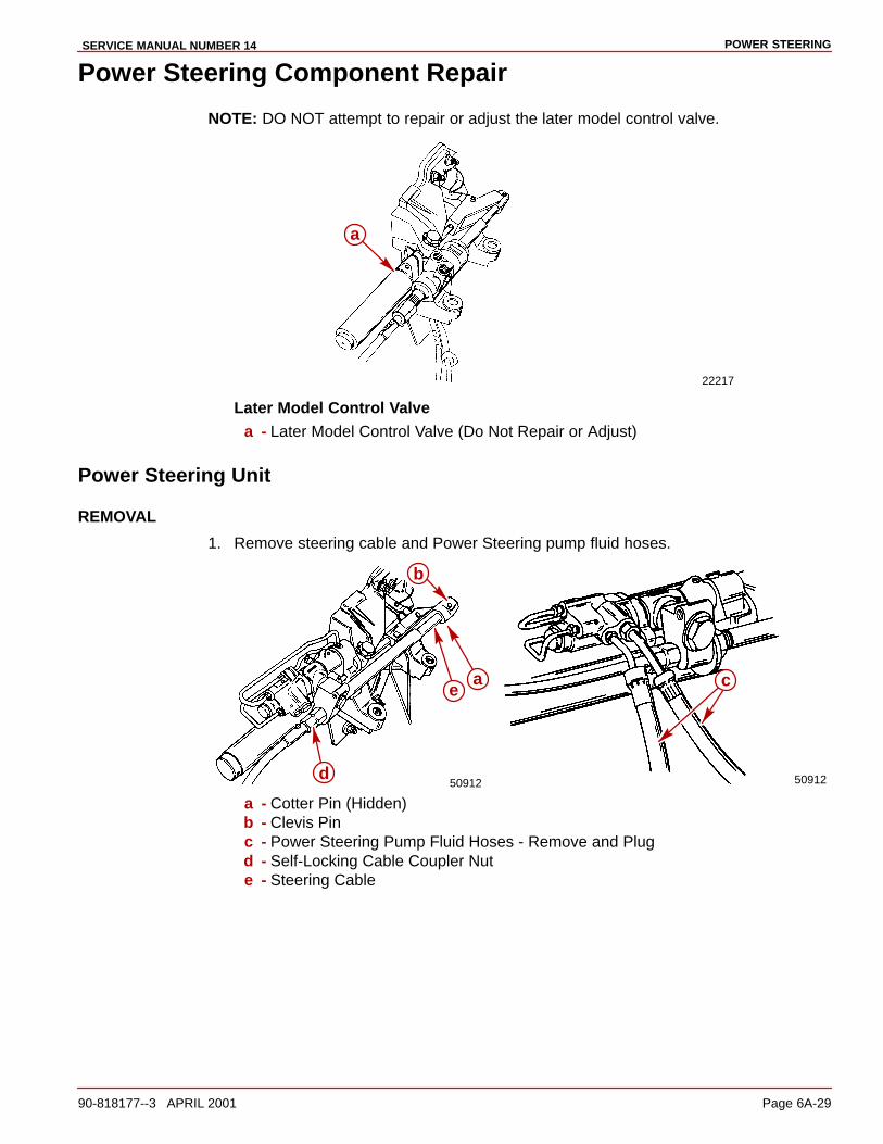
POWER STEERINGSERVICE MANUAL NUMBER 14
90-818177--3 APRIL 2001 Page 6A-29
Power Steering Component Repair
NOTE: DO NOT attempt to repair or adjust the later model control valve.
22217
a
Later Model Control Valvea - Later Model Control Valve (Do Not Repair or Adjust)
Power Steering Unit
REMOVAL
1. Remove steering cable and Power Steering pump fluid hoses.
50912 50912
ae
b
d
c
a - Cotter Pin (Hidden)b - Clevis Pinc - Power Steering Pump Fluid Hoses - Remove and Plugd - Self-Locking Cable Coupler Nute - Steering Cable

POWER STEERING SERVICE MANUAL NUMBER 14
Page 6A-30 90-818177--3 APRIL 2001
2. Remove Power Steering unit.
22137a b c
b c
a - Power Steering Unitb - Tab Washer - Bend Tab Away from Pivot Boltc - Pivot Bolt
INSTALLATION
1. Lubricate power steering unit bushings with Special Lubricant 101..
22167
a
a - Bushings
2. Lubricate pivot bolts with Special Lubricant 101.
3. HAND THREAD pivot bolts all-the-way into inner transom plate and swivel ring. DO NOTuse a wrench.
4. Straddle tab washer tangs on inner transom plate ridge.
22168
c b
a
c
a b
a - Pivot Bolts - HAND THREAD into Transom Plate and Power Steering Unitb - Tab Washer - Straddle Inner Transom Plate Ridgec - Swivel Ring
5. Torque pivot bolts to 25 lb-ft (35 Nm). Bend washer tabs against corresponding flats onbolt tabs.

POWER STEERINGSERVICE MANUAL NUMBER 14
90-818177--3 APRIL 2001 Page 6A-31
6. Move power steering unit back-and-forth to ensure that it pivots freely.
22169
a
a - Move Power Steering Unit Back-and-Forth
7. Connect power steering piston rod clevis to drive unit steering lever. Secure with pin andcotter pin.
50927
a
c
d b
a - Clevisb - Pinc - Cotter Pind - Steering Lever
8. Apply a liberal amount of Special Lubricant 101 to end of steering cable and install cableend in clevis. Secure with pin and cotter pin.
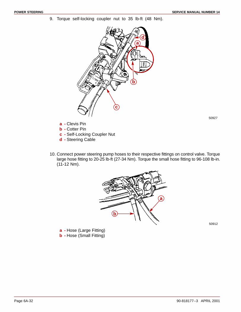
POWER STEERING SERVICE MANUAL NUMBER 14
Page 6A-32 90-818177--3 APRIL 2001
9. Torque self-locking coupler nut to 35 lb-ft (48 Nm).
50927
b
c
da
a - Clevis Pinb - Cotter Pinc - Self-Locking Coupler Nutd - Steering Cable
10. Connect power steering pump hoses to their respective fittings on control valve. Torquelarge hose fitting to 20-25 lb-ft (27-34 Nm). Torque the small hose fitting to 96-108 lb-in.(11-12 Nm).
50912
a
b
a - Hose (Large Fitting)b - Hose (Small Fitting)
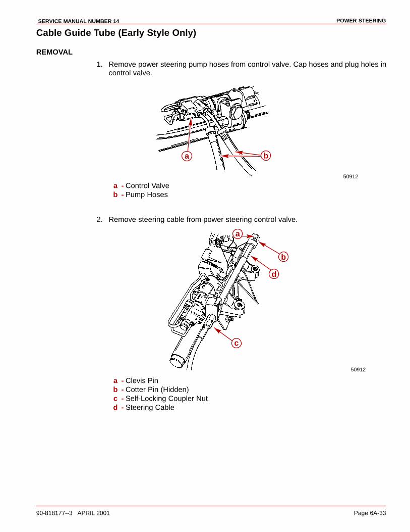
POWER STEERINGSERVICE MANUAL NUMBER 14
90-818177--3 APRIL 2001 Page 6A-33
Cable Guide Tube (Early Style Only)
REMOVAL
1. Remove power steering pump hoses from control valve. Cap hoses and plug holes incontrol valve.
50912
ba
a - Control Valveb - Pump Hoses
2. Remove steering cable from power steering control valve.
50912
a
b
d
c
a - Clevis Pinb - Cotter Pin (Hidden)c - Self-Locking Coupler Nutd - Steering Cable
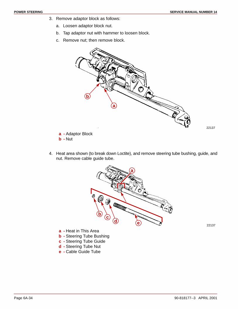
POWER STEERING SERVICE MANUAL NUMBER 14
Page 6A-34 90-818177--3 APRIL 2001
3. Remove adaptor block as follows:
a. Loosen adaptor block nut.
b. Tap adaptor nut with hammer to loosen block.
c. Remove nut; then remove block.
22137
a
b
a - Adaptor Blockb - Nut
4. Heat area shown (to break down Loctite), and remove steering tube bushing, guide, andnut. Remove cable guide tube.
22137
a
dc
b
e
a - Heat in This Areab - Steering Tube Bushingc - Steering Tube Guided - Steering Tube Nute - Cable Guide Tube

POWER STEERINGSERVICE MANUAL NUMBER 14
90-818177--3 APRIL 2001 Page 6A-35
INSTALLATION
WARNINGLoctite MUST BE applied to cable guide tube threads to prevent tube fromloosening during operation.
1. Clean guide tube threads with a wire brush to remove old Loctite. Apply QuicksilverLoctite 8831 or 271 to guide tube threads in the area where adaptor block and locknutwill be installed.
22137a
a - Loctite 8831 or 271 to Threads of Cable Guide Tube
2. Reinstall steering tube and related hardware and position so that threaded end of tubeprotrudes exactly 3/4 in. (19 mm) through adaptor block. Torque steering tube nut to 40lb-ft (54 Nm).
22137e
ab c d
a - Steering Guide Tubeb - Steering Tube Bushingc - Steering Tube Guided - Steering Tube Nute - 3/4 in. (19 mm)
3. Apply a liberal amount of Special Lubricant 101 to end of steering cable and install cableend in clevis. Secure with pin and cotter pin.
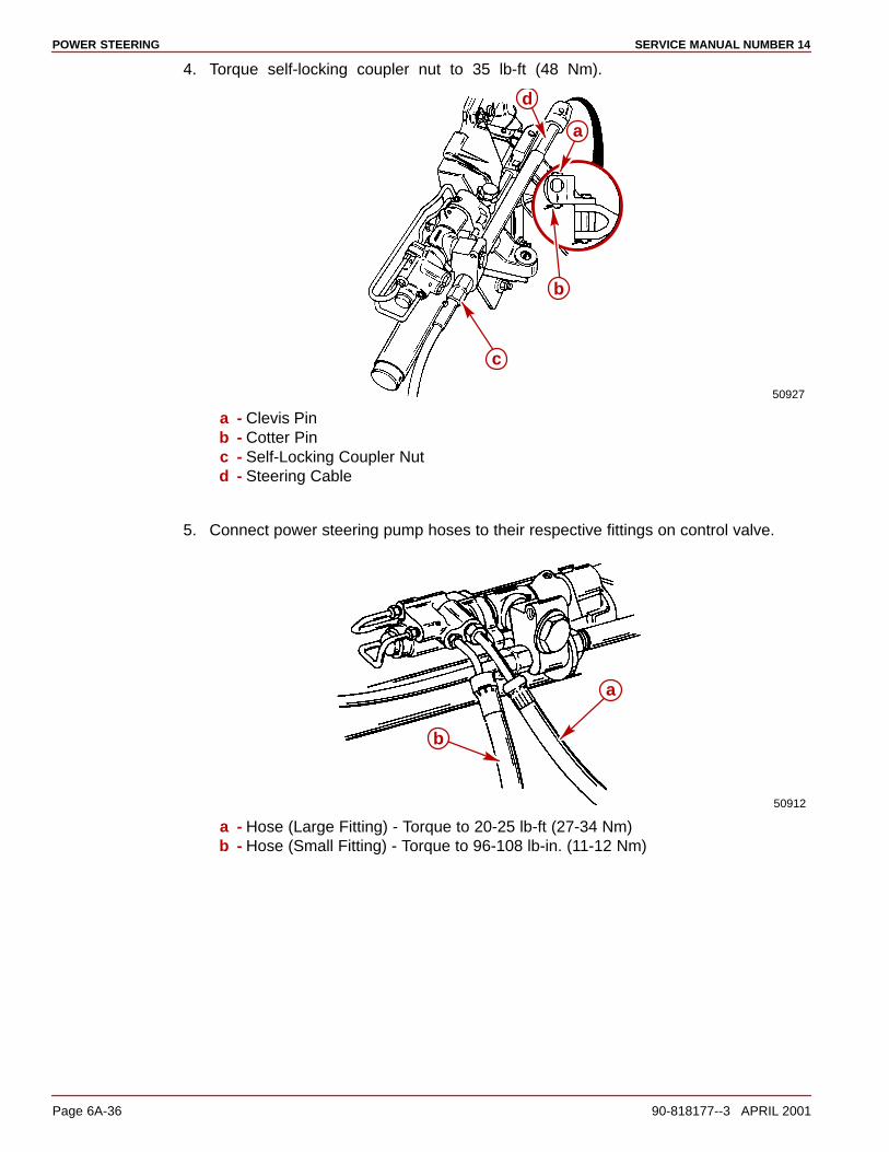
POWER STEERING SERVICE MANUAL NUMBER 14
Page 6A-36 90-818177--3 APRIL 2001
4. Torque self-locking coupler nut to 35 lb-ft (48 Nm).
50927
a
d
c
b
a - Clevis Pinb - Cotter Pinc - Self-Locking Coupler Nutd - Steering Cable
5. Connect power steering pump hoses to their respective fittings on control valve.
50912
a
b
a - Hose (Large Fitting) - Torque to 20-25 lb-ft (27-34 Nm)b - Hose (Small Fitting) - Torque to 96-108 lb-in. (11-12 Nm)

POWER STEERINGSERVICE MANUAL NUMBER 14
90-818177--3 APRIL 2001 Page 6A-37
Control Valve (Early Style Only)NOTE: If accessibility to control valve area is limited, remove Power Steering unit from tran-som assembly, to gain easier access to control valve.
REMOVAL
1. Remove steering cable and Power Steering pump fluid hoses.
50912
c
b
e
a
d
a - Cotter Pins (Hidden)b - Clevis Pinsc - Power Steering Pump Fluid Hoses - Remove and Plugd - Cable Self-Locking Coupler Nute - Steering Cable
2. Remove tubes from control valve.
a
a - Metal Tubes
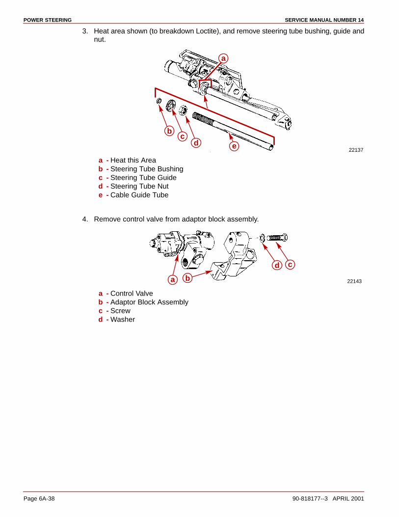
POWER STEERING SERVICE MANUAL NUMBER 14
Page 6A-38 90-818177--3 APRIL 2001
3. Heat area shown (to breakdown Loctite), and remove steering tube bushing, guide andnut.
22137
a
dc
b
e
a - Heat this Areab - Steering Tube Bushingc - Steering Tube Guided - Steering Tube Nute - Cable Guide Tube
4. Remove control valve from adaptor block assembly.
22143
cd
a b
a - Control Valveb - Adaptor Block Assemblyc - Screwd - Washer

POWER STEERINGSERVICE MANUAL NUMBER 14
90-818177--3 APRIL 2001 Page 6A-39
DISASSEMBLY
1. Remove adaptor block as follows:Loosen adaptor block nut. Tap adaptor nut with hammer to loosen block. Remove nut,washer and adaptor block.
22143
ab
cd
a - Adaptor Block Nutb - Washerc - Adaptor Blockd - Control Valve
2. Remove dust cover and adjusting nut.
22139
a b
a - Dust Coverb - Adjusting Nut
3. Separate valve housing from adaptor.
22145b d
c
a
a - Valve Housingb - Adaptorc - Screws (2)d - Lockwashers (2)

POWER STEERING SERVICE MANUAL NUMBER 14
Page 6A-40 90-818177--3 APRIL 2001
4. Remove components shown.
22138
bcefg
io
aj
phk
ld
mn
a - Valve Spoolb - Valve Adjustment Springc - Reaction Spoold - Spring Thrust Washere - Valve Springf - Spring Retainerg - Annulus Sealh - Large ID Washeri - Reaction Spool O-ringj - Valve Spool “V” Block Sealk - Annulus Spacerl - Gasket
m - Small Washern - Plug to Sleeve Keyo - O-ringp - Valve Housing
5. Carefully (so as not to nick the top surface) turn adjuster plug out of sleeve.
22139
a b
a - Adjuster Plugb - Turn Counterclockwise
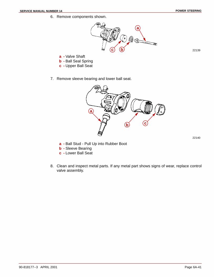
POWER STEERINGSERVICE MANUAL NUMBER 14
90-818177--3 APRIL 2001 Page 6A-41
6. Remove components shown.
22139bc
a
a - Valve Shaftb - Ball Seal Springc - Upper Ball Seat
7. Remove sleeve bearing and lower ball seat.
22140
b c
a
a - Ball Stud - Pull Up into Rubber Bootb - Sleeve Bearingc - Lower Ball Seat
8. Clean and inspect metal parts. If any metal part shows signs of wear, replace controlvalve assembly.
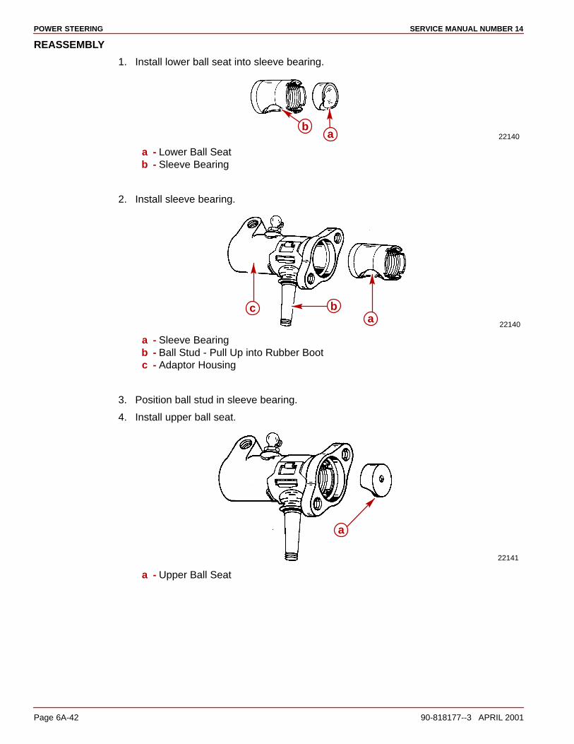
POWER STEERING SERVICE MANUAL NUMBER 14
Page 6A-42 90-818177--3 APRIL 2001
REASSEMBLY
1. Install lower ball seat into sleeve bearing.
22140b
a
a - Lower Ball Seatb - Sleeve Bearing
2. Install sleeve bearing.
22140a
bc
a - Sleeve Bearingb - Ball Stud - Pull Up into Rubber Bootc - Adaptor Housing
3. Position ball stud in sleeve bearing.
4. Install upper ball seat.
22141
a
a - Upper Ball Seat

POWER STEERINGSERVICE MANUAL NUMBER 14
90-818177--3 APRIL 2001 Page 6A-43
5. Install ball seat spring.
22141
a
a - Ball Seat Spring - Small Coil Down
6. Insert valve shaft into adjuster plug. Screw adjuster plug into sleeve until tight; thenback-off plug until slot lines up with notches in sleeve.
22139
ab
a - Valve Shaftb - Adjuster Plug
7. Install key.
22141
a
a - Key - Tangs on Key to Fit into Notches in Sleeve
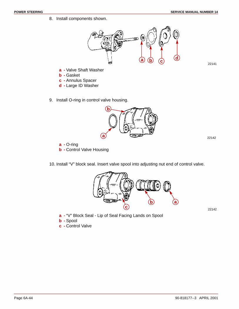
POWER STEERING SERVICE MANUAL NUMBER 14
Page 6A-44 90-818177--3 APRIL 2001
8. Install components shown.
22141a b c
d
a - Valve Shaft Washerb - Gasketc - Annulus Spacerd - Large ID Washer
9. Install O-ring in control valve housing.
22142a
b
a - O-ringb - Control Valve Housing
10. Install “V” block seal. Insert valve spool into adjusting nut end of control valve.
22142
abc
a - “V” Block Seal - Lip of Seal Facing Lands on Spoolb - Spoolc - Control Valve
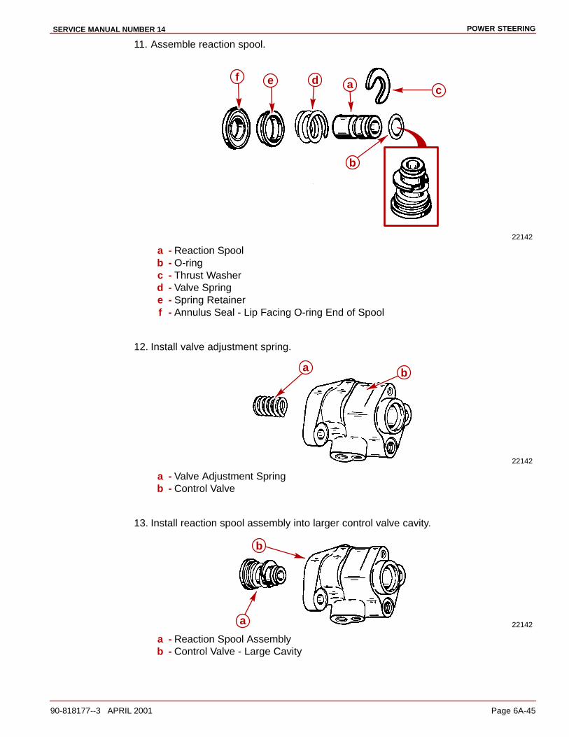
POWER STEERINGSERVICE MANUAL NUMBER 14
90-818177--3 APRIL 2001 Page 6A-45
11. Assemble reaction spool.
22142
cadef
b
a - Reaction Spoolb - O-ringc - Thrust Washerd - Valve Springe - Spring Retainerf - Annulus Seal - Lip Facing O-ring End of Spool
12. Install valve adjustment spring.
22142
ba
a - Valve Adjustment Springb - Control Valve
13. Install reaction spool assembly into larger control valve cavity.
22142a
b
a - Reaction Spool Assemblyb - Control Valve - Large Cavity
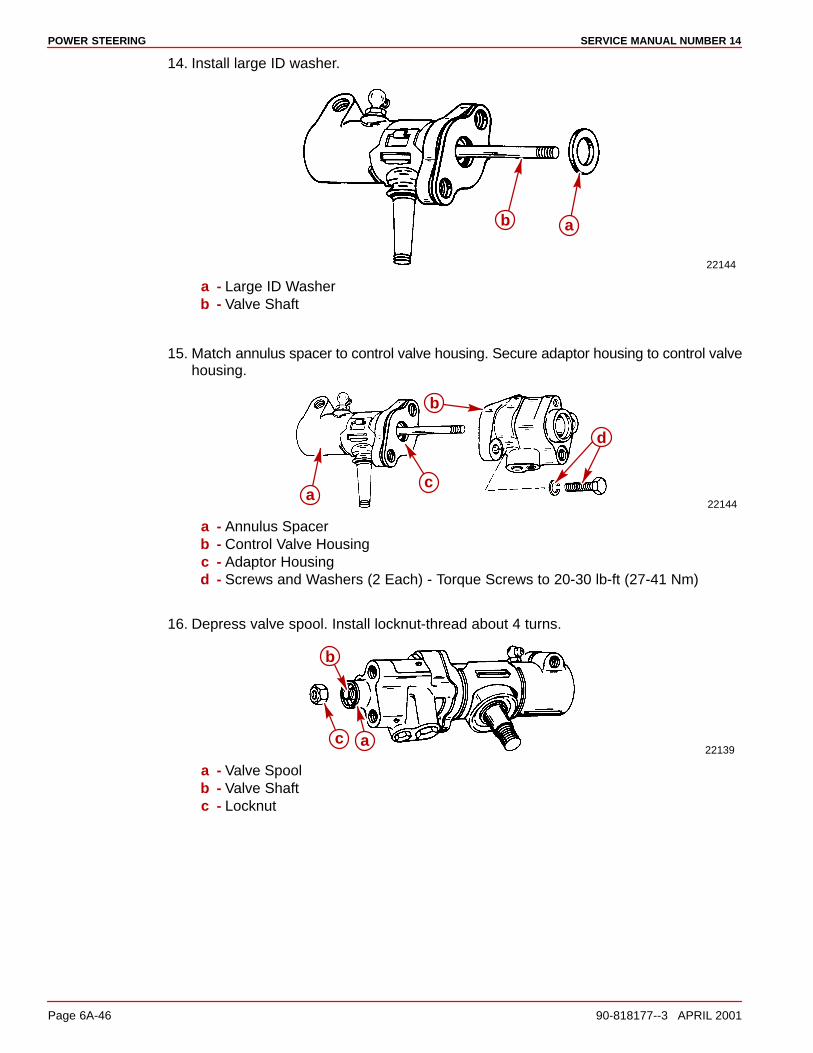
POWER STEERING SERVICE MANUAL NUMBER 14
Page 6A-46 90-818177--3 APRIL 2001
14. Install large ID washer.
22144
ab
a - Large ID Washerb - Valve Shaft
15. Match annulus spacer to control valve housing. Secure adaptor housing to control valvehousing.
22144a
b
c
d
a - Annulus Spacerb - Control Valve Housingc - Adaptor Housingd - Screws and Washers (2 Each) - Torque Screws to 20-30 lb-ft (27-41 Nm)
16. Depress valve spool. Install locknut-thread about 4 turns.
22139ac
b
a - Valve Spoolb - Valve Shaftc - Locknut
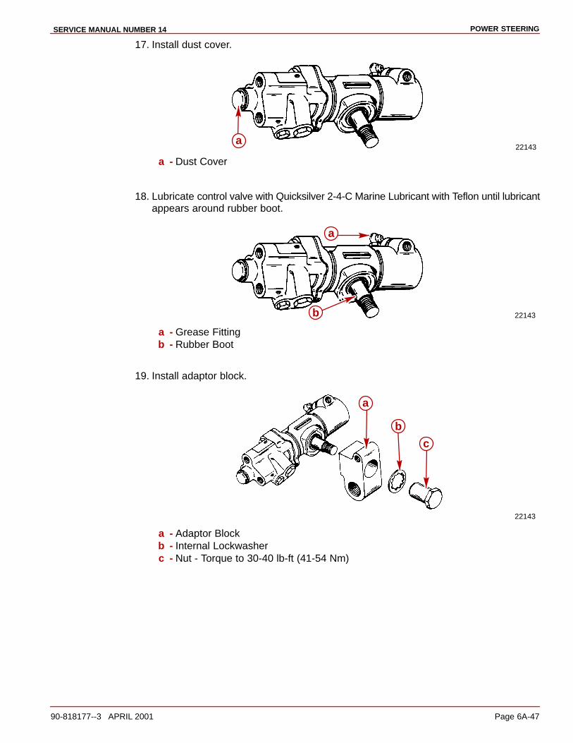
POWER STEERINGSERVICE MANUAL NUMBER 14
90-818177--3 APRIL 2001 Page 6A-47
17. Install dust cover.
22143a
a - Dust Cover
18. Lubricate control valve with Quicksilver 2-4-C Marine Lubricant with Teflon until lubricantappears around rubber boot.
22143b
a
a - Grease Fittingb - Rubber Boot
19. Install adaptor block.
22143
b
c
a
a - Adaptor Blockb - Internal Lockwasherc - Nut - Torque to 30-40 lb-ft (41-54 Nm)
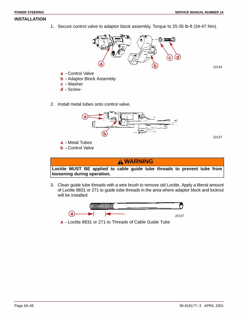
POWER STEERING SERVICE MANUAL NUMBER 14
Page 6A-48 90-818177--3 APRIL 2001
INSTALLATION
1. Secure control valve to adaptor block assembly. Torque to 25-35 lb-ft (34-47 Nm).
22143
c d
ba
a - Control Valveb - Adaptor Block Assemblyc - Washerd - Screw-
2. Install metal tubes onto control valve.
22137b
a
a - Metal Tubesb - Control Valve
WARNINGLoctite MUST BE applied to cable guide tube threads to prevent tube fromloosening during operation.
3. Clean guide tube threads with a wire brush to remove old Loctite. Apply a liberal amountof Loctite 8831 or 271 to guide tube threads in the area where adaptor block and locknutwill be installed.
22137a
a - Loctite 8831 or 271 to Threads of Cable Guide Tube
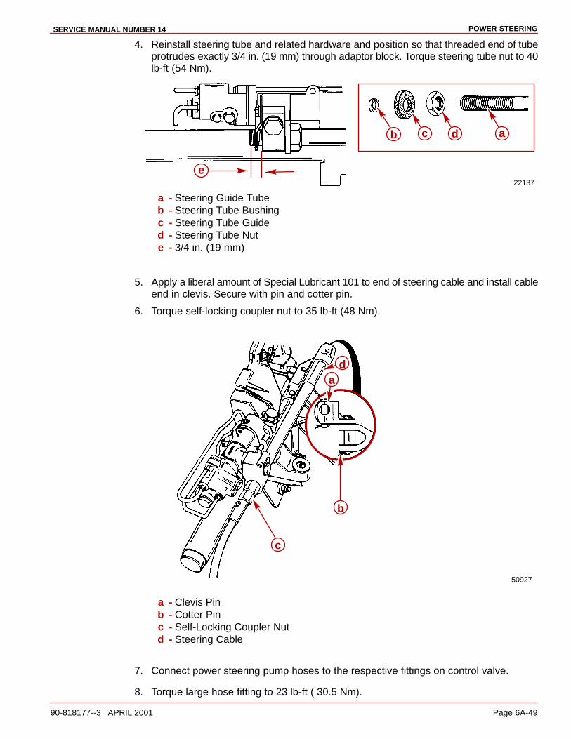
POWER STEERINGSERVICE MANUAL NUMBER 14
90-818177--3 APRIL 2001 Page 6A-49
4. Reinstall steering tube and related hardware and position so that threaded end of tubeprotrudes exactly 3/4 in. (19 mm) through adaptor block. Torque steering tube nut to 40lb-ft (54 Nm).
22137
e
ab c d
a - Steering Guide Tubeb - Steering Tube Bushingc - Steering Tube Guided - Steering Tube Nute - 3/4 in. (19 mm)
5. Apply a liberal amount of Special Lubricant 101 to end of steering cable and install cableend in clevis. Secure with pin and cotter pin.
6. Torque self-locking coupler nut to 35 lb-ft (48 Nm).
50927
b
c
da
a - Clevis Pinb - Cotter Pinc - Self-Locking Coupler Nutd - Steering Cable
7. Connect power steering pump hoses to the respective fittings on control valve.
8. Torque large hose fitting to 23 lb-ft ( 30.5 Nm).

POWER STEERING SERVICE MANUAL NUMBER 14
Page 6A-50 90-818177--3 APRIL 2001
9. Torque the small hose fitting to 102 lb-in. (11.5 Nm).
50912b
a
a - Hose (Large Fitting)b - Hose (Small Fitting)
Booster Cylinder (Early Style Only)
REMOVAL
NOTE: If accessibility to booster cylinder area is limited, remove Power Steering unit fromtransom assembly to gain easier access to booster cylinder.
1. Remove steering cable and Power Steering pump fluid hoses.
50912 50912d
a
e b
c
a - Cotter Pin (Hidden)b - Clevis Pinc - Power Steering Pump Fluid Hoses - Remove and Plugd - Self-Locking Cable Coupler Nute - Steering Cable
2. Remove metal lines from control valve.
22137
a
a - Metal Lines

POWER STEERINGSERVICE MANUAL NUMBER 14
90-818177--3 APRIL 2001 Page 6A-51
3. Remove control valve from adaptor block assembly.
22143
cda b
a - Control Valveb - Adaptor Block Assemblyc - Screwd - Washer
4. Remove clevis assembly.
22157
ab
c
d
a - Clevis Assemblyb - Nutc - Washerd - Booster Cylinder
5. Separate booster cylinder from adaptor block assembly.
22158
a
b
c
d
b
a - Cotter Pinb - Retaining Pins (2)c - Booster Cylinderd - Adaptor Block Assembly
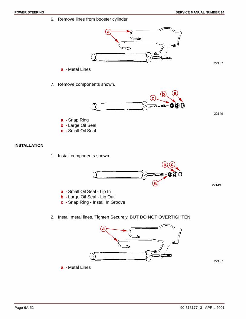
POWER STEERING SERVICE MANUAL NUMBER 14
Page 6A-52 90-818177--3 APRIL 2001
6. Remove lines from booster cylinder.
22157
a
a - Metal Lines
7. Remove components shown.
22149
abc
a - Snap Ringb - Large Oil Sealc - Small Oil Seal
INSTALLATION
1. Install components shown.
22149
b c
a
a - Small Oil Seal - Lip Inb - Large Oil Seal - Lip Outc - Snap Ring - Install In Groove
2. Install metal lines. Tighten Securely, BUT DO NOT OVERTIGHTEN
22157
a
a - Metal Lines
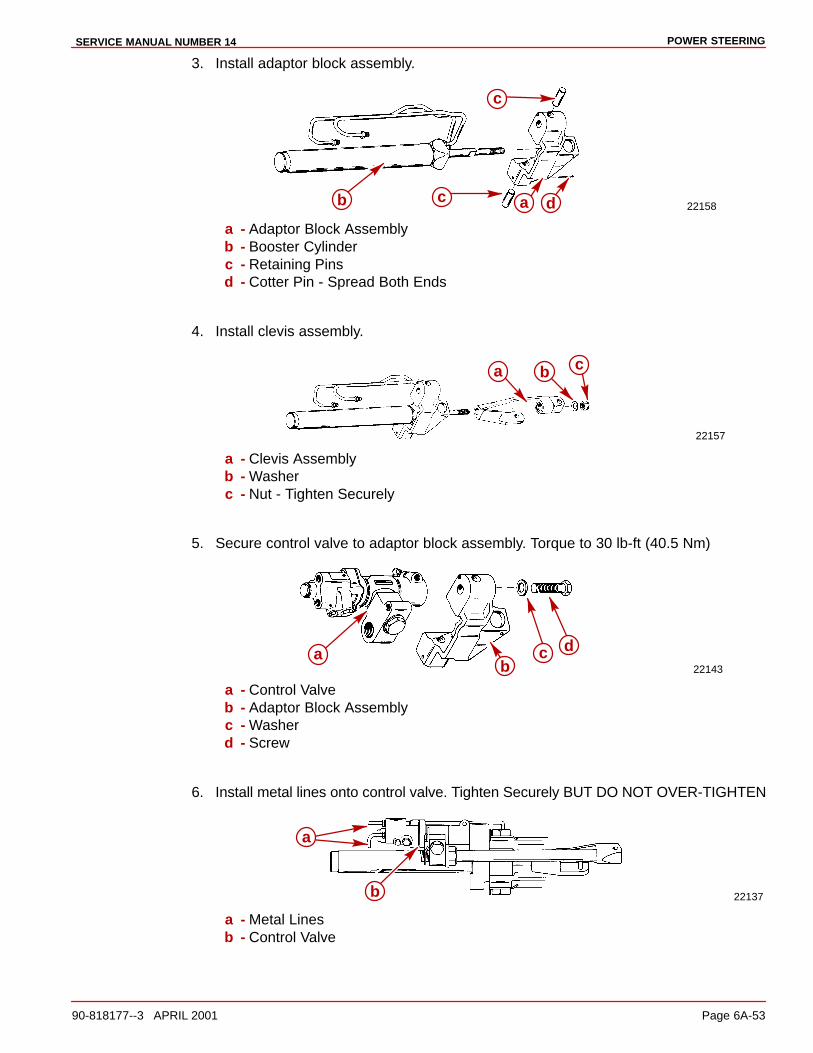
POWER STEERINGSERVICE MANUAL NUMBER 14
90-818177--3 APRIL 2001 Page 6A-53
3. Install adaptor block assembly.
22158a db c
c
a - Adaptor Block Assemblyb - Booster Cylinderc - Retaining Pinsd - Cotter Pin - Spread Both Ends
4. Install clevis assembly.
22157
a b c
a - Clevis Assemblyb - Washerc - Nut - Tighten Securely
5. Secure control valve to adaptor block assembly. Torque to 30 lb-ft (40.5 Nm)
22143a c d
ba - Control Valveb - Adaptor Block Assemblyc - Washerd - Screw
6. Install metal lines onto control valve. Tighten Securely BUT DO NOT OVER-TIGHTEN
22137
a
b
a - Metal Linesb - Control Valve
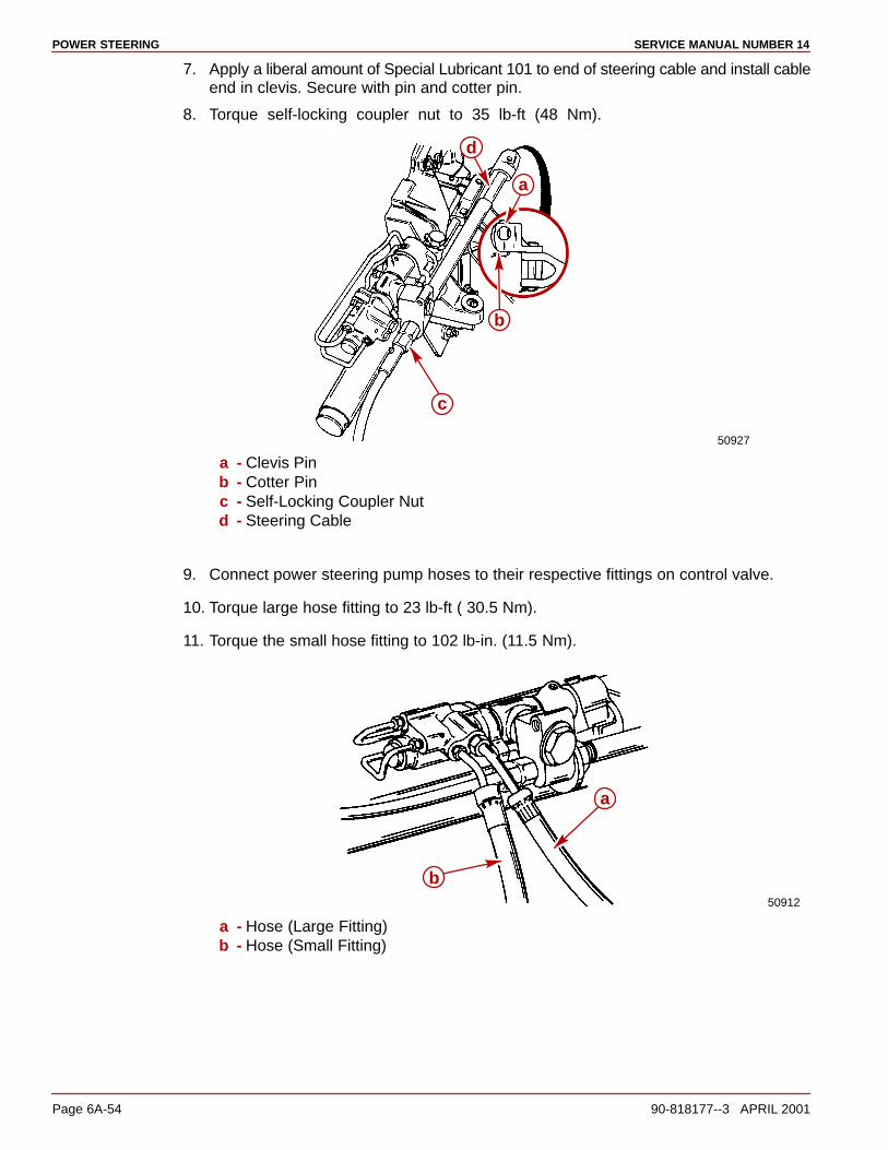
POWER STEERING SERVICE MANUAL NUMBER 14
Page 6A-54 90-818177--3 APRIL 2001
7. Apply a liberal amount of Special Lubricant 101 to end of steering cable and install cableend in clevis. Secure with pin and cotter pin.
8. Torque self-locking coupler nut to 35 lb-ft (48 Nm).
50927
b
c
d
a
a - Clevis Pinb - Cotter Pinc - Self-Locking Coupler Nutd - Steering Cable
9. Connect power steering pump hoses to their respective fittings on control valve.
10. Torque large hose fitting to 23 lb-ft ( 30.5 Nm).
11. Torque the small hose fitting to 102 lb-in. (11.5 Nm).
50912
b
a
a - Hose (Large Fitting)b - Hose (Small Fitting)

POWER STEERINGSERVICE MANUAL NUMBER 14
90-818177--3 APRIL 2001 Page 6A-55
Power Steering Pump
Removal1. Disconnect hoses at pump. Cap hose and fittings.
2. Loosen pump bolts at engine to remove pump belt.
3. Remove bracket from pump.
Flow Control Valve Servicing1. Drain fluid from pump.
2. Remove components shown.
22149
d
d
ab
c
a - Fitting Assemblyb - Control Valve Assemblyc - Flow Control Springd - O-rings
3. Inspect control valve assembly and fitting assembly.
4. Install components shown.
5. Torque to 35 lb-ft (47 Nm).
22149
c
dc b
a
a - Flow Control Springb - Control Valve Assemblyc - New O-ringsd - Fitting Assembly
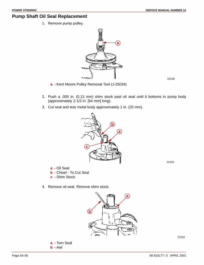
POWER STEERING SERVICE MANUAL NUMBER 14
Page 6A-56 90-818177--3 APRIL 2001
Pump Shaft Oil Seal Replacement1. Remove pump pulley.
22149
a
a - Kent Moore Pulley Removal Tool (J-25034)
2. Push a .005 in. (0.13 mm) shim stock past oil seal until it bottoms in pump body(approximately 2-1/2 in. [64 mm] long).
3. Cut seal and tear metal body approximately 1 in. (25 mm).
22152
a
b
c
a - Oil Sealb - Chisel - To Cut Sealc - Shim Stock
4. Remove oil seal. Remove shim stock.
22152
a
b
a - Torn Sealb - Awl
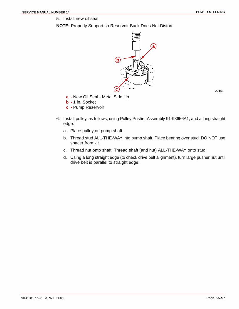
POWER STEERINGSERVICE MANUAL NUMBER 14
90-818177--3 APRIL 2001 Page 6A-57
5. Install new oil seal.
NOTE: Properly Support so Reservoir Back Does Not Distort
22151c
b
a
a - New Oil Seal - Metal Side Upb - 1 in. Socketc - Pump Reservoir
6. Install pulley, as follows, using Pulley Pusher Assembly 91-93656A1, and a long straightedge:
a. Place pulley on pump shaft.
b. Thread stud ALL-THE-WAY into pump shaft. Place bearing over stud. DO NOT usespacer from kit.
c. Thread nut onto shaft. Thread shaft (and nut) ALL-THE-WAY onto stud.
d. Using a long straight edge (to check drive belt alignment), turn large pusher nut untildrive belt is parallel to straight edge.

POWER STEERING SERVICE MANUAL NUMBER 14
Page 6A-58 90-818177--3 APRIL 2001
e. Check pulley installation for correct alignment.
a
b c d f
g
h
i
e
a - Power Steering Pump Pulleyb - Studc - DO NOT Use Spacerd - Bearinge - Nutf - Shaftg - Crankshaft Pulley (Shown) or Water Circulating Pump Pulleyh - Long Straight Edgei - Drive Belt Parallel
Disassembly1. Drain fluid from pump.
2. Remove pump pulley.
22149
a
a - Kent Moore Pulley Removal Tool (J-25034)

POWER STEERINGSERVICE MANUAL NUMBER 14
90-818177--3 APRIL 2001 Page 6A-59
3. Remove reservoir.
22155a b c e
ff
f
d f f
a - Fitting Assemblyb - Control Valve Assemblyc - Flow Control Springd - Studse - Reservoirf - O-rings
4. Remove retaining ring and end plate.
22150
c
a
b
a - Retaining Ring - Position so that Ring End is 1 in. (25 mm) from End of Hole inHousing
b - Holec - Screwdriver
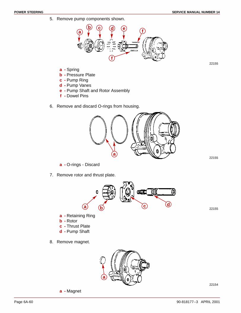
POWER STEERING SERVICE MANUAL NUMBER 14
Page 6A-60 90-818177--3 APRIL 2001
5. Remove pump components shown.
22155
ac d e f
b
f
a - Springb - Pressure Platec - Pump Ringd - Pump Vanese - Pump Shaft and Rotor Assemblyf - Dowel Pins
6. Remove and discard O-rings from housing.
22155a
a - O-rings - Discard
7. Remove rotor and thrust plate.
22155a c db
a - Retaining Ringb - Rotorc - Thrust Plated - Pump Shaft
8. Remove magnet.
22154
a
a - Magnet

POWER STEERINGSERVICE MANUAL NUMBER 14
90-818177--3 APRIL 2001 Page 6A-61
Cleaning And Inspection1. Clean and inspect all metal parts.
ReassemblyNOTE: All references to Power Steering fluid refer to Quicksilver Power Trim and SteeringFluid, or Dexron II if Quicksilver product is not available.
NOTE: Obtain and install a new seal kit 5688044 from a local GM automotive dealer whenreassembling pump.
1. Install new pump shaft oil seal.
NOTE: Properly support so the back of the reservoir does not distort.
22151
b
c
a
a - New Oil Seal - Metal Side Upb - 1 in. Socketc - Pump Reservoir
2. Install pressure plate O-ring and dowel pins.
22150
a c
b
a - Pressure Plate O-ring - Lubricate with Power Steering Fluid; Place in ThirdGroove in Housing
b - Dowel Pins

POWER STEERING SERVICE MANUAL NUMBER 14
Page 6A-62 90-818177--3 APRIL 2001
3. Assemble pump shaft and rotor assembly.
22155abc
d
a - Pump Shaftb - Thrust Platec - Rotor - Countersunk Side Toward Thrust Plated - Retaining Ring
4. Install pump shaft and rotor assembly.
22154
a
b
a - Pump Shaft and Rotor Assemblyb - Pump Housing
5. Install pump ring.
22154a
a - Pump Ring - Place 2 Smaller Holes Over Dowel Pins
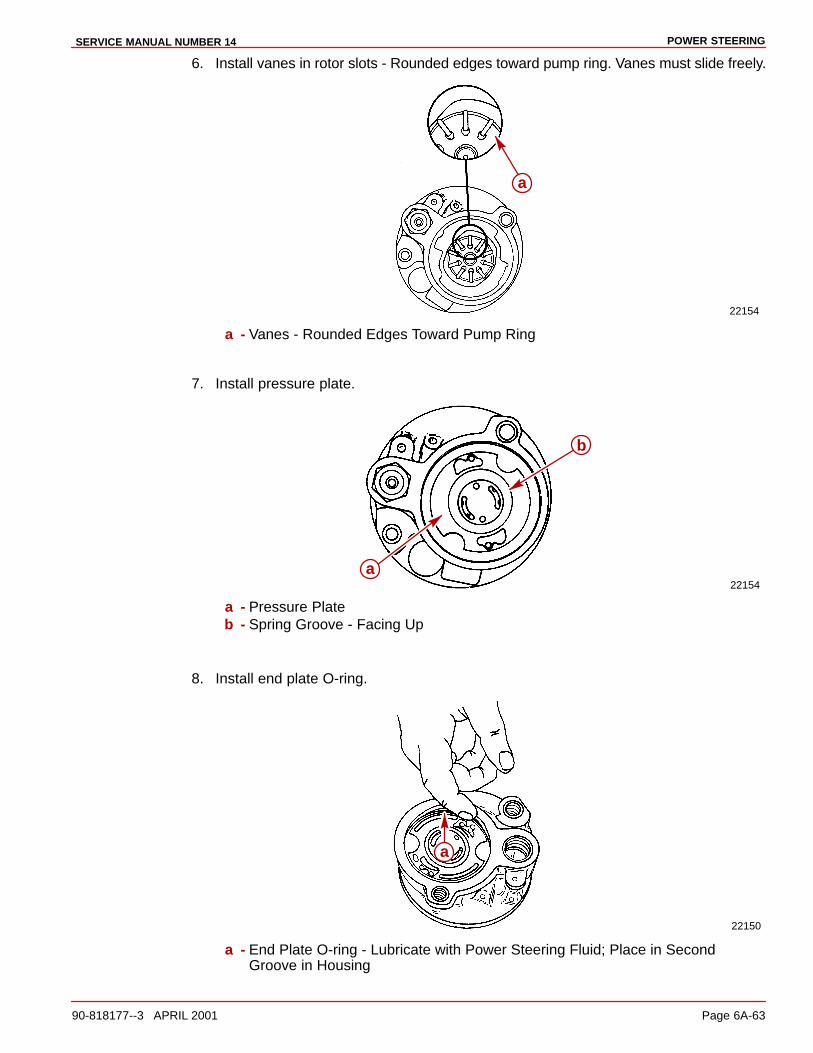
POWER STEERINGSERVICE MANUAL NUMBER 14
90-818177--3 APRIL 2001 Page 6A-63
6. Install vanes in rotor slots - Rounded edges toward pump ring. Vanes must slide freely.
22154
a
a - Vanes - Rounded Edges Toward Pump Ring
7. Install pressure plate.
22154
b
a
a - Pressure Plateb - Spring Groove - Facing Up
8. Install end plate O-ring.
22150
a
a - End Plate O-ring - Lubricate with Power Steering Fluid; Place in SecondGroove in Housing
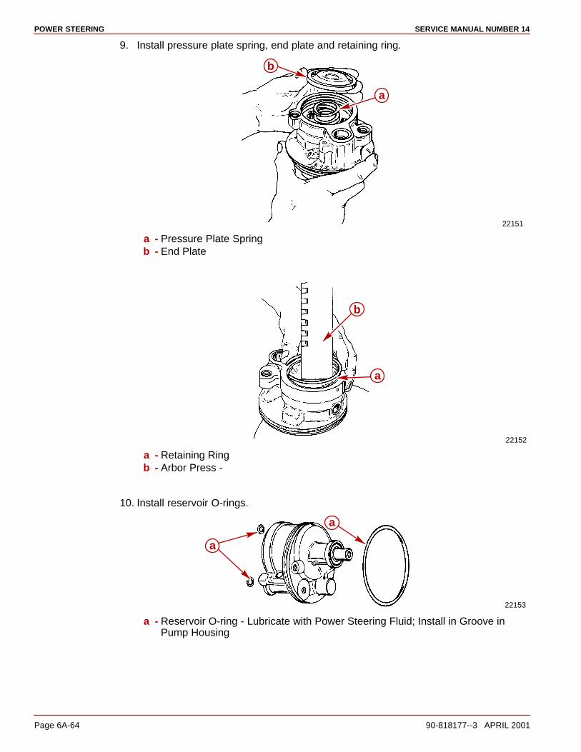
POWER STEERING SERVICE MANUAL NUMBER 14
Page 6A-64 90-818177--3 APRIL 2001
9. Install pressure plate spring, end plate and retaining ring.
22151
b
a
a - Pressure Plate Springb - End Plate
22152
b
a
a - Retaining Ringb - Arbor Press -
10. Install reservoir O-rings.
22153
a
a
a - Reservoir O-ring - Lubricate with Power Steering Fluid; Install in Groove inPump Housing

POWER STEERINGSERVICE MANUAL NUMBER 14
90-818177--3 APRIL 2001 Page 6A-65
11. Place magnet on housing.
22153
a
a - Magnet
12. Secure reservoir to pump housing. Torque studs to 35 lb-ft (47 Nm).
22153
c
a
b
a - Reservoirb - Pump Housingc - Studs
13. Install components shown. Torque fitting assembly to 35 lb-ft (47 Nm).
22153
d b
a
c
a - Flow Control Springb - Control Valve Assemblyc - O-ring - for Fitting Assemblyd - Fitting Assembly

POWER STEERING SERVICE MANUAL NUMBER 14
Page 6A-66 90-818177--3 APRIL 2001
14. Install pulley, as follows, using Pulley Pusher Assembly 91-93656A1, and a long straightedge:
a. Place pulley on pump shaft.
b. Thread stud ALL-THE-WAY into pump shaft. Place bearing over stud. DO NOT usespacer from kit.
c. Thread nut onto shaft. Thread shaft (and nut) ALL-THE-WAY onto stud.
d. Using a long straight edge (to check drive belt alignment), turn large pusher nut untildrive belt is parallel to straight edge.
e. Check pulley installation for correct alignment.
i
c d e fb
a
g
h
a - Power Steering Pump Pulleyb - Studc - DO NOT Use Spacerd - Bearinge - Nutf - Shaftg - Crankshaft Pulley (Shown) or Water Circulating Pump Pulleyh - Long Straight Edgei - Drive Belt Parallel
15. Install power steering pump on engine. (Refer to appropriate Engine Service Manual.)

POWER STEERINGSERVICE MANUAL NUMBER 14
90-818177--3 APRIL 2001 Page 6A-67
Multiple Sterndrive Steering Tie Bar ArrangementsWith multiple sterndrives it is important to consider which of several possible steering sys-tems should be selected.
CAUTIONFailure to observe the recommended Tie Bar Arrangements as presented in thissection could result in serious damage to the steering and/or trim system compo-nents. This damage could adversely affect control of the boat.
INTERNAL TIE BAR ONLY
At the lower end of the performance spectrum (boats not capable of speeds in excess of60 MPH) the basic internal tie bar is recommended. It connects the slave sterndrive to thesterndrive that is directly connected to the factory power steering output. This internal tiebar is available in a variety of lengths from the sterndrive manufacturer.
INTERNAL AND EXTERNAL TIE BAR
As a boat moves into a moderate performance range (60-70 MPH) or for a reduction in steer-ing backlash, an external tie bar should be added. External tie bars are usually designedto attach at the aft power trim cylinder bosses which is an excellent location because of itsproximity to the propeller. HOWEVER, because of the potential overstress that can occurif one drive is trimmed much differently than the other, a dual trim control kit (Part Number90362A3) should be installed so as to limit this potential tilt differential to about 20°.
EXTERNAL POWER STEERING
When boat speeds move past 70 MPH or if additional steering backlash reduction is desired,external power steering is recommended. This normally will include an external tie barmounted at the same general location of the power steering cylinders which are generallyattached at the top of the sterndrive’s drive shaft housing. With this steering system, no inter-nal tie bar should be used. These steering cylinders can be attached either inboard (be-tween) or outboard of the sterndrives.
EXTERNAL POWER STEERING WITH LOW EXTERNAL TIE BAR
For the fastest boats (over 80 MPH) or for the ultimate in steering backlash reduction, useexternal power steering, BUT (where mechanically possible) with the external tie barmounted at the trim cylinder boss location (as previously described in “Internal and ExternalTie Bar” statements). Again this system does not use an internal tie bar.
Mercury Marine does not recommend the use of an external tie bar ONLY (no internal tiebar) when using the internal power steering system. This can cause excessive loads on thesteering components on the drive connected to the internal power steering system. Theseincreased loads can damage the steering components, resulting in increased play in thesteering of the boat.
Determining Tie Bar Length
WARNINGON DUAL INSTALLATION USING STARBOARD TIE BAR KIT. The steering cableMUST have a minimum radius of 8 in. (203 mm) at the transom end. A radius lessthan 8 in. (203 mm) may kink the steering cable which, in turn, may affect steeringoperation. If the minimum 8 in. (203 mm) requirement cannot be met due to boatconstruction, etc., steering cable must then be routed to port transom and a porttransom and a port tie bar kit 96708A4, A5 or A6 MUST BE used in place of thestarboard tie bar kit.

POWER STEERING SERVICE MANUAL NUMBER 14
Page 6A-68 90-818177--3 APRIL 2001
NOTE: If drive units are to be “toed-in” or “toed-out,” measure from centerlines of steeringlevers (with drive units positioned as desired), instead of centerlines of power packages. Inmost cases, the best boat handling and performance characteristics will be obtained withthe drive units positioned parallel.
1. Determine tie bar length.
a. Measure centerline distance (Dimple in Gimbal Housing is located beneath thedecal in the top center).
b. Apply measurement to appropriate chart to determine tie bar length.
70133
b c
a
a - Distance Between Centerlinesb - Port Transom Assembly Centerlinec - Starboard Transom Assembly Centerline
Selection
TIE BAR CHART
For Dual Installations with Steering Cable Attached to Starboard Power Package
* 16” to 30” 92020A1
* 30” to 46” 92020A2
46” to 62” 92020A3
* If centerline distance is the same as maximum figure, use next larger size tie bar.
TIE BAR CHART
For Dual Installations with Steering Cable Attached to Port Power Package
* 28” to 37-1/2” 96708A4
* 37-1/2” to 55” 96708A5
55” to 72” 96708A6
* If centerline distance is the same as maximum figure, use next larger size tie bar.
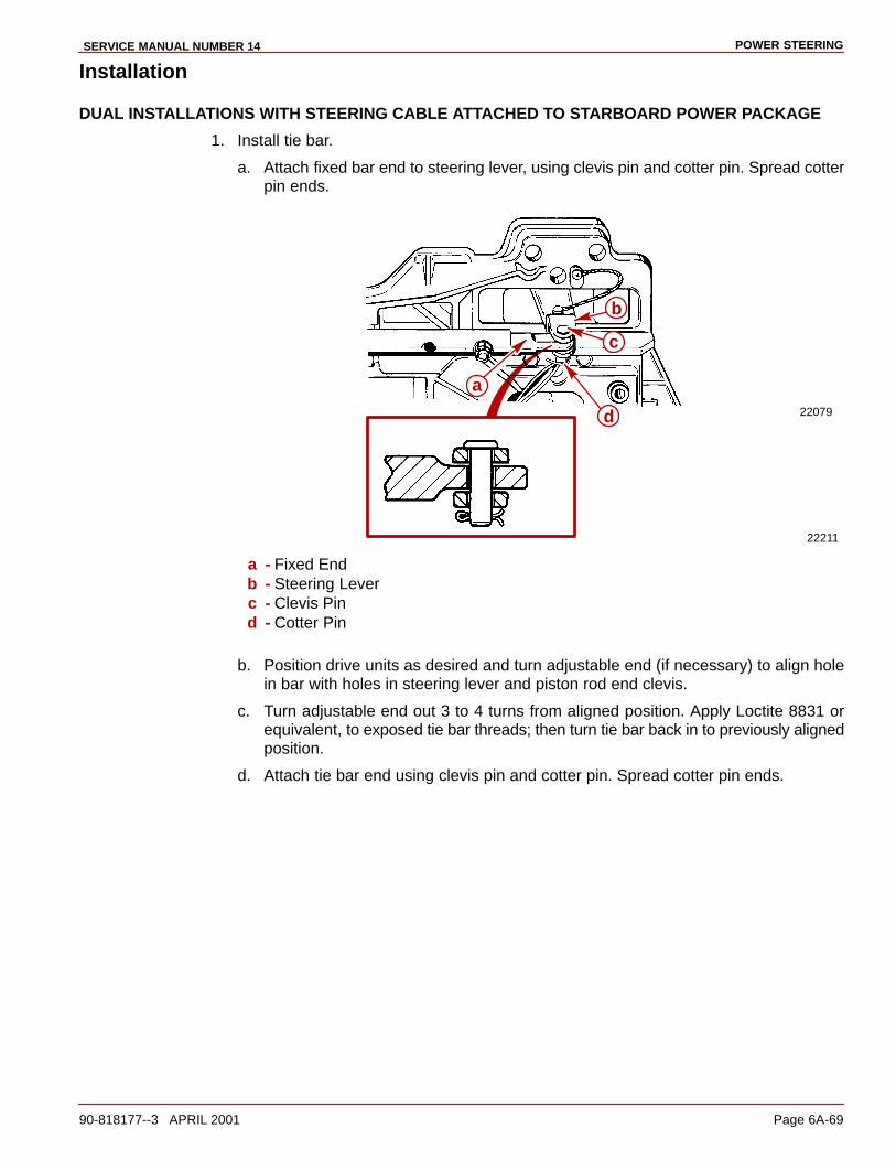
POWER STEERINGSERVICE MANUAL NUMBER 14
90-818177--3 APRIL 2001 Page 6A-69
Installation
DUAL INSTALLATIONS WITH STEERING CABLE ATTACHED TO STARBOARD POWER PACKAGE
1. Install tie bar.
a. Attach fixed bar end to steering lever, using clevis pin and cotter pin. Spread cotterpin ends.
22079
22211
a
b
c
d
a - Fixed Endb - Steering Leverc - Clevis Pind - Cotter Pin
b. Position drive units as desired and turn adjustable end (if necessary) to align holein bar with holes in steering lever and piston rod end clevis.
c. Turn adjustable end out 3 to 4 turns from aligned position. Apply Loctite 8831 orequivalent, to exposed tie bar threads; then turn tie bar back in to previously alignedposition.
d. Attach tie bar end using clevis pin and cotter pin. Spread cotter pin ends.
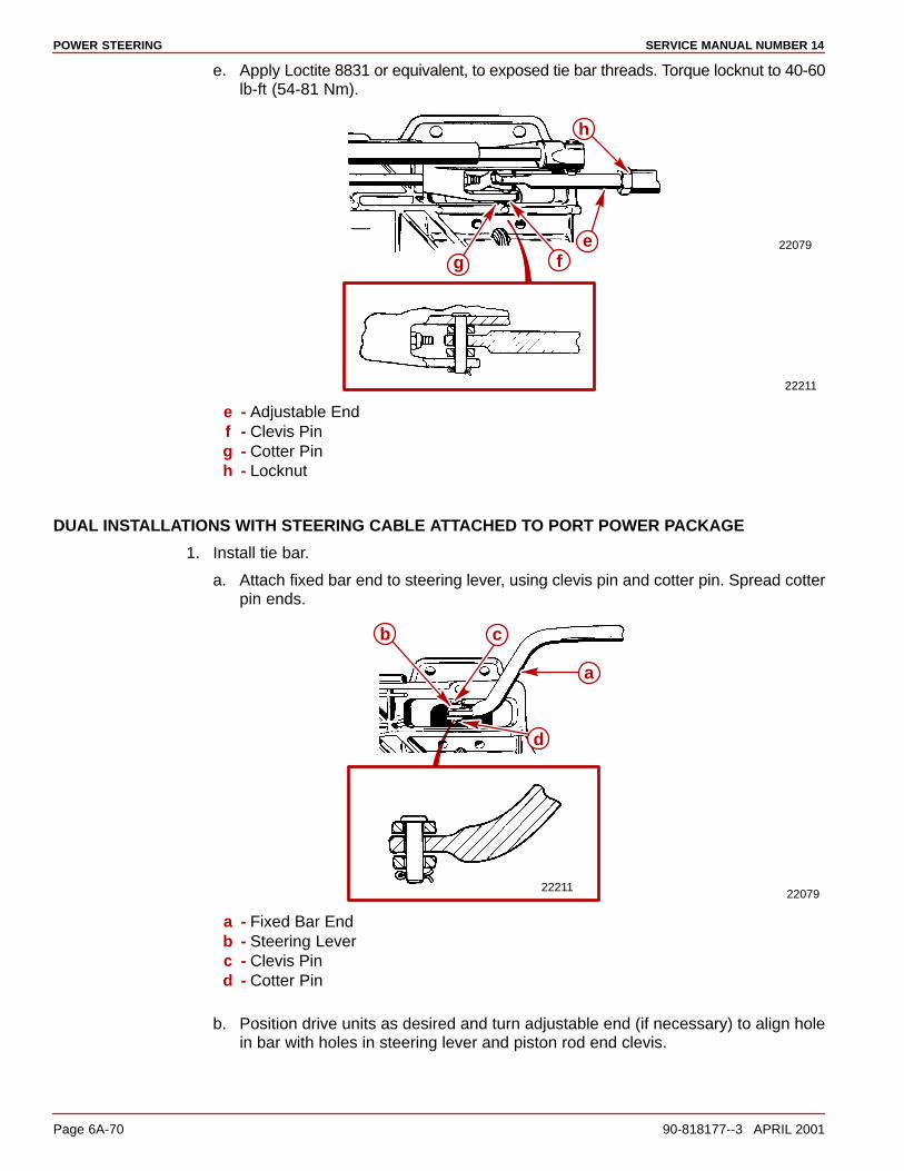
POWER STEERING SERVICE MANUAL NUMBER 14
Page 6A-70 90-818177--3 APRIL 2001
e. Apply Loctite 8831 or equivalent, to exposed tie bar threads. Torque locknut to 40-60lb-ft (54-81 Nm).
22079
22211
e
h
g f
e - Adjustable Endf - Clevis Ping - Cotter Pinh - Locknut
DUAL INSTALLATIONS WITH STEERING CABLE ATTACHED TO PORT POWER PACKAGE
1. Install tie bar.
a. Attach fixed bar end to steering lever, using clevis pin and cotter pin. Spread cotterpin ends.
2207922211
b c
a
d
a - Fixed Bar Endb - Steering Leverc - Clevis Pind - Cotter Pin
b. Position drive units as desired and turn adjustable end (if necessary) to align holein bar with holes in steering lever and piston rod end clevis.
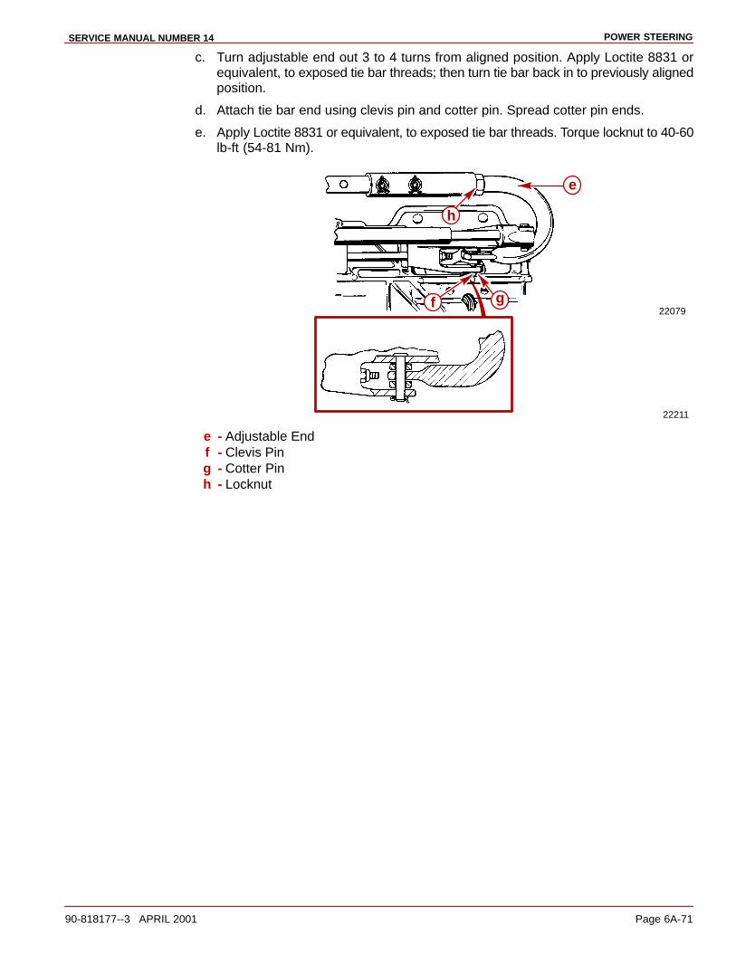
POWER STEERINGSERVICE MANUAL NUMBER 14
90-818177--3 APRIL 2001 Page 6A-71
c. Turn adjustable end out 3 to 4 turns from aligned position. Apply Loctite 8831 orequivalent, to exposed tie bar threads; then turn tie bar back in to previously alignedposition.
d. Attach tie bar end using clevis pin and cotter pin. Spread cotter pin ends.
e. Apply Loctite 8831 or equivalent, to exposed tie bar threads. Torque locknut to 40-60lb-ft (54-81 Nm).
22079
22211
f g
e
h
e - Adjustable Endf - Clevis Ping - Cotter Pinh - Locknut

POWER STEERING SERVICE MANUAL NUMBER 14
Page 6A-72 90-818177--3 APRIL 2001
THIS PAGE IS INTENTIONALLY BLANK
6B
MANUAL STEERINGSERVICE MANUAL NUMBER 14
90-818177--3 APRIL 2001 Page 6B-1
STEERING SYSTEMSection 6B - Manual Steering
Table of Contents
Specifications 6B-2. . . . . . . . . . . . . . . . . . . . . . . Torque Specifications 6B-2. . . . . . . . . . . . . Lubricants/Sealers/Adhesives 6B-2. . . . . .
Steering Cable Selection, Removal and Installation 6B-2. . . . . . . . . . . . . . . . . . . . .
Selection 6B-2. . . . . . . . . . . . . . . . . . . . . . . . Removal 6B-4. . . . . . . . . . . . . . . . . . . . . . . . . Installation 6B-4. . . . . . . . . . . . . . . . . . . . . . .
Manual Steering Swivel Ring Component Repair 6B-6. . . . . . . . . . . . . . . . . .
Removal 6B-6. . . . . . . . . . . . . . . . . . . . . . . . . Disassembly 6B-7. . . . . . . . . . . . . . . . . . . . . Reassembly 6B-7. . . . . . . . . . . . . . . . . . . . . Installation 6B-9. . . . . . . . . . . . . . . . . . . . . . .
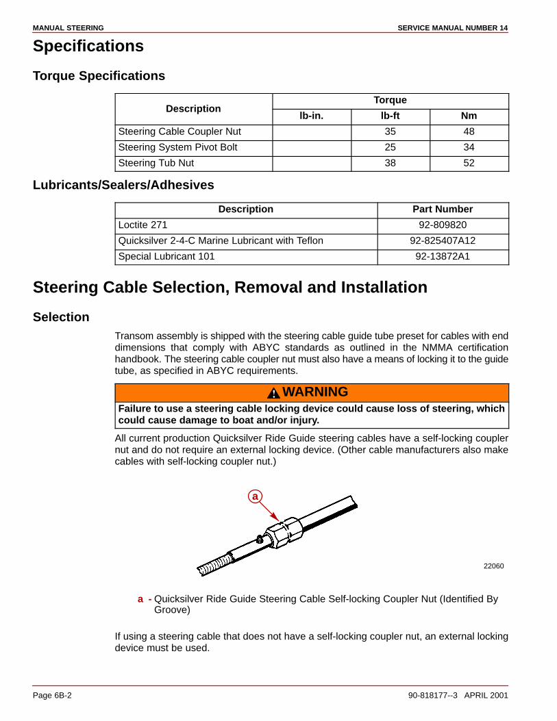
MANUAL STEERING SERVICE MANUAL NUMBER 14
Page 6B-2 90-818177--3 APRIL 2001
Specifications
Torque Specifications
TorqueDescription
lb-in. lb-ft Nm
Steering Cable Coupler Nut 35 48
Steering System Pivot Bolt 25 34
Steering Tub Nut 38 52
Lubricants/Sealers/Adhesives
Description Part Number
Loctite 271 92-809820
Quicksilver 2-4-C Marine Lubricant with Teflon 92-825407A12
Special Lubricant 101 92-13872A1
Steering Cable Selection, Removal and Installation
SelectionTransom assembly is shipped with the steering cable guide tube preset for cables with enddimensions that comply with ABYC standards as outlined in the NMMA certificationhandbook. The steering cable coupler nut must also have a means of locking it to the guidetube, as specified in ABYC requirements.
WARNINGFailure to use a steering cable locking device could cause loss of steering, whichcould cause damage to boat and/or injury.
All current production Quicksilver Ride Guide steering cables have a self-locking couplernut and do not require an external locking device. (Other cable manufacturers also makecables with self-locking coupler nut.)
22060
a
a - Quicksilver Ride Guide Steering Cable Self-locking Coupler Nut (Identified ByGroove)
If using a steering cable that does not have a self-locking coupler nut, an external lockingdevice must be used.

MANUAL STEERINGSERVICE MANUAL NUMBER 14
90-818177--3 APRIL 2001 Page 6B-3
Manual Steering Models
50627a
a - Locking Sleeve Kit 71669A1
1. Steering cable must be the correct length, particularly when installed in larger boats.
2. Avoid sharp bends, kinks or loops in cable.
CAUTIONSteering cables MUST BE THE CORRECT LENGTH, particularly when installed inlarge boats. Sharp bends or too-short cables result in kinks; too-long cables requireunnecessary bends and/or loops. Both place an extra stress on the cable. Theproper cable is as short as possible, with the fewest bends and with radii as largeas possible.
CAUTIONIf cables with improper dimensions are installed, severe damage to the transomand/or steering system may result.
21435
CL
ab
c
de
fg
h
i
jk
l
a - Coupler Nut - 7/8 - 14 UNF - 2B Threadb - 11-3/4 in. (298 mm) Min.c - Interface Pointd - 1/2 in. (12.7 mm) Max.e - 27/64 in. (10.7 mm) Min. Flatf - 7/64 in. (3.1 mm) Min. Radiusg - 5/8 in. (15.9 mm) Max. Diameter End Fittingh - 3/8 in. (9.5 mm)i - 3/8 in. (9.8 mm) Diameter Thru Hole, Chamfered Each Sidej - 1-3/8 in. (34.9 mm) Max.k - 5/8 in. (15.9 mm) Diameter Tubel - Cable Travel:
-Mid-Travel Position - 16-7/8 in. (428.6 mm). -Total Travel To Be 8 in. (203.2 mm) Min., to 9 in. (228.6 mm) Max. -Travel Each Side of Mid-Travel Position - 4 in. (101.6 mm) Min., 4-1/2 in. (114.3 mm) Max.

MANUAL STEERING SERVICE MANUAL NUMBER 14
Page 6B-4 90-818177--3 APRIL 2001
Removal1. Remove steering cable.
70373
ab
c
a - Clevis Pin - Removeb - Cable Coupler Nut - Unthreadc - Steering Cable
Installation1. Liberally coat steering cable end with Special Lubricant 101 and install cable.
WARNINGSteering cable outer casing MUST BE free to move back and forth for steering tofunction properly. DO NOT fasten wires, cables or other items to the steering cable,as this may prevent it from moving.
70373
a
c d
b f
e
g
a - Steering Cableb - Cable Coupler Nutc - Steering Cable Guide Tubed - Steering Cable Ende - Cotter Pinf - Clevis Ping - Steering Lever
NOTE: On dual installations only, secure clevis assembly to steering cable end.
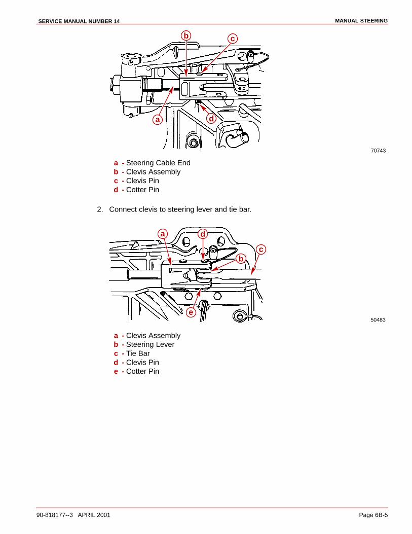
MANUAL STEERINGSERVICE MANUAL NUMBER 14
90-818177--3 APRIL 2001 Page 6B-5
70743
a
b c
d
a - Steering Cable Endb - Clevis Assemblyc - Clevis Pind - Cotter Pin
2. Connect clevis to steering lever and tie bar.
50483
a
b
d
e
c
a - Clevis Assemblyb - Steering Leverc - Tie Bard - Clevis Pine - Cotter Pin
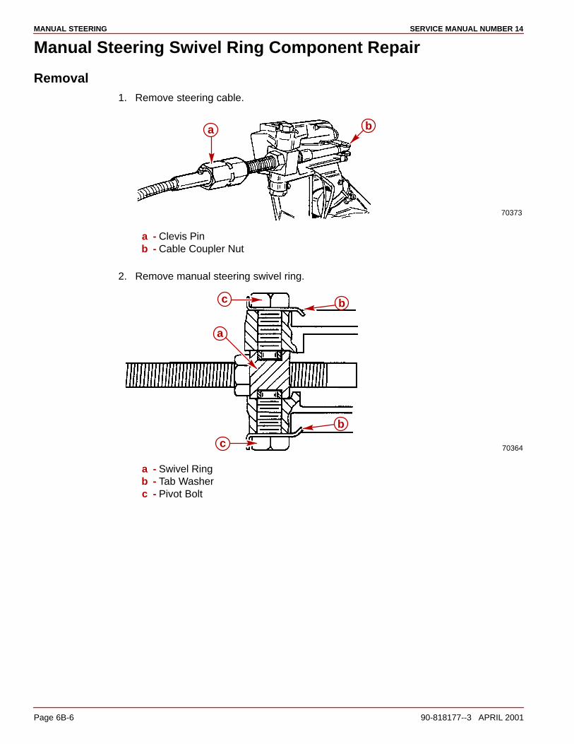
MANUAL STEERING SERVICE MANUAL NUMBER 14
Page 6B-6 90-818177--3 APRIL 2001
Manual Steering Swivel Ring Component Repair
Removal1. Remove steering cable.
70373
a b
a - Clevis Pinb - Cable Coupler Nut
2. Remove manual steering swivel ring.
70364
a
b
c
bc
a - Swivel Ringb - Tab Washerc - Pivot Bolt
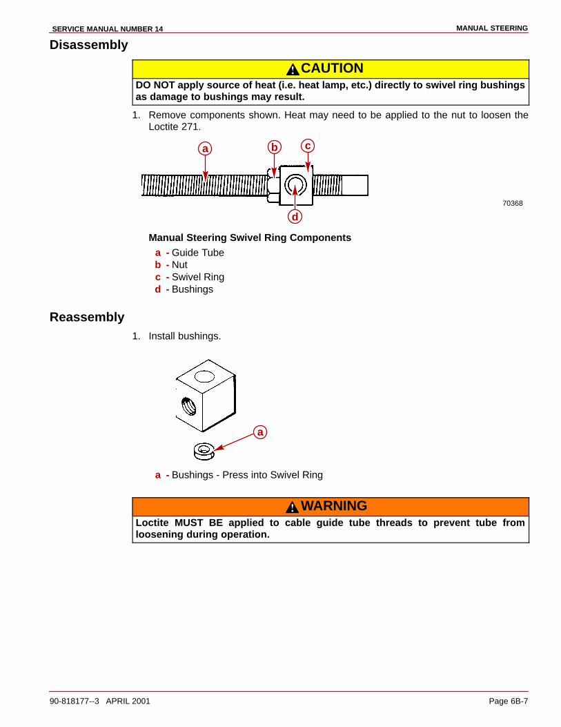
MANUAL STEERINGSERVICE MANUAL NUMBER 14
90-818177--3 APRIL 2001 Page 6B-7
Disassembly
CAUTIONDO NOT apply source of heat (i.e. heat lamp, etc.) directly to swivel ring bushingsas damage to bushings may result.
1. Remove components shown. Heat may need to be applied to the nut to loosen theLoctite 271.
70368
a
d
b c
Manual Steering Swivel Ring Componentsa - Guide Tubeb - Nutc - Swivel Ringd - Bushings
Reassembly1. Install bushings.
a
a - Bushings - Press into Swivel Ring
WARNINGLoctite MUST BE applied to cable guide tube threads to prevent tube fromloosening during operation.

MANUAL STEERING SERVICE MANUAL NUMBER 14
Page 6B-8 90-818177--3 APRIL 2001
2. Clean guide tube threads with a wire brush to remove old Loctite. Apply a liberal amountof Loctite 271 to guide tube threads (in area where swivel ring and locknut will beinstalled).
70365
a
a - Loctite 271
3. Turn swivel ring to obtain dimension shown.
70366
ab
c
a - Cable Guide Tubeb - Swivel Ringc - 2-1/2 in. � 1/8 in. (64 mm � 3 mm)
4. Tighten nut and washer against swivel ring. Torque to 37.5 lb-ft (50.5 Nm).
70367
a b
a - Nutb - Swivel Ring
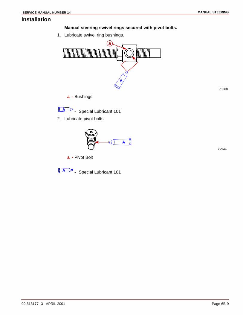
MANUAL STEERINGSERVICE MANUAL NUMBER 14
90-818177--3 APRIL 2001 Page 6B-9
InstallationManual steering swivel rings secured with pivot bolts.
1. Lubricate swivel ring bushings.
70368
A
a
a - Bushings
A - Special Lubricant 101
2. Lubricate pivot bolts.
22944
A
a - Pivot Bolt
A - Special Lubricant 101
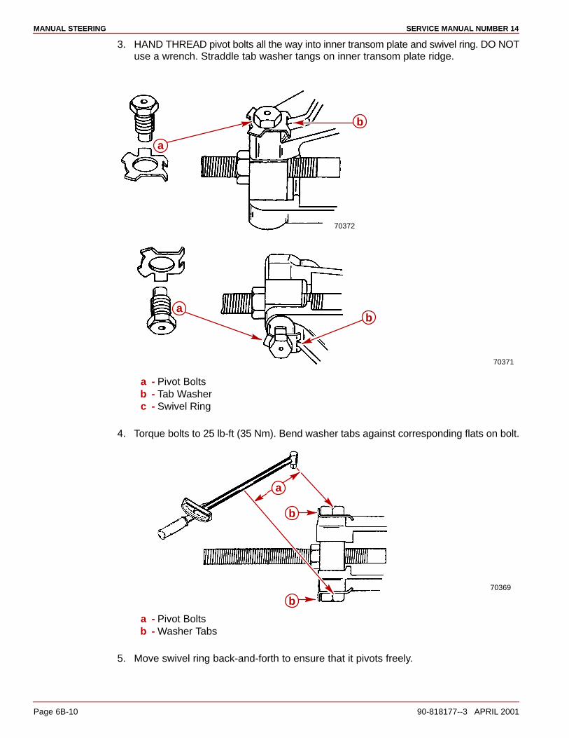
MANUAL STEERING SERVICE MANUAL NUMBER 14
Page 6B-10 90-818177--3 APRIL 2001
3. HAND THREAD pivot bolts all the way into inner transom plate and swivel ring. DO NOTuse a wrench. Straddle tab washer tangs on inner transom plate ridge.
70372
70371
a
b
ba
a - Pivot Boltsb - Tab Washerc - Swivel Ring
4. Torque bolts to 25 lb-ft (35 Nm). Bend washer tabs against corresponding flats on bolt.
70369
a
b
b
a - Pivot Boltsb - Washer Tabs
5. Move swivel ring back-and-forth to ensure that it pivots freely.

MANUAL STEERINGSERVICE MANUAL NUMBER 14
90-818177--3 APRIL 2001 Page 6B-11
THIS PAGE IS INTENTIONALLY BLANK

MANUAL STEERING SERVICE MANUAL NUMBER 14
Page 6B-12 90-818177--3 APRIL 2001
THIS PAGE IS INTENTIONALLY BLANK
Related Documents