Disclaimer The following version of the Owner‘s Manual describes all models, series and special equipment of your vehicle. Country-specific language variations are possible. Please note that your vehicle might not be equipped with all the described functions. This also affects safety-relevant systems and functions. Please contact your authorised Mercedes-Benz dealership if you would like to receive a printed Owner‘s Manual for other vehicle models and vehicle model years. The online Owner‘s Manual is the current and valid version. It is possible that deviations affecting your specific vehicle could not be taken into account as Mercedes-Benz constantly adapts its vehicles according to the latest technology and makes changes to the form and the equipment. Please also read the printed Owner‘s Manual, supplementary documents and the digital Owner‘s Manual in the vehicle. Copyright All rights reserved. All texts, images and graphics are subject to copyright and other laws for the protection of intellectual property. They may not be copied or changed for any commercial use or for the purpose of being passed on nor used on other webistes.

Welcome message from author
This document is posted to help you gain knowledge. Please leave a comment to let me know what you think about it! Share it to your friends and learn new things together.
Transcript
Disclaimer
Das folgende PDF-Dokument für dieses Fahrzeugmodell bezieht sich in allen Sprachversionen nur auf die Fahrzeuge, die für den deutschen Markt bestimmt sind und die den deutschen Vorschriften entsprechen. Bitte wenden Sie sich an Ihren autorisierten Mercedes-Benz Servicestützpunkt, um ein gedrucktes Exemplar für andere Fahrzeugmodelle und Fahrzeugmodelljahre zu erhalten.
Dieses PDF-Dokument stellt die aktuelle Version dar. Mögliche Abweichungen zu Ihrem konkreten Fahrzeug könnten nicht berücksichtigt sein, da Mercedes-Benz seine Fahrzeuge ständig dem neuesten Stand der Technik anpasst, sowie Änderungen in Form und Ausstattung vornimmt. Bitte beachten Sie daher, dass dieses PDF-Dokument in keinem Fall das gedruckte Exemplar ersetzt, das mit dem Fahrzeug ausgeliefert wurde.
Internal use only
Disclaimer
All language versions of the following PDF document for this vehicle model relate solely to vehicles intended for sale on the German market and which correspond to German regulations.
Please contact your authorised Mercedes-Benz Service Centre to obtain a printed version for other vehicle models and vehicle model years. This PDF document is the latest version. Possible variations to your vehicle may not be taken into account as Mercedes-Benz constantly updates their vehicles to the state of the art and introduces changes in design and equipment. Please therefore note that this PDF document in no way replaces the printed version which was delivered with your vehicle.
Internal use only
Disclaimer
The following version of the Owner‘s Manual describes all models, series and special equipment of your vehicle. Country-specific language variations are possible. Please note that your vehicle might not be equipped with all the described functions. This also affects safety-relevant systems and functions. Please contact your authorised Mercedes-Benz dealership if you would like to receive a printed Owner‘s Manual for other vehicle models and vehicle model years.
The online Owner‘s Manual is the current and valid version. It is possible that deviations affecting your specific vehicle could not be taken into account as Mercedes-Benz constantly adapts its vehicles according to the latest technology and makes changes to the form and the equipment.
Please also read the printed Owner‘s Manual, supplementary documents and the digital Owner‘s Manual in the vehicle.
CopyrightAll rights reserved. All texts, images and graphics are subject to copyright and other laws for the protection of intellectual property. They may not be copied or changed for any commercial use or for the purpose of being passed on nor used on other webistes.
WWelcome telcome to to the whe wororld of Merld of Mercedes-Benzcedes-BenzBefore you rst drive o , read these OperatingInstructions carefully and familiarise yourself withyour vehicle. For your own safety and a longeroperating lifespan, follow the instructions andwarning notices in these Operating Instructions.Disregarding them may result in damage to thevehicle or environment or in injuries to people.The standard equipment and product descriptionof your vehicle may vary and depends on the fol-lowing factors:R ModelR OrderR National versionR availability
The illustrations in these Operating Instructionsshow a le -hand drive vehicle. On right-hand-drivevehicles, the layout of car parts and control ele-ments di ers accordingly.Mercedes-Benz is constantly developing its vehi-cles further.Mercedes-Benz therefore reserves the right tointroduce changes in the following areas:R DesignR EquipmentR Technical features
Your vehicle may therefore di er, in individualcases, from that shown in the descriptions andillustrations.The following documents are integral parts of thevehicle:R Digital Operating InstructionsR printed Operating InstructionsR service bookletR equipment-dependent supplements
Always keep these documents in the vehicle. If yousell the vehicle, always pass all documents on tothe new owner.
4475842510Z102
4475842510Z102
SymbolsSymbols ....................................................... 44
AAt a glancet a glance ................................................... 66Cockpit ........................................................ 6Indicator and warning lamps ......................... 7Steering wheel with buttons ......................... 8Centre console ............................................ 9Overhead control panel .............................. 13Door control panel ..................................... 14
DigitDigital Operal Operating Insating Instrtructionsuctions ..................... 1515Calling up the Digital Operating Instruc-tions .......................................................... 15
GenerGeneral notal noteses ............................................ 1616Environmental protection ........................... 16Take-back of end-of-life vehicles ................. 16Mercedes-Benz GenuineParts ..................... 16Information about attachments, add-onequipment, installations and conver-sions .......................................................... 17Operating Instructions ................................ 17Operating safety ......................................... 18Declarations of conformity and notes ondriving in di erent countries ....................... 19Diagnostics connection .............................. 23Quali ed specialist workshop ..................... 24Vehicle registration .................................... 24Correct use of the vehicle .......................... 24Information on the REACH directive ............ 25Notes for persons with electronic medi-cal aids ...................................................... 25Implied warranty ........................................ 25QR codes for rescue card ........................... 25Data storage .............................................. 25Copyright ................................................... 28
Occupant safeOccupant safetyty ......................................... 2929Restraint system ........................................ 29Seat belts .................................................. 30Airbags ...................................................... 33PRE-SAFE® System .................................... 38Automatic measures a er an accident ........ 38Safely transporting children in the vehi-cle ............................................................. 38Notes on pets in the vehicle ....................... 50
Opening and closingOpening and closing ................................... 5151Key ............................................................ 51Doors ........................................................ 53Sliding door ............................................... 55
Electric sliding door .................................... 56Tailgate ...................................................... 59Side window .............................................. 62Panorama sliding sunroof ........................... 64Anti-the prevention .................................. 67
Seats and stowSeats and stowagagee ..................................... 7070Notes on the correct driver's seat posi-tion ............................................................ 70Seats ......................................................... 70Steering wheel ........................................... 95Stowage areas ........................................... 96Folding table .............................................. 97Information about the bottle holder .......... 100Cup holders ............................................. 100Ashtray and cigarette lighter ..................... 101Sockets .................................................... 102Switching the refrigerator box in thecentre console on and o ......................... 103
Light and visionLight and vision ........................................ 104104Exterior lighting ........................................ 104Adjusting the interior lighting .................... 109Changing bulbs ........................................ 110Windscreen wipers ................................... 114Mirrors ..................................................... 116Operating sun visors ................................ 119
ClimatClimate contre controlol ........................................ 120120Overview of climate control systems ......... 120Operating climate control systems ........... 121Operating air vents ................................... 125Notes on pre-entry climate control ........... 126Using pre-entry climate control via thekey ........................................................... 126Using pre-entry climate control fordeparture time ......................................... 126Activating/deactivating pre-entry cli-mate control using the button .................. 127
DrDriving and pariving and parkingking .................................. 129129Driving ..................................................... 129Transmission ............................................ 135AIRMATIC ................................................ 137Charging the high-voltage battery ............. 138Parking .................................................... 146Driving and driving safety systems ............ 148
InsInstrtrument clustument cluster and on-boarer and on-board com-d com-putputerer ........................................................ 171171Overview of the instrument cluster ........... 171
22 Contents
Function of the power availability display .. 171Overview and operation of the on-boardcomputer ................................................. 172Overview of data shown on the instru-ment cluster display ................................. 173Function of the charge level display .......... 174Display of the available power .................. 174Adjusting the instrument lighting .............. 174Overview of menus on the on-boardcomputer ................................................. 175Menus and submenus .............................. 175
MerMercedes mecedes me ........................................... 182182Mercedes me calls ................................... 182Mercedes me connect ............................. 184Mercedes me and apps ............................ 185
MBUX multimedia systMBUX multimedia systemem ......................... 187187Overview and operation ............................ 187System settings ....................................... 190Navigation ................................................ 193Mercedes PRO connect ............................ 198Overview of Smartphone Integration ......... 201Web browser overview ............................. 201Radio and media ...................................... 202Sound settings ......................................... 205
TTrransporansportingting ............................................. 206206Notes on loading guidelines ...................... 206Load distribution ...................................... 207Securing loads ......................................... 208Load securing aid ..................................... 210Carrier systems ........................................ 213
MaintMaintenance and carenance and caree .............................. 215215Notes on maintenance ............................. 215Service interval display ............................. 215Engine compartment ................................ 216Cleaning and care .................................... 218
BrBreakdoeakdown assistwn assistanceance .............................. 224224Emergency ............................................... 224Mercedes-Benz emergency call system .... 225Flat tyre ................................................... 227Battery ..................................................... 227Towing or tow-starting .............................. 229Electrical fuses ......................................... 233Vehicle tool kit ......................................... 233
Wheels and tyrWheels and tyreses ...................................... 235235Information on noise or unusual drivingcharacteristics ......................................... 235Notes on regularly inspecting wheelsand tyres ................................................. 235Information on driving with summertyres ........................................................ 235Information on M+S tyres ......................... 235Notes on snow chains .............................. 236Tyre pressure ........................................... 236Changing a wheel ..................................... 239Information on wheel and tyre combina-tions ........................................................ 244Spare wheel ............................................. 245
TTecechnical dathnical dataa .......................................... 247247Information on the technical data ............. 247On-board electronics ................................ 247Regulatory radio identi cations andnotes ....................................................... 248Vehicle identi cation plate, vehicle iden-ti cation number (VIN) and engine num-ber ........................................................... 248Operating uids and capacities ................ 249Vehicle data ............................................. 251Lashing points and carrier systems ........... 252
DisplaDisplay messagy messages and wes and wararning and indi-ning and indi-catcator lamor lampsps .............................................. 254254Display messages ..................................... 254Warning and indicator lamps .................... 275
IndeIndexx ....................................................... 282282
Contents 33
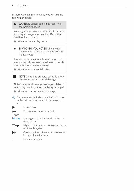
In these Operating Instructions, you will nd thefollowing symbols:
& WWARNINGARNING Danger due to not observingthe warning notices
Warning notices draw your attention to hazardsthat may endanger your health or life, or thehealth or life of others.# Observe the warning notices.
+ ENVIRENVIRONMENTONMENTAL NOAL NOTETE Environmentaldamage due to failure to observe environ-mental notes
Environmental notes include information onenvironmentally responsible behaviour or envi-ronmentally responsible disposal.# Observe environmental notes.
* NNOOTETE Damage to property due to failure toobserve notes on material damage
Notes on material damage inform you of riskswhich may lead to your vehicle being damaged.# Observe notes on material damage.
% These symbols indicate useful instructions orfurther information that could be helpful toyou.
# Instructions(/page)
Further information on a topic
Display Messages on the display of the instru-ment cluster
4 Highest menu level to be selected in themultimedia system
5 Corresponding submenus to be selectedin the multimedia system
* Indicates a cause
44 Symbols

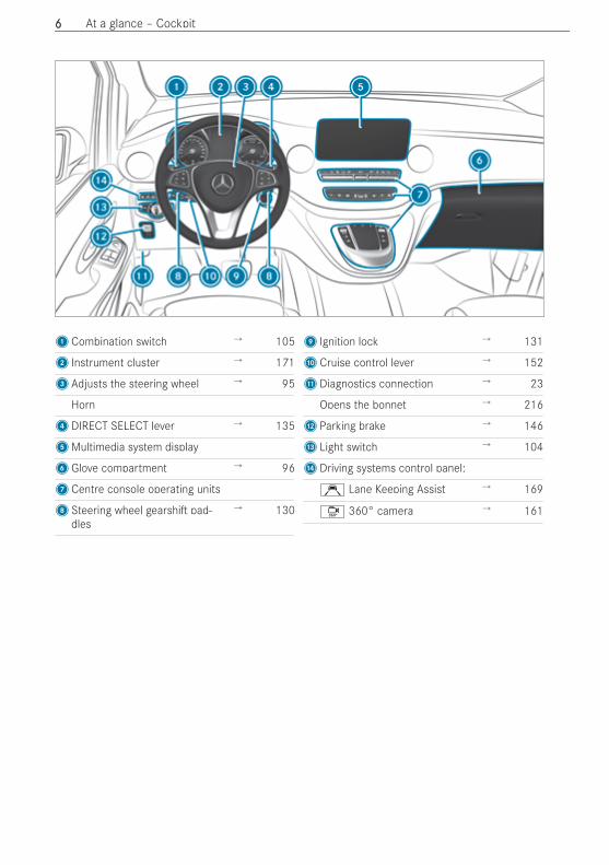
1Combination switch → 105
2 Instrument cluster → 171
3Adjusts the steering wheel → 95
Horn
4DIRECT SELECT lever → 135
5Multimedia system display
6Glove compartment → 96
7Centre console operating units
8Steering wheel gearshi pad-dles
→ 130
9 Ignition lock → 131
ACruise control lever → 152
BDiagnostics connection → 23
Opens the bonnet → 216
CParking brake → 146
D Light switch → 104
EDriving systems control panel:
Ç Lane Keeping Assist → 169
Ô 360° camera → 161
66 At a glance – Cockpit
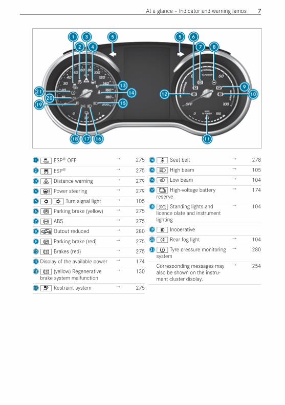
1å ESP® OFF → 275
2÷ ESP® → 275
3· Distance warning → 279
4Ð Power steering → 279
5#! Turn signal light → 105
6! Parking brake (yellow) → 275
7! ABS → 275
8O Output reduced → 280
9! Parking brake (red) → 275
AJ Brakes (red) → 275
BDisplay of the available power → 174
CJ (yellow) Regenerativebrake system malfunction
→ 130
D6 Restraint system → 275
Eü Seat belt → 278
FK High beam → 105
GL Low beam → 104
HÝ High-voltage batteryreserve
→ 174
IT Standing lights andlicence plate and instrumentlighting
→ 104
JN Inoperative
KR Rear fog light → 104
Lh Tyre pressure monitoringsystem
→ 280
Corresponding messages mayalso be shown on the instru-ment cluster display.
→ 254
At a glance – Indicator and warning lamps 77
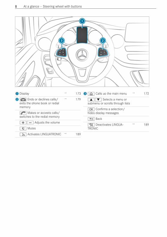
1Display → 173
2~ Ends or declines calls/exits the phone book or redialmemory
→ 179
6 Makes or accepts calls/switches to the redial memory
WX Adjusts the volume
8 Mutes
ó Activates LINGUATRONIC → 189
3ò Calls up the main menu → 172
9: Selects a menu orsubmenu or scrolls through lists
a Con rms a selection/hides display messages
% Back
ñ Deactivates LINGUA-TRONIC
→ 189
88 At a glance – Steering wheel with buttons
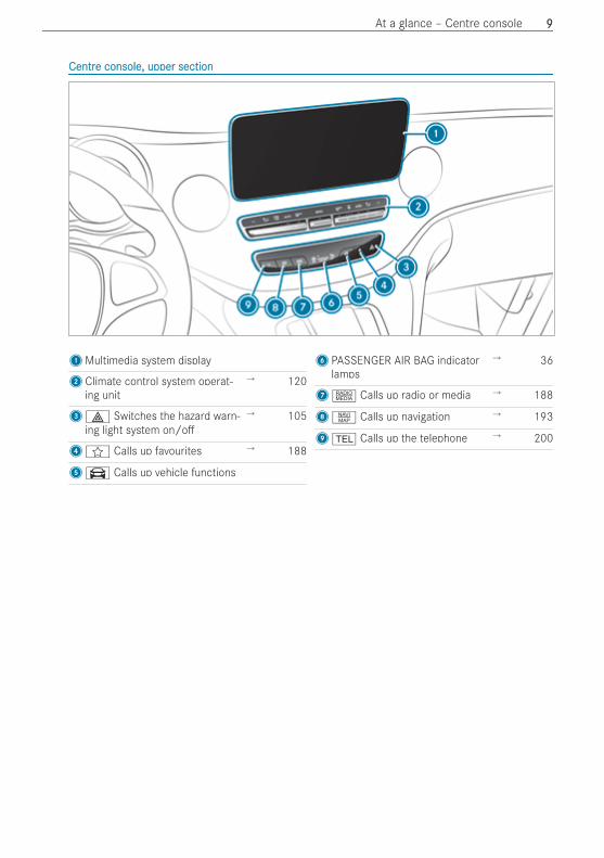
CentrCentre console, upper sectione console, upper section
1Multimedia system display
2Climate control system operat-ing unit
→ 120
3£ Switches the hazard warn-ing light system on/o
→ 105
4f Calls up favourites → 188
5\ Calls up vehicle functions
6PASSENGER AIR BAG indicatorlamps
→ 36
7| Calls up radio or media → 188
8z Calls up navigation → 193
9% Calls up the telephone → 200
At a glance – Centre console 99
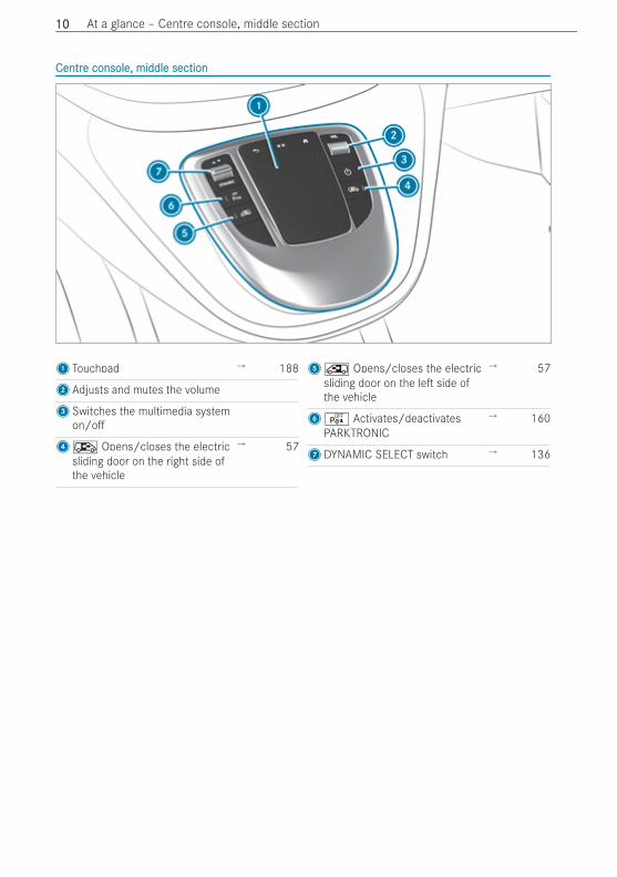
CentrCentre console, middle sectione console, middle section
1 Touchpad → 188
2Adjusts and mutes the volume
3Switches the multimedia systemon/o
4Æ Opens/closes the electricsliding door on the right side ofthe vehicle
→ 57
5Å Opens/closes the electricsliding door on the le side ofthe vehicle
→ 57
6é Activates/deactivatesPARKTRONIC
→ 160
7DYNAMIC SELECT switch → 136
1010 At a glance – Centre console, middle section
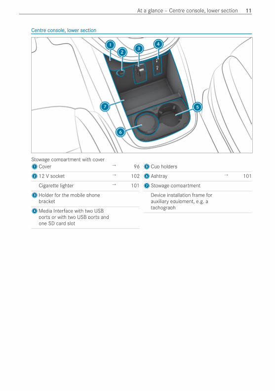
CentrCentre console, lowe console, lower sectioner section
Stowage compartment with cover1Cover → 96
212 V socket → 102
Cigarette lighter → 101
3Holder for the mobile phonebracket
4Media Interface with two USBports or with two USB ports andone SD card slot
5Cup holders
6Ashtray → 101
7Stowage compartment
Device installation frame forauxiliary equipment, e.g. atachograph
At a glance – Centre console, lower section 1111
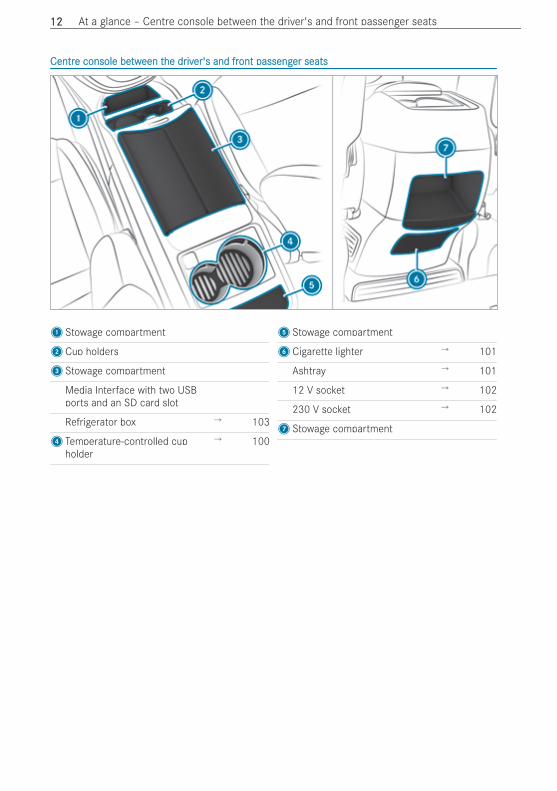
CentrCentre console bee console betwtween teen the drhe driviver's and frer's and front passengont passenger seatser seats
1Stowage compartment
2Cup holders
3Stowage compartment
Media Interface with two USBports and an SD card slot
Refrigerator box → 103
4 Temperature-controlled cupholder
→ 100
5Stowage compartment
6Cigarette lighter → 101
Ashtray → 101
12 V socket → 102
230 V socket → 102
7Stowage compartment
1212 At a glance – Centre console between the driver's and front passenger seats
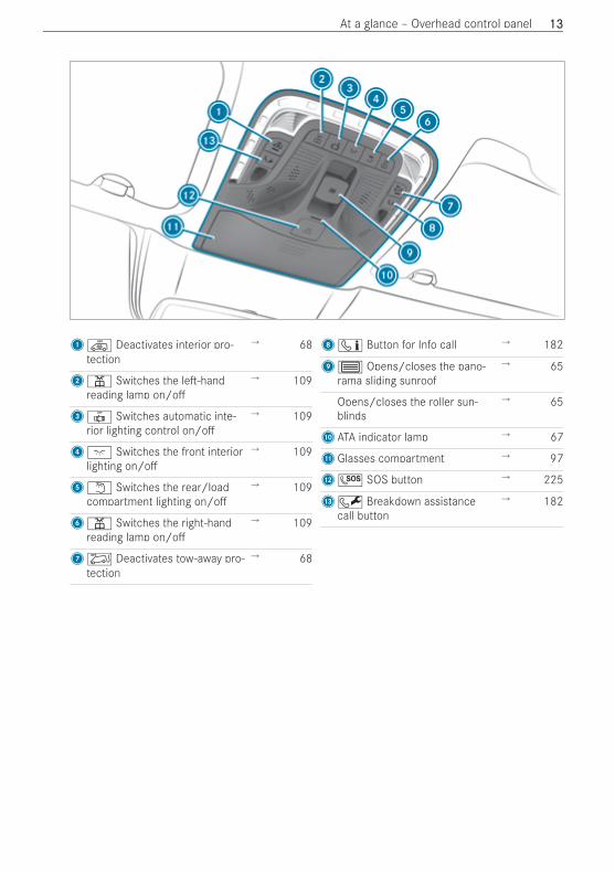
1Ì Deactivates interior pro-tection
→ 68
2p Switches the le -handreading lamp on/o
→ 109
3| Switches automatic inte-rior lighting control on/o
→ 109
4c Switches the front interiorlighting on/o
→ 109
5w Switches the rear/loadcompartment lighting on/o
→ 109
6p Switches the right-handreading lamp on/o
→ 109
7Ë Deactivates tow-away pro-tection
→ 68
8ï Button for Info call → 182
93 Opens/closes the pano-rama sliding sunroof
→ 65
Opens/closes the roller sun-blinds
→ 65
AATA indicator lamp → 67
BGlasses compartment → 97
CG SOS button → 225
DF Breakdown assistancecall button
→ 182
At a glance – Overhead control panel 1313
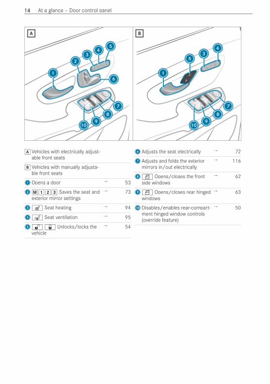
dVehicles with electrically adjust-able front seats
eVehicles with manually adjusta-ble front seats
1Opens a door → 53
2p123 Saves the seat andexterior mirror settings
→ 73
3@ Seat heating → 94
4s Seat ventilation → 95
5%& Unlocks/locks thevehicle
→ 54
6Adjusts the seat electrically → 72
7Adjusts and folds the exteriormirrors in/out electrically
→ 116
8W Opens/closes the frontside windows
→ 62
9W Opens/closes rear hingedwindows
→ 63
ADisables/enables rear-compart-ment hinged window controls(override feature)
→ 50
1414 At a glance – Door control panel
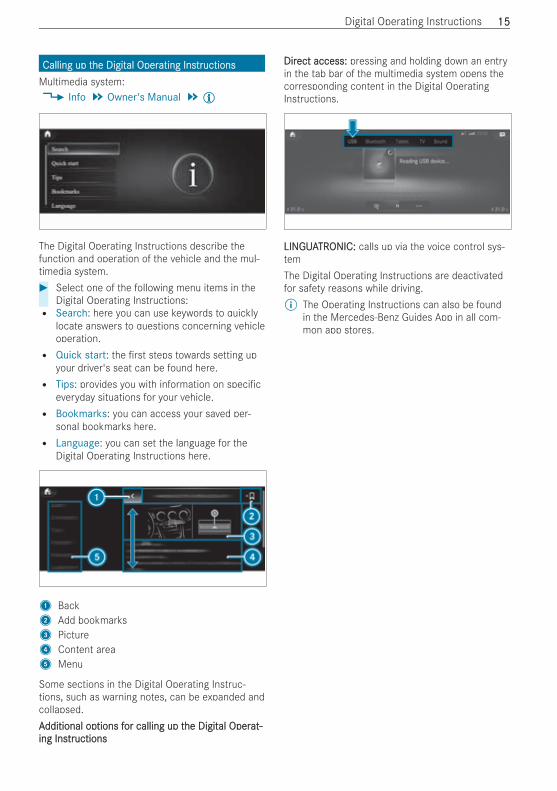
Calling up tCalling up the Digithe Digital Operal Operating Insating InstrtructionsuctionsMultimedia system:4 Info 5 Owner's Manual 5Õ
The Digital Operating Instructions describe thefunction and operation of the vehicle and the mul-timedia system.# Select one of the following menu items in the
Digital Operating Instructions:R Search: here you can use keywords to quickly
locate answers to questions concerning vehicleoperation.R Quick start: the rst steps towards setting up
your driver's seat can be found here.R Tips: provides you with information on speci c
everyday situations for your vehicle.R Bookmarks: you can access your saved per-
sonal bookmarks here.R Language: you can set the language for the
Digital Operating Instructions here.
1 Back2 Add bookmarks3 Picture4 Content area5 Menu
Some sections in the Digital Operating Instruc-tions, such as warning notes, can be expanded andcollapsed.AAdditional opdditional options ftions for calling up tor calling up the Digithe Digital Operal Operat-at-ing Insing Instrtructionsuctions
DirDirect access:ect access: pressing and holding down an entryin the tab bar of the multimedia system opens thecorresponding content in the Digital OperatingInstructions.
LINLINGUAGUATRTRONIC:ONIC: calls up via the voice control sys-temThe Digital Operating Instructions are deactivatedfor safety reasons while driving.% The Operating Instructions can also be found
in the Mercedes-Benz Guides App in all com-mon app stores.
Digital Operating Instructions 1515
EnEnvirvironmentonmental protal protectionection
+ ENVIRENVIRONMENTONMENTAL NOAL NOTETE Environmentaldamage due to operating conditions andpersonal driving style
Operate your vehicle in an environmentallyresponsible manner to help protect the envi-ronment. Please observe the following recom-mendations on operating conditions and per-sonal driving style.OperOperating conditions:ating conditions:# Make sure that the tyre pressure is cor-
rect.# Do not carry any unnecessary weight
(e.g. roof luggage racks once you no lon-ger need them).
# Monitor the energy consumption.# Adhere to the service intervals.
A regularly serviced vehicle will contrib-ute to environmental protection.
# Always have maintenance work carriedout at a quali ed specialist workshop.
PPerersonal drsonal driving siving stytyle:le:# Drive carefully and maintain a suitable
distance from the vehicle in front.# Avoid frequent, sudden acceleration and
braking.# Drive in a style which saves energy.
Observe the ECO display for an economi-cal driving style.
+ ENVIRENVIRONMENTONMENTAL NOAL NOTETE Environmentalpollution caused by irresponsible disposalof the high-voltage battery
A high-voltage battery contains materials whichare harmful to the environment.# Dispose of faulty high-voltage batteries at
a quali ed specialist workshop.
TTakake-bace-back of end-of-lifk of end-of-life ve vehiclesehicles
EU countrEU countries only:ies only:Mercedes-Benz will take back your end-of-life vehi-cle for environment-friendly disposal in accordancewith the European Union (EU) End-Of-Life VehiclesDirective.A network of vehicle take-back points and disman-tlers has been established for you to return your
vehicle. You can leave it at any of these points freeof charge. This makes an important contribution toclosing the recycling circle and conserving resour-ces.For further information about the recycling and dis-posal of end-of-life vehicles, and the take-backconditions, please visit the national Mercedes-Benz website for your country.
MerMercedes-Benz GenuinePcedes-Benz GenuineParartsts
+ ENVIRENVIRONMENTONMENTAL NOAL NOTETE Environmentaldamage caused by not using recycledreconditioned components
Mercedes‑Benz AG o ers recycled recondi-tioned components and parts with the samequality as new parts. The same entitlementfrom the implied warranty is valid as for newparts.# Recycled reconditioned components and
parts from Mercedes‑Benz AG.
* NNOOTETE Impairment of the operating e -ciency of the restraint systems from instal-ling accessory parts or from repairs orwelding
Airbags and seat belt tensioners, as well ascontrol units and sensors for the restraint sys-tems, may be installed in the following areas ofyour vehicle:R DoorsR Door pillarsR Door sillsR SeatsR CockpitR Instrument clusterR Centre consoleR Lateral roof frame
# Do not install accessory parts such asaudio systems in these areas.
# Do not carry out repairs or welding.# Have accessory parts retro tted at a
quali ed specialist workshop.
If you use parts, tyres, wheels or safety-relevantaccessories which have not been approved byMercedes-Benz, the operating safety of the vehiclemay be jeopardised. Safety-relevant systems, e.g.
1616 General notes
the brake system, may malfunction. Use only genu-ine Mercedes-Benz GenuineParts or parts of equalquality. Use only tyres, wheels and accessory partsthat are approved for your vehicle model.Mercedes-Benz tests original parts, conversionparts and accessory parts that have beenapproved for your vehicle model for reliability,safety and suitability. Despite ongoing marketresearch, Mercedes-Benz is unable to assess otherparts. Mercedes-Benz accepts no responsibility forthe use of such parts in Mercedes-Benz vehicles,even if they have been approved o cially or inde-pendently by a testing centre.Certain parts are only o cially approved for instal-lation or modi cation if they comply with legalrequirements. All genuine Mercedes-Benz Genu-ineParts meet the registration requirements. Theuse of non-approved parts may invalidate the vehi-cle's general operating permit.This is the case in the following situations:R the vehicle type changes from that stated in
the general operating permit.R other road users could be endangered.R the noise level increases.
Always specify the vehicle identi cation number(VIN) when ordering genuine Mercedes-Benz parts(/ page 248).
InfInforormation about attmation about attacachments, add-on eqhments, add-on equip-uip-ment, instment, installations and convallations and converersionssions
NotNotes on body/eqes on body/equipment mounting diruipment mounting directivectivesesFor safety reasons, have add-on equipment pro-duced and tted in accordance with the validMercedes-Benz body/equipment mounting direc-tives. These body/equipment mounting directivesensure that the chassis and add-on equipmentform one unit and that the greatest possible levelof operational and driving safety is achieved.Both vehicle manufacturers and body manufactur-ers must always ensure that the products theymanufacture come into circulation only in a safestate and do not pose any risks to people. Other-wise, there may be consequences under civil, crim-inal or public law. All manufacturers are responsi-ble for the products that they have manufactured.Manufacturers of attachments, add-on equipment,installations and conversions must guarantee com-pliance with Directive 2001/95/EC on generalproduct safety.
Mercedes-Benz recommends the following proce-dure for safety reasons:R Do not make any other changes to the vehicle.R Obtain approval from Mercedes-Benz in the
event of deviations from the approved body/equipment mounting directives.
Acceptance tests performed by public test bodiesor o cial approvals do not rule out safety risks.Comply with the information about Mercedes-Benzgenuine parts (/ page 16).You will nd the Mercedes-Benz body/equipmentmounting directives online at the https://bb-portal.mercedes-benz.com/en/GLOBALYou will also nd information about the PIN assign-ment and changing the fuse there.% You can obtain further information at a quali-
ed specialist workshop.
& WWARNINGARNING Risk of accident and injury inthe event of improper conversions orchanges to the vehicle
Conversions or changes to the vehicle can pre-vent systems or components from functioningproperly and/or jeopardise the vehicle'soperational safety.# Always have conversions or changes to
the vehicle carried out at a quali edworkshop.
NNoottes on tes on the rhe radiatadiatororEven seemingly minor changes to the vehicle, suchas attaching a radiator grille in winter, are not per-mitted. Do not cover the radiator. Do not use anythermal mats, insect protection covers etc.Otherwise, the values of the vehicle's diagnosticsystem will be distorted. In some countries, therecording of engine diagnostics data is prescribedby law and must be veri able and correct at alltimes.
OperOperating Insating InstrtructionsuctionsThese Operating Instructions describe all models,as well as standard and optional equipment of yourvehicle that was available at the time of going topress. Country-speci c di erences are possible.Note that your vehicle may not be tted with allfunctions described. This is also the case for sys-tems and functions relevant to safety. Therefore,the equipment on your vehicle may di er from thatin the descriptions and illustrations.
General notes 1717
The original purchase agreement documentationfor your vehicle contains a list of all the systems inyour vehicle.Should you have any questions concerning equip-ment and operation, consult a Mercedes-BenzService Centre.The Operating Instructions and Service Booklet areimportant documents and should be kept in thevehicle.
NNootte on ve on vehicles whicehicles which arh are eqe equipped buipped by body man-y body man-ufufacturacturersersAlways observe the body manufacturer's OperatingInstructions. You could otherwise fail to recognisedangers.
OperOperating safeating safetyty
& WWARNINGARNING Risk of injury due to malfunc-tions or system failure
In order to avoid malfunctions or system fail-ures:# Always have the speci ed service/main-
tenance work as well as any necessaryrepairs carried out at a quali ed special-ist workshop.
& WWARNINGARNING Risk of accident or injury due toimproper modi cations to electronic com-ponents
Modi cations to electronic components, theirso ware or wiring can impair their functionalityand/or the functionality of other networkedcomponents or safety-relevant systems.This can endanger the vehicle's operatingsafety.# You must not tamper with wiring, elec-
tronic components, or their so ware.# Always have work on electrical and elec-
tronic devices carried out at a quali edspecialist workshop.
If you make any changes to the on-board electron-ics, the general operating permit is rendered inva-lid.Observe the "Vehicle electronics" section in "Tech-nical data".
* NNOOTETE Damage to the vehicle due to drivingtoo fast and due to impacts to the vehicleunderbody and suspension components
In the following situations, in particular, there isa risk of damage to the vehicle:R the vehicle becomes grounded, e.g. on a
high kerb or an unpaved roadR the vehicle is driven too fast over an obsta-
cle, e.g. a kerb, speed bump or potholeR a heavy object strikes the underbody or
suspension components
In situations such as these, damage to thebody, underbody, suspension components,wheels or tyres and high-voltage battery com-ponents may not be visible. Components dam-aged in this way can unexpectedly fail or, in thecase of an accident, may no longer absorb theresulting force as intended.# Have the vehicle checked and repaired
immediately at a quali ed specialistworkshop.
or# If driving safety is impaired while continu-
ing your journey, pull over and stop thevehicle immediately, while paying atten-tion to road and tra c conditions, andcontact a quali ed specialist workshop.
Electric vehicles have an electric motor. The elec-tric motor's voltage supply is provided by the high-voltage on-board electrical system.
& DDANANGERGER Risk of death and re due tomodi ed and/or damaged components ofthe high-voltage on-board electrical sys-tem
The vehicle's high-voltage on-board electricalsystem is under high voltage. If you modifycomponent parts in the vehicle's high-voltageon-board electrical system or touch damagedcomponent parts, you may be electrocuted. Inaddition, modi ed and/or damaged compo-nents may cause a re.In the event of an accident or impact to thevehicle underbody, components of the high-voltage electrical system may be damagedalthough the damage is not visible.# Never make any modi cations to the
high-voltage on-board electrical system.
1818 General notes
# Do not switch on or use the vehicle if itshigh-voltage on-board electrical systemcomponents have been modi ed or dam-aged.
# Never touch damaged components of thehigh-voltage on-board electrical system.
# A er an accident, do not touch any com-ponents of the high-voltage on-boardelectrical system.
# A er an accident, have the vehicle trans-ported away.
# Have the components of the high-voltageon-board electrical system checked at aquali ed specialist workshop andreplaced if necessary.
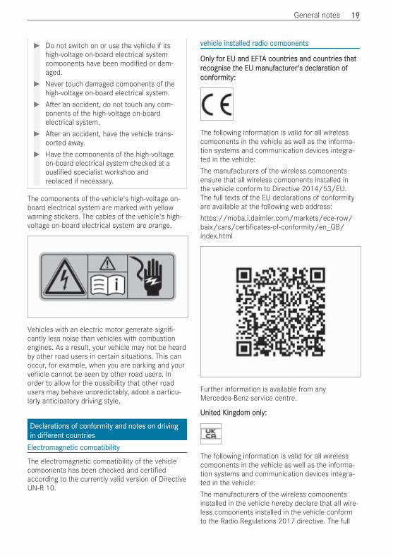
The components of the vehicle's high-voltage on-board electrical system are marked with yellowwarning stickers. The cables of the vehicle's high-voltage on-board electrical system are orange.
Vehicles with an electric motor generate signi -cantly less noise than vehicles with combustionengines. As a result, your vehicle may not be heardby other road users in certain situations. This canoccur, for example, when you are parking and yourvehicle cannot be seen by other road users. Inorder to allow for the possibility that other roadusers may behave unpredictably, adopt a particu-larly anticipatory driving style.
DeclarDeclarations of confations of conforormity and notmity and notes on dres on drivingivinginin di erdi erentent countrcountriesiesElectrElectromagneomagnetic comtic compatibilitypatibility
The electromagnetic compatibility of the vehiclecomponents has been checked and certi edaccording to the currently valid version of DirectiveUN-R 10.
vvehicle instehicle installed ralled radio comadio componentsponents
OnlOnly fy for EU and EFTor EU and EFTA countrA countries and countries and countries ties thathatrrecognise tecognise the EU manufhe EU manufacturacturer's declarer's declaration ofation ofconfconforormity:mity:
The following information is valid for all wirelesscomponents in the vehicle as well as the informa-tion systems and communication devices integra-ted in the vehicle:The manufacturers of the wireless componentsensure that all wireless components installed inthe vehicle conform to Directive 2014/53/EU.The full texts of the EU declarations of conformityare available at the following web address:https://moba.i.daimler.com/markets/ece-row/baix/cars/certi cates-of-conformity/en_GB/index.html
Further information is available from anyMercedes-Benz service centre.
UUnitnited Kingdom only:ed Kingdom only:
The following information is valid for all wirelesscomponents in the vehicle as well as the informa-tion systems and communication devices integra-ted in the vehicle:The manufacturers of the wireless componentsinstalled in the vehicle hereby declare that all wire-less components installed in the vehicle conformto the Radio Regulations 2017 directive. The full
General notes 1919
texts of the declarations of conformity are availa-ble at the following web address:https://moba.i.daimler.com/markets/ece-row/baix/cars/certi cates-of-conformity/en_GB/index.html
BrBrazil only:azil only:
Note on the two-way radio system in the vehicle:This system is not subject to protection againstharmful interference and must not cause interfer-ence in properly approved systems.
RRussia onlyussia only
The manufacturers of the wireless componentsinstalled in the vehicle hereby declare that all wire-less components installed in the vehicle conformto the technical regulations for two-way radios.Further information is available from anyMercedes-Benz service centre.
UkrUkraine only:aine only:
The manufacturers of the wireless componentsinstalled in the vehicle hereby declare that all wire-less components installed in the vehicle conformto the technical regulations for two-way radios.Further information is available from anyMercedes-Benz service centre.
ManufManufacturacturer addrer addresses:esses:Subsequently you will nd the postal address ofmanufacturers of radio components, that due totheir size or nature do not allow to indicate thisinformation on the equipment.
RRemotemote Keyse KeysMarquardt GmbH, Schloßstraße 16, 78604 Rie-theim, GermanyHuf Hülsbeck & Fürst GmbH & Co. KG, SteegerStraße 17, 42551 Velbert, Germany
TTyryre Pre Pressuressure Monite Monitororing Sensorsing SensorsSchrader Electronics Ltd., 11 Technology Park,Belfast Road, Antrim BT41 1QS, Northern Ireland
BlocBlock Heatk Heater Rer Remotemote Contre ContrololEberspächer Climate Control Systems GmbH & Co.KG, Eberspächerstrasse 24, 73730 Esslingen, Ger-many
RRadar Sensorsadar SensorsAutoliv Electronics ASP Inc., 26545 AmericanDrive, South eld, MI 48034, USARobert Bosch GmbH, Daimlerstraße 6,71229 Leonberg, Germany
Mobile Communication & TMobile Communication & TelematicselematicsAlpine Electronics Inc., 20-1 Yoshima-Kogyodan-chi, Iwaki-Shi Fukushima-Ken, JapanHarman Becker Automotive Systems GmbH, Post-fach 2260, 76303 Karlsbad, Germany
TrTransmittansmitter keyer keyHELLA GmbH & Co. KGaA, Rixbecker Straße 75,59552 Lippstadt, Germany
Head unit NTHead unit NTG6 (MBUX)G6 (MBUX)Harman Becker Automotive Systems GmbH,Becker-Goehring- Strasse 18, 76307 Karlsbad,Germany
2020 General notes
WWirireless centreless central local lockingkingHirschmann Car Communication GmbH, Stuttgar-ter Straße 45 – 51, 72654 Neckartenzlingen, Ger-many
TType of wirype of wireless applications in teless applications in the vhe vehicleehicleBesides the typical frequencies for mobile commu-nication cars by Mercedes-Benz make use of thefollowing automotive radio applications.
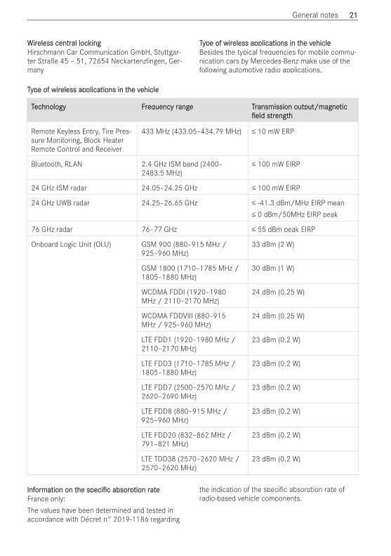
TType of wirype of wireless applications in teless applications in the vhe vehicleehicle
TTecechnology Frhnology Freqequency ruency range Trange Transmission output/magneansmission output/magneticticeldeld sstrtrengthength
Remote Keyless Entry, Tire Pres-sure Monitoring, Block HeaterRemote Control and Receiver
433 MHz (433.05–434.79 MHz) ≤ 10 mW ERP
Bluetooth, RLAN 2.4 GHz ISM band (2400–2483.5 MHz)
≤ 100 mW EIRP
24 GHz ISM radar 24.05–24.25 GHz ≤ 100 mW EIRP
24 GHz UWB radar 24.25–26.65 GHz ≤ -41.3 dBm/MHz EIRP mean≤ 0 dBm/50MHz EIRP peak
76 GHz radar 76–77 GHz ≤ 55 dBm peak EIRP
Onboard Logic Unit (OLU) GSM 900 (880–915 MHz /925–960 MHz)
33 dBm (2 W)
GSM 1800 (1710–1785 MHz /1805–1880 MHz)
30 dBm (1 W)
WCDMA FDDI (1920–1980MHz / 2110–2170 MHz)
24 dBm (0.25 W)
WCDMA FDDVIII (880–915MHz / 925–960 MHz)
24 dBm (0.25 W)
LTE FDD1 (1920–1980 MHz /2110–2170 MHz)
23 dBm (0.2 W)
LTE FDD3 (1710–1785 MHz /1805–1880 MHz)
23 dBm (0.2 W)
LTE FDD7 (2500–2570 MHz /2620–2690 MHz)
23 dBm (0.2 W)
LTE FDD8 (880–915 MHz /925–960 MHz)
23 dBm (0.2 W)
LTE FDD20 (832–862 MHz /791–821 MHz)
23 dBm (0.2 W)
LTE TDD38 (2570–2620 MHz /2570–2620 MHz)
23 dBm (0.2 W)
InfInforormation on tmation on thehe speci cspeci c absorpabsorption rtion rateateFrance only:The values have been determined and tested inaccordance with Décret n° 2019-1186 regarding
the indication of the speci c absorption rate ofradio-based vehicle components.
General notes 2121
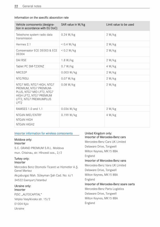
InfInforormation on tmation on thehe speci cspeci c absorpabsorption rtion rateate
VVehicle comehicle components (designa-ponents (designa-tion in accortion in accordance witdance with EU DoC)h EU DoC)
SSAR vAR value in W/kgalue in W/kg Limit vLimit value talue to be usedo be used
Telephone system radio datatransmission
0.24 W/kg 2 W/kg
Hermes 2.1 < 0.4 W/kg 2 W/kg
Compensator ECE DE003 & ECEDE004
< 0.2 W/kg 2 W/kg
DAI RSE 1.8 W/kg 2 W/kg
Tablet PC SM-T230NZ 0.7 W/kg 4 W/kg
NRCS2P 0.003 W/kg 2 W/kg
NTG7RSU 0.07 W/kg 2 W/kg
NTG7 MID, NTG7 HIGH, NTG7PREMIUM, NTG7 PREMIUM-PLUS, NTG7 MID LFT2, NTG7HIGH LFT2, NTG7 PREMIUMLFT2, NTG7 PREMIUMPLUSLFT2
0.08 W/kg 2 W/kg
RAMSES 1.0 and 1.1 0.036 W/kg 2 W/kg
NTG6N MID/ENTRYNTG6N HIGHNTG6N HIGH2
0.199 W/kg 4 W/kg
ImImportporter infer inforormation fmation for wiror wireless comeless componentsponents
MoldovMoldova only:a only:ImImportportererS.C. GRAND PREMIUM S.R.L. Moldovamun. Chisinau, str. Hîncesti sos., 2/2
TTurkeurkey only:y only:ImImportportererMercedes Benz Otomotiv Ticaret ve Hizmetler A.Ş.Genel MerkezAkçaburgaz Mah. Süleyman Şah Cad. No: 6/134522 Esenyurt/Istanbul
UkrUkraine only:aine only:ImImportportererPJSC „AUTOCAPITAL“Velyka Vasylkivska str. 15/201004 KyivUkraine
UUnitnited Kingdom only:ed Kingdom only:ImImportporter of Merer of Mercedes-Benz carscedes-Benz carsMercedes-Benz Cars UK LimitedDelaware Drive, TongwellMilton Keynes, MK15 8BAEnglandImImportporter of Merer of Mercedes-Benz vcedes-Benz vansansMercedes-Benz Vans UK LimitedDelaware Drive, TongwellMilton Keynes, MK15 8BAEnglandImImportporter of Merer of Mercedes-Benz sparcedes-Benz spare pare partstsMercedes-Benz Parts LogisticsDelaware Drive, TongwellMilton Keynes, MK15 8BAEngland
2222 General notes
JackJack
Copy and translation of the original declaration ofconformity:EC declarEC declaration of confation of conforormitymity1.The undersigned, representingManufacturer:BRANO a.s.74741 Hradec nad Moravicí, Opavská 1000,The Czech RepublicID No.: 64-387-5933VAT No.: CZ64-387-5933herewith declares under our sole responsibility thatthe product:2. a)Name:JackType:A) A 164 580 02 18, A 166 580 01 18B) A 240 580 00 18C) A 639 580 02 18Year of manufacture: 2015Complies with all relevant provisionsDirective No. 2006/42/ECb)Description and purpose of use:The jack is only intended for raising the speci edvehicle in accordance with the operating instruc-tions a xed to the jack.3.Reference data of the harmonised standards orspeci cationsA) ISO 4063, EN ISO 14341-A, DBL 7382.20, MBN10435, AS 2693B) ISO 4063, ISO 14341-A, DBL 7392.10, MBN10435C) DBL 7392.10, DBL 8230.10Technical documentation of the product is storedat the premises of the manufacturer. The personresponsible for assembling the technical documen-tation of the product: Head of the technicaldepartment Brano a.s.4.Hradec nad MoravicíCity
5.05.05.2015DateSigned by:Director of Quality
DiagnosDiagnostics connectiontics connectionThe diagnostics connection is a technical interfacein the vehicle. It is used, for example, in the con-text of repair and maintenance work or for readingout vehicle data by a specialist workshop. Diagnos-tic devices should therefore only be connected bya quali ed specialist workshop.
& WWARNINGARNING Risk of accident due to con-necting devices to the diagnostics connec-tion
If you connect devices to the diagnostics con-nection of the vehicle, the function of vehiclesystems and operating safety may be impaired.# For safety reasons, we recommend that
you only use and connect productsapproved by your Mercedes-Benz servicecentre.
& WWARNINGARNING Risk of accident due to objectsin the driver's footwell
Objects in the driver's footwell may impedepedal travel or block a depressed pedal.This jeopardises the operating and road safetyof the vehicle.# Stow all objects in the vehicle securely
so that they cannot get into the driver'sfootwell.
# Always t the oor mats securely and asprescribed in order to ensure that thereis always su cient room for the pedals.
# Do not use loose oor mats and do notplace oor mats on top of one another.
* NNOOTETE Battery discharging from using devi-ces connected to the diagnostics connec-tion
Using devices at the diagnostics connectiondrains the battery.# Check the charge level of the battery.# If the charge level is low, charge the bat-
tery.
General notes 2323
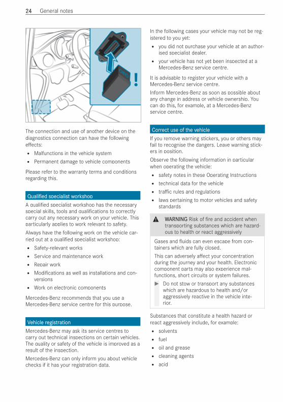
The connection and use of another device on thediagnostics connection can have the followinge ects:R Malfunctions in the vehicle systemR Permanent damage to vehicle components
Please refer to the warranty terms and conditionsregarding this.
Quali edQuali ed specialisspecialist wt workorkshopshopA quali ed specialist workshop has the necessaryspecial skills, tools and quali cations to correctlycarry out any necessary work on your vehicle. Thisparticularly applies to work relevant to safety.Always have the following work on the vehicle car-ried out at a quali ed specialist workshop:R Safety-relevant worksR Service and maintenance workR Repair workR Modi cations as well as installations and con-
versionsR Work on electronic components
Mercedes-Benz recommends that you use aMercedes-Benz service centre for this purpose.
VVehicle rehicle regisegistrtrationationMercedes-Benz may ask its service centres tocarry out technical inspections on certain vehicles.The quality or safety of the vehicle is improved as aresult of the inspection.Mercedes-Benz can only inform you about vehiclechecks if it has your registration data.
In the following cases your vehicle may not be reg-istered to you yet:R you did not purchase your vehicle at an author-
ised specialist dealer.R your vehicle has not yet been inspected at a
Mercedes-Benz service centre.
It is advisable to register your vehicle with aMercedes-Benz service centre.Inform Mercedes-Benz as soon as possible aboutany change in address or vehicle ownership. Youcan do this, for example, at a Mercedes-Benzservice centre.
CorrCorrect use of tect use of the vhe vehicleehicleIf you remove warning stickers, you or others mayfail to recognise the dangers. Leave warning stick-ers in position.Observe the following information in particularwhen operating the vehicle:R safety notes in these Operating InstructionsR technical data for the vehicleR tra c rules and regulationsR laws pertaining to motor vehicles and safety
standards
& WWARNINGARNING Risk of re and accident whentransporting substances which are hazard-ous to health or react aggressively
Gases and uids can even escape from con-tainers which are fully closed.This can adversely a ect your concentrationduring the journey and your health. Electroniccomponent parts may also experience mal-functions, short circuits or system failures.# Do not stow or transport any substances
which are hazardous to health and/oraggressively reactive in the vehicle inte-rior.
Substances that constitute a health hazard orreact aggressively include, for example:R solventsR fuelR oil and greaseR cleaning agentsR acid
2424 General notes
InfInforormation on tmation on the REAChe REACH dirH directiveectiveEU and EFTEU and EFTA countrA countries only:ies only:The REACH directive (Directive (EC) No.1907/2006, Article 33) stipulates a duty to supplyinformation about substances of very high concern(SVHCs).Mercedes‑Benz AG acts to the best of its knowl-edge to prevent these SVHCs from being used andto enable customers to safely handle these sub-stances. There are SVHCs known toMercedes‑Benz AG, according to supplier informa-tion and internal product information, found in indi-vidual components of this vehicle in quantities ofover 0.1 percent by weight.Further information can be obtained at the follow-ing addresses:R https://reach.daimler.com/de/home/R https://reach.daimler.com/en/home/
NNoottes fes for peror persons witsons with electrh electronic medical aidsonic medical aidsMercedes-Benz AG cannot, despite carefully devel-oping vehicle systems, completely rule out theinteraction of vehicle systems with electronic med-ical aids such as cardiac pacemakers.In addition, there are components built into thevehicle that, regardless of the operating status ofyour vehicle, can generate magnetic elds on a parwith permanent magnets. These elds can befound, for example, in the area around the multi-media and sound system or also in the area of theseats, depending on the vehicle equipment.For this reason, the following can occur in isolatedcases, depending on the aids used:R medical aids malfunctioningR adverse health e ects
Observe the notes and warnings of the manufac-turer of the medical aids; if in doubt, contact thedevice manufacturer and/or your doctor. If there iscontinuing uncertainty concerning the possibilityof medical aids malfunctioning, Mercedes-Benz AGrecommends using only few electrical vehicle sys-tems and/or maintaining a distance from the com-ponents.When charging the high-voltage battery, keep a dis-tance of at least an arm's length between the med-ical aid and the following components:R the power supply equipment
This includes charging stations in the form of awallbox or a public charging point, for example.R vehicle components carrying live voltage
This includes the charging cable and the charg-ing control box, for example.
Only have repairs and maintenance work in thearea of the following components carried out by aquali ed specialist workshop:R vehicle components carrying live voltageR transmission aerialsR multimedia system and sound system
If you have any queries or suggestions, consult aquali ed specialist workshop.
ImImplied wplied warrarrantyanty
* NONOTETE Damage to the vehicle arising fromviolation of these operating instructions.
Damage to the vehicle can arise from violationof these operating instructions.Such damage is not covered by either the Limi-ted Warranty or the new or used-vehicle war-ranty.# Observe the instructions in these operat-
ing instructions on proper operation ofyour vehicle as well as regarding possiblevehicle damage.
QR codes fQR codes for ror rescue cardescue cardThe QR code stickers are a xed to the B-pillar onthe driver's and front passenger side. In the eventof an accident, emergency services can use theQR code to quickly determine the correspondingrescue card for your vehicle. The current rescuecard contains the most important informationabout your vehicle in a compact form, e.g. therouting of the electric lines.Further information can be obtained at https://www.mercedes-benz.de/qr-code
DatData sta stororageageDatData pra processing in tocessing in the vhe vehicleehicle
ElectrElectronic contronic control unitsol unitsElectronic control units are tted in your vehicle.Control units process data which, for example,they receive from vehicle sensors, generate them-
General notes 2525
selves or exchange between themselves. Somecontrol units are required for the safe operation ofyour vehicle, some assist you when driving, suchas driver assistance systems, while others enablecomfort or infotainment functions.The following provides you with general informa-tion regarding data processing in the vehicle. Addi-tional information regarding exactly which data inyour vehicle are collected, saved and transmittedto third parties, and for what purpose, can befound in the information directly related to thefunctional characteristics in question in theirrespective operating instructions. This informationis also available online and, depending on the vehi-cle equipment, digitally.
PPerersonal datasonal dataEvery vehicle is identi ed by a unique vehicle iden-ti cation number. Depending on the country, thisvehicle identi cation number can be used by, forexample, governmental authorities to determinethe identity of the owner. There are other possibili-ties for using data collected from the vehicle toidentify the owner or driver, such as the licenceplate number.Therefore, data generated or processed by controlunits may be attributable to a person or, under cer-tain conditions, become attributable to a person.Depending on which vehicle data are available, itmay be possible to make inferences about, forexample, your driving behaviour, your location, yourroute or your use patterns.
LegLegal ral reqequiruirements rements regegararding tding the disclosurhe disclosure ofe ofdatadataIf legally required to do so, manufacturers are, inindividual cases, legally obliged to provide govern-mental entities, upon request and to the extentrequired, data stored by the manufacturer. Forexample, this may be the case during the investiga-tion of a criminal o ence.Governmental entities are themselves, in individualcases and within the applicable legal framework,authorised to read out data from the vehicle. In thecase of an accident, information that can help withan investigation can, therefore, be taken from theairbag control unit, for example.
OperOperational datational data in ta in the vhe vehicleehicleThis is data regarding the operation of the vehicle,which have been processed by control units.This includes the following data, for example:R vehicle status information such as the speed,
longitudinal acceleration, lateral acceleration,
number of wheel revolutions or the fastenedseat belts displayR ambient conditions, such as temperature, rain
sensor or distance sensor
Generally, these are volatile data and will not bestored beyond the period of operation but will onlybe processed within the vehicle itself. Controlunits, vehicle keys for example, o en contain datamemories. Their use permits the temporary or per-manent documentation of technical informationabout the vehicle's operating state, componentloads, maintenance requirements and technicalevents or faults.Depending on the technical equipment, the follow-ing data are stored:R operating status of system components, such
as ll levels, tyre pressure or battery statusR malfunctions or faults in important system
components, such as lights or brakesR system reactions in special driving situations,
such as airbag deployment or the interventionof stability control systemsR information on events in which the vehicle is
damaged
In certain cases, it may be required to store datathat would have otherwise been temporary. Thismay be the case if the vehicle has detected a mal-function, for example.If you use services, such as repair services andmaintenance work, stored operational data as wellas the vehicle identi cation number can be readout and used. They can be read out by service net-work employees, such as workshops and manufac-turers or third parties, such as breakdown serv-ices. The same is true in the case of warrantyclaims and quality assurance measures.In general, the readout is performed via the legallyprescribed port for the diagnostics connection inthe vehicle. The operational data that are read outdocument technical states of the vehicle or of indi-vidual components and assist in the diagnosis ofmalfunctions, compliance with warranty obliga-tions and quality improvement. To that end, thesedata, in particular information about componentloads, technical events, malfunctions and otherfaults may be transmitted along with the vehicleidenti cation number to the manufacturer. In addi-tion, the manufacturer is subject to product liabil-ity. For this reason, the manufacturer also usesoperational data from the vehicle, for example, for
2626 General notes
recalls. These data can also be used to examinethe customer's warranty and guarantee claims.Fault memories in the vehicle can be reset by aservice outlet or at your request as part of repairor maintenance work.
ConvConvenience and infotenience and infotainment functionsainment functionsYou can store convenience settings and individualsettings in the vehicle and change or reset them atany time.Depending on the vehicle equipment, this includesthe following settings, for example:R seat and steering wheel positionsR suspension and climate control settingsR individual settings, such as interior lighting
Depending on the selected equipment, you canimport data into vehicle infotainment functionsyourself.Depending on the vehicle equipment, this includesthe following data, for example:R multimedia data, such as music, lms or pho-
tos for playback in an integrated multimediasystemR address book data for use in an integrated
hands-free system or an integrated navigationsystemR entered navigation destinationsR data on the use of Internet services
These data for convenience and infotainment func-tions may be saved locally in the vehicle or theymay be located on a device which you have con-nected to the vehicle, such as a smartphone, USBash drive or MP3 player. If you have entered these
data yourself, you can delete them at any time.This data is transmitted from the vehicle to thirdparties only at your request. This applies, in partic-ular, when you use online services in accordancewith the settings that you have selected.
SmarSmartphone inttphone integregration (e.g. Andration (e.g. Android Aoid Aututo oro orApple CarPlayApple CarPlay®®))If your vehicle is equipped appropriately, you canconnect your smartphone or another mobile enddevice to the vehicle. You can then control them bymeans of the control elements integrated in thevehicle. The smartphone's picture and sound canbe output via the multimedia system. Simultane-ously, speci c items of information are transferredto your smartphone. Depending on the type ofintegration, this includes position data, day/nightmode and other general vehicle statuses. For more
information, please consult the vehicle OperatingInstructions/infotainment system.This integration allows the use of selected smart-phone apps, such as navigation or music playerapps. There is no additional interaction betweenthe smartphone and the vehicle, particularly activeaccess to vehicle data. The type of additional dataprocessing is determined by the provider of theapp being used. Which settings you can make, ifany, depends on the speci c app and the operat-ing system of your smartphone.
Online serOnline servicesvices
WWirireless neeless netwtworork connectionk connectionIf your vehicle has a wireless network connection,data can be exchanged between your vehicle andother systems. The wireless network connection ismade possible by the vehicle's own transmitterand receiver or by a mobile end device that youhave brought into the vehicle, for example, asmartphone. Online functions can be used via thiswireless network connection. This includes onlineservices and applications/apps provided to you bythe manufacturer or by other providers.
ManufManufacturacturer's oer's own serwn servicesvicesRegarding the manufacturer's online services, theindividual functions are described by the manufac-turer in a suitable place, for example, in the Oper-ating Instructions or on the manufacturer's web-site, where the relevant data protection informa-tion is also given. Personal identi cation data maybe used to provide online services. Data isexchanged via a secure connection, e.g. the manu-facturer's designated IT systems. Any personaldata which are collected, processed and used,other than for the provision of services, is done soexclusively on the basis of legal permission. This isthe case, for example, for a legally prescribedemergency call system, a contractual agreementor when consent has been given.You can have services and functions, some ofwhich are subject to a fee, activated or deactiva-ted. This excludes legally prescribed functions andservices, such as an emergency call system.
SerServices of tvices of thirhird pard partiestiesIf you use online services from other providers(third parties), these services are the responsibilityof the provider in question and subject to that pro-vider's data protection conditions and terms ofuse. As a general rule, the manufacturer has noin uence on the content exchanged.
General notes 2727
For this reason, when services are provided bythird parties, please ask the service provider inquestion for information about the type, extent andpurpose of the collection and use of personal data.
OnboarOnboard Logic Ud Logic Unit (OLnit (OLU)U)The Onboard Logic Unit (OLU) is available to com-mercial customers.It contains control units, including aerials for con-nection via wireless networks, that permit theexchange of data between your vehicle and othersystems. The control units can be used in conjunc-tion with service provided by a third party. Undercertain circumstances, these services may alterthe basic con guration of the vehicle and coulda ect the performance of certain vehicle func-tions.For further information about speci c services,read the operating instructions of the third-partyprovider. For further information about theOnboard Logic Unit, consult a Mercedes-BenzService Centre.If you, yourself, do not own and are not responsi-ble for the vehicle, you may not know the currentstatus of the Onboard Logic Unit. For further infor-mation concerning the services which are cur-rently active, including any data which may bebeing processed as de ned by the GDPR, pleasecontact the person responsible for the vehicle.
DatData prota protection rection rightsights
Depending on your country or the equipment andrange of functions of your vehicle as well as theservices you use and the services on o er, you areentitled to di erent data protection rights. Furtherinformation on data protection and your data pro-tection rights can either be found on the manufac-turer's website or you will receive this informationas part of the various services and service o ers.There, you will also nd the contact information forthe manufacturer and its data protection o cer.At a workshop, for example, with the support of aspecialist and possibly for a fee, you can have dataread out which is stored only locally in the vehicle.
CopCopyryrightightInformation on licences for free and open-sourceso ware used in your vehicle can be found on thedata storage medium in your vehicle documentwallet and with updates on the following website:https://www.mercedes-benz.com/opensource.
2828 General notes
RResestrtraint systaint systememProtProtection proection provided bvided by ty the rhe resestrtraint systaint systemem
The restraint system includes the following compo-nents:R Seat belt systemR AirbagsR Child restraint systemR Child seat securing systems
The restraint system can help prevent the vehicleoccupants from coming into contact with parts ofthe vehicle interior in the event of an accident. Inthe event of an accident, the restraint system canalso reduce the forces to which the vehicle occu-pants are subjected.Only a seat belt which is worn correctly can pro-vide the intended level of protection. Depending onthe detected accident situation, seat belt tension-ers and/or airbags supplement the protectiono ered by a correctly worn seat belt. Seat belt ten-sioners and/or airbags are not deployed in everyaccident.In order for the restraint system to provide theintended level of protection, each vehicle occupantmust observe the following information:R Fasten seat belts correctly.R Sit in an almost upright seat position with their
back against the seat backrest.R Sit with their feet resting on the oor, if possi-
ble.R Always secure persons under 1.50 m tall in an
additional restraint system suitable forMercedes-Benz vehicles.
However, no system available today can completelyeliminate injuries and fatalities in every accidentsituation. In particular, the seat belt and airbaggenerally do not protect against objects penetrat-ing the vehicle from the outside. It is also not pos-sible to completely rule out the risk of injurycaused by the airbag deploying.
LimitLimitations of tations of the prothe protection proection provided bvided by ty theherresestrtraint systaint systemem
& WWARNINGARNING Risk of injury or death due tomodi cations to the restraint system
Vehicle occupants may no longer be protectedas intended if alterations are made to therestraint system.
# Never alter the parts of the restraint sys-tem.
# Never tamper with the wiring or any elec-tronic component parts or their so ware.
If it is necessary to adjust the vehicle to accommo-date a person with disabilities, contact a quali edspecialist workshop.Mercedes-Benz recommends that you only usedriving aids which have been approved speci callyfor your vehicle by Mercedes-Benz.
RResestrtraint systaint system functionalityem functionality
When the vehicle is switched on, a self-test is per-formed, during which the 6 restraint systemwarning lamp lights up. It goes out no later than afew seconds a er the vehicle is started. The com-ponents of the restraint system are then func-tional.
RResestrtraint systaint system malfunctionem malfunction
A malfunction has occurred in the restraint systemin the following cases:R The 6 restraint system warning lamp does
not light up when the vehicle is switched on.R The 6 restraint system warning lamp lights
up continuously or repeatedly during a journey.
& DDANANGERGER Risk of fatal injuries due torestraint system malfunctions
Components in the restraint system may beactivated unintentionally or not deploy as plan-ned in an accident. In the event of an accident,the high-voltage on-board electrical systemmay not be deactivated as intended.You may su er an electric shock if you touchthe damaged components of the high-voltageon-board electrical system.# Have the restraint system checked and
repaired immediately at a quali ed spe-cialist workshop.
# A er an accident, switch o the vehicleimmediately.
Occupant safety 2929
FFunction of tunction of the rhe resestrtraint systaint system in an accidentem in an accident
How the restraint system works is determined bythe severity of the impact detected and the type ofaccident anticipated:R frontal impactR rear impactR side impactR overturning or rollover
The activation thresholds for the components ofthe restraint system are determined based on theevaluation of the sensor values measured at vari-ous points in the vehicle. This process is pre-emp-tive in nature. The triggering/deployment of thecomponents of the restraint system should takeplace in good time at the start of the collision.Factors which can only be seen and measureda er a collision has occurred cannot play a deci-sive role in airbag deployment. Nor do they providean indication of airbag deployment.The vehicle may be deformed signi cantly withoutan airbag being deployed. This is the case if onlyparts which are relatively easily deformed area ected and the rate of vehicle deceleration is nothigh. Conversely, an airbag may be deployed eventhough the vehicle su ers only minor deformation.If very rigid vehicle parts, such as longitudinalmembers, are hit, the vehicle deceleration may behigh enough for this to happen.Depending on the detected deployment situation,the components of the restraint system can beactivated or deployed independently of each other:R Seat belt tensioner: frontal impact, rear
impact, side impact, overturning, rolloverR Driver's airbag, front passenger airbag: frontal
impactR Side airbag: side impactR Window airbag: side impact, overturning, roll-
over, frontal impact
The co-driver airbag can only be deployed in theevent of an accident if the PASSENGER AIR BAGOFF indicator lamp is o . If the co-driver seat isoccupied, make sure, both before and during thejourney, that the status of the co-driver airbag iscorrect (/ page 36).
& WWARNINGARNING Risk of burns from hot airbagcomponents
The airbag parts are hot a er an airbag hasbeen deployed.
# Do not touch the airbag parts.# Have a deployed airbag replaced at a
quali ed specialist workshop as soon aspossible.
Mercedes-Benz recommends that you have thevehicle towed to a quali ed specialist workshopa er an accident. Take this into account, particu-larly if a seat belt tensioner is triggered or an air-bag deployed.If the seat belt tensioners are triggered or an air-bag is deployed, you will hear a bang, and a smallamount of powder may also be released:R the bang will not generally a ect your hearing.R in general, the powder released is not hazard-
ous to health but may cause short-term breath-ing di culties to persons su ering fromasthma or other pulmonary conditions.Provided it is safe to do so, leave the vehicleimmediately or open the window in order toprevent breathing di culties.
Seat beltsSeat beltsProtProtection proection provided bvided by ty the seat belthe seat belt
Always fasten your seat belt correctly before start-ing a journey. Only a seat belt which is worn cor-rectly can provide the intended level of protection.
& WWARNINGARNING Risk of injury or death due toincorrectly fastened seat belt
If the seat belt is not worn correctly, it cannotperform its intended protective function.In addition, an incorrectly fastened seat beltcan also cause injuries, for example, in theevent of an accident or when braking or chang-ing direction suddenly.# Always ensure that all vehicle occupants
have their seat belts fastened correctlyand are sitting properly.
Always observe the instructions about the correctdriver's seat position and adjusting the seat(/ page 70).
3030 Occupant safety
In order for the correctly worn seat belt to providethe intended level of protection, each vehicle occu-pant must observe the following information:R The seat belt must not be twisted and must t
tightly and snugly across the body.R The seat belt must be routed across the centre
of the shoulder and as low down across thehips as possible.R The shoulder section of the seat belt should
not touch your neck nor be routed under yourarm or behind your back.R Avoid wearing bulky clothing, e.g. a winter
coat.R Push the lap belt down as far as possible
across your hips and pull tight with the shoul-der section of the belt. Never route the lap beltacross your abdomen.Pregnant women must also take particular carewith this.R Never route the seat belt across sharp, poin-
ted, abrasive or fragile objects.R Only one person should use each seat belt at
any one time.R Never secure objects with a seat belt if the
seat belt is being used by one of the vehicle'soccupants.Also ensure that no objects, e.g. a cushion, areever placed between a person and the seat.
If children are travelling in the vehicle, alwaysobserve the instructions and safety notes on "Chil-dren in the vehicle" (/ page 39).Always observe the instructions for loading thevehicle when securing objects, luggage or loads(/ page 206).
LimitLimitations of tations of the prothe protection proection provided bvided by ty the seathe seatbeltbelt
& WWARNINGARNING Risk of injury or death due toincorrect seat position
The seat belt will not o er the intended level ofprotection if you have not moved the seatbackrest to an almost vertical position.In particular, you may slip under the seatbeltand injure yourself.# Adjust the seat properly before beginning
your journey.# Always ensure that the seat backrest is
in an almost vertical position and that
the shoulder section of your seat belt isrouted across the centre of your shoul-der.
& WWARNINGARNING Risk of injury or death whenadditional restraint systems are not usedfor persons with a smaller stature
Persons under 1.50 m tall cannot wear theseat belt correctly without a suitable additionalrestraint system.# Always secure persons under 1.50 m tall
in a suitable restraint system.
& WWARNINGARNING Risk of injury or death due todamaged or modi ed seat belts
Seat belts cannot provide protection in the fol-lowing situations:R the seat belt is damaged, has been modi-
ed, is extremely dirty, bleached or dyedR the seat belt buckle is damaged or
extremely dirtyR modi cations have been made to the seat
belt tensioner, seat belt anchorage or seatbelt retractor
Seat belts may sustain non-visible damage inan accident, e.g. due to glass splinters.Modi ed or damaged seat belts could tear orfail in the event of an accident, for example.Modi ed seat belt tensioners could acciden-tally trigger or fail to function as intended.# Never modify the seat belt system, for
example the seat belt, seat belt buckle,seat belt tensioner, seat belt anchorageand seat belt retractor.
# Make sure that the seat belts are undam-aged, not worn and clean.
# Always have the seat belts checkedimmediately a er an accident at a quali-ed specialist workshop.
Mercedes-Benz recommends that you use seatbelts which have been approved for your vehicle byMercedes-Benz.
& WWARNINGARNING Risk of injury or death fromdeployed pyrotechnic seat belt tensioners
Pyrotechnic seat belt tensioners that havebeen deployed are no longer operational and
Occupant safety 3131
are unable to perform their intended protectivefunction.# Therefore, have deployed pyrotechnic
seat belt tensioners immediatelyreplaced at a quali ed specialist work-shop.
Mercedes-Benz recommends that you have thevehicle towed to a quali ed specialist workshopa er an accident.
* NNOOTETE Damage caused by trapping the seatbelt
If an unused seat belt is not fully retracted, itmay become trapped in the door or in the seatmechanism.# Always ensure that an unused seat belt is
fully retracted.
FFastastening and adjusening and adjusting seat beltsting seat belts
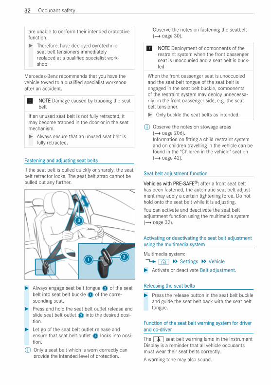
If the seat belt is pulled quickly or sharply, the seatbelt retractor locks. The seat belt strap cannot bepulled out any further.
# Always engage seat belt tongue2 of the seatbelt into seat belt buckle1 of the corre-sponding seat.
# Press and hold the seat belt outlet release andslide seat belt outlet3 into the desired posi-tion.
# Let go of the seat belt outlet release andensure that seat belt outlet3 locks into posi-tion.
% Only a seat belt which is worn correctly canprovide the intended level of protection.
Observe the notes on fastening the seatbelt(/ page 30).
* NONOTETE Deployment of components of therestraint system when the front passengerseat is unoccupied and a seat belt is buck-led
When the front passenger seat is unoccupiedand the seat belt tongue of the seat belt isengaged in the seat belt buckle, componentsof the restraint system may deploy unnecessa-rily on the front passenger side, e.g. the seatbelt tensioner.# Only buckle the seat belts as intended.
% Observe the notes on stowage areas(/ page 206).Information on tting a child restraint systemand on children travelling in the vehicle can befound in the "Children in the vehicle" section(/ page 42).
Seat belt adjusSeat belt adjustment functiontment function
VVehicles witehicles with PRE-Sh PRE-SAFEAFE®®:: a er a front seat belthas been fastened, the automatic seat belt adjust-ment may apply a certain tightening force. Do nothold onto the seat belt while it is adjusting.You can activate and deactivate the seat beltadjustment function using the multimedia system(/ page 32).
AActivctivating or deactivating or deactivating tating the seat belt adjushe seat belt adjustmenttmentusing tusing the multimedia systhe multimedia systemem
Multimedia system:4© 5 Settings 5 Vehicle# Activate or deactivate Belt adjustment.
RReleasing teleasing the seat beltshe seat belts
# Press the release button in the seat belt buckleand guide the seat belt back with the seat belttongue.
FFunction of tunction of the seat belt whe seat belt wararning systning system fem for dror drivivererand co-drand co-driviverer
The ü seat belt warning lamp in the InstrumentDisplay is a reminder that all vehicle occupantsmust wear their seat belts correctly.A warning tone may also sound.
3232 Occupant safety
The seat belt warning goes out when the driver andco-driver fasten their seat belts.Only for certain countries: regardless of whetherthe driver's and co-driver's seat belts are alreadyfastened, the ü seat belt warning lamp lightsup for six seconds every time the vehicle isswitched on. A er the vehicle is started, it goesout as soon as the driver's and the co-driver's seatbelts have been fastened.
AirbagsAirbagsOvOverervieview of airbagsw of airbags
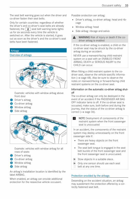
Example: vehicles with window airbag abovefront door
1 Driver's airbag2 Co-driver airbag3 Window airbag4 Side airbag
Example: vehicles with window airbag for allrows of seats
1 Driver's airbag2 Co-driver airbag3 Window airbag4 Side airbag
An airbag's installation location is identi ed by thelabel AIRBAG.When enabled, an airbag can provide additionalprotection for the respective vehicle occupant.
Possible protection per airbag:R Driver's airbag, co-driver airbag: head and rib-
cageR Window airbag: headR Side airbag: ribcage and pelvis
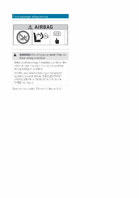
& WWARNINGARNING Risk of injury or death if the co-driver airbag is enabled
If the co-driver airbag is enabled, a child on theco-driver seat may be struck by the co-driverairbag during an accident.NEVER use a rearward-facing child restraintsystem on a seat with an ENABLED FRONTAIRBAG; DEATH or SERIOUS INJURY to theCHILD can occur.
When tting a child restraint system to the co-driver seat, observe the vehicle-speci c informa-tion (/ page 48). Also be sure to observe thenotes on rearward-facing or forward-facing childrestraint systems on the co-driver seat.
InfInforormation on tmation on the authe automatic co-dromatic co-driviver airbager airbag shut-shut-ooThe co-driver airbag can only be deployed in theevent of an accident if the PASSENGER AIR BAGOFF indicator lamp is o . If the co-driver seat isoccupied, make sure, both before and during thejourney, that the status of the co-driver airbag iscorrect (/ page 36).
* NONOTETE Deployment of components of therestraint system when the front passengerseat is unoccupied
In an accident, the components of the restraintsystem may deploy unnecessarily on the frontpassenger side if:R There are heavy objects on the front
passenger seat.R The seat belt tongue is engaged in the seat
belt buckle of the front passenger seat andthe front passenger seat is unoccupied.
# Stow objects in a suitable place.# Only one person should use each seat
belt at any one time.
ProtProtection proection provided bvided by ty the airbagshe airbags
Depending on the accident situation, an airbagmay supplement the protection o ered by a cor-rectly fastened seat belt.
Occupant safety 3333
& WWARNINGARNING Risk of injury or death due to anincorrect seat position
If you deviate from the correct seat position,the airbag cannot perform its intended protec-tive function.Each vehicle occupant must make sure of thefollowing:R Fasten seat belts correctly. Pregnant
women must take particular care to ensurethat the lap belt never lies across the abdo-men.R Adopt the correct seat position and keep
as far away as possible from the airbags.R Observe the following information.
# Always make sure that there are noobjects between the airbag and vehicleoccupant.
To avoid the risks resulting from the deployment ofan airbag, each vehicle occupant must observe thefollowing information in particular:R Before starting your journey, adjust your seat
correctly; both the driver's and co-driver seatshould be moved as far back as possible.When doing so, always observe the informationon the correct driver's seat position(/ page 70).R Only hold the steering wheel by the steering
wheel rim. This allows the airbag to be fullydeployed.R Always lean against the seat backrest when
the vehicle is in motion. Do not lean forwardsor against the door or side window. You mayotherwise be in the deployment area of the air-bags.R Always keep your feet on the oor. Do not put
your feet on the cockpit, for example. Your feetmay otherwise be in the deployment area ofthe airbag.R If children are travelling in the vehicle, observe
the additional notes (/ page 39).R Always stow and secure objects correctly.
Objects in the vehicle interior may prevent an air-bag from functioning correctly. Each vehicle occu-pant must always make sure of the following inparticular:R There are no people, animals or objects
between the vehicle occupants and an airbag.R There are no objects between the seat, door
and door pillar (B-pillar).R There are no hard objects, e.g. coat hangers,
hanging on the grab handles or coat hooks.R There are no accessories, such as mobile navi-
gation devices, mobile phones or cup holders,within the deployment area of an airbag, e.g.on the cockpit, on the door, on the side win-dow or on the side trim.In addition, no connecting cables, tensioningstraps or retaining straps must be routed orattached to the vehicle within the deploymentarea of an airbag. Always comply with theaccessory manufacturer's installation instruc-tions and, in particular, the notes on suitableplaces for installation.R There are no heavy, sharp-edged or fragile
objects in the pockets of your clothing. Storesuch objects in a suitable place.
LimitLimitations of tations of the prothe protection proection provided bvided by airbagsy airbags
& WWARNINGARNING Risk of injury due to modi ca-tions to the cover of an airbag
If you modify the cover of an airbag or a xobjects such as stickers to it, the airbag can nolonger function as intended.# Never modify the cover of an airbag.# Do not attach any objects to the cover.
An airbag's installation location is identi ed by thelabel AIRBAG (/ page 33).Objects in the deployment area of an airbag mayprevent the airbag from functioning correctly.
& WWARNINGARNING Risk of injury from objects inthe deployment area of an airbag
Objects in the deployment area of an airbagcan hinder or prevent the correct deploymentof the airbag.The airbag may then deploy in an uncontrolledmanner and may even cause additional injuriesto the vehicle occupants by deploying. This
3434 Occupant safety
may be the case in particular if the airbag isintegrated into the seat.# Always stow and secure objects cor-
rectly.# Before commencing your journey, make
sure that no objects are stowed in thedeployment area of an airbag.
& WWARNINGARNING Risk of injury or death due tothe use of unsuitable seat covers
Due to unsuitable seat covers, the airbags can-not protect vehicle occupants as intended.In addition, the operation of the automaticfront passenger airbag shuto could be restric-ted.# You should only use seat covers that
have been approved for the correspond-ing seats by Mercedes-Benz.
VVehicles witehicles with windoh window airbags in all roww airbags in all rows of seats:s of seats:
& WWARNINGARNING Risk of injury due to malfunc-tioning sensors in the door
The function of the airbags can be impaireddue to modi cations or incorrect work per-formed on the doors or door trim, or if thedoors are damaged.# Never modify the doors or parts of the
doors.# Always have work on the doors or door
trim carried out at a quali ed specialistworkshop.
& WWARNINGARNING Risk of injury due to deployedairbag
A deployed airbag no longer o ers any protec-tion.# Have the vehicle towed to a quali ed
specialist workshop in order to have thedeployed airbag replaced.
Have deployed airbags replaced immediately.
SSttatus of tatus of the co-drhe co-driviver airbager airbag
FFunction of tunction of the authe automatic co-dromatic co-driviver airbager airbag shutshutooThe automatic co-driver airbag shuto is able todetect whether the co-driver seat is occupied by aperson or a child restraint system. The co-driverairbag is enabled or disabled accordingly.
& WWARNINGARNING Risk of injury or death due toobjects under the co-driver seat
Objects trapped under the co-driver seat caninterfere with the function of the automatic co-driver airbag shuto or damage the system.# Do not store any objects under the co-
driver seat.# When the co-driver seat is occupied,
make sure that no objects are trappedunder the co-driver seat.
When tting a child restraint system to the co-driver seat, observe the vehicle-speci c informa-tion (/ page 48). Also be sure to observe thenotes on rearward-facing or forward-facing childrestraint systems on the co-driver seat(/ page 48).
& WWARNINGARNING Risk of injury or death due toobjects between the seat surface and thechild restraint system
Objects between the sitting surface and thechild restraint system could a ect the functionof the automatic co-driver airbag shuto .# Do not place any objects between the
sitting surface and the child restraint sys-tem.
# Make sure that the entire base of thechild restraint system is resting on thesitting surface of the co-driver seat.
# Make sure that the backrest of theforward-facing child restraint system is,as far as possible, resting on the seatbackrest of the co-driver seat.
# Always comply with the child restraintsystem manufacturer's installationinstructions.
A person on the co-driver seat must observe thefollowing information:R Fasten seat belts correctly (/ page 30).R Sit in an almost upright seat position with their
back against the seat backrest.R Sit with their feet resting on the oor, if possi-
ble.
Occupant safety 3535
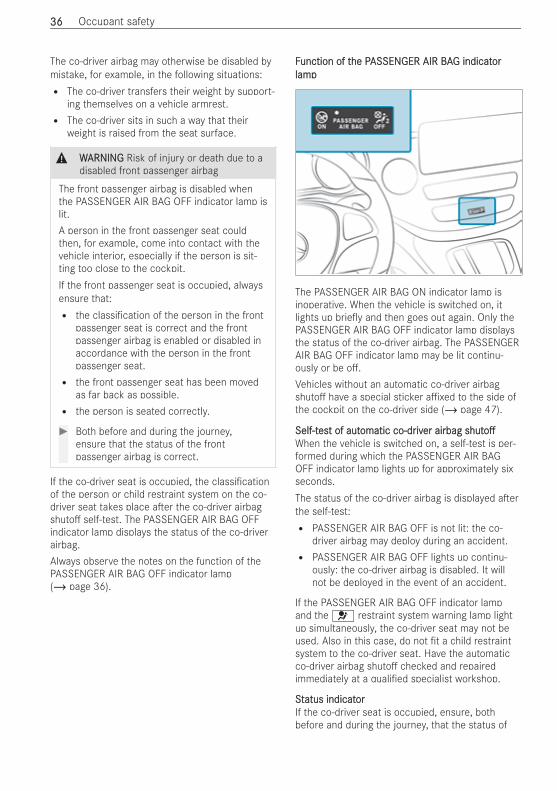
The co-driver airbag may otherwise be disabled bymistake, for example, in the following situations:R The co-driver transfers their weight by support-
ing themselves on a vehicle armrest.R The co-driver sits in such a way that their
weight is raised from the seat surface.
& WWARNINGARNING Risk of injury or death due to adisabled front passenger airbag
The front passenger airbag is disabled whenthe PASSENGER AIR BAG OFF indicator lamp islit.A person in the front passenger seat couldthen, for example, come into contact with thevehicle interior, especially if the person is sit-ting too close to the cockpit.If the front passenger seat is occupied, alwaysensure that:R the classi cation of the person in the front
passenger seat is correct and the frontpassenger airbag is enabled or disabled inaccordance with the person in the frontpassenger seat.R the front passenger seat has been moved
as far back as possible.R the person is seated correctly.
# Both before and during the journey,ensure that the status of the frontpassenger airbag is correct.
If the co-driver seat is occupied, the classi cationof the person or child restraint system on the co-driver seat takes place a er the co-driver airbagshuto self-test. The PASSENGER AIR BAG OFFindicator lamp displays the status of the co-driverairbag.Always observe the notes on the function of thePASSENGER AIR BAG OFF indicator lamp(/ page 36).
FFunction of tunction of the Phe PASSENASSENGER AIR BAGER AIR BAG indicatG indicatororlamplamp
The PASSENGER AIR BAG ON indicator lamp isinoperative. When the vehicle is switched on, itlights up brie y and then goes out again. Only thePASSENGER AIR BAG OFF indicator lamp displaysthe status of the co-driver airbag. The PASSENGERAIR BAG OFF indicator lamp may be lit continu-ously or be o .Vehicles without an automatic co-driver airbagshuto have a special sticker a xed to the side ofthe cockpit on the co-driver side (/ page 47).
Self-tSelf-tesest of autt of automatic co-dromatic co-driviver airbager airbag shutshutooWhen the vehicle is switched on, a self-test is per-formed during which the PASSENGER AIR BAGOFF indicator lamp lights up for approximately sixseconds.The status of the co-driver airbag is displayed a erthe self-test:R PASSENGER AIR BAG OFF is not lit: the co-
driver airbag may deploy during an accident.R PASSENGER AIR BAG OFF lights up continu-
ously: the co-driver airbag is disabled. It willnot be deployed in the event of an accident.
If the PASSENGER AIR BAG OFF indicator lampand the 6 restraint system warning lamp lightup simultaneously, the co-driver seat may not beused. Also in this case, do not t a child restraintsystem to the co-driver seat. Have the automaticco-driver airbag shuto checked and repairedimmediately at a quali ed specialist workshop.
StStatus indicatatus indicatororIf the co-driver seat is occupied, ensure, bothbefore and during the journey, that the status of
3636 Occupant safety
the co-driver airbag is correct for the current situa-tion.A erA er ttingtting a ra rearwearwarard-fd-facing cacing child rhild resestrtraint syaint sys-s-ttem tem to to the co-drhe co-driviver seater seat:: PASSENGER AIR BAGOFF must be lit continuously.
& WWARNINGARNING Risk of injury or death whenusing a rearward-facing child restraint sys-tem while the front passenger airbag isenabled
If you secure a child in a rearward-facing childrestraint system on the front passenger seatand the PASSENGER AIR BAG OFF indicatorlamp is o , the front passenger airbag candeploy in the event of an accident.The child could be struck by the airbag.# Always ensure that the front passenger
airbag is disabled. The PASSENGER AIRBAG OFF indicator lamp must be lit.
# NEVER use a rearward-facing childrestraint system on a seat with an ENA-BLED FRONT AIRBAG. This can result inthe DEATH of or SERIOUS INJURY to theCHILD.
When tting a child restraint system to the co-driver seat, observe the vehicle-speci c informa-tion (/ page 48).Depending on the child restraint system and thestature of the child, the PASSENGER AIR BAG OFFindicator lamp may be o . In this case, do not tthe rearward-facing child restraint system to theco-driver seat.Instead, t the rearward-facing child restraint sys-tem to a suitable rear seat.A erA er ttingtting a fa forworwarard-fd-facing cacing child rhild resestrtraint systaint systememtto to the co-drhe co-driviver seat:er seat: depending on the childrestraint system and the stature of the child,PASSENGER AIR BAG OFF may be lit continuouslyor be o . Always observe the following informa-tion.
& WWARNINGARNING Risk of injury or death due toincorrect positioning of the forward-facingchild restraint system
If you secure a child in a forward-facing childrestraint system on the front passenger seatthat is positioned too close to the cockpit, inthe event of an accident, the child could:R come into contact with the vehicle interior
if the PASSENGER AIR BAG OFF indicatorlamp is lit, for exampleR be struck by the airbag if the PASSENGER
AIR BAG OFF indicator lamp is o .
# Always move the front passenger seat asfar back as possible and fully retract theseat cushion length adjustment. Whiledoing so, always make sure that theshoulder belt strap is correctly routedfrom the seat belt outlet of the vehicle tothe shoulder belt guide on the childrestraint system. The shoulder belt strapmust be routed forwards and downwardsfrom the seat belt outlet. If necessary,adjust the seat belt outlet and the frontpassenger seat accordingly.
# Always comply with the child restraintsystem manufacturer's installationinstructions.
When tting a child restraint system to the co-driver seat, observe the vehicle-speci c informa-tion (/ page 48).If a perIf a person is sitting on tson is sitting on the co-drhe co-driviver seater seat::PASSENGER AIR BAG OFF may be lit continuouslyor be o , depending on the person's stature.A person on the co-driver seat must alwaysobserve the following information:R If the co-driver seat is occupied by an adult or
a person with a stature corresponding to thatof an adult, the PASSENGER AIR BAG OFF indi-cator lamp must be o . This indicates that theco-driver airbag is enabled.If the PASSENGER AIR BAG OFF indicator lampis lit continuously, an adult or person with abuild corresponding to that of an adult shouldnot use the co-driver seat.Instead, they should use a rear seat.R If the co-driver seat is occupied by a person of
smaller stature (e.g. a teenager or small adult),the PASSENGER AIR BAG OFF indicator lamp
Occupant safety 3737
either lights up continuously or remains o ,depending on the result of the classi cation.- If the PASSENGER AIR BAG OFF indicator
lamp is o : move the co-driver seat as farback as possible, or the person of smallerstature should use a rear seat.
- If the PASSENGER AIR BAG OFF indicatorlamp is lit continuously: the person ofsmaller stature should not use the co-driver seat.
& WWARNINGARNING Risk of injury or death when thePASSENGER AIR BAG OFF indicator lampis lit
If the PASSENGER AIR BAG OFF indicator lampremains lit a er the self-test, the frontpassenger airbag is disabled.If the front passenger seat is occupied, alwaysensure that:R The classi cation of the person in the front
passenger seat is correct and the frontpassenger airbag is enabled or disabled inaccordance with the person in the frontpassenger seat.R The person is seated properly with a cor-
rectly fastened seat belt.R The front passenger seat has been moved
as far back as possible.
Be sure to also observe the following further rela-ted subjects:R Child restraint system on the co-driver seat
(/ page 48)R Suitable positioning of the child restraint sys-
tem (/ page 42)
PRE-SPRE-SAFEAFE®® SystSystememFFunction of PRE-Sunction of PRE-SAFEAFE®® (anticipat(anticipatorory occupant pry occupant pro-o-ttection)ection)
PRE-SAFE® can detect certain hazardous situa-tions and take pre-emptive measures to protectthe vehicle occupants.PRE-SAFE® can implement the following measuresindependently of each other:R Tightening the seat belts on the driver's seat
and co-driver seat.R Closing the side windows.
R VVehicles witehicles with a sliding sunrh a sliding sunroof:oof: closing the slid-ing sunroof.R VVehicles witehicles with memorh memory function:y function: adjusting the
co-driver seat to a more favourable seat posi-tion.
* NONOTETE Damage caused by objects in thefootwell or behind the seat
The automatic adjustment of the seat positionmay result in damage to the seat and/or theobject.# Stow objects in a suitable place.
RReevverersing tsing the PRE-She PRE-SAFEAFE®® systsystem measurem measureses
If an accident did not occur, the pre-emptive meas-ures that were taken are reversed.You will need to make certain adjustments your-self.# If the seat belt pre-tensioning is not reduced,
move the seat backrest back slightly.The locking mechanism releases.
AAututomatic measuromatic measureses a era er an accidentan accidentDepending on the type and severity of the acci-dent, and depending on the vehicle's equipment,the following measures can be implemented, forexample:R activating the hazard warning lightsR triggering an automatic emergency call
(/ page 225)R switching o the drive system and high-voltage
on-board electrical systemR unlocking the vehicle doorsR lowering the front side windowsR switching on the interior lighting
SafSafelely try transporansporting cting childrhildren in ten in the vhe vehicleehicleAlwayAlways observs observe when ce when childrhildren aren are trave travelling in telling in thehevvehicleehicle
% Always observe the safety notes relevant tothe situation. In doing so, you will be able toidentify possible risks and avoid dangers whenchildren are travelling in the vehicle(/ page 39).
3838 Occupant safety
Be diligBe diligententBear in mind that negligence when securing a childin the child restraint system may have serious con-sequences. Always be diligent and secure a childcarefully before each journey.Infants and children must never travel sitting onthe lap of a vehicle occupant.To improve protection for children younger than 12years old or under 1.50 m in height, Mercedes-Benz recommends you observe the following infor-mation:R Always secure the child in a child restraint sys-
tem suitable for this Mercedes-Benz vehicle.R The child restraint system must be appropriate
to the age, weight and size of the child.R The vehicle seat must be suitable for tting a
child restraint system (/ page 42).
Accident statistics show that children secured onthe rear seats are generally safer than childrensecured on the front seats. For this reason,Mercedes-Benz strongly advises that you t a childrestraint system to a rear seat.
The gThe genereneric tic tererm cm child rhild resestrtraint systaint systememThe generic term child restraint system is used inthis set of Operating Instructions. A child restraintsystem is, for example:R a baby car seatR a rearward-facing child seatR a forward-facing child seatR a child booster seat with a backrest and seat
belt guides
The child restraint system must be appropriate tothe age, weight and size of the child.
ObservObserve lawe laws and rs and regulationsegulationsAlways observe the legal requirements when usinga child restraint system in the vehicle.Make sure that the child restraint system isapproved in accordance with the valid test speci -cations and guidelines. You can obtain furtherinformation at a quali ed specialist workshop.Mercedes-Benz recommends that you use aMercedes-Benz Service Centre for this purpose.
OnlOnly use approvy use approved ced child rhild resestrtraint systaint systemsemsOnly child restraint systems with the UNECE stand-ard UN-R44 are approved for use in the vehicle.Information on child restraint system approval cat-egories and details on the approval label on thechild restraint system (/ page 42).
DetDetecting recting riskisks, avs, avoiding dangoiding dangerer
SecurSecuring systing systems fems for cor child rhild resestrtraint systaint systems in tems in thehevvehicleehicleOnly use the following securing systems for childrestraint systems:R the ISOFIX securing ringsR the seat belt system of the vehicleR the Top Tether anchorages
Fitting an ISOFIX child restraint system is prefer-red.Simply attaching to the securing rings on the vehi-cle can reduce the risk of tting the child restraintsystem incorrectly.When securing a child with the integrated seat beltof the ISOFIX child restraint system, always complywith the permissible gross weight for the child andchild restraint system (/ page 44).
AAdvdvantantagage of a re of a rearwearwarard-fd-facing cacing child rhild resestrtraint syaint sys-s-ttememIt is preferable to transport a baby or a small childin a suitable rearward-facing child restraint sys-tem. In this case, the child sits in the oppositedirection to the direction of travel and faces back-wards.Babies and small children have comparativelyweak neck muscles in relation to the size andweight of their head. The risk of injury to the cervi-cal spine during an accident can be reduced in arearward-facing child restraint system.
AlwayAlways securs secure a ce a child rhild resestrtraint systaint system correm correctlyectly
& WWARNINGARNING Risk of injury or death due toincorrect installation of the child restraintsystem
The child can then not be protected orrestrained as intended.# Be sure to comply with the manufactur-
er's installation instructions for the childrestraint system and its correct use.
# Make sure that the entire base of thechild restraint system always rests on thesitting surface of the seat.
# Never place objects (e.g. cushions)under or behind the child restraint sys-tem.
# Use child restraint systems only with theoriginal cover designed for them.
Occupant safety 3939
# Always replace damaged covers withgenuine covers.
& WWARNINGARNING Risk of injury or death due tounsecured child restraint systems in thevehicle
If the child restraint system is incorrectly ttedor not secured, it can come loose.The child restraint system could be ungaround and hit vehicle occupants.# Always install child restraint systems cor-
rectly, even when not in use.# Always comply with the child restraint
system manufacturer's installationinstructions.
R Always observe the child restraint system man-ufacturer's installation and operating instruc-tions as well as the vehicle-speci c informa-tion:- Fitting the ISOFIX child restraint system on
the rear seat (/ page 44).- Securing the child restraint system with the
seat belt on the rear seat (/ page 47).- Securing the child restraint system with the
seat belt on the co-driver seat(/ page 48). Observe the speci cinstructions for the rearward-facing andforward-facing child restraint systems(/ page 48).If the co-driver seat is occupied, ensure,both before and during the journey, thatthe status of the co-driver airbag is correctfor the current situation (/ page 36).
R Observe the warning labels in the vehicle inte-rior and on the child restraint system.R Also secure Top Tether if present.
Do noDo not modify tt modify the che child rhild resestrtraint systaint systemem
& WWARNINGARNING Risk of injury due to modi ca-tions to the child restraint system
The child restraint system can no longer func-tion properly. This poses an increased risk ofinjury.# Never modify a child restraint system.# Only a x accessories which have been
specially approved for this child restraintsystem by the child restraint system'smanufacturer.
Mercedes‑Benz recommends Mercedes-Benz careproducts for cleaning child restraint systems rec-ommended by Mercedes-Benz.
OnlOnly use cy use child rhild resestrtraint systaint systems whicems which arh are ine inprproper woper wororking conditionking condition
& WWARNINGARNING Risk of injury or death causedby the use of damaged child restraint sys-tems
Child restraint systems or their retaining sys-tems that have been subjected to stress in anaccident may not be able to perform theirintended protective function.It may be the case that the child cannot beproperly restrained.# Always immediately replace child
restraint systems that have been dam-aged or involved in an accident.
# Have the securing systems for the childrestraint systems checked at a quali edspecialist workshop before installing achild restraint system again.
AAvvoid diroid direct sunlightect sunlight
& WWARNINGARNING Risk of burns when the childseat is exposed to direct sunlight
If the child restraint system is exposed todirect sunlight or heat, parts could heat up.Children could su er burns from these parts,particularly on metallic parts of the childrestraint system.# Always make sure that the child restraint
system is not exposed to direct sunlight.# Protect the child restraint system with a
blanket, for example.# If the child restraint system has been
exposed to direct sunlight, allow it tocool before securing a child into it.
# Never leave children unattended in thevehicle.
4040 Occupant safety
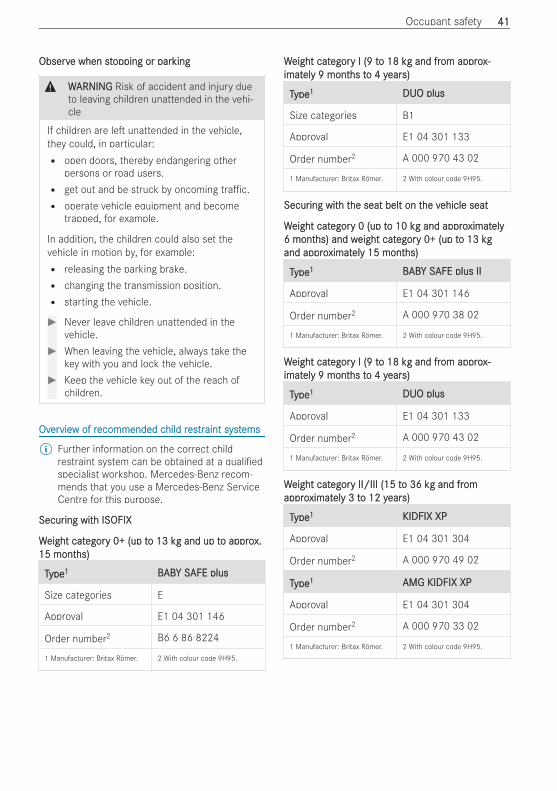
ObservObserve when ste when stopping or paropping or parkingking
& WWARNINGARNING Risk of accident and injury dueto leaving children unattended in the vehi-cle
If children are le unattended in the vehicle,they could, in particular:R open doors, thereby endangering other
persons or road users.R get out and be struck by oncoming tra c.R operate vehicle equipment and become
trapped, for example.
In addition, the children could also set thevehicle in motion by, for example:R releasing the parking brake.R changing the transmission position.R starting the vehicle.
# Never leave children unattended in thevehicle.
# When leaving the vehicle, always take thekey with you and lock the vehicle.
# Keep the vehicle key out of the reach ofchildren.
OvOverervieview of rw of recommended cecommended child rhild resestrtraint systaint systemsems
% Further information on the correct childrestraint system can be obtained at a quali edspecialist workshop. Mercedes-Benz recom-mends that you use a Mercedes-Benz ServiceCentre for this purpose.
SecurSecuring witing with ISOFIXh ISOFIX
WWeight cateight categoregory 0+ (up ty 0+ (up to 13 ko 13 kg and up tg and up to approo approx.x.15 mont15 months)hs)
TTypeype11 BBABABY SY SAFE plusAFE plus
Size categories E
Approval E1 04 301 146
Order number2 B6 6 86 8224
1 Manufacturer: Britax Römer. 2 With colour code 9H95.
WWeight cateight categoregory I (9 ty I (9 to 18 ko 18 kg and frg and from approom approx-x-imatimatelely 9 monty 9 months ths to 4 yo 4 yearears)s)
TTypeype11 DUO plusDUO plus
Size categories B1
Approval E1 04 301 133
Order number2 A 000 970 43 02
1 Manufacturer: Britax Römer. 2 With colour code 9H95.
SecurSecuring witing with th the seat belt on the seat belt on the vhe vehicle seatehicle seat
WWeight cateight categoregory 0 (up ty 0 (up to 10 ko 10 kg and approg and approximatximatelyely6 mont6 months) and whs) and weight cateight categoregory 0+ (up ty 0+ (up to 13 kgo 13 kgand approand approximatximatelely 15 monty 15 months)hs)
TTypeype11 BBABABY SY SAFE plus IIAFE plus II
Approval E1 04 301 146
Order number2 A 000 970 38 02
1 Manufacturer: Britax Römer. 2 With colour code 9H95.
WWeight cateight categoregory I (9 ty I (9 to 18 ko 18 kg and frg and from approom approx-x-imatimatelely 9 monty 9 months ths to 4 yo 4 yearears)s)
TTypeype11 DUO plusDUO plus
Approval E1 04 301 133
Order number2 A 000 970 43 02
1 Manufacturer: Britax Römer. 2 With colour code 9H95.
WWeight cateight categoregory II/III (15 ty II/III (15 to 36 ko 36 kg and frg and fromomapproapproximatximatelely 3 ty 3 to 12 yo 12 yearears)s)
TTypeype11 KIDFIX XPKIDFIX XP
Approval E1 04 301 304
Order number2 A 000 970 49 02
TTypeype11 AMG KIDFIX XPAMG KIDFIX XP
Approval E1 04 301 304
Order number2 A 000 970 33 02
1 Manufacturer: Britax Römer. 2 With colour code 9H95.
Occupant safety 4141
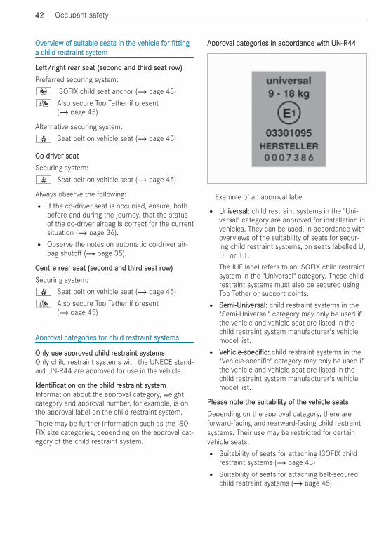
OvOverervieview of suitw of suitable seats in table seats in the vhe vehicle fehicle foror ttingttinga ca child rhild resestrtraint systaint systemem
Le /rLe /rightight rrear seat (second and tear seat (second and thirhird seat rod seat row)w)Preferred securing system:® ISOFIX child seat anchor (/ page 43)¯ Also secure Top Tether if present
(/ page 45)
Alternative securing system:7 Seat belt on vehicle seat (/ page 45)
Co-drCo-driviver seater seatSecuring system:7 Seat belt on vehicle seat (/ page 45)
Always observe the following:R If the co-driver seat is occupied, ensure, both
before and during the journey, that the statusof the co-driver airbag is correct for the currentsituation (/ page 36).R Observe the notes on automatic co-driver air-
bag shuto (/ page 35).
CentrCentre re rear seat (second and tear seat (second and thirhird seat rod seat row)w)Securing system:7 Seat belt on vehicle seat (/ page 45)¯ Also secure Top Tether if present
(/ page 45)
ApprovApproval catal categoregories fies for cor child rhild resestrtraint systaint systemsems
OnlOnly use approvy use approved ced child rhild resestrtraint systaint systemsemsOnly child restraint systems with the UNECE stand-ard UN-R44 are approved for use in the vehicle.
Identi cationIdenti cation on ton the che child rhild resestrtraint systaint systememInformation about the approval category, weightcategory and approval number, for example, is onthe approval label on the child restraint system.There may be further information such as the ISO-FIX size categories, depending on the approval cat-egory of the child restraint system.
ApprovApproval catal categoregories in accories in accordance witdance with UN-R44h UN-R44
Example of an approval label
R UnivUniverersal:sal: child restraint systems in the "Uni-versal" category are approved for installation invehicles. They can be used, in accordance withoverviews of the suitability of seats for secur-ing child restraint systems, on seats labelled U,UF or IUF.The IUF label refers to an ISOFIX child restraintsystem in the "Universal" category. These childrestraint systems must also be secured usingTop Tether or support points.R Semi-USemi-Univniverersal:sal: child restraint systems in the
"Semi-Universal" category may only be used ifthe vehicle and vehicle seat are listed in thechild restraint system manufacturer's vehiclemodel list.R VVehicle-speci c:ehicle-speci c: child restraint systems in the
"Vehicle-speci c" category may only be used ifthe vehicle and vehicle seat are listed in thechild restraint system manufacturer's vehiclemodel list.
Please notPlease note te the suithe suitability of tability of the vhe vehicle seatsehicle seatsDepending on the approval category, there areforward-facing and rearward-facing child restraintsystems. Their use may be restricted for certainvehicle seats.R Suitability of seats for attaching ISOFIX child
restraint systems (/ page 43)R Suitability of seats for attaching belt-secured
child restraint systems (/ page 45)
4242 Occupant safety
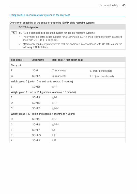
FFitting an ISOFIX citting an ISOFIX child rhild resestrtraint systaint system on tem on the rhe rear seatear seat
OvOverervieview of suitw of suitability of tability of the seats fhe seats for attor attacaching ISOFIX ching ISOFIX child rhild resestrtraint systaint systemsems
ISOFIX designationISOFIX designation
® ISOFIX is a standardised securing system for special restraint systems.R The symbol indicates seats suitable for attaching an ISOFIX child restraint system in accord-
ance with UN R44 (/ page 42).R Attach only child restraint systems that are approved in accordance with UN R44 as per the
following ISOFIX tables.
Size class:Size class: EqEquipment: Ruipment: Rear seat / rear seat / rear bencear bench seath seat
CarrCarry coty cot
F ISO/L1 X (rear seat) IL1 (rear bench seat)
G ISO/L2 X (rear seat) IL2, 3 (rear bench seat)
WWeight greight group 0 (up toup 0 (up to 10 ko 10 kg and up tg and up to approo approx. 6 montx. 6 months)hs)
E ISO/R1 IL2, 3
WWeight greight group 0+ (up toup 0+ (up to 13 ko 13 kg and up tg and up to approo approx. 15 montx. 15 months)hs)
E ISO/R1 IL2, 3
D ISO/R2 IL2, 3
C ISO/R3 IL2, 3, 4
WWeight greight group 1 (9–18 koup 1 (9–18 kg and approg and approx. 9 montx. 9 months ths to 4 yo 4 yearears)s)
D ISO/R2 IL2, 3
C ISO/R3 IL2, 3, 4
B ISO/F2 IUF
B1 ISO/F2X IUF
A ISO/F3 IUF
Occupant safety 4343
Size class:Size class: EqEquipment: Ruipment: Rear seat / rear seat / rear bencear bench seath seat
X Not suitable for an ISOFIX child restraint system in this weight group and/or size class.
IL Suitable for ISOFIX child restraint systems according to the table in "Overview of the recommended child restraint systems", or if the vehicle and
the seat are listed on the child restraint system manufacturer's vehicle model list.
IUF Suitable for forward-facing ISOFIX child restraint systems of the "Universal" category in this weight group.
1 Only on the rst rear seat row on a rear bench seat
2 The seat must be installed in the direction of travel.
3 It is permissible to use a seat on the second rear seat row only if the maximum distance between the two rear seat rows is set. To this end, the
seat on the second rear seat row must be tted in the rearmost position allowed and the seat on the rst rear seat row in front of it must be tted
in the foremost position allowed. If you use the centre seat on the second rear seat row, all seats on the rst rear seat row must be tted in the
foremost position allowed.
4 If you are using a child restraint system in size class C (ISO/R3), make sure that the seat backrest of the front seat is not in contact with the child
restraint system. If possible, move the front seat to the highest position and the seat backrest to the upright position.
FFitting an ISOFIX citting an ISOFIX child rhild resestrtraint systaint system on tem on the rhe rearearseatseat
& WWARNINGARNING Risk of injury or death if thepermissible gross mass of the child andchild restraint system together is excee-ded.
Too much load may be placed on the ISOFIXchild restraint system and the child may not berestrained correctly in the event of an acci-dent, for example.# If the child and the child restraint system
together weigh more than the permissi-ble gross mass of 33 kg , only use anISOFIX child restraint system with whichthe child is secured with the vehicle seatbelt.
# Also secure the child restraint systemwith the Top Tether belt, if available.
Always comply with the information about themass of the child restraint system:R in the manufacturer's installation and operat-
ing instructions for the child restraint systemusedR on a label on the child restraint system, if avail-
able
Check regularly that the permissible gross mass ofthe child plus the child restraint system is notexceeded.
When you install a child restraint system, observethe following:O Always observe the correct use and suitability
of the seats for attaching a child restraint sys-tem.ISOFIX child seat anchor (/ page 43)
O Always observe the manufacturer's installa-tion and operating instructions for the childrestraint system used.
O Make sure that the child's feet do not touchthe front seat. If necessary, move the frontseat slightly forwards.
®When tting an ISOFIX child restraint system,also observe the following:O When using a GrWhen using a Group 0/0+ baboup 0/0+ baby car seat andy car seat and
a Gra Group 1 roup 1 rearwearwarard-fd-facing cacing child rhild resestrtraint syaint sys-s-ttem on a rem on a rear seatear seat:: adjust the front seat sothat the seat does not touch the childrestraint system.
O Move the rear seat backrest to an uprightposition before you t the child seat. Do notadjust the seat backrest when an ISOFIX childrestraint system is tted.
O For certain child restraint systems in weightgroup 2 or 3, there may be restrictions on themaximum size setting, e.g. due to possiblecontact with the roof.
O Do not put the child restraint system understrain between the roof and the sitting surfaceand/or t it facing the wrong direction.
4444 Occupant safety
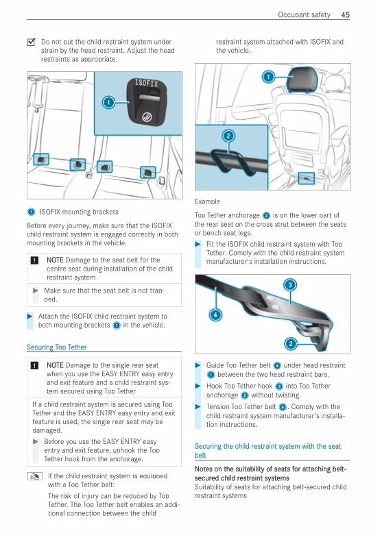
O Do not put the child restraint system understrain by the head restraint. Adjust the headrestraints as appropriate.
1 ISOFIX mounting brackets
Before every journey, make sure that the ISOFIXchild restraint system is engaged correctly in bothmounting brackets in the vehicle.
* NNOOTETE Damage to the seat belt for thecentre seat during installation of the childrestraint system
# Make sure that the seat belt is not trap-ped.
# Attach the ISOFIX child restraint system toboth mounting brackets1 in the vehicle.
SecurSecuring Ting Top Tetop Tetherher
* NNOOTETE Damage to the single rear seatwhen you use the EASY ENTRY easy entryand exit feature and a child restraint sys-tem secured using Top Tether
If a child restraint system is secured using TopTether and the EASY ENTRY easy entry and exitfeature is used, the single rear seat may bedamaged.# Before you use the EASY ENTRY easy
entry and exit feature, unhook the TopTether hook from the anchorage.
¯ If the child restraint system is equippedwith a Top Tether belt:The risk of injury can be reduced by TopTether. The Top Tether belt enables an addi-tional connection between the child
restraint system attached with ISOFIX andthe vehicle.
Example
Top Tether anchorage2 is on the lower part ofthe rear seat on the cross strut between the seatsor bench seat legs.# Fit the ISOFIX child restraint system with Top
Tether. Comply with the child restraint systemmanufacturer's installation instructions.
# Guide Top Tether belt4 under head restraint1 between the two head restraint bars.
# Hook Top Tether hook3 into Top Tetheranchorage2 without twisting.
# Tension Top Tether belt4. Comply with thechild restraint system manufacturer's installa-tion instructions.
SecurSecuring ting the che child rhild resestrtraint systaint system witem with th the seathe seatbeltbelt
NNoottes on tes on the suithe suitability of seats fability of seats for attor attacaching belt-hing belt-secursecured ced child rhild resestrtraint systaint systemsemsSuitability of seats for attaching belt-secured childrestraint systems
Occupant safety 4545
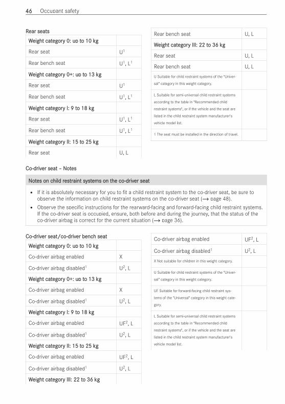
RRear seatsear seats
WWeight cateight categoregory 0: up ty 0: up to 10 kgo 10 kg
Rear seat U1
Rear bench seat U1, L1
WWeight cateight categoregory 0+: up ty 0+: up to 13 ko 13 kgg
Rear seat U1
Rear bench seat U1, L1
WWeight cateight categoregory I: 9 ty I: 9 to 18 kgo 18 kg
Rear seat U1, L1
Rear bench seat U1, L1
WWeight cateight categoregory II: 15 ty II: 15 to 25 ko 25 kgg
Rear seat U, L
Rear bench seat U, L
WWeight cateight categoregory III: 22 ty III: 22 to 36 kgo 36 kg
Rear seat U, L
Rear bench seat U, L
U Suitable for child restraint systems of the "Univer-
sal" category in this weight category.
L Suitable for semi-universal child restraint systems
according to the table in "Recommended child
restraint systems", or if the vehicle and the seat are
listed in the child restraint system manufacturer's
vehicle model list.
1 The seat must be installed in the direction of travel.
Co-drCo-driviver seat – Noter seat – Noteses
NNoottes on ces on child rhild resestrtraint systaint systems on tems on the co-drhe co-driviver seater seat
R If it is absolutely necessary for you to t a child restraint system to the co-driver seat, be sure toobserve the information on child restraint systems on the co-driver seat (/ page 48).R Observe the speci c instructions for the rearward-facing and forward-facing child restraint systems.
If the co-driver seat is occupied, ensure, both before and during the journey, that the status of theco-driver airbag is correct for the current situation (/ page 36).
Co-drCo-driviver seat/co-drer seat/co-driviver bencer bench seath seat
WWeight cateight categoregory 0: up ty 0: up to 10 kgo 10 kg
Co-driver airbag enabled X
Co-driver airbag disabled1 U2, L
WWeight cateight categoregory 0+: up ty 0+: up to 13 ko 13 kgg
Co-driver airbag enabled X
Co-driver airbag disabled1 U2, L
WWeight cateight categoregory I: 9 ty I: 9 to 18 kgo 18 kg
Co-driver airbag enabled UF2, L
Co-driver airbag disabled1 U2, L
WWeight cateight categoregory II: 15 ty II: 15 to 25 ko 25 kgg
Co-driver airbag enabled UF2, L
Co-driver airbag disabled1 U2, L
WWeight cateight categoregory III: 22 ty III: 22 to 36 kgo 36 kg
Co-driver airbag enabled UF2, L
Co-driver airbag disabled1 U2, L
X Not suitable for children in this weight category.
U Suitable for child restraint systems of the "Univer-
sal" category in this weight category.
UF Suitable for forward-facing child restraint sys-
tems of the "Universal" category in this weight cate-
gory.
L Suitable for semi-universal child restraint systems
according to the table in "Recommended child
restraint systems", or if the vehicle and the seat are
listed in the child restraint system manufacturer's
vehicle model list.
4646 Occupant safety
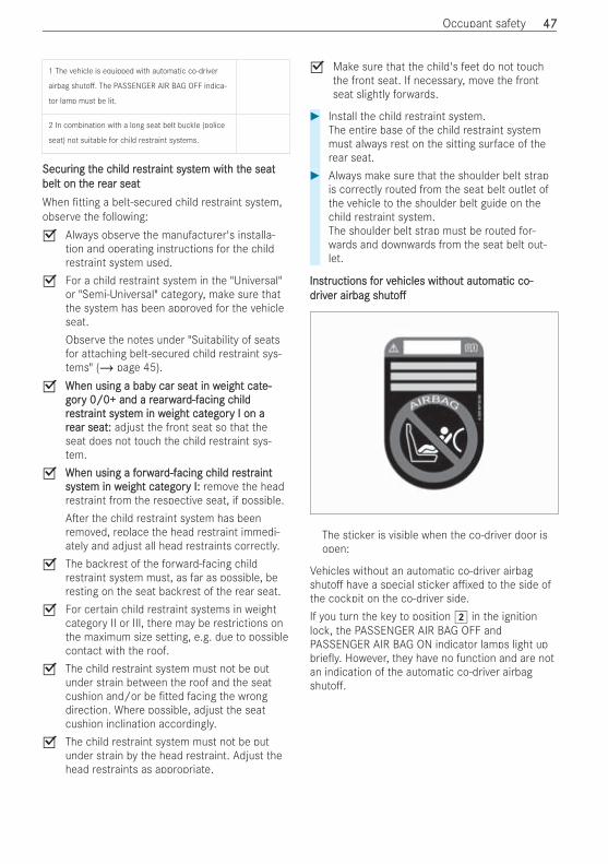
1 The vehicle is equipped with automatic co-driver
airbag shuto . The PASSENGER AIR BAG OFF indica-
tor lamp must be lit.
2 In combination with a long seat belt buckle (police
seat) not suitable for child restraint systems.
SecurSecuring ting the che child rhild resestrtraint systaint system witem with th the seathe seatbelt on tbelt on the rhe rear seatear seatWhen tting a belt-secured child restraint system,observe the following:O Always observe the manufacturer's installa-
tion and operating instructions for the childrestraint system used.
O For a child restraint system in the "Universal"or "Semi-Universal" category, make sure thatthe system has been approved for the vehicleseat.Observe the notes under "Suitability of seatsfor attaching belt-secured child restraint sys-tems" (/ page 45).
O When using a babWhen using a baby car seat in wy car seat in weight cateight cate-e-gorgory 0/0+ and a ry 0/0+ and a rearwearwarard-fd-facing cacing childhildrresestrtraint systaint system in wem in weight cateight categoregory I on ay I on arrear seatear seat:: adjust the front seat so that theseat does not touch the child restraint sys-tem.
O When using a fWhen using a forworwarard-fd-facing cacing child rhild resestrtraintaintsystsystem in wem in weight cateight categoregory I:y I: remove the headrestraint from the respective seat, if possible.A er the child restraint system has beenremoved, replace the head restraint immedi-ately and adjust all head restraints correctly.
O The backrest of the forward-facing childrestraint system must, as far as possible, beresting on the seat backrest of the rear seat.
O For certain child restraint systems in weightcategory II or III, there may be restrictions onthe maximum size setting, e.g. due to possiblecontact with the roof.
O The child restraint system must not be putunder strain between the roof and the seatcushion and/or be tted facing the wrongdirection. Where possible, adjust the seatcushion inclination accordingly.
O The child restraint system must not be putunder strain by the head restraint. Adjust thehead restraints as appropriate.
O Make sure that the child's feet do not touchthe front seat. If necessary, move the frontseat slightly forwards.
# Install the child restraint system.The entire base of the child restraint systemmust always rest on the sitting surface of therear seat.
# Always make sure that the shoulder belt strapis correctly routed from the seat belt outlet ofthe vehicle to the shoulder belt guide on thechild restraint system.The shoulder belt strap must be routed for-wards and downwards from the seat belt out-let.
InsInstrtructions fuctions for vor vehicles witehicles without authout automatic co-omatic co-drdriviver airbager airbag shutshutoo
The sticker is visible when the co-driver door isopen:
Vehicles without an automatic co-driver airbagshuto have a special sticker a xed to the side ofthe cockpit on the co-driver side.If you turn the key to position 2 in the ignitionlock, the PASSENGER AIR BAG OFF andPASSENGER AIR BAG ON indicator lamps light upbrie y. However, they have no function and are notan indication of the automatic co-driver airbagshuto .
Occupant safety 4747
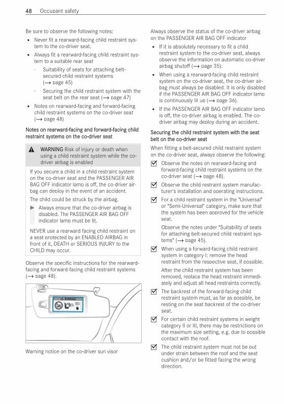
Be sure to observe the following notes:R Never t a rearward-facing child restraint sys-
tem to the co-driver seat.R Always t a rearward-facing child restraint sys-
tem to a suitable rear seat- Suitability of seats for attaching belt-
secured child restraint systems(/ page 45)
- Securing the child restraint system with theseat belt on the rear seat (/ page 47)
R Notes on rearward-facing and forward-facingchild restraint systems on the co-driver seat(/ page 48)
NNoottes on res on rearwearwarard-fd-facing and facing and forworwarard-fd-facing cacing childhildrresestrtraint systaint systems on tems on the co-drhe co-driviver seater seat
& WWARNINGARNING Risk of injury or death whenusing a child restraint system while the co-driver airbag is enabled
If you secure a child in a child restraint systemon the co-driver seat and the PASSENGER AIRBAG OFF indicator lamp is o , the co-driver air-bag can deploy in the event of an accident.The child could be struck by the airbag.# Always ensure that the co-driver airbag is
disabled. The PASSENGER AIR BAG OFFindicator lamp must be lit.
NEVER use a rearward facing child restraint ona seat protected by an ENABLED AIRBAG infront of it, DEATH or SERIOUS INJURY to theCHILD may occur.
Observe the speci c instructions for the rearward-facing and forward-facing child restraint systems(/ page 48).
Warning notice on the co-driver sun visor
Always observe the status of the co-driver airbagon the PASSENGER AIR BAG OFF indicatorR If it is absolutely necessary to t a child
restraint system to the co-driver seat, alwaysobserve the information on automatic co-driverairbag shuto (/ page 35).R When using a rearward-facing child restraint
system on the co-driver seat, the co-driver air-bag must always be disabled. It is only disabledif the PASSENGER AIR BAG OFF indicator lampis continuously lit up (/ page 36).R If the PASSENGER AIR BAG OFF indicator lamp
is o , the co-driver airbag is enabled. The co-driver airbag may deploy during an accident.
SecurSecuring ting the che child rhild resestrtraint systaint system witem with th the seathe seatbelt on tbelt on the co-drhe co-driviver seater seatWhen tting a belt-secured child restraint systemon the co-driver seat, always observe the following:O Observe the notes on rearward-facing and
forward-facing child restraint systems on theco-driver seat (/ page 48).
O Observe the child restraint system manufac-turer's installation and operating instructions.
O For a child restraint system in the "Universal"or "Semi-Universal" category, make sure thatthe system has been approved for the vehicleseat.Observe the notes under "Suitability of seatsfor attaching belt-secured child restraint sys-tems" (/ page 45).
O When using a forward-facing child restraintsystem in category I: remove the headrestraint from the respective seat, if possible.A er the child restraint system has beenremoved, replace the head restraint immedi-ately and adjust all head restraints correctly.
O The backrest of the forward-facing childrestraint system must, as far as possible, beresting on the seat backrest of the co-driverseat.
O For certain child restraint systems in weightcategory II or III, there may be restrictions onthe maximum size setting, e.g. due to possiblecontact with the roof.
O The child restraint system must not be putunder strain between the roof and the seatcushion and/or be tted facing the wrongdirection.
4848 Occupant safety
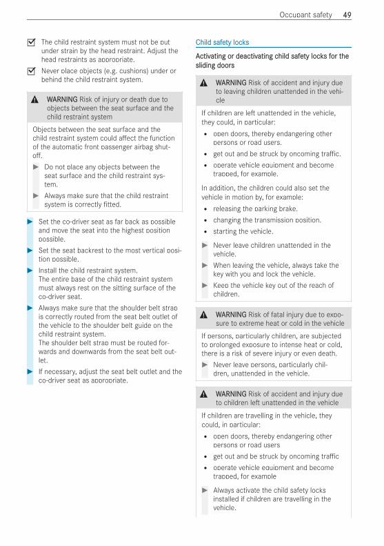
O The child restraint system must not be putunder strain by the head restraint. Adjust thehead restraints as appropriate.
O Never place objects (e.g. cushions) under orbehind the child restraint system.
& WWARNINGARNING Risk of injury or death due toobjects between the seat surface and thechild restraint system
Objects between the seat surface and thechild restraint system could a ect the functionof the automatic front passenger airbag shut-o .# Do not place any objects between the
seat surface and the child restraint sys-tem.
# Always make sure that the child restraintsystem is correctly tted.
# Set the co-driver seat as far back as possibleand move the seat into the highest positionpossible.
# Set the seat backrest to the most vertical posi-tion possible.
# Install the child restraint system.The entire base of the child restraint systemmust always rest on the sitting surface of theco-driver seat.
# Always make sure that the shoulder belt strapis correctly routed from the seat belt outlet ofthe vehicle to the shoulder belt guide on thechild restraint system.The shoulder belt strap must be routed for-wards and downwards from the seat belt out-let.
# If necessary, adjust the seat belt outlet and theco-driver seat as appropriate.
Child safeChild safety locksty locks
AActivctivating or deactivating or deactivating cating child safehild safety lockty locks fs for tor thehesliding doorssliding doors
& WWARNINGARNING Risk of accident and injury dueto leaving children unattended in the vehi-cle
If children are le unattended in the vehicle,they could, in particular:R open doors, thereby endangering other
persons or road users.R get out and be struck by oncoming tra c.R operate vehicle equipment and become
trapped, for example.
In addition, the children could also set thevehicle in motion by, for example:R releasing the parking brake.R changing the transmission position.R starting the vehicle.
# Never leave children unattended in thevehicle.
# When leaving the vehicle, always take thekey with you and lock the vehicle.
# Keep the vehicle key out of the reach ofchildren.
& WWARNINGARNING Risk of fatal injury due to expo-sure to extreme heat or cold in the vehicle
If persons, particularly children, are subjectedto prolonged exposure to intense heat or cold,there is a risk of severe injury or even death.# Never leave persons, particularly chil-
dren, unattended in the vehicle.
& WWARNINGARNING Risk of accident and injury dueto children le unattended in the vehicle
If children are travelling in the vehicle, theycould, in particular:R open doors, thereby endangering other
persons or road usersR get out and be struck by oncoming tra cR operate vehicle equipment and become
trapped, for example
# Always activate the child safety locksinstalled if children are travelling in thevehicle.
Occupant safety 4949

# Never leave children unattended in thevehicle.
# When leaving the vehicle, always take thekey with you and lock the vehicle.
The following doors have child safety locks:R sliding doorsR pop-out windowsThe child safety locks on the doors secure eachdoor separately. The doors can no longer beopened from the inside (exception: electric slidingdoor). When the vehicle is unlocked, the door canbe opened from the outside.If the electric sliding door is secured, only the slid-ing door controls in the rear are deactivated. Theelectric sliding door can be opened at any timeusing the switch in the centre console.
# Slide child safety lock bolt1 to position 2(activate) or 3 (deactivate).
# Make sure that the child safety locks are work-ing properly.
AActivctivating or deactivating or deactivating cating child safehild safety lockty locks fs fororhinghinged windowsed windows
# TTo activo activatate and deactive and deactivatate:e: press button1.If the indicator lamp on button1 is lit, opera-tion of the electrical hinged windows is disa-bled. Operation is then only possible using thebuttons in the driver's door.
NNoottes on pees on pets in tts in the vhe vehicleehicle
& WWARNINGARNING Risk of accident and injury dueto animals le unsecured or unattended inthe vehicle
If you leave animals in the vehicle unattendedor unsecured, they could press buttons orswitches, for instance.An animal may:R activate vehicle equipment and become
trapped, for exampleR switch systems on or o and endanger
other road users
Unsecured animals may be thrown about thevehicle in the event of an accident, or suddensteering and braking manoeuvres, and injurevehicle occupants.# Never leave animals unattended in the
vehicle.# Always correctly secure animals while
driving, e.g. using a suitable animal car-rier.
5050 Occupant safety
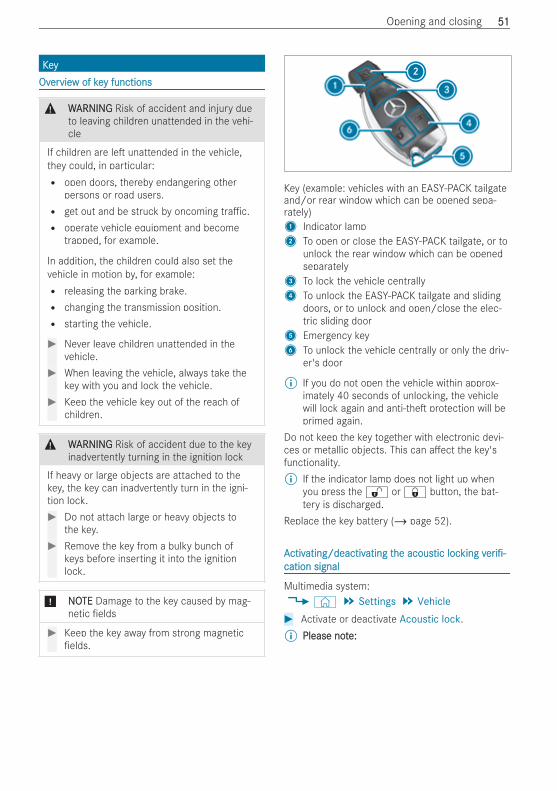
KKeeyyOvOverervieview of kew of key functionsy functions
& WWARNINGARNING Risk of accident and injury dueto leaving children unattended in the vehi-cle
If children are le unattended in the vehicle,they could, in particular:R open doors, thereby endangering other
persons or road users.R get out and be struck by oncoming tra c.R operate vehicle equipment and become
trapped, for example.
In addition, the children could also set thevehicle in motion by, for example:R releasing the parking brake.R changing the transmission position.R starting the vehicle.
# Never leave children unattended in thevehicle.
# When leaving the vehicle, always take thekey with you and lock the vehicle.
# Keep the vehicle key out of the reach ofchildren.
& WWARNINGARNING Risk of accident due to the keyinadvertently turning in the ignition lock
If heavy or large objects are attached to thekey, the key can inadvertently turn in the igni-tion lock.# Do not attach large or heavy objects to
the key.# Remove the key from a bulky bunch of
keys before inserting it into the ignitionlock.
* NNOOTETE Damage to the key caused by mag-netic elds
# Keep the key away from strong magneticelds.
Key (example: vehicles with an EASY-PACK tailgateand/or rear window which can be opened sepa-rately)1 Indicator lamp2 To open or close the EASY-PACK tailgate, or to
unlock the rear window which can be openedseparately
3 To lock the vehicle centrally4 To unlock the EASY-PACK tailgate and sliding
doors, or to unlock and open/close the elec-tric sliding door
5 Emergency key6 To unlock the vehicle centrally or only the driv-
er's door
% If you do not open the vehicle within approx-imately 40 seconds of unlocking, the vehiclewill lock again and anti-the protection will beprimed again.
Do not keep the key together with electronic devi-ces or metallic objects. This can a ect the key'sfunctionality.% If the indicator lamp does not light up when
you press the % or & button, the bat-tery is discharged.
Replace the key battery (/ page 52).
AActivctivating/deactivating/deactivating tating the acoushe acoustic loctic lockingking vvereri -i -cationcation signalsignal
Multimedia system:4© 5 Settings 5 Vehicle# Activate or deactivate Acoustic lock.% Please notPlease note:e:
Opening and closing 5151
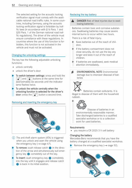
The selected setting for the acoustic lockingveri cation signal must comply with the appli-cable national road tra c rules. In some coun-tries, including Germany, using the acousticlocking veri cation signal is forbidden by traf-fic laws (in accordance with §16 Para. 1 and§30 Para. 1 of the German national road traf-fic regulations). The driver of the vehicle mustensure compliance with these regulations. Incountries where the use of this function is for-bidden, this function is not activated in thevehicle and must not be activated.
Changing tChanging the unloche unlocking seking settingsttings
The key has the following adjustable unlockingfunctions:R unlock centrallyR unlock the driver's door
# TTo switco switch beh betwtween seeen settings:ttings: press and hold the% and & buttons at the same time forapproximately six seconds until the indicatorlamp ashes twice.
# TTo unloco unlock tk the vhe vehicle centrehicle centrallally when ty when theheunlocunlocking function is selectking function is selected fed for tor the drhe driviver'ser'sdoordoor:: press the % button a second time.
RRemoemoving and inserving and inserting tting the emerghe emergency keyency key
% The anti-the alarm system (ATA) is triggeredwhen you unlock and open the vehicle usingthe emergency key (/ page 67).
# TTo ro removemove:e: push release catch1 in the direc-tion of the arrow and simultaneously pull emer-gency key2 completely out of the key.
# TTo inserto insert:: push emergency key2 completelyinto the key until it engages and release catch1 is back in its initial position.
RReplacing teplacing the kehe key batty batteryery
& DDANANGERGER Risk of fatal injuries due to swal-lowing batteries
Batteries contain toxic and corrosive substan-ces. Swallowing batteries may cause severeinternal burns to occur within two hours.There is a risk of fatal injury.# Keep batteries out of the reach of chil-
dren.# If the battery compartment does not
close securely, do not use the key anylonger and keep it out of the reach ofchildren.
# If batteries are swallowed, seek medicalattention immediately.
+ ENVIRENVIRONMENTONMENTAL NOAL NOTETE Environmentaldamage due to improper disposal of bat-teries
Batteries contain pollutants. It isillegal to dispose of them with the householdrubbish.#
Dispose of batteries in anenvironmentally responsible manner.Take discharged batteries to a quali edspecialist workshop or to a collectionpoint for used batteries.
RReqequiruirementsementsR you require a CR 2025 3 V cell battery
Changing tChanging the batthe batteryeryMercedes-Benz recommends that you have thebattery changed at a quali ed specialist workshop.# Remove the emergency key (/ page 52).
5252 Opening and closing
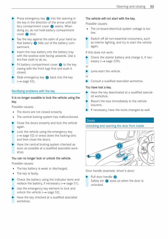
# Press emergency key2 into the opening inthe key in the direction of the arrow until bat-tery compartment cover1 opens. Whendoing so, do not hold battery compartmentcover1 shut.
# Tap the key against the palm of your hand sothat battery3 falls out of the battery com-partment.
# Insert the new battery into the battery traywith the positive pole facing upwards. Use alint-free cloth to do so.
# Fit battery compartment cover1 to the keycasing with the front lugs rst and push itclosed.
# Slide emergency key2 back into the key(/ page 52).
RRectifying prectifying problems witoblems with th the keyhe key
It is no longIt is no longer possible ter possible to loco lock tk the vhe vehicle using tehicle using thehekey.key.Possible causes:R The doors are not closed properly.R The central locking system has malfunctioned.
# Close the doors properly and lock the vehicleagain.
# Lock the vehicle using the emergency key(/ page 52) or press down the locking pinsand then close the doors.
# Have the central locking system checked assoon as possible at a quali ed specialist work-shop.
YYou can no longou can no longer locer lock or unlock or unlock tk the vhe vehicle.ehicle.Possible causes:R The key battery is weak or discharged.R The key is faulty.
# Check the battery using the indicator lamp andreplace the battery, if necessary (/ page 51).
# Use the emergency key element to lock andunlock the vehicle (/ page 52).
# Have the key checked at a quali ed specialistworkshop.
The vThe vehicle will noehicle will not stt starart witt with th the key.he key.Possible causes:R The on-board electrical system voltage is too
low.
# Switch o all non-essential consumers, suchas interior lighting, and try to start the vehicleagain.
If this does not work:# Check the starter battery and charge it, if nec-
essary (/ page 229).or# Jump-start the vehicle.or# Consult a quali ed specialist workshop.
YYou havou have lose lost a key.t a key.# Have the key deactivated at a quali ed special-
ist workshop.# Report the loss immediately to the vehicle
insurers.# If necessary, have the locks changed as well.
DoorsDoorsUUnlocnlocking and opening tking and opening the door frhe door from insideom inside
Door handle (example: driver's door)
# Pull door handle2.Safety pin1 pops up when the door isunlocked.
Opening and closing 5353
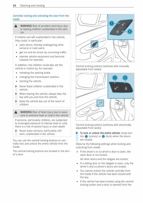
CentrCentrallally locy locking and unlocking and unlocking tking the door frhe door from tom theheinsideinside
& WWARNINGARNING Risk of accident and injury dueto leaving children unattended in the vehi-cle
If children are le unattended in the vehicle,they could, in particular:R open doors, thereby endangering other
persons or road users.R get out and be struck by oncoming tra c.R operate vehicle equipment and become
trapped, for example.
In addition, the children could also set thevehicle in motion by, for example:R releasing the parking brake.R changing the transmission position.R starting the vehicle.
# Never leave children unattended in thevehicle.
# When leaving the vehicle, always take thekey with you and lock the vehicle.
# Keep the vehicle key out of the reach ofchildren.
& WWARNINGARNING Risk of fatal injury due to expo-sure to extreme heat or cold in the vehicle
If persons, particularly children, are subjectedto prolonged exposure to intense heat or cold,there is a risk of severe injury or even death.# Never leave persons, particularly chil-
dren, unattended in the vehicle.
You can use the central locking buttons to cen-trally lock and unlock the entire vehicle from theinside.The central locking buttons are located in the driv-er's door.
Central locking buttons (vehicles with manuallyadjustable front seats)
Central locking buttons (vehicles with electricallyadjustable front seats)
# TTo loco lock or unlock or unlock tk the entirhe entire ve vehicle:ehicle: press but-ton1 (unlock) or2 (lock) when the doorsare closed.
Observe the following settings when locking andunlocking from inside:R If the driver's or co-driver's door is open, the
open door is not locked.All other doors and the tailgate are locked.R If a sliding door or the tailgate is open, only the
driver's and co-driver's doors are locked.R You cannot unlock the vehicle centrally from
the inside if the vehicle has been locked withthe key.R If the vehicle has been locked using the central
locking button and a door is opened from the
5454 Opening and closing
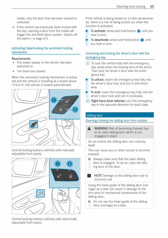
inside, only the door that has been opened isunlocked.R If the vehicle has previously been locked with
the key, opening a door from the inside willtrigger the anti-the alarm system. Switch othe alarm (/ page 67).
AActivctivating/deactivating/deactivating tating the authe automatic locomatic lockingkingmecmechanismhanism
RReqequiruirements:ements:R The power supply or the vehicle has been
switched on.R The doors are closed.
When the automatic locking mechanism is activa-ted and the vehicle is travelling at a speed above15 km/h, the vehicle is locked automatically.
Central locking buttons (vehicles with manuallyadjustable front seats)
Central locking buttons (vehicles with electricallyadjustable front seats)
If the vehicle is being tested on a roller dynamome-ter, there is a risk of being locked out when thefunction is activated.# TTo activo activatate:e: press and hold button2 until you
hear a tone.# TTo deactivo deactivatate:e: press and hold button1 until
you hear a tone.
UUnlocnlocking and locking and locking tking the drhe driviver's door witer's door with th theheemergemergency keyency key
% To lock the vehicle fully with the emergencykey, press down the locking pins of the doors.Then lock the driver's door with the emer-gency key.
# TTo unloco unlock:k: insert the emergency key fully intothe driver's door lock and turn it anti-clock-wise.
# TTo loco lock:k: insert the emergency key fully into thedriver's door lock and turn it clockwise.
% Right-hand drRight-hand drivive ve vehicles:ehicles: turn the emergencykey in the opposite direction for each case.
Sliding doorSliding doorOpening/closing tOpening/closing the sliding door frhe sliding door from outsideom outside
& WWARNINGARNING Risk of becoming trapped dueto an open sliding door which is notengaged in place
On an incline, the sliding door can move byitself.This can cause you or other people to becometrapped.# Always make sure that the open sliding
door is engaged. To do so, open the slid-ing door to the stop.
* NNOOTETE Damage to the sliding door due toincorrect use
Using the lower guide of the sliding door (car-riage) as a step can result in damage to thetrim and/or mechanical components of thesliding door.# Do not use the lower guide of the sliding
door (carriage) as a step.
Opening and closing 5555
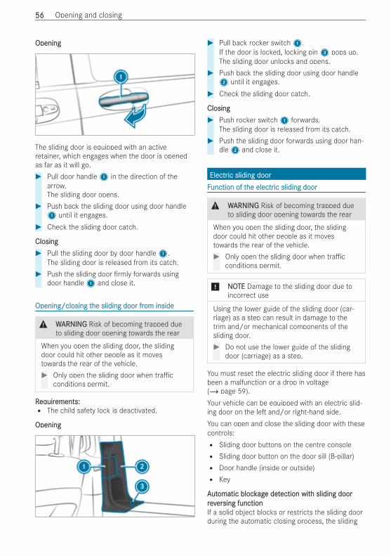
OpeningOpening
The sliding door is equipped with an activeretainer, which engages when the door is openedas far as it will go.# Pull door handle1 in the direction of the
arrow.The sliding door opens.
# Push back the sliding door using door handle1 until it engages.
# Check the sliding door catch.
ClosingClosing# Pull the sliding door by door handle1.
The sliding door is released from its catch.# Push the sliding door rmly forwards using
door handle1 and close it.
Opening/closing tOpening/closing the sliding door frhe sliding door from insideom inside
& WWARNINGARNING Risk of becoming trapped dueto sliding door opening towards the rear
When you open the sliding door, the slidingdoor could hit other people as it movestowards the rear of the vehicle.# Only open the sliding door when tra c
conditions permit.
RReqequiruirements:ements:R The child safety lock is deactivated.
OpeningOpening
# Pull back rocker switch1.If the door is locked, locking pin3 pops up.The sliding door unlocks and opens.
# Push back the sliding door using door handle2 until it engages.
# Check the sliding door catch.
ClosingClosing# Push rocker switch1 forwards.
The sliding door is released from its catch.# Push the sliding door forwards using door han-
dle2 and close it.
ElectrElectric sliding dooric sliding doorFFunction of tunction of the electrhe electric sliding dooric sliding door
& WWARNINGARNING Risk of becoming trapped dueto sliding door opening towards the rear
When you open the sliding door, the slidingdoor could hit other people as it movestowards the rear of the vehicle.# Only open the sliding door when tra c
conditions permit.
* NNOOTETE Damage to the sliding door due toincorrect use
Using the lower guide of the sliding door (car-riage) as a step can result in damage to thetrim and/or mechanical components of thesliding door.# Do not use the lower guide of the sliding
door (carriage) as a step.
You must reset the electric sliding door if there hasbeen a malfunction or a drop in voltage(/ page 59).Your vehicle can be equipped with an electric slid-ing door on the le and/or right-hand side.You can open and close the sliding door with thesecontrols:R Sliding door buttons on the centre consoleR Sliding door button on the door sill (B-pillar)R Door handle (inside or outside)R Key
AAututomatic blockomatic blockagage dete detection witection with sliding doorh sliding doorrevreverersing functionsing functionIf a solid object blocks or restricts the sliding doorduring the automatic closing process, the sliding
5656 Opening and closing
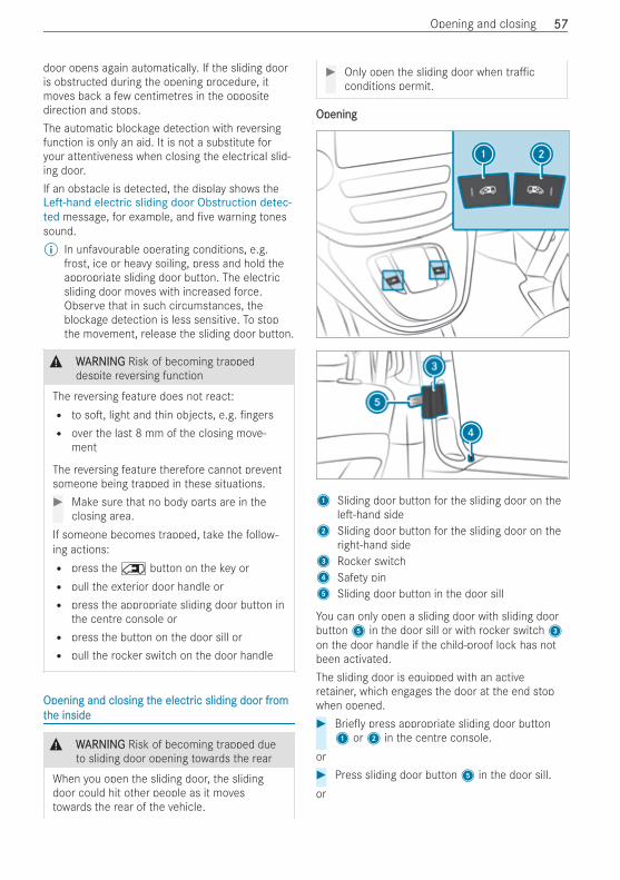
door opens again automatically. If the sliding dooris obstructed during the opening procedure, itmoves back a few centimetres in the oppositedirection and stops.The automatic blockage detection with reversingfunction is only an aid. It is not a substitute foryour attentiveness when closing the electrical slid-ing door.If an obstacle is detected, the display shows theLeft-hand electric sliding door Obstruction detec-ted message, for example, and ve warning tonessound.% In unfavourable operating conditions, e.g.
frost, ice or heavy soiling, press and hold theappropriate sliding door button. The electricsliding door moves with increased force.Observe that in such circumstances, theblockage detection is less sensitive. To stopthe movement, release the sliding door button.
& WWARNINGARNING Risk of becoming trappeddespite reversing function
The reversing feature does not react:R to so , light and thin objects, e.g. ngersR over the last 8 mm of the closing move-
ment
The reversing feature therefore cannot preventsomeone being trapped in these situations.# Make sure that no body parts are in the
closing area.If someone becomes trapped, take the follow-ing actions:R press the 5 button on the key orR pull the exterior door handle orR press the appropriate sliding door button in
the centre console orR press the button on the door sill orR pull the rocker switch on the door handle
Opening and closing tOpening and closing the electrhe electric sliding door fric sliding door fromomtthe insidehe inside
& WWARNINGARNING Risk of becoming trapped dueto sliding door opening towards the rear
When you open the sliding door, the slidingdoor could hit other people as it movestowards the rear of the vehicle.
# Only open the sliding door when tra cconditions permit.
OpeningOpening
1 Sliding door button for the sliding door on thele -hand side
2 Sliding door button for the sliding door on theright-hand side
3 Rocker switch4 Safety pin5 Sliding door button in the door sill
You can only open a sliding door with sliding doorbutton5 in the door sill or with rocker switch3on the door handle if the child-proof lock has notbeen activated.The sliding door is equipped with an activeretainer, which engages the door at the end stopwhen opened.# Brie y press appropriate sliding door button1 or2 in the centre console.
or# Press sliding door button5 in the door sill.or
Opening and closing 5757
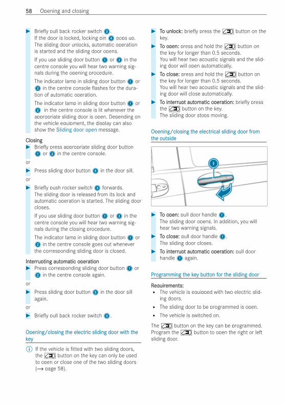
# Brie y pull back rocker switch3.If the door is locked, locking pin4 pops up.The sliding door unlocks, automatic operationis started and the sliding door opens.If you use sliding door button1 or2 in thecentre console you will hear two warning sig-nals during the opening procedure.The indicator lamp in sliding door button1 or2 in the centre console ashes for the dura-tion of automatic operation.The indicator lamp in sliding door button1 or2 in the centre console is lit whenever theappropriate sliding door is open. Depending onthe vehicle equipment, the display can alsoshow the Sliding door open message.
ClosingClosing# Brie y press appropriate sliding door button1 or2 in the centre console.
or# Press sliding door button5 in the door sill.or# Brie y push rocker switch3 forwards.
The sliding door is released from its lock andautomatic operation is started. The sliding doorcloses.If you use sliding door button1 or2 in thecentre console you will hear two warning sig-nals during the closing procedure.The indicator lamp in sliding door button1 or2 in the centre console goes out wheneverthe corresponding sliding door is closed.
IntInterrerrupupting autting automatic operomatic operationation# Press corresponding sliding door button1 or2 in the centre console again.
or# Press sliding door button5 in the door sill
again.or# Brie y pull back rocker switch3.
Opening/closing tOpening/closing the electrhe electric sliding door witic sliding door with th thehekeykey
% If the vehicle is tted with two sliding doors,the 5 button on the key can only be usedto open or close one of the two sliding doors(/ page 58).
# TTo unloco unlock:k: brie y press the 5 button on thekey.
# TTo open:o open: press and hold the 5 button onthe key for longer than 0.5 seconds.You will hear two acoustic signals and the slid-ing door will open automatically.
# TTo close:o close: press and hold the 5 button onthe key for longer than 0.5 seconds.You will hear two acoustic signals and the slid-ing door will close automatically.
# TTo into interrerrupupt autt automatic operomatic operation:ation: brie y pressthe 5 button on the key.The sliding door stops moving.
Opening/closing tOpening/closing the electrhe electrical sliding door frical sliding door fromomtthe outsidehe outside
# TTo open:o open: pull door handle1.The sliding door opens. In addition, you willhear two warning signals.
# TTo close:o close: pull door handle1.The sliding door closes.
# TTo into interrerrupupt autt automatic operomatic operation:ation: pull doorhandle1 again.
PrProgrogramming tamming the kehe key butty button fon for tor the sliding doorhe sliding door
RReqequiruirements:ements:R The vehicle is equipped with two electric slid-
ing doors.R The sliding door to be programmed is open.R The vehicle is switched on.
The 5 button on the key can be programmed.Program the 5 button to open the right or lesliding door.
5858 Opening and closing
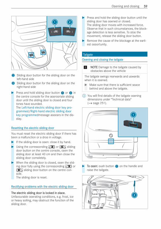
1 Sliding door button for the sliding door on thele -hand side
2 Sliding door button for the sliding door on theright-hand side
# Press and hold sliding door button1 or2 inthe centre console for the appropriate slidingdoor until the sliding door is closed and fourtones have sounded.The Left-hand electric sliding door key pro-grammed/Right-hand electric sliding doorkey programmedmessage appears in the dis-play.
RReseesetting ttting the electrhe electric sliding dooric sliding door
You must reset the electric sliding door if there hasbeen a malfunction or a drop in voltage.# If the sliding door is open: close it by hand.# Using the corresponding 5 or 4 sliding
door button on the centre console, open thesliding door at least 40 cm and then close thesliding door completely.
# When the sliding door is closed, open the slid-ing door fully using the corresponding 5 or4 sliding door button on the centre con-sole.The sliding door is reset.
RRectifying prectifying problems witoblems with th the electrhe electric sliding dooric sliding door
The electrThe electric sliding door is lockic sliding door is locked in place.ed in place.Unfavourable operating conditions, e.g. frost, iceor heavy soiling, may obstruct the function of thesliding door.
# Press and hold the sliding door button until thesliding door has opened or closed.The sliding door moves with increased force.Observe that in such circumstances, the block-age detection is less sensitive. To stop themovement, release the sliding door button.
# Remove the cause of the blockage at the earli-est opportunity.
TTailgailgateateOpening and closing tOpening and closing the the tailgailgateate
* NNOOTETE Damage to the tailgate caused byobstacles above the vehicle
The tailgate swings rearwards and upwardswhen it is opened.# Make sure that there is su cient space
behind and above the tailgate.
% You will nd details of the tailgate openingdimensions under "Technical data"(/ page 251).
# TTo open:o open: push button1 on the handle andraise the tailgate.
Opening and closing 5959

# TTo close:o close: pull the tailgate rmly downwards byloop2 and close it from outside.
Opening tOpening the the tailgailgatate in an emerge in an emergencyencyIf the battery voltage is low or the voltage supply isinterrupted, the tailgate cannot be opened.In an emergency, you can open the tailgate usingthe release catch for service purposes.# Prise o the cover on the lower part of the tail-
gate with a suitable tool, e.g. the screwdriverfrom the vehicle tool kit.
# Insert the screwdriver into the opening andmove the release lever until the tailgateunlocks and opens.
# Li the tailgate upwards.
EASYEASY-PAC-PACK tK tailgailgateate
NNoottes on tes on the EASYhe EASY-PAC-PACK tK tailgailgateate
* NONOTETE Damage to the tailgate caused byobstacles above the vehicle
The tailgate swings rearwards and upwardswhen it is opened.# Make sure that there is su cient space
behind and above the tailgate.
% You will nd details of the tailgate openingdimensions under "Technical data"(/ page 251).
ObsObstrtruction detuction detection witection with revh reverersing functionsing functionThe tailgate is equipped with automatic objectdetection with reversing function. If a solid objectblocks or restricts the tailgate during the auto-matic closing process, the tailgate opens againautomatically. The automatic object detection withreversing function is only an aid. It is not a substi-tute for your attentiveness when closing the tail-gate.
& WWARNINGARNING Risk of becoming trappeddespite reversing function
The reversing feature does not react:R to so , light and thin objects, e.g. ngersR over the last 8 mm of the closing move-
ment
The reversing feature therefore cannot preventsomeone being trapped in these situations.# Make sure that no body parts are in the
closing area.
If someone is trapped:R press the q button on the key orR press the closing button on the tailgate orR pull the handle of the tailgate
Opening and closing tOpening and closing the EASYhe EASY-PAC-PACK tK tailgailgateate
* NONOTETE Damage to the tailgate caused byobstacles above the vehicle
The tailgate swings rearwards and upwardswhen it is opened.# Make sure that there is su cient space
behind and above the tailgate.
RReqequiruirements:ements:R The rear window is closed.R The tailgate is unlocked.R Nobody is within the range of movement of the
tailgate.R The q button on the key is programmed to
open and close the tailgate (/ page 62).
OpeningOpening
# Press button1 on the handle and step out ofthe range of movement of the tailgate.
or# Press and brie y hold the q button on the
key.An automatic operation starts. The tailgateopens and swings upward.In addition, two acoustic signals sound.
6060 Opening and closing
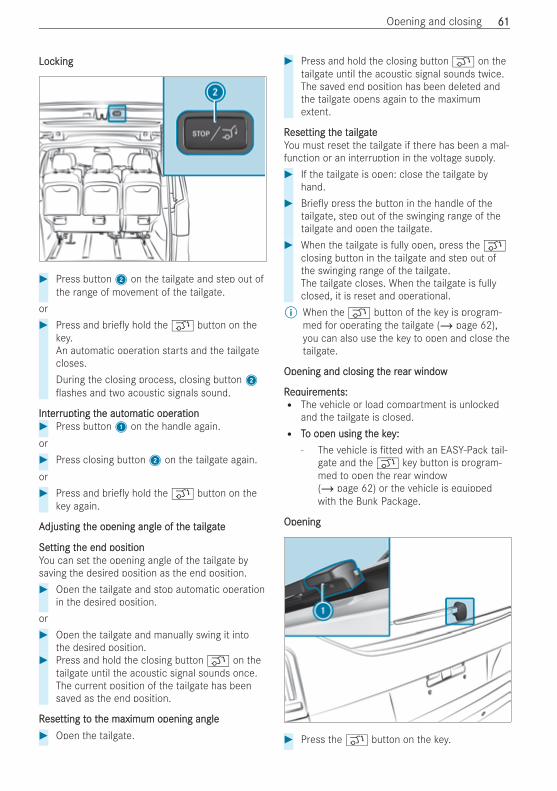
LocLockingking
# Press button2 on the tailgate and step out ofthe range of movement of the tailgate.
or# Press and brie y hold the q button on the
key.An automatic operation starts and the tailgatecloses.During the closing process, closing button2ashes and two acoustic signals sound.
IntInterrerrupupting tting the authe automatic operomatic operationation# Press button1 on the handle again.or# Press closing button2 on the tailgate again.or# Press and brie y hold the q button on the
key again.
AAdjusdjusting tting the opening angle of the opening angle of the the tailgailgateate
SeSetting ttting the end positionhe end positionYou can set the opening angle of the tailgate bysaving the desired position as the end position.# Open the tailgate and stop automatic operation
in the desired position.or# Open the tailgate and manually swing it into
the desired position.# Press and hold the closing button q on the
tailgate until the acoustic signal sounds once.The current position of the tailgate has beensaved as the end position.
RReseesetting ttting to to the maximum opening anglehe maximum opening angle# Open the tailgate.
# Press and hold the closing button q on thetailgate until the acoustic signal sounds twice.The saved end position has been deleted andthe tailgate opens again to the maximumextent.
RReseesetting ttting the the tailgailgateateYou must reset the tailgate if there has been a mal-function or an interruption in the voltage supply.# If the tailgate is open: close the tailgate by
hand.# Brie y press the button in the handle of the
tailgate, step out of the swinging range of thetailgate and open the tailgate.
# When the tailgate is fully open, press the qclosing button in the tailgate and step out ofthe swinging range of the tailgate.The tailgate closes. When the tailgate is fullyclosed, it is reset and operational.
% When the q button of the key is program-med for operating the tailgate (/ page 62),you can also use the key to open and close thetailgate.
Opening and closing tOpening and closing the rhe rear windowear window
RReqequiruirements:ements:R The vehicle or load compartment is unlocked
and the tailgate is closed.R TTo open using to open using the key:he key:
- The vehicle is tted with an EASY-Pack tail-gate and the q key button is program-med to open the rear window(/ page 62) or the vehicle is equippedwith the Bunk Package.
OpeningOpening
# Press the q button on the key.
Opening and closing 6161
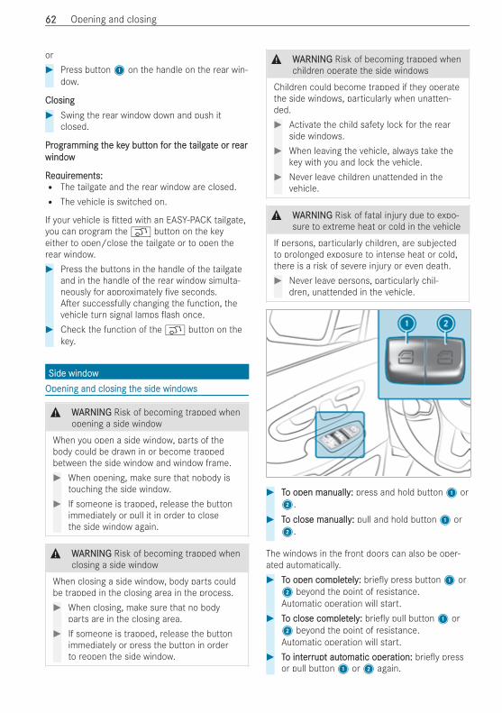
or# Press button1 on the handle on the rear win-
dow.
ClosingClosing# Swing the rear window down and push it
closed.
PrProgrogramming tamming the kehe key butty button fon for tor the the tailgailgatate or re or rearearwindowwindow
RReqequiruirements:ements:R The tailgate and the rear window are closed.R The vehicle is switched on.
If your vehicle is tted with an EASY-PACK tailgate,you can program the q button on the keyeither to open/close the tailgate or to open therear window.# Press the buttons in the handle of the tailgate
and in the handle of the rear window simulta-neously for approximately ve seconds.A er successfully changing the function, thevehicle turn signal lamps ash once.
# Check the function of the q button on thekey.
Side windowSide windowOpening and closing tOpening and closing the side windowshe side windows
& WWARNINGARNING Risk of becoming trapped whenopening a side window
When you open a side window, parts of thebody could be drawn in or become trappedbetween the side window and window frame.# When opening, make sure that nobody is
touching the side window.# If someone is trapped, release the button
immediately or pull it in order to closethe side window again.
& WWARNINGARNING Risk of becoming trapped whenclosing a side window
When closing a side window, body parts couldbe trapped in the closing area in the process.# When closing, make sure that no body
parts are in the closing area.# If someone is trapped, release the button
immediately or press the button in orderto reopen the side window.
& WWARNINGARNING Risk of becoming trapped whenchildren operate the side windows
Children could become trapped if they operatethe side windows, particularly when unatten-ded.# Activate the child safety lock for the rear
side windows.# When leaving the vehicle, always take the
key with you and lock the vehicle.# Never leave children unattended in the
vehicle.
& WWARNINGARNING Risk of fatal injury due to expo-sure to extreme heat or cold in the vehicle
If persons, particularly children, are subjectedto prolonged exposure to intense heat or cold,there is a risk of severe injury or even death.# Never leave persons, particularly chil-
dren, unattended in the vehicle.
# TTo open manually:o open manually: press and hold button1 or2.
# TTo close manually:o close manually: pull and hold button1 or2.
The windows in the front doors can also be oper-ated automatically.# TTo open como open completpletely:ely: brie y press button1 or2 beyond the point of resistance.Automatic operation will start.
# TTo close como close completpletely:ely: brie y pull button1 or2 beyond the point of resistance.Automatic operation will start.
# TTo into interrerrupupt autt automatic operomatic operation:ation: brie y pressor pull button1 or2 again.
6262 Opening and closing
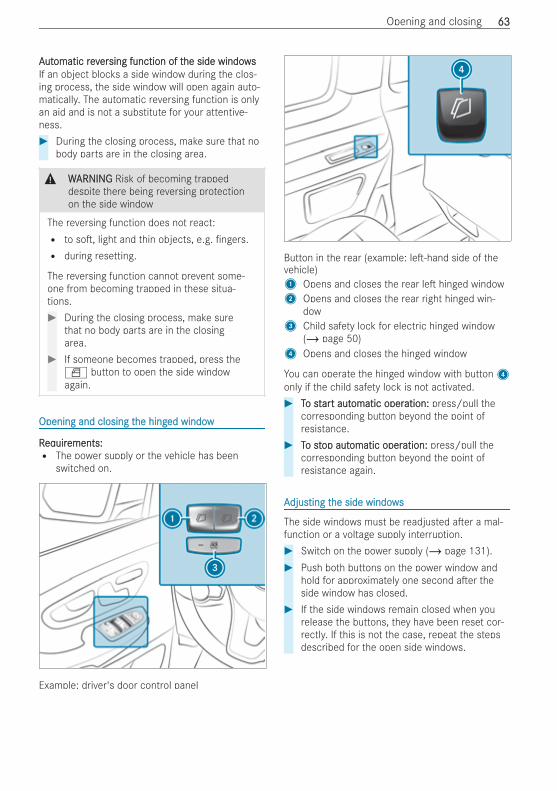
AAututomatic revomatic reverersing function of tsing function of the side windowshe side windowsIf an object blocks a side window during the clos-ing process, the side window will open again auto-matically. The automatic reversing function is onlyan aid and is not a substitute for your attentive-ness.# During the closing process, make sure that no
body parts are in the closing area.
& WWARNINGARNING Risk of becoming trappeddespite there being reversing protectionon the side window
The reversing function does not react:R to so , light and thin objects, e.g. ngers.R during resetting.
The reversing function cannot prevent some-one from becoming trapped in these situa-tions.# During the closing process, make sure
that no body parts are in the closingarea.
# If someone becomes trapped, press theW button to open the side windowagain.
Opening and closing tOpening and closing the hinghe hinged windowed window
RReqequiruirements:ements:R The power supply or the vehicle has been
switched on.
Example: driver's door control panel
Button in the rear (example: le -hand side of thevehicle)1 Opens and closes the rear le hinged window2 Opens and closes the rear right hinged win-
dow3 Child safety lock for electric hinged window
(/ page 50)4 Opens and closes the hinged window
You can operate the hinged window with button4only if the child safety lock is not activated.# TTo sto starart autt automatic operomatic operation:ation: press/pull the
corresponding button beyond the point ofresistance.
# TTo sto stop autop automatic operomatic operation:ation: press/pull thecorresponding button beyond the point ofresistance again.
AAdjusdjusting tting the side windowshe side windows
The side windows must be readjusted a er a mal-function or a voltage supply interruption.# Switch on the power supply (/ page 131).# Push both buttons on the power window and
hold for approximately one second a er theside window has closed.
# If the side windows remain closed when yourelease the buttons, they have been reset cor-rectly. If this is not the case, repeat the stepsdescribed for the open side windows.
Opening and closing 6363
RRectifying prectifying problems witoblems with th the side windowshe side windows
& WWARNINGARNING Risk of becoming trapped orfatally injured if reversing protection is notactivated
If you close a side window again immediatelya er it has been blocked, the side window willclose with increased or maximum force. Thereversing function is then not active and bodyparts may become trapped.# Make sure that no parts of the body are
in the closing area.# To stop the closing process, release the
button or press the button again toreopen the side window.
YYou cannoou cannot open or close a side windot open or close a side window all tw all theheway.way.# Check to see if there are any objects in the
window guide.# Reset the side windows (/ page 63).
PPanoranorama sliding sunrama sliding sunroofoofNNoottes on tes on the panorhe panorama sliding sunrama sliding sunroofoof
In this section, the term "sliding sunroof" refers tothe panorama sliding sunroof.
& WWARNINGARNING Risk of becoming trapped whenthe sliding sunroof is being opened andclosed
Body parts may become trapped in the rangeof movement.# During opening and closing, make sure
that no body parts are in the range ofmovement.
# Release the button immediately if some-body becomes trapped.
or# Brie y press the button in any direction
during automatic operation.The opening or closing process will bestopped.
& WWARNINGARNING Risk of entrapment if the slidingsunroof is operated by children
Children operating the sliding sunroof couldget caught in the moving parts, particularly ifunattended.
# Never leave children unattended in thevehicle.
# When leaving the vehicle, always take thekey with you and lock the vehicle.
* NNOOTETE Malfunction due to snow and ice
Snow and ice may cause the sliding sunroof tomalfunction.# Open the sliding sunroof only if it is free
of snow and ice.
* NNOOTETE Damage caused by protrudingobjects
Objects that protrude from the sliding sunroofmay damage the seals.# Do not allow anything to protrude from
the sliding sunroof.
* NNOOTETE Damage to on-board electronicscaused by the ingress of water
Water may enter the vehicle interior when thesliding sunroof is being cleaned.This may damage the on-board electronics.# Clean the sliding sunroof only when it is
closed.
% When the sliding sunroof is open, resonancenoise may also occur in addition to the usualair ow noises. This is caused by minor pres-sure uctuations in the vehicle interior. To pre-vent or stop these noises, alter the position ofthe sliding sunroof or open a side windowslightly.
Sliding sunrSliding sunroof revoof reverersing functionsing functionThe sliding sunroof is equipped with an automaticreversing function. If a solid object prevents or hin-ders the closing process, the sliding sunroof willopen again automatically. The automatic reversingfunction is only an aid and is not a substitute foryour attentiveness in the process of closing thesliding sunroof.
6464 Opening and closing
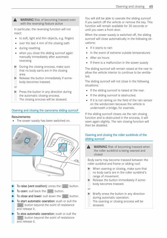
& WWARNINGARNING Risk of becoming trapped evenwith the reversing feature active
In particular, the reversing function will notreact:R to so , light and thin objects, e.g. ngersR over the last 4 mm of the closing pathR during resettingR when you close the sliding sunroof again
manually immediately a er automaticreversing
# During the closing process, make surethat no body parts are in the closingarea.
# Release the button immediately if some-body becomes trapped.
or# Press the button in any direction during
the automatic closing process.The closing process will be stopped.
Opening and closing tOpening and closing the panorhe panorama sliding sunrama sliding sunroofoof
RReqequiruirements:ements:R The power supply has been switched on.
# TTo ro raise (vaise (vent position):ent position): press the 3 button.# TTo open:o open: pull back the 3 button.# TTo close and lowo close and lowerer:: pull down the 3 button.# TTo sto starart autt automatic operomatic operation:ation: push or pull the
3 button beyond the point of resistanceand release it.
# TTo sto stop autop automatic operomatic operation:ation: push or pull the3 button beyond the point of resistanceand release it.
You will still be able to operate the sliding sunroofif you switch o the vehicle or remove the key. Thisfunction will remain available for 30 seconds oruntil you open a front door.When the power supply is switched o , the slidingsunroof will close automatically in the following sit-uations:R If it starts to rainR In the event of extreme outside temperaturesR A er six hoursR If there is a malfunction in the power supply
The sliding sunroof will remain raised at the rear toallow the vehicle interior to continue to be ventila-ted.The sliding sunroof will not close in the followingsituations:R If the sliding sunroof is raised at the rear.R If the sliding sunroof is obstructed.R If it is not raining on the eld of the rain sensor
on the windscreen because the vehicle isunderneath a bridge, for example.
If the sliding sunroof closes via the rain closingfunction and is obstructed in the process, it willopen again slightly. The rain closing function willthen be disabled.
Opening and closing tOpening and closing the rhe roller sunblinds of toller sunblinds of thehesliding sunrsliding sunroofoof
& WWARNINGARNING Risk of becoming trapped whenthe roller sunblind is being opened andclosed
Body parts may become trapped between theroller sunblind and frame or sliding roof.# When opening or closing, make sure that
no body parts are in the roller sunblind'srange of movement.
# Release the button immediately if some-body becomes trapped.
or# Brie y press the button in any direction
during automatic operation.The opening or closing process will bestopped.
Opening and closing 6565
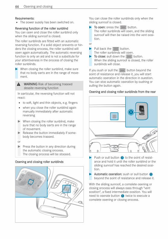
RReqequiruirements:ements:R The power supply has been switched on.
RevReverersing function of tsing function of the rhe roller sunblindoller sunblindYou can open and close the roller sunblind onlywhen the sliding sunroof is closed.The roller sunblinds are tted with an automaticreversing function. If a solid object prevents or hin-ders the closing process, the roller sunblind willopen again automatically. The automatic reversingfunction is only an aid and is not a substitute foryour attentiveness in the process of closing theroller sunblinds.# When closing the roller sunblind, make sure
that no body parts are in the range of move-ment.
& WWARNINGARNING Risk of becoming trappeddespite reversing function
In particular, the reversing function will notreact:R to so , light and thin objects, e.g. ngersR when you close the roller sunblind again
manually immediately a er automaticreversing
# When closing the roller sunblind, makesure that no body parts are in the rangeof movement.
# Release the button immediately if some-body becomes trapped.
or# Press the button in any direction during
the automatic closing process.The closing process will be stopped.
Opening and closing rOpening and closing roller sunblindsoller sunblinds
You can close the roller sunblinds only when thesliding sunroof is closed.# TTo open:o open: press the 3 button.
The roller sunblinds will open, and the slidingsunroof will then be raised into the vent posi-tion.
or# Pull back the 3 button.
The roller sunblinds will open.# TTo close:o close: pull down the 3 button.
When the sliding sunroof is closed, the rollersunblinds will close.
If you push or pull the 3 button beyond thepoint of resistance and release it, you will startautomatic operation in the direction in question.You can stop automatic operation by pushing orpulling the button again.
Opening and closing rOpening and closing roller sunblinds froller sunblinds from tom the rhe rearear
# Push or pull button1 to the point of resist-ance and hold it until the roller sunblind or thesliding sunroof has reached the desired posi-tion.
# AAututomatic operomatic operation:ation: push or pull button1beyond the point of resistance and release it.
With the sliding sunroof, a complete opening orclosing process will always pass through "ventposition", a xed intermediate position. You willneed to operate button1 twice to execute acomplete opening or closing process.
6666 Opening and closing
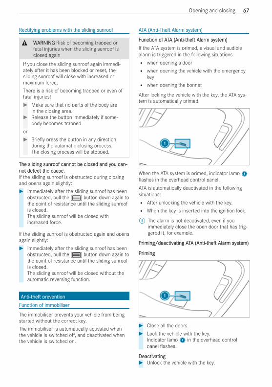
RRectifying prectifying problems witoblems with th the sliding sunrhe sliding sunroofoof
& WWARNINGARNING Risk of becoming trapped orfatal injuries when the sliding sunroof isclosed again
If you close the sliding sunroof again immedi-ately a er it has been blocked or reset, thesliding sunroof will close with increased ormaximum force.There is a risk of becoming trapped or even offatal injuries!# Make sure that no parts of the body are
in the closing area.# Release the button immediately if some-
body becomes trapped.or# Brie y press the button in any direction
during the automatic closing process.The closing process will be stopped.
The sliding sunrThe sliding sunroof cannooof cannot be closed and yt be closed and you can-ou can-nonot dett detect tect the cause.he cause.If the sliding sunroof is obstructed during closingand opens again slightly:# Immediately a er the sliding sunroof has been
obstructed, pull the 3 button down again tothe point of resistance until the sliding sunroofis closed.The sliding sunroof will be closed withincreased force.
If the sliding sunroof is obstructed again and opensagain slightly:# Immediately a er the sliding sunroof has been
obstructed, pull the 3 button down again tothe point of resistance until the sliding sunroofis closed.The sliding sunroof will be closed without theautomatic reversing function.
Anti-tAnti-thehe prevpreventionentionFFunction of immobiliserunction of immobiliser
The immobiliser prevents your vehicle from beingstarted without the correct key.The immobiliser is automatically activated whenthe vehicle is switched o , and deactivated whenthe vehicle is switched on.
AATTAA (Anti-(Anti-TheThe AlarAlarm systm system)em)
FFunction of ATunction of ATAA (Anti-t(Anti-thehe AlarAlarm systm system)em)If the ATA system is primed, a visual and audiblealarm is triggered in the following situations:R when opening a doorR when opening the vehicle with the emergency
keyR when opening the bonnet
A er locking the vehicle with the key, the ATA sys-tem is automatically primed.
When the ATA system is primed, indicator lamp1ashes in the overhead control panel.
ATA is automatically deactivated in the followingsituations:R A er unlocking the vehicle with the key.R When the key is inserted into the ignition lock.
% The alarm is not deactivated, even if youimmediately close the open door that has trig-gered it, for example.
PrPriming/deactiviming/deactivating ATating ATAA (Anti-t(Anti-thehe AlarAlarm systm system)em)
PrPrimingiming
# Close all the doors.# Lock the vehicle with the key.
Indicator lamp1 in the overhead controlpanel ashes.
DeactivDeactivatingating# Unlock the vehicle with the key.
Opening and closing 6767
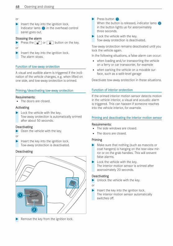
or# Insert the key into the ignition lock.
Indicator lamp1 in the overhead controlpanel goes out.
SSttopping topping the alarmhe alarm# Press the % or & button on the key.or# Insert the key into the ignition lock.
The alarm stops.
FFunction of towunction of tow-awa-away proty protectionection
A visual and audible alarm is triggered if the incli-nation of the vehicle changes, e.g. when li ed onone side, and tow-away protection is primed.
PrPriming/deactiviming/deactivating towating tow-awa-away proty protectionection
RReqequiruirements:ements:R The doors are closed.
AActivctivatingating# Lock the vehicle with the key.
Tow-away protection is automatically primeda er about 50 seconds.
DeactivDeactivatingating# Open the vehicle with the key.or# Insert the key into the ignition lock.
Tow-away protection is deactivated.
DeactivDeactivatingating
# Remove the key from the ignition lock.
# Press button1.When the button is released, indicator lamp2in the button lights up for approximatelythree seconds.
# Lock the vehicle with the key.Tow-away protection is deactivated.
Tow-away protection remains deactivated until youlock the vehicle again.In the following situations, a false alarm can occur:R when loading and/or transporting the vehicle
on a ferry or car transporter, for exampleR when parking the vehicle on a movable sur-
face, such as a split-level garage
Deactivate tow-away protection in these situations.
FFunction of intunction of intererior protior protectionection
If the primed interior motion sensor detects motionin the vehicle interior, a visual and acoustic alarmis triggered. This can happen if someone reachesinto the vehicle interior, for example.
PrPriming and deactiviming and deactivating tating the inthe intererior moior motion sensortion sensor
RReqequiruirements:ements:R The side windows are closed.R The doors are closed.
PrPrimingiming# Make sure that nothing (such as mascots or
coat hangers) is hanging on the rear-view mir-ror or on the grab handles. This will preventfalse alarms.
# Lock the vehicle with the key.The interior motion sensor is primed a erapproximately 20 seconds.
DeactivDeactivatingating# Unlock the vehicle with the key.or# Insert the key into the ignition lock.
The interior motion sensor automaticallyswitches o .
6868 Opening and closing
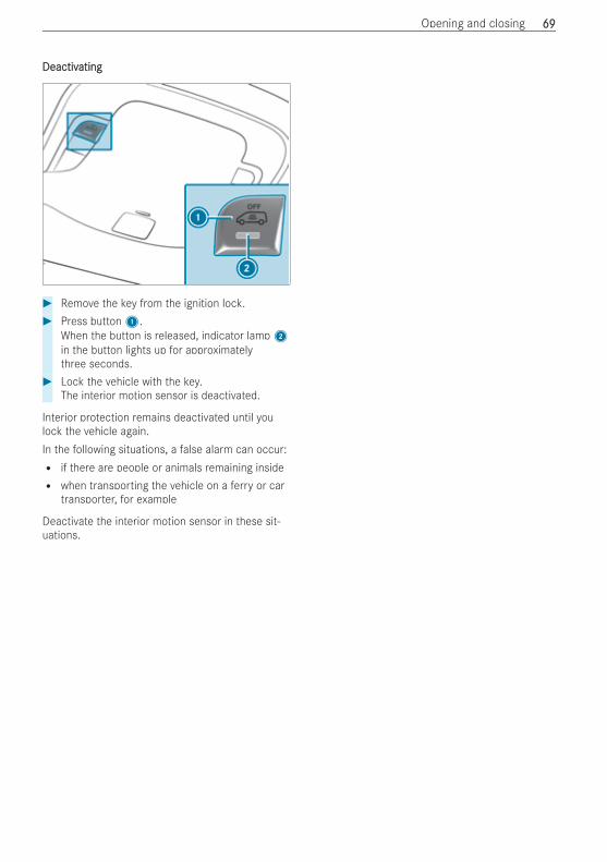
DeactivDeactivatingating
# Remove the key from the ignition lock.# Press button1.
When the button is released, indicator lamp2in the button lights up for approximatelythree seconds.
# Lock the vehicle with the key.The interior motion sensor is deactivated.
Interior protection remains deactivated until youlock the vehicle again.In the following situations, a false alarm can occur:R if there are people or animals remaining insideR when transporting the vehicle on a ferry or car
transporter, for example
Deactivate the interior motion sensor in these sit-uations.
Opening and closing 6969
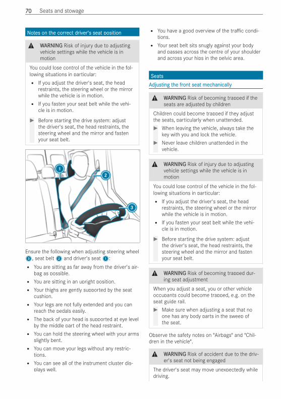
NNoottes on tes on the corrhe correct drect driviver's seat positioner's seat position
& WWARNINGARNING Risk of injury due to adjustingvehicle settings while the vehicle is inmotion
You could lose control of the vehicle in the fol-lowing situations in particular:R If you adjust the driver's seat, the head
restraints, the steering wheel or the mirrorwhile the vehicle is in motion.R If you fasten your seat belt while the vehi-
cle is in motion.
# Before starting the drive system: adjustthe driver's seat, the head restraints, thesteering wheel and the mirror and fastenyour seat belt.
Ensure the following when adjusting steering wheel3, seat belt2 and driver's seat1:R You are sitting as far away from the driver's air-
bag as possible.R You are sitting in an upright position.R Your thighs are gently supported by the seat
cushion.R Your legs are not fully extended and you can
reach the pedals easily.R The back of your head is supported at eye level
by the middle part of the head restraint.R You can hold the steering wheel with your arms
slightly bent.R You can move your legs without any restric-
tions.R You can see all of the instrument cluster dis-
plays well.
R You have a good overview of the tra c condi-tions.R Your seat belt sits snugly against your body
and passes across the centre of your shoulderand across your hips in the pelvic area.
SeatsSeatsAAdjusdjusting tting the frhe front seat mecont seat mechanicallyhanically
& WWARNINGARNING Risk of becoming trapped if theseats are adjusted by children
Children could become trapped if they adjustthe seats, particularly when unattended.# When leaving the vehicle, always take the
key with you and lock the vehicle.# Never leave children unattended in the
vehicle.
& WWARNINGARNING Risk of injury due to adjustingvehicle settings while the vehicle is inmotion
You could lose control of the vehicle in the fol-lowing situations in particular:R If you adjust the driver's seat, the head
restraints, the steering wheel or the mirrorwhile the vehicle is in motion.R If you fasten your seat belt while the vehi-
cle is in motion.
# Before starting the drive system: adjustthe driver's seat, the head restraints, thesteering wheel and the mirror and fastenyour seat belt.
& WWARNINGARNING Risk of becoming trapped dur-ing seat adjustment
When you adjust a seat, you or other vehicleoccupants could become trapped, e.g. on theseat guide rail.# Make sure when adjusting a seat that no
one has any body parts in the sweep ofthe seat.
Observe the safety notes on "Airbags" and "Chil-dren in the vehicle".
& WWARNINGARNING Risk of accident due to the driv-er's seat not being engaged
The driver's seat may move unexpectedly whiledriving.
7070 Seats and stowage
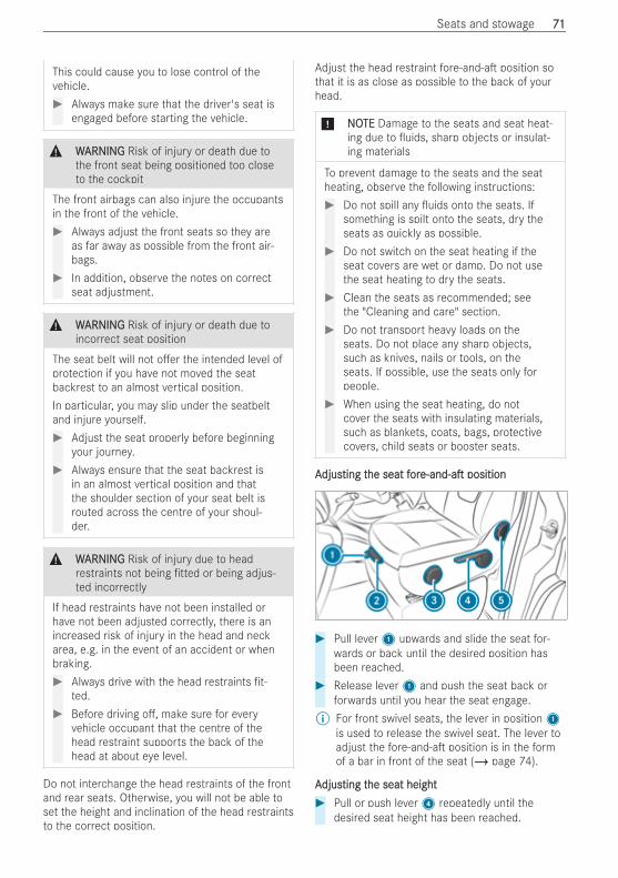
This could cause you to lose control of thevehicle.# Always make sure that the driver's seat is
engaged before starting the vehicle.
& WWARNINGARNING Risk of injury or death due tothe front seat being positioned too closeto the cockpit
The front airbags can also injure the occupantsin the front of the vehicle.# Always adjust the front seats so they are
as far away as possible from the front air-bags.
# In addition, observe the notes on correctseat adjustment.
& WWARNINGARNING Risk of injury or death due toincorrect seat position
The seat belt will not o er the intended level ofprotection if you have not moved the seatbackrest to an almost vertical position.In particular, you may slip under the seatbeltand injure yourself.# Adjust the seat properly before beginning
your journey.# Always ensure that the seat backrest is
in an almost vertical position and thatthe shoulder section of your seat belt isrouted across the centre of your shoul-der.
& WWARNINGARNING Risk of injury due to headrestraints not being tted or being adjus-ted incorrectly
If head restraints have not been installed orhave not been adjusted correctly, there is anincreased risk of injury in the head and neckarea, e.g. in the event of an accident or whenbraking.# Always drive with the head restraints t-
ted.# Before driving o , make sure for every
vehicle occupant that the centre of thehead restraint supports the back of thehead at about eye level.
Do not interchange the head restraints of the frontand rear seats. Otherwise, you will not be able toset the height and inclination of the head restraintsto the correct position.
Adjust the head restraint fore-and-a position sothat it is as close as possible to the back of yourhead.
* NNOOTETE Damage to the seats and seat heat-ing due to uids, sharp objects or insulat-ing materials
To prevent damage to the seats and the seatheating, observe the following instructions:# Do not spill any uids onto the seats. If
something is spilt onto the seats, dry theseats as quickly as possible.
# Do not switch on the seat heating if theseat covers are wet or damp. Do not usethe seat heating to dry the seats.
# Clean the seats as recommended; seethe "Cleaning and care" section.
# Do not transport heavy loads on theseats. Do not place any sharp objects,such as knives, nails or tools, on theseats. If possible, use the seats only forpeople.
# When using the seat heating, do notcover the seats with insulating materials,such as blankets, coats, bags, protectivecovers, child seats or booster seats.
AAdjusdjusting tting the seathe seat fforore-and-ae-and-a positionposition
# Pull lever1 upwards and slide the seat for-wards or back until the desired position hasbeen reached.
# Release lever1 and push the seat back orforwards until you hear the seat engage.
% For front swivel seats, the lever in position1is used to release the swivel seat. The lever toadjust the fore-and-a position is in the formof a bar in front of the seat (/ page 74).
AAdjusdjusting tting the seat heighthe seat height# Pull or push lever4 repeatedly until the
desired seat height has been reached.
Seats and stowage 7171
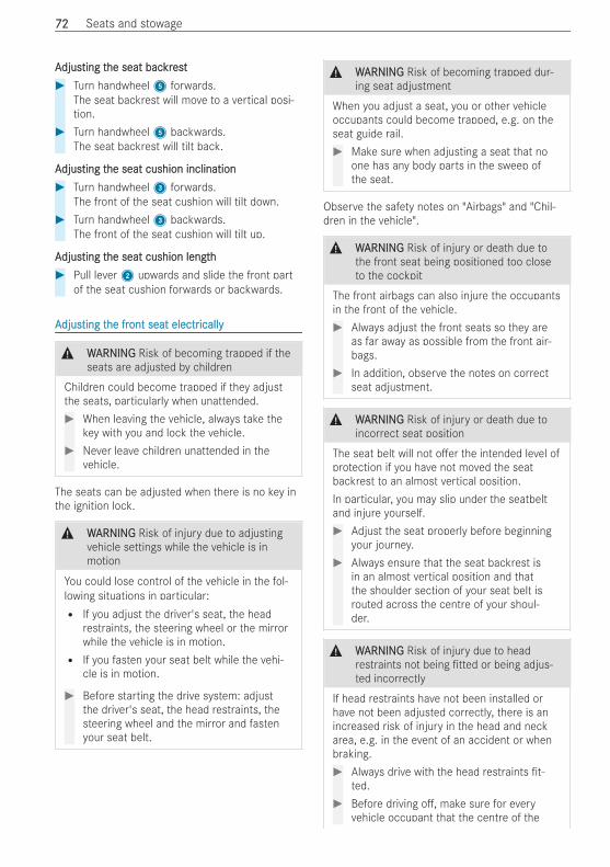
AAdjusdjusting tting the seat bache seat backrkrestest# Turn handwheel5 forwards.
The seat backrest will move to a vertical posi-tion.
# Turn handwheel5 backwards.The seat backrest will tilt back.
AAdjusdjusting tting the seat cushion inclinationhe seat cushion inclination# Turn handwheel3 forwards.
The front of the seat cushion will tilt down.# Turn handwheel3 backwards.
The front of the seat cushion will tilt up.
AAdjusdjusting tting the seat cushion lengthhe seat cushion length# Pull lever2 upwards and slide the front part
of the seat cushion forwards or backwards.
AAdjusdjusting tting the frhe front seat electront seat electricallyically
& WWARNINGARNING Risk of becoming trapped if theseats are adjusted by children
Children could become trapped if they adjustthe seats, particularly when unattended.# When leaving the vehicle, always take the
key with you and lock the vehicle.# Never leave children unattended in the
vehicle.
The seats can be adjusted when there is no key inthe ignition lock.
& WWARNINGARNING Risk of injury due to adjustingvehicle settings while the vehicle is inmotion
You could lose control of the vehicle in the fol-lowing situations in particular:R If you adjust the driver's seat, the head
restraints, the steering wheel or the mirrorwhile the vehicle is in motion.R If you fasten your seat belt while the vehi-
cle is in motion.
# Before starting the drive system: adjustthe driver's seat, the head restraints, thesteering wheel and the mirror and fastenyour seat belt.
& WWARNINGARNING Risk of becoming trapped dur-ing seat adjustment
When you adjust a seat, you or other vehicleoccupants could become trapped, e.g. on theseat guide rail.# Make sure when adjusting a seat that no
one has any body parts in the sweep ofthe seat.
Observe the safety notes on "Airbags" and "Chil-dren in the vehicle".
& WWARNINGARNING Risk of injury or death due tothe front seat being positioned too closeto the cockpit
The front airbags can also injure the occupantsin the front of the vehicle.# Always adjust the front seats so they are
as far away as possible from the front air-bags.
# In addition, observe the notes on correctseat adjustment.
& WWARNINGARNING Risk of injury or death due toincorrect seat position
The seat belt will not o er the intended level ofprotection if you have not moved the seatbackrest to an almost vertical position.In particular, you may slip under the seatbeltand injure yourself.# Adjust the seat properly before beginning
your journey.# Always ensure that the seat backrest is
in an almost vertical position and thatthe shoulder section of your seat belt isrouted across the centre of your shoul-der.
& WWARNINGARNING Risk of injury due to headrestraints not being tted or being adjus-ted incorrectly
If head restraints have not been installed orhave not been adjusted correctly, there is anincreased risk of injury in the head and neckarea, e.g. in the event of an accident or whenbraking.# Always drive with the head restraints t-
ted.# Before driving o , make sure for every
vehicle occupant that the centre of the
7272 Seats and stowage
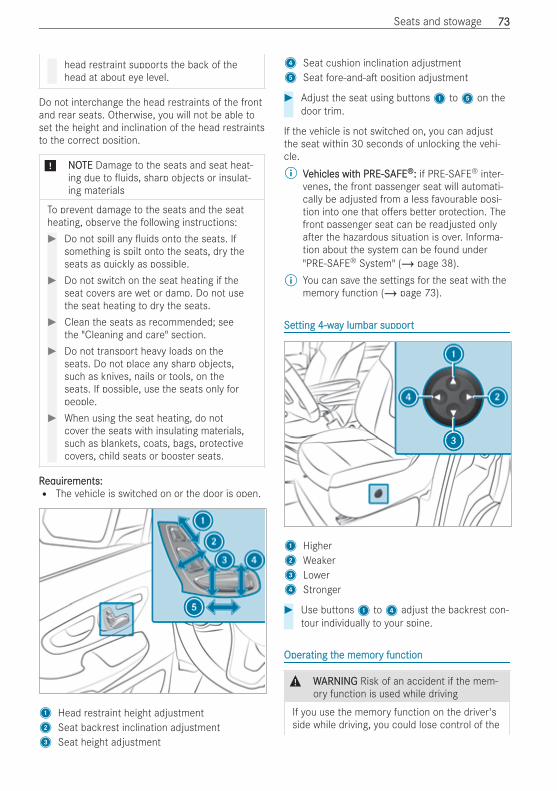
head restraint supports the back of thehead at about eye level.
Do not interchange the head restraints of the frontand rear seats. Otherwise, you will not be able toset the height and inclination of the head restraintsto the correct position.
* NNOOTETE Damage to the seats and seat heat-ing due to uids, sharp objects or insulat-ing materials
To prevent damage to the seats and the seatheating, observe the following instructions:# Do not spill any uids onto the seats. If
something is spilt onto the seats, dry theseats as quickly as possible.
# Do not switch on the seat heating if theseat covers are wet or damp. Do not usethe seat heating to dry the seats.
# Clean the seats as recommended; seethe "Cleaning and care" section.
# Do not transport heavy loads on theseats. Do not place any sharp objects,such as knives, nails or tools, on theseats. If possible, use the seats only forpeople.
# When using the seat heating, do notcover the seats with insulating materials,such as blankets, coats, bags, protectivecovers, child seats or booster seats.
RReqequiruirements:ements:R The vehicle is switched on or the door is open.
1 Head restraint height adjustment2 Seat backrest inclination adjustment3 Seat height adjustment
4 Seat cushion inclination adjustment5 Seat fore-and-a position adjustment
# Adjust the seat using buttons1 to5 on thedoor trim.
If the vehicle is not switched on, you can adjustthe seat within 30 seconds of unlocking the vehi-cle.% VVehicles witehicles with PRE-Sh PRE-SAFEAFE®®:: if PRE-SAFE® inter-
venes, the front passenger seat will automati-cally be adjusted from a less favourable posi-tion into one that o ers better protection. Thefront passenger seat can be readjusted onlya er the hazardous situation is over. Informa-tion about the system can be found under"PRE-SAFE® System" (/ page 38).
% You can save the settings for the seat with thememory function (/ page 73).
SeSetting 4-watting 4-way lumbar supporty lumbar support
1 Higher2 Weaker3 Lower4 Stronger
# Use buttons1 to4 adjust the backrest con-tour individually to your spine.
OperOperating tating the memorhe memory functiony function
& WWARNINGARNING Risk of an accident if the mem-ory function is used while driving
If you use the memory function on the driver'sside while driving, you could lose control of the
Seats and stowage 7373
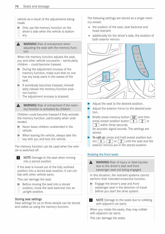
vehicle as a result of the adjustments beingmade.# Only use the memory function on the
driver's side when the vehicle is station-ary.
& WWARNINGARNING Risk of entrapment whenadjusting the seat with the memory func-tion
When the memory function adjusts the seat,you and other vehicle occupants – particularlychildren – could become trapped.# During the adjustment process of the
memory function, make sure that no onehas any body parts in the sweep of theseat.
# If somebody becomes trapped, immedi-ately release the memory function posi-tion button.The adjustment process is stopped.
& WWARNINGARNING Risk of entrapment if the mem-ory function is activated by children
Children could become trapped if they activatethe memory function, particularly when unat-tended.# Never leave children unattended in the
vehicle.# When leaving the vehicle, always take the
key with you and lock the vehicle.
The memory function can be used when the vehi-cle is switched o .
* NNOOTETE Damage to the seat when movinginto a stored position
If the seat is moved out of the fully reclinedposition into a stored seat position, it can col-lide with other vehicle parts.This can damage the seat.# Before moving the seat into a stored
position, move the seat backrest into anupright position.
SSttororing seat seing seat settingsttingsSeat settings for up to three people can be storedand called up using the memory function.
The following settings are stored as a single mem-ory preset:R the position of the seat, seat backrest and
head restraintR additionally for the driver's side, the position of
both exterior mirrors
# Adjust the seat to the desired position.# Adjust the exterior mirror to the desired posi-
tion.# Brie y press memory buttonV and then
press preset position button 4,T orU within three seconds.An acoustic signal sounds. The settings arestored.
# TTo call up:o call up: press and hold preset position but-ton 4,T orU until the seat and theexterior mirrors are in the stored position.
RRoottating tating the frhe front seatsont seats
& WWARNINGARNING Risk of injury or fatal injuriesdue to the driver's seat and frontpassenger seat not being engaged
In this situation, the restraint systems cannotperform their intended protective function.# Engage the driver's seat and front
passenger seat in the direction of travelbefore you start the drive system.
* NNOOTETE Damage to the seats due to collidingwith adjacent car parts
When you rotate the seats, they may collidewith adjacent car parts.This can damage the seats.
7474 Seats and stowage
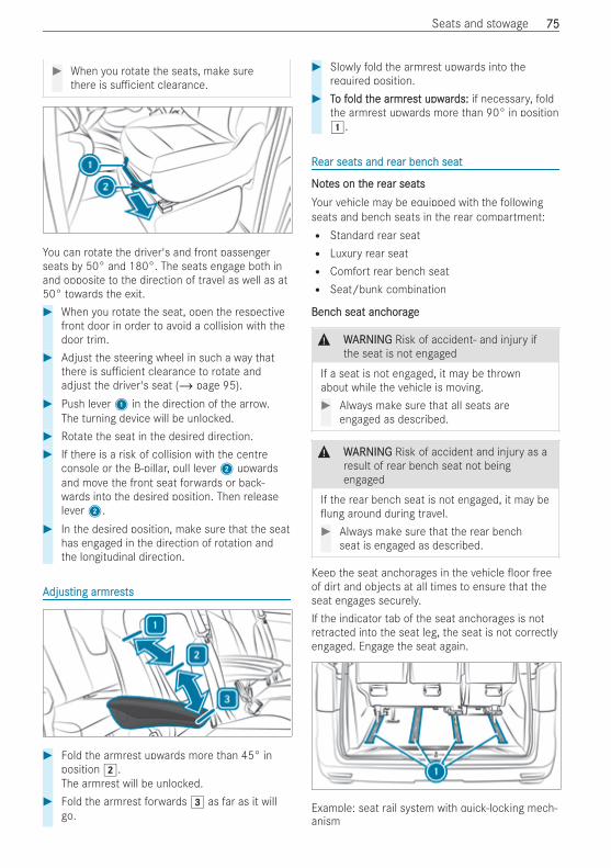
# When you rotate the seats, make surethere is su cient clearance.
You can rotate the driver's and front passengerseats by 50° and 180°. The seats engage both inand opposite to the direction of travel as well as at50° towards the exit.# When you rotate the seat, open the respective
front door in order to avoid a collision with thedoor trim.
# Adjust the steering wheel in such a way thatthere is su cient clearance to rotate andadjust the driver's seat (/ page 95).
# Push lever1 in the direction of the arrow.The turning device will be unlocked.
# Rotate the seat in the desired direction.# If there is a risk of collision with the centre
console or the B‑pillar, pull lever2 upwardsand move the front seat forwards or back-wards into the desired position. Then releaselever2.
# In the desired position, make sure that the seathas engaged in the direction of rotation andthe longitudinal direction.
AAdjusdjusting arting armrmreseststs
# Fold the armrest upwards more than 45° inposition 2.The armrest will be unlocked.
# Fold the armrest forwards 3 as far as it willgo.
# Slowly fold the armrest upwards into therequired position.
# TTo fo fold told the arhe armrmresest upwt upwarards:ds: if necessary, foldthe armrest upwards more than 90° in position1.
RRear seats and rear seats and rear bencear bench seath seat
NNoottes on tes on the rhe rear seatsear seatsYour vehicle may be equipped with the followingseats and bench seats in the rear compartment:R Standard rear seatR Luxury rear seatR Comfort rear bench seatR Seat/bunk combination
BencBench seat anch seat anchorhorageage
& WWARNINGARNING Risk of accident‑ and injury ifthe seat is not engaged
If a seat is not engaged, it may be thrownabout while the vehicle is moving.# Always make sure that all seats are
engaged as described.
& WWARNINGARNING Risk of accident and injury as aresult of rear bench seat not beingengaged
If the rear bench seat is not engaged, it may beung around during travel.# Always make sure that the rear bench
seat is engaged as described.
Keep the seat anchorages in the vehicle oor freeof dirt and objects at all times to ensure that theseat engages securely.If the indicator tab of the seat anchorages is notretracted into the seat leg, the seat is not correctlyengaged. Engage the seat again.
Example: seat rail system with quick-locking mech-anism
Seats and stowage 7575
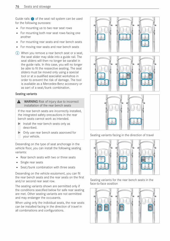
Guide rails1 of the seat rail system can be usedfor the following purposes:R For mounting up to two rear seat rowsR For mounting both rear seat rows facing one
anotherR For mounting rear seats and rear bench seatsR For moving rear seats and rear bench seats
% When you remove a rear bench seat or a seat,the seat slider may slide into a guide rail. Theseat sliders will then no longer be parallel inthe guide rails. In this case, you will no longerbe able to t the respective seating. The seatsliders must be moved only using a specialtool or at a quali ed specialist workshop inorder to prevent the risk of damage. The toolis available as a Mercedes-Benz accessory oras part of a seat/bunk combination.
Seating vSeating varariantsiants
& WWARNINGARNING Risk of injury due to incorrectinstallation of the rear bench seats
If the rear bench seats are incorrectly installed,the integrated safety precautions in the rearbench seats cannot work as intended.# Install the rear bench seats only as
described.# Only use rear bench seats approved for
your vehicle.
Depending on the type of seat anchorage in thevehicle oor, you can install the following seatingvariants:R Rear bench seats with two or three seatsR Single rear seatsR Seat/bunk combination with three seats
Depending on the vehicle equipment, you can tthe rear bench seats and the rear seats on the rstand/or second rear seat row.The seating variants shown are permitted only ifthe conditions speci ed below for safe rear seatingare met. Other seating variants are not permittedand may endanger the occupants.When using only the individual seats, the rear seatscan be installed facing in the direction of travel inall combinations and con gurations.
Seating variants facing in the direction of travel
Seating variants for the rear bench seats in theface-to-face position
7676 Seats and stowage
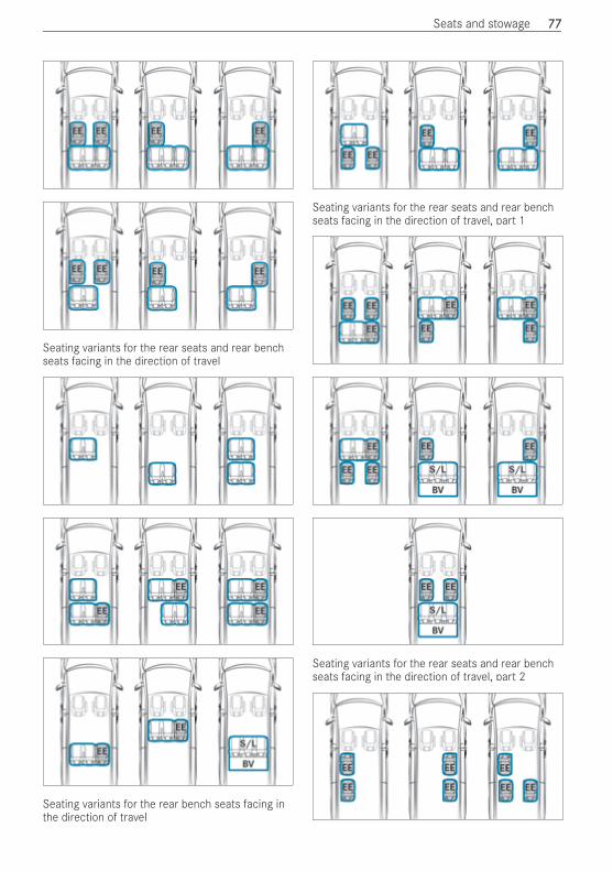
Seating variants for the rear seats and rear benchseats facing in the direction of travel
Seating variants for the rear bench seats facing inthe direction of travel
Seating variants for the rear seats and rear benchseats facing in the direction of travel, part 1
Seating variants for the rear seats and rear benchseats facing in the direction of travel, part 2
Seats and stowage 7777
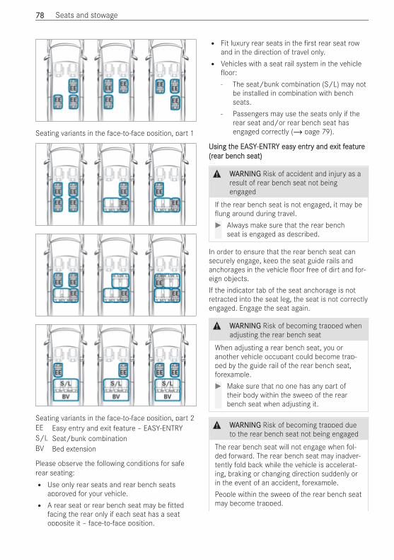
Seating variants in the face-to-face position, part 1
Seating variants in the face-to-face position, part 2EE Easy entry and exit feature – EASY-ENTRYS/L Seat/bunk combinationBV Bed extension
Please observe the following conditions for saferear seating:R Use only rear seats and rear bench seats
approved for your vehicle.R A rear seat or rear bench seat may be tted
facing the rear only if each seat has a seatopposite it – face-to-face position.
R Fit luxury rear seats in the rst rear seat rowand in the direction of travel only.R Vehicles with a seat rail system in the vehicle
oor:- The seat/bunk combination (S/L) may not
be installed in combination with benchseats.
- Passengers may use the seats only if therear seat and/or rear bench seat hasengaged correctly (/ page 79).
Using tUsing the EASYhe EASY-ENTR-ENTRY easy entrY easy entry and ey and exit fxit featureeature(r(rear bencear bench seat)h seat)
& WWARNINGARNING Risk of accident and injury as aresult of rear bench seat not beingengaged
If the rear bench seat is not engaged, it may beung around during travel.# Always make sure that the rear bench
seat is engaged as described.
In order to ensure that the rear bench seat cansecurely engage, keep the seat guide rails andanchorages in the vehicle oor free of dirt and for-eign objects.If the indicator tab of the seat anchorage is notretracted into the seat leg, the seat is not correctlyengaged. Engage the seat again.
& WWARNINGARNING Risk of becoming trapped whenadjusting the rear bench seat
When adjusting a rear bench seat, you oranother vehicle occupant could become trap-ped by the guide rail of the rear bench seat,forexample.# Make sure that no one has any part of
their body within the sweep of the rearbench seat when adjusting it.
& WWARNINGARNING Risk of becoming trapped dueto the rear bench seat not being engaged
The rear bench seat will not engage when fol-ded forward. The rear bench seat may inadver-tently fold back while the vehicle is accelerat-ing, braking or changing direction suddenly orin the event of an accident, forexample.People within the sweep of the rear bench seatmay become trapped.
7878 Seats and stowage
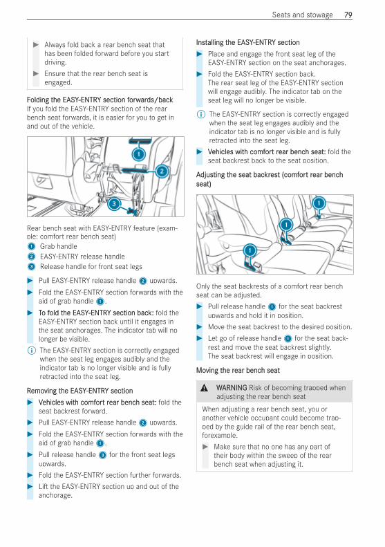
# Always fold back a rear bench seat thathas been folded forward before you startdriving.
# Ensure that the rear bench seat isengaged.
FFolding tolding the EASYhe EASY-ENTR-ENTRY section fY section forworwarards/backds/backIf you fold the EASY-ENTRY section of the rearbench seat forwards, it is easier for you to get inand out of the vehicle.
Rear bench seat with EASY-ENTRY feature (exam-ple: comfort rear bench seat)1 Grab handle2 EASY-ENTRY release handle3 Release handle for front seat legs
# Pull EASY-ENTRY release handle2 upwards.# Fold the EASY-ENTRY section forwards with the
aid of grab handle1.# TTo fo fold told the EASYhe EASY-ENTR-ENTRY section bacY section back:k: fold the
EASY-ENTRY section back until it engages inthe seat anchorages. The indicator tab will nolonger be visible.
% The EASY-ENTRY section is correctly engagedwhen the seat leg engages audibly and theindicator tab is no longer visible and is fullyretracted into the seat leg.
RRemoemoving tving the EASYhe EASY-ENTR-ENTRY sectionY section# VVehicles witehicles with comfh comforort rt rear bencear bench seat:h seat: fold the
seat backrest forward.# Pull EASY-ENTRY release handle2 upwards.# Fold the EASY-ENTRY section forwards with the
aid of grab handle1.# Pull release handle3 for the front seat legs
upwards.# Fold the EASY-ENTRY section further forwards.# Li the EASY-ENTRY section up and out of the
anchorage.
InstInstalling talling the EASYhe EASY-ENTR-ENTRY sectionY section# Place and engage the front seat leg of the
EASY-ENTRY section on the seat anchorages.# Fold the EASY-ENTRY section back.
The rear seat leg of the EASY-ENTRY sectionwill engage audibly. The indicator tab on theseat leg will no longer be visible.
% The EASY-ENTRY section is correctly engagedwhen the seat leg engages audibly and theindicator tab is no longer visible and is fullyretracted into the seat leg.
# VVehicles witehicles with comfh comforort rt rear bencear bench seat:h seat: fold theseat backrest back to the seat position.
AAdjusdjusting tting the seat bache seat backrkresest (comft (comforort rt rear benchear benchseat)seat)
Only the seat backrests of a comfort rear benchseat can be adjusted.# Pull release handle1 for the seat backrest
upwards and hold it in position.# Move the seat backrest to the desired position.# Let go of release handle1 for the seat back-
rest and move the seat backrest slightly.The seat backrest will engage in position.
MoMoving tving the rhe rear bencear bench seath seat
& WWARNINGARNING Risk of becoming trapped whenadjusting the rear bench seat
When adjusting a rear bench seat, you oranother vehicle occupant could become trap-ped by the guide rail of the rear bench seat,forexample.# Make sure that no one has any part of
their body within the sweep of the rearbench seat when adjusting it.
Seats and stowage 7979
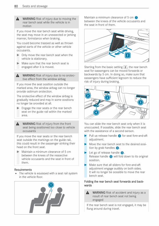
& WWARNINGARNING Risk of injury due to moving therear bench seat while the vehicle is inmotion
If you move the rear bench seat while driving,the seat may move in an unexpected or jerkingmanner, forinstance when braking.You could become trapped as well as thrownagainst parts of the vehicle or other vehicleoccupants.# Only move the rear bench seat when the
vehicle is stationary.# Make sure that the rear bench seat is
engaged a er it is moved.
& WWARNINGARNING Risk of injury due to no protec-tive e ect from the window airbag
If you move the seat position outside themarked area, the window airbag can no longerprovide optimum protection.The protective e ect of the window airbag isgradually reduced and may in some positionsno longer be provided at all.# Engage the rear seats or the rear bench
seat on the guide rail within the markedarea.
& WWARNINGARNING Risk of injury from the frontseat being positioned too close to vehicleoccupants
If you move the rear seats or the rear benchseat outside the markings on the guide rail,this could result in the passenger striking theirhead on the front seat.# Maintain a minimum clearance of 5 cm
between the knees of the respectivevehicle occupants and the seat in front ofthem.
RReqequiruirementsementsR The vehicle is equipped with a seat rail system
in the vehicle oor.
Maintain a minimum clearance of 5 cm1between the knees of the vehicle occupants andthe seat in front of them.
Starting from the basic setting 2, the rear benchseat for passengers can be moved forwards orbackwards by 5 cm. In doing so, make sure thatpassengers have su cient legroom to reduce therisk of injury during braking.
You can slide the rear bench seat only when it isunoccupied. If possible, slide the rear bench seatwith the assistance of a second person.# Pull up release handle4 for seat fore-and-a
adjustment.# Move the rear bench seat to the desired posi-
tion by grab handles3.# Let go of release handle4.
Release handle4 will fold down to its originalposition.
# Make sure that all sliders for fore-and-aadjustment engage audibly on both sides.It will no longer be possible to move the rearbench seat.
FFolding tolding the rhe rear bencear bench seat fh seat forworwarards and back-ds and back-wwarardsds
& WWARNINGARNING Risk of accident and injury as aresult of rear bench seat not beingengaged
If the rear bench seat is not engaged, it may beung around during travel.
8080 Seats and stowage
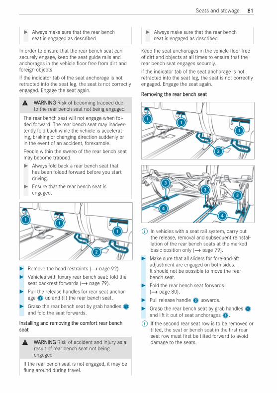
# Always make sure that the rear benchseat is engaged as described.
In order to ensure that the rear bench seat cansecurely engage, keep the seat guide rails andanchorages in the vehicle oor free from dirt andforeign objects.If the indicator tab of the seat anchorage is notretracted into the seat leg, the seat is not correctlyengaged. Engage the seat again.
& WWARNINGARNING Risk of becoming trapped dueto the rear bench seat not being engaged
The rear bench seat will not engage when fol-ded forward. The rear bench seat may inadver-tently fold back while the vehicle is accelerat-ing, braking or changing direction suddenly orin the event of an accident, forexample.People within the sweep of the rear bench seatmay become trapped.# Always fold back a rear bench seat that
has been folded forward before you startdriving.
# Ensure that the rear bench seat isengaged.
# Remove the head restraints (/ page 92).# Vehicles with luxury rear bench seat: fold the
seat backrest forwards (/ page 79).# Pull the release handles for rear seat anchor-
age2 up and tilt the rear bench seat.# Grasp the rear bench seat by grab handles1
and fold the seat forwards.
InstInstalling and ralling and remoemoving tving the comfhe comforort rt rear benchear benchseatseat
& WWARNINGARNING Risk of accident and injury as aresult of rear bench seat not beingengaged
If the rear bench seat is not engaged, it may beung around during travel.
# Always make sure that the rear benchseat is engaged as described.
Keep the seat anchorages in the vehicle oor freeof dirt and objects at all times to ensure that therear bench seat engages securely.If the indicator tab of the seat anchorage is notretracted into the seat leg, the seat is not correctlyengaged. Engage the seat again.
RRemoemoving tving the rhe rear bencear bench seath seat
% In vehicles with a seat rail system, carry outthe release, removal and subsequent reinstal-lation of the rear bench seats at the markedbasic position only (/ page 79).
# Make sure that all sliders for fore-and-aadjustment are engaged on both sides.It should not be possible to move the rearbench seat.
# Fold the rear bench seat forwards(/ page 80).
# Pull release handle3 upwards.# Grasp the rear bench seat by grab handles1
and li it out of seat anchorages4.% If the second rear seat row is to be removed or
tilted, the seat or bench seat in the rst rearseat row must rst be tilted forward to avoiddamage to the seats.
Seats and stowage 8181
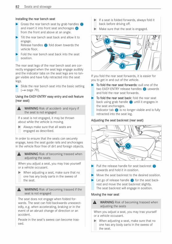
InstInstalling talling the rhe rear bencear bench seath seat# Grasp the rear bench seat by grab handles1
and insert it into front seat anchorages4from the front and above at an angle.
# Tilt the rear bench seat back and allow it toengage.Release handles2 fold down towards thevehicle oor.
# Fold the rear bench seat back into the seatposition.
The rear seat legs of the rear bench seat are cor-rectly engaged when the seat legs engage audiblyand the indicator tabs on the seat legs are no lon-ger visible and have fully retracted into the seatlegs.# Slide the rear bench seat into the basic setting
(/ page 79).
Using tUsing the EASYhe EASY-ENTR-ENTRY easy entrY easy entry and ey and exit fxit featureeature(r(rear seat)ear seat)
& WWARNINGARNING Risk of accident‑ and injury ifthe seat is not engaged
If a seat is not engaged, it may be thrownabout while the vehicle is moving.# Always make sure that all seats are
engaged as described.
In order to ensure that the seats can securelyengage, keep the seat guide rails and anchoragesin the vehicle oor free of dirt and foreign objects.
& WWARNINGARNING Risk of becoming trapped whenadjusting the seats
When you adjust a seat, you may trap yourselfor a vehicle occupant.# When adjusting a seat, make sure that no
one has any body parts in the sweep ofthe seat.
& WWARNINGARNING Risk of becoming trapped if theseat is not engaged
The seat does not engage when folded for-wards. The seat can fold backwards unexpect-edly, e.g. when accelerating, braking or in theevent of an abrupt change of direction or anaccident.People in the seat's sweep can become trap-ped.
# If a seat is folded forwards, always fold itback before driving o .
# Make sure that the seat is engaged.
If you fold the rear seat forwards, it is easier foryou to get in and out of the vehicle.# TTo fo fold told the rhe rear seat fear seat forworwarards:ds: pull one of the
two EASY-ENTRY release handles2 upwardsand fold the rear seat forwards.
# TTo fo fold told the rhe rear seat bacear seat back:k: fold the rear seatback using grab handle1 until it engages inthe seat anchorages.Indicator tab3 is no longer visible and is fullyretracted into the seat leg.
AAdjusdjusting tting the seat bache seat backrkresest (rt (rear seat)ear seat)
# Pull the release handle for seat backrest1upwards and hold it in position.
# Move the seat backrest to the desired position.# Let go of release handle1 for the seat back-
rest and move the seat backrest slightly.The seat backrest will engage in position.
MoMoving tving the rhe rear seatear seat
& WWARNINGARNING Risk of becoming trapped whenadjusting the seats
When you adjust a seat, you may trap yourselfor a vehicle occupant.# When adjusting a seat, make sure that no
one has any body parts in the sweep ofthe seat.
8282 Seats and stowage
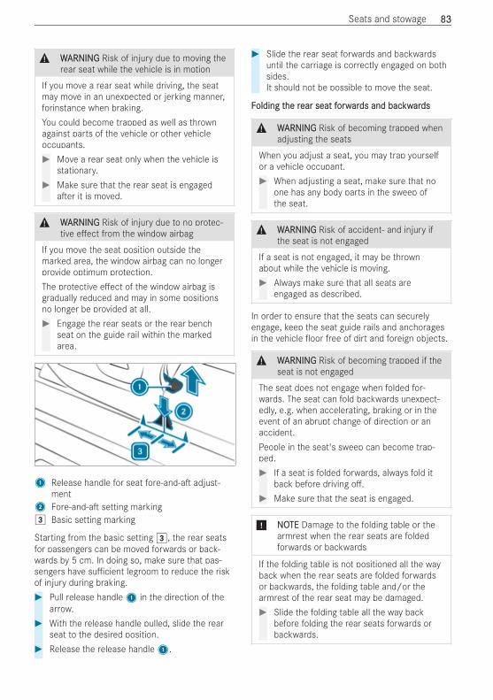
& WWARNINGARNING Risk of injury due to moving therear seat while the vehicle is in motion
If you move a rear seat while driving, the seatmay move in an unexpected or jerking manner,forinstance when braking.You could become trapped as well as thrownagainst parts of the vehicle or other vehicleoccupants.# Move a rear seat only when the vehicle is
stationary.# Make sure that the rear seat is engaged
a er it is moved.
& WWARNINGARNING Risk of injury due to no protec-tive e ect from the window airbag
If you move the seat position outside themarked area, the window airbag can no longerprovide optimum protection.The protective e ect of the window airbag isgradually reduced and may in some positionsno longer be provided at all.# Engage the rear seats or the rear bench
seat on the guide rail within the markedarea.
1 Release handle for seat fore-and-a adjust-ment
2 Fore-and-a setting marking3 Basic setting marking
Starting from the basic setting 3, the rear seatsfor passengers can be moved forwards or back-wards by 5 cm. In doing so, make sure that pas-sengers have su cient legroom to reduce the riskof injury during braking.# Pull release handle1 in the direction of the
arrow.# With the release handle pulled, slide the rear
seat to the desired position.# Release the release handle1.
# Slide the rear seat forwards and backwardsuntil the carriage is correctly engaged on bothsides.It should not be possible to move the seat.
FFolding tolding the rhe rear seat fear seat forworwarards and bacds and backwkwarardsds
& WWARNINGARNING Risk of becoming trapped whenadjusting the seats
When you adjust a seat, you may trap yourselfor a vehicle occupant.# When adjusting a seat, make sure that no
one has any body parts in the sweep ofthe seat.
& WWARNINGARNING Risk of accident‑ and injury ifthe seat is not engaged
If a seat is not engaged, it may be thrownabout while the vehicle is moving.# Always make sure that all seats are
engaged as described.
In order to ensure that the seats can securelyengage, keep the seat guide rails and anchoragesin the vehicle oor free of dirt and foreign objects.
& WWARNINGARNING Risk of becoming trapped if theseat is not engaged
The seat does not engage when folded for-wards. The seat can fold backwards unexpect-edly, e.g. when accelerating, braking or in theevent of an abrupt change of direction or anaccident.People in the seat's sweep can become trap-ped.# If a seat is folded forwards, always fold it
back before driving o .# Make sure that the seat is engaged.
* NNOOTETE Damage to the folding table or thearmrest when the rear seats are foldedforwards or backwards
If the folding table is not positioned all the wayback when the rear seats are folded forwardsor backwards, the folding table and/or thearmrest of the rear seat may be damaged.# Slide the folding table all the way back
before folding the rear seats forwards orbackwards.
Seats and stowage 8383
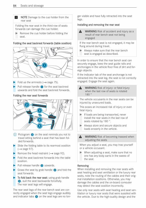
* NNOOTETE Damage to the cup holder from therear seat
Folding the rear seat in the third row of seatsforwards can damage the cup holder.# Remove the cup holder before folding the
seat.
FFolding tolding the seat bache seat backrkresest ft forworwarards (tds (table position)able position)
# Fold up the armrests (/ page 75).# Pull release handle1 for the seat backrest
upwards and fold the seat backrest forwards.
FFolding tolding the rhe rear seat fear seat forworwarardsds
% Pictogram4 on the seat reminds you not totravel sitting behind a seat that has been fol-ded forwards.
# Slide the folding table to its rearmost position(/ page 97).
# Remove the head restraint (/ page 92).# Fold the seat backrest forwards into the table
position.# Pull release handle3 upwards.# Grasp the seat by grab handle2 and fold the
seat forwards.# TTo fo fold bacold back tk the rhe rear seat:ear seat: using grab handle2, pull the seat backwards forcefully.The rear seat legs will engage.
The rear seat legs of the rear bench seat are cor-rectly engaged when the seat legs engage audiblyand indicator tabs5 on the seat legs are no lon-
ger visible and have fully retracted into the seatlegs.
InstInstalling and ralling and remoemoving tving the rhe rear seatear seat
& WWARNINGARNING Risk of accident and injury as aresult of rear bench seat not beingengaged
If the rear bench seat is not engaged, it may beung around during travel.# Always make sure that the rear bench
seat is engaged as described.
In order to ensure that the rear bench seat cansecurely engage, keep the seat guide rails andanchorages in the vehicle oor free of dirt and for-eign objects.If the indicator tab of the seat anchorage is notretracted into the seat leg, the seat is not correctlyengaged. Engage the seat again.
& WWARNINGARNING Risk of injury‑ or fatal injurywhen the last row of seats is rotated180 °
The vehicle occupants in the rear seats can beinjured by unsecured loads.This poses an increased risk of injury or evenfatal injury.# If loads are being transported, never
install the rear seats in the last row ofseats rotated by 180 °.
# Always store and secure objects andloads properly in the vehicle.
& WWARNINGARNING Risk of becoming trapped whenadjusting the seats
When you adjust a seat, you may trap yourselfor a vehicle occupant.# When adjusting a seat, make sure that no
one has any body parts in the sweep ofthe seat.
RRemoemovingvingWhen installing and removing the rear seats withseat heating and seat ventilation or the luxury rearseats, note the routing of the cables and their orig-inal installation positions. Otherwise, you maydamage the cables and the on-board computermay detect the seat position incorrectly.Use only rear seats with seat heating and seat ven-tilation or luxury rear seats that were supplied withthe vehicle. Due to the high-quality design and the
8484 Seats and stowage
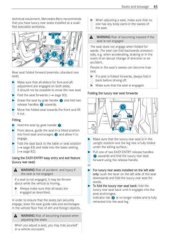
technical equipment, Mercedes-Benz recommendsthat you have luxury rear seats installed at a quali-ed specialist workshop.
Rear seat folded forward (example: standard rearseat)
# Make sure that all sliders for fore-and-aadjustment are engaged on both sides.It should not be possible to move the rear seat.
# Fold the seat forwards (/ page 83).# Grasp the seat by grab handle1 and fold two
release handles2 upwards.# Move the folded seat towards the front and li
it out.
FFittingitting# Hold the seat by grab handle1.# From above, guide the seat in a tilted position
into front seat anchorages3 and allow it toengage.
# Fold the seat back to the table or seat position(/ page 83) and slide into the basic setting(/ page 82).
Using tUsing the EASYhe EASY-ENTR-ENTRY easy entrY easy entry and ey and exit fxit featureeature(luxur(luxury ry rear seat)ear seat)
& WWARNINGARNING Risk of accident‑ and injury ifthe seat is not engaged
If a seat is not engaged, it may be thrownabout while the vehicle is moving.# Always make sure that all seats are
engaged as described.
In order to ensure that the seats can securelyengage, keep the seat guide rails and anchoragesin the vehicle oor free of dirt and foreign objects.
& WWARNINGARNING Risk of becoming trapped whenadjusting the seats
When you adjust a seat, you may trap yourselfor a vehicle occupant.
# When adjusting a seat, make sure that noone has any body parts in the sweep ofthe seat.
& WWARNINGARNING Risk of becoming trapped if theseat is not engaged
The seat does not engage when folded for-wards. The seat can fold backwards unexpect-edly, e.g. when accelerating, braking or in theevent of an abrupt change of direction or anaccident.People in the seat's sweep can become trap-ped.# If a seat is folded forwards, always fold it
back before driving o .# Make sure that the seat is engaged.
FFolding tolding the luxurhe luxury ry rear seat fear seat forworwarardsds
# Make sure that the luxury rear seat is in theupright position and the leg rest is fully foldedunder the sitting surface.
# Pull one of two EASY-ENTRY release handles1 upwards and fold the luxury rear seatforward using the release handle.
or# FFor luxuror luxury ry rear seats instear seats installed on talled on thehe lele sideside
onlyonly:: push the lever on the le side of the seatdownwards and fold the luxury rear seat for-wards.
# TTo fo fold told the luxurhe luxury ry rear seat bacear seat back:k: fold theluxury rear seat back until it engages into theseat anchorages.Indicator tab2 is no longer visible and is fullyretracted into the seat leg.
Seats and stowage 8585
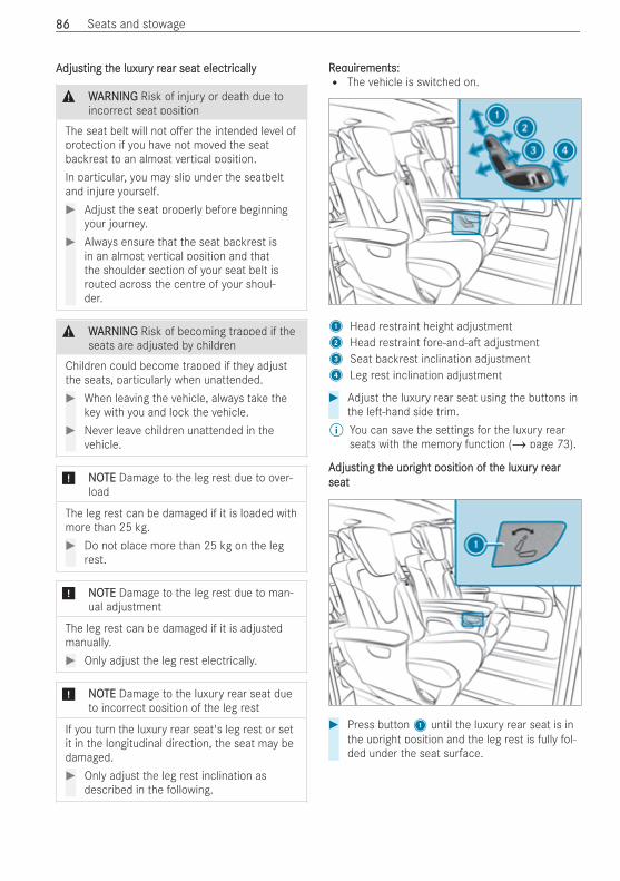
AAdjusdjusting tting the luxurhe luxury ry rear seat electrear seat electricallyically
& WWARNINGARNING Risk of injury or death due toincorrect seat position
The seat belt will not o er the intended level ofprotection if you have not moved the seatbackrest to an almost vertical position.In particular, you may slip under the seatbeltand injure yourself.# Adjust the seat properly before beginning
your journey.# Always ensure that the seat backrest is
in an almost vertical position and thatthe shoulder section of your seat belt isrouted across the centre of your shoul-der.
& WWARNINGARNING Risk of becoming trapped if theseats are adjusted by children
Children could become trapped if they adjustthe seats, particularly when unattended.# When leaving the vehicle, always take the
key with you and lock the vehicle.# Never leave children unattended in the
vehicle.
* NNOOTETE Damage to the leg rest due to over-load
The leg rest can be damaged if it is loaded withmore than 25 kg.# Do not place more than 25 kg on the leg
rest.
* NNOOTETE Damage to the leg rest due to man-ual adjustment
The leg rest can be damaged if it is adjustedmanually.# Only adjust the leg rest electrically.
* NNOOTETE Damage to the luxury rear seat dueto incorrect position of the leg rest
If you turn the luxury rear seat's leg rest or setit in the longitudinal direction, the seat may bedamaged.# Only adjust the leg rest inclination as
described in the following.
RReqequiruirements:ements:R The vehicle is switched on.
1 Head restraint height adjustment2 Head restraint fore-and-a adjustment3 Seat backrest inclination adjustment4 Leg rest inclination adjustment
# Adjust the luxury rear seat using the buttons inthe le -hand side trim.
% You can save the settings for the luxury rearseats with the memory function (/ page 73).
AAdjusdjusting tting the uprhe upright position of tight position of the luxurhe luxury ry rearearseatseat
# Press button1 until the luxury rear seat is inthe upright position and the leg rest is fully fol-ded under the seat surface.
8686 Seats and stowage
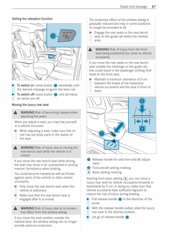
SeSetting ttting the rhe relaxelaxation functionation function
# TTo switco switch on:h on: press button1 repeatedly untilthe desired massage program has been set.
# TTo switco switchh o :o : press button1 until all indica-tor lamps are o .
MoMoving tving the luxurhe luxury ry rear seatear seat
& WWARNINGARNING Risk of becoming trapped whenadjusting the seats
When you adjust a seat, you may trap yourselfor a vehicle occupant.# When adjusting a seat, make sure that no
one has any body parts in the sweep ofthe seat.
& WWARNINGARNING Risk of injury due to moving therear bench seat while the vehicle is inmotion
If you move the rear bench seat while driving,the seat may move in an unexpected or jerkingmanner, forinstance when braking.You could become trapped as well as thrownagainst parts of the vehicle or other vehicleoccupants.# Only move the rear bench seat when the
vehicle is stationary.# Make sure that the rear bench seat is
engaged a er it is moved.
& WWARNINGARNING Risk of injury due to no protec-tive e ect from the window airbag
If you move the seat position outside themarked area, the window airbag can no longerprovide optimum protection.
The protective e ect of the window airbag isgradually reduced and may in some positionsno longer be provided at all.# Engage the rear seats or the rear bench
seat on the guide rail within the markedarea.
& WWARNINGARNING Risk of injury from the frontseat being positioned too close to vehicleoccupants
If you move the rear seats or the rear benchseat outside the markings on the guide rail,this could result in the passenger striking theirhead on the front seat.# Maintain a minimum clearance of 5 cm
between the knees of the respectivevehicle occupants and the seat in front ofthem.
1 Release handle for seat fore-and-a adjust-ment
2 Fore-and-a setting marking3 Basic setting marking
Starting from basic setting 3, you can move aluxury rear seat for vehicle occupants forwards orbackwards by 5 cm. In doing so, make sure thatvehicle occupants have su cient legroom toreduce the risk of injury during braking.# Pull release handle1 in the direction of the
arrow.# With the release handle pulled, slide the luxury
rear seat to the desired position.# Let go of release handle1.
Seats and stowage 8787

# Slide the luxury rear seat forwards and back-wards until the sliders engage correctly onboth sides.It should not be possible to move the seat.
MoMoving tving the luxurhe luxury ry rear seat frear seat from tom the second seathe second seatrowrow
# Push lever3 down.# Slide the luxury rear seat forwards or back-
wards.% A luxury rear seat is generally removed and
installed in the same way as a standard rearseat (/ page 84). Due to the high-qualitydesign and the technical equipment,Mercedes-Benz recommends that you haveluxury rear seats installed at a quali ed spe-cialist workshop.
NNoottes on tes on the seat/bunk combinationhe seat/bunk combination
& WWARNINGARNING Risk of becoming trapped whenadjusting the rear bench seat
When adjusting a rear bench seat, you oranother vehicle occupant could become trap-ped by the guide rail of the rear bench seat,forexample.# Make sure that no one has any part of
their body within the sweep of the rearbench seat when adjusting it.
& WWARNINGARNING Risk of injury due to moving therear bench seat while the vehicle is inmotion
If you move the rear bench seat while driving,the seat may move in an unexpected or jerkingmanner, forinstance when braking.You could become trapped as well as thrownagainst parts of the vehicle or other vehicleoccupants.# Only move the rear bench seat when the
vehicle is stationary.
# Make sure that the rear bench seat isengaged a er it is moved.
& WWARNINGARNING Risk of injury due to no protec-tive e ect from the window airbag
If you move the seat position outside themarked area, the window airbag can no longerprovide optimum protection.The protective e ect of the window airbag isgradually reduced and may in some positionsno longer be provided at all.# Engage the seat‑/‑bunk combination on
the guide rail within the marked area.
& WWARNINGARNING Risk of injury due to positioningthe seat‑/‑bunk combination outside themarkings
If you move the seat‑/‑bunk combination out-side the markings on the guide rail, this couldresult in the passenger striking their head onthe seat.# Maintain a minimum clearance of 5 cm
between the knees of the respectivevehicle occupants and the seats in frontof them.
* NNOOTETE Damage to the seat/bunk combina-tion when moving
If you grasp and push the seat/bunk combina-tion by the stowage compartment plastic coveronly, the cover may break o .If the space in front of or behind the seat/bunk combination is not clear, objects maybecome trapped when displaced.The seat/bunk combination, trim or theobjects may become damaged.# To move, use the loop between the seat
backrest and sitting surface.# When moving, make sure that the space
in front of or behind the seat/bunk com-bination is clear.
8888 Seats and stowage
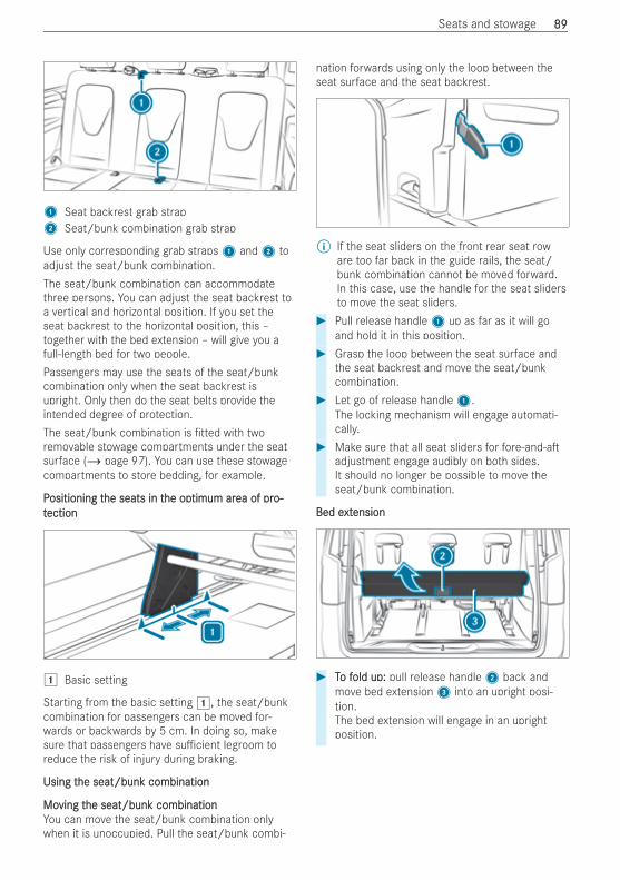
1 Seat backrest grab strap2 Seat/bunk combination grab strap
Use only corresponding grab straps1 and2 toadjust the seat/bunk combination.The seat/bunk combination can accommodatethree persons. You can adjust the seat backrest toa vertical and horizontal position. If you set theseat backrest to the horizontal position, this –together with the bed extension – will give you afull-length bed for two people.Passengers may use the seats of the seat/bunkcombination only when the seat backrest isupright. Only then do the seat belts provide theintended degree of protection.The seat/bunk combination is tted with tworemovable stowage compartments under the seatsurface (/ page 97). You can use these stowagecompartments to store bedding, for example.
PPositioning tositioning the seats in the seats in the ophe optimum artimum area of prea of pro-o-ttectionection
1 Basic setting
Starting from the basic setting 1, the seat/bunkcombination for passengers can be moved for-wards or backwards by 5 cm. In doing so, makesure that passengers have su cient legroom toreduce the risk of injury during braking.
Using tUsing the seat/bunk combinationhe seat/bunk combination
MoMoving tving the seat/bunk combinationhe seat/bunk combinationYou can move the seat/bunk combination onlywhen it is unoccupied. Pull the seat/bunk combi-
nation forwards using only the loop between theseat surface and the seat backrest.
% If the seat sliders on the front rear seat roware too far back in the guide rails, the seat/bunk combination cannot be moved forward.In this case, use the handle for the seat slidersto move the seat sliders.
# Pull release handle1 up as far as it will goand hold it in this position.
# Grasp the loop between the seat surface andthe seat backrest and move the seat/bunkcombination.
# Let go of release handle1.The locking mechanism will engage automati-cally.
# Make sure that all seat sliders for fore-and-aadjustment engage audibly on both sides.It should no longer be possible to move theseat/bunk combination.
Bed eBed extxtensionension
# TTo fo fold up:old up: pull release handle2 back andmove bed extension3 into an upright posi-tion.The bed extension will engage in an uprightposition.
Seats and stowage 8989
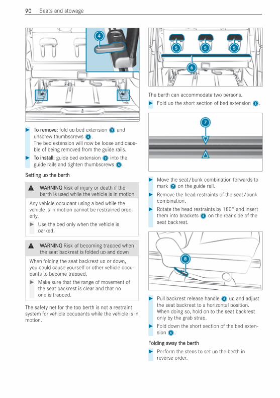
# TTo ro removemove:e: fold up bed extension3 andunscrew thumbscrews4.The bed extension will now be loose and capa-ble of being removed from the guide rails.
# TTo insto install:all: guide bed extension3 into theguide rails and tighten thumbscrews4.
SeSetting up ttting up the berthhe berth
& WWARNINGARNING Risk of injury or death if theberth is used while the vehicle is in motion
Any vehicle occupant using a bed while thevehicle is in motion cannot be restrained prop-erly.# Use the bed only when the vehicle is
parked.
& WWARNINGARNING Risk of becoming trapped whenthe seat backrest is folded up and down
When folding the seat backrest up or down,you could cause yourself or other vehicle occu-pants to become trapped.# Make sure that the range of movement of
the seat backrest is clear and that noone is trapped.
The safety net for the top berth is not a restraintsystem for vehicle occupants while the vehicle is inmotion.
The berth can accommodate two persons.# Fold up the short section of bed extension6.
# Move the seat/bunk combination forwards tomark7 on the guide rail.
# Remove the head restraints of the seat/bunkcombination.
# Rotate the head restraints by 180° and insertthem into brackets5 on the rear side of theseat backrest.
# Pull backrest release handle8 up and adjustthe seat backrest to a horizontal position.When doing so, hold on to the seat backrestonly by the grab strap.
# Fold down the short section of the bed exten-sion6.
FFolding awaolding away ty the berthhe berth# Perform the steps to set up the berth in
reverse order.
9090 Seats and stowage
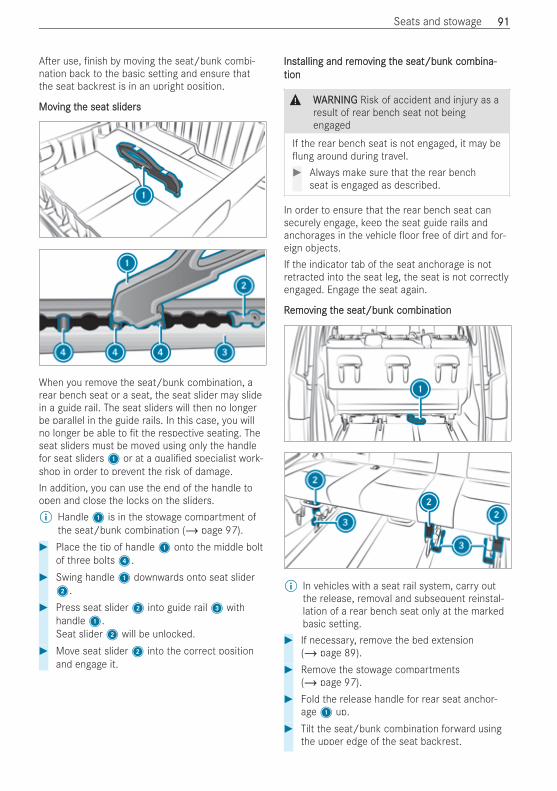
A er use, nish by moving the seat/bunk combi-nation back to the basic setting and ensure thatthe seat backrest is in an upright position.
MoMoving tving the seat slidershe seat sliders
When you remove the seat/bunk combination, arear bench seat or a seat, the seat slider may slidein a guide rail. The seat sliders will then no longerbe parallel in the guide rails. In this case, you willno longer be able to t the respective seating. Theseat sliders must be moved using only the handlefor seat sliders1 or at a quali ed specialist work-shop in order to prevent the risk of damage.In addition, you can use the end of the handle toopen and close the locks on the sliders.% Handle1 is in the stowage compartment of
the seat/bunk combination (/ page 97).# Place the tip of handle1 onto the middle bolt
of three bolts4.# Swing handle1 downwards onto seat slider2.
# Press seat slider2 into guide rail3 withhandle1.Seat slider2 will be unlocked.
# Move seat slider2 into the correct positionand engage it.
InstInstalling and ralling and remoemoving tving the seat/bunk combina-he seat/bunk combina-tiontion
& WWARNINGARNING Risk of accident and injury as aresult of rear bench seat not beingengaged
If the rear bench seat is not engaged, it may beung around during travel.# Always make sure that the rear bench
seat is engaged as described.
In order to ensure that the rear bench seat cansecurely engage, keep the seat guide rails andanchorages in the vehicle oor free of dirt and for-eign objects.If the indicator tab of the seat anchorage is notretracted into the seat leg, the seat is not correctlyengaged. Engage the seat again.
RRemoemoving tving the seat/bunk combinationhe seat/bunk combination
% In vehicles with a seat rail system, carry outthe release, removal and subsequent reinstal-lation of a rear bench seat only at the markedbasic setting.
# If necessary, remove the bed extension(/ page 89).
# Remove the stowage compartments(/ page 97).
# Fold the release handle for rear seat anchor-age1 up.
# Tilt the seat/bunk combination forward usingthe upper edge of the seat backrest.
Seats and stowage 9191
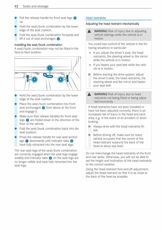
# Pull the release handle for front seat legs2up.
# Hold the seat/bunk combination by the loweredge of the seat cushion.
# Fold the seat/bunk combination forwards andli it out of seat anchorages3.
InstInstalling talling the seat/bunk combinationhe seat/bunk combinationA seat/bunk combination may not be tted in theface-to-face position.
# Hold the seat/bunk combination by the loweredge of the seat cushion.
# Place the seat/bunk combination into frontseat anchorages3 from above at the frontand engage it.
# Make sure that release handles for front seatlegs2 are folded down in the direction of theoor of the vehicle.
# Fold the seat/bunk combination back into theseat position.
# Press the release handle for rear seat anchor-age1 downwards until indicator tabs4have fully retracted into the rear seat legs.
The rear seat legs of the seat/bunk combinationare correctly engaged when the seat legs engageaudibly and indicator tabs4 on the seat legs areno longer visible and have fully retracted into theseat legs.
Head rHead resestrtraintsaints
AAdjusdjusting tting the head rhe head resestrtraint mecaint mechanicallyhanically
& WWARNINGARNING Risk of injury due to adjustingvehicle settings while the vehicle is inmotion
You could lose control of the vehicle in the fol-lowing situations in particular:R If you adjust the driver's seat, the head
restraints, the steering wheel or the mirrorwhile the vehicle is in motion.R If you fasten your seat belt while the vehi-
cle is in motion.
# Before starting the drive system: adjustthe driver's seat, the head restraints, thesteering wheel and the mirror and fastenyour seat belt.
& WWARNINGARNING Risk of injury due to headrestraints not being tted or being adjus-ted incorrectly
If head restraints have not been installed orhave not been adjusted correctly, there is anincreased risk of injury in the head and neckarea, e.g. in the event of an accident or whenbraking.# Always drive with the head restraints t-
ted.# Before driving o , make sure for every
vehicle occupant that the centre of thehead restraint supports the back of thehead at about eye level.
Do not interchange the head restraints of the frontand rear seats. Otherwise, you will not be able toset the height and inclination of the head restraintsto the correct position.Using the head restraint fore-and-a adjustment,adjust the head restraint so that it is as close tothe back of the head as possible.
9292 Seats and stowage
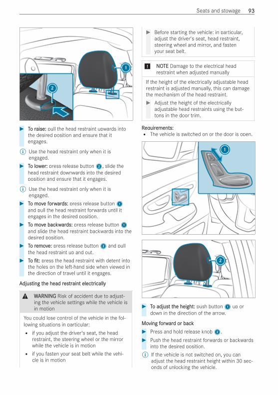
# TTo ro raise:aise: pull the head restraint upwards intothe desired position and ensure that itengages.
% Use the head restraint only when it isengaged.
# TTo lowo lowerer:: press release button2, slide thehead restraint downwards into the desiredposition and ensure that it engages.
% Use the head restraint only when it isengaged.
# TTo movo move fe forworwarards:ds: press release button1and pull the head restraint forwards until itengages in the desired position.
# TTo movo move bace backwkwarards:ds: press release button1and slide the head restraint backwards into thedesired position.
# TTo ro removemove:e: press release button2 and pullthe head restraint up and out.
# TToo t:t: press the head restraint with detent intothe holes on the le -hand side when viewed inthe direction of travel until it engages.
AAdjusdjusting tting the head rhe head resestrtraint electraint electricallyically
& WWARNINGARNING Risk of accident due to adjust-ing the vehicle settings while the vehicle isin motion
You could lose control of the vehicle in the fol-lowing situations in particular:R if you adjust the driver's seat, the head
restraint, the steering wheel or the mirrorwhile the vehicle is in motionR if you fasten your seat belt while the vehi-
cle is in motion
# Before starting the vehicle: in particular,adjust the driver's seat, head restraint,steering wheel and mirror, and fastenyour seat belt.
* NNOOTETE Damage to the electrical headrestraint when adjusted manually
If the height of the electrically adjustable headrestraint is adjusted manually, this can damagethe mechanism of the head restraint.# Adjust the height of the electrically
adjustable head restraints using the but-tons in the door trim.
RReqequiruirements:ements:R The vehicle is switched on or the door is open.
# TTo adjuso adjust tt the heighthe height:: push button1 up ordown in the direction of the arrow.
MoMoving fving forworwarard or backd or back# Press and hold release knob2.# Push the head restraint forwards or backwards
into the desired position.% If the vehicle is not switched on, you can
adjust the head restraint height within 30 sec-onds of unlocking the vehicle.
Seats and stowage 9393
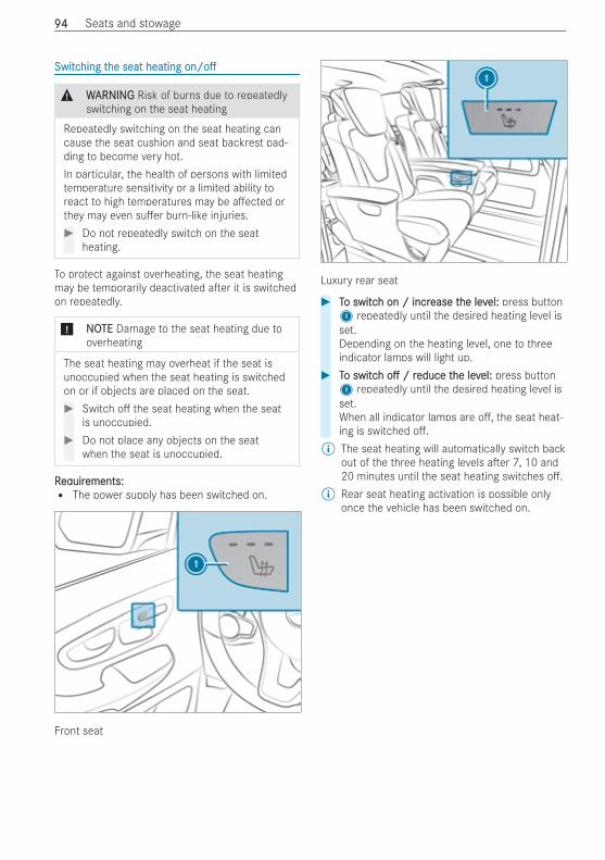
SwitcSwitching thing the seat heatinghe seat heating on/oon/o
& WWARNINGARNING Risk of burns due to repeatedlyswitching on the seat heating
Repeatedly switching on the seat heating cancause the seat cushion and seat backrest pad-ding to become very hot.In particular, the health of persons with limitedtemperature sensitivity or a limited ability toreact to high temperatures may be a ected orthey may even su er burn-like injuries.# Do not repeatedly switch on the seat
heating.
To protect against overheating, the seat heatingmay be temporarily deactivated a er it is switchedon repeatedly.
* NNOOTETE Damage to the seat heating due tooverheating
The seat heating may overheat if the seat isunoccupied when the seat heating is switchedon or if objects are placed on the seat.# Switch o the seat heating when the seat
is unoccupied.# Do not place any objects on the seat
when the seat is unoccupied.
RReqequiruirements:ements:R The power supply has been switched on.
Front seat
Luxury rear seat
# TTo switco switch on / incrh on / increase tease the levhe level:el: press button1 repeatedly until the desired heating level isset.Depending on the heating level, one to threeindicator lamps will light up.
# TTo switco switchh oo / r/ reduce teduce the levhe level:el: press button1 repeatedly until the desired heating level isset.When all indicator lamps are o , the seat heat-ing is switched o .
% The seat heating will automatically switch backout of the three heating levels a er 7, 10 and20 minutes until the seat heating switches o .
% Rear seat heating activation is possible onlyonce the vehicle has been switched on.
9494 Seats and stowage
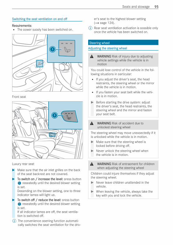
SwitcSwitching thing the seat vhe seat ventilation on andentilation on and oo
RReqequiruirements:ements:R The power supply has been switched on.
Front seat
Luxury rear seat
# Make sure that the air inlet grilles on the backof the seat backrest are not covered.
# TTo switco switch on / incrh on / increase tease the levhe level:el: press button1 repeatedly until the desired blower settingis set.Depending on the blower setting, one to threeindicator lamps will light up.
# TTo switco switchh oo / r/ reduce teduce the levhe level:el: press button1 repeatedly until the desired blower settingis set.If all indicator lamps are o , the seat ventila-tion is switched o .
% The convenience opening function automati-cally switches the seat ventilation for the driv-
er's seat to the highest blower setting(/ page 124).
% Rear seat ventilation activation is possible onlyonce the vehicle has been switched on.
SStteereering wheeling wheelAAdjusdjusting tting the sthe steereering wheeling wheel
& WWARNINGARNING Risk of injury due to adjustingvehicle settings while the vehicle is inmotion
You could lose control of the vehicle in the fol-lowing situations in particular:R If you adjust the driver's seat, the head
restraints, the steering wheel or the mirrorwhile the vehicle is in motion.R If you fasten your seat belt while the vehi-
cle is in motion.
# Before starting the drive system: adjustthe driver's seat, the head restraints, thesteering wheel and the mirror and fastenyour seat belt.
& WWARNINGARNING Risk of accident due tounlocked steering wheel
The steering wheel may move unexpectedly if itis unlocked while the vehicle is in motion.# Make sure that the steering wheel is
locked before driving o .# Never unlock the steering wheel when
the vehicle is in motion.
& WWARNINGARNING Risk of entrapment for childrenwhen adjusting the steering wheel
Children could injure themselves if they adjustthe steering wheel.# Never leave children unattended in the
vehicle.# When leaving the vehicle, always take the
key with you and lock the vehicle.
Seats and stowage 9595
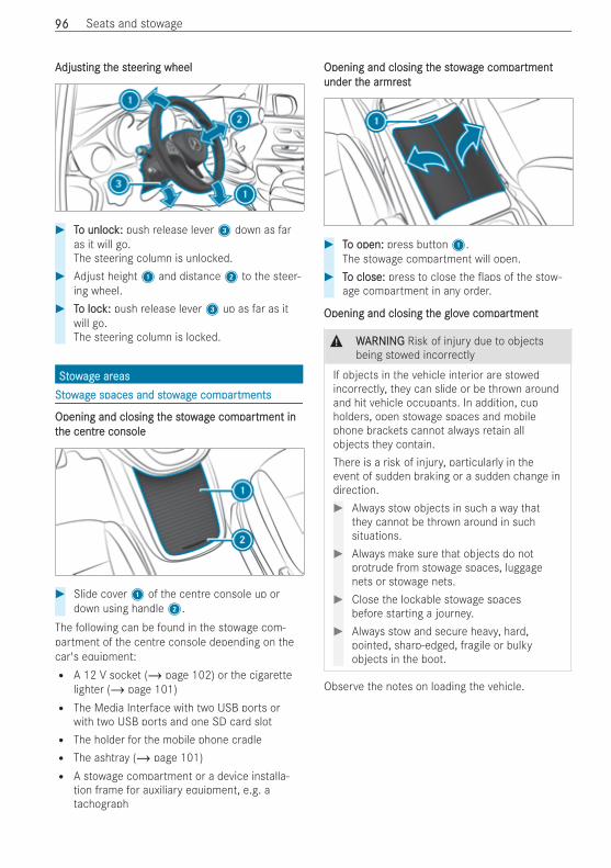
AAdjusdjusting tting the sthe steereering wheeling wheel
# TTo unloco unlock:k: push release lever3 down as faras it will go.The steering column is unlocked.
# Adjust height1 and distance2 to the steer-ing wheel.
# TTo loco lock:k: push release lever3 up as far as itwill go.The steering column is locked.
SSttoowwagage are areaseasSSttoowwagage spaces and stowe spaces and stowagage come comparpartmentstments
Opening and closing tOpening and closing the stowhe stowagage come comparpartment intment intthe centrhe centre consolee console
# Slide cover1 of the centre console up ordown using handle2.
The following can be found in the stowage com-partment of the centre console depending on thecar's equipment:R A 12 V socket (/ page 102) or the cigarette
lighter (/ page 101)R The Media Interface with two USB ports or
with two USB ports and one SD card slotR The holder for the mobile phone cradleR The ashtray (/ page 101)R A stowage compartment or a device installa-
tion frame for auxiliary equipment, e.g. atachograph
Opening and closing tOpening and closing the stowhe stowagage come comparpartmenttmentunder tunder the arhe armrmrestest
# TTo open:o open: press button1.The stowage compartment will open.
# TTo close:o close: press to close the aps of the stow-age compartment in any order.
Opening and closing tOpening and closing the glovhe glove come comparpartmenttment
& WWARNINGARNING Risk of injury due to objectsbeing stowed incorrectly
If objects in the vehicle interior are stowedincorrectly, they can slide or be thrown aroundand hit vehicle occupants. In addition, cupholders, open stowage spaces and mobilephone brackets cannot always retain allobjects they contain.There is a risk of injury, particularly in theevent of sudden braking or a sudden change indirection.# Always stow objects in such a way that
they cannot be thrown around in suchsituations.
# Always make sure that objects do notprotrude from stowage spaces, luggagenets or stowage nets.
# Close the lockable stowage spacesbefore starting a journey.
# Always stow and secure heavy, hard,pointed, sharp-edged, fragile or bulkyobjects in the boot.
Observe the notes on loading the vehicle.
9696 Seats and stowage
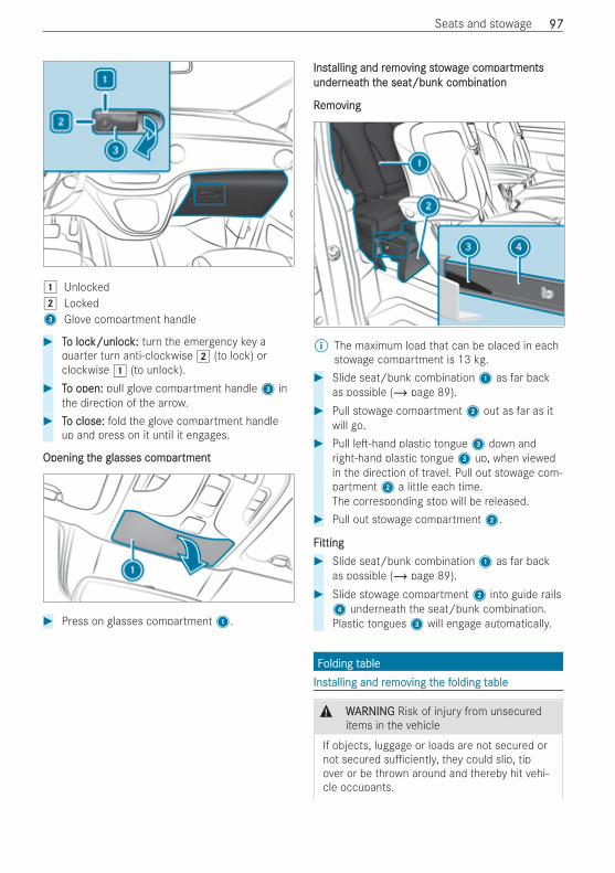
1 Unlocked2 Locked3 Glove compartment handle
# TTo loco lock/unlock/unlock:k: turn the emergency key aquarter turn anti-clockwise 2 (to lock) orclockwise 1 (to unlock).
# TTo open:o open: pull glove compartment handle3 inthe direction of the arrow.
# TTo close:o close: fold the glove compartment handleup and press on it until it engages.
Opening tOpening the glasses comhe glasses comparpartmenttment
# Press on glasses compartment1.
InstInstalling and ralling and remoemoving stowving stowagage come comparpartmentstmentsunderunderneatneath th the seat/bunk combinationhe seat/bunk combination
RRemoemovingving
% The maximum load that can be placed in eachstowage compartment is 13 kg.
# Slide seat/bunk combination1 as far backas possible (/ page 89).
# Pull stowage compartment2 out as far as itwill go.
# Pull le -hand plastic tongue3 down andright-hand plastic tongue3 up, when viewedin the direction of travel. Pull out stowage com-partment2 a little each time.The corresponding stop will be released.
# Pull out stowage compartment2.
FFittingitting# Slide seat/bunk combination1 as far back
as possible (/ page 89).# Slide stowage compartment2 into guide rails4 underneath the seat/bunk combination.Plastic tongues3 will engage automatically.
FFolding tolding tableableInstInstalling and ralling and remoemoving tving the fhe folding tolding tableable
& WWARNINGARNING Risk of injury from unsecureditems in the vehicle
If objects, luggage or loads are not secured ornot secured su ciently, they could slip, tipover or be thrown around and thereby hit vehi-cle occupants.
Seats and stowage 9797
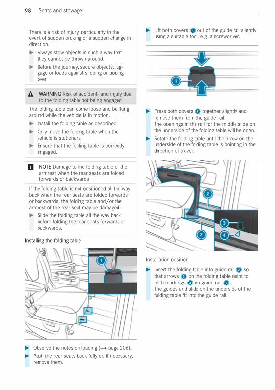
There is a risk of injury, particularly in theevent of sudden braking or a sudden change indirection.# Always stow objects in such a way that
they cannot be thrown around.# Before the journey, secure objects, lug-
gage or loads against slipping or tippingover.
& WWARNINGARNING Risk of accident‑ and injury dueto the folding table not being engaged
The folding table can come loose and be ungaround while the vehicle is in motion.# Install the folding table as described.# Only move the folding table when the
vehicle is stationary.# Ensure that the folding table is correctly
engaged.
* NNOOTETE Damage to the folding table or thearmrest when the rear seats are foldedforwards or backwards
If the folding table is not positioned all the wayback when the rear seats are folded forwardsor backwards, the folding table and/or thearmrest of the rear seat may be damaged.# Slide the folding table all the way back
before folding the rear seats forwards orbackwards.
InstInstalling talling the fhe folding tolding tableable
# Observe the notes on loading (/ page 206).# Push the rear seats back fully or, if necessary,
remove them.
# Li both covers1 out of the guide rail slightlyusing a suitable tool, e.g. a screwdriver.
# Press both covers1 together slightly andremove them from the guide rail.The openings in the rail for the middle slide onthe underside of the folding table will be open.
# Rotate the folding table until the arrow on theunderside of the folding table is pointing in thedirection of travel.
Installation position
# Insert the folding table into guide rail2 sothat arrows3 on the folding table point toboth markings4 on guide rail2.The guides and slide on the underside of thefolding table t into the guide rail.
9898 Seats and stowage
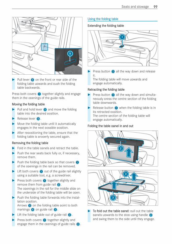
# Pull lever5 on the front or rear side of thefolding table upwards and push the foldingtable backwards.
Press both covers1 together slightly and engagethem in the openings of the guide rails.
MoMoving tving the fhe folding tolding tableable# Pull and hold lever5 and move the folding
table into the desired position.# Release lever5.# Move the folding table until it automatically
engages in the next possible position.# A er repositioning the table, ensure that the
folding table is properly secured again.
RRemoemoving tving the fhe folding tolding tableable# Fold in the table panels and retract the table.# Push the rear seats back fully or, if necessary,
remove them.# Push the folding table back so that covers1
of the openings in the rail can be removed.# Li both covers1 out of the guide rail slightly
using a suitable tool, e.g. a screwdriver.# Press both covers1 together slightly and
remove them from guide rail2.The openings in the rail for the middle slide onthe underside of the folding table will be open.
# Push the folding table forwards into the instal-lation position.Arrows3 on the folding table point to bothmarkings4 on guide rail2.
# Li the folding table out of guide rail2.# Press both covers1 together slightly and
engage them in the openings of guide rails2.
Using tUsing the fhe folding tolding tableable
ExtExtending tending the fhe folding tolding tableable
# Press button1 all the way down and releaseit.The folding table will move upwards andengage automatically.
RReetrtracting tacting the fhe folding tolding tableable# Press button1 all the way down and simulta-
neously press the centre section of the foldingtable downwards.
# Release button1 when the folding table is inits retracted position.The centre section of the folding table willengage automatically.
FFolding tolding the the table panel in and outable panel in and out
# TTo fo fold out told out the the table panel:able panel: pull out the tablepanels upwards to the stop using handle2and swing them to the side until they engage.
Seats and stowage 9999
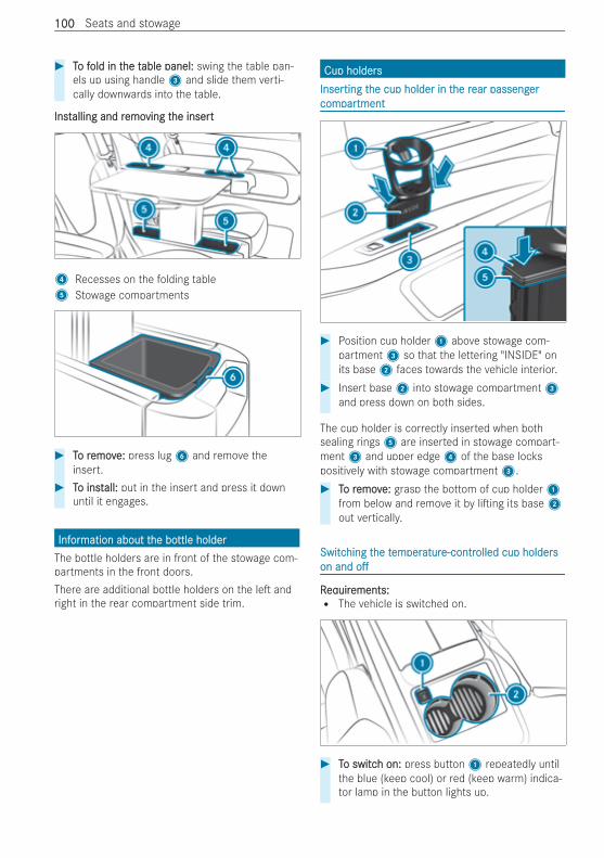
# TTo fo fold in told in the the table panel:able panel: swing the table pan-els up using handle3 and slide them verti-cally downwards into the table.
InstInstalling and ralling and remoemoving tving the inserthe insert
4 Recesses on the folding table5 Stowage compartments
# TTo ro removemove:e: press lug6 and remove theinsert.
# TTo insto install:all: put in the insert and press it downuntil it engages.
InfInforormation about tmation about the bohe bottle holderttle holderThe bottle holders are in front of the stowage com-partments in the front doors.There are additional bottle holders on the le andright in the rear compartment side trim.
Cup holdersCup holdersInserInserting tting the cup holder in the cup holder in the rhe rear passengear passengerercomcomparpartmenttment
# Position cup holder1 above stowage com-partment3 so that the lettering "INSIDE" onits base2 faces towards the vehicle interior.
# Insert base2 into stowage compartment3and press down on both sides.
The cup holder is correctly inserted when bothsealing rings5 are inserted in stowage compart-ment3 and upper edge4 of the base lockspositively with stowage compartment3.# TTo ro removemove:e: grasp the bottom of cup holder1
from below and remove it by li ing its base2out vertically.
SwitcSwitching thing the the tememperperaturature-contre-controlled cup holdersolled cup holderson andon and oo
RReqequiruirements:ements:R The vehicle is switched on.
# TTo switco switch on:h on: press button1 repeatedly untilthe blue (keep cool) or red (keep warm) indica-tor lamp in the button lights up.
100100 Seats and stowage
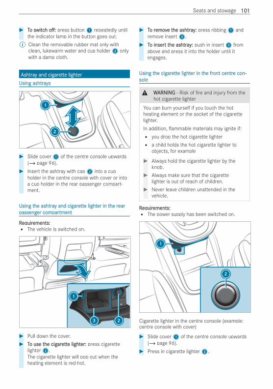
# TTo switco switchh o :o : press button1 repeatedly untilthe indicator lamp in the button goes out.
% Clean the removable rubber mat only withclean, lukewarm water and cup holder2 onlywith a damp cloth.
AshtraAshtray and cigy and cigarearetttte lighte lightererUsing ashtraysUsing ashtrays
# Slide cover1 of the centre console upwards(/ page 96).
# Insert the ashtray with cap2 into a cupholder in the centre console with cover or intoa cup holder in the rear passenger compart-ment.
Using tUsing the ashtrahe ashtray and cigy and cigarearetttte lighte lighter in ter in the rhe rearearpassengpassenger comer comparpartmenttment
RReqequiruirements:ements:R The vehicle is switched on.
# Pull down the cover.# TTo use to use the cighe cigarearetttte lighte lighterer:: press cigarette
lighter2.The cigarette lighter will pop out when theheating element is red-hot.
# TTo ro removemove te the ashtrayhe ashtray:: press ribbing1 andremove insert3.
# TTo insero insert tt the ashtrayhe ashtray:: push in insert3 fromabove and press it into the holder until itengages.
Using tUsing the cighe cigarearetttte lighte lighter in ter in the frhe front centront centre con-e con-solesole
& WWARNINGARNING ‑ Risk of re and injury from thehot cigarette lighter
You can burn yourself if you touch the hotheating element or the socket of the cigarettelighter.In addition, ammable materials may ignite if:R you drop the hot cigarette lighterR a child holds the hot cigarette lighter to
objects, for example
# Always hold the cigarette lighter by theknob.
# Always make sure that the cigarettelighter is out of reach of children.
# Never leave children unattended in thevehicle.
RReqequiruirements:ements:R The power supply has been switched on.
Cigarette lighter in the centre console (example:centre console with cover)
# Slide cover1 of the centre console upwards(/ page 96).
# Press in cigarette lighter2.
Seats and stowage 101101
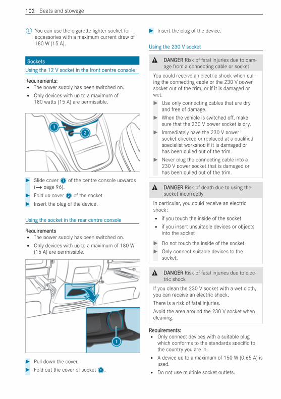
% You can use the cigarette lighter socket foraccessories with a maximum current draw of180 W (15 A).
SockeSocketstsUsing tUsing the 12 V sockehe 12 V socket in tt in the frhe front centront centre consolee console
RReqequiruirements:ements:R The power supply has been switched on.R Only devices with up to a maximum of
180 watts (15 A) are permissible.
# Slide cover1 of the centre console upwards(/ page 96).
# Fold up cover2 of the socket.# Insert the plug of the device.
Using tUsing the sockehe socket in tt in the rhe rear centrear centre consolee console
RReqequiruirementsementsR The power supply has been switched on.R Only devices with up to a maximum of 180 W
(15 A) are permissible.
# Pull down the cover.# Fold out the cover of socket1.
# Insert the plug of the device.
Using tUsing the 230 V sockethe 230 V socket
& DDANANGERGER Risk of fatal injuries due to dam-age from a connecting cable or socket
You could receive an electric shock when pull-ing the connecting cable or the 230 V powersocket out of the trim, or if it is damaged orwet.# Use only connecting cables that are dry
and free of damage.# When the vehicle is switched o , make
sure that the 230 V power socket is dry.# Immediately have the 230 V power
socket checked or replaced at a quali edspecialist workshop if it is damaged orhas been pulled out of the trim.
# Never plug the connecting cable into a230 V power socket that is damaged orhas been pulled out of the trim.
& DDANANGERGER Risk of death due to using thesocket incorrectly
In particular, you could receive an electricshock:R if you touch the inside of the socketR if you insert unsuitable devices or objects
into the socket
# Do not touch the inside of the socket.# Only connect suitable devices to the
socket.
& DDANANGERGER Risk of fatal injuries due to elec-tric shock
If you clean the 230 V socket with a wet cloth,you can receive an electric shock.There is a risk of fatal injuries.Avoid the area around the 230 V socket whencleaning.
RReqequiruirements:ements:R Only connect devices with a suitable plug
which conforms to the standards speci c tothe country you are in.R A device up to a maximum of 150 W (0.65 A) is
used.R Do not use multiple socket outlets.
102102 Seats and stowage
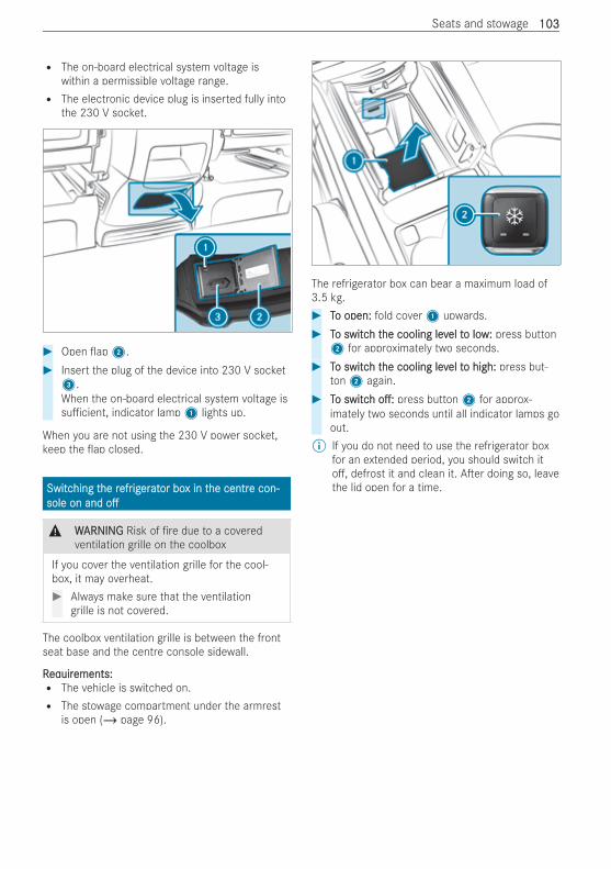
R The on-board electrical system voltage iswithin a permissible voltage range.R The electronic device plug is inserted fully into
the 230 V socket.
# Open ap2.# Insert the plug of the device into 230 V socket3.When the on-board electrical system voltage issu cient, indicator lamp1 lights up.
When you are not using the 230 V power socket,keep the ap closed.
SwitcSwitching thing the rhe refrefrigigereratator boor box in tx in the centrhe centre con-e con-sole on andsole on and oo
& WWARNINGARNING Risk of re due to a coveredventilation grille on the coolbox
If you cover the ventilation grille for the cool-box, it may overheat.# Always make sure that the ventilation
grille is not covered.
The coolbox ventilation grille is between the frontseat base and the centre console sidewall.
RReqequiruirements:ements:R The vehicle is switched on.R The stowage compartment under the armrest
is open (/ page 96).
The refrigerator box can bear a maximum load of3.5 kg.# TTo open:o open: fold cover1 upwards.# TTo switco switch th the cooling levhe cooling level tel to low:o low: press button2 for approximately two seconds.
# TTo switco switch th the cooling levhe cooling level tel to high:o high: press but-ton2 again.
# TTo switco switchh o :o : press button2 for approx-imately two seconds until all indicator lamps goout.
% If you do not need to use the refrigerator boxfor an extended period, you should switch ito , defrost it and clean it. A er doing so, leavethe lid open for a time.
Seats and stowage 103103
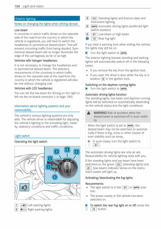
ExtExtererior lightingior lightingNNoottes on ces on changing thanging the lights when drhe lights when driving abriving abroadoad
LoLow beamw beamIn countries in which tra c drives on the oppositeside of the road from the country in which thevehicle is registered, you will have to switch theheadlamps to symmetrical dipped beam. This willprevent oncoming tra c from being dazzled. Sym-metrical dipped beam will no longer illuminate theedge of the carriageway as far or as high.VVehicles witehicles with halogh halogen headlamen headlamps:ps:It is not necessary to change the headlamps overto symmetrical dipped beam. The statutoryrequirements of the countries in which tra cdrives on the opposite side of the road from thecountry in which the vehicle is registered will alsobe met without changing over.VVehicles witehicles with LED headlamh LED headlamps:ps:You can set the low beam for driving on the right orle via the on-board computer (/ page 180).
InfInforormation about lighting systmation about lighting systems and yems and yourourrresponsibilityesponsibility
The vehicle's various lighting systems are onlyaids. The vehicle driver is responsible for adjustingthe vehicle's lighting to the prevailing light, visibil-ity, statutory conditions and tra c conditions.
Light switchLight switch
OperOperating tating the light switchhe light switch
1 W Le parking lights2 X Right parking lights
3 T Standing lights and licence plate andinstrument lighting
4 Ã Automatic driving lights (preferred lightswitch position)
5 L Low beam or high beam6 R Rear fog light
If you hear a warning tone when exiting the vehicle,the lights may still be on.# Turn the light switch to Ã.The exterior lighting (except standing and parkinglights) will automatically switch o in the followingcases:R If you remove the key from the ignition lock.R if you open the driver's door while the key is in
position g in the ignition lock.
SwitcSwitching on thing on the dahe daytime rytime running lightsunning lights# Turn the light switch to Ã.
AAututomatic dromatic driving lights functioniving lights functionThe standing lights, low beam and daytime runninglights will be switched on automatically dependingon the vehicle status and the light conditions.
& WWARNINGARNING Risk of accident when thedipped beam is switched o in poor visibil-ity
When the light switch is set to Ã, thedipped beam may not be switched on automat-ically if there is fog, snow or other causes ofpoor visibility such as spray.# In such cases, turn the light switch to
L.
The automatic driving lights are only an aid.Responsibility for vehicle lighting rests with you.If the standing lights and low beam have beenswitched on, the green T (standing lights) andL (low beam) indicator lamps on the instru-ment cluster will light up.
AActivctivating/deactivating/deactivating tating the fhe fog lightsog lights
RReqequiruirements:ements:R The light switch is in the L or à posi-
tion.R The power supply or the vehicle has been
switched on.
# TTo switco switch th the rhe rear fear fog light on orog light on or o :o : press theR button.
104104 Light and vision
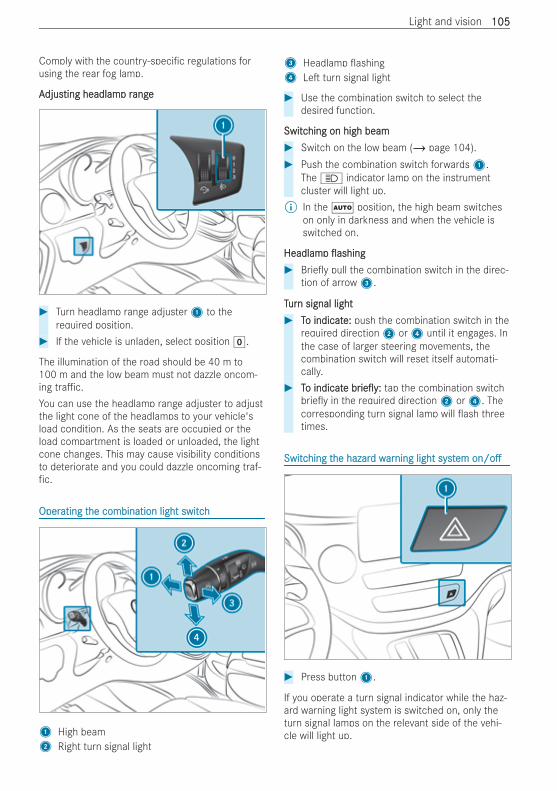
Comply with the country-speci c regulations forusing the rear fog lamp.
AAdjusdjusting headlamting headlamp rp rangeange
# Turn headlamp range adjuster1 to therequired position.
# If the vehicle is unladen, select position g.
The illumination of the road should be 40 m to100 m and the low beam must not dazzle oncom-ing tra c.You can use the headlamp range adjuster to adjustthe light cone of the headlamps to your vehicle'sload condition. As the seats are occupied or theload compartment is loaded or unloaded, the lightcone changes. This may cause visibility conditionsto deteriorate and you could dazzle oncoming traf-fic.
OperOperating tating the combination light switchhe combination light switch
1 High beam2 Right turn signal light
3 Headlamp ashing4 Le turn signal light
# Use the combination switch to select thedesired function.
SwitcSwitching on high beamhing on high beam# Switch on the low beam (/ page 104).# Push the combination switch forwards1.
The K indicator lamp on the instrumentcluster will light up.
% In the à position, the high beam switcheson only in darkness and when the vehicle isswitched on.
HeadlamHeadlampp ashingashing# Brie y pull the combination switch in the direc-
tion of arrow3.
TTururn signal lightn signal light# TTo indicato indicate:e: push the combination switch in the
required direction2 or4 until it engages. Inthe case of larger steering movements, thecombination switch will reset itself automati-cally.
# TTo indicato indicatee brbrie y:ie y: tap the combination switchbrie y in the required direction2 or4. Thecorresponding turn signal lamp will ash threetimes.
SwitcSwitching thing the hazarhe hazard wd wararning light systning light systemem on/oon/o
# Press button1.
If you operate a turn signal indicator while the haz-ard warning light system is switched on, only theturn signal lamps on the relevant side of the vehi-cle will light up.
Light and vision 105105
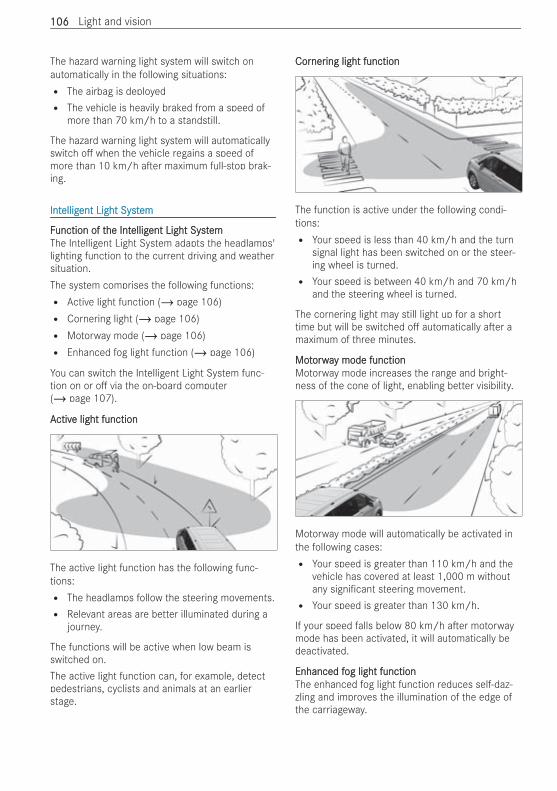
The hazard warning light system will switch onautomatically in the following situations:R The airbag is deployedR The vehicle is heavily braked from a speed of
more than 70 km/h to a standstill.
The hazard warning light system will automaticallyswitch o when the vehicle regains a speed ofmore than 10 km/h a er maximum full-stop brak-ing.
IntIntelligelligent Light Systent Light Systemem
FFunction of tunction of the Inthe Intelligelligent Light Systent Light SystememThe Intelligent Light System adapts the headlamps'lighting function to the current driving and weathersituation.The system comprises the following functions:R Active light function (/ page 106)R Cornering light (/ page 106)R Motorway mode (/ page 106)R Enhanced fog light function (/ page 106)
You can switch the Intelligent Light System func-tion on or o via the on-board computer(/ page 107).
AActivctive light functione light function
The active light function has the following func-tions:R The headlamps follow the steering movements.R Relevant areas are better illuminated during a
journey.
The functions will be active when low beam isswitched on.The active light function can, for example, detectpedestrians, cyclists and animals at an earlierstage.
CorCornernering light functioning light function
The function is active under the following condi-tions:R Your speed is less than 40 km/h and the turn
signal light has been switched on or the steer-ing wheel is turned.R Your speed is between 40 km/h and 70 km/h
and the steering wheel is turned.
The cornering light may still light up for a shorttime but will be switched o automatically a er amaximum of three minutes.
MotMotorwaorway mode functiony mode functionMotorway mode increases the range and bright-ness of the cone of light, enabling better visibility.
Motorway mode will automatically be activated inthe following cases:R Your speed is greater than 110 km/h and the
vehicle has covered at least 1,000 m withoutany signi cant steering movement.R Your speed is greater than 130 km/h.
If your speed falls below 80 km/h a er motorwaymode has been activated, it will automatically bedeactivated.
Enhanced fEnhanced fog light functionog light functionThe enhanced fog light function reduces self-daz-zling and improves the illumination of the edge ofthe carriageway.
106106 Light and vision
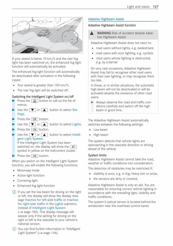
If your speed is below 70 km/h and the rear foglight has been switched on, the enhanced fog lightfunction will automatically be activated.The enhanced fog light function will automaticallybe deactivated a er activation in the followingcases:R Your speed is greater than 100 km/h.R The rear fog light will be switched o .
SwitcSwitching thing the Inthe Intelligelligent Light Systent Light Systemem on/oon/o# Press the ò button to call up the list of
menus.# Use the : or 9 button to select Set-
tings.# Press the a button.# Use the : or 9 button to select Lights.# Press the a button.# Use the : or 9 button to select Intelli-
gent Light System.If the Intelligent Light System has beenswitched on, the display will show the Lsymbol in yellow on the instrument cluster.
# Press the a button.When you switch on the Intelligent Light Systemfunction, you will enable the following functions:R Motorway modeR Active light functionR Cornering lightR Enhanced fog light function
% If you set the low beam for driving on the rightor le , the display will show the display mes-sage Inactive for left-side traffic or Inactivefor right-side traffic in the Lights submenuinstead of Intelligent Light System(/ page 180). This display message willappear only if the setting for driving on theright or le is the opposite to your vehicle'snational version.
% You can nd further information in "IntelligentLight System" (/ page 106).
AAdapdaptivtive Highbeam Assiste Highbeam Assist
AAdapdaptivtive Highbeam Assise Highbeam Assist functiont function
& WWARNINGARNING Risk of accident despite Adap-tive Highbeam Assist
Adaptive Highbeam Assist does not react to:R road users without lights, e.g. pedestriansR road users with poor lighting, e.g. cyclistsR road users whose lighting is obstructed,
e.g. by a barrier
On very rare occasions, Adaptive HighbeamAssist may fail to recognise other road userswith their own lighting, or may recognise themtoo late.In these, or in similar situations, the automatichigh beam will not be deactivated or will beactivated despite the presence of other roadusers.# Always observe the road and tra c con-
ditions carefully and switch o the highbeam in good time.
The Adaptive Highbeam Assist automaticallyswitches between the following settings:R Low beamR High beam
The system detects that vehicle lights areapproaching in the opposite direction or drivingahead of the vehicle.
SystSystem limitsem limitsAdaptive Highbeam Assist cannot take the road,weather or tra c conditions into consideration.The detection of obstacles may be restricted if:R visibility is poor, e.g. in fog, heavy rain or snow.R the sensors are dirty or covered.
Adaptive Highbeam Assist is only an aid. You areresponsible for ensuring correct vehicle lighting inaccordance with the prevailing light, visibility andtra c conditions.The system's optical sensor is located behind thewindscreen near the overhead control panel.
Light and vision 107107
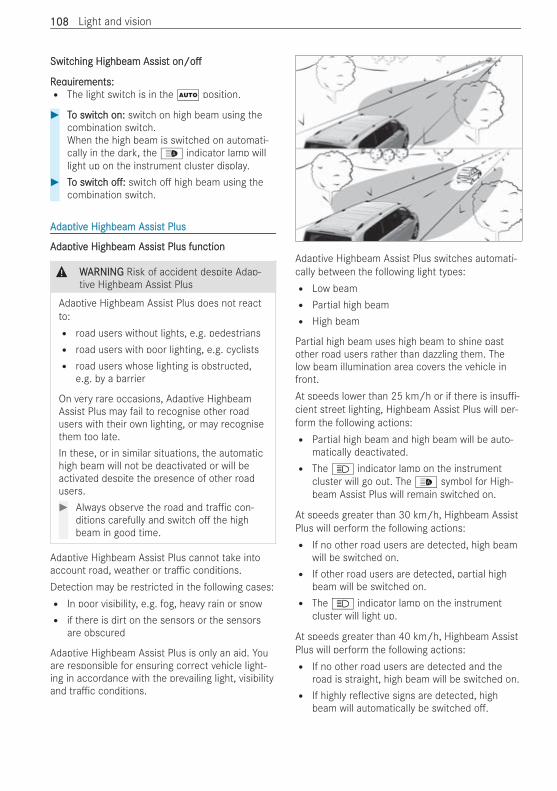
SwitcSwitching Highbeam Assishing Highbeam Assistt on/oon/o
RReqequiruirements:ements:R The light switch is in the à position.
# TTo switco switch on:h on: switch on high beam using thecombination switch.When the high beam is switched on automati-cally in the dark, the _ indicator lamp willlight up on the instrument cluster display.
# TTo switco switchh o :o : switch o high beam using thecombination switch.
AAdapdaptivtive Highbeam Assise Highbeam Assist Plust Plus
AAdapdaptivtive Highbeam Assise Highbeam Assist Plus functiont Plus function
& WWARNINGARNING Risk of accident despite Adap-tive Highbeam Assist Plus
Adaptive Highbeam Assist Plus does not reactto:R road users without lights, e.g. pedestriansR road users with poor lighting, e.g. cyclistsR road users whose lighting is obstructed,
e.g. by a barrier
On very rare occasions, Adaptive HighbeamAssist Plus may fail to recognise other roadusers with their own lighting, or may recognisethem too late.In these, or in similar situations, the automatichigh beam will not be deactivated or will beactivated despite the presence of other roadusers.# Always observe the road and tra c con-
ditions carefully and switch o the highbeam in good time.
Adaptive Highbeam Assist Plus cannot take intoaccount road, weather or tra c conditions.Detection may be restricted in the following cases:R In poor visibility, e.g. fog, heavy rain or snowR if there is dirt on the sensors or the sensors
are obscured
Adaptive Highbeam Assist Plus is only an aid. Youare responsible for ensuring correct vehicle light-ing in accordance with the prevailing light, visibilityand tra c conditions.
Adaptive Highbeam Assist Plus switches automati-cally between the following light types:R Low beamR Partial high beamR High beam
Partial high beam uses high beam to shine pastother road users rather than dazzling them. Thelow beam illumination area covers the vehicle infront.At speeds lower than 25 km/h or if there is insu -cient street lighting, Highbeam Assist Plus will per-form the following actions:R Partial high beam and high beam will be auto-
matically deactivated.R The K indicator lamp on the instrument
cluster will go out. The _ symbol for High-beam Assist Plus will remain switched on.
At speeds greater than 30 km/h, Highbeam AssistPlus will perform the following actions:R If no other road users are detected, high beam
will be switched on.R If other road users are detected, partial high
beam will be switched on.R The K indicator lamp on the instrument
cluster will light up.
At speeds greater than 40 km/h, Highbeam AssistPlus will perform the following actions:R If no other road users are detected and the
road is straight, high beam will be switched on.R If highly re ective signs are detected, high
beam will automatically be switched o .
108108 Light and vision
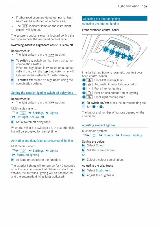
R If other road users are detected, partial highbeam will be switched on automatically.R The K indicator lamp on the instrument
cluster will light up.
The system's optical sensor is located behind thewindscreen near the overhead control panel.
SwitcSwitching Ahing Adapdaptivtive Highbeam Assise Highbeam Assist Plust Plus on/oon/o
RReqequiruirements:ements:R The light switch is in the à position.
# TTo switco switch on:h on: switch on high beam using thecombination switch.When the high beam is switched on automati-cally in the dark, the _ indicator lamp willlight up on the instrument cluster display.
# TTo switco switchh o :o : switch o high beam using thecombination switch.
SeSetting ttting the ehe extxtererior lightingior lighting switcswitch-oh-o deladelay timey time
RReqequiruirements:ements:R The light switch is in the à position.
Multimedia system:4© 5 Settings 5 Lights5 Ext. light. del. sw. off# Set a switch-o delay time.
When the vehicle is switched o , the exterior light-ing will be activated for the set time.
AActivctivating and deactivating and deactivating tating the surrhe surround lightingound lighting
Multimedia system:4© 5 Settings 5 Lights5 Surround lighting# Activate or deactivate the function.
The exterior lighting will remain on for 40 secondsa er the vehicle is unlocked. When you start thevehicle, the surround lighting will be deactivatedand the automatic driving lights activated.
AAdjusdjusting tting the inthe intererior lightingior lightingAAdjusdjusting tting the inthe intererior lightingior lighting
FFrront ovont overerhead contrhead control panelol panel
Interior lighting buttons (example: comfort over-head control panel)1p Front-le reading lamp2| Automatic interior lighting control3c Front interior lighting4w Rear or load compartment lighting5p Front-right reading lamp
# TTo switco switchh on/o :on/o : press the corresponding but-ton1 –5.
The layout and number of buttons depend on theequipment.
AAdjusdjusting ambient lightingting ambient lighting
Multimedia system:4© 5 Comfort 5 Ambient lighting
SeSetting ttting the colourhe colour# Select Colour.# Set the required colour.or# Select a colour combination.
AAdjusdjusting tting the brhe brightnessightness# Select Brightness.# Adjust the brightness.
Light and vision 109109
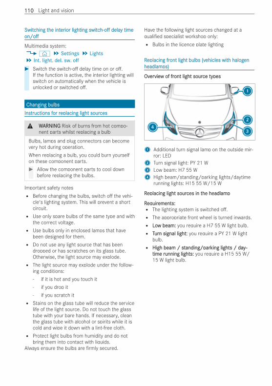
SwitcSwitching thing the inthe intererior lightingior lighting switcswitch-oh-o deladelay timey timeon/oon/o
Multimedia system:4© 5 Settings 5 Lights5 Int. light. del. sw. off# Switch the switch-o delay time on or o .
If the function is active, the interior lighting willswitch on automatically when the vehicle isunlocked or switched o .
Changing bulbsChanging bulbsInsInstrtructions fuctions for ror replacing light soureplacing light sourcesces
& WWARNINGARNING Risk of burns from hot compo-nent parts whilst replacing a bulb
Bulbs, lamps and plug connectors can becomevery hot during operation.When replacing a bulb, you could burn yourselfon these component parts.# Allow the component parts to cool down
before replacing the bulbs.
Important safety notesR Before changing the bulbs, switch o the vehi-
cle's lighting system. This will prevent a shortcircuit.R Use only spare bulbs of the same type and with
the correct voltage.R Use bulbs only in enclosed lamps that have
been designed for them.R Do not use any light source that has been
dropped or has scratches on its glass tube.Otherwise, the light source may explode.R The light source may explode under the follow-
ing conditions:- if it is hot and you touch it- if you drop it- if you scratch itR Stains on the glass tube will reduce the service
life of the light source. Do not touch the glasstube with your bare hands. If necessary, cleanthe glass tube with alcohol or spirits while it iscold and wipe it down with a lint-free cloth.R Protect light bulbs from humidity and do not
bring them into contact with liquids.Always ensure the bulbs are rmly secured.
Have the following light sources changed at aquali ed specialist workshop only:R Bulbs in the licence plate lighting
RReplacing freplacing front light bulbs (vont light bulbs (vehicles witehicles with halogh halogenenheadlamheadlamps)ps)
OvOverervieview of frw of front light souront light source typesce types
1 Additional turn signal lamp on the outside mir-ror: LED
2 Turn signal light: PY 21 W3 Low beam: H7 55 W4 High beam/standing/parking lights/daytime
running lights: H15 55 W/15 W
RReplacing light soureplacing light sources in tces in the headlamphe headlamp
RReqequiruirements:ements:R The lighting system is switched o .R The appropriate front wheel is turned inwards.R LoLow beam:w beam: you require a H7 55 W light bulb.R TTururn signal lightn signal light:: you require a PY 21 W light
bulb.R High beam / stHigh beam / standing/paranding/parking lights / day-king lights / day-
time rtime running lights:unning lights: you require a H15 55 W/15 W light bulb.
110110 Light and vision
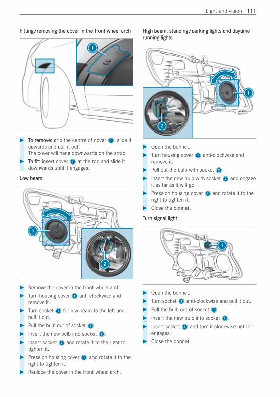
FFitting/ritting/remoemoving tving the covhe cover in ter in the frhe front wheel archont wheel arch
# TTo ro removemove:e: grip the centre of cover1, slide itupwards and pull it out.The cover will hang downwards on the strap.
# TToo t:t: insert cover1 at the top and slide itdownwards until it engages.
LoLow beamw beam
# Remove the cover in the front wheel arch.# Turn housing cover1 anti-clockwise and
remove it.# Turn socket2 for low beam to the le and
pull it out.# Pull the bulb out of socket2.# Insert the new bulb into socket2.# Insert socket2 and rotate it to the right to
tighten it.# Press on housing cover1 and rotate it to the
right to tighten it.# Replace the cover in the front wheel arch.
High beam, stHigh beam, standing/paranding/parking lights and daking lights and daytimeytimerrunning lightsunning lights
# Open the bonnet.# Turn housing cover1 anti-clockwise and
remove it.# Pull out the bulb with socket2.# Insert the new bulb with socket2 and engage
it as far as it will go.# Press on housing cover1 and rotate it to the
right to tighten it.# Close the bonnet.
TTururn signal lightn signal light
# Open the bonnet.# Turn socket1 anti-clockwise and pull it out.# Pull the bulb out of socket1.# Insert the new bulb into socket1.# Insert socket1 and turn it clockwise until it
engages.# Close the bonnet.
Light and vision 111111
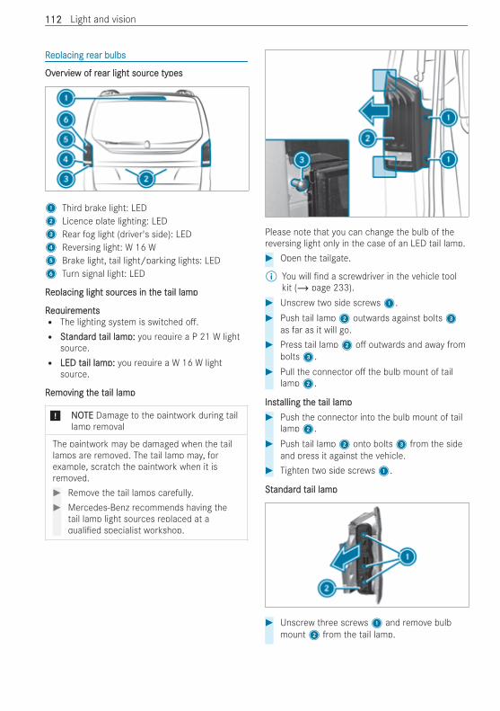
RReplacing replacing rear bulbsear bulbs
OvOverervieview of rw of rear light sourear light source typesce types
1 Third brake light: LED2 Licence plate lighting: LED3 Rear fog light (driver's side): LED4 Reversing light: W 16 W5 Brake light, tail light/parking lights: LED6 Turn signal light: LED
RReplacing light soureplacing light sources in tces in the the tail lampail lamp
RReqequiruirementsementsR The lighting system is switched o .R StStandarandard td tail lamail lamp:p: you require a P 21 W light
source.R LED tLED tail lamail lamp:p: you require a W 16 W light
source.
RRemoemoving tving the the tail lampail lamp
* NONOTETE Damage to the paintwork during taillamp removal
The paintwork may be damaged when the taillamps are removed. The tail lamp may, forexample, scratch the paintwork when it isremoved.# Remove the tail lamps carefully.# Mercedes-Benz recommends having the
tail lamp light sources replaced at aquali ed specialist workshop.
Please note that you can change the bulb of thereversing light only in the case of an LED tail lamp.# Open the tailgate.
% You will nd a screwdriver in the vehicle toolkit (/ page 233).
# Unscrew two side screws1.# Push tail lamp2 outwards against bolts3
as far as it will go.# Press tail lamp2 o outwards and away from
bolts3.# Pull the connector o the bulb mount of tail
lamp2.
InstInstalling talling the the tail lampail lamp# Push the connector into the bulb mount of tail
lamp2.# Push tail lamp2 onto bolts3 from the side
and press it against the vehicle.# Tighten two side screws1.
SSttandarandard td tail lampail lamp
# Unscrew three screws1 and remove bulbmount2 from the tail lamp.
112112 Light and vision
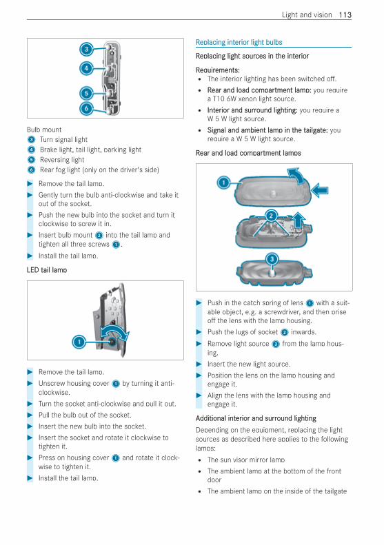
Bulb mount3 Turn signal light4 Brake light, tail light, parking light5 Reversing light6 Rear fog light (only on the driver's side)
# Remove the tail lamp.# Gently turn the bulb anti-clockwise and take it
out of the socket.# Push the new bulb into the socket and turn it
clockwise to screw it in.# Insert bulb mount2 into the tail lamp and
tighten all three screws1.# Install the tail lamp.
LED tLED tail lampail lamp
# Remove the tail lamp.# Unscrew housing cover1 by turning it anti-
clockwise.# Turn the socket anti-clockwise and pull it out.# Pull the bulb out of the socket.# Insert the new bulb into the socket.# Insert the socket and rotate it clockwise to
tighten it.# Press on housing cover1 and rotate it clock-
wise to tighten it.# Install the tail lamp.
RReplacing inteplacing intererior light bulbsior light bulbs
RReplacing light soureplacing light sources in tces in the inthe intereriorior
RReqequiruirements:ements:R The interior lighting has been switched o .R RRear and load comear and load comparpartment lamtment lamp:p: you require
a T10 6W xenon light source.R IntIntererior and surrior and surround lighting:ound lighting: you require a
W 5 W light source.R Signal and ambient lamSignal and ambient lamp in tp in the the tailgailgatate:e: you
require a W 5 W light source.
RRear and load comear and load comparpartment lamtment lampsps
# Push in the catch spring of lens1 with a suit-able object, e.g. a screwdriver, and then priseo the lens with the lamp housing.
# Push the lugs of socket2 inwards.# Remove light source3 from the lamp hous-
ing.# Insert the new light source.# Position the lens on the lamp housing and
engage it.# Align the lens with the lamp housing and
engage it.
AAdditional intdditional intererior and surrior and surround lightingound lightingDepending on the equipment, replacing the lightsources as described here applies to the followinglamps:R The sun visor mirror lampR The ambient lamp at the bottom of the front
doorR The ambient lamp on the inside of the tailgate
Light and vision 113113
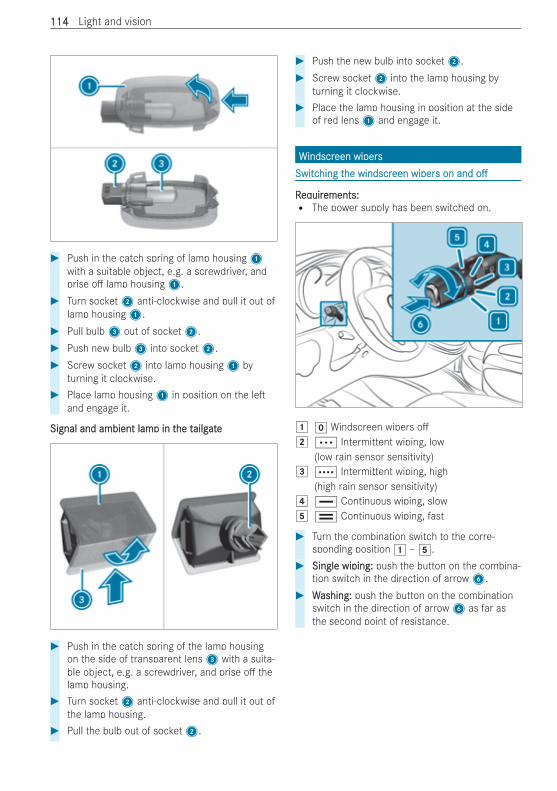
# Push in the catch spring of lamp housing1with a suitable object, e.g. a screwdriver, andprise o lamp housing1.
# Turn socket2 anti-clockwise and pull it out oflamp housing1.
# Pull bulb3 out of socket2.# Push new bulb3 into socket2.# Screw socket2 into lamp housing1 by
turning it clockwise.# Place lamp housing1 in position on the le
and engage it.
Signal and ambient lamSignal and ambient lamp in tp in the the tailgailgateate
# Push in the catch spring of the lamp housingon the side of transparent lens3 with a suita-ble object, e.g. a screwdriver, and prise o thelamp housing.
# Turn socket2 anti-clockwise and pull it out ofthe lamp housing.
# Pull the bulb out of socket2.
# Push the new bulb into socket2.# Screw socket2 into the lamp housing by
turning it clockwise.# Place the lamp housing in position at the side
of red lens1 and engage it.
WWindscrindscreen wiperseen wipersSwitcSwitching thing the windscrhe windscreen wipereen wipers on ands on and oo
RReqequiruirements:ements:R The power supply has been switched on.
1 g Windscreen wipers o2 Ä Intermittent wiping, low
(low rain sensor sensitivity)3 Å Intermittent wiping, high
(high rain sensor sensitivity)4 ° Continuous wiping, slow5 ¯ Continuous wiping, fast
# Turn the combination switch to the corre-sponding position 1 – 5.
# Single wiping:Single wiping: push the button on the combina-tion switch in the direction of arrow6.
# WWashing:ashing: push the button on the combinationswitch in the direction of arrow6 as far asthe second point of resistance.
114114 Light and vision
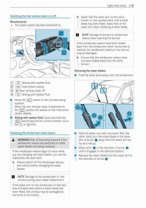
SwitcSwitching thing the rhe rear windoear window wiperw wiper on/oon/o
RReqequiruirements:ements:R The power supply has been switched on.
1 ô Wiping with washer uid2 ° Intermittent wiping3 g Rear window wiper o4 ô Wiping with washer uid
# Move the è switch to the correspondingposition.When the rear window wiper is switched on,the è symbol will appear on the instrumentcluster display.
# WWiping witiping with wh washerasher uid:uid: press and hold theè switch beyond the current position up tothe 1 or 4 limit.
RReplacing teplacing the windscrhe windscreen wiper bladeseen wiper blades
& WWARNINGARNING Risk of becoming trapped if thewindscreen wipers are switched on whilewiper blades are being replaced
If the windscreen wipers begin to move whileyou are changing the wiper blades, you can betrapped by the wiper arm.# Always switch o the windscreen wipers
and vehicle before changing the wiperblades.
* NNOOTETE Damage to the windscreen or rearwindow during wiper blade replacement
If the wiper arm on the windscreen or rear win-dow is folded back before a wiper blade hasbeen tted, the window may be damaged bythe force of the impact.
# Never fold the wiper arm on the wind-screen or rear window back until a wiperblade has been tted. Keep hold of thewiper arm when replacing a wiper blade.
* NNOOTETE Damage to bonnet or windscreenwipers when opening the bonnet
If the windscreen wipers have been foldedback from the windscreen when the bonnet isopened, the windscreen wipers or the bonnetmay be damaged.# Ensure that the windscreen wipers have
not been folded back from the wind-screen.
RRemoemoving tving the wiper bladeshe wiper blades# Fold the wiper arms away from the windscreen.
# Hold the wiper arm with one hand. With theother hand, turn the wiper blade in the direc-tion of arrow1 away from the wiper arm asfar as it will go.
# Slide catch2 in the direction of arrow3until it engages in the removal position.
# Remove the wiper blade from the wiper arm inthe direction of arrow4.
Light and vision 115115
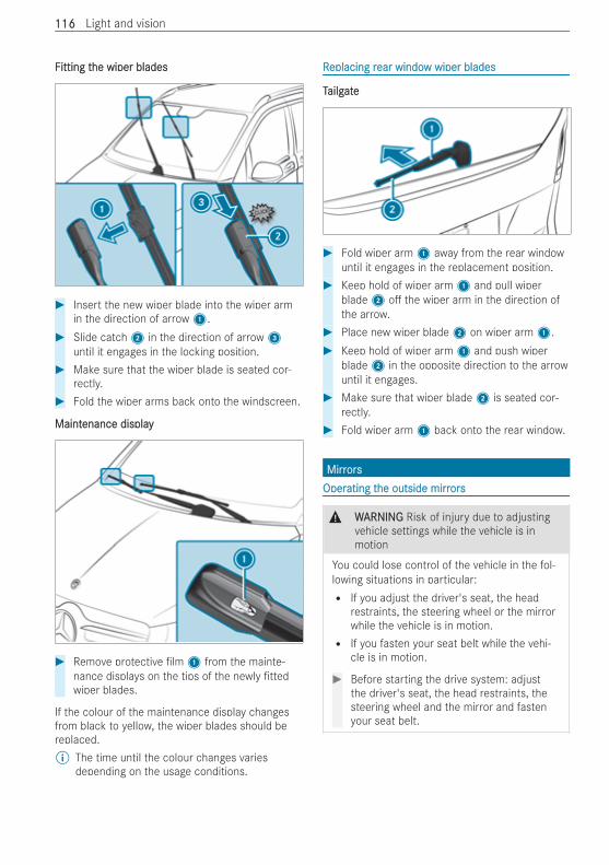
FFitting titting the wiper bladeshe wiper blades
# Insert the new wiper blade into the wiper armin the direction of arrow1.
# Slide catch2 in the direction of arrow3until it engages in the locking position.
# Make sure that the wiper blade is seated cor-rectly.
# Fold the wiper arms back onto the windscreen.
MaintMaintenance displayenance display
# Remove protective lm1 from the mainte-nance displays on the tips of the newly ttedwiper blades.
If the colour of the maintenance display changesfrom black to yellow, the wiper blades should bereplaced.% The time until the colour changes varies
depending on the usage conditions.
RReplacing replacing rear windoear window wiper bladesw wiper blades
TTailgailgateate
# Fold wiper arm1 away from the rear windowuntil it engages in the replacement position.
# Keep hold of wiper arm1 and pull wiperblade2 o the wiper arm in the direction ofthe arrow.
# Place new wiper blade2 on wiper arm1.# Keep hold of wiper arm1 and push wiper
blade2 in the opposite direction to the arrowuntil it engages.
# Make sure that wiper blade2 is seated cor-rectly.
# Fold wiper arm1 back onto the rear window.
MirrMirrorsorsOperOperating tating the outside mirrhe outside mirrorsors
& WWARNINGARNING Risk of injury due to adjustingvehicle settings while the vehicle is inmotion
You could lose control of the vehicle in the fol-lowing situations in particular:R If you adjust the driver's seat, the head
restraints, the steering wheel or the mirrorwhile the vehicle is in motion.R If you fasten your seat belt while the vehi-
cle is in motion.
# Before starting the drive system: adjustthe driver's seat, the head restraints, thesteering wheel and the mirror and fastenyour seat belt.
116116 Light and vision
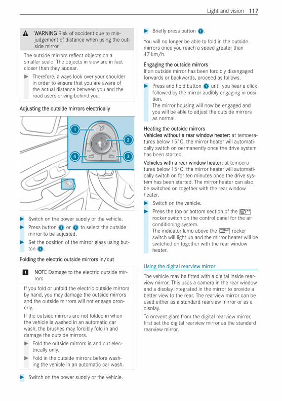
& WWARNINGARNING Risk of accident due to mis-judgement of distance when using the out-side mirror
The outside mirrors re ect objects on asmaller scale. The objects in view are in factcloser than they appear.# Therefore, always look over your shoulder
in order to ensure that you are aware ofthe actual distance between you and theroad users driving behind you.
AAdjusdjusting tting the outside mirrhe outside mirrorors electrs electricallyically
# Switch on the power supply or the vehicle.# Press button3 or4 to select the outside
mirror to be adjusted.# Set the position of the mirror glass using but-
ton2.
FFolding tolding the electrhe electric outside mirric outside mirrorors in/outs in/out
* NONOTETE Damage to the electric outside mir-rors
If you fold or unfold the electric outside mirrorsby hand, you may damage the outside mirrorsand the outside mirrors will not engage prop-erly.If the outside mirrors are not folded in whenthe vehicle is washed in an automatic carwash, the brushes may forcibly fold in anddamage the outside mirrors.# Fold the outside mirrors in and out elec-
trically only.# Fold in the outside mirrors before wash-
ing the vehicle in an automatic car wash.
# Switch on the power supply or the vehicle.
# Brie y press button1.
You will no longer be able to fold in the outsidemirrors once you reach a speed greater than47 km/h.
EngEngaging taging the outside mirrhe outside mirrorsorsIf an outside mirror has been forcibly disengagedforwards or backwards, proceed as follows.# Press and hold button1 until you hear a click
followed by the mirror audibly engaging in posi-tion.The mirror housing will now be engaged andyou will be able to adjust the outside mirrorsas normal.
Heating tHeating the outside mirrhe outside mirrorsorsVVehicles witehicles without a rhout a rear windoear window heatw heaterer:: at tempera-tures below 15°C, the mirror heater will automati-cally switch on permanently once the drive systemhas been started.VVehicles witehicles with a rh a rear windoear window heatw heaterer:: at tempera-tures below 15°C, the mirror heater will automati-cally switch on for ten minutes once the drive sys-tem has been started. The mirror heater can alsobe switched on together with the rear windowheater.# Switch on the vehicle.# Press the top or bottom section of the ¤
rocker switch on the control panel for the airconditioning system.The indicator lamp above the ¤ rockerswitch will light up and the mirror heater will beswitched on together with the rear windowheater.
Using tUsing the digithe digital ral rearearvieview mirrw mirroror
The vehicle may be tted with a digital inside rear-view mirror. This uses a camera in the rear windowand a display integrated in the mirror to provide abetter view to the rear. The rearview mirror can beused either as a standard rearview mirror or as adisplay.To prevent glare from the digital rearview mirror,rst set the digital rearview mirror as the standard
rearview mirror.
Light and vision 117117
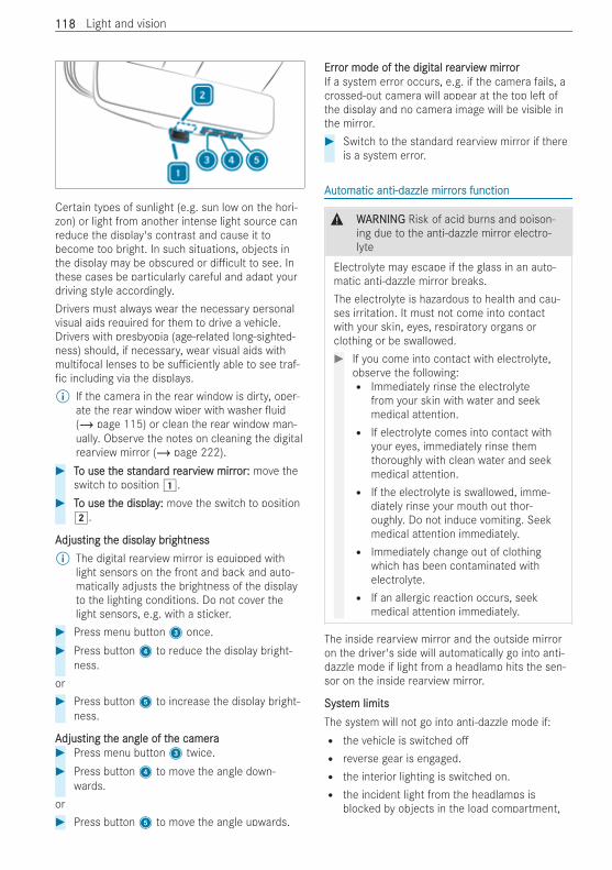
Certain types of sunlight (e.g. sun low on the hori-zon) or light from another intense light source canreduce the display's contrast and cause it tobecome too bright. In such situations, objects inthe display may be obscured or di cult to see. Inthese cases be particularly careful and adapt yourdriving style accordingly.Drivers must always wear the necessary personalvisual aids required for them to drive a vehicle.Drivers with presbyopia (age-related long-sighted-ness) should, if necessary, wear visual aids withmultifocal lenses to be su ciently able to see traf-fic including via the displays.% If the camera in the rear window is dirty, oper-
ate the rear window wiper with washer uid(/ page 115) or clean the rear window man-ually. Observe the notes on cleaning the digitalrearview mirror (/ page 222).
# TTo use to use the sthe standarandard rd rearearvieview mirrw mirroror:: move theswitch to position 1.
# TTo use to use the displayhe display:: move the switch to position2.
AAdjusdjusting tting the displahe display bry brightnessightness% The digital rearview mirror is equipped with
light sensors on the front and back and auto-matically adjusts the brightness of the displayto the lighting conditions. Do not cover thelight sensors, e.g. with a sticker.
# Press menu button3 once.# Press button4 to reduce the display bright-
ness.or# Press button5 to increase the display bright-
ness.
AAdjusdjusting tting the angle of the angle of the camerahe camera# Press menu button3 twice.# Press button4 to move the angle down-
wards.or# Press button5 to move the angle upwards.
ErrError mode of tor mode of the digithe digital ral rearearvieview mirrw mirrororIf a system error occurs, e.g. if the camera fails, acrossed-out camera will appear at the top le ofthe display and no camera image will be visible inthe mirror.# Switch to the standard rearview mirror if there
is a system error.
AAututomatic anti-dazzle mirromatic anti-dazzle mirrorors functions function
& WWARNINGARNING Risk of acid burns and poison-ing due to the anti-dazzle mirror electro-lyte
Electrolyte may escape if the glass in an auto-matic anti-dazzle mirror breaks.The electrolyte is hazardous to health and cau-ses irritation. It must not come into contactwith your skin, eyes, respiratory organs orclothing or be swallowed.# If you come into contact with electrolyte,
observe the following:R Immediately rinse the electrolyte
from your skin with water and seekmedical attention.R If electrolyte comes into contact with
your eyes, immediately rinse themthoroughly with clean water and seekmedical attention.R If the electrolyte is swallowed, imme-
diately rinse your mouth out thor-oughly. Do not induce vomiting. Seekmedical attention immediately.R Immediately change out of clothing
which has been contaminated withelectrolyte.R If an allergic reaction occurs, seek
medical attention immediately.
The inside rearview mirror and the outside mirroron the driver's side will automatically go into anti-dazzle mode if light from a headlamp hits the sen-sor on the inside rearview mirror.
SystSystem limitsem limitsThe system will not go into anti-dazzle mode if:R the vehicle is switched oR reverse gear is engaged.R the interior lighting is switched on.R the incident light from the headlamps is
blocked by objects in the load compartment,
118118 Light and vision
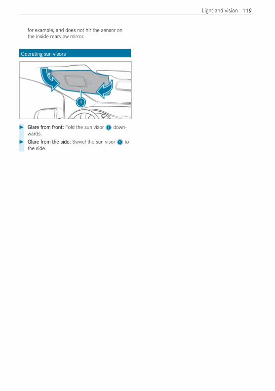
for example, and does not hit the sensor onthe inside rearview mirror.
OperOperating sun visorsating sun visors
# GlarGlare fre from from frontont:: Fold the sun visor1 down-wards.
# GlarGlare fre from tom the side:he side: Swivel the sun visor1 tothe side.
Light and vision 119119
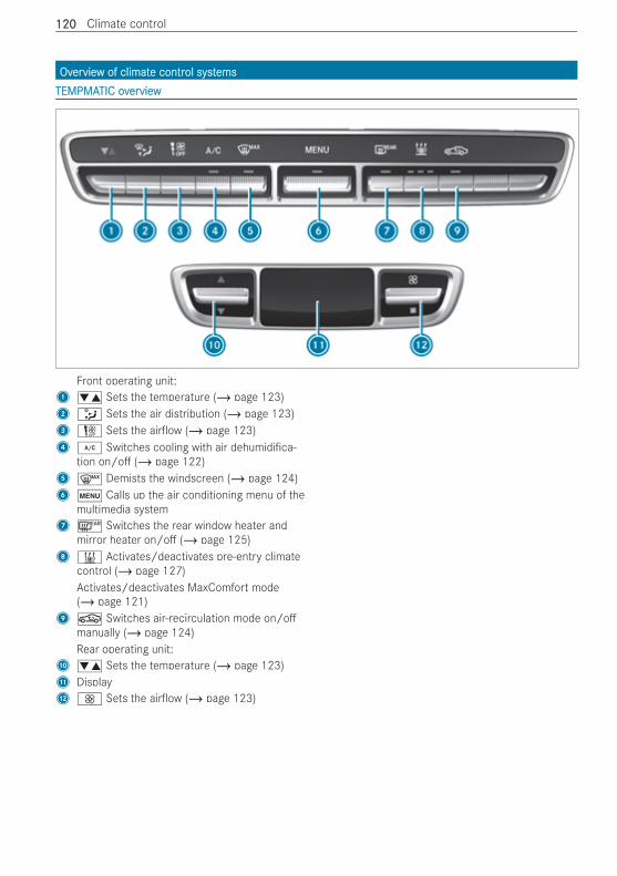
OvOverervieview of climatw of climate contre control systol systemsemsTEMPMATEMPMATIC ovTIC overerviewview
Front operating unit:1 w Sets the temperature (/ page 123)2 _ Sets the air distribution (/ page 123)3H Sets the air ow (/ page 123)4 ¿ Switches cooling with air dehumidi ca-
tion on/o (/ page 122)5 ¬ Demists the windscreen (/ page 124)6 t Calls up the air conditioning menu of the
multimedia system7 ¤ Switches the rear window heater and
mirror heater on/o (/ page 125)8 & Activates/deactivates pre-entry climate
control (/ page 127)Activates/deactivates MaxComfort mode(/ page 121)
9 g Switches air-recirculation mode on/omanually (/ page 124)Rear operating unit:
A w Sets the temperature (/ page 123)B DisplayC K Sets the air ow (/ page 123)
120120 Climate control
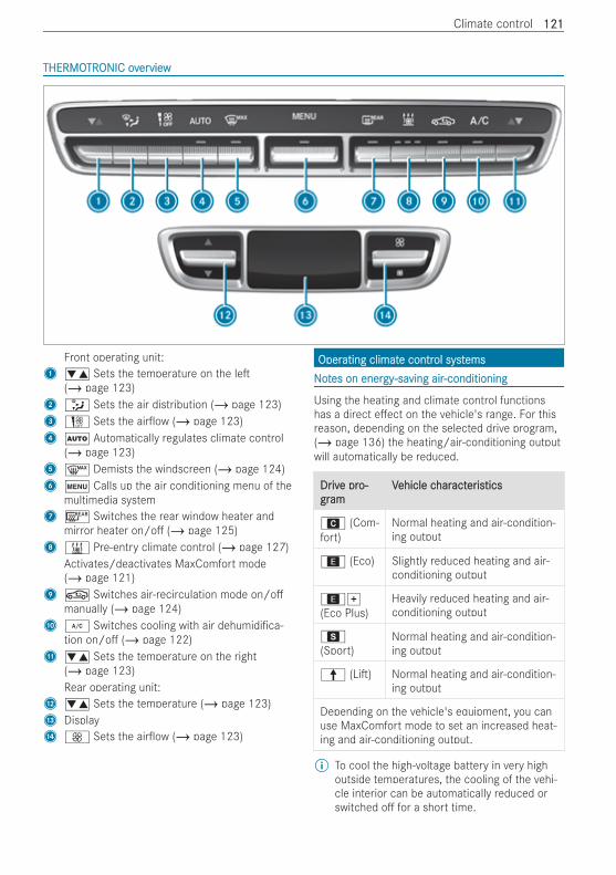
THERMOTHERMOTRTRONIC ovONIC overerviewview
Front operating unit:1 w Sets the temperature on the le
(/ page 123)2 _ Sets the air distribution (/ page 123)3H Sets the air ow (/ page 123)4 Ã Automatically regulates climate control
(/ page 123)5 ¬ Demists the windscreen (/ page 124)6 t Calls up the air conditioning menu of the
multimedia system7 ¤ Switches the rear window heater and
mirror heater on/o (/ page 125)8 & Pre-entry climate control (/ page 127)
Activates/deactivates MaxComfort mode(/ page 121)
9 g Switches air-recirculation mode on/omanually (/ page 124)
A ¿ Switches cooling with air dehumidi ca-tion on/o (/ page 122)
B w Sets the temperature on the right(/ page 123)Rear operating unit:
C w Sets the temperature (/ page 123)D DisplayE K Sets the air ow (/ page 123)
OperOperating climatating climate contre control systol systemsemsNNoottes on eneres on energygy-sa-saving airving air-conditioning-conditioning
Using the heating and climate control functionshas a direct e ect on the vehicle's range. For thisreason, depending on the selected drive program,(/ page 136) the heating/air-conditioning outputwill automatically be reduced.
DrDrivive pre pro-o-grgramam
VVehicle cehicle charharactactererisisticstics
A (Com-fort)
Normal heating and air-condition-ing output
; (Eco) Slightly reduced heating and air-conditioning output
;q(Eco Plus)
Heavily reduced heating and air-conditioning output
C(Sport)
Normal heating and air-condition-ing output
¦ (Li ) Normal heating and air-condition-ing output
Depending on the vehicle's equipment, you canuse MaxComfort mode to set an increased heat-ing and air-conditioning output.
% To cool the high-voltage battery in very highoutside temperatures, the cooling of the vehi-cle interior can be automatically reduced orswitched o for a short time.
Climate control 121121
A reduction in the heating/air-conditioning outputmay mean that it takes longer than usual to reachthe desired vehicle interior temperature or that itcannot be reached at all.
MaxComfMaxComforort modet modeDepending on its equipment, your vehicle mayhave a MaxComfort mode.When the vehicle is switched on, MaxComfortmode can be activated in all drive programs bypressing the & button on the air conditioningcontrol panel. The maximum output of the heat-ing/climate control system is activated in thismode. This enables faster heating of the vehicle,but can have a negative in uence on the range.The function is switched on when the indicatorlamp in the & button is lit.
FFurturther infher inforormationmationIn the drive program; or;q, the bestheating output is achieved with a low blower set-ting (level 1 to max. 3).If the windows threaten to mist up, the blower set-ting should be increased, and a drive program witha higher heating/air-conditioning output selected ifneed be. If necessary, switch on the "Demist wind-screen" function (/ page 124).Moreover, comply with the following air-condition-ing instructions in order to minimise energy con-sumption:R Select as low a blower setting as possible.R Use the function for demisting the windscreen
only brie y until the misted-up windscreen isclear again.R Ventilate the vehicle for a short time in warm
weather. To achieve quicker cooling, switch theclimate control to air-recirculation modebrie y. This will accelerate the cooling processand the desired vehicle interior temperaturewill be reached more quickly.R Vehicles with seat heating: using the seat heat-
ing in conjunction with a medium vehicle inte-rior temperature results in lower fuel consump-tion than selecting a high vehicle interior tem-perature.
SwitcSwitching thing the climathe climate contre control systol systemem on/oon/o
# Switch on the vehicle.# TTo switco switch on:h on: press the top or bottom section
of the t rocker switch.The multimedia system air conditioning menuwill open.
or# Set the air ow to level 1 or higher using theH rocker switch.
# TTo switco switchh o :o : press the top or bottom sectionof the t rocker switch.
or# Set the air ow to level g using theH
rocker switch.% When climate control is switched o , "OFF"
will appear on the display of the rear operatingunit.
% When the vehicle is started, the climate con-trol settings most recently selected will beadopted automatically.Vehicles with rear climate control: the statusof the rear climate control a er the vehicle isstarted depends on the zone selected on thePre-entry climate ctrl menu (/ page 126).
SwitcSwitching thing the A/C functionhe A/C function on/oon/o
RReqequiruirements:ements:R The climate control system has been switched
on (/ page 122).R The vehicle has been started.
When the "Cooling with air dehumidi cation" func-tion is switched on, the air inside the vehicle iscooled and dehumidi ed according to the temper-ature selected.The function can be activated or deactivated onlyin the climate control menu and not in the climatecontrol menu for rear-compartment air condition-ing (second menu level).# Set the air ow to level 1 or higher using theH rocker switch.
# Press the top or bottom section of rockerswitch ¿.When the indicator lamp above the¿ rocker switch lights up, the "Cooling withair dehumidi cation" function is switched on.
or# Switch the function on and o via the air con-
ditioning menu of the multimedia system.When the indicator lamp above the ¿ rockerswitch ashes three times, the function is switchedo due to a defect. Have the climate control sys-tem checked at a quali ed specialist workshop.% Switch o the A/C function only brie y. Other-
wise, the windows could mist up more quickly.
122122 Climate control
% Condensation may leak from the underside ofthe vehicle in cooling mode. This is not a signof a defect.
AAututomaticallomatically ry regulating climategulating climate contre controlol
RReqequiruirements:ements:R The climate control system has been switched
on (/ page 122).
THERMOTHERMOTRTRONIC autONIC automatic climatomatic climate contre contrololWhen THERMOTRONIC automatic climate controlis in automatic mode, the set temperature willautomatically be kept constant. The system auto-matically regulates the temperature of the dis-pensed air, the air ow and the air distribution.Automatic mode can be activated or deactivatedonly in the climate control menu and not in the cli-mate control menu for rear-compartment air con-ditioning (second menu level).# TTo switco switch auth automatic modeomatic mode on/o :on/o : press the
top or bottom section of the à rockerswitch.When the indicator lamp above the Ãrocker switch lights up, automatic mode isswitched on.
In automatic mode, if you adjust the air ow or airdistribution manually, the indicator lamp above theà rocker switch will go out. The function thathas not been changed manually, however, will con-tinue to be regulated automatically. When the man-ually changed function switches back to automaticmode, the indicator lamp above the à rockerswitch will light up again.
InfInforormation on tmation on the air dishe air distrtribution seibution settingsttings
TEMPMATIC air-conditioning system andTHERMOTRONIC automatic climate control¯ Directs air to the demister ventsb Directs air to the demister, centre and side
air vents_ Directs air to the demister, centre, side and
footwell ventsa Directs air to the demister and footwell
ventsP Directs air to the centre and side air ventsS Directs air to the centre, side and footwell
ventsO Directs air to the footwell ventsW Controls air distribution automatically
SeSetting ttting the air dishe air distrtributionibution
RReqequiruirements:ements:R The climate control system is switched on.
# Press rocker switch _ up or down.The various air distribution settings appear inthe air conditioning menu of the multimediasystem.
# Press the _ rocker switch up or down untilthe desired setting is reached.
VVehicles witehicles with rh rear climatear climate contre contrololWhen the rear air conditioning system is switchedon, the air distribution setting on the control panelalso applies to rear climate control.This also applies to the automatic mode ofTHERMOTRONIC automatic climate control. The airis then automatically directed to the footwelland/or the headroom of the rear compartment.
SeSetting ttting thehe air owair ow
RReqequiruirements:ements:R The climate control system is switched on.
# TTo incro increase or decrease or decrease:ease: press the top or bot-tom section of theH rocker switch.
Vehicles with rear climate control: use the air con-ditioning menu of the multimedia system or therear control panel to set the air ow for the rearcompartment.
SeSetting ttting the the tememperperatureature
RReqequiruirements:ements:R The climate control system is switched on.
# TTo incro increase or decrease or decrease:ease: press the top or bot-tom section of the w rocker switch.
Vehicles with rear climate control: use the air con-ditioning menu of the multimedia system or therear control panel to set the temperature for therear compartment.
SwitcSwitching thing the synche synchrhronisation functiononisation function on/oon/o
RReqequiruirements:ements:R The climate control system has been switched
on (/ page 122).
The temperature can be set centrally using thesynchronisation function. The temperature settingfor the driver's side will then be adopted for the
Climate control 123123
front passenger side and, in vehicles with rear cli-mate control, the rear compartment as well.# Switch the "Synchronisation" function on and
o via the air conditioning menu of the multi-media system.
The synchronisation function will be switched o ifthe settings for the front passenger side or rearcompartment are changed.
DemisDemisting tting the windscrhe windscreeneen
You can use this function to defrost and demist thewindscreen and the front side windows from theinside.If the "Demist windscreen" function has beenswitched on, any reduction in heating and air con-ditioning power will automatically be deactivated.Switch o the "Demist windscreen" function assoon as the windscreen is clear.% Vehicles with THERMOTRONIC: if the vehicle
detects mist on the windows, the function willautomatically be switched on.
# Switch on climate control (/ page 122).# TTo switco switchh on/o :on/o : push the top or bottom sec-
tion of the ¬ rocker switch on the frontcontrol panel.If the indicator lamp above the ¬ rockerswitch lights up, the function has beenswitched on. The current air-conditioning set-tings will be deactivated.The temperature, air ow and air distributionwill be regulated automatically to optimise thedemisting e ect. Air-recirculation mode will bedeactivated.
When you enable automatic mode, the "Demistwindscreen" function will switch o automatically.When you switch o the "Demist windscreen" func-tion, the previous settings for automatic climatecontrol will be applied again.Note the following exceptions:R Air-recirculation mode will remain switched o .R If the A/C function has been automatically
activated, it will remain active.
SwitcSwitching airhing air-r-recirecirculation modeculation mode on/oon/o
When air-recirculation mode is switched on, thewindows may mist up more quickly. Switch on air-recirculation mode only brie y.
# Press the top or bottom section of the grocker switch.When the indicator lamp above the grocker switch lights up, air-recirculation modeis switched on.
Air-recirculation mode will automatically switch onin the following cases:R in high outside temperaturesR while the vehicle is driving through a tunnel
(vehicles with THERMOTRONIC automatic cli-mate control and navigation only)
A er approximately 30 minutes, outside air willautomatically be introduced again.Air-recirculation mode will automatically switch oin the following cases:R a er approximately ve minutes at outside
temperatures below approximately 7°CR a er approximately ve minutes when the
"Cooling with air dehumidi cation" function isdeactivatedR a er approximately 30 minutes at outside tem-
peratures above approximately 7°C and whenthe "Cooling with air dehumidi cation" functionis switched on.
ConvConvenience opening/closingenience opening/closing
& WWARNINGARNING Risk of entrapment due to notpaying attention during convenience clos-ing
When the convenience closing feature is oper-ating, parts of the body could become trappedin the closing area of the side windows.# When the convenience closing feature is
operating, monitor the entire closingprocess and make sure that no bodyparts are in the closing area.
& WWARNINGARNING Risk of entrapment when open-ing a side window
When opening a side window, parts of the bodycould be drawn in or become trapped betweenthe side window and window frame.# When opening, make sure that nobody is
touching the side window.# Release the button immediately if some-
body becomes trapped.
124124 Climate control
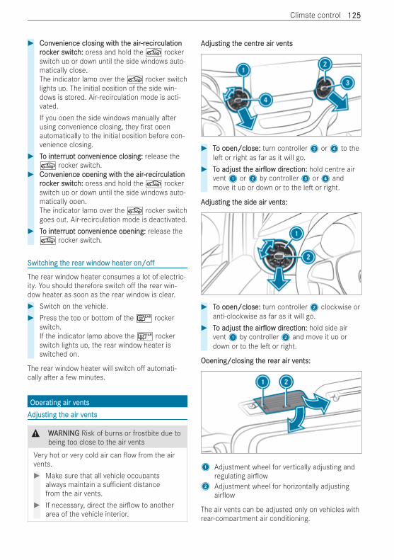
# ConvConvenience closing witenience closing with th the airhe air-r-recirecirculationculationrrockocker switcer switch:h: press and hold the g rockerswitch up or down until the side windows auto-matically close.The indicator lamp over the g rocker switchlights up. The initial position of the side win-dows is stored. Air-recirculation mode is acti-vated.If you open the side windows manually a erusing convenience closing, they rst openautomatically to the initial position before con-venience closing.
# TTo into interrerrupupt convt convenience closing:enience closing: release theg rocker switch.
# ConvConvenience opening witenience opening with th the airhe air-r-recirecirculationculationrrockocker switcer switch:h: press and hold the g rockerswitch up or down until the side windows auto-matically open.The indicator lamp over the g rocker switchgoes out. Air-recirculation mode is deactivated.
# TTo into interrerrupupt convt convenience opening:enience opening: release theg rocker switch.
SwitcSwitching thing the rhe rear windoear window heatw heaterer on/oon/o
The rear window heater consumes a lot of electric-ity. You should therefore switch o the rear win-dow heater as soon as the rear window is clear.# Switch on the vehicle.# Press the top or bottom of the ¤ rocker
switch.If the indicator lamp above the ¤ rockerswitch lights up, the rear window heater isswitched on.
The rear window heater will switch o automati-cally a er a few minutes.
OperOperating air vating air ventsentsAAdjusdjusting tting the air vhe air ventsents
& WWARNINGARNING Risk of burns or frostbite due tobeing too close to the air vents
Very hot or very cold air can ow from the airvents.# Make sure that all vehicle occupants
always maintain a su cient distancefrom the air vents.
# If necessary, direct the air ow to anotherarea of the vehicle interior.
AAdjusdjusting tting the centrhe centre air ve air ventsents
# TTo open/close:o open/close: turn controller3 or4 to thele or right as far as it will go.
# TTo adjuso adjust tt thehe air owair ow dirdirection:ection: hold centre airvent1 or2 by controller3 or4 andmove it up or down or to the le or right.
AAdjusdjusting tting the side air vhe side air vents:ents:
# TTo open/close:o open/close: turn controller2 clockwise oranti-clockwise as far as it will go.
# TTo adjuso adjust tt thehe air owair ow dirdirection:ection: hold side airvent1 by controller2 and move it up ordown or to the le or right.
Opening/closing tOpening/closing the rhe rear air vear air vents:ents:
1 Adjustment wheel for vertically adjusting andregulating air ow
2 Adjustment wheel for horizontally adjustingair ow
The air vents can be adjusted only on vehicles withrear-compartment air conditioning.
Climate control 125125
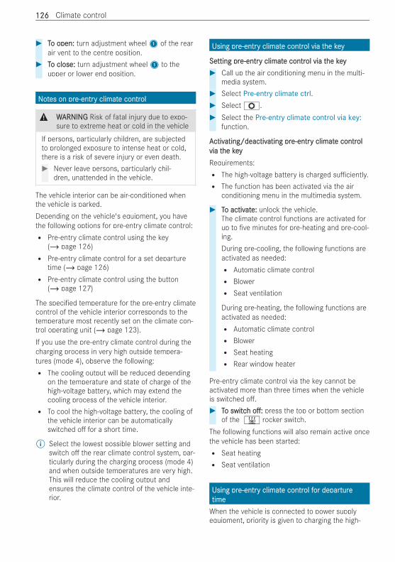
# TTo open:o open: turn adjustment wheel1 of the rearair vent to the centre position.
# TTo close:o close: turn adjustment wheel1 to theupper or lower end position.
NNoottes on pres on pre-entre-entry climaty climate contre controlol
& WWARNINGARNING Risk of fatal injury due to expo-sure to extreme heat or cold in the vehicle
If persons, particularly children, are subjectedto prolonged exposure to intense heat or cold,there is a risk of severe injury or even death.# Never leave persons, particularly chil-
dren, unattended in the vehicle.
The vehicle interior can be air-conditioned whenthe vehicle is parked.Depending on the vehicle's equipment, you havethe following options for pre-entry climate control:R Pre-entry climate control using the key
(/ page 126)R Pre-entry climate control for a set departure
time (/ page 126)R Pre-entry climate control using the button
(/ page 127)
The speci ed temperature for the pre-entry climatecontrol of the vehicle interior corresponds to thetemperature most recently set on the climate con-trol operating unit (/ page 123).If you use the pre-entry climate control during thecharging process in very high outside tempera-tures (mode 4), observe the following:R The cooling output will be reduced depending
on the temperature and state of charge of thehigh-voltage battery, which may extend thecooling process of the vehicle interior.R To cool the high-voltage battery, the cooling of
the vehicle interior can be automaticallyswitched o for a short time.
% Select the lowest possible blower setting andswitch o the rear climate control system, par-ticularly during the charging process (mode 4)and when outside temperatures are very high.This will reduce the cooling output andensures the climate control of the vehicle inte-rior.
Using prUsing pre-entre-entry climaty climate contre control via tol via the keyhe key
SeSetting prtting pre-entre-entry climaty climate contre control via tol via the keyhe key# Call up the air conditioning menu in the multi-
media system.# Select Pre-entry climate ctrl.# SelectZ.# Select the Pre-entry climate control via key:
function.
AActivctivating/deactivating/deactivating prating pre-entre-entry climaty climate contre contrololvia tvia the keyhe keyRequirements:R The high-voltage battery is charged su ciently.R The function has been activated via the air
conditioning menu in the multimedia system.
# TTo activo activatate:e: unlock the vehicle.The climate control functions are activated forup to ve minutes for pre-heating and pre-cool-ing.During pre-cooling, the following functions areactivated as needed:R Automatic climate controlR BlowerR Seat ventilation
During pre-heating, the following functions areactivated as needed:R Automatic climate controlR BlowerR Seat heatingR Rear window heater
Pre-entry climate control via the key cannot beactivated more than three times when the vehicleis switched o .# TTo switco switchh o :o : press the top or bottom section
of the & rocker switch.The following functions will also remain active oncethe vehicle has been started:R Seat heatingR Seat ventilation
Using prUsing pre-entre-entry climaty climate contre control fol for deparor departureturetimetimeWhen the vehicle is connected to power supplyequipment, priority is given to charging the high-
126126 Climate control
voltage battery up to a speci ed minimum chargelevel.The time for which pre-entry climate control willrun may be reduced under the following condi-tions:R The vehicle is not connected to power supply
equipment.R The high-voltage battery is not fully charged.
With active pre-entry climate control, the chargelevel of the high-voltage battery may be reduced,even if the charging cable connector is inserted.# Call up the air conditioning menu in the multi-
media system.# Select Pre-entry climate ctrl.
SeSetting a single departting a single departurture timee time# Select Once.# Set a departure time.
Changing tChanging the activhe active depare departurture timee time# Select the pen icon next to the displayed
departure time.# Set a departure time.
Selecting tSelecting the zonehe zone# SelectZ.# Select Driver's seat only.
If the Driver's seat only setting is deactivated,pre-entry climate control will take place for theentire vehicle.Seat heating/ventilation for the driver's andfront passenger seats will also be activated aswell as rear climate control.The zone selected for pre-entry climate controlalso has an e ect on rear climate control a erthe vehicle is started. If the Driver's seat onlysetting is activated, rear climate control will beswitched o a er the vehicle is started. If thesetting is deactivated, the setting for rear cli-mate control most recently selected willremain active.
AActivctivating/deactivating/deactivating prating pre-entre-entry climaty climate contre contrololffor deparor departurture timee timeRequirements:R The high-voltage battery is charged su ciently.R The function has been activated via the air
conditioning menu in the multimedia system.
# TTo activo activatate:e: set the departure time.During cooling, the following functions are acti-vated as needed:R Automatic climate controlR BlowerR Seat ventilation
During heating, the following functions are acti-vated as needed:R Automatic climate controlR BlowerR Seat heatingR Rear window heater
Pre-entry climate control switches on a maxi-mum of 50 minutes before the selected depar-ture time. It will remain active for another tenminutes if the departure is delayed.
# TTo switco switchh o :o : press the top or bottom sectionof the & rocker switch.
The following functions will also remain active oncethe vehicle has been started:R Seat heatingR Seat ventilation
% The departure time and pre-entry climate con-trol can also be set via the Mercedes me Con-nect app (Mercedes PRO connect)(/ page 184).
AActivctivating/deactivating/deactivating prating pre-entre-entry climaty climate contre contrololusing tusing the butthe buttonon
RReqequiruirements:ements:R The vehicle is switched o
Climate control 127127
The vehicle interior can continue to be air-condi-tioned for up to 30 minutes, e.g. if the journey isinterrupted.# TTo switco switchh on/o :on/o : press the top or bottom sec-
tion of rocker switch1.The speci ed temperature for pre-entry climatecontrol corresponds to the temperature mostrecently set on the climate control operatingunit.The red or blue indicator lamp on the &button will go on or o .
The colours of the indicator lamp have the follow-ing meanings when the vehicle is switched o :R Blue:Blue: cooling activatedR RRed:ed: heating activatedR YYellow:ellow: departure time preselected
128128 Climate control

DrDrivingivingNNoottes on electres on electric modeic mode
& WWARNINGARNING Risk of chemical burns and poi-soning from damaged high-voltage battery
If the housing of the high-voltage battery hasbeen damaged, electrolyte and gases may leakout.# Avoid contact with the skin, eyes or
clothing.# Immediately rinse electrolyte splashes o
with water and seek medical attentionstraight away.
& DDANANGERGER Risk of re and explosion fromexcessive internal pressure of the high-voltage battery
In the event of a vehicle re, ammable gascan escape and ignite.# Stop the charging process immediately in
case of unusual odours, smoke or burnmarks.
# Leave the danger zone immediately.Secure the danger zone at a su cientdistance.
# Call the re service.
Observe the following notes on vehicle noise emis-sions and the acoustic vehicle alerting system:R The vehicle is equipped with a purely electric
drive system and develops considerably lowervehicle noise emissions than vehicles with acombustion engine.It is for this reason that the vehicle is equippedwith a sound generator, which serves as anacoustic vehicle alerting system (AVAS).R The sound generator generates speed-depend-
ent and stationary vehicle noise emissionswhen driving forward and backing up at aspeed of up to around 30 km/h speed-depend-ent vehicle noise emissions when driving for-wards and reversing.This helps other road users, particularly pedes-trians and cyclists, to hear your vehicle better.R from a speed of 20 km/h the acoustic vehicle
alerting system gradually switches o .
R despite the sound generator, the vehicle stillmay not be heard by other road users. Adaptyour driving style accordingly.R The sound generator is o when the vehicle is
stationary.
ManuallManually disconnecting ty disconnecting the high-vhe high-voltoltagage on-boarde on-boardelectrelectrical systical systemem
& DDANANGERGER Risk of death and re due tomodi ed and/or damaged components ofthe high-voltage on-board electrical sys-tem
The vehicle's high-voltage on-board electricalsystem is under high voltage. If you modifycomponent parts in the vehicle's high-voltageon-board electrical system or touch damagedcomponent parts, you may be electrocuted. Inaddition, modi ed and/or damaged compo-nents may cause a re.In the event of an accident or impact to thevehicle underbody, components of the high-voltage electrical system may be damagedalthough the damage is not visible.# Never make any modi cations to the
high-voltage on-board electrical system.# Do not switch on or use the vehicle if its
high-voltage on-board electrical systemcomponents have been modi ed or dam-aged.
# Never touch damaged components of thehigh-voltage on-board electrical system.
# A er an accident, do not touch any com-ponents of the high-voltage on-boardelectrical system.
# A er an accident, have the vehicle trans-ported away.
# Have the components of the high-voltageon-board electrical system checked at aquali ed specialist workshop andreplaced if necessary.
RReqequiruirements:ements:R The 6 restraint system warning lamp lights
up in the instrument cluster, e.g. a er an acci-dent.R The vehicle is badly damaged, e.g. a er an
accident, and the restraint system componentshave not been triggered.R The vehicle has not been started.R The vehicle is secured against rolling away.
Driving and parking 129129
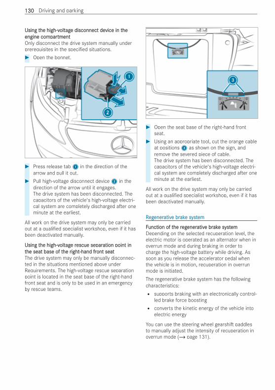
Using tUsing the high-vhe high-voltoltagage disconnect dee disconnect device in tvice in theheengine comengine comparpartmenttmentOnly disconnect the drive system manually underprerequisites in the speci ed situations.# Open the bonnet.
# Press release tab1 in the direction of thearrow and pull it out.
# Pull high-voltage disconnect device2 in thedirection of the arrow until it engages.The drive system has been disconnected. Thecapacitors of the vehicle's high-voltage electri-cal system are completely discharged a er oneminute at the earliest.
All work on the drive system may only be carriedout at a quali ed specialist workshop, even if it hasbeen deactivated manually.
Using tUsing the high-vhe high-voltoltagage re rescue separescue separation point ination point intthe seat base of the seat base of the rhe right-hand fright-hand front seatont seatThe drive system may only be manually disconnec-ted in the situations mentioned above underRequirements. The high-voltage rescue separationpoint is located in the seat base of the right-handfront seat and is only to be used in an emergencyby rescue teams.
# Open the seat base of the right-hand frontseat.
# Using an appropriate tool, cut the orange cableat positions3 as shown on the sign, andremove the severed piece of cable.The drive system has been disconnected. Thecapacitors of the vehicle's high-voltage electri-cal system are completely discharged a er oneminute at the earliest.
All work on the drive system may only be carriedout at a quali ed specialist workshop, even if it hasbeen deactivated manually.
RRegegenerenerativative bre brakake syste systemem
FFunction of tunction of the rhe regegenerenerativative bre brakake syste systememDepending on the selected recuperation level, theelectric motor is operated as an alternator when inoverrun mode and during braking in order tocharge the high-voltage battery while driving. Assoon as you release the accelerator pedal whenthe vehicle is in motion, recuperation in overrunmode is initiated.The regenerative brake system has the followingcharacteristics:R supports braking with an electronically control-
led brake force boostingR converts the kinetic energy of the vehicle into
electric energy
You can use the steering wheel gearshi paddlesto manually adjust the intensity of recuperation inoverrun mode (/ page 131).
130130 Driving and parking
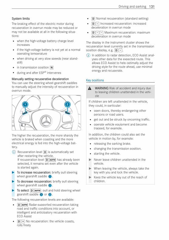
SystSystem limitsem limitsThe braking e ect of the electric motor duringrecuperation in overrun mode may be reduced ormay not be available at all in the following situa-tions:R when the high-voltage battery charge level
increasesR if the high-voltage battery is not yet at a normal
operating temperatureR when driving at very slow speeds (near stand-
still)R in transmission position i
R during and a er ESP® intervenes
ManuallManually sey setting rtting recuperecuperativative decelere decelerationationYou can use the steering wheel gearshi paddlesto manually adjust the intensity of recuperation inoverrun mode.
The higher the recuperation, the more sharply thevehicle is braked when coasting and the moreelectrical energy is fed into the high-voltage bat-tery.% Recuperation level h is automatically set
a er restarting the vehicle.If recuperation level hà has already beenselected, it remains set even a er the vehicleis started again.
# TTo incro increase rease recuperecuperation:ation: brie y pull steeringwheel gearshi paddle1.
# TTo decro decrease rease recuperecuperation:ation: brie y pull steeringwheel gearshi paddle2.
# TTo selecto select hÃ: pull and hold steering wheelgearshi paddle1 or2.
The following recuperation levels are available:R hà Radar-supported recuperation taking
road and tra c conditions into account, orintelligent and anticipatory recuperation withECO AssistR hq No recuperation: the vehicle coasts,
rolls freely
R h Normal recuperation (standard setting)R h± Increased recuperation: increased
deceleration in overrun modeR h±± Maximum recuperation: maximum
deceleration in overrun mode
The display in the instrument cluster shows therecuperation level currently set in the transmissionposition display, e.g. h±.% In addition to radar detection, ECO Assist anal-
yses other data for the expected route. Thisallows ECO Assist to help optimally adjust thedriving style for the route ahead, use minimalenergy and recuperate.
KKeey positionsy positions
& WWARNINGARNING Risk of accident and injury dueto leaving children unattended in the vehi-cle
If children are le unattended in the vehicle,they could, in particular:R open doors, thereby endangering other
persons or road users.R get out and be struck by oncoming tra c.R operate vehicle equipment and become
trapped, for example.
In addition, the children could also set thevehicle in motion by, for example:R releasing the parking brake.R changing the transmission position.R starting the vehicle.
# Never leave children unattended in thevehicle.
# When leaving the vehicle, always take thekey with you and lock the vehicle.
# Keep the vehicle key out of the reach ofchildren.
Driving and parking 131131
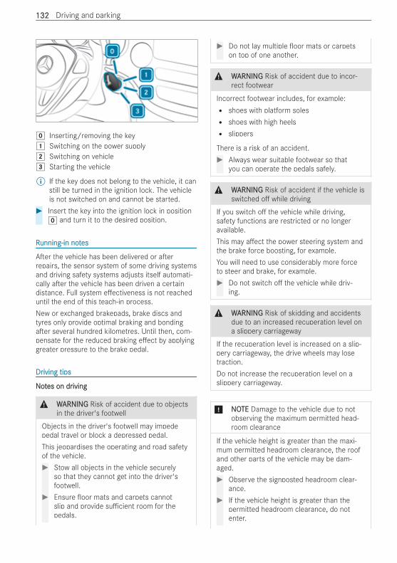
g Inserting/removing the key1 Switching on the power supply2 Switching on vehicle3 Starting the vehicle
% If the key does not belong to the vehicle, it canstill be turned in the ignition lock. The vehicleis not switched on and cannot be started.
# Insert the key into the ignition lock in positiong and turn it to the desired position.
RRunning-in notunning-in noteses
A er the vehicle has been delivered or a errepairs, the sensor system of some driving systemsand driving safety systems adjusts itself automati-cally a er the vehicle has been driven a certaindistance. Full system e ectiveness is not reacheduntil the end of this teach-in process.New or exchanged brakepads, brake discs andtyres only provide optimal braking and bondinga er several hundred kilometres. Until then, com-pensate for the reduced braking e ect by applyinggreater pressure to the brake pedal.
DrDriving tipsiving tips
NNoottes on dres on drivingiving
& WWARNINGARNING Risk of accident due to objectsin the driver's footwell
Objects in the driver's footwell may impedepedal travel or block a depressed pedal.This jeopardises the operating and road safetyof the vehicle.# Stow all objects in the vehicle securely
so that they cannot get into the driver'sfootwell.
# Ensure oor mats and carpets cannotslip and provide su cient room for thepedals.
# Do not lay multiple oor mats or carpetson top of one another.
& WWARNINGARNING Risk of accident due to incor-rect footwear
Incorrect footwear includes, for example:R shoes with platform solesR shoes with high heelsR slippers
There is a risk of an accident.# Always wear suitable footwear so that
you can operate the pedals safely.
& WWARNINGARNING Risk of accident if the vehicle isswitched o while driving
If you switch o the vehicle while driving,safety functions are restricted or no longeravailable.This may a ect the power steering system andthe brake force boosting, for example.You will need to use considerably more forceto steer and brake, for example.# Do not switch o the vehicle while driv-
ing.
& WWARNINGARNING Risk of skidding and accidentsdue to an increased recuperation level ona slippery carriageway
If the recuperation level is increased on a slip-pery carriageway, the drive wheels may losetraction.Do not increase the recuperation level on aslippery carriageway.
* NNOOTETE Damage to the vehicle due to notobserving the maximum permitted head-room clearance
If the vehicle height is greater than the maxi-mum permitted headroom clearance, the roofand other parts of the vehicle may be dam-aged.# Observe the signposted headroom clear-
ance.# If the vehicle height is greater than the
permitted headroom clearance, do notenter.
132132 Driving and parking
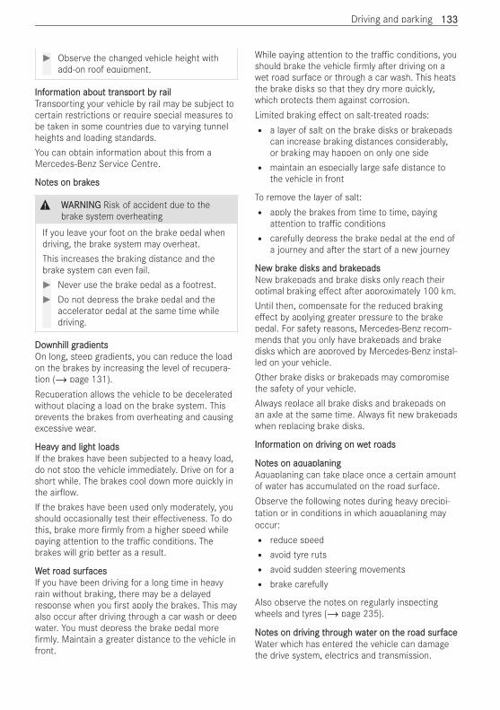
# Observe the changed vehicle height withadd-on roof equipment.
InfInforormation about trmation about transporansport bt by ry railailTransporting your vehicle by rail may be subject tocertain restrictions or require special measures tobe taken in some countries due to varying tunnelheights and loading standards.You can obtain information about this from aMercedes-Benz Service Centre.
NotNotes on bres on brakakeses
& WWARNINGARNING Risk of accident due to thebrake system overheating
If you leave your foot on the brake pedal whendriving, the brake system may overheat.This increases the braking distance and thebrake system can even fail.# Never use the brake pedal as a footrest.# Do not depress the brake pedal and the
accelerator pedal at the same time whiledriving.
DoDownhill grwnhill gradientsadientsOn long, steep gradients, you can reduce the loadon the brakes by increasing the level of recupera-tion (/ page 131).Recuperation allows the vehicle to be deceleratedwithout placing a load on the brake system. Thisprevents the brakes from overheating and causingexcessive wear.
HeaHeavy and light loadsvy and light loadsIf the brakes have been subjected to a heavy load,do not stop the vehicle immediately. Drive on for ashort while. The brakes cool down more quickly inthe air ow.If the brakes have been used only moderately, youshould occasionally test their e ectiveness. To dothis, brake more rmly from a higher speed whilepaying attention to the tra c conditions. Thebrakes will grip better as a result.
WeWet rt road surfoad surfacesacesIf you have been driving for a long time in heavyrain without braking, there may be a delayedresponse when you rst apply the brakes. This mayalso occur a er driving through a car wash or deepwater. You must depress the brake pedal morermly. Maintain a greater distance to the vehicle in
front.
While paying attention to the tra c conditions, youshould brake the vehicle rmly a er driving on awet road surface or through a car wash. This heatsthe brake disks so that they dry more quickly,which protects them against corrosion.Limited braking e ect on salt-treated roads:R a layer of salt on the brake disks or brakepads
can increase braking distances considerably,or braking may happen on only one sideR maintain an especially large safe distance to
the vehicle in front
To remove the layer of salt:R apply the brakes from time to time, paying
attention to tra c conditionsR carefully depress the brake pedal at the end of
a journey and a er the start of a new journey
NNeew brw brakake diske disks and brs and brakakepadsepadsNew brakepads and brake disks only reach theiroptimal braking e ect a er approximately 100 km.Until then, compensate for the reduced brakinge ect by applying greater pressure to the brakepedal. For safety reasons, Mercedes-Benz recom-mends that you only have brakepads and brakedisks which are approved by Mercedes-Benz instal-led on your vehicle.Other brake disks or brakepads may compromisethe safety of your vehicle.Always replace all brake disks and brakepads onan axle at the same time. Always t new brakepadswhen replacing brake disks.
InfInforormation on drmation on driving on weiving on wet rt roadsoads
NotNotes on aqes on aquaplaninguaplaningAquaplaning can take place once a certain amountof water has accumulated on the road surface.Observe the following notes during heavy precipi-tation or in conditions in which aquaplaning mayoccur:R reduce speedR avoid tyre rutsR avoid sudden steering movementsR brake carefully
Also observe the notes on regularly inspectingwheels and tyres (/ page 235).
NotNotes on dres on driving tiving thrhrough wough watater on ter on the rhe road surfoad surfaceaceWater which has entered the vehicle can damagethe drive system, electrics and transmission.
Driving and parking 133133
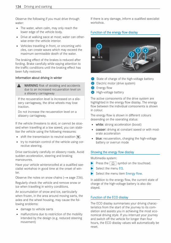
Observe the following if you must drive throughwater:R The water, when calm, may only reach the
lower edge of the vehicle body.R Drive at walking pace at most; water can other-
wise enter the vehicle interior.R Vehicles travelling in front, or oncoming vehi-
cles, can create waves which may exceed themaximum permissible depth of the water.
The braking e ect of the brakes is reduced a erfording. Brake carefully while paying attention tothe tra c conditions until the braking e ect hasbeen fully restored.
InfInforormation about drmation about driving in wintiving in winterer
& WWARNINGARNING Risk of skidding and accidentsdue to an increased recuperation level ona slippery carriageway
If the recuperation level is increased on a slip-pery carriageway, the drive wheels may losetraction.Do not increase the recuperation level on aslippery carriageway.
If the vehicle threatens to skid, or cannot be stop-ped when travelling at a low speed, you can stabi-lise the vehicle using the following measures:R shi the transmission to neutral position i.R try to maintain control of the vehicle using cor-
rective steering.
Drive particularly carefully on slippery roads. Avoidsudden acceleration, steering and brakingmanoeuvres.Have your vehicle winterproofed at a quali ed spe-cialist workshop in good time at the onset of win-ter.Observe the notes on snow chains (/ page 236).Regularly check the vehicle and remove snow orice when travelling in wintry conditions.An accumulation of snow and ice, particularlywhen frozen, in the area around moving parts, theaxles and the wheel housing, may cause the fol-lowing problems:R damage to vehicle partsR malfunctions due to restriction of the mobility
intended by the design (e.g. reduced steeringmovement)
If there is any damage, inform a quali ed specialistworkshop.
FFunction of tunction of the enerhe energygy owow displaydisplay
1 State of charge of the high-voltage battery2 Electric motor (drive system)3 Energy ow4 High-voltage battery
The active components of the drive system arehighlighted in the energy ow display. The energyow between the individual components is shown
in colour.The energy ow is shown in di erent coloursdepending on the operating status:R whitwhite:e: strong acceleration (boost)R coppercopper:: driving at constant speed or with mod-
erate accelerationR blue:blue: recuperation, charging the high-voltage
battery or overrun mode
ShoShowing twing the enerhe energygy owow displaydisplay
Multimedia system:# Press the© symbol on the touchpad.# Select the menu EQ.# Select the menu item Energy flow.
In addition to the energy ow, the current state ofcharge of the high-voltage battery is also dis-played.
FFunction of tunction of the EChe ECO displayO display
The ECO display summarises your driving charac-teristics from the start of the journey to its com-pletion and assists you in achieving the most eco-nomical driving style. If you interrupt your journeyand switch o the vehicle for longer than fourhours, the ECO display values will automatically bereset.
134134 Driving and parking
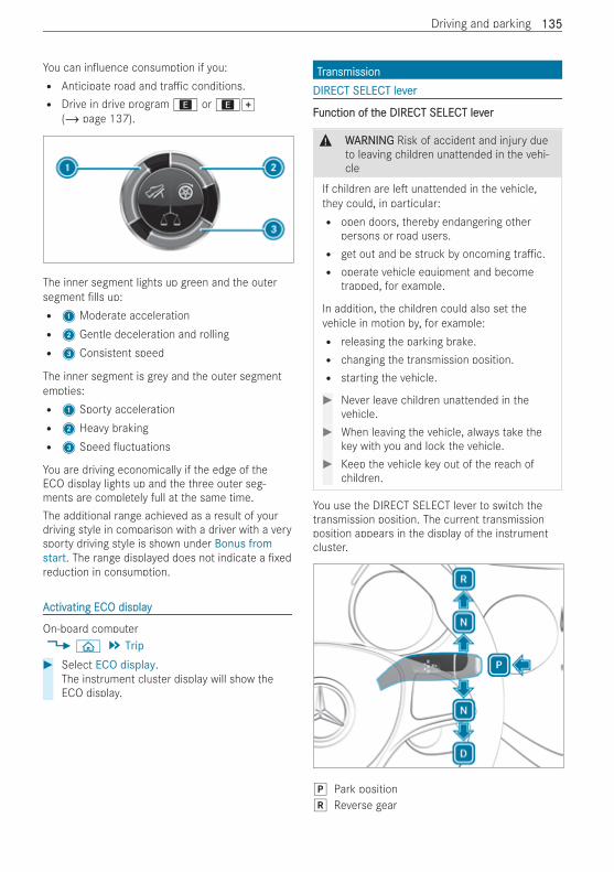
You can in uence consumption if you:R Anticipate road and tra c conditions.R Drive in drive program; or;q
(/ page 137).
The inner segment lights up green and the outersegment lls up:R 1 Moderate accelerationR 2 Gentle deceleration and rollingR 3 Consistent speed
The inner segment is grey and the outer segmentempties:R 1 Sporty accelerationR 2 Heavy brakingR 3 Speed uctuations
You are driving economically if the edge of theECO display lights up and the three outer seg-ments are completely full at the same time.The additional range achieved as a result of yourdriving style in comparison with a driver with a verysporty driving style is shown under Bonus fromstart. The range displayed does not indicate a xedreduction in consumption.
AActivctivating ECating ECO displayO display
On-board computer4 ò 5 Trip# Select ECO display.
The instrument cluster display will show theECO display.
TTrransmissionansmissionDIRECT SELECT levDIRECT SELECT leverer
FFunction of tunction of the DIRECT SELECT levhe DIRECT SELECT leverer
& WWARNINGARNING Risk of accident and injury dueto leaving children unattended in the vehi-cle
If children are le unattended in the vehicle,they could, in particular:R open doors, thereby endangering other
persons or road users.R get out and be struck by oncoming tra c.R operate vehicle equipment and become
trapped, for example.
In addition, the children could also set thevehicle in motion by, for example:R releasing the parking brake.R changing the transmission position.R starting the vehicle.
# Never leave children unattended in thevehicle.
# When leaving the vehicle, always take thekey with you and lock the vehicle.
# Keep the vehicle key out of the reach ofchildren.
You use the DIRECT SELECT lever to switch thetransmission position. The current transmissionposition appears in the display of the instrumentcluster.
j Park positionk Reverse gear
Driving and parking 135135
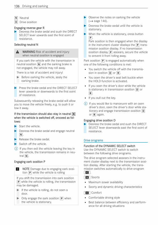
i Neutralh Drive position
EngEngaging revaging revererse gse gear Rear R# Depress the brake pedal and push the DIRECT
SELECT lever upwards past the rst point ofresistance.
Selecting neutrSelecting neutral Nal N
& WWARNINGARNING Risk of accident and injurywhen neutral position is engaged
If you park the vehicle with the transmission inneutral position i and the parking brake isnot engaged, the vehicle may roll away.There is a risk of accident and injury!# Before parking the vehicle, apply the
parking brake.
# Press the brake pedal and the DIRECT SELECTlever upwards or downwards to the rst pointof resistance.
Subsequently releasing the brake pedal will allowyou to move the vehicle freely, e.g. to push it ortow it away.
If tIf the trhe transmission should also staansmission should also stay in neutry in neutralal iiwhen twhen the vhe vehicle is switcehicle is switchedhed o ,o , prproceed as foceed as fol-ol-lowlows:s:# Start the vehicle.# Depress the brake pedal and engage neutral
i.# Release the brake pedal.# Switch o the vehicle.% If you then exit the vehicle leaving the key in
the vehicle, the transmission remains in neu-tral i.
EngEngaging paraging park position Pk position P
* NONOTETE Damage due to engaging park posi-tion j while the vehicle is rolling
If you shi the transmission into park positionj while the vehicle is rolling, the transmissionmay be damaged.# If the vehicle is rolling, do not open a
door.# Only engage the park position j when
the vehicle is stationary.
# Observe the notes on parking the vehicle(/ page 146).
# Depress the brake pedal until the vehicle isstationary.
# When the vehicle is stationary, press buttonj.Park position is then engaged when the displayin the instrument cluster displays the j trans-mission position display. If no transmissionposition display j appears, secure the vehicleto prevent it from rolling away.
Park position j is engaged automatically whenone of the following conditions is met:R You switch the vehicle o with the transmis-
sion in position h or k.R You open the driver's seat belt buckle when
the HOLD function is activated.R If you open the driver's door while the vehicle
is stationary in transmission position h ork.R If you pull out the key.
% If you would like to manoeuvre with an opendriver's door, open the driver's door while sta-tionary and engage transmission position hor k again.
EngEngaging draging drivive position De position D# Depress the brake pedal and push the DIRECT
SELECT lever downwards past the rst point ofresistance.
DrDrivive pre progrogramsams
FFunction of tunction of the Dhe DYNYNAMIC SELECT switchAMIC SELECT switchUse the DYNAMIC SELECT switch to switchbetween the following drive programs.The drive program selected appears in the instru-ment cluster display next to the transmission posi-tion display. A er starting the vehicle, the trans-mission switches automatically to drive programA.C SportsR Maximum power availabilityR Sporty and dynamic driving characteristics
A ComfortR Comfortable driving styleR Best balance between e ciency and perform-
ance for all driving situations
136136 Driving and parking
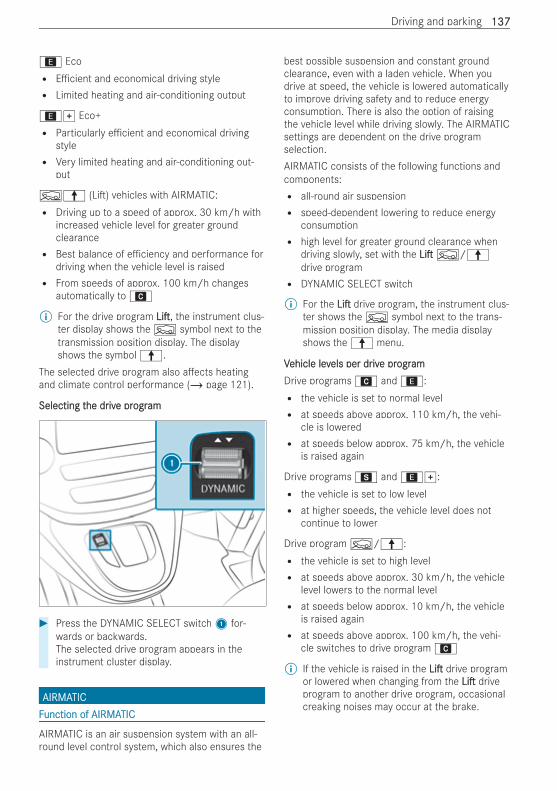
; EcoR E cient and economical driving styleR Limited heating and air-conditioning output
;q Eco+R Particularly e cient and economical driving
styleR Very limited heating and air-conditioning out-
put
F¦ (Li ) vehicles with AIRMATIC:R Driving up to a speed of approx. 30 km/h with
increased vehicle level for greater groundclearanceR Best balance of e ciency and performance for
driving when the vehicle level is raisedR From speeds of approx. 100 km/h changes
automatically toA
% For the drive program LiLi , the instrument clus-ter display shows theF symbol next to thetransmission position display. The displayshows the symbol¦.
The selected drive program also a ects heatingand climate control performance (/ page 121).
Selecting tSelecting the drhe drivive pre progrogramam
# Press the DYNAMIC SELECT switch1 for-wards or backwards.The selected drive program appears in theinstrument cluster display.
AIRMAAIRMATICTICFFunction of AIRMAunction of AIRMATICTIC
AIRMATIC is an air suspension system with an all-round level control system, which also ensures the
best possible suspension and constant groundclearance, even with a laden vehicle. When youdrive at speed, the vehicle is lowered automaticallyto improve driving safety and to reduce energyconsumption. There is also the option of raisingthe vehicle level while driving slowly. The AIRMATICsettings are dependent on the drive programselection.AIRMATIC consists of the following functions andcomponents:R all-round air suspensionR speed-dependent lowering to reduce energy
consumptionR high level for greater ground clearance when
driving slowly, set with the LiLi F/¦drive programR DYNAMIC SELECT switch
% For the LiLi drive program, the instrument clus-ter shows theF symbol next to the trans-mission position display. The media displayshows the¦ menu.
VVehicle levehicle levels per drels per drivive pre progrogramamDrive programsA and;:R the vehicle is set to normal levelR at speeds above approx. 110 km/h, the vehi-
cle is loweredR at speeds below approx. 75 km/h, the vehicle
is raised again
Drive programsC and;q:R the vehicle is set to low levelR at higher speeds, the vehicle level does not
continue to lower
Drive programF/¦:R the vehicle is set to high levelR at speeds above approx. 30 km/h, the vehicle
level lowers to the normal levelR at speeds below approx. 10 km/h, the vehicle
is raised againR at speeds above approx. 100 km/h, the vehi-
cle switches to drive programA
% If the vehicle is raised in the LiLi drive programor lowered when changing from the LiLi driveprogram to another drive program, occasionalcreaking noises may occur at the brake.
Driving and parking 137137
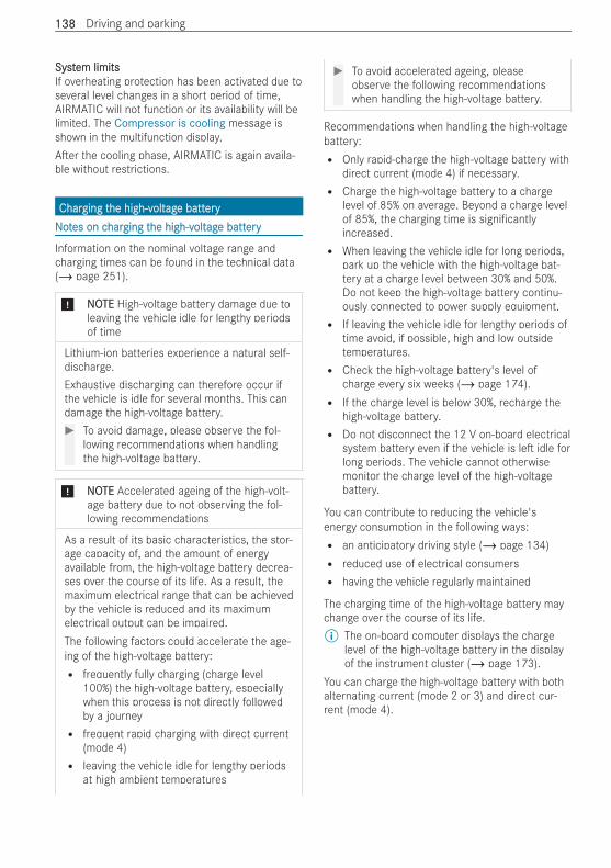
SystSystem limitsem limitsIf overheating protection has been activated due toseveral level changes in a short period of time,AIRMATIC will not function or its availability will belimited. The Compressor is cooling message isshown in the multifunction display.A er the cooling phase, AIRMATIC is again availa-ble without restrictions.
CharCharging tging the high-vhe high-voltoltagage batte batteryeryNNoottes on ces on charharging tging the high-vhe high-voltoltagage batte batteryery
Information on the nominal voltage range andcharging times can be found in the technical data(/ page 251).
* NNOOTETE High-voltage battery damage due toleaving the vehicle idle for lengthy periodsof time
Lithium-ion batteries experience a natural self-discharge.Exhaustive discharging can therefore occur ifthe vehicle is idle for several months. This candamage the high-voltage battery.# To avoid damage, please observe the fol-
lowing recommendations when handlingthe high-voltage battery.
* NNOOTETE Accelerated ageing of the high-volt-age battery due to not observing the fol-lowing recommendations
As a result of its basic characteristics, the stor-age capacity of, and the amount of energyavailable from, the high-voltage battery decrea-ses over the course of its life. As a result, themaximum electrical range that can be achievedby the vehicle is reduced and its maximumelectrical output can be impaired.The following factors could accelerate the age-ing of the high-voltage battery:R frequently fully charging (charge level
100%) the high-voltage battery, especiallywhen this process is not directly followedby a journeyR frequent rapid charging with direct current
(mode 4)R leaving the vehicle idle for lengthy periods
at high ambient temperatures
# To avoid accelerated ageing, pleaseobserve the following recommendationswhen handling the high-voltage battery.
Recommendations when handling the high-voltagebattery:R Only rapid-charge the high-voltage battery with
direct current (mode 4) if necessary.R Charge the high-voltage battery to a charge
level of 85% on average. Beyond a charge levelof 85%, the charging time is signi cantlyincreased.R When leaving the vehicle idle for long periods,
park up the vehicle with the high-voltage bat-tery at a charge level between 30% and 50%.Do not keep the high-voltage battery continu-ously connected to power supply equipment.R If leaving the vehicle idle for lengthy periods of
time avoid, if possible, high and low outsidetemperatures.R Check the high-voltage battery's level of
charge every six weeks (/ page 174).R If the charge level is below 30%, recharge the
high-voltage battery.R Do not disconnect the 12 V on-board electrical
system battery even if the vehicle is le idle forlong periods. The vehicle cannot otherwisemonitor the charge level of the high-voltagebattery.
You can contribute to reducing the vehicle'senergy consumption in the following ways:R an anticipatory driving style (/ page 134)R reduced use of electrical consumersR having the vehicle regularly maintained
The charging time of the high-voltage battery maychange over the course of its life.% The on-board computer displays the charge
level of the high-voltage battery in the displayof the instrument cluster (/ page 173).
You can charge the high-voltage battery with bothalternating current (mode 2 or 3) and direct cur-rent (mode 4).
138138 Driving and parking
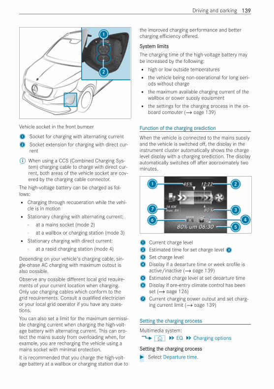
Vehicle socket in the front bumper
1 Socket for charging with alternating current2 Socket extension for charging with direct cur-
rent
% When using a CCS (Combined Charging Sys-tem) charging cable to charge with direct cur-rent, both areas of the vehicle socket are cov-ered by the charging cable connector.
The high-voltage battery can be charged as fol-lows:R Charging through recuperation while the vehi-
cle is in motionR Stationary charging with alternating current:
- at a mains socket (mode 2)- at a wallbox or charging station (mode 3)R Stationary charging with direct current:
- at a rapid charging station (mode 4)
Depending on your vehicle's charging cable, sin-gle-phase AC charging with maximum output isalso possible.Observe any possible di erent local grid require-ments of your current location when charging.Only use charging cables which conform to thegrid requirements. Consult a quali ed electricianor your local grid operator if you have any ques-tions.You can also set a limit for the maximum permissi-ble charging current when charging the high-volt-age battery with alternating current. This can pro-tect the mains supply from overloading when, forexample, you are recharging the vehicle using amains socket with minimal protection.It is recommended that you charge the high-volt-age battery at a wallbox or charging station due to
the improved charging performance and bettercharging e ciency o ered.
SystSystem limitsem limitsThe charging time of the high-voltage battery maybe increased by the following:R high or low outside temperaturesR the vehicle being non-operational for long peri-
ods without chargeR the maximum available charging current of the
wallbox or power supply equipmentR the settings for the charging process in the on-
board computer (/ page 139)
FFunction of tunction of the che charharging prging predictionediction
When the vehicle is connected to the mains supplyand the vehicle is switched o , the display in theinstrument cluster automatically shows the chargelevel display with a charging prediction. The displayautomatically switches o a er approximately twominutes.
1 Current charge level2 Estimated time for set charge level33 Set charge level4 Display if a departure time or week pro le is
active/inactive (/ page 139)5 Estimated charge level at set departure time6 Display if pre-entry climate control has been
set (/ page 126)7 Current charging power output and set charg-
ing current limit (/ page 139)
SeSetting ttting the che charharging prging processocess
Multimedia system:4© 5 EQ 5 Charging options
SeSetting ttting the che charharging prging processocess# Select Departure time.
Driving and parking 139139
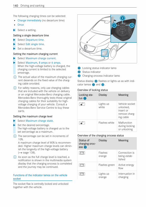
The following charging times can be selected:R Charge immediately (no departure time)R Once
# Select a setting.
SeSetting a single departting a single departurture timee time# Select Departure time.# Select Edit single time.# Set a departure time.
SeSetting ttting the maximum che maximum charharging currging currentent# Select Maximum charge current.# Select Maximum, 8 amps or 6 amps.
When the high-voltage battery is charged, thecharging current is limited to the selectedamperage.
% The actual value of the maximum charging cur-rent depends on the xed value of the charg-ing cable provided.
% For safety reasons, only use charging cablesthat are included with the vehicle on deliveryor an original Mercedes-Benz charging cable.Mercedes-Benz thoroughly tests these originalcharging cables for their suitability for high-voltage charging of your vehicle. Consult aMercedes-Benz Service Centre to buy theseparts.
SeSetting ttting the maximum che maximum chargharge leve levelel# Select Maximum charge state.# Set the desired percentage.
The high-voltage battery is charged up to theset percentage as a maximum.
% The percentage can be set in increments of10%.A maximum charge level of 80% is recommen-ded. Higher maximum charge levels can dimin-ish the longevity of the high-voltage battery(/ page 138).
% As soon as the full charge level is reached, anoti cation is shown in the multimedia systemdisplay that the charging process is completedand the journey may be continued.
FFunctions of tunctions of the indicathe indicator lamor lamps on tps on the vhe vehicleehiclesocketsocket
The socket ap is centrally locked and unlockedtogether with the vehicle.
1 Locking status indicator lamp2 Status indicator3 Charging process indicator lamp
Status display2 ashes or lights up as with indi-cator lamps1 and3.
OvOverervieview of locw of locking stking statusatus
LocLocking stking sta-a-tustus11
DisplayDisplay MeaningMeaning
% Lights upwhite
Vehicle socketunlocked,insert orremove charg-ing cable
% Flashes white Malfunctionduring lockingor unlocking
OvOverervieview of tw of the che charharging prging process stocess statusatus
SSttatus ofatus ofccharharging prging proc-oc-essess33
DisplayDisplay MeaningMeaning
# Flashesorange
Connection isbeing estab-lished
# Flashes green Active energyow
# Lights uporange
Interruption incharging
140140 Driving and parking
SSttatus ofatus ofccharharging prging proc-oc-essess33
DisplayDisplay MeaningMeaning
# Lights upgreen
Chargingprocess com-pleted
# Flashes red(for approx.90 s)
Malfunctionwhen charg-ing
NNoottes on ces on charharging tging the high-vhe high-voltoltagage batte batterery at ty at thehemains sockemains socket (mode 2)t (mode 2)
& DDANANGERGER Risk of fatal injury from incor-rectly installed component parts
Connecting the charging cable to a mainssocket using incorrectly installed componentparts could cause a re or an electric shock,for example.# Only connect the charging cable to a
mains socket that:R Has been properly installed andR Has been inspected by a quali ed electri-
cian
# For safety reasons, only use the chargingcable supplied with the vehicle or anoriginal Mercedes-Benz charging cable.
# Purchase these parts at a Mercedes-Benz Service Centre and obtain advicethere.
Mercedes-Benz thoroughly tests these originalcharging cables for their suitability for high-voltage charging of your vehicle.# Never use a damaged charging cable.# Do not use:R Extension cablesR Extension reelsR Multiple sockets
# Never use socket adapters to connectthe charging cable to the mains socket.The only exception being if the adapterhas been tested and approved by themanufacturer for charging the high-volt-age battery of an electric vehicle.
# Observe the safety notes in the operatinginstructions for the socket adapter.
* NNOOTETE Overloading the mains socket due toexcessive charging current
If the charging current is too high, the fusecould be tripped or the external mains supplycould overheat.# Make sure that the external mains supply
has been designed to handle the setcharging current.
# If necessary, reduce the set charging cur-rent or use a di erent mains socket.
# For safety reasons, only use the chargingcable supplied with the vehicle or anoriginal Mercedes-Benz charging cable.Mercedes-Benz thoroughly tests theseoriginal charging cables for their suitabil-ity for high-voltage charging of your vehi-cle. Purchase these parts at a Mercedes-Benz Service Centre and obtain advicethere.
# Check the setting of the maximumcharge current using the charging capa-city shown in the display of the instru-ment cluster.
Before charging at a mains outlet, have the maxi-mum permissible charging current for the relevantmains outlet or the building inspected by a quali-ed electrician.
The charging cable can be set to a country-speci cmaximum charging current value. When chargingabroad, the maximum value may exceed the per-mitted value for that country.When abroad, observe the country-speci c lawswhen charging.Only charging cables which ful l the local gridrequirements of your location and are approved foryour vehicle may be used.If you have questions concerning charging cablesor if there is a malfunction, please contact a quali-ed specialist workshop.
You can set the maximum permissible chargingcurrent in the on-board computer (/ page 139).The charging process can vary depending on thepower supply equipment.% If the vehicle requires more time than usual to
charge the high-voltage battery, check themaximum charging current settings in the on-board computer.
Driving and parking 141141
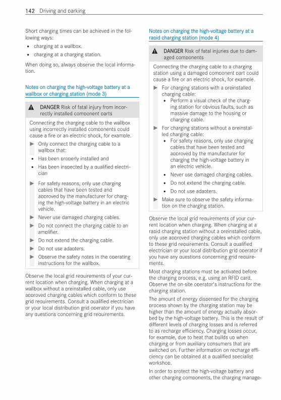
Short charging times can be achieved in the fol-lowing ways:R charging at a wallbox.R charging at a charging station.
When doing so, always observe the local informa-tion.
NNoottes on ces on charharging tging the high-vhe high-voltoltagage batte batterery at ay at awwallboallbox or cx or charharging stging station (mode 3)ation (mode 3)
& DDANANGERGER Risk of fatal injury from incor-rectly installed component parts
Connecting the charging cable to the wallboxusing incorrectly installed components couldcause a re or an electric shock, for example.# Only connect the charging cable to a
wallbox that:R Has been properly installed andR Has been inspected by a quali ed electri-
cian
# For safety reasons, only use chargingcables that have been tested andapproved by the manufacturer for charg-ing the high-voltage battery in an electricvehicle.
# Never use damaged charging cables.# Do not connect the charging cable to an
ampli er.# Do not extend the charging cable.# Do not use adapters.# Observe the safety notes in the operating
instructions for the wallbox.
Observe the local grid requirements of your cur-rent location when charging. When charging at awallbox without a preinstalled cable, only useapproved charging cables which conform to thesegrid requirements. Consult a quali ed electricianor your local distribution grid operator if you haveany questions concerning grid requirements.
NNoottes on ces on charharging tging the high-vhe high-voltoltagage batte batterery at ay at arrapid capid charharging stging station (mode 4)ation (mode 4)
& DDANANGERGER Risk of fatal injuries due to dam-aged components
Connecting the charging cable to a chargingstation using a damaged component part couldcause a re or an electric shock, for example.# For charging stations with a preinstalled
charging cable:R Perform a visual check of the charg-
ing station for obvious faults, such asmassive damage to the housing orcharging cable.
# For charging stations without a preinstal-led charging cable:R For safety reasons, only use charging
cables that have been tested andapproved by the manufacturer forcharging the high-voltage battery inan electric vehicle.R Never use damaged charging cables.R Do not extend the charging cable.R Do not use adapters.
# Make sure to observe the safety informa-tion on the charging station.
Observe the local grid requirements of your cur-rent location when charging. When charging at arapid charging station without a preinstalled cable,only use approved charging cables which conformto these grid requirements. Consult a quali edelectrician or your local distribution grid operator ifyou have any questions concerning grid require-ments.Most charging stations must be activated beforethe charging process, e.g. using an RFID card.Observe the on-site operator's instructions for thecharging station.The amount of energy dispensed for the chargingprocess shown by the charging station may behigher than the amount of energy actually absor-bed by the high-voltage battery. This is the result ofdi erent levels of charging losses and is referredto as recharge e ciency. Charging losses occur,for example, due to heat that builds up whencharging or from auxiliary consumers that areswitched on. Further information on recharge e -ciency can be obtained at a quali ed specialistworkshop.In order to protect the high-voltage battery andother charging components, the charging manage-
142142 Driving and parking
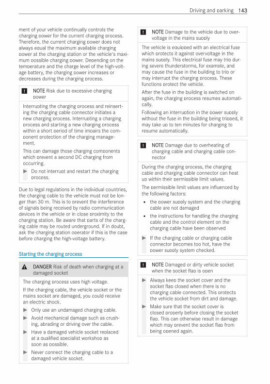
ment of your vehicle continually controls thecharging power for the current charging process.Therefore, the current charging power does notalways equal the maximum available chargingpower at the charging station or the vehicle's maxi-mum possible charging power. Depending on thetemperature and the charge level of the high-volt-age battery, the charging power increases ordecreases during the charging process.
* NNOOTETE Risk due to excessive chargingpower
Interrupting the charging process and reinsert-ing the charging cable connector initiates anew charging process. Interrupting a chargingprocess and starting a new charging processwithin a short period of time impairs the com-ponent protection of the charging manage-ment.This can damage those charging componentswhich prevent a second DC charging fromoccurring.# Do not interrupt and restart the charging
process.
Due to legal regulations in the individual countries,the charging cable to the vehicle must not be lon-ger than 30 m. This is to prevent the interferenceof signals being received by radio communicationdevices in the vehicle or in close proximity to thecharging station. Be aware that parts of the charg-ing cable may be routed underground. If in doubt,ask the charging station operator if this is the casebefore charging the high-voltage battery.
SSttararting tting the che charharging prging processocess
& DDANANGERGER Risk of death when charging at adamaged socket
The charging process uses high voltage.If the charging cable, the vehicle socket or themains socket are damaged, you could receivean electric shock.# Only use an undamaged charging cable.# Avoid mechanical damage such as crush-
ing, abrading or driving over the cable.# Have a damaged vehicle socket replaced
at a quali ed specialist workshop assoon as possible.
# Never connect the charging cable to adamaged vehicle socket.
* NNOOTETE Damage to the vehicle due to over-voltage in the mains supply
The vehicle is equipped with an electrical fusewhich protects it against overvoltage in themains supply. This electrical fuse may trip dur-ing severe thunderstorms, for example, andmay cause the fuse in the building to trip ormay interrupt the charging process. Thesefunctions protect the vehicle.A er the fuse in the building is switched onagain, the charging process resumes automati-cally.Following an interruption in the power supplywithout the fuse in the building being tripped, itmay take up to ten minutes for charging toresume automatically.
* NNOOTETE Damage due to overheating ofcharging cable and charging cable con-nector
During the charging process, the chargingcable and charging cable connector can heatup within their permissible limit values.The permissible limit values are in uenced bythe following factors:R the power supply system and the charging
cable are not damagedR the instructions for handling the charging
cable and the control element on thecharging cable have been observed
# If the charging cable or charging cableconnector becomes too hot, have thepower supply system checked.
* NNOOTETE Damaged or dirty vehicle socketwhen the socket ap is open
# Always keep the socket cover and thesocket ap closed when there is nocharging cable connected. This protectsthe vehicle socket from dirt and damage.
# Make sure that the socket cover isclosed properly before closing the socketap. This can otherwise result in damage
which may prevent the socket ap frombeing opened again.
Driving and parking 143143
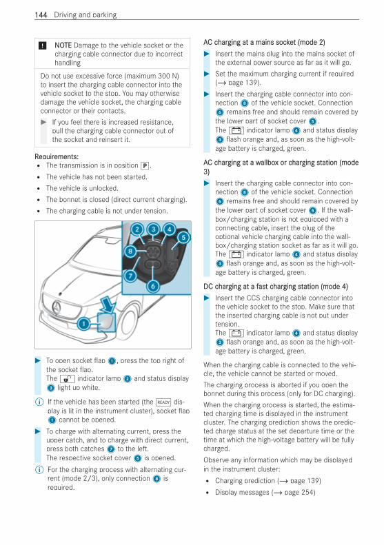
* NNOOTETE Damage to the vehicle socket or thecharging cable connector due to incorrecthandling
Do not use excessive force (maximum 300 N)to insert the charging cable connector into thevehicle socket to the stop. You may otherwisedamage the vehicle socket, the charging cableconnector or their contacts.# If you feel there is increased resistance,
pull the charging cable connector out ofthe socket and reinsert it.
RReqequiruirements:ements:R The transmission is in position j.R The vehicle has not been started.R The vehicle is unlocked.R The bonnet is closed (direct current charging).R The charging cable is not under tension.
# To open socket ap1, press the top right ofthe socket ap.The % indicator lamp2 and status display3 light up white.
% If the vehicle has been started (theõ dis-play is lit in the instrument cluster), socket ap1 cannot be opened.
# To charge with alternating current, press theupper catch, and to charge with direct current,press both catches7 to the le .The respective socket cover5 is opened.
% For the charging process with alternating cur-rent (mode 2/3), only connection8 isrequired.
AAC cC charharging at a mains sockeging at a mains socket (mode 2)t (mode 2)# Insert the mains plug into the mains socket of
the external power source as far as it will go.# Set the maximum charging current if required
(/ page 139).# Insert the charging cable connector into con-
nection8 of the vehicle socket. Connection6 remains free and should remain covered bythe lower part of socket cover5.The # indicator lamp4 and status display3 ash orange and, as soon as the high-volt-age battery is charged, green.
AAC cC charharging at a wging at a wallboallbox or cx or charharging stging station (modeation (mode3)3)# Insert the charging cable connector into con-
nection8 of the vehicle socket. Connection6 remains free and should remain covered bythe lower part of socket cover5. If the wall-box/charging station is not equipped with aconnecting cable, insert the plug of theoptional vehicle charging cable into the wall-box/charging station socket as far as it will go.The # indicator lamp4 and status display3 ash orange and, as soon as the high-volt-age battery is charged, green.
DC cDC charharging at a fging at a fasast ct charharging stging station (mode 4)ation (mode 4)# Insert the CCS charging cable connector into
the vehicle socket to the stop. Make sure thatthe inserted charging cable is not put undertension.The # indicator lamp4 and status display3 ash orange and, as soon as the high-volt-age battery is charged, green.
When the charging cable is connected to the vehi-cle, the vehicle cannot be started or moved.The charging process is aborted if you open thebonnet during this process (only for DC charging).When the charging process is started, the estima-ted charging time is displayed in the instrumentcluster. The charging prediction shows the predic-ted charge status at the set departure time or thetime at which the high-voltage battery will be fullycharged.Observe any information which may be displayedin the instrument cluster:R Charging prediction (/ page 139)R Display messages (/ page 254)
144144 Driving and parking
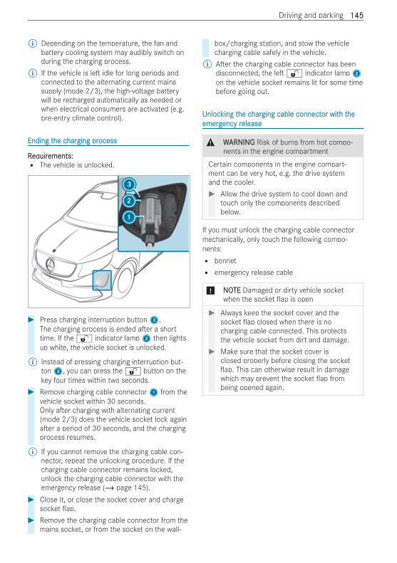
% Depending on the temperature, the fan andbattery cooling system may audibly switch onduring the charging process.
% If the vehicle is le idle for long periods andconnected to the alternating current mainssupply (mode 2/3), the high-voltage batterywill be recharged automatically as needed orwhen electrical consumers are activated (e.g.pre-entry climate control).
Ending tEnding the che charharging prging processocess
RReqequiruirements:ements:R The vehicle is unlocked.
# Press charging interruption button3.The charging process is ended a er a shorttime. If the % indicator lamp2 then lightsup white, the vehicle socket is unlocked.
% Instead of pressing charging interruption but-ton3, you can press the % button on thekey four times within two seconds.
# Remove charging cable connector1 from thevehicle socket within 30 seconds.Only a er charging with alternating current(mode 2/3) does the vehicle socket lock againa er a period of 30 seconds, and the chargingprocess resumes.
% If you cannot remove the charging cable con-nector, repeat the unlocking procedure. If thecharging cable connector remains locked,unlock the charging cable connector with theemergency release (/ page 145).
# Close it, or close the socket cover and chargesocket ap.
# Remove the charging cable connector from themains socket, or from the socket on the wall-
box/charging station, and stow the vehiclecharging cable safely in the vehicle.
% A er the charging cable connector has beendisconnected, the le % indicator lamp2on the vehicle socket remains lit for some timebefore going out.
UUnlocnlocking tking the che charharging cable connectging cable connector witor with th theheemergemergency rency releaseelease
& WWARNINGARNING Risk of burns from hot compo-nents in the engine compartment
Certain components in the engine compart-ment can be very hot, e.g. the drive systemand the cooler.# Allow the drive system to cool down and
touch only the components describedbelow.
If you must unlock the charging cable connectormechanically, only touch the following compo-nents:R bonnetR emergency release cable
* NNOOTETE Damaged or dirty vehicle socketwhen the socket ap is open
# Always keep the socket cover and thesocket ap closed when there is nocharging cable connected. This protectsthe vehicle socket from dirt and damage.
# Make sure that the socket cover isclosed properly before closing the socketap. This can otherwise result in damage
which may prevent the socket ap frombeing opened again.
Driving and parking 145145
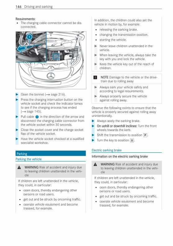
RReqequiruirements:ements:R The charging cable connector cannot be dis-
connected.
# Open the bonnet (/ page 216).# Press the charging interruption button on the
vehicle socket and check the indicator lampsto see if the charging process has ended(/ page 145).
# Pull cable1 in the direction of the arrow anddisconnect the charging cable connector fromthe vehicle socket within 30 seconds.
# Close the socket cover and the charge socketap of the vehicle socket.
# Have the vehicle socket checked at a quali edspecialist workshop.
PPararkingkingPPararking tking the vhe vehicleehicle
& WWARNINGARNING Risk of accident and injury dueto leaving children unattended in the vehi-cle
If children are le unattended in the vehicle,they could, in particular:R open doors, thereby endangering other
persons or road users.R get out and be struck by oncoming tra c.R operate vehicle equipment and become
trapped, for example.
In addition, the children could also set thevehicle in motion by, for example:R releasing the parking brake.R changing the transmission position.R starting the vehicle.
# Never leave children unattended in thevehicle.
# When leaving the vehicle, always take thekey with you and lock the vehicle.
# Keep the vehicle key out of the reach ofchildren.
* NNOOTETE Damage to the vehicle or the drive-train due to rolling away
# Always park your vehicle safely andaccording to legal requirements.
# Always properly secure the vehicleagainst rolling away.
Observe the following points to ensure that thevehicle is properly secured against rolling awayunintentionally.# Always apply the parking brake.# On uphill or doOn uphill or downhill inclines:wnhill inclines: Turn the front
wheels towards the kerb.# Shi the transmission to position j.# Turn the key to position g.
ElectrElectric paric parking brking brakeake
InfInforormation on tmation on the electrhe electric paric parking brking brakeake
& WWARNINGARNING Risk of accident and injury dueto leaving children unattended in the vehi-cle
If children are le unattended in the vehicle,they could, in particular:R open doors, thereby endangering other
persons or road users.R get out and be struck by oncoming tra c.R operate vehicle equipment and become
trapped, for example.
146146 Driving and parking
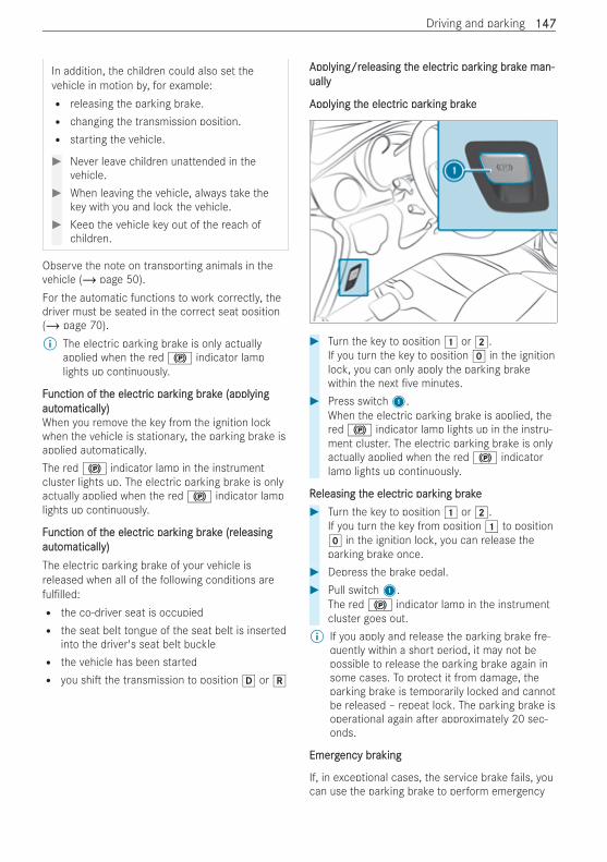
In addition, the children could also set thevehicle in motion by, for example:R releasing the parking brake.R changing the transmission position.R starting the vehicle.
# Never leave children unattended in thevehicle.
# When leaving the vehicle, always take thekey with you and lock the vehicle.
# Keep the vehicle key out of the reach ofchildren.
Observe the note on transporting animals in thevehicle (/ page 50).For the automatic functions to work correctly, thedriver must be seated in the correct seat position(/ page 70).% The electric parking brake is only actually
applied when the red ! indicator lamplights up continuously.
FFunction of tunction of the electrhe electric paric parking brking brakake (apple (applyingyingautautomaticallomatically)y)When you remove the key from the ignition lockwhen the vehicle is stationary, the parking brake isapplied automatically.The red ! indicator lamp in the instrumentcluster lights up. The electric parking brake is onlyactually applied when the red ! indicator lamplights up continuously.
FFunction of tunction of the electrhe electric paric parking brking brakake (re (releasingeleasingautautomaticallomatically)y)The electric parking brake of your vehicle isreleased when all of the following conditions areful lled:R the co-driver seat is occupiedR the seat belt tongue of the seat belt is inserted
into the driver's seat belt buckleR the vehicle has been startedR you shi the transmission to position h or k
ApplApplying/rying/releasing teleasing the electrhe electric paric parking brking brakake man-e man-uallyually
ApplApplying tying the electrhe electric paric parking brking brakeake
# Turn the key to position 1 or 2.If you turn the key to position g in the ignitionlock, you can only apply the parking brakewithin the next ve minutes.
# Press switch1.When the electric parking brake is applied, thered ! indicator lamp lights up in the instru-ment cluster. The electric parking brake is onlyactually applied when the red ! indicatorlamp lights up continuously.
RReleasing teleasing the electrhe electric paric parking brking brakeake# Turn the key to position 1 or 2.
If you turn the key from position 1 to positiong in the ignition lock, you can release theparking brake once.
# Depress the brake pedal.# Pull switch1.
The red ! indicator lamp in the instrumentcluster goes out.
% If you apply and release the parking brake fre-quently within a short period, it may not bepossible to release the parking brake again insome cases. To protect it from damage, theparking brake is temporarily locked and cannotbe released – repeat lock. The parking brake isoperational again a er approximately 20 sec-onds.
EmergEmergency brency brakingaking
If, in exceptional cases, the service brake fails, youcan use the parking brake to perform emergency
Driving and parking 147147
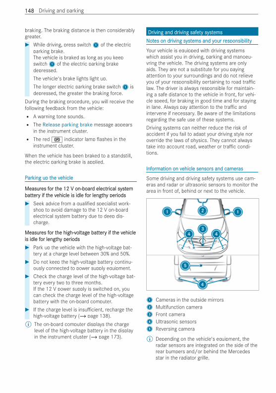
braking. The braking distance is then considerablygreater.# While driving, press switch1 of the electric
parking brake.The vehicle is braked as long as you keepswitch1 of the electric parking brakedepressed.The vehicle's brake lights light up.The longer electric parking brake switch1 isdepressed, the greater the braking force.
During the braking procedure, you will receive thefollowing feedback from the vehicle:R A warning tone sounds.R The Release parking brake message appears
in the instrument cluster.R The red ! indicator lamp ashes in the
instrument cluster.
When the vehicle has been braked to a standstill,the electric parking brake is applied.
PPararking up tking up the vhe vehicleehicle
MeasurMeasures fes for tor the 12 V on-boarhe 12 V on-board electrd electrical systical systemembattbatterery if ty if the vhe vehicle is idle fehicle is idle for lengthor lengthy pery periodsiods# Seek advice from a quali ed specialist work-
shop to avoid damage to the 12 V on-boardelectrical system battery due to deep dis-charge.
MeasurMeasures fes for tor the high-vhe high-voltoltagage batte batterery if ty if the vhe vehicleehicleis idle fis idle for lengthor lengthy pery periodsiods# Park up the vehicle with the high-voltage bat-
tery at a charge level between 30% and 50%.# Do not keep the high-voltage battery continu-
ously connected to power supply equipment.# Check the charge level of the high-voltage bat-
tery every two to three months.If the 12 V power supply is switched on, youcan check the charge level of the high-voltagebattery with the on-board computer.
# If the charge level is insu cient, recharge thehigh-voltage battery (/ page 138).
% The on-board computer displays the chargelevel of the high-voltage battery in the displayin the instrument cluster (/ page 173).
DrDriving and driving and driving safeiving safety systty systemsemsNNoottes on dres on driving systiving systems and yems and your rour responsibilityesponsibility
Your vehicle is equipped with driving systemswhich assist you in driving, parking and manoeu-vring the vehicle. The driving systems are onlyaids. They are not a substitute for you payingattention to your surroundings and do not relieveyou of your responsibility pertaining to road tra claw. The driver is always responsible for maintain-ing a safe distance to the vehicle in front, for vehi-cle speed, for braking in good time and for stayingin lane. Always pay attention to the tra c andintervene if necessary. Be aware of the limitationsregarding the safe use of these systems.Driving systems can neither reduce the risk ofaccident if you fail to adapt your driving style noroverride the laws of physics. They cannot alwaystake into account road, weather or tra c condi-tions.
InfInforormation on vmation on vehicle sensorehicle sensors and camers and camerasas
Some driving and driving safety systems use cam-eras and radar or ultrasonic sensors to monitor thearea in front of, behind or next to the vehicle.
1 Cameras in the outside mirrors2 Multifunction camera3 Front camera4 Ultrasonic sensors5 Reversing camera
% Depending on the vehicle's equipment, theradar sensors are integrated on the side of therear bumpers and/or behind the Mercedesstar in the radiator grille.
148148 Driving and parking
& WWARNINGARNING Risk of accident due to restric-ted detection performance of vehicle sen-sors and cameras
If the area around vehicle sensors or camerasis covered, damaged or dirty, certain drivingand safety systems cannot function correctly.There is a risk of an accident.# Keep the area around vehicle sensors or
cameras clear of any obstructions andclean.
# Have damage to the bumper, radiatorgrille or stone chipping in the area of thefront and rear windows repaired at aquali ed specialist workshop.
Keep the areas of the cameras and sensors free ofdirt, ice and slush (/ page 221). The sensors andcameras must not be covered and the detectionranges around them must be kept free. Do notattach additional license plate brackets, advertise-ments, stickers, foils or foils to protect againststone chippings in the detection range of the sen-sors and cameras. Make sure that there are nooverhanging loads protruding into the detectionrange.In the event of damage, or following a severeimpact, have the function of the sensors checkedat a quali ed specialist workshop. Have damage orstone chipping in the area of the cameras repairedat a quali ed specialist workshop.
OvOverervieview of drw of driving systiving systems and drems and driving safeiving safety syty sys-s-ttemsems
In this section, you will nd information about thefollowing driving systems and driving safety sys-tems:R ABS (AAnti-lock BBraking SSystem) (/ page 149)R BAS (BBrake AAssist SSystem) (/ page 149)R ESP® (EElectronic SStability PProgram)
(/ page 149)R EBD (EElectronic BBrakeforce DDistribution)
(/ page 150)R Active Brake Assist (/ page 150)R Adaptive brake lights (/ page 152)R Cruise control (/ page 152) and limiter
(/ page 153)R Active Distance Assist DISTRONIC
(/ page 154)R Hill start assist (/ page 157)
R HOLD function (/ page 158)R Parking Assist PARKTRONIC (/ page 158)R Reversing camera (/ page 160)R 360° Camera (/ page 161)R Active Parking Assist (/ page 163)R ATTENTION ASSIST (/ page 166)R Tra c Sign Assist (/ page 167)R Blind Spot Assist (/ page 168)R Lane Keeping Assist (/ page 169)
FFunction of ABS (Anti-locunction of ABS (Anti-lock Brk Braking Systaking System)em)
ABS controls the brake pressure in critical situa-tions:R During braking, for instance, at maximum full-
stop braking or if there is insu cient tyre trac-tion, the wheels are prevented from locking.R The steerability of the vehicle in terms of physi-
cal possibilities is ensured when braking.
If ABS intervenes, you will feel pulsations in thebrake pedal. The pulsating brake pedal may be anindication of hazardous road conditions and func-tions as a reminder to take extra care while driving.
FFunction of Bunction of BAS (BrAS (Brakake Assise Assist Systt System)em)
BAS supports you with additional braking force inan emergency braking situation.If you depress the brake pedal quickly, BAS is acti-vated:R BAS automatically boosts the braking force of
the brakesR BAS can shorten the braking distanceR ABS prevents the wheels from locking
When you release the brake pedal, the brakesfunction as usual again. BAS is deactivated.
FFunction of ESPunction of ESP®® (Electr(Electronic Stonic Stability Prability Progrogram)am)
& WWARNINGARNING Risk of skidding if ESP® is deac-tivated
If you deactivate ESP®, ESP® cannot carry outvehicle stabilisation.# ESP® should only be deactivated in the
following situations.
Driving and parking 149149
ESP® can, within physical limits, monitor andimprove driving stability and traction in the follow-ing situations:R when driving and pulling away on wet or slip-
pery road surfacesR when braking
If the vehicle is deviating from the directiondesired by the driver, ESP® can stabilise the vehi-cle by performing the following actions:R one or more wheels are brakedR the drive system performance is adapted
depending on the situation
% Only use wheels with the recommended tyresizes. Only then will ESP® function properly.
If the ÷ warning lamp ashes in the instrumentcluster, one or more wheels have reached theirtraction limit:R adapt your driving style to suit the prevailing
road and weather conditionsR do not deactivate ESP® under any circumstan-
cesR only depress the accelerator pedal as far as is
necessary when pulling away
Deactivate ESP® in the following situations toimprove traction:R When using snow chains.R In deep snow.R On sand or gravel.
% Spinning the wheels results in a cutting action,which enhances traction.
If the ÷ warning lamp lights up continuously,ESP® is not available due to a malfunction.Observe the information on warning lamps and dis-play messages (/ page 275).When ESP® is deactivated, the å warning lampin the instrument cluster lights up continuously.Observe the following points when ESP® is deacti-vated:R vehicle stabilisation is delayed and is signi -
cantly reduced in the lower speed rangeR the drive wheels may start to spinR traction control is still active
% If ESP® is deactivated, ESP® will still supportyou when braking.
DeactivDeactivating or activating or activating ESPating ESP®®
On-board computer:4 ò 5 Settings 5 Assistance 5 ESP# TTo deactivo deactivatate/active/activatate:e: press the a button.
If ESP® is deactivated, the å warning lampin the instrument cluster lights up.
% Observe the information on warning lamps anddisplay messages (/ page 275).
FFunction of ESPunction of ESP®® CrCrosswind Assistosswind Assist
ESP® Crosswind Assist detects sudden gusts ofside wind and helps the driver to keep the vehiclein the lane:R ESP® Crosswind Assist is active at vehicle
speeds above approx. 80 km/h when drivingstraight ahead or cornering slightly.R The vehicle is stabilised by means of individual
brake application on one side. The instrumentcluster displays a message with the tra c signfor a strong crosswind.
ESP® Crosswind Assist does not react under thefollowing conditions:R The vehicle is subjected to severe jolts and
vibrations, e.g. as a result of uneven surfacesor potholes.R The vehicle loses traction, e.g. on snow or ice
or when aquaplaning.
FFunction of EBD (Electrunction of EBD (Electronic Bronic Brakakefefororce Disce Distrtribu-ibu-tion)tion)
EBD has the following characteristics:R monitoring and controlling the braking force on
the rear wheelsR improving driving stabilisation when braking,
especially on bends
FFunction of Aunction of Activctive Bre Brakake Assiste Assist
Active Brake Assist consists of the following func-tions:R Distance warning functionR Autonomous braking functionR Situation-dependent brake force boosting
Active Brake Assist can help you to minimise therisk of a collision with vehicles, cyclists or pedes-trians, or reduce the e ects of such a collision.
150150 Driving and parking
If Active Brake Assist has detected a risk of colli-sion, a warning tone sounds and theL warninglamp lights up in the instrument cluster.If you do not react to the warning, autonomousbraking can be initiated in critical situations. Inespecially critical situations, Active Brake Assistcan initiate autonomous braking directly. In thiscase, the warning lamp and warning tone are acti-vated simultaneously with the braking application.If you apply the brake yourself in a situation detec-ted as critical by Active Brake Assist, or apply thebrake during autonomous braking, situation-dependent brake force boosting occurs. The brakepressure increases up to maximum full-stop brak-ing if necessary.If autonomous braking or a situation-dependentbraking boosting e ect has occurred, theLwarning lamp ashes brie y and then goes out.VVehicles witehicles with PRE-Sh PRE-SAFEAFE®®:: if the autonomous brak-ing function or the situation-dependent brake forceboosting is triggered, additional preventive meas-ures for occupant protection (PRE-SAFE) may alsobe initiated (/ page 38).
& WWARNINGARNING Risk of an accident caused bylimited detection performance of ActiveBrake Assist
Active Brake Assist cannot always clearly iden-tify objects and complex tra c situations.In such cases, Active Brake Assist might:R Give a warning or brake without reasonR Not give a warning or not brake
Active Brake Assist is only an aid. The driver isresponsible for maintaining a su ciently safedistance to the vehicle in front, vehicle speedand for braking in good time.# Always pay careful attention to the tra c
situation; do not rely on Active BrakeAssist alone.
# Be prepared to brake or swerve if neces-sary.
Observe the system limitations of Active BrakeAssist. Due to the nature of the system, complexbut non-critical driving conditions may also causeActive Brake Assist to intervene during braking.
The individual subfunctions arThe individual subfunctions are ave available in tailable in the fhe fol-ol-lolowing speed rwing speed ranganges:es:DistDistance wance wararning functionning function
The distance warning function warns you in the fol-lowing situations:R From approximately 30 km/h, if over several
seconds the distance maintained to the vehicletravelling in front is insu cient for the drivenspeed, theL warning lamp lights up in theinstrument cluster.R From approximately 7 km/h, if your vehicle is
critically close to a vehicle or pedestrian, anintermittent warning tone sounds and theLwarning lamp lights up in the instrument clus-ter.
Brake immediately or take evasive action, providedit is safe to do so and the tra c situation allowsthis.The distance warning function can aid you in thefollowing situations with an intermittent warningtone and a warning lamp:R VVehicles travehicles travelling in frelling in frontont:: up to approximately
250 km/hR StStationarationary vy vehicles:ehicles: up to approximately
80 km/hR CrCrossing vossing vehicles:ehicles: no reactionR MoMoving pedesving pedestrtrians/cyians/cyclisclists ahead:ts ahead: up to
approximately 80 km/hR CrCrossing cyossing cyclisclists:ts: up to approximately
60 km/hR StStationarationary pedesy pedestrtrians:ians: no reaction
AAututonomous bronomous braking functionaking functionThe autonomous braking function may intervene atspeeds starting from approximately 7 km/h in thefollowing situations:R VVehicles travehicles travelling in frelling in frontont:: up to approximately
200 km/hR StStationarationary vy vehicles:ehicles: up to approximately
50 km/hR CrCrossing vossing vehicles:ehicles: no reactionR CyCyclisclists ahead:ts ahead: up to approximately 80 km/hR MoMoving pedesving pedestrtrians/crians/crossing cyossing cyclisclists:ts: up to
approximately 60 km/hR StStationarationary pedesy pedestrtrians:ians: no reaction
Driving and parking 151151
Situation-dependent brSituation-dependent brakake fe fororce boosce boostingtingSituation-dependent brake force boosting mayintervene at speeds starting from approximately7 km/h in the following situations:R VVehicles travehicles travelling in frelling in frontont:: up to approximately
250 km/hR StStationarationary vy vehicles:ehicles: up to approximately
80 km/hR CrCrossing vossing vehicles:ehicles: no reactionR CyCyclisclists ahead:ts ahead: up to approximately 80 km/hR MoMoving pedesving pedestrtrians/crians/crossing cyossing cyclisclists:ts: up to
approximately 60 km/hR StStationarationary pedesy pedestrtrians:ians: no reaction
Cancelling a brCancelling a brakake application of Ae application of Activctive Bre BrakeakeAssistAssistYou can cancel a brake application of Active BrakeAssist at any time by:R Fully depressing the accelerator pedal or with
kickdown.R Releasing the brake pedal.
Active Brake Assist may cancel the brake applica-tion when one of the following conditions is ful l-led:R You manoeuvre to avoid the obstacle.R There is no longer a risk of collision.R An obstacle is no longer detected in front of
your vehicle.
SystSystem limitsem limitsFull system performance is not yet available for afew seconds a er switching on the vehicle or a erdriving o .The system may be impaired or may not function inthe following situations:R In snow, rain, fog or heavy spray.R If the sensors are dirty, misted up, damaged or
covered.R If the sensors are impaired due to interference
from other radar sources, e.g. strong radarre ections in multi-storey car parks.R If a loss of tyre pressure or a defective tyre has
been detected and displayed.R In complex tra c situations where objects
cannot always be clearly identi ed.R If pedestrians or vehicles move quickly into the
sensor detection range.R If pedestrians are hidden by other objects.
R If the typical outline of a pedestrian cannot bedistinguished from the background.R If a pedestrian is not detected as such, e.g.
due to special clothing or other objects.R In bends with a narrow radius.
AActivctivating or deactivating or deactivating Aating Activctive Bre Brakake Assiste Assist
On-board computer:4 ò 5 Settings 5 Assistance5 Active Brake Assist% It is recommended that Active Brake Assist is
always le activated.# TTo activo activatate/deactive/deactivatate:e: press the a button.
The distance warning function and the autono-mous braking function of Active Brake Assistare deactivated or activated.When the functions are deactivated, the æsymbol appears in the assistance graphic inthe instrument cluster display.
The next time the vehicle is started, Active BrakeAssist is automatically activated.
FFunction of Aunction of Adapdaptivtive Bre Brakake Lightse Lights
Adaptive Brake Lights warn following tra c in anemergency braking situation with the following sig-nals:R By ashing the brake lampsR By activating the hazard warning lights
If the vehicle is braked sharply from speeds above50 km/h, the brake lamps ash rapidly. This pro-vides tra c travelling behind you with an evenmore noticeable warning.If the vehicle is travelling at speeds of more than70 km/h at the beginning of the brake application,the hazard warning lights switch on once the vehi-cle is stationary. When pulling away again, the haz-ard warning lights switch o automatically atapproximately 10 km/h.You can also switch o the hazard warning lightsusing the hazard warning button (/ page 105).
CrCruise contruise control and limitol and limiterer
FFunction of crunction of cruise contruise contrololCruise control accelerates and brakes the vehicleautomatically in order to maintain a previouslystored speed.
152152 Driving and parking
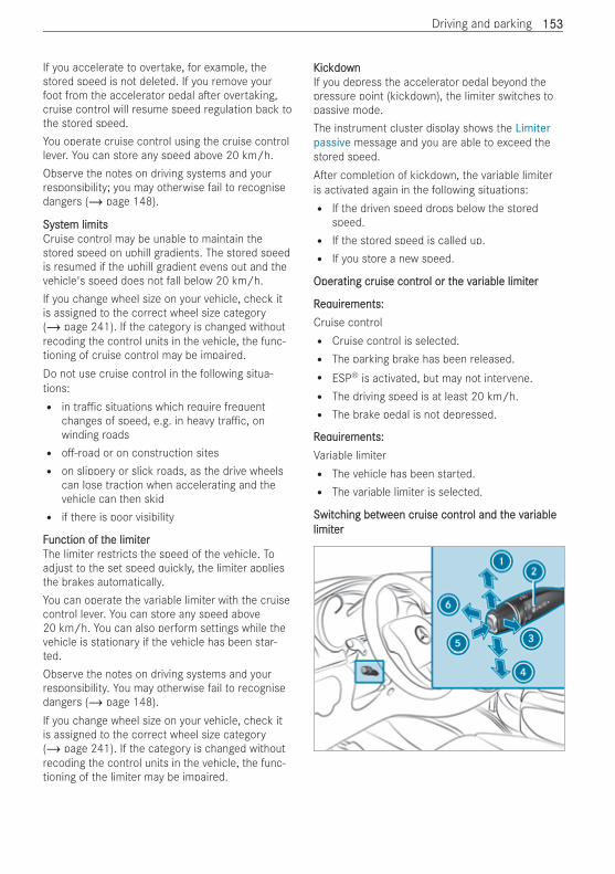
If you accelerate to overtake, for example, thestored speed is not deleted. If you remove yourfoot from the accelerator pedal a er overtaking,cruise control will resume speed regulation back tothe stored speed.You operate cruise control using the cruise controllever. You can store any speed above 20 km/h.Observe the notes on driving systems and yourresponsibility; you may otherwise fail to recognisedangers (/ page 148).
SystSystem limitsem limitsCruise control may be unable to maintain thestored speed on uphill gradients. The stored speedis resumed if the uphill gradient evens out and thevehicle's speed does not fall below 20 km/h.If you change wheel size on your vehicle, check itis assigned to the correct wheel size category(/ page 241). If the category is changed withoutrecoding the control units in the vehicle, the func-tioning of cruise control may be impaired.Do not use cruise control in the following situa-tions:R in tra c situations which require frequent
changes of speed, e.g. in heavy tra c, onwinding roadsR o -road or on construction sitesR on slippery or slick roads, as the drive wheels
can lose traction when accelerating and thevehicle can then skidR if there is poor visibility
FFunction of tunction of the limithe limitererThe limiter restricts the speed of the vehicle. Toadjust to the set speed quickly, the limiter appliesthe brakes automatically.You can operate the variable limiter with the cruisecontrol lever. You can store any speed above20 km/h. You can also perform settings while thevehicle is stationary if the vehicle has been star-ted.Observe the notes on driving systems and yourresponsibility. You may otherwise fail to recognisedangers (/ page 148).If you change wheel size on your vehicle, check itis assigned to the correct wheel size category(/ page 241). If the category is changed withoutrecoding the control units in the vehicle, the func-tioning of the limiter may be impaired.
KicKickdokdownwnIf you depress the accelerator pedal beyond thepressure point (kickdown), the limiter switches topassive mode.The instrument cluster display shows the Limiterpassive message and you are able to exceed thestored speed.A er completion of kickdown, the variable limiteris activated again in the following situations:R If the driven speed drops below the stored
speed.R If the stored speed is called up.R If you store a new speed.
OperOperating crating cruise contruise control or tol or the vhe varariable limitiable limiterer
RReqequiruirements:ements:Cruise controlR Cruise control is selected.R The parking brake has been released.R ESP® is activated, but may not intervene.R The driving speed is at least 20 km/h.R The brake pedal is not depressed.
RReqequiruirements:ements:Variable limiterR The vehicle has been started.R The variable limiter is selected.
SwitcSwitching behing betwtween creen cruise contruise control and tol and the vhe varariableiablelimitlimiterer
Driving and parking 153153
# Press button5.R LIM indicator lamp2 o : cruise control is
selected.R LIM indicator lamp2 lit: the variable lim-
iter is selected.
SSttororing and mainting and maintaining taining the currhe current speedent speed# Brie y press the cruise control lever up1 or
down4.The current speed is stored and the vehiclemaintains this speed (cruise control) or doesnot exceed it (variable limiter).
When you activate cruise control, the stored speedis brie y shown in the text eld of the instrumentcluster display. The display also shows the ¯symbol and the stored speed.When you activate the variable limiter, the instru-ment cluster display brie y shows the storedspeed. The display also shows the È symboland the stored speed.% For vehicles with Active Distance Assist
DISTRONIC, the segments between the startof the scale and the stored speed light up inthe speedometer dial instead.
Calling up tCalling up the sthe storored speeded speed
& WWARNINGARNING Risk of accident due to storedspeed
If you call up the stored speed and this is lowerthan your current speed, the vehicle deceler-ates.# Take into account the tra c situation
before calling up the stored speed.
# Brie y pull the cruise control lever in direction3.The last stored speed is called up and the vehi-cle maintains this speed (cruise control) ordoes not exceed it (variable limiter).If the last stored speed has previously beendeleted, the currently driven speed is stored.
% When you switch o the vehicle, the last speedstored is cleared.
IncrIncreasing or reasing or reducing teducing the speedhe speed# Press the cruise control lever up1 or down4 as far as the 1st pressure point.The stored speed is increased or reduced by1 km/h.
or
# Press the cruise control lever up1 or down4 beyond the 1st pressure point.The stored speed is increased or reduced by10 km/h.
If you have set Miles as the unit for the digitalspeedometer, you can maintain any speed from20 mph (cruise control) or set it as the limit speed(variable limiter). You can then set the limit speedin increments of 1 mph and 5 mph.
DeactivDeactivating crating cruise contruise control or tol or the vhe varariable limitiable limiterer# Brie y press the cruise control lever forwards6.
or# Press button5.
The ¯ or È symbol and the storedspeed in the instrument cluster display then goout.
% Cruise control is deactivated in the followingsituations:R you apply the brakes.R you drive below a speed of 20 km/h.R you shi the transmission to position i.R ESP® intervenes.
In these cases the variable limiter remainsactivated.If you deactivate ESP®, or ABS or ESP® is mal-functioning, cruise control and the limiter aredeactivated.
If cruise control automatically deactivates, a warn-ing tone sounds and the Cruise control off mes-sage appears brie y in the instrument cluster dis-play.
AActivctive Diste Distance Assisance Assist DISt DISTRTRONICONIC
FFunction of Aunction of Activctive Diste Distance Assisance Assist DISt DISTRTRONICONICActive Distance Assist DISTRONIC maintains theset speed on free- owing roads. If vehicles aheadare detected, the set distance is maintained, ifnecessary until the vehicle comes to a halt. Thevehicle accelerates or brakes, depending on thedistance to the vehicle in front and the set speed.The speed and distance to the vehicle in front areset and saved using the cruise control lever. Thespeed can be set in the range between 20 km/hand 200 km/h.Other features of Active Distance AssistDISTRONIC:R Depending on the preselected distance,
DISTRONIC intervenes either dynamically
154154 Driving and parking
(short distance) or to save energy (long dis-tance).R Depending on the vehicle mass detected, the
dynamics of the DISTRONIC intervention arereduced.R Acceleration to the stored speed is initiated if
the turn signal indicator is switched on tochange to the overtaking lane.
Observe the notes on driving systems and yourresponsibility; you may otherwise fail to recognisedangers (/ page 148).
SystSystem limitsem limitsThe system may be impaired or may not function inthe following situations, for example:R in snow, rain, fog or heavy sprayR if there is dirt on the radar sensors or they are
coveredR if there is interference from radar sources or
strong radar re ections, for example in multi-storey car parksR in tra c situations where frequent speed
changes are required, e.g. in heavy tra c or onwinding roads or o -roadR on roads with steep downhill or uphill gradientsR on winding roads
The system cannot detect stationary objectsunless these were previously detected as moving.In addition, on slippery or slick roads, braking oraccelerating can cause one or several of the drivewheels to lose traction and the vehicle can thenskid.Do not use Active Distance Assist DISTRONIC inthese situations.
& WWARNINGARNING Risk of accident from accelera-tion or braking by Active Distance AssistDISTRONIC
Active Distance Assist DISTRONIC may accel-erate or brake in the following cases, for exam-ple:R If the vehicle pulls away using Active Dis-
tance Assist DISTRONIC.R If the stored speed is called up and is con-
siderably faster or slower than the cur-rently driven speed.R If Active Distance Assist DISTRONIC no
longer detects a vehicle in front or doesnot react to relevant objects.
# Always carefully observe the tra c con-ditions and be ready to brake at all times.
# Take into account the tra c situationbefore calling up the stored speed.
& WWARNINGARNING Risk of accident due to insu -cient deceleration by Active DistanceAssist DISTRONIC
Active Distance Assist DISTRONIC brakes yourvehicle with up to 50% of the possible deceler-ation. If this deceleration is not su cient,Active Distance Assist DISTRONIC alerts youwith a visual and acoustic warning.# Adjust your speed and maintain a suita-
ble distance from the vehicle in front.# Brake the vehicle yourself and/or take
evasive action.
& WWARNINGARNING Risk of accident if detectionfunction of Active Distance AssistDISTRONIC is impaired
Active Distance Assist DISTRONIC does notreact or has a limited reaction:R when driving on a di erent lane or when
changing lanesR to pedestrians, animals, bicycles or station-
ary vehicles, or unexpected obstaclesR to complex tra c conditionsR to oncoming vehicles and crossing tra c
As a result, Active Distance Assist DISTRONICmay neither give warnings nor intervene insuch situations.# Always observe the tra c conditions
carefully and react accordingly.
Active Distance Assist DISTRONIC may not detectnarrow vehicles driving in front, e.g. motorcycles orvehicles not travelling in line with your vehicle.If the following requirements for activation are nolonger ful lled or the system is malfunctioning,Active Distance Assist DISTRONIC is automaticallydeactivated. If the vehicle is stationary or is mov-ing very slowly during automatic deactivation, thetransmission automatically shi s to park positionj.
Driving and parking 155155
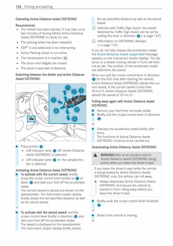
OperOperating Aating Activctive Diste Distance Assisance Assist DISt DISTRTRONICONIC
RReqequiruirements:ements:R The vehicle has been started. It may take up to
two minutes of driving before Active DistanceAssist DISTRONIC is ready for use.R The parking brake has been released.R ESP® is activated and is not intervening.R Active Parking Assist is not active.R The transmission is in position h.R The doors and tailgate are closed.R The driver's seat belt is fastened.
SwitcSwitching behing betwtween teen the limithe limiter and Aer and Activctive Diste DistanceanceAssisAssist DISt DISTRTRONICONIC
# Press button6.R LIM indicator lamp3 o : Active Distance
Assist DISTRONIC is selected.R LIM indicator lamp3 lit: the variable lim-
iter is selected.
AActivctivating Aating Activctive Diste Distance Assisance Assist DISt DISTRTRONICONIC# TTo activo activatate wite with th the currhe current speed:ent speed: brie y
press the cruise control lever brie y up1 ordown5 and take your foot o the acceleratorpedal.The current speed is stored and shown on thespeedometer. The instrument cluster displaybrie y shows the set speci ed distance as wellas the stored speed.
or# TTo activo activatate wite with th the sthe storored speed:ed speed: pull the
cruise control lever brie y in direction4 andtake your foot o the accelerator pedal.The speed is displayed on the speedometer.The instrument cluster display brie y shows
the set speci ed distance as well as the storedspeed.
% Vehicles with Tra c Sign Assist: the speeddetected by Tra c Sign Assist can be set bypulling the lever in direction4(/ page 167).
% Information on DISTRONIC displays(/ page 157).
If you do not fully release the accelerator pedal,the Active Distance Assist suspended messageappears on the instrument cluster display. The dis-tance to a slower-moving vehicle in front will thennot be set. The position of the accelerator pedalwill determine the speed.When you pull the cruise control lever in direction4 for the rst time a er starting the vehicle,Active Distance Assist DISTRONIC adopts the cur-rent speed. If the current speed is less than20 km/h, Active Distance Assist DISTRONICadopts the speed of 20 km/h.
Pulling awaPulling away agy again witain with Ah Activctive Diste Distance Assistance AssistDISDISTRTRONICONIC# Remove your foot from the brake pedal.# Brie y pull the cruise control lever in direction4.
or# Depress the accelerator pedal brie y with
force.The functions of Active Distance AssistDISTRONIC continue to be carried out.
DeactivDeactivating Aating Activctive Diste Distance Assisance Assist DISt DISTRTRONICONIC
& WWARNINGARNING Risk of an accident due toActive Distance Assist DISTRONIC beingactive when you leave the driver's seat
If you leave the driver's seat while the vehicleis being braked by Active Distance AssistDISTRONIC only, the vehicle can roll away.# Always deactivate Active Distance Assist
DISTRONIC and secure the vehicle toprevent it from rolling away before youleave the driver's seat.
# Brie y push the cruise control lever forwards7.
or# Brake if the vehicle is moving.or
156156 Driving and parking
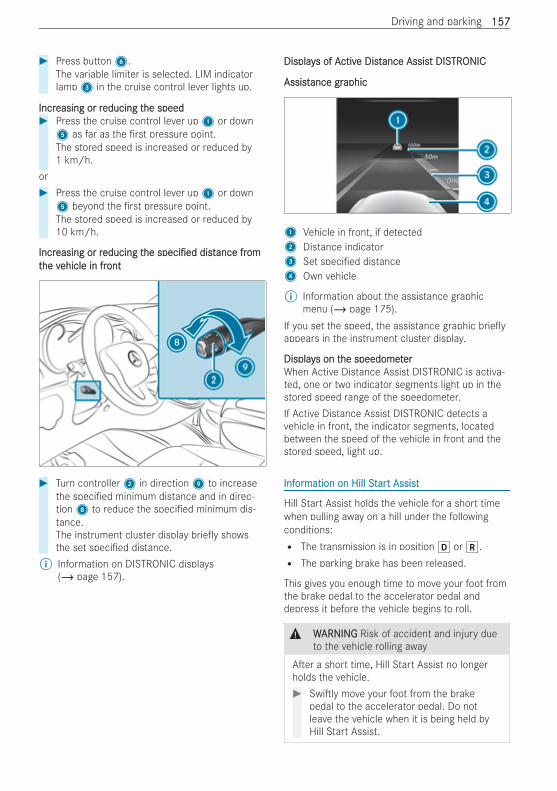
# Press button6.The variable limiter is selected. LIM indicatorlamp3 in the cruise control lever lights up.
IncrIncreasing or reasing or reducing teducing the speedhe speed# Press the cruise control lever up1 or down5 as far as the rst pressure point.The stored speed is increased or reduced by1 km/h.
or# Press the cruise control lever up1 or down5 beyond the rst pressure point.The stored speed is increased or reduced by10 km/h.
IncrIncreasing or reasing or reducing teducing thehe speci edspeci ed distdistance france fromomtthe vhe vehicle in frehicle in frontont
# Turn controller2 in direction9 to increasethe speci ed minimum distance and in direc-tion8 to reduce the speci ed minimum dis-tance.The instrument cluster display brie y showsthe set speci ed distance.
% Information on DISTRONIC displays(/ page 157).
DisplayDisplays of As of Activctive Diste Distance Assisance Assist DISt DISTRTRONICONIC
AssistAssistance grance graphicaphic
1 Vehicle in front, if detected2 Distance indicator3 Set speci ed distance4 Own vehicle
% Information about the assistance graphicmenu (/ page 175).
If you set the speed, the assistance graphic brie yappears in the instrument cluster display.
DisplayDisplays on ts on the speedomethe speedometererWhen Active Distance Assist DISTRONIC is activa-ted, one or two indicator segments light up in thestored speed range of the speedometer.If Active Distance Assist DISTRONIC detects avehicle in front, the indicator segments, locatedbetween the speed of the vehicle in front and thestored speed, light up.
InfInforormation on Hill Stmation on Hill Starart Assistt Assist
Hill Start Assist holds the vehicle for a short timewhen pulling away on a hill under the followingconditions:R The transmission is in position h or k.R The parking brake has been released.
This gives you enough time to move your foot fromthe brake pedal to the accelerator pedal anddepress it before the vehicle begins to roll.
& WWARNINGARNING Risk of accident and injury dueto the vehicle rolling away
A er a short time, Hill Start Assist no longerholds the vehicle.# Swi ly move your foot from the brake
pedal to the accelerator pedal. Do notleave the vehicle when it is being held byHill Start Assist.
Driving and parking 157157
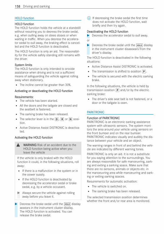
HOLD functionHOLD function
HOLD functionHOLD functionThe HOLD function holds the vehicle at a standstillwithout requiring you to depress the brake pedal,e.g. when pulling away on steep slopes or whenwaiting in tra c. When you depress the accelera-tor pedal to pull away, the braking e ect is cancel-led and the HOLD function is deactivated.The HOLD function is only an aid. The responsibil-ity for the vehicle safely standing still remains withthe driver.
SystSystem limitsem limitsThe HOLD function is only intended to provideassistance when driving and is not a su cientmeans of safeguarding the vehicle against rollingaway when stationary.R The incline cannot be greater than 30%.
AActivctivating or deactivating or deactivating tating the HOLD functionhe HOLD function
RReqequiruirements:ements:R The vehicle has been started.R All the doors and the tailgate are closed and
the seatbelt is fastened.R The parking brake has been released.R The selector lever is in the h, k or i posi-
tion.R Active Distance Assist DISTRONIC is deactiva-
ted.
AActivctivating tating the HOLD functionhe HOLD function
& WWARNINGARNING Risk of an accident due to theHOLD function being active when youleave the vehicle
If the vehicle is only braked with the HOLDfunction it could, in the following situations, rollaway:R If there is a malfunction in the system or in
the power supply.R If the HOLD function is deactivated by
depressing the accelerator pedal or brakepedal, e.g. by a vehicle occupant.
# Always secure the vehicle against rollingaway before you leave it.
# Depress the brake pedal until the ë displayappears in the instrument cluster display.The HOLD function is activated. You canrelease the brake pedal.
% If depressing the brake pedal the rst timedoes not activate the HOLD function, waitbrie y and then try again.
DeactivDeactivating tating the HOLD functionhe HOLD function# Depress the accelerator pedal to pull away.or# Depress the brake pedal until the ë display
in the instrument cluster disappears from thedriver's display.
The HOLD function is deactivated in the followingsituations:R Active Distance Assist DISTRONIC is activated.R The transmission is shi ed to position j.R The vehicle is secured with the electric parking
brake.
In the following situations, the vehicle is held bytransmission position j and/or by the electricparking brake:R The driver's side seat belt is not fastened, or a
door or the tailgate is open.
PPARKARKTRTRONICONIC
FFunction of Punction of PARKARKTRTRONICONICPARKTRONIC is an electronic parking assistancesystem with ultrasonic sensors. The system moni-tors the area around your vehicle using sensors onthe front bumper and on the rear bumper.PARKTRONIC indicates visually and audibly the dis-tance between your vehicle and an object.The warning ranges in front of and behind the vehi-cle are indicated by di erent warning tones.PARKTRONIC is only an aid. It is not a substitutefor you paying attention to the surroundings. Youare always responsible for safe manoeuvring, park-ing and exiting a parking space. Make sure thatthere are no persons, animals or objects etc. inthe manoeuvring area while manoeuvring and park-ing or exiting parking spaces.Requirements for automatic activation:R The vehicle is switched on.R The parking brake has been released.
The selected transmission position determineswhether the front and/or rear area is monitored.
158158 Driving and parking
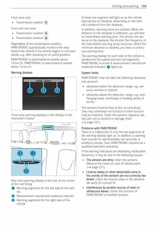
Front area only:R Transmission position h
Front and rear area:R Transmission position k
R Transmission position i
Regardless of the transmission position,PARKTRONIC automatically monitors the areabehind the vehicle if the vehicle begins to roll back-wards, e.g. a er stopping on an uphill gradient.PARKTRONIC is deactivated at speeds above18 km/h. PARKTRONIC is reactivated at speedsbelow 16 km/h.
WWararning displaysning displays
Front zone warning displays in the display of theinstrument cluster
Rear area warning display in the rear at the centreof the roof lining1 Warning segments for the le side of the vehi-
cle2 Measurement operational readiness indicator3 Warning segments for the right side of the
vehicle
At least one segment will light up as the vehicleapproaches an obstacle, depending on the vehi-cle's distance from the obstacle.In addition, warning tones are emitted. When thedistance to the obstacle is su cient, you will hearan intermittent warning tone. The shorter the dis-tance to the obstacle, the shorter the frequency ofthe intermittent warning tones becomes. When theminimum distance is reached, you hear a continu-ous warning tone.The warning display for each side of the vehicle isdivided into ve yellow and two red segments.PARKTRONIC is active if measurement operationalreadiness indicator2 lights up.
SystSystem limitsem limitsPARKTRONIC may not take the following obstaclesinto account:R obstacles below the detection range, e.g. per-
sons, animals or objectsR obstacles above the detection range, e.g. over-
hanging loads, overhangs or loading ramps oflorries
The sensors must be free of dirt, ice and slush.They may otherwise not function or their functionmay be impaired. Clean the sensors regularly, tak-ing care not to scratch or damage them(/ page 221).
PrProblems witoblems with Ph PARKARKTRTRONICONICThere is a malfunction if only the red segments ofthe warning display light up. In addition, a warningtone sounds for approximately two seconds. Ifproblems persist, have PARKTRONIC checked at aquali ed specialist workshop.If the warning indicators are displaying implausibledistances, it may be due to the following causes:R The sensorThe sensors ars are dire dirtyty:: clean the sensors.
Observe the notes on care of vehicle parts(/ page 221).R Licence platLicence plates or otes or other dether detacachable parhable parts ints in
tthe vicinity of the vicinity of the sensorhe sensors ars are noe not corrt correctlectly fy fas-as-ttened:ened: check the licence plate or the detacha-ble parts for correct t.R IntInterferfererence bence by anoty another sourher source of rce of radio oradio or
ultrultrasound wavasound waves:es: check the function ofPARKTRONIC at another location.
Driving and parking 159159
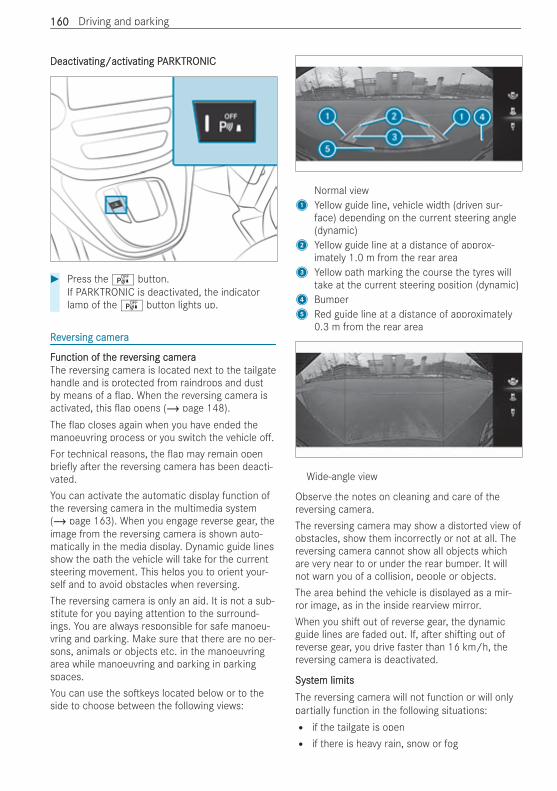
DeactivDeactivating/activating/activating Pating PARKARKTRTRONICONIC
# Press theé button.If PARKTRONIC is deactivated, the indicatorlamp of theé button lights up.
RReevverersing camerasing camera
FFunction of tunction of the revhe reverersing camerasing cameraThe reversing camera is located next to the tailgatehandle and is protected from raindrops and dustby means of a ap. When the reversing camera isactivated, this ap opens (/ page 148).The ap closes again when you have ended themanoeuvring process or you switch the vehicle o .For technical reasons, the ap may remain openbrie y a er the reversing camera has been deacti-vated.You can activate the automatic display function ofthe reversing camera in the multimedia system(/ page 163). When you engage reverse gear, theimage from the reversing camera is shown auto-matically in the media display. Dynamic guide linesshow the path the vehicle will take for the currentsteering movement. This helps you to orient your-self and to avoid obstacles when reversing.The reversing camera is only an aid. It is not a sub-stitute for you paying attention to the surround-ings. You are always responsible for safe manoeu-vring and parking. Make sure that there are no per-sons, animals or objects etc. in the manoeuvringarea while manoeuvring and parking in parkingspaces.You can use the so keys located below or to theside to choose between the following views:
Normal view1 Yellow guide line, vehicle width (driven sur-
face) depending on the current steering angle(dynamic)
2 Yellow guide line at a distance of approx-imately 1.0 m from the rear area
3 Yellow path marking the course the tyres willtake at the current steering position (dynamic)
4 Bumper5 Red guide line at a distance of approximately
0.3 m from the rear area
Wide-angle view
Observe the notes on cleaning and care of thereversing camera.The reversing camera may show a distorted view ofobstacles, show them incorrectly or not at all. Thereversing camera cannot show all objects whichare very near to or under the rear bumper. It willnot warn you of a collision, people or objects.The area behind the vehicle is displayed as a mir-ror image, as in the inside rearview mirror.When you shi out of reverse gear, the dynamicguide lines are faded out. If, a er shi ing out ofreverse gear, you drive faster than 16 km/h, thereversing camera is deactivated.
SystSystem limitsem limitsThe reversing camera will not function or will onlypartially function in the following situations:R if the tailgate is openR if there is heavy rain, snow or fog
160160 Driving and parking
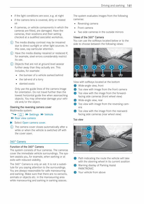
R if the light conditions are poor, e.g. at nightR if the camera lens is covered, dirty or misted
upR if cameras, or vehicle components in which the
cameras are tted, are damaged. Have thecameras, their positions and their settingchecked at a quali ed specialist workshop.
% The media display contrast may be impaireddue to direct sunlight or other light sources. Inthis case, pay particular attention.
% Have the media display repaired or replaced if,for example, pixel errors considerably restrictits use.
% Objects that are not at ground level appearfurther away than they actually are. Thisincludes, for example:R the bumper of a vehicle parked behindR the tail-end of a lorryR slanted posts
Only use the guide lines of the camera imagefor orientation. Do not travel further than thelowest horizontal guide line when approachingobjects. You may otherwise damage your vehi-cle and/or the object.
Opening tOpening the revhe reverersing camersing camera cova covererMultimedia system:4© 5 Settings 5 Vehicle5 Rear view camera# Select Open camera cover.% The camera cover closes automatically a er a
while or when the vehicle is switched o withthe cover open.
360° Camera360° Camera
FFunction of tunction of the 360° Camerahe 360° CameraThe system consists of four cameras. The camerascover the immediate vehicle surroundings. The sys-tem assists you, for example, when parking or atexits with reduced visibility.The 360° Camera is only an aid. It is not a substi-tute for you paying attention to the surroundings.You are always responsible for safe manoeuvringand parking. Make sure that there are no persons,animals or objects etc. in the manoeuvring areawhile manoeuvring and parking in parking spaces.
The system evaluates images from the followingcameras:R Reversing cameraR Front cameraR Two side cameras in the outside mirrors
VViewiews of ts of the 360° Camerahe 360° CameraYou can use the so keys located below or to theside to choose between the following views:
View with so keys located at the bottom1 Wide-angle view, front2 Top view with image from the front camera3 Top view with the image from the forward-
facing side cameras (front wheel view)4 Wide-angle view, rear5 Top view with image from the reversing cam-
era6 Top view with the image from the rearward-
facing side cameras (rear wheel view)
TTop viewop view
1 Path indicating the route the vehicle will takewith the steering wheel in its current position
2 Warning display of Parking AssistPARKTRONIC
3 Your vehicle from above
Driving and parking 161161
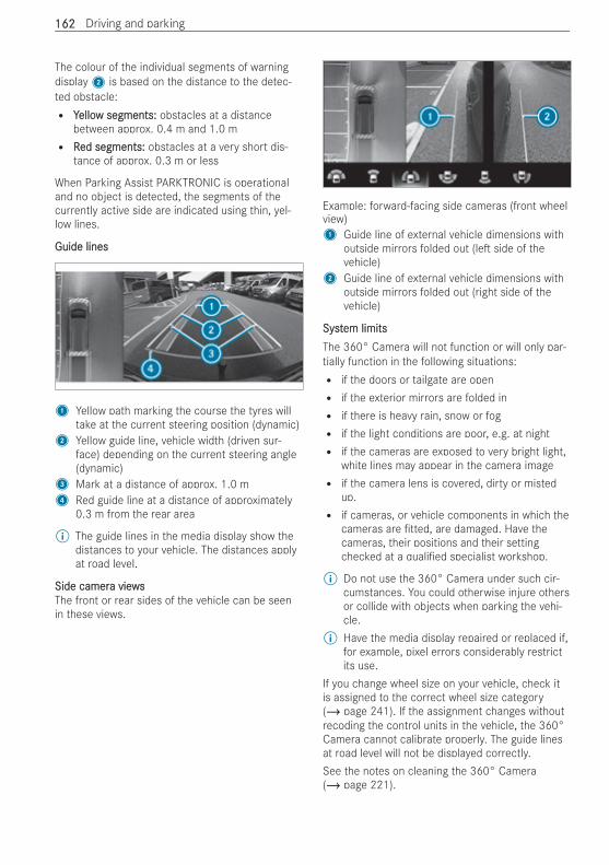
The colour of the individual segments of warningdisplay2 is based on the distance to the detec-ted obstacle:R YYelloellow segments:w segments: obstacles at a distance
between approx. 0.4 m and 1.0 mR RRed segments:ed segments: obstacles at a very short dis-
tance of approx. 0.3 m or less
When Parking Assist PARKTRONIC is operationaland no object is detected, the segments of thecurrently active side are indicated using thin, yel-low lines.
Guide linesGuide lines
1 Yellow path marking the course the tyres willtake at the current steering position (dynamic)
2 Yellow guide line, vehicle width (driven sur-face) depending on the current steering angle(dynamic)
3 Mark at a distance of approx. 1.0 m4 Red guide line at a distance of approximately
0.3 m from the rear area
% The guide lines in the media display show thedistances to your vehicle. The distances applyat road level.
Side camerSide camera viewsa viewsThe front or rear sides of the vehicle can be seenin these views.
Example: forward-facing side cameras (front wheelview)1 Guide line of external vehicle dimensions with
outside mirrors folded out (le side of thevehicle)
2 Guide line of external vehicle dimensions withoutside mirrors folded out (right side of thevehicle)
SystSystem limitsem limitsThe 360° Camera will not function or will only par-tially function in the following situations:R if the doors or tailgate are openR if the exterior mirrors are folded inR if there is heavy rain, snow or fogR if the light conditions are poor, e.g. at nightR if the cameras are exposed to very bright light,
white lines may appear in the camera imageR if the camera lens is covered, dirty or misted
up.R if cameras, or vehicle components in which the
cameras are tted, are damaged. Have thecameras, their positions and their settingchecked at a quali ed specialist workshop.
% Do not use the 360° Camera under such cir-cumstances. You could otherwise injure othersor collide with objects when parking the vehi-cle.
% Have the media display repaired or replaced if,for example, pixel errors considerably restrictits use.
If you change wheel size on your vehicle, check itis assigned to the correct wheel size category(/ page 241). If the assignment changes withoutrecoding the control units in the vehicle, the 360°Camera cannot calibrate properly. The guide linesat road level will not be displayed correctly.See the notes on cleaning the 360° Camera(/ page 221).
162162 Driving and parking
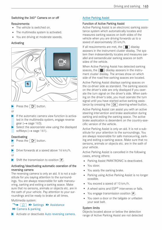
SwitcSwitching thing the 360° Camerhe 360° Camera on ora on or oo
RReqequiruirements:ements:R The vehicle is switched on.R The multimedia system is activated.R You are driving at moderate speeds.
AActivctivatingating
# Press theÔ button.or# If the automatic camera view function is activa-
ted in the multimedia system, engage reversegear (/ page 163).
# Select the appropriate view using the displayedso keys (/ page 161).
DeactivDeactivatingating# Press theÔ button.or# Drive forwards at a speed above 16 km/h.or# Shi the transmission to position j.
AActivctivating/deactivating/deactivating autating automatic operomatic operation of tation of theherevreverersing camerasing cameraThe reversing camera is only an aid. It is not a sub-stitute for you paying attention to the surround-ings. You are always responsible for safe manoeu-vring, parking and exiting a parking space. Makesure that no persons, animals or objects etc. are inthe path of your vehicle. Pay attention to your sur-roundings and be ready to brake at all times.Multimedia system:4© 5 Settings 5 Assistance5 Camera & parking# Activate or deactivate Auto reversing camera.
AActivctive Pe Pararking Assistking Assist
FFunction of Aunction of Activctive Pe Pararking Assistking AssistActive Parking Assist is an electronic parking assis-tance system which automatically locates andmeasures parking spaces on both sides of thevehicle when you are driving forwards up to aspeed of approximately 35 km/h.If all requirements are met, theÇ displayappears in the instrument cluster display. The sys-tem then independently locates and measures par-allel and perpendicular parking spaces on bothsides of the vehicle.When Active Parking Assist has detected parkingspaces, theÈ display appears in the instru-ment cluster display. The arrows show on whichside of the road free parking spaces are located.Active Parking Assist displays parking spaces onthe co-driver side as standard. The parking spaceson the driver's side are only displayed if you oper-ate the turn signal on the driver's side. When park-ing on the driver's side, you must operate the turnsignal until you have started active parking assis-tance by pressing the a steering-wheel button.Active Parking Assist can assist you with an activesteering intervention and brake application duringparking and exiting the parking space. The activebrake application is dependent on the country-spe-ci c version of the vehicle.Active Parking Assist is only an aid. It is not a sub-stitute for your attention to the surroundings. Youare always responsible for safe manoeuvring, park-ing and exiting a parking space. Make sure that nopersons, animals or objects etc. are in the path ofyour vehicle.Active Parking Assist is cancelled in the followingcases, among others:R Parking Assist PARKTRONIC is deactivated.R You steer.R You apply the parking brake.R Parking using Active Parking Assist is no longer
possible.R You exceed a speed of 10 km/h.R A wheel spins and ESP® intervenes or fails.R You engage transmission position j.R You open a door or the tailgate or unfasten
your seat belt.
SystSystem limitsem limitsObjects located above or below the detectionrange of Active Parking Assist are not detected
Driving and parking 163163
when the parking space is being measured. Theseare also not taken into account when the parkingmanoeuvre is calculated, e.g. overhanging loads,overhangs or loading ramps of lorries, or the boun-daries of parking spaces. In some circumstances,Active Parking Assist may therefore guide you intothe parking space prematurely.
& WWARNINGARNING Risk of accident due to objectslocated above or below the detectionrange of Active Parking Assist
If there are objects above or below the detec-tion range, the following situations may arise:R Active Parking Assist may steer too early.R The vehicle may not stop in front of these
objects.
There is a danger of collision!# In these situations, do not use Active
Parking Assist.
Snowfall or heavy rain may lead to a parking spacebeing measured inaccurately. Parking spaces thatare partially occupied by trailer drawbars might notbe identi ed as such or be measured incorrectly.Only use Active Parking Assist on level, high-gripground.Do not use Active Parking Assist in the followingsituations, among others:R in extreme weather conditions such as ice,
packed snow or in heavy rainR when corneringR for parking spaces which are not on the same
level as the road, e.g. not on the pavementR when transporting a load that protrudes
beyond the vehicleR when snow chains are tted
Active Parking Assist may also display parkingspaces that are not suitable for parking, for exam-ple:R parking spaces where parking is prohibitedR parking spaces on unsuitable surfaces
Active Parking Assist will not assist you with park-ing spaces perpendicular to the direction of travelin the following situations:R if two parking spaces are located immediately
next to each otherR if the parking space is immediately next to a
low obstacle such as a kerbR if you are parking forwards
Active Parking Assist will not assist you with park-ing spaces parallel or perpendicular to the direc-tion of travel in the following situations:R if the parking space is on a kerbR if the system deems the parking space to be
blocked, such as by foliage or grass pavingblocksR if the area is too small for the vehicle to
manoeuvre intoR if the parking space is bordered by an obsta-
cle, e.g. a tree, a post or a trailer
PPararking using Aking using Activctive Pe Pararking Assistking Assist
& WWARNINGARNING Risk of accident due to insu -ciently securing the vehicle against rollingaway when exiting the vehicle
If you leave the driver's seat when the vehicleis being braked by Active Parking Assist only, itcould roll away in the following situations:R if there is a malfunction in the system or in
the power supply.R if the electrical system in the engine com-
partment, the battery or the fuses are tam-pered with.R if the battery is disconnected.R if the vehicle is accelerated, e.g. by a vehi-
cle occupant.
# Before leaving the driver's seat, alwayssecure the vehicle against rolling away.
# Bring the vehicle safely to a stop when theparking symbol with an arrow shows thedesired parking space.
& WWARNINGARNING Risk of accident due to vehicleswinging out while parking or pulling out ofa parking space
While parking or pulling out of a parking space,the vehicle swings out and can drive ontoareas of the oncoming lane.
164164 Driving and parking
This could cause you to collide with objects orother road users.# Pay attention to objects and other road
users.# Where necessary, stop the vehicle or
cancel the parking procedure with Park-ing Pilot.
# Shi the transmission to position k.The instrument cluster display shows the StartParking Assist? Yes: OK No:~ messageand the location of the parking space.
# TTo cancel to cancel the prhe process:ocess: press the~ steer-ing-wheel button or drive o .
or# TTo paro park using activk using active pare parking assistking assistance:ance: press
the a steering-wheel button.The Parking Assist in operation Accelerateand brake Observe surroundings message isshown in the instrument cluster display.
# Release the steering wheel.# Reverse the vehicle, being ready to brake at all
times. Reverse slowly, and do not drive fasterthan 10 km/h. Parking assistance is otherwisecancelled and Active Parking Assist is stopped.When the vehicle approaches the rear borderof the parking space, Active Parking Assist canbrake it to a standstill.
# Stop at the rear border of the parking space.Stop when PARKTRONIC sounds the continu-ous warning tone, if not before.
Manoeuvring may be required in tight parkingspaces. Observe the messages in the instrumentcluster display.On completion of the parking procedure, theActive Parking Assist finished message appearsand an acoustic signal sounds. Active ParkingAssist no longer supports you with steering inter-ventions and brake applications.
Exiting a parExiting a parking space witking space with Ah Activctive Pe Pararking Assistking Assist
RReqequiruirements:ements:R The vehicle has been parked parallel to the
direction of travel using Active Parking Assist.R The border of the parking space must be high
enough at the front and the rear; a kerb, forinstance, is not su cient.R The border of the parking space must not be
too wide. Your vehicle can be manoeuvred into
a position at a maximum angle of 45° to thestarting position in the parking space.R A manoeuvring distance of at least 1 m must
be available.
Please note that you are responsible for the vehicleand surroundings during the entire parking proce-dure.# Start the vehicle.# Switch on the turn signal on the side you
intend to exit the parking space.
& WWARNINGARNING Risk of accident due to vehicleswinging out while parking or pulling out ofa parking space
While parking or exiting a parking space, thevehicle swings out and can drive onto areas ofthe oncoming lane.This could cause you to collide with objects orother road users.# Pay attention to objects and other road
users.# Where necessary, stop the vehicle or
cancel the parking procedure with ActiveParking Assist.
# Shi the transmission to position h or k.The instrument cluster display shows the StartParking Assist? Yes: OK No:~ messageand the location of the parking space.
# TTo cancel to cancel the prhe process:ocess: press the~ steer-ing-wheel button or drive o .
or# TTo eo exit txit the parhe parking space using activking space using active pare parkingking
assistassistance:ance: press the a steering-wheel but-ton.The Parking Assist in operation Accelerateand brake Observe surroundings message isshown in the instrument cluster display.
# Release the steering wheel.# Pull away and be ready to brake at all times.
Reverse slowly, and do not drive faster than10 km/h. Parking assistance is otherwise can-celled and Active Parking Assist is stopped.When the vehicle approaches the rear borderof the parking space, Active Parking Assist canbrake it to a standstill.
Manoeuvring may be required in tight parkingspaces. Observe the messages in the instrumentcluster display.
Driving and parking 165165
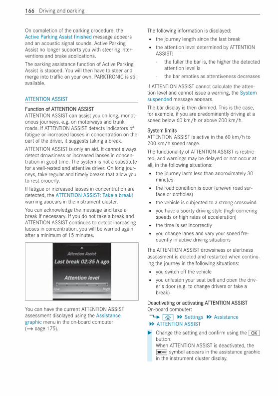
On completion of the parking procedure, theActive Parking Assist finished message appearsand an acoustic signal sounds. Active ParkingAssist no longer supports you with steering inter-ventions and brake applications.The parking assistance function of Active ParkingAssist is stopped. You will then have to steer andmerge into tra c on your own. PARKTRONIC is stillavailable.
AATTENTION ASSISTTTENTION ASSIST
FFunction of Aunction of ATTENTION ASSISTTTENTION ASSISTATTENTION ASSIST can assist you on long, monot-onous journeys, e.g. on motorways and trunkroads. If ATTENTION ASSIST detects indicators offatigue or increased lapses in concentration on thepart of the driver, it suggests taking a break.ATTENTION ASSIST is only an aid. It cannot alwaysdetect drowsiness or increased lapses in concen-tration in good time. The system is not a substitutefor a well-rested and attentive driver. On long jour-neys, take regular and timely breaks that allow youto rest properly.If fatigue or increased lapses in concentration aredetected, the ATTENTION ASSIST: Take a break!warning appears in the instrument cluster.You can acknowledge the message and take abreak if necessary. If you do not take a break andATTENTION ASSIST continues to detect increasinglapses in concentration, you will be warned againa er a minimum of 15 minutes.
You can have the current ATTENTION ASSISTassessment displayed using the Assistancegraphic menu in the on-board computer(/ page 175).
The following information is displayed:R the journey length since the last breakR the attention level determined by ATTENTION
ASSIST:- the fuller the bar is, the higher the detected
attention level is- the bar empties as attentiveness decreases
If ATTENTION ASSIST cannot calculate the atten-tion level and cannot issue a warning, the Systemsuspended message appears.The bar display is then dimmed. This is the case,for example, if you are predominantly driving at aspeed below 60 km/h or above 200 km/h.
SystSystem limitsem limitsATTENTION ASSIST is active in the 60 km/h to200 km/h speed range.The functionality of ATTENTION ASSIST is restric-ted, and warnings may be delayed or not occur atall, in the following situations:R the journey lasts less than approximately 30
minutesR the road condition is poor (uneven road sur-
face or potholes)R the vehicle is subjected to a strong crosswindR you have a sporty driving style (high cornering
speeds or high rates of acceleration)R the time is set incorrectlyR you change lanes and vary your speed fre-
quently in active driving situations
The ATTENTION ASSIST drowsiness or alertnessassessment is deleted and restarted when continu-ing the journey in the following situations:R you switch o the vehicleR you unfasten your seat belt and open the driv-
er's door (e.g. to change drivers or take abreak)
DeactivDeactivating or activating or activating Aating ATTENTION ASSISTTTENTION ASSISTOn-board computer:4 ò 5 Settings 5 Assistance5 ATTENTION ASSIST# Change the setting and con rm using the a
button.When ATTENTION ASSIST is deactivated, theé symbol appears in the assistance graphicin the instrument cluster display.
166166 Driving and parking
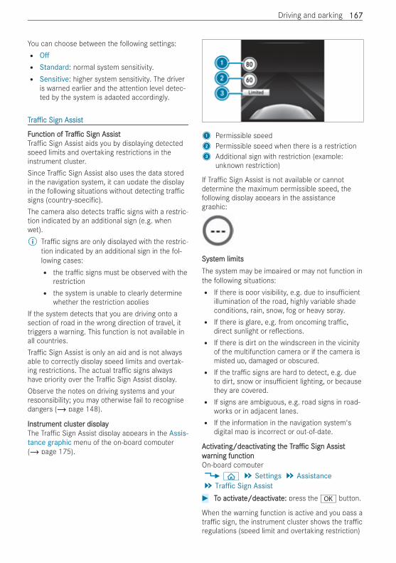
You can choose between the following settings:R OffR Standard: normal system sensitivity.R Sensitive: higher system sensitivity. The driver
is warned earlier and the attention level detec-ted by the system is adapted accordingly.
TTrra ca c Sign AssistSign Assist
FFunction ofunction of TrTra ca c Sign AssistSign AssistTra c Sign Assist aids you by displaying detectedspeed limits and overtaking restrictions in theinstrument cluster.Since Tra c Sign Assist also uses the data storedin the navigation system, it can update the displayin the following situations without detecting tra csigns (country-speci c).The camera also detects tra c signs with a restric-tion indicated by an additional sign (e.g. whenwet).% Tra c signs are only displayed with the restric-
tion indicated by an additional sign in the fol-lowing cases:R the tra c signs must be observed with the
restrictionR the system is unable to clearly determine
whether the restriction appliesIf the system detects that you are driving onto asection of road in the wrong direction of travel, ittriggers a warning. This function is not available inall countries.Tra c Sign Assist is only an aid and is not alwaysable to correctly display speed limits and overtak-ing restrictions. The actual tra c signs alwayshave priority over the Tra c Sign Assist display.Observe the notes on driving systems and yourresponsibility; you may otherwise fail to recognisedangers (/ page 148).
InsInstrtrument clustument cluster displayer displayThe Tra c Sign Assist display appears in the Assis-tance graphic menu of the on-board computer(/ page 175).
1 Permissible speed2 Permissible speed when there is a restriction3 Additional sign with restriction (example:
unknown restriction)
If Tra c Sign Assist is not available or cannotdetermine the maximum permissible speed, thefollowing display appears in the assistancegraphic:
SystSystem limitsem limitsThe system may be impaired or may not function inthe following situations:R If there is poor visibility, e.g. due to insu cient
illumination of the road, highly variable shadeconditions, rain, snow, fog or heavy spray.R If there is glare, e.g. from oncoming tra c,
direct sunlight or re ections.R If there is dirt on the windscreen in the vicinity
of the multifunction camera or if the camera ismisted up, damaged or obscured.R If the tra c signs are hard to detect, e.g. due
to dirt, snow or insu cient lighting, or becausethey are covered.R If signs are ambiguous, e.g. road signs in road-
works or in adjacent lanes.R If the information in the navigation system's
digital map is incorrect or out-of-date.
AActivctivating/deactivating/deactivating tating thehe TrTra ca c Sign AssistSign Assistwwararning functionning functionOn-board computer4 ò 5 Settings 5 Assistance5 Traffic Sign Assist# TTo activo activatate/deactive/deactivatate:e: press the a button.
When the warning function is active and you pass atra c sign, the instrument cluster shows the tra cregulations (speed limit and overtaking restriction)
Driving and parking 167167
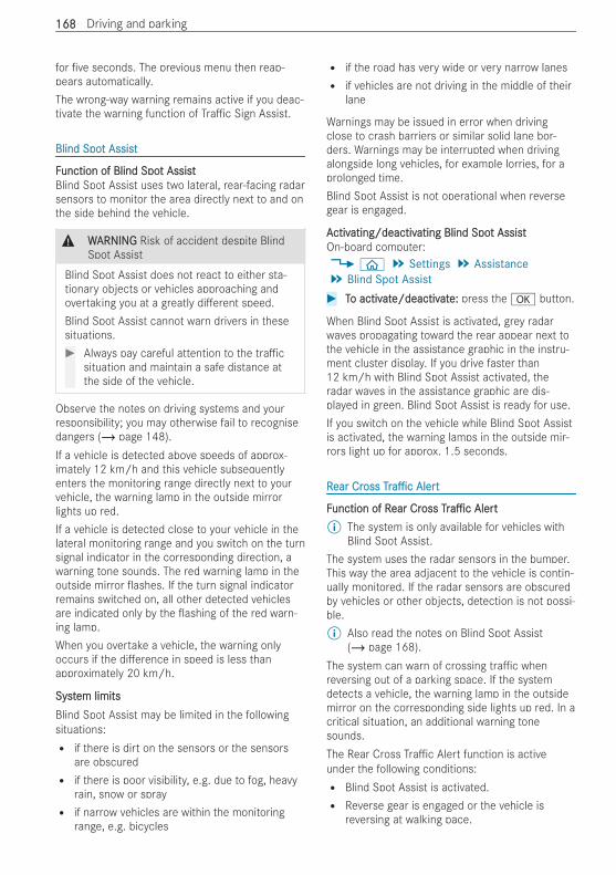
for ve seconds. The previous menu then reap-pears automatically.The wrong-way warning remains active if you deac-tivate the warning function of Tra c Sign Assist.
Blind SpoBlind Spot Assistt Assist
FFunction of Blind Spounction of Blind Spot Assistt AssistBlind Spot Assist uses two lateral, rear-facing radarsensors to monitor the area directly next to and onthe side behind the vehicle.
& WWARNINGARNING Risk of accident despite BlindSpot Assist
Blind Spot Assist does not react to either sta-tionary objects or vehicles approaching andovertaking you at a greatly di erent speed.Blind Spot Assist cannot warn drivers in thesesituations.# Always pay careful attention to the tra c
situation and maintain a safe distance atthe side of the vehicle.
Observe the notes on driving systems and yourresponsibility; you may otherwise fail to recognisedangers (/ page 148).If a vehicle is detected above speeds of approx-imately 12 km/h and this vehicle subsequentlyenters the monitoring range directly next to yourvehicle, the warning lamp in the outside mirrorlights up red.If a vehicle is detected close to your vehicle in thelateral monitoring range and you switch on the turnsignal indicator in the corresponding direction, awarning tone sounds. The red warning lamp in theoutside mirror ashes. If the turn signal indicatorremains switched on, all other detected vehiclesare indicated only by the ashing of the red warn-ing lamp.When you overtake a vehicle, the warning onlyoccurs if the di erence in speed is less thanapproximately 20 km/h.
SystSystem limitsem limitsBlind Spot Assist may be limited in the followingsituations:R if there is dirt on the sensors or the sensors
are obscuredR if there is poor visibility, e.g. due to fog, heavy
rain, snow or sprayR if narrow vehicles are within the monitoring
range, e.g. bicycles
R if the road has very wide or very narrow lanesR if vehicles are not driving in the middle of their
lane
Warnings may be issued in error when drivingclose to crash barriers or similar solid lane bor-ders. Warnings may be interrupted when drivingalongside long vehicles, for example lorries, for aprolonged time.Blind Spot Assist is not operational when reversegear is engaged.
AActivctivating/deactivating/deactivating Blind Spoating Blind Spot Assistt AssistOn-board computer:4 ò 5 Settings 5 Assistance5 Blind Spot Assist# TTo activo activatate/deactive/deactivatate:e: press the a button.
When Blind Spot Assist is activated, grey radarwaves propagating toward the rear appear next tothe vehicle in the assistance graphic in the instru-ment cluster display. If you drive faster than12 km/h with Blind Spot Assist activated, theradar waves in the assistance graphic are dis-played in green. Blind Spot Assist is ready for use.If you switch on the vehicle while Blind Spot Assistis activated, the warning lamps in the outside mir-rors light up for approx. 1.5 seconds.
RRear Crear Crossoss TrTra ca c AlertAlert
FFunction of Runction of Rear Crear Crossoss TrTra ca c AlertAlert% The system is only available for vehicles with
Blind Spot Assist.The system uses the radar sensors in the bumper.This way the area adjacent to the vehicle is contin-ually monitored. If the radar sensors are obscuredby vehicles or other objects, detection is not possi-ble.% Also read the notes on Blind Spot Assist
(/ page 168).The system can warn of crossing tra c whenreversing out of a parking space. If the systemdetects a vehicle, the warning lamp in the outsidemirror on the corresponding side lights up red. In acritical situation, an additional warning tonesounds.The Rear Cross Tra c Alert function is activeunder the following conditions:R Blind Spot Assist is activated.R Reverse gear is engaged or the vehicle is
reversing at walking pace.
168168 Driving and parking
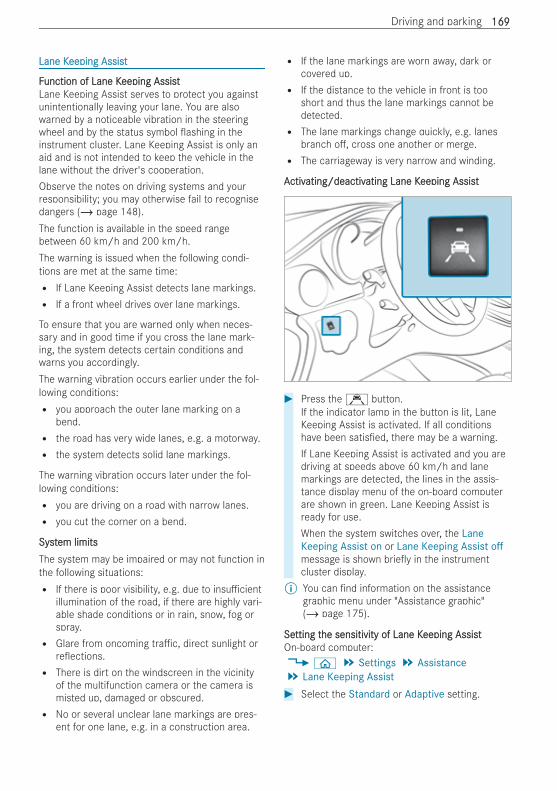
Lane KLane Keeping Assisteeping Assist
FFunction of Lane Kunction of Lane Keeping Assisteeping AssistLane Keeping Assist serves to protect you againstunintentionally leaving your lane. You are alsowarned by a noticeable vibration in the steeringwheel and by the status symbol ashing in theinstrument cluster. Lane Keeping Assist is only anaid and is not intended to keep the vehicle in thelane without the driver's cooperation.Observe the notes on driving systems and yourresponsibility; you may otherwise fail to recognisedangers (/ page 148).The function is available in the speed rangebetween 60 km/h and 200 km/h.The warning is issued when the following condi-tions are met at the same time:R If Lane Keeping Assist detects lane markings.R If a front wheel drives over lane markings.
To ensure that you are warned only when neces-sary and in good time if you cross the lane mark-ing, the system detects certain conditions andwarns you accordingly.The warning vibration occurs earlier under the fol-lowing conditions:R you approach the outer lane marking on a
bend.R the road has very wide lanes, e.g. a motorway.R the system detects solid lane markings.
The warning vibration occurs later under the fol-lowing conditions:R you are driving on a road with narrow lanes.R you cut the corner on a bend.
SystSystem limitsem limitsThe system may be impaired or may not function inthe following situations:R If there is poor visibility, e.g. due to insu cient
illumination of the road, if there are highly vari-able shade conditions or in rain, snow, fog orspray.R Glare from oncoming tra c, direct sunlight or
re ections.R There is dirt on the windscreen in the vicinity
of the multifunction camera or the camera ismisted up, damaged or obscured.R No or several unclear lane markings are pres-
ent for one lane, e.g. in a construction area.
R If the lane markings are worn away, dark orcovered up.R If the distance to the vehicle in front is too
short and thus the lane markings cannot bedetected.R The lane markings change quickly, e.g. lanes
branch o , cross one another or merge.R The carriageway is very narrow and winding.
AActivctivating/deactivating/deactivating Lane Kating Lane Keeping Assisteeping Assist
# Press theÇ button.If the indicator lamp in the button is lit, LaneKeeping Assist is activated. If all conditionshave been satis ed, there may be a warning.If Lane Keeping Assist is activated and you aredriving at speeds above 60 km/h and lanemarkings are detected, the lines in the assis-tance display menu of the on-board computerare shown in green. Lane Keeping Assist isready for use.When the system switches over, the LaneKeeping Assist on or Lane Keeping Assist offmessage is shown brie y in the instrumentcluster display.
% You can nd information on the assistancegraphic menu under "Assistance graphic"(/ page 175).
SeSetting ttting the sensitivity of Lane Khe sensitivity of Lane Keeping Assisteeping AssistOn-board computer:4 ò 5 Settings 5 Assistance5 Lane Keeping Assist# Select the Standard or Adaptive setting.
Driving and parking 169169
In the Standard setting, no warning vibrationoccurs in the following situations:R you operate the turn signal in the correspond-
ing direction. In this event, the warnings aresuppressed for a certain period of time.R a driving safety system intervenes or regulates,
such as ABS, BAS or ESP®.
In the Adaptive setting, there will also be no warn-ing vibration in the following situations:R you accelerate hard, e.g. kickdown.R you brake hard.R you steer actively, e.g. swerve to avoid an
obstacle or change lane quickly.R you cut the corner on a sharp bend.
170170 Driving and parking
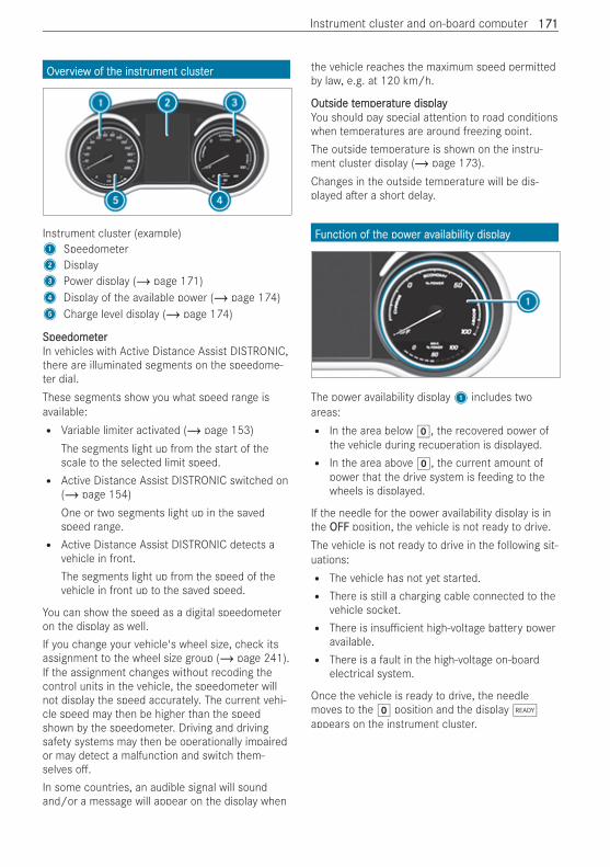
OvOverervieview of tw of the inshe instrtrument clustument clusterer
Instrument cluster (example)1 Speedometer2 Display3 Power display (/ page 171)4 Display of the available power (/ page 174)5 Charge level display (/ page 174)
SpeedometSpeedometererIn vehicles with Active Distance Assist DISTRONIC,there are illuminated segments on the speedome-ter dial.These segments show you what speed range isavailable:R Variable limiter activated (/ page 153)
The segments light up from the start of thescale to the selected limit speed.R Active Distance Assist DISTRONIC switched on
(/ page 154)One or two segments light up in the savedspeed range.R Active Distance Assist DISTRONIC detects a
vehicle in front.The segments light up from the speed of thevehicle in front up to the saved speed.
You can show the speed as a digital speedometeron the display as well.If you change your vehicle's wheel size, check itsassignment to the wheel size group (/ page 241).If the assignment changes without recoding thecontrol units in the vehicle, the speedometer willnot display the speed accurately. The current vehi-cle speed may then be higher than the speedshown by the speedometer. Driving and drivingsafety systems may then be operationally impairedor may detect a malfunction and switch them-selves o .In some countries, an audible signal will soundand/or a message will appear on the display when
the vehicle reaches the maximum speed permittedby law, e.g. at 120 km/h.
Outside tOutside tememperperaturature displaye displayYou should pay special attention to road conditionswhen temperatures are around freezing point.The outside temperature is shown on the instru-ment cluster display (/ page 173).Changes in the outside temperature will be dis-played a er a short delay.
FFunction of tunction of the powhe power aver availability displayailability display
The power availability display1 includes twoareas:R In the area below g, the recovered power of
the vehicle during recuperation is displayed.R In the area above g, the current amount of
power that the drive system is feeding to thewheels is displayed.
If the needle for the power availability display is inthe OFFOFF position, the vehicle is not ready to drive.The vehicle is not ready to drive in the following sit-uations:R The vehicle has not yet started.R There is still a charging cable connected to the
vehicle socket.R There is insu cient high-voltage battery power
available.R There is a fault in the high-voltage on-board
electrical system.
Once the vehicle is ready to drive, the needlemoves to the g position and the displayõappears on the instrument cluster.
Instrument cluster and on-board computer 171171
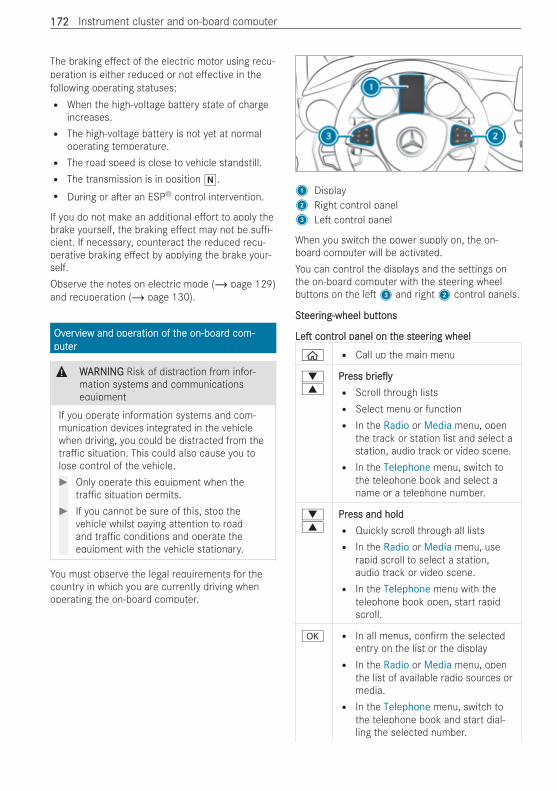
The braking e ect of the electric motor using recu-peration is either reduced or not e ective in thefollowing operating statuses:R When the high-voltage battery state of charge
increases.R The high-voltage battery is not yet at normal
operating temperature.R The road speed is close to vehicle standstill.R The transmission is in position i.R During or a er an ESP® control intervention.
If you do not make an additional e ort to apply thebrake yourself, the braking e ect may not be su -cient. If necessary, counteract the reduced recu-perative braking e ect by applying the brake your-self.Observe the notes on electric mode (/ page 129)and recuperation (/ page 130).
OvOverervieview and operw and operation of tation of the on-boarhe on-board com-d com-putputerer
& WWARNINGARNING Risk of distraction from infor-mation systems and communicationsequipment
If you operate information systems and com-munication devices integrated in the vehiclewhen driving, you could be distracted from thetra c situation. This could also cause you tolose control of the vehicle.# Only operate this equipment when the
tra c situation permits.# If you cannot be sure of this, stop the
vehicle whilst paying attention to roadand tra c conditions and operate theequipment with the vehicle stationary.
You must observe the legal requirements for thecountry in which you are currently driving whenoperating the on-board computer.
1 Display2 Right control panel3 Le control panel
When you switch the power supply on, the on-board computer will be activated.You can control the displays and the settings onthe on-board computer with the steering wheelbuttons on the le 3 and right2 control panels.
SStteereering-wheel butting-wheel buttonsons
LeLe contrcontrol panel on tol panel on the sthe steereering wheeling wheel
ò R Call up the main menu
:9
PrPressess brbrie yie yR Scroll through listsR Select menu or functionR In the Radio or Media menu, open
the track or station list and select astation, audio track or video scene.R In the Telephone menu, switch to
the telephone book and select aname or a telephone number.
:9
PrPress and holdess and holdR Quickly scroll through all listsR In the Radio or Media menu, use
rapid scroll to select a station,audio track or video scene.R In the Telephone menu with the
telephone book open, start rapidscroll.
a R In all menus, con rm the selectedentry on the list or the displayR In the Radio or Media menu, open
the list of available radio sources ormedia.R In the Telephone menu, switch to
the telephone book and start dial-ling the selected number.
172172 Instrument cluster and on-board computer
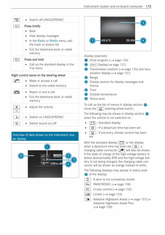
ñ R Switch o LINGUATRONIC
% PrPressess brbrie yie yR BackR Hide display messagesR In the Radio or Media menu, exit
the track or station listR Exit the telephone book or redial
memory
% PrPress and holdess and holdR Call up the standard display in the
Trip menu
Right contrRight control panel on tol panel on the sthe steereering wheeling wheel
6 R Make or accept a callR Switch to the redial memory
~ R Reject or end a callR Exit the telephone book or redial
memory
WXR Adjust the volume
ó R Switch on LINGUATRONIC
8 R Switch sound on/o
OvOverervieview of datw of data shoa shown on twn on the inshe instrtrument clus-ument clus-tter displayer display
Display (example)1 Drive program (/ page 136)2õ Display(/ page 131)3 Transmission position (/ page 135) and recu-
peration display (/ page 131)4 Range5 Display section for display messages and
menus6 Time7 Outside temperature8 Status area
To call up the list of menus in display section5,press the ò steering-wheel button.The following may be shown in display section5when the vehicle is not switched on:R# - Standard displayRù - If a departure time has been setR& - If pre-entry climate control has been
set
With the standard display # or the displaywhen a departure time has been set ù, acharging cable connector è will also be shown.If the state of charge of the high-voltage battery isbelow approximately 80% and the high-voltage bat-tery is not being charged, the charging cable con-nector will be shown as orange instead of white.The following displays may appear in status area8 of the display:1 A door is not completely closed= PARKTRONIC (/ page 158)¯ Cruise control (/ page 152)È Limiter (/ page 153)_ Adaptive Highbeam Assist (/ page 107) or
Adaptive Highbeam Assist Plus(/ page 108)
Instrument cluster and on-board computer 173173
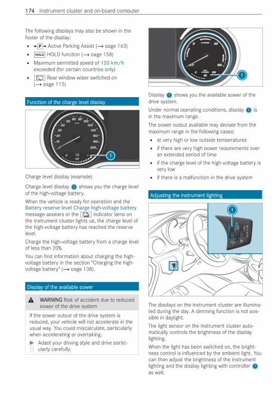
The following displays may also be shown in thefooter of the display:R XjY Active Parking Assist (/ page 163)Rë HOLD function (/ page 158)R Maximum permitted speed of 120 km/h
exceeded (for certain countries only)R è Rear window wiper switched on
(/ page 115)
FFunction of tunction of the che chargharge leve level displayel display
Charge level display (example)
Charge level display1 shows you the charge levelof the high-voltage battery.When the vehicle is ready for operation and theBattery reserve level Charge high-voltage batterymessage appears or the Ý indicator lamp onthe instrument cluster lights up, the charge level ofthe high-voltage battery has reached the reservelevel.Charge the high-voltage battery from a charge levelof less than 20%.You can nd information about charging the high-voltage battery in the section "Charging the high-voltage battery" (/ page 138).
DisplaDisplay of ty of the avhe available powailable powerer
& WWARNINGARNING Risk of accident due to reducedpower of the drive system
If the power output of the drive system isreduced, your vehicle will not accelerate in theusual way. You could miscalculate, particularlywhen accelerating or overtaking.# Adapt your driving style and drive partic-
ularly carefully.
Display1 shows you the available power of thedrive system.Under normal operating conditions, display1 isin the maximum range.The power output available may deviate from themaximum range in the following cases:R at very high or low outside temperaturesR if there are very high power requirements over
an extended period of timeR if the charge level of the high-voltage battery is
very lowR if there is a malfunction in the drive system
AAdjusdjusting tting the inshe instrtrument lightingument lighting
The displays on the instrument cluster are illumina-ted during the day. A dimming function is not pos-sible in daylight.The light sensor on the instrument cluster auto-matically controls the brightness of the displaylighting.When the light has been switched on, the bright-ness control is in uenced by the ambient light. Youcan then adjust the brightness of the instrumentlighting and the display lighting with controller1as well.
174174 Instrument cluster and on-board computer
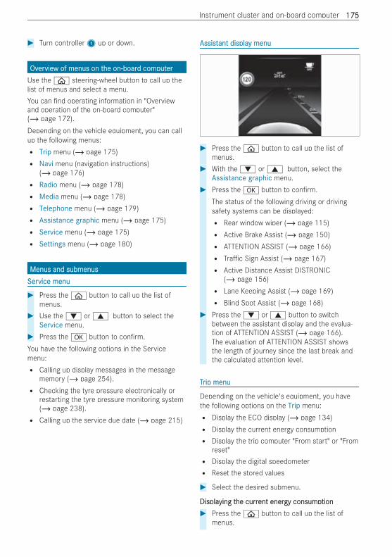
# Turn controller1 up or down.
OvOverervieview of menus on tw of menus on the on-boarhe on-board comd computputererUse the ò steering-wheel button to call up thelist of menus and select a menu.You can nd operating information in "Overviewand operation of the on-board computer"(/ page 172).Depending on the vehicle equipment, you can callup the following menus:R Trip menu (/ page 175)R Navi menu (navigation instructions)
(/ page 176)R Radio menu (/ page 178)R Media menu (/ page 178)R Telephone menu (/ page 179)R Assistance graphic menu (/ page 175)R Service menu (/ page 175)R Settings menu (/ page 180)
Menus and submenusMenus and submenusSerService menuvice menu
# Press the ò button to call up the list ofmenus.
# Use the : or 9 button to select theService menu.
# Press the a button to con rm.You have the following options in the Servicemenu:R Calling up display messages in the message
memory (/ page 254).R Checking the tyre pressure electronically or
restarting the tyre pressure monitoring system(/ page 238).R Calling up the service due date (/ page 215)
AssistAssistant displaant display menuy menu
# Press the ò button to call up the list ofmenus.
# With the : or 9 button, select theAssistance graphic menu.
# Press the a button to con rm.The status of the following driving or drivingsafety systems can be displayed:R Rear window wiper (/ page 115)R Active Brake Assist (/ page 150)R ATTENTION ASSIST (/ page 166)R Tra c Sign Assist (/ page 167)R Active Distance Assist DISTRONIC
(/ page 156)R Lane Keeping Assist (/ page 169)R Blind Spot Assist (/ page 168)
# Press the : or 9 button to switchbetween the assistant display and the evalua-tion of ATTENTION ASSIST (/ page 166).The evaluation of ATTENTION ASSIST showsthe length of journey since the last break andthe calculated attention level.
TTrrip menuip menu
Depending on the vehicle's equipment, you havethe following options on the Trip menu:R Display the ECO display (/ page 134)R Display the current energy consumptionR Display the trip computer "From start" or "From
reset"R Display the digital speedometerR Reset the stored values
# Select the desired submenu.
DisplaDisplaying tying the currhe current enerent energy consumpgy consumptiontion# Press the ò button to call up the list of
menus.
Instrument cluster and on-board computer 175175
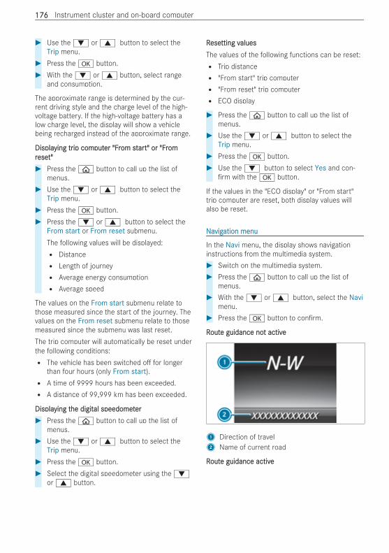
# Use the : or 9 button to select theTrip menu.
# Press the a button.# With the : or 9 button, select range
and consumption.
The approximate range is determined by the cur-rent driving style and the charge level of the high-voltage battery. If the high-voltage battery has alow charge level, the display will show a vehiclebeing recharged instead of the approximate range.
DisplaDisplaying trying trip comip computputer "Frer "From stom starart" or "Frt" or "Fromomrreseeset"t"# Press the ò button to call up the list of
menus.# Use the : or 9 button to select the
Trip menu.# Press the a button.# Press the : or 9 button to select the
From start or From reset submenu.The following values will be displayed:R DistanceR Length of journeyR Average energy consumptionR Average speed
The values on the From start submenu relate tothose measured since the start of the journey. Thevalues on the From reset submenu relate to thosemeasured since the submenu was last reset.The trip computer will automatically be reset underthe following conditions:R The vehicle has been switched o for longer
than four hours (only From start).R A time of 9999 hours has been exceeded.R A distance of 99,999 km has been exceeded.
DisplaDisplaying tying the digithe digital speedometal speedometerer# Press the ò button to call up the list of
menus.# Use the : or 9 button to select the
Trip menu.# Press the a button.# Select the digital speedometer using the :
or 9 button.
RReseesetting vtting valuesaluesThe values of the following functions can be reset:R Trip distanceR "From start" trip computerR "From reset" trip computerR ECO display
# Press the ò button to call up the list ofmenus.
# Use the : or 9 button to select theTrip menu.
# Press the a button.# Use the : button to select Yes and con-
rm with the a button.
If the values in the "ECO display" or "From start"trip computer are reset, both display values willalso be reset.
NNaavigvigation menuation menu
In the Navi menu, the display shows navigationinstructions from the multimedia system.# Switch on the multimedia system.# Press the ò button to call up the list of
menus.# With the : or 9 button, select the Navi
menu.# Press the a button to con rm.
RRoutoute guidance noe guidance not activet active
1 Direction of travel2 Name of current road
RRoutoute guidance activee guidance active
176176 Instrument cluster and on-board computer
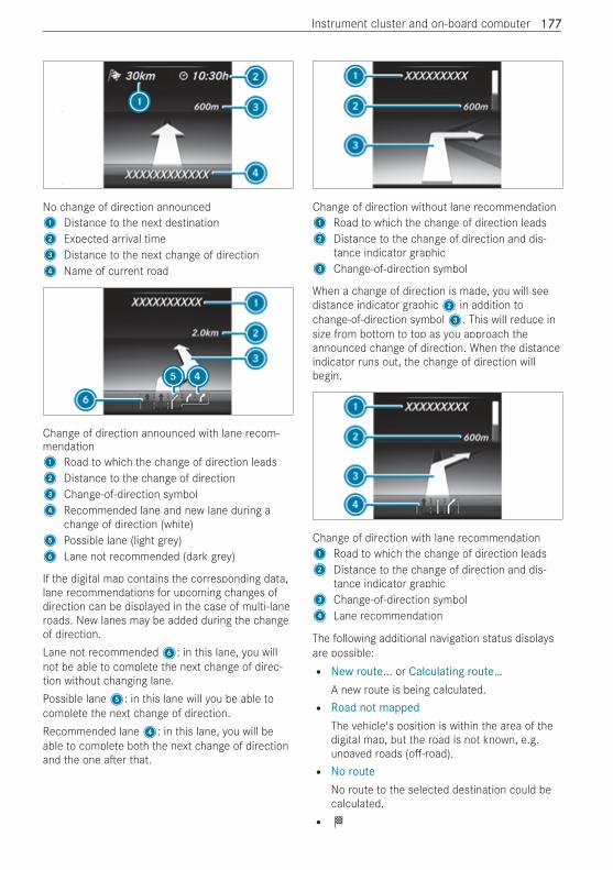
No change of direction announced1 Distance to the next destination2 Expected arrival time3 Distance to the next change of direction4 Name of current road
Change of direction announced with lane recom-mendation1 Road to which the change of direction leads2 Distance to the change of direction3 Change-of-direction symbol4 Recommended lane and new lane during a
change of direction (white)5 Possible lane (light grey)6 Lane not recommended (dark grey)
If the digital map contains the corresponding data,lane recommendations for upcoming changes ofdirection can be displayed in the case of multi-laneroads. New lanes may be added during the changeof direction.Lane not recommended6: in this lane, you willnot be able to complete the next change of direc-tion without changing lane.Possible lane5: in this lane will you be able tocomplete the next change of direction.Recommended lane4: in this lane, you will beable to complete both the next change of directionand the one a er that.
Change of direction without lane recommendation1 Road to which the change of direction leads2 Distance to the change of direction and dis-
tance indicator graphic3 Change-of-direction symbol
When a change of direction is made, you will seedistance indicator graphic2 in addition tochange-of-direction symbol3. This will reduce insize from bottom to top as you approach theannounced change of direction. When the distanceindicator runs out, the change of direction willbegin.
Change of direction with lane recommendation1 Road to which the change of direction leads2 Distance to the change of direction and dis-
tance indicator graphic3 Change-of-direction symbol4 Lane recommendation
The following additional navigation status displaysare possible:R New route... or Calculating route…
A new route is being calculated.R Road not mapped
The vehicle's position is within the area of thedigital map, but the road is not known, e.g.unpaved roads (o -road).R No route
No route to the selected destination could becalculated.R O
Instrument cluster and on-board computer 177177
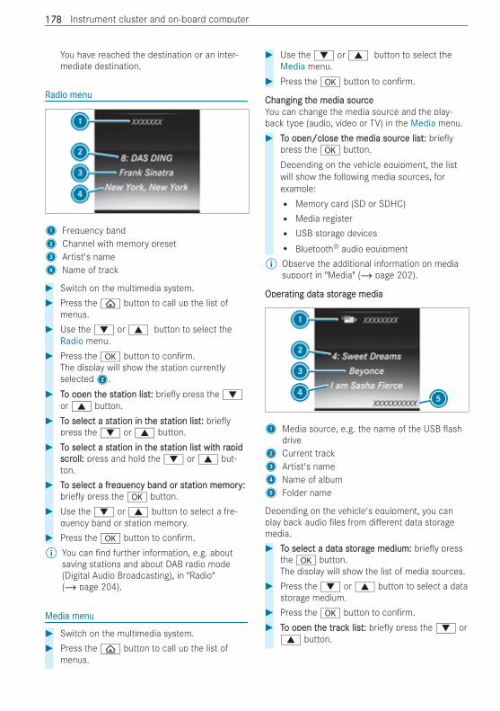
You have reached the destination or an inter-mediate destination.
RRadio menuadio menu
1 Frequency band2 Channel with memory preset3 Artist's name4 Name of track
# Switch on the multimedia system.# Press the ò button to call up the list of
menus.# Use the : or 9 button to select the
Radio menu.# Press the a button to con rm.
The display will show the station currentlyselected2.
# TTo open to open the sthe station listation list:: brie y press the :or 9 button.
# TTo select a sto select a station in tation in the sthe station listation list:: brie ypress the : or 9 button.
# TTo select a sto select a station in tation in the sthe station lisation list witt with rh rapidapidscrscroll:oll: press and hold the : or 9 but-ton.
# TTo select a fro select a freqequency band or stuency band or station memoryation memory::brie y press the a button.
# Use the : or 9 button to select a fre-quency band or station memory.
# Press the a button to con rm.% You can nd further information, e.g. about
saving stations and about DAB radio mode(Digital Audio Broadcasting), in "Radio"(/ page 204).
Media menuMedia menu
# Switch on the multimedia system.# Press the ò button to call up the list of
menus.
# Use the : or 9 button to select theMedia menu.
# Press the a button to con rm.
Changing tChanging the media sourhe media sourceceYou can change the media source and the play-back type (audio, video or TV) in the Media menu.# TTo open/close to open/close the media sourhe media source listce list:: brie y
press the a button.Depending on the vehicle equipment, the listwill show the following media sources, forexample:R Memory card (SD or SDHC)R Media registerR USB storage devicesR Bluetooth® audio equipment
% Observe the additional information on mediasupport in "Media" (/ page 202).
OperOperating datating data sta stororagage mediae media
1 Media source, e.g. the name of the USB ashdrive
2 Current track3 Artist's name4 Name of album5 Folder name
Depending on the vehicle's equipment, you canplay back audio les from di erent data storagemedia.# TTo select a dato select a data sta stororagage medium:e medium: brie y press
the a button.The display will show the list of media sources.
# Press the : or 9 button to select a datastorage medium.
# Press the a button to con rm.# TTo open to open the trhe tracack listk list:: brie y press the : or
9 button.
178178 Instrument cluster and on-board computer
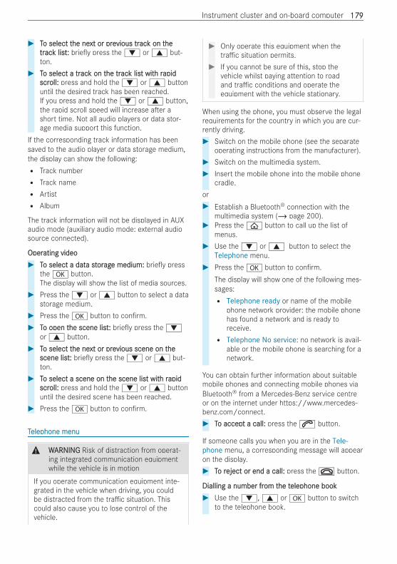
# TTo select to select the nehe next or prext or previous trvious tracack on tk on thehetrtracack listk list:: brie y press the : or 9 but-ton.
# TTo select a tro select a tracack on tk on the trhe tracack lisk list witt with rh rapidapidscrscroll:oll: press and hold the : or 9 buttonuntil the desired track has been reached.If you press and hold the : or 9 button,the rapid scroll speed will increase a er ashort time. Not all audio players or data stor-age media support this function.
If the corresponding track information has beensaved to the audio player or data storage medium,the display can show the following:R Track numberR Track nameR ArtistR Album
The track information will not be displayed in AUXaudio mode (auxiliary audio mode: external audiosource connected).
OperOperating videoating video# TTo select a dato select a data sta stororagage medium:e medium: brie y press
the a button.The display will show the list of media sources.
# Press the : or 9 button to select a datastorage medium.
# Press the a button to con rm.# TTo open to open the scene listhe scene list:: brie y press the :
or 9 button.# TTo select to select the nehe next or prext or previous scene on tvious scene on thehe
scene listscene list:: brie y press the : or 9 but-ton.
# TTo select a scene on to select a scene on the scene lishe scene list witt with rh rapidapidscrscroll:oll: press and hold the : or 9 buttonuntil the desired scene has been reached.
# Press the a button to con rm.
TTelephone menuelephone menu
& WWARNINGARNING Risk of distraction from operat-ing integrated communication equipmentwhile the vehicle is in motion
If you operate communication equipment inte-grated in the vehicle when driving, you couldbe distracted from the tra c situation. Thiscould also cause you to lose control of thevehicle.
# Only operate this equipment when thetra c situation permits.
# If you cannot be sure of this, stop thevehicle whilst paying attention to roadand tra c conditions and operate theequipment with the vehicle stationary.
When using the phone, you must observe the legalrequirements for the country in which you are cur-rently driving.# Switch on the mobile phone (see the separate
operating instructions from the manufacturer).# Switch on the multimedia system.# Insert the mobile phone into the mobile phone
cradle.or# Establish a Bluetooth® connection with the
multimedia system (/ page 200).# Press the ò button to call up the list of
menus.# Use the : or 9 button to select the
Telephone menu.# Press the a button to con rm.
The display will show one of the following mes-sages:R Telephone ready or name of the mobile
phone network provider: the mobile phonehas found a network and is ready toreceive.R Telephone No service: no network is avail-
able or the mobile phone is searching for anetwork.
You can obtain further information about suitablemobile phones and connecting mobile phones viaBluetooth® from a Mercedes-Benz service centreor on the internet under https://www.mercedes-benz.com/connect.# TTo accepo accept a call:t a call: press the 6 button.
If someone calls you when you are in the Tele-phone menu, a corresponding message will appearon the display.# TTo ro reject or end a call:eject or end a call: press the ~ button.
Dialling a number frDialling a number from tom the the telephone bookelephone book# Use the :, 9 or a button to switch
to the telephone book.
Instrument cluster and on-board computer 179179
# Use the : or 9 button to scroll throughthe names.If you press and hold the button for longer thanone second, the names in the telephone bookwill be displayed quickly one a er the other.
or# Press and hold the : or 9 button for
longer than ve seconds.Rapid scrolling – the name that starts with thenext letter or the previous letter in the alphabetis displayed.Rapid scrolling will stop when you release thebutton or reach the end of the list.
# If onlIf only one ty one telephone number has been savelephone number has been savededffor a name:or a name: press the 6 or a button tostart dialling.
or# If sevIf severeral tal telephone numberelephone numbers havs have been save been saveded
ffor a name:or a name: press the 6 or a button todisplay the telephone numbers.
# Use the : or 9 button to select thetelephone number.
# Press the 6 or a button to start dial-ling.
# TTo eo exit txit the the telephone book:elephone book: press the ~ or% button.
Using rUsing redialedial# Press the 6 button to switch to the redial
memory.# Use the : or 9 button to select the
name or telephone number.# Press the 6 or a button to start dial-
ling.# TTo eo exit txit the rhe redial memoryedial memory:: press the ~ or
% button.
SeSettings menuttings menu
# Press the ò button to call up the list ofmenus.
# Use the : or 9 button to select theSettings menu.
# Press the a button to con rm.
You have the following options on the Settingsmenu:R Changing the settings for the driver assistance
systems on the Assistance submenuR Changing the settings for the exterior lighting
on the Lights submenu
R Changing the display options on the Instrumentcluster submenuR Resetting the settings to factory settings
# Select the desired submenu and con rm yourselection.
AssistAssistance submenuance submenu# Select a driving or driver assistance system
and con gure a setting.R Switching ESP® on/o (/ page 150).R Switching Tra c Sign Assist on/o
(/ page 167).R Switching Active Brake Assist on/o
(/ page 152).R Switching Blind Spot Assist on/o
(/ page 168)R Adjusting ATTENTION ASSIST
(/ page 166).R Setting Lane Keeping Assist
(/ page 169).
Lights submenuLights submenuThe following settings are possible on the Lightssubmenu:R Switching the Intelligent Light System on/o
(/ page 107)R Switching between low beam for right- and le -
side tra c (in vehicles with Intelligent LightSystem only)
# Use the : or 9 button to select theLights submenu.
# Press the a button to con rm.# TTo switco switch beh betwtween loeen low beam fw beam for ror right- andight- and le -le -
sideside trtra c:a c: use the : or 9 button toselect Dipped beams Setting for.The display will show the selected setting.
# Change the selected setting with the a but-ton.When you change the setting, the switchoverwill not take place until the next time the vehi-cle is stationary.
When you switch over the low beam for right- orle -side tra c, motorway mode and the enhancedfog light function may not be available. This deacti-vation will take place only if the setting for drivingon the right or le is the opposite to your vehicle'snational version.
180180 Instrument cluster and on-board computer
You can have the low beam set for right- or le -side tra c at a quali ed specialist workshop aswell.
InsInstrtrument clustument cluster submenuer submenu# Use the : or 9 button to select the
Instrument cluster submenu.# Press the a button to con rm.# TTo select to select the unit of measurhe unit of measurement fement for dis-or dis-
ttance:ance: use the : or 9 button to selectthe Display unit Speed-/odometer function.The display will show the selected setting kmor Miles.
# Change the selected setting with the a but-ton.
# TTo switco switch th the additional speedomethe additional speedometerer on/o :on/o :use the : or 9 button to select Addit.speedo.The current selection will appear.
# Press the a button to change the setting.% The unit in the additional speedometer is
always inverse to the unit of the speedometer.
VVehicle submenuehicle submenu# Use the : or 9 button to select the
Vehicle submenu.# Press the a button to con rm.# TTo ro reseeset tt to fo factactorory sey settings:ttings: use the : or
9 button to select the Factory settingssubmenu.
# Press the a button to con rm.The Reset all settings? function will be dis-played.
# Use the : or 9 button to select No orYes.
# Press the a button to con rm.If you selected Yes previously, the display willshow a con rmation message.
Instrument cluster and on-board computer 181181
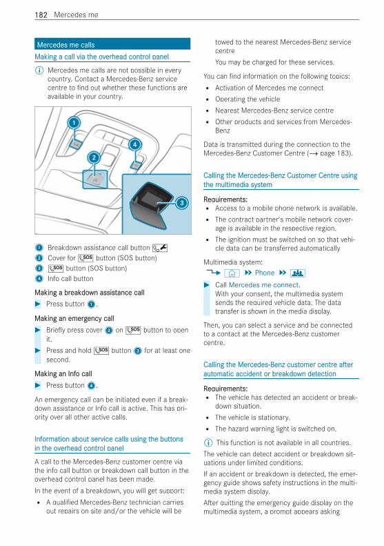
MerMercedes me callscedes me callsMaking a call via tMaking a call via the ovhe overerhead contrhead control panelol panel
% Mercedes me calls are not possible in everycountry. Contact a Mercedes-Benz servicecentre to nd out whether these functions areavailable in your country.
1 Breakdown assistance call button F2 Cover for G button (SOS button)3 G button (SOS button)4 Info call button
Making a brMaking a breakdoeakdown assistwn assistance callance call# Press button1.
Making an emergMaking an emergency callency call# Brie y press cover2 on G button to open
it.# Press and hold G button3 for at least one
second.
Making an InfMaking an Info callo call# Press button4.
An emergency call can be initiated even if a break-down assistance or Info call is active. This has pri-ority over all other active calls.
InfInforormation about sermation about service calls using tvice calls using the butthe buttonsonsin tin the ovhe overerhead contrhead control panelol panel
A call to the Mercedes-Benz customer centre viathe info call button or breakdown call button in theoverhead control panel has been made.In the event of a breakdown, you will get support:R A quali ed Mercedes-Benz technician carries
out repairs on site and/or the vehicle will be
towed to the nearest Mercedes-Benz servicecentreYou may be charged for these services.
You can nd information on the following topics:R Activation of Mercedes me connectR Operating the vehicleR Nearest Mercedes-Benz service centreR Other products and services from Mercedes-
Benz
Data is transmitted during the connection to theMercedes-Benz Customer Centre (/ page 183).
Calling tCalling the Merhe Mercedes-Benz Custcedes-Benz Customer Centromer Centre usinge usingtthe multimedia systhe multimedia systemem
RReqequiruirements:ements:R Access to a mobile phone network is available.R The contract partner's mobile network cover-
age is available in the respective region.R The ignition must be switched on so that vehi-
cle data can be transferred automatically
Multimedia system:4© 5 Phone 5g
# Call Mercedes me connect.With your consent, the multimedia systemsends the required vehicle data. The datatransfer is shown in the media display.
Then, you can select a service and be connectedto a contact at the Mercedes-Benz customercentre.
Calling tCalling the Merhe Mercedes-Benz custcedes-Benz customer centromer centree a era erautautomatic accident or bromatic accident or breakdoeakdown detwn detectionection
RReqequiruirements:ements:R The vehicle has detected an accident or break-
down situation.R The vehicle is stationary.R The hazard warning light is switched on.
% This function is not available in all countries.The vehicle can detect accident or breakdown sit-uations under limited conditions.If an accident or breakdown is detected, the emer-gency guide shows safety instructions in the multi-media system display.A er quitting the emergency guide display on themultimedia system, a prompt appears asking
182182 Mercedes me
whether you wish to get support from theMercedes-Benz customer centre.# Select Call.R A er your agreement, or if the Mercedes
me connect service "Accident and Break-down Management" is active, the vehicledata is transferred automatically(/ page 185).R The Mercedes-Benz customer centre will
take your call and organise breakdown andaccident assistance.
You may be charged for these services.% Depending on the severity of the accident, an
automatic emergency call can be made. Thishas priority over all other active calls.
% In addition, if the "Telediagnosis" Mercedes meconnect service is active, a similar query mayappear at a later time in the event of a break-down. If you are already in contact with theMercedes-Benz customer centre or havereceived help, this query can be ignored orrejected.
% If you answer the prompt for support from theMercedes-Benz customer centre with Laterthe message will disappear and reappear at alater time.The query triggered by the "Telediagnosis"Mercedes me connect service can either becon rmed or rejected. A er rejection, it is nolonger displayed.
ArrArranging a seranging a service appointment via Mervice appointment via Mercedes mecedes mecallcall
If you have activated the maintenance manage-ment service, relevant vehicle data is transferredautomatically to the Mercedes-Benz CustomerCentre. You will then receive individual recommen-dations regarding the maintenance of your vehicle.Regardless of whether you have consented to themaintenance management service, the multimediasystem reminds you a er a certain amount of timethat a service is due. A prompt appears asking ifyou would like to make an appointment.# TTo arro arrangange a sere a service appointmentvice appointment:: select Call.
A er your con rmation, the vehicle data issent and the Mercedes-Benz customer centredeals with your appointment. The informationis then sent to your desired service outlet.They will contact you to con rm the appoint-ment and, if necessary, to discuss the details.
% If you select Later a er the service messageappears, the message is hidden and reappearsat a later time.
Consenting tConsenting to dato data tra transfansfer fer for a Meror a Mercedes me callcedes me call
RReqequiruirements:ements:R There is an active Mercedes me call via the
multimedia system or the buttons in the over-head control panel (/ page 182).
% The prompt to con rm data transfer does notappear in all countries.
If the Accident and Breakdown Management serv-ices are not activated on Mercedes me, the follow-ing message appears Do you want to transmitvehicle data and the vehicle's position to theMercedes-Benz Customer Centre in order toimprove the processing of your request?.# Select Yes.
Relevant identi cation data is transmittedautomatically.
More information on Mercedes me: https://www.mercedes.me
TTrransfansferrerred dated data dura during a Mering a Mercedes me callcedes me call
When you make a service call via Mercedes me,data is transmitted. This enables targeted adviceand smooth service.The following requirements must be met for thedata transfer:R The vehicle is switched on.R The necessary data transmission technology is
supported by the mobile network provider.R A su cient mobile phone connection quality is
provided.
Multi-stage transmission depends on the followingfactors:R Reason for the initiation of the callR Available mobile radio transmission technologyR Activated Mercedes me connect servicesR Selected service in the voice dialogue system
% A request for consent to data transmission isonly made if the corresponding Mercedes meconnect service has not been activated.
Mercedes me 183183
DatData tra transmission when Meransmission when Mercedes me connectcedes me connectserservices arvices are noe not activt activatatededIf no Mercedes me connect services are activatedand the data protection query has been con rmed,the following data will be transferred:R Vehicle identi cation numberR Time of the callR Reason for the initiation of the callR Con rmation of the data protection promptR Vehicle country codeR Set language for the multimedia systemR Call number of the communication platform
installed in the vehicle
If a call is made for a service appointment via theservice reminder, the following data is also trans-mitted:R Current mileage and maintenance data
If a call was made via the multimedia system a erautomatic accident or breakdown detection, thefollowing data is also transmitted:R Current mileage and maintenance dataR Current vehicle location
If the Accident and Breakdown Management selec-tion has been made via the voice dialogue systemand no service has been activated, but the dataprotection query has been con rmed, the followingdata can be additionally requested from the vehicleby the Mercedes-Benz customer centre:R Current vehicle location
If the data protection request has been declined,the following data will be transferred to enable tar-geted advice and a smooth service:R Reason for the initiation of the callR Rejection of the data protection promptR Vehicle country codeR Set language for the multimedia systemR Call number of the communication platform
installed in the vehicle
DatData tra transmission when Meransmission when Mercedes me connectcedes me connectserservices arvices are active activatatededOnly in the second step, only for the respectiveactivated services, further case-speci c data istransmitted in order to enable an optimal service.An overview of the transmitted data can be foundin the respective terms of use for Mercedes me
connect services. These can be obtained in theMercedes me portal: https://me.secure.mercedes-benz.com
DatData pra processingocessingThe data transmitted as part of the call will bedeleted from the transmitting systems once thecall has been completed, provided they are notused for other activated Mercedes me connectservices.The case-related data will be processed and storedin the Mercedes-Benz customer centre and, if nec-essary for case processing, forwarded to theservice partners commissioned by the Mercedes-Benz customer centre. Please refer to the dataprotection information on the Mercedes me web-site at https://www.mercedes.me or in the recor-ded message immediately a er the call to theMercedes-Benz customer centre has been set up.% The recorded message is not available in every
country.
MerMercedes me connectcedes me connectInfInforormation about Mermation about Mercedes me connectcedes me connect
% Mercedes me connect or individual Mercedesme connect services are not available in everycountry. Contact a Mercedes-Benz servicecentre to nd out whether these functions areavailable in your country.
Mercedes me connect consists of a variety ofservices.Using the multimedia system or the overhead con-trol panel, you can use the following services, forexample:R Accident and Breakdown Management (Break-
down call button or the situation-dependentdisplay in the multimedia system)R Accident and Breakdown Management (break-
down button)R Mercedes-Benz emergency call system (auto-
matic emergency call and SOS button)
Mercedes me connect Accident and BreakdownManagement and the Mercedes-Benz emergencycall centre are available to you around the clock.You will nd the breakdown call button and theSOS button in the vehicle's overhead control panel(/ page 182).You can also call the Mercedes-Benz customercentre using the multimedia system(/ page 182).
184184 Mercedes me
Please note that Mercedes me connect is aMercedes-Benz service. In emergencies, call thenational emergency services rst using the stand-ard national emergency service phone numbers. Inemergencies, you can also use the Mercedes-Benzemergency call system (/ page 225).Observe the conditions of use for Mercedes meconnect and other services. These can beobtained in the Mercedes me portal: https://me.secure.mercedes-benz.comFurther information about Mercedes me connect,the provided service scope and operation:https://moba.i.daimler.com/markets/ece-row/baix/cars/connectme/en_GB/#emotions/Startseite.html
InfInforormation on Mermation on Mercedes me connect Acedes me connect Accidentccidentand Brand Breakdoeakdown Managwn Managementement
The Accident and Breakdown Management can,amongst others, include the following functions:R Supplement to the Mercedes-Benz emergency
call system (/ page 225)If necessary, the contact person at theMercedes-Benz emergency call centre for-wards the call to Mercedes me connect Acci-dent and Breakdown Management. However,call forwarding is not possible in all countries.R Breakdown assistance on location by a techni-
cian and/or towing away of the vehicle to thenearest Mercedes-Benz Service CentreYou may be charged for these services.R Supplement to the emergency guide a er auto-
matic accident or breakdown detection(/ page 182)In the event of a breakdown or accident, exten-ded vehicle data is sent, enabling optimumsupport from the Mercedes-Benz customercentre and the appointed service partner orbreakdown mechanic.R Supplement to the Mercedes me connect tele-
diagnostics serviceWith the telediagnostics function, certain wearand failure messages, insofar as they can beclearly interpreted and are available by moni-toring diagnosable components, are recordedby the service provider.If your vehicle detects a breakdown or impend-ing breakdown, you may be prompted via themultimedia system to contact the Mercedes-Benz customer centre for further assistance.
This prompt in the multimedia system onlyappears when the vehicle is stationary.
% These services are subject to technical restric-tions such as mobile coverage and mobile net-work quality and the interpretability of thetransmitted data in the processing systems.Under certain circumstances, this may resultin delays or omission of the message in themultimedia system.
Further information about Mercedes me connectservices can be obtained in the Mercedes me Por-tal: https://me.secure.mercedes-benz.com
TTrransmittansmitted dated data wita with th the Merhe Mercedes me connectcedes me connectcall sercall servicesvices
The data transferred during the Mercedes me con-nect call depends on:R The reason for the initiation of the callR The service selected in the voice dialogue sys-
temR The activated Mercedes me connect services
You can nd out which data is transferred duringthe services in the currently valid Mercedes meconnect terms of use and the data protectioninformation for Mercedes me connect. You cannd these in your Mercedes me user account.
MerMercedes me and appscedes me and appsInfInforormation about Mermation about Mercedes mecedes me
When you log in with a user account to theMercedes me Portal, then services and o ers fromMercedes-Benz will be available to you.Availability is country-dependent.For more information consult a Mercedes-Benzservice centre or visit the Mercedes me portal:https://me.secure.mercedes-benz.com% Make sure that you always keep the Mercedes
me apps up to date.
Calling up a MerCalling up a Mercedes me user accountcedes me user account
Multimedia system:4© 5 Mercedes me & Apps
VVehicle is linkehicle is linked ted to user accounto user account# Select Mercedes me.
Information about the connected user accountappears.
Mercedes me 185185
VVehicle is noehicle is not yet yet linkt linked ted to user accounto user account# Select Mercedes me.# Follow the instructions on the media display to
create a user account and link the vehicle to it.% If the Mercedes me app is available on a
mobile phone, the vehicle link can be made viathe displayed QR code.
Calling up MerCalling up Mercedes me sercedes me servicesvices
RReqequiruirements:ements:R The vehicle is connected with the user
account.
Multimedia system:4© 5 Mercedes me & Apps# Select Services.
You will be shown the Mercedes me servicesthat you have already purchased and thosethat you can also still purchase within the vari-ous categories.To activate or deactivate the services, log in tothe Mercedes me Portal with your useraccount.
RRemoemoving tving the link behe link betwtween teen the user account andhe user account andtthe vhe vehicleehicle
RReqequiruirements:ements:R The user pro le of the user account that was
rst linked to the vehicle is selected.R The pro le is synchronised.R A PIN has been saved.
Multimedia system:4© 5 Mercedes me & Apps5 Mercedes me# Select Delete vehicle assignment.# Enter the PIN of the linked user account.% Only the user whose user account was linked
to the vehicle rst can remove the linkbetween all user accounts and the vehicle.
186186 Mercedes me
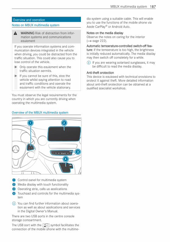
OvOverervieview and operw and operationationNNoottes on MBUX multimedia systes on MBUX multimedia systemem
& WWARNINGARNING Risk of distraction from infor-mation systems and communicationsequipment
If you operate information systems and com-munication devices integrated in the vehiclewhen driving, you could be distracted from thetra c situation. This could also cause you tolose control of the vehicle.# Only operate this equipment when the
tra c situation permits.# If you cannot be sure of this, stop the
vehicle whilst paying attention to roadand tra c conditions and operate theequipment with the vehicle stationary.
You must observe the legal requirements for thecountry in which you are currently driving whenoperating the multimedia system.
OvOverervieview of tw of the MBUX multimedia syhe MBUX multimedia syststemem
1 Control panel for multimedia system2 Media display with touch functionality3 Operating strip, calls up applications4 Touchpad and controls for the multimedia sys-
tem
% You can nd further information about opera-tion as well as about applications and servicesin the Digital Owner's Manual.
There are two USB ports in the centre consolestorage compartment.The USB port with theç symbol facilitates theconnection of the mobile phone with the multime-
dia system using a suitable cable. This will enableyou to use the functions of the mobile phone viaApple CarPlay® or Android Auto.
NNoottes on tes on the media displayhe media displayObserve the notes on caring for the interior(/ page 222).AAututomatic tomatic tememperperaturature-contre-controlledolled switcswitch-oh-o ffea-ea-turture:e: if the temperature is too high, the brightnessis initially reduced automatically. The media displaymay then switch o completely for a while.% If you are wearing polarised sunglasses, it may
be di cult to read the media display.
Anti-tAnti-thehe protprotectionectionThis device is equipped with technical provisions toprotect it against the . More detailed informationabout anti-the protection can be obtained at aquali ed specialist workshop.
MBUX multimedia system 187187
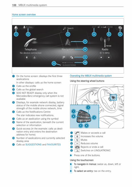
Home scrHome screen oveen overerviewview
1 On the home screen: displays the rst threeapplicationsIn other displays: calls up the home screen
2 Calls up the pro le3 Calls up the global search4 SOS NOT READY display only when the
Mercedes-Benz emergency call system is notavailable
5 Displays, for example network display, batterystatus of the mobile phone connected, signalstrength of the mobile phone network, time
6 Calls up the Noti cations CentreThe star indicates new noti cations.
7 Calls up an application using the symbol8 Name of the application, beneath the current
selection or information9 Quick-access (in the example: calls up desti-
nation entry and enters the destinationaddress for home)
A Number of applications and currently selecteddisplay area
B Calls up SUGGESTIONS and FAVOURITES
OperOperating tating the MBUX multimedia systhe MBUX multimedia systemem
Using tUsing the sthe steereering wheel butting wheel buttonsons
1 6 Makes or accepts a call2 W Increases the volume3 8 Mutes4 X Reduces volume5 ~ Rejects or ends a call6 ó Switches on LINGUATRONIC
# Press one of the buttons.
Using tUsing the the toucouchscrhscreeneen# TTo nao navigvigatate in menus:e in menus: swipe up, down, le or
right.# TTo select an entryo select an entry:: tap on the entry.
188188 MBUX multimedia system
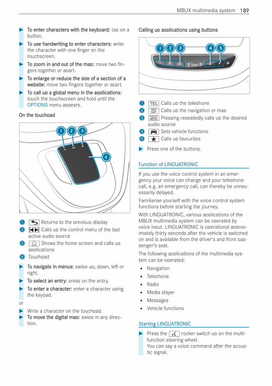
# TTo ento enter cer charharactacterers wits with th the kehe keyboaryboard:d: tap on abutton.
# TTo use handwro use handwriting titing to ento enter cer charharactacterers:s: writethe character with one nger on thetouchscreen.
# TTo zoom in and out of to zoom in and out of the map:he map: move two n-gers together or apart.
# TTo enlargo enlarge or re or reduce teduce the size of a section of ahe size of a section of awwebsitebsite:e: move two ngers together or apart.
# TTo call up a global menu in to call up a global menu in the applications:he applications:touch the touchscreen and hold until theOPTIONS menu appears.
On tOn the the toucouchpadhpad
1G Returns to the previous display2~ Calls up the control menu of the last
active audio source3 © Shows the home screen and calls up
applications4 Touchpad
# TTo nao navigvigatate in menus:e in menus: swipe up, down, le orright.
# TTo select an entryo select an entry:: press on the entry.# TTo ento enter a cer a charharactacterer:: enter a character using
the keypad.or# Write a character on the touchpad.# TTo movo move te the digithe digital map:al map: swipe in any direc-
tion.
Calling up applications using buttCalling up applications using buttonsons
1 % Calls up the telephone2z Calls up the navigation or map3| Pressing repeatedly calls up the desired
audio source4 ´ Sets vehicle functions5 ß Calls up favourites
# Press one of the buttons.
FFunction of LINunction of LINGUAGUATRTRONICONIC
If you use the voice control system in an emer-gency your voice can change and your telephonecall, e.g. an emergency call, can thereby be unnec-essarily delayed.Familiarise yourself with the voice control systemfunctions before starting the journey.With LINGUATRONIC, various applications of theMBUX multimedia system can be operated byvoice input. LINGUATRONIC is operational approx-imately thirty seconds a er the vehicle is switchedon and is available from the driver's and front pas-senger's seat.The following applications of the multimedia sys-tem can be operated:R NavigationR TelephoneR RadioR Media playerR MessagesR Vehicle functions
SSttararting LINting LINGUAGUATRTRONICONIC
# Press the£ rocker switch up on the multi-function steering wheel.You can say a voice command a er the acous-tic signal.
MBUX multimedia system 189189
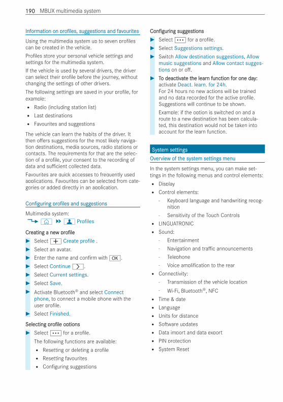
InfInforormation onmation on prpro les,o les, suggsuggesestions and favtions and favourourititeses
Using the multimedia system up to seven pro lescan be created in the vehicle.Pro les store your personal vehicle settings andsettings for the multimedia system.If the vehicle is used by several drivers, the drivercan select their pro le before the journey, withoutchanging the settings of other drivers.The following settings are saved in your pro le, forexample:R Radio (including station list)R Last destinationsR Favourites and suggestions
The vehicle can learn the habits of the driver. Itthen o ers suggestions for the most likely naviga-tion destinations, media sources, radio stations orcontacts. The requirements for that are the selec-tion of a pro le, your consent to the recording ofdata and su cient collected data.Favourites are quick accesses to frequently usedapplications. Favourites can be selected from cate-gories or added directly in an application.
Con gurCon guringing prpro leso les and suggand suggesestionstions
Multimedia system:4© 5f Profiles
CrCreating a neeating a neww prpro leo le# Select W Create profile .# Select an avatar.# Enter the name and con rm with a.# Select Continuer.# Select Current settings.# Select Save.# Activate Bluetooth® and select Connect
phone, to connect a mobile phone with theuser pro le.
# Select Finished.
SelectingSelecting prpro leo le opoptionstions# Select Ä for a pro le.
The following functions are available:R Resetting or deleting a pro leR Resetting favouritesR Con guring suggestions
Con gurCon guringing suggsuggesestionstions# Select Ä for a pro le.# Select Suggestions settings.# Switch Allow destination suggestions, Allow
music suggestions and Allow contact sugges-tions on or o .
# TTo deactivo deactivatate te the learhe learn function fn function for one dayor one day::activate Deact. learn. for 24h.For 24 hours no new actions will be trainedand no data recorded for the active pro le.Suggestions will continue to be shown.Example: if the option is switched on and aroute to a new destination has been calcula-ted, this destination would not be taken intoaccount for the learn function.
SystSystem seem settingsttingsOvOverervieview of tw of the syhe syststem seem settings menuttings menu
In the system settings menu, you can make set-tings in the following menus and control elements:R DisplayR Control elements:
- Keyboard language and handwriting recog-nition
- Sensitivity of the Touch ControlsR LINGUATRONICR Sound:
- Entertainment- Navigation and tra c announcements- Telephone- Voice ampli cation to the rearR Connectivity:
- Transmission of the vehicle location- Wi-Fi, Bluetooth®, NFCR Time & dateR LanguageR Units for distanceR So ware updatesR Data import and data exportR PIN protectionR System Reset
190190 MBUX multimedia system
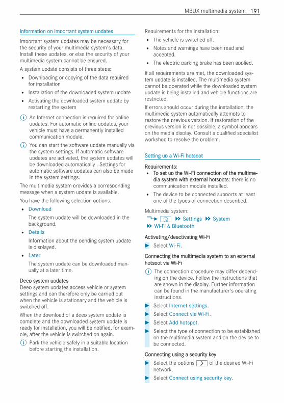
InfInforormation on immation on importportant systant system updatem updateses
Important system updates may be necessary forthe security of your multimedia system's data.Install these updates, or else the security of yourmultimedia system cannot be ensured.A system update consists of three steps:R Downloading or copying of the data required
for installationR Installation of the downloaded system updateR Activating the downloaded system update by
restarting the system
% An Internet connection is required for onlineupdates. For automatic online updates, yourvehicle must have a permanently installedcommunication module.
% You can start the so ware update manually viathe system settings. If automatic so wareupdates are activated, the system updates willbe downloaded automatically . Settings forautomatic so ware updates can also be madein the system settings.
The multimedia system provides a correspondingmessage when a system update is available.You have the following selection options:R Download
The system update will be downloaded in thebackground.R Details
Information about the pending system updateis displayed.R Later
The system update can be downloaded man-ually at a later time.
Deep systDeep system updatem updatesesDeep system updates access vehicle or systemsettings and can therefore only be carried outwhen the vehicle is stationary and the vehicle isswitched o .When the download of a deep system update iscomplete and the downloaded system update isready for installation, you will be noti ed, for exam-ple, a er the vehicle is switched on again.% Park the vehicle safely in a suitable location
before starting the installation.
Requirements for the installation:R The vehicle is switched o .R Notes and warnings have been read and
accepted.R The electric parking brake has been applied.
If all requirements are met, the downloaded sys-tem update is installed. The multimedia systemcannot be operated while the downloaded systemupdate is being installed and vehicle functions arerestricted.If errors should occur during the installation, themultimedia system automatically attempts torestore the previous version. If restoration of theprevious version is not possible, a symbol appearson the media display. Consult a quali ed specialistworkshop to resolve the problem.
SeSetting up a Wtting up a Wi-Fi-Fi hoi hotspottspot
RReqequiruirements:ements:R TTo seo set up tt up the Whe Wi-Fi-Fi connection of ti connection of the multime-he multime-
dia systdia system witem with eh extxterernal honal hotspotspots:ts: there is nocommunication module installed.R The device to be connected supports at least
one of the types of connection described.
Multimedia system:4© 5 Settings 5 System5 Wi-Fi & Bluetooth
AActivctivating/deactivating/deactivating Wating Wi-Fii-Fi# Select Wi-Fi.
Connecting tConnecting the multimedia systhe multimedia system tem to an eo an extxterernalnalhohotspotspot via Wt via Wi-Fii-Fi% The connection procedure may di er depend-
ing on the device. Follow the instructions thatare shown in the display. Further informationcan be found in the manufacturer's operatinginstructions.
# Select Internet settings.# Select Connect via Wi-Fi.# Select Add hotspot.# Select the type of connection to be established
on the multimedia system and on the device tobe connected.
Connecting using a securConnecting using a security keyity key# Select the options r of the desired Wi-Fi
network.# Select Connect using security key.
MBUX multimedia system 191191
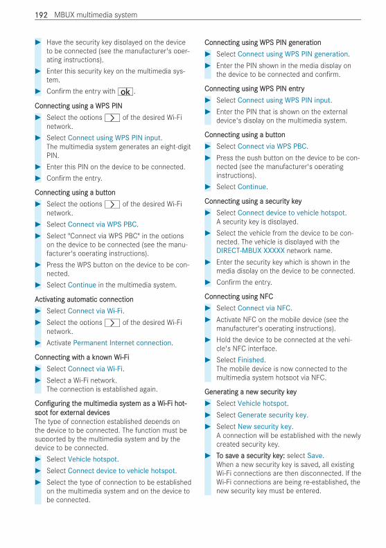
# Have the security key displayed on the deviceto be connected (see the manufacturer's oper-ating instructions).
# Enter this security key on the multimedia sys-tem.
# Con rm the entry with¡.
Connecting using a WPS PINConnecting using a WPS PIN# Select the options r of the desired Wi-Fi
network.# Select Connect using WPS PIN input.
The multimedia system generates an eight-digitPIN.
# Enter this PIN on the device to be connected.# Con rm the entry.
Connecting using a buttConnecting using a buttonon# Select the options r of the desired Wi-Fi
network.# Select Connect via WPS PBC.# Select "Connect via WPS PBC" in the options
on the device to be connected (see the manu-facturer's operating instructions).
# Press the WPS button on the device to be con-nected.
# Select Continue in the multimedia system.
AActivctivating autating automatic connectionomatic connection# Select Connect via Wi-Fi.# Select the options r of the desired Wi-Fi
network.# Activate Permanent Internet connection.
Connecting witConnecting with a knoh a known Wwn Wi-Fii-Fi# Select Connect via Wi-Fi.# Select a Wi-Fi network.
The connection is established again.
Con gurCon guringing tthe multimedia systhe multimedia system as a Wem as a Wi-Fi-Fi hoi hot-t-spospot ft for eor extxterernal denal devicesvicesThe type of connection established depends onthe device to be connected. The function must besupported by the multimedia system and by thedevice to be connected.# Select Vehicle hotspot.# Select Connect device to vehicle hotspot.# Select the type of connection to be established
on the multimedia system and on the device tobe connected.
Connecting using WPS PIN gConnecting using WPS PIN generenerationation# Select Connect using WPS PIN generation.# Enter the PIN shown in the media display on
the device to be connected and con rm.
Connecting using WPS PIN entryConnecting using WPS PIN entry# Select Connect using WPS PIN input.# Enter the PIN that is shown on the external
device's display on the multimedia system.
Connecting using a buttConnecting using a buttonon# Select Connect via WPS PBC.# Press the push button on the device to be con-
nected (see the manufacturer's operatinginstructions).
# Select Continue.
Connecting using a securConnecting using a security keyity key# Select Connect device to vehicle hotspot.
A security key is displayed.# Select the vehicle from the device to be con-
nected. The vehicle is displayed with theDIRECT-MBUX XXXXX network name.
# Enter the security key which is shown in themedia display on the device to be connected.
# Con rm the entry.
Connecting using NFCConnecting using NFC# Select Connect via NFC.# Activate NFC on the mobile device (see the
manufacturer's operating instructions).# Hold the device to be connected at the vehi-
cle's NFC interface.# Select Finished.
The mobile device is now connected to themultimedia system hotspot via NFC.
GenerGenerating a neating a new securw security keyity key# Select Vehicle hotspot.# Select Generate security key.# Select New security key.
A connection will be established with the newlycreated security key.
# TTo savo save a secure a security keyity key:: select Save.When a new security key is saved, all existingWi-Fi connections are then disconnected. If theWi-Fi connections are being re-established, thenew security key must be entered.
192192 MBUX multimedia system
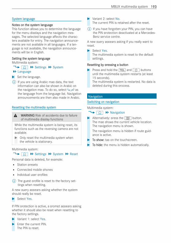
SystSystem languageem language
NNoottes on tes on the systhe system languageem languageThis function allows you to determine the languagefor the menu displays and the navigation mes-sages. The selected language a ects the charac-ters available for entry. The navigation announce-ments are not available in all languages. If a lan-guage is not available, the navigation announce-ments will be in English.
SeSetting ttting the systhe system languageem languageMultimedia system:4© 5 Settings 5 System5 Language# Set the language.% If you are using Arabic map data, the text
information can also be shown in Arabic onthe navigation map. To do so, select asthe language from the language list. Navigationannouncements are then also made in Arabic.
RReseesetting ttting the multimedia systhe multimedia systemem
& WWARNINGARNING Risk of accidents due to failureof multimedia display functions
While the multimedia system is being reset, itsfunctions such as the reversing camera are notavailable.# Only reset the multimedia system when
the vehicle is stationary.
Multimedia system:4© 5 Settings 5 System 5 ResetPersonal data is deleted, for example:R Station presetsR Connected mobile phonesR Individual user pro les
% The guest pro le is reset to the factory set-tings when resetting.
A new query appears asking whether the systemshould really be reset.# Select Yes.
If PIN protection is active, a prompt appears askingwhether it should also be reset when resetting tothe factory settings.# Variant 1: select Yes.# Enter the current PIN.
The PIN is reset.
# Variant 2: select No.The current PIN is retained a er the reset.
% If you have forgotten your PIN, you can havethe PIN protection deactivated at a Mercedes-Benz service centre.
A new query appears asking if you really want toreset.# Select Yes.
The multimedia system is reset to the defaultsettings.
RReseesetting btting by pry pressing a buttessing a buttonon# Press and hold the % andf buttons
until the multimedia system restarts (at least15 seconds).The multimedia system is restarted. No data isdeleted during this process.
NNaavigvigationationSwitcSwitching on nahing on navigvigationation
Multimedia system:4© 5 Navigation# Alternatively: press thez button.
The map shows the current vehicle location.The navigation menu is shown.The navigation menu is hidden if route guid-ance is active.
# TTo showo show:: tap on the touchscreen.# TTo hide:o hide: the menu is hidden automatically.
MBUX multimedia system 193193
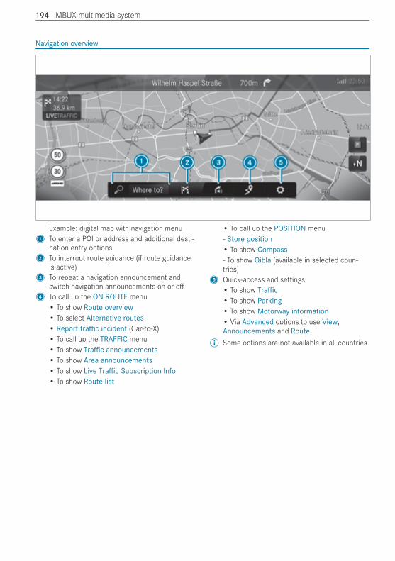
NNaavigvigation ovation overerviewview
Example: digital map with navigation menu1 To enter a POI or address and additional desti-
nation entry options2 To interrupt route guidance (if route guidance
is active)3 To repeat a navigation announcement and
switch navigation announcements on or o4 To call up the ON ROUTE menu
• To show Route overview• To select Alternative routes• Report traffic incident (Car-to-X)• To call up the TRAFFIC menu• To show Traffic announcements• To show Area announcements• To show Live Traffic Subscription Info• To show Route list
• To call up the POSITION menu- Store position• To show Compass- To show Qibla (available in selected coun-tries)
5 Quick-access and settings• To show Traffic• To show Parking• To show Motorway information• Via Advanced options to use View,Announcements and Route
% Some options are not available in all countries.
194194 MBUX multimedia system
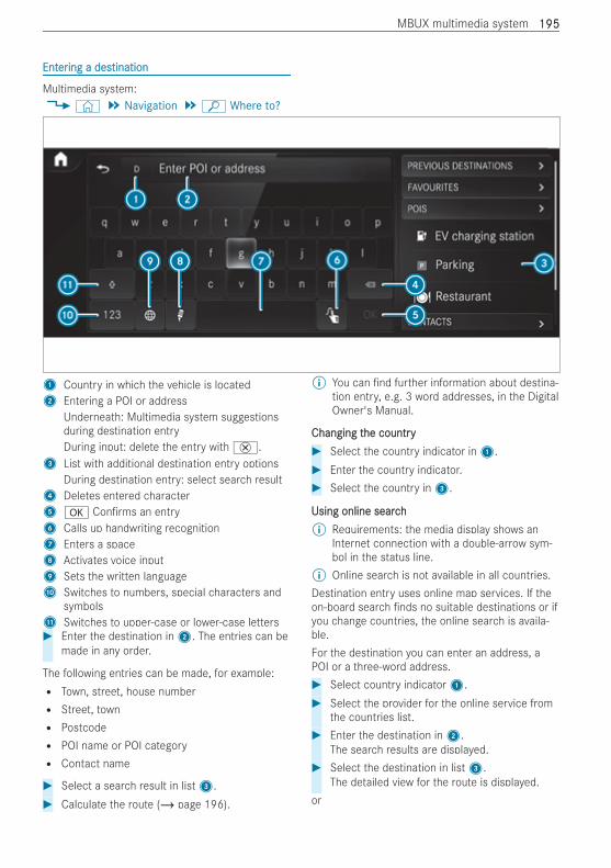
EntEnterering a desing a destinationtination
Multimedia system:4© 5 Navigation 5ª Where to?
1 Country in which the vehicle is located2 Entering a POI or address
Underneath: Multimedia system suggestionsduring destination entryDuring input: delete the entry with£.
3 List with additional destination entry optionsDuring destination entry: select search result
4 Deletes entered character5 a Con rms an entry6 Calls up handwriting recognition7 Enters a space8 Activates voice input9 Sets the written languageA Switches to numbers, special characters and
symbolsB Switches to upper-case or lower-case letters# Enter the destination in2. The entries can be
made in any order.
The following entries can be made, for example:R Town, street, house numberR Street, townR PostcodeR POI name or POI categoryR Contact name
# Select a search result in list3.# Calculate the route (/ page 196).
% You can nd further information about destina-tion entry, e.g. 3 word addresses, in the DigitalOwner's Manual.
Changing tChanging the countryhe country# Select the country indicator in1.# Enter the country indicator.# Select the country in3.
Using online searchUsing online search% Requirements: the media display shows an
Internet connection with a double-arrow sym-bol in the status line.
% Online search is not available in all countries.Destination entry uses online map services. If theon-board search nds no suitable destinations or ifyou change countries, the online search is availa-ble.For the destination you can enter an address, aPOI or a three-word address.# Select country indicator1.# Select the provider for the online service from
the countries list.# Enter the destination in2.
The search results are displayed.# Select the destination in list3.
The detailed view for the route is displayed.or
MBUX multimedia system 195195
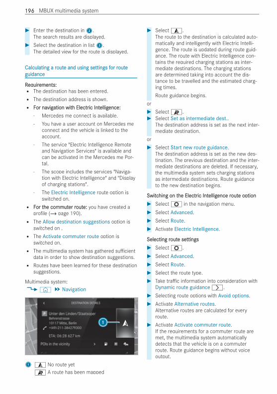
# Enter the destination in2.The search results are displayed.
# Select the destination in list3.The detailed view for the route is displayed.
Calculating a rCalculating a routoute and using see and using settings fttings for ror routeouteguidanceguidance
RReqequiruirements:ements:R The destination has been entered.R The destination address is shown.R FFor naor navigvigation witation with Electrh Electric Intic Intelligelligence:ence:
- Mercedes me connect is available.- You have a user account on Mercedes me
connect and the vehicle is linked to theaccount.
- The service "Electric Intelligence Remoteand Navigation Services" is available andcan be activated in the Mercedes me Por-tal.
- The scope includes the services "Naviga-tion with Electric Intelligence" and "Displayof charging stations".
- The Electric Intelligence route option isswitched on.
R FFor tor the commuthe commuter rer routoute:e: you have created apro le (/ page 190).R The Allow destination suggestions option is
switched on .R The Activate commuter route option is
switched on.R The multimedia system has gathered su cient
data in order to show destination suggestions.R Routes have been learned for these destination
suggestions.
Multimedia system:4© 5 Navigation
1¥ No route yet¦ A route has been mapped
# Select¥.The route to the destination is calculated auto-matically and intelligently with Electric Intelli-gence. The route is updated during route guid-ance. The route with Electric Intelligence con-tains the required charging stations as inter-mediate destinations. The charging stationsare determined taking into account the dis-tance to be travelled and the estimated charg-ing times.Route guidance begins.
or# Select¦.# Select Set as intermediate dest..
The destination address is set as the next inter-mediate destination.
or# Select Start new route guidance.
The destination address is set as the new des-tination. The previous destination and the inter-mediate destinations are deleted. If necessary,the multimedia system sets charging stationsas intermediate destinations. Route guidanceto the new destination begins.
SwitcSwitching on thing on the Electrhe Electric Intic Intelligelligence rence routoute ope optiontion# SelectZ in the navigation menu.# Select Advanced.# Select Route.# Activate Electric Intelligence.
Selecting rSelecting routoute see settingsttings# SelectZ.# Select Advanced.# Select Route.# Select the route type.# Take tra c information into consideration with
Dynamic route guidancer.# Selecting route options with Avoid options.# Activate Alternative routes.
Alternative routes are calculated for everyroute.
# Activate Activate commuter route.If the requirements for a commuter route aremet, the multimedia system automaticallydetects that the vehicle is on a commuterroute. Route guidance begins without voiceoutput.
196196 MBUX multimedia system
Using map functionsUsing map functions
Multimedia system:4© 5 Navigation
EnlarEnlarging tging the map scalehe map scale# When the map is shown, tap twice quickly with
one nger on the media display.or# Move two ngers apart on the media display.
RReducing teducing the map scalehe map scale# Tap with two ngers on the media display.or# Move two ngers together on the media dis-
play.
MoMoving tving the maphe map# Move one nger in any direction on the
touchscreen.# TTo ro reseeset tt the map the map to to the currhe current vent vehicle posi-ehicle posi-
tion:tion: press\ brie y.
Selecting map orSelecting map orientientationation# Press theÄ compass symbol repeatedly on
the map.The view changes in the sequence 3D, 2Dheading up to 2D north up.
SwitcSwitching mothing motorwaorway infy inforormation on ormation on or oo# SelectZ.# Activate or deactivate Motorway information.
Using serUsing servicesvices
RReqequiruirements:ements:R There is an Internet connection.R Mercedes me connect is available.R You have set up a user account in the
Mercedes me Portal.R The vehicle is connected to a user account and
you have accepted the conditions of use forthe service.Further information can be found at: https://www.mercedes.meR The service is available and has been activa-
ted.
Multimedia system:4© 5 Navigation
DisplaDisplaying tying thehe trtra ca c situation witsituation with Livh Livee TrTra ca cInfInforormationmation# SelectZ.# Activate Traffic.# Select Advanced.# Select View.# Select Map elements.# Switch on Traffic incidents, Free-flowing traf-
fic and Delay.If tra c information has been received, thentra c incidents such as roadworks, roadblocks, local area reports (e.g. fog) and warn-ing messages are displayed.The tra c delay is displayed for the currentroute. Tra c delays lasting a period of oneminute or longer are taken into consideration.
DisplaDisplaying hazarying hazard wd wararnings witnings with Carh Car-t-to-Xo-X-Commu--Commu-nicationnicationIf hazard warnings are available these are shownas symbols on the map. The display depends onthe settings for the Traffic and Traffic incidentsoptions.# Set the options.
If Traffic is switched o and Traffic incidents isswitched on, the symbols are shown on theprospective route.
DisplaDisplaying wying weateather infher inforormation and otmation and other mapher mapcontcontentsents# SelectZ.# Select Advanced.# Select View.# Select Map elements.# Scroll up and show the ONLINE MAP CON-
TENTS category.# Switch on a service, e.g. Weather.
Current weather information is displayed onthe navigation map, e.g. temperature or cloudcover.
MBUX multimedia system 197197
PPararking serking servicevice
* NONOTETE Damage to the vehicle due to notobserving the maximum permitted head-room clearance
If the vehicle height is greater than the maxi-mum permitted headroom clearance, the roofand other parts of the vehicle may be dam-aged.# Observe the signposted headroom clear-
ance.# If the vehicle height is greater than the
permitted headroom clearance, do notenter.
# Observe the changed vehicle height withadd-on roof equipment.
* NNOOTETE Before selecting the parking option
The data is based on information provided bythe respective service provider.Mercedes Benz accepts no liability for theaccuracy of the information provided relatingto the multi-storey car park/parking area.# Always observe the local Information and
conditions.
% This service is not available in all countries.# Tap on j on the map.# Select a parking option.
The map shows the parking options in thevicinity.The following information is displayed (if availa-ble):R Destination address, distance from current
vehicle position and arrival timeR Information on the multi-storey car
park/car park, for example:- Opening times- Parking charges- Current occupancy- Maximum parking time- Maximum clearMaximum clearance heightance height
The maximum clearance height shownby the parking service does not replacethe need for observation of the actualcircumstances.
R Available payment options (Mercedes pay,coins, bank notes, cards)
R Details on parking tari sR Number of available parking spacesR Payment method (e.g. at parking meters)R Services/facilities at the parking optionR Telephone number
MerMercedes PRcedes PRO connectO connectTTelephonyelephony
NNoottes on tes on telephonyelephony
& WWARNINGARNING Risk of distraction from operat-ing integrated communication equipmentwhile the vehicle is in motion
If you operate communication equipment inte-grated in the vehicle when driving, you couldbe distracted from the tra c situation. Thiscould also cause you to lose control of thevehicle.# Only operate this equipment when the
tra c situation permits.# If you cannot be sure of this, stop the
vehicle whilst paying attention to roadand tra c conditions and operate theequipment with the vehicle stationary.
& WWARNINGARNING Risk of an accident from oper-ating mobile communication equipmentwhile the vehicle is in motion
Mobile communications devices distract thedriver from the tra c situation. This could alsocause the driver to lose control of the vehicle.# As the driver, only operate mobile com-
munications devices when the vehicle isstationary.
# As a vehicle occupant, only use mobilecommunications devices in the areasintended for this purpose, e.g. in the rearpassenger compartment.
You must observe the legal requirements for thecountry in which you are currently driving whenoperating mobile communication equipment in thevehicle.BluetBluetoothooth®® connection:connection:The menu view and the available functions in thephone menu are partly dependent on the Blue-tooth® pro le of the mobile phone connected.
198198 MBUX multimedia system
If the mobile phone supports these Bluetooth®
pro les, the full range of features is available:R PBAP (Phone Book Access Pro le)
- The mobile phone's contacts are automati-cally displayed on the multimedia system.
R MAP (Message Access Pro le)- The message functions of the mobile
phone can be used on the multimedia sys-tem.
Irrespective of this, Bluetooth® audio functionalitycan by used with any mobile device.For information on the functionality of the mobiledevice to be connected, see the manufacturer'soperating instructions.NNeetwtworork connection:k connection:In the following cases, calls may be interruptedwhile driving:R there is insu cient network coverage in the
area.R you switch to a transmitting/receiving station
in which no communication channel is free.R the SIM card used is not compatible with the
network availableR a mobile phone with "Twincard" is logged into
the network with the second SIM card at thesame time
The multimedia system supports calls in HDVoice® for improved speech quality. A requirementfor this is that the mobile phone and the mobilephone network provider of the person you are call-ing support HD Voice®.Depending on the quality of the connection, thevoice quality may uctuate.Further information can be obtained from aMercedes-Benz service centre or at: https://www.mercedes-benz-mobile.com/
MBUX multimedia system 199199
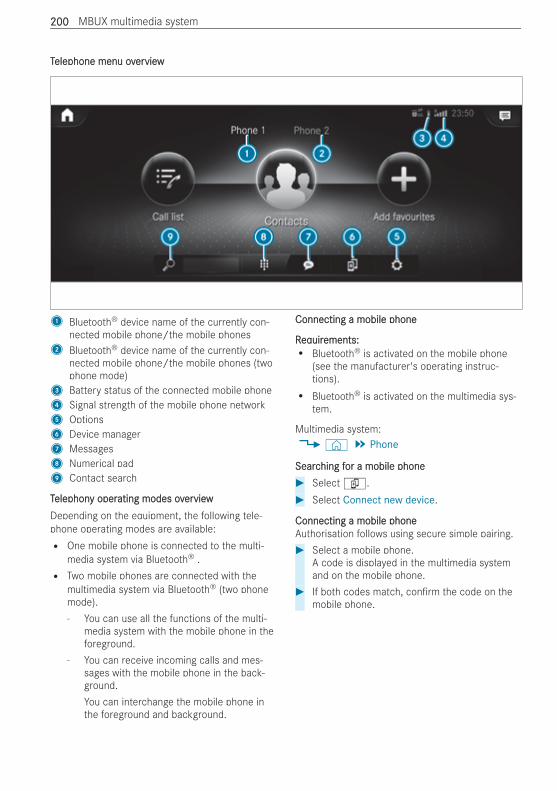
TTelephone menu ovelephone menu overerviewview
1 Bluetooth® device name of the currently con-nected mobile phone/the mobile phones
2 Bluetooth® device name of the currently con-nected mobile phone/the mobile phones (twophone mode)
3 Battery status of the connected mobile phone4 Signal strength of the mobile phone network5 Options6 Device manager7 Messages8 Numerical pad9 Contact search
TTelephonelephony opery operating modes ovating modes overerviewviewDepending on the equipment, the following tele-phone operating modes are available:R One mobile phone is connected to the multi-
media system via Bluetooth® .R Two mobile phones are connected with the
multimedia system via Bluetooth® (two phonemode).- You can use all the functions of the multi-
media system with the mobile phone in theforeground.
- You can receive incoming calls and mes-sages with the mobile phone in the back-ground.You can interchange the mobile phone inthe foreground and background.
Connecting a mobile phoneConnecting a mobile phone
RReqequiruirements:ements:R Bluetooth® is activated on the mobile phone
(see the manufacturer's operating instruc-tions).R Bluetooth® is activated on the multimedia sys-
tem.
Multimedia system:4© 5 Phone
SearcSearching fhing for a mobile phoneor a mobile phone# Selectí.# Select Connect new device.
Connecting a mobile phoneConnecting a mobile phoneAuthorisation follows using secure simple pairing.# Select a mobile phone.
A code is displayed in the multimedia systemand on the mobile phone.
# If both codes match, con rm the code on themobile phone.
200200 MBUX multimedia system
FFunctions in tunctions in the The Telephonelephony menuy menuThe functions available in the Telephony menuinclude the following:R Making calls, e.g.:
- R Accepting a call- k End call- i Create conferen. call- Accepting or rejecting a waiting callR Managing contacts, e.g.:
- Downloading mobile phone contacts- Editing the format of a contact's name- Saving contacts in the vehicleR Receiving and sending messages, e.g.:
- Using the read-aloud function- Dictating a new message
OvOverervieview of Smarw of Smartphone Inttphone IntegregrationationWith Smartphone Integration, you can use certainfunctions on your mobile phone via the multimediasystem display.Only one mobile phone at a time can be connectedvia Smartphone Integration to the multimedia sys-tem. Also for use with two phone mode with smart-phone integration, only one additional mobilephone can be connected using Bluetooth® with themultimedia system.The full range of functions for Smartphone Integra-tion is only possible with an Internet connection.The appropriate application must be downloadedon the mobile phone to use Smartphone Integra-tion. The mobile phone must be switched on andconnected to a USB port with theç symbol onthe multimedia system using a suitable cable.Apps for Smartphone IntegrationR Apple CarPlay®
R Android Auto
You can start Apple CarPlay® or Android Autousing the Apps menu.Alternative: If an application is active via Smart-phone Integration (e.g. when music is being playedor route guidance is active), you can call up theactive application using the| orz or %application buttons
You can end Smartphone Integration by discon-necting the connecting cable between the mobilephone and multimedia system.% Mercedes-Benz recommends disconnecting
the connecting cable only when the vehicle isstationary.
When using Android Auto or Apple CarPlay®, cer-tain vehicle data is transferred to the mobilephone. This enables you to get the best out ofselected mobile phone services. Vehicle data isnot directly accessible.The following system information is transmitted:R So ware release of the multimedia systemR System ID (anonymised)
The transfer of this data is used to optimise com-munication between the vehicle and the mobilephone.To do this, and to assign several vehicles to themobile phone, a vehicle ID is randomly generated.This has no connection to the vehicle identi cationnumber (VIN) and is deleted when the multimediasystem is reset (/ page 193).The following vehicle status data is transmitted:R The transmission position engagedR The distinction between parked, standstill, roll-
ing and drivingR The day/night mode of the instrument cluster
The transfer of this data is used to alter how con-tent is displayed to correspond to the driving situa-tion.The following position data is transmitted:R CoordinatesR SpeedR Compass directionR Acceleration direction
This data is only transferred while the navigationsystem is active, in order to improve it (e.g. so itcan continue functioning when in a tunnel).
WWeb broweb browser ovser overerviewviewThe web browser is launched on the home screena er selecting Apps viaz Browser.
MBUX multimedia system 201201
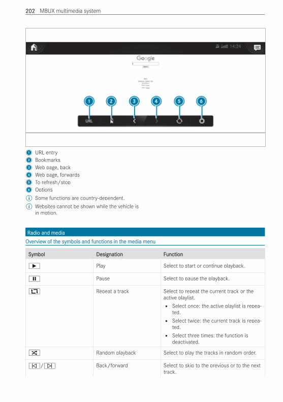
1 URL entry2 Bookmarks3 Web page, back4 Web page, forwards5 To refresh/stop6 Options% Some functions are country-dependent.% Websites cannot be shown while the vehicle is
in motion.
RRadio and mediaadio and mediaOvOverervieview of tw of the symbols and functions in the symbols and functions in the media menuhe media menu
SymbolSymbol Designation FDesignation Functionunction
Ì Play Select to start or continue playback.
Ë Pause Select to pause the playback.
: Repeat a track Select to repeat the current track or theactive playlist.R Select once: the active playlist is repea-
ted.R Select twice: the current track is repea-
ted.R Select three times: the function is
deactivated.
9 Random playback Select to play the tracks in random order.
û/ü Back/forward Select to skip to the previous or to the nexttrack.
202202 MBUX multimedia system
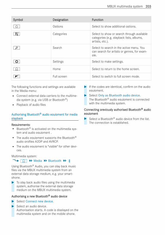
SymbolSymbol Designation FDesignation Functionunction
f Options Select to show additional options.
5 Categories Select to show or search through availablecategories (e.g. playback lists, albums,artists, etc.).
è Search Select to search in the active menu. Youcan search for artists or genres, for exam-ple.
Z Settings Select to make settings.
© Home Select to return to the home screen.
2 Full screen Select to switch to full screen mode.
The following functions and settings are availablein the Media menu:R Connect external data carriers to the multime-
dia system (e.g. via USB or Bluetooth®)R Playback of audio les
AAututhorhorising Bluetising Bluetoothooth®® audio eqaudio equipment fuipment for mediaor mediaplaplaybackyback
RReqequiruirements:ements:R Bluetooth® is activated on the multimedia sys-
tem and audio equipment .R The audio equipment supports the Bluetooth®
audio pro les A2DP and AVRCP.R The audio equipment is "visible" for other devi-
ces.
Multimedia system:4© 5 Media 5 Bluetooth 5 ª
Using Bluetooth® Audio, you can play back musicles via the MBUX multimedia system from an
external data storage medium, e.g. your smart-phone.# To play back audio les using the multimedia
system, authorise the external data storagemedium on the MBUX multimedia system.
AAututhorhorising a neising a new Bluetw Bluetoothooth®® audio deaudio devicevice# Select Connect new device.# Select an audio device.
Authorisation starts. A code is displayed on themultimedia system and on the mobile phone.
# If the codes are identical, con rm on the audioequipment.
# Select Only as Bluetooth audio device.The Bluetooth® audio equipment is connectedwith the multimedia system.
Connecting preConnecting previouslviously auty authorhorised Bluetised Bluetoothooth®® audioaudioeqequipmentuipment# Select a Bluetooth® audio device from the list.
The connection is established.
MBUX multimedia system 203203
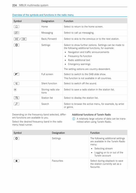
OvOverervieview of tw of the symbols and functions in the symbols and functions in the rhe radio menuadio menu
SymbolSymbol Designation FDesignation Functionunction
© Home Select to return to the home screen.
j Messaging Select to call up messaging.
û/ü Back/forward Select to skip to the previous or to the next station.
Z Settings Select to show further options. Settings can be made tothe following additional functions, for example:R Navigation and tra c announcementsR Frequency x functionR Radio additional textR Emergency warnings
The setting options are country-dependent.
2 Full screen Select to switch to the DAB slide show.This function is not available in all countries.
8 Silent function Select to switch o the sound.
f Storing radio sta-tions
Select to save a radio station in the station list.
4 Station list Select to display the station list.
ª Search Select to browse the active menu, for example, by artistor genre.
Depending on the frequency band selected, di er-ent functions are available to you.Select the desired frequency band in the radiomenu head runner.
AAdditional functions of Tdditional functions of TuneIn RuneIn Radioadio% A relatively large volume of data can be trans-
mitted when using TuneIn Radio.
SymbolSymbol Designation FDesignation Functionunction
Z Settings The following additional settingsare available in the TuneIn Radiomenu:R Selecting streamR Logging on to or out of the
TuneIn account
ß Favourites Select during playback to savethe station currently set as afavourite.
204204 MBUX multimedia system
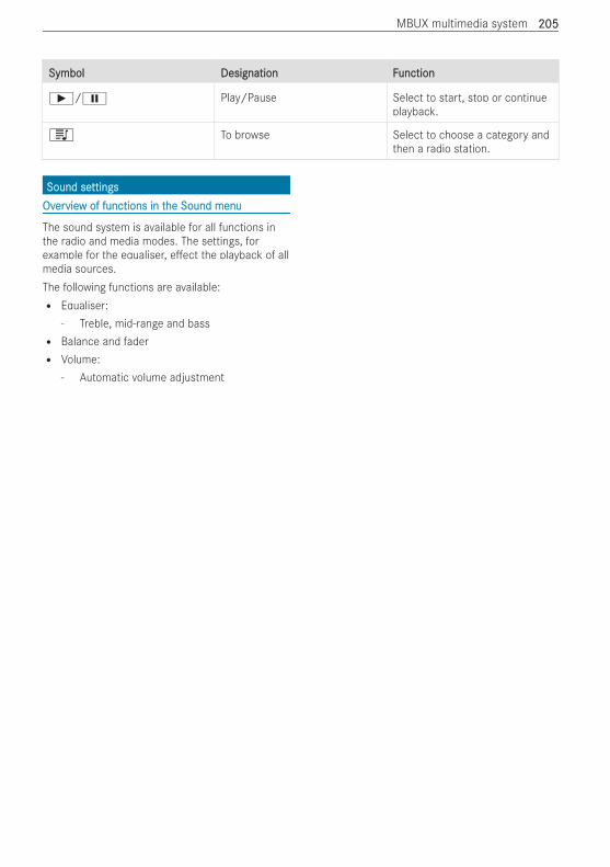
SymbolSymbol Designation FDesignation Functionunction
Ì/Ë Play/Pause Select to start, stop or continueplayback.
5 To browse Select to choose a category andthen a radio station.
Sound seSound settingsttingsOvOverervieview of functions in tw of functions in the Sound menuhe Sound menu
The sound system is available for all functions inthe radio and media modes. The settings, forexample for the equaliser, e ect the playback of allmedia sources.The following functions are available:R Equaliser:
- Treble, mid-range and bassR Balance and faderR Volume:
- Automatic volume adjustment
MBUX multimedia system 205205
NNoottes on loading guidelineses on loading guidelines
& WWARNINGARNING Risk of injury from unsecuredobjects in the vehicle
When objects are unsecured or inadequatelysecured, they can slip, tip over or be thrownabout, striking vehicle occupants.This also applies to:R luggage or loadsR seats which have been removed and are
being transported in the vehicle in anexceptional case
There is a risk of injury, particularly in theevent of braking manoeuvres or abruptchanges in direction.# Always stow objects in such a way that
they cannot be tossed about.# Before travelling, secure objects, luggage
or load to prevent them slipping or tip-ping over.
# When a seat is removed, keep it prefera-bly outside the vehicle.
& WWARNINGARNING Risk of accident due to incor-rectly placed load
The centre of gravity of the load may be toohigh and/or too far back.This can signi cantly impair the driving, steer-ing and braking characteristics.# Always ensure that the centre of gravity
of the load is between the axles and aslow as possible near the rear axle.
& WWARNINGARNING Risk of accident due to exceed-ing the permissible wheel/axle loads orthe gross vehicle weight
The driving characteristics, as well as steeringand braking, may be greatly impaired. Overloa-ded tyres may overheat and burst as a conse-quence.# When transporting a load, always
observe the permissible wheel loads,axle loads and the maximum permissiblegross mass for the vehicle (includingoccupants).
& WWARNINGARNING Risk of injury if unsuitableclimbing aids are used
In the event that you use openings in the body-work or attachments as steps, you could:R Slip and/or fall.R Damage the vehicle and thus slip and fall.
# Always use non-slip, stable climbing aids,e.g. a suitable ladder.
* NNOOTETE Damage caused by the use of open-ings in the bodywork or detachable part asa step
Using the lower guide of the sliding door (car-riage) as a step can damage the trim and/ormechanism of the sliding door.# Do not use the guide of the sliding door
(carriage) as a step.
If you are using a roof luggage rack, please notethe maximum roof load and the maximum loadcapacity of the roof luggage rack (/ page 253).The handling characteristics of your vehicle aredependent on the load distribution.Therefore, please observe the following noteswhen loading:R the load must not protrude above the upper
edge of the seat backrests.R if possible, always transport the load in the
load compartment.R fasten the load to the tie-down eyes and dis-
tribute the load evenly among them.R if available, use a load protection net to secure
the load (/ page 210).R use tie-down eyes and fastening components
which are suitable for the weight and size ofthe load.
Observe the operating instructions of the manufac-turer when using load securing aids or lashingmaterial and the notes on their expiration dates.In the following cases, load securing aids or lash-ing materials are worn out, should not be used andmust be replaced:R there is missing or illegible identi cationR there is cord breakage or damage to load-bear-
ing seams or other traces of cracking
206206 Transporting
R there are cuts, holes, deformations, crushedareas or other damageR there is damage to clamping elements or fas-
teners
If the luggage compartment oor or loading areaare damaged in the event of an accident, have thetie-down eyes and the lashing material checked ata quali ed specialist workshop.Even if you adhere to all the loading guidelines, anincreased load increases the risk of injury in theevent of an accident.
BefBeforore loadinge loadingCheck and, when necessary, adjust the tyre pres-sure (/ page 236).
When loadingWhen loadingObserve the following when loading the vehicle:R Never exceed the permissible axle load or the
vehicle's permissible gross mass.The vehicle's kerb weight is increased if acces-sories or optional equipment are tted. Thisreduces the maximum payload.R Observe the notes on load distribution
(/ page 207).R Observe the notes on load securing
(/ page 208) and the legal requirements ofthe country in which you are currently driving.R Observe the information on the carrier systems
(/ page 213).
A erA er loadingloadingObserve the following a er loading the vehicle:R Check that the luggage and/or load is secure
before every journey and at regular intervals onlong trips.R Close all doors and the tailgate.R Adjust the range of the headlamps according
to the vehicle load (/ page 105).R Adjust the tyre pressure according to the vehi-
cle load (/ page 236).R Adapt your driving style according to the vehi-
cle load.
Load disLoad distrtributionibution
* NONOTETE Damage to the oor covering due touneven loading
Excessive point loading on the load compart-ment oor or on the load area can negativelya ect the driving characteristics and coulddamage the oor covering.# Distribute the load evenly. When doing
so, ensure that the overall centre of grav-ity of the load is always as low and closeto the centre as possible and betweenthe axles near the rear axle.
Observe the following notes:R Always transport loads in the load compart-
ment and with the seat backrests folded upand properly locked in position.R Always place the load against the front or rear
seat backrests.R Move large and heavy loads as far as possible
towards the front of the vehicle in the directionof travel, against the front or rear seats. Stowloads ush with the rear or front seats.R Additionally secure the load with suitable load
securing aids or lashing material.R The load must not protrude above the upper
edge of the seat backrests.R Transport loads behind seats that are not
occupied.R If the rear bench seat is not occupied, insert
the seat belts crosswise into the seat beltbuckle of the opposite seat belt.
Load comLoad comparpartment vtment varariantsiantsYou can vary the load compartment according toyour transportation requirements as follows:R by folding the rear seat backrests or rear
bench seat backrests forward to the table posi-tionR by folding the rear seats forwardsR by folding the rear bench seat forwardsR by removing the rear seats and/or the rear
bench seatR by removing the seat/bunk combinationR by folding up or removing the bed extension of
the seat/bunk combination
Transporting 207207
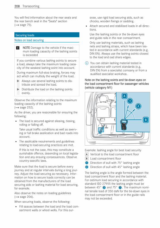
You will nd information about the rear seats andthe rear bench seat in the "Seats" section(/ page 75).
SecurSecuring loadsing loadsNNoottes on load secures on load securinging
* NONOTETE Damage to the vehicle if the maxi-mum loading capacity of the lashing pointsis exceeded
If you combine various lashing points to securea load, always take the maximum loading capa-city of the weakest lashing point into account.During maximum full-stop braking, forces mayact which can multiply the weight of the load.# Always use several lashing points to dis-
tribute and spread the load.# Distribute the load on the lashing points
evenly.
Observe the information relating to the maximumloading capacity of the lashing points(/ page 252).As the driver, you are responsible for ensuring thefollowing:R The load is secured against slipping, tipping,
rolling or falling o .Take usual tra c conditions as well as swerv-ing or full brake application and bad roads intoaccount.R The applicable requirements and guidelines
relating to load-securing practices are met.If this is not the case, this may constitute apunishable o ence, depending on local legisla-tion and any ensuing consequences. Observecountry-speci c laws.
Make sure that the load is secure before everyjourney and at regular intervals during a long jour-ney. Adjust the load securing as necessary. Infor-mation on how to secure loads correctly can beobtained from the manufacturers of the loadsecuring aids or lashing material for load securing,for example.Also observe the notes on loading guidelines(/ page 206).When securing loads, observe the following:R Fill spaces between the load and the load com-
partment walls or wheel wells. For this pur-
pose, use rigid load securing aids, such aschocks, wooden xings or padding.R Attach secured and stabilised loads in all direc-
tions.Use the lashing points or the tie-down eyesand guide rails in the rear compartment.Only use lashing materials, such as lashingnets and lashing straps, which have been tes-ted in accordance with current standards (e.g.DIN EN). Always use the lashing points closestto the load and pad sharp edges.
% You can obtain lashing material tested inaccordance with current standards (e.g.DIN EN) from a specialist company or from aquali ed specialist workshop.
NNootte on te on the lashing points and tie-dohe lashing points and tie-down eywn eyes ones ontthe load comhe load comparpartmenttment ooroor ffor passengor passenger ver vehiclesehicles(v(vehicle catehicle categoregory M1)y M1)
Example: lashing angle for best load securityd Vertical to the load compartment oore Load compartment oor1 Direction of pull with 75° lashing angle2 Direction of pull with 45° lashing angle
The lashing angle is the angle formed between theload compartment oor and the lashing material.For optimum load securing in accordance withstandard ISO 27955 the lashing angle must bebetween 45°2 and 75°1. The maximum nomi-nal tensile load of 350 daN for the tie-down eyes inthe load compartment oor or in the guide railsmay not be exceeded.
208208 Transporting
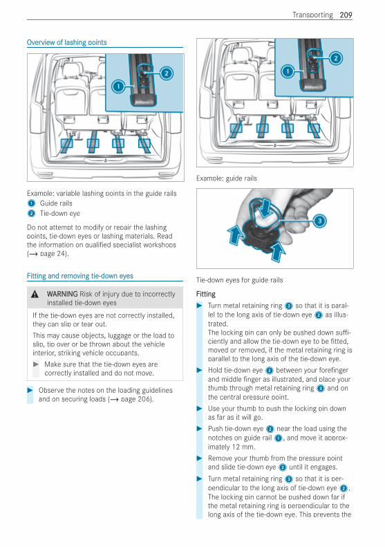
OvOverervieview of lashing pointsw of lashing points
Example: variable lashing points in the guide rails1 Guide rails2 Tie-down eye
Do not attempt to modify or repair the lashingpoints, tie-down eyes or lashing materials. Readthe information on quali ed specialist workshops(/ page 24).
FFitting and ritting and remoemoving tie-doving tie-down eywn eyeses
& WWARNINGARNING Risk of injury due to incorrectlyinstalled tie-down eyes
If the tie-down eyes are not correctly installed,they can slip or tear out.This may cause objects, luggage or the load toslip, tip over or be thrown about the vehicleinterior, striking vehicle occupants.# Make sure that the tie-down eyes are
correctly installed and do not move.
# Observe the notes on the loading guidelinesand on securing loads (/ page 206).
Example: guide rails
Tie-down eyes for guide rails
FFittingitting# Turn metal retaining ring3 so that it is paral-
lel to the long axis of tie-down eye2 as illus-trated.The locking pin can only be pushed down su -ciently and allow the tie-down eye to be tted,moved or removed, if the metal retaining ring isparallel to the long axis of the tie-down eye.
# Hold tie-down eye2 between your fore ngerand middle nger as illustrated, and place yourthumb through metal retaining ring3 and onthe central pressure point.
# Use your thumb to push the locking pin downas far as it will go.
# Push tie-down eye2 near the load using thenotches on guide rail1, and move it approx-imately 12 mm.
# Remove your thumb from the pressure pointand slide tie-down eye2 until it engages.
# Turn metal retaining ring3 so that it is per-pendicular to the long axis of tie-down eye2.The locking pin cannot be pushed down far ifthe metal retaining ring is perpendicular to thelong axis of the tie-down eye. This prevents the
Transporting 209209
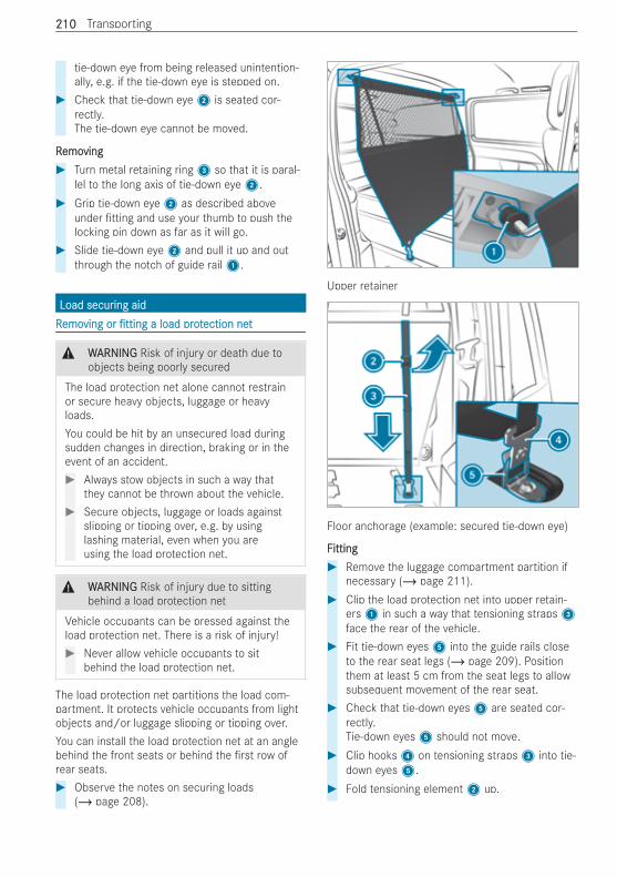
tie-down eye from being released unintention-ally, e.g. if the tie-down eye is stepped on.
# Check that tie-down eye2 is seated cor-rectly.The tie-down eye cannot be moved.
RRemoemovingving# Turn metal retaining ring3 so that it is paral-
lel to the long axis of tie-down eye2.# Grip tie-down eye2 as described above
under tting and use your thumb to push thelocking pin down as far as it will go.
# Slide tie-down eye2 and pull it up and outthrough the notch of guide rail1.
Load securLoad securing aiding aidRRemoemoving orving or ttingtting a load prota load protection netection net
& WWARNINGARNING Risk of injury or death due toobjects being poorly secured
The load protection net alone cannot restrainor secure heavy objects, luggage or heavyloads.You could be hit by an unsecured load duringsudden changes in direction, braking or in theevent of an accident.# Always stow objects in such a way that
they cannot be thrown about the vehicle.# Secure objects, luggage or loads against
slipping or tipping over, e.g. by usinglashing material, even when you areusing the load protection net.
& WWARNINGARNING Risk of injury due to sittingbehind a load protection net
Vehicle occupants can be pressed against theload protection net. There is a risk of injury!# Never allow vehicle occupants to sit
behind the load protection net.
The load protection net partitions the load com-partment. It protects vehicle occupants from lightobjects and/or luggage slipping or tipping over.You can install the load protection net at an anglebehind the front seats or behind the rst row ofrear seats.# Observe the notes on securing loads
(/ page 208).
Upper retainer
Floor anchorage (example: secured tie-down eye)
FFittingitting# Remove the luggage compartment partition if
necessary (/ page 211).# Clip the load protection net into upper retain-
ers1 in such a way that tensioning straps3face the rear of the vehicle.
# Fit tie-down eyes5 into the guide rails closeto the rear seat legs (/ page 209). Positionthem at least 5 cm from the seat legs to allowsubsequent movement of the rear seat.
# Check that tie-down eyes5 are seated cor-rectly.Tie-down eyes5 should not move.
# Clip hooks4 on tensioning straps3 into tie-down eyes5.
# Fold tensioning element2 up.
210210 Transporting
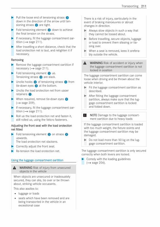
# Pull the loose end of tensioning straps3down in the direction of the arrow until ten-sioning straps3 are tight.
# Fold tensioning element2 down to achievethe nal tension on the straps.
# If necessary, t the luggage compartment par-tition (/ page 211).
# A er travelling a short distance, check that theload protection net is taut, and retighten it ifnecessary.
RRemoemovingving# Remove the luggage compartment partition if
necessary (/ page 211).# Fold tensioning element2 up.
Tensioning straps3 are slack.# Unclip hooks4 of tensioning straps3 from
tie-down eyes5 at the bottom.# Unclip the load protection net from upper
retainers1.# When required, remove tie-down eyes5
(/ page 209).# If necessary, t the luggage compartment par-
tition (/ page 211).# Roll up the load protection net and fasten it,
still rolled up, using the Velcro fasteners.
AAdjusdjusting tting the frhe front seat witont seat with th the load prothe load protectionectionnenett tttteded# Fold tensioning element2 on straps3
upwards.The load protection net slackens.
# Correctly adjust the front seat.# Re-tension the load protection net.
Using tUsing the lugghe luggagage come comparpartment partment partitiontition
& WWARNINGARNING Risk of injury from unsecuredobjects in the vehicle
When objects are unsecured or inadequatelysecured, they can slip, tip over or be thrownabout, striking vehicle occupants.This also applies to:R luggage or loadsR seats which have been removed and are
being transported in the vehicle in anexceptional case
There is a risk of injury, particularly in theevent of braking manoeuvres or abruptchanges in direction.# Always stow objects in such a way that
they cannot be tossed about.# Before travelling, secure objects, luggage
or load to prevent them slipping or tip-ping over.
# When a seat is removed, keep it prefera-bly outside the vehicle.
& WWARNINGARNING Risk of accident or injury whenthe luggage compartment partition is notlocked in position
The luggage compartment partition can comeloose when driving and be thrown about thevehicle interior.# Fit the luggage compartment partition as
described.# A er tting the luggage compartment
partition, always make sure that the lug-gage compartment partition is lockedand folded down.
* NNOOTETE Damage to the luggage compart-ment partition due to heavy loads
If the luggage compartment partition is loadedwith too much weight, the xture points andthe luggage compartment partition may bedamaged.# Do not load more than 50 kg on the lug-
gage compartment partition.
The luggage compartment partition is only securedcorrectly when both levers are locked.# Comply with the loading guidelines
(/ page 206).
Transporting 211211
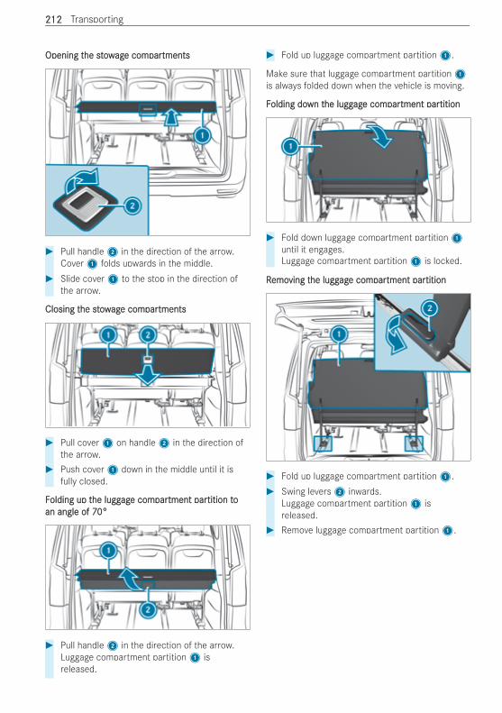
Opening tOpening the stowhe stowagage come comparpartmentstments
# Pull handle2 in the direction of the arrow.Cover1 folds upwards in the middle.
# Slide cover1 to the stop in the direction ofthe arrow.
Closing tClosing the stowhe stowagage come comparpartmentstments
# Pull cover1 on handle2 in the direction ofthe arrow.
# Push cover1 down in the middle until it isfully closed.
FFolding up tolding up the lugghe luggagage come comparpartment partment partition totition toan angle of 70°an angle of 70°
# Pull handle2 in the direction of the arrow.Luggage compartment partition1 isreleased.
# Fold up luggage compartment partition1.
Make sure that luggage compartment partition1is always folded down when the vehicle is moving.
FFolding doolding down twn the lugghe luggagage come comparpartment partment partitiontition
# Fold down luggage compartment partition1until it engages.Luggage compartment partition1 is locked.
RRemoemoving tving the lugghe luggagage come comparpartment partment partitiontition
# Fold up luggage compartment partition1.# Swing levers2 inwards.
Luggage compartment partition1 isreleased.
# Remove luggage compartment partition1.
212212 Transporting
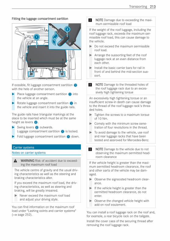
FFitting titting the lugghe luggagage come comparpartment partment partitiontition
If possible, t luggage compartment partition1with the help of another person.# Place luggage compartment partition1 into
the vehicle at an angle.# Rotate luggage compartment partition1 in
the vehicle and insert it into the guide rails.
The guide rails have triangular markings at theplace to be inserted which must be at the sameheight as levers2.# Swing levers2 outwards.
Luggage compartment partition1 is locked.# Fold luggage compartment partition1 down.
CarrCarrier syier syststemsemsNNoottes on carres on carrier systier systemsems
& WWARNINGARNING Risk of accident due to exceed-ing the maximum roof load
The vehicle centre of gravity and the usual driv-ing characteristics as well as the steering andbraking characteristics alter.If you exceed the maximum roof load, the driv-ing characteristics, as well as steering andbraking, will be greatly impaired.# Never exceed the maximum roof load
and adjust your driving style.
You can nd information on the maximum roofload under "Lashing points and carrier systems"(/ page 252).
* NONOTETE Damage due to exceeding the maxi-mum permissible roof load
If the weight of the roof luggage, including theroof luggage rack, exceeds the maximum per-missible roof load, this can cause damage tothe vehicle.# Do not exceed the maximum permissible
roof load.# Arrange the supporting feet of the roof
luggage rack at an even distance fromeach other.
# Install the basic carrier bars for rail infront of and behind the mid-section sup-port.
* NNOOTETE Damage to the threaded holes ofthe roof luggage rack due to an exces-sively high tightening torque
An excessively high tightening torque or aninsu cient screw-in depth can cause damageto the thread of the roof luggage rack's threa-ded holes.# Tighten the screws to a maximum torque
of 10 Nm.# Comply with the minimum screw pene-
tration of four revolutions in the thread.# To avoid damage to the vehicle, use roof
and rear luggage racks that have beentested and approved for Mercedes-Benz.
* NNOOTETE Damage to the vehicle due to notobserving the maximum permitted head-room clearance
If the vehicle height is greater than the maxi-mum permitted headroom clearance, the roofand other parts of the vehicle may be dam-aged.# Observe the signposted headroom clear-
ance.# If the vehicle height is greater than the
permitted headroom clearance, do notenter.
# Observe the changed vehicle height withadd-on roof equipment.
You can install a roof luggage rack on the roof and,for example, a rear bicycle rack on the tailgate.Install the cover caps of the securing thread a erremoving the roof luggage rack.
Transporting 213213

If you have installed a rear luggage rack on the tail-gate, the additional weight will restrict the assis-tance o ered by the pneumatic springs when youopen the tailgate. You will then need more force toopen the tailgate. At low outside temperaturesbelow freezing point, you should provide additionalsupport for the tailgate a er opening it in order toprevent it from lowering unintentionally.
214214 Transporting
NNoottes on maintes on maintenanceenance
+ ENVIRENVIRONMENTONMENTAL NOAL NOTETE Environmentalpollution due to disposal in a non-environ-mentally-friendly manner
If, for operating reasons, individual mainte-nance work is carried out under your owndirection, the environmental protectionrequirements must be observed. When dispos-ing of service products, e.g. coolant, you mustcomply with the legal requirements. This alsoapplies to all parts that have been in contactwith operating uids.# Dispose of empty containers, cleaning
cloths and care products in an environ-mentally responsible manner.
# Observe the instructions for care prod-ucts.
When working on the vehicle, comply with allsafety regulations, such as the operating instruc-tions, regulations concerning hazardous materials,environmental protection measures, work safetyand accident prevention regulations.% You must secure the vehicle on jack stands of
su cient load-bearing capacity if work isbeing carried out underneath the vehicle.
Please also refer to the notes about quali ed spe-cialist workshops (/ page 24).The scope and regularity of the inspection andmaintenance work primarily depend on the o endiverse operating conditions.You can obtain further information concerning theservicing of your vehicle from a quali ed specialistworkshop, e.g. a Mercedes-Benz Service Centre.You will nd information about operating uidsapproved for Mercedes-Benz and capacities under"Operating Fluids and Capacities" (/ page 249).Observe the information under "Mercedes-BenzGenuineParts" (/ page 16).
SerService intvice interverval displayal displaySerService intvice interverval displaal display functiony function
The ASSYST PLUS service interval display on theinstrument cluster display provides information onthe remaining time or distance before the nextservice due date.Under arduous operating conditions or if the vehi-cle is subjected to increased loads, the ASSYST
PLUS service interval display may shorten theservice interval.You can obtain further information concerning theservicing of your vehicle from a quali ed specialistworkshop.
DisplaDisplaying tying the serhe service due datevice due date
RReqequiruirementsementsR The ignition is switched on.
On-board computer:4 Service 5 ASSYST PLUSThe next service due date is displayed.# TTo eo exit txit the displayhe display:: press the a or %
steering-wheel button.
InfInforormation on rmation on regular maintegular maintenance wenance workork
* NNOOTETE Premature wear through failure toobserve service due dates
Maintenance work which is not carried out atthe right time or incompletely can lead toincreased wear and damage to the vehicle.# Adhere to the prescribed service inter-
vals.# Always have the prescribed maintenance
work carried out at a quali ed specialistworkshop.
* NNOOTETE Irreparable damage to the high-volt-age battery due to maintenance work notbeing carried out
The high-voltage battery is subject to wear.Maintenance work which is not carried out intime can lead to irreparable damage to thehigh-voltage battery.# Always observe the warning messages
about the high-voltage battery and imme-diately consult a quali ed specialist work-shop.
# Have the necessary maintenance workon the high-voltage battery carried out ata quali ed specialist workshop.
NNoottes on special seres on special service rvice reqequiruirementsements
The prescribed service interval is based on normalvehicle use. Maintenance work will need to be per-formed more o en than prescribed if the vehicle is
Maintenance and care 215215
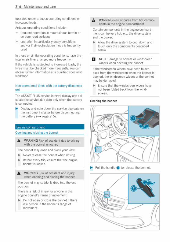
operated under arduous operating conditions orincreased loads.Arduous operating conditions include:R frequent operation in mountainous terrain or
on poor road surfacesR operation in particularly dusty conditions
and/or if air-recirculation mode is frequentlyused
In these or similar operating conditions, have theinterior air lter changed more frequently.If the vehicle is subjected to increased loads, thetyres must be checked more frequently. You canobtain further information at a quali ed specialistworkshop.
NNon-operon-operational times witational times with th the batthe batterery disconnec-y disconnec-tteded
The ASSYST PLUS service interval display can cal-culate the service due date only when the batteryis connected.# Display and note down the service due date on
the instrument cluster before disconnectingthe battery (/ page 215).
Engine comEngine comparpartmenttmentOpening and closing tOpening and closing the bonnethe bonnet
& WWARNINGARNING Risk of accident due to drivingwith the bonnet unlocked
The bonnet may open and block your view.# Never release the bonnet when driving.# Before every trip, ensure that the engine
bonnet is locked.
& WWARNINGARNING Risk of accident and injurywhen opening and closing the bonnet
The bonnet may suddenly drop into the endposition.There is a risk of injury for anyone in theengine bonnet's range of movement.# Do not open or close the bonnet if there
is a person in the bonnet's range ofmovement.
& WWARNINGARNING Risk of burns from hot compo-nents in the engine compartment
Certain components in the engine compart-ment can be very hot, e.g. the drive systemand the cooler.# Allow the drive system to cool down and
touch only the components describedbelow.
* NNOOTETE Damage to bonnet or windscreenwipers when opening the bonnet
If the windscreen wipers have been foldedback from the windscreen when the bonnet isopened, the windscreen wipers or the bonnetmay be damaged.# Ensure that the windscreen wipers have
not been folded back from the wind-screen.
Opening tOpening the bonnethe bonnet
# Pull the handle1 to release the bonnet.
216216 Maintenance and care
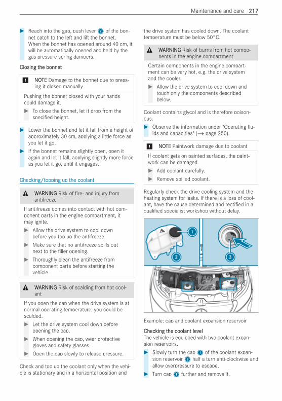
# Reach into the gap, push lever2 of the bon-net catch to the le and li the bonnet.When the bonnet has opened around 40 cm, itwill be automatically opened and held by thegas pressure spring dampers.
Closing tClosing the bonnethe bonnet
* NONOTETE Damage to the bonnet due to press-ing it closed manually
Pushing the bonnet closed with your handscould damage it.# To close the bonnet, let it drop from the
speci ed height.
# Lower the bonnet and let it fall from a height ofapproximately 30 cm, applying a little force asyou let it go.
# If the bonnet remains slightly open, open itagain and let it fall, applying slightly more forceas you let it go, until it engages.
ChecChecking/tking/topping up topping up the coolanthe coolant
& WWARNINGARNING Risk of re‑ and injury fromantifreeze
If antifreeze comes into contact with hot com-ponent parts in the engine compartment, itmay ignite.# Allow the drive system to cool down
before you top up the antifreeze.# Make sure that no antifreeze spills out
next to the ller opening.# Thoroughly clean the antifreeze from
component parts before starting thevehicle.
& WWARNINGARNING Risk of scalding from hot cool-ant
If you open the cap when the drive system is atnormal operating temperature, you could bescalded.# Let the drive system cool down before
opening the cap.# When opening the cap, wear protective
gloves and safety glasses.# Open the cap slowly to release pressure.
Check and top up the coolant only when the vehi-cle is stationary and in a horizontal position and
the drive system has cooled down. The coolanttemperature must be below 50°C.
& WWARNINGARNING Risk of burns from hot compo-nents in the engine compartment
Certain components in the engine compart-ment can be very hot, e.g. the drive systemand the cooler.# Allow the drive system to cool down and
touch only the components describedbelow.
Coolant contains glycol and is therefore poison-ous.# Observe the information under "Operating u-
ids and capacities" (/ page 250).
* NONOTETE Paintwork damage due to coolant
If coolant gets on painted surfaces, the paint-work can be damaged.# Add coolant carefully.# Remove spilled coolant.
Regularly check the drive cooling system and theheating system for leaks. If there is a loss of cool-ant, have the cause determined and recti ed in aquali ed specialist workshop without delay.
Example: cap and coolant expansion reservoir
ChecChecking tking the coolant levhe coolant levelelThe vehicle is equipped with two coolant expan-sion reservoirs.# Slowly turn the cap1 of the coolant expan-
sion reservoir2 half a turn anti-clockwise andallow overpressure to escape.
# Turn cap1 further and remove it.
Maintenance and care 217217
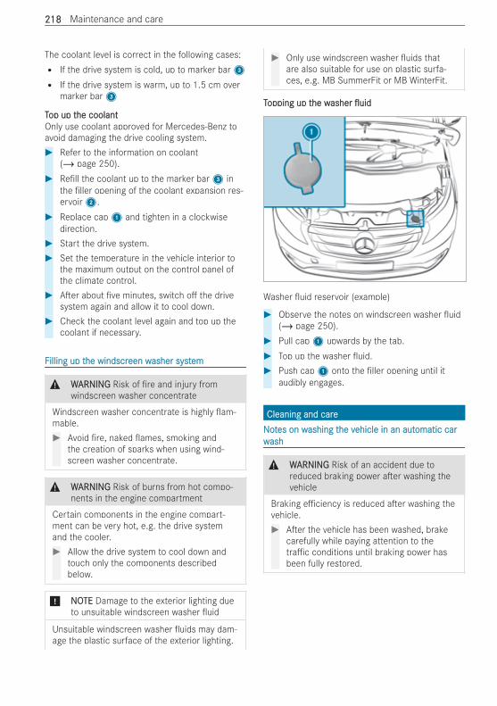
The coolant level is correct in the following cases:R If the drive system is cold, up to marker bar3R If the drive system is warm, up to 1.5 cm over
marker bar3
TTop up top up the coolanthe coolantOnly use coolant approved for Mercedes-Benz toavoid damaging the drive cooling system.# Refer to the information on coolant
(/ page 250).# Re ll the coolant up to the marker bar3 in
the ller opening of the coolant expansion res-ervoir2.
# Replace cap1 and tighten in a clockwisedirection.
# Start the drive system.# Set the temperature in the vehicle interior to
the maximum output on the control panel ofthe climate control.
# A er about ve minutes, switch o the drivesystem again and allow it to cool down.
# Check the coolant level again and top up thecoolant if necessary.
FFilling up tilling up the windscrhe windscreen ween washer systasher systemem
& WWARNINGARNING Risk of re and injury fromwindscreen washer concentrate
Windscreen washer concentrate is highly am-mable.# Avoid re, naked ames, smoking and
the creation of sparks when using wind-screen washer concentrate.
& WWARNINGARNING Risk of burns from hot compo-nents in the engine compartment
Certain components in the engine compart-ment can be very hot, e.g. the drive systemand the cooler.# Allow the drive system to cool down and
touch only the components describedbelow.
* NNOOTETE Damage to the exterior lighting dueto unsuitable windscreen washer uid
Unsuitable windscreen washer uids may dam-age the plastic surface of the exterior lighting.
# Only use windscreen washer uids thatare also suitable for use on plastic surfa-ces, e.g. MB SummerFit or MB WinterFit.
TTopping up topping up the whe washerasher uiduid
Washer uid reservoir (example)
# Observe the notes on windscreen washer uid(/ page 250).
# Pull cap1 upwards by the tab.# Top up the washer uid.# Push cap1 onto the ller opening until it
audibly engages.
Cleaning and careCleaning and careNNoottes on wes on washing tashing the vhe vehicle in an autehicle in an automatic caromatic carwwashash
& WWARNINGARNING Risk of an accident due toreduced braking power a er washing thevehicle
Braking e ciency is reduced a er washing thevehicle.# A er the vehicle has been washed, brake
carefully while paying attention to thetra c conditions until braking power hasbeen fully restored.
218218 Maintenance and care
* NNOOTETE Damage to the vehicle due to auto-matic braking
When the following functions are activated, thevehicle brakes automatically in certain situa-tions:R Active Brake AssistR Active Distance Assist DISTRONICR HOLD function
To avoid damage to the vehicle, deactivatethese systems in the following or similar situa-tions:# when towing# in a car wash
* NNOOTETE Damage due to unsuitable car wash# Before driving into a car wash make sure
that the car wash is suitable for the vehi-cle dimensions.
# Ensure there is su cient ground clear-ance between the underbody and theguide rails of the car wash.
# Ensure that the clearance width of thecar wash, in particular the width of theguide rails, is su cient.
To avoid damage to your vehicle, observe the fol-lowing before using an automatic car wash:R Active Brake Assist is deactivated.R Active Distance Assist DISTRONIC is deactiva-
ted.R The HOLD function is switched o .R The side windows and roof are completely
closed.R The outside mirrors are folded in and an addi-
tional antenna is removed, if present.R The climate control blower is switched o .R The windscreen wiper switch is in position g.
If the vehicle is very dirty, wash o excess dirtbefore cleaning the vehicle in an automatic carwash.
A er leaving the car wash, pay attention to the fol-lowing:R The outside mirrors are fully folded out again
and an additional antenna is mounted again, ifpresent.R Remove wax residues on the windscreen and
wiper rubbers to prevent smearing and reducewiper noise.
Remove wax residues from the camera lens invehicles with a reversing camera (/ page 221).
NNoottes on use of a high-pres on use of a high-pressuressure cleanere cleaner
& WWARNINGARNING Risk of an accident when usinghigh-pressure cleaners with round-spraynozzles
The water jet can cause externally invisibledamage.Components damaged in this way may unex-pectedly fail.# Do not use a high-pressure cleaner with
round-spray nozzles.# Have damaged tyres or chassis parts
replaced immediately.
* NNOOTETE Damage to component parts due toimproper high-pressure cleaning
Components can be damaged if the distanceof the high-pressure nozzle is too small.# Maintain a minimum distance of about
30 cm between the high-pressure nozzleand car parts.
# Do not use a high-pressure cleaner witha round-spray nozzle.
# Keep the water jet moving constantlywhile cleaning.
# Do not clean the following componentswith the high-pressure cleaner:R electrical componentsR plug connectorsR reversing cameraR drivetrainR sealsR hoses
Maintenance and care 219219

* NNOOTETE Damage caused by the use of ahigh-pressure cleaner in the vehicle inte-rior
The pressurised water created by the high-pressure cleaner and the associated spraycould cause considerable damage to the vehi-cle.# Never use a high-pressure cleaner in the
vehicle interior.
WWashing tashing the enginehe engine
* NONOTETE Damage and malfunctions due towashing the engine
# To prevent damage and malfunctions ofthe drive system, observe the followingpoints:R when using high-pressure or steam
cleaners, do not point the water jetdirectly at electrical components andthe end of electric cables.R make sure that no water enters the
vent and ventilation openings.R preserve the drive system a er wash-
ing the engine.R protect the belt drive from preserva-
tion agents.
WWashing tashing the vhe vehicle behicle by handy hand
Observe the legal requirements, e.g. in a numberof countries, washing by hand is only permitted inspecially designated wash bays.# Wash the vehicle with lukewarm water and a
so car sponge. When doing so, do not exposethe vehicle to direct sunlight.
# Use a mild cleaning agent, e.g. a Mercedes-Benz approved car shampoo.
# Carefully spray the vehicle with water and dryo with a leather cloth. Do not point the waterjet directly into the air inlet grille.
When operating the vehicle in winter, remove alltraces of road salt deposits carefully and as soonas possible.
NNoottes on cares on care of paint and matte of paint and matt nishnish
* NNOOTETE Paintwork damage and corrosiondue to inadequate care
Failure to promptly and thoroughly remove dirtfrom bird droppings or other residue couldresult in paintwork damage and corrosion at alater date.# Clean dirt o paint and matt nish thor-
oughly and as soon as possible.
Observe the notes on cleaning and care to avoidpaintwork damage.
PPaintaintR Insect remains: soak with insect remover and
then wash o .R Bird droppings: soak with water and then wash
o .R Tree resin, oils and greases: remove by rubbing
gently with a cloth soaked in petroleum etheror lighter uid.R Coolant and brake uid: remove with a moist
cloth and clean water.R Tar stains: use tar remover.R Wax: use silicone remover.R Do not a x stickers, lms or similar.R Remove dirt as soon as possible.
MattMatt nishnishR Only use care products approved for
Mercedes-Benz.R Do not polish the vehicle and light-alloy
wheels.R Use only automatic car washes that meet cur-
rent technological standards.R Do not use a wash program that ends with a
hot wax treatment in automatic car washes.R Do not use paint cleaners, bu ng or polishing
products, or gloss preservers, e.g. wax.R Always have paintwork repairs carried out at a
quali ed specialist workshop.
220220 Maintenance and care
NNoottes on tes on the carhe care of ve of vehicle parehicle partsts
& WWARNINGARNING Risk of injury if unsuitableclimbing aids are used
In the event that you use openings in the body-work or attachments as steps, you could:R Slip and/or fall.R Damage the vehicle and thus slip and fall.
# Always use non-slip, stable climbing aids,e.g. a suitable ladder.
& WWARNINGARNING Risk of entrapment if the wind-screen wipers are switched on while thewindscreen is being cleaned
If the windscreen wipers are set in motionwhile you are cleaning the windscreen or wiperblades, you can be trapped by the wiper arm.# Always switch o the windscreen wipers
and the ignition before cleaning the wind-screen or wiper blades.
* NNOOTETE Damage caused by the use of open-ings in the bodywork or detachable part asa step
Using the lower guide of the sliding door (car-riage) as a step can damage the trim and/ormechanism of the sliding door.# Do not use the guide of the sliding door
(carriage) as a step.
% Information on suitable cleaning agents orcleaning cloths can be obtained from a quali-ed specialist workshop.
To prevent damage to the vehicle, observe thenotes for cleaning and care of the following vehicleparts:
Wheels and rWheels and rimsimsR Use water and acid-free alloy wheel cleaner.R Do not use acidic alloy wheel cleaners to
remove brake dust. Otherwise, wheel bolts andbrake components could be damaged.R To avoid corrosion of brake discs and brake-
pads, drive for a few minutes a er cleaningbefore parking the vehicle. The brake discs andbrakepads warm up and dry out.
WWindowsindowsR Clean the windows inside and outside with a
damp cloth and with a cleaning agent recom-mended for Mercedes-Benz.R Do not use dry cloths, abrasive cleaning agents
or cleaners containing solvents to clean theinside of windows.
WWiper bladesiper bladesR With the wiper arms folded away, clean the
wiper blades with a damp cloth (/ page 115).R Do not clean the wiper blades too o en.
ExtExtererior lightingior lightingR Clean the lenses with a wet sponge and mild
cleaning agent, for example, car shampoo.R Only use cleaning agents or cloths suitable for
plastic lenses.
VVehicle sockeehicle socket (high-vt (high-voltoltagage batte batterery)y)R Clean the vehicle socket with a so cloth and
clean water.R Do not use a high-pressure cleaner or cleaning
agents (e.g. soap).
SensorsSensorsR Clean the sensors in the front and rear bump-
ers with a so cloth and car shampoo(/ page 148).R When using a high-pressure cleaner, keep a
minimum distance of 30 cm.
RevReverersing camersing camera and 360° Cameraa and 360° CameraR Open the camera cover with the multimedia
system (/ page 161).R Use clean water and a so cloth to clean the
camera lens.R Do not use a high-pressure cleaner.
Sliding doorSliding doorR Remove foreign objects from the vicinity of the
contact plates and contact pins of the slidingdoor.R Clean the contact plates and contact pins with
a mild cleaning agent and a so cloth.R Do not oil or grease the contact plates and the
contact pins.
Maintenance and care 221221
NNoottes on tes on the cleaning and carhe cleaning and care of te of the inthe intereriorior
& WWARNINGARNING Risk of injury from plastic partsbreaking o a er the use of solvent-basedcare products
Care and cleaning products containing sol-vents can cause surfaces in the cockpit tobecome porous. When the airbags aredeployed, plastic parts may break away.# Do not use any care or cleaning products
containing solvents to clean the cockpit.
& WWARNINGARNING Risk of injury or fatal injuriesfrom bleached seat belts
Bleaching or dyeing seat belts can severelyweaken them.This can, for example, cause seat belts to tearor fail in an accident.# Never bleach or dye seat belts.
* NNOOTETE Property damage due to disinfec-tants and cleaning agents
The interior includes a number of sensitive sur-faces such as displays, plastics and leather.Disinfectants and cleaning agents can containsubstances that penetrate and damage surfa-ces. Technology behind buttons and displayscan also be damaged.# Select disinfectants and cleaning agents
carefully and use them only for surfacesexplicitly approved by the manufacturer.
# Do not use disinfectants and cleaningagents in enclosed spaces and ventilatea er use.
# Use the disinfectant or cleaning agentcarefully according to the manufacturer'sinstructions and do not soak any parts ofthe interior.
* NNOOTETE Property damage due to disinfec-tants
The interior includes a number of sensitive sur-faces such as displays, plastics and leather.Disinfectants can contain alcohol and othersubstances that attack and damage surfaces.Technology behind buttons and displays canalso be damaged.
# Only use disinfectant on surfaces explic-itly approved by the manufacturer.
# Do not use disinfectants in enclosedspaces and ventilate a er use.
# Do not use disinfectants that containalcohol.
# Use disinfectant carefully according tothe manufacturer's instructions and donot soak any parts of the interior.
To prevent damage to the vehicle, observe the fol-lowing notes for cleaning and care:
Seat beltsSeat beltsR Clean with lukewarm soapy water.R Do not use chemical cleaning agents.R No heating over 80°C or drying in direct sun-
light.
InsInstrtrument clustument cluster lenseser lensesR Clean the surfaces carefully with a micro bre
cloth and acrylic glass care products.R Do not use any other agents.
DisplayDisplayR Switch o the display and let it cool down.R Clean the surface carefully with a micro bre
cloth and a suitable display cleaning product(TFT-LCD).R Do not use any other agents.
DigitDigital inside ral inside rearearvieview mirrw mirrororR Clean the mirror glass with a cloth moistened
with glass cleaner.R Clean the light sensors of the inside rearview
mirror with a dry cotton cloth.R Do not spray the glass cleaner on the mirror
glass.R Do not use any other agents.
PlasPlastic trtic trimimR Clean with a damp micro bre cloth.R For heavy soiling: Use a cleaning product rec-
ommended for Mercedes-Benz.R Do not a x stickers, lms or similar.R Do not allow to come into contact with cos-
metics, insect repellent and sun creams.
222222 Maintenance and care
RRoof liningoof liningR Clean with a brush or dry shampoo.
CarCarpetpetR Use a carpet and textile cleaning agent recom-
mended for Mercedes-Benz.
Genuine leatGenuine leather seat covher seat coversersR Clean with a damp cloth and then wipe with a
dry cloth.R Leather care: Use a leather care agent recom-
mended for Mercedes-Benz.R Do not allow the leather to become too damp.R Do not use a micro bre cloth.
ImitImitation leatation leather seat covher seat coversersR Clean with a damp cloth and 1% soapy water.R Do not use a micro bre cloth.
ClotCloth seat covh seat coversersR Clean with a damp micro bre cloth and 1%
soap solution and allow to dry.
StSteereering wheel fring wheel from gom genuine leatenuine leatherher
* NONOTETE Damage caused by wrong cleaners# Do not use solvent-based cleaning
agents such as tar remover or wheelcleaner; neither should you use polishesor waxes. Otherwise you may damagethe nish.
R Clean with a damp cloth and a 1% soapy watersolution and then wipe with a dry cloth.R For heavy soiling: Use a cleaning product rec-
ommended for Mercedes-Benz.R Leather care: Use a leather care agent recom-
mended for Mercedes-Benz.R Do not allow the leather to become too damp.R Do not use a micro bre cloth.
% Leather is a natural product. It has natural sur-face properties, such as di erences in struc-ture, marks caused by growth and injury orsubtle colour di erences.
RReal weal wood and trood and trim elementsim elementsR Clean with a micro bre cloth.R Black piano-lacquer look: Clean with a damp
cloth and soapy water.R For heavy soiling: Use a cleaning product rec-
ommended for Mercedes-Benz.R Do not use any cleaning agents, polishes or
waxes containing solvents containing solvents.
Maintenance and care 223223
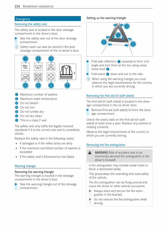
EmergEmergencyencyRRemoemoving tving the safehe safety vty vestest
The safety vest is located in the door stowagecompartment in the driver's door.# Take the safety vest out of the door stowage
compartment.% Safety vests can also be stored in the door
stowage compartment of the co-driver's door.
1 Maximum number of washes2 Maximum wash temperature3 Do not bleach4 Do not iron5 Do not tumble dry6 Do not dry-clean7 This is a class 2 vest
The safety vest only ful ls the legally requiredstandards if it is the correct size and is completelyclosed.Replace the safety vest in the following cases:R if damaged or if the re ex strips are dirtyR if the maximum permitted number of washes is
exceededR if the safety vest's uorescence has faded
WWararning trning triangleiangle
RRemoemoving tving the whe wararning trning triangleiangleThe warning triangle is located in the stowagecompartment in the driver's door.# Take the warning triangle out of the stowage
compartment.
SeSetting up ttting up the whe wararning trning triangleiangle
# Fold side re ectors1 upwards to form a tri-angle and lock them at the top using upperpress-stud2.
# Fold stand3 down and out to the side.% When using the warning triangle you must
observe the legal requirements for the countryin which you are currently driving.
RRemoemoving tving thehe rsrst-aidt-aid kitkit (so(so sided)sided)
The rst-aid kit (so sided) is located in the stow-age compartment in the co-driver door.# Remove rst-aid (so sided) kit from the stow-
age compartment.
Check the expiry date on the rst-aid kit (sosided) at least once a year. Replace any expired ormissing contents.Observe the legal requirements of the country inwhich you are currently driving.
RRemoemoving tving thehe rere eextinguisherxtinguisher
& WWARNINGARNING Risk of accident due to anincorrectly secured re extinguisher in thedriver's footwell
A re extinguisher may impede pedal travel orblock a depressed pedal.This jeopardises the operating and road safetyof the vehicle.The re extinguisher can be ung around andinjure the driver or other vehicle occupants.# Always store and secure the re extin-
guisher in the bracket.# Do not remove the re extinguisher while
driving.
224224 Breakdown assistance
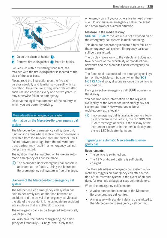
# Open the clasp of holder2.# Remove re extinguisher1 from its holder.
For vehicles with a swivelling front seat, theretainer with the re extinguisher is located at theside of the seat base.Please read the instructions on the re extin-guisher carefully and familiarise yourself with itsoperation. Have the re extinguisher re lled a ereach use and checked every one or two years. Itmay otherwise fail in an emergency.Observe the legal requirements of the country inwhich you are currently driving.
MerMercedes-Benz emergcedes-Benz emergency call systency call systememInfInforormation on tmation on the Merhe Mercedes-Benz emergcedes-Benz emergency callency callsystsystemem
The Mercedes-Benz emergency call system onlyfunctions in areas where mobile phone coverage isavailable from the relevant contract partner. Insuf-ficient network coverage from the relevant con-tract partner may result in an emergency call notbeing transmitted.The ignition must be switched on before an auto-matic emergency call can be made.% The Mercedes-Benz emergency call system is
activated at the factory. Using the Mercedes-Benz emergency call system is free of charge.
OvOverervieview of tw of the Merhe Mercedes-Benz emergcedes-Benz emergency callency callsystsystemem
The Mercedes-Benz emergency call system canhelp to decisively reduce the time between anaccident and the arrival of emergency services atthe site of the accident. It helps locate an accidentsite in places that are di cult to access.The emergency call can be triggered automatically(/ page 225).You also have the option of triggering the emer-gency call manually (/ page 226). Only make
emergency calls if you or others are in need of res-cue. Do not make an emergency call in the eventof a breakdown or a similar situation.
MessagMessage in te in the media display:he media display:SOS NOT READY: the vehicle is not switched on orthe emergency call system is malfunctioning.This does not necessarily indicate a total failure ofthe emergency call system. Emergency calls canstill be transmitted.The display refers only to the vehicle and does nottake account of the availability of mobile phonenetworks and the Mercedes-Benz emergency callcentre.The functional readiness of the emergency call sys-tem on the vehicle can be seen when the SOSNOT READY display disappears once the vehicle isswitched on.During an active emergency call, G appears inthe display.You can nd more information on the regionalavailability of the Mercedes-Benz emergency callsystem at: https://www.mercedes-benz-mobile.com/extra/ecall/% If no emergency call is available due to a tech-
nical problem in the vehicle, the red SOS NOTREADY message appears in the display of theinstrument cluster or in the media display andthe red LED indicator lights up.
TTrriggiggerering an auting an automatic Meromatic Mercedes-Benz emer-cedes-Benz emer-ggency callency call
RReqequiruirements:ements:R The vehicle is switched on.R The 12 V on-board battery is su ciently
charged.
The Mercedes-Benz emergency call system auto-matically triggers an emergency call a er activa-tion of the restraint system in the event of an acci-dent, for example airbags or seat belt tensioners.When the emergency call is made:R A voice connection is made to the Mercedes-
Benz emergency call centre.R A message with accident data is transmitted to
the Mercedes-Benz emergency call centre.
Breakdown assistance 225225
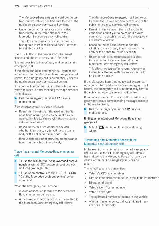
The Mercedes-Benz emergency call centre cantransmit the vehicle position data to one of thepublic emergency services call centres.R Under certain circumstances data is also
transmitted in the voice channel to theMercedes-Benz emergency call centre.This allows measures for rescue, recovery ortowing to a Mercedes-Benz Service Centre tobe initiated quickly.
The SOS button in the overhead control panelashes until the emergency call is nished.
It is not possible to immediately end an automaticemergency call.If the Mercedes-Benz emergency call system can-not connect to the Mercedes-Benz emergency callcentre, the emergency call is automatically sent tothe public emergency services call centre.If no connection can be made to the public emer-gency services, a corresponding message appearsin the display.# Dial the emergency number 112112 on your
mobile phone.If an emergency call has been initiated:R Remain in the vehicle if the road and tra c
conditions permit you to do so until a voiceconnection is established with the emergencycall centre operator.R Based on the call, the operator decides
whether it is necessary to call rescue teamsand/or the police to the accident site.R If no vehicle occupant answers, an ambulance
is sent to the vehicle immediately.
TTrriggiggerering a manual Mering a manual Mercedes-Benz emergcedes-Benz emergencyencycallcall
# TTo use to use the SOS butthe SOS button in ton in the ovhe overerhead contrhead contrololpanel:panel: press the SOS button at least one sec-ond long (/ page 182).
# TTo use vo use voice controice control:ol: use the LINGUATRONIC"Call the Mercedes accident centre" voicecommand.
When the emergency call is made:R A voice connection is made to the Mercedes-
Benz emergency call centre.R A message with accident data is transmitted to
the Mercedes-Benz emergency call centre.
The Mercedes-Benz emergency call centre cantransmit the vehicle position data to one of thepublic emergency services call centres.R Remain in the vehicle if the road and tra c
conditions permit you to do so until a voiceconnection is established with the emergencycall centre operator.R Based on the call, the operator decides
whether it is necessary to call rescue teamsand/or the police to the accident site.R Under certain circumstances data is also
transmitted in the voice channel to theMercedes-Benz emergency call centre.This allows measures for rescue, recovery ortowing to a Mercedes-Benz service centre tobe initiated quickly.
If the Mercedes-Benz emergency call system can-not connect to the Mercedes-Benz emergency callcentre, the emergency call is automatically sent tothe public emergency services call centre.If no connection can be made to the public emer-gency services, a corresponding message appearsin the media display.# Dial the emergency number 112112 on your
mobile phone.
Ending an unintEnding an unintentional Merentional Mercedes-Benz emer-cedes-Benz emer-ggency callency call# Select ~ on the multifunction steering
wheel.
TTrransmittansmitted dated data Mera Mercedes-Benz witcedes-Benz with th theheMerMercedes-Benz emergcedes-Benz emergency callency call
In the event of an automatic or manual emergencycall, as well as for a 112112 emergency call, data istransmitted to the Mercedes-Benz emergency callcentre or the public emergency services callcentre.The following data is transmitted:R Vehicle's GPS position dataR GPS position data on the route (a few hundred metres beforR Direction of travelR Vehicle identi cation numberR Vehicle drive typeR The estimated number of people in the vehicleR Whether the emergency call was initiated man-
ually or automatically
226226 Breakdown assistance
R Time of the accidentR Language setting on the multimedia system
For accident clari cation purposes, the followingmeasures can be taken up to an hour a er theemergency call has been initiated:R The current vehicle position can be called up.R A voice connection to the vehicle occupants
can be established.
% FFor Euror Eurasian Economic Uasian Economic Union:nion: various func-tions, e.g. receiving tra c information, cannotbe used for up to two hours a er sending anemergency call.
Flat tyreFlat tyreNNoottes ones on atat tyrtyreses
& WWARNINGARNING Risk of accident due to a attyre
A at tyre strongly impairs the vehicle's drivingcharacteristics, as well as its steering andbraking characteristics.# Do not drive with a at tyre.# Replace the at tyre with the spare
wheel. Alternatively, consult a quali edspecialist workshop.
You will nd a sticker with the Mercedes-BenzService24h telephone number on the B-pillar onthe driver's side, for example.For vehicles with a spare wheel, information in theevent of a at tyre can be found under "Wheelsand tyres" (/ page 239).
BattBatteryeryNNoottes on tes on the 12 V on-boarhe 12 V on-board electrd electrical systical system bat-em bat-tteryery
& WWARNINGARNING Risk of a re due to work car-ried out incorrectly on the battery
The battery clamps may be live even a er theyhave been disconnected. This can result in ashort circuit.# Always have work on the batteries car-
ried out at a quali ed specialist work-shop.
# Never disconnect the battery yourself.
& WWARNINGARNING Risk of an accident due to workcarried out incorrectly on the battery
Work carried out incorrectly on the batterycan, for example, lead to a short circuit. Thiscan restrict functions relevant for safety sys-tems and impair the operating safety of yourvehicle.You could lose control of the vehicle in the fol-lowing situations in particular:R when brakingR in the event of abrupt steering manoeuvres
and/or when the vehicle's speed is notadapted to the road conditions
# In the event of a short circuit or a similarincident, contact a quali ed specialistworkshop immediately.
# Do not drive on.# Always have work on the battery carried
out at a quali ed specialist workshop.
R Further information on ABS (/ page 149)R Further information on ESP®(/ page 149)
For safety reasons, Mercedes-Benz recommendsthat you only use batteries that have been testedand approved for your vehicle by Mercedes-Benz.These batteries provide increased impact protec-tion to prevent vehicle occupants from su eringacid burns should the battery be damaged in anaccident.
& WWARNINGARNING Risk of explosion due to elec-trostatic charge
Electrostatic charge can ignite the highly explo-sive gas mixture in the battery.# To discharge any electrostatic charge
that may have built up, touch the metalvehicle body before handling the battery.
The highly ammable gas mixture is created whilethe battery is charging and when jump-starting.
& WWARNINGARNING Danger of chemical burns fromthe battery acid
Battery acid is caustic.# Avoid contact with the skin, eyes or
clothing.# Do not lean over the battery.# Do not inhale battery gases.
Breakdown assistance 227227
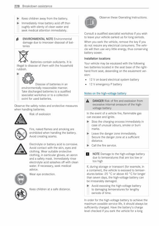
# Keep children away from the battery.# Immediately rinse battery acid o thor-
oughly with plenty of clean water andseek medical attention immediately.
+ ENVIRENVIRONMENTONMENTAL NOAL NOTETE Environmentaldamage due to improper disposal of bat-teries
Batteries contain pollutants. It isillegal to dispose of them with the householdrubbish.#
Dispose of batteries in anenvironmentally responsible manner.Take discharged batteries to a quali edspecialist workshop or to a collectionpoint for used batteries.
Observe the safety notes and protective measureswhen handling batteries.
Risk of explosion
Fire, naked ames and smoking areprohibited when handling the battery.Avoid creating sparks.
Electrolyte or battery acid is corrosive.Avoid contact with the skin, eyes andclothing. Wear suitable protectiveclothing, in particular gloves, an apronand a safety mask. Immediately rinseelectrolyte acid splashes o with cleanwater. If necessary, seek medicaladvice.Wear eye protection.
Keep children at a safe distance.
Observe these Operating Instructions.
Consult a quali ed specialist workshop if you wishto leave your vehicle parked up for long periods.When you park the vehicle, remove the key if youdo not require any electrical consumers. The vehi-cle will then use very little energy, thus conservingbattery power.
InstInstallation locationsallation locationsYour vehicle may be equipped with the followingtwo batteries located in the seat base of the right-hand front seat, depending on the equipment ver-sion:R 12 V on-board electrical system batteryR 12 V emergency P battery
NNoottes on tes on the high-vhe high-voltoltagage batte batteryery
& DDANANGERGER Risk of re and explosion fromexcessive internal pressure of the high-voltage battery
In the event of a vehicle re, ammable gascan escape and ignite.# Stop the charging process immediately in
case of unusual odours, smoke or burnmarks.
# Leave the danger zone immediately.Secure the danger zone at a su cientdistance.
# Call the re service.
* NNOOTETE Damage to the high-voltage batterydue to temperatures that are too low ortoo high
If, during storage or transport (for example, ina container), the vehicle is exposed to temper-atures below -25 °C or above 40 °C for longerthan seven days, the high-voltage battery canbe irreparably damaged.# Avoid exposing the high-voltage battery
to damaging temperatures for lengthyperiods of time.
In order for the high-voltage battery to achieve themaximum possible service life, it should always besu ciently charged. Have the battery's chargelevel checked if you park the vehicle for a long
228228 Breakdown assistance
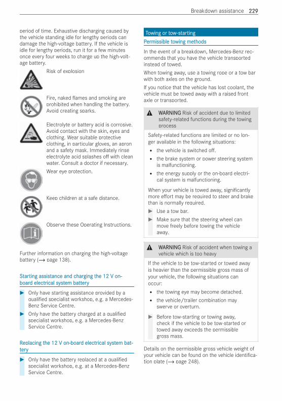
period of time. Exhaustive discharging caused bythe vehicle standing idle for lengthy periods candamage the high-voltage battery. If the vehicle isidle for lengthy periods, run it for a few minutesonce every four weeks to charge up the high-volt-age battery.
Risk of explosion
Fire, naked ames and smoking areprohibited when handling the battery.Avoid creating sparks.
Electrolyte or battery acid is corrosive.Avoid contact with the skin, eyes andclothing. Wear suitable protectiveclothing, in particular gloves, an apronand a safety mask. Immediately rinseelectrolyte acid splashes o with cleanwater. Consult a doctor if necessary.Wear eye protection.
Keep children at a safe distance.
Observe these Operating Instructions.
Further information on charging the high-voltagebattery (/ page 138).
SSttararting assistting assistance and cance and charharging tging the 12 V on-he 12 V on-boarboard electrd electrical systical system battem batteryery
# Only have starting assistance provided by aquali ed specialist workshop, e.g. a Mercedes-Benz Service Centre.
# Only have the battery charged at a quali edspecialist workshop, e.g. a Mercedes-BenzService Centre.
RReplacing teplacing the 12 V on-boarhe 12 V on-board electrd electrical systical system bat-em bat-tteryery
# Only have the battery replaced at a quali edspecialist workshop, e.g. at a Mercedes-BenzService Centre.
TToowing or towwing or tow-st-starartingtingPPerermissible tomissible towing metwing methodshods
In the event of a breakdown, Mercedes-Benz rec-ommends that you have the vehicle transportedinstead of towed.When towing away, use a towing rope or a tow barwith both axles on the ground.If you notice that the vehicle has lost coolant, thevehicle must be towed away with a raised frontaxle or transported.
& WWARNINGARNING Risk of accident due to limitedsafety-related functions during the towingprocess
Safety-related functions are limited or no lon-ger available in the following situations:R the vehicle is switched o .R the brake system or power steering system
is malfunctioning.R the energy supply or the on-board electri-
cal system is malfunctioning.
When your vehicle is towed away, signi cantlymore e ort may be required to steer and brakethan is normally required.# Use a tow bar.# Make sure that the steering wheel can
move freely before towing the vehicleaway.
& WWARNINGARNING Risk of accident when towing avehicle which is too heavy
If the vehicle to be tow-started or towed awayis heavier than the permissible gross mass ofyour vehicle, the following situations canoccur:R the towing eye may become detached.R the vehicle/trailer combination may
swerve or overturn.
# Before tow-starting or towing away,check if the vehicle to be tow-started ortowed away exceeds the permissiblegross mass.
Details on the permissible gross vehicle weight ofyour vehicle can be found on the vehicle identi ca-tion plate (/ page 248).
Breakdown assistance 229229
* NNOOTETE Damage due to incorrect connec-tion of the tow bar or improper use of thetowing device
# Only connect the tow rope or tow bar tothe towing eyes.
# Do not use the towing eyes to recover avehicle.
* NNOOTETE Damage due to pulling force beingtoo high
Pulling away abruptly can damage the vehiclesif the tractive forces are too high.# Pull away as straight, slowly and
smoothly as possible.
* NNOOTETE Damage due to improper towingwith a tow rope
If you ignore safety and protective measureswhen towing with a tow rope, this can result indamage to the vehicle.Observe the following points:# Secure the tow rope on the same side on
both vehicles.# Secure the tow rope to the towing eyes.# Do not exceed the legally prescribed
length of the tow rope.# Mark the tow rope in the middle, e.g.
with a white cloth (30 x 30 cm). This willmake other road users aware that a vehi-cle is being towed.
# During the journey, observe the brakelamps of the towing vehicle and maintainthe distance so that the tow rope doesnot sag.
# Do not use steel cables or chains to towyour vehicle.
* NNOOTETE Damage due to towing the vehicle attoo high a speed or too far
Towing the vehicle at too high a speed or toofar can damage the drivetrain.# Do not exceed a towing speed of
50 km/h.
# Do not exceed a towing distance of50 km.
* NNOOTETE Damage to the drivetrain due toinsu cient cooling
If the cooling system is damaged, towing thevehicle can damage the drivetrain.# Have the vehicle towed with the front
axle raised or have it transported.
* NNOOTETE Damage to the drivetrain due tounauthorised towing of the vehicle
Towing the vehicle backwards is not permittedas this can damage the drivetrain.# Only tow the vehicle forwards.
* NNOOTETE Damage to the vehicle due to auto-matic braking
When the following functions are activated, thevehicle brakes automatically in certain situa-tions:R Active Brake AssistR Active Distance Assist DISTRONICR HOLD function
To avoid damage to the vehicle, deactivatethese systems in the following or similar situa-tions:# when towing# in a car wash
* NNOOTETE Damage to the transmission whentowing due to shi ing into transmissionposition j
If you open the driver's or co-driver door whentowing, the transmission can shi into positionj and become damaged.# Shi the automatic transmission to posi-
tion i.# Do not open any doors during the towing
process.
230230 Breakdown assistance
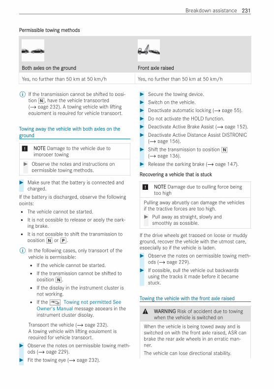
PPerermissible tomissible towing metwing methodshods
BotBoth axles on th axles on the grhe groundound FFrront axle ront axle raisedaised
Yes, no further than 50 km at 50 km/h Yes, no further than 50 km at 50 km/h
% If the transmission cannot be shi ed to posi-tion i, have the vehicle transported(/ page 232). A towing vehicle with li ingequipment is required for vehicle transport.
TToowing awawing away ty the vhe vehicle witehicle with both both axles on th axles on thehegrgroundound
* NNOOTETE Damage to the vehicle due toimproper towing
# Observe the notes and instructions onpermissible towing methods.
# Make sure that the battery is connected andcharged.
If the battery is discharged, observe the followingpoints:R The vehicle cannot be started.R It is not possible to release or apply the park-
ing brake.R It is not possible to shi the transmission to
position i or j.
% In the following cases, only transport of thevehicle is permissible:R If the vehicle cannot be started.R If the transmission cannot be shi ed to
position i.R If the display in the instrument cluster is
not working.R If theá Towing not permitted See
Owner's Manual message appears in theinstrument cluster display.
Transport the vehicle (/ page 232).A towing vehicle with li ing equipment isrequired for vehicle transport.
# Observe the notes on permissible towing meth-ods (/ page 229).
# Fit the towing eye (/ page 232).
# Secure the towing device.# Switch on the vehicle.# Deactivate automatic locking (/ page 55).# Do not activate the HOLD function.# Deactivate Active Brake Assist (/ page 152).# Deactivate Active Distance Assist DISTRONIC
(/ page 156).# Shi the transmission to position i
(/ page 136).# Release the parking brake (/ page 147).
RRecovecoverering a ving a vehicle tehicle that is shat is stucktuck
* NONOTETE Damage due to pulling force beingtoo high
Pulling away abruptly can damage the vehiclesif the tractive forces are too high.# Pull away as straight, slowly and
smoothly as possible.
If the drive wheels get trapped on loose or muddyground, recover the vehicle with the utmost care,especially so if the vehicle is laden.# Observe the notes on permissible towing meth-
ods (/ page 229).# If possible, pull the vehicle out backwards
using the tracks it made before it becamestuck.
TToowing twing the vhe vehicle witehicle with th the frhe front axle ront axle raisedaised
& WWARNINGARNING Risk of accident due to towingwhen the vehicle is switched on
When the vehicle is being towed away and isswitched on with the front axle raised, ASR canbrake the rear axle wheels in an erratic man-ner.The vehicle can lose directional stability.
Breakdown assistance 231231
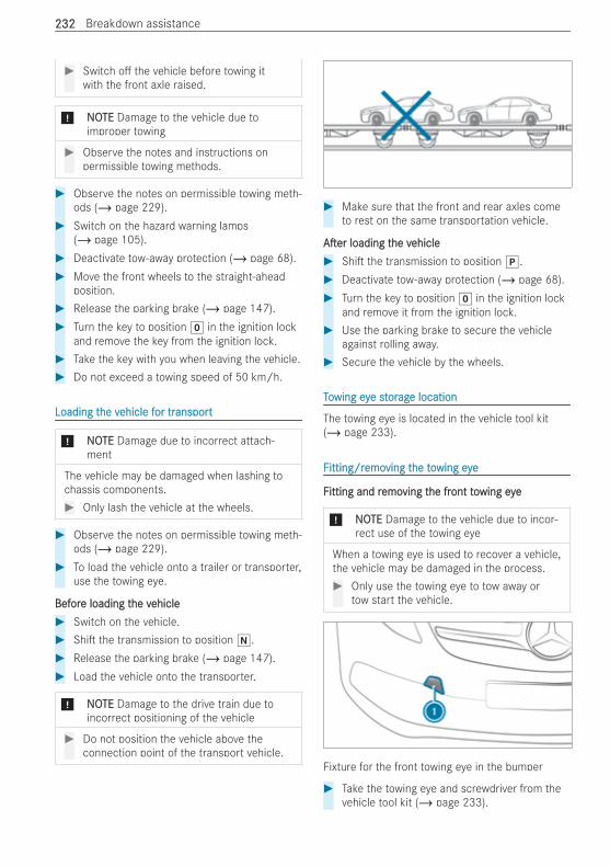
# Switch o the vehicle before towing itwith the front axle raised.
* NNOOTETE Damage to the vehicle due toimproper towing
# Observe the notes and instructions onpermissible towing methods.
# Observe the notes on permissible towing meth-ods (/ page 229).
# Switch on the hazard warning lamps(/ page 105).
# Deactivate tow-away protection (/ page 68).# Move the front wheels to the straight-ahead
position.# Release the parking brake (/ page 147).# Turn the key to position g in the ignition lock
and remove the key from the ignition lock.# Take the key with you when leaving the vehicle.# Do not exceed a towing speed of 50 km/h.
Loading tLoading the vhe vehicle fehicle for tror transportansport
* NNOOTETE Damage due to incorrect attach-ment
The vehicle may be damaged when lashing tochassis components.# Only lash the vehicle at the wheels.
# Observe the notes on permissible towing meth-ods (/ page 229).
# To load the vehicle onto a trailer or transporter,use the towing eye.
BefBeforore loading te loading the vhe vehicleehicle# Switch on the vehicle.# Shi the transmission to position i.# Release the parking brake (/ page 147).# Load the vehicle onto the transporter.
* NNOOTETE Damage to the drive train due toincorrect positioning of the vehicle
# Do not position the vehicle above theconnection point of the transport vehicle.
# Make sure that the front and rear axles cometo rest on the same transportation vehicle.
A erA er loading tloading the vhe vehicleehicle# Shi the transmission to position j.# Deactivate tow-away protection (/ page 68).# Turn the key to position g in the ignition lock
and remove it from the ignition lock.# Use the parking brake to secure the vehicle
against rolling away.# Secure the vehicle by the wheels.
TToowing eywing eye ste stororagage locatione location
The towing eye is located in the vehicle tool kit(/ page 233).
FFitting/ritting/remoemoving tving the tohe towing eyewing eye
FFitting and ritting and remoemoving tving the frhe front toont towing eyewing eye
* NONOTETE Damage to the vehicle due to incor-rect use of the towing eye
When a towing eye is used to recover a vehicle,the vehicle may be damaged in the process.# Only use the towing eye to tow away or
tow start the vehicle.
Fixture for the front towing eye in the bumper
# Take the towing eye and screwdriver from thevehicle tool kit (/ page 233).
232232 Breakdown assistance
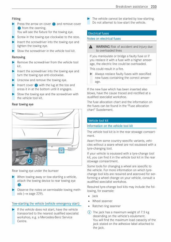
FFittingitting# Press the arrow on cover1 and remove cover1 from the opening.You will see the xture for the towing eye.
# Screw in the towing eye clockwise to the stop.# Insert the screwdriver into the towing eye and
tighten the towing eye.# Stow the screwdriver in the vehicle tool kit.
RRemoemovingving# Remove the screwdriver from the vehicle tool
kit.# Insert the screwdriver into the towing eye and
turn the towing eye anti-clockwise.# Unscrew and remove the towing eye.# Insert cover1 with the lug at the top and
press it in at the bottom until it engages.# Stow the towing eye and the screwdriver with
the vehicle tool kit.
RRear toear towing eyewing eye
Rear towing eye under the bumper
# When towing away or tow-starting a vehicle,attach the towing device to rear towing eye2.
# Observe the notes on permissible towing meth-ods (/ page 229).
TTooww-st-stararting tting the vhe vehicle (vehicle (vehicle emergehicle emergency stency starart)t)
# If the vehicle does not start, have the vehicletransported to the nearest quali ed specialistworkshop, e.g. a Mercedes-Benz ServiceCentre.
# The vehicle cannot be started by tow-starting.Do not attempt to tow-start the vehicle.
ElectrElectrical fusesical fusesNNoottes on electres on electrical fusesical fuses
& WWARNINGARNING Risk of accident and injury dueto overloaded lines
If you manipulate or bridge a faulty fuse or ifyou replace it with a fuse with a higher amper-age, the electric line could be overloaded.This could result in a re.# Always replace faulty fuses with speci ed
new fuses containing the correct amper-age.
If the new fuse which has been inserted alsoblows, have the cause traced and recti ed at aquali ed specialist workshop.The fuse allocation chart and the information onthe fuses can be found in the "Fuse allocationchart" Supplement.
VVehicle tehicle tool kitool kitInfInforormation on tmation on the vhe vehicle tehicle tool kitool kit
The vehicle tool kit is in the rear stowage compart-ment.Apart from some country-speci c variants, vehi-cles without a spare wheel are not equipped with atyre-changing tool.If your vehicle is equipped with a tyre-change toolkit, you can nd it in the vehicle tool kit in the rearstowage compartment.Some tools for changing a wheel are speci c tothe vehicle. For more information on which tyre-change tool kits are required and approved for per-forming a wheel change on your vehicle, consult aquali ed specialist workshop.Required tyre-change tool kits may include the fol-lowing, for example:R JackR Wheel spannerR Ratchet ring spanner
% The jack has a maximum weight of 7.5 kgdepending on the vehicle's equipment.You will nd the maximum load capacity of thejack stated on the adhesive label attached tothe jack.
Breakdown assistance 233233
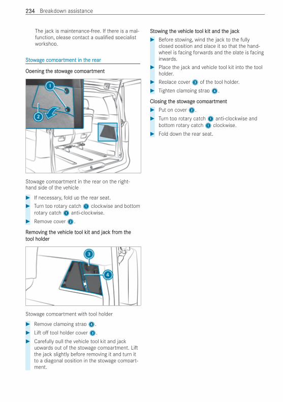
The jack is maintenance-free. If there is a mal-function, please contact a quali ed specialistworkshop.
SSttoowwagage come comparpartment in ttment in the rhe rearear
Opening tOpening the stowhe stowagage come comparpartmenttment
Stowage compartment in the rear on the right-hand side of the vehicle
# If necessary, fold up the rear seat.# Turn top rotary catch1 clockwise and bottom
rotary catch1 anti-clockwise.# Remove cover2.
RRemoemoving tving the vhe vehicle tehicle tool kit and jacool kit and jack frk from tom thehettool holderool holder
Stowage compartment with tool holder
# Remove clamping strap4.# Li o tool holder cover3.# Carefully pull the vehicle tool kit and jack
upwards out of the stowage compartment. Lithe jack slightly before removing it and turn itto a diagonal position in the stowage compart-ment.
SSttoowing twing the vhe vehicle tehicle tool kit and tool kit and the jackhe jack# Before stowing, wind the jack to the fully
closed position and place it so that the hand-wheel is facing forwards and the plate is facinginwards.
# Place the jack and vehicle tool kit into the toolholder.
# Replace cover3 of the tool holder.# Tighten clamping strap4.
Closing tClosing the stowhe stowagage come comparpartmenttment# Put on cover2.# Turn top rotary catch1 anti-clockwise and
bottom rotary catch1 clockwise.# Fold down the rear seat.
234234 Breakdown assistance
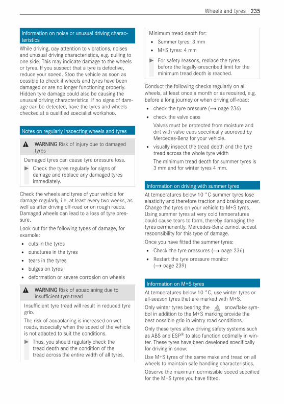
InfInforormation on noise or unusual drmation on noise or unusual driving civing charharac-ac-ttererisisticsticsWhile driving, pay attention to vibrations, noisesand unusual driving characteristics, e.g. pulling toone side. This may indicate damage to the wheelsor tyres. If you suspect that a tyre is defective,reduce your speed. Stop the vehicle as soon aspossible to check if wheels and tyres have beendamaged or are no longer functioning properly.Hidden tyre damage could also be causing theunusual driving characteristics. If no signs of dam-age can be detected, have the tyres and wheelschecked at a quali ed specialist workshop.
NNoottes on res on regularlegularly inspecting wheels and tyry inspecting wheels and tyreses
& WWARNINGARNING Risk of injury due to damagedtyres
Damaged tyres can cause tyre pressure loss.# Check the tyres regularly for signs of
damage and replace any damaged tyresimmediately.
Check the wheels and tyres of your vehicle fordamage regularly, i.e. at least every two weeks, aswell as a er driving o -road or on rough roads.Damaged wheels can lead to a loss of tyre pres-sure.Look out for the following types of damage, forexample:R cuts in the tyresR punctures in the tyresR tears in the tyresR bulges on tyresR deformation or severe corrosion on wheels
& WWARNINGARNING Risk of aquaplaning due toinsu cient tyre tread
Insu cient tyre tread will result in reduced tyregrip.The risk of aquaplaning is increased on wetroads, especially when the speed of the vehicleis not adapted to suit the conditions.# Thus, you should regularly check the
tread depth and the condition of thetread across the entire width of all tyres.
Minimum tread depth for:R Summer tyres: 3 mmR M+S tyres: 4 mm
# For safety reasons, replace the tyresbefore the legally-prescribed limit for theminimum tread depth is reached.
Conduct the following checks regularly on allwheels, at least once a month or as required, e.g.before a long journey or when driving o -road:R check the tyre pressure (/ page 236)R check the valve caps
Valves must be protected from moisture anddirt with valve caps speci cally approved byMercedes-Benz for your vehicle.R visually inspect the tread depth and the tyre
tread across the whole tyre widthThe minimum tread depth for summer tyres is3 mm and for winter tyres 4 mm.
InfInforormation on drmation on driving witiving with summer tyrh summer tyresesAt temperatures below 10 °C summer tyres loseelasticity and therefore traction and braking power.Change the tyres on your vehicle to M+S tyres.Using summer tyres at very cold temperaturescould cause tears to form, thereby damaging thetyres permanently. Mercedes-Benz cannot acceptresponsibility for this type of damage.Once you have tted the summer tyres:R Check the tyre pressures (/ page 236)R Restart the tyre pressure monitor
(/ page 239)
InfInforormation on M+S tyrmation on M+S tyresesAt temperatures below 10 °C, use winter tyres orall-season tyres that are marked with M+S.Only winter tyres bearing the i snow ake sym-bol in addition to the M+S marking provide thebest possible grip in wintry road conditions.Only these tyres allow driving safety systems suchas ABS and ESP® to also function optimally in win-ter. These tyres have been developed speci callyfor driving in snow.Use M+S tyres of the same make and tread on allwheels to maintain safe handling characteristics.Observe the maximum permissible speed speci edfor the M+S tyres you have tted.
Wheels and tyres 235235
If you t M+S tyres that have a lower maximumpermissible speed than the maximum designspeed of the vehicle, a x an appropriate warningsign in the driver's eld of vision. You can obtainthis at a quali ed specialist workshop.Once you have tted the winter tyres M+S, takethe following measures:R check the tyre pressure (/ page 236)R restart the tyre pressure monitoring system
(/ page 239)
NNoottes on snoes on snow cw chainshains
& WWARNINGARNING Risk of accident due to incor-rectly tted snow chains
If you have tted snow chains to the rearwheels, they may drag against the vehicle bodyor chassis components.# Never t snow chains on the rear wheels.# Only t snow chains on the front wheels
in pairs.
For safety reasons, Mercedes-Benz recommendsthat you only use snow chains that have beenchecked and approved. You can nd further infor-mation on snow chains recommended forMercedes-Benz in the wheel and tyre overview athttps://www.mercedes-benz.de.
& WWARNINGARNING Risk of accident due to snowchains breaking
If you drive too fast with snow chains, they canbreak, injure other persons, and damage thevehicle.# Observe the maximum permissible speed
for operation with snow chains.
Observe the following notes when using snowchains:R Snow chains are only permissible for certain
wheel/tyre combinations. You can obtain infor-mation on them at a quali ed specialist work-shop.R For safety reasons, only use snow chains
approved by Mercedes-Benz.R Use snow chains only when the road surface is
completely snow-covered. Remove the snowchains as soon as possible when you come toa road that is not snow-covered.
R Local regulations may restrict the use of snowchains. Observe the applicable regulationsbefore tting snow chains.R If snow chains are tted, the maximum permis-
sible speed is 50 km/h.
% You can deactivate ESP® to pull away(/ page 150). This allows the wheels to spin,achieving an increased driving force.
TTyryre pre pressureessureNNoottes on tyres on tyre pre pressureessure
Driving with tyre pressure that is too high or toolow can:R Shorten the service life of the tyresR Cause increased tyre damageR Adversely a ect handling characteristics and
thus driving safety, for example, due to aqua-planing
& WWARNINGARNING Risk of accident due to repea-ted pressure drop in the tyres
The wheels, valves or tyres could be damaged.Too low a tyre pressure can lead to the tyresbursting.# Examine the tyres for foreign objects.# Check whether the tyre has a puncture
or the valve has a leak.# If you are unable to rectify the damage,
contact a quali ed specialist workshop.
Information on the recommended tyre pressure forthe vehicle's factory- tted tyres can be foundinside the ap on the le B-pillar or in the tyrepressure tables (/ page 237).Use a suitable pressure gauge to check the tyrepressure. The outer appearance of a tyre does notpermit any reliable conclusion about the tyre pres-sure.% The di erence in pressure of the tyres of an
axle may not be higher than 10 kPa (0.1 bar/1.5 psi).
VVehicles witehicles with a tyrh a tyre pre pressuressure monite monitororing sying syststem:em:you can also check the tyre pressure using the on-board computer.
236236 Wheels and tyres
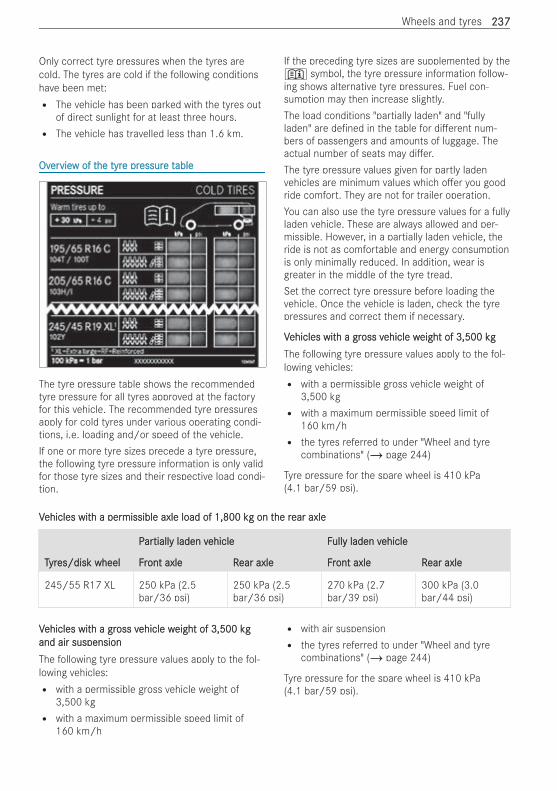
Only correct tyre pressures when the tyres arecold. The tyres are cold if the following conditionshave been met:R The vehicle has been parked with the tyres out
of direct sunlight for at least three hours.R The vehicle has travelled less than 1.6 km.
OvOverervieview of tw of the tyrhe tyre pre pressuressure te tableable
The tyre pressure table shows the recommendedtyre pressure for all tyres approved at the factoryfor this vehicle. The recommended tyre pressuresapply for cold tyres under various operating condi-tions, i.e. loading and/or speed of the vehicle.If one or more tyre sizes precede a tyre pressure,the following tyre pressure information is only validfor those tyre sizes and their respective load condi-tion.
If the preceding tyre sizes are supplemented by the+ symbol, the tyre pressure information follow-ing shows alternative tyre pressures. Fuel con-sumption may then increase slightly.The load conditions "partially laden" and "fullyladen" are de ned in the table for di erent num-bers of passengers and amounts of luggage. Theactual number of seats may di er.The tyre pressure values given for partly ladenvehicles are minimum values which o er you goodride comfort. They are not for trailer operation.You can also use the tyre pressure values for a fullyladen vehicle. These are always allowed and per-missible. However, in a partially laden vehicle, theride is not as comfortable and energy consumptionis only minimally reduced. In addition, wear isgreater in the middle of the tyre tread.Set the correct tyre pressure before loading thevehicle. Once the vehicle is laden, check the tyrepressures and correct them if necessary.
VVehicles witehicles with a grh a gross voss vehicle wehicle weight ofeight of 3,500 kg3,500 kgThe following tyre pressure values apply to the fol-lowing vehicles:R with a permissible gross vehicle weight of
3,500 kgR with a maximum permissible speed limit of
160 km/hR the tyres referred to under "Wheel and tyre
combinations" (/ page 244)
Tyre pressure for the spare wheel is 410 kPa(4.1 bar/59 psi).
VVehicles witehicles with a perh a permissible axle load ofmissible axle load of 1,800 k1,800 kg on tg on the rhe rear axleear axle
PParartialltially laden vy laden vehicle Fehicle Fullully laden vy laden vehicleehicle
TTyryres/disk wheel Fres/disk wheel Front axle Ront axle Rear axle Frear axle Front axle Ront axle Rear axleear axle
245/55 R17 XL 250 kPa (2.5bar/36 psi)
250 kPa (2.5bar/36 psi)
270 kPa (2.7bar/39 psi)
300 kPa (3.0bar/44 psi)
VVehicles witehicles with a grh a gross voss vehicle wehicle weight ofeight of 3,500 kg3,500 kgand air suspensionand air suspensionThe following tyre pressure values apply to the fol-lowing vehicles:R with a permissible gross vehicle weight of
3,500 kgR with a maximum permissible speed limit of
160 km/h
R with air suspensionR the tyres referred to under "Wheel and tyre
combinations" (/ page 244)
Tyre pressure for the spare wheel is 410 kPa(4.1 bar/59 psi).
Wheels and tyres 237237
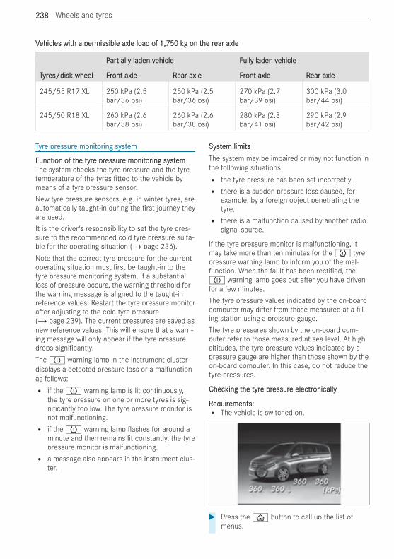
VVehicles witehicles with a perh a permissible axle load ofmissible axle load of 1,750 k1,750 kg on tg on the rhe rear axleear axle
PParartialltially laden vy laden vehicle Fehicle Fullully laden vy laden vehicleehicle
TTyryres/disk wheel Fres/disk wheel Front axle Ront axle Rear axle Frear axle Front axle Ront axle Rear axleear axle
245/55 R17 XL 250 kPa (2.5bar/36 psi)
250 kPa (2.5bar/36 psi)
270 kPa (2.7bar/39 psi)
300 kPa (3.0bar/44 psi)
245/50 R18 XL 260 kPa (2.6bar/38 psi)
260 kPa (2.6bar/38 psi)
280 kPa (2.8bar/41 psi)
290 kPa (2.9bar/42 psi)
TTyryre pre pressuressure monite monitororing systing systemem
FFunction of tunction of the tyrhe tyre pre pressuressure monite monitororing systing systememThe system checks the tyre pressure and the tyretemperature of the tyres tted to the vehicle bymeans of a tyre pressure sensor.New tyre pressure sensors, e.g. in winter tyres, areautomatically taught-in during the rst journey theyare used.It is the driver's responsibility to set the tyre pres-sure to the recommended cold tyre pressure suita-ble for the operating situation (/ page 236).Note that the correct tyre pressure for the currentoperating situation must rst be taught-in to thetyre pressure monitoring system. If a substantialloss of pressure occurs, the warning threshold forthe warning message is aligned to the taught-inreference values. Restart the tyre pressure monitora er adjusting to the cold tyre pressure(/ page 239). The current pressures are saved asnew reference values. This will ensure that a warn-ing message will only appear if the tyre pressuredrops signi cantly.The h warning lamp in the instrument clusterdisplays a detected pressure loss or a malfunctionas follows:R if the h warning lamp is lit continuously,
the tyre pressure on one or more tyres is sig-ni cantly too low. The tyre pressure monitor isnot malfunctioning.R if the h warning lamp ashes for around a
minute and then remains lit constantly, the tyrepressure monitor is malfunctioning.R a message also appears in the instrument clus-
ter.
SystSystem limitsem limitsThe system may be impaired or may not function inthe following situations:R the tyre pressure has been set incorrectly.R there is a sudden pressure loss caused, for
example, by a foreign object penetrating thetyre.R there is a malfunction caused by another radio
signal source.
If the tyre pressure monitor is malfunctioning, itmay take more than ten minutes for the h tyrepressure warning lamp to inform you of the mal-function. When the fault has been recti ed, theh warning lamp goes out a er you have drivenfor a few minutes.The tyre pressure values indicated by the on-boardcomputer may di er from those measured at a ll-ing station using a pressure gauge.The tyre pressures shown by the on-board com-puter refer to those measured at sea level. At highaltitudes, the tyre pressure values indicated by apressure gauge are higher than those shown by theon-board computer. In this case, do not reduce thetyre pressures.
ChecChecking tking the tyrhe tyre pre pressuressure electre electronicallyonically
RReqequiruirements:ements:R The vehicle is switched on.
# Press the ò button to call up the list ofmenus.
238238 Wheels and tyres
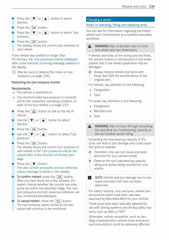
# Press the : or 9 button to selectService.
# Press the a button.# Press the : or 9 button to select Tyre
pressure.# Press the a button.
The display shows the current tyre pressure ofeach wheel.
If the vehicle was parked for longer than20 minutes, the Tyre pressures will be displayedafter a few minutes of driving message appears inthe display.% Also be sure to observe the notes on tyre
pressure (/ page 236).
RRestestararting tting the tyrhe tyre pre pressuressure monite monitoror
RReqequiruirements:ements:R The vehicle is switched on.R The recommended tyre pressure is correctly
set for the respective operating condition oneach of the four wheels (/ page 237).
# Press the ò button to call up the list ofmenus.
# Use the : or 9 button to selectService.
# Press the a button.# Use the : or 9 button to select Tyre
pressure.# Press the a button.
The display shows the current tyre pressure ofeach wheel or the Tyre pressures will be dis-played after a few minutes of driving mes-sage.
# Press the : button.The Use current pressures as new referencevalues message is shown in the display.
# TToo con rmcon rm rrestestartart:: press the a button.A er you have driven for a few minutes, thesystem checks whether the current tyre pres-sures are within the speci ed range. The newtyre pressures are then saved as reference val-ues, monitored and displayed.
# TTo cancel ro cancel restestartart:: press the % button.The tyre pressure values stored at the lastrestart will continue to be monitored.
Changing a wheelChanging a wheelNNoottes on selecting,es on selecting, ttingtting and rand replacing tyreplacing tyreses
You can ask for information regarding permittedwheel/tyre combinations at a quali ed specialistworkshop.
& WWARNINGARNING Risk of accident due to incor-rect wheel and tyre dimensions
If wheels and tyres of the wrong size are tted,the service brakes or components in the brakesystem and in the wheel suspension may bedamaged.# Always replace wheels and tyres with
those that ful l the speci cations of theoriginal part.
For wheels, pay attention to the following:R DesignationR Type
For tyres, pay attention to the following:R DesignationR ManufacturerR Type
& WWARNINGARNING Risk of injury through exceedingthe speci ed tyre load-bearing capacity orthe permissible speed rating
Exceeding the load-bearing capacity of thetyres can lead to tyre damage and could causethe tyres to explode.# Therefore, only use tyre types and sizes
approved for your vehicle model.# Observe the tyre load-bearing capacity
rating and speed rating required for yourvehicle.
* NNOOTETE Vehicle and tyre damage due to tyretypes and sizes that have not beenapproved
For safety reasons, only use tyres, wheels andaccessories which have been speciallyapproved by Mercedes-Benz for your vehicle.These tyres have been specially adapted foruse with driving systems and driving safety sys-tems, such as ABS or ESP®.Otherwise, certain properties, such as han-dling characteristics, vehicle noise emissionsand consumption could be adversely a ected.
Wheels and tyres 239239
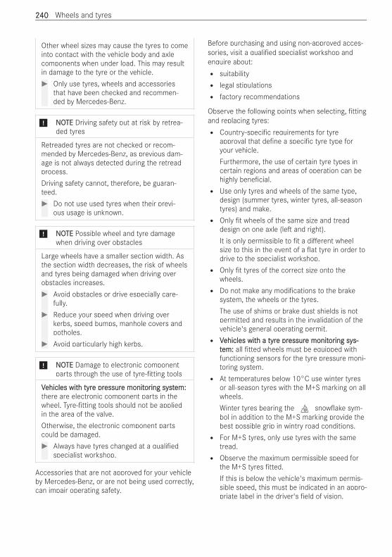
Other wheel sizes may cause the tyres to comeinto contact with the vehicle body and axlecomponents when under load. This may resultin damage to the tyre or the vehicle.# Only use tyres, wheels and accessories
that have been checked and recommen-ded by Mercedes-Benz.
* NNOOTETE Driving safety put at risk by retrea-ded tyres
Retreaded tyres are not checked or recom-mended by Mercedes-Benz, as previous dam-age is not always detected during the retreadprocess.Driving safety cannot, therefore, be guaran-teed.# Do not use used tyres when their previ-
ous usage is unknown.
* NNOOTETE Possible wheel and tyre damagewhen driving over obstacles
Large wheels have a smaller section width. Asthe section width decreases, the risk of wheelsand tyres being damaged when driving overobstacles increases.# Avoid obstacles or drive especially care-
fully.# Reduce your speed when driving over
kerbs, speed bumps, manhole covers andpotholes.
# Avoid particularly high kerbs.
* NNOOTETE Damage to electronic componentparts through the use of tyre- tting tools
VVehicles witehicles with tyrh tyre pre pressuressure monite monitororing systing system:em:there are electronic component parts in thewheel. Tyre- tting tools should not be appliedin the area of the valve.Otherwise, the electronic component partscould be damaged.# Always have tyres changed at a quali ed
specialist workshop.
Accessories that are not approved for your vehicleby Mercedes-Benz, or are not being used correctly,can impair operating safety.
Before purchasing and using non-approved acces-sories, visit a quali ed specialist workshop andenquire about:R suitabilityR legal stipulationsR factory recommendations
Observe the following points when selecting, ttingand replacing tyres:R Country-speci c requirements for tyre
approval that de ne a speci c tyre type foryour vehicle.Furthermore, the use of certain tyre types incertain regions and areas of operation can behighly bene cial.R Use only tyres and wheels of the same type,
design (summer tyres, winter tyres, all-seasontyres) and make.R Only t wheels of the same size and tread
design on one axle (le and right).It is only permissible to t a di erent wheelsize to this in the event of a at tyre in order todrive to the specialist workshop.R Only t tyres of the correct size onto the
wheels.R Do not make any modi cations to the brake
system, the wheels or the tyres.The use of shims or brake dust shields is notpermitted and results in the invalidation of thevehicle's general operating permit.R VVehicles witehicles with a tyrh a tyre pre pressuressure monite monitororing sying sys-s-
ttem:em: all tted wheels must be equipped withfunctioning sensors for the tyre pressure moni-toring system.R At temperatures below 10°C use winter tyres
or all-season tyres with the M+S marking on allwheels.Winter tyres bearing the i snow ake sym-bol in addition to the M+S marking provide thebest possible grip in wintry road conditions.R For M+S tyres, only use tyres with the same
tread.R Observe the maximum permissible speed for
the M+S tyres tted.If this is below the vehicle's maximum permis-sible speed, this must be indicated in an appro-priate label in the driver's eld of vision.
240240 Wheels and tyres
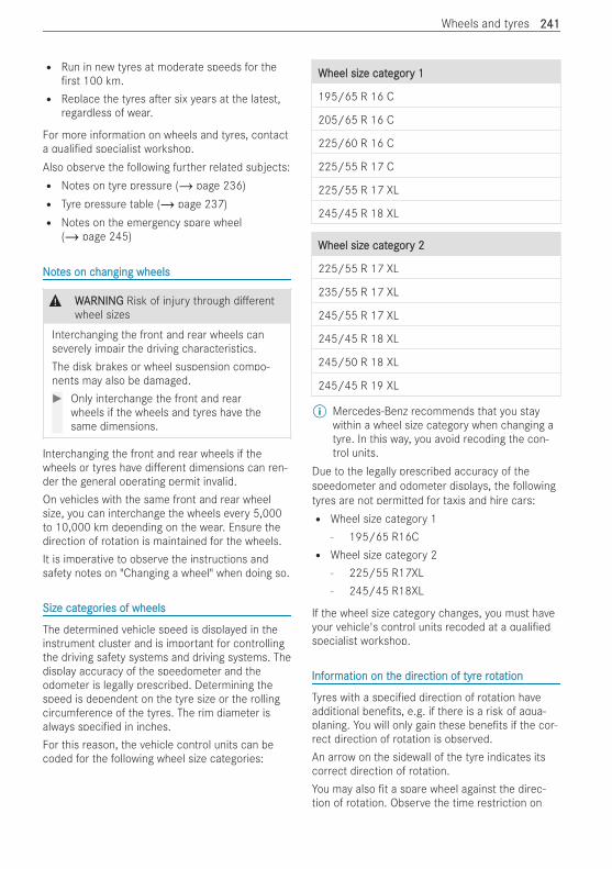
R Run in new tyres at moderate speeds for therst 100 km.
R Replace the tyres a er six years at the latest,regardless of wear.
For more information on wheels and tyres, contacta quali ed specialist workshop.Also observe the following further related subjects:R Notes on tyre pressure (/ page 236)R Tyre pressure table (/ page 237)R Notes on the emergency spare wheel
(/ page 245)
NNoottes on ces on changing wheelshanging wheels
& WWARNINGARNING Risk of injury through di erentwheel sizes
Interchanging the front and rear wheels canseverely impair the driving characteristics.The disk brakes or wheel suspension compo-nents may also be damaged.# Only interchange the front and rear
wheels if the wheels and tyres have thesame dimensions.
Interchanging the front and rear wheels if thewheels or tyres have di erent dimensions can ren-der the general operating permit invalid.On vehicles with the same front and rear wheelsize, you can interchange the wheels every 5,000to 10,000 km depending on the wear. Ensure thedirection of rotation is maintained for the wheels.It is imperative to observe the instructions andsafety notes on "Changing a wheel" when doing so.
Size catSize categoregories of wheelsies of wheels
The determined vehicle speed is displayed in theinstrument cluster and is important for controllingthe driving safety systems and driving systems. Thedisplay accuracy of the speedometer and theodometer is legally prescribed. Determining thespeed is dependent on the tyre size or the rollingcircumference of the tyres. The rim diameter isalways speci ed in inches.For this reason, the vehicle control units can becoded for the following wheel size categories:
Wheel size catWheel size categoregory 1y 1
195/65 R 16 C
205/65 R 16 C
225/60 R 16 C
225/55 R 17 C
225/55 R 17 XL
245/45 R 18 XL
Wheel size catWheel size categoregory 2y 2
225/55 R 17 XL
235/55 R 17 XL
245/55 R 17 XL
245/45 R 18 XL
245/50 R 18 XL
245/45 R 19 XL
% Mercedes-Benz recommends that you staywithin a wheel size category when changing atyre. In this way, you avoid recoding the con-trol units.
Due to the legally prescribed accuracy of thespeedometer and odometer displays, the followingtyres are not permitted for taxis and hire cars:R Wheel size category 1
- 195/65 R16CR Wheel size category 2
- 225/55 R17XL- 245/45 R18XL
If the wheel size category changes, you must haveyour vehicle's control units recoded at a quali edspecialist workshop.
InfInforormation on tmation on the dirhe direction of tyrection of tyre rote rotationation
Tyres with a speci ed direction of rotation haveadditional bene ts, e.g. if there is a risk of aqua-planing. You will only gain these bene ts if the cor-rect direction of rotation is observed.An arrow on the sidewall of the tyre indicates itscorrect direction of rotation.You may also t a spare wheel against the direc-tion of rotation. Observe the time restriction on
Wheels and tyres 241241

use as well as the speed restriction speci ed onthe spare wheel.
InfInforormation on stmation on stororing wheelsing wheels
Observe the following when storing wheels:R Wheels that have been removed should be
stored in a cool, dry and, if possible, darkplace.R Protect the tyres from oil, grease and fuel.
PrPrepareparing ting the vhe vehicle fehicle for a wheel cor a wheel changehange
RReqequiruirements:ements:R The tyre-change tool kit is available.R The vehicle is not on a slope.R The vehicle is on solid, non-slippery and level
ground.
# Apply the parking brake.# Move the front wheels to the straight-ahead
position.# Shi the transmission to position j.# Switch o the vehicle.# Make sure that the vehicle cannot be switched
on.# On levOn level tel terrerrain:ain: place chocks or other suitable
objects under the front and rear of the wheelthat is diagonally opposite the wheel to bechanged.
# On slight inclines:On slight inclines: place chocks or other suita-ble objects under the wheels on the front andrear axles opposite the wheel to be changed.
# If included in the vehicle equipment, take thetyre-change tool kit out of the vehicle tool kit(/ page 234).
# If included in the vehicle equipment, removethe spare wheel from the spare wheel holder(/ page 245).
# If necessary, remove the wheel trim.
# Using the wheel wrench, loosen the wheelbolts on the wheel you wish to change byabout one full turn. Do not unscrew the wheelbolts.
# Raise the vehicle (/ page 242).
RRaising taising the vhe vehicle when cehicle when changing a wheelhanging a wheel
& WWARNINGARNING Risk of injury from incorrectpositioning of the jack
If you do not position the jack correctly at theappropriate jacking point of the vehicle, thejack could tip with the vehicle raised.# Only position the jack at the appropriate
jacking point of the vehicle. The base ofthe jack must be positioned verticallyunder the jacking point of the vehicle.
& WWARNINGARNING Risk of injury from vehicle tip-ping
On slopes, the jack could tip with the vehicleraised.# Never change a wheel on a slope.# Consult a quali ed specialist workshop.
* NNOOTETE Vehicle damage from the jack
If you do not position the jack correctly at theappropriate jack support point of the vehicle,the jack could tip over with the vehicle raised.# The jack is designed exclusively for jack-
ing up the vehicle at the jack supportpoints.
RReqequiruirements:ements:R There are no persons in the vehicle.R The vehicle is prepared for changing a wheel
(/ page 242).
Important notes on using the jack:R Only use the vehicle-speci c jack that has
been tested and approved by Mercedes-Benzto raise the vehicle. If the jack is used incor-rectly, it could tip over while the vehicle israised.R The jack is designed only to raise the vehicle
for a short time while a wheel is being changedand is not suitable for carrying out mainte-nance work under the vehicle.R Avoid changing a wheel on uphill and downhill
slopes.
242242 Wheels and tyres
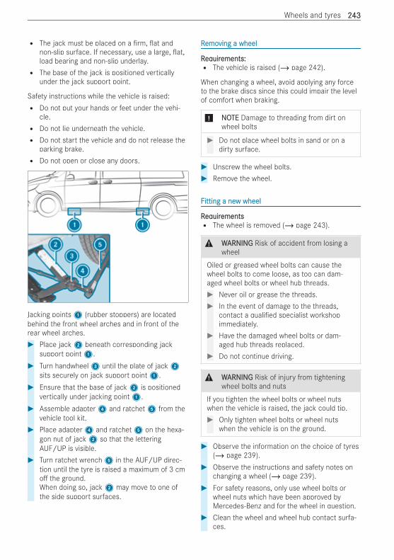
R The jack must be placed on a rm, at andnon-slip surface. If necessary, use a large, at,load bearing and non-slip underlay.R The base of the jack is positioned vertically
under the jack support point.
Safety instructions while the vehicle is raised:R Do not put your hands or feet under the vehi-
cle.R Do not lie underneath the vehicle.R Do not start the vehicle and do not release the
parking brake.R Do not open or close any doors.
Jacking points1 (rubber stoppers) are locatedbehind the front wheel arches and in front of therear wheel arches.# Place jack2 beneath corresponding jack
support point1.# Turn handwheel3 until the plate of jack2
sits securely on jack support point1.# Ensure that the base of jack2 is positioned
vertically under jacking point1.# Assemble adapter4 and ratchet5 from the
vehicle tool kit.# Place adapter4 and ratchet5 on the hexa-
gon nut of jack2 so that the letteringAUF/UP is visible.
# Turn ratchet wrench5 in the AUF/UP direc-tion until the tyre is raised a maximum of 3 cmo the ground.When doing so, jack2 may move to one ofthe side support surfaces.
RRemoemoving a wheelving a wheel
RReqequiruirements:ements:R The vehicle is raised (/ page 242).
When changing a wheel, avoid applying any forceto the brake discs since this could impair the levelof comfort when braking.
* NONOTETE Damage to threading from dirt onwheel bolts
# Do not place wheel bolts in sand or on adirty surface.
# Unscrew the wheel bolts.# Remove the wheel.
FFitting a neitting a new wheelw wheel
RReqequiruirementsementsR The wheel is removed (/ page 243).
& WWARNINGARNING Risk of accident from losing awheel
Oiled or greased wheel bolts can cause thewheel bolts to come loose, as too can dam-aged wheel bolts or wheel hub threads.# Never oil or grease the threads.# In the event of damage to the threads,
contact a quali ed specialist workshopimmediately.
# Have the damaged wheel bolts or dam-aged hub threads replaced.
# Do not continue driving.
& WWARNINGARNING Risk of injury from tighteningwheel bolts and nuts
If you tighten the wheel bolts or wheel nutswhen the vehicle is raised, the jack could tip.# Only tighten wheel bolts or wheel nuts
when the vehicle is on the ground.
# Observe the information on the choice of tyres(/ page 239).
# Observe the instructions and safety notes onchanging a wheel (/ page 239).
# For safety reasons, only use wheel bolts orwheel nuts which have been approved byMercedes-Benz and for the wheel in question.
# Clean the wheel and wheel hub contact surfa-ces.
Wheels and tyres 243243
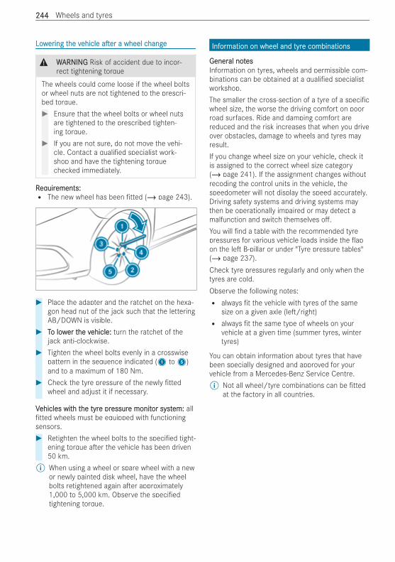
LowLowerering ting the vhe vehicleehicle a era er a wheel ca wheel changehange
& WWARNINGARNING Risk of accident due to incor-rect tightening torque
The wheels could come loose if the wheel boltsor wheel nuts are not tightened to the prescri-bed torque.# Ensure that the wheel bolts or wheel nuts
are tightened to the prescribed tighten-ing torque.
# If you are not sure, do not move the vehi-cle. Contact a quali ed specialist work-shop and have the tightening torquechecked immediately.
RReqequiruirements:ements:R The new wheel has been tted (/ page 243).
# Place the adapter and the ratchet on the hexa-gon head nut of the jack such that the letteringAB/DOWN is visible.
# TTo lowo lower ter the vhe vehicle:ehicle: turn the ratchet of thejack anti-clockwise.
# Tighten the wheel bolts evenly in a crosswisepattern in the sequence indicated (1 to5)and to a maximum of 180 Nm.
# Check the tyre pressure of the newly ttedwheel and adjust it if necessary.
VVehicles witehicles with th the tyrhe tyre pre pressuressure monite monitor systor system:em: alltted wheels must be equipped with functioning
sensors.# Retighten the wheel bolts to the speci ed tight-
ening torque a er the vehicle has been driven50 km.
% When using a wheel or spare wheel with a newor newly painted disk wheel, have the wheelbolts retightened again a er approximately1,000 to 5,000 km. Observe the speci edtightening torque.
InfInforormation on wheel and tyrmation on wheel and tyre combinationse combinations
GenerGeneral notal notesesInformation on tyres, wheels and permissible com-binations can be obtained at a quali ed specialistworkshop.The smaller the cross-section of a tyre of a speci cwheel size, the worse the driving comfort on poorroad surfaces. Ride and damping comfort arereduced and the risk increases that when you driveover obstacles, damage to wheels and tyres mayresult.If you change wheel size on your vehicle, check itis assigned to the correct wheel size category(/ page 241). If the assignment changes withoutrecoding the control units in the vehicle, thespeedometer will not display the speed accurately.Driving safety systems and driving systems maythen be operationally impaired or may detect amalfunction and switch themselves o .You will nd a table with the recommended tyrepressures for various vehicle loads inside the apon the le B-pillar or under "Tyre pressure tables"(/ page 237).Check tyre pressures regularly and only when thetyres are cold.Observe the following notes:R always t the vehicle with tyres of the same
size on a given axle (le /right)R always t the same type of wheels on your
vehicle at a given time (summer tyres, wintertyres)
You can obtain information about tyres that havebeen specially designed and approved for yourvehicle from a Mercedes-Benz Service Centre.% Not all wheel/tyre combinations can be tted
at the factory in all countries.
244244 Wheels and tyres
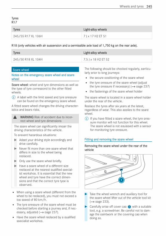
TTyryresesR17R17
TTyryreses Light-alloLight-alloy wheelsy wheels
245/55 R17 XL 106H 7 J x 17 H2 ET 51
R18 (onlR18 (only vy vehicles witehicles with air suspension and a perh air suspension and a permissible axle load ofmissible axle load of 1,750 kg1,750 kg on ton the rhe rear axle).ear axle).
TTyryreses Light-alloLight-alloy wheelsy wheels
245/50 R18 XL 104H 7.5 J x 18 H2 ET 52
SparSpare wheele wheelNNoottes on tes on the emerghe emergency sparency spare wheel and sparee wheel and sparewheelwheel
SparSpare wheel:e wheel: wheel and tyre dimensions as well asthe type of tyre correspond to the other ttedwheels.% A label with the limit speed and tyre pressure
can be found on the emergency spare wheel.A tted spare wheel changes the driving character-istics and bears risks.
& WWARNINGARNING Risk of accident due to incor-rect wheel and tyre dimensions
The spare wheel can signi cantly impair thedriving characteristics of the vehicle.To prevent hazardous situations:# Adapt your driving style accordingly and
drive carefully.# Never t more than one spare wheel that
di ers in size to the wheel beingreplaced.
# Only use the spare wheel brie y.# Have a spare wheel of a di erent size
replaced at the nearest quali ed special-ist workshop. It is essential that the newwheel and tyre have the correct dimen-sions and that the correct tyre type isobserved.
R When using a spare wheel (di erent from thewheel to be replaced), you must not exceed atop speed of 80 km/h.R The tyre pressure of the spare wheel must be
checked before starting a journey and, if nec-essary, adjusted (/ page 237).R Have the spare wheel replaced by a quali ed
specialist workshop.
The following should be checked regularly, particu-larly prior to long journeys:R the secure positioning of the spare wheelR the tyre pressure of the spare wheel (adjust
the tyre pressure if necessary) (/ page 237)R the fastenings of the spare wheel holder
The spare wheel is located in a spare wheel holderunder the rear of the vehicle.Replace the tyres a er six years at the latest,regardless of wear. This also applies to the sparewheel.% If you have tted a spare wheel, the tyre pres-
sure monitor will not function for this wheel.The spare wheel is not equipped with a sensorfor monitoring tyre pressure.
FFitting and ritting and remoemoving tving the sparhe spare wheele wheel
RRemoemoving tving the sparhe spare wheel under te wheel under the rhe rear of tear of thehevvehicleehicle
# Take the wheel wrench and auxiliary tool forthe spare wheel li er out of the vehicle tool kit(/ page 233).
# Carefully prise o cover cap1 with a suitabletool, e.g. a screwdriver. Be careful not to dam-age the paintwork or the covering cap whendoing so.
Wheels and tyres 245245
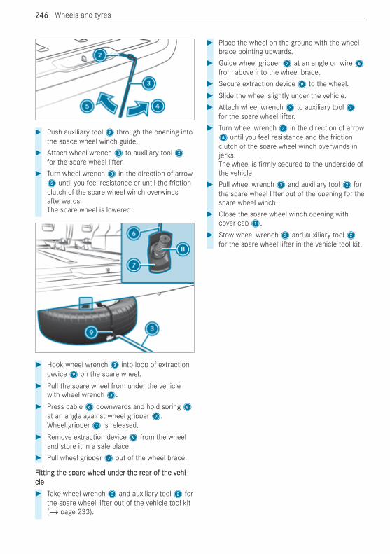
# Push auxiliary tool2 through the opening intothe space wheel winch guide.
# Attach wheel wrench3 to auxiliary tool2for the spare wheel li er.
# Turn wheel wrench3 in the direction of arrow5 until you feel resistance or until the frictionclutch of the spare wheel winch overwindsa erwards.The spare wheel is lowered.
# Hook wheel wrench3 into loop of extractiondevice9 on the spare wheel.
# Pull the spare wheel from under the vehiclewith wheel wrench3.
# Press cable6 downwards and hold spring8at an angle against wheel gripper7.Wheel gripper7 is released.
# Remove extraction device9 from the wheeland store it in a safe place.
# Pull wheel gripper7 out of the wheel brace.
FFitting titting the sparhe spare wheel under te wheel under the rhe rear of tear of the vhe vehi-ehi-clecle# Take wheel wrench3 and auxiliary tool2 for
the spare wheel li er out of the vehicle tool kit(/ page 233).
# Place the wheel on the ground with the wheelbrace pointing upwards.
# Guide wheel gripper7 at an angle on wire6from above into the wheel brace.
# Secure extraction device9 to the wheel.# Slide the wheel slightly under the vehicle.# Attach wheel wrench3 to auxiliary tool2
for the spare wheel li er.# Turn wheel wrench3 in the direction of arrow4 until you feel resistance and the frictionclutch of the spare wheel winch overwinds injerks.The wheel is rmly secured to the underside ofthe vehicle.
# Pull wheel wrench3 and auxiliary tool2 forthe spare wheel li er out of the opening for thespare wheel winch.
# Close the spare wheel winch opening withcover cap1.
# Stow wheel wrench3 and auxiliary tool2for the spare wheel li er in the vehicle tool kit.
246246 Wheels and tyres
InfInforormation on tmation on the the tecechnical datahnical dataThe technical data was determined in accordancewith EU Directives. The given data only applies tovehicles with standard equipment. You can obtainfurther information at a quali ed specialist work-shop.OnlOnly fy for certor certain countrain countries:ies: you can nd vehicle-speci c vehicle data in the COC documents (CER-TIFICATE OF CONFORMITY). These documents aresupplied when the vehicle is delivered.
On-boarOn-board electrd electronicsonicsNNoottes on wes on worork on tk on the engine electrhe engine electronicsonics
* NNOOTETE Premature wear through impropermaintenance
Improper maintenance may cause vehicle com-ponents to wear more quickly and the vehicle'soperating permit may be invalidated.# Always have work on the engine elec-
tronics and related components carriedout at a quali ed specialist workshop.
TTwwo-wao-way ry radiosadios
InstInstallation notallation notes fes for twor two-wao-way ry radiosadios
& WWARNINGARNING Risk of accident due toimproper work on two-way radios
If two-way radios are manipulated or retro ttedincorrectly, the electromagnetic radiation fromthe two-way radios can interfere with the vehi-cle electronics and jeopardise the operatingsafety of the vehicle.# You should have all work on electrical
and electronic components carried outat a quali ed specialist workshop.
& WWARNINGARNING Risk of accident due toimproper operation of two-way radios
If you use two-way radios in the vehicleimproperly, their electromagnetic radiation candisrupt the vehicle's electronics. This is thecase in the following situations, in particular:R The two-way radio is not connected to an
exterior aerial.R The exterior aerial is tted incorrectly or is
not a low-re ection aerial.
This could jeopardise the operating safety ofthe vehicle.# Have the low-re ection exterior aerial t-
ted at a quali ed specialist workshop.# When operating two-way radios in the
vehicle, always connect them to the low-re ection exterior aerial.
* NNOOTETE Invalidation of the operating permitdue to failure to comply with the instruc-tions for installation and use
The operating permit may be invalidated if theinstructions for installation and use of two-wayradios are not observed.# Only use approved frequency bands.# Observe the maximum permissible out-
put power in these frequency bands.# Only use approved aerial positions.
Use Technical Speci cation ISO/TS 21609 (RoadVehicles - EMC guidelines for installation of a er-market radio frequency transmitting equipment)when retro tting two-way radios. Comply with thelegal requirements for detachable parts.If your vehicle has ttings for two-way radio equip-ment, use the power supply or aerial connectionsintended for use with the ttings. Observe themanufacturer's supplements during installation.
TTwwo-wao-way ry radio tradio transmission outputansmission outputThe maximum transmission outputs (PEAK) at thebase of the aerial must not exceed the values inthe following table:
FrFreqequency band and maximum truency band and maximum transmission out-ansmission out-putput
FFrreqequency banduency band Maximum trMaximum transmis-ansmis-sion outputsion output
Short wave3 – 54 MHz
100 W
4 m waveband74 – 88 MHz
30 W
2 m waveband144 – 174 MHz
50 W
Trunked radio system/Tetra380 – 460 MHz
10 W
Technical data 247247
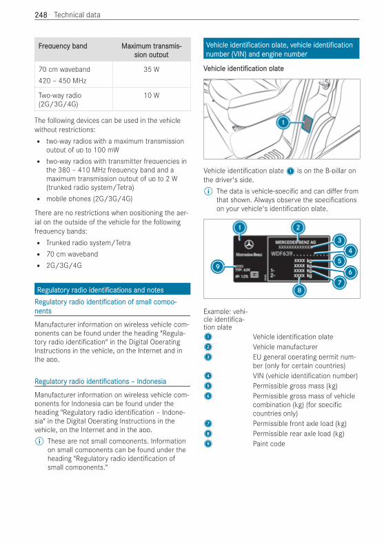
FFrreqequency banduency band Maximum trMaximum transmis-ansmis-sion outputsion output
70 cm waveband420 – 450 MHz
35 W
Two-way radio(2G/3G/4G)
10 W
The following devices can be used in the vehiclewithout restrictions:R two-way radios with a maximum transmission
output of up to 100 mWR two-way radios with transmitter frequencies in
the 380 – 410 MHz frequency band and amaximum transmission output of up to 2 W(trunked radio system/Tetra)R mobile phones (2G/3G/4G)
There are no restrictions when positioning the aer-ial on the outside of the vehicle for the followingfrequency bands:R Trunked radio system/TetraR 70 cm wavebandR 2G/3G/4G
RRegulategulatorory ry radioadio identi cationsidenti cations and notand notesesRRegulategulatorory ry radioadio identi cationidenti cation of small comof small compo-po-nentsnents
Manufacturer information on wireless vehicle com-ponents can be found under the heading "Regula-tory radio identi cation" in the Digital OperatingInstructions in the vehicle, on the Internet and inthe app.
RRegulategulatorory ry radioadio identi cationsidenti cations – Indonesia– Indonesia
Manufacturer information on wireless vehicle com-ponents for Indonesia can be found under theheading "Regulatory radio identi cation – Indone-sia" in the Digital Operating Instructions in thevehicle, on the Internet and in the app.% These are not small components. Information
on small components can be found under theheading "Regulatory radio identi cation ofsmall components."
VVehicleehicle identi cationidenti cation platplate, ve, vehicleehicle identi cationidenti cationnumber (VIN) and engine numbernumber (VIN) and engine number
VVehicleehicle identi cationidenti cation plateplate
Vehicle identi cation plate1 is on the B-pillar onthe driver's side.% The data is vehicle-speci c and can di er from
that shown. Always observe the speci cationson your vehicle's identi cation plate.
Example: vehi-cle identi ca-tion plate1 Vehicle identi cation plate2 Vehicle manufacturer3 EU general operating permit num-
ber (only for certain countries)4 VIN (vehicle identi cation number)5 Permissible gross mass (kg)6 Permissible gross mass of vehicle
combination (kg) (for speci ccountries only)
7 Permissible front axle load (kg)8 Permissible rear axle load (kg)9 Paint code
248248 Technical data
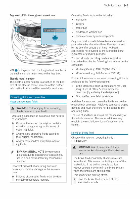
EngravEngraved VIN in ted VIN in the engine comhe engine comparpartmenttment
VIN1 is engraved into the longitudinal member inthe engine compartment next to the fuse box.
ElectrElectric motic motor numberor numberThe electric motor number is attached to the bot-tom of the electric motor. You can obtain furtherinformation from a quali ed specialist workshop.
OperOperatingating uidsuids and capacitiesand capacitiesNNoottes on operes on operatingating uidsuids
& WWARNINGARNING Risk of injury from operatinguids harmful to your health
Operating uids may be poisonous and harmfulto your health.# Observe the text on the original contain-
ers when using, storing or disposing ofoperating uids.
# Always store operating uids sealed intheir original containers.
# Always keep children away from operat-ing uids.
+ ENVIRENVIRONMENTONMENTAL NOAL NOTETE Environmentalpollution due to disposing of operating u-ids in a non-environmentally responsiblemanner
Incorrect disposal of operating uids cancause considerable damage to the environ-ment.# Dispose of operating uids in an environ-
mentally responsible manner.
Operating uids include the following:R lubricantsR coolantR brake uidR windscreen washer uidR climate control system refrigerants
Only use products which have been approved foryour vehicle by Mercedes-Benz. Damage causedby the use of products that have not beenapproved is not covered by the Mercedes-Benzguarantee or goodwill gestures.You can identify operating uids approved byMercedes-Benz by the following inscriptions on thecontainer:R MB-Freigabe (e.g. MB-Freigabe 229.51)R MB-Approval (e.g. MB-Approval 229.51)
Further information on approved operating uids isavailable at the following locations:R In the Mercedes-Benz Speci cations for Oper-
ating Fluids at https://bevo.mercedes-benz.com (by entering the designation)R At a quali ed specialist workshop
Additives for approved operating uids are neitherrequired nor permitted. Additives can cause enginedamage and must therefore not be added to theoperating uids.The use of additives is always the responsibility ofthe vehicle operator. The use of additives mayresult in the restriction or loss of your warrantyclaims.
NNoottes on bres on brakakee uiduid
Observe the notes on operating uids(/ page 249).
& WWARNINGARNING Risk of an accident due tovapour pockets forming in the brake sys-tem
The brake uid constantly absorbs moisturefrom the air. This lowers the boiling point of thebrake uid. If the boiling point is too low,vapour pockets may form in the brake systemwhen the brakes are applied hard.This impairs the braking e ect.# Have the brake uid renewed at the
speci ed intervals.
Technical data 249249
* NNOOTETE Damage to paint, plastic or rubberby brake uid
There is a risk of damage to property if brakeuid comes into contact with paint, plastic or
rubber.# If paint, plastic or rubber comes into con-
tact with brake uid, rinse with waterimmediately.
Observe the notes on paintwork/matt nish paint-work care (/ page 220).Have the brake uid renewed every two years at aquali ed specialist workshop.Only use brake uid approved by Mercedes-Benz inaccordance with MB-Freigabe or MB-Approval331.0.Information on brake uid is available at the follow-ing locations:R in the Mercedes-Benz Speci cation for Operat-
ing Fluids 331.0- At https://bevo.mercedes-benz.com- In the Mercedes-Benz BeVo appR At a quali ed specialist workshop
CoolantCoolant
NNoottes on coolantes on coolantObserve the notes on operating uids(/ page 249).
& WWARNINGARNING Risk of re‑ and injury fromantifreeze
If antifreeze comes into contact with hot com-ponent parts in the engine compartment, itmay ignite.# Allow the drive system to cool down
before you top up the antifreeze.# Make sure that no antifreeze spills out
next to the ller opening.# Thoroughly clean the antifreeze from
component parts before starting thevehicle.
* NNOOTETE Damage caused by incorrect cool-ant
# Only add coolant that has been premixedwith the required antifreeze protection.
Information on coolant is available at the followinglocations:R In the Mercedes-Benz Speci cation for Operat-
ing Fluids 320.1- At https://bevo.mercedes-benz.com- In the Mercedes-Benz BeVo appR At a quali ed specialist workshop
* NNOOTETE Overheating at high outside temper-atures
If an inappropriate coolant is used, the enginecooling system is not su ciently protectedagainst overheating and corrosion at high out-side temperatures.# Always use coolant approved for
Mercedes-Benz.# Observe the instructions in the
Mercedes-Benz Speci cation for Operat-ing Fluids 320.1.
* NNOOTETE Paintwork damage due to coolant# Do not spill coolant on painted surfaces.
Have the coolant regularly replaced at a quali edspecialist workshop.Note the proportion of anti-corrosion agent/anti-freeze in the engine cooling system within the fol-lowing temperature ranges:R A minimum of 50% (antifreeze protection down
to about -37°C)R A maximum of 55% (antifreeze protection down
to -45°C)
WWindscrindscreen ween washerasher uiduid
NNoottes on windscres on windscreen ween washerasher uiduidObserve the notes on operating uids(/ page 249).
& WWARNINGARNING Risk of re and injury fromwindscreen washer concentrate
Windscreen washer concentrate is highly am-mable. If it comes into contact with hot com-ponents, it may ignite.# Make sure that windscreen washer con-
centrate is not spilled near to the lleropening.
250250 Technical data
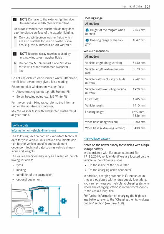
* NNOOTETE Damage to the exterior lighting dueto unsuitable windscreen washer uid
Unsuitable windscreen washer uids may dam-age the plastic surface of the exterior lighting.# Only use windscreen washer uids which
are also suitable for use on plastic surfa-ces, e.g. MB SummerFit or MB WinterFit.
* NNOOTETE Blocked spray nozzles caused bymixing windscreen washer uids
# Do not mix MB SummerFit and MB Win-terFit with other windscreen washer u-ids.
Do not use distilled or de-ionised water. Otherwise,the ll level sensor may give a false reading.Recommended windscreen washer uid:R Above freezing point: e.g. MB SummerFitR Below freezing point: e.g. MB WinterFit
For the correct mixing ratio, refer to the informa-tion on the anti-freeze container.Mix the washer uid with windscreen washer uidall year round.
VVehicle dataehicle dataInfInforormation on vmation on vehicle dimensionsehicle dimensions
The following section contains important technicaldata for your vehicle. Your vehicle documents con-tain further vehicle-speci c and equipment-dependent technical data such as vehicle dimen-sions and weights.The values speci ed may vary as a result of the fol-lowing variables:R tyresR loadingR condition of the suspensionR optional equipment
Opening rOpening rangeange
All modelsAll models
1 Height of the tailgate whenopened
2153 mm
2 Opening range of the tail-gate
1047 mm
VVehicle dimensionsehicle dimensions
All modelsAll models
Vehicle length (long version) 5140 mm
Vehicle length (extra-long ver-sion)
5370 mm
Vehicle width including outsidemirrors
2249 mm
Vehicle width excluding outsidemirrors
1928 mm
Load width 1205 mm
Vehicle height 1910 mm
Loading height 1297 mm –1326 mm
Wheelbase (long version) 3200 mm
Wheelbase (extra-long version) 3430 mm
High-vHigh-voltoltagage batte batteryery
NNoottes on tes on the powhe power suppler supply fy for vor vehicles witehicles with a high-h a high-vvoltoltagage batte batteryeryIn accordance with European standard EN17186:2019, vehicle identi ers are located on thevehicle in the following places:R On the inside of the socket apR On the charging cable connector
In addition, charging stations in European coun-tries are equipped with energy supply identi ers.You can recharge your vehicle at charging stationswhere the charging station identi er correspondsto the vehicle identi er.For further information on charging the high-volt-age battery, refer to the "Charging the high-voltagebattery" section (/ page 138).
Technical data 251251
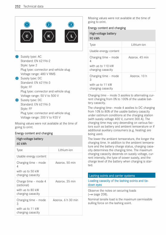
1 Supply type: ACStandard: EN 62196-2Style: type 2Plug type: connector and vehicle plugVoltage range: 480 V RMS
2 Supply type: DCStandard: EN 62196-3Style: FFPlug type: connector and vehicle plugVoltage range: 50 V to 500 V
3 Supply type: DCStandard: EN 62196-3Style: FFPlug type: connector and vehicle plugVoltage range: 200 V to 920 V
Missing values were not available at the time ofgoing to print.
EnerEnergy contgy content and cent and charhargingging
High-vHigh-voltoltagage batte batteryery60 kWh60 kWh
Type Lithium-ion
Usable energy content
Charging time – mode4with up to 50 kWcharging capacity
Approx. 50 min
Charge time – mode 4(optional)with up to 80 kWcharging capacity
Approx. 35 min
Charging time – mode3with up to 11 kWcharging capacity
Approx. 6 h 30 min
Missing values were not available at the time ofgoing to print.
EnerEnergy contgy content and cent and charhargingging
High-vHigh-voltoltagage batte batteryery90 kWh90 kWh
Type Lithium-ion
Usable energy content
Charging time – mode4with up to 110 kWcharging capacity
Approx. 45 min
Charging time – mode3with up to 11 kWcharging capacity
Approx. 10 h
Charging time – mode 3 applies to alternating cur-rent charging from 0% to 100% of the usable bat-tery capacity.The charging time– mode 4 applies to DC chargingfrom 10% to 80% of the usable battery capacityunder optimum conditions at the charging station(with supply voltage 400 V, current 300 A). Thecharging time may vary depending on various fac-tors such as battery and ambient temperature or ifadditional auxiliary consumers (e.g. heating) arebeing used.The lower the ambient temperature, the longer thecharging time. In addition to the ambient tempera-ture and the battery charge status, charging capa-city determines the charging time. The maximumcharging capacity depends on supply voltage, cur-rent intensity, the type of power supply, and thecharge level of the battery when charging is star-ted.
Lashing points and carrLashing points and carrier systier systemsemsLoading capacity of tLoading capacity of the lashing points and tie-he lashing points and tie-dodown eywn eyeses
Observe the notes on securing loads(/ page 208).Nominal tensile load is the maximum permissiblepulling force on the lashing point.
252252 Technical data
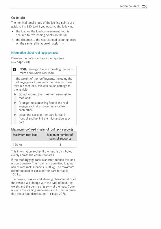
Guide rGuide railsailsThe nominal tensile load of the lashing points of aguide rail is 350 daN if you observe the following:R the load on the load compartment oor is
secured to two lashing points on the railR the distance to the nearest load-securing point
on the same rail is approximately 1 m
InfInforormation about rmation about roof luggoof luggagage re racksacks
Observe the notes on the carrier systems(/ page 213).
* NNOOTETE Damage due to exceeding the maxi-mum permissible roof load
If the weight of the roof luggage, including theroof luggage rack, exceeds the maximum per-missible roof load, this can cause damage tothe vehicle.# Do not exceed the maximum permissible
roof load.# Arrange the supporting feet of the roof
luggage rack at an even distance fromeach other.
# Install the basic carrier bars for rail infront of and behind the mid-section sup-port.
Maximum rMaximum roof load / pairoof load / pairs of rs of roof roof racack suppork supportsts
Maximum rMaximum roof loadoof load Minimum number ofMinimum number ofpairpairs of suppors of supportsts
150 kg 3
This information applies if the load is distributedevenly across the entire roof area.If the roof luggage rack is shorter, reduce the loadproportionately. The maximum permitted load perpair of roof rack supports is 50 kg. The maximumpermitted load of basic carrier bars for rail is100 kg.The driving, braking and steering characteristics ofthe vehicle will change with the type of load, theweight and the centre of gravity of the load. Com-ply with the loading guidelines and further informa-tion about load distribution (/ page 207).
Technical data 253253
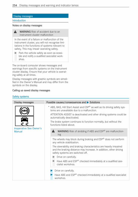
DisplaDisplay messagy messagesesIntrIntroductionoduction
NNoottes on displaes on display messagy messageses
& WWARNINGARNING Risk of accident due to aninstrument cluster malfunction
In the event of a failure or malfunction of theinstrument cluster, you will not recognise limi-tations in the functions of systems relevant tosafety. This may impair operating safety.# Park the vehicle safely as soon as possi-
ble and notify a quali ed specialist work-shop.
The on-board computer shows messages andwarnings from speci c systems on the instrumentcluster display. Ensure that your vehicle is operat-ing safely at all times.Display messages with graphic symbols are simpli-ed in the Owner's Manual and may di er from the
symbols on the display.
Calling up savCalling up saved displaed display messagy messageses
SafeSafety systty systemsems
DisplaDisplay messagy messages Pes Possible causes/conseqossible causes/consequences anduences and MM SolutionsSolutions
!÷inoperative See Owner'sManual
* ABS, BAS, Hill Start Assist and ESP® as well as its driving safety sys-tems are unavailable due to a malfunction.ATTENTION ASSIST is deactivated and other driving systems could beautomatically deactivated.The brake system continues to function normally, but without thefunctions listed above.
& WWARNINGARNING Risk of skidding if ABS and ESP® are malfunction-ing
The wheels may block during braking and ESP® does not performany vehicle stabilization.The steerability and braking characteristics are heavily impairedand the braking distance may increase. In addition, other drivingsafety systems are switched o .# Drive on carefully.# Have ABS and ESP® checked immediately at a quali ed spe-
cialist workshop.
# Drive on carefully.# Have ABS and ESP® checked immediately at a quali ed specialist
workshop.
254254 Display messages and warning and indicator lamps
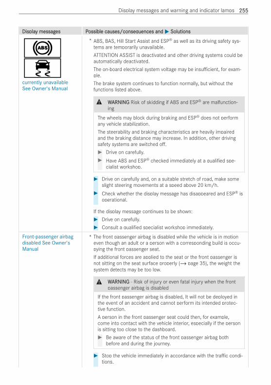
DisplaDisplay messagy messages Pes Possible causes/conseqossible causes/consequences anduences and MM SolutionsSolutions
!÷currently unavailableSee Owner's Manual
* ABS, BAS, Hill Start Assist and ESP® as well as its driving safety sys-tems are temporarily unavailable.ATTENTION ASSIST is deactivated and other driving systems could beautomatically deactivated.The on-board electrical system voltage may be insu cient, for exam-ple.The brake system continues to function normally, but without thefunctions listed above.
& WWARNINGARNING Risk of skidding if ABS and ESP® are malfunction-ing
The wheels may block during braking and ESP® does not performany vehicle stabilization.The steerability and braking characteristics are heavily impairedand the braking distance may increase. In addition, other drivingsafety systems are switched o .# Drive on carefully.# Have ABS and ESP® checked immediately at a quali ed spe-
cialist workshop.
# Drive on carefully and, on a suitable stretch of road, make someslight steering movements at a speed above 20 km/h.
# Check whether the display message has disappeared and ESP® isoperational.
If the display message continues to be shown:# Drive on carefully.# Consult a quali ed specialist workshop immediately.
Front-passenger airbagdisabled See Owner'sManual
* The front passenger airbag is disabled while the vehicle is in motioneven though an adult or a person with a corresponding build is occu-pying the front passenger seat.If additional forces are applied to the seat or the front passenger isnot sitting on the seat surface properly (/ page 35), the weight thesystem detects may be too low.
& WWARNINGARNING ‑ Risk of injury or even fatal injury when the frontpassenger airbag is disabled
If the front passenger airbag is disabled, It will not be deployed inthe event of an accident and cannot perform its intended protec-tive function.A person in the front passenger seat could then, for example,come into contact with the vehicle interior, especially if the personis sitting too close to the dashboard.# Be aware of the status of the front passenger airbag both
before and during the journey.
# Stop the vehicle immediately in accordance with the tra c condi-tions.
Display messages and warning and indicator lamps 255255
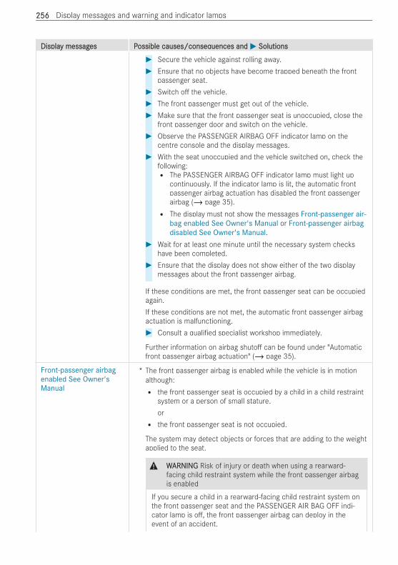
DisplaDisplay messagy messages Pes Possible causes/conseqossible causes/consequences anduences and MM SolutionsSolutions# Secure the vehicle against rolling away.# Ensure that no objects have become trapped beneath the front
passenger seat.# Switch o the vehicle.# The front passenger must get out of the vehicle.# Make sure that the front passenger seat is unoccupied, close the
front passenger door and switch on the vehicle.# Observe the PASSENGER AIRBAG OFF indicator lamp on the
centre console and the display messages.# With the seat unoccupied and the vehicle switched on, check the
following:R The PASSENGER AIRBAG OFF indicator lamp must light up
continuously. If the indicator lamp is lit, the automatic frontpassenger airbag actuation has disabled the front passengerairbag (/ page 35).R The display must not show the messages Front-passenger air-
bag enabled See Owner's Manual or Front-passenger airbagdisabled See Owner's Manual.
# Wait for at least one minute until the necessary system checkshave been completed.
# Ensure that the display does not show either of the two displaymessages about the front passenger airbag.
If these conditions are met, the front passenger seat can be occupiedagain.If these conditions are not met, the automatic front passenger airbagactuation is malfunctioning.# Consult a quali ed specialist workshop immediately.
Further information on airbag shuto can be found under "Automaticfront passenger airbag actuation" (/ page 35).
Front-passenger airbagenabled See Owner'sManual
* The front passenger airbag is enabled while the vehicle is in motionalthough:R the front passenger seat is occupied by a child in a child restraint
system or a person of small stature.orR the front passenger seat is not occupied.
The system may detect objects or forces that are adding to the weightapplied to the seat.
& WWARNINGARNING Risk of injury or death when using a rearward-facing child restraint system while the front passenger airbagis enabled
If you secure a child in a rearward-facing child restraint system onthe front passenger seat and the PASSENGER AIR BAG OFF indi-cator lamp is o , the front passenger airbag can deploy in theevent of an accident.
256256 Display messages and warning and indicator lamps
DisplaDisplay messagy messages Pes Possible causes/conseqossible causes/consequences anduences and MM SolutionsSolutions
The child could be struck by the airbag.# Always ensure that the front passenger airbag is disabled.
The PASSENGER AIR BAG OFF indicator lamp must be lit.# NEVER use a rearward-facing child restraint system on a
seat with an ENABLED FRONT AIRBAG. This can result in theDEATH of or SERIOUS INJURY to the CHILD.
# Stop the vehicle immediately in accordance with the tra c condi-tions.
# Secure the vehicle against rolling away.# Ensure that no objects have become trapped beneath the front
passenger seat.# Switch o the vehicle.# Open the front passenger door.# Remove the child and the child restraint system from the front
passenger seat.# Make sure there are no objects applying additional weight to the
seat.The system may otherwise detect the additional weight and inter-pret the vehicle occupant's weight on the front passenger seat asgreater than it actually is.
# Make sure that the front passenger seat is unoccupied, close thefront passenger door and switch on the vehicle.
# Observe the PASSENGER AIRBAG OFF indicator lamp on thecentre console and the display.
# With the seat unoccupied and the vehicle switched on, check thefollowing:R The PASSENGER AIRBAG OFF indicator lamp must light up
continuously. If the indicator lamp is lit, the automatic frontpassenger airbag actuation has disabled the front passengerairbag.R The display must not show the messages Front-passenger air-
bag enabled See Owner's Manual or Front-passenger airbagdisabled See Owner's Manual.
# Wait for at least one minute until the necessary system checkshave been completed.
# Ensure that the display does not show either of the two displaymessages about the front passenger airbag.
If these conditions are met, the front passenger seat can be occupiedagain. Observe the notes on seat occupancy recognition and theresult of the classi cation of the automatic front passenger airbagactuation (/ page 35).If these conditions are not met, the automatic front passenger airbagactuation is malfunctioning.# Fit the child restraint system to a suitable rear seat.or
Display messages and warning and indicator lamps 257257

DisplaDisplay messagy messages Pes Possible causes/conseqossible causes/consequences anduences and MM SolutionsSolutions# Seat a person of small stature on a suitable rear seat.# Consult a quali ed specialist workshop immediately.
Further information on airbag shuto can be found under "Automaticfront passenger airbag actuation" (/ page 35).
Check brake pad wear * The brakepads have reached their wear limit.# Consult a quali ed specialist workshop.
JCheck brake fluid level
* There is insu cient brake uid in the brake uid reservoir.
& WWARNINGARNING Risk of an accident due to low brake uid level
If the brake uid level is too low, the braking e ect and the brak-ing characteristics may be impaired.# Stop the vehicle as soon as possible, paying attention to
road and tra c conditions. Do not continue driving.# Consult a quali ed specialist workshop.# Do not top up the brake uid.
T!÷inoperative See Owner'sManual
* EBD is unavailable due to a malfunction. This means that ABS, BAS,Hill Start Assist and ESP® as well as its driving safety systems, forexample, are also unavailable.ATTENTION ASSIST is deactivated and other driving systems could beautomatically deactivated.The brake system continues to function normally, but without thefunctions listed above.
& WWARNINGARNING Risk of skidding if EBD, ABS and ESP® are mal-functioning
The wheels may block during braking and ESP® does not performany vehicle stabilization.The steerability and braking characteristics are heavily impairedand the braking distance may increase. In addition, other drivingsafety systems are switched o .# Drive on carefully.# Have the brake system checked immediately at a quali ed
specialist workshop.
÷inoperative See Owner'sManual
* ESP®, BAS and Hill Start Assist are unavailable due to a malfunction.ATTENTION ASSIST is deactivated and other driving systems could beautomatically deactivated.The brake system continues to function normally, but without thefunctions listed above. The wheels could therefore lock up at an earlystage in the event of maximum full-stop braking, for example.This will severely impair steerability and braking. Braking distance mayincrease in an emergency braking situation.
258258 Display messages and warning and indicator lamps
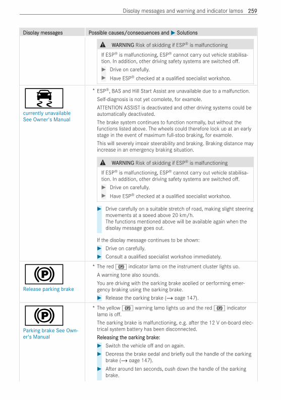
DisplaDisplay messagy messages Pes Possible causes/conseqossible causes/consequences anduences and MM SolutionsSolutions
& WWARNINGARNING Risk of skidding if ESP® is malfunctioning
If ESP® is malfunctioning, ESP® cannot carry out vehicle stabilisa-tion. In addition, other driving safety systems are switched o .# Drive on carefully.# Have ESP® checked at a quali ed specialist workshop.
÷currently unavailableSee Owner's Manual
* ESP®, BAS and Hill Start Assist are unavailable due to a malfunction.Self-diagnosis is not yet complete, for example.ATTENTION ASSIST is deactivated and other driving systems could beautomatically deactivated.The brake system continues to function normally, but without thefunctions listed above. The wheels could therefore lock up at an earlystage in the event of maximum full-stop braking, for example.This will severely impair steerability and braking. Braking distance mayincrease in an emergency braking situation.
& WWARNINGARNING Risk of skidding if ESP® is malfunctioning
If ESP® is malfunctioning, ESP® cannot carry out vehicle stabilisa-tion. In addition, other driving safety systems are switched o .# Drive on carefully.# Have ESP® checked at a quali ed specialist workshop.
# Drive carefully on a suitable stretch of road, making slight steeringmovements at a speed above 20 km/h.The functions mentioned above will be available again when thedisplay message goes out.
If the display message continues to be shown:# Drive on carefully.# Consult a quali ed specialist workshop immediately.
!Release parking brake
* The red ! indicator lamp on the instrument cluster lights up.A warning tone also sounds.You are driving with the parking brake applied or performing emer-gency braking using the parking brake.# Release the parking brake (/ page 147).
!Parking brake See Own-er's Manual
* The yellow ! warning lamp lights up and the red ! indicatorlamp is o .The parking brake is malfunctioning, e.g. a er the 12 V on-board elec-trical system battery has been disconnected.RReleasing teleasing the parhe parking brking brakake:e:# Switch the vehicle o and on again.# Depress the brake pedal and brie y pull the handle of the parking
brake (/ page 147).# A er around ten seconds, push down the handle of the parking
brake.
Display messages and warning and indicator lamps 259259
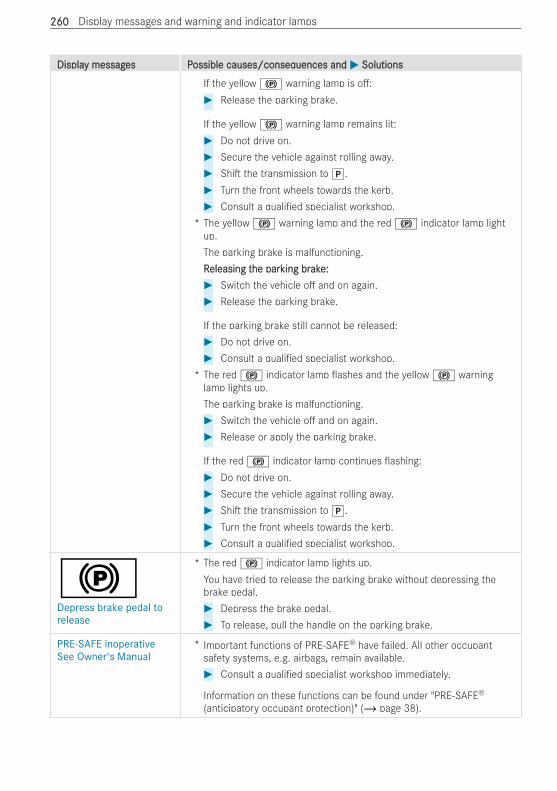
DisplaDisplay messagy messages Pes Possible causes/conseqossible causes/consequences anduences and MM SolutionsSolutions
If the yellow ! warning lamp is o :# Release the parking brake.
If the yellow ! warning lamp remains lit:# Do not drive on.# Secure the vehicle against rolling away.# Shi the transmission to j.# Turn the front wheels towards the kerb.# Consult a quali ed specialist workshop.
* The yellow ! warning lamp and the red ! indicator lamp lightup.The parking brake is malfunctioning.RReleasing teleasing the parhe parking brking brakake:e:# Switch the vehicle o and on again.# Release the parking brake.
If the parking brake still cannot be released:# Do not drive on.# Consult a quali ed specialist workshop.
* The red ! indicator lamp ashes and the yellow ! warninglamp lights up.The parking brake is malfunctioning.# Switch the vehicle o and on again.# Release or apply the parking brake.
If the red ! indicator lamp continues ashing:# Do not drive on.# Secure the vehicle against rolling away.# Shi the transmission to j.# Turn the front wheels towards the kerb.# Consult a quali ed specialist workshop.
!Depress brake pedal torelease
* The red ! indicator lamp lights up.You have tried to release the parking brake without depressing thebrake pedal.# Depress the brake pedal.# To release, pull the handle on the parking brake.
PRE-SAFE inoperativeSee Owner's Manual
* Important functions of PRE-SAFE® have failed. All other occupantsafety systems, e.g. airbags, remain available.# Consult a quali ed specialist workshop immediately.
Information on these functions can be found under "PRE‑SAFE®
(anticipatory occupant protection)" (/ page 38).
260260 Display messages and warning and indicator lamps

DisplaDisplay messagy messages Pes Possible causes/conseqossible causes/consequences anduences and MM SolutionsSolutions
6Restraint sys. malfunc-tion Consult workshop
* The restraint system is malfunctioning. In addition, the 6 warninglamp on the instrument cluster lights up.
& DDANANGERGER Risk of fatal injuries due to restraint system mal-functions
Components in the restraint system may be activated unintention-ally or not deploy as planned in an accident. In the event of anaccident, the high-voltage on-board electrical system may not bedeactivated as intended.You may su er an electric shock if you touch the damaged com-ponents of the high-voltage on-board electrical system.# Have the restraint system checked and repaired immediately
at a quali ed specialist workshop.# A er an accident, switch o the vehicle immediately.
Further information on the restraint system and its components canbe found under "Occupant safety".
6Front left malfunctionConsult workshop (exam-ple)
* The corresponding restraint system is malfunctioning. In addition, the6 warning lamp on the instrument cluster lights up.
& DDANANGERGER Risk of fatal injuries due to restraint system mal-functions
Components in the restraint system may be activated unintention-ally or not deploy as planned in an accident. In the event of anaccident, the high-voltage on-board electrical system may not bedeactivated as intended.You may su er an electric shock if you touch the damaged com-ponents of the high-voltage on-board electrical system.# Have the restraint system checked and repaired immediately
at a quali ed specialist workshop.# A er an accident, switch o the vehicle immediately.
# Consult a quali ed specialist workshop immediately.
6Left windowbag malfunc-tion Consult work-shop (example)
* The corresponding window airbag is malfunctioning. In addition, the6 warning lamp on the instrument cluster lights up.
& WWARNINGARNING Risk of injury or fatal injury due to a malfunction inthe windowbag
The windowbag might be triggered unintentionally or might not betriggered at all in the event of an accident.# Have the windowbag checked and repaired immediately at a
quali ed specialist workshop.
# Consult a quali ed specialist workshop immediately.
Display messages and warning and indicator lamps 261261
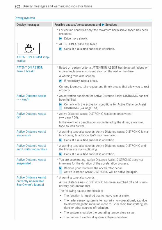
DrDriving systiving systemsems
DisplaDisplay messagy messages Pes Possible causes/conseqossible causes/consequences anduences and MM SolutionsSolutions
* For certain countries only: the maximum permissible speed has beenexceeded.# Drive more slowly.
ÀATTENTION ASSIST inop-erative
* ATTENTION ASSIST has failed.# Consult a quali ed specialist workshop.
ATTENTION ASSIST:Take a break!
* Based on certain criteria, ATTENTION ASSIST has detected fatigue orincreasing lapses in concentration on the part of the driver.A warning tone also sounds.# If necessary, take a break.
On long journeys, take regular and timely breaks that allow you to restproperly.
Active Distance Assist- - - km/h
* An activation condition for Active Distance Assist DISTRONIC has notbeen ful lled.# Comply with the activation conditions for Active Distance Assist
DISTRONIC (/ page 154).
Active Distance AssistOff
* Active Distance Assist DISTRONIC has been deactivated(/ page 154).In the event of a deactivation not initiated by the driver, a warningtone sounds as well.
Active Distance Assistinoperative
* A warning tone also sounds. Active Distance Assist DISTRONIC is mal-functioning. In addition, BAS may have failed.# Consult a quali ed specialist workshop.
Active Distance Assistand Limiter inoperative
* A warning tone also sounds. Active Distance Assist DISTRONIC andthe limiter are malfunctioning.# Consult a quali ed specialist workshop.
Active Distance Assistsuspended
* You are accelerating. Active Distance Assist DISTRONIC does notintervene for the duration of the acceleration process.# Remove your foot from the accelerator pedal.
Active Distance Assist DISTRONIC will be activated again.
Active Distance Assistcurrently unavailableSee Owner's Manual
* A warning tone also sounds.Active Distance Assist DISTRONIC has been switched o and is tem-porarily non-operational.The following causes are possible:R The function is impaired due to heavy rain or snow.R The radar sensor system is temporarily non-operational, e.g. due
to electromagnetic radiation close to TV or radio transmitting sta-tions or other sources of radiation.R The system is outside the operating temperature range.R The on-board electrical system voltage is too low.
262262 Display messages and warning and indicator lamps
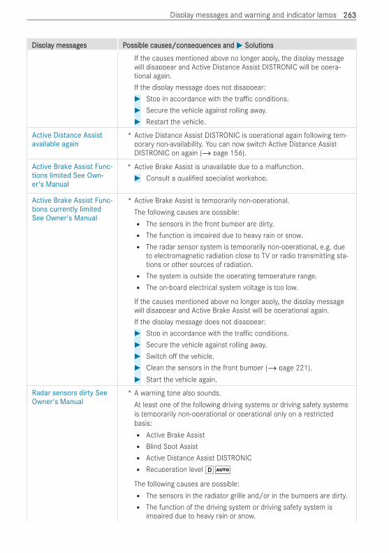
DisplaDisplay messagy messages Pes Possible causes/conseqossible causes/consequences anduences and MM SolutionsSolutions
If the causes mentioned above no longer apply, the display messagewill disappear and Active Distance Assist DISTRONIC will be opera-tional again.If the display message does not disappear:# Stop in accordance with the tra c conditions.# Secure the vehicle against rolling away.# Restart the vehicle.
Active Distance Assistavailable again
* Active Distance Assist DISTRONIC is operational again following tem-porary non-availability. You can now switch Active Distance AssistDISTRONIC on again (/ page 156).
Active Brake Assist Func-tions limited See Own-er's Manual
* Active Brake Assist is unavailable due to a malfunction.# Consult a quali ed specialist workshop.
Active Brake Assist Func-tions currently limitedSee Owner's Manual
* Active Brake Assist is temporarily non-operational.The following causes are possible:R The sensors in the front bumper are dirty.R The function is impaired due to heavy rain or snow.R The radar sensor system is temporarily non-operational, e.g. due
to electromagnetic radiation close to TV or radio transmitting sta-tions or other sources of radiation.R The system is outside the operating temperature range.R The on-board electrical system voltage is too low.
If the causes mentioned above no longer apply, the display messagewill disappear and Active Brake Assist will be operational again.If the display message does not disappear:# Stop in accordance with the tra c conditions.# Secure the vehicle against rolling away.# Switch o the vehicle.# Clean the sensors in the front bumper (/ page 221).# Start the vehicle again.
Radar sensors dirty SeeOwner's Manual
* A warning tone also sounds.At least one of the following driving systems or driving safety systemsis temporarily non-operational or operational only on a restrictedbasis:R Active Brake AssistR Blind Spot AssistR Active Distance Assist DISTRONICR Recuperation level hÃ
The following causes are possible:R The sensors in the radiator grille and/or in the bumpers are dirty.R The function of the driving system or driving safety system is
impaired due to heavy rain or snow.
Display messages and warning and indicator lamps 263263
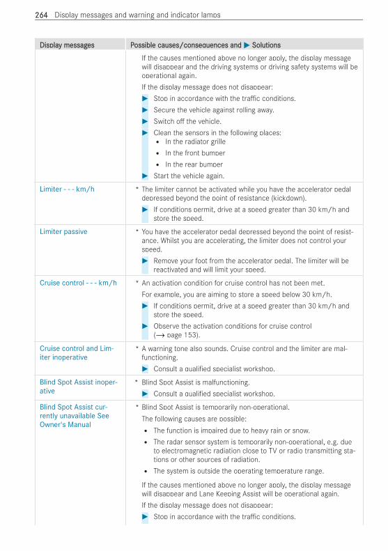
DisplaDisplay messagy messages Pes Possible causes/conseqossible causes/consequences anduences and MM SolutionsSolutions
If the causes mentioned above no longer apply, the display messagewill disappear and the driving systems or driving safety systems will beoperational again.If the display message does not disappear:# Stop in accordance with the tra c conditions.# Secure the vehicle against rolling away.# Switch o the vehicle.# Clean the sensors in the following places:R In the radiator grilleR In the front bumperR In the rear bumper
# Start the vehicle again.
Limiter - - - km/h * The limiter cannot be activated while you have the accelerator pedaldepressed beyond the point of resistance (kickdown).# If conditions permit, drive at a speed greater than 30 km/h and
store the speed.
Limiter passive * You have the accelerator pedal depressed beyond the point of resist-ance. Whilst you are accelerating, the limiter does not control yourspeed.# Remove your foot from the accelerator pedal. The limiter will be
reactivated and will limit your speed.
Cruise control - - - km/h * An activation condition for cruise control has not been met.For example, you are aiming to store a speed below 30 km/h.# If conditions permit, drive at a speed greater than 30 km/h and
store the speed.# Observe the activation conditions for cruise control
(/ page 153).
Cruise control and Lim-iter inoperative
* A warning tone also sounds. Cruise control and the limiter are mal-functioning.# Consult a quali ed specialist workshop.
Blind Spot Assist inoper-ative
* Blind Spot Assist is malfunctioning.# Consult a quali ed specialist workshop.
Blind Spot Assist cur-rently unavailable SeeOwner's Manual
* Blind Spot Assist is temporarily non-operational.The following causes are possible:R The function is impaired due to heavy rain or snow.R The radar sensor system is temporarily non-operational, e.g. due
to electromagnetic radiation close to TV or radio transmitting sta-tions or other sources of radiation.R The system is outside the operating temperature range.
If the causes mentioned above no longer apply, the display messagewill disappear and Lane Keeping Assist will be operational again.If the display message does not disappear:# Stop in accordance with the tra c conditions.
264264 Display messages and warning and indicator lamps
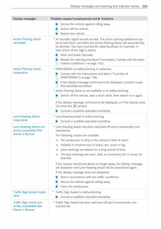
DisplaDisplay messagy messages Pes Possible causes/conseqossible causes/consequences anduences and MM SolutionsSolutions# Secure the vehicle against rolling away.# Switch o the vehicle.# Restart the vehicle.
Active Parking Assistcancelled
* An acoustic signal sounds as well. The active parking assistance sys-tems have been cancelled and Active Parking Assist will automaticallybe aborted. You have touched the steering wheel, for example, orhave driven at too high a speed.# Steer and brake manually.# Repeat the parking procedure if necessary. Comply with the deac-
tivation conditions (/ page 163).
Active Parking Assistinoperative
* PARKTRONIC is malfunctioning or defective.# Comply with the instructions and aids in "Function of
PARKTRONIC"(/ page 158).# If the display message continues to be displayed, consult a quali-
ed specialist workshop:* Active Parking Assist is not available or is malfunctioning.# Switch o the vehicle, wait a short while, then switch it on again.
If the display message continues to be displayed, or if the display doesnot show the j symbol:# Consult a quali ed specialist workshop.
Lane Keeping Assistinoperative
* Lane Keeping Assist is malfunctioning.# Consult a quali ed specialist workshop.
Lane Keeping Assist cur-rently unavailable SeeOwner's Manual
* Lane Keeping Assist has been switched o and is temporarily non-operational.The following causes are possible:R The windscreen is dirty in the camera's eld of vision.R Visibility is impaired due to heavy rain, snow or fog.R Lane markings are absent for a long period of time.R The lane markings are worn, dark or covered by dirt or snow, for
example.
If the causes mentioned above no longer apply, the display messagewill disappear and Lane Keeping Assist will be operational again.If the display message does not disappear:# Stop in accordance with the tra c conditions.# Secure the vehicle against rolling away.# Clean the windscreen.
Traffic Sign Assist inoper-ative
* Tra c Sign Assist is malfunctioning.# Consult a quali ed specialist workshop.
Traffic Sign Assist cur-rently unavailable SeeOwner's Manual
* Tra c Sign Assist has been switched o and is temporarily non-operational.
Display messages and warning and indicator lamps 265265
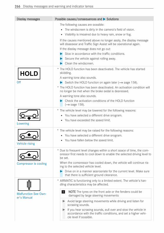
DisplaDisplay messagy messages Pes Possible causes/conseqossible causes/consequences anduences and MM SolutionsSolutions
The following causes are possible:R The windscreen is dirty in the camera's eld of vision.R Visibility is impaired due to heavy rain, snow or fog.
If the causes mentioned above no longer apply, the display messagewill disappear and Tra c Sign Assist will be operational again.If the display message does not go out:# Stop in accordance with the tra c conditions.# Secure the vehicle against rolling away.# Clean the windscreen.
ëOff
* The HOLD function has been deactivated. The vehicle has startedskidding.A warning tone also sounds.# Switch the HOLD function on again later (/ page 158).
* The HOLD function has been deactivated. An activation condition willno longer be met when the brake pedal is depressed.A warning tone also sounds.# Check the activation conditions of the HOLD function
(/ page 158).
ÂLowering
* The vehicle level may be lowered for the following reasons:R You have selected a di erent drive program.R You have exceeded the speed limit.
ÁVehicle rising
* The vehicle level may be raised for the following reasons:R You have selected a di erent drive program.R You have fallen below the speed limit.
ÁCompressor is cooling
* Due to frequent level changes within a short space of time, the com-pressor rst needs to cool down to enable the selected driving level tobe set.When the compressor has cooled down, the vehicle will continue ris-ing to the selected vehicle level.# Drive on in a manner appropriate for the current level. Make sure
that there is su cient ground clearance.
äMalfunction See Own-er's Manual
* AIRMATIC is functioning only to a limited extent. The vehicle's han-dling characteristics may be a ected.
* NNOOTETE The tyres on the front axle or the fenders could bedamaged by large steering movements
# Avoid large steering movements while driving and listen forscraping sounds.
# If you hear scraping sounds, pull over and stop the vehicle inaccordance with the tra c conditions, and set a higher vehi-cle level if possible.
266266 Display messages and warning and indicator lamps
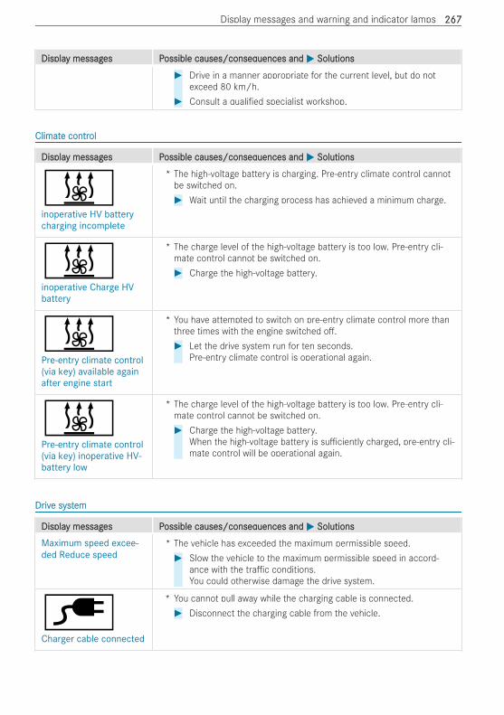
DisplaDisplay messagy messages Pes Possible causes/conseqossible causes/consequences anduences and MM SolutionsSolutions# Drive in a manner appropriate for the current level, but do not
exceed 80 km/h.# Consult a quali ed specialist workshop.
ClimatClimate contre controlol
DisplaDisplay messagy messages Pes Possible causes/conseqossible causes/consequences anduences and MM SolutionsSolutions
&inoperative HV batterycharging incomplete
* The high-voltage battery is charging. Pre-entry climate control cannotbe switched on.# Wait until the charging process has achieved a minimum charge.
&inoperative Charge HVbattery
* The charge level of the high-voltage battery is too low. Pre-entry cli-mate control cannot be switched on.# Charge the high-voltage battery.
&Pre-entry climate control(via key) available againafter engine start
* You have attempted to switch on pre-entry climate control more thanthree times with the engine switched o .# Let the drive system run for ten seconds.
Pre-entry climate control is operational again.
&Pre-entry climate control(via key) inoperative HV-battery low
* The charge level of the high-voltage battery is too low. Pre-entry cli-mate control cannot be switched on.# Charge the high-voltage battery.
When the high-voltage battery is su ciently charged, pre-entry cli-mate control will be operational again.
DrDrivive syste systemem
DisplaDisplay messagy messages Pes Possible causes/conseqossible causes/consequences anduences and MM SolutionsSolutions
Maximum speed excee-ded Reduce speed
* The vehicle has exceeded the maximum permissible speed.# Slow the vehicle to the maximum permissible speed in accord-
ance with the tra c conditions.You could otherwise damage the drive system.
èCharger cable connected
* You cannot pull away while the charging cable is connected.# Disconnect the charging cable from the vehicle.
Display messages and warning and indicator lamps 267267
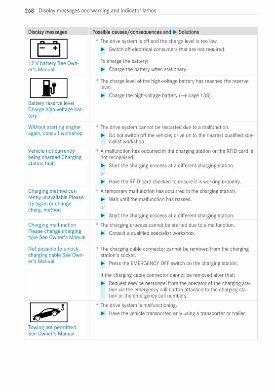
DisplaDisplay messagy messages Pes Possible causes/conseqossible causes/consequences anduences and MM SolutionsSolutions
#12 V battery See Own-er's Manual
* The drive system is o and the charge level is too low.# Switch o electrical consumers that are not required.
To charge the battery:# Charge the battery when stationary.
wBattery reserve levelCharge high-voltage bat-tery
* The charge level of the high-voltage battery has reached the reservelevel.# Charge the high-voltage battery (/ page 138).
Without starting engineagain, consult workshop
* The drive system cannot be restarted due to a malfunction.# Do not switch o the vehicle; drive on to the nearest quali ed spe-
cialist workshop.
Vehicle not currentlybeing charged Chargingstation fault
* A malfunction has occurred in the charging station or the RFID card isnot recognised.# Start the charging process at a di erent charging station.or# Have the RFID card checked to ensure it is working properly.
Charging method cur-rently unavailable Pleasetry again or changecharg. method
* A temporary malfunction has occurred in the charging station.# Wait until the malfunction has passed.or# Start the charging process at a di erent charging station.
Charging malfunctionPlease change chargingtype See Owner's Manual
* The charging process cannot be started due to a malfunction.# Consult a quali ed specialist workshop.
Not possible to unlockcharging cable See Own-er's Manual
* The charging cable connector cannot be removed from the chargingstation's socket.# Press the EMERGENCY OFF switch on the charging station.
If the charging cable connector cannot be removed a er that:# Request service personnel from the operator of the charging sta-
tion via the emergency call button attached to the charging sta-tion or the emergency call numbers.
uTowing not permittedSee Owner's Manual
* The drive system is malfunctioning.# Have the vehicle transported only using a transporter or trailer.
268268 Display messages and warning and indicator lamps
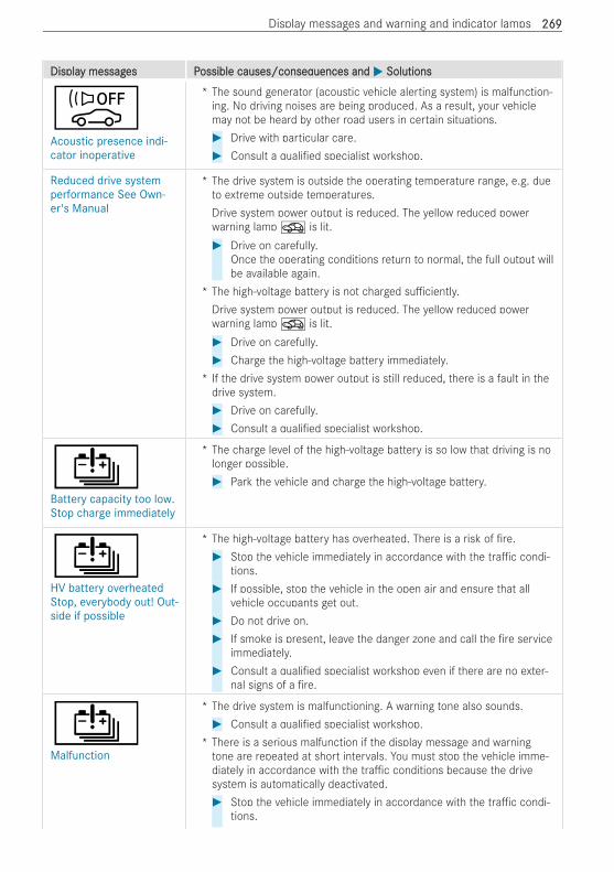
DisplaDisplay messagy messages Pes Possible causes/conseqossible causes/consequences anduences and MM SolutionsSolutions
òAcoustic presence indi-cator inoperative
* The sound generator (acoustic vehicle alerting system) is malfunction-ing. No driving noises are being produced. As a result, your vehiclemay not be heard by other road users in certain situations.# Drive with particular care.# Consult a quali ed specialist workshop.
Reduced drive systemperformance See Own-er's Manual
* The drive system is outside the operating temperature range, e.g. dueto extreme outside temperatures.Drive system power output is reduced. The yellow reduced powerwarning lampO is lit.# Drive on carefully.
Once the operating conditions return to normal, the full output willbe available again.
* The high-voltage battery is not charged su ciently.Drive system power output is reduced. The yellow reduced powerwarning lampO is lit.# Drive on carefully.# Charge the high-voltage battery immediately.
* If the drive system power output is still reduced, there is a fault in thedrive system.# Drive on carefully.# Consult a quali ed specialist workshop.
ÛBattery capacity too low.Stop charge immediately
* The charge level of the high-voltage battery is so low that driving is nolonger possible.# Park the vehicle and charge the high-voltage battery.
ÛHV battery overheatedStop, everybody out! Out-side if possible
* The high-voltage battery has overheated. There is a risk of re.# Stop the vehicle immediately in accordance with the tra c condi-
tions.# If possible, stop the vehicle in the open air and ensure that all
vehicle occupants get out.# Do not drive on.# If smoke is present, leave the danger zone and call the re service
immediately.# Consult a quali ed specialist workshop even if there are no exter-
nal signs of a re.
ÛMalfunction
* The drive system is malfunctioning. A warning tone also sounds.# Consult a quali ed specialist workshop.
* There is a serious malfunction if the display message and warningtone are repeated at short intervals. You must stop the vehicle imme-diately in accordance with the tra c conditions because the drivesystem is automatically deactivated.# Stop the vehicle immediately in accordance with the tra c condi-
tions.
Display messages and warning and indicator lamps 269269
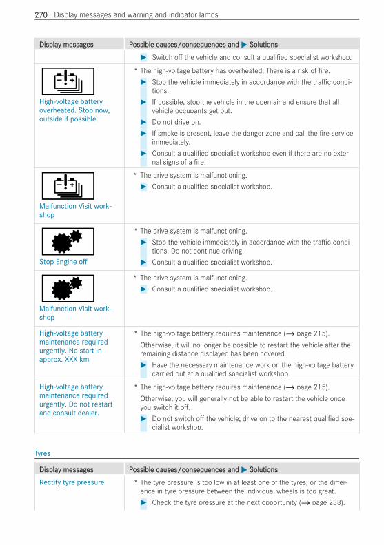
DisplaDisplay messagy messages Pes Possible causes/conseqossible causes/consequences anduences and MM SolutionsSolutions# Switch o the vehicle and consult a quali ed specialist workshop.
ÛHigh-voltage batteryoverheated. Stop now,outside if possible.
* The high-voltage battery has overheated. There is a risk of re.# Stop the vehicle immediately in accordance with the tra c condi-
tions.# If possible, stop the vehicle in the open air and ensure that all
vehicle occupants get out.# Do not drive on.# If smoke is present, leave the danger zone and call the re service
immediately.# Consult a quali ed specialist workshop even if there are no exter-
nal signs of a re.
ÛMalfunction Visit work-shop
* The drive system is malfunctioning.# Consult a quali ed specialist workshop.
dStop Engine off
* The drive system is malfunctioning.# Stop the vehicle immediately in accordance with the tra c condi-
tions. Do not continue driving!# Consult a quali ed specialist workshop.
dMalfunction Visit work-shop
* The drive system is malfunctioning.# Consult a quali ed specialist workshop.
High-voltage batterymaintenance requiredurgently. No start inapprox. XXX km
* The high-voltage battery requires maintenance (/ page 215).Otherwise, it will no longer be possible to restart the vehicle a er theremaining distance displayed has been covered.# Have the necessary maintenance work on the high-voltage battery
carried out at a quali ed specialist workshop.
High-voltage batterymaintenance requiredurgently. Do not restartand consult dealer.
* The high-voltage battery requires maintenance (/ page 215).Otherwise, you will generally not be able to restart the vehicle onceyou switch it o .# Do not switch o the vehicle; drive on to the nearest quali ed spe-
cialist workshop.
TTyryreses
DisplaDisplay messagy messages Pes Possible causes/conseqossible causes/consequences anduences and MM SolutionsSolutions
Rectify tyre pressure * The tyre pressure is too low in at least one of the tyres, or the di er-ence in tyre pressure between the individual wheels is too great.# Check the tyre pressure at the next opportunity (/ page 238).
270270 Display messages and warning and indicator lamps
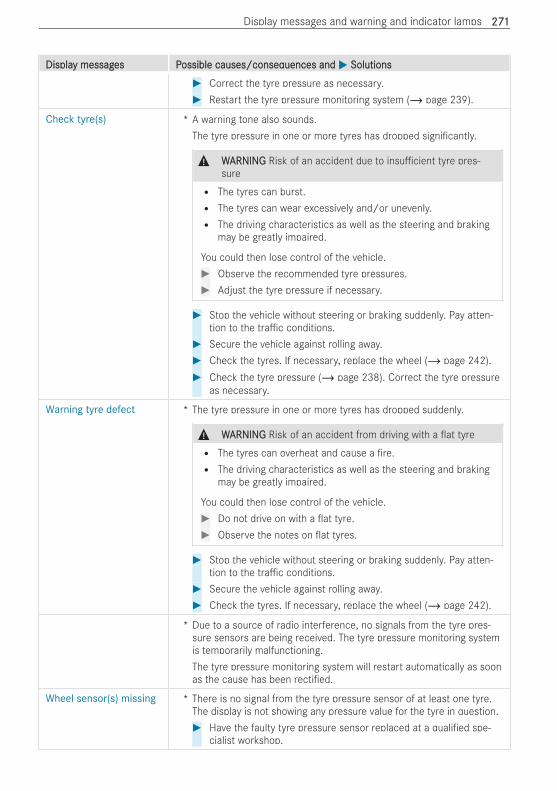
DisplaDisplay messagy messages Pes Possible causes/conseqossible causes/consequences anduences and MM SolutionsSolutions# Correct the tyre pressure as necessary.# Restart the tyre pressure monitoring system (/ page 239).
Check tyre(s) * A warning tone also sounds.The tyre pressure in one or more tyres has dropped signi cantly.
& WWARNINGARNING Risk of an accident due to insu cient tyre pres-sure
R The tyres can burst.R The tyres can wear excessively and/or unevenly.R The driving characteristics as well as the steering and braking
may be greatly impaired.
You could then lose control of the vehicle.# Observe the recommended tyre pressures.# Adjust the tyre pressure if necessary.
# Stop the vehicle without steering or braking suddenly. Pay atten-tion to the tra c conditions.
# Secure the vehicle against rolling away.# Check the tyres. If necessary, replace the wheel (/ page 242).# Check the tyre pressure (/ page 238). Correct the tyre pressure
as necessary.
Warning tyre defect * The tyre pressure in one or more tyres has dropped suddenly.
& WWARNINGARNING Risk of an accident from driving with a at tyreR The tyres can overheat and cause a re.R The driving characteristics as well as the steering and braking
may be greatly impaired.
You could then lose control of the vehicle.# Do not drive on with a at tyre.# Observe the notes on at tyres.
# Stop the vehicle without steering or braking suddenly. Pay atten-tion to the tra c conditions.
# Secure the vehicle against rolling away.# Check the tyres. If necessary, replace the wheel (/ page 242).
* Due to a source of radio interference, no signals from the tyre pres-sure sensors are being received. The tyre pressure monitoring systemis temporarily malfunctioning.The tyre pressure monitoring system will restart automatically as soonas the cause has been recti ed.
Wheel sensor(s) missing * There is no signal from the tyre pressure sensor of at least one tyre.The display is not showing any pressure value for the tyre in question.# Have the faulty tyre pressure sensor replaced at a quali ed spe-
cialist workshop.
Display messages and warning and indicator lamps 271271
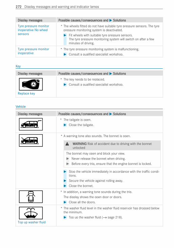
DisplaDisplay messagy messages Pes Possible causes/conseqossible causes/consequences anduences and MM SolutionsSolutions
Tyre pressure monitorinoperative No wheelsensors
* The wheels tted do not have suitable tyre pressure sensors. The tyrepressure monitoring system is deactivated.# Fit wheels with suitable tyre pressure sensors.
The tyre pressure monitoring system will switch on a er a fewminutes of driving.
Tyre pressure monitorinoperative
* The tyre pressure monitoring system is malfunctioning.# Consult a quali ed specialist workshop.
KKeeyy
DisplaDisplay messagy messages Pes Possible causes/conseqossible causes/consequences anduences and MM SolutionsSolutions
ÂReplace key
* The key needs to be replaced.# Consult a quali ed specialist workshop.
VVehicleehicle
DisplaDisplay messagy messages Pes Possible causes/conseqossible causes/consequences anduences and MM SolutionsSolutions
Ò* The tailgate is open.# Close the tailgate.
Ó* A warning tone also sounds. The bonnet is open.
& WWARNINGARNING Risk of accident due to driving with the bonnetunlocked
The bonnet may open and block your view.# Never release the bonnet when driving.# Before every trip, ensure that the engine bonnet is locked.
# Stop the vehicle immediately in accordance with the tra c condi-tions.
# Secure the vehicle against rolling away.# Close the bonnet.
C* In addition, a warning tone sounds during the trip.
The display shows the open door or doors.# Close all the doors.
¥Top up washer fluid
* The washer uid level in the washer uid reservoir has dropped belowthe minimum.# Top up the washer uid (/ page 218).
272272 Display messages and warning and indicator lamps
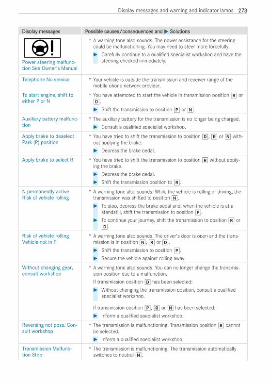
DisplaDisplay messagy messages Pes Possible causes/conseqossible causes/consequences anduences and MM SolutionsSolutions
ÐPower steering malfunc-tion See Owner's Manual
* A warning tone also sounds. The power assistance for the steeringcould be malfunctioning. You may need to steer more forcefully.# Carefully continue to a quali ed specialist workshop and have the
steering checked immediately.
Telephone No service * Your vehicle is outside the transmission and receiver range of themobile phone network provider.
To start engine, shift toeither P or N
* You have attempted to start the vehicle in transmission position k orh.# Shi the transmission to position j or i.
Auxiliary battery malfunc-tion
* The auxiliary battery for the transmission is no longer being charged.# Consult a quali ed specialist workshop.
Apply brake to deselectPark (P) position
* You have tried to shi the transmission to position h, k or i with-out applying the brake.# Depress the brake pedal.
Apply brake to select R * You have tried to shi the transmission to position k without apply-ing the brake.# Depress the brake pedal.# Shi the transmission position to k.
N permanently activeRisk of vehicle rolling
* A warning tone also sounds. While the vehicle is rolling or driving, thetransmission was shi ed to position i.# To stop, depress the brake pedal and, when the vehicle is at a
standstill, shi the transmission to position j.# To continue your journey, shi the transmission to position k or
h.
Risk of vehicle rollingVehicle not in P
* A warning tone also sounds. The driver's door is open and the trans-mission is in position i, k or h.# Shi the transmission to position j.# Secure the vehicle against rolling away.
Without changing gear,consult workshop
* A warning tone also sounds. You can no longer change the transmis-sion position due to a malfunction.If transmission position h has been selected:# Without changing the transmission position, consult a quali ed
specialist workshop.
If transmission position j, k or i has been selected:# Inform a quali ed specialist workshop.
Reversing not poss. Con-sult workshop
* The transmission is malfunctioning. Transmission position k cannotbe selected.# Inform a quali ed specialist workshop.
Transmission Malfunc-tion Stop
* The transmission is malfunctioning. The transmission automaticallyswitches to neutral i.
Display messages and warning and indicator lamps 273273
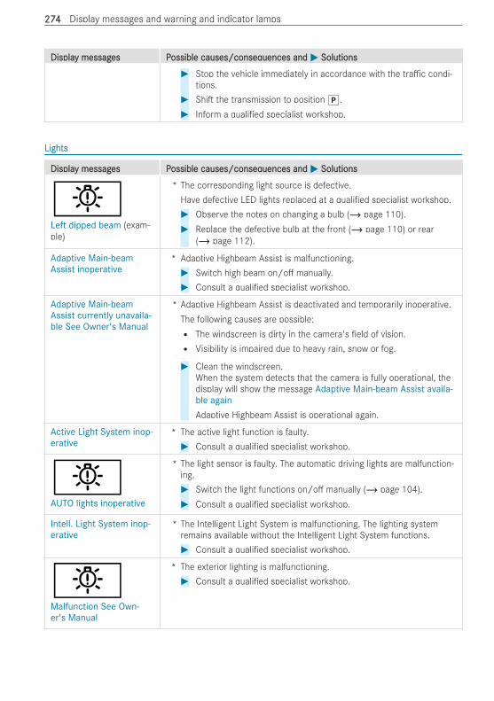
DisplaDisplay messagy messages Pes Possible causes/conseqossible causes/consequences anduences and MM SolutionsSolutions# Stop the vehicle immediately in accordance with the tra c condi-
tions.# Shi the transmission to position j.# Inform a quali ed specialist workshop.
LightsLights
DisplaDisplay messagy messages Pes Possible causes/conseqossible causes/consequences anduences and MM SolutionsSolutions
bLeft dipped beam (exam-ple)
* The corresponding light source is defective.Have defective LED lights replaced at a quali ed specialist workshop.# Observe the notes on changing a bulb (/ page 110).# Replace the defective bulb at the front (/ page 110) or rear
(/ page 112).
Adaptive Main-beamAssist inoperative
* Adaptive Highbeam Assist is malfunctioning.# Switch high beam on/o manually.# Consult a quali ed specialist workshop.
Adaptive Main-beamAssist currently unavaila-ble See Owner's Manual
* Adaptive Highbeam Assist is deactivated and temporarily inoperative.The following causes are possible:R The windscreen is dirty in the camera's eld of vision.R Visibility is impaired due to heavy rain, snow or fog.
# Clean the windscreen.When the system detects that the camera is fully operational, thedisplay will show the message Adaptive Main-beam Assist availa-ble againAdaptive Highbeam Assist is operational again.
Active Light System inop-erative
* The active light function is faulty.# Consult a quali ed specialist workshop.
bAUTO lights inoperative
* The light sensor is faulty. The automatic driving lights are malfunction-ing.# Switch the light functions on/o manually (/ page 104).# Consult a quali ed specialist workshop.
Intell. Light System inop-erative
* The Intelligent Light System is malfunctioning. The lighting systemremains available without the Intelligent Light System functions.# Consult a quali ed specialist workshop.
bMalfunction See Own-er's Manual
* The exterior lighting is malfunctioning.# Consult a quali ed specialist workshop.
274274 Display messages and warning and indicator lamps
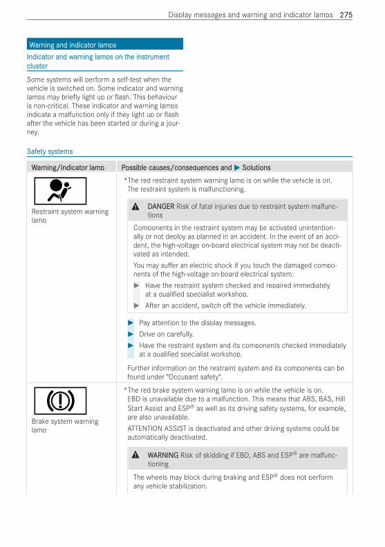
WWararning and indicatning and indicator lamor lampspsIndicatIndicator and wor and wararning lamning lamps on tps on the inshe instrtrumentumentclustclusterer
Some systems will perform a self-test when thevehicle is switched on. Some indicator and warninglamps may brie y light up or ash. This behaviouris non-critical. These indicator and warning lampsindicate a malfunction only if they light up or asha er the vehicle has been started or during a jour-ney.
SafeSafety systty systemsems
WWararning/indicatning/indicator lamp Por lamp Possible causes/conseqossible causes/consequences anduences and MM SolutionsSolutions
6Restraint system warninglamp
*The red restraint system warning lamp is on while the vehicle is on.The restraint system is malfunctioning.
& DDANANGERGER Risk of fatal injuries due to restraint system malfunc-tions
Components in the restraint system may be activated unintention-ally or not deploy as planned in an accident. In the event of an acci-dent, the high-voltage on-board electrical system may not be deacti-vated as intended.You may su er an electric shock if you touch the damaged compo-nents of the high-voltage on-board electrical system.# Have the restraint system checked and repaired immediately
at a quali ed specialist workshop.# A er an accident, switch o the vehicle immediately.
# Pay attention to the display messages.# Drive on carefully.# Have the restraint system and its components checked immediately
at a quali ed specialist workshop.
Further information on the restraint system and its components can befound under "Occupant safety".
JBrake system warninglamp
*The red brake system warning lamp is on while the vehicle is on.EBD is unavailable due to a malfunction. This means that ABS, BAS, HillStart Assist and ESP® as well as its driving safety systems, for example,are also unavailable.ATTENTION ASSIST is deactivated and other driving systems could beautomatically deactivated.
& WWARNINGARNING Risk of skidding if EBD, ABS and ESP® are malfunc-tioning
The wheels may block during braking and ESP® does not performany vehicle stabilization.
Display messages and warning and indicator lamps 275275
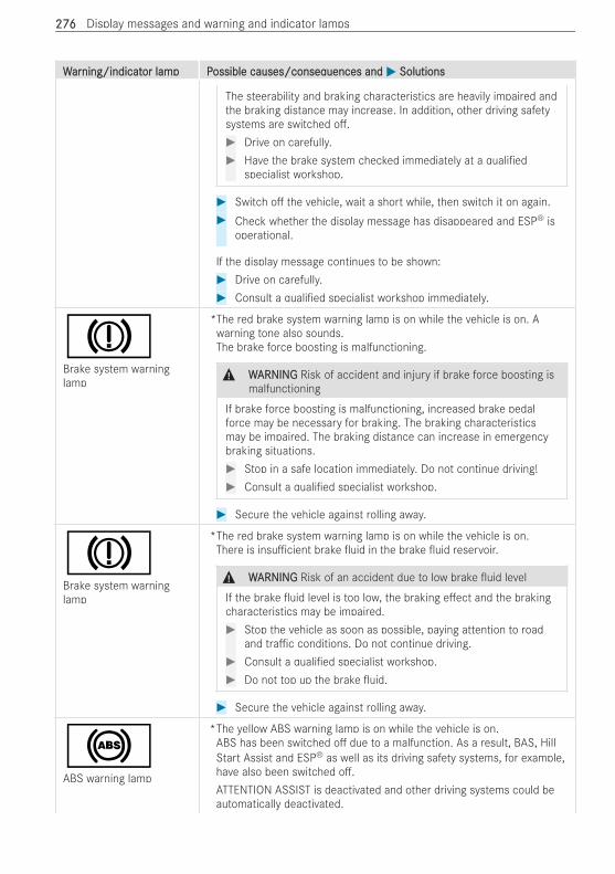
WWararning/indicatning/indicator lamp Por lamp Possible causes/conseqossible causes/consequences anduences and MM SolutionsSolutions
The steerability and braking characteristics are heavily impaired andthe braking distance may increase. In addition, other driving safetysystems are switched o .# Drive on carefully.# Have the brake system checked immediately at a quali ed
specialist workshop.
# Switch o the vehicle, wait a short while, then switch it on again.# Check whether the display message has disappeared and ESP® is
operational.
If the display message continues to be shown:# Drive on carefully.# Consult a quali ed specialist workshop immediately.
JBrake system warninglamp
*The red brake system warning lamp is on while the vehicle is on. Awarning tone also sounds.The brake force boosting is malfunctioning.
& WWARNINGARNING Risk of accident and injury if brake force boosting ismalfunctioning
If brake force boosting is malfunctioning, increased brake pedalforce may be necessary for braking. The braking characteristicsmay be impaired. The braking distance can increase in emergencybraking situations.# Stop in a safe location immediately. Do not continue driving!# Consult a quali ed specialist workshop.
# Secure the vehicle against rolling away.
JBrake system warninglamp
*The red brake system warning lamp is on while the vehicle is on.There is insu cient brake uid in the brake uid reservoir.
& WWARNINGARNING Risk of an accident due to low brake uid level
If the brake uid level is too low, the braking e ect and the brakingcharacteristics may be impaired.# Stop the vehicle as soon as possible, paying attention to road
and tra c conditions. Do not continue driving.# Consult a quali ed specialist workshop.# Do not top up the brake uid.
# Secure the vehicle against rolling away.
!ABS warning lamp
*The yellow ABS warning lamp is on while the vehicle is on.ABS has been switched o due to a malfunction. As a result, BAS, HillStart Assist and ESP® as well as its driving safety systems, for example,have also been switched o .ATTENTION ASSIST is deactivated and other driving systems could beautomatically deactivated.
276276 Display messages and warning and indicator lamps
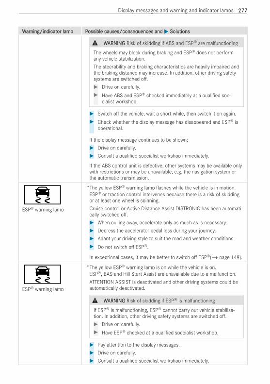
WWararning/indicatning/indicator lamp Por lamp Possible causes/conseqossible causes/consequences anduences and MM SolutionsSolutions
& WWARNINGARNING Risk of skidding if ABS and ESP® are malfunctioning
The wheels may block during braking and ESP® does not performany vehicle stabilization.The steerability and braking characteristics are heavily impaired andthe braking distance may increase. In addition, other driving safetysystems are switched o .# Drive on carefully.# Have ABS and ESP® checked immediately at a quali ed spe-
cialist workshop.
# Switch o the vehicle, wait a short while, then switch it on again.# Check whether the display message has disappeared and ESP® is
operational.
If the display message continues to be shown:# Drive on carefully.# Consult a quali ed specialist workshop immediately.
If the ABS control unit is defective, other systems may be available onlywith restrictions or may be unavailable, e.g. the navigation system orthe automatic transmission.
÷ESP® warning lamp
*The yellow ESP® warning lamp ashes while the vehicle is in motion.ESP® or traction control intervenes because there is a risk of skiddingor at least one wheel is spinning.Cruise control or Active Distance Assist DISTRONIC has been automati-cally switched o .# When pulling away, accelerate only as much as is necessary.# Depress the accelerator pedal less during your journey.# Adapt your driving style to suit the road and weather conditions.# Do not switch o ESP®.
In exceptional cases, it may be better to switch o ESP®(/ page 149).
÷ESP® warning lamp
*The yellow ESP® warning lamp is on while the vehicle is on.ESP®, BAS and Hill Start Assist are unavailable due to a malfunction.ATTENTION ASSIST is deactivated and other driving systems could beautomatically deactivated.
& WWARNINGARNING Risk of skidding if ESP® is malfunctioning
If ESP® is malfunctioning, ESP® cannot carry out vehicle stabilisa-tion. In addition, other driving safety systems are switched o .# Drive on carefully.# Have ESP® checked at a quali ed specialist workshop.
# Pay attention to the display messages.# Drive on carefully.# Consult a quali ed specialist workshop immediately.
Display messages and warning and indicator lamps 277277
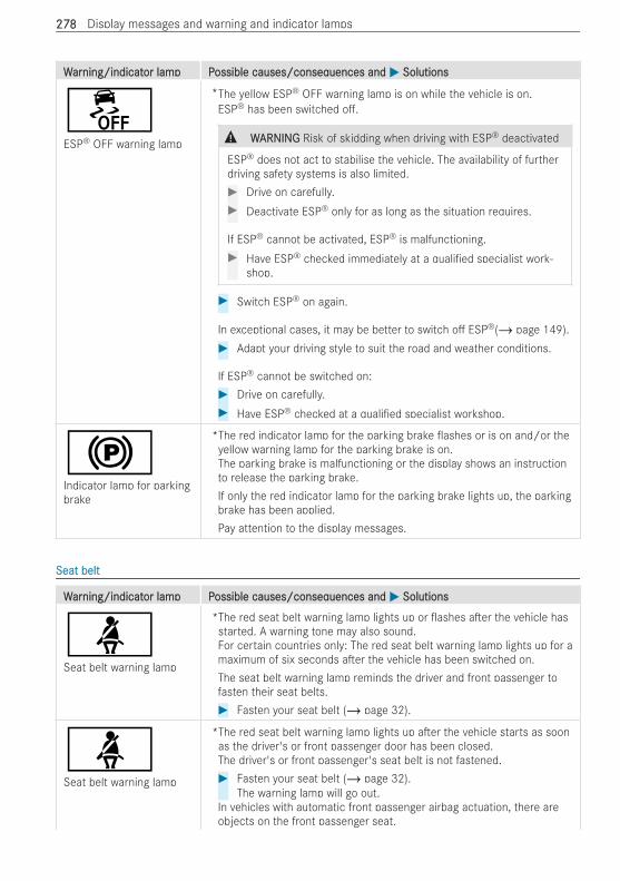
WWararning/indicatning/indicator lamp Por lamp Possible causes/conseqossible causes/consequences anduences and MM SolutionsSolutions
åESP® OFF warning lamp
*The yellow ESP® OFF warning lamp is on while the vehicle is on.ESP® has been switched o .
& WWARNINGARNING Risk of skidding when driving with ESP® deactivated
ESP® does not act to stabilise the vehicle. The availability of furtherdriving safety systems is also limited.# Drive on carefully.# Deactivate ESP® only for as long as the situation requires.
If ESP® cannot be activated, ESP® is malfunctioning.# Have ESP® checked immediately at a quali ed specialist work-
shop.
# Switch ESP® on again.
In exceptional cases, it may be better to switch o ESP®(/ page 149).# Adapt your driving style to suit the road and weather conditions.
If ESP® cannot be switched on:# Drive on carefully.# Have ESP® checked at a quali ed specialist workshop.
!Indicator lamp for parkingbrake
*The red indicator lamp for the parking brake ashes or is on and/or theyellow warning lamp for the parking brake is on.The parking brake is malfunctioning or the display shows an instructionto release the parking brake.If only the red indicator lamp for the parking brake lights up, the parkingbrake has been applied.Pay attention to the display messages.
Seat beltSeat belt
WWararning/indicatning/indicator lamp Por lamp Possible causes/conseqossible causes/consequences anduences and MM SolutionsSolutions
üSeat belt warning lamp
*The red seat belt warning lamp lights up or ashes a er the vehicle hasstarted. A warning tone may also sound.For certain countries only: The red seat belt warning lamp lights up for amaximum of six seconds a er the vehicle has been switched on.The seat belt warning lamp reminds the driver and front passenger tofasten their seat belts.# Fasten your seat belt (/ page 32).
üSeat belt warning lamp
*The red seat belt warning lamp lights up a er the vehicle starts as soonas the driver's or front passenger door has been closed.The driver's or front passenger's seat belt is not fastened.# Fasten your seat belt (/ page 32).
The warning lamp will go out.In vehicles with automatic front passenger airbag actuation, there areobjects on the front passenger seat.
278278 Display messages and warning and indicator lamps
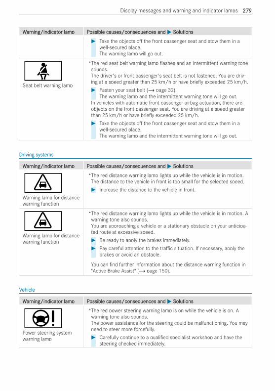
WWararning/indicatning/indicator lamp Por lamp Possible causes/conseqossible causes/consequences anduences and MM SolutionsSolutions# Take the objects o the front passenger seat and stow them in a
well-secured place.The warning lamp will go out.
üSeat belt warning lamp
*The red seat belt warning lamp ashes and an intermittent warning tonesounds.The driver's or front passenger's seat belt is not fastened. You are driv-ing at a speed greater than 25 km/h or have brie y exceeded 25 km/h.# Fasten your seat belt (/ page 32).
The warning lamp and the intermittent warning tone will go out.In vehicles with automatic front passenger airbag actuation, there areobjects on the front passenger seat. You are driving at a speed greaterthan 25 km/h or have brie y exceeded 25 km/h.# Take the objects o the front passenger seat and stow them in a
well-secured place.The warning lamp and the intermittent warning tone will go out.
DrDriving systiving systemsems
WWararning/indicatning/indicator lamp Por lamp Possible causes/conseqossible causes/consequences anduences and MM SolutionsSolutions
·Warning lamp for distancewarning function
*The red distance warning lamp lights up while the vehicle is in motion.The distance to the vehicle in front is too small for the selected speed.# Increase the distance to the vehicle in front.
·Warning lamp for distancewarning function
*The red distance warning lamp lights up while the vehicle is in motion. Awarning tone also sounds.You are approaching a vehicle or a stationary obstacle on your anticipa-ted route at excessive speed.# Be ready to apply the brakes immediately.# Pay careful attention to the tra c situation. If necessary, apply the
brakes or avoid an obstacle.
You can nd further information about the distance warning function in"Active Brake Assist" (/ page 150).
VVehicleehicle
WWararning/indicatning/indicator lamp Por lamp Possible causes/conseqossible causes/consequences anduences and MM SolutionsSolutions
ÐPower steering systemwarning lamp
*The red power steering warning lamp is on while the vehicle is on. Awarning tone also sounds.The power assistance for the steering could be malfunctioning. You mayneed to steer more forcefully.# Carefully continue to a quali ed specialist workshop and have the
steering checked immediately.
Display messages and warning and indicator lamps 279279
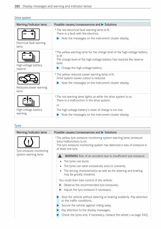
DrDrivive syste systemem
WWararning/indicatning/indicator lamp Por lamp Possible causes/conseqossible causes/consequences anduences and MM SolutionsSolutions
#Electrical fault warninglamp
*The red electrical fault warning lamp is lit.There is a fault with the electrics.# Note the messages on the instrument cluster display.
ÝHigh-voltage batteryreserve
*The yellow warning lamp for the charge level of the high-voltage batteryis lit.The charge level of the high-voltage battery has reached the reservelevel.# Charge the high-voltage battery.
OReduced power warninglamp
*The yellow reduced power warning lamp is lit.Drive system power output is reduced.# Note the messages on the instrument cluster display.
ÛHigh-voltage batterywarning
*The red warning lamp lights up while the drive system is on.There is a malfunction in the drive system.orThe high-voltage battery's state of charge is too low.# Note the messages on the instrument cluster display.
TTyryreses
WWararning/indicatning/indicator lamp Por lamp Possible causes/conseqossible causes/consequences anduences and MM SolutionsSolutions
hTyre pressure monitoringsystem warning lamp
*The yellow tyre pressure monitoring system warning lamp (pressureloss/malfunction) is on.The tyre pressure monitoring system has detected a loss of pressure inat least one tyre.
& WWARNINGARNING Risk of an accident due to insu cient tyre pressureR The tyres can burst.R The tyres can wear excessively and/or unevenly.R The driving characteristics as well as the steering and braking
may be greatly impaired.
You could then lose control of the vehicle.# Observe the recommended tyre pressures.# Adjust the tyre pressure if necessary.
# Stop the vehicle without steering or braking suddenly. Pay attentionto the tra c conditions.
# Secure the vehicle against rolling away.# Pay attention to the display messages.# Check the tyres and, if necessary, replace the wheel (/ page 242).
280280 Display messages and warning and indicator lamps
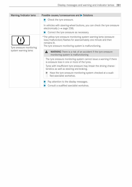
WWararning/indicatning/indicator lamp Por lamp Possible causes/conseqossible causes/consequences anduences and MM SolutionsSolutions# Check the tyre pressure.
In vehicles with steering-wheel buttons, you can check the tyre pressureelectronically (/ page 238).# Correct the tyre pressure as necessary.
hTyre pressure monitoringsystem warning lamp
*The yellow tyre pressure monitoring system warning lamp (pressureloss/malfunction) ashes for approximately one minute and thenremains lit.The tyre pressure monitoring system is malfunctioning.
& WWARNINGARNING There is a risk of an accident if the tyre pressuremonitoring system is malfunctioning
The tyre pressure monitoring system cannot issue a warning if thereis pressure loss in one or more of the tyres.Tyres with insu cient tyre pressure may impair the driving charac-teristics as well as steering and braking.# Have the tyre pressure monitoring system checked at a quali-
ed specialist workshop.
# Pay attention to the display messages.# Consult a quali ed specialist workshop.
Display messages and warning and indicator lamps 281281
1, 2, 3 ...1, 2, 3 ...12 V batt12 V batteryery
see On-board electrical system bat-tery (12 V)
12 V socket12 V socketsee Socket (12 V)
230 V socket230 V socketsee Socket (230 V)
360° Camera360° CameraButton................................................ 163Care................................................... 221Function............................................. 161Opening the camera cover (revers-ing camera)........................................ 161Switching automatic operationon/o (reversing camera)................... 163
AAABS (anti-locABS (anti-lock brk braking systaking system)em).................. 149AAccident and Brccident and Breakdoeakdown Managwn Managementement
Mercedes me connect........................ 185AAcouscoustic loctic lockingking vvereri cationi cation signalsignal
Activating/deactivating......................... 51AAcouscoustic prtic presence indicatesence indicator (soundor (soundggenereneratator)or)
Notes................................................. 129AActivctive Bre Brakake Assiste Assist
Function/notes................................... 150Switching on/o ................................. 152
AActivctive Diste Distance Assisance Assist DISt DISTRTRONICONICCalling up a speed.............................. 156Displays.............................................. 157Function............................................. 154Increasing/decreasing speed.............. 156Selecting............................................ 156Storing a speed................................... 156Switching o /deactivating.................. 156Switching on/activating...................... 156System limitations............................... 154
AActivctive light functione light function.................................. 106AActivctive Pe Pararking Assistking Assist
Exiting a parking space....................... 165Function............................................. 163Parking............................................... 164System limits...................................... 163
AAdapdaptivtive bre brakake lightse lights................................. 152AAdapdaptivtive cre cruise contruise controlol
see Active Distance Assist DISTRONICAAdapdaptivtive Highbeam Assiste Highbeam Assist
Function............................................. 107
Switching on/o ................................. 108AAdapdaptivtive Highbeam Assise Highbeam Assist Plust Plus
Function............................................. 108Switching on/o ................................. 109
AAdd-on eqdd-on equipmentuipment....................................... 17AAdd-on eqdd-on equipment guidelinesuipment guidelines...................... 17AAdjusdjusting tting the air vhe air ventsents............................... 125A erA er-sales-sales serservicevice
see ASSYST PLUS service interval displayAir suspensionAir suspension
see AIRMATICAirAir-r-recirecirculation buttculation buttonon
Convenience opening/closing............. 124AirbagAirbag
Activation............................................. 30Automatic front passenger airbag shuto ..................................................... 35Front airbag (driver, co-driver)............... 33Installation locations............................. 33Overview............................................... 33PASSENGER AIR BAG indicator lamp..... 36Protection impaired............................... 34Protection provided............................... 33Side airbag........................................... 33Window airbag...................................... 33
AIRMAAIRMATICTICSuspension......................................... 137
AlarAlarm systm systememsee ATA (Anti-The Alarm system)
Ambient lightingAmbient lightingSetting (MBUX multimedia system)...... 109
AndrAndroid Aoid Autoutosee Smartphone integration
AnimalsAnimalsPets in the vehicle................................. 50
Anti-locAnti-lock brk braking systaking systememsee ABS (anti-lock braking system)
Anti-skid cAnti-skid chainshainssee Snow chains
Anti-tAnti-thehe alaralarm systm systememsee ATA (Anti-The Alarm system)
Anti-tAnti-thehe protprotectionectionImmobiliser........................................... 67
Anti-tAnti-thehe protprotectionectionsee ATA (Anti-The Alarm system)
AnticipatAnticipatorory occupant proty occupant protectionectionsee PRE-SAFE® (anticipatory occu-pant protection)
282282 Index
AnticipatAnticipatorory occupant proty occupant protection syection sys-s-ttemem
see PRE-SAFE® (anticipatory occu-pant protection)
Apple CarPlayApple CarPlay®®see Smartphone integration
AqAquaplaninguaplaning.............................................. 133ArArmrmrestest
Stowage compartment.......................... 96AshtrayAshtray
Rear passenger compartment............. 101Use (front centre console)................... 101
AssistAssistance systance systemsemssee Driving safety system
AssistAssistant displaant display (on-boary (on-board comd computputer)er)....... 175ASSYSTASSYST
see ASSYST PLUS service interval displayASSYSASSYST PLT PLUS serUS service intvice interverval displayal display
Displaying the service due date........... 215Function/notes................................... 215Non-operational times with the bat-tery disconnected............................... 216Regular maintenance work.................. 215Special service requirements.............. 215
ATATAA (Anti-(Anti-TheThe AlarAlarm systm system)em)Activating/deactivating interior pro-tection.................................................. 68Function............................................... 67Interior motion sensor function............. 68Priming and deactivating....................... 67Switching tow-away protection on/o ... 68Tow-away protection function................ 68
AAttttacachmentshments............................................... 17AATTENTION ASSISTTTENTION ASSIST
Function............................................. 166Switching on/o ................................. 166System limits...................................... 166
AAttttention assistention assistantantsee ATTENTION ASSIST
AAututhorhorised wised workorkshopshopsee Quali ed specialist workshop
AAututomatic co-dromatic co-driviver airbager airbag shutshutooFunction of co-driver airbag shuto ....... 35PASSENGER AIR BAG indicator lamp..... 36
AAututomatic distomatic distance adjustmentance adjustmentsee Active Distance Assist DISTRONIC
AAututomatic dromatic driving lightsiving lights............................. 104AAututomatic measuromatic measureses a era er an accidentan accident......... 38
AAuxiliaruxiliary climaty climate contre contrololNotes................................................. 126
Axle loadAxle load................................................... 248
BBBacBack supportk support
see Lumbar support (4-way)BBAS (BrAS (Brakake Assise Assist Systt System)em)........................ 149BattBatteryery
Key....................................................... 52Notes (vehicle).................................... 227
BattBatteryerysee High-voltage battery
BattBatterery (high-vy (high-voltoltagage on-boare on-board electrd electricalicalsystsystem)em)
see High-voltage batteryBeltBelt
see Seat beltBelt wBelt wararningning
see Seat beltBlind SpoBlind Spot Assistt Assist
Function............................................. 168Rear Cross Tra c Alert....................... 168Switching on/o ................................. 168System limits...................................... 168
BoBottle holderttle holder............................................. 100BrBrakeake
ABS (anti-lock braking system)............ 149Activating/deactivating the HOLDfunction.............................................. 158Active Brake Assist............................. 150Adaptive brake lights........................... 152BAS (Brake Assist System).................. 149Braking with the parking brake............ 133Downhill gradient................................ 133Driving instructions............................. 133EBD (Electronic Brakeforce Distribu-tion).................................................... 150Heavy and light loads.......................... 133HOLD function.................................... 158Limited braking e ect (salt-treatedroads)................................................. 133New brake disks and brakepads.......... 133New/replaced brake disks andbrakepads........................................... 132Running-in notes................................. 132Wet roadway....................................... 133
BrBrakake Assise Assist Systt Systememsee BAS (Brake Assist System)
BrBrakake Assiste Assistanceancesee BAS (Brake Assist System)
Index 283283
BrBrakakee uiduidNotes................................................. 249
BrBrakakefefororce Disce DistrtributionibutionEBD (Electronic Brakeforce Distribu-tion).................................................... 150
BrBrakakesesPost-collision brake............................... 38
BrBrakakesessee Recuperation
BrBreakdoeakdownwnChanging a wheel................................ 242Towing away....................................... 231Towing away (with front axle raised).... 231Transporting the vehicle...................... 232Vehicle does not start......................... 233
BrBreakdoeakdownwnsee Flat tyre
ButtButtons on tons on the sthe steereering wheeling wheel....................... 8
CCCameraCamera
Information......................................... 148CameraCamera
see 360° Camerasee Reversing camera
Car wCar washashsee Care
Car wCar wash (carash (care)e)......................................... 218CarCar-t-to-Xo-X-Communication-Communication
Displaying hazard warnings................. 197CareCare
Automatic car wash............................ 218Carpet................................................ 222Display............................................... 222Exterior lighting................................... 221High-pressure cleaner......................... 219Instrument cluster............................... 222Matt nish.......................................... 220Paint................................................... 220Plastic trim......................................... 222Real wood/trim elements................... 222Reversing camera............................... 221Reversing camera/360° Camera........ 221Roof lining.......................................... 222Seat belt............................................. 222Seat cover.......................................... 222Sensors.............................................. 221Vehicle socket.................................... 221Washing by hand................................. 220Wheels/rims....................................... 221Windows............................................. 221
Wiper blades....................................... 221CarCarpepet (cart (care)e)............................................ 222CarrCarrier systier systemsems
Notes................................................. 213CentrCentre consolee console
Between the seats (overview)................ 12Lower section (overview)....................... 11Middle section (overview)...................... 10Stowage compartment.......................... 96Top (overview)......................................... 9
Changing a bulbChanging a bulbsee Changing bulbs
Changing a wheelChanging a wheelLowering the vehicle........................... 244Preparing............................................ 242Raising the vehicle.............................. 242Removing a wheel............................... 243
Changing bulbsChanging bulbsLight bulb types halogen headlamps.... 110Notes................................................. 110
Changing lamChanging lampspssee Changing bulbs
ChargCharge leve level displayel display.................................. 174CharChargingging
Charging cable connector emer-gency release..................................... 145Ending the charging process............... 145Indicator lamps on vehicle socket........ 140Notes - charging station (mode 3)....... 142Notes - fast charging station (mode4)....................................................... 142Notes - mains socket (mode 2)............ 141Notes - wallbox (mode 3)..................... 142Notes on charging the high-voltagebattery................................................ 138Notes on the high-voltage battery........ 228On-board electrical system battery(12 V)................................................. 229Starting the charging process............. 143
CharCharging prging predictionediction................................... 139CharCharging tging the batthe batteryery
For departure time.............................. 139Setting the maximum charge level....... 139Setting the maximum charging cur-rent.................................................... 139
Child safeChild safety lockty lockHinged windows.................................... 50
Child safeChild safety locty lock (doork (doors)s).............................. 49Child seatChild seat
Approval categories.............................. 42Attaching (notes).................................. 42
284284 Index
Basic instructions................................. 38Front passenger seat (notes)................. 48Front passenger seat (without auto-matic airbag shuto )............................. 47ISOFIX ( tting)...................................... 44Notes on risks and dangers................... 39Recommendations for childrestraint systems.................................. 41Seats suitable for belt-secured childrestraint systems.................................. 45Seats suitable for ISOFIX childrestraint systems.................................. 43Securing on the co-driver seat............... 48Securing on the rear seat...................... 47Top Tether............................................. 45
ChildrChildrenenAvoiding dangers in the vehicle............. 39Basic instructions................................. 38
CigCigarearetttte lighte lightererFront centre console........................... 101
CleaningCleaningsee Care
ClimatClimate contre contrololActivating/deactivating....................... 122Adjusting the air vents........................ 125Air distribution settings....................... 123Automatic control............................... 123Auxiliary climate control...................... 126Demisting the windscreen................... 124Demisting windows............................. 124Energy-saving use............................... 121Notes................................................. 121Setting the air distribution................... 123Setting the air ow............................... 123Setting the temperature...................... 123Switching air-recirculation modeon/o ................................................ 124Switching the A/C function on/o ...... 122Switching the rear window heateron/o ................................................ 125Switching the reset function on/o(control panel).................................... 123TEMPMATIC operating unit.................. 120THERMOTRONIC control panel............ 121
Co-drCo-driviver airbager airbag shutshutoosee Automatic co-driver airbag shuto
CocCockpit (ovkpit (overervieview)w)........................................ 6Combination switchCombination switch
see Headlamp ashingsee High beamsee Turn signal light
ComfComforort rt rear bencear bench seath seatAdjusting the seat backrest................... 79
ConstConstant headlamant headlamp modep modesee Daytime running lights
ConvConvenience opening/closingenience opening/closing................... 124ConvConverersionssions................................................ 17CoolantCoolant
Checking level.................................... 217Topping up.......................................... 217
Coolant (drCoolant (drivive syste system)em)Notes................................................. 250
CopCopyryrightight.................................................... 28CorCornernering lighting light.......................................... 106CrCrosswind Assistosswind Assist
Function/notes................................... 150CrCruise contruise controlol
Activating........................................... 153Calling up a speed.............................. 153Deactivating....................................... 153Function............................................. 152Increasing/decreasing speed.............. 153Lever.................................................. 153Requirements:.................................... 153Selecting............................................ 153Setting the speed................................ 153Storing a speed................................... 153System limits...................................... 152
Cup holdersCup holdersRear................................................... 100Switching the cooling/heating func-tion on/o .......................................... 100
DDDashboarDashboard lightingd lighting
see Instrument lightingDatData acqa acquisition (vuisition (vehicle)ehicle)............................ 25DatData prota protection rection rightsights
Data storage......................................... 28DatData sta stororageage
Data protection rights........................... 28Electronic control units......................... 25Service provider.................................... 27
DaDaytime rytime running lightsunning lightsActivating/deactivating....................... 104Replacing light sources....................... 110
DeactivDeactivating tating the alarhe alarm (ATm (ATA)A)....................... 67DealerDealershipship
see Quali ed specialist workshopDeclarDeclaration of confation of conforormitymity
Electromagnetic compatibility............... 19Importer addresses............................... 22Jack...................................................... 23
Index 285285
Speci c absorption rate........................ 19Wireless vehicle components................ 19
DemisDemisting windscrting windscreeneen............................... 124DeparDeparturture timee time
Auxiliary climate control...................... 126DesDestination entrytination entry
Entering a POI or address.................... 195DiagnosDiagnostics connectiontics connection............................... 23Dialling a phone number (on-boardDialling a phone number (on-boardcomcomputputer)er)................................................. 179DigitDigital inside ral inside rearearvieview mirrw mirroror..................... 117DigitDigital Owner's Manualal Owner's Manual............................... 15Dipped beamDipped beam
Setting for abroad (symmetrical)......... 104DIRECT SELECT levDIRECT SELECT leverer
Engaging drive position....................... 136Engaging neutral................................. 136Engaging park position automatically... 136Engaging reverse gear......................... 136Function............................................. 135Selecting park position....................... 136Transmission position display.............. 135Transmission positions........................ 135
DisplayDisplayAvailable power................................... 174
DisplaDisplay (cary (care)e)............................................ 222DisplaDisplay (insy (instrtrument clustument cluster)er)....................... 173DisplaDisplay (multimedia systy (multimedia system)em)
Home screen...................................... 188DisplaDisplay messagey message
Calling up (on-board computer)........... 254Notes................................................. 254
DistDistance adjusance adjustmenttmentsee Active Distance Assist DISTRONIC
DistDistance contrance contrololsee Active Distance Assist DISTRONIC
DistDistance wance wararning functionning functionsee Active Brake Assist
DISDISTRTRONICONICsee Active Distance Assist DISTRONIC
DoorDoorActivating/deactivating the auto-matic locking mechanism...................... 55Locking (emergency key)....................... 55Opening (from the inside)...................... 53Unlocking (emergency key)................... 55Unlocking (from the inside)................... 53
Door contrDoor control panelol panel...................................... 14DrDrivive pre progrogram displayam display............................... 137
DrDrivive pre progrogramsamssee DYNAMIC SELECT
DrDrivive syste systememManually switching o ......................... 129
DrDriving civing charharactactererisistics (unusual)tics (unusual)................ 235DrDriving insiving instrtructionsuctions
Brakes................................................ 133Downhill gradient................................ 133Driving in winter.................................. 134General driving tips............................. 132Limited braking e ect (salt-treatedroads)................................................. 133New brake disks and brakepads.......... 133Parking brake...................................... 133Running-in notes................................. 132Subjecting brakes to a load................. 133Wet roadway....................................... 133
DrDriving lightsiving lightssee Automatic driving lights
DrDriving notiving notesesTransport by rail.................................. 133
DrDriving safeiving safety systty systememABS (anti-lock braking system)............ 149Adaptive brake lights........................... 152BAS (Brake Assist System).................. 149Cameras............................................. 148EBD (Electronic Brakeforce Distribu-tion).................................................... 150ESP® Crosswind Assist....................... 150Overview............................................ 149Radar and ultrasonic sensors.............. 148Responsibility...................................... 148
DrDriving systiving systememsee 360° Camerasee Active Distance Assist DISTRONICsee Active Parking Assistsee AIRMATICsee ATTENTION ASSISTsee Blind Spot Assistsee Cruise controlsee Driving safety systemsee HOLD functionsee Lane Keeping Assistsee Limitersee PARKTRONICsee Reversing camerasee Tra c Sign Assist
DrDriving tipsiving tipsAquaplaning........................................ 133Driving abroad (symmetrical dippedbeam)................................................. 104Driving on ooded roads..................... 133Driving on wet roads........................... 133
286286 Index
DrDriving tipsiving tipssee Recuperation
DrowDrowsiness detsiness detectionectionsee ATTENTION ASSIST
DDYNYNAMIC SELECTAMIC SELECTDrive program display......................... 137Drive programs................................... 136Function............................................. 136Operating........................................... 137Selecting the drive program................ 137
EEEASYEASY-ENTR-ENTRY easy entrY easy entry and ey and exit fxit featureeature
Folding the EASY-ENTRY sectionforwards/back (rear bench seat)........... 78Using (luxury rear seat)......................... 85Using (rear bench seat)......................... 78Using (rear seat)................................... 82
EASYEASY-PAC-PACK tK tailgailgateateNotes.................................................... 60Opening and closing............................. 60
EBD (ElectrEBD (Electronic Bronic Brakakefefororce Disce Distrtribution)ibution).... 150ECECO displayO display
Activating........................................... 135Function............................................. 134
ElectrElectric modeic modeNotes................................................. 129
ElectrElectric paric parking brking brakeakeApplying automatically........................ 147Applying or releasing manually............ 147Emergency braking............................. 147Notes................................................. 146Releasing automatically....................... 147
ElectrElectric sliding dooric sliding doorFunction............................................... 56Opening/closing (from the inside)......... 57Opening/closing (with the key)............. 58Opening/closing from the outside......... 58Opening/closing with the door handle... 58Opening/closing with the key................ 58Problems.............................................. 59Programming the key............................ 58Programming the key button................. 58Resetting.............................................. 59
ElectrElectric sliding dooric sliding doorsee Electric sliding door
ElectrElectromagneomagnetic comtic compatibilitypatibilityDeclaration of conformity...................... 19
ElectrElectronic Stonic Stability Prability Progrogramamsee ESP® (Electronic Stability Program)
ElectrElectronicsonics................................................ 247
EmergEmergencyencyFire extinguisher................................. 224First-aid kit (so -sided)....................... 224Removing the warning triangle............ 224Safety vest.......................................... 224Setting up the warning triangle............ 224
EmergEmergency brency brakingakingElectric parking brake......................... 147
EmergEmergency callency callsee Mercedes-Benz emergency call system
EmergEmergency keyency keyLocking a door...................................... 55Removing/inserting.............................. 52Unlocking a door................................... 55
EmergEmergency rency releaseeleasesee Vehicle's high-voltage electrical system
EmergEmergencyency shutshutoosee Vehicle's high-voltage electrical system
EnerEnergy consumpgy consumptiontionDisplaying the average........................ 175
EnerEnergygy owowDisplaying........................................... 175
EnerEnergygy owow displaydisplayDisplaying........................................... 134Function/notes................................... 134
EngEngaging draging drivive position (tre position (transmission)ansmission)....... 136EngEngaging revaging revererse gse gearear............................... 136EngineEngine
Engine number.................................... 248Engine electrEngine electronics (notonics (noteses.......................... 247Engine numberEngine number.......................................... 248EnEnvirvironmentonmental protal protectionection
Take-back of end-of-life vehicles............ 16ESC (ElectrESC (Electronic Stonic Stability Contrability Control)ol)
see ESP® (Electronic Stability Program)ESPESP®®
Crosswind Assist................................. 150ESPESP®® (Electr(Electronic Stonic Stability Prability Progrogram)am)
Activating/deactivating....................... 150Function/notes................................... 149
ExtExtererior lightingior lightingCare................................................... 221
ExtExtererior lightingior lightingsee Lights
FFFFatigue detatigue detectionection
see ATTENTION ASSIST
Index 287287
FFault messageault messagesee Display message
FFilling up tilling up the windscrhe windscreen ween washing syashing sys-s-ttemem........................................................... 218FFirire ee extinguisherxtinguisher....................................... 224FFirsirst-aid kitt-aid kit (so -sided)(so -sided)............................. 224Flat tyreFlat tyre
Changing a wheel................................ 242Notes................................................. 227
FFog light (eog light (extxtended rended rangange)e)......................... 106FFoil covoil covereringing
Radar and ultrasonic sensors.............. 148FFolding tolding tableable
Fitting/removing................................... 97Moving................................................. 97Using.................................................... 99
FFororeign treign tripipSymmetrical dipped beam................... 104
FrFreeee so wso wareare.............................................. 28FrFreqequenciesuencies
Mobile phone...................................... 247Two-way radio..................................... 247
FrFront airbag (dront airbag (driviverer, co-dr, co-driviver)er)..................... 33FrFront seatsont seats
Rotating................................................ 74FrFront wheel archont wheel arch
Fitting/removing the cover.................. 110Wing................................................... 110
FFusesuses........................................................ 233
GGGenerGeneral operal operating perating permit number (EC)mit number (EC)...... 248Genuine parGenuine partsts............................................. 16Glasses comGlasses comparpartmenttment................................. 97GlovGlove come comparpartmenttment
Opening/closing................................... 96
HHHandbrHandbrakake (electre (electrical)ical)
see Electric parking brakeHazarHazard wd wararning light systning light systemem
Switching on/o ................................. 105Head rHead resestrtraintaint
Adjusting electrically............................. 93Adjusting mechanically......................... 92
HeadlamHeadlampp ashingashing.................................... 105Help callHelp call
see Mercedes-Benz emergency call system
High beamHigh beamAdaptive Highbeam Assist Plus............ 108Replacing light sources....................... 110Switching on/o ................................. 105
High-prHigh-pressuressure cleaner (care cleaner (care)e)..................... 219High-vHigh-voltoltagage batte batteryery
Charging cable connector emer-gency release..................................... 145Charging duration............................... 251Charging prediction............................ 139Connection types................................ 251Ending the charging process............... 145Energy content................................... 251Energy ow display............................. 134Function/notes................................... 228General notes on charging.................. 138Indicator lamps on vehicle socket........ 140Notes on charging (charging station,mode 3).............................................. 142Notes on charging (fast chargingstation, mode 4)................................. 142Notes on charging (mains socket,mode 2).............................................. 141Notes on charging (wallbox, mode 3)... 142Starting the charging process............. 143Type................................................... 251Voltage types...................................... 251
HighbeamHighbeamAdaptive Highbeam Assist................... 107
Hill StHill Starart Assistt Assist......................................... 157HingHinged windowsed windows
Child safety lock................................... 50HOLD functionHOLD function
Notes................................................. 158Switching on/o ................................. 158
Home scrHome screen (media displaeen (media display)y).................... 188
IIIdenti cationIdenti cation plateplate
Engine................................................ 248Vehicle............................................... 248
Ignition keyIgnition keysee Key
Ignition lockIgnition lock.............................................. 131ImmobiliserImmobiliser................................................. 67ImImplied wplied warrarranty (vanty (vehicle)ehicle)............................ 25ImImportporter addrer addressesesses
Wireless components............................ 22IndicatIndicator lamor lampsps
see Warning/indicator lamps
288288 Index
InstInstallationsallations................................................ 17InsInstrtrument clustument clusterer
Adjusting the lighting.......................... 174Available power display....................... 174Care................................................... 222Charge level display............................ 174Displays.............................................. 171Information on the display................... 173Notes on warning/indicator lamps...... 275Overview of displays........................... 171Power display...................................... 171Warning/indicator lamps overview.......... 7
InsInstrtrument lightingument lighting.................................... 174InsInstrtrument panelument panel
see Cockpit (overview)IntIntelligelligent Light Systent Light Systemem
Active light function............................ 106Adaptive Highbeam Assist................... 107Cornering light.................................... 106Motorway mode.................................. 106Overview............................................ 106Switching on/o ................................. 107
IntIntererior lightingior lightingAmbient lighting.................................. 109Replacing light sources....................... 113Setting................................................ 109Switch-o delay time.......................... 110
IntIntererior moior motion sensortion sensorFunction............................................... 68Switching on/o ................................... 68
iPhoneiPhone®®
see Smartphone integrationISOFIX cISOFIX child seat anchild seat anchorhor
Fitting................................................... 44Seats suitable for attaching................... 43
JJJackJack
Declaration of conformity...................... 23Storage location.................................. 233Stowage compartment in the rear....... 234
JumJump-stp-starart connectiont connection............................... 229
KKKKeeyy
Acoustic locking veri cation signal........ 51Battery................................................. 52Convenience opening.......................... 124Emergency key...................................... 52Fastening to keyring.............................. 52Functions.............................................. 51
Overview............................................... 51Pre-entry climate control..................... 126Problem................................................ 53Programming the button for theelectric sliding door.............................. 58Starting the vehicle............................. 131Unlocking setting.................................. 52
KKeey positionsy positions............................................ 131
LLLane KLane Keeping Assisteeping Assist
Activating/deactivating....................... 169Function............................................. 169Sensitivity........................................... 169
LanguageLanguageNotes................................................. 193Setting................................................ 193
Lashing pointsLashing pointsInformation......................................... 252Overview............................................ 209
LevLevel contrel contrololsee AIRMATIC
Light switcLight switch (ovh (overervieview)w).............................. 104LightingLighting
see LightsLightsLights
Active light function............................ 106Adaptive Highbeam Assist................... 107Adaptive Highbeam Assist Plus............ 108Adjusting the instrument lighting......... 174Automatic driving lights....................... 104Combination switch............................ 105Cornering light.................................... 106Driving abroad (symmetrical dippedbeam)................................................. 104Fog light (extended range)................... 106Hazard warning light........................... 105Headlamp ashing.............................. 105High beam.......................................... 105Intelligent Light System....................... 106Light switch........................................ 104Low beam........................................... 104Motorway mode.................................. 106Parking lights...................................... 104Range................................................. 105Rear fog light...................................... 104Responsibility with lighting systems..... 104Setting the exterior lighting switch-o delay time...................................... 109Standing lights.................................... 104Switching the Intelligent Light Sys-tem on/o .......................................... 107
Index 289289
Switching the surround lightingon/o ................................................ 109Turn signal light................................... 105
LimitLimitererActivating........................................... 153Calling up a speed.............................. 153Deactivating....................................... 153Function............................................. 153Increasing/decreasing speed.............. 153Kickdown............................................ 153Lever.................................................. 153Requirements:.................................... 153Selecting............................................ 153Setting the speed................................ 153Storing a speed................................... 153Switching o /deactivating.................. 156Switching on/activating...................... 156
Limiting tLimiting the opening angle (the opening angle (tailgailgatate)e)............ 61LINLINGUAGUATRTRONICONIC
Operable functions............................. 189Starting.............................................. 189
LivLivee TrTra ca c InfInforormationmationSwitching the tra c informationdisplay on........................................... 197
Load comLoad comparpartment and rtment and rear intear intererioriorlamlampsps
Replacing light sources....................... 113Load disLoad distrtributionibution....................................... 207Load protLoad protection netection net................................... 210Load securLoad securinging
Fitting and removing tie-down eyes..... 209Lashing points.................................... 209Notes................................................. 208Removing/ tting a loadprotection net..................................... 210
Load securLoad securing aiding aidLuggage compartment partition.......... 211Removing/ tting a loadprotection net..................................... 210
Loading guidelinesLoading guidelines.................................... 206LocLocking/unlocking/unlockingking
Activating/deactivating the auto-matic locking mechanism...................... 55Opening the door (from the inside)........ 53Unlocking the door (from the inside)...... 53
LoLow beamw beamReplacing light sources....................... 110Switching on/o ................................. 104
LLugguggagage come comparpartment partment partitiontitionFolding up/down................................ 211Removing/ tting................................. 211
Stowage compartments...................... 211LLumbar supporumbar support (4-wat (4-way)y).............................. 73LLuxuruxury ry rear seatear seat
Adjusting electrically............................. 86EASY-ENTRY easy entry and exitfeature.................................................. 85Moving................................................. 87
MMM+S tyrM+S tyreses................................................. 235MaintMaintenanceenance
Notes................................................. 215MaintMaintenanceenance
see ASSYST PLUS service interval displayMalfunctionMalfunction
Restraint system................................... 29MapMap
Displaying online map contents........... 197Displaying weather information........... 197Moving............................................... 197Selecting the map orientation............. 197Setting the map scale......................... 197Switching motorway informationon/o ................................................ 197
MattMatt nishnish (cleaning ins(cleaning instrtructions)uctions).............. 220Maximum grMaximum gross voss vehicle wehicle weighteight.................. 248Maximum speedMaximum speed
see LimiterMBUX multimedia systMBUX multimedia systemem
Notes................................................. 187Operating the touchscreen.................. 188Overview............................................ 187Restoring (factory settings)................. 193
MediaMediaMenu (on-board computer)................. 178Operating media playback................... 178Overview of the functions and sym-bols.................................................... 202Selecting a media source.................... 178
Media displayMedia displayHome screen...................................... 188Operating........................................... 188
Media modeMedia modeConnecting Bluetooth® audio equip-ment................................................... 203
Medical aidsMedical aids............................................... 25MemorMemory function (seat)y function (seat)............................... 73Menu (on-boarMenu (on-board comd computputer)er)
Assistant display................................. 175Media................................................. 178
290290 Index
Navigation.......................................... 176Radio.................................................. 178Service............................................... 175Settings.............................................. 180Telephone........................................... 179
Menu ovMenu overervieview (on-boarw (on-board comd computputer)er)......... 175MerMercedes me appcedes me app
Calling up services.............................. 186Calling up your user account............... 185Unlinking the user account.................. 186
MerMercedes me Appscedes me AppsInformation......................................... 185
MerMercedes me callscedes me callsArranging a service appointment......... 183Calling the Mercedes-Benz cus-tomer centre....................................... 182Calling the Mercedes-Benz cus-tomer centre a er automatic acci-dent or breakdown detection.............. 182Consenting to data transfer................. 183Information......................................... 182Transferred data................................. 183
MerMercedes me connectcedes me connectAccident and Breakdown Manage-ment................................................... 185Information......................................... 184Making a call via the overhead con-trol panel............................................ 182Transferred data................................. 185
MerMercedes-Benz emergcedes-Benz emergency call systency call systememAutomatic emergency call................... 225Information......................................... 225Information about data transfer........... 226Manual emergency call....................... 226Overview............................................ 225
MerMercedes-Benz sercedes-Benz service centrevice centresee Quali ed specialist workshop
MessagMessage (displae (display section of ty section of the inshe instrtru-u-ment displament display)y)
see Display messageMessagMessage memorye memory...................................... 254MirrMirrorsors
Digital inside rearview mirror............... 117MirrMirrorsors
see Outside mirrorsMobile phoneMobile phone
Frequencies........................................ 247Transmission output (maximum).......... 247
Mobile phoneMobile phonesee Mobile phonesee Smartphone integration
see TelephoneModel serModel seriesies
see Vehicle identi cation plateMotMotorwaorway modey mode........................................ 106Mounting a loadMounting a load........................................ 206
NNNNaavigvigationation
Activating........................................... 193Displaying/hiding the menu................ 193Menu (on-board computer)................. 176Overview............................................ 194
NaNavigvigationationsee Destination entrysee Mapsee Route
NaNavigvigation insation instrtructions (on-boaructions (on-board com-d com-putputer)er)........................................................ 176NaNavigvigation witation with Electrh Electric Intic Intelligelligenceence
see Route
OOOccupant safeOccupant safetyty
see Airbagsee Automatic co-driver airbag shutosee Automatic measures a er an accidentsee Child seatsee Pets in the vehiclesee Post-collision brakesee PRE-SAFE® (anticipatory occu-pant protection)see Restraint systemsee Seat belt
On-boarOn-board comd computputererAssistant display menu........................ 175Digital speedometer............................ 175Display............................................... 173Displaying the energy ow................... 175Displaying the service due date........... 215Media menu........................................ 178Menu navigation................................. 176Menu overview.................................... 175Operation........................................... 172Overview............................................ 172Radio menu........................................ 178Service menu...................................... 175Settings menu..................................... 180Showing the range.............................. 175Telephone menu................................. 179Trip menu........................................... 175
On-boarOn-board diagnosd diagnostic inttic interferfaceacesee Diagnostics connection
Index 291291
On-boarOn-board electrd electrical systical system battem batterery (12 V)y (12 V)Charging............................................. 229Replacing............................................ 229Starting assistance............................. 229
On-boarOn-board electrd electronicsonicsEngine electronics.............................. 247Notes................................................. 247Two-way radios................................... 247
OnboarOnboard Logic Ud Logic UnitnitOnline services..................................... 27Vehicle data storage............................. 27
Open-sourOpen-sourcece so wso wareare................................. 28Opening/closing tOpening/closing the bonnethe bonnet..................... 216OperOperatingating uidsuids
Brake uid.......................................... 249Coolant (drive system)........................ 250Notes................................................. 249Windscreen washer uid..................... 250
OperOperating safeating safetytyDeclaration of conformity (electro-magnetic compatibility)......................... 19Declaration of conformity (Jack)............ 23Declaration of conformity (wirelessvehicle components)............................. 19Information........................................... 18
OperOperating sun visorating sun visor................................... 119Outside mirrOutside mirrorsors
Anti-dazzle mode (automatic).............. 118folding in/out..................................... 116Setting................................................ 116Setting options..................................... 14
OvOvererhead contrhead control panelol panelAdjusting the interior lighting............... 109Overview............................................... 13
Owner's Manual (digitOwner's Manual (digital)al).............................. 15Owner's Manual (vOwner's Manual (vehicle eqehicle equipment)uipment)........... 17
PPPPaint (cleaning insaint (cleaning instrtructions)uctions)...................... 220PPaint codeaint code................................................ 248PPanoranorama sliding sunrama sliding sunroofoof
Closing................................................. 65Notes.................................................... 64Opening................................................ 65Opening/closing the roller sunblind...... 65Problems.............................................. 67
PParark positionk positionEngaging............................................. 136Engaging automatically....................... 136
PPararking aidking aidsee PARKTRONIC
PPararking brking brakake (electre (electrical)ical)see Electric parking brake
PPararking lightsking lights............................................ 104PPararking upking up................................................ 148PPARKARKTRTRONICONIC
Function............................................. 158Switching on/o ................................. 160
PPASSENASSENGER AIR BAGER AIR BAG stG status indicatatus indicatororsee Automatic co-driver airbag shuto
PPerermissible axle loadmissible axle load................................. 248PPerermissible grmissible gross massoss mass............................. 248PPerermissible tomissible towing metwing methodshods...................... 229PePets in tts in the vhe vehicleehicle....................................... 50PlasPlastic trtic trim (carim (care)e)...................................... 222PPop-out windowsop-out windows
Opening/closing................................... 63PPosost-collision brt-collision brakeake..................................... 38PowPower displayer display
Function/notes................................... 171PowPower supplyer supply
Activating........................................... 131PrPre-entre-entry climaty climate contre controlol
Activating/deactivating using thebutton................................................. 127For departure time.............................. 126Via the key.......................................... 126
PRE-SPRE-SAFEAFE®® (anticipat(anticipatorory occupant proty occupant protection)ection)Function............................................... 38Reversing measures.............................. 38
PrPro leo leCreating a new pro le......................... 190Notes................................................. 190Selecting pro le options...................... 190
ProtProtection of tection of the enhe envirvironmentonmentNotes.................................................... 16
QQQR code (rQR code (rescue carescue card)d)................................ 25Quali edQuali ed specialisspecialist wt workorkshopshop...................... 24
RRRRadar and ultradar and ultrasonic sensorsasonic sensors
Damage.............................................. 148RRadioadio
Menu (on-board computer)................. 178
292292 Index
Overview of the functions and sym-bols.................................................... 204
RRangeangeDisplaying........................................... 175
REACREACH rH regulationegulation........................................ 25RReal weal wood (carood (care)e)....................................... 222RRear and load comear and load comparpartment lamtment lampsps
Replacing light sources....................... 113RRear bencear bench seath seat
Folding forwards and backwards........... 80Moving................................................. 79Notes.................................................... 75Using the easy entry and exit fea-ture (EASY-ENTRY)................................ 78
RRear bencear bench seath seatsee Seat/bunk combinationsee Seats
RRear Crear Crossoss TrTra ca c AlertAlert............................. 168RRear fear fog lightog light............................................ 104RRear luggear luggagage re rackack
Notes................................................. 213RRear seatear seat
Adjusting the seat backrest................... 82EASY-ENTRY easy entry and exitfeature.................................................. 82Folding forwards and backwards........... 83Installing and removing......................... 84Moving................................................. 82
RRear seatsear seatsNotes.................................................... 75Seat anchorage..................................... 75Seating variants.................................... 75
RRear windowear windowSeparately opening and closing............. 61
RRear windoear window wiperw wiperReplacing............................................ 116Switching on/o ................................. 115
RRearear-vie-view mirrw mirrororAnti-dazzle mode (automatic).............. 118
RRearear-vie-view mirrw mirrororsee Outside mirrors
RRecuperecuperationationFunction............................................. 130Setting................................................ 131
RRecyecyclingclingsee Take-back of end-of-life vehicles(environmental protection)
RRefrefrigigereratator boxor boxSwitching on and o ........................... 103
RRegisegistrtrationationVehicle................................................. 24
RRegulating headlamegulating headlamp rp rangeange....................... 105RRegulation of vegulation of vehicle dynamicsehicle dynamics
see ESP® (Electronic Stability Program)RRegulategulatorory ry radioadio identi cationidenti cation
Indonesia............................................ 248Small components.............................. 248
RReplacing a wheeleplacing a wheelFitting a new wheel............................. 243
RReplacing bulbseplacing bulbsTail lamp types.................................... 112Tail lamps........................................... 112
RReplacing light soureplacing light sourcescesDaytime running lights........................ 110Fitting/removing cover (front wheelarch)................................................... 110High beam.......................................... 110Low beam........................................... 110Rear and load compartment lamps...... 113Standing/parking lights...................... 110Surround lighting................................ 113Turn signal light................................... 110
RRescue cardescue card................................................ 25RRescue separescue separation pointation point............................ 129RReseeset function (MBUX multimedia syt function (MBUX multimedia sys-s-ttem)em).......................................................... 193RRestestororing (fing (factactorory sey settings)ttings)
see Reset function (MBUX multime-dia system)
RRestrestraint systaint systememBasic instructions for children............... 38Function in an accident......................... 30Functionality......................................... 29Malfunction.......................................... 29Protection impaired............................... 29Protection provided............................... 29Self-test................................................ 29Warning lamps...................................... 29
RevReverersing camerasing cameraCare................................................... 221Function............................................. 160Opening the camera cover (360°Camera)............................................. 161Switching automatic operationon/o (360° Camera)........................ 163
RRoll awaoll away proty protectionectionsee HOLD function
RRoller sunblindoller sunblindPanorama sliding sunroof...................... 65
Index 293293
RRoof carroof carrieriersee Roof luggage rack
RRoof lining (caroof lining (care)e)....................................... 222RRoof luggoof luggagage re rackack
Notes................................................. 213RRouteoute
Calculating......................................... 196Selecting options................................ 196Switching on Electric Intelligence........ 196
RRunning-in notunning-in noteses....................................... 132
SSSafeSafety systty systemsems
see Driving safety systemSafeSafety vty vestest................................................ 224SeatSeat
Correct driver's seat position................ 70Seat beltSeat belt
Activating/deactivating seat beltadjustment........................................... 32Adjusting the height.............................. 32Care................................................... 222Fastening.............................................. 32Protection............................................. 30Protection impaired............................... 31Releasing.............................................. 32Seat belt adjustment (function)............. 32Warning lamps...................................... 32
Seat belt adjusSeat belt adjustmenttmentActivating/deactivating......................... 32Function............................................... 32
Seat belt tSeat belt tensionersensionersActivation............................................. 30
Seat covSeat cover (carer (care)e)....................................... 222Seat vSeat ventilationentilation
Switching on/o ................................... 95Seat/bunk combinationSeat/bunk combination
Fitting/removing stowage compart-ment..................................................... 97Folding up the bed extension................. 89Installing and removing......................... 91Installing/removing bed extension........ 89Moving................................................. 89Notes.................................................... 88Setting up/folding away the berth......... 89
SeatsSeats4-way lumbar support........................... 73Adjusting (electrically)........................... 72Adjusting (manually).............................. 70Adjusting armrests................................ 75
Adjusting the head restraint electri-cally...................................................... 93Adjusting the head restraintsmechanically......................................... 92Installing and removing rear benchseat...................................................... 81Operating the memory function............. 73Rotating (front seats)............................ 74Setting options..................................... 14
SecurSecuring lugging luggageage...................................... 206SelectSelector levor leverer
see DIRECT SELECT leverSelf-tSelf-testest
Automatic co-driver airbag shuto ......... 36SensorSensors (cars (care)e).......................................... 221SerServicevice
see ASSYST PLUS service interval displaySerService (on-boarvice (on-board comd computputer)er)..................... 175SerService Centrevice Centre
see Quali ed specialist workshopSeSetting a speed limittting a speed limit
see LimiterSeSetting ttting thehe air owair ow..................................... 123SeSetting ttting the map scalehe map scale
see MapSeSetting ttting the speedhe speed
see Cruise controlSeSettings (on-boarttings (on-board comd computputer)er).................... 180Shi ingShi ing tto neutro neutral (tral (transmission)ansmission)............... 136Side airbagSide airbag.................................................. 33Side windowSide window
Problems.............................................. 64Side windowsSide windows
Adjusting.............................................. 63Closing................................................. 62Opening................................................ 62Opening/closing the pop-out window.... 63
Sliding doorSliding doorChild safety lock................................... 49Closing (from the inside)....................... 56Closing (from the outside)..................... 55Opening (from the inside)...................... 56Opening (from the outside).................... 55
Sliding sunrSliding sunroofoofsee Panorama sliding sunroof
SmarSmartphonetphonesee Smartphone integrationsee Telephone
294294 Index
SmarSmartphone inttphone integregrationationOverview............................................ 201
SnoSnow cw chainshains............................................. 236SockeSocket (12 V)t (12 V)
Front centre console........................... 102Rear................................................... 102
SockeSocket (230 V)t (230 V)Rear................................................... 102
SockeSocket (high-vt (high-voltoltagage batte batterery)y)see Vehicle socket
So wSo wareare updateupdateSystem updates.................................. 191
Sound gSound genereneratatororNotes................................................. 129
Sound menuSound menuFunctions overview............................. 205
SparSpare wheele wheelFitting/removing................................. 245Notes................................................. 245
SpecialisSpecialist wt workorkshopshopsee Quali ed specialist workshop
Speci cSpeci c absorpabsorption rtion rateate.............................. 19SpeedometSpeedometerer............................................ 171StStanding lightsanding lights.......................................... 104StStanding/paranding/parking lightsking lights
Replacing light sources....................... 110StStarart tt the drhe drivive syste systemem
see VehicleStStararting assistting assistanceance
see Jump-start connectionStStararting-oting-o aidaid
see Hill Start AssistStSteereering wheeling wheel
Adjusting.............................................. 95StSteereering-wheel butting-wheel buttonsons.................................. 8StowStowagage come comparpartment in ttment in the rhe rearear
Jack.................................................... 234Vehicle tool kit.................................... 234
StowStowagage spacee spaceGlasses compartment........................... 97
SuggSuggesestionstionsCon guring......................................... 190
Summer tyrSummer tyreses........................................... 235SurrSurround lightingound lighting
Switching on/o ................................. 109SurrSurround Vound Viewiew
see 360° Camera
SuspensionSuspensionsee AIRMATIC
SSVHC (substVHC (substances of vances of verery high concery high concern)n)..... 25SwitcSwitch-oh-o deladelay timey time
Exterior............................................... 109Interior............................................... 110
SwitcSwitch-oh-o dedevicevice...................................... 129SwitcSwitching airhing air-r-recirecirculation modeculation mode on/oon/o .... 124SwitcSwitchinghing oo tthe drhe drivive syste systemem
see VehicleSwitcSwitching on thing on the ignitionhe ignition
see VehicleSwitcSwitching thing the A/C functionhe A/C function on/oon/o ............ 122SwitcSwitching thing the rhe rear windoear window heatw heaterer on/oon/o ... 125SwitcSwitching thing the rhe reseeset functiont function on/oon/o(contr(control panel)ol panel).......................................... 123SystSystem seem settingsttings
Overview of the system settingsmenu.................................................. 190Reset function (MBUX multimediasystem)............................................... 193
SystSystem seem settingsttingssee Language
TTTTableable
see Folding tableTTail lamail lamps (rps (replacing bulbs)eplacing bulbs)....................... 112TTailgailgateate
Adjusting.............................................. 61EASY-PACK........................................... 60Limiting the opening angle.................... 61Opening in an emergency...................... 59Opening/closing................................... 59Programming the key button................. 62Separately opening rear window............ 61
TTakake-bace-back of end-of-lifk of end-of-life ve vehicles (enehicles (envi-vi-rronmentonmental protal protection)ection)................................. 16TTecechnical datahnical data
Information......................................... 247Regulatory radio identi cation(Indonesia).......................................... 248Regulatory radio identi cation ofsmall components............................... 248Vehicle identi cation plate.................. 248
TTelephoneelephoneConnecting a mobile phone (Pass-key).................................................... 200Connecting a mobile phone (SecureSimple Pairing).................................... 200
Index 295295
Functions in the telephone menu........ 201Menu (on-board computer)................. 179Notes................................................. 198Operating modes................................ 200Telephone menu overview................... 200
TTelephonelephony opery operating modesating modesBluetooth® Telephony.......................... 200Business telephony............................. 200
TTememperperatureatureSetting (heating/air conditioning)........ 123
TEMPMATEMPMATIC (operTIC (operating unit)ating unit)...................... 120THERMOTHERMOTRTRONIC (contrONIC (control panel)ol panel)................ 121TTie-doie-down eywn eyeses........................................... 209TTo switco switch seat heatingh seat heating on/oon/o ...................... 94TToolool
see Vehicle tool kitTTop Tetop Tetherher................................................... 45TToucouch Contrh Controlol
Operating........................................... 188TToucouchpadhpad
Operating........................................... 188TToucouchscrhscreeneen
Operating........................................... 188TowTow-awa-away proty protectionection
Function............................................... 68Switching on/o ................................... 68
ToTowing awaywing awayWith front axle raised.......................... 231
ToTowing eyewing eyeFitting/removing................................. 232Storage location.................................. 232
ToTowing metwing methodshods........................................ 229TrTra ca c infinforormationmation
Switching on the display...................... 197TrTra ca c Sign AssistSign Assist
Function/notes................................... 167Setting................................................ 167System limits...................................... 167
TrTrailer operailer operationationPermissible axle load.......................... 248
TrTransmissionansmissionDIRECT SELECT lever.......................... 135Drive program display......................... 137Drive programs................................... 136DYNAMIC SELECT switch.................... 136Engaging drive position....................... 136Engaging neutral................................. 136Engaging reverse gear......................... 136Selecting park position....................... 136
Transmission position display.............. 135Transmission positions........................ 135
TTrransmission position displayansmission position display.................... 135TrTransporansport bt by ry railail........................................ 133TrTransporansporting (vting (vehicle brehicle breakdoeakdown)wn).............. 232TrTrim element (carim element (care)e)................................... 222TrTrip comip computputerer
Resetting............................................ 175TTururn signal indicatn signal indicatorsors
see Turn signal lightTTururn signal lightn signal light
Replacing light sources....................... 110Switching on/o ................................. 105
TwTwo-wao-way ry radio tadio telephoneelephonesee Mobile phone
TwTwo-wao-way ry radiosadiosFrequencies........................................ 247Notes on installation........................... 247Transmission output (maximum).......... 247
TTyryre pre pressureessureChecking (tyre pressure monitoringsystem)............................................... 238Notes................................................. 236Restarting the tyre pressure monitor... 239Tyre pressure monitoring system(function)............................................ 238Tyre pressure table............................. 237
TTyryre pre pressuressure monite monitororChecking the tyre pressures................ 238Checking the tyre temperature............ 238Function............................................. 238
TTyryre pre pressuressure monite monitororing systing systememRestarting........................................... 239
TTyryre pre pressuressure te tableable.................................... 237TTyryre te tememperperatureature
Checking (tyre pressure monitoringsystem)............................................... 238Tyre pressure monitoring system(function)............................................ 238
TTyryre tre treadead................................................. 235TTyryreses
Checking............................................ 235Checking the tyre pressure (tyrepressure monitoring system)............... 238Direction of rotation............................ 241Fitting................................................. 243Flat tyre.............................................. 227M+S tyres........................................... 235Noise.................................................. 235Notes on tting................................... 239
296296 Index

Removing............................................ 243Replacing.................................... 239, 242Restarting the tyre pressure monitor... 239Selection............................................ 239Snow chains....................................... 236Storing................................................ 242Summer tyres..................................... 235Tyre pressure (Notes).......................... 236Tyre pressure monitoring system(function)............................................ 238Tyre pressure table............................. 237Unusual driving characteristics............ 235Wheel size categories......................... 241Wheel/tyre combination..................... 244
TTyryresessee Wheels
UUUUpdatpdateses
Important system updates................... 191
VVVVehicleehicle
Correct use........................................... 24Data acquisition.................................... 25Deactivating....................................... 146Diagnostics connection......................... 23Equipment............................................ 17Implied warranty................................... 25Locking (automatic).............................. 55Locking (from the inside)....................... 54Locking/unlocking (emergency key)...... 55Lowering............................................. 244Medical aids......................................... 25Parking............................................... 146Parking up.......................................... 148QR code rescue card............................ 25Quali ed specialist workshop................ 24Raising................................................ 242REACH regulation................................. 25Registration.......................................... 24Starting (key)...................................... 131SVHC (substances of very high con-cern)..................................................... 25Switching on the power supply............ 131Unlocking (from the inside)................... 54
VVehicle battehicle batteryerysee On-board electrical system bat-tery (12 V)
VVehicle cameraehicle cameraInformation......................................... 148
VVehicle dataehicle dataVehicle height..................................... 251
Vehicle length..................................... 251Vehicle width...................................... 251Wheelbase.......................................... 251
VVehicle datehicle data sta stororageageOnboard Logic Unit............................... 27
VVehicle dimensionsehicle dimensions................................... 251VVehicleehicle identi cationidenti cation numbernumber
see VINVVehicleehicle identi cationidenti cation plateplate
EC general operating permit number... 248Maximum permissible gross vehicleweight................................................ 248Paint code.......................................... 248Permissible axle load.......................... 248VIN..................................................... 248
VVehicle keyehicle keysee Key
VVehicle maintehicle maintenanceenancesee ASSYST PLUS service interval display
VVehicle sensorsehicle sensorsInformation......................................... 148
VVehicle socketehicle socketIndicator lamps................................... 140
VVehicle sockeehicle socket (high-vt (high-voltoltagage batte batterery)y)Care................................................... 221
VVehicle tehicle tool kitool kitInformation......................................... 233Jack.................................................... 233Stowage compartment in the rear....... 234Towing eye.......................................... 232
VVehicle's high-vehicle's high-voltoltagage electre electrical systical systememCharging cable connector emer-gency release..................................... 145Indicator lamps on vehicle socket........ 140Manual disconnection......................... 129Rescue separation point...................... 129Switch-o device................................ 129
VINVINIdenti cation plate.............................. 248Reading out........................................ 248Seat................................................... 248Windscreen......................................... 248
VVisionisionDemisting windows............................. 124
WWWWararning systning systemem
see ATA (Anti-The Alarm system)WWararning trning triangleiangle
Removing............................................ 224
Index 297297
Setting up........................................... 224WWararning/indicatning/indicator lampor lamp
! ABS warning lamp...................... 276J Brake system warning lamp.................................................. 275, 276# Electrical fault warning lamp...... 280å ESP® OFF warning lamp............. 278÷ ESP® warning lamp.................... 277Ý High-voltage battery reserve...... 280Û High-voltage battery warning...... 280! Indicator lamp for parkingbrake.................................................. 278Ð Power steering system warn-ing lamp............................................. 279O Reduced power warning lamp.... 2806 Restraint system warning lamp... 275ü Seat belt warning lamp...... 278, 279h Tyre pressure monitoring sys-tem warning lamp....................... 280, 281· Warning lamp for distancewarning function................................. 279PASSENGER AIR BAG............................ 36
WWararning/indicatning/indicator lamor lampspsNotes................................................. 275Overview................................................. 7
WWarrarrantyanty..................................................... 25WWasherasher uiduid
see Windscreen washer uidWWashing bashing by hand (cary hand (care)e)............................. 220WWashing tashing the enginehe engine................................... 219WWeateather infher inforormationmation.................................. 197WWeb broweb browserssers
Overview............................................ 201Wheel rotWheel rotationation.......................................... 241WheelsWheels
Care................................................... 221Changing............................................ 241Checking............................................ 235Checking the tyre pressure (tyrepressure monitoring system)............... 238Fitting................................................. 243Flat tyre.............................................. 227Noise.................................................. 235Notes on tting................................... 239Removing............................................ 243Replacing.................................... 239, 242
Restarting the tyre pressure monitor... 239Selection............................................ 239Snow chains....................................... 236Storing................................................ 242Technical data..................................... 244Tyre pressure (Notes).......................... 236Tyre pressure monitoring system(function)............................................ 238Tyre pressure table............................. 237Unusual driving characteristics............ 235Wheel size categories......................... 241Wheel/tyre combination..................... 244
Wheels (carWheels (care)e)............................................ 221WWi-Fii-Fi
Setting................................................ 191WWindoindow airbagw airbag............................................ 33WWindoindoww li erli er
see Side windowsWWindowsindows
see Side windowsWWindowindows (cars (care)e)......................................... 221WWindscrindscreeneen
Demisting........................................... 124Replacing the wiper blades.................. 115
WWindscrindscreeneensee Windscreen
WWindscrindscreen ween washerasher uiduid........................... 250WWindscrindscreen wiperseen wipers
Replacing the wiper blades.................. 115Switching on/o ................................. 114
WWindscrindscreen wiperseen wiperssee Rear window wiper
WWintinter drer driving (snoiving (snow cw chains)hains)...................... 236WWintinter tyrer tyreses.............................................. 235WWiper bladesiper blades
Care................................................... 221Replacing (rear window)...................... 116Replacing (windscreen)....................... 115
WWirireless comeless componentsponentsImporter addresses............................... 22
WWirireless veless vehicle comehicle componentsponentsDeclaration of conformity...................... 19Speci c absorption rate........................ 19
WWorkorkshopshopsee Quali ed specialist workshop
298298 Index


Related Documents