Washington University in St. Louis Washington University in St. Louis Washington University Open Scholarship Washington University Open Scholarship Mechanical Engineering Design Project Class Mechanical Engineering & Materials Science Fall 2021 MEMS 411: Volleyball Setter MEMS 411: Volleyball Setter Alexander Zuga Washington University in St. Louis Liam Cadden Washington University in St. Louis Neil Cumberland Washington University in St. Louis Jacob Ridderhoff Washington University in St. Louis Follow this and additional works at: https://openscholarship.wustl.edu/mems411 Part of the Mechanical Engineering Commons Recommended Citation Recommended Citation Zuga, Alexander; Cadden, Liam; Cumberland, Neil; and Ridderhoff, Jacob, "MEMS 411: Volleyball Setter" (2021). Mechanical Engineering Design Project Class. 169. https://openscholarship.wustl.edu/mems411/169 This Final Report is brought to you for free and open access by the Mechanical Engineering & Materials Science at Washington University Open Scholarship. It has been accepted for inclusion in Mechanical Engineering Design Project Class by an authorized administrator of Washington University Open Scholarship. For more information, please contact [email protected].

Welcome message from author
This document is posted to help you gain knowledge. Please leave a comment to let me know what you think about it! Share it to your friends and learn new things together.
Transcript
Washington University in St. Louis Washington University in St. Louis
Washington University Open Scholarship Washington University Open Scholarship
Mechanical Engineering Design Project Class Mechanical Engineering & Materials Science
Fall 2021
MEMS 411: Volleyball Setter MEMS 411: Volleyball Setter
Alexander Zuga Washington University in St. Louis
Liam Cadden Washington University in St. Louis
Neil Cumberland Washington University in St. Louis
Jacob Ridderhoff Washington University in St. Louis
Follow this and additional works at: https://openscholarship.wustl.edu/mems411
Part of the Mechanical Engineering Commons
Recommended Citation Recommended Citation Zuga, Alexander; Cadden, Liam; Cumberland, Neil; and Ridderhoff, Jacob, "MEMS 411: Volleyball Setter" (2021). Mechanical Engineering Design Project Class. 169. https://openscholarship.wustl.edu/mems411/169
This Final Report is brought to you for free and open access by the Mechanical Engineering & Materials Science at Washington University Open Scholarship. It has been accepted for inclusion in Mechanical Engineering Design Project Class by an authorized administrator of Washington University Open Scholarship. For more information, please contact [email protected].
FL21 MEMS 411 Mechanical Engineering Design Project
Group C: Volleyball Setter
Our volleyball setting machine is intended for use by the WashU men’s clubvolleyball team to improve their training. It allows their skilled hitters to getmore reps in practice because there currently aren’t enough skilled setters on theirteam. Several sports training devices that incorporated flywheels were used forinspiration in our initial designs. Eventually, we decided that using elastic bandsto apply force to the ball would be simpler and even more effective than flywheelsbecause elastic won’t put spin on the ball. Our first prototype consisted of a rampwith elastic bands wrapped around the front that shot the volleyball. The rampwas attached to a base with a metal hinge. The initial prototype nearly achievedall the performance goals. It could shoot around 20 feet far and 14 feet high, andit could be shot at 10 different angles. The tension preload in the elastic helpedthe initial prototype perform so well. Our initial prototype was difficult to operatebecause it was so low to the ground. To pull the elastic all the way back, you neededto squat all the way to the ground. It also couldn’t lock at a specific angle, so whenpulled back at the highest angle, the ramp would fall back onto the operator. Forthe final prototype, a base on wheels was constructed so that the operator couldpull the elastic all the way back while standing, and a mechanism to lock the angleat its highest setting was added. Both of these features made the setter much easierto use. The elastic was also tightened, and we were able to shoot the volleyballfarther than 20 feet and higher than 14 feet. We were also able to launch 10 ballsin under 1 minute. The tension preload was critical to the success of our volleyballsetter as we easily hit our height and distance performance goals.
CADDEN, LiamCUMBERLAND, NeilRIDDERHOFF, Jacob
ZUGA, Alexander
Contents
List of Figures 2
List of Tables 2
1 Introduction 3
2 Problem Understanding 32.1 Existing Devices . . . . . . . . . . . . . . . . . . . . . . . . . . . . . . . . . . . . . . 32.2 Patents . . . . . . . . . . . . . . . . . . . . . . . . . . . . . . . . . . . . . . . . . . 62.3 Codes & Standards . . . . . . . . . . . . . . . . . . . . . . . . . . . . . . . . . . . . 72.4 User Needs . . . . . . . . . . . . . . . . . . . . . . . . . . . . . . . . . . . . . . . . 72.5 Design Metrics . . . . . . . . . . . . . . . . . . . . . . . . . . . . . . . . . . . . . . 92.6 Project Management . . . . . . . . . . . . . . . . . . . . . . . . . . . . . . . . . . . 10
3 Concept Generation 123.1 Mockup Prototype . . . . . . . . . . . . . . . . . . . . . . . . . . . . . . . . . . . . 123.2 Functional Decomposition . . . . . . . . . . . . . . . . . . . . . . . . . . . . . . . . 133.3 Morphological Chart . . . . . . . . . . . . . . . . . . . . . . . . . . . . . . . . . . . 143.4 Alternative Design Concepts . . . . . . . . . . . . . . . . . . . . . . . . . . . . . . . 15
4 Concept Selection 194.1 Selection Criteria . . . . . . . . . . . . . . . . . . . . . . . . . . . . . . . . . . . . . 194.2 Concept Evaluation . . . . . . . . . . . . . . . . . . . . . . . . . . . . . . . . . . . . 194.3 Evaluation Results . . . . . . . . . . . . . . . . . . . . . . . . . . . . . . . . . . . . 204.4 Engineering Models/Relationships . . . . . . . . . . . . . . . . . . . . . . . . . . . . 20
5 Concept Embodiment 235.1 Initial Embodiment . . . . . . . . . . . . . . . . . . . . . . . . . . . . . . . . . . . . 235.2 Performance Goals Recap . . . . . . . . . . . . . . . . . . . . . . . . . . . . . . . . 275.3 Proofs-of-Concept . . . . . . . . . . . . . . . . . . . . . . . . . . . . . . . . . . . . . 275.4 Design Changes . . . . . . . . . . . . . . . . . . . . . . . . . . . . . . . . . . . . . . 27
6 Design Refinement 286.1 Model-Based Design Decisions . . . . . . . . . . . . . . . . . . . . . . . . . . . . . . 286.2 Design for Saftey . . . . . . . . . . . . . . . . . . . . . . . . . . . . . . . . . . . . . 336.3 Design for Manufacturing . . . . . . . . . . . . . . . . . . . . . . . . . . . . . . . . 356.4 Design for Usability . . . . . . . . . . . . . . . . . . . . . . . . . . . . . . . . . . . . 36
7 Final Prototype 377.1 Overview . . . . . . . . . . . . . . . . . . . . . . . . . . . . . . . . . . . . . . . . . . 377.2 Documentation . . . . . . . . . . . . . . . . . . . . . . . . . . . . . . . . . . . . . . 38
1
List of Figures
1 Attack II Volleyball Training Machine . . . . . . . . . . . . . . . . . . . . . . . . . . 32 JUGS Football Machine . . . . . . . . . . . . . . . . . . . . . . . . . . . . . . . . . 43 Dr. Dish Shooting Machine . . . . . . . . . . . . . . . . . . . . . . . . . . . . . . . 54 Patent Images for Micro Adjustment Mechanism for a Pitching Machine . . . . . . 65 Patent Images for Airborne Athletics Sports Training Machine . . . . . . . . . . . . 76 Gantt chart for design project . . . . . . . . . . . . . . . . . . . . . . . . . . . . . . 117 Mockup of Volleyball Setter . . . . . . . . . . . . . . . . . . . . . . . . . . . . . . . 128 Function tree for volleyball setter, hand-drawn and scanned . . . . . . . . . . . . . 139 Morphological Chart for Volleyball Setter . . . . . . . . . . . . . . . . . . . . . . . . 1410 Sketches of Trough Feeder concept . . . . . . . . . . . . . . . . . . . . . . . . . . . 1511 Sketches of Spring-Loaded Cannon concept . . . . . . . . . . . . . . . . . . . . . . . 1612 Sketch of Tripod-Flywheels Concept . . . . . . . . . . . . . . . . . . . . . . . . . . . 1713 Sketch of Flinging Claws Concept . . . . . . . . . . . . . . . . . . . . . . . . . . . . 1814 Analytic Hierarchy Process (AHP) to determine scoring matrix weights . . . . . . . 1915 Weighted Scoring Matrix (WSM) for choosing between alternative concepts . . . . . 1916 Assembled Prototype about to be tested . . . . . . . . . . . . . . . . . . . . . . . . 2317 Assembled projected views with overall dimensions . . . . . . . . . . . . . . . . . . 2418 Assembled isometric view with bill of materials (BOM) . . . . . . . . . . . . . . . . 2519 Exploded view with callout to BOM . . . . . . . . . . . . . . . . . . . . . . . . . . 2620 Diagram for Preload Calculations . . . . . . . . . . . . . . . . . . . . . . . . . . . . 2821 MATLAB used to calculate the necessary pre-load, Part 1 . . . . . . . . . . . . . . 2922 MATLAB used to calculate the necessary pre-load, Part 2 . . . . . . . . . . . . . . 3023 Track Length Calculations . . . . . . . . . . . . . . . . . . . . . . . . . . . . . . . . 3124 Track Length Calculations . . . . . . . . . . . . . . . . . . . . . . . . . . . . . . . . 3225 Risk Heat Map . . . . . . . . . . . . . . . . . . . . . . . . . . . . . . . . . . . . . . 3326 Final Design . . . . . . . . . . . . . . . . . . . . . . . . . . . . . . . . . . . . . . . . 3827 Minimum Firing Angle of Design . . . . . . . . . . . . . . . . . . . . . . . . . . . . 3928 Maximum Firing Angle of Design . . . . . . . . . . . . . . . . . . . . . . . . . . . . 3929 Maximum Firing Distance of Design . . . . . . . . . . . . . . . . . . . . . . . . . . 4030 Maximum Firing Distance of Design . . . . . . . . . . . . . . . . . . . . . . . . . . 41
List of Tables
1 Interpreted Customer Needs . . . . . . . . . . . . . . . . . . . . . . . . . . . . . . . 92 Target Specifications . . . . . . . . . . . . . . . . . . . . . . . . . . . . . . . . . . . 10
2
1 Introduction
Several sports involve moving balls that must manipulated in some way, such batting a pitchedbaseball, catching a thrown football, or in the case of volleyball, spiking a set ball set by a teammate.Athletes, always looking for an advantage over their opponents, use equipment that allow them topractice these actions without the use of a partner. For baseball and football, there are pitching andfootball-throwing machines that imitate the velocity and spin of the ball in a real game environment.However, there exists no common device that imitates a set in volleyball, allowing athletes topractice spiking the ball without the use of a skilled partner. Our aim is to make a device that canconsistently launch a volleyball in a manner to imitate various types of sets in volleyball, allowing asingle person to practice spiking. This product should be able to be powered by a standard electricaloutlet, be safe and reliable, and be able to simulate sets in a variety of game situations.
2 Problem Understanding
2.1 Existing Devices
Three existing devices: the Attack II Volleyball Training Machine, the JUGS Football Machine,and the Dr. Dish Shooting Machine will serve as benchmarks for our volleyball setting machinedesign and are described below.
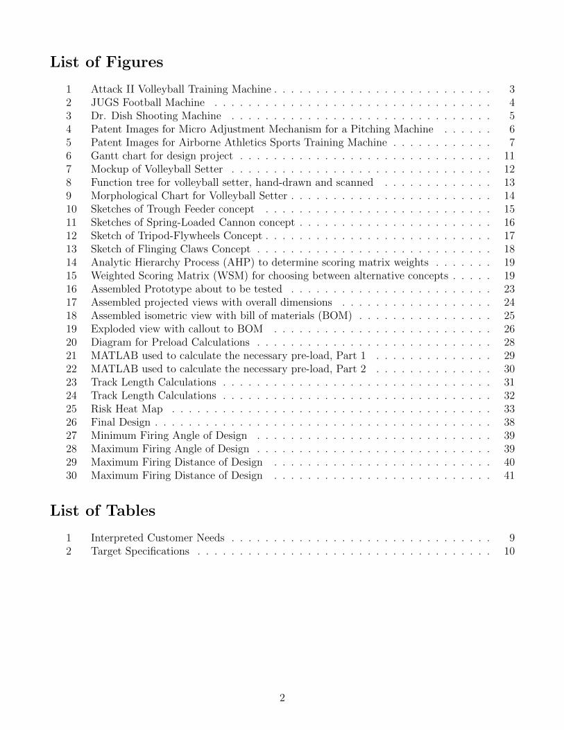
2.1.1 Existing Device #1: Attack II Volleyball Training Machine
Figure 1: Attack II Volleyball Training Machine
Link: https://www.allvolleyball.com/product/attack-II-volleyball-machine?utm_term=
&utm_campaign=&utm_source=adwords&utm_medium=ppc&hsa_acc=3836796041&hsa_cam=11076910990&
hsa_grp=108236079723&hsa_ad=463031664365&hsa_src=u&hsa_tgt=pla-407544821248&hsa_kw=
&hsa_mt=&hsa_net=adwords&hsa_ver=3&gclid=Cj0KCQjwkIGKBhCxARIsAINMioKoOxfmmuH-NWRBLkX5-omf4xwAWGN4XFZT58rzyYpNv4p9wcyC9RUaArKsEALw_
wcB
3
Description: The Attack II Volleyball Training Machine is a multipurpose volleyball training device.It can simulate many in-game volleyball situations and is best for serving, digging, and spikingpractice. Spinning wheels allow the operator to put back or forward spin on the ball and the height,angle, and speed of release can all be adjusted. There is a platform with safety restraints that thecoach or operator stands on to feed the ball into the spinning wheels. The Attack II can be used topractice setting, but is better suited for attack mode due to its height. It is best for angling shotsdown over the net which simulates a spike or shooting the ball over a far distance, simulating aserve.
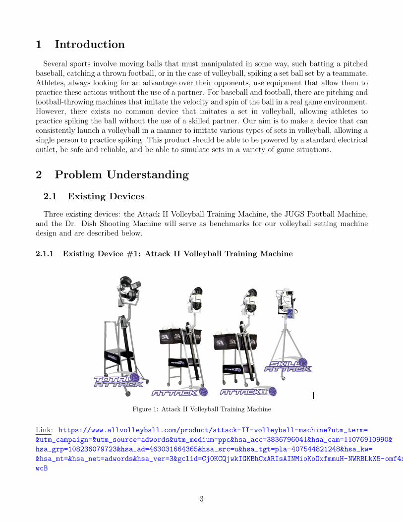
2.1.2 Existing Device #2: JUGS Football Machine
Figure 2: JUGS Football Machine
Link: https://jugssports.com/products/football-passing-machine.htmlThe JUGS Football Machine is a training machine used to throw passes to skill position players
like wide receivers, tight ends, and running backs. Generally there are more receivers, runningbacks, and tight ends who need to catch passes than there are quarterbacks who can make thepasses, so the JUGS machine solved a similar problem for football as we are solving for volleyball.Two angled spinning wheels can accurately throw a football from 5 to 80 yards, and the height canbe varied depending on the type of pass the player needs.
4
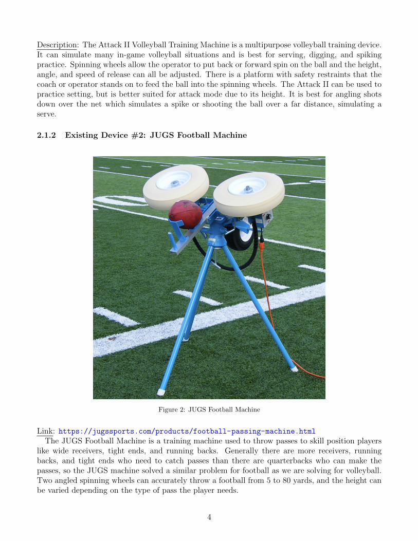
2.1.3 Existing Device #3: Dr. Dish Shooting Machine
Figure 3: Dr. Dish Shooting Machine
Link: https://www.drdishbasketball.com/schools?hsCtaTracking=5b7ba84b-9d9f-4413-96c0-3828a12acd33%7C6417a7c8-a73e-4575-91c4-0c8b6d4a3b4b
The Dr. Dish Shooting Machine is a basketball training device that returns the ball back to theplayer after they shoot. This increases training efficiency because the player doesn’t have to chaseafter the ball after every shot they take. It can hold multiple balls at once so it can be used by awhole team at one time, and a rotating shooting mechanism allows it to pass to or be positionedanywhere on the court.
5
2.2 Patents
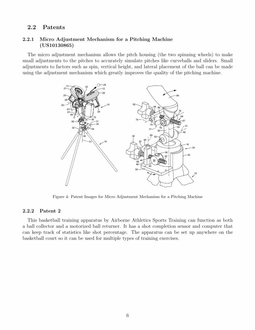
2.2.1 Micro Adjustment Mechanism for a Pitching Machine(US10130865)
The micro adjustment mechanism allows the pitch housing (the two spinning wheels) to makesmall adjustments to the pitches to accurately simulate pitches like curveballs and sliders. Smalladjustments to factors such as spin, vertical height, and lateral placement of the ball can be madeusing the adjustment mechanism which greatly improves the quality of the pitching machine.
Figure 4: Patent Images for Micro Adjustment Mechanism for a Pitching Machine
2.2.2 Patent 2
This basketball training apparatus by Airborne Athletics Sports Training can function as botha ball collector and a motorized ball returner. It has a shot completion sensor and computer thatcan keep track of statistics like shot percentage. The apparatus can be set up anywhere on thebasketball court so it can be used for multiple types of training exercises.
6
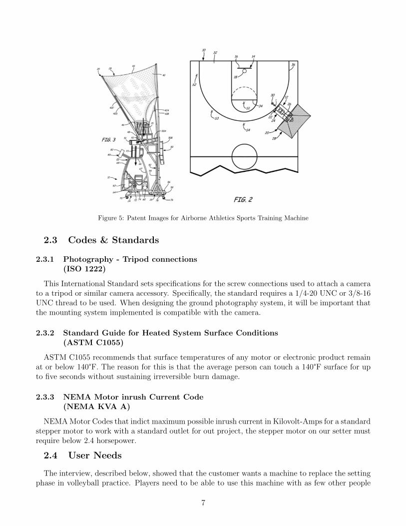
Figure 5: Patent Images for Airborne Athletics Sports Training Machine
2.3 Codes & Standards
2.3.1 Photography - Tripod connections(ISO 1222)
This International Standard sets specifications for the screw connections used to attach a camerato a tripod or similar camera accessory. Specifically, the standard requires a 1/4-20 UNC or 3/8-16UNC thread to be used. When designing the ground photography system, it will be important thatthe mounting system implemented is compatible with the camera.
2.3.2 Standard Guide for Heated System Surface Conditions(ASTM C1055)
ASTM C1055 recommends that surface temperatures of any motor or electronic product remainat or below 140°F. The reason for this is that the average person can touch a 140°F surface for upto five seconds without sustaining irreversible burn damage.
2.3.3 NEMA Motor inrush Current Code(NEMA KVA A)
NEMA Motor Codes that indict maximum possible inrush current in Kilovolt-Amps for a standardstepper motor to work with a standard outlet for out project, the stepper motor on our setter mustrequire below 2.4 horsepower.
2.4 User Needs
The interview, described below, showed that the customer wants a machine to replace the settingphase in volleyball practice. Players need to be able to use this machine with as few other people
7
as possible, alone if necessary, to simulate in-game sets to better prepare for spiking a volleyball.
2.4.1 Customer Interview
Interviewee: Alex CobinLocation: Danforth University Center, Washington University in St. Louis, Danforth CampusDate: September 13th, 2021Setting: We met Alex Cobin at the Danforth University Center for an interview that lasted around25 minutes. We showed him videos of a basketball shooting machine that collects balls and passesthem back to the player. We made diagrams of a volleyball court to see learn more about setting,both the typical court locations and where the ball ideally is set to. Alex is a member of a semi-provolleyball team in St. Louis that placed third in their league this summer.Interview Notes:What were some of the biggest challenges your volleyball team faced last season?
– In competitive play, most points are earned by spiking the ball for your team’s third hit. Thehitting order ideally goes bump, set, and finally spike. In volleyball, setting places the ballat the right height and position to be spiked by a teammates. Skilled opponents will easilyreturn a ball that is bumped or set over the net. If our team can set up more spikes, then wewill score more points. For our team to get more spikes, we first need to master setting theball, though.
What do in-game sets normally look like?
– After being bumped, the ball is set, usually from the outside of the court towards the middle.Most importantly the ball is sent towards another player in the direction of the net. Thesesets typically form a high arcing pattern, the ball should fall no more than 10 feet from whereit was set.
What would perfect function look like?
– The ball should not land more than eight to ten feet away from the machine and form a higharc with a maximum height between nine and fifteen feet off the floor. The angle the ballcomes in at should be able to change, just like the height since not all sets are the same duringgame play.
How do you see this device being used?
– This machine would most likely be used primarily in practice, most often in a gymnasium.Players could use it alone or with a few others there. Ideally, the machine would take theplace of another player. In practice, whoever was using the machine could spike on an emptycourt or towards other teammates. In theory, the entire team would not need to show up topractice making coordinating schedules much easier.
How important is portability?
– The machine would probably not be moved far from where it is stored, similar to a tennis ballshooter. It would most likely stay entirely in a gym.
How important is ease of use and operation?
– Ideally, whoever is practicing with the machine can easily change the settings regarding ballplacement, angle, height, etc. The machine should be able to set multiple balls so that it didnot need to be reset every time is sets a ball. The fewer people needed to operate it the moreuseful it will be.
8
What dimensions would increase ease of use?
– The machine ideally would be small enough to placed in most storage closets that alreadyhouse lots of equipment. When in use, it should be small enough that it does not obstructplayers using it when they are running around for spiking. It should be as out of the way aspossible.
2.4.2 Interpreted User Needs
The interview was interpreted and used to create a table of the customer’s needs for the volleyballsetter. These needs, along with their understood importance, are shown in Table 1.
Table 1: Interpreted Customer Needs
Need Number Need Importance
1 The VS launches ball at consistent velocity 42 The VS can be operated without a second person 43 The VS launch angle can be changed 44 The VS launch velocity can be changed 45 The VS does not damage volleyballs 56 The VS is safe to use 57 The VS can be powered using a standard electrical outlet 58 The VS is quick to set up 39 The VS does not need frequent repair 4
Because these customer needs are mostly non-quantifiable, they must be converted into achievablemetrics in order to determine the success or failure of the volleyball setter.
2.5 Design Metrics
The customer needs described in Table 1 were converted into acceptable and ideal target specifi-cations. These specifications are describes in Table 2.
9
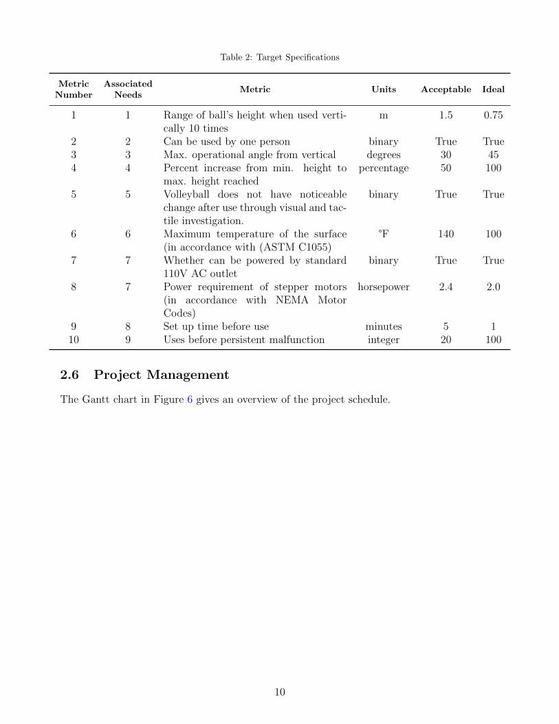
Table 2: Target Specifications
MetricNumber
AssociatedNeeds
Metric Units Acceptable Ideal
1 1 Range of ball’s height when used verti-cally 10 times
m 1.5 0.75
2 2 Can be used by one person binary True True3 3 Max. operational angle from vertical degrees 30 454 4 Percent increase from min. height to
max. height reachedpercentage 50 100
5 5 Volleyball does not have noticeablechange after use through visual and tac-tile investigation.
binary True True
6 6 Maximum temperature of the surface(in accordance with (ASTM C1055)
°F 140 100
7 7 Whether can be powered by standard110V AC outlet
binary True True
8 7 Power requirement of stepper motors(in accordance with NEMA MotorCodes)
horsepower 2.4 2.0
9 8 Set up time before use minutes 5 110 9 Uses before persistent malfunction integer 20 100
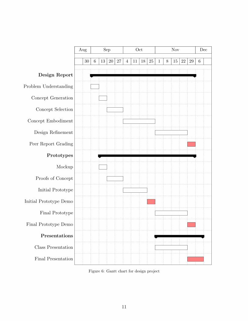
2.6 Project Management
The Gantt chart in Figure 6 gives an overview of the project schedule.
10
Aug Sep Oct Nov Dec
30 6 13 20 27 4 11 18 25 1 8 15 22 29 6
Design Report
Problem Understanding
Concept Generation
Concept Selection
Concept Embodiment
Design Refinement
Peer Report Grading
Prototypes
Mockup
Proofs of Concept
Initial Prototype
Initial Prototype Demo
Final Prototype
Final Prototype Demo
Presentations
Class Presentation
Final Presentation
Figure 6: Gantt chart for design project
11
3 Concept Generation
3.1 Mockup Prototype
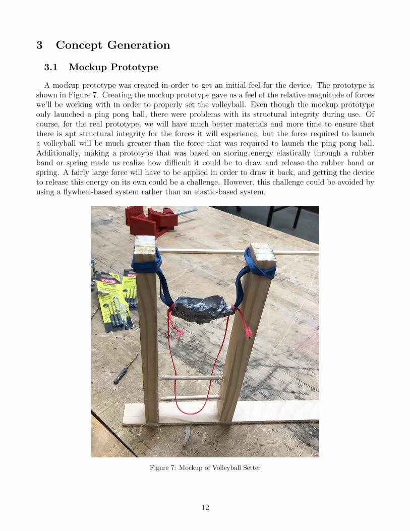
A mockup prototype was created in order to get an initial feel for the device. The prototype isshown in Figure 7. Creating the mockup prototype gave us a feel of the relative magnitude of forceswe’ll be working with in order to properly set the volleyball. Even though the mockup prototypeonly launched a ping pong ball, there were problems with its structural integrity during use. Ofcourse, for the real prototype, we will have much better materials and more time to ensure thatthere is apt structural integrity for the forces it will experience, but the force required to launcha volleyball will be much greater than the force that was required to launch the ping pong ball.Additionally, making a prototype that was based on storing energy elastically through a rubberband or spring made us realize how difficult it could be to draw and release the rubber band orspring. A fairly large force will have to be applied in order to draw it back, and getting the deviceto release this energy on its own could be a challenge. However, this challenge could be avoided byusing a flywheel-based system rather than an elastic-based system.
Figure 7: Mockup of Volleyball Setter
12
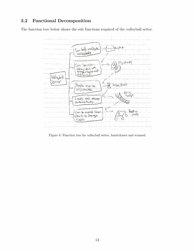
3.2 Functional Decomposition
The function tree below shows the sub functions required of the volleyball setter.
Figure 8: Function tree for volleyball setter, hand-drawn and scanned
13
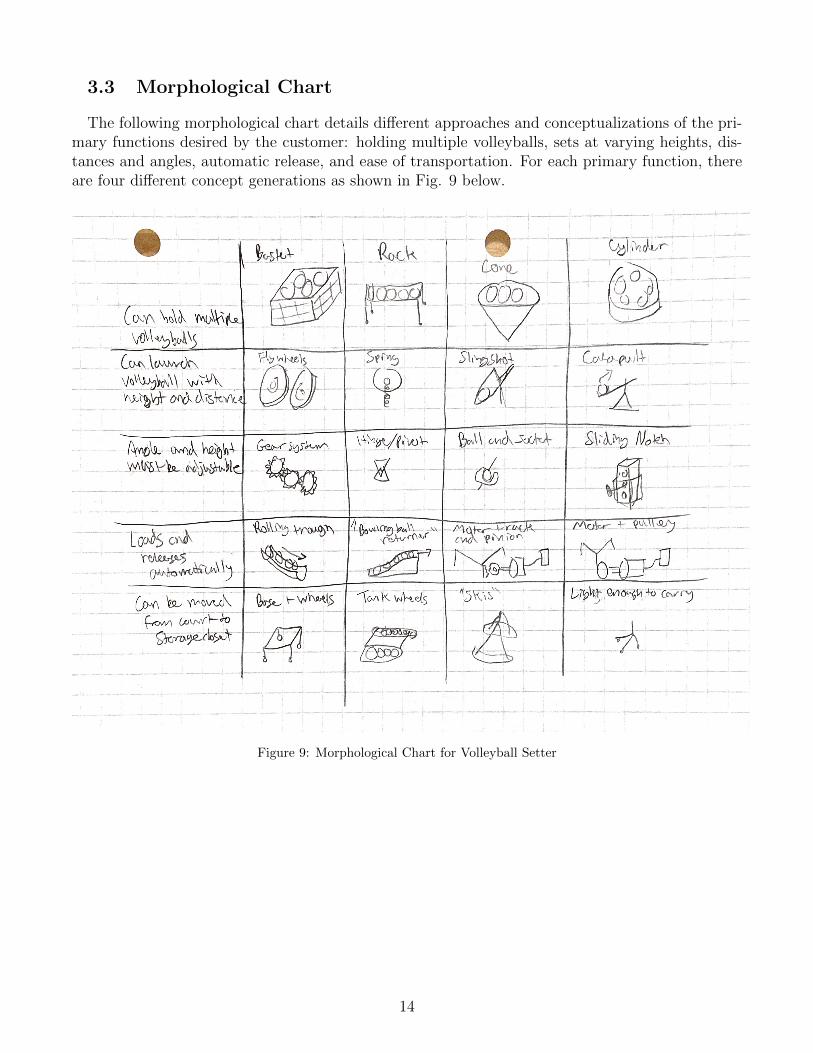
3.3 Morphological Chart
The following morphological chart details different approaches and conceptualizations of the pri-mary functions desired by the customer: holding multiple volleyballs, sets at varying heights, dis-tances and angles, automatic release, and ease of transportation. For each primary function, thereare four different concept generations as shown in Fig. 9 below.
Figure 9: Morphological Chart for Volleyball Setter
14
3.4 Alternative Design Concepts
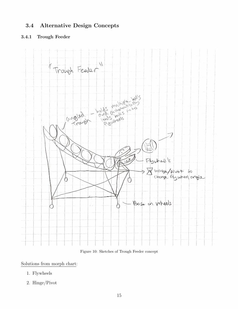
3.4.1 Trough Feeder
Figure 10: Sketches of Trough Feeder concept
Solutions from morph chart:
1. Flywheels
2. Hinge/Pivot
15
3. Rolling Trough
4. Base on Wheels
Description: An angled trough holds the volleyballs and feeds them into the spinning flywheels. Theangled trough utilizes gravity to bring the volleyballs down into the flywheels, rather than using amechanical device to automatically load the machine. This way, many balls can be pre-loaded intothe machine at the start of practice. The spinning flywheel are attached to the base with two barsthat go to the front two corners of the base. A hinge device is attached to the wheels which allowsthem to pivot and change the launch angle of the volleyball. Wheels are an important addition tothe base because they allow the machine to be easily moved off the court to its storage location.
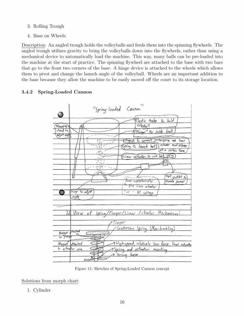
3.4.2 Spring-Loaded Cannon
Figure 11: Sketches of Spring-Loaded Cannon concept
Solutions from morph chart:
1. Cylinder
16
2. Spring
3. Hinge/Pivot
4. Motor+Rack and Pinion (internal in actuator)
5. Light enough to carry
Description: There is a cylindrical tube to serve as the housing for the volleyball, where it will belaunched out of. Inside, there is a plunger that can push the ball, with a large but not very stiff com-pression spring and strong rare-earth magnet attached to the bottom of the plunger. Additionally,There is a high-speed, relatively low force linear actuator with a magnet or ferrous metal attachedto its arm, which is then attached to the other magnet. When used, a power supply and controllersupplies a positive or negative voltage to the actuator to pull the armature back, compressing thespring. Once the spring is compressed to a certain force, the two magnets (or magnet and ferrousmetal) will separate, causing the spring to move rapidly up and quickly push the ball outside of thehousing. Additionally, there is a hinge at the bottom and a telescoping stand so the angle can beadjusted.
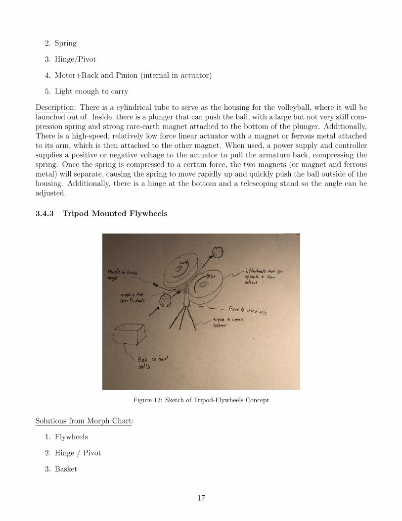
3.4.3 Tripod Mounted Flywheels
Figure 12: Sketch of Tripod-Flywheels Concept
Solutions from Morph Chart:
1. Flywheels
2. Hinge / Pivot
3. Basket
17
4. Light enough to carry
Description Volleyballs will be fed into two oppositely spinning flywheels to be launched out of. Twomotors (not shown as they are hidden by the flywheels) induce a moment to spin each wheel.Theflywheels rest on a plate that is atop a pivot so that an operator can adjust to set volleyballs to aplace of their choosing. The pivot will allow the balls’ launch paths to vary in both the x and ydirections. The entire system will rest on a tripod to support an stabilize. This base can be foldedto allow for easier carrying and transportation as well. Off to the side is a basket which will holdvolleyballs for future use.
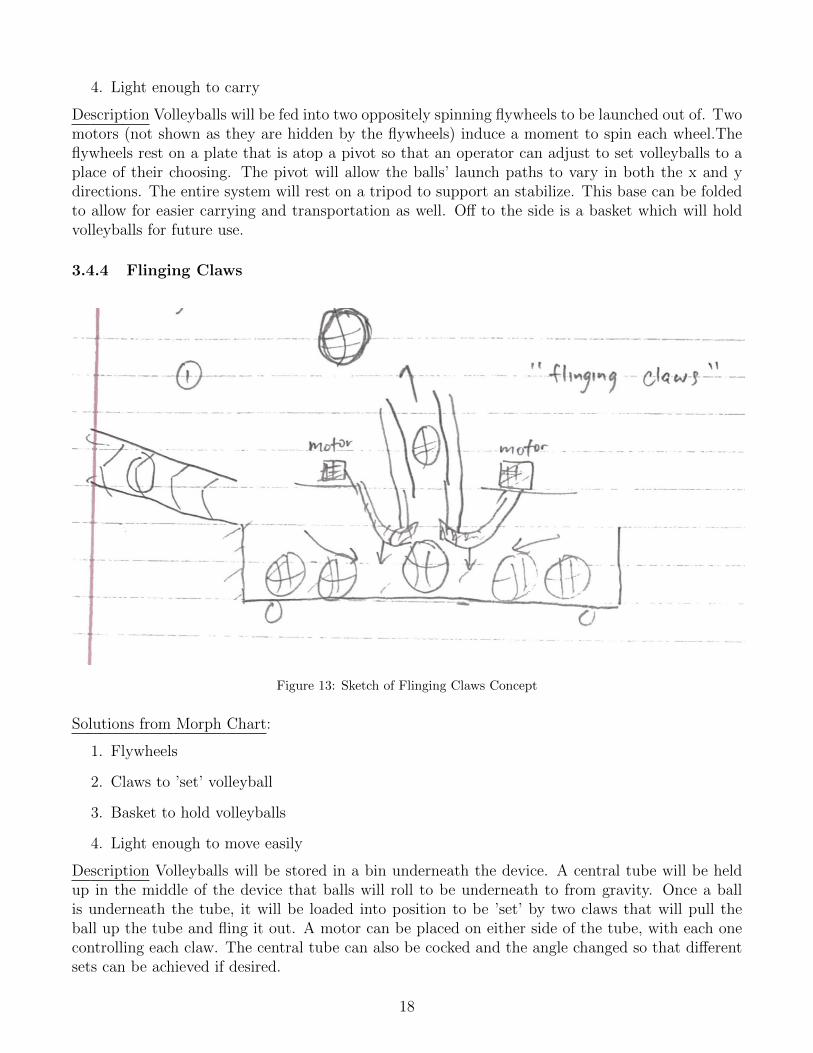
3.4.4 Flinging Claws
Figure 13: Sketch of Flinging Claws Concept
Solutions from Morph Chart:
1. Flywheels
2. Claws to ’set’ volleyball
3. Basket to hold volleyballs
4. Light enough to move easily
Description Volleyballs will be stored in a bin underneath the device. A central tube will be heldup in the middle of the device that balls will roll to be underneath to from gravity. Once a ballis underneath the tube, it will be loaded into position to be ’set’ by two claws that will pull theball up the tube and fling it out. A motor can be placed on either side of the tube, with each onecontrolling each claw. The central tube can also be cocked and the angle changed so that differentsets can be achieved if desired.
18
4 Concept Selection
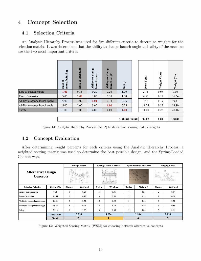
4.1 Selection Criteria
An Analytic Hierarchy Process was used for five different criteria to determine weights for theselection matrix. It was determined that the ability to change launch angle and safety of the machineare the two most important criteria.
Figure 14: Analytic Hierarchy Process (AHP) to determine scoring matrix weights
4.2 Concept Evaluation
After determining weight percents for each criteria using the Analytic Hierarchy Process, aweighted scoring matrix was used to determine the best possible design, and the Spring-LoadedCannon won.
Figure 15: Weighted Scoring Matrix (WSM) for choosing between alternative concepts
19
4.3 Evaluation Results
As seen in the weighted scoring matrix, the Spring-Loaded Cannon (SLC) was decided to bethe best design. It performed best compared to its peers in the ”Ease of manufacturing” category,scoring a five. This is because the flywheel designs (Trough Feeder and Tripod-Mounted Flywheels)would require much tighter tolerances, as the flywheels would have to be the perfect distance apartin order to apply the right amount of force to the volleyball. Additionally, the Trough Feeder andFlinging Claws would require a large structure, while the SLC’s is much more minimal.
The SLC performed decently well in the ”Ease of operation” category. The reason it didn’t do aswell in this category compared to the Trough Feeder and Flinging Claws is because there is no wayit can be automatically loaded (as in, a new volleyball has to manually be put in each time beforeuse). However, this is a sacrifice that likely has to be made in order to finish with a working product.
The SLC actually performed the worst out of all the designs in its ability to change the launchspeed of the volleyball. This is because, unlike the other designs, the launch speed can’t simply bechanged by adjusting the voltage sent to the motors. Instead, either the spring constant will have tobe changed (likely by using elastic bands rather than a spring and adjusting their tightness) or thedistance the ball is pulled back will have to be changed (by adjusting the strength of the magnet).Both of these would require more work by the user, but again, this may be a sacrifice that has tobe made in order to come up with a working prototype.
The SLC performed well in its ability to change the launch angle because the entire device cansimply be put on a hinge with some way of holding a specific angle. The other ones, on the otherhand, could have problems with loading the ball into the flywheels or claws when a very verticalangle is desired.
And finally, the SLC did fairly average in safety. The benefits of not having fairly high powermotors operating at fairly high speeds is largely countered by the elastic energy storage, whichcauses a very quick release in energy that could potentially cause parts to break off and go flying.Additionally, because the ball must be loaded in before each use, the user will, on average, be closerto the machine, slightly increasing the chance of injury if something goes wrong.
4.4 Engineering Models/Relationships
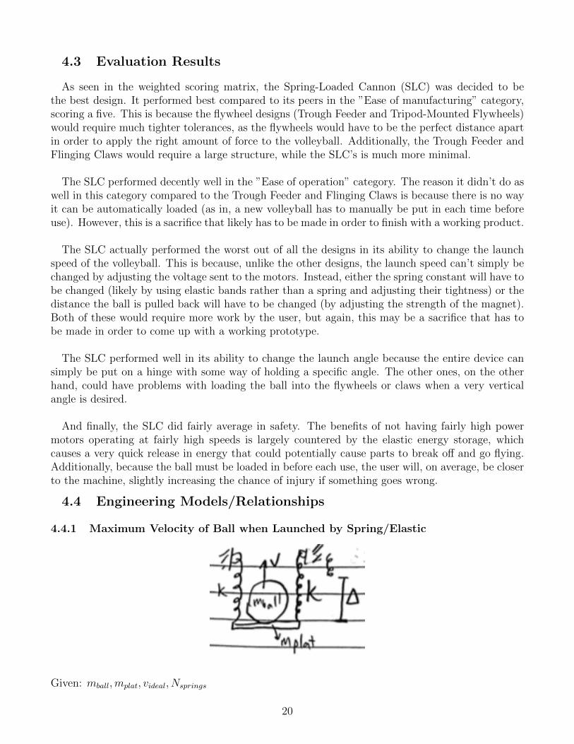
4.4.1 Maximum Velocity of Ball when Launched by Spring/Elastic
Given: mball,mplat, videal, Nsprings
20
Find: k,∆ ∑Ei =
∑Ef
PEspring = KEball +KEplat
1
2k∆2 ∗Nsprings =
1
2v2(mball +mplat)
k =v2ideal(mball +mplat)
∆2 ∗Nsprings
∆ =
√√√√v2ideal(mball +mplat)
Nspringsk
Conservation of energy states that the elastic energy of the compressed spring will be equal to thekinetic energy of the ball just as it is launched and the platform pushing the ball as the ball islaunched. Assuming that there is an ideal launch velocity (determined by how high the user wantsthe volleyball to be set), it is possible to find the relationship between the spring constant and thedistance that the ball must be pulled back. There is an inverse relationship between k and ∆, sofor a given videal, either a relatively higher k and lower ∆ can be used, or a relatively higher ∆and lower k. This will be useful, because right now, we are unsure on which way will be easiestto change the launch velocity: manipulating the elastic material in the design to change the springconstant, or pulling the ball and platform further back before release. The equations for the energyof a spring and kinetic energy were acquired from www.hyperphysics.com.
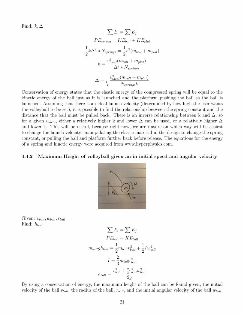
4.4.2 Maximum Height of volleyball given an in initial speed and angular velocity
Given: vball, wball, rballFind: hball ∑
Ei =∑
Ef
PEball = KEball
mballghball =1
2mballv
2ball +
1
2Iw2
ball
I =2
3mballr
2ball
hball =v2ball + 2
3r2ballw
2ball
2g
By using a conservation of energy, the maximum height of the ball can be found given, the initialvelocity of the ball vball, the radius of the ball, rball, and the initial angular velocity of the ball wball.
21
The moment of inertia is for a ball with a thin shell, which a meets the criteria for a volleyballsince it is filled with air. The equations and the moment of inertia were found on hyperphysics.com,”Moment of Inertia, Sphere”.
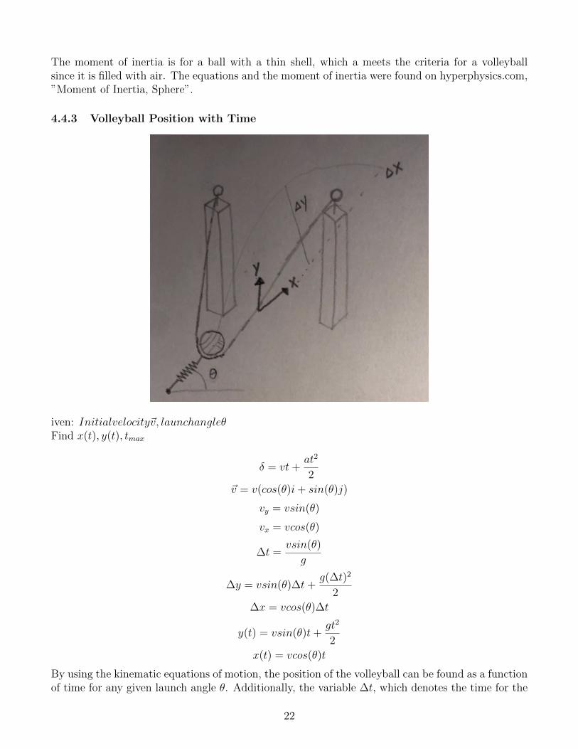
4.4.3 Volleyball Position with Time
iven: Initialvelocity~v, launchangleθFind x(t), y(t), tmax
δ = vt+at2
2
~v = v(cos(θ)i+ sin(θ)j)
vy = vsin(θ)
vx = vcos(θ)
∆t =vsin(θ)
g
∆y = vsin(θ)∆t+g(∆t)2
2
∆x = vcos(θ)∆t
y(t) = vsin(θ)t+gt2
2
x(t) = vcos(θ)t
By using the kinematic equations of motion, the position of the volleyball can be found as a functionof time for any given launch angle θ. Additionally, the variable ∆t, which denotes the time for the
22
volleyball to reach its maximum height, can be used to find the maximum height and the distancethe ball will reach before coming into contact with the ground for its first bounce. These equationsand the moment were found on physicsclassroom.com but were originally derived by Galileo Galilei.
5 Concept Embodiment
5.1 Initial Embodiment
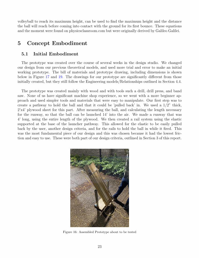
The prototype was created over the course of several weeks in the design studio. We changedour design from our previous theoretical models, and used more trial and error to make an initialworking prototype. The bill of materials and prototype drawing, including dimensions is shownbelow in Figure 17 and 19. The drawings for our prototype are significantly different from thoseinitially created, but they still follow the Engineering models/Relationships outlined in Section 4.4.
The prototype was created mainly with wood and with tools such a drill, drill press, and bandsaw. None of us have significant machine shop experience, so we went with a more beginner ap-proach and used simpler tools and materials that were easy to manipulate. Our first step was tocreate a pathway to hold the ball and that it could be ’pulled back’ in. We used a 1/2” thick,2’x4’ plywood sheet for this part. After measuring the ball, and calculating the length necessaryfor the runway, so that the ball can be launched 14’ into the air. We made a runway that was4’ long, using the entire length of the plywood. We then created a rail system using the elasticsupported at the base of the launcher pathway. This allowed for the elastic to be easily pulledback by the user, another design criteria, and for the rails to hold the ball in while it fired. Thiswas the most fundamental piece of our design and this was chosen because it had the lowest fric-tion and easy to use. These were both part of our design criteria, outlined in Section 3 of this report.
Figure 16: Assembled Prototype about to be tested
23
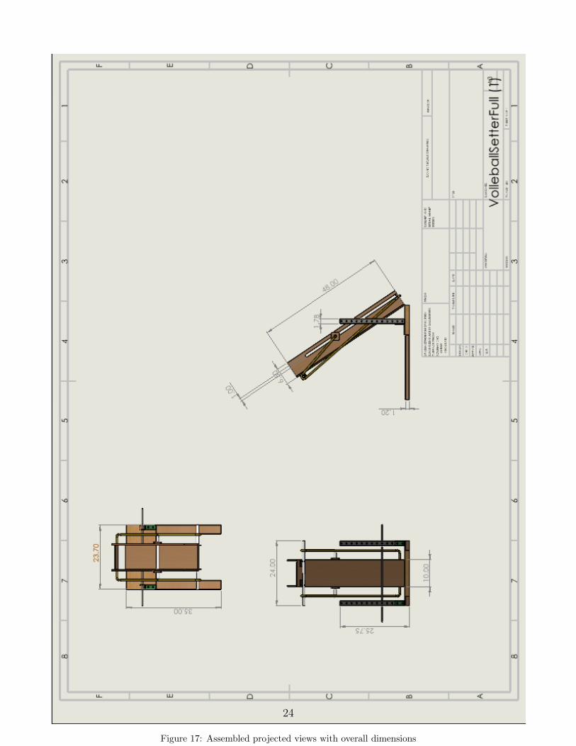
Figure 17: Assembled projected views with overall dimensions
24
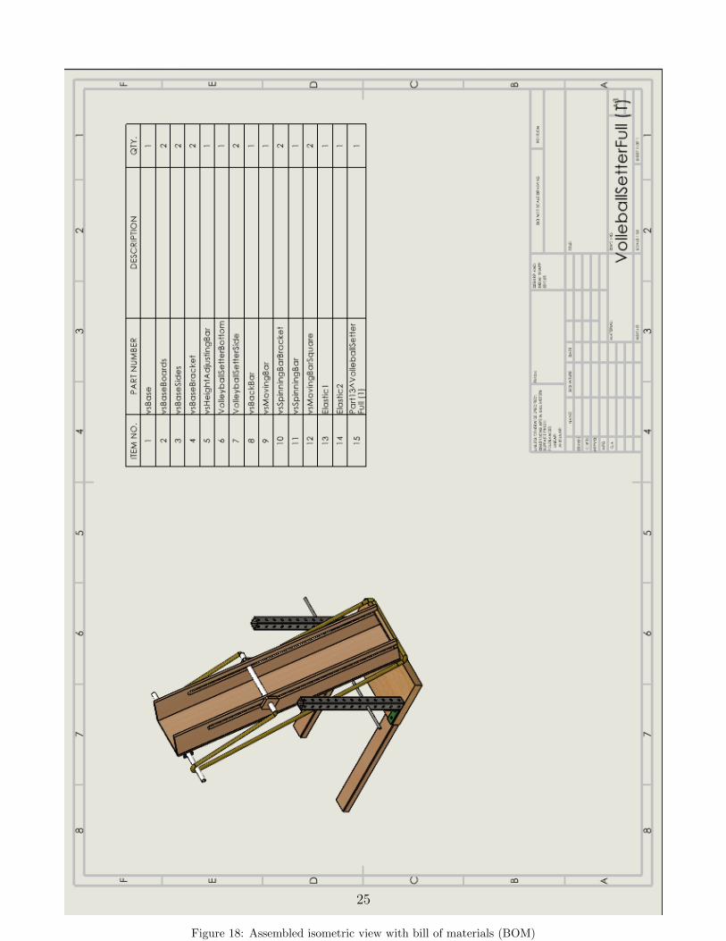
Figure 18: Assembled isometric view with bill of materials (BOM)
25
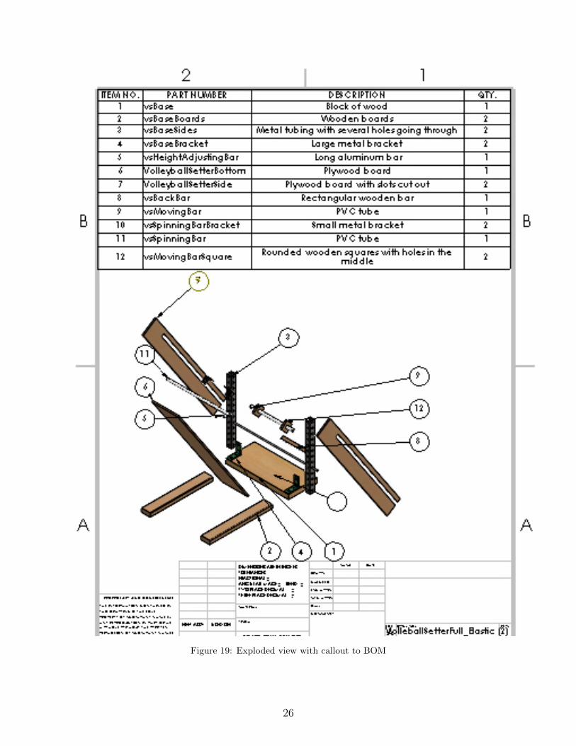
Figure 19: Exploded view with callout to BOM
26
5.2 Performance Goals Recap
Our volleyball setter needed to shoot volleyballs at a rate of 10 balls per minute (one ball every6 seconds) and be able vary the launch angle between 30 and 80 degrees with a maximum heightof 14 feet. Additionally, our customer wanted this device to be light enough to be carried by justone person and operated by as few people as possible, one if possible.
For our prototype, we focused primarily on the launch capabilities for our design: maximumheight, variable angles, and how quickly balls could be launched. Our final prototype accomplishedevery performance goal, not just the ones relating to launching.
5.3 Proofs-of-Concept
Our first proof of concept involved the flywheel design but with only one flywheel.. We found aworking motor-flywheel system, a volleyball and a wooden board. We held the board stationaryand turned the flywheel on, while another group member fed the volleyball through. The ball waslaunched with no angle, at the horizontal, and ended up traveling several feet before hitting theground. While this met none of the design goals it did show that the flywheel design could work.Analysis for our proof on concept and prototype constructions involved kinematics for the ball’sposition and arc, Hooke’s Law to model the elastic bands, and the energy equation.
∆t =vsin(θ)
g
y(t) = vsin(θ)t+gt2
2
x(t) = vcos(θ)t
F = kx
Energy = KE + PE
Our second proof of concept came from the elastic band design that ended up being our proto-type. The ball was launched at an intermediate angle between 30 and 80 degrees, and ended uphitting the both the height and distance requirements set by our customer. The launch angle hadmaintained by a group member (the hinge was not applied yet, nor was the base), but this trialaccomplished the proof of concept.
5.4 Design Changes
Our original design would have implemented a fixed double flywheel design to launch volleyballswith motors to drive the flywheels. Our current design is human powered, using an elastic band anda wooden track to achieve our design goals. During our prototype construction, the flywheel designran into problems with launching the ball the desired distance and during the loading process. Thewheels either spun too fast and ball causing the ball to slip and no launch, or the wheels spun toslow and the ball barely left the machine. While the correct rotational speed and motor output wassomewhere in the middle of where we tested, we felt that a human-powered device would be safer,more reliable, and easier to construct and improve. We made these fundamental design changesafter speaking with our customer and Professor Potter (see Section 2.4.1 above for full customer
27
interview).
Our current design launches volleyballs with elastic bands attached to a PVC handle that ispulled back by the operator and released. The superstructure of this design is comprised of twovertical plywood planks secured perpendicular to a third, horizontal board, with screws. The hor-izontal plywood sheets have slots cut to the width of thee PVC handle so that the handle can bepulled back with by the operator and released. This structure is attached to a wide base by a hingeto allow for alteration of the launch angle.
Another important part of our prototype was the ability and ease of changing the launch angle.We used materials found in the design studio, including 2’ steel supports with holes 1/2” in diam-eter, every 2 inches. We put one of these on either side of the launcher, and used an aluminum barplaced through holes in each of the supports. The launcher then rested on the aluminum bar whichallowed for different angles of launch, depending how high up the bar was in the steel supports.This design is shown in more detail in 17
6 Design Refinement
6.1 Model-Based Design Decisions
6.1.1 Model 1: Finding the Necessary Preload in the Elastic
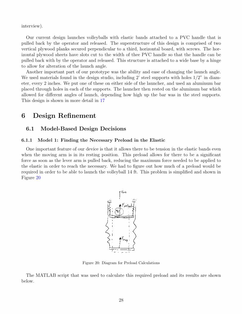
One important feature of our device is that it allows there to be tension in the elastic bands evenwhen the moving arm is in its resting position. This preload allows for there to be a significantforce as soon as the lever arm is pulled back, reducing the maximum force needed to be applied tothe elastic in order to reach the necessary. We had to figure out how much of a preload would berequired in order to be able to launch the volleyball 14 ft. This problem is simplified and shown inFigure 20
Figure 20: Diagram for Preload Calculations
The MATLAB script that was used to calculate this required preload and its results are shownbelow.
28
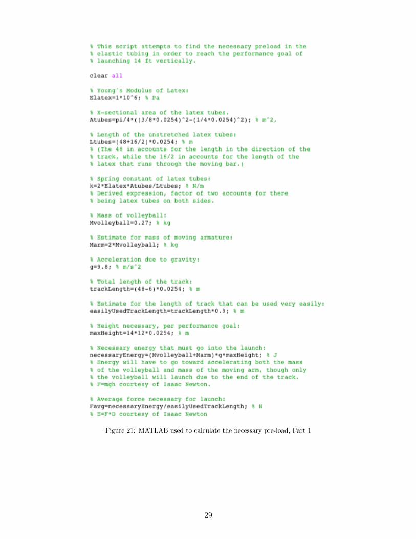
Figure 21: MATLAB used to calculate the necessary pre-load, Part 1
29
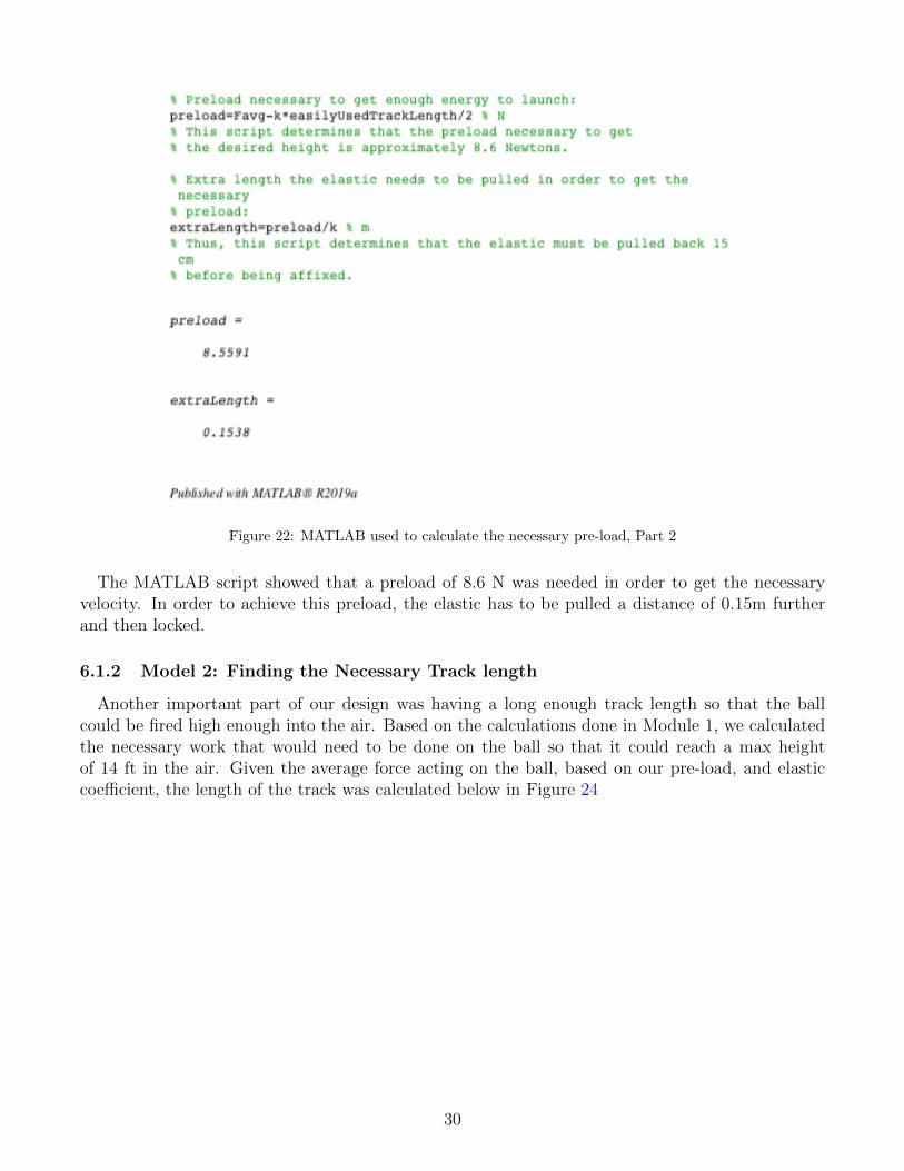
Figure 22: MATLAB used to calculate the necessary pre-load, Part 2
The MATLAB script showed that a preload of 8.6 N was needed in order to get the necessaryvelocity. In order to achieve this preload, the elastic has to be pulled a distance of 0.15m furtherand then locked.
6.1.2 Model 2: Finding the Necessary Track length
Another important part of our design was having a long enough track length so that the ballcould be fired high enough into the air. Based on the calculations done in Module 1, we calculatedthe necessary work that would need to be done on the ball so that it could reach a max heightof 14 ft in the air. Given the average force acting on the ball, based on our pre-load, and elasticcoefficient, the length of the track was calculated below in Figure 24
30
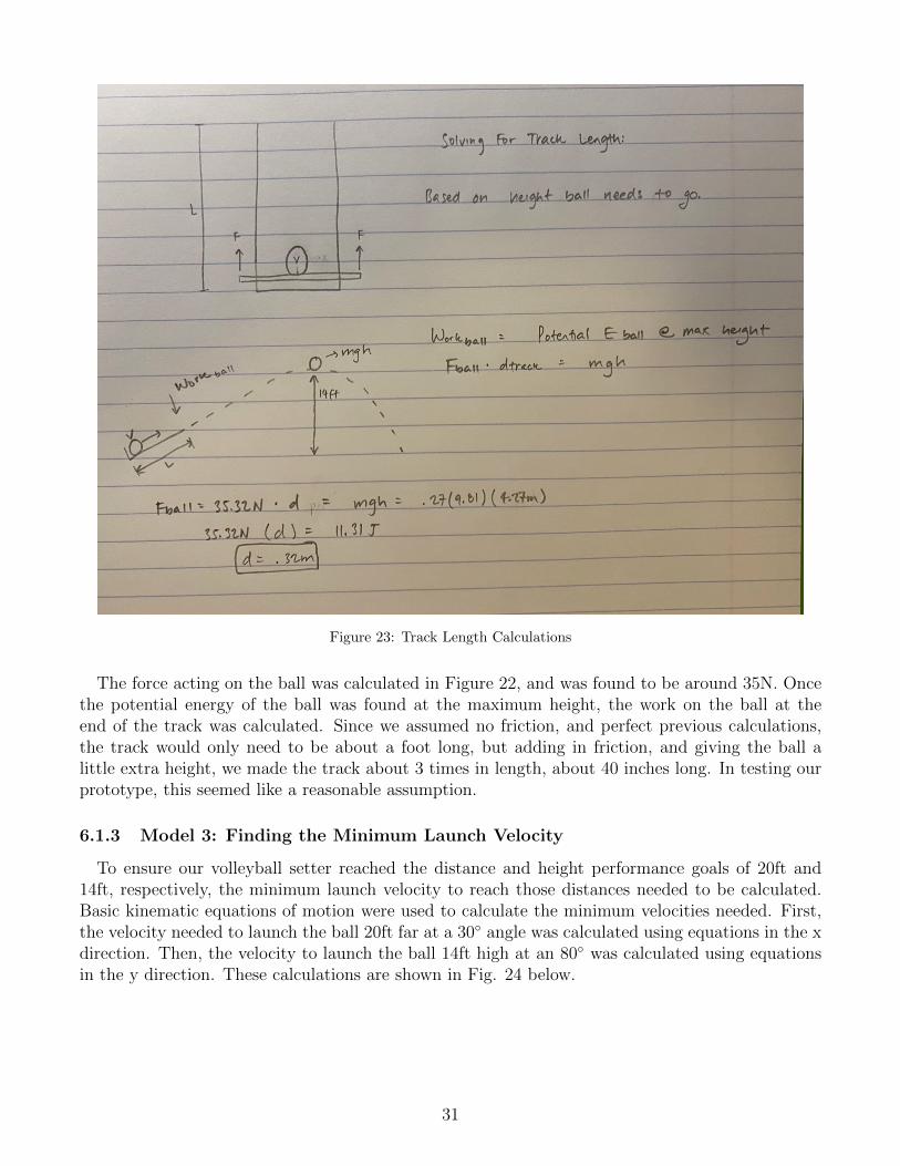
Figure 23: Track Length Calculations
The force acting on the ball was calculated in Figure 22, and was found to be around 35N. Oncethe potential energy of the ball was found at the maximum height, the work on the ball at theend of the track was calculated. Since we assumed no friction, and perfect previous calculations,the track would only need to be about a foot long, but adding in friction, and giving the ball alittle extra height, we made the track about 3 times in length, about 40 inches long. In testing ourprototype, this seemed like a reasonable assumption.
6.1.3 Model 3: Finding the Minimum Launch Velocity
To ensure our volleyball setter reached the distance and height performance goals of 20ft and14ft, respectively, the minimum launch velocity to reach those distances needed to be calculated.Basic kinematic equations of motion were used to calculate the minimum velocities needed. First,the velocity needed to launch the ball 20ft far at a 30◦ angle was calculated using equations in the xdirection. Then, the velocity to launch the ball 14ft high at an 80◦ was calculated using equationsin the y direction. These calculations are shown in Fig. 24 below.
31
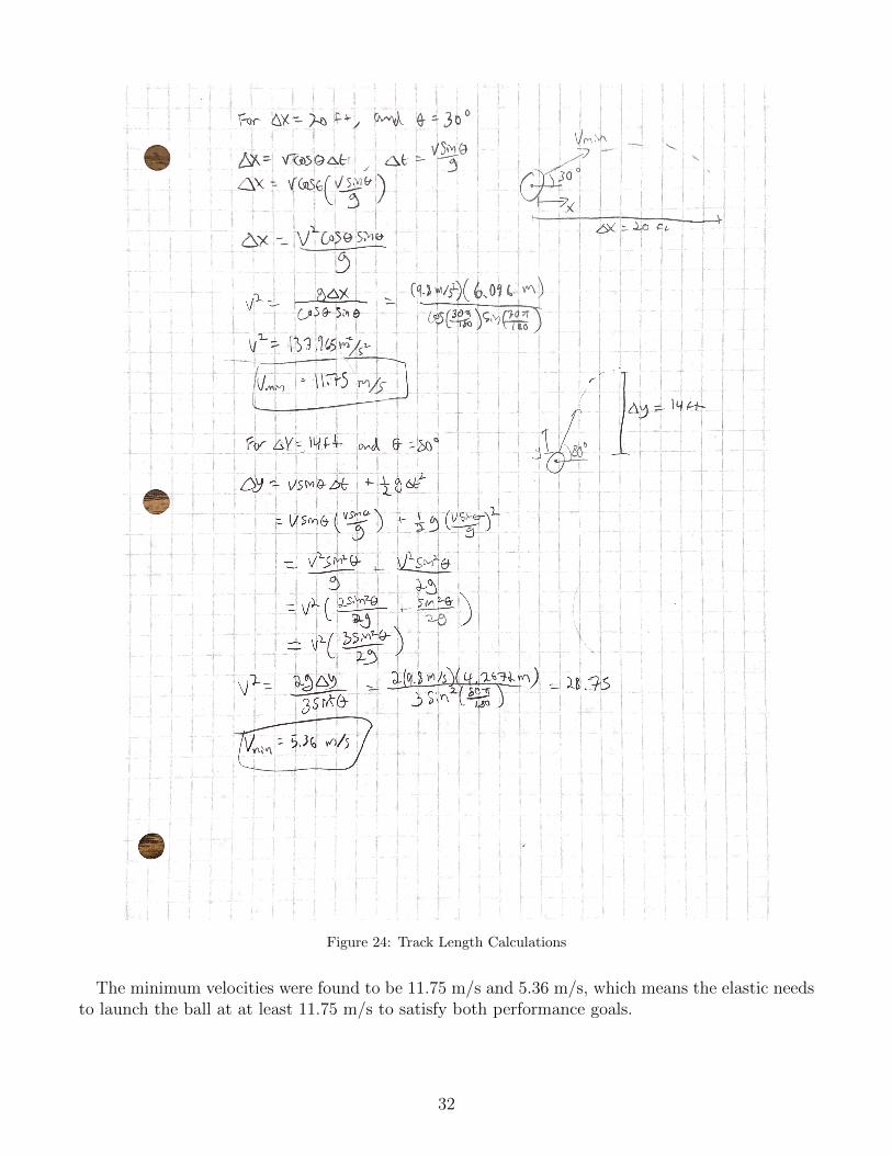
Figure 24: Track Length Calculations
The minimum velocities were found to be 11.75 m/s and 5.36 m/s, which means the elastic needsto launch the ball at at least 11.75 m/s to satisfy both performance goals.
32
6.2 Design for Saftey
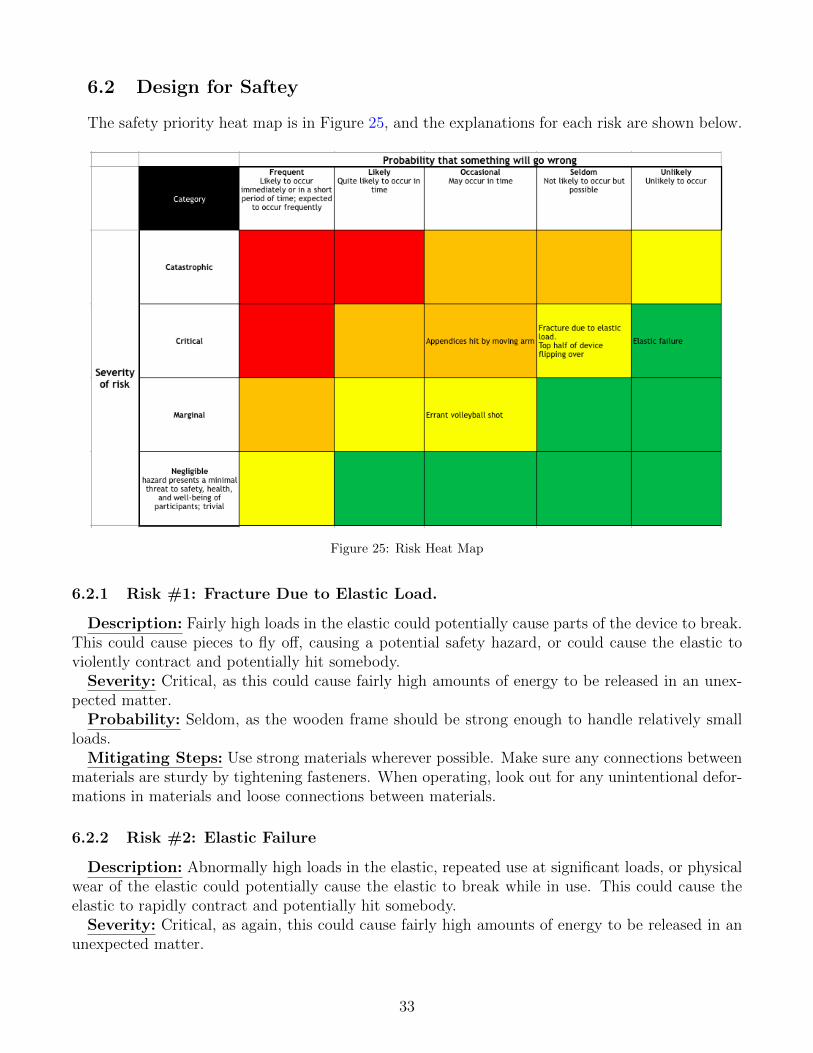
The safety priority heat map is in Figure 25, and the explanations for each risk are shown below.
Figure 25: Risk Heat Map
6.2.1 Risk #1: Fracture Due to Elastic Load.
Description: Fairly high loads in the elastic could potentially cause parts of the device to break.This could cause pieces to fly off, causing a potential safety hazard, or could cause the elastic toviolently contract and potentially hit somebody.
Severity: Critical, as this could cause fairly high amounts of energy to be released in an unex-pected matter.
Probability: Seldom, as the wooden frame should be strong enough to handle relatively smallloads.
Mitigating Steps: Use strong materials wherever possible. Make sure any connections betweenmaterials are sturdy by tightening fasteners. When operating, look out for any unintentional defor-mations in materials and loose connections between materials.
6.2.2 Risk #2: Elastic Failure
Description: Abnormally high loads in the elastic, repeated use at significant loads, or physicalwear of the elastic could potentially cause the elastic to break while in use. This could cause theelastic to rapidly contract and potentially hit somebody.
Severity: Critical, as again, this could cause fairly high amounts of energy to be released in anunexpected matter.
33
Probability: Unlikely, as the elastic bands should be used at loads much lower than would breakthem even if they are pulled all the way back.
Mitigating Steps: Visually inspect elastic before use. Do not pull elastic further than it isintended.
6.2.3 Risk #3: Errant Volleyball Shot
Description: Reckless operation of the device or a failure in the base could cause the device tolaunch a volleyball at an unexpected angle or direction. The potentially high-speed volleyball couldthen hit an unsuspecting person.
Severity: Marginal, as a launched volleyball is not likely to cause major harm to a person.Probability: Occasional, as it is possible that people will not be operating the device in an ideal
manner.Mitigating Steps: During use, make sure the volleyball is securely on the rail, and make sure
the upper section is in the right position. Additionally, make sure that bystanders are aware thatthe device is in use in case there is an errant shot. Additionally, the base can be made of sturdymaterials with strong connections to ensure that the correct angle is maintained.
6.2.4 Risk #4: Appendices Hit by Moving Arm
Description: If the device is not used properly, or a non-user is carelessly putting their handsor legs close to the device while in operation by another person, the moving arm that launches thevolleyball could hit somebody. This would be especially dangerous if someone’s hand is inside thedevice’s guide rails when in operation, because then the device could violently pinch or crush theirhand.
Severity: Critical, as the device slamming and crushing someones arm or finger could causesignificant bruising or worse.
Probability: Occasional, as people probably know not to stick their hands inside during use.Mitigating Steps: Do not allow non-users to get to close to the device when it is in use. When
operating the device, make sure that your entire body is behind the path of the moving arm.Additionally, physical guardrails could be installed to prevent people from getting too close.
6.2.5 Risk #5: Top Half of Device Flipping Over
Description: The apparatus that allows the angle to be set only prevents the top portion frommoving downward, so the angle is maintained due to gravity. During operation, if an unintendedforce is applied in the direction opposite of gravity, the top portion of the device could lift off ofthe angle-setting bar. If the device is already set at a high angle, this could cause the top half ofthe device to flip over onto the user, potentially harming them. This could be especially dangerousif there is a high amount of energy stored in the elastic when the top flips over.
Severity: Critical, as the top half of the device is somewhat heavy and this cold cause the elasticenergy to be released.
Probability: Seldom, as the device would have to be used somewhat carelessly for this to occur.Mitigating Steps: When operating the device, make sure that no force is applied in a direction
that could cause the device to lift from the angle-setting bar and potentially flip over. Additionally,a physical safeguard could be added that prevents the device from reaching an angle more than the
34
maximum operational angle, so even if the top portion is lifted off the angle-setting bar, there is nodanger of it flipping over onto the user.
6.2.6 Risk Prioritization
As seen in the heat map, there are no risks that are both likely to occur and create serious safetyconcerns if they do occur. That being said, the highest priority risk is people’s appendices being hitby the moving arm. This is because it is probably the most dangerous, as it leads to a concentratedrelease of energy onto someone’s body, and though people should know not to touch it when someoneelse is using it, people can be reckless. The next highest priorities are an errant volleyball shot,structural fracture, and the top half of the device flipping over. The errant volleyball shot is inthis category because although people probably won’t be seriously harmed by a volleyball beinglaunched at them, it is probably the most likely failure. The fracture due to the elastic load fallsin this category because it is only somewhat likely to occur if the device is properly used and therelease of energy is not concentrated at someone’s body. The top half of the device flipping is in thiscategory because it could cause a release in energy and a fairly heavy object hitting someone but itis fairly unlikely to occur because it requires somewhat careless use. Finally, the elastic failure wasdeemed the least important risk because though this failure would cause a rapid release in energy,it is to occur because the elastic can be pulled much further without breaking than it is pulled intypical operation.
6.3 Design for Manufacturing
Number of parts: 20Number of threaded fasteners: 11Theoretically Necessary Parts:
1. Elastic - The elastic is theoretically necessary because it must be made of a specific material.The material needs to have enough elasticity to stretch the length of the setter and provideenough force to launch the volleyball.
2. Spinning Bar - The spinning bar is necessary because it provides the pre-load for the elastic.It needs to be circular because it needs to spin in the brackets relative to the elastic as theelastic is pulled back and released.
3. Moving Bar - The moving bar is necessary because it must move with the elastic to guideit through the grooves in the side board and keep it in the same plane as the volleyball islaunched.
4. Base Hinge - The hinge between the base and bottom board of the setter is necessary becausethe launch angle needs to change between 30◦ and 80◦. It’s material is also necessary becausemetal the only material that makes sense for a hinge.
5. Setter Side Walls - The side walls are made of standard plywood and cut with a band sawan inch wide. The open end is covered with duct take to stop the handlebar from leavingthe drawing track. The rails needed to be sanded to reduce friction on the track as well asreducing the risk of splinters.
35
6. Setter Bottom Wall - The bottom section wall was made from plywood and cut with aband saw into a square. This wood is to be fitted between the side walls and fastened withsmall. It is situated at the end of the track by the user and the elastic band wraps around toinduce a pre-load.
7. Base - The base is also cut from plywood and a band saw. It has the same length as the sidewalls and a width an arbitrarily larger than the bottom wall. Ideally, this has a tolerance of0.5 inches to either side.
Modifications: Most parts related to function can be modified to fit user needs. The easiestalteration comes from replacing the elastic band in exchange for an elastic with a larger Young’smodulus. The old band could be easily removed by untying the knot at the base of the setter,feeding the other through and retying.
Additionally, a larger base can be added to increase stability to allow the ball to be set at anglessmaller than 30 degrees. The current configuration allows for angles more acute than 30 degreesbut the relatively narrow base may allow for the setter to tip.
Finally, the metal could be shortened to allow for easier transportation. As the prototype standsright now, the poles have been kept long so allow for the height to be more easily changed but atthe cost of visual appearance and transportation capabilities. A shorter metal bar would be moredifficult to feed into the holes as well as being more likely to fall out.
6.4 Design for Usability
6.4.1 Vision Impairment
A vision impairment such as presbyopia could influence usability of the volleyball setter becauseit could be difficult to accurately set the ball toward the target if it is difficult for the user to seethe target. Specifically, it might be hard for someone with farsightedness to tell how far to pullback the elastic to set the volleyball with the proper distance. To fix this, markings that show howfar to pull the elastic at what angle could be made in the notch that the elastic slides through.Engineering calculations would need to be done to determine how far the ball will go based ondistance the elastic is pulled and launch angle.
6.4.2 Hearing Impairment
There are no auditory cues needed to use our volleyball setter, and it makes hardly any noiseat all, so a hearing impairment shouldn’t affect usability. A hearing impairment could hindercommunication between the operator and the player, but they will be facing each other at all timesduring use, so visual cues such as pointing higher or lower for angle could be used.
6.4.3 Physical Impairment
A physical impairment, especially muscle weakness or arthritis would influence usability. Itrequires force to pull the elastic back, so having the strength to pull enough weight to effectivelyload the setter is necessary. It is difficult to fix this because it is required that the ball be able totravel as high as 14 feet and as far as 20 feet. A linear actuator can pull the elastic back, but thoseoperate much slower than a human, and another requirement is that the device launch 10 balls in60 seconds, which a linear actuator could not accomplish. Arthritis and back pain in particularalso hinder usability of the setter. To pull the elastic all the way down, the operator needs to bend
36
down all the way to the ground. One solution to this would be adding a base to elevate the settera few feet.
6.4.4 Control Impairment
A control impairment would have an impact on ease of use for the operator. Adjusting the angleof the setter would be the most difficult part of operating the machine for someone with a controlimpairment because a rod needs to be fed through small holes in the metal posts that hold up thelaunch mechanism. This proved difficult for us without control impairments, so this could definitelybe improved. Using posts with bigger holes would make this easier.
7 Final Prototype
7.1 Overview
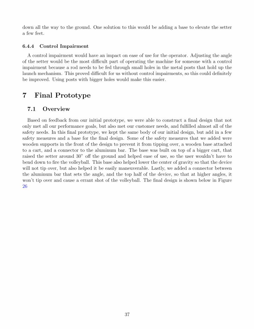
Based on feedback from our initial prototype, we were able to construct a final design that notonly met all our performance goals, but also met our customer needs, and fulfilled almost all of thesafety needs. In this final prototype, we kept the same body of our initial design, but add in a fewsafety measures and a base for the final design. Some of the safety measures that we added werewooden supports in the front of the design to prevent it from tipping over, a wooden base attachedto a cart, and a connector to the aluminum bar. The base was built on top of a bigger cart, thatraised the setter around 30” off the ground and helped ease of use, so the user wouldn’t have tobend down to fire the volleyball. This base also helped lower the center of gravity so that the devicewill not tip over, but also helped it be easily maneuverable. Lastly, we added a connector betweenthe aluminum bar that sets the angle, and the top half of the device, so that at higher angles, itwon’t tip over and cause a errant shot of the volleyball. The final design is shown below in Figure26
37
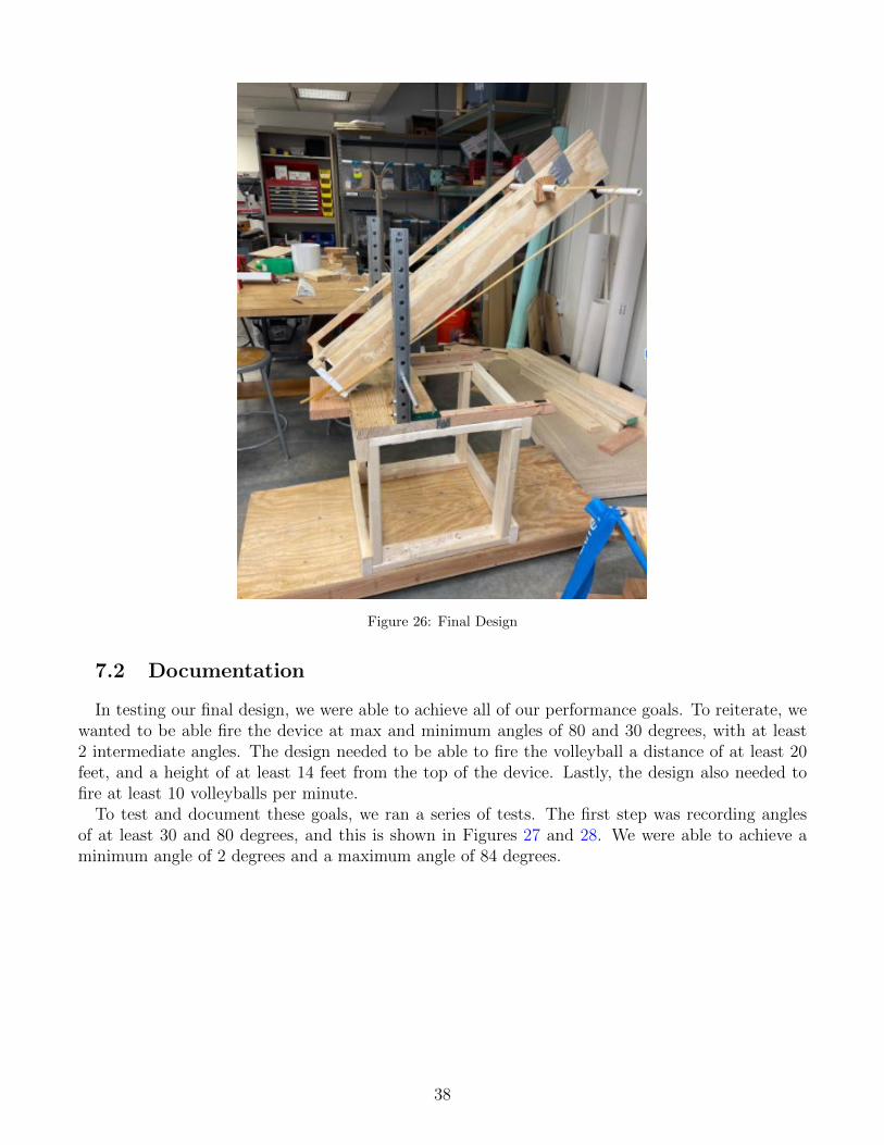
Figure 26: Final Design
7.2 Documentation
In testing our final design, we were able to achieve all of our performance goals. To reiterate, wewanted to be able fire the device at max and minimum angles of 80 and 30 degrees, with at least2 intermediate angles. The design needed to be able to fire the volleyball a distance of at least 20feet, and a height of at least 14 feet from the top of the device. Lastly, the design also needed tofire at least 10 volleyballs per minute.
To test and document these goals, we ran a series of tests. The first step was recording anglesof at least 30 and 80 degrees, and this is shown in Figures 27 and 28. We were able to achieve aminimum angle of 2 degrees and a maximum angle of 84 degrees.
38
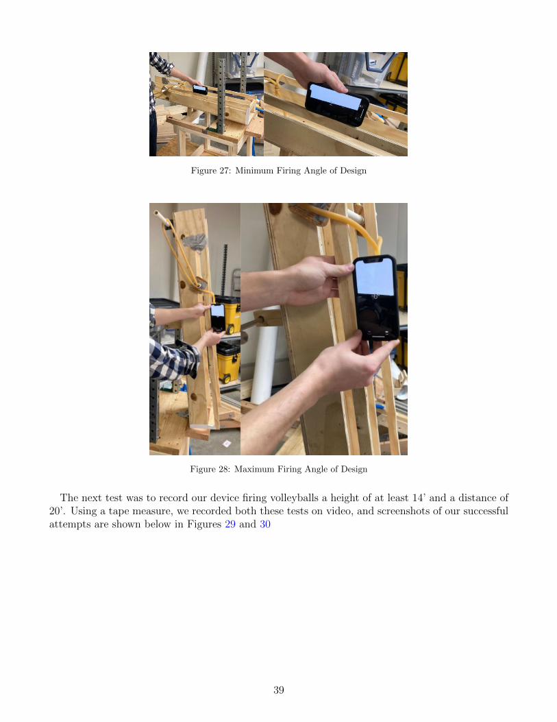
Figure 27: Minimum Firing Angle of Design
Figure 28: Maximum Firing Angle of Design
The next test was to record our device firing volleyballs a height of at least 14’ and a distance of20’. Using a tape measure, we recorded both these tests on video, and screenshots of our successfulattempts are shown below in Figures 29 and 30
39
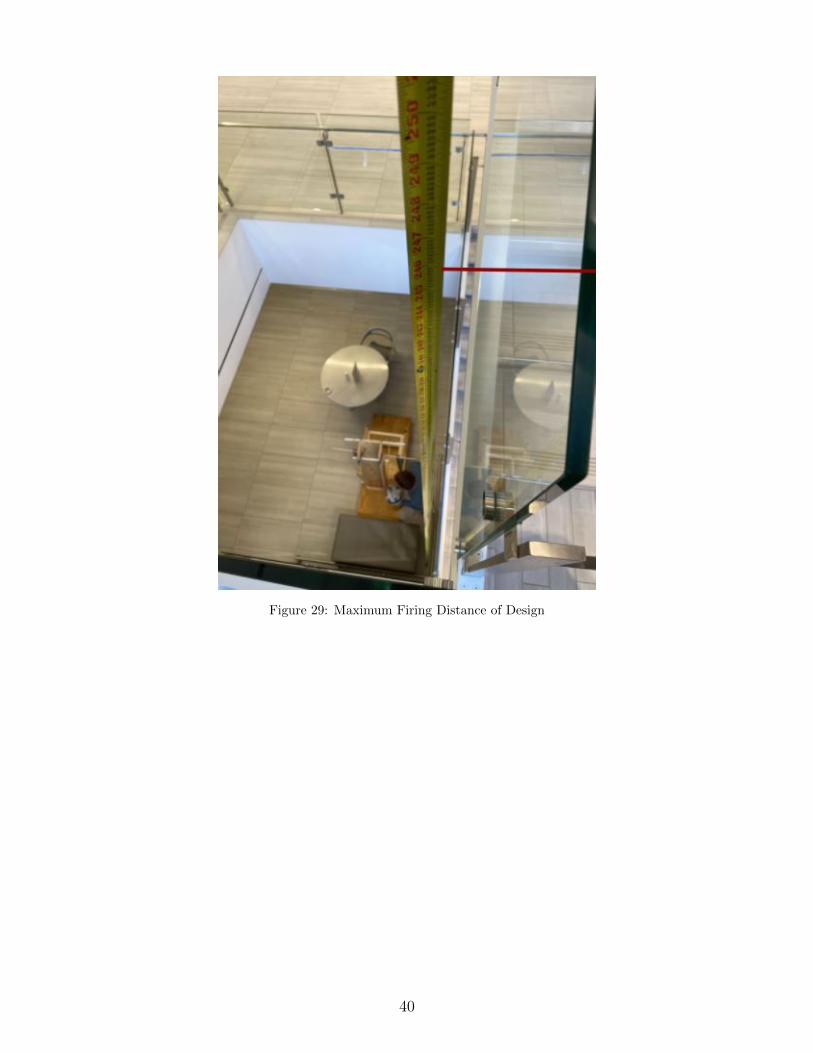
Figure 29: Maximum Firing Distance of Design
40
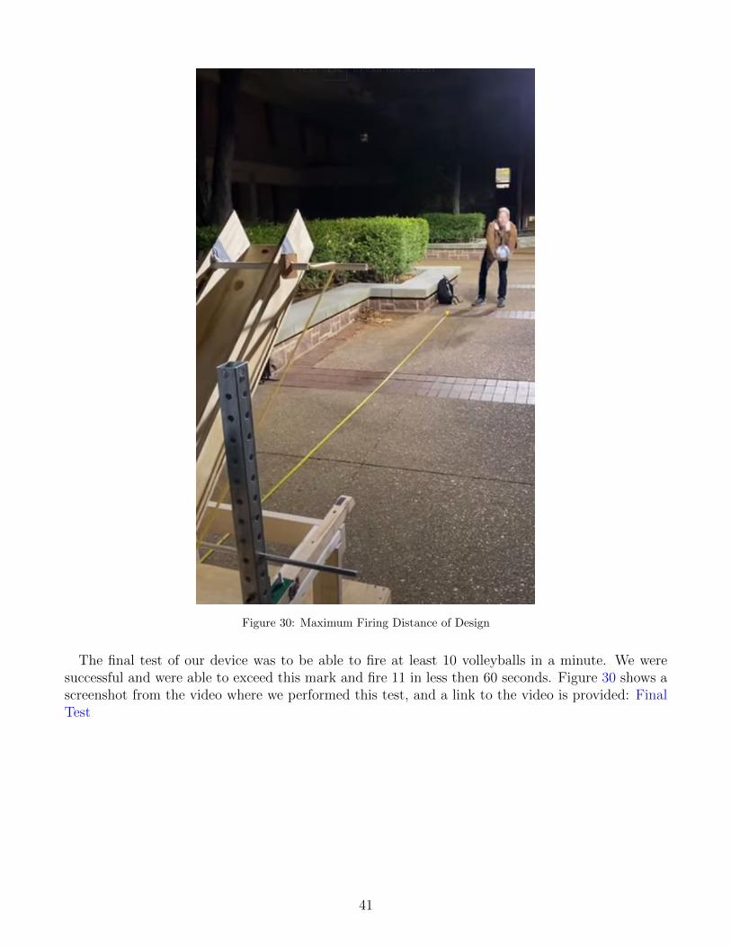
Figure 30: Maximum Firing Distance of Design
The final test of our device was to be able to fire at least 10 volleyballs in a minute. We weresuccessful and were able to exceed this mark and fire 11 in less then 60 seconds. Figure 30 shows ascreenshot from the video where we performed this test, and a link to the video is provided: FinalTest
41
Related Documents