Memory System Support for Dynamic Cache Line Assembly Lixin Zhang, Venkata K. Pingali, Bharat Chandramouli, and John B. Carter School of Computing University of Utah Salt Lake City, UT 84112 {lizhang, kmohan, bharat, retrac}@cs.utah.edu http://www.cs.utah.edu/impulse/ Abstract. The effectiveness of cache-based memory hierarchies depends on the presence of spatial and temporal locality in applications. Memory accesses of many important applications have predictable behavior but poor locality. As a result, the performance of these applications suffers from the increasing gap between processor and memory performance. In this paper, we describe a novel mechanism provided by the Impulse memory controller called Dynamic Cache Line Assembly that can be used by applications to improve memory performance. This mechanism allows applications to gather on-the-fly data spread through memory into contiguous cache lines, which creates spatial data locality where none exists naturally. We have used dynamic cache line assembly to optimize a random access loop and an implementation of Fast Fourier Transform (FFTW). Detailed simulation results show that the use of dynamic cache line assembly improves the performance of these benchmarks by up to a factor of 3.2 and 1.4, respectively. 1 Introduction The performance gap between processors and memory is widening at a rapid rate. Processor clock rates have been increasing 60% per year, while DRAM latencies have been decreasing only 7% per year. Computer architects have developed a variety of mechanisms to bridge this performance gap including out-of-order ex- ecution, non-blocking multi-level caches, speculative loads, prefetching, cache- conscious data/computation transformation, moving computation to DRAM chips, and memory request reordering. Many of these mechanisms achieve re- markable success for some applications, but none are particularly effective for irregular applications with poor spatial or temporal locality. For example, no This effort was sponsored in part by the Defense Advanced Research Projects Agency (DARPA) and the Air Force Research Laboratory (AFRL) under agreement number F30602-98-1-0101 and DARPA Order Numbers F393/00-01 and F376/00. The views and conclusions contained herein are those of the authors and should not be inter- preted as necessarily representing the official polices or endorsements, either express or implied, of DARPA, AFRL, or the US Government.

Welcome message from author
This document is posted to help you gain knowledge. Please leave a comment to let me know what you think about it! Share it to your friends and learn new things together.
Transcript

Memory System Support for
Dynamic Cache Line Assembly
Lixin Zhang, Venkata K. Pingali, Bharat Chandramouli, and John B. Carter
School of ComputingUniversity of Utah
Salt Lake City, UT 84112{lizhang, kmohan, bharat, retrac}@cs.utah.edu
http://www.cs.utah.edu/impulse/
Abstract. The effectiveness of cache-based memory hierarchies dependson the presence of spatial and temporal locality in applications. Memoryaccesses of many important applications have predictable behavior butpoor locality. As a result, the performance of these applications suffersfrom the increasing gap between processor and memory performance.In this paper, we describe a novel mechanism provided by the Impulsememory controller called Dynamic Cache Line Assembly that can beused by applications to improve memory performance. This mechanismallows applications to gather on-the-fly data spread through memory intocontiguous cache lines, which creates spatial data locality where noneexists naturally. We have used dynamic cache line assembly to optimizea random access loop and an implementation of Fast Fourier Transform(FFTW). Detailed simulation results show that the use of dynamic cacheline assembly improves the performance of these benchmarks by up to afactor of 3.2 and 1.4, respectively.
1 Introduction
The performance gap between processors and memory is widening at a rapid rate.Processor clock rates have been increasing 60% per year, while DRAM latencieshave been decreasing only 7% per year. Computer architects have developed avariety of mechanisms to bridge this performance gap including out-of-order ex-ecution, non-blocking multi-level caches, speculative loads, prefetching, cache-conscious data/computation transformation, moving computation to DRAMchips, and memory request reordering. Many of these mechanisms achieve re-markable success for some applications, but none are particularly effective forirregular applications with poor spatial or temporal locality. For example, no
This effort was sponsored in part by the Defense Advanced Research Projects Agency(DARPA) and the Air Force Research Laboratory (AFRL) under agreement numberF30602-98-1-0101 and DARPA Order Numbers F393/00-01 and F376/00. The viewsand conclusions contained herein are those of the authors and should not be inter-preted as necessarily representing the official polices or endorsements, either expressor implied, of DARPA, AFRL, or the US Government.

2 Lixin Zhang et al.
systems based on conventional microprocessors can handle the following loopefficiently if the array A is sufficiently large:
float A[SIZE];
for (i = 0; i < itcount; i++) {
sum += A[random()%SIZE];
}
We are developing a memory system called Impulse that lets applicationscontrol how, when, and what data is placed in the processor cache [2]. We dothis by adding an optional extra level of physical-to-physical address translationat the main memory controller (MMC). This extra level of translation enablesoptimizations such as “gathering” sparse data into dense cache lines, no-copypage coloring, and no-copy superpage creation. In this paper, we describe anew mechanism called dynamic cache line assembly that we are considering forImpulse. This mechanism allows applications to request that a cache line beloaded on-the-fly with data from disjoint parts of memory. Applications thatcan determine the addresses that they will access in the near future can requestthat data from those addresses be fetched from memory. This mechanism letsapplications create spatial locality where none exists naturally and works insituations where prefetching would fail due to bandwidth constraints. Simulationindicates that dynamic cache line assembly improves the performance of therandom access loop above by a factor of 3.2 and the performance of the dominantphase of FFTW by a factor of 2.6 to 3.4.
The rest of the paper is organized as follows. Section 3 briefly describes thebasic technology of Impulse. Section 4 presents the design details of dynamiccache line assembly. Section 5 studies the performance evaluation of the pro-posed mechanism. And finally, Section 6 discusses future work and concludesthis paper.
2 Related Work
Much work has been done to increase the spatial and temporal locality of regularapplications using static analysis. Compiler techniques such as loop transforma-tions [1] and data transformations [3] have been useful in improving memorylocality of applications. However, these methods are not well suited to tackle thelocality problem in irregular applications where the locality characteristics arenot known at compile time.
A hybrid hardware/software approach to improving locality proposed by Ya-mada et al. [12] involves memory hierarchy and instruction set changes to sup-port combined data relocation and prefetching into the L1 cache. Their solutionuses a separate relocation buffer to translate array elements’ virtual addressesinto the virtual relocation buffer space. The compiler inserts code to initiatethe remapping, and it replaces the original array references with correspondingrelocation buffer references. However, this approach can only relocate stridedarray references. Also, it saves no bus bandwidth because it performs relocation

Dynamic Cache Line Assembly 3
at the processor. Contention for cache and TLB ports could be greatly increasedbecause the collecting procedure of each relocated cache line must access thecache and CPU/MMU multiple times. This approach is also not designed forirregular applications.
There has been some work in developing dynamic techniques for improvinglocality. Ding and Kennedy [5] introduce the notion of dynamic data packing,which is a run time optimization that groups data accessed at close intervals inthe program into the same cache line. This optimization is efficient only if thegathered data is accessed many times to amortize the overhead of packing and ifthe access order does not change frequently during execution. DCA setup incursmuch lesser overhead because it does not involve data copying, and it allowsfrequent changes to the indirection vector.
To the best of our knowledge, hardware support for general-purpose cacheline gathering such as is supported by DCA is not present in any architectureother than Cray vector machines. For example, the Cray T3E [10] provides spe-cial support for single-word load. Sparse data can be gathered into contiguousE-registers and the resulting blocks of E-registers can then be loaded “broad-side” into the processor in cache line sized blocks, thus substantially reducingunnecessary bus bandwidth that would have been used in normal cache line fills.Dynamic cache line assembly provides similar scatter gather capability for con-ventional microprocessors without the need for special vector registers, vectormemory operations in the instruction set, or an SRAM main memory.
3 Impulse Architecture
The Impulse adaptable memory system expands the traditional virtual memoryhierarchy by adding address translation hardware to the main memory controller(MMC) [2, 11, 14]. Impulse uses physical addresses unused in conventional sys-tems as remapped aliases of real physical addresses. For instance, in a systemwith 32-bit physical addresses and one gigabyte of installed DRAM, the physi-cal addresses inside [0x40000000 – 0xFFFFFFFF] normally would be consideredinvalid. 1 Those, otherwise unused, physical addresses refer to a shadow addressspace.
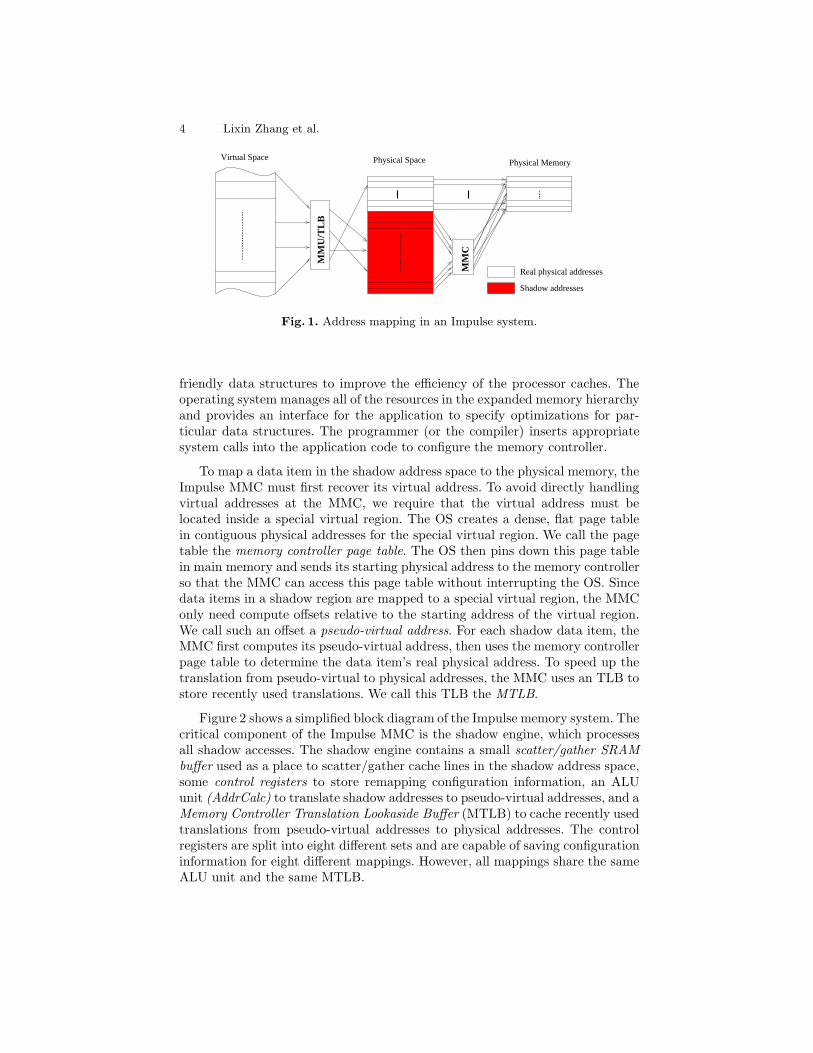
Figure 1 shows how addresses are mapped in an Impulse system. The realphysical address space is directly backed up by physical memory; its size isexactly the size of installed physical memory. The shadow address space doesnot directly point to any real physical memory (thus the term shadow) and mustbe remapped to real physical addresses through the Impulse MMC. How theMMC interprets shadow addresses presented to it is configured by the operatingsystem.
This virtualization of unused physical addresses can provide different viewsof data stored in physical memory to programs. For example, it can create cache-
1 It is common to have I/O devices mapped to special “high” addresses. This problemcan be easily avoided by not letting shadow address space overlap with I/O devicesaddresses.
4 Lixin Zhang et al.
MM
U/T
LB
MM
C
Virtual Space Physical Space Physical Memory
Real physical addresses
Shadow addresses
Fig. 1. Address mapping in an Impulse system.
friendly data structures to improve the efficiency of the processor caches. Theoperating system manages all of the resources in the expanded memory hierarchyand provides an interface for the application to specify optimizations for par-ticular data structures. The programmer (or the compiler) inserts appropriatesystem calls into the application code to configure the memory controller.
To map a data item in the shadow address space to the physical memory, theImpulse MMC must first recover its virtual address. To avoid directly handlingvirtual addresses at the MMC, we require that the virtual address must belocated inside a special virtual region. The OS creates a dense, flat page tablein contiguous physical addresses for the special virtual region. We call the pagetable the memory controller page table. The OS then pins down this page tablein main memory and sends its starting physical address to the memory controllerso that the MMC can access this page table without interrupting the OS. Sincedata items in a shadow region are mapped to a special virtual region, the MMConly need compute offsets relative to the starting address of the virtual region.We call such an offset a pseudo-virtual address. For each shadow data item, theMMC first computes its pseudo-virtual address, then uses the memory controllerpage table to determine the data item’s real physical address. To speed up thetranslation from pseudo-virtual to physical addresses, the MMC uses an TLB tostore recently used translations. We call this TLB the MTLB.
Figure 2 shows a simplified block diagram of the Impulse memory system. Thecritical component of the Impulse MMC is the shadow engine, which processesall shadow accesses. The shadow engine contains a small scatter/gather SRAMbuffer used as a place to scatter/gather cache lines in the shadow address space,some control registers to store remapping configuration information, an ALUunit (AddrCalc) to translate shadow addresses to pseudo-virtual addresses, and aMemory Controller Translation Lookaside Buffer (MTLB) to cache recently usedtranslations from pseudo-virtual addresses to physical addresses. The controlregisters are split into eight different sets and are capable of saving configurationinformation for eight different mappings. However, all mappings share the sameALU unit and the same MTLB.

Dynamic Cache Line Assembly 5
DRAM
L1CPU
MMU
L2
DRAM
syst
em m
emor
y b
us
MMCShadow Address
DRAM Interface
Norm
al Address
Shadow engine
Buf
fer
Registers
AddrCalc
MTLB
?
Fig. 2. Impulse architecture.
4 Design
The proposed dynamic cache line assembly mechanism is an extension of Im-pulse’s scatter/gather through an indirection vector remapping mechanism. Itsmain goal is to enable applications to access data spread through memory asif it were stored sequentially. In this section, we first talk about scatter/gatherthrough an indirection vector, then describe the design of dynamic cache lineassembly.
4.1 Scatter/Gather through An Indirection Vector
The Impulse system supports a remapping called scatter/gather through an in-direction vector. For simplicity, we refer to it as IV remapping throughout therest of this paper. IV remapping maps a region of shadow addresses to a datastructure such that a shadow address at offset soffset in the shadow region ismapped to data item addressed by vector[soffset] in the physical memory.
Figure 3 shows an example of using IV remapping on a sparse matrix-vectorproduct algorithm. In this example, Pi is an alias array in the shadow ad-dress space. An element Pi[j] of this array is mapped to element P[ColIdx[j]]in the physical memory by the Impulse memory controller. For a shadow cacheline containing elements Pi[j], Pi[j+1], . . . , Pi[j+k], the MMC fetches elementsP[ColIdx[j]], P[ColIdx[j+1]], . . . , P[ColIdx[j+k]] one by one from the physicalmemory and packs them into a dense cache line.
Figure 4 illustrates the gathering procedure. The shadow engine containsa one cache line SRAM buffer to store indirection vectors. We call this SRAMbuffer the IV buffer. When the MMC receives a request for a cache line of Pi[], itloads the corresponding cache line of ColIdx[] into the IV buffer, if the IV buffer

6 Lixin Zhang et al.
Pi[j]sum += Data[j] *
}b[i] = sum;
;
After remappingOriginal code
for (j = Rows[i]; j < Rows[i+1]; j++)
sum += Data[j] * P[ColIdx[j]];
for (j = Rows[i]; j < Rows[i+1]; j++)
sum = 0;
for (i = 0; i < n; i++) {
b[i] = sum;
sum = 0;
for (i = 0; i < n; i++) {
Pi = AMS_remap(P, ColIdx, n, ...);
}
Fig. 3. Scatter/gather through an indirection vector changes indirect accesses to se-quential accesses.
AddrCalc
MTLB
IV bufferShadow engine
Scatter/gather buf
System Bus
Physical Memory
Cache
Fig. 4. Visualize the gathering procedure through an indirection vector.
does not already contain it. The MMC then can interpret one element of theindirection vector per cycle. The indirection vector may store virtual addresses,array indices, or even real physical addresses. What it stores (addresses or in-dices) is specified when the remapping is configured; without loss of generality,we will refer to the contents of the IV buffer generically as “addresses” through-out the rest of this paper. If the IV buffer stores virtual address or array indices,the MMC passes each entry to the AddrCalc unit to generate a pseudo-virtualaddress and translates the pseudo-virtual address to a physical address using theMTLB. Once the MMC has a physical address for a data element, it uses thisaddress to access physical memory. When a data item returns, it is packed intoa dense cache line in the scatter/gather buffer.
By mapping sparse, indirectly addressed data items into packed cache lines,scatter/gather through an indirection vector enables applications to replace indi-rect accesses with sequential accesses. As a result, applications reduce their busbandwidth consumption, the cache footprint of their data, and the number ofmemory loads they must issue.
A naive implementation of IV remapping requires that the indirection vectorexists in the program and its number of elements be the same as the number ofdata items being gathered, e.g., Rows[n] in Figure 3. We extend IV remapping toimplement dynamic cache line assembly, which can be used by programs whereno indirection vector exists naturally and where the size of an indirection vectorneed not be equal to the number of data items being gathered.

Dynamic Cache Line Assembly 7
4.2 Dynamic Cache Line Assembly
The basic idea of dynamic cache line assembly is to create indirection vec-tors dynamically during program execution and to access them using Impulse’sIV remapping mechanism. The indirection vectors typically are small, usuallysmaller than a page. We choose small indirection vectors because accessing themand the resulting small alias arrays leaves a very small footprint in the cache.The small indirection vectors and alias arrays can be reused to remap large datastructures.
To use DCA, the application performs a system call to allocate two specialranges of shadow addresses and have the operating system map new virtualaddresses to these two ranges. The first range is used to store the addressesfrom which the application wishes to load data (we call this the address region),while the second range is used to store the requested data (we call this the dataregion). The number of addresses that can be stored in the address region is thesame as the number of data items that can be stored in the data region. Thereis a one-to-one mapping between elements of the two ranges: the ith elementof the address region is the address of the ith element of the data region. Theoperating system also allocates a contiguous real physical memory to back upthe address region in case an indirection vector is forced out of the IV bufferbefore the MMC has finished using it.
After setting up the regions, the operating system informs the MMC of theirlocation, as well as the size of each address and the size of the object that needsto be loaded from each address. For simplicity, we currently require that boththe address and data regions are a multiple of a cache line size, and that thedata objects are a power of two bytes.
After setup, the application can exploit dynamic cache line assembly by fill-ing a cache line in the address region with a set of addresses and writing it backto memory through a cache flush operation. When the MMC sees and recognizesthis write-back, it stores the write-back cache line into both the IV buffer andthe memory. Storing the write-back into the memory is necessary because the IVbuffer may be used by another writeback. When the MMC receives a load requestfor a cache line in the data region, it checks to see if the IV buffer contains thecorresponding cache line in the address region. If the required cache line is notin the IV buffer, the shadow engine loads it from memory. The MMC then inter-prets the contents of the IV buffer as a set of addresses, passes these addressesthrough the AddrCalc unit and the MTLB to generate the corresponding physi-cal addresses, fetches data from these physical addresses, and stores the fetcheddata densely into the scatter/gather buffer inside the shadow engine. After anentire cache line has been packed, the MMC supplies it to the system bus fromthe scatter/gather buffer.
Figure 5 shows how dynamic cache line assembly can be used to improve theperformance of the random access loop presented in Section 1. In this example,we assume that L2 cache lines are 128 bytes, so each cache line can hold 32

8 Lixin Zhang et al.
float *aliasarray;
int *idxvector;
/* aliasarray[i] <== A[idxvector[i]] */
setup_call(A, SIZE, 32, &aliasarray, &idxvector);
for (i = 0; i < itcount/32; i++) {
for (k = 0; k < 32; k++)
idxvector[k] = & (A[random()%SIZE]);
flush_cache line(idxvector);
memory_barrier();
for (k = 0; k < 32; k++)
sum += aliasarray[k];
purge_cache line(aliasarray);
}
Fig. 5. Using dynamic cache line assembly on the random access loop
addresses or 32 floats2. The program first allocates a 32-element address regionidxvector and a 32-element data region aliasarray through the system callsetup call(). In each iteration, the application fills a cache line’s worth of theaddress region with addresses, flushes it, and then reads from the correspondingshadow data region to access the data. Traditional microprocessors with out-of-order execution usually give reads higher priority than writes, so the readrequest for the data may be issued before the flush occurs. To ensure this doesnot happen, we insert a memory barrier after the flush. Since the same dataregion is used in every iteration, the old data in the cache must be invalidatedso that the next fetch will go to the MMC to retrieve the right data.
The main overhead of using dynamic cache line assembly is that the programmust handle the address regions (i.e., indirection vectors) and the MMC mustgather a cache line using multiple DRAM fetches. In this example, filling a cacheline of the indirection vector introduces 32 sequential memory accesses that donot exist in the original code. Fortunately, those 32 accesses generate only onecache miss. Accessing a cache line of the data region results in another cache miss.As a result, the Impulse version has 2 cache misses for every 32 data accesses.In the original code, however, the same 32 data accesses generate roughly (32
* (1 - sizeof(cache) / sizeof(A)) cache misses when the array A is largerthan the cache. Dynamically gathering a cache line in the MMC is much moreexpensive than fetching a single dense region of memory. Consequently, the codein Figure 5 will be memory-bound because there is a long waiting time in each
2 It is not required that the objects being fetched are the same size as an address. If,for example, you want to dynamically fetch quad-precision floating point numbers(16 bytes), each time the application flushes a line of addresses, the MMC will fetchfour cache lines full of data.

Dynamic Cache Line Assembly 9
iteration for the MMC packing and returning data. However, its performancecan be improved using unroll-and-jam.
#define PrecomputeAddresses(start, end) \
for (k = start; k < end; k++) \
idxvector[k] = &(A[random()%SIZE]); \
flush_cache line(&(idxvector[start])); \
memory_barrier(); \
prefetch_cache line(&(aliasarray[start]));
#define AccessData(start, end) \
for (l = start; l < end; l++) \
sum += aliasarray[l]; \
purge_cache line(&(aliasarray[start]));
float *aliasarray;
int *idxvector;
/* aliasarray[i] <== A[idxvector[i]] */
setup_call(A, SIZE, 64, &aliasarray, &idxvector);
PrecomputeAddresses(0, 32);
for (i = 0; i < itcount/64 - 1; i++) {
PrecomputeAddresses(32, 64);
AccessData(0, 32);
PrecomputeAddresses(0, 32);
AccessData(32, 64);
}
......
Fig. 6. Using unroll-and-jam with dynamic cache line assembly.
Figure 6 illustrates how unroll-and-jam can be used to improve performance.By using two cache lines for each of the address and data regions, we can overlapcomputation on one line’s worth of data while prefetching the next line, therebyhiding the long memory latency of dynamic cache line gathering. To support thisoptimization, we need to increase the size of the IV buffer to two cache lines.With software unroll-and-jam, the processor may flush back one cache line ofthe address region while the MMC is gathering data from another set of address.With two cache lines in the IV buffer, the second write-back can be saved in thebuffer instead of being written back to DRAM and then reloaded when needed.

10 Lixin Zhang et al.
5 Performance Evaluation
We evaluated the performance of dynamic cache line assembly using execution-driven simulation. We compared the performance of two benchmarks using dy-namic cache line assembly with the same benchmarks unmodified. The firstbenchmark is the synthetic “random walk” microbenchmark described in Sec-tion 1. The second benchmark is a three-dimensional FFT [6] program from DISbenchmark suite [7]. Both benchmarks were compiled using the SPARC SC4.2compiler with the -xO4 option to produce optimized code.
5.1 Simulation Environment
Our studies use the execution-driven simulator URSIM [13] derived from RSIM [9].URSIM models a microprocessor close to MIPS R1000 [8] and a split-transactionMIPS R10000 cluster bus with a snoopy coherence protocol. It also simulates theImpulse adaptable memory system in great detail. The processor is a four-way,out-of-order superscalar with a 64-entry instruction window. The D/I unifiedTLB is single-cycle, fully associative, software-managed, and has 128 entries.The instruction cache is assumed to be perfect. The 64-kilobyte L1 data cacheis non-blocking, write-back, virtually indexed, physically tagged, direct-mapped,and has 32-byte lines and one-cycle latency. The 512-kilobyte L2 data cache isnon-blocking, write-back, physically indexed, physically tagged, two-way asso-ciative, and has 128-byte lines and eight-cycle latency. The split-transaction busmultiplexes addresses and data, is eight bytes wide, has a three-cycle arbitrationdelay and a one-cycle turn-around time. The system bus, memory controller,and DRAMs have the same clock rate, which is one third of the CPU clock. Thememory supports critical word first. It returns the critical quad-word for a loadrequest 16 bus cycles after the corresponding L2 cache miss occurs. The memorysystem contains 8 banks, pairs of which share an eight-byte wide bus betweenDRAM and the MMC.
The address translation procedure in the shadow engine is fully pipelined. Foreach shadow access entering the pipeline, the engine generates the first physicaladdress four cycles later and one physical address per cycle afterwards, providedthat no MTLB miss occurs. On an MTLB miss, the pipeline is stalled untilthe required page table entry has been loaded into the MTLB. The MTLB isconfigured to be four-way associative, with 256 entries and a one-memory-cyclelookup latency.
5.2 Results
The performance results presented here are obtained through complete simula-tion of the benchmarks, including both kernel and application time, the overheadof setting up and using dynamic cache line assembly, and the resulting effectson the memory system.

Dynamic Cache Line Assembly 11
Elapsed TLB hit L1 hit L2 hit Miss Memory Speedupcycles rate rate rate rate latency
Base 196M 73.67% 65.68% 7.76% 26.56% 51 cycles
Impulse 61M 99.97% 93.37% 6.21% 0.42% 113 cycles 3.22
Table 1. Performance results for the microbenchmark.
Microbenchmark In the synthetic microbenchmark, A[] holds one millionelements and two million random accesses are performed. In theory, its cache hitrate should be the size of the cache divided by the size of A[]. So larger A[] hassmaller cache hit rate and likely yields better performance improvement withdynamic cache line assembly. We choose A[] to contain one million elementssimply because it is large enough to prove the effectiveness of dynamic cacheline assembly and its simulation can complete in a reasonable amount of time.
Table 1 presents the results of this experiment. The unrolled version of themicrobenchmark shown in Figure 6, which uses DCA, executes 3.2 times fasterthan the baseline version. The Impulse version increases the L1 cache hit ratefrom 65.68% to 93.37% and reduces the number of accesses that are handledby the main memory from 26.56% to 0.42%. One nice side effect of dynamiccache line assembly is the improved TLB performance. The base version of thisbenchmark has very bad TLB behavior because the TLB is not big enough tohold the translations for the entire array A[]. After using dynamic cache lineassembly, the TLB needs at most two entries to hold the translations for theaddress and data regions. Table 1 shows that the TLB hit rate has indeed beengreatly improved (from 73.67% to 99.97%).
Average memory latency increases from 51 cycles to 113 cycles, because dy-namic cache line assembly requires more work than a simple dense cache line fill,but the improved cache performance overwhelms the effect of the increased mem-ory latency. The memory latency reported here is the average latency for all loadaccesses, excluding prefetch accesses. The average memory latency of prefetchaccesses reaches around 600 cycles due to high MTLB miss rate (82.97%). TheMTLB is configured to be four-way set associative with 256 entries. The simu-lated system uses four-kilobyte base page, so the MTLB’s maximum reach is onlyone megabyte, much less than the A[], which is four megabytes. In the real hard-ware we are building, the MTLB has 1024 entries. We reduced the MTLB size to256 entries in our simulations to generate high MTLB miss rates, while leavingthe MTLB larger than the CPU TLB (an important feature of Impulse [11]).The good performance of /dynamiciv/ even with such high MTLB miss ratesgives us confidence that our results will hold, and perhaps even improve, onlarger data structures. Despite the high latency of dynamic cache line assembly,the use of prefetching results in an average latency of demand requests of 113cycles. In this microbenchmark, not enough work is done on each piece of datafor prefetching to completely hide the load latency, so we still see a high aver-

12 Lixin Zhang et al.
age memory latency. If more work were performed per data item, the memorylatency perceived by the processor would drop.
FFT Fast Fourier Transform(FFT) is generally characterized by poor temporaland spatial locality. FFTW [6] is a specific implementation of FFT whose self-optimizing approach lets it outperform most other FFT implementations. Wechose this FFT implementation as our baseline and modified it to use dynamiccache line assembly.
������������������������
��������������������
Y
X
Z
DEPTH
1 L2 CACHE LINE
MEMORYACCESSES
Fig. 7. Shows memory access pattern of depth phase and a cache-column
In general, 3D FFTW operates in two phases. The 3D input array is accessedalong x and y axes in the first phase of the computation. In the second phase,which we call the Depth Phase, data is accessed along the z axis. For large arrays,row-major array layout causes poor locality when the array is accessed along they and z dimensions. The memory performance accesses along the y dimension isusually acceptable because (1) the preceding the x dimension access load much ofthe necessary data into the cache and (2) the amount of data accessed per planeis usually smaller than the cache. As a result, most y accesses hits in the cache.However, most z accesses during the depth phase suffer cache misses, whichaccounts for 40-70% of total execution time. Accesses along the y-dimension andz-dimension load into the cache columns of data whose length is the length ofthe array dimension being traversed (y or z) and whose width is one cache line.We call each such block of data a cache column, one of which is highlighted inFigure 7. Each cache column, once loaded, is reused for as many column accessesas possible.
For FFTW, array elements are 16 bytes (a pair of double precision floatingpoint numbers). Eight elements can fit into each 128-byte L2 cache line, so asingle cache column will be able to service as many as seven adjacent columnaccesses before a cache miss will occur. However, if a cache column is larger than

Dynamic Cache Line Assembly 13
Input Type Elapsed TLB hit L1 hit L2 hit Miss SpeedupCycles rate rate rate rate Depth Overall
567x61x51 Base 3.1B 98.92% 92.66% 4.97% 2.37%
Impulse 2.2B 99.99% 93.50% 5.50% 1.00% 2.64 1.40
576x57x31 Base 1.8B 99.06% 93.03% 4.90% 2.07%
Impulse 1.2B 99.99% 94.55% 4.42% 1.03% 2.74 1.47
576x7x11 Base 36.5M 99.46% 92.53% 4.70% 2.77%
Impulse 18.6M 99.98% 93.92% 5.48% 0.60% 3.38 2.29
Table 2. Performance results for FFTW benchmark
the L2 cache, which is the case for input arrays with large y or z dimensions,then almost every access during the depth phase will be a cache miss. The reasonfor this is that each cache line in the cache column will be evicted before it canbe reused. For this benchmark, prefetching is ineffective because the amount ofwork performed per element is dwarfed by the time required to load a cacheline from memory. Because FFTs of interest are performed on fairly large inputarrays, we evaluated the performance of DCA only for such arrays where thecache column size exceeds cache sizes. Also, we only consider arrays with largez dimensions and thus restrict our optimization to the depth phase. This makesour results conservative, as additional performance benefits could be had byapplying DCA to accesses along the y accesses in the first phase of the FFT.To reduce simulation overhead, we simulated an 8-kilobyte L1 cache and a 64-kilobyte 64K L2 cache. For these cache sizes, the height of a cache column to beat least 512. We arbitrarily chose input’s z dimension value to be 567 and 576.the x and y dimension sizes also were chosen arbitrarily.
The FFTW library consists of highly optimized code for computing partsof the transform, called codelets [6]. Every multidimensional FFT is translatedinto a series of calls to these codelets. As part of optimizing FFTW to exploitImpulse’s DCA mechanism, we modified each codelet to create dynamic indirec-tion vectors pointing at the array elements being accessed by that codelet. Asin the random access benchmark, we unrolled-and-jammed the resulting codeand added prefetching instructions to overlap computation with the DCA oper-ation. Conventional compiler-directed prefetching or data reordering techniqueswill not work because the addresses and strides are input parameters for thecodelets, and thus only known at runtime.
Table 2 presents our results for the FFT benchmark for various input sizes.DCA improves the performance of the depth phase by 2.64 to 3.48, depending onthe input size. Total application speedup ranged from 1.40 to 2.29. The reasonfor these performance improvements can also be seen in Table 2. The use ofDCA reduces the miss rate by more than a factor of two, and TLB performanceimproves significantly. The TLB performance improvement is due to the factthat all DCA accesses are to a small range of addresses, rather than the entirerange of the input array.

14 Lixin Zhang et al.
6 Conclusions and Future Work
The development of the dynamic cache line assembly mechanism is still in itsinfancy. Future work includes applying it to more applications and further opti-mizing its performance. We believe the proposed mechanism can be effective formany applications with poor locality. To confirm this hypothesis, we are evalu-ating DCA’s potential on a mix of pointer-intensive programs from the Oldenbenchmark suite, image processing programs, and irregular scientific applicationkernels (Moldyn and NBF).
The performance of dynamic cache line assembly can be improved in a num-ber of ways. The current implementation loads each cache line of the addressregion from the memory before overwriting it with new addresses. If the proces-sor we modeled had supported for write, no-allocate, such as is possible via theAlpha 21264 WH64 instruction [4], we could eliminate this unnecessary cachemiss. Along the same lines, without support from the ISA, we must synchro-nize flushes of the address region and the subsequent accesses of the data regionusing memory barriers. A memory barrier serializes accesses before and after itand can impede the processor access streams. One way to eliminate this effectwould be to extend the ISA with a special “indirection gather” instruction. Theinstruction would combine a flush back of the address region with a prefetch ofthe corresponding data region.
In conclusion, we believe that as the performance gap between processorsand DRAM grows, a more flexible memory interface will be necessary to hidememory latency. Simply building larger on-chip caches will not suffice, and willincrease cache access latency. We have begun investigating the potential benefitsof allowing applications to selectively read/write data from/to random locationsin memory efficiently when conventional caching does not suffice. Our initialexperimental results have shown that for applications with poor spatial locality,such a mechanism can improve performance by a factor of three or more.
References
1. S. Carr, K. McKinley, and C.-W. Tseng. Compiler optimizations for improvingdata locality. In Proceedings of the 6th Symposium on Architectural Support forProgramming Languages and Operating Systems, pages 252–262, Oct. 1994.
2. J. Carter, W. Hsieh, L. Stoller, M. Swanson, L. Zhang, E. Brunvand, A. Davis,C.-C. Kuo, R. Kuramkote, M. Parker, L. Schaelicke, and T. Tateyama. Impulse:Building a smarter memory controller. In Proceedings of the Fifth Annual Sympo-sium on High Performance Computer Architecture, pages 70–79, Jan. 1999.
3. M. Cierniak and W. Li. Unifying data and control transformations for distributedshared memory machines. Technical Report TR-542, University of Rochester,November 1994.
4. Compaq Computer Corporation. Alpha 21264 Microprocessor Hardware ReferenceManual, July 1999.
5. C. Ding and K. Kennedy. Improving cache performance in dynamic applicationsthrough data and computation reorganization at run time. In Proceedings of the

Dynamic Cache Line Assembly 15
1999 ACM SIGPLAN Conference on Programming Language Design and Imple-mentation, pages 229–241, May 1999.
6. M. Frigo and S. Johnson. FFTW: An adaptive software architecture for the FFT.In Proceedings of ICASSP Conference, 1998.
7. J. W. Manke and J. Wu. Data-Intensive System Benchmark Suite Analysis andSpecification. Atlantic Aerospace Electronics Corp., June 1999.
8. MIPS Technologies Inc. MIPS R10000 Microprocessor User’s Manual, Version 2.0,Dec. 1996.
9. V. Pai, P. Ranganathan, and S. Adve. RSIM reference manual, version 1.0. IEEETechnical Committee on Computer Architecture Newsletter, Fall 1997.
10. S. Scott. Synchronization and communication in the T3E multiprocessor. In Pro-ceedings of the 7th Symposium on Architectural Support for Programming Lan-guages and Operating Systems, Oct. 1996.
11. M. Swanson, L. Stoller, and J. Carter. Increasing TLB reach using superpagesbacked by shadow memory. In Proceedings of the 25th Annual International Sym-posium on Computer Architecture, pages 204–213, June 1998.
12. Y. Yamada. Data Relocation and Prefetching in Programs with Large Data Sets.PhD thesis, University of Illinois at Urbana-Champaign, Urbana, IL, 1995.
13. L. Zhang. URSIM reference manual. Technical Report UUCS-00-015, Universityof Utah, August 2000.
14. L. Zhang, J. Carter, W. Hsieh, and S. McKee. Memory system support for im-age processing. In Proceedings of the 1999 International Conference on ParallelArchitectures and Compilation Techniques, pages 98–107, Oct. 1999.
Related Documents