1 Dimensions are in millimeters (inches) www.fcai.fujitsu.com Specifications subject to change MEMORY CARD CONNECTORS (PCMCIA CONFORMABLE) 560H SERIES ■ FEATURES • The connectors conform to the Japan Electronic Industry Development Association (JEIDA) and Personal Computer Memory Card International Association (PCMCIA) standards Ver. 4. • Contact pitch of 1.27 mm (0.050 in.) x 1.27 mm (0.050 in.). Incorrect insertion is prevented. Hot system plugging is possible (contact detection). • Plugs have an easy-to-use ejection mechanism. • Raised mounting type connectors (under which components can be mounted) and low-profile connectors are available. • In addition to connectors for type I and type II cards, a connector for type III cards has been provided. • The sockets are of the SMT type. A straddle-type socket for double-sided mounting and a socket for single-sided mounting are available. ■ PIN CONNECTOR (PLUG) CONTACT LENGTH ■ SPECIFICATIONS Item Operating temperature range Current rating Voltage rating Contact resistance Insulation resistance Dielectric withstanding voltage Insertion/withdrawal life Specification – 55°C to + 85°C DC 0.5 A AC 250 V 40 mΩ max (6 VDC, 0.1 A) 1000 MΩ min. (500 VDC) 500 VAC for 1 minute Industrial environment: 5,000 times Office environment: 10,000 times Contact type Power, ground pins Card detection pins Other signal pins Pin No. 1, 17, 34, 35, 51, 68 36, 67 Others Contact length 5.0 mm (0.196 in.) 3.5 mm (0.137 in.) 4.25 mm (0.167 in.) ■ MATERIALS Plug body: PPS resin UL94V-0 : 6T nylon (for type III card connector) UL94V-0 Ejector: Polyester : PPS resin (for SMT and type III card connectors) Copper alloy Contact: Gold over palladium over nickel (PAGOS) Terminal: Palladium Specification Item Insulating material Conductor Plating

Welcome message from author
This document is posted to help you gain knowledge. Please leave a comment to let me know what you think about it! Share it to your friends and learn new things together.
Transcript
1Dimensions are in millimeters (inches) www.fcai.fujitsu.com
Specificationssubject to change
MEMORY CARD CONNECTORS(PCMCIA CONFORMABLE)
560H SERIES
FEATURES
• The connectors conform to the Japan Electronic IndustryDevelopment Association (JEIDA) and PersonalComputer Memory Card International Association(PCMCIA) standards Ver. 4.
• Contact pitch of 1.27 mm (0.050 in.) x 1.27 mm (0.050 in.).Incorrect insertion is prevented. Hot system plugging ispossible (contact detection).
• Plugs have an easy-to-use ejection mechanism.
• Raised mounting type connectors (under whichcomponents can be mounted) and low-profile connectorsare available.
• In addition to connectors for type I and type II cards, aconnector for type III cards has been provided.
• The sockets are of the SMT type. A straddle-type socket for double-sided mounting and a socket for single-sidedmounting are available.
PIN CONNECTOR (PLUG) CONTACT LENGTH SPECIFICATIONS
Item
Operating temperature range
Current rating
Voltage rating
Contact resistance
Insulation resistance
Dielectric withstanding voltage
Insertion/withdrawal life
Specification
– 55°C to + 85°C
DC 0.5 A
AC 250 V
40 mΩ max (6 VDC, 0.1 A)
1000 MΩ min. (500 VDC)
500 VAC for 1 minute
Industrial environment: 5,000 times
Office environment: 10,000 times
Contact type
Power, ground pins
Card detection pins
Other signal pins
Pin No.
1, 17, 34, 35, 51, 68
36, 67
Others
Contact length
5.0 mm (0.196 in.)
3.5 mm (0.137 in.)
4.25 mm (0.167 in.)
MATERIALS
Plug body: PPS resin UL94V-0
: 6T nylon (for type III card connector) UL94V-0
Ejector: Polyester
: PPS resin (for SMT and type III card connectors)
Copper alloy
Contact: Gold over palladium over nickel(PAGOS)Terminal: Palladium
SpecificationItem
Insulating material
Conductor
Plating

560H Series Connector Conforming to Ver. 4
2Dimensions are in millimeters (inches) www.fcai.fujitsu.com
Specificationssubject to change
ORDERING PART NUMBER [PLUG]
V4: Conforms to Ver.4E4: Conforms to Ver.4 and anti-ESD
Specification
Plating G: Gold plating
Number of contacts: 68, 136
Body P: Plug
Pin type 4: Straight5: Right-angle8: SMT
560 series connector
Fujitsu connector
FCN-56 5 P 068-G / XC-V4
ORDERING PART NUMBER [SOCKET]
FCN-56 8 J 068-G / 0
Terminal type 0: PC board double-sided straddle type B: PC board single-sided mounting type
Plating G: Gold plating
Number of contacts: 68
Body J: Socket
Pin type 8: SMT
560 series connector
Fujitsu connector
560H Series Connector Conforming to Ver. 4
3Dimensions are in millimeters (inches) www.fcai.fujitsu.com
Specificationssubject to change
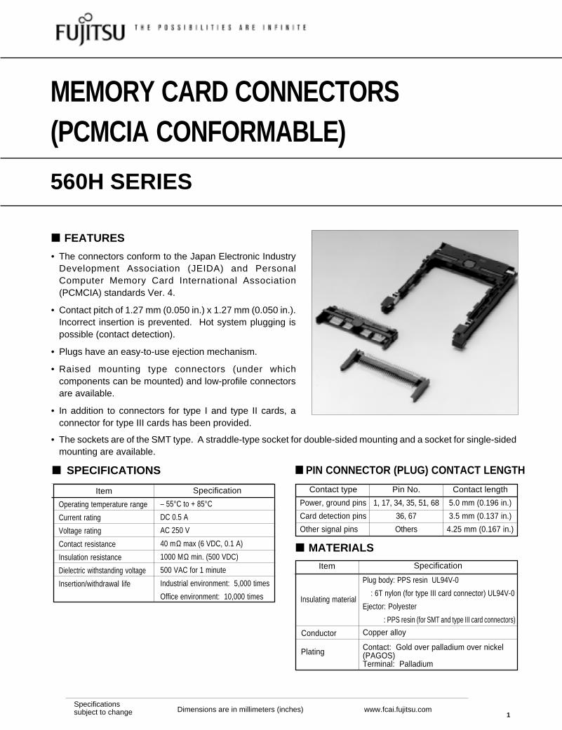
RIGHT-ANGLE PLUG, THROUGH HOLE TYPE (WITH NO EJECTOR, STANDARD TYPE)
SUPPORTS TYPE I, II CARDS
DIMENSIONS AND PC BOARD MOUNTING HOLE LAYOUT (MOUNTING SIDE)
RIGHT-ANGLE PLUG, THROUGHHOLE TYPE (((((WITH NO EJECTOR, LOW-PROFILE TYPE )))))SUPPORTS TYPE I, II CARDS
DIMENSIONS AND PC BOARD MOUNTING HOLE LAYOUT (MOUNTING SIDE)
Unit: mm (in.)
Part number: FCN-565P068-G/C-V4
3(0.118)
4(0.157)
1.51
(0.
059)
1.90
5 (0
.075
)
3.81
0 (0
.15)
5.71
5 (0
.225
)
50.8 (2)
1.27 (0.05) × (34-1) = 41.91 (1.65)
1.27 (0.05)
3(0
.118
)42
(1.
65)
12.2
(0.
48)
58.7 (2.31)
24.9
(0.
98)
1.27
(0.
05) 1.27 (0.05)
1.27 (0.05) × (34-1) = 41.91 (1.65)
No.1
No.35 No.68
No.34
2- ø 2.8 (0.11)
2.5mm (0.098)deep spot facing
3.6 (0.141)
Part number: FCN-565P068-G/01-V4
• Models with a board lock (metal fitting for direct mounting) are also available. Part number: FCN-565P068-G/12-V4 (for 1.2 mm (0.047 in.) to 1.6 mm (0.063 in.) thick PC board)FCN-565P068-G/08-V4 (for 1.0 mm (0.039 in.) thick PC board)
• Long-terminal models are also available. Part number: FCN-565P068-G/13-V4 (4 mm (0.157 in.))FCN-565P068-G/02-V4 (10 mm (0.394 in.))
• Models which support Type III are also available. Part number: FCN-565P068-G/17-V4FCN-565P068-G/18-V4 (with board lock, for 1.2 mm (0.047 in.) to 1.6 mm(0.063 in.) thick PC board )
Unit: mm (in.)
50.8 (2)
0.51
(0.
02)
1.90
5 (0
.075
)
3.81
0 (0
.15)
5.71
5 (0
.225
)
7 (0.276)
3 (0.118)
11.2
(0.
44)
5 (0
.197
)
1 (0
.039
)4.
25 (
0.16
7)3.
5 (0
.138
)
2- ø 2.8 (0.110)41.91 (1.65)
1.27 (0.05)
59.7(2.35)
2.42
(0.
095)
35.2
(1.
39)
2.5mm (0.098)deep spot facing
41.91 (1.65)1.27 (0.05)
No.17
No.51No.34
No.68No.35
No.1
1.27
(0.
05)
4 (0
.157
)
50.8 (2) ±0.1 (0.0039)
41.91 (1.65) ±0.1 (0.0039)
1.27 (0.05) ±0.05 (0.0020)
No.3
No.1
No.2
5.715 (0.225)±0.05 (0.0020)
3.810 (0.15)±0.05 (0.0020)
1.905 (0.075)±0.05 (0.0020) No.68
2- ø 2.8 (0.110)±0.1 (0.0039)
68- ø 1 (0.039)±0.05 (0.0020)
(Card insertion side)
50.8 (2) ±0.1 (0.0039)
41.91(1.65) ±0.1 (0.0039)
1.27 (0.05) ±0.05 (0.0020)
No.3
No.1
No.2
5.715 (0.225) ±0.05 (0.0020)
3.810 (0.15) ±0.05 (0.0020)
1.905 (0.075) ±0.05 (0.0020) No.68
2- ø 2.8 (0.110)±0.1 (0.0039)
68- ø 1 (0.039)±0.05 (0.0020)
(Card insertion side)Use M2.5 (0.098 in) nut and screws. Screw torque is 3.2 kg/cm.In order to avoid damage to the connector, do not pull out the card at an angle.
560H Series Connector Conforming to Ver. 4
4Dimensions are in millimeters (inches) www.fcai.fujitsu.com
Specificationssubject to change
0.51
(0.
059)
3 (0.118)
1.90
5 (0
.075
)
3.81
0 (0
.15)
5.71
5 (0
.225
)
6 (0
.236
)
8 (0
.315
)
7 (0.276)
4.5 (0.177)
2.42
(0.
095)
35.2
(1.
385)
11.2
(0.
441)
59.7 (2.35)
50.8 (2)
2- ø 2.2 (0.0866)
1.27 (0.05) × (34 – 1) = 41.91 (1.65)
1.27 (0.05)
No.1 No.17
No.35 No.51
No.34
No.68
1.27
(0.
05)
53.7 (2.114)
8.5
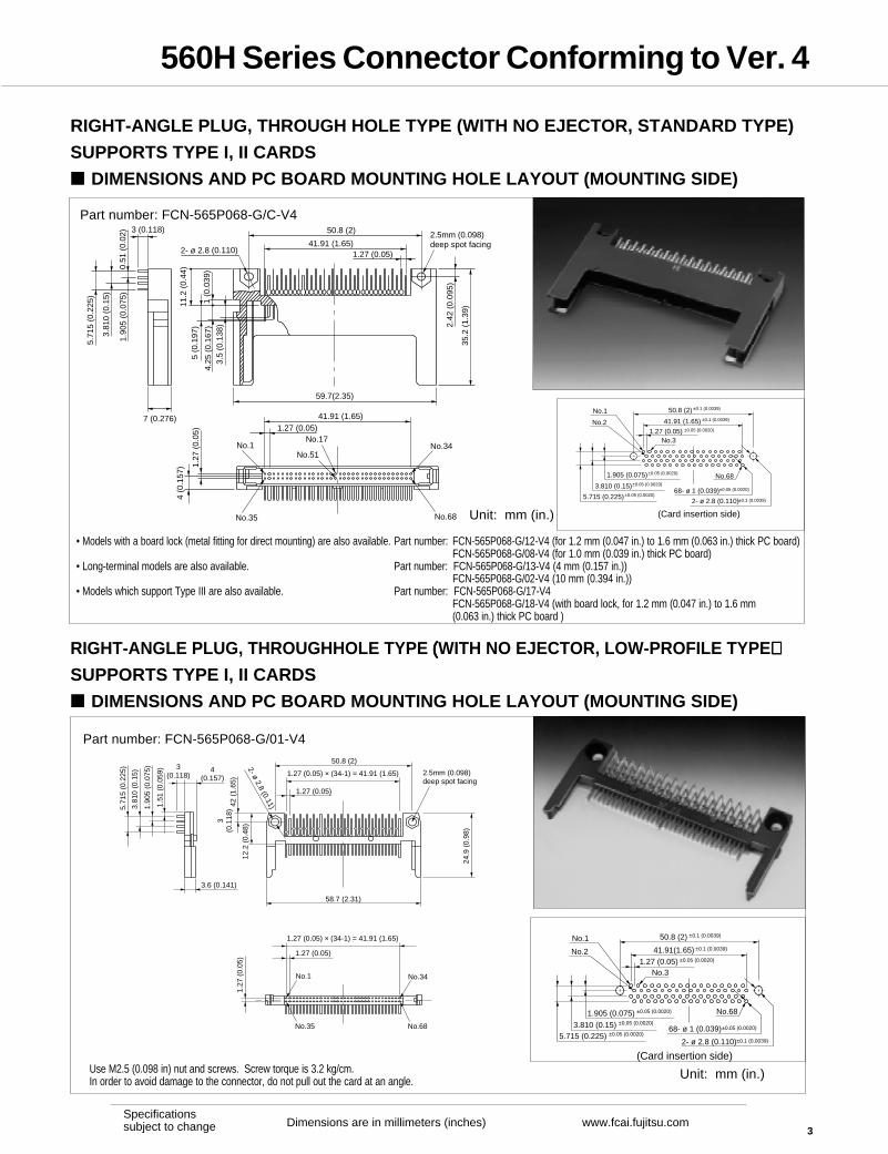
RIGHT-ANGLE PLUG, THROUGHHOLE TYPE (WITH NO EJECTOR, TO BE MOUNTED ON
THE BACK OF THE PC BOARD) SUPPORTS TYPE I, II CARDS
DIMENSIONS AND PC BOARD MOUNTING HOLE LAYOUT (MOUNTING SIDE)
RIGHT-ANGLE PLUG, THROUGHHOLE TYPE (WITH NO EJECTOR, RAISED MOUNTING
TYPE) SUPPORTS TYPE I, II CARDS
DIMENSIONS AND PC BOARD MOUNTING HOLE LAYOUT (MOUNTING SIDE)
Unit: mm (in.)
Part number: FCN-565P068-G/F-V4
Part number: FCN-565P068-G/J-V4 (SUPPORTS TYPE I, II CARD)Part number: FCN-565P068-G/J-4V (SUPPORTS TYPE I, II, III CARD)
7 (0.276)2.5 (0.098)
1 (0
.039
)
5.71
5 (0
.225
)3.
810
(0.1
5)1.
905
(0.0
75)
0.51
(0.
059)
2.42
(0.
095)
35.2
(1.
385)
11.2
(0.
441)
59.7 (2.35)
50.8 (2)
1.27 (0.05)
1.27 (0.05) × (34 – 1) = 41.91 (1.65)
(2) M2.5 (0.098 in.)thread nut
1.27 (0.05) × (34 – 1) = 41.91 (1.65)
1.27 (0.05)
1.27
(0.
05)
No.68 No.51 No.35
No.1No.17No.34
4(0.
157)
Unit: mm (in.)• A model with no nuts buried is available. Part number: FCN-565P068-G/H-V4
• Applicable screw: Self-tapping screw M2.5 (0.098 in.) x 5 mm (0.197 in.) (for 1.6 mm (0.063 in.) thick PC board)
• A model mounted on bottom of a PC board is also available. Part number: FCN-565P068-G16-V4 (supports type I, II)
50.8 (2) ±0.05 (0.0039)
1.27 (0.05) × (68/2-1) =41.91 (1.65) ±0.1 (0.0039)
1.27 (0.05)±0.05 (0.0020)
No.34
No.68
5.715 (0.225) ±0.05 (0.0020)
3.810 (0.15)±0.05 (0.0020)1.905 (0.075)±0.05 (0.0020)
No.35
68- ø 1 (0.039)±0.05 (0.0020)
(Card insertion side)
2- ø 2.8 (0.110)±0.1 (0.0039)
<To be mounted on back of PC board>
No.1
50.8 (2) ±0.1 (0.0039)
41.91 (1.65) ±0.1 (0.0039)
1.27 (0.05) ±0.05 (0.0020)
No.3
No.1
No.2
5.715 (0.225)±0.05 (0.0020)
3.810 (0.15)±0.05 (0.0020)
1.905 (0.075) ±0.05 (0.0020)No.68
2- ø 2.8 (0.110)±0.1 (0.0039)
68- ø 1 (0.039)±0.05 (0.0020)
(Card insertion side)

560H Series Connector Conforming to Ver. 4
5Dimensions are in millimeters (inches) www.fcai.fujitsu.com
Specificationssubject to change
RIGHT-ANGLE PLUG, THROUGHHOLE TYPE (WITH NO EJECTOR, SUNK MOUNTING TYPE)
SUPPORTS TYPE I, II CARDS
DIMENSIONS AND PC BOARD MOUNTING HOLE LAYOUT (MOUNTING SIDE)
Unit: mm (in.)
Part number: FCN-565P068-G/A-V4
3 (0.118) 4.5 (0.177)
1.90
5 (0
.075
)3.
810
(0.1
5)5.
715
(0.2
25)
6 (0.236)
11.2
(0.
441)
50.8 (2)
1.27 (0.05) × (34–1) = 41.91 (1.65)
1.27 (0.05)
59.7 (2.35)
2.42
(0.
095)
35.2
(1.
39)
2- ø 2.8 (0.110)
1.27 (0.05) × (34–1) = 41.91 (1.65)
1.27 (0.05)
1.27
(0.
05)
3 (0
.118
)
No.1 No.17 No.34
No.68No.51No.35
2.5mm (0.098)deep spot facing
5.715 (0.225)±0.05 (0.0020)
3.810 (0.15) ±0.05 (0.0020)
1.905 (0.075)±0.05 (0.0020)
2- ø 2.8 (0.110)±0.1 (0.0039)
68- ø 1 (0.039)±0.05 (0.0020)
1.27 (0.05)
50.8 (2) ±0.1 (0.0039)
±0.05 (0.0020)
1.27 (0.05) × (68/2-1) =41.91 (1.65) ±0.1 (0.0039)
No.35
No.1
No.68
No.34
6.7
(0.2
64)±
0
RIGHT-ANGLE PLUG, THROUGHHOLE TYPE (WITH NO EJECTOR, TWO LAYER STACK TYPE)
DIMENSIONS AND PC BOARD MOUNTING HOLE LAYOUT (MOUNTING SIDE)
Unit: mm (in.)
Part number: FCN-565P136-G/0-V4
7(0.276)
7(0.276)
1.90
5 (0
.075
)
1.90
5 (0
.075
) ×
(8-1
) =
13.
335
(0.5
25)
35.2
(1.
39)
11.2
(0.
441)
2.42
(0.
095)
59.7 (2.35)
50.8 (2)
11 (
0.43
3)
3(0
.118
)
4 (0
.157
)
No.35
No.1
No.35
No.1
No.34
No.68
No.34
No.68
1.905 (0.075)±0.05 (0.0020)
No.35
No.1
1.90
5 (0
.075
) ×
(8-1
)=
13.
335
(0.5
25)
No.1
No.35
±0.1 (0.0039)50.8 (2)1.27 (0.05) × (68/2-1)= 41.91 (1.65) ±0.1 (0.0039)
1.27 (0.05) ±0.05 (0.0020)
No.34
No.68
No.34
No.68
±0.
05 (
0.00
20)
2- ø 2.8 (0.110)±0.1 (0.0039)
136- ø 1 (0.039) ±0.05 (0.0020)

560H Series Connector Conforming to Ver. 4
6Dimensions are in millimeters (inches) www.fcai.fujitsu.com
Specificationssubject to change
RIGHT-ANGLE PLUG, THROUGHHOLE TYPE (WITH NO EJECTOR, WITH GUIDE)
SUPPORTS TYPE I, II CARDS
DIMENSIONS
Part number: FCN-565P068-G/C34-V4
*A 60.48 mm (2.381 in.) model is also available. FCN-565P068-G/C32-V4
Unit: mm (in.)
PC BOARD MOUNTING HOLE LAYOUT (MOUNTING SIDE)
Unit: mm (in.)
50.8 (2) ±0.1 (0.0039)
1.27 (0.05) × (68/2-1)= 41.91 (1.65) ±0.1 (0.0039)
1.27 (0.05) ±0.05 (0.0020)
No.1
No.35
5.715 (0.225) ±0.05 (0.0020)
3.810 (0.15) ±0.05 (0.0020)
1.905 (0.075) ±0.05 (0.0020) No.68
No.34
2- ø 2.8 (0.110) ±0.1 (0.0039)
±0.05 (0.0020)68- ø 1 (0.039)
0.51
(0.
02)
3 (0.118)1.
905
(0.0
75)
3.81
0 (0
.15)
5.71
5 (0
.225
)
7(0.276) 59.7 (2.35)
50.8 (2)
2- ø 2.8 (0.110)
2.42
(0.
095)
35.2
(1.
386)
11.2
(0.
441)
No.1
No.35
No.34
No.68
7 (0
.276
) 4 (0
.157
) 59 (2.32)
2.5mm (0.098)deep spot facing
83.3
8 (3
.283
)*A

560H Series Connector Conforming to Ver. 4
7Dimensions are in millimeters (inches) www.fcai.fujitsu.com
Specificationssubject to change
RIGHT-ANGLE PLUG, THROUGHHOLE TYPE (WITH RIGHT-BUTTON EJECTOR)
SUPPORTS TYPE I, II CARDS
DIMENSIONS
Part number: FCN-565P068-G/XC-V4 (Type I, II Card, Button color: Black)Part number: FCN-565P068-G/XC-4V (Type I, II, III Card, Button color: Black)Part number: FCN-565P068-G/PC-V4 (Type I, II Card, Button color: Beige)
7 (0.276)3 (0.118)
0.51
(0.
020)
1.90
5 (0
.075
)
3.81
0 (0
.15)
5.71
5 (0
.225
)
35.2
(1.
386)
2.42
(0.
095)
11.2
(0.
441)
8 (0
.315
)83
.38
(3.2
83)
67.31 (2.65)
59.7 (2.35)
50.8 (2)
34 (1.339)
4.25
(0.
167)
3.5
(0.1
38)
36 (
1.41
7)
40 (
1.57
4)R 1.4
3.7
(0.1
46)
10 (0.394)78.5 (3.091)59 (2.323)
42 (1.654)35.5 (1.398)
7 (0
.276
)11
(0.
433)
4.8 (0.189)
2.1
(0.0
83)
4 (0
.157
)
No.1 No.17
No.35 No.51 No.68
No.18 No.34
No.52
ø 2.
8 (0
.110
)2- ø 2.8 (0.110)
2.5mm (0.098)deep spot facing
5 (0
.197
)
A model with an FG accessory for ESD protection is also available. Specify part number FCN-565P068-G/C23-E4,instead of FCN-565P068-G/XC-V4.
PC BOARD MOUNTING HOLE LAYOUT (MOUNTING SIDE)
50.8 (2) ±0.1 (0.0039)
41.91 (1.65) ±0.1 (0.0039)
1.27 (0.05)±0.05 (0.0020)
No.3
No.1
No.2
5.71
5 (0
.225
)±0.
05 (
0.00
20)
3.81
0 (0
.15)
±0.
05 (
0.00
20)
1.90
5 (0
.075
)±0.
05 (
0.00
20)
No.68
2- ø 2.8 (0.110)
(Card insertion side)
34 (1.339)±0.05 (0.0020)
67.31 (2.65)~68.0 (2.677)
40 (
1.57
4)±
0.1
(0.0
039)
4- ø 2.8 (0
.110)±0.1 (0
.0039)
±0.1 (0.0039)
±0.05 (0.0020)
68- ø 1 (0.039)
Unit: mm (in.)
Unit: mm (in.)
560H Series Connector Conforming to Ver. 4
8Dimensions are in millimeters (inches) www.fcai.fujitsu.com
Specificationssubject to change
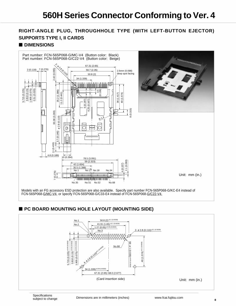
RIGHT-ANGLE PLUG, THROUGHHOLE TYPE (WITH LEFT-BUTTON EJECTOR)
SUPPORTS TYPE I, II CARDS
DIMENSIONS
Part number: FCN-565P068-G/MC-V4 (Button color: Black)Part number: FCN-565P068-G/C22-V4 (Button color: Beige)
Unit: mm (in.)
7 (0.276)3 (0.118)
0.51
(0.
020)
1.90
5 (0
.075
)
3.81
0 (0
.15)
5.71
5 (0
.225
)
35.2
(1.
386)
2.42
(0.
095)
11.2
(0.
441)
8 (0
.315
)
83.3
8 (3
.283
)
67.31 (2.65)
59.7 (2.35)
50.8 (2)
34 (1.339)
4.25
(0.
167)
3.5
(0.1
38)
36 (
1.41
7)
40 (
1.57
4)R 1.4
3.7
(0.1
46)
10 (0.394) 78.5 (3.091)59 (2.323)
42 (1.654)35.5 (1.398)
7 (0
.276
)11
(0.
433)
4.8 (0.189)
2.1
(0.0
83)
4 (0
.157
)
No.1 No.17
No.35 No.51 No.68
No.18 No.34
No.52
2- ø 2.8 (0.110)
2.5mm (0.098)deep spot facing
5 (0
.197
)
ø 2
.8 (
0.11
0)
PC BOARD MOUNTING HOLE LAYOUT (MOUNTING SIDE)
Models with an FG accessory ESD protection are also available. Specify part number FCN-565P068-G/KC-E4 instead ofFCN-565P068-G/MC-V4, or specify FCN-565P068-G/C33-E4 instead of FCN-565P068-G/C22-V4.
50.8 (2) ±0.1 (0.0039)
41.91 (1.65) ±0.1 (0.0039)
1.27 (0.05)±0.05 (0.0020)
No.3
No.1
No.2
5.71
5 (0
.225
)±0.
05 (
0.00
20)
3.81
0 (0
.15)
±0.
05 (
0.00
20)
1.90
5 (0
.075
)±0.
05 (
0.00
20)
No.68
2- ø 2.8 (0.110)
(Card insertion side)
34 (1.339)±0.05 (0.0020)
67.31 (2.65)~68.0 (2.677)
40 (
1.57
4)±
0.1
(0.0
039)
4- ø 2.8 (0
.110)±0.1 (0
.0039)
±0.1 (0.0039)
68- ø 1 (0.039)
±0.05 (0.0020)
Unit: mm (in.)
560H Series Connector Conforming to Ver. 4
9Dimensions are in millimeters (inches) www.fcai.fujitsu.com
Specificationssubject to change
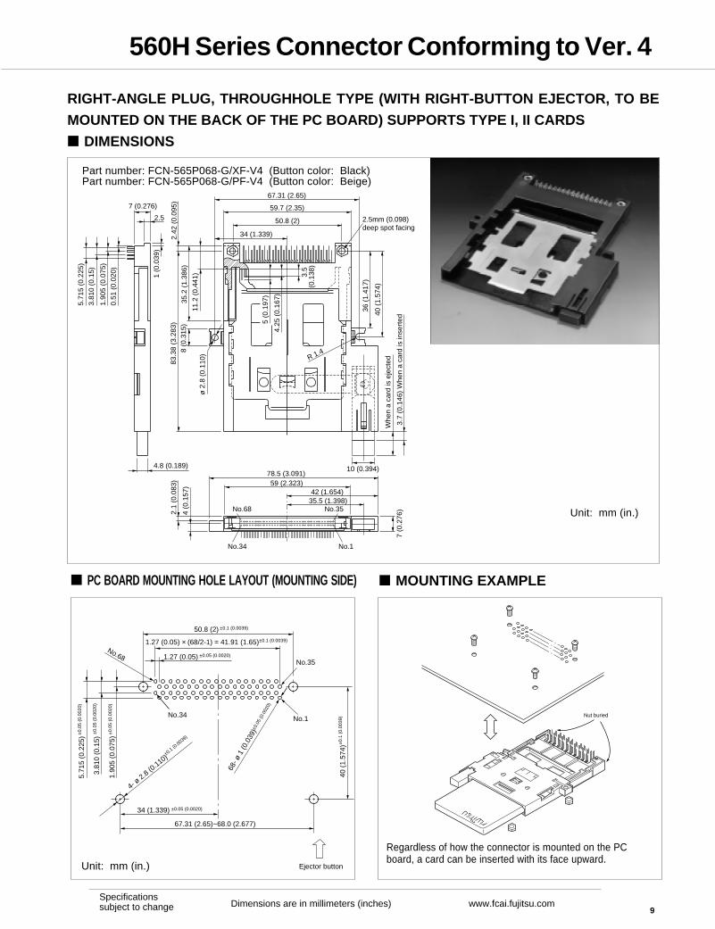
RIGHT-ANGLE PLUG, THROUGHHOLE TYPE (WITH RIGHT-BUTTON EJECTOR, TO BE
MOUNTED ON THE BACK OF THE PC BOARD) SUPPORTS TYPE I, II CARDS
DIMENSIONS
Unit: mm (in.)
Part number: FCN-565P068-G/XF-V4 (Button color: Black)Part number: FCN-565P068-G/PF-V4 (Button color: Beige)
2.5
7 (0.276)
0.51
(0.
020)
1.90
5 (0
.075
)
3.81
0 (0
.15)
5.71
5 (0
.225
)
35.2
(1.
386)
2.42
(0.
095)
11.2
(0.
441)
8 (0
.315
)83
.38
(3.2
83)
67.31 (2.65)
59.7 (2.35)
50.8 (2)
34 (1.339)
4.25
(0.
167)
3.5
(0.1
38)
36 (
1.41
7)
40 (
1.57
4)
R 1.4
3.7
(0.1
46)
10 (0.394)78.5 (3.091)
4.8 (0.189)
42 (1.654)35.5 (1.398)
7 (0
.276
)
1 (0
.039
)
2.5mm (0.098)deep spot facing
59 (2.323)
2.1
(0.0
83)
4 (0
.157
)
No.68 No.35
No.1No.34
ø 2
.8 (
0.11
0)
Whe
n a
card
is e
ject
ed
Whe
n a
card
is in
sert
ed5 (0
.197
)
Unit: mm (in.)
PC BOARD MOUNTING HOLE LAYOUT (MOUNTING SIDE) MOUNTING EXAMPLE
50.8 (2) ±0.1 (0.0039)
1.27 (0.05) × (68/2-1) = 41.91 (1.65)±0.1 (0.0039)
1.27 (0.05) ±0.05 (0.0020)
No.34 No.1
No.68
5.71
5 (0
.225
)±0.
05 (
0.00
20)
3.81
0 (0
.15)
±0.
05 (
0.00
20)
1.90
5 (0
.075
)±0.
05 (
0.00
20)
68- ø
1 (0
.039
)±0.
05 (0
.002
0)
Ejector button
34 (1.339) ±0.05 (0.0020)
67.31 (2.65)~68.0 (2.677)
40 (
1.57
4)±
0.1
(0.0
039)
4- ø 2.8 (0
.110)±0.1 (0
.0039)
No.35
Regardless of how the connector is mounted on the PCboard, a card can be inserted with its face upward.
Nut buried
560H Series Connector Conforming to Ver. 4
10Dimensions are in millimeters (inches) www.fcai.fujitsu.com
Specificationssubject to change
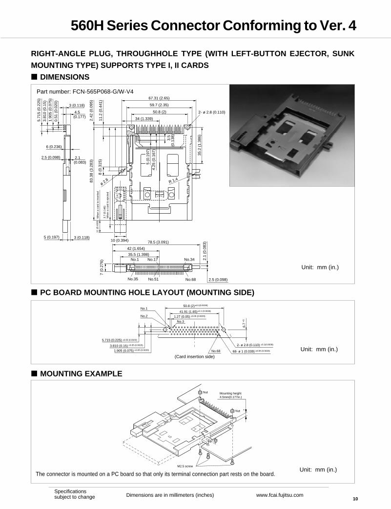
RIGHT-ANGLE PLUG, THROUGHHOLE TYPE (WITH LEFT-BUTTON EJECTOR, SUNK
MOUNTING TYPE) SUPPORTS TYPE I, II CARDS
DIMENSIONS
Part number: FCN-565P068-G/W-V4
PC BOARD MOUNTING HOLE LAYOUT (MOUNTING SIDE)
The connector is mounted on a PC board so that only its terminal connection part rests on the board.
5.715 (0.225) ±0.05 (0.0020)
3.810 (0.15) ±0.05 (0.0020)
1.905 (0.075) ±0.05 (0.0020)
1.27 (0.05)
50.8 (2)±0.1(0.0039)
±0.05 (0.0020)
41.91 (1.65)±0.1 (0.0039)No.1
No.68
6.7
+0
No.2
No.3
(Card insertion side)
2- ø 2.8 (0.110)
68- ø 1 (0.039)
±0.1(0.0039)
±0.05 (0.0020)
MOUNTING EXAMPLE
M2.5 screw
Nut
Mounting height4.5mm(0.177in.)
Nut
Unit: mm (in.)
Unit: mm (in.)
Unit: mm (in.)
3 (0.118)
6 (0.236)
0.51
(0.
020)
1.90
5 (0
.075
)3.
810
(0.1
5)
5.71
5 (0
.225
)
4.5 (0.177)
2.5 (0.098) 2.1(0.083)
5 (0.197) 3 (0.118)
67.31 (2.65)
59.7 (2.35)
50.8 (2)
34 (1.339)2.42
(0.
095)
11.2
(0.
441)
8 (0
.315
)
ø 2.8
3.5
(0.1
38)
35.2
(1.
386)
R 1.4
2- ø 2.8 (0.110)
83.3
8 (3
.283
)
3.7
(0.1
46)
10 (0.394)
Whe
n a
card
is e
ject
ed
Whe
n a
card
is in
sert
ed11
(0.
433)
78.5 (3.091)
42 (1.654)
35.5 (1.398)
7 (0
.276
) 2.1
(0.0
83)
No.68No.35
No.1 No.34No.17
No.51 2.5 (0.098)
5 (0
.197
)
4.25
(0.
167)

560H Series Connector Conforming to Ver. 4
11Dimensions are in millimeters (inches) www.fcai.fujitsu.com
Specificationssubject to change
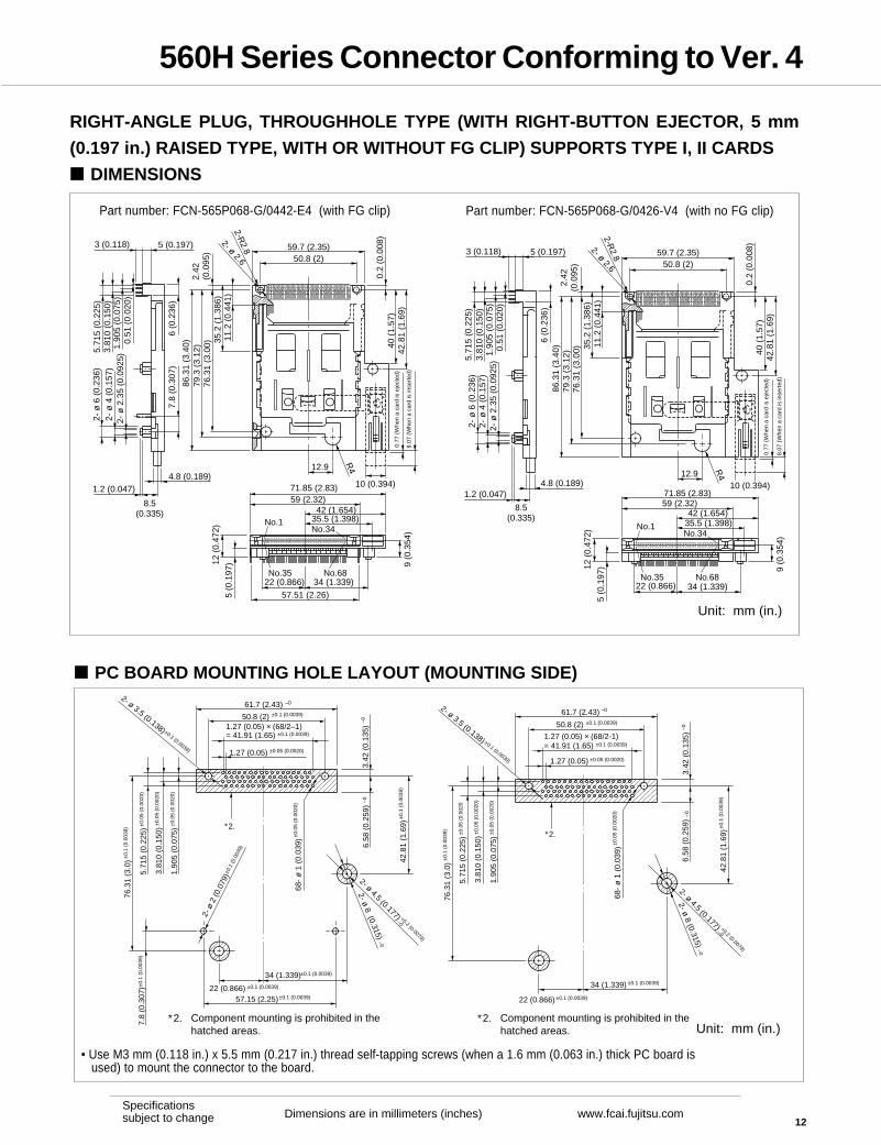
RIGHT-ANGLE PLUG, THROUGHHOLE TYPE (WITH RIGHT-BUTTON EJECTOR, 4.5 MM
(0.177 IN.) RAISED TYPE) SUPPORTS TYPE I, II CARDS
DIMENSIONS
Part number: FCN-565P068-G/J25-V4 (supports type I, II card)Part number: FCN-565P068-G/J25-4V (supports type I, II, III card)
3(0.118)
0.51
(0.
020)
1.90
5 (0
.075
)
3.81
0 (0
.15)
5.71
5 (0
.225
)
8(0
.315
)
4.5 (0.177)
9 (0
.354
)
4.8 (0.189)
8 (0.315)
2.42
(0.0
95)
11.2
(0.
441)
2- ø 2.2 (0.087)
76.4
8 (3
.011
)
81.8
8 (3
.224
)
59.7 (2.35)
50.8 (2)
0.2
(0.0
078)
35.2
(1.
386)
4.25
(0.
167)
3.5
(0.1
38)
5.2
(0.2
05)
10 (0.394)
Whe
n a
card
is in
sert
ed12
.5 (
0.49
2)
42 (1.654)
35.5 (1.398)
4.5
(0.1
77)
59 (2.323)
No.68No.35
No.1 No.34
11.5
(0.
453)
7(0
.276
)
50.8 (2)
8.5
(0.3
35)
8 (0.315)
ø 2
.2 ,
4.5
deep
Whe
n a
card
is e
ject
ed
5 (0
.197
)
PC BOARD MOUNTING HOLE LAYOUT (MOUNTING SIDE) MOUNTING EXAMPLE
±0.1 (0.0039)
5.71
5 (0
.225
)±
0.05
(0.
0020
)
3.81
0 (0
.15)
±0.
05 (
0.00
20)
1.90
5 (0
.075
)±
0.05
(0.
0020
)
50.8 (2) ±0.1 (0.0039)
1.27 (0.05) ±0.05 (0.0020)
1.27 (0.05) × (68/2-1)= 41.91 (1.65)
No.1No.34
No.35No.68
3.42
(0.
135)
–0–0 +
0
33.7
8 (1
.330
)–0
76.4
8 (3
.011
)±
0.1
71.8
8 (2
.830
)+
0
82.8
8 (3
.263
)–0
51.7 (2.035) +0
61.7 (2.429) –0
41.7 (1.642) +0
50.8 (2) ±0.1 (0.0039)
61.7 (2.429) –0
±0.1 (0.0039)
±0.05 (0.0020)
6.58
(0.
259)
23.7
8 (0
.936
)
4 - ø 2.8 (0.110)
68- ø 1 (0.0394)
Unit: mm (in.)
Component mounting is prohibited in the hatched areas.
• Components with a height of 4.3 mm (0.169 in.) maximum canbe installed under the connector.
• Use M2.5 mm (0.098 in.) x 5 mm (0.197in.) self-tapping screws(when a 1.6 mm (0.063 in.) thick PC board is used) to mount
the connector to the board.
Unit: mm (in.)
560H Series Connector Conforming to Ver. 4
12Dimensions are in millimeters (inches) www.fcai.fujitsu.com
Specificationssubject to change
Part number: FCN-565P068-G/0442-E4 (with FG clip)
PC BOARD MOUNTING HOLE LAYOUT (MOUNTING SIDE)
Part number: FCN-565P068-G/0426-V4 (with no FG clip)
5 (0.197)
0.51
(0.
020)
2- ø 2.6
3 (0.118)
1.90
5 (0
.075
)3.
810
(0.1
50)
5.71
5 (0
.225
)
6 (0
.236
)
11.2
(0.
441)
35.2
(1.
386)
2.42
(0.0
95)
76.3
1 (3
.00)
79.3
(3.
12)
86.3
1 (3
.40)
4.8 (0.189)
7.8
(0.3
07)
1.2 (0.047)
8.5(0.335)
2- ø
2.3
5 (0
.092
5)2-
ø 4
(0.
157)
2- ø
6 (
0.23
6)
59.7 (2.35)50.8 (2)
2-R2.8
0.2
(0.0
08)
40 (
1.57
)42
.81
(1.6
9)
R412.9
10 (0.394)71.85 (2.83)59 (2.32)
42 (1.654)35.5 (1.398)
34 (1.339)
57.51 (2.26)
22 (0.866)No.35 No.68
No.1No.34
9 (0
.354
)
5 (0
.197
)12 (
0.47
2)
71.85 (2.83)59 (2.32)
42 (1.654)35.5 (1.398)
34 (1.339)22 (0.866)No.35 No.68
No.1No.34
9 (0
.354
)
5 (0
.197
)12 (
0.47
2)
2- ø 2.6
11.2
(0.
441)
35.2
(1.
386)
2.42
(0.0
95)
76.3
1 (3
.00)
79.3
(3.
12)
86.3
1 (3
.40)
59.7 (2.35)50.8 (2)
2-R2.8
0.2
(0.0
08)
40 (
1.57
)42
.81
(1.6
9)0.
77 (
Whe
n a
card
is e
ject
ed)
8.07
(W
hen
a ca
rd is
inse
rted
)
R412.9
10 (0.394)
5 (0.197)
0.51
(0.
020)
3 (0.118)
1.90
5 (0
.075
)3.
810
(0.1
50)
5.71
5 (0
.225
)
6 (0
.236
)
4.8 (0.189)1.2 (0.047)
8.5(0.335)
2- ø
2.3
5 (0
.092
5)2-
ø 4
(0.
157)
2- ø
6 (
0.23
6)
0.77
(W
hen
a ca
rd is
eje
cted
)
8.07
(W
hen
a ca
rd is
inse
rted
)
Component mounting is prohibited in thehatched areas.
∗2.
50.8 (2) ±0.1 (0.0039)
1.27 (0.05) × (68/2–1)= 41.91 (1.65) ±0.1 (0.0039)
1.27 (0.05) ±0.05 (0.0020)
61.7 (2.43) –0
5.71
5 (0
.225
)±0.
05 (
0.00
20)
3.81
0 (0
.150
)±0.
05 (
0.00
20)
1.90
5 (0
.075
)±0.
05 (
0.00
20)
76.3
1 (3
.0)±
0.1
(0.0
039)
7.8
(0.3
07)±
0.1
(0.0
039)
3.42
(0.
135)
–06.
58 (
0.25
9)–0
42.8
1 (1
.69)
±0.
1 (0
.003
9)
2- ø 4.5 (0.177) +0.2 (0.0079)
–0
2- ø 8 (0.315) –0
22 (0.866) ±0.1 (0.0039)
34 (1.339)±0.1 (0.0039)
57.15 (2.25)±0.1 (0.0039)
2- ø
2 (0
.079
)±0.
1 (0
.003
9)
5.71
5 (0
.225
)±0.
05 (
0.00
20
3.81
0 (0
.150
)±0.
05 (
0.00
20)
1.90
5 (0
.075
)±0.
05 (
0.00
20)
2- ø 3.5 (0.138) ±0.1 (0.0039)
2- ø 3.5 (0.138) ±0.1 (0.0039)
50.8 (2) ±0.1 (0.0039)
1.27 (0.05) × (68/2-1)= 41.91 (1.65) ±0.1 (0.0039)
1.27 (0.05) ±0.05 (0.0020)
61.7 (2.43) –0
3.42
(0.
135)
–06.
58 (
0.25
9)–0
42.8
1 (1
.69)
±0.
1 (0
.003
9)
2- ø 4.5 (0.177) +0.2 (0.0079)
–0
2- ø 8 (0.315) –0
22 (0.866)
±0.1 (0.0039)34 (1.339)
±0.1 (0.0039)
76.3
1 (3
.0)±
0.1
(0.0
039)
∗2.∗2.
Component mounting is prohibited in thehatched areas.
∗2.
68-
ø 1
(0.
039)
±0.
05 (
0.00
20)
68-
ø 1
(0.
039)
±0.
05 (
0.00
20)
• Use M3 mm (0.118 in.) x 5.5 mm (0.217 in.) thread self-tapping screws (when a 1.6 mm (0.063 in.) thick PC board is used) to mount the connector to the board.
Unit: mm (in.)
Unit: mm (in.)
RIGHT-ANGLE PLUG, THROUGHHOLE TYPE (WITH RIGHT-BUTTON EJECTOR, 5 mm
(0.197 in.) RAISED TYPE, WITH OR WITHOUT FG CLIP) SUPPORTS TYPE I, II CARDS
DIMENSIONS
560H Series Connector Conforming to Ver. 4
13Dimensions are in millimeters (inches) www.fcai.fujitsu.com
Specificationssubject to change
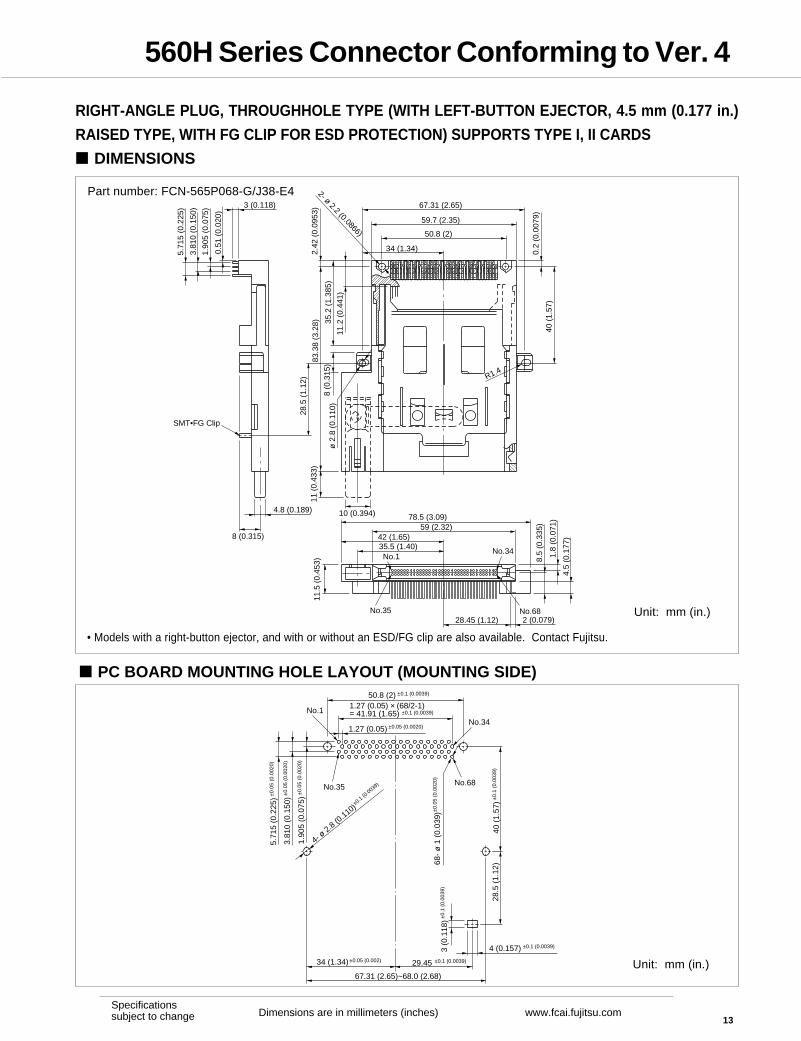
RIGHT-ANGLE PLUG, THROUGHHOLE TYPE (WITH LEFT-BUTTON EJECTOR, 4.5 mm (0.177 in.)
RAISED TYPE, WITH FG CLIP FOR ESD PROTECTION) SUPPORTS TYPE I, II CARDS
DIMENSIONS
Part number: FCN-565P068-G/J38-E4
PC BOARD MOUNTING HOLE LAYOUT (MOUNTING SIDE)
• Models with a right-button ejector, and with or without an ESD/FG clip are also available. Contact Fujitsu.
Unit: mm (in.)
Unit: mm (in.)
3 (0.118)
0.51
(0.
020)
1.90
5 (0
.075
)
3.81
0 (0
.150
)
5.71
5 (0
.225
)
SMT•FG Clip
4.8 (0.189)
8 (0.315)
10 (0.394)
28.5
(1.
12)
83.3
8 (3
.28)
8 (0
.315
)
11 (
0.43
3)2.
42 (
0.09
53)
35.2
(1.
385)
11.2
(0.
441)
67.31 (2.65)
59.7 (2.35)
50.8 (2)
34 (1.34)
2- ø 2.2 (0.0866)
0.2
(0.0
079)
40 (
1.57
)
R1.4
78.5 (3.09)59 (2.32)
42 (1.65)35.5 (1.40)No.1
No.35
11.5
(0.
453)
28.45 (1.12)No.682 (0.079)
8.5
(0.3
35)
No.34 1.8
(0.0
71)
4.5
(0.1
77)
ø 2
.8 (
0.11
0)
5.71
5 (0
.225
)±0.
05 (
0.00
20)
3.81
0 (0
.150
)±0.
05 (
0.00
20)
1.90
5 (0
.075
)±0.
05 (
0.00
20)
50.8 (2) ±0.1 (0.0039)
1.27 (0.05) × (68/2-1)= 41.91 (1.65) ±0.1 (0.0039)
1.27 (0.05) ±0.05 (0.0020)
No.1
No.35
68-
ø 1
(0.
039)
±0.
05 (
0.00
20)
No.34
No.68
4- ø 2.8 (0
.110)±0.1 (0
.0039)
34 (1.34)±0.05 (0.002) 29.45 ±0.1 (0.0039)
67.31 (2.65)~68.0 (2.68)
3 (0
.118
)±0.
1 (0
.003
9)
4 (0.157) ±0.1 (0.0039)
28.5
(1.
12)
40 (
1.57
)±0.
1 (0
.003
9)
560H Series Connector Conforming to Ver. 4
14Dimensions are in millimeters (inches) www.fcai.fujitsu.com
Specificationssubject to change
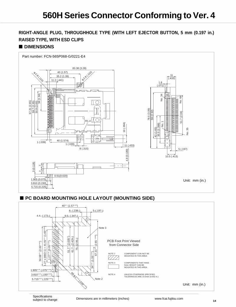
RIGHT-ANGLE PLUG, THROUGHHOLE TYPE (WITH LEFT EJECTOR BUTTON, 5 mm (0.197 in.)
RAISED TYPE, WITH ESD CLIPS
DIMENSIONS
Part number: FCN-565P068-G/0221-E4
PC BOARD MOUNTING HOLE LAYOUT (MOUNTING SIDE)
Unit: mm (in.)
Unit: mm (in.)
83.38 (3.28)
40 (1.57)
35.2 (1.39)
11.2 (.441)
67.3
1 (2
.65)
59.7
(2.
35)
50.8
(2.
00)
34 (
1.34
)
1 (.039)40 (1.574)
1 (.039)
8 (.315)11 (.433)
10 (
.394
)
φ 2.8 (.110) φ 2.8
(.110
)
R1.4
10.5 (.413)
5 (.197)
11(.433)
1.8(.071)
78.5
(3.
09)
59 (
2.32
)42
(1.
65)
35.5
(1.
398)
51.7
(2.
04)
No.
68
No.
1N
o. 3
4
No.
35
1.905 (0.075)
3.810 (0.150)5.715 (0.225)
0.51(0.020)
77
3 (0
.118
)
4.8
(0.1
89)
(.27
6)(.
276)
40±0.1 (1.57±.002)
9.5-0 (.347-0)4.4-0 (.173-0)
6-0 (.236-0) 5-0(.197-0)
51.7
+0 (
2.03
5+0 )
61.7
-0 (
2.42
9-0)
75-0 (
2.95
-0)
34±0
.05 (
1.33
±0.0
02)
67.3
1+0.
2 (2.
65 +
0.00
8 )
50.0
8±0.1 (
2.00
±0.0
04)
1.27
x (
68/2
-1)
= 4
1.91
±0.1 (
1.65
±0.0
04)
1.27
±0.0
5 (0.
05±0
.002
)
1.905±0.05 (.075±0.002)
3.810±0.05 (.150±0.002)
5.715±0.05 (.225±0.002)
68-φ 1 ±0.05 (.039 ±0.002)
Note 2
Note 3
PCB Foot Print Viewed from Connector Side
NOTE 2 COMPONENT CON NOT BEMOUNTED IN THIS AREA
NOTE 3 COMPONENTS THAT HAVE 5mm HEIGHT CAN BEMOUNTED IN THIS AREA
NOTE 4 UNLESS OTHERWISE SPECIFIEDTOLERANCES ARE ±0.5mm (0.002 in.)
560H Series Connector Conforming to Ver. 4
15Dimensions are in millimeters (inches) www.fcai.fujitsu.com
Specificationssubject to change
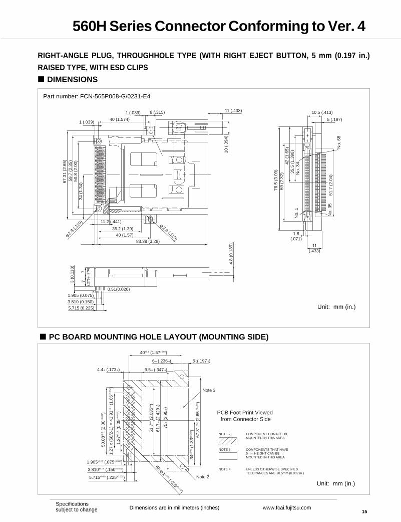
RIGHT-ANGLE PLUG, THROUGHHOLE TYPE (WITH RIGHT EJECT BUTTON, 5 mm (0.197 in.)
RAISED TYPE, WITH ESD CLIPS
DIMENSIONS
PC BOARD MOUNTING HOLE LAYOUT (MOUNTING SIDE)
Unit: mm (in.)
Unit: mm (in.)
83.38 (3.28)40 (1.57)
35.2 (1.39)
11.2 (.441)
67.3
1 (2
.65)
59.7
(2.
35)
50.8
(2.
00)
34 (
1.34
)
1 (.039)40 (1.574)
1 (.039) 8 (.315) 11 (.433)
10 (
.394
)φ 2.8 (.110)φ 2
.8 (.
110)
10.5 (.413)
5 (.197)
11(.433)
1.8(.071)
78.5
(3.
09)
59 (
2.32
)42
(1.
65)
35.5
(1.
398)
51.7
(2.
04)
No.
68
No.
1N
o. 3
4
No.
35
1.905 (0.075)
3.810 (0.150)5.715 (0.225)
0.51(0.020)
77
3 (0
.118
)
4.8
(0.1
89)
(.27
6)(.
276)
40±0.1 (1.57±.002)
9.5-0 (.347-0)4.4-0 (.173-0)
6-0 (.236-0) 5-0(.197-0)
51.7
+0 (
2.03
5+0 )
61.7
-0 (
2.42
9-0)
75-0 (
2.95
-0)
34±0
.05 (
1.33
±0.0
02)
67.3
1+0.
2 (2.
65 +
0.00
8 )
50.0
8±0.1 (
2.00
±0.0
04)
1.27
x (
68/2
-1)
= 4
1.91
±0.1 (
1.65
±0.0
04)
1.27
±0.0
5 (0.
05±0
.002
)
1.905±0.05 (.075±0.002)
3.810±0.05 (.150±0.002)
5.715±0.05 (.225±0.002)
68-φ 1 ±0.05 (.039 ±0.002)
Note 2
Note 3
PCB Foot Print Viewed from Connector Side
NOTE 2 COMPONENT CON NOT BEMOUNTED IN THIS AREA
NOTE 3 COMPONENTS THAT HAVE 5mm HEIGHT CAN BEMOUNTED IN THIS AREA
NOTE 4 UNLESS OTHERWISE SPECIFIEDTOLERANCES ARE ±0.5mm (0.002 in.)
Part number: FCN-565P068-G/0231-E4
560H Series Connector Conforming to Ver. 4
16Dimensions are in millimeters (inches) www.fcai.fujitsu.com
Specificationssubject to change
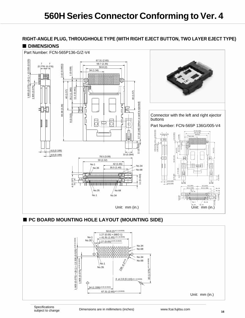
RIGHT-ANGLE PLUG, THROUGHHOLE TYPE (WITH RIGHT EJECT BUTTON, TWO LAYER EJECT TYPE)
DIMENSIONS
PC BOARD MOUNTING HOLE LAYOUT (MOUNTING SIDE)
7(0.276)
7(0.276)
1.90
5 (0
.075
)
1.90
5 (0
.075
) ×
(8-1
) =
13.
335
(0.5
25)
4.8 (0.189)
4.8 (0.189)
67.31 (2.65)59.7 (2.35)
50.8 (2)34 (1.34)
2.42
(0.
0953
)
40 (
1.57
)
1 (0
.039
)35
.2 (
1.38
5)
11.2
(0.
441)
8 (0
.315
)
83.3
8 (3
.28)
10 (0.394) 11 (
0.43
3)3.
7 (0
.146
) (W
hen
a ca
rd is
eje
cted
)
40 (
1.57
)
78.5 (3.09)
59 (2.32)
No.35
No.1 42 (1.65)
35.5 (1.40)
11 (
0.43
3)
4 (0
.157
)
No.1
No.35 No.68
No.34
No.34
No.68
50.8 (2)±0.1 (0.0039)
1.27 (0.05) × (68/2-1)= 41.91 (1.65) ±0.1 (0.0039)
1.27 (0.05)±0.05 (0.0020)
No.1No.35
No.1
No.35
1.90
5 (0
.075
)±0.
05 (
0.00
20)
1.90
5 (0
.075
) ×
(8-1
) =
13.
335
(0.5
25)±
0.05
(0.
0020
)
34 (1.339)±0.05 (0.0020)
67.31 (2.65)±0.1 (0.0039)
4- ø 2.8 (0.110)±0.1 (0.0039) 40 (
1.57
5)±
0.1
(0.0
039)
136-
ø 1
±0.0
5
No.34No.68
No.34
No.68
7 (0.276)
7 (0.276)
1.90
5 (0
.075
)
1.90
5 (0
.075
) ×
(8-1
) =
13.
335
(0.5
25)
4.8 (0.189)
4.8 (0.189)
34 (1.34)
67.31 (2.65)
59.7 (2.35)50.8 (2)
1 (0
.039
)
11.2
(0.
441)
35.2
(1.
385)
40 (
1.57
)
83.3
8 (3
.28)
2.42
(0.
0953
)
3.7
(0.1
46)
11 (
0,.4
33)
10(0.394)
11 (
0.43
3)
40 (
1.57
)
No. 1No. 35
No. 1
No. 35
No. 68
No. 34
No. 34
No. 68
4 (0
.157
)
42 (1.654)
35.5 (1.398)
11
(0.4
33)
3 (0
.118
)
10(0.394)
42 (1.654)
35.5 (1.398)
2.1
(0.0
83)
Connector with the left and right ejectorbuttons
Part Number: FCN-565P 136G/005-V4
Unit: mm (in.)
Unit: mm (in.)
Unit: mm (in.)
Part Number: FCN-565P136-G/Z-V4
560H Series Connector Conforming to Ver. 4
17Dimensions are in millimeters (inches) www.fcai.fujitsu.com
Specificationssubject to change
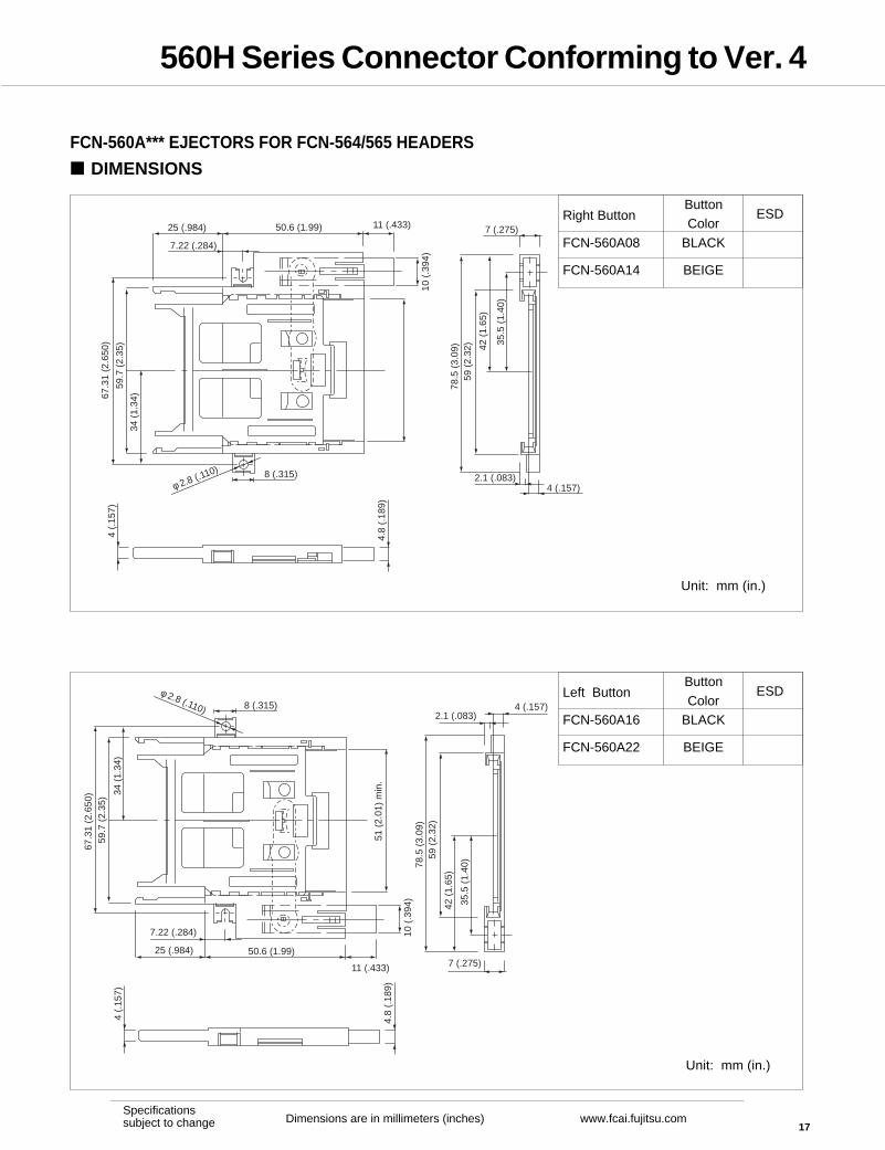
FCN-560A*** EJECTORS FOR FCN-564/565 HEADERS
DIMENSIONS
Unit: mm (in.)
Unit: mm (in.)
8 (.315)
50.6 (1.99)25 (.984)
7.22 (.284)
11 (.433)
10 (
.394
)
67.3
1 (2
.650
)
59.7
(2.
35)
34 (
1.34
)
φ 2.8 (.110)
7 (.275)
78.5
(3.
09)
59 (
2.32
) 42 (
1.65
)
35.5
(1.
40)
2.1 (.083)4 (.157)
4.8
(.18
9)
4 (.
157)
8 (.315)
50.6 (1.99)25 (.984)
7.22 (.284)
11 (.433)
10 (
.394
)
67.3
1 (2
.650
)59
.7 (
2.35
) 34 (
1.34
)
φ 2.8 (.110)
51 (
2.01
) m
in.
7 (.275)
78.5
(3.
09)
59 (
2.32
)
42 (
1.65
)
35.5
(1.
40)
2.1 (.083)4 (.157)
4.8
(.18
9)
4 (.
157)
Right Button
FCN-560A08
FCN-560A14
ButtonColor
BLACK
BEIGE
ESD
Left Button
FCN-560A16
FCN-560A22
Button
ColorBLACK
BEIGE
ESD
560H Series Connector Conforming to Ver. 4
18Dimensions are in millimeters (inches) www.fcai.fujitsu.com
Specificationssubject to change
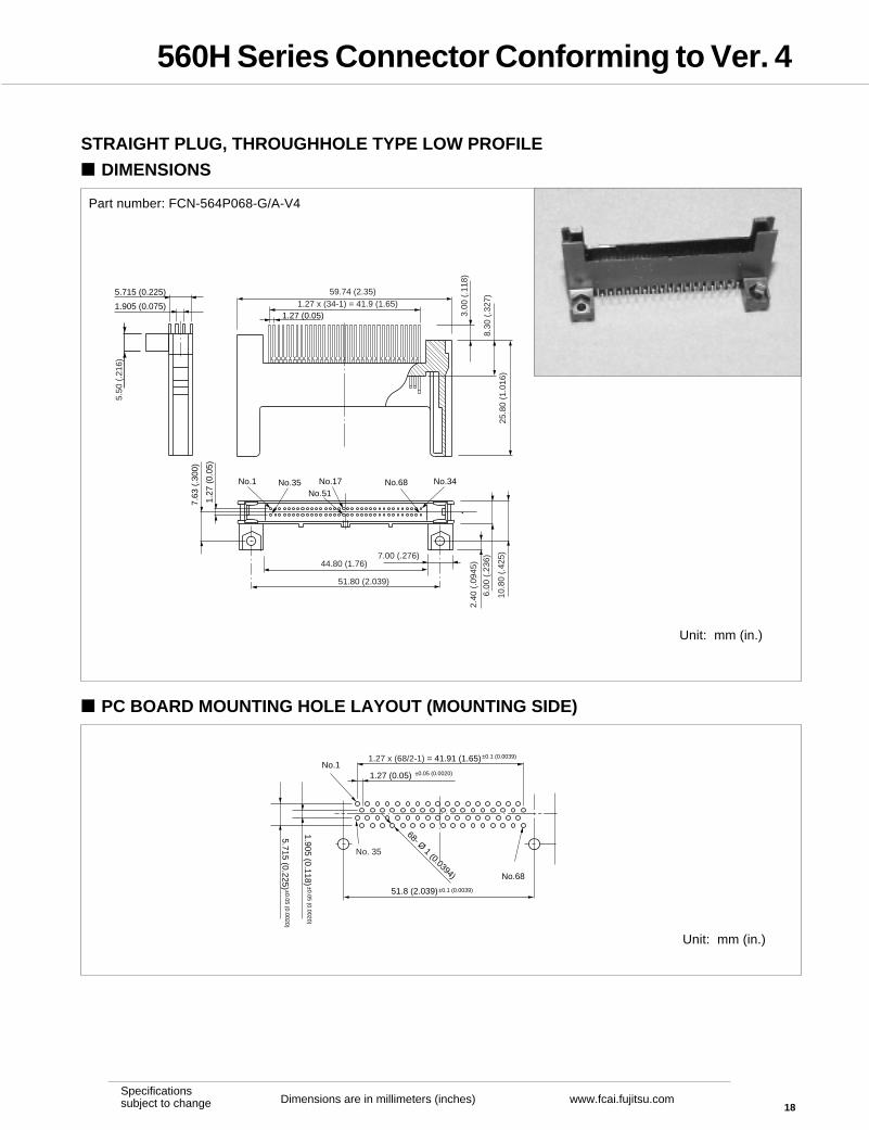
STRAIGHT PLUG, THROUGHHOLE TYPE LOW PROFILE
DIMENSIONS
Part number: FCN-564P068-G/A-V4
PC BOARD MOUNTING HOLE LAYOUT (MOUNTING SIDE)
Unit: mm (in.)
Unit: mm (in.)
1.27
(0.
05)
7.63
(.3
00)
No.1
1.905 (0.075)
5.715 (0.225)
1.27 (0.05)
No.35 No.17No.51
No.34No.68
5.50
(.2
16)
10.8
0 (.
425)
6.00
(.2
36)
2.40
(.0
945)44.80 (1.76)
51.80 (2.039)
7.00 (.276)
25.8
0 (1
.016
)
8.30
(.3
27)
3.00
(.1
18)
59.74 (2.35)1.27 x (34-1) = 41.9 (1.65)
51.8 (2.039)±0.1 (0.0039)
No.1
No.68
1.27 x (68/2-1) = 41.91 (1.65)±0.1 (0.0039)
1.27 (0.05) ±0.05 (0.0020)
5.715 (0.225) ±0.05 (0.0020)1.905 (0.118)
±0.05 (0.0020)
68- Ø 1 (0.0394)
No. 35
560H Series Connector Conforming to Ver. 4
19Dimensions are in millimeters (inches) www.fcai.fujitsu.com
Specificationssubject to change
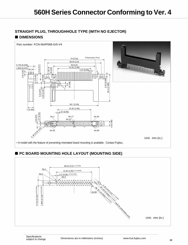
STRAIGHT PLUG, THROUGHHOLE TYPE (WITH NO EJECTOR)
DIMENSIONS
Part number: FCN-564P068-G/0-V4
• A model with the feature of preventing mismated board mounting is available. Contact Fujitsu.
PC BOARD MOUNTING HOLE LAYOUT (MOUNTING SIDE)
Unit: mm (in.)
Unit: mm (in.)
66.04 (2.6) ±0.1 (0.0039)
No.2
No.1
No.68
41.91 (1.65) ±0.1 (0.0039)
1.27 (0.05) ±0.05 (0.0020)
5.71
5 (0
.225
)±0.0
5 (0
.002
0)
1.90
5 (0
.118
)±0.0
5 (0
.002
0) 68- Ø 1 (0.0394) ±0.05 (0.0020)
2- Ø 2.8 (0.110) ±0.1 (0.0039)
No.3
Ø 1.00 (0.0394) used for polarization post
±0.1 (0.0039)
41.91 (1.65)
1.27 (0.05)
1.27
(0.
05)
4 (0
.157
)
No.1
3 (0
.118
)
11.2
(0.
441)
5.5
(0.2
17)
1.905 (0.075)
5.715 (0.225)
5 (0
.197
)
4.25
(0.
167)
2- Ø
2.8
(0.1
10)
2.42
(0.
095)
74 (2.91)
66.04 (2.6)
50.8 (2)41.91 (1.65)
1.27 (0.05)
35.2
(1.
390)
59.7 (2.35)
7 (0.394)
3.5
(0.1
38)
No.35
No.17No.51
No.34
No.68
6 (0
.236
)
2- Ø
2.8
(0.1
10)
1 (0
.039
)
Polarization Post

560H Series Connector Conforming to Ver. 4
20Dimensions are in millimeters (inches) www.fcai.fujitsu.com
Specificationssubject to change
STRAIGHT PLUG, THROUGHHOLE TYPE (WITH EJECTOR)
DIMENSIONS
Part number: FCN-564P068-G/X0-V4
PC BOARD MOUNTING HOLE LAYOUT (MOUNTING SIDE)
74 (2.91)
67.31 (2.65)
66.04 (2.6)
34 (1.34)
50.8 (2)
1.27 (0.05)41.91 (1.65)
35.2
(1.
39)
83.3
8 (3
.28)
2.42
(0.
095)
1.905 (0.075)
5.715 (0.225)
4 (0.157)
3 (0
.118
)
4.8 (0.177)
78.5 (3.09)
2.1
(0.0
83)
42 (1.653)
35.5 (1,40)No.1
No.35
No.17
No.51
No.34
No.68
7 (0
.276
)
10 (0.394)
3.7
(0.1
46)
(Whe
n a
card
is e
ject
ed)
11 (
0.43
3)
(Whe
n a
card
is in
sert
ed)
40 (
1.57
)
36 (
1.42
)8
(0.3
15)
2 – Ø 2.8 (0.110)
R1.4
Ø 2
.8 (
0.11
0)
5 (0
.197
)
3.5
(0.1
38)
4.25
(0.
167)
66.04 (2.6)±0.1 (0.0039)
No.2
No.1
No.68
41.91 (1.65) ±0.1 (0.0039)
1.27 (0.05)±0.05 (0.0020)
5.71
5 (0
.225
)±0.
05 (
0.00
20)
1.90
5 (0
.075
)±0.
05 (
0.00
20)
68- Ø 1 (0.0394) ±0.05 (0.0020)
2- Ø 2.8 (0.110) ±0.1 (0.0039)
No.3
Unit: mm (in.)
Unit: mm (in.)

560H Series Connector Conforming to Ver. 4
21Dimensions are in millimeters (inches) www.fcai.fujitsu.com
Specificationssubject to change
© 2007 Fujitsu Components America, Inc. All rights reserved. All trademarks or registered trademarks are the prop-erty of their respective owners. Fujitsu Components America, Inc. or its affiliates do not warrant that the content of thedatatasheet is error free. In a continuing effort to improve our products, Fujitsu Components America, Inc. or itsaffiliates reserve the right to change specifications/datasheets witout prior notice. Rev. November 2, 2007.
JapanFujitsu Component LimitedGotanda-Chuo Building3-5, Higashigotanda 2-chome, Shinagawa-kuTokyo 141-0022, JapanTel: (81-3) 5449-7010Fax: (81-3) 5449-2626Email: [email protected]: www.fcl.fujitsu.com
North and South AmericaFujitsu Components America, Inc.250 E. Caribbean DriveSunnyvale, CA 94089 U.S.A.Tel: (1-408) 745-4900Fax: (1-408) 745-4970Email: [email protected]: http://us.fujitsu.com/components
EuropeFujitsu Components Europe B.V.Diamantlaan 252132 WV HoofddorpNetherlandsTel: (31-23) 5560910Fax: (31-23) 5560950Email: [email protected]: emea.fujitsu.com/components
Asia PacificFujitsu Components Asia Ltd.102E Pasir Panjang Road#01-01 Citilink Warehouse ComplexSingapore 118529Tel: (65) 6375-8560Fax: (65) 6273-3021Email: [email protected]
Fujitsu ComponentsInternationalHeadquarterOffices
Related Documents