MEMORANDUM DATE: April 4, 2014 TO: Jim Hamilton, Mammoet CC: Shanon Murgoitio, ITD FROM: Christopher M. Atkinson, E.I.T. / Jason W. Wolfe, P.E. RE: Overweight Load Permit Assistance; For Mammoet Calumet Reactor Configuration T04 Rev 00; Long Bridge over Lake Pend Oreille. (3 Pages) This memo summarizes the results and recommendations from the load rating analysis of the Long Bridge on US-95 over Lake Pend Oreille (Bridge Key 18715) following ITD Bridge procedures for overweight truck permit application reviews. Mammoet is currently unable to utilize I-90 for the Calumet Reactor Configuration T04 Rev 00 truck configuration (referred to as “the truck configuration”, see Figure 1). Originally the route for the configuration proceeded from the port in Lewiston up US-95 and along I-90 to the Idaho/Montana border. Mammoet requested that Forsgren Associates analyze the Long Bridge which is on the proposed alternate route that uses US-95 from Coeur d’Alene to Sandpoint then SH-200 to the Idaho/Montana border. Description of ‘The Long Bridge’ The Long Bridge (bridge key 18715) across Lake Pend Oreille is a 180-span structure, with four superstructure unit types (see Figure 2): Navigation Span: One unit is a simple, one-span structure called the navigation span. The navigation span bridges a distance of 81ft and uses adjacent pre- stressed concrete box girders with a 4” reinforced concrete slab. Three-Span Unit: Two units are three-span continuous superstructures found at either end of the bridge. The span configuration is 34’-7”, 35 feet, and 35 feet. Six-span Unit: On either side of the navigation span is a six-span continuous superstructure unit. Five of the six spans are 35ft. A shorter 17ft span is found three spans away from either side of the navigation span. Seven-Span Unit: Finally, there are twenty-eight continuous seven-span units. Six of the seven spans are 35ft and the span in the center of each unit is 17ft. With the exception of the navigation span, the superstructures of each span are made with pre-stressed adjacent five-T-girders topped with a 4” reinforced concrete deck. The deck carries two lanes of traffic, has a roadway width of 39’-2” and an overall deck width of 42’-2”.

Welcome message from author
This document is posted to help you gain knowledge. Please leave a comment to let me know what you think about it! Share it to your friends and learn new things together.
Transcript
MEMORANDUM
DATE: April 4, 2014
TO: Jim Hamilton, Mammoet
CC: Shanon Murgoitio, ITD FROM: Christopher M. Atkinson, E.I.T. / Jason W. Wolfe, P.E.
RE: Overweight Load Permit Assistance; For Mammoet Calumet Reactor
Configuration T04 Rev 00; Long Bridge over Lake Pend Oreille. (3 Pages)
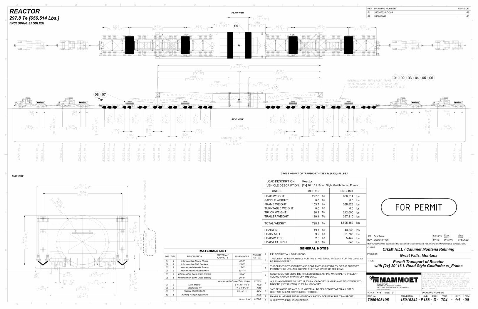
This memo summarizes the results and recommendations from the load rating analysis of the Long Bridge on US-95 over Lake Pend Oreille (Bridge Key 18715) following ITD Bridge procedures for overweight truck permit application reviews. Mammoet is currently unable to utilize I-90 for the Calumet Reactor Configuration T04 Rev 00 truck configuration (referred to as “the truck configuration”, see Figure 1). Originally the route for the configuration proceeded from the port in Lewiston up US-95 and along I-90 to the Idaho/Montana border. Mammoet requested that Forsgren Associates analyze the Long Bridge which is on the proposed alternate route that uses US-95 from Coeur d’Alene to Sandpoint then SH-200 to the Idaho/Montana border. Description of ‘The Long Bridge’ The Long Bridge (bridge key 18715) across Lake Pend Oreille is a 180-span structure, with four superstructure unit types (see Figure 2):
Navigation Span: One unit is a simple, one-span structure called the navigation span. The navigation span bridges a distance of 81ft and uses adjacent pre-stressed concrete box girders with a 4” reinforced concrete slab.
Three-Span Unit: Two units are three-span continuous superstructures found at either end of the bridge. The span configuration is 34’-7”, 35 feet, and 35 feet.
Six-span Unit: On either side of the navigation span is a six-span continuous superstructure unit. Five of the six spans are 35ft. A shorter 17ft span is found three spans away from either side of the navigation span.
Seven-Span Unit: Finally, there are twenty-eight continuous seven-span units. Six of the seven spans are 35ft and the span in the center of each unit is 17ft.
With the exception of the navigation span, the superstructures of each span are made with pre-stressed adjacent five-T-girders topped with a 4” reinforced concrete deck. The deck carries two lanes of traffic, has a roadway width of 39’-2” and an overall deck width of 42’-2”.
Memorandum
2014.04.04.Mammoet
Page 2 of 4
415 South 4th
Street · Boise, Idaho, 83702 · 208-342-3144 · Forsgren.com
Initial Analysis The inspection report for the bridge was reviewed. The report records minor deterioration. After review of the report, it was determined that the noted deterioration is not anticipated to affect the load rating analysis. The Mammoet configuration was applied to the Long Bridge BrR models supplied by ITD. The results of this initial analysis are summarized in Table 1. Three items in the structure warranted further analysis.
1. The truck configuration resulted in an operating rating less than 1.0 for the six-span units. The controlling rating occurred at piers 14 and 19 (as labeled in Figure 2). The rating is due to positive moment at these supports. Since a positive moment at the supports is not created with standard truck configurations, the ITD load rating model did not include a continuity diaphragm at the supports.
2. In addition to positive moments, uplift is also generated at piers 6, 7, 13, 14, and
all similar locations throughout the bridge (see Figure 2). A check of the resistance to uplift was warranted.
3. The simply supported “Navigation Span” of the structure model was initially rated
as a line girder in BrR, due to limitations of the program at the time of the original rating. The load rating value shown in Table 1 does not reflect any adjustment in the live load distribution factor to account for the narrow gage of the Mammoet configuration. In lieu of adjusting the LLDF, the load rating model was revised from a line girder to a girder system.
Continuity Diaphragms The Mammoet truck configuration causes a unique loading case for the Long Bridge with a significant positive moment at piers 14 and 19 (see Figure 2). The low rating was attributed to exceeding the concrete tensile strength of the continuity diaphragm. Noting the significant positive moment it was determined that the continuity diaphragm should be modelled for the given truck configuration. The design plans and shop drawing of the structure were used to determine the amount of reinforcing steel in the continuity diaphragms at the piers. The capacity of the steel was calculated using the design guidance of the AASHTO Standard Specifications. This reinforcement steel could not be fully developed as detailed in the shop drawings and design plans. The allowable resistance was scaled accordingly and was modeled in BrR. (See the appendix for calculations.) Results of the analysis with the Calumet Reactor T04 Rev 00 truck configuration, for the girders mentioned, with the update to the model yielded a load rating of 1.039. (Results are detailed in Table 2.)
Memorandum
2014.04.04.Mammoet
Page 3 of 4
415 South 4th
Street · Boise, Idaho, 83702 · 208-342-3144 · Forsgren.com
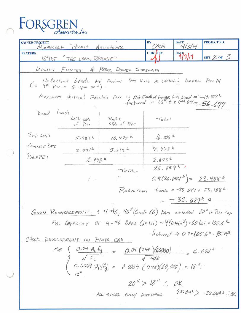
Check of Uplift Capacity Uplift of the 17ft spans of the six-span and seven-span continuous units of the Long Bridge was shown to be significant in the software modelling results. BrR is currently unable to assess the strength of structures against uplift forces. Relying upon the design plans and shop drawings, the capacity of the steel dowels that tie the diaphragms to the piers was evaluated. The strength of the embedment of the steel in the pier and diaphragms was also calculated. Using the results from the updated BrR model of the bridge, the factored uplift and dead load forces at the controlling pier were determined and summed. The load rating result of the uplift capacity with the truck configuration is 2.423. (See calculations in the Appendix.) Modelling of the Navigation Span The original BrR model of the Long Bridge navigation span was created using the line girder method. Although the initial rating results were above one, they were based on live load distribution factors for standard gage widths. Adjusting the live load distribution factors to reflect the narrow gage of the Mammoet configuration would have resulted in a rating value below 1.0. Preliminary review of the bridge indicated that the structure is a girder system, and as such could be modelled more accurately in BrR, with the benefit of interacting girders that better distribute the truck loads. The plans indicated that the girders were similar in strength, keyed together by grout, and tied with rods at the third points. The simple span is also covered with a composite reinforced concrete slab similar to the continuous spans which helps distribute live loads. The design calculations stated clearly that the navigation span was designed as a girder system for purposes of live load distribution. The inspection report did not have any record of longitudinal cracking of the navigation span deck, which would indicate a line girder design behavior. Consultation with HDR (creators of the original model) also indicates that BrR could only model prestressed box girders as line girders with the versions of VIRTIS being used in 2010. The review and consultation concluded that the line girder method was used due to the limitations of Virtis (now BrR) software at the time, and not for any structural concerns. Forsgren Associates used the existing model information to create a girder system model of the navigation span. The analysis using the girder system yielded a controlling rating of 1.306 for the navigation span with the Mammoet truck configuration. Conclusion Upon reviewing the Long Bridge (bridge key 18715) with the Calumet Reactor T04 Rev 00 Truck Configuration and per ITD policy, an operating rating factor of greater than 1.0 has been computed for each of the bridge units for the Long Bridge. It is recommended that the vehicle proceed down the centerline of the bridge with no other vehicles allowed on the bridge. A reduced speed of 10mph or less is also recommended.
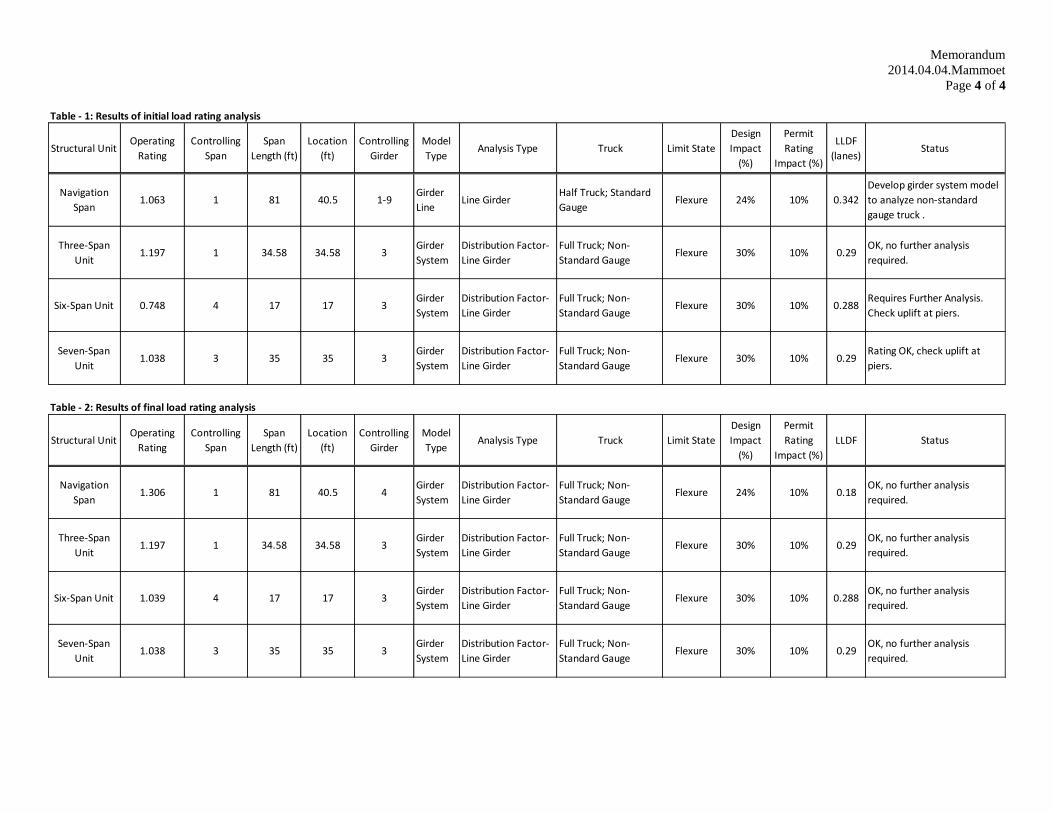
Table - 1: Results of initial load rating analysis
Structural UnitOperating
Rating
Controlling
Span
Span
Length (ft)
Location
(ft)
Controlling
Girder
Model
TypeAnalysis Type Truck Limit State
Design
Impact
(%)
Permit
Rating
Impact (%)
LLDF
(lanes)Status
Navigation
Span1.063 1 81 40.5 1-9
Girder
LineLine Girder
Half Truck; Standard
GaugeFlexure 24% 10% 0.342
Develop girder system model
to analyze non-standard
gauge truck .
Three-Span
Unit1.197 1 34.58 34.58 3
Girder
System
Distribution Factor-
Line Girder
Full Truck; Non-
Standard GaugeFlexure 30% 10% 0.29
OK, no further analysis
required.
Six-Span Unit 0.748 4 17 17 3Girder
System
Distribution Factor-
Line Girder
Full Truck; Non-
Standard GaugeFlexure 30% 10% 0.288
Requires Further Analysis.
Check uplift at piers.
Seven-Span
Unit1.038 3 35 35 3
Girder
System
Distribution Factor-
Line Girder
Full Truck; Non-
Standard GaugeFlexure 30% 10% 0.29
Rating OK, check uplift at
piers.
Table - 2: Results of final load rating analysis
Structural UnitOperating
Rating
Controlling
Span
Span
Length (ft)
Location
(ft)
Controlling
Girder
Model
TypeAnalysis Type Truck Limit State
Design
Impact
(%)
Permit
Rating
Impact (%)
LLDF Status
Navigation
Span1.306 1 81 40.5 4
Girder
System
Distribution Factor-
Line Girder
Full Truck; Non-
Standard GaugeFlexure 24% 10% 0.18
OK, no further analysis
required.
Three-Span
Unit1.197 1 34.58 34.58 3
Girder
System
Distribution Factor-
Line Girder
Full Truck; Non-
Standard GaugeFlexure 30% 10% 0.29
OK, no further analysis
required.
Six-Span Unit 1.039 4 17 17 3Girder
System
Distribution Factor-
Line Girder
Full Truck; Non-
Standard GaugeFlexure 30% 10% 0.288
OK, no further analysis
required.
Seven-Span
Unit1.038 3 35 35 3
Girder
System
Distribution Factor-
Line Girder
Full Truck; Non-
Standard GaugeFlexure 30% 10% 0.29
OK, no further analysis
required.
Memorandum
2014.04.04.Mammoet
Page 4 of 4
CAtkinson
Typewritten Text
Figure 1

:.t
I
tr:,rn.i ¡!; .- I !
:7:s'iiàfe"q)PI
¡Uorrøl&alzãn7æîî-
{8ttîúu t8 , Í¿tr6asac
/6rf ¿a8tlenfs
7VF/€â¿ E¿êY4ftôttl6
æÁ/ÐþtÁ/r 8PD6á P¿Pt ßCCiaeNTOY€e ¿4t€ P€ì{lø OPf/Ll.E
574. 228 ¡7í5
t*7. rt'7tItrrrl
3TÂTË oFTñ*¡ISPORTA?IQ¡{
olv¡srolt ôF^ 801tt
IDÀHOOEP¡ßTùlÊtlT
rr0xr¡Y¡¡. /4'-ê'
rnt È'r
¡ü u&lF*¡ä"
*:vr¡aÕN3
¿3I5ö767lê¡,/2r.t/*t5tat7/â
t, to/4, ßt6. t7l7 ,23¿t,30ao,3737,1441,5¡5t,&8,65ê5,727ã,7çn,ñ{,c6,9,tt,[ro
&o,/47tol, /t4
3ß&rt,/ l134,tâI I ).16
t? ír&&,tt ,23-2/,30tt,379,1115,,5/52,ã85r, é54¿,7273, 7a'm'â(^ê7, e3ç/, , lëo
M/,/A7Øe, t#
t,2êzt222tz*25z62??þ
t3t,l38t28,tsãttt,ttat42,t4t,t5ô,tô3,
u4
Ì1?t5tt¿37¿7770
tza,E8l¿ç, /t5/3ô, /42tût, /¿,/50, /5&15?, /69/é1, /7at7t, /7?t78, /80
&tj^,tË2lwat! -u-í tsoas í z .,28/2ttâ
42 .b C?cur O'âlcna
I * J a ,å
* #58 (Ê õcerin! spon rc¡
,l(ê ecèrag*pen ø)t 5îa. t29.42
.tbã1a/ ftol
Á
6par,
***adee¡at--* * #¡g *zo f * n * Àa6t¿ 25 to
{lnifs á27 si¡ttilarfa lJai* 2
,I Y,6nhuwg5øts
tWøal futlTcnWãT"5
$nil ,a'b Å
I' ô"
t
JóÉ
¡
{;J
ts(3
..1\
å
CAtkinson
Typewritten Text
Figure 2

Appendix

l
FoNGÆN_BY
û1¿'ft*DATE PROJECT NO.OWNER-PROJECT
/- 1a.r'e_
SHT OF 3BY
t r1FEÄTURE
/7
ctúlll
sêe,*þr
-TtN t)
5- We6 -T/-#fBa.,Þet¡"1.
mAX "[at
l7,fi = 0.0'l At
êtlryú-spe, ,rcla =l g -€ &"ç Pr, C),io6.
wql' ln 14,, i4 âwú. r4l4çt+ro s?ò çPEe g, zfa
t'cdL lâ
tl
a,a,l .3 ã)() l>ti = 10,0g"5r5o07st
o, No'l (a, azr,,,) úô, oo\p,; : tt 'ta.0m,l
c,7r/(,t4 lælou¿qf 2'l-'/z
f ,lt tV t'O1 AAsttto Srr) sP€c 8,"q.4
Ao: /a,, i (tr+"'c\x ./ultu ' tl^oo 16 /E = tzto (P,øzr') /6 = t¡,86'/
Antl 0.7 {or,6. 8,21,g,2>,/,,t= O,z(l'&6,t\= ?.3Ò"
U* = 1'5'l
Gwvw lí u¡¡e> l,tE¡J r S,, ilo.L leyla, = 40"- zo/r"- €-,/r" - Z.'1, . Z,g', .i /k
I k, bor,( nrd,ns/t/,T5.
A"l""l./ ..,
3" ducl'pøt+[ ,ïretuu¡An 4ø1+. ltrvtt^*b<.t
U str p ktto
Þ
/'x0"l¿,
Ahf þ1od¿a4Þ5þ¿
lC
4O
,|l¡
,6",
?I,k' øn"r¿lwntkrs ûx- ow, lo¡rpruirr,9>/tt¡¿s no,o,à
^ 1,3 lorç- (l[tn*o d,sz,s,z\"or
rc,L¿,¿ airittilc bt' %,ç= Q,16?z',\ d,l
P^'J,
¡dttud*ct 3" , a,7ôþ2. 2.3r..8t1
Z, s 0t,,'< g, 30,, noo ()
0F s47r.:.t:'+ ?.31t/6,s6" = 2Ì, 8'/o .2 0,278 r fho=1,31
f-
Iæ pAf¡sJ
"l FoNGHN_
)
OWNER.PROJECT' /4i*ao¿1- Rm,j *cysh,ac+
BY
tL(4DATE
q/s/trt PROJECTNO.
FEATURE
t*'lt<' ' -rvr t oNG ßßlÞ6¿ "'":lï" 'îl:/rl sør /-o* 9
UpurJ-
fuAn l>rbr¿-L S-rz<¿¡tcora
(,, .Un*ac{o*,( /ao/s a^/ koch,,s I'r,- Vþh\ e 7oalrolr,¿t41^ P,:et th 6 -sp^n vur*) ,
j /ocohì, Ptet l(
hor r^*^ ú¿rh'n ( [4orh.'^ l)^. +. lltÀ-sþtof 6otre L,à lrnrl,='-l?, fl7L1-.ç^¿ - 1,3'' 2,2 (tq,tuz): -56 " 6fr
Þeoo( Laocls
h{t, ,,¿oî Þu.
R,nL tç(oL o{ ftur
-Tota I
SeuF Lont:>
Òr"<etç Ncr
P,tB nPe f
{, ?sz\ /¿, oog \
2,5't l\ 5, zsz L l, ?lz t<
z,ffisL 2,t?s L
--lor*ur
2¿, 65q
o, q (z¿, nt / n) = 23.15f 4
RusrtrAttr LaftD = -57 'ú77 + 29 , ?t g L
= -32. 6ry2t
N rñFu¿u fuyr<"t.,¡ tr Lt -i¿ Eu<s Qo *s;) = | (o,ul,;), /0 ksì = /0t:,6 l-
4"+"*¿ =Þ O.q,(Olta= ffaf{Clltctc bÇvecopnrtt T tN Ptet<. C*Þ
AaX o, o,l A'Q ,M (0, ,/4 - ì
= /¿ . 6fá'/t,. qw
o;lon'Ç"\$ /,olúq (o,zr)Qî,*o) ,= l8"-
20" > l&" ."' ft). ;T6EL Ft^Ly Þøvrørwt)
OK?ç.lq¡> -s?,6g¿l¿.i0k
/a, ,77s \
J

'îFoNGHN_
)
BY DÄTE PROJECTNO.
t1 SHT OF ?a-rl'ttr
FEATURE $
A^
Ctl rcN
7u^,
TA^øi(^bL sçe¿Í
Þ*ø€uoru*r tþ
ið,*o^îj l,,d
ÞtfrwÊt cz4
d'^,,y shoø #ó lro, Ð*f- @ e¿,1" /'ne- "' A 'rott' {'p
lrytL lq d,rpg^ = '/û " ' /ó" -'á" 6*y p4 =/f {çÊ- lçuan+ rs /î '/r.'' ^ ls " (+ ,, &^f. ttak,) - S"(Ao,t b-,¿) = / '¿
u
uce F'//r o' o( zú,uo6yo.v-r,
rfr, þt U4) = 7(,2 * >RAtwt, FÅcro,z' STÈEN¿rrry -E upt,*+ W^.
L,}Pl¡rs AE6 pos,?ru^e ,'kr = C-A
Conu'¿n,
RC-t, 3 ( [e,Èû
(ô¿u*
AzL +1
(= tfl.L Úr/r)=rtn T '- o ,l : Þ -,(- 36.64 n)
ftr- 1,9 L = tot' 8t/
+l*+ 4L alro/' l,o/ hþu ,i 1l* røy A, , ,s *k^ 4, &, A't
)
q øEq
) ( t,t¡ilt,181_*LT,3L1
J
Related Documents