1 Yaskawa Electric Corporation MEMOBUS SIO Driver 1 System Configuration ....................................................................................................... 3 2 Selection of External Device ............................................................................................ 9 3 Example of Communication Setting ............................................................................... 10 4 Setup Items .................................................................................................................... 53 5 Cable Diagram ............................................................................................................... 58 6 Supported Device........................................................................................................... 90 7 Device Code and Address Code .................................................................................... 95 8 Error Messages .............................................................................................................. 97

Welcome message from author
This document is posted to help you gain knowledge. Please leave a comment to let me know what you think about it! Share it to your friends and learn new things together.
Transcript
1
Yaskawa Electric Corporation
MEMOBUS SIO Driver
1 System Configuration....................................................................................................... 3
2 Selection of External Device ............................................................................................ 9
3 Example of Communication Setting ............................................................................... 10
4 Setup Items .................................................................................................................... 53
5 Cable Diagram ............................................................................................................... 58
6 Supported Device........................................................................................................... 90
7 Device Code and Address Code.................................................................................... 95
8 Error Messages.............................................................................................................. 97

MEMOBUS SIO Driver
GP-Pro EX Device/PLC Connection Manual 2
PREFACEThis manual describes how to connect the Display and the External Device (target PLC).
In this manual, the connection procedure will be described by following the below sections:
1 System ConfigurationThis section shows the types of External Devices which can be connected and SIO type.
"1 System Configuration" (page 3)
2 Selection of External DeviceSelect a model (series) of the External Device to be connected and connection method.
"2 Selection of External Device" (page 9)
3 Example of Communication SettingsThis section shows setting examples for communicating between the Display and the External Device.
"3 Example of Communication Setting" (page 10)
4 Setup ItemsThis section describes communication setup items on the Display.Set communication settings of the Display with GP-Pro EX or in off-line mode.
"4 Setup Items" (page 53)
5 Cable DiagramThis section shows cables and adapters for connecting the Display and the External Device.
"5 Cable Diagram" (page 58)
Operation
MEMOBUS SIO Driver
GP-Pro EX Device/PLC Connection Manual 3
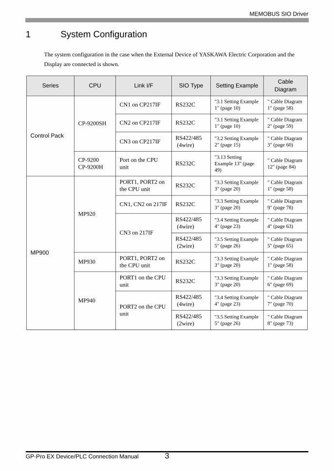
1 System Configuration
The system configuration in the case when the External Device of YASKAWA Electric Corporation and the
Display are connected is shown.
Series CPU Link I/F SIO Type Setting ExampleCable
Diagram
Control Pack
CP-9200SH
CN1 on CP217IF RS232C "3.1 Setting Example 1" (page 10)
" Cable Diagram 1" (page 58)
CN2 on CP217IF RS232C "3.1 Setting Example 1" (page 10)
" Cable Diagram 2" (page 59)
CN3 on CP217IF RS422/485 (4wire)
"3.2 Setting Example 2" (page 15)
" Cable Diagram 3" (page 60)
CP-9200CP-9200H
Port on the CPU unit RS232C
"3.13 Setting Example 13" (page 49)
" Cable Diagram 12" (page 84)
MP900
MP920
PORT1, PORT2 on the CPU unit RS232C "3.3 Setting Example
3" (page 20)" Cable Diagram 1" (page 58)
CN1, CN2 on 217IF RS232C "3.3 Setting Example 3" (page 20)
" Cable Diagram 9" (page 78)
CN3 on 217IF
RS422/485 (4wire)
"3.4 Setting Example 4" (page 23)
" Cable Diagram 4" (page 63)
RS422/485 (2wire)
"3.5 Setting Example 5" (page 26)
" Cable Diagram 5" (page 65)
MP930 PORT1, PORT2 on the CPU unit RS232C "3.3 Setting Example
3" (page 20)" Cable Diagram 1" (page 58)
MP940
PORT1 on the CPU unit RS232C "3.3 Setting Example
3" (page 20)" Cable Diagram 6" (page 69)
PORT2 on the CPU unit
RS422/485 (4wire)
"3.4 Setting Example 4" (page 23)
" Cable Diagram 7" (page 70)
RS422/485 (2wire)
"3.5 Setting Example 5" (page 26)
" Cable Diagram 8" (page 73)

MEMOBUS SIO Driver
GP-Pro EX Device/PLC Connection Manual 4
MP2000
MP2300MP2200MP2310MP2300S
Serial port on 218IF-01 RS232C "3.6 Setting Example
6" (page 29)" Cable Diagram 1" (page 58)
Serial port on 218IF-02 RS232C "3.6 Setting Example
6" (page 29)" Cable Diagram 1" (page 58)
Serial port on 260IF-01 RS232C "3.6 Setting Example
6" (page 29)" Cable Diagram 1" (page 58)
Serial port on 261IF-01 RS232C "3.6 Setting Example
6" (page 29)" Cable Diagram 1" (page 58)
PORT on 217IF-01 RS232C "3.6 Setting Example 6" (page 29)
" Cable Diagram 1" (page 58)
RS422/485 on 217IF-01
RS422/485 (4wire)
"3.7 Setting Example 7" (page 33)
" Cable Diagram 7" (page 70)
RS422/485 (2wire)
"3.8 Setting Example 8" (page 37)
" Cable Diagram 8" (page 73)
MEMOCONGL
GL120
MEMOBUS port 1 on the CPU10 unitMEMOBUS port 2 on the CPU10 unitMEMOBUS port on the CPU20 unitMEMOBUS port on the CPU21 unit
RS232C "3.9 Setting Example 9" (page 41)
" Cable Diagram10" (page 79)
JAMSC-120NOM26100
JAMSC-120NOM27100
RS422/485 (4wire)
"3.10 Setting Example 10" (page 43)
" Cable Diagram 11" (page 80)
GL130
MEMOBUS port on the CPU30 unitMEMOBUS port on the CPU35 unit RS232C "3.9 Setting Example
9" (page 41)
" Cable Diagram10" (page 79)
JAMSC-120NOM26100
JAMSC-120NOM27100
RS422/485 (4wire)
"3.10 Setting Example 10" (page 43)
" Cable Diagram 11" (page 80)
Series CPU Link I/F SIO Type Setting ExampleCable
Diagram
MEMOBUS SIO Driver
GP-Pro EX Device/PLC Connection Manual 5
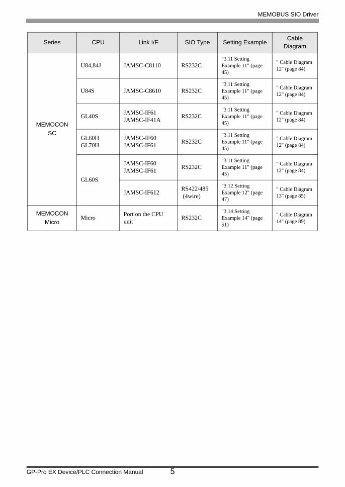
MEMOCONSC
U84,84J JAMSC-C8110 RS232C"3.11 Setting Example 11" (page 45)
" Cable Diagram 12" (page 84)
U84S JAMSC-C8610 RS232C"3.11 Setting Example 11" (page 45)
" Cable Diagram 12" (page 84)
GL40S JAMSC-IF61JAMSC-IF41A RS232C
"3.11 Setting Example 11" (page 45)
" Cable Diagram 12" (page 84)
GL60HGL70H
JAMSC-IF60JAMSC-IF61 RS232C
"3.11 Setting Example 11" (page 45)
" Cable Diagram 12" (page 84)
GL60S
JAMSC-IF60JAMSC-IF61 RS232C
"3.11 Setting Example 11" (page 45)
" Cable Diagram 12" (page 84)
JAMSC-IF612 RS422/485 (4wire)
"3.12 Setting Example 12" (page 47)
" Cable Diagram 13" (page 85)
MEMOCONMicro
Micro Port on the CPU unit RS232C
"3.14 Setting Example 14" (page 51)
" Cable Diagram 14" (page 89)
Series CPU Link I/F SIO Type Setting ExampleCable
Diagram
MEMOBUS SIO Driver
GP-Pro EX Device/PLC Connection Manual 6
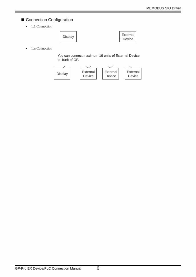
Connection Configuration• 1:1 Connection
• 1:n Connection
Display ExternalDevice
Display ExternalDevice
ExternalDevice
ExternalDevice
You can connect maximum 16 units of External Device to 1unit of GP.
MEMOBUS SIO Driver
GP-Pro EX Device/PLC Connection Manual 7
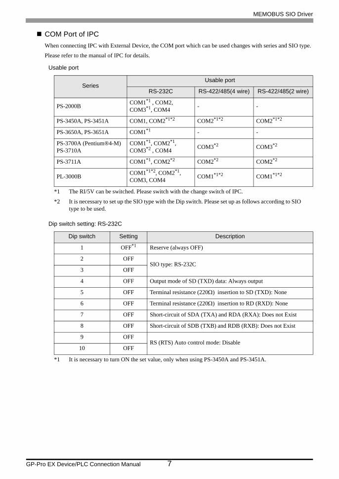
COM Port of IPCWhen connecting IPC with External Device, the COM port which can be used changes with series and SIO type.
Please refer to the manual of IPC for details.
Usable port
Dip switch setting: RS-232C
SeriesUsable port
RS-232C RS-422/485(4 wire) RS-422/485(2 wire)
PS-2000B COM1*1 , COM2, COM3*1, COM4
*1 The RI/5V can be switched. Please switch with the change switch of IPC.
- -
PS-3450A, PS-3451A COM1, COM2*1*2 COM2*1*2 COM2*1*2
PS-3650A, PS-3651A COM1*1 - -
PS-3700A (Pentium®4-M)PS-3710A
COM1*1, COM2*1, COM3*2 , COM4
*2 It is necessary to set up the SIO type with the Dip switch. Please set up as follows according to SIO type to be used.
COM3*2 COM3*2
PS-3711A COM1*1, COM2*2 COM2*2 COM2*2
PL-3000B COM1*1*2, COM2*1, COM3, COM4 COM1*1*2 COM1*1*2
Dip switch Setting Description
1 OFF*1
*1 It is necessary to turn ON the set value, only when using PS-3450A and PS-3451A.
Reserve (always OFF)
2 OFFSIO type: RS-232C
3 OFF
4 OFF Output mode of SD (TXD) data: Always output
5 OFF Terminal resistance (220Ω) insertion to SD (TXD): None
6 OFF Terminal resistance (220Ω) insertion to RD (RXD): None
7 OFF Short-circuit of SDA (TXA) and RDA (RXA): Does not Exist
8 OFF Short-circuit of SDB (TXB) and RDB (RXB): Does not Exist
9 OFFRS (RTS) Auto control mode: Disable
10 OFF

MEMOBUS SIO Driver
GP-Pro EX Device/PLC Connection Manual 8
Dip switch setting: RS-422/485 (4 wire)
Dip switch setting: RS-422/485 (2 wire)
Dip switch Setting Description
1 OFF Reserve (always OFF)
2 ONSIO type: RS-422/485
3 ON
4 OFF Output mode of SD (TXD) data: Always output
5 OFF Terminal resistance (220Ω) insertion to SD (TXD): None
6 OFF Terminal resistance (220Ω) insertion to RD (RXD): None
7 OFF Short-circuit of SDA (TXA) and RDA (RXA): Does not Exist
8 OFF Short-circuit of SDB (TXB) and RDB (RXB): Does not Exist
9 OFFRS (RTS) Auto control mode: Disable
10 OFF
Dip switch Setting Description
1 OFF Reserve (always OFF)
2 ONSIO type: RS-422/485
3 ON
4 OFF Output mode of SD (TXD) data: Always output
5 OFF Terminal resistance (220Ω) insertion to SD (TXD): None
6 OFF Terminal resistance (220Ω) insertion to RD (RXD): None
7 ON Short-circuit of SDA (TXA) and RDA (RXA): Exist
8 ON Short-circuit of SDB (TXB) and RDB (RXB): Exist
9 ONRS (RTS) Auto control mode: Enable
10 ON

MEMOBUS SIO Driver
GP-Pro EX Device/PLC Connection Manual 9
2 Selection of External Device
Select the External Device to be connected to the Display.
Setup Items Setup Description
Maker Select the maker of the External Device to be connected. Select "YASKAWA Electric Corporation".
Driver
Select a model (series) of the External Device to be connected and connection method. Select "MEMOBUS SIO".Check the External Device which can be connected in "MEMOBUS SIO" in system configuration.
"1 System Configuration" (page 3)
Use System Area
Check this option when you synchronize the system data area of the Display and the device (memory) of the External Device. When synchronized, you can use the ladder program of the External Device to switch the display or display the window on the Display.
Cf. GP-Pro EX Reference Manual "Appendix 1.4 LS Area (Direct Access Method)"
This can be also set with GP-Pro EX or in off-line mode of the Display.
Cf. GP-Pro EX Reference Manual "5.17.6 Setting Guide of [System Setting Window], Setting Guide of [Main Unit Settings], System Area Setting"
Cf. Maintenance/Troubleshooting "2.15.1 Settings common to all Display models System Area Settings"
Port Select the Display port to be connected to the External Device.
MEMOBUS SIO Driver
GP-Pro EX Device/PLC Connection Manual 10
3 Example of Communication Setting
Examples of communication settings of the Display and the External Device, recommended by Digital
Electronics Corp., are shown.
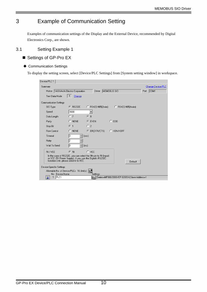
3.1 Setting Example 1
Settings of GP-Pro EX
Communication Settings
To display the setting screen, select [Device/PLC Settings] from [System setting window] in workspace.
MEMOBUS SIO Driver
GP-Pro EX Device/PLC Connection Manual 11
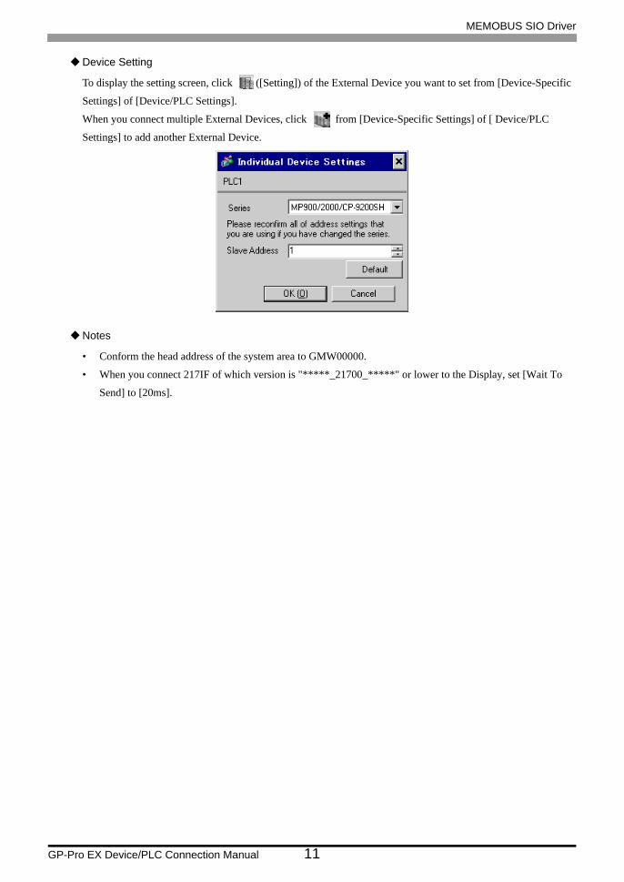
Device Setting
To display the setting screen, click ([Setting]) of the External Device you want to set from [Device-Specific
Settings] of [Device/PLC Settings].
When you connect multiple External Devices, click from [Device-Specific Settings] of [ Device/PLC
Settings] to add another External Device.
Notes
• Conform the head address of the system area to GMW00000.
• When you connect 217IF of which version is "*****_21700_*****" or lower to the Display, set [Wait To
Send] to [20ms].
MEMOBUS SIO Driver
GP-Pro EX Device/PLC Connection Manual 12
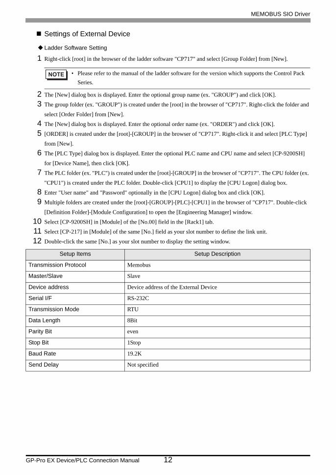
Settings of External Device
Ladder Software Setting
1 Right-click [root] in the browser of the ladder software "CP717" and select [Group Folder] from [New].
2 The [New] dialog box is displayed. Enter the optional group name (ex. "GROUP") and click [OK].
3 The group folder (ex. "GROUP") is created under the [root] in the browser of "CP717". Right-click the folder and
select [Order Folder] from [New].
4 The [New] dialog box is displayed. Enter the optional order name (ex. "ORDER") and click [OK].
5 [ORDER] is created under the [root]-[GROUP] in the browser of "CP717". Right-click it and select [PLC Type]
from [New].
6 The [PLC Type] dialog box is displayed. Enter the optional PLC name and CPU name and select [CP-9200SH]
for [Device Name], then click [OK].
7 The PLC folder (ex. "PLC") is created under the [root]-[GROUP] in the browser of "CP717". The CPU folder (ex.
"CPU1") is created under the PLC folder. Double-click [CPU1] to display the [CPU Logon] dialog box.
8 Enter "User name" and "Password" optionally in the [CPU Logon] dialog box and click [OK].
9 Multiple folders are created under the [root]-[GROUP]-[PLC]-[CPU1] in the browser of "CP717". Double-click
[Definition Folder]-[Module Configuration] to open the [Engineering Manager] window.
10 Select [CP-9200SH] in [Module] of the [No.00] field in the [Rack1] tab.
11 Select [CP-217] in [Module] of the same [No.] field as your slot number to define the link unit.
12 Double-click the same [No.] as your slot number to display the setting window.
• Please refer to the manual of the ladder software for the version which supports the Control Pack Series.
Setup Items Setup Description
Transmission Protocol Memobus
Master/Slave Slave
Device address Device address of the External Device
Serial I/F RS-232C
Transmission Mode RTU
Data Length 8Bit
Parity Bit even
Stop Bit 1Stop
Baud Rate 19.2K
Send Delay Not specified

[ H0000 [=>DW00024 ] .../007$
0003
0005
0000 "### MSG-RCV ###"
0001
0009
0011
0007
00000
00000
00000
00000
09998
$ONCOIL
00000
=>DW00019
=>DW00020
=>DW00018
=>DW00022 .../002$
DB000000 .../012$SB000004 DB000001 DB000003 DB000004
.../018 .../032 .../034
.../030 .../032
.../034
.../012
.../018
DB000002 DB000003 005. 00 DW00030
DB000004
DB000001 .../009 .../018$ .../022
DB000002 .../013 .../030$
DB000003 .../010 .../014 .../032$DB000001
DB000000
DB000004 .../011 .../017 .../034$
=>DW00023 .../004$
=>DW00021
0013
0016
0021
0014
0025
0028
0030
0027
0032
0034
0035
0033
00005 ========>
00002 ========>
00001 ========>
00001 ========>
0043 DEND
0036
[
$FSCAN-LSB000003
[
EXECUTEFIN
BUSYFOUT
ABORTFIN
COMPLETEFOUT
DEV-TYPFIN
ERRORFOUT
PRO-TYPFIN
CIR-NOFIN
CH-NOFIN
MSG-RCV
PARAM
DA00010
T
You can change this step value to change
the line number (CN) connected to GP.
Example) When using the line 2
Message reception function
(system standard function)
MEMOBUS SIO Driver
GP-Pro EX Device/PLC Connection Manual 13
Example of Ladder Program
You need the ladder program to connect the Display to the Link I/F CP217IF by YASKAWA Electric Corporation.
The ladder program example is shown below.
• This ladder program example enables to communicate the 1 CN port with the Display. Note that each CN port requires the ladder program when you use multiple ports, CN1 to CN3, to communicate simultaneously.
• Use the ladder software to perform the communication settings on the External Device. Those settings are not performed in this ladder program.

MEMOBUS SIO Driver
GP-Pro EX Device/PLC Connection Manual 14
Notes
• Please refer to the manual of the ladder software for more detail on other setting description.
MEMOBUS SIO Driver
GP-Pro EX Device/PLC Connection Manual 15
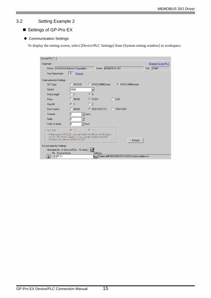
3.2 Setting Example 2
Settings of GP-Pro EX
Communication Settings
To display the setting screen, select [Device/PLC Settings] from [System setting window] in workspace.

MEMOBUS SIO Driver
GP-Pro EX Device/PLC Connection Manual 16
Device Setting
To display the setting screen, click ([Setting]) of the External Device you want to set from [Device-Specific
Settings] of [Device/PLC Settings].
When you connect multiple External Devices, click from [Device-Specific Settings] of [ Device/PLC
Settings] to add another External Device.
Notes
• Conform the head address of the system area to GMW00000.
• When you connect 217IF of which version is "*****_21700_*****" or lower to the Display, set [Wait To
Send] to [20ms].

MEMOBUS SIO Driver
GP-Pro EX Device/PLC Connection Manual 17
Settings of External Device
Ladder Software Setting
1 Right-click [root] in the browser of the ladder software "CP717" and select [Group Folder] from [New].
2 The [New] dialog box is displayed. Enter the optional group name (ex. "GROUP") and click [OK].
3 The group folder (ex. "GROUP") is created under the [root] in the browser of "CP717". Right-click the folder and
select [Order Folder] from [New].
4 The [New] dialog box is displayed. Enter the optional order name (ex. "ORDER") and click [OK].
5 [ORDER] is created under the [root]-[GROUP] in the browser of "CP717". Right-click it and select [PLC Type]
from [New].
6 The [PLC Type] dialog box is displayed. Enter the optional PLC name and CPU name and select [CP-9200SH]
for [Device Name], then click [OK].
7 The PLC folder (ex. "PLC") is created under the [root]-[GROUP] in the browser of "CP717". The CPU folder (ex.
"CPU1") is created under the PLC folder. Double-click [CPU1] to display the [CPU Logon] dialog box.
8 Enter "User name" and "Password" optionally in the [CPU Logon] dialog box and click [OK].
9 Multiple folders are created under the [root]-[GROUP]-[PLC]-[CPU1] in the browser of "CP717". Double-click
[Definition Folder]-[Module Configuration] to open the [Engineering Manager] window.
10 Select [CP-9200SH] in [Module] of the [No.00] field in the [Rack1] tab.
11 Select [CP-217] in [Module] of the same [No.] field as your slot number to define the link unit.
12 Double-click the same [No.] as your slot number to display the setting window.
• Please refer to the manual of the ladder software for the version which supports the Control Pack Series.
Setup Items Setup Description
Transmission Protocol Memobus
Master/Slave Slave
Device address Device address of the External Device
Serial I/F RS-485
Transmission Mode RTU
Data Length 8Bit
Parity Bit even
Stop Bit 1Stop
Baud Rate 19.2K
Send Delay Not specified
[ H0000 [=>DW00024 ] .../007$
0003
0005
0000 "### MSG-RCV ###"
0001
0009
0011
0007
00000
00000
00000
00000
09998
$ONCOIL
00000
=>DW00019
=>DW00020
=>DW00018
=>DW00022 .../002$
DB000000 .../012$SB000004 DB000001 DB000003 DB000004
.../018 .../032 .../034
.../030 .../032
.../034
.../012
.../018
DB000002 DB000003 005. 00 DW00030
DB000004
DB000001 .../009 .../018$ .../022
DB000002 .../013 .../030$
DB000003 .../010 .../014 .../032$DB000001
DB000000
DB000004 .../011 .../017 .../034$
=>DW00023 .../004$
=>DW00021
0013
0016
0021
0014
0025
0028
0030
0027
0032
0034
0035
0033
00005 ========>
00002 ========>
00001 ========>
00001 ========>
0043 DEND
0036
[
$FSCAN-LSB000003
[
EXECUTEFIN
BUSYFOUT
ABORTFIN
COMPLETEFOUT
DEV-TYPFIN
ERRORFOUT
PRO-TYPFIN
CIR-NOFIN
CH-NOFIN
MSG-RCV
PARAM
DA00010
T
You can change this step value to change
the line number (CN) connected to GP.
Example) When using the line 2
Message reception function
(system standard function)
MEMOBUS SIO Driver
GP-Pro EX Device/PLC Connection Manual 18
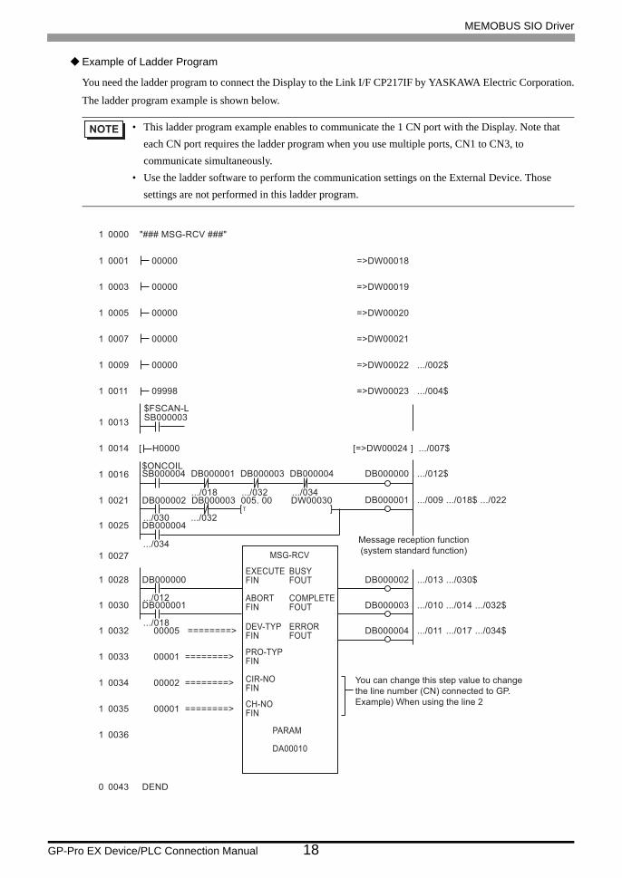
Example of Ladder Program
You need the ladder program to connect the Display to the Link I/F CP217IF by YASKAWA Electric Corporation.
The ladder program example is shown below.
• This ladder program example enables to communicate the 1 CN port with the Display. Note that each CN port requires the ladder program when you use multiple ports, CN1 to CN3, to communicate simultaneously.
• Use the ladder software to perform the communication settings on the External Device. Those settings are not performed in this ladder program.

MEMOBUS SIO Driver
GP-Pro EX Device/PLC Connection Manual 19
Notes
• Please refer to the manual of the ladder software for more detail on other setting description.

MEMOBUS SIO Driver
GP-Pro EX Device/PLC Connection Manual 20
3.3 Setting Example 3
Settings of GP-Pro EX
Communication Settings
To display the setting screen, select [Device/PLC Settings] from [System setting window] in workspace.
Device Setting
To display the setting screen, click ([Setting]) of the External Device you want to set from [Device-Specific
Settings] of [Device/PLC Settings].
When you connect multiple External Devices, click from [Device-Specific Settings] of [ Device/PLC
Settings] to add another External Device.

MEMOBUS SIO Driver
GP-Pro EX Device/PLC Connection Manual 21
Settings of External Device
Ladder Software Setting
1 Right-click [root] in the browser of the ladder software "MPE720" and select [Group Folder] from [New].
2 The [New] dialog box is displayed. Enter the optional group name (ex. "GROUP") and click [OK].
3 The group folder (ex. "GROUP") is created under the [root] in the browser of "MPE720". Right-click the folder
and select [Order Folder] from [New].
4 The [New] dialog box is displayed. Enter the optional order name (ex. "ORDER") and click [OK].
5 [ORDER] is created under the [root]-[GROUP] in the browser of "MPE720". Right-click it and select [PLC Type]
from [New].
6 The [PLC Type] dialog box is displayed. Enter the optional PLC name and CPU name and select your External
Device for [Device Name], then click [OK].
7 The PLC folder (ex. "PLC") is created under the [root]-[GROUP] in the browser of "MPE720". The CPU folder
(ex. "CPU1") is created under the PLC folder. Double-click [CPU1] to display the [CPU Logon] dialog box.
8 Enter "User name" and "Password" optionally in the [CPU Logon] dialog box and click [OK].
9 Multiple folders are created under the [root]-[GROUP]-[PLC]-[CPU1] in the browser of "MPE720".
Double-click [Definition Folder]-[Module Configuration] to open the [Engineering Manager] window.
10 Select your link unit in [Module] of the [No.00] field in the [Rack1] tab.
11 Double-click the same [No.] field as your slot number to display the setting window.
Setup Items Setup Description
Transmission Protocol Memobus
Master/Slave Slave
Device address Device address of the External Device
Serial I/F RS-232C
Transmission Mode RTU
Data Length 8Bit
Parity Bit even
Stop Bit 1Stop
Baud Rate 19.2K
Send Delay Not specified
Auto Reception*1
*1 When [Auto Reception] is set to [Not specified], the ladder program is required to communicate the Display with the External Device. It is not required in case of [Specified].
Not specified
MEMOBUS SIO Driver
GP-Pro EX Device/PLC Connection Manual 22
Example of Ladder Program
Notes
Please refer to the manual of the ladder software for more detail on other setting description.
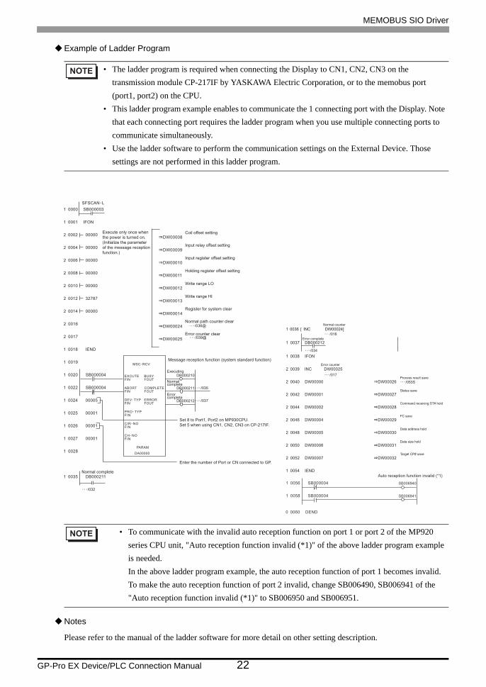
• The ladder program is required when connecting the Display to CN1, CN2, CN3 on the transmission module CP-217IF by YASKAWA Electric Corporation, or to the memobus port (port1, port2) on the CPU.
• This ladder program example enables to communicate the 1 connecting port with the Display. Note that each connecting port requires the ladder program when you use multiple connecting ports to communicate simultaneously.
• Use the ladder software to perform the communication settings on the External Device. Those settings are not performed in this ladder program.
• To communicate with the invalid auto reception function on port 1 or port 2 of the MP920 series CPU unit, "Auto reception function invalid (*1)" of the above ladder program example is needed. In the above ladder program example, the auto reception function of port 1 becomes invalid. To make the auto reception function of port 2 invalid, change SB006490, SB006941 of the "Auto reception function invalid (*1)" to SB006950 and SB006951.
0000 SB000003
0001 IFON
0002 00000
0004 00000
0006 00000
0008 00000
0010 00000
0012 32787
0014 00000
0016
0017
0018 IEND
0019
0020 SB000004
0022 SB000004
0024 00005
0025 00001
0026 00001
0027 00001
0028
0035 DB000211
DW00008
DW00009
DW00010
DW00011
DW00012
DW00013
DW00014
DW00024
DW00025
EXCUTE BUSYFIN FOUT
ABORT COMPLETEFIN FOUT
ERRORFIN FOUT
FIN
FIN
FIN
PARAM
DA00000
/035
/037
/036@
/039@
/032
Execute only once when
the power is turned on.
(Initialize the parameter
of the message reception
function.)
Coil offset setting
Input relay offset setting
Input register offset setting
Write range LO
Write range HI
Register for system clear
Normal path counter clear
Error counter clear
Holding register offset setting
Message reception function (system standard function)
Executing
Normalcomplete
Errorcomplete
Set 8 to Port1, Port2 on MP930CPU.
Set 5 when using CN1, CN2, CN3 on CP-217IF.
Enter the number of Port or CN connected to GP.
Normal complete
0036 INC DW00024]
0037 DB000212
0038 IFON
0039 INC DW00025
0040 DW00000
0042 DW00001
0044 DW00002
0046 DW00004
0048 DW00005
0050 DW00006
0052 DW00007
0054 IEND
DW00026
DW00027
DW00028
DW00029
DW00030
DW00031
DW00032
/053S
/017
/016
/034
[Normal counter
Error complete
Error counter
Process result save
Status save
Command receiving ST# hold
FC save
Data address hold
Data size hold
Target CP# save
0 0060 DEND
1 0056 SB000004
1 0058 SB000004
SB006940
SB006941
Auto reception function invalid (*1)

MEMOBUS SIO Driver
GP-Pro EX Device/PLC Connection Manual 23
3.4 Setting Example 4
Settings of GP-Pro EX
Communication Settings
To display the setting screen, select [Device/PLC Settings] from [System setting window] in workspace.
Device Setting
To display the setting screen, click ([Setting]) of the External Device you want to set from [Device-Specific
Settings] of [Device/PLC Settings].
When you connect multiple External Devices, click from [Device-Specific Settings] of [ Device/PLC
Settings] to add another External Device.

MEMOBUS SIO Driver
GP-Pro EX Device/PLC Connection Manual 24
Settings of External Device
Ladder Software Setting
1 Right-click [root] in the browser of the ladder software "MPE720" and select [Group Folder] from [New].
2 The [New] dialog box is displayed. Enter the optional group name (ex. "GROUP") and click [OK].
3 The group folder (ex. "GROUP") is created under the [root] in the browser of "MPE720". Right-click the folder
and select [Order Folder] from [New].
4 The [New] dialog box is displayed. Enter the optional order name (ex. "ORDER") and click [OK].
5 [ORDER] is created under the [root]-[GROUP] in the browser of "MPE720". Right-click it and select [PLC Type]
from [New].
6 The [PLC Type] dialog box is displayed. Enter the optional PLC name and CPU name and select your External
Device for [Device Name], then click [OK].
7 The PLC folder (ex. "PLC") is created under the [root]-[GROUP] in the browser of "MPE720". The CPU folder
(ex. "CPU1") is created under the PLC folder. Double-click [CPU1] to display the [CPU Logon] dialog box.
8 Enter "User name" and "Password" optionally in the [CPU Logon] dialog box and click [OK].
9 Multiple folders are created under the [root]-[GROUP]-[PLC]-[CPU1] in the browser of "MPE720".
Double-click [Definition Folder]-[Module Configuration] to open the [Engineering Manager] window.
10 Select your link unit in [Module] of the [No.00] field in the [Rack1] tab.
11 Double-click the same [No.] field as your slot number to display the setting window.
Setup Items Setup Description
Transmission Protocol Memobus
Master/Slave Slave
Device address Device address of the External Device
Serial I/F RS-485
Transmission Mode RTU
Data Length 8Bit
Parity Bit even
Stop Bit 1Stop
Baud Rate 19.2K
Send Delay Not specified
Auto Reception*1
*1 When [Auto Reception] is set to [Not specified], the ladder program is required to communicate the Display with the External Device. It is not required in case of [Specified].
Not specified

MEMOBUS SIO Driver
GP-Pro EX Device/PLC Connection Manual 25
Example of Ladder Program
Notes
Please refer to the manual of the ladder software for more detail on other setting description.
• The ladder program is required when connecting the Display to CN1, CN2, CN3 on the transmission module CP-217IF by YASKAWA Electric Corporation, or to the memobus port (port1, port2) on the CPU.
• This ladder program example enables to communicate the 1 connecting port with the Display. Note that each connecting port requires the ladder program when you use multiple connecting ports to communicate simultaneously.
• Use the ladder software to perform the communication settings on the External Device. Those settings are not performed in this ladder program.
0000 SB000003
0001 IFON
0002 00000
0004 00000
0006 00000
0008 00000
0010 00000
0012 32787
0014 00000
0016
0017
0018 IEND
0019
0020 SB000004
0022 SB000004
0024 00005
0025 00001
0026 00001
0027 00001
0028
0035 DB000211
DW00008
DW00009
DW00010
DW00011
DW00012
DW00013
DW00014
DW00024
DW00025
EXCUTE BUSYFIN FOUT
ABORT COMPLETEFIN FOUT
ERRORFIN FOUT
FIN
FIN
FIN
PARAM
DA00000
/035
/037
/036@
/039@
/032
Execute only once when
the power is turned on.
(Initialize the parameter
of the message reception
function.)
Coil offset setting
Input relay offset setting
Input register offset setting
Write range LO
Write range HI
Register for system clear
Normal path counter clear
Error counter clear
Holding register offset setting
Message reception function (system standard function)
Executing
Normalcomplete
Errorcomplete
Set 8 to Port1, Port2 on MP930CPU.
Set 5 when using CN1, CN2, CN3 on CP-217IF.
Enter the number of Port or CN connected to GP.
Normal complete
0036 INC DW00024]
0037 DB000212
0038 IFON
0039 INC DW00025
0040 DW00000
0042 DW00001
0044 DW00002
0046 DW00004
0048 DW00005
0050 DW00006
0052 DW00007
0054 IEND
0055 DEND
DW00026
DW00027
DW00028
DW00029
DW00030
DW00031
DW00032
/053S
/017
/016
/034
[Normal counter
Error complete
Error counter
Process result save
Status save
Command receiving ST# hold
FC save
Data address hold
Data size hold
Target CP# save

MEMOBUS SIO Driver
GP-Pro EX Device/PLC Connection Manual 26
3.5 Setting Example 5
Settings of GP-Pro EX
Communication Settings
To display the setting screen, select [Device/PLC Settings] from [System setting window] in workspace.
Device Setting
To display the setting screen, click ([Setting]) of the External Device you want to set from [Device-Specific
Settings] of [Device/PLC Settings].
When you connect multiple External Devices, click from [Device-Specific Settings] of [ Device/PLC
Settings] to add another External Device.

MEMOBUS SIO Driver
GP-Pro EX Device/PLC Connection Manual 27
Settings of External Device
Ladder Software Setting
1 Right-click [root] in the browser of the ladder software "MPE720" and select [Group Folder] from [New].
2 The [New] dialog box is displayed. Enter the optional group name (ex. "GROUP") and click [OK].
3 The group folder (ex. "GROUP") is created under the [root] in the browser of "MPE720". Right-click the folder
and select [Order Folder] from [New].
4 The [New] dialog box is displayed. Enter the optional order name (ex. "ORDER") and click [OK].
5 [ORDER] is created under the [root]-[GROUP] in the browser of "MPE720". Right-click it and select [PLC Type]
from [New].
6 The [PLC Type] dialog box is displayed. Enter the optional PLC name and CPU name and select your External
Device for [Device Name], then click [OK].
7 The PLC folder (ex. "PLC") is created under the [root]-[GROUP] in the browser of "MPE720". The CPU folder
(ex. "CPU1") is created under the PLC folder. Double-click [CPU1] to display the [CPU Logon] dialog box.
8 Enter "User name" and "Password" optionally in the [CPU Logon] dialog box and click [OK].
9 Multiple folders are created under the [root]-[GROUP]-[PLC]-[CPU1] in the browser of "MPE720".
Double-click [Definition Folder]-[Module Configuration] to open the [Engineering Manager] window.
10 Select your link unit in [Module] of the [No.00] field in the [Rack1] tab.
11 Double-click the same [No.] field as your slot number to display the setting window.
Setup Items Setup Description
Transmission Protocol Memobus
Master/Slave Slave
Device address Device address of the External Device
Serial I/F RS-485
Transmission Mode RTU
Data Length 8Bit
Parity Bit even
Stop Bit 1Stop
Baud Rate 19.2K
Send Delay Not specified
Auto Reception*1
*1 When [Auto Reception] is set to [Not specified], the ladder program is required to communicate the Display with the External Device. It is not required in case of [Specified].
Not specified

MEMOBUS SIO Driver
GP-Pro EX Device/PLC Connection Manual 28
Example of Ladder Program
Notes
Please refer to the manual of the ladder software for more detail on other setting description.
• The ladder program is required when connecting the Display to CN1, CN2, CN3 on the transmission module CP-217IF by YASKAWA Electric Corporation, or to the memobus port (port1, port2) on the CPU.
• This ladder program example enables to communicate the 1 connecting port with the Display. Note that each connecting port requires the ladder program when you use multiple connecting ports to communicate simultaneously.
• Use the ladder software to perform the communication settings on the External Device. Those settings are not performed in this ladder program.
0000 SB000003
0001 IFON
0002 00000
0004 00000
0006 00000
0008 00000
0010 00000
0012 32787
0014 00000
0016
0017
0018 IEND
0019
0020 SB000004
0022 SB000004
0024 00005
0025 00001
0026 00001
0027 00001
0028
0035 DB000211
DW00008
DW00009
DW00010
DW00011
DW00012
DW00013
DW00014
DW00024
DW00025
EXCUTE BUSYFIN FOUT
ABORT COMPLETEFIN FOUT
ERRORFIN FOUT
FIN
FIN
FIN
PARAM
DA00000
/035
/037
/036@
/039@
/032
Execute only once when
the power is turned on.
(Initialize the parameter
of the message reception
function.)
Coil offset setting
Input relay offset setting
Input register offset setting
Write range LO
Write range HI
Register for system clear
Normal path counter clear
Error counter clear
Holding register offset setting
Message reception function (system standard function)
Executing
Normalcomplete
Errorcomplete
Set 8 to Port1, Port2 on MP930CPU.
Set 5 when using CN1, CN2, CN3 on CP-217IF.
Enter the number of Port or CN connected to GP.
Normal complete
0036 INC DW00024]
0037 DB000212
0038 IFON
0039 INC DW00025
0040 DW00000
0042 DW00001
0044 DW00002
0046 DW00004
0048 DW00005
0050 DW00006
0052 DW00007
0054 IEND
0055 DEND
DW00026
DW00027
DW00028
DW00029
DW00030
DW00031
DW00032
/053S
/017
/016
/034
[Normal counter
Error complete
Error counter
Process result save
Status save
Command receiving ST# hold
FC save
Data address hold
Data size hold
Target CP# save
MEMOBUS SIO Driver
GP-Pro EX Device/PLC Connection Manual 29
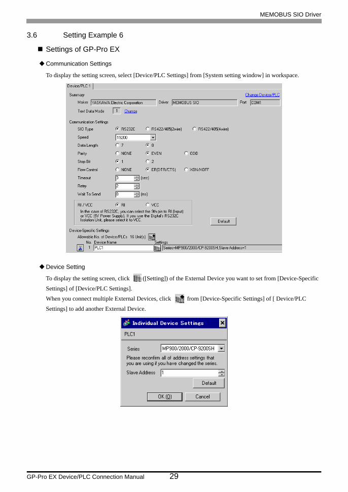
3.6 Setting Example 6
Settings of GP-Pro EX
Communication Settings
To display the setting screen, select [Device/PLC Settings] from [System setting window] in workspace.
Device Setting
To display the setting screen, click ([Setting]) of the External Device you want to set from [Device-Specific
Settings] of [Device/PLC Settings].
When you connect multiple External Devices, click from [Device-Specific Settings] of [ Device/PLC
Settings] to add another External Device.
MEMOBUS SIO Driver
GP-Pro EX Device/PLC Connection Manual 30
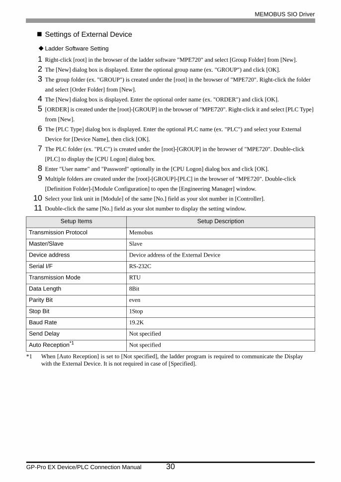
Settings of External Device
Ladder Software Setting
1 Right-click [root] in the browser of the ladder software "MPE720" and select [Group Folder] from [New].
2 The [New] dialog box is displayed. Enter the optional group name (ex. "GROUP") and click [OK].
3 The group folder (ex. "GROUP") is created under the [root] in the browser of "MPE720". Right-click the folder
and select [Order Folder] from [New].
4 The [New] dialog box is displayed. Enter the optional order name (ex. "ORDER") and click [OK].
5 [ORDER] is created under the [root]-[GROUP] in the browser of "MPE720". Right-click it and select [PLC Type]
from [New].
6 The [PLC Type] dialog box is displayed. Enter the optional PLC name (ex. "PLC") and select your External
Device for [Device Name], then click [OK].
7 The PLC folder (ex. "PLC") is created under the [root]-[GROUP] in the browser of "MPE720". Double-click
[PLC] to display the [CPU Logon] dialog box.
8 Enter "User name" and "Password" optionally in the [CPU Logon] dialog box and click [OK].
9 Multiple folders are created under the [root]-[GROUP]-[PLC] in the browser of "MPE720". Double-click
[Definition Folder]-[Module Configuration] to open the [Engineering Manager] window.
10 Select your link unit in [Module] of the same [No.] field as your slot number in [Controller].
11 Double-click the same [No.] field as your slot number to display the setting window.
Setup Items Setup Description
Transmission Protocol Memobus
Master/Slave Slave
Device address Device address of the External Device
Serial I/F RS-232C
Transmission Mode RTU
Data Length 8Bit
Parity Bit even
Stop Bit 1Stop
Baud Rate 19.2K
Send Delay Not specified
Auto Reception*1
*1 When [Auto Reception] is set to [Not specified], the ladder program is required to communicate the Display with the External Device. It is not required in case of [Specified].
Not specified

DW00028
DW00031
DW00027
DW00029
DW00030
DW00032
00000 DW00025
SB000003
IF ON
IEND
FORi=0 TO 31 BY 1
0
FEND
DW0000i
00000 DW00008
00000 DW00009
00000 DW00010
00000 DW00011
00000 DW00012
65534 DW00013
00000 DW00024
00000 DW00014
DW0002
DW00000
DW0001
DW0004
DW0005
DW0006
DW0007
DW00026
IFON
DB000211
[ INC DW00024 ]
DB000212
INC DW00025
IEND
DEND
SB000004
EXECUTE
ABORT
DEV- TYP
PRO-TYP
CIR-NOI
CH-NO
BUSY
COMPLETE
ERROR
MSG-RCV
RECV PARAM
DA00000
SB000004
DB000210
DB000211
DB000212
00008
00001
00001
00001
CPU module: 8
217IF: 5
218IF: 6
1 scan when the power is turned on
Setting value related to
device address
Instruct
Abort
Set the following
value for each
module.
Set the line number
to connect to GP.
Normal complete
Normal counter
Error complete
Error counter
Parameter setting when
executing 1 scan when
the power is turned on
DW register clear
Coil offset setting
Relay offset setting
Input offset setting
Holding register offset setting
Write range LO
Write range HI
Normal pulse counter clear
Error pulse counter clear
Clear for system
Executing
Normal complete
Error complete
Turn ON when complete
receiving instruction
message and sending
response message
Normal pulse counter increased
Complete upon transmission error
Error pulse counter increased
Process result save
Status save
Target CP# save
FC save
Data address save
Data size save
Target CP# save
MEMOBUS SIO Driver
GP-Pro EX Device/PLC Connection Manual 31
Example of Ladder Program
• This ladder program example enables to communicate the 1 connecting port with the Display. Note that each connecting port requires the ladder program when you use multiple connecting ports to communicate simultaneously.
• Note that each connector requires the ladder program when you connect the RS232C connector, the RS422 connector on 217IF-01, the RS232C connector on 218IF-01, and the RS232C connector on 218IF-02 simultaneously.
• Use the ladder software to perform the communication settings on the External Device. Those settings are not performed in this ladder program.

MEMOBUS SIO Driver
GP-Pro EX Device/PLC Connection Manual 32
Notes
• Please refer to the manual of the ladder software for more detail on other setting description.
MEMOBUS SIO Driver
GP-Pro EX Device/PLC Connection Manual 33
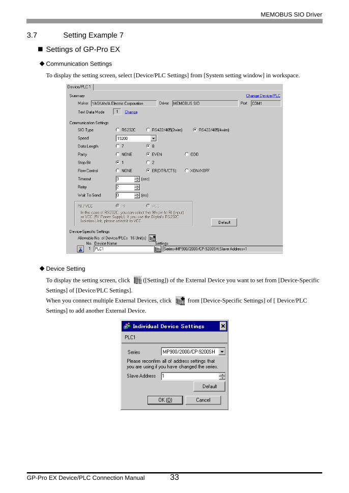
3.7 Setting Example 7
Settings of GP-Pro EX
Communication Settings
To display the setting screen, select [Device/PLC Settings] from [System setting window] in workspace.
Device Setting
To display the setting screen, click ([Setting]) of the External Device you want to set from [Device-Specific
Settings] of [Device/PLC Settings].
When you connect multiple External Devices, click from [Device-Specific Settings] of [ Device/PLC
Settings] to add another External Device.

MEMOBUS SIO Driver
GP-Pro EX Device/PLC Connection Manual 34
Settings of External Device
Ladder Software Setting
1 Right-click [root] in the browser of the ladder software "MPE720" and select [Group Folder] from [New].
2 The [New] dialog box is displayed. Enter the optional group name (ex. "GROUP") and click [OK].
3 The group folder (ex. "GROUP") is created under the [root] in the browser of "MPE720". Right-click the folder
and select [Order Folder] from [New].
4 The [New] dialog box is displayed. Enter the optional order name (ex. "ORDER") and click [OK].
5 [ORDER] is created under the [root]-[GROUP] in the browser of "MPE720". Right-click it and select [PLC Type]
from [New].
6 The [PLC Type] dialog box is displayed. Enter the optional PLC name (ex. "PLC") and select your External
Device for [Device Name], then click [OK].
7 The PLC folder (ex. "PLC") is created under the [root]-[GROUP] in the browser of "MPE720". Double-click
[PLC] to display the [CPU Logon] dialog box.
8 Enter "User name" and "Password" optionally in the [CPU Logon] dialog box and click [OK].
9 Multiple folders are created under the [root]-[GROUP]-[PLC] in the browser of "MPE720". Double-click
[Definition Folder]-[Module Configuration] to open the [Engineering Manager] window.
10 Select your link unit in [Module] of the same [No.] field as your slot number in [Controller].
11 Double-click the same [No.] field as your slot number to display the setting window.
Setup Items Setup Description
Transmission Protocol Memobus
Master/Slave Slave
Device address Device address of the External Device
Serial I/F RS-485
Transmission Mode RTU
Data Length 8Bit
Parity Bit even
Stop Bit 1Stop
Baud Rate 19.2K
Send Delay Not specified
Auto Reception*1
*1 When [Auto Reception] is set to [Not specified], the ladder program is required to communicate the Display with the External Device. It is not required in case of [Specified].
Not specified
DW00028
DW00031
DW00027
DW00029
DW00030
DW00032
00000 DW00025
SB000003
IF ON
IEND
FORi=0 TO 31 BY 1
0
FEND
DW0000i
00000 DW00008
00000 DW00009
00000 DW00010
00000 DW00011
00000 DW00012
65534 DW00013
00000 DW00024
00000 DW00014
DW0002
DW00000
DW0001
DW0004
DW0005
DW0006
DW0007
DW00026
IFON
DB000211
[ INC DW00024 ]
DB000212
INC DW00025
IEND
DEND
SB000004
EXECUTE
ABORT
DEV- TYP
PRO-TYP
CIR-NOI
CH-NO
BUSY
COMPLETE
ERROR
MSG-RCV
RECV PARAM
DA00000
SB000004
DB000210
DB000211
DB000212
00008
00001
00001
00001
CPU module: 8
217IF: 5
218IF: 6
1 scan when the power is turned on
Setting value related to
device address
Instruct
Abort
Set the following
value for each
module.
Set the line number
to connect to GP.
Normal complete
Normal counter
Error complete
Error counter
Parameter setting when
executing 1 scan when
the power is turned on
DW register clear
Coil offset setting
Relay offset setting
Input offset setting
Holding register offset setting
Write range LO
Write range HI
Normal pulse counter clear
Error pulse counter clear
Clear for system
Executing
Normal complete
Error complete
Turn ON when complete
receiving instruction
message and sending
response message
Normal pulse counter increased
Complete upon transmission error
Error pulse counter increased
Process result save
Status save
Target CP# save
FC save
Data address save
Data size save
Target CP# save
MEMOBUS SIO Driver
GP-Pro EX Device/PLC Connection Manual 35
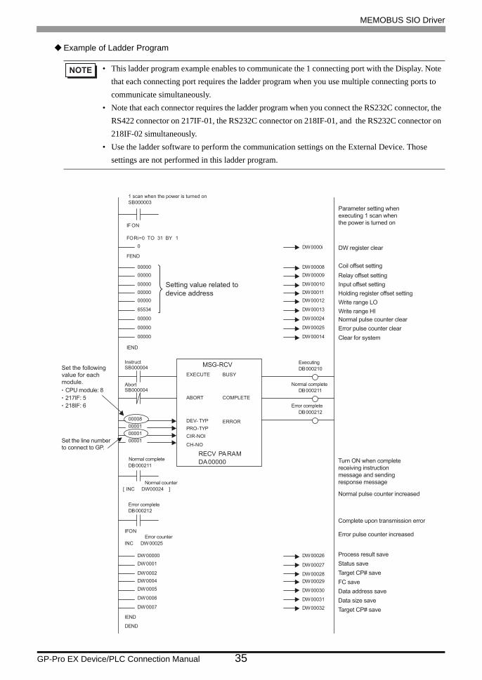
Example of Ladder Program
• This ladder program example enables to communicate the 1 connecting port with the Display. Note that each connecting port requires the ladder program when you use multiple connecting ports to communicate simultaneously.
• Note that each connector requires the ladder program when you connect the RS232C connector, the RS422 connector on 217IF-01, the RS232C connector on 218IF-01, and the RS232C connector on 218IF-02 simultaneously.
• Use the ladder software to perform the communication settings on the External Device. Those settings are not performed in this ladder program.

MEMOBUS SIO Driver
GP-Pro EX Device/PLC Connection Manual 36
Notes
• Please refer to the manual of the ladder software for more detail on other setting description.
MEMOBUS SIO Driver
GP-Pro EX Device/PLC Connection Manual 37
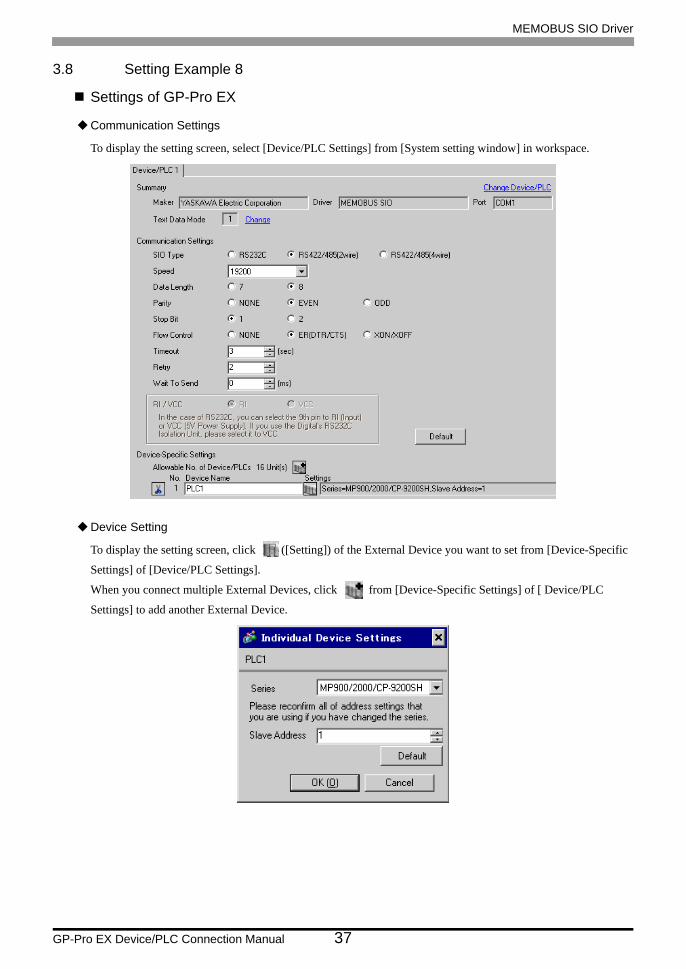
3.8 Setting Example 8
Settings of GP-Pro EX
Communication Settings
To display the setting screen, select [Device/PLC Settings] from [System setting window] in workspace.
Device Setting
To display the setting screen, click ([Setting]) of the External Device you want to set from [Device-Specific
Settings] of [Device/PLC Settings].
When you connect multiple External Devices, click from [Device-Specific Settings] of [ Device/PLC
Settings] to add another External Device.

MEMOBUS SIO Driver
GP-Pro EX Device/PLC Connection Manual 38
Settings of External Device
Ladder Software Setting
1 Right-click [root] in the browser of the ladder software "MPE720" and select [Group Folder] from [New].
2 The [New] dialog box is displayed. Enter the optional group name (ex. "GROUP") and click [OK].
3 The group folder (ex. "GROUP") is created under the [root] in the browser of "MPE720". Right-click the folder
and select [Order Folder] from [New].
4 The [New] dialog box is displayed. Enter the optional order name (ex. "ORDER") and click [OK].
5 [ORDER] is created under the [root]-[GROUP] in the browser of "MPE720". Right-click it and select [PLC Type]
from [New].
6 The [PLC Type] dialog box is displayed. Enter the optional PLC name (ex. "PLC") and select your External
Device for [Device Name], then click [OK].
7 The PLC folder (ex. "PLC") is created under the [root]-[GROUP] in the browser of "MPE720". Double-click
[PLC] to display the [CPU Logon] dialog box.
8 Enter "User name" and "Password" optionally in the [CPU Logon] dialog box and click [OK].
9 Multiple folders are created under the [root]-[GROUP]-[PLC] in the browser of "MPE720". Double-click
[Definition Folder]-[Module Configuration] to open the [Engineering Manager] window.
10 Select your link unit in [Module] of the same [No.] field as your slot number in [Controller].
11 Double-click the same [No.] field as your slot number to display the setting window.
Setup Items Setup Description
Transmission Protocol Memobus
Master/Slave Slave
Device address Device address of the External Device
Serial I/F RS-485
Transmission Mode RTU
Data Length 8Bit
Parity Bit even
Stop Bit 1Stop
Baud Rate 19.2K
Send Delay Not specified
Auto Reception*1
*1 When [Auto Reception] is set to [Not specified], the ladder program is required to communicate the Display with the External Device. It is not required in case of [Specified].
Not specified

DW00028
DW00031
DW00027
DW00029
DW00030
DW00032
00000 DW00025
SB000003
IF ON
IEND
FORi=0 TO 31 BY 1
0
FEND
DW0000i
00000 DW00008
00000 DW00009
00000 DW00010
00000 DW00011
00000 DW00012
65534 DW00013
00000 DW00024
00000 DW00014
DW0002
DW00000
DW0001
DW0004
DW0005
DW0006
DW0007
DW00026
IFON
DB000211
[ INC DW00024 ]
DB000212
INC DW00025
IEND
DEND
SB000004
EXECUTE
ABORT
DEV- TYP
PRO-TYP
CIR-NOI
CH-NO
BUSY
COMPLETE
ERROR
MSG-RCV
RECV PARAM
DA00000
SB000004
DB000210
DB000211
DB000212
00008
00001
00001
00001
CPU module: 8
217IF: 5
218IF: 6
1 scan when the power is turned on
Setting value related to
device address
Instruct
Abort
Set the following
value for each
module.
Set the line number
to connect to GP.
Normal complete
Normal counter
Error complete
Error counter
Parameter setting when
executing 1 scan when
the power is turned on
DW register clear
Coil offset setting
Relay offset setting
Input offset setting
Holding register offset setting
Write range LO
Write range HI
Normal pulse counter clear
Error pulse counter clear
Clear for system
Executing
Normal complete
Error complete
Turn ON when complete
receiving instruction
message and sending
response message
Normal pulse counter increased
Complete upon transmission error
Error pulse counter increased
Process result save
Status save
Target CP# save
FC save
Data address save
Data size save
Target CP# save
MEMOBUS SIO Driver
GP-Pro EX Device/PLC Connection Manual 39
Example of Ladder Program
• This ladder program example enables to communicate the 1 connecting port with the Display. Note that each connecting port requires the ladder program when you use multiple connecting ports to communicate simultaneously.
• Note that each connector requires the ladder program when you connect the RS232C connector, the RS422 connector on 217IF-01, the RS232C connector on 218IF-01, and the RS232C connector on 218IF-02 simultaneously.
• Use the ladder software to perform the communication settings on the External Device. Those settings are not performed in this ladder program.

MEMOBUS SIO Driver
GP-Pro EX Device/PLC Connection Manual 40
Notes
• Please refer to the manual of the ladder software for more detail on other setting description.
MEMOBUS SIO Driver
GP-Pro EX Device/PLC Connection Manual 41
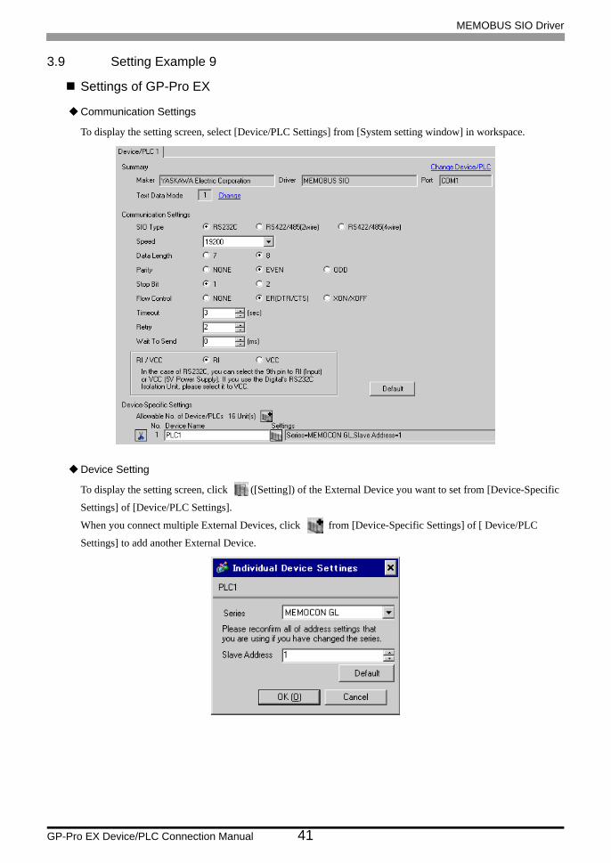
3.9 Setting Example 9
Settings of GP-Pro EX
Communication Settings
To display the setting screen, select [Device/PLC Settings] from [System setting window] in workspace.
Device Setting
To display the setting screen, click ([Setting]) of the External Device you want to set from [Device-Specific
Settings] of [Device/PLC Settings].
When you connect multiple External Devices, click from [Device-Specific Settings] of [ Device/PLC
Settings] to add another External Device.
MEMOBUS SIO Driver
GP-Pro EX Device/PLC Connection Manual 42
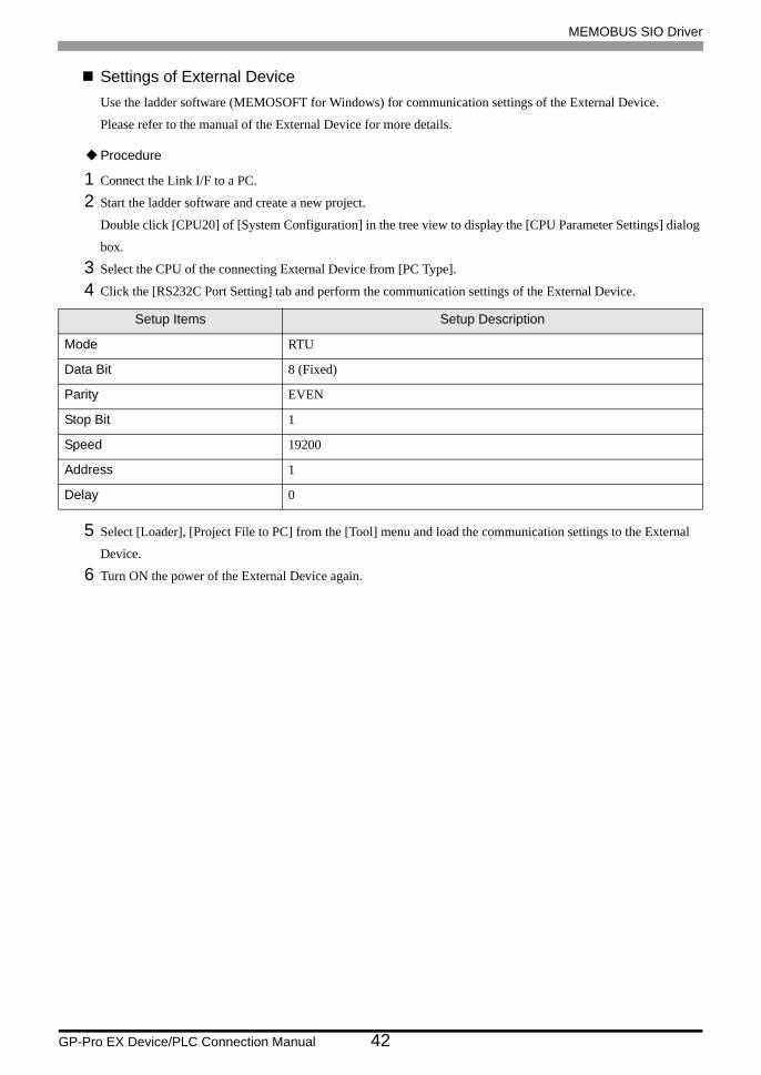
Settings of External DeviceUse the ladder software (MEMOSOFT for Windows) for communication settings of the External Device.
Please refer to the manual of the External Device for more details.
Procedure
1 Connect the Link I/F to a PC.
2 Start the ladder software and create a new project.
Double click [CPU20] of [System Configuration] in the tree view to display the [CPU Parameter Settings] dialog
box.
3 Select the CPU of the connecting External Device from [PC Type].
4 Click the [RS232C Port Setting] tab and perform the communication settings of the External Device.
5 Select [Loader], [Project File to PC] from the [Tool] menu and load the communication settings to the External
Device.
6 Turn ON the power of the External Device again.
Setup Items Setup Description
Mode RTU
Data Bit 8 (Fixed)
Parity EVEN
Stop Bit 1
Speed 19200
Address 1
Delay 0

MEMOBUS SIO Driver
GP-Pro EX Device/PLC Connection Manual 43
3.10 Setting Example 10
Settings of GP-Pro EX
Communication Settings
To display the setting screen, select [Device/PLC Settings] from [System setting window] in workspace.
Device Setting
To display the setting screen, click ([Setting]) of the External Device you want to set from [Device-Specific
Settings] of [Device/PLC Settings].
When you connect multiple External Devices, click from [Device-Specific Settings] of [ Device/PLC
Settings] to add another External Device.

MEMOBUS SIO Driver
GP-Pro EX Device/PLC Connection Manual 44
Settings of External DeviceUse the ladder software (MEMOSOFT for Windows) for communication settings of the External Device.
Please refer to the manual of the External Device for more details.
Procedure
1 Connect the Link I/F to a PC.
2 Start the ladder software and create a new project.
Double click [Port Settings] of [System Configuration] in the tree view to display the [COMM. Parameter
Settings] dialog box.
3 Perform the communication settings for the COMM. port of the channel to be used.
4 Select [Loader], [Project File to PC] from the [Tool] menu and load the communication settings to the External
Device.
5 Turn ON the power of the External Device again.
Setup Items Setup Description
Mode RTU
Data Bit 8 (Fixed)
Parity EVEN
Stop Bit 1
Speed 19200
Address 1
Delay 0

MEMOBUS SIO Driver
GP-Pro EX Device/PLC Connection Manual 45
3.11 Setting Example 11
Settings of GP-Pro EX
Communication Settings
To display the setting screen, select [Device/PLC Settings] from [System setting window] in workspace.
Device Setting
To display the setting screen, click ([Setting]) of the External Device you want to set from [Device-Specific
Settings] of [Device/PLC Settings].
When you connect multiple External Devices, click from [Device-Specific Settings] of [ Device/PLC
Settings] to add another External Device.
MEMOBUS SIO Driver
GP-Pro EX Device/PLC Connection Manual 46
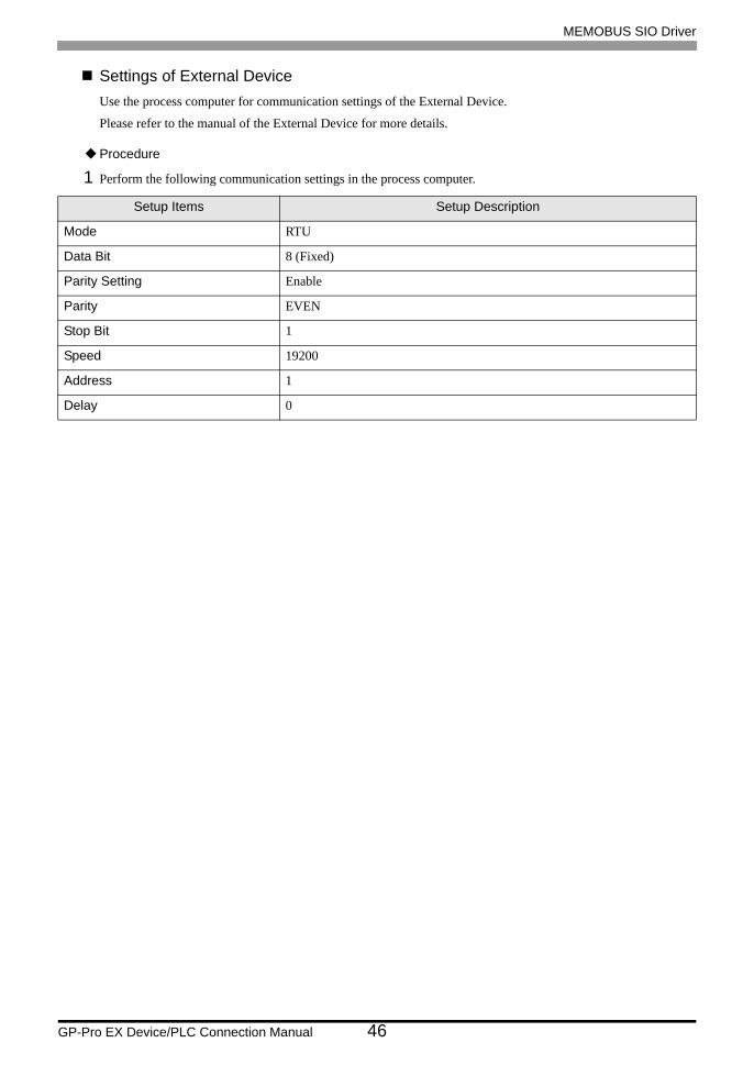
Settings of External DeviceUse the process computer for communication settings of the External Device.
Please refer to the manual of the External Device for more details.
Procedure
1 Perform the following communication settings in the process computer.
Setup Items Setup Description
Mode RTU
Data Bit 8 (Fixed)
Parity Setting Enable
Parity EVEN
Stop Bit 1
Speed 19200
Address 1
Delay 0
MEMOBUS SIO Driver
GP-Pro EX Device/PLC Connection Manual 47
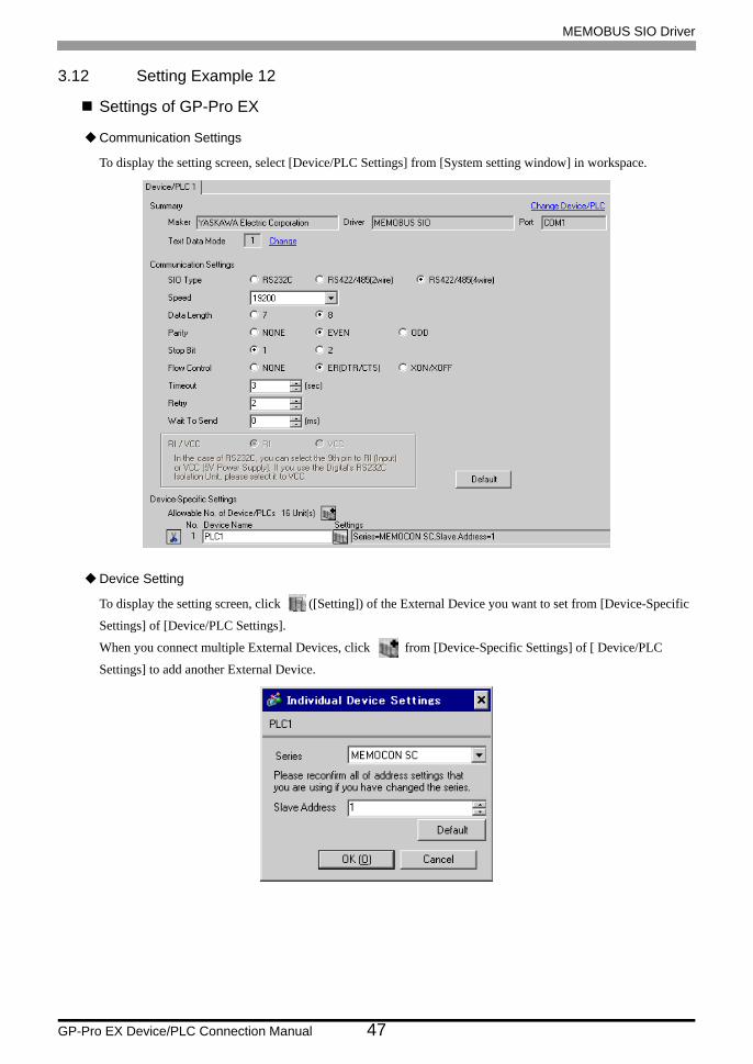
3.12 Setting Example 12
Settings of GP-Pro EX
Communication Settings
To display the setting screen, select [Device/PLC Settings] from [System setting window] in workspace.
Device Setting
To display the setting screen, click ([Setting]) of the External Device you want to set from [Device-Specific
Settings] of [Device/PLC Settings].
When you connect multiple External Devices, click from [Device-Specific Settings] of [ Device/PLC
Settings] to add another External Device.

MEMOBUS SIO Driver
GP-Pro EX Device/PLC Connection Manual 48
Settings of External DeviceUse the process computer for communication settings of the External Device.
Please refer to the manual of the External Device for more details.
Procedure
1 Perform the following communication settings in the process computer.
Setup Items Setup Description
Mode RTU
Data Bit 8 (Fixed)
Parity Setting Enable
Parity EVEN
Stop Bit 1
Speed 19200
Address 1
Delay 0

MEMOBUS SIO Driver
GP-Pro EX Device/PLC Connection Manual 49
3.13 Setting Example 13
Settings of GP-Pro EX
Communication Settings
To display the setting screen, select [Device/PLC Settings] from [System setting window] in workspace.
Device Setting
To display the setting screen, click ([Setting]) of the External Device you want to set from [Device-Specific
Settings] of [Device/PLC Settings].
When you connect multiple External Devices, click from [Device-Specific Settings] of [ Device/PLC
Settings] to add another External Device.
MEMOBUS SIO Driver
GP-Pro EX Device/PLC Connection Manual 50
Settings of External DeviceThere is no communication setting on the External Device.
Note that the address should be set using the DIP switch 3 SW of the External Device.

MEMOBUS SIO Driver
GP-Pro EX Device/PLC Connection Manual 51
3.14 Setting Example 14
Settings of GP-Pro EX
Communication Settings
To display the setting screen, select [Device/PLC Settings] from [System setting window] in workspace.
Device Setting
To display the setting screen, click ([Setting]) of the External Device you want to set from [Device-Specific
Settings] of [Device/PLC Settings].
When you connect multiple External Devices, click from [Device-Specific Settings] of [ Device/PLC
Settings] to add another External Device.
MEMOBUS SIO Driver
GP-Pro EX Device/PLC Connection Manual 52
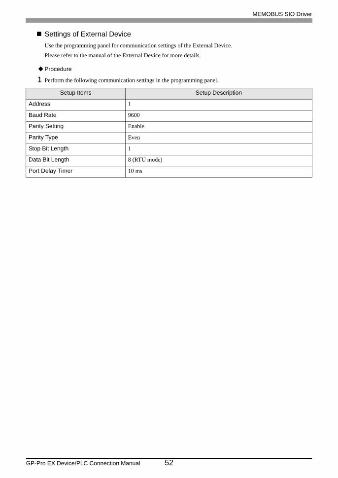
Settings of External DeviceUse the programming panel for communication settings of the External Device.
Please refer to the manual of the External Device for more details.
Procedure
1 Perform the following communication settings in the programming panel.
Setup Items Setup Description
Address 1
Baud Rate 9600
Parity Setting Enable
Parity Type Even
Stop Bit Length 1
Data Bit Length 8 (RTU mode)
Port Delay Timer 10 ms
MEMOBUS SIO Driver
GP-Pro EX Device/PLC Connection Manual 53
4 Setup Items
Set communication settings of the Display with GP-Pro EX or in off-line mode of the Display.
The setting of each parameter must be identical to that of External Device.
"3 Example of Communication Setting" (page 10)
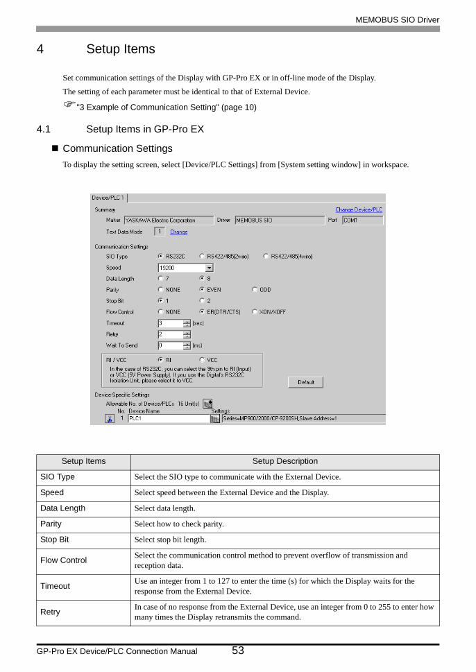
4.1 Setup Items in GP-Pro EX
Communication SettingsTo display the setting screen, select [Device/PLC Settings] from [System setting window] in workspace.
Setup Items Setup Description
SIO Type Select the SIO type to communicate with the External Device.
Speed Select speed between the External Device and the Display.
Data Length Select data length.
Parity Select how to check parity.
Stop Bit Select stop bit length.
Flow Control Select the communication control method to prevent overflow of transmission and reception data.
Timeout Use an integer from 1 to 127 to enter the time (s) for which the Display waits for the response from the External Device.
Retry In case of no response from the External Device, use an integer from 0 to 255 to enter how many times the Display retransmits the command.
MEMOBUS SIO Driver
GP-Pro EX Device/PLC Connection Manual 54
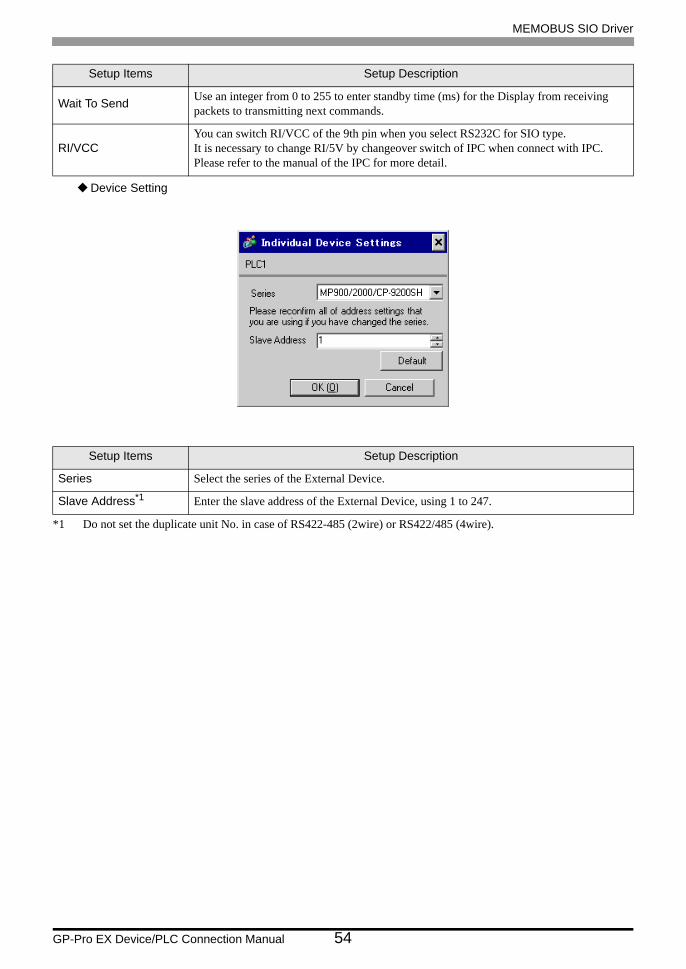
Device Setting
Wait To Send Use an integer from 0 to 255 to enter standby time (ms) for the Display from receiving packets to transmitting next commands.
RI/VCCYou can switch RI/VCC of the 9th pin when you select RS232C for SIO type.It is necessary to change RI/5V by changeover switch of IPC when connect with IPC. Please refer to the manual of the IPC for more detail.
Setup Items Setup Description
Series Select the series of the External Device.
Slave Address*1
*1 Do not set the duplicate unit No. in case of RS422-485 (2wire) or RS422/485 (4wire).
Enter the slave address of the External Device, using 1 to 247.
Setup Items Setup Description

MEMOBUS SIO Driver
GP-Pro EX Device/PLC Connection Manual 55
4.2 Setup Items in Off-Line Mode
Communication Settings
To display the setting screen, touch [Device/PLC Settings] from [Peripheral Equipment Settings] in off-line mode.
Touch the External Device you want to set from the displayed list.
• Refer to the Maintenance/Troubleshooting manual for information on how to enter off-line mode or about the operation.
Cf. Maintenance/Troubleshooting Manual "2.2 Off-line Mode"
Setup Items Setup Description
SIO Type
Select the SIO type to communicate with the External Device.
To make the communication settings correctly, confirm the serial interface specifications of Display unit for [SIO Type].We cannot guarantee the operation if a communication type that the serial interface does not support is specified.For details concerning the serial interface specifications, refer to the manual for Display unit.
Speed Select speed between the External Device and the Display.
Data Length Select data length.
Parity Select how to check parity.
Stop Bit Select stop bit length.
Flow Control Select the communication control method to prevent overflow of transmission and reception data.
Timeout (s) Use an integer from 1 to 127 to enter the time (s) for which the Display waits for the response from the External Device.

MEMOBUS SIO Driver
GP-Pro EX Device/PLC Connection Manual 56
Device Setting
To display the setting screen, touch [Device/PLC Settings] from [Peripheral Equipment Settings]. Touch the
External Device you want to set from the displayed list, and touch [Device Settings].
*1 Do not set the duplicate unit No. in case of RS422-485 (2wire) or RS422/485 (4wire).
Retry In case of no response from the External Device, use an integer from 0 to 255 to enter how many times the Display retransmits the command.
Wait To Send (ms) Use an integer from 0 to 255 to enter standby time (ms) for the Display from receiving packets to transmitting next commands.
Setup Items Setup Description
Device/PLC Name Select the External Device to set. Device name is a title of the External Device set with GP-Pro EX. (Initial value [PLC1])
Series Displays the series of the External Device.
Slave Address *1 Enter the slave address of the External Device, using 1 to 247.
Setup Items Setup Description

MEMOBUS SIO Driver
GP-Pro EX Device/PLC Connection Manual 57
Option
To display the setting screen, touch [Device/PLC Settings] from [Peripheral Equipment Settings]. Touch the
External Device you want to set from the displayed list, and touch [Option].
Setup Items Setup Description
RI/VCCYou can switch RI/VCC of the 9th pin when you select RS232C for SIO type.It is necessary to change RI/5V by changeover switch of IPC when connect with IPC. Please refer to the manual of the IPC for more detail.

MEMOBUS SIO Driver
GP-Pro EX Device/PLC Connection Manual 58
5 Cable Diagram
The cable diagram shown below may be different from the cable diagram recommended by YASKAWA Electric
Corporation. Please be assured there is no operational problem in applying the cable diagram shown in this
manual.
• The FG pin of the main body of the External Device must be D-class grounded. Please refer to the manual of
the External Device for more details.
• SG and FG are connected inside the Display. When connecting SG to the External Device, design the system
not to form short-circuit loop.
• Connect the isolation unit, when communication is not stabilized under the influence of a noise etc..
Cable Diagram 1
Display(Connection Port)
Cable Remarks
GP (COM1)ST (COM1)IPC*1
PC/AT
*1 Only the COM port which can communicate by RS-232C can be used. COM Port of IPC (page 7)
Your own cable The cable length must be 15m or less.
2
3
4
5
RD(RXD)
SD(TXD)
ER(DTR)
SG
6
7
DR(DSR)
RS(RTS) FG1
2
3
4
5
SD
RD
RS
CS
7 SG
8 CS(CTS)
FG
D-sub 9 pin (socket) Shield
External Device
D-sub 9 pin (plug)
Display
Shell
PinPin Signal name Signalname

MEMOBUS SIO Driver
GP-Pro EX Device/PLC Connection Manual 59
Cable Diagram 2
Display(Connection Port)
Cable Remarks
GP (COM1)ST (COM1)IPC*1
PC/AT
*1 Only the COM port which can communicate by RS-232C can be used. COM Port of IPC (page 7)
Your own cable The cable length must be 15m or less.
2
3
4
5
RD(RXD)
SD(TXD)
ER(DTR)
SG
6
7
DR(DSR)
RS(RTS)
FG1
2
3
4
5
SD
RD
RS
CS
6 DR
8 CS(CTS)
FG
1 CD
7 SG
8 CD
9 ER
Display
D-sub 9 pin (socket) Shield
External Device
D-sub 25 pin (plug)
PinPin Signal nameSignalname
Shell
MEMOBUS SIO Driver
GP-Pro EX Device/PLC Connection Manual 60
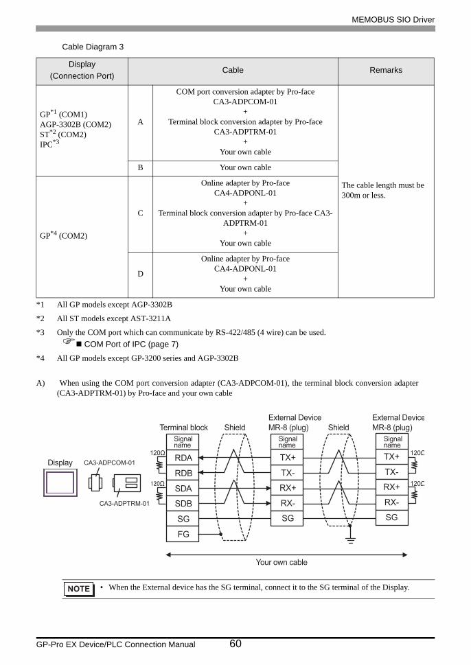
Cable Diagram 3
A) When using the COM port conversion adapter (CA3-ADPCOM-01), the terminal block conversion adapter (CA3-ADPTRM-01) by Pro-face and your own cable
Display(Connection Port)
Cable Remarks
GP*1 (COM1)AGP-3302B (COM2)ST*2 (COM2)IPC*3
*1 All GP models except AGP-3302B
*2 All ST models except AST-3211A
*3 Only the COM port which can communicate by RS-422/485 (4 wire) can be used. COM Port of IPC (page 7)
A
COM port conversion adapter by Pro-faceCA3-ADPCOM-01
+Terminal block conversion adapter by Pro-face
CA3-ADPTRM-01+
Your own cable
The cable length must be 300m or less.
B Your own cable
GP*4 (COM2)
*4 All GP models except GP-3200 series and AGP-3302B
C
Online adapter by Pro-faceCA4-ADPONL-01
+Terminal block conversion adapter by Pro-face CA3-
ADPTRM-01+
Your own cable
D
Online adapter by Pro-faceCA4-ADPONL-01
+Your own cable
• When the External device has the SG terminal, connect it to the SG terminal of the Display.
RDA
RDB
SDA
SDB
SG
TX-
RX+
RX-
SG
TX+
CA3-ADPTRM-01
CA3-ADPCOM-01
FG
TX-
RX+
RX-
SG
TX+Display
Terminal block Shield Shield
External Device
MR-8 (plug)
External Device
MR-8 (plug)
Signalname
Signalname
Signalname
Your own cable
MEMOBUS SIO Driver
GP-Pro EX Device/PLC Connection Manual 61
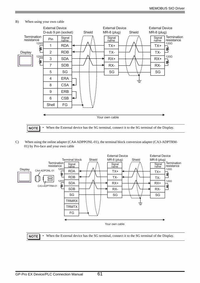
B) When using your own cable
C) When using the online adapter (CA4-ADPPONL-01), the terminal block conversion adapter (CA3-ADPTRM- 01) by Pro-face and your own cable
• When the External device has the SG terminal, connect it to the SG terminal of the Display.
• When the External device has the SG terminal, connect it to the SG terminal of the Display.
TX-
RX+
RX-
SG
TX+
TX-
RX+
RX-
SG
TX+
2
3
7
5
RDB
SDA
SDB
SG
4
8
ERA
CSA
9
6
ERB
CSB
1 RDA
FG
Your own cable
Display
External Device
D-sub 9 pin (socket)
External Device
MR-8 (plug)
External Device
MR-8 (plug)Shield Shield
Pin Signalname
Signalname
Signalname
Terminationresistance
Terminationresistance
Shell
TX-
RX+
RX-
SG
TX+
TX-
RX+
RX-
SG
TX+
CA3-ADPTRM-01
RDA
RDB
SDA
SDB
TRMRX
TRMTX
CA4-ADPONL-01
FG
SG
Display
Terminationresistance
Terminationresistance
Terminal block
External Device
MR-8 (plug)
External Device
MR-8 (plug)Shield Shield
Signalname
Signalname
Signalname
Your own cable
MEMOBUS SIO Driver
GP-Pro EX Device/PLC Connection Manual 62
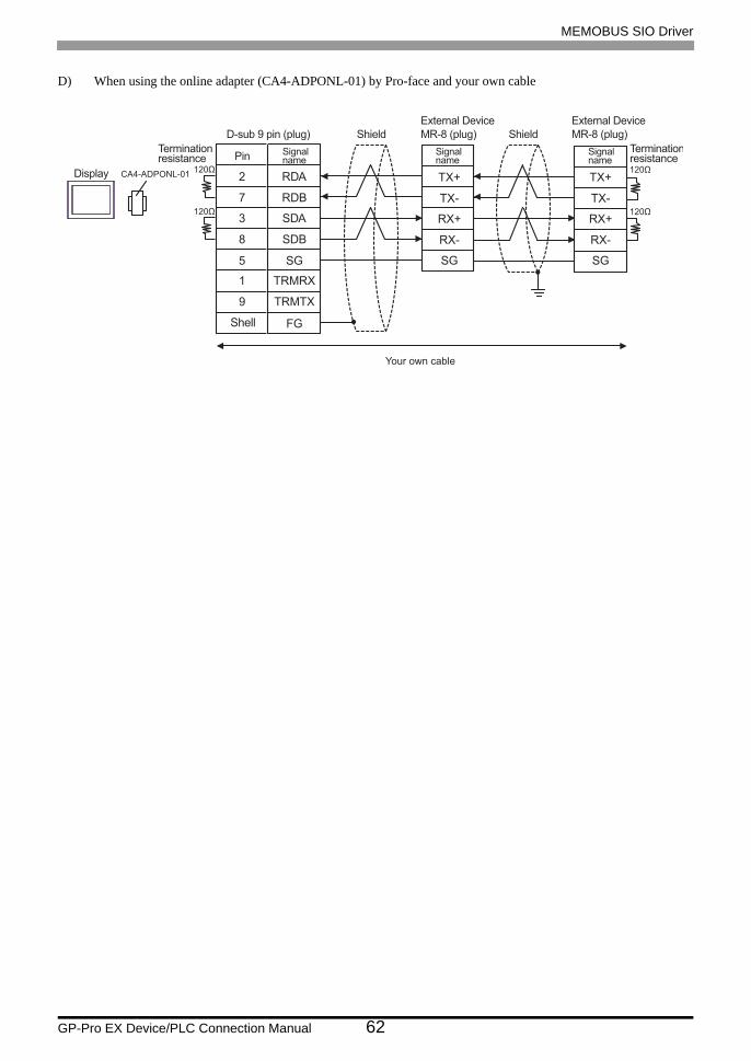
D) When using the online adapter (CA4-ADPONL-01) by Pro-face and your own cable
TX-
RX+
RX-
SG
TX+
TX-
RX+
RX-
SG
TX+2
7
3
8
RDA
RDB
SDA
SDB
9
5
TRMTX
SG
FG
1 TRMRX
CA4-ADPONL-01Display
Terminationresistance
Terminationresistance
D-sub 9 pin (plug)
External Device
MR-8 (plug)
External Device
MR-8 (plug)Shield Shield
Pin Signalname
Signalname
Signalname
Your own cable
Shell

MEMOBUS SIO Driver
GP-Pro EX Device/PLC Connection Manual 63
Cable Diagram 4
A) When using the COM port conversion adapter (CA3-ADPCOM-01), the terminal block conversion adapter (CA3-ADPTRM-01) by Pro-face and your own cable
Display(Connection Port)
Cable Remarks
GP*1 (COM1)AGP-3302B (COM2)ST*2 (COM2)IPC*3
*1 All GP models except AGP-3302B
*2 All ST models except AST-3211A
*3 Only the COM port which can communicate by RS-422/485 (4 wire) can be used. COM Port of IPC (page 7)
A
COM port conversion adapter by Pro-faceCA3-ADPCOM-01
+Terminal block conversion adapter by Pro-face
CA3-ADPTRM-01+
Your own cable
The cable length must be 300m or less.
B Your own cable
GP*4 (COM2)
*4 All GP models except GP-3200 series and AGP-3302B
C
Online adapter by Pro-faceCA4-ADPONL-01
+Terminal block conversion adapter by Pro-face CA3-
ADPTRM-01+
Your own cable
D
Online adapter by Pro-faceCA4-ADPONL-01
+Your own cable
RDA
RDB
SDA
SDB
SG
FG
CA3-ADPTRM-01
CA3-ADPCOM-01
6
5
2
1
TX-
TXR
RX+
RX-
4
3
RXR
SH
7 TX+Display
Terminationresistance
External Device
MR-8 (plug)ShieldTerminal block
Pin Signalname
Signalname
Your own cable

MEMOBUS SIO Driver
GP-Pro EX Device/PLC Connection Manual 64
B) When using your own cable
C) When using the online adapter (CA4-ADPONL-01), the terminal block conversion adapter (CA3-ADPTRM- 01) by Pro-face and your own cable
D) When using the online adapter (CA4-ADPONL-01) by Pro-face and your own cable
6
5
2
1
TX-
TXR
RX+
RX-
4
3
RXR
SH
7 TX+
2
3
7
5
RDB
SDA
SDB
SG
4
8
ERA
CSA
9
6
ERB
CSB
1 RDA
FG
Display
External Device
D-sub 9 pin (socket)
External Device
MR-8 (plug)Shield
Terminationresistance Pin Signal
name Pin Signalname
Shell
RDA
TRMRX
RDB
SG
FG
CA3-ADPTRM-01
6
5
2
1
TX-
TXR
RX+
RX-
4
3
RXR
SH
7 TX+CA4-ADPONL-01
SDA
SDB
TRMTX
Display
External Device
MR-8 (plug)ShieldTerminal blockTerminationresistance Pin Signal
nameSignalname
Your own cable
6
5
2
1
TX-
TXR
RX+
RX-
4
3
RXR
SH
7 TX+2
7
3
8
RDA
RDB
SDA
SDB
9
5
TRMTX
SG
FG
1 TRMRX
CA4-ADPONL-01
Display
D-sub 9 pin (plug)
External Device
MR-8 (plug)ShieldTerminationresistance Pin Signal
name Pin Signalname
Your own cable
Shell

MEMOBUS SIO Driver
GP-Pro EX Device/PLC Connection Manual 65
Cable Diagram 5
Display(Connection Port)
Cable Remarks
GP*1 (COM1)AGP-3302B (COM2)ST*2 (COM2)
*1 All GP models except AGP-3302B
*2 All ST models except AST-3211A
A
Terminal block conversion adapter by Pro-faceCA3-ADPTRM-01
+COM port conversion adapter by Pro-face
CA3-ADPCOM-01+
Your own cable
The cable length must be 300m or less.
B Your own cable
GP*3 (COM2)
*3 All GP models except GP-3200 series and AGP-3302B
C
Online adapter by Pro-face(CA4-ADPONL-01)
+Terminal block conversion adapter by Pro-face
CA3-ADPTRM-01+
Your own cable
D
Online adapter by Pro-face(CA4-ADPONL-01)
+Your own cable
IPC*4
*4 Only the COM port which can communicate by RS-422/485 (2 wire) can be used. COM Port of IPC (page 7)
E
Terminal block conversion adapter by Pro-faceCA3-ADPTRM-01
+COM port conversion adapter by Pro-face
CA3-ADPCOM-01+
Your own cableF Your own cable

MEMOBUS SIO Driver
GP-Pro EX Device/PLC Connection Manual 66
A) When using the terminal block conversion adapter (CA3-ADPTRM-01), the COM port conversion adapter (CA3-ADPCOM-01) by Pro-face and your own cable
B) When using your own cable
RDA
RDB
SDA
SDB
SG
FG
6
5
2
1
TX-
TXR
RX+
RX-
4
3
RXR
SH
7 TX+
CA3-ADPTRM-01
CA3-ADPCOM-01
6
5
2
1
TX-
TXR
RX+
RX-
4
3
RXR
SH
7 TX+Display
External Device
MR-8 (plug)
External Device
MR-8 (plug)ShieldTerminal block ShieldTerminationresistance Pin Signal
nameSignalname Pin Signal
name
Your own cable
6
5
2
1
TX-
TXR
RX+
RX-
4
3
RXR
SH
7 TX+120
2
3
7
5
RDB
SDA
SDB
SG
4
8
ERA
CSA
9
6
ERB
CSB
1 RDA
FG
6
5
2
1
TX-
TXR
RX+
RX-
4
3
RXR
SH
7 TX+
Display
D-sub 9 pin (socket)
External Device
MR-8 (plug)
External Device
MR-8 (plug)
Shield
Shield
Pin Signalname Pin Signal
name Pin Signalname
Shell

MEMOBUS SIO Driver
GP-Pro EX Device/PLC Connection Manual 67
C) When using the online adapter (CA4-ADPONL-01), the terminal block conversion adapter (CA3-ADPTRM- 01) by Pro-face and your own cable
D) When using the online adapter (CA4-ADPONL-01) by Pro-face and your own cable
RDA
TRMRX
RDB
SDA
SDB
TRMTX
SG
FG
6
5
2
1
TX-
TXR
RX+
RX-
4
3
RXR
SH
7 TX+
CA3-ADPTRM-01
CA4-ADPONL-01
6
5
2
1
TX-
TXR
RX+
RX-
4
3
RXR
SH
7 TX+Display
External Device
MR-8 (plug)
External Device
MR-8 (plug)ShieldTerminal block Shield
Terminationresistance Pin Signal
namePin Signalname
Signalname
Your own cable
6
5
2
1
TX-
TXR
RX+
RX-
4
3
RXR
SH
7 TX+2
7
3
8
RDA
RDB
SDA
SDB
9
5
TRMTX
SG
FG
1 TRMRXCA4-ADPONL-01
6
5
2
1
TX-
TXR
RX+
RX-
4
3
RXR
SH
7 TX+Display
D-sub 9 pin (plug)
External Device
MR-8 (plug)
External Device
MR-8 (plug)Shield Shield
Terminationresistance Pin Signal
name Pin Signalname Pin Signal
name
Your own cable
Shell
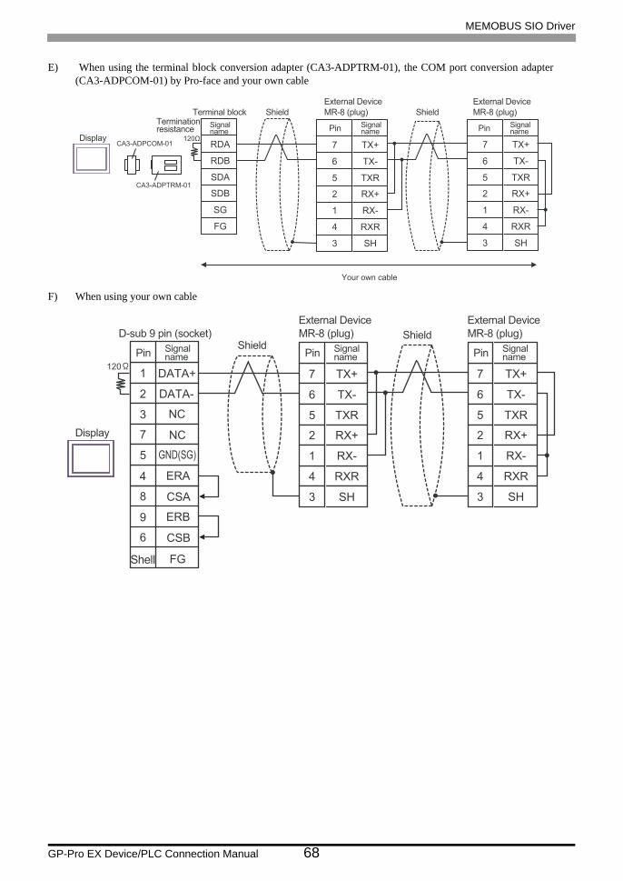
MEMOBUS SIO Driver
GP-Pro EX Device/PLC Connection Manual 68
E) When using the terminal block conversion adapter (CA3-ADPTRM-01), the COM port conversion adapter (CA3-ADPCOM-01) by Pro-face and your own cable
F) When using your own cable
RDA
RDB
SDA
SDB
SG
FG
6
5
2
1
TX-
TXR
RX+
RX-
4
3
RXR
SH
7 TX+
CA3-ADPTRM-01
CA3-ADPCOM-01
6
5
2
1
TX-
TXR
RX+
RX-
4
3
RXR
SH
7 TX+Display
External Device
MR-8 (plug)
External Device
MR-8 (plug)ShieldTerminal block ShieldTerminationresistance Pin Signal
nameSignalname Pin Signal
name
Your own cable
6
5
2
1
TX-
TXR
RX+
RX-
4
3
RXR
SH
7 TX+120
2
3
7
5
DATA-
NC
NC
4
8
ERA
CSA
9
6
ERB
CSB
GND(SG)
1 DATA+
FG
6
5
2
1
TX-
TXR
RX+
RX-
4
3
RXR
SH
7 TX+
Display
D-sub 9 pin (socket)
External Device
MR-8 (plug)
External Device
MR-8 (plug)Shield
Shield
Pin Signalname Pin Signal
name Pin Signalname
Shell

MEMOBUS SIO Driver
GP-Pro EX Device/PLC Connection Manual 69
Cable Diagram 6
Display(Connection Port)
CableRemarks
GP (COM1)ST (COM1)IPC*1
PC/AT
*1 Only the COM port which can communicate by RS-232C can be used. COM Port of IPC (page 7)
Your own cable The cable length must be 15m or less.
2
3
4
5
RD(RXD)
SD(TXD)
ER(DTR)
SG
6
7
DR(DSR)
RS(RTS)
TXD1
3
6
12
14
RXD
CTS
RTS
GND8 CS(CTS)
FG
Display
D-sub 9 pin (socket)
External Device
MDR-14 pin (plug)Shield
Pin Signal name Pin Signalname
Your own cable
Shell

MEMOBUS SIO Driver
GP-Pro EX Device/PLC Connection Manual 70
Cable Diagram 7
Display(Connection Port)
Cable Remarks
GP*1 (COM1)AGP-3302B (COM2)ST*2 (COM2)IPC*3
*1 All GP models except AGP-3302B
*2 All ST models except AST-3211A
*3 Only the COM port which can communicate by RS-422/485 (4 wire) can be used. COM Port of IPC (page 7)
A
COM port conversion adapter by Pro-faceCA3-ADPCOM-01
+Terminal block conversion adapter by Pro-face
CA3-ADPTRM-01+
Your own cable
The cable length must be 300m or less.
B Your own cable
GP*4 (COM2)
*4 All GP models except GP-3200 series and AGP-3302B
C
Online adapter by Pro-face(CA4-ADPONL-01)
+Terminal block conversion adapter by Pro-face CA3-
ADPTRM-01+
Your own cable
D
Online adapter by Pro-face(CA4-ADPONL-01)
+Your own cable
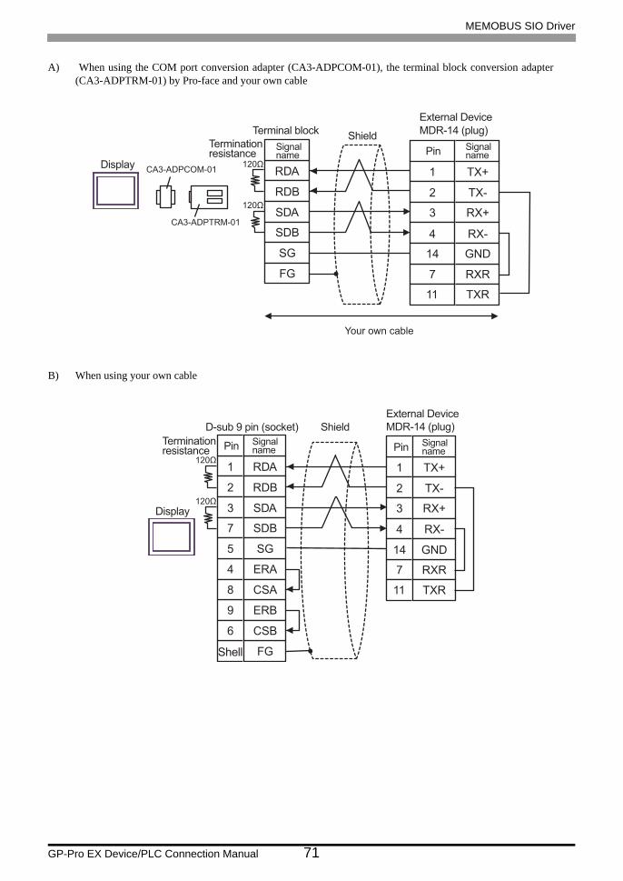
MEMOBUS SIO Driver
GP-Pro EX Device/PLC Connection Manual 71
A) When using the COM port conversion adapter (CA3-ADPCOM-01), the terminal block conversion adapter (CA3-ADPTRM-01) by Pro-face and your own cable
B) When using your own cable
RDA
RDB
SDA
SDB
SG
FG
CA3-ADPTRM-01
CA3-ADPCOM-01
2
11
3
4
TX-
TXR
RX+
RX-
7
14
RXR
GND
1 TX+Display
External Device
MDR-14 (plug)Shield
Terminal block
Terminationresistance Pin Signal
nameSignalname
Your own cable
2
11
3
4
TX-
TXR
RX+
RX-
7
14
RXR
GND
1 TX+
2
3
7
5
RDB
SDA
SDB
SG
4
8
ERA
CSA
9
6
ERB
CSB
1 RDA
FG
Display
D-sub 9 pin (socket)
External Device
MDR-14 (plug)Shield
Terminationresistance Pin Signal
name Pin Signalname
Shell
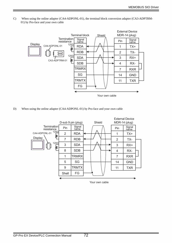
MEMOBUS SIO Driver
GP-Pro EX Device/PLC Connection Manual 72
C) When using the online adapter (CA4-ADPONL-01), the terminal block conversion adapter (CA3-ADPTRM- 01) by Pro-face and your own cable
D) When using the online adapter (CA4-ADPONL-01) by Pro-face and your own cable
RDA
TRMRX
RDB
SDA
SDB
SG
FG
CA3-ADPTRM-01
2
11
3
4
TX-
TXR
RX+
RX-
7
14
RXR
GND
1 TX+CA4-ADPONL-01
TRMTX
Display
Terminationresistance
External Device
MDR-14 (plug)ShieldTerminal block
Pin Signalname
Signalname
Your own cable
2
11
3
4
TX-
TXR
RX+
RX-
7
14
RXR
GND
1 TX+2
7
3
8
RDA
RDB
SDA
SDB
9
5
TRMTX
SG
1 TRMRX
CA4-ADPONL-01
FG
Display
Terminationresistance
D-sub 9 pin (plug)
External Device
MDR-14 (plug)Shield
Pin Signalname Pin Signal
name
Your own cable
Shell

MEMOBUS SIO Driver
GP-Pro EX Device/PLC Connection Manual 73
Cable Diagram 8
Display(Connection Port)
Cable Remarks
GP*1 (COM1)AGP-3302B (COM2)ST*2 (COM2)
*1 All GP models except AGP-3302B
*2 All ST models except AST-3211A
A
COM port conversion adapter by Pro-faceCA3-ADPCOM-01
+Terminal block conversion adapter by Pro-face
CA3-ADPTRM-01+
Your own cable
The cable length must be 300m or less.
B Your own cable
GP*3 (COM2)
*3 All GP models except GP-3200 series and AGP-3302B
C
Online adapter by Pro-face(CA4-ADPONL-01)
+Terminal block conversion adapter by Pro-face CA3-
ADPTRM-01+
Your own cable
D
Online adapter by Pro-face(CA4-ADPONL-01)
+Your own cable
IPC*4
*4 Only the COM port which can communicate by RS-422/485 (2 wire) can be used. COM Port of IPC (page 7)
E
COM port conversion adapter by Pro-faceCA3-ADPCOM-01
+Terminal block conversion adapter by Pro-face
CA3-ADPTRM-01+
Your own cable
F Your own cable
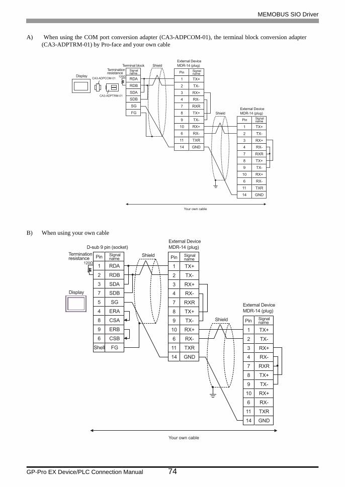
MEMOBUS SIO Driver
GP-Pro EX Device/PLC Connection Manual 74
A) When using the COM port conversion adapter (CA3-ADPCOM-01), the terminal block conversion adapter (CA3-ADPTRM-01) by Pro-face and your own cable
B) When using your own cable
RDA
RDB
SDA
SDB
SG
FG
CA3-ADPTRM-01
CA3-ADPCOM-01
2
3
4
7
TX-
RX+
RX-
RXR
8
9
TX+
TX-
10
6
RX+
RX-
11
14
TXR
GND
1 TX+
2
3
4
7
TX-
RX+
RX-
RXR
8
9
TX+
TX-
10
6
RX+
RX-
11
14
TXR
GND
1 TX+
Display
Terminationresistance
External Device
MDR-14 (plug)Shield
External Device
MDR-14 (plug)Shield
Terminal block
Pin Signalname
Pin Signalname
Signalname
Your own cable
2
3
4
7
TX-
RX+
RX-
RXR
8
9
TX+
TX-
10
6
RX+
RX-
11
14
TXR
GND
1 TX+
2
3
4
7
TX-
RX+
RX-
RXR
8
9
TX+
TX-
10
6
RX+
RX-
11
14
TXR
GND
1 TX+
2
3
7
5
RDB
SDA
SDB
SG
4
8
ERA
CSA
9
6
ERB
CSB
1 RDA
FG
Display
Terminationresistance
External Device
MDR-14 (plug)
Shield
External Device
MDR-14 (plug)
Shield
D-sub 9 pin (socket)
Pin Signalname Pin Signal
name
Pin Signalname
Shell
Your own cable

MEMOBUS SIO Driver
GP-Pro EX Device/PLC Connection Manual 75
C) When using the online adapter (CA4-ADPONL-01), the terminal block conversion adapter (CA3-ADPTRM- 01) by Pro-face and your own cable
RDA
RDB
SDA
SDB
SG
CA3-ADPTRM-01
2
3
4
7
TX-
RX+
RX-
RXR
8
9
TX+
TX-
10
6
RX+
RX-
11
14
TXR
GND
1 TX+
2
3
4
7
TX-
RX+
RX-
RXR
8
9
TX+
TX-
10
6
RX+
RX-
11
14
TXR
GND
1 TX+
CA4-ADPONL-01
FG
TRMTX
TRMRX
Display
Terminationresistance
External Device
MDR-14 (plug)Shield
External Device
MDR-14 (plug)Shield
Terminal block
Pin Signalname
Pin Signalname
Signalname
Your own cable

MEMOBUS SIO Driver
GP-Pro EX Device/PLC Connection Manual 76
D) When using the online adapter (CA4-ADPONL-01) by Pro-face and your own cable
E) When using the COM port conversion adapter (CA3-ADPCOM-01), the terminal block conversion adapter (CA3-ADPTRM-01) by Pro-face and your own cable
2
3
4
7
TX-
RX+
RX-
RXR
8
9
TX+
TX-
10
6
RX+
RX-
11
14
TXR
GND
1 TX+
2
3
4
7
TX-
RX+
RX-
RXR
8
9
TX+
TX-
10
6
RX+
RX-
11
14
TXR
GND
1 TX+
2
7
3
8
RDA
RDB
SDA
SDB
9
5
TRMTX
SG
FG
1 TRMRX
CA4-ADPONL-01
DisplayTerminationresistance
D-sub 9 pin (plug) Shield
External Device
MDR-14 (plug)
External Device
MDR-14 (plug)Shield
Pin Signalname Pin Signal
name
Pin Signalname
Shell
Your own cable
RDA
RDB
SDA
SDB
SG
FG
CA3-ADPTRM-01
CA3-ADPCOM-01
2
3
4
7
TX-
RX+
RX-
RXR
8
9
TX+
TX-
10
6
RX+
RX-
11
14
TXR
GND
1 TX+
2
3
4
7
TX-
RX+
RX-
RXR
8
9
TX+
TX-
10
6
RX+
RX-
11
14
TXR
GND
1 TX+
Display
Terminationresistance
External Device
MDR-14 (plug)Shield
External Device
MDR-14 (plug)Shield
Terminal block
Pin Signalname
Pin Signalname
Signalname
Your own cable

MEMOBUS SIO Driver
GP-Pro EX Device/PLC Connection Manual 77
F) When using your own cable
2
3
4
7
TX-
RX+
RX-
RXR
8
9
TX+
TX-
10
6
RX+
RX-
11
14
TXR
GND
1 TX+
2
3
4
7
TX-
RX+
RX-
RXR
8
9
TX+
TX-
10
6
RX+
RX-
11
14
TXR
GND
1 TX+
2
3
7
5
DATA-
NC
NC
GND(SG)
4
8
ERA
CSA
9
6
ERB
CSB
1 DATA+
FG
Display
Terminationresistance
External Device
MDR-14 (plug)
Shield
External Device
MDR-14 (plug)
Shield
D-sub 9 pin (socket)
Pin Signalname Pin Signal
name
Pin Signalname
Shell
Your own cable
120Ω
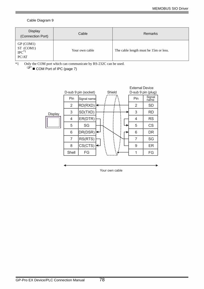
MEMOBUS SIO Driver
GP-Pro EX Device/PLC Connection Manual 78
Cable Diagram 9
Display(Connection Port)
Cable Remarks
GP (COM1)ST (COM1)IPC*1
PC/AT
*1 Only the COM port which can communicate by RS-232C can be used. COM Port of IPC (page 7)
Your own cable The cable length must be 15m or less.
2
3
4
5
RD(RXD)
SD(TXD)
ER(DTR)
SG
6
7
DR(DSR)
RS(RTS)
FG1
2
3
4
5
SD
RD
RS
CS
6 DR
7 SG
9 ER8 CS(CTS)
FG
Display
D-sub 9 pin (socket)
External Device
D-sub 9 pin (plug)Shield
Your own cable
Shell
Pin Signal name Pin Signalname
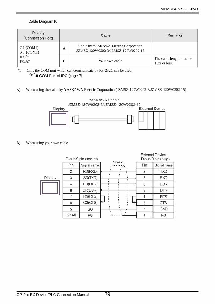
MEMOBUS SIO Driver
GP-Pro EX Device/PLC Connection Manual 79
Cable Diagram10
A) When using the cable by YASKAWA Electric Corporation (JZMSZ-120W0202-3/JZMSZ-120W0202-15)
B) When using your own cable
Display(Connection Port)
Cable Remarks
GP (COM1)ST (COM1)IPC*1
PC/AT
*1 Only the COM port which can communicate by RS-232C can be used. COM Port of IPC (page 7)
A Cable by YASKAWA Electric CorporationJZMSZ-120W0202-3/JZMSZ-120W0202-15
B Your own cable The cable length must be 15m or less.
Display
YASKAWA's cable
JZMSZ-120W0202-3/JZMSZ-120W0202-15External Device
Signal name
DR(DSR)6
SD(TXD)3
SG5
7 RS(RTS)
ER(DTR)4
FG
RD(RXD)2
CS(CTS)8
D-sub 9 pin (socket)
Pin
Shell
Signal name
CTS5
RXD3
DTR9
DSR6
GND
TXD2
RTS4
D-sub 9 pin (plug)External Device
Pin
7
Shield
Display
FG1
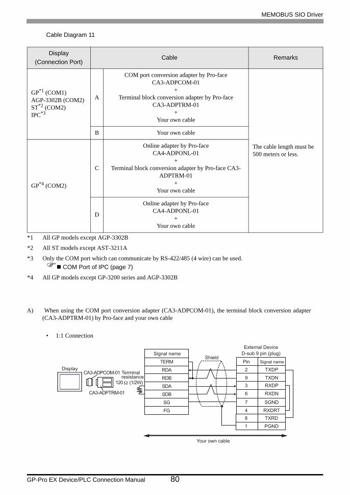
MEMOBUS SIO Driver
GP-Pro EX Device/PLC Connection Manual 80
Cable Diagram 11
A) When using the COM port conversion adapter (CA3-ADPCOM-01), the terminal block conversion adapter (CA3-ADPTRM-01) by Pro-face and your own cable
• 1:1 Connection
Display(Connection Port)
Cable Remarks
GP*1 (COM1)AGP-3302B (COM2)ST*2 (COM2)IPC*3
*1 All GP models except AGP-3302B
*2 All ST models except AST-3211A
*3 Only the COM port which can communicate by RS-422/485 (4 wire) can be used. COM Port of IPC (page 7)
A
COM port conversion adapter by Pro-faceCA3-ADPCOM-01
+Terminal block conversion adapter by Pro-face
CA3-ADPTRM-01+
Your own cable
The cable length must be 500 meters or less.
B Your own cable
GP*4 (COM2)
*4 All GP models except GP-3200 series and AGP-3302B
C
Online adapter by Pro-faceCA4-ADPONL-01
+Terminal block conversion adapter by Pro-face CA3-
ADPTRM-01+
Your own cable
D
Online adapter by Pro-faceCA4-ADPONL-01
+Your own cable
Signal name
RDB
SDB
SG
FG
CA3-ADPCOM-01
CA3-ADPTRM-01
Display
Shield
RDA
SDA
TERM
2
9
3
Signal name
TXDP
TXDN
RXDP
Pin
6 RXDN
7 SGND
4 RXDRT
Your own cable
8 TXRD
1 PGND
120 Ω (1/2W)
Terminalresistance
External Device
D-sub 9 pin (plug)
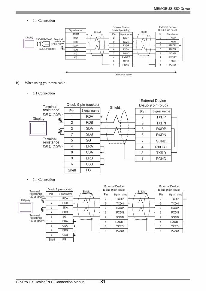
MEMOBUS SIO Driver
GP-Pro EX Device/PLC Connection Manual 81
• 1:n Connection
B) When using your own cable
• 1:1 Connection
• 1:n Connection
Signal name
RDB
SDB
SG
FG
CA3-ADPCOM-01
CA3-ADPTRM-01
Display
Shield
RDA
SDA
TERM
2
9
3
Signal name
TXDP
TXDN
RXDP
Pin
6 RXDN
7 SGND
4 RXDRT
External Device
Your own cable
8 TXRD
1 PGND
120 Ω (1/2W)
Terminalresistance
Shield
2
9
3
Signal name
TXDP
TXDN
RXDP
Pin
6 RXDN
7 SGND
4 RXDRT
8 TXRD
1 PGND
D-sub 9 pin (plug)
External Device
D-sub 9 pin (plug)
Signal name
SDA3
RDB2
SG5
4 ERA
SDB
ERB
7
9
CSB6
FG
RDA1
CSA8
D-sub 9 pin (socket)
Pin
Shell
Display
Shield
2
9
3
Signal name
TXDP
TXDN
RXDP
Pin
6 RXDN
7 SGND
4 RXDRT
8 TXRD
1 PGND
External Device
D-sub 9 pin (plug)
120 Ω (1/2W)
Terminalresistance
120 Ω (1/2W)
Terminalresistance
Signal name
SDA3
RDB2
SG5
4 ERA
SDB
ERB
7
9
CSB6
FG
RDA1
CSA8
D-sub 9 pin (socket)
Pin
Shell
Display
Shield
2
9
3
Signal name
TXDP
TXDN
RXDP
Pin
6 RXDN
7 SGND
4 RXDRT
8 TXRD
1 PGND
External Device
D-sub 9 pin (plug)
120 Ω (1/2W)
Terminalresistance
120 Ω (1/2W)
Terminalresistance
Shield
2
9
3
Signal name
TXDP
TXDN
RXDP
Pin
6 RXDN
7 SGND
4 RXDRT
8 TXRD
1 PGND
External Device
D-sub 9 pin (plug)
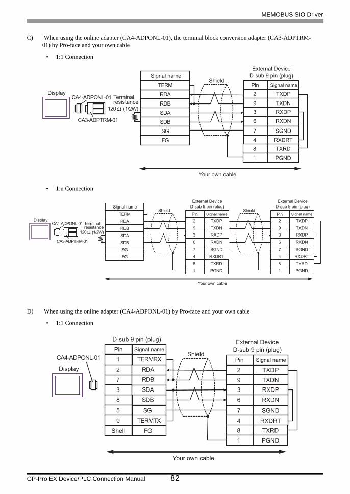
MEMOBUS SIO Driver
GP-Pro EX Device/PLC Connection Manual 82
C) When using the online adapter (CA4-ADPONL-01), the terminal block conversion adapter (CA3-ADPTRM- 01) by Pro-face and your own cable
• 1:1 Connection
• 1:n Connection
D) When using the online adapter (CA4-ADPONL-01) by Pro-face and your own cable
• 1:1 Connection
Signal name
RDB
SDB
SG
FG
CA4-ADPONL-01
CA3-ADPTRM-01
Display
Shield
RDA
SDA
TERM
2
9
3
Signal name
TXDP
TXDN
RXDP
Pin
6 RXDN
7 SGND
4 RXDRT
Your own cable
8 TXRD
1 PGND
120 Ω (1/2W)
Terminalresistance
External Device
D-sub 9 pin (plug)
Signal name
RDB
SDB
SG
FG
CA4-ADPONL-01
CA3-ADPTRM-01
Display
Shield
RDA
SDA
TERM
2
9
3
Signal name
TXDP
TXDN
RXDP
Pin
6 RXDN
7 SGND
4 RXDRT
Your own cable
8 TXRD
1 PGND
120 Ω (1/2W)
Terminalresistance
External Device
D-sub 9 pin (plug)Shield
2
9
3
Signal name
TXDP
TXDN
RXDP
Pin
6 RXDN
7 SGND
4 RXDRT
8 TXRD
1 PGND
External Device
D-sub 9 pin (plug)
CA4-ADPONL-01
Display
ShieldSignal name
RDB7
RDA2
SDB8
9 TERMTX
SDA
FG
3
TERMRX1
SG5
D-sub 9 pin (plug)
Pin
Shell
Your own cable
2
9
3
Signal name
TXDP
TXDN
RXDP
Pin
6 RXDN
7 SGND
4 RXDRT
8 TXRD
1 PGND
External Device
D-sub 9 pin (plug)
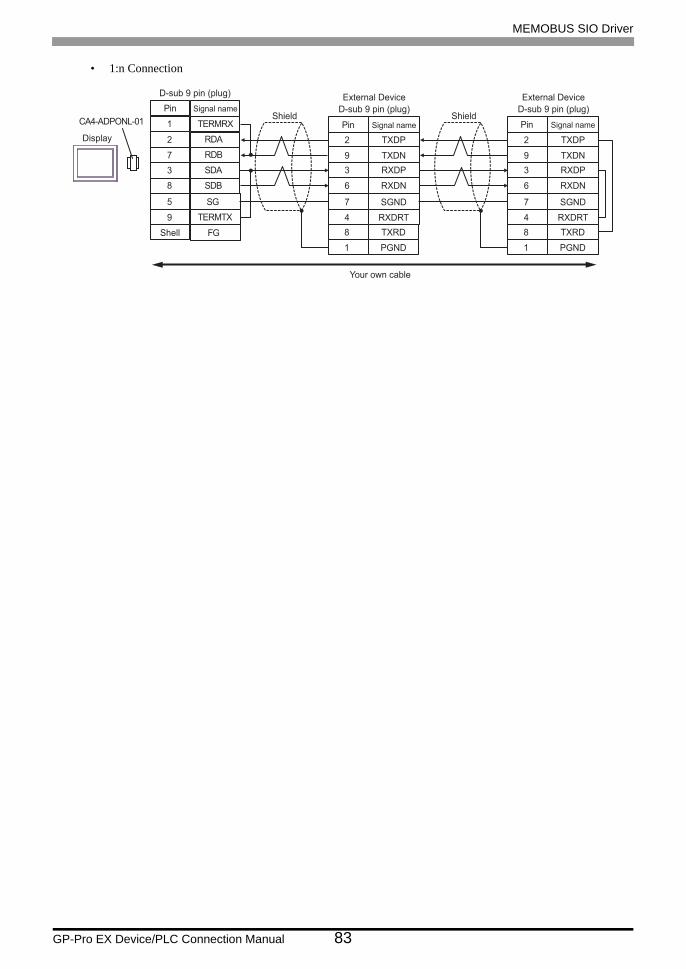
MEMOBUS SIO Driver
GP-Pro EX Device/PLC Connection Manual 83
• 1:n Connection
CA4-ADPONL-01
Display
ShieldSignal name
RDB7
RDA2
SDB8
9 TERMTX
SDA
FG
3
TERMRX1
SG5
D-sub 9 pin (plug)
Pin
Shell
Your own cable
2
9
3
Signal name
TXDP
TXDN
RXDP
Pin
6 RXDN
7 SGND
4 RXDRT
8 TXRD
1 PGND
External Device
D-sub 9 pin (plug)Shield
2
9
3
Signal name
TXDP
TXDN
RXDP
Pin
6 RXDN
7 SGND
4 RXDRT
8 TXRD
1 PGND
External Device
D-sub 9 pin (plug)

MEMOBUS SIO Driver
GP-Pro EX Device/PLC Connection Manual 84
Cable Diagram 12
Display(Connection Port)
Cable Remarks
GP (COM1)ST (COM1)IPC*1
PC/AT
*1 Only the COM port which can communicate by RS-232C can be used. COM Port of IPC (page 7)
Your own cable The cable length must be 15m or less.
Signal name
DR(DSR)6
SD(TXD)3
SG5
7 RS(RTS)
ER(DTR)4
FG
RD(RXD)2
CS(CTS)8
D-sub 9 pin (socket)
Pin
Shell
Signal name
CTS5
RXD3
SG7
4 RTS
DSR6
FG
TXD2
DTR9
D-sub 9 pin (plug)External Device
Pin
1
Shield
Display

MEMOBUS SIO Driver
GP-Pro EX Device/PLC Connection Manual 85
Cable Diagram 13
A) When using the COM port conversion adapter (CA3-ADPCOM-01), the terminal block conversion adapter (CA3-ADPTRM-01) by Pro-face and your own cable
• 1:1 Connection
Display(Connection Port)
Cable Remarks
GP*1 (COM1)AGP-3302B (COM2)ST*2 (COM2)IPC*3
*1 All GP models except AGP-3302B
*2 All ST models except AST-3211A
*3 Only the COM port which can communicate by RS-422/485 (4 wire) can be used. COM Port of IPC (page 7)
A
COM port conversion adapter by Pro-faceCA3-ADPCOM-01
+Terminal block conversion adapter by Pro-face
CA3-ADPTRM-01+
Your own cable
The cable length must be 500 meters or less.
B Your own cable
GP*4 (COM2)
*4 All GP models except GP-3200 series and AGP-3302B
C
Online adapter by Pro-faceCA4-ADPONL-01
+Terminal block conversion adapter by Pro-face CA3-
ADPTRM-01+
Your own cable
D
Online adapter by Pro-faceCA4-ADPONL-01
+Your own cable
Signal name
RDB
SDB
SG
FG
CA3-ADPCOM-01
CA3-ADPTRM-01
Display
Shield
RDA
SDA
TERM
Your own cable
330 Ω (1/4W)
Terminalresistance
2
9
3
Signal name
TXDP
TXDN
RXDP
Pin
6 RXDN
7 SG
External Device
D-sub 9 pin (plug)
1 FG330 Ω (1/4W)
Terminalresistance
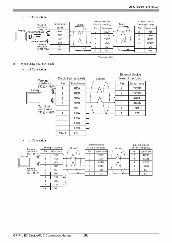
MEMOBUS SIO Driver
GP-Pro EX Device/PLC Connection Manual 86
• 1:n Connection
B) When using your own cable
• 1:1 Connection
• 1:n Connection
Signal name
RDB
SDB
SG
FG
CA3-ADPCOM-01
CA3-ADPTRM-01
Display
Shield
RDA
SDA
TERM
Your own cable
330 Ω (1/4W)
Terminalresistance
2
9
3
Signal name
TXDP
TXDN
RXDP
Pin
6 RXDN
7 SG
External Device
D-sub 9 pin (plug)
1 FG330 Ω (1/4W)
Terminalresistance
Shield
2
9
3
Signal name
TXDP
TXDN
RXDP
Pin
6 RXDN
7 SG
External Device
D-sub 9 pin (plug)
1 FG
Signal name
SDA3
RDB2
SG5
4 ERA
SDB
ERB
7
9
CSB6
FG
RDA1
CSA8
D-sub 9 pin (socket)
Pin
Shell
Display
330 Ω (1/4W)
Terminalresistance
330 Ω (1/4W)
Terminalresistance
Shield
2
9
3
Signal name
TXDP
TXDN
RXDP
Pin
6 RXDN
7 SG
External Device
D-sub 9 pin (plug)
1 FG
SDA3
RDB2
SG5
4 ERA
SDB
ERB
7
9
CSB6
FG
RDA1
CSA8
330 Ω (1/4W)
330 Ω (1/4W)
2
9
3
TXDP
TXDN
RXDP
6 RXDN
7 SG
1 FG
2
9
3
TXDP
TXDN
RXDP
6 RXDN
7 SG
1 FG
Signal name
D-sub 9 pin (socket)
Pin
Shell
Display
Terminalresistance
Terminalresistance
Shield
Signal namePin
External Device
D-sub 9 pin (plug)
Signal namePin
External Device
D-sub 9 pin (plug)Shield

MEMOBUS SIO Driver
GP-Pro EX Device/PLC Connection Manual 87
C) When using the online adapter (CA4-ADPONL-01), the terminal block conversion adapter (CA3-ADPTRM- 01) by Pro-face and your own cable
• 1:1 Connection
• 1:n Connection
D) When using the online adapter (CA4-ADPONL-01) by Pro-face and your own cable
• 1:1 Connection
RDB
SDB
SG
FG
CA4-ADPONL-01
CA3-ADPTRM-01
RDA
SDA
TERM330 Ω (1/4W)
2
9
3
TXDP
TXDN
RXDP
6 RXDN
7 SG
1 FG330 Ω (1/4W)
Signal name
Display
Shield
Signal namePin
Your own cable
Terminalresistance
External Device
D-sub 9 pin (plug)
Terminalresistance
RDB
SDB
SG
FG
CA4-ADPONL-01
CA3-ADPTRM-01
RDA
SDA
TERM330 Ω (1/4W)
2
9
3
TXDP
TXDN
RXDP
6 RXDN
7 SG
1 FG330 Ω (1/4W)
2
9
3
TXDP
TXDN
RXDP
6 RXDN
7 SG
1 FG
Signal name
Display
Shield
Signal namePin
Your own cable
Terminalresistance
External Device
D-sub 9 pin (plug)
Terminalresistance
Shield
Signal namePin
External Device
D-sub 9 pin (plug)
CA4-ADPONL-01
RDB7
RDA2
SDB8
9 TERMTX
SDA
FG
3
TERMRX1
SG5
330 Ω (1/4W)
330 Ω (1/4W)
2
9
3
TXDP
TXDN
RXDP
6 RXDN
7 SG
1 FG
Signal name
D-sub 9 pin (plug)
Pin
Shell
Display
Terminalresistance
Terminalresistance
Shield
Signal namePin
External Device
D-sub 9 pin (plug)
Your own cable

MEMOBUS SIO Driver
GP-Pro EX Device/PLC Connection Manual 88
1:n Connection
CA4-ADPONL-01
RDB7
RDA2
SDB8
9 TERMTX
SDA
FG
3
TERMRX1
SG5
330 Ω (1/4W)
330 Ω (1/4W)
2
9
3
TXDP
TXDN
RXDP
6 RXDN
7 SG
1 FG
2
9
3
TXDP
TXDN
RXDP
6 RXDN
7 SG
1 FG
Signal name
D-sub 9 pin (plug)
Pin
Shell
Display
Terminalresistance
Terminalresistance
Shield
Signal namePin
External Device
D-sub 9 pin (plug)
Your own cable
Shield
Signal namePin
External Device
D-sub 9 pin (plug)
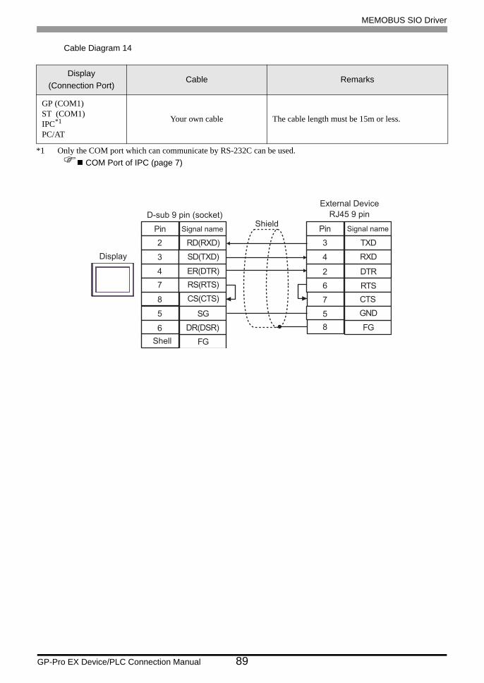
MEMOBUS SIO Driver
GP-Pro EX Device/PLC Connection Manual 89
Cable Diagram 14
Display(Connection Port)
Cable Remarks
GP (COM1)ST (COM1)IPC*1
PC/AT
*1 Only the COM port which can communicate by RS-232C can be used. COM Port of IPC (page 7)
Your own cable The cable length must be 15m or less.
DR(DSR)6
SD(TXD)3
SG5
7 RS(RTS)
ER(DTR)4
FG
RD(RXD)2
CS(CTS)8 CTS7
RXD4
DTR2
GND
TXD3
RTS6
5
FG8
Signal name
D-sub 9 pin (socket)
Pin
Display
ShieldSignal namePin
External Device
RJ45 9 pin
Shell

MEMOBUS SIO Driver
GP-Pro EX Device/PLC Connection Manual 90
6 Supported Device
Range of supported device address is shown in the table below. Please note that the actually supported range of
the devices varies depending on the External Device to be used. Please check the actual range in the manual of
your External Device.
6.1 MP900/2000/CP-9200SH
This address can be specified as system data area.
Device Display on GP-Pro EX Supported Address*1
*1 When you specify "GMW00000" in GP-Pro EX, the address of "MW00000" to which offset value is added, is specified as the actual address in the External Device. Offset value is described as "Head REG" in the ladder software.
32bits
Remarks
Coil(Bit device) GMB0000.0-GMB4095.F MW00000 + Offset -
MW4095F + Offset
Coil(Word device) GMB0000-GMB4095 MW0000 + Offset -
MW4095 + Offset
Input Relay(Bit device) GIB0000.0-GIB0FFF.F IW00000 + Offset -
IWOFFFF + Offset*2
*2 Write disable
Input Relay(Word device) GIB0000-GIB0FFFF IW0000 + Offset -
IW0FFFF + Offset*2
Input Register GIW0000-GIW7FFF IW0000 + Offset - IW7FFFF + Offset
*2
Holding Register GMW00000-GMW65534 MW00000 + Offset - MW65534 + Offset
• Please refer to the GP-Pro EX Reference Manual for system data area.
Cf. GP-Pro EX Reference Manual "Appendix 1.4 LS Area (Direct Access Method)"
• Please refer to the precautions on manual notation for icons in the table.
"Manual Symbols and Terminology"
GMW000
MW00000
MWxxxxx
External DeviceMW device
Offset

MEMOBUS SIO Driver
GP-Pro EX Device/PLC Connection Manual 91
6.2 MEMOCON GL
This address can be specified as system data area.
Device Bit Address Word Address32bits
Remarks
Coil(Output/Internal) 000001-008192 000001-008177 *1
*1 When you write the bit address, the Display reads the word address corresponding to that of the External Device first. Then, it changes the target bit address among the word data once read and returns the word data to the External Device. Note that the correct data may not be read if you change the word address value in the ladder program while the Display reads the data of the External Device and returns it to the External Device.
Input Relay 100001-101024 100001-101009 *2
*2 Write disable
Link Coil 1 D10001-D11024 D10001-D11009 *1
Link Coil 2 D20001-D21024 D20001-D21009 *1
MC Relay 1 X10001-X10256 X10001-X10241 *2
MC Relay 2 X20001-X20256 X20001-X20241 *2
MC Coil 1 Y10001-Y10256 Y10001-Y10241 *1
MC Coil 2 Y20001-Y20256 Y2001-Y20241 *1
MC Cord Relay 1 M10001-M10096 M10001-M10081 *2
MCCord Relay 2 M20001-M20096 M20001-M20081 *2
MC Control Relay 1 P10001-P10256 P10001-P10241 *2
MC Control Relay 2 P20001-P20256 P20001-P20241 *2
MC Control Coil 1 Q10001-Q10256 Q10001-Q10241 *1
MC Control Coil 2 Q20001-Q20256 Q20001-Q20241 *1
Input Register - 300001-300512 *2
Holding Register - 400001-409999
Link Register 1 - R10001-R11024
Link Register 2 - R20001-R21024
Constant Register - 700001-704096
• Please refer to the GP-Pro EX Reference Manual for system data area.
Cf. GP-Pro EX Reference Manual "Appendix 1.4 LS Area (Direct Access Method)"
• Please refer to the precautions on manual notation for icons in the table.
"Manual Symbols and Terminology"
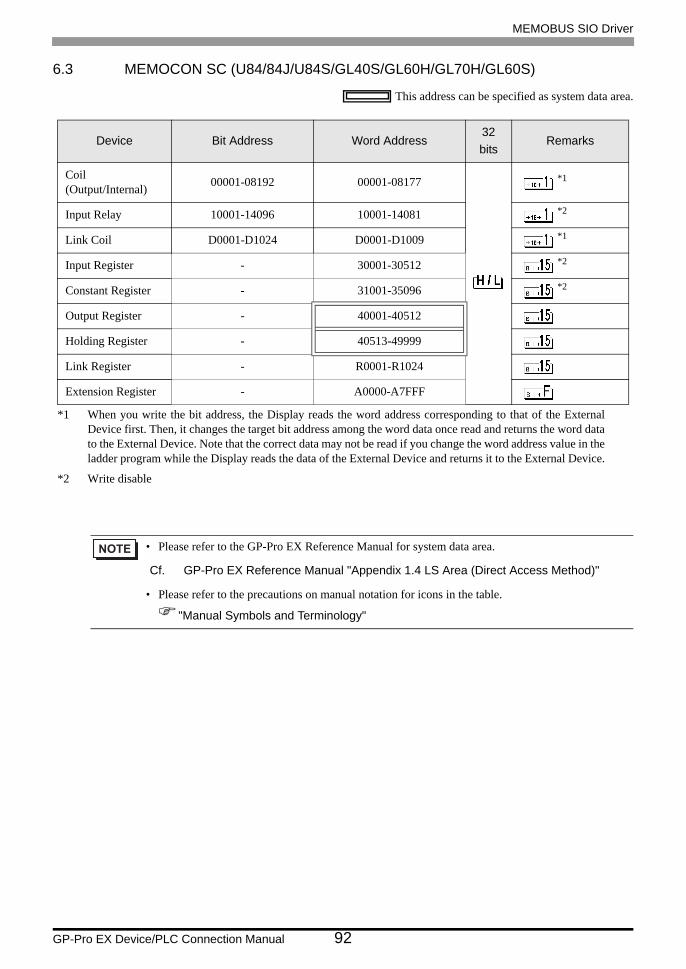
MEMOBUS SIO Driver
GP-Pro EX Device/PLC Connection Manual 92
6.3 MEMOCON SC (U84/84J/U84S/GL40S/GL60H/GL70H/GL60S)
This address can be specified as system data area.
Device Bit Address Word Address32bits
Remarks
Coil(Output/Internal) 00001-08192 00001-08177 *1
*1 When you write the bit address, the Display reads the word address corresponding to that of the External Device first. Then, it changes the target bit address among the word data once read and returns the word data to the External Device. Note that the correct data may not be read if you change the word address value in the ladder program while the Display reads the data of the External Device and returns it to the External Device.
Input Relay 10001-14096 10001-14081 *2
*2 Write disable
Link Coil D0001-D1024 D0001-D1009 *1
Input Register - 30001-30512 *2
Constant Register - 31001-35096 *2
Output Register - 40001-40512
Holding Register - 40513-49999
Link Register - R0001-R1024
Extension Register - A0000-A7FFF
• Please refer to the GP-Pro EX Reference Manual for system data area.
Cf. GP-Pro EX Reference Manual "Appendix 1.4 LS Area (Direct Access Method)"
• Please refer to the precautions on manual notation for icons in the table.
"Manual Symbols and Terminology"
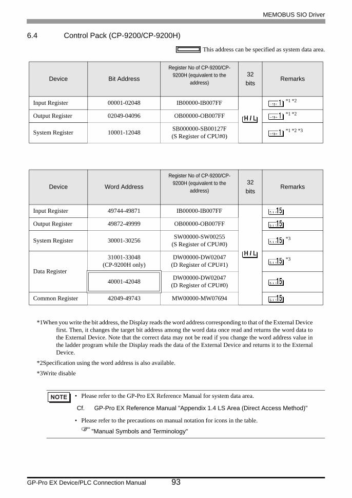
MEMOBUS SIO Driver
GP-Pro EX Device/PLC Connection Manual 93
6.4 Control Pack (CP-9200/CP-9200H)
This address can be specified as system data area.
*1When you write the bit address, the Display reads the word address corresponding to that of the External Device first. Then, it changes the target bit address among the word data once read and returns the word data to the External Device. Note that the correct data may not be read if you change the word address value in the ladder program while the Display reads the data of the External Device and returns it to the External Device.
*2Specification using the word address is also available.
*3Write disable
Device Bit Address
Register No of CP-9200/CP-9200H (equivalent to the
address)32bits
Remarks
Input Register 00001-02048 IB00000-IB007FF *1 *2
Output Register 02049-04096 OB00000-OB007FF *1 *2
System Register 10001-12048 SB000000-SB00127F(S Register of CPU#0)
*1 *2 *3
Device Word Address
Register No of CP-9200/CP-9200H (equivalent to the
address)32bits
Remarks
Input Register 49744-49871 IB00000-IB007FF
Output Register 49872-49999 OB00000-OB007FF
System Register 30001-30256 SW00000-SW00255(S Register of CPU#0)
*3
Data Register
31001-33048(CP-9200H only)
DW00000-DW02047(D Register of CPU#1)
*3
40001-42048 DW00000-DW02047(D Register of CPU#0)
Common Register 42049-49743 MW00000-MW07694
• Please refer to the GP-Pro EX Reference Manual for system data area.
Cf. GP-Pro EX Reference Manual "Appendix 1.4 LS Area (Direct Access Method)"
• Please refer to the precautions on manual notation for icons in the table.
"Manual Symbols and Terminology"

MEMOBUS SIO Driver
GP-Pro EX Device/PLC Connection Manual 94
6.5 MEMOCON Micro
This address can be specified as system data area.
Device Bit Address Word Address32bits
Remarks
Coil(Output/Internal) 00001-01531 - *1 *2
*1 When you write the bit address, the Display reads the word address corresponding to that of the External Device first. Then, it changes the target bit address among the word data once read and returns the word data to the External Device. Note that the correct data may not be read if you change the word address value in the ladder program while the Display reads the data of the External Device and returns it to the External Device.
*2 Specification using the word address is also available.
Input Relay 10001-10511 - *1 *2 *3
*3 Write disable
Input Register - 30001-30047 *3
Output/Holding Register - 40001-41871
• Please refer to the GP-Pro EX Reference Manual for system data area.
Cf. GP-Pro EX Reference Manual "Appendix 1.4 LS Area (Direct Access Method)"
• Please refer to the precautions on manual notation for icons in the table.
"Manual Symbols and Terminology"
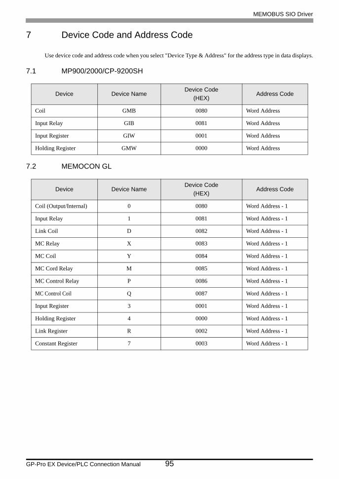
MEMOBUS SIO Driver
GP-Pro EX Device/PLC Connection Manual 95
7 Device Code and Address Code
Use device code and address code when you select "Device Type & Address" for the address type in data displays.
7.1 MP900/2000/CP-9200SH
7.2 MEMOCON GL
Device Device NameDevice Code
(HEX)Address Code
Coil GMB 0080 Word Address
Input Relay GIB 0081 Word Address
Input Register GIW 0001 Word Address
Holding Register GMW 0000 Word Address
Device Device NameDevice Code
(HEX)Address Code
Coil (Output/Internal) 0 0080 Word Address - 1
Input Relay 1 0081 Word Address - 1
Link Coil D 0082 Word Address - 1
MC Relay X 0083 Word Address - 1
MC Coil Y 0084 Word Address - 1
MC Cord Relay M 0085 Word Address - 1
MC Control Relay P 0086 Word Address - 1
MC Control Coil Q 0087 Word Address - 1
Input Register 3 0001 Word Address - 1
Holding Register 4 0000 Word Address - 1
Link Register R 0002 Word Address - 1
Constant Register 7 0003 Word Address - 1
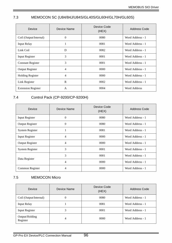
MEMOBUS SIO Driver
GP-Pro EX Device/PLC Connection Manual 96
7.3 MEMOCON SC (U84/84J/U84S/GL40S/GL60H/GL70H/GL60S)
7.4 Control Pack (CP-9200/CP-9200H)
7.5 MEMOCON Micro
Device Device NameDevice Code
(HEX)Address Code
Coil (Output/Internal) 0 0080 Word Address - 1
Input Relay 1 0081 Word Address - 1
Link Coil D 0082 Word Address - 1
Input Register 3 0001 Word Address - 1
Constant Register 3 0001 Word Address - 1
Output Register 4 0000 Word Address - 1
Holding Register 4 0000 Word Address - 1
Link Register R 0002 Word Address - 1
Extension Register A 0004 Word Address
Device Device NameDevice Code
(HEX)Address Code
Input Register 0 0080 Word Address - 1
Output Register 0 0080 Word Address - 1
System Register 1 0081 Word Address - 1
Input Register 4 0000 Word Address - 1
Output Register 4 0000 Word Address - 1
System Register 3 0001 Word Address - 1
Data Register3 0001 Word Address - 1
4 0000 Word Address - 1
Common Register 4 0000 Word Address - 1
Device Device NameDevice Code
(HEX)Address Code
Coil (Output/Internal) 0 0080 Word Address - 1
Input Relay 1 0081 Word Address - 1
Input Register 3 0001 Word Address - 1
Output/Holding Register 4 0000 Word Address - 1
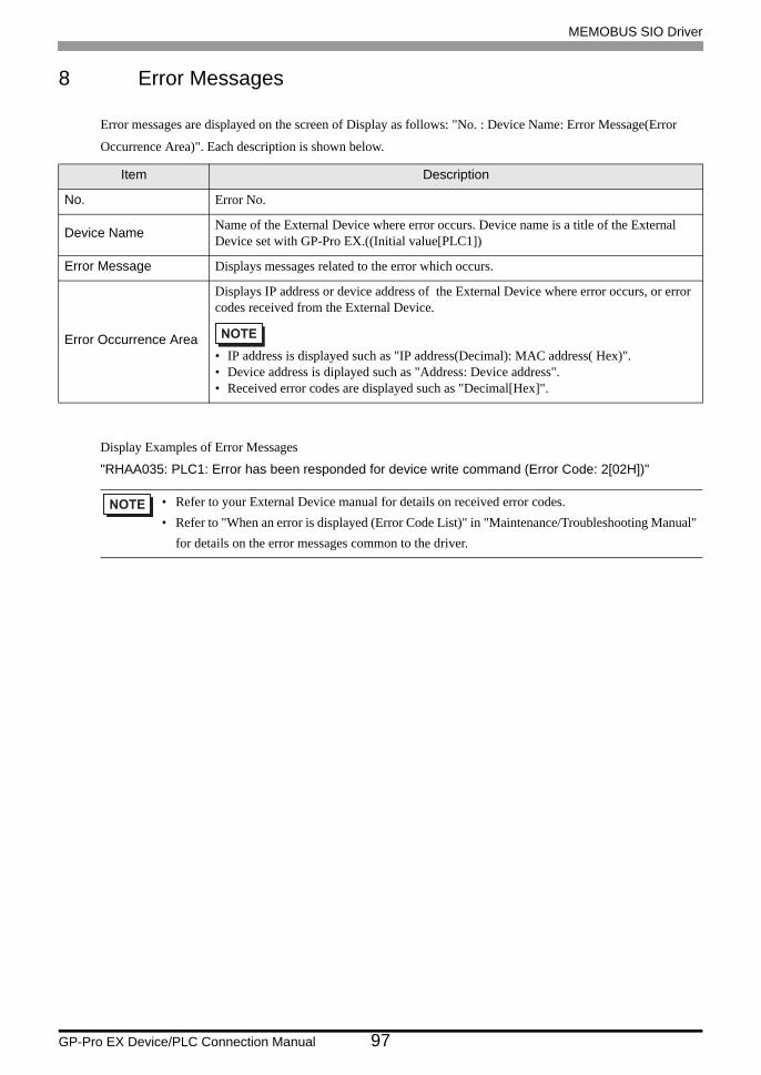
MEMOBUS SIO Driver
GP-Pro EX Device/PLC Connection Manual 97
8 Error Messages
Error messages are displayed on the screen of Display as follows: "No. : Device Name: Error Message(Error
Occurrence Area)". Each description is shown below.
Display Examples of Error Messages
"RHAA035: PLC1: Error has been responded for device write command (Error Code: 2[02H])"
Item Description
No. Error No.
Device Name Name of the External Device where error occurs. Device name is a title of the External Device set with GP-Pro EX.((Initial value[PLC1])
Error Message Displays messages related to the error which occurs.
Error Occurrence Area
Displays IP address or device address of the External Device where error occurs, or error codes received from the External Device.
• IP address is displayed such as "IP address(Decimal): MAC address( Hex)".• Device address is diplayed such as "Address: Device address".• Received error codes are displayed such as "Decimal[Hex]".
• Refer to your External Device manual for details on received error codes.• Refer to "When an error is displayed (Error Code List)" in "Maintenance/Troubleshooting Manual"
for details on the error messages common to the driver.

MEMOBUS SIO Driver
GP-Pro EX Device/PLC Connection Manual 98
Related Documents