Membrane technologies for meat processing waste streams

Welcome message from author
This document is posted to help you gain knowledge. Please leave a comment to let me know what you think about it! Share it to your friends and learn new things together.
Transcript
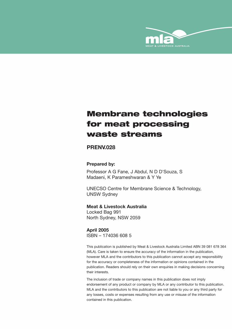
Membrane technologies for meat processing waste streams
Prepared by:
Professor A G Fane, J Abdul, N D D'Souza, SMadaeni, K Parameshwaran & Y Ye
UNECSO Centre for Membrane Science & Technology,UNSW Sydney
Meat & Livestock AustraliaLocked Bag 991North Sydney, NSW 2059
April 2005ISBN – 174036 608 5
This publication is published by Meat & Livestock Australia Limited ABN 39 081 678 364(MLA). Care is taken to ensure the accuracy of the information in the publication,however MLA and the contributors to this publication cannot accept any responsibilityfor the accuracy or completeness of the information or opinions contained in thepublication. Readers should rely on their own enquiries in making decisions concerningtheir interests.
The inclusion of trade or company names in this publication does not implyendorsement of any product or company by MLA or any contributor to this publication.MLA and the contributors to this publication are not liable to you or any third party forany losses, costs or expenses resulting from any use or misuse of the informationcontained in this publication.
Membrane technologies for meat processing waste streams
PRENV.028

Executive summary 5Scenario 1: Stickwater treatment 6Scenario 2: Sterilizer/handwash remediation 9Scenario 3: Effluent reclamation 11
Conclusions and recommendations 121. Introduction 13
1.1 Objectives 131.2 Scenario descriptions 131.2.1 Scenario 1: Stickwater treatment 131.2.2 Scenario 2: Sterilizer/handwash remediation 131.2.3 Scenario 3: Effluent reclamation 14
1.3 Report methodology and structure 151.4 An introduction to membrane technology 15
1.4.1 The range of membrane processes (Appendix A, Figures A1 to 3) 151.4.2 Membrane materials and properties (Appendix A Figures A4 to 6) 151.4.3 Performance definitions (Figure A7) 151.4.4 Membrane modules (Figures A8 to 22) 161.4.5 Flux-enhancing strategies (Figures A23 to 24) 161.4.6 Fouling and cleaning (Figures A25 to 28) 161.4.7 Economics – cost trends (Figures A29 to A32) 16
2. Scenario 1: Stickwater treatment 172.1 General considerations 17
2.1.1 Initial ‘screening’ 172.2 High shear devices 18
2.2.1 Vibratory shear enhanced process (VSEP) 182.2.2 Rotating membrane devices 24
2.3 Tubular modules 292.3.1 Principle and general performance 292.3.2 Specific examples 322.3.3 Economic factors 332.3.4 Capabilities and limitations 342.3.5 Contacts and suppliers 352.3.6 References 35
2. 4 Dynamic membranes 352.4.1 Principle 352.4.2 General performance 362.4.3 Specific examples 362.4.4 Economic factors 372.4.5 Capabilities and limitations 382.4.6 Contacts 382.4.7 References 38
2.5. Discussion 39
co
nte
nts
3. Scenario 2: Sterilizer/handwash remediation 403.1 General considerations 40
3.1.1 Initial screening 403.2 Membrane options 41
3.2.1 Depth filtration – principles and performance 413.2.2 Surface filters – principles and performance 413.3. Related applications 433.3.1 Sterilization in the pharmaceutical industry 433.3.2 Beverage clarification and stabilisation 433.3.3 Ceramic membranes – dilute feed 43
3.4 Economic factors 443.4.1 Polymeric cartridge filters 443.4.2 Ceramic membranes 443.4.3 Microsieves 44
3.5 Capabilities and limitations 453.5.1 Polymeric cartridge filters 453.5.2 Ceramic membranes 463.5.3 Microsieves 46
3.6 Contacts 473.7 References 47
4. Scenario 3: Effluent reclamation 484.1 General considerations 48
4.1.1 Initial screening 484.2 Treatment options 48
4.2.1 Principles and performance 494.3 Specific examples 51
4.3.1 Membrane clarification 514.3.2 Dual membrane plant 524.3.3. MBRs 52
4.4 Economic factors 534.4.1 Dual membrane plant 534.4.2 Biological treatment and membranes 534.4.3. MBRs 54
4.5 Capabilities and limitations 544.6 Contacts of suppliers/manufacturers 554.7 References 56
5. Conclusions and recommendations 57APPENDIX A 59An introduction to membrane technology 59APPENDIX B 73VSEP applications 73APPENDIX C 74Membrane cartridges and microsieves 74

Executive summaryThis report evaluates the potential application ofmembrane technologies to various aqueous wastestreams in the meat processing industry. The reportidentifies membrane types and modules most suitablefor each of the applications, typical flux rates andrecoveries, as well as process issues (such as fouling,temperature related factors, membrane life etc) thatshould be evaluated in future trials of the concepts. Inaddition, an analysis is given of the approximate costsassociated with each of the applications as well as alist of suitable suppliers and contacts. For eachtechnical option the potential benefits and risks aresummarized in a SWOT analysis table. Section 1.4 andAppendix A provide an introduction to membranetechnology for those unfamiliar with the technology.Three wastewater scenarios have been considered, asfollows:
(i) Scenario 1: Stickwater treatment(ii) Scenario 2: Sterilizer/handwash remediation(iii) Scenario 3: Effluent reclamation
The evaluations for each of these scenarios aresummarised below.
5
Membrane technologies for meat processing waste streams

Scenario 1: StickwatertreatmentStickwater is hot (80–90°C) and contains high levels ofCOD (100,000 mg/L), fine solids (TSS of the order20,000 mg/L), nitrogen (2–4,000 mg/L), phosphorus (2–300 mg/L) and oil and grease (1–2% w/v). Flows aretypically low at 5,000–30,000 litres/day depending onthroughput. This stream is a challenging application formembrane technology due to the raised temperature,the high COD, the oil and grease and the suspendedsolids. However, if it is possible to concentrate from aninitial 20 g/L solids (ie 2% solids) to 10% solids, thisprovides a five fold concentration which reduces thevolume to 20% and removes 80% of the water; thusthere is a potential for a large saving of evaporatorenergy. Values present in the concentrate would alsohelp to offset costs.
Initial screening suggests the application of:
• inorganic (or robust polymer) membranes• high shear devices• tubular modules with high crossflow or a flux
enhancing strategy
• dynamic membranes amenable to regeneration
High shear devices
To cope with the highly fouling feed it is possible thebest option is to use high surface shear that canminimise concentration polarisation and fouling. Thetwo generic approaches to this are:
Vibrating the membrane; and
Rotary motion of the membrane or the fluid above themembrane.
The vibratory shear enhanced process (VSEP) wasdeveloped about 10 years ago and is based on thelateral vibration of flat sheet membranes at about 60Hz. This procedure generates shear at the membranesurface that is typically 10 times that achieved byconventional pumped crossflow. As a result, the VSEPmembrane process is able to minimize surface depositsand fouling in many applications. It is also reported tooperate to relatively high solids concentrations. A widerange of applications are reported, but not specificallystickwater. The technique is being evaluated inAustralia for effluent from masonite production.
The VSEP has been used with membranes rangingfrom microfilters to reverse osmosis. However it has notbe used with ceramic membranes, reportedly becausethey would not handle the vibrations without damage.This may limit the application of VSEP at 90°C althoughseveral commercially available polymer membranes(such as polyethersulphone, PVDF) are claimed to besatisfactory (or close to) at this temperature. Theeconomics for VSEP are in the same range as the otheroptions (see below).
The key features of the SWOT analysis for VSEP aregiven below.
6
Membrane technologies for meat processing waste streams
SWOT Assessment of VSEP for stickwater processing
Strengths Provides high shear to control cake formation and fouling at high solids content
Weakness Mechanical vibration limits the application of ceramic membranes
Opportunities VSEP could provide compact and effective separation
Threats Suitable membrane may not be commercially available
Typical fluxes 200 to 50 l/m2 hr, depending on feed
Typical recoveries 80 to 90 should be feasible
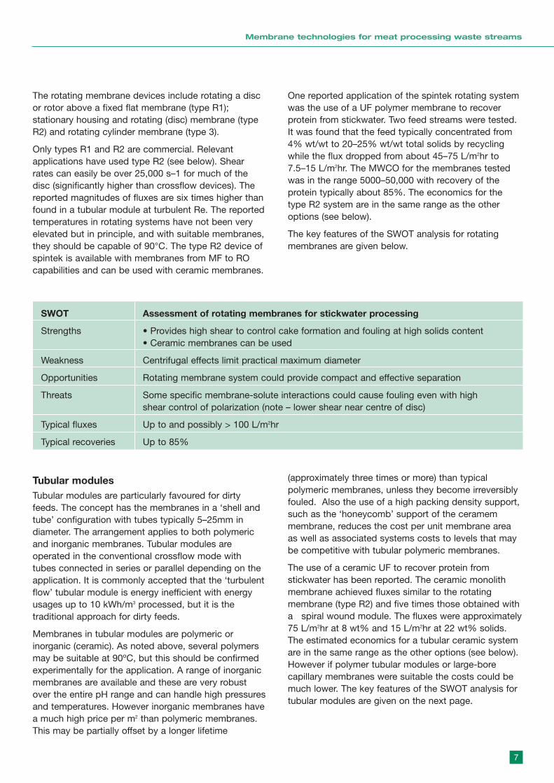
The rotating membrane devices include rotating a discor rotor above a fixed flat membrane (type R1);stationary housing and rotating (disc) membrane (typeR2) and rotating cylinder membrane (type 3).
Only types R1 and R2 are commercial. Relevantapplications have used type R2 (see below). Shearrates can easily be over 25,000 s–1 for much of thedisc (significantly higher than crossflow devices). Thereported magnitudes of fluxes are six times higher thanfound in a tubular module at turbulent Re. The reportedtemperatures in rotating systems have not been veryelevated but in principle, and with suitable membranes,they should be capable of 90°C. The type R2 device ofspintek is available with membranes from MF to ROcapabilities and can be used with ceramic membranes.
One reported application of the spintek rotating systemwas the use of a UF polymer membrane to recoverprotein from stickwater. Two feed streams were tested.It was found that the feed typically concentrated from4% wt/wt to 20–25% wt/wt total solids by recyclingwhile the flux dropped from about 45–75 L/m2hr to 7.5–15 L/m2hr. The MWCO for the membranes testedwas in the range 5000–50,000 with recovery of theprotein typically about 85%. The economics for thetype R2 system are in the same range as the otheroptions (see below).
The key features of the SWOT analysis for rotatingmembranes are given below.
7
Membrane technologies for meat processing waste streams
SWOT Assessment of rotating membranes for stickwater processing
Strengths • Provides high shear to control cake formation and fouling at high solids content• Ceramic membranes can be used
Weakness Centrifugal effects limit practical maximum diameter
Opportunities Rotating membrane system could provide compact and effective separation
Threats Some specific membrane-solute interactions could cause fouling even with highshear control of polarization (note – lower shear near centre of disc)
Typical fluxes Up to and possibly > 100 L/m2hr
Typical recoveries Up to 85%
Tubular modulesTubular modules are particularly favoured for dirtyfeeds. The concept has the membranes in a ‘shell andtube’ configuration with tubes typically 5–25mm indiameter. The arrangement applies to both polymericand inorganic membranes. Tubular modules areoperated in the conventional crossflow mode withtubes connected in series or parallel depending on theapplication. It is commonly accepted that the ‘turbulentflow’ tubular module is energy inefficient with energyusages up to 10 kWh/m3 processed, but it is thetraditional approach for dirty feeds.
Membranes in tubular modules are polymeric orinorganic (ceramic). As noted above, several polymersmay be suitable at 90ºC, but this should be confirmedexperimentally for the application. A range of inorganicmembranes are available and these are very robustover the entire pH range and can handle high pressuresand temperatures. However inorganic membranes havea much high price per m2 than polymeric membranes.This may be partially offset by a longer lifetime
(approximately three times or more) than typicalpolymeric membranes, unless they become irreversiblyfouled. Also the use of a high packing density support,such as the ‘honeycomb’ support of the ceramemmembrane, reduces the cost per unit membrane areaas well as associated systems costs to levels that maybe competitive with tubular polymeric membranes.
The use of a ceramic UF to recover protein fromstickwater has been reported. The ceramic monolithmembrane achieved fluxes similar to the rotatingmembrane (type R2) and five times those obtained witha spiral wound module. The fluxes were approximately75 L/m2hr at 8 wt% and 15 L/m2hr at 22 wt% solids.The estimated economics for a tubular ceramic systemare in the same range as the other options (see below).However if polymer tubular modules or large-borecapillary membranes were suitable the costs could bemuch lower. The key features of the SWOT analysis fortubular modules are given on the next page.
Dynamic membranesDynamic membranes are formed by use of a precoaton a porous substrate. The formed membrane isremoved and regenerated when fouled. This type ofmembrane has been successfully used in someindustrial wastewater applications. The nature of theporous substrate, the characteristics of the coatedmaterial and the formation protocol all influence theperformance of the dynamic membrane.
Several applications have been demonstrated in SouthAfrica. One industrial application was for the processingof highly fouling wool scouring effluent. However afterseveral years operation it is reported that the dynamicmembrane process has been replaced by ceramicmembranes.
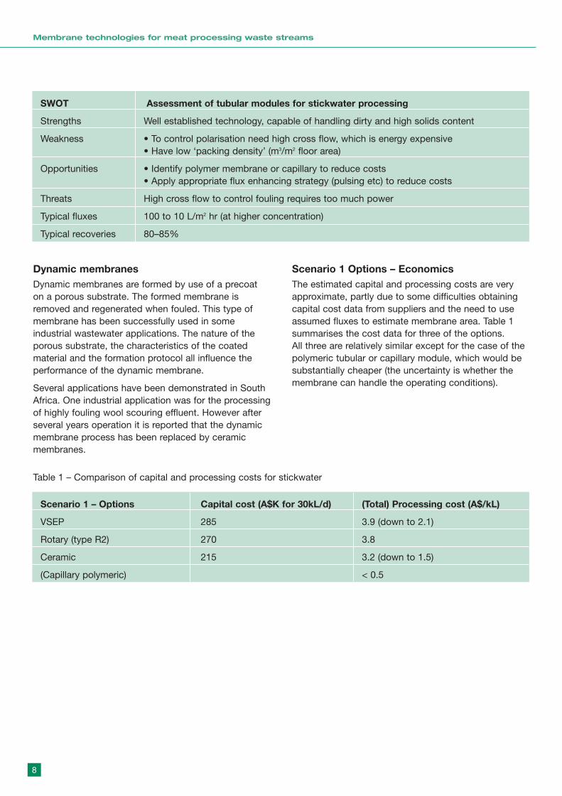
Scenario 1 Options – EconomicsThe estimated capital and processing costs are veryapproximate, partly due to some difficulties obtainingcapital cost data from suppliers and the need to useassumed fluxes to estimate membrane area. Table 1summarises the cost data for three of the options. All three are relatively similar except for the case of thepolymeric tubular or capillary module, which would besubstantially cheaper (the uncertainty is whether themembrane can handle the operating conditions).
8
Membrane technologies for meat processing waste streams
SWOT Assessment of tubular modules for stickwater processing
Strengths Well established technology, capable of handling dirty and high solids content
Weakness • To control polarisation need high cross flow, which is energy expensive• Have low ‘packing density’ (m3/m2 floor area)
Opportunities • Identify polymer membrane or capillary to reduce costs• Apply appropriate flux enhancing strategy (pulsing etc) to reduce costs
Threats High cross flow to control fouling requires too much power
Typical fluxes 100 to 10 L/m2 hr (at higher concentration)
Typical recoveries 80–85%
Scenario 1 – Options Capital cost (A$K for 30kL/d) (Total) Processing cost (A$/kL)
VSEP 285 3.9 (down to 2.1)
Rotary (type R2) 270 3.8
Ceramic 215 3.2 (down to 1.5)
(Capillary polymeric) < 0.5
Table 1 – Comparison of capital and processing costs for stickwater
Scenario 2:Sterilizer/handwashremediationThe streams to be treated are very dilute and hot towarm. There are two generic streams:
• 2A is greater than 80°C and very lightly contaminatedand may contain some bacteria; it is required for ‘immediate’ reuse (to maintain its enthalpy) but must be effectively sterilized
• 2B is warm (ca 40ºC), slightly more contaminated andrequired for high quality non-potable reuse
Both streams need a ‘sterilizing’ membrane barrierfollowed by a disinfection step such as UV. Theelevated temperature of stream 2A would provide asignificantly reduced viscosity of water (at 80°C theviscosity is 36% of that at 20°C) and this providesbenefits of higher fluxes or lower transmembranepressures (TMP) for the same flux. Stream 2A requiresa high integrity, high flux (low residence time) robustmembrane in a compact ‘packaged’ system. Stream 2Bwould also be suited to a similar membrane but hasless demand on temperature of operation; it may needto be readily backwashable.
Initial screening suggests:
• Modules such as flat sheet, pleated cartidges or tubular configurations (including cartridges) suited to dead end (or low crossflow) operation. Both depth and surface filtration could apply.
• For effective sterilization the membrane needs to be a microfilter (MF) of pore size ≤ 0.2 µm. For surface filters the ideal membrane would be a high porosity isoporous (mono pore size) membrane which has high flux to give rapid processing without significant cooling.
From these considerations the options appear to be:
• polymeric cartridge filters• microsieves• ceramic membranes
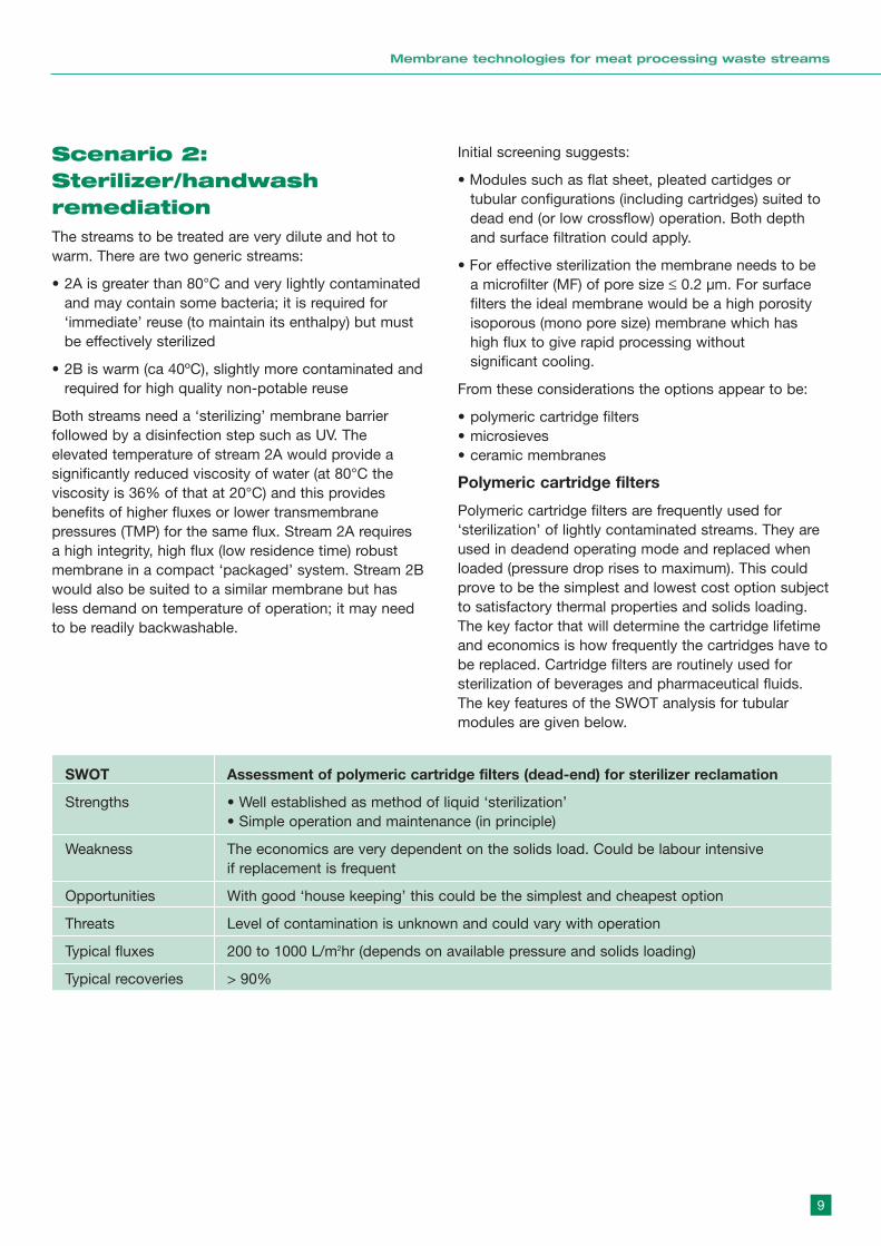
Polymeric cartridge filters
Polymeric cartridge filters are frequently used for‘sterilization’ of lightly contaminated streams. They areused in deadend operating mode and replaced whenloaded (pressure drop rises to maximum). This couldprove to be the simplest and lowest cost option subjectto satisfactory thermal properties and solids loading.The key factor that will determine the cartridge lifetimeand economics is how frequently the cartridges have tobe replaced. Cartridge filters are routinely used forsterilization of beverages and pharmaceutical fluids.The key features of the SWOT analysis for tubularmodules are given below.
9
Membrane technologies for meat processing waste streams
SWOT Assessment of polymeric cartridge filters (dead-end) for sterilizer reclamation
Strengths • Well established as method of liquid ‘sterilization’ • Simple operation and maintenance (in principle)
Weakness The economics are very dependent on the solids load. Could be labour intensive if replacement is frequent
Opportunities With good ‘house keeping’ this could be the simplest and cheapest option
Threats Level of contamination is unknown and could vary with operation
Typical fluxes 200 to 1000 L/m2hr (depends on available pressure and solids loading)
Typical recoveries > 90%

MicrosievesMicrosieves are a new special class of surfacemicrofilters developed based on semiconductortechnology. These membranes are highly isoporous(very uniform pore size) with a high surface porosity,silicon based with excellent chemical and temperaturestability and possessing high mechanical and tensilestrength. As the filters are very thin they have very lowresistance, making low-pressure operation possible andfeaturing compact installations. The microsieve has a
water permeability one or two orders of magnitudehigher than conventional membranes or track etchedmembranes. For bulk and continuous processing withthe microsieve it is necessary to remove the depositedlayer. This is achieved by rapid backpulsing with a lowcrossflow to remove backpulsed solids. The microsievehas been successfully applied to beer filtration at fluxestwo orders higher than for ceramic crossflowmembranes. The key features of the SWOT analysis formicrosieves are given below.
10
Membrane technologies for meat processing waste streams
SWOT Assessment of ceramic membranes for steriliser reclamation
Strengths Easy application for this membrane. Tight MF/ UF for effective sterilisation.
Weakness Relatively costly in terms of capital and operating costs.
Opportunities Use similar membranes to Scenario 1. Could develop optimized back pulsing.Could couple with UV (hybrid process development).
Threats Other options may be cheaper or more compact.
Typical fluxes In range 100 to 200 L/m2 hr.
Typical recoveries To 90%.
SWOT Assessment of microsieves for sterilizer reclamation
Strengths • Exceptionally high permeability• Very compact and small foot print is possible• ‘Near perfect’ isoporosity provides very effective sterilisation
Weakness Very novel technology with single supplier
Opportunities • High flux would permit very compact units with short residence time• Could develop a ‘sterlizer water recycle’ product (in partnership with supplier)
Threats If anticipated fluxes (10 to 20kL/m2 hr) cannot be sustained
Typical fluxes In range 10,000 to 20,000 L/m2 hr at 80°C
Typical recoveries > 90%
Ceramic membranesInorganic ceramic microfiltration membranes may alsobe suitable for recycling the hot dilute wastewater.Compared with organic microfiltration membranes, theycan cope better at high temperature and have
exceptional cleaning performance and potentiallylonger service life. The key features of the SWOTanalysis for ceramic membranes are given on the next page.
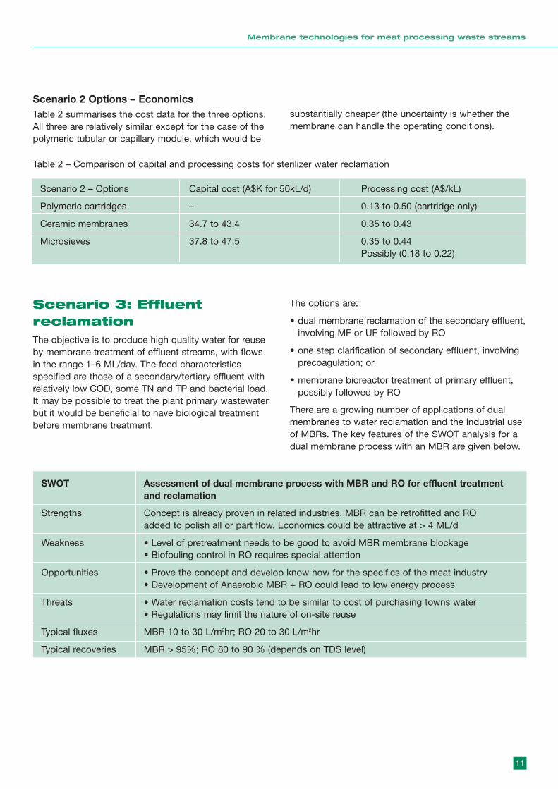
Scenario 2 Options – EconomicsTable 2 summarises the cost data for the three options.All three are relatively similar except for the case of thepolymeric tubular or capillary module, which would be
substantially cheaper (the uncertainty is whether themembrane can handle the operating conditions).
11
Membrane technologies for meat processing waste streams
Scenario 2 – Options Capital cost (A$K for 50kL/d) Processing cost (A$/kL)
Polymeric cartridges – 0.13 to 0.50 (cartridge only)
Ceramic membranes 34.7 to 43.4 0.35 to 0.43
Microsieves 37.8 to 47.5 0.35 to 0.44Possibly (0.18 to 0.22)
Table 2 – Comparison of capital and processing costs for sterilizer water reclamation
Scenario 3: EffluentreclamationThe objective is to produce high quality water for reuseby membrane treatment of effluent streams, with flowsin the range 1–6 ML/day. The feed characteristicsspecified are those of a secondary/tertiary effluent withrelatively low COD, some TN and TP and bacterial load.It may be possible to treat the plant primary wastewaterbut it would be beneficial to have biological treatmentbefore membrane treatment.
The options are:
• dual membrane reclamation of the secondary effluent,involving MF or UF followed by RO
• one step clarification of secondary effluent, involving precoagulation; or
• membrane bioreactor treatment of primary effluent, possibly followed by RO
There are a growing number of applications of dualmembranes to water reclamation and the industrial useof MBRs. The key features of the SWOT analysis for adual membrane process with an MBR are given below.
SWOT Assessment of dual membrane process with MBR and RO for effluent treatmentand reclamation
Strengths Concept is already proven in related industries. MBR can be retrofitted and ROadded to polish all or part flow. Economics could be attractive at > 4 ML/d
Weakness • Level of pretreatment needs to be good to avoid MBR membrane blockage• Biofouling control in RO requires special attention
Opportunities • Prove the concept and develop know how for the specifics of the meat industry• Development of Anaerobic MBR + RO could lead to low energy process
Threats • Water reclamation costs tend to be similar to cost of purchasing towns water• Regulations may limit the nature of on-site reuse
Typical fluxes MBR 10 to 30 L/m2hr; RO 20 to 30 L/m2hr
Typical recoveries MBR > 95%; RO 80 to 90 % (depends on TDS level)
Scenario 3 Options – EconomicsCost data vary depending on the source, scale ofoperation and the type of MBR assumed. The followingsummarises the processing cost data.
(a) MF/UF of secondary: approximately A$0.2 to 0.3 /kL(excludes disinfection);
(b) Dual Membrane (MF/UF + RO)A$0.4 to 2.0 /kL, but could be A$0.4 to A$0.64 /kL(Zenon MBR + RO); or
(c) MBR A$0.57/kL (2ML/d Kubota) to A$0.35/kL (4ML/dZenon).
Conclusions andrecommendationsThe three waste stream scenarios are technicallyamenable to membrane treatment to achieve theobjectives of water and resource reclamation. For eachscenario there are at least two membrane-basedoptions worthy of consideration. The SWOT analysescan be used as starting points for further work,providing the rationale (strengths and opportunities)and the issues (weaknesses and threats) that need tobe resolved to build confidence in the option. Anyoption of specific interest can be assessed at relativelysmall pilot plant scale to get the necessary operatingand economic data.
It is recommended that the industry continue to assessthe application of membrane technology to its wastewater streams, with a view to reducing the water inputsto the process and the effluents from the process.
12
Membrane technologies for meat processing waste streams
1. Introduction Modern meat processing plants are large users ofwater and generate a variety of waste streams, whichmay be warm to hot and contain proteins ands fats.These waste streams may be amenable to treatment torecover water for reuse, thereby reducing net waterconsumption, and producing added-value concentratesfor recovery in product cookers and driers. The trend tosegregation of waste streams encourages thisapproach as it isolates high strength and low strengthflows allowing the application or more specificseparation techniques.
Membrane technology provides a means for separationof aqueous mixtures by ‘filtering’ the feed through a‘selective’ barrier. There are numerous examples ofwater and residuals recovery from waste streams usingmembranes. Over the past decade there have beensignificant developments in membrane technology thathave created many options in terms of separationapplications. It is therefore appropriate and timely toevaluate the potential application of membranetechnologies to waste stream treatment in the meatprocessing industry. A brief introduction to membranetechnology is given in section 2 of this report, beforediscussing the specific applications.
1.1 Objectives
The overall objective of this report is to provide areview of the application of membrane technologies tovarious meat processing streams as described insection 1.2. Specific issues addressed include,
- identification of membrane types and modules mostsuitable for each of the applications;
- identification of which membrane types and modulesare not suitable for each of the applications;
- identification of typical flux rates and recoveries thatcould be expected;
- identification of any process issues , such as fouling,temperature related factors, membrane life etc thatshould be evaluated in future trials of the concepts;
- provision of a list of suitable suppliers and contacts;and
- provision an approximate analysis of the economicsassociated with each of the applications.
1.2 Scenario descriptionsThe scenarios specified in the terms of reference aredepicted in Figure 1. Brief descriptions are given below.
1.2.1 Scenario 1: Stickwater treatment
Stickwater is the highly polluted by-product ofrendering, where waste meat and bones are cooked athigh temperature to form a protein meal (solids) andliquid fat (tallow). During the process, tallow is water-washed in a centrifuge. The water phase leaving thecentrifuge is hot (80–90°C) and contains high levels ofCOD (100,000 mg/L), fine solids (TSS of the order20,000 mg/L), nitrogen (2–4,000 mg/L), phosphorus(2–300 mg/L) and oil and grease (1–2% w/v). Flows aretypically low at 5,000 to 30,000 litres/day depending onthroughput. Usually the stream is dumped to thewastewater treatment system, or evaporated in wasteheat evaporators (WHE).
This report considers membrane technologies that canhandle stickwater to either pre-concentrate it forevaporation or take it up to high solids content beforedrying. The flowsheet in Figure 1 implies pretreatmentoptions (based on the terms of reference).
1.2.2 Scenario 2: Sterilizer/handwash remediation
Very large amounts of water are used for sterilizingtools used in fractionating meat, for hand and apronwashes and for washing of tables. Sterilizer water ishigh temperature (82ºC) and generally high qualitycontaining only traces of organics and nutrients andlow levels of total organisms. Handwash and tablewash water is cooler (about 43ºC) and may be slightlymore contaminated.
This report considers membrane technologies thatmight be applied to treat either sterilizer water only forits immediate reuse as high (potable) quality water(possibly after further disinfection) or a combinedstream for high quality (non-potable) reuse. It isenvisaged that the system could comprise severalsmall distributed package units with total flows of theorder of 50,000 to 200,000 litres/day for sterilizer waterand triple that for the combined flows.
13
Membrane technologies for meat processing waste streams
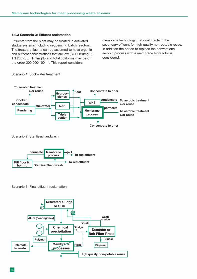
1.2.3 Scenario 3: Effluent reclamation
Effluents from the plant may be treated in activatedsludge systems including sequencing batch reactors.The treated effluents can be assumed to have organicand nutrient concentrations that are low (COD 120mg/L;TN 20mg/L; TP 1mg/L) and total coliforms may be ofthe order 200,000/100 ml. This report considers
membrane technology that could reclaim thissecondary effluent for high quality non-potable reuse.In addition the option to replace the conventionalaerobic process with a membrane bioreactor isconsidered.
14
Membrane technologies for meat processing waste streams
Scenario 1. Stickwater treatment
Kill floor &boning Steriliser /
Membraneprocess
permeate reject
To red effluent
To red effluent
Rendering
stickwater DAF
Hydrocy-clones
float
WHE
Concentrate to drier
To aerobic treatment
+/or reuse
condensate
Concentrate to drier
To aerobic treatment
+/or reuse
permeate
Cooker
condensate
To aerobic treatment
+/or reuse
Triplesettler
Membrane
process
handwash
F
Activated sludgeor SBR
Decanter orBelt Filter Press
Membraneprocesses
Chemicalprecipitation
Alum (contingency)
Polymer
Petentateto waste
Float
Sludge
Filtrate
Sludge
Wastesludge
Disposal
High quality non-potable reuse
Scenario 2. Steriliser/handwash
Kill floor &boning Steriliser /
Membraneprocess
permeate reject
To red effluent
To red effluent
Rendering
stickwater DAF
Hydrocy-clones
float
WHE
Concentrate to drier
To aerobic treatment
+/or reuse
condensate
Concentrate to drier
To aerobic treatment
+/or reuse
permeate
Cooker
condensate
To aerobic treatment
+/or reuse
Triplesettler
Membrane
process
handwash
F
Activated sludgeor SBR
Decanter orBelt Filter Press
Membraneprocesses
Chemicalprecipitation
Alum (contingency)
Polymer
Petentateto waste
Float
Sludge
Filtrate
Sludge
Wastesludge
Disposal
High quality non-potable reuse
Scenario 3. Final effluent reclamation
Kill floor &boning Steriliser /
Membraneprocess
permeate reject
To red effluent
To red effluent
Rendering
stickwater DAF
Hydrocy-clones
float
WHE
Concentrate to drier
To aerobic treatment
+/or reuse
condensate
Concentrate to drier
To aerobic treatment
+/or reuse
permeate
Cooker
condensate
To aerobic treatment
+/or reuse
Triplesettler
Membrane
process
handwash
F
Activated sludgeor SBR
Decanter orBelt Filter Press
Membraneprocesses
Chemicalprecipitation
Alum (contingency)
Polymer
Petentateto waste
Float
Sludge
Filtrate
Sludge
Wastesludge
Disposal
High quality non-potable reuse

1.3 Report methodology and structureThe report methodology involved an initial screening ofoptions based on the specified characteristics of thestreams in the three scenarios. This was followed by acomprehensive literature and web search. Companiesidentified as having potentially suitable products werecontacted for further details and economic data.Specific reference to the meat processing industry wasavoided and the applications were specified as ‘agro-food’ with compositions based on the scenariodescriptions. In some cases this generic descriptionmay have limited the information (particularly economic)provided by the membrane suppliers.
In the next section the report provides a brief overviewof current membrane technology options and importantdesign and operating features that would influence theselection of a particular membrane process for a givenapplication. The report then deals with the threescenarios in turn. For each scenario the streamcharacteristics described in 1.2 are discussed in termsof the implications and constraints for membraneprocessing.
1.4 An introduction to membrane technologyThis section provides a brief introduction to the salientfeatures of membrane technology discussed in thisreport. Appendix A provides supplementary informationin a tutorial format.
1.4.1 The range of membrane processes (AppendixA, Figures A1 to 3)
Membrane technology covers a broad range ofseparations including the liquid phase pressure drivenmembrane processes, as follows:
reverse osmosis (RO), which uses essentiallynonporous films to separate microsolutes (such assodium and chloride ions) from water;
nanofiltration (NF), which has nanopores and iscapable of passing monovalent ions and retainingmultivalent ions, as well as retaining relatively smallorganic molecules;
ultrafiltration (UF), which has fine micropores and iscapable of retaining macrosolutes, such as proteins,and fine colloids;
microfiltration (MF), which has micropores and iscapable of retaining bacterial cells and large colloids;
dynamic membranes, which are formed by applying a‘precoat’ material and/or retained species on a supportmatrix to achieve a separation equivalent to amembrane process (UF capabilities and even NF orRO). These membranes are dynamic in the sense thatthey can be removed and regenerated in-situ;
hybrid membrane processes, which combine one ofthe above with another operation , such as theMembrane Bioreactor (MBR) which combines abioreactor with MF or UF.
1.4.2 Membrane materials and properties (AppendixA – Figures A4 to 6)
Membranes are produced from various polymers andinorganic (usually ceramic) materials. They areproduced in flat sheets, tubes and hollow fibre formatsthat are housed in various modules (see 1.4.4 below).The way the membrane is made and the material ofconstruction determine important membranecharacteristics – pore size, hydrophobicity, surfacecharge, chemical and physical compatibility and cost.New membranes are constantly being developed andgenerally costs are steadily decreasing (see 1.4.7).
1.4.3 Performance definitions (Figure A7)
The two key performance parameters in membranetechnology are throughput and separation capability.These parameters are defined by:
Flux = volume filtered per unit membrane area per unit time, for example,
= Litres / m2 hr
Retention (of species) = 100 x {
Thus retention of 100% means that the species iscompletely retained and a retention of 0% means thatthe membrane completely transmits that species. Aconvenient, though potentially misleading, terminologyis the Molecular Weight Cut Off (MWCO) of themembrane. The MWCO is the molecular weight of thespecies that is retained at the 90% level. It is used forUF membranes (MWCOs usually range from about5,000 to 500,000) and NF membranes (MWCOs fromabout 200 to1000). However the effective MWCO varieswith operating conditions, solute conformation, solutionchemistry (pH etc) and degree of membrane fouling.
15
Membrane technologies for meat processing waste streams
1-concentration in permeateconcentration in feed }

1.4.4 Membrane modules (Figures A8 to 22)
The membrane module provides a housing for themembranes and is designed to provide effective ’fluidmanagement’ (discussed below). A membrane planttypically comprises several, possibly many, modulesconnected in series or parallel to the feed pump andaccessories. There are several module concepts asfollows:
• flat sheet modules, where membranes are placed on a porous support in thin flow channels, stacked and connected in series or parallel;
• spiral wound modules (SWM), where membranes , produced as flat sheets, are assembled in ‘leaves’ which are wrapped around a central permeate tube; flow channel spacers define the flow channel dimensions. These are the most popular design concept for large scale RO and NF plants;
• tubular modules , where membranes are housed in ‘shell and tube’ configuration with tubes typically 5 to 25mm in diameter. This is a popular arrangement for inorganic membranes, with multichannel monolith structures;
• hollow fibre modules use hollow fibres (OD from < 0.5mm to > 1.00 mm) configured in a shell and tube configuration with thousands of fibres potted into a tube. Feed may be from outside to in or vice versa;
• submerged membrane systems use hollow fibres or vertical flat plates immersed in an unpressurised tank.Permeate is driven by gravity or suction and fouling controlled by backwashing and/or air scour.
The various module concepts have advantages anddisadvantages. Module characteristics are compared inAppendix A Figure A21.
Of particular relevance to meat processing wastetreatment is the characteristic ‘fluid management andfouling control’. In brief, fluid management relates tothe use of shear forces at the membrane surface tolimit the accumulation of retained species (known asconcentration polarisation) and potential fouling (see1.4.6 below). Usually the surface shear is provided bypumped crossflow and the modules are designed toconvert the crossflow to effective polarisation control;some modules are more effective than others. Inaddition to pumping the feed across the membranesurface there are a number of ‘flux-enhancing’strategies (see 1.4.5 below) and some of these may bepertinent to the meat processing wastes.
Under some circumstances it is possible to dispensewith crossflow and operate in ‘dead-end’ mode (Figure
A22) with intermittent backwashing to remove depositson the membrane surface. The dead-end approachtends to be well suited to feeds that have low solidscontent, such as scenario 2.
1.4.5 Flux-enhancing strategies (Figures A23 to A24)
Various techniques are used to improve flux and/or slowthe rate of fouling. Most of these techniques increase thelocal shear at the membrane surface, and this usuallyinvolves additional energy or capital investment.However the techniques are usually justified on techno-economic grounds. Of particular interest in the scenario1 application, which appears to be highly fouling, is theuse of high shear strategies (see 2.2).
1.4.6 Fouling and cleaning (Figures A25 to A28)Fouling is the ‘irreversible’ deposition of retainedspecies onto or within the membrane. Depending onthe membrane properties and the species in the feedthe fouling may be a gradual closure of pores, ablocking or plugging of pores or cake formation, or acombination of these mechanisms. The consequencesof fouling are the loss of water permeability and achange in retention properties (an increase or decreasedepending on the circumstances). In general fouling isundesirable and can be minimised by careful selectionof membrane, module, operating strategy and possiblyby pretreatment. It should be noted that some degreeof fouling is inevitable and membrane cleaning will benecessary. Cleaning strategies (Figures A27 and A28)include physical and chemical cleaning techniques.Finding the most effective strategy often requires pilottesting.
1.4.7 Economics – cost trends (Figures A29 to A32)
Over the past 10 years there have been significantdeclines in the costs of membrane operations,particularly in the processing of raw water for waterproduction. Figure A29 shows how the installed cost forUSFilter systems has dropped by a factor of 30 overabout 10 years. Figure A30 shows data from Zenonwith a drop in water treatment costs by a factor of 10since 1995. RO desalination costs have also dropped,in this case by a factor of 3, over 10 years (Figure A31).This decline is partly due to a drop in energy costs by afactor of 6 due to improved membranes (Figure A32).Whilst the above data apply to water production theyreflect a general trend with reducing costs formembrane operations.
16
Membrane technologies for meat processing waste streams
2. Scenario 1: StickwatertreatmentFor each scenario we start with some generalconsiderations that influence membrane processselection. We then give an ‘initial screening’ based onthe stream characteristics and the applicability ofvarious membranes, modules and operating strategies.This screening also aims to identify approaches whichare unsuitable or inappropriate for this application.
2.1 General considerationsThis stream is a challenging application for membranetechnology due to the raised temperature, the highCOD, the oil and grease and the suspended solids. Itmay be able to be processed directly but some pre-treatment would be advisable. If the permeate is forreuse it will need a relatively low MWCO membrane ora two stage membrane process.
If it is possible to concentrate from an initial 20 g/Lsolids (ie 2% solids) to 10% solids this provides a 5fold concentration which reduces the volume to 20%and removes 80% of the water; thus there is a potentialfor a large saving of evaporator energy.
However it should be noted that increased feedconcentration decreases the flux. A relationship of thefollowing form usually applies:
J = a – b{Re} ln ( Cfeed )
where J is flux, a is a constant for a given feed species,b is a function of module hydrodynamics (determinedby Re number) and Cfeed is feed concentration. Thusas concentration increases J drops towards zero at acritical concentration. The implications of this is that asthe final concentration is increased the amount ofmembrane area (and capital) increases, and there is aphysical limit to the final concentration achievable. For example, as discussed in 2.3.2 (example 3), in oneapplication the flux was 75 L/m2hr at 8 wt% anddropped to 15 L/m2hr at 22 wt% and would beessentially zero at 30 wt%.
The elevated temperature of this stream would providea significantly reduced viscosity of water (at 90°C theviscosity is 32% of that at 20°C) and this would providebenefits of higher fluxes or lower transmembranepressures (TMP) for the same flux (TMP = viscosity xflux/resistance).
2.1.1 Initial ‘screening’
The membrane process will be ultrafiltration ormicrofiltration (possibly with a permeate polishing step).The membranes need to be robust and the module andoperating strategy must be suitable for a highly foulingfeed.
2.1.1.1 Appropriate technology
The following are judged to be appropriate candidatesand will be discussed in more detail in 2.2, 2.3 and 2.4:
• inorganic (or robust polymer) membranes;• high shear devices (2.2); or• tubular modules (2.3) with high crossflow or a flux
enhancing strategy; or• dynamic membranes (2.4) amenable to regeneration.
2.1.1.2 Inappropriate
A number of membrane approaches would probably beunsuitable for this application and are briefly notedbelow.
(i) Some polymer membranes – many polymermembranes would be unsuitable due to the highstream temperature. This means caution is required ifconsideration is given to polymers. (The potentialadvantage of polymer membranes is the lower cost).Some potentially suitable polymer membranes arediscussed in 2.3.1.1.
(ii) Spiral – wound modules and (small bore) hollow fibremodules – are not suitable for highly fouling feedsunless there is effective pre-treatment. The raisedtemperature may also pose a materials problem forboth of these modules.
17
Membrane technologies for meat processing waste streams
2.2 High shear devicesTo cope with the highly fouling feed it is possible thatthe best option would be to use high surface shear thatcan minimise concentration polarisation and fouling.There are two generic approaches to high sheardevices:
• Vibrating the membrane (see 2.2.1); and• Rotary motion of the membrane or the fluid above the
membrane (see 2.2.2).
2.2.1 Vibratory shear enhanced process (VSEP)
2.2.1.1 Principle
In 1992 the original concept of dynamic filtration, nowknown as the vibratory shear enhanced process(VSEP), was described by Armando et al (1992). InVSEP, vibration is used to produce high shear forces onthe membrane surface. The membranes move with alateral vibratory motion tangential to the membranesurface (Nuortila-Jokinen et al., 2003). VSEP combinescross flow with torsional oscillation of the membranesthemselves to repel suspended solids from themembrane surface (Johnson et al., 2003). Figure A24in Appendix A depicts the VSEP system.
The VSEP module is similar to a plate and framesystem with open channel flow. The filter pack consistsof leaf elements arranged as parallel discs andseparated by gaskets. The disk stack is oscillated atapproximately 60 Hz above a torsion spring that movesthe stack back and forth approximately 22 mm (7/8inches) (New Logic Int. Inc., 2003a).
Because the membrane is moving at the same rate asthe plate, high shear rates are developed at themembrane surface. In filtration applications, shearwaves cause solids and foulants to be lifted off themembrane surface and remixed with the bulk materialflowing through the membrane stack. The high surfaceshear rates can reduce the buildup of materials on themembrane surface, and liquid flows through themembrane pores relatively unhindered. According toNew Logic this can potentially increase fluxes tobetween 3 and 10 times the throughput of conventionalcross flow modules (New Logic Int. Inc., 2003a). In thissystem the feed flow is uncoupled from the sheargeneration so that the feed slurry remains nearlystationary, moving in a leisurely, meandering flowbetween the parallel membrane leaf elements.
In VSEP, the feed slurry can become extremely viscous(up to 70% solids) and still be successfully dewatered(New Logic Int. Inc., 2001, New Logic Int. Inc., 2003a).It is also claimed that VSEP is able to prevent mineralscale fouling of reverse osmosis membranes (Johnsonet al., 2003) because crystals form in the bulk liquidrather than on the membranes.
It should be pointed out that VSEP processing will notnecessarily overcome specific membrane – soluteinteractions which are driven by surface chemistry,such as adsorptive deposition or hydrophobicinteractions. However because VSEP can reduceconcentration polarisation it should reduce the localconcentration capable of interaction. This aspect willalways need to evaluated at the pilot scale.
2.2.1.2 General Performance
Shear
In conventional cross flow, the shear rate is around2,000 to 3,000 s-1 (Yi et al., 2002) (Bian et al., 1999).Higher shear can be achieved by increasing crossflowbut there is a large penalty in terms of pressure lossand energy consumption due to the relationships (forturbulent flow).
Flux Mass transfer a (crossflow velocity)0.8
Pressure loss a (crossflow velocity)1.8
Thus as crossflow doubles the flux increases by 1.7x (ifthere is no fouling) but pressure losses increase by3.5x. An optimum crossflow exists due to the trade offbetween capital and operating costs.
VSEP can combine high shear rates with low pressureloss since the membrane shear rate is created by theinertia of the fluid (Al-Aloum et al., 2002a) and not bythe feed flow, which can be very low (Al-Aloum et al.,2002b). Reported shear rates for VSEP are as high as150,000 s-1 at the membrane/ liquid interface (NewLogic Int. Inc., 2003a). Other reported shear rates are60,000 s-1 (Yi et al., 2002), 120,000 s-1 at the maximumvibratory amplitude of 25mm (1 inch) (Bian et al.,1999),and for water at 20°C the maximum and mean shearrates are 112,000 and 37,000 s-1 (Al-Aloum et al.,2002a). Importantly, the shear in a VSEP system isfocused at the membrane surface where it is costeffective and most useful in preventing fouling, whilethe bulk fluid between the membrane disks moves verylittle (New Logic Int. Inc., 2001, New Logic Int. Inc.,2003a). Thus VSEP allows nearly 99% of the totalenergy utilised to be converted to shear at the
18
Membrane technologies for meat processing waste streams
membrane surface. In contrast for a typical cross flowfiltration module only 10% of the energy is converted tosurface shear.
System design and operation
At the core of VSEP is a patented resonating drivesystem. The VSEP apparatus is composed of four maincomponents, ie the drive system which generatesvibration, the filter pack with membranes, torsion springwhich transfers vibration to the filter pack and thevibration control system (Bian et al., 1999, New LogicInt. Inc., 2003a). Shearing is produced by the torsionoscillation of the filter stack. Typically the stackoscillates with an amplitude of 19 to 32 mm peak topeak displacement at the rim of the stack. Theoscillation frequency is approximately 60 Hz andproduces a maximum shear intensity of about 150,000s-1 as mentioned above.
The system is compact and a VSEP occupying 2m2 offloor space can support up to 200m2 of membrane area(New Logic Int. Inc., 2003a).
Membranes
New Logic offers a very wide range of polymermembranes in its filter packs. However there is noreport of using ceramic membrane in the VSEP systemand New Logic confirmed that they have not triedthem. There are two probable reasons why there are noreported applications of VSEP with ceramicmembranes:
• the added weight of ceramic membranes which mayrequire a redesign of the drive and torsion spring.(However New Logic have used metal [stainless steel]membranes which implies that there may not be amajor issue with heavier structured membrane).
• there is a high probability that ceramic membraneswill break due to the high frequency vibrations (LeeFoster, 2003).
In response to a direct query New Logic stated, "Wehave not tried the ceramic membranes in our VSEPsystems. We are not sure how they would hold up tothe vibration and also the expense has kept us frominvestigating" (Michelle Monroe, New Logic).
The literature survey revealed an extensive range ofpolymeric membranes used as follows:
Teflon (Foster et al., 2002, Al-Akoum et al., 2002b),acrylic (New Logic Int. Inc., 2001), PVDF (Foster et al.,2002), polysulphone (New Logic Int. Inc., 2001),sulphonated polysulphone (Foster et al., 2002, Yi et al.,2002), polyether sulphone (Huuhilo et al., 2001, Fosteret al., 2002, Al-Akoum et al., 2002a, Al-Akoum et al.,2002b, Akoum, 2003), sulphonated polyether sulphone(Bian et al., 1999), polyester (Foster et al., 2002),polyimide sulphone (Foster et al., 2002), poly-piperazine-amide (Yi et al., 2002), regenerated cellulose(Huuhilo et al., 2001, Nuortila-Jokinen et al., 2003),aromatic polyamide/ polysulphone (Nuortila-Jokinen etal., 2003), silicone (Vane et al., 1999), nylon (New LogicInt. Inc., 2001 Al-Akoum et al., 2002a), polyamide urea(Johnson et al., 2003), aromatic polyamide (Huuhilo etal., 2001), and polypropylene (New Logic Int. Inc.,2001). Some of the above polymer membranes areclaimed to be suitable to a maximum of 900C (seebelow).
The above include both MF and UF membranes. MFranged from 0.1mm (Foster et al., 2002, Al-Akoum etal., 2002b), 0.2mm (Al-Aloum et al., 2002a), 0.3mm(Huuhilo et al., 2001) to 2mm (Foster et al., 2002). UFmembranes have been used with MWCOs ranging from2, 8, 9 kD (Foster et al., 2002), 10 kD (Huuhilo et al.,2001, Al-Akoum et al., 2002b, Akoum, 2003), 20 kD(Huuhilo et al., 2001), 30 kD (Huuhilo et al., 2001,Nuortila-Jokinen et al., 2003), 50 kD (Huuhilo et al.,2001, Al-Akoum et al., 2002a, Akoum, 2003) and 150kD (Al-Aloum et al., 2002b).
Other membrane processes such as NF (Bian et al.,1999, Foster et al., 2002, Yi et al., 2002, Nuortila-Jokinen et al., 2003, New Logic Int. Inc., 2003a, NewLogic Int. Inc., 2003b) and RO (New Logic Int. Inc.,2003a, New Logic Int. Inc., 2003b, Johnson et al.,2003) have also been evaluated.
19
Membrane technologies for meat processing waste streams
Temperature
The temperature limit on a standard VSEP system is92°C but higher temperature (140°C) constructions arealso available (New Logic Int. Inc., 2003a).
The maximum temperature for the membrane dependson the material and specifications of the membrane.The following membranes have been used in VSEP andare claimed by the manufacturers to have a maximumtemperature capability of 90°C.
Polymer membranes capable of 90°C:
Polyethersulphone (Celgard/Hoechst, Desal Systems[GEOsmonics] );
Sulphonated polysulphone;
Polyvinylidenefluoride (Celgard/Hoechst, DesalSystems); and
Aromatic Polyamide (Celgard)
Note: there are other suppliers of membranes madefrom these materials.
There are some reports of elevated temperatureapplications of VSEP using these membranes. Themost interesting are operations at about 78°C usingpolyethersulphone membranes (Foster et al., 2002),(Huuhilo et al., 2001). There are no reports ofapplications to 90°C.
Pressure
VSEP machines can routinely operate at pressures ashigh as 7 Mpa (70 bar) (New Logic Int. Inc., 2001, NewLogic Int. Inc., 2003a). According to the manufacturer,the minimum recommended pressure for the VSEP is200 Kpa (2 bars); at lower pressures there is apossibility that the membranes will slip on the supportdue to the vibrations – this could possibly be overcomeby using a membrane cartridge.
However the reported effect of pressure onperformance can be unusual. In a study carried out byHuuhilo et al. (2001) for processing of ground wood mill(GWM) water, pressure did not have any increasingeffect on the permeate flux; eg, after 4 hours offiltration at a pressure of 1 bar (lower thanrecommended) the permeate flux was 213 L/m2.h andat a pressure of 13 bar it was 205 L/m2.h. Meanwhile,the pressure affected the pure water flux (PWF) afterfiltration was 238 L/m2.h (close to the PWF beforefiltration) after the 1 bar filtration and 93 L/m2.h after the13 bar filtration; the higher the pressure, the moreirreversible fouling occurred.
Scale
Commercially available VSEP modules provide variousmembrane areas such as 150 m2 (Model i84), 60 m2(Model i36) and 22 m2 (Model i15) for industrialapplications and 0.048 m2 (Model LP) and 5 m2 (ModelP-50) for lab scale trails (New Logic Int. Inc., 2003a).The modules may be combined to supply a desiredmembrane area. Pall Corporation provides lab scalemodules (PallSep) in the range of 0.1 to 1 m2 nominalarea (Pall Corporation, 2003).
Example I below (2.2.1.3) considers a plant with thecapacity of 1 ML/d (Foster et al., 2002).
Treatment of boiler feed water at industrial scale andpower plants has been reported (New Logic Int. Inc.,2003b).
2.2.1.3 Specific Examples
Vibrating modules have been commercially availablesince 1994. Table 1 summarises a range of reportedapplications with process and flux information andAppendix B 1 provides a list of VSEP applications fromthe New Logic website.
Example 1 – Hardboard effluent processing
VSEP is being seriously evaluated by AustralianHardboards to process the effluent from the productionof Masonite (Foster et al., 2002). The characteristics ofthe effluent may be summarised as follows:
Flow >1 ML/d at 55 to 60°C
SS 2.3 g/L
TDS 10.8 g/L
TOC 7150 mg/L
COD 4043 mg/L
pH 3.6
In plant changes are aimed at reducing the effluentvolume to 35%, but the solids loads will be unchanged(concentrations increase) and temperature mayincrease to 85 to 90°C.
Due to the high TDS the process evaluation was donewith NF membranes at pressures in the range 1725 to2410 kPa. The temperatures were up to 50°C, and thepre-treatment was a 250 micron screen. During a batchprocess the fluxes started at about 165 L/m2 h (1.4%solids) and dropped to 25 L/m2 h at 33% solids; thebatch average flux was about 70 L/m2 h. The recovery
20
Membrane technologies for meat processing waste streams
of water was over 95% in this study. Due to the lowretention of sodium and small MWt organics furthertests using RO membranes are proposed; a recovery of85% is anticipated.
Comment: This example is of interest in that itdemonstrates the effectiveness of VSEP on high solidseffluent with limited pre-treatment and its ability toproduce a reusable treated permeate. It is also areference study for Australia. However the effluentprocessed differs from stickwater in terms of proteincontent and grease; also the reported tests did notapproach 90°C.
Example 2 Pulp and paper industry
A number of papers report on the cleaning of effluentsand process waters from the pulp and paper industry(Kuide et al., 1999, Konishi et al. 1998, Huuhilo et al,2001, Nuortila-Jokinen et al., 1998). The followingsummarises the work described in Huuhilo et al. 2001.The feed characteristics were,
• GWM circulation water – from an integrated pulp and paper mill
• Turbidity 200 – 1300 FTU
• TOC – 500 mg/L
• Temperature from 46 to 78°C
Tests were done in the lab and also on plant using UFmembranes (aromatic polyamide and regeneratedcellulose) with pre-treatment by screening. The fluxesobtained on plant (1300 FTU) were about 100 L/m2 h.The authors comment that during membrane selectionthey found that the more hydrophilic membranesperformed more effectively. This confirms that forsuccessful VSEP applications it is necessary to takeaccount of membrane-feed interactions.
Example 3 Concentrated effluent
The feed to the VSEP units contained between2,000–8,000 mg/L of total suspended solids (TSS), hada chemical oxygen demand (COD) of 20,000–70,000mg/L and 2,000–5,000 mg/L of oil and grease. Thepermeate concentration was reduced to approximately1 mg/L of TSS, 500 mg/L of COD, and 10 mg/L of oiland grease (New Logic Int. Inc., 2001).
2.2.1.4 Economic Factors
New Logic Int. Inc. has three different sizes of industrialmachines. These are:
• Model i15 : membrane area 15 to 22 m2; cost is approximately 188,000 USD
• Model i36 : membrane area 45 to 60 m2;
• Model i84 : membrane area 110 to 150 m2; cost is approximately 270,000 USD
The numbering identifies size, ie a 15" filter pack, a 36"filter pack and an 84" filter pack. The price is for acomplete system with a single VSEP machine and feedpump/CIP skid.
Comment:
Assuming a conservative average flux of 50 L/m2 h and16 hr day, the Model i15 (18m2) could process 14,400L/d, and the Model i36 (50 m2) could process 40,000L/d. (Recall: range for the stickwater is 5,000 to 30,000L/d).
Indicative Procesing Costs
The following assumptions are made:
(i) Feed flowrate is 30,000 litres /day;
(ii) Concentration factor is 5x so concentrate volumeis 6,000 litres and permeate is 24,000 litres/d;
(iii) A batch process with an average flux of 50 L/m2hr;
(iv) Daily operation with 16 hr batch operation and 8hrs for cleaning etc (it may be feasible to run batchover 20 hours etc);
(v) Operation for 300 days per year;
(vi) Annual capital charges are 10% of installed capitalcost; and
(vii) Capital charges represent 80% of processing costs(this is slightly higher than the value of 75% used in2.3.3.1 for inorganic tubular membranes – see thissection for basis).
21
Membrane technologies for meat processing waste streams
22
Membrane technologies for meat processing waste streams
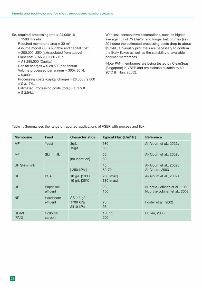
So, required processing rate = 24,000/16 = 1500 litres/hrRequired membrane area = 30 m2
Assume model i36 is suitable and capital cost = 200,000 USD (extrapolated from above)Plant cost = A$ 200,000 / 0.7 = A$ 285,000 (Capital)Capital charges = $ 28,500 per annumVolume processed per annum = 300x 30 kL = 9,000kLProcessing costs (capital charge) = 28,500 / 9,000= $ 3.17/kLEstimated Processing costs (total) = 3.17/.8 = $ 3.9/kL
With less conservative assumptions, such as higheraverage flux of 75 L/m2hr, and longer batch times (say20 hours) the estimated processing costs drop to about$2.1/kL. Obviously pilot trials are necessary to confirmthe likely fluxes as well as the suitability of availablepolymer membranes.
(Note PAN membranes are being tested by CleanSeas[Singapore] in VSEP and are claimed suitable to 80-90°C (H Han, 2003)).
Membrane Feed Characteristics Typical Flux (L/m2 h ) Reference
MF Yeast 3g/L 580 Al-Aloum et al., 2002a15g/L 80
MF Skim milk 50 Al-Aloum et al., 2002b[no vibration] 30
UF Skim milk 40 Al-Aloum et al., 2002b,[ 250 kPa ] 60-70 Al-Aloum, 2003
UF BSA 10 g/L [10°C] 200 [max] Al-Aloum et al., 2002a10 g/L [35°C] 380 [max]
UF Paper mill 28 Nuortila-Jokinen et al., 1998effluent 100 Nuortila-Jokinen et al., 2003
NF Hardboard SS 2.3 g/Leffluent 1700 kPa 70 Foster et al., 2002
2410 kPa 95
UF/MF Colloidal 100 to H Han, 2003(PAN) carbon 200
Table 1: Summarises the range of reported applications of VSEP with process and flux

2.2.1.5 Capabilities and limitations (SWOT analysis)
The strengths, weakness, opportunities and threats areanalysed in SWOT 1 below. Also included areassessments of typical fluxes and recoveries, andcomments on process issues – fouling, temperatureand membrane life.
2.2.1.6 Contacts and suppliers
(i) Michele MonroeInternational Sales ManagerNew Logic Research1295 67th St., Emeryville, CA 94608 [email protected]: + 1 707 469 7622Fax: + 1 707 469 7623
(ii) Lee FosterSPEC Engineers,[email protected]: 07 3871 0687, 0422005856
2.2.1.7 References
Al-Akoum, M. Y. Jaffrin, L. Ding, P. Paullier, C.Vanhoutte (2002a), An hydrodynamic investigation ofmicrofiltration and ultrafiltration in a vibrating membranemodule, J. Membr. Sci., 197, 37-52
O. Al-Akoum, L. Ding, R. Chotard-Ghodsnia, M. Y.Jaffrin, G. Gesan-Guizioub (2002b), Casein micellesseparation from skimmed milk using a VSEP dynamicfiltration module, Desalination, 144, 325-330
O. Al-Akoum (2003), Ultrafiltration of low-heat and UHTskim milks with a shear-enhanced vibrating filtrationsystem, Sep. Sci. Tech., 38(3), 571 - 589
A.D Armando, B. Culkin and D.B. Purchas, (1992), Newseparation system extends the use of membranes, in:Proceedings of the Euromembrane’92, Vol. 6, Lavoisier,Paris, 459-462
23
Membrane technologies for meat processing waste streams
SWOT 1 Assessment of VSEP for stickwater processing
Strengths Provides high shear to control cake formation and fouling at high solids content.The shear is directed at membrane surface and not dissipated in crossflow.Small footprint can be anticipated (high flux and vertical stacking).
Weakness Mechanical vibration limits the application of ceramic membranes.Mechanical vibration may involve considerable maintenance.Single supplier of this technology.
Opportunities VSEP could provide compact and effective separation.Identify non ceramic membrane that allows use of VSEP.
Threats Suitable membrane may not be commercially available.Some specific membrane-solute interactions could cause fouling even withvibratory control of polarisation.Potentially high capital cost unless significant flux enhancement achieved.
Typical fluxes 200 to 50 L/m2 hr, depending on feed (see Table 1).Typical recoveries 80 to 90 should be feasible.
Fouling issues Unlikely, unless specific membrane-solute interactions occur.
Temperature Ceramic membranes not appropriate for VSEP so need to identify thermally stableissues polymer membranes.
Membrane life If polymers are identified the elevated temperature operation could reduce lifetime.issues

R. Bian, Y. watanabe, N. Tambo, G. Ozawa (1999),Removal of humic substances by UF and MF membranesystems, Wat. Sci. Tech., 40(9), 121-129
R. Bian, K. Yamamoto and Y. Watanabe (2000), The effectof shear rate on controlling the concentration polarizationand membrane fouling, Desalination, 131, 225-236.
L. A. Foster, J. Scukovic, S. Singh, P. J. Foster (2002),Reducing water consumption in industry using VSEPmembrane technology- Pilot plant trails, in: Proceedingsof the IWA, Germany, 447-454
T. Huuhilo, P. Vaisanen, J. Nuortila-Jokinen, M. Nystrom(2001), Influence of shear on flux in membrane filtration ofintegrated pulp and paper mill circulation water,Desalination, 141, 245-258
G. Johnson, B. Culkin, M. Monroe (2003), Vibratory shearguards against mineral scale membrane fouling, Fil. Sep.,Jan/ Feb, 24-29
Y. Konishi, K. Takata, K. Tanida and Y. Takeo (1998),VSEP: Vibratory shear enhanced processing - Applicationof VSEP for pulp and paper industry, Jpn Tappi J., 52(8),33-40
Y. Kuide and K. Yamomoto (1999), Application of VSEPfor pulp and paper industry, Jpn Tappi J., 53(10), 76-80
New Logic Int. Inc. (2001), Is membrane fouling a thing ofthe past, Fil. Sep., Jan/ Feb, 20-21
New Logic Int. Inc. (2003a), www.vsep.com
New Logic Int. Inc. (2003b), Feed water treatment forindustrial boilers and power palnts, Fil. Sep., June, 28-29
J. Nuortila-Jokinen, A. Kuparinen, M. Nyström (1998),Tailoring an economical membrane process for internalpurification in the paper industry. Desalination, 119, 11-19
J. Nuortila-Jokinen, M. Kallioinen, M. Nyström (2003), Theeffect of operation conditions on the fouling in the VSEPfilter in the pulp and paper applications, IMSTEC03
Pall Corporation (2003), www.pall.com
K. Takata, K. Yamamoto, R. Brian and Y. Watanabe (1999)Removal of humic substances with vibratory shear-enhanced processing membrane filtration, Water Supply,17, 93-102
L. M. Vane, F. R. Alvarez, E. L. Giroux (1999), Reduction ofconcentration polarization in pervaporation using vibratingmembrane module, J. Membr. Sci. 153, 233-241
S.-H. Yi, S. Ahmed, Y. Watanabe, K. Watari (2002),Arsenic removal by MF mrmbrane with chemical sludgeadsorption and NF membrane equipped with vibratoryshear enhanced process, in: Proceedings of the IWA,Germany, 297-305
2.2.2 Rotating membrane devices2.2.2.1 Principle
The other approach to generating high shear is rotation athigh speed. There are three types of rotating membranedevice,
rotating disc or rotor above a fixed flat membrane (Type R1);
stationary housing and rotating (disc) membrane (Type R2);
- rotating cylinder membrane ( Type R3 ).
The three concepts are depicted in Figures 2 (a)–(c).
Discussion of all three types can be found in theliterature, but only types 1 and 2 are believed to becommercial. In addition these two types may be able togenerate higher shear. Our discussion will include the 3types for completeness.
For the type R1 the shear stress on the membrane hasbeen shown (Chang et al 1998., Bouzerar et al.,2000) tobe given by,
Tw = A r w1.8 r1.6 n0.2
Where A is a constant ( quoted from 0.1 to 0.3 ), r w r nare density, speed of rotation, radius and kinematicviscosity. This relationship shows the importance ofrotational speed and the benefit of increasing the radius.Two points come from this:
• shear rates can easily be > 25,000 s-1 for much of the disc ( significantly higher than crossflow devices)
• there will be a region, near the centre of the disc where r is small, with low shear
It is expected that type R2 devices will be governed by asimilar principle. The only reported analysis (Viadero andReed, 1999) on an oily waste gives,
J = f (w)0.9
This also shows the importance of rotation speed. Thereported magnitudes of fluxes are 6 times higher thanfound in a tubular module at turbulent Re.
Type R3 rotating systems may consist of a cylindricalmembrane, rotating within a stationary cylindrical shell.Toroidal Taylor vortices occur in the gap between therotating inner cylinder and the stationary outer cylinderabove a critical speed as a result of centrifugal flowinstabilities (Lee and Lueptow, 2003). The rotation of theinner cylinder results in a flow configuration that is similarto cross flow filtration except that the membrane movespast the suspension rather than the suspension flowingparallel to the membrane surface (Wereley et al., 2002).
24
Membrane technologies for meat processing waste streams

25
Membrane technologies for meat processing waste streams
Figure 2 (a) Type R1 rotating system – stationary membrane/ rotating disc
Figure 2 (b) Type R2 rotating system – rotating membrane
Figure 2 (c) Type R3 rotating system – rotating cylinder membrane
Four mechanisms could help to control deposition: (1) the axial shear due to the annular Poiseuille flowbetween the two cylinders, (2) the rotational shear dueto the circular Couette flow created by the highrotational speed of the inner cylinder, (3) the centrifugalsedimentation produced by the rotational field, and (4)the washing of particles away from the filter surface bya secondary vortical flow known as Taylor vorticesconsisting of pairs of counter-rotating toroidal vorticesthat fill the annular gap between differentially-rotatingcylinders (Schwille et al., 2002).
All three types of rotating system have been studiedand applied. The type R1 has been evaluated byBouzerar et al. (2000a,2000b), Huuhilo et al (2001) andChang et al. (1998). The type R2 was evaluated byAdach et al. (2003), Aubert et al. (1993), Leiknes et al.(2003), Murase et al. (1991), Reed et al. (1997), ViaderoJr. et al. (1999a, 1999b) and used commercially byHitachi Plant Engineering & Construction (2003) andSpinTek Filtration (2003). The type R3 was used by Leeand Lueptow (2001), Lee and Lueptow (2002), Lee andLueptow (2003), Schwille et al. (2002) and Wereley et al.(2002).
2.2.2.2 General Performance
(i) Shear
As noted above high shear is generated in all three typesand is independent of the feed flow – ie the surfaceshear is decoupled from the feed flowrate. Types R1 and2 generate shear rates of 104 to 105 s-1 whereas typetype R3 probably develops lower values. On the otherhand types R1 and R2 experience a shear distributionacross the surface and type R3 can have ahomogeneous distribution (over the cylindrical surface ).
(ii) System design and operation
Type RI has a fixed membrane and a disc or rotorspinning in close proximity to the membrane surface.The system used by Huuhilo et al (2001) was a pilotplant module (CR 1000/10) produced by Valmet Flootekwith a spinning rotor. This pilot module had a filtrationarea of 13.5 m2 and comprised 10 cells above eachother (2 membranes per cell = 20 membranes). Thediameter was about 1m and the maximum speed of therotor was 365 rpm, which corresponds to a tip velocityof about 19 m/s. Each cell has its own feed inlet,concentrate and permeate outlet.
An example of type R2 is the high shear rotary UF(HSRUF) system produced by Spintek. Its design hasbeen described by Viadero et al (1999a): "Flat, roundmembrane disk packs are set on a hollow rotating shaftinside a (fixed) cylindrical housing. The feed streamenters the membrane chamber under pressure and isdistributed across the membrane surface by hydraulicaction. The permeate is forced through the membraneunder pressure, is collected through the hollow centershaft, and is discharged. The concentrate exits thevessel at the edge of the membrane disk pack. In thissystem, hydraulic turbulence is achieved by membranerotation; thus the pump is only required to providetransmembrane pressure and a small amount ofrecirculation flow. To enhance hydraulic turbulence atthe membrane surface, stationary turbulence promotersmay be located on each side of the disk pack. Thus, itis possible to treat highly concentrated wastes usingthe HSRUF system because the cleaning action iseffectively decoupled from feed pressurization/recirculation" (Viadero Jr. et al., 1999a). The HSRUF isquoted as having a maximum rotational speed as highas 1750 rpm. Viadero used a pilot unit of 20cmdiameter, but larger are available – see scale below. Inthis type of rotary system, liquid velocities are quotedas around 18 m/s (Viadero Jr. et al., 1999b) to 20 m/s(SpinTek Filtration, 2003).
The type R3 rotating filter is a porous inner cylinderrotating concentrically within an outer non-porouscylinder. The suspension enters the annular gap at oneend of the annulus. Filtrate passes through the innerporous cylinder and is removed through a hollow shaft.Concentrate is removed from the annular gap at theend of the device opposite the suspension entrance(Schwille et al., 2002). Rotational speeds of several100s rpm are reported.
(iii) Membranes
Three categories of membranes i.e. polymeric, ceramicand metallic can be used in rotating systems (SpinTekFiltration, 2003). The membranes cover a wide range ofpore sizes from 200 MWCO to 3 micron (SpinTekFiltration, 2003). The reported membrane types are MF(Wereley et al., 2002; SpinTek Filtration, 2003), MF (0.1mm) (Aubert et al., 1993), MF (0.45 µm) (Chang et al.,1998; Adach et al., 2003), UF (Viadero Jr. et al., 1999a;Viadero Jr. et al., 1999b; SpinTek Filtration, 2003;Hitachi Plant Engineering & Construction, 2003), UF(100 kD) (Reed et al., 1997), UF (750 kD) (Leiknes et al.,2003), NF (SpinTek Filtration, 2003) and RO (Lee andLueptow, 2001; Lee and Lueptow, 2002).
26
Membrane technologies for meat processing waste streams

The reported polymers for rotating systems arepolyethylene terphtalate (PET) (Adach et al., 2003), nylon(Chang et al., 1998; Adach et al., 2003), PVDF (Reed etal., 1997; SpinTek Filtration, 2003) and polysulphone(Leiknes et al., 2003; SpinTek Filtration, 2003).
Ceramic membranes including UF ((Viadero Jr. et al.,1999a; Viadero Jr. et al., 1999b; Reed et al., 1997) andMF (Murase et al., 1991) are made from TiO2, Al2O3(Viadero Jr. et al., 1999a; Viadero Jr. et al., 1999b; Reed etal., 1997; SpinTek Filtration, 2003), Zr2O or combinationof the three (SpinTek Filtration, 2003). Metallicmembranes are prepared from stainless steel with poresizes from 1 to 10 micron (SpinTek Filtration, 2003).
(iv) Temperature
The reported temperatures in rotating systems have notbeen very elevated but in principle and with suitablemembranes they should be capable of 90°C. The typeR1 fixed membrane with rotor used by Huuhilo et al(2001) was operated at up to 78°C with polymermembranes. Tests with oily wastes with the (typeR2)HSRUF at 43°C to 60oC are described by Viadero Jr. etal.,(1999a, 1999b ) and (Reed et al., 1997). Over thistemperature range flux increased from 370 to 542L/m2.h (Reed et al., 1997). (These are very high fluxesfor oily wastes).
(v) Scale
In general, rotating systems will be limited in diameterdue to material stress considerations (stress increaseswith [diameter]2). In terms of capacity Spin Tek havesystems ranging from 1 to 10,000 litres per hour(SpinTek Filtration, 2003). This upper limit is equivalentto 240,000 Litres per day. (Recall the range forstickwater is 5,000 to 30,000 L/d).
2.2.2.3 Specific Examples
Example 1 Stickwater
Smith and Leung (1999) studied UF to recover proteinfrom waste edible stickwater (from meat processing).Various module geometries were tested including aspiral wound membrane, ceramic monolith membrane(see 2.3 ) and rotating membranes. Two feed streamswere tested. It was found that the feed typicallyconcentrated from 4% wt/wt to 20–25% wt/wt totalsolids by recycling while the flux dropped from about45–75 L/m2hr to 7.5–15 L/m2hr. The MWCO for themembranes tested was in the range 5,000 to 50,000
with recovery of the protein typically about 85%. Twodifferent rotating PVDF membranes were tested; onehad a stationary housing and rotating membrane (typeR2) and the other a rotating housing. In addition to theuse of centrifugal force associated with the rotatingmembrane, further shear was generated from flowthrough the narrow gap between the stationary housingand the rotating membrane and this helped to reducethe concentration build-up (polarisation) adjacent to themembrane surface. Under certain operating conditions,secondary flows can also be generated with thisgeometry which further minimise concentrationpolarisation resulting in a higher flux. The system withthe rotating membrane and stationary housing (type R2)performed better with fluxes 2 times those of type R3.
Other Applications
Other examples of applications include pulp and papermill process steams (Huuhilo et al (2001) – type R1device), and oily wastewaters (Viadero Jr. et al.,(1999a,1999b ) and (Reed et al., 1997) – type R2). Spin Tekquote (SpinTek Filtration, 2003) the following successfulapplications for their type R2 devices:
• vanilla extract bacterial filtration;
• latex recovery (up to 50%);
• yeast concentration (to above 35%);
• biodigestor sludge concentration; and
• blood plasma fractionation.
All of the above are particularly challenging applicationsof membranes.
2.2.2.4 Economic Factors
Spin Tek, who supplied the Type R2 systems successfullyused on stickwater (see Example 1 above), provided thefollowing quotations for the lower and upper capacitiesand for 5 times concentration of the feed (quotations inUS $ converted to A $ by factor 1:0.7)
Capacity: 5,000 L/d model Spin Tek ST-II-15 (15 ceramic discs) US$ 95,000 (A$ 136K);
Capacity: 30,000 L/d model ST-II-25 (25 ceramic discs)US $ 190,000 (A$ 271K).
Assuming:
• 300 days/yr operation
• annual capital charges are 10% of installed capital cost
27
Membrane technologies for meat processing waste streams
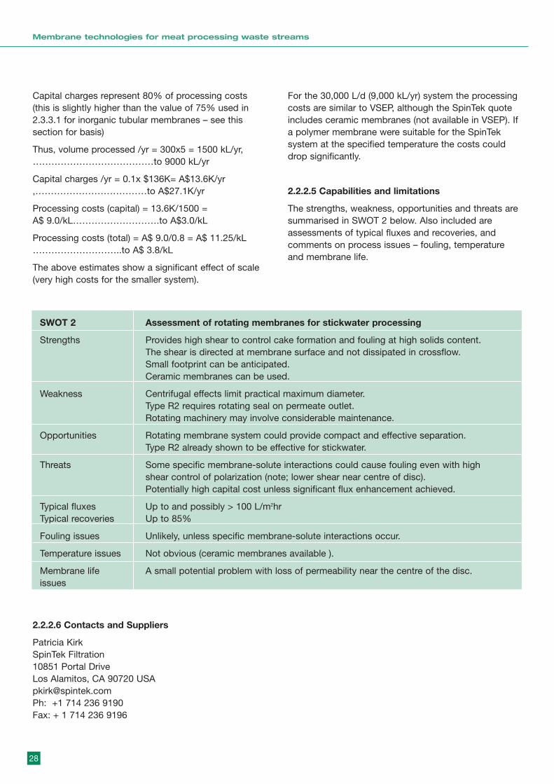
Capital charges represent 80% of processing costs(this is slightly higher than the value of 75% used in2.3.3.1 for inorganic tubular membranes – see thissection for basis)
Thus, volume processed /yr = 300x5 = 1500 kL/yr,…………………………………to 9000 kL/yr
Capital charges /yr = 0.1x $136K= A$13.6K/yr,………………………………to A$27.1K/yr
Processing costs (capital) = 13.6K/1500 = A$ 9.0/kL……………………….to A$3.0/kL
Processing costs (total) = A$ 9.0/0.8 = A$ 11.25/kL………………………..to A$ 3.8/kL
The above estimates show a significant effect of scale(very high costs for the smaller system).
For the 30,000 L/d (9,000 kL/yr) system the processingcosts are similar to VSEP, although the SpinTek quoteincludes ceramic membranes (not available in VSEP). Ifa polymer membrane were suitable for the SpinTeksystem at the specified temperature the costs coulddrop significantly.
2.2.2.5 Capabilities and limitations
The strengths, weakness, opportunities and threats aresummarised in SWOT 2 below. Also included areassessments of typical fluxes and recoveries, andcomments on process issues – fouling, temperatureand membrane life.
28
Membrane technologies for meat processing waste streams
SWOT 2 Assessment of rotating membranes for stickwater processing
Strengths Provides high shear to control cake formation and fouling at high solids content.The shear is directed at membrane surface and not dissipated in crossflow.Small footprint can be anticipated.Ceramic membranes can be used.
Weakness Centrifugal effects limit practical maximum diameter.Type R2 requires rotating seal on permeate outlet.Rotating machinery may involve considerable maintenance.
Opportunities Rotating membrane system could provide compact and effective separation.Type R2 already shown to be effective for stickwater.
Threats Some specific membrane-solute interactions could cause fouling even with highshear control of polarization (note; lower shear near centre of disc).Potentially high capital cost unless significant flux enhancement achieved.
Typical fluxes Up to and possibly > 100 L/m2hrTypical recoveries Up to 85%
Fouling issues Unlikely, unless specific membrane-solute interactions occur.
Temperature issues Not obvious (ceramic membranes available ).
Membrane life A small potential problem with loss of permeability near the centre of the disc.issues
2.2.2.6 Contacts and Suppliers
Patricia KirkSpinTek Filtration10851 Portal DriveLos Alamitos, CA 90720 [email protected]: +1 714 236 9190Fax: + 1 714 236 9196
2.2.2.7 References
A. Adach, S. Wronski, M. Buczkowski, W. Starosta, B.Sartowska (2002), Mechanism of microfiltration on therotating track membrane, Sep. Purific. Technol. 26,33–41
M.-C. Aubert, M.-P. Elluard and H. Barnier (1993), Shearstress induced erosion of filtration cake studied by a flatrotating disk method. Determination of the critical shearstress of erosion, J. Membr. Sci.,84, 229-240
R. Bouzerar, L. Ding, M. Y. Jaffrin (2000a), Localpermeate flux–shear–pressure relationships in a rotatingdisk microfiltration module: implications for globalperformance, J. Membr. Sci., 170, 127–141
R. Bouzerar, M. Y. Jaffrin, L. Ding, and P. Paullier (2000b),Influence of geometry and angular velocity onperformance of a rotating disk filter, AIChE Journal, 46(2),257-265
S. Chang, H. Li and A. G. Fane (1998), Characteristics ofoperation of a rotating disk membrane filter, inEnvironmental Engineering Research Events, edited byA. I. Schafer, L. Basson and B. S. Richards, AvocaBeach, NSW, Australai, 153-158
Hitachi Plant Engineering & Construction (2003),www.hitachiplant.hbi.ne.jp
S. Lee, R. M. Lueptow (2001), Rotating reverse osmosis:a dynamic model for flux and rejection, J. Membr. Sci.,192, 129–143
S. Lee, R. M. Lueptow (2002), Experimental verificationof a model for rotating reverse osmosis, Desalination146, 353-359
S. Lee, R. M. Lueptow (2003), Control of scale formationin reverse osmosis by membrane rotation, Desalination,155, 131-139
T. Leiknes, H. Ødegaard, H. Ohme, M. Lazarova (2003),Ozonation/ biofiltration for NOM-removal using rotatingdisk membranes, IMSTEC03
T. Murase, C. Pradistsuwana, E. Iritani and K. Kano(1991), Dynamic microfiltration of dilute slurries with arotating ceramic membrane, J. Membr. Sci. 62(2), 187-199
B. E. Reed, W. Lin, R. Viadero Jr. and J. Young (1997),Treatment of oily wastes using high-shear rotaryultrafiltration, J. Envir. Eng., December, 1234-1242
J. A. Schwille, D. Mitra, R. M. Lueptow (2002), Designparameters for rotating cylindrical filtration, J. Membr.Sci., 204, 53–65
SpinTek Filtration (2003), www.spintek.com
R. C. Viadero Jr., R. L. Vaughan Jr., B. E. Reed (1999a),Study of series resistances in high-shear rotaryultrafiltration, J. Membr. Sci., 162, 199-211
R. C. Viadero Jr.and B. E. Reed (1999b), Rotation andconcentration effects in high-shear ultrafiltration, J. Envir.Eng., July, 638-646
S. T. Wereley, A. Akonur, R. M. Lueptow (2002),Particle–fluid velocities and fouling in rotating filtration ofa suspension, J. Membr. Sci., 209, 469–484
2.3 Tubular modules
2.3.1 Principle and general performanceTubular modules are particularly favoured for dirty feeds.The concept has the membranes in a ‘shell and tube’configuration with tubes typically 5 to 25mm in diameter(such as Figure A16 in Appendix A). The arrangementapplies to both polymeric and inorganic membranes. Forpolymer membranes it is usual to have the membranesinserted into support tubes which can handle relativelyhigh pressures although some polymeric tubularmembranes are self supporting at low pressure. Thetubular module is a popular arrangement for inorganicmembranes, with multichannel monolith structures.
Tubular modules are operated in the conventionalcrossflow mode with tubes connected in series orparallel depending on the application. For a tubeprocessing a water-like feed at a crossflow velocity of 1 m/s (relatively modest) the Reynolds number Re = 106 x (tube dia). For a tube of 10mm diameter the Re is104 which is clearly in the turbulent regime, and this ischaracteristic of the tubular module. The performance isdetermined by the flow Reynolds number which controlssurface mass transfer and pressure losses. Thecharacteristic relationships are:
Flux = f (Re)0.8 , [increase in crossflow increases flux]Pressure Loss = f (Re)1.8 , [pressure loss more sensitive toRe]
The above relationships suggest a potential trade off toselect the optimal crossflow to minimise capital andoperating cost. It is commonly accepted that the‘turbulent flow’ tubular module is energy inefficient withenergy usages up to 10 kWh/m3 processed, but it is thetraditional approach for dirty feeds.
29
Membrane technologies for meat processing waste streams

2.3.1.1 Membrane materials
POLYMER
Several polymers are used for the manufacture oftubular membranes and have a wide range of poresizes for UF applications. Commonly used polymers arebased on engineering polymers like polysulfone (PS),polyacrylonitrile (PAN), polyvinylidene-fluoride (PVDF),polyethersulfone (PES) and polyamide (PA). Several of
these materials are relatively robust in terms oftemperature limit and pH tolerances. Most are quiteresistant to oxidising agents such as hypochlorite.Table 2 summarises allowable operating conditions ofthe common polymers based on manufacturersspecifications in the membrane handbook (Ho andSirkar, 1992 ). It is apparent that some polymer tubularmembranes may be applicable to the 90°C applicationbeing considered.
30
Membrane technologies for meat processing waste streams
Polymer type Maximum T (°C) pH range Comment Supplier
Polysulphone (PS) 90 1-13 some quote 100C Osmonics
Polyether sulphone (PES) 90 1-13 Koch, Daicel
Polyacrylonitrile (PAN ) 60 2-10 PCI80 CleanSeas
Polyvinylidene-fluoride (PVDF) 90 1-11 Koch
Polyamide (PA) 80 2-12 Flat sheet Hoechst
INORGANIC – CERAMICS
A range of inorganic membranes, typically inert mineralalumina or other ceramic materials (for example,zirconium dioxide and titanium dioxide) are available.These membranes are highly resistant to organic andinorganic solvents over the entire pH range and canhandle high pressures and temperatures. Inorganicmembranes do have some disadvantages compared topolymeric ones, especially with respect to the highprice per square metre of membranes. The use of ahigh packing density support, such as the ‘honeycomb’support of the Ceramem membrane reduces the costper unit membrane area as well as associated systemscosts to levels that may be competitive with tubularpolymeric membranes. (Schröeder et al., 2002). Theinorganic membrane should have a longer lifetime (say3 times or more, see Table 4) than typical polymericmembranes, unless it becomes irreversibly fouled.
One example of commercially available ceramicmembranes is the Membralox® product. Ceramicmembranes are constructed from multiple ceramiclayers and formed into an asymmetric, multi-channel
element. The ceramic membranes are manufacturedusing alumina, zirconia or titania depending on thedesired pore size of the membrane and then sinteredonto an alpha alumina support. Microfiltration (MF)membranes with pore diameters 0.1 mm and higher aremade of pure alpha alumina and UF (20 nm to 100 nmpore size) membranes are made of zirconia. Severalmembrane pore sizes are available to suit specificfiltration needs – in MF/UF ranges. Table 3 gives thecharacteristics of these ceramic membranes. Ceramicmembrane elements are available from severalmanufacturers in different shapes (round, hexagonal)and with various feed channel diameters. The multi-channel construction of the membrane elementprovides a higher membrane packing density than atubular element of the same length. The ceramicmembrane elements have sealing gaskets attached ateach end, and then are assembled within housings,available in 316L SS (standard), PVDF, or other alloys(Sondhi et al., 2002).
A qualitative comparison of polymeric and ceramictubular membranes is shown in Table 3.
Table 2: Manufacturers maximum temperature and pH range for various polymer membranes
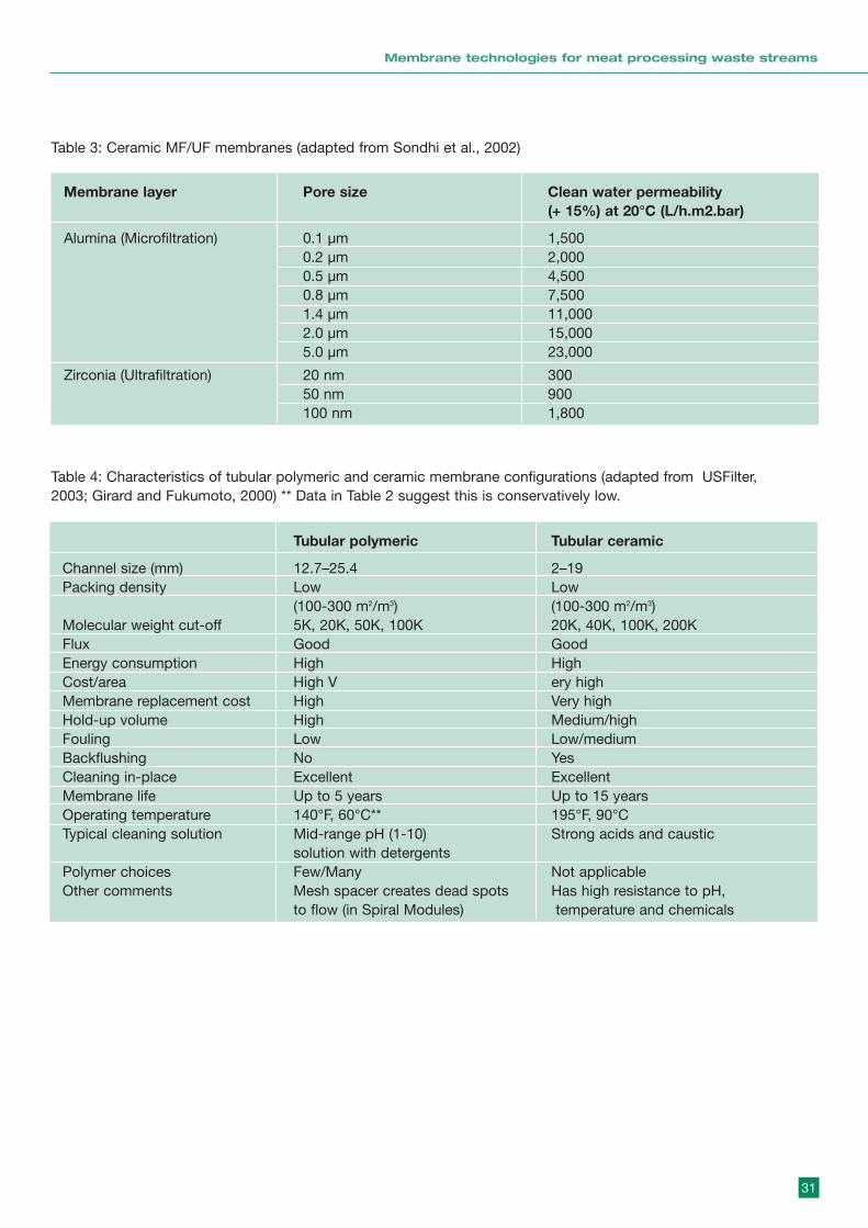
31
Membrane technologies for meat processing waste streams
Table 3: Ceramic MF/UF membranes (adapted from Sondhi et al., 2002)
Membrane layer Pore size Clean water permeability(+ 15%) at 20°C (L/h.m2.bar)
Alumina (Microfiltration) 0.1 µm 1,5000.2 µm 2,0000.5 µm 4,5000.8 µm 7,5001.4 µm 11,0002.0 µm 15,0005.0 µm 23,000
Zirconia (Ultrafiltration) 20 nm 30050 nm 900100 nm 1,800
Tubular polymeric Tubular ceramic
Channel size (mm) 12.7–25.4 2–19Packing density Low Low
(100-300 m2/m3) (100-300 m2/m3)Molecular weight cut-off 5K, 20K, 50K, 100K 20K, 40K, 100K, 200KFlux Good GoodEnergy consumption High HighCost/area High V ery highMembrane replacement cost High Very highHold-up volume High Medium/highFouling Low Low/mediumBackflushing No YesCleaning in-place Excellent ExcellentMembrane life Up to 5 years Up to 15 yearsOperating temperature 140°F, 60°C** 195°F, 90°CTypical cleaning solution Mid-range pH (1-10) Strong acids and caustic
solution with detergentsPolymer choices Few/Many Not applicableOther comments Mesh spacer creates dead spots Has high resistance to pH,
to flow (in Spiral Modules) temperature and chemicals
Table 4: Characteristics of tubular polymeric and ceramic membrane configurations (adapted from USFilter,2003; Girard and Fukumoto, 2000) ** Data in Table 2 suggest this is conservatively low.
2.3.2 Specific Examples
Example 1 Cane juice
In the filtration of sugar cane juice, ceramic membranesare used in several different stages in the raw and refinedsugar production. One interesting opportunity is in theMF/UF of clarified juice (7–14 Brix) and/or pre-evaporatedjuice (20–25 Brix) as a pretreatment prior to ion exchangeor chromatographic separations. Pretreated and filteredjuice is softened, evaporated and purified using ionexchange and chromatographic processes leading to abetter quality refined sugar. Typical operating conditionsinclude feed temperatures of 90–100ºC, high cross-flowvelocities (4–7 m/s) and transmembrane pressures up to5 bar (Sondhi et al., 2002).
Example 2 Cleaning solution regeneration
In the food and beverage industry, hot caustic solutionsare used to clean a variety of equipment such as tanks,mixers, evaporators and crystallisers. This is necessary tomaintain proper sanitary conditions between batches.The spent caustic solutions contain suspended solids(pulp, low molecular weight proteins, organic polymers,oligosaccharides, etc) and additives such as wettingagents and surfactants. Ceramic membranes are able toretain the suspended solids and allow permeation of theadditives. Typical operating conditions include feedtemperatures of 50–70ºC, high cross-flow velocities (4–7m/s) and transmembrane pressures up to 5 bar (Sondhiet al., 2002).
Example 3 Stickwater
There are 3 studies particularly relevant to Stickwater asfollows,
(i) Fish Meal. From a study by Dornier and Bennasar(1991), proteins in stickwater remaining after fish mealmanufacture were concentrated by cross-flow filtrationon Membralox membranes (alumina with 0.2 mm poresand zirconia with 0.1 mm pores). Filtration was carriedout at a temperature of 60ºC, transmembrane pressureof 1.5 bar and a cross-flow velocity of 5 m/s. The feedconcentrations varied from about 110 to 160 g/L totalsolids. Tests without concentration showed a flux ofabout 130 L/m2hr using the zirconia 0.1 mm poremembrane and 90 dropping to 60 L/m2hr for thealumina 0.2 mm pore membrane. It was assumed thatthe larger pore membrane was subject to more internalfouling. Tests with concentration, using the 0.1 mmpore, showed an initial flux of 130 L/m2hr dropping to16 L/m2hr at a concentration factor of about 8.0.
Unfortunately extreme protein degradation in thestickwater limited the recovery of total nitrogen toapproximately 20% for both membranes and this isexplained by the high proportion of non-proteincompounds contained in stickwater. The results ofDornier and Bennasar are not encouraging and suggestthat tighter membranes should have been used.
(ii) Meat Processing. Smith and Leung (1999) studied theuse of UF to recover protein from waste ediblestickwater (meat processing). Various modulegeometries were tested including a spiral woundmembrane, ceramic monolith membrane and rotatingmembrane (as described in 2.2.2.3). Two feed streamswere tested; a temperature of about 70°C ismentioned. It was found that the feed typicallyconcentrated from 4% wt/wt to 20–25% wt/wt totalsolids by recycling while the flux dropped from about45–75 L/m2hr to 7.5–15 L/m2hr. The MWCO for themembranes tested was in the range 5,000 to 50,000with recovery of the protein typically about 85%. Theceramic monolith membrane achieved fluxes similar tothe rotating membrane (type R2) and 5 times thoseobtained with the spiral wound module. The fluxeswere approximately:
• 75 L/m2hr at 8 wt% solids
• 15 L/m2hr at 22 wt% solids
The results of Smith and Leung are encouraging andshow the importance of membrane (MWCO) and moduleselection.
(iii) Slaughterhouse. Reimann (2003) recently reported theapplication of tubular MF to the processing ofslaughter house waste water. The feed had a COD ofabout 2220 mg/L (significantly less than the Scenario1 feed of 100,000 mg/L) and there was no mention ofelevated temperature processing. The membranesused were alumina of 19 and 15 mm diameter andpore size 0.1 mm; this is in the MF range. Themodules were operated with a crossflow of 6.3 m/s(this is a high value and energy expensive) and at 1and 2 bar. Initial fluxes were about 160 L/m2hrdropping to 140–70 L/m2hr over a period ofconcentration (no figures were provided for theconcentration factor). These reported fluxes are high,probably because the solids content was relatively low(recall equation in section 2.1).
Example 4 Wool scour rinse water
This example was initially looking at the application ofdynamic membranes (see 2.4.3.1) but is now using
32
Membrane technologies for meat processing waste streams
ceramic membranes (C H Steenkamp, 2003). Themembrane plant uses Membralox ceramic membranes(supplied by SCT in France) with 20 nm pore size and aflux of 300 to 400 L/m2hr (a very high flux, possibly thewater flux). The operators find a significant rejection ofcolour and salts, probably due to a ‘secondary’ dynamicmembrane formation from keratin in the feed. The planthas 4 x 19 element modules with an area of 3.8 m2 each.The total area is 15.2 m2 and the operating cost isestimated at US 50c/m3. The recovery achieved is 85%with the recovered water suitable for reuse in the rinsephase. Cleaning is once per week.
Example 5 ‘ Capillary’ (hollow fibres) and dirty feeds
Capillary hollow fibres are large bore fibres that are on theborder line of tubular membranes. They have the potentialadvantage over conventional hollow fibres of being lesseasily blocked. One example is provided by CleanSeasCompany in Singapore. They produce hollow fibres of3mm ID and claim that with a good pre-screening theycan handle heavily polluted waste water, such as piggerywaste. The maximum operating temperature claimed fortheir PAN polymer membranes is 80°C. The advantage ofthe CleanSeas polymer membranes would be their lowcost (standard modules at A$ 25 to 60/m2).
2.3.3 Economic Factors
Specific economic data are difficult to obtain fromsuppliers. The following are some ‘ball park’ figures forreference;
(i) Relative costs of tubular polymeric and ceramic
Installed plant costs, ceramic / polymer are in the range1.4 to 2.5 (Ho and Sirkar, 1992 Table 35-4, and Fane andVigneswaran, 1993). Although ceramic membranes maybe 4 to10 times the cost of polymer membranes the factthat the membranes are only about 15 to 35% of theinstalled cost reduces the installed cost ratio.
(ii) Ceramic module costs
The CeraMem Corporation produces a novel honeycombmodule which is claimed to be cheaper than moreconventional modules. CeraMem provided the followingcost information, "Our production scale UF membranemodules (elements in housings) sell for about $87 persquare foot (115 sq. ft module). As our production volumeincreases and we make improvements in our modules,we anticipate selling for $40 to $50 per square foot. We
are only supplying membrane modules, not systems, andcannot comment on systems costs".
This equates to about A$ 1250/m2, potentially dropping toA$ 715 to 570/m2 ( assuming A$ = 0.7USD). Note forcomparison the costs quoted in Example 5 above for ‘lowcost’ polymer membranes, at A$ 25 to 60/m2.
2.3.3.1 Indicative processing costs
The following is a rough estimation of processing costsusing an inorganic membrane of cost similar toCeraMem. The following assumptions are made:
(i) Feed flowrate is 30,000 litres/day;
(ii) Concentration factor is 5x so concentrate volume is6,000 litres and permeate is 24,000 litres/day;
(iii) A batch process with an initial flux of 50 dropping to10 L/m2hr, so an ‘average’ of about 25 L/m2hr overthe batch;
(iv) Daily operation with 16 hr batch operation and 8 hrsfor cleaning etc (it may be feasible to run batch over20 hours etc);
(v) Operation for 300 days per year;
(vi) Annual capital charges are 10% of installed capitalcost;
(vii) Capital charges represent 75% of processing costs(energy + labour + chemicals makes up theremaining 25%), based on survey data (Fane &Vigneswaran (1993) which shows for ceramicmembranes the capital charges to be in the range 70to 80% of processing costs;
(viii) Modules are 35% of plant cost (estimated from Ho and Sirkar, 1992 Table 35-4 for ceramics)
For module costs of A$ 1250 /m2 (as quoted by Ceramem)
With less conservative assumptions:
(a) lower ceramic membrane costs (say A$ 715/m2 – asmooted above) and longer batch times (say 20 hours),the estimated processing costs drop by about 50% to$ 1.5 /kL.
(b) low cost polymer capillary membranes havemembrane costs < 10% of the above, and if they wereviable they could cut processing costs to
33
Membrane technologies for meat processing waste streams
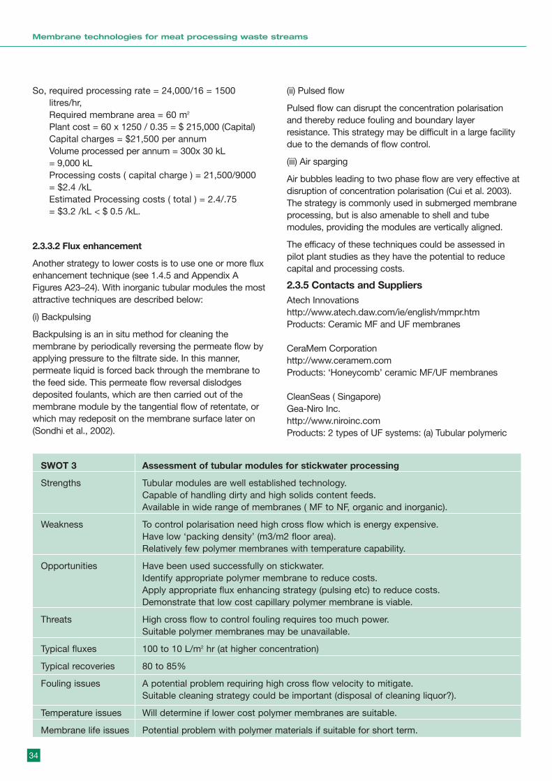
So, required processing rate = 24,000/16 = 1500litres/hr,Required membrane area = 60 m2
Plant cost = 60 x 1250 / 0.35 = $ 215,000 (Capital)Capital charges = $21,500 per annumVolume processed per annum = 300x 30 kL = 9,000 kLProcessing costs ( capital charge ) = 21,500/9000 = $2.4 /kLEstimated Processing costs ( total ) = 2.4/.75 = $3.2 /kL < $ 0.5 /kL.
2.3.3.2 Flux enhancement
Another strategy to lower costs is to use one or more fluxenhancement technique (see 1.4.5 and Appendix AFigures A23–24). With inorganic tubular modules the mostattractive techniques are described below:
(i) Backpulsing
Backpulsing is an in situ method for cleaning themembrane by periodically reversing the permeate flow byapplying pressure to the filtrate side. In this manner,permeate liquid is forced back through the membrane tothe feed side. This permeate flow reversal dislodgesdeposited foulants, which are then carried out of themembrane module by the tangential flow of retentate, orwhich may redeposit on the membrane surface later on(Sondhi et al., 2002).
(ii) Pulsed flow
Pulsed flow can disrupt the concentration polarisationand thereby reduce fouling and boundary layerresistance. This strategy may be difficult in a large facilitydue to the demands of flow control.
(iii) Air sparging
Air bubbles leading to two phase flow are very effective atdisruption of concentration polarisation (Cui et al. 2003).The strategy is commonly used in submerged membraneprocessing, but is also amenable to shell and tubemodules, providing the modules are vertically aligned.
The efficacy of these techniques could be assessed inpilot plant studies as they have the potential to reducecapital and processing costs.
2.3.5 Contacts and SuppliersAtech Innovations http://www.atech.daw.com/ie/english/mmpr.htmProducts: Ceramic MF and UF membranes
CeraMem Corporationhttp://www.ceramem.comProducts: ‘Honeycomb’ ceramic MF/UF membranes
CleanSeas ( Singapore)Gea-Niro Inc.http://www.niroinc.comProducts: 2 types of UF systems: (a) Tubular polymeric
34
Membrane technologies for meat processing waste streams
SWOT 3 Assessment of tubular modules for stickwater processing
Strengths Tubular modules are well established technology.Capable of handling dirty and high solids content feeds.Available in wide range of membranes ( MF to NF, organic and inorganic).
Weakness To control polarisation need high cross flow which is energy expensive.Have low ‘packing density’ (m3/m2 floor area).Relatively few polymer membranes with temperature capability.
Opportunities Have been used successfully on stickwater.Identify appropriate polymer membrane to reduce costs.Apply appropriate flux enhancing strategy (pulsing etc) to reduce costs.Demonstrate that low cost capillary polymer membrane is viable.
Threats High cross flow to control fouling requires too much power.Suitable polymer membranes may be unavailable.
Typical fluxes 100 to 10 L/m2 hr (at higher concentration)
Typical recoveries 80 to 85%
Fouling issues A potential problem requiring high cross flow velocity to mitigate.Suitable cleaning strategy could be important (disposal of cleaning liquor?).
Temperature issues Will determine if lower cost polymer membranes are suitable.
Membrane life issues Potential problem with polymer materials if suitable for short term.
membrane systems (b) Tubular Ceramic membrane systems.
Koch Membrane Systemshttp://www.kochmembrane.comProducts: Tubular polymeric UF membranes
Norit X-Flowhttp://www.x-flow.com/import/bestanden/pdf/CLAS-ALL-0242.pdfProducts: X-Flow COMPACT and CLASSIC Tubular UFmembranes: PVDF and Hydrophilic polysulphone
PCI Membraneshttp://www.pcimem.comProducts: Tubular polymeric PVDF membranes
Tami Industries http://www.tami-industries.com/products/ceramuk.aspProducts: 2 types of tubular ceramic membranes: (a)CéRAM INSIDE membrane (b) PURE TITANIUM FILTERmembrane.
USFilter http://www.usfilter.comProducts: 2 types of UF systems: (a) Tubular polymericmembrane systems (b) Ceramic membrane systems.
2.3.6 ReferencesCEPIS, 2003,http://www.cepis.org.pe/muwww/fulltext/epa/pcsi/pcscap08.html, Accessed on 7 July 2003.
Z.F.Cui, S.Chang and A.G.Fane, The use of gas bubblingto enhance membrane processes, Journal of MembraneScience 221 (1-2) (2003) 1-36.
M. Dornier, M. Bennasar, Recovery of protein instickwater from the manufacture of fish meal: cross-flowfiltration on inorganic membranes, Industries Alimentaireset Agricoles 108(11) (1991) 953-960.
W. Doyen, W. Adriansens, B. Molenberghs, R. Leysen, Acomparison between polysulfone, zirconia and organo-mineral membranes for use in ultrafiltration, Journal ofMembrane Science 113 (1996) 247-258.
A.G.Fane and S.Vigneswaran, Membrane Technology forWater Treatment, Report to Sydney Water (1993).
B. Girard, L.R. Fukumoto, Membrane processing of fruitjuices and beverages: A review, Critical Reviews inBiotechnology 20(2) (2000) 109-175.
W. Ho and K.Sirkar, ‘Membrane Handbook’, VanNostrand Reinhold (1992)
Koch Membrane Systems, 2003, Industrial water andwastewater,http://www.kochmembrane.com/APPLICATIONS/IWW.html, Accessed on 25 August 2003.
PCI Membranes, 2003, Membrane Information,http://www.pcimem.com, Accessed on 7 July 2003.
K-J. Schröder, T. Boger, K. Drury, G. Lachut, P. Makris, Anew generation of ceramic membranes with excellentspace and cost efficiency, Journal of the Filtration Society2(4) (2002) 9-11.
R. Sondhi, R. Bhave, G. Jung, Ceramic membranes:Applications and benefits – from "A" to "Z", Fluid/ParticleSeparation Journal 14(2) (2002) 130-134.
P.T. Smith, W.F. Leung, Recovery of protein from ediblestickwater using ultrafiltration, Advances in filtration andseparation technology 13A (1999) 466-474.
C H Steenkamp, Gubb and Inggs (personalcommunication – email 030903)
USFilter, 2003, Ultrafiltration systems for waste watertreatment, http://www.usfilter.com Accessed on 25August 2003.
2. 4 Dynamic Membranes2.4.1 Principle
Although membrane technology has been widely used inwaste water processing the treatment of high strength,highly fouling or hot industrial effluents by conventionalmembrane technology is problematic. The dynamicmembrane could be a good choice to treat this highstrength wastewater. The advantages of dynamicmembranes are high permeability, ease of removal andthe possibility of membrane formation by a range ofinorganic or organic materials.
There are two basic types of dynamic membrane, pre-coated and self-forming dynamic membranes. The pre-coated membrane is produced by passing a solution ofone or more specific components over the surface of aporous support. The most promising dynamicmembranes, which have been developed, are thehydrous zirconium (iv) oxide/polyacrylic membranes(Thomas et al., 1974). The porous supports normally usedare porous stainless steel, sintered materials andceramics. The modules reported for dynamic membranesystems employ cross-flow and are usually tubularconfiguration.
A self-forming membrane is a dynamic membrane inwhich the membrane forming materials are the same asthose to be separated. It is formed on a porous support
35
Membrane technologies for meat processing waste streams
by circulation of the sample solution under pressure. Self-forming dynamic membranes tend to be fortuitous andless ‘controlled’ or engineered than pre-coat dynamicmembranes.
Dynamic membranes are suited to an operating cycleinvolving ‘dynamic’ formation, membrane operation,cleaning and removal. For effective operation themembrane operating period needs to be maximised.
2.4.2 General Performance
The traditional pre-coated membranes have beensuccessfully used in some industrial waste waterapplications. It was found the nature of the poroussubstrate, the mean pore size and the pore sizedistribution are very important. Also the characteristics ofthe coated material influences the final performance ofthe dynamic membrane. The procedure for formation ofthe dynamic membrane can be complicated and timeconsuming. In order to obtain high quality reproducibledynamic membranes, a computer assisted protocol andqualified staff are recommended to control the membraneformation process. It is important to note that goodmembrane formation is possible only under well definedconditions (clean surfaces, accurate pH control etc).
The application of self-forming dynamic membranes isless clearly identified although it may be occurring inmany applications. The example 4 in section 2.3.2 hasbeen described as having a performance improvementdue to a self forming membrane.
2.4.3 Specific Examples
There has been significant effort in dynamic membraneapplication in South Africa. During the period from 1977to 1992, the Pollution Research Group, University ofNatal; the Institute for Polymer Science, University ofStellenbosch; and the Division of Water Technology, CSIRundertook a number of research projects funded by theWater Research Commission, which related to thedevelopment of dynamic membranes for the treatment ofindustrial (primarily textile) effluents (Groves et al. 1983,Neytzell-de 1988, Townsend 1992a,b). During this period,three plants employing dynamic membrane technologywere commissioned. These were the Gubb and Inggsmodular demonstration plant for the treatment of woolscouring effluents, the plant for recycling textile effluent atMym Textiles and the white-water effluent recycling plantof Rohm and Haas (now Supacryl).
Example 1 Wool Scouring Effluent Treatment Plant
Wool scouring effluents are highly polluting and contain10–20g/L grease, 7–15g/L of suint salts and 30–50g/L oftotal solids. This stream is hard to treat via traditionalwastewater treatment methods. In this plant, dynamicmembranes of hydrous zirconium (iv) oxide were formedon porous stainless steel supports under automaticcontrol. The plant operated on rinse effluent at anaverage permeate flux of 65 L/m2h. The permeate qualitywas acceptable.
Several trials on alternative membrane types were alsocarried out. One trial was conducted on the use of a duallayer Zr/PAA membrane. The results of this trial showedthat permeate of excellent quality could be obtained. Theflux varied from a starting value of 60 LM/m2h to a valueof 22 L/m2h after one month of operation. The secondtrial was conducted on woven fabric tubes precoatedwith either fumed silica or precipitated hydrous zirconium(iv) oxide and used in laboratory cross-flow microfiltrationtests. It was found that complete clarification could beachieved but that colour removal was not significant. Thepermeate flux varied from 80 L/m2h to 50 L/m2h.
The third trial was run with a standard hydrous zirconium(iv) oxide membrane formed on a ceramic module. Theresults indicated that the ceramic module may haveadvantages over the porous stainless steel supports. Itwas possible to operate these modules at an initial flux of200 L/m2h (approximately three times that of the porousstainless steel modules) even though the inlet pressurewas only 10% higher than that of the porous stainlesssteel supports. This means that the use of a ceramicmicrofiltration module could achieve significant costsavings in pump and piping requirements and membranearea.
Important update note: The above membrane plant wasoperated by Gubb and Inggs at Uitenhage, South Africa.Correspondence with the company indicates that theyhave abandoned the dynamic membrane application infavour of ceramic membranes (see 2.3.2 Example 4). Thefollowing information was provided by C R Steenkamp(Plant Manager, Sept 03).
We abandoned the dynamic zirconium oxide membranesfor two reasons:
• High maintenance and running costs because of thehigh pressures and temperatures required;
• Rapid deterioration of fluxes necessitating frequentcleaning and reformation of membranes.
36
Membrane technologies for meat processing waste streams
Example 2 Dyehouse effluent treatment plant
Dual-layer Zr/PAA dynamic membranes were used in thisplant for the treatment of hot (60ºC) viscose/polyesterdyeing effluents. Permeate of reusable quality wasconsistently produced. The reduction in concentratevolume was such that it was less expensive to tanker theconcentrate to a marine disposal facility than to operatethe evaporator.
Example 3 Emulsion polymerisation wash watereffluent treatment plant
The studies in this plant showed that the modification ofpore size of the porous stainless steel membrane supportwith suspensions of fumed silica and precipitatedhydrous zirconium (iv) oxide, prior to dynamic membraneformation, was very important. This pore size modificationresulted in improved flux and rejection properties ofhydrous zirconium (iv) oxide (Zr) or poly(acrylic) acid duallayer membranes (Zr/PAA). However, It was demonstratedthat, although emulsion-containing effluents could betreated using a variety of membranes on porous stainlesssteel substrates, the problems encountered when theemulsion particles penetrated the substrate or furtherpolymerised in the tubes, rendered the plant extremelydifficult to operate.
Based on the above research and development in thesethree process applications it is concluded that dynamicmembranes are suitable for treating a range of effluents,which could irreversibly foul conventional membranes. Itwas also found that the nature of the porous substrate isvery important and that the use of ceramic microfiltrationmodules, of varying pore sizes, could provide technicaland cost benefits for difficult effluents. However therecent report from South Africa (above) suggests thatthere may be problems applying dynamic membranesindustrially.
Example 4 Other research reports
Holdich and Boston (1990) investigated the application ofdynamically formed membranes in the microfiltration oftap water using mineral species for that purpose. Thesemineral species included fluorspar, diatomite, kaolin,
silicate flakes and limestone. They concluded that goodpermeate flux rates were obtained with symmetricalminerals of narrow particle distribution, such aslimestone, whereas superior permeate quality wasobtained with highly irregular silicate flake particles.
Muhammad (1997) investigated the effect of dynamicmembrane formation on the performance of crossflowmicrofiltration in treating domestic wastewater. Thedynamic membrane was formed on top of a wovenpolyester primary membrane by circulating a precipitateof MnO2. The results showed that, at optimumconditions, the permeate turbidity could be stabilized atvalues of less than 0.2NTU. Membrane cleaning wasachieved easily and efficiently by brushing the outsidesurface of the primary membrane.
2.4.4 Economic Factors
According to Townsend (1992a), the capital cost of adynamic membrane system using porous stainless steelsupports (Du Pont Separation Systems 1989) was about20 times the cost (at that time) of a conventional polymermembrane system. Even though there is a large capitalcost difference between the two membrane systems, thismay be partially offset by way of the decreased need forexpensive pre-treatment techniques such ascentrifugation. Also the porous supports normally havelonger service life than traditional membrane.
2.4.5 Capabilities and LimitationsThe strengths, weakness, opportunities and threats aresummarised in SWOT 4 below. Also included areassessments of typical fluxes and recoveries, andcomments on process issues – fouling, temperature andmembrane life.
37
Membrane technologies for meat processing waste streams

38
Membrane technologies for meat processing waste streams
SWOT 4 Assessment of dynamic membranes for stickwater processing
Strengths Can ‘tailor’ the membrane properties to the specific application.In principle can handle fouling feeds and simply regenerate the membrane.Should have no problems with heated feed.
Weakness Very careful (automated) control of formation protocol is required.May be difficult to prepare at the industrial scale (10s of m2).
Opportunities Development of a dynamic membrane ‘product’ (specialised protocol for theScenario 1 application).
Threats Inability to overcome the technical challenges posed by the Weakness factors.Very frequent regeneration could make it nonviable.
Typical fluxes In range 100 to 50 L/m2 hr.
Typical recoveries To 80%.
Fouling issues Heavy fouling could require too frequent cleaning and regeneration.
Temperature issues Should not be an issue.
Membrane life issues Support should have extended life. The issue relates to the feasible life cycle ofthe dynamic membrane.
2.4.6 Contacts Dynamic membrane plant in South AfricaAnthony Kirsten (MD)Gubb and Inggs, UitenhageSouth AfricaEmail: [email protected]
2.4.7 ReferencesDavid G. Thomas, P H Hayes, William R. Mixon andJohn D. Sheppard, Engineering development ofhyperfiltration with dynamic membranes, Part I.Process and module development The pilot plant andits performance with brackish water feed. Desalination,15(1974) 287-306.
David G. Thomas, P H Hayes, William R. Mixon andJohn D. Sheppard, Engineering development ofhyperfiltration with dynamic membranes, Part II.Brackish water pre-treatment pilot plant. Desalination,15(1974) 307-323.
David G. Thomas, P H Hayes, William R. Mixon andJohn D. Sheppard, Engineering development ofhyperfiltration with dynamic membranes, Part III. Thepilot plant and its performance with brackish waterfeed. Desalination, 15(1974) 325-341.
F.G. Neytzell-de Wilde, C.A. Buckley and M.P.R.Cawdron, Dynamically formed hydrous zirconium (iv)oxide/polyacrylic membranes; low pressure formation,high pressure evaluation, Desalination, 70 (1988),pp121-136.
G.R. Groves, C.A. Buckley, J. M. Cox, A. Kirk, C. D.Macmillan and M. J. Simpsom, Dynamic Membraneultrafiltration and hyperfiltration for the treatment ofindustrial effluents for water reuse, Desalination, 46(1983), pp305-312.
Holdich R. G. and Boston R. G. (1990) Microfiltrationusing a dynamically formed membrane, FiltrationSeparation, 28(3), 192-194.
Muhammad H. Al-malack and G. K. Anderson,Crossflow microfiltration with dynamic membranes,Wat. Res. 31(1997) 1969-1979.
R Jiraratananon, D. Uttapap, C. Tangamornsuksun,Self-forming dynamic membrane for ultrafiltration ofpineapple juice, Journal of membrane science129(1997) 135-143.
R.B. Townsend, F G Neytzell-de Wilde, C A Buckley,DWF Turpie and C Steenkamp, The use of dynamicmembranes for the treatment of effluents arisingfrommwool scouring and textile dyeing effluents, WaterSA, 18 (1992) 81-86.
R.B. Townsend, Final report - The technical support forthe application of dynamic membrane plants for thetreatment of industrial effluents, 1992.
S. Kishihara, H. Tamaki, S. Fuji and M. Komoto,Clarification of sugar solution through a dynamicmembrane formed on a porous ceramic tube, Journalof membrane science, 41 (1984) 103-114.
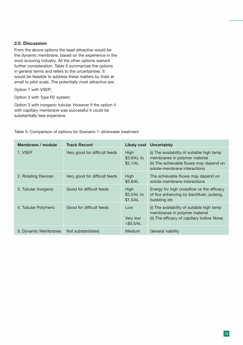
39
2.5. DiscussionFrom the above options the least attractive would bethe dynamic membrane, based on the experience in thewool scouring industry. All the other options warrantfurther consideration. Table 5 summarizes the optionsin general terms and refers to the uncertainties. Itwould be feasible to address these matters by trials atsmall to pilot scale. The potentially most attractive are:
Option 1 with VSEP;
Option 2 with Type R2 system;
Option 3 with inorganic tubular. However if the option 4with capillary membrane was successful it could besubstantially less expensive.
Membrane / module Track Record Likely cost Uncertainty
1. VSEP Very good for difficult feeds High (i) The availability of suitable high temp$3.9/kL to membranes in polymer material$2.1/kL (ii) The achievable fluxes may depend on
solute-membrane interactions
2. Rotating Devices Very good for difficult feeds High The achievable fluxes may depend on$3.8/kL solute-membrane interactions
3. Tubular Inorganic Good for difficult feeds High Energy for high crossflow vs the efficacy$3.2/kL to of flux enhancing by backflush, pulsing,$1.5/kL bubbling etc
4. Tubular Polymeric Good for difficult feeds Low (i) The availability of suitable high tempmembranes in polymer material
Very low (ii) The efficacy of capillary hollow fibres<$0.5/kL
5. Dynamic Membranes Not substantiated Medium General viability
Table 5: Comparison of options for Scenario 1: stickwater treatment
40
Membrane technologies for meat processing waste streams
3. Scenario 2: Sterilizer/handwash remediation
3.1 General considerationsThe streams to be treated are very dilute and hot towarm. There are two generic streams:
• 2A is > 80°C and very lightly contaminated and maycontain some bacteria; it is required for ‘immediate’reuse (to maintain its enthalpy) but must beeffectively sterilized;
• 2B is warm (ca 40ºC), slightly more contaminatedand required for high quality non-potable reuse.
Both streams need a ‘sterilizing’ membrane barrierfollowed by a disinfection step. Chlorination would notbe suitable due to the raised temperature, but UV couldbe effective, subject to the required dose/responsetime.
There are analogous applications in sterilization in thepharmaceutical industry, in beverage filtration and inultra pure water (UPW) filtration. The key features arevery dilute streams and the need to remove bacteriaeffectively. The dilute feed, high recovery requirementand low residence time would also indicate a dead endfiltration process, either with back flushing or regularreplacement of cartridges. However if the solids load ineither scenario is too high it may necessitate somecrossflow and/or special attention to regularbackflushing.
The elevated temperature of stream 2A would provide asignificantly reduced viscosity of water (at 80°C theviscosity is 36% of that at 20°C) and this would providebenefits of higher fluxes or lower transmembranepressures (TMP) for the same flux (TMP = viscosity xflux/resistance).
3.1.1 Initial screening
Stream 2A requires a high integrity, high flux (lowresidence time) robust membrane in a compact‘packaged’ system. Stream 2B would also be suited toa similar membrane but has less demand ontemperature of operation; it may need to be readilybackwashable. The following initial considerationsapply:
(i) Module concepts:
Those which would be suitable are flat sheet, pleatedcartidges or tubular configurations (including cartridges)suited to dead end (or low crossflow) operation. Forboth streams and particularly stream 2B the systemmay need to backwashable (difficult on flat sheets).Both depth and surface filtration are applied to fluidsterilization.
(ii) Membrane type
For effective sterilization (bacterial removal) themembrane needs to be a microfilter (MF) of pore size < 0.22 mm (Goel et al. 1992 , Table 34-5). The majorityof membranes used in sterilization applications arepolymeric and produced by the phase inversionprocess. This means they have a distribution of poresizes. However, based on their popularity in analogousapplications they can be considered here.
The ideal membrane for this application would be anisoporous (mono pore size) membrane with pores in theMF size range of about 0.2mm or less and which hashigh flux to give rapid processing without significantcooling. There are two types of isoporous membraneavailable, the track-etched membranes, typified by theNuclepore polycarbonate membrane and microsieves,such as the silicon nitride flat sheets produced byFluxxion.
(iii) Temperature
Stream 2A would involve continuous application at >80°C and this places a constraint on the microfiltersthat can be used. The following microfilters are quoted(Goel et al. 1992, Table 34-18) as suitable at 80°C:
Polysulphone;
Acrylic copolymer;
Polyvinylidene fluoride;
Polycarbonate (79°C);
Plus we can add;
Polytetrafluoro ethylene;
Silicon nitride; and
Ceramics.
In the initial sceening we should not exclude any of theabove.
41
Membrane technologies for meat processing waste streams
3.2 Membrane options3.2.1 Depth filtration – principles and performance
The depth filter is designed to remove the particleswithin its structure rather than on the surface. Thus themembrane tends to be open-structured in cross sectionand reasonably thick. An example of the depth filter isshown in Figure C1 in Appendix C. These microfiltersshould be able to give effective removal of bacteriaparticularly if they are graded-density with smallerpores towards the downstream. Cartridge depth filtersare available with low holdup allowing a short residencetime. They are also available in sterilized condition andsome can be steamed in-situ. However they aredesigned to be disposable and the annual cost woulddepend on the contaminant level which woulddetermine the frequency of replacement.
The key properties are the ‘holding capacity’ of thefilter, which determines its lifetime, and its retentioncapabilities. It is not feasible to estimate filter lifetimeapriori since it depends on the nature and amount ofthe particle load; tests are necessary to specify filtersize and capacity. The depth filter can be operated atconstant pressure which means that the flux willdecline as the filter becomes loaded; the form of therelationship is:
J = a ( ∆P/ [Cf t] )-0.5 [constant pressure]
Where J is the flux, Cf is the solids concentration and tis the time. This shows that flux declines with time anddeclines more for feeds of higher solids content.
Alternatively the flux can be held constant and thepressure drop, DP, allowed to rise with time; the form ofthe relationship is:
∆P = a J + b Cf J2 t
From the above relationship it is evident that DP riseswith time and feed concentration and is sensitive to(flux)2. Both the above equations tend to breakdown athigh loadings as the fluid pathways in the filter arereduced and at a critical loading the flux drops or the∆P rises dramatically. Usually the depth filter isoperated at constant flux and has to be replaced whena specified ∆Pmax is reached. The coefficients in theequations incorporate the filtrate viscosity and thisdecreases significantly at elevated temperature, so fluxis higher or pressure drop is lower at 80°C; as notedabove the viscosity drops to about one third theambient value at 80°C.
The retention capabilities of the depth filter depend onthe relative particle and pore size, the filter thickness,and the degree of filter loading. When a filter is loadedit starts to shed particles to the filtrate. Another factorwhich may be important is the relative surface chargeon the particle and membrane filter. Various theorieshave been summarized in Davis and Grant (1992), butthe bottom line is that it is necessary to checkperformance under test conditions.
3.2.2 Surface Filters – Principles and Performance
The surface filter operates by sieving at the membranesurface (under some conditions charge interactions canalso play a role). Some of the retained particles mayblock or obstruct pores but the principle collectionmechanism is as a cake upon the surface. Retentionproperties rely on the pore size distribution with fewover-size pores and this favours the more isoporousmembranes described below.
For constant pressure or constant flux operation theequations in 3.2.1 above also apply. However becausethe cake resistance tends to control it is possible tomeasure it experimentally and then use the data forscale up or extrapolation. Surface filters will exhibit fluxor ∆P changes more rapidly than depth filters and willneed to be regenerated by backflushing or crossflow toremove the deposit layer. However they are amenableto continuous operation without frequent replacementas long as these regeneration techniques are effective.
3.2.2.1 Track-etched membranes
Track-etched membranes are produced by neutron (orsimilar) bombardment of polymers such aspolycarbonates followed by etching. This producesmembranes with very close pore size but relatively lowporosity (typically < 10%). The membranes are flatsheet but can be pleated and inserted into cartridges.In this case the membrane is sandwiched between twononwoven fabric supports before pleating. The twoends are sealed to form a cylinder, and a plastic core isinserted inside the cylinder and the assembly is theninserted into a sleeve. This construction allows somedegree of backwashing. The pleated cartridge can beused as a single element or as a multi-element stack. Apleated cartridge track-etched module is shown inFigure C2 in Appendix C.
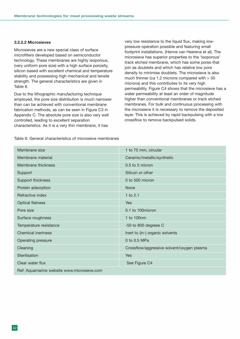
42
Membrane technologies for meat processing waste streams
3.2.2.2 Microsieves
Microsieves are a new special class of surfacemicrofilters developed based on semiconductortechnology. These membranes are highly isoporous,(very uniform pore size) with a high surface porosity,silicon based with excellent chemical and temperaturestability and possessing high mechanical and tensilestrength. The general characteristics are given in Table 6.
Due to the lithographic manufacturing techniqueemployed, the pore size distribution is much narrowerthan can be achieved with conventional membranefabrication methods, as can be seen in Figure C3 inAppendix C. The absolute pore size is also very wellcontrolled, leading to excellent separationcharacteristics. As it is a very thin membrane, it has
very low resistance to the liquid flux, making low-pressure operation possible and featuring smallfootprint installations. (Henne van Heerena et al). Themicrosieve has superior properties to the ‘isoporous’track etched membrane, which has some pores thatjoin as doublets and which has relative low poredensity to minimise doublets. The microsieve is alsomuch thinner (ca 1.2 microns compared with > 50microns) and this contributes to its very highpermeability. Figure C4 shows that the microsieve has awater permeability at least an order of magnitudehigher than conventional membranes or track etchedmembranes. For bulk and continuous processing withthe microsieve it is necessary to remove the depositedlayer. This is achieved by rapid backpulsing with a lowcrossflow to remove backpulsed solids.
Membrane size 1 to 75 mm, circular
Membrane material Ceramic/metallic/synthetic
Membrane thickness 0.5 to 5 micron
Support Silicon or other
Support thickness 0 to 500 micron
Protein adsorption None
Refractive index 1 to 2.1
Optical flatness Yes
Pore size 0.1 to 100micron
Surface roughness 1 to 100nm
Temperature resistance -50 to 800 degrees C
Chemical inertness Inert to (in-) organic solvents
Operating pressure 0 to 0.5 MPa
Cleaning Crossflow/aggressive solvent/oxygen plasma
Sterilisation Yes
Clear water flux See Figure C4
Ref: Aquamarine website www.microsieve.com
Table 6: General characteristics of microsieve membranes
43
Membrane technologies for meat processing waste streams
3.2.2.3 Ceramic membranes
Inorganic ceramic microfiltration membranes (describedin 2.3.1.1) may also be suitable for recycling the hotdilute wastewater. Compared with organicmicrofiltration membranes, they can cope better at hightemperature and have exceptional cleaningperformance and potentially longer service life. In somecases they exhibit less fouling interactions with proteinsthan organic membranes (Afonso, 2002). Comparedwith the inorganic ultrafiltration membrane, themicrofiltration membrane can provide a higher flux at alower pressure drop, and meet the high flowrequirement (short residence time) required.
Inorganic microfiltration membranes with nominal poresize down to 0.1um are commercially available butbecause of the pore size distribution (they are notisoporous), there will be a number of pores potentiallymuch larger than the mean pore size. Thus it is notpossible to claim that bacteria can be totally removedwith MF(a similar limitation applies to polymer MF). Toaccount for this a secondary disinfection stage, such asUV, should be considered.
3.3. Related applicationsThere are many examples of (deadend) microfiltrationapplied to purification of dilute aqueous feeds. Thefollowing illustrate the application.
3.3.1 Sterilization in the pharmaceutical industry
The applications range from water for injection,producing synthetic parenterals, ophthalmic solutions,fermentation products and serum and plasmaprocessing (Goel et al, 1992). These are demandingfiltration tasks and for sterilization a 0.2mm rated poresize is specified. Both depth and surface filters areused. In these applications an important requirement isthe integrity test which can be readily confirmed bythe bubble point test. An example is the tortuous poreMillipore Durapore 0.22µm (more of a surface filter) andremoval of P.diminuta.
• Water bubble point 34.5 psig is equivalent to LogRemoval Value of > 10.0 (sterile);
• Water bubble point 33 psig is equivalent to LRV of 5.3;
where Log Removal = Ln ( Concentration in feed/concentration in filtrate).
The sterilization grade Durapore has a specified waterbubble point of > 42 psig. Other integrity test areavailable, including the diffusive air flow test. The pointto note is that simple and effective integrity tests areavailable.
3.3.2 Beverage clarification and stabilisation
Beverage applications in which membrane filtration isused include beer, wine, bottled water, fruit-flavouredbeverages; of these 90% are beer and wine. Bothdepth and surface filters are applied. In manyapplications two filters are used in series, a prefilterfollowed by a final filter. This can extend the lifetime ofthe final filter and give better quality filtrate (Goel et al.,1992).
The microsieve has been successfully applied to thefiltration of lager beer (Kuiper et al., 2002). Using poresizes of 0.8–1.5 µm, average fluxes up to 4x10³ L/m2 hhave been obtained. Further results show forcentrifuged beer and a microsieve with a pore diameterof 0.55µm a haze of 0.23 EBC was obtained during10.5 h of filtration at an average flux of 2.21x10³ L/m2
h. For a sieve with slit-shaped perforations of0.70µmx3.0µm a haze of 0.46 EBC was obtainedduring 9 hours of filtration at an average flux of1.43x104 L/m2 h. To control surface fouling thepermeate was frequently back pulsed. The observedfluxes are approximately one-order of magnitude higherthan is commonly obtained for kieselguhr filtration andnearly two-orders higher than for filtration withconventional ceramic membranes (Gan et al., 1997). It is of interest that the slit-shaped pores showed lessfouling tendency than the circular pores.
3.3.3 Ceramic membranes – dilute feed
Bottino (2001) and his co-workers used 0.2mm ceramicmembranes to treat lake water and proved that it issuitable for drinking water production. Suspendedsolids were completely removed along withmicroorganisms and algae, and retentions of 64% andca 56% were achieved for TOC and chloroform,respectively. The permeate fluxes decreased with anincrease in the concentration ratio, and at the highestNTU reached, it levelled off at a value around 200L/m2h.A complete recovery of the permeate flux was easilyachieved by a simple chemical cleaning.
44
Membrane technologies for meat processing waste streams
3.4 Economic factors
3.4.1 Polymeric cartridge filters
Polymeric cartridges could be a relatively low costoption depending on the ability to operate about 80°C,and to handle the solids loading (this is an uncertaintyin any cost estimation). The following information wasprovided by QEDOcctech (Macintosh, 2004):
• depth filters are specified as 10 inch equivalents,
• for low loading applications the design basis is10L/min per 10 inch cartridge,
• cost per cartridge is approximately A$10 (cartridge only),
• lifetime about 1 week ( but this is uncertain and isfeed dependent).
An estimate can be made based on 50 kL processedper day and 16 to 20 hrs per day.
Flowrate per hour = 2500 to 3125 L/hr
Flowrate per min = 42 to 32 L/min
Cartridges required from 4 to 5
Cartridge replacement costs from A$ 40 to A$ 50.Consider lifetimes of 1 week and 2 days.
Lifetime of 1 week (6 days) gives 300 kL beforereplacement, so costs (cartridge only)= A$ 0.13 to A$ 0.17 / kL, (cartridge only).
Lifetime of 2 days costs increase by 3x to= A$ 0.40 to A$ 0.50 / kL (cartridge only). Additionalcosts would include housing and labour.
3.4.2 Ceramic membranes
An estimate can be made based on the costing in2.3.3.1 for the CeraMem membrane but with anassumed higher flux for the dilute stream. Theassumptions are:
• 50 kL processed per day,
• flux of 150 L/m2hr ( this should be feasible based onexample in 3.3.3 and the effect of high temperatureon flux) and recovery of 90% (ie 10% water losses).
• for a 20 hour day the amount processed is 2500l/hrand a membrane area of 17.0 m2 is required, for a 16 hour day the area required is 21 m2.
At a module cost of A$ 715/ m2 and 0.35 factor toestimate plant costs (see 2.3.3.1) the plant cost is inthe range:
capital cost = A$ 34,700 to 43,400. So,capital chargesper year = $3,470 to $4,340
Volume processed per annum = 300 (days) x 50(kL/d) =15,000 kL/yr x 0.9 (recovery factor)
Processing costs (capital charge) = A$ 0.26 to 0.32 /kL
Estimated processing costs (total ) = A$ 0.35 to 0.43 /kL
Note that this is the cost of providing the water ‘sterile’and close to 80°C (assuming small heat losses and90% recovery of water).
3.4.3 Microsieves
Information from Fluxxion (Biernet, 2004) is that 1 m2 ofmicrosieve requires 89 wafers at Euro 800 per wafer (including clamping module). The cost per m2 is thusabout A$ 116,720 (based on A$ = 0.61Euro). Howeverto compensate for this the microsieves operate withexceptionally high fluxes.
For Scenario 2A conditions fluxes of 10,000 to 20,000L/m2hr are estimated. For example, for the filtration ofbeer (see 3.3.2), which is a difficult feed, the Microsieveexhibited fluxes up to 4,000 L/m2hr at ambienttemperature. Allowing for viscosity effects this could beextrapolated to at least 10,000 L/m2hr. In response to adirect query, Biernet (2004) comments that for tapwater at 12°C, using a 0.5 micron microsieve, the fluxesare in the range 10,000 L/m2hr, which could increase to30,000 L/m2hr at 80°C. For the specified Scenario 2Afeed he suggested a flux of 20,000 L/m2hr .
Thus:• 50 kL processed per day is 2,500 L/hr (20hr/d) to
3,125 L/hr (16hr/d),
• for flux of 10,000 L/m2hr area required is 0.25 to 0.32m2, or 23 wafers to 29 wafers,
• the capital cost of wafers is Euro 18,400 to 23,200 =A$ 30,200 to A$ 38,000
• in addition a crossflow system and backpulse systemare required. Let us assume that the high costmodules represent 80% of the installed capital:
Capital cost = A$ 37,800 to A$ 47,500. So, capitalcharges per year = A$ 3,780 to A$ 4,750

45
Membrane technologies for meat processing waste streams
Volume processed per annum = 15,000 kL/yr x 0.9(recovery factor),
Processing costs (capital charge) = A$ 0.28 to 0.35 /kL
Assume capital component is 80% of total processingcost (slightly higher than ceramic tube systems)
Estimated processing costs (total ) = A$ 0.35 to 0.44 /kL
For the less conservative flux assumption of 20,000L/m2hr, the membrane areas and estimated costsdecrease by 50% to, processing costs (total) = A$ 0.18to 0.22 /kL.
The sustainable flux is a considerable uncertainty inthese estimates. Fluxxion have a pilot system and a labsystem which would permit feasibility tests.
In its favour the Microsieve should give a better qualitywater and would operate with a shorter retention time(less loss of sensible heat) than other modules.
3.5 Capabilities and limitations
3.5.1 Polymeric cartridge filters
The strengths, weakness, opportunities and threats forpolymeric cartridge filters are summarised in SWOT 5below. Also included are assessments of typical fluxesand recoveries, and comments on process issues –fouling, temperature and membrane life.
SWOT 5 Assessment of polymeric cartridge filters (dead-end) for sterilizer reclamation
Strengths • Well established as method of liquid ‘sterilisation’.• Wide choice of suppliers.• Simple operation and maintenance (in principle).• Grade-depth or tracketched can give very good log removal.
Weakness • The economics are very dependent on the solids load (if load doubles lifetime ishalved and replacement costs are doubled).
• Could be labour intensive if replacement is frequent.• Pumping costs rise as filter becomes loaded (Power = Flow x Delivery pressure).
Opportunities • With good ‘house keeping’ this could be the simplest and possibly the cheapestoption (particularly for scenario 2A).
• Couple with efficient pretreatment to extend filter life.
Threats Level of contamination is unknown and could vary from plant to plant and fromtime to time.
Typical fluxes 200 to 1,000 L/m2hr ( depends on available pressure and solids loading).
Typical recoveries > 90%
Fouling issues Depends directly on level of contamination. Probably greater problem for 2B.
Temperature issues Several polymers should be capable of ca. 80°C.
Membrane life Cartridges are ‘disposable’. Lifetime depends on solids load.issues

46
SWOT 6 Assessment of ceramic membranes for sterilizer reclamation
Strengths • Easy application for this membrane.• No membrane material problems.• Tight MF or UF would give effective strelization.
Weakness Relatively costly in terms of capital (inorganic vs polymer membranes) andoperating costs (crosslow).
Opportunities • Could use similar membranes to Scenario 1 (such as Ceramem module), butwith different operating strategy.
• Could develop optimized back pulsing ( or similar technique ).• Could couple with UV ( hybrid process development)**Note 1 below
Threats Other options may be cheaper or more compact.
Typical fluxes In range 100 to 200 L/m2 hr.
Typical recoveries To 90 %.
Fouling issues Unlikely to be a problem with correct membrane selection.
Temperature issues Should not be an issue.
Membrane life issues Can anticipate long membrane life.
Note 1. Novel technology coupling UV and membranes is under development (Fane et al, 2004)
3.5.3 Microsieves
The strengths, weakness, opportunities and threats formicrosieves are summarised in SWOT 7 below. Alsoincluded are assessments of typical fluxes and
recoveries, and comments on process issues – fouling,temperature and membrane life.
SWOT 7 Assessment of microsieves for sterilizer reclamation
Strengths • Exceptionally high permeability (high flux at low pressure).• Very compact and small foot print is possible.• Near perfect’ isoporosity provides very effective sterilization.
Weakness • Very novel technology.• Single supplier.• Backflushing will need to be optimized to maintain flux.
Opportunities • High flux would permit very compact units with short residence time.• Could develop a ‘sterliser water recycle’ product (in partnership with supplier).
Threats • If anticipated fluxes (10 to 20kL/m2 hr) cannot be sustained it will impact oncapital costs.
• Longevity of the module.
Typical fluxes In range 10,000 to 20,000 L/m2 hr at 80°C.
Typical recoveries > 90 %.
Fouling issues • Although very low solids the fouling could be exacerbated by the very high flux.• Optimal backflushing will be essential.
Temperature issues Should not be an issue.
Membrane life issues In principle very long, but depends on quality of wafer assembly.
3.5.2 Ceramic membranes
The strengths, weakness, opportunities and threats ofceramic membranes are summarised in SWOT 6 below.
Also included are assessments of typical fluxes andrecoveries, and comments on process issues – fouling,temperature and membrane life.
Membrane technologies for meat processing waste streams

47
Membrane technologies for meat processing waste streams
3.6 Contacts(i) Polymer – cartridge
Filter Products Companywww.fpcfilters.com(general suppliers of cartridge filters )
Peter Macintosh,QED Occtech,322 Hay St, Subiaco,WA [email protected]
(ii) CeramicsSee 2.3.5
(iii) MicrosievesfluXXion B.V.Philips High Tech Campus Building WAE room 124Prof.Holst Laan 4 5656AA Eindhoven The Netherlands
Ir. J.A.M. Bienert fluXXion B.V.Manager Marketing & Sales,Philips High Tech Campus, Eindhoventelephone: +31 (0) 40 274 3095fax: +31 (0) 40 274 4199 E-mail: [email protected] Website: <http://www.fluxxion.com>
3.7 ReferencesM. D. Afonso, R. Bórquez, Nanofiltration ofwastewaters from the fish meal industry, Desalination151 (2002) 131-138
W.Biernet, Fluxxion (personal communication, 2004 ).
A.Bottino, C. Capannelli, A. Del Borghi, M. Colombino,O. Conio, Water treatment for drinking purpose:ceramic microfiltration application, Desalination 141(2001) 75-79
Q. Gan, R.W. Field, M.R. Bird, R. England, J.A. Howell,M.T. Mckechnie and C.L. O’Shaughnessy, ‘Beerclarification by cross-flow micro filtration: foulingmechanisms and flux enhancement’, Trans. Inst. Chem.Eng 75, part A, January (1997)
R.H.Davis and D.C.Grant, Chapter 32 in W.Ho andK.Sirkar, ‘Membrane Handbook’ Van NostrandReinhold.(1992).
A.G Fane et al. ‘Hybrid UV Membrane Process’, patentapplication ( 2004).
V. Goel et al.Chapter 34,in W.Ho and K.Sirkar,‘Membrane Handbook’ Van Nostrand Reinhold.(1992).
S. Kuiper, Cees van Rijn, Wietze Nijdam, Onno Raspe,et al., "Filtration of lager beer with micro sieves: flux,permeate haze and in-line microscope observations", J. Memb Sci, Volume 196 (2002), 159-170
P. Macintosh, QED Occtech (personal communication,2004).
H. van Heerena, W.Nijdam, D. van de Kerka, S.Sancheza, J. Vosa, N. Denis,, ‘Micro filters made withsemiconductor technologies’: A revolution in particle-fluid separation,www.fuse-network.com/fuse/demonstration/333/529/FL_529.pdf
C.J M van Rijn, W. Nijdam, S. Kuiper, G. J Veldhuis, H.van Wolferen and M. Elwenspoek, ‘Microsieves madewith laser interference lithography for micro-filtrationapplications’, J. Micromech. Microeng. 9 (1999)170–172.
C.J.M. van Rijn, M.C. Elwenspoek, Micro filtrationmembrane sieve with silicon micro machining forindustrial and biomedical applications, IEEE proc.MEMS (1995), p 83-87www.acefesa.es/novedades/microtamiz/microtamiz.htmwww.microsieve.com

48
Membrane technologies for meat processing waste streams
4. Scenario 3: Effluentreclamation
4.1 General considerationsThe objective is to produce high quality water for reuseby membrane treatment of effluent streams, with flowsin the range 1 to 2 ML/day (medium size plant) to 6ML/day. The feed characteristics specified are those ofa secondary/tertiary effluent with relatively low COD,some TN and TP and bacterial load.
Initial comments are:
(i) the feed is amenable to membrane processing but could be prone to biofouling;
(ii) there are several membrane options for thisscenario.
The process will have to provide good pre-treatmentand high levels of bacterial inactivation.
4.1.1 Initial screening
In this scenario the feed streams are close to ambientconditions so the use of inorganic, or specificallyrobust, membranes is not warranted. To accommodatethe suspended solids load the use of spiral woundmodules (for example for RO) would require a high levelof pre-treatment. If membranes are used for pre-treatment the externally fed hollow fibres would bepreferred. If direct application of UF or NF wereconsidered the most favoured approach would betubular (although this usually involves higher energyusage).
It may be possible to treat the plant wastewater(primary effluent) with direct membrane filtration.However some studies indicate membranes foulseverely in such situations (Johnson et al., 1996), andthis would be even worse for meat processingwastewater, as this may contain blood and protein.Also, almost all the soluble pollutants, which arenormally the majority components in the wastewaters,pass through porous membranes (MF/UF). Therefore itis beneficial to have a biological treatment beforemembrane treatment. The anticipated characteristics ofthe wastewater are suitable for biological treatment. Itmay be necessary to have biological nitrogen removalbecause of the high level of TN.
Depending on the strength of the primary wastewater, itmay be of interest to consider anaerobic processingfollowed by membranes. The benefit of the anaerobicprocess is the potential to recover biogas which canlead to energy savings.
4.2 Treatment OptionsPotential membrane treatment alternatives are depictedin Figure 3. Membrane processes can be incorporatedas stand alone processes following conventionalbiological treatment (effluent polishing) or can becombined with biological membrane processes such asmembrane bioreactors (MBR). Removal of differentspecies present in the wastewater is dependent on thetype of membrane used (Table 7).
Bioiogical treatment(ASP / SBR)
Prefilters(<500 micron)
MF/UF UVww
MBR
NF/RO UV
NF UV
Figure 3 Treatment options for waste reclamation.

49
Membrane technologies for meat processing waste streams
Thus the following can be considered:
(i) Dual membrane reclamationThe ‘conventional’ approach involves pre-treatmentby MF or UF followed by RO. Within this there areoptions on the use of contained or submergedmembranes for pre-treatment and the type of RO(typically spiral wound module). An alternative couldbe to use NF, depending on the reuse option.
(ii) One step membrane clarificationFollowing conventional biological treatment thestream can be clarified by MF, UF or NF. Using UFalone could remove most bacteria and someorganics, and if further disinfection were applied(such as UV or chlorination) the log removal shouldbe >> 6. Using NF alone (possibly tubular) plusdisinfection would remove most of the organics , N and P and bacteria. A hybrid process using UFwith coagulants (Scoffer et al., 2000) may beequivalent to the use of NF and be less expensive.
(iii) Membrane BioreactorThe primary effluent could be processed by anMBR, either a new unit or retrofitted to an existingbioreactor. The membranes used in MBRs are eitherMF or UF and in principle the treated water qualityis equivalent to membrane clarified secondary ortertiary effluent.
4.2.1 Principles and performance
4.2.1.1 Biological treatment followed by membraneprocess
The use of membrane processes as a tertiary treatmentto upgrade secondary effluents to a reusable standardis becoming common place. The complete treatmentsystem includes the conventional biological treatmentunit followed by single or two stage membrane
processes, depending on the reuse application.
The main advantage of such systems is that the tertiarytreatment system can be sized to reuse demand. Suchsystems can also be readily operated and shut downdepending on the demand. To increase capacityadditional membrane treatment units can be built andcommissioned without disturbing the existingprocesses. It is also reported that the completemembrane treatment systems occupy a factor of 6–8times (m3/m2) smaller foot print compare toconventional treatment systems offering similartreatment level (Leslie, 2002)
MF and UF can effectively remove all the suspendedsolids present in the effluent. They can also removemost of the bacteria, and UF can removemacromolecules and viruses (> 5 log removal). SinceUF is a tighter membrane its removal efficiency is betterthan MF (~ 1 log removal for virus). However due tohigher transmembrane pressures (TMP) with UFmembranes, the costs are slightly higher than MF.
Hollow fibre MF/UF (0.01–0.2 mm) membranesoperated in dead end (flow through) mode are nowcommonly used in effluent reuse applications (withrecoveries of 85-95%). For pressurized modules theoperating TMP varies between 50 and 250 kPa. In thecase of submerged membranes operated under suctionthe TMP is in the range 10–70 kPa. With secondaryeffluent, MF (0.2 mm pores) is typically operated atabout 50–60 L/m2h whereas UF is operated at about 40L/m2h. Usually the filtration direction is from outside toinside (shell side to lumen side) although some inside-out membranes are also available. To maintainsustainable flux the membranes are periodicallybackwashed with filtrate of high-pressure air. Airscouring is also used to prevent foulant deposits insubmerged membrane systems. When the membrane
Table 7: Removal of wastewater constituents by membrane processes
MF UF NF RO
Suspended solids Y Y Y Y
Submicron colloids P Y Y Y
Macrosolutes P P Y Y
Viruses P Y Y Y
Microsolutes N N P Y
Y = Yes; P = Partial; N = No (Adapted from Fane and Chang, 2002)

50
Membrane technologies for meat processing waste streams
permeability declines below a specified value themembranes need to be cleaned with chemicals torecover the permeability to an acceptable level. (Inaddition, tubular and spiral wound configurations arealso available for UF membranes but are not verycommon in secondary effluent treatment). To protectthe membrane system pre-filters (< 500 micron) need tobe used before the membrane system.
Although in some cases the MF/UF filtered water isreused (following some disinfection), it is possible totreat by RO (or NF) to remove TDS and otherconstituents transmitted from the previous stage. RO is generally found in spiral wound configuration.Although dual membrane systems are an effectivebarrier for pathogens, some form of disinfection, suchas UV or chlorination, is also used, as membraneintegrity can be breached occasionally. Table 8(adapted from Trussell et al., 2003) shows the log
removals that can be anticipated from the variousstages of reclamation. (Note the lower virus removal forRO is related to the slightly increased risk involved inspiral wound module usage).
Some of the challenges faced in the application of theabove technology are:
(i) Biological fouling – can be controlled by chlorine (foroxidant resistant membranes only) or chloramines;
(ii) Varying solid loading rate can affect the recoveryrate and cleaning frequencies;
(iii) Fibre/membrane failure can cause pathogen breakthrough (can be detected by integrity tests).
Components Virus (Log Removal) Cryptosporidium
Usage A Usage B Usage A Usage B
UF (MBR) 5 5 5 5
RO - 4 - 5
UV 2 2 3 3
Cl2 5 5 0.2 0.2
Combined 12 16 8.2 13.2
Above with MF (MBR) 8 12 8.2 13.2
* With MF (MBR) optionUsage A Irrigation and non-potable reuse; Usage B Non-potable and indirect potable
4.2.1.2 Membrane bioreactors (MBR)
Membrane bioreactors are combined processes ofbiological treatment and membrane separation in asingle unit. Membrane separation essentially replacesthe sedimentation step of an activated sludge process.There are several advantages of MBRs (Visvanathan etal, 2000; Heiner and Bonner; 1999). Since themembrane retains the biosolids, the sedimentationproperty of the biosolids is no longer a concern. Thiscan favor slow growing microbes (nitrifiers, anaerobes,substrate specific bacteria, etc.) and non floc formingmicrobes. Since biosolids concentration is independentof hydraulic retention time higher concentrations can be
maintained. Therefore the treatment capacity isimproved and plant size is reduced. Since membranescan also partially retain macromolecules, these can beretained in the reactor and degraded thus improving thewater quality. Also, due to the long sludge retentiontime (SRT), sludge production will be less. Otheradvantages are the smaller foot print (about 15% ofconventional systems), the possibility of containment toreduce odours and the reduced operator requirementsince it can be automated. The treated water can bedirectly reused following disinfection (see Table 4) orcan be readily used as feed to an RO reclamationprocess.
Table 8: Estimated log removals of virus and protozoa for individual and combined systems using membranes(after Trussell et al. 2003)
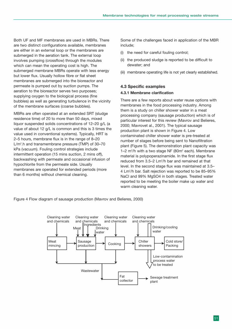
51
Membrane technologies for meat processing waste streams
Both UF and MF membranes are used in MBRs. Thereare two distinct configurations available, membranesare either in an external loop or the membranes aresubmerged in the aeration tank. The external loopinvolves pumping (crossflow) through the moduleswhich can mean the operating cost is high. Thesubmerged membrane MBRs operate with less energybut lower flux. Usually hollow fibre or flat sheetmembranes are submerged into the bioreactor andpermeate is pumped out by suction pumps. Theaeration to the bioreactor serves two purposes;supplying oxygen to the biological process (finebubbles) as well as generating turbulence in the vicinityof the membrane surfaces (coarse bubbles).
MBRs are often operated at an extended SRT (sludgeresidence time) of 20 to more than 50 days, mixedliquor suspended solids concentrations of 12–20 g/L (avalue of about 12 g/L is common and this is 3 times thevalue used in conventional systems). Typically, HRT is2–5 hours, membrane flux is in the range of 8–20L/m2.h and transmembrane pressure (TMP) of 30–70kPa (vacuum). Fouling control strategies includeintermittent operation (15 mins suction, 2 mins off),backwashing with permeate and occasional infusion ofhypochlorite from the permeate side. Usuallymembranes are operated for extended periods (morethan 6 months) without chemical cleaning.
Some of the challenges faced in application of the MBRinclude;
(i) the need for careful fouling control;
(ii) the produced sludge is reported to be difficult todewater; and
(iii) membrane operating life is not yet clearly established.
4.3 Specific examples4.3.1 Membrane clarification
There are a few reports about water reuse options withmembranes in the food processing industry. Amongthem is a study on chiller shower water in a meatprocessing company (sausage production) which is ofparticular interest for this review (Mavrov and Belieres,2000; Mavrovet al., 2001). The typical sausageproduction plant is shown in Figure 4. Lowcontaminated chiller shower water is pre-treated atnumber of stages before being sent to Nanofiltrationplant (Figure 5). The demonstration plant capacity was1–2 m3/h with a two stage NF (80m2 each). Membranematerial is polypoperazinamide. In the first stage fluxreduced from 3.5–2 Lm2/h bar and remained at thatlevel. In the second stage flux was maintained at 3.5– 4 Lm2/h bar. Salt rejection was reported to be 85–95%NaCl and 99% MgSO4 in both stages. Treated waterreported to be meeting the boiler make up water andwarm cleaning water.
Cleaning waterand chemicals
Cleaning waterand chemicals
Cleaning waterand chemicals
Cleaning waterand chemicals
Drinking/coolingwater
Low-contaminationprocess waterto be treated
MeatIngredients
Drinkingwater
Meatmincing
Spentprocesswater
Cooking
Fatcollector
Chillershowers
Cold store/Packing
Sausageproduction
Beltfiltration
Wastewater
Sewage treatmentplant
Nanofiltrationstage 1
Nanofiltrationstage 2
Cartridgefiltrationtwo stages
UVpredis-infection
UVpredis-infection
Water for reuse
Pretreatment
Figure 4 Flow diagram of sausage production (Mavrov and Belieres, 2000)

52
Membrane technologies for meat processing waste streams
4.3.2 Dual membrane plant
There are a number of industrial-scale dual membraneplants in operation around Australia and elsewhere totreat the municipal secondary effluents. Some of themare summarised in Table 9 and detailed descriptions
can be found in the references. Other than the LuggagePoint plant all the plants in Table 9 uses US FilterMemcor hollow fibre microfiltration systems. Both thinfilm composite (TFC) and cellulose acetate (CA)membranes are used in RO plants.
Figure 5 Flow diagram of membrane plant (Mavrov and Belieres, 2000)
Cleaning waterand chemicals
Cleaning waterand chemicals
Cleaning waterand chemicals
Cleaning waterand chemicals
Drinking/coolingwater
Low-contaminationprocess waterto be treated
MeatIngredients
Drinkingwater
Meatmincing
Spentprocesswater
Cooking
Fatcollector
Chillershowers
Cold store/Packing
Sausageproduction
Beltfiltration
Wastewater
Sewage treatmentplant
Nanofiltrationstage 1
Nanofiltrationstage 2
Cartridgefiltrationtwo stages
UVpredis-infection
UVpredis-infection
Water for reuse
Pretreatment
Location Process Capacity End Use Reference(ML/d)
Rouse Hill, Sydney MF 3 7 Domestic Cooper, 2003
Olympic Park, Sydney MF/RO 2.7 Domestic Cooney, 2001
Water Factory 21, USA MF/RO 4 GW recharge Durham and Walton, 1999
Eraring Power station, MF/RO 15 Boiler feed etc. Masson and Deans, 1996Hunter region
West Basin, USA MF/RO 11.5 Refinery Durham and Walton, 1999boiler feed
Luggage Point, Brisbane UF/RO 14 GW recharge Barr, 2002Refinery process water
Table 9: Membrane filtration plants for secondary effluent reuse
GW = Ground water
4.3.3. MBRs
There are a number of membrane bioreactors installedaround the world with varying capacities. The majorplayers in the field include:
(i) Zenon (Livas, 2001)Zenon MBRs use submerged hollow fibremembranes (0.04–0.1 µm pore size). Zenon MBRsare treating both municipal and industrialwastewaters. There are a number of large municipalMBRs with the capacities ranging from 0.8–15 ML/din USA and Canada, and up to 40 ML/d in Italy.There is a plant installed in Australia at Lake Cathie,NSW (1.0 ML/D) to treat municipal wastewater.
(ii) Kubota (Johnson, 2001; Churchouse, 1999)Over 800 plants are in operation. These plants treatsewage, brewery, diary, meat, seafood, vegetable,bakery, pharmaceutical, etc wastewaters. The largestplant capacity is 12.7 ML/d. The plant configurationis submerged flat sheet membrane (0.4 µm poresize). They are planning to build a plant inQueensland.
(iii) Mitsubisi – Rayon (Stafford, 2001)Installed over 500 plants with total capacity of50ML/d mainly in Japan and the Far East, but thereare also some plants in USA, Australia and Europe.About half of these plants are installed to treat foodprocessing industrial wastewaters. The largest
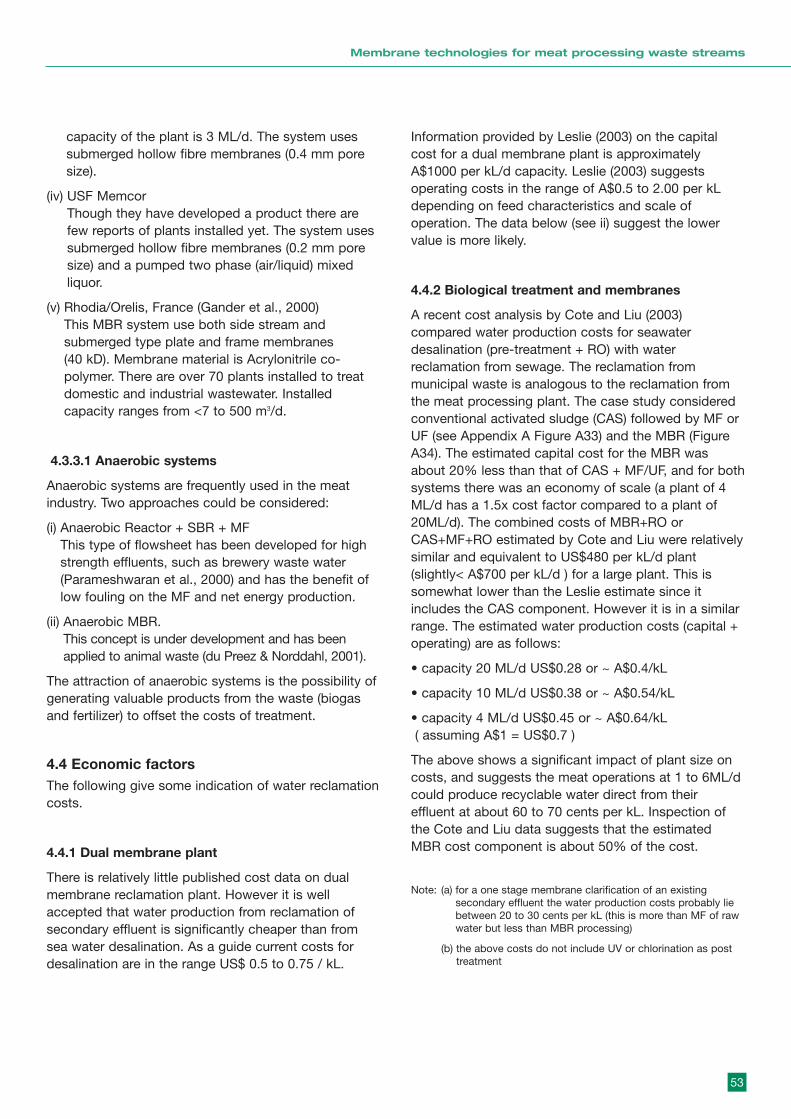
53
Membrane technologies for meat processing waste streams
capacity of the plant is 3 ML/d. The system usessubmerged hollow fibre membranes (0.4 mm poresize).
(iv) USF Memcor Though they have developed a product there arefew reports of plants installed yet. The system usessubmerged hollow fibre membranes (0.2 mm poresize) and a pumped two phase (air/liquid) mixedliquor.
(v) Rhodia/Orelis, France (Gander et al., 2000)This MBR system use both side stream andsubmerged type plate and frame membranes (40 kD). Membrane material is Acrylonitrile co-polymer. There are over 70 plants installed to treatdomestic and industrial wastewater. Installedcapacity ranges from <7 to 500 m3/d.
4.3.3.1 Anaerobic systems
Anaerobic systems are frequently used in the meatindustry. Two approaches could be considered:
(i) Anaerobic Reactor + SBR + MFThis type of flowsheet has been developed for highstrength effluents, such as brewery waste water(Parameshwaran et al., 2000) and has the benefit oflow fouling on the MF and net energy production.
(ii) Anaerobic MBR.This concept is under development and has beenapplied to animal waste (du Preez & Norddahl, 2001).
The attraction of anaerobic systems is the possibility ofgenerating valuable products from the waste (biogasand fertilizer) to offset the costs of treatment.
4.4 Economic factorsThe following give some indication of water reclamationcosts.
4.4.1 Dual membrane plant
There is relatively little published cost data on dualmembrane reclamation plant. However it is wellaccepted that water production from reclamation ofsecondary effluent is significantly cheaper than fromsea water desalination. As a guide current costs fordesalination are in the range US$ 0.5 to 0.75 / kL.
Information provided by Leslie (2003) on the capitalcost for a dual membrane plant is approximatelyA$1000 per kL/d capacity. Leslie (2003) suggestsoperating costs in the range of A$0.5 to 2.00 per kLdepending on feed characteristics and scale ofoperation. The data below (see ii) suggest the lowervalue is more likely.
4.4.2 Biological treatment and membranes
A recent cost analysis by Cote and Liu (2003)compared water production costs for seawaterdesalination (pre-treatment + RO) with waterreclamation from sewage. The reclamation frommunicipal waste is analogous to the reclamation fromthe meat processing plant. The case study consideredconventional activated sludge (CAS) followed by MF orUF (see Appendix A Figure A33) and the MBR (FigureA34). The estimated capital cost for the MBR wasabout 20% less than that of CAS + MF/UF, and for bothsystems there was an economy of scale (a plant of 4ML/d has a 1.5x cost factor compared to a plant of20ML/d). The combined costs of MBR+RO orCAS+MF+RO estimated by Cote and Liu were relativelysimilar and equivalent to US$480 per kL/d plant(slightly< A$700 per kL/d ) for a large plant. This issomewhat lower than the Leslie estimate since itincludes the CAS component. However it is in a similarrange. The estimated water production costs (capital +operating) are as follows:
• capacity 20 ML/d US$0.28 or ~ A$0.4/kL
• capacity 10 ML/d US$0.38 or ~ A$0.54/kL
• capacity 4 ML/d US$0.45 or ~ A$0.64/kL( assuming A$1 = US$0.7 )
The above shows a significant impact of plant size oncosts, and suggests the meat operations at 1 to 6ML/dcould produce recyclable water direct from theireffluent at about 60 to 70 cents per kL. Inspection ofthe Cote and Liu data suggests that the estimatedMBR cost component is about 50% of the cost.
Note: (a) for a one stage membrane clarification of an existingsecondary effluent the water production costs probably liebetween 20 to 30 cents per kL (this is more than MF of rawwater but less than MBR processing)
(b) the above costs do not include UV or chlorination as posttreatment
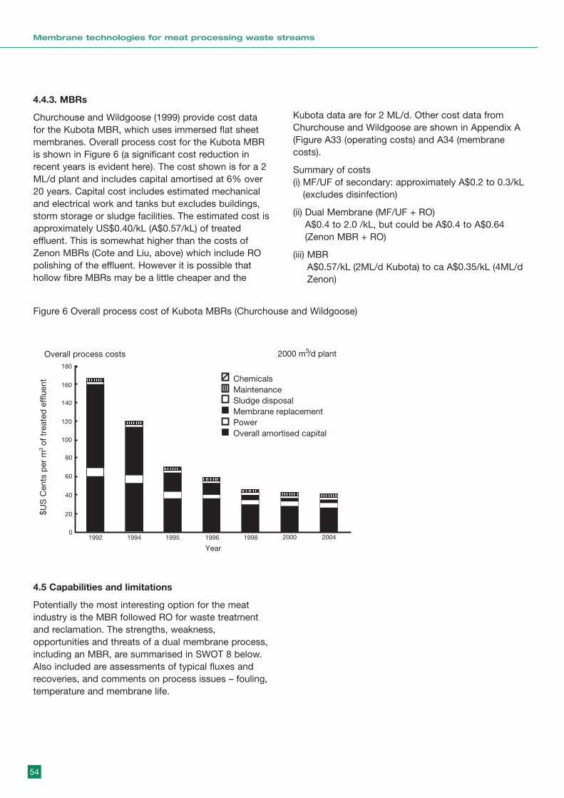
54
Membrane technologies for meat processing waste streams
Figure 6 Overall process cost of Kubota MBRs (Churchouse and Wildgoose)
Overall process costs
$US
Cen
ts p
er m
of t
reat
ed e
fflu
ent
3
ChemicalsMaintenanceSludge disposalMembrane replacementPowerOverall amortised capital
0
20
40
60
80
100
120
140
160
180
1992 1994 1995 1996 1998 2000 2004
Year
2000 m /d plant3
4.5 Capabilities and limitations
Potentially the most interesting option for the meatindustry is the MBR followed RO for waste treatmentand reclamation. The strengths, weakness,opportunities and threats of a dual membrane process,including an MBR, are summarised in SWOT 8 below.Also included are assessments of typical fluxes andrecoveries, and comments on process issues – fouling,temperature and membrane life.
4.4.3. MBRs
Churchouse and Wildgoose (1999) provide cost datafor the Kubota MBR, which uses immersed flat sheetmembranes. Overall process cost for the Kubota MBRis shown in Figure 6 (a significant cost reduction inrecent years is evident here). The cost shown is for a 2ML/d plant and includes capital amortised at 6% over20 years. Capital cost includes estimated mechanicaland electrical work and tanks but excludes buildings,storm storage or sludge facilities. The estimated cost isapproximately US$0.40/kL (A$0.57/kL) of treatedeffluent. This is somewhat higher than the costs ofZenon MBRs (Cote and Liu, above) which include ROpolishing of the effluent. However it is possible thathollow fibre MBRs may be a little cheaper and the
Kubota data are for 2 ML/d. Other cost data fromChurchouse and Wildgoose are shown in Appendix A(Figure A33 (operating costs) and A34 (membranecosts).
Summary of costs(i) MF/UF of secondary: approximately A$0.2 to 0.3/kL
(excludes disinfection)
(ii) Dual Membrane (MF/UF + RO)A$0.4 to 2.0 /kL, but could be A$0.4 to A$0.64(Zenon MBR + RO)
(iii) MBR A$0.57/kL (2ML/d Kubota) to ca A$0.35/kL (4ML/dZenon)
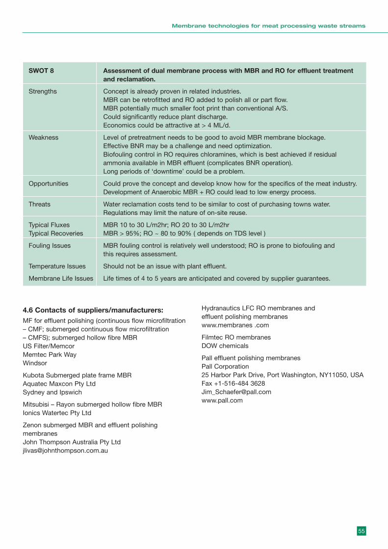
55
Membrane technologies for meat processing waste streams
4.6 Contacts of suppliers/manufacturers:MF for effluent polishing (continuous flow microfiltration– CMF; submerged continuous flow microfiltration – CMFS); submerged hollow fibre MBRUS Filter/MemcorMemtec Park WayWindsor
Kubota Submerged plate frame MBRAquatec Maxcon Pty LtdSydney and Ipswich
Mitsubisi – Rayon submerged hollow fibre MBRIonics Watertec Pty Ltd
Zenon submerged MBR and effluent polishingmembranesJohn Thompson Australia Pty [email protected]
Hydranautics LFC RO membranes and effluent polishing membraneswww.membranes .com
Filmtec RO membranesDOW chemicals
Pall effluent polishing membranesPall Corporation25 Harbor Park Drive, Port Washington, NY11050, USAFax +1-516-484 [email protected]
SWOT 8 Assessment of dual membrane process with MBR and RO for effluent treatmentand reclamation.
Strengths Concept is already proven in related industries.MBR can be retrofitted and RO added to polish all or part flow.MBR potentially much smaller foot print than conventional A/S.Could significantly reduce plant discharge.Economics could be attractive at > 4 ML/d.
Weakness Level of pretreatment needs to be good to avoid MBR membrane blockage.Effective BNR may be a challenge and need optimization.Biofouling control in RO requires chloramines, which is best achieved if residualammonia available in MBR effluent (complicates BNR operation).Long periods of ‘downtime’ could be a problem.
Opportunities Could prove the concept and develop know how for the specifics of the meat industry.Development of Anaerobic MBR + RO could lead to low energy process.
Threats Water reclamation costs tend to be similar to cost of purchasing towns water.Regulations may limit the nature of on-site reuse.
Typical Fluxes MBR 10 to 30 L/m2hr; RO 20 to 30 L/m2hrTypical Recoveries MBR > 95%; RO ~ 80 to 90% ( depends on TDS level )
Fouling Issues MBR fouling control is relatively well understood; RO is prone to biofouling andthis requires assessment.
Temperature Issues Should not be an issue with plant effluent.
Membrane Life Issues Life times of 4 to 5 years are anticipated and covered by supplier guarantees.

56
Membrane technologies for meat processing waste streams
4.7 ReferencesAlonso E., Santos A., Solis G.J. and Riesco P. (2001)On the feasibility of urban wastewater tertiary treatmentby membranes: a comparative assessment.Desalination 141 (2001) 39-51.
Barr K. (2002) Operating a water reclamation plant toconvert sewage effluent to high quality water forindustrial reuse. Proc. IWA 3rd World Water Congress,Melbouure, Australia, 7-12 April 2002.
Blocher M., Noronha L., Funfrocken J., Dorda V.,Mavrov H. D. Janke, H. Chmiel. (2002) Recycling ofspent process water in the food industry by anintegrated process of biological treatment andmembrane separation. Desalination 144 (2002) 143-150.
Churchouse S. (1997) Membrane bioreactors forwastewater treatment-operating experiences with thekubota submerged membrane activated sludgeprocess, Memb Tech. 83:5-9
Churchouse S. and Wildgoose D. (1999) Membranebioreactors progress from the laboratory to full-scaleuse, Memb tech. 111:4-8.
Cooney E. (2001) Water reclamation plant a greenwinner for Olympic site. Proc. Aust Water Assn 19thFederal Convention, Canberra, April 2001.
Cooper E. (2003) Rouse Hill and Picton ReuseSchemes: innovative approaches to large-scale reuse.Water Science and Technology:Water Supply Vol 3 No3 pp 49-54.
du Preez.J. and Norddahl, B. (2001) The Biorekconcept: converting organic waste tp energy, fertilizersand potable water, paper A.1-8 in Proceedings ofEngineering with Membranes , Vol.1, Granada, Spain,IBSN 84-669-5013-4.
Durham B. and Walton A. (1999) Membranepretreatment of reverse osmosis: long-term experienceon difficult waters, Desal. 122:157-170
Fane A.G. and Chang S. (2002) Membrane Bioreactors:Design & Operational Options. Filtration & Separation,39(5):26-29, June.
Gander M., Jefferson B. and Judd S. (2000) AerobicMBRs for domestic wastewater treatment: a reviewwith cost considerations, Sep. & Puri. Tech. 18:119-130
Heiner G. and Bonner F. (1999). Is the MBR ProcessSuited to your Treatment Plant? Pollution Engineering,December 1999.
Johnson W. T., Phelps R.W. and Beatson P.J. (1996)."Water Mining" using membranes. Proceedings of the"Water Reuse for the community and Industry – LatestDevelopments and Future Directions" Symposium,University of South Wales, Sydney, Australia, August 11996.
Johnston G. (2001) Kubota Submerged MembraneBioreactor Technology for Wastewater Treatment,Workshop on Membrane bioreactors and hybridsystems: Advanced methods fro water reuse,November 20, 2001, Organized by UNSW/UTS.
Leslie G. (2002) Membranes in water reuse, Workshopon membrane technologies in water and wastewatertreatment, UNSW, Nov 12-13, 2002
Leslie G. (2003) Associate Professor UNSW/CH2MHill,personal communication
Livas J. (2001) ZeeWeed® / ZenoGem® MunicipalWastewater Treatment Applications, Workshop onMembrane bioreactors and hybrid systems: Advancedmethods fro water reuse, November 20, 2001,Organized by UNSW/UTS.
MacCormic A.B. and Johnson W.T. (1996) Tandemmembrane treatment of secondary sewage approachesthe current price of potable water, WATERTECH, pp.335-342.
Masson M and Deans G. (1996) Membrane filtrationand reverse osmosis purification of sewage: secondaryeffluent for reuse at Eraring power station, Desal.106:11-15.
Mavrov V. and Belieres E. (2000). Reduction of waterconsumption and wastewater quantities in the foodindustry by water recycling using membrane processes.Desalination 131 (2000) 75- 86.
Mavrov V., Chmiel H. and Belieres E. (2001). Spentprocess water desalination and organic removal bymembranes for water reuse in the food industry.Desalination 138 (2001) 65–74.
Parameshwaran,K., Fane, A.G. et al., (2002) Low energytreatment system for brewery wastewater reuse, Proc.IWA World Congress, Melbourne, April 2002, papere20625a CDRom.
Scoffer Y., Ben Aim R. and Adin A. (2000). Membranefor water reuse: effect of pre-coagulation on fouling andselectivity. Water Science and Technology, Vol 42 No1–2 pp 376–372.
57
Membrane technologies for meat processing waste streams
Stafford P. (2001) MBR Applications & NewDevelopments, Workshop on Membrane bioreactorsand hybrid systems: Advanced methods for waterreuse, November 20, 2001, Organized by UNSW/UTS
Visvanathan C., Ben Aim R, and Parameshwaran K.(2000). Membrane Separation Bioreactors forWastewater Treatment. Critical Review in EnvironmentScience and Technology, 30(1):1–48 (2000).
5. Conclusions andrecommendationsThe three waste stream scenarios are technicallyamenable to membrane treatment to achieve theobjectives of water and resource reclamation. For eachscenario there are at least two membrane-basedoptions worthy of consideration. The SWOT analysescan be used as starting points for further work,providing the rationale (strengths and opportunities)and the issues (weaknesses and threats) that need tobe resolved to build confidence in the option. Anyoption of specific interest can be assessed at relativelysmall pilot plant scale to get the necessary operatingand economic data.
It is recommended that the industry continue to assessthe application of membrane technology to itswastewater streams, with a view to reducing the waterinputs to the process and the effluents from theprocess.
58
Membrane technologies for meat processing waste streams
APPENDIX AAn introduction to membrane technology
APPENDIX BVSEP applications
APPENDIX CMembrane cartridges and microsieves
ap
pe
nd
ix
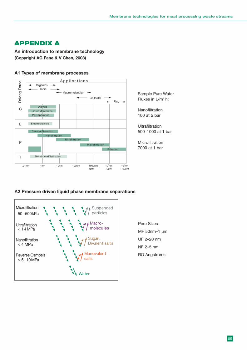
59
Membrane technologies for meat processing waste streams
APPENDIX A An introduction to membrane technology(Copyright AG Fane & V Chen, 2003)
A1 Types of membrane processes
Sample Pure WaterFluxes in L/m2 h:
Nanofiltration100 at 5 bar
Ultrafiltration500–1000 at 1 bar
Microfiltration7000 at 1 bar
A2 Pressure driven liquid phase membrane separations
Pore Sizes
MF 50nm–1 µm
UF 2–20 nm
NF 2–5 nm
RO Angstroms
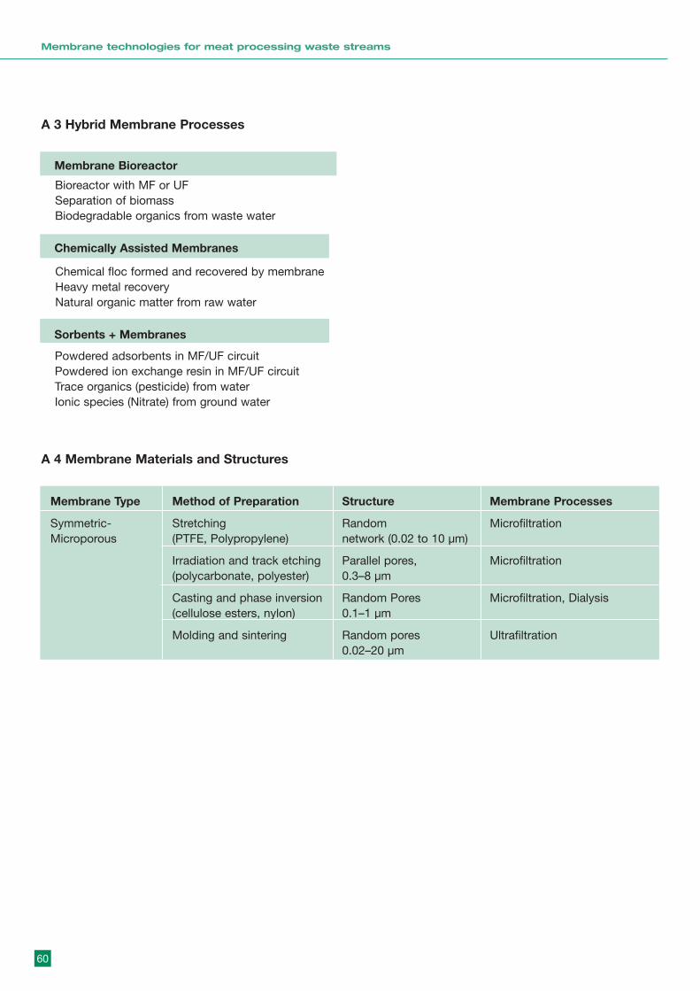
60
Membrane technologies for meat processing waste streams
A 3 Hybrid Membrane Processes
Membrane Bioreactor
Chemically Assisted Membranes
Sorbents + Membranes
Bioreactor with MF or UFSeparation of biomassBiodegradable organics from waste water
Powdered adsorbents in MF/UF circuitPowdered ion exchange resin in MF/UF circuitTrace organics (pesticide) from waterIonic species (Nitrate) from ground water
Chemical floc formed and recovered by membraneHeavy metal recoveryNatural organic matter from raw water
A 4 Membrane Materials and Structures
Membrane Type Method of Preparation Structure Membrane Processes
Symmetric- Stretching Random MicrofiltrationMicroporous (PTFE, Polypropylene) network (0.02 to 10 µm)
Irradiation and track etching Parallel pores, Microfiltration(polycarbonate, polyester) 0.3–8 µm
Casting and phase inversion Random Pores Microfiltration, Dialysis(cellulose esters, nylon) 0.1–1 µm
Molding and sintering Random pores Ultrafiltration0.02–20 µm

61
Membrane technologies for meat processing waste streams
Membrane Technologies for M eat Processing Waste Streams
A 7 Definitions
Feed
PermeateRetentate
Membrane
�
∆P, ∆C, ∆E
� �CB CP
A 8 The Components of Membrane Technology
Membranes
Systems Modules
4
Modules, Pumps, PipingTanks, Controls, Monitoring,Pretreatment Facilities,Cleaning Facilities
Series/ParallelTapered CascadeContinuous/BatchCrossflow/Dead End
A5 Membrane materials and structures
A6 Important membrane properties
Membrane Type Method of preparation Structure Membrane processes
Asymmetricsingle layer
Casting and phase-inversion(cellulosics, polyamides,polysulphone)
Dense or finelyporous skingrading to (marco)microporous substructure
Microfiltration, Ultrafiltration,Nanofiltration, ReverseOsmosis, Gas Separation
Dip Coating Finely porous layer onmacroporous structure
Microfiltration, Ultrafiltration
Film formation microporoussupport (dissimlar material)
Dense skin on microporoussupport
Nanofiltraiton, ReverseOsmosis, Gas Separation,Pervaporation
Deposition of fine precoateon microporous barrier
Thin (removable) layer onmicroporous membrane
Microfiltration, Ultrafiltration,Nanofiltration, ReverseOsmosis
Asymmetriccomposite
Dynamic
Impact Characterisation
Porosity and pore size distribution Flux, separation, fouling Bubble PointSolute ChallengeElectronMicroscopy
Fouling, cleaning, membranepreparation
Contact angle
Separation and fouling Streamingpotential,XPS, Auger, etc.
Hydrophilicity/hydrophobicity
Surface charge/chemistry
Applications, operation, andcleaning
Acceleratedaging tests,swelling andflux tests
Chemical and physical compatibility
Applications and economics $/m2 membrane or$/m3 permeate
Cost of fabrication/replacement/maintenance
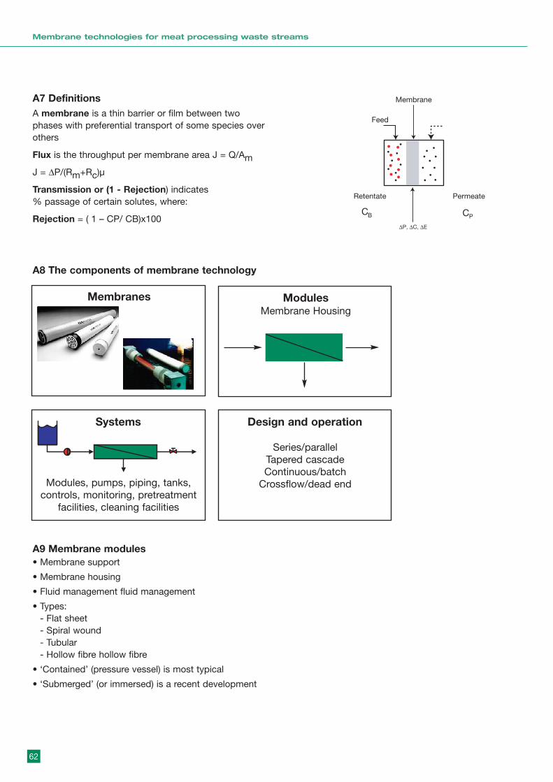
62
Membrane technologies for meat processing waste streams
A7 DefinitionsA membrane is a thin barrier or film between twophases with preferential transport of some species overothers
Flux is the throughput per membrane area J = Q/Am
J = ∆P/(Rm+Rc)µ
Transmission or (1 - Rejection) indicates% passage of certain solutes, where:
Rejection = ( 1 – CP/ CB)x100
A8 The components of membrane technology
Membrane Technologies for M eat Processing Waste Streams
A 7 Definitions
Feed
PermeateRetentate
Membrane
�
∆P, ∆C, ∆E
� �CB CP
A 8 The Components of Membrane Technology
Membranes
Systems Modules
4
Modules, Pumps, PipingTanks, Controls, Monitoring,Pretreatment Facilities,Cleaning Facilities
Series/ParallelTapered CascadeContinuous/BatchCrossflow/Dead End
A9 Membrane modules• Membrane support
• Membrane housing
• Fluid management fluid management
• Types:- Flat sheet- Spiral wound- Tubular- Hollow fibre hollow fibre
• ‘Contained’ (pressure vessel) is most typical
• ‘Submerged’ (or immersed) is a recent development
ModulesMembrane Housing
Design and operation
Series/parallelTapered cascadeContinuous/batch
Crossflow/dead end
Membrane Technologies for M eat Processing Waste Streams
A 7 Definitions
Feed
PermeateRetentate
Membrane
�
∆P, ∆C, ∆E
� �CB CP
A 8 The Components of Membrane Technology
Membranes
Systems Modules
4
Modules, Pumps, PipingTanks, Controls, Monitoring,Pretreatment Facilities,Cleaning Facilities
Series/ParallelTapered CascadeContinuous/BatchCrossflow/Dead End
Systems
Modules, pumps, piping, tanks,controls, monitoring, pretreatment
facilities, cleaning facilities
Membranes

63
Membrane technologies for meat processing waste streams
A10 Crossflow operation• Crossflow:
- Limits ‘cake’ deposited on surface andincreases flux (J) increases flux (J)
- Limits concentration at membrane surface (CW) and increases flux increases flux
- Most modules operate in crossflow
A11 Crossflow – fluid management• From mass and momentum transfer considerations
• For fouling feeds the effect of fouling may be diminished as crossflow increases
• Module design for fluid-management involves a trade-off between magnitude of flux ( Membrane Area, Capital) and pressure losses ( Energy, Operating)
• Some module designs favour laminar flow (lower Some module designs favour laminar flow (lower flux, more area) and others favour turbulent or flux, more area) and others favour turbulent or disrupted flow (higher pressure losses, more
Crossflow
Flux
Cak
eFlux
Cake
J = P
µ(R M + R C)
Film Model
J = k Sln(CW /C B)
kS= f (cr ossf low)
Crossflow
Flux C
W
Flux
CW
5
Flux = f(crossflow velocity)n
= f(Re)n
Pressure losses = (Re)m
A12 Flat-plate modules• Flat-sheet membranes on a porous support plate.
• Flow channels are thin, usually 1 to 3 mm height.
• Flow channel spacers may be used (see spiral wound modules)
• Membranes stacked in flow channels (series or parallel)
• Applications: MF, UF, NF, RO (small/medium scale)

64
Membrane technologies for meat processing waste streams
A13 Flat-plate modules (cont.)Some designs have rectangular supports with flowfrom one end to the other. from one end to the other.eg TECH SEP ‘Pleiade’
A14 Spiral-wound modules• Flat sheets wound around a central around a central
permeate tube
• Membranes supported by a permeate spacer, forminga membrane leaf
• Several leaves connected to the connected to thepermeate tube
• FEED CHANNEL SPACERS (a net SPACERS sheet)placed between leaves to define leaves to definechannel height and improve mass transfer
A15 Spiral-wound modules (cont.)• One or more modules are fitted into a single
cylindrical housing with axial permeate tubesconnected together.
• Module sizes are ‘standard’ (2 module sizes are‘standard’ (21/2 inch diameter, 4 inch, 8 inch) inchdiameter, 4 inch, 8 inch).
• Applications: UF, NF, RO (small to large scale).
• The most popular module design for large NF and RO plant.
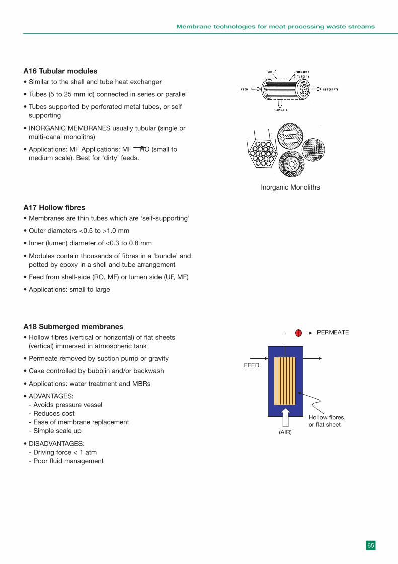
65
Membrane technologies for meat processing waste streams
A16 Tubular modules• Similar to the shell and tube heat exchanger
• Tubes (5 to 25 mm id) connected in series or parallel
• Tubes supported by perforated metal tubes, or selfsupporting
• INORGANIC MEMBRANES usually tubular (single ormulti-canal monoliths)
• Applications: MF Applications: MF RO (small tomedium scale). Best for ‘dirty’ feeds.
A17 Hollow fibres• Membranes are thin tubes which are ‘self-supporting’
• Outer diameters <0.5 to >1.0 mm
• Inner (lumen) diameter of <0.3 to 0.8 mm
• Modules contain thousands of fibres in a ‘bundle’ andpotted by epoxy in a shell and tube arrangement
• Feed from shell-side (RO, MF) or lumen side (UF, MF)
• Applications: small to large
A18 Submerged membranes• Hollow fibres (vertical or horizontal) of flat sheets
(vertical) immersed in atmospheric tank
• Permeate removed by suction pump or gravity
• Cake controlled by bubblin and/or backwash
• Applications: water treatment and MBRs
• ADVANTAGES:- Avoids pressure vessel - Reduces cost- Ease of membrane replacement- Simple scale up
• DISADVANTAGES:- Driving force < 1 atm - Poor fluid management
Inorganic Monoliths
FEED
(AIR)
PERMEATE
Hollow fibres,or flat sheet
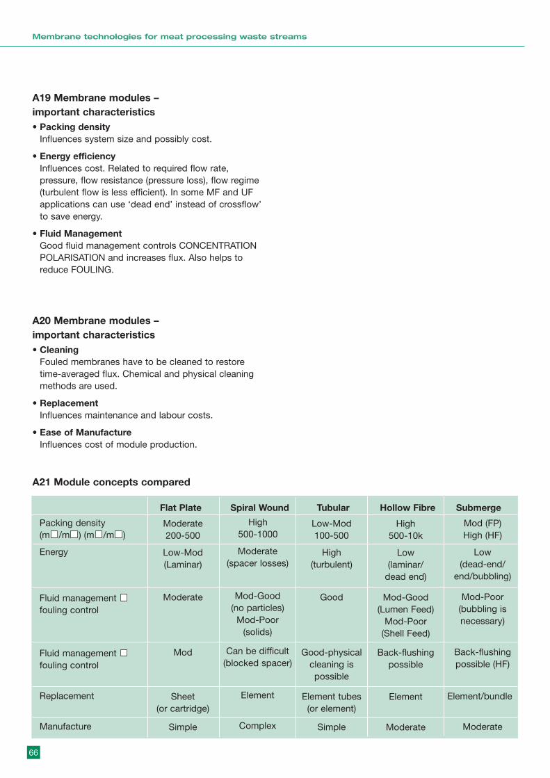
66
Membrane technologies for meat processing waste streams
A19 Membrane modules – important characteristics• Packing density
Influences system size and possibly cost.
• Energy efficiencyInfluences cost. Related to required flow rate,pressure, flow resistance (pressure loss), flow regime(turbulent flow is less efficient). In some MF and UFapplications can use ‘dead end’ instead of crossflow’to save energy.
• Fluid ManagementGood fluid management controls CONCENTRATIONPOLARISATION and increases flux. Also helps toreduce FOULING.
A20 Membrane modules – important characteristics• Cleaning
Fouled membranes have to be cleaned to restoretime-averaged flux. Chemical and physical cleaningmethods are used.
• ReplacementInfluences maintenance and labour costs.
• Ease of ManufactureInfluences cost of module production.
A21 Module concepts compared
Moderate 200-500
Low-Mod100-500
High500-1000
High500-10k
Mod (FP)High (HF)
Packing density (m /m ) (m /m )
Low-Mod(Laminar)
High(turbulent)
Moderate(spacer losses)
Low(laminar/
dead end)
Low(dead-end/
end/bubbling)
Energy
Moderate GoodMod-Good (no particles)
Mod-Poor(solids)
Mod-Good(Lumen Feed)
Mod-Poor (Shell Feed)
Mod-Poor(bubbling isnecessary)
Fluid management fouling control
Mod Good-physicalcleaning ispossible
Can be difficult(blocked spacer)
Back-flushingpossible
Back-flushingpossible (HF)
Fluid management fouling control
Sheet (or cartridge)
Element tubes(or element)
Element Element Element/bundle Replacement
Simple SimpleComplex Moderate ModerateManufacture
Flat Plate Spiral Wound Tubular Hollow Fibre Submerge
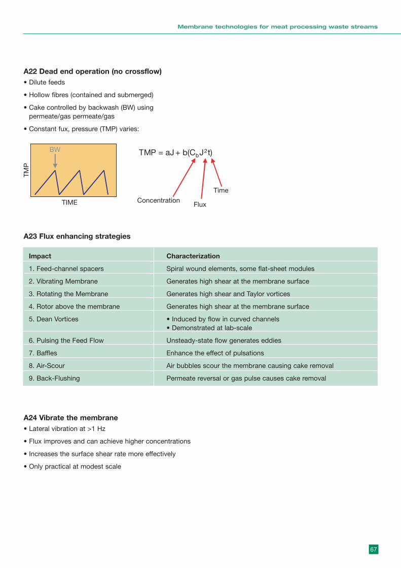
67
Membrane technologies for meat processing waste streams
A22 Dead end operation (no crossflow)• Dilute feeds
• Hollow fibres (contained and submerged)
• Cake controlled by backwash (BW) usingpermeate/gas permeate/gas
• Constant fux, pressure (TMP) varies:
A23 Flux enhancing strategies
Impact Characterization
1. Feed-channel spacers Spiral wound elements, some flat-sheet modules
2. Vibrating Membrane Generates high shear at the membrane surface
3. Rotating the Membrane Generates high shear and Taylor vortices
4. Rotor above the membrane Generates high shear at the membrane surface
5. Dean Vortices • Induced by flow in curved channels• Demonstrated at lab-scale
6. Pulsing the Feed Flow Unsteady-state flow generates eddies
7. Baffles Enhance the effect of pulsations
8. Air-Scour Air bubbles scour the membrane causing cake removal
9. Back-Flushing Permeate reversal or gas pulse causes cake removal
A24 Vibrate the membrane• Lateral vibration at >1 Hz
• Flux improves and can achieve higher concentrations
• Increases the surface shear rate more effectively
• Only practical at modest scale
TIME
TMP
BW TMP = aJ + b(CbJ2t)
ConcentrationFlux
Time
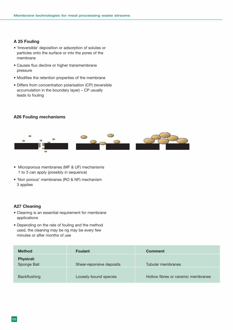
68
Membrane technologies for meat processing waste streams
A 25 Fouling• ‘Irreversible’ deposition or adsorption of solutes or
particles onto the surface or into the pores of themembrane
• Causes flux decline or higher transmembranepressure
• Modifies the retention properties of the membrane
• Differs from concentration polarisation (CP) (reversibleaccumulation in the boundary layer) – CP usuallyleads to fouling
A26 Fouling mechanisms
• Microporous membranes (MF & UF) mechanisms 1 to 3 can apply (possibly in sequence)
• ‘Non porous’ membranes (RO & NF) mechanism 3 applies
A27 Cleaning• Cleaning is an essential requirement for membrane
applications
• Depending on the rate of fouling and the methodused, the cleaning may be ng may be every fewminutes or after months of use
Method Foulant Comment
Physical:Sponge Ball Shear-reponsive deposits Tubular membranes
Backflushing Loosely-bound species Hollow fibres or ceramic membranes
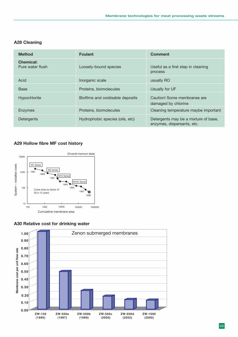
69
Membrane technologies for meat processing waste streams
A28 Cleaning
A29 Hollow fibre MF cost history
A30 Relative cost for drinking water
Method Foulant Comment
Chemical:Pure water flush Loosely-bound species Useful as a first step in cleaning
process
Acid Inorganic scale usually RO
Base Proteins, biomolecules Usually for UF
Hypochlorite Biofilms and oxidisable deposits Caution! Some membranes are damaged by chlorine
Enzymes Proteins, biomolecules Cleaning temperature maybe important
Detergents Hydrophobic species (oils, etc) Detergents may be a mixture of base, enzymes, dispersants, etc.
0.00
0.10
0.20
0.30
0.40
0.50
0.60
0.70
0.80
0.90
1.00
Me
mb
arn
ec
os
tn
u re
p i t
f lo
war
te
ZW-150
(1995)
ZW-500a
(1997)
ZW-500b
(1999)
ZW-500c
(2000)
ZW-500d
(2002)
ZW-1000
(2000)
Zenon submerged membranes
Sys
tem
– in
stal
led
cos
ts
Cumulative membrane area
10
100
19871989
1991
19931995
1997
1999
100
1000
1000
10000
10000 100000 1000000
Costs drop by factor of 30 in 12 years
M1 Series
M2 Series
M10 Series
M10C Series
(Vivendi-memcor data)
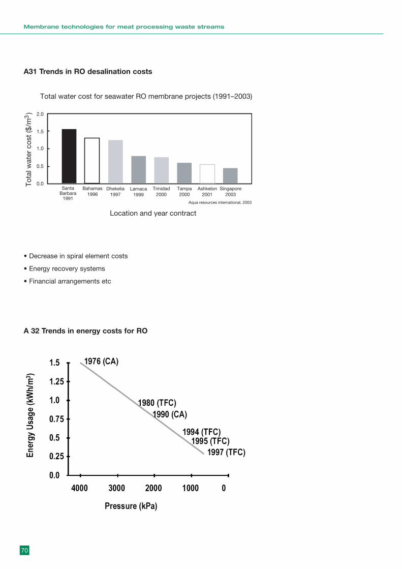
70
Membrane technologies for meat processing waste streams
A31 Trends in RO desalination costs
• Decrease in spiral element costs
• Energy recovery systems
• Financial arrangements etc
A 32 Trends in energy costs for RO
Tota
l wat
er c
ost
($/m
)3
Total water cost for seawater RO membrane projects (1991–2003)
Location and year contract
Santa Barbara
1991
Bahamas1996
Dhekelia1997
Larnaca1999
Trinidad2000
Tampa2000
Ashkelon2001
Singapore2003
0.0
0.5
1.0
1.5
2.0
Aqua resources international, 2003

71
Membrane technologies for meat processing waste streams
A33 Flow sheet for conventional AS and tertiary MF/UF
A34 Flowsheet for MBR (after Cote and Lui, 2003)

72
Membrane technologies for meat processing waste streams
A35 Kubota MBR operating costs (churchouse and wildgoose)
Revenue costs 1992-2004
1992 1998
1995 2004
107 $c/m3
16 $c/m3
33 $c/m3
11 $c/m3
2000 m /d plant3
Chemicals etcMaintenanceSludge disposalPowerMembrane replacement
73
Membrane technologies for meat processing waste streams
APPENDIX BSUPPLEMENTARY INFORMATION
VSEP Applications
Taken from VSEP Web site (www.vsep.com)1. Water and wastewaterBOD / COD / TSS / TDS / TOC removalLandfill leachateBoiler feed waterOily wastewaterCooling tower blowdownPrimary and secondary treatmentDrinking waterProcess water purificationGlycol recoveryReclaimed waterGroundwater remediationRO reject concentrationIndustrial laundry wastewaterRecyclingTextile dye wastewaterIndustrial wastewater and fluid recyclingUltra-pure water
2. Pulp and paperBlack liquorMedium density fibreboardBleach plant effluentPaper coating effluentBox and bag plant effluentTDS/ TSS/ BOD/ COD/ colour removalClarifier overflowWhitewaterHardboard manufacturing
3. Paints and pigmentsBio-Sludge concentrationOrganic and inorganic pigment washingCarbon black concentrationOrganic and inorganic pigment concentratingCarbon black washingScrubber effulentGeneral wastewater reduction and recyclingSludge dewatering
4. Chemical process industryAcid clarificationFertilizer clarificationBoiler water treatmentLatex emulsion concentrationBroad range of high-solids concentrations (up to 70%)
Metal hydroxide treatmentCalcium carbonate concentrationNaOH recoveryCalcium chloride clarificationOthalic acid catalyst finesCatalyst washing and concentrationPhosphate filtrationColloidal silica filtrationPolymer washing and concentrating (diafiltration)Ethanol productionTitanium dioxide filtration and concentration
5. Oil production/processing/recyclingCompletion fluidsFuel tank washdownCracking catalyst removalInjection waterDesalter effluentProcess water clarification and recyclingDrilling mudsProduced waterExtraction brine recoveryRefinery wastewater recyclingFuel storage tank bottom waterWaste oil recycling
6. Mining and related processesAcid mine drainageLanthanide mining/milling effluentBentoniteMineral clay dewateringCalcium carbonate concentrationMine tailing processingKaolin clayPrecious metal recovery
7. ManufacturingCircuit board manufacturingMetal platingCoolant recoveryOily wastewaterElectrochemical machining metalHydroxidesPrecious metal recovery
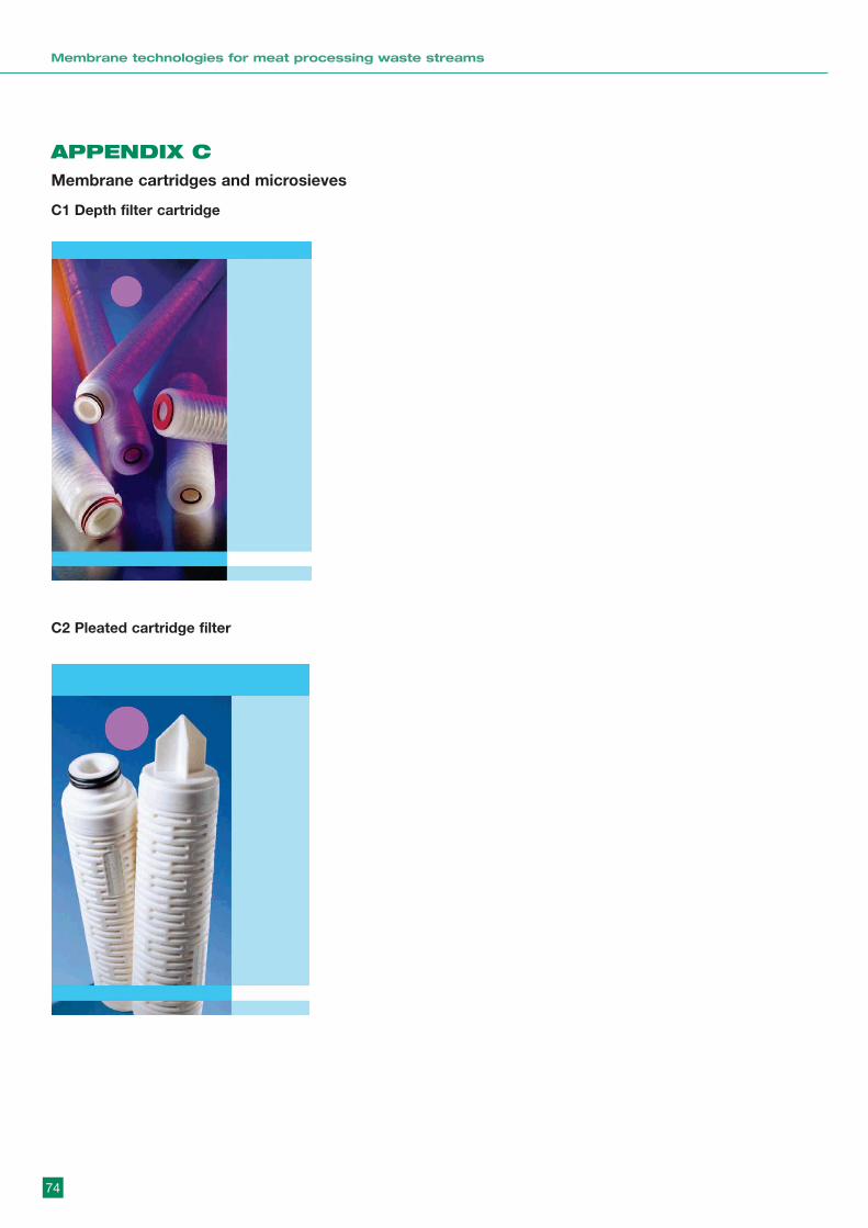
74
Membrane technologies for meat processing waste streams
APPENDIX C Membrane cartridges and microsieves
C1 Depth filter cartridge
C2 Pleated cartridge filter
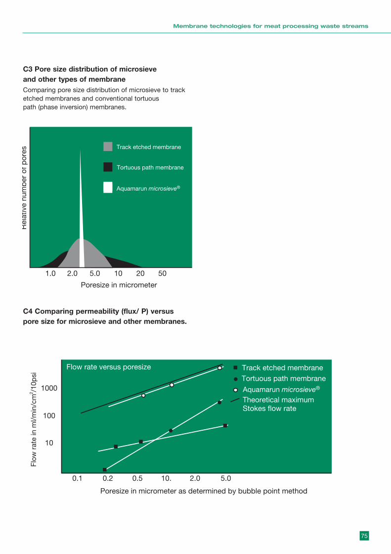
75
Membrane technologies for meat processing waste streams
C4 Comparing permeability (flux/ ÆP) versuspore size for microsieve and other membranes.
C3 Pore size distribution of microsieveand other types of membraneComparing pore size distribution of microsieve to track etched membranes and conventional tortuouspath (phase inversion) membranes.
Rel
ativ
e nu
mb
er o
f por
es
Poresize in micrometer
Poresize in micrometer as determined by bubble point method
Track etched membrane
Tortuous path membrane
1.0
0.1
10
100
1000
0.2 0.5 10. 2.0 5.0
2.0 5.0 10 20 50
Flow
rat
e in
ml/m
in/c
m /
10p
si
2
Track etched membraneTortuous path membrane
Flow rate versus poresize
Aquamarun microsieve®
Aquamarun microsieve®
Theoretical maximum Stokes flow rate

76
Membrane technologies for meat processing waste streams
Notes

77
Membrane technologies for meat processing waste streams

78
Membrane technologies for meat processing waste streams

Level 1, 165 Walker StreetNorth Sydney NSW 2060Ph: +61 2 9463 9333Fax: +61 2 9463 9393
www.mla.com.au
Related Documents