MELSEC-Q Series to MELSEC iQ-R Series Migration Guide

Welcome message from author
This document is posted to help you gain knowledge. Please leave a comment to let me know what you think about it! Share it to your friends and learn new things together.
Transcript

MELSEC-Q Series to MELSEC iQ-R Series Migration Guide


SAFETY PRECAUTIONS(Read these precautions before using this product.)Before using MELSEC iQ-R series programmable controllers, please read the manuals for the product and the relevant manuals introduced in those manuals carefully, and pay full attention to safety to handle the product correctly.In this manual, the safety precautions are classified into two levels: " WARNING" and " CAUTION".
Under some circumstances, failure to observe the precautions given under " CAUTION" may lead to serious consequences.Observe the precautions of both levels because they are important for personal and system safety.Make sure that the end users read this document and then keep the document in a safe place for future reference.
WARNING Indicates that incorrect handling may cause hazardous conditions, resulting in death or severe injury.
CAUTION Indicates that incorrect handling may cause hazardous conditions, resulting in minor or moderate injury or property damage.
1

2
[Design Precautions]WARNING
● Configure safety circuits external to the programmable controller to ensure that the entire system operates safely even when a fault occurs in the external power supply or the programmable controller. Failure to do so may result in an accident due to an incorrect output or malfunction.(1) Emergency stop circuits, protection circuits, and protective interlock circuits for conflicting
operations (such as forward/reverse rotations or upper/lower limit positioning) must be configured external to the programmable controller.
(2) When the programmable controller detects an abnormal condition, it stops the operation and all outputs are: • Turned off if the overcurrent or overvoltage protection of the power supply module is activated. • Held or turned off according to the parameter setting if the self-diagnostic function of the CPU
module detects an error such as a watchdog timer error.(3) All outputs may be turned on if an error occurs in a part, such as an I/O control part, where the
CPU module cannot detect any error. To ensure safety operation in such a case, provide a safety mechanism or a fail-safe circuit external to the programmable controller.
(4) Outputs may remain on or off due to a failure of a component such as a relay and transistor in an output circuit. Configure an external circuit for monitoring output signals that could cause a serious accident.
● In an output circuit, when a load current exceeding the rated current or an overcurrent caused by a load short-circuit flows for a long time, it may cause smoke and fire. To prevent this, configure an external safety circuit, such as a fuse.
● Configure a circuit so that the programmable controller is turned on first and then the external power supply. If the external power supply is turned on first, an accident may occur due to an incorrect output or malfunction.
● For the operating status of each station after a communication failure, refer to manuals relevant to the network. Incorrect output or malfunction due to a communication failure may result in an accident.
● When connecting an external device with a CPU module or intelligent function module to modify data of a running programmable controller, configure an interlock circuit in the program to ensure that the entire system will always operate safely. For other forms of control (such as program modification, parameter change, forced output, or operating status change) of a running programmable controller, read the relevant manuals carefully and ensure that the operation is safe before proceeding. Improper operation may damage machines or cause accidents.

[Design Precautions]WARNING
● Especially, when a remote programmable controller is controlled by an external device, immediate action cannot be taken if a problem occurs in the programmable controller due to a communication failure. To prevent this, configure an interlock circuit in the program, and determine corrective actions to be taken between the external device and CPU module in case of a communication failure.
● Do not write any data to the "system area" and "write-protect area" of the buffer memory in the module. Also, do not use any "use prohibited" signals as an output signal from the CPU module to each module. Doing so may cause malfunction of the programmable controller system. For the "system area", "write-protect area", and the "use prohibited" signals, refer to the user's manual for the module used.
● If a communication cable is disconnected, the network may be unstable, resulting in a communication failure of multiple stations. Configure an interlock circuit in the program to ensure that the entire system will always operate safely even if communications fail. Incorrect output or malfunction due to a communication failure may result in an accident.
● To maintain the safety of the programmable controller system against unauthorized access from external devices via the network, take appropriate measures. To maintain the safety against unauthorized access via the Internet, take measures such as installing a firewall.
[Precautions for using digital-analog converter modules and high speed digital-analog converter modules]● Analog outputs may remain on due to a failure of the module. Configure an external interlock circuit
for output signals that could cause a serious accident.[Precautions for using high-speed counter modules]● Outputs may remain on or off due to a failure of a transistor for external output. Configure an external
circuit for monitoring output signals that could cause a serious accident.[Precautions for using positioning modules]● Configure safety circuits external to the programmable controller to ensure that the entire system
operates safely even when a fault occurs in the external power supply or the programmable controller. Failure to do so may result in an accident due to an incorrect output or malfunction.(1) Machine OPR (Original Point Return) is controlled by two kinds of data: an OPR direction and an
OPR speed. Deceleration starts when the near-point dog signal turns on. If an incorrect OPR direction is set, motion control may continue without deceleration. To prevent machine damage caused by this, configure an interlock circuit external to the programmable controller.
(2) When the positioning module detects an error, the motion slows down and stops or the motion suddenly stops, depending on the stop group setting in parameter. Set the parameters to meet the specifications of the positioning control system used. In addition, set the OPR parameters and positioning data within the specified setting range.
(3) Outputs may remain on or off, or become undefined due to a failure of a component such as an insulation element and transistor in an output circuit, where the positioning module cannot detect any error. In a system where the incorrect outputs could cause a serious accident, configure an external circuit for monitoring output signals.
● An absolute position restoration by the positioning module may turn off the servo-on signal (servo off) for approximately 60ms + scan time, and the motor may run unexpectedly. If this causes a problem, provide an electromagnetic brake to lock the motor during absolute position restoration.
3

4
[Design Precautions]WARNING
[Precautions for using CC-Link IE Controller Network (when optical fiber cables are used)]● The optical transmitter and receiver of the CC-Link IE Controller Network module use laser diodes
(class 1 in accordance with IEC 60825-1). Do not look directly at a laser beam. Doing so may harm your eyes.
[Precautions for using CC-Link system master/local modules]● To set a refresh device in the module parameters, select the device Y for the remote output (RY)
refresh device. If a device other than Y, such as M and L, is selected, the CPU module holds the device status even after its status is changed to STOP. For how to stop data link, refer to the MELSEC iQ-R CC-Link System Master/Local Module User's Manual (Application).
[Precautions for using C Controller modules]● In the settings of refresh parameters, link output (LY) refresh devices and remote output (RY) refresh
devices do not allow the specification of Y. Thus, the CPU module holds the device status even after its status is changed to STOP.
[Precautions for using products in a Class , Division 2 environment]● Products with the Cl., DIV.2 mark on the rating plate are suitable for use in Class , Division 2,
Groups A, B, C and D hazardous locations, or nonhazardous locations only.This mark indicates that the product is certified for use in the Class , Division 2 environment where
flammable gases, vapors, or liquids exist under abnormal conditions. When using the products in the Class , Division 2 environment, observe the following to reduce the risk of explosion. • This device is open-type and is to be installed in an enclosure suitable for the environment and
require a tool or key to open. • Warning - Explosion Hazard - Substitution of any component may impair suitability for Class ,
Division 2. • Warning - Explosion Hazard - Do not disconnect equipment while the circuit is live or unless the
area is known to be free of ignitable concentrations. • Do not open the cover of the CPU module and remove the battery unless the area is known to
be nonhazardous. • All MELSEC iQ-R modules (except base modules) are to be connected to a base module only.
[Precautions for using AnyWireASLINK master modules]● An AnyWireASLINK system has no control function for ensuring safety.[Precautions for using DeviceNet master/slave modules]● If a communication failure occurs on a DeviceNet network, faulty nodes will behave as (1) and (2)
below. Configure an interlock circuit in the program using the communication status information of slave nodes and provide a safety mechanism external to the slave node to ensure that the entire system will operate safely.(1) The master node (RJ71DN91) holds input data which had been received from slave nodes before
the communication failure occurred.(2) Whether output signals of a slave node are turned off or held is determined by the specifications
of slave nodes or the parameter settings of the master node. When the RJ71DN91 is used as a slave node, it holds input data that had been received from the master node before the communication failure occurred.

[Design Precautions]WARNING
[Precautions for using PROFIBUS-DP modules]● If a communication failure occurs with a PROFIBUS-DP network, the operating status of each station
is as follows:(1) The DP-Master holds the input data when the communication failure occurs.(2) If the DP-Master goes down, the output status of each DP-Slave depends on the parameter
setting of the DP-Master.(3) If a DP-Slave goes down, the output status of other DP-Slaves depends on the parameter setting
of the DP-Master.Check the diagnostic information and configure an interlock circuit in the program to ensure that the entire system will operate safely. Failure to do so may result in an accident due to an incorrect output or malfunction.
● The assignments of I/O signals and buffer memory areas differ depending on whether the RJ71PB91V is used as the DP-Master or a DP-Slave. Configure an interlock circuit in the program to ensure that the program does not run with the incorrect station type.
● If a stop error occurs in the CPU module, the operating status of the DP-Master is as follows.In a redundant system, however, the operation is the same as when "CPU Error Output Mode Setting" is set to "Hold" regardless of its setting value.(1) When "CPU Error Output Mode Setting" is set to "Clear"
• I/O data exchanges with DP-Slaves are interrupted. • Output data in the buffer memory of the DP-Master are cleared and not sent. • Input data which have been received from DP-Slaves when a stop error occurs in the CPU
module are held in the buffer memory of the DP-Master.(2) When "CPU Error Output Mode Setting" is set to "Hold"
• I/O data exchanges with DP-Slaves are continued. • Output data which have been stored in the buffer memory of the DP-Master when a stop error
occurs in the CPU module are held and sent to DP-Slaves. • Data in the buffer memory of the DP-Master are updated with input data received from DP-
Slaves.● If a stop error occurs in the CPU module, the operating status of DP-Slaves is as follows:
(1) When "CPU Error Output Mode Setting" is set to "Clear" • Input data to be sent from DP-Slaves to the DP-Master are cleared. • Output data which have been received from the DP-Master when a stop error occurs in the
CPU module are held in the buffer memory of DP-Slaves.(2) When "CPU Error Output Mode Setting" is set to "Hold"
• Input data to be sent from DP-Slaves to the DP-Master when a stop error occurs in the CPU module are held.
• Output data which have been received from the DP-Master when a stop error occurs in the CPU module are held in the buffer memory of DP-Slaves.
5

6
[Design Precautions]CAUTION
● Do not install the control lines or communication cables together with the main circuit lines or power cables. Keep a distance of 100mm or more between them. Failure to do so may result in malfunction due to noise.
● During control of an inductive load such as a lamp, heater, or solenoid valve, a large current (approximately ten times greater than normal) may flow when the output is turned from off to on. Therefore, use a module that has a sufficient current rating.
● After the CPU module is powered on or is reset, the time taken to enter the RUN status varies depending on the system configuration, parameter settings, and/or program size. Design circuits so that the entire system will always operate safely, regardless of the time.
● Do not power off the programmable controller or reset the CPU module while the settings are being written. Doing so will make the data in the flash ROM and SD memory card undefined. The values need to be set in the buffer memory and written to the flash ROM and SD memory card again. Doing so also may cause malfunction or failure of the module.
● When changing the operating status of the CPU module from external devices (such as the remote RUN/STOP functions), select "Do Not Open by Program" for "Opening Method" of "Module Parameter". If "Open by Program" is selected, an execution of the remote STOP function causes the communication line to close. Consequently, the CPU module cannot reopen the line, and external devices cannot execute the remote RUN function.
[Precautions for using digital-analog converter modules and high speed digital-analog converter modules]● Power on or off the external power supply while the programmable controller is on. Failure to do so
may result in incorrect output or malfunction.● At on/off of the power or external power supply, or at the output range switching, a voltage may occur
or a current may flow between output terminals for a moment. In this case, start the control after analog outputs become stable.
[Precautions for using high-speed counter modules]● Do not install the control lines or communication cables together with the main circuit lines or power
cables. Keep a distance of 150mm or more between them. Failure to do so may result in malfunction due to noise.

[Installation Precautions]
[Installation Precautions]
WARNING● Shut off the external power supply (all phases) used in the system before mounting or removing the
module. Failure to do so may result in electric shock or cause the module to fail or malfunction.[Precautions for using C Controller modules]● When mounting a C Controller module, make sure to attach the connector cover included in a base
unit to the module connector of the second slot to prevent entrance of foreign material such as dust.
CAUTION● Use the programmable controller in an environment that meets general specifications. Failure to do so
may result in electric shock, fire, malfunction, or damage to or deterioration of the product.● To mount a module, place the concave part(s) located at the bottom onto the guide(s) of the base unit,
and push in the module until the hook(s) located at the top snaps into place. Incorrect interconnection may cause malfunction, failure, or drop of the module.
● To mount a module with no module fixing hook, place the concave part(s) located at the bottom onto the guide(s) of the base unit, push in the module, and fix it with screw(s). Incorrect interconnection may cause malfunction, failure, or drop of the module.
● When using the programmable controller in an environment of frequent vibrations, fix the module with a screw.
● Tighten the screws within the specified torque range. Undertightening can cause drop of the screw, short circuit, or malfunction. Overtightening can damage the screw and/or module, resulting in drop, short circuit, or malfunction.
● When using an extension cable, connect it to the extension cable connector of the base unit securely. Check the connection for looseness. Poor contact may cause malfunction.
● When using an SD memory card, fully insert it into the SD memory card slot. Check that it is inserted completely. Poor contact may cause malfunction.
● Securely insert an extended SRAM cassette into the cassette connector of the CPU module. After insertion, close the cassette cover and check that the cassette is inserted completely. Poor contact may cause malfunction.
● Do not directly touch any conductive parts and electronic components of the module, SD memory card, extended SRAM cassette, or connector. Doing so can cause malfunction or failure of the module.
7
8
[Wiring Precautions]
[Wiring Precautions]
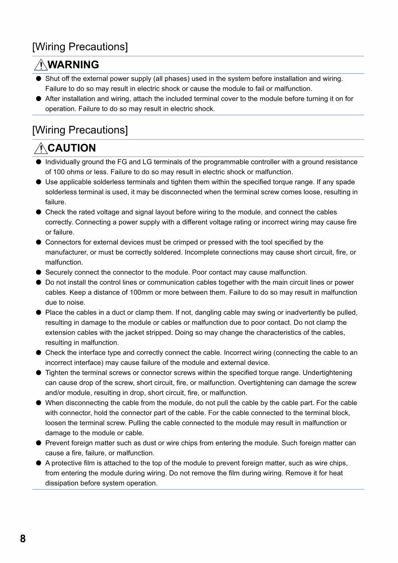
WARNING● Shut off the external power supply (all phases) used in the system before installation and wiring.
Failure to do so may result in electric shock or cause the module to fail or malfunction.● After installation and wiring, attach the included terminal cover to the module before turning it on for
operation. Failure to do so may result in electric shock.
CAUTION● Individually ground the FG and LG terminals of the programmable controller with a ground resistance
of 100 ohms or less. Failure to do so may result in electric shock or malfunction.● Use applicable solderless terminals and tighten them within the specified torque range. If any spade
solderless terminal is used, it may be disconnected when the terminal screw comes loose, resulting in failure.
● Check the rated voltage and signal layout before wiring to the module, and connect the cables correctly. Connecting a power supply with a different voltage rating or incorrect wiring may cause fire or failure.
● Connectors for external devices must be crimped or pressed with the tool specified by the manufacturer, or must be correctly soldered. Incomplete connections may cause short circuit, fire, or malfunction.
● Securely connect the connector to the module. Poor contact may cause malfunction.● Do not install the control lines or communication cables together with the main circuit lines or power
cables. Keep a distance of 100mm or more between them. Failure to do so may result in malfunction due to noise.
● Place the cables in a duct or clamp them. If not, dangling cable may swing or inadvertently be pulled, resulting in damage to the module or cables or malfunction due to poor contact. Do not clamp the extension cables with the jacket stripped. Doing so may change the characteristics of the cables, resulting in malfunction.
● Check the interface type and correctly connect the cable. Incorrect wiring (connecting the cable to an incorrect interface) may cause failure of the module and external device.
● Tighten the terminal screws or connector screws within the specified torque range. Undertightening can cause drop of the screw, short circuit, fire, or malfunction. Overtightening can damage the screw and/or module, resulting in drop, short circuit, fire, or malfunction.
● When disconnecting the cable from the module, do not pull the cable by the cable part. For the cable with connector, hold the connector part of the cable. For the cable connected to the terminal block, loosen the terminal screw. Pulling the cable connected to the module may result in malfunction or damage to the module or cable.
● Prevent foreign matter such as dust or wire chips from entering the module. Such foreign matter can cause a fire, failure, or malfunction.
● A protective film is attached to the top of the module to prevent foreign matter, such as wire chips, from entering the module during wiring. Do not remove the film during wiring. Remove it for heat dissipation before system operation.
[Wiring Precautions]CAUTION
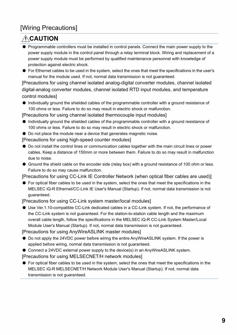
● Programmable controllers must be installed in control panels. Connect the main power supply to the power supply module in the control panel through a relay terminal block. Wiring and replacement of a power supply module must be performed by qualified maintenance personnel with knowledge of protection against electric shock.
● For Ethernet cables to be used in the system, select the ones that meet the specifications in the user's manual for the module used. If not, normal data transmission is not guaranteed.
[Precautions for using channel isolated analog-digital converter modules, channel isolated digital-analog converter modules, channel isolated RTD input modules, and temperature control modules]● Individually ground the shielded cables of the programmable controller with a ground resistance of
100 ohms or less. Failure to do so may result in electric shock or malfunction.[Precautions for using channel isolated thermocouple input modules]● Individually ground the shielded cables of the programmable controller with a ground resistance of
100 ohms or less. Failure to do so may result in electric shock or malfunction.● Do not place the module near a device that generates magnetic noise.[Precautions for using high-speed counter modules]● Do not install the control lines or communication cables together with the main circuit lines or power
cables. Keep a distance of 150mm or more between them. Failure to do so may result in malfunction due to noise.
● Ground the shield cable on the encoder side (relay box) with a ground resistance of 100 ohm or less. Failure to do so may cause malfunction.
[Precautions for using CC-Link IE Controller Network (when optical fiber cables are used)]● For optical fiber cables to be used in the system, select the ones that meet the specifications in the
MELSEC iQ-R Ethernet/CC-Link IE User's Manual (Startup). If not, normal data transmission is not guaranteed.
[Precautions for using CC-Link system master/local modules]● Use Ver.1.10-compatible CC-Link dedicated cables in a CC-Link system. If not, the performance of
the CC-Link system is not guaranteed. For the station-to-station cable length and the maximum overall cable length, follow the specifications in the MELSEC iQ-R CC-Link System Master/Local Module User's Manual (Startup). If not, normal data transmission is not guaranteed.
[Precautions for using AnyWireASLINK master modules]● Do not apply the 24VDC power before wiring the entire AnyWireASLINK system. If the power is
applied before wiring, normal data transmission is not guaranteed.● Connect a 24VDC external power supply to the device(s) in an AnyWireASLINK system.[Precautions for using MELSECNET/H network modules]● For optical fiber cables to be used in the system, select the ones that meet the specifications in the
MELSEC iQ-R MELSECNET/H Network Module User's Manual (Startup). If not, normal data transmission is not guaranteed.
9

10
[Startup and Maintenance Precautions]
[Startup and Maintenance Precautions]
WARNING● Do not touch any terminal while power is on. Doing so will cause electric shock or malfunction.● Correctly connect the battery connector. Do not charge, disassemble, heat, short-circuit, solder, or
throw the battery into the fire. Also, do not expose it to liquid or strong shock. Doing so will cause the battery to produce heat, explode, ignite, or leak, resulting in injury and fire.
● Shut off the external power supply (all phases) used in the system before cleaning the module or retightening the terminal screws, connector screws, or module fixing screws. Failure to do so may result in electric shock.
CAUTION● When connecting an external device with a CPU module or intelligent function module to modify data
of a running programmable controller, configure an interlock circuit in the program to ensure that the entire system will always operate safely. For other forms of control (such as program modification, parameter change, forced output, or operating status change) of a running programmable controller, read the relevant manuals carefully and ensure that the operation is safe before proceeding. Improper operation may damage machines or cause accidents.
● Especially, when a remote programmable controller is controlled by an external device, immediate action cannot be taken if a problem occurs in the programmable controller due to a communication failure. To prevent this, configure an interlock circuit in the program, and determine corrective actions to be taken between the external device and CPU module in case of a communication failure.
● Do not disassemble or modify the modules. Doing so may cause failure, malfunction, injury, or a fire.● Use any radio communication device such as a cellular phone or PHS (Personal Handy-phone
System) more than 25cm away in all directions from the programmable controller. Failure to do so may cause malfunction.
● Shut off the external power supply (all phases) used in the system before mounting or removing the module. Failure to do so may cause the module to fail or malfunction.
● Tighten the screws within the specified torque range. Undertightening can cause drop of the component or wire, short circuit, or malfunction. Overtightening can damage the screw and/or module, resulting in drop, short circuit, or malfunction.
● After the first use of the product, do not mount/remove the module to/from the base unit, and the terminal block to/from the module, and do not insert/remove the extended SRAM cassette to/from the CPU module more than 50 times (IEC 61131-2 compliant) respectively. Exceeding the limit may cause malfunction.
● After the first use of the product, do not insert/remove the SD memory card to/from the CPU module more than 500 times. Exceeding the limit may cause malfunction.
● Do not touch the metal terminals on the back side of the SD memory card. Doing so may cause malfunction or failure of the module.
● Do not touch the integrated circuits on the circuit board of an extended SRAM cassette. Doing so may cause malfunction or failure of the module.
[Startup and Maintenance Precautions]CAUTION
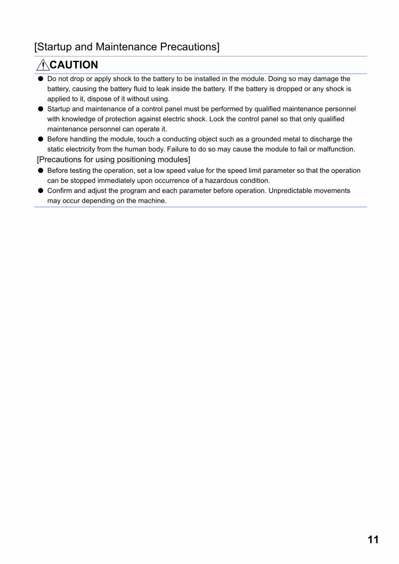
● Do not drop or apply shock to the battery to be installed in the module. Doing so may damage the battery, causing the battery fluid to leak inside the battery. If the battery is dropped or any shock is applied to it, dispose of it without using.
● Startup and maintenance of a control panel must be performed by qualified maintenance personnel with knowledge of protection against electric shock. Lock the control panel so that only qualified maintenance personnel can operate it.
● Before handling the module, touch a conducting object such as a grounded metal to discharge the static electricity from the human body. Failure to do so may cause the module to fail or malfunction.
[Precautions for using positioning modules]● Before testing the operation, set a low speed value for the speed limit parameter so that the operation
can be stopped immediately upon occurrence of a hazardous condition.● Confirm and adjust the program and each parameter before operation. Unpredictable movements
may occur depending on the machine.
11

12
[Operating Precautions]
[Disposal Precautions]
[Transportation Precautions]
CAUTION● When changing data and operating status, and modifying program of the running programmable
controller from an external device such as a personal computer connected to an intelligent function module, read relevant manuals carefully and ensure the safety before operation. Incorrect change or modification may cause system malfunction, damage to the machines, or accidents.
● Do not power off the programmable controller or reset the CPU module while the setting values in the buffer memory are being written to the flash ROM in the module. Doing so will make the data in the flash ROM and SD memory card undefined. The values need to be set in the buffer memory and written to the flash ROM and SD memory card again. Doing so can cause malfunction or failure of the module.
[Precautions for using positioning modules]● Note that when the reference axis speed is specified for interpolation operation, the speed of the
partner axis (2nd, 3rd, or 4th axis) may exceed the speed limit value.● Do not go near the machine during test operations or during operations such as teaching. Doing so
may lead to injuries.
CAUTION● When disposing of this product, treat it as industrial waste.● When disposing of batteries, separate them from other wastes according to the local regulations.
CAUTION● When transporting lithium batteries, follow the transportation regulations.● The halogens (such as fluorine, chlorine, bromine, and iodine), which are contained in a fumigant
used for disinfection and pest control of wood packaging materials, may cause failure of the product. Prevent the entry of fumigant residues into the product or consider other methods (such as heat treatment) instead of fumigation. The disinfection and pest control measures must be applied to unprocessed raw wood.

CONDITIONS OF USE FOR THE PRODUCT
INTRODUCTIONThank you for purchasing the Mitsubishi Electric MELSEC iQ-R series programmable controllers.This document describes the system configuration, specifications, installation, wiring, maintenance, and inspection of MELSEC iQ-R series programmable controllers.Before using this product, please read this document and the relevant manuals carefully and develop familiarity with the functions and performance of the MELSEC iQ-R series programmable controller to handle the product correctly.When applying the program and circuit examples provided in this document to an actual system, ensure the applicability and confirm that it will not cause system control problems.Please make sure that the end users read this document.Specifications are subject to change without notice.
(1) Mitsubishi programmable controller ("the PRODUCT") shall be used in conditions;i) where any problem, fault or failure occurring in the PRODUCT, if any, shall not lead to any major or serious accident; and ii) where the backup and fail-safe function are systematically or automatically provided outside of the PRODUCT for the case of any problem, fault or failure occurring in the PRODUCT.
(2) The PRODUCT has been designed and manufactured for the purpose of being used in general industries.MITSUBISHI SHALL HAVE NO RESPONSIBILITY OR LIABILITY (INCLUDING, BUT NOT LIMITED TO ANY AND ALL RESPONSIBILITY OR LIABILITY BASED ON CONTRACT, WARRANTY, TORT, PRODUCT LIABILITY) FOR ANY INJURY OR DEATH TO PERSONS OR LOSS OR DAMAGE TO PROPERTY CAUSED BY the PRODUCT THAT ARE OPERATED OR USED IN APPLICATION NOT INTENDED OR EXCLUDED BY INSTRUCTIONS, PRECAUTIONS, OR WARNING CONTAINED IN MITSUBISHI'S USER, INSTRUCTION AND/OR SAFETY MANUALS, TECHNICAL BULLETINS AND GUIDELINES FOR the PRODUCT. ("Prohibited Application")Prohibited Applications include, but not limited to, the use of the PRODUCT in;• Nuclear Power Plants and any other power plants operated by Power companies, and/or any other cases in which the
public could be affected if any problem or fault occurs in the PRODUCT.• Railway companies or Public service purposes, and/or any other cases in which establishment of a special quality
assurance system is required by the Purchaser or End User.• Aircraft or Aerospace, Medical applications, Train equipment, transport equipment such as Elevator and Escalator,
Incineration and Fuel devices, Vehicles, Manned transportation, Equipment for Recreation and Amusement, and Safety devices, handling of Nuclear or Hazardous Materials or Chemicals, Mining and Drilling, and/or other applications where there is a significant risk of injury to the public or property.
Notwithstanding the above restrictions, Mitsubishi may in its sole discretion, authorize use of the PRODUCT in one or more of the Prohibited Applications, provided that the usage of the PRODUCT is limited only for the specific applications agreed to by Mitsubishi and provided further that no special quality assurance or fail-safe, redundant or other safety features which exceed the general specifications of the PRODUCTs are required. For details, please contact the Mitsubishi representative in your region.
13

14
CONTENTSSAFETY PRECAUTIONS . . . . . . . . . . . . . . . . . . . . . . . . . . . . . . . . . . . . . . . . . . . . . . . . . . . . . . . . . . . . . . . . . . . .1CONDITIONS OF USE FOR THE PRODUCT . . . . . . . . . . . . . . . . . . . . . . . . . . . . . . . . . . . . . . . . . . . . . . . . . . .13INTRODUCTION. . . . . . . . . . . . . . . . . . . . . . . . . . . . . . . . . . . . . . . . . . . . . . . . . . . . . . . . . . . . . . . . . . . . . . . . . .13GENERIC TERMS USED IN THIS MANUAL . . . . . . . . . . . . . . . . . . . . . . . . . . . . . . . . . . . . . . . . . . . . . . . . . . . .17
CHAPTER 1 OVERVIEW 181.1 Overview of the MELSEC iQ-R Series . . . . . . . . . . . . . . . . . . . . . . . . . . . . . . . . . . . . . . . . . . . . . . . . . . . . . . . 181.2 Differences in System. . . . . . . . . . . . . . . . . . . . . . . . . . . . . . . . . . . . . . . . . . . . . . . . . . . . . . . . . . . . . . . . . . . . 201.3 How to Migrate the System from the MELSEC-Q Series to MELSEC iQ-R Series. . . . . . . . . . . . . . . . . . . . 21
CHAPTER 2 CPU MODULE MIGRATION 222.1 CPU Module Migration Model List . . . . . . . . . . . . . . . . . . . . . . . . . . . . . . . . . . . . . . . . . . . . . . . . . . . . . . . . . . 22
Basic model QCPU . . . . . . . . . . . . . . . . . . . . . . . . . . . . . . . . . . . . . . . . . . . . . . . . . . . . . . . . . . . . . . . . . . . . . . . 22High Performance model QCPU . . . . . . . . . . . . . . . . . . . . . . . . . . . . . . . . . . . . . . . . . . . . . . . . . . . . . . . . . . . . . 23Universal model QCPU . . . . . . . . . . . . . . . . . . . . . . . . . . . . . . . . . . . . . . . . . . . . . . . . . . . . . . . . . . . . . . . . . . . . 24Process CPU/Universal model Process CPU . . . . . . . . . . . . . . . . . . . . . . . . . . . . . . . . . . . . . . . . . . . . . . . . . . . 27C Controller module. . . . . . . . . . . . . . . . . . . . . . . . . . . . . . . . . . . . . . . . . . . . . . . . . . . . . . . . . . . . . . . . . . . . . . . 28
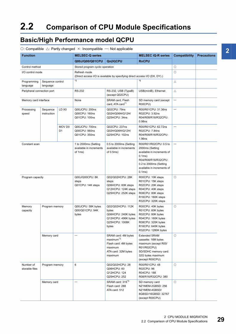
2.2 Comparison of CPU Module Specifications . . . . . . . . . . . . . . . . . . . . . . . . . . . . . . . . . . . . . . . . . . . . . . . . . . 29Basic/High Performance model QCPU . . . . . . . . . . . . . . . . . . . . . . . . . . . . . . . . . . . . . . . . . . . . . . . . . . . . . . . . 29Universal model QCPU . . . . . . . . . . . . . . . . . . . . . . . . . . . . . . . . . . . . . . . . . . . . . . . . . . . . . . . . . . . . . . . . . . . . 32Process CPU/Universal model Process CPU . . . . . . . . . . . . . . . . . . . . . . . . . . . . . . . . . . . . . . . . . . . . . . . . . . . 38C Controller module. . . . . . . . . . . . . . . . . . . . . . . . . . . . . . . . . . . . . . . . . . . . . . . . . . . . . . . . . . . . . . . . . . . . . . . 41
2.3 Comparison of CPU Module Functions. . . . . . . . . . . . . . . . . . . . . . . . . . . . . . . . . . . . . . . . . . . . . . . . . . . . . . 44Basic/High Performance model QCPU . . . . . . . . . . . . . . . . . . . . . . . . . . . . . . . . . . . . . . . . . . . . . . . . . . . . . . . . 44Universal model QCPU . . . . . . . . . . . . . . . . . . . . . . . . . . . . . . . . . . . . . . . . . . . . . . . . . . . . . . . . . . . . . . . . . . . . 46Process CPU/Universal model Process CPU . . . . . . . . . . . . . . . . . . . . . . . . . . . . . . . . . . . . . . . . . . . . . . . . . . . 50C Controller module. . . . . . . . . . . . . . . . . . . . . . . . . . . . . . . . . . . . . . . . . . . . . . . . . . . . . . . . . . . . . . . . . . . . . . . 54
2.4 Precautions for CPU Module Migration. . . . . . . . . . . . . . . . . . . . . . . . . . . . . . . . . . . . . . . . . . . . . . . . . . . . . . 56Precautions for programmable controller CPU/Process CPU module migration. . . . . . . . . . . . . . . . . . . . . . . . . 56Precautions for C Controller module migration . . . . . . . . . . . . . . . . . . . . . . . . . . . . . . . . . . . . . . . . . . . . . . . . . . 57
CHAPTER 3 I/O MODULE MIGRATION 593.1 I/O Module Migration Model List . . . . . . . . . . . . . . . . . . . . . . . . . . . . . . . . . . . . . . . . . . . . . . . . . . . . . . . . . . . 593.2 Comparison of I/O Module Specifications . . . . . . . . . . . . . . . . . . . . . . . . . . . . . . . . . . . . . . . . . . . . . . . . . . . 66
Comparison of input module specifications . . . . . . . . . . . . . . . . . . . . . . . . . . . . . . . . . . . . . . . . . . . . . . . . . . . . . 66Comparison of output module specifications. . . . . . . . . . . . . . . . . . . . . . . . . . . . . . . . . . . . . . . . . . . . . . . . . . . 106Comparison of I/O combined module specifications . . . . . . . . . . . . . . . . . . . . . . . . . . . . . . . . . . . . . . . . . . . . . 126Comparison of interrupt module specifications . . . . . . . . . . . . . . . . . . . . . . . . . . . . . . . . . . . . . . . . . . . . . . . . . 132Comparison of blank cover module specifications . . . . . . . . . . . . . . . . . . . . . . . . . . . . . . . . . . . . . . . . . . . . . . 133
3.3 Precautions for I/O Module Migration . . . . . . . . . . . . . . . . . . . . . . . . . . . . . . . . . . . . . . . . . . . . . . . . . . . . . . 134
CHAPTER 4 POWER SUPPLY MODULE MIGRATION 1354.1 Power Supply Module Migration Model List . . . . . . . . . . . . . . . . . . . . . . . . . . . . . . . . . . . . . . . . . . . . . . . . . 1354.2 Comparison of Power Supply Module Specifications . . . . . . . . . . . . . . . . . . . . . . . . . . . . . . . . . . . . . . . . . 1364.3 Precautions for Power Supply Module Migration. . . . . . . . . . . . . . . . . . . . . . . . . . . . . . . . . . . . . . . . . . . . . 150

CO
NTE
NTS
CHAPTER 5 BASE UNIT AND EXTENSION CABLE MIGRATION 1515.1 Base Unit and Extension Cable Migration Model List . . . . . . . . . . . . . . . . . . . . . . . . . . . . . . . . . . . . . . . . . 151
Base unit migration model list . . . . . . . . . . . . . . . . . . . . . . . . . . . . . . . . . . . . . . . . . . . . . . . . . . . . . . . . . . . . . . 151Extension cable migration model list . . . . . . . . . . . . . . . . . . . . . . . . . . . . . . . . . . . . . . . . . . . . . . . . . . . . . . . . . 151
5.2 Comparison of the Base Unit and Extension Cable Specifications . . . . . . . . . . . . . . . . . . . . . . . . . . . . . . 152Comparison of extension cable specifications. . . . . . . . . . . . . . . . . . . . . . . . . . . . . . . . . . . . . . . . . . . . . . . . . . 156
5.3 Precautions for Base Unit/Extension Cable Migration . . . . . . . . . . . . . . . . . . . . . . . . . . . . . . . . . . . . . . . . 1575.4 RQ Extension Base Unit . . . . . . . . . . . . . . . . . . . . . . . . . . . . . . . . . . . . . . . . . . . . . . . . . . . . . . . . . . . . . . . . . 158
CHAPTER 6 MEMORY AND BATTERY MIGRATION 1606.1 Memory and Battery Migration Model List . . . . . . . . . . . . . . . . . . . . . . . . . . . . . . . . . . . . . . . . . . . . . . . . . . 1606.2 Precautions for Memory and Battery Migration . . . . . . . . . . . . . . . . . . . . . . . . . . . . . . . . . . . . . . . . . . . . . . 161
CHAPTER 7 ANALOG I/O MODULE MIGRATION 1627.1 Analog I/O Module Migration Model List . . . . . . . . . . . . . . . . . . . . . . . . . . . . . . . . . . . . . . . . . . . . . . . . . . . . 1627.2 Comparison of Analog I/O Module Specifications . . . . . . . . . . . . . . . . . . . . . . . . . . . . . . . . . . . . . . . . . . . . 166
Comparison of analog input module specifications . . . . . . . . . . . . . . . . . . . . . . . . . . . . . . . . . . . . . . . . . . . . . . 166Comparison of analog output module specifications . . . . . . . . . . . . . . . . . . . . . . . . . . . . . . . . . . . . . . . . . . . . . 176Comparison of temperature input module specifications. . . . . . . . . . . . . . . . . . . . . . . . . . . . . . . . . . . . . . . . . . 196Comparison of temperature control module specifications . . . . . . . . . . . . . . . . . . . . . . . . . . . . . . . . . . . . . . . . 200
7.3 Comparison of Analog I/O Module Functions . . . . . . . . . . . . . . . . . . . . . . . . . . . . . . . . . . . . . . . . . . . . . . . 222Comparison of analog input module functions . . . . . . . . . . . . . . . . . . . . . . . . . . . . . . . . . . . . . . . . . . . . . . . . . 222Comparison of analog output module functions . . . . . . . . . . . . . . . . . . . . . . . . . . . . . . . . . . . . . . . . . . . . . . . . 226Comparison of temperature input module functions . . . . . . . . . . . . . . . . . . . . . . . . . . . . . . . . . . . . . . . . . . . . . 229Comparison of temperature control module functions. . . . . . . . . . . . . . . . . . . . . . . . . . . . . . . . . . . . . . . . . . . . 232
7.4 Precautions for Analog I/O Module Migration . . . . . . . . . . . . . . . . . . . . . . . . . . . . . . . . . . . . . . . . . . . . . . . 239
CHAPTER 8 POSITIONING MODULE AND PULSE I/O MODULE MIGRATION 2408.1 Positioning Module and Pulse I/O Module Migration Model List . . . . . . . . . . . . . . . . . . . . . . . . . . . . . . . . 2408.2 Comparison of Positioning Module and Pulse I/O Module Specifications . . . . . . . . . . . . . . . . . . . . . . . . 243
Comparison of positioning module specifications . . . . . . . . . . . . . . . . . . . . . . . . . . . . . . . . . . . . . . . . . . . . . . . 243Comparison of high-speed counter module specifications . . . . . . . . . . . . . . . . . . . . . . . . . . . . . . . . . . . . . . . . 267Comparison of channel isolated pulse input module . . . . . . . . . . . . . . . . . . . . . . . . . . . . . . . . . . . . . . . . . . . . . 276
8.3 Comparison of Positioning Module and Pulse I/O Module Functions . . . . . . . . . . . . . . . . . . . . . . . . . . . . 278Comparison of positioning module functions. . . . . . . . . . . . . . . . . . . . . . . . . . . . . . . . . . . . . . . . . . . . . . . . . . . 278Comparison of high-speed counter module functions . . . . . . . . . . . . . . . . . . . . . . . . . . . . . . . . . . . . . . . . . . . . 283Comparison of channel isolated pulse input module functions . . . . . . . . . . . . . . . . . . . . . . . . . . . . . . . . . . . . . 284
8.4 Precautions for Positioning Module and Pulse I/O Module Migration . . . . . . . . . . . . . . . . . . . . . . . . . . . . 285
CHAPTER 9 CONTROL NETWORK MODULE MIGRATION 2869.1 Control Network Module Migration Model List . . . . . . . . . . . . . . . . . . . . . . . . . . . . . . . . . . . . . . . . . . . . . . . 2869.2 Comparison of Control Network Module Specifications . . . . . . . . . . . . . . . . . . . . . . . . . . . . . . . . . . . . . . . 289
Comparison of CC-Link IE Controller Network module specifications. . . . . . . . . . . . . . . . . . . . . . . . . . . . . . . . 289Comparison of CC-Link IE Field Network master/local modules specifications . . . . . . . . . . . . . . . . . . . . . . . . 293Comparison of CC-Link system master/local module specifications . . . . . . . . . . . . . . . . . . . . . . . . . . . . . . . . . 295Comparison of AnyWireASLINK master module specifications. . . . . . . . . . . . . . . . . . . . . . . . . . . . . . . . . . . . . 298Comparison of MELSECNET/H network modules specifications . . . . . . . . . . . . . . . . . . . . . . . . . . . . . . . . . . . 299Comparison of DeviceNet master-slave module specifications. . . . . . . . . . . . . . . . . . . . . . . . . . . . . . . . . . . . . 300Comparison of PROFIBUS-DP master module specifications . . . . . . . . . . . . . . . . . . . . . . . . . . . . . . . . . . . . . 301Comparison of PROFIBUS-DP slave module specifications. . . . . . . . . . . . . . . . . . . . . . . . . . . . . . . . . . . . . . . 303
15

16
9.3 Comparison of Control Network Module Functions . . . . . . . . . . . . . . . . . . . . . . . . . . . . . . . . . . . . . . . . . . 304Comparison of CC-Link IE Controller Network module functions . . . . . . . . . . . . . . . . . . . . . . . . . . . . . . . . . . . 304Comparison of CC-Link IE Field Network master/local modules. . . . . . . . . . . . . . . . . . . . . . . . . . . . . . . . . . . . 308Comparison of CC-Link system master/local module functions . . . . . . . . . . . . . . . . . . . . . . . . . . . . . . . . . . . . 311Comparison of AnyWireASLINK master module functions . . . . . . . . . . . . . . . . . . . . . . . . . . . . . . . . . . . . . . . . 314Comparison of MELSECNET/H network module functions. . . . . . . . . . . . . . . . . . . . . . . . . . . . . . . . . . . . . . . . 315Comparison of DeviceNet master-slave module functions . . . . . . . . . . . . . . . . . . . . . . . . . . . . . . . . . . . . . . . . 318Comparison of PROFIBUS-DP master module functions . . . . . . . . . . . . . . . . . . . . . . . . . . . . . . . . . . . . . . . . . 319Comparison of PROFIBUS-DP slave module functions . . . . . . . . . . . . . . . . . . . . . . . . . . . . . . . . . . . . . . . . . . 320
9.4 Precautions for Control Network Module Migration . . . . . . . . . . . . . . . . . . . . . . . . . . . . . . . . . . . . . . . . . . 321Precautions common to the control network modules. . . . . . . . . . . . . . . . . . . . . . . . . . . . . . . . . . . . . . . . . . . . 321Precautions for CC-Link IE Field Network master/local module migration . . . . . . . . . . . . . . . . . . . . . . . . . . . . 321Precautions for CC-Link system master/local module migration . . . . . . . . . . . . . . . . . . . . . . . . . . . . . . . . . . . . 321Precautions for AnyWireASLINK master module migration. . . . . . . . . . . . . . . . . . . . . . . . . . . . . . . . . . . . . . . . 322Precautions for MELSECNET/H network module migration . . . . . . . . . . . . . . . . . . . . . . . . . . . . . . . . . . . . . . . 322Precautions for DeviceNet master-slave module migration. . . . . . . . . . . . . . . . . . . . . . . . . . . . . . . . . . . . . . . . 322Precautions for PROFIBUS-DP master-slave module migration. . . . . . . . . . . . . . . . . . . . . . . . . . . . . . . . . . . . 323
CHAPTER 10 INFORMATION MODULE MIGRATION 32410.1 Information Module Migration Model List . . . . . . . . . . . . . . . . . . . . . . . . . . . . . . . . . . . . . . . . . . . . . . . . . . . 32410.2 Comparison of Information Module Specifications . . . . . . . . . . . . . . . . . . . . . . . . . . . . . . . . . . . . . . . . . . . 326
Comparison of MES interface module specifications . . . . . . . . . . . . . . . . . . . . . . . . . . . . . . . . . . . . . . . . . . . . 326Comparison of high speed data logger module specifications . . . . . . . . . . . . . . . . . . . . . . . . . . . . . . . . . . . . . 331Comparison of Ethernet interface module specifications . . . . . . . . . . . . . . . . . . . . . . . . . . . . . . . . . . . . . . . . . 337Comparison of serial communication module specifications . . . . . . . . . . . . . . . . . . . . . . . . . . . . . . . . . . . . . . . 340
10.3 Comparison of Information Module Functions. . . . . . . . . . . . . . . . . . . . . . . . . . . . . . . . . . . . . . . . . . . . . . . 350Comparison of MES interface module functions . . . . . . . . . . . . . . . . . . . . . . . . . . . . . . . . . . . . . . . . . . . . . . . . 350Comparison of high speed data logger module functions . . . . . . . . . . . . . . . . . . . . . . . . . . . . . . . . . . . . . . . . . 352Comparison of Ethernet interface module functions . . . . . . . . . . . . . . . . . . . . . . . . . . . . . . . . . . . . . . . . . . . . . 354Comparison of serial communication module functions . . . . . . . . . . . . . . . . . . . . . . . . . . . . . . . . . . . . . . . . . . 356
10.4 Precautions for Information Module Migration. . . . . . . . . . . . . . . . . . . . . . . . . . . . . . . . . . . . . . . . . . . . . . . 360Precautions for MES interface module migration . . . . . . . . . . . . . . . . . . . . . . . . . . . . . . . . . . . . . . . . . . . . . . . 360Precautions for high speed data logger module migration . . . . . . . . . . . . . . . . . . . . . . . . . . . . . . . . . . . . . . . . 361Precautions for Ethernet interface module migration . . . . . . . . . . . . . . . . . . . . . . . . . . . . . . . . . . . . . . . . . . . . 362Precautions for serial communication module migration . . . . . . . . . . . . . . . . . . . . . . . . . . . . . . . . . . . . . . . . . . 364
CHAPTER 11 PROJECT MIGRATION 36511.1 Project Migration Procedure . . . . . . . . . . . . . . . . . . . . . . . . . . . . . . . . . . . . . . . . . . . . . . . . . . . . . . . . . . . . . 365
Procedure for migrating projects stored in the QCPU . . . . . . . . . . . . . . . . . . . . . . . . . . . . . . . . . . . . . . . . . . . . 365Procedure for migrating projects stored in a personal computer. . . . . . . . . . . . . . . . . . . . . . . . . . . . . . . . . . . . 381Procedure for migration of PX Developer projects . . . . . . . . . . . . . . . . . . . . . . . . . . . . . . . . . . . . . . . . . . . . . . 397
11.2 Instruction Migration. . . . . . . . . . . . . . . . . . . . . . . . . . . . . . . . . . . . . . . . . . . . . . . . . . . . . . . . . . . . . . . . . . . . 40011.3 Parameter Migration . . . . . . . . . . . . . . . . . . . . . . . . . . . . . . . . . . . . . . . . . . . . . . . . . . . . . . . . . . . . . . . . . . . . 40511.4 Special Relay and Special Register Migration . . . . . . . . . . . . . . . . . . . . . . . . . . . . . . . . . . . . . . . . . . . . . . . 408
Migration of special relay. . . . . . . . . . . . . . . . . . . . . . . . . . . . . . . . . . . . . . . . . . . . . . . . . . . . . . . . . . . . . . . . . . 408Migration of special register. . . . . . . . . . . . . . . . . . . . . . . . . . . . . . . . . . . . . . . . . . . . . . . . . . . . . . . . . . . . . . . . 412
11.5 Precautions for Project Migration . . . . . . . . . . . . . . . . . . . . . . . . . . . . . . . . . . . . . . . . . . . . . . . . . . . . . . . . . 417REVISIONS. . . . . . . . . . . . . . . . . . . . . . . . . . . . . . . . . . . . . . . . . . . . . . . . . . . . . . . . . . . . . . . . . . . . . . . . . . . . .434WARRANTY . . . . . . . . . . . . . . . . . . . . . . . . . . . . . . . . . . . . . . . . . . . . . . . . . . . . . . . . . . . . . . . . . . . . . . . . . . . .435TRADEMARKS . . . . . . . . . . . . . . . . . . . . . . . . . . . . . . . . . . . . . . . . . . . . . . . . . . . . . . . . . . . . . . . . . . . . . . . . . .438

17
GENERIC TERMS USED IN THIS MANUALGeneric term DescriptionBasic model QCPU A generic term for the Q00JCPU, Q00CPU, and Q01CPU
High Performance model QCPU A generic term for the Q02CPU, Q02HCPU, Q06HCPU, Q12HCPU, and Q25HCPU
High-speed Universal model QCPU A generic term for the Q03UDVCPU, Q04UDVCPU, Q06UDVCPU, Q13UDVCPU, and Q26UDVCPU
Process CPU A generic term for the Q02PHCPU, Q06PHCPU, Q12PHCPU, and Q25PHCPU
QCPU A generic term for the MELSEC-Q series CPU module
Qn(H)CPU A generic term for the High Performance model QCPU
QnPHCPU A generic term for the Process CPU
QnU(D)(E)(H)CPU A generic term for the Q00UJCPU, Q00UCPU, Q01UCPU, Q02UCPU, Q03UDCPU, Q03UDECPU, Q04UDHCPU, Q04UDEHCPU, Q06UDHCPU, Q06UDEHCPU, Q10UDHCPU, Q10UDEHCPU, Q13UDHCPU, Q13UDEHCPU, Q20UDHCPU, Q20UDEHCPU, Q26UDHCPU, Q26UDEHCPU, Q50UDEHCPU, and Q100UDEHCPU
QnUCPU A generic term for the Universal model QCPU
QnUDPVCPU A generic term for the Universal model Process CPU
QnUDVCPU A generic term for the High-speed Universal model QCPU
RCPU A generic term for the MELSEC iQ-R series CPU module
RnCPU A generic term for the R00CPU, R01CPU, R02CPU, R04CPU, R08CPU, R16CPU, R32CPU, and R120CPU
RnPCPU A generic term for the R08PCPU, R16PCPU, R32PCPU, and R120PCPU
Universal model Process CPU A generic term for the Q04UDPVCPU, Q06UDPVCPU, Q13UDPVCPU, and Q26UDPVCPU
Universal model QCPU A generic term for the Q00UJCPU, Q00UCPU, Q01UCPU, Q02UCPU, Q03UDCPU, Q03UDVCPU, Q03UDECPU, Q04UDHCPU, Q04UDVCPU, Q04UDEHCPU, Q06UDHCPU, Q06UDVCPU, Q06UDEHCPU, Q10UDHCPU, Q10UDEHCPU, Q13UDHCPU, Q13UDVCPU, Q13UDEHCPU, Q20UDHCPU, Q20UDEHCPU, Q26UDHCPU, Q26UDVCPU, Q26UDEHCPU, Q50UDEHCPU, and Q100UDEHCPU

18
1 OVERVIEWThis document describes models to select in migration from the MELSEC-Q series to MELSEC iQ-R series.
1.1 Overview of the MELSEC iQ-R SeriesMELSEC iQ-R series modules equipped with the newly developed high-speed system bus significantly reduces the takt time.And with its high-accuracy motion control achieved by the multiple CPU high-speed transmission, the MELSEC iQ-R series is at the core of automation systems, helping to provide solutions to customers.
Revolutionary, next-generation controllers building a new era in automationTo succeed in highly competitive markets, it's important to build automation systems that ensure high productivity and consistent product quality.The MELSEC iQ-R Series has been developed from the ground up based on common problems faced by customers and rationalizing them into seven key areas: Productivity, Engineering, Maintenance, Quality, Connectivity, Security and Compatibility. Mitsubishi Electric is taking a three-point approach to solving these problems: Reducing TCO*1, increasing Reliability and Reusability of existing assets.*1 Total Cost of Ownership
Process: High availability process control in a scalable automation solution • Extensive visualization and data acquisition • High availability across multiple levels • Integrated process control software simplifies engineering
Safety: System design flexibility with integrated safety control • Integrated generic and safety control • Consolidated network topology • Complies with international safety standards
Intelligence: Extensive data handling from shop floor to business process systems • Direct data collection and analysis • C/C++ based programming • Collect factory data in real-time • Expand features using third party partner applications
Productivity: Improve productivity through advanced performance/functionality • New high-speed system bus realizing shorter production cycle • Super-high-accuracy motion control utilizing advanced multiple CPU features • Inter-modular synchronization resulting in increased processing accuracy
Engineering: Reducing development costs through intuitive engineering • Intuitive engineering environment covering the product development cycle • Simple point-and-click programming architecture • Understanding globalization by multiple language support
1 OVERVIEW1.1 Overview of the MELSEC iQ-R Series

1
Maintenance: Reduce maintenance costs/downtime with easier maintenance features • Visualize entire plant data in real-time • Extensive preventative maintenance functions embedded into modulesQuality: Reliable and trusted MELSEC product quality • Robust design ideal for harsh industrial environments • Improve and maintain actual manufacturing quality • Conforms to main international standards
Connectivity: Seamless network reduces system costs • Seamless connectivity within all levels of manufacturing • High-speed and large data bandwidth ideal for large-scale control systems • Easy connection of third-party components utilizing device library
Security: Robust security that can be relied on • Protect intellectual property • Unauthorized access protection across distributed control network
Compatibility: Extensive compatibility with existing products • Utilize existing assets while taking advantage of cutting-edge technology • Compatible with most existing MELSEC-Q Series I/O
1 OVERVIEW1.1 Overview of the MELSEC iQ-R Series 19

20
1.2 Differences in SystemThis section describes the differences between the MELSEC-Q series and the MELSEC iQ-R series in the system configuration.: Available, : Partially available, : Not available
*1 The existing MELSEC-Q series system can be used with the use of the RQ extension base unit. For details, refer to the following manual. MELSEC iQ-R Module Configuration Manual (SH-081262ENG)
*2 The existing MELSEC-A series system can be used with the use of the QA extension base unit. For details, refer to the following manual. QCPU User's Manual (Hardware Design, Maintenance and Inspection) (SH-080483ENG)
*3 For GOT which is connectable to the MELSEC iQ-R series system and its connection type, refer to the following. GOT2000 NEWS Vol.1 (L08301ENG-A)
Item MELSEC-Q series MELSEC iQ-R seriesOverall system configuration Single CPU system
Multiple CPU system
Redundant system
Available module MELSEC iQ-R series module
MELSEC-Q series module *1
MELSEC-A series module *2
GOT Bus connection *3
Available network Ethernet
CC-Link IE Controller Network
CC-Link IE Field Network
CC-Link IE Field Network Basic
CC-Link
MELSECNET/H
AnyWire
Engineering software GX Works2GX Developer
GX Works3
1 OVERVIEW1.2 Differences in System

1
1.3 How to Migrate the System from the MELSEC-QSeries to MELSEC iQ-R SeriesThis section describes how to migrate the system from the MELSEC-Q series to MELSEC iQ-R series.
Selecting a modelSelect a model to migrate to. For details, refer to the following.Page 22 CPU MODULE MIGRATION to Page 324 INFORMATION MODULE MIGRATION
Project conversionConvert projects used in the MELSEC-Q series so that they can be used in the MELSEC iQ-R series. For details, refer to the following.Page 365 PROJECT MIGRATION
1 OVERVIEW1.3 How to Migrate the System from the MELSEC-Q Series to MELSEC iQ-R Series 21

22
2 CPU MODULE MIGRATION
2.1 CPU Module Migration Model ListThis section describes examples of migration to MELSEC iQ-R series CPU modules in accordance with the program capacity, number of I/O points, and functions of the MELSEC-Q series CPU module.Consider the scope of control by the MELSEC-Q series CPU module used and the system specifications and extensibility after migration to choose a model that best suits your application.
Basic model QCPU
*1 The Q00JCPU is a CPU module that integrates the power supply module and main base unit.For the power supply module, refer to the following.Page 146 Q00JCPU (power supply part) and R61PFor the main base unit, refer to the following.Page 152 Q35B/Q35DB and R35B
*2 The alternative models have less program memory capacity. Use the CPU module with larger capacity as necessary.*3 For details on the battery, refer to the following.
Page 160 MEMORY AND BATTERY MIGRATION
Item MELSEC-Q series
MELSEC iQ-R series
Specification difference
Basic model QCPU Q00JCPU R00CPU (1) Number of I/O points: 256 4096(2) Number of I/O device points: 2048 8192(3) Program capacity: 8K steps 10K steps(4) Basic processing speed (LD instruction): 200ns 31.36ns(5) Program memory capacity: 58K bytes 40K bytes*2
(6) Peripheral connection ports: RS-232 USB (miniB), Ethernet(7) Memory card I/F: None(8) Others: Equipped with the 5-slot base unit, power supply module (100 to 240VAC
input/3A at 5VDC output) None*1, battery required battery not required*3
Q00CPU R00CPU (1) Number of I/O points: 1024 4096(2) Number of I/O device points: 2048 8192(3) Program capacity: 8K steps 10K steps(4) Basic processing speed (LD instruction): 160ns 31.36ns(5) Program memory capacity: 94K bytes 40K bytes*2
(6) Peripheral connection ports: RS-232 USB (miniB), Ethernet(7) Memory card I/F: None(8) Others: battery required battery not required*3
Q01CPU R01CPU (1) Number of I/O points: 1024 4096(2) Number of I/O device points: 2048 8192(3) Program capacity: 14K steps 15K steps(4) Basic processing speed (LD instruction): 100ns 31.36ns(5) Program memory capacity: 94K bytes 60K bytes*2
(6) Peripheral connection ports: RS-232 USB (miniB), Ethernet(7) Memory card I/F: None SD memory card(8) Others: battery required battery not required*3
2 CPU MODULE MIGRATION2.1 CPU Module Migration Model List

2
High Performance model QCPU
*1 The alternative models have less program capacity and program memory capacity. Use the CPU module with larger capacity as necessary.
*2 For details on the battery, refer to the following.Page 160 MEMORY AND BATTERY MIGRATION
Item MELSEC-Q series
MELSEC iQ-R series
Specification difference
High Performance model QCPU
Q02CPU R02CPU (1) Number of I/O points: 4096(2) Number of I/O device points: 8192(3) Program capacity: 28K steps 20K steps*1
(4) Basic processing speed (LD instruction): 79ns 3.92ns(5) Program memory capacity: 112K bytes 80K bytes*1
(6) Peripheral connection ports: RS-232 USB (miniB), Ethernet(7) Memory card I/F: SRAM card, Flash card, ATA card SD memory card(8) Others: battery required battery not required*2
R04CPU (1) Number of I/O points: 4096(2) Number of I/O device points: 8192 12288(3) Program capacity: 28K steps 40K steps(4) Basic processing speed (LD instruction): 79ns 0.98ns(5) Program memory capacity: 112K bytes 160K bytes(6) Peripheral connection ports: RS-232 USB (miniB), Ethernet(7) Memory card I/F: SRAM card, Flash card, ATA card SD memory card
Q02HCPU R02CPU (1) Number of I/O points: 4096(2) Number of I/O device points: 8192(3) Program capacity: 28K steps 20K steps*1
(4) Basic processing speed (LD instruction): 34ns 3.92ns(5) Program memory capacity: 112K bytes 80K bytes*1
(6) Peripheral connection ports: USB (Type B), RS-232 USB (miniB), Ethernet(7) Memory card I/F: SRAM card, Flash card, ATA card SD memory card(8) Others: battery required battery not required*2
R04CPU (1) Number of I/O points: 4096(2) Number of I/O device points: 8192 12288(3) Program capacity: 28K steps 40K steps(4) Basic processing speed (LD instruction): 34ns 0.98ns(5) Program memory capacity: 112K bytes 160K bytes(6) Peripheral connection ports: USB (Type B), RS-232 USB (miniB), Ethernet(7) Memory card I/F: SRAM card, Flash card, ATA card SD memory card
Q06HCPU R08CPU (1) Number of I/O points: 4096(2) Number of I/O device points: 8192 12288(3) Program capacity: 60K steps 80K steps(4) Basic processing speed (LD instruction): 34ns 0.98ns(5) Program memory capacity: 240K bytes 320K bytes(6) Peripheral connection ports: USB (Type B), RS-232 USB (miniB), Ethernet(7) Memory card I/F: SRAM card, Flash card, ATA card SD memory card
Q12HCPU R16CPU (1) Number of I/O points: 4096(2) Number of I/O device points: 8192 12288(3) Program capacity: 124K steps 160K steps(4) Basic processing speed (LD instruction): 34ns 0.98ns(5) Program memory capacity: 496K bytes 640K bytes(6) Peripheral connection ports: USB (Type B), RS-232 USB (miniB), Ethernet(7) Memory card I/F: SRAM card, Flash card, ATA card SD memory card
Q25HCPU R32CPU (1) Number of I/O points: 4096(2) Number of I/O device points: 8192 12288(3) Program capacity: 252K steps 320K steps(4) Basic processing speed (LD instruction): 34ns 0.98ns(5) Program memory capacity: 1008K bytes 1280K bytes(6) Peripheral connection ports: USB (Type B), RS-232 USB (miniB), Ethernet(7) Memory card I/F: SRAM card, Flash card, ATA card SD memory card
2 CPU MODULE MIGRATION2.1 CPU Module Migration Model List 23

24
Universal model QCPUItem MELSEC-Q
seriesMELSEC iQ-R series
Specification difference
Universal model QCPU Q00UJCPU R00CPU (1) Number of I/O points: 256 4096(2) Number of I/O device points: 8192(3) Program capacity: 10K steps(4) Basic processing speed (LD instruction): 120ns 31.36ns(5) Program memory capacity: 40K bytes(6) Peripheral connection ports: USB (miniB), RS-232 USB (miniB), Ethernet(7) Memory card I/F: None(8) Others: Equipped with the 5-slot base unit, power supply module (100 to 240VAC
input/3A at 5VDC output) None*1, battery required battery not required*2
Q00UCPU R00CPU (1) Number of I/O points: 1024 4096(2) Number of I/O device points: 8192(3) Program capacity: 10K steps(4) Basic processing speed (LD instruction): 80ns 31.36ns(5) Program memory capacity: 40K bytes(6) Peripheral connection ports: USB (miniB), RS-232 USB (miniB), Ethernet(7) Memory card I/F: None(8) Others: battery required battery not required*2
Q01UCPU R01CPU (1) Number of I/O points: 1024 4096(2) Number of I/O device points: 8192(3) Program capacity: 15K steps(4) Basic processing speed (LD instruction): 60ns 31.36ns(5) Program memory capacity: 60K bytes(6) Peripheral connection ports: USB (miniB), RS-232 USB (miniB), Ethernet(7) Memory card I/F: None SD memory card(8) Others: battery required battery not required*2
Q02UCPU R02CPU (1) Number of I/O points: 2048 4096(2) Number of I/O device points: 8192(3) Program capacity: 20K steps(4) Basic processing speed (LD instruction): 40ns 3.92ns(5) Program memory capacity: 80K bytes(6) Peripheral connection ports: USB (miniB), RS-232 USB (miniB), Ethernet(7) Memory card I/F: None SD memory card(8) Others: battery required battery not required*2
Q03UDCPUQ03UDECPU
R04CPU (1) Number of I/O points: 4096 4096(2) Number of I/O device points: 8192 12288(3) Program capacity: 30K steps 40K steps(4) Basic processing speed (LD instruction): 20ns 0.98ns(5) Program memory capacity: 120K bytes 160K bytes(6) Peripheral connection ports: USB (miniB), RS-232 (Q03UDCPU), Ethernet
(Q03UDECPU) USB (miniB), Ethernet(7) Memory card I/F: SRAM card, Flash card, ATA card SD memory card
Q04UDHCPUQ04UDEHCPU
R04CPU (1) Number of I/O points: 4096(2) Number of I/O device points: 8192 12288(3) Program capacity: 40K steps(4) Basic processing speed (LD instruction): 9.5ns 0.98ns(5) Program memory capacity: 160K bytes(6) Peripheral connection ports: USB (miniB), RS-232 (Q04UDHCPU), Ethernet
(Q04UDEHCPU) USB (miniB), Ethernet(7) Memory card I/F: SRAM card, Flash card, ATA card SD memory card
Q06UDHCPUQ06UDEHCPU
R08CPU (1) Number of I/O points: 4096(2) Number of I/O device points: 8192 12288(3) Program capacity: 60K steps 80K steps(4) Basic processing speed (LD instruction): 9.5ns 0.98ns(5) Program memory capacity: 240K bytes 320K bytes(6) Peripheral connection ports: USB (miniB), RS-232 (Q06UDHCPU), Ethernet
(Q06UDEHCPU) USB (miniB), Ethernet(7) Memory card I/F: SRAM card, Flash card, ATA card SD memory card
2 CPU MODULE MIGRATION2.1 CPU Module Migration Model List

2
Universal model QCPU Q10UDHCPUQ10UDEHCPU
R16CPU (1) Number of I/O points: 4096(2) Number of I/O device points: 8192 12288(3) Program capacity: 100K steps 160K steps(4) Basic processing speed (LD instruction): 9.5ns 0.98ns(5) Program memory capacity: 400K bytes 640K bytes(6) Peripheral connection ports: USB (miniB), RS-232 (Q10UDHCPU), Ethernet
(Q10UDEHCPU) USB (miniB), Ethernet(7) Memory card I/F: SRAM card, Flash card, ATA card SD memory card
Q13UDHCPUQ13UDEHCPU
R16CPU (1) Number of I/O points: 4096(2) Number of I/O device points: 8192 12288(3) Program capacity: 130K steps 160K steps(4) Basic processing speed (LD instruction): 9.5ns 0.98ns(5) Program memory capacity: 520K bytes 640K bytes(6) Peripheral connection ports: USB (miniB), RS-232 (Q13UDHCPU), Ethernet
(Q13UDEHCPU) USB (miniB), Ethernet(7) Memory card I/F: SRAM card, Flash card, ATA card SD memory card
Q20UDHCPUQ20UDEHCPU
R32CPU (1) Number of I/O points: 4096(2) Number of I/O device points: 8192 12288(3) Program capacity: 200K steps 320K steps(4) Basic processing speed (LD instruction): 9.5ns 0.98ns(5) Program memory capacity: 800K bytes 1280K bytes(6) Peripheral connection ports: USB (miniB), RS-232 (Q20UDHCPU), Ethernet
(Q20UDEHCPU) USB (miniB), Ethernet(7) Memory card I/F: SRAM card, Flash card, ATA card SD memory card
Q26UDHCPUQ26UDEHCPU
R32CPU (1) Number of I/O points: 4096(2) Number of I/O device points: 8192 12288(3) Program capacity: 260K steps 320K steps(4) Basic processing speed (LD instruction): 9.5ns 0.98ns(5) Program memory capacity: 1040K bytes 1280K bytes(6) Peripheral connection ports: USB (miniB), RS-232 (Q26UDHCPU), Ethernet
(Q26UDEHCPU) USB (miniB), Ethernet(7) Memory card I/F: SRAM card, Flash card, ATA card SD memory card
Q50UDEHCPU R120CPU (1) Number of I/O points: 4096(2) Number of I/O device points: 8192 12288(3) Program capacity: 500K steps 1200K steps(4) Basic processing speed (LD instruction): 9.5ns 0.98ns(5) Program memory capacity: 2000K bytes 4800K bytes(6) Peripheral connection ports: USB (miniB), Ethernet(7) Memory card I/F: SRAM card, Flash card, ATA card SD memory card
Q100UDEHCPU R120CPU (1) Number of I/O points: 4096(2) Number of I/O device points: 8192 12288(3) Program capacity: 1000K steps 1200K steps(4) Basic processing speed (LD instruction): 9.5ns 0.98ns(5) Program memory capacity: 4000K bytes 4800K bytes(6) Peripheral connection ports: USB (miniB), Ethernet(7) Memory card I/F: SRAM card, Flash card, ATA card SD memory card
Item MELSEC-Qseries
MELSEC iQ-R series
Specification difference
2 CPU MODULE MIGRATION2.1 CPU Module Migration Model List 25

26
*1 The Q00UJCPU is a CPU module that integrates the power supply module and main base unit.For the power supply module, refer to the following.Page 148 Q00UJCPU (power supply part) and R61PFor the main base unit, refer to the following.Page 152 Q35B/Q35DB and R35B
*2 For details on the battery, refer to the following.Page 160 MEMORY AND BATTERY MIGRATION
High-speed Universal model QCPU
Q03UDVCPU R04CPU (1) Number of I/O points: 4096(2) Number of I/O device points: 8192 12288(3) Program capacity: 30K steps 40K steps(4) Basic processing speed (LD instruction): 1.9ns 0.98ns(5) Program memory capacity: 120K bytes 160K bytes(6) Peripheral connection ports: USB (miniB), Ethernet(7) Memory card I/F: SD memory card
Q04UDVCPU R04CPU (1) Number of I/O points: 4096(2) Number of I/O device points: 8192 12288(3) Program capacity: 40K steps(4) Basic processing speed (LD instruction): 1.9ns 0.98ns(5) Program memory capacity: 160K bytes(6) Peripheral connection ports: USB (miniB), Ethernet(7) Memory card I/F: SD memory card
Q06UDVCPU R08CPU (1) Number of I/O points: 4096(2) Number of I/O device points: 8192 12288(3) Program capacity: 60K steps 80K steps(4) Basic processing speed (LD instruction): 1.9ns 0.98ns(5) Program memory capacity: 240K bytes 320K bytes(6) Peripheral connection ports: USB (miniB), Ethernet(7) Memory card I/F: SD memory card
Q13UDVCPU R16CPU (1) Number of I/O points: 4096(2) Number of I/O device points: 8192 12288(3) Program capacity: 130K steps 160K steps(4) Basic processing speed (LD instruction): 1.9ns 0.98ns(5) Program memory capacity: 520K bytes 640K bytes(6) Peripheral connection ports: USB (miniB), Ethernet(7) Memory card I/F: SD memory card
Q26UDVCPU R32CPU (1) Number of I/O points: 4096(2) Number of I/O device points: 8192 12288(3) Program capacity: 260K steps 320K steps(4) Basic processing speed (LD instruction): 1.9ns 0.98ns(5) Program memory capacity: 1040K bytes 1280K bytes(6) Peripheral connection ports: USB (miniB), Ethernet(7) Memory card I/F: SD memory card
Item MELSEC-Qseries
MELSEC iQ-R series
Specification difference
2 CPU MODULE MIGRATION2.1 CPU Module Migration Model List

2
Process CPU/Universal model Process CPUItem MELSEC-Q
seriesMELSEC iQ-R series
Specification difference
Process CPU Q02PHCPU R08PCPU (1) Number of I/O points: 4096(2) Number of I/O device points: 8192 12288(3) Program capacity: 28K steps 80K steps(4) Basic processing speed (LD instruction): 34ns 0.98ns(5) Program memory capacity: 112K bytes 320K bytes(6) Peripheral connection ports: USB (TypeB), RS-232 USB (miniB), Ethernet(7) Memory card I/F: SRAM card, Flash card, ATA card SD memory card
Q06PHCPU R08PCPU (1) Number of I/O points: 4096(2) Number of I/O device points: 8192 12288(3) Program capacity: 60K steps 80K steps(4) Basic processing speed (LD instruction): 34ns 0.98ns(5) Program memory capacity: 240K bytes 320K bytes(6) Peripheral connection ports: USB (TypeB), RS-232 USB (miniB), Ethernet(7) Memory card I/F: SRAM card, Flash card, ATA card SD memory card
Q12PHCPU R16PCPU (1) Number of I/O points: 4096(2) Number of I/O device points: 8192 12288(3) Program capacity: 124K steps 160K steps(4) Basic processing speed (LD instruction): 34ns 0.98ns(5) Program memory capacity: 496K bytes 640K bytes(6) Peripheral connection ports: USB (TypeB), RS-232 USB (miniB), Ethernet(7) Memory card I/F: SRAM card, Flash card, ATA card SD memory card
Q25PHCPU R32PCPU (1) Number of I/O points: 4096(2) Number of I/O device points: 8192 12288(3) Program capacity: 252K steps 320K steps(4) Basic processing speed (LD instruction): 34ns 0.98ns(5) Program memory capacity: 1008K bytes 1280K bytes(6) Peripheral connection ports: USB (TypeB), RS-232 USB (miniB), Ethernet(7) Memory card I/F: SRAM card, Flash card, ATA card SD memory card
Universal model Process CPU
Q04UDPVCPU R08PCPU (1) Number of I/O points: 4096(2) Number of I/O device points: 8192 12288(3) Program capacity: 40K steps 80K steps(4) Basic processing speed (LD instruction): 1.9ns 0.98ns(5) Program memory capacity: 160K bytes 320K bytes(6) Peripheral connection ports: USB (miniB), Ethernet(7) Memory card I/F: SD memory card
Q06UDPVCPU R08PCPU (1) Number of I/O points: 4096(2) Number of I/O device points: 8192 12288(3) Program capacity: 60K steps 80K steps(4) Basic processing speed (LD instruction): 1.9ns 0.98ns(5) Program memory capacity: 240K bytes 320K bytes(6) Peripheral connection ports: USB (miniB), Ethernet(7) Memory card I/F: SD memory card
Q13UDPVCPU R16PCPU (1) Number of I/O points: 4096(2) Number of I/O device points: 8192 12288(3) Program capacity: 130K steps 160K steps(4) Basic processing speed (LD instruction): 1.9ns 0.98ns(5) Program memory capacity: 520K bytes 640K bytes(6) Peripheral connection ports: USB (miniB), Ethernet(7) Memory card I/F: SD memory card
Q26UDPVCPU R32PCPU (1) Number of I/O points: 4096(2) Number of I/O device points: 8192 12288(3) Program capacity: 260K steps 320K steps(4) Basic processing speed (LD instruction): 1.9ns 0.98ns(5) Program memory capacity: 1040K bytes 1280K bytes(6) Peripheral connection ports: USB (miniB), Ethernet(7) Memory card I/F: SD memory card
2 CPU MODULE MIGRATION2.1 CPU Module Migration Model List 27

28
C Controller moduleItem MELSEC-Q
seriesMELSEC iQ-R series
Specification difference
C Controller module Q06CCPU-V R12CCPU-V (1) Number of I/O points: 4096(2) Endian format: Little-endian(3) MPU: SH4 ARM Cortex-A9 Dual Core(4) Memory capacity: Work RAM 64M bytes, Standard ROM 6M bytes, Backup RAM
128K bytes Work RAM 256M bytes, Standard ROM 16M bytes, Backup RAM 4M bytes
(5) OS: VxWorks Version 5.4 VxWorks Version 6.9(6) Peripheral connection ports: Ethernet (10BASE-T/100BASE-TX) 1ch, RS-232 (9-
pin D-sub) Ethernet (10BASE-T/100BASE-TX/1000BASE-T) 2ch, RS-232 (9-pin D-sub), USB(TypeA)
(7) Memory card I/F: CompactFlash card SD/SDHC memory card
Q06CCPU-V-B R12CCPU-V (1) Number of I/O points: 4096(2) Endian format: Big-endian Little-endian(3) MPU: SH4 ARM Cortex-A9 Dual Core(4) Memory capacity: Work RAM 64M bytes, Standard ROM 6M bytes, Backup RAM
128K bytes Work RAM 256M bytes, Standard ROM 16M bytes, Backup RAM 4M bytes
(5) OS: VxWorks Version 5.4 VxWorks Version 6.9(6) Peripheral connection ports: Ethernet (10BASE-T/100BASE-TX) 1ch, RS-232 (9-
pin D-sub) Ethernet (10BASE-T/100BASE-TX/1000BASE-T) 2ch, RS-232 (9-pin D-sub), USB(TypeA)
(7) Memory card I/F: None SD/SDHC memory card
Q12DCCPU-V R12CCPU-V (1) Number of I/O points: 4096(2) Endian format: Little-endian(3) MPU: SH4A ARM Cortex-A9 Dual Core(4) Memory capacity: Work RAM 128M bytes, Standard ROM 12M bytes, Backup RAM
512 to 3584K bytes Work RAM 256M bytes, Standard ROM 16M bytes, Backup RAM 4M bytes
(5) OS: VxWorks Version 6.4 VxWorks Version 6.9(6) Peripheral connection ports: Ethernet (10BASE-T/100BASE-TX) 2ch, RS-232
(Round connector (10-pin)), USB(miniB) Ethernet (10BASE-T/100BASE-TX/1000BASE-T) 2ch, RS-232 (9-pin D-sub), USB(TypeA)
(7) Memory card I/F: CompactFlash card SD/SDHC memory card
Q24DHCCPU-V R12CCPU-V (1) Number of I/O points: 4096(2) Endian format: Little-endian(3) MPU: SH4A+Intel ATOM ARM Cortex-A9 Dual Core(4) Memory capacity: Work RAM 512M bytes, Standard ROM 382M bytes, Backup
RAM 5M bytes maximum Work RAM 256M bytes, Standard ROM 16M bytes, Backup RAM 4M bytes
(5) OS: VxWorks Version 6.8.1 VxWorks Version 6.9(6) Peripheral connection ports: Ethernet (10BASE-T/100BASE-TX/1000BASE-T) 2ch,
System Ethernet port (10BASE-T/100BASE-TX) 1ch, RS-232 (Round connector (10-pin)), USB(TypeA), USB (Connector type mini-B) Ethernet (10BASE-T/100BASE-TX/1000BASE-T) 2ch, RS-232 (9-pin D-sub), USB(TypeA)
(7) Memory card I/F: SD/SDHC memory card
Q24DHCCPU-VG No applicable module
Q24DHCCPU-LS No applicable module
Q26DHCCPU-LS No applicable module
2 CPU MODULE MIGRATION2.1 CPU Module Migration Model List
2
2.2 Comparison of CPU Module SpecificationsBasic/High Performance model QCPU: Compatible : Partly changed : Incompatible : Not applicable
Function MELSEC-Q series MELSEC iQ-R series Compatibility Precautions
Q00J/Q00/Q01CPU Qn(H)CPU RnCPUControl method Stored program cyclic operation
I/O control mode Refresh mode(Direct access I/O is available by specifying direct access I/O (DX, DY).)
Programming language
Sequence control language
*5 *6
Peripheral connection port RS-232 RS-232, USB (TypeB) (except Q02CPU)
USB(miniB), Ethernet
Memory card interface None SRAM card, Flash card, ATA card*1
SD memory card (except R00CPU)
Processing speed
Sequence instruction
LD X0 Q00JCPU: 200nsQ00CPU: 160nsQ01CPU: 100ns
Q02CPU: 79nsQ02H/Q06H/Q12H/Q25HCPU: 34ns
R00/R01CPU: 31.36nsR02CPU: 3.92nsR04/R08/R16/R32CPU: 0.98ns
MOV D0 D1
Q00JCPU: 700nsQ00CPU: 560nsQ01CPU: 350ns
Q02CPU: 237nsQ02H/Q06H/Q12H/Q25HCPU: 102ns
R00/R01CPU: 62.72nsR02CPU: 7.84nsR04/R08/R16/R32CPU: 1.96ns
Constant scan 1 to 2000ms (Setting available in increments of 1ms)
0.5 to 2000ms (Setting available in increments of 0.5ms)
R00/R01/R02CPU: 0.5 to 2000ms (Setting available in increments of 0.1ms)R04/R08/R16/R32CPU: 0.2 to 2000ms (Setting available in increments of 0.1ms)
Program capacity Q00J/Q00CPU: 8K stepsQ01CPU: 14K steps
Q02/Q02HCPU: 28K stepsQ06HCPU: 60K stepsQ12HCPU: 124K stepsQ25HCPU: 252K steps
R00CPU: 10K stepsR01CPU: 15K stepsR02CPU: 20K stepsR04CPU: 40K stepsR08CPU: 80K steps R16CPU: 160K stepsR32CPU: 320K steps
Memory capacity
Program memory Q00JCPU: 58K bytesQ00/Q01CPU: 94K bytes
Q02/Q02HCPU: 112K bytesQ06HCPU: 240K bytesQ12HCPU: 496K bytesQ25HCPU: 1008K bytes
R00CPU: 40K bytesR01CPU: 60K bytesR02CPU: 80K bytesR04CPU: 160K bytesR08CPU: 320K bytesR16CPU: 640K bytesR32CPU: 1280K bytes
Memory card SRAM card: 4M bytes maximum*2
Flash card: 4M bytes maximumATA card: 32M bytes maximum
Extended SRAM cassette: 16M bytes maximum (except R00/R01/R02CPU)SD/SDHC memory card: 32G bytes maximum (except R00CPU)
Number of storable files
Program memory 6 Q02/Q02HCPU: 28Q06HCPU: 60Q12HCPU: 124Q25HCPU: 252
R00/R01CPU: 48R02CPU: 96R04CPU: 188R08/R16/R32CPU: 380
Memory card SRAM card: 319*3
Flash card: 288ATA card: 512
SD memory cardNZ1MEM-2GBSD: 256NZ1MEM-4GBSD/8GBSD/16GBSD: 32767(except R00CPU)
2 CPU MODULE MIGRATION2.2 Comparison of CPU Module Specifications 29

30
Number of I/O points Q00JCPU: 256 pointsQ00/Q01CPU: 1024 points
4096 points
Number of device points
Input [X] 2048 points 8192 points R00/R01/R02CPU: 8192 pointsR04/R08/R16/R32CPU: 12288 points
Output [Y] 8192 points R00/R01/R02CPU: 8192 pointsR04/R08/R16/R32CPU: 12288 points
Internal relay [M] 8192 points R00/R01/R02CPU: 8192 pointsR04/R08/R16/R32CPU: 12288 points
*7
Latch relay [L] 2048 points 8192 points *7
Link relay [B] 2048 points 8192 points *7
Timer [T] 512 points 2048 points R00/R01/R02CPU: 2048 pointsR04/R08/R16/R32CPU: 1024 points (Timer [T]) + 1024 points (Long timer [LT])
*7
Counter [C] 512 points 1024 points R00/R01/R02CPU: 1024 pointsR04/R08/R16/R32CPU: 512 points+ 512 points (Long counter [LC])
*7
Data register [D] 11136 points 12288 points R00/R01/R02CPU: 12282 pointsR04/R08/R16/R32CPU: 18432 points
*7
Link register [W] 2048 points 8192 points *7
Annunciator [F] 1024 points 2048 points *7
Edge relay [V] 1024 points 2048 points *7
File register [R] Q00JCPU: Not availableQ00/Q01CPU: The number of points specified in the ZR section can be used by switching blocks in increments of 32768 points.
The number of points specified in the ZR section can be used by switching blocks in increments of 32768 points.
*7
File register [ZR] Q00JCPU: Not availableStandard RAM: Q00/Q01CPU: 65536 points
Standard RAM: Q02CPU: 32768 pointsQ02H/Q06HCPU: 65536 pointsQ12H/Q25HCPU: 131072 pointsSRAM card: 1041408 points maximumFlash card: 1042432 points maximum(The maximum number of points varies depending on the model.)
R00/R01/R02CPU: 98304 pointsR04/R08/R16/R32CPU: Calculated by a formula.*4
(The maximum number of points varies depending on the model.)
*7
Link special relay [SB] 1024 points 2048 points *7
Link special register [SW]
1024 points 2048 points *7
Function MELSEC-Q series MELSEC iQ-R series Compatibility Precautions
Q00J/Q00/Q01CPU Qn(H)CPU RnCPU
2 CPU MODULE MIGRATION2.2 Comparison of CPU Module Specifications

2
*1 Q3MEM-8MBS cannot be used.*2 The maximum capacity is 2M bytes for CPU modules with a serial number "16020" (first five digits) or earlier.*3 The maximum capacity is 287 files for CPU modules with a serial number "16020" (first five digits) or earlier (with the Q2MEM-2MBS
used).*4 The maximum value of the file register is [ + ].
: <R**CPU capacity> ** = 04: 160K words, 08: 544K words, 16: 800K words, 32: 1088K words : Capacity of the extended SRAM cassetteThe setting must be in the following range.File register file storage area [ + ]
*5 Programming languages available for the Q00J/Q00/Q01CPU and Qn(H)CPU are the following:Relay symbol language, logic symbolic language, MELSAP3 (SFC), MELSAP-L, function block, structured text (ST)
*6 Programming languages available for the RCPU are the following:Ladder diagram (LD), sequential function chart (SFC), structured text (ST), function block diagram (FBD/LD), function block (FB), label programming (system/local/global)Note that the relay symbol language is equivalent to the ladder diagram (LD); MELSAP3 (SFC) is equivalent to the sequential function chart (SFC); and the function block is equivalent to the function block (FB).
*7 The number of device points for use in the RCPU can be changed by the engineering tool.
Number of device points
Step relay [S] 2048 points 8192 points R00/R01/R02CPU: 8192 pointsR04/R08/R16/R32CPU: 16384 points
*7
Index register [Z] 10 points 16 points 20 points *7
Pointer [P] 300 points 4096 points 8192 points *7
Interrupt pointer [I] 128 points 256 points 1024 points
Special relay [SM] 1024 points 2048 points 4096 points
Special register [SD] 1024 points 2048 points 4096 points
Function input [FX] 16 points
Function output [FY] 16 points
Function register [FD] 5 points 5 points 4 words
Link direct device Specified form: J\X, J\Y, J\W, J\B, J\SW, J\SB
Intelligent function module device Specified form: U\G
Latch (data retention during power failure) range
2048 points 8192 points
RUN/PAUSE contact One contact can be set up in X0 to 7FF for each of RUN and PAUSE.
One contact can be set up in X0 to 1FFF for each of RUN and PAUSE.
R00/R01/R02CPU: One contact can be set up in X0 to 1FFF for each of RUN and PAUSE.R04/R08/R16/R32CPU: One contact can be set up in X0 to 2FFF for each of RUN and PAUSE.
Internal current consumption (5VDC) Q00JCPU (including the base unit and power supply module): 0.26AQ00CPU: 0.25AQ01CPU: 0.27A
Q02CPU: 0.60AQ02H/Q06H/Q12H/Q25HCPU: 0.64A
0.67A
External dimensions Q00JCPU (including the base unit): 98(H) 244.4(W) 98(D)mmQ00/Q01CPU: 98(H) 27.4(W) 89.3(D)mm
98(H) 27.4(W) 89.3(D)mm
106(H) 27.8(W) 110(D)mm
Weight Q00JCPU (including the base unit and power supply module): 0.66kgQ00/Q01CPU: 0.13kg
0.20kg 0.20kg
Function MELSEC-Q series MELSEC iQ-R series Compatibility Precautions
Q00J/Q00/Q01CPU Qn(H)CPU RnCPU
2 CPU MODULE MIGRATION2.2 Comparison of CPU Module Specifications 31
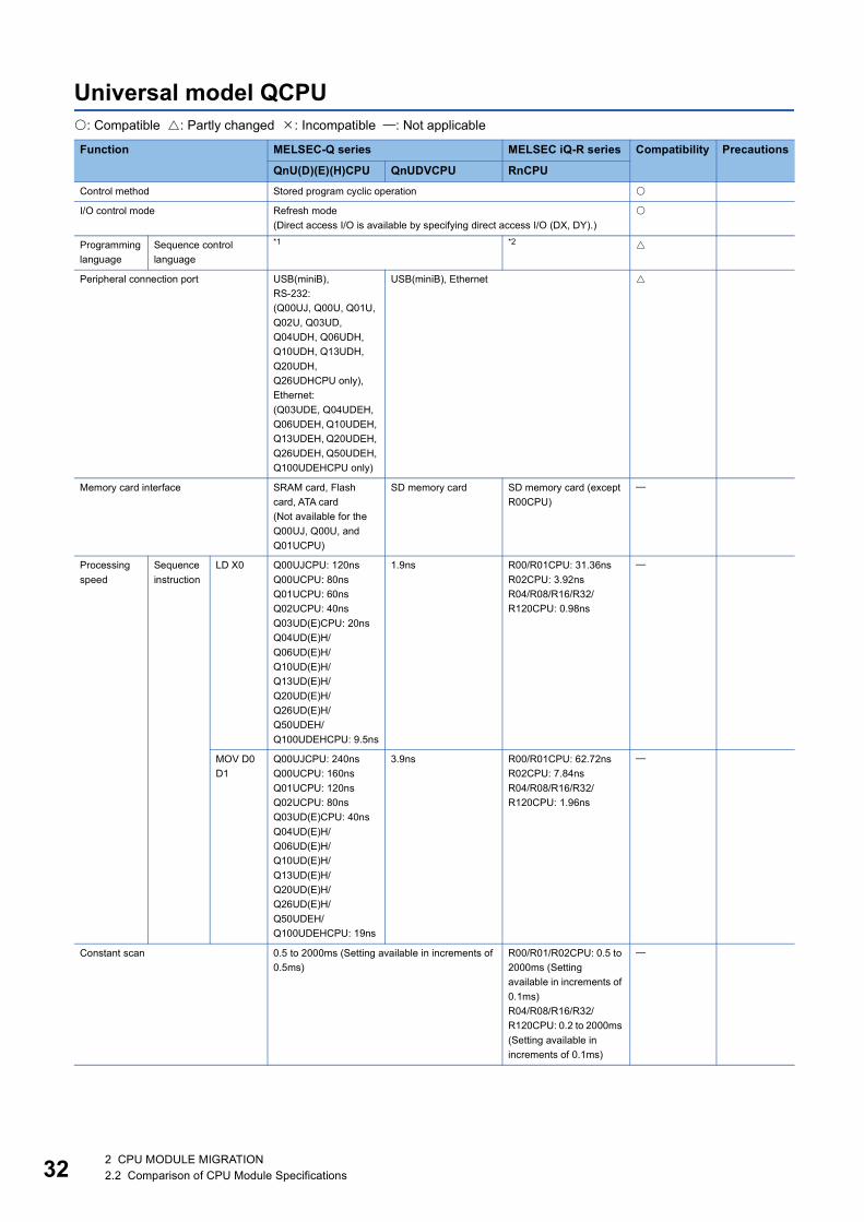
32
Universal model QCPU: Compatible : Partly changed : Incompatible : Not applicable
Function MELSEC-Q series MELSEC iQ-R series Compatibility Precautions
QnU(D)(E)(H)CPU QnUDVCPU RnCPUControl method Stored program cyclic operation
I/O control mode Refresh mode(Direct access I/O is available by specifying direct access I/O (DX, DY).)
Programming language
Sequence control language
*1 *2
Peripheral connection port USB(miniB),RS-232: (Q00UJ, Q00U, Q01U, Q02U, Q03UD, Q04UDH, Q06UDH, Q10UDH, Q13UDH, Q20UDH, Q26UDHCPU only),Ethernet: (Q03UDE, Q04UDEH, Q06UDEH, Q10UDEH, Q13UDEH, Q20UDEH, Q26UDEH, Q50UDEH, Q100UDEHCPU only)
USB(miniB), Ethernet
Memory card interface SRAM card, Flash card, ATA card(Not available for the Q00UJ, Q00U, and Q01UCPU)
SD memory card SD memory card (except R00CPU)
Processing speed
Sequence instruction
LD X0 Q00UJCPU: 120nsQ00UCPU: 80nsQ01UCPU: 60nsQ02UCPU: 40nsQ03UD(E)CPU: 20nsQ04UD(E)H/Q06UD(E)H/Q10UD(E)H/Q13UD(E)H/Q20UD(E)H/Q26UD(E)H/Q50UDEH/Q100UDEHCPU: 9.5ns
1.9ns R00/R01CPU: 31.36nsR02CPU: 3.92nsR04/R08/R16/R32/R120CPU: 0.98ns
MOV D0 D1
Q00UJCPU: 240nsQ00UCPU: 160nsQ01UCPU: 120nsQ02UCPU: 80nsQ03UD(E)CPU: 40nsQ04UD(E)H/Q06UD(E)H/Q10UD(E)H/Q13UD(E)H/Q20UD(E)H/Q26UD(E)H/Q50UDEH/Q100UDEHCPU: 19ns
3.9ns R00/R01CPU: 62.72nsR02CPU: 7.84nsR04/R08/R16/R32/R120CPU: 1.96ns
Constant scan 0.5 to 2000ms (Setting available in increments of 0.5ms)
R00/R01/R02CPU: 0.5 to 2000ms (Setting available in increments of 0.1ms)R04/R08/R16/R32/R120CPU: 0.2 to 2000ms (Setting available in increments of 0.1ms)
2 CPU MODULE MIGRATION2.2 Comparison of CPU Module Specifications

2
Program capacity Q00UJ/Q00UCPU: 10K stepsQ01UCPU: 15K stepsQ02UCPU: 20K stepsQ03UD(E)CPU: 30K stepsQ04UD(E)HCPU: 40K stepsQ06UD(E)HCPU: 60K stepsQ10UD(E)HCPU: 100K stepsQ13UD(E)HCPU: 130K stepsQ20UD(E)HCPU: 200K stepsQ26UD(E)HCPU: 260K stepsQ50UDEHCPU: 500K stepsQ100UDEHCPU: 1000K steps
Q03UDVCPU: 30K stepsQ04UDVCPU: 40K stepsQ06UDVCPU: 60K stepsQ13UDVCPU: 130K stepsQ26UDVCPU: 260K steps
R00CPU: 10K steps R01CPU: 15K stepsR02CPU: 20K steps R04CPU: 40K stepsR08CPU: 80K steps R16CPU: 160K stepsR32CPU: 320K stepsR120CPU: 1200K steps
Memory capacity
Program memory Q00UJ/Q00UCPU: 40K bytesQ01UCPU: 60K bytesQ02UCPU: 80K bytesQ03UD(E)CPU: 120K bytesQ04UD(E)HCPU: 160K bytesQ06UD(E)HCPU: 240K bytesQ10UD(E)HCPU: 400K bytesQ13UD(E)HCPU: 520K bytesQ20UD(E)HCPU: 800K bytesQ26UD(E)HCPU: 1040K bytesQ50UDEHCPU: 2000K bytesQ100UDEHCPU: 4000K bytes
Q03UDVCPU: 120K bytesQ04UDVCPU: 160K bytesQ06UDVCPU: 240K bytesQ13UDVCPU: 520K bytesQ26UDVCPU: 1040K bytes
R00CPU: 40K bytesR01CPU: 60K bytesR02CPU: 80K bytesR04CPU: 160K bytesR08CPU: 320K bytesR16CPU: 640K bytesR32CPU: 1280K bytesR120CPU: 4800K bytes
Memory card SRAM card: 8M bytes maximumFlash card: 4M bytes maximumATA card: 32M bytes maximum(Not available for the Q00UJ, Q00U, and Q01UCPU)
Extended SRAM cassette: 8M bytes maximumSD/SDHC memory card: 32G bytes maximum
Extended SRAM cassette: 16M bytes maximum (except R00/R01/R02CPU)SD/SDHC memory card: 32G bytes maximum (except R00CPU)
Number of storable files
Program memory Q00UJ/Q00U/Q01UCPU: 32Q02UCPU: 64Q03UD(E)/Q04UD(E)H/Q06UD(E)HCPU: 124Q10UD(E)H/Q13UD(E)H/Q20UD(E)H/Q26UD(E)H/Q50UDEH/Q100UDEHCPU: 252
Q03UDV/Q04UDV/Q06UDVCPU: 124Q13UDV/Q26UDVCPU: 252
R00/R01CPU: 48R02CPU: 96R04CPU: 188R08/R16/R32/R120CPU: 380
Function MELSEC-Q series MELSEC iQ-R series Compatibility Precautions
QnU(D)(E)(H)CPU QnUDVCPU RnCPU
2 CPU MODULE MIGRATION2.2 Comparison of CPU Module Specifications 33

34
Number of storable files
Memory card SRAM card: 319Flash card: 288ATA card: 511
SD memory card: 512SDHC memory card: 65535
SD memory cardNZ1MEM-2GBSD: 256NZ1MEM-4GBSD/8GBSD/16GBSD: 32767(except R00CPU)
Number of I/O points Q00UJCPU: 256 pointsQ00U/Q01UCPU: 1024 pointsQ02UCPU: 2048 pointsQ03UD(E)/Q04UD(E)H/Q06UD(E)H/Q10UD(E)H/Q13UD(E)H/Q20UD(E)H/Q26UD(E)H/Q50UDEH/Q100UDEHCPU: 4096 points
4096 points
Number of device points
Input [X] 8192 points R00/R01/R02CPU: 8192 pointsR04/R08/R16/R32/R120CPU: 12288 points
Output [Y] 8192 points R00/R01/R02CPU: 8192 pointsR04/R08/R16/R32/R120CPU: 12288 points
Internal relay [M] 8192 points Q03UDVCPU: 9216 pointsQ04UDV/Q06UDVCPU: 15360 pointsQ13UDV/Q26UDVCPU: 28672 points
R00/R01/R02CPU: 8192 pointsR04/R08/R16/R32/R120CPU: 12288 points
*3
Latch relay [L] 8192 points *3
Link relay [B] 8192 points *3
Timer [T] 2048 points R00/R01/R02CPU: 2048 pointsR04/R08/R16/R32/R120CPU: 1024 points (Timer [T]) + 1024 points (Long timer [LT])
*3
Counter [C] 1024 points R00/R01/R02CPU: 1024 pointsR04/R08/R16/R32/R120CPU: 512 points (Counter [C]) + 512 points (Long counter [LC])
*3
Data register [D] 12288 points Q03UDVCPU: 13312 pointsQ04UDV/Q06UDVCPU: 22528 pointsQ13UDV/Q26UDVCPU: 41984 points
R00/R01/R02CPU: 12282 pointsR04/R08/R16/R32/R120CPU: 18432 points
*3
Link register [W] 8192 points *3
Annunciator [F] 2048 points *3
Edge relay [V] 2048 points *3
Function MELSEC-Q series MELSEC iQ-R series Compatibility Precautions
QnU(D)(E)(H)CPU QnUDVCPU RnCPU
2 CPU MODULE MIGRATION2.2 Comparison of CPU Module Specifications

2
Number of device points
File register [R] Q00UJCPU: Not availableQ00U/Q01U/Q02U/Q03UD(E)/Q04UD(E)H/Q06UD(E)H/Q10UD(E)H/Q13UD(E)H/Q20UD(E)H/Q26UD(E)H/Q50UDEHCPU/Q100UDEHCPU: The number of points specified in the ZR section can be used by switching blocks in increments of 32768 points.
The number of points specified in the ZR section can be used by switching blocks in increments of 32768 points.
*3
File register [ZR] Q00UJCPU: Not availableStandard RAM: Q00U/Q01U/Q02UCPU: 65536 pointsQ03UD(E)CPU: 98304 pointsQ04UD(E)HCPU: 131072 pointsQ06UD(E)HCPU: 393216 pointsQ10UD(E)H/Q13UD(E)HCPU: 524288 pointsQ20UD(E)H/Q26UD(E)HCPU: 655360 pointsQ50UDEHCPU: 786432 pointsQ100UDEHCPU: 917504 pointsSRAM card: 4184064 points maximumFlash card: 2087936 points maximum(The maximum number of points varies depending on the model.)
Q03UDVCPU: Extended SRAM cassette not used: 98304 points,Extended SRAM cassette used: 4292608 points maximum,Q04UDVCPU: Extended SRAM cassette not used: 131072 points,Extended SRAM cassette used: 4325376 points maximumQ06UDVCPU: Extended SRAM cassette not used: 393216 points,Extended SRAM cassette used: 4587520 points maximumQ13UDVCPU: Extended SRAM cassette not used: 524288 points,Extended SRAM cassette used: 4718592 points maximum,Q26UDVCPU: Extended SRAM cassette not used: 655360 points,Extended SRAM cassette used: 4849664 points maximum,
R00/R01/R02CPU: 98304 pointsR04/R08/R16/R32/R120CPU: Calculated by a formula.*4
(The maximum number of points varies depending on the model.)
*3
Link special relay [SB] 2048 points *3
Link special register [SW]
2048 points *3
Step relay [S] 8192 points R00/R01/R02CPU: 8192 pointsR04/R08/R16/R32/R120CPU: 16384 points
*3
Index register [Z] 20 points *3
Function MELSEC-Q series MELSEC iQ-R series Compatibility Precautions
QnU(D)(E)(H)CPU QnUDVCPU RnCPU
2 CPU MODULE MIGRATION2.2 Comparison of CPU Module Specifications 35
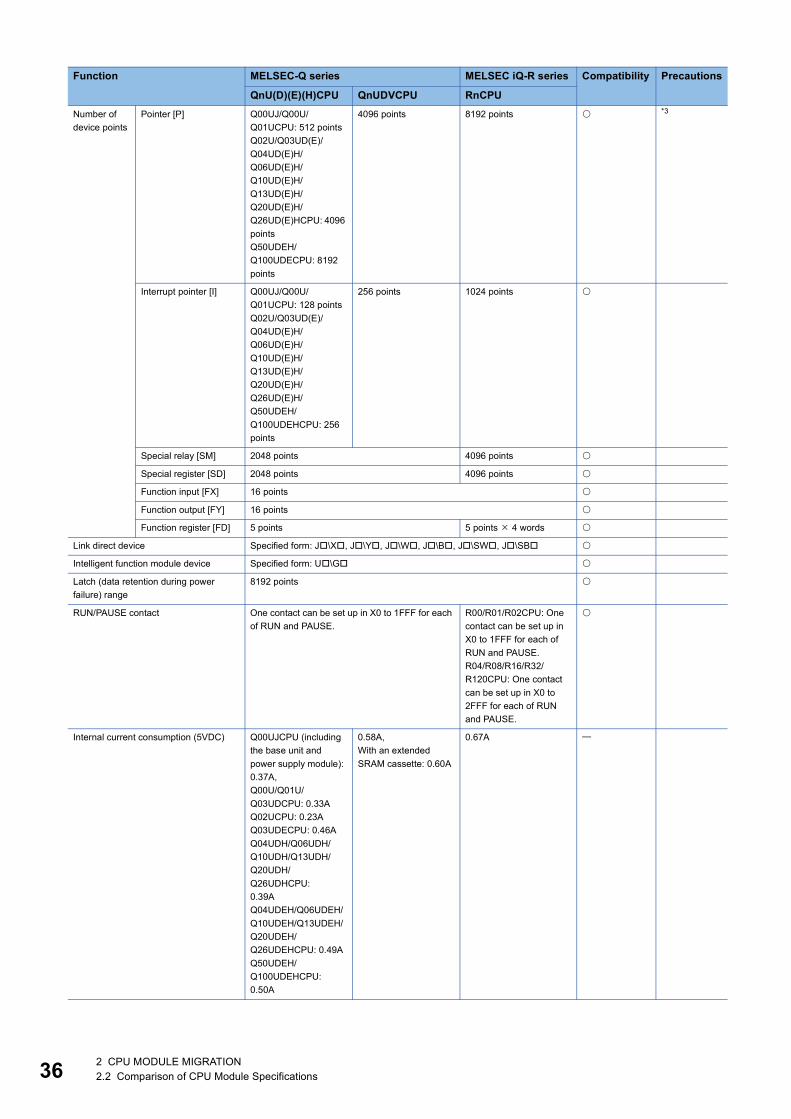
36
Number of device points
Pointer [P] Q00UJ/Q00U/Q01UCPU: 512 pointsQ02U/Q03UD(E)/Q04UD(E)H/Q06UD(E)H/Q10UD(E)H/Q13UD(E)H/Q20UD(E)H/Q26UD(E)HCPU: 4096 pointsQ50UDEH/Q100UDECPU: 8192 points
4096 points 8192 points *3
Interrupt pointer [I] Q00UJ/Q00U/Q01UCPU: 128 pointsQ02U/Q03UD(E)/Q04UD(E)H/Q06UD(E)H/Q10UD(E)H/Q13UD(E)H/Q20UD(E)H/Q26UD(E)H/Q50UDEH/Q100UDEHCPU: 256 points
256 points 1024 points
Special relay [SM] 2048 points 4096 points
Special register [SD] 2048 points 4096 points
Function input [FX] 16 points
Function output [FY] 16 points
Function register [FD] 5 points 5 points 4 words
Link direct device Specified form: J\X, J\Y, J\W, J\B, J\SW, J\SB
Intelligent function module device Specified form: U\G
Latch (data retention during power failure) range
8192 points
RUN/PAUSE contact One contact can be set up in X0 to 1FFF for each of RUN and PAUSE.
R00/R01/R02CPU: One contact can be set up in X0 to 1FFF for each of RUN and PAUSE.R04/R08/R16/R32/R120CPU: One contact can be set up in X0 to 2FFF for each of RUN and PAUSE.
Internal current consumption (5VDC) Q00UJCPU (including the base unit and power supply module): 0.37A,Q00U/Q01U/Q03UDCPU: 0.33AQ02UCPU: 0.23AQ03UDECPU: 0.46AQ04UDH/Q06UDH/Q10UDH/Q13UDH/Q20UDH/Q26UDHCPU: 0.39AQ04UDEH/Q06UDEH/Q10UDEH/Q13UDEH/Q20UDEH/Q26UDEHCPU: 0.49AQ50UDEH/Q100UDEHCPU: 0.50A
0.58A,With an extended SRAM cassette: 0.60A
0.67A
Function MELSEC-Q series MELSEC iQ-R series Compatibility Precautions
QnU(D)(E)(H)CPU QnUDVCPU RnCPU
2 CPU MODULE MIGRATION2.2 Comparison of CPU Module Specifications

2
*1 Programming languages available for the QnU(D)(E)(H)CPU and QnUDVCPU are the following:Relay symbol language, logic symbolic language, MELSAP3 (SFC), MELSAP-L, function block, and structured text (ST).Note that the logic symbolic language cannot be used in the QnUDVCPU because it is not supported by GX Works2.
*2 Programming languages available for the RCPU are the following:Ladder diagram (LD), sequential function chart (SFC), structured text (ST), function block diagram (FBD/LD), function block (FB), and label programming (system/local/global).Note that the relay symbol language is equivalent to the ladder diagram (LD); MELSAP3 (SFC) is equivalent to the sequential function chart (SFC); and the function block is equivalent to the function block (FB).
*3 The number of device points for use in the RCPU can be changed by the engineering tool.*4 The maximum value of the file register is [ + ].
: <R**CPU capacity> ** = 04: 160K words, 08: 544K words, 16: 800K words, 32: 1088K words, 120: 1600K words : Capacity of the extended SRAM cassetteThe setting must be in the following range.File register file storage area [ + ]
External dimensions Q00UJCPU (including the base unit and power supply module): 98(H) 244.4(W) 98(D)mmQ00U/Q01U/02U/Q03UD/Q04UDH/Q06UDH/Q10UDH/Q13UDH/Q20UDH/Q26UDHCPU: 98(H) 27.4(W) 89.3(D)mmQ03UDE/Q04UDEH/Q06UDEH/Q10UDEH/Q13UDEH/Q20UDEH/Q26UDEH/Q50UDEH/Q100UDEHCPU: 98(H) 27.4(W) 115(D)mm
98(H) 27.4(W) 115(D)mm
106(H) 27.8(W) 110(D)mm
Weight Q00UJCPU (including the base unit and power supply module): 0.70kgQ00UCPU, Q01UCPU: 0.15kgQ02UCPU, Q03UDCPU, Q04UDHCPU, Q06UDHCPU, Q10UDHCPU, Q13UDHCPU, Q20UDHCPU, Q26UDHCPU: 0.20kgQ03UDECPU, Q04UDEHCPU, Q06UDEHCPU, Q10UDEHCPU, Q13UDEHCPU, Q20UDEHCPU,Q26UDEHCPU: 0.22kgQ50UDEHCPU, Q100UDEHCPU: 0.24kg
0.20kg 0.20kg
Function MELSEC-Q series MELSEC iQ-R series Compatibility Precautions
QnU(D)(E)(H)CPU QnUDVCPU RnCPU
2 CPU MODULE MIGRATION2.2 Comparison of CPU Module Specifications 37

38
Process CPU/Universal model Process CPU: Compatible : Partly changed : Incompatible : Not applicable
Function MELSEC-Q series MELSEC iQ-R series Compatibility Precautions
QnPHCPU QnUDPVCPU RnPCPUControl method Stored program cyclic operation
I/O control mode Refresh mode(Direct access I/O is available by specifying direct access I/O (DX, DY).)
Programming language
Sequence control language
*1 *2
Process control language
FBD for process control (PX Developer) FBD/LD program for process control (GX Works3)
Peripheral connection port RS-232, USB (TypeB) USB (miniB), Ethernet
Memory card interface SRAM card, Flash card, ATA card*3
SD memory card
Processing speed
Sequence instruction
LD X0 34ns 1.9ns 0.98ns
MOV D0 D1
102ns 3.9ns 1.96ns
Constant scan 0.5 to 2000ms (Setting available in increments of 0.5ms)
0.5 to 2000ms (Setting available in increments of 0.1ms)
0.2 to 2000ms (Setting available in increments of 0.1ms)
Program capacity Q02PHCPU: 28K stepsQ06PHCPU: 60K stepsQ12PHCPU: 124K stepsQ25PHCPU: 252K steps
Q04UDPVCPU: 40K stepsQ06UDPVCPU: 60K stepsQ13UDPVCPU: 130K stepsQ26UDPVCPU: 260K steps
R08PCPU: 80K stepsR16PCPU: 160K stepsR32PCPU: 320K steps
Memory capacity
Program memory Q02PHCPU: 112K bytesQ06PHCPU: 240K bytesQ12PHCPU: 496K bytesQ25PHCPU: 1008K bytes
Q04UDPVCPU: 160K bytesQ06UDPVCPU: 240K bytesQ13UDPVCPU: 520K bytesQ26UDPVCPU: 1040K bytes
R08PCPU: 320K bytesR16PCPU: 640K bytesR32PCPU: 1280K bytes
Memory card SRAM card: 4M bytes maximum*4
Flash card: 4M bytes maximumATA card: 32M bytes maximum
Extended SRAM cassette: 8M bytes maximumSD/SDHC memory card: 32G bytes maximum
Extended SRAM cassette: 8M bytes maximumSD/SDHC memory card: 32G bytes maximum
Number of storable files
Program memory Q02PHCPU: 28Q06PHCPU: 60Q12PHCPU: 124Q25PHCPU: 252
Q04UDPV/Q06UDPVCPU: 124Q13UDPV/Q26UDPVCPU: 252
Program file: 252FB file: 128 (One FB file can store 64 function blocks.)
Memory card SRAM card: 319*5
Flash card: 288ATA card: 512
SD memory card: 512SDHC memory card: 65535
SD memory cardNZ1MEM-2GBSD: 256NZ1MEM-4GBSD/8GBSD/16GBSD: 32767
Number of I/O points 4096 points
2 CPU MODULE MIGRATION2.2 Comparison of CPU Module Specifications

2
Number of device points
Input [X] 8192 points 12288 points
Output [Y] 8192 points 12288 points
Internal relay [M] 8192 points Q04UDPV/Q06UDPVCPU: 15360 pointsQ13UDPV/Q26UDPVCPU: 28672 points
12288 points *6
Latch relay [L] 8192 points *6
Link relay [B] 8192 points *6
Timer [T] 2048 points 1024 + 1024 points (Long timer [LT])
*6
Counter [C] 1024 points 512 + 512 points (Long counter [LC])
*6
Data register [D] 12288 points Q04UDPV/Q06UDPVCPU: 22528 pointsQ13UDPV/Q26UDPVCPU: 41984 points
18432 points *6
Link register [W] 8192 points *6
Annunciator [F] 2048 points *6
Edge relay [V] 2048 points *6
File register [R] The number of points specified in the ZR section can be used by switching blocks in increments of 32768 points.
*6
File register [ZR] Standard RAM: Q02PH/Q06PHCPU: 65536 pointsQ12PH/Q25PHCPU: 131072 pointsSRAM card: 1041408 points maximumFlash card: 1042432 points maximum(The maximum number of points varies depending on the model.)
Q04UDPVCPU: Extended SRAM cassette not used: 131072 points,Extended SRAM cassette used: 4325376 points maximumQ06UDPVCPU: Extended SRAM cassette not used: 393216 points,Extended SRAM cassette used: 4587520 points maximumQ13UDPVCPU: Extended SRAM cassette not used: 524288 points,Extended SRAM cassette used: 4718592 points maximumQ26UDPVCPU: Extended SRAM cassette not used: 655360 points,Extended SRAM cassette used: 4849664 points maximum
Calculated by a formula.*7
(The maximum number of points varies depending on the model.)
*6
Link special relay [SB] 2048 points *6
Link special register [SW]
2048 points *6
Step relay [S] 8192 points 16384 points *6
Index register [Z] 16 points 20 points *6
Pointer [P] 4096 points 8192 points *6
Function MELSEC-Q series MELSEC iQ-R series Compatibility Precautions
QnPHCPU QnUDPVCPU RnPCPU
2 CPU MODULE MIGRATION2.2 Comparison of CPU Module Specifications 39

40
*1 Programming languages available for the QnPHCPU and QnUDPVCPU are the following:Relay symbol language, logic symbolic language, MELSAP3 (SFC), MELSAP-L, function block, structured text (ST). Note that the logic symbolic language cannot be used in the QnUDPVCPU because it is not supported by GX Works2.
*2 Programming languages available for the RCPU are the following:Ladder diagram (LD), sequential function chart (SFC), structured text (ST), function block diagram (FBD/LD), function block (FB), label programming (system/local/global)Note that the relay symbol language is equivalent to the ladder diagram (LD); MELSAP3 (SFC) is equivalent to the sequential function chart (SFC); and the function block is equivalent to the function block (FB).
*3 Q3MEM-8MBS cannot be used.*4 The maximum capacity is 2M bytes for CPU modules with a serial number "16020" (first five digits) or earlier.*5 The maximum capacity is 287 files for CPU modules with a serial number "16020" (first five digits) or earlier (with the Q2MEM-2MBS
used).*6 The number of device points for use in the RCPU can be changed by the engineering tool.*7 The maximum value of the file register is [ + ].
: <Capacity of the R**CPU> (R08CPU: 544K words, R16CPU: 800K words, R32CPU: 1088K words), : Capacity of the extended SRAM cassette The value must be in the following range.File register file storage area [ + ]
Number of device points
Interrupt pointer [I] 256 points 1024 points
Special relay [SM] 2048 points 4096 points
Special register [SD] 2048 points 4096 points
Function input [FX] 16 points
Function output [FY] 16 points
Function register [FD] 5 points 5 points 4 words
Link direct device Specified form: J\X, J\Y, J\W, J\B, J\SW, J\SB
Intelligent function module device Specified form: U\G
Latch (data retention during power failure) range
8192 points
RUN/PAUSE contact One contact can be set up in X0 to 1FFF for each of RUN and PAUSE.
One contact can be set up in X0 to 2FFF for each of RUN and PAUSE.
Internal current consumption (5VDC) 0.64A 0.58A (CPU module only)0.6A (With an extended SRAM cassette)
0.76A
External dimensions 98(H) 27.4(W) 89.3(D)mm
98(H) 27.4(W) 115(D)mm
106(H) 27.8(W) 110(D)mm
Weight 0.20kg
Function MELSEC-Q series MELSEC iQ-R series Compatibility Precautions
QnPHCPU QnUDPVCPU RnPCPU
2 CPU MODULE MIGRATION2.2 Comparison of CPU Module Specifications

2
C Controller module: Compatible : Partly changed : Incompatible : Not applicable
Function MELSEC-Q series MELSEC iQ-R series Compatibility Precautions
Q06CCPU-V(-B) Q12DCCPU-VQ24DHCCPU-V
R12CCPU-V
Hardware Endian format Q06CCPU-V: Little-endianQ06CCPU-V-B: Big-endian
Little-endian
MPU SH4 Q12DCCPU-V: SH4AQ24DHCCPU-V: SH4A+Intel ATOM
ARM Cortex-A9 Dual Core
Memory capacity
Standard RAM
Q12DCCPU-V: 3M bytesQ24DHCCPU-V: 0 to 4M bytes*1
Standard ROM
6M bytes Q12DCCPU-V: 12M bytes (extended mode only)Q24DHCCPU-V: 382M bytes
16M bytes
Memory card
Depending on the CompactFlash cardQ06CCPU-V: 1G byte maximum, Q06CCPU-V-B: Not available
Depending on the CompactFlash card/memory cardQ12DCCPU-V: 8G bytes maximumQ24DHCCPU-V: 16G bytes maximum
Depending on the memory card16G bytes maximum
Work RAM 64M bytes Q12DCCPU-V: 128M bytesQ24DHCCPU-V: 512M bytes
256M bytes
Battery backup RAM 128K bytes Q12DCCPU-V: 512 to 3584K bytes*2
Q24DHCCPU-V: 1 to 5M bytes*3
4MB
Software OS VxWorks Version 5.4 Q12DCCPU-V: VxWorks Version 6.4Q24DHCCPU-V: VxWorks Version 6.8.1
VxWorks Version 6.9
Programming language
C language (C/C++)
Ethernet port Number of channels 1 channel Q12DCCPU-V: 2 channelsQ24DHCCPU-V: User Ethernet 2 channels, System Ethernet 1 channel
2 channels
Interface 10BASE-T/100BASE-TX
Q12DCCPU-V: 10BASE-T/100BASE-TXQ24DHCCPU-V: User Ethernet 10BASE-T/100BASE-TX/1000BASE-T, System Ethernet 10BASE-T/100BASE-TX
10BASE-T/100BASE-TX/1000BASE-T
Communication method
Full-duplex/half-duplex
Flow control Full-duplex: NoneHalf-duplex: Back pressure congestion control
Full-duplex: IEEE802.3xHalf-duplex: Back pressure congestion control
Full-duplex: NoneHalf-duplex: Back pressure congestion control
2 CPU MODULE MIGRATION2.2 Comparison of CPU Module Specifications 41

42
Ethernet port Data transmission speed
10Mbps(10BASE-T)/100Mbps(100BASE-TX)
Q12DCCPU-V: 10Mbps(10BASE-T)/100Mbps(100BASE-TX)Q24DHCCPU-V: User Ethernet 10Mbps (10BASE-T)/100Mbps (100BASE-TX)/1000Mbps (1000BASE-T), System Ethernet 10Mbps (10BASE-T)/100Mbps (100BASE-TX)
10Mbps(10BASE-T)/100Mbps(100BASE-TX)/1000Mbps(1000BASE-T)
Transmission method Base band
Number of cascade connections*4
4 levels maximum (10BASE-T)/2 levels maximum (100BASE-TX)
Maximum segment length
100m
Connector for external wiring
RJ45
Supported function Auto negotiation function (automatic recognition of communication speed/communication method)
Auto negotiation function (automatic recognition of communication speed/communication method)Auto-MDI/MDI-X (automatic recognition of a straight/crossing cable)
RS-232 connector
Number of channels 1 channel
Interface Compliant with RS-232
Communication method
Full-duplex/half-duplex
Synchronization method
Asynchronous method
Transmission speed 9600, 14400, 19200, 28800, 38400, 57600, 115200bps
Transmission distance 15m maximum
Data format
Start bits 1
Data bits 7/8
Parity bits 1/None
Stop bits 1/2
Parity check Yes (Even/Odd)/No
Sum check code Yes/No
Transmission control Flow control (RS/CS control)
Connector for external wiring
9-pin D-sub (male) screw type
Round connector (10-pin)
9-pin D-sub (male) screw type
USB connector
Interface USB2.0 ready
Connector Q12DCCPU-V: USB(miniB)Q24DHCCPU-V: USB(TypeA), USB(miniB)
USB(TypeA)
Transmission speed Q12DCCPU-V: 12Mbps (Full Speed)Q24DHCCPU-V: USB(TypeA) 480Mbps (High Speed), USB(miniB) 12Mbps (Full Speed)
480Mbps(High Speed)
Function MELSEC-Q series MELSEC iQ-R series Compatibility Precautions
Q06CCPU-V(-B) Q12DCCPU-VQ24DHCCPU-V
R12CCPU-V
2 CPU MODULE MIGRATION2.2 Comparison of CPU Module Specifications

2
*1 The area for standard RAM is created by specifying the memory capacity in the battery backup RAM with parameters.*2 The maximum capacity is 128K bytes for the Q12DCCPU-V with a serial number "12041" (first five digits) or earlier.*3 When the area for standard RAM is created, the memory specified for standard RAM is occupied, therefore, the battery backup RAM
area will be decreased.*4 This applies when a repeater hub is used. For the number of levels that can be constructed when a switching hub is used, consult the
manufacturer of the switching hub used.*5 Select an appropriate USB Mass Storage Class-compliant device to be connected to observe the current consumption limit.
USB connector
Power supply Q12DCCPU-V: Self-PoweredQ24DHCCPU-V: USB(TypeA) Bus power +5VDC, 500mA maximum*5, USB(miniB) Self-Powered
Bus power +5VDC, 500mA maximum*5
CompactFlash card
Supply power voltage 3.3V5% (Q06CCPU-V-B, Q24DHCCPU-V: None)
Supply power capacity 150mA maximum (Q06CCPU-V-B, Q24DHCCPU-V: None)
Card size TYPE card, TYPE card is not allowed. I/O cards, such as a modem card are not allowed. (Q06CCPU-V-B, Q24DHCCPU-V: None)
Number of loadable cards
1 (Q06CCPU-V-B, Q24DHCCPU-V: None)
SD memory card slot
Interface SD/SDHC memory card (16G bytes maximum) (Q12DCCPU-V: None)
Power supply +3.3VDC, 200mA maximum (Q12DCCPU-V: None)
Number of loadable cards
1 (Q12DCCPU-V: None)
Number of I/O points 4096 points
Clock function Displayed information Year, month, day, hour, minute, second, day of week (automatic leap year detection)
Accuracy During power-on: Accuracy of VxWorks POSIX Clock (Accuracy may vary by the operation program.)During power-off: Daily error: -10.89 to +8.64 seconds (0 to 55), Daily error: -4.32 to +5.25 seconds (25). An additional error of -0.5 to +0.5 seconds may occur when the power is turned on.
Daily error: -5.86 to +3.35 (0 to 55), Daily error: -1.71 to +3.35 seconds (25)
Allowable momentary power failure time Depends on the power supply module
Number of occupied slots 1 Q12DCCPU-V: 1Q24DHCCPU-V: 3
2
Internal current consumption (5VDC) Q06CCPU-V: 0.75AQ06CCPU-V-B: 0.71A
Q12DCCPU-V: 0.97AQ24DHCCPU-V: 2.8A
1.26A
External dimensions 98(H)27.4(W)89.3(D)mm
Q12DCCPU-V: 98(H)27.4(W)115(D)mmQ24DHCCPU-V: 98(H)83(W)115(D)mm
106(H)56(W)110(D)mm
Weight 0.17kg Q12DCCPU-V: 0.24kgQ24DHCCPU-V: 0.63kg
0.35kg
Function MELSEC-Q series MELSEC iQ-R series Compatibility Precautions
Q06CCPU-V(-B) Q12DCCPU-VQ24DHCCPU-V
R12CCPU-V
2 CPU MODULE MIGRATION2.2 Comparison of CPU Module Specifications 43
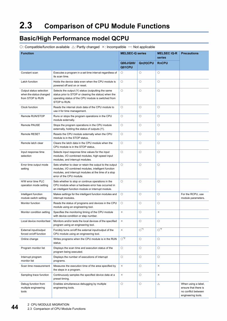
44
2.3 Comparison of CPU Module FunctionsBasic/High Performance model QCPU: Compatible/function available : Partly changed : Incompatible : Not applicable
Function MELSEC-Q series MELSEC iQ-R series
Precautions
Q00J/Q00/Q01CPU
Qn(H)CPU RnCPU
Constant scan Executes a program in a set time interval regardless of its scan time.
Latch function Holds the device data even when the CPU module is powered off and on or reset.
Output status selection when the status changed from STOP to RUN
Selects the output (Y) status (outputting the same status prior to STOP or clearing the status) when the operating status of the CPU module is switched from STOP to RUN.
Clock function Reads the internal clock data of the CPU module to use it for time management.
Remote RUN/STOP Runs or stops the program operations in the CPU module externally.
Remote PAUSE Stops the program operations in the CPU module externally, holding the status of outputs (Y).
Remote RESET Resets the CPU module externally when the CPU module is in the STOP status.
Remote latch clear Clears the latch data in the CPU module when the CPU module is in the STOP status.
Input response time selection
Selects input response time values for the input modules, I/O combined modules, high-speed input modules, and interrupt modules.
Error time output mode setting
Sets whether to clear or retain the output to the output modules, I/O combined modules, intelligent function modules, and interrupt modules at the time of a stop error of the CPU module.
H/W error time PLC operation mode setting
Sets whether to stop or continue operations in the CPU module when a hardware error has occurred in an intelligent function module or interrupt module.
Intelligent function module switch setting
Makes settings for the intelligent function modules and interrupt modules.
For the RCPU, use module parameters.
Monitor function Reads the status of programs and devices in the CPU module using an engineering tool.
Monitor condition setting Specifies the monitoring timing of the CPU module with device condition or step number.
Local device monitor/test Monitors and/or tests the local devices of the specified program using an engineering tool.
External input/output forced on/off function
Forcibly turns on/off the external input/output of the CPU module using an engineering tool.
*1 *7
Online change Writes programs when the CPU module is in the RUN status.
*2
Program monitor list Displays the scan time and execution status of the program being executed.
Interrupt program monitor list
Displays the number of executions of interrupt programs.
Scan time measurement Measures the execution time of the area specified by the steps in a program.
Sampling trace function Continuously samples the specified device data at a preset timing.
Debug function from multiple engineering tools
Enables simultaneous debugging by multiple engineering tools.
When using a label, ensure that there is no conflict between engineering tools.
2 CPU MODULE MIGRATION2.3 Comparison of CPU Module Functions

2
*1 Only products with a serial number "02092" (first five digits) or later supports this function.*2 The online change (files) is not available.*3 System protection using DIP switches is not available.*4 Only products with a serial number "04122" (first five digits) or later supports this function.*5 This function is not available for the Q02CPU.*6 This function is not available for the Q00JCPU.*7 Availability depends on the version of the CPU module. For details, refer to the following.
MELSEC iQ-R CPU Module User's Manual (Application)
Watchdog timer Monitors operational delays caused by hardware failure or program error of the CPU module.
Self-diagnostic function Self-diagnoses the CPU module to see whether an error exists or not.
Error history Stores the result of self-diagnostics to the memory as error history data.
For the RCPU, the result is stored as event history data.
System protection Prevents the programs from being modified from an engineering tool, an Ethernet module, and a serial communication module.
*3
Password registration Prohibits reading/writing data from/to each file in the CPU module using an engineering tool.
Remote password Prevents unauthorized access from external devices. *4 *1
System display Monitors the system configuration using an engineering tool.
LED indication Displays the operating status of the CPU module with LEDs on the front of the module.
LED indication priority Sets priorities for error messages that are stored in the LED display data (SD220 to SDS227) when errors occur.This function can also disable LED indication.
High-speed interrupt function
Executes an interrupt program at fixed intervals of 0.2 to 1.0ms using the interrupt pointer (I49).
*5
Interrupt from intelligent function module
Executes an interrupt program at the time of interrupt request from the intelligent function module.
*4
Serial communication function
Connects the RS-232 interface of the CPU module and the personnel computer or HMI with RS-232 cable and communicates in the MC protocol.
*6
Module service interval time read
Monitors the service interval time (time taken from CPU module's acceptance of one access to its acceptance of next access) of the intelligent function module, network module, or engineering tools.
Initial device value Registers data used in a program to the device or the buffer memory of the intelligent function module and special function module without a program.
*4
Function MELSEC-Q series MELSEC iQ-R series
Precautions
Q00J/Q00/Q01CPU
Qn(H)CPU RnCPU
2 CPU MODULE MIGRATION2.3 Comparison of CPU Module Functions 45

46
Universal model QCPU: Compatible/function available : Partly changed : Incompatible : Not applicable
Function MELSEC-Q series MELSEC iQ-R series
Precautions
QnU(D)(E)(H)CPU
QnUDVCPU RnCPU
Boot operation Transfers and boots data stored in a memory card or SD memory card to the program memory or the standard ROM at power-on or reset.
*1 *7
Constant scan Executes a program in a set time interval regardless of its scan time.
Latch function Holds the device data even when the CPU module is powered off and on or reset.
Output status selection when the status changed from STOP to RUN
Selects the output (Y) status (outputting the same status prior to STOP or clearing the status) when the operating status of the CPU module is switched from STOP to RUN.
Clock function Reads the internal clock data of the CPU module to use it for time management.
Remote RUN/STOP Runs or stops the program operations in the CPU module externally.
Remote PAUSE Stops the program operations in the CPU module externally, holding the status of outputs (Y).
Remote RESET Resets the CPU module externally when the CPU module is in the STOP status.
Remote latch clear Clears the latch data in the CPU module when the CPU module is in the STOP status.
Input response time selection
Selects input response time values for the input modules, I/O combined modules, high-speed input modules, and interrupt modules.
Error time output mode setting
Sets whether to clear or retain the output to the output modules, I/O combined modules, intelligent function modules, and interrupt modules at the time of a stop error of the CPU module.
H/W error time PLC operation mode setting
Sets whether to stop or continue operations in the CPU module when a hardware error has occurred in an intelligent function module or interrupt module.
Intelligent function module switch setting
Makes settings for the intelligent function modules and interrupt modules.
For the RCPU, use module parameters.
Monitor function Reads the status of programs and devices in the CPU module using an engineering tool.
Monitor condition setting
Specifies the monitoring timing of the CPU module with device condition or step number.
*1*2
Local device monitor/test
Monitors and/or tests the local devices of the specified program using an engineering tool.
*2*3
External input/output forced on/off
Forcibly turns on/off the external input/output of the CPU module using an engineering tool.
*2 *10
Executional conditioned device test
Changes a device value within the specified step of a sequence program.
*2 *10
Online change Writes programs when the CPU module is in the RUN status.
Program monitor list Displays the scan time and execution status of the program being executed.
Interrupt program monitor list
Displays the number of executions of interrupt programs.
Scan time measurement
Measures the execution time of the area specified by the steps in a program.
*2
Sampling trace function
Continuously samples the specified device data at a preset timing.
*3
2 CPU MODULE MIGRATION2.3 Comparison of CPU Module Functions

2
Debug function from multiple engineering toolsEnables simultaneous debugging by multiple engineering tools.
When using a label, ensure that there is no conflict between engineering tools.
Watchdog timer Monitors operational delays caused by hardware failure or program error of the CPU module.
Self-diagnostic function
Self-diagnoses the CPU module to see whether an error exists or not.
Error history Stores the result of self-diagnostics to the memory as error history data.
For the RCPU, the result is stored as event history data.
Security function Protects data in the CPU module against tampering and theft by unauthorized persons.
Password registration Prohibits reading/writing data from/to each file in the CPU module using an engineering tool.
File password 32 Prohibits reading/writing data from/to each file in the CPU module using an engineering tool. Sets a read password and write password for each file stored in the CPU module.
File access control by security key
Prevents unauthorized access to the files in the CPU module by writing a security key to the module. (The CPU module is locked with a security key.)
Remote password Prevents unauthorized access from external devices.
Block password Prevents access to program contents by setting a block password for each POU.
LED indication Displays the operating status of the CPU module with LEDs on the front of the module.
LED indication priority Sets whether to indicate an error with LED according to the priority of each error.
High-speed interrupt function
Executes an interrupt program at fixed intervals of 0.1 to 1.0ms using the high-speed interrupt pointer (I49).
Interrupt from intelligent function module
Executes an interrupt program at the time of interrupt request from the intelligent function module.
Serial communication function
Communicates data using the MC protocol by connecting the RS-232 interface of the CPU module and a personal computer or HMI from other companies using an RS-232 cable.
*2*4
Service processing setting
Specifies the service processing count or time to be executed in END processing.
Initial device value Registers data used in a program to the device or the buffer memory of the intelligent function module and special function module without a program.
Battery life-prolonging function
Extends the life of a battery by holding only clock data using the battery.
Program cache memory auto recovery function
Restores the error location automatically by using data in the program memory, which are stored in the flash ROM, when the memory check function detects an error in the program cache memory.
*2
Latch data backup to standard ROM
Backs up latch data such as device data and error history to the standard ROM without using a battery.
Writing/reading device data to/from standard ROM
Writes/reads device data to/from the standard ROM.
CPU module change function with memory card
Backs up all the data (only the file register files and latch-target device data) in a CPU module to a memory card or SD memory card. The data backed up can be restored to a replaced CPU module.
*1*2 *7
Function MELSEC-Q series MELSEC iQ-R series
Precautions
QnU(D)(E)(H)CPU
QnUDVCPU RnCPU
2 CPU MODULE MIGRATION2.3 Comparison of CPU Module Functions 47
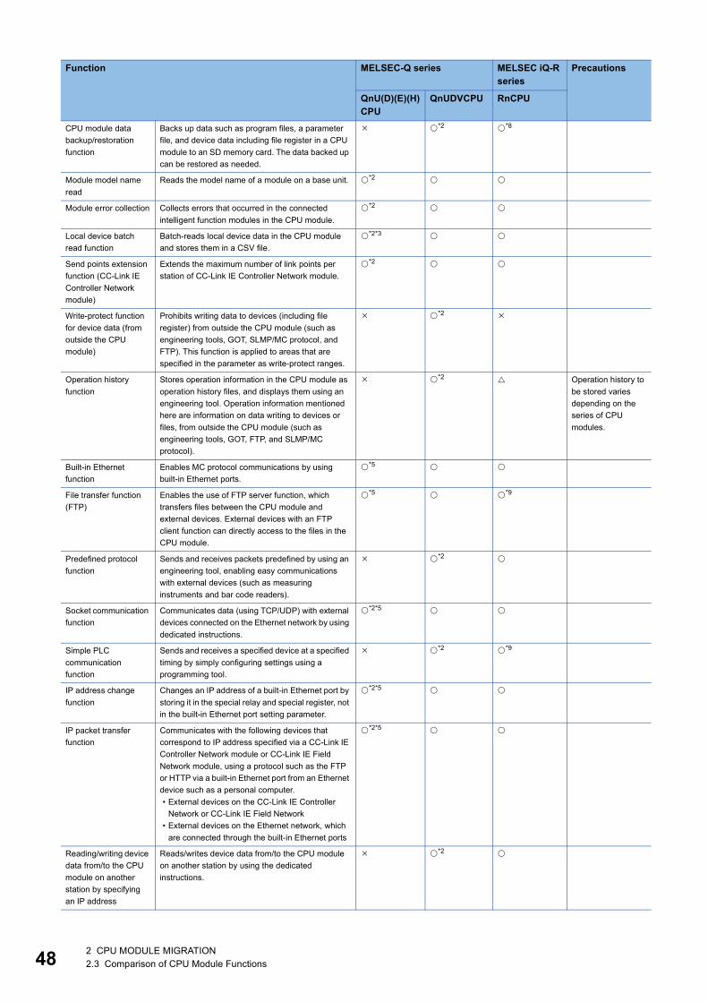
48
CPU module data backup/restoration function
Backs up data such as program files, a parameter file, and device data including file register in a CPU module to an SD memory card. The data backed up can be restored as needed.
*2 *8
Module model name read
Reads the model name of a module on a base unit. *2
Module error collection Collects errors that occurred in the connected intelligent function modules in the CPU module.
*2
Local device batch read function
Batch-reads local device data in the CPU module and stores them in a CSV file.
*2*3
Send points extension function (CC-Link IE Controller Network module)
Extends the maximum number of link points per station of CC-Link IE Controller Network module.
*2
Write-protect function for device data (from outside the CPU module)
Prohibits writing data to devices (including file register) from outside the CPU module (such as engineering tools, GOT, SLMP/MC protocol, and FTP). This function is applied to areas that are specified in the parameter as write-protect ranges.
*2
Operation history function
Stores operation information in the CPU module as operation history files, and displays them using an engineering tool. Operation information mentioned here are information on data writing to devices or files, from outside the CPU module (such as engineering tools, GOT, FTP, and SLMP/MC protocol).
*2 Operation history to be stored varies depending on the series of CPU modules.
Built-in Ethernet function
Enables MC protocol communications by using built-in Ethernet ports.
*5
File transfer function (FTP)
Enables the use of FTP server function, which transfers files between the CPU module and external devices. External devices with an FTP client function can directly access to the files in the CPU module.
*5 *9
Predefined protocol function
Sends and receives packets predefined by using an engineering tool, enabling easy communications with external devices (such as measuring instruments and bar code readers).
*2
Socket communication function
Communicates data (using TCP/UDP) with external devices connected on the Ethernet network by using dedicated instructions.
*2*5
Simple PLC communication function
Sends and receives a specified device at a specified timing by simply configuring settings using a programming tool.
*2 *9
IP address change function
Changes an IP address of a built-in Ethernet port by storing it in the special relay and special register, not in the built-in Ethernet port setting parameter.
*2*5
IP packet transfer function
Communicates with the following devices that correspond to IP address specified via a CC-Link IE Controller Network module or CC-Link IE Field Network module, using a protocol such as the FTP or HTTP via a built-in Ethernet port from an Ethernet device such as a personal computer.• External devices on the CC-Link IE Controller
Network or CC-Link IE Field Network• External devices on the Ethernet network, which
are connected through the built-in Ethernet ports
*2*5
Reading/writing device data from/to the CPU module on another station by specifying an IP address
Reads/writes device data from/to the CPU module on another station by using the dedicated instructions.
*2
Function MELSEC-Q series MELSEC iQ-R series
Precautions
QnU(D)(E)(H)CPU
QnUDVCPU RnCPU
2 CPU MODULE MIGRATION2.3 Comparison of CPU Module Functions

2
*1 This function is not available for the Q00UJCPU, Q00UCPU, and Q01UCPU.*2 Availability depends on the version of the CPU module. For details, refer to the following.
QnUCPU User's Manual (Function Explanation, Program Fundamentals)*3 This function is not available for the Q00UJCPU.*4 This function is not available for the QnUDE(H)CPU.*5 This function is available only for the QnUDE(H)CPU.*6 This function is available only for the QnUD(E)(H)CPU.*7 This function is not available for the R00CPU.*8 This function is not available for the R00CPU, R01CPU, and R02CPU.*9 Availability depends on the version of the CPU module. For details, refer to the following.
MELSEC iQ-R Ethernet User's Manual (Application)*10 Availability depends on the version of the CPU module. For details, refer to the following.
MELSEC iQ-R CPU Module User's Manual (Application)
SLMP frame send instruction
Sends MC protocol messages (QnA-compatible 3E frame and 4E frame) from the CPU module to external devices connected on the Ethernet network.
*2
Writing/reading data to/from refresh devices with the specified station number
Writes/reads data by specifying the station number of the target station, without considering the assignment of refresh devices.
*6 *2
Data logging function Collects data from the specified device of a CPU module at a specified timing. The data logging file can be transferred from a CPU module to the FTP server using the data logging file transfer function.
*7
iQ Sensor Solution functionAutomatic detection of connected device
Detects devices supporting iQ Sensor Solution connected to the CPU module, and automatically displays them on "List of devices" and "Device map area" using an engineering tool.
*2
iQ Sensor Solution functionSystem configuration check
Compares the system configuration information displayed on an engineering tool with the actual system configuration, and checks if they match.
*2
iQ Sensor Solution functionCommunication setting reflection
Reflects the communication settings (such as IP addresses) of devices supporting iQ Sensor Solution on "Device map area" to the devices connected over Ethernet in the system.
*2
iQ Sensor Solution functionSensor parameter read/write
Reads/writes parameters (operation parameters for devices supporting iQ Sensor Solution) from/to devices supporting iQ Sensor Solution.
*2
iQ Sensor Solution functionMonitoring
Monitors the current values (such as measurement values and input/output values), status (error existence), and error information of devices supporting iQ Sensor Solution graphically using an engineering tool.
*2
iQ Sensor Solution functionData backup/restoration
Backs up setting data (such as parameters) in a device supporting iQ Sensor Solution to an SD memory card. The data backed up can be restored as needed.
*2 *7
CC-Link IE Field Network Basic function
A set of functions that can be used in CC-Link IE Field Network Basic
*2
Function MELSEC-Q series MELSEC iQ-R series
Precautions
QnU(D)(E)(H)CPU
QnUDVCPU RnCPU
2 CPU MODULE MIGRATION2.3 Comparison of CPU Module Functions 49

50
Process CPU/Universal model Process CPU: Compatible/function available : Partly changed : Incompatible : Not applicable
Function MELSEC-Q series MELSEC iQ-R series
Precautions
QnPHCPU QnUDPVCPU RnPCPUBoot operation Transfers and boots data stored in a memory card
or SD memory card to the program memory or the standard ROM at power-on or reset.
Constant scan Executes a program in a set time interval regardless of its scan time.
Latch function Holds the device data even when the CPU module is powered off and on or reset.
Output status selection when the status changed from STOP to RUN
Selects the output (Y) status (outputting the same status prior to STOP or clearing the status) when the operating status of the CPU module is switched from STOP to RUN.
Clock function Reads the internal clock data of the CPU module to use it for time management.
Remote RUN/STOP Runs or stops the program operations in the CPU module externally.
Remote PAUSE Stops the program operations in the CPU module externally, holding the status of outputs (Y).
Remote RESET Resets the CPU module externally when the CPU module is in the STOP status.
Remote latch clear Clears the latch data in the CPU module when the CPU module is in the STOP status.
Input response time selection
Selects input response time values for the input modules, I/O combined modules, high-speed input modules, and interrupt modules.
Error time output mode setting
Sets whether to clear or retain the output to the output modules, I/O combined modules, intelligent function modules, and interrupt modules at the time of a stop error of the CPU module.
H/W error time PLC operation mode setting
Sets whether to stop or continue operations in the CPU module when a hardware error has occurred in an intelligent function module or interrupt module.
Intelligent function module switch setting
Makes settings for the intelligent function modules and interrupt modules.
For the RCPU, use module parameters.
Monitor function Reads the status of programs and devices in the CPU module using a programming tool.
Monitor condition setting
Specifies the monitoring timing of the CPU module with device condition or step number.
Local device monitor/test
Monitors and/or tests the local devices of the specified program using a programming tool.
External input/output forced on/off function
Forcibly turns on/off the external input/output of the CPU module using a programming tool.
*2
Executional conditioned device test
Changes a device value within the specified step of a sequence program.
*2
Online change Writes programs when the CPU module is in the RUN status.
Program monitor list Displays the scan time and execution status of the program being executed.
Interrupt program monitor list
Displays the number of executions of interrupt programs.
Scan time measurement
Measures the execution time of the area specified by the steps in a program.
Sampling trace function
Continuously samples the specified device data at a preset timing.
2 CPU MODULE MIGRATION2.3 Comparison of CPU Module Functions

2
Debug function from multiple programming tools
Enables simultaneous debugging by multiple programming tools.
When using a label, ensure that there is no conflict between programming tools.
Watchdog timer Monitors operational delays caused by hardware failure or program error of the CPU module.
Self-diagnostic function
Self-diagnoses the CPU module to see whether an error exists or not.
Error history Stores the result of self-diagnostics to the memory as error history data.
For the RCPU, the result is stored as event history data.
Security function Protects data in the CPU module against tampering and theft by unauthorized persons.
Password registration Prohibits reading/writing data from/to each file in the CPU module using a programming tool.
File password 32 Prohibits reading/writing data from/to each file in the CPU module using a programming tool. Sets a read password and write password for each file stored in the CPU module.
File access control by security key
Prevents unauthorized access to the files in the CPU module by writing a security key to the module. (The CPU module is locked with a security key.)
Remote password Prevents unauthorized access from external devices.
Block password Prevents access to program contents by setting a block password for each POU.
LED indication Displays the operating status of the CPU module with LEDs on the front of the module.
LED indication priority Sets whether to indicate an error with LED according to the priority of each error.
High-speed interrupt function
Executes an interrupt program at fixed intervals of 0.1 to 1.0ms using the interrupt pointer (I49).
Interrupt from intelligent function module
Executes an interrupt program at the time of interrupt request from the intelligent function module.
Module service interval time read
Monitors the service interval time (time taken from CPU module's acceptance of one access to its acceptance of next access) of the intelligent function module, network module, or programming tools.
Service processing setting
Specifies the service processing count or time to be executed in END processing.
For the QnPHCPU, use the special register for the setting. For the QnUDPVCPU/RnPCPU, use the parameter for the setting.
Initial device value Registers data used in a program to the device or the buffer memory of the intelligent function module and special function module without a program.
Memory check function
Checks whether data in the memory of CPU module has been changed unintentionally due to factors such as excessive electrical noise.
*1
Online module change Enables a module change without the system being stopped.
Operation using engineering tool is not supported.
Function MELSEC-Q series MELSEC iQ-R series
Precautions
QnPHCPU QnUDPVCPU RnPCPU
2 CPU MODULE MIGRATION2.3 Comparison of CPU Module Functions 51

52
Auto tuning function Sets an initial value of PID constants. In addition, this function is used in a process where responses are relatively slow, such as temperature control, in a loop using the S.PID instruction or the S.2PID instruction.
Program cache memory auto recovery function
Restores the error location automatically by using data in the program memory, which are stored in the flash ROM, when the memory check function detects an error in the program cache memory.
Latch data backup to standard ROM
Backs up latch data such as device data and error history to the standard ROM without using a battery.
Writing/reading device data to/from standard ROM
Writes/reads device data to/from the standard ROM.
CPU module change function with memory card
Backs up all the data (only the file register files and latch-target device data) in a CPU module to a memory card or SD memory card. The data backed up can be restored to a replaced CPU module.
*1
CPU module data backup/restoration function
Backs up data such as program files, a parameter file, and device data including file register in a CPU module to an SD memory card. The data backed up can be restored as needed.
*1 *2
Module model name read
Reads the model name of a module on a base unit.
Module error collection Collects errors that occurred in the connected intelligent function modules in the CPU module.
Errors can be checked with the event history.
Local device batch read function
Batch-reads local device data in the CPU module and stores them in a CSV file.
Send points extension function (CC-Link IE Controller Network module)
Extends the maximum number of link points per station of CC-Link IE Controller Network module.
Write-protect function for device data (from outside the CPU module)
Prohibits writing data to devices (including file register) from outside the CPU module (such as engineering tools, GOT, SLMP/MC protocol, and FTP). This function is applied to areas that are specified in the parameter as write-protect ranges.
*1
Operation history function
Stores operation information in the CPU module as operation history files, and displays them using an engineering tool. Operation information mentioned here are information on data writing to devices or files, from outside the CPU module (such as engineering tools, GOT, FTP, and SLMP/MC protocol).
*1 Operation history to be stored varies depending on the series of CPU modules.
Built-in Ethernet function
Enables MC protocol communications by using built-in Ethernet ports.
File transfer function (FTP)
Enables the use of FTP server function, which transfers files between the CPU module and external devices. External devices with an FTP client function can directly access to the files in the CPU module.
*3
Predefined protocol function
Sends and receives packets predefined by using an engineering tool, enabling easy communications with external devices (such as measuring instruments and bar code readers).
*1
Socket communication function
Communicates data (using TCP/UDP) with external devices connected on the Ethernet network by using dedicated instructions.
Simple PLC communication function
Sends and receives a specified device at a specified timing by simply configuring settings using a programming tool.
*1
Function MELSEC-Q series MELSEC iQ-R series
Precautions
QnPHCPU QnUDPVCPU RnPCPU
2 CPU MODULE MIGRATION2.3 Comparison of CPU Module Functions

2
*1 Availability depends on the version of the CPU module. For details, refer to the following. QnUCPU User's Manual (Function Explanation, Program Fundamentals)
*2 Availability depends on the version of the CPU module. For details, refer to the following. MELSEC iQ-R CPU Module User's Manual (Application)
*3 Availability depends on the version of the CPU module. For details, refer to the following. MELSEC iQ-R Ethernet User's Manual (Application)
IP address change function
Changes an IP address of a built-in Ethernet port by storing it in the special relay and special register, not in the built-in Ethernet port setting parameter.
IP packet transfer function
Communicates with the following devices that correspond to IP address specified via a CC-Link IE Controller Network module or CC-Link IE Field Network module, using a protocol such as the FTP or HTTP via a built-in Ethernet port from an Ethernet device such as a personal computer.• External devices on the CC-Link IE Controller
Network or CC-Link IE Field Network• External devices on the Ethernet network, which
are connected through the built-in Ethernet ports
Reading/writing device data from/to the CPU module on another station by specifying an IP address
Reads/writes device data from/to the CPU module on another station by using the dedicated instructions.
SLMP frame send instruction
Sends MC protocol messages (QnA-compatible 3E frame and 4E frame) from the CPU module to external devices connected on the Ethernet network.
*1
Writing/reading data to/from refresh devices with the specified station number
Writes/reads data by specifying the station number of the target station, without considering the assignment of refresh devices.
*1
Data logging function Collects data from the specified device of a CPU module at a specified timing. The data logging file can be transferred from a CPU module to the FTP server using the data logging file transfer function.
iQ Sensor Solution functionAutomatic detection of connected device
Detects devices supporting iQ Sensor Solution connected to the CPU module, and automatically displays them on "List of devices" and "Device map area" using an engineering tool.
*1
iQ Sensor Solution functionSystem configuration check
Compares the system configuration information displayed on an engineering tool with the actual system configuration, and checks if they match.
*1
iQ Sensor Solution functionCommunication setting reflection
Reflects the communication settings (such as IP addresses) of devices supporting iQ Sensor Solution on "Device map area" to the devices connected over Ethernet in the system.
*1
iQ Sensor Solution functionSensor parameter read/write
Reads/writes parameters (operation parameters for devices supporting iQ Sensor Solution) from/to devices supporting iQ Sensor Solution.
*1
iQ Sensor Solution functionMonitoring
Monitors the current values (such as measurement values and input/output values), status (error existence), and error information of devices supporting iQ Sensor Solution graphically using an engineering tool.
*1
iQ Sensor Solution functionData backup/restoration
Backs up setting data (such as parameters) in a device supporting iQ Sensor Solution to an SD memory card. The data backed up can be restored as needed.
*1
CC-Link IE Field Network Basic function
A set of functions that can be used in CC-Link IE Field Network Basic
*1
Function MELSEC-Q series MELSEC iQ-R series
Precautions
QnPHCPU QnUDPVCPU RnPCPU
2 CPU MODULE MIGRATION2.3 Comparison of CPU Module Functions 53
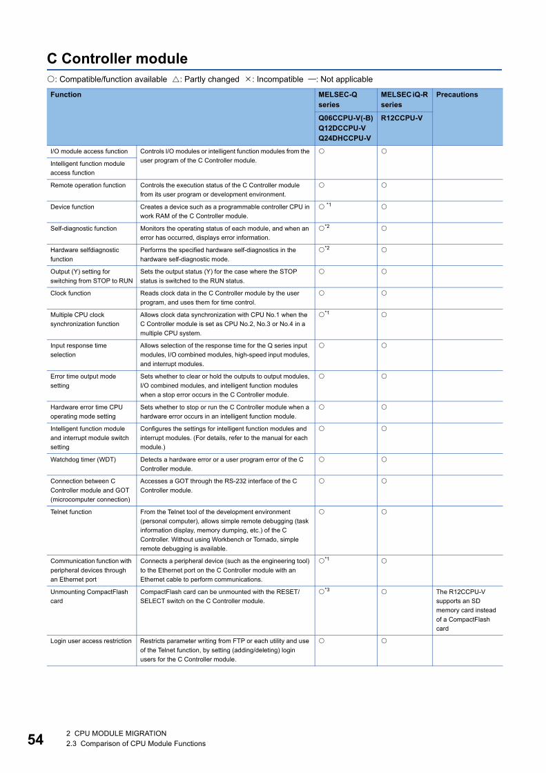
54
C Controller module: Compatible/function available : Partly changed : Incompatible : Not applicable
Function MELSEC-Q series
MELSEC iQ-R series
Precautions
Q06CCPU-V(-B)Q12DCCPU-VQ24DHCCPU-V
R12CCPU-V
I/O module access function Controls I/O modules or intelligent function modules from the user program of the C Controller module.
Intelligent function module access function
Remote operation function Controls the execution status of the C Controller module from its user program or development environment.
Device function Creates a device such as a programmable controller CPU in work RAM of the C Controller module.
*1
Self-diagnostic function Monitors the operating status of each module, and when an error has occurred, displays error information.
*2
Hardware selfdiagnostic function
Performs the specified hardware self-diagnostics in the hardware self-diagnostic mode.
*2
Output (Y) setting for switching from STOP to RUN
Sets the output status (Y) for the case where the STOP status is switched to the RUN status.
Clock function Reads clock data in the C Controller module by the user program, and uses them for time control.
Multiple CPU clock synchronization function
Allows clock data synchronization with CPU No.1 when the C Controller module is set as CPU No.2, No.3 or No.4 in a multiple CPU system.
*1
Input response time selection
Allows selection of the response time for the Q series input modules, I/O combined modules, high-speed input modules, and interrupt modules.
Error time output mode setting
Sets whether to clear or hold the outputs to output modules, I/O combined modules, and intelligent function modules when a stop error occurs in the C Controller module.
Hardware error time CPU operating mode setting
Sets whether to stop or run the C Controller module when a hardware error occurs in an intelligent function module.
Intelligent function module and interrupt module switch setting
Configures the settings for intelligent function modules and interrupt modules. (For details, refer to the manual for each module.)
Watchdog timer (WDT) Detects a hardware error or a user program error of the C Controller module.
Connection between C Controller module and GOT (microcomputer connection)
Accesses a GOT through the RS-232 interface of the C Controller module.
Telnet function From the Telnet tool of the development environment (personal computer), allows simple remote debugging (task information display, memory dumping, etc.) of the C Controller. Without using Workbench or Tornado, simple remote debugging is available.
Communication function with peripheral devices through an Ethernet port
Connects a peripheral device (such as the engineering tool) to the Ethernet port on the C Controller module with an Ethernet cable to perform communications.
*1
Unmounting CompactFlash card
CompactFlash card can be unmounted with the RESET/SELECT switch on the C Controller module.
*3 The R12CCPU-V supports an SD memory card instead of a CompactFlash card
Login user access restriction Restricts parameter writing from FTP or each utility and use of the Telnet function, by setting (adding/deleting) login users for the C Controller module.
2 CPU MODULE MIGRATION2.3 Comparison of CPU Module Functions

2
*1 This function is not available for the Q06CCPU-V(-B).*2 The Q06CCPU-V(-B) does not support some functions. For details, refer to the following.
C Controller Module User's Manual (Hardware Design, Function Explanation)*3 This function is not available for the Q06CCPU-V-B.
Multiple CPU system
Data communications by MELSEC data link functions
Accesses device data of a programmable controller CPU from the C Controller module's user program, which is created with MELSEC data link functions.
*3
Event notification
Issues an event to the standby status user program in a C Controller module to resume the user program that was waiting for an interrupt event. The event is issued from either of the following.• Sequence program of programmable controller CPU• User program of C Controller module
Multiple CPU synchronous interrupt function
By registering a routine corresponding to a multiple CPU synchronous interrupt by the QBF_EntryMultiCPUSyncInt function, the created program can be executed in synchronization with a Motion CPU (Q172DCPU or Q173DCPU).
*1
Data communications using CPU shared memory
Transfers data via the CPU shared memory among the C Controller module, programmable controller CPUs, and Motion CPUs.
Data communications using multiple CPU high speed transmission area
Transfers data via the multiple CPU high speed transmission area in the CPU shared memory among the C Controller module, programmable controller CPUs, and Motion CPUs.
*1
Programmable controller remote control function
From the user program of the C Controller module, controls the execution status of a programmable controller CPU.
*3
Sequence program control function
From the user program of the C Controller module, controls the execution type of the sequence program.
Interrupt issue to Motion CPU
From the user program of the C Controller module, issues an interrupt to a Motion CPU.
*2
Motion CPU control instruction
From the user program of the C Controller module, starts a Motion CPU's SFC program or servo program or changes the set or present values of the servo.
*2
Motion CPU device access
From the user program of the C Controller module, reads data from or writes data to Motion CPU's devices.
*2
Function MELSEC-Q series
MELSEC iQ-R series
Precautions
Q06CCPU-V(-B)Q12DCCPU-VQ24DHCCPU-V
R12CCPU-V
2 CPU MODULE MIGRATION2.3 Comparison of CPU Module Functions 55

56
2.4 Precautions for CPU Module MigrationPrecautions for programmable controller CPU/Process CPU module migration
ParametersSet parameters, such as the program setting, that is specific to each CPU module in the CPU parameter. In addition, set the module parameter to use the built-in Ethernet function of the CPU module, and set the memory card parameter to perform boot operation.
Sampling trace functionThe RCPU does not support the sampling trace function.Use the trigger logging of the data logging function instead. Note that, depending on the versions of CPU modules and engineering tools, an SD memory card is required to store the data because the CPU built-in memory cannot be used as data storage destination. For the versions, refer to the following. MELSEC iQ-R CPU Module User's Manual (Application)
Latch data backup to standard ROMThe RCPU does not support the latch data backup to standard ROM function.Use the CPU module data backup/restoration function instead. Or, read data by using GX Works3 and store the data or write the data back again to the CPU module. The R00/R01/R02CPU does not support the data backup/restoration function.
CPU module change function with memory cardThe RCPU does not support the CPU module change function with memory card.Use the CPU module data backup/restoration function instead. Or, read data by using GX Works3 and store the data or write the data back again to the CPU module.
File password and remote passwordThe number of characters in a password differs between the QCPU and the RCPU. Set a password within the range of 6 to 32 characters for the R series CPU module.Also, change the number of characters in a password of an external device when an external device such as an FTP client accesses the programmable controller.
For details on these precautions, refer to the following. MELSEC iQ-R Module Configuration Manual MELSEC iQ-R CPU Module User's Manual (Startup) MELSEC iQ-R CPU Module User's Manual (Application) Differences between MELSEC-Q series and MELSEC iQ-R series (FA-A-0171) Differences of programmable controllers for process control and redundant system between MELSEC-Q series and MELSEC iQ-R series (FA-A-0214)
2 CPU MODULE MIGRATION2.4 Precautions for CPU Module Migration

2
Precautions for C Controller module migration
Supported software packagesThe following table shows the supported versions of main software packages related to C Controller modules.: Not supported
FunctionsFor the differences of functions, refer to the following manual. MELSEC iQ-R C Controller Module Programming Manual
ParametersIn CW Configurator, parameters of a programmable controller can be set on a module configuration diagram, as if to configure the actual system.When it is possible to connect the actual system configuration, parameters can be set by reading the configuration.Parameters also can be set in the Navigation window in the same way as Setting/monitoring tools for the C Controller module.Parameters of functions in common with a CPU module are set by using an interface equivalent to GX Works2/GX Works3 in Setting/monitoring tools for the C Controller module/CW Configurator.For details on the parameter configuration, refer to the following.Page 405 Parameter Migration
Software package Q06CCPU-V Q06CCPU-V-B Q12DCCPU-V Q24DHCCPU-V R12CCPU-VSetting/monitoring tool
CW Configurator
SW1DND-RCCPU-J/E Version 1.00A or later
Setting/monitoring tools for the C Controller
SW4PVC-CCPU-J/E Version 4.04E or later
Version 4.00A or later
SW3PVC-CCPU-J/E Version 3.00A or later
Version 3.01B or later
Engineering tool
CW Workbench SW1DND-CWWR-E/EZ/EVZ
Version 1.00A or later
SW1DND-CWWLQ24-E/EZ
Version 1.00A or later
SW1DND-CWWLQ12-E/EZ
Version 1.00A or later
VxWorks simulator for CW Workbench
CW-Sim SW1DND-CWSIMR-EZ Version 1.00A or later
SW1DNC-CWSIM-EZ Version 1.00A or later
Version 1.00A or later
CW-Sim Standalone
SW1DNC-CWSIMSAR-E
Version 1.00A or later
SW1DNC-CWSIMSA-E Version 1.00A or later
Version 1.00A or later
Wind River Workbench Version 2.6.1 Version 3.2 Version 3.3
Tornado Version 2.6.0 Version 2.6.0
2 CPU MODULE MIGRATION2.4 Precautions for CPU Module Migration 57

58
DeviceThere is no change in I/O devices and link direct devices.For other devices, available points increase in MELSEC iQ-R series C Controller modules.The following table shows devices which their names were changed to or which are newly available.
Some of the SM/SD number assignments differ. Also, some SM/SD areas are used for different purposes. If SM/SD is used in the MELSEC-Q series program, the program needs to be corrected for MELSEC iQ-R series. For details, refer to the user's manual of a CPU module used.
Project replacementImport a project of the Q12DCCPU-V by using the import function of CW Workbench (SW1DND-CWWR-E/EZ/EVZ). Select "Build Support and Specs" tab in "Properties" window of imported project and change into "ARMARCH7gnu_SMP" on "Active build spec". Select "Tools" tab and input "-mlong-calls" on "Tool Flags" and "-fsigned-char" on [Debug mode] and [Non Debug mode] of "Debug mode flags".For importing the project and changing items on "Properties" window, refer to the following. CW Workbench/CW-Sim Operating Manual
VxWorks standard API functions migrationOperating system of the R12CCPU-V is upgraded than that of the Q12DCCPU-V. (VxWorks 6.4VxWorks 6.9)For VxWorks standard API functions migration, check "MIGRATION GUIDE" of VxWorks.PDF file "MIGRATION GUIDE" of VxWorks is included in CW Workbench.
Device typeSome device types of the bus interface function and MELSEC data link function are deleted from the R12CCPU-V.When they are used in the user program, change the processing described in the alternative method.For the alternative method, refer to the following. MELSEC iQ-R C Controller Module Programming Manual
For details on these precautions, refer to the following. MELSEC iQ-R C Controller Module User's Manual (Startup) MELSEC iQ-R C Controller Module User's Manual (Application) MELSEC iQ-R C Controller Module Programming Manual Differences between MELSEC-Q series and MELSEC iQ-R series (FA-A0171)
MELSEC-Q series MELSEC iQ-R seriesIntelligent function module device (Un\G) Module access device (Un\G)
Cyclic transmission area device (U3En\G) CPU buffer memory access device (U4En\G)
Not supported Fixed scan communication area access device (U4En\HG)File register (ZR)Interrupt pointer (I)
2 CPU MODULE MIGRATION2.4 Precautions for CPU Module Migration

3
3 I/O MODULE MIGRATION
3.1 I/O Module Migration Model ListThis section describes examples of migration to MELSEC iQ-R series I/O modules in accordance with the MELSEC-Q series I/O module specifications.Consider the specifications of your MELSEC-Q series I/O module to choose a model that best suits your application.
Item MELSEC-Q series
MELSEC iQ-R series
Specification difference
Input module QX10 RX10 (1) Number of input points: 16(2) Rated input voltage: 100 to 120VAC(3) Rated input current: Approx. 8mA (100VAC, 60Hz)/approx. 7mA (100VAC, 50Hz) 8.2mA
(100VAC, 60Hz)/6.8mA (100VAC, 50Hz)(4) Response time: 20ms(5) Common terminal arrangement: 16 points/common(6) External interface: 18-point screw terminal block (M3 screws)(7) Number of occupied I/O points: 16 (I/O assignment: Input 16 points)
QX10-TS RX10 (1) Number of input points: 16(2) Rated input voltage: 100 to 120VAC(3) Rated input current: Approx. 8mA (100VAC, 60Hz)/approx. 7mA (100VAC, 50Hz) 8.2mA
(100VAC, 60Hz)/6.8mA (100VAC, 50Hz)(4) Response time: 20ms(5) Common terminal arrangement: 16 points/common(6) External interface: Two-piece spring clamp terminal block 18-point screw terminal block (M3
screws))(7) Number of occupied I/O points: 16 (I/O assignment: Input 16 points)
QX28 RX28 (1) Number of input points: 8(2) Rated input voltage: 100 to 240VAC(3) Rated input current: Approx. 17mA (200VAC, 60Hz)/approx. 14mA (200VAC, 50Hz)/approx. 8mA
(100VAC, 60Hz)/approx. 7mA (100VAC, 50Hz) 16.4mA (200VAC, 60Hz)/13.7mA (200VAC, 50Hz)/8.2mA (100VAC, 60Hz)/6.8mA (100VAC, 50Hz)
(4) Response time: 20ms(5) Common terminal arrangement: 8 points/common(6) External interface: 18-point screw terminal block (M3 screws)(7) Number of occupied I/O points: 16 (I/O assignment: Input 16 points)
QX40 RX40C7 (1) Number of input points: 16(2) Rated input voltage: 24VDC(3) Rated input current: 4mA 7mA(4) Response time: 1/5/10/20/70ms 0.1/0.2/0.4/0.6/1/5/10/20/70ms(5) Common terminal arrangement: 16 points/common, positive common type 16 points/common,
positive common/negative common shared type(6) External interface: 18-point screw terminal block (M3 screws)(7) Number of occupied I/O points: 16 (I/O assignment: Input 16 points)
QX40-S1 RX40C7 (1) Number of input points: 16(2) Rated input voltage: 24VDC(3) Rated input current: 6mA 7mA(4) Response time: 0.1/0.2/0.4/0.6/1ms 0.1/0.2/0.4/0.6/1/5/10/20/70ms(5) Common terminal arrangement: 16 points/common, positive common type 16 points/common,
positive common/negative common shared type(6) External interface: 18-point screw terminal block (M3 screws)(7) Number of occupied I/O points: 16 (I/O assignment: Input 16 points)
QX40-TS RX40C7 (1) Number of input points: 16(2) Rated input voltage: 24VDC(3) Rated input current: 4mA 7mA(4) Response time: 1/5/10/20/70ms 0.1/0.2/0.4/0.6/1/5/10/20/70ms(5) Common terminal arrangement: 16 points/common, positive common type 16 points/common,
positive common/negative common shared type(6) External interface: Two-piece spring clamp terminal block 18-point screw terminal block (M3
screws)(7) Number of occupied I/O points: 16 (I/O assignment: Input 16 points)
3 I/O MODULE MIGRATION3.1 I/O Module Migration Model List 59

60
Input module QX40H RX40PC6H (1) Number of input points: 16(2) Rated input voltage: 24VDC(3) Rated input current: 6mA(4) Response time: 0/0.1/0.2/0.4/0.6/1ms No setting/20/50s, 0.1/0.2/0.4/0.6/1/5/10/20/70ms(5) Common terminal arrangement: 8 points/common, positive common type(6) External interface: 18-point screw terminal block (M3 screws)(7) Number of occupied I/O points: 16 (I/O assignment: High-speed input 16 points/interrupt 16
points) 16 (I/O assignment: Input 16 points)
QX41 RX41C4 (1) Number of input points: 32(2) Rated input voltage: 24VDC(3) Rated input current: 4mA(4) Response time: 1/5/10/20/70ms 0.1/0.2/0.4/0.6/1/5/10/20/70ms(5) Common terminal arrangement: 32 points/common, positive common type 32 points/common,
positive common/negative common shared type(6) External interface: 40-pin connector(7) Number of occupied I/O points: 32 (I/O assignment: Input 32 points)
QX41-S1 RX41C4 (1) Number of input points: 32(2) Rated input voltage: 24VDC(3) Rated input current: 4mA(4) Response time: 0.1/0.2/0.4/0.6/1ms 0.1/0.2/0.4/0.6/1/5/10/20/70ms(5) Common terminal arrangement: 32 points/common, positive common type 32 points/common,
positive common/negative common shared type(6) External interface: 40-pin connector(7) Number of occupied I/O points: 32 (I/O assignment: High-speed input 32 points) 32 (I/O
assignment: Input 32 points)
QX41-S2 RX41C6HS (1) Number of input points: 32(2) Rated input voltage: 24VDC(3) Rated input current: 6mA(4) Response time: 1/5/10/20/70ms No setting/10/20/50s, 0.1/0.2/0.4/0.6/1/5/10/20/70ms(5) Common terminal arrangement: 32 points/common, positive common type 32 points/common,
positive common/negative common shared type(6) External interface: 40-pin connector(7) Number of occupied I/O points: 32 (I/O assignment: Input 32 points)
QX42 RX42C4 (1) Number of input points: 64(2) Rated input voltage: 24VDC(3) Rated input current: 4mA(4) Response time: 1/5/10/20/70ms 0.1/0.2/0.4/0.6/1/5/10/20/70ms(5) Common terminal arrangement: 32 points/common, positive common type 32 points/common,
positive common/negative common shared type(6) External interface: 40-pin connector 2(7) Number of occupied I/O points: 64 (I/O assignment: Input 64 points)
QX42-S1 RX42C4 (1) Number of input points: 64(2) Rated input voltage: 24VDC(3) Rated input current: 4mA(4) Response time: 0.1/0.2/0.4/0.6/1ms 0.1/0.2/0.4/0.6/1/5/10/20/70ms(5) Common terminal arrangement: 32 points/common, positive common type 32 points/common,
positive common/negative common shared type(6) External interface: 40-pin connector 2(7) Number of occupied I/O points: 64 (I/O assignment: High-speed input 64 points) 64 (I/O
assignment: Input 64 points)
QX50 No applicable module
Connect the RQ extension base unit (RQ6B) to use the Q series modules.
QX70 RX70C4 (1) Number of input points: 16(2) Rated input voltage: 5/12VDC(3) Rated input current: 1.2mA at 5VDC/3.3mA at 12VDC 1.7mA at 5VDC/4.8mA at 12VDC(4) Response time: 1/5/10/20/70ms 0.1/0.2/0.4/0.6/1/5/10/20/70ms(5) Common terminal arrangement: 16 points/common, positive common/negative common shared
type(6) External interface: 18-point screw terminal block (M3 screws)(7) Number of occupied I/O points: 16 (I/O assignment: Input 16 points)
Item MELSEC-Q series
MELSEC iQ-R series
Specification difference
3 I/O MODULE MIGRATION3.1 I/O Module Migration Model List

3
Input module QX70H RX61C6HS (1) Number of input points: 16 32(2) Rated input voltage: 5VDC(3) Rated input current: 6mA(4) Response time: 0/0.1/0.2/0.4/0.6/1ms No setting/10//20/50s, 0.1/0.2/0.4/0.6/1/5/10/20/70ms(5) Common terminal arrangement: 8 points/common, positive common type 32 points/common,
positive common/negative common shared type(6) External interface: 18-point screw terminal block (M3 screws) 40-pin connector(7) Number of occupied I/O points: 16 (I/O assignment: High-speed input 16 points/interrupt 16
points) 32 (I/O assignment: Input 32 points)
QX71 RX71C4 (1) Number of input points: 32(2) Rated input voltage: 5/12VDC(3) Rated input current: 1.2mA at 5VDC/3.3mA at 12VDC 1.7mA at 5VDC/4.8mA at 12VDC(4) Response time: 1/5/10/20/70ms 0.1/0.2/0.4/0.6/1/5/10/20/70ms(5) Common terminal arrangement: 32 points/common, positive common/negative common shared
type(6) External interface: 40-pin connector(7) Number of occupied I/O points: 32 (I/O assignment: Input 32 points)
QX72 RX72C4 (1) Number of input points: 64(2) Rated input voltage: 5/12VDC(3) Rated input current: 1.2mA at 5VDC/3.3mA at 12VDC 1.7mA at 5VDC/4.8mA at 12VDC(4) Response time: 1/5/10/20/70ms 0.1/0.2/0.4/0.6/1/5/10/20/70ms(5) Common terminal arrangement: 32 points/common, positive common/negative common shared
type(6) External interface: 40-pin connector 2(7) Number of occupied I/O points: 64 (I/O assignment: Input 64 points)
QX80 RX40C7 (1) Number of input points: 16(2) Rated input voltage: 24VDC(3) Rated input current: 4mA 7mA(4) Response time: 1/5/10/20/70ms 0.1/0.2/0.4/0.6/1/5/10/20/70ms(5) Common terminal arrangement: 16 points/common, negative common type 16 points/common,
positive common/negative common shared type(6) External interface: 18-point screw terminal block (M3 screws)(7) Number of occupied I/O points: 16 (I/O assignment: Input 16 points)
QX80-TS RX40C7 (1) Number of input points: 16(2) Rated input voltage: 24VDC(3) Rated input current: 4mA 7mA(4) Response time: 1/5/10/20/70ms 0.1/0.2/0.4/0.6/1/5/10/20/70ms(5) Common terminal arrangement: 16 points/common, negative common type 16 points/common,
positive common/negative common shared type(6) External interface: Two-piece spring clamp terminal block 18-point screw terminal block (M3
screws)(7) Number of occupied I/O points: 16 (I/O assignment: Input 16 points)
QX80H RX40NC6H (1) Number of input points: 16(2) Rated input voltage: 24VDC(3) Rated input current: 6mA(4) Response time: 0/0.1/0.2/0.4/0.6/1ms No setting/20/50s, 0.1/0.2/0.4/0.6/1/5/10/20/70ms(5) Common terminal arrangement: 8 points/common, negative common type(6) External interface: 18-point screw terminal block (M3 screws)(7) Number of occupied I/O points: 16 (I/O assignment: High-speed input 16 points/interrupt 16
points) 16 (I/O assignment: Input 16 points)
QX81 RX41C4 (1) Number of input points: 32(2) Rated input voltage: 24VDC(3) Rated input current: 4mA(4) Response time: 1/5/10/20/70ms 0.1/0.2/0.4/0.6/1/5/10/20/70ms(5) Common terminal arrangement: 32 points/common, negative common type 32 points/common,
positive common/negative common shared type(6) External interface: 37-pin D-sub connector 40-pin connector(7) Number of occupied I/O points: 32 (I/O assignment: Input 32 points)
QX81-S2 RX41C6HS (1) Number of input points: 32(2) Rated input voltage: 24VDC(3) Rated input current: 6mA(4) Response time: 1/5/10/20/70ms No setting/10/20/50s, 0.1/0.2/0.4/0.6/1/5/10/20/70ms(5) Common terminal arrangement: 32 points/common, negative common type 32 points/common,
positive common/negative common shared type(6) External interface: 37-pin D-sub connector 40-pin connector(7) Number of occupied I/O points: 32 (I/O assignment: Input 32 points)
Item MELSEC-Q series
MELSEC iQ-R series
Specification difference
3 I/O MODULE MIGRATION3.1 I/O Module Migration Model List 61

62
Input module QX82 RX42C4 (1) Number of input points: 64(2) Rated input voltage: 24VDC(3) Rated input current: 4mA(4) Response time: 1/5/10/20/70ms 0.1/0.2/0.4/0.6/1/5/10/20/70ms(5) Common terminal arrangement: 32 points/common, negative common type 32 points/common,
positive common/negative common shared type(6) External interface: 40-pin connector 2(7) Number of occupied I/O points: 64 (I/O assignment: Input 64 points)
QX82-S1 RX42C4 (1) Number of input points: 64(2) Rated input voltage: 24VDC(3) Rated input current: 4mA(4) Response time: 0.1/0.2/0.4/0.6/1ms 0.1/0.2/0.4/0.6/1/5/10/20/70ms(5) Common terminal arrangement: 32 points/common, negative common type 32 points/common,
positive common/negative common shared type(6) External interface: 40-pin connector 2(7) Number of occupied I/O points: 64 (I/O assignment: High-speed input 64 points) 64 (I/O
assignment: Input 64 points)
QX90H RX61C6HS (1) Number of input points: 16 32(2) Rated input voltage: 5VDC(3) Rated input current: 6mA(4) Response time: 0/0.1/0.2/0.4/0.6/1ms No setting/10//20/50s, 0.1/0.2/0.4/0.6/1/5/10/20/70ms(5) Common terminal arrangement: 8 points/common, negative common type 32 points/common,
positive common/negative common shared type(6) External interface: 18-point screw terminal block (M3 screws) 40-pin connector(7) Number of occupied I/O points: 16 (I/O assignment: High-speed input 16 points/interrupt 16
points) 32 (I/O assignment: Input 32 points)
Output module QY10 RY10R2 (1) Output type: Contact output(2) Number of output points: 16(3) Rated switching voltage/current: 24VDC/240VAC, 2A/point, 8A/common(4) Response time: 12ms(5) Common terminal arrangement: 16 points/common(6) External interface: 18-point screw terminal block (M3 screws)(7) Number of occupied I/O points: 16 (I/O assignment: Output 16 points)
QY10-TS RY10R2 (1) Output type: Contact output(2) Number of output points: 16(3) Rated switching voltage/current: 24VDC/240VAC, 2A/point, 8A/common(4) Response time: 12ms(5) Common terminal arrangement: 16 points/common(6) External interface: Two-piece spring clamp terminal block 18-point screw terminal block (M3
screws)(7) Number of occupied I/O points: 16 (I/O assignment: Output 16 points)
QY18A RY18R2A (1) Output type: Contact output(2) Number of output points: 8(3) Rated switching voltage/current: 24VDC/240VAC, 2A/point, 8A/module(4) Response time: 12ms(5) Common terminal arrangement: All points independent common(6) External interface: 18-point screw terminal block (M3 screws)(7) Number of occupied I/O points: 16 (I/O assignment: Output 16 points)
QY22 RY20S6 (1) Output type: Triac output(2) Number of output points: 16(3) Rated load voltage: 100 to 240VAC(4) Maximum load current: 0.6A/point, 4.8A/common(5) Response time: 1ms and 0.5 cycles(6) Common terminal arrangement: 16 points/common(7) External interface: 18-point screw terminal block (M3 screws)(8) Number of occupied I/O points: 16 (I/O assignment: Output 16 points)(9) Protection function: CR absorber
Item MELSEC-Q series
MELSEC iQ-R series
Specification difference
3 I/O MODULE MIGRATION3.1 I/O Module Migration Model List

3
Output module QY40P RY40NT5P (1) Output type: Transistor output(2) Number of output points: 16(3) Rated load voltage: 12 to 24VDC(4) Maximum load current: 0.1A/point, 1.6A/common 0.5A/point, 5A/common(5) Response time: 1ms(6) Common terminal arrangement: 16 points/common, sink type(7) External interface: 18-point screw terminal block (M3 screws)(8) Number of occupied I/O points: 16 (I/O assignment: Output 16 points)(9) Protection function: Zener diode, overheat protection function, overload protection function
QY40P-TS RY40NT5P (1) Output type: Transistor output(2) Number of output points: 16(3) Rated load voltage: 12 to 24VDC(4) Maximum load current: 0.1A/point, 1.6A/common 0.5A/point, 5A/common(5) Response time: 1ms(6) Common terminal arrangement: 16 points/common, sink type(7) External interface: Two-piece spring clamp terminal block 18-point screw terminal block (M3
screws)(8) Number of occupied I/O points: 16 (I/O assignment: Output 16 points)(9) Protection function: Zener diode, overheat protection function, overload protection function
QY41H RY41NT2H (1) Output type: Transistor output(2) Number of output points: 32(3) Rated load voltage: 5 to 24VDC(4) Maximum load current: 0.2A/point, 2A/common(5) Response time: 2s(6) Common terminal arrangement: 32 points/common, sink type(7) External interface: 40-pin connector(8) Number of occupied I/O points: 32 (I/O assignment: Output 32 points)(9) Protection function: Zener diode
QY41P RY41NT2P (1) Output type: Transistor output(2) Number of output points: 32(3) Rated load voltage: 12 to 24VDC(4) Maximum load current: 0.1A/point, 2A/common 0.2A/point, 2A/common(5) Response time: 1ms(6) Common terminal arrangement: 32 points/common, sink type(7) External interface: 40-pin connector(8) Number of occupied I/O points: 32 (I/O assignment: Output 32 points)(9) Protection function: Zener diode, overheat protection function, overload protection function
QY42P RY42NT2P (1) Output type: Transistor output(2) Number of output points: 64(3) Rated load voltage: 12 to 24VDC(4) Maximum load current: 0.1A/point, 2A/common 0.2A/point, 2A/common(5) Response time: 1ms(6) Common terminal arrangement: 32 points/common, sink type(7) External interface: 40-pin connector 2(8) Number of occupied I/O points: 64 (I/O assignment: Output 64 points)(9) Protection function: Zener diode, overheat protection function, overload protection function
QY50 RY40NT5P (1) Output type: Transistor output(2) Number of output points: 16(3) Rated load voltage: 12 to 24VDC(4) Maximum load current: 0.5A/point, 4A/common 0.5A/point, 5A/common(5) Response time: 1ms(6) Common terminal arrangement: 16 points/common, sink type(7) External interface: 18-point screw terminal block (M3 screws)(8) Number of occupied I/O points: 16 (I/O assignment: Output 16 points)(9) Protection function: Zener diode, fuse Zener diode, overheat protection function, overload
protection function
QY68A RY18R2A (1) Output type: Transistor output Contact output(2) Number of output points: 8(3) Rated load voltage: 5 to 24VDC 24VDC/240VAC(4) Maximum load current: 2A/point, 8A/module(5) Response time: 10ms 12ms(6) Common terminal arrangement: All points independent common(7) External interface: 18-point screw terminal block (M3 screws)(8) Number of occupied I/O points: 16 (I/O assignment: Output 16 points)(9) Protection function: Zener diode None
Item MELSEC-Q series
MELSEC iQ-R series
Specification difference
3 I/O MODULE MIGRATION3.1 I/O Module Migration Model List 63
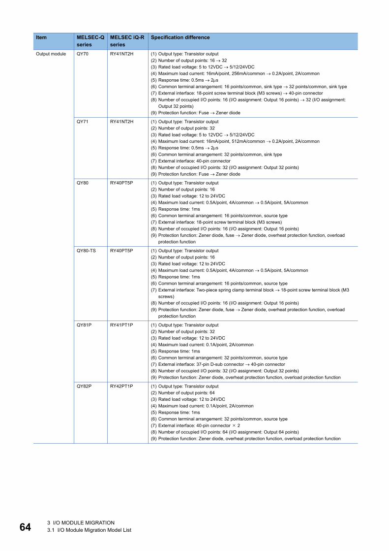
64
Output module QY70 RY41NT2H (1) Output type: Transistor output(2) Number of output points: 16 32(3) Rated load voltage: 5 to 12VDC 5/12/24VDC(4) Maximum load current: 16mA/point, 256mA/common 0.2A/point, 2A/common(5) Response time: 0.5ms 2s(6) Common terminal arrangement: 16 points/common, sink type 32 points/common, sink type(7) External interface: 18-point screw terminal block (M3 screws) 40-pin connector(8) Number of occupied I/O points: 16 (I/O assignment: Output 16 points) 32 (I/O assignment:
Output 32 points)(9) Protection function: Fuse Zener diode
QY71 RY41NT2H (1) Output type: Transistor output(2) Number of output points: 32(3) Rated load voltage: 5 to 12VDC 5/12/24VDC(4) Maximum load current: 16mA/point, 512mA/common 0.2A/point, 2A/common(5) Response time: 0.5ms 2s(6) Common terminal arrangement: 32 points/common, sink type(7) External interface: 40-pin connector(8) Number of occupied I/O points: 32 (I/O assignment: Output 32 points)(9) Protection function: Fuse Zener diode
QY80 RY40PT5P (1) Output type: Transistor output(2) Number of output points: 16(3) Rated load voltage: 12 to 24VDC(4) Maximum load current: 0.5A/point, 4A/common 0.5A/point, 5A/common(5) Response time: 1ms(6) Common terminal arrangement: 16 points/common, source type(7) External interface: 18-point screw terminal block (M3 screws)(8) Number of occupied I/O points: 16 (I/O assignment: Output 16 points)(9) Protection function: Zener diode, fuse Zener diode, overheat protection function, overload
protection function
QY80-TS RY40PT5P (1) Output type: Transistor output(2) Number of output points: 16(3) Rated load voltage: 12 to 24VDC(4) Maximum load current: 0.5A/point, 4A/common 0.5A/point, 5A/common(5) Response time: 1ms(6) Common terminal arrangement: 16 points/common, source type(7) External interface: Two-piece spring clamp terminal block 18-point screw terminal block (M3
screws)(8) Number of occupied I/O points: 16 (I/O assignment: Output 16 points)(9) Protection function: Zener diode, fuse Zener diode, overheat protection function, overload
protection function
QY81P RY41PT1P (1) Output type: Transistor output(2) Number of output points: 32(3) Rated load voltage: 12 to 24VDC(4) Maximum load current: 0.1A/point, 2A/common(5) Response time: 1ms(6) Common terminal arrangement: 32 points/common, source type(7) External interface: 37-pin D-sub connector 40-pin connector(8) Number of occupied I/O points: 32 (I/O assignment: Output 32 points)(9) Protection function: Zener diode, overheat protection function, overload protection function
QY82P RY42PT1P (1) Output type: Transistor output(2) Number of output points: 64(3) Rated load voltage: 12 to 24VDC(4) Maximum load current: 0.1A/point, 2A/common(5) Response time: 1ms(6) Common terminal arrangement: 32 points/common, source type(7) External interface: 40-pin connector 2(8) Number of occupied I/O points: 64 (I/O assignment: Output 64 points)(9) Protection function: Zener diode, overheat protection function, overload protection function
Item MELSEC-Q series
MELSEC iQ-R series
Specification difference
3 I/O MODULE MIGRATION3.1 I/O Module Migration Model List

3
I/O combined module
QH42P RH42C4NT2P ■Input specifications(1) Number of input points: 32(2) Rated input voltage: 24VDC(3) Rated input current: 4mA(4) Response time: 1/5/10/20/70ms 0.1/0.2/0.4/0.6/1/5/10/20/70ms(5) Common terminal arrangement: 32 points/common, positive common type 32 points/common,
positive common/negative common shared type■Output specifications(6) Output type: Transistor output(7) Number of output points: 32(8) Rated load voltage: 12 to 24VDC(9) Maximum load current: 0.1A/point, 2A/common 0.2A/point, 2A/common(10)Response time: 1ms(11)Common terminal arrangement: 32 points/common, sink type(12)Protection function: Zener diode, overheat protection function, overload protection function■Common specifications(13)External interface: 40-pin connector 2(14)Number of occupied I/O points: 32 (I/O assignment: I/O combined 32 points)
QX41Y41P RH42C4NT2P ■Input specifications(1) Number of input points: 32(2) Rated input voltage: 24VDC(3) Rated input current: 4mA(4) Response time: 1/5/10/20/70ms 0.1/0.2/0.4/0.6/1/5/10/20/70ms(5) Common terminal arrangement: 32 points/common, positive common type 32 points/common,
positive common/negative common shared type■Output specifications(6) Output type: Transistor output(7) Number of output points: 32(8) Rated load voltage: 12 to 24VDC(9) Maximum load current: 0.1A/point, 2A/common 0.2A/point, 2A/common(10)Response time: 1ms(11)Common terminal arrangement: 32 points/common, sink type(12)Protection function: Zener diode, overheat protection function, overload protection function■Common specifications(13)External interface: 40-pin connector 2(14)Number of occupied I/O points: 64 (I/O assignment: I/O combined 64 points) 32 (I/O
assignment: I/O combined 32 points)
QX48Y57 RX40C7+RY40NT5P
■Input specifications(1) Number of input points: 8 16(2) Rated input voltage: 24VDC(3) Rated input current: 4mA 7mA(4) Response time: 1/5/10/20/70ms 0.1/0.2/0.4/0.6/1/5/10/20/70ms(5) Common terminal arrangement: 8 points/common, positive common type 16 points/common,
positive common/negative common shared type■Output specifications(6) Output type: Transistor output(7) Number of output points: 7 16(8) Rated load voltage: 12 to 24VDC(9) Maximum load current: 0.5A/point, 2A/common 0.5A/point, 5A/common(10)Response time: 1ms(11)Common terminal arrangement: 7 points/common, sink type 16 points/common, sink type(12)Protection function: Zener diode, fuse Zener diode, overheat protection function, overload
protection function■Common specifications(13)External interface: 18-point screw terminal block (M3 screws) 18-point screw terminal block
(M3 screws) 2(14)Number of occupied I/O points: 16 (I/O assignment: I/O combined 16 points) 16 (I/O
assignment: Input 16 points) +16 (I/O assignment: Output 16 points)
Interrupt module QI60 RX40C7 (1) Number of input points: 16(2) Rated input voltage: 24VDC(3) Rated input current: 6mA 7mA(4) Response time: 0.1/0.2/0.4/0.6/1ms 0.1/0.2/0.4/0.6/1/5/10/20/70ms(5) Common terminal arrangement: 16 points/common, positive common type 16 points/common,
positive common/negative common shared type(6) External interface: 18-point screw terminal block (M3 screws)(7) Number of occupied I/O points: 16 (I/O assignment: Interrupt 16 points) 16 (I/O assignment:
Input 16 points)
Blank cover module
QG60 RG60 None in particular
Item MELSEC-Q series
MELSEC iQ-R series
Specification difference
3 I/O MODULE MIGRATION3.1 I/O Module Migration Model List 65

66
3.2 Comparison of I/O Module SpecificationsComparison of input module specifications
QX10 and RX10: Compatible : Partly changed : Incompatible : Not applicable
*1 The following figures show derating charts.
Item Specifications Compatibility Precautions
QX10 RX10Input type AC input
Number of input points 16 points
Isolation method Photocoupler
Rated input voltage, frequency
100 to 120VAC (+10/-15%) 50/60Hz (3Hz)
Input voltage distortion Within 5%
Rated input current Approx. 8mA (100VAC, 60Hz)Approx. 7mA (100VAC, 50Hz)
8.2mA (100VAC, 60Hz)6.8mA (100VAC, 50Hz)
Input derating Refer to the derating chart.*1 Use the module within the range shown in the derating chart.
Inrush current 200mA maximum, within 1ms
ON voltage/ON current 80VAC or higher/5mA or higher (50Hz, 60Hz)
OFF voltage/OFF current 30VAC or lower/1.7mA or lower (50Hz, 60Hz)
Input impedance Approx. 12k (60Hz), approx. 15k (50Hz)
12.2k (60Hz), 14.6k (50Hz)
Response time
OFF to ON 15ms or less (100VAC 50Hz, 60Hz)
ON to OFF 20ms or less (100VAC 50Hz, 60Hz)
Dielectric withstand voltage 1780VAC rms/3 cycles 1400VAC rms for 1 minute
Insulation resistance 10M or more by insulation resistance tester
Noise immunity By noise simulator of 1500Vp-p noise voltage, 1s noise widthand 25 to 60Hz noise frequency
Protection degree IP1X
Common terminal arrangement
16 points/common (common terminal: TB17)
Number of occupied I/O points 16 points (I/O assignment: Input 16 points)
External interface 18-point terminal block (M3 6 screws) The existing external wiring and terminal blocks in the existing system can be used.
Applicable wire size 0.3 to 0.75 core (2.8mm OD maximum)
Applicable solderless terminal R1.25-3 (solderless terminal with an insulation sleeve cannot be used.)
Internal current consumption (5VDC)
50mA (TYP. all points ON) 110mA (TYP. all points ON)
Weight 0.17kg 0.18kg
QX10 RX10
: Input voltage 120VAC●: Input voltage 132VACX: Ambient temperature ()Y: Number of simultaneous on points (point)
100908070605040
0 10 20 30 40 50 55
(%)
(°C)
ON ratio
Ambient temperature
120VAC
132VAC
55X
Y
500 20 3010 400
4
16
12
8
(35,16) (45,16)
(55,13)
(55,10)
3 I/O MODULE MIGRATION3.2 Comparison of I/O Module Specifications

3
QX10-TS and RX10: Compatible : Partly changed : Incompatible : Not applicable
*1 The following figures show derating charts.
*2 The Q6TE-18SN does not have a connection check indicator. Tools are required to connect cables.The applicable wire size for the Q6TE-18SN is 0.3 to 1.5 core (22 to 16 AWG).
Item Specifications Compatibility Precautions
QX10-TS RX10Input type AC input
Number of input points 16 points
Isolation method Photocoupler
Rated input voltage, frequency
100 to 120VAC (+10/-15%) 50/60Hz (3Hz)
Input voltage distortion Within 5%
Rated input current Approx. 8mA (100VAC, 60Hz)Approx. 7mA (100VAC, 50Hz)
8.2mA (100VAC, 60Hz)6.8mA (100VAC, 50Hz)
Input derating Refer to the derating chart.*1 Use the module within the range shown in the derating chart.
Inrush current 200mA maximum, within 1ms
ON voltage/ON current 80VAC or higher/5mA or higher (50Hz, 60Hz)
OFF voltage/OFF current 30VAC or lower/1.7mA or lower (50Hz, 60Hz)
Input impedance Approx. 12k (60Hz), approx. 15k (50Hz)
12.2k (60Hz), 14.6k (50Hz)
Response time
OFF to ON 15ms or less (100VAC 50Hz, 60Hz)
ON to OFF 20ms or less (100VAC 50Hz, 60Hz)
Dielectric withstand voltage 1780VAC rms/3 cycles 1400VAC rms for 1 minute
Insulation resistance 10M or more by insulation resistance tester
Noise immunity By noise simulator of 1500Vp-p noise voltage, 1s noise widthand 25 to 60Hz noise frequency
Protection degree IP1X
Common terminal arrangement
16 points/common (common terminal: TB17)
Number of occupied I/O points 16 points (I/O assignment: Input 16 points)
External interface Two-piece spring clamp terminal block
18-point terminal block (M3 6 screws)
When the existing wiring is used, use the Q series spring clamp terminal blocks in the existing system or the Q6TE-18SN.*2*3Applicable wire size 0.3 to 2.0 core (22 to 15
AWG)0.3 to 0.75 core (2.8mm OD maximum)
Applicable solderless terminal Refer to the list of reference products.*3
R1.25-3 (solderless terminal with an insulation sleeve cannot be used.)
Internal current consumption (5VDC)
50mA (TYP. all points ON) 110mA (TYP. all points ON)
Weight 0.17kg 0.18kg
QX10-TS RX10
: Input voltage 120VAC●: Input voltage 132VACX: Ambient temperature ()Y: Number of simultaneous on points (point)
100908070605040
0 10 20 30 40 50 55
(%)
(°C)
ON ratio
Ambient temperature
120VAC
132VAC
55X
Y
500 20 3010 400
4
16
12
8
(35,16) (45,16)
(55,13)
(55,10)
3 I/O MODULE MIGRATION3.2 Comparison of I/O Module Specifications 67

68
*3 The following tables list the applicable solderless terminals as reference products.QX10-TS
Q6TE-18SN
Manufacturer Product Model Applicable wire sizeMitsubishi Electric System & Service Co., Ltd.
Spring clamp terminal block tool KD-5339
NICHIFU Co., Ltd. Bar solderless terminal TE 0.5-8TE 0.5-10
0.3 to 0.5(22 AWG)
TE 0.75-8TE 0.75-10
0.75(20 AWG)
TE 1.0-8TE 1.0-10
1.0(18 AWG)
TE 1.5-8TE 1.5-10
1.5(16 AWG)
Bar solderless terminal tool NH79
PHOENIX CONTACT GmbH & Co. KG Bar solderless terminal AI 0.34-8TQ 0.34
AI 0.5-8WHAI 0.5-10WH
0.5
AI 0.75-8GYAI 0.75-10GY
0.75
AI 1-8RDAI 1-10RD
1.0
AI 1.5-8BKAI 1.5-10BK
1.5
AI 2.5-8BUAI 2.5-10BU
2.0 to 2.5
Bar solderless terminal tool CRIMPFOX ZA 3
Manufacturer Product Model Applicable wire sizeMitsubishi Electric System & Service Co., Ltd.
Spring clamp terminal block tool KD-5339
NICHIFU Co., Ltd. Bar solderless terminal TE 0.5-8TE 0.5-10
0.3 to 0.5(22 AWG)
TE 0.75-8TE 0.75-10
0.75(20 AWG)
TE 1.0-8TE 1.0-10
1.0(18 AWG)
TE 1.5-8TE 1.5-10
1.5(16 AWG)
Bar solderless terminal tool NH79
3 I/O MODULE MIGRATION3.2 Comparison of I/O Module Specifications

3
QX28 and RX28: Compatible : Partly changed : Incompatible : Not applicable
*1 The following figures show derating charts.
Item Specifications Compatibility Precautions
QX28 RX28Input type AC input
Number of input points 8 points
Isolation method Photocoupler
Rated input voltage, frequency
100 to 240VAC (+10/-15%), 50/60Hz (3Hz)
Input voltage distortion Within 5%
Rated input current Approx. 17mA (200VAC, 60Hz)Approx. 14mA (200VAC, 50Hz)Approx. 8mA (100VAC, 60Hz)Approx. 7mA (100VAC, 50Hz)
16.4mA (200VAC, 60Hz)13.7mA (200VAC, 50Hz)8.2mA (100VAC, 60Hz)6.8mA (100VAC, 50Hz)
Input derating Refer to the derating chart.*1 Use the module within the range shown in the derating chart.
Inrush current 950mA maximum within 1ms (at 264VAC)
ON voltage/ON current 80VAC or higher/5mA or higher (50Hz, 60Hz)
OFF voltage/OFF current 30VAC or lower/1.7mA or lower (50Hz, 60Hz)
Input impedance Approx. 12k (60Hz), approx. 15k (50Hz)
12.1k (60Hz), 14.5k (50Hz)
Response time
OFF to ON 10ms or less (200VAC 50Hz, 60Hz)
ON to OFF 20ms or less (200VAC 50Hz, 60Hz)
Dielectric withstand voltage 2830VAC rms/3 cycles 2300VAC rms for 1 minute
Insulation resistance 10M or more by insulation resistance tester
Noise immunity By noise simulator of 1500Vp-p noise voltage, 1s noise widthand 25 to 60Hz noise frequency
Protection degree IP1X
Common terminal arrangement
8 points/common (common terminal: TB17)
Number of occupied I/O points 16 points (I/O assignment: Input 16 points)
External interface 18-point terminal block (M3 6 screws) The existing external wiring and terminal blocks in the existing system can be used.
Applicable wire size 0.3 to 0.75 core (2.8mm OD maximum)
Applicable solderless terminal R1.25-3 (solderless terminal with an insulation sleeve cannot be used.)
Internal current consumption (5VDC)
50mA (TYP. all points ON) 90mA (TYP. all points ON)
Weight 0.20kg 0.18kg
QX28 RX28
: Input voltage 240VAC●: Input voltage 264VACX: Ambient temperature ()Y: Number of simultaneous on points (point)
100908070605040
0 10 20 30 40 50 55
(%)100%45°C
87.5% 55°C
100% 55°C
240V264V
(°C)
ON ratio
Ambient temperature
55X
Y
500 20 3010 400
2
8
6
4
(45,8)
(55,8)(55,7)
3 I/O MODULE MIGRATION3.2 Comparison of I/O Module Specifications 69
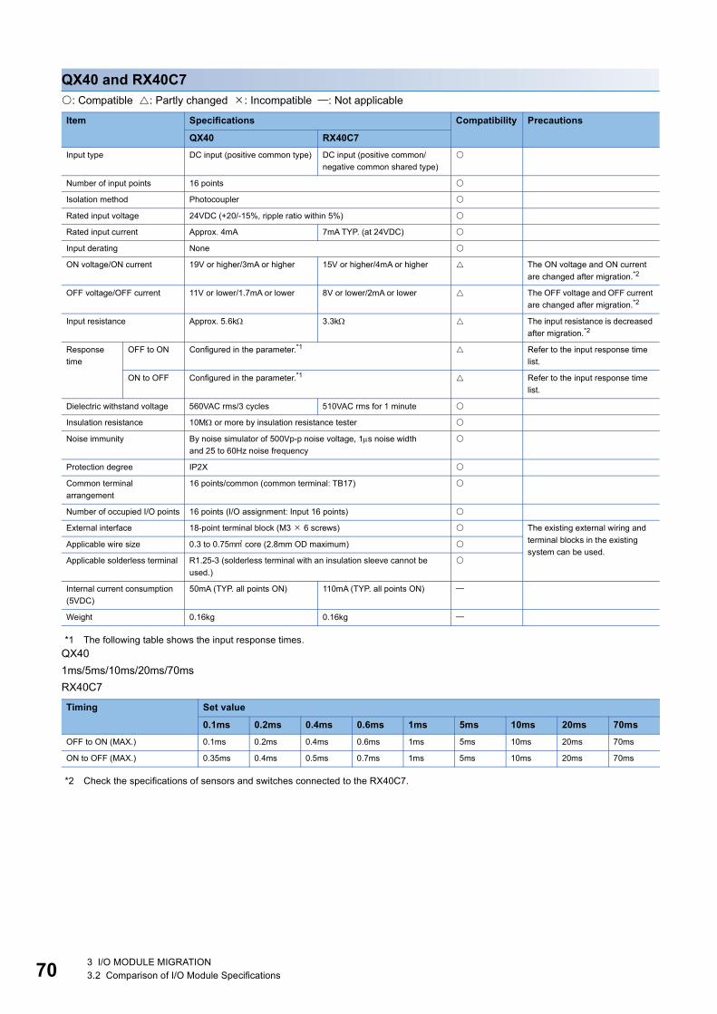
70
QX40 and RX40C7: Compatible : Partly changed : Incompatible : Not applicable
*1 The following table shows the input response times.QX401ms/5ms/10ms/20ms/70msRX40C7
*2 Check the specifications of sensors and switches connected to the RX40C7.
Item Specifications Compatibility Precautions
QX40 RX40C7Input type DC input (positive common type) DC input (positive common/
negative common shared type)
Number of input points 16 points
Isolation method Photocoupler
Rated input voltage 24VDC (+20/-15%, ripple ratio within 5%)
Rated input current Approx. 4mA 7mA TYP. (at 24VDC)
Input derating None
ON voltage/ON current 19V or higher/3mA or higher 15V or higher/4mA or higher The ON voltage and ON current are changed after migration.*2
OFF voltage/OFF current 11V or lower/1.7mA or lower 8V or lower/2mA or lower The OFF voltage and OFF current are changed after migration.*2
Input resistance Approx. 5.6k 3.3k The input resistance is decreased after migration.*2
Response time
OFF to ON Configured in the parameter.*1 Refer to the input response time list.
ON to OFF Configured in the parameter.*1 Refer to the input response time list.
Dielectric withstand voltage 560VAC rms/3 cycles 510VAC rms for 1 minute
Insulation resistance 10M or more by insulation resistance tester
Noise immunity By noise simulator of 500Vp-p noise voltage, 1s noise widthand 25 to 60Hz noise frequency
Protection degree IP2X
Common terminal arrangement
16 points/common (common terminal: TB17)
Number of occupied I/O points 16 points (I/O assignment: Input 16 points)
External interface 18-point terminal block (M3 6 screws) The existing external wiring and terminal blocks in the existing system can be used.
Applicable wire size 0.3 to 0.75 core (2.8mm OD maximum)
Applicable solderless terminal R1.25-3 (solderless terminal with an insulation sleeve cannot be used.)
Internal current consumption (5VDC)
50mA (TYP. all points ON) 110mA (TYP. all points ON)
Weight 0.16kg 0.16kg
Timing Set value
0.1ms 0.2ms 0.4ms 0.6ms 1ms 5ms 10ms 20ms 70msOFF to ON (MAX.) 0.1ms 0.2ms 0.4ms 0.6ms 1ms 5ms 10ms 20ms 70ms
ON to OFF (MAX.) 0.35ms 0.4ms 0.5ms 0.7ms 1ms 5ms 10ms 20ms 70ms
3 I/O MODULE MIGRATION3.2 Comparison of I/O Module Specifications

3
QX40-S1 and RX40C7: Compatible : Partly changed : Incompatible : Not applicable
*1 The following tables show the input response times.QX40-S1
RX40C7
*2 Check the specifications of sensors and switches connected to the RX40C7.
Item Specifications Compatibility Precautions
QX40-S1 RX40C7Input type DC input (positive common type) DC input (positive common/
negative common shared type)
Number of input points 16 points
Isolation method Photocoupler
Rated input voltage 24VDC (+20/-15%, ripple ratio within 5%)
Rated input current Approx. 6mA 7mA TYP. (at 24VDC)
Input derating None
ON voltage/ON current 19V or higher/4mA or higher 15V or higher/4mA or higher The ON voltage and ON current are changed after migration.*2
OFF voltage/OFF current 11V or lower/1.7mA or lower 8V or lower/2mA or lower The OFF voltage and OFF current are changed after migration.*2
Input resistance Approx. 3.9k 3.3k The input resistance is decreased after migration.*2
Response time
OFF to ON Configured in the parameter.*1 Refer to the input response time list.
ON to OFF Configured in the parameter.*1 Refer to the input response time list.
Dielectric withstand voltage 560VAC rms/3 cycles 510VAC rms for 1 minute
Insulation resistance 10M or more by insulation resistance tester
Noise immunity By noise simulator of 500Vp-p noise voltage, 1s noise widthand 25 to 60Hz noise frequency
Protection degree IP2X
Common terminal arrangement
16 points/common (common terminal: TB17)
Number of occupied I/O points 16 points (I/O assignment: High-speed input 16 points)
16 points (I/O assignment: Input 16 points)
External interface 18-point terminal block (M3 6 screws) The existing external wiring and terminal blocks in the existing system can be used.
Applicable wire size 0.3 to 0.75 core (2.8mm OD maximum)
Applicable solderless terminal R1.25-3 (solderless terminal with an insulation sleeve cannot be used.)
Internal current consumption (5VDC)
60mA (TYP. all points ON) 110mA (TYP. all points ON)
Weight 0.20kg 0.16kg
Set value 0.1 0.2 0.4 0.6 1OFF to ON TYP. 0.05ms 0.15ms 0.30ms 0.55ms 1.05ms
MAX. 0.10ms 0.20ms 0.40ms 0.60ms 1.20ms
ON to OFF TYP. 0.15ms 0.20ms 0.35ms 0.60ms 1.10ms
MAX. 0.20ms 0.30ms 0.50ms 0.70ms 1.30ms
Timing Set value
0.1ms 0.2ms 0.4ms 0.6ms 1ms 5ms 10ms 20ms 70msOFF to ON (MAX.) 0.1ms 0.2ms 0.4ms 0.6ms 1ms 5ms 10ms 20ms 70ms
ON to OFF (MAX.) 0.35ms 0.4ms 0.5ms 0.7ms 1ms 5ms 10ms 20ms 70ms
3 I/O MODULE MIGRATION3.2 Comparison of I/O Module Specifications 71

72
QX40-TS and RX40C7: Compatible : Partly changed : Incompatible : Not applicable
*1 The following tables show the input response times.QX40-TS1ms/5ms/10ms/20ms/70msRX40C7
*2 The Q6TE-18SN does not have a connection check indicator. Tools are required to connect cables.The applicable wire size for the Q6TE-18SN is 0.3 to 1.5 core (22 to 16 AWG).
Item Specifications Compatibility Precautions
QX40-TS RX40C7Input type DC input (positive common type) DC input (positive common/
negative common shared type)
Number of input points 16 points
Isolation method Photocoupler
Rated input voltage 24VDC (+20/-15%, ripple ratio within 5%)
Rated input current Approx. 4mA 7mA TYP. (at 24VDC)
Input derating None
ON voltage/ON current 19V or higher/3mA or higher 15V or higher/4mA or higher The ON voltage and ON current are changed after migration.*4
OFF voltage/OFF current 11V or lower/1.7mA or lower 8V or lower/2mA or lower The OFF voltage and OFF current are changed after migration.*4
Input resistance Approx. 5.6k 3.3k The input resistance is decreased after migration.*4
Response time
OFF to ON Configured in the parameter.*1 Refer to the input response time list.
ON to OFF Configured in the parameter.*1 Refer to the input response time list.
Dielectric withstand voltage 560VAC rms/3 cycles 510VAC rms for 1 minute
Insulation resistance 10M or more by insulation resistance tester
Noise immunity By noise simulator of 500Vp-p noise voltage, 1s noise widthand 25 to 60Hz noise frequency
Protection degree IP2X
Common terminal arrangement
16 points/common (common terminal: TB17)
Number of occupied I/O points 16 points (I/O assignment: Input 16 points)
External interface Two-piece spring clamp terminal block
18-point terminal block (M3 6 screws)
When the existing wiring is used, use the Q series spring clamp terminal blocks in the existing system or the Q6TE-18SN.*2*3Applicable wire size 0.3 to 2.0 core (22 to 15
AWG)0.3 to 0.75 core (2.8mm OD maximum)
Applicable solderless terminal Refer to the list of reference products.*3
R1.25-3 (solderless terminal with an insulation sleeve cannot be used.)
Internal current consumption (5VDC)
50mA (TYP. all points ON) 110mA (TYP. all points ON)
Weight 0.16kg 0.16kg
Timing Set value
0.1ms 0.2ms 0.4ms 0.6ms 1ms 5ms 10ms 20ms 70msOFF to ON (MAX.) 0.1ms 0.2ms 0.4ms 0.6ms 1ms 5ms 10ms 20ms 70ms
ON to OFF (MAX.) 0.35ms 0.4ms 0.5ms 0.7ms 1ms 5ms 10ms 20ms 70ms
3 I/O MODULE MIGRATION3.2 Comparison of I/O Module Specifications

3
*3 The following tables list the applicable solderless terminals as reference products.QX40-TS
Q6TE-18SN
*4 Check the specifications of sensors and switches connected to the RX40C7.
Manufacturer Product Model Applicable wire sizeMitsubishi Electric System & Service Co., Ltd.
Spring clamp terminal block tool KD-5339
NICHIFU Co., Ltd. Bar solderless terminal TE 0.5-8TE 0.5-10
0.3 to 0.5(22 AWG)
TE 0.75-8TE 0.75-10
0.75(20 AWG)
TE 1.0-8TE 1.0-10
1.0(18 AWG)
TE 1.5-8TE 1.5-10
1.5(16 AWG)
Bar solderless terminal tool NH79
PHOENIX CONTACT GmbH & Co. KG Bar solderless terminal AI 0.34-8TQ 0.34
AI 0.5-8WHAI 0.5-10WH
0.5
AI 0.75-8GYAI 0.75-10GY
0.75
AI 1-8RDAI 1-10RD
1.0
AI 1.5-8BKAI 1.5-10BK
1.5
AI 2.5-8BUAI 2.5-10BU
2.0 to 2.5
Bar solderless terminal tool CRIMPFOX ZA 3
Manufacturer Product Model Applicable wire sizeMitsubishi Electric System & Service Co., Ltd.
Spring clamp terminal block tool KD-5339
NICHIFU Co., Ltd. Bar solderless terminal TE 0.5-8TE 0.5-10
0.3 to 0.5(22 AWG)
TE 0.75-8TE 0.75-10
0.75(20 AWG)
TE 1.0-8TE 1.0-10
1.0(18 AWG)
TE 1.5-8TE 1.5-10
1.5(16 AWG)
Bar solderless terminal tool NH79
3 I/O MODULE MIGRATION3.2 Comparison of I/O Module Specifications 73

74
QX40H and RX40PC6H: Compatible : Partly changed : Incompatible : Not applicable
*1 The following figures show derating charts.
Item Specifications Compatibility Precautions
QX40H RX40PC6HInput type DC input (positive common type)
Number of input points 16 points
Isolation method Photocoupler
Rated input voltage 24VDC (+20/-15%, ripple ratio within 5%)
Rated input current Approx. 6mA 6mA TYP. (at 24VDC)
Input derating Refer to the derating chart.*1 Use the module within the range shown in the derating chart.
ON voltage/ON current 13V or higher/3mA or higher 15V or higher/4mA or higher The ON voltage and ON current are changed after migration.*3
OFF voltage/OFF current 8V or lower/1.6mA or lower 8V or lower/1.7mA or lower The OFF current is changed after migration.*3
Input resistance Approx. 3.9k 3.9k
Response time and function setting
OFF to ON Configured in the parameter.*2 Refer to the input response time list.
ON to OFF Configured in the parameter.*2 Refer to the input response time list.
Dielectric withstand voltage 560VAC rms/3 cycles 510VAC rms for 1 minute
Insulation resistance 10M or more by insulation resistance tester
Noise immunity By noise simulator of 500Vp-p noise voltage, 1s noise widthand 25 to 60Hz noise frequency
Protection degree IP2X
Common terminal arrangement
8 points/common (common terminal: TB9, TB18)
Number of occupied I/O points 16 points (I/O assignment: High-speed input 16 points/interrupt 16 points)
16 points (I/O assignment: Input 16 points)
Interrupt settings can be configured in the parameter setting of GX Works3.
External interface 18-point terminal block (M3 6 screws) The existing external wiring and terminal blocks in the existing system can be used.
Applicable wire size 0.3 to 0.75 core (2.8mm OD maximum)
Applicable solderless terminal R1.25-3 (solderless terminal with an insulation sleeve cannot be used.)
Internal current consumption (5VDC)
80mA (TYP. all points ON) 100mA (TYP. all points ON)
Weight 0.16kg 0.16kg
QX40H RX40PC6H
●: Input voltage 26.4VDC: Input voltage 28.8VDCX: Ambient temperature ()Y: Number of simultaneous on points (point)
100908070605040
0 10 20 30 40 50 55
(%)
(°C)Ambient temperature
ON ratio/common 28.8VDC
26.4VDC
■
■
55X
(55,12)
(55,16)
(50,16)
Y
500 20 3010 400
16
12
8
4
3 I/O MODULE MIGRATION3.2 Comparison of I/O Module Specifications

3
*2 The following tables show the input response times.QX40H
RX40PC6H
*3 Check the specifications of sensors and switches connected to the RX40PC6H.
SW1 (noise filter) OFF ON
Set value Invalid 0.1 0.2 0.4 0.6 1OFF to ON TYP. 0ms 0.04ms 0.10ms 0.25ms 0.50ms 0.95ms
MAX. 0.05ms 0.15ms 0.30ms 0.60ms 1.00ms
ON to OFF TYP. 0ms 0.04ms 0.10ms 0.25ms 0.50ms 0.95ms
MAX. 0.05ms 0.15ms 0.30ms 0.60ms 1.00ms
SW2 Off: Interrupt/On: High-speed input
Timing Set value
No Setting
20s 50s 0.1ms 0.2ms 0.4ms 0.6ms 1ms 5ms 10ms 20ms 70ms
OFF to ON (MAX.) 5s 20s 50s 0.1ms 0.2ms 0.4ms 0.6ms 1ms 5ms 10ms 20ms 70ms
ON to OFF (MAX.) 10s 25s 50s 0.1ms 0.2ms 0.4ms 0.6ms 1ms 5ms 10ms 20ms 70ms
3 I/O MODULE MIGRATION3.2 Comparison of I/O Module Specifications 75

76
QX41 and RX41C4: Compatible : Partly changed : Incompatible : Not applicable
*1 The following figures show derating charts.
Item Specifications Compatibility Precautions
QX41 RX41C4Input type DC input (positive common type) DC input (positive common/
negative common shared type)
Number of input points 32 points
Isolation method Photocoupler
Rated input voltage 24VDC (+20/-15%, ripple ratio within 5%)
Rated input current Approx. 4mA 4mA TYP. (at 24VDC)
Input derating Refer to the derating chart.*1 Use the module within the range shown in the derating chart.
ON voltage/ON current 19V or higher/3mA or higher 19V or higher/3mA or higher
OFF voltage/OFF current 11V or lower/1.7mA or lower 6V or lower/1mA or lower The OFF voltage and OFF current are changed after migration.*3
Input resistance Approx. 5.6k 5.3k The input resistance is decreased after migration.*3
Response time
OFF to ON Configured in the parameter.*2 Refer to the input response time list.
ON to OFF Configured in the parameter.*2 Refer to the input response time list.
Dielectric withstand voltage 560VAC rms/3 cycles 510VAC rms for 1 minute
Insulation resistance 10M or more by insulation resistance tester
Noise immunity By noise simulator of 500Vp-p noise voltage, 1s noise widthand 25 to 60Hz noise frequency
Protection degree IP2X
Common terminal arrangement
32 points/common (common terminal: B01, B02)
Number of occupied I/O points 32 points (I/O assignment: Input 32 points)
External interface 40-pin connector (A6CON1/2/3/4) Existing external wiring can be used.Applicable wire size 0.088 to 0.3
Internal current consumption (5VDC)
75mA (TYP. all points ON) 150mA (TYP. all points ON)
Weight 0.15kg 0.11kg
QX41 RX41C4
●: Input voltage 26.4VDC: Input voltage 28.8VDCX: Ambient temperature ()Y: Number of simultaneous on points (point)
100908070605040
0 10 20 30 40 50 55
(%)
(°C)Ambient temperature
28.8VDCONratio
55X
Y
50
(50,32)
(55,32)
(55,24)
0 20 3010 4004
322824201612
8
3 I/O MODULE MIGRATION3.2 Comparison of I/O Module Specifications

3
*2 The following table shows the input response times.QX411ms/5ms/10ms/20ms/70msRX41C4
*3 Check the specifications of sensors and switches connected to the RX41C4.
Timing Set value
0.1ms 0.2ms 0.4ms 0.6ms 1ms 5ms 10ms 20ms 70msOFF to ON (MAX.) 0.1ms 0.2ms 0.4ms 0.6ms 1ms 5ms 10ms 20ms 70ms
ON to OFF (MAX.) 0.2ms 0.3ms 0.5ms 0.7ms 1ms 5ms 10ms 20ms 70ms
3 I/O MODULE MIGRATION3.2 Comparison of I/O Module Specifications 77
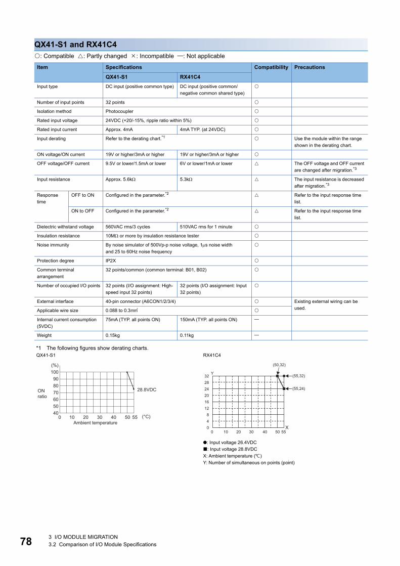
78
QX41-S1 and RX41C4: Compatible : Partly changed : Incompatible : Not applicable
*1 The following figures show derating charts.
Item Specifications Compatibility Precautions
QX41-S1 RX41C4Input type DC input (positive common type) DC input (positive common/
negative common shared type)
Number of input points 32 points
Isolation method Photocoupler
Rated input voltage 24VDC (+20/-15%, ripple ratio within 5%)
Rated input current Approx. 4mA 4mA TYP. (at 24VDC)
Input derating Refer to the derating chart.*1 Use the module within the range shown in the derating chart.
ON voltage/ON current 19V or higher/3mA or higher 19V or higher/3mA or higher
OFF voltage/OFF current 9.5V or lower/1.5mA or lower 6V or lower/1mA or lower The OFF voltage and OFF current are changed after migration.*3
Input resistance Approx. 5.6k 5.3k The input resistance is decreased after migration.*3
Response time
OFF to ON Configured in the parameter.*2 Refer to the input response time list.
ON to OFF Configured in the parameter.*2 Refer to the input response time list.
Dielectric withstand voltage 560VAC rms/3 cycles 510VAC rms for 1 minute
Insulation resistance 10M or more by insulation resistance tester
Noise immunity By noise simulator of 500Vp-p noise voltage, 1s noise widthand 25 to 60Hz noise frequency
Protection degree IP2X
Common terminal arrangement
32 points/common (common terminal: B01, B02)
Number of occupied I/O points 32 points (I/O assignment: High-speed input 32 points)
32 points (I/O assignment: Input 32 points)
External interface 40-pin connector (A6CON1/2/3/4) Existing external wiring can be used.Applicable wire size 0.088 to 0.3
Internal current consumption (5VDC)
75mA (TYP. all points ON) 150mA (TYP. all points ON)
Weight 0.15kg 0.11kg
QX41-S1 RX41C4
●: Input voltage 26.4VDC: Input voltage 28.8VDCX: Ambient temperature ()Y: Number of simultaneous on points (point)
100908070605040
0 10 20 30 40 50 55
(%)
(°C)Ambient temperature
28.8VDCONratio
55X
Y
50
(50,32)
(55,32)
(55,24)
0 20 3010 4004
322824201612
8
3 I/O MODULE MIGRATION3.2 Comparison of I/O Module Specifications

3
*2 The following tables show the input response times.QX41-S1
RX41C4
*3 Check the specifications of sensors and switches connected to the RX41C4.
Set value 0.1 0.2 0.4 0.6 1OFF to ON TYP. 0.05ms 0.15ms 0.30ms 0.55ms 1.05ms
MAX. 0.12ms 0.20ms 0.40ms 0.60ms 1.20ms
ON to OFF TYP. 0.15ms 0.20ms 0.35ms 0.60ms 1.10ms
MAX. 0.20ms 0.30ms 0.50ms 0.70ms 1.30ms
Timing Set value
0.1ms 0.2ms 0.4ms 0.6ms 1ms 5ms 10ms 20ms 70msOFF to ON (MAX.) 0.1ms 0.2ms 0.4ms 0.6ms 1ms 5ms 10ms 20ms 70ms
ON to OFF (MAX.) 0.2ms 0.3ms 0.5ms 0.7ms 1ms 5ms 10ms 20ms 70ms
3 I/O MODULE MIGRATION3.2 Comparison of I/O Module Specifications 79

80
QX41-S2 and RX41C6HS: Compatible : Partly changed : Incompatible : Not applicable
*1 The following figures show derating charts.
Item Specifications Compatibility Precautions
QX41-S2 RX41C6HSInput type DC input (positive common type) DC input (positive common/
negative common shared type)
Number of input points 32 points
Isolation method Photocoupler
Rated input voltage 24VDC (+20/-15%, ripple ratio within 5%)
Rated input current Approx. 6mA 6mA TYP. (at 24VDC)
Input derating Refer to the derating chart.*1 Use the module within the range shown in the derating chart.
ON voltage/ON current 15V or higher/3mA or higher 19V or higher/4mA or higher The ON voltage and ON current are changed after migration.*3
OFF voltage/OFF current 5V or lower/1.7mA or lower 6V or lower/1.7mA or lower The OFF voltage is changed after migration.*3
Input resistance Approx. 3.6k 4k The input resistance is larger.*3
Response time
OFF to ON Configured in the parameter.*2 Refer to the input response time list.
ON to OFF Configured in the parameter.*2 Refer to the input response time list.
Dielectric withstand voltage 560VAC rms/3 cycles 510VAC rms for 1 minute
Insulation resistance 10M or more by insulation resistance tester
Noise immunity By noise simulator of 500Vp-p noise voltage, 1s noise widthand 25 to 60Hz noise frequency
Protection degree IP2X
Common terminal arrangement
32 points/common (common terminal: B01, B02)
Number of occupied I/O points 32 points (I/O assignment: Input 32 points)
External interface 40-pin connector (A6CON1/2/3/4) Existing external wiring can be used.Applicable wire size 0.088 to 0.3
Internal current consumption (5VDC)
75mA (TYP. all points ON) 150mA (TYP. all points ON)
Weight 0.15kg 0.12kg
QX41-S2 RX41C6HS
: Input voltage 24VDC●: Input voltage 26.4VDC: Input voltage 28.8VX: Ambient temperature ()Y: Number of simultaneous on points (point)
100908070605040
0 10 20 30 40 50 55
302010
(%)
(°C)Ambient temperature
ONratio
(31.25%) 24VDC
(18.75%) 28.8VDC
55X
Y
500 20 3010 4004
3228242016128
(45,32) (50,32)
(55,32)
(55,24)
(55,19)
3 I/O MODULE MIGRATION3.2 Comparison of I/O Module Specifications

3
*2 The following table shows the input response times.QX41-S21ms/5ms/10ms/20ms/70msRX41C6HS
*3 Check the specifications of sensors and switches connected to the RX41C6HS.
Timing Set value
No Setting
10s 20s 50s 0.1ms 0.2ms 0.4ms 0.6ms 1ms 5ms 10ms 20ms 70ms
OFF to ON (MAX.)
1s 10s 20s 50s 0.1ms 0.2ms 0.4ms 0.6ms 1ms 5ms 10ms 20ms 70ms
ON to OFF (MAX.)
1s 10s 20s 50s 0.1ms 0.2ms 0.4ms 0.6ms 1ms 5ms 10ms 20ms 70ms
3 I/O MODULE MIGRATION3.2 Comparison of I/O Module Specifications 81

82
QX42 and RX42C4: Compatible : Partly changed : Incompatible : Not applicable
*1 The following figures show derating charts.
Item Specifications Compatibility Precautions
QX42 RX42C4Input type DC input (positive common type) DC input (positive common/
negative common shared type)
Number of input points 64 points
Isolation method Photocoupler
Rated input voltage 24VDC (+20/-15%, ripple ratio within 5%)
Rated input current Approx. 4mA 4mA TYP. (at 24VDC)
Input derating Refer to the derating chart.*1 Use the module within the range shown in the derating chart.
ON voltage/ON current 19V or higher/3mA or higher 19V or higher/3mA or higher
OFF voltage/OFF current 11V or lower/1.7mA or lower 6V or lower/1mA or lower The OFF voltage and OFF current are changed after migration.*3
Input resistance Approx. 5.6k 5.3k The input resistance is decreased after migration.*3
Response time
OFF to ON Configured in the parameter.*2 Refer to the input response time list.
ON to OFF Configured in the parameter.*2 Refer to the input response time list.
Dielectric withstand voltage 560VAC rms/3 cycles 510VAC rms for 1 minute
Insulation resistance 10M or more by insulation resistance tester
Noise immunity By noise simulator of 500Vp-p noise voltage, 1s noise widthand 25 to 60Hz noise frequency
Protection degree IP2X
Common terminal arrangement
32 points/common (common terminal: 1B01, 1B02, 2B01, 2B02)
Number of occupied I/O points 64 points (I/O assignment: Input 64 points)
External interface 40-pin connector 2 (A6CON1/2/3/4) Existing external wiring can be used.Applicable wire size 0.088 to 0.3
Internal current consumption (5VDC)
90mA (TYP. all points ON) 180mA (TYP. all points ON)
Weight 0.18kg 0.13kg
QX42 RX42C4
: Input voltage 24VDC●: Input voltage 26.4VDC: Input voltage 28.8VX: Ambient temperature ()Y: Number of simultaneous on points (point)
100908070605040
0 10 20 30 40 50 55
3020
(%)
(°C)Ambient temperature
ON ratio/common
24VDC
26.4VDC
28.8VDC■
■
55X
Y
500 20 3010 4008
64564840322416
(25,64) (35,64) (45,64)
(55,40)(55,32)(55,24)
3 I/O MODULE MIGRATION3.2 Comparison of I/O Module Specifications

3
*2 The following table shows the input response times.QX421ms/5ms/10ms/20ms/70msRX42C4
*3 Check the specifications of sensors and switches connected to the RX42C4.
Timing Set value
0.1ms 0.2ms 0.4ms 0.6ms 1ms 5ms 10ms 20ms 70msOFF to ON (MAX.) 0.1ms 0.2ms 0.4ms 0.6ms 1ms 5ms 10ms 20ms 70ms
ON to OFF (MAX.) 0.2ms 0.3ms 0.5ms 0.7ms 1ms 5ms 10ms 20ms 70ms
3 I/O MODULE MIGRATION3.2 Comparison of I/O Module Specifications 83

84
QX42-S1 and RX42C4: Compatible : Partly changed : Incompatible : Not applicable
*1 The following figures show derating charts.
Item Specifications Compatibility Precautions
QX42-S1 RX42C4Input type DC input (positive common type) DC input (positive common/
negative common shared type)
Number of input points 64 points
Isolation method Photocoupler
Rated input voltage 24VDC (+20/-15%, ripple ratio within 5%)
Rated input current Approx. 4mA 4mA TYP. (at 24VDC)
Input derating Refer to the derating chart.*1 Use the module within the range shown in the derating chart.
ON voltage/ON current 19V or higher/3mA or higher 19V or higher/3mA or higher
OFF voltage/OFF current 9.5V or lower/1.5mA or lower 6V or lower/1mA or lower The OFF voltage and OFF current are changed after migration.*3
Input resistance Approx. 5.6k 5.3k The input resistance is decreased after migration.*3
Response time
OFF to ON Configured in the parameter.*2 Refer to the input response time list.
ON to OFF Configured in the parameter.*2 Refer to the input response time list.
Dielectric withstand voltage 560VAC rms/3 cycles 510VAC rms for 1 minute
Insulation resistance 10M or more by insulation resistance tester
Noise immunity By noise simulator of 500Vp-p noise voltage, 1s noise widthand 25 to 60Hz noise frequency
Protection degree IP2X
Common terminal arrangement
32 points/common (common terminal: 1B01, 1B02, 2B01, 2B02)
Number of occupied I/O points 64 points (I/O assignment: High-speed input 64 points)
64 points (I/O assignment: Input 64 points)
External interface 40-pin connector 2 (A6CON1/2/3/4) Existing external wiring can be used.Applicable wire size 0.088 to 0.3
Internal current consumption (5VDC)
90mA (TYP. all points ON) 180mA (TYP. all points ON)
Weight 0.18kg 0.13kg
QX42-S1 RX42C4
: Input voltage 24VDC●: Input voltage 26.4VDC: Input voltage 28.8VDCX: Ambient temperature ()Y: Number of simultaneous on points (point)
100908070605040
0 10 20 30 40 50 55
3020
(%)
(°C)Ambient temperature
ON ratio/common
24VDC
26.4VDC
28.8VDC■
■
55X
Y
500 20 3010 4008
64564840322416
(25,64) (35,64) (45,64)
(55,40*1)(55,32*2)(55,24*3)
3 I/O MODULE MIGRATION3.2 Comparison of I/O Module Specifications

3
*2 The following tables show the input response times.QX42-S1
RX42C4
*3 Check the specifications of sensors and switches connected to the RX42C4.
Set value 0.1 0.2 0.4 0.6 1OFF to ON TYP. 0.05ms 0.15ms 0.30ms 0.55ms 1.05ms
MAX. 0.12ms 0.20ms 0.40ms 0.60ms 1.20ms
ON to OFF TYP. 0.15ms 0.20ms 0.35ms 0.60ms 1.10ms
MAX. 0.20ms 0.30ms 0.50ms 0.70ms 1.30ms
Timing Set value
0.1ms 0.2ms 0.4ms 0.6ms 1ms 5ms 10ms 20ms 70msOFF to ON (MAX.) 0.1ms 0.2ms 0.4ms 0.6ms 1ms 5ms 10ms 20ms 70ms
ON to OFF (MAX.) 0.2ms 0.3ms 0.5ms 0.7ms 1ms 5ms 10ms 20ms 70ms
3 I/O MODULE MIGRATION3.2 Comparison of I/O Module Specifications 85

86
QX70 and RX70C4: Compatible : Partly changed : Incompatible : Not applicable
*1 The following table shows the input response times.QX701ms/5ms/10ms/20ms/70msRX70C4
*2 Check the specifications of sensors and switches connected to the RX70C4.
Item Specifications Compatibility Precautions
QX70 RX70C4Input type DC input (positive common/negative common shared type)
Number of input points 16 points
Isolation method Photocoupler
Rated input voltage 5VDC (+20/-15%, ripple ratio within 5%)12VDC (+20/-15%, ripple ratio within 5%)
Rated input current Approx. 1.2mA (5VDC)Approx. 3.3mA (12VDC)
1.7mA TYP. (at 5VDC), 4.8mA TYP. (at 12VDC)
Input derating None
ON voltage/ON current 3.5V or higher/1mA or higher
OFF voltage/OFF current 1V or lower/0.1mA or lower
Input resistance Approx. 3.3k 2.3k The input resistance is decreased after migration.*2
Response time and function setting
OFF to ON Configured in the parameter.*1 Refer to the input response time list.
ON to OFF Configured in the parameter.*1 Refer to the input response time list.
Dielectric withstand voltage 560VAC rms/3 cycles 510VAC rms for 1 minute
Insulation resistance 10M or more by insulation resistance tester
Noise immunity By noise simulator of 500Vp-p noise voltage, 1s noise widthand 25 to 60Hz noise frequency
Protection degree IP2X
Common terminal arrangement
16 points/common (common terminal: TB17)
Number of occupied I/O points 16 points (I/O assignment: Input 16 points)
External interface 18-point terminal block (M3 6 screws) The existing external wiring and terminal blocks in the existing system can be used.
Applicable wire size 0.3 to 0.75 core (2.8mm OD maximum)
Applicable solderless terminal R1.25-3 (solderless terminal with an insulation sleeve cannot be used.)
Internal current consumption (5VDC)
55mA (TYP. all points ON) 100mA (TYP. all points ON)
Weight 0.14kg 0.16kg
Timing Set value
0.1ms 0.2ms 0.4ms 0.6ms 1ms 5ms 10ms 20ms 70msOFF to ON (MAX.) 0.2ms 0.3ms 0.4ms 0.5ms 1ms 5ms 10ms 20ms 70ms
ON to OFF (MAX.) 0.41ms 0.5ms 0.6ms 0.7ms 1ms 5ms 10ms 20ms 70ms
3 I/O MODULE MIGRATION3.2 Comparison of I/O Module Specifications

3
QX70H and RX61C6HS: Compatible : Partly changed : Incompatible : Not applicable
*1 The following tables show the input response times.QX70H
Item Specifications Compatibility Precautions
QX70H RX61C6HSInput type DC input (positive common type) DC input (positive common/
negative common shared type)
Number of input points 16 points 32 points
Isolation method Photocoupler
Rated input voltage 5VDC (+20/-15%, ripple ratio within 5%)
Rated input current Approx. 6mA 6mA TYP. (at 5VDC)
Input derating None
ON voltage/ON current 3.5V or higher/3mA or higher 3.5V or higher/3mA or higher
OFF voltage/OFF current 1V or lower/1mA or lower 1V or lower/1mA or lower
Input resistance Approx. 470 600 The input resistance is larger.*2
Response time and function setting
OFF to ON Configured in the parameter.*1 Refer to the input response time list.
ON to OFF Configured in the parameter.*1 Refer to the input response time list.
Dielectric withstand voltage 560VAC rms/3 cycles 510VAC rms for 1 minute
Insulation resistance 10M or more by insulation resistance tester
Noise immunity By noise simulator of 500Vp-p noise voltage, 1s noise widthand 25 to 60Hz noise frequency
Protection degree IP2X
Common terminal arrangement
8 points/common(common terminal: TB9, TB18)
32 points/common(common terminal: B01, B02)
The number of commons per module has decreased.
Number of occupied I/O points 16 points (I/O assignment: High-speed input 16 points/interrupt 16 points)
32 points (I/O assignment: Input 32 points)
Interrupt settings can be configured in the parameter setting of GX Works3.The number of occupied I/O points is increased after migration.
External interface 18-point terminal block (M3 6 screws)
40-pin connector (A6CON1/2/3/4)
Wiring needs to be changed after migration.
Applicable wire size 0.3 to 0.75 core(2.8mm OD maximum)
0.088 to 0.3 The applicable wire size is smaller after migration.
Applicable solderless terminal R1.25-3 (solderless terminal with an insulation sleeve cannot be used.)
Internal current consumption (5VDC)
80mA (TYP. all points ON) 150mA (TYP. all points ON)
Weight 0.14kg 0.12kg
SW1 (noise filter) OFF ON
Set value Invalid 0.1 0.2 0.4 0.6 1OFF to ON TYP. 0ms 0.04ms 0.10ms 0.25ms 0.50ms 0.95ms
MAX. 0.05ms 0.15ms 0.30ms 0.60ms 1.00ms
ON to OFF TYP. 0ms 0.04ms 0.10ms 0.25ms 0.50ms 0.95ms
MAX. 0.05ms 0.15ms 0.30ms 0.60ms 1.00ms
SW2 Off: Interrupt/On: High-speed input
3 I/O MODULE MIGRATION3.2 Comparison of I/O Module Specifications 87

88
RX61C6HS
*2 Check the specifications of sensors and switches connected to the RX61C6HS.
Timing Set value
No Setting
10s 20s 50s 0.1ms 0.2ms 0.4ms 0.6ms 1ms 5ms 10ms 20ms 70ms
OFF to ON (MAX.)
1s 10s 20s 50s 0.1ms 0.2ms 0.4ms 0.6ms 1ms 5ms 10ms 20ms 70ms
ON to OFF (MAX.)
1s 10s 20s 50s 0.1ms 0.2ms 0.4ms 0.6ms 1ms 5ms 10ms 20ms 70ms
3 I/O MODULE MIGRATION3.2 Comparison of I/O Module Specifications

3
QX71 and RX71C4: Compatible : Partly changed : Incompatible : Not applicable
*1 The following table shows the input response times.QX711ms/5ms/10ms/20ms/70msRX71C4
*2 Check the specifications of sensors and switches connected to the RX71C4.
Item Specifications Compatibility Precautions
QX71 RX71C4Input type DC input (positive common/negative common shared type)
Number of input points 32 points
Isolation method Photocoupler
Rated input voltage 5VDC (+20/-15%, ripple ratio within 5%)12VDC (+20/-15%, ripple ratio within 5%)
Rated input current Approx. 1.2mA (5VDC)Approx. 3.3mA (12VDC)
1.7mA TYP. (at 5VDC)4.8mA TYP. (at 12VDC)
Input derating None
ON voltage/ON current 3.5V or higher/1mA or higher
OFF voltage/OFF current 1V or lower/0.1mA or lower
Input resistance Approx. 3.3k 2.3k The input resistance is decreased after migration.*2
Response time and function setting
OFF to ON Configured in the parameter.*1 Refer to the input response time list.
ON to OFF Configured in the parameter.*1 Refer to the input response time list.
Dielectric withstand voltage 560VAC rms/3 cycles 510VAC rms for 1 minute
Insulation resistance 10M or more by insulation resistance tester
Noise immunity By noise simulator of 500Vp-p noise voltage, 1s noise widthand 25 to 60Hz noise frequency
Protection degree IP2X
Common terminal arrangement
32 points/common (common terminal: B01, B02)
Number of occupied I/O points 32 points (I/O assignment: Input 32 points)
External interface 40-pin connector (A6CON1/2/3/4) Existing external wiring can be used.Applicable wire size 0.088 to 0.3
Internal current consumption (5VDC)
70mA (TYP. all points ON) 140mA (TYP. all points ON)
Weight 0.12kg 0.12kg
Timing Set value
0.1ms 0.2ms 0.4ms 0.6ms 1ms 5ms 10ms 20ms 70msOFF to ON (MAX.) 0.2ms 0.3ms 0.5ms 0.6ms 1ms 5ms 10ms 20ms 70ms
ON to OFF (MAX.) 0.21ms 0.3ms 0.5ms 0.6ms 1ms 5ms 10ms 20ms 70ms
3 I/O MODULE MIGRATION3.2 Comparison of I/O Module Specifications 89

90
QX72 and RX72C4: Compatible : Partly changed : Incompatible : Not applicable
*1 The following table shows the input response times.QX721ms/5ms/10ms/20ms/70msRX72C4
*2 Check the specifications of sensors and switches connected to the RX72C4.
Item Specifications Compatibility Precautions
QX72 RX72C4Input type DC input (positive common/negative common shared type)
Number of input points 64 points
Isolation method Photocoupler
Rated input voltage 5VDC (+20/-15%, ripple ratio within 5%)12VDC (+20/-15%, ripple ratio within 5%)
Rated input current Approx. 1.2mA (5VDC)Approx. 3.3mA (12VDC)
1.7mA TYP. (at 5VDC)4.8mA TYP. (at 12VDC)
Input derating None
ON voltage/ON current 3.5V or higher/1mA or higher
OFF voltage/OFF current 1V or lower/0.1mA or lower
Input resistance Approx. 3.3k 2.3k The input resistance is decreased after migration.*2
Response time and function setting
OFF to ON Configured in the parameter.*1 Refer to the input response time list.
ON to OFF Configured in the parameter.*1 Refer to the input response time list.
Dielectric withstand voltage 560VAC rms/3 cycles 510VAC rms for 1 minute
Insulation resistance 10M or more by insulation resistance tester
Noise immunity By noise simulator of 500Vp-p noise voltage, 1s noise widthand 25 to 60Hz noise frequency
Protection degree IP2X
Common terminal arrangement
32 points/common (common terminal: 1B01, 1B02, 2B01, 2B02)
Number of occupied I/O points 64 points (I/O assignment: Input 64 points)
External interface 40-pin connector 2 (A6CON1/2/3/4) Existing external wiring can be used.Applicable wire size 0.088 to 0.3
Internal current consumption (5VDC)
85mA (TYP. all points ON) 150mA (TYP. all points ON)
Weight 0.13kg 0.14kg
Timing Set value
0.1ms 0.2ms 0.4ms 0.6ms 1ms 5ms 10ms 20ms 70msOFF to ON (MAX.) 0.2ms 0.3ms 0.5ms 0.6ms 1ms 5ms 10ms 20ms 70ms
ON to OFF (MAX.) 0.21ms 0.3ms 0.5ms 0.6ms 1ms 5ms 10ms 20ms 70ms
3 I/O MODULE MIGRATION3.2 Comparison of I/O Module Specifications

3
QX80 and RX40C7: Compatible : Partly changed : Incompatible : Not applicable
*1 The following table shows the input response times.QX801ms/5ms/10ms/20ms/70msRX40C7
*2 Check the specifications of sensors and switches connected to the RX40C7.
Item Specifications Compatibility Precautions
QX80 RX40C7Input type DC input (negative common
type)DC input (positive common/negative common shared type)
Number of input points 16 points
Isolation method Photocoupler
Rated input voltage 24VDC (+20/-15%, ripple ratio within 5%)
Rated input current Approx. 4mA 7mA TYP. (at 24VDC)
Input derating None
ON voltage/ON current 19V or higher/3mA or higher 15V or higher/4mA or higher The ON voltage and ON current are changed after migration.
OFF voltage/OFF current 11V or lower/1.7mA or lower 8V or lower/2mA or lower The OFF voltage and OFF current are changed after migration.*2
Input resistance Approx. 5.6k 3.3k The input resistance is decreased after migration.*2
Response time
OFF to ON Configured in the parameter.*1 Refer to the input response time list.
ON to OFF Configured in the parameter.*1 Refer to the input response time list.
Dielectric withstand voltage 560VAC rms/3 cycles 510VAC rms for 1 minute
Insulation resistance 10M or more by insulation resistance tester
Noise immunity By noise simulator of 500Vp-p noise voltage, 1s noise widthand 25 to 60Hz noise frequency
Protection degree IP2X
Common terminal arrangement
16 points/common (common terminal: TB18)
16 points/common (common terminal: TB17)
The common terminal numbers are different.
Number of occupied I/O points 16 points (I/O assignment: Input 16 points)
External interface 18-point terminal block (M3 6 screws) The terminal blocks in the existing system can be used.However, change of the wiring is required, since the common terminal numbers are different.
Applicable wire size 0.3 to 0.75 core (2.8mm OD maximum)
Applicable solderless terminal R1.25-3 (solderless terminal with an insulation sleeve cannot be used.)
Internal current consumption (5VDC)
50mA (TYP. all points ON) 110mA (TYP. all points ON)
Weight 0.16kg 0.16kg
Timing Set value
0.1ms 0.2ms 0.4ms 0.6ms 1ms 5ms 10ms 20ms 70msOFF to ON (MAX.) 0.1ms 0.2ms 0.4ms 0.6ms 1ms 5ms 10ms 20ms 70ms
ON to OFF (MAX.) 0.35ms 0.4ms 0.5ms 0.7ms 1ms 5ms 10ms 20ms 70ms
3 I/O MODULE MIGRATION3.2 Comparison of I/O Module Specifications 91

92
QX80-TS and RX40C7: Compatible : Partly changed : Incompatible : Not applicable
*1 The following table shows the input response times.QX80-TS1ms/5ms/10ms/20ms/70msRX40C7
*2 The Q6TE-18SN does not have a connection check indicator. Tools are required to connect cables.The applicable wire size for the Q6TE-18SN is 0.3 to 1.5 core (22 to 16 AWG).
Item Specifications Compatibility Precautions
QX80-TS RX40C7Input type DC input (negative common
type)DC input (positive common/negative common shared type)
Number of input points 16 points
Isolation method Photocoupler
Rated input voltage 24VDC (+20/-15%, ripple ratio within 5%)
Rated input current Approx. 4mA 7mA TYP. (at 24VDC)
Input derating None
ON voltage/ON current 19V or higher/3mA or higher 15V or higher/4mA or higher The ON voltage and ON current are changed after migration.
OFF voltage/OFF current 11V or lower/1.7mA or lower 8V or lower/2mA or lower The OFF voltage and OFF current are changed after migration.*4
Input resistance Approx. 5.6k 3.3k The input resistance is decreased after migration.*4
Response time
OFF to ON Configured in the parameter.*1 Refer to the input response time list.
ON to OFF Configured in the parameter.*1 Refer to the input response time list.
Dielectric withstand voltage 560VAC rms/3 cycles 510VAC rms for 1 minute
Insulation resistance 10M or more by insulation resistance tester
Noise immunity By noise simulator of 500Vp-p noise voltage, 1s noise widthand 25 to 60Hz noise frequency
Protection degree IP2X
Common terminal arrangement
16 points/common (common terminal: TB18)
16 points/common (common terminal: TB17)
The common terminal numbers are different.
Number of occupied I/O points 16 points (I/O assignment: Input 16 points)
External interface Two-piece spring clamp terminal block
18-point terminal block (M3 6 screws)
When the existing wiring is used, use the Q series spring clamp terminal blocks in the existing system or the Q6TE-18SN.Since the common terminal numbers are different, wiring change is required.*2*3
Applicable wire size 0.3 to 2.0 core (22 to 15 AWG)
0.3 to 0.75 core (2.8mm OD maximum)
Applicable solderless terminal Refer to the list of reference products.*3
R1.25-3 (solderless terminal with an insulation sleeve cannot be used.)
Internal current consumption (5VDC)
50mA (TYP. all points ON) 110mA (TYP. all points ON)
Weight 0.16kg 0.16kg
Timing Set value
0.1ms 0.2ms 0.4ms 0.6ms 1ms 5ms 10ms 20ms 70msOFF to ON (MAX.) 0.1ms 0.2ms 0.4ms 0.6ms 1ms 5ms 10ms 20ms 70ms
ON to OFF (MAX.) 0.35ms 0.4ms 0.5ms 0.7ms 1ms 5ms 10ms 20ms 70ms
3 I/O MODULE MIGRATION3.2 Comparison of I/O Module Specifications

3
*3 The following tables list the applicable solderless terminals as reference products.QX80-TS
Q6TE-18SN
*4 Check the specifications of sensors and switches connected to the RX40C7.
Manufacturer Product Model Applicable wire sizeMitsubishi Electric System & Service Co., Ltd.
Spring clamp terminal block tool KD-5339
NICHIFU Co., Ltd. Bar solderless terminal TE 0.5-8TE 0.5-10
0.3 to 0.5(22 AWG)
TE 0.75-8TE 0.75-10
0.75(20 AWG)
TE 1.0-8TE 1.0-10
1.0(18 AWG)
TE 1.5-8TE 1.5-10
1.5(16 AWG)
Bar solderless terminal tool NH79
PHOENIX CONTACT GmbH & Co. KG Bar solderless terminal AI 0.34-8TQ 0.34
AI 0.5-8WHAI 0.5-10WH
0.5
AI 0.75-8GYAI 0.75-10GY
0.75
AI 1-8RDAI 1-10RD
1.0
AI 1.5-8BKAI 1.5-10BK
1.5
AI 2.5-8BUAI 2.5-10BU
2.0 to 2.5
Bar solderless terminal tool CRIMPFOX ZA 3
Manufacturer Product Model Applicable wire sizeMitsubishi Electric System & Service Co., Ltd.
Spring clamp terminal block tool KD-5339
NICHIFU Co., Ltd. Bar solderless terminal TE 0.5-8TE 0.5-10
0.3 to 0.5(22 AWG)
TE 0.75-8TE 0.75-10
0.75(20 AWG)
TE 1.0-8TE 1.0-10
1.0(18 AWG)
TE 1.5-8TE 1.5-10
1.5(16 AWG)
Bar solderless terminal tool NH79
3 I/O MODULE MIGRATION3.2 Comparison of I/O Module Specifications 93

94
QX80H and RX40NC6H: Compatible : Partly changed : Incompatible : Not applicable
*1 The following figures show derating charts.
Item Specifications Compatibility Precautions
QX80H RX40NC6HInput type DC input (negative common type)
Number of input points 16 points
Isolation method Photocoupler
Rated input voltage 24VDC (+20/-15%, ripple ratio within 5%)
Rated input current Approx. 6mA 6mA TYP. (at 24VDC)
Input derating Refer to the derating chart.*1 Use the module within the range shown in the derating chart.
ON voltage/ON current 13V or higher/3mA or higher 15V or higher/4mA or higher The ON voltage and ON current are changed after migration.*3
OFF voltage/OFF current 8V or lower/1.6mA or lower 8V or lower/1.7mA or lower The OFF voltage and OFF current are changed after migration.*3
Input resistance Approx. 3.9k 3.9k
Response time and function setting
OFF to ON Configured in the parameter.*2 Refer to the input response time list.
ON to OFF Configured in the parameter.*2 Refer to the input response time list.
Dielectric withstand voltage 560VAC rms/3 cycles 510VAC rms for 1 minute
Insulation resistance 10M or more by insulation resistance tester
Noise immunity By noise simulator of 500Vp-p noise voltage, 1s noise widthand 25 to 60Hz noise frequency
Protection degree IP2X
Common terminal arrangement
8 points/common (common terminal: TB9, TB18)
Number of occupied I/O points 16 points (I/O assignment: High-speed input 16 points/interrupt 16 points)
16 points (I/O assignment: Input 16 points)
Interrupt settings can be configured in the parameter setting of GX Works3.
External interface 18-point terminal block (M3 6 screws) The existing external wiring and terminal blocks in the existing system can be used.
Applicable wire size 0.3 to 0.75 core (2.8mm OD maximum)
Applicable solderless terminal R1.25-3 (solderless terminal with an insulation sleeve cannot be used.)
Internal current consumption (5VDC)
80mA (TYP. all points ON) 100mA (TYP. all points ON)
Weight 0.16kg 0.16kg
QX80H RX40NC6H
●: Input voltage 26.4VDC: Input voltage 28.8VDCX: Ambient temperature ()Y: Number of simultaneous on points (point)
100908070605040
0 10 20 30 40 50 55
(%)
(°C)
28.8VDC
26.4VDC
Ambient temperature
ON ratio/common
■
■
55X
(55,12)
(55,16)
(50,16)
Y
500 20 3010 400
16
12
8
4
3 I/O MODULE MIGRATION3.2 Comparison of I/O Module Specifications

3
*2 The following tables show the input response times.QX80H
RX40NC6H
*3 Check the specifications of sensors and switches connected to the RX40NC6H.
SW1 (noise filter) OFF ON
Set value Invalid 0.1 0.2 0.4 0.6 1OFF to ON TYP. 0ms 0.04ms 0.10ms 0.25ms 0.50ms 0.95ms
MAX. 0.05ms 0.15ms 0.30ms 0.60ms 1.00ms
ON to OFF TYP. 0ms 0.04ms 0.10ms 0.25ms 0.50ms 0.95ms
MAX. 0.05ms 0.15ms 0.30ms 0.60ms 1.00ms
SW2 Off: Interrupt/On: High-speed input
Timing Set value
No Setting
20s 50s 0.1ms 0.2ms 0.4ms 0.6ms 1ms 5ms 10ms 20ms 70ms
OFF to ON (MAX.) 5s 20s 50s 0.1ms 0.2ms 0.4ms 0.6ms 1ms 5ms 10ms 20ms 70ms
ON to OFF (MAX.) 10s 25s 50s 0.1ms 0.2ms 0.4ms 0.6ms 1ms 5ms 10ms 20ms 70ms
3 I/O MODULE MIGRATION3.2 Comparison of I/O Module Specifications 95

96
QX81 and RX41C4: Compatible : Partly changed : Incompatible : Not applicable
*1 The following figures show derating charts.
Item Specifications Compatibility Precautions
QX81 RX41C4Input type DC input (negative common
type)DC input (positive common/negative common shared type)
Number of input points 32 points
Isolation method Photocoupler
Rated input voltage 24VDC (+20/-15%, ripple ratio within 5%)
Rated input current Approx. 4mA 4mA TYP. (at 24VDC)
Input derating Refer to the derating chart.*1 Use the module within the range shown in the derating chart.
ON voltage/ON current 19V or higher/3mA or higher 19V or higher/3mA or higher
OFF voltage/OFF current 11V or lower/1.7mA or lower 6V or lower/1mA or lower The OFF voltage and OFF current are changed after migration.*3
Input resistance Approx. 5.6k 5.3k The input resistance is decreased after migration.*3
Response time
OFF to ON Configured in the parameter.*2 Refer to the input response time list.
ON to OFF Configured in the parameter.*2 Refer to the input response time list.
Dielectric withstand voltage 560VAC rms/3 cycles 510VAC rms for 1 minute
Insulation resistance 10M or more by insulation resistance tester
Noise immunity By noise simulator of 500Vp-p noise voltage, 1s noise widthand 25 to 60Hz noise frequency
Protection degree IP2X
Common terminal arrangement
32 points/common(common terminal: 17, 18, 36)
32 points/common(common terminal: B01, B02)
The common terminal numbers are different.
Number of occupied I/O points 32 points (I/O assignment: Input 32 points)
External interface 37-pin D-sub connector(A6CON1E/2E/3E)
40-pin connector(A6CON1/2/3/4)
Wiring needs to be changed after migration.By using the upgrade tool conversion adapter (ERNT-ASLCXY81), the existing external wiring and connectors in the existing system can be used.*4
Applicable wire size 0.088 to 0.3
Internal current consumption (5VDC)
75mA (TYP. all points ON) 150mA (TYP. all points ON)
Weight 0.16kg 0.11kg
QX81 RX41C4
: Input voltage 24VDC●: Input voltage 26.4VDC: Input voltage 28.8VX: Ambient temperature ()Y: Number of simultaneous on points (point)
100908070605040
0 10 20 30 40 50 55
(%)
(°C)
28.8VDCON ratio
Ambient temperature
55X
Y
50
(50,32)
(55,32)
(55,24)
0 20 3010 4004
322824201612
8
3 I/O MODULE MIGRATION3.2 Comparison of I/O Module Specifications

3
*2 The following table shows the input response times.QX811ms/5ms/10ms/20ms/70msRX41C4
*3 Check the specifications of sensors and switches connected to the RX41C4.*4 For an upgrade tool, please consult your local Mitsubishi Electric representative.
Timing Set value
0.1ms 0.2ms 0.4ms 0.6ms 1ms 5ms 10ms 20ms 70msOFF to ON (MAX.) 0.1ms 0.2ms 0.4ms 0.6ms 1ms 5ms 10ms 20ms 70ms
ON to OFF (MAX.) 0.2ms 0.3ms 0.5ms 0.7ms 1ms 5ms 10ms 20ms 70ms
3 I/O MODULE MIGRATION3.2 Comparison of I/O Module Specifications 97

98
QX81-S2 and RX41C6HS: Compatible : Partly changed : Incompatible : Not applicable
*1 The following figures show derating charts.
Item Specifications Compatibility Precautions
QX81-S2 RX41C6HSInput type DC input (negative common
type)DC input (positive common/negative common shared type)
Number of input points 32 points
Isolation method Photocoupler
Rated input voltage 24VDC (+20/-15%, ripple ratio within 5%)
Rated input current Approx. 6mA 6mA TYP. (at 24VDC)
Input derating Refer to the derating chart.*1 Use the module within the range shown in the derating chart.
ON voltage/ON current 15V or higher/3mA or higher 19V or higher/4mA or higher The ON voltage and ON current are changed after migration.*3
OFF voltage/OFF current 5V or lower/1.7mA or lower 6V or lower/1.7mA or lower The OFF voltage and OFF current are changed after migration.*3
Input resistance Approx. 3.6k 4k The input resistance is larger.*3
Response time
OFF to ON Configured in the parameter.*2 Refer to the input response time list.
ON to OFF Configured in the parameter.*2 Refer to the input response time list.
Dielectric withstand voltage 560VAC rms/3 cycles 510VAC rms for 1 minute
Insulation resistance 10M or more by insulation resistance tester
Noise immunity By noise simulator of 500Vp-p noise voltage, 1s noise widthand 25 to 60Hz noise frequency
Protection degree IP2X
Common terminal arrangement
32 points/common(common terminal: 17, 18, 36)
32 points/common(common terminal: B01, B02)
The common terminal numbers are different.
Number of occupied I/O points 32 points (I/O assignment: Input 32 points)
External interface 37-pin D-sub connector(A6CON1E/2E/3E)
40-pin connector(A6CON1/2/3/4)
Wiring needs to be changed after migration.By using the upgrade tool conversion adapter (ERNT-ASLCXY81), the existing external wiring and connectors in the existing system can be used.*4
Applicable wire size 0.088 to 0.3
Internal current consumption (5VDC)
75mA (TYP. all points ON) 150mA (TYP. all points ON)
Weight 0.16kg 0.12kg
QX81-S2 RX41C6HS
: Input voltage 24VDC●: Input voltage 26.4VDC: Input voltage 28.8VX: Ambient temperature ()Y: Number of simultaneous on points (point)
100908070605040
0 10 20 30 40 50 55
302010
(%)
(°C)
(31.25%) 24VDC
(18.75%) 28.8VDC
ON ratio
Ambient temperature55
X
Y
500 20 3010 4004
3228242016128
(45,32) (50,32)
(55,32)
(55,24)
(55,19)
3 I/O MODULE MIGRATION3.2 Comparison of I/O Module Specifications

3
*2 The following table shows the input response times.QX81-S21ms/5ms/10ms/20ms/70msRX41C6HS
*3 Check the specifications of sensors and switches connected to the RX41C6HS.*4 For an upgrade tool, please consult your local Mitsubishi Electric representative.
Timing Set value
No Setting
10s 20s 50s 0.1ms 0.2ms 0.4ms 0.6ms 1ms 5ms 10ms 20ms 70ms
OFF to ON (MAX.)
1s 10s 20s 50s 0.1ms 0.2ms 0.4ms 0.6ms 1ms 5ms 10ms 20ms 70ms
ON to OFF (MAX.)
1s 10s 20s 50s 0.1ms 0.2ms 0.4ms 0.6ms 1ms 5ms 10ms 20ms 70ms
3 I/O MODULE MIGRATION3.2 Comparison of I/O Module Specifications 99
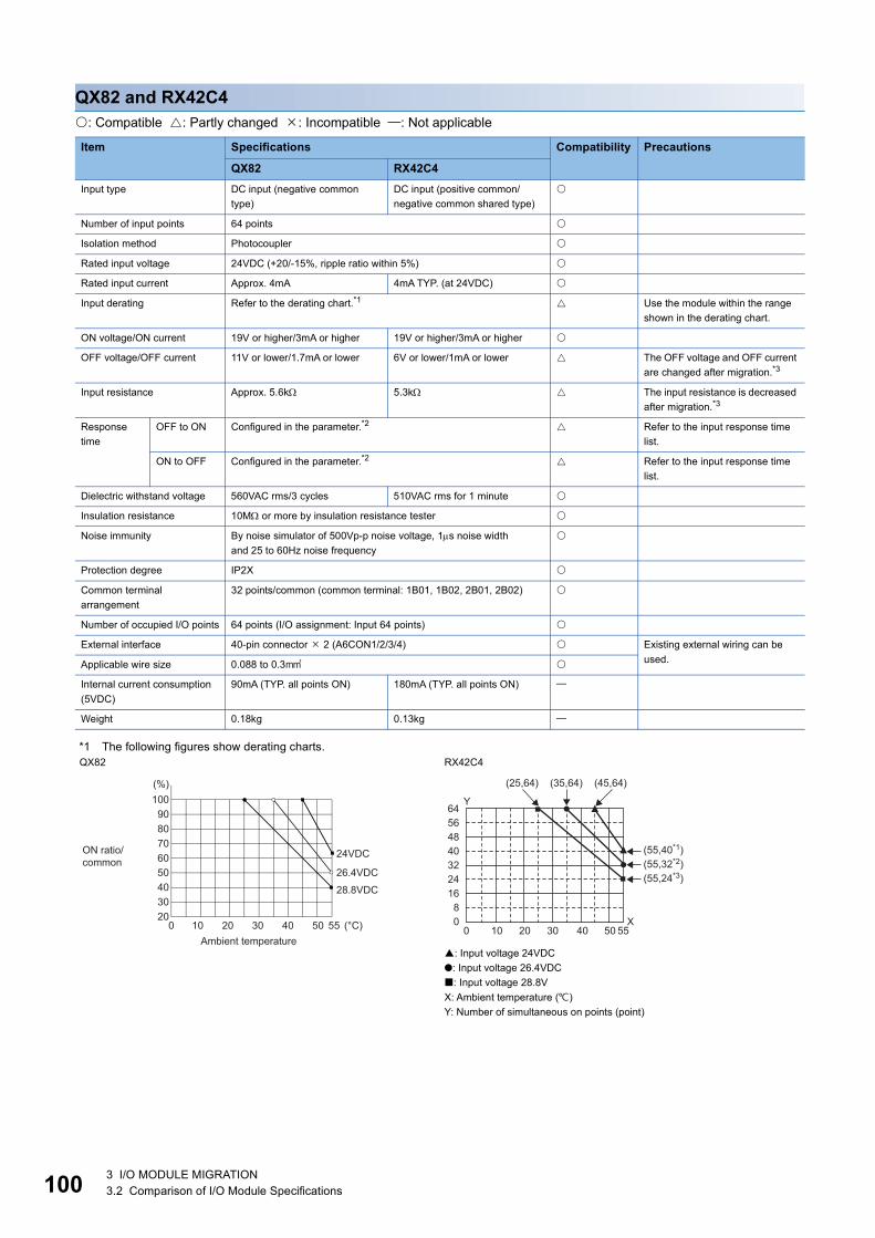
10
QX82 and RX42C4: Compatible : Partly changed : Incompatible : Not applicable
*1 The following figures show derating charts.
Item Specifications Compatibility Precautions
QX82 RX42C4Input type DC input (negative common
type)DC input (positive common/negative common shared type)
Number of input points 64 points
Isolation method Photocoupler
Rated input voltage 24VDC (+20/-15%, ripple ratio within 5%)
Rated input current Approx. 4mA 4mA TYP. (at 24VDC)
Input derating Refer to the derating chart.*1 Use the module within the range shown in the derating chart.
ON voltage/ON current 19V or higher/3mA or higher 19V or higher/3mA or higher
OFF voltage/OFF current 11V or lower/1.7mA or lower 6V or lower/1mA or lower The OFF voltage and OFF current are changed after migration.*3
Input resistance Approx. 5.6k 5.3k The input resistance is decreased after migration.*3
Response time
OFF to ON Configured in the parameter.*2 Refer to the input response time list.
ON to OFF Configured in the parameter.*2 Refer to the input response time list.
Dielectric withstand voltage 560VAC rms/3 cycles 510VAC rms for 1 minute
Insulation resistance 10M or more by insulation resistance tester
Noise immunity By noise simulator of 500Vp-p noise voltage, 1s noise widthand 25 to 60Hz noise frequency
Protection degree IP2X
Common terminal arrangement
32 points/common (common terminal: 1B01, 1B02, 2B01, 2B02)
Number of occupied I/O points 64 points (I/O assignment: Input 64 points)
External interface 40-pin connector 2 (A6CON1/2/3/4) Existing external wiring can be used.Applicable wire size 0.088 to 0.3
Internal current consumption (5VDC)
90mA (TYP. all points ON) 180mA (TYP. all points ON)
Weight 0.18kg 0.13kg
QX82 RX42C4
: Input voltage 24VDC●: Input voltage 26.4VDC: Input voltage 28.8VX: Ambient temperature ()Y: Number of simultaneous on points (point)
100908070605040
0 10 20 30 40 50 55
3020
(%)
(°C)
24VDC
26.4VDC
28.8VDC
Ambient temperature
ON ratio/common
■
■
55X
Y
500 20 3010 4008
64564840322416
(25,64) (35,64) (45,64)
(55,40*1)(55,32*2)(55,24*3)
0 3 I/O MODULE MIGRATION3.2 Comparison of I/O Module Specifications

3
*2 The following table shows the input response times.QX821ms/5ms/10ms/20ms/70msRX42C4
*3 Check the specifications of sensors and switches connected to the RX42C4.
Timing Set value
0.1ms 0.2ms 0.4ms 0.6ms 1ms 5ms 10ms 20ms 70msOFF to ON (MAX.) 0.1ms 0.2ms 0.4ms 0.6ms 1ms 5ms 10ms 20ms 70ms
ON to OFF (MAX.) 0.2ms 0.3ms 0.5ms 0.7ms 1ms 5ms 10ms 20ms 70ms
3 I/O MODULE MIGRATION3.2 Comparison of I/O Module Specifications 101

10
QX82-S1 and RX42C4: Compatible : Partly changed : Incompatible : Not applicable
*1 The following figures show derating charts.
Item Specifications Compatibility Precautions
QX82-S1 RX42C4Input type DC input (negative common
type)DC input (positive common/negative common shared type)
Number of input points 64 points
Isolation method Photocoupler
Rated input voltage 24VDC (+20/-15%, ripple ratio within 5%)
Rated input current Approx. 4mA 4mA TYP. (at 24VDC)
Input derating Refer to the derating chart.*1 Use the module within the range shown in the derating chart.
ON voltage/ON current 19V or higher/3mA or higher 19V or higher/3mA or higher
OFF voltage/OFF current 9.5V or lower/1.5mA or lower 6V or lower/1mA or lower The OFF voltage and OFF current are changed after migration.*3
Input resistance Approx. 5.6k 5.3k The input resistance is decreased after migration.*3
Response time
OFF to ON Configured in the parameter.*2 Refer to the input response time list.
ON to OFF Configured in the parameter.*2 Refer to the input response time list.
Dielectric withstand voltage 560VAC rms/3 cycles 510VAC rms for 1 minute
Insulation resistance 10M or more by insulation resistance tester
Noise immunity By noise simulator of 500Vp-p noise voltage, 1s noise widthand 25 to 60Hz noise frequency
Protection degree IP2X
Common terminal arrangement
32 points/common (common terminal: 1B01, 1B02, 2B01, 2B02)
Number of occupied I/O points 64 points (I/O assignment: High-speed input 64 points)
64 points (I/O assignment: Input 64 points)
External interface 40-pin connector (A6CON1/2/3/4) Existing external wiring can be used.Applicable wire size 0.088 to 0.3
Internal current consumption (5VDC)
90mA (TYP. all points ON) 180mA (TYP. all points ON)
Weight 0.18kg 0.13kg
QX82-S1 RX42C4
: Input voltage 24VDC●: Input voltage 26.4VDC: Input voltage 28.8VX: Ambient temperature ()Y: Number of simultaneous on points (point)
100908070605040
0 10 20 30 40 50 55
3020
(%)
(°C)
24VDC
26.4VDC
28.8VDC
Ambient temperature
ON ratio/common
■
■
55X
Y
500 20 3010 4008
64564840322416
(25,64) (35,64) (45,64)
(55,40)(55,32)(55,24)
2 3 I/O MODULE MIGRATION3.2 Comparison of I/O Module Specifications
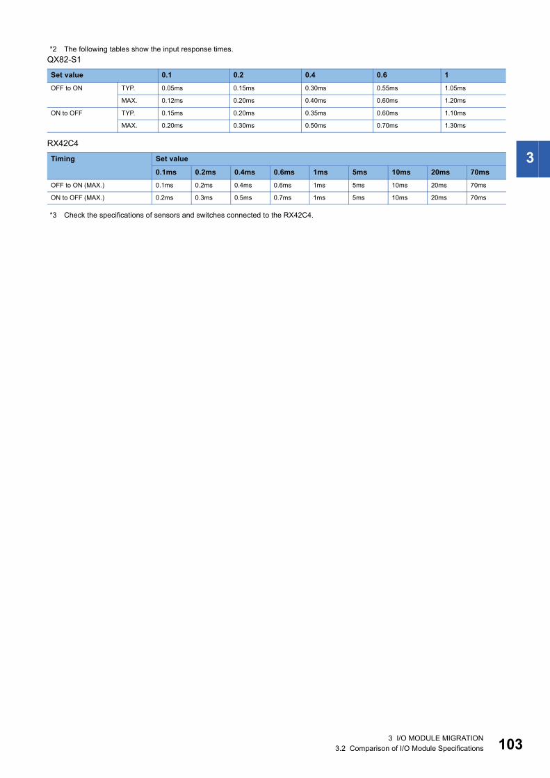
3
*2 The following tables show the input response times.QX82-S1
RX42C4
*3 Check the specifications of sensors and switches connected to the RX42C4.
Set value 0.1 0.2 0.4 0.6 1OFF to ON TYP. 0.05ms 0.15ms 0.30ms 0.55ms 1.05ms
MAX. 0.12ms 0.20ms 0.40ms 0.60ms 1.20ms
ON to OFF TYP. 0.15ms 0.20ms 0.35ms 0.60ms 1.10ms
MAX. 0.20ms 0.30ms 0.50ms 0.70ms 1.30ms
Timing Set value
0.1ms 0.2ms 0.4ms 0.6ms 1ms 5ms 10ms 20ms 70msOFF to ON (MAX.) 0.1ms 0.2ms 0.4ms 0.6ms 1ms 5ms 10ms 20ms 70ms
ON to OFF (MAX.) 0.2ms 0.3ms 0.5ms 0.7ms 1ms 5ms 10ms 20ms 70ms
3 I/O MODULE MIGRATION3.2 Comparison of I/O Module Specifications 103

10
QX90H and RX61C6HS: Compatible : Partly changed : Incompatible : Not applicable
Item Specifications Compatibility Precautions
QX90H RX61C6HSInput type DC input (negative common
type)DC input (positive common/negative common shared type)
Number of input points 16 points 32 points
Isolation method Photocoupler
Rated input voltage 5VDC (+20/-15%, ripple ratio within 5%)
Rated input current Approx. 6mA 6mA TYP. (at 5VDC)
Input derating None
ON voltage/ON current 3.5V or higher/3mA or higher 3.5V or higher/3mA or higher
OFF voltage/OFF current 1V or lower/1mA or lower 1V or lower/1mA or lower
Input resistance Approx. 470 600 The input resistance is larger.*2
Response time and function setting
OFF to ON Configured in the parameter.*1 Refer to the input response time list.
ON to OFF Configured in the parameter.*1 Refer to the input response time list.
Dielectric withstand voltage 560VAC rms/3 cycles 510VAC rms for 1 minute
Insulation resistance 10M or more by insulation resistance tester
Noise immunity By noise simulator of 500Vp-p noise voltage, 1s noise widthand 25 to 60Hz noise frequency
Protection degree IP2X
Common terminal arrangement
8 points/common(common terminal: TB9, TB18)
32 points/common(common terminal: B01, B02)
The number of commons per module has decreased.
Number of occupied I/O points 16 points(I/O assignment: High-speed input/interrupt 16 points)
32 points(I/O assignment: Input 32 points)
Interrupt settings can be configured in the parameter setting of GX Works3. The number of occupied I/O points is increased after migration.
External interface 18-point terminal block (M3 6 screws)
40-pin connector (A6CON1/2/3/4)
Wiring needs to be changed after migration.
Applicable wire size 0.3 to 0.75 core(2.8mm OD maximum)
0.088 to 0.3 The applicable wire size is larger after migration.
Applicable solderless terminal R1.25-3 (solderless terminal with an insulation sleeve cannot be used.)
Internal current consumption (5VDC)
80mA (TYP. all points ON) 150mA (TYP. all points ON)
Weight 0.14kg 0.12kg
4 3 I/O MODULE MIGRATION3.2 Comparison of I/O Module Specifications

3
*1 The following tables show the input response times.QX90H
RX61C6HS
*2 Check the specifications of sensors and switches connected to the RX61C6HS.
SW1 (noise filter) OFF ON
Set value Invalid 0.1 0.2 0.4 0.6 1OFF to ON TYP. 0ms 0.04ms 0.10ms 0.25ms 0.50ms 0.95ms
MAX. 0.05ms 0.15ms 0.30ms 0.60ms 1.00ms
ON to OFF TYP. 0ms 0.04ms 0.10ms 0.25ms 0.50ms 0.95ms
MAX. 0.05ms 0.15ms 0.30ms 0.60ms 1.00ms
SW2 Off: Interrupt/On: High-speed input
Timing Set value
No Setting
10s 20s 50s 0.1ms 0.2ms 0.4ms 0.6ms 1ms 5ms 10ms 20ms 70ms
OFF to ON (MAX.)
1s 10s 20s 50s 0.1ms 0.2ms 0.4ms 0.6ms 1ms 5ms 10ms 20ms 70ms
ON to OFF (MAX.)
1s 10s 20s 50s 0.1ms 0.2ms 0.4ms 0.6ms 1ms 5ms 10ms 20ms 70ms
3 I/O MODULE MIGRATION3.2 Comparison of I/O Module Specifications 105

10
Comparison of output module specifications
QY10 and RY10R2: Compatible : Partly changed : Incompatible : Not applicable
*1 The following table shows the life data.QY10, RY10R2
Item Specifications Compatibility Precautions
QY10 RY10R2Output type Contact output
Number of output points 16 points
Isolation method Relay
Rated switching voltage, current
24VDC 2A (resistive load)/point, 8A/common2A at 240VAC (COS = 1)/point, 8A/common
Minimum switching load 1mA at 5VDC
Maximum switching load 264VAC, 125VDC
Response time
OFF to ON 10ms or less
ON to OFF 12ms or less
Life Refer to the life table.*1
Maximum switching frequency 3600 times/hour
Surge suppressor None
Fuse None
Dielectric withstand voltage 2830VAC rms/3 cycles 2300VAC rms for 1 minute
Insulation resistance 10M or more by insulation resistance tester
Noise immunity By noise simulator of 1500Vp-p noise voltage, 1s noise widthand 25 to 60Hz noise frequency
Protection degree IP1X
Common terminal arrangement
16 points/common (common terminal: TB17)
Number of occupied I/O points 16 points (I/O assignment: Output 16 points)
External interface 18-point terminal block (M3 6 screws) The existing external wiring and terminal blocks in the existing system can be used.
Applicable wire size 0.3 to 0.75 core (2.8mm OD maximum)
Applicable solderless terminal R1.25-3 (solderless terminal with an insulation sleeve cannot be used.)
Internal current consumption (5VDC)
430mA (TYP. all points ON) 450mA (TYP. all points ON)
Weight 0.22kg 0.22kg
Mechanical 20 million times or more
Electrical Rated switching voltage/current load: 100 thousand times or more
1.5A at 200VAC, 1A at 240VAC (COS = 0.7) 100 thousand times or more0.4A at 200VAC, 0.3A at 240VAC (COS = 0.7) 300 thousand times or more
1A at 200VAC, 0.5A at 240VAC (COS = 0.35) 100 thousand times or more0.3A at 200VAC, 0.15A at 240VAC (COS = 0.35) 300 thousand times or more
1A at 24VDC, 0.1A at 100VDC (L/R = 7ms) 100 thousand times or more0.3A at 24VDC, 0.03A at 100VDC (L/R = 7ms) 300 thousand times or more
6 3 I/O MODULE MIGRATION3.2 Comparison of I/O Module Specifications

3
QY10-TS and RY10R2: Compatible : Partly changed : Incompatible : Not applicable
*1 The following table shows the life data.QY10-TS, RY10R2
*2 The Q6TE-18SN does not have a connection check indicator. Tools are required to connect cables.The applicable wire size for the Q6TE-18SN is 0.3 to 1.5 core (22 to 16 AWG).
Item Specifications Compatibility Precautions
QY10-TS RY10R2Output type Contact output
Number of output points 16 points
Isolation method Relay
Rated switching voltage, current
24VDC 2A (resistive load)/point, 8A/common2A at 240VAC (COS = 1)/point, 8A/common
Minimum switching load 1mA at 5VDC
Maximum switching load 264VAC, 125VDC
Response time
OFF to ON 10ms or less
ON to OFF 12ms or less
Life Refer to the life table.*1
Maximum switching frequency 3600 times/hour
Surge suppressor None
Fuse None
Dielectric withstand voltage 2830VAC rms/3 cycles 2300VAC rms for 1 minute
Insulation resistance 10M or more by insulation resistance tester
Noise immunity By noise simulator of 1500Vp-p noise voltage, 1s noise widthand 25 to 60Hz noise frequency
Protection degree IP1X
Common terminal arrangement
16 points/common (common terminal: TB17)
Number of occupied I/O points 16 points (I/O assignment: Output 16 points)
External interface Two-piece spring clamp terminal block
18-point terminal block (M3 6 screws)
When the existing wiring is used, use the Q series spring clamp terminal blocks in the existing system or the Q6TE-18SN.*2*3Applicable wire size 0.3 to 2.0 core (22 to 15
AWG)0.3 to 0.75 core (2.8mm OD maximum)
Applicable solderless terminal Refer to the list of reference products.*3
R1.25-3 (solderless terminal with an insulation sleeve cannot be used.)
Internal current consumption (5VDC)
430mA (TYP. all points ON) 450mA (TYP. all points ON)
Weight 0.22kg 0.22kg
Mechanical 20 million times or more
Electrical Rated switching voltage/current load: 100 thousand times or more
1.5A at 200VAC, 1A at 240VAC (COS = 0.7) 100 thousand times or more0.4A at 200VAC, 0.3A at 240VAC (COS = 0.7) 300 thousand times or more
1A at 200VAC, 0.5A at 240VAC (COS = 0.35) 100 thousand times or more0.3A at 200VAC, 0.15A at 240VAC (COS = 0.35) 300 thousand times or more
1A at 24VDC, 0.1A at 100VDC (L/R = 7ms) 100 thousand times or more0.3A at 24VDC, 0.03A at 100VDC (L/R = 7ms) 300 thousand times or more
3 I/O MODULE MIGRATION3.2 Comparison of I/O Module Specifications 107
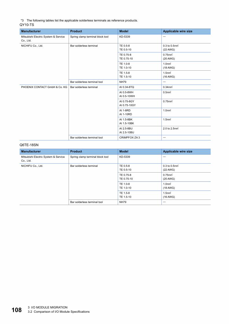
10
*3 The following tables list the applicable solderless terminals as reference products.QY10-TS
Q6TE-18SN
Manufacturer Product Model Applicable wire sizeMitsubishi Electric System & Service Co., Ltd.
Spring clamp terminal block tool KD-5339
NICHIFU Co., Ltd. Bar solderless terminal TE 0.5-8TE 0.5-10
0.3 to 0.5(22 AWG)
TE 0.75-8TE 0.75-10
0.75(20 AWG)
TE 1.0-8TE 1.0-10
1.0(18 AWG)
TE 1.5-8TE 1.5-10
1.5(16 AWG)
Bar solderless terminal tool NH79
PHOENIX CONTACT GmbH & Co. KG Bar solderless terminal AI 0.34-8TQ 0.34
AI 0.5-8WHAI 0.5-10WH
0.5
AI 0.75-8GYAI 0.75-10GY
0.75
AI 1-8RDAI 1-10RD
1.0
AI 1.5-8BKAI 1.5-10BK
1.5
AI 2.5-8BUAI 2.5-10BU
2.0 to 2.5
Bar solderless terminal tool CRIMPFOX ZA 3
Manufacturer Product Model Applicable wire sizeMitsubishi Electric System & Service Co., Ltd.
Spring clamp terminal block tool KD-5339
NICHIFU Co., Ltd. Bar solderless terminal TE 0.5-8TE 0.5-10
0.3 to 0.5(22 AWG)
TE 0.75-8TE 0.75-10
0.75(20 AWG)
TE 1.0-8TE 1.0-10
1.0(18 AWG)
TE 1.5-8TE 1.5-10
1.5(16 AWG)
Bar solderless terminal tool NH79
8 3 I/O MODULE MIGRATION3.2 Comparison of I/O Module Specifications

3
QY18A and RY18R2A: Compatible : Partly changed : Incompatible : Not applicable
*1 The following table shows the life data.QY18A, RY18R2A
Item Specifications Compatibility Precautions
QY18A RY18R2AOutput type Contact output
Number of output points 8 points
Isolation method Relay
Rated switching voltage, current
24VDC 2A (resistive load)/point, 8A/module2A at 240VAC (COS = 1)/point, 8A/module
Minimum switching load 1mA at 5VDC
Maximum switching load 264VAC, 125VDC
Response time
OFF to ON 10ms or less
ON to OFF 12ms or less
Life Refer to the life table.*1
Maximum switching frequency 3600 times/hour
Surge suppressor None
Fuse None
Dielectric withstand voltage 2830VAC rms/3 cycles 2300VAC rms for 1 minute
Insulation resistance 10M or more by insulation resistance tester
Noise immunity By noise simulator of 1500Vp-p noise voltage, 1s noise widthand 25 to 60Hz noise frequency
Protection degree IP1X
Common terminal arrangement
No common (all points independent)
Number of occupied I/O points 16 points (I/O assignment: Output 16 points)
External interface 18-point terminal block (M3 6 screws) The existing external wiring and terminal blocks in the existing system can be used.
Applicable wire size 0.3 to 0.75 core (2.8mm OD maximum)
Applicable solderless terminal R1.25-3 (solderless terminal with an insulation sleeve cannot be used.)
Internal current consumption (5VDC)
240mA (TYP. all points ON) 260mA (TYP. all points ON)
Weight 0.22kg 0.19kg
Mechanical 20 million times or more
Electrical Rated switching voltage/current load: 100 thousand times or more
1.5A at 200VAC, 1A at 240VAC (COS = 0.7) 100 thousand times or more0.4A at 200VAC, 0.3A at 240VAC (COS = 0.7) 300 thousand times or more
1A at 200VAC, 0.5A at 240VAC (COS = 0.35) 100 thousand times or more0.3A at 200VAC, 0.15A at 240VAC (COS = 0.35) 300 thousand times or more
1A at 24VDC, 0.1A at 100VDC (L/R = 7ms) 100 thousand times or more0.3A at 24VDC, 0.03A at 100VDC (L/R = 7ms) 300 thousand times or more
3 I/O MODULE MIGRATION3.2 Comparison of I/O Module Specifications 109

11
QY22 and RY20S6: Compatible : Partly changed : Incompatible : Not applicable
Item Specifications Compatibility Precautions
QY22 RY20S6Output type Triac output
Number of output points 16 points
Isolation method Photocoupler
Rated load voltage, frequency 100 to 240VAC 50/60Hz5% 100 to 240VAC (+10%/-15%),50/60Hz (3Hz)
Maximum load current 0.6A/point, 4.8A/common
Load voltage distortion rate Within 5%
Maximum load voltage 264VAC
Minimum load voltage/current 100mA at 24VAC, 25mA at 100VAC, 25mA at 240VAC
Maximum inrush current 20A/cycle or lower
Leakage current at OFF 3mA or lower (at 240V, 60Hz), 1.5mA or lower (at 120V, 60Hz)
Maximum voltage drop at ON 1.5V or lower
Response time
OFF to ON Total of 1ms and 0.5 cycles or less
ON to OFF Total of 1ms and 0.5 cycles or less (rated load, resistive load)
Surge suppressor CR absorber
Fuse None
Dielectric withstand voltage 2830VAC rms/3 cycles 2300VAC rms for 1 minute
Insulation resistance 10M or more by insulation resistance tester
Noise immunity By noise simulator of 1500Vp-p noise voltage, 1s noise widthand 25 to 60Hz noise frequency
Protection degree IP1X
Common terminal arrangement
16 points/common (common terminal: TB17)
Number of occupied I/O points 16 points (I/O assignment: Output 16 points)
External interface 18-point terminal block (M3 6 screws) The existing external wiring and terminal blocks in the existing system can be used.
Applicable wire size 0.3 to 0.75 core (2.8mm OD maximum)
Applicable solderless terminal R1.25-3 (solderless terminal with an insulation sleeve cannot be used.)
Internal current consumption (5VDC)
250mA (TYP. all points ON) 280mA (TYP. all points ON)
Weight 0.40kg 0.24kg
0 3 I/O MODULE MIGRATION3.2 Comparison of I/O Module Specifications

3
QY40P and RY40NT5P: Compatible : Partly changed : Incompatible : Not applicable
Item Specifications Compatibility Precautions
QY40P RY40NT5POutput type Transistor output (sink type)
Number of output points 16 points
Isolation method Photocoupler
Rated load voltage 12/24VDC (+20%/-15%)
Maximum load current 0.1A/point, 1.6A/common 0.5A/point, Pilot Duty, 5A/common
Maximum inrush current 0.7A, 10ms or less Current is to be limited by the overload protection function.
Carefully select the load to be used because the inrush current value is changed after migration.
Leakage current at OFF 0.1mA or lower
Maximum voltage drop at ON 0.1A at 0.1VDC (TYP.),0.1A at 0.2VDC (MAX.)
0.5A at 0.2VDC (TYP.),0.5A at 0.3VDC (MAX.)
Response time
OFF to ON 1ms or less 0.5ms or less
ON to OFF 1ms or less (rated load, resistive load)
Surge suppressor Zener diode
Fuse None
External power supply
Voltage 12/24VDC (+20/-15%) (ripple ratio within 5%)
Current 10mA maximum (at 24VDC, all points ON)
4mA (at 24VDC)
Dielectric withstand voltage 560VAC rms/3 cycles 510VAC rms for 1 minute
Insulation resistance 10M or more by insulation resistance tester
Noise immunity By noise simulator of 500Vp-p noise voltage, 1s noise widthand 25 to 60Hz noise frequency
Protection degree IP2X
Common terminal arrangement
16 points/common (common terminal: TB18)
Number of occupied I/O points 16 points (I/O assignment: Output 16 points)
Protection function Overheat protection function (in increments of 1 point), overload protection function (in increments of 1 point)
External interface 18-point terminal block (M3 6 screws) The existing external wiring and terminal blocks in the existing system can be used.
Applicable wire size 0.3 to 0.75 core (2.8mm OD maximum)
Applicable solderless terminal R1.25-3 (solderless terminal with an insulation sleeve cannot be used.)
Internal current consumption (5VDC)
65mA (TYP. all points ON) 140mA (TYP. all points ON)
Weight 0.16kg 0.16kg
3 I/O MODULE MIGRATION3.2 Comparison of I/O Module Specifications 111

11
QY40P-TS and RY40NT5P: Compatible : Partly changed : Incompatible : Not applicable
*1 The Q6TE-18SN does not have a connection check indicator. Tools are required to connect cables.The applicable wire size for the Q6TE-18SN is 0.3 to 1.5 core (22 to 16 AWG).
Item Specifications Compatibility Precautions
QY40P-TS RY40NT5POutput type Transistor output (sink type)
Number of output points 16 points
Isolation method Photocoupler
Rated load voltage 12/24VDC (+20%/-15%)
Maximum load current 0.1A/point, 1.6A/common 0.5A/point, Pilot Duty, 5A/common
Maximum inrush current 0.7A, 10ms or less Current is to be limited by the overload protection function.
Carefully select the load to be used because the inrush current value is changed after migration.
Leakage current at OFF 0.1mA or lower
Maximum voltage drop at ON 0.1A at 0.1VDC (TYP.),0.1A at 0.2VDC (MAX.)
0.5A at 0.2VDC (TYP.),0.5A at 0.3VDC (MAX.)
Response time
OFF to ON 1ms or less 0.5ms or less
ON to OFF 1ms or less (rated load, resistive load)
Surge suppressor Zener diode
Fuse None
External power supply
Voltage 12/24VDC (+20/-15%) (ripple ratio within 5%)
Current 10mA maximum (at 24VDC, all points ON)
4mA (at 24VDC)
Dielectric withstand voltage 560VAC rms/3 cycles 510VAC rms for 1 minute
Insulation resistance 10M or more by insulation resistance tester
Noise immunity By noise simulator of 500Vp-p noise voltage, 1s noise widthand 25 to 60Hz noise frequency
Protection degree IP2X
Common terminal arrangement
16 points/common (common terminal: TB18)
Number of occupied I/O points 16 points (I/O assignment: Output 16 points)
Protection function Overheat protection function (in increments of 1 point), overload protection function (in increments of 1 point)
External interface Two-piece spring clamp terminal block
18-point terminal block (M3 6 screws)
When the existing wiring is used, use the Q series spring clamp terminal blocks in the existing system or the Q6TE-18SN.*1*2Applicable wire size 0.3 to 2.0 core (22 to 15
AWG)0.3 to 0.75 core (2.8mm OD maximum)
Applicable solderless terminal Refer to the list of reference products.*2
R1.25-3 (solderless terminal with an insulation sleeve cannot be used.)
Internal current consumption (5VDC)
65mA (TYP. all points ON) 140mA (TYP. all points ON)
Weight 0.16kg 0.16kg
2 3 I/O MODULE MIGRATION3.2 Comparison of I/O Module Specifications

3
*2 The following tables list the applicable solderless terminals as reference products.QY40P-TS
Q6TE-18SN
Manufacturer Product Model Applicable wire sizeMitsubishi Electric System & Service Co., Ltd.
Spring clamp terminal block tool KD-5339
NICHIFU Co., Ltd. Bar solderless terminal TE 0.5-8TE 0.5-10
0.3 to 0.5(22 AWG)
TE 0.75-8TE 0.75-10
0.75(20 AWG)
TE 1.0-8TE 1.0-10
1.0(18 AWG)
TE 1.5-8TE 1.5-10
1.5(16 AWG)
Bar solderless terminal tool NH79
PHOENIX CONTACT GmbH & Co. KG Bar solderless terminal AI 0.34-8TQ 0.34
AI 0.5-8WHAI 0.5-10WH
0.5
AI 0.75-8GYAI 0.75-10GY
0.75
AI 1-8RDAI 1-10RD
1.0
AI 1.5-8BKAI 1.5-10BK
1.5
AI 2.5-8BUAI 2.5-10BU
2.0 to 2.5
Bar solderless terminal tool CRIMPFOX ZA 3
Manufacturer Product Model Applicable wire sizeMitsubishi Electric System & Service Co., Ltd.
Spring clamp terminal block tool KD-5339
NICHIFU Co., Ltd. Bar solderless terminal TE 0.5-8TE 0.5-10
0.3 to 0.5(22 AWG)
TE 0.75-8TE 0.75-10
0.75(20 AWG)
TE 1.0-8TE 1.0-10
1.0(18 AWG)
TE 1.5-8TE 1.5-10
1.5(16 AWG)
Bar solderless terminal tool NH79
3 I/O MODULE MIGRATION3.2 Comparison of I/O Module Specifications 113

11
QY41H and RY41NT2H: Compatible : Partly changed : Incompatible : Not applicable
Item Specifications Compatibility Precautions
QY41H RY41NT2HOutput type Transistor output (sink type)
Number of output points 32 points
Isolation method Photocoupler
Rated load voltage 5/12/24VDC (+20%/-15%)
Maximum load current 0.2A/point, 2A/common
Maximum inrush current 0.7A, 10ms or less
Leakage current at OFF 0.1mA or lower
Maximum voltage drop at ON 0.1A at 0.1VDC (TYP.),0.1A at 0.2VDC (MAX.)
0.2A at 0.1VDC (TYP.),0.2A at 0.2VDC (MAX.)
Response time
OFF to ON 2s or less 1s or less
ON to OFF 2s or less (rated load, resistive load)
Surge suppressor Zener diode
Fuse None
Dielectric withstand voltage 560VAC rms/3 cycles 510VAC rms for 1 minute
Insulation resistance 10M or more by insulation resistance tester
Noise immunity By noise simulator of 500Vp-p noise voltage, 1s noise widthand 25 to 60Hz noise frequency
Protection degree IP2X
Common terminal arrangement
32 points/common (common terminal: A01, A02)
Number of occupied I/O points 32 points (I/O assignment: Output 32 points)
Protection function None
External interface 40-pin connector (A6CON1/2/3/4) Existing external wiring can be used.Applicable wire size 0.088 to 0.3
Internal current consumption (5VDC)
370mA (TYP. all points ON) 420mA (TYP. all points ON)
Weight 0.10kg 0.12kg
4 3 I/O MODULE MIGRATION3.2 Comparison of I/O Module Specifications

3
QY41P and RY41NT2P: Compatible : Partly changed : Incompatible : Not applicable
Item Specifications Compatibility Precautions
QY41P RY41NT2POutput type Transistor output (sink type)
Number of output points 32 points
Isolation method Photocoupler
Rated load voltage 12/24VDC (+20%/-15%)
Maximum load current 0.1A/point, 2A/common 0.2A/point, Pilot Duty, 2A/common
Maximum inrush current 0.7A, 10ms or less Current is to be limited by the overload protection function.
Carefully select the load to be used because the inrush current value is changed after migration.
Leakage current at OFF 0.1mA or lower
Maximum voltage drop at ON 0.1A at 0.1VDC (TYP.),0.1A at 0.2VDC (MAX.)
0.2A at 0.2VDC (TYP.),0.2A at 0.3VDC (MAX.)
Response time
OFF to ON 1ms or less 0.5ms or less
ON to OFF 1ms or less (rated load, resistive load)
Surge suppressor Zener diode
Fuse None
External power supply
Voltage 12/24VDC (+20/-15%) (ripple ratio within 5%)
Current 20mA (at 24VDC) 16mA (at 24VDC)
Dielectric withstand voltage 560VAC rms/3 cycles 510VAC rms for 1 minute
Insulation resistance 10M or more by insulation resistance tester
Noise immunity By noise simulator of 500Vp-p noise voltage, 1s noise widthand 25 to 60Hz noise frequency
Protection degree IP2X
Common terminal arrangement
32 points/common (common terminal: A01, A02)
Number of occupied I/O points 32 points (I/O assignment: Output 32 points)
Protection function Overheat protection function (in increments of 1 point), overload protection function (in increments of 1 point)
External interface 40-pin connector (A6CON1/2/3/4) Existing external wiring can be used.Applicable wire size 0.088 to 0.3
Internal current consumption (5VDC)
105mA (TYP. all points ON) 180mA (TYP. all points ON)
Weight 0.15kg 0.11kg
3 I/O MODULE MIGRATION3.2 Comparison of I/O Module Specifications 115

11
QY42P and RY42NT2P: Compatible : Partly changed : Incompatible : Not applicable
Item Specifications Compatibility Precautions
QY42P RY42NT2POutput type Transistor output (sink type)
Number of output points 64 points
Isolation method Photocoupler
Rated load voltage 12/24VDC (+20%/-15%)
Maximum load current 0.1A/point, 2A/common 0.2A/point, Pilot Duty, 2A/common
Maximum inrush current 0.7A, 10ms or less Current is to be limited by the overload protection function.
Carefully select the load to be used because the inrush current value is changed after migration.
Leakage current at OFF 0.1mA or lower
Maximum voltage drop at ON 0.1A at 0.1VDC (TYP.),0.1A at 0.2VDC (MAX.)
0.2A at 0.2VDC (TYP.),0.2A at 0.3VDC (MAX.)
Response time
OFF to ON 1ms or less 0.5ms or less
ON to OFF 1ms or less (rated load, resistive load)
Surge suppressor Zener diode
Fuse None
External power supply
Voltage 12/24VDC (+20/-15%) (ripple ratio within 5%)
Current 20mA (at 24VDC)/common 16mA (at 24VDC)/common
Dielectric withstand voltage 560VAC rms/3 cycles 510VAC rms for 1 minute
Insulation resistance 10M or more by insulation resistance tester
Noise immunity By noise simulator of 500Vp-p noise voltage, 1s noise widthand 25 to 60Hz noise frequency
Protection degree IP2X
Common terminal arrangement
32 points/common (common terminal: 1A01, 1A02, 2A01, 2A02)
Number of occupied I/O points 64 points (I/O assignment: Output 64 points)
Protection function Overheat protection function (in increments of 1 point), overload protection function (in increments of 1 point)
External interface 40-pin connector (A6CON1/2/3/4) Existing external wiring can be used.Applicable wire size 0.088 to 0.3
Internal current consumption (5VDC)
150mA (TYP. all points ON) 250mA (TYP. all points ON)
Weight 0.17kg 0.13kg
6 3 I/O MODULE MIGRATION3.2 Comparison of I/O Module Specifications

3
QY50 and RY40NT5P: Compatible : Partly changed : Incompatible : Not applicable
Item Specifications Compatibility Precautions
QY50 RY40NT5POutput type Transistor output (sink type)
Number of output points 16 points
Isolation method Photocoupler
Rated load voltage 12/24VDC (+20%/-15%)
Maximum load current 0.5A/point, 4A/common 0.5A/point, Pilot Duty, 5A/common
Maximum inrush current 4A, 10ms or less Current is to be limited by the overload protection function.
Carefully select the load to be used because the inrush current value is changed after migration.
Leakage current at OFF 0.1mA or lower
Maximum voltage drop at ON 0.5A at 0.2VDC (TYP.), 0.5A at 0.3VDC (MAX.)
Response time
OFF to ON 1ms or less 0.5ms or less
ON to OFF 1ms or less (rated load, resistive load)
Surge suppressor Zener diode
Fuse 6.7A (unchangeable)(fuse capacity: 50A)
None The module after migration has the protection function instead of the fuse.Protection function None Overheat protection (in
increments of 1 point),Overload protection (in increments of 1 point)
External power supply
Voltage 12/24VDC (+20/-15%) (ripple ratio within 5%)
Current 20mA (24VDC) 4mA (at 24VDC)
Dielectric withstand voltage 560VAC rms/3 cycles 510VAC rms for 1 minute
Insulation resistance 10M or more by insulation resistance tester
Noise immunity By noise simulator of 500Vp-p noise voltage, 1s noise widthand 25 to 60Hz noise frequency
Protection degree IP2X
Common terminal arrangement
16 points/common (common terminal: TB18)
Number of occupied I/O points 16 points (I/O assignment: Output 16 points)
External interface 18-point terminal block (M3 6 screws) The existing external wiring and terminal blocks in the existing system can be used.
Applicable wire size 0.3 to 0.75 core (2.8mm OD maximum)
Applicable solderless terminal R1.25-3 (solderless terminal with an insulation sleeve cannot be used.)
Internal current consumption (5VDC)
80mA (TYP. all points ON) 140mA (TYP. all points ON)
Weight 0.17kg 0.16kg
3 I/O MODULE MIGRATION3.2 Comparison of I/O Module Specifications 117

11
QY68A and RY18R2A: Compatible : Partly changed : Incompatible : Not applicable
*1 The following table shows the life data.
Item Specifications Compatibility Precautions
QY68A RY18R2AOutput type Transistor output (all points
independent, sink/source type)Contact output The output type ischanged after
migration.
Number of output points 8 points
Isolation method Photocoupler Relay Each isolation method has the same isolation performance although the method is changed after migration.
Rated load voltage 5 to 24VDC (+20%/-10%) 24VDC/240VAC
Maximum load current 2A/point, 8A/module
Maximum inrush current 8A, 10ms or less
Leakage current at OFF 0.1mA or lower
Maximum voltage drop at ON 2A at 0.3VDC (MAX.)
Response time
OFF to ON 3ms or less 10ms or less The response speed becomes slower.ON to OFF 10ms or less (rated load,
resistive load)12ms or less
Life Unlimited electrical life Refer to the life table.*1 The electrical/mechanical life is limited because contact output is used.
Maximum switching frequency Unlimited mechanical life 3600 times/hour
Surge suppressor Zener diode None The surge suppressor is not built in this model.
Fuse None
Dielectric withstand voltage 560VAC rms/3 cycles 2300VAC rms for 1 minute
Insulation resistance 10M or more by insulation resistance tester
Noise immunity By noise simulator of 500Vp-p noise voltage, 1s noise widthand 25 to 60Hz noise frequency
By noise simulator of 1500Vp-p noise voltage, 1s noise widthand 25 to 60Hz noise frequency
Protection degree IP2X IP1X
Common terminal arrangement
No common (all points independent)
Number of occupied I/O points 16 points (I/O assignment: Output 16 points)
External interface 18-point terminal block (M3 6 screws) The existing external wiring and terminal blocks in the existing system can be used.
Applicable wire size 0.3 to 0.75 core (2.8mm OD maximum)
Applicable solderless terminal R1.25-3 (solderless terminal with an insulation sleeve cannot be used.)
Internal current consumption (5VDC)
110mA (TYP. all points ON) 260mA (TYP. all points ON)
Weight 0.14kg 0.19kg
Mechanical 20 million times or more
Electrical Rated switching voltage/current load: 100 thousand times or more
1.5A at 200VAC, 1A at 240VAC (COS = 0.7) 100 thousand times or more0.4A at 200VAC, 0.3A at 240VAC (COS = 0.7) 300 thousand times or more
1A at 200VAC, 0.5A at 240VAC (COS = 0.35) 100 thousand times or more0.3A at 200VAC, 0.15A at 240VAC (COS = 0.35) 300 thousand times or more
1A at 24VDC, 0.1A at 100VDC (L/R = 7ms) 100 thousand times or more0.3A at 24VDC, 0.03A at 100VDC (L/R = 7ms) 300 thousand times or more
8 3 I/O MODULE MIGRATION3.2 Comparison of I/O Module Specifications

3
QY70 and RY41NT2H: Compatible : Partly changed : Incompatible : Not applicable
*1 To prevent burnout or damage of the external devices and modules in the event of a load short circuit, install a fuse for each external terminal. Also, if fuse blown indication is required, configure a relevant external circuit.
Item Specifications Compatibility Precautions
QY70 RY41NT2HOutput type Transistor output (sink type)
Number of output points 16 points 32 points
Isolation method Photocoupler
Rated load voltage 5 to 12VDC (+25/-10%) 5/12/24VDC (+20%/-15%)
Maximum load current 16mA/point, 256mA/common 0.2A/point, 2A/common
Maximum inrush current 40mA, 10ms or less 0.7A, 10ms or less
Output voltage at OFF VOH: 3.5VDC(Vcc = 5VDC, IOH = 0.4mA)
Maximum voltage drop at ON VOL: 0.3VDC 0.2A at 0.1VDC (TYP.),0.2A at 0.2VDC (MAX.)
Response time
OFF to ON 0.5ms or less 1s or less
ON to OFF 0.5ms or less (resistive load) 2s or less (rated load, resistive load)
Surge suppressor None Zener diode
Fuse 1.6A (unchangeable)(fuse capacity: 50A)
None No fuse is built in this model.*1
External power supply
Voltage 5 to 12VDC (+25/-10%)(ripple ratio within 5%)
No external power supply is required.
Current 90mA maximum (at 12VDC, all points ON)
Dielectric withstand voltage 560VAC rms/3 cycles 510VAC rms for 1 minute
Insulation resistance 10M or more by insulation resistance tester
Noise immunity By noise simulator of 500Vp-p noise voltage, 1s noise widthand 25 to 60Hz noise frequency
Protection degree IP2X
Common terminal arrangement
16 points/common (common terminal: TB18)
32 points/common(common terminal: A01, A02)
Number of occupied I/O points 16 points (I/O assignment: Output 16 points)
32 points (I/O assignment: Output 32 points)
The number of occupied I/O points is increased after migration.
Protection function None
External interface 18-point terminal block (M3 6 screws)
40-pin connector (A6CON1/2/3/4)
Wiring needs to be changed after migration.
Applicable wire size 0.3 to 0.75 core(2.8mm OD maximum)
0.088 to 0.3 The applicable wire size is smaller.
Applicable solderless terminal R1.25-3 (solderless terminal with an insulation sleeve cannot be used.)
Internal current consumption (5VDC)
150mA (TYP. all points ON) 420mA (TYP. all points ON)
Weight 0.14kg 0.12kg
3 I/O MODULE MIGRATION3.2 Comparison of I/O Module Specifications 119

12
QY71 and RY41NT2H: Compatible : Partly changed : Incompatible : Not applicable
*1 To prevent burnout or damage of the external devices and modules in the event of a load short circuit, install a fuse for each external terminal. Also, if fuse blown indication is required, configure a relevant external circuit.
Item Specifications Compatibility Precautions
QY71 RY41NT2HOutput type Transistor output (sink type)
Number of output points 32 points
Isolation method Photocoupler
Rated load voltage 5/12/24VDC (+20%/-15%)
Maximum load current 16mA/point, 512mA/common 0.2A/point, 2A/common
Maximum inrush current 40mA, 10ms or less 0.7A, 10ms or less
Output voltage at OFF VOH: 3.5VDC(Vcc = 5VDC, IOH = 0.4mA)
Maximum voltage drop at ON VOL: 0.3VDC 0.2A at 0.1VDC (TYP.),0.2A at 0.2VDC (MAX.)
Response time
OFF to ON 0.5ms or less 1s or less
ON to OFF 0.5ms or less (resistive load) 2s or less (rated load, resistive load)
Surge suppressor None Zener diode
Fuse 1.6A (unchangeable)(fuse capacity: 50A)
None No fuse is built in this model.*1
External power supply
Voltage 5 to 12VDC (+25/-10%)(ripple ratio within 5%)
No external power supply is required.
Current 170mA maximum (at 12VDC, all points ON)
Dielectric withstand voltage 560VAC rms/3 cycles 510VAC rms for 1 minute
Insulation resistance 10M or more by insulation resistance tester
Noise immunity By noise simulator of 500Vp-p noise voltage, 1s noise widthand 25 to 60Hz noise frequency
Protection degree IP2X
Common terminal arrangement
32 points/common (common terminal: A01, A02)
Number of occupied I/O points 32 points (I/O assignment: Output 32 points)
Protection function None
External interface 40-pin connector (A6CON1/2/3/4) Existing external wiring can be used.Applicable wire size 0.088 to 0.3
Internal current consumption (5VDC)
150mA (TYP. all points ON) 420mA (TYP. all points ON)
Weight 0.14kg 0.12kg
0 3 I/O MODULE MIGRATION3.2 Comparison of I/O Module Specifications
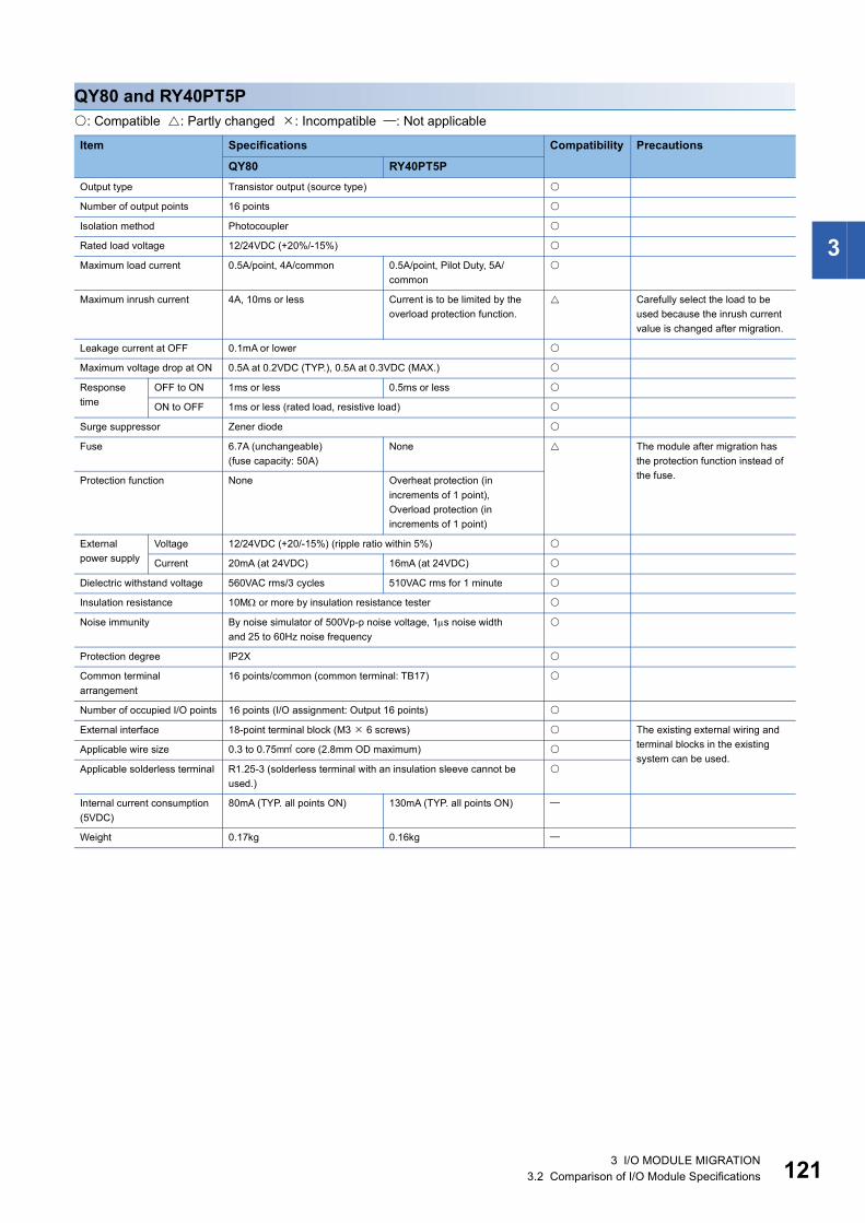
3
QY80 and RY40PT5P: Compatible : Partly changed : Incompatible : Not applicable
Item Specifications Compatibility Precautions
QY80 RY40PT5POutput type Transistor output (source type)
Number of output points 16 points
Isolation method Photocoupler
Rated load voltage 12/24VDC (+20%/-15%)
Maximum load current 0.5A/point, 4A/common 0.5A/point, Pilot Duty, 5A/common
Maximum inrush current 4A, 10ms or less Current is to be limited by the overload protection function.
Carefully select the load to be used because the inrush current value is changed after migration.
Leakage current at OFF 0.1mA or lower
Maximum voltage drop at ON 0.5A at 0.2VDC (TYP.), 0.5A at 0.3VDC (MAX.)
Response time
OFF to ON 1ms or less 0.5ms or less
ON to OFF 1ms or less (rated load, resistive load)
Surge suppressor Zener diode
Fuse 6.7A (unchangeable)(fuse capacity: 50A)
None The module after migration has the protection function instead of the fuse.Protection function None Overheat protection (in
increments of 1 point),Overload protection (in increments of 1 point)
External power supply
Voltage 12/24VDC (+20/-15%) (ripple ratio within 5%)
Current 20mA (at 24VDC) 16mA (at 24VDC)
Dielectric withstand voltage 560VAC rms/3 cycles 510VAC rms for 1 minute
Insulation resistance 10M or more by insulation resistance tester
Noise immunity By noise simulator of 500Vp-p noise voltage, 1s noise widthand 25 to 60Hz noise frequency
Protection degree IP2X
Common terminal arrangement
16 points/common (common terminal: TB17)
Number of occupied I/O points 16 points (I/O assignment: Output 16 points)
External interface 18-point terminal block (M3 6 screws) The existing external wiring and terminal blocks in the existing system can be used.
Applicable wire size 0.3 to 0.75 core (2.8mm OD maximum)
Applicable solderless terminal R1.25-3 (solderless terminal with an insulation sleeve cannot be used.)
Internal current consumption (5VDC)
80mA (TYP. all points ON) 130mA (TYP. all points ON)
Weight 0.17kg 0.16kg
3 I/O MODULE MIGRATION3.2 Comparison of I/O Module Specifications 121
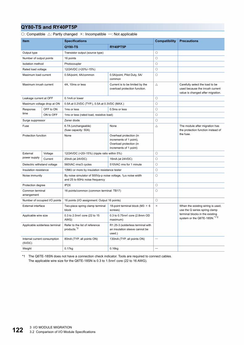
12
QY80-TS and RY40PT5P: Compatible : Partly changed : Incompatible : Not applicable
*1 The Q6TE-18SN does not have a connection check indicator. Tools are required to connect cables.The applicable wire size for the Q6TE-18SN is 0.3 to 1.5 core (22 to 16 AWG).
Item Specifications Compatibility Precautions
QY80-TS RY40PT5POutput type Transistor output (source type)
Number of output points 16 points
Isolation method Photocoupler
Rated load voltage 12/24VDC (+20%/-15%)
Maximum load current 0.5A/point, 4A/common 0.5A/point, Pilot Duty, 5A/common
Maximum inrush current 4A, 10ms or less Current is to be limited by the overload protection function.
Carefully select the load to be used because the inrush current value is changed after migration.
Leakage current at OFF 0.1mA or lower
Maximum voltage drop at ON 0.5A at 0.2VDC (TYP.), 0.5A at 0.3VDC (MAX.)
Response time
OFF to ON 1ms or less 0.5ms or less
ON to OFF 1ms or less (rated load, resistive load)
Surge suppressor Zener diode
Fuse 6.7A (unchangeable)(fuse capacity: 50A)
None The module after migration has the protection function instead of the fuse.Protection function None Overheat protection (in
increments of 1 point),Overload protection (in increments of 1 point)
External power supply
Voltage 12/24VDC (+20/-15%) (ripple ratio within 5%)
Current 20mA (at 24VDC) 16mA (at 24VDC)
Dielectric withstand voltage 560VAC rms/3 cycles 510VAC rms for 1 minute
Insulation resistance 10M or more by insulation resistance tester
Noise immunity By noise simulator of 500Vp-p noise voltage, 1s noise widthand 25 to 60Hz noise frequency
Protection degree IP2X
Common terminal arrangement
16 points/common (common terminal: TB17)
Number of occupied I/O points 16 points (I/O assignment: Output 16 points)
External interface Two-piece spring clamp terminal block
18-point terminal block (M3 6 screws)
When the existing wiring is used, use the Q series spring clamp terminal blocks in the existing system or the Q6TE-18SN.*1*2Applicable wire size 0.3 to 2.0 core (22 to 15
AWG)0.3 to 0.75 core (2.8mm OD maximum)
Applicable solderless terminal Refer to the list of reference products.*2
R1.25-3 (solderless terminal with an insulation sleeve cannot be used.)
Internal current consumption (5VDC)
80mA (TYP. all points ON) 130mA (TYP. all points ON)
Weight 0.17kg 0.16kg
2 3 I/O MODULE MIGRATION3.2 Comparison of I/O Module Specifications

3
*2 The following tables list the applicable solderless terminals as reference products.QY80-TS
Q6TE-18SN
Manufacturer Product Model Applicable wire sizeMitsubishi Electric System & Service Co., Ltd.
Spring clamp terminal block tool KD-5339
NICHIFU Co., Ltd. Bar solderless terminal TE 0.5-8TE 0.5-10
0.3 to 0.5(22 AWG)
TE 0.75-8TE 0.75-10
0.75(20 AWG)
TE 1.0-8TE 1.0-10
1.0(18 AWG)
TE 1.5-8TE 1.5-10
1.5(16 AWG)
Bar solderless terminal tool NH79
PHOENIX CONTACT GmbH & Co. KG Bar solderless terminal AI 0.34-8TQ 0.34
AI 0.5-8WHAI 0.5-10WH
0.5
AI 0.75-8GYAI 0.75-10GY
0.75
AI 1-8RDAI 1-10RD
1.0
AI 1.5-8BKAI 1.5-10BK
1.5
AI 2.5-8BUAI 2.5-10BU
2.0 to 2.5
Bar solderless terminal tool CRIMPFOX ZA 3
Manufacturer Product Model Applicable wire sizeMitsubishi Electric System & Service Co., Ltd.
Spring clamp terminal block tool KD-5339
NICHIFU Co., Ltd. Bar solderless terminal TE 0.5-8TE 0.5-10
0.3 to 0.5(22 AWG)
TE 0.75-8TE 0.75-10
0.75(20 AWG)
TE 1.0-8TE 1.0-10
1.0(18 AWG)
TE 1.5-8TE 1.5-10
1.5(16 AWG)
Bar solderless terminal tool NH79
3 I/O MODULE MIGRATION3.2 Comparison of I/O Module Specifications 123

12
QY81P and RY41PT1P: Compatible : Partly changed : Incompatible : Not applicable
*1 For an upgrade tool, please consult your local Mitsubishi Electric representative.
Item Specifications Compatibility Precautions
QY81P RY41PT1POutput type Transistor output (source type)
Number of output points 32 points
Isolation method Photocoupler
Rated load voltage 12/24VDC (+20%/-15%)
Maximum load current 0.1A/point, Pilot Duty, 2A/common
Maximum inrush current 0.7A, 10ms or less Current is to be limited by the overload protection function.
Carefully select the load to be used because the inrush current value is changed after migration.
Leakage current at OFF 0.1mA or lower
Maximum voltage drop at ON 0.1A at 0.1VDC (TYP.), 0.1A at 0.2VDC (MAX.)
Response time
OFF to ON 1ms or less 0.5ms or less
ON to OFF 1ms or less (rated load, resistive load)
Surge suppressor Zener diode
Fuse None
External power supply
Voltage 12/24VDC (+20/-15%) (ripple ratio within 5%)
Current 40mA (at 24VDC) 19mA (at 24VDC)
Dielectric withstand voltage 560VAC rms/3 cycles 510VAC rms for 1 minute
Insulation resistance 10M or more by insulation resistance tester
Noise immunity By noise simulator of 500Vp-p noise voltage, 1s noise widthand 25 to 60Hz noise frequency
Protection degree IP2X
Common terminal arrangement
32 points/common(common terminal: 17, 18, 36)
32 points/common(common terminal: B01, B02)
Number of occupied I/O points 32 points (I/O assignment: Output 32 points)
Protection function Overheat protection function (in increments of 2 points), overload protection function (in increments of 1 point)
External interface 37-pin D-sub connector(A6CON1E/2E/3E)
40-pin connector(A6CON1/2/3/4)
Wiring needs to be changed after migration.By using the upgrade tool conversion adapter (ERNT-ASLCXY81), the existing external wiring and connectors in the existing system can be used.*1
Applicable wire size 0.088 to 0.3
Internal current consumption (5VDC)
95mA (TYP. all points ON) 190mA (TYP. all points ON)
Weight 0.15kg 0.11kg
4 3 I/O MODULE MIGRATION3.2 Comparison of I/O Module Specifications

3
QY82P and RY42PT1P: Compatible : Partly changed : Incompatible : Not applicable
Item Specifications Compatibility Precautions
QY82P RY42PT1POutput type Transistor output (source type)
Number of output points 64 points
Isolation method Photocoupler
Rated load voltage 12/24VDC (+20%/-15%)
Maximum load current 0.1A/point, Pilot Duty, 2A/common
Maximum inrush current 0.7A, 10ms or less Current is to be limited by the overload protection function.
Carefully select the load to be used because the inrush current value is changed after migration.
Leakage current at OFF 0.1mA or lower
Maximum voltage drop at ON 0.1A at 0.1VDC (TYP.), 0.1A at 0.2VDC (MAX.)
Response time
OFF to ON 1ms or less 0.5ms or less
ON to OFF 1ms or less (rated load, resistive load)
Surge suppressor Zener diode
Fuse None
External power supply
Voltage 12/24VDC (+20/-15%) (ripple ratio within 5%)
Current 40mA (at 24VDC) 19mA (at 24VDC)
Dielectric withstand voltage 560VAC rms/3 cycles 510VAC rms for 1 minute
Insulation resistance 10M or more by insulation resistance tester
Noise immunity By noise simulator of 500Vp-p noise voltage, 1s noise widthand 25 to 60Hz noise frequency
Protection degree IP2X
Common terminal arrangement
32 points/common (common terminal: 1B01, 1B02, 2B01, 2B02)
Number of occupied I/O points 64 points (I/O assignment: Output 64 points)
Protection function Overheat protection function (in increments of 2 points), overload protection function (in increments of 1 point)
External interface 40-pin connector (A6CON1/2/3/4) Existing external wiring can be used.Applicable wire size 0.088 to 0.3
Internal current consumption (5VDC)
160mA (TYP. all points ON) 290mA (TYP. all points ON)
Weight 0.17kg 0.13kg
3 I/O MODULE MIGRATION3.2 Comparison of I/O Module Specifications 125

12
Comparison of I/O combined module specifications
QH42P and RH42C4NT2P■Input specifications: Compatible : Partly changed : Incompatible : Not applicable
*1 The following figures show input derating charts.
*2 The following table shows the input response times.QH42P1ms/5ms/10ms/20ms/70msRH42C4NT2P
*3 Check the specifications of sensors and switches connected to the RH42C4NT2P.
Item Specifications Compatibility Precautions
QH42P RH42C4NT2PInput type DC input (positive common type) DC input (positive common/
negative common shared type)
Number of input points 32 points
Rated input voltage 24VDC (+20/-15%, ripple ratio within 5%)
Rated input current Approx. 4mA 4mA TYP. (at 24VDC)
Input derating Refer to the derating chart.*1 Use the module within the range shown in the derating chart.
ON voltage/ON current 19V or higher/3mA or higher
OFF voltage/OFF current 11V or lower/1.7mA or lower 6V or lower/1.0mA or lower The OFF voltage and OFF current are changed after migration.*3
Input resistance Approx. 5.6k 5.3k The input resistance is decreased after migration.*3
Response time
OFF to ON Configured in the parameter.*2 Refer to the input response time list.
ON to OFF Configured in the parameter.*2 Refer to the input response time list.
Input common terminal arrangement
32 points/common (common terminal: 1B01, 1B02)
QH42P RH42C4NT2P
●: Input voltage 26.4VDC: Input voltage 28.8VX: Ambient temperature ()Y: Number of simultaneous on points (point)
Timing Set value
0.1ms 0.2ms 0.4ms 0.6ms 1ms 5ms 10ms 20ms 70msOFF to ON (MAX.) 0.1ms 0.2ms 0.4ms 0.6ms 1ms 5ms 10ms 20ms 70ms
ON to OFF (MAX.) 0.2ms 0.3ms 0.5ms 0.7ms 1ms 5ms 10ms 20ms 70ms
100908070605040
0 10 20 30 40 50 55
(%)
(°C)
28.8VDCON ratio
Ambient temperature
55X
Y
(50,32)
(55,32)
(55,24)
500 20 3010 40
4
1620
812
32
2428
■
■
6 3 I/O MODULE MIGRATION3.2 Comparison of I/O Module Specifications

3
■Output specifications: Compatible : Partly changed : Incompatible : Not applicable
■Common specifications: Compatible : Partly changed : Incompatible : Not applicable
Item Specifications Compatibility Precautions
QH42P RH42C4NT2POutput type Transistor output (sink type)
Number of output points 32 points
Rated load voltage 12/24VDC (+20%/-15%)
Maximum load current 0.1A/point, 2A/common 0.2A/point, Pilot Duty, 2A/common
Maximum inrush current 0.7A, 10ms or less Current is to be limited by the overload protection function.
Carefully select the load to be used because the inrush current value is changed after migration.
Leakage current at OFF 0.1mA or lower
Maximum voltage drop at ON 0.1A at 0.1VDC (TYP.),0.1A at 0.2VDC (MAX.)
0.2A at 0.2VDC (TYP.),0.2A at 0.3VDC (MAX.)
Response time
OFF to ON 1ms or less 0.5ms or less
ON to OFF 1ms or less (rated load, resistive load)
Surge suppressor Zener diode
Fuse None
Protection function Overheat protection function (in increments of 1 point), overload protection function (in increments of 1 point)
External power supply
Voltage 12/24VDC (+20/-15%) (ripple ratio within 5%)
Current 15mA (at 24VDC) 16mA (at 24VDC) The current consumption of external power supply is larger.
Output common terminal arrangement
32 points/common (common terminal: 2A01, 2A02)
Item Specifications Compatibility Precautions
QH42P RH42C4NT2PIsolation method Photocoupler
Dielectric withstand voltage 560VAC rms/3 cycles 510VAC rms for 1 minute
Insulation resistance 10M or more by insulation resistance tester
Noise immunity By noise simulator of 500Vp-p noise voltage, 1s noise widthand 25 to 60Hz noise frequency
Protection degree IP2X
Number of occupied I/O points 32 points (I/O assignment: I/O combined 32 points)
External interface 40-pin connector 2 (A6CON1/2/3/4) Existing external wiring can be used.Applicable wire size 0.088 to 0.3
Internal current consumption (5VDC)
130mA (TYP. all points ON) 220mA (TYP. all points ON)
Weight 0.20kg 0.13kg
3 I/O MODULE MIGRATION3.2 Comparison of I/O Module Specifications 127

12
QX41Y41P and RH42C4NT2P■Input specifications: Compatible : Partly changed : Incompatible : Not applicable
*1 The following figures show input derating charts.
*2 The following table shows the input response times.QX41Y41P1ms/5ms/10ms/20ms/70msRH42C4NT2P
*3 Check the specifications of sensors and switches connected to the RH42C4NT2P.
Item Specifications Compatibility Precautions
QX41Y41P RH42C4NT2PInput type DC input (positive common type) DC input (positive common/
negative common shared type)
Number of input points 32 points
Rated input voltage 24VDC (+20/-15%, ripple ratio within 5%)
Rated input current Approx. 4mA 4mA TYP. (at 24VDC)
Input derating Refer to the derating chart.*1 Use the module within the range shown in the derating chart.
ON voltage/ON current 19V or higher/3mA or higher
OFF voltage/OFF current 11V or lower/1.7mA or lower 6V or lower/1.0mA or lower The OFF voltage and OFF current are changed after migration.*3
Input resistance Approx. 5.6k 5.3k The input resistance is decreased after migration.*3
Response time
OFF to ON Configured in the parameter.*2 Refer to the input response time list.
ON to OFF Configured in the parameter.*2 Refer to the input response time list.
Input common terminal arrangement
32 points/common (common terminal: 1B01, 1B02)
QX41Y41P RH42C4NT2P
●: Input voltage 26.4VDC: Input voltage 28.8VX: Ambient temperature ()Y: Number of simultaneous on points (point)
Timing Set value
0.1ms 0.2ms 0.4ms 0.6ms 1ms 5ms 10ms 20ms 70msOFF to ON (MAX.) 0.1ms 0.2ms 0.4ms 0.6ms 1ms 5ms 10ms 20ms 70ms
ON to OFF (MAX.) 0.2ms 0.3ms 0.5ms 0.7ms 1ms 5ms 10ms 20ms 70ms
100908070605040
0 10 20 30 40 50 55
(%)
(°C)
28.8VDC
Ambient temperature
ON ratio
55X
Y
(50,32)
(55,32)
(55,24)
500 20 3010 40
4
1620
812
32
2428
■
■
8 3 I/O MODULE MIGRATION3.2 Comparison of I/O Module Specifications

3
■Output specifications: Compatible : Partly changed : Incompatible : Not applicable
■Common specifications: Compatible : Partly changed : Incompatible : Not applicable
Item Specifications Compatibility Precautions
QX41Y41P RH42C4NT2POutput type Transistor output (sink type)
Number of output points 32 points
Rated load voltage 12/24VDC (+20%/-15%)
Maximum load current 0.1A/point, 2A/common 0.2A/point, Pilot Duty, 2A/common
Maximum inrush current 0.7A, 10ms or less Current is to be limited by the overload protection function.
Carefully select the load to be used because the inrush current value is changed after migration.
Leakage current at OFF 0.1mA or lower
Maximum voltage drop at ON 0.1A at 0.1VDC (TYP.),0.1A at 0.2VDC (MAX.)
0.2A at 0.2VDC (TYP.),0.2A at 0.3VDC (MAX.)
Response time
OFF to ON 1ms or less 0.5ms or less
ON to OFF 1ms or less (rated load, resistive load)
Surge suppressor Zener diode
Fuse None
Protection function Overheat protection function (in increments of 1 point), overload protection function (in increments of 1 point)
External power supply
Voltage 12/24VDC (+20/-15%) (ripple ratio within 5%)
Current 15mA (at 24VDC) 16mA (at 24VDC) The current consumption of external power supply is larger.
Output common terminal arrangement
32 points/common (common terminal: 2A01, 2A02)
Item Specifications Compatibility Precautions
QX41Y41P RH42C4NT2PIsolation method Photocoupler
Dielectric withstand voltage 560VAC rms/3 cycles 510VAC rms for 1 minute
Insulation resistance 10M or more by insulation resistance tester
Noise immunity By noise simulator of 500Vp-p noise voltage, 1s noise widthand 25 to 60Hz noise frequency
Protection degree IP2X
Number of occupied I/O points 64 points (I/O assignment: I/O combined 64 points)
32 points (I/O assignment: I/O combined 32 points)
The number of occupied I/O points is changed after migration.
External interface 40-pin connector 2 (A6CON1/2/3/4) Existing external wiring can be used.Applicable wire size 0.088 to 0.3
Internal current consumption (5VDC)
130mA (TYP. all points ON) 220mA (TYP. all points ON)
Weight 0.20kg 0.13kg
3 I/O MODULE MIGRATION3.2 Comparison of I/O Module Specifications 129
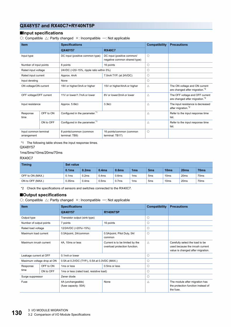
13
QX48Y57 and RX40C7+RY40NT5P■Input specifications: Compatible : Partly changed : Incompatible : Not applicable
*1 The following table shows the input response times.QX48Y571ms/5ms/10ms/20ms/70msRX40C7
*2 Check the specifications of sensors and switches connected to the RX40C7.
■Output specifications: Compatible : Partly changed : Incompatible : Not applicable
Item Specifications Compatibility Precautions
QX48Y57 RX40C7Input type DC input (positive common type) DC input (positive common/
negative common shared type)
Number of input points 8 points 16 points
Rated input voltage 24VDC (+20/-15%, ripple ratio within 5%)
Rated input current Approx. 4mA 7.0mA TYP. (at 24VDC)
Input derating None
ON voltage/ON current 19V or higher/3mA or higher 15V or higher/4mA or higher The ON voltage and ON current are changed after migration.*2
OFF voltage/OFF current 11V or lower/1.7mA or lower 8V or lower/2mA or lower The OFF voltage and OFF current are changed after migration.*2
Input resistance Approx. 5.6k 3.3k The input resistance is decreased after migration.*2
Response time
OFF to ON Configured in the parameter.*1 Refer to the input response time list.
ON to OFF Configured in the parameter.*1 Refer to the input response time list.
Input common terminal arrangement
8 points/common (common terminal: TB9)
16 points/common (common terminal: TB17)
Timing Set value
0.1ms 0.2ms 0.4ms 0.6ms 1ms 5ms 10ms 20ms 70msOFF to ON (MAX.) 0.1ms 0.2ms 0.4ms 0.6ms 1ms 5ms 10ms 20ms 70ms
ON to OFF (MAX.) 0.35ms 0.4ms 0.5ms 0.7ms 1ms 5ms 10ms 20ms 70ms
Item Specifications Compatibility Precautions
QX48Y57 RY40NT5POutput type Transistor output (sink type)
Number of output points 7 points 16 points
Rated load voltage 12/24VDC (+20%/-15%)
Maximum load current 0.5A/point, 2A/common 0.5A/point, Pilot Duty, 5A/common
Maximum inrush current 4A, 10ms or less Current is to be limited by the overload protection function.
Carefully select the load to be used because the inrush current value is changed after migration.
Leakage current at OFF 0.1mA or lower
Maximum voltage drop at ON 0.5A at 0.2VDC (TYP.), 0.5A at 0.3VDC (MAX.)
Response time
OFF to ON 1ms or less 0.5ms or less
ON to OFF 1ms or less (rated load, resistive load)
Surge suppressor Zener diode
Fuse 4A (unchangeable)(fuse capacity: 50A)
None The module after migration has the protection function instead of the fuse.
0 3 I/O MODULE MIGRATION3.2 Comparison of I/O Module Specifications

3
■Common specifications: Compatible : Partly changed : Incompatible : Not applicableProtection function None Overheat protection (in increments of 1 point),Overload protection (in increments of 1 point)
External power supply
Voltage 12/24VDC (+20/-15%) (ripple ratio within 5%)
Current 10mA (at 24VDC) 4mA (at 24VDC)
Output common terminal arrangement
7 points/common (common terminal: TB18)
16 points/common (common terminal: TB18)
Item Specifications Compatibility Precautions
QX48Y57 RX40C7+RY40NT5PIsolation method Photocoupler
Dielectric withstand voltage 560VAC rms/3 cycles 510VAC rms for 1 minute
Insulation resistance 10M or more by insulation resistance tester
Noise immunity By noise simulator of 500Vp-p noise voltage, 1s noise widthand 25 to 60Hz noise frequency
Protection degree IP2X
Number of occupied I/O points 16 points (I/O assignment: I/O combined 16 points)
16 points (I/O assignment: Input 16 points) +16 points (I/O assignment: Output 16 points)
One input module and one output module need to be used.
External interface 18-point terminal block (M3 6 screws)
18-point terminal block (M3 6 screws) 2
Applicable wire size 0.3 to 0.75 core (2.8mm OD maximum)
Applicable solderless terminal R1.25-3 (solderless terminal with an insulation sleeve cannot be used.)
Internal current consumption (5VDC)
80mA (TYP. all points ON) 110mA + 140mA (TYP. all points ON)
Weight 0.20kg 0.16kg+0.16kg
Item Specifications Compatibility Precautions
QX48Y57 RY40NT5P
3 I/O MODULE MIGRATION3.2 Comparison of I/O Module Specifications 131

13
Comparison of interrupt module specifications
QI60 and RX40C7: Compatible : Partly changed : Incompatible : Not applicable
*1 The following tables show the input response times.QI60
RX40C7
*2 Check the specifications of sensors and switches connected to the RX40C7.
Item Specifications Compatibility Precautions
QI60 RX40C7Input type DC input (positive common type) DC input (positive common/
negative common shared type)
Number of input points 16 points
Isolation method Photocoupler
Rated input voltage 24VDC (+20/-15%, ripple ratio within 5%)
Rated input current Approx. 6mA 7mA TYP. (at 24VDC)
Input derating None
ON voltage/ON current 19V or higher/4mA or higher 15V or higher/4mA or higher The ON voltage and ON current are changed after migration.*2
OFF voltage/OFF current 11V or lower/1.7mA or lower 8V or lower/2mA or lower The OFF voltage and OFF current are changed after migration.*2
Input resistance Approx. 3.9k 3.3k The input resistance is decreased after migration.*2
Response time
OFF to ON Configured in the parameter.*1 Refer to the input response time list.
ON to OFF Configured in the parameter.*1 Refer to the input response time list.
Dielectric withstand voltage 560VAC rms/3 cycles 510VAC rms for 1 minute
Insulation resistance 10M or more by insulation resistance tester
Noise immunity By noise simulator of 500Vp-p noise voltage, 1s noise widthand 25 to 60Hz noise frequency
Protection degree IP2X
Common terminal arrangement
16 points/common (common terminal: TB17)
Number of occupied I/O points 16 points (I/O assignment: Interrupt 16 points)
16 points (I/O assignment: Input 16 points)
Interrupt settings can be configured in the parameter setting of GX Works3.
External interface 18-point terminal block (M3 6 screws) The existing external wiring and terminal blocks in the existing system can be used.
Applicable wire size 0.3 to 0.75 core (2.8mm OD maximum)
Applicable solderless terminal R1.25-3 (solderless terminal with an insulation sleeve cannot be used.)
Internal current consumption (5VDC)
60mA (TYP. all points ON) 110mA (TYP. all points ON)
Weight 0.20kg 0.16kg
Set value 0.1 0.2 0.4 0.6 1OFF to ON TYP. 0.05ms 0.15ms 0.30ms 0.55ms 1.05ms
MAX. 0.10ms 0.20ms 0.40ms 0.60ms 1.20ms
ON to OFF TYP. 0.15ms 0.20ms 0.35ms 0.60ms 1.10ms
MAX. 0.20ms 0.30ms 0.50ms 0.70ms 1.30ms
Timing Set value
0.1ms 0.2ms 0.4ms 0.6ms 1ms 5ms 10ms 20ms 70msOFF to ON (MAX.) 0.1ms 0.2ms 0.4ms 0.6ms 1ms 5ms 10ms 20ms 70ms
ON to OFF (MAX.) 0.35ms 0.4ms 0.5ms 0.7ms 1ms 5ms 10ms 20ms 70ms
2 3 I/O MODULE MIGRATION3.2 Comparison of I/O Module Specifications

3
Comparison of blank cover module specifications
QG60 and RG60: Compatible : Partly changed : Incompatible : Not applicable
Item Specifications Compatibility Precautions
QG60 RG60Number of occupied I/O points Default: 16 points
(Can be changed to 0, 16, 32, 48, 64, 128, 256, 512, or 1024 points by "PLC system" of "PLC parameter".)
Application Used as a dustproof cover for a slot not loaded with an I/O module (especially a vacant slot between modules).
Weight 0.07kg
3 I/O MODULE MIGRATION3.2 Comparison of I/O Module Specifications 133

13
3.3 Precautions for I/O Module Migration
Input response time settingThe pulse width that can be taken in as input varies in the input modules of MELSEC-Q series and MELSEC iQ-R series, depending on the input response time setting. For details, refer to the following.
Connector typeThe MELSEC-Q series modules (QX81, QX81-S2, and QY81P) with 37-pin D-sub connectors are replaced with the MELSEC iQ-R series modules (RX41C4, RX41C6HS, and RY41PT1P) with 40-pin connectors. Change the connectors accordingly.
Interrupt function (interrupt module)To use the interrupt function in the MELSEC iQ-R series system, use an input module. Set the interrupt function in the module parameter of the input module used.
For details on these precautions, refer to the following. MELSEC iQ-R Module Configuration Manual MELSEC iQ-R I/O Module User's Manual I/O Module Type Building Block User's Manual Differences between MELSEC-Q series and MELSEC iQ-R series (FA-A-0171)
Input response time setting value 1ms 5ms 10ms 20ms 70msMELSEC-Q series 0.3ms 3ms 6ms 12ms 45ms
MELSEC iQ-R series 0.3ms 1.5ms 4ms 8ms 35ms
4 3 I/O MODULE MIGRATION3.3 Precautions for I/O Module Migration

4
4 POWER SUPPLY MODULE MIGRATION
4.1 Power Supply Module Migration Model ListThis section describes examples of migration to MELSEC iQ-R series power supply modules in accordance with the MELSEC-Q series power supply module specifications.Consider the specifications of your MELSEC-Q series power supply module to choose a model that best suits your application.
Item MELSEC-Q series
MELSEC iQ-R series
Specification difference
Power supply module
Q61P R61P (1) External wiring: Changed (M3.5 screw M4.0 screw (for screw terminal block))(2) Slots: Not changed(3) Specifications: Changed (Rated output current 6.0A 6.5A)
Q61P-A1 R61P (1) External wiring: Changed (M3.5 screw M4.0 screw (for screw terminal block))(2) Slots: Not changed(3) Specifications: Changed (Input power supply voltage 100 to 120VAC 100 to 240VAC, rated
output current 6.0A 6.5A)
Q61P-A2 R61P (1) External wiring: Changed (M3.5 screw M4.0 screw (for screw terminal block))(2) Slots: Not changed(3) Specifications: Changed (Input power supply voltage 200 to 240VAC 100 to 240VAC, rated
output current 6.0A 6.5A)
Q61P-D R61P (1) External wiring: Changed (M3.5 screw M4.0 screw (for screw terminal block))(2) Slots: Not changed(3) Specifications: Changed (Rated output current 6.0A 6.5A, life detection function available
not available)
Q61SP R61P (1) External wiring: Changed (M3.5 screw M4.0 screw (for screw terminal block))(2) Slots: Changed (slim type base unit standard base unit)(3) Specifications: Changed (Rated output current 2.0A 6.5A)
Q62P R62P (1) External wiring: Changed (M3.5 screw M4.0 screw (for screw terminal block)) (M3.5 screw for +24V, 24G terminals)
(2) Slots: Not changed(3) Specifications: Changed (Rated output current 3.0A 3.5A)
Q63P R63P (1) External wiring: Changed (M3.5 screw M4.0 screw (for screw terminal block))(2) Slots: Not changed(3) Specifications: Changed (Rated output current 6.0A 6.5A)
Q64P R64P (1) External wiring: Changed (M3.5 screw M4.0 screw (for screw terminal block))(2) Slots: Not changed(3) Specifications: Changed (Input power supply voltage 100 to 120VAC/200 to 240VAC 100 to
240VAC, rated output current 8.5A 9.0A)
Q64PN R64P (1) External wiring: Changed (M3.5 screw M4.0 screw (for screw terminal block))(2) Slots: Not changed(3) Specifications: Changed (Rated output current 8.5A 9.0A)
Q00JCPU(Power supply part)
R61P (1) External wiring: Changed (M3.5 screw M4.0 screw (for screw terminal block))(2) Slots: Changed (Integrated structure of the main base, CPU, and power supply part Single
power supply module)(3) Specifications: Changed (Contact output section available not available, rated output current
3.0A 6.5A)
Q00UJCPU(Power supply part)
R61P (1) External wiring: Changed (M3.5 screw M4.0 screw (for screw terminal block))(2) Slots: Changed (Integrated structure of the main base, CPU, and power supply part Single
power supply module)(3) Specifications: Changed (Contact output section available not available, rated output current
3.0A 6.5A)
4 POWER SUPPLY MODULE MIGRATION4.1 Power Supply Module Migration Model List 135

13
4.2 Comparison of Power Supply Module Specifications
Q61P and R61P: Compatible : Partly changed : Incompatible : Not applicable
Item Specifications Compatibility Precautions
Q61P R61PInput power supply voltage 100 to 240VAC (+10%, -15%) (85 to 264VAC)
Input frequency 50/60Hz5%
Input voltage distortion Within 5%
Maximum input apparent power 130VA
Maximum input power
Inrush current 20A within 8ms
Rated output current
5VDC 6A 6.5A
24VDC
External output voltage
Overcurrent protection
5VDC 6.6A or higher 7.1A or higher
24VDC
Overvoltage protection
5VDC 5.5 to 6.5V
24VDC
Efficiency 70% or more 76% or more
Allowable momentary power failure time
Within 20ms
Dielectric withstand voltage 2300VAC rms per minute (altitude 0 to 2000m), between the combined "line input/LG terminals" and the "FG terminal and output"
Insulation resistance 10M or higher by 500VDC insulation resistance tester between the combined "line input/LG terminals" and the "FG terminal and output", the line input and LG terminals, the output and FG terminals
Noise durability Noise voltage IEC 61000-4-4, 2kV by noise simulator of 1500Vp-p noise voltage, 1s noise width and 25 to 60Hz noise frequency
Operation indication LED indication (Normal: On (green), Error: Off)
Fuse Built-in (user-unchangeable)
Contact output section
Application ERR. contact
Rated switching voltage, current
0.5A at 24VDC
Minimum switching load
1mA at 5VDC
Response time OFF to ON: 10ms maximum, ON to OFF: 12ms maximum
Life Mechanical: More than 20 million timesElectrical: More than 100 thousand times at rated switching voltage, current
Surge suppressor
None
Fuse None
Terminal screw size M3.5 M4.0 Wiring needs to be changed.
Applicable wire size 0.75 to 2
Applicable solderless terminal RAV1.25-3.5, RAV2-3.5,Thickness 0.8mm or less. Two solderless terminals can be connected to one terminal.
RAV1.25-4, RAV2-4,Thickness 0.8mm or less. Two solderless terminals can be connected to one terminal.
Solderless terminals need to be changed.
Applicable tightening torque 0.66 to 0.89Nm 1.02 to 1.38Nm Tighten screws to the applicable tightening torque.
External dimensions 98(H) 55.2(W) 90(D)mm 106(H) 54.6(W) 110(D)mm
Weight 0.40kg 0.41kg
6 4 POWER SUPPLY MODULE MIGRATION4.2 Comparison of Power Supply Module Specifications
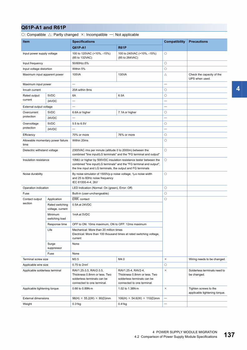
4
Q61P-A1 and R61P: Compatible : Partly changed : Incompatible : Not applicable
Item Specifications Compatibility Precautions
Q61P-A1 R61PInput power supply voltage 100 to 120VAC (+10%, -15%)
(85 to 132VAC)100 to 240VAC (+10%, -15%)(85 to 264VAC)
Input frequency 50/60Hz5%
Input voltage distortion Within 5%
Maximum input apparent power 105VA 130VA Check the capacity of the UPS when used.
Maximum input power
Inrush current 20A within 8ms
Rated output current
5VDC 6A 6.5A
24VDC
External output voltage
Overcurrent protection
5VDC 6.6A or higher 7.1A or higher
24VDC
Overvoltage protection
5VDC 5.5 to 6.5V
24VDC
Efficiency 70% or more 76% or more
Allowable momentary power failure time
Within 20ms
Dielectric withstand voltage 2300VAC rms per minute (altitude 0 to 2000m) between the combined "line input/LG terminals" and the "FG terminal and output"
Insulation resistance 10M or higher by 500VDC insulation resistance tester between the combined "line input/LG terminals" and the "FG terminal and output", the line input and LG terminals, the output and FG terminals
Noise durability By noise simulator of 1500Vp-p noise voltage, 1s noise widthand 25 to 60Hz noise frequencyIEC 61000-4-4, 2kV
Operation indication LED indication (Normal: On (green), Error: Off)
Fuse Built-in (user-unchangeable)
Contact output section
Application ERR. contact
Rated switching voltage, current
0.5A at 24VDC
Minimum switching load
1mA at 5VDC
Response time OFF to ON: 10ms maximum, ON to OFF: 12ms maximum
Life Mechanical: More than 20 million timesElectrical: More than 100 thousand times at rated switching voltage, current
Surge suppressor
None
Fuse None
Terminal screw size M3.5 M4.0 Wiring needs to be changed.
Applicable wire size 0.75 to 2
Applicable solderless terminal RAV1.25-3.5, RAV2-3.5,Thickness 0.8mm or less. Two solderless terminals can be connected to one terminal.
RAV1.25-4, RAV2-4,Thickness 0.8mm or less. Two solderless terminals can be connected to one terminal.
Solderless terminals need to be changed.
Applicable tightening torque 0.66 to 0.89Nm 1.02 to 1.38Nm Tighten screws to the applicable tightening torque.
External dimensions 98(H) 55.2(W) 90(D)mm 106(H) 54.6(W) 110(D)mm
Weight 0.31kg 0.41kg
4 POWER SUPPLY MODULE MIGRATION4.2 Comparison of Power Supply Module Specifications 137
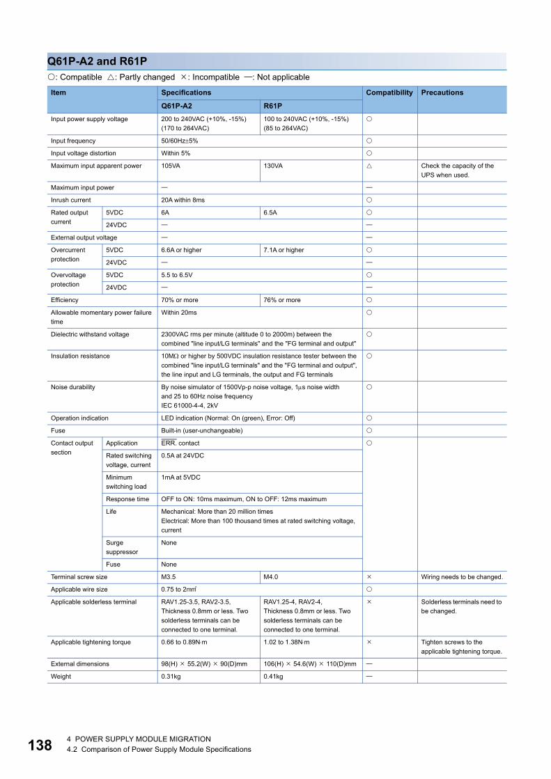
13
Q61P-A2 and R61P: Compatible : Partly changed : Incompatible : Not applicable
Item Specifications Compatibility Precautions
Q61P-A2 R61PInput power supply voltage 200 to 240VAC (+10%, -15%)
(170 to 264VAC)100 to 240VAC (+10%, -15%)(85 to 264VAC)
Input frequency 50/60Hz5%
Input voltage distortion Within 5%
Maximum input apparent power 105VA 130VA Check the capacity of the UPS when used.
Maximum input power
Inrush current 20A within 8ms
Rated output current
5VDC 6A 6.5A
24VDC
External output voltage
Overcurrent protection
5VDC 6.6A or higher 7.1A or higher
24VDC
Overvoltage protection
5VDC 5.5 to 6.5V
24VDC
Efficiency 70% or more 76% or more
Allowable momentary power failure time
Within 20ms
Dielectric withstand voltage 2300VAC rms per minute (altitude 0 to 2000m) between the combined "line input/LG terminals" and the "FG terminal and output"
Insulation resistance 10M or higher by 500VDC insulation resistance tester between the combined "line input/LG terminals" and the "FG terminal and output", the line input and LG terminals, the output and FG terminals
Noise durability By noise simulator of 1500Vp-p noise voltage, 1s noise widthand 25 to 60Hz noise frequencyIEC 61000-4-4, 2kV
Operation indication LED indication (Normal: On (green), Error: Off)
Fuse Built-in (user-unchangeable)
Contact output section
Application ERR. contact
Rated switching voltage, current
0.5A at 24VDC
Minimum switching load
1mA at 5VDC
Response time OFF to ON: 10ms maximum, ON to OFF: 12ms maximum
Life Mechanical: More than 20 million timesElectrical: More than 100 thousand times at rated switching voltage, current
Surge suppressor
None
Fuse None
Terminal screw size M3.5 M4.0 Wiring needs to be changed.
Applicable wire size 0.75 to 2
Applicable solderless terminal RAV1.25-3.5, RAV2-3.5,Thickness 0.8mm or less. Two solderless terminals can be connected to one terminal.
RAV1.25-4, RAV2-4,Thickness 0.8mm or less. Two solderless terminals can be connected to one terminal.
Solderless terminals need to be changed.
Applicable tightening torque 0.66 to 0.89Nm 1.02 to 1.38Nm Tighten screws to the applicable tightening torque.
External dimensions 98(H) 55.2(W) 90(D)mm 106(H) 54.6(W) 110(D)mm
Weight 0.31kg 0.41kg
8 4 POWER SUPPLY MODULE MIGRATION4.2 Comparison of Power Supply Module Specifications

4
Q61P-D and R61P: Compatible : Partly changed : Incompatible : Not applicable
Item Specifications Compatibility Precautions
Q61P-D R61PInput power supply voltage 100 to 240VAC (+10%, -15%) (85 to 264VAC)
Input frequency 50/60Hz5%
Input voltage distortion Within 5%
Maximum input apparent power 130VA
Maximum input power
Inrush current 20A within 8ms
Rated output current
5VDC 6A 6.5A
24VDC
External output voltage
Overcurrent protection
5VDC 6.6A or higher 7.1A or higher
24VDC
Overvoltage protection
5VDC 5.5 to 6.5V
24VDC
Efficiency 70% or more 76% or more
Allowable momentary power failure time
Within 20ms
Dielectric withstand voltage 2300VAC rms per minute (altitude 0 to 2000m) between the combined "line input/LG terminals" and the "FG terminal and output"
Insulation resistance 10M or higher by 500VDC insulation resistance tester between the combined "line input/LG terminals" and the "FG terminal and output", the line input and LG terminals, the output and FG terminals
Noise durability By noise simulator of 1500Vp-p noise voltage, 1s noise widthand 25 to 60Hz noise frequencyIEC 61000-4-4, 2kV
Operation indication LED indication (POWER LED, LIFE LED)
LED indication (Normal: On (green), Error: Off)
The life detection function is not available.
Fuse Built-in (user-unchangeable)
Contact output section
Application ERR. contact, LIFE OUT contact ERR. contact The life detection function is not available.
Rated switching voltage, current
0.5A at 24VDC
Minimum switching load
1mA at 5VDC
Response time OFF to ON: 10ms maximum, ON to OFF: 12ms maximum
Life Mechanical: More than 20 million timesElectrical: More than 100 thousand times at rated switching voltage, current
Surge suppressor
None
Fuse None
Terminal screw size M3.5 M4.0 Wiring needs to be changed.
Applicable wire size 0.75 to 2
Applicable solderless terminal RAV1.25-3.5, RAV2-3.5,Thickness 0.8mm or less. Two solderless terminals can be connected to one terminal.
RAV1.25-4, RAV2-4,Thickness 0.8mm or less. Two solderless terminals can be connected to one terminal.
Solderless terminals need to be changed.
Applicable tightening torque 0.66 to 0.89Nm 1.02 to 1.38Nm Tighten screws to the applicable tightening torque.
External dimensions 98(H) 55.2(W) 90(D)mm 106(H) 54.6(W) 110(D)mm
Weight 0.45kg 0.41kg
4 POWER SUPPLY MODULE MIGRATION4.2 Comparison of Power Supply Module Specifications 139

14
Q61SP and R61P: Compatible : Partly changed : Incompatible : Not applicable
Item Specifications Compatibility Precautions
Q61SP R61PInput power supply voltage 100 to 240VAC (+10%, -15%) (85 to 264VAC)
Input frequency 50/60Hz5%
Input voltage distortion Within 5%
Maximum input apparent power 40VA 130VA Check the capacity of the UPS when used.
Maximum input power
Inrush current 40A within 8ms 20A within 8ms
Rated output current
5VDC 2A 6.5A
24VDC
External output voltage
Overcurrent protection
5VDC 2.2A or higher 7.1A or higher
24VDC
Overvoltage protection
5VDC 5.5 to 6.5V
24VDC
Efficiency 70% or more 76% or more
Allowable momentary power failure time
Within 20ms
Dielectric withstand voltage 2300VAC rms per minute (altitude 0 to 2000m) between the combined "line input/LG terminals" and the "FG terminal and output"
Insulation resistance 10M or higher by 500VDC insulation resistance tester between the combined "line input/LG terminals" and the "FG terminal and output", the line input and LG terminals, the output and FG terminals
Noise durability By noise simulator of 1500Vp-p noise voltage, 1s noise widthand 25 to 60Hz noise frequencyIEC 61000-4-4, 2kV
Operation indication LED indication (Normal: On (green), Error: Off)
Fuse Built-in (user-unchangeable)
Contact output section
Application ERR. contact
Rated switching voltage, current
0.5A at 24VDC
Minimum switching load
1mA at 5VDC
Response time OFF to ON: 10ms maximum, ON to OFF: 12ms maximum
Life Mechanical: More than 20 million timesElectrical: More than 100 thousand times at rated switching voltage, current
Surge suppressor
None
Fuse None
Terminal screw size M3.5 M4.0 Wiring needs to be changed.
Applicable wire size 0.75 to 2
Applicable solderless terminal RAV1.25-3.5, RAV2-3.5,Thickness 0.8mm or less. Two solderless terminals can be connected to one terminal.
RAV1.25-4, RAV2-4,Thickness 0.8mm or less. Two solderless terminals can be connected to one terminal.
Solderless terminals need to be changed.
Applicable tightening torque 0.66 to 0.89Nm 1.02 to 1.38Nm Tighten screws to the applicable tightening torque.
External dimensions 98(H) 27.4(W) 104(D)mm 106(H) 54.6(W) 110(D)mm The size is larger.The base that can be installed is regarded as the standard base.
Weight 0.18kg 0.41kg
0 4 POWER SUPPLY MODULE MIGRATION4.2 Comparison of Power Supply Module Specifications
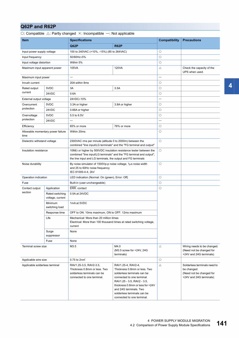
4
Q62P and R62P: Compatible : Partly changed : Incompatible : Not applicable
Item Specifications Compatibility Precautions
Q62P R62PInput power supply voltage 100 to 240VAC (+10%, -15%) (85 to 264VAC)
Input frequency 50/60Hz5%
Input voltage distortion Within 5%
Maximum input apparent power 105VA 120VA Check the capacity of the UPS when used.
Maximum input power
Inrush current 20A within 8ms
Rated output current
5VDC 3A 3.5A
24VDC 0.6A
External output voltage 24VDC10%
Overcurrent protection
5VDC 3.3A or higher 3.8A or higher
24VDC 0.66A or higher
Overvoltage protection
5VDC 5.5 to 6.5V
24VDC
Efficiency 65% or more 76% or more
Allowable momentary power failure time
Within 20ms
Dielectric withstand voltage 2300VAC rms per minute (altitude 0 to 2000m) between the combined "line input/LG terminals" and the "FG terminal and output"
Insulation resistance 10M or higher by 500VDC insulation resistance tester between the combined "line input/LG terminals" and the "FG terminal and output", the line input and LG terminals, the output and FG terminals
Noise durability By noise simulator of 1500Vp-p noise voltage, 1s noise widthand 25 to 60Hz noise frequencyIEC 61000-4-4, 2kV
Operation indication LED indication (Normal: On (green), Error: Off)
Fuse Built-in (user-unchangeable)
Contact output section
Application ERR. contact
Rated switching voltage, current
0.5A at 24VDC
Minimum switching load
1mA at 5VDC
Response time OFF to ON: 10ms maximum, ON to OFF: 12ms maximum
Life Mechanical: More than 20 million timesElectrical: More than 100 thousand times at rated switching voltage, current
Surge suppressor
None
Fuse None
Terminal screw size M3.5 M4.0(M3.5 screw for +24V, 24G terminals)
Wiring needs to be changed.(Need not be changed for +24V and 24G terminals)
Applicable wire size 0.75 to 2
Applicable solderless terminal RAV1.25-3.5, RAV2-3.5,Thickness 0.8mm or less. Two solderless terminals can be connected to one terminal.
RAV1.25-4, RAV2-4,Thickness 0.8mm or less. Two solderless terminals can be connected to one terminal.RAV1.25 - 3.5, RAV2 - 3.5, thickness 0.8mm or less for +24V and 24G terminals. Two solderless terminals can be connected to one terminal.
Solderless terminals need to be changed.(Need not be changed for +24V and 24G terminals)
4 POWER SUPPLY MODULE MIGRATION4.2 Comparison of Power Supply Module Specifications 141

14
Applicable tightening torque 0.66 to 0.89Nm 1.02 to 1.38Nm(0.66 to 0.89Nm for +24V and 24G terminals)
Tighten screws to the applicable tightening torque. (Need not be changed for +24V and 24G terminals)
External dimensions 98(H) 55.2(W) 90(D)mm 106(H) 54.6(W) 110(D)mm
Weight 0.39kg 0.45kg
Item Specifications Compatibility Precautions
Q62P R62P
2 4 POWER SUPPLY MODULE MIGRATION4.2 Comparison of Power Supply Module Specifications

4
Q63P and R63P: Compatible : Partly changed : Incompatible : Not applicable
Item Specifications Compatibility Precautions
Q63P R63PInput power supply voltage 24VDC (+30%, -35%) (15.6 to 31.2VDC)
Input frequency
Input voltage distortion
Maximum input power 45W 50W
Inrush current 100mA, 1ms or less (at 24VDC input)
Rated output current
5VDC 6A 6.5A
24VDC
External output voltage
Overcurrent protection
5VDC 6.6A or higher 7.1A or higher
24VDC
Overvoltage protection
5VDC 5.5 to 6.5V
24VDC
Efficiency 70% or more
Allowable momentary power failure time
Within 10ms (at 24VDC input)
Dielectric withstand voltage 510VAC per minute (altitude 0 to 2000m), between primary terminal and 5VDC terminal
Insulation resistance 10M or higher by 500VDC insulation resistance tester between the combined "line input/LG terminals" and the "FG terminal and output", the line input and LG terminals, the output and FG terminals
Noise durability By noise simulator of 500Vp-p noise voltage, 1s noise widthand 25 to 60Hz noise frequency
Operation indication LED indication (Normal: On (green), Error: Off)
Fuse Built-in (user-unchangeable)
Contact output section
Application ERR. contact
Rated switching voltage, current
0.5A at 24VDC
Minimum switching load
1mA at 5VDC
Response time OFF to ON: 10ms maximum, ON to OFF: 12ms maximum
Life Mechanical: More than 20 million timesElectrical: More than 100 thousand times at rated switching voltage, current
Surge suppressor
None
Fuse None
Terminal screw size M3.5 M4.0 Wiring needs to be changed.
Applicable wire size 0.75 to 2
Applicable solderless terminal RAV1.25-3.5, RAV2-3.5,Thickness 0.8mm or less. Two solderless terminals can be connected to one terminal.
RAV1.25-4, RAV2-4,Thickness 0.8mm or less. Two solderless terminals can be connected to one terminal.
Solderless terminals need to be changed.
Applicable tightening torque 0.66 to 0.89Nm 1.02 to 1.38Nm Tighten screws to the applicable tightening torque.
External dimensions 98(H) 55.2(W) 90(D)mm 106(H) 54.6(W) 110(D)mm
Weight 0.33kg 0.41kg
4 POWER SUPPLY MODULE MIGRATION4.2 Comparison of Power Supply Module Specifications 143

14
Q64P and R64P: Compatible : Partly changed : Incompatible : Not applicable
Item Specifications Compatibility Precautions
Q64P R64PInput power supply voltage 100 to 120VAC/200 to 240VAC
(+10%, -15%)(85 to 132VAC/170 to 264VAC)
100 to 240VAC (+10%, -15%)(85 to 264VAC)
Input frequency 50/60Hz5%
Input voltage distortion Within 5%
Maximum input apparent power 160VA
Maximum input power
Inrush current 20A within 8ms
Rated output current
5VDC 8.5A 9.0A
24VDC
External output voltage
Overcurrent protection
5VDC 9.9A or higher 10.0A or higher
24VDC
Overvoltage protection
5VDC 5.5 to 6.5V
24VDC
Efficiency 70% or more 76% or more
Allowable momentary power failure time
Within 20ms
Dielectric withstand voltage 2300VAC rms per minute (altitude 0 to 2000m) between the combined "line input/LG terminals" and the "FG terminal and output"
Insulation resistance 10M or higher by 500VDC insulation resistance tester between the combined "line input/LG terminals" and the "FG terminal and output", the line input and LG terminals, the output and FG terminals
Noise durability By noise simulator of 1500Vp-p noise voltage, 1s noise widthand 25 to 60Hz noise frequencyIEC 61000-4-4, 2kV
Operation indication LED indication (Normal: On (green), Error: Off)
Fuse Built-in (user-unchangeable)
Contact output section
Application ERR. contact
Rated switching voltage, current
0.5A at 24VDC
Minimum switching load
1mA at 5VDC
Response time OFF to ON: 10ms maximum, ON to OFF: 12ms maximum
Life Mechanical: More than 20 million timesElectrical: More than 100 thousand times at rated switching voltage, current
Surge suppressor
None
Fuse None
Terminal screw size M3.5 M4.0 Wiring needs to be changed.
Applicable wire size 0.75 to 2
Applicable solderless terminal RAV1.25-3.5, RAV2-3.5,Thickness 0.8mm or less. Two solderless terminals can be connected to one terminal.
RAV1.25-4, RAV2-4,Thickness 0.8mm or less. Two solderless terminals can be connected to one terminal.
Solderless terminals need to be changed.
Applicable tightening torque 0.66 to 0.89Nm 1.02 to 1.38Nm Tighten screws to the applicable tightening torque.
External dimensions 98(H) 55.2(W) 115(D)mm 106(H) 54.6(W) 110(D)mm
Weight 0.40kg 0.46kg
4 4 POWER SUPPLY MODULE MIGRATION4.2 Comparison of Power Supply Module Specifications

4
Q64PN and R64P: Compatible : Partly changed : Incompatible : Not applicable
Item Specifications Compatibility Precautions
Q64PN R64PInput power supply voltage 100 to 240VAC (+10%, -15%) (85 to 264VAC)
Input frequency 50/60Hz5%
Input voltage distortion Within 5%
Maximum input apparent power 160VA
Maximum input power
Inrush current 20A within 8ms
Rated output current
5VDC 8.5A 9.0A
24VDC
External output voltage
Overcurrent protection
5VDC 9.9A or higher 10.0A or higher
24VDC
Overvoltage protection
5VDC 5.5 to 6.5V
24VDC
Efficiency 70% or more 76% or more
Allowable momentary power failure time
Within 20ms
Dielectric withstand voltage 2300VAC rms per minute (altitude 0 to 2000m) between the combined "line input/LG terminals" and the "FG terminal and output"
Insulation resistance 10M or higher by 500VDC insulation resistance tester between the combined "line input/LG terminals" and the "FG terminal and output", the line input and LG terminals, the output and FG terminals
Noise durability By noise simulator of 1500Vp-p noise voltage, 1s noise widthand 25 to 60Hz noise frequencyIEC 61000-4-4, 2kV
Operation indication LED indication (Normal: On (green), Error: Off)
Fuse Built-in (user-unchangeable)
Contact output section
Application ERR. contact
Rated switching voltage, current
0.5A at 24VDC
Minimum switching load
1mA at 5VDC
Response time OFF to ON: 10ms maximum, ON to OFF: 12ms maximum
Life Mechanical: More than 20 million timesElectrical: More than 100 thousand times at rated switching voltage, current
Surge suppressor
None
Fuse None
Terminal screw size M3.5 M4.0 Wiring needs to be changed.
Applicable wire size 0.75 to 2
Applicable solderless terminal RAV1.25-3.5, RAV2-3.5,Thickness 0.8mm or less. Two solderless terminals can be connected to one terminal.
RAV1.25-4, RAV2-4,Thickness 0.8mm or less. Two solderless terminals can be connected to one terminal.
Solderless terminals need to be changed.
Applicable tightening torque 0.66 to 0.89Nm 1.02 to 1.38Nm Tighten screws to the applicable tightening torque.
External dimensions 98(H) 55.2(W) 115(D)mm 106(H) 54.6(W) 110(D)mm
Weight 0.47kg 0.46kg
4 POWER SUPPLY MODULE MIGRATION4.2 Comparison of Power Supply Module Specifications 145
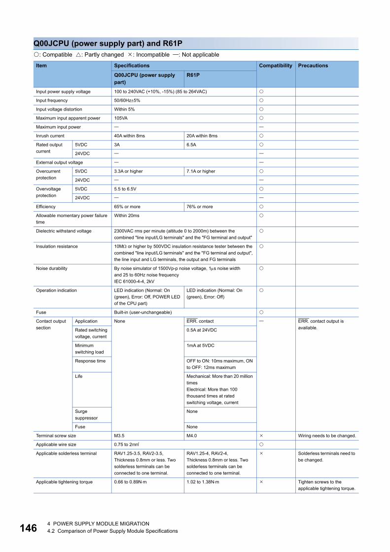
14
Q00JCPU (power supply part) and R61P: Compatible : Partly changed : Incompatible : Not applicable
Item Specifications Compatibility Precautions
Q00JCPU (power supply part)
R61P
Input power supply voltage 100 to 240VAC (+10%, -15%) (85 to 264VAC)
Input frequency 50/60Hz5%
Input voltage distortion Within 5%
Maximum input apparent power 105VA
Maximum input power
Inrush current 40A within 8ms 20A within 8ms
Rated output current
5VDC 3A 6.5A
24VDC
External output voltage
Overcurrent protection
5VDC 3.3A or higher 7.1A or higher
24VDC
Overvoltage protection
5VDC 5.5 to 6.5V
24VDC
Efficiency 65% or more 76% or more
Allowable momentary power failure time
Within 20ms
Dielectric withstand voltage 2300VAC rms per minute (altitude 0 to 2000m) between the combined "line input/LG terminals" and the "FG terminal and output"
Insulation resistance 10M or higher by 500VDC insulation resistance tester between the combined "line input/LG terminals" and the "FG terminal and output", the line input and LG terminals, the output and FG terminals
Noise durability By noise simulator of 1500Vp-p noise voltage, 1s noise widthand 25 to 60Hz noise frequencyIEC 61000-4-4, 2kV
Operation indication LED indication (Normal: On (green), Error: Off, POWER LED of the CPU part)
LED indication (Normal: On (green), Error: Off)
Fuse Built-in (user-unchangeable)
Contact output section
Application None ERR. contact ERR. contact output is available.Rated switching
voltage, current0.5A at 24VDC
Minimum switching load
1mA at 5VDC
Response time OFF to ON: 10ms maximum, ON to OFF: 12ms maximum
Life Mechanical: More than 20 million timesElectrical: More than 100 thousand times at rated switching voltage, current
Surge suppressor
None
Fuse None
Terminal screw size M3.5 M4.0 Wiring needs to be changed.
Applicable wire size 0.75 to 2
Applicable solderless terminal RAV1.25-3.5, RAV2-3.5,Thickness 0.8mm or less. Two solderless terminals can be connected to one terminal.
RAV1.25-4, RAV2-4,Thickness 0.8mm or less. Two solderless terminals can be connected to one terminal.
Solderless terminals need to be changed.
Applicable tightening torque 0.66 to 0.89Nm 1.02 to 1.38Nm Tighten screws to the applicable tightening torque.
6 4 POWER SUPPLY MODULE MIGRATION4.2 Comparison of Power Supply Module Specifications

4
External dimensions 98(H) 244.4(W) 98(D)mm(including the CPU module and base unit)
106(H) 54.6(W) 110(D)mm Single power supply module
Weight 0.66kg(including the CPU module and base unit)
0.41kg Single power supply module
Item Specifications Compatibility Precautions
Q00JCPU (power supply part)
R61P
4 POWER SUPPLY MODULE MIGRATION4.2 Comparison of Power Supply Module Specifications 147

14
Q00UJCPU (power supply part) and R61P: Compatible : Partly changed : Incompatible : Not applicable
Item Specifications Compatibility Precautions
Q00UJCPU (power supply part)
R61P
Input power supply voltage 100 to 240VAC (+10%, -15%) (85 to 264VAC)
Input frequency 50/60Hz5%
Input voltage distortion Within 5%
Maximum input apparent power 105VA
Maximum input power
Inrush current 40A within 8ms 20A within 8ms
Rated output current
5VDC 3A 6.5A
24VDC
External output voltage
Overcurrent protection
5VDC 3.3A or higher 7.1A or higher
24VDC
Overvoltage protection
5VDC 5.5 to 6.5V
24VDC
Efficiency 65% or more 76% or more
Allowable momentary power failure time
Within 20ms
Dielectric withstand voltage 2300VAC rms per minute (altitude 0 to 2000m) between the combined "line input/LG terminals" and the "FG terminal and output"
Insulation resistance 10M or higher by 500VDC insulation resistance tester between the combined "line input/LG terminals" and the "FG terminal and output", the line input and LG terminals, the output and FG terminals
Noise durability By noise simulator of 1500Vp-p noise voltage, 1s noise widthand 25 to 60Hz noise frequencyIEC 61000-4-4, 2kV
Operation indication LED indication (Normal: On (green), Error: Off, POWER LED of the CPU part)
LED indication (Normal: On (green), Error: Off)
Fuse Built-in (user-unchangeable)
Contact output section
Application None ERR. contact ERR. contact output is available.Rated switching
voltage, current0.5A at 24VDC
Minimum switching load
1mA at 5VDC
Response time OFF to ON: 10ms maximumON to OFF: 12ms maximum
Life Mechanical: More than 20 million timesElectrical: More than 100 thousand times at rated switching voltage, current
Surge suppressor
None
Fuse None
Terminal screw size M3.5 M4.0 Wiring needs to be changed.
Applicable wire size 0.75 to 2
Applicable solderless terminal RAV1.25-3.5, RAV2-3.5,Thickness 0.8mm or less. Two solderless terminals can be connected to one terminal.
RAV1.25-4, RAV2-4,Thickness 0.8mm or less. Two solderless terminals can be connected to one terminal.
Solderless terminals need to be changed.
Applicable tightening torque 0.66 to 0.89Nm 1.02 to 1.38Nm Tighten screws to the applicable tightening torque.
8 4 POWER SUPPLY MODULE MIGRATION4.2 Comparison of Power Supply Module Specifications

4
External dimensions 98(H) 244.4(W) 98(D)mm(including the CPU module and base unit)
106(H) 54.6(W) 110(D)mm Single power supply module
Weight 0.70kg(including the CPU module and base unit)
0.41kg Single power supply module
Item Specifications Compatibility Precautions
Q00UJCPU (power supply part)
R61P
4 POWER SUPPLY MODULE MIGRATION4.2 Comparison of Power Supply Module Specifications 149
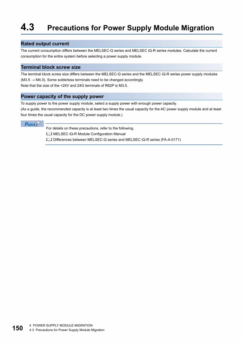
15
4.3 Precautions for Power Supply Module Migration
Rated output currentThe current consumption differs between the MELSEC-Q series and MELSEC iQ-R series modules. Calculate the current consumption for the entire system before selecting a power supply module.
Terminal block screw sizeThe terminal block screw size differs between the MELSEC-Q series and the MELSEC iQ-R series power supply modules (M3.5 M4.0). Some solderless terminals need to be changed accordingly.Note that the size of the +24V and 24G terminals of R62P is M3.5.
Power capacity of the supply powerTo supply power to the power supply module, select a supply power with enough power capacity.(As a guide, the recommended capacity is at least two times the usual capacity for the AC power supply module and at least four times the usual capacity for the DC power supply module.)
For details on these precautions, refer to the following. MELSEC iQ-R Module Configuration Manual Differences between MELSEC-Q series and MELSEC iQ-R series (FA-A-0171)
0 4 POWER SUPPLY MODULE MIGRATION4.3 Precautions for Power Supply Module Migration
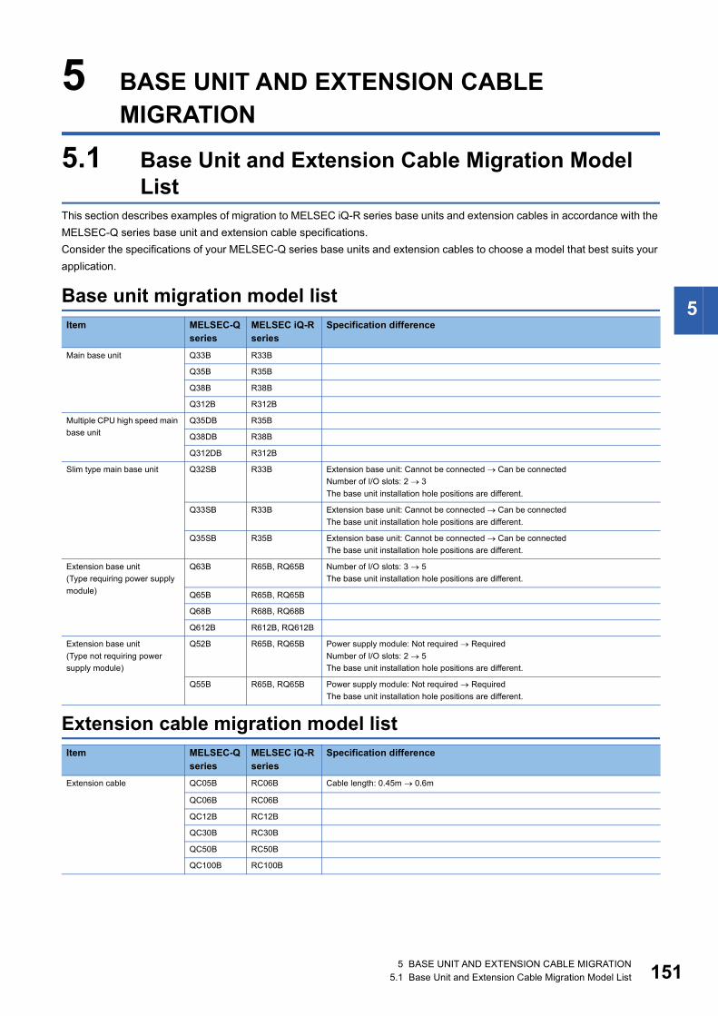
5
5 BASE UNIT AND EXTENSION CABLE MIGRATION
5.1 Base Unit and Extension Cable Migration Model List
This section describes examples of migration to MELSEC iQ-R series base units and extension cables in accordance with the MELSEC-Q series base unit and extension cable specifications.Consider the specifications of your MELSEC-Q series base units and extension cables to choose a model that best suits your application.
Base unit migration model list
Extension cable migration model list
Item MELSEC-Q series
MELSEC iQ-R series
Specification difference
Main base unit Q33B R33B
Q35B R35B
Q38B R38B
Q312B R312B
Multiple CPU high speed main base unit
Q35DB R35B
Q38DB R38B
Q312DB R312B
Slim type main base unit Q32SB R33B Extension base unit: Cannot be connected Can be connectedNumber of I/O slots: 2 3The base unit installation hole positions are different.
Q33SB R33B Extension base unit: Cannot be connected Can be connectedThe base unit installation hole positions are different.
Q35SB R35B Extension base unit: Cannot be connected Can be connectedThe base unit installation hole positions are different.
Extension base unit(Type requiring power supply module)
Q63B R65B, RQ65B Number of I/O slots: 3 5The base unit installation hole positions are different.
Q65B R65B, RQ65B
Q68B R68B, RQ68B
Q612B R612B, RQ612B
Extension base unit(Type not requiring power supply module)
Q52B R65B, RQ65B Power supply module: Not required RequiredNumber of I/O slots: 2 5The base unit installation hole positions are different.
Q55B R65B, RQ65B Power supply module: Not required RequiredThe base unit installation hole positions are different.
Item MELSEC-Q series
MELSEC iQ-R series
Specification difference
Extension cable QC05B RC06B Cable length: 0.45m 0.6m
QC06B RC06B
QC12B RC12B
QC30B RC30B
QC50B RC50B
QC100B RC100B
5 BASE UNIT AND EXTENSION CABLE MIGRATION5.1 Base Unit and Extension Cable Migration Model List 151

15
5.2 Comparison of the Base Unit and Extension Cable Specifications
Q33B and R33B: Compatible : Partly changed : Incompatible : Not applicable
Q35B/Q35DB and R35B: Compatible : Partly changed : Incompatible : Not applicable
Q38B/Q38DB and R35B: Compatible : Partly changed : Incompatible : Not applicable
Item Specifications Compatibility Precautions
Q33B R33BNumber of mountable I/O modules 3
Extendability Extendable
Internal current consumption (5VDC) 0.11A 0.46A
Installation hole size M4 screw hole or 4.5 hole (for M4 screw)
External dimensions 98(H) 189(W) 44.1(D)mm
101(H)189(W)32.5(D)mm The base unit installation hole positions are interchangeable.
Weight 0.21kg 0.31kg
Accessories Installation screw M4 14
DIN rail mounting adapter type Q6DIN3 R6DIN1
Item Specifications Compatibility Precautions
Q35B Q35DB R35BNumber of mountable I/O modules 5
Extendability Extendable
Internal current consumption (5VDC) 0.11A 0.23A 0.58A
Installation hole size M4 screw hole or 4.5 hole (for M4 screw)
External dimensions 98(H) 245(W) 44.1(D)mm 101(H) 245(W) 32.5(D)mm
The base unit installation hole positions are interchangeable.
Weight 0.27kg 0.32kg 0.41kg
Accessories Installation screw M4 14
DIN rail mounting adapter type Q6DIN2 R6DIN1
Item Specifications Compatibility Precautions
Q38B Q38DB R38BNumber of mountable I/O modules 8
Extendability Extendable
Internal current consumption (5VDC) 0.12A 0.23A 0.71A
Installation hole size M4 screw hole or 4.5 hole (for M4 screw)
External dimensions 98(H) 328(W) 44.1(D)mm 101(H) 328(W) 32.5(D)mm
The base unit installation hole positions are interchangeable.
Weight 0.36kg 0.41kg 0.55kg
Accessories Installation screw M4 14
DIN rail mounting adapter type Q6DIN1 R6DIN1
2 5 BASE UNIT AND EXTENSION CABLE MIGRATION5.2 Comparison of the Base Unit and Extension Cable Specifications

5
Q312B/Q312DB and R312B: Compatible : Partly changed : Incompatible : Not applicable
Q32SB and R33B: Compatible : Partly changed : Incompatible : Not applicable
Q33SB and R33B: Compatible : Partly changed : Incompatible : Not applicable
Item Specifications Compatibility Precautions
Q312B Q312DB R312BNumber of mountable I/O modules 12
Extendability Extendable
Internal current consumption (5VDC) 0.13A 0.24A 0.88A
Installation hole size M4 screw hole or 4.5 hole (for M4 screw)
External dimensions 98(H) 439(W) 44.1(D)mm 101(H) 439(W) 32.5(D)mm
The base unit installation hole positions are interchangeable.
Weight 0.47kg 0.54kg 0.72kg
Accessories Installation screw M4 14
DIN rail mounting adapter type Q6DIN1 R6DIN1
Item Specifications Compatibility Precautions
Q32SB R33BNumber of mountable I/O modules 2 3 The number of slots increases.
Extendability Not extendable Extendable
Internal current consumption (5VDC) 0.09A 0.46A
Installation hole size M4 screw hole or 4.5 hole (for M4 screw)
External dimensions 98(H) 114(W) 18.5(D)mm
101(H)189(W)32.5(D)mm The base unit installation hole positions are different.
Weight 0.12kg 0.31kg
Accessories Installation screw M4 14
DIN rail mounting adapter type Q6DIN3 R6DIN1
Item Specifications Compatibility Precautions
Q33SB R33BNumber of mountable I/O modules 3
Extendability Not extendable Extendable
Internal current consumption (5VDC) 0.09A 0.46A
Installation hole size M4 screw hole or 4.5 hole (for M4 screw)
External dimensions 98(H) 142(W) 18.5(D)mm
101(H)189(W)32.5(D)mm The base unit installation hole positions are different.
Weight 0.15kg 0.31kg
Accessories Installation screw M4 14
DIN rail mounting adapter type Q6DIN3 R6DIN1
5 BASE UNIT AND EXTENSION CABLE MIGRATION5.2 Comparison of the Base Unit and Extension Cable Specifications 153

15
Q35SB and R35B: Compatible : Partly changed : Incompatible : Not applicable
Q63B and R65B/RQ65B: Compatible : Partly changed : Incompatible : Not applicable
Q65B and R65B/RQ65B: Compatible : Partly changed : Incompatible : Not applicable
Item Specifications Compatibility Precautions
Q35SB R35BNumber of mountable I/O modules 5
Extendability Not extendable Extendable
Internal current consumption (5VDC) 0.10A 0.58A
Installation hole size M4 screw hole or 4.5 hole (for M4 screw)
External dimensions 98(H) 197.5(W) 18.5(D)mm
101(H) 245(W) 32.5(D)mm
The base unit installation hole positions are different.
Weight 0.21kg 0.41kg
Accessories Installation screw M4 14
DIN rail mounting adapter type Q6DIN3 R6DIN1
Item Specifications Compatibility Precautions
Q63B R65B RQ65BNumber of mountable I/O modules 3 5 The number of slots increases.
Extendability Extendable
Internal current consumption (5VDC) 0.11A 0.70A 0.28A
Installation hole size M4 screw hole or 4.5 hole (for M4 screw)
External dimensions 98(H) 189(W) 44.1(D)mm
101(H) 245(W) 32.5(D)mm
98(H) 245(W) 44.1(D)mm
The base unit installation hole positions are different.
Weight 0.23kg 0.41kg 0.32kg
Accessories Installation screw M4 14
DIN rail mounting adapter type Q6DIN3 R6DIN1 Q6DIN2
Item Specifications Compatibility Precautions
Q65B R65B RQ65BNumber of mountable I/O modules 5
Extendability Extendable
Internal current consumption (5VDC) 0.11A 0.70A 0.28A
Installation hole size M4 screw hole or 4.5 hole (for M4 screw)
External dimensions 98(H) 245(W) 44.1(D)mm
101(H) 245(W) 32.5(D)mm
98(H) 245(W) 44.1(D)mm
The base unit installation hole positions are interchangeable.
Weight 0.28kg 0.41kg 0.32kg
Accessories Installation screw M4 14
DIN rail mounting adapter type Q6DIN2 R6DIN1 Q6DIN2
4 5 BASE UNIT AND EXTENSION CABLE MIGRATION5.2 Comparison of the Base Unit and Extension Cable Specifications

5
Q68B and R68B/RQ68B: Compatible : Partly changed : Incompatible : Not applicable
Q612B and R612B/RQ612B: Compatible : Partly changed : Incompatible : Not applicable
Q52B and R65B/RQ65B: Compatible : Partly changed : Incompatible : Not applicable
Item Specifications Compatibility Precautions
Q68B R68B RQ68BNumber of mountable I/O modules 8
Extendability Extendable
Internal current consumption (5VDC) 0.12A 0.81A 0.31A
Installation hole size M4 screw hole or 4.5 hole (for M4 screw)
External dimensions 98(H) 328(W) 44.1(D)mm
101(H) 328(W) 32.5(D)mm
98(H) 328(W) 44.1(D)mm
The base unit installation hole positions are interchangeable.
Weight 0.38kg 0.55kg 0.41kg
Accessories Installation screw M4 14
DIN rail mounting adapter type Q6DIN1 R6DIN1 Q6DIN1
Item Specifications Compatibility Precautions
Q612B R612B RQ612BNumber of mountable I/O modules 12
Extendability Extendable
Internal current consumption (5VDC) 0.13A 0.92A 0.32A
Installation hole size M4 screw hole or 4.5 hole (for M4 screw)
External dimensions 98(H) 439(W) 44.1(D)mm
101(H) 439(W) 32.5(D)mm
98(H) 439(W) 44.1(D)mm
The base unit installation hole positions are interchangeable.
Weight 0.48kg 0.73kg 0.55kg
Accessories Installation screw M4 14
DIN rail mounting adapter type Q6DIN1 R6DIN1 Q6DIN1
Item Specifications Compatibility Precautions
Q52B R65B RQ65BNumber of mountable I/O modules 2 5 The power supply module
needs to be installed.The number of slots increases.
Extendability Extendable
Internal current consumption (5VDC) 0.08A 0.70A 0.28A
Installation hole size M4 screw hole or 4.5 hole (for M4 screw)
External dimensions 98(H) 106(W) 44.1(D)mm
101(H) 245(W) 32.5(D)mm
98(H) 245(W) 44.1(D)mm
The base unit installation hole positions are different.
Weight 0.14kg 0.41kg 0.32kg
Accessories Installation screw M4 14
DIN rail mounting adapter type Q6DIN3 R6DIN1 Q6DIN2
5 BASE UNIT AND EXTENSION CABLE MIGRATION5.2 Comparison of the Base Unit and Extension Cable Specifications 155

15
Q55B and R65B/RQ65B: Compatible : Partly changed : Incompatible : Not applicable
Comparison of extension cable specifications: Compatible : Partly changed : Incompatible : Not applicable
Item Specifications Compatibility Precautions
Q55B R65B RQ65BNumber of mountable I/O modules 5 The power supply module
needs to be installed.
Extendability Extendable
Internal current consumption (5VDC) 0.10A 0.70A 0.28A
Installation hole size M4 screw hole or 4.5 hole (for M4 screw)
External dimensions 98(H) 189(W) 44.1(D)mm
101(H) 245(W) 32.5(D)mm
98(H) 245(W) 44.1(D)mm
The base unit installation hole positions are different.
Weight 0.23kg 0.41kg 0.32kg
Accessories Installation screw M4 14
DIN rail mounting adapter type Q6DIN3 R6DIN1 Q6DIN2
Item Type Compatibility Precautions
MELSEC-Q series MELSEC iQ-R seriesCable length 0.45m QC05B RC06B The cable length is changed
from 0.45m to 0.6m.
0.6m QC06B RC06B
1.2m QC12B RC12B
3.0m QC30B RC30B
5.0m QC50B RC50B
10.0m QC100B RC100B This cable can only be used for base units with the 10m mark printed.
6 5 BASE UNIT AND EXTENSION CABLE MIGRATION5.2 Comparison of the Base Unit and Extension Cable Specifications

5
5.3 Precautions for Base Unit/Extension Cable Migration
Fixing the extension cablesExtension cables are fixed by lock buttons in the MELSEC iQ-R series system while they are fixed by the fixing screws in the MELSEC-Q series system.
Extension level settingThe extension level setting is not required in the MELSEC iQ-R series system while it needs to be configured with connector pins in the MELSEC-Q series system.
DIN rail mounting adaptersThe DIN rail mounting adapter differs between the MELSEC-Q series and the MELSEC iQ-R series.
For details on these precautions, refer to the following. MELSEC iQ-R Module Configuration Manual Differences between MELSEC-Q series and MELSEC iQ-R series (FA-A-0171)
5 BASE UNIT AND EXTENSION CABLE MIGRATION5.3 Precautions for Base Unit/Extension Cable Migration 157

15
5.4 RQ Extension Base UnitTo continue to use the MELSEC-Q series modules for the RCPU, use the RQ extension base units (RQ65B, RQ68B, RQ612B).The following table lists the MELSEC-Q series modules that can be used with the RQ extension base units.
Item TypePower supply module Q61P, Q61P-A1, Q61P-A2, Q62P, Q63P, Q64P, Q64PN, Q61P-D
I/O module AC input module QX10, QX10-TS, QX28
DC input module QX40, QX40-TS, QX40-S1, QX41, QX41-S1, QX41-S2, QX42, QX42-S1, QX70, QX71, QX72, QX80, QX80-TS, QX81, QX81-S2, QX82, QX82-S1
DC high-speed input module QX40H, QX70H, QX80H, QX90H
DC/AC input module QX50
Contact output module QY10, QY10-TS, QY18A
Triac output module QY22
Transistor output module QY40P, QY40P-TS, QY41P, QY42P, QY50, QY68A, QY70, QY71, QY80, QY80-TS, QY81P, QY82P
Transistor high-speed output module QY41H
I/O combined module QH42P, QX48Y57, QX41Y41P
Interrupt module QI60
Blank cover module QG60
Analog I/O module Analogdigital converter module Q64AD, Q68ADV, Q68ADI
Channel isolated high resolution analogdigital converter module
Q64AD-GH
Channel isolated high resolution analog-digital converter module (with signal conditioning function)
Q62AD-DGH
Channel isolated analogdigital converter module
Q68AD-G
Channel isolated analog-digital converter module (with signal conditioning function)
Q66AD-DG
High speed analogdigital converter module Q64ADH
Digital-analog converter module Q62DA, Q62DAN, Q64DA, Q64DAN, Q68DAV, Q68DAVN, Q68DAI, 68DAIN
Channel isolated digitalanalog converter module
Q62DA-FG, Q66DA-G
High speed digital-analog converter module Q64DAH
Analog I/O module Q64AD2DA
Load cell input module Q61LD
CT input module Q68CT
RTD input module Q64RD
Channel isolated RTD input module Q64RD-G, Q68RD3-G
Thermocouple input module Q64TD
Channel isolated thermocouple/micro voltage input module
Q64TDV-GH
Channel isolated thermocouple input module Q68TD-G-H01, Q68TD-G-H02
Temperature control module Q64TCTTN, Q64TCRTN, Q64TCTTBWN, Q64TCRTBWN
Loop control module Q62HLC
Positioning module and pulse I/O module
Multichannel high-speed counter module QD63P6
4Mpps capable high-speed counter module QD64D2
Channel isolated pulse input module QD60P8-G
Multifunction counter/timer module QD65PD2
Positioning module QD70P4, QD70P8, QD70D4, QD70D8, QD73A1
Positioning module with built-in counter function
QD72P3C3
8 5 BASE UNIT AND EXTENSION CABLE MIGRATION5.4 RQ Extension Base Unit
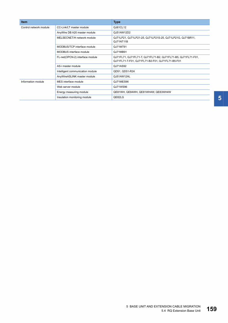
5
Control network module CC-Link/LT master module QJ61CL12
AnyWire DB A20 master module QJ51AW12D2
MELSECNET/H network module QJ71LP21, QJ71LP21-25, QJ71LP21S-25, QJ71LP21G, QJ71BR11, QJ71NT11B
MODBUS/TCP interface module QJ71MT91
MODBUS interface module QJ71MB91
FL-net(OPCN-2) interface module QJ71FL71, QJ71FL71-T, QJ71FL71-B2, QJ71FL71-B5, QJ71FL71-F01, QJ71FL71-T-F01, QJ71FL71-B2-F01, QJ71FL71-B5-F01
AS-i master module QJ71AS92
Intelligent communication module QD51, QD51-R24
AnyWireASLINK master module QJ51AW12AL
Information module MES interface module QJ71MES96
Web server module QJ71WS96
Energy measuring module QE81WH, QE84WH, QE81WH4W, QE83WH4W
Insulation monitoring module QE82LG
Item Type
5 BASE UNIT AND EXTENSION CABLE MIGRATION5.4 RQ Extension Base Unit 159
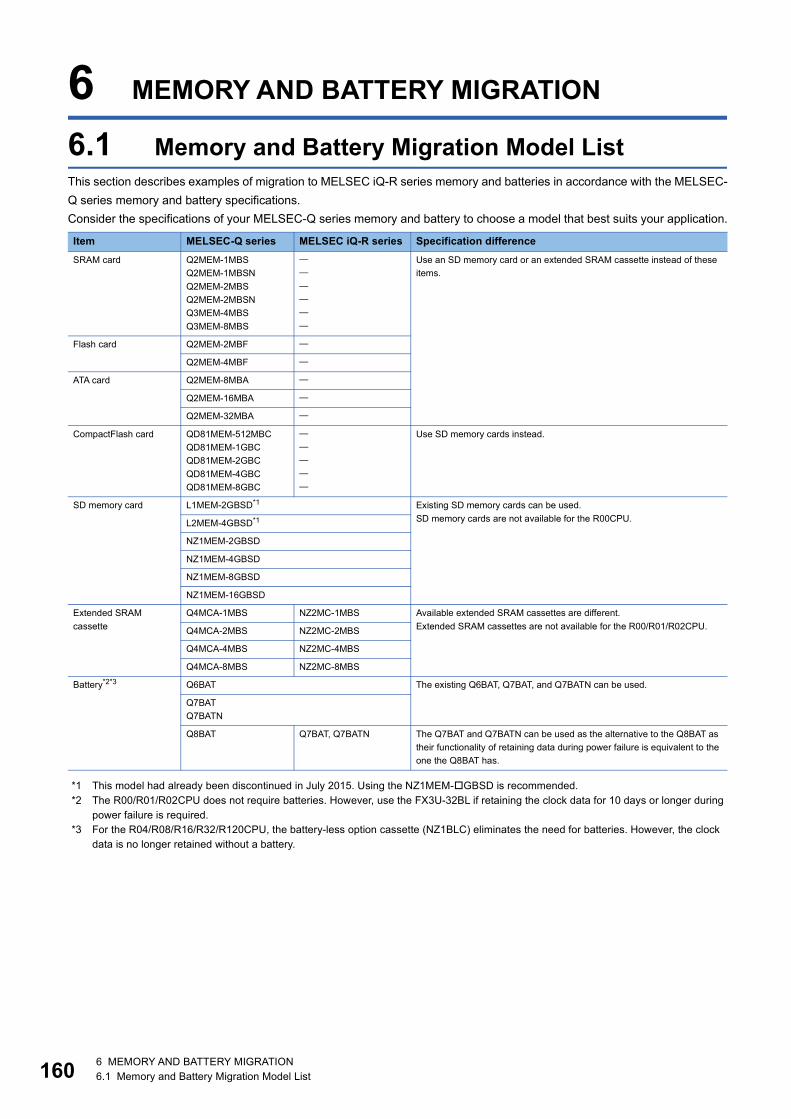
16
6 MEMORY AND BATTERY MIGRATION
6.1 Memory and Battery Migration Model ListThis section describes examples of migration to MELSEC iQ-R series memory and batteries in accordance with the MELSEC-Q series memory and battery specifications.Consider the specifications of your MELSEC-Q series memory and battery to choose a model that best suits your application.
*1 This model had already been discontinued in July 2015. Using the NZ1MEM-GBSD is recommended.*2 The R00/R01/R02CPU does not require batteries. However, use the FX3U-32BL if retaining the clock data for 10 days or longer during
power failure is required.*3 For the R04/R08/R16/R32/R120CPU, the battery-less option cassette (NZ1BLC) eliminates the need for batteries. However, the clock
data is no longer retained without a battery.
Item MELSEC-Q series MELSEC iQ-R series Specification differenceSRAM card Q2MEM-1MBS
Q2MEM-1MBSNQ2MEM-2MBSQ2MEM-2MBSNQ3MEM-4MBSQ3MEM-8MBS
Use an SD memory card or an extended SRAM cassette instead of these items.
Flash card Q2MEM-2MBF
Q2MEM-4MBF
ATA card Q2MEM-8MBA
Q2MEM-16MBA
Q2MEM-32MBA
CompactFlash card QD81MEM-512MBCQD81MEM-1GBCQD81MEM-2GBCQD81MEM-4GBCQD81MEM-8GBC
Use SD memory cards instead.
SD memory card L1MEM-2GBSD*1 Existing SD memory cards can be used.SD memory cards are not available for the R00CPU.L2MEM-4GBSD*1
NZ1MEM-2GBSD
NZ1MEM-4GBSD
NZ1MEM-8GBSD
NZ1MEM-16GBSD
Extended SRAM cassette
Q4MCA-1MBS NZ2MC-1MBS Available extended SRAM cassettes are different.Extended SRAM cassettes are not available for the R00/R01/R02CPU.Q4MCA-2MBS NZ2MC-2MBS
Q4MCA-4MBS NZ2MC-4MBS
Q4MCA-8MBS NZ2MC-8MBS
Battery*2*3 Q6BAT The existing Q6BAT, Q7BAT, and Q7BATN can be used.
Q7BATQ7BATN
Q8BAT Q7BAT, Q7BATN The Q7BAT and Q7BATN can be used as the alternative to the Q8BAT as their functionality of retaining data during power failure is equivalent to the one the Q8BAT has.
0 6 MEMORY AND BATTERY MIGRATION6.1 Memory and Battery Migration Model List

6
6.2 Precautions for Memory and Battery Migration
Extended SRAM cassetteThe extended SRAM cassette differs between the MELSEC-Q series and the MELSEC iQ-R series.
BatteryBatteries used in the MELSEC-Q series system can also be used in the MELSEC iQ-R series system.Note that only the Q8BAT cannot be used.
For details on these precautions, refer to the following. MELSEC iQ-R Module Configuration Manual MELSEC iQ-R CPU Module User's Manual (Startup) Differences between MELSEC-Q series and MELSEC iQ-R series (FA-A-0171)
6 MEMORY AND BATTERY MIGRATION6.2 Precautions for Memory and Battery Migration 161

16
7 ANALOG I/O MODULE MIGRATION
7.1 Analog I/O Module Migration Model ListThis section describes examples of migration to MELSEC iQ-R series analog I/O modules in accordance with the MELSEC-Q series analog I/O module specifications and functions.Consider the scope of control by your MELSEC-Q series analog I/O module and the system specifications and extensibility after migration to choose a model that best suits your application.
Item MELSEC-Qseries
MELSEC iQ-Rseries
Specification difference
Analog input module
Q64AD R60AD4 (1) External wiring: Not changed(2) Number of slots: Not changed(3) Programs: Some input signals are not available. The resolution (digital output value range) and
buffer memory assignment (R mode: Not compatible, Q compatible mode: Compatible) are changed.
(4) Performance specifications: The resolution, conversion speed (only for the Q64AD with temperature drift compensation enabled), and number of offset/gain settings are changed.
(5) Function specifications: Temperature drift compensation function not available
Q68ADV R60ADV8 (1) External wiring: Not changed(2) Number of slots: Not changed(3) Programs: Some input signals are not available. The resolution (digital output value range) and
buffer memory assignment (R mode: Not compatible, Q compatible mode: Compatible) are changed.
(4) Performance specifications: The resolution, conversion speed (only for the Q68ADV with temperature drift compensation enabled), and number of offset/gain settings are changed.
(5) Function specifications: Temperature drift compensation function not available
Q68ADI R60ADI8 (1) External wiring: Not changed(2) Number of slots: Not changed(3) Programs: Some input signals are not available. The resolution (digital output value range) and
buffer memory assignment (R mode: Not compatible, Q compatible mode: Compatible) are changed.
(4) Performance specifications: The resolution, conversion speed (only for the Q68ADI with temperature drift compensation enabled), and number of offset/gain settings are changed.
(5) Function specifications: Temperature drift compensation function not available
Q64AD-GH No applicable module
Check the specification difference and consider replacing the Q series module with the R60AD8-G.If the module cannot be replaced with the R60AD8-G, connect the RQ extension base unit (RQ6B) to use the Q series module.
Q62AD-DGH No applicable module
Connect the RQ extension base unit (RQ6B) to use the Q series module.
Q68AD-G R60AD8-G (1) External wiring: Not changed(2) Number of slots: Not changed(3) Programs: Some input signals are not available. The resolution (digital output value range) and
buffer memory assignment (R mode: Not compatible, Q compatible mode: Compatible) are changed.
(4) Performance specifications: The resolution and accuracy (temperature coefficient) are changed.
(5) Function specifications: Not changed
Q66AD-DG No applicable module
Connect the RQ extension base unit (RQ6B) to use the Q series module.
Q64ADH R60ADH4 (1) External wiring: Not changed(2) Number of slots: Not changed(3) Programs: Input signal assignment and resolution (digital output value range) are changed.
Buffer memory assignment is incompatible.(4) Performance specifications: The resolution, conversion speed, and number of offset/gain
settings are changed.(5) Function specifications: The input range extended mode function and the flow amount
integration function are not available.
2 7 ANALOG I/O MODULE MIGRATION7.1 Analog I/O Module Migration Model List

7
Analog output module
Q62DA R60DA4 (1) External wiring: Not changed(2) Number of slots: Not changed(3) Programs: Some I/O signals are changed, and the resolution (digital value range) is changed.
Buffer memory assignment (R mode: Not compatible, Q compatible mode: Compatible)(4) Performance specifications: The resolution and number of offset/gain settings are changed.
The external power supply specifications are changed.(5) Function specifications: The synchronous output function is not available. (Consider using the
R60DAH4.)
Q62DAN R60DA4 (1) External wiring: Not changed(2) Number of slots: Not changed(3) Programs: Some I/O signals are changed, and the resolution (digital value range) is changed.
Buffer memory assignment (R mode: Not compatible, Q compatible mode: Compatible)(4) Performance specifications: The resolution and number of offset/gain settings are changed.
The external power supply specifications are changed.(5) Function specifications: The synchronous output function is not available. (Consider using the
R60DAH4.)
Q64DA R60DA4 (1) External wiring: Not changed(2) Number of slots: Not changed(3) Programs: Some I/O signals are changed, and the resolution (digital value range) is changed.
Buffer memory assignment (R mode: Not compatible, Q compatible mode: Compatible)(4) Performance specifications: The resolution and number of offset/gain settings are changed.
The external power supply specifications are changed.(5) Function specifications: The synchronous output function is not available. (Consider using the
R60DAH4.)
Q64DAN R60DA4 (1) External wiring: Not changed(2) Number of slots: Not changed(3) Programs: Some I/O signals are changed, and the resolution (digital value range) is changed.
Buffer memory assignment (R mode: Not compatible, Q compatible mode: Compatible)(4) Performance specifications: The resolution and number of offset/gain settings are changed.
The external power supply specifications are changed.(5) Function specifications: The synchronous output function is not available. (Consider using the
R60DAH4.)
Q68DAV R60DAV8 (1) External wiring: Not changed(2) Number of slots: Not changed(3) Programs: Some I/O signals are changed, and the resolution (digital value range) is changed.
Buffer memory assignment (R mode: Not compatible, Q compatible mode: Compatible)(4) Performance specifications: The resolution and number of offset/gain settings are changed.
The external power supply specifications are changed.(5) Function specifications: The synchronous output function is not available. (Consider using the
R60DAH4.)
Q68DAVN R60DAV8 (1) External wiring: Not changed(2) Number of slots: Not changed(3) Programs: Some I/O signals are changed, and the resolution (digital value range) is changed.
Buffer memory assignment (R mode: Not compatible, Q compatible mode: Compatible)(4) Performance specifications: The resolution and number of offset/gain settings are changed.
The external power supply specifications are changed.(5) Function specifications: The synchronous output function is not available. (Consider using the
R60DAH4.)
Q68DAI R60DAI8 (1) External wiring: Not changed(2) Number of slots: Not changed(3) Programs: Some I/O signals are changed, and the resolution (digital value range) is changed.
Buffer memory assignment (R mode: Not compatible, Q compatible mode: Compatible)(4) Performance specifications: The resolution and number of offset/gain settings are changed.
The external power supply specifications are changed.(5) Function specifications: The synchronous output function is not available. (Consider using the
R60DAH4.)
Q68DAIN R60DAI8 (1) External wiring: Not changed(2) Number of slots: Not changed(3) Programs: Some I/O signals are changed, and the resolution (digital value range) is changed.
Buffer memory assignment (R mode: Not compatible, Q compatible mode: Compatible)(4) Performance specifications: The resolution and number of offset/gain settings are changed.
The external power supply specifications are changed.(5) Function specifications: The synchronous output function is not available. (Consider using the
R60DAH4.)
Q62DA-FG No applicable module
Connect the RQ extension base unit (RQ6B) to use the Q series module.
Item MELSEC-Qseries
MELSEC iQ-Rseries
Specification difference
7 ANALOG I/O MODULE MIGRATION7.1 Analog I/O Module Migration Model List 163

16
Analog output module
Q66DA-G R60DA8-G (1) External wiring: Changed(2) Number of slots: Not changed(3) Programs: Some I/O signals are changed, and the resolution (digital value range) is changed.
Buffer memory assignment (R mode: Not compatible, Q compatible mode: Compatible)(4) Performance specifications: The resolution, accuracy (temperature coefficient), conversion
speed, and the external power supply specifications are changed.(5) Function specifications: Not changed
Q64DAH R60DAH4 (1) External wiring: Not changed(2) Number of slots: Not changed(3) Programs: Buffer memory assignment is incompatible. The resolution (digital value range) is
changed.(4) Performance specifications: The external load resistance value, resolution, conversion speed,
and number of offset/gain settings are changed.(5) Function specifications: Not changed
Analog I/O module
Q64AD2DA2 No applicable module
Connect the RQ extension base unit (RQ6B) to use the Q series module.
Load cell input module
Q61LD No applicable module
Connect the RQ extension base unit (RQ6B) to use the Q series module.
CT input module
Q68CT No applicable module
Connect the RQ extension base unit (RQ6B) to use the Q series module.
Temperature input module
Q64RD No applicable module
Check the specification difference and consider replacing the Q series module with the R60RD8-G.If the module cannot be replaced with the R60RD8-G, connect the RQ extension base unit (RQ6B) to use the Q series module.
Q64RD-G No applicable module
Check the specification difference and consider replacing the Q series module with the R60RD8-G.If the module cannot be replaced with the R60RD8-G, connect the RQ extension base unit (RQ6B) to use the Q series module.
Q68RD3-G R60RD8-G (1) Number of analog input channels: 8(2) Usable RTD: Pt100, JPt100, Ni100 Pt100, JPt100, Ni100, Pt50(3) Conversion speed: 320ms/8 channels 10ms/channel(4) External interface: 40-pin connector(5) Function: Channel isolated
Q64TD No applicable module
Check the specification difference and consider replacing the Q series module with the R60TD8-G.If the module cannot be replaced with the R60TD8-G, connect the RQ extension base unit (RQ6B) to use the Q series module.
Q64TDV-GH No applicable module
Check the specification difference and consider replacing the Q series module with the R60TD8-G.If the module cannot be replaced with the R60TD8-G, connect the RQ extension base unit (RQ6B) to use the Q series module.
Q68TD-G-H01 R60TD8-G (1) Number of analog input channels: 8(2) Thermocouple compliance standards: IEC60584-1(1995), IEC60584-2(1982), JIS C1602-1995(3) Conversion speed: 320ms/8 channels 30ms/channel(4) External interface: 40-pin connector(5) Functions: Disconnection monitor function, channel isolated disconnection detection
function, channel isolated
Q68TD-G-H02 R60TD8-G (1) Number of analog input channels: 8(2) Thermocouple compliance standards: IEC60584-1(1995), IEC60584-2(1982), JIS C1602-1995(3) Conversion speed: 640ms/8 channels 30ms/channel(4) External interface: 40-pin connector(5) Functions: Disconnection detection function, channel isolated
Temperature control module
Q64TCTT R60TCTRT2TT2 (1) Number of analog input channels: 4(2) Usable thermocouples: R, K, J, T, S, B, E, N, U, L, PLII, W5Re/W26Re(3) Sampling cycle: 500ms/4 channels 250ms/4 channels, 500ms/4 channels(4) External interface: 18-point screw terminal block (M3 screws)(5) Functions: Heater disconnection detection not available, channel isolated Heater
disconnection detection not available, channel isolated, heating-cooling control, position proportional control
Q64TCTTN R60TCTRT2TT2 (1) Number of analog input channels: 4(2) Usable thermocouples: R, K, J, T, S, B, E, N, U, L, PLII, W5Re/W26Re(3) Sampling cycle: 500ms/4 channels 250ms/4 channels, 500ms/4 channels(4) External interface: 18-point screw terminal block (M3 screws)(5) Functions: Heater disconnection detection not available, channel isolated, heating-cooling
control Heater disconnection detection not available, channel isolated, heating-cooling control, position proportional control
Item MELSEC-Qseries
MELSEC iQ-Rseries
Specification difference
4 7 ANALOG I/O MODULE MIGRATION7.1 Analog I/O Module Migration Model List

7
Temperature control module
Q64TCRT R60TCRT4 (1) Number of analog input channels: 4(2) Usable RTD: Pt100, JPt100(3) Sampling cycle: 500ms/4 channels 250ms/4 channels, 500ms/4 channels(4) External interface: 18-point screw terminal block (M3 screws)(5) Functions: Heater disconnection detection not available, channel isolated Heater
disconnection detection not available, channel isolated, heating-cooling control, position proportional control
Q64TCRTN R60TCRT4 (1) Number of analog input channels: 4(2) Usable RTD: Pt100, JPt100(3) Sampling cycle: 500ms/4 channels 250ms/4 channels, 500ms/4 channels(4) External interface: 18-point screw terminal block (M3 screws)(5) Functions: Heater disconnection detection not available, channel isolated, heating-cooling
control Heater disconnection detection not available, channel isolated, heating-cooling control, position proportional control
Q64TCTTBW R60TCTRT2TT2BW (1) Number of analog input channels: 4(2) Usable thermocouples: R, K, J, T, S, B, E, N, U, L, PLII, W5Re/W26Re(3) Sampling cycle: 500ms/4 channels 250ms/4 channels, 500ms/4 channels(4) External interface: 18-point screw terminal block (M3 screws) 2(5) Functions: Heater disconnection detection, channel isolated Heater disconnection
detection, channel isolated, heating-cooling control, position proportional control
Q64TCTTBWN R60TCTRT2TT2BW (1) Number of analog input channels: 4(2) Usable thermocouples: R, K, J, T, S, B, E, N, U, L, PLII, W5Re/W26Re(3) Sampling cycle: 500ms/4 channels 250ms/4 channels, 500ms/4 channels(4) External interface: 18-point screw terminal block (M3 screws) 2(5) Functions: Heater disconnection detection, channel isolated, heating-cooling control Heater
disconnection detection, channel isolated, heating-cooling control, position proportional control
Q64TCRTBW R60TCRT4BW (1) Number of analog input channels: 4(2) Usable RTD: Pt100, JPt100(3) Sampling cycle: 500ms/4 channels 250ms/4 channels, 500ms/4 channels(4) External interface: 18-point screw terminal block (M3 screws) 2(5) Functions: Heater disconnection detection, channel isolated Heater disconnection
detection, channel isolated, heating-cooling control, position proportional control
Q64TCRTBWN R60TCRT4BW (1) Number of analog input channels: 4(2) Usable RTD: Pt100, JPt100(3) Sampling cycle: 500ms/4 channels 250ms/4 channels, 500ms/4 channels(4) External interface: 18-point screw terminal block (M3 screws) 2(5) Functions: Heater disconnection detection, channel isolated, heating-cooling control Heater
disconnection detection, channel isolated, heating-cooling control, position proportional control
Loop control module
Q62HLC No applicable module
Connect the RQ extension base unit (RQ6B) to use the Q series module.
Item MELSEC-Qseries
MELSEC iQ-Rseries
Specification difference
7 ANALOG I/O MODULE MIGRATION7.1 Analog I/O Module Migration Model List 165
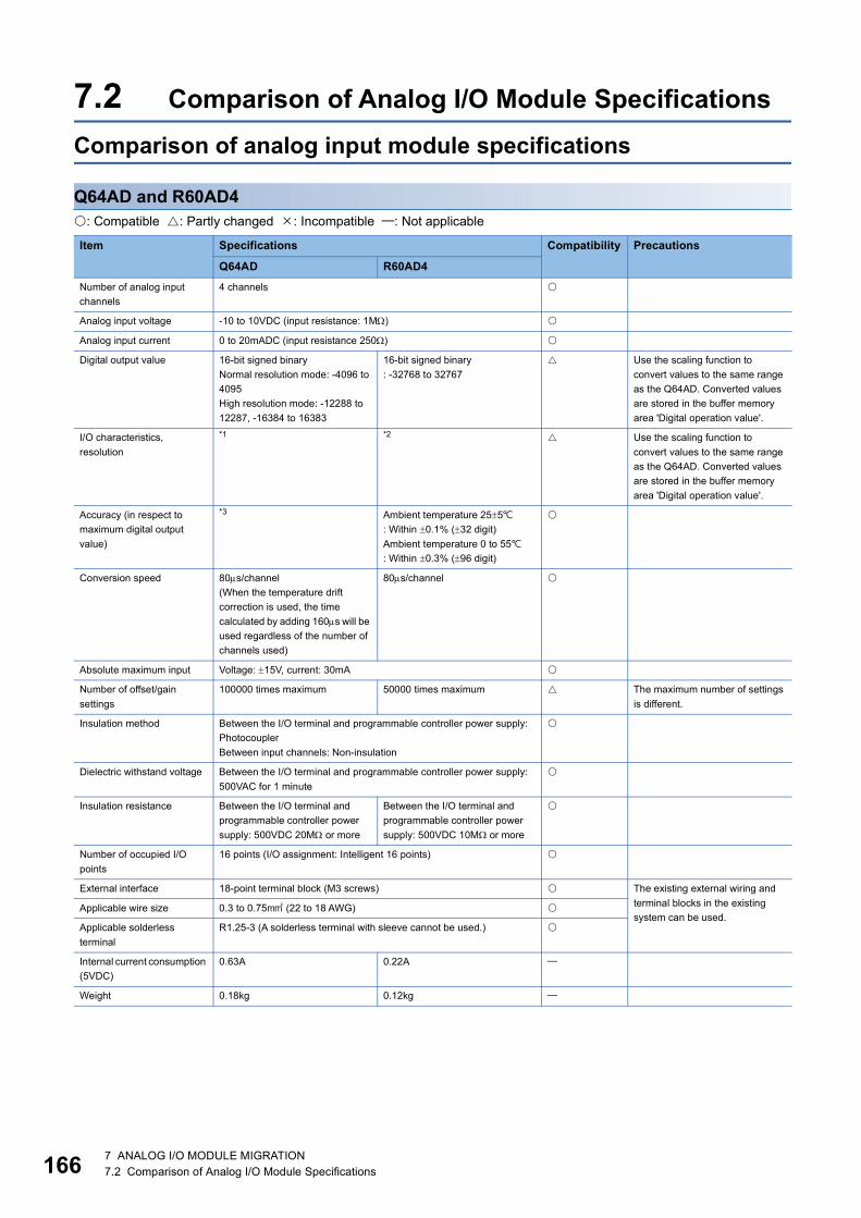
16
7.2 Comparison of Analog I/O Module SpecificationsComparison of analog input module specifications
Q64AD and R60AD4: Compatible : Partly changed : Incompatible : Not applicable
Item Specifications Compatibility Precautions
Q64AD R60AD4Number of analog input channels
4 channels
Analog input voltage -10 to 10VDC (input resistance: 1M)
Analog input current 0 to 20mADC (input resistance 250)
Digital output value 16-bit signed binaryNormal resolution mode: -4096 to 4095High resolution mode: -12288 to 12287, -16384 to 16383
16-bit signed binary: -32768 to 32767
Use the scaling function to convert values to the same range as the Q64AD. Converted values are stored in the buffer memory area 'Digital operation value'.
I/O characteristics, resolution
*1 *2 Use the scaling function to convert values to the same range as the Q64AD. Converted values are stored in the buffer memory area 'Digital operation value'.
Accuracy (in respect to maximum digital output value)
*3 Ambient temperature 255: Within 0.1% (32 digit)Ambient temperature 0 to 55: Within 0.3% (96 digit)
Conversion speed 80s/channel(When the temperature drift correction is used, the time calculated by adding 160s will be used regardless of the number of channels used)
80s/channel
Absolute maximum input Voltage: 15V, current: 30mA
Number of offset/gain settings
100000 times maximum 50000 times maximum The maximum number of settings is different.
Insulation method Between the I/O terminal and programmable controller power supply: PhotocouplerBetween input channels: Non-insulation
Dielectric withstand voltage Between the I/O terminal and programmable controller power supply: 500VAC for 1 minute
Insulation resistance Between the I/O terminal and programmable controller power supply: 500VDC 20M or more
Between the I/O terminal and programmable controller power supply: 500VDC 10M or more
Number of occupied I/O points
16 points (I/O assignment: Intelligent 16 points)
External interface 18-point terminal block (M3 screws) The existing external wiring and terminal blocks in the existing system can be used.
Applicable wire size 0.3 to 0.75 (22 to 18 AWG)
Applicable solderless terminal
R1.25-3 (A solderless terminal with sleeve cannot be used.)
Internal current consumption (5VDC)
0.63A 0.22A
Weight 0.18kg 0.12kg
6 7 ANALOG I/O MODULE MIGRATION7.2 Comparison of Analog I/O Module Specifications

7
*1 The following table lists the I/O characteristics and resolution values of the Q64AD.
*2 The following table lists the I/O characteristics and resolution values of the R60AD4.
*3 The following table lists the accuracy of the Q64AD.
Analog input range Normal resolution mode High resolution mode
Digital output value Resolution Digital output value ResolutionVoltage 0 to 10V 0 to 4000 2.5mV 0 to 16000 0.625mV
0 to 5V 1.25mV 0 to 12000 0.416mV
1 to 5V 1.0mV 0.333mV
-10 to 10V -4000 to 4000 2.5mV -16000 to 16000 0.625mV
User range setting 0.375mV -12000 to 12000 0.333mV
Current 0 to 20mA 0 to 4000 5A 0 to 12000 1.66A
4 to 20mA 4A 1.33A
User range setting -4000 to 4000 1.37A -12000 to 12000 1.33A
Analog input range Digital output value ResolutionVoltage 0 to 10V 0 to 32000 312.5V
0 to 5V 156.3V
1 to 5V 125.0V
1 to 5V (extended mode) -8000 to 32000 125.0V
-10 to 10V -32000 to 32000 312.5V
User range setting 47.7V
Current 0 to 20mA 0 to 32000 625.0nA
4 to 20mA 500.0nA
4 to 20mA (extended mode)
-8000 to 32000 500.0nA
User range setting -32000 to 32000 190.7nA
Analog input range Normal resolution mode High resolution mode
Ambient temperature 0 to 55
Ambient temperature 255
Ambient temperature 0 to 55
Ambient temperature 255With
temperature drift correction
Without temperature drift correction
With temperature drift correction
Without temperature drift correction
Voltage 0 to 10V Within 0.3%(12 digit)
Within 0.4%(16 digit)
Within 0.1%(4 digit)
Within 0.3%(48 digit)
Within 0.4%(64 digit)
Within 0.1%(16 digit)-10 to 10V
0 to 5V Within 0.3%(36 digit)
Within 0.4%(48 digit)
Within 0.1%(12 digit)1 to 5V
User range setting
Current 0 to 20mA
4 to 20mA
User range setting
7 ANALOG I/O MODULE MIGRATION7.2 Comparison of Analog I/O Module Specifications 167
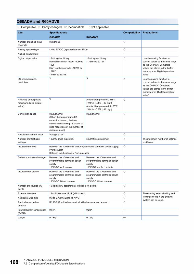
16
Q68ADV and R60ADV8: Compatible : Partly changed : Incompatible : Not applicable
Item Specifications Compatibility Precautions
Q68ADV R60ADV8Number of analog input channels
8 channels
Analog input voltage -10 to 10VDC (input resistance: 1M)
Analog input current
Digital output value 16-bit signed binaryNormal resolution mode: -4096 to 4095High resolution mode: -12288 to 12287,-16384 to 16383
16-bit signed binary: -32768 to 32767
Use the scaling function to convert values to the same range as the Q68ADV. Converted values are stored in the buffer memory area 'Digital operation value'.
I/O characteristics, resolution
*1 *2 Use the scaling function to convert values to the same range as the Q68ADV. Converted values are stored in the buffer memory area 'Digital operation value'.
Accuracy (in respect to maximum digital output value)
*3 Ambient temperature 255: Within 0.1% (32 digit)Ambient temperature 0 to 55: Within 0.3% (96 digit)
Conversion speed 80s/channel(When the temperature drift correction is used, the time calculated by adding 160s will be used regardless of the number of channels used)
80s/channel
Absolute maximum input Voltage: 15V
Number of offset/gain settings
100000 times maximum 50000 times maximum The maximum number of settings is different.
Insulation method Between the I/O terminal and programmable controller power supply: PhotocouplerBetween input channels: Non-insulation
Dielectric withstand voltage Between the I/O terminal and programmable controller power supply: 500VAC for 1 minute
Between the I/O terminal and programmable controller power supply: 500VAC rms for 1 minute
Insulation resistance Between the I/O terminal and programmable controller power supply: 500VDC 20M or more
Between the I/O terminal and programmable controller power supply: 500VDC 10M or more
Number of occupied I/O points
16 points (I/O assignment: Intelligent 16 points)
External interface 18-point terminal block (M3 screws) The existing external wiring and terminal blocks in the existing system can be used.
Applicable wire size 0.3 to 0.75 (22 to 18 AWG)
Applicable solderless terminal
R1.25-3 (A solderless terminal with sleeve cannot be used.)
Internal current consumption (5VDC)
0.64A 0.23A
Weight 0.19kg 0.12kg
8 7 ANALOG I/O MODULE MIGRATION7.2 Comparison of Analog I/O Module Specifications

7
*1 The following table lists the I/O characteristics and resolution values of the Q68ADV.
*2 The following table lists the I/O characteristics and resolution values of the R60ADV8.
*3 The following table lists the accuracy of the Q68ADV.
Analog input range Normal resolution mode High resolution mode
Digital output value Resolution Digital output value ResolutionVoltage 0 to 10V 0 to 4000 2.5mV 0 to 16000 0.625mV
0 to 5V 1.25mV 0 to 12000 0.416mV
1 to 5V 1.0mV 0.333mV
-10 to 10V -4000 to 4000 2.5mV -16000 to 16000 0.625mV
User range setting 0.375mV -12000 to 12000 0.333mV
Analog input range Digital output value ResolutionVoltage 0 to 10V 0 to 32000 312.5V
0 to 5V 156.3V
1 to 5V 125.0V
1 to 5V (extended mode) -8000 to 32000 125.0V
-10 to 10V -32000 to 32000 312.5V
User range setting 47.7V
Analog input range Normal resolution mode High resolution mode
Ambient temperature 0 to 55
Ambient temperature 255
Ambient temperature 0 to 55
Ambient temperature 255With
temperature drift correction
Without temperature drift correction
With temperature drift correction
Without temperature drift correction
Voltage 0 to 10V Within 0.3%(12 digit)
Within 0.4%(16 digit)
Within 0.1%(4 digit)
Within 0.3%(48 digit)
Within 0.4%(64 digit)
Within 0.1%(16 digit)-10 to 10V
0 to 5V Within 0.3%(36 digit)
Within 0.4%(48 digit)
Within 0.1%(12 digit)1 to 5V
User range setting
7 ANALOG I/O MODULE MIGRATION7.2 Comparison of Analog I/O Module Specifications 169

17
Q68ADI and R60ADI8: Compatible : Partly changed : Incompatible : Not applicable
*1 The following table lists the I/O characteristics and resolution values of the Q68ADI.
Item Specifications Compatibility Precautions
Q68ADI R60ADI8Number of analog input channels
8 channels
Analog input voltage
Analog input current 0 to 20mADC (input resistance 250)
Digital output value 16-bit signed binaryNormal resolution mode: -4096 to 4095High resolution mode: -12288 to 12287, -16384 to 16383
16-bit signed binary: -32768 to 32767
Use the scaling function to convert values to the same range as the Q68ADI. Converted values are stored in the buffer memory area 'Digital operation value'.
I/O characteristics, resolution
*1 *2 Use the scaling function to convert values to the same range as the Q68ADI. Converted values are stored in the buffer memory area 'Digital operation value'.
Accuracy (in respect to maximum digital output value)
*3 Ambient temperature 255: Within 0.1% (32 digit)Ambient temperature 0 to 55: Within 0.3% (96 digit)
Conversion speed 80s/channel(When the temperature drift correction is used, the time calculated by adding 160s will be used regardless of the number of channels used)
80s/channel
Absolute maximum input Current: 30mA
Number of offset/gain settings
100000 times maximum 50000 times maximum The maximum number of settings is different.
Insulation method Between the I/O terminal and programmable controller power supply: PhotocouplerBetween input channels: Non-insulation
Dielectric withstand voltage Between the I/O terminal and programmable controller power supply: 500VAC for 1 minute
Between the I/O terminal and programmable controller power supply: 500VAC rms for 1 minute
Insulation resistance Between the I/O terminal and programmable controller power supply: 500VDC 20M or more
Between the I/O terminal and programmable controller power supply: 500VDC 10M or more
Number of occupied I/O points
16 points (I/O assignment: Intelligent 16 points)
External interface 18-point terminal block (M3 screws) The existing external wiring and terminal blocks in the existing system can be used.
Applicable wire size 0.3 to 0.75 (22 to 18 AWG)
Applicable solderless terminal
R1.25-3 (A solderless terminal with sleeve cannot be used.)
Internal current consumption (5VDC)
0.64A 0.22A
Weight 0.19kg 0.12kg
Analog input range Normal resolution mode High resolution mode
Digital output value Resolution Digital output value ResolutionCurrent 0 to 20mA 0 to 4000 5A 0 to 12000 1.66A
4 to 20mA 4A 1.33A
User range setting -4000 to 4000 1.37A -12000 to 12000 1.33A
0 7 ANALOG I/O MODULE MIGRATION7.2 Comparison of Analog I/O Module Specifications

7
*2 The following table lists the I/O characteristics and resolution values of the R60ADI8.
*3 The following table lists the accuracy of the Q68ADI.
Analog input range Digital output value ResolutionCurrent 0 to 20mA 0 to 32000 625.0nA
4 to 20mA 500.0nA
4 to 20mA (extended mode)
-8000 to 32000 500.0nA
User range setting -32000 to 32000 190.7nA
Analog input range Normal resolution mode High resolution mode
Ambient temperature 0 to 55
Ambient temperature 255
Ambient temperature 0 to 55
Ambient temperature 255With
temperature drift correction
Without temperature drift correction
With temperature drift correction
Without temperature drift correction
Current 0 to 20mA Within 0.3%(12 digit)
Within 0.4%(16 digit)
Within 0.1%(4 digit)
Within 0.3%(36 digit)
Within 0.4%(48 digit)
Within 0.1%(12 digit)4 to 20mA
User range setting
7 ANALOG I/O MODULE MIGRATION7.2 Comparison of Analog I/O Module Specifications 171

17
Q68AD-G and R60AD8-G: Compatible : Partly changed : Incompatible : Not applicable
Item Specifications Compatibility Precautions
Q68AD-G R60AD8-GNumber of analog input channels
8 channels
Analog input voltage -10 to 10VDC (input resistance: 1M)
Analog input current 0 to 20mADC (input resistance 250)
Digital output value 16-bit signed binaryNormal resolution mode: -4096 to 4095High resolution mode: -12288 to 12287, -16384 to 16383Using scaling function: -32768 to 32767
16-bit signed binary: -32768 to 32767
Use the scaling function to convert values to the same range as the Q68AD-G. Converted values are stored in the buffer memory area 'Digital operation value'.
I/O characteristics, resolution
*1 *2 Use the scaling function to convert values to the same range as the Q68AD-G. Converted values are stored in the buffer memory area 'Digital operation value'.
Accuracy (in respect to maximum digital output value)
Reference accuracy: 0.1%Normal resolution mode: 4 digitHigh resolution mode (0 to 10V, -10 to 10V): 16 digitHigh resolution mode (other than the above): 12 digitTemperature coefficient: 71.4ppm/ (0.00714%/)
Reference accuracy: Within 0.1% (32 digit)Temperature coefficient: 35ppm/ (0.0035%/)
Common mode characteristics
Common mode voltage between input and common ground (input voltage 0V): 500VACCommon mode voltage rejection ratio (VCM < 500V): 60Hz 107dB, 50Hz 106dB
Sampling cycle (conversion speed)
10ms/channel
Response time 20ms
Absolute maximum input Voltage: 15V, current: 30mA
Isolation method Between I/O terminals and programmable controller power supply: TransformerBetween analog input channels: Transformer
Dielectric withstand voltage Between the I/O terminal and programmable controller power supply: 500VAC rms for 1 minuteBetween analog input channels: 1000VAC rms for 1 minute
Insulation resistance Between the I/O terminal and programmable controller power supply: 500VDC 10M or moreBetween analog input channels: 500VDC 10M or more
Maximum number of writes to flash memory
50000 times maximum
Number of occupied I/O points
16 points (I/O assignment: Intelligent 16 points)
External interface 40-pin connector (A6CON1/2/4) Existing external wiring can be used.Applicable wire size For A6CON1/4: 0.088 to 0.3 (28 to 22 AWG) (stranded wire)
For A6CON2: 0.088 to 0.24 (28 to 24 AWG) (stranded wire)
Internal current consumption (5VDC)
0.46A 0.33A
Weight 0.16kg 0.19kg
2 7 ANALOG I/O MODULE MIGRATION7.2 Comparison of Analog I/O Module Specifications

7
*1 The following table lists the I/O characteristics and resolution values of the Q68AD-G.
*2 The following table lists the I/O characteristics and resolution values of the R60AD8-G.
Input Analog input range Normal resolution mode High resolution mode
Digital output value Resolution Digital output value ResolutionVoltage 0 to 10V 0 to 4000 2.5mV 0 to 16000 0.625mV
0 to 5V 1.25mV 0 to 12000 0.416mV
1 to 5V 1.0mV 0.333mV
1 to 5V (extended mode) -1000 to 4500 1.0mV -3000 to 13500 0.333mV
-10 to 10V -4000 to 4000 2.5mV -16000 to 16000 0.625mV
User range setting 0.375mV -12000 to 12000 0.333mV
Current 0 to 20mA 0 to 4000 5A 0 to 12000 1.66A
4 to 20mA 4A 1.33A
4 to 20mA (extended mode)
-1000 to 4500 4A -3000 to 13500 1.33A
User range setting -4000 to 4000 1.37A -12000 to 12000 1.33A
Analog input range Digital output value ResolutionVoltage 0 to 10V 0 to 32000 312.5V
0 to 5V 156.3V
1 to 5V 125.0V
1 to 5V (extended mode) -8000 to 32767 (-8000 to 36000) 125.0V
-10 to 10V -32000 to 32000 312.5V
User range setting 29.2V
Current 0 to 20mA 0 to 32000 625.0nA
4 to 20mA 500.0nA
4 to 20mA (extended mode)
-8000 to 32767 (-8000 to 36000) 500.0nA
User range setting -32000 to 32000 115.5nA
7 ANALOG I/O MODULE MIGRATION7.2 Comparison of Analog I/O Module Specifications 173

17
Q64ADH and R60ADH4: Compatible : Partly changed : Incompatible : Not applicable
Item Specifications Compatibility Precautions
Q64ADH R60ADH4Number of analog input channels
4 channels
Analog input voltage -10 to 10VDC (input resistance: 1M)
Analog input current 0 to 20mADC (input resistance 250)
Digital output value 16-bit signed binary: -20480 to 20479Using scaling function: -32768 to 32767
16-bit signed binary: -32768 to 32767
Use the scaling function to convert values to the same range as the Q64ADH. Converted values are stored in the buffer memory area 'Digital operation value'.
I/O characteristics, resolution
*1 *2 Use the scaling function to convert values to the same range as the Q64ADH. Converted values are stored in the buffer memory area 'Digital operation value'.
Accuracy (in respect to maximum digital output value)
Ambient temperature 255: Within 0.1% (20 digit)Ambient temperature 0 to 55: Within 0.2% (40 digit)
Ambient temperature 255: Within 0.1% (32 digit)Ambient temperature 0 to 55: Within 0.2% (64 digit)
Conversion speed High speed: 20s/channelMedium speed: 80s/channelLow speed: 1ms/channel
Simultaneous conversion mode: 5s/4 channels, normal mode (medium speed): 10s/channelNormal mode (low speed): 20s/channel
The conversion speed is faster than the low and medium speeds of the Q64ADH.Therefore, some noise may be retrieved as analog signals which is not the case with the Q64ADH. In this case, use the averaging processing function to eliminate noise effect.
Absolute maximum input Voltage: 15V, current: 30mA
Number of offset/gain settings
50000 times maximum 10000 times maximum The maximum number of settings is different.
Isolation method Between the I/O terminal and programmable controller power supply: PhotocouplerBetween input channels: Non-insulation
Dielectric withstand voltage Between the I/O terminal and programmable controller power supply: 500VAC rms for 1 minute
Insulation resistance Between the I/O terminal and programmable controller power supply: 500VDC 10M or more
Number of occupied I/O points
16 points (I/O assignment: Intelligent 16 points) The existing external wiring and terminal blocks in the existing system can be used.External interface 18-point terminal block (M3 screws)
Applicable wire size 0.3 to 0.75 (22 to 18 AWG)
Applicable solderless terminal
R1.25-3 (A solderless terminal with sleeve cannot be used.)
Internal current consumption (5VDC)
0.52A 0.73A
Weight 0.18kg 0.20kg
4 7 ANALOG I/O MODULE MIGRATION7.2 Comparison of Analog I/O Module Specifications

7
*1 The following table lists the I/O characteristics and resolution values of the Q64ADH.
*2 The following table lists the I/O characteristics and resolution values of the R60ADH4.
Analog input range Digital output value ResolutionVoltage 0 to 10V 0 to 20000 500V
0 to 5V 250V
1 to 5V 200V
-10 to 10V -20000 to 20000 500V
1 to 5V (extended mode) -5000 to 22500 200V
User range setting -20000 to 20000 219V
Current 0 to 20mA 0 to 20000 1000nA
4 to 20mA 800nA
4 to 20mA (extended mode)
-5000 to 22500 800nA
User range setting -20000 to 20000 878nA
Analog input range Digital output value ResolutionVoltage 0 to 10V 0 to 32000 312.5V
0 to 5V 156.3V
1 to 5V 125.0V
1 to 5V (extended mode) -8000 to 32000 125.0V
-10 to 10V -32000 to 32000 312.5V
User range setting 125.0V
Current 0 to 20mA 0 to 32000 625.0nA
4 to 20mA 500.0nA
4 to 20mA (extended mode)
-8000 to 32000 500.0nA
User range setting -32000 to 32000 500.0nA
7 ANALOG I/O MODULE MIGRATION7.2 Comparison of Analog I/O Module Specifications 175

17
Comparison of analog output module specifications
Q62DA and R60DA4: Compatible : Partly changed : Incompatible : Not applicable
Item Specifications Compatibility Precautions
Q62DA R60DA4Number of analog output channels
2 channels 4 channels
Digital input 16-bit signed binaryNormal resolution mode: -4096 to 4095High resolution mode: -12288 to 12287, -16384 to 16383
16-bit signed binary: -32768 to 32767
Use the scaling function to convert values to the same range as the Q62DA.
Analog output voltage -10 to 10VDC(External load resistance value 1k to 1M)
-10 to 10VDC(External load resistance value 1k or more)0 to 5VDC(External load resistance value 500 or more)
Analog output current 0 to 20mADC (External load resistance value 0 to 600)
I/O characteristics, resolution
*1 *2 Use the scaling function to convert values to the same range as the Q62DA.
Accuracy (in respect to maximum analog output value)
Ambient temperature 255: Within 0.1% (Voltage: 10mV, Current: 20A)Ambient temperature 0 to 55: Within 0.3% (Voltage: 30mV, Current: 60A)
Conversion speed 80s/channel
Absolute maximum output Voltage: 12V, current: 21mA
Number of offset/gain settings
100000 times maximum 50000 times maximum The maximum number of settings is different.
Output short circuit protection
Available
Insulation method Between the I/O terminal and programmable controller power supply: PhotocouplerBetween output channels: Non-insulationBetween external power supply and analog output: Non-insulation
Between the I/O terminal and programmable controller power supply: PhotocouplerBetween output channels: Non-insulationBetween external power supply and analog output: Transformer
Dielectric withstand voltage Between the I/O terminal and programmable controller power supply: 500VAC for 1 minuteBetween external power supply and analog output: 500VAC for 1 minute
Between the I/O terminal and programmable controller power supply: 500VAC rms for 1 minuteBetween external power supply and analog output: 500VAC rms for 1 minute
Insulation resistance Between the I/O terminal and programmable controller power supply: 500VDC 20M or moreBetween external power supply and analog output: 500VDC 20M or more
Between the I/O terminal and programmable controller power supply: 500VDC 10M or more
Number of occupied I/O points
16 points (I/O assignment: Intelligent 16 points)
External interface 18-point terminal block (M3 screws) The existing external wiring and terminal blocks in the existing system can be used.
Applicable wire size 0.3 to 0.75 (22 to 18 AWG)
Applicable solderless terminal
R1.25-3 (A solderless terminal with sleeve cannot be used.)
6 7 ANALOG I/O MODULE MIGRATION7.2 Comparison of Analog I/O Module Specifications

7
*1 The following table lists the I/O characteristics and resolution values of the Q62DA.
*2 The following table lists the I/O characteristics and resolution values of the R60DA4.
External power supply 24VDC +20%, -15%Ripple, spike 500mVp-p or lessInrush current: 1.9A, within 300sCurrent consumption: 0.12A
24VDC +20%, -15%Ripple, spike 500mVp-p or lessInrush current: 5.0A, within 690sCurrent consumption: 0.14A
Check the specifications of the external power supply used before migration.
Internal current consumption (5VDC)
0.33A 0.16A
Weight 0.19kg 0.14kg
Analog output range Normal resolution mode High resolution mode
Digital input value Resolution Digital input value ResolutionVoltage 0 to 5V 0 to 4000 1.25mV 0 to 12000 0.416mV
1 to 5V 1.0mV 0.333mV
-10 to 10V -4000 to 4000 2.5mV -16000 to 16000 0.625mV
User range setting 0.75mV -12000 to 12000 0.333mV
Current 0 to 20mA 0 to 4000 5A 0 to 12000 1.66A
4 to 20mA 4A 1.33A
User range setting -4000 to 4000 1.5A -12000 to 12000 0.83A
Analog output range Digital output value ResolutionVoltage 0 to 5V 0 to 32000 156.3V
1 to 5V 125.0V
-10 to 10V -32000 to 32000 312.5V
User range setting (voltage)
312.5V
Current 0 to 20mA 0 to 32000 625.0nA
4 to 20mA 500.0nA
User range setting (current)
-32000 to 32000 350.9nA
Item Specifications Compatibility Precautions
Q62DA R60DA4
7 ANALOG I/O MODULE MIGRATION7.2 Comparison of Analog I/O Module Specifications 177

17
Q62DAN and R60DA4: Compatible : Partly changed : Incompatible : Not applicable
Item Specifications Compatibility Precautions
Q62DAN R60DA4Number of analog output channels
2 channels 4 channels
Digital input 16-bit signed binaryNormal resolution mode: -4096 to 4095High resolution mode: -12288 to 12287,-16384 to 16383
16-bit signed binary: -32768 to 32767
Use the scaling function to convert values to the same range as the Q62DAN.
Analog output voltage -10 to 10VDC(External load resistance value 1k to 1M)
-10 to 10VDC(External load resistance value 1k or more)0 to 5VDC(External load resistance value 500 or more)
Analog output current 0 to 20mADC (External load resistance value 0 to 600)
I/O characteristics, resolution
*1 *2 Use the scaling function to convert values to the same range as the Q62DAN.
Accuracy (in respect to maximum analog output value)
Ambient temperature 255: Within 0.1% (Voltage: 10mV, Current: 20A)Ambient temperature 0 to 55: Within 0.3% (Voltage: 30mV, Current: 60A)
Conversion speed 80s/channel
Absolute maximum output Voltage: 12V, current: 21mA
Number of offset/gain settings
100000 times maximum 50000 times maximum The maximum number of settings is different.
Output short circuit protection
Available
Insulation method Between the I/O terminal and programmable controller power supply: PhotocouplerBetween output channels: Non-insulationBetween external power supply and analog output: Transformer
Dielectric withstand voltage Between the I/O terminal and programmable controller power supply: 500VAC for 1 minuteBetween external power supply and analog output: 500VAC for 1 minute
Between the I/O terminal and programmable controller power supply: 500VAC rms for 1 minuteBetween external power supply and analog output: 500VAC rms for 1 minute
Insulation resistance Between the I/O terminal and programmable controller power supply: 500VDC 20M or moreBetween external power supply and analog output: 500VDC 20M or more
Between the I/O terminal and programmable controller power supply: 500VDC 10M or more
Number of occupied I/O points
16 points (I/O assignment: Intelligent 16 points)
External interface 18-point terminal block (M3 screws) The existing external wiring and terminal blocks in the existing system can be used.
Applicable wire size 0.3 to 0.75 (22 to 18 AWG)
Applicable solderless terminal
R1.25-3 (A solderless terminal with sleeve cannot be used.)
External power supply 24VDC +20%, -15%Ripple, spike 500mVp-p or lessInrush current: 2.5A, within 250sCurrent consumption: 0.15A
24VDC +20%, -15%Ripple, spike 500mVp-p or lessInrush current: 5.0A, within 690sCurrent consumption: 0.14A
Check the specifications of the external power supply used before migration.
Internal current consumption (5VDC)
0.33A 0.16A
Weight 0.19kg 0.14kg
8 7 ANALOG I/O MODULE MIGRATION7.2 Comparison of Analog I/O Module Specifications
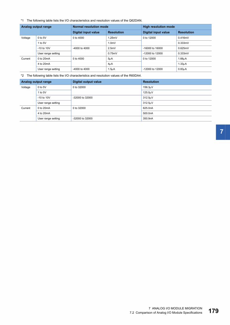
7
*1 The following table lists the I/O characteristics and resolution values of the Q62DAN.
*2 The following table lists the I/O characteristics and resolution values of the R60DA4.
Analog output range Normal resolution mode High resolution mode
Digital input value Resolution Digital input value ResolutionVoltage 0 to 5V 0 to 4000 1.25mV 0 to 12000 0.416mV
1 to 5V 1.0mV 0.333mV
-10 to 10V -4000 to 4000 2.5mV -16000 to 16000 0.625mV
User range setting 0.75mV -12000 to 12000 0.333mV
Current 0 to 20mA 0 to 4000 5A 0 to 12000 1.66A
4 to 20mA 4A 1.33A
User range setting -4000 to 4000 1.5A -12000 to 12000 0.83A
Analog output range Digital output value ResolutionVoltage 0 to 5V 0 to 32000 156.3V
1 to 5V 125.0V
-10 to 10V -32000 to 32000 312.5V
User range setting 312.5V
Current 0 to 20mA 0 to 32000 625.0nA
4 to 20mA 500.0nA
User range setting -32000 to 32000 350.9nA
7 ANALOG I/O MODULE MIGRATION7.2 Comparison of Analog I/O Module Specifications 179

18
Q64DA and R60DA4: Compatible : Partly changed : Incompatible : Not applicable
Item Specifications Compatibility Precautions
Q64DA R60DA4Number of analog output channels
4 channels
Digital input 16-bit signed binaryNormal resolution mode: -4096 to 4095High resolution mode: -12288 to 12287,-16384 to 16383
16-bit signed binary: -32768 to 32767
Use the scaling function to convert values to the same range as the Q64DA.
Analog output voltage -10 to 10VDC(External load resistance value 1k to 1M)
-10 to 10VDC(External load resistance value 1k or more)0 to 5VDC(External load resistance value 500 or more)
Analog output current 0 to 20mADC (External load resistance value 0 to 600)
I/O characteristics, resolution
*1 *2 Use the scaling function to convert values to the same range as the Q64DA.
Accuracy (in respect to maximum analog output value)
Ambient temperature 255: Within 0.1% (Voltage: 10mV, Current: 20A)Ambient temperature 0 to 55: Within 0.3% (Voltage: 30mV, Current: 60A)
Conversion speed 80s/channel
Absolute maximum output Voltage: 12V, current: 21mA
Number of offset/gain settings
100000 times maximum 50000 times maximum The maximum number of settings is different.
Output short circuit protection
Available
Insulation method Between the I/O terminal and programmable controller power supply: PhotocouplerBetween output channels: Non-insulationBetween external power supply and analog output: Non-insulation
Between the I/O terminal and programmable controller power supply: PhotocouplerBetween output channels: Non-insulationBetween external power supply and analog output: Transformer
Dielectric withstand voltage Between the I/O terminal and programmable controller power supply: 500VAC for 1 minuteBetween external power supply and analog output: 500VAC for 1 minute
Between the I/O terminal and programmable controller power supply: 500VAC rms for 1 minuteBetween external power supply and analog output: 500VAC rms for 1 minute
Insulation resistance Between the I/O terminal and programmable controller power supply: 500VDC 20M or moreBetween external power supply and analog output: 500VDC 20M or more
Between the I/O terminal and programmable controller power supply: 500VDC 10M or more
Number of occupied I/O points
16 points (I/O assignment: Intelligent 16 points)
External interface 18-point terminal block (M3 screws) The existing external wiring and terminal blocks in the existing system can be used.
Applicable wire size 0.3 to 0.75 (22 to 18 AWG)
Applicable solderless terminal
R1.25-3 (A solderless terminal with sleeve cannot be used.)
External power supply 24VDC +20%, -15%Ripple, spike 500mVp-p or lessInrush current: 3.1A, within 300sCurrent consumption: 0.18A
24VDC +20%, -15%Ripple, spike 500mVp-p or lessInrush current: 5.0A, within 690sCurrent consumption: 0.14A
Check the specifications of the external power supply used before migration.
0 7 ANALOG I/O MODULE MIGRATION7.2 Comparison of Analog I/O Module Specifications
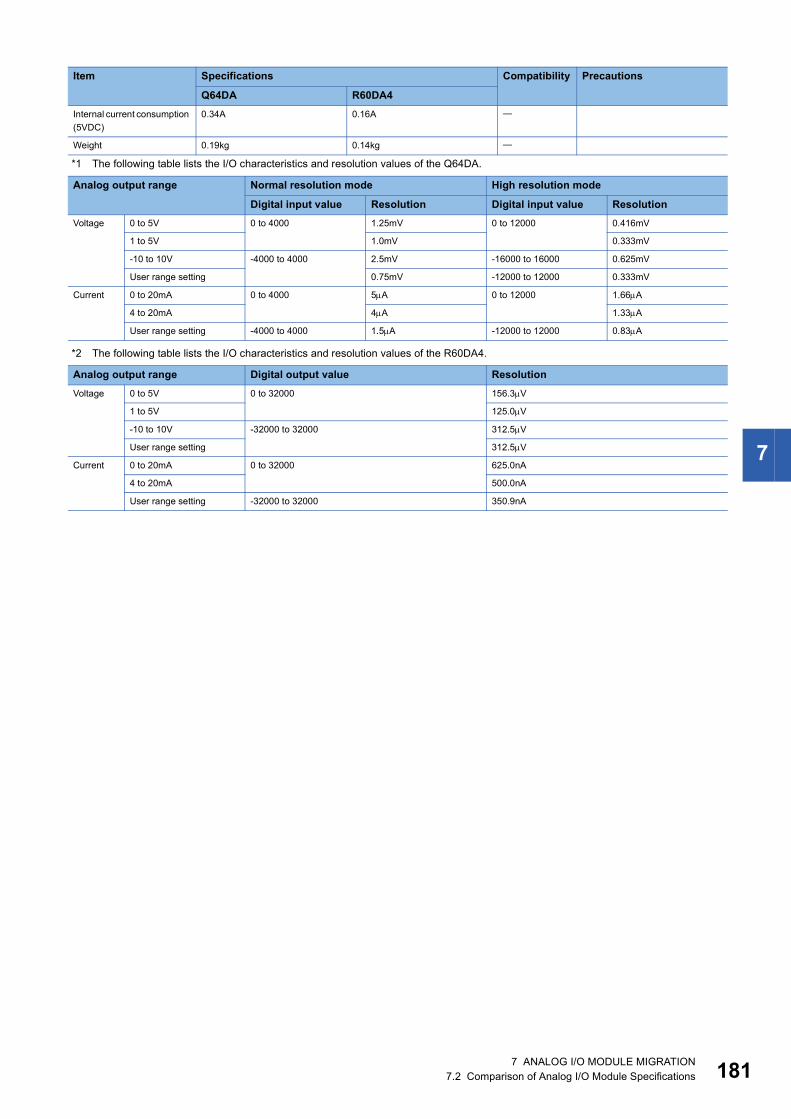
7
*1 The following table lists the I/O characteristics and resolution values of the Q64DA.
*2 The following table lists the I/O characteristics and resolution values of the R60DA4.
Internal current consumption (5VDC)
0.34A 0.16A
Weight 0.19kg 0.14kg
Analog output range Normal resolution mode High resolution mode
Digital input value Resolution Digital input value ResolutionVoltage 0 to 5V 0 to 4000 1.25mV 0 to 12000 0.416mV
1 to 5V 1.0mV 0.333mV
-10 to 10V -4000 to 4000 2.5mV -16000 to 16000 0.625mV
User range setting 0.75mV -12000 to 12000 0.333mV
Current 0 to 20mA 0 to 4000 5A 0 to 12000 1.66A
4 to 20mA 4A 1.33A
User range setting -4000 to 4000 1.5A -12000 to 12000 0.83A
Analog output range Digital output value ResolutionVoltage 0 to 5V 0 to 32000 156.3V
1 to 5V 125.0V
-10 to 10V -32000 to 32000 312.5V
User range setting 312.5V
Current 0 to 20mA 0 to 32000 625.0nA
4 to 20mA 500.0nA
User range setting -32000 to 32000 350.9nA
Item Specifications Compatibility Precautions
Q64DA R60DA4
7 ANALOG I/O MODULE MIGRATION7.2 Comparison of Analog I/O Module Specifications 181

18
Q64DAN and R60DA4: Compatible : Partly changed : Incompatible : Not applicable
Item Specifications Compatibility Precautions
Q64DAN R60DA4Number of analog output channels
4 channels
Digital input 16-bit signed binaryNormal resolution mode: -4096 to 4095High resolution mode: -12288 to 12287, -16384 to 16383
16-bit signed binary: -32768 to 32767
Use the scaling function to convert values to the same range as the Q64DAN.
Analog output voltage -10 to 10VDC(External load resistance value 1k to 1M)
-10 to 10VDC(External load resistance value 1k or more)0 to 5VDC(External load resistance value 500 or more)
Analog output current 0 to 20mADC (External load resistance value 0 to 600)
I/O characteristics, resolution
*1 *2 Use the scaling function to convert values to the same range as the Q64DAN.
Accuracy (in respect to maximum analog output value)
Ambient temperature 255: Within 0.1% (Voltage: 10mV, Current: 20A)Ambient temperature 0 to 55: Within 0.3% (Voltage: 30mV, Current: 60A)
Conversion speed 80s/channel
Absolute maximum output Voltage: 12V, current: 21mA
Number of offset/gain settings
100000 times maximum 50000 times maximum The maximum number of settings is different.
Output short circuit protection
Available
Insulation method Between the I/O terminal and programmable controller power supply: PhotocouplerBetween output channels: Non-insulationBetween external power supply and analog output: Transformer
Dielectric withstand voltage Between the I/O terminal and programmable controller power supply: 500VAC for 1 minuteBetween external power supply and analog output: 500VAC for 1 minute
Between the I/O terminal and programmable controller power supply: 500VAC rms for 1 minuteBetween external power supply and analog output: 500VAC rms for 1 minute
Insulation resistance Between the I/O terminal and programmable controller power supply: 500VDC 20M or moreBetween external power supply and analog output: 500VDC 20M or more
Between the I/O terminal and programmable controller power supply: 500VDC 10M or more
Number of occupied I/O points
16 points (I/O assignment: Intelligent 16 points)
External interface 18-point terminal block (M3 screws) The existing external wiring and terminal blocks in the existing system can be used.
Applicable wire size 0.3 to 0.75 (22 to 18 AWG)
Applicable solderless terminal
R1.25-3 (A solderless terminal with sleeve cannot be used.)
External power supply 24VDC +20%, -15%Ripple, spike 500mVp-p or lessInrush current: 2.5A, within 250sCurrent consumption: 0.24A
24VDC +20%, -15%Ripple, spike 500mVp-p or lessInrush current: 5.0A, within 690sCurrent consumption: 0.14A
Check the specifications of the external power supply used before migration.
Internal current consumption (5VDC)
0.34A 0.16A
Weight 0.20kg 0.14kg
2 7 ANALOG I/O MODULE MIGRATION7.2 Comparison of Analog I/O Module Specifications

7
*1 The following table lists the I/O characteristics and resolution values of the Q64DAN.
*2 The following table lists the I/O characteristics and resolution values of the R60DA4.
Analog output range Normal resolution mode High resolution mode
Digital input value Resolution Digital input value ResolutionVoltage 0 to 5V 0 to 4000 1.25mV 0 to 12000 0.416mV
1 to 5V 1.0mV 0.333mV
-10 to 10V -4000 to 4000 2.5mV -16000 to 16000 0.625mV
User range setting 0.75mV -12000 to 12000 0.333mV
Current 0 to 20mA 0 to 4000 5A 0 to 12000 1.66A
4 to 20mA 4A 1.33A
User range setting -4000 to 4000 1.5A -12000 to 12000 0.83A
Analog output range Digital output value ResolutionVoltage 0 to 5V 0 to 32000 156.3V
1 to 5V 125.0V
-10 to 10V -32000 to 32000 312.5V
User range setting 312.5V
Current 0 to 20mA 0 to 32000 625.0nA
4 to 20mA 500.0nA
User range setting -32000 to 32000 350.9nA
7 ANALOG I/O MODULE MIGRATION7.2 Comparison of Analog I/O Module Specifications 183

18
Q68DAV and R60DAV8: Compatible : Partly changed : Incompatible : Not applicable
Item Specifications Compatibility Precautions
Q68DAV R60DAV8Number of analog output channels
8 channels
Digital input 16-bit signed binaryNormal resolution mode: -4096 to 4095High resolution mode: -12288 to 12287, -16384 to 16383
16-bit signed binary: -32768 to 32767
Use the scaling function to convert values to the same range as the Q68DAV.
Analog output voltage -10 to 10VDC(External load resistance value 1k to 1M)
-10 to 10VDC(External load resistance value 1k or more)0 to 5VDC(External load resistance value 500 or more)
Analog output current
I/O characteristics, resolution
*1 *2 Use the scaling function to convert values to the same range as the Q68DAV.
Accuracy (in respect to maximum analog output value)
Ambient temperature 255: Within 0.1% (Voltage: 10mV)Ambient temperature 0 to 55: Within 0.3% (Voltage: 30mV)
Conversion speed 80s/channel
Absolute maximum output Voltage: 12V
Number of offset/gain settings
100000 times maximum 50000 times maximum The maximum number of settings is different.
Output short circuit protection
Available
Insulation method Between the I/O terminal and programmable controller power supply: PhotocouplerBetween output channels: Non-insulationBetween external power supply and analog output: Non-insulation
Between the I/O terminal and programmable controller power supply: PhotocouplerBetween output channels: Non-insulationBetween external power supply and analog output: Transformer
Dielectric withstand voltage Between the I/O terminal and programmable controller power supply: 500VAC for 1 minuteBetween external power supply and analog output: 500VAC for 1 minute
Between the I/O terminal and programmable controller power supply: 500VAC rms for 1 minuteBetween external power supply and analog output: 500VAC rms for 1 minute
Insulation resistance Between the I/O terminal and programmable controller power supply: 500VDC 20M or moreBetween external power supply and analog output: 500VDC 20M or more
Between the I/O terminal and programmable controller power supply: 500VDC 10M or more
Number of occupied I/O points
16 points (I/O assignment: Intelligent 16 points)
External interface 18-point terminal block (M3 screws) The existing external wiring and terminal blocks in the existing system can be used.
Applicable wire size 0.3 to 0.75 (22 to 18 AWG)
Applicable solderless terminal
FG terminal: R1.25-3, 1.25-YS3, RAV1.25-3, V1.25-YS3ATerminal other than FG terminal: R1.25-3(A solderless terminal with sleeve cannot be used.)
R1.25-3(A solderless terminal with sleeve cannot be used.)
4 7 ANALOG I/O MODULE MIGRATION7.2 Comparison of Analog I/O Module Specifications

7
*1 The following table lists the I/O characteristics and resolution values of the Q68DAV.
*2 The following table lists the I/O characteristics and resolution values of the R60DAV8.
External power supply 24VDC +20%, -15%Ripple, spike 500mVp-p or lessInrush current: 3.3A, within 70sCurrent consumption: 0.19A
24VDC +20%, -15%Ripple, spike 500mVp-p or lessInrush current: 5.0A, within 670sCurrent consumption: 0.16A
Check the specifications of the external power supply used before migration.
Internal current consumption (5VDC)
0.39A 0.16A
Weight 0.18kg 0.14kg
Analog output range Normal resolution mode High resolution mode
Digital input value Resolution Digital input value ResolutionVoltage 0 to 5V 0 to 4000 1.25mV 0 to 12000 0.416mV
1 to 5V 1.0mV 0.333mV
-10 to 10V -4000 to 4000 2.5mV -16000 to 16000 0.625mV
User range setting 0.75mV -12000 to 12000 0.333mV
Analog output range Digital output value ResolutionVoltage 0 to 5V 0 to 32000 156.3V
1 to 5V 125.0V
-10 to 10V -32000 to 32000 312.5V
User range setting 312.5V
Item Specifications Compatibility Precautions
Q68DAV R60DAV8
7 ANALOG I/O MODULE MIGRATION7.2 Comparison of Analog I/O Module Specifications 185

18
Q68DAVN and R60DAV8: Compatible : Partly changed : Incompatible : Not applicable
Item Specifications Compatibility Precautions
Q68DAVN R60DAV8Number of analog output channels
8 channels
Digital input 16-bit signed binaryNormal resolution mode: -4096 to 4095High resolution mode: -12288 to 12287,-16384 to 16383
16-bit signed binary: -32768 to 32767
Use the scaling function to convert values to the same range as the Q68DAVN.
Analog output voltage -10 to 10VDC(External load resistance value 1k to 1M)
-10 to 10VDC(External load resistance value 1k or more)0 to 5VDC(External load resistance value 500 or more)
Analog output current
I/O characteristics, resolution
*1 *2 Use the scaling function to convert values to the same range as the Q68DAVN.
Accuracy (in respect to maximum analog output value)
Ambient temperature 255: Within 0.1% (Voltage: 10mV)Ambient temperature 0 to 55: Within 0.3% (Voltage: 30mV)
Conversion speed 80s/channel
Absolute maximum output Voltage: 12V
Number of offset/gain settings
100000 times maximum 50000 times maximum The maximum number of settings is different.
Output short circuit protection
Available
Insulation method Between the I/O terminal and programmable controller power supply: PhotocouplerBetween output channels: Non-insulationBetween external power supply and analog output: Transformer
Dielectric withstand voltage Between the I/O terminal and programmable controller power supply: 500VAC for 1 minuteBetween external power supply and analog output: 500VAC for 1 minute
Between the I/O terminal and programmable controller power supply: 500VAC rms for 1 minuteBetween external power supply and analog output: 500VAC rms for 1 minute
Insulation resistance Between the I/O terminal and programmable controller power supply: 500VDC 20M or moreBetween external power supply and analog output: 500VDC 20M or more
Between the I/O terminal and programmable controller power supply: 500VDC 10M or more
Number of occupied I/O points
16 points (I/O assignment: Intelligent 16 points)
External interface 18-point terminal block (M3 screws) The existing external wiring and terminal blocks in the existing system can be used.
Applicable wire size 0.3 to 0.75 (22 to 18 AWG)
Applicable solderless terminal
FG terminal: R1.25-3, 1.25-YS3, RAV1.25-3, V1.25-YS3ATerminal other than FG terminal: R1.25-3(A solderless terminal with sleeve cannot be used.)
R1.25-3(A solderless terminal with sleeve cannot be used.)
External power supply 24VDC +20%, -15%Ripple, spike 500mVp-p or lessInrush current: 2.5A, within 230sCurrent consumption: 0.20A
24VDC +20%, -15%Ripple, spike 500mVp-p or lessInrush current: 5.0A, within 670sCurrent consumption: 0.16A
Check the specifications of the external power supply used before migration.
6 7 ANALOG I/O MODULE MIGRATION7.2 Comparison of Analog I/O Module Specifications

7
*1 The following table lists the I/O characteristics and resolution values of the Q68DAVN.
*2 The following table lists the I/O characteristics and resolution values of the R60DAV8.
Internal current consumption (5VDC)
0.38A 0.16A
Weight 0.20kg 0.14kg
Analog output range Normal resolution mode High resolution mode
Digital input value Resolution Digital input value ResolutionVoltage 0 to 5V 0 to 4000 1.25mV 0 to 12000 0.416mV
1 to 5V 1.0mV 0.333mV
-10 to 10V -4000 to 4000 2.5mV -16000 to 16000 0.625mV
User range setting 0.75mV -12000 to 12000 0.333mV
Analog output range Digital output value ResolutionVoltage 0 to 5V 0 to 32000 156.3V
1 to 5V 125.0V
-10 to 10V -32000 to 32000 312.5V
User range setting 312.5V
Item Specifications Compatibility Precautions
Q68DAVN R60DAV8
7 ANALOG I/O MODULE MIGRATION7.2 Comparison of Analog I/O Module Specifications 187

18
Q68DAI and R60DAI8: Compatible : Partly changed : Incompatible : Not applicable
Item Specifications Compatibility Precautions
Q68DAI R60DAI8Number of analog output channels
8 channels
Digital input 16-bit signed binaryNormal resolution mode: -4096 to 4095High resolution mode: -12288 to 12287
16-bit signed binary: -32768 to 32767
Use the scaling function to convert values to the same range as the Q68DAI.
Analog output voltage
Analog output current 0 to 20mADC (External load resistance value 0 to 600)
I/O characteristics, resolution
*1 *2 Use the scaling function to convert values to the same range as the Q68DAI.
Accuracy (in respect to maximum analog output value)
Ambient temperature 255: Within 0.1% (Voltage: 20A)Ambient temperature 0 to 55: Within 0.3% (Voltage: 60A)
Conversion speed 80s/channel
Absolute maximum output Current: 21mA
Number of offset/gain settings
100000 times maximum 50000 times maximum The maximum number of settings is different.
Output short circuit protection
Available
Insulation method Between the I/O terminal and programmable controller power supply: PhotocouplerBetween output channels: Non-insulationBetween external power supply and analog output: Non-insulation
Between the I/O terminal and programmable controller power supply: PhotocouplerBetween output channels: Non-insulationBetween external power supply and analog output: Transformer
Dielectric withstand voltage Between the I/O terminal and programmable controller power supply: 500VAC for 1 minuteBetween external power supply and analog output: 500VAC for 1 minute
Between the I/O terminal and programmable controller power supply: 500VAC rms for 1 minuteBetween external power supply and analog output: 500VAC rms for 1 minute
Insulation resistance Between the I/O terminal and programmable controller power supply: 500VDC 20M or moreBetween external power supply and analog output: 500VDC 20M or more
Between the I/O terminal and programmable controller power supply: 500VDC 10M or more
Number of occupied I/O points
16 points (I/O assignment: Intelligent 16 points)
External interface 18-point terminal block (M3 screws) The existing external wiring and terminal blocks in the existing system can be used.
Applicable wire size 0.3 to 0.75 (22 to 18 AWG)
Applicable solderless terminal
FG terminal: R1.25-3, 1.25-YS3, RAV1.25-3, V1.25-YS3ATerminal other than FG terminal: R1.25-3(A solderless terminal with sleeve cannot be used.)
R1.25-3(A solderless terminal with sleeve cannot be used.)
External power supply 24VDC +20%, -15%Ripple, spike 500mVp-p or lessInrush current: 3.1A, within 75sCurrent consumption: 0.28A
24VDC +20%, -15%Ripple, spike 500mVp-p or lessInrush current: 5.0A, within 700sCurrent consumption: 0.26A
Check the specifications of the external power supply used before migration.
Internal current consumption (5VDC)
0.38A 0.16A
Weight 0.18kg 0.14kg
8 7 ANALOG I/O MODULE MIGRATION7.2 Comparison of Analog I/O Module Specifications

7
*1 The following table lists the I/O characteristics and resolution values of the Q68DAI.
*2 The following table lists the I/O characteristics and resolution values of the R60DAI8.
Analog output range Normal resolution mode High resolution mode
Digital input value Resolution Digital input value ResolutionCurrent 0 to 20mA 0 to 4000 5A 0 to 12000 1.66A
4 to 20mA 4A 1.33A
User range setting -4000 to 4000 1.5A -12000 to 12000 0.83A
Analog output range Digital output value ResolutionCurrent 0 to 20mA 0 to 32000 625.0nA
4 to 20mA 500.0nA
User range setting -32000 to 32000 350.9nA
7 ANALOG I/O MODULE MIGRATION7.2 Comparison of Analog I/O Module Specifications 189

19
Q68DAIN and R60DAI8: Compatible : Partly changed : Incompatible : Not applicable
Item Specifications Compatibility Precautions
Q68DAIN R60DAI8Number of analog output channels
8 channels
Digital input 16-bit signed binaryNormal resolution mode: -4096 to 4095High resolution mode: -12288 to 12287
16-bit signed binary: -32768 to 32767
Use the scaling function to convert values to the same range as the Q68DAIN.
Analog output voltage
Analog output current 0 to 20mADC (External load resistance value 0 to 600)
I/O characteristics, resolution
*1 *2 Use the scaling function to convert values to the same range as the Q68DAIN.
Accuracy (in respect to maximum analog output value)
Ambient temperature 255: Within 0.1% (Voltage: 20A)Ambient temperature 0 to 55: Within 0.3% (Voltage: 60A)
Conversion speed 80s/channel
Absolute maximum output Current: 21mA
Number of offset/gain settings
100000 times maximum 50000 times maximum The maximum number of settings is different.
Output short circuit protection
Available
Insulation method Between the I/O terminal and programmable controller power supply: PhotocouplerBetween output channels: Non-insulationBetween external power supply and analog output: Transformer
Dielectric withstand voltage Between the I/O terminal and programmable controller power supply: 500VAC for 1 minuteBetween external power supply and analog output: 500VAC for 1 minute
Between the I/O terminal and programmable controller power supply: 500VAC rms for 1 minuteBetween external power supply and analog output: 500VAC rms for 1 minute
Insulation resistance Between the I/O terminal and programmable controller power supply: 500VDC 20M or moreBetween external power supply and analog output: 500VDC 20M or more
Between the I/O terminal and programmable controller power supply: 500VDC 10M or more
Number of occupied I/O points
16 points (I/O assignment: Intelligent 16 points)
External interface 18-point terminal block (M3 screws) The existing external wiring and terminal blocks in the existing system can be used.
Applicable wire size 0.3 to 0.75 (22 to 18 AWG)
Applicable solderless terminal
FG terminal: R1.25-3, 1.25-YS3, RAV1.25-3, V1.25-YS3ATerminal other than FG terminal: R1.25-3(A solderless terminal with sleeve cannot be used.)
R1.25-3(A solderless terminal with sleeve cannot be used.)
External power supply 24VDC +20%, -15%Ripple, spike 500mVp-p or lessInrush current: 2.5A, within 230sCurrent consumption: 0.27A
24VDC +20%, -15%Ripple, spike 500mVp-p or lessInrush current: 5.0A, within 700sCurrent consumption: 0.26A
Check the specifications of the external power supply used before migration.
Internal current consumption (5VDC)
0.38A 0.16A
Weight 0.20kg 0.14kg
0 7 ANALOG I/O MODULE MIGRATION7.2 Comparison of Analog I/O Module Specifications

7
*1 The following table lists the I/O characteristics and resolution values of the Q68DAIN.
*2 The following table lists the I/O characteristics and resolution values of the R60DAI8.
Analog output range Normal resolution mode High resolution mode
Digital input value Resolution Digital input value ResolutionCurrent 0 to 20mA 0 to 4000 5A 0 to 12000 1.66A
4 to 20mA 4A 1.33A
User range setting -4000 to 4000 1.5A -12000 to 12000 0.83A
Analog output range Digital output value ResolutionCurrent 0 to 20mA 0 to 32000 625.0nA
4 to 20mA 500.0nA
User range setting -32000 to 32000 350.9nA
7 ANALOG I/O MODULE MIGRATION7.2 Comparison of Analog I/O Module Specifications 191

19
Q66DA-G and R60DA8-G: Compatible : Partly changed : Incompatible : Not applicable
Item Specifications Compatibility Precautions
Q66DA-G R60DA8-GNumber of analog output channels
6 channels 8 channels
Digital input 16-bit signed binaryNormal resolution mode: -4096 to 4095High resolution mode: -12288 to 12287,-16384 to 16383
16-bit signed binary: -32768 to 32767
Use the scaling function to convert values to the same range as the Q66DA-G.
Analog output voltage -12 to 12VDC (external load resistance value 1k to 1M)
Analog output current 0 to 20mADC (External load resistance value 0 to 600)0 to 22mADC (external load resistance value*3)
I/O characteristics, resolution
*1 *2 Use the scaling function to convert values to the same range as the Q66DA-G.
Accuracy (in respect to maximum analog output value)
Reference accuracy: 0.1%(Voltage: 10mV, Current: 20A)Temperature coefficient: 80ppm/ (0.008%/)
Reference accuracy: 0.1%(Voltage: 10mV, Current: 20A)Temperature coefficient: 50ppm/ (0.005%/)
Conversion speed 6ms/channel 1ms/channel
Absolute maximum output Voltage: 13V, current: 23mA
Maximum number of writes to Flash memory
50000 times maximum
Output short circuit protection
Available
Isolation method Between the output terminal and programmable controller power supply: TransformerBetween analog output channels: TransformerBetween external power supply and analog output channel: Transformer
Dielectric withstand voltage Between the output terminal and programmable controller power supply: 500VAC rms for 1 minuteBetween analog output channels: 1000VAC rms for 1 minuteBetween external power supply and analog output channel: 500VAC rms for 1 minute
Insulation resistance Between the output terminal and programmable controller power supply: 500VDC, 10M or moreBetween analog output channels: 500VDC,10M or moreBetween external power supply and analog output channel: 500VDC, 10M or more
Number of occupied I/O points
16 points (I/O assignment: Intelligent 16 points)
External interface 40-pin connector (A6CON1/2/4) Existing external wiring can be used.Applicable wire size For A6CON1/4: 0.088 to 0.3 (28 to 22 AWG) (stranded wire)
For A6CON2: 0.088 to 0.24 (28 to 24 AWG) (stranded wire)
External power supply 24VDC +20%, -15%Ripple, spike 500mVp-p or lessInrush current: 4.8A, within 400sCurrent consumption: 0.22A
24VDC +20%, -15%Ripple, spike 500mVp-p or lessInrush current: 4.2A, within 540sCurrent consumption: 0.36A
Check the specifications of the external power supply used before migration.
Internal current consumption (5VDC)
0.62A 0.18A
Weight 0.22kg 0.21kg
2 7 ANALOG I/O MODULE MIGRATION7.2 Comparison of Analog I/O Module Specifications

7
*1 The following table lists the I/O characteristics and resolution values of the Q66DA-G.
*2 The following table lists the I/O characteristics and resolution values of the R60DA8-G.
*3 For an output current of 20mA or higher, the corresponding external load resistance value is plotted as shown below.
Analog output range Normal resolution mode High resolution mode
Digital input value Resolution Digital input value ResolutionVoltage 0 to 5V 0 to 4000 1.25mV 0 to 12000 0.416mV
1 to 5V 1.0mV 0.333mV
-10 to 10V -4000 to 4000 2.5mV -16000 to 16000 0.625mV
1 to 5V (extended mode) -1000 to 4500 1.0mV -3000 to 13500 0.333mV
User range setting 2 -4000 to 4000 0.75mV -12000 to 12000 0.400mV
User range setting 3 0.375mV 0.210mV
Current 0 to 20mA 0 to 4000 5A 0 to 12000 1.66A
4 to 20mA 4A 1.33A
4 to 20mA (extended mode)
-1000 to 4500 4A -3000 to 13500 1.33A
User range setting 1 -4000 to 4000 1.5A -12000 to 12000 0.95A
Analog output range Digital output value ResolutionVoltage 0 to 5V 0 to 32000 156.3V
1 to 5V 125.0V
-10 to 10V -32000 to 32000 312.5V
-12 to 12V 378.4V
1 to 5V (extended mode) -8000 to 36000 125.0V
User range setting 2 -32000 to 32000 378.4V
User range setting 3 312.0V
Current 0 to 20mA 0 to 32000 625.0nA
4 to 20mA 500.0nA
4 to 20mA (extended mode)
-8000 to 36000 500.0nA
User range setting 1 -32000 to 32000 360.1nA
600Ω500Ω
20mA
22mA
External load resistance value
Out
put c
urre
nt
7 ANALOG I/O MODULE MIGRATION7.2 Comparison of Analog I/O Module Specifications 193

19
Q64DAH and R60DAH4: Compatible : Partly changed : Incompatible : Not applicable
Item Specifications Compatibility Precautions
Q64DAH R60DAH4Number of analog output channels
4 channels
Digital input 16-bit signed binary: -20480 to 20479Using scaling function: -32768 to 32767
16-bit signed binary: -32768 to 32767
Use the scaling function to convert values to the same range as the Q64DAH.
Analog output voltage -10 to 10VDC(External load resistance value 1k to 1M)
-10 to 10VDC(External load resistance value 1k or more)0 to 5VDC(External load resistance value 500 or more)
Analog output current 0 to 20mADC(External load resistance value 0 to 600)
0 to 20mADC(External load resistance value 50 to 600)
The external load should be 50 or more.
I/O characteristics, resolution
*1 *2 Use the scaling function to convert values to the same range as the Q64DAH.
Accuracy (in respect to maximum analog output value)
Ambient temperature 255: Within 0.1% (Voltage: 10mV, Current: 20A)Ambient temperature 0 to 55: Within 0.3% (Voltage: 30mV, Current: 60A)
Conversion speed Normal output mode: 20s/channelWave output mode: 50s/channel, 80s/channel
High-speed output mode: 1s/channelNormal output mode: 10s/channelWave output mode: 20s/channel
*3
Number of offset/gain settings
50000 times maximum 10000 times maximum The maximum number of settings is different.
Output short circuit protection
Available
Insulation method Between the I/O terminal and programmable controller power supply: PhotocouplerBetween output channels: Non-insulationBetween external power supply and analog output: Transformer
Dielectric withstand voltage Between the I/O terminal and programmable controller power supply: 500VAC rms for 1 minuteBetween external power supply and analog output: 500VAC rms for 1 minute
Insulation resistance Between the I/O terminal and programmable controller power supply: 500VDC 10M or more
Number of occupied I/O points
16 points (I/O assignment: Intelligent 16 points)
External interface 18-point terminal block (M3 screws) The existing external wiring and terminal blocks in the existing system can be used.
Applicable wire size 0.3 to 0.75 (22 to 18 AWG)
Applicable solderless terminal
R1.25-3 (A solderless terminal with sleeve cannot be used.)
External power supply 24VDC +20%, -15%Ripple, spike 500mVp-p or lessInrush current: 4.3A, 1000s or shorterCurrent consumption: 0.18A
24VDC +20%, -15%Ripple, spike 500mVp-p or lessInrush current: 3.8A, 700s or shorterCurrent consumption: 0.13A
Internal current consumption (5VDC)
0.12A 0.27A
Weight 0.19kg 0.20kg
4 7 ANALOG I/O MODULE MIGRATION7.2 Comparison of Analog I/O Module Specifications

7
*1 The following table lists the I/O characteristics and resolution values of the Q64DAH.
*2 The following table lists the I/O characteristics and resolution values of the R60DAH4.
*3 Because the conversion speed is faster than that of the Q64DAH, the analog output time per wave data point in wave output mode is shorter.Adjust the analog output time by using any of the following methods. Set the "CH Constant for wave output conversion cycle" and adjust the analog output time per wave data point. Modify the wave data according to the conversion speed of the R60DAH4.
Analog output range Digital value ResolutionVoltage 0 to 5V 0 to 20000 250V
1 to 5V 200V
-10 to 10V -20000 to 20000 500V
User range setting 333V
Current 0 to 20mA 0 to 20000 1000nA
4 to 20mA 800nA
User range setting -20000 to 20000 700nA
Analog output range Digital output value ResolutionVoltage 0 to 5V 0 to 32000 156.3V
1 to 5V 125.0V
-10 to 10V -32000 to 32000 312.5V
User range setting (voltage)
312.5V
Current 0 to 20mA 0 to 32000 625.0nA
4 to 20mA 500.0nA
User range setting (current)
-32000 to 32000 360.0nA
7 ANALOG I/O MODULE MIGRATION7.2 Comparison of Analog I/O Module Specifications 195
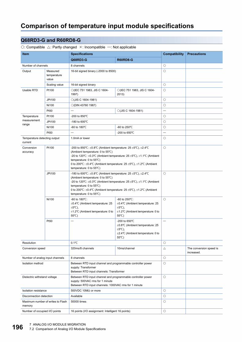
19
Comparison of temperature input module specifications
Q68RD3-G and R60RD8-G: Compatible : Partly changed : Incompatible : Not applicable
Item Specifications Compatibility Precautions
Q68RD3-G R60RD8-GNumber of channels 8 channels
Output Measured temperature value
16-bit signed binary (-2000 to 8500)
Scaling value 16-bit signed binary
Usable RTD Pt100 (IEC 751 1983, JIS C 1604-1997)
(IEC 751 1983, JIS C 1604-2013)
JPt100 (JIS C 1604-1981)
Ni100 (DIN 43760 1987)
Pt50 (JIS C 1604-1981)
Temperature measurement range
Pt100 -200 to 850
JPt100 -180 to 600
Ni100 -60 to 180 -60 to 250
Pt50 -200 to 650
Temperature detecting output current
1.0mA or lower
Conversion accuracy
Pt100 -200 to 850: 0.8 (Ambient temperature: 25 5), 2.4 (Ambient temperature: 0 to 55)-20 to 120: 0.3 (Ambient temperature: 25 5), 1.1 (Ambient temperature: 0 to 55)0 to 200: 0.4 (Ambient temperature: 25 5), 1.2 (Ambient temperature: 0 to 55)
JPt100 -180 to 600: 0.8 (Ambient temperature: 25 5), 2.4 (Ambient temperature: 0 to 55)-20 to 120: 0.3 (Ambient temperature: 25 5), 1.1 (Ambient temperature: 0 to 55)0 to 200: 0.4 (Ambient temperature: 25 5), 1.2 (Ambient temperature: 0 to 55)
Ni100 -60 to 180: 0.4 (Ambient temperature: 25 5),1.2 (Ambient temperature: 0 to 55)
-60 to 250: 0.4 (Ambient temperature: 25 5),1.2 (Ambient temperature: 0 to 55)
Pt50 -200 to 6500.8 (Ambient temperature: 25 5),2.4 (Ambient temperature: 0 to 55)
Resolution 0.1
Conversion speed 320ms/8 channels 10ms/channel The conversion speed is increased.
Number of analog input channels 8 channels
Isolation method Between RTD input channel and programmable controller power supply: TransformerBetween RTD input channels: Transformer
Dielectric withstand voltage Between RTD input channel and programmable controller power supply: 500VAC rms for 1 minuteBetween RTD input channels: 1000VAC rms for 1 minute
Isolation resistance 500VDC 10M or more
Disconnection detection Available
Maximum number of writes to Flash memory
50000 times
Number of occupied I/O points 16 points (I/O assignment: Intelligent 16 points)
6 7 ANALOG I/O MODULE MIGRATION7.2 Comparison of Analog I/O Module Specifications
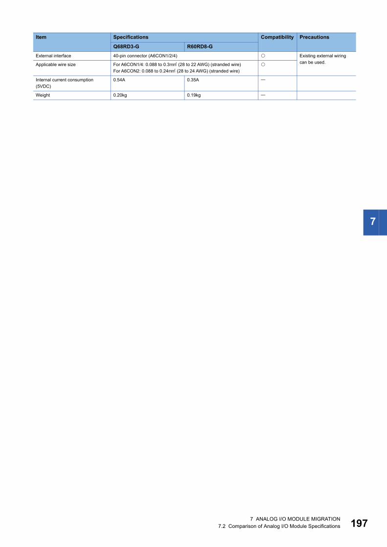
7
External interface 40-pin connector (A6CON1/2/4) Existing external wiring can be used.Applicable wire size For A6CON1/4: 0.088 to 0.3 (28 to 22 AWG) (stranded wire)
For A6CON2: 0.088 to 0.24 (28 to 24 AWG) (stranded wire)
Internal current consumption (5VDC)
0.54A 0.35A
Weight 0.20kg 0.19kg
Item Specifications Compatibility Precautions
Q68RD3-G R60RD8-G
7 ANALOG I/O MODULE MIGRATION7.2 Comparison of Analog I/O Module Specifications 197

19
Q68TD-G-H01 and R60TD8-G: Compatible : Partly changed : Incompatible : Not applicable
Item Specifications Compatibility Precautions
Q68TD-G-H01 R60TD8-GNumber of channels 8 channels
Output Measured temperature value
16-bit signed binary (-2700 to 18200)
Scaling value 16-bit signed binary
Thermocouple compliance standards
IEC60584-1(1995), IEC60584-2(1982), JIS C1602-1995
Cold junction compensation accuracy
1.0
Accuracy (Conversion accuracy) + (Temperature characteristics) (Operating ambient temperature variation) + (Cold junction compensation accuracy)
Resolution B, R, S, N: 0.3 K, E, J, T: 0.1
Conversion speed 320ms/8 channels 30ms/channel The conversion speed is increased.Sampling cycle 320ms/8 channels
Number of analog input channels 8 channels + Cold junction compensation channels/ 1 module
Isolation method Between thermocouple input channel and programmable controller power supply: TransformerBetween thermocouple input channels: TransformerBetween cold junction compensation channel and programmable controller power supply: No isolation
Dielectric withstand voltage Between thermocouple input channel and programmable controller power supply: 500VAC rms for 1 minuteBetween thermocouple input channels: 1000VAC rms for 1 minute
Isolation resistance Between thermocouple input channel and programmable controller power supply: 500VDC, 10M or moreBetween thermocouple input channels: 500VDC, 10M or more
Disconnection detection Not available Available
Maximum number of writes to flash memory
50000 times
Number of occupied I/O points 16 points (I/O assignment: Intelligent 16 points)
External interface 40-pin connector (A6CON1/2/4) Existing external wiring can be used.Applicable wire size For A6CON1/4: 0.088 to 0.3 (28 to 22 AWG) (stranded wire)
For A6CON2: 0.088 to 0.24 (28 to 24 AWG) (stranded wire)
Internal current consumption (5VDC)
0.49A 0.36A
Weight 0.18kg 0.19kg
8 7 ANALOG I/O MODULE MIGRATION7.2 Comparison of Analog I/O Module Specifications

7
Q68TD-G-H02 and R60TD8-G: Compatible : Partly changed : Incompatible : Not applicable
Item Specifications Compatibility Precautions
Q68TD-G-H02 R60TD8-GNumber of channels 8 channels
Output Measured temperature value
16-bit signed binary (-2700 to 18200)
Scaling value 16-bit signed binary
Thermocouple compliance standards
IEC60584-1(1995), IEC60584-2(1982), JIS C1602-1995
Cold junction compensation accuracy
1.0
Accuracy (Conversion accuracy) + (Temperature characteristics) (Operating ambient temperature variation) + (Cold junction compensation accuracy)
Resolution B, R, S, N: 0.3 K, E, J, T: 0.1
Conversion speed 640ms/8 channels 30ms/channel The conversion speed is increased.Sampling cycle 320ms/8 channels
Number of analog input channels 8 channels + Cold junction compensation channels/ 1 module
Isolation method Between thermocouple input channel and programmable controller power supply: TransformerBetween thermocouple input channels: TransformerBetween cold junction compensation channel and programmable controller power supply: No isolation
Dielectric withstand voltage Between thermocouple input channel and programmable controller power supply: 500VAC rms for 1 minuteBetween thermocouple input channels: 1000VAC rms for 1 minute
Isolation resistance Between thermocouple input channel and programmable controller power supply: 500VDC, 10M or moreBetween thermocouple input channels: 500VDC, 10M or more
Disconnection detection Available
Maximum number of writes to flash memory
50000 times
Number of occupied I/O points 16 points (I/O assignment: Intelligent 16 points)
External interface 40-pin connector (A6CON1/2/4) Existing external wiring can be used.Applicable wire size For A6CON1/4: 0.088 to 0.3 (28 to 22 AWG) (stranded wire)
For A6CON2: 0.088 to 0.24 (28 to 24 AWG) (stranded wire)
Internal current consumption (5VDC)
0.65A 0.36A
Weight 0.22kg 0.19kg
7 ANALOG I/O MODULE MIGRATION7.2 Comparison of Analog I/O Module Specifications 199
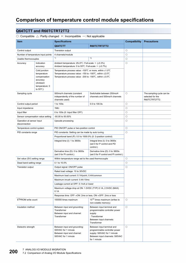
20
Comparison of temperature control module specifications
Q64TCTT and R60TCTRT2TT2: Compatible : Partly changed : Incompatible : Not applicable
Item Specifications Compatibility Precautions
Q64TCTT R60TCTRT2TT2Control output Transistor output
Number of temperature input points 4 channels/module
Usable thermocouples *1 *2
Accuracy Indication accuracy
Ambient temperature: 255: Full-scale (0.3%)Ambient temperature: 0 to 55: Full-scale (0.7%)
Cold junction temperature compensation accuracy (Ambient temperature: 0 to 55)
Temperature process value: -100 or more, within 1.0Temperature process value: -150 to -100, within 2.0Temperature process value: -200 to -150, within 3.0
Sampling cycle 500ms/4 channels (constant independently of the number of channels used)
Switchable between 250ms/4 channels and 500ms/4 channels
The sampling cycle can be selected for the R60TCTRT2TT2.
Control output period 1 to 100s 0.5 to 100.0s
Input impedance 1M
Input filter 0 to 100s (0: Input filter OFF)
Sensor compensation value setting -50.00 to 50.00%
Operation at sensor input disconnection
Upscale processing
Temperature control system PID ON/OFF pulse or two-position control
PID constants range PID constants: Setting can be made by auto tuning.
Proportional band (P): 0.0 to 1000.0% (0: 2-position control)
Integral time (I): 1 to 3600s Integral time (I): 0 to 3600s(set 0 for P control and PD control.)
Derivative time (D): 0 to 3600s(set 0 for PI control.)
Derivative time (D): 0 to 3600s(set 0 for P control and PI control.)
Set value (SV) setting range Within temperature range set to the used thermocouple
Dead band setting range 0.1 to 10.0%
Transistor output Output signal: ON/OFF pulse
Rated load voltage: 10 to 30VDC
Maximum load current: 0.1A/point, 0.4A/common
Maximum inrush current: 0.4A 10ms
Leakage current at OFF: 0.1mA or lower
Maximum voltage drop at ON: 1.0VDC (TYP) 0.1A, 2.5VDC (MAX) 0.1A
Response time: OFFON: 2ms or less, ONOFF: 2ms or less
E2PROM write count 100000 times maximum 1012 times maximum (writes to non-volatile memory)
Insulation method Between input and grounding: TransformerBetween input and channel: Transformer
Between input terminal and programmable controller power supply: TransformerBetween input channels: Transformer
Dielectric strength Between input and grounding: 500VAC for 1 minuteBetween input and channel: 500VAC for 1 minute
Between input terminal and programmable controller power supply: 500VAC for 1 minuteBetween input channels: 500VAC for 1 minute
0 7 ANALOG I/O MODULE MIGRATION7.2 Comparison of Analog I/O Module Specifications
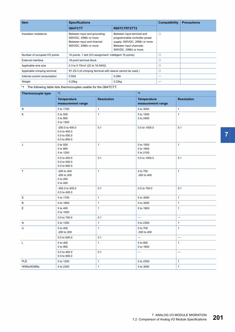
7
*1 The following table lists thermocouples usable for the Q64TCTT.
Insulation resistance Between input and grounding: 500VDC, 20M or moreBetween input and channel: 500VDC, 20M or more
Between input terminal and programmable controller power supply: 500VDC, 20M or moreBetween input channels: 500VDC, 20M or more
Number of occupied I/O points 16 points, 1 slot (I/O assignment: intelligent 16 points)
External interface 18-point terminal block
Applicable wire size 0.3 to 0.75 (22 to 18 AWG)
Applicable crimping terminal R1.25-3 (A crimping terminal with sleeve cannot be used.)
Internal current consumption 0.55A 0.28A
Weight 0.20kg 0.22kg
Thermocouple type
Temperature measurement range
Resolution Temperature measurement range
Resolution
R 0 to 1700 1 0 to 3000 1
K 0 to 5000 to 8000 to 1300
1 0 to 10000 to 2400
1
-200.0 to 400.00.0 to 400.00.0 to 500.00.0 to 800.0
0.1 0.0 to 1000.0 0.1
J 0 to 5000 to 8000 to 1200
1 0 to 10000 to 16000 to 2100
1
0.0 to 400.00.0 to 500.00.0 to 800.0
0.1 0.0 to 1000.0 0.1
T -200 to 400-200 to 2000 to 2000 to 400
1 0 to 700-300 to 400
1
-200.0 to 400.00.0 to 400.0
0.1 0.0 to 700.0 0.1
S 0 to 1700 1 0 to 3000 1
B 0 to 1800 1 0 to 3000 1
E 0 to 4000 to 1000
1 0 to 1800 1
0.0 to 700.0 0.1
N 0 to 1300 1 0 to 2300 1
U 0 to 400-200 to 200
1 0 to 700-300 to 400
1
0.0 to 600.0 0.1
L 0 to 4000 to 900
1 0 to 8000 to 1600
1
0.0 to 400.00.0 to 900.0
0.1
PL 0 to 1200 1 0 to 2300 1
W5Re/W26Re 0 to 2300 1 0 to 3000 1
Item Specifications Compatibility Precautions
Q64TCTT R60TCTRT2TT2
7 ANALOG I/O MODULE MIGRATION7.2 Comparison of Analog I/O Module Specifications 201

20
*2 The following table lists thermocouples usable for the R60TCTRT2TT2.
Thermocouple type
Temperature measuring range
Resolution Effect from wiring resistance of 1 (/)
Temperature measuring range
Resolution Effect from wiring resistance of 1 (/)
R 0 to 1700 1 0.030 0 to 3000 1 0.054
K 0 to 5000 to 8000 to 1300
1 0.005 0 to 10000 to 2400
1 0.008
-200.0 to 400.00.0 to 400.00.0 to 500.00.0 to 800.0-200.0 to 1300.0
0.1 0.0 to 1000.0 0.1
J 0 to 5000 to 8000 to 1200
1 0.003 0 to 10000 to 16000 to 2100
1 0.006
0.0 to 400.00.0 to 500.00.0 to 800.0-200.0 to 1000.0
0.1 0.0 to 1000.0 0.1
T -200 to 400-200 to 2000 to 2000 to 400
1 0.004 0 to 700-300 to 400
1 0.008
-200.0 to 400.00.0 to 400.0
0.1 0.0 to 700.0 0.1
S 0 to 1700 1 0.030 0 to 3000 1 0.054
B 0 to 1800 1 0.038 0 to 3000 1 0.068
E 0 to 4000 to 1000
1 0.003 0 to 1800 1 0.005
0.0 to 700.0-200.0 to 1000.0
0.1
N 0 to 1300 1 0.006 0 to 2300 1 0.011
0.0 to 1000.0 0.1
U 0 to 400-200 to 200
1 0.004 0 to 700-300 to 400
1 0.009
0.0 to 600.0 0.1
L 0 to 4000 to 900
1 0.003 0 to 8000 to 1600
1 0.006
0.0 to 400.00.0 to 900.0
0.1
PL 0 to 1200 1 0.005 0 to 2300 1 0.010
W5Re/W26Re 0 to 2300 1 0.017 0 to 3000 1 0.021
2 7 ANALOG I/O MODULE MIGRATION7.2 Comparison of Analog I/O Module Specifications
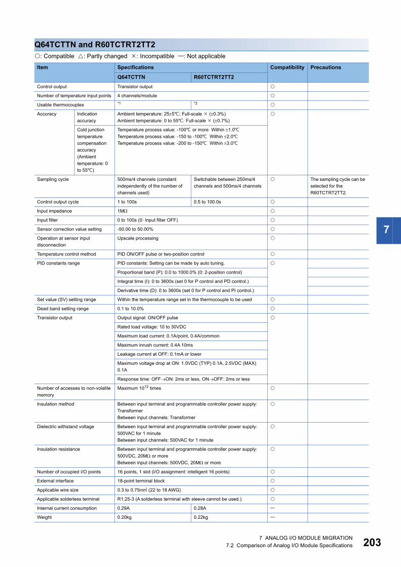
7
Q64TCTTN and R60TCTRT2TT2: Compatible : Partly changed : Incompatible : Not applicable
Item Specifications Compatibility Precautions
Q64TCTTN R60TCTRT2TT2Control output Transistor output
Number of temperature input points 4 channels/module
Usable thermocouples *1 *2
Accuracy Indication accuracy
Ambient temperature: 255: Full-scale (0.3%)Ambient temperature: 0 to 55: Full-scale (0.7%)
Cold junction temperature compensation accuracy (Ambient temperature: 0 to 55)
Temperature process value: -100 or more Within 1.0Temperature process value: -150 to -100 Within 2.0Temperature process value: -200 to -150 Within 3.0
Sampling cycle 500ms/4 channels (constant independently of the number of channels used)
Switchable between 250ms/4 channels and 500ms/4 channels
The sampling cycle can be selected for the R60TCTRT2TT2.
Control output cycle 1 to 100s 0.5 to 100.0s
Input impedance 1M
Input filter 0 to 100s (0: Input filter OFF)
Sensor correction value setting -50.00 to 50.00%
Operation at sensor input disconnection
Upscale processing
Temperature control method PID ON/OFF pulse or two-position control
PID constants range PID constants: Setting can be made by auto tuning.
Proportional band (P): 0.0 to 1000.0% (0: 2-position control)
Integral time (I): 0 to 3600s (set 0 for P control and PD control.)
Derivative time (D): 0 to 3600s (set 0 for P control and PI control.)
Set value (SV) setting range Within the temperature range set in the thermocouple to be used
Dead band setting range 0.1 to 10.0%
Transistor output Output signal: ON/OFF pulse
Rated load voltage: 10 to 30VDC
Maximum load current: 0.1A/point, 0.4A/common
Maximum inrush current: 0.4A 10ms
Leakage current at OFF: 0.1mA or lower
Maximum voltage drop at ON: 1.0VDC (TYP) 0.1A, 2.5VDC (MAX) 0.1A
Response time: OFFON: 2ms or less, ONOFF: 2ms or less
Number of accesses to non-volatile memory
Maximum 1012 times
Insulation method Between input terminal and programmable controller power supply: TransformerBetween input channels: Transformer
Dielectric withstand voltage Between input terminal and programmable controller power supply: 500VAC for 1 minuteBetween input channels: 500VAC for 1 minute
Insulation resistance Between input terminal and programmable controller power supply: 500VDC, 20M or moreBetween input channels: 500VDC, 20M or more
Number of occupied I/O points 16 points, 1 slot (I/O assignment: intelligent 16 points)
External interface 18-point terminal block
Applicable wire size 0.3 to 0.75 (22 to 18 AWG)
Applicable solderless terminal R1.25-3 (A solderless terminal with sleeve cannot be used.)
Internal current consumption 0.29A 0.28A
Weight 0.20kg 0.22kg
7 ANALOG I/O MODULE MIGRATION7.2 Comparison of Analog I/O Module Specifications 203

20
*1 The following table lists thermocouples usable for the Q64TCTTN.
Thermocouple type
Temperature measuring range
Resolution Effect from wiring resistance of 1 (/)
Temperature measuring range
Resolution Effect from wiring resistance of 1 (/)
R 0 to 1700 1 0.030 0 to 3000 1 0.054
K 0 to 5000 to 8000 to 1300
1 0.005 0 to 10000 to 2400
1 0.008
-200.0 to 400.00.0 to 400.00.0 to 500.00.0 to 800.0
0.1 0.0 to 1000.0 0.1
J 0 to 5000 to 8000 to 1200
1 0.003 0 to 10000 to 16000 to 2100
1 0.006
0.0 to 400.00.0 to 500.00.0 to 800.0
0.1 0.0 to 1000.0 0.1
T -200 to 400-200 to 2000 to 2000 to 400
1 0.004 0 to 700-300 to 400
1 0.008
-200.0 to 400.00.0 to 400.0
0.1 0.0 to 700.0 0.1
S 0 to 1700 1 0.030 0 to 3000 1 0.054
B 0 to 1800 1 0.038 0 to 3000 1 0.068
E 0 to 4000 to 1000
1 0.003 0 to 1800 1 0.005
0.0 to 700.0 0.1
N 0 to 1300 1 0.006 0 to 2300 1 0.011
U 0 to 400-200 to 200
1 0.004 0 to 700-300 to 400
1 0.009
0.0 to 600.0 0.1
L 0 to 4000 to 900
1 0.003 0 to 8000 to 1600
1 0.006
0.0 to 400.00.0 to 900.0
0.1
PL 0 to 1200 1 0.005 0 to 2300 1 0.010
W5Re/W26Re 0 to 2300 1 0.017 0 to 3000 1 0.021
4 7 ANALOG I/O MODULE MIGRATION7.2 Comparison of Analog I/O Module Specifications

7
*2 The following table lists thermocouples usable for the R60TCTRT2TT2.
Thermocouple type
Temperature measuring range
Resolution Effect from wiring resistance of 1 (/)
Temperature measuring range
Resolution Effect from wiring resistance of 1 (/)
R 0 to 1700 1 0.030 0 to 3000 1 0.054
K 0 to 5000 to 8000 to 1300
1 0.005 0 to 10000 to 2400
1 0.008
-200.0 to 400.00.0 to 400.00.0 to 500.00.0 to 800.0-200.0 to 1300.0
0.1 0.0 to 1000.0 0.1
J 0 to 5000 to 8000 to 1200
1 0.003 0 to 10000 to 16000 to 2100
1 0.006
0.0 to 400.00.0 to 500.00.0 to 800.0-200.0 to 1000.0
0.1 0.0 to 1000.0 0.1
T -200 to 400-200 to 2000 to 2000 to 400
1 0.004 0 to 700-300 to 400
1 0.008
-200.0 to 400.00.0 to 400.0
0.1 0.0 to 700.0 0.1
S 0 to 1700 1 0.030 0 to 3000 1 0.054
B 0 to 1800 1 0.038 0 to 3000 1 0.068
E 0 to 4000 to 1000
1 0.003 0 to 1800 1 0.005
0.0 to 700.0-200.0 to 1000.0
0.1
N 0 to 1300 1 0.006 0 to 2300 1 0.011
0.0 to 1000.0 0.1
U 0 to 400-200 to 200
1 0.004 0 to 700-300 to 400
1 0.009
0.0 to 600.0 0.1
L 0 to 4000 to 900
1 0.003 0 to 8000 to 1600
1 0.006
0.0 to 400.00.0 to 900.0
0.1
PL 0 to 1200 1 0.005 0 to 2300 1 0.010
W5Re/W26Re 0 to 2300 1 0.017 0 to 3000 1 0.021
7 ANALOG I/O MODULE MIGRATION7.2 Comparison of Analog I/O Module Specifications 205

20
Q64TCRT and R60TCRT4: Compatible : Partly changed : Incompatible : Not applicable
Item Specifications Compatibility Precautions
Q64TCRT R60TCRT4Control output Transistor output
Number of temperature input points 4 channels/module
Usable platinum temperature-measuring resistor
*1 *2
Accuracy Indication accuracy
Ambient temperature: 255: Full-scale (0.3%)Ambient temperature: 0 to 55: Full-scale (0.7%)
Sampling cycle 500ms/4 channels (constant independently of the number of channels used)
Switchable between 250ms/4 channels and 500ms/4 channels
The sampling cycle can be selected for the R60TCRT4.
Control output period 1 to 100s 0.5 to 100.0s
Input impedance 1M
Input filter 0 to 100s (0: Input filter OFF)
Sensor compensation value setting -50.00 to 50.00%
Operation at sensor input disconnection
Upscale processing
Temperature control system PID ON/OFF pulse or two-position control
PID constants range PID constants: Setting can be made by auto tuning.
Proportional band (P): 0.0 to 1000.0% (0: 2-position control)
Integral time (I): 1 to 3600s Integral time (I): 0 to 3600s(set 0 for P control and PD control.)
Derivative time (D): 0 to 3600s(set 0 for PI control.)
Derivative time (D): 0 to 3600s(set 0 for P control and PI control.)
Set value (SV) setting range Within the temperature range set to the used platinum temperature-measuring resistor
Dead band setting range 0.1 to 10.0%
Transistor output Output signal: ON/OFF pulse
Rated load voltage: 10 to 30VDC
Maximum load current: 0.1A/point, 0.4A/common
Maximum inrush current: 0.4A 10ms
Leakage current at OFF: 0.1mA or lower
Maximum voltage drop at ON: 1.0VDC (TYP) 0.1A, 2.5VDC (MAX) 0.1A
Response time: OFFON: 2ms or less, ONOFF: 2ms or less
E2PROM write count 100000 times maximum 1012 times maximum (writes to non-volatile memory)
Insulation method Between input and grounding: TransformerBetween input and channel: Transformer
Between input terminal and programmable controller power supply: TransformerBetween input channels: Transformer
Dielectric strength Between input and grounding: 500VAC for 1 minuteBetween input and channel: 500VAC for 1 minute
Between input terminal and programmable controller power supply: 500VAC for 1 minuteBetween input channels: 500VAC for 1 minute
Insulation resistance Between input and grounding: 500VDC, 20M or moreBetween input and channel: 500VDC, 20M or more
Between input terminal and programmable controller power supply: 500VDC, 20M or moreBetween input channels: 500VDC, 20M or more
Number of occupied I/O points 16 points, 1 slot (I/O assignment: intelligent 16 points)
External interface 18-point terminal block
Applicable wire size 0.3 to 0.75 (22 to 18 AWG)
6 7 ANALOG I/O MODULE MIGRATION7.2 Comparison of Analog I/O Module Specifications
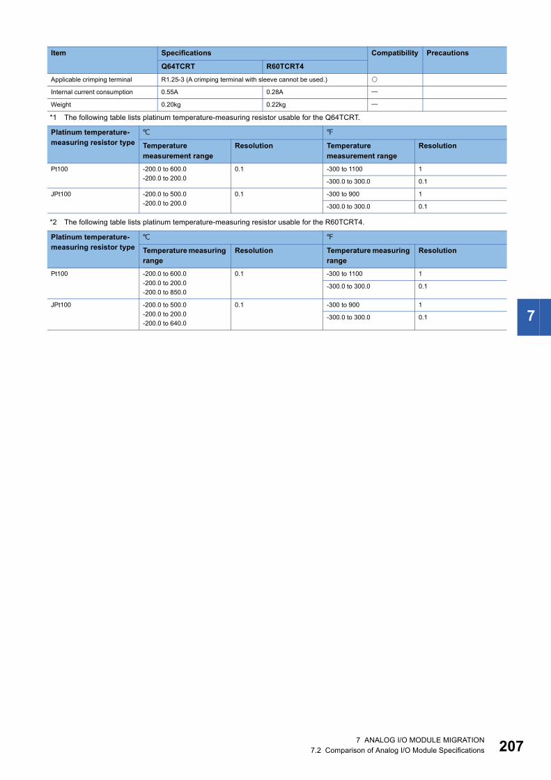
7
*1 The following table lists platinum temperature-measuring resistor usable for the Q64TCRT.
*2 The following table lists platinum temperature-measuring resistor usable for the R60TCRT4.
Applicable crimping terminal R1.25-3 (A crimping terminal with sleeve cannot be used.)
Internal current consumption 0.55A 0.28A
Weight 0.20kg 0.22kg
Platinum temperature-measuring resistor type
Temperature measurement range
Resolution Temperature measurement range
Resolution
Pt100 -200.0 to 600.0-200.0 to 200.0
0.1 -300 to 1100 1
-300.0 to 300.0 0.1
JPt100 -200.0 to 500.0-200.0 to 200.0
0.1 -300 to 900 1
-300.0 to 300.0 0.1
Platinum temperature-measuring resistor type
Temperature measuring range
Resolution Temperature measuring range
Resolution
Pt100 -200.0 to 600.0-200.0 to 200.0-200.0 to 850.0
0.1 -300 to 1100 1
-300.0 to 300.0 0.1
JPt100 -200.0 to 500.0-200.0 to 200.0-200.0 to 640.0
0.1 -300 to 900 1
-300.0 to 300.0 0.1
Item Specifications Compatibility Precautions
Q64TCRT R60TCRT4
7 ANALOG I/O MODULE MIGRATION7.2 Comparison of Analog I/O Module Specifications 207
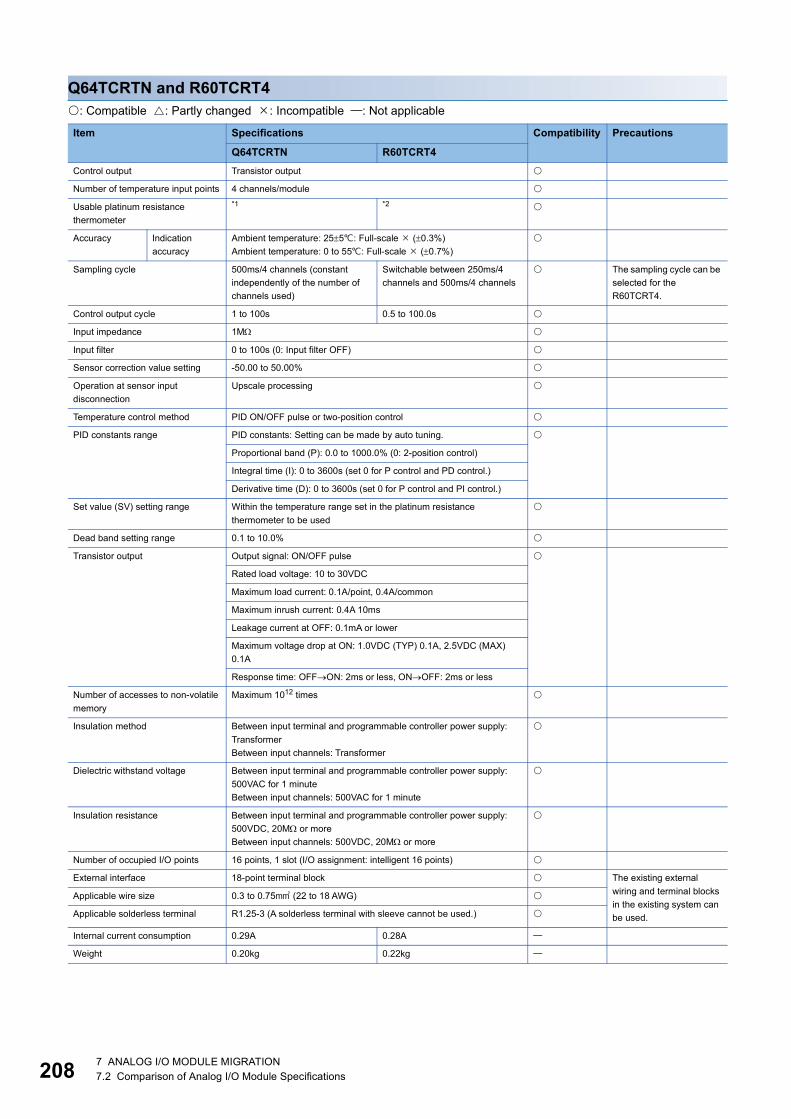
20
Q64TCRTN and R60TCRT4: Compatible : Partly changed : Incompatible : Not applicable
Item Specifications Compatibility Precautions
Q64TCRTN R60TCRT4Control output Transistor output
Number of temperature input points 4 channels/module
Usable platinum resistance thermometer
*1 *2
Accuracy Indication accuracy
Ambient temperature: 255: Full-scale (0.3%)Ambient temperature: 0 to 55: Full-scale (0.7%)
Sampling cycle 500ms/4 channels (constant independently of the number of channels used)
Switchable between 250ms/4 channels and 500ms/4 channels
The sampling cycle can be selected for the R60TCRT4.
Control output cycle 1 to 100s 0.5 to 100.0s
Input impedance 1M
Input filter 0 to 100s (0: Input filter OFF)
Sensor correction value setting -50.00 to 50.00%
Operation at sensor input disconnection
Upscale processing
Temperature control method PID ON/OFF pulse or two-position control
PID constants range PID constants: Setting can be made by auto tuning.
Proportional band (P): 0.0 to 1000.0% (0: 2-position control)
Integral time (I): 0 to 3600s (set 0 for P control and PD control.)
Derivative time (D): 0 to 3600s (set 0 for P control and PI control.)
Set value (SV) setting range Within the temperature range set in the platinum resistance thermometer to be used
Dead band setting range 0.1 to 10.0%
Transistor output Output signal: ON/OFF pulse
Rated load voltage: 10 to 30VDC
Maximum load current: 0.1A/point, 0.4A/common
Maximum inrush current: 0.4A 10ms
Leakage current at OFF: 0.1mA or lower
Maximum voltage drop at ON: 1.0VDC (TYP) 0.1A, 2.5VDC (MAX) 0.1A
Response time: OFFON: 2ms or less, ONOFF: 2ms or less
Number of accesses to non-volatile memory
Maximum 1012 times
Insulation method Between input terminal and programmable controller power supply: TransformerBetween input channels: Transformer
Dielectric withstand voltage Between input terminal and programmable controller power supply: 500VAC for 1 minuteBetween input channels: 500VAC for 1 minute
Insulation resistance Between input terminal and programmable controller power supply: 500VDC, 20M or moreBetween input channels: 500VDC, 20M or more
Number of occupied I/O points 16 points, 1 slot (I/O assignment: intelligent 16 points)
External interface 18-point terminal block The existing external wiring and terminal blocks in the existing system can be used.
Applicable wire size 0.3 to 0.75 (22 to 18 AWG)
Applicable solderless terminal R1.25-3 (A solderless terminal with sleeve cannot be used.)
Internal current consumption 0.29A 0.28A
Weight 0.20kg 0.22kg
8 7 ANALOG I/O MODULE MIGRATION7.2 Comparison of Analog I/O Module Specifications
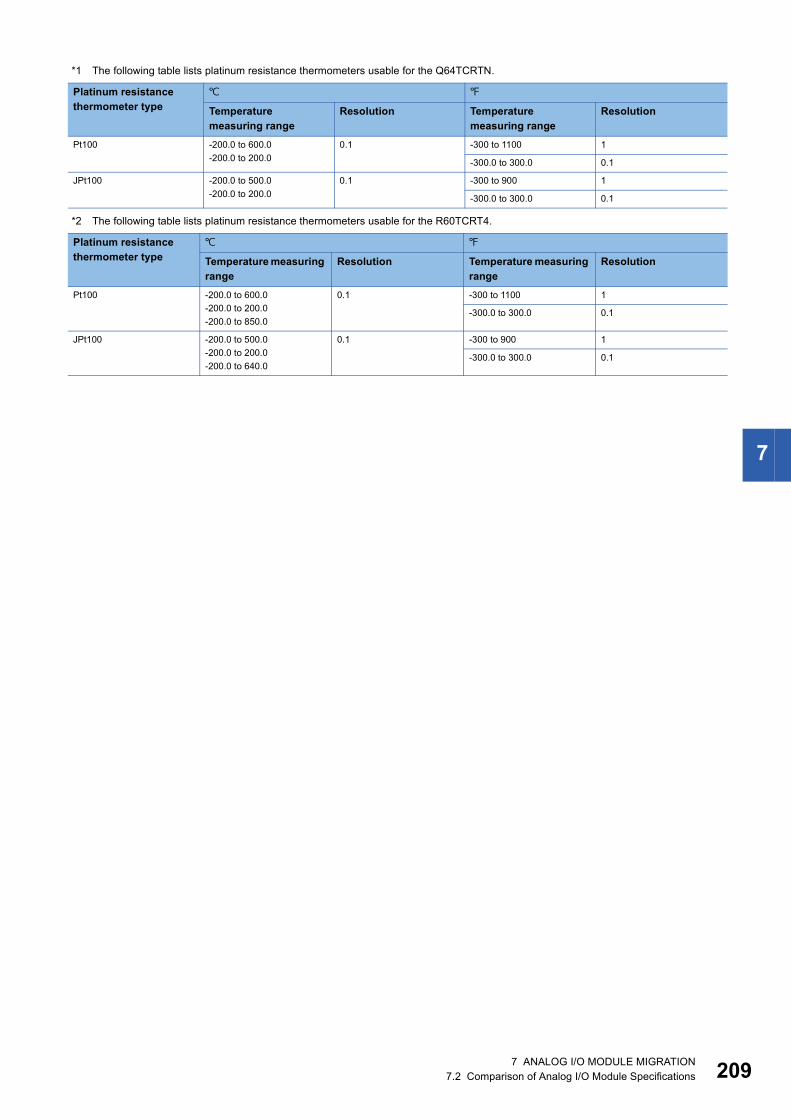
7
*1 The following table lists platinum resistance thermometers usable for the Q64TCRTN.
*2 The following table lists platinum resistance thermometers usable for the R60TCRT4.
Platinum resistance thermometer type
Temperature measuring range
Resolution Temperature measuring range
Resolution
Pt100 -200.0 to 600.0-200.0 to 200.0
0.1 -300 to 1100 1
-300.0 to 300.0 0.1
JPt100 -200.0 to 500.0-200.0 to 200.0
0.1 -300 to 900 1
-300.0 to 300.0 0.1
Platinum resistance thermometer type
Temperature measuring range
Resolution Temperature measuring range
Resolution
Pt100 -200.0 to 600.0-200.0 to 200.0-200.0 to 850.0
0.1 -300 to 1100 1
-300.0 to 300.0 0.1
JPt100 -200.0 to 500.0-200.0 to 200.0-200.0 to 640.0
0.1 -300 to 900 1
-300.0 to 300.0 0.1
7 ANALOG I/O MODULE MIGRATION7.2 Comparison of Analog I/O Module Specifications 209

21
Q64TCTTBW and R60TCTRT2TT2BW: Compatible : Partly changed : Incompatible : Not applicable
Item Specifications Compatibility Precautions
Q64TCTTBW R60TCTRT2TT2BWControl output Transistor output
Number of temperature input points 4 channels/module
Usable thermocouples *1 *2
Accuracy Indication accuracy
Ambient temperature: 255: Full-scale (0.3%)Ambient temperature: 0 to 55: Full-scale (0.7%)
Cold junction temperature compensation accuracy (Ambient temperature: 0 to 55)
Temperature process value: -100 or more Within 1.0Temperature process value: -150 to -100 Within 2.0Temperature process value: -200 to -150 Within 3.0
Sampling cycle 500ms/4 channels (constant independently of the number of channels used)
Switchable between 250ms/4 channels and 500ms/4 channels
The sampling cycle can be selected for the R60TCTRT2TT2BW.
Control output period 1 to 100s 0.5 to 100.0s
Input impedance 1M
Input filter 0 to 100s (0: Input filter OFF)
Sensor compensation value setting -50.00 to 50.00%
Operation at sensor input disconnection
Upscale processing
Temperature control system PID ON/OFF pulse or two-position control
PID constants range PID constants: Setting can be made by auto tuning.
Proportional band (P): 0.0 to 1000.0% (0: 2-position control)
Integral time (I): 1 to 3600s Integral time (I): 0 to 3600s(set 0 for P control and PD control.)
Derivative time (D): 0 to 3600s(set 0 for PI control.)
Derivative time (D): 0 to 3600s(set 0 for P control and PI control.)
Set value (SV) setting range Within the temperature range set in the thermocouple to be used
Dead band setting range 0.1 to 10.0%
Transistor output Output signal: ON/OFF pulse
Rated load voltage: 10 to 30VDC
Maximum load current: 0.1A/point, 0.4A/common
Maximum inrush current: 0.4A 10ms
Leakage current at OFF: 0.1mA or lower
Maximum voltage drop at ON: 1.0VDC (TYP) 0.1A, 2.5VDC (MAX) 0.1A
Response time: OFFON: 2ms or less, ONOFF: 2ms or less
E2PROM write count 100000 times maximum 1012 times maximum (writes to non-volatile memory)
Insulation method Between input and grounding: TransformerBetween input and channel: Transformer
Between input terminal and programmable controller power supply: TransformerBetween input channels: Transformer
Dielectric strength Between input and grounding: 500VAC for 1 minuteBetween input and channel: 500VAC for 1 minute
Between input terminal and programmable controller power supply: 500VAC for 1 minuteBetween input channels: 500VAC for 1 minute
0 7 ANALOG I/O MODULE MIGRATION7.2 Comparison of Analog I/O Module Specifications

7
*1 The following table lists thermocouples usable for the Q64TCTTBW.
Insulation resistance Between input and grounding: 500VDC, 20M or moreBetween input and channel: 500VDC, 20M or more
Between input terminal and programmable controller power supply: 500VDC, 20M or moreBetween input channels: 500VDC, 20M or more
Heater disconnection detection specifications
Current sensor*3
Input accuracy: Full scale (1.0%)
Alert delay count: 3 to 255 times
Number of occupied I/O points 32 points, 2 slots (I/O assignment: empty 16 points + intelligent 16 points)
External interface 18-point terminal block 2
Applicable wire size 0.3 to 0.75 (22 to 18 AWG)
Applicable crimping terminal R1.25-3 (A crimping terminal with sleeve cannot be used.)
Internal current consumption 0.64A 0.31A
Weight 0.30kg 0.34kg
Thermocouple type
Temperature measurement range
Resolution Temperature measurement range
Resolution
R 0 to 1700 1 0 to 3000 1
K 0 to 5000 to 8000 to 1300
1 0 to 10000 to 2400
1
-200.0 to 400.00.0 to 400.00.0 to 500.00.0 to 800.0
0.1 0.0 to 1000.0 0.1
J 0 to 5000 to 8000 to 1200
1 0 to 10000 to 16000 to 2100
1
0.0 to 400.00.0 to 500.00.0 to 800.0
0.1 0.0 to 1000.0 0.1
T -200 to 400-200 to 2000 to 2000 to 400
1 0 to 700-300 to 400
1
-200.0 to 400.00.0 to 400.0
0.1 0.0 to 700.0 0.1
S 0 to 1700 1 0 to 3000 1
B 0 to 1800 1 0 to 3000 1
E 0 to 4000 to 1000
1 0 to 1800 1
0.0 to 700.0 0.1
N 0 to 1300 1 0 to 2300 1
U 0 to 400-200 to 200
1 0 to 700-300 to 400
1
0.0 to 600.0 0.1
L 0 to 4000 to 900
1 0 to 8000 to 1600
1
0.0 to 400.00.0 to 900.0
0.1
PL 0 to 1200 1 0 to 2300 1
W5Re/W26Re 0 to 2300 1 0 to 3000 1
Item Specifications Compatibility Precautions
Q64TCTTBW R60TCTRT2TT2BW
7 ANALOG I/O MODULE MIGRATION7.2 Comparison of Analog I/O Module Specifications 211

21
*2 The following table lists thermocouples usable for the R60TCTRT2TT2BW.
*3 The following list selectable current sensors.Q64TCTTBW • CTL-12-S36-8 (0.0 to 100.0A) • CTL-6-P-H (0.0~20.00A) (The conventional CTL-6-P is also available.)R60TCTRT2TT2BW
Thermocouple type
Temperature measuring range
Resolution Effect from wiring resistance of 1 (/)
Temperature measuring range
Resolution Effect from wiring resistance of 1 (/)
R 0 to 1700 1 0.030 0 to 3000 1 0.054
K 0 to 5000 to 8000 to 1300
1 0.005 0 to 10000 to 2400
1 0.008
-200.0 to 400.00.0 to 400.00.0 to 500.00.0 to 800.0-200.0 to 1300.0
0.1 0.0 to 1000.0 0.1
J 0 to 5000 to 8000 to 1200
1 0.003 0 to 10000 to 16000 to 2100
1 0.006
0.0 to 400.00.0 to 500.00.0 to 800.0-200.0 to 1000.0
0.1 0.0 to 1000.0 0.1
T -200 to 400-200 to 2000 to 2000 to 400
1 0.004 0 to 700-300 to 400
1 0.008
-200.0 to 400.00.0 to 400.0
0.1 0.0 to 700.0 0.1
S 0 to 1700 1 0.030 0 to 3000 1 0.054
B 0 to 1800 1 0.038 0 to 3000 1 0.068
E 0 to 4000 to 1000
1 0.003 0 to 1800 1 0.005
0.0 to 700.0-200.0 to 1000.0
0.1
N 0 to 1300 1 0.006 0 to 2300 1 0.011
0.0 to 1000.0 0.1
U 0 to 400-200 to 200
1 0.004 0 to 700-300 to 400
1 0.009
0.0 to 600.0 0.1
L 0 to 4000 to 900
1 0.003 0 to 8000 to 1600
1 0.006
0.0 to 400.00.0 to 900.0
0.1
PL 0 to 1200 1 0.005 0 to 2300 1 0.010
W5Re/W26Re 0 to 2300 1 0.017 0 to 3000 1 0.021
Model name ContactCTL-12-S36-10 (0.0 to 100.0A) U.R.D. Co., LTD.
www.u-rd.comCTL-12-S56-10 (0.0 to 100.0A)
CTL-6-P-H (0.00 to 20.00A)
CTL-6-S-H (0.00 to 20.00A)
CTL-12L-8 (0.0 to 100.0A)
2 7 ANALOG I/O MODULE MIGRATION7.2 Comparison of Analog I/O Module Specifications
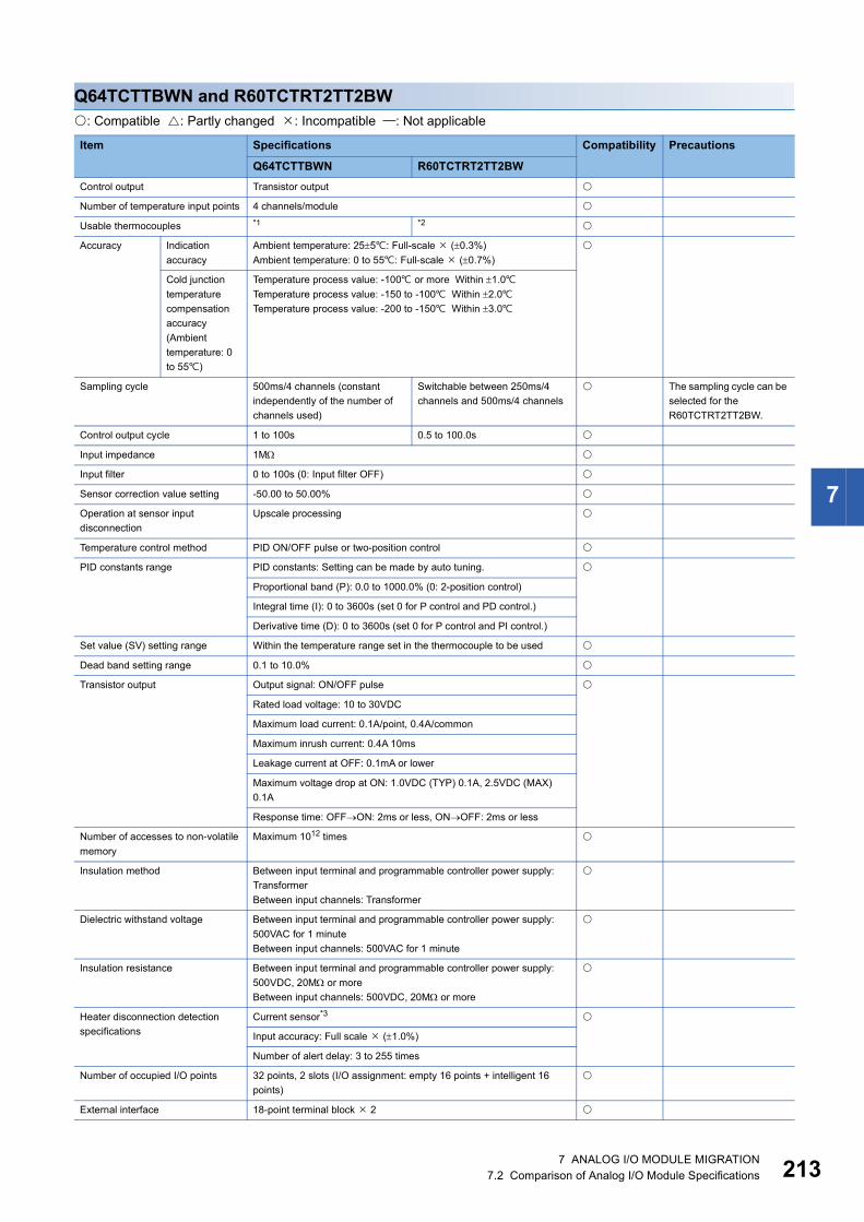
7
Q64TCTTBWN and R60TCTRT2TT2BW: Compatible : Partly changed : Incompatible : Not applicable
Item Specifications Compatibility Precautions
Q64TCTTBWN R60TCTRT2TT2BWControl output Transistor output
Number of temperature input points 4 channels/module
Usable thermocouples *1 *2
Accuracy Indication accuracy
Ambient temperature: 255: Full-scale (0.3%)Ambient temperature: 0 to 55: Full-scale (0.7%)
Cold junction temperature compensation accuracy (Ambient temperature: 0 to 55)
Temperature process value: -100 or more Within 1.0Temperature process value: -150 to -100 Within 2.0Temperature process value: -200 to -150 Within 3.0
Sampling cycle 500ms/4 channels (constant independently of the number of channels used)
Switchable between 250ms/4 channels and 500ms/4 channels
The sampling cycle can be selected for the R60TCTRT2TT2BW.
Control output cycle 1 to 100s 0.5 to 100.0s
Input impedance 1M
Input filter 0 to 100s (0: Input filter OFF)
Sensor correction value setting -50.00 to 50.00%
Operation at sensor input disconnection
Upscale processing
Temperature control method PID ON/OFF pulse or two-position control
PID constants range PID constants: Setting can be made by auto tuning.
Proportional band (P): 0.0 to 1000.0% (0: 2-position control)
Integral time (I): 0 to 3600s (set 0 for P control and PD control.)
Derivative time (D): 0 to 3600s (set 0 for P control and PI control.)
Set value (SV) setting range Within the temperature range set in the thermocouple to be used
Dead band setting range 0.1 to 10.0%
Transistor output Output signal: ON/OFF pulse
Rated load voltage: 10 to 30VDC
Maximum load current: 0.1A/point, 0.4A/common
Maximum inrush current: 0.4A 10ms
Leakage current at OFF: 0.1mA or lower
Maximum voltage drop at ON: 1.0VDC (TYP) 0.1A, 2.5VDC (MAX) 0.1A
Response time: OFFON: 2ms or less, ONOFF: 2ms or less
Number of accesses to non-volatile memory
Maximum 1012 times
Insulation method Between input terminal and programmable controller power supply: TransformerBetween input channels: Transformer
Dielectric withstand voltage Between input terminal and programmable controller power supply: 500VAC for 1 minuteBetween input channels: 500VAC for 1 minute
Insulation resistance Between input terminal and programmable controller power supply: 500VDC, 20M or moreBetween input channels: 500VDC, 20M or more
Heater disconnection detection specifications
Current sensor*3
Input accuracy: Full scale (1.0%)
Number of alert delay: 3 to 255 times
Number of occupied I/O points 32 points, 2 slots (I/O assignment: empty 16 points + intelligent 16 points)
External interface 18-point terminal block 2
7 ANALOG I/O MODULE MIGRATION7.2 Comparison of Analog I/O Module Specifications 213

21
Applicable wire size 0.3 to 0.75 (22 to 18 AWG)
Applicable solderless terminal R1.25-3 (A solderless terminal with sleeve cannot be used.)
Internal current consumption 0.33A 0.31A
Weight 0.30kg 0.34kg
Item Specifications Compatibility Precautions
Q64TCTTBWN R60TCTRT2TT2BW
4 7 ANALOG I/O MODULE MIGRATION7.2 Comparison of Analog I/O Module Specifications

7
*1 The following table lists thermocouples usable for the Q64TCTTBWN.
Thermocouple type
Temperature measuring range
Resolution Effect from wiring resistance of 1 (/)
Temperature measuring range
Resolution Effect from wiring resistance of 1 (/)
R 0 to 1700 1 0.030 0 to 3000 1 0.054
K 0 to 5000 to 8000 to 1300
1 0.005 0 to 10000 to 2400
1 0.008
-200.0 to 400.00.0 to 400.00.0 to 500.00.0 to 800.0
0.1 0.0 to 1000.0 0.1
J 0 to 5000 to 8000 to 1200
1 0.003 0 to 10000 to 16000 to 2100
1 0.006
0.0 to 400.00.0 to 500.00.0 to 800.0
0.1 0.0 to 1000.0 0.1
T -200 to 400-200 to 2000 to 2000 to 400
1 0.004 0 to 700-300 to 400
1 0.008
-200.0 to 400.00.0 to 400.0
0.1 0.0 to 700.0 0.1
S 0 to 1700 1 0.030 0 to 3000 1 0.054
B 0 to 1800 1 0.038 0 to 3000 1 0.068
E 0 to 4000 to 1000
1 0.003 0 to 1800 1 0.005
0.0 to 700.0 0.1
N 0 to 1300 1 0.006 0 to 2300 1 0.011
U 0 to 400-200 to 200
1 0.004 0 to 700-300 to 400
1 0.009
0.0 to 600.0 0.1
L 0 to 4000 to 900
1 0.003 0 to 8000 to 1600
1 0.006
0.0 to 400.00.0 to 900.0
0.1
PL 0 to 1200 1 0.005 0 to 2300 1 0.010
W5Re/W26Re 0 to 2300 1 0.017 0 to 3000 1 0.021
7 ANALOG I/O MODULE MIGRATION7.2 Comparison of Analog I/O Module Specifications 215

21
*2 The following table lists thermocouples usable for the R60TCTRT2TT2BW.
Thermocouple type
Temperature measuring range
Resolution Effect from wiring resistance of 1 (/)
Temperature measuring range
Resolution Effect from wiring resistance of 1 (/)
R 0 to 1700 1 0.030 0 to 3000 1 0.054
K 0 to 5000 to 8000 to 1300
1 0.005 0 to 10000 to 2400
1 0.008
-200.0 to 400.00.0 to 400.00.0 to 500.00.0 to 800.0-200.0 to 1300.0
0.1 0.0 to 1000.0 0.1
J 0 to 5000 to 8000 to 1200
1 0.003 0 to 10000 to 16000 to 2100
1 0.006
0.0 to 400.00.0 to 500.00.0 to 800.0-200.0 to 1000.0
0.1 0.0 to 1000.0 0.1
T -200 to 400-200 to 2000 to 2000 to 400
1 0.004 0 to 700-300 to 400
1 0.008
-200.0 to 400.00.0 to 400.0
0.1 0.0 to 700.0 0.1
S 0 to 1700 1 0.030 0 to 3000 1 0.054
B 0 to 1800 1 0.038 0 to 3000 1 0.068
E 0 to 4000 to 1000
1 0.003 0 to 1800 1 0.005
0.0 to 700.0-200.0 to 1000.0
0.1
N 0 to 1300 1 0.006 0 to 2300 1 0.011
0.0 to 1000.0 0.1
U 0 to 400-200 to 200
1 0.004 0 to 700-300 to 400
1 0.009
0.0 to 600.0 0.1
L 0 to 4000 to 900
1 0.003 0 to 8000 to 1600
1 0.006
0.0 to 400.00.0 to 900.0
0.1
PL 0 to 1200 1 0.005 0 to 2300 1 0.010
W5Re/W26Re 0 to 2300 1 0.017 0 to 3000 1 0.021
6 7 ANALOG I/O MODULE MIGRATION7.2 Comparison of Analog I/O Module Specifications

7
*3 The following tables list selectable current sensors.Q64TCTTBWN
R60TCTRT2TT2BW
Model name ContactCTL-12-S36-8 (0.0 to 100.0A) U.R.D. Co., LTD.
www.u-rd.comCTL-12-S36-10 (0.0 to 100.0A)
CTL-12-S56-10 (0.0 to 100.0A)
CTL-6-P (0.00 to 20.00A)
CTL-6-P-H (0.00 to 20.00A)
Model name ContactCTL-12-S36-10 (0.0 to 100.0A) U.R.D. Co., LTD.
www.u-rd.comCTL-12-S56-10 (0.0 to 100.0A)
CTL-6-P-H (0.00 to 20.00A)
CTL-6-S-H (0.00 to 20.00A)
CTL-12L-8 (0.0 to 100.0A)
7 ANALOG I/O MODULE MIGRATION7.2 Comparison of Analog I/O Module Specifications 217
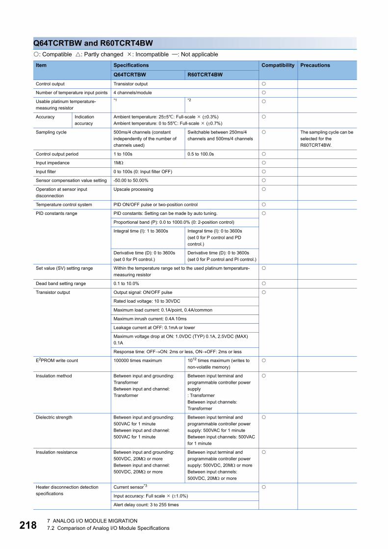
21
Q64TCRTBW and R60TCRT4BW: Compatible : Partly changed : Incompatible : Not applicable
Item Specifications Compatibility Precautions
Q64TCRTBW R60TCRT4BWControl output Transistor output
Number of temperature input points 4 channels/module
Usable platinum temperature-measuring resistor
*1 *2
Accuracy Indication accuracy
Ambient temperature: 255: Full-scale (0.3%)Ambient temperature: 0 to 55: Full-scale (0.7%)
Sampling cycle 500ms/4 channels (constant independently of the number of channels used)
Switchable between 250ms/4 channels and 500ms/4 channels
The sampling cycle can be selected for the R60TCRT4BW.
Control output period 1 to 100s 0.5 to 100.0s
Input impedance 1M
Input filter 0 to 100s (0: Input filter OFF)
Sensor compensation value setting -50.00 to 50.00%
Operation at sensor input disconnection
Upscale processing
Temperature control system PID ON/OFF pulse or two-position control
PID constants range PID constants: Setting can be made by auto tuning.
Proportional band (P): 0.0 to 1000.0% (0: 2-position control)
Integral time (I): 1 to 3600s Integral time (I): 0 to 3600s(set 0 for P control and PD control.)
Derivative time (D): 0 to 3600s(set 0 for PI control.)
Derivative time (D): 0 to 3600s(set 0 for P control and PI control.)
Set value (SV) setting range Within the temperature range set to the used platinum temperature-measuring resistor
Dead band setting range 0.1 to 10.0%
Transistor output Output signal: ON/OFF pulse
Rated load voltage: 10 to 30VDC
Maximum load current: 0.1A/point, 0.4A/common
Maximum inrush current: 0.4A 10ms
Leakage current at OFF: 0.1mA or lower
Maximum voltage drop at ON: 1.0VDC (TYP) 0.1A, 2.5VDC (MAX) 0.1A
Response time: OFFON: 2ms or less, ONOFF: 2ms or less
E2PROM write count 100000 times maximum 1012 times maximum (writes to non-volatile memory)
Insulation method Between input and grounding: TransformerBetween input and channel: Transformer
Between input terminal and programmable controller power supply: TransformerBetween input channels: Transformer
Dielectric strength Between input and grounding: 500VAC for 1 minuteBetween input and channel: 500VAC for 1 minute
Between input terminal and programmable controller power supply: 500VAC for 1 minuteBetween input channels: 500VAC for 1 minute
Insulation resistance Between input and grounding: 500VDC, 20M or moreBetween input and channel: 500VDC, 20M or more
Between input terminal and programmable controller power supply: 500VDC, 20M or moreBetween input channels: 500VDC, 20M or more
Heater disconnection detection specifications
Current sensor*3
Input accuracy: Full scale (1.0%)
Alert delay count: 3 to 255 times
8 7 ANALOG I/O MODULE MIGRATION7.2 Comparison of Analog I/O Module Specifications

7
*1 The following table lists platinum temperature-measuring resistor usable for the Q64TCRTBW.
*2 The following table lists platinum temperature-measuring resistor usable for the R60TCRT4BW.
*3 The following list selectable current sensors.Q64TCRTBW • CTL-12-S36-8 (0.0 to 100.0A) • CTL-6-P-H (0.0~20.00A) (The conventional CTL-6-P is also available.)R60TCRT4BW
Number of occupied I/O points 32 points, 2 slots (I/O assignment: empty 16 points + intelligent 16 points)
External interface 18-point terminal block 2
Applicable wire size 0.3 to 0.75 (22 to 18 AWG)
Applicable crimping terminal R1.25-3 (A crimping terminal with sleeve cannot be used.)
Internal current consumption 0.64A 0.31A
Weight 0.30kg 0.34kg
Platinum temperature-measuring resistor type
Temperature measurement range
Resolution Temperature measurement range
Resolution
Pt100 -200.0 to 600.0-200.0 to 200.0
0.1 -300 to 1100 1
-300.0 to 300.0 0.1
JPt100 -200.0 to 500.0-200.0 to 200.0
0.1 -300 to 900 1
-300.0 to 300.0 0.1
Platinum temperature-measuring resistor type
Temperature measuring range
Resolution Temperature measuring range
Resolution
Pt100 -200.0 to 600.0-200.0 to 200.0-200.0 to 850.0
0.1 -300 to 1100 1
-300.0 to 300.0 0.1
JPt100 -200.0 to 500.0-200.0 to 200.0-200.0 to 640.0
0.1 -300 to 900 1
-300.0 to 300.0 0.1
Model name ContactCTL-12-S36-10 (0.0 to 100.0A) U.R.D. Co., LTD.
www.u-rd.comCTL-12-S56-10 (0.0 to 100.0A)
CTL-6-P-H (0.00 to 20.00A)
CTL-6-S-H (0.00 to 20.00A)
CTL-12L-8 (0.0 to 100.0A)
Item Specifications Compatibility Precautions
Q64TCRTBW R60TCRT4BW
7 ANALOG I/O MODULE MIGRATION7.2 Comparison of Analog I/O Module Specifications 219

22
Q64TCRTBWN and R60TCRT4BW: Compatible : Partly changed : Incompatible : Not applicable
Item Specifications Compatibility Precautions
Q64TCRTBWN R60TCRT4BWControl output Transistor output
Number of temperature input points 4 channels/module
Usable platinum resistance thermometer
*1 *2
Accuracy Indication accuracy
Ambient temperature: 255: Full-scale (0.3%)Ambient temperature: 0 to 55: Full-scale (0.7%)
Sampling cycle 500ms/4 channels (constant independently of the number of channels used)
Switchable between 250ms/4 channels and 500ms/4 channels
The sampling cycle can be selected for the R60TCRT4BW.
Control output cycle 1 to 100s 0.5 to 100.0s
Input impedance 1M
Input filter 0 to 100s (0: Input filter OFF)
Sensor correction value setting -50.00 to 50.00%
Operation at sensor input disconnection
Upscale processing
Temperature control method PID ON/OFF pulse or two-position control
PID constants range PID constants: Setting can be made by auto tuning.
Proportional band (P): 0.0 to 1000.0% (0: 2-position control)
Integral time (I): 0 to 3600s (set 0 for P control and PD control.)
Derivative time (D): 0 to 3600s (set 0 for P control and PI control.)
Set value (SV) setting range Within the temperature range set in the platinum resistance thermometer to be used
Dead band setting range 0.1 to 10.0%
Transistor output Output signal: ON/OFF pulse
Rated load voltage: 10 to 30VDC
Maximum load current: 0.1A/point, 0.4A/common
Maximum inrush current: 0.4A 10ms
Leakage current at OFF: 0.1mA or lower
Maximum voltage drop at ON: 1.0VDC (TYP) 0.1A, 2.5VDC (MAX) 0.1A
Response time: OFFON: 2ms or less, ONOFF: 2ms or less
Number of accesses to non-volatile memory
Maximum 1012 times
Insulation method Between input terminal and programmable controller power supply: TransformerBetween input channels: Transformer
Dielectric withstand voltage Between input terminal and programmable controller power supply: 500VAC for 1 minuteBetween input channels: 500VAC for 1 minute
Insulation resistance Between input terminal and programmable controller power supply: 500VDC, 20M or moreBetween input channels: 500VDC, 20M or more
Heater disconnection detection specifications
Current sensor*3
Input accuracy: Full scale (1.0%)
Number of alert delay: 3 to 255 times
Number of occupied I/O points 32 points, 2 slots (I/O assignment: empty 16 points + intelligent 16 points)
External interface 18-point terminal block 2
Applicable wire size 0.3 to 0.75 (22 to 18 AWG)
Applicable solderless terminal R1.25-3 (A solderless terminal with sleeve cannot be used.)
Internal current consumption 0.33A 0.31A
Weight 0.30kg 0.34kg
0 7 ANALOG I/O MODULE MIGRATION7.2 Comparison of Analog I/O Module Specifications

7
*1 The following table lists platinum resistance thermometers usable for the Q64TCRTBWN.
*2 The following table lists platinum resistance thermometers usable for the R60TCRT4BW.
*3 The following tables list selectable current sensors.Q64TCRTBWN
R60TCRT4BW
Platinum resistance thermometer type
Temperature measurement range
Resolution Temperature measurement range
Resolution
Pt100 -200.0 to 600.0-200.0 to 200.0
0.1 -300 to 1100 1
-300.0 to 300.0 0.1
JPt100 -200.0 to 500.0-200.0 to 200.0
0.1 -300 to 900 1
-300.0 to 300.0 0.1
Platinum resistance thermometer type
Temperature measuring range
Resolution Temperature measuring range
Resolution
Pt100 -200.0 to 600.0-200.0 to 200.0-200.0 to 850.0
0.1 -300 to 1100 1
-300.0 to 300.0 0.1
JPt100 -200.0 to 500.0-200.0 to 200.0-200.0 to 640.0
0.1 -300 to 900 1
-300.0 to 300.0 0.1
Model name ContactCTL-12-S36-8 (0.0 to 100.0A) U.R.D. Co., LTD.
www.u-rd.comCTL-12-S36-10 (0.0 to 100.0A)
CTL-12-S56-10 (0.0 to 100.0A)
CTL-6-P (0.00 to 20.00A)
CTL-6-P-H (0.00 to 20.00A)
Model name ContactCTL-12-S36-10 (0.0 to 100.0A) U.R.D. Co., LTD.
www.u-rd.comCTL-12-S56-10 (0.0 to 100.0A)
CTL-6-P-H (0.00 to 20.00A)
CTL-6-S-H (0.00 to 20.00A)
CTL-12L-8 (0.0 to 100.0A)
7 ANALOG I/O MODULE MIGRATION7.2 Comparison of Analog I/O Module Specifications 221
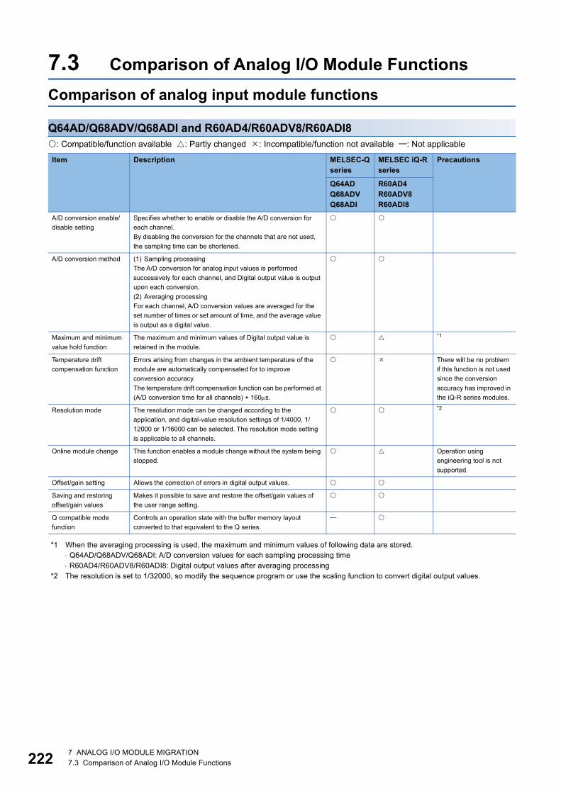
22
7.3 Comparison of Analog I/O Module FunctionsComparison of analog input module functions
Q64AD/Q68ADV/Q68ADI and R60AD4/R60ADV8/R60ADI8: Compatible/function available : Partly changed : Incompatible/function not available : Not applicable
*1 When the averaging processing is used, the maximum and minimum values of following data are stored. Q64AD/Q68ADV/Q68ADI: A/D conversion values for each sampling processing time R60AD4/R60ADV8/R60ADI8: Digital output values after averaging processing
*2 The resolution is set to 1/32000, so modify the sequence program or use the scaling function to convert digital output values.
Item Description MELSEC-Q series
MELSEC iQ-R series
Precautions
Q64ADQ68ADVQ68ADI
R60AD4R60ADV8R60ADI8
A/D conversion enable/disable setting
Specifies whether to enable or disable the A/D conversion for each channel.By disabling the conversion for the channels that are not used, the sampling time can be shortened.
A/D conversion method (1) Sampling processingThe A/D conversion for analog input values is performed successively for each channel, and Digital output value is output upon each conversion.(2) Averaging processingFor each channel, A/D conversion values are averaged for the set number of times or set amount of time, and the average value is output as a digital value.
Maximum and minimum value hold function
The maximum and minimum values of Digital output value is retained in the module.
*1
Temperature drift compensation function
Errors arising from changes in the ambient temperature of the module are automatically compensated for to improve conversion accuracy.The temperature drift compensation function can be performed at (A/D conversion time for all channels) + 160s.
There will be no problem if this function is not used since the conversion accuracy has improved in the iQ-R series modules.
Resolution mode The resolution mode can be changed according to the application, and digital-value resolution settings of 1/4000, 1/12000 or 1/16000 can be selected. The resolution mode setting is applicable to all channels.
*2
Online module change This function enables a module change without the system being stopped.
Operation using engineering tool is not supported.
Offset/gain setting Allows the correction of errors in digital output values.
Saving and restoring offset/gain values
Makes it possible to save and restore the offset/gain values of the user range setting.
Q compatible mode function
Controls an operation state with the buffer memory layout converted to that equivalent to the Q series.
2 7 ANALOG I/O MODULE MIGRATION7.3 Comparison of Analog I/O Module Functions
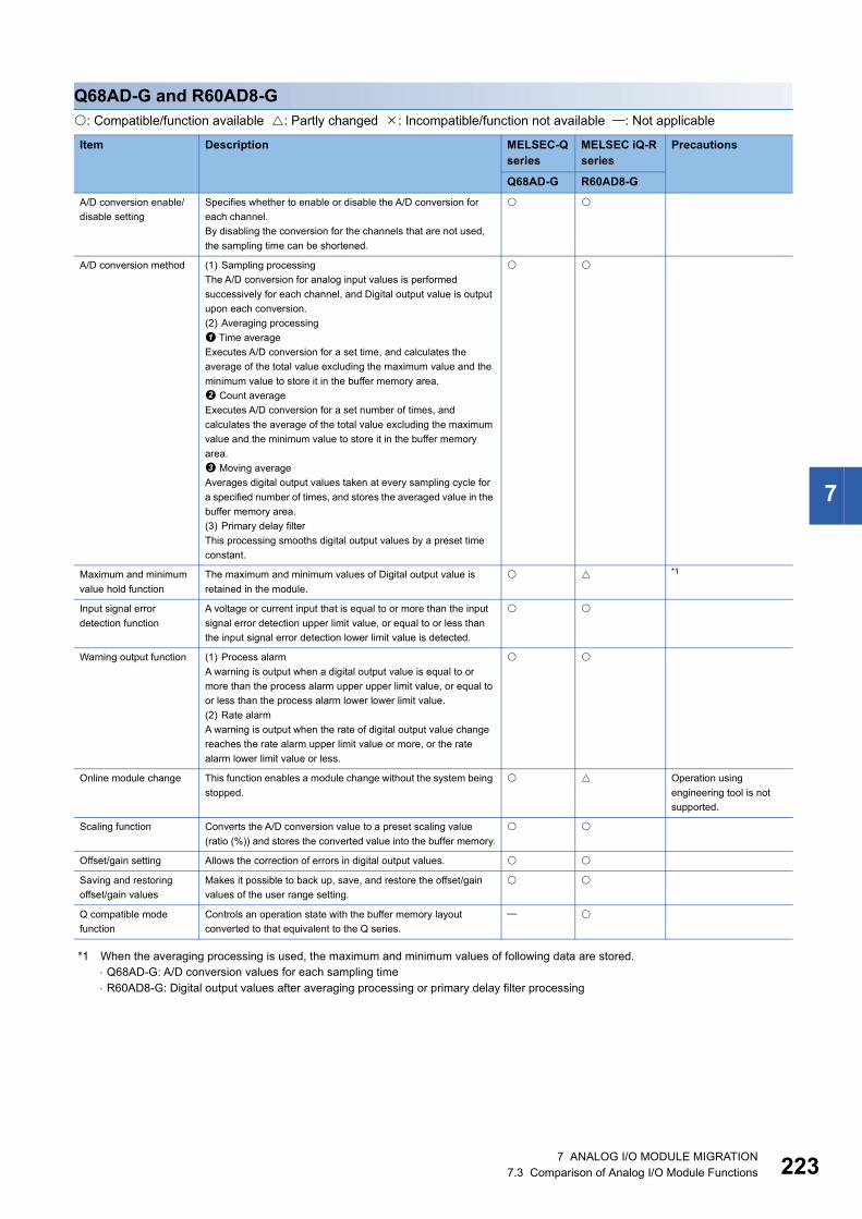
7
Q68AD-G and R60AD8-G: Compatible/function available : Partly changed : Incompatible/function not available : Not applicable
*1 When the averaging processing is used, the maximum and minimum values of following data are stored. Q68AD-G: A/D conversion values for each sampling time R60AD8-G: Digital output values after averaging processing or primary delay filter processing
Item Description MELSEC-Q series
MELSEC iQ-R series
Precautions
Q68AD-G R60AD8-GA/D conversion enable/disable setting
Specifies whether to enable or disable the A/D conversion for each channel.By disabling the conversion for the channels that are not used, the sampling time can be shortened.
A/D conversion method (1) Sampling processingThe A/D conversion for analog input values is performed successively for each channel, and Digital output value is output upon each conversion.(2) Averaging processing Time averageExecutes A/D conversion for a set time, and calculates the average of the total value excluding the maximum value and the minimum value to store it in the buffer memory area. Count averageExecutes A/D conversion for a set number of times, and calculates the average of the total value excluding the maximum value and the minimum value to store it in the buffer memory area. Moving averageAverages digital output values taken at every sampling cycle for a specified number of times, and stores the averaged value in the buffer memory area.(3) Primary delay filterThis processing smooths digital output values by a preset time constant.
Maximum and minimum value hold function
The maximum and minimum values of Digital output value is retained in the module.
*1
Input signal error detection function
A voltage or current input that is equal to or more than the input signal error detection upper limit value, or equal to or less than the input signal error detection lower limit value is detected.
Warning output function (1) Process alarmA warning is output when a digital output value is equal to or more than the process alarm upper upper limit value, or equal to or less than the process alarm lower lower limit value.(2) Rate alarmA warning is output when the rate of digital output value change reaches the rate alarm upper limit value or more, or the rate alarm lower limit value or less.
Online module change This function enables a module change without the system being stopped.
Operation using engineering tool is not supported.
Scaling function Converts the A/D conversion value to a preset scaling value (ratio (%)) and stores the converted value into the buffer memory.
Offset/gain setting Allows the correction of errors in digital output values.
Saving and restoring offset/gain values
Makes it possible to back up, save, and restore the offset/gain values of the user range setting.
Q compatible mode function
Controls an operation state with the buffer memory layout converted to that equivalent to the Q series.
7 ANALOG I/O MODULE MIGRATION7.3 Comparison of Analog I/O Module Functions 223
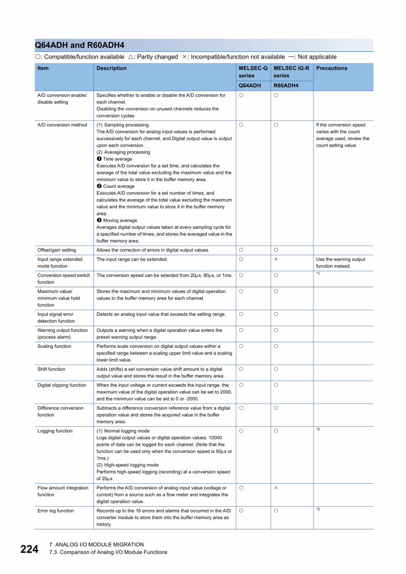
22
Q64ADH and R60ADH4: Compatible/function available : Partly changed : Incompatible/function not available : Not applicable
Item Description MELSEC-Q series
MELSEC iQ-R series
Precautions
Q64ADH R60ADH4A/D conversion enable/disable setting
Specifies whether to enable or disable the A/D conversion for each channel.Disabling the conversion on unused channels reduces the conversion cycles.
A/D conversion method (1) Sampling processingThe A/D conversion for analog input values is performed successively for each channel, and Digital output value is output upon each conversion.(2) Averaging processing Time averageExecutes A/D conversion for a set time, and calculates the average of the total value excluding the maximum value and the minimum value to store it in the buffer memory area. Count averageExecutes A/D conversion for a set number of times, and calculates the average of the total value excluding the maximum value and the minimum value to store it in the buffer memory area. Moving averageAverages digital output values taken at every sampling cycle for a specified number of times, and stores the averaged value in the buffer memory area.
If the conversion speed varies with the count average used, review the count setting value.
Offset/gain setting Allows the correction of errors in digital output values.
Input range extended mode function
The input range can be extended. Use the warning output function instead.
Conversion speed switch function
The conversion speed can be selected from 20s, 80s, or 1ms. *1
Maximum value/minimum value hold function
Stores the maximum and minimum values of digital operation values to the buffer memory area for each channel.
Input signal error detection function
Detects an analog input value that exceeds the setting range.
Warning output function (process alarm)
Outputs a warning when a digital operation value enters the preset warning output range.
Scaling function Performs scale conversion on digital output values within a specified range between a scaling upper limit value and a scaling lower limit value.
Shift function Adds (shifts) a set conversion value shift amount to a digital output value and stores the result in the buffer memory area.
Digital clipping function When the input voltage or current exceeds the input range, the maximum value of the digital operation value can be set to 2000, and the minimum value can be set to 0 or -2000.
Difference conversion function
Subtracts a difference conversion reference value from a digital operation value and stores the acquired value in the buffer memory area.
Logging function (1) Normal logging modeLogs digital output values or digital operation values. 10000 points of data can be logged for each channel. (Note that the function can be used only when the conversion speed is 80s or 1ms.)(2) High-speed logging modePerforms high-speed logging (recording) at a conversion speed of 20s.
*2
Flow amount integration function
Performs the A/D conversion of analog input value (voltage or current) from a source such as a flow meter and integrates the digital operation value.
Error log function Records up to the 16 errors and alarms that occurred in the A/D converter module to store them into the buffer memory area as history.
*3
4 7 ANALOG I/O MODULE MIGRATION7.3 Comparison of Analog I/O Module Functions

7
*1 For the R60ADH4, the function specifications are as follows.Operation mode: Medium speed: 10s/CH, Low speed: 20s/CH, Simultaneous conversion: 5s/4CH, Synchronization: Inter-module synchronization cycleFor details, refer to the following. MELSEC iQ-R High Speed Analog-Digital Converter Module User's Manual (Application)
*2 For the R60ADH4, the function specifications are as follows.(1) Normal logging functionA maximum of 90000 points of data can be logged. The conversion speed is 20s/channel.(2) Continuous logging functionThe function logs digital values in four channels simultaneously and transfers the logging data to the CPU module continuously without stopping the logging operation.The data that have been converted from analog to digital can be continuously collected at high speed (5s cycle at a maximum) and in four channels simultaneously.
*3 For the Q64ADH, alarms are stored together with errors in the error history. For the R60ADH4, alarms are stored in the dedicated alarm history.
Module error collection function
Collects errors and alarms occurred in the A/D converter module and stores them to the CPU module.
For the R60ADH4, use the event history function instead.
Error clear function Clears an error from the system monitor when it occurs.
Online module change Enables a module change without the system being stopped. Operation using engineering tool is not supported.
Saving and restoring offset/gain values
Makes it possible to save and restore the offset/gain values of the user range setting.
Item Description MELSEC-Q series
MELSEC iQ-R series
Precautions
Q64ADH R60ADH4
7 ANALOG I/O MODULE MIGRATION7.3 Comparison of Analog I/O Module Functions 225
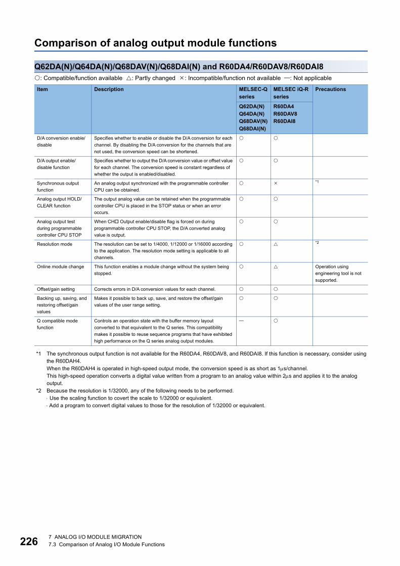
22
Comparison of analog output module functions
Q62DA(N)/Q64DA(N)/Q68DAV(N)/Q68DAI(N) and R60DA4/R60DAV8/R60DAI8: Compatible/function available : Partly changed : Incompatible/function not available : Not applicable
*1 The synchronous output function is not available for the R60DA4, R60DAV8, and R60DAI8. If this function is necessary, consider using the R60DAH4.When the R60DAH4 is operated in high-speed output mode, the conversion speed is as short as 1s/channel.This high-speed operation converts a digital value written from a program to an analog value within 2s and applies it to the analog output.
*2 Because the resolution is 1/32000, any of the following needs to be performed. Use the scaling function to covert the scale to 1/32000 or equivalent. Add a program to convert digital values to those for the resolution of 1/32000 or equivalent.
Item Description MELSEC-Q series
MELSEC iQ-R series
Precautions
Q62DA(N)Q64DA(N)Q68DAV(N)Q68DAI(N)
R60DA4R60DAV8R60DAI8
D/A conversion enable/disable
Specifies whether to enable or disable the D/A conversion for each channel. By disabling the D/A conversion for the channels that are not used, the conversion speed can be shortened.
D/A output enable/disable function
Specifies whether to output the D/A conversion value or offset value for each channel. The conversion speed is constant regardless of whether the output is enabled/disabled.
Synchronous output function
An analog output synchronized with the programmable controller CPU can be obtained.
*1
Analog output HOLD/CLEAR function
The output analog value can be retained when the programmable controller CPU is placed in the STOP status or when an error occurs.
Analog output test during programmable controller CPU STOP
When CH Output enable/disable flag is forced on during programmable controller CPU STOP, the D/A converted analog value is output.
Resolution mode The resolution can be set to 1/4000, 1/12000 or 1/16000 according to the application. The resolution mode setting is applicable to all channels.
*2
Online module change This function enables a module change without the system being stopped.
Operation using engineering tool is not supported.
Offset/gain setting Corrects errors in D/A conversion values for each channel.
Backing up, saving, and restoring offset/gain values
Makes it possible to back up, save, and restore the offset/gain values of the user range setting.
Q compatible mode function
Controls an operation state with the buffer memory layout converted to that equivalent to the Q series. This compatibility makes it possible to reuse sequence programs that have exhibited high performance on the Q series analog output modules.
6 7 ANALOG I/O MODULE MIGRATION7.3 Comparison of Analog I/O Module Functions
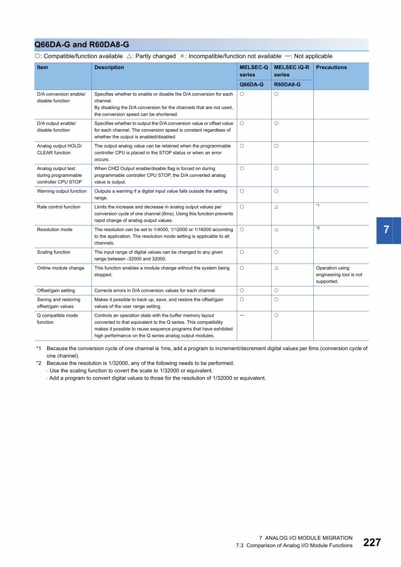
7
Q66DA-G and R60DA8-G: Compatible/function available : Partly changed : Incompatible/function not available : Not applicable
*1 Because the conversion cycle of one channel is 1ms, add a program to increment/decrement digital values per 6ms (conversion cycle of one channel).
*2 Because the resolution is 1/32000, any of the following needs to be performed. Use the scaling function to covert the scale to 1/32000 or equivalent. Add a program to convert digital values to those for the resolution of 1/32000 or equivalent.
Item Description MELSEC-Q series
MELSEC iQ-R series
Precautions
Q66DA-G R60DA8-GD/A conversion enable/disable function
Specifies whether to enable or disable the D/A conversion for each channel.By disabling the D/A conversion for the channels that are not used, the conversion speed can be shortened.
D/A output enable/disable function
Specifies whether to output the D/A conversion value or offset value for each channel. The conversion speed is constant regardless of whether the output is enabled/disabled.
Analog output HOLD/CLEAR function
The output analog value can be retained when the programmable controller CPU is placed in the STOP status or when an error occurs.
Analog output test during programmable controller CPU STOP
When CH Output enable/disable flag is forced on during programmable controller CPU STOP, the D/A converted analog value is output.
Warning output function Outputs a warning if a digital input value falls outside the setting range.
Rate control function Limits the increase and decrease in analog output values per conversion cycle of one channel (6ms). Using this function prevents rapid change of analog output values.
*1
Resolution mode The resolution can be set to 1/4000, 1/12000 or 1/16000 according to the application. The resolution mode setting is applicable to all channels.
*2
Scaling function The input range of digital values can be changed to any given range between -32000 and 32000.
Online module change This function enables a module change without the system being stopped.
Operation using engineering tool is not supported.
Offset/gain setting Corrects errors in D/A conversion values for each channel.
Saving and restoring offset/gain values
Makes it possible to back up, save, and restore the offset/gain values of the user range setting.
Q compatible mode function
Controls an operation state with the buffer memory layout converted to that equivalent to the Q series. This compatibility makes it possible to reuse sequence programs that have exhibited high performance on the Q series analog output modules.
7 ANALOG I/O MODULE MIGRATION7.3 Comparison of Analog I/O Module Functions 227

22
Q64DAH and R60DAH4: Compatible/function available : Partly changed : Incompatible/function not available : Not applicable
*1 Because the conversion speed is faster than that of the Q64DAH, the analog output time per wave data point in wave output mode is shorter. Adjust the analog output time by using any of the following methods. Set the "CH Constant for wave output conversion cycle" and adjust the analog output time per wave data point. Modify the wave data according to the conversion speed of the R60DAH4.
*2 For the Q64DAH, alarms are stored together with errors in the error history. For the R60DAH4, alarms are stored in the dedicated alarm history.
Item Description MELSEC-Q series
MELSEC iQ-R series
Precautions
Q64DAH R60DAH4D/A conversion enable/disable function
Specifies whether to enable or disable the D/A conversion for each channel.By disabling the D/A conversion for the channels that are not used, the conversion speed can be shortened.
D/A output enable/disable function
Specifies whether to output the D/A conversion value or offset value for each channel. The conversion speed is constant regardless of whether the output is enabled/disabled.
Analog output HOLD/CLEAR function
The output analog value can be retained when the programmable controller CPU is placed in the STOP status or when an error occurs.
Analog output test when CPU module is in STOP status
When the CPU module is in STOP operation status, forcibly turning CH Output enable/disable flag ON outputs the D/A-converted analog value.
Warning output function Outputs a warning if a digital value falls outside the setting range (warning output lower limit value to warning output upper limit value).
Wave output function Registering prepared wave data (digital value) in the D/A converter module enables continuous analog output in the specified conversion cycle.
*1
Scaling function The input range of digital values can be changed to any given range between -32000 and 32000.
Online module change This function enables a module change without the system being stopped.
Operation using engineering tool is not supported.
Error log function Records up to the 16 errors and alarms that occurred in the D/A converter module to store them into the buffer memory area as history.
*2
Error clear function Clears an error from the system monitor when it occurs.
Module error collection function
Collects errors and alarms occurred in the D/A converter module and stores them to the CPU module.
For the R60DAH4, use the event history function instead.
Range switching function
The output range to be used can be selected from the following.• Industrial shipment range (4 to 20mA, 0 to 20mA, 1 to 5V, 0 to 5V,
-10 to 10V)• User range setting
External power supply READY flag (X7)
This signal turns on when the external power supply 24VDC is supplied.When the signal is off, the analog output value is 0V/0mA regardless of other settings.
8 7 ANALOG I/O MODULE MIGRATION7.3 Comparison of Analog I/O Module Functions

7
Comparison of temperature input module functions
Q68RD3-G and R60RD8-G: Compatible/function available : Partly changed : Incompatible/function not available : Not applicable
Item Description MELSEC-Q series
MELSEC iQ-R series
Precautions
Q68RD3-G R60RD8-GTemperature conversion function
This function incorporates temperature data to a module by connecting a RTD. Temperature data are stored into the buffer memory in 16-bit signed binary (-2000 to 8500).
Temperature conversion system
(1) Sampling processingThis processing converts every temperature input value for each channel, and outputs a measured temperature value after every conversion. All the values output are then saved in the buffer memory.(2) Averaging processingThis processing averages measured temperature values for each channel and stores the averaged value in the buffer memory. The following three methods are used for the averaging processing. Time average Count average Moving average(3) Primary delay filterThis processing smooths measured temperature values by a preset time constant.
Conversion enable/disable function
This function specifies temperature conversion availability (enable or disable) for each channel.
RTD type selection function, Range switching function
This function sets RTD type and measurement range for each channel.
Disconnection detection function
This function detects disconnection of RTD which is connected to each conversion-enabled channel.
Conversion setting for disconnection detection function
This function is to select a value to be stored in the CH Measured temperature value (Un\G11 to Un\G18) from "Up scale", "Down scale" or "Given value" when disconnection is detected.
For the R60RD8-G, "Value just before disconnection" can be selected.
Warning output function (1) Process alarmA warning is output when the measured temperature value is equal to or more than the process alarm upper upper limit value, or equal to or less than the process alarm lower lower limit value.(2) Rate alarmA warning is output when the measured temperature value changes in a rate by which the measured temperature value reaches the rate alarm upper limit value or more, or the rate alarm lower limit value or less.
Scaling function This function converts a measured temperature value to a preset scaling value (ratio (%)) and stores the converted value into the buffer memory.
Offset/gain setting function
This function compensates an error of measured temperature value.
Online module change This function enables a module change without the system being stopped.
Operation using engineering tool is not supported.
Q compatible mode function
This function controls an operation state with the buffer memory layout converted to that equivalent to the Q series.
7 ANALOG I/O MODULE MIGRATION7.3 Comparison of Analog I/O Module Functions 229

23
Q68TD-G-H02(H01) and R60TD8-G: Compatible/function available : Partly changed : Incompatible/function not available : Not applicable
Item Description MELSEC-Q series
MELSEC iQ-R series
Precautions
Q68TD-G(-H02/H01)
R60TD8-G
Temperature conversion function
This function incorporates temperature data to a module by connecting a thermocouple. Temperature data are stored into the buffer memory in 16-bit signed binary (-2700 to 18200).
Temperature conversion system
(1) Sampling processingThis processing converts every temperature input value for each channel, and outputs a measured temperature value after every conversion. All the values output are then saved in the buffer memory.(2) Averaging processingThis processing averages measured temperature values for each channel and stores the averaged value in the buffer memory. The following three methods are used for the averaging processing. Time average Count average Moving average(3) Primary delay filterThis processing smooths measured temperature values by a preset time constant.
Conversion enable/disable function
This function specifies temperature conversion availability (enable or disable) for each channel.
Thermocouple type selection function
This function sets the type of thermocouple on each channel.
Disconnection detection function
This function detects the disconnection of the connected thermocouple on each conversion-enabled channel.
(Q68TD-G-H02 only)
Conversion setting for disconnection detection function
This function is to select a value to be stored in CH Measured temperature value (Un\G11 to Un\G18) from "Up scale", "Down scale" or "Given scale" when disconnection is detected.
(Q68TD-G-H02 only)
For the R60TD8-G, "Value just before disconnection" can be selected.
Disconnection monitor function
This function checks the disconnection state of the connected thermocouple on each conversion-enabled channel.
(Q68TD-G-H01 only)
For the R60TD8-G, use the disconnection detection function.
Disconnection state conversion setting function
This function is to select a value to be stored in CH Measured temperature value (Un\G11 to Un\G18) from "Up scale", "Down scale" or "Given scale" in disconnection state.
(Q68TD-G-H01 only)
For the R60TD8-G, use the disconnection detection function.
Cold junction temperature compensation with/without setting function
This function sets whether to use cold junction temperature compensation.Use this function to measure temperature in higher accuracy than the cold junction temperature compensation accuracy (1) by the cold junction temperature compensation resistor (RTD) that is included with the module.The cold junction temperature compensation accuracy can be improved by disabling the cold junction temperature compensation and providing a precision ice bath externally.
Cold junction temperature compensation resistor disconnection detection function
This function detects a disconnection of connected cold junction temperature compensation resistor (RTD).
Warning output function
(1) Process alarmA warning is output when the measured temperature value is equal to or more than the process alarm upper upper limit value, or equal to or less than the process alarm lower lower limit value.(2) Rate alarmA warning is output when the measured temperature value changes in a rate by which the measured temperature value reaches the rate alarm upper limit value or more, or the rate alarm lower limit value or less.
0 7 ANALOG I/O MODULE MIGRATION7.3 Comparison of Analog I/O Module Functions

7
Scaling function This function converts a measured temperature value to a preset scaling value (ratio (%)) and stores the converted value into the buffer memory.
Offset/gain setting function
This function compensates an error of measured temperature value.
Online module change
This function enables a module change without the system being stopped.
Operation using engineering tool is not supported.
Q compatible mode function
This function controls an operation state with the buffer memory layout converted to that equivalent to the Q series.
Item Description MELSEC-Q series
MELSEC iQ-R series
Precautions
Q68TD-G(-H02/H01)
R60TD8-G
7 ANALOG I/O MODULE MIGRATION7.3 Comparison of Analog I/O Module Functions 231

23
Comparison of temperature control module functions
Q64TCTT/Q64TCRT and R60TCTRT2TT2/R60TCRT4: Compatible/function available : Partly changed : Incompatible/function not available : Not applicable
Item Description MELSEC-Q series
MELSEC iQ-Rseries
Precautions
Q64TCTTQ64TCRT
R60TCTRT2TT2R60TCRT4
Auto tuning function Sets suitable PID constants automatically. "AT error status monitor" is not available for the R60TCTRT2TT2 and R60TCRT4. Check for auto tuning failure using error codes.
Forward action/reverse action selection function
Heat control (reverse action) or cooling control (forward action) can be selected for operation control.
RFB limiter function Limits the manipulation value overshoot which frequently occurs when the set value (SV) is changed or control target is changed.
Sensor compensation function
Reduces the difference between the measured value and actual temperature to zero when these two are different due to measurement conditions.
Unused channel setting
Sets the PID operation for channels that do not perform temperature adjustment to "not execute".
PID control forced stop
Stops the PID operation for channels that is performing temperature adjustment.
Loop disconnection detection function
Detects errors in the control system (control loop) caused by a load (heater) disconnection, abnormal external operation device (such as magnet relay), or a temperature sensor disconnection.
Data storage on E2PROM
By backing up the buffer memory contents to E2PROM, the load of sequence program can be reduced.
Alert function Monitors the process value (PV) and alerts the user.
Control output setting at CPU stop error occurrence
Continues/stops temperature adjustment control output when a CPU stop error occurs.
For the R60TCTRT2TT2 and R60TCRT4, use the HOLD/CLEAR function instead.
Q64TC control status The Q64TC can be controlled by the output signal and buffer memory settings of the Q64TC.
Online module change
A module change is made without the system being stopped. Operation using engineering tool is not supported.
Q compatible mode function
This function arranges the buffer memory addresses of the temperature control module to become equivalent to the ones of a MELSEC-Q series module.This compatibility makes it possible to reuse programs that have exhibited high performance on the MELSEC-Q series modules.
2 7 ANALOG I/O MODULE MIGRATION7.3 Comparison of Analog I/O Module Functions

7
Q64TCTTN/Q64TCRTN and R60TCTRT2TT2/R60TCRT4: Compatible/function available : Partly changed : Incompatible/function not available : Not applicable
Item Description MELSEC-Q series
MELSEC iQ-Rseries
Precautions
Q64TCTTNQ64TCRTN
R60TCTRT2TT2R60TCRT4
Control mode selection function
A control mode can be selected from the following modes.• Standard control• Heating-cooling control (normal mode)• Heating-cooling control (expanded mode)• Mix control (normal mode)• Mix control (expanded mode)
Control output setting at CPU stop error
Whether to clear or hold the transistor output status when a CPU module stop error occurs or when a CPU module is turned from RUN to STOP can be selected.
For the R60TCTRT2TT2 and R60TCRT4, use the HOLD/CLEAR function instead.
Control method The following control methods can be used with the settings of proportional band (P), integral time (I), and derivative time (D).• Two-position control• P control• PI control• PD control• PID control
Manual reset function
The stable status position in the P control or PD control can be moved manually.
Manual control A manipulated value (MV) can be set manually by users without being automatically calculated by the PID control.
Auto tuning function Sets suitable PID constants automatically.
Simple two-degree-of-freedom
In addition to the PID control, this function selects a suitable response speed for the set value (SV) change from three levels to simply achieve the two-degree-of-freedom PID control.
Derivative action selection function
This function improves dynamic characteristics by selecting a suitable derivative action for fixed value actions or ramp actions.
Setting change rate limiter setting function
The change rate setting of the set value (SV) per set time unit when this value is changed. The batch setting or individual setting can be selected for the temperature rise and drop.
Moving averaging process to a temperature process value (PV)
Moving averaging process can be set to a temperature process value (PV). With this function, the fluctuation of temperature process values (PV) can be reduced in electrically noisy environments or in the environments where temperature process values (PV) fluctuate greatly. The moving averaging process can be disabled to hasten the response to the change of temperature process values (PV).
Temperature process value (PV) scaling function
This function can convert temperature process values (PV) into the set width to import them in the buffer memory.
Alert function This function issues an alert when a temperature process value (PV) or deviation (E) meets the condition set in advance.
RFB limiter function When deviation (E) continues for a long period of time, this function prevents the PID operation results (manipulated value (MV)) calculated by integral actions from exceeding the effective range of the manipulated value (MV).
Sensor correction function
When there is a difference between the temperature process value (PV) and actual temperature due to the measurement condition, this function corrects the error. Select one of the following two correction methods.• Normal sensor correction (one-point correction) function: Corrects an
error by using the percentage of a difference to the full scale of the set input range as an error corrected value.
• Sensor two-point correction function: Corrects an error by setting any two points (corrected offset value and corrected gain value).
Auto-setting at input range change
When the input range is changed, the related buffer memory data is automatically changed to prevent the values in those buffer memory areas from being out of the setting range.
7 ANALOG I/O MODULE MIGRATION7.3 Comparison of Analog I/O Module Functions 233

23
Input/output (with another analog module) function
This function can input and output with other analog modules (including A/D converter module and D/A converter module) on the system.
ON delay output function
This function enables users to configure settings considering the delay time (response/scan time delay) of an actual transistor output.
Self-tuning function This function constantly monitors the control state. When the control system is oscillatory just after the control start, owing to the set value (SV) change or fluctuation of characteristics of a controlled object, PID constants are changed automatically.
Peak current suppression function
This function suppresses the peak current by automatically changing the values of the upper limit output limiter of each channel and dividing the timing of the transistor output.
Simultaneous temperature rise function
This function allows several loops to reach the set value (SV) at the same time.
Forward/reverse action selection function
Whether to execute a PID operation with a forward action or a reverse action can be selected.
Loop disconnection detection function
This function detects errors in the control system (control loop).
During AT loop disconnection detection function
This function detects loop disconnections during auto tuning.
Proportional band setting function
This function can set the proportional band (P) individually for heating or cooling.
Cooling method setting function
When the auto tuning is executed, an auto tuning formula is automatically selected according to the selected cooling method and the operation starts.
Overlap/dead band function
By changing the temperature where the cooling transistor output is started, whether control stability is prioritized or energy saving is prioritized can be selected.
Temperature conversion function (using unused channels)
In the heating-cooling control (normal mode) and mix control (normal mode), only the temperature measurement can be performed using unused temperature input terminals.
Buffer memory data backup function
A set value in a buffer memory area can be backed up in the E2PROM.Because the backed up value is restored at the next startup of the module, an initial setting program is not required once this function is executed.
Error history function Up to 16 errors and alarms that occur are stored in the buffer memory as history.
Module error history collection function
This function notifies the CPU module of errors and alarms that occur. Error information is held in the memory inside of the CPU module as module error history.
For the R60TCTRT2TT2 and R60TCRT4, use the event history function instead.
Error clear function This function clears an error from the system monitor when it occurs.
Online module change
A module change is made without the system being stopped. Operation using engineering tool is not supported.
Q compatible mode function
This function arranges the buffer memory addresses of the temperature control module to become equivalent to the ones of a MELSEC-Q series module.This compatibility makes it possible to reuse programs that have exhibited high performance on the MELSEC-Q series modules.
Item Description MELSEC-Q series
MELSEC iQ-Rseries
Precautions
Q64TCTTNQ64TCRTN
R60TCTRT2TT2R60TCRT4
4 7 ANALOG I/O MODULE MIGRATION7.3 Comparison of Analog I/O Module Functions

7
Q64TCTTBW/Q64TCRTBW and R60TCTRT2TT2BW/R60TCRT4BW: Compatible/function available : Partly changed : Incompatible/function not available : Not applicable
Item Description MELSEC-Qseries
MELSEC iQ-Rseries
Precautions
Q64TCTTBWQ64TCRTBW
R60TCTRT2TT2BWR60TCRT4BW
Auto tuning function Sets suitable PID constants automatically. "AT error status monitor" is not available for the R60TCTRT2TT2BW and R60TCRT4BW. Check for auto tuning failure using error codes.
Forward action/reverse action selection function
Heat control (reverse action) or cooling control (forward action) can be selected for operation control.
RFB limiter function Limits the manipulation value overshoot which frequently occurs when the set value (SV) is changed or control target is changed.
Sensor compensation function
Reduces the difference between the measured value and actual temperature to zero when these two are different due to measurement conditions.
Unused channel setting
Sets the PID operation for channels that do not perform temperature adjustment to "not execute".
PID control forced stop
Stops the PID operation for channels that is performing temperature adjustment.
Heater disconnection detection function
Measures the current which flows in the heater main circuit to detect disconnection.
Current error detection function when output is off
Measures whether the current flows in the heater main circuit when the transistor output is off to check for any error.
Loop disconnection detection function
Detects errors in the control system (control loop) caused by a load (heater) disconnection, abnormal external operation device (such as magnet relay), or a temperature sensor disconnection.
Data storage on E2PROM
By backing up the buffer memory contents to E2PROM, the load of sequence program can be reduced.
Alert function Monitors the process value (PV) and alerts the user.
Control output setting at CPU stop error occurrence
Continues/stops temperature adjustment control output when a CPU stop error occurs.
For the R60TCTRT2TT2BW and R60TCRT4BW, use the HOLD/CLEAR function instead.
Q64TC control status The Q64TC can be controlled by the output signal and buffer memory settings of the Q64TC.
Online module change
A module change is made without the system being stopped. Operation using engineering tool is not supported.
Q compatible mode function
This function arranges the buffer memory addresses of the temperature control module to become equivalent to the ones of a MELSEC-Q series module.This compatibility makes it possible to reuse programs that have exhibited high performance on the MELSEC-Q series modules.
7 ANALOG I/O MODULE MIGRATION7.3 Comparison of Analog I/O Module Functions 235

23
Q64TCTTBWN/Q64TCRTBWN and R60TCTRT2TT2BW/R60TCRT4BW: Compatible/function available : Partly changed : Incompatible/function not available : Not applicable
Item Description MELSEC-Qseries
MELSEC iQ-Rseries
Precautions
Q64TCTTBWNQ64TCRTBWN
R60TCTRT2TT2BWR60TCRT4BW
Control mode selection function
A control mode can be selected from the following modes.• Standard control• Heating-cooling control (normal mode)• Heating-cooling control (expanded mode)• Mix control (normal mode)• Mix control (expanded mode)
Control output setting at CPU stop error
Whether to clear or hold the transistor output status when a CPU module stop error occurs or when a CPU module is turned from RUN to STOP can be selected.
For the R60TCTRT2TT2BW and R60TCRT4BW, use the HOLD/CLEAR function instead.
Control method The following control methods can be used with the settings of proportional band (P), integral time (I), and derivative time (D).• Two-position control• P control• PI control• PD control• PID control
Manual reset function
The stable status position in the P control or PD control can be moved manually.
Manual control A manipulated value (MV) can be set manually by users without being automatically calculated by the PID control.
Auto tuning function Sets suitable PID constants automatically.
Simple two-degree-of-freedom
In addition to the PID control, this function selects a suitable response speed for the set value (SV) change from three levels to simply achieve the two-degree-of-freedom PID control.
Derivative action selection function
This function improves dynamic characteristics by selecting a suitable derivative action for fixed value actions or ramp actions.
Setting change rate limiter setting function
The change rate setting of the set value (SV) per set time unit when this value is changed. The batch setting or individual setting can be selected for the temperature rise and drop.
Moving averaging process to a temperature process value (PV)
Moving averaging process can be set to a temperature process value (PV). With this function, the fluctuation of temperature process values (PV) can be reduced in electrically noisy environments or in the environments where temperature process values (PV) fluctuate greatly. The moving averaging process can be disabled to hasten the response to the change of temperature process values (PV).
Temperature process value (PV) scaling function
This function can convert temperature process values (PV) into the set width to import them in the buffer memory.
Alert function This function issues an alert when a temperature process value (PV) or deviation (E) meets the condition set in advance.
RFB limiter function When deviation (E) continues for a long period of time, this function prevents the PID operation results (manipulated value (MV)) calculated by integral actions from exceeding the effective range of the manipulated value (MV).
Sensor correction function
When there is a difference between the temperature process value (PV) and actual temperature due to the measurement condition, this function corrects the error. Select one of the following two correction methods.• Normal sensor correction (one-point correction) function:
Corrects an error by using the percentage of a difference to the full scale of the set input range as an error corrected value.
• Sensor two-point correction function: Corrects an error by setting any two points (corrected offset value and corrected gain value).
6 7 ANALOG I/O MODULE MIGRATION7.3 Comparison of Analog I/O Module Functions

7
Auto-setting at input range change
When the input range is changed, the related buffer memory data is automatically changed to prevent the values in those buffer memory areas from being out of the setting range.
Input/output (with another analog module) function
This function can input and output with other analog modules (including A/D converter module and D/A converter module) on the system.
ON delay output function
This function enables users to configure settings considering the delay time (response/scan time delay) of an actual transistor output.
Self-tuning function This function constantly monitors the control state. When the control system is oscillatory just after the control start, owing to the set value (SV) change or fluctuation of characteristics of a controlled object, PID constants are changed automatically.
Peak current suppression function
This function suppresses the peak current by automatically changing the values of the upper limit output limiter of each channel and dividing the timing of the transistor output.
Simultaneous temperature rise function
This function allows several loops to reach the set value (SV) at the same time.
Forward/reverse action selection function
Whether to execute a PID operation with a forward action or a reverse action can be selected.
Loop disconnection detection function
This function detects errors in the control system (control loop).
During AT loop disconnection detection function
This function detects loop disconnections during auto tuning.
Proportional band setting function
This function can set the proportional band (P) individually for heating or cooling.
Cooling method setting function
When the auto tuning is executed, an auto tuning formula is automatically selected according to the selected cooling method and the operation starts.
Overlap/dead band function
By changing the temperature where the cooling transistor output is started, whether control stability is prioritized or energy saving is prioritized can be selected.
Temperature conversion function (using unused channels)
In the heating-cooling control (normal mode) and mix control (normal mode), only the temperature measurement can be performed using unused temperature input terminals.
Heater disconnection detection function
The current which flows in the heater main circuit can be measured and disconnections can be detected.
Output off-time current error detection function
An error of when the transistor output is off can be detected.
Buffer memory data backup function
A set value in a buffer memory area can be backed up in the E2PROM.Because the backed up value is restored at the next startup of the module, an initial setting program is not required once this function is executed.
Error history function
Up to 16 errors and alarms that occur are stored in the buffer memory as history.
Module error history collection function
This function notifies the CPU module of errors and alarms that occur. Error information is held in the memory inside of the CPU module as module error history.
For the R60TCTRT2TT2BW and R60TCRT4BW, use the event history function instead.
Error clear function This function clears an error from the system monitor when it occurs.
Item Description MELSEC-Qseries
MELSEC iQ-Rseries
Precautions
Q64TCTTBWNQ64TCRTBWN
R60TCTRT2TT2BWR60TCRT4BW
7 ANALOG I/O MODULE MIGRATION7.3 Comparison of Analog I/O Module Functions 237

23
Online module change
A module change is made without the system being stopped. Operation using engineering tool is not supported.
Q compatible mode function
This function arranges the buffer memory addresses of the temperature control module to become equivalent to the ones of a MELSEC-Q series module.This compatibility makes it possible to reuse programs that have exhibited high performance on the MELSEC-Q series modules.
Item Description MELSEC-Qseries
MELSEC iQ-Rseries
Precautions
Q64TCTTBWNQ64TCRTBWN
R60TCTRT2TT2BWR60TCRT4BW
8 7 ANALOG I/O MODULE MIGRATION7.3 Comparison of Analog I/O Module Functions

7
7.4 Precautions for Analog I/O Module Migration
Wiring■Analog output moduleThe terminal layout differs between the Q66DA-G and the R60DA8-G.To use the 40-pin connector of the Q66DA-G with the R60DA8-G, wiring needs to be corrected accordingly except the external power supply pins (A19, A20, B19, and B20).
Dedicated instructionThere is no difference between the MELSEC-Q series and the MELSEC iQ-R series.
I/O signals and buffer memory areasThe layouts of I/O signals and buffer memory areas differ between the MELSEC-Q series and the MELSEC iQ-R series.If I/O signals and buffer memory areas are used in the MELSEC-Q series program, the program needs to be corrected for the MELSEC iQ-R series.In Q compatible mode, the MELSEC-Q series program can be used as it is except for the differences in some signals and functions.
Resolution mode switching functionThe MELSEC iQ-R series modules do not support the resolution mode switching function because the resolution has already been enhanced.By using the scaling function, a converted value which is equivalent to that in the MELSEC-Q series can be determined.
Temperature drift compensation functionThe MELSEC iQ-R series modules do not support the temperature drift compensation function because the accuracy has already been enhanced. (The accuracy is comparable to that of the MELSEC-Q series with the temperature drift compensation function used.)If the function is used in the MELSEC-Q series program, the program needs to be corrected for the MELSEC iQ-R series.
Temperature conversion systemFor the MELSEC iQ-R series, the setting value of the averaging processing in the temperature conversion system is changed because the conversion speed is enhanced. If the processing is used in the MELSEC-Q series program, the program needs to be corrected for the MELSEC iQ-R series.
For details on these precautions, refer to the following. MELSEC iQ-R Module Configuration Manual MELSEC iQ-R Analog-Digital Converter Module User's Manual (Startup) MELSEC iQ-R Analog-Digital Converter Module User's Manual (Application) MELSEC iQ-R Digital-Analog Converter Module User's Manual (Startup) MELSEC iQ-R Digital-Analog Converter Module User's Manual (Application) MELSEC iQ-R Channel Isolated Thermocouple Input Module/Channel Isolated RTD Input Module User's Manual (Startup) MELSEC iQ-R Channel Isolated Thermocouple Input Module/Channel Isolated RTD Input Module User's Manual (Application) MELSEC iQ-R Temperature Control Module User's Manual (Startup) MELSEC iQ-R Temperature Control Module User's Manual (Application) Differences between MELSEC-Q series and MELSEC iQ-R series (FA-A-0171)
7 ANALOG I/O MODULE MIGRATION7.4 Precautions for Analog I/O Module Migration 239

24
8 POSITIONING MODULE AND PULSE I/O MODULE MIGRATION
8.1 Positioning Module and Pulse I/O Module Migration Model List
This section describes examples of migration to MELSEC iQ-R series positioning modules and pulse I/O modules in accordance with the MELSEC-Q series positioning/pulse I/O module specifications.Consider the scope of control by the MELSEC-Q series positioning module and pulse I/O module used and the system specifications and extensibility after migration to choose a model that best suits your application.
Item MELSEC-Q series
MELSEC iQ-R series
Specification difference
Positioning Open collector output
QD75P1N RD75P2 (1) External wiring: Not changed(2) Number of slots: Not changed(3) Programs: The number of occupied I/O points, I/O signals, and buffer memory
addresses are not changed.(4) Specifications: Changed(5) Functions: Not changed
QD75P1 RD75P2 (1) External wiring: Not changed(2) Number of slots: Not changed(3) Programs: The number of occupied I/O points, I/O signals, and buffer memory
addresses are not changed.(4) Specifications: Changed(5) Functions: Not changed
QD75P2N RD75P2 (1) External wiring: Not changed(2) Number of slots: Not changed(3) Programs: The number of occupied I/O points, I/O signals, and buffer memory
addresses are not changed.(4) Specifications: Changed(5) Functions: Not changed
QD75P2 RD75P2 (1) External wiring: Not changed(2) Number of slots: Not changed(3) Programs: The number of occupied I/O points, I/O signals, and buffer memory
addresses are not changed.(4) Specifications: Changed(5) Functions: Not changed
QD75P4N RD75P4 (1) External wiring: Not changed(2) Number of slots: Not changed(3) Programs: The number of occupied I/O points, I/O signals, and buffer memory
addresses are not changed.(4) Specifications: Changed(5) Functions: Not changed
QD75P4 RD75P4 (1) External wiring: Not changed(2) Number of slots: Not changed(3) Programs: The number of occupied I/O points, I/O signals, and buffer memory
addresses are not changed.(4) Specifications: Changed(5) Functions: Not changed
QD70P4 No applicable module
Connect the RQ extension base unit (RQ6B) to use the Q series module.
QD70P8 No applicable module
Connect the RQ extension base unit (RQ6B) to use the Q series module.
0 8 POSITIONING MODULE AND PULSE I/O MODULE MIGRATION8.1 Positioning Module and Pulse I/O Module Migration Model List

8
Positioning Differential output
QD75D1N RD75D2 (1) External wiring: Changed (Pin 2B19/20: Not used PULSE COM)(2) Number of slots: Not changed(3) Programs: The number of occupied I/O points, I/O signals, and buffer memory
addresses are not changed.(4) Specifications: Changed(5) Functions: Not changed
QD75D1 RD75D2 (1) External wiring: Changed (Pin 2B19/20: Not used PULSE COM)(2) Number of slots: Not changed(3) Programs: The number of occupied I/O points, I/O signals, and buffer memory
addresses are not changed.(4) Specifications: Changed(5) Functions: Not changed
QD75D2N RD75D2 (1) External wiring: Changed (Pin 2B19/20: Not used PULSE COM)(2) Number of slots: Not changed(3) Programs: The number of occupied I/O points, I/O signals, and buffer memory
addresses are not changed.(4) Specifications: Changed(5) Functions: Not changed
QD75D2 RD75D2 (1) External wiring: Changed (Pin 2B19/20: Not used PULSE COM)(2) Number of slots: Not changed(3) Programs: The number of occupied I/O points, I/O signals, and buffer memory
addresses are not changed.(4) Specifications: Changed(5) Functions: Not changed
QD75D4N RD75D4 (1) External wiring: Changed (Pin 2B19/20: Not used PULSE COM)(2) Number of slots: Not changed(3) Programs: The number of occupied I/O points, I/O signals, and buffer memory
addresses are not changed.(4) Specifications: Changed(5) Functions: Not changed
QD75D4 RD75D4 (1) External wiring: Changed (Pin 2B19/20: Not used PULSE COM)(2) Number of slots: Not changed(3) Programs: The number of occupied I/O points, I/O signals, and buffer memory
addresses are not changed.(4) Specifications: Changed(5) Functions: Not changed
QD70D4 No applicable module
Connect the RQ extension base unit (RQ6B) to use the Q series module.
QD70D8 No applicable module
Connect the RQ extension base unit (RQ6B) to use the Q series module.
Open collector output with built-in counter function
QD72P3C3 No applicable module
Connect the RQ extension base unit (RQ6B) to use the Q series module.
Analog positioning
QD73A1 No applicable module
Connect the RQ extension base unit (RQ6B) to use the Q series module.
Item MELSEC-Q series
MELSEC iQ-R series
Specification difference
8 POSITIONING MODULE AND PULSE I/O MODULE MIGRATION8.1 Positioning Module and Pulse I/O Module Migration Model List 241

24
High-speed counter QD62 RD62P2 (1) External wiring: Not changed(2) Number of slots: Not changed(3) Programs: The number of occupied I/O points is not changed, I/O signals are
changed, and buffer memory addresses are not changed.(4) Specifications: Changed(5) Functions: Not changed
QD62E RD62P2E (1) External wiring: Changed (2) Number of slots: Not changed(3) Programs: The number of occupied I/O points is not changed, I/O signals are
changed, and buffer memory addresses are not changed.(4) Specifications: Changed(5) Functions: Not changed
QD62D RD62D2 (1) External wiring: Not changed(2) Number of slots: Not changed(3) Programs: The number of occupied I/O points is not changed, I/O signals are
changed, and buffer memory addresses are not changed.(4) Specifications: Changed(5) Functions: Not changed
QD63P6 No applicable module
Connect the RQ extension base unit (RQ6B) to use the Q series module.
QD64D2 No applicable module
Connect the RQ extension base unit (RQ6B) to use the Q series module.
QD65PD2 No applicable module
Connect the RQ extension base unit (RQ6B) to use the Q series module.
Channel isolated pulse input QD60P8-G RD60P8-G (1) External wiring: Not changed(2) Number of slots: Not changed(3) Programs: The number of occupied I/O points and I/O signals are not changed, and
the buffer memory assignment (R mode: Not compatible, Q compatible mode: Compatible) is changed.
(4) Specifications: Changed(5) Functions: Not changed
Item MELSEC-Q series
MELSEC iQ-R series
Specification difference
2 8 POSITIONING MODULE AND PULSE I/O MODULE MIGRATION8.1 Positioning Module and Pulse I/O Module Migration Model List

8
8.2 Comparison of Positioning Module and Pulse I/O Module Specifications
Comparison of positioning module specifications
QD75P1N and RD75P2: Compatible : Partly changed : Incompatible : Not applicable
Item Specifications Compatibility Precautions
QD75P1N RD75P2No. of control axes 1 2 The number of axes varies.
Interpolation function None 2-axis linear interpolation, 2-axis circular interpolation
Control system PTP (Point To Point) control, path control (linear can be set), speed control, speed-position switching control, position-speed switching control
PTP (Point To Point) control, path control (all of linear and circular can be set), speed control, speed-position switching control, position-speed switching control
Control unit mm, inch, degree, pulse
Positioning data 600 data/axis
Backup Parameters, positioning data, and block start data can be saved on the flash ROM (battery-less backup).
The following save destination can be selected for positioning data and block start data.• CPU module• Flash ROM of the positioning
module (battery-less)
The timing at which the backup data is reflected to the buffer memory is different. To change the parameters, positioning data, and block start data via a program, do it after confirming that Module access flag (X1) has turned on.
Positioning Positioning system
PTP control: Incremental system/absolute system
Speed-position switching control: Incremental system/absolute system
Position-speed switching control: Incremental system
Path control: Incremental system/absolute system
Positioning range
In absolute system-214748364.8 to 214748364.7m, -21474.83648 to 21474.83647 inch, 0 to 359.99999 degree, -2147483648 to 2147483647 pulse
In incremental system-214748364.8 to 214748364.7m, -21474.83648 to 21474.83647 inch,-21474.83648 to 21474.83647 degree, -2147483648 to 2147483647 pulse
In speed-position switching control (INC mode)/position-speed switching control0 to 214748364.7m, 0 to 21474.83647 inch, 0 to 21474.83647 degree, 0 to 2147483647 pulse
In speed-position switching control (ABS mode)0 to 359.99999 degree
Speed command
0.01 to 20000000.00 mm/min0.001 to 2000000.000 inch/min0.001 to 2000000.000 degree/min1 to 4000000 pulse/s
0.01 to 20000000.00 mm/min0.001 to 2000000.000 inch/min0.001 to 3000000.000 degree/min1 to 5000000 pulse/s
Acceleration/deceleration process
Trapezoidal acceleration/deceleration, S-curve acceleration/deceleration
Acceleration/deceleration time
1 to 8388608ms (Four patterns can be set for each of acceleration time and deceleration time.)
Sudden stop deceleration time
1 to 8388608ms
8 POSITIONING MODULE AND PULSE I/O MODULE MIGRATION8.2 Comparison of Positioning Module and Pulse I/O Module Specifications 243

24
Starting time 1-axis linear control: 1.5ms In Q compatible mode
1-axis speed control: 1.5ms
2-axis linear interpolation control (Composite speed): 1.5ms
2-axis linear interpolation control (Reference axis speed): 1.5ms
2-axis circular interpolation control: 2.0ms
2-axis speed control: 1.5ms
3-axis linear interpolation control (Composite speed): 1.7ms
3-axis linear interpolation control (Reference axis speed): 1.7ms
3-axis speed control: 1.7ms
4-axis linear interpolation control: 1.8ms
4-axis speed control: 1.8ms
Quick start function Start with the positioning start signal: 8s
Start with the external command signal: 20s
Start time adjustment function 0.00 to 100000.00ms (in increments of 0.01ms)
Start time when the inter-module synchronization function is used
8s
External interface 40-pin connector (A6CON1/2/4)
Applicable wire size For A6CON1/4: 0.088 to 0.3 (28 to 22 AWG) (stranded wire)For A6CON2: 0.088 to 0.24 (28 to 24 AWG) (stranded wire)
Maximum output pulse 200000pulse/s
Maximum connection distance between servos
2m
Flash ROM write count 100000 times maximum
Number of occupied I/O points 32 points (I/O assignment: Intelligent 32 points)
Internal current consumption (5VDC)
0.29A 0.38A
Weight 0.14kg 0.14kg
Item Specifications Compatibility Precautions
QD75P1N RD75P2
4 8 POSITIONING MODULE AND PULSE I/O MODULE MIGRATION8.2 Comparison of Positioning Module and Pulse I/O Module Specifications

8
QD75P1 and RD75P2: Compatible : Partly changed : Incompatible : Not applicable
Item Specifications Compatibility Precautions
QD75P1 RD75P2No. of control axes 1 2 The number of axes varies.
Interpolation function None 2-axis linear interpolation, 2-axis circular interpolation
Control system PTP (Point To Point) control, path control (linear can be set), speed control, speed-position switching control, position-speed switching control
PTP (Point To Point) control, path control (all of linear and circular can be set), speed control, speed-position switching control, position-speed switching control
Control unit mm, inch, degree, pulse
Positioning data 600 data/axis
Backup Parameters, positioning data, and block start data can be saved on the flash ROM (battery-less backup).
The following save destination can be selected for positioning data and block start data.• CPU module• Flash ROM of the positioning
module (battery-less)
The timing at which the backup data is reflected to the buffer memory is different. To change the parameters, positioning data, and block start data via a program, do it after confirming that Module access flag (X1) has turned on.
Positioning Positioning system
PTP control: Incremental system/absolute system
Speed-position switching control: Incremental system/absolute system
Position-speed switching control: Incremental system
Path control: Incremental system/absolute system
Positioning range
In absolute system-214748364.8 to 214748364.7m, -21474.83648 to 21474.83647 inch, 0 to 359.99999 degree, -2147483648 to 2147483647 pulse
In incremental system-214748364.8 to 214748364.7m, -21474.83648 to 21474.83647 inch,-21474.83648 to 21474.83647 degree, -2147483648 to 2147483647 pulse
In speed-position switching control (INC mode)/position-speed switching control0 to 214748364.7m, 0 to 21474.83647 inch, 0 to 21474.83647 degree, 0 to 2147483647 pulse
In speed-position switching control (ABS mode)0 to 359.99999 degree
Speed command
0.01 to 20000000.00 mm/min0.001 to 2000000.000 inch/min0.001 to 2000000.000 degree/min1 to 1000000 pulse/s
0.01 to 20000000.00 mm/min0.001 to 2000000.000 inch/min0.001 to 3000000.000 degree/min1 to 5000000 pulse/s
Acceleration/deceleration process
Trapezoidal acceleration/deceleration, S-curve acceleration/deceleration
Acceleration/deceleration time
1 to 8388608ms (Four patterns can be set for each of acceleration time and deceleration time.)
Sudden stop deceleration time
1 to 8388608ms
8 POSITIONING MODULE AND PULSE I/O MODULE MIGRATION8.2 Comparison of Positioning Module and Pulse I/O Module Specifications 245

24
Starting time 1-axis linear control: 6ms 1-axis linear control: 1.5ms The RD75 is upward compatibility with the QD75 and has the same programs.Because the performance such as the starting time and refreshing cycle is enhanced, modify each program as needed while checking the timing of the processing.
1-axis speed control: 6ms 1-axis speed control: 1.5ms
2-axis linear interpolation control (Composite speed): 7ms
2-axis linear interpolation control (Composite speed): 1.5ms
2-axis linear interpolation control (Reference axis speed): 7ms
2-axis linear interpolation control (Reference axis speed): 1.5ms
2-axis circular interpolation control: 7ms
2-axis circular interpolation control: 2.0ms
2-axis speed control: 6ms 2-axis speed control: 1.5ms
3-axis linear interpolation control (Composite speed): 7ms
3-axis linear interpolation control (Composite speed): 1.7ms
3-axis linear interpolation control (Reference axis speed): 7ms
3-axis linear interpolation control (Reference axis speed): 1.7ms
3-axis speed control: 6ms 3-axis speed control: 1.7ms
4-axis linear interpolation control: 7ms
4-axis linear interpolation control: 1.8ms
4-axis speed control: 7ms 4-axis speed control: 1.8ms
Quick start function Start with the positioning start signal: 8s
Start with the external command signal: 20s
Start time adjustment function 0.00 to 100000.00ms (in increments of 0.01ms)
Start time when the inter-module synchronization function is used
8s
External interface 40-pin connector (A6CON1/2/4)
Applicable wire size For A6CON1/4: 0.088 to 0.3 (28 to 22 AWG) (stranded wire)For A6CON2: 0.088 to 0.24 (28 to 24 AWG) (stranded wire)
Maximum output pulse 200000pulse/s
Maximum connection distance between servos
2m
Flash ROM write count 100000 times maximum
Number of occupied I/O points 32 points (I/O assignment: Intelligent 32 points)
Internal current consumption (5VDC)
0.40A 0.38A
Weight 0.15kg 0.14kg
Item Specifications Compatibility Precautions
QD75P1 RD75P2
6 8 POSITIONING MODULE AND PULSE I/O MODULE MIGRATION8.2 Comparison of Positioning Module and Pulse I/O Module Specifications

8
QD75P2N and RD75P2: Compatible : Partly changed : Incompatible : Not applicable
Item Specifications Compatibility Precautions
QD75P2N RD75P2No. of control axes 2
Interpolation function 2-axis linear interpolation, 2-axis circular interpolation
Control system PTP (Point To Point) control, path control (all of linear and circular can be set), speed control, speed-position switching control, position-speed switching control
Control unit mm, inch, degree, pulse
Positioning data 600 data/axis
Backup Parameters, positioning data, and block start data can be saved on the flash ROM (battery-less backup).
The following save destination can be selected for positioning data and block start data.• CPU module• Flash ROM of the positioning
module (battery-less)
The timing at which the backup data is reflected to the buffer memory is different. To change the parameters, positioning data, and block start data via a program, do it after confirming that Module access flag (X1) has turned on.
Positioning Positioning system
PTP control: Incremental system/absolute system
Speed-position switching control: Incremental system/absolute system
Position-speed switching control: Incremental system
Path control: Incremental system/absolute system
Positioning range
In absolute system-214748364.8 to 214748364.7m, -21474.83648 to 21474.83647 inch, 0 to 359.99999 degree, -2147483648 to 2147483647 pulse
In incremental system-214748364.8 to 214748364.7m, -21474.83648 to 21474.83647 inch,-21474.83648 to 21474.83647 degree, -2147483648 to 2147483647 pulse
In speed-position switching control (INC mode)/position-speed switching control0 to 214748364.7m, 0 to 21474.83647 inch, 0 to 21474.83647 degree, 0 to 2147483647 pulse
In speed-position switching control (ABS mode)0 to 359.99999 degree
Speed command
0.01 to 20000000.00 mm/min0.001 to 2000000.000 inch/min0.001 to 2000000.000 degree/min1 to 4000000 pulse/s
0.01 to 20000000.00 mm/min0.001 to 2000000.000 inch/min0.001 to 3000000.000 degree/min1 to 5000000 pulse/s
Acceleration/deceleration process
Trapezoidal acceleration/deceleration, S-curve acceleration/deceleration
Acceleration/deceleration time
1 to 8388608ms (Four patterns can be set for each of acceleration time and deceleration time.)
Sudden stop deceleration time
1 to 8388608ms
8 POSITIONING MODULE AND PULSE I/O MODULE MIGRATION8.2 Comparison of Positioning Module and Pulse I/O Module Specifications 247
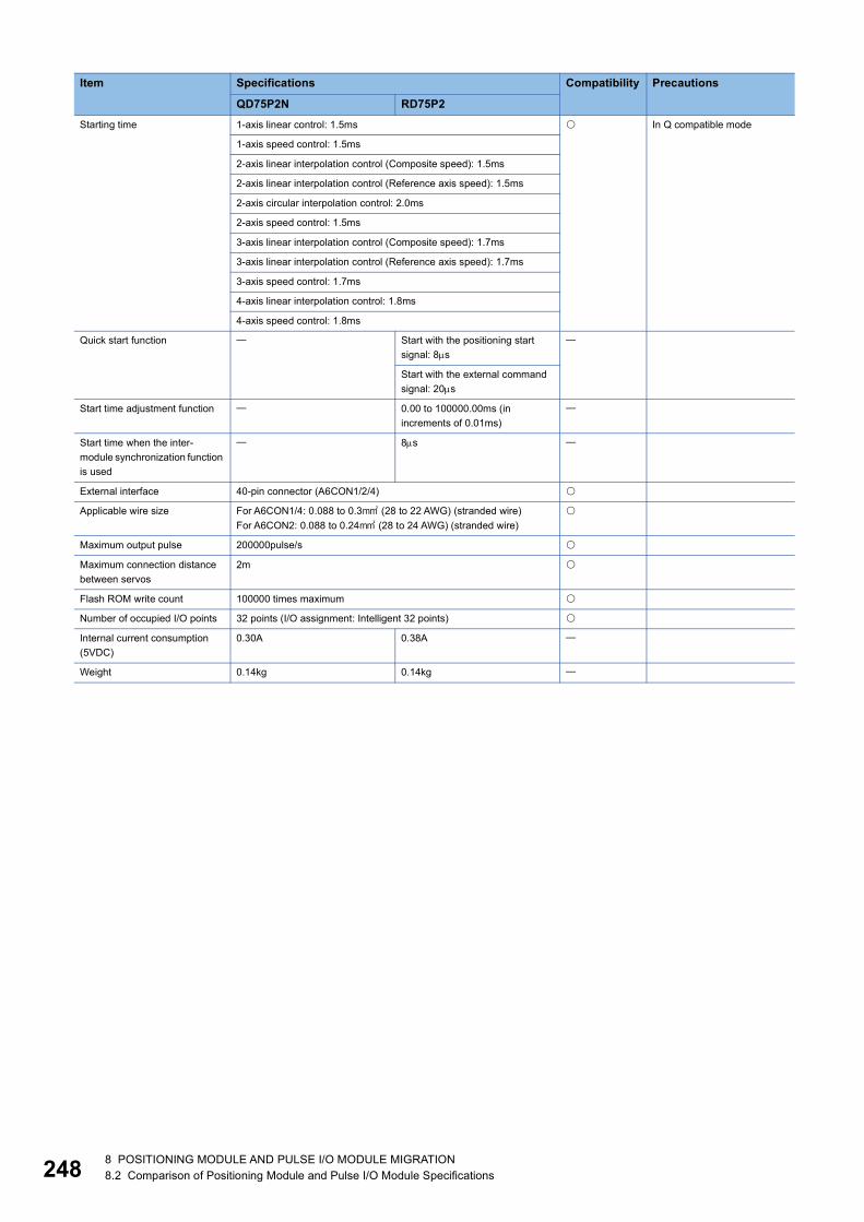
24
Starting time 1-axis linear control: 1.5ms In Q compatible mode
1-axis speed control: 1.5ms
2-axis linear interpolation control (Composite speed): 1.5ms
2-axis linear interpolation control (Reference axis speed): 1.5ms
2-axis circular interpolation control: 2.0ms
2-axis speed control: 1.5ms
3-axis linear interpolation control (Composite speed): 1.7ms
3-axis linear interpolation control (Reference axis speed): 1.7ms
3-axis speed control: 1.7ms
4-axis linear interpolation control: 1.8ms
4-axis speed control: 1.8ms
Quick start function Start with the positioning start signal: 8s
Start with the external command signal: 20s
Start time adjustment function 0.00 to 100000.00ms (in increments of 0.01ms)
Start time when the inter-module synchronization function is used
8s
External interface 40-pin connector (A6CON1/2/4)
Applicable wire size For A6CON1/4: 0.088 to 0.3 (28 to 22 AWG) (stranded wire)For A6CON2: 0.088 to 0.24 (28 to 24 AWG) (stranded wire)
Maximum output pulse 200000pulse/s
Maximum connection distance between servos
2m
Flash ROM write count 100000 times maximum
Number of occupied I/O points 32 points (I/O assignment: Intelligent 32 points)
Internal current consumption (5VDC)
0.30A 0.38A
Weight 0.14kg 0.14kg
Item Specifications Compatibility Precautions
QD75P2N RD75P2
8 8 POSITIONING MODULE AND PULSE I/O MODULE MIGRATION8.2 Comparison of Positioning Module and Pulse I/O Module Specifications

8
QD75P2 and RD75P2: Compatible : Partly changed : Incompatible : Not applicable
Item Specifications Compatibility Precautions
QD75P2 RD75P2No. of control axes 2
Interpolation function 2-axis linear interpolation, 2-axis circular interpolation
Control system PTP (Point To Point) control, path control (all of linear and circular can be set), speed control, speed-position switching control, position-speed switching control
Control unit mm, inch, degree, pulse
Positioning data 600 data/axis
Backup Parameters, positioning data, and block start data can be saved on the flash ROM (battery-less backup).
The following save destination can be selected for positioning data and block start data.• CPU module• Flash ROM of the positioning
module (battery-less)
The timing at which the backup data is reflected to the buffer memory is different. To change the parameters, positioning data, and block start data via a program, do it after confirming that Module access flag (X1) has turned on.
Positioning Positioning system
PTP control: Incremental system/absolute system
Speed-position switching control: Incremental system/absolute system
Position-speed switching control: Incremental system
Path control: Incremental system/absolute system
Positioning range
In absolute system-214748364.8 to 214748364.7m, -21474.83648 to 21474.83647 inch, 0 to 359.99999 degree, -2147483648 to 2147483647 pulse
In incremental system-214748364.8 to 214748364.7m, -21474.83648 to 21474.83647 inch,-21474.83648 to 21474.83647 degree, -2147483648 to 2147483647 pulse
In speed-position switching control (INC mode)/position-speed switching control0 to 214748364.7m, 0 to 21474.83647 inch, 0 to 21474.83647 degree, 0 to 2147483647 pulse
In speed-position switching control (ABS mode)0 to 359.99999 degree
Speed command
0.01 to 20000000.00 mm/min0.001 to 2000000.000 inch/min0.001 to 2000000.000 degree/min1 to 1000000 pulse/s
0.01 to 20000000.00 mm/min0.001 to 2000000.000 inch/min0.001 to 3000000.000 degree/min1 to 5000000 pulse/s
Acceleration/deceleration process
Trapezoidal acceleration/deceleration, S-curve acceleration/deceleration
Acceleration/deceleration time
1 to 8388608ms (Four patterns can be set for each of acceleration time and deceleration time.)
Sudden stop deceleration time
1 to 8388608ms
8 POSITIONING MODULE AND PULSE I/O MODULE MIGRATION8.2 Comparison of Positioning Module and Pulse I/O Module Specifications 249

25
Starting time 1-axis linear control: 6ms 1-axis linear control: 1.5ms The RD75 is upward compatibility with the QD75 and has the same programs.Because the performance such as the starting time and refreshing cycle is enhanced, modify each program as needed while checking the timing of the processing.
1-axis speed control: 6ms 1-axis speed control: 1.5ms
2-axis linear interpolation control (Composite speed): 7ms
2-axis linear interpolation control (Composite speed): 1.5ms
2-axis linear interpolation control (Reference axis speed): 7ms
2-axis linear interpolation control (Reference axis speed): 1.5ms
2-axis circular interpolation control: 7ms
2-axis circular interpolation control: 2.0ms
2-axis speed control: 6ms 2-axis speed control: 1.5ms
3-axis linear interpolation control (Composite speed): 7ms
3-axis linear interpolation control (Composite speed): 1.7ms
3-axis linear interpolation control (Reference axis speed): 7ms
3-axis linear interpolation control (Reference axis speed): 1.7ms
3-axis speed control: 6ms 3-axis speed control: 1.7ms
4-axis linear interpolation control: 7ms
4-axis linear interpolation control: 1.8ms
4-axis speed control: 7ms 4-axis speed control: 1.8ms
Quick start function Start with the positioning start signal: 8s
Start with the external command signal: 20s
Start time adjustment function 0.00 to 100000.00ms (in increments of 0.01ms)
Start time when the inter-module synchronization function is used
8s
External interface 40-pin connector (A6CON1/2/4)
Applicable wire size For A6CON1/4: 0.088 to 0.3 (28 to 22 AWG) (stranded wire)For A6CON2: 0.088 to 0.24 (28 to 24 AWG) (stranded wire)
Maximum output pulse 200000pulse/s
Maximum connection distance between servos
2m
Flash ROM write count 100000 times maximum
Number of occupied I/O points 32 points (I/O assignment: Intelligent 32 points)
Internal current consumption (5VDC)
0.46A 0.38A
Weight 0.15kg 0.14kg
Item Specifications Compatibility Precautions
QD75P2 RD75P2
0 8 POSITIONING MODULE AND PULSE I/O MODULE MIGRATION8.2 Comparison of Positioning Module and Pulse I/O Module Specifications

8
QD75P4N and RD75P4: Compatible : Partly changed : Incompatible : Not applicable
Item Specifications Compatibility Precautions
QD75P4N RD75P4No. of control axes 4
Interpolation function 2-, 3-, or 4-axis linear interpolation, 2-axis circular interpolation, 3-axis helical interpolation
Control system PTP (Point To Point) control, path control (all of linear, circular, and helical can be set), speed control, speed-position switching control, position-speed switching control
Control unit mm, inch, degree, pulse
Positioning data 600 data/axis
Backup Parameters, positioning data, and block start data can be saved on the flash ROM (battery-less backup).
The following save destination can be selected for positioning data and block start data.• CPU module• Flash ROM of the positioning
module (battery-less)
The timing at which the backup data is reflected to the buffer memory is different. To change the parameters, positioning data, and block start data via a program, do it after confirming that Module access flag (X1) has turned on.
Positioning Positioning system
PTP control: Incremental system/absolute system
Speed-position switching control: Incremental system/absolute system
Position-speed switching control: Incremental system
Path control: Incremental system/absolute system
Positioning range
In absolute system-214748364.8 to 214748364.7m, -21474.83648 to 21474.83647 inch,0 to 359.99999 degree, -2147483648 to 2147483647 pulse
In incremental system-214748364.8 to 214748364.7m, -21474.83648 to 21474.83647 inch,-21474.83648 to 21474.83647 degree, -2147483648 to 2147483647 pulse
In speed-position switching control (INC mode)/position-speed switching control0 to 214748364.7m, 0 to 21474.83647 inch,0 to 21474.83647 degree, 0 to 2147483647 pulse
In speed-position switching control (ABS mode)0 to 359.99999 degree
Speed command
0.01 to 20000000.00 mm/min0.001 to 2000000.000 inch/min0.001 to 2000000.000 degree/min1 to 4000000 pulse/s
0.01 to 20000000.00 mm/min0.001 to 2000000.000 inch/min0.001 to 3000000.000 degree/min1 to 5000000 pulse/s
Acceleration/deceleration process
Trapezoidal acceleration/deceleration, S-curve acceleration/deceleration
Acceleration/deceleration time
1 to 8388608ms (Four patterns can be set for each of acceleration time and deceleration time.)
Sudden stop deceleration time
1 to 8388608ms
8 POSITIONING MODULE AND PULSE I/O MODULE MIGRATION8.2 Comparison of Positioning Module and Pulse I/O Module Specifications 251

25
Starting time 1-axis linear control: 1.5ms In Q compatible mode
1-axis speed control: 1.5ms
2-axis linear interpolation control (Composite speed): 1.5ms
2-axis linear interpolation control (Reference axis speed): 1.5ms
2-axis circular interpolation control: 2.0ms
2-axis speed control: 1.5ms
3-axis linear interpolation control (Composite speed): 1.7ms
3-axis linear interpolation control (Reference axis speed): 1.7ms
3-axis helical interpolation control: 2.6ms
3-axis speed control: 1.7ms
4-axis linear interpolation control: 1.8ms
4-axis speed control: 1.8ms
Quick start function Start with the positioning start signal: 8s
Start with the external command signal: 20s
Start time adjustment function 0.00 to 100000.00ms (in increments of 0.01ms)
Start time when the inter-module synchronization function is used
8s
External interface 40-pin connector (A6CON1/2/4)
Applicable wire size For A6CON1/4: 0.088 to 0.3 (28 to 22 AWG) (stranded wire)For A6CON2: 0.088 to 0.24 (28 to 24 AWG) (stranded wire)
Maximum output pulse 200000pulse/s
Maximum connection distance between servos
2m
Flash ROM write count 100000 times maximum
Number of occupied I/O points 32 points (I/O assignment: Intelligent 32 points)
Internal current consumption (5VDC)
0.36A 0.42A
Weight 0.16kg 0.15kg
Item Specifications Compatibility Precautions
QD75P4N RD75P4
2 8 POSITIONING MODULE AND PULSE I/O MODULE MIGRATION8.2 Comparison of Positioning Module and Pulse I/O Module Specifications

8
QD75P4 and RD75P4: Compatible : Partly changed : Incompatible : Not applicable
Item Specifications Compatibility Precautions
QD75P4 RD75P4No. of control axes 4
Interpolation function 2-, 3-, or 4-axis linear interpolation, 2-axis circular interpolation
2-, 3-, or 4-axis linear interpolation, 2-axis circular interpolation, 3-axis helical interpolation
Control system PTP (Point To Point) control, path control (all of linear and circular can be set), speed control, speed-position switching control, position-speed switching control
PTP (Point To Point) control, path control (all of linear, circular, and helical can be set), speed control, speed-position switching control, position-speed switching control
Control unit mm, inch, degree, pulse
Positioning data 600 data/axis
Backup Parameters, positioning data, and block start data can be saved on the flash ROM (battery-less backup).
The following save destination can be selected for positioning data and block start data.• CPU module• Flash ROM of the positioning
module (battery-less)
The timing at which the backup data is reflected to the buffer memory is different. To change the parameters, positioning data, and block start data via a program, do it after confirming that Module access flag (X1) has turned on.
Positioning Positioning system
PTP control: Incremental system/absolute system
Speed-position switching control: Incremental system/absolute system
Position-speed switching control: Incremental system
Path control: Incremental system/absolute system
Positioning range
In absolute system-214748364.8 to 214748364.7m, -21474.83648 to 21474.83647 inch, 0 to 359.99999 degree, -2147483648 to 2147483647 pulse
In incremental system-214748364.8 to 214748364.7m, -21474.83648 to 21474.83647 inch,-21474.83648 to 21474.83647 degree, -2147483648 to 2147483647 pulse
In speed-position switching control (INC mode)/position-speed switching control0 to 214748364.7m, 0 to 21474.83647 inch,0 to 21474.83647 degree, 0 to 2147483647 pulse
In speed-position switching control (ABS mode)0 to 359.99999 degree
Speed command
0.01 to 20000000.00 mm/min0.001 to 2000000.000 inch/min0.001 to 2000000.000 degree/min1 to 1000000 pulse/s
0.01 to 20000000.00 mm/min0.001 to 2000000.000 inch/min0.001 to 3000000.000 degree/min1 to 5000000 pulse/s
Acceleration/deceleration process
Trapezoidal acceleration/deceleration, S-curve acceleration/deceleration
Acceleration/deceleration time
1 to 8388608ms (Four patterns can be set for each of acceleration time and deceleration time.)
Sudden stop deceleration time
1 to 8388608ms
8 POSITIONING MODULE AND PULSE I/O MODULE MIGRATION8.2 Comparison of Positioning Module and Pulse I/O Module Specifications 253

25
Starting time 1-axis linear control: 6ms 1-axis linear control: 1.5ms The RD75 is upward compatibility with the QD75 and has the same programs.Because the performance such as the starting time and refreshing cycle is enhanced, modify each program as needed while checking the timing of the processing.
1-axis speed control: 6ms 1-axis speed control: 1.5ms
2-axis linear interpolation control (Composite speed): 7ms
2-axis linear interpolation control (Composite speed): 1.5ms
2-axis linear interpolation control (Reference axis speed): 7ms
2-axis linear interpolation control (Reference axis speed): 1.5ms
2-axis circular interpolation control: 7ms
2-axis circular interpolation control: 2.0ms
2-axis speed control: 6ms 2-axis speed control: 1.5ms
3-axis linear interpolation control (Composite speed): 7ms
3-axis linear interpolation control (Composite speed): 1.7ms
3-axis linear interpolation control (Reference axis speed): 7ms
3-axis linear interpolation control (Reference axis speed): 1.7ms
3-axis helical interpolation control: 2.6ms
3-axis speed control: 6ms 3-axis speed control: 1.7ms
4-axis linear interpolation control: 7ms
4-axis linear interpolation control: 1.8ms
4-axis speed control: 7ms 4-axis speed control: 1.8ms
Quick start function Start with the positioning start signal: 8s
Start with the external command signal: 20s
Start time adjustment function 0.00 to 100000.00ms (in increments of 0.01ms)
Start time when the inter-module synchronization function is used
8s
External interface 40-pin connector (A6CON1/2/4)
Applicable wire size For A6CON1/4: 0.088 to 0.3 (28 to 22 AWG) (stranded wire)For A6CON2: 0.088 to 0.24 (28 to 24 AWG) (stranded wire)
Maximum output pulse 200000pulse/s
Maximum connection distance between servos
2m
Flash ROM write count 100000 times maximum
Number of occupied I/O points 32 points (I/O assignment: Intelligent 32 points)
Internal current consumption (5VDC)
0.58A 0.42A
Weight 0.16kg 0.15kg
Item Specifications Compatibility Precautions
QD75P4 RD75P4
4 8 POSITIONING MODULE AND PULSE I/O MODULE MIGRATION8.2 Comparison of Positioning Module and Pulse I/O Module Specifications
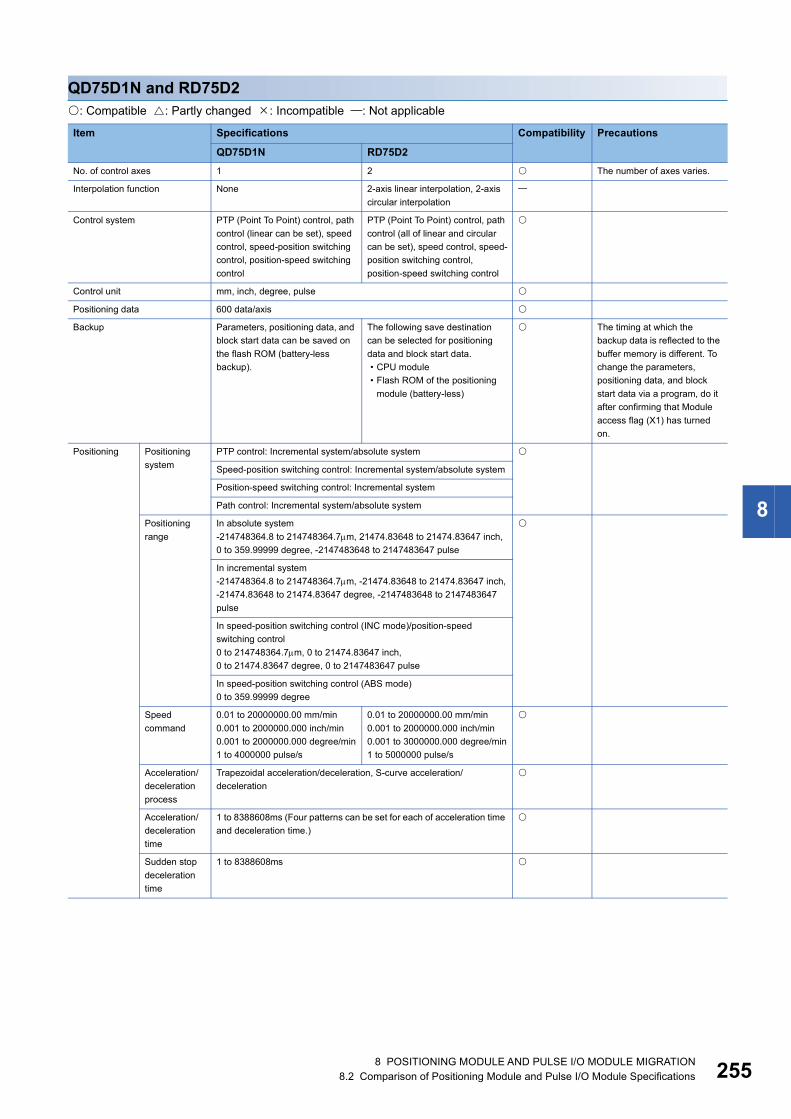
8
QD75D1N and RD75D2: Compatible : Partly changed : Incompatible : Not applicable
Item Specifications Compatibility Precautions
QD75D1N RD75D2No. of control axes 1 2 The number of axes varies.
Interpolation function None 2-axis linear interpolation, 2-axis circular interpolation
Control system PTP (Point To Point) control, path control (linear can be set), speed control, speed-position switching control, position-speed switching control
PTP (Point To Point) control, path control (all of linear and circular can be set), speed control, speed-position switching control, position-speed switching control
Control unit mm, inch, degree, pulse
Positioning data 600 data/axis
Backup Parameters, positioning data, and block start data can be saved on the flash ROM (battery-less backup).
The following save destination can be selected for positioning data and block start data.• CPU module• Flash ROM of the positioning
module (battery-less)
The timing at which the backup data is reflected to the buffer memory is different. To change the parameters, positioning data, and block start data via a program, do it after confirming that Module access flag (X1) has turned on.
Positioning Positioning system
PTP control: Incremental system/absolute system
Speed-position switching control: Incremental system/absolute system
Position-speed switching control: Incremental system
Path control: Incremental system/absolute system
Positioning range
In absolute system-214748364.8 to 214748364.7m, 21474.83648 to 21474.83647 inch,0 to 359.99999 degree, -2147483648 to 2147483647 pulse
In incremental system-214748364.8 to 214748364.7m, -21474.83648 to 21474.83647 inch,-21474.83648 to 21474.83647 degree, -2147483648 to 2147483647 pulse
In speed-position switching control (INC mode)/position-speed switching control0 to 214748364.7m, 0 to 21474.83647 inch,0 to 21474.83647 degree, 0 to 2147483647 pulse
In speed-position switching control (ABS mode)0 to 359.99999 degree
Speed command
0.01 to 20000000.00 mm/min0.001 to 2000000.000 inch/min0.001 to 2000000.000 degree/min1 to 4000000 pulse/s
0.01 to 20000000.00 mm/min0.001 to 2000000.000 inch/min0.001 to 3000000.000 degree/min1 to 5000000 pulse/s
Acceleration/deceleration process
Trapezoidal acceleration/deceleration, S-curve acceleration/deceleration
Acceleration/deceleration time
1 to 8388608ms (Four patterns can be set for each of acceleration time and deceleration time.)
Sudden stop deceleration time
1 to 8388608ms
8 POSITIONING MODULE AND PULSE I/O MODULE MIGRATION8.2 Comparison of Positioning Module and Pulse I/O Module Specifications 255

25
Starting time 1-axis linear control: 1.5ms In Q compatible mode
1-axis speed control: 1.5ms
2-axis linear interpolation control (Composite speed): 1.5ms
2-axis linear interpolation control (Reference axis speed): 1.5ms
2-axis circular interpolation control: 2.0ms
2-axis speed control: 1.5ms
3-axis linear interpolation control (Composite speed): 1.7ms
3-axis linear interpolation control (Reference axis speed): 1.7ms
3-axis speed control: 1.7ms
4-axis linear interpolation control: 1.8ms
4-axis speed control: 1.8ms
Quick start function Start with the positioning start signal: 8s
Start with the external command signal: 20s
Start time adjustment function 0.00 to 100000.00ms (in increments of 0.01ms)
Start time when the inter-module synchronization function is used
8s
External interface 40-pin connector (A6CON1/2/4)
Applicable wire size For A6CON1/4: 0.088 to 0.3 (28 to 22 AWG) (stranded wire)For A6CON2: 0.088 to 0.24 (28 to 24 AWG) (stranded wire)
Maximum output pulse 4000000pulse/s 5000000pulse/s
Maximum connection distance between servos
10m
Flash ROM write count 100000 times maximum
Number of occupied I/O points 32 points (I/O assignment: Intelligent 32 points)
Internal current consumption (5VDC)
0.43A 0.54A
Weight 0.15kg 0.15kg
Item Specifications Compatibility Precautions
QD75D1N RD75D2
6 8 POSITIONING MODULE AND PULSE I/O MODULE MIGRATION8.2 Comparison of Positioning Module and Pulse I/O Module Specifications

8
QD75D1 and RD75D2: Compatible : Partly changed : Incompatible : Not applicable
Item QD75D1 RD75D2 Compatibility Precautions
SpecificationsNo. of control axes 1 2 The number of axes varies.
Interpolation function None 2-axis linear interpolation, 2-axis circular interpolation
Control system PTP (Point To Point) control, path control (linear can be set), speed control, speed-position switching control, position-speed switching control
PTP (Point To Point) control, path control (all of linear and circular can be set), speed control, speed-position switching control, position-speed switching control
Control unit mm, inch, degree, pulse
Positioning data 600 data/axis
Backup Parameters, positioning data, and block start data can be saved on the flash ROM (battery-less backup).
The following save destination can be selected for positioning data and block start data.• CPU module• Flash ROM of the positioning
module (battery-less)
The timing at which the backup data is reflected to the buffer memory is different. To change the parameters, positioning data, and block start data via a program, do it after confirming that Module access flag (X1) has turned on.
Positioning Positioning system
PTP control: Incremental system/absolute system
Speed-position switching control: Incremental system/absolute system
Position-speed switching control: Incremental system
Path control: Incremental system/absolute system
Positioning range
In absolute system-214748364.8 to 214748364.7m, -21474.83648 to 21474.83647 inch, 0 to 359.99999 degree, -2147483648 to 2147483647 pulse
In incremental system-214748364.8 to 214748364.7m, -21474.83648 to 21474.83647 inch,-21474.83648 to 21474.83647 degree, -2147483648 to 2147483647 pulse
In speed-position switching control (INC mode)/position-speed switching control0 to 214748364.7m, 0 to 21474.83647 inch, 0 to 21474.83647 degree, 0 to 2147483647 pulse
In speed-position switching control (ABS mode)0 to 359.99999 degree
Speed command
0.01 to 20000000.00 mm/min0.001 to 2000000.000 inch/min0.001 to 2000000.000 degree/min1 to 1000000 pulse/s
0.01 to 20000000.00 mm/min0.001 to 2000000.000 inch/min0.001 to 3000000.000 degree/min1 to 5000000 pulse/s
Acceleration/deceleration process
Trapezoidal acceleration/deceleration, S-curve acceleration/deceleration
Acceleration/deceleration time
1 to 8388608ms (Four patterns can be set for each of acceleration time and deceleration time.)
Sudden stop deceleration time
1 to 8388608ms
8 POSITIONING MODULE AND PULSE I/O MODULE MIGRATION8.2 Comparison of Positioning Module and Pulse I/O Module Specifications 257

25
Starting time 1-axis linear control: 6ms 1-axis linear control: 1.5ms The RD75 is upward compatibility with the QD75 and has the same programs.Because the performance such as the starting time and refreshing cycle is enhanced, modify each program as needed while checking the timing of the processing.
1-axis speed control: 6ms 1-axis speed control: 1.5ms
2-axis linear interpolation control (Composite speed): 7ms
2-axis linear interpolation control (Composite speed): 1.5ms
2-axis linear interpolation control (Reference axis speed): 7ms
2-axis linear interpolation control (Reference axis speed): 1.5ms
2-axis circular interpolation control: 7ms
2-axis circular interpolation control: 2.0ms
2-axis speed control: 6ms 2-axis speed control: 1.5ms
3-axis linear interpolation control (Composite speed): 7ms
3-axis linear interpolation control (Composite speed): 1.7ms
3-axis linear interpolation control (Reference axis speed): 7ms
3-axis linear interpolation control (Reference axis speed): 1.7ms
3-axis speed control: 6ms 3-axis speed control: 1.7ms
4-axis linear interpolation control: 7ms
4-axis linear interpolation control: 1.8ms
4-axis speed control: 7ms 4-axis speed control: 1.8ms
Quick start function Start with the positioning start signal: 8s
Start with the external command signal: 20s
Start time adjustment function 0.00 to 100000.00ms(in increments of 0.01ms)
Start time when the inter-module synchronization function is used
8s
External interface 40-pin connector (A6CON1/2/4)
Applicable wire size For A6CON1/4: 0.088 to 0.3 (28 to 22 AWG) (stranded wire)For A6CON2: 0.088 to 0.24 (28 to 24 AWG) (stranded wire)
Maximum output pulse 1000000pulse/s 5000000pulse/s
Maximum connection distance between servos
10m
Flash ROM write count 100000 times maximum
Number of occupied I/O points 32 points (I/O assignment: Intelligent 32 points)
Internal current consumption (5VDC)
0.52A 0.54A
Weight 0.15kg 0.15kg
Item QD75D1 RD75D2 Compatibility Precautions
Specifications
8 8 POSITIONING MODULE AND PULSE I/O MODULE MIGRATION8.2 Comparison of Positioning Module and Pulse I/O Module Specifications

8
QD75D2N and RD75D2: Compatible : Partly changed : Incompatible : Not applicable
Item Specifications Compatibility Precautions
QD75D2N RD75D2No. of control axes 2
Interpolation function 2-axis linear interpolation, 2-axis circular interpolation
Control system PTP (Point To Point) control, path control (all of linear and circular can be set), speed control, speed-position switching control, position-speed switching control
Control unit mm, inch, degree, pulse
Positioning data 600 data/axis
Backup Parameters, positioning data, and block start data can be saved on the flash ROM (battery-less backup).
The following save destination can be selected for positioning data and block start data.• CPU module• Flash ROM of the positioning
module (battery-less)
The timing at which the backup data is reflected to the buffer memory is different. To change the parameters, positioning data, and block start data via a program, do it after confirming that Module access flag (X1) has turned on.
Positioning Positioning system
PTP control: Incremental system/absolute system
Speed-position switching control: Incremental system/absolute system
Position-speed switching control: Incremental system
Path control: Incremental system/absolute system
Positioning range
In absolute system-214748364.8 to 214748364.7m, -21474.83648 to 21474.83647 inch, 0 to 359.99999 degree, -2147483648 to 2147483647 pulse
In incremental system-214748364.8 to 214748364.7m, -21474.83648 to 21474.83647 inch,-21474.83648 to 21474.83647 degree, -2147483648 to 2147483647 pulse
In speed-position switching control (INC mode)/position-speed switching control0 to 214748364.7m, 0 to 21474.83647 inch, 0 to 21474.83647 degree, 0 to 2147483647 pulse
In speed-position switching control (ABS mode)0 to 359.99999 degree
Speed command
0.01 to 20000000.00 mm/min0.001 to 2000000.000 inch/min0.001 to 2000000.000 degree/min1 to 4000000 pulse/s
0.01 to 20000000.00 mm/min0.001 to 2000000.000 inch/min0.001 to 3000000.000 degree/min1 to 5000000 pulse/s
Acceleration/deceleration process
Trapezoidal acceleration/deceleration, S-curve acceleration/deceleration
Acceleration/deceleration time
1 to 8388608ms (Four patterns can be set for each of acceleration time and deceleration time.)
Sudden stop deceleration time
1 to 8388608ms
8 POSITIONING MODULE AND PULSE I/O MODULE MIGRATION8.2 Comparison of Positioning Module and Pulse I/O Module Specifications 259

26
Starting time 1-axis linear control: 1.5ms In Q compatible mode
1-axis speed control: 1.5ms
2-axis linear interpolation control (Composite speed): 1.5ms
2-axis linear interpolation control (Reference axis speed): 1.5ms
2-axis circular interpolation control: 2.0ms
2-axis speed control: 1.5ms
3-axis linear interpolation control (Composite speed): 1.7ms
3-axis linear interpolation control (Reference axis speed): 1.7ms
3-axis speed control: 1.7ms
4-axis linear interpolation control: 1.8ms
4-axis speed control: 1.8ms
Quick start function Start with the positioning start signal: 8s
Start with the external command signal: 20s
Start time adjustment function 0.00 to 100000.00ms(in increments of 0.01ms)
Start time when the inter-module synchronization function is used
8s
External interface 40-pin connector (A6CON1/2/4)
Applicable wire size For A6CON1/4: 0.088 to 0.3 (28 to 22 AWG) (stranded wire)For A6CON2: 0.088 to 0.24 (28 to 24 AWG) (stranded wire)
Maximum output pulse 4000000pulse/s 5000000pulse/s
Maximum connection distance between servos
10m
Flash ROM write count 100000 times maximum
Number of occupied I/O points 32 points (I/O assignment: Intelligent 32 points)
Internal current consumption (5VDC)
0.45A 0.54A
Weight 0.15kg 0.15kg
Item Specifications Compatibility Precautions
QD75D2N RD75D2
0 8 POSITIONING MODULE AND PULSE I/O MODULE MIGRATION8.2 Comparison of Positioning Module and Pulse I/O Module Specifications
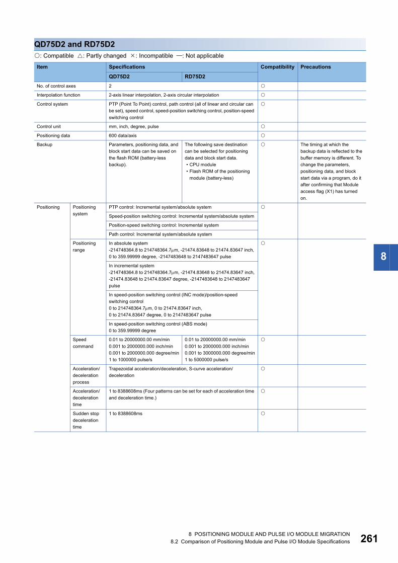
8
QD75D2 and RD75D2: Compatible : Partly changed : Incompatible : Not applicable
Item Specifications Compatibility Precautions
QD75D2 RD75D2No. of control axes 2
Interpolation function 2-axis linear interpolation, 2-axis circular interpolation
Control system PTP (Point To Point) control, path control (all of linear and circular can be set), speed control, speed-position switching control, position-speed switching control
Control unit mm, inch, degree, pulse
Positioning data 600 data/axis
Backup Parameters, positioning data, and block start data can be saved on the flash ROM (battery-less backup).
The following save destination can be selected for positioning data and block start data.• CPU module• Flash ROM of the positioning
module (battery-less)
The timing at which the backup data is reflected to the buffer memory is different. To change the parameters, positioning data, and block start data via a program, do it after confirming that Module access flag (X1) has turned on.
Positioning Positioning system
PTP control: Incremental system/absolute system
Speed-position switching control: Incremental system/absolute system
Position-speed switching control: Incremental system
Path control: Incremental system/absolute system
Positioning range
In absolute system-214748364.8 to 214748364.7m, -21474.83648 to 21474.83647 inch, 0 to 359.99999 degree, -2147483648 to 2147483647 pulse
In incremental system-214748364.8 to 214748364.7m, -21474.83648 to 21474.83647 inch,-21474.83648 to 21474.83647 degree, -2147483648 to 2147483647 pulse
In speed-position switching control (INC mode)/position-speed switching control0 to 214748364.7m, 0 to 21474.83647 inch,0 to 21474.83647 degree, 0 to 2147483647 pulse
In speed-position switching control (ABS mode)0 to 359.99999 degree
Speed command
0.01 to 20000000.00 mm/min0.001 to 2000000.000 inch/min0.001 to 2000000.000 degree/min1 to 1000000 pulse/s
0.01 to 20000000.00 mm/min0.001 to 2000000.000 inch/min0.001 to 3000000.000 degree/min1 to 5000000 pulse/s
Acceleration/deceleration process
Trapezoidal acceleration/deceleration, S-curve acceleration/deceleration
Acceleration/deceleration time
1 to 8388608ms (Four patterns can be set for each of acceleration time and deceleration time.)
Sudden stop deceleration time
1 to 8388608ms
8 POSITIONING MODULE AND PULSE I/O MODULE MIGRATION8.2 Comparison of Positioning Module and Pulse I/O Module Specifications 261

26
Starting time 1-axis linear control: 6ms 1-axis linear control: 1.5ms The RD75 is upward compatibility with the QD75 and has the same programs.Because the performance such as the starting time and refreshing cycle is enhanced, modify each program as needed while checking the timing of the processing.
1-axis speed control: 6ms 1-axis speed control: 1.5ms
2-axis linear interpolation control (Composite speed): 7ms
2-axis linear interpolation control (Composite speed): 1.5ms
2-axis linear interpolation control (Reference axis speed): 7ms
2-axis linear interpolation control (Reference axis speed): 1.5ms
2-axis circular interpolation control: 7ms
2-axis circular interpolation control: 2.0ms
2-axis speed control: 6ms 2-axis speed control: 1.5ms
3-axis linear interpolation control (Composite speed): 7ms
3-axis linear interpolation control (Composite speed): 1.7ms
3-axis linear interpolation control (Reference axis speed): 7ms
3-axis linear interpolation control (Reference axis speed): 1.7ms
3-axis speed control: 6ms 3-axis speed control: 1.7ms
4-axis linear interpolation control: 7ms
4-axis linear interpolation control: 1.8ms
4-axis speed control: 7ms 4-axis speed control: 1.8ms
Quick start function Start with the positioning start signal: 8s
Start with the external command signal: 20s
Start time adjustment function 0.00 to 100000.00ms(in increments of 0.01ms)
Start time when the inter-module synchronization function is used
8s
External interface 40-pin connector (A6CON1/2/4)
Applicable wire size For A6CON1/4: 0.088 to 0.3 (28 to 22 AWG) (stranded wire)For A6CON2: 0.088 to 0.24 (28 to 24 AWG) (stranded wire)
Maximum output pulse 1000000pulse/s 5000000pulse/s
Maximum connection distance between servos
10m
Flash ROM write count 100000 times maximum
Number of occupied I/O points 32 points (I/O assignment: Intelligent 32 points)
Internal current consumption (5VDC)
0.56A 0.54A
Weight 0.15kg 0.15kg
Item Specifications Compatibility Precautions
QD75D2 RD75D2
2 8 POSITIONING MODULE AND PULSE I/O MODULE MIGRATION8.2 Comparison of Positioning Module and Pulse I/O Module Specifications
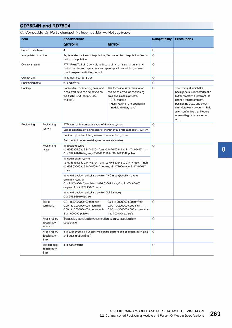
8
QD75D4N and RD75D4: Compatible : Partly changed : Incompatible : Not applicable
Item Specifications Compatibility Precautions
QD75D4N RD75D4No. of control axes 4
Interpolation function 2-, 3-, or 4-axis linear interpolation, 2-axis circular interpolation, 3-axis helical interpolation
Control system PTP (Point To Point) control, path control (all of linear, circular, and helical can be set), speed control, speed-position switching control, position-speed switching control
Control unit mm, inch, degree, pulse
Positioning data 600 data/axis
Backup Parameters, positioning data, and block start data can be saved on the flash ROM (battery-less backup).
The following save destination can be selected for positioning data and block start data.• CPU module• Flash ROM of the positioning
module (battery-less)
The timing at which the backup data is reflected to the buffer memory is different. To change the parameters, positioning data, and block start data via a program, do it after confirming that Module access flag (X1) has turned on.
Positioning Positioning system
PTP control: Incremental system/absolute system
Speed-position switching control: Incremental system/absolute system
Position-speed switching control: Incremental system
Path control: Incremental system/absolute system
Positioning range
In absolute system-214748364.8 to 214748364.7m, -21474.83648 to 21474.83647 inch, 0 to 359.99999 degree, -2147483648 to 2147483647 pulse
In incremental system-214748364.8 to 214748364.7m, -21474.83648 to 21474.83647 inch,-21474.83648 to 21474.83647 degree, -2147483648 to 2147483647 pulse
In speed-position switching control (INC mode)/position-speed switching control0 to 214748364.7m, 0 to 21474.83647 inch, 0 to 21474.83647 degree, 0 to 2147483647 pulse
In speed-position switching control (ABS mode)0 to 359.99999 degree
Speed command
0.01 to 20000000.00 mm/min0.001 to 2000000.000 inch/min0.001 to 2000000.000 degree/min1 to 4000000 pulse/s
0.01 to 20000000.00 mm/min0.001 to 2000000.000 inch/min0.001 to 3000000.000 degree/min1 to 5000000 pulse/s
Acceleration/deceleration process
Trapezoidal acceleration/deceleration, S-curve acceleration/deceleration
Acceleration/deceleration time
1 to 8388608ms (Four patterns can be set for each of acceleration time and deceleration time.)
Sudden stop deceleration time
1 to 8388608ms
8 POSITIONING MODULE AND PULSE I/O MODULE MIGRATION8.2 Comparison of Positioning Module and Pulse I/O Module Specifications 263

26
Starting time 1-axis linear control: 1.5ms In Q compatible mode
1-axis speed control: 1.5ms
2-axis linear interpolation control (Composite speed): 1.5ms
2-axis linear interpolation control (Reference axis speed): 1.5ms
2-axis circular interpolation control: 2.0ms
2-axis speed control: 1.5ms
3-axis linear interpolation control (Composite speed): 1.7ms
3-axis linear interpolation control (Reference axis speed): 1.7ms
3-axis helical interpolation control: 2.6ms
3-axis speed control: 1.7ms
4-axis linear interpolation control: 1.8ms
4-axis speed control: 1.8ms
Quick start function Start with the positioning start signal: 8s
Start with the external command signal: 20s
Start time adjustment function 0.00 to 100000.00ms(in increments of 0.01ms)
Start time when the inter-module synchronization function is used
8s
External interface 40-pin connector (A6CON1/2/4)
Applicable wire size For A6CON1/4: 0.088 to 0.3 (28 to 22 AWG) (stranded wire)For A6CON2: 0.088 to 0.24 (28 to 24 AWG) (stranded wire)
Maximum output pulse 4000000pulse/s 5000000pulse/s
Maximum connection distance between servos
10m
Flash ROM write count 100000 times maximum
Number of occupied I/O points 32 points (I/O assignment: Intelligent 32 points)
Internal current consumption (5VDC)
0.66A 0.78A
Weight 0.16kg 0.15kg
Item Specifications Compatibility Precautions
QD75D4N RD75D4
4 8 POSITIONING MODULE AND PULSE I/O MODULE MIGRATION8.2 Comparison of Positioning Module and Pulse I/O Module Specifications

8
QD75D4 and RD75D4: Compatible : Partly changed : Incompatible : Not applicable
Item Specifications Compatibility Precautions
QD75D4 RD75D4No. of control axes 4
Interpolation function 2-, 3-, or 4-axis linear interpolation, 2-axis circular interpolation
2-, 3-, or 4-axis linear interpolation, 2-axis circular interpolation, 3-axis helical interpolation
Control system PTP (Point To Point) control, path control (all of linear and circular can be set), speed control, speed-position switching control, position-speed switching control
PTP (Point To Point) control, path control (all of linear, circular, and helical can be set), speed control, speed-position switching control, position-speed switching control
Control unit mm, inch, degree, pulse
Positioning data 600 data/axis
Backup Parameters, positioning data, and block start data can be saved on the flash ROM (battery-less backup).
The following save destination can be selected for positioning data and block start data.• CPU module• Flash ROM of the positioning
module (battery-less)
The timing at which the backup data is reflected to the buffer memory is different. To change the parameters, positioning data, and block start data via a program, do it after confirming that Module access flag (X1) has turned on.
Positioning Positioning system
PTP control: Incremental system/absolute system
Speed-position switching control: Incremental system/absolute system
Position-speed switching control: Incremental system
Path control: Incremental system/absolute system
Positioning range
In absolute system-214748364.8 to 214748364.7m, -21474.83648 to 21474.83647 inch, 0 to 359.99999 degree, -2147483648 to 2147483647 pulse
In incremental system-214748364.8 to 214748364.7m, -21474.83648 to 21474.83647 inch,-21474.83648 to 21474.83647 degree, -2147483648 to 2147483647 pulse
In speed-position switching control (INC mode)/position-speed switching control0 to 214748364.7m, 0 to 21474.83647 inch, 0 to 21474.83647 degree, 0 to 2147483647 pulse
In speed-position switching control (ABS mode)0 to 359.99999 degree
Speed command
0.01 to 20000000.00 mm/min0.001 to 2000000.000 inch/min0.001 to 2000000.000 degree/min1 to 1000000 pulse/s
0.01 to 20000000.00 mm/min0.001 to 2000000.000 inch/min0.001 to 3000000.000 degree/min1 to 5000000 pulse/s
Acceleration/deceleration process
Trapezoidal acceleration/deceleration, S-curve acceleration/deceleration
Acceleration/deceleration time
1 to 8388608ms (Four patterns can be set for each of acceleration time and deceleration time.)
Sudden stop deceleration time
1 to 8388608ms
8 POSITIONING MODULE AND PULSE I/O MODULE MIGRATION8.2 Comparison of Positioning Module and Pulse I/O Module Specifications 265

26
Starting time 1-axis linear control: 6ms 1-axis linear control: 1.5ms The RD75 is upward compatibility with the QD75 and has the same programs.Because the performance such as the starting time and refreshing cycle is enhanced, modify each program as needed while checking the timing of the processing.
1-axis speed control: 6ms 1-axis speed control: 1.5ms
2-axis linear interpolation control (Composite speed): 7ms
2-axis linear interpolation control (Composite speed): 1.5ms
2-axis linear interpolation control (Reference axis speed): 7ms
2-axis linear interpolation control (Reference axis speed): 1.5ms
2-axis circular interpolation control: 7ms
2-axis circular interpolation control: 2.0ms
2-axis speed control: 6ms 2-axis speed control: 1.5ms
3-axis linear interpolation control (Composite speed): 7ms
3-axis linear interpolation control (Composite speed): 1.7ms
3-axis linear interpolation control (Reference axis speed): 7ms
3-axis linear interpolation control (Reference axis speed): 1.7ms
3-axis helical interpolation control: 2.6ms
3-axis speed control: 6ms 3-axis speed control: 1.7ms
4-axis linear interpolation control: 7ms
4-axis linear interpolation control: 1.8ms
4-axis speed control: 7ms 4-axis speed control: 1.8ms
Quick start function Start with the positioning start signal: 8s
Start with the external command signal: 20s
Start time adjustment function 0.00 to 100000.00ms(in increments of 0.01ms)
Start time when the inter-module synchronization function is used
8s
External interface 40-pin connector (A6CON1/2/4)
Applicable wire size For A6CON1/4: 0.088 to 0.3 (28 to 22 AWG) (stranded wire)For A6CON2: 0.088 to 0.24 (28 to 24 AWG) (stranded wire)
Maximum output pulse 1000000pulse/s 5000000pulse/s
Maximum connection distance between servos
10m
Flash ROM write count 100000 times maximum
Number of occupied I/O points 32 points (I/O assignment: Intelligent 32 points)
Internal current consumption (5VDC)
0.82A 0.78A
Weight 0.16kg 0.15kg
Item Specifications Compatibility Precautions
QD75D4 RD75D4
6 8 POSITIONING MODULE AND PULSE I/O MODULE MIGRATION8.2 Comparison of Positioning Module and Pulse I/O Module Specifications

8
Comparison of high-speed counter module specifications
QD62 and RD62P2: Compatible : Partly changed : Incompatible : Not applicable
Item Specifications Compatibility Precautions
QD62 RD62P2Counting speed switch setting
200k 100k to 200kpps
100k 10k to 100kpps
10k 10kpps or less
Number of channels 2 channels
Count input signal
Phase 1-phase input (1 multiple/2 multiples), 2-phase input (1 multiple/2 multiples/4 multiples), CW/CCW input
Signal level (A, B)
5/12/24VDC, 2 to 5mA
Counter Counting speed (maximum)*1
200k setting: 200kpps, 100k setting: 100kpps, 10k setting: 10kpps
Counting range 32-bit signed binary values (-2147483648 to 2147483647)
Model UP/DOWN preset counter + Ring counter function
Minimum count pulse width (duty ratio: 50%)
*2 *3
Coincidence output
Comparison range
32-bit signed binary values
Comparison result
Set value < Count value, Set value = Count value, Set value > Count value
External input
Preset 5/12/24VDC, 2 to 5mA 5/12/24VDC, 7 to 10mA The external input specifications are different. Check the specifications of external devices.
Function start
External output
Coincidence output
Transistor (sinking type) output2 points/channel12/24VDC, 0.5A/point, 2A/commonCurrent consumption of the external auxiliary power supply: 8mA (TYP., 24VDC)
Transistor (sinking type) output2 points/channel12/24VDC, 0.5A/point, 2A/commonCurrent consumption of the external auxiliary power supply: 43mA (TYP., 24VDC and all points ON/common)
The external output specifications are different. Check the specifications of external devices.
Number of occupied I/O points 16 points (I/O assignment: Intelligent 16 points)
External interface 40-pin connector (A6CON1/2/3/4) 40-pin connector (A6CON1/2/4) The A6CON3 cannot be used.
Applicable wire size For A6CON1/4: 0.3 (22 AWG) (stranded wire)For A6CON2: 0.088 to 0.24 (28 to 24 AWG) (stranded wire)For A6CON3: 28 AWG (stranded wire), 30 AWG (solid wire)
For A6CON1/4: 0.088 to 0.3 (28 to 22 AWG) (stranded wire)For A6CON2: 0.088 to 0.24 (28 to 24 AWG) (stranded wire)
Internal current consumption (5VDC)
0.30A 0.11A
Weight 0.11kg 0.11kg
8 POSITIONING MODULE AND PULSE I/O MODULE MIGRATION8.2 Comparison of Positioning Module and Pulse I/O Module Specifications 267

26
*1 The counting speed is affected by the pulse rise/fall time. A count can be performed with the following counting speed.
*2 The following table shows the minimum count pulse width for the QD62.
Counting speed switch setting 200kpps 100kpps 10kppsRise/fall time Both 1- and 2-phase inputs
t = 1.25s or less 200kpps 100kpps 10kpps
t = 2.5s or less 100kpps 100kpps 10kpps
t = 25s or less 10kpps 10kpps
t = 500s or less 500pps
Counting speed switch setting
200kpps 100kpps 10kpps
(Unit: s)(Minimum phase differential for 2-phase input: 1.25s)
(Unit: s)(Minimum phase differential for 2-phase input: 2.5s)
(Unit: s)(Minimum phase differential for 2-phase input: 25s)
tt
2.5 2.5
5
5 5
10
50 50
100
8 8 POSITIONING MODULE AND PULSE I/O MODULE MIGRATION8.2 Comparison of Positioning Module and Pulse I/O Module Specifications

8
*3 The following table shows the minimum count pulse width for the RD62P2.
Pulse input mode Waveform (in up count, duty ratio: 50%)
Minimum count pulse cycle, T, and phase difference, t (s), at each counting speed
200kpps 100kpps 10kpps1-phase multiple of 1 T=5 T=10 T=100
1-phase multiple of 2 T=10 T=20 T=200
CW/CCW T=5 T=10 T=100
2-phase multiple of 1 T=5t=1.25
T=10t=2.5
T=100t=25
2-phase multiple of 2 T=10t=2.5
T=20t=5
T=200t=50
2-phase multiple of 4 T=20t=5
T=40t=10
T=400t=100
T
ΦAΦB and
CH1 Down count command
(Y3)
T
ΦA
ΦB and CH1 Down
count command (Y3)
T
ΦA
ΦB
T
t
ΦA
ΦB
T
t
ΦA
ΦB
T
t
ΦA
ΦB
8 POSITIONING MODULE AND PULSE I/O MODULE MIGRATION8.2 Comparison of Positioning Module and Pulse I/O Module Specifications 269

27
QD62E and RD62P2E: Compatible : Partly changed : Incompatible : Not applicable
Item Specifications Compatibility Precautions
QD62E RD62P2ECounting speed switch setting
200k 100k to 200kpps
100k 10k to 100kpps
10k 10kpps or less
Number of channels 2 channels
Count input signal
Phase 1-phase input (1 multiple/2 multiples), 2-phase input (1 multiple/2 multiples/4 multiples), CW/CCW input
Signal level (A, B)
5/12/24VDC, 2 to 5mA
Counter Counting speed (maximum)*1
200k setting: 200kpps, 100k setting: 100kpps, 10k setting: 10kpps
Counting range 32-bit signed binary values (-2147483648 to 2147483647)
Model UP/DOWN preset counter + Ring counter function
Minimum count pulse width (duty ratio: 50%)
*2 *3
Coincidence output
Comparison range
32-bit signed binary values
Comparison result
Set value < Count value, Set value = Count value, Set value > Count value
External input
Preset 5/12/24VDC, 2 to 5mA 5/12/24VDC, 7 to 10mA The external input specifications are different. Check the specifications of external devices.
Function start
External output
Coincidence output
Transistor (sourcing type) output2 points/channel12/24VDC, 0.1A/point, 0.4A/commonCurrent consumption of the external auxiliary power supply: 8mA (TYP., 24VDC)
Transistor (sourcing type) output2 points/channel12/24VDC, 0.4A/point, 0.4A/commonCurrent consumption of the external auxiliary power supply: 43mA (TYP., 24VDC and all points ON/common)
The external output specifications are different. Check the specifications of external devices.
Number of occupied I/O points 16 points (I/O assignment: Intelligent 16 points)
External interface 40-pin connector (A6CON1/2/3/4) 40-pin connector (A6CON1/2/4) The A6CON3 cannot be used.
Applicable wire size For A6CON1/4: 0.3 (22 AWG) (stranded wire)For A6CON2: 0.088 to 0.24 (28 to 24 AWG) (stranded wire)For A6CON3: 28 AWG (stranded wire), 30 AWG (solid wire)
For A6CON1/4: 0.088 to 0.3 (28 to 22 AWG) (stranded wire)For A6CON2: 0.088 to 0.24 (28 to 24 AWG) (stranded wire)
Internal current consumption (5VDC)
0.33A 0.20A
Weight 0.11kg 0.12kg
0 8 POSITIONING MODULE AND PULSE I/O MODULE MIGRATION8.2 Comparison of Positioning Module and Pulse I/O Module Specifications

8
*1 The counting speed is affected by the pulse rise/fall time. A count can be performed with the following counting speed.
*2 The following table shows the minimum count pulse width for the QD62E.
Counting speed switch setting 200kpps 100kpps 10kppsRise/fall time Both 1- and 2-phase inputs
t = 1.25s or less 200kpps 100kpps 10kpps
t = 2.5s or less 100kpps 100kpps 10kpps
t = 25s or less 10kpps 10kpps
t = 500s or less 500pps
Counting speed switch setting
200kpps 100kpps 10kpps
(Unit: s)(Minimum phase differential for 2-phase input: 1.25s)
(Unit: s)(Minimum phase differential for 2-phase input: 2.5s)
(Unit: s)(Minimum phase differential for 2-phase input: 25s)
tt
2.5 2.5
5
5 5
10
50 50
100
8 POSITIONING MODULE AND PULSE I/O MODULE MIGRATION8.2 Comparison of Positioning Module and Pulse I/O Module Specifications 271
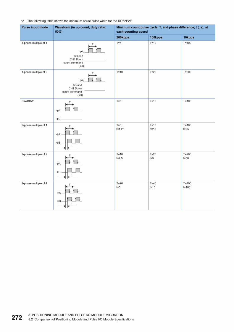
27
*3 The following table shows the minimum count pulse width for the RD62P2E.
Pulse input mode Waveform (in up count, duty ratio: 50%)
Minimum count pulse cycle, T, and phase difference, t (s), at each counting speed
200kpps 100kpps 10kpps1-phase multiple of 1 T=5 T=10 T=100
1-phase multiple of 2 T=10 T=20 T=200
CW/CCW T=5 T=10 T=100
2-phase multiple of 1 T=5t=1.25
T=10t=2.5
T=100t=25
2-phase multiple of 2 T=10t=2.5
T=20t=5
T=200t=50
2-phase multiple of 4 T=20t=5
T=40t=10
T=400t=100
T
ΦAΦB and
CH1 Down count command
(Y3)
T
ΦA
ΦB and CH1 Down
count command (Y3)
T
ΦA
ΦB
T
t
ΦA
ΦB
T
t
ΦA
ΦB
T
t
ΦA
ΦB
2 8 POSITIONING MODULE AND PULSE I/O MODULE MIGRATION8.2 Comparison of Positioning Module and Pulse I/O Module Specifications

8
QD62D and RD62D2: Compatible : Partly changed : Incompatible : Not applicable
Item Specifications Compatibility Precautions
QD62D RD62D2Counting speed switch setting
8M 4M to 8Mpps In multiple of 4
4M 2M to 4Mpps In multiple of 2/multiple of 4
2M 1M to 2Mpps
1M 500k to 1Mpps
500k 200k to 500kpps
200k 100k to 200kpps
100k 10k to 100kpps
10k 10kpps or less
Number of channels 2 channels
Count input signal
Phase 1-phase input (1 multiple/2 multiples), 2-phase input (1 multiple/2 multiples/4 multiples), CW/CCW input
Signal level (A, B)
EIA Standard RS-422-A differential line driver level(AM26LS31 (manufactured by Texas Instruments Japan Limited.) or equivalent)
Counter Counting speed (maximum)*1
500k setting: 500kpps200k setting: 200kpps100k setting: 100kpps10k setting: 10kpps
8M setting: 8Mpps4M setting: 4Mpps2M setting: 2Mpps1M setting: 1Mpps500k setting: 500kpps200k setting: 200kpps100k setting: 100kpps10k setting: 10kpps
Counting range 32-bit signed binary values (-2147483648 to 2147483647)
Model UP/DOWN preset counter + Ring counter function
Minimum count pulse width (duty ratio: 50%)
*2 *3
Coincidence output
Comparison range
32-bit signed binary values
Comparison result
Set value < Count value, Set value = Count value, Set value > Count value
External input
Preset 5/12/24VDC, 2 to 5mA 5/12/24VDC, 7 to 10mA The external input specifications are different. Check the specifications of external devices.
Function start
External output
Coincidence output
Transistor (sinking type) output2 points/channel12/24VDC, 0.5A/point, 2A/commonCurrent consumption of the external auxiliary power supply: 8mA (TYP., 24VDC)
Transistor (sinking type) output2 points/channel12/24VDC, 0.5A/point, 2A/commonCurrent consumption of the external auxiliary power supply: 43mA (TYP., 24VDC and all points ON/common)
The external output specifications are different. Check the specifications of external devices.
Number of occupied I/O points 16 points (I/O assignment: Intelligent 16 points)
External interface 40-pin connector (A6CON1/2/3/4) 40-pin connector (A6CON1/2/4) The A6CON3 cannot be used.
Applicable wire size For A6CON1/4: 0.3 (22 AWG) (stranded wire)For A6CON2: 0.088 to 0.24 (28 to 24 AWG) (stranded wire)For A6CON3: 28 AWG (stranded wire), 30 AWG (solid wire)
For A6CON1/4: 0.088 to 0.3 (28 to 22 AWG) (stranded wire)For A6CON2: 0.088 to 0.24 (28 to 24 AWG) (stranded wire)
Internal current consumption (5VDC)
0.38A 0.17A
Weight 0.12kg 0.12kg
8 POSITIONING MODULE AND PULSE I/O MODULE MIGRATION8.2 Comparison of Positioning Module and Pulse I/O Module Specifications 273

27
*1 The counting speed is affected by the pulse rise/fall time. A count can be performed with the following counting speed.
*2 The following table shows the minimum count pulse width for the QD62D.
Counting speed switch setting 8Mpps4Mpps2Mpps
1Mpps 500kpps 200kpps 100kpps 10kpps
Rise/fall time Both 1- and 2-phase inputs
t = 0.125s or less 2Mpps 1Mpps 500kpps 200kpps 100kpps 10kpps
t = 0.25s or less 1Mpps 1Mpps 500kpps 200kpps 100kpps 10kpps
t = 0.5s or less 500kpps 500kpps 200kpps 100kpps 10kpps
t = 1.25s or less 200kpps 200kpps 100kpps 10kpps
t = 2.5s or less 100kpps 100kpps 10kpps
t = 25s or less 10kpps 10kpps
t = 500s or less 500pps
Counting speed switch setting
500kpps 200kpps 100kpps 10kpps
(Unit: s)(Minimum phase differential for 2-phase input: 0.5s)
(Unit: s)(Minimum phase differential for 2-phase input: 1.25s)
(Unit: s)(Minimum phase differential for 2-phase input: 2.5s)
(Unit: s)(Minimum phase differential for 2-phase input: 25s)
tt
1 1
2
2.5 2.5
5
5 5
10
50 50
100
4 8 POSITIONING MODULE AND PULSE I/O MODULE MIGRATION8.2 Comparison of Positioning Module and Pulse I/O Module Specifications

8
*3 The following table shows the minimum count pulse width for the RD62D2.
Pulse input mode
Waveform (in up count, duty ratio: 50%)
Minimum count pulse cycle, T, and phase difference, t (s), at each counting speed
8Mpps 4Mpps 2Mpps 1Mpps 500kpps 200kpps 100kpps 10kpps1-phase multiple of 1
T=0.5 T=1 T=2 T=5 T=10 T=100
1-phase multiple of 2
T=0.5 T=1 T=2 T=4 T=10 T=20 T=200
CW/CCW T=0.5 T=1 T=2 T=5 T=10 T=100
2-phase multiple of 1
T=0.5t=0.125
T=1t=0.25
T=2t=0.5
T=5t=1.25
T=10t=2.5
T=100t=25
2-phase multiple of 2
T=0.5t=0.125
T=1t=0.25
T=2t=0.5
T=4t=1
T=10t=2.5
T=20t=5
T=200t=50
2-phase multiple of 4
T=0.5t=0.125
T=1t=0.25
T=2t=0.5
T=4t=1
T=8t=2
T=20t=5
T=40t=10
T=400t=100
T
ΦAΦB and
CH1 Down count command
(Y3)
T
ΦA
ΦB and CH1 Down
count command (Y3)
T
ΦA
ΦB
T
t
ΦA
ΦB
T
t
ΦA
ΦB
T
t
ΦA
ΦB
8 POSITIONING MODULE AND PULSE I/O MODULE MIGRATION8.2 Comparison of Positioning Module and Pulse I/O Module Specifications 275

27
Comparison of channel isolated pulse input module
QD60P8-G and RD60P8-G: Compatible : Partly changed : Incompatible : Not applicable
Item Specifications Compatibility Precautions
QD60P8-G RD60P8-GCounting speed switch setting
30kpps 10k to 30kpps
10kpps 1k to 10kpps
1kpps 100 to 1kpps
100pps 50 to 100pps
50pps 10 to 50pps
10pps 1 to 10pps
1pps 0.1 to 1pps
0.1pps 0.05 to 0.1pps
Number of channels 8 channels
Count input signal Phase 1-phase input
Signal level 5VDC/12 to 24VDC
Counter Counting speed (maximum)*1
30kpps setting: 30kpps, 10kpps setting: 10kpps,1kpps setting: 1kpps, 100pps setting: 100pps,50pps setting: 50pps, 10pps setting: 10pps,1pps setting: 1pps, 0.1pps setting: 0.1pps
Counting range Sampling pulse number: 16-bit unsigned binary (0 to 32767)Accumulating count value: 32-bit unsigned binary (0 to 99999999)Input pulse value: 32-bit unsigned binary (0 to 2147483647)
Count type Linear counter, ring counter
Minimum count pulse width (Duty ratio 50%)
*2
Withstand voltage For 1 min at 1500VAC between AC external connecting terminals and general groundingFor 1 min at 500VAC between DC external connecting terminals and general groundingFor 1 min at 1780VAC between channels
For 1 min at 500VAC rms between I/O terminal and programmable controller power supplyFor 1 min at 1780VAC between channels
Insulation resistance 5M or more at 500VDC between all AC external terminals and general grounding
10M or more at 500VDC between I/O terminal and programmable controller power supply10M or more at 500VDC between channels
External interface 18-point terminal block (M3 screws) The existing external wiring and terminal blocks in the existing system can be used.
Applicable wire size 0.3 to 0.75 (22 to 18 AWG)
Applicable solderless terminal R1.25-3 (solderless terminal with an insulation sleeve cannot be used)
Internal current consumption (5VDC) 0.58A 0.72A
Weight 0.17kg 0.23kg
6 8 POSITIONING MODULE AND PULSE I/O MODULE MIGRATION8.2 Comparison of Positioning Module and Pulse I/O Module Specifications

8
*1 The counting speed is affected by the rise/fall time of pulses. A count can be performed with the following counting speed.
*2 The following table shows the minimum count pulse width for the QD60P8-G and RD60P8-G.
Rise/fall time Counting speed switch setting
30kpps 10kpps 1kpps 100pps 50pps 10pps 1pps 0.1ppst = 8.4s or less 30kpps 10kpps 1kpps 100pps 50pps 10pps 1pps 0.1pps
t = 25s or less 10kpps 10kpps 1kpps 100pps 50pps 10pps 1pps 0.1pps
t = 250s or less 1kpps 1kpps 100pps 50pps 10pps 1pps 0.1pps
t = 2.5ms or less 100pps 100pps 50pps 10pps 1pps 0.1pps
t = 5ms or less 50pps 50pps 10pps 1pps 0.1pps
t = 25ms or less 10pps 10pps 1pps 0.1pps
t = 250ms or less 1pps 1pps 0.1pps
t = 2.5s or less 0.1pps 0.1pps
t = 5s or less 0.05pps
■30kpps ■1kpps ■50pps ■1pps
■10kpps ■100pps ■10pps ■0.1pps
t t
33.4μs
16.7μs 16.7μs
1ms
0.5ms 0.5ms
20ms
10ms 10ms
1s
0.5s 0.5s
100μs
50μs 50μs
10ms
5ms 5ms
100ms
50ms 50ms
10s
5s 5s
8 POSITIONING MODULE AND PULSE I/O MODULE MIGRATION8.2 Comparison of Positioning Module and Pulse I/O Module Specifications 277

27
8.3 Comparison of Positioning Module and Pulse I/O Module Functions
Comparison of positioning module functions
QD75P(N)/QD75D(N) and RD75P/RD75D■Main functions: Compatible/function available : Partly changed : Incompatible/function not available : Not applicable
Item Description MELSEC-Q series
MELSEC iQ-R series
Precautions
QD75P(N)QD75D(N)
RD75PRD75D
OPR control • Machine OPR controlMechanically establishes the positioning start point using a near-point dog or stopper. (Positioning start No.9001)• Fast OPR control
Positions a target to the OP address ([Md.21] Machine feed value) stored in the module using machine OPR control. (Positioning start No.9002)
Position control • Linear control (1-axis linear control, 2-/3-/4-axis linear interpolation control)
Positions a target using a linear path to the address set in the positioning data or to the position specified with the movement amount.• Fixed-feed control (1-/2-/3-/4-axis fixed-feed control)
Positions a target by the movement amount specified with the amount set in the positioning data.(With the fixed-feed control, [Md.20] Current feed value is set to 0 when the control is started. In the 2-axis fixed-feed control, 3-axis fixed-feed control, or 4-axis fixed-feed control, the fixed-feed is performed along a linear path obtained by interpolation.)• 2-axis circular interpolation control
Positions a target using an arc path to the address set in the positioning data, or to the position specified with the movement amount, sub point, or center point.• 3-axis helical interpolation control
Positions a target using a helical path to the address set in the positioning data, or to the position specified with the movement amount, sub point, or center point.
Speed control (1-/2-/3-/4-axis speed control)Continuously outputs the pulses corresponding to the command speed set in the positioning data.
Speed-position switching control
Performs the speed control, and position control (Positioning with the specified address or movement amount) immediately after that by turning on Speed-position switching signal.
Position-speed switching control
Performs the position control, and speed control (Continuous output of the pulses corresponding to the specified command speed) immediately after that by turning on Position-speed switching signal.
Current value changing Changes [Md.20] Current feed value to the address set in the positioning data.The following two methods can be used. (Machine feed value cannot be changed.)• Current value changing using positioning data• Current value changing using the current value changing start No.
(No. 9003)
NOP instruction A control system that is not executed. When the NOP instruction is set, the operation of the next data starts and this instruction is not executed.
JUMP instruction Unconditionally or conditionally jumps to the specified positioning data No.
LOOP Performs the loop control with repeated LOOP to LEND.
LEND Returns to the beginning of the loop control with repeated LOOP to LEND.
8 8 POSITIONING MODULE AND PULSE I/O MODULE MIGRATION8.3 Comparison of Positioning Module and Pulse I/O Module Functions
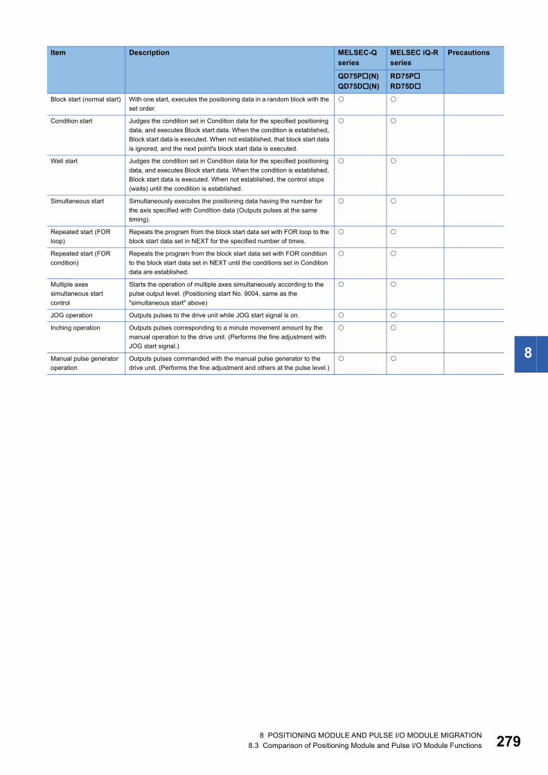
8
Block start (normal start) With one start, executes the positioning data in a random block with the set order.
Condition start Judges the condition set in Condition data for the specified positioning data, and executes Block start data. When the condition is established, Block start data is executed. When not established, that block start data is ignored, and the next point's block start data is executed.
Wait start Judges the condition set in Condition data for the specified positioning data, and executes Block start data. When the condition is established, Block start data is executed. When not established, the control stops (waits) until the condition is established.
Simultaneous start Simultaneously executes the positioning data having the number for the axis specified with Condition data (Outputs pulses at the same timing).
Repeated start (FOR loop)
Repeats the program from the block start data set with FOR loop to the block start data set in NEXT for the specified number of times.
Repeated start (FOR condition)
Repeats the program from the block start data set with FOR condition to the block start data set in NEXT until the conditions set in Condition data are established.
Multiple axes simultaneous start control
Starts the operation of multiple axes simultaneously according to the pulse output level. (Positioning start No. 9004, same as the "simultaneous start" above)
JOG operation Outputs pulses to the drive unit while JOG start signal is on.
Inching operation Outputs pulses corresponding to a minute movement amount by the manual operation to the drive unit. (Performs the fine adjustment with JOG start signal.)
Manual pulse generator operation
Outputs pulses commanded with the manual pulse generator to the drive unit. (Performs the fine adjustment and others at the pulse level.)
Item Description MELSEC-Q series
MELSEC iQ-R series
Precautions
QD75P(N)QD75D(N)
RD75PRD75D
8 POSITIONING MODULE AND PULSE I/O MODULE MIGRATION8.3 Comparison of Positioning Module and Pulse I/O Module Functions 279

28
■Sub functions: Compatible/function available : Partly changed : Incompatible/function not available : Not applicable
Item Description MELSEC-Q series
MELSEC iQ-R series
Precautions
QD75P(N)QD75D(N)
RD75PRD75D
OPR retry function Retries the machine OPR with the upper/lower limit switches during the machine OPR. This allows the machine OPR to be performed even if the axis is not returned to a position before the near-point dog with operations such as the JOG operation.
OP shift function After the machine OPR, this function compensates the position by the specified distance from the machine OP position and sets that position as the OP address.
Backlash compensation function
Compensates the backlash amount of the machine system. Feed pulses equivalent to the set backlash amount are output each time the movement direction changes.
Electronic gear function By setting the movement amount per pulse, this function can freely change the machine movement amount per commanded pulse. A flexible positioning system that matches the machine system can be structured with this function.
Near pass function Suppresses the machine vibration when the positioning data is switched during continuous path control in the interpolation control.
Output timing selection of near pass control
This function allows the user to select the timing to output the difference between the actual and the set positioning end addresses in the continuous path control, in which the difference is output during the execution of the next positioning data.
Speed limit function If the command speed exceeds [Pr.8] Speed limit value during the control, this function limits the command speed to within the setting range of [Pr.8] Speed limit value.
Torque limit function If the torque generated in the servo motor exceeds [Pr.17] Torque limit setting value during the control, this function limits the generated torque to within the setting range of [Pr.17] Torque limit setting value.
Software stroke limit function
If a command outside of the upper/lower limit stroke limit setting range, set in the parameters, is issued, this function will not execute the positioning for that command.
Hardware stroke limit function
Performs the deceleration stop with the limit switch connected to the connector for external devices.
Speed change function Changes the speed during positioning. Set the new speed in [Cd.14] New speed value, the speed change buffer memory area, and change the speed with [Cd.15] Speed change request.
Override function Changes the speed during positioning within a percentage of 1 to 300%. Execute this function using [Cd.13] Positioning operation speed override.
Acceleration/deceleration time change function
Changes the acceleration/deceleration time at the speed change. (This function is added to the speed change function and override function)
Torque change function Changes the torque limit value during the control.
Target position change function
Changes the target position during positioning. The position and speed can be changed simultaneously.
Absolute position restoration function
Restores the absolute position of a specified axis.By this function, the OPR after power-on is not required once the OPR is executed at system start-up.
Step function Temporarily stops the operation to check the positioning operation during debugging and other operation. The operation can be stopped for each Automatic deceleration or Positioning data.
Skip function Pauses (decelerates to stop) the positioning being executed when Skip signal is input, and performs the next positioning.
M code output function Issues a command for a subsidiary work (such as stopping clamps or drills and changing tools) corresponding to each M code number (0 to 65535) that can be set to each positioning data.
Teaching function Stores the address positioned with the manual control into the positioning address of the specified positioning data No. ([Cd.39]).
0 8 POSITIONING MODULE AND PULSE I/O MODULE MIGRATION8.3 Comparison of Positioning Module and Pulse I/O Module Functions

8
*1 For the RD75P/D, starting positioning when OPR is not complete causes an error for safety reasons.To make the operation compatible with the QD75P/D, set [Pr.58] Setting of operation during uncompleted OPR to "1: Execute the positioning control".
Command in-position function
At each automatic deceleration, this function calculates the remaining distance for the module to reach the positioning stop position, and sets Command in-position flag to 1 when the value is less than or equal to the set value.When performing another subsidiary work before the control ends, use this function as a trigger for the subsidiary work.
Acceleration/deceleration process function
Adjusts acceleration/deceleration of the control (acceleration/deceleration time and curve).
Continuous operation interrupt function
Interrupts the continuous operation. When this request is accepted, the operation will stop at the completion of the positioning data being executed.
Pre-reading start function
Shortens the virtual start time.
Deceleration start flag function
To inform the stop timing, this function turns on Deceleration start flag when the speed status is changed from the constant speed or acceleration to deceleration during the position control whose operation pattern is Positioning complete.
Stop command processing for deceleration stop function
Selects a deceleration curve when a stop cause occurs during the deceleration stop processing to speed 0.
During uncompleted OPR operation setting function
Sets whether or not to execute the positioning control when OPR request flag is on.
*1
Positioning options The following settings can be set for each positioning data.• M code ON signal output timing• ABS direction in degrees• Interpolation speed designation method
Item Description MELSEC-Q series
MELSEC iQ-R series
Precautions
QD75P(N)QD75D(N)
RD75PRD75D
8 POSITIONING MODULE AND PULSE I/O MODULE MIGRATION8.3 Comparison of Positioning Module and Pulse I/O Module Functions 281

28
■Common functions: Compatible/function available : Partly changed : Incompatible/function not available : Not applicable
Item Description MELSEC-Q series
MELSEC iQ-R series
Precautions
QD75P(N)QD75D(N)
RD75PRD75D
Parameter initialization function
Resets the "parameters" stored in the module buffer memory and flash ROM to the default values. The following two methods can be used.• Method using a sequence program.• Method using GX Works2/GX Configurator-QP.
For the RD75P/D, use the module data initialization function instead.Only the method using a sequence program is supported.
Execution data backup function
Stores the setting data currently being executed into the flash ROM. The following two methods can be used.• Method using a sequence program.• Method using GX Works2/GX Configurator-QP.
For the RD75P/D, use the module data backup function instead.Only the method using a sequence program is supported.
External I/O signal logic switching function
Switches I/O signal logics according to the externally connected devices.This function enables the use of the system that does not use b (N.C.) contact signals, such as Drive unit READY or Upper/lower limit signal, by setting parameters to positive logic.
External I/O signal monitor function
Monitors the external I/O signal monitor information in the module's detailed information which can be displayed on the system monitor of GX Works2.
For the RD75P/D, use the module diagnostics function of GX Works3.
History monitor function Monitors the error history, warning history, and start history of all axes.
Module error history function
Collects errors that occurred and stores them to the CPU module. For the RD75P/D, use the event history function of GX Works3.
2 8 POSITIONING MODULE AND PULSE I/O MODULE MIGRATION8.3 Comparison of Positioning Module and Pulse I/O Module Functions

8
Comparison of high-speed counter module functions
QD62(E/D) and RD62(P2/P2E/D2): Compatible/function available : Partly changed : Incompatible/function not available : Not applicable
*1 The counter operation mode for the RD62P2/RD62P2E/RD62D2 is "pulse count mode".
Item Description MELSEC-Q series
MELSEC iQ-R series
Precautions
QD62QD62EQD62D
RD62P2RD62P2ERD62D2
Linear counter function Values from -2147483648 to 2147483647 can be counted. If the count exceeds the range, the overflow is detected.
*1
Ring counter function Counts pulses repeatedly within the range between the ring counter upper limit and the ring counter lower limit.
*1
Coincidence output function
Compares the coincidence output point of any preset channel with the present counter value, and outputs the ON/OFF signal.
*1
Coincidence detection interrupt function
Generates an interrupt signal to the CPU module when coincidence is detected, and starts the interrupt program.
*1
Preset function Overwrites the present counter value with any numerical value. *1
Counter function selection
(1) Disable count functionMakes it possible to stop counting pulses while the count enable command is on.(2) Latch counter functionStores the present counter value at the signal input of Counter function selection start command in the buffer memory.(3) Sampling counter functionCounts the pulses that are input during the preset sampling time period from the time the counter function selection start command is input, and stores the count in the buffer memory.(4) Periodic pulse counter functionStores the present and previous counter values to the buffer memory at the preset cycle (T) while the counter function selection start command signal is input. (For the RD62P2/RD62P2E/RD62D2, the difference value is also stored.)
*1
8 POSITIONING MODULE AND PULSE I/O MODULE MIGRATION8.3 Comparison of Positioning Module and Pulse I/O Module Functions 283

28
Comparison of channel isolated pulse input module functions
QD60P8-G and RD60P8-G: Compatible/function available : Partly changed : Incompatible/function not available : Not applicable
Item Description MELSEC-Q series
MELSEC iQ-R series
Precautions
QD60P8-G RD60P8-GAccumulating counter
Linear counter function
Counts from 0 to 99999999 and detects an overflow when the count range is exceeded.
Ring counter function
Repeats counting between 0 and 99999999.
Comparison output function
Turns on Accumulating counter comparison flag (X0 to X17) when Accumulating count value reaches or exceeds Comparison output setting value.
Sampling counter
Count cycle change function
Changes the count cycle of Sampling pulse number or Accumulating count value.
Movement averaging function
Performs movement averaging processing by the specified number of times if there are variations in Sampling pulse number.
Pre-scale function Converts the number of pulses by multiplying the number of input pulses by any setting number.
Warning output function
Sets the upper/upper limit value, upper/lower limit value, lower/upper limit value and lower/lower limit value for Sampling pulse number converted by the pre-scale function to output alarms.
Counter reset function Resets Sampling pulse number, Accumulating count value, or Input pulse value. A reset can be made at any timing.
Pulse edge selection function Selects whether the rise or fall of an input pulse will be used for counting.
Count enable function Starts input pulse count operation when Count enable (Y18 to Y1F) is turned on.
Online module change function Changes the module without stopping the system. Operation using engineering tool is not supported.
Interrupt function Executes an interrupt program of the CPU module when an interrupt factor such as an error or warning output is detected.
Error history function Stores up to 16 errors and alarms that occurred in the pulse input module in the buffer memory areas.
Event history function Collects the errors and alarms that occurred and the operations executed in the pulse input module as event information into the CPU module.
Q compatible mode function Assigns the buffer memory addresses of the pulse input module in the same way as those of the MELSEC-Q series module.
4 8 POSITIONING MODULE AND PULSE I/O MODULE MIGRATION8.3 Comparison of Positioning Module and Pulse I/O Module Functions

8
8.4 Precautions for Positioning Module and Pulse I/O Module Migration
Wiring■Positioning moduleThere are differences in the layout of PULSE COM terminals between the QD75D2N/QD75D4N and the RD75D2/RD75D4.To use the 40-pin connector of the QD75D2N/QD75D4N with the RD75D2/RD75D4, wiring to the 2B20 and 2B19 pins is required.
■High-speed counter moduleThe wiring for coincidence output differs between the QD62E and the RD62P2E.To use the 40-pin connector of the QD62E with the RD62P2E, wiring to the A01 and A02 pins is no longer required. (A01 and A02 are non-connection pins.)
Dedicated instructionThere is no difference between the MELSEC-Q series and the MELSEC iQ-R series.
Writing parametersThe MELSEC iQ-R series allows parameters to be written to the CPU module as well as the positioning module. This makes it possible to control parameters centrally by the CPU module, thereby making it easier to change the module in maintenance.The module parameters and module extension parameters stored in the CPU module are reflected to the positioning module when the system is powered on, the CPU module is reset, or the operating status of the CPU module is changed from STOP to RUN.To set the module extension parameters using a program, execute the parameter setting program after Module access flag turns on. Because changing the operating status of the CPU module from STOP to RUN overwrites the parameters stored in the CPU module, restart the parameter setting program.To set positioning data using a program or change positioning data using the teaching function, especially for the system where positioning data varies from one workpiece to another or the system where settings are changed with GOT or other external devices, set "Positioning module" in "Extended parameter storage setting" under "Basic setting" of module parameter, and store parameters into the positioning module using the module backup function.
I/O signals and buffer memory areasThe layouts of I/O signals and buffer memory areas differ between the MELSEC-Q series and the MELSEC iQ-R series.If I/O signals and buffer memory areas are used in the MELSEC-Q series program, the program needs to be corrected for the MELSEC iQ-R series.
For details on these precautions, refer to the following. MELSEC iQ-R Module Configuration Manual MELSEC iQ-R Positioning Module User's Manual (Startup) MELSEC iQ-R Positioning Module User's Manual (Application) MELSEC iQ-R High-Speed Counter Module User's Manual (Startup) MELSEC iQ-R High-Speed Counter Module User's Manual (Application) MELSEC iQ-R Channel Isolated Pulse Input Module User's Manual (Startup) MELSEC iQ-R Channel Isolated Pulse Input Module User's Manual (Application) Differences between MELSEC-Q series and MELSEC iQ-R series (FA-A-0171)
8 POSITIONING MODULE AND PULSE I/O MODULE MIGRATION8.4 Precautions for Positioning Module and Pulse I/O Module Migration 285

28
9 CONTROL NETWORK MODULE MIGRATION
9.1 Control Network Module Migration Model ListThe following describes examples of migration to MELSEC iQ-R series control network modules in accordance with the MELSEC-Q series control network module specifications.Consider the scope of control by your MELSEC-Q series control network module and the system specifications and extensibility after migration to choose a model that best suits your application.
Item MELSEC-Qseries
MELSEC iQ-R series
Specification difference
CC-Link IE Controller Network
QJ71GP21-SX RJ71GP21-SX (1) External wiring: Not changed(2) Number of slots: Not changed(3) Programs: The number of occupied I/O points, I/O signals, and buffer memory
addresses are not changed.(4) Specifications: Not changed(5) Functions: Changed
QJ71GP21S-SX RJ71GP21S-SX (1) External wiring: Not changed(2) Number of slots: Not changed(3) Programs: The number of occupied I/O points, I/O signals, and buffer memory
addresses are not changed.(4) Specifications: Not changed(5) Functions: Changed
CC-Link IE Field Network QJ71GF11-T2 RJ71GF11-T2 (1) External wiring: Not changed(2) Number of slots: Not changed(3) Programs: The number of occupied I/O points and I/O signals are not changed,
and the buffer memory addresses are changed.(4) Specifications: Not changed(5) Functions: Changed
QJ71GF11-T2 RJ71EN71 The RJ71EN71 can be connected by configuring settings using an engineering tool.*1
CC-Link QJ61BT11 RJ61BT11 (1) External wiring: Not changed(2) Number of slots: Not changed(3) Programs: The number of occupied I/O points and I/O signals are not changed,
and the buffer memory addresses are changed.(4) Specifications: Not changed(5) Functions: Changed
QJ61BT11N RJ61BT11 (1) External wiring: Not changed(2) Number of slots: Not changed(3) Programs: The number of occupied I/O points and I/O signals are not changed,
and the buffer memory addresses are changed.(4) Specifications: Not changed(5) Functions: Changed
CC-Link/LT QJ61CL12 No applicable module
Connect the RQ extension base unit (RQ6B) to use the Q series module.
AnyWireASLINK QJ51AW12AL RJ51AW12AL (1) External wiring: Changed(2) Number of slots: Not changed(3) Programs: The number of occupied I/O points, I/O signals, and buffer memory
addresses are not changed.(4) Specifications: Not changed(5) Functions: Not changed
AnyWire DB A20 QJ51AW12D2 No applicable module
Connect the RQ extension base unit (RQ6B) to use the Q series module.
6 9 CONTROL NETWORK MODULE MIGRATION9.1 Control Network Module Migration Model List
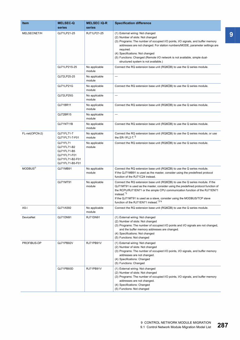
9
MELSECNET/H QJ71LP21-25 RJ71LP21-25 (1) External wiring: Not changed(2) Number of slots: Not changed(3) Programs: The number of occupied I/O points, I/O signals, and buffer memoryaddresses are not changed. For station numbers/MODE, parameter settings are required.
(4) Specifications: Not changed(5) Functions: Changed (Remote I/O network is not available, simple dual-
structured system is not available.)
QJ71LP21S-25 No applicable module
Connect the RQ extension base unit (RQ6B) to use the Q series module.
QJ72LP25-25 No applicable module
QJ71LP21G No applicable module
Connect the RQ extension base unit (RQ6B) to use the Q series module.
QJ72LP25G No applicable module
QJ71BR11 No applicable module
Connect the RQ extension base unit (RQ6B) to use the Q series module.
QJ72BR15 No applicable module
QJ71NT11B No applicable module
Connect the RQ extension base unit (RQ6B) to use the Q series module.
FL-net(OPCN-2) QJ71FL71-TQJ71FL71-T-F01
No applicable module
Connect the RQ extension base unit (RQ6B) to use the Q series module, or use the ER-1FL2-T.*2
QJ71FL71QJ71FL71-B2QJ71FL71-B5QJ71FL71-F01QJ71FL71-B2-F01QJ71FL71-B5-F01
No applicable module
Connect the RQ extension base unit (RQ6B) to use the Q series module.
MODBUS QJ71MB91 No applicable module
Connect the RQ extension base unit (RQ6B) to use the Q series module.If the QJ71MB91 is used as the master, consider using the predefined protocol function of the RJ71C24 instead.
QJ71MT91 No applicable module
Connect the RQ extension base unit (RQ6B) to use the Q series module. If the QJ71MT91 is used as the master, consider using the predefined protocol function of the RCPU/RJ71EN71 or the simple CPU communication function of the RJ71EN71 instead.*3
If the QJ71MT91 is used as a slave, consider using the MODBUS/TCP slave function of the RJ71EN71 instead.*3*4
AS-i QJ71AS92 No applicable module
Connect the RQ extension base unit (RQ6B) to use the Q series module.
DeviceNet QJ71DN91 RJ71DN91 (1) External wiring: Not changed(2) Number of slots: Not changed(3) Programs: The number of occupied I/O points and I/O signals are not changed,
and the buffer memory addresses are changed.(4) Specifications: Not changed(5) Functions: Not changed
PROFIBUS-DP QJ71PB92V RJ71PB91V (1) External wiring: Not changed(2) Number of slots: Not changed(3) Programs: The number of occupied I/O points, I/O signals, and buffer memory
addresses are not changed.(4) Specifications: Changed(5) Functions: Changed
QJ71PB93D RJ71PB91V (1) External wiring: Not changed(2) Number of slots: Not changed(3) Programs: The number of occupied I/O points, I/O signals, and buffer memory
addresses are not changed.(4) Specifications: Changed(5) Functions: Not changed
Item MELSEC-Qseries
MELSEC iQ-R series
Specification difference
9 CONTROL NETWORK MODULE MIGRATION9.1 Control Network Module Migration Model List 287

28
*1 For details, refer to the following. MELSEC iQ-R Ethernet/CC-Link IE User's Manual (Startup) MELSEC iQ-R Ethernet User's Manual (Application)
*2 For details on the ER-1FL2-T, please consult your local Mitsubishi representative.*3 For the firmware version for using each function, refer to the User's Manual (Application) for the target models.*4 For details, refer to the following.
MELSEC iQ-R Ethernet User's Manual (Application)
8 9 CONTROL NETWORK MODULE MIGRATION9.1 Control Network Module Migration Model List
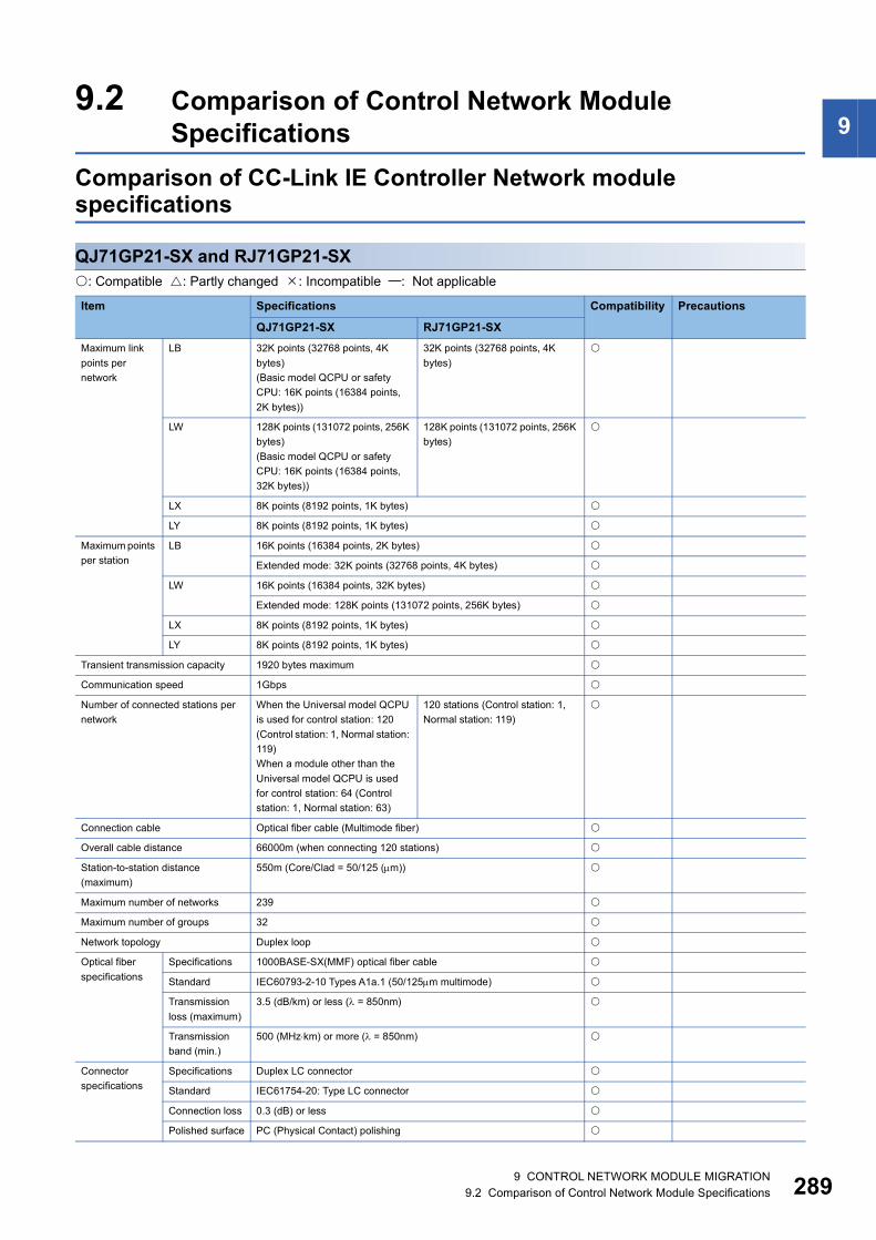
9
9.2 Comparison of Control Network ModuleSpecificationsComparison of CC-Link IE Controller Network module specifications
QJ71GP21-SX and RJ71GP21-SX: Compatible : Partly changed : Incompatible : Not applicable
Item Specifications Compatibility Precautions
QJ71GP21-SX RJ71GP21-SXMaximum link points per network
LB 32K points (32768 points, 4K bytes)(Basic model QCPU or safety CPU: 16K points (16384 points, 2K bytes))
32K points (32768 points, 4K bytes)
LW 128K points (131072 points, 256K bytes)(Basic model QCPU or safety CPU: 16K points (16384 points, 32K bytes))
128K points (131072 points, 256K bytes)
LX 8K points (8192 points, 1K bytes)
LY 8K points (8192 points, 1K bytes)
Maximum points per station
LB 16K points (16384 points, 2K bytes)
Extended mode: 32K points (32768 points, 4K bytes)
LW 16K points (16384 points, 32K bytes)
Extended mode: 128K points (131072 points, 256K bytes)
LX 8K points (8192 points, 1K bytes)
LY 8K points (8192 points, 1K bytes)
Transient transmission capacity 1920 bytes maximum
Communication speed 1Gbps
Number of connected stations per network
When the Universal model QCPU is used for control station: 120 (Control station: 1, Normal station: 119)When a module other than the Universal model QCPU is used for control station: 64 (Control station: 1, Normal station: 63)
120 stations (Control station: 1, Normal station: 119)
Connection cable Optical fiber cable (Multimode fiber)
Overall cable distance 66000m (when connecting 120 stations)
Station-to-station distance (maximum)
550m (Core/Clad = 50/125 (m))
Maximum number of networks 239
Maximum number of groups 32
Network topology Duplex loop
Optical fiber specifications
Specifications 1000BASE-SX(MMF) optical fiber cable
Standard IEC60793-2-10 Types A1a.1 (50/125m multimode)
Transmission loss (maximum)
3.5 (dB/km) or less ( = 850nm)
Transmission band (min.)
500 (MHzkm) or more ( = 850nm)
Connector specifications
Specifications Duplex LC connector
Standard IEC61754-20: Type LC connector
Connection loss 0.3 (dB) or less
Polished surface PC (Physical Contact) polishing
9 CONTROL NETWORK MODULE MIGRATION9.2 Comparison of Control Network Module Specifications 289
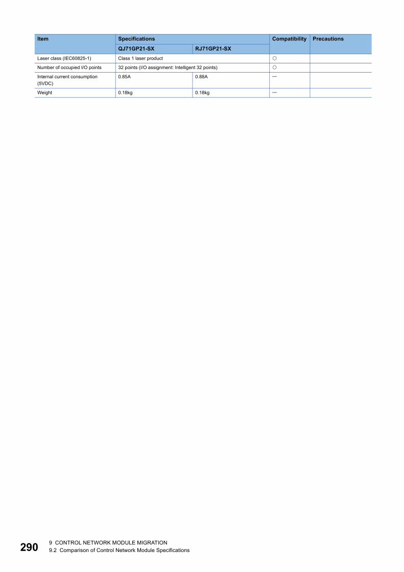
29
Laser class (IEC60825-1) Class 1 laser product
Number of occupied I/O points 32 points (I/O assignment: Intelligent 32 points)
Internal current consumption (5VDC)
0.85A 0.88A
Weight 0.18kg 0.18kg
Item Specifications Compatibility Precautions
QJ71GP21-SX RJ71GP21-SX
0 9 CONTROL NETWORK MODULE MIGRATION9.2 Comparison of Control Network Module Specifications

9
QJ71GP21S-SX and RJ71GP21S-SX: Compatible : Partly changed : Incompatible : Not applicableItem Specifications Compatibility Precautions
QJ71GP21S-SX RJ71GP21S-SXMaximum link points per network
LB 32K points (32768 points, 4K bytes)(Basic model QCPU or safety CPU: 16K points (16384 points, 2K bytes))
32K points (32768 points, 4K bytes)
LW 128K points (131072 points, 256K bytes)(Basic model QCPU or safety CPU: 16K points (16384 points, 32K bytes))
128K points (131072 points, 256K bytes)
LX 8K points (8192 points, 1K bytes)
LY 8K points (8192 points, 1K bytes)
Maximum link points per station
LB 16K points (16384 points, 2K bytes)
Extended mode: 32K points (32768 points, 4K bytes)
LW 16K points (16384 points, 32K bytes)
Extended mode: 128K points (131072 points, 256K bytes)
LX 8K points (8192 points, 1K bytes)
LY 8K points (8192 points, 1K bytes)
Transient transmission capacity 1920 bytes maximum
Communication speed 1Gbps
Number of connected stations per network
When the QnCPU is used for control station: 120 stations (Control station: 1, Normal station: 119)When a module other than the QnCPU is used for control station: 64 stations (Control station: 1, Normal station: 63)
120 stations (Control station: 1, Normal station: 119)
Connection cable Optical fiber cable (Multimode fiber)
Overall cable distance 66000m (when connecting 120 stations)
Station-to-station distance (maximum)
550m (Core/Clad = 50/125 (m))
Maximum number of networks 239
Maximum number of groups 32
Network topology Duplex loop
Optical fiber specifications
Specifications 1000BASE-SX(MMF) optical fiber cable
Standard IEC60793-2-10 Types A1a.1 (50/125m multimode)
Transmission loss (maximum)
3.5 (dB/km) or less ( = 850nm)
Transmission band (min.)
500 (MHzkm) or more ( = 850nm)
Connector specifications
Specifications Duplex LC connector
Standard IEC61754-20: Type LC connector
Connection loss 0.3 (dB) or less
Polished surface PC (Physical Contact) polishing
Laser class (IEC60825-1) Class 1 laser product
Number of occupied I/O points 48 points (I/O assignment: Empty first half: 16 points, Latter half 32 points for intelligent)
9 CONTROL NETWORK MODULE MIGRATION9.2 Comparison of Control Network Module Specifications 291
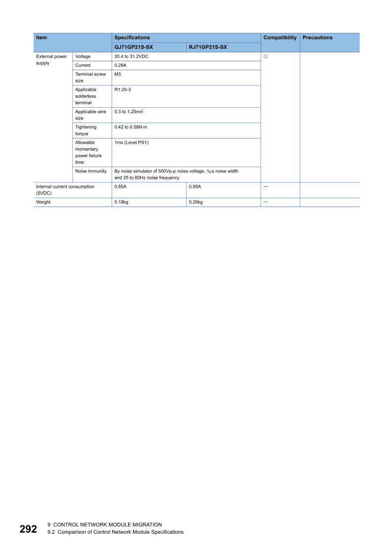
29
External power supply
Voltage 20.4 to 31.2VDC
Current 0.28A
Terminal screw size
M3
Applicable solderless terminal
R1.25-3
Applicable wire size
0.3 to 1.25
Tightening torque
0.42 to 0.58Nm
Allowable momentary power failure time
1ms (Level PS1)
Noise immunity By noise simulator of 500Vp-p noise voltage, 1s noise widthand 25 to 60Hz noise frequency
Internal current consumption (5VDC)
0.85A 0.95A
Weight 0.18kg 0.26kg
Item Specifications Compatibility Precautions
QJ71GP21S-SX RJ71GP21S-SX
2 9 CONTROL NETWORK MODULE MIGRATION9.2 Comparison of Control Network Module Specifications
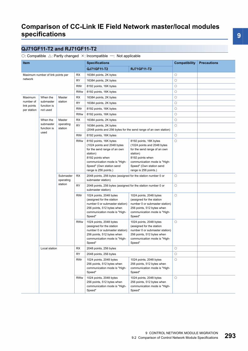
9
Comparison of CC-Link IE Field Network master/local modules specificationsQJ71GF11-T2 and RJ71GF11-T2: Compatible : Partly changed : Incompatible : Not applicable
Item Specifications Compatibility Precautions
QJ71GF11-T2 RJ71GF11-T2Maximum number of link points per network
RX 16384 points, 2K bytes
RY 16384 points, 2K bytes
RWr 8192 points, 16K bytes
RWw 8192 points, 16K bytes
Maximum number of link points per station
When the submaster function is not used
Master station
RX 16384 points, 2K bytes
RY 16384 points, 2K bytes
RWr 8192 points, 16K bytes
RWw 8192 points, 16K bytes
When the submaster function is used
Master operating station
RX 16384 points, 2K bytes
RY 16384 points, 2K bytes(2048 points and 256 bytes for the send range of an own station)
RWr 8192 points, 16K bytes
RWw 8192 points, 16K bytes(1024 points and 2048 bytes for the send range of an own station)8192 points when communication mode is "High-Speed" (Own station send range is 256 points.)
8192 points, 16K bytes(1024 points and 2048 bytes for the send range of an own station)8192 points when communication mode is "High-Speed" (Own station send range is 256 points.)
Submaster operating station
RX 2048 points, 256 bytes (assigned for the station number 0 or submaster station)
RY 2048 points, 256 bytes (assigned for the station number 0 or submaster station)
RWr 1024 points, 2048 bytes (assigned for the station number 0 or submaster station)256 points, 512 bytes when communication mode is "High-Speed"
1024 points, 2048 bytes (assigned for the station number 0 or submaster station)256 points, 512 bytes when communication mode is "High-Speed"
RWw 1024 points, 2048 bytes (assigned for the station number 0 or submaster station)256 points, 512 bytes when communication mode is "High-Speed"
1024 points, 2048 bytes (assigned for the station number 0 or submaster station)256 points, 512 bytes when communication mode is "High-Speed"
Local station RX 2048 points, 256 bytes
RY 2048 points, 256 bytes
RWr 1024 points, 2048 bytes256 points, 512 bytes when communication mode is "High-Speed"
1024 points, 2048 bytes256 points, 512 bytes when communication mode is "High-Speed"
RWw 1024 points, 2048 bytes256 points, 512 bytes when communication mode is "High-Speed"
1024 points, 2048 bytes256 points, 512 bytes when communication mode is "High-Speed"
9 CONTROL NETWORK MODULE MIGRATION9.2 Comparison of Control Network Module Specifications 293

29
Ethernet part
Communication speed 1Gbps
Network topology Line topology, star topology (Coexistence of line topology and star topology is also possible.), or ring topology
Connection cable Ethernet cable which satisfies 1000BASE-T standard: Category 5e or higher, straight cable (double shielded, STP)
Maximum station-to-station distance
100m maximum (conforms to ANSI/TIA/EIA-568-B (Category 5e))
Overall cable distance Line topology: 12000m(When the master station and 120 slave and submaster stations are connected)Star topology: Depends on the system configurationRing topology: 12100m(When the master station and 120 slave and submaster stations are connected)
Number of cascade connections 20 levels maximum
Number of stations per network
Master station 1 station (Up to 120 slave and submaster stations can be connected to the master station)
Submaster station 1 station
Local station 120 stations (including the submaster station)
Maximum number of networks 239
Communication method Token passing
Number of occupied I/O points 32 points (I/O assignment: Intelligent 32 points)
Internal current consumption (5VDC) 0.85A 0.82A
Weight 0.18kg 0.17kg
Item Specifications Compatibility Precautions
QJ71GF11-T2 RJ71GF11-T2
4 9 CONTROL NETWORK MODULE MIGRATION9.2 Comparison of Control Network Module Specifications

9
Comparison of CC-Link system master/local module specificationsQJ61BT11 and RJ61BT11: Compatible : Partly changed : Incompatible : Not applicable
Item Specifications Compatibility Precautions
QJ61BT11 RJ61BT11Transmission speed Selected from 156kbps, 625kbps, 2.5Mbps, 5Mbps, and 10Mbps.
Maximum number of connected modules (master station)
64
Number of occupied stations (local station)
1 to 4 stations
Maximum number of link points per system
CC-Link Ver.1
Remote I/O (RX, RY): 2048 pointsRemote register (RWw): 256 points (master station remote device station/local station/intelligent device station/standby master station)Remote register (RWr): 256 points (remote device station/local station/intelligent device station/standby master station master station)
CC-Link Ver.2
Remote I/O (RX, RY): 8192 pointsRemote register (RWw): 2048 points (master station remote device station/local station/intelligent device station/standby master station)Remote register (RWr): 2048 points (remote device station/local station/intelligent device station/standby master station master station)
Number of link points per remote station/local station/intelligent device station/standby master station
CC-Link Ver.1
Remote I/O (RX, RY): 32 points (30 points for a local station)Remote register (RWw): 4 points (master station remote device station/local station/intelligent device station/standby master station)Remote register (RWr): 4 points (remote device station/local station/intelligent device station/standby master station master station)
CC-Link Ver.2
*1
Communication method Broadcast polling method
Synchronization method Frame synchronization method
Encoding method NRZI method
Network topology Bus (RS-485)
Transmission format HDLC compliant
Error control system CRC(X16+X12+X5+1)
Connection cable • Ver.1.10-compatible CC-Link dedicated cable
• CC-Link dedicated cable (Ver.1.00-compatible)
• CC-Link dedicated high-performance cable (Ver.1.00-compatible)
• Ver.1.10-compatible CC-Link dedicated cable
For the RJ61BT11, only the Ver.1.10-compatible CC-Link dedicated cable can be used.
Maximum overall cable distance (maximum transmission distance)
Depends on the transmission speed. For details, refer to the relevant manuals.
RAS function • Standby master station • Automatic return function• Slave station cutoff function• Error detection using link special relay areas (SB) and link special register
areas (SW)
Number of I/O points 32 points (I/O assignment: Intelligent 32 points)
Internal current consumption (5VDC)
0.46A 0.34A
Weight 0.12kg 0.16kg
9 CONTROL NETWORK MODULE MIGRATION9.2 Comparison of Control Network Module Specifications 295

29
*1 The following table shows the number of link points per station.
Item Extended cyclic setting
Single Double Quadruple OctupleRemote I/O (RX, RY) 32 points
(30 points for a local station)32 points(30 points for a local station)
64 points(62 points for a local station)
128 points(126 points for a local station)
Remote register (RWw) 4 points 8 points 16 points 32 points
Remote register (RWr) 4 points 8 points 16 points 32 points
6 9 CONTROL NETWORK MODULE MIGRATION9.2 Comparison of Control Network Module Specifications

9
QJ61BT11N and RJ61BT11: Compatible : Partly changed : Incompatible : Not applicable*1 The following table shows the number of link points per station.
Item Specifications Compatibility Precautions
QJ61BT11N RJ61BT11Transmission speed Selected from 156kbps, 625kbps, 2.5Mbps, 5Mbps, and 10Mbps.
Maximum number of connected modules (master station)
64 modules
Number of occupied stations (local station)
1 to 4 stations
Maximum number of link points per system
CC-Link Ver.1
• Remote I/O (RX, RY): 2048 points• Remote register (RWw): 256 points (master station remote device
station/local station/intelligent device station/standby master station)• Remote register (RWr): 256 points (remote device station/local station/
intelligent device station/standby master station master station)
CC-Link Ver.2
• Remote I/O (RX, RY): 8192 points• Remote register (RWw): 2048 points (master station remote device
station/local station/intelligent device station/standby master station)• Remote register (RWr): 2048 points (remote device station/local station/
intelligent device station/standby master station master station)
Number of link points per remote station/local station/intelligent device station/standby master station
CC-Link Ver.1
• Remote I/O (RX, RY): 32 points (30 points for a local station)• Remote register (RWw): 4 points (master station remote device station/
local station/intelligent device station/standby master station)• Remote register (RWr): 4 points (remote device station/local station/
intelligent device station/standby master station master station)
CC-Link Ver.2
*1
Communication method Broadcast polling method
Synchronization method Frame synchronization method
Encoding method NRZI method
Network topology Bus (RS-485)
Transmission format HDLC compliant
Error control system CRC(X16+X12+X5+1)
Connection cable • Ver.1.10-compatible CC-Link dedicated cable
• CC-Link dedicated cable (Ver.1.00-compatible)
• CC-Link dedicated high-performance cable (Ver.1.00-compatible)
• Ver.1.10-compatible CC-Link dedicated cable
For the RJ61BT11, only the Ver.1.10-compatible CC-Link dedicated cable can be used.
Maximum overall cable distance (maximum transmission distance)
Depends on the transmission speed. For details, refer to the relevant manuals.
RAS function • Standby master station • Automatic return function • Slave station cutoff function• Error detection using link special relay areas (SB) and link special register
areas (SW)
Number of I/O points 32 points (I/O assignment: Intelligent 32 points)
Internal current consumption (5VDC)
0.46A 0.34A
Weight 0.12kg 0.16kg
Item Extended cyclic setting
Single Double Quadruple OctupleRemote I/O (RX, RY) 32 points
(30 points for a local station)32 points(30 points for a local station)
64 points(62 points for a local station)
128 points(126 points for a local station)
Remote register (RWw) 4 points 8 points 16 points 32 points
Remote register (RWr) 4 points 8 points 16 points 32 points
9 CONTROL NETWORK MODULE MIGRATION9.2 Comparison of Control Network Module Specifications 297

29
Comparison of AnyWireASLINK master module specifications
QJ51AW12AL and RJ51AW12AL: Compatible : Partly changed : Incompatible : Not applicable
Item Specifications Compatibility Precautions
QJ51AW12AL RJ51AW12ALTransmission clock 27.0kHz
Maximum transmission distance (total length)
200m
Transmission system DC power supply transmission total frame cyclic transmission cyclic system
Connection type Bus topology (multidrop system, T-branch system, tree branch system)
Transmission protocol Dedicated protocol (AnyWireASLINK)
Error control Checksum, double-check system
Number of connected I/O points 512 points maximum (input: 256 points, output: 256 points)
Number of connectable slave modules
128 maximum (varies depending on the current consumption of each slave module)
RAS function Disconnected transmission cable location detection function, transmission cable short detection function, transmission cable voltage drop detection function
Transmission cable (DP, DN) • UL-listed general-purpose 2-wire cable (VCTF, VCT1.25, 0.75, temperature rating 70 or higher)
• UL-listed general-purpose wire (1.25, 0.75, temperature rating 70 or higher)
• Dedicated flat cable (1.25, 0.75, temperature rating 90)
Power cable (24V, 0V) • UL-listed general-purpose 2-wire cable (VCTF, VCT0.75 to 2.0, temperature rating 70 or higher)
• UL-listed general-purpose wire (0.75 to 2.0, temperature rating 70 or higher)
• Dedicated flat cable (1.25, 0.75, temperature rating 90)
Transmission cable supply current
When using a 1.25 cable: 2A maximum, When using a 0.75 cable: 1.2A maximum
Maximum number of writes to EEPROM
100000 times maximum
Power supply Internal current consumption (5VDC)
Voltage: 5VDC5%Current consumption: 0.2A maximum
0.2A
External power supply
Voltage: 21.6 to 27.6VDC (24VDC -10 to +15%), ripple voltage 0.5Vp-p or lowerRecommended voltage: 26.4VDC (24VDC +10%)Module current consumption: 0.1ATransmission cable supply current: 2A maximum
Voltage: 21.6 to 27.6VDC (24VDC -10 to +15%), ripple voltage 0.5Vp-p or lowerRecommended voltage: 26.4VDC (24VDC +10%)Transmission cable supply current: 2A maximum
Number of occupied I/O points 32 points (I/O assignment: Intelligent 32 points)
Weight 0.2kg 0.13kg
8 9 CONTROL NETWORK MODULE MIGRATION9.2 Comparison of Control Network Module Specifications

9
Comparison of MELSECNET/H network modules specificationsQJ71LP21-25 and RJ71LP21-25: Compatible : Partly changed : Incompatible : Not applicable
Item Specifications Compatibility Precautions
QJ71LP21-25 RJ71LP21-25Maximum link points per network
LB 16384 points (MELSECNET/10 mode: 8192 points)
LW
LX 8K points (8192 points, 1K bytes)
LY
Maximum number of link points per station
LB • MELSECNET/H mode, MELSECNET/10 mode{(LY+LB)8+(2LW)}2000 bytes• MELSECNET/H extended mode
{(LY+LB)8+(2LW)}35840 bytes
LW
LX
LY
Communication speed 25Mbps/10Mbps(The operating mode must be set by using the mode setting switch, according to the communication speed.)
25Mbps/10Mbps
Number of connected stations per network
64 stations (Control station: 1, Normal station: 63)
Connection cable Optical fiber cable (obtained by user)
Overall cable distance 30km
Station-to-station distance
25Mbps SI optical cable: 200mH-PCF optical cable: 400mBroadband H-PCF optical cable: 1kmQSI optical cable: 1km
10Mbps SI optical cable: 500mH-PCF optical cable: 1kmBroadband H-PCF optical cable: 1kmQSI optical cable: 1km
Maximum number of networks 239 (total number including the remote I/O network)
Maximum number of groups 32 (MELSECNET/10 mode: 9)
Network topology Duplex loop
Communication method Token ring
Error control system CRC (X16 + X12 + X5 + 1) and retry due to timeout
RAS function • Loopback function (using error detection and cable disconnection)• Diagnostic function (line check of own station for link)• System failure prevention using control station switching• Error detection using link special relay areas and link special register
areas
Transient transmission • N: N communications (such as monitoring and upload/download of programs)
• Send/receive instructions from the sequence program (ZNRD/ZNWR, SEND/RECV, RECVS, READ/WRITE, SREAD/SWRITE, REQ, RRUN/RSTOP, RTMRD/RTMWR)
• Transmission function using channel numbers (channel 1 to 8) as destination
Special cyclic transmission function
Low speed cyclic transmission function
Number of occupied I/O points 32 points (I/O assignment: Intelligent 32 points)
Internal current consumption (5VDC)
0.55A 0.48A
Weight 0.11kg 0.15kg
9 CONTROL NETWORK MODULE MIGRATION9.2 Comparison of Control Network Module Specifications 299

30
Comparison of DeviceNet master-slave module specifications
QJ71DN91 and RJ71DN91: Compatible : Partly changed : Incompatible : Not applicable
*1 The following table shows the maximum cable length. (The length complies with THE CIP NETWORKS LIBRARY Volume 3 DeviceNet Adaptation of CIP Edition 1.14.)
Item Specifications Compatibility Precautions
QJ71DN91 RJ71DN91Master function
Node type DeviceNet master (Group 2 only client)
Node No. 0 to 63
Number of connections
Message connection 63
63 (polling, bit strobe, change of state, cyclic)
Communication data size
I/O communication
Send Max. 4096 points (512 bytes), max. 256 bytes per node
Receive Max. 4096 points (512 bytes), max. 256 bytes per node
Message communication
Send Max. 240 bytes
Receive Max. 240 bytes
Slave function
Node type DeviceNet slaves (Group 2 server)
Node No. 0 to 63
Number of connections
I/O connection 1 (polling)
Communication data size
I/O communication
Send Max. 1024 points (128 bytes)
Receive Max. 1024 points (128 bytes)
Communication speed Selectable from 125kbaud, 250kbaud and 500kbaud.
Maximum cable length *1
Current consumption required on the network 0.03A
Number of writes to flash ROM Max. 100000 times
No. of occupied I/O points 32 points (I/O assignment: Intelligent 32 points)
Internal current consumption (5VDC) 0.17A 0.30A
Weight 0.11kg 0.15kg
Communication speed Maximum trunk line distance
Thick cables Thin cables Combination of thick and thin cables125kbaud 500m 100m Thick cable length +5 Thin cable length 500m
250kbaud 250m Thick cable length +2.5 Thin cable length 250m
500kbaud 100m Thick cable length + Thin cable length 100m
0 9 CONTROL NETWORK MODULE MIGRATION9.2 Comparison of Control Network Module Specifications
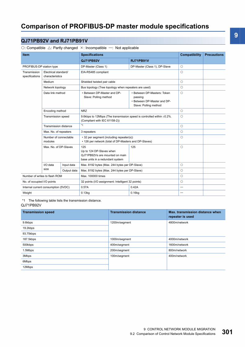
9
Comparison of PROFIBUS-DP master module specificationsQJ71PB92V and RJ71PB91V: Compatible : Partly changed : Incompatible : Not applicable
*1 The following table lists the transmission distance.QJ71PB92V
Item Specifications Compatibility Precautions
QJ71PB92V RJ71PB91VPROFIBUS-DP station type DP-Master (Class 1) DP-Master (Class 1), DP-Slave
Transmission specifications
Electrical standard/characteristics
EIA-RS485 compliant
Medium Shielded twisted pair cable
Network topology Bus topology (Tree topology when repeaters are used)
Data link method • Between DP-Master and DP-Slave: Polling method
• Between DP-Masters: Token passing
• Between DP-Master and DP-Slave: Polling method
Encoding method NRZ
Transmission speed 9.6kbps to 12Mbps (The transmission speed is controlled within 0.2%. (Compliant with IEC 61158-2))
Transmission distance *1
Max. No. of repeaters 3 repeaters
Number of connectable modules
• 32 per segment (including repeater(s))• 126 per network (total of DP-Masters and DP-Slaves)
Max. No. of DP-Slaves 125Up to 124 DP-Slaves when QJ71PB92Vs are mounted on main base units in a redundant system
125
I/O data size
Input data Max. 8192 bytes (Max. 244 bytes per DP-Slave)
Output data Max. 8192 bytes (Max. 244 bytes per DP-Slave)
Number of writes to flash ROM Max. 100000 times
No. of occupied I/O points 32 points (I/O assignment: Intelligent 32 points)
Internal current consumption (5VDC) 0.57A 0.42A
Weight 0.13kg 0.16kg
Transmission speed Transmission distance Max. transmission distance when repeater is used
9.6kbps 1200m/segment 4800m/network
19.2kbps
93.75kbps
187.5kbps 1000m/segment 4000m/network
500kbps 400m/segment 1600m/network
1.5Mbps 200m/segment 800m/network
3Mbps 100m/segment 400m/network
6Mbps
12Mbps
9 CONTROL NETWORK MODULE MIGRATION9.2 Comparison of Control Network Module Specifications 301

30
RJ71PB91V
The max. transmission distance in the table above is based on the case where 3 repeaters are used. The calculation formula for the transmission distance extended using a repeater(s) is:Max. transmission distance [m/network] = (Number of repeaters + 1) Transmission distance [m/segment]
Transmission speed Transmission distance9.6kbps 1200m/segment
19.2kbps
45.45kbps
93.75kbps
187.5kbps 1000m/segment
500kbps 400m/segment
1.5Mbps 200m/segment
3Mbps 100m/segment
6Mbps
12Mbps
2 9 CONTROL NETWORK MODULE MIGRATION9.2 Comparison of Control Network Module Specifications

9
Comparison of PROFIBUS-DP slave module specificationsQJ71PB93D and RJ71PB91V: Compatible : Partly changed : Incompatible : Not applicable
*1 The following table lists the transmission distance.
The max. transmission distance in the table above is based on the case where 3 repeaters are used. The calculation formula for the transmission distance extended using a repeater(s) is:Max. transmission distance [m/network] = (Number of repeaters + 1) Transmission distance [m/segment]
Item Specifications Compatibility Precautions
QJ71PB93D RJ71PB91VPROFIBUS-DP station type Slave station DP-Master (Class 1), DP-Slave
Station numbers that may be set 0 to 125
Max. number of data that may be communicated
Number of I/O data is 192 words in total. (Size of I/O data is up to 122 words.)
Maximum of 244 bytes (maximum of 384 bytes in total of I/O data)
Transmission specifications
Electrical standard/characteristics
Complies with EIA-RS485
Medium Shielded twisted pair cable
Network topology Bus topology (Tree topology when repeaters are used)
Data link method Polling method
Encoding method NRZ
Transmission speed 9.6kbps to 12Mbps (Transmission speed control within 0.3% (EN50170 Volume 2 compliant))
9.6kbps to 12Mbps (Transmission speed control is within 0.2% (compliant with IEC 61158-2).)
Transmission distance
*1
Maximum number of repeaters
3 units per network
Number of connectable modules
32 units per segment (including repeaters)
Flash ROM write count Max. 10000 times Max. 100000 times
Number of occupied I/O points 32 points (I/O assignment: Intelligent 32 points)
5VDC Internal power consumption 0.44A 0.42A
Weight 0.11kg 0.16kg
Transmission speed Transmission distance9.6kbps 1200m/segment
19.2kbps
45.45kbps
93.75kbps
187.5kbps 1000m/segment
500kbps 400m/segment
1.5Mbps 200m/segment
3Mbps 100m/segment
6Mbps
12Mbps
9 CONTROL NETWORK MODULE MIGRATION9.2 Comparison of Control Network Module Specifications 303
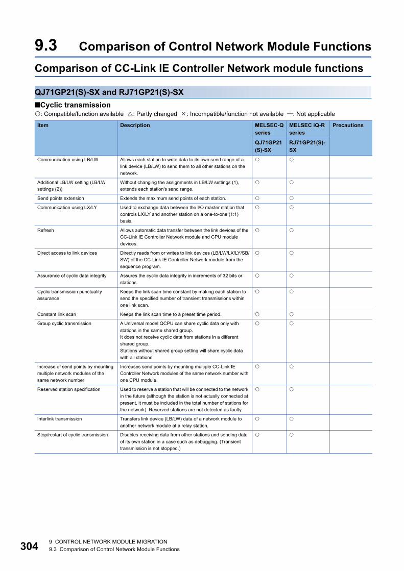
30
9.3 Comparison of Control Network Module FunctionsComparison of CC-Link IE Controller Network module functions
QJ71GP21(S)-SX and RJ71GP21(S)-SX■Cyclic transmission: Compatible/function available : Partly changed : Incompatible/function not available : Not applicable
Item Description MELSEC-Q series
MELSEC iQ-R series
Precautions
QJ71GP21(S)-SX
RJ71GP21(S)-SX
Communication using LB/LW Allows each station to write data to its own send range of a link device (LB/LW) to send them to all other stations on the network.
Additional LB/LW setting (LB/LW settings (2))
Without changing the assignments in LB/LW settings (1), extends each station's send range.
Send points extension Extends the maximum send points of each station.
Communication using LX/LY Used to exchange data between the I/O master station that controls LX/LY and another station on a one-to-one (1:1) basis.
Refresh Allows automatic data transfer between the link devices of the CC-Link IE Controller Network module and CPU module devices.
Direct access to link devices Directly reads from or writes to link devices (LB/LW/LX/LY/SB/SW) of the CC-Link IE Controller Network module from the sequence program.
Assurance of cyclic data integrity Assures the cyclic data integrity in increments of 32 bits or stations.
Cyclic transmission punctuality assurance
Keeps the link scan time constant by making each station to send the specified number of transient transmissions within one link scan.
Constant link scan Keeps the link scan time to a preset time period.
Group cyclic transmission A Universal model QCPU can share cyclic data only with stations in the same shared group.It does not receive cyclic data from stations in a different shared group.Stations without shared group setting will share cyclic data with all stations.
Increase of send points by mounting multiple network modules of the same network number
Increases send points by mounting multiple CC-Link IE Controller Network modules of the same network number with one CPU module.
Reserved station specification Used to reserve a station that will be connected to the network in the future (although the station is not actually connected at present, it must be included in the total number of stations for the network). Reserved stations are not detected as faulty.
Interlink transmission Transfers link device (LB/LW) data of a network module to another network module at a relay station.
Stop/restart of cyclic transmission Disables receiving data from other stations and sending data of its own station in a case such as debugging. (Transient transmission is not stopped.)
4 9 CONTROL NETWORK MODULE MIGRATION9.3 Comparison of Control Network Module Functions

9
■Transient transmission: Compatible/function available : Partly changed : Incompatible/function not available : Not applicableItem Description MELSEC-Q series
MELSEC iQ-R series
Precautions
QJ71GP21(S)-SX
RJ71GP21(S)-SX
Link dedicated instruction
Read from/write to other station devices(for Q/QnA series)
Reads or writes data from/to devices of a programmable controller on another station.(READ/SREAD/WRITE/SWRITE instruction)
Transient request to another station(for Q/QnA series)
Remotely runs or stops a programmable controller on another station. (REQ instruction)Reads or writes clock data from/to a programmable controller on another station. (REQ instruction)
Data send/receive(for Q/QnA series)
Sends data to a programmable controller on another station. (SEND instruction)Reads data received from a programmable controller on another station. (RECV/RECVS instruction)
Read from/write to other station devices(for A series)
Reads or writes data from/to devices of a programmable controller on another station. (ZNRD/ZNWR instruction)
Remote RUN/STOP(for Q series)
Remotely runs or stops a programmable controller on another station. (RRUN/RSTOP instruction)
Read/write of another station's clock data (for Q series)
Reads or writes clock data from/to a programmable controller on another station. (RTMRD/RTMWR instruction)
CC-Link dedicated instruction
Read/write of another station's data
Reads or writes the specified points of data from the target station's device. (RIRD/RIWT instruction)
Engineering tool access to other stations
Allows seamless access to the Ethernet, CC-Link IE Controller Network, MELSECNET/H, MELSECNET/10, CC-Link IE Field Network, and CC-Link systems using an engineering tool.
Group By specifying transient transmission target stations as a group, data can be sent to all stations of the same group number.
Routing Allows transient transmissions to stations located on other networks in a multi-network system.
Clock setting from an engineering tool
Sets up the clock of the CPU module that is connected to the network using an engineering tool.
Changing number of transient transmissions
The number of transient transmissions that one station can execute during one link scan can be changed.
9 CONTROL NETWORK MODULE MIGRATION9.3 Comparison of Control Network Module Functions 305
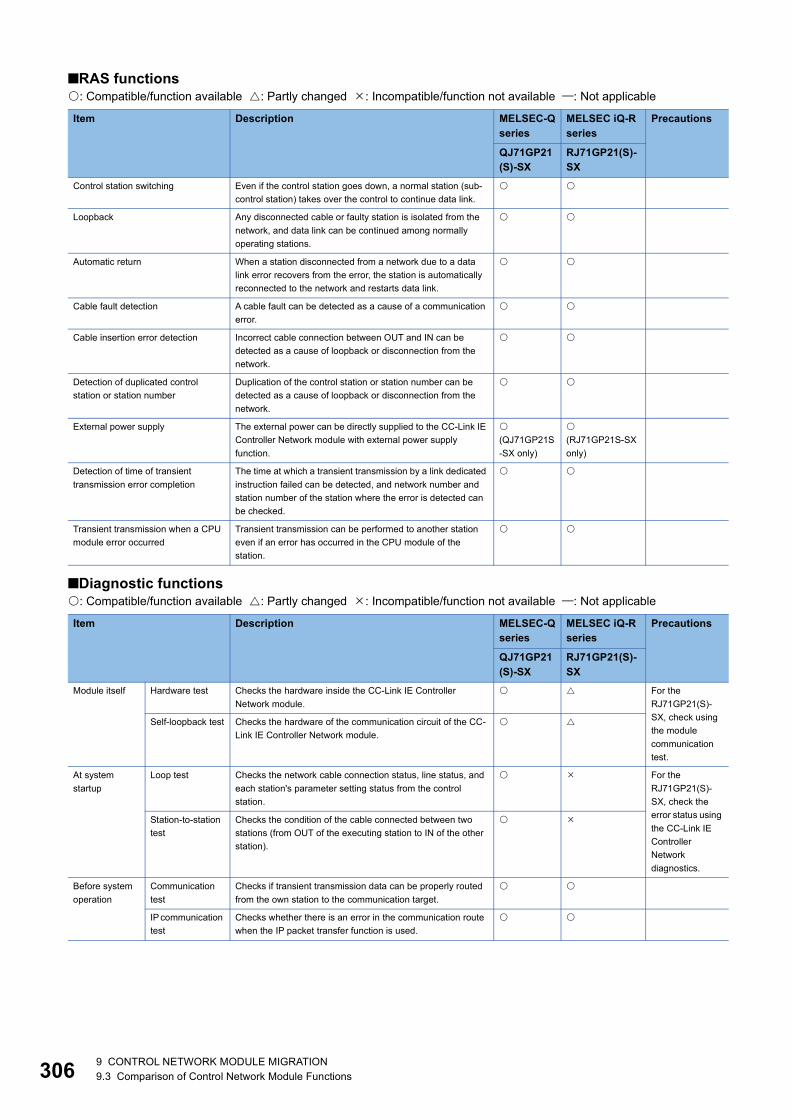
30
■RAS functions: Compatible/function available : Partly changed : Incompatible/function not available : Not applicable
■Diagnostic functions: Compatible/function available : Partly changed : Incompatible/function not available : Not applicable
Item Description MELSEC-Q series
MELSEC iQ-R series
Precautions
QJ71GP21(S)-SX
RJ71GP21(S)-SX
Control station switching Even if the control station goes down, a normal station (sub-control station) takes over the control to continue data link.
Loopback Any disconnected cable or faulty station is isolated from the network, and data link can be continued among normally operating stations.
Automatic return When a station disconnected from a network due to a data link error recovers from the error, the station is automatically reconnected to the network and restarts data link.
Cable fault detection A cable fault can be detected as a cause of a communication error.
Cable insertion error detection Incorrect cable connection between OUT and IN can be detected as a cause of loopback or disconnection from the network.
Detection of duplicated control station or station number
Duplication of the control station or station number can be detected as a cause of loopback or disconnection from the network.
External power supply The external power can be directly supplied to the CC-Link IE Controller Network module with external power supply function.
(QJ71GP21S-SX only)
(RJ71GP21S-SX only)
Detection of time of transient transmission error completion
The time at which a transient transmission by a link dedicated instruction failed can be detected, and network number and station number of the station where the error is detected can be checked.
Transient transmission when a CPU module error occurred
Transient transmission can be performed to another station even if an error has occurred in the CPU module of the station.
Item Description MELSEC-Q series
MELSEC iQ-R series
Precautions
QJ71GP21(S)-SX
RJ71GP21(S)-SX
Module itself Hardware test Checks the hardware inside the CC-Link IE Controller Network module.
For the RJ71GP21(S)-SX, check using the module communication test.
Self-loopback test Checks the hardware of the communication circuit of the CC-Link IE Controller Network module.
At system startup
Loop test Checks the network cable connection status, line status, and each station's parameter setting status from the control station.
For the RJ71GP21(S)-SX, check the error status using the CC-Link IE Controller Network diagnostics.
Station-to-station test
Checks the condition of the cable connected between two stations (from OUT of the executing station to IN of the other station).
Before system operation
Communication test
Checks if transient transmission data can be properly routed from the own station to the communication target.
IP communication test
Checks whether there is an error in the communication route when the IP packet transfer function is used.
6 9 CONTROL NETWORK MODULE MIGRATION9.3 Comparison of Control Network Module Functions
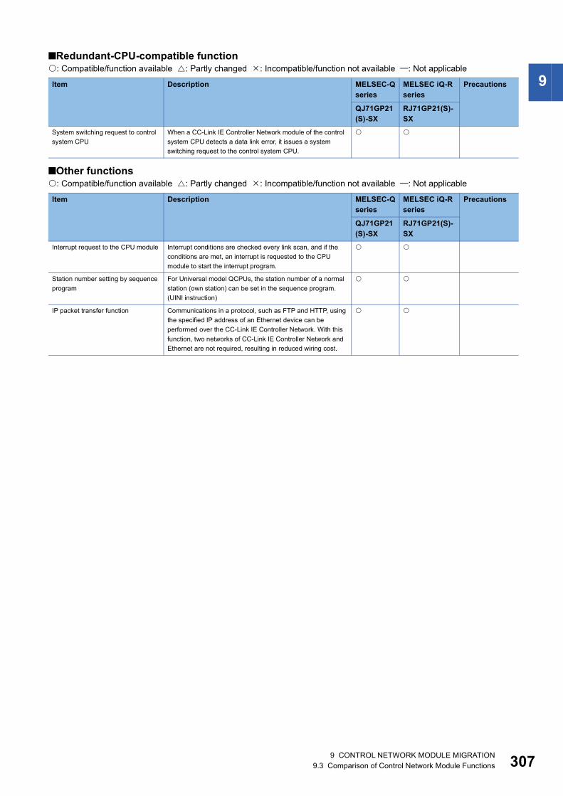
9
■Redundant-CPU-compatible function: Compatible/function available : Partly changed : Incompatible/function not available : Not applicable■Other functions: Compatible/function available : Partly changed : Incompatible/function not available : Not applicable
Item Description MELSEC-Q series
MELSEC iQ-R series
Precautions
QJ71GP21(S)-SX
RJ71GP21(S)-SX
System switching request to control system CPU
When a CC-Link IE Controller Network module of the control system CPU detects a data link error, it issues a system switching request to the control system CPU.
Item Description MELSEC-Q series
MELSEC iQ-R series
Precautions
QJ71GP21(S)-SX
RJ71GP21(S)-SX
Interrupt request to the CPU module Interrupt conditions are checked every link scan, and if the conditions are met, an interrupt is requested to the CPU module to start the interrupt program.
Station number setting by sequence program
For Universal model QCPUs, the station number of a normal station (own station) can be set in the sequence program. (UINI instruction)
IP packet transfer function Communications in a protocol, such as FTP and HTTP, using the specified IP address of an Ethernet device can be performed over the CC-Link IE Controller Network. With this function, two networks of CC-Link IE Controller Network and Ethernet are not required, resulting in reduced wiring cost.
9 CONTROL NETWORK MODULE MIGRATION9.3 Comparison of Control Network Module Functions 307

30
Comparison of CC-Link IE Field Network master/local modules
QJ71GF11-T2 and RJ71GF11-T2■Cyclic transmission: Compatible/function available : Partly changed : Incompatible/function not available : Not applicable
■Transient transmission: Compatible/function available : Partly changed : Incompatible/function not available : Not applicable
Item Description MELSEC-Q series
MELSEC iQ-R series
Precautions
QJ71GF11-T2
RJ71GF11-T2
Communications with other stations
Communications using RX and RY
Communicates I/O data in units of bits between the master station and other stations.
Communications using RWr and RWw
Communicates I/O data in units of words between the master station and other stations.
Access to devices and link devices
Link refresh Automatically transfers data between a link device of the master/local module and a device in a CPU module.
Direct access to link devices
Directly accesses the link devices of the master/local module directly from the program.
Interlink transmission Transfers link device data of the master station or submaster station to another network module on a relay station.
Mode selection for cyclic transmission
This mode is selected for optimizing the performance of cyclic transmission based on the cyclic transmission and transient transmission frequency. The mode can be selected from "Online (Normal Mode)" and "Online (High Speed Mode)".
Assurance of cyclic data integrity Assures the cyclic data integrity in increments of 32 bits or stations.
Scan synchronization specification Selects whether link scan is set to asynchronous or synchronous with the sequence scan of the CPU module.
Input status setting for data link faulty station
Selects whether input data from another station where a data link error occurs is cleared or held.
Output status setting for CPU STOP Selects whether cyclic data output is held or cleared when the CPU module mounted with the master/local module is set to STOP state.
Output status setting for CPU stop error
Selects whether cyclic transmission output is held or cleared when a stop error occurs in the CPU module where a master/local module is mounted.
Cyclic transmission stop and restart Stops the cyclic transmission during debugging and other operations. (Data reception from a slave station and data sending from the own station are stopped.) Also, the stopped cyclic transmission is restarted. Transient transmission does not stop.
Item Description MELSEC-Q series
MELSEC iQ-R series
Precautions
QJ71GF11-T2
RJ71GF11-T2
Communications within the same network
Performs the transient transmission to other stations using dedicated instructions and GX Works2.
Communications with different networks
By presetting the routing parameters (communication route) using GX Works2, transient transmission can be performed to stations on different networks through GX Works2. Seamless communications are available with the following networks.• Ethernet• CC-Link IE Controller Network• MELSECNET/H, MELSECNET/10• CC-Link (when using GX Works2)
8 9 CONTROL NETWORK MODULE MIGRATION9.3 Comparison of Control Network Module Functions

9
■RAS functions: Compatible/function available : Partly changed : Incompatible/function not available : Not applicable■Diagnostic functions: Compatible/function available : Partly changed : Incompatible/function not available : Not applicable
Item Description MELSEC-Q series
MELSEC iQ-R series
Precautions
QJ71GF11-T2
RJ71GF11-T2
Slave station disconnection Only the slave station where an error occurs is disconnected, and data link continues with the stations that are operating normally.In line topology, all stations connected after the faulty station are disconnected.
Automatic return When the station disconnected from the network due to a data link failure recovers, it automatically returns to the network and restarts data link.
Module error collection function An error that has occurred in a master/local module can be stored in the CPU module as error history. The history data can be stored on a memory with backup power feature; therefore error details are held even if the CPU module is reset or the system is powered off.
For the RJ71GF11-T2, use the event history function instead.
Loopback function Only the station where an error occurs is disconnected, and data link continues with the stations that are operating normally. All stations after the faulty station are disconnected in line topology. By using the loopback function with ring topology, data link continues with the stations that are operating normally.
Submaster Function This function allows the submaster station to control slave stations instead of the master station when the master station is disconnected in a system where the master station and submaster station are connected on the same network. Using this function prevents the entire network from going down due to disconnection of the master station.
Item Description MELSEC-Q series
MELSEC iQ-R series
Precautions
QJ71GF11-T2
RJ71GF11-T2
CC-Link IE Field Network diagnostics
The status of CC-Link IE Field Network can be checked using GX Works2. The error locations, error causes, corrective actions, and event history can be checked in GX Works2.
Diagnostics of the module alone
Hardware test Checks the hardware in the master/local module. For the RJ71GF11-T2, use the module communication test instead.
Self-loopback test Checks the communication circuit in the transmission system of the master/local module.
Diagnostics of own network
Loop test Checks the network line status, and each station's parameter setting status.
Cable test Checks the connection status of the Ethernet cables.
Diagnostics of other network
Communication test
Checks whether the communication route for transient transmission from the own station to the destination station is correct.
IP communication test
Checks whether there is an error in the communication route when the IP packet transfer function is used.
9 CONTROL NETWORK MODULE MIGRATION9.3 Comparison of Control Network Module Functions 309

31
■Other functions: Compatible/function available : Partly changed : Incompatible/function not available : Not applicable
Item Description MELSEC-Q series
MELSEC iQ-R series
Precautions
QJ71GF11-T2
RJ71GF11-T2
Reserved station specification The reserved stations are included in the number of stations that will be connected to the network in the future without actually connecting them. Reserved stations are not detected as faulty stations even though they are not actually connected.
Temporary cancel of the reserved station setting
Reserved station specification can be temporarily canceled without changing the parameters.
Error invalid station and temporary error invalid station setting
Prevents the master station from detecting a slave station as a faulty station even if the slave station is disconnected during data link. This can be used when replacing a slave station during data link, for instance.
Interrupt request to the CPU module Checks interrupt conditions in every link scan, and makes an interrupt request to the CPU module to start the interrupt program if the interrupt conditions are met.
IP packet transfer function Communications in a protocol, such as FTP and HTTP, using the specified IP address of an Ethernet device can be performed over the CC-Link IE Field Network. With this function, two networks of CC-Link IE Field Network and Ethernet are not required, resulting in reduced wiring cost.
Station number setting using a program
The station numbers of a local station (own station) can be set using a program. When there are local stations with the same program and network parameters (excluding the station numbers), setting the station numbers using a program allows project data items other than the station number to be the same, leading to reduced development work hours.
Data backup/restoration The setting data of the slave station is backed up into the SD memory card of the CPU module on the master station. The setting data backed up on the SD memory card of the CPU module on the master station is restored into the slave station.
0 9 CONTROL NETWORK MODULE MIGRATION9.3 Comparison of Control Network Module Functions

9
Comparison of CC-Link system master/local module functionsQJ61BT11(N) and RJ61BT11■Cyclic transmission: Compatible/function available : Partly changed : Incompatible/function not available : Not applicable
*1 This function is not available for the QJ61BT11.
■Transient transmission: Compatible/function available : Partly changed : Incompatible/function not available : Not applicable
Item Description MELSEC-Q series
MELSEC iQ-R series
Precautions
QJ61BT11(N) RJ61BT11Communications with other stations
Remote net Ver.1 mode
Remote net Ver.2 mode *1
Remote net additional mode *1 Use the remote net Ver.2 mode instead.
Remote I/O net mode
Auto refresh Automatically transfers data between the RX/RY/RWr/RWw/SB/SW of the master/local module and a device in a CPU module.The RX/RY/RWr/RWw/SB/SW can be accessed by accessing a device in a CPU module from a program.
Scan synchronization Selects whether link scan is set to asynchronous or synchronous with the sequence scan.If it is set to asynchronous, the input transmission delay time will shorten. If it is set to synchronous, the output transmission delay time will shorten.
Cyclic data block data assurance per station
Prevents read/write data per station from being separated between new and old data depending on the auto refresh timing. Because the setting is configured only on an engineering tool, a program to prevent data separation is not required.
*1
32-bit data integrity assurance
Prevents read/write data in 32-bit increments from being separated between new and old data.
Data link stop/restart Stops or restarts data link of the own station using an engineering tool or SB/SW. This function is used when data link should be temporarily stopped for maintenance or other reasons.
Remote I/O station points setting
When the master station is in the remote net Ver.2 mode, the refresh points with a remote I/O station can be selected from 8 points, 16 points, and 32 points. Changing the number of points can save the areas of the refresh device in a CPU module. (In modes other than the remote net Ver.2 mode, only 32 points per station can be selected.)
*1
Item Description MELSEC-Q series
MELSEC iQ-R series
Precautions
QJ61BT11(N) RJ61BT11Communication using a dedicated instruction
Communication with other station is possible at any timing.Unlike cyclic transmission, direct access to buffer memory areas in other stations can be performed. This function is used to access data that is updated infrequently.
9 CONTROL NETWORK MODULE MIGRATION9.3 Comparison of Control Network Module Functions 311

31
■RAS functions: Compatible/function available : Partly changed : Incompatible/function not available : Not applicable
*1 This function is not available for the QJ61BT11.
■Diagnostic functions: Compatible/function available : Partly changed : Incompatible/function not available : Not applicable
*1 This function is not available for the QJ61BT11.
Item Description MELSEC-Q series
MELSEC iQ-R series
Precautions
QJ61BT11(N) RJ61BT11Slave station cutoff function
Data link can be continued in a normal station by disconnecting a slave station that cannot perform data link due to reasons such as power-off. (No parameter setting is required.)Using this function prevents the entire system from going down when one station goes down.
Automatic return function When a slave station that has been disconnected from data link due to reasons such as power-off returns to the normal status, data link is automatically restarted. The time between an error and a return can be shortened.
Setting of the data link status upon an error in the programmable controller CPU of the master station
Selects whether to stop or continue data link when a stop error occurs in the CPU module of a master station.
Setting of the status of the input data from a data link faulty station
Selects whether to clear or hold input data from a data link faulty station. Selects how data should be handled according to the system used.
Slave station refresh/compulsory clear setting in case of programmable controller CPU STOP
Selects whether to refresh or compulsorily clear remote output (RY) when the switch on a CPU module is set to STOP. Selects how data should be handled according to the system used.
*1
Standby master station If the master station goes down due to an error in a CPU module, power supply, or others, switching the control to the standby master station (a backup station for the master station) continues data link. This function is used not to stop the entire system even if the master station goes down.
Master station duplication error canceling function
Clears a master station duplication error without resetting the CPU module or powering off and on the system when the error has been detected.
*1
Item Description MELSEC-Q series
MELSEC iQ-R series
Precautions
QJ61BT11(N) RJ61BT11Line test Checks whether a CC-Link dedicated cable is properly connected and
data link can be performed with slave stations.
Transmission speed test Checks whether the transmission speed setting of a slave station is the same as that of the master station. The station number of the slave station having a different transmission speed setting can be also checked; therefore, corrective action upon a transmission error can be easily taken.
*1
CC-Link diagnostics Checks the status of CC-Link system using an engineering tool. Unlike the link special relay (SB) and the link special register (SW), the system status can be checked on a graphical window; therefore, corrective actions can be easily taken.
Hardware test Checks the hardware in the master/local module.
2 9 CONTROL NETWORK MODULE MIGRATION9.3 Comparison of Control Network Module Functions

9
■Other functions: Compatible/function available : Partly changed : Incompatible/function not available : Not applicable*1 This function is not available for the QJ61BT11.
Item Description MELSEC-Q series
MELSEC iQ-R series
Precautions
QJ61BT11(N) RJ61BT11Remote device station initialization procedure registration function
Using an engineering tool, registers in advance the initial setting of a remote device station which was performed on a program, and saves the setting by turning on the link special relay (SB). A program for the initial setting is not required.
Event issuance for the interrupt program
Issues an interrupt request to a CPU module when the interrupt conditions that have been set using an engineering tool are satisfied, and executes the interrupt program. This function is used to stop the control and execute an interrupt program upon an error or for other purposes.
Automatic CC-Link startup
Data link can be performed by powering on the master/local module. This function is used to check the operation of when a system is configured.
For the RJ61BT11, set the module parameters.
Reserved station function Prevents slave stations that are not actually connected (but will be connected in future) from detecting as "Data Link Faulty Station" in the master station and local station.By setting slave stations that will be connected in future as reserved stations, slave stations can be added without a program change because the RX/RY/RWr/RWw assignment is not changed. In addition, the number of points of a slave station that has been set as a reserved station can be set to zero points.
Error invalid station setting function
Prevents a slave station from being detected as a faulty station in the master station and local station even if a data link error occurs in the slave station. This function is used when a slave station is powered off as a matter of the system configuration or for other purposes.
Temporary error invalid station setting function
Prevents a slave station from being detected as a faulty station in the master station and local station even if a data link error occurs in the slave station. This setting can be configured even during data link, unlike the error invalid station setting function. This function is used to exchange slave stations for maintenance or for other purposes during data link.
Automatic detection of connected device
The time of setting parameters can be reduced by automatically reading information of slave stations.The model names of slave stations can be read.
*1 For the RJ61BT11, set the module parameters.
Data backup/restoration The setting data of the slave station is backed up into the SD memory card of the CPU module on the master station. The setting data backed up on the SD memory card of the CPU module on the master station is restored into the slave station.
*1 For the RJ61BT11, use GX Works3 to set parameters of slave stations.
9 CONTROL NETWORK MODULE MIGRATION9.3 Comparison of Control Network Module Functions 313
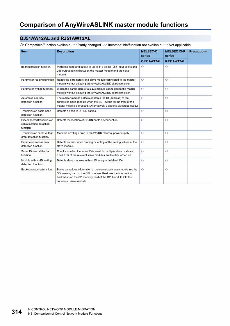
31
Comparison of AnyWireASLINK master module functions
QJ51AW12AL and RJ51AW12AL: Compatible/function available : Partly changed : Incompatible/function not available : Not applicable
Item Description MELSEC-Qseries
MELSEC iQ-R series
Precautions
QJ51AW12AL RJ51AW12ALBit transmission function Performs input and output of up to 512 points (256 input points and
256 output points) between the master module and the slave module.
Parameter reading function Reads the parameters of a slave module connected to the master module without delaying the AnyWireASLINK bit transmission.
Parameter writing function Writes the parameters of a slave module connected to the master module without delaying the AnyWireASLINK bit transmission.
Automatic address detection function
The master module detects or stores the ID (address) of the connected slave module when the SET switch on the front of the master module is pressed. (Alternatively a specific bit can be used.)
Transmission cable short detection function
Detects a short in DP-DN cables.
Disconnected transmission cable location detection function
Detects the location of DP-DN cable disconnection.
Transmission cable voltage drop detection function
Monitors a voltage drop in the 24VDC external power supply.
Parameter access error detection function
Detects an error upon reading or writing of the setting values of the slave module.
Same ID used detection function
Checks whether the same ID is used for multiple slave modules. The LEDs of the relevant slave modules are forcibly turned on.
Module with no ID setting detection function
Detects slave modules with no ID assigned (default ID).
Backup/restoring function Backs up various information of the connected slave module into the SD memory card of the CPU module. Restores the information backed up on the SD memory card of the CPU module into the connected slave module.
4 9 CONTROL NETWORK MODULE MIGRATION9.3 Comparison of Control Network Module Functions

9
Comparison of MELSECNET/H network module functionsQJ71LP21(S)-25 and RJ71LP21-25: Compatible/function available : Partly changed : Incompatible/function not available : Not applicable
Item Description MELSEC-Q series
MELSEC iQ-R series
Precautions
QJ71LP21-25 RJ71LP21-25■Cyclic transmission
Communication using LB/LW
Writes data on the link relay (LB) and the link register (LW) of the network module, and sends the data to all stations connected in the same network.
Communication using LX/LY
Exchanges data between the following stations on a one-to-one (1:1) basis: the I/O master station that controls LX/LY, another station (optical loop system: 63 stations maximum, coaxial bus system and twist bus system: 31 stations maximum)
Interlink data transfer function
Transfers link data to the other networks at the same time by using parameters. This function is used when one programmable controller is connected to multiple networks.
Low speed cyclic transmission
Useful for collectively sending data that do not require high-speed performance to another station by link devices (LB, LW).
■RAS function
Automatic return function If a station is disconnected from the network due to a data link error, this function automatically returns the station to the network when it recovers, and restarts data link.
Control station switching function
If the control station (station where common parameters are set) goes down, this function changes another normal station to a sub-control station, and continues data link.
Control station recovery control function
This function shortens network downtime by resolving the cause of an error in the control station and making that station join the network as a normal station.
Loopback function (optical loop system)
The optical loop system uses duplex transmission path.If an error occurs on a transmission path, this function switches the transmission path from forward loop to reverse loop and vice versa, or performs loopback to disconnect a faulty area and continue transmission between stations on which data are communicated normally.
Transient transmission enabled even at CPU module error
This function enables the network module to continue transient transmission even at an error occurrence that stops the CPU module during system operation.
Check of the time when transient transmission failed
Information (such as time, faulty network number, and faulty station number) related to a failure of transient transmission by the instruction (such as SEND, READ, SREAD, WRITE, SWRITE, or REQ instruction) can be checked.
Diagnostic function The line status of the network and the module setting status can be checked with this function.
■Transient transmission
Communication function Exchanges data between stations using a communication request.
Routing function Allows transient transmissions to stations with different network numbers in a multi-network system.
Group function Divides transient transmission target stations into groups, and sends data to all the stations in one group with one instruction.
Sending messages by using logical channel numbers
Useful for when many types of information is involved in the transmission and you want to limit messages to be received on the stations.
9 CONTROL NETWORK MODULE MIGRATION9.3 Comparison of Control Network Module Functions 315

31
Data send/receive (SEND/RECV)
Communicates data with another station (another network) at any timing by using a sequence program.
Read from/write to word device on another station (READ/SREAD/WRITE/SWRITE)
Transient request to another station (REQ)
Read from/write to word device on another station (ZNRD/ZNWR)
Remote RUN/Remote STOP (RRUN/RSTOP)
Remote RUN/Remote STOP
Read/write clock data from/to CPU module on another station (RTMRD/RTMWR)
Sets up the clock of a CPU module that is connected to the network using a programming tool.
■Redundant system function
Pairing setting Sets a combination of station numbers of network modules that are included in the redundant system.
Redundant system settings Sets the operation mode for the network module mounted on system B.
System switching request function
When a network module is connected to a control system CPU module in the redundant system, if a data link error occurs on this network module and the error status (D.LINK LED off) continues for the system switching monitoring time (set in SW0018) or longer, this function automatically issues a system switching request to the control system CPU module.
For the RJ71LP21-25, use the module parameter to set the system switching monitoring time.
■Other functions
Direct access to link devices
Directly reads/writes data from/to link devices (LB, LW, LX, LY, SB, SW) of a network module using a sequence program, independent from the link refresh of CPU module.
Clock setting to a station on the network with a programming tool
Sets up the clock of a CPU module that is connected to the network using a programming tool.
Interrupt sequence program activation
Uses the interrupt settings parameters of the own station and checks the interrupt condition at the timing data are received from another station. When the interrupt condition is established, an interrupt request is made from the network module to the CPU module, and the interrupt sequence program of the CPU module on the own station is activated.
Multiplex transmission function (optical loop system)
Performs high speed communications using duplex transmission path (forward loop and reverse loop).
The RJ71LP21-25 cannot operate as a control station with multiplex transmission function.
Simple dual-structured network
For a network with this structure, two network modules (operative, standby) are connected to each CPU module. If an error (such as disconnection) occurs and it affects some areas on the operative network, the module performing link refresh is switched from the operative module to the standby module (standby network) to continue data link.
Instead of refresh settings, use a sequence program to execute refresh.*1
Stopping/restarting cyclic transmission, stopping link refresh (network test)
Stops/restarts the cyclic transmission using the network test of GX Developer.
Increase of send points by mounting multiple network modules of the same network number
Increases the number of send points (a maximum of 2000 bytes per station) to a maximum of 8000 bytes (when four modules are mounted) by mounting multiple network modules with the same network number to one CPU module.
Item Description MELSEC-Q series
MELSEC iQ-R series
Precautions
QJ71LP21-25 RJ71LP21-25
6 9 CONTROL NETWORK MODULE MIGRATION9.3 Comparison of Control Network Module Functions
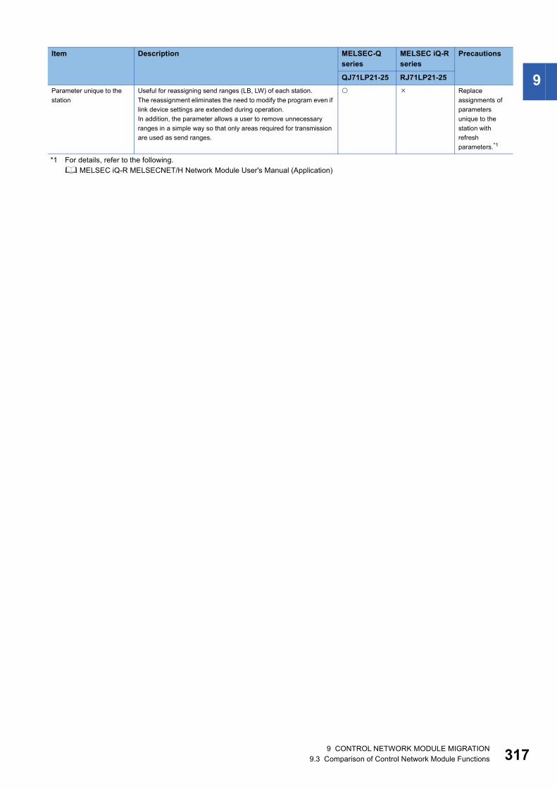
9
*1 For details, refer to the following. MELSEC iQ-R MELSECNET/H Network Module User's Manual (Application)
Parameter unique to the station
Useful for reassigning send ranges (LB, LW) of each station.The reassignment eliminates the need to modify the program even if link device settings are extended during operation.In addition, the parameter allows a user to remove unnecessary ranges in a simple way so that only areas required for transmission are used as send ranges.
Replace assignments of parameters unique to the station with refresh parameters.*1
Item Description MELSEC-Q series
MELSEC iQ-R series
Precautions
QJ71LP21-25 RJ71LP21-25
9 CONTROL NETWORK MODULE MIGRATION9.3 Comparison of Control Network Module Functions 317

31
Comparison of DeviceNet master-slave module functions
QJ71DN91 and RJ71DN91■Data communications: Compatible/function available : Partly changed : Incompatible/function not available : Not applicable
■RAS: Compatible/function available : Partly changed : Incompatible/function not available : Not applicable
Item Description MELSEC-Q series
MELSEC iQ-R series
Precautions
QJ71DN91 RJ71DN91Master function
I/O communication function
A function for I/O data communications with each slave node (up to 63 nodes) using the buffer memory of the DeviceNet master-slave module.
Message communication function
A function for reading/writing attribute data of slave nodes using the buffer memory of the DeviceNet master-slave module.
Slave function
I/O communication function
A function for I/O data communications with the master node using the buffer memory of the DeviceNet master-slave module.
Data consistency function
Dedicated instruction
Maintains I/O data consistency using dedicated instructions.
Refresh Maintains I/O data consistency by refreshing.
Auto configuration Detects slave nodes on the network and automatically creates parameters for the master function.
Item Description MELSEC-Q series
MELSEC iQ-R series
Precautions
QJ71DN91 RJ71DN91Hardware test Checks if the module operates normally.
The ROM check, RAM check, and self-loopback test is performed.
Communication test Performs the transmit test and receive test with the DeviceNet master-slave module connected to another DeviceNet device using a DeviceNet cable.
8 9 CONTROL NETWORK MODULE MIGRATION9.3 Comparison of Control Network Module Functions

9
Comparison of PROFIBUS-DP master module functionsQJ71PB92V and RJ71PB91V: Compatible : Partly changed : Incompatible : Not applicable
Item Description MELSEC-Q series
MELSEC iQ-R series
Precautions
QJ71PB92V RJ71PB91VPROFIBUS-DPV0
I/O data exchange
Up to 125 DP-Slaves can be connected to a single QJ71PB92V, enables the I/O data exchange.
Acquisition of diagnostic and extended diagnostic information
Diagnostic or extended diagnostic information of an error occurred on a DP-Slaves during I/O data exchange can be easily acquired using the buffer memory and I/O signals.
Global control function
By sending services (SYNC, UNSYNC, FREEZE, UNFREEZE) to each DP-Slave in a group, synchronous control of DP-Slave I/O data is available.
PROFIBUS-DPV1
Acyclic communication
Allows data reading/writing to DP-Slaves at any specific timing independently of I/O data exchange.
Alarm acquisition Enables acquisition of up to 8 alarms or status information data that have been generated on any DP-Slave.
PROFIBUS-DPV2
Time control over DP-Slaves
Operates as the time master and set the time of each DP-Slave.
Data swap function Swaps the upper and lower bytes in word units when I/O data is sent and received.
Data consistency function When I/O data from DP-Slaves are read from or written to the buffer memory, prevents the I/O data from being separated and incorrectly mixed.
Output status setting for the case of a CPU stop error
Sets the handling of I/O data when a CPU stop error occurs in a CPU module to which the PROFIBUS-DP master module is mounted.
Temporary slave reservation function
Without modifying the slave parameter in GX Configurator-DP, allows the DP-Slave type to be changed to "Reserved station" temporarily.
Redundant system support function
When the control system CPU or the PROFIBUS-DP master module detects an error, the control and standby systems are switched each other to continue communications.
9 CONTROL NETWORK MODULE MIGRATION9.3 Comparison of Control Network Module Functions 319

32
Comparison of PROFIBUS-DP slave module functions
QJ71PB93D and RJ71PB91V: Compatible : Partly changed : Incompatible : Not applicable
Item Description MELSEC-Q series
MELSEC iQ-R series
Precautions
QJ71PB93D RJ71PB91VI/O data communication function
Operates as a PROFIBUS-DP slave station and communicates I/O data with the master station.
Separation prevention function
Prevents the I/O data of the CPU module from being unmatched with the I/O data of the master station.
Global control function Controlled simultaneously for each specified group by multicasting (broadcasting) from the master station
Swap function Swapped in word units when input or output data are sent to or received from the master station.
Notification function of extended diagnostic information
Notifies DP-Master of extended diagnostic information occurring during I/O data exchange.
I/O data read function Sends I/O data on the request from the DP-Master (Class 2).
I/O configuration information read function
Sends I/O configuration information on the request from the DP-Master (Class 2).
FDL address changing function
Changes FDL address of DP-Slaves from the DP-Master (Class 2) or a program.
Output status setting for the case of a CPU stop error
Sets the handling of I/O data when a CPU stop error occurs in a CPU module to which the PROFIBUS-DP slave module is mounted.
Operation mode changing function
Changes the operation mode using a program.
0 9 CONTROL NETWORK MODULE MIGRATION9.3 Comparison of Control Network Module Functions

9
9.4 Precautions for Control Network Module MigrationPrecautions common to the control network modulesInterrupt settingTo execute an interrupt program in the MELSEC iQ-R series network modules, set the interrupt pointer number in module parameter.
Dedicated instructions (common to CC-Link IE Field/CC-Link IE Controller)The MELSEC iQ-R series modules cannot specify 254 (Network specified in Valid module during other station access) as a network number in dedicated instructions. Specify the network number of the own station.
Precautions for CC-Link IE Field Network master/local module migration
System configurationWhen the module other than the RJ71GF11-T2 is used as the master station, there may be additional restrictions to the serial number of the master station used.
Dedicated instructionThere is no difference between the MELSEC-Q series and the MELSEC iQ-R series.
Link special relay (SB) and link special register (SW)Some of the SB/SW number assignments differ between the MELSEC-Q series and MELSEC iQ-R series modules. If the SB/SW is used in the MELSEC-Q series program, the program needs to be corrected for the MELSEC iQ-R series.
Precautions for CC-Link system master/local module migration
Dedicated instruction • RLPASETFor the MELSEC-Q series module, the mode is set in b14 and b15 of the device (S1+1) (Setting flag) in the control data. However, for the MELSEC iQ-R series, set 0 in b14 and b15 because the mode is set in module parameter.
Link special relay (SB) and link special register (SW)Some of the SB/SW number assignments differ between the MELSEC-Q series and MELSEC iQ-R series modules. If the SB/SW is used in the MELSEC-Q series program, the program needs to be corrected for the MELSEC iQ-R series.
Buffer memoryThe layout of buffer memory areas differs between the MELSEC-Q series and the MELSEC iQ-R series.If buffer memory areas are used in the MELSEC-Q series program, the program needs to be corrected for the MELSEC iQ-R series.
9 CONTROL NETWORK MODULE MIGRATION9.4 Precautions for Control Network Module Migration 321
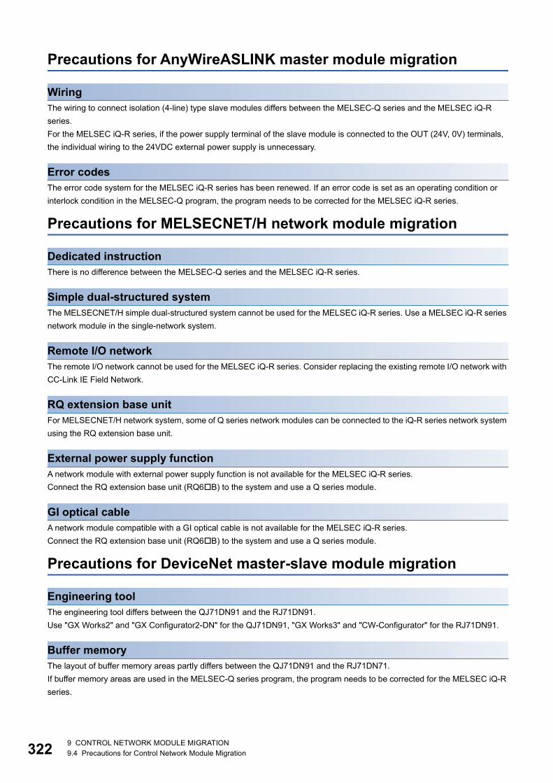
32
Precautions for AnyWireASLINK master module migration
WiringThe wiring to connect isolation (4-line) type slave modules differs between the MELSEC-Q series and the MELSEC iQ-R series.For the MELSEC iQ-R series, if the power supply terminal of the slave module is connected to the OUT (24V, 0V) terminals, the individual wiring to the 24VDC external power supply is unnecessary.
Error codesThe error code system for the MELSEC iQ-R series has been renewed. If an error code is set as an operating condition or interlock condition in the MELSEC-Q program, the program needs to be corrected for the MELSEC iQ-R series.
Precautions for MELSECNET/H network module migration
Dedicated instructionThere is no difference between the MELSEC-Q series and the MELSEC iQ-R series.
Simple dual-structured systemThe MELSECNET/H simple dual-structured system cannot be used for the MELSEC iQ-R series. Use a MELSEC iQ-R series network module in the single-network system.
Remote I/O networkThe remote I/O network cannot be used for the MELSEC iQ-R series. Consider replacing the existing remote I/O network with CC-Link IE Field Network.
RQ extension base unitFor MELSECNET/H network system, some of Q series network modules can be connected to the iQ-R series network system using the RQ extension base unit.
External power supply functionA network module with external power supply function is not available for the MELSEC iQ-R series.Connect the RQ extension base unit (RQ6B) to the system and use a Q series module.
GI optical cableA network module compatible with a GI optical cable is not available for the MELSEC iQ-R series.Connect the RQ extension base unit (RQ6B) to the system and use a Q series module.
Precautions for DeviceNet master-slave module migration
Engineering toolThe engineering tool differs between the QJ71DN91 and the RJ71DN91.Use "GX Works2" and "GX Configurator2-DN" for the QJ71DN91, "GX Works3" and "CW-Configurator" for the RJ71DN91.
Buffer memoryThe layout of buffer memory areas partly differs between the QJ71DN91 and the RJ71DN71.If buffer memory areas are used in the MELSEC-Q series program, the program needs to be corrected for the MELSEC iQ-R series.
2 9 CONTROL NETWORK MODULE MIGRATION9.4 Precautions for Control Network Module Migration

9
Precautions for PROFIBUS-DP master-slave module migrationEngineering toolThe engineering tool differs between the QJ71PB92V/QJ71PB93D and the RJ71PB91V.Use "GX Works2/GX Developer" and "GX Configurator-DP" for the QJ71PB92V/QJ71PB93D, "GX Works3" and "PROFIBUS Configuration Tool" for the RJ71PB91V.
For details on these precautions, refer to the following. MELSEC iQ-R Module Configuration Manual MELSEC iQ-R Ethernet/CC-Link IE User's Manual (Startup) MELSEC iQ-R CC-Link IE Controller Network User's Manual (Application) MELSEC iQ-R CC-Link IE Field Network User's Manual (Application) MELSEC iQ-R CC-Link System Master/Local Module User's Manual (Startup) MELSEC iQ-R CC-Link System Master/Local Module User's Manual (Application) MELSEC iQ-R AnyWireASLINK Master Module User's Manual (Startup) MELSEC iQ-R AnyWireASLINK Master Module User's Manual (Application) MELSEC iQ-R MELSECNET/H Network Module User's Manual (Startup) MELSEC iQ-R MELSECNET/H Network Module User's Manual (Application) MELSEC iQ-R DeviceNet Master/Slave Module User's Manual (Startup) MELSEC iQ-R DeviceNet Master/Slave Module User's Manual (Application) MELSEC iQ-R PROFIBUS-DP Module User's Manual (Startup) MELSEC iQ-R PROFIBUS-DP Module User's Manual (Application) Differences between MELSEC-Q series and MELSEC iQ-R series (FA-A-0171)
9 CONTROL NETWORK MODULE MIGRATION9.4 Precautions for Control Network Module Migration 323

32
10 INFORMATION MODULE MIGRATION
10.1 Information Module Migration Model ListThis section describes examples of migration to MELSEC iQ-R series information modules in accordance with the MELSEC-Q series information module specifications.Consider the scope of control by the MELSEC-Q series information module used and the system specifications and extensibility after migration to choose a model that best suits your application.
Item MELSEC-Qseries
MELSEC iQ-R series
Specification difference
MES interface QJ71MES96QJ71MES96N
RD81MES96N (1) External wiring: Not changed(2) Number of slots: Not changed(3) Programs: The number of occupied I/O points is not changed, I/O signals are
changed, and buffer memory addresses are changed.(4) Specifications: Changed(5) Functions: Changed
High speed data logger QD81DL96 RD81DL96 (1) External wiring: Not changed(2) Number of slots: Not changed(3) Programs: The number of occupied I/O points is not changed, I/O signals are
changed, and buffer memory addresses are changed.(4) Specifications: Changed(5) Functions: Changed
High speed data communication
QJ71DC96 No applicable module
Web server QJ71WS96 No applicable module
Connect the RQ extension base unit (RQ6B) to use the Q series module.For some functions, consider using the Web server function of the CPU module instead.*1
Ethernet interface QJ71E71-B2 RJ71EN71 (1) External wiring: Changed(2) Number of slots: Not changed(3) Programs: The number of occupied I/O points is not changed, I/O signals are
changed, and buffer memory addresses are changed.(4) Specifications: Changed(5) Functions: Changed
QJ71E71-B5 RJ71EN71 (1) External wiring: Changed(2) Number of slots: Not changed(3) Programs: The number of occupied I/O points is not changed, I/O signals are
changed, and buffer memory addresses are changed.(4) Specifications: Changed(5) Functions: Changed
QJ71E71-100 RJ71EN71 (1) External wiring: Not changed(2) Number of slots: Not changed(3) Programs: The number of occupied I/O points is not changed, I/O signals are
changed, and buffer memory addresses are changed.(4) Specifications: Changed(5) Functions: Changed
4 10 INFORMATION MODULE MIGRATION10.1 Information Module Migration Model List

10
*1 For details, refer to the following. MELSEC iQ-R/MELSEC iQ-F Web Server Function Guide Book
Serial communication QJ71C24 RJ71C24 (1) External wiring: Not changed(2) Number of slots: Not changed(3) Programs: The number of occupied I/O points is not changed, I/O signals are
changed, and buffer memory addresses are changed.(4) Specifications: Changed(5) Functions: Changed
QJ71C24N RJ71C24 (1) External wiring: Not changed(2) Number of slots: Not changed(3) Programs: The number of occupied I/O points is not changed, I/O signals are
changed, and buffer memory addresses are changed.(4) Specifications: Changed(5) Functions: Changed
QJ71C24-R2 RJ71C24-R2 (1) External wiring: Not changed(2) Number of slots: Not changed(3) Programs: The number of occupied I/O points is not changed, I/O signals are
changed, and buffer memory addresses are changed.(4) Specifications: Changed(5) Functions: Changed
QJ71C24N-R2 RJ71C24-R2 (1) External wiring: Not changed(2) Number of slots: Not changed(3) Programs: The number of occupied I/O points is not changed, I/O signals are
changed, and buffer memory addresses are changed.(4) Specifications: Changed(5) Functions: Changed
QJ71C24N-R4 RJ71C24-R4 (1) External wiring: Not changed(2) Number of slots: Not changed(3) Programs: The number of occupied I/O points is not changed, I/O signals are
changed, and buffer memory addresses are changed.(4) Specifications: Changed(5) Functions: Changed
Intelligent communication QD51 No applicable module
Connect the RQ extension base unit (RQ6B) to use the Q series module.If the QD51 is used for data communication processing with external devices, consider using the communication protocol function of the RJ71C24 instead.
QD51-R24 No applicable module
Connect the RQ extension base unit (RQ6B) to use the Q series module.If the QD51-R24 is used for data communication processing with external devices, consider using the communication protocol function of the RJ71C24 instead.
Item MELSEC-Qseries
MELSEC iQ-R series
Specification difference
10 INFORMATION MODULE MIGRATION10.1 Information Module Migration Model List 325

32
10.2 Comparison of Information Module SpecificationsComparison of MES interface module specifications
QJ71MES96(N) and RD81MES96N■Transmission and interface: Compatible : Partly changed : Incompatible : Not applicable
Item Specifications Compatibility Precautions
QJ71MES96(N) RD81MES96NEthernet Interface 10BASE-T/100BASE-TX 10BASE-T/100BASE-TX/
1000BASE-T
Communication method Full-duplex/half-duplex
Flow control Full-duplex: NoneHalf-duplex: Back pressure congestion control
Data transmission rate 10M/100Mbps 10M/100Mbps/1000Mbps
Number of cascade stages (Number of connectable stages when a repeater hub is used.)
4 stages maximum/2 stages maximum
4 stages maximum/2 stages maximum/
Maximum segment length 100m (length between a hub and a node)
Supported function Auto-negotiation function Auto-negotiation functionAuto MDI/MDI-X
Memory card
Supply power voltage 3.3V5% +3.3VDC
Supply power capacity 150mA maximum 200mA maximum
Card size CompactFlash card TYPE I SD memory card/SDHC memory card
Number of installable cards 1
Number of I/O points 32 points (I/O assignment: Intelligent 32 points)
Clock The clock data is obtained from a programmable controller CPU (in multiple CPU system, CPU No.1) or the SNTP server computer.
The clock data is obtained from a programmable controller CPU (in multiple CPU system, CPU No.1).
Internal current consumption (5VDC) QJ71MES96N: 0.50AQJ71MES96: 0.69A
1.25A
Weight QJ71MES96N: 0.15kgQJ71MES96: 0.16kg
0.25kg
6 10 INFORMATION MODULE MIGRATION10.2 Comparison of Information Module Specifications

10
■MES interface: Compatible : Partly changed : Incompatible : Not applicable
Item Specifications Compatibility Precautions
QJ71MES96(N) RD81MES96NNumber of connected databases 32 maximum 16 maximum The number of
connected databases is fewer.
Accessible database *1 *2
Job Allowable number of settings 64 items/project maximum
Trigger buffering 128 times maximum 192 times maximum
Trigger conditions
Number of conditions that can be combined
2 conditions maximum
Condition type • Value monitoring• time• Period• Module startup• Handshake
• Condition (Value monitoring)• Condition (Period of time)• Event (Value changed)• Event (Fixed time)• Event (Fixed cycle) (Timer
interval/time interval)• Event (Module monitoring)
(MES interface module/Control CPU)
• Handshake
Action Allowable number of settings
10 actions/job maximum 30 actions/job maximum• 20 actions for main processing• 10 actions for pre-/post-
processing
Type • Select• Insert• Update• Delete• Multiselect• Stored procedure• Operation
• Select• Insert• Update• Delete• MultiSelect• Stored Procedure• Operation
Number of communication action fields
8192 fields/project maximum• [DB-tag link settings] (Select/
Update/Insert/MultiSelect): 256 rows/communication action maximum
• [DB-tag link settings] (Stored procedure): 257 rows/communication action maximum
• [Select/Update/Delete conditions]: 8 rows/communication action maximum
• [Select sort settings]: 8 rows/communication action maximum
65536 fields/project maximum• [DB-tag link settings] (Select/
Update/Insert/MultiSelect): 1024 rows/DB communication action maximum
• [DB-tag link settings] (Stored procedure): 1024 rows/communication action maximum
• [Narrowing-Down conditions]: 8 rows/DB communication action maximum
• [Sorting Order]: 8 rows/DB communication action maximum
Number of records/data selectable for communication action
40000 records/MultiSelect communication action maximum45000 words/job maximum
40960 records/MultiSelect communication action maximum819200 words/job maximum
Number of operations possible for operation action
(20 dyadic operations maximum)/operation action
20 operations/operation action600 operations/job (20 operations 30 actions)
10 INFORMATION MODULE MIGRATION10.2 Comparison of Information Module Specifications 327

32
Job Action Operators for operation action
• Arithmetic operations: Addition, subtraction, multiplication, division, remainder, String operations: Concatenation
• Substitution• Arithmetic operations: Addition,
subtraction, multiplication, division, remainder
• Character String operations: CONCAT, LENGTH, RIGHT, LEFT, UPPER, LOWER, RTRIM, LTRIM
• Bit operations: AND, OR, XOR, RSHIFT, LSHIFT
• Type conversion: STR2INT, STR2REAL, INT2STR, REAL2STR
Program execution
Allowable number of settings
2 programs/job maximum• One program before execution
of initial action + one program after execution of final action
10 external communication actions/job maximum• A total of 10 actions for pre- and
post-processing
Device tag Number of access target CPU settings
64 settings/project 16 settings/project Fewer number of access target CPU settings
Number of tags 64 tags/project 64 tags/project
Number of components 256 components/tag4096 components/project
1024 components/tag62236 components/project
Data type • Signed single-precision integer type (16 bits)
• Signed double-precision integer type (32 bits)
• Single-precision floating point type (32 bits)
• Bit type• Character string type (1 to 32
characters)• 16-bit BCD• 32-bit BCD
• Bit• Word [unsigned]/Bit String [16-
bits]• Double word [unsigned]/bit
string [32 bits]• Word [signed]• Double word [signed]• 16bit BCD• 32bit BCD• FLOAT [Single Precision]• FLOAT [Double Precision]• Character string [Unicode]• Character string [SJIS]
Statistical processing Average, maximum, minimum, moving average, moving maximum, moving minimum
For the RD81MES96N, statistical processing is not available.
DB buffering Buffering capacity during communication error
Maximum capacity: CompactFlash card capacity: 32M bytes(16 to 512M bytes)
Maximum capacity: 2048M bytes/2 settings(1024M bytes/setting maximum)
XML processing
Command type One-shot execution of a job, enabling the job, disabling the job
One-shot execution of a job, enabling the job, disabling the job, acquisition of job information
For the RD81MES96N, use the REST server function instead of the XML processing.
Request message size 128K bytes maximum 128K bytes maximum
Reception protocol HTTP1.0
Character code UTF-8
User authentication Number of accounts: 16User ID: 1 to 20 charactersPassword: 6 to 14 characters
Number of accounts: 16User name: 6 to 32 charactersPassword: 6 to 32 characters
Item Specifications Compatibility Precautions
QJ71MES96(N) RD81MES96N
8 10 INFORMATION MODULE MIGRATION10.2 Comparison of Information Module Specifications
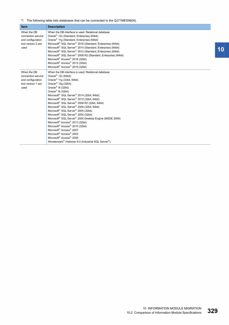
10
*1 The following table lists databases that can be connected to the QJ71MES96(N).
Item DescriptionWhen the DB connection service and configuration tool version 2 are used
When the DB interface is used: Relational databaseOracle 12c (Standard, Enterprise) (64bit)Oracle 11g (Standard, Enterprise) (64bit)Microsoft SQL Server 2016 (Standard, Enterprise) (64bit)Microsoft SQL Server 2014 (Standard, Enterprise) (64bit)Microsoft SQL Server 2012 (Standard, Enterprise) (64bit)Microsoft SQL Server 2008 R2 (Standard, Enterprise) (64bit)Microsoft Access 2016 (32bit)Microsoft Access 2013 (32bit)Microsoft Access 2010 (32bit)
When the DB connection service and configuration tool version 1 are used
When the DB interface is used: Relational databaseOracle 12c (64bit)Oracle 11g (32bit, 64bit)Oracle 10g (32bit)Oracle 9i (32bit)Oracle 8i (32bit)Microsoft SQL Server 2014 (32bit, 64bit)Microsoft SQL Server 2012 (32bit, 64bit)Microsoft SQL Server 2008 R2 (32bit, 64bit)Microsoft SQL Server 2008 (32bit, 64bit)Microsoft SQL Server 2005 (32bit)Microsoft SQL Server 2000 (32bit)Microsoft SQL Server 2000 Desktop Engine (MSDE 2000)Microsoft Access 2013 (32bit)Microsoft Access 2010 (32bit)Microsoft Access 2007Microsoft Access 2003Microsoft Access 2000Wonderware Historian 9.0 (Industrial SQL Server)
10 INFORMATION MODULE MIGRATION10.2 Comparison of Information Module Specifications 329

33
*2 The following table lists databases that can be connected to the RD81MES96N.
Database type Accessible database type Supported software Supported editionDatabase server Oracle Oracle 11g Express Edition Only the 64-bit version
is supported.Standard Edition
Enterprise Edition
Oracle 12c Express Edition
Standard Edition
Enterprise Edition
Oracle 18c Express Edition
Standard Edition
Enterprise Edition
Microsoft SQL Server SQL Server 2008 R2 Express Edition
Standard Edition
Enterprise Edition
SQL Server 2012 Express Edition
Standard Edition
Enterprise Edition
SQL Server 2014 Express Edition
Standard Edition
Enterprise Edition
SQL Server 2016 Express Edition
Standard Edition
Enterprise Edition
SQL Server 2017 Express Edition
Standard Edition
Enterprise Edition
Microsoft Access Access 2010 Only the 32-bit version is supported.Access 2013
Access 2016
MySQL MySQL Community Edition Only the 64-bit version is supported.Standard Edition
PostgreSQL PostgreSQL
0 10 INFORMATION MODULE MIGRATION10.2 Comparison of Information Module Specifications

10
Comparison of high speed data logger module specifications
QD81DL96 and RD81DL96■Transmission and interface: Compatible : Partly changed : Incompatible : Not applicable
Item Specifications Compatibility Precautions
QD81DL96 RD81DL96Ethernet Interface 100BASE-TX, 10BASE-T 1000BASE-T, 100BASE-TX,
10BASE-T
Communication method
Full-duplex/half-duplex
Flow control Full-duplex: None, Half-duplex: Back pressure congestion control
Data transmission rate
100BASE-TX: 100Mbps10BASE-T: 10Mbps
1000BASE-T: 1Gbps100BASE-TX: 100Mbps10BASE-T: 10Mbps
Transmission method
Base band
Number of cascaded stages(When a repeater hub is used)
100BASE-TX: 2 stages maximum10BASE-T: 4 stages maximum
1000BASE-T: 100BASE-TX: 2 stages maximum10BASE-T: 4 stages maximum
Maximum segment length
100m
Supported function
Auto-negotiation Auto-negotiationAuto MDI/MDI-X
Card Supply power voltage
3.3V5%
Supply power capacity
150mA maximum 200mA maximum
Card size CompactFlashType I card
SD memory cardSDHC memory card
Number of installable cards
1
Number of occupied I/O points 32 points (I/O assignment: Intelligent 32 points)
Clock • Obtained from a programmable controller CPU (in multiple CPU system, CPU No.1) or SNTP server.
• Time accuracy after obtaining the time is a daily variation of 9.504 seconds.
• Obtained from a CPU module (in multiple CPU system, CPU No.1).
• Time accuracy after obtaining the time is a daily variation of 9.504 seconds.
Internal current consumption (5VDC)
0.50A 1.1A
Weight 0.15kg 0.24kg
10 INFORMATION MODULE MIGRATION10.2 Comparison of Information Module Specifications 331

33
■Data sampling: Compatible : Partly changed : Incompatible : Not applicable
Item Specifications Compatibility Precautions
QD81DL96 RD81DL96Number of access target CPUs 64 CPUs maximum
Data sampling interval
High speed data sampling
• Sequence scan time synchronization
• 1 to 32767ms (for trigger logging)
• 3 to 32767ms (for continuous logging)
• Sequence scan time synchronization
• 0.5 to 0.9ms, 1 to 32767ms (for trigger logging)
• 2 to 32767ms (for continuous logging)
General data sampling
• 0.1 to 0.9s, 1 to 32767s• Time interval specification (specify hour/minute/second)
Amount of sampled data
High speed data sampling
Overall amount of data: 8192 maximum (per setting: 256)Overall number of device points: 8192 maximum (per setting: 256)
Overall amount of data: 32768 (per setting: 1024)Overall number of device points: 32768 (per setting: 4096)
General data sampling
Overall amount of data: 16384 maximum (per setting: 256)Overall number of device points: 262144 maximum (per setting: 4096)
Overall amount of data: 65536 (per setting: 1024)Overall number of device points: 262144 (per setting: 4096)
Data type • Bit• Word [signed]• Double word [signed]• Word [unsigned]• Double word [unsigned]• Float (single precision)• Float (double precision)• 16bitBCD• 32bitBCD• String: 1 to 8192 characters• Raw: 1 to 8192 bytes
Data output format CSV file• Bit• Decimal format: 0 to 14 digits
after the decimal point• Exponential format: 0 to 14
digits after the decimal point• Hexadecimal format• String • Raw
Unicode text file, CSV file• Bit• Decimal format: 0 to 14 digits
after the decimal point• Exponential format: 0 to 14
digits after the decimal point• Hexadecimal format• String• Raw
Scaling Basic arithmetic operations: calculations combining (, ) and (+, -)
2 10 INFORMATION MODULE MIGRATION10.2 Comparison of Information Module Specifications

10
■Data logging: Compatible : Partly changed : Incompatible : Not applicable
Item Specifications Compatibility Precautions
QD81DL96 RD81DL96Number of settings 64 settings maximum
Logging type • Continuous logging• Trigger logging
File format • CSV file (extension: .CSV)• Binary file (extension: .BIN)
• Unicode text file (extension: .TXT)
• CSV file (extension: .CSV)• Binary file (extension: .BIN)
Period Specify applicable period or exclusion period.• Data condition: Bit ON/OFF, compare data to constant value,
compare data to data• Date range: Specify start and/or end month/day• Time range: Specify start and/or end hour/minute/second• Day of week/week condition: Specify days of the week and/or weeks
AND or OR combination of the above: 8 conditions maximum
Trigger logging Trigger conditions
■Conditions: • Comparison: Bit ON/OFF, compare data to constant value, compare
data to data.• At the time of change of value• Fixed cycle: 1 to 86400 seconds• Time interval specification: Specify hour/minute/second.• Time of day specification: Specify month/day/hour/minute/second• At module startup
AND or OR combination of the above: 8 conditions maximum■Condition execution count: 3 conditions■Condition execution order (order and/or time conditions): 4 conditions maximum
Number of logging lines
• Before trigger occurs: 0 to 65534 lines• After trigger occurs: 1 to 65535 lines
The sum of lines of before and after trigger occurrence is up to 65535 lines.
File switching timing ■Number of lines (number of records)specification: 100 to 100000 lines■File size specification: 10 to 16384K bytes■Condition specification: • Comparison: Bit ON/OFF, compare data to constant value, compare
data to data• Fixed cycle: 1 to 86400 seconds• Time interval specification: Specify hour/minute/second• Time of day specification: Specify month/day/hour/minute/second• At module startup
AND or OR combination of the above: 8 conditions maximum■Trigger logging unit
Number of saved files 1 to 65535
10 INFORMATION MODULE MIGRATION10.2 Comparison of Information Module Specifications 333
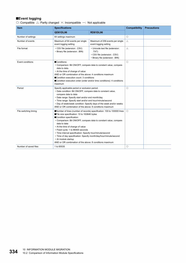
33
■Event logging: Compatible : Partly changed : Incompatible : Not applicable
Item Specifications Compatibility Precautions
QD81DL96 RD81DL96Number of settings 64 settings maximum
Number of events Maximum of 64 events per single event logging setting
Maximum of 256 events per single event logging setting
File format • CSV file (extension: .CSV)• Binary file (extension: .BIN)
• Unicode text file (extension: .TXT)
• CSV file (extension: .CSV)• Binary file (extension: .BIN)
Event conditions ■Conditions: • Comparison: Bit ON/OFF, compare data to constant value, compare
data to data.• At the time of change of value
AND or OR combination of the above: 4 conditions maximum■Condition execution count: 3 conditions■Condition execution order (order and/or time conditions): 4 conditions maximum
Period Specify applicable period or exclusion period.• Data condition: Bit ON/OFF, compare data to constant value,
compare data to data• Date range: Specify start and/or end month/day.• Time range: Specify start and/or end hour/minute/second• Day of week/week condition: Specify days of the week and/or weeks
AND or OR combination of the above: 8 conditions maximum
File switching timing ■Number of lines (number of records) specification: 100 to 100000 lines■File size specification: 10 to 16384K bytes■Condition specification: • Comparison: Bit ON/OFF, compare data to constant value, compare
data to data• At the time of change of value• Fixed cycle: 1 to 86400 seconds• Time interval specification: Specify hour/minute/second• Time of day specification: Specify month/day/hour/minute/second• At module startup
AND or OR combination of the above: 8 conditions maximum
Number of saved files 1 to 65535
4 10 INFORMATION MODULE MIGRATION10.2 Comparison of Information Module Specifications

10
■Report: Compatible : Partly changed : Incompatible : Not applicable
Item Specifications Compatibility Precautions
QD81DL96 RD81DL96Number of settings 64 settings maximum
File format Excel file (extension: .xls)
Output data type • Data inside data logging file• Current value data• Creation time
Amount of output data 64 layouts per single report setting, 65535 cells in total
Creation trigger conditions ■Conditions: • Comparison: Bit ON/OFF, compare data to constant value, compare
data to data.• Fixed cycle: 1 to 86400 seconds• Time interval specification: Specify hour/minute/second• Time of day specification: Specify month/day/hour/minute/second• At module startup• At the time of the data logging file is switched
AND or OR combination of the above: 8 conditions maximum■Condition execution count: 3 conditions■Condition execution order (order and/or time conditions): 4 conditions maximum
Period Specify applicable period or exclusion period.• Data condition: Bit ON/OFF, compare data to constant value,
compare data to data• Date range: Specify start and/or end month/day• Time range: Specify start and/or end hour/minute/second• Day of week/week condition: Specify days of the week and/or weeks
AND or OR combination of the above: 8 conditions maximum
Layout file size 10M bytes maximum
Number of saved files 1 to 65535
10 INFORMATION MODULE MIGRATION10.2 Comparison of Information Module Specifications 335

33
■Other: Compatible : Partly changed : Incompatible : Not applicable
Item Specifications Compatibility Precautions
QD81DL96 RD81DL96E-mail Application • Notification when event occurs
• Transmit saved files
Subject • Event notification e-mail: User specified• Saved file transmission e-mail: Automatically created/user specified
Body • Event notification e-mail: User specified• Saved file transmission e-mail: Automatically created/user specified
Attachment • Event notification e-mail: None• Saved file transmission e-mail:
Saved files (CSV, binary, and Excel files), 512K bytes maximum
• Event notification e-mail: None• Saved file transmission e-mail:
Saved files (Unicode text, binary, CSV, and Excel files), 512K bytes maximum
Attachment format
MIME format
MIME version 1.0
Communications with mail server
Port number: 25, 587, others (1 to 65535)Authentication method • No authentication• SMTP-AUTH (PLAIN, LOGIN, CRAM-MD5)• POP before SMTP
Target address 16 groups maximum
Operability verified e-mail client software
• Microsoft Outlook Express 6.0• Microsoft Windows Mail 6.0
Microsoft Outlook 2013 Microsoft Outlook 2013 is used for e-mail client operability verification.
FTP server Application Read and delete saved files, and read, write, and delete recipe files.
Operability verified FTP client software
• Microsoft Internet Explorer 6.0• Windows Internet Explorer 7.0• Windows Internet Explorer 8.0• Windows Internet Explorer 9.0• Windows Internet Explorer 10.0• Windows Internet Explorer 11.0
Windows Internet Explorer 8.0Windows Internet Explorer 9.0Windows Internet Explorer 10.0Windows Internet Explorer 11.0
Microsoft Internet Explorer 6.0 and Windows Internet Explorer 7.0 are not supported.
Session count 10
FTP client Application Transfer saved files
Operability verified FTP server software
Microsoft Internet Information Services
Recipe Number of data 256 data maximum
Number of records
256 records maximum
Data type • Bit• Word [signed]• Double word [signed]• Word [unsigned]• Double word [unsigned]• FLOAT [single precision]• FLOAT [double precision]• 16bitBCD• 32bitBCD
Recipe file CSV file (extension: .CSV), 256 files maximum
Execution type Dedicated instructions (ladder program), configuration tool
6 10 INFORMATION MODULE MIGRATION10.2 Comparison of Information Module Specifications

10
Comparison of Ethernet interface module specifications
QJ71E71-B2 and RJ71EN71: Compatible : Partly changed : Incompatible : Not applicable
*1 When using 1Gbps, set "Communication Speed" under "Application Settings" to "Automatic Negotiation". ("1Gbps/full-duplex" cannot be selected.)
Item Specifications Compatibility Precautions
QJ71E71-B2 RJ71EN71
Q-compatible Ethernet
Ethernet
Transmission specifications
Data transmission speed
10Mbps (half-duplex) 1Gbps*1
100Mbps (full-duplex/half-duplex)10Mbps (full-duplex/half-duplex)
1Gbps100Mbps (full-duplex/half-duplex)10Mbps (full-duplex/half-duplex)
Flow control Back pressure congestion control
Full-duplex: None, Half-duplex: Back pressure congestion control
Interface 10BASE2: BNC RJ45 (AUTO MDI/MDI-X)
Transmission method
Base band
Maximum segment length
185m 100m (length between a hub and a node) For the RJ71EN71, connect another hub if the segment length is 100 meters or longer.
Maximum number of nodes/connection
30 modules/segment Cascade connection1000BASE-T: Depends on the switching hub used.100BASE-TX: 2 levels maximum10BASE-T: 4 levels maximum
Maximum frame size
1518 bytes 1518 bytes9022 bytes (when jumbo frames are used)
Jumbo frame Not available Available Only available for the RJ71EN71 (Ethernet)
IP version Compatible with IPv4
Sending/receiving data storage memory
Number of simultaneous open connections(connections usable on a program)
16 connections 128 connectionsFor fixed buffer: 16 connectionsFor socket communications: 112 connections
Fixed buffer 1K words 16 5K words 16
Socket communications
5K words 48 (when only P1 is used)5K words 112 (when P1 and P2 are used)
Only available for the RJ71EN71 (Ethernet)
Random access buffer
6K words 1
E-mail (attachment)
6K words 1 The e-mail function is not available for the RJ71EN71.E-mail (main
text)960 words 1
Number of occupied I/O points 32 points (I/O assignment: Intelligent 32 points)
Internal current consumption (5VDC)
0.60A 0.82A
Weight 0.13kg 0.17kg
10 INFORMATION MODULE MIGRATION10.2 Comparison of Information Module Specifications 337

33
QJ71E71-B5 and RJ71EN71: Compatible : Partly changed : Incompatible : Not applicable
*1 When using 1Gbps, set "Communication Speed" under "Application Settings" to "Automatic Negotiation". ("1Gbps/full-duplex" cannot be selected.)
Item Specifications Compatibility Precautions
QJ71E71-B5 RJ71EN71
Q-compatible Ethernet
Ethernet
Transmission specifications
Data transmission speed
10Mbps (Half-duplex) 1Gbps*1
100Mbps (Full-duplex/Half-duplex)10Mbps (Full-duplex/Half-duplex)
1Gbps100Mbps (Full-duplex/Half-duplex)10Mbps (Full-duplex/Half-duplex)
Flow control Back pressure congestion control
Full-duplex: None, Half-duplex: Back pressure congestion control
Interface 10BASE5: AUI RJ45 (AUTO MDI/MDI-X)
Transmission method
Base band
Maximum segment length
500m 100m (length between a hub and a node) For the RJ71EN71, connect another hub if the segment length is 100 meters or longer.
Maximum number of nodes/connection
100 modules/segment Cascade connection1000BASE-T: Depends on the switching hub used.100BASE-TX: 2 levels maximum10BASE-T: 4 levels maximum
Maximum frame size
1518 bytes 1518 bytes9022 bytes (when jumbo frames are used)
Jumbo frame Not available Available Only available for the RJ71EN71 (Ethernet)
IP version Compatible with IPv4
Sending/receiving data storage memory
Number of simultaneous open connections(connections usable on a program)
16 connections 128 connectionsFor fixed buffer: 16 connectionsFor socket communications: 112 connections
Fixed buffer 1K words 16 5K words 16
Socket communications
5K words 48 (when only P1 is used)5K words 112 (when P1 and P2 are used)
Only available for the RJ71EN71 (Ethernet)
Random access buffer
6K words 1
E-mail (attachment)
6K words 1 The e-mail function is not available for the RJ71EN71.E-mail (main
text)960 words 1
Number of occupied I/O points 32 points (I/O assignment: Intelligent 32 points)
Internal current consumption (5VDC)
0.60A 0.82A
Weight 0.13kg 0.17kg
8 10 INFORMATION MODULE MIGRATION10.2 Comparison of Information Module Specifications

10
QJ71E71-100 and RJ71EN71: Compatible : Partly changed : Incompatible : Not applicable
*1 When using 1Gbps, set "Communication Speed" under "Application Settings" to "Automatic Negotiation". ("1Gbps/full-duplex" cannot be selected.)
Item Specifications Compatibility Precautions
QJ71E71-100 RJ71EN71
Q-compatible Ethernet
Ethernet
Transmission specifications
Data transmission speed
100Mbps (Full-duplex/Half-duplex)10Mbps (Half-duplex)
1Gbps*1
100Mbps (Full-duplex/Half-duplex)10Mbps (Full-duplex/Half-duplex)
1Gbps100Mbps (Full-duplex/Half-duplex)10Mbps (Full-duplex/Half-duplex)
Flow control Full-duplex: None, Half-duplex: Back pressure congestion control
Interface RJ45 (Fixed to MDI) RJ45 (AUTO MDI/MDI-X)
Transmission method
Base band
Maximum segment length
100m (length between a hub and a node)
Number of cascade connections
100BASE-TX: 2 levels maximum10BASE-T: 4 levels maximum
1000BASE-T: Depends on the switching hub used.100BASE-TX: 2 levels maximum10BASE-T: 4 levels maximum
Maximum frame size
1518 bytes 1518 bytes9022 bytes (when jumbo frames are used)
Jumbo frame Not available Available Only available for the RJ71EN71 (Ethernet)
IP version Compatible with IPv4
Sending/receiving data storage memory
Number of simultaneous open connections(connections usable on a program)
16 connections 128 connectionsFor fixed buffer: 16 connectionsFor socket communications: 112 connections
Fixed buffer 1K words 16 5K words 16
Socket communications
5K words 48 (when only P1 is used)5K words 112 (when P1 and P2 are used)
Only available for the RJ71EN71 (Ethernet)
Random access buffer
6K words 1
E-mail (attachment)
6K words 1 The e-mail function is not available for the RJ71EN71.E-mail (main
text)960 words 1
Number of occupied I/O points 32 points (I/O assignment: Intelligent 32 points)
Internal current consumption (5VDC)
0.50A 0.82A
Weight 0.11kg 0.17kg
10 INFORMATION MODULE MIGRATION10.2 Comparison of Information Module Specifications 339

34
Comparison of serial communication module specifications
QJ71C24 and RJ71C24: Compatible : Partly changed : Incompatible : Not applicable
Item Specifications Compatibility Precautions
QJ71C24 RJ71C24Interface CH1 RS-232-compliance (D-sub 9 pin female)
CH2 RS-422/485-compliance (2-piece terminal block)
Communications system
Line Full-duplex/half-duplex communications
MC protocols communication
Half-duplex communications
Non procedure protocol communication
Full-duplex/half-duplex communications
Bidirectional protocol communication
Full-duplex/half-duplex communications
Pre-defined protocol communication
Full-duplex/half-duplex communications
Synchronization method Start-stop synchronization method
Transmission speed *1
Data format Start bits 1
Data bits 7/8
Parity bits 1 (vertical parity) or none
Stop bits 1/2
Access cycle MC protocols communication
Processes one request during the END processing of the CPU module of the station with the C24.
Non procedure protocol communication/bidirectional protocol communication
Sends each time a send request is issued. Can receive at any time.
Pre-defined protocol communication
Sends or receives data when requested with the dedicated instruction (CPRTCL).
Error detection Parity check Selected for all protocols and when this check is enabled, ODD or EVEN is selected by a parameter.
Sum check code For the MC or bidirectional protocol, selected by a parameter.For the non procedure protocol, selected in the user frame.
Transmission control *2
Line configuration (Connection)
RS-232 1: 1
RS-422/485 1: 1, 1: n, n: 1, m: n
Line configuration(Data communication)RS-232
MC protocols communication
1: 1
Non procedure protocol communication
1: 1
Bidirectional protocol communication
1: 1
Pre-defined protocol communication
1: 1
0 10 INFORMATION MODULE MIGRATION10.2 Comparison of Information Module Specifications

10
*1 The transmission speed which can be set differs between the QJ71C24 and RJ71C24.: Available, : Not available
In the QJ71C24, the total transmission speed of CH1 and CH2 needs to be set within 115200bps.*2 The following table lists the transmission controls.
DTR/DSR signal control and DC code control are selected by the user.
Line configuration(Data communication)RS-422/485
MC protocols communication
1: 1, 1: n, m: n
Non procedure protocol communication
1: 1, 1: n, n: 1
Bidirectional protocols communication
1: 1
Pre-defined protocol communication
1: 1, n: 1
Transmission distance(Overall distance)
RS-232 15m maximum
RS-422/485 1200m maximum (Overall distance)
Number of write accesses to a flash ROM
Maximum 100000 times to the same area
Number of occupied I/O points 32 points (I/O assignment: Intelligent 32 points)
Applicable connector for external wiring D-sub 9 pin (male) screw type
Internal current consumption (5VDC) 0.31A
Weight 0.20kg 0.16kg
Item QJ71C24 RJ71C24Transmission speed (bps)
50, 300, 600
1200, 2400, 4800, 9600, 14400, 19200, 28800, 38400, 57600, 115200
230400
Item RS-232 RS-422/485DTR/DSR control
RS/CS control
CD (DCD) signal control
DC1/DC3 (Xon/Xoff) controlDC2/DC4 control
Item Specifications Compatibility Precautions
QJ71C24 RJ71C24
10 INFORMATION MODULE MIGRATION10.2 Comparison of Information Module Specifications 341
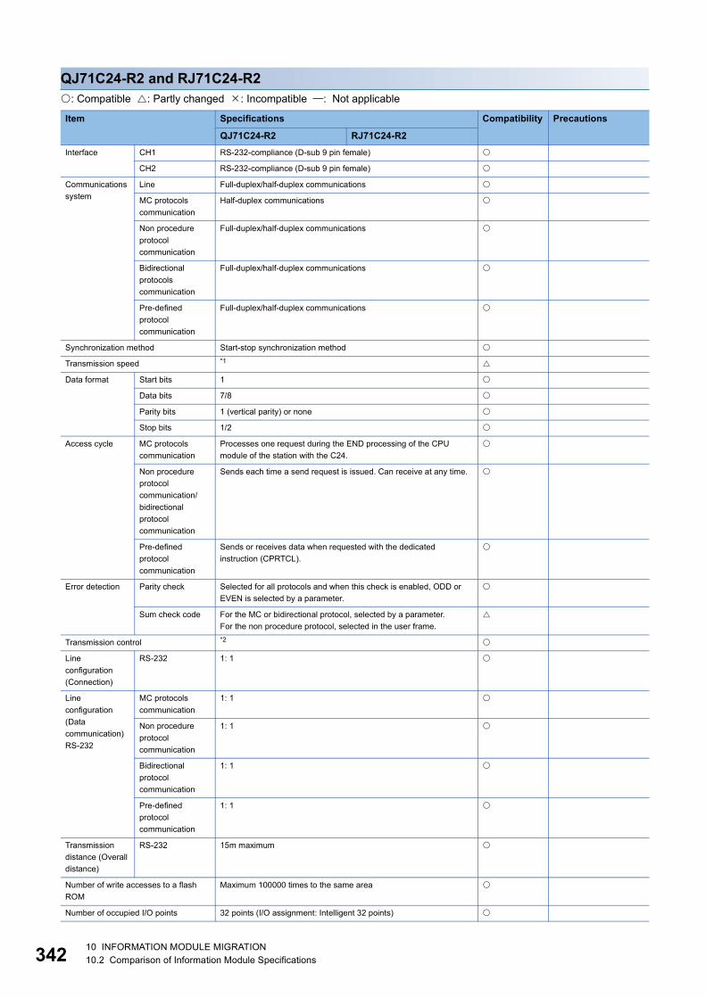
34
QJ71C24-R2 and RJ71C24-R2: Compatible : Partly changed : Incompatible : Not applicable
Item Specifications Compatibility Precautions
QJ71C24-R2 RJ71C24-R2Interface CH1 RS-232-compliance (D-sub 9 pin female)
CH2 RS-232-compliance (D-sub 9 pin female)
Communications system
Line Full-duplex/half-duplex communications
MC protocols communication
Half-duplex communications
Non procedure protocol communication
Full-duplex/half-duplex communications
Bidirectional protocols communication
Full-duplex/half-duplex communications
Pre-defined protocol communication
Full-duplex/half-duplex communications
Synchronization method Start-stop synchronization method
Transmission speed *1
Data format Start bits 1
Data bits 7/8
Parity bits 1 (vertical parity) or none
Stop bits 1/2
Access cycle MC protocols communication
Processes one request during the END processing of the CPU module of the station with the C24.
Non procedure protocol communication/bidirectional protocol communication
Sends each time a send request is issued. Can receive at any time.
Pre-defined protocol communication
Sends or receives data when requested with the dedicated instruction (CPRTCL).
Error detection Parity check Selected for all protocols and when this check is enabled, ODD or EVEN is selected by a parameter.
Sum check code For the MC or bidirectional protocol, selected by a parameter.For the non procedure protocol, selected in the user frame.
Transmission control *2
Line configuration (Connection)
RS-232 1: 1
Line configuration(Data communication)RS-232
MC protocols communication
1: 1
Non procedure protocol communication
1: 1
Bidirectional protocol communication
1: 1
Pre-defined protocol communication
1: 1
Transmission distance (Overall distance)
RS-232 15m maximum
Number of write accesses to a flash ROM
Maximum 100000 times to the same area
Number of occupied I/O points 32 points (I/O assignment: Intelligent 32 points)
2 10 INFORMATION MODULE MIGRATION10.2 Comparison of Information Module Specifications

10
*1 The transmission speed which can be set differs between the QJ71C24-R2 and RJ71C24-R2.: Available, : Not availableIn the QJ71C24-R2, the total transmission speed of CH1 and CH2 needs to be set within 115200bps.*2 The following table lists the transmission controls.
DTR/DSR signal control and DC code control are selected by the user.
Applicable connector for external wiring D-sub 9 pin (male) screw type
Internal current consumption (5VDC) 0.26A 0.20A
Weight 0.20kg 0.14kg
Item QJ71C24-R2 RJ71C24-R2Transmission speed (bps)
50, 300, 600
1200, 2400, 4800, 9600, 14400, 19200, 28800, 38400, 57600, 115200
230400
Item RS-232DTR/DSR control
RS/CS control
CD (DCD) signal control
DC1/DC3 (Xon/Xoff) controlDC2/DC4 control
Item Specifications Compatibility Precautions
QJ71C24-R2 RJ71C24-R2
10 INFORMATION MODULE MIGRATION10.2 Comparison of Information Module Specifications 343

34
QJ71C24N and RJ71C24: Compatible : Partly changed : Incompatible : Not applicable
Item Specifications Compatibility Precautions
QJ71C24N RJ71C24Interface CH1 RS-232-compliance (D-sub 9 pin female)
CH2 RS-422/485-compliance (2-piece terminal block)
Communications system
Line Full-duplex/half-duplex communications
MC protocols communication
Half-duplex communications
Non procedure protocol communication
Full-duplex/half-duplex communications
Bidirectional protocol communication
Full-duplex/half-duplex communications
Pre-defined protocol communication
Full-duplex/half-duplex communications
Synchronization method Start-stop synchronization method
Transmission speed *1
Data format Start bits 1
Data bits 7/8
Parity bits 1 (vertical parity) or none
Stop bits 1/2
Access cycle MC protocols communication
Processes one request during the END processing of the CPU module of the station with the C24.
Non procedure protocol communication/bidirectional protocol communication
Sends each time a send request is issued. Can receive at any time.
Pre-defined protocol communication
Sends or receives data when requested with the dedicated instruction (CPRTCL).
Error detection Parity check Selected for all protocols and when this check is enabled, ODD or EVEN is selected by a parameter.
Sum check code For the MC or bidirectional protocol, selected by a parameter.For the non procedure protocol, selected in the user frame.For the pre-defined protocol, whether or not a sum check code is needed depends on the selected protocol.
Transmission control *2
Line configuration (Connection)
RS-232 1: 1
RS-422/485 1: 1, 1: n, n: 1, m: n
Line configuration(Data communication)RS-232
MC protocols communication
1: 1
Non procedure protocol communication
1: 1
Bidirectional protocol communication
1: 1
Pre-defined protocol communication
1: 1
4 10 INFORMATION MODULE MIGRATION10.2 Comparison of Information Module Specifications

10
*1 The transmission speed which can be set differs between the QJ71C24N and RJ71C24.: Available, : Not available
In the MELSEC-Q series, the total transmission speed of CH1 and CH2 needs to be set within 230400bps. When using the communication data monitoring function, the total speed needs to be set within 115200bps.*2 The following table lists the transmission controls.
DTR/DSR signal control and DC code control are selected by the user.
Line configuration(Data communication)RS-422/485
MC protocols communication
1: 1, 1: n, m: n
Non procedure protocol communication
1: 1, 1: n, n: 1
Bidirectional protocols communication
1: 1
Pre-defined protocol communication
1: 1, n: 1
Transmission distance(Overall distance)
RS-232 15m maximum
RS-422/485 1200m maximum (Overall distance)
Number of write accesses to a flash ROM
Maximum 100000 times to the same area
Number of occupied I/O points 32 points (I/O assignment: Intelligent 32 points)
Applicable connector for external wiring D-sub 9 pin (male) screw type
Internal current consumption (5VDC) 0.31A
Weight 0.20kg 0.16kg
Item QJ71C24N RJ71C24Transmission speed (bps)
50, 300, 600
1200, 2400, 4800, 9600, 14400, 19200, 28800, 38400, 57600, 115200
230400 : CH1 only
Item RS-232 RS-422/485DTR/DSR control
RS/CS control
CD (DCD) signal control
DC1/DC3 (Xon/Xoff) controlDC2/DC4 control
Item Specifications Compatibility Precautions
QJ71C24N RJ71C24
10 INFORMATION MODULE MIGRATION10.2 Comparison of Information Module Specifications 345

34
QJ71C24N-R2 and RJ71C24-R2: Compatible : Partly changed : Incompatible : Not applicable
Item Specifications Compatibility Precautions
QJ71C24N-R2 RJ71C24-R2Interface CH1 RS-232-compliance (D-sub 9 pin female)
CH2 RS-232-compliance (D-sub 9pin female)
Communications system
Line Full-duplex/half-duplex communications
MC protocols communication
Half-duplex communications
Non procedure protocol communication
Full-duplex/half-duplex communications
Bidirectional protocol communication
Full-duplex/half-duplex communications
Pre-defined protocol communication
Full-duplex/half-duplex communications
Synchronization method Start-stop synchronization method
Transmission speed *1
Data format Start bits 1
Data bits 7/8
Parity bits 1 (vertical parity) or none
Stop bits 1/2
Access cycle MC protocols communication
Processes one request during the END processing of the CPU module of the station with the C24.
Non procedure protocol communication/bidirectional protocol communication
Sends each time a send request is issued. Can receive at any time.
Pre-defined protocol communication
Sends or receives data when requested with the dedicated instruction (CPRTCL).
Error detection Parity check Selected for all protocols and when this check is enabled, ODD or EVEN is selected by a parameter.
Sum check code For the MC or bidirectional protocol, selected by a parameter.For the non procedure protocol, selected in the user frame.For the pre-defined protocol, whether or not a sum check code is needed depends on the selected protocol.
Transmission control *2
Line configuration (Connection)
RS-232 1: 1
Line configuration(Data communication)RS-232
MC protocols communication
1: 1
Non procedure protocol communication
1: 1
Bidirectional protocol communication
1: 1
Pre-defined protocol communication
1: 1
Transmission distance (Overall distance)
RS-232 15m maximum
Number of write accesses to a flash ROM
Maximum 100000 times to the same area
6 10 INFORMATION MODULE MIGRATION10.2 Comparison of Information Module Specifications
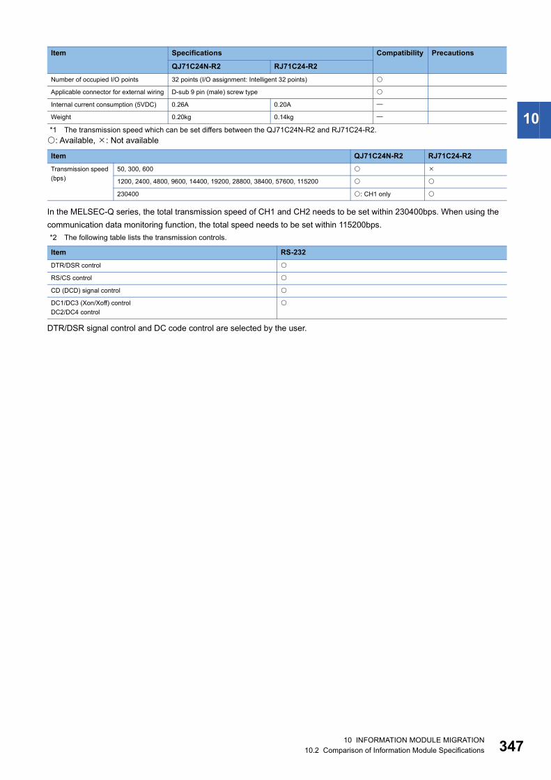
10
*1 The transmission speed which can be set differs between the QJ71C24N-R2 and RJ71C24-R2.: Available, : Not availableIn the MELSEC-Q series, the total transmission speed of CH1 and CH2 needs to be set within 230400bps. When using the communication data monitoring function, the total speed needs to be set within 115200bps.*2 The following table lists the transmission controls.
DTR/DSR signal control and DC code control are selected by the user.
Number of occupied I/O points 32 points (I/O assignment: Intelligent 32 points)
Applicable connector for external wiring D-sub 9 pin (male) screw type
Internal current consumption (5VDC) 0.26A 0.20A
Weight 0.20kg 0.14kg
Item QJ71C24N-R2 RJ71C24-R2Transmission speed (bps)
50, 300, 600
1200, 2400, 4800, 9600, 14400, 19200, 28800, 38400, 57600, 115200
230400 : CH1 only
Item RS-232DTR/DSR control
RS/CS control
CD (DCD) signal control
DC1/DC3 (Xon/Xoff) controlDC2/DC4 control
Item Specifications Compatibility Precautions
QJ71C24N-R2 RJ71C24-R2
10 INFORMATION MODULE MIGRATION10.2 Comparison of Information Module Specifications 347

34
QJ71C24N-R4 and RJ71C24-R4: Compatible : Partly changed : Incompatible : Not applicable
Item Specifications Compatibility Precautions
QJ71C24N-R4 RJ71C24-R4Interface CH1 RS-422/485-compliance (2-piece plug-in connector socket block)
CH2 RS-422/485-compliance (2-piece plug-in connector socket block)
Communications system
Line Full-duplex/half-duplex communications
MC protocols communication
Half-duplex communications
Non procedure protocol communication
Full-duplex/half-duplex communications
Bidirectional protocol communication
Full-duplex/half-duplex communications
Pre-defined protocol communication
Full-duplex/half-duplex communications
Synchronization method Start-stop synchronization method
Transmission speed *1
Data format Start bits 1
Data bits 7/8
Parity bits 1 (vertical parity) or none
Stop bits 1/2
Access cycle MC protocols communication
Processes one request during the END processing of the CPU module of the station with the C24.
Non procedure protocol communication/bidirectional protocol communication
Sends each time a send request is issued. Can receive at any time.
Pre-defined protocol communication
Sends or receives data when requested with the dedicated instruction (CPRTCL).
Error detection Parity check Selected for all protocols and when this check is enabled, ODD or EVEN is selected by a parameter.
Sum check code For the MC or bidirectional protocol, selected by a parameter.For the non procedure protocol, selected in the user frame.For the pre-defined protocol, whether or not a sum check code is needed depends on the selected protocol.
Transmission control *2
Line configuration (Connection)
RS-422/485 1: 1, 1: n, n: 1, m: n
Line configuration(Data communication)RS-422/485
MC protocols communication
1: 1, 1: n, m: n
Non procedure protocol communication
1: 1, 1: n, n: 1
Bidirectional protocol communication
1: 1
Pre-defined protocol communication
1: 1, n: 1
Transmission distance(Overall distance)
RS-422/485 1200m maximum (Overall distance)
8 10 INFORMATION MODULE MIGRATION10.2 Comparison of Information Module Specifications
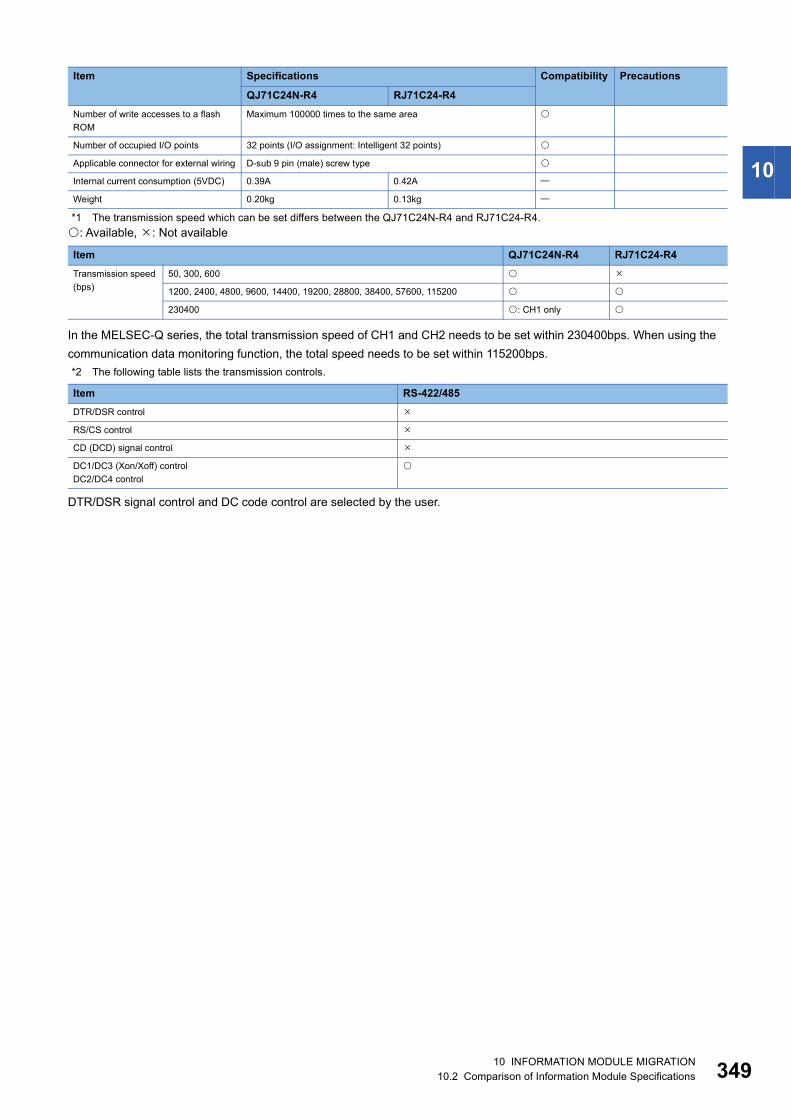
10
*1 The transmission speed which can be set differs between the QJ71C24N-R4 and RJ71C24-R4.: Available, : Not available
In the MELSEC-Q series, the total transmission speed of CH1 and CH2 needs to be set within 230400bps. When using the communication data monitoring function, the total speed needs to be set within 115200bps.*2 The following table lists the transmission controls.
DTR/DSR signal control and DC code control are selected by the user.
Number of write accesses to a flash ROM
Maximum 100000 times to the same area
Number of occupied I/O points 32 points (I/O assignment: Intelligent 32 points)
Applicable connector for external wiring D-sub 9 pin (male) screw type
Internal current consumption (5VDC) 0.39A 0.42A
Weight 0.20kg 0.13kg
Item QJ71C24N-R4 RJ71C24-R4Transmission speed (bps)
50, 300, 600
1200, 2400, 4800, 9600, 14400, 19200, 28800, 38400, 57600, 115200
230400 : CH1 only
Item RS-422/485DTR/DSR control
RS/CS control
CD (DCD) signal control
DC1/DC3 (Xon/Xoff) controlDC2/DC4 control
Item Specifications Compatibility Precautions
QJ71C24N-R4 RJ71C24-R4
10 INFORMATION MODULE MIGRATION10.2 Comparison of Information Module Specifications 349

35
10.3 Comparison of Information Module FunctionsComparison of MES interface module functions
QJ71MES96(N) and RD81MES96N: Compatible/function available : Partly changed : Incompatible/function not available : Not applicable
Item Description MELSEC-Q series
MELSEC iQ-R series
Precautions
QJ71MES96(N)
RD81MES96N
DB interface function
Tag function Collects device data of the programmable controller CPUs on the network in units of tags.By allocating database fields to tag components, the DB interface function enables the following.• Database value reading/writing• Reading/writing of programmable controller CPU
device data specified with tag components
For the RD81MES96N, use the device memory input/output function instead.The RD81MES96N collects device data used for trigger judgment and jobs, instead of collecting device data in units of tags.
Trigger monitoring function
Monitors values such as the time and tag values, and when the trigger condition changes from false to true (when the conditions are met), starts a job.
For the RD81MES96N, use the trigger condition monitoring function.*1
Trigger buffering function
When multiple sets of conditions for data transmission are met in a concentrated manner, their data and trigger times are buffered in the module's internal memory so that actions (data operation/transmission) can be executed later using the buffered data.Even if the frequency of data transmission triggers is high, jobs are executed without missing any trigger.
For the RD81MES96N, the number of trigger buffering times increases.
SQL text transmission function(Communication action)
Automatically creates an SQL text and communicates with the database.The following types of SQL texts are available.• Select/MultiSelect• Update• Insert• Delete
For the RD81MES96N, use the DB record input/output function instead.
Stored procedure call function(Communication action)
Starts a stored procedure in the database. For the RD81MES96N, the stored procedure call function is included in the DB record input/output function.
Arithmetic processing function(Operation action)
Performs operations for tag component values. For the RD81MES96N, use the data operation and processing function instead.*2
Program execution function
Executes programs in the application server computer before execution of the first action and after execution of the last one in a job.
DB buffering function
Buffers SQL texts into a CompactFlash card when they cannot be sent due to network disconnection or failure of the database server computer.After recovery, the buffered SQL texts are automatically sent to the database. (Manual operation is also possible.)
The RD81MES96N provides an increased DB buffering capacity.
XML processing function Processes execution of requests made by user applications using XML format messages. The XML processing function allows the following instructions for job execution.• One-shot execution of a job• Validating a job (The job is executed when the trigger
conditions are met.)• Invalidating a job (The job is not executed even if the
trigger conditions are met.)
For the RD81MES96N, use the REST server function instead of the XML processing function.
0 10 INFORMATION MODULE MIGRATION10.3 Comparison of Information Module Functions

10
*1 For the RD81MES96N, the following trigger conditions are added. Event (Value change) Event (Module monitoring) Control CPU
*2 For the RD81MES96N, the following operations are added. Character String operations: (LENGTH, RIGHT, LEFT, UPPER, LOWER, RTRIM, LTRIM) Bit operations (AND, OR, XOR, RSHIFT, LSHIFT) Type conversion (STR2INT, STR2REAL, INT2STR, REAL2STR)
Time synchronization function
Synchronizes the time of the MES interface module with the time of the SNTP server computer on the network or a programmable controller CPU (No.1 CPU in the multiple CPU system).
For the RD81MES96N, the clock is acquired from the CPU module.
MES Interface Function Configuration Tool function
The MES Interface Function Configuration Tool is used to configure various settings of the MES interface module, which are necessary for the MES interface functions.Apart from the MES interface function settings, various operations can be performed such as checking the operating status of the MES interface functions, the operation history, and stopping/restarting the MES interface functions.
For the RD81MES96N, the statistical processing and time synchronization setting are not available.
DB connection service function
By installing the DB connection service on the server computer, the MES interface functions of the MES interface module can be used.
Item Description MELSEC-Q series
MELSEC iQ-R series
Precautions
QJ71MES96(N)
RD81MES96N
10 INFORMATION MODULE MIGRATION10.3 Comparison of Information Module Functions 351
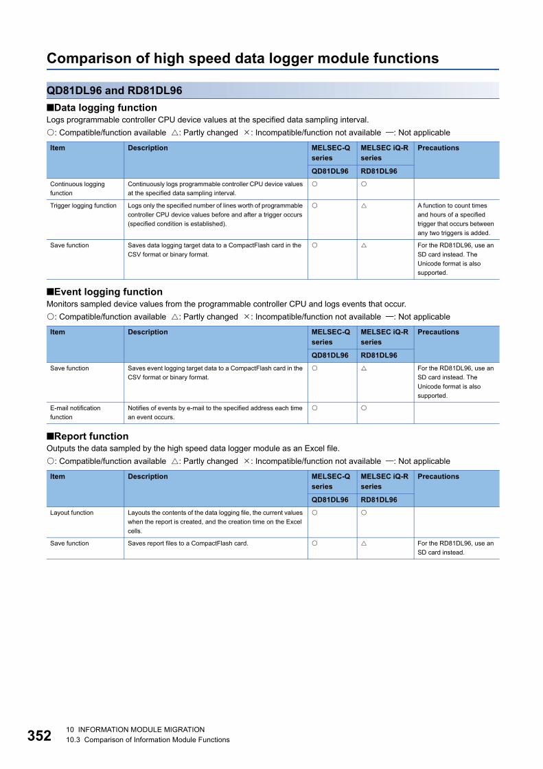
35
Comparison of high speed data logger module functions
QD81DL96 and RD81DL96■Data logging functionLogs programmable controller CPU device values at the specified data sampling interval.: Compatible/function available : Partly changed : Incompatible/function not available : Not applicable
■Event logging functionMonitors sampled device values from the programmable controller CPU and logs events that occur.: Compatible/function available : Partly changed : Incompatible/function not available : Not applicable
■Report functionOutputs the data sampled by the high speed data logger module as an Excel file.: Compatible/function available : Partly changed : Incompatible/function not available : Not applicable
Item Description MELSEC-Q series
MELSEC iQ-R series
Precautions
QD81DL96 RD81DL96Continuous logging function
Continuously logs programmable controller CPU device values at the specified data sampling interval.
Trigger logging function Logs only the specified number of lines worth of programmable controller CPU device values before and after a trigger occurs (specified condition is established).
A function to count times and hours of a specified trigger that occurs between any two triggers is added.
Save function Saves data logging target data to a CompactFlash card in the CSV format or binary format.
For the RD81DL96, use an SD card instead. The Unicode format is also supported.
Item Description MELSEC-Q series
MELSEC iQ-R series
Precautions
QD81DL96 RD81DL96Save function Saves event logging target data to a CompactFlash card in the
CSV format or binary format. For the RD81DL96, use an
SD card instead. The Unicode format is also supported.
E-mail notification function
Notifies of events by e-mail to the specified address each time an event occurs.
Item Description MELSEC-Q series
MELSEC iQ-R series
Precautions
QD81DL96 RD81DL96Layout function Layouts the contents of the data logging file, the current values
when the report is created, and the creation time on the Excel cells.
Save function Saves report files to a CompactFlash card. For the RD81DL96, use an SD card instead.
2 10 INFORMATION MODULE MIGRATION10.3 Comparison of Information Module Functions
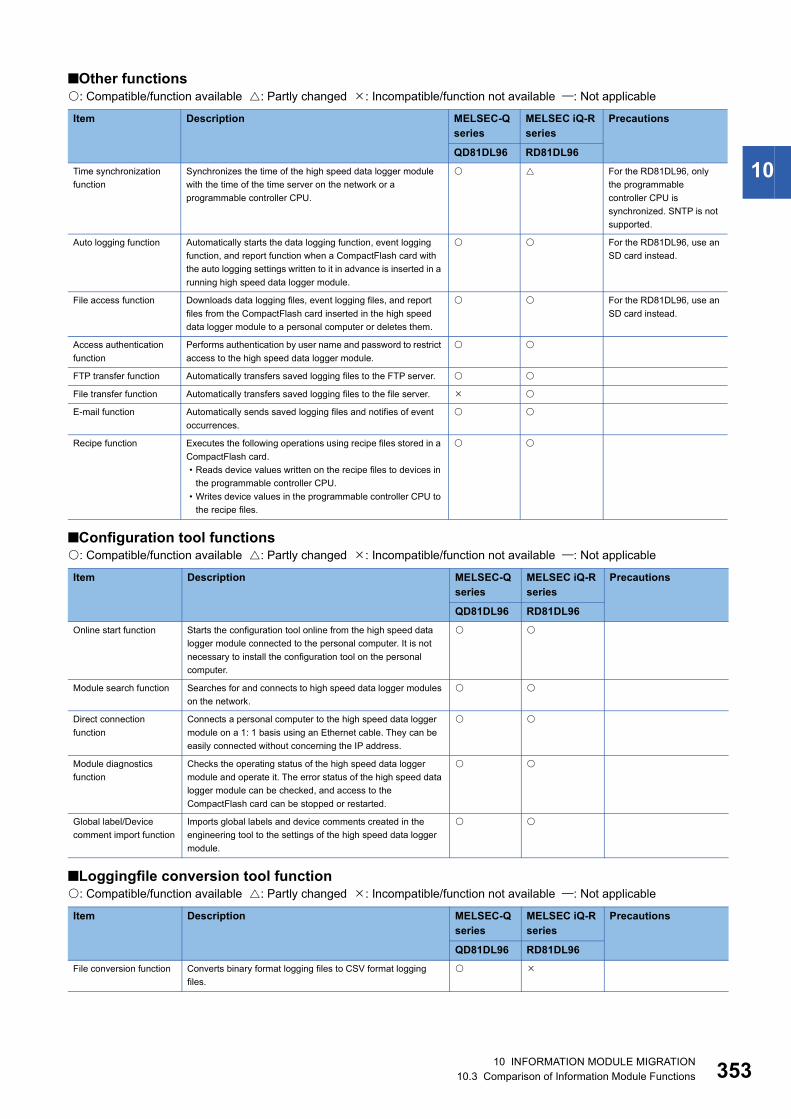
10
■Other functions: Compatible/function available : Partly changed : Incompatible/function not available : Not applicable
■Configuration tool functions: Compatible/function available : Partly changed : Incompatible/function not available : Not applicable
■Loggingfile conversion tool function: Compatible/function available : Partly changed : Incompatible/function not available : Not applicable
Item Description MELSEC-Q series
MELSEC iQ-R series
Precautions
QD81DL96 RD81DL96Time synchronization function
Synchronizes the time of the high speed data logger module with the time of the time server on the network or a programmable controller CPU.
For the RD81DL96, only the programmable controller CPU is synchronized. SNTP is not supported.
Auto logging function Automatically starts the data logging function, event logging function, and report function when a CompactFlash card with the auto logging settings written to it in advance is inserted in a running high speed data logger module.
For the RD81DL96, use an SD card instead.
File access function Downloads data logging files, event logging files, and report files from the CompactFlash card inserted in the high speed data logger module to a personal computer or deletes them.
For the RD81DL96, use an SD card instead.
Access authentication function
Performs authentication by user name and password to restrict access to the high speed data logger module.
FTP transfer function Automatically transfers saved logging files to the FTP server.
File transfer function Automatically transfers saved logging files to the file server.
E-mail function Automatically sends saved logging files and notifies of event occurrences.
Recipe function Executes the following operations using recipe files stored in a CompactFlash card.• Reads device values written on the recipe files to devices in
the programmable controller CPU.• Writes device values in the programmable controller CPU to
the recipe files.
Item Description MELSEC-Q series
MELSEC iQ-R series
Precautions
QD81DL96 RD81DL96Online start function Starts the configuration tool online from the high speed data
logger module connected to the personal computer. It is not necessary to install the configuration tool on the personal computer.
Module search function Searches for and connects to high speed data logger modules on the network.
Direct connection function
Connects a personal computer to the high speed data logger module on a 1: 1 basis using an Ethernet cable. They can be easily connected without concerning the IP address.
Module diagnostics function
Checks the operating status of the high speed data logger module and operate it. The error status of the high speed data logger module can be checked, and access to the CompactFlash card can be stopped or restarted.
Global label/Device comment import function
Imports global labels and device comments created in the engineering tool to the settings of the high speed data logger module.
Item Description MELSEC-Q series
MELSEC iQ-R series
Precautions
QD81DL96 RD81DL96File conversion function Converts binary format logging files to CSV format logging
files.
10 INFORMATION MODULE MIGRATION10.3 Comparison of Information Module Functions 353

35
Comparison of Ethernet interface module functions
QJ71E71-100/B2/B5 and RJ71EN71: Compatible/function available : Partly changed : Incompatible/function not available : Not applicable
■Communications using a fixed buffer: Compatible/function available : Partly changed : Incompatible/function not available : Not applicable
Item Description MELSEC-Qseries
MELSEC iQ-R series
Precautions
QJ71E71-B2QJ71E71-B5QJ71E71-100
RJ71EN71
Connecting with MELSOFT products and a GOT
Connects an E71 to MELSOFT products (such as an engineering tool and MX Component), and a GOT.
MC protocol communications
Reads/writes CPU module data from/to connected devices, or accesses CPU module files.
Communications using SLMP
The connected device can read/write data from/to the buffer memory or device of an SLMP-compatible device connected to the shared network with the E71. In addition, the connected device can read/write data from/to the device of the CPU module where an E71 is mounted.
Data communications using the predefined protocol
Sends/receives data with protocols appropriate to each connected device. The connected device side protocol can be easily selected, or created/edited from the Predefined Protocol Library.
Item Description MELSEC-Qseries
MELSEC iQ-R series
Precautions
QJ71E71-B2QJ71E71-B5QJ71E71-100
RJ71EN71
Procedure exists/No procedure
Sends/receives any data between the CPU module and connected device using the fixed buffer of the E71.
Pairing open Pairing receiving/sending connections enables data communications with two connections by performing the open process for one port.
Broadcast communications
Broadcast communications are enabled with all E71-mounted stations in the same Ethernet network that is connected to the E71 when "No Procedure" communications using a fixed buffer are performed using UDP/IP.
Socket communications Using dedicated instructions, any data can be exchanged with an external device connected by Ethernet over TCP/IP or UDP/IP.
This function is not available for the RJ71EN71 (Q-compatible Ethernet).
Communications using a random access buffer
Reads/writes data from multiple connected devices to the random access buffer of the E71.
Router relay function Communicates data through a router and a gateway. This function is not the function where the E71 operates as a router.
Communications using an auto-open UDP port
Communications are enabled without the open/close processes after an E71-mounted station is started up.
IP filter function The IP address of the connected device to be passed or blocked is set in the buffer memory, and access from connected devices is restricted.
This function is not available for the RJ71EN71 (Q-compatible Ethernet).
Remote password Prevents unauthorized access to the CPU module from a remote location.
Hub connection status monitor function
The current connection status and transmission speed of the E71 and a hub and the number of times that the E71 detected disconnection can be checked.
4 10 INFORMATION MODULE MIGRATION10.3 Comparison of Information Module Functions

10
IP address in use detection functionIf different stations in the same network use the same IP address, the address in use can be detected.
Network configuration in a redundant system
A network can be configured in a redundant system.
Alive check function Checks whether a connected device is normally operating after a connection is established (open processing).
For the RJ71EN71, only KeepAlive is available for TCP/IP.
Module error collection function
Stores an error that has occurred in the E71 in the CPU module as error history. The history data can be stored on a memory with backup power feature; therefore error details are held even if the CPU module is reset or the system is powered off.
For the RJ71EN71, use the event history instead.
E-mail function Sends/receives data using an e-mail.• Sends/receives data by a CPU module.• Sends data by the programmable controller CPU
monitoring function (automatic notification function).
CC-Link IE Controller Network, CC-Link IE Field Network, MELSECNET/H, MELSECNET/10 relay communications
Communicates data over multiple network systems where Ethernet and other networks exist together or network systems that relay multiple Ethernet networks.
Communications using data link instructions
Reads/writes data of a CPU module in other stations over Ethernet using data link instructions.
File transfer (FTP server) function
Reads/writes data in files from connected devices using an exclusive FTP command.
Web function Allows data to be read/written from/to a remote CPU module over the Internet using a commercially available web browser.
Dedicated instructions Dedicated instructions facilitate programming for using intelligent function modules.
For the RJ71EN71 (Ethernet), the ERRCLR instruction is replaced with the ERRCLEAR instruction. For the RJ71EN71 (Q-compatible Ethernet), the UINI instruction is available.
IP address change function
Changes the Ethernet-equipped module's IP address without changing the parameter settings.
For the RJ71EN71 (Ethernet), use the buffer memory areas instead. For the RJ71EN71 (Q-compatible Ethernet), the UINI instruction is available.
Item Description MELSEC-Qseries
MELSEC iQ-R series
Precautions
QJ71E71-B2QJ71E71-B5QJ71E71-100
RJ71EN71
10 INFORMATION MODULE MIGRATION10.3 Comparison of Information Module Functions 355
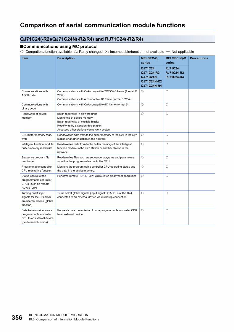
35
Comparison of serial communication module functions
QJ71C24(-R2)/QJ71C24N(-R2/R4) and RJ71C24(-R2/R4)■Communications using MC protocol: Compatible/function available : Partly changed : Incompatible/function not available : Not applicable
Item Description MELSEC-Qseries
MELSEC iQ-R series
Precautions
QJ71C24QJ71C24-R2QJ71C24NQJ71C24N-R2QJ71C24N-R4
RJ71C24RJ71C24-R2RJ71C24-R4
Communications with ASCII code
Communications with QnA compatible 2C/3C/4C frame (format 1/2/3/4)Communications with A compatible 1C frame (format 1/2/3/4)
Communications with binary code
Communications with QnA compatible 4C frame (format 5)
Read/write of device memory
Batch read/write in bit/word unitsMonitoring of device memoryBatch read/write of multiple blocksRead/write by extension designationAccesses other stations via network system
C24 buffer memory read/write
Reads/writes data from/to the buffer memory of the C24 in the own station or another station in the network.
Intelligent function module buffer memory read/write
Reads/writes data from/to the buffer memory of the intelligent function module in the own station or another station in the network.
Sequence program file read/write
Reads/writes files such as sequence programs and parameters stored in the programmable controller CPU.
Programmable controller CPU monitoring function
Monitors the programmable controller CPU operating status and the data in the device memory.
Status control of the programmable controller CPUs (such as remote RUN/STOP)
Performs remote RUN/STOP/PAUSE/latch clear/reset operations.
Turning on/off input signals for the C24 from an external device (global function)
Turns on/off global signals (input signal: X1A/X1B) of the C24 connected to an external device via multidrop connection.
Data transmission from a programmable controller CPU to an external device (on-demand function)
Requests data transmission from a programmable controller CPU to an external device.
6 10 INFORMATION MODULE MIGRATION10.3 Comparison of Information Module Functions

10
■Communication using non procedure protocol: Compatible/function available : Partly changed : Incompatible/function not available : Not applicable
■Communication using bidirectional protocol: Compatible/function available : Partly changed : Incompatible/function not available : Not applicable
Item Description MELSEC-Qseries
MELSEC iQ-R series
Precautions
QJ71C24QJ71C24-R2QJ71C24NQJ71C24N-R2QJ71C24N-R4
RJ71C24RJ71C24-R2RJ71C24-R4
Data transmission/reception in any format
Sends/receives any data between a programmable controller CPU and an external device using the message format and transmission control procedure specified by the user.
Data transmission/reception using user frames
Transmits/receives data by registering the corresponding user frames to the C24 in advance to match the data contents that are transmitted and received between the external device and the C24.
Data reception by interrupt programs
Receives data using an interrupt program. Receiving data with an interrupt program expedites data reception by the programmable controller CPU.
Programmable controller CPU monitoring function
Monitors the programmable controller CPU operating status and the data in the device memory.
ASCII data transmission/reception by ASCII-BIN conversion
Binary code data that is processed by the programmable controller CPU can be converted to ASCII code data for communication.
Data transmission/reception by specifying transparent code
Sends/receives one-byte data by using a transparent code for transmission control on the external device side as user data.
Item Description MELSEC-Qseries
MELSEC iQ-R series
Precautions
QJ71C24QJ71C24-R2QJ71C24NQJ71C24N-R2QJ71C24N-R4
RJ71C24RJ71C24-R2RJ71C24-R4
Data transmission/reception in any format
Sends/receives any data using the message format and transmission control procedure for the C24 bidirectional protocol between external devices and programmable controller CPUs.
Data reception by interrupt programs
Receives data using an interrupt program. Receiving data with an interrupt program expedites data reception by the programmable controller CPU.
ASCII data transmission/reception by ASCII-BIN conversion
Binary code data that is processed by the programmable controller CPU can be converted to ASCII code data for communication.
Data transmission/reception by specifying transparent code
Sends/receives one-byte data by using a transparent code for transmission control on the external device side as user data.
10 INFORMATION MODULE MIGRATION10.3 Comparison of Information Module Functions 357

35
■Communications using the pre-defined protocol: Compatible/function available : Partly changed : Incompatible/function not available : Not applicable
*1 This function is not available for the QJ71C24 and QJ71C24-R2.
■Communication via public network and others (modem function)The pager receiver setting is not available for the RJ71C24.: Compatible/function available : Partly changed : Incompatible/function not available : Not applicable
■Transmission control: Compatible/function available : Partly changed : Incompatible/function not available : Not applicable
Item Description MELSEC-Qseries
MELSEC iQ-R series
Precautions
QJ71C24QJ71C24-R2QJ71C24NQJ71C24N-R2QJ71C24N-R4
RJ71C24RJ71C24-R2RJ71C24-R4
Data transmission/reception by a protocol selected from the predefined protocol library
Communicates data using an external device side protocol selected from the pre-defined protocol library.
*1
Data transmission/reception by a created or edited protocol
Communicates data using a protocol created or edited in the external device.
*1
Item Description MELSEC-Qseries
MELSEC iQ-R series
Precautions
QJ71C24QJ71C24-R2QJ71C24NQJ71C24N-R2QJ71C24N-R4
RJ71C24RJ71C24-R2RJ71C24-R4
Communication with MC protocol/non procedure protocol/bidirectional protocol
Communicates with an external device in a remote location via a modem.
Programmable controller access from the engineering tool
Accesses a programmable controller CPU in a remote location from the engineering tool.
Item Description MELSEC-Qseries
MELSEC iQ-R series
Precautions
QJ71C24QJ71C24-R2QJ71C24NQJ71C24N-R2QJ71C24N-R4
RJ71C24RJ71C24-R2RJ71C24-R4
DC code control (including Xon/Xoff control)
Sends/receives the DC1 and DC3 code data, and notifies the external device of whether or not data can be received. Encloses the user data with DC2 and DC4 code data, and notifies the external device of the valid transmission data range.
DTR/DSR control Notifies the external device of whether or not data communication can be performed using the ER (DTR) and DR (DSR) signals.
8 10 INFORMATION MODULE MIGRATION10.3 Comparison of Information Module Functions

10
■Other: Compatible/function available : Partly changed : Incompatible/function not available : Not applicable
*1 This function is not available for the QJ71C24 and QJ71C24-R2.
■Debugging support function: Compatible/function available : Partly changed : Incompatible/function not available : Not applicable
*1 This function is not available for the QJ71C24 and QJ71C24-R2.
Item Description MELSEC-Qseries
MELSEC iQ-R series
Precautions
QJ71C24QJ71C24-R2QJ71C24NQJ71C24N-R2QJ71C24N-R4
RJ71C24RJ71C24-R2RJ71C24-R4
Independent/linked operation of each interface
Sets whether to use each of two interfaces for independent data communication or to use the two for linked data communication.
Monitoring/testing of initial settings and setting values with utility software
The initial setting and monitor setting of the C24by using dedicated screens without having to consider the I/O signals and buffer memory areas.
Supporting multiple CPU system
The multiple CPU system is supported.
Remote password check Allows the C24 to execute the remote password check set in the CPU when there is communication from the external device to the C24 using MC protocol or the programmable controller is accessed using the engineering tool.
Echo back enable/disable setting for RS-422/485 interface
Specifies whether to receive or not (discard) the returned data sent to RDA and RDB of the own station when data is sent through RS-485 (2-wire type).
*1
(CH2 only) For the RJ71C24,
this function can be used on both CH1 and CH2.
Item Description MELSEC-Qseries
MELSEC iQ-R series
Precautions
QJ71C24QJ71C24-R2QJ71C24NQJ71C24N-R2QJ71C24N-R4
RJ71C24RJ71C24-R2RJ71C24-R4
Circuit trace function Traces the transmitted/received data and communication control signal between the C24 and external devices.
Protocol execution log storage function
Checks the detailed execution status and results of the predefined protocol for each channel.
*1
10 INFORMATION MODULE MIGRATION10.3 Comparison of Information Module Functions 359
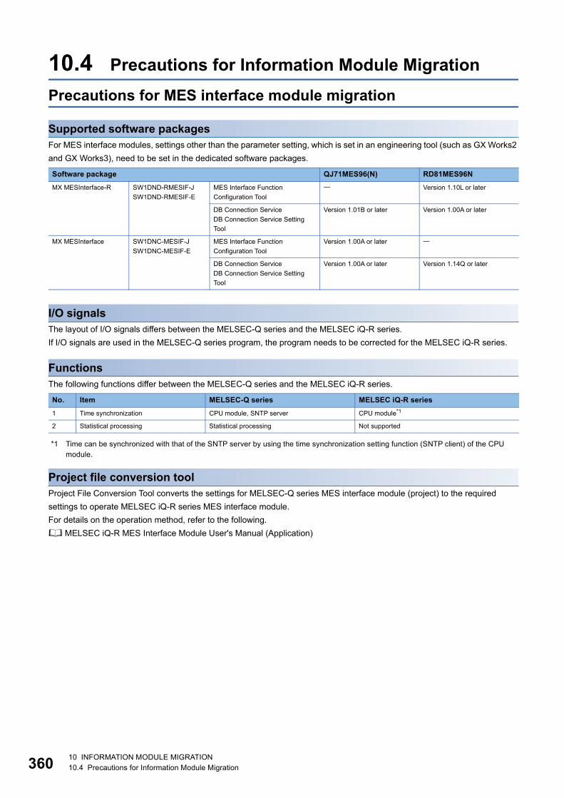
36
10.4 Precautions for Information Module MigrationPrecautions for MES interface module migration
Supported software packagesFor MES interface modules, settings other than the parameter setting, which is set in an engineering tool (such as GX Works2 and GX Works3), need to be set in the dedicated software packages.
I/O signalsThe layout of I/O signals differs between the MELSEC-Q series and the MELSEC iQ-R series.If I/O signals are used in the MELSEC-Q series program, the program needs to be corrected for the MELSEC iQ-R series.
FunctionsThe following functions differ between the MELSEC-Q series and the MELSEC iQ-R series.
*1 Time can be synchronized with that of the SNTP server by using the time synchronization setting function (SNTP client) of the CPU module.
Project file conversion toolProject File Conversion Tool converts the settings for MELSEC-Q series MES interface module (project) to the required settings to operate MELSEC iQ-R series MES interface module.For details on the operation method, refer to the following. MELSEC iQ-R MES Interface Module User's Manual (Application)
Software package QJ71MES96(N) RD81MES96NMX MESInterface-R SW1DND-RMESIF-J
SW1DND-RMESIF-EMES Interface Function Configuration Tool
Version 1.10L or later
DB Connection ServiceDB Connection Service Setting Tool
Version 1.01B or later Version 1.00A or later
MX MESInterface SW1DNC-MESIF-JSW1DNC-MESIF-E
MES Interface Function Configuration Tool
Version 1.00A or later
DB Connection ServiceDB Connection Service Setting Tool
Version 1.00A or later Version 1.14Q or later
No. Item MELSEC-Q series MELSEC iQ-R series1 Time synchronization CPU module, SNTP server CPU module*1
2 Statistical processing Statistical processing Not supported
0 10 INFORMATION MODULE MIGRATION10.4 Precautions for Information Module Migration

10
Precautions for high speed data logger module migration
Supported software packagesThe following table lists the supported versions of main software packages related to high speed data logger modules.
*1 Use the logging file conversion function of GX LogViewer (version 1.54G or later) in MELSEC iQ-R series.
Dedicated instructionsThere is no difference between the MELSEC-Q series and the MELSEC iQ-R series.
I/O signalsThe layout of I/O signals differs between the MELSEC-Q series and the MELSEC iQ-R series.If I/O signals are used in the MELSEC-Q series program, the program needs to be corrected for the MELSEC iQ-R series.
FunctionsThe following functions differ between the MELSEC-Q series and the MELSEC iQ-R series.
*1 Time can be synchronized with that of the SNTP server by using the time synchronization setting function (SNTP client) of the CPU module.
Software package QD81DL96 RD81DL96GX LogViewer SW1DNN-VIEWER-M Version 1.00A or later Version 1.54G or later
MELSEC iQ-R High Speed Data Logger Module Tool
SW1DNN-RDLUTL-JSW1DNN-RDLUTL-E
MELSEC iQ-R High Speed Data Logger Module Configuration Tool
Version 1.00A or later
High Speed Data Logger Module Tool
SW1DNN-DLUTL-JSW1DNN-DLUTL-E
High Speed Data Logger Module Configuration Tool
Version 1.00A or later
Logging File Conversion Tool Version 1.07H or later *1
No. Item MELSEC-Q series MELSEC iQ-R series1 Time synchronization CPU module, SNTP server CPU module*1
2 E-mail notification (Event logging) Binary file, CSV file CSV file
3 High speed data sampling setting Batch mode, Split mode Not supported(It is performed in the batch mode.)
10 INFORMATION MODULE MIGRATION10.4 Precautions for Information Module Migration 361
36
Precautions for Ethernet interface module migration
Dedicated instructions ■ZP.OPENTo perform open processing by using the control data, if the external device is specified with the MAC address, change the MAC address to the IP address for the MELSEC iQ-R series.
■ZP.MRECV/ZP.MSENDThis function is not available for the MELSEC iQ-R series.
■ZP.ERRCLRIt is changed to "ZP.ERRCLEAR" in the MELSEC iQ-R series.
SLMP (MC protocol) communication settingSelect "SLMP Connection Module" for the MELSEC iQ-R series.
Random access buffer communication settingSelect the connection target module, and then select "Random Access Buffer" in "Communication Method" for the MELSEC iQ-R series.
Broadcast settingSelect the connection target module, and then select "Broadcast Send" or "Broadcast Receive" in "Communication Method" for the MELSEC iQ-R series.
Unused connection setting Set "MELSOFT Connection Module" in the unused connection number for the MELSEC iQ-R series.
TCP/IP connection module settingSetting the connected device automatically determines the protocol in the MELSEC iQ-R series.
Alive check settingFor the MELSEC iQ-R series, set whether to perform an alive check in "External Device Configuration" for each connection. For the TCP/IP alive check, only the KeepAlive command can be used.
Online change settingFor the MELSEC iQ-R series, enable the online change function in "Enable/Disable Online Change" under "Own Node Settings" of "Basic Settings" when the SLMP communications are performed. When the FTP server function is used, enable the function in "Allow Online Change" under "FTP Server Settings" of "Application Settings".
Send frame settingOnly "Ethernet (V2.0)" frame can be used for the MELSEC iQ-R series. "IEEE802.3" frame can be used for received data only.
2 10 INFORMATION MODULE MIGRATION10.4 Precautions for Information Module Migration

10
Gateway parameter settingsSet "Subnet Mask" or "Default Gateway" under "Own Node Settings" of "Basic Settings" and set "Gateway Information" under "Gateway Parameter Settings" of "Application Settings" for the MELSEC iQ-R series.Names of some parameter setting items have been changed for the MELSEC iQ-R series. • "Subnet Mask Pattern" "Subnet Mask" • "Default Router IP Address" "Default Gateway" • "Router Information" "Gateway Information" • "Router IP Address" "Gateway IP Address"
Interrupt settingNames of some parameter setting items have been changed for the MELSEC iQ-R series. • "RECVS Instruction" "SEND Instruction Data Reception" • "Fixed Buffer" "Reception Connection"
I/O signals and buffer memory areasThe layouts of I/O signals and buffer memory areas differ between the MELSEC-Q series and the MELSEC iQ-R series.If I/O signals and buffer memory areas are used in the MELSEC-Q series program, the program needs to be corrected for the MELSEC iQ-R series.
10 INFORMATION MODULE MIGRATION10.4 Precautions for Information Module Migration 363

36
Precautions for serial communication module migration
Dedicated instructionsThere is no difference between the MELSEC-Q series and the MELSEC iQ-R series.
Send area and receive area in the refresh settingIn MELSEC iQ-R series, the range of the send area and the receive area cannot be specified in the refresh setting. All the send and receive areas listed below are refreshed. • Send area (CH1): Buffer memory address 1024 to 1535 (400H to 5FFH) • Receive area (CH1): Buffer memory address 1536 to 2047 (600H to 7FFH) • Send area (CH2): Buffer memory address 2048 to 2559 (800H to 9FFH) • Receive area (CH2): Buffer memory address 2560 to 3071 (A00H to BFFH)
Writing parametersFor MELSEC iQ-R series modules, parameters can be written to the CPU module as well as the serial communication module. This enables the CPU module to control parameters centrally, and thus process of changing a module for maintenance becomes easier.The module parameters and module extension parameters stored in the CPU module are reflected to the serial communication module when the system is powered on, the CPU module is reset, or the operating status of the CPU module is changed from STOP to RUN.
I/O signalsThe layout of I/O signals differs between the MELSEC-Q series and the MELSEC iQ-R series.If I/O signals are used in the MELSEC-Q series program, the program needs to be corrected for the MELSEC iQ-R series.
Buffer memoryThe layout of buffer memory areas differs between the MELSEC-Q series and the MELSEC iQ-R series.If buffer memory areas are used in the MELSEC-Q series program, the program needs to be corrected for the MELSEC iQ-R series.
For details on these precautions, refer to the following. MELSEC iQ-R Module Configuration Manual MELSEC iQ-R MES Interface Module User's Manual (Startup) MELSEC iQ-R MES Interface Module User's Manual (Application) MELSEC iQ-R High Speed Data Logger Module User's Manual (Startup) MELSEC iQ-R High Speed Data Logger Module User's Manual (Application) MELSEC iQ-R Ethernet/CC-Link IE User's Manual (Startup) MELSEC iQ-R Ethernet User's Manual (Application) MELSEC iQ-R Serial Communication Module User's Manual (Startup) MELSEC iQ-R Serial Communication Module User's Manual (Application) Differences between MELSEC-Q series and MELSEC iQ-R series (FA-A-0171)
4 10 INFORMATION MODULE MIGRATION10.4 Precautions for Information Module Migration

11
11 PROJECT MIGRATIONUse GX Works3 to migrate projects from the MELSEC-Q series system to the MELSEC iQ-R series system.
11.1 Project Migration ProcedureProcedure for migrating projects stored in the QCPUThis section describes the procedure for migrating projects stored in the QCPU.
Flow of migration of projects stored in the QCPUPerform the following steps 1 to 7 to migrate projects stored in the QCPU.
■Step 1: Reading a project stored in the QCPU (operation with GX Works2)Read a project stored in the QCPU. Select [Read from PLC] of GX Works2 to read a project.Page 366 Step 1: Reading a project stored in the QCPU (operation with GX Works2)
■Step 2: Confirmation before project migration (operation with GX Works2)Check various parameters of the project before migration.Page 368 Step 2: Confirmation before project migration (operation with GX Works2)
■Step 3: PLC type conversion to the QnUCPU (operation with GX Works2)Convert the PLC type of the project to the QnUCPU that can be read with GX Works3. Use [Change PLC Type] of GX Works2 to convert the project. If the PLC type of the project is the QnUCPU, conversion in Step 3 is not required.Page 372 Step 3: PLC type conversion to the QnUCPU (operation with GX Works2)
■Step 4: Opening a GX Works2 formatted project on GX Works3 (operation with GX Works3)On GX Works3, read a GX Works2 formatted project. Select [Project] [Open Other Format File] of GX Works3 to read a project.Page 374 Step 4: Opening a GX Works2 project on GX Works3 (operation with GX Works3)
■Step 5: Confirmation before writing the project (operation with GX Works3)Check settings before project migration.Page 376 Step 5: Confirmation before writing the project (operation with GX Works3)
■Step 6: Writing the project to the RCPU (operation with GX Works3)Write the project to the RCPU.Page 377 Step 6: Writing the project to the RCPU (operation with GX Works3)
■Step 7: Saving the RCPU project (operation with GX Works3)Save the RCPU project.Page 380 Step 7: Saving the RCPU project (operation with GX Works3)
RCPU
QCPU
GX Works2
GX Works3
Personal computer
Project data for QnUCPU
Project data for RCPU
Step 1
Step 6
Step 3
Step 7
Step 4
Step 2
Step 5
11 PROJECT MIGRATION11.1 Project Migration Procedure 365

36
Step 1: Reading a project stored in the QCPU (operation with GX Works2)1. From [Online] menu, select [Read from PLC].
2. Select "QCPU (Q mode)" for "PLC Series".
3. On the "Transfer Setup" window, configure the setting according to the programmable controller to be connected.(In this example, "PLC Direct Coupled Setting" is selected.)Click "Connection Test" to check that communications are possible.
6 11 PROJECT MIGRATION11.1 Project Migration Procedure
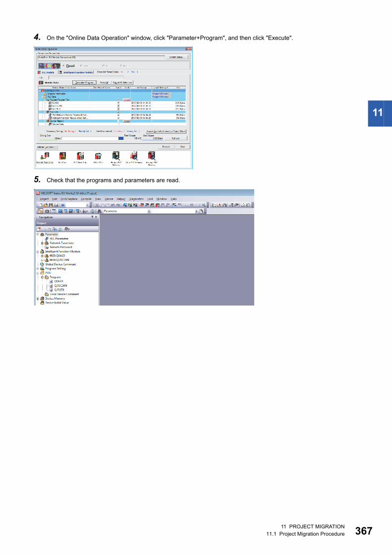
11
4. On the "Online Data Operation" window, click "Parameter+Program", and then click "Execute".
5. Check that the programs and parameters are read.
11 PROJECT MIGRATION11.1 Project Migration Procedure 367
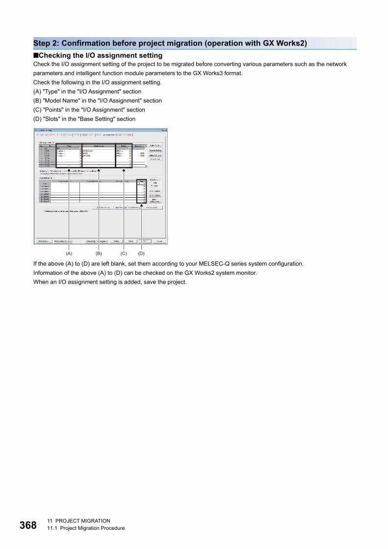
36
Step 2: Confirmation before project migration (operation with GX Works2)■Checking the I/O assignment settingCheck the I/O assignment setting of the project to be migrated before converting various parameters such as the network parameters and intelligent function module parameters to the GX Works3 format.Check the following in the I/O assignment setting.(A) "Type" in the "I/O Assignment" section(B) "Model Name" in the "I/O Assignment" section(C) "Points" in the "I/O Assignment" section(D) "Slots" in the "Base Setting" section
If the above (A) to (D) are left blank, set them according to your MELSEC-Q series system configuration.Information of the above (A) to (D) can be checked on the GX Works2 system monitor.When an I/O assignment setting is added, save the project.
(A) (B) (C) (D)
8 11 PROJECT MIGRATION11.1 Project Migration Procedure

11
■Checking on the system monitor1. From the [Diagnostics] menu, select [System Monitor].
2. Click "Product Information List" on the "System Monitor" window.The number of slots for each base is displayed in "Base Information List", which can be set in "Base Setting" in "I/O Assignment" on the "Q Parameter Setting" window.
3. The "Type" and "Point" settings on the "Product Information List" window are reflected to the "I/O Assignment" section of "I/O Assignment" on the "Q Parameter Setting" window.
The product information list can be output as a CSV file. Click "Create CSV File", and name and save the list.(Check the I/O assignment setting using the saved CSV file.)
11 PROJECT MIGRATION11.1 Project Migration Procedure 369
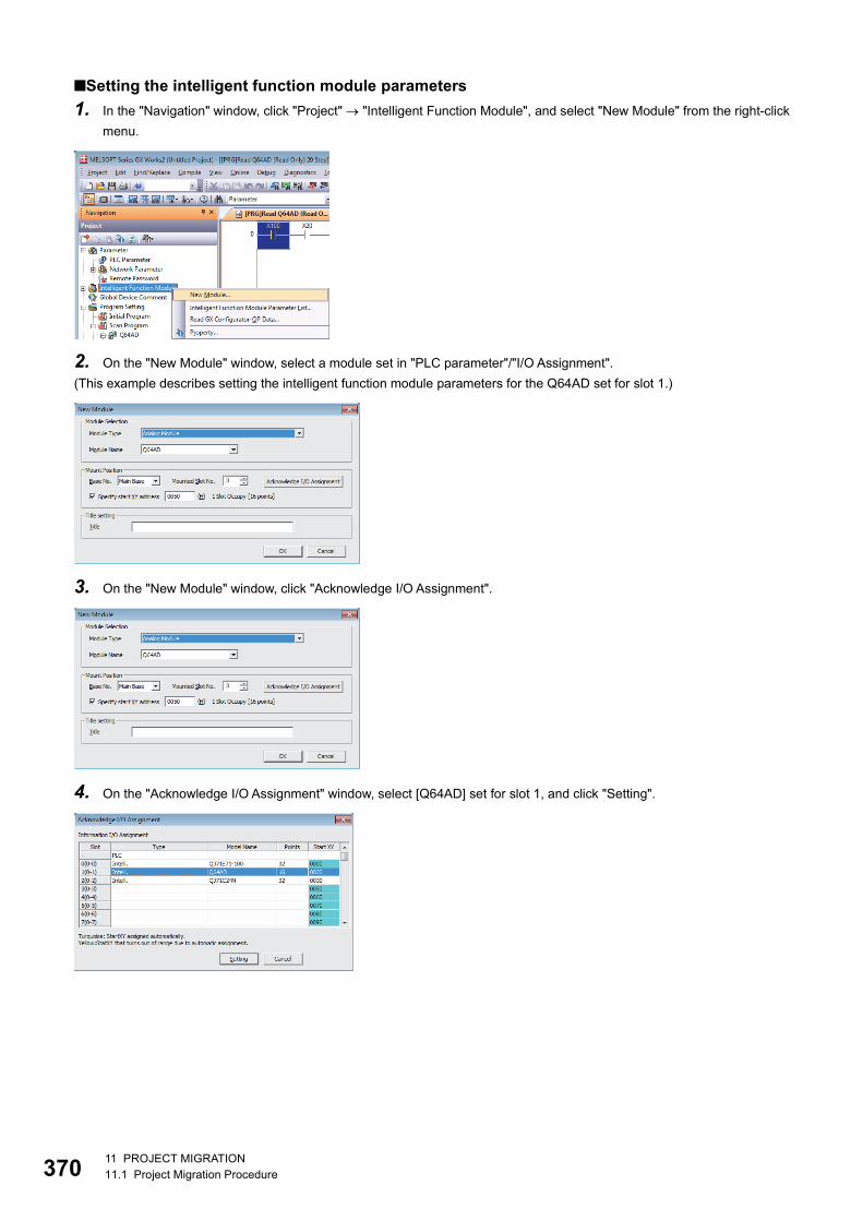
37
■Setting the intelligent function module parameters1. In the "Navigation" window, click "Project" "Intelligent Function Module", and select "New Module" from the right-click
menu.
2. On the "New Module" window, select a module set in "PLC parameter"/"I/O Assignment".(This example describes setting the intelligent function module parameters for the Q64AD set for slot 1.)
3. On the "New Module" window, click "Acknowledge I/O Assignment".
4. On the "Acknowledge I/O Assignment" window, select [Q64AD] set for slot 1, and click "Setting".
0 11 PROJECT MIGRATION11.1 Project Migration Procedure

11
5. On the "New Module" window, check that "Mounted Slot No." has been changed, and click "OK".
6. On the following window, click "Yes".
7. Create "0020: Q64AD" for "Intelligent Function Module".Double-click "Switch Setting" and check the setting.
8. Set the other intelligent function module parameters using the same procedure.
11 PROJECT MIGRATION11.1 Project Migration Procedure 371

37
Step 3: PLC type conversion to the QnUCPU (operation with GX Works2)1. From the [Project] menu, select [Change PLC Type].
2. In "PLC Type" on the "Change PLC Type" window, select a recommended model as an alternative to the Qn(H)CPU or QnPHCPU.
The following table lists recommended models as alternatives to the Qn(H)CPU.
The following table lists recommended models as alternatives to the QnPHCPU.
3. On the following window, select any relevant check boxes, and click "Yes".
4. The following window is displayed when the PLC type change is complete.Click "Yes" to display the change result, or click "No" not to display the result.
Existing model (Qn(H)CPU) Recommended model (QnUCPU)Q00JCPU Q00UJCPU
Q00CPU Q00UCPU
Q01CPU Q01UCPU
Q02CPU/Q02HCPU Q03UDVCPU
Q06HCPU Q06UDVCPU
Q12HCPU Q13UDVCPU
Q25HCPU Q26UDVCPU
Existing model (QnPHCPU) Recommended model (QnUCPU) Q02PHCPU Q04UDPVCPU
Q06PHCPU Q06UDPVCPU
Q12PHCPU Q13UDPVCPU
Q25PHCPU Q26UDPVCPU
2 11 PROJECT MIGRATION11.1 Project Migration Procedure

11
The following figure shows an example of change result.
5. From the [Project] menu, select [Save As].(If there is any data not converted or complied, make sure to perform "Rebuild All" before saving the project.)
6. Set "File name" and click "Save".
11 PROJECT MIGRATION11.1 Project Migration Procedure 373

37
Step 4: Opening a GX Works2 project on GX Works3 (operation with GX Works3)1. From the [Project] menu, select [Open Other Format File] [GX Works2 Format] [Open Project].
2. Select a project for which the PLC type is changed to the QnUCPU, and click "Open".
On the following window, click "OK".
4 11 PROJECT MIGRATION11.1 Project Migration Procedure
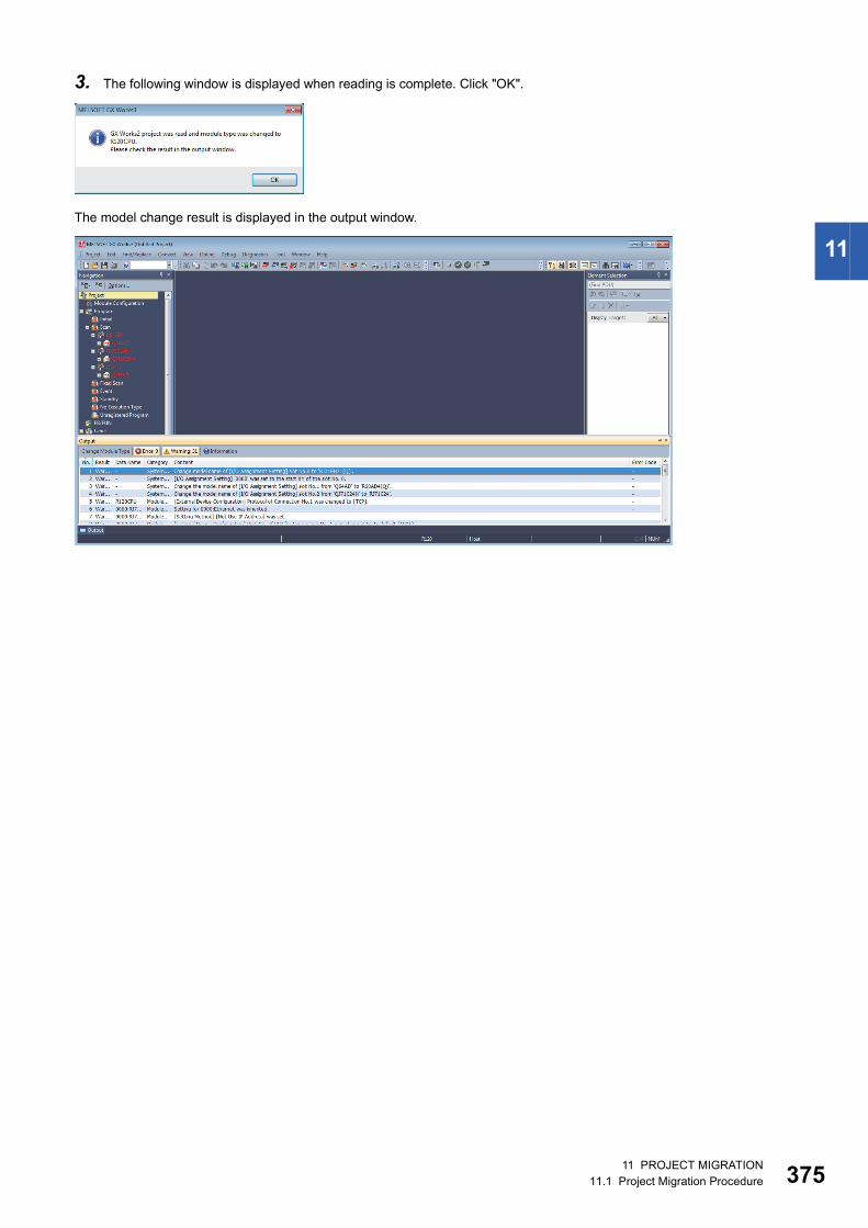
11
3. The following window is displayed when reading is complete. Click "OK".
The model change result is displayed in the output window.
11 PROJECT MIGRATION11.1 Project Migration Procedure 375

37
Step 5: Confirmation before writing the project (operation with GX Works3)Project data of GX Works2 is changed to the R120CPU.Before writing the project, rename the model to the one actually to be used.
1. From the [Project] menu, select [Change Module Type/Operation Mode].
2. Select a model to be actually used, and click "OK".
On the following window, click "OK".
3. After the model is changed, convert programs.From the [Convert] menu, select [Rebuild All].
4. On the [Rebuild All] window, select the "Check Program" check box and click "OK".
6 11 PROJECT MIGRATION11.1 Project Migration Procedure

11
Step 6: Writing the project to the RCPU (operation with GX Works3)1. From [Online] menu, select [Current Connection Destination].
2. On the "Specify Connection Destination" window, configure the setting according to the programmable controller to be connected.
(In this example, "CPU Module Direct Coupled Setting" is selected.)
3. On the "CPU Module Direct Coupled Setting" window, select "USB" and click "Yes".
11 PROJECT MIGRATION11.1 Project Migration Procedure 377
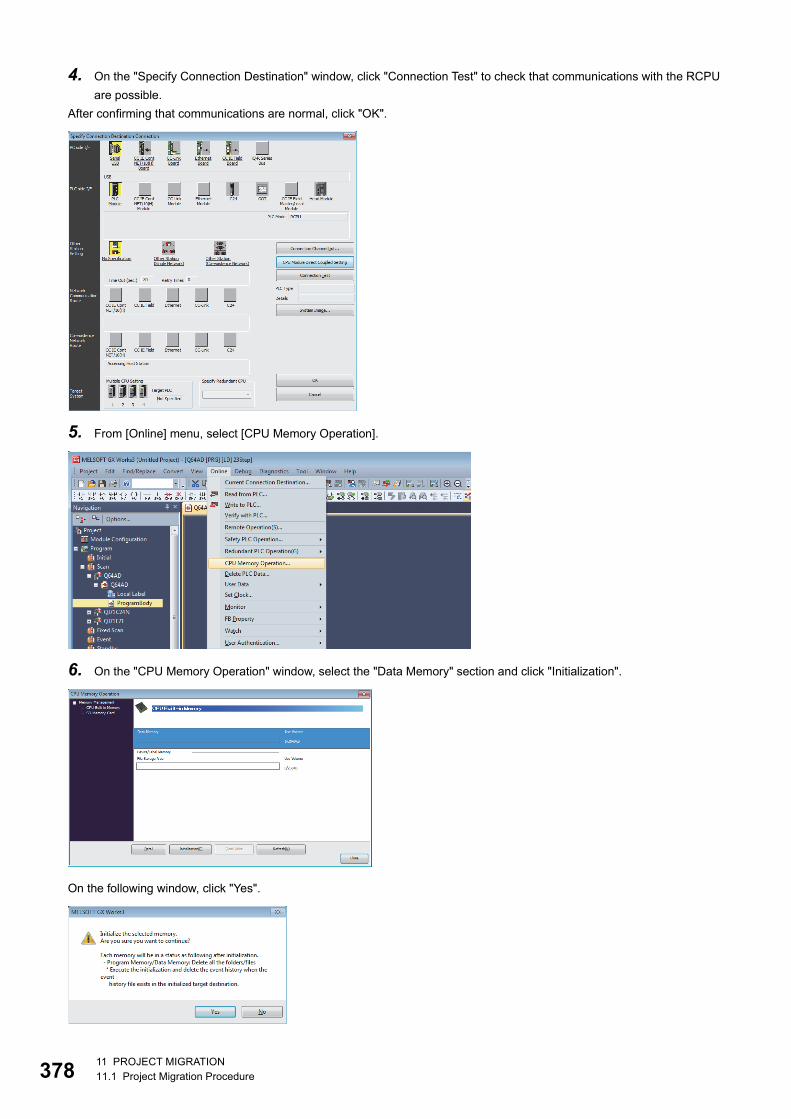
37
4. On the "Specify Connection Destination" window, click "Connection Test" to check that communications with the RCPU are possible.
After confirming that communications are normal, click "OK".
5. From [Online] menu, select [CPU Memory Operation].
6. On the "CPU Memory Operation" window, select the "Data Memory" section and click "Initialization".
On the following window, click "Yes".
8 11 PROJECT MIGRATION11.1 Project Migration Procedure

11
7. From [Online] menu, select [Write to PLC].
8. On the "Online Data Operation" window, click "Parameter + Program", and then click "Execute".
9. When writing to the programmable controller is complete, reset the RCPU.10. Set the RUN/STOP/RESET switch (1) to the RESET position for
a second or longer.
11. Check that the ERROR LED (2) flashes and turns off.
12. Set the switch back to the STOP position.
(2)
(1)
11 PROJECT MIGRATION11.1 Project Migration Procedure 379

38
Step 7: Saving the RCPU project (operation with GX Works3)1. From the [Project] menu, select [Save As].
2. Set "File name" and click "Save".
For details on operations of each engineering tool, refer to the following. GX Works3 Operating Manual GX Works2 Version 1 Operating Manual (Common)
0 11 PROJECT MIGRATION11.1 Project Migration Procedure

11
Procedure for migrating projects stored in a personal computerThis section describes the procedure for migrating projects stored in a personal computer.
Flow of migration of projects stored in a personal computerPerform the following steps 1 to 7 to migrate a project stored in a personal computer.
■Step 1: Reading a project stored in a personal computer (operation with GX Works2)Read a project stored in a personal computer.To read a GX Works2 formatted project, select [Project] [Open] on GX Works2. To read a GX Developer formatted project, select [Project] [Open Other Data] [Open Other Project] on GX Works2.Page 382 Step 1: Reading a project stored in a personal computer (operation with GX Works2)
■Step 2: Confirmation before project migration (operation with GX Works2)Check various parameters of the project before migration.Page 384 Step 2: Confirmation before project migration (operation with GX Works2)
■Step 3: PLC type conversion to the QnUCPU (operation with GX Works2)Convert the PLC type of the project to the QnUCPU that can be read with GX Works3. Use [Change PLC Type] of GX Works2 to convert the project. If the PLC type of the project is the QnUCPU, conversion in Step 3 is not required.Page 388 Step 3: PLC type conversion to the QnUCPU (operation with GX Works2)
■Step 4: Opening a GX Works2 formatted project on GX Works3 (operation with GX Works3)On GX Works3, read a GX Works2 formatted project. Select [Project] [Open Other Format File] of GX Works3 to read a project.Page 390 Step 4: Opening a GX Works2 project on GX Works3 (operation with GX Works3)
■Step 5: Confirmation before writing the project (operation with GX Works3)Check settings before project migration.Page 392 Step 5: Confirmation before writing the project (operation with GX Works3)
■Step 6: Writing the project to the RCPU (operation with GX Works3)Write the project to the RCPU.Page 393 Step 6: Writing the project to the RCPU (operation with GX Works3)
■Step 7: Saving the RCPU project (operation with GX Works3)Save the RCPU project.Page 396 Step 7: Saving the RCPU project (operation with GX Works3)
RCPU
Personal computer
Project data for QCPU (GX Works2/GX Developer format)
Project data for RCPU
Step 1
Step 6
Step 3
Step 7
Step 4
Project data for QnUCPU
GX Works2
GX Works3
Step 2
Step 5
11 PROJECT MIGRATION11.1 Project Migration Procedure 381

38
Step 1: Reading a project stored in a personal computer (operation with GX Works2)■Reading a GX Works2 formatted project1. From the [Project] menu, select [Open].
2. Select a desired file, and click "Open".
3. The project opens.
2 11 PROJECT MIGRATION11.1 Project Migration Procedure

11
■Reading a GX Developer formatted project1. From the [Project] menu, select [Open Other Data] [Open Other Project].
2. Select a desired GX Developer project, and click "Open".
3. On the following window, click "Yes".
4. From the [Compile] menu, select [Rebuild All].
11 PROJECT MIGRATION11.1 Project Migration Procedure 383

38
Step 2: Confirmation before project migration (operation with GX Works2)■Checking the I/O assignment settingCheck the I/O assignment setting of the project to be migrated before converting various parameters such as the network parameters and intelligent function module parameters to the GX Works3 format.Check the following in the I/O assignment setting.(A) "Type" in the "I/O Assignment" section(B) "Model Name" in the "I/O Assignment" section(C) "Points" in the "I/O Assignment" section(D) "Slots" in the "Base Setting" section
If the above (A) to (D) are left blank, set them according to your MELSEC-Q series system configuration.Information of the above (A) to (D) can be checked on the GX Works2 system monitor.When an I/O assignment setting is added, save the project.
(A) (B) (C) (D)
4 11 PROJECT MIGRATION11.1 Project Migration Procedure
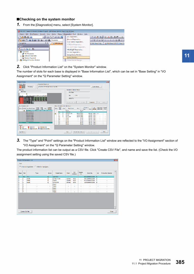
11
■Checking on the system monitor1. From the [Diagnostics] menu, select [System Monitor].
2. Click "Product Information List" on the "System Monitor" window.The number of slots for each base is displayed in "Base Information List", which can be set in "Base Setting" in "I/O Assignment" on the "Q Parameter Setting" window.
3. The "Type" and "Point" settings on the "Product Information List" window are reflected to the "I/O Assignment" section of "I/O Assignment" on the "Q Parameter Setting" window.
The product information list can be output as a CSV file. Click "Create CSV File", and name and save the list. (Check the I/O assignment setting using the saved CSV file.)
11 PROJECT MIGRATION11.1 Project Migration Procedure 385

38
■Setting the intelligent function module parameters1. In the "Navigation" window, click "Project" "Intelligent Function Module", and select "New Module" from the right-click
menu.
2. On the "New Module" window, select a module set in "PLC parameter"/"I/O Assignment".(This example describes setting the intelligent function module parameters for the Q64AD set for slot 1.)
3. On the "New Module" window, click "Acknowledge I/O Assignment".
4. On the "Acknowledge I/O Assignment" window, select [Q64AD] set for slot 1, and click "Setting".
5. On the "New Module" window, check that "Mounted Slot No." has been changed, and click "OK".
6 11 PROJECT MIGRATION11.1 Project Migration Procedure

11
6. On the following window, click "Yes".
7. Create "0020: Q64AD" for "Intelligent Function Module".Double-click "Switch Setting" and check the setting.
8. Set the other intelligent function module parameters using the same procedure.
11 PROJECT MIGRATION11.1 Project Migration Procedure 387

38
Step 3: PLC type conversion to the QnUCPU (operation with GX Works2)1. From the [Project] menu, select [Change PLC Type].
2. In "PLC Type" on the "Change PLC Type" window, select a recommended model as an alternative to the Qn(H)CPU or QnPHCPU.
The following table lists recommended models as alternatives to the Qn(H)CPU.
The following table lists recommended models as alternatives to the QnPHCPU.
3. On the following window, select any relevant check boxes, and click "Yes".
4. The following window is displayed when the PLC type change is complete.Click "Yes" to display the change result, or click "No" not to display the result.
Existing model (Qn(H)CPU) Recommended model (QnUCPU)Q00JCPU Q00UJCPU
Q00CPU Q00UCPU
Q01CPU Q01UCPU
Q02CPU/Q02HCPU Q03UDVCPU
Q06HCPU Q06UDVCPU
Q12HCPU Q13UDVCPU
Q25HCPU Q26UDVCPU
Existing model (QnPHCPU) Recommended model (QnUCPU) Q02PHCPU Q04UDPVCPU
Q06PHCPU Q06UDPVCPU
Q12PHCPU Q13UDPVCPU
Q25PHCPU Q26UDPVCPU
8 11 PROJECT MIGRATION11.1 Project Migration Procedure
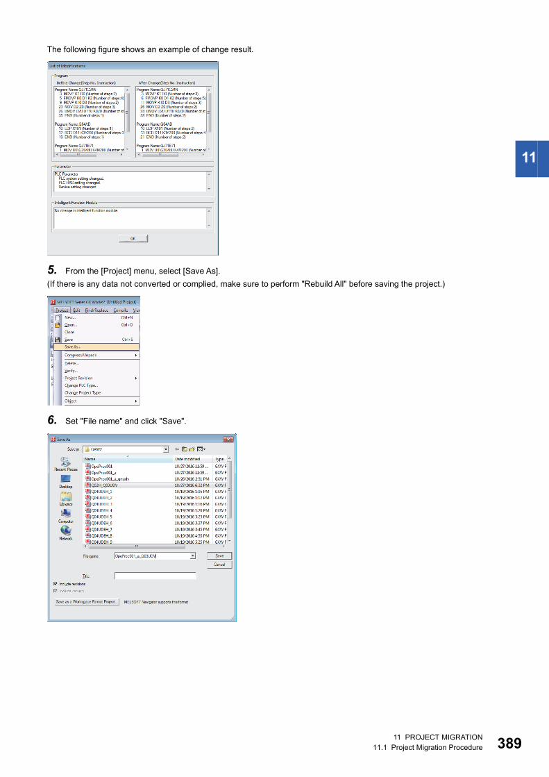
11
The following figure shows an example of change result.
5. From the [Project] menu, select [Save As].(If there is any data not converted or complied, make sure to perform "Rebuild All" before saving the project.)
6. Set "File name" and click "Save".
11 PROJECT MIGRATION11.1 Project Migration Procedure 389

39
Step 4: Opening a GX Works2 project on GX Works3 (operation with GX Works3)1. From the [Project] menu, select [Open Other Format File] [GX Works2 Format] [Open Project].
2. Select a project for which the PLC type is changed to the QnUCPU, and click "Open".
On the following window, click "OK".
0 11 PROJECT MIGRATION11.1 Project Migration Procedure

11
3. The following window is displayed when reading is complete. Click "OK".
The model change result is displayed in the output window.
11 PROJECT MIGRATION11.1 Project Migration Procedure 391

39
Step 5: Confirmation before writing the project (operation with GX Works3)Project data of GX Works2 is changed to the R120CPU.Before writing the project, rename the model to the one actually to be used.
1. From the [Project] menu, select [Change Module Type/Operation Mode].
2. Select a model to be actually used, and click "OK".
On the following window, click "OK".
3. After the model is changed, convert programs.From the [Convert] menu, select [Rebuild All].
4. On the [Rebuild All] window, select the "Check Program" check box and click "OK".
2 11 PROJECT MIGRATION11.1 Project Migration Procedure

11
Step 6: Writing the project to the RCPU (operation with GX Works3)1. From [Online] menu, select [Current Connection Destination].
2. On the "Specify Connection Destination" window, configure the setting according to the programmable controller to be connected.
(In this example, "CPU Module Direct Coupled Setting" is selected.)
3. On the "CPU Module Direct Coupled Setting" window, select "USB" and click "Yes".
11 PROJECT MIGRATION11.1 Project Migration Procedure 393

39
4. On the "Specify Connection Destination" window, click "Connection Test" to check that communications with the RCPU are possible.
After confirming that communications are normal, click "OK".
5. From [Online] menu, select [CPU Memory Operation].
6. On the "CPU Memory Operation" window, select the "Data Memory" section and click "Initialization".
On the following window, click "Yes".
4 11 PROJECT MIGRATION11.1 Project Migration Procedure

11
7. From [Online] menu, select [Write to PLC].
8. On the "Online Data Operation" window, click "Parameter + Program", and then click "Execute".
9. When writing to the programmable controller is complete, reset the RCPU.10. Set the RUN/STOP/RESET switch (1) to the RESET position for
a second or longer.
11. Check that the ERROR LED (2) flashes and turns off.
12. Set the switch back to the STOP position.
(2)
(1)
11 PROJECT MIGRATION11.1 Project Migration Procedure 395

39
Step 7: Saving the RCPU project (operation with GX Works3)1. From the [Project] menu, select [Save As].
2. Set "File name" and click "Save".
For details on operations of each engineering tool, refer to the following. GX Works3 Operating Manual GX Works2 Version 1 Operating Manual (Common)
6 11 PROJECT MIGRATION11.1 Project Migration Procedure

11
Procedure for migration of PX Developer projectsThis section describes the procedure for converting projects used for PX Developer to projects for GX Works3.For models requiring the conversion, refer to the following. GX Works3 Operating Manual
Procedure1. From the [Project] menu of GX Works3, select [Open Other Format File] [PX Developer Format] [Open Project].
2. Select a PX Developer formatted project to be converted, and click the [Open] button.
11 PROJECT MIGRATION11.1 Project Migration Procedure 397

39
3. The following message appears. Read the message, and click the [OK] button.
4. The PX Developer formatted project is opened in GX Works3.Select whether to read initial values of FB Property.The changes in project data by this conversion (model change) are displayed in the "Output" window. According to the displayed items, change parameters and programs if necessary. Note that the model of project has been automatically changed to "R120PCPU".
8 11 PROJECT MIGRATION11.1 Project Migration Procedure

11
5. Change it to the model that is actually used by selecting [Project] of GX Works3 [Change Module Type/Operation Mode].
For details on operations of each engineering tool, refer to the following. GX Works3 Operating Manual PX Developer Version 1 Operating Manual (Programming Tool) Differences of PX Developer and GX Works3 process control functions (FA-A-0236)
11 PROJECT MIGRATION11.1 Project Migration Procedure 399

40
11.2 Instruction MigrationThis section describes the differences of instructions after migration from the QCPU to RCPU.
Category Description MELSEC-Q series MELSEC iQ-R series
Precautions
Q00J/Q00/Q01CPU, Qn(H)CPU
QnUCPU RCPU
Basic instruction
Conversion from BIN 16-bit data to floating-point data (single precision)
FLT*1 INT2FLT Instruction names differ between the QCPU and RCPU.Names of instructions for the RCPU are changed so that the data status before and after conversion can be easily understood from the name.*9
Conversion from BIN 32-bit data to floating-point data (single precision)
DFLT*1 DINT2FLT
Conversion from BIN 16-bit data to floating-point data (double precision)
FLTD INT2DBL
Conversion from BIN 32-bit data to floating-point data (double precision)
DFLTD DINT2DBL
Conversion from floating-point data to BIN 16-bit data (single precision)
INT*1 FLT2INT
Conversion from floating-point data to BIN 32-bit data (single precision)
DINT*1 FLT2DINT
Conversion from floating-point data to BIN 16-bit data (double precision)
INTD DBL2INT
Conversion from floating-point data to BIN 32-bit data (double precision)
DINTD DBL2DINT
Conversion from BIN 16-bit to BIN 32-bit data
DBL INT2DINT
Conversion from BIN 32-bit to BIN 16-bit data
WORD DINT2INT
Conversion from single precision to double precision
ECON FLT2DBL
Conversion from double precision to single precision
EDCON DBL2FLT
Application instruction
Conversion from ASCII to hexadecimal BIN
HEX*2 ASC2INT Instruction names differ between the QCPU and RCPU.Names of instructions for the RCPU are changed so that the data status before and after conversion can be easily understood from the name.*9
Conversion from hexadecimal BIN to ASCII
ASC*2 INT2ASC
Square root operation for floating-point data (single precision)
SQR*1 ESQRT
Square root operation for floating-point data (double precision)
SQRD EDSQRT
BCD 4-digit square roots BSQR*2 BSQRT
BCD 8-digit square roots BDSQR*2 BDSQRT
Ramp signal RAMP*2 RAMPQ
16-bit data search SER SERDATA
32-bit data search DSER DSERDATA
BIN 16-bit data sort operations SORT SORTD
BIN 32-bit data sort operations DSORT DSORTD
Converting time data from hour/minute/second to second
SECOND TIME2SEC
Converting time data from second to hour/minute/second
HOUR SEC2TIME
Reading 2-word data from the intelligent function module
DFRO DFROM
0 11 PROJECT MIGRATION11.2 Instruction Migration

11
Application instruction
Reading device comment data COMRD*2 Not supported This instruction is not available for the RCPU. Change the program so that a device comment is read, stored and displayed on the GOT. (Use a GOT connectable to the RCPU.)*9
File setting for comments QCDSET*2
Instruction to read SFC step comment S.SFCSCOMR*2*3
Instruction to read comment of SFC transition condition
S.SFCTCOMR*2*3
High-speed block transfer of file register
RBMOV*2*4 BMOV
Subroutine calls between program files ECALL*2 ECALL (Unicode specification)
For the QCPU, the character code that can be specified to the file name (string) of the argument was ASCII and Shift JIS. However, for the RCPU, it is changed to Unicode. Therefore, if the file name is specified with the character string constant of ASCII or Shift JIS, it needs to be changed to Unicode. When changing the character code to Unicode, use the SJIS2WS(P) instruction.*9
Subroutine output OFF calls between program files
EFCALL*2 EFCALL (Unicode specification)
Program standby PSTOP*2 PSTOP (Unicode specification)
Program output OFF standby POFF*2 POFF (Unicode specification)
Program scan execution registration PSCAN*2 PSCAN (Unicode specification)
Reading data from designated file SP.FREAD*7 SP.FREAD (Unicode specification)
Writing data to designated file SP.FWRITE*7 SP.FWRITE (Unicode specification)
Trace set/reset TRACE/TRACER*2*4 Not supported The RCPU does not support the TRACE and TRACER instruction. For the MELSEC iQ-R series, the sampling trace function is integrated into the data logging function. When sampling the device data as if it is performed as the sampling trace function, use the trigger logging of the data logging function.*9
Index modification of entire ladder IX/IXEND Not supported This instruction is not available for the QnUCPU and RCPU. Use a replacement program.*10
Modification value specification in index modification of entire ladder
IXDEV/IXSET Not supported This instruction is not available for the QnUCPU and RCPU.Change the program so that a device offset value is set to the index modification table by an instruction such as the MOV instruction, instead of being specified by the IXSET instruction.*10
Print ASCII code PR*2 Not supported This instruction is not available for the QnUCPU and RCPU. Use the GOT or a replacement program.*10
Print comment PRC*2 Not supported This instruction is not available for the QnUCPU and RCPU. Use the GOT.*10
Special format failure check CHKST/CHK*2 Not supported This instruction is not available for the QnUCPU and RCPU. Use a replacement program.*10
Changing check format of check instruction
CHKCIR/CHKEND*2
Not supported This instruction is not available for the QnUCPU and RCPU. Use a replacement program.*10
Program low speed execution registration
PLOW*2 Not supported No low speed program is available for the QnUCPU and RCPU.*10
Program execution status check PCHK*2 Not supported This instruction is not available for the QnUCPU and RCPU. Check the status with the program list monitor.*10
Numerical key input using keyboard KEY*2 Not supported This instruction is not available for the QnUCPU and RCPU. Use the GOT or a replacement program.*10
Category Description MELSEC-Q series MELSEC iQ-R series
Precautions
Q00J/Q00/Q01CPU, Qn(H)CPU
QnUCPU RCPU
11 PROJECT MIGRATION11.2 Instruction Migration 401

40
Application instruction
Loading program from memory card PLOADP*2 Not supported This instruction is not available for the QnUCPU and RCPU.All programs to be executed must be stored in the program memory. For the QnUCPU and RCPU, it is not possible to add a program to the program memory or switch to another program in the RUN state.If the program memory capacity is not enough, move parameters, device comments, and device initial values from the program memory to a standard ROM or memory card.*10
Unloading program from program memory
PUNLOADP*2 Not supported
Loading and unloading PSWAPP*2 Not supported
Refresh COM (without execution condition)
COM (with execution condition)
The RCPU does not support the CCOM instruction. Use the COM instruction instead.Since an execution condition is given to the COM instruction for the RCPU, it operates in the same way as the CCOM instruction for the QnUCPU.*9
Selecting refresh to be performed CCOM (with execution condition)*5
• Program of GX Works2
• Program of GX Works3
Writing to host CPU shared memory TO/S.TO*6 TO The RCPU does not support the S.TO instruction. Use the TO instruction instead.Since data write is complete within execution of the TO instruction, the completion device (D), which turns on for one scan upon completion of the processing, is not provided for the TO instruction. If (D) is used in the MELSEC-Q series program, the program needs to be modified for the MELSEC iQ-R series.*9
• Program of GX Works2
• Program of GX Works3
Reading module information UNIRD UNIINFRD The RCPU does not support the UNIRD instruction. Use the UNIINFRD instruction instead.The UNIINFRD instruction reads module information in units of two words. If the module information read by using the UNIRD instruction (in units of one word) is used in the MELSEC-Q series program, the program needs to be modified for the MELSEC iQ-R series.*9
Category Description MELSEC-Q series MELSEC iQ-R series
Precautions
Q00J/Q00/Q01CPU, Qn(H)CPU
QnUCPU RCPU
Processing performed after data are written
Processing performed after data are written
2 11 PROJECT MIGRATION11.2 Instruction Migration

11
Application instruction
• Program of GX Works2
• Program of GX Works3
Interrupt disable DI (without execution condition)
DI (with execution condition)
An execution condition is given to the DI and EI instructions for the RCPU.This eliminates the need of using an instruction (such as jump instruction) to skip the execution of DI or EI instruction for the RCPU when the execution is not necessary. To execute DI or EI instruction every scan for the RCPU in the same way as doing for the QCPU, set SM400 (Always ON) as an execution condition.*9
Interrupt enable EI (without execution condition)
EI (with execution condition)
• Program of GX Works2
• Program of GX Works3
Category Description MELSEC-Q series MELSEC iQ-R series
Precautions
Q00J/Q00/Q01CPU, Qn(H)CPU
QnUCPU RCPU
� �
D0b15 b0b12
Intelligent function module
Power supply module
CPU module
Input module
0000H 0010HStart I/O number
16 16Number of points
Read the module information and store it to D0.
System configuration Module information
On: Module ready
On: Module mounted
Processing performed when the module is ready
� �
D0
D1
b15 b0b2Intelligent function module
Power supply module
CPU module
Input module
0000H 0010HStart I/O number
16 16Number of points
System configuration
Processing performed when the module is ready
Module information
On: Module ready
On: Module mounted
Read the module information and store it to D0 and D1.
11 PROJECT MIGRATION11.2 Instruction Migration 403
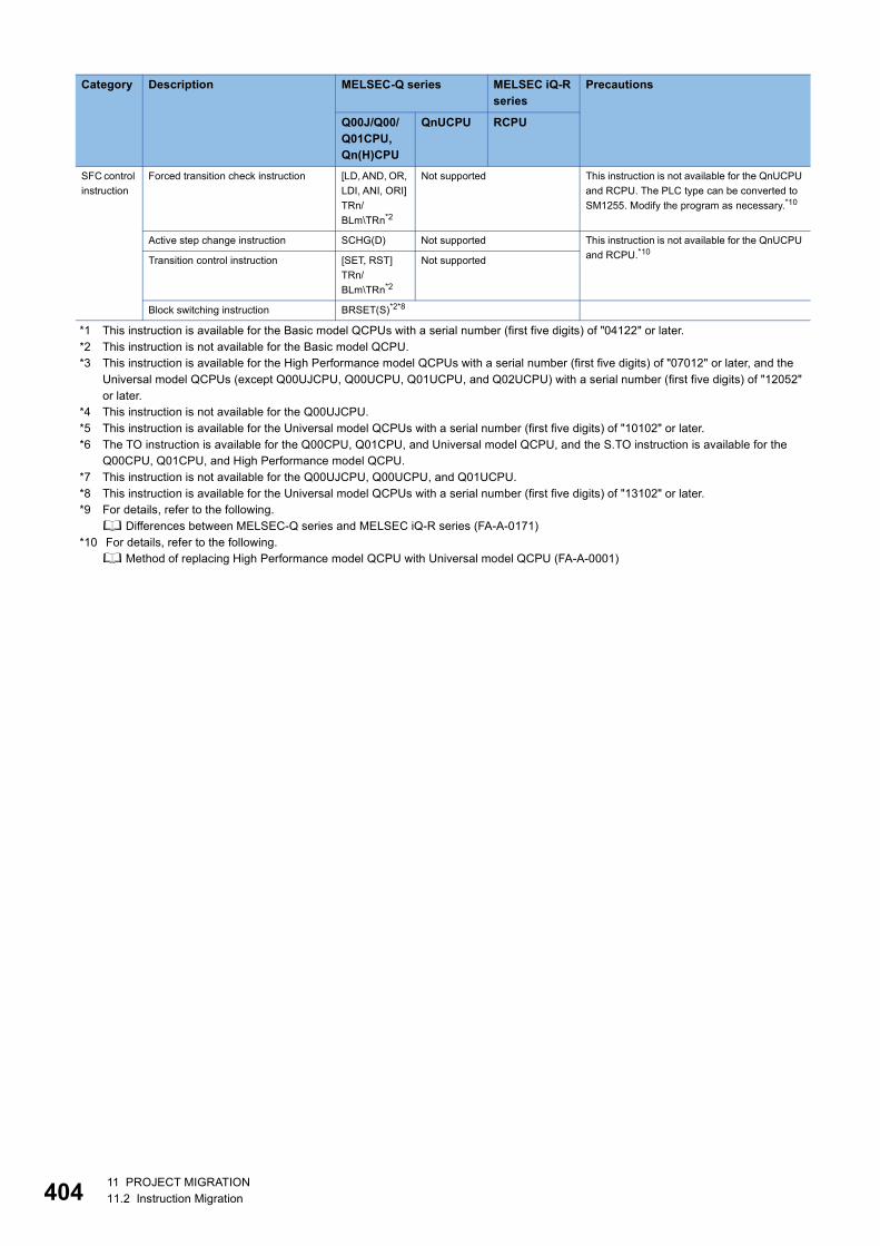
40
*1 This instruction is available for the Basic model QCPUs with a serial number (first five digits) of "04122" or later.*2 This instruction is not available for the Basic model QCPU.*3 This instruction is available for the High Performance model QCPUs with a serial number (first five digits) of "07012" or later, and the
Universal model QCPUs (except Q00UJCPU, Q00UCPU, Q01UCPU, and Q02UCPU) with a serial number (first five digits) of "12052" or later.
*4 This instruction is not available for the Q00UJCPU.*5 This instruction is available for the Universal model QCPUs with a serial number (first five digits) of "10102" or later.*6 The TO instruction is available for the Q00CPU, Q01CPU, and Universal model QCPU, and the S.TO instruction is available for the
Q00CPU, Q01CPU, and High Performance model QCPU.*7 This instruction is not available for the Q00UJCPU, Q00UCPU, and Q01UCPU.*8 This instruction is available for the Universal model QCPUs with a serial number (first five digits) of "13102" or later.*9 For details, refer to the following.
Differences between MELSEC-Q series and MELSEC iQ-R series (FA-A-0171)*10 For details, refer to the following.
Method of replacing High Performance model QCPU with Universal model QCPU (FA-A-0001)
SFC control instruction
Forced transition check instruction [LD, AND, OR, LDI, ANI, ORI] TRn/BLm\TRn*2
Not supported This instruction is not available for the QnUCPU and RCPU. The PLC type can be converted to SM1255. Modify the program as necessary.*10
Active step change instruction SCHG(D) Not supported This instruction is not available for the QnUCPU and RCPU.*10
Transition control instruction [SET, RST] TRn/BLm\TRn*2
Not supported
Block switching instruction BRSET(S)*2*8
Category Description MELSEC-Q series MELSEC iQ-R series
Precautions
Q00J/Q00/Q01CPU, Qn(H)CPU
QnUCPU RCPU
4 11 PROJECT MIGRATION11.2 Instruction Migration

11
11.3 Parameter MigrationThe following table lists the differences of parameters after migration from the QCPU to RCPU.
Category Description MELSEC-Q series MELSEC iQ-R series Precautions
Q00J/Q00/Q01CPU/Qn(H)CPU
QnUCPU RCPU
CPU module CPU module settings PLC parameter (PARAM.QPA)
• System parameter (SYSTEM.PRM)
• CPU parameter (CPU.PRM)
• Module parameter (UNIT.PRM)
• Memory card parameter (MEMCARD.PRM)
For the RCPU, set parameters, such as I/O assignment setting, that are common to all the CPU modules in the multiple CPU system in system parameter, and set parameters, such as program setting, that is specific to each CPU module in CPU parameter. In addition, set the module parameter to use the built-in Ethernet function of the CPU module, and set the memory card parameter to perform boot operation.*1
I/O module Input response time setting/interrupt setting/output mode upon error setting
I/O assignment setting of PLC parameter
Module parameter For the RCPU, use module parameters.*1
Analog I/O module
Error time output mode I/O assignment setting of PLC parameter
Module parameter For the RCPU, use module parameters.*1
Switch setting/parameter (each setting)/auto refresh
Intelligent function module parameter
Positioning module
Error time output mode I/O assignment setting of PLC parameter
Module parameter For the RCPU, use module parameters and module extension parameters.*1
Parameter (each setting)/auto refresh
Intelligent function module parameter
Positioning data/block start data Module extension parameter
High-speed counter module
Error time output mode I/O assignment setting of PLC parameter
Module parameter For the RCPU, use module parameters.*1
Switch setting/parameter (each setting)/auto refresh
Intelligent function module parameter
CC-Link IE Field Network master/local modules
Network configuration setting Network parameter - Network configuration setting
Module parameter - Basic setting - Network configuration setting
For the RCPU, use module parameters.*1
Mode setting Network parameter - Mode Module parameter - Application setting - Module operation mode setting
CC-Link system master/local module
Station number setting/transmission speed
Set with the rotary switch. Module parameter For the RCPU, the setting method is different.*1
Mode setting Set in network parameter or switch setting.
Refresh Set the start number of the refresh target device.
Set the start number and end number, or the start number and number of points of the refresh target device.
CC-Link configuration setting Set in the station information settings (table format) or CC-Link configuration setting.
Set in the CC-Link configuration setting.
11 PROJECT MIGRATION11.3 Parameter Migration 405

40
*1 For details, refer to the following. Differences between MELSEC-Q series and MELSEC iQ-R series (FA-A-0171)
AnyWireASLINK master module
Number of transmission points Intelligent function module parameter - Switch setting
Module parameter - Basic setting
For the RCPU, the setting method is different.*1
Refresh Intelligent function module parameter - Auto refresh
Module parameter - Refresh setting
Operation mode at startup time/superencryption/error status automatic recovery
Not supported Module parameter - Basic setting
AnyWireASLINK configuration Intelligent function module parameter - AnyWireASLINK configuration
AnyWireASLINK configuration
Ethernet interface module
SLMP (MC protocol) communication setting/random access buffer communication setting/broadcast setting/unused connection setting/TCP/IP connection module setting/alive check setting
Network parameter - Open setting
Module parameter For the RCPU, use module parameters.*1
Online change setting/send frame setting
Network parameter - Operation setting
Router relay (gateway) parameter setting
Network parameter - Router relay parameter
Interrupt setting Network parameter - Interrupt setting
Serial communication module
Switch setting I/O assignment setting of PLC parameter
Module parameter For the RCPU, use module parameters and module extension parameters.*1
Various control specification/programmable controller CPU monitoring function/user frame specification/auto refresh
Intelligent function module parameter
Modem function/user frame content
Module extension parameter
Category Description MELSEC-Q series MELSEC iQ-R series Precautions
Q00J/Q00/Q01CPU/Qn(H)CPU
QnUCPU RCPU
6 11 PROJECT MIGRATION11.3 Parameter Migration

11
• PLC parameter setting window and Write to PLC window (GX Works2)
• System parameter setting window, CPU parameter setting window, and Write to PLC window (GX Works3)
Set these parameters to execute the built-in Ethernet function or perform boot operation.
11 PROJECT MIGRATION11.3 Parameter Migration 407

40
11.4 Special Relay and Special Register MigrationMigration of special relayThe following table lists the differences of special relay after migration from the QCPU to RCPU.
Category Description MELSEC-Q series MELSEC iQ-R series
Precautions
Q00J/Q00/Q01CPU/Qn(H)CPU
QnUCPU RCPU
Special relay (SM)
Error common information SM5 Not supported
Error individual information SM16 Not supported
CHK detection SM80*3 Not supported This relay is not available for the QnUCPU and RCPU.*1*2
For the RCPU, SM80 is "Detailed information 1: Flag in use".
Error clear Not supported SM84 Not supported
Startup of monitoring timer for step transition
SM91 to SM99*3 Not supported This relay is not available for the QnUCPU and RCPU.*2
LED OFF command SM202*3 Not supported
PAUSE enable coil SM206 Not supported
Device range check inhibit flag Not supported SM237*4 Not supported
No.'n' CPU error flag SM244 to SM247*5 SM230 to SM233
Max. loaded I/O read SM250*3 Not supported For the QnUCPU and RCPU, SM250 need not be operated since SD250 always stores the maximum loaded I/O.
All stations refresh command SM254*3 Not supported
MELSECNET/10, MELSECNET/H module 1 information
SM255 to SM257*3
Not supported This special relay is for use in the simple dual-structured network function.For the RCPU and QnUCPU, the simple dual-structured network function is not available. Remove sections that use this special relay.
MELSECNET/10, MELSECNET/H module 2 information
SM260 to SM262*3
MELSECNET/10, MELSECNET/H module 3 information
SM265 to SM267*3
MELSECNET/10, MELSECNET/H module 4 information
SM270 to SM272*3
CC-Link error SM280*3 Not supported This relay is not available for the QnUCPU and RCPU.Use the I/O signals (Xn0, Xn1, XnF) of the installed CC-Link module instead.*2
Online change (inactive block) status flag
Not supported SM329*4
Operation mode for low speed execution type program
SM330*3 Not supported Low speed execution type programs are not available for the QnUCPU and RCPU. Remove sections that use this special relay.*2
Normal SFC program execution status
SM331*3 Not supported For the QnUCPU and RCPU, only the normal SFC programs are available.Remove interlock by SM331 and SM332, or use SM321 instead.*2
Program execution management SFC program execution status
SM332*3
Latch clear execution command Not supported SM339*4*6 Not supported
8 11 PROJECT MIGRATION11.4 Special Relay and Special Register Migration

11
Special relay (SM)
Access execution flag SM390*3 Not supported This relay is not available for the QnUCPU and RCPU.Refer to sample programs in the manual of each module, and modify the program so that interlock is acquired by the module ready signal (Xn).*2
Low speed execution type programON for 1 scan only after RUN
SM404*3 Not supported Low speed execution type programs are not available for the QnUCPU and RCPU.Remove sections that use this special relay, or use the special relay (SM402 and SM403) for scan execution type programs.*2
Low speed execution type programOFF for 1 scan only after RUN
SM405*3
User timing clock No.5(for low speed programs)
SM430*3 Not supported Low speed execution type programs are not available for the QnUCPU and RCPU.Remove sections that use this special relay, or use the special relay (SM420 to SM424) for scan execution type programs.*2
User timing clock No.6(for low speed programs)
SM431*3
User timing clock No.7(for low speed programs)
SM432*3
User timing clock No.8(for low speed programs)
SM433*3
User timing clock No.9(for low speed programs)
SM434*3
Low speed program execution flag
SM510*3 Not supported Low speed execution type programs are not available for the QnUCPU and RCPU.*2
Reads module service interval SM551*3 Not supported The service interval measurement function is not available for the QnUCPU and RCPU.*2
Memory card remove/insert enable flag
SM609*3*4 SM605
Drives 3 and 4 usable flags SM620 Not supported
Drives 3 and 4 protection flag SM621 Not supported
Drive 3 flag SM622*7 Not supported
Drive 4 flag SM623 Not supported
Drive 3/4 in-use flag SM624*3 Not supported
Directory batch delete flag Not supported SM638*6 Not supported For the RCPU, SM638 is "System memory rewrite count error flag".*1
File register use SM640*7 Not supported
Comment use SM650*3 Not supported
Boot operation SM660*3*8 Not supported
Memory card file register access range flag
SM672*3 Not supported For the QnUCPU and RCPU, if an area out of the file register range of the memory card is accessed, "OPERATION ERROR" (error code: 4101) is detected.Therefore, there is no need to use this special relay to handle errors in a program.Remove sections that use this special relay.*2
Category Description MELSEC-Q series MELSEC iQ-R series
Precautions
Q00J/Q00/Q01CPU/Qn(H)CPU
QnUCPU RCPU
11 PROJECT MIGRATION11.4 Special Relay and Special Register Migration 409
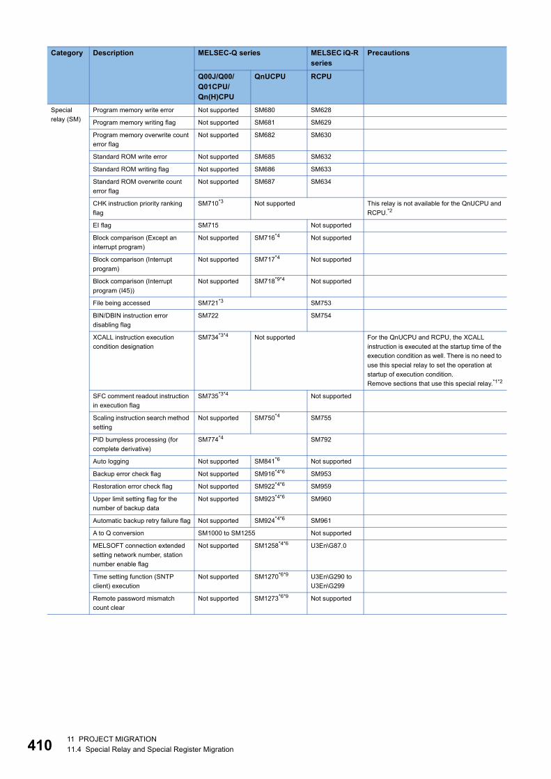
41
Special relay (SM)
Program memory write error Not supported SM680 SM628
Program memory writing flag Not supported SM681 SM629
Program memory overwrite count error flag
Not supported SM682 SM630
Standard ROM write error Not supported SM685 SM632
Standard ROM writing flag Not supported SM686 SM633
Standard ROM overwrite count error flag
Not supported SM687 SM634
CHK instruction priority ranking flag
SM710*3 Not supported This relay is not available for the QnUCPU and RCPU.*2
EI flag SM715 Not supported
Block comparison (Except an interrupt program)
Not supported SM716*4 Not supported
Block comparison (Interrupt program)
Not supported SM717*4 Not supported
Block comparison (Interrupt program (I45))
Not supported SM718*9*4 Not supported
File being accessed SM721*3 SM753
BIN/DBIN instruction error disabling flag
SM722 SM754
XCALL instruction execution condition designation
SM734*3*4 Not supported For the QnUCPU and RCPU, the XCALL instruction is executed at the startup time of the execution condition as well. There is no need to use this special relay to set the operation at startup of execution condition.Remove sections that use this special relay.*1*2
SFC comment readout instruction in execution flag
SM735*3*4 Not supported
Scaling instruction search method setting
Not supported SM750*4 SM755
PID bumpless processing (for complete derivative)
SM774*4 SM792
Auto logging Not supported SM841*6 Not supported
Backup error check flag Not supported SM916*4*6 SM953
Restoration error check flag Not supported SM922*4*6 SM959
Upper limit setting flag for the number of backup data
Not supported SM923*4*6 SM960
Automatic backup retry failure flag Not supported SM924*4*6 SM961
A to Q conversion SM1000 to SM1255 Not supported
MELSOFT connection extended setting network number, station number enable flag
Not supported SM1258*4*6 U3En\G87.0
Time setting function (SNTP client) execution
Not supported SM1270*6*9 U3En\G290 toU3En\G299
Remote password mismatch count clear
Not supported SM1273*6*9 Not supported
Category Description MELSEC-Q series MELSEC iQ-R series
Precautions
Q00J/Q00/Q01CPU/Qn(H)CPU
QnUCPU RCPU
0 11 PROJECT MIGRATION11.4 Special Relay and Special Register Migration

11
*1 For details, refer to the following. Differences between MELSEC-Q series and MELSEC iQ-R series (FA-A-0171)
*2 For details, refer to the following. Method of replacing High Performance model QCPU with Universal model QCPU (FA-A-0001)
*3 This relay is not available for the Basic model QCPU.*4 Availability depends on the version of the CPU module. For details, refer to the following.
QnUCPU User's Manual (Function Explanation, Program Fundamentals)*5 This relay is not available for the Q00JCPU and Q00UJCPU.*6 This relay is available for the High-speed Universal model QCPU.*7 This relay is not available for the Q00UJCPU.*8 This relay is not available for the Q00UJCPU, Q00UCPU, and Q01UCPU.*9 This relay is available for the QnUDE(H)CPU.
Special relay (SM)
IP address storage area write request
Not supported SM1292*4*6*9 SM1520
IP address storage area write completion
Not supported SM1293*4*6*9 SM1520
IP address storage area write error
Not supported SM1294*4*6*9 SM1521
IP address storage area clear request
Not supported SM1295*4*6*9 SM1522
IP address storage area clear completion
Not supported SM1296*4*6*9 SM1522
IP address storage area clear error
Not supported SM1297*4*6*9 SM1523
Predefined protocol ready (for built-in Ethernet communications)
Not supported SM1354*4 U3En\G692
Predefined protocol setting check request (for built-in Ethernet communications)
Not supported SM1355*4 Not supported
Power supply off detection flag SM1780*3*4 Not supported
Power supply failure detection flag
SM1781*3*4 Not supported
Momentary power failure detection flag for power supply 1
SM1782*3*4 Not supported
Momentary power failure detection flag for power supply 2
SM1783*3*4 Not supported
Backup status flag Not supported SM1925*4*6 SM1350
Backup execution request Not supported SM1926*4*6 SM1351
Restoration status flag Not supported SM1928*4*6 SM1353
Restoration execution request Not supported SM1929*4*6 SM1354
Retry status flag for automatic backup
Not supported SM1931*4*6 SM1356
Data logging Not supported SM1940 to SM2037*6
SM1210 to SM1308
Category Description MELSEC-Q series MELSEC iQ-R series
Precautions
Q00J/Q00/Q01CPU/Qn(H)CPU
QnUCPU RCPU
11 PROJECT MIGRATION11.4 Special Relay and Special Register Migration 411

41
Migration of special registerThe following table lists the differences of special register after migration from the QCPU to RCPU.
Category Description MELSEC-Q series MELSEC iQ-R series
Precautions
Q00J/Q00/Q01CPU, Qn(H)CPU
QnUCPU RCPU
Special register (SD)
Clock time for diagnosis error occurrence
SD1 to SD3 SD1 to SD7 For the RCPU, the latest self-diagnostic error time is stored. The stored data is different and not automatically converted.*1
Error information categories, error common information, error individual information
SD4, SD5 to SD15, SD16 to SD26 SD80 to SD143 For the RCPU, detailed information 1 and 2 are stored. The stored data are different and not automatically converted.*1
Error reset SD50 Not supported
Battery low SD51, SD52 Not supported
CHK number SD80*3 Not supported This register is not available for the QnUCPU and RCPU.*2
Continuation error cause Not supported SD81, SD82*4*6 Not supported
Continuation error clear Not supported SD84, SD85*6 Not supported
Step transition monitoring timer setting value
SD90 to SD99*3 Not supported This register is not available for the QnUCPU and RCPU.*2
IP packet transfer function related information
Not supported SD180 to SD183*4
U3En\G310 toU3En\G313
Status of switch SD200 SD200
LED status SD201 SD201
LED off command SD202*3 Not supported
Operating status of CPU SD203 SD203
LED display color Not supported SD204 Not supported
LED display priority ranking SD207 to SD209 Not supported
Clock data SD210 to SD213 SD210 to SD216 For the RCPU, the stored data is different and not automatically converted.*1
LED display data SD220 to SD227 Not supported
Base mode SD240 Not supported
Installed Q base presence/absence
SD242 For the RCPU, this register is "Identification for whether or not Q series module can be mounted".*1
CC-Link error SD280, SD281*3 Not supported This register is not available for the QnUCPU and RCPU.Use the I/O signals (Xn0, Xn1, XnF) of the installed CC-Link module instead.*2
Device assignment SD290 to SD304 SD282 to SD311*4
SD260 to SD309
Time reserved for communication processing
SD315 Not supported For the QnUCPU and RCPU, the service processing setting is available in the system setting for parameters.
Online change (inactive block) target block number
Not supported SD329*4
Latch clear operation setting Not supported SD339*4*6 Not supported
2 11 PROJECT MIGRATION11.4 Special Relay and Special Register Migration
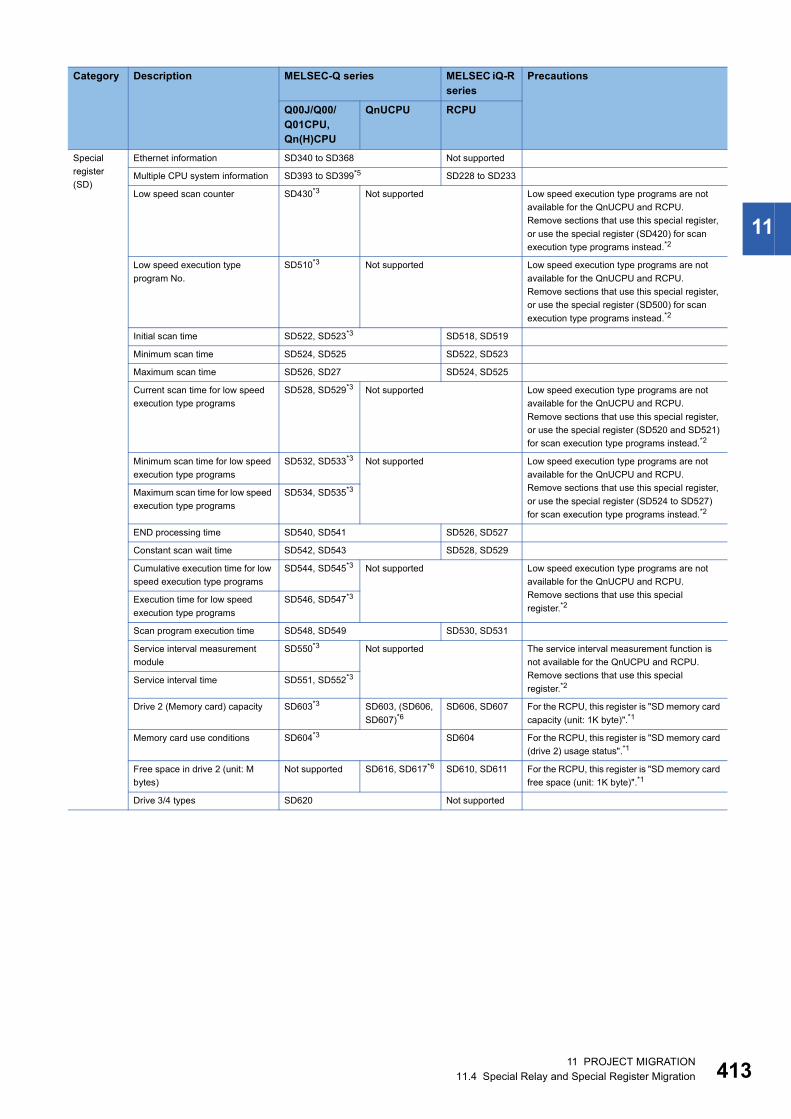
11
Special register (SD)
Ethernet information SD340 to SD368 Not supported
Multiple CPU system information SD393 to SD399*5 SD228 to SD233
Low speed scan counter SD430*3 Not supported Low speed execution type programs are not available for the QnUCPU and RCPU.Remove sections that use this special register, or use the special register (SD420) for scan execution type programs instead.*2
Low speed execution type program No.
SD510*3 Not supported Low speed execution type programs are not available for the QnUCPU and RCPU.Remove sections that use this special register, or use the special register (SD500) for scan execution type programs instead.*2
Initial scan time SD522, SD523*3 SD518, SD519
Minimum scan time SD524, SD525 SD522, SD523
Maximum scan time SD526, SD27 SD524, SD525
Current scan time for low speed execution type programs
SD528, SD529*3 Not supported Low speed execution type programs are not available for the QnUCPU and RCPU.Remove sections that use this special register, or use the special register (SD520 and SD521) for scan execution type programs instead.*2
Minimum scan time for low speed execution type programs
SD532, SD533*3 Not supported Low speed execution type programs are not available for the QnUCPU and RCPU.Remove sections that use this special register, or use the special register (SD524 to SD527) for scan execution type programs instead.*2
Maximum scan time for low speed execution type programs
SD534, SD535*3
END processing time SD540, SD541 SD526, SD527
Constant scan wait time SD542, SD543 SD528, SD529
Cumulative execution time for low speed execution type programs
SD544, SD545*3 Not supported Low speed execution type programs are not available for the QnUCPU and RCPU.Remove sections that use this special register.*2
Execution time for low speed execution type programs
SD546, SD547*3
Scan program execution time SD548, SD549 SD530, SD531
Service interval measurement module
SD550*3 Not supported The service interval measurement function is not available for the QnUCPU and RCPU.Remove sections that use this special register.*2
Service interval time SD551, SD552*3
Drive 2 (Memory card) capacity SD603*3 SD603, (SD606, SD607)*6
SD606, SD607 For the RCPU, this register is "SD memory card capacity (unit: 1K byte)".*1
Memory card use conditions SD604*3 SD604 For the RCPU, this register is "SD memory card (drive 2) usage status".*1
Free space in drive 2 (unit: M bytes)
Not supported SD616, SD617*6 SD610, SD611 For the RCPU, this register is "SD memory card free space (unit: 1K byte)".*1
Drive 3/4 types SD620 Not supported
Category Description MELSEC-Q series MELSEC iQ-R series
Precautions
Q00J/Q00/Q01CPU, Qn(H)CPU
QnUCPU RCPU
11 PROJECT MIGRATION11.4 Special Relay and Special Register Migration 413
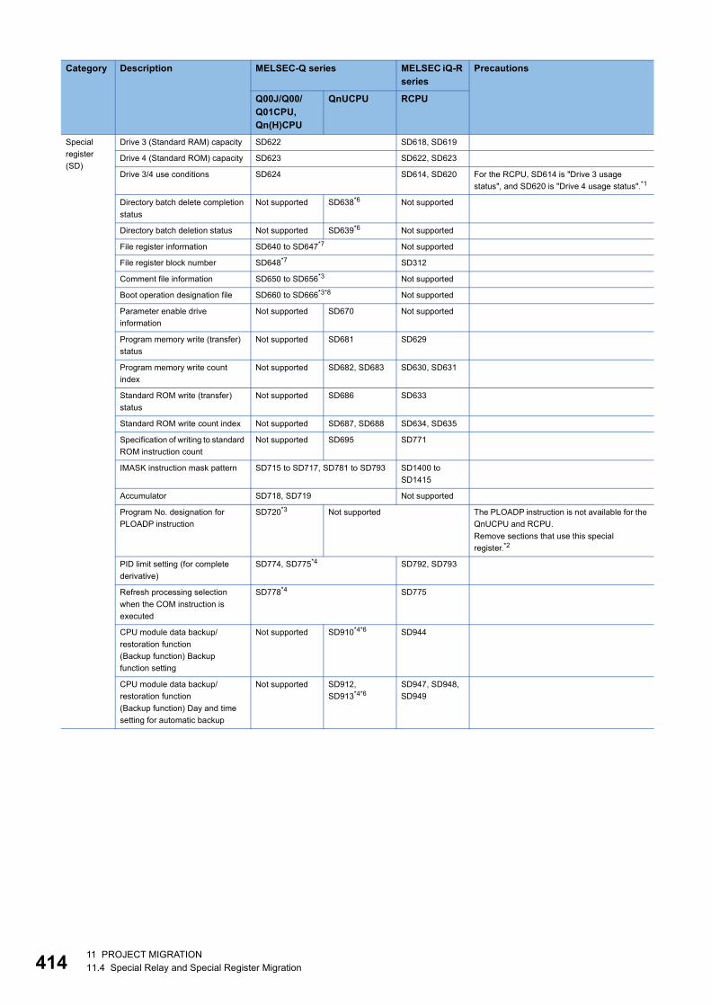
41
Special register (SD)
Drive 3 (Standard RAM) capacity SD622 SD618, SD619
Drive 4 (Standard ROM) capacity SD623 SD622, SD623
Drive 3/4 use conditions SD624 SD614, SD620 For the RCPU, SD614 is "Drive 3 usage status", and SD620 is "Drive 4 usage status".*1
Directory batch delete completion status
Not supported SD638*6 Not supported
Directory batch deletion status Not supported SD639*6 Not supported
File register information SD640 to SD647*7 Not supported
File register block number SD648*7 SD312
Comment file information SD650 to SD656*3 Not supported
Boot operation designation file SD660 to SD666*3*8 Not supported
Parameter enable drive information
Not supported SD670 Not supported
Program memory write (transfer) status
Not supported SD681 SD629
Program memory write count index
Not supported SD682, SD683 SD630, SD631
Standard ROM write (transfer) status
Not supported SD686 SD633
Standard ROM write count index Not supported SD687, SD688 SD634, SD635
Specification of writing to standard ROM instruction count
Not supported SD695 SD771
IMASK instruction mask pattern SD715 to SD717, SD781 to SD793 SD1400 to SD1415
Accumulator SD718, SD719 Not supported
Program No. designation for PLOADP instruction
SD720*3 Not supported The PLOADP instruction is not available for the QnUCPU and RCPU.Remove sections that use this special register.*2
PID limit setting (for complete derivative)
SD774, SD775*4 SD792, SD793
Refresh processing selection when the COM instruction is executed
SD778*4 SD775
CPU module data backup/restoration function(Backup function) Backup function setting
Not supported SD910*4*6 SD944
CPU module data backup/restoration function(Backup function) Day and time setting for automatic backup
Not supported SD912, SD913*4*6
SD947, SD948, SD949
Category Description MELSEC-Q series MELSEC iQ-R series
Precautions
Q00J/Q00/Q01CPU, Qn(H)CPU
QnUCPU RCPU
4 11 PROJECT MIGRATION11.4 Special Relay and Special Register Migration

11
Special register (SD)
CPU module data backup/restoration function(Backup function) Time and day of the week setting for automatic backup
Not supported SD914, SD915*4*6
SD950, SD951, SD952
CPU module data backup/restoration function(Backup function) Cause of error occurred at backup
Not supported SD916*4*6 SD953
CPU module data backup/restoration function(Restoration function) Restoration target data setting
Not supported SD917*4*6 SD954
CPU module data backup/restoration function(Restoration function) Restoration function setting
Not supported SD918*4*6 SD955
CPU module data backup/restoration function(Restoration function) Restoration target folder
Not supported SD919, SD920, SD921*4*6
SD956, SD957, SD958
CPU module data backup/restoration function(Restoration function) Cause of error occurred during restoration
Not supported SD922*4*6 SD959
CPU module data backup/restoration function(Restoration function) Upper limit value status for the number of backup data
Not supported SD923*4*6 SD960
Device information during "RAM ERROR"
Not supported SD927, SD928*4 Not supported
Remote password count Not supported SD979 to SD999*6*9
U3En\G320 toU3En\G340
A to Q conversion SD1000 to SD1255 Not supported
MELSOFT connection extended setting network number
Not supported SD1258*6 U3En\G77
MELSOFT connection extended setting station number
Not supported SD1259*6 U3En\G78
IP address in-use Not supported SD1260 to SD1265*4*6*9
U3En\G50 toU3En\G65
For the RCPU, this register is "Own node IP address".*1
MAC address Not supported SD1266 to SD1268*4*6*9
U3En\G74 toU3En\G76
For the RCPU, this register is "Own node MAC address".*1
Time setting function (SNTP) related information
Not supported SD1270 to SD1275*6*9
U3En\G290 toU3En\G299
For the RCPU, the stored data is different and not automatically converted.*1
Forced connection invalidation Not supported SD1276, SD1277*4*6*9
U3En\G280, U3En\G281
Category Description MELSEC-Q series MELSEC iQ-R series
Precautions
Q00J/Q00/Q01CPU, Qn(H)CPU
QnUCPU RCPU
11 PROJECT MIGRATION11.4 Special Relay and Special Register Migration 415

41
*1 For details, refer to the following. Differences between MELSEC-Q series and MELSEC iQ-R series (FA-A-0171)
*2 For details, refer to the following. Method of replacing High Performance model QCPU with Universal model QCPU (FA-A-0001)
*3 This register is not available for the Basic model QCPU.*4 Availability depends on the version of the CPU module. For details, refer to the following.
QnUCPU User's Manual (Function Explanation, Program Fundamentals)*5 This register is not available for the Q00JCPU and Q00UJCPU.*6 This register is available for the High-speed Universal model QCPU.*7 This register is not available for the Q00UJCPU.*8 This register is not available for the Q00UJCPU, Q00UCPU, and Q01UCPU.*9 This register is available for the QnUDE(H)CPU.
Special register (SD)
Open completion signal Not supported SD1282*4*6*9 SD1504
Open request signal Not supported SD1284*4*6*9 SD1505
Reception status signal Not supported SD1286*4*6*9 SD1506
Built-in Ethernet port connection status
Not supported SD1288*4*6*9 Not supported
Ethernet basic time-out time Not supported SD1289*6*9 Not supported
IP address setting IP address (lower digits)
Not supported SD1292*4*6*9 SD1520
IP address setting IP address (upper digits)
Not supported SD1293*4*6*9 SD1521
IP address setting Subnet mask pattern (lower digits)
Not supported SD1294*4*6*9 SD1522
IP address setting Subnet mask pattern (upper digits)
Not supported SD1295*4*6*9 SD1523
IP address setting Default router IP address (lower digits)
Not supported SD1296*4*6*9 SD1524
IP address setting Default router IP address (upper digits)
Not supported SD1297*4*6*9 SD1525
IP address storage area write error factor
Not supported SD1298*4*6*9 SD1526
IP address storage area clear error factor
Not supported SD1299*4*6*9 SD1527
Fuse blown module SD1300 to SD1331*3 Not supported
IP address change function related information
Not supported SD1359 to SD1381*4*6
U3En\G710 toU3En\G729
Built-in Ethernet port counter Not supported SD1395*4*6*9 U3En\G226 For the RCPU, this register is "Receive FIFO overflow count".*1
I/O module verification SD1400 to SD1431*3 Not supported
Number of backup/restoration uncompleted files
Not supported SD1925*4*6 SD1350
Backup/restoration progression status
Not supported SD1926*4*6 SD1351
Upper limit value setting for the number of backup data
Not supported SD1928*4*6 SD1353
Data logging Not supported SD1940 to SD2037*6
SD1210 to SD1306
Category Description MELSEC-Q series MELSEC iQ-R series
Precautions
Q00J/Q00/Q01CPU, Qn(H)CPU
QnUCPU RCPU
6 11 PROJECT MIGRATION11.4 Special Relay and Special Register Migration

11
11.5 Precautions for Project Migration
TCP (MELSOFT connection)/UDP (MELSOFT connection) settingFor the RCPU, set connection numbers. Set "MELSOFT Connection Module" in the connection number not used.The open setting is not required when connecting the GOT or other external devices using UDP. (An automatic UDP port is used.) • Built-in Ethernet setting window of PLC parameter (GX Works2)
• Module parameter setting window (GX Works3)
TCP connection setting of socket communications (TCP/IP connection)For the RCPU, select "Active Connection Module", "Unpassive Connection Module", or "Fullpassive Connection Module" in the Ethernet device setting, and then set "Socket Communication in "Communication Method". • Built-in Ethernet setting window of PLC parameter (GX Works2)
• Module parameter setting window (GX Works3)
11 PROJECT MIGRATION11.5 Precautions for Project Migration 417
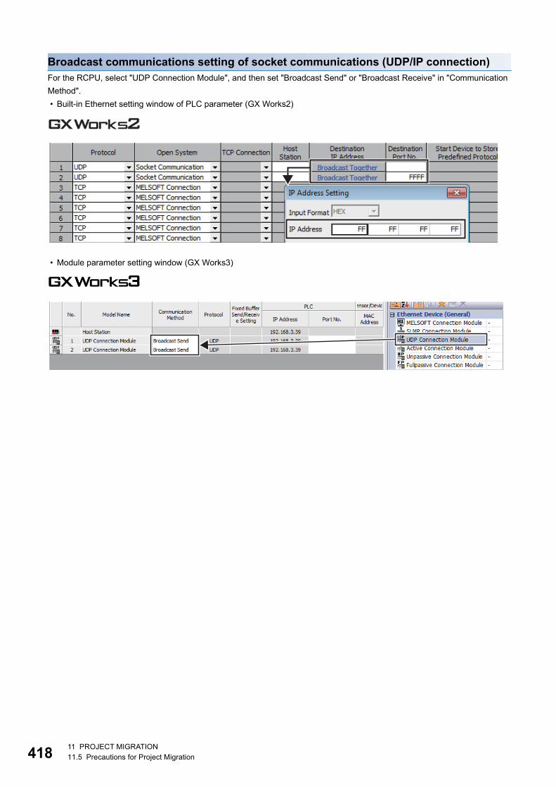
41
Broadcast communications setting of socket communications (UDP/IP connection)For the RCPU, select "UDP Connection Module", and then set "Broadcast Send" or "Broadcast Receive" in "Communication Method". • Built-in Ethernet setting window of PLC parameter (GX Works2)
• Module parameter setting window (GX Works3)
8 11 PROJECT MIGRATION11.5 Precautions for Project Migration

11
Time zone setting of time setting (SNTP client)For the RCPU, set the time zone in "Clock Related Setting" of CPU parameter because the time zone can be set in the clock data of the CPU module. • Built-in Ethernet setting window of PLC parameter (GX Works2)
• Module parameter setting window (GX Works3)
• CPU parameter setting window (GX Works3)
Setting of communications using the predefined protocolFor the RCPU, check the predefined protocol operating status such as protocol execution status and protocol execution count in the CPU buffer memory (U3En\G*).If the start device where the operating status of the predefined protocol is stored is set in the open setting of PLC parameter and the device is used in the MELSEC-Q series program, the program needs to be corrected for the MELSEC iQ-R series.
11 PROJECT MIGRATION11.5 Precautions for Project Migration 419

42
SFC programSFC programs can be used in the RCPU (GX Works3). However, the operation method of the engineering tool is different. For details on the operation method of GX Works3, refer to the following. GX Works3 Operating ManualWhen reading the MELSAP3/MELSAP-L SFC programs created with GX Works2, refer to the following. Considerations for opening SFC programs in GX Works2 format with GX Works3 (FA-A-0192)
Monitor condition settingThe RCPU does not support the monitor condition setting. Use the trigger logging of the data logging function instead.Trigger logging collects monitor data at the timing of specified condition or step number.
Executional conditioned device testFor the RCPU, availability of the executional conditioned device test varies depending on the firmware version of the CPU module. If the executional conditioned device test is not available, use the following method instead.To change a device value at the specified step, execute the online change function, and add a replacement program to the desired position. (Delete the program to disable the processing.)If the execution timing is set to before execution of an instruction in the QnUDVCPU program, add a program for the device test before the corresponding step in the RCPU program. If the execution timing is set to after execution of an instruction, add a program after the corresponding step. • Program and Device Test with Execution Condition window (GX Works2)
Executional conditioned device test setting for (1) Executional conditioned device test setting for (2)
(1) Without depending on the program before the instruction, turn on M100 and execute the instruction.
(2) Regardless of the operation result, change the value in D200 to K500 and execute the program after this step.
0 11 PROJECT MIGRATION11.5 Precautions for Project Migration

11
• Program (GX Works3)
<Program before change>
<Program after change>
Add this program to change the value in D200 to K500 and execute the program after this step regardless of the operation result.
Add this program to turn on M100 and execute the instruction without depending on the program before the instruction.
(2)
(1)
11 PROJECT MIGRATION11.5 Precautions for Project Migration 421
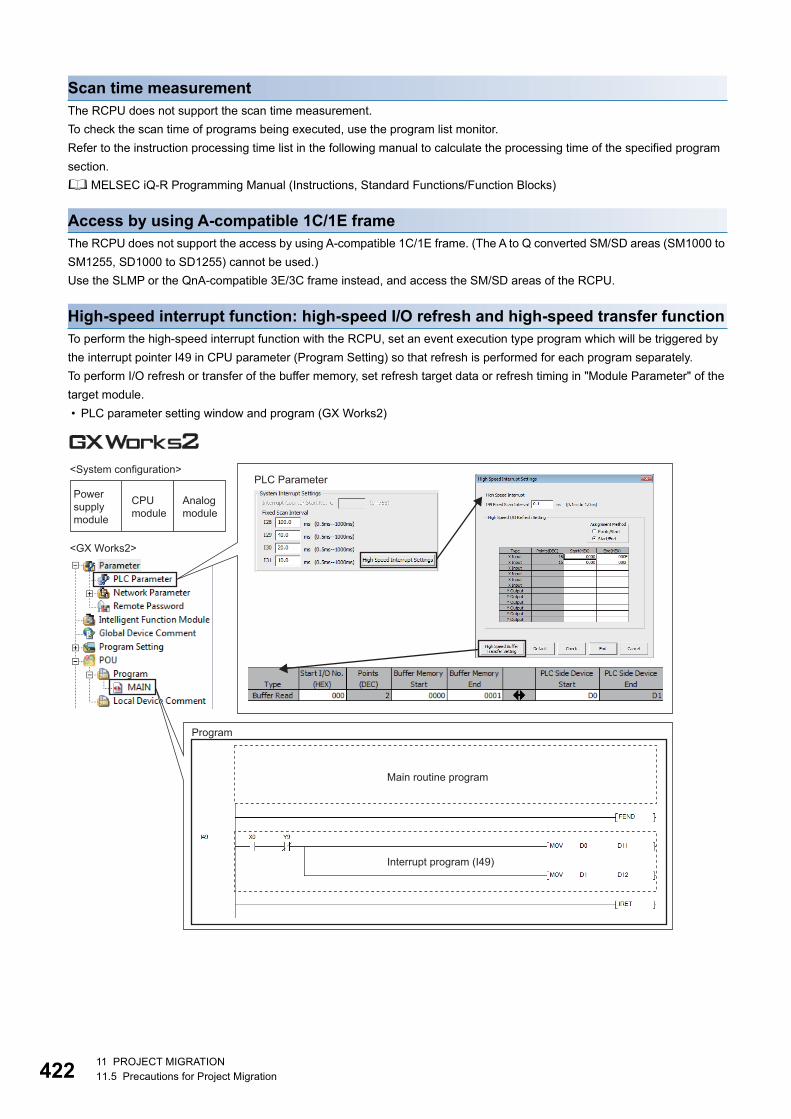
42
Scan time measurementThe RCPU does not support the scan time measurement.To check the scan time of programs being executed, use the program list monitor.Refer to the instruction processing time list in the following manual to calculate the processing time of the specified program section. MELSEC iQ-R Programming Manual (Instructions, Standard Functions/Function Blocks)
Access by using A-compatible 1C/1E frameThe RCPU does not support the access by using A-compatible 1C/1E frame. (The A to Q converted SM/SD areas (SM1000 to SM1255, SD1000 to SD1255) cannot be used.)Use the SLMP or the QnA-compatible 3E/3C frame instead, and access the SM/SD areas of the RCPU.
High-speed interrupt function: high-speed I/O refresh and high-speed transfer functionTo perform the high-speed interrupt function with the RCPU, set an event execution type program which will be triggered by the interrupt pointer I49 in CPU parameter (Program Setting) so that refresh is performed for each program separately.To perform I/O refresh or transfer of the buffer memory, set refresh target data or refresh timing in "Module Parameter" of the target module. • PLC parameter setting window and program (GX Works2)
PLC Parameter<System configuration>
Analog module
CPU module
Power supply module
<GX Works2>
Program
Interrupt program (I49)
Main routine program
2 11 PROJECT MIGRATION11.5 Precautions for Project Migration

11
• CPU parameter setting window, module parameter setting window, and program (GX Works3)
Service processingThe RCPU performs file access processing, such as reading program files, without being synchronized with each scan (not during END processing) so that the scan time will not be delayed due to the processing.For this reason, the response performance does not improve even though the number of processing counts is increased in the device/label access service processing setting. (The response performance does not improve either even though the COM instruction is used.)On the other hand, the RCPU performs device access processing, such as reading device data, during END processing. Therefore, the response performance of device access processing can be improved by increasing the number of processing counts in the device/label access service processing setting or by using the COM instruction.
<System configuration>
<GX Works3>
Analog module
CPU module
Power supply module
CPU ParameterInterrupt Settings
Program Setting
Module Parameter
Program (scan execution type)
Main routine program
Program (event execution type)
Program triggered by the interrupt pointer, I49
11 PROJECT MIGRATION11.5 Precautions for Project Migration 423

42
Data logging file transfer functionFor the RCPU, availability of the data logging file transfer function varies depending on the firmware version of the CPU module. If the data logging file transfer function is not available, use the following method instead.For the RCPU, use the FTP server function of built-in Ethernet and load logging result files stored in the CPU module to the server, such as a personal computer. • File transfer window (CPU Module Logging Configuration Tool)
• Command Prompt window for FTP file transfer (FTP server)
Set a transfer destination.
226 Transfer complete.150 Opening connection.200 Port command successful.mget 2:\logging\log01\00000001\00000001.TXT? y200 TYPE is now ASCII.ftp> mget 2:\logging\log01\00000001\*.txt230 User logged in.Password: 331 Password required.User (192.0.1.254(none)):RCPU220 iQ-R FTP server ready.Connected to 192.0.1.254FTP> open 192.0.1.254C:\>FTP
Transfer Unicode text files (in units of files) by using the FTP command (mget).
4 11 PROJECT MIGRATION11.5 Precautions for Project Migration

11
Access to the host CPU operation information area in CPU shared memoryThe RCPU does not have the host CPU operation information area (U3En\G0 and later) in CPU shared memory. If the host CPU operation information area is used in the MELSEC-Q series program, the program needs to be corrected for the MELSEC iQ-R series.To check the operation information of another CPU module, refresh the data in the corresponding special register (SD) to the CPU shared memory, and then access to the data stored in the memory.
Access to the multiple CPU high speed transmission areaArea used for data communications among multiple CPU modules has been extended in the RCPU. The multiple CPU high speed transmission area is included in the fixed scan communication area, and the addresses have been changed from U3En\G10000 and later to U3En\HG0 and later.If the multiple CPU high speed transmission area is used in the MELSEC-Q series program, the program needs to be corrected for the MELSEC iQ-R series.When a project created by using GX Works2 is opened by "Open Other Format File" in GX Works3 and edited, the addresses U3En\G10000 and later are automatically converted to U3En\HG0 and later. Note, however, that if the fixed scan communication area is accessed by using the FROM/TO instructions, the access method needs to be corrected. Use the data transfer instruction and CPU buffer memory access device, (example: MOV U3En\HG*D0) instead of the FROM/TO instructions. • Program to access the multiple CPU high speed transmission area (GX Works2)
• Program to access the fixed scan communication area (GX Works3)
11 PROJECT MIGRATION11.5 Precautions for Project Migration 425

42
Refresh using the multiple CPU high speed transmission areaThe RCPU performs multiple CPU refresh at two timings: during END processing and at execution of the multiple CPU synchronous interrupt (I45). Since refresh timing differs, if refresh using the multiple CPU high speed transmission area is set in the MELSEC-Q series program, the program needs to be corrected for the MELSEC iQ-R series.To perform refresh during END processing (the same timing as the QCPU), set the refresh timing in system parameter ("Refresh Setting (At the END)" under "CPU Buffer Memory Setting"). • PLC parameter setting window (Multiple CPU Setting) and refresh timing (GX Works2)
END END
Interrupt program (I45)
Scan execution type program
Time
Multiple CPU refresh (Reading/writing data from/to other CPU modules)
6 11 PROJECT MIGRATION11.5 Precautions for Project Migration

11
• System parameter setting window (Multiple CPU Setting) and refresh timing (GX Works3)
END END
Interrupt program (I45)
Scan execution type program
Time
Multiple CPU refresh (Reading/writing data from/to other CPU modules)
Multiple CPU refresh (Reading/writing data from/to other CPU modules)
11 PROJECT MIGRATION11.5 Precautions for Project Migration 427

42
Self-diagnostic functionThe RCPU batch-clears all the continuation errors being detected.The delete-target continuation error does not need to be specified individually.The error code system has been renewed for the RCPU. If an error code is set as an operating condition or interlock condition in the MELSEC-Q program, the program needs to be corrected for the MELSEC iQ-R series.
Long timerA long timer contact turns on after a long timer coil turns on. Note that the operation (timing) may slightly differ between the RCPU and QCPU. When the long timer (LT) is used for the RCPU, the timing the contact turns on is not immediately after the coil turns on. The contact remains off until the next coil instruction is executed after the turning on of the coil, then turns on.
File size of a projectThe file size of a project may increase when a project used for the MELSEC-Q series is converted to a project for the MELSEC iQ-R series. The increased file size, however, can be reduced by configuring a setting to compress a project file in GX Works3.This project file compression setting is available for GX Works3 with the version of 1.047Z or later.Follow the procedure below.
1. Select a project in the Navigation window and select [Project] [Data Operation] [Properties]. Or right-click the project and select [Properties] from the shortcut menu.
2. Select "Compression" for "File Size" and click the [OK] button. A project is saved with the file being compressed to the smaller size.
For details, refer to the following. GX Works3 Operating Manual
8 11 PROJECT MIGRATION11.5 Precautions for Project Migration

11
Extended data register (D) and extended link register (W)The extended data register (D) and extended link register (W) cannot be used for the RCPU.When using the RCPU, increase the device area capacity as well as the number of points for the data register (D) and link register (W) in CPU parameter. (To increase the device area capacity, decrease the file storage area capacity.) • PLC parameter setting window (GX Works2)
• CPU parameter setting window (GX Works3)
Change the capacity from 40K words (default) to 60K words.
Change the capacity from 128K words (default) to 108K words.
Detailed Setting (Change the point setting: 18K→28K for D device, 8K→18K for W device)
11 PROJECT MIGRATION11.5 Precautions for Project Migration 429
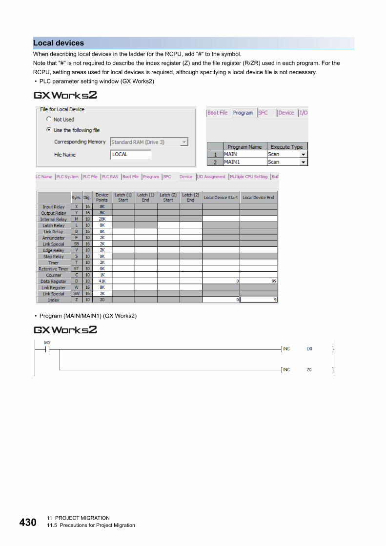
43
Local devicesWhen describing local devices in the ladder for the RCPU, add "#" to the symbol.Note that "#" is not required to describe the index register (Z) and the file register (R/ZR) used in each program. For the RCPU, setting areas used for local devices is required, although specifying a local device file is not necessary. • PLC parameter setting window (GX Works2)
• Program (MAIN/MAIN1) (GX Works2)
0 11 PROJECT MIGRATION11.5 Precautions for Project Migration

11
• CPU parameter setting window (GX Works3)
Change the capacity from 128K words (default) to 100K words. (Secure the local device area capacity.)
Detailed Setting (Local Device setting)
Set the local index register points.
Program Setting
Memory/Device Setting
11 PROJECT MIGRATION11.5 Precautions for Project Migration 431

43
• Program (MAIN/MAIN1) (GX Works3)
File nameSince the RCPU handles file names as Unicode data, specify the file name in Unicode when loading a file to the CPU module from an external device, such as an FTP client.File names specified in a character string (specified by using " ") on the program do not need to be changed because they are recognized as Unicode. However, if string data stored in the device are actually used by the program, the program needs to be modified for the MELSEC iQ-R series.
For details on these precautions, refer to the following. MELSEC iQ-R Module Configuration Manual MELSEC iQ-R Programming Manual (Program Design) MELSEC iQ-R Programming Manual (Instructions, Standard Functions/Function Blocks) Differences between MELSEC-Q series and MELSEC iQ-R series (FA-A-0171)
Describe the device with #.
Describe the device as is (without #).
2 11 PROJECT MIGRATION11.5 Precautions for Project Migration

11
MEMO
11 PROJECT MIGRATION11.5 Precautions for Project Migration 433

434
REVISIONS* The document number is given on the bottom left of the back cover.
Japanese manual number: L08489-E
2017 MITSUBISHI ELECTRIC CORPORATION
Revision date Document number DescriptionNovember 2017 L(NA)08510ENG-A First edition
February 2019 L(NA)08510ENG-B ■Added modelsRX70, RX71, RX72, RJ71GP21S-SX, RJ71DN91, RJ71PB91VR33B, RD60P8-G■Partial correctionSection 3.1, 3.2, 5.1, 5.2, 6.1, 7.2, Chapter 8, 9, 10
March 2020 L(NA)08510ENG-C ■Added modelsR08PCPU, R16PCPU, R32PCPU, RJ71LP21-25■Changed modelRD81MES96 RD81MES96N■AdditionSection 1.2■Partial correctionSection 1.2 Section 1.3, Chapter 2, Section 3.2, 7.1, 7.3, Chapter 9, 10, Section 11.1, 11.2, 11.5
This manual confers no industrial property rights or any rights of any other kind, nor does it confer any patent licenses. Mitsubishi Electric Corporation cannot be held responsible for any problems involving industrial property rights which may occur as a result of using the contents noted in this manual.

WARRANTYPlease confirm the following product warranty details before using this product.
1. Gratis Warranty Term and Gratis Warranty RangeIf any faults or defects (hereinafter "Failure") found to be the responsibility of Mitsubishi occurs during use of the product within the gratis warranty term, the product shall be repaired at no cost via the sales representative or Mitsubishi Service Company.However, if repairs are required onsite at domestic or overseas location, expenses to send an engineer will be solely at the customer's discretion. Mitsubishi shall not be held responsible for any re-commissioning, maintenance, or testing on-site that involves replacement of the failed module.[Gratis Warranty Term]The gratis warranty term of the product shall be for one year after the date of purchase or delivery to a designated place.Note that after manufacture and shipment from Mitsubishi, the maximum distribution period shall be six (6) months, and the longest gratis warranty term after manufacturing shall be eighteen (18) months. The gratis warranty term of repair parts shall not exceed the gratis warranty term before repairs.[Gratis Warranty Range](1) The range shall be limited to normal use within the usage state, usage methods and usage environment, etc., which
follow the conditions and precautions, etc., given in the instruction manual, user's manual and caution labels on the product.
(2) Even within the gratis warranty term, repairs shall be charged for in the following cases.1. Failure occurring from inappropriate storage or handling, carelessness or negligence by the user. Failure caused
by the user's hardware or software design.2. Failure caused by unapproved modifications, etc., to the product by the user.3. When the Mitsubishi product is assembled into a user's device, Failure that could have been avoided if functions
or structures, judged as necessary in the legal safety measures the user's device is subject to or as necessary by industry standards, had been provided.
4. Failure that could have been avoided if consumable parts (battery, backlight, fuse, etc.) designated in the instruction manual had been correctly serviced or replaced.
5. Failure caused by external irresistible forces such as fires or abnormal voltages, and Failure caused by force majeure such as earthquakes, lightning, wind and water damage.
6. Failure caused by reasons unpredictable by scientific technology standards at time of shipment from Mitsubishi.7. Any other failure found not to be the responsibility of Mitsubishi or that admitted not to be so by the user.
2. Onerous repair term after discontinuation of production(1) Mitsubishi shall accept onerous product repairs for seven (7) years after production of the product is discontinued.
Discontinuation of production shall be notified with Mitsubishi Technical Bulletins, etc.(2) Product supply (including repair parts) is not available after production is discontinued.
3. Overseas serviceOverseas, repairs shall be accepted by Mitsubishi's local overseas FA Center. Note that the repair conditions at each FA Center may differ.
4. Exclusion of loss in opportunity and secondary loss from warranty liabilityRegardless of the gratis warranty term, Mitsubishi shall not be liable for compensation to:(1) Damages caused by any cause found not to be the responsibility of Mitsubishi.(2) Loss in opportunity, lost profits incurred to the user by Failures of Mitsubishi products.(3) Special damages and secondary damages whether foreseeable or not, compensation for accidents, and
compensation for damages to products other than Mitsubishi products.(4) Replacement by the user, maintenance of on-site equipment, start-up test run and other tasks.
5. Changes in product specificationsThe specifications given in the catalogs, manuals or technical documents are subject to change without prior notice.
435

43
For Safety CPUs
Please confirm the following product warranty details before using this product.
1. Limited Warranty and Product Support.a. Mitsubishi Electric Company ("MELCO") warrants that for a period of eighteen (18) months after date of delivery from the point of
manufacture or one year from date of Customer's purchase, whichever is less, Mitsubishi MELSEC Safety programmable logic controllers (the "Products") will be free from defects in material and workmanship.
b. At MELCO's option, for those Products MELCO determines are not as warranted, MELCO shall either repair or replace them or issue a credit or return the purchase price paid for them.
c. For this warranty to apply:(1) Customer shall give MELCO (i) notice of a warranty claim to MELCO and the authorized dealer or distributor from whom the
Products were purchased, (ii) the notice shall describe in reasonable details the warranty problem, (iii) the notice shall be provided promptly and in no event later than thirty (30) days after the Customer knows or has reason to believe that Products are not as warranted, and (iv) in any event, the notice must given within the warranty period;
(2) Customer shall cooperate with MELCO and MELCO's representatives in MELCO's investigation of the warranty claim, including preserving evidence of the claim and its causes, meaningfully responding to MELCO's questions and investigation of the problem, grant MELCO access to witnesses, personnel, documents, physical evidence and records concerning the warranty problem, and allow MELCO to examine and test the Products in question offsite or at the premises where they are installed or used; and
(3) If MELCO requests, Customer shall remove Products it claims are defective and ship them to MELCO or MELCO's authorized representative for examination and, if found defective, for repair or replacement. The costs of removal, shipment to and from MELCO's designated examination point, and reinstallation of repaired or replaced Products shall be at Customer's expense.
(4) If Customer requests and MELCO agrees to effect repairs onsite at any domestic or overseas location, the Customer will pay for the costs of sending repair personnel and shipping parts. MELCO is not responsible for any re-commissioning, maintenance, or testing on-site that involves repairs or replacing of the Products.
d. Repairs of Products located outside of Japan are accepted by MELCO's local authorized service facility centers ("FA Centers"). Terms and conditions on which each FA Center offers repair services for Products that are out of warranty or not covered by MELCO's limited warranty may vary.
e. Subject to availability of spare parts, MELCO will offer Product repair services for (7) years after each Product model or line is discontinued, at MELCO's or its FA Centers' rates and charges and standard terms in effect at the time of repair. MELCO usually produces and retains sufficient spare parts for repairs of its Products for a period of seven (7) years after production is discontinued.
f. MELCO generally announces discontinuation of Products through MELCO's Technical Bulletins. Products discontinued and repair parts for them may not be available after their production is discontinued.
2. Limits of Warranties.a. MELCO does not warrant or guarantee the design, specify, manufacture, construction or installation of the materials, construction
criteria, functionality, use, properties or other characteristics of the equipment, systems, or production lines into which the Products may be incorporated, including any safety, fail-safe and shut down systems using the Products.
b. MELCO is not responsible for determining the suitability of the Products for their intended purpose and use, including determining if the Products provide appropriate safety margins and redundancies for the applications, equipment or systems into which they are incorporated.
c. Customer acknowledges that qualified and experienced personnel are required to determine the suitability, application, design, construction and proper installation and integration of the Products. MELCO does not supply such personnel.
d. MELCO is not responsible for designing and conducting tests to determine that the Product functions appropriately and meets application standards and requirements as installed or incorporated into the end-user's equipment, production lines or systems.
e. MELCO does not warrant any Product:(1) repaired or altered by persons other than MELCO or its authorized engineers or FA Centers;(2) subjected to negligence, carelessness, accident, misuse, or damage;(3) improperly stored, handled, installed or maintained;(4) integrated or used in connection with improperly designed, incompatible or defective hardware or software;(5) that fails because consumable parts such as batteries, backlights, or fuses were not tested, serviced or replaced;(6) operated or used with equipment, production lines or systems that do not meet applicable and commensurate legal, safety and
industry-accepted standards;(7) operated or used in abnormal applications;(8) installed, operated or used in contravention of instructions, precautions or warnings contained in MELCO's user, instruction
and/or safety manuals, technical bulletins and guidelines for the Products;(9) used with obsolete technologies or technologies not fully tested and widely accepted and in use at the time of the Product's
manufacture;(10) subjected to excessive heat or moisture, abnormal voltages, shock, excessive vibration, physical damage or other improper
environment; or(11) damaged or malfunctioning due to Acts of God, fires, acts of vandals, criminals or terrorists, communication or power failures, or
any other cause or failure that results from circumstances beyond MELCO's control.f. All Product information and specifications contained on MELCO's website and in catalogs, manuals, or technical information
materials provided by MELCO are subject to change without prior notice.
6
g. The Product information and statements contained on MELCO's website and in catalogs, manuals, technical bulletins or other materials provided by MELCO are provided as a guide for Customer's use. They do not constitute warranties and are not incorporated in the contract of sale for the Products.
h. These terms and conditions constitute the entire agreement between Customer and MELCO with respect to warranties, remedies and damages and supersede any other understandings, whether written or oral, between the parties. Customer expressly acknowledges that any representations or statements made by MELCO or others concerning the Products outside these terms are not part of the basis of the bargain between the parties and are not factored into the pricing of the Products.
i. THE WARRANTIES AND REMEDIES SET FORTH IN THESE TERMS ARE THE EXCLUSIVE AND ONLY WARRANTIES AND REMEDIES THAT APPLY TO THE PRODUCTS.
j. MELCO DISCLAIMS THE IMPLIED WARRANTIES OF MERCHANTABILITY AND FITNESS FOR A PARTICULAR PURPOSE.
3. Limits on Damages.a. MELCO'S MAXIMUM CUMULATIVE LIABILITY BASED ON ANY CLAIMS FOR BREACH OF WARRANTY OR CONTRACT,
NEGLIGENCE, STRICT TORT LIABILITY OR OTHER THEORIES OF RECOVERY REGARDING THE SALE, REPAIR, REPLACEMENT, DELIVERY, PERFORMANCE, CONDITION, SUITABILITY, COMPLIANCE, OR OTHER ASPECTS OF THE PRODUCTS OR THEIR SALE, INSTALLATION OR USE SHALL BE LIMITED TO THE PRICE PAID FOR PRODUCTS NOT AS WARRANTED.
b. Although MELCO has obtained the certification for Product's compliance to the international safety standards IEC61508 and EN954-1/ISO13849-1 from TUV Rheinland, this fact does not guarantee that Product will be free from any malfunction or failure. The user of this Product shall comply with any and all applicable safety standard, regulation or law and take appropriate safety measures for the system in which the Product is installed or used and shall take the second or third safety measures other than the Product. MELCO is not liable for damages that could have been prevented by compliance with any applicable safety standard, regulation or law.
c. MELCO prohibits the use of Products with or in any application involving power plants, trains, railway systems, airplanes, airline operations, other transportation systems, amusement equipments, hospitals, medical care, dialysis and life support facilities or equipment, incineration and fuel devices, handling of nuclear or hazardous materials or chemicals, mining and drilling, and other applications where the level of risk to human life, health or property are elevated.
d. MELCO SHALL NOT BE LIABLE FOR SPECIAL, INCIDENTAL, CONSEQUENTIAL, INDIRECT OR PUNITIVE DAMAGES, FOR LOSS OF PROFITS, SALES, OR REVENUE, FOR INCREASED LABOR OR OVERHEAD COSTS, FOR DOWNTIME OR LOSS OF PRODUCTION, FOR COST OVERRUNS, OR FOR ENVIRONMENTAL OR POLLUTION DAMAGES OR CLEAN-UP COSTS, WHETHER THE LOSS IS BASED ON CLAIMS FOR BREACH OF CONTRACT OR WARRANTY, VIOLATION OF STATUTE, NEGLIGENCE OR OTHER TORT, STRICT LIABILITY OR OTHERWISE.
e. In the event that any damages which are asserted against MELCO arising out of or relating to the Products or defects in them, consist of personal injury, wrongful death and/or physical property damages as well as damages of a pecuniary nature, the disclaimers and limitations contained in these terms shall apply to all three types of damages to the fullest extent permitted by law. If, however, the personal injury, wrongful death and/or physical property damages cannot be disclaimed or limited by law or public policy to the extent provided by these terms, then in any such event the disclaimer of and limitations on pecuniary or economic consequential and incidental damages shall nevertheless be enforceable to the fullest extent allowed by law.
f. In no event shall any cause of action arising out of breach of warranty or otherwise concerning the Products be brought by Customer more than one year after the cause of action accrues.
g. Each of the limitations on remedies and damages set forth in these terms is separate and independently enforceable, notwithstanding the unenforceability or failure of essential purpose of any warranty, undertaking, damage limitation, other provision of these terms or other terms comprising the contract of sale between Customer and MELCO.
4. Delivery/Force Majeure.a. Any delivery date for the Products acknowledged by MELCO is an estimated and not a promised date. MELCO will make all
reasonable efforts to meet the delivery schedule set forth in Customer's order or the purchase contract but shall not be liable for failure to do so.
b. Products stored at the request of Customer or because Customer refuses or delays shipment shall be at the risk and expense of Customer.
c. MELCO shall not be liable for any damage to or loss of the Products or any delay in or failure to deliver, service, repair or replace the Products arising from shortage of raw materials, failure of suppliers to make timely delivery, labor difficulties of any kind, earthquake, fire, windstorm, flood, theft, criminal or terrorist acts, war, embargoes, governmental acts or rulings, loss or damage or delays in carriage, acts of God, vandals or any other circumstances reasonably beyond MELCO's control.
5. Choice of Law/Jurisdiction.These terms and any agreement or contract between Customer and MELCO shall be governed by the laws of the State of New York without regard to conflicts of laws. To the extent any action or dispute is not arbitrated, the parties consent to the exclusive jurisdiction and venue of the federal and state courts located in the Southern District of the State of New York. Any judgment there obtained may be enforced in any court of competent jurisdiction.
6. Arbitration.Any controversy or claim arising out of, or relating to or in connection with the Products, their sale or use or these terms, shall besettled by arbitration conducted in accordance with the Center for Public Resources (CPR) Rules for Non-Administered Arbitration of International Disputes, by a sole arbitrator chosen from the CPR's panels of distinguished neutrals. Judgment upon the award rendered by the Arbitrator shall be final and binding and may be entered by any court having jurisdiction thereof. The place of the arbitration shall be New York City, New York. The language of the arbitration shall be English. The neutral organization designated to perform the functions specified in Rule 6 and Rules 7.7(b), 7.8 and 7.9 shall be the CPR.
437

438
TRADEMARKSQR Code is either a registered trademark or a trademark of DENSO WAVE INCORPORATED in the United States, Japan, and/or other countries.The SD and SDHC logos are trademarks of SD-3C, LLC.The company names, system names and product names mentioned in this manual are either registered trademarks or trademarks of their respective companies.In some cases, trademark symbols such as '' or '' are not specified in this manual.
L(NA)08510ENG-C


Programmable Controller
L(NA)08510ENG-C(2003)MEENew publication, effective Mar. 2020.Specifications are subject to change without notice.
Related Documents