MELSEC iQ-R Motion Controller Programming Manual (Positioning Control) -R16MTCPU -R32MTCPU -R64MTCPU

Welcome message from author
This document is posted to help you gain knowledge. Please leave a comment to let me know what you think about it! Share it to your friends and learn new things together.
Transcript
MELSEC iQ-R Motion ControllerProgramming Manual (Positioning Control)
-R16MTCPU-R32MTCPU-R64MTCPU

SAFETY PRECAUTIONS(Read these precautions before using this product.)
Before using this product, please read this manual and the relevant manuals carefully and pay full attention to safety to handle
the product correctly.
The precautions given in this manual are concerned with this product only. Refer to MELSEC iQ-R Module Configuration
Manual for a description of the PLC system safety precautions.
In this manual, the safety precautions are classified into two levels: " WARNING" and " CAUTION".
Under some circumstances, failure to observe the precautions given under " CAUTION" may lead to serious
consequences.
Observe the precautions of both levels because they are important for personal and system safety.
Make sure that the end users read this manual and then keep the manual in a safe place for future reference.
[Design Precautions]
WARNING● Configure safety circuits external to the programmable controller to ensure that the entire system
operates safely even when a fault occurs in the external power supply or the programmable controller.
Failure to do so may result in an accident due to an incorrect output or malfunction.
(1) Emergency stop circuits, protection circuits, and protective interlock circuits for conflicting
operations (such as forward/reverse rotations or upper/lower limit positioning) must be configured
external to the programmable controller.
(2) When the programmable controller detects an abnormal condition, it stops the operation and all
outputs are:
• Turned off if the overcurrent or overvoltage protection of the power supply module is activated.
• Held or turned off according to the parameter setting if the self-diagnostic function of the CPU
module detects an error such as a watchdog timer error.
(3) All outputs may be turned on if an error occurs in a part, such as an I/O control part, where the
CPU module cannot detect any error. To ensure safety operation in such a case, provide a safety
mechanism or a fail-safe circuit external to the programmable controller. For a fail-safe circuit
example, refer to "General Safety Requirements" in the MELSEC iQ-R Module Configuration
Manual.
(4) Outputs may remain on or off due to a failure of a component such as a relay and transistor in an
output circuit. Configure an external circuit for monitoring output signals that could cause a
serious accident.
● In an output circuit, when a load current exceeding the rated current or an overcurrent caused by a
load short-circuit flows for a long time, it may cause smoke and fire. To prevent this, configure an
external safety circuit, such as a fuse.
● Configure a circuit so that the programmable controller is turned on first and then the external power
supply. If the external power supply is turned on first, an accident may occur due to an incorrect output
or malfunction.
WARNING Indicates that incorrect handling may cause hazardous conditions, resulting in death or severe injury.
CAUTION Indicates that incorrect handling may cause hazardous conditions, resulting in minor or moderate injury or property damage.
1
2
[Design Precautions]
WARNING● For the operating status of each station after a communication failure, refer to manuals relevant to the
network. Incorrect output or malfunction due to a communication failure may result in an accident.
● When connecting an external device with a CPU module or intelligent function module to modify data
of a running programmable controller, configure an interlock circuit in the program to ensure that the
entire system will always operate safely. For other forms of control (such as program modification,
parameter change, forced output, or operating status change) of a running programmable controller,
read the relevant manuals carefully and ensure that the operation is safe before proceeding. Improper
operation may damage machines or cause accidents.
● Especially, when a remote programmable controller is controlled by an external device, immediate
action cannot be taken if a problem occurs in the programmable controller due to a communication
failure. To prevent this, configure an interlock circuit in the program, and determine corrective actions
to be taken between the external device and CPU module in case of a communication failure.
● Do not write any data to the "system area" and "write-protect area" of the buffer memory in the
module. Also, do not use any "use prohibited" signals as an output signal from the CPU module to
each module. Doing so may cause malfunction of the programmable controller system. For the
"system area", "write-protect area", and the "use prohibited" signals, refer to the user's manual for the
module used.
● If a communication cable is disconnected, the network may be unstable, resulting in a communication
failure of multiple stations. Configure an interlock circuit in the program to ensure that the entire
system will always operate safely even if communications fail. Failure to do so may result in an
accident due to an incorrect output or malfunction.
● To maintain the safety of the programmable controller system against unauthorized access from
external devices via the network, take appropriate measures. To maintain the safety against
unauthorized access via the Internet, take measures such as installing a firewall.
● Configure safety circuits external to the programmable controller to ensure that the entire system
operates safely even when a fault occurs in the external power supply or the programmable controller.
Failure to do so may result in an accident due to an incorrect output or malfunction.
● If safety standards (ex., robot safety rules, etc.,) apply to the system using the module, servo amplifier
and servo motor, make sure that the safety standards are satisfied.
● Construct a safety circuit externally of the module or servo amplifier if the abnormal operation of the
module or servo amplifier differs from the safety directive operation in the system.
● Do not remove the SSCNET cable while turning on the control circuit power supply of modules and
servo amplifier. Do not see directly the light generated from SSCNET connector of the module or
servo amplifier and the end of SSCNET cable. When the light gets into eyes, you may feel
something wrong with eyes. (The light source of SSCNET complies with class 1 defined in
JISC6802 or IEC60825-1.)
[Design Precautions]
[Installation Precautions]
CAUTION● Do not install the control lines or communication cables together with the main circuit lines or power
cables. Keep a distance of 100mm or more between them. Failure to do so may result in malfunction
due to noise.
● During control of an inductive load such as a lamp, heater, or solenoid valve, a large current
(approximately ten times greater than normal) may flow when the output is turned from off to on.
Therefore, use a module that has a sufficient current rating.
● After the CPU module is powered on or is reset, the time taken to enter the RUN status varies
depending on the system configuration, parameter settings, and/or program size. Design circuits so
that the entire system will always operate safely, regardless of the time.
● Do not power off the programmable controller or reset the CPU module while the settings are being
written. Doing so will make the data in the flash ROM and SD memory card undefined. The values
need to be set in the buffer memory and written to the flash ROM and SD memory card again. Doing
so also may cause malfunction or failure of the module.
● When changing the operating status of the CPU module from external devices (such as the remote
RUN/STOP functions), select "Do Not Open by Program" for "Opening Method" of "Module
Parameter". If "Open by Program" is selected, an execution of the remote STOP function causes the
communication line to close. Consequently, the CPU module cannot reopen the line, and external
devices cannot execute the remote RUN function.
WARNING● Shut off the external power supply (all phases) used in the system before mounting or removing the
module. Failure to do so may result in electric shock or cause the module to fail or malfunction.
3
4
[Installation Precautions]
[Wiring Precautions]
CAUTION● Use the programmable controller in an environment that meets the general specifications in the Safety
Guidelines included with the base unit. Failure to do so may result in electric shock, fire, malfunction,
or damage to or deterioration of the product.
● To mount a module, place the concave part(s) located at the bottom onto the guide(s) of the base unit,
and push in the module until the hook(s) located at the top snaps into place. Incorrect interconnection
may cause malfunction, failure, or drop of the module.
● To mount a module with no module fixing hook, place the concave part(s) located at the bottom onto
the guide(s) of the base unit, push in the module, and fix it with screw(s). Incorrect interconnection
may cause malfunction, failure, or drop of the module.
● When using the programmable controller in an environment of frequent vibrations, fix the module with
a screw.
● Tighten the screws within the specified torque range. Undertightening can cause drop of the screw,
short circuit, or malfunction. Overtightening can damage the screw and/or module, resulting in drop,
short circuit, or malfunction.
● When using an extension cable, connect it to the extension cable connector of the base unit securely.
Check the connection for looseness. Poor contact may cause malfunction.
● When using an SD memory card, fully insert it into the SD memory card slot. Check that it is inserted
completely. Poor contact may cause malfunction.
● Securely insert an extended SRAM cassette or a battery-less option cassette into the cassette
connector of the CPU module. After insertion, close the cassette cover and check that the cassette is
inserted completely. Poor contact may cause malfunction.
● Do not directly touch any conductive parts and electronic components of the module, SD memory
card, extended SRAM cassette, battery-less option cassette, or connector. Doing so can cause
malfunction or failure of the module.
WARNING● Shut off the external power supply (all phases) used in the system before installation and wiring.
Failure to do so may result in electric shock or cause the module to fail or malfunction.
● After installation and wiring, attach a blank cover module (RG60) to each empty slot and an included
extension connector protective cover to the unused extension cable connector before powering on the
system for operation. Failure to do so may result in electric shock.
[Wiring Precautions]
CAUTION● Individually ground the FG and LG terminals of the programmable controller with a ground resistance
of 100 ohms or less. Failure to do so may result in electric shock or malfunction.
● Use applicable solderless terminals and tighten them within the specified torque range. If any spade
solderless terminal is used, it may be disconnected when the terminal screw comes loose, resulting in
failure.
● Check the rated voltage and signal layout before wiring to the module, and connect the cables
correctly. Connecting a power supply with a different voltage rating or incorrect wiring may cause fire
or failure.
● Connectors for external devices must be crimped or pressed with the tool specified by the
manufacturer, or must be correctly soldered. Incomplete connections may cause short circuit, fire, or
malfunction.
● Securely connect the connector to the module. Poor contact may cause malfunction.
● Do not install the control lines or communication cables together with the main circuit lines or power
cables. Keep a distance of 100mm or more between them. Failure to do so may result in malfunction
due to noise.
● Place the cables in a duct or clamp them. If not, dangling cable may swing or inadvertently be pulled,
resulting in damage to the module or cables or malfunction due to poor contact. Do not clamp the
extension cables with the jacket stripped. Doing so may change the characteristics of the cables,
resulting in malfunction.
● Check the interface type and correctly connect the cable. Incorrect wiring (connecting the cable to an
incorrect interface) may cause failure of the module and external device.
● Tighten the terminal screws or connector screws within the specified torque range. Undertightening
can cause drop of the screw, short circuit, fire, or malfunction. Overtightening can damage the screw
and/or module, resulting in drop, short circuit, fire, or malfunction.
● When disconnecting the cable from the module, do not pull the cable by the cable part. For the cable
with connector, hold the connector part of the cable. For the cable connected to the terminal block,
loosen the terminal screw. Pulling the cable connected to the module may result in malfunction or
damage to the module or cable.
● Prevent foreign matter such as dust or wire chips from entering the module. Such foreign matter can
cause a fire, failure, or malfunction.
● A protective film is attached to the top of the module to prevent foreign matter, such as wire chips,
from entering the module during wiring. Do not remove the film during wiring. Remove it for heat
dissipation before system operation.
● Programmable controllers must be installed in control panels. Connect the main power supply to the
power supply module in the control panel through a relay terminal block. Wiring and replacement of a
power supply module must be performed by qualified maintenance personnel with knowledge of
protection against electric shock. For wiring, refer to the MELSEC iQ-R Module Configuration Manual.
● For Ethernet cables to be used in the system, select the ones that meet the specifications in the user's
manual for the module used. If not, normal data transmission is not guaranteed.
5
6
[Startup and Maintenance Precautions]
[Startup and Maintenance Precautions]
WARNING● Do not touch any terminal while power is on. Doing so will cause electric shock or malfunction.
● Correctly connect the battery connector. Do not charge, disassemble, heat, short-circuit, solder, or
throw the battery into the fire. Also, do not expose it to liquid or strong shock. Doing so will cause the
battery to produce heat, explode, ignite, or leak, resulting in injury and fire.
● Shut off the external power supply (all phases) used in the system before cleaning the module or
retightening the terminal screws, connector screws, or module fixing screws. Failure to do so may
result in electric shock.
CAUTION● When connecting an external device with a CPU module or intelligent function module to modify data
of a running programmable controller, configure an interlock circuit in the program to ensure that the
entire system will always operate safely. For other forms of control (such as program modification,
parameter change, forced output, or operating status change) of a running programmable controller,
read the relevant manuals carefully and ensure that the operation is safe before proceeding. Improper
operation may damage machines or cause accidents.
● Especially, when a remote programmable controller is controlled by an external device, immediate
action cannot be taken if a problem occurs in the programmable controller due to a communication
failure. To prevent this, configure an interlock circuit in the program, and determine corrective actions
to be taken between the external device and CPU module in case of a communication failure.
● Do not disassemble or modify the modules. Doing so may cause failure, malfunction, injury, or a fire.
● Use any radio communication device such as a cellular phone or PHS (Personal Handy-phone
System) more than 25cm away in all directions from the programmable controller. Failure to do so
may cause malfunction.
● Shut off the external power supply (all phases) used in the system before mounting or removing the
module. Failure to do so may cause the module to fail or malfunction.
● Tighten the screws within the specified torque range. Undertightening can cause drop of the
component or wire, short circuit, or malfunction. Overtightening can damage the screw and/or module,
resulting in drop, short circuit, or malfunction.
● After the first use of the product, do not perform each of the following operations more than 50 times
(IEC 61131-2/JIS B 3502 compliant).
Exceeding the limit may cause malfunction.
• Mounting/removing the module to/from the base unit
• Inserting/removing the extended SRAM cassette or battery-less option cassette to/from the
CPU module
• Mounting/removing the terminal block to/from the module
● After the first use of the product, do not insert/remove the SD memory card to/from the CPU module
more than 500 times. Exceeding the limit may cause malfunction.
● Do not touch the metal terminals on the back side of the SD memory card. Doing so may cause
malfunction or failure of the module.
● Do not touch the integrated circuits on the circuit board of an extended SRAM cassette or a battery-
less option cassette. Doing so may cause malfunction or failure of the module.
[Startup and Maintenance Precautions]
[Operating Precautions]
CAUTION● Do not drop or apply shock to the battery to be installed in the module. Doing so may damage the
battery, causing the battery fluid to leak inside the battery. If the battery is dropped or any shock is
applied to it, dispose of it without using.
● Startup and maintenance of a control panel must be performed by qualified maintenance personnel
with knowledge of protection against electric shock. Lock the control panel so that only qualified
maintenance personnel can operate it.
● Before handling the module, touch a conducting object such as a grounded metal to discharge the
static electricity from the human body. Failure to do so may cause the module to fail or malfunction.
● Before testing the operation, set a low speed value for the speed limit parameter so that the operation
can be stopped immediately upon occurrence of a hazardous condition.
● Confirm and adjust the program and each parameter before operation. Unpredictable movements
may occur depending on the machine.
● When using the absolute position system function, on starting up, and when the module or absolute
position motor has been replaced, always perform a home position return.
● Before starting the operation, confirm the brake function.
● Do not perform a megger test (insulation resistance measurement) during inspection.
● After maintenance and inspections are completed, confirm that the position detection of the absolute
position detection function is correct.
● Lock the control panel and prevent access to those who are not certified to handle or install electric
equipment.
CAUTION● When changing data and operating status, and modifying program of the running programmable
controller from an external device such as a personal computer connected to an intelligent function
module, read relevant manuals carefully and ensure the safety before operation. Incorrect change or
modification may cause system malfunction, damage to the machines, or accidents.
● Do not power off the programmable controller or reset the CPU module while the setting values in the
buffer memory are being written to the flash ROM in the module. Doing so will make the data in the
flash ROM and SD memory card undefined. The values need to be set in the buffer memory and
written to the flash ROM and SD memory card again. Doing so also may cause malfunction or failure
of the module.
● Note that when the reference axis speed is specified for interpolation operation, the speed of the
partner axis (2nd, 3rd, or 4th axis) may exceed the speed limit value.
● Do not go near the machine during test operations or during operations such as teaching. Doing so
may lead to injuries.
7
8
[Disposal Precautions]
[Transportation Precautions]
CAUTION● When disposing of this product, treat it as industrial waste.
● When disposing of batteries, separate them from other wastes according to the local regulations. For
details on battery regulations in EU member states, refer to the MELSEC iQ-R Module Configuration
Manual.
CAUTION● When transporting lithium batteries, follow the transportation regulations. For details on the regulated
models, refer to the MELSEC iQ-R Module Configuration Manual.
● The halogens (such as fluorine, chlorine, bromine, and iodine), which are contained in a fumigant
used for disinfection and pest control of wood packaging materials, may cause failure of the product.
Prevent the entry of fumigant residues into the product or consider other methods (such as heat
treatment) instead of fumigation. The disinfection and pest control measures must be applied to
unprocessed raw wood.
CONDITIONS OF USE FOR THE PRODUCT
INTRODUCTIONThank you for purchasing the Mitsubishi Electric MELSEC iQ-R series programmable controllers.
This manual describes the dedicated signals, parameters, servo programs, and functions required for performing positioning
control of the relevant products listed below.
Before using this product, please read this manual and the relevant manuals carefully and develop familiarity with the
functions and performance of the MELSEC iQ-R series programmable controller to handle the product correctly.
When applying the program examples provided in this manual to an actual system, ensure the applicability and confirm that it
will not cause system control problems.
Please make sure that the end users read this manual.
Relevant productsR16MTCPU, R32MTCPU, R64MTCPU
(1) Mitsubishi programmable controller ("the PRODUCT") shall be used in conditions;i) where any problem, fault or failure occurring in the PRODUCT, if any, shall not lead to any major or serious accident; and ii) where the backup and fail-safe function are systematically or automatically provided outside of the PRODUCT for the case of any problem, fault or failure occurring in the PRODUCT.
(2) The PRODUCT has been designed and manufactured for the purpose of being used in general industries.MITSUBISHI SHALL HAVE NO RESPONSIBILITY OR LIABILITY (INCLUDING, BUT NOT LIMITED TO ANY AND ALL RESPONSIBILITY OR LIABILITY BASED ON CONTRACT, WARRANTY, TORT, PRODUCT LIABILITY) FOR ANY INJURY OR DEATH TO PERSONS OR LOSS OR DAMAGE TO PROPERTY CAUSED BY the PRODUCT THAT ARE OPERATED OR USED IN APPLICATION NOT INTENDED OR EXCLUDED BY INSTRUCTIONS, PRECAUTIONS, OR WARNING CONTAINED IN MITSUBISHI'S USER, INSTRUCTION AND/OR SAFETY MANUALS, TECHNICAL BULLETINS AND GUIDELINES FOR the PRODUCT. ("Prohibited Application")Prohibited Applications include, but not limited to, the use of the PRODUCT in;• Nuclear Power Plants and any other power plants operated by Power companies, and/or any other cases in which the
public could be affected if any problem or fault occurs in the PRODUCT.• Railway companies or Public service purposes, and/or any other cases in which establishment of a special quality
assurance system is required by the Purchaser or End User.• Aircraft or Aerospace, Medical applications, Train equipment, transport equipment such as Elevator and Escalator,
Incineration and Fuel devices, Vehicles, Manned transportation, Equipment for Recreation and Amusement, and Safety devices, handling of Nuclear or Hazardous Materials or Chemicals, Mining and Drilling, and/or other applications where there is a significant risk of injury to the public or property.
Notwithstanding the above restrictions, Mitsubishi may in its sole discretion, authorize use of the PRODUCT in one or more of the Prohibited Applications, provided that the usage of the PRODUCT is limited only for the specific applications agreed to by Mitsubishi and provided further that no special quality assurance or fail-safe, redundant or other safety features which exceed the general specifications of the PRODUCTs are required. For details, please contact the Mitsubishi representative in your region.
9
10
CONTENTSSAFETY PRECAUTIONS . . . . . . . . . . . . . . . . . . . . . . . . . . . . . . . . . . . . . . . . . . . . . . . . . . . . . . . . . . . . . . . . . . . .1
CONDITIONS OF USE FOR THE PRODUCT . . . . . . . . . . . . . . . . . . . . . . . . . . . . . . . . . . . . . . . . . . . . . . . . . . . .9
INTRODUCTION. . . . . . . . . . . . . . . . . . . . . . . . . . . . . . . . . . . . . . . . . . . . . . . . . . . . . . . . . . . . . . . . . . . . . . . . . . .9
RELEVANT MANUALS . . . . . . . . . . . . . . . . . . . . . . . . . . . . . . . . . . . . . . . . . . . . . . . . . . . . . . . . . . . . . . . . . . . . .15
TERMS . . . . . . . . . . . . . . . . . . . . . . . . . . . . . . . . . . . . . . . . . . . . . . . . . . . . . . . . . . . . . . . . . . . . . . . . . . . . . . . . .16
MANUAL PAGE ORGANIZATION. . . . . . . . . . . . . . . . . . . . . . . . . . . . . . . . . . . . . . . . . . . . . . . . . . . . . . . . . . . . .17
CHAPTER 1 POSITIONING CONTROL BY THE MOTION CPU 20
1.1 Positioning Control by the Motion CPU . . . . . . . . . . . . . . . . . . . . . . . . . . . . . . . . . . . . . . . . . . . . . . . . . . . . . 20
Parameters and programs used for positioning control. . . . . . . . . . . . . . . . . . . . . . . . . . . . . . . . . . . . . . . . . . . . 20
Starting a servo program. . . . . . . . . . . . . . . . . . . . . . . . . . . . . . . . . . . . . . . . . . . . . . . . . . . . . . . . . . . . . . . . . . . 21
Direct positioning start from the PLC CPU . . . . . . . . . . . . . . . . . . . . . . . . . . . . . . . . . . . . . . . . . . . . . . . . . . . . . 21
JOG operation . . . . . . . . . . . . . . . . . . . . . . . . . . . . . . . . . . . . . . . . . . . . . . . . . . . . . . . . . . . . . . . . . . . . . . . . . . . 21
Manual pulse generator operation. . . . . . . . . . . . . . . . . . . . . . . . . . . . . . . . . . . . . . . . . . . . . . . . . . . . . . . . . . . . 21
CHAPTER 2 POSITIONING DEDICATED SIGNALS 22
2.1 Internal Relays. . . . . . . . . . . . . . . . . . . . . . . . . . . . . . . . . . . . . . . . . . . . . . . . . . . . . . . . . . . . . . . . . . . . . . . . . . 24
Axis status . . . . . . . . . . . . . . . . . . . . . . . . . . . . . . . . . . . . . . . . . . . . . . . . . . . . . . . . . . . . . . . . . . . . . . . . . . . . . . 27
Axis command signals. . . . . . . . . . . . . . . . . . . . . . . . . . . . . . . . . . . . . . . . . . . . . . . . . . . . . . . . . . . . . . . . . . . . . 37
Command generation axis status . . . . . . . . . . . . . . . . . . . . . . . . . . . . . . . . . . . . . . . . . . . . . . . . . . . . . . . . . . . . 46
Command generation axis command signal . . . . . . . . . . . . . . . . . . . . . . . . . . . . . . . . . . . . . . . . . . . . . . . . . . . . 49
Synchronous encoder axis status . . . . . . . . . . . . . . . . . . . . . . . . . . . . . . . . . . . . . . . . . . . . . . . . . . . . . . . . . . . . 52
Synchronous encoder axis command signal . . . . . . . . . . . . . . . . . . . . . . . . . . . . . . . . . . . . . . . . . . . . . . . . . . . . 53
Output axis status . . . . . . . . . . . . . . . . . . . . . . . . . . . . . . . . . . . . . . . . . . . . . . . . . . . . . . . . . . . . . . . . . . . . . . . . 54
Output axis command signal . . . . . . . . . . . . . . . . . . . . . . . . . . . . . . . . . . . . . . . . . . . . . . . . . . . . . . . . . . . . . . . . 56
Synchronous control signal . . . . . . . . . . . . . . . . . . . . . . . . . . . . . . . . . . . . . . . . . . . . . . . . . . . . . . . . . . . . . . . . . 58
Synchronous analysis complete signal . . . . . . . . . . . . . . . . . . . . . . . . . . . . . . . . . . . . . . . . . . . . . . . . . . . . . . . . 60
Synchronous control start signal . . . . . . . . . . . . . . . . . . . . . . . . . . . . . . . . . . . . . . . . . . . . . . . . . . . . . . . . . . . . . 62
Synchronous analysis request signal . . . . . . . . . . . . . . . . . . . . . . . . . . . . . . . . . . . . . . . . . . . . . . . . . . . . . . . . . 64
Machine common command signals . . . . . . . . . . . . . . . . . . . . . . . . . . . . . . . . . . . . . . . . . . . . . . . . . . . . . . . . . . 66
Machine command signals . . . . . . . . . . . . . . . . . . . . . . . . . . . . . . . . . . . . . . . . . . . . . . . . . . . . . . . . . . . . . . . . . 67
Machine status . . . . . . . . . . . . . . . . . . . . . . . . . . . . . . . . . . . . . . . . . . . . . . . . . . . . . . . . . . . . . . . . . . . . . . . . . . 69
Common devices. . . . . . . . . . . . . . . . . . . . . . . . . . . . . . . . . . . . . . . . . . . . . . . . . . . . . . . . . . . . . . . . . . . . . . . . . 71
2.2 Data Registers . . . . . . . . . . . . . . . . . . . . . . . . . . . . . . . . . . . . . . . . . . . . . . . . . . . . . . . . . . . . . . . . . . . . . . . . . . 88
Axis monitor devices . . . . . . . . . . . . . . . . . . . . . . . . . . . . . . . . . . . . . . . . . . . . . . . . . . . . . . . . . . . . . . . . . . . . . . 91
JOG speed setting registers . . . . . . . . . . . . . . . . . . . . . . . . . . . . . . . . . . . . . . . . . . . . . . . . . . . . . . . . . . . . . . . 104
Servo input axis monitor device. . . . . . . . . . . . . . . . . . . . . . . . . . . . . . . . . . . . . . . . . . . . . . . . . . . . . . . . . . . . . 106
Servo input axis control device . . . . . . . . . . . . . . . . . . . . . . . . . . . . . . . . . . . . . . . . . . . . . . . . . . . . . . . . . . . . . 108
Command generation axis monitor device . . . . . . . . . . . . . . . . . . . . . . . . . . . . . . . . . . . . . . . . . . . . . . . . . . . . 110
Command generation axis control device . . . . . . . . . . . . . . . . . . . . . . . . . . . . . . . . . . . . . . . . . . . . . . . . . . . . . 113
Synchronous encoder axis monitor device . . . . . . . . . . . . . . . . . . . . . . . . . . . . . . . . . . . . . . . . . . . . . . . . . . . . 115
Synchronous encoder axis control device . . . . . . . . . . . . . . . . . . . . . . . . . . . . . . . . . . . . . . . . . . . . . . . . . . . . . 117
Output axis monitor device . . . . . . . . . . . . . . . . . . . . . . . . . . . . . . . . . . . . . . . . . . . . . . . . . . . . . . . . . . . . . . . . 118
Output axis control device . . . . . . . . . . . . . . . . . . . . . . . . . . . . . . . . . . . . . . . . . . . . . . . . . . . . . . . . . . . . . . . . . 121
Machine control device . . . . . . . . . . . . . . . . . . . . . . . . . . . . . . . . . . . . . . . . . . . . . . . . . . . . . . . . . . . . . . . . . . . 128
Machine monitor device. . . . . . . . . . . . . . . . . . . . . . . . . . . . . . . . . . . . . . . . . . . . . . . . . . . . . . . . . . . . . . . . . . . 130
G-code control common command signal . . . . . . . . . . . . . . . . . . . . . . . . . . . . . . . . . . . . . . . . . . . . . . . . . . . . . 134
G-code control common control device . . . . . . . . . . . . . . . . . . . . . . . . . . . . . . . . . . . . . . . . . . . . . . . . . . . . . . . 135
CO
NT
EN
TS
G-code control common status . . . . . . . . . . . . . . . . . . . . . . . . . . . . . . . . . . . . . . . . . . . . . . . . . . . . . . . . . . . . . 136
G-code control common monitor device . . . . . . . . . . . . . . . . . . . . . . . . . . . . . . . . . . . . . . . . . . . . . . . . . . . . . . 137
G-code control line command signal . . . . . . . . . . . . . . . . . . . . . . . . . . . . . . . . . . . . . . . . . . . . . . . . . . . . . . . . . 138
G-code control line control device . . . . . . . . . . . . . . . . . . . . . . . . . . . . . . . . . . . . . . . . . . . . . . . . . . . . . . . . . . . 139
G-code control line status . . . . . . . . . . . . . . . . . . . . . . . . . . . . . . . . . . . . . . . . . . . . . . . . . . . . . . . . . . . . . . . . . 140
G-code control line monitor device . . . . . . . . . . . . . . . . . . . . . . . . . . . . . . . . . . . . . . . . . . . . . . . . . . . . . . . . . . 142
G-code control line monitor device (expansion) . . . . . . . . . . . . . . . . . . . . . . . . . . . . . . . . . . . . . . . . . . . . . . . . 146
G-code control axis status . . . . . . . . . . . . . . . . . . . . . . . . . . . . . . . . . . . . . . . . . . . . . . . . . . . . . . . . . . . . . . . . . 151
G-code control axis monitor device . . . . . . . . . . . . . . . . . . . . . . . . . . . . . . . . . . . . . . . . . . . . . . . . . . . . . . . . . . 153
Common devices. . . . . . . . . . . . . . . . . . . . . . . . . . . . . . . . . . . . . . . . . . . . . . . . . . . . . . . . . . . . . . . . . . . . . . . . 155
2.3 Motion Registers (#) . . . . . . . . . . . . . . . . . . . . . . . . . . . . . . . . . . . . . . . . . . . . . . . . . . . . . . . . . . . . . . . . . . . . 161
Monitor devices 2 of each axis . . . . . . . . . . . . . . . . . . . . . . . . . . . . . . . . . . . . . . . . . . . . . . . . . . . . . . . . . . . . . 162
2.4 Special Relays (SM). . . . . . . . . . . . . . . . . . . . . . . . . . . . . . . . . . . . . . . . . . . . . . . . . . . . . . . . . . . . . . . . . . . . . 164
2.5 Special Registers (SD) . . . . . . . . . . . . . . . . . . . . . . . . . . . . . . . . . . . . . . . . . . . . . . . . . . . . . . . . . . . . . . . . . . 164
CHAPTER 3 PARAMETERS FOR POSITIONING CONTROL 165
3.1 Parameters Used by the Motion CPU . . . . . . . . . . . . . . . . . . . . . . . . . . . . . . . . . . . . . . . . . . . . . . . . . . . . . . 165
3.2 Indirect Setting Method by Devices for Parameters . . . . . . . . . . . . . . . . . . . . . . . . . . . . . . . . . . . . . . . . . . 167
3.3 Fixed Parameters. . . . . . . . . . . . . . . . . . . . . . . . . . . . . . . . . . . . . . . . . . . . . . . . . . . . . . . . . . . . . . . . . . . . . . . 167
Unit Setting . . . . . . . . . . . . . . . . . . . . . . . . . . . . . . . . . . . . . . . . . . . . . . . . . . . . . . . . . . . . . . . . . . . . . . . . . . . . 168
Number of pulses per rotation/Travel value per rotation . . . . . . . . . . . . . . . . . . . . . . . . . . . . . . . . . . . . . . . . . . 168
Backlash compensation amount . . . . . . . . . . . . . . . . . . . . . . . . . . . . . . . . . . . . . . . . . . . . . . . . . . . . . . . . . . . . 170
Upper/lower stroke limit value . . . . . . . . . . . . . . . . . . . . . . . . . . . . . . . . . . . . . . . . . . . . . . . . . . . . . . . . . . . . . . 171
Command in-position range . . . . . . . . . . . . . . . . . . . . . . . . . . . . . . . . . . . . . . . . . . . . . . . . . . . . . . . . . . . . . . . 173
Speed control 10 x multiplier setting for degree axis. . . . . . . . . . . . . . . . . . . . . . . . . . . . . . . . . . . . . . . . . . . . . 173
3.4 Home Position Return Data . . . . . . . . . . . . . . . . . . . . . . . . . . . . . . . . . . . . . . . . . . . . . . . . . . . . . . . . . . . . . . 177
Home position return direction. . . . . . . . . . . . . . . . . . . . . . . . . . . . . . . . . . . . . . . . . . . . . . . . . . . . . . . . . . . . . . 178
Home position return method . . . . . . . . . . . . . . . . . . . . . . . . . . . . . . . . . . . . . . . . . . . . . . . . . . . . . . . . . . . . . . 179
Home position address . . . . . . . . . . . . . . . . . . . . . . . . . . . . . . . . . . . . . . . . . . . . . . . . . . . . . . . . . . . . . . . . . . . 179
Home position return speed . . . . . . . . . . . . . . . . . . . . . . . . . . . . . . . . . . . . . . . . . . . . . . . . . . . . . . . . . . . . . . . 179
Creep speed . . . . . . . . . . . . . . . . . . . . . . . . . . . . . . . . . . . . . . . . . . . . . . . . . . . . . . . . . . . . . . . . . . . . . . . . . . . 179
Travel value after proximity dog ON . . . . . . . . . . . . . . . . . . . . . . . . . . . . . . . . . . . . . . . . . . . . . . . . . . . . . . . . . 180
Parameter block setting. . . . . . . . . . . . . . . . . . . . . . . . . . . . . . . . . . . . . . . . . . . . . . . . . . . . . . . . . . . . . . . . . . . 181
Home position return retry function/dwell time at the home position return retry . . . . . . . . . . . . . . . . . . . . . . . 182
Home position shift amount/speed set at the home position shift . . . . . . . . . . . . . . . . . . . . . . . . . . . . . . . . . . . 183
Torque limit value at the creep speed . . . . . . . . . . . . . . . . . . . . . . . . . . . . . . . . . . . . . . . . . . . . . . . . . . . . . . . . 184
Operation setting for incompletion of home position return . . . . . . . . . . . . . . . . . . . . . . . . . . . . . . . . . . . . . . . . 185
Setting items for home position return data. . . . . . . . . . . . . . . . . . . . . . . . . . . . . . . . . . . . . . . . . . . . . . . . . . . . 186
3.5 JOG Operation Data . . . . . . . . . . . . . . . . . . . . . . . . . . . . . . . . . . . . . . . . . . . . . . . . . . . . . . . . . . . . . . . . . . . . 187
3.6 External Signal Parameter . . . . . . . . . . . . . . . . . . . . . . . . . . . . . . . . . . . . . . . . . . . . . . . . . . . . . . . . . . . . . . . 189
3.7 Expansion Parameters . . . . . . . . . . . . . . . . . . . . . . . . . . . . . . . . . . . . . . . . . . . . . . . . . . . . . . . . . . . . . . . . . . 192
Positive direction torque limit value monitor device/negative direction torque limit value monitor device . . . . . 193
Acceleration/deceleration time change parameter . . . . . . . . . . . . . . . . . . . . . . . . . . . . . . . . . . . . . . . . . . . . . . 194
Servo motor maximum speed check parameter . . . . . . . . . . . . . . . . . . . . . . . . . . . . . . . . . . . . . . . . . . . . . . . . 195
ABS direction in degrees device . . . . . . . . . . . . . . . . . . . . . . . . . . . . . . . . . . . . . . . . . . . . . . . . . . . . . . . . . . . . 197
3.8 Speed-torque control data . . . . . . . . . . . . . . . . . . . . . . . . . . . . . . . . . . . . . . . . . . . . . . . . . . . . . . . . . . . . . . . 201
Control mode switching request device. . . . . . . . . . . . . . . . . . . . . . . . . . . . . . . . . . . . . . . . . . . . . . . . . . . . . . . 202
Control mode setting device . . . . . . . . . . . . . . . . . . . . . . . . . . . . . . . . . . . . . . . . . . . . . . . . . . . . . . . . . . . . . . . 202
Speed limit value at speed-torque control . . . . . . . . . . . . . . . . . . . . . . . . . . . . . . . . . . . . . . . . . . . . . . . . . . . . . 202
Torque limit value at speed-torque control. . . . . . . . . . . . . . . . . . . . . . . . . . . . . . . . . . . . . . . . . . . . . . . . . . . . . 203
11
12
Speed command device . . . . . . . . . . . . . . . . . . . . . . . . . . . . . . . . . . . . . . . . . . . . . . . . . . . . . . . . . . . . . . . . . . 203
Command speed acceleration time, Command speed deceleration time . . . . . . . . . . . . . . . . . . . . . . . . . . . . . 203
Torque command device . . . . . . . . . . . . . . . . . . . . . . . . . . . . . . . . . . . . . . . . . . . . . . . . . . . . . . . . . . . . . . . . . . 204
Command torque time constant (positive direction), Command torque time constant (negative direction) . . . 205
Speed initial value selection at control mode switching. . . . . . . . . . . . . . . . . . . . . . . . . . . . . . . . . . . . . . . . . . . 205
Torque initial value selection at control mode switching . . . . . . . . . . . . . . . . . . . . . . . . . . . . . . . . . . . . . . . . . . 205
Invalid selection during zero speed at control mode switching . . . . . . . . . . . . . . . . . . . . . . . . . . . . . . . . . . . . . 206
3.9 Pressure control data . . . . . . . . . . . . . . . . . . . . . . . . . . . . . . . . . . . . . . . . . . . . . . . . . . . . . . . . . . . . . . . . . . . 207
Pressure control selection . . . . . . . . . . . . . . . . . . . . . . . . . . . . . . . . . . . . . . . . . . . . . . . . . . . . . . . . . . . . . . . . . 208
Feed/dwell startup device . . . . . . . . . . . . . . . . . . . . . . . . . . . . . . . . . . . . . . . . . . . . . . . . . . . . . . . . . . . . . . . . . 208
Dwell forced switching device . . . . . . . . . . . . . . . . . . . . . . . . . . . . . . . . . . . . . . . . . . . . . . . . . . . . . . . . . . . . . . 208
Pressure release startup device . . . . . . . . . . . . . . . . . . . . . . . . . . . . . . . . . . . . . . . . . . . . . . . . . . . . . . . . . . . . 208
Pressure command reference . . . . . . . . . . . . . . . . . . . . . . . . . . . . . . . . . . . . . . . . . . . . . . . . . . . . . . . . . . . . . . 208
Speed limit reference. . . . . . . . . . . . . . . . . . . . . . . . . . . . . . . . . . . . . . . . . . . . . . . . . . . . . . . . . . . . . . . . . . . . . 208
Abnormal pressure switching mode . . . . . . . . . . . . . . . . . . . . . . . . . . . . . . . . . . . . . . . . . . . . . . . . . . . . . . . . . 208
Abnormal pressure setting. . . . . . . . . . . . . . . . . . . . . . . . . . . . . . . . . . . . . . . . . . . . . . . . . . . . . . . . . . . . . . . . . 208
Abnormal pressure setting time. . . . . . . . . . . . . . . . . . . . . . . . . . . . . . . . . . . . . . . . . . . . . . . . . . . . . . . . . . . . . 209
Mode reset selection after passing dwell time. . . . . . . . . . . . . . . . . . . . . . . . . . . . . . . . . . . . . . . . . . . . . . . . . . 209
Pressure profile start device . . . . . . . . . . . . . . . . . . . . . . . . . . . . . . . . . . . . . . . . . . . . . . . . . . . . . . . . . . . . . . . 209
Pressure control status device . . . . . . . . . . . . . . . . . . . . . . . . . . . . . . . . . . . . . . . . . . . . . . . . . . . . . . . . . . . . . 209
Feed execution point device . . . . . . . . . . . . . . . . . . . . . . . . . . . . . . . . . . . . . . . . . . . . . . . . . . . . . . . . . . . . . . . 209
Dwell execution point device . . . . . . . . . . . . . . . . . . . . . . . . . . . . . . . . . . . . . . . . . . . . . . . . . . . . . . . . . . . . . . . 209
Pressure release execution point device. . . . . . . . . . . . . . . . . . . . . . . . . . . . . . . . . . . . . . . . . . . . . . . . . . . . . . 209
3.10 Override Data . . . . . . . . . . . . . . . . . . . . . . . . . . . . . . . . . . . . . . . . . . . . . . . . . . . . . . . . . . . . . . . . . . . . . . . . . . 210
Override ratio setting device . . . . . . . . . . . . . . . . . . . . . . . . . . . . . . . . . . . . . . . . . . . . . . . . . . . . . . . . . . . . . . . 210
3.11 Vibration Suppression Command Filter Data . . . . . . . . . . . . . . . . . . . . . . . . . . . . . . . . . . . . . . . . . . . . . . . . 211
Vibration suppression command filter 1 . . . . . . . . . . . . . . . . . . . . . . . . . . . . . . . . . . . . . . . . . . . . . . . . . . . . . . 212
Vibration suppression command filter 2 . . . . . . . . . . . . . . . . . . . . . . . . . . . . . . . . . . . . . . . . . . . . . . . . . . . . . . 213
Feed current value monitor device after filter . . . . . . . . . . . . . . . . . . . . . . . . . . . . . . . . . . . . . . . . . . . . . . . . . . 213
Command output complete signal after filter . . . . . . . . . . . . . . . . . . . . . . . . . . . . . . . . . . . . . . . . . . . . . . . . . . . 213
3.12 Servo Parameters . . . . . . . . . . . . . . . . . . . . . . . . . . . . . . . . . . . . . . . . . . . . . . . . . . . . . . . . . . . . . . . . . . . . . . 214
3.13 Parameter Block . . . . . . . . . . . . . . . . . . . . . . . . . . . . . . . . . . . . . . . . . . . . . . . . . . . . . . . . . . . . . . . . . . . . . . . 215
Interpolation control unit . . . . . . . . . . . . . . . . . . . . . . . . . . . . . . . . . . . . . . . . . . . . . . . . . . . . . . . . . . . . . . . . . . 217
Speed limit value, acceleration time, deceleration time and rapid stop deceleration time . . . . . . . . . . . . . . . . 218
S-curve ratio . . . . . . . . . . . . . . . . . . . . . . . . . . . . . . . . . . . . . . . . . . . . . . . . . . . . . . . . . . . . . . . . . . . . . . . . . . . 220
Advanced S-curve acceleration/deceleration . . . . . . . . . . . . . . . . . . . . . . . . . . . . . . . . . . . . . . . . . . . . . . . . . . 222
Torque limit value. . . . . . . . . . . . . . . . . . . . . . . . . . . . . . . . . . . . . . . . . . . . . . . . . . . . . . . . . . . . . . . . . . . . . . . . 234
Deceleration processing on STOP input . . . . . . . . . . . . . . . . . . . . . . . . . . . . . . . . . . . . . . . . . . . . . . . . . . . . . . 234
Allowable error range for circular interpolation . . . . . . . . . . . . . . . . . . . . . . . . . . . . . . . . . . . . . . . . . . . . . . . . . 235
Bias speed at start. . . . . . . . . . . . . . . . . . . . . . . . . . . . . . . . . . . . . . . . . . . . . . . . . . . . . . . . . . . . . . . . . . . . . . . 235
CHAPTER 4 SERVO PROGRAMS FOR POSITIONING CONTROL 237
4.1 Servo Program Composition Area. . . . . . . . . . . . . . . . . . . . . . . . . . . . . . . . . . . . . . . . . . . . . . . . . . . . . . . . . 237
Servo program composition. . . . . . . . . . . . . . . . . . . . . . . . . . . . . . . . . . . . . . . . . . . . . . . . . . . . . . . . . . . . . . . . 237
4.2 Servo Instructions . . . . . . . . . . . . . . . . . . . . . . . . . . . . . . . . . . . . . . . . . . . . . . . . . . . . . . . . . . . . . . . . . . . . . . 239
4.3 Positioning Data . . . . . . . . . . . . . . . . . . . . . . . . . . . . . . . . . . . . . . . . . . . . . . . . . . . . . . . . . . . . . . . . . . . . . . . 243
4.4 Setting Method for Positioning Data . . . . . . . . . . . . . . . . . . . . . . . . . . . . . . . . . . . . . . . . . . . . . . . . . . . . . . . 249
Setting method for direct setting by numerical values . . . . . . . . . . . . . . . . . . . . . . . . . . . . . . . . . . . . . . . . . . . . 249
Indirect setting method by devices . . . . . . . . . . . . . . . . . . . . . . . . . . . . . . . . . . . . . . . . . . . . . . . . . . . . . . . . . . 249
CO
NT
EN
TS
CHAPTER 5 POSITIONING CONTROL 251
5.1 Basics of Positioning Control . . . . . . . . . . . . . . . . . . . . . . . . . . . . . . . . . . . . . . . . . . . . . . . . . . . . . . . . . . . . 251
Positioning speed . . . . . . . . . . . . . . . . . . . . . . . . . . . . . . . . . . . . . . . . . . . . . . . . . . . . . . . . . . . . . . . . . . . . . . . 251
Positioning speed at the interpolation control . . . . . . . . . . . . . . . . . . . . . . . . . . . . . . . . . . . . . . . . . . . . . . . . . . 252
Control units for 1 axis positioning control. . . . . . . . . . . . . . . . . . . . . . . . . . . . . . . . . . . . . . . . . . . . . . . . . . . . . 256
Control units for interpolation control. . . . . . . . . . . . . . . . . . . . . . . . . . . . . . . . . . . . . . . . . . . . . . . . . . . . . . . . . 256
Control in the control unit "degree" . . . . . . . . . . . . . . . . . . . . . . . . . . . . . . . . . . . . . . . . . . . . . . . . . . . . . . . . . . 258
Stop processing and restarting after stop . . . . . . . . . . . . . . . . . . . . . . . . . . . . . . . . . . . . . . . . . . . . . . . . . . . . . 260
Acceleration/deceleration processing . . . . . . . . . . . . . . . . . . . . . . . . . . . . . . . . . . . . . . . . . . . . . . . . . . . . . . . . 265
5.2 1 Axis Linear Positioning Control . . . . . . . . . . . . . . . . . . . . . . . . . . . . . . . . . . . . . . . . . . . . . . . . . . . . . . . . . 268
5.3 2 Axes Linear Interpolation Control. . . . . . . . . . . . . . . . . . . . . . . . . . . . . . . . . . . . . . . . . . . . . . . . . . . . . . . . 271
5.4 3 Axes Linear Interpolation Control. . . . . . . . . . . . . . . . . . . . . . . . . . . . . . . . . . . . . . . . . . . . . . . . . . . . . . . . 274
5.5 4 Axes Linear Interpolation Control. . . . . . . . . . . . . . . . . . . . . . . . . . . . . . . . . . . . . . . . . . . . . . . . . . . . . . . . 278
5.6 Auxiliary Point-Specified Circular Interpolation Control . . . . . . . . . . . . . . . . . . . . . . . . . . . . . . . . . . . . . . . 281
5.7 Radius-Specified Circular Interpolation Control . . . . . . . . . . . . . . . . . . . . . . . . . . . . . . . . . . . . . . . . . . . . . 285
5.8 Central Point-Specified Circular Interpolation Control . . . . . . . . . . . . . . . . . . . . . . . . . . . . . . . . . . . . . . . . 289
5.9 Helical Interpolation Control . . . . . . . . . . . . . . . . . . . . . . . . . . . . . . . . . . . . . . . . . . . . . . . . . . . . . . . . . . . . . 293
Circular interpolation specified method by helical interpolation. . . . . . . . . . . . . . . . . . . . . . . . . . . . . . . . . . . . . 294
5.10 Axis Fixed-Pitch Feed Control . . . . . . . . . . . . . . . . . . . . . . . . . . . . . . . . . . . . . . . . . . . . . . . . . . . . . . . . . . . . 307
5.11 Fixed-Pitch Feed Control Using 2 Axes Linear Interpolation . . . . . . . . . . . . . . . . . . . . . . . . . . . . . . . . . . . 310
5.12 Fixed-Pitch Feed Control Using 3 Axes Linear Interpolation . . . . . . . . . . . . . . . . . . . . . . . . . . . . . . . . . . . 313
5.13 Speed Control (I) . . . . . . . . . . . . . . . . . . . . . . . . . . . . . . . . . . . . . . . . . . . . . . . . . . . . . . . . . . . . . . . . . . . . . . . 316
5.14 Speed Control (II). . . . . . . . . . . . . . . . . . . . . . . . . . . . . . . . . . . . . . . . . . . . . . . . . . . . . . . . . . . . . . . . . . . . . . . 319
5.15 Speed/Position Switching Control. . . . . . . . . . . . . . . . . . . . . . . . . . . . . . . . . . . . . . . . . . . . . . . . . . . . . . . . . 322
Speed/position switching control start . . . . . . . . . . . . . . . . . . . . . . . . . . . . . . . . . . . . . . . . . . . . . . . . . . . . . . . . 322
Re-starting after stop during control . . . . . . . . . . . . . . . . . . . . . . . . . . . . . . . . . . . . . . . . . . . . . . . . . . . . . . . . . 328
5.16 Speed Control with Fixed Position Stop . . . . . . . . . . . . . . . . . . . . . . . . . . . . . . . . . . . . . . . . . . . . . . . . . . . . 332
5.17 Continuous Trajectory Control. . . . . . . . . . . . . . . . . . . . . . . . . . . . . . . . . . . . . . . . . . . . . . . . . . . . . . . . . . . . 336
Specification of pass points by repetition instructions . . . . . . . . . . . . . . . . . . . . . . . . . . . . . . . . . . . . . . . . . . . . 339
Speed-switching by instruction execution . . . . . . . . . . . . . . . . . . . . . . . . . . . . . . . . . . . . . . . . . . . . . . . . . . . . . 343
1 axis continuous trajectory control . . . . . . . . . . . . . . . . . . . . . . . . . . . . . . . . . . . . . . . . . . . . . . . . . . . . . . . . . . 346
2 to 4 axes continuous trajectory control . . . . . . . . . . . . . . . . . . . . . . . . . . . . . . . . . . . . . . . . . . . . . . . . . . . . . . 349
Continuous trajectory control for helical interpolation . . . . . . . . . . . . . . . . . . . . . . . . . . . . . . . . . . . . . . . . . . . . 353
Pass point skip function. . . . . . . . . . . . . . . . . . . . . . . . . . . . . . . . . . . . . . . . . . . . . . . . . . . . . . . . . . . . . . . . . . . 358
FIN signal wait function . . . . . . . . . . . . . . . . . . . . . . . . . . . . . . . . . . . . . . . . . . . . . . . . . . . . . . . . . . . . . . . . . . . 360
5.18 Position Follow-Up Control . . . . . . . . . . . . . . . . . . . . . . . . . . . . . . . . . . . . . . . . . . . . . . . . . . . . . . . . . . . . . . 367
5.19 High-Speed Oscillation . . . . . . . . . . . . . . . . . . . . . . . . . . . . . . . . . . . . . . . . . . . . . . . . . . . . . . . . . . . . . . . . . . 371
5.20 Simultaneous Start . . . . . . . . . . . . . . . . . . . . . . . . . . . . . . . . . . . . . . . . . . . . . . . . . . . . . . . . . . . . . . . . . . . . . 373
5.21 Home Position Return. . . . . . . . . . . . . . . . . . . . . . . . . . . . . . . . . . . . . . . . . . . . . . . . . . . . . . . . . . . . . . . . . . . 375
Servo program for home position return . . . . . . . . . . . . . . . . . . . . . . . . . . . . . . . . . . . . . . . . . . . . . . . . . . . . . . 376
Home position return by the proximity dog method 1 . . . . . . . . . . . . . . . . . . . . . . . . . . . . . . . . . . . . . . . . . . . . 378
Home position return by the proximity dog method 2 . . . . . . . . . . . . . . . . . . . . . . . . . . . . . . . . . . . . . . . . . . . . 380
Home position return by the count method 1. . . . . . . . . . . . . . . . . . . . . . . . . . . . . . . . . . . . . . . . . . . . . . . . . . . 382
Home position return by the count method 2. . . . . . . . . . . . . . . . . . . . . . . . . . . . . . . . . . . . . . . . . . . . . . . . . . . 383
Home position return by the count method 3. . . . . . . . . . . . . . . . . . . . . . . . . . . . . . . . . . . . . . . . . . . . . . . . . . . 384
Home position return by the data set method 1. . . . . . . . . . . . . . . . . . . . . . . . . . . . . . . . . . . . . . . . . . . . . . . . . 386
Home position return by the data set method 2. . . . . . . . . . . . . . . . . . . . . . . . . . . . . . . . . . . . . . . . . . . . . . . . . 387
Home position return by the data set method 3. . . . . . . . . . . . . . . . . . . . . . . . . . . . . . . . . . . . . . . . . . . . . . . . . 388
Home position return by the dog cradle method . . . . . . . . . . . . . . . . . . . . . . . . . . . . . . . . . . . . . . . . . . . . . . . . 389
Home position return by the stopper method 1 . . . . . . . . . . . . . . . . . . . . . . . . . . . . . . . . . . . . . . . . . . . . . . . . . 392
13
14
Home position return by the stopper method 2 . . . . . . . . . . . . . . . . . . . . . . . . . . . . . . . . . . . . . . . . . . . . . . . . . 393
Home position return by the limit switch combined method . . . . . . . . . . . . . . . . . . . . . . . . . . . . . . . . . . . . . . . 394
Home position return by the scale home position signal detection method. . . . . . . . . . . . . . . . . . . . . . . . . . . . 396
Home position return by the dogless home position signal reference method . . . . . . . . . . . . . . . . . . . . . . . . . 398
Home position return by the driver home position return method . . . . . . . . . . . . . . . . . . . . . . . . . . . . . . . . . . . 403
Home position return retry function . . . . . . . . . . . . . . . . . . . . . . . . . . . . . . . . . . . . . . . . . . . . . . . . . . . . . . . . . . 404
Home position shift function . . . . . . . . . . . . . . . . . . . . . . . . . . . . . . . . . . . . . . . . . . . . . . . . . . . . . . . . . . . . . . . 407
Home position set condition selection . . . . . . . . . . . . . . . . . . . . . . . . . . . . . . . . . . . . . . . . . . . . . . . . . . . . . . . . 410
5.22 Current Value Change. . . . . . . . . . . . . . . . . . . . . . . . . . . . . . . . . . . . . . . . . . . . . . . . . . . . . . . . . . . . . . . . . . . 411
CHAPTER 6 MANUAL CONTROL 413
6.1 JOG Operation. . . . . . . . . . . . . . . . . . . . . . . . . . . . . . . . . . . . . . . . . . . . . . . . . . . . . . . . . . . . . . . . . . . . . . . . . 413
Individual start . . . . . . . . . . . . . . . . . . . . . . . . . . . . . . . . . . . . . . . . . . . . . . . . . . . . . . . . . . . . . . . . . . . . . . . . . . 413
Simultaneous start. . . . . . . . . . . . . . . . . . . . . . . . . . . . . . . . . . . . . . . . . . . . . . . . . . . . . . . . . . . . . . . . . . . . . . . 416
6.2 Manual Pulse Generator Operation . . . . . . . . . . . . . . . . . . . . . . . . . . . . . . . . . . . . . . . . . . . . . . . . . . . . . . . . 418
CHAPTER 7 AUXILIARY AND APPLIED FUNCTIONS 423
7.1 M-code Output Function . . . . . . . . . . . . . . . . . . . . . . . . . . . . . . . . . . . . . . . . . . . . . . . . . . . . . . . . . . . . . . . . . 423
7.2 Backlash Compensation Function. . . . . . . . . . . . . . . . . . . . . . . . . . . . . . . . . . . . . . . . . . . . . . . . . . . . . . . . . 425
7.3 Torque Limit Function. . . . . . . . . . . . . . . . . . . . . . . . . . . . . . . . . . . . . . . . . . . . . . . . . . . . . . . . . . . . . . . . . . . 426
7.4 Skip Function in which Disregards Stop Command . . . . . . . . . . . . . . . . . . . . . . . . . . . . . . . . . . . . . . . . . . 428
7.5 Speed-Torque Control. . . . . . . . . . . . . . . . . . . . . . . . . . . . . . . . . . . . . . . . . . . . . . . . . . . . . . . . . . . . . . . . . . . 429
Operation of speed-torque control. . . . . . . . . . . . . . . . . . . . . . . . . . . . . . . . . . . . . . . . . . . . . . . . . . . . . . . . . . . 430
7.6 Acceleration/Deceleration Time Change Function. . . . . . . . . . . . . . . . . . . . . . . . . . . . . . . . . . . . . . . . . . . . 443
7.7 Pressure Control . . . . . . . . . . . . . . . . . . . . . . . . . . . . . . . . . . . . . . . . . . . . . . . . . . . . . . . . . . . . . . . . . . . . . . . 448
System configuration . . . . . . . . . . . . . . . . . . . . . . . . . . . . . . . . . . . . . . . . . . . . . . . . . . . . . . . . . . . . . . . . . . . . . 449
Outline of pressure control . . . . . . . . . . . . . . . . . . . . . . . . . . . . . . . . . . . . . . . . . . . . . . . . . . . . . . . . . . . . . . . . 450
Pressure profile . . . . . . . . . . . . . . . . . . . . . . . . . . . . . . . . . . . . . . . . . . . . . . . . . . . . . . . . . . . . . . . . . . . . . . . . . 451
Feed/dwell operation . . . . . . . . . . . . . . . . . . . . . . . . . . . . . . . . . . . . . . . . . . . . . . . . . . . . . . . . . . . . . . . . . . . . . 455
Pressure release operation . . . . . . . . . . . . . . . . . . . . . . . . . . . . . . . . . . . . . . . . . . . . . . . . . . . . . . . . . . . . . . . . 457
Operation by stroke limit . . . . . . . . . . . . . . . . . . . . . . . . . . . . . . . . . . . . . . . . . . . . . . . . . . . . . . . . . . . . . . . . . . 457
Using point No. to substitute M-code. . . . . . . . . . . . . . . . . . . . . . . . . . . . . . . . . . . . . . . . . . . . . . . . . . . . . . . . . 457
Pressure control settings . . . . . . . . . . . . . . . . . . . . . . . . . . . . . . . . . . . . . . . . . . . . . . . . . . . . . . . . . . . . . . . . . . 458
Mode reset after passing dwell time . . . . . . . . . . . . . . . . . . . . . . . . . . . . . . . . . . . . . . . . . . . . . . . . . . . . . . . . . 459
Stop causes during pressure control mode. . . . . . . . . . . . . . . . . . . . . . . . . . . . . . . . . . . . . . . . . . . . . . . . . . . . 459
7.8 Override Function . . . . . . . . . . . . . . . . . . . . . . . . . . . . . . . . . . . . . . . . . . . . . . . . . . . . . . . . . . . . . . . . . . . . . . 460
7.9 Vibration Suppression Command Filter . . . . . . . . . . . . . . . . . . . . . . . . . . . . . . . . . . . . . . . . . . . . . . . . . . . . 465
Vibration suppression command filter operation . . . . . . . . . . . . . . . . . . . . . . . . . . . . . . . . . . . . . . . . . . . . . . . . 465
Precautions when using vibration suppression command filter. . . . . . . . . . . . . . . . . . . . . . . . . . . . . . . . . . . . . 468
APPENDICES 471
Appendix 1 Processing Times of the Motion CPU . . . . . . . . . . . . . . . . . . . . . . . . . . . . . . . . . . . . . . . . . . . . . . . . . 471
REVISIONS. . . . . . . . . . . . . . . . . . . . . . . . . . . . . . . . . . . . . . . . . . . . . . . . . . . . . . . . . . . . . . . . . . . . . . . . . . . . .474
WARRANTY . . . . . . . . . . . . . . . . . . . . . . . . . . . . . . . . . . . . . . . . . . . . . . . . . . . . . . . . . . . . . . . . . . . . . . . . . . . .475
TRADEMARKS . . . . . . . . . . . . . . . . . . . . . . . . . . . . . . . . . . . . . . . . . . . . . . . . . . . . . . . . . . . . . . . . . . . . . . . . . .476
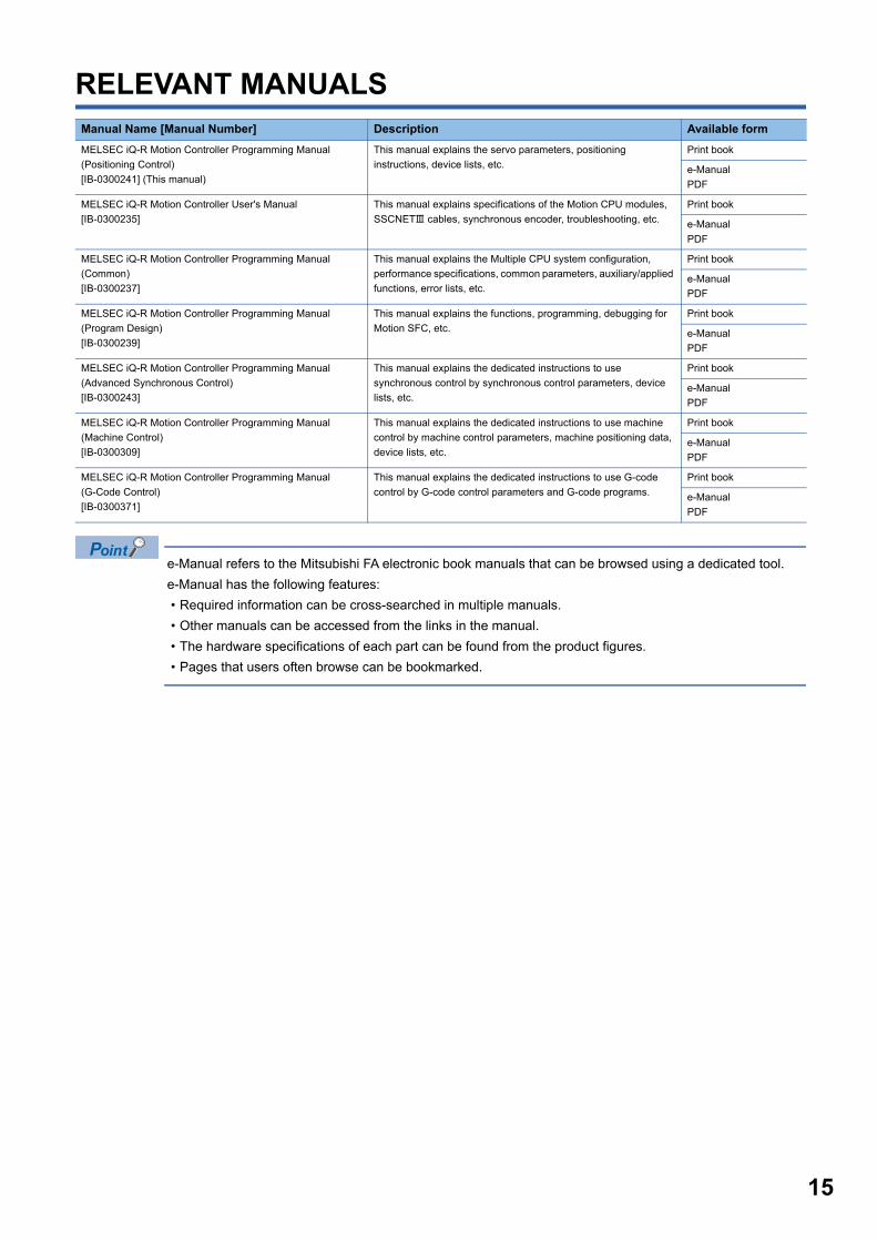
RELEVANT MANUALS
e-Manual refers to the Mitsubishi FA electronic book manuals that can be browsed using a dedicated tool.
e-Manual has the following features:
• Required information can be cross-searched in multiple manuals.
• Other manuals can be accessed from the links in the manual.
• The hardware specifications of each part can be found from the product figures.
• Pages that users often browse can be bookmarked.
Manual Name [Manual Number] Description Available form
MELSEC iQ-R Motion Controller Programming Manual
(Positioning Control)
[IB-0300241] (This manual)
This manual explains the servo parameters, positioning
instructions, device lists, etc.
Print book
e-Manual
MELSEC iQ-R Motion Controller User's Manual
[IB-0300235]
This manual explains specifications of the Motion CPU modules,
SSCNET cables, synchronous encoder, troubleshooting, etc.
Print book
e-Manual
MELSEC iQ-R Motion Controller Programming Manual
(Common)
[IB-0300237]
This manual explains the Multiple CPU system configuration,
performance specifications, common parameters, auxiliary/applied
functions, error lists, etc.
Print book
e-Manual
MELSEC iQ-R Motion Controller Programming Manual
(Program Design)
[IB-0300239]
This manual explains the functions, programming, debugging for
Motion SFC, etc.
Print book
e-Manual
MELSEC iQ-R Motion Controller Programming Manual
(Advanced Synchronous Control)
[IB-0300243]
This manual explains the dedicated instructions to use
synchronous control by synchronous control parameters, device
lists, etc.
Print book
e-Manual
MELSEC iQ-R Motion Controller Programming Manual
(Machine Control)
[IB-0300309]
This manual explains the dedicated instructions to use machine
control by machine control parameters, machine positioning data,
device lists, etc.
Print book
e-Manual
MELSEC iQ-R Motion Controller Programming Manual
(G-Code Control)
[IB-0300371]
This manual explains the dedicated instructions to use G-code
control by G-code control parameters and G-code programs.
Print book
e-Manual
15

16
TERMSUnless otherwise specified, this manual uses the following terms.
*1 SSCNET: Servo System Controller NETwork
Term Description
R64MTCPU/R32MTCPU/R16MTCPU or
Motion CPU (module)
Abbreviation for MELSEC iQ-R series Motion controller
MR-J4(W)-B Servo amplifier model MR-J4-B/MR-J4W-B
MR-J3(W)-B Servo amplifier model MR-J3-B/MR-J3W-B
AMP or Servo amplifier General name for "Servo amplifier model MR-J4-B/MR-J4W-B/MR-J3-B/MR-J3W-B"
RnCPU, PLC CPU or PLC CPU module Abbreviation for MELSEC iQ-R series CPU module
Multiple CPU system or Motion system Abbreviation for "Multiple PLC system of the R series"
CPUn Abbreviation for "CPU No.n (n = 1 to 4) of the CPU module for the Multiple CPU system"
Operating system software General name for "SW10DNC-RMTFW"
Engineering software package General name for MT Developer2/GX Works3
MELSOFT MT Works2 General product name for the Motion controller engineering software "SW1DND-MTW2"
MT Developer2 Abbreviation for the programming software included in the "MELSOFT MT Works2" Motion controller
engineering software
GX Works3 General product name for the MELSEC PLC software package "SW1DND-GXW3"
Serial absolute synchronous encoder or
Q171ENC-W8
Abbreviation for "Serial absolute synchronous encoder (Q171ENC-W8)"
SSCNET/H*1 High speed synchronous network between Motion controller and servo amplifier
SSCNET*1
SSCNET(/H) General name for SSCNET/H, SSCNET
Absolute position system General name for "system using the servo motor and servo amplifier for absolute position"
Intelligent function module General name for module that has a function other than input or output such as A/D converter module and D/A
converter module.
SSCNET/H head module*1 Abbreviation for "MELSEC-L series SSCNET/H head module (LJ72MS15)"
Optical hub unit or MR-MV200 Abbreviation for SSCNET/H Compatible Optical Hub Unit (MR-MV200)
Sensing module General name for SSCNET/H compatible sensing module MR-MT2000 series
Sensing SSCNET/H head module*1 or
MR-MT2010
Abbreviation for SSCNET/H head module (MR-MT2010)
Sensing extension module General name for I/O module (MR-MT2100), pulse I/O module (MR-MT2200), analog I/O module (MR-
MT2300), encoder I/F module (MR-MT2400)
Sensing I/O module or MR-MT2100 Abbreviation for I/O module (MR-MT2100)
Sensing pulse I/O module or MR-MT2200 Abbreviation for pulse I/O module (MR-MT2200)
Sensing analog I/O module or MR-MT2300 Abbreviation for analog I/O module (MR-MT2300)
Sensing encoder I/F module or MR-MT2400 Abbreviation for encoder I/F module (MR-MT2400)
MANUAL PAGE ORGANIZATION
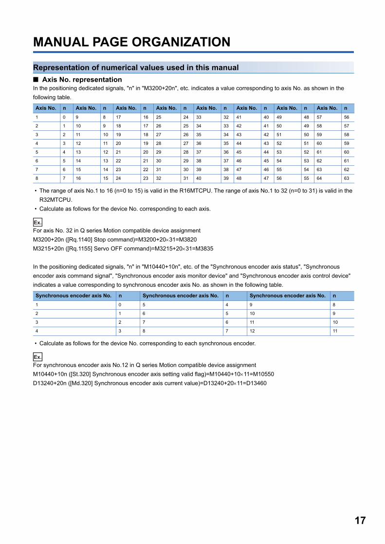
Representation of numerical values used in this manual
■ Axis No. representationIn the positioning dedicated signals, "n" in "M3200+20n", etc. indicates a value corresponding to axis No. as shown in the
following table.
• The range of axis No.1 to 16 (n=0 to 15) is valid in the R16MTCPU. The range of axis No.1 to 32 (n=0 to 31) is valid in the
R32MTCPU.
• Calculate as follows for the device No. corresponding to each axis.
Ex.
For axis No. 32 in Q series Motion compatible device assignment
M3200+20n ([Rq.1140] Stop command)=M3200+2031=M3820
M3215+20n ([Rq.1155] Servo OFF command)=M3215+2031=M3835
In the positioning dedicated signals, "n" in "M10440+10n", etc. of the "Synchronous encoder axis status", "Synchronous
encoder axis command signal", "Synchronous encoder axis monitor device" and "Synchronous encoder axis control device"
indicates a value corresponding to synchronous encoder axis No. as shown in the following table.
• Calculate as follows for the device No. corresponding to each synchronous encoder.
Ex.
For synchronous encoder axis No.12 in Q series Motion compatible device assignment
M10440+10n ([St.320] Synchronous encoder axis setting valid flag)=M10440+1011=M10550
D13240+20n ([Md.320] Synchronous encoder axis current value)=D13240+2011=D13460
Axis No. n Axis No. n Axis No. n Axis No. n Axis No. n Axis No. n Axis No. n Axis No. n
1 0 9 8 17 16 25 24 33 32 41 40 49 48 57 56
2 1 10 9 18 17 26 25 34 33 42 41 50 49 58 57
3 2 11 10 19 18 27 26 35 34 43 42 51 50 59 58
4 3 12 11 20 19 28 27 36 35 44 43 52 51 60 59
5 4 13 12 21 20 29 28 37 36 45 44 53 52 61 60
6 5 14 13 22 21 30 29 38 37 46 45 54 53 62 61
7 6 15 14 23 22 31 30 39 38 47 46 55 54 63 62
8 7 16 15 24 23 32 31 40 39 48 47 56 55 64 63
Synchronous encoder axis No. n Synchronous encoder axis No. n Synchronous encoder axis No. n
1 0 5 4 9 8
2 1 6 5 10 9
3 2 7 6 11 10
4 3 8 7 12 11
17
18
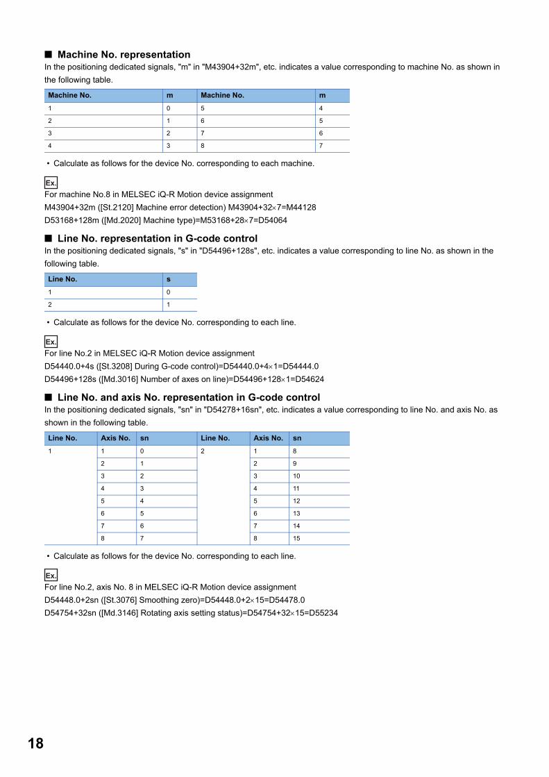
■ Machine No. representationIn the positioning dedicated signals, "m" in "M43904+32m", etc. indicates a value corresponding to machine No. as shown in
the following table.
• Calculate as follows for the device No. corresponding to each machine.
Ex.
For machine No.8 in MELSEC iQ-R Motion device assignment
M43904+32m ([St.2120] Machine error detection) M43904+327=M44128
D53168+128m ([Md.2020] Machine type)=M53168+287=D54064
■ Line No. representation in G-code controlIn the positioning dedicated signals, "s" in "D54496+128s", etc. indicates a value corresponding to line No. as shown in the
following table.
• Calculate as follows for the device No. corresponding to each line.
Ex.
For line No.2 in MELSEC iQ-R Motion device assignment
D54440.0+4s ([St.3208] During G-code control)=D54440.0+41=D54444.0
D54496+128s ([Md.3016] Number of axes on line)=D54496+1281=D54624
■ Line No. and axis No. representation in G-code controlIn the positioning dedicated signals, "sn" in "D54278+16sn", etc. indicates a value corresponding to line No. and axis No. as
shown in the following table.
• Calculate as follows for the device No. corresponding to each line.
Ex.
For line No.2, axis No. 8 in MELSEC iQ-R Motion device assignment
D54448.0+2sn ([St.3076] Smoothing zero)=D54448.0+215=D54478.0
D54754+32sn ([Md.3146] Rotating axis setting status)=D54754+3215=D55234
Machine No. m Machine No. m
1 0 5 4
2 1 6 5
3 2 7 6
4 3 8 7
Line No. s
1 0
2 1
Line No. Axis No. sn Line No. Axis No. sn
1 1 0 2 1 8
2 1 2 9
3 2 3 10
4 3 4 11
5 4 5 12
6 5 6 13
7 6 7 14
8 7 8 15
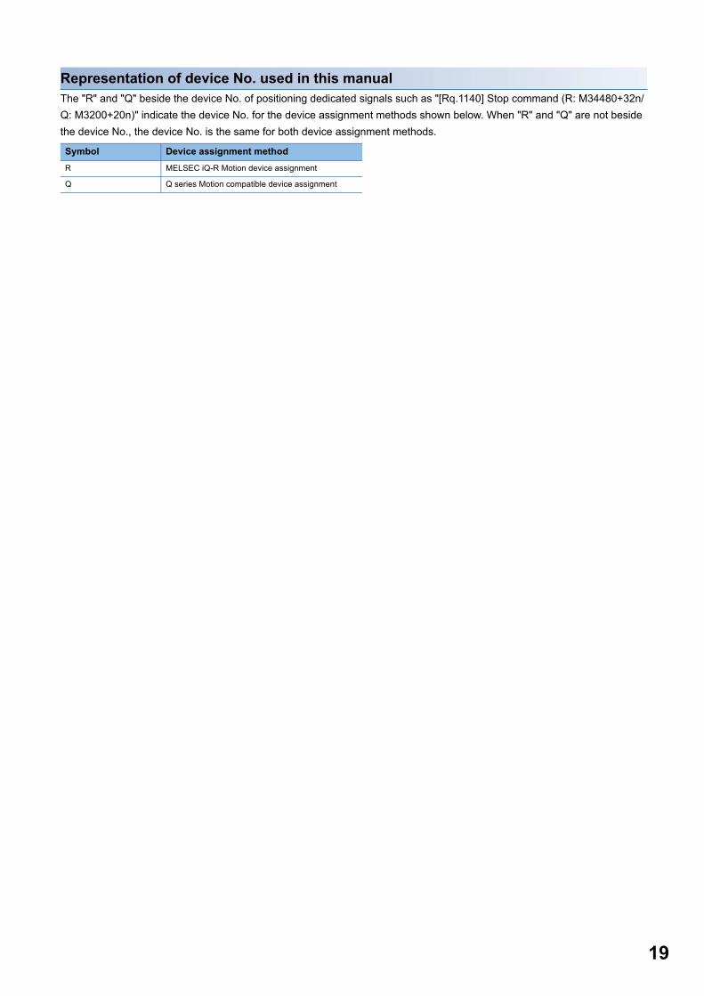
Representation of device No. used in this manualThe "R" and "Q" beside the device No. of positioning dedicated signals such as "[Rq.1140] Stop command (R: M34480+32n/
Q: M3200+20n)" indicate the device No. for the device assignment methods shown below. When "R" and "Q" are not beside
the device No., the device No. is the same for both device assignment methods.
Symbol Device assignment method
R MELSEC iQ-R Motion device assignment
Q Q series Motion compatible device assignment
19
20
1 POSITIONING CONTROL BY THE MOTION CPU
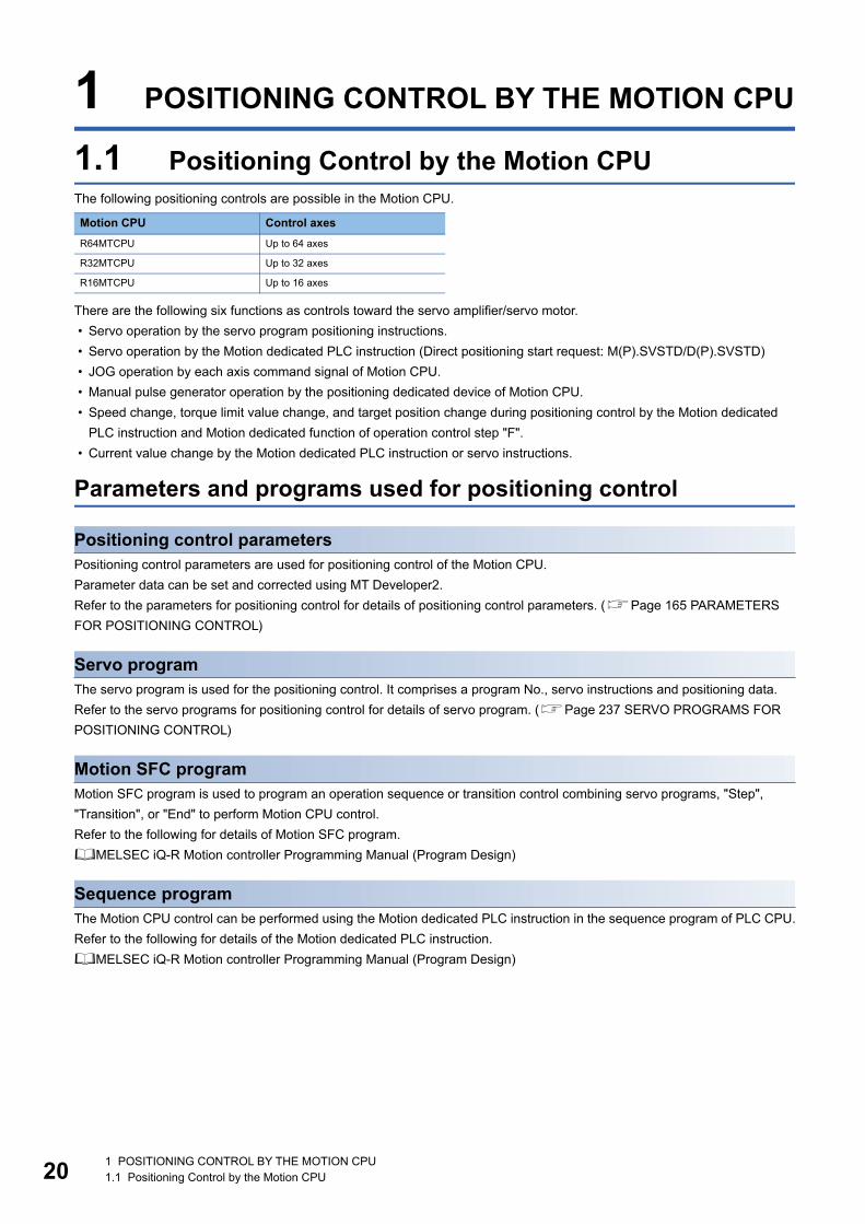
1.1 Positioning Control by the Motion CPUThe following positioning controls are possible in the Motion CPU.
There are the following six functions as controls toward the servo amplifier/servo motor.
• Servo operation by the servo program positioning instructions.
• Servo operation by the Motion dedicated PLC instruction (Direct positioning start request: M(P).SVSTD/D(P).SVSTD)
• JOG operation by each axis command signal of Motion CPU.
• Manual pulse generator operation by the positioning dedicated device of Motion CPU.
• Speed change, torque limit value change, and target position change during positioning control by the Motion dedicated
PLC instruction and Motion dedicated function of operation control step "F".
• Current value change by the Motion dedicated PLC instruction or servo instructions.
Parameters and programs used for positioning control
Positioning control parametersPositioning control parameters are used for positioning control of the Motion CPU.
Parameter data can be set and corrected using MT Developer2.
Refer to the parameters for positioning control for details of positioning control parameters. (Page 165 PARAMETERS
FOR POSITIONING CONTROL)
Servo programThe servo program is used for the positioning control. It comprises a program No., servo instructions and positioning data.
Refer to the servo programs for positioning control for details of servo program. (Page 237 SERVO PROGRAMS FOR
POSITIONING CONTROL)
Motion SFC programMotion SFC program is used to program an operation sequence or transition control combining servo programs, "Step",
"Transition", or "End" to perform Motion CPU control.
Refer to the following for details of Motion SFC program.
MELSEC iQ-R Motion controller Programming Manual (Program Design)
Sequence programThe Motion CPU control can be performed using the Motion dedicated PLC instruction in the sequence program of PLC CPU.
Refer to the following for details of the Motion dedicated PLC instruction.
MELSEC iQ-R Motion controller Programming Manual (Program Design)
Motion CPU Control axes
R64MTCPU Up to 64 axes
R32MTCPU Up to 32 axes
R16MTCPU Up to 16 axes
1 POSITIONING CONTROL BY THE MOTION CPU1.1 Positioning Control by the Motion CPU
1
Starting a servo programThere are the following two methods for starting a servo program.Starting by Motion SFC programUse the Motion control step "K" in the Motion SFC program to start the specified servo program.
Refer to the following for details of starting a Motion SFC program.
MELSEC iQ-R Motion controller Programming Manual (Program Design)
Starting by sequence programBy executing the Motion dedicated PLC instruction (Servo program start request: M(P).SVST/D(P).SVST) in the sequence
program of the PLC CPU, the servo program in the Motion CPU can be started.
Refer to the following for details of the Motion dedicated PLC instruction.
MELSEC iQ-R Motion controller Programming Manual (Program Design)
Direct positioning start from the PLC CPUExecute the Motion dedicated PLC instruction (Direct positioning start request: M(P).SVSTD/D(P).SVSTD) in the sequence
program of the PLC CPU, and start the positioning control set in the device of the Motion CPU.
With this instruction, servo operations are possible without using a servo program.
Refer to the following for details of the Motion dedicated PLC instruction.
MELSEC iQ-R Motion controller Programming Manual (Program Design)
JOG operationJOG operation can be performed by controlling the JOG dedicated device of the Motion CPU.
Refer to the JOG operation for details of JOG operation. (Page 413 JOG Operation)
Manual pulse generator operationManual pulse generator operation can be performed with a manual pulse generator connected to a high-speed counter
module controlled by the Motion CPU. The manual pulse generator is operated by controlling the manual pulse generator
dedicated device of the Motion CPU.
Refer to the manual pulse generator operation for details of manual pulse generator operation. (Page 418 Manual Pulse
Generator Operation)
1 POSITIONING CONTROL BY THE MOTION CPU1.1 Positioning Control by the Motion CPU 21
22
2 POSITIONING DEDICATED SIGNALS
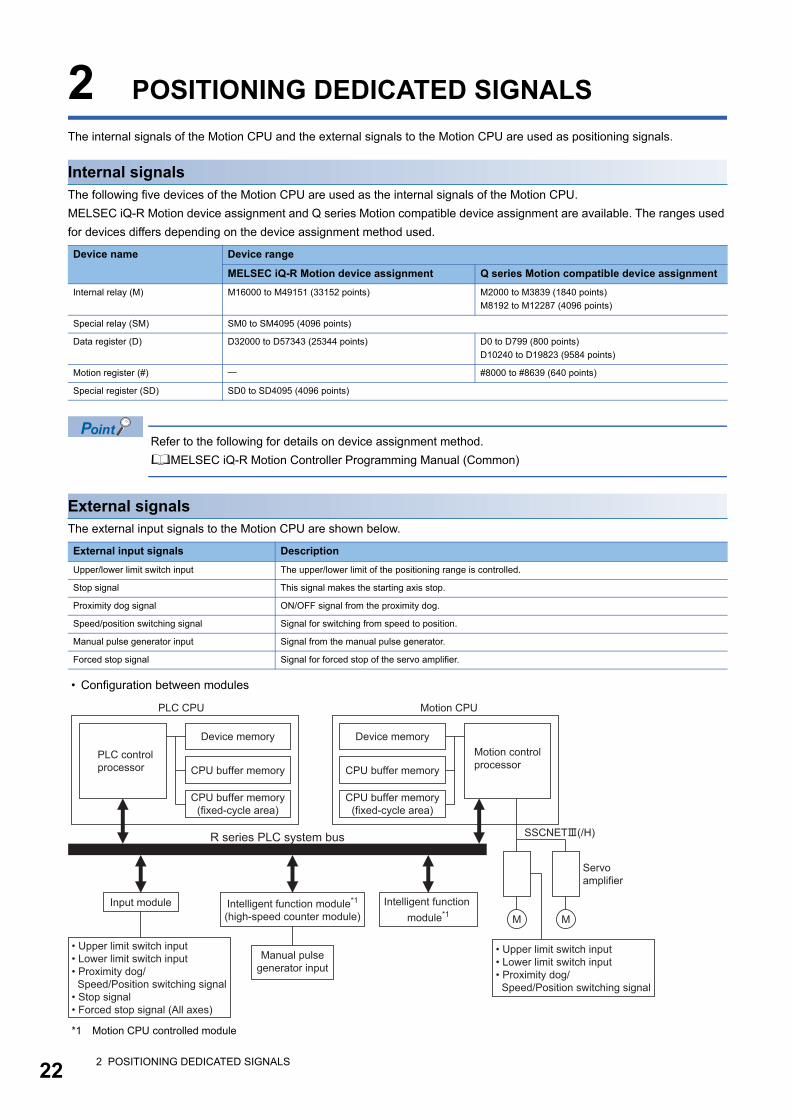
The internal signals of the Motion CPU and the external signals to the Motion CPU are used as positioning signals.
Internal signalsThe following five devices of the Motion CPU are used as the internal signals of the Motion CPU.
MELSEC iQ-R Motion device assignment and Q series Motion compatible device assignment are available. The ranges used
for devices differs depending on the device assignment method used.
Refer to the following for details on device assignment method.
MELSEC iQ-R Motion Controller Programming Manual (Common)
External signalsThe external input signals to the Motion CPU are shown below.
• Configuration between modules
*1 Motion CPU controlled module
Device name Device range
MELSEC iQ-R Motion device assignment Q series Motion compatible device assignment
Internal relay (M) M16000 to M49151 (33152 points) M2000 to M3839 (1840 points)
M8192 to M12287 (4096 points)
Special relay (SM) SM0 to SM4095 (4096 points)
Data register (D) D32000 to D57343 (25344 points) D0 to D799 (800 points)
D10240 to D19823 (9584 points)
Motion register (#) #8000 to #8639 (640 points)
Special register (SD) SD0 to SD4095 (4096 points)
External input signals Description
Upper/lower limit switch input The upper/lower limit of the positioning range is controlled.
Stop signal This signal makes the starting axis stop.
Proximity dog signal ON/OFF signal from the proximity dog.
Speed/position switching signal Signal for switching from speed to position.
Manual pulse generator input Signal from the manual pulse generator.
Forced stop signal Signal for forced stop of the servo amplifier.
R series PLC system bus SSCNET(/H)
M
Servoamplifier
M
• Upper limit switch input• Lower limit switch input• Proximity dog/ Speed/Position switching signal
PLC CPU
Device memory
CPU buffer memory
CPU buffer memory(fixed-cycle area)
Motion controlprocessor
Motion CPU
Device memory
CPU buffer memory
CPU buffer memory(fixed-cycle area)
PLC controlprocessor
Input module
• Upper limit switch input• Lower limit switch input• Proximity dog/ Speed/Position switching signal• Stop signal• Forced stop signal (All axes)
Intelligent function module*1
(high-speed counter module)
Manual pulsegenerator input
Intelligent function module*1
2 POSITIONING DEDICATED SIGNALS
2
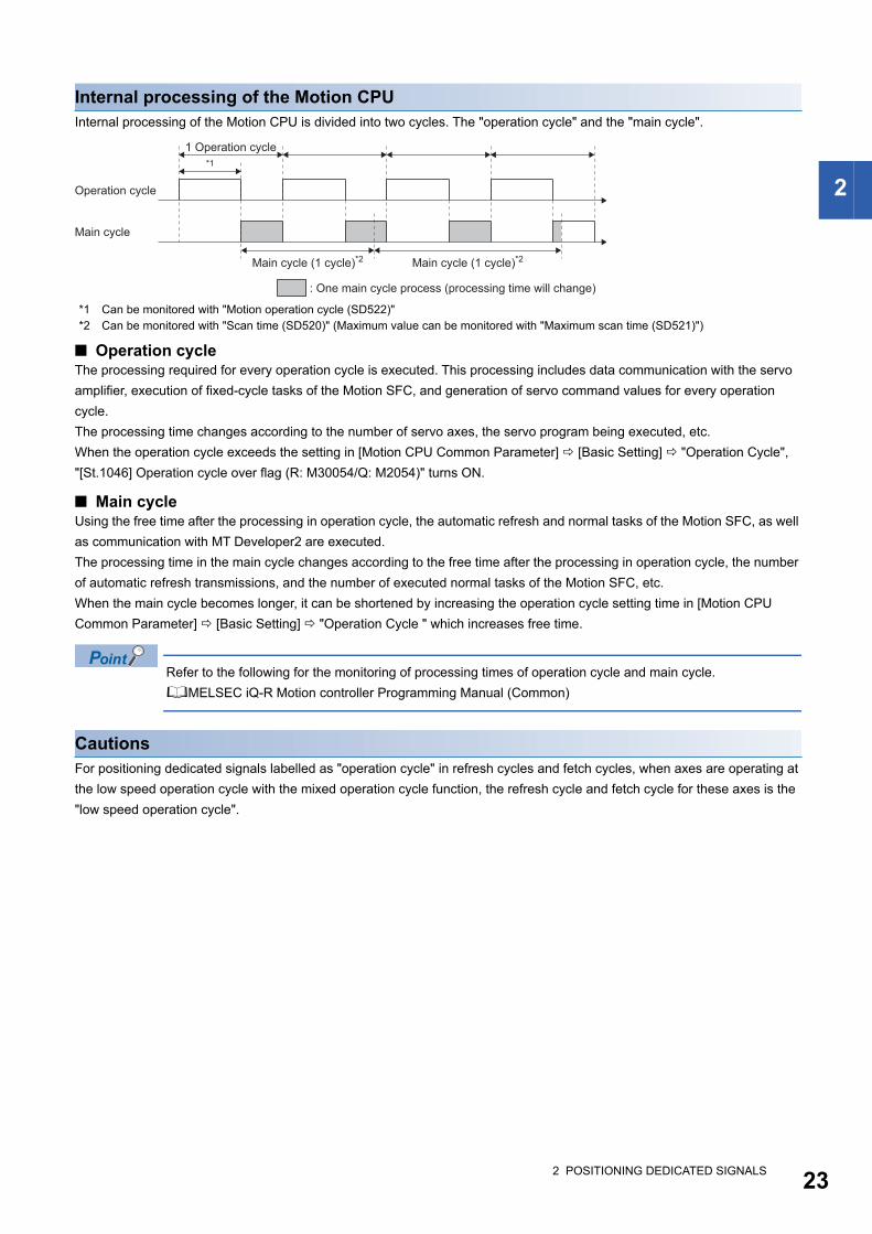
Internal processing of the Motion CPUInternal processing of the Motion CPU is divided into two cycles. The "operation cycle" and the "main cycle".
*1 Can be monitored with "Motion operation cycle (SD522)"*2 Can be monitored with "Scan time (SD520)" (Maximum value can be monitored with "Maximum scan time (SD521)")
■ Operation cycleThe processing required for every operation cycle is executed. This processing includes data communication with the servo
amplifier, execution of fixed-cycle tasks of the Motion SFC, and generation of servo command values for every operation
cycle.
The processing time changes according to the number of servo axes, the servo program being executed, etc.
When the operation cycle exceeds the setting in [Motion CPU Common Parameter] [Basic Setting] "Operation Cycle",
"[St.1046] Operation cycle over flag (R: M30054/Q: M2054)" turns ON.
■ Main cycleUsing the free time after the processing in operation cycle, the automatic refresh and normal tasks of the Motion SFC, as well
as communication with MT Developer2 are executed.
The processing time in the main cycle changes according to the free time after the processing in operation cycle, the number
of automatic refresh transmissions, and the number of executed normal tasks of the Motion SFC, etc.
When the main cycle becomes longer, it can be shortened by increasing the operation cycle setting time in [Motion CPU
Common Parameter] [Basic Setting] "Operation Cycle " which increases free time.
Refer to the following for the monitoring of processing times of operation cycle and main cycle.
MELSEC iQ-R Motion controller Programming Manual (Common)
CautionsFor positioning dedicated signals labelled as "operation cycle" in refresh cycles and fetch cycles, when axes are operating at
the low speed operation cycle with the mixed operation cycle function, the refresh cycle and fetch cycle for these axes is the
"low speed operation cycle".
Operation cycle
Main cycle
1 Operation cycle
: One main cycle process (processing time will change)
Main cycle (1 cycle)*2 Main cycle (1 cycle)*2
*1
2 POSITIONING DEDICATED SIGNALS 23
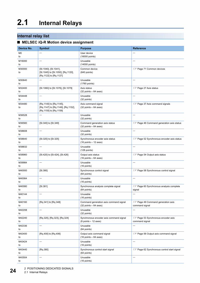
24
2.1 Internal Relays
Internal relay list
■ MELSEC iQ-R Motion device assignment
Device No. Symbol Purpose Reference
M0
to
User device
(16000 points)
M16000
to
Unusable
(14000 points)
M30000
to
[St.1040], [St.1041],
[St.1045] to [St.1050], [Rq.1120],
[Rq.1122] to [Rq.1127]
Common device
(640 points)
Page 71 Common devices
M30640
to
Unusable
(1760 points)
M32400
to
[St.1060] to [St.1076], [St.1079] Axis status
(32 points 64 axes)
Page 27 Axis status
M34448
to
Unusable
(32 points)
M34480
to
[Rq.1140] to [Rq.1145],
[Rq.1147] to [Rq.1149], [Rq.1152],
[Rq.1155] to [Rq.1159]
Axis command signal
(32 points 64 axes)
Page 37 Axis command signals
M36528
to
Unusable
(32 points)
M36560
to
[St.340] to [St.349] Command generation axis status
(32 points 64 axes)
Page 46 Command generation axis status
M38608
to
Unusable
(32 points)
M38640
to
[St.320] to [St.325] Synchronous encoder axis status
(16 points 12 axes)
Page 52 Synchronous encoder axis status
M38832
to
Unusable
(128 points)
M38960
to
[St.420] to [St.424], [St.426] Output axis status
(16 points 64 axes)
Page 54 Output axis status
M39984
to
Unusable
(16 points)
M40000
to
[St.380] Synchronous control signal
(64 points)
Page 58 Synchronous control signal
M40064
to
Unusable
(16 points)
M40080
to
[St.381] Synchronous analysis complete signal
(64 points)
Page 60 Synchronous analysis complete
signal
M40144
to
Unusable
(16 points)
M40160
to
[Rq.341] to [Rq.348] Command generation axis command signal
(32 points 64 axes)
Page 49 Command generation axis
command signal
M42208
to
Unusable
(32 points)
M42240
to
[Rq.320], [Rq.323], [Rq.324] Synchronous encoder axis command signal
(8 points 12 axes)
Page 53 Synchronous encoder axis
command signal
M42336
to
Unusable
(64 points)
M42400
to
[Rq.400] to [Rq.406] Output axis command signal
(16 points 64 axes)
Page 56 Output axis command signal
M43424
to
Unusable
(16 points)
M43440
to
[Rq.380] Synchronous control start signal
(64 points)
Page 62 Synchronous control start signal
M43504
to
Unusable
(16 points)
2 POSITIONING DEDICATED SIGNALS2.1 Internal Relays
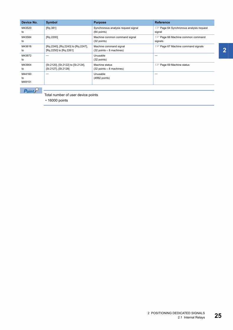
2
Total number of user device points
• 16000 points
M43520
to
[Rq.381] Synchronous analysis request signal
(64 points)
Page 64 Synchronous analysis request
signal
M43584
to
[Rq.2200] Machine common command signal
(32 points)
Page 66 Machine common command
signals
M43616
to
[Rq.2240], [Rq.2243] to [Rq.2247],
[Rq.2250] to [Rq.2261]
Machine command signal
(32 points 8 machines)
Page 67 Machine command signals
M43872
to
Unusable
(32 points)
M43904
to
[St.2120], [St.2122] to [St.2124],
[St.2127], [St.2128]
Machine status
(32 points 8 machines)
Page 69 Machine status
M44160
to
M49151
Unusable
(4992 points)
Device No. Symbol Purpose Reference
2 POSITIONING DEDICATED SIGNALS2.1 Internal Relays 25
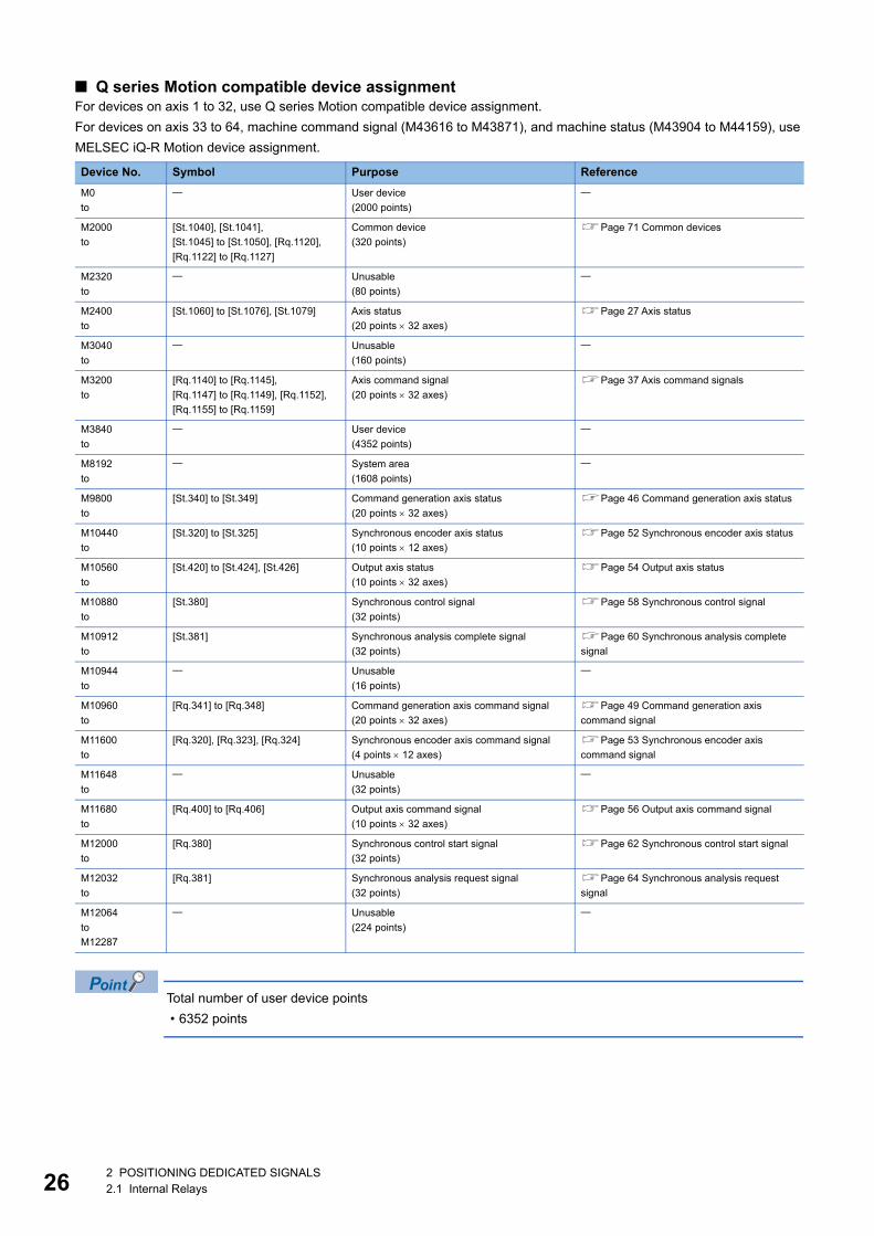
26
■ Q series Motion compatible device assignmentFor devices on axis 1 to 32, use Q series Motion compatible device assignment.
For devices on axis 33 to 64, machine command signal (M43616 to M43871), and machine status (M43904 to M44159), use
MELSEC iQ-R Motion device assignment.
Total number of user device points
• 6352 points
Device No. Symbol Purpose Reference
M0
to
User device
(2000 points)
M2000
to
[St.1040], [St.1041],
[St.1045] to [St.1050], [Rq.1120],
[Rq.1122] to [Rq.1127]
Common device
(320 points)
Page 71 Common devices
M2320
to
Unusable
(80 points)
M2400
to
[St.1060] to [St.1076], [St.1079] Axis status
(20 points 32 axes)
Page 27 Axis status
M3040
to
Unusable
(160 points)
M3200
to
[Rq.1140] to [Rq.1145],
[Rq.1147] to [Rq.1149], [Rq.1152],
[Rq.1155] to [Rq.1159]
Axis command signal
(20 points 32 axes)
Page 37 Axis command signals
M3840
to
User device
(4352 points)
M8192
to
System area
(1608 points)
M9800
to
[St.340] to [St.349] Command generation axis status
(20 points 32 axes)
Page 46 Command generation axis status
M10440
to
[St.320] to [St.325] Synchronous encoder axis status
(10 points 12 axes)
Page 52 Synchronous encoder axis status
M10560
to
[St.420] to [St.424], [St.426] Output axis status
(10 points 32 axes)
Page 54 Output axis status
M10880
to
[St.380] Synchronous control signal
(32 points)
Page 58 Synchronous control signal
M10912
to
[St.381] Synchronous analysis complete signal
(32 points)
Page 60 Synchronous analysis complete
signal
M10944
to
Unusable
(16 points)
M10960
to
[Rq.341] to [Rq.348] Command generation axis command signal
(20 points 32 axes)
Page 49 Command generation axis
command signal
M11600
to
[Rq.320], [Rq.323], [Rq.324] Synchronous encoder axis command signal
(4 points 12 axes)
Page 53 Synchronous encoder axis
command signal
M11648
to
Unusable
(32 points)
M11680
to
[Rq.400] to [Rq.406] Output axis command signal
(10 points 32 axes)
Page 56 Output axis command signal
M12000
to
[Rq.380] Synchronous control start signal
(32 points)
Page 62 Synchronous control start signal
M12032
to
[Rq.381] Synchronous analysis request signal
(32 points)
Page 64 Synchronous analysis request
signal
M12064
to
M12287
Unusable
(224 points)
2 POSITIONING DEDICATED SIGNALS2.1 Internal Relays
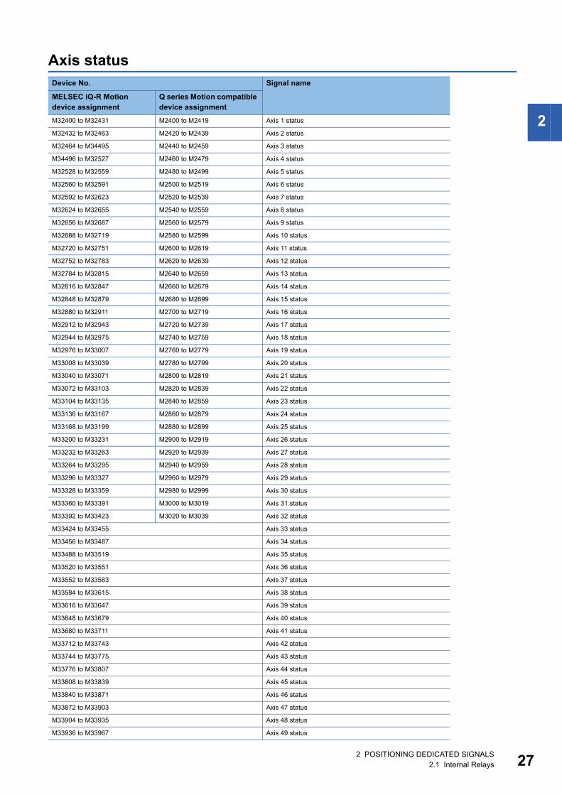
2
Axis statusDevice No. Signal name
MELSEC iQ-R Motion device assignment
Q series Motion compatible device assignment
M32400 to M32431 M2400 to M2419 Axis 1 status
M32432 to M32463 M2420 to M2439 Axis 2 status
M32464 to M34495 M2440 to M2459 Axis 3 status
M34496 to M32527 M2460 to M2479 Axis 4 status
M32528 to M32559 M2480 to M2499 Axis 5 status
M32560 to M32591 M2500 to M2519 Axis 6 status
M32592 to M32623 M2520 to M2539 Axis 7 status
M32624 to M32655 M2540 to M2559 Axis 8 status
M32656 to M32687 M2560 to M2579 Axis 9 status
M32688 to M32719 M2580 to M2599 Axis 10 status
M32720 to M32751 M2600 to M2619 Axis 11 status
M32752 to M32783 M2620 to M2639 Axis 12 status
M32784 to M32815 M2640 to M2659 Axis 13 status
M32816 to M32847 M2660 to M2679 Axis 14 status
M32848 to M32879 M2680 to M2699 Axis 15 status
M32880 to M32911 M2700 to M2719 Axis 16 status
M32912 to M32943 M2720 to M2739 Axis 17 status
M32944 to M32975 M2740 to M2759 Axis 18 status
M32976 to M33007 M2760 to M2779 Axis 19 status
M33008 to M33039 M2780 to M2799 Axis 20 status
M33040 to M33071 M2800 to M2819 Axis 21 status
M33072 to M33103 M2820 to M2839 Axis 22 status
M33104 to M33135 M2840 to M2859 Axis 23 status
M33136 to M33167 M2860 to M2879 Axis 24 status
M33168 to M33199 M2880 to M2899 Axis 25 status
M33200 to M33231 M2900 to M2919 Axis 26 status
M33232 to M33263 M2920 to M2939 Axis 27 status
M33264 to M33295 M2940 to M2959 Axis 28 status
M33296 to M33327 M2960 to M2979 Axis 29 status
M33328 to M33359 M2980 to M2999 Axis 30 status
M33360 to M33391 M3000 to M3019 Axis 31 status
M33392 to M33423 M3020 to M3039 Axis 32 status
M33424 to M33455 Axis 33 status
M33456 to M33487 Axis 34 status
M33488 to M33519 Axis 35 status
M33520 to M33551 Axis 36 status
M33552 to M33583 Axis 37 status
M33584 to M33615 Axis 38 status
M33616 to M33647 Axis 39 status
M33648 to M33679 Axis 40 status
M33680 to M33711 Axis 41 status
M33712 to M33743 Axis 42 status
M33744 to M33775 Axis 43 status
M33776 to M33807 Axis 44 status
M33808 to M33839 Axis 45 status
M33840 to M33871 Axis 46 status
M33872 to M33903 Axis 47 status
M33904 to M33935 Axis 48 status
M33936 to M33967 Axis 49 status
2 POSITIONING DEDICATED SIGNALS2.1 Internal Relays 27
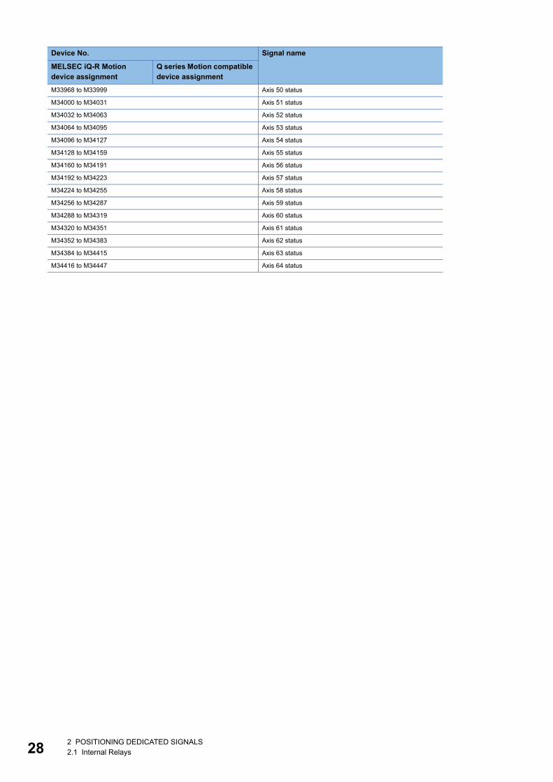
28
M33968 to M33999 Axis 50 status
M34000 to M34031 Axis 51 status
M34032 to M34063 Axis 52 status
M34064 to M34095 Axis 53 status
M34096 to M34127 Axis 54 status
M34128 to M34159 Axis 55 status
M34160 to M34191 Axis 56 status
M34192 to M34223 Axis 57 status
M34224 to M34255 Axis 58 status
M34256 to M34287 Axis 59 status
M34288 to M34319 Axis 60 status
M34320 to M34351 Axis 61 status
M34352 to M34383 Axis 62 status
M34384 to M34415 Axis 63 status
M34416 to M34447 Axis 64 status
Device No. Signal name
MELSEC iQ-R Motion device assignment
Q series Motion compatible device assignment
2 POSITIONING DEDICATED SIGNALS2.1 Internal Relays
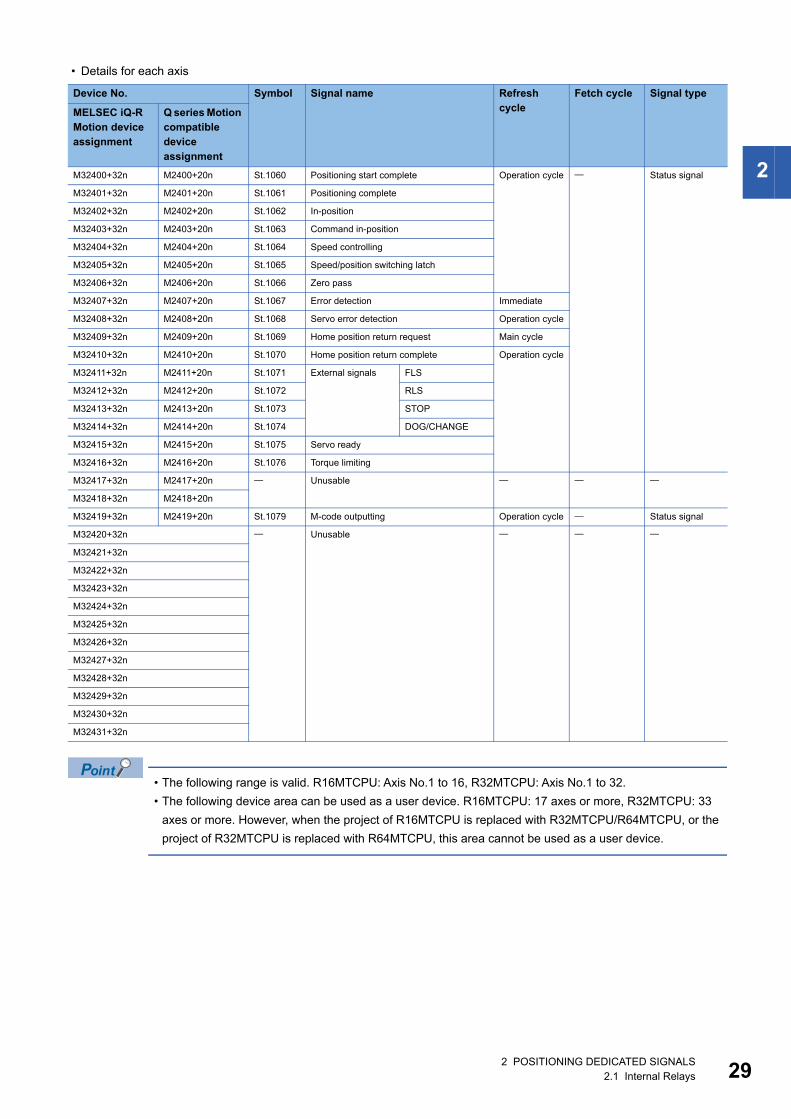
2
• Details for each axis
• The following range is valid. R16MTCPU: Axis No.1 to 16, R32MTCPU: Axis No.1 to 32.
• The following device area can be used as a user device. R16MTCPU: 17 axes or more, R32MTCPU: 33
axes or more. However, when the project of R16MTCPU is replaced with R32MTCPU/R64MTCPU, or the
project of R32MTCPU is replaced with R64MTCPU, this area cannot be used as a user device.
Device No. Symbol Signal name Refresh cycle
Fetch cycle Signal type
MELSEC iQ-R Motion device assignment
Q series Motion compatible device assignment
M32400+32n M2400+20n St.1060 Positioning start complete Operation cycle Status signal
M32401+32n M2401+20n St.1061 Positioning complete
M32402+32n M2402+20n St.1062 In-position
M32403+32n M2403+20n St.1063 Command in-position
M32404+32n M2404+20n St.1064 Speed controlling
M32405+32n M2405+20n St.1065 Speed/position switching latch
M32406+32n M2406+20n St.1066 Zero pass
M32407+32n M2407+20n St.1067 Error detection Immediate
M32408+32n M2408+20n St.1068 Servo error detection Operation cycle
M32409+32n M2409+20n St.1069 Home position return request Main cycle
M32410+32n M2410+20n St.1070 Home position return complete Operation cycle
M32411+32n M2411+20n St.1071 External signals FLS
M32412+32n M2412+20n St.1072 RLS
M32413+32n M2413+20n St.1073 STOP
M32414+32n M2414+20n St.1074 DOG/CHANGE
M32415+32n M2415+20n St.1075 Servo ready
M32416+32n M2416+20n St.1076 Torque limiting
M32417+32n M2417+20n Unusable
M32418+32n M2418+20n
M32419+32n M2419+20n St.1079 M-code outputting Operation cycle Status signal
M32420+32n Unusable
M32421+32n
M32422+32n
M32423+32n
M32424+32n
M32425+32n
M32426+32n
M32427+32n
M32428+32n
M32429+32n
M32430+32n
M32431+32n
2 POSITIONING DEDICATED SIGNALS2.1 Internal Relays 29
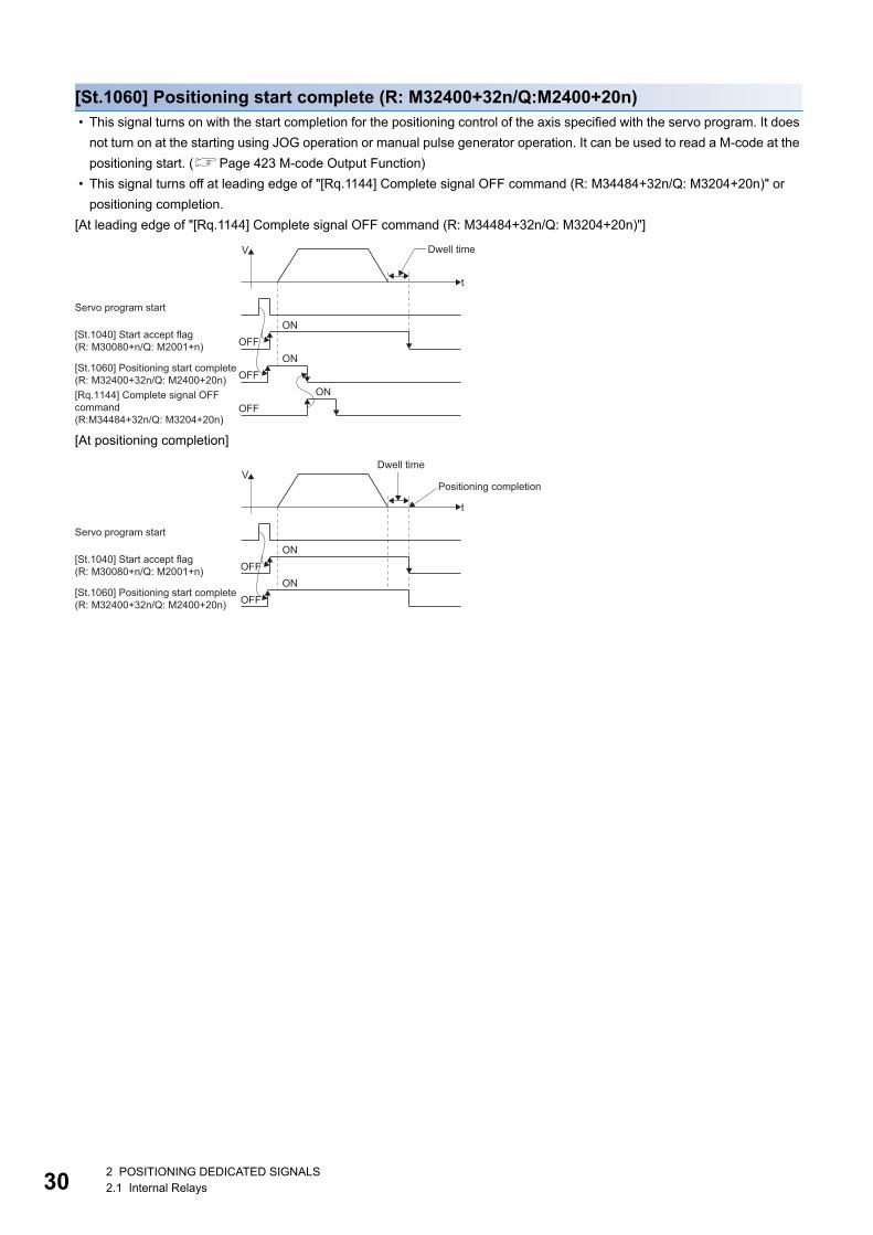
30
[St.1060] Positioning start complete (R: M32400+32n/Q:M2400+20n) • This signal turns on with the start completion for the positioning control of the axis specified with the servo program. It does
not turn on at the starting using JOG operation or manual pulse generator operation. It can be used to read a M-code at the
positioning start. (Page 423 M-code Output Function)
• This signal turns off at leading edge of "[Rq.1144] Complete signal OFF command (R: M34484+32n/Q: M3204+20n)" or
positioning completion.
[At leading edge of "[Rq.1144] Complete signal OFF command (R: M34484+32n/Q: M3204+20n)"]
[At positioning completion]
[St.1060] Positioning start complete(R: M32400+32n/Q: M2400+20n)
[St.1040] Start accept flag(R: M30080+n/Q: M2001+n)
[Rq.1144] Complete signal OFFcommand(R:M34484+32n/Q: M3204+20n)
OFFON
OFFON
OFFON
Servo program start
t
Dwell timeV
Dwell time
Positioning completion
OFFON
OFFON
Servo program start
t
V
[St.1060] Positioning start complete(R: M32400+32n/Q: M2400+20n)
[St.1040] Start accept flag(R: M30080+n/Q: M2001+n)
2 POSITIONING DEDICATED SIGNALS2.1 Internal Relays
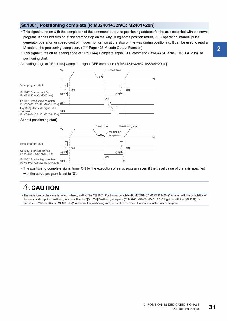
2
[St.1061] Positioning complete (R:M32401+32n/Q: M2401+20n) • This signal turns on with the completion of the command output to positioning address for the axis specified with the servo
program. It does not turn on at the start or stop on the way using home position return, JOG operation, manual pulse
generator operation or speed control. It does not turn on at the stop on the way during positioning. It can be used to read a
M-code at the positioning completion. (Page 423 M-code Output Function)
• This signal turns off at leading edge of "[Rq.1144] Complete signal OFF command (R:M34484+32n/Q: M3204+20n)" or
positioning start.
[At leading edge of "[Rq.1144] Complete signal OFF command (R:M34484+32n/Q: M3204+20n)"]
[At next positioning start]
• The positioning complete signal turns ON by the execution of servo program even if the travel value of the axis specified
with the servo program is set to "0".
CAUTION• The deviation counter value is not considered, so that The "[St.1061] Positioning complete (R: M32401+32n/Q:M2401+20n)" turns on with the completion of
the command output to positioning address. Use the "[St.1061] Positioning complete (R: M32401+32n/Q:M2401+20n)" together with the "[St.1062] In-
position (R: M32402+32n/Q: M2402+20n)" to confirm the positioning completion of servo axis in the final instruction under program.
OFF
OFFON
OFF OFFON ON
Servo program start
ON
t
Dwell timeV
[St.1061] Positioning complete (R: M32401+32n/Q: M2401+20n)
[St.1040] Start accept flag (R: M30080+n/Q: M2001+n)
[Rq.1144] Complete signal OFFcommand(R: M34484+32n/Q: M3204+20n)
Positioning start
OFFON
OFF OFFON ON
Servo program start
t
VDwell time
Positioningcompletion
[St.1061] Positioning complete(R: M32401+32n/Q: M2401+20n)
[St.1040] Start accept flag(R: M30080+n/Q: M2001+n)
2 POSITIONING DEDICATED SIGNALS2.1 Internal Relays 31
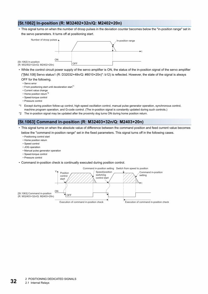
32
[St.1062] In-position (R: M32402+32n/Q: M2402+20n) • This signal turns on when the number of droop pulses in the deviation counter becomes below the "in-position range" set in
the servo parameters. It turns off at positioning start.
• While the control circuit power supply of the servo amplifier is ON, the status of the in-position signal of the servo amplifier
("[Md.108] Servo status1 (R: D32032+48n/Q: #8010+20n)": b12) is reflected. However, the state of the signal is always
OFF for the following.
*1 Except during position follow-up control, high-speed oscillation control, manual pulse generator operation, synchronous control, machine program operation, and G-code control. (The in-position signal is constantly updated during such controls.)
*2 The in-position signal may be updated after the proximity dog turns ON during home position return.
[St.1063] Command in-position (R: M32403+32n/Q: M2403+20n) • This signal turns on when the absolute value of difference between the command position and feed current value becomes
below the "command in-position range" set in the fixed parameters. This signal turns off in the following cases.
• Command in-position check is continually executed during position control.
• Servo error
• From positioning start until deceleration start*1
• Current value change
• Home position return*2
• Speed-torque control
• Pressure control
• Positioning control start
• Home position return
• Speed control
• JOG operation
• Manual pulse generator operation
• Speed-torque control
• Pressure control
ONOFF
[St.1062] In-position(R: M32402+32n/Q: M2402+20n)
t
In-position rangeNumber of droop pulses
Speed/positionswitching control start
Positioncontrolstart
Switch from speed to position
Execution of command in-position check Execution of command in-position check
ONOFF
[St.1063] Command in-position(R: M32403+32n/Q: M2403+20n)
t
VCommand in-position setting
Command in-positionsetting
2 POSITIONING DEDICATED SIGNALS2.1 Internal Relays
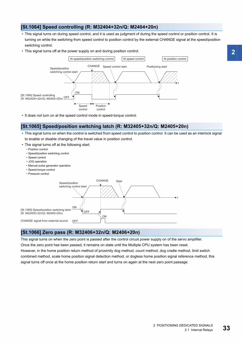
2
[St.1064] Speed controlling (R: M32404+32n/Q: M2404+20n) • This signal turns on during speed control, and it is used as judgment of during the speed control or position control. It is
turning on while the switching from speed control to position control by the external CHANGE signal at the speed/position
switching control.
• This signal turns off at the power supply on and during position control.
• It does not turn on at the speed control mode in speed-torque control.
[St.1065] Speed/position switching latch (R: M32405+32n/Q: M2405+20n) • This signal turns on when the control is switched from speed control to position control. It can be used as an interlock signal
to enable or disable changing of the travel value in position control.
• The signal turns off at the following start.
[St.1066] Zero pass (R: M32406+32n/Q: M2406+20n)This signal turns on when the zero point is passed after the control circuit power supply on of the servo amplifier.
Once the zero point has been passed, it remains on state until the Multiple CPU system has been reset.
However, in the home position return method of proximity dog method, count method, dog cradle method, limit switch
combined method, scale home position signal detection method, or dogless home position signal reference method, this
signal turns off once at the home position return start and turns on again at the next zero point passage.
• Position control
• Speed/position switching control
• Speed control
• JOG operation
• Manual pulse generator operation
• Speed-torque control
• Pressure control
Speed control start Positioning startSpeed/positionswitching control start
CHANGE
Speedcontrol
Positioncontrol
ON
OFF[St.1064] Speed controlling(R: M32404+32n/Q: M2404+20n)
t
At speed/position switching control At speed control At position control
StartSpeed/positionswitching control start
CHANGE
ONOFF
t
ONOFF
[St.1065] Speed/position switching latch(R: M32405+32n/Q: M2405+20n)
CHANGE signal from external source
2 POSITIONING DEDICATED SIGNALS2.1 Internal Relays 33
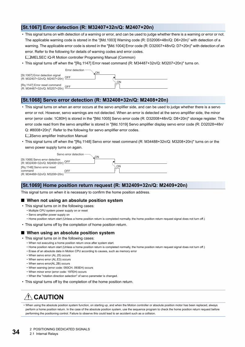
34
[St.1067] Error detection (R: M32407+32n/Q: M2407+20n) • This signal turns on with detection of a warning or error, and can be used to judge whether there is a warning or error or not.
The applicable warning code is stored in the “[Md.1003] Warning code (R: D32006+48n/Q: D6+20n)” with detection of a
warning. The applicable error code is stored in the "[Md.1004] Error code (R: D32007+48n/Q: D7+20n)" with detection of an
error. Refer to the following for details of warning codes and error codes.
MELSEC iQ-R Motion controller Programing Manual (Common)
• This signal turns off when the "[Rq.1147] Error reset command (R: M34487+32n/Q: M3207+20n)" turns on.
[St.1068] Servo error detection (R: M32408+32n/Q: M2408+20n) • This signal turns on when an error occurs at the servo amplifier side, and can be used to judge whether there is a servo
error or not. However, servo warnings are not detected. When an error is detected at the servo amplifier side, the minor
error (error code: 1C80H) is stored in the "[Md.1005] Servo error code (R: D32008+48n/Q: D8+20n)" storage register. The
error code read from the servo amplifier is stored in "[Md.1019] Servo amplifier display servo error code (R: D32028+48n/
Q: #8008+20n)". Refer to the following for servo amplifier error codes.
Servo amplifier Instruction Manual
• This signal turns off when the "[Rq.1148] Servo error reset command (R: M34488+32n/Q: M3208+20n)" turns on or the
servo power supply turns on again.
[St.1069] Home position return request (R: M32409+32n/Q: M2409+20n)This signal turns on when it is necessary to confirm the home position address.
■ When not using an absolute position system • This signal turns on in the following cases:
• This signal turns off by the completion of home position return.
■ When using an absolute position system • This signal turns on in the following cases:
• This signal turns off by the completion of the home position return.
• Multiple CPU system power supply on or reset
• Servo amplifier power supply on
• Home position return start (Unless a home position return is completed normally, the home position return request signal does not turn off.)
• When not executing a home position return once after system start.
• Home position return start (Unless a home position return is completed normally, the home position return request signal does not turn off.)
• Erase of an absolute data in Motion CPU according to causes, such as memory error
• When servo error (AL.25) occurs
• When servo error (AL.E3) occurs
• When servo error(AL.2B) occurs
• When warning (error code: 093CH, 093EH) occurs
• When minor error (error code: 197EH) occurs
• When the "rotation direction selection" of servo parameter is changed.
CAUTION• When using the absolute position system function, on starting up, and when the Motion controller or absolute position motor has been replaced, always
perform a home position return. In the case of the absolute position system, use the sequence program to check the home position return request before
performing the positioning control. Failure to observe this could lead to an accident such as a collision.
Error detectionON
OFF[St.1067] Error detection signal(R: M32407+32n/Q: M2407+20n)
[Rq.1147] Error reset command(R: M34487+32n/Q: M3207+20n)
ONOFF
Servo error detectionON
OFF[St.1068] Servo error detection(R: M32408+32n/Q: M2408+20n)[Rq.1148] Servo error resetcommand(R: M34488+32n/Q: M3208+20n)
ONOFF
2 POSITIONING DEDICATED SIGNALS2.1 Internal Relays
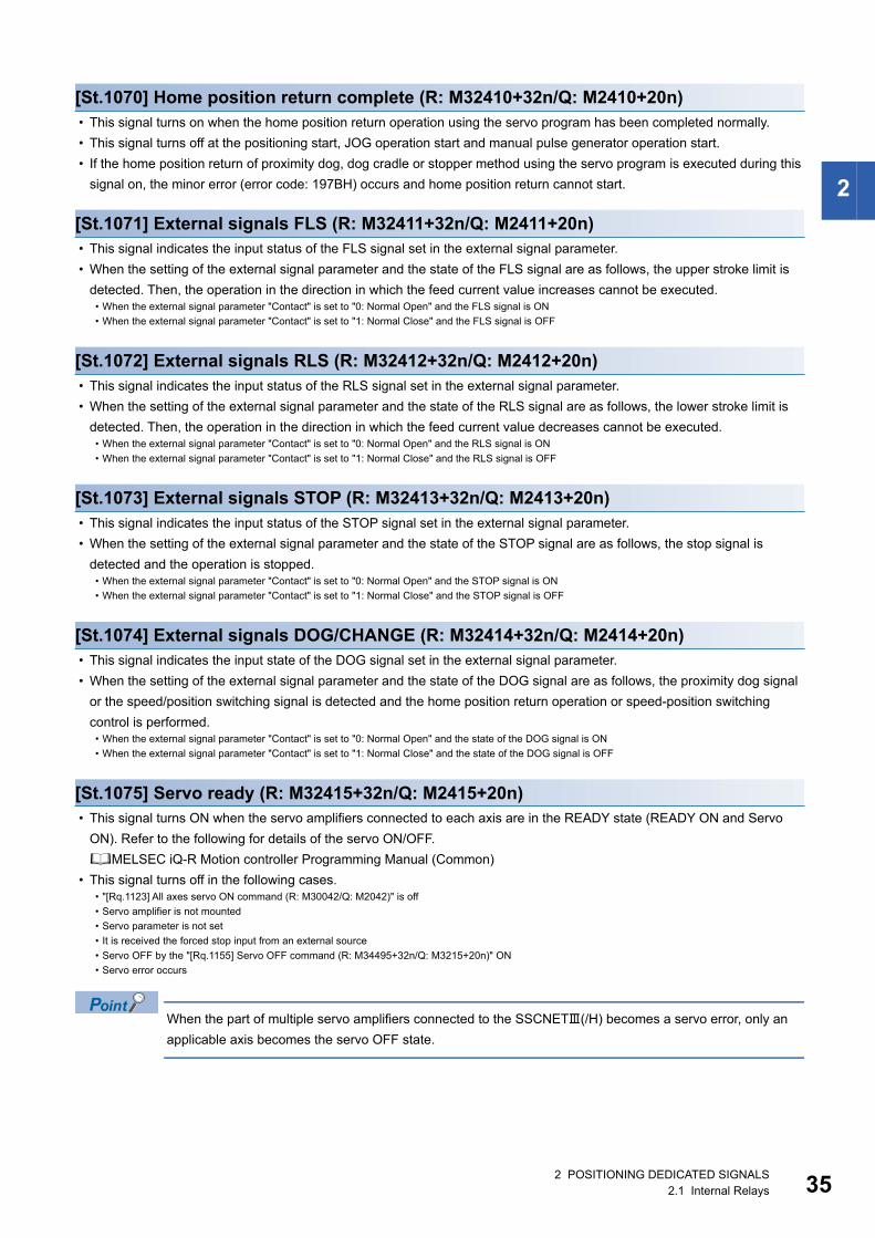
2
[St.1070] Home position return complete (R: M32410+32n/Q: M2410+20n) • This signal turns on when the home position return operation using the servo program has been completed normally.
• This signal turns off at the positioning start, JOG operation start and manual pulse generator operation start.
• If the home position return of proximity dog, dog cradle or stopper method using the servo program is executed during this
signal on, the minor error (error code: 197BH) occurs and home position return cannot start.
[St.1071] External signals FLS (R: M32411+32n/Q: M2411+20n) • This signal indicates the input status of the FLS signal set in the external signal parameter.
• When the setting of the external signal parameter and the state of the FLS signal are as follows, the upper stroke limit is
detected. Then, the operation in the direction in which the feed current value increases cannot be executed.
[St.1072] External signals RLS (R: M32412+32n/Q: M2412+20n) • This signal indicates the input status of the RLS signal set in the external signal parameter.
• When the setting of the external signal parameter and the state of the RLS signal are as follows, the lower stroke limit is
detected. Then, the operation in the direction in which the feed current value decreases cannot be executed.
[St.1073] External signals STOP (R: M32413+32n/Q: M2413+20n) • This signal indicates the input status of the STOP signal set in the external signal parameter.
• When the setting of the external signal parameter and the state of the STOP signal are as follows, the stop signal is
detected and the operation is stopped.
[St.1074] External signals DOG/CHANGE (R: M32414+32n/Q: M2414+20n) • This signal indicates the input state of the DOG signal set in the external signal parameter.
• When the setting of the external signal parameter and the state of the DOG signal are as follows, the proximity dog signal
or the speed/position switching signal is detected and the home position return operation or speed-position switching
control is performed.
[St.1075] Servo ready (R: M32415+32n/Q: M2415+20n) • This signal turns ON when the servo amplifiers connected to each axis are in the READY state (READY ON and Servo
ON). Refer to the following for details of the servo ON/OFF.
MELSEC iQ-R Motion controller Programming Manual (Common)
• This signal turns off in the following cases.
When the part of multiple servo amplifiers connected to the SSCNET(/H) becomes a servo error, only an
applicable axis becomes the servo OFF state.
• When the external signal parameter "Contact" is set to "0: Normal Open" and the FLS signal is ON
• When the external signal parameter "Contact" is set to "1: Normal Close" and the FLS signal is OFF
• When the external signal parameter "Contact" is set to "0: Normal Open" and the RLS signal is ON
• When the external signal parameter "Contact" is set to "1: Normal Close" and the RLS signal is OFF
• When the external signal parameter "Contact" is set to "0: Normal Open" and the STOP signal is ON
• When the external signal parameter "Contact" is set to "1: Normal Close" and the STOP signal is OFF
• When the external signal parameter "Contact" is set to "0: Normal Open" and the state of the DOG signal is ON
• When the external signal parameter "Contact" is set to "1: Normal Close" and the state of the DOG signal is OFF
• "[Rq.1123] All axes servo ON command (R: M30042/Q: M2042)" is off
• Servo amplifier is not mounted
• Servo parameter is not set
• It is received the forced stop input from an external source
• Servo OFF by the "[Rq.1155] Servo OFF command (R: M34495+32n/Q: M3215+20n)" ON
• Servo error occurs
2 POSITIONING DEDICATED SIGNALS2.1 Internal Relays 35
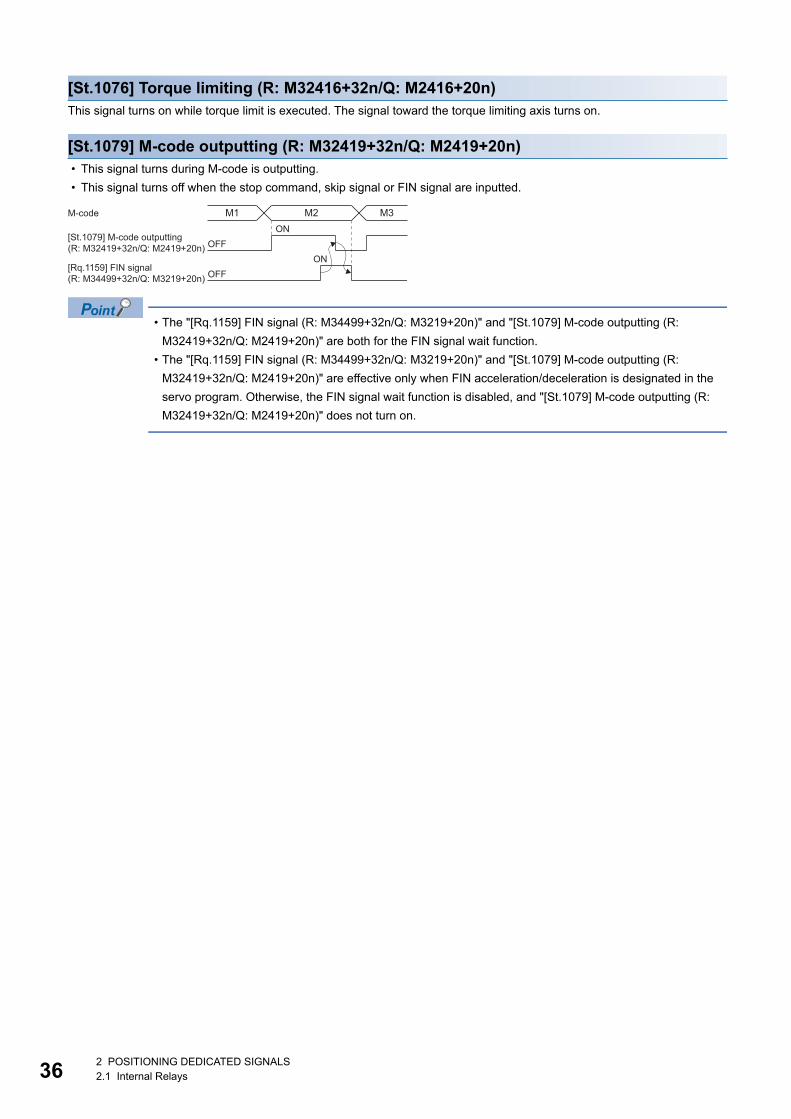
36
[St.1076] Torque limiting (R: M32416+32n/Q: M2416+20n)This signal turns on while torque limit is executed. The signal toward the torque limiting axis turns on.
[St.1079] M-code outputting (R: M32419+32n/Q: M2419+20n) • This signal turns during M-code is outputting.
• This signal turns off when the stop command, skip signal or FIN signal are inputted.
• The "[Rq.1159] FIN signal (R: M34499+32n/Q: M3219+20n)" and "[St.1079] M-code outputting (R:
M32419+32n/Q: M2419+20n)" are both for the FIN signal wait function.
• The "[Rq.1159] FIN signal (R: M34499+32n/Q: M3219+20n)" and "[St.1079] M-code outputting (R:
M32419+32n/Q: M2419+20n)" are effective only when FIN acceleration/deceleration is designated in the
servo program. Otherwise, the FIN signal wait function is disabled, and "[St.1079] M-code outputting (R:
M32419+32n/Q: M2419+20n)" does not turn on.
OFF[St.1079] M-code outputting(R: M32419+32n/Q: M2419+20n)
ON
M1M-code M2 M3
OFF[Rq.1159] FIN signal(R: M34499+32n/Q: M3219+20n)
ON
2 POSITIONING DEDICATED SIGNALS2.1 Internal Relays
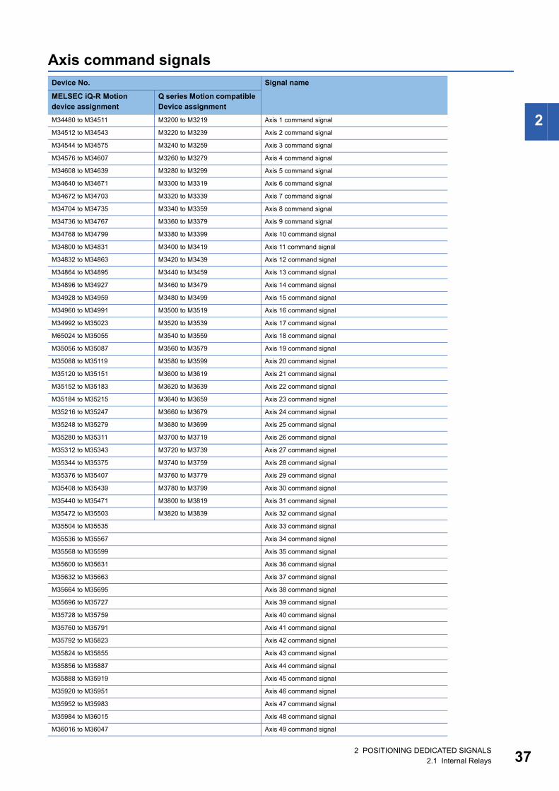
2
Axis command signalsDevice No. Signal name
MELSEC iQ-R Motion device assignment
Q series Motion compatible Device assignment
M34480 to M34511 M3200 to M3219 Axis 1 command signal
M34512 to M34543 M3220 to M3239 Axis 2 command signal
M34544 to M34575 M3240 to M3259 Axis 3 command signal
M34576 to M34607 M3260 to M3279 Axis 4 command signal
M34608 to M34639 M3280 to M3299 Axis 5 command signal
M34640 to M34671 M3300 to M3319 Axis 6 command signal
M34672 to M34703 M3320 to M3339 Axis 7 command signal
M34704 to M34735 M3340 to M3359 Axis 8 command signal
M34736 to M34767 M3360 to M3379 Axis 9 command signal
M34768 to M34799 M3380 to M3399 Axis 10 command signal
M34800 to M34831 M3400 to M3419 Axis 11 command signal
M34832 to M34863 M3420 to M3439 Axis 12 command signal
M34864 to M34895 M3440 to M3459 Axis 13 command signal
M34896 to M34927 M3460 to M3479 Axis 14 command signal
M34928 to M34959 M3480 to M3499 Axis 15 command signal
M34960 to M34991 M3500 to M3519 Axis 16 command signal
M34992 to M35023 M3520 to M3539 Axis 17 command signal
M65024 to M35055 M3540 to M3559 Axis 18 command signal
M35056 to M35087 M3560 to M3579 Axis 19 command signal
M35088 to M35119 M3580 to M3599 Axis 20 command signal
M35120 to M35151 M3600 to M3619 Axis 21 command signal
M35152 to M35183 M3620 to M3639 Axis 22 command signal
M35184 to M35215 M3640 to M3659 Axis 23 command signal
M35216 to M35247 M3660 to M3679 Axis 24 command signal
M35248 to M35279 M3680 to M3699 Axis 25 command signal
M35280 to M35311 M3700 to M3719 Axis 26 command signal
M35312 to M35343 M3720 to M3739 Axis 27 command signal
M35344 to M35375 M3740 to M3759 Axis 28 command signal
M35376 to M35407 M3760 to M3779 Axis 29 command signal
M35408 to M35439 M3780 to M3799 Axis 30 command signal
M35440 to M35471 M3800 to M3819 Axis 31 command signal
M35472 to M35503 M3820 to M3839 Axis 32 command signal
M35504 to M35535 Axis 33 command signal
M35536 to M35567 Axis 34 command signal
M35568 to M35599 Axis 35 command signal
M35600 to M35631 Axis 36 command signal
M35632 to M35663 Axis 37 command signal
M35664 to M35695 Axis 38 command signal
M35696 to M35727 Axis 39 command signal
M35728 to M35759 Axis 40 command signal
M35760 to M35791 Axis 41 command signal
M35792 to M35823 Axis 42 command signal
M35824 to M35855 Axis 43 command signal
M35856 to M35887 Axis 44 command signal
M35888 to M35919 Axis 45 command signal
M35920 to M35951 Axis 46 command signal
M35952 to M35983 Axis 47 command signal
M35984 to M36015 Axis 48 command signal
M36016 to M36047 Axis 49 command signal
2 POSITIONING DEDICATED SIGNALS2.1 Internal Relays 37
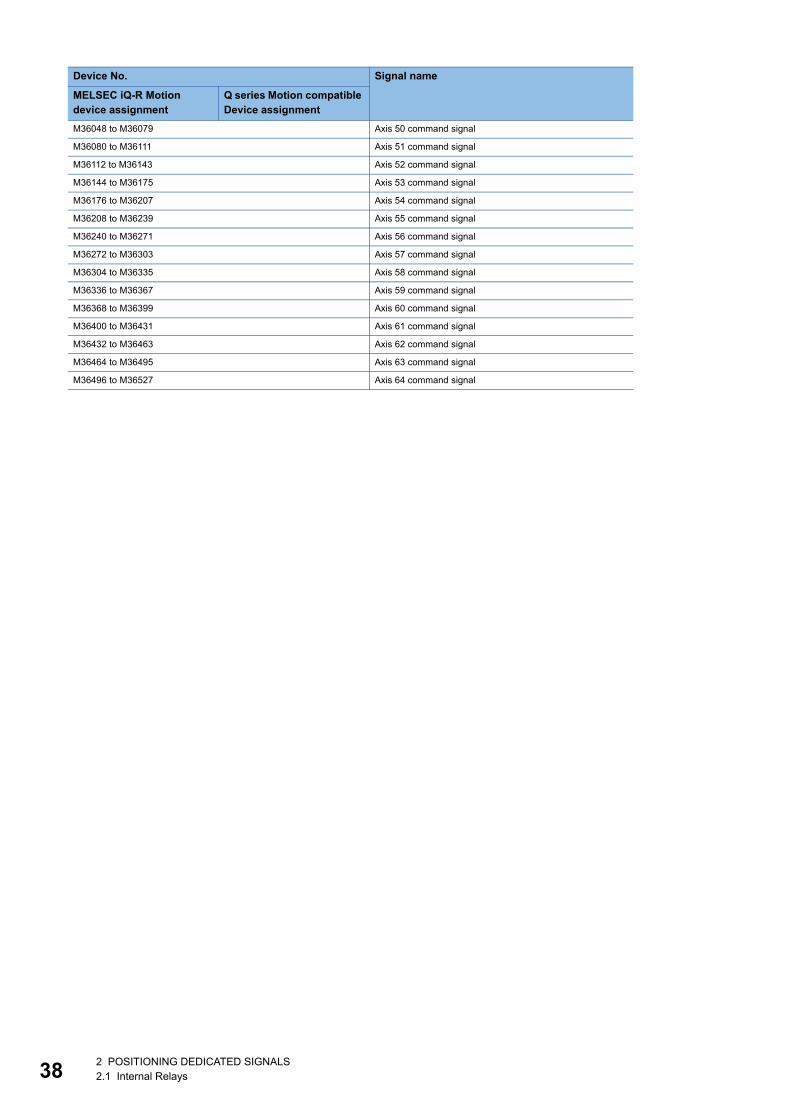
38
M36048 to M36079 Axis 50 command signal
M36080 to M36111 Axis 51 command signal
M36112 to M36143 Axis 52 command signal
M36144 to M36175 Axis 53 command signal
M36176 to M36207 Axis 54 command signal
M36208 to M36239 Axis 55 command signal
M36240 to M36271 Axis 56 command signal
M36272 to M36303 Axis 57 command signal
M36304 to M36335 Axis 58 command signal
M36336 to M36367 Axis 59 command signal
M36368 to M36399 Axis 60 command signal
M36400 to M36431 Axis 61 command signal
M36432 to M36463 Axis 62 command signal
M36464 to M36495 Axis 63 command signal
M36496 to M36527 Axis 64 command signal
Device No. Signal name
MELSEC iQ-R Motion device assignment
Q series Motion compatible Device assignment
2 POSITIONING DEDICATED SIGNALS2.1 Internal Relays
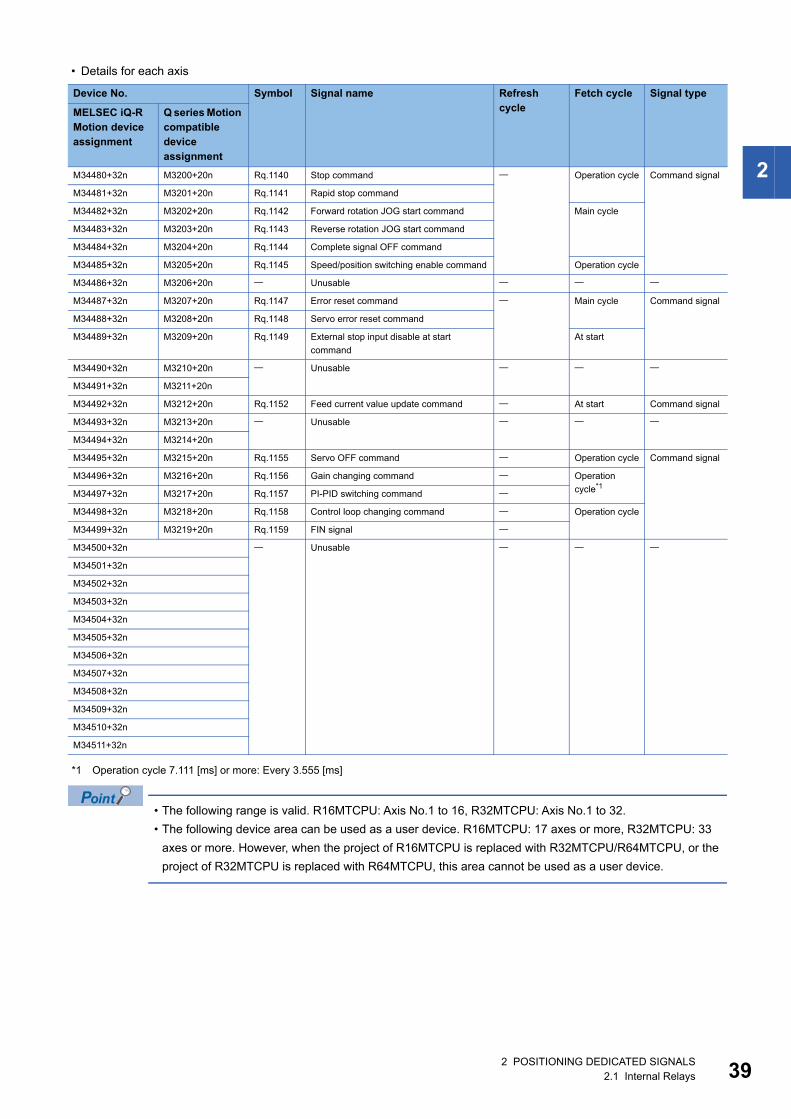
2
• Details for each axis
*1 Operation cycle 7.111 [ms] or more: Every 3.555 [ms]
• The following range is valid. R16MTCPU: Axis No.1 to 16, R32MTCPU: Axis No.1 to 32.
• The following device area can be used as a user device. R16MTCPU: 17 axes or more, R32MTCPU: 33
axes or more. However, when the project of R16MTCPU is replaced with R32MTCPU/R64MTCPU, or the
project of R32MTCPU is replaced with R64MTCPU, this area cannot be used as a user device.
Device No. Symbol Signal name Refresh cycle
Fetch cycle Signal type
MELSEC iQ-R Motion device assignment
Q series Motion compatible device assignment
M34480+32n M3200+20n Rq.1140 Stop command Operation cycle Command signal
M34481+32n M3201+20n Rq.1141 Rapid stop command
M34482+32n M3202+20n Rq.1142 Forward rotation JOG start command Main cycle
M34483+32n M3203+20n Rq.1143 Reverse rotation JOG start command
M34484+32n M3204+20n Rq.1144 Complete signal OFF command
M34485+32n M3205+20n Rq.1145 Speed/position switching enable command Operation cycle
M34486+32n M3206+20n Unusable
M34487+32n M3207+20n Rq.1147 Error reset command Main cycle Command signal
M34488+32n M3208+20n Rq.1148 Servo error reset command
M34489+32n M3209+20n Rq.1149 External stop input disable at start
command
At start
M34490+32n M3210+20n Unusable
M34491+32n M3211+20n
M34492+32n M3212+20n Rq.1152 Feed current value update command At start Command signal
M34493+32n M3213+20n Unusable
M34494+32n M3214+20n
M34495+32n M3215+20n Rq.1155 Servo OFF command Operation cycle Command signal
M34496+32n M3216+20n Rq.1156 Gain changing command Operation
cycle*1M34497+32n M3217+20n Rq.1157 PI-PID switching command
M34498+32n M3218+20n Rq.1158 Control loop changing command Operation cycle
M34499+32n M3219+20n Rq.1159 FIN signal
M34500+32n Unusable
M34501+32n
M34502+32n
M34503+32n
M34504+32n
M34505+32n
M34506+32n
M34507+32n
M34508+32n
M34509+32n
M34510+32n
M34511+32n
2 POSITIONING DEDICATED SIGNALS2.1 Internal Relays 39
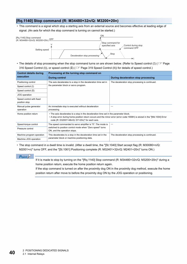
40
[Rq.1140] Stop command (R: M34480+32n/Q: M3200+20n) • This command is a signal which stop a starting axis from an external source and becomes effective at leading edge of
signal. (An axis for which the stop command is turning on cannot be started.)
• The details of stop processing when the stop command turns on are shown below. (Refer to Speed control () (Page
316 Speed Control (I)), or speed control () (Page 319 Speed Control (II)) for details of speed control.)
• The stop command in a dwell time is invalid. (After a dwell time, the "[St.1040] Start accept flag (R: M30080+n/Q:
M2001+n)" turns OFF, and the "[St.1061] Positioning complete (R: M32401+32n/Q: M2401+20n)" turns ON.)
If it is made to stop by turning on the "[Rq.1140] Stop command (R: M34480+32n/Q: M3200+20n)" during a
home position return, execute the home position return again.
If the stop command is turned on after the proximity dog ON in the proximity dog method, execute the home
position return after move to before the proximity dog ON by the JOG operation or positioning.
Control details during execution
Processing at the turning stop command on
During control During deceleration stop processing
Positioning control The axis decelerates to a stop in the deceleration time set in
the parameter block or servo program.
The deceleration stop processing is continued.
Speed control ()
Speed control ()
JOG operation
Speed control with fixed
position stop
Manual pulse generator
operation
An immediate stop is executed without deceleration
processing.
Home position return • The axis decelerates to a stop in the deceleration time set in the parameter block.
• A stop error during home position return occurs and the minor error (error code:1908H) is stored in the "[Md.1004] Error
code (R: D32007+48n/Q: D7+20n)" for each axis.
Speed-torque control The speed commanded to servo amplifier is "0". The mode is
switched to position control mode when "Zero speed" turns
ON, and the operation stops.
Pressure control
Machine program operation This decelerates to a stop in the deceleration time set in the
parameter block or machine positioning data.
The deceleration stop processing is continued.
Machine JOG operation
t
V
[Rq.1140] Stop command(R: M34480+32n/Q: M3200+20n) OFF
ON
Setting speed
Stop command forspecified axis
Stop
Control during stopcommand OFF
Deceleration stop processing
2 POSITIONING DEDICATED SIGNALS2.1 Internal Relays
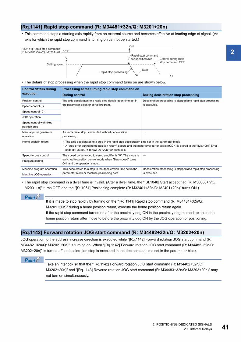
2
[Rq.1141] Rapid stop command (R: M34481+32n/Q: M3201+20n) • This command stops a starting axis rapidly from an external source and becomes effective at leading edge of signal. (An
axis for which the rapid stop command is turning on cannot be started.)
• The details of stop processing when the rapid stop command turns on are shown below.
• The rapid stop command in a dwell time is invalid. (After a dwell time, the "[St.1040] Start accept flag (R: M30080+n/Q:
M2001+n)" turns OFF, and the "[St.1061] Positioning complete (R: M32401+32n/Q: M2401+20n)" turns ON.)
If it is made to stop rapidly by turning on the "[Rq.1141] Rapid stop command (R: M34481+32n/Q:
M3201+20n)" during a home position return, execute the home position return again.
If the rapid stop command turned on after the proximity dog ON in the proximity dog method, execute the
home position return after move to before the proximity dog ON by the JOG operation or positioning.
[Rq.1142] Forward rotation JOG start command (R: M34482+32n/Q: M3202+20n)JOG operation to the address increase direction is executed while "[Rq.1142] Forward rotation JOG start command (R:
M34482+32n/Q: M3202+20n)" is turning on. When "[Rq.1142] Forward rotation JOG start command (R: M34482+32n/Q:
M3202+20n)" is turned off, a deceleration stop is executed in the deceleration time set in the parameter block.
Take an interlock so that the "[Rq.1142] Forward rotation JOG start command (R: M34482+32n/Q:
M3202+20n)" and "[Rq.1143] Reverse rotation JOG start command (R: M34483+32n/Q: M3203+20n)" may
not turn on simultaneously.
Control details during execution
Processing at the turning rapid stop command on
During control During deceleration stop processing
Position control The axis decelerates to a rapid stop deceleration time set in
the parameter block or servo program.
Deceleration processing is stopped and rapid stop processing
is executed.Speed control ()
Speed control ()
JOG operation
Speed control with fixed
position stop
Manual pulse generator
operation
An immediate stop is executed without deceleration
processing.
Home position return • The axis decelerates to a stop in the rapid stop deceleration time set in the parameter block.
• A "stop error during home position return" occurs and the minor error (error code:192DH) is stored in the "[Md.1004] Error
code (R: D32007+48n/Q: D7+20n" for each axis.
Speed-torque control The speed commanded to servo amplifier is "0". The mode is
switched to position control mode when "Zero speed" turns
ON, and the operation stops.
Pressure control
Machine program operation This decelerates to a stop in the deceleration time set in the
parameter block or machine positioning data.
Deceleration processing is stopped and rapid stop processing
is executed.Machine JOG operation
t
V
[Rq.1141] Rapid stop command(R: M34481+32n/Q: M3201+20n) OFF
ON
Setting speed
Rapid stop commandfor specified axis
Stop
Control during rapidstop command OFF
Rapid stop processing
2 POSITIONING DEDICATED SIGNALS2.1 Internal Relays 41
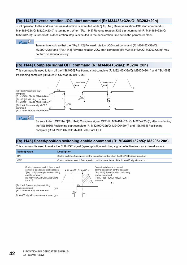
42
[Rq.1143] Reverse rotation JOG start command (R: M34483+32n/Q: M3203+20n)JOG operation to the address decrease direction is executed while "[Rq.1143] Reverse rotation JOG start command (R:
M34483+32n/Q: M3203+20n)" is turning on. When "[Rq.1143] Reverse rotation JOG start command (R: M34483+32n/Q:
M3203+20n)" is turned off, a deceleration stop is executed in the deceleration time set in the parameter block.
Take an interlock so that the "[Rq.1142] Forward rotation JOG start command (R: M34482+32n/Q:
M3202+20n)" and "[Rq.1143] Reverse rotation JOG start command (R: M34483+32n/Q: M3203+20n)" may
not turn on simultaneously.
[Rq.1144] Complete signal OFF command (R: M34484+32n/Q: M3204+20n)This command is used to turn off the "[St.1060] Positioning start complete (R: M32400+32n/Q: M2400+20n)" and "[St.1061]
Positioning complete (R: M32401+32n/Q: M2401+20n)".
Be sure to turn OFF the "[Rq.1144] Complete signal OFF (R: M34484+32n/Q: M3204+20n)", after confirming
the "[St.1060] Positioning start complete (R: M32400+32n/Q: M2400+20n)" and "[St.1061] Positioning
complete (R: M32401+32n/Q: M2401+20n)" are OFF.
[Rq.1145] Speed/position switching enable command (R: M34485+32n/Q: M3205+20n)This command is used to make the CHANGE signal (speed/position switching signal) effective from an external source.
Setting value Description
ON Control switches from speed control to position control when the CHANGE signal turned on.
OFF Control does not switch from speed to position control even if the CHANGE signal turns on.
Dwell timeDwell time
ONOFF
[St.1060] Positioning startcomplete (R: M32400+32n/Q: M2400+20n) ON
OFF[St.1061] Positioning complete(R: M32401+32n/Q: M2401+20n)
ONOFF
[Rq.1144] Complete signal OFFcommand (R: M34484+32n/Q: M3204+20n)
t
ONOFF
[Rq.1145] Speed/position switchingenable command(R: M34485+32n/Q: M3205+20n)
ONOFFCHANGE signal from external source
t
CHANGEControl switches from speedcontrol to position control because"[Rq.1145] Speed/position switchingenable command(R: M34485+32n/Q: M3205+20n)turns on
CHANGEControl does not switch from speedcontrol to position control because"[Rq.1145] Speed/position switchingenable command(R: M34485+32n/Q: M3205+20n)turns off
2 POSITIONING DEDICATED SIGNALS2.1 Internal Relays
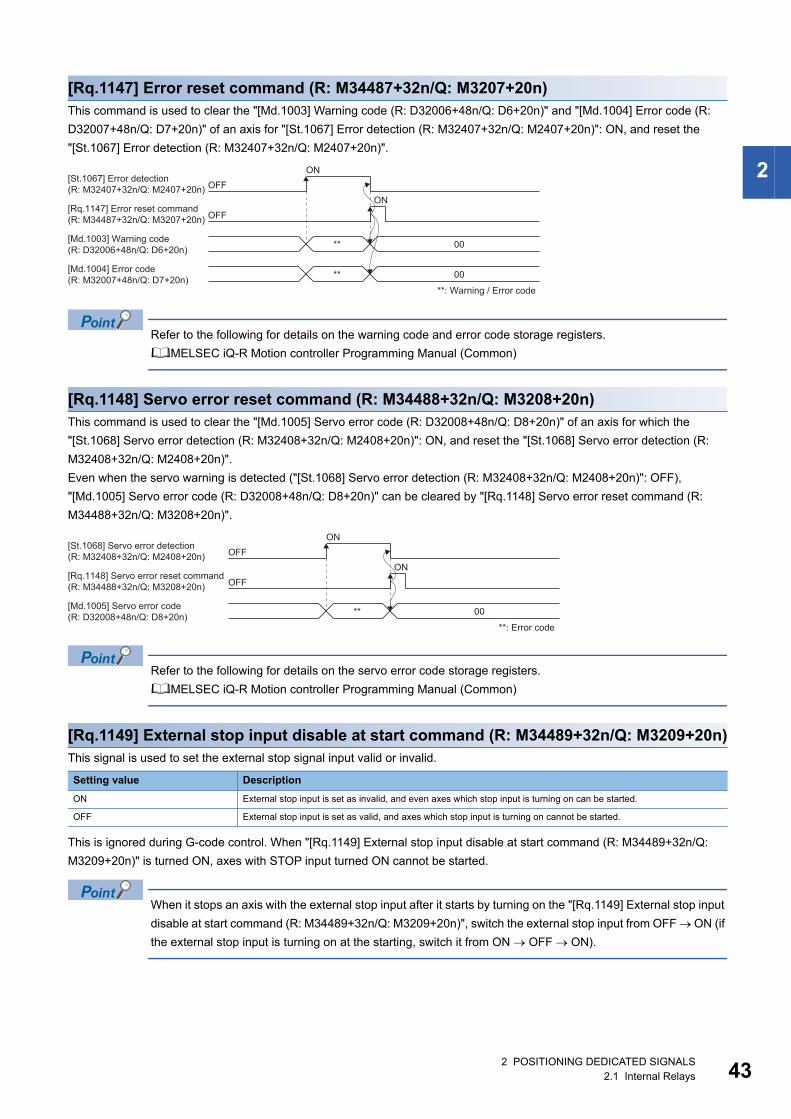
2
[Rq.1147] Error reset command (R: M34487+32n/Q: M3207+20n)This command is used to clear the "[Md.1003] Warning code (R: D32006+48n/Q: D6+20n)" and "[Md.1004] Error code (R:
D32007+48n/Q: D7+20n)" of an axis for "[St.1067] Error detection (R: M32407+32n/Q: M2407+20n)": ON, and reset the
"[St.1067] Error detection (R: M32407+32n/Q: M2407+20n)".
Refer to the following for details on the warning code and error code storage registers.
MELSEC iQ-R Motion controller Programming Manual (Common)
[Rq.1148] Servo error reset command (R: M34488+32n/Q: M3208+20n)This command is used to clear the "[Md.1005] Servo error code (R: D32008+48n/Q: D8+20n)" of an axis for which the
"[St.1068] Servo error detection (R: M32408+32n/Q: M2408+20n)": ON, and reset the "[St.1068] Servo error detection (R:
M32408+32n/Q: M2408+20n)".
Even when the servo warning is detected ("[St.1068] Servo error detection (R: M32408+32n/Q: M2408+20n)": OFF),
"[Md.1005] Servo error code (R: D32008+48n/Q: D8+20n)" can be cleared by "[Rq.1148] Servo error reset command (R:
M34488+32n/Q: M3208+20n)".
Refer to the following for details on the servo error code storage registers.
MELSEC iQ-R Motion controller Programming Manual (Common)
[Rq.1149] External stop input disable at start command (R: M34489+32n/Q: M3209+20n)This signal is used to set the external stop signal input valid or invalid.
This is ignored during G-code control. When "[Rq.1149] External stop input disable at start command (R: M34489+32n/Q:
M3209+20n)" is turned ON, axes with STOP input turned ON cannot be started.
When it stops an axis with the external stop input after it starts by turning on the "[Rq.1149] External stop input
disable at start command (R: M34489+32n/Q: M3209+20n)", switch the external stop input from OFF ON (if
the external stop input is turning on at the starting, switch it from ON OFF ON).
Setting value Description
ON External stop input is set as invalid, and even axes which stop input is turning on can be started.
OFF External stop input is set as valid, and axes which stop input is turning on cannot be started.
ONOFF
[St.1067] Error detection(R: M32407+32n/Q: M2407+20n)
ONOFF
[Rq.1147] Error reset command(R: M34487+32n/Q: M3207+20n)
** 00[Md.1003] Warning code (R: D32006+48n/Q: D6+20n)
**
**: Warning / Error code
00[Md.1004] Error code(R: M32007+48n/Q: D7+20n)
ONOFF
[St.1068] Servo error detection(R: M32408+32n/Q: M2408+20n)
ONOFF
[Rq.1148] Servo error reset command(R: M34488+32n/Q: M3208+20n)
** 00[Md.1005] Servo error code(R: D32008+48n/Q: D8+20n)
**: Error code
2 POSITIONING DEDICATED SIGNALS2.1 Internal Relays 43
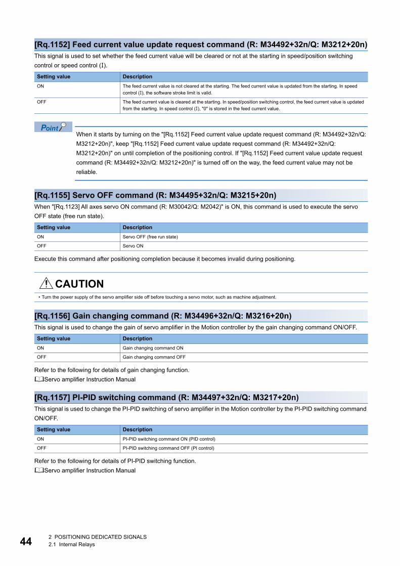
44
[Rq.1152] Feed current value update request command (R: M34492+32n/Q: M3212+20n)This signal is used to set whether the feed current value will be cleared or not at the starting in speed/position switching
control or speed control ().
When it starts by turning on the "[Rq.1152] Feed current value update request command (R: M34492+32n/Q:
M3212+20n)", keep "[Rq.1152] Feed current value update request command (R: M34492+32n/Q:
M3212+20n)" on until completion of the positioning control. If "[Rq.1152] Feed current value update request
command (R: M34492+32n/Q: M3212+20n)" is turned off on the way, the feed current value may not be
reliable.
[Rq.1155] Servo OFF command (R: M34495+32n/Q: M3215+20n)When "[Rq.1123] All axes servo ON command (R: M30042/Q: M2042)" is ON, this command is used to execute the servo
OFF state (free run state).
Execute this command after positioning completion because it becomes invalid during positioning.
[Rq.1156] Gain changing command (R: M34496+32n/Q: M3216+20n)This signal is used to change the gain of servo amplifier in the Motion controller by the gain changing command ON/OFF.
Refer to the following for details of gain changing function.
Servo amplifier Instruction Manual
[Rq.1157] PI-PID switching command (R: M34497+32n/Q: M3217+20n)This signal is used to change the PI-PID switching of servo amplifier in the Motion controller by the PI-PID switching command
ON/OFF.
Refer to the following for details of PI-PID switching function.
Servo amplifier Instruction Manual
Setting value Description
ON The feed current value is not cleared at the starting. The feed current value is updated from the starting. In speed
control (), the software stroke limit is valid.
OFF The feed current value is cleared at the starting. In speed/position switching control, the feed current value is updated
from the starting. In speed control (), "0" is stored in the feed current value.
Setting value Description
ON Servo OFF (free run state)
OFF Servo ON
CAUTION• Turn the power supply of the servo amplifier side off before touching a servo motor, such as machine adjustment.
Setting value Description
ON Gain changing command ON
OFF Gain changing command OFF
Setting value Description
ON PI-PID switching command ON (PID control)
OFF PI-PID switching command OFF (PI control)
2 POSITIONING DEDICATED SIGNALS2.1 Internal Relays
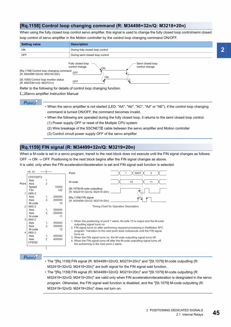
2
[Rq.1158] Control loop changing command (R: M34498+32n/Q: M3218+20n)When using the fully closed loop control servo amplifier, this signal is used to change the fully closed loop control/semi closed
loop control of servo amplifier in the Motion controller by the control loop changing command ON/OFF.
Refer to the following for details of control loop changing function.
Servo amplifier Instruction Manual
• When the servo amplifier is not started (LED: "AA", "Ab", "AC", "Ad" or "AE"), if the control loop changing
command is turned ON/OFF, the command becomes invalid.
• When the following are operated during the fully closed loop, it returns to the semi closed loop control.
(1) Power supply OFF or reset of the Multiple CPU system
(2) Wire breakage of the SSCNET cable between the servo amplifier and Motion controller
(3) Control circuit power supply OFF of the servo amplifier
[Rq.1159] FIN signal (R: M34499+32n/Q: M3219+20n)When a M-code is set in a servo program, transit to the next block does not execute until the FIN signal changes as follows:
OFF ON OFF. Positioning to the next block begins after the FIN signal changes as above.
It is valid, only when the FIN acceleration/deceleration is set and FIN signal wait function is selected.
• The "[Rq.1159] FIN signal (R: M34499+32n/Q: M3219+20n)" and "[St.1079] M-code outputting (R:
M32419+32n/Q: M2419+20n)" are both signal for the FIN signal wait function.
• The "[Rq.1159] FIN signal (R: M34499+32n/Q: M3219+20n)" and "[St.1079] M-code outputting (R:
M32419+32n/Q: M2419+20n)" are valid only when FIN acceleration/deceleration is designated in the servo
program. Otherwise, the FIN signal wait function is disabled, and the "[St.1079] M-code outputting (R:
M32419+32n/Q: M2419+20n)" does not turn on.
Setting value Description
ON During fully closed loop control
OFF During semi closed loop control
ONOFF
[Rq.1158] Control loop changing command(R: M34498+32n/Q: M3218+20n)
Fully closed loop control change
Semi closed loop control change
ONOFF
[St.1050] Control loop monitor status(R: M30336+n/Q: M2272+n)
CPSTART2 Axis Axis Speed FINABS-2 Axis Axis M-codeABS-2 Axis Axis M-codeABS-2 Axis Axis M-codeABS-2 Axis AxisCPEND
Point
1
2
3
4
12
1,2,
1,2,
1,2,
1,2
10000100
200000200000
10
300000250000
11
350000300000
12
400000400000
<K 0> Point 1 WAIT 2
M-code
[St.1079] M-code outputting(R: M32419+32n/Q: M2419+20n)
[Rq.1159] FIN signal(R: M34499+32n/Q: M3219+20n)
10 11
Timing Chart for Operation Description
1. When the positioning of point 1 starts, M-code 10 is output and the M-codeoutputting signal turns on.
2. FIN signal turns on after performing required processing in theMotion SFCprogram. Transition to the next point does notexecute until the FIN signalturns on.
3. When the FIN signal turns on, the M-code outputting signal turns off.4. When the FIN signal turns off after the M-code outputting signal turns off,
the positioning to the next point 2 starts.
2 POSITIONING DEDICATED SIGNALS2.1 Internal Relays 45
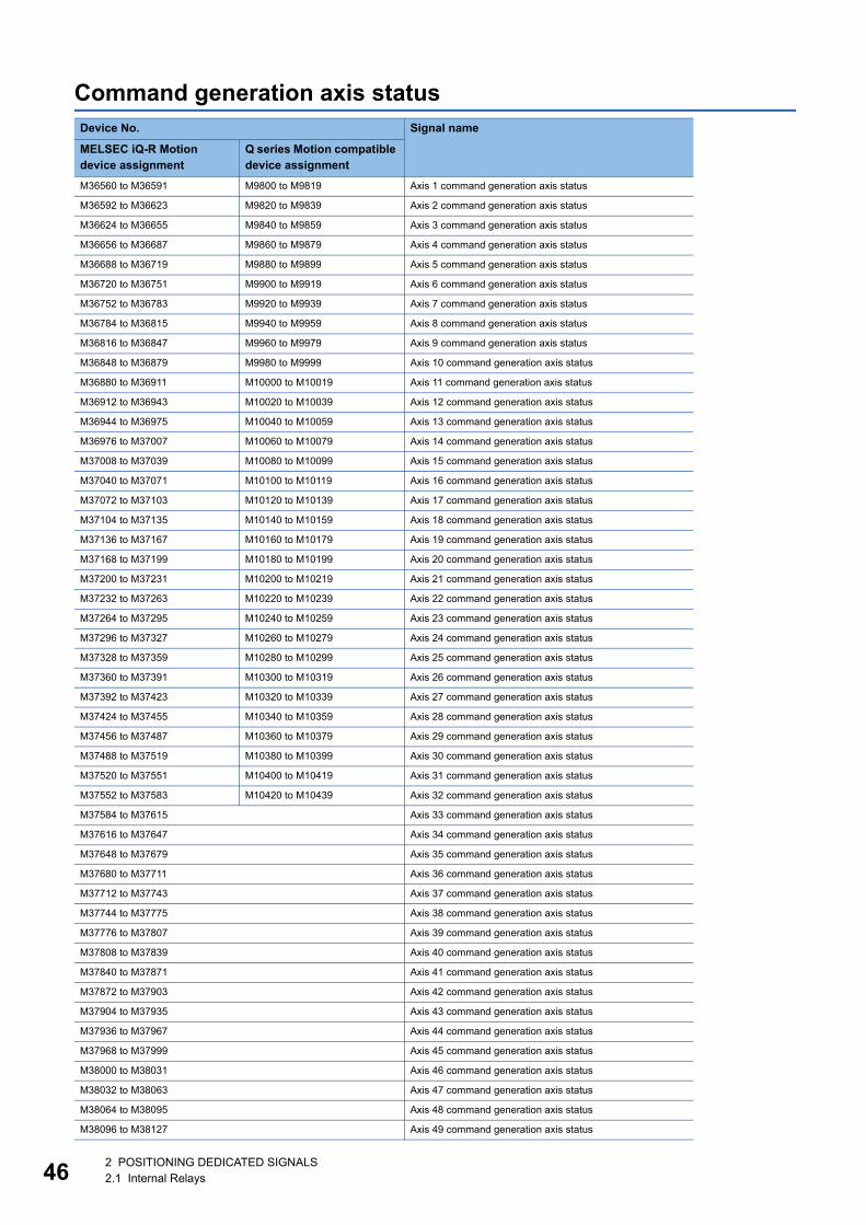
46
Command generation axis statusDevice No. Signal name
MELSEC iQ-R Motion device assignment
Q series Motion compatible device assignment
M36560 to M36591 M9800 to M9819 Axis 1 command generation axis status
M36592 to M36623 M9820 to M9839 Axis 2 command generation axis status
M36624 to M36655 M9840 to M9859 Axis 3 command generation axis status
M36656 to M36687 M9860 to M9879 Axis 4 command generation axis status
M36688 to M36719 M9880 to M9899 Axis 5 command generation axis status
M36720 to M36751 M9900 to M9919 Axis 6 command generation axis status
M36752 to M36783 M9920 to M9939 Axis 7 command generation axis status
M36784 to M36815 M9940 to M9959 Axis 8 command generation axis status
M36816 to M36847 M9960 to M9979 Axis 9 command generation axis status
M36848 to M36879 M9980 to M9999 Axis 10 command generation axis status
M36880 to M36911 M10000 to M10019 Axis 11 command generation axis status
M36912 to M36943 M10020 to M10039 Axis 12 command generation axis status
M36944 to M36975 M10040 to M10059 Axis 13 command generation axis status
M36976 to M37007 M10060 to M10079 Axis 14 command generation axis status
M37008 to M37039 M10080 to M10099 Axis 15 command generation axis status
M37040 to M37071 M10100 to M10119 Axis 16 command generation axis status
M37072 to M37103 M10120 to M10139 Axis 17 command generation axis status
M37104 to M37135 M10140 to M10159 Axis 18 command generation axis status
M37136 to M37167 M10160 to M10179 Axis 19 command generation axis status
M37168 to M37199 M10180 to M10199 Axis 20 command generation axis status
M37200 to M37231 M10200 to M10219 Axis 21 command generation axis status
M37232 to M37263 M10220 to M10239 Axis 22 command generation axis status
M37264 to M37295 M10240 to M10259 Axis 23 command generation axis status
M37296 to M37327 M10260 to M10279 Axis 24 command generation axis status
M37328 to M37359 M10280 to M10299 Axis 25 command generation axis status
M37360 to M37391 M10300 to M10319 Axis 26 command generation axis status
M37392 to M37423 M10320 to M10339 Axis 27 command generation axis status
M37424 to M37455 M10340 to M10359 Axis 28 command generation axis status
M37456 to M37487 M10360 to M10379 Axis 29 command generation axis status
M37488 to M37519 M10380 to M10399 Axis 30 command generation axis status
M37520 to M37551 M10400 to M10419 Axis 31 command generation axis status
M37552 to M37583 M10420 to M10439 Axis 32 command generation axis status
M37584 to M37615 Axis 33 command generation axis status
M37616 to M37647 Axis 34 command generation axis status
M37648 to M37679 Axis 35 command generation axis status
M37680 to M37711 Axis 36 command generation axis status
M37712 to M37743 Axis 37 command generation axis status
M37744 to M37775 Axis 38 command generation axis status
M37776 to M37807 Axis 39 command generation axis status
M37808 to M37839 Axis 40 command generation axis status
M37840 to M37871 Axis 41 command generation axis status
M37872 to M37903 Axis 42 command generation axis status
M37904 to M37935 Axis 43 command generation axis status
M37936 to M37967 Axis 44 command generation axis status
M37968 to M37999 Axis 45 command generation axis status
M38000 to M38031 Axis 46 command generation axis status
M38032 to M38063 Axis 47 command generation axis status
M38064 to M38095 Axis 48 command generation axis status
M38096 to M38127 Axis 49 command generation axis status
2 POSITIONING DEDICATED SIGNALS2.1 Internal Relays
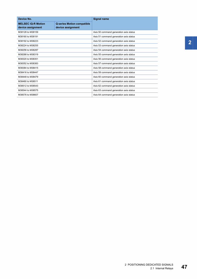
2
M38128 to M38159 Axis 50 command generation axis status
M38160 to M38191 Axis 51 command generation axis status
M38192 to M38223 Axis 52 command generation axis status
M38224 to M38255 Axis 53 command generation axis status
M38256 to M38287 Axis 54 command generation axis status
M38288 to M38319 Axis 55 command generation axis status
M38320 to M38351 Axis 56 command generation axis status
M38352 to M38383 Axis 57 command generation axis status
M38384 to M38415 Axis 58 command generation axis status
M38416 to M38447 Axis 59 command generation axis status
M38448 to M38479 Axis 60 command generation axis status
M38480 to M38511 Axis 61 command generation axis status
M38512 to M38543 Axis 62 command generation axis status
M38544 to M38575 Axis 63 command generation axis status
M38576 to M38607 Axis 64 command generation axis status
Device No. Signal name
MELSEC iQ-R Motion device assignment
Q series Motion compatible device assignment
2 POSITIONING DEDICATED SIGNALS2.1 Internal Relays 47
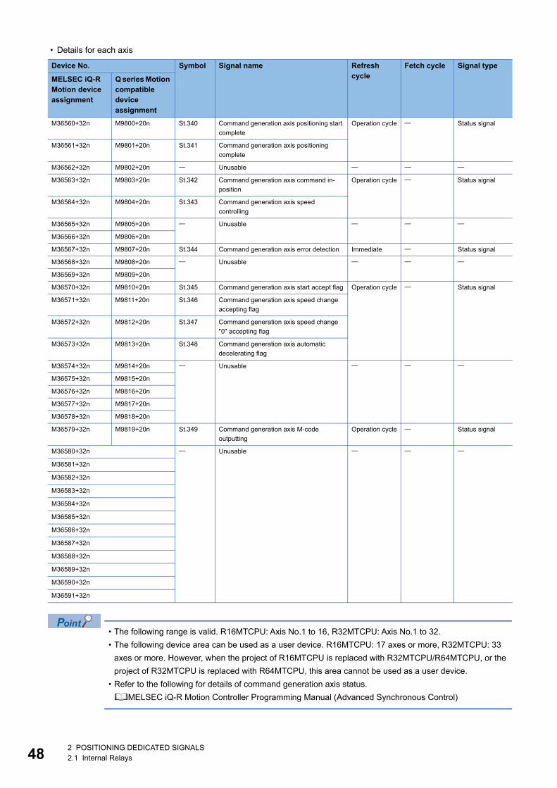
48
• Details for each axis
• The following range is valid. R16MTCPU: Axis No.1 to 16, R32MTCPU: Axis No.1 to 32.
• The following device area can be used as a user device. R16MTCPU: 17 axes or more, R32MTCPU: 33
axes or more. However, when the project of R16MTCPU is replaced with R32MTCPU/R64MTCPU, or the
project of R32MTCPU is replaced with R64MTCPU, this area cannot be used as a user device.
• Refer to the following for details of command generation axis status.
MELSEC iQ-R Motion Controller Programming Manual (Advanced Synchronous Control)
Device No. Symbol Signal name Refresh cycle
Fetch cycle Signal type
MELSEC iQ-R Motion device assignment
Q series Motion compatible device assignment
M36560+32n M9800+20n St.340 Command generation axis positioning start
complete
Operation cycle Status signal
M36561+32n M9801+20n St.341 Command generation axis positioning
complete
M36562+32n M9802+20n Unusable
M36563+32n M9803+20n St.342 Command generation axis command in-
position
Operation cycle Status signal
M36564+32n M9804+20n St.343 Command generation axis speed
controlling
M36565+32n M9805+20n Unusable
M36566+32n M9806+20n
M36567+32n M9807+20n St.344 Command generation axis error detection Immediate Status signal
M36568+32n M9808+20n Unusable
M36569+32n M9809+20n
M36570+32n M9810+20n St.345 Command generation axis start accept flag Operation cycle Status signal
M36571+32n M9811+20n St.346 Command generation axis speed change
accepting flag
M36572+32n M9812+20n St.347 Command generation axis speed change
"0" accepting flag
M36573+32n M9813+20n St.348 Command generation axis automatic
decelerating flag
M36574+32n M9814+20n Unusable
M36575+32n M9815+20n
M36576+32n M9816+20n
M36577+32n M9817+20n
M36578+32n M9818+20n
M36579+32n M9819+20n St.349 Command generation axis M-code
outputting
Operation cycle Status signal
M36580+32n Unusable
M36581+32n
M36582+32n
M36583+32n
M36584+32n
M36585+32n
M36586+32n
M36587+32n
M36588+32n
M36589+32n
M36590+32n
M36591+32n
2 POSITIONING DEDICATED SIGNALS2.1 Internal Relays

2
Command generation axis command signalDevice No. Signal name
MELSEC iQ-R Motion device assignment
Q series Motion compatible device assignment
M40160 to M40191 M10960 to M10979 Axis 1 command generation axis command signal
M40192 to M40223 M10980 to M10999 Axis 2 command generation axis command signal
M40224 to M40255 M11000 to M11019 Axis 3 command generation axis command signal
M40256 to M40287 M11020 to M11039 Axis 4 command generation axis command signal
M40288 to M40319 M11040 to M11059 Axis 5 command generation axis command signal
M40320 to M40351 M11060 to M11079 Axis 6 command generation axis command signal
M40352 to M40383 M11080 to M11099 Axis 7 command generation axis command signal
M40384 to M40415 M11100 to M11119 Axis 8 command generation axis command signal
M40416 to M40447 M11120 to M11139 Axis 9 command generation axis command signal
M40448 to M40479 M11140 to M11159 Axis 10 command generation axis command signal
M40480 to M40511 M11160 to M11179 Axis 11 command generation axis command signal
M40512 to M40543 M11180 to M11199 Axis 12 command generation axis command signal
M40544 to M40575 M11200 to M11219 Axis 13 command generation axis command signal
M40576 to M40607 M11220 to M11239 Axis 14 command generation axis command signal
M40608 to M40639 M11240 to M11259 Axis 15 command generation axis command signal
M40640 to M40671 M11260 to M11279 Axis 16 command generation axis command signal
M40672 to M40703 M11280 to M11299 Axis 17 command generation axis command signal
M40704 to M40735 M11300 to M11319 Axis 18 command generation axis command signal
M40736 to M40767 M11320 to M11339 Axis 19 command generation axis command signal
M40768 to M40799 M11340 to M11359 Axis 20 command generation axis command signal
M40800 to M40831 M11360 to M11379 Axis 21 command generation axis command signal
M40832 to M40863 M11380 to M11399 Axis 22 command generation axis command signal
M40864 to M40895 M11400 to M11419 Axis 23 command generation axis command signal
M40896 to M40927 M11420 to M11439 Axis 24 command generation axis command signal
M40928 to M40959 M11440 to M11459 Axis 25 command generation axis command signal
M40960 to M40991 M11460 to M11479 Axis 26 command generation axis command signal
M40992 to M41023 M11480 to M11499 Axis 27 command generation axis command signal
M41024 to M41055 M11500 to M11519 Axis 28 command generation axis command signal
M41056 to M41087 M11520 to M11539 Axis 29 command generation axis command signal
M41088 to M41119 M11540 to M11559 Axis 30 command generation axis command signal
M41120 to M41151 M11560 to M11579 Axis 31 command generation axis command signal
M41152 to M41183 M11580 to M11599 Axis 32 command generation axis command signal
M41184 to M41215 Axis 33 command generation axis command signal
M41216 to M41247 Axis 34 command generation axis command signal
M41248 to M41279 Axis 35 command generation axis command signal
M41280 to M41311 Axis 36 command generation axis command signal
M41312 to M41343 Axis 37 command generation axis command signal
M41344 to M41375 Axis 38 command generation axis command signal
M41376 to M41407 Axis 39 command generation axis command signal
M41408 to M41439 Axis 40 command generation axis command signal
M41440 to M41471 Axis 41 command generation axis command signal
M41472 to M41503 Axis 42 command generation axis command signal
M41504 to M41535 Axis 43 command generation axis command signal
M41536 to M41567 Axis 44 command generation axis command signal
M41568 to M41599 Axis 45 command generation axis command signal
M41600 to M41631 Axis 46 command generation axis command signal
M41632 to M41663 Axis 47 command generation axis command signal
M41664 to M41695 Axis 48 command generation axis command signal
M41696 to M41727 Axis 49 command generation axis command signal
2 POSITIONING DEDICATED SIGNALS2.1 Internal Relays 49
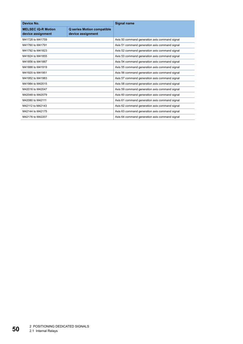
50
M41728 to M41759 Axis 50 command generation axis command signal
M41760 to M41791 Axis 51 command generation axis command signal
M41792 to M41823 Axis 52 command generation axis command signal
M41824 to M41855 Axis 53 command generation axis command signal
M41856 to M41887 Axis 54 command generation axis command signal
M41888 to M41919 Axis 55 command generation axis command signal
M41920 to M41951 Axis 56 command generation axis command signal
M41952 to M41983 Axis 57 command generation axis command signal
M41984 to M42015 Axis 58 command generation axis command signal
M42016 to M42047 Axis 59 command generation axis command signal
M42048 to M42079 Axis 60 command generation axis command signal
M42080 to M42111 Axis 61 command generation axis command signal
M42112 to M42143 Axis 62 command generation axis command signal
M42144 to M42175 Axis 63 command generation axis command signal
M42176 to M42207 Axis 64 command generation axis command signal
Device No. Signal name
MELSEC iQ-R Motion device assignment
Q series Motion compatible device assignment
2 POSITIONING DEDICATED SIGNALS2.1 Internal Relays
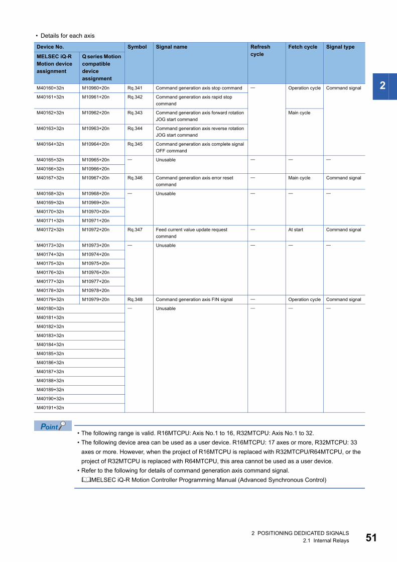
2
• Details for each axis
• The following range is valid. R16MTCPU: Axis No.1 to 16, R32MTCPU: Axis No.1 to 32.
• The following device area can be used as a user device. R16MTCPU: 17 axes or more, R32MTCPU: 33
axes or more. However, when the project of R16MTCPU is replaced with R32MTCPU/R64MTCPU, or the
project of R32MTCPU is replaced with R64MTCPU, this area cannot be used as a user device.
• Refer to the following for details of command generation axis command signal.
MELSEC iQ-R Motion Controller Programming Manual (Advanced Synchronous Control)
Device No. Symbol Signal name Refresh cycle
Fetch cycle Signal type
MELSEC iQ-R Motion device assignment
Q series Motion compatible device assignment
M40160+32n M10960+20n Rq.341 Command generation axis stop command Operation cycle Command signal
M40161+32n M10961+20n Rq.342 Command generation axis rapid stop
command
M40162+32n M10962+20n Rq.343 Command generation axis forward rotation
JOG start command
Main cycle
M40163+32n M10963+20n Rq.344 Command generation axis reverse rotation
JOG start command
M40164+32n M10964+20n Rq.345 Command generation axis complete signal
OFF command
M40165+32n M10965+20n Unusable
M40166+32n M10966+20n
M40167+32n M10967+20n Rq.346 Command generation axis error reset
command
Main cycle Command signal
M40168+32n M10968+20n Unusable
M40169+32n M10969+20n
M40170+32n M10970+20n
M40171+32n M10971+20n
M40172+32n M10972+20n Rq.347 Feed current value update request
command
At start Command signal
M40173+32n M10973+20n Unusable
M40174+32n M10974+20n
M40175+32n M10975+20n
M40176+32n M10976+20n
M40177+32n M10977+20n
M40178+32n M10978+20n
M40179+32n M10979+20n Rq.348 Command generation axis FIN signal Operation cycle Command signal
M40180+32n Unusable
M40181+32n
M40182+32n
M40183+32n
M40184+32n
M40185+32n
M40186+32n
M40187+32n
M40188+32n
M40189+32n
M40190+32n
M40191+32n
2 POSITIONING DEDICATED SIGNALS2.1 Internal Relays 51
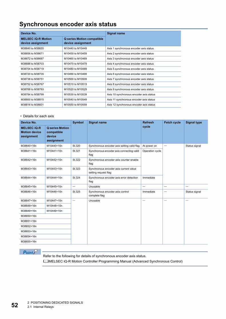
52
Synchronous encoder axis status
• Details for each axis
Refer to the following for details of synchronous encoder axis status.
MELSEC iQ-R Motion Controller Programming Manual (Advanced Synchronous Control)
Device No. Signal name
MELSEC iQ-R Motion device assignment
Q series Motion compatible device assignment
M38640 to M38655 M10440 to M10449 Axis 1 synchronous encoder axis status
M38656 to M38671 M10450 to M10459 Axis 2 synchronous encoder axis status
M38672 to M38687 M10460 to M10469 Axis 3 synchronous encoder axis status
M38688 to M38703 M10470 to M10479 Axis 4 synchronous encoder axis status
M38704 to M38719 M10480 to M10489 Axis 5 synchronous encoder axis status
M38720 to M38735 M10490 to M10499 Axis 6 synchronous encoder axis status
M38736 to M38751 M10500 to M10509 Axis 7 synchronous encoder axis status
M38752 to M38767 M10510 to M10519 Axis 8 synchronous encoder axis status
M38768 to M38783 M10520 to M10529 Axis 9 synchronous encoder axis status
M38784 to M38799 M10530 to M10539 Axis 10 synchronous encoder axis status
M38800 to M38815 M10540 to M10549 Axis 11 synchronous encoder axis status
M38816 to M38831 M10550 to M10559 Axis 12 synchronous encoder axis status
Device No. Symbol Signal name Refresh cycle
Fetch cycle Signal type
MELSEC iQ-R Motion device assignment
Q series Motion compatible device assignment
M38640+16n M10440+10n St.320 Synchronous encoder axis setting valid flag At power on Status signal
M38641+16n M10441+10n St.321 Synchronous encoder axis connecting valid
flag
Operation cycle
M38642+16n M10442+10n St.322 Synchronous encoder axis counter enable
flag
M38643+16n M10443+10n St.323 Synchronous encoder axis current value
setting request flag
M38644+16n M10444+10n St.324 Synchronous encoder axis error detection
flag
Immediate
M38645+16n M10445+10n Unusable
M38646+16n M10446+10n St.325 Synchronous encoder axis control
complete flag
Immediate Status signal
M38647+16n M10447+10n Unusable
M38648+16n M10448+10n
M38649+16n M10449+10n
M38650+16n
M38651+16n
M38652+16n
M38653+16n
M38654+16n
M38655+16n
2 POSITIONING DEDICATED SIGNALS2.1 Internal Relays
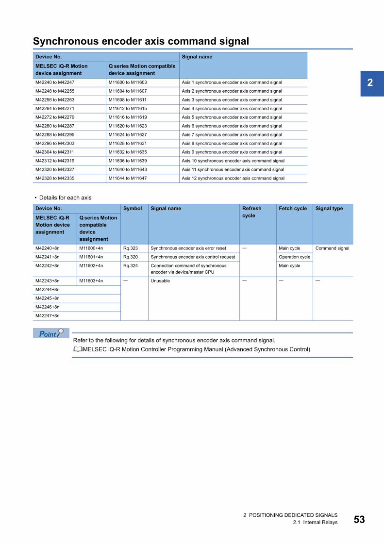
2
Synchronous encoder axis command signal
• Details for each axis
Refer to the following for details of synchronous encoder axis command signal.
MELSEC iQ-R Motion Controller Programming Manual (Advanced Synchronous Control)
Device No. Signal name
MELSEC iQ-R Motion device assignment
Q series Motion compatible device assignment
M42240 to M42247 M11600 to M11603 Axis 1 synchronous encoder axis command signal
M42248 to M42255 M11604 to M11607 Axis 2 synchronous encoder axis command signal
M42256 to M42263 M11608 to M11611 Axis 3 synchronous encoder axis command signal
M42264 to M42271 M11612 to M11615 Axis 4 synchronous encoder axis command signal
M42272 to M42279 M11616 to M11619 Axis 5 synchronous encoder axis command signal
M42280 to M42287 M11620 to M11623 Axis 6 synchronous encoder axis command signal
M42288 to M42295 M11624 to M11627 Axis 7 synchronous encoder axis command signal
M42296 to M42303 M11628 to M11631 Axis 8 synchronous encoder axis command signal
M42304 to M42311 M11632 to M11635 Axis 9 synchronous encoder axis command signal
M42312 to M42319 M11636 to M11639 Axis 10 synchronous encoder axis command signal
M42320 to M42327 M11640 to M11643 Axis 11 synchronous encoder axis command signal
M42328 to M42335 M11644 to M11647 Axis 12 synchronous encoder axis command signal
Device No. Symbol Signal name Refresh cycle
Fetch cycle Signal type
MELSEC iQ-R Motion device assignment
Q series Motion compatible device assignment
M42240+8n M11600+4n Rq.323 Synchronous encoder axis error reset Main cycle Command signal
M42241+8n M11601+4n Rq.320 Synchronous encoder axis control request Operation cycle
M42242+8n M11602+4n Rq.324 Connection command of synchronous
encoder via device/master CPU
Main cycle
M42243+8n M11603+4n Unusable
M42244+8n
M42245+8n
M42246+8n
M42247+8n
2 POSITIONING DEDICATED SIGNALS2.1 Internal Relays 53
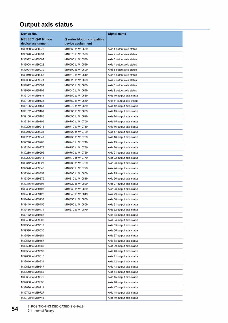
54
Output axis statusDevice No. Signal name
MELSEC iQ-R Motion device assignment
Q series Motion compatible device assignment
M38960 to M38975 M10560 to M10569 Axis 1 output axis status
M38976 to M38991 M10570 to M10579 Axis 2 output axis status
M38992 to M39007 M10580 to M10589 Axis 3 output axis status
M39008 to M39023 M10590 to M10599 Axis 4 output axis status
M39024 to M39039 M10600 to M10609 Axis 5 output axis status
M39040 to M39055 M10610 to M10619 Axis 6 output axis status
M39056 to M39071 M10620 to M10629 Axis 7 output axis status
M39072 to M39087 M10630 to M10639 Axis 8 output axis status
M39088 to M39103 M10640 to M10649 Axis 9 output axis status
M39104 to M39119 M10650 to M10659 Axis 10 output axis status
M39120 to M39135 M10660 to M10669 Axis 11 output axis status
M39136 to M39151 M10670 to M10679 Axis 12 output axis status
M39152 to M39167 M10680 to M10689 Axis 13 output axis status
M39168 to M39183 M10690 to M10699 Axis 14 output axis status
M39184 to M39199 M10700 to M10709 Axis 15 output axis status
M39200 to M39215 M10710 to M10719 Axis 16 output axis status
M39216 to M39231 M10720 to M10729 Axis 17 output axis status
M39232 to M39247 M10730 to M10739 Axis 18 output axis status
M39248 to M39263 M10740 to M10749 Axis 19 output axis status
M39264 to M39279 M10750 to M10759 Axis 20 output axis status
M39280 to M39295 M10760 to M10769 Axis 21 output axis status
M39296 to M39311 M10770 to M10779 Axis 22 output axis status
M39312 to M39327 M10780 to M10789 Axis 23 output axis status
M39328 to M39343 M10790 to M10799 Axis 24 output axis status
M39344 to M39359 M10800 to M10809 Axis 25 output axis status
M39360 to M39375 M10810 to M10819 Axis 26 output axis status
M39376 to M39391 M10820 to M10829 Axis 27 output axis status
M39392 to M39407 M10830 to M10839 Axis 28 output axis status
M39408 to M39423 M10840 to M10849 Axis 29 output axis status
M39424 to M39439 M10850 to M10859 Axis 30 output axis status
M39440 to M39455 M10860 to M10869 Axis 31 output axis status
M39456 to M39471 M10870 to M10879 Axis 32 output axis status
M39472 to M39487 Axis 33 output axis status
M39488 to M39503 Axis 34 output axis status
M39504 to M39519 Axis 35 output axis status
M39520 to M39535 Axis 36 output axis status
M39536 to M39551 Axis 37 output axis status
M39552 to M39567 Axis 38 output axis status
M39568 to M39583 Axis 39 output axis status
M39584 to M39599 Axis 40 output axis status
M39600 to M39615 Axis 41 output axis status
M39616 to M39631 Axis 42 output axis status
M39632 to M39647 Axis 43 output axis status
M39648 to M39663 Axis 44 output axis status
M39664 to M39679 Axis 45 output axis status
M39680 to M39695 Axis 46 output axis status
M39696 to M39711 Axis 47 output axis status
M39712 to M39727 Axis 48 output axis status
M39728 to M39743 Axis 49 output axis status
2 POSITIONING DEDICATED SIGNALS2.1 Internal Relays
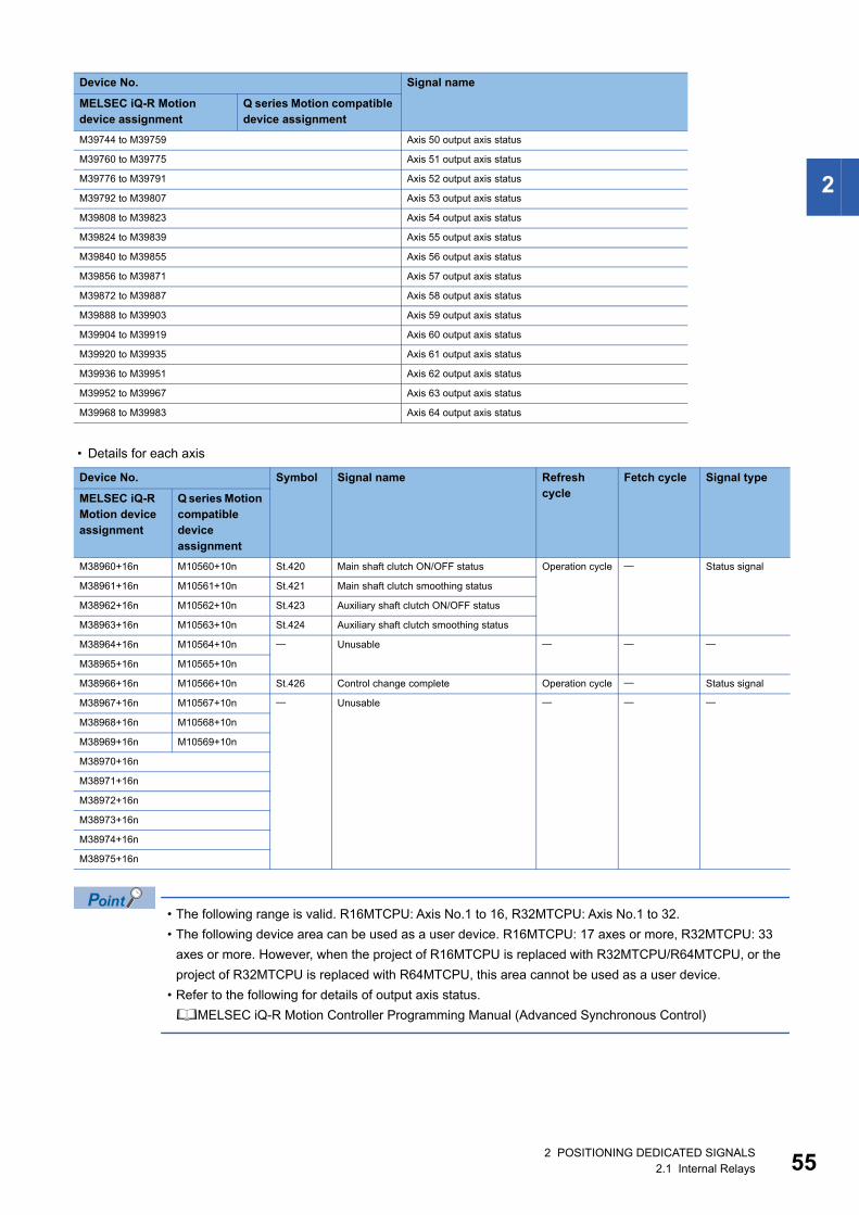
2
• Details for each axis
• The following range is valid. R16MTCPU: Axis No.1 to 16, R32MTCPU: Axis No.1 to 32.
• The following device area can be used as a user device. R16MTCPU: 17 axes or more, R32MTCPU: 33
axes or more. However, when the project of R16MTCPU is replaced with R32MTCPU/R64MTCPU, or the
project of R32MTCPU is replaced with R64MTCPU, this area cannot be used as a user device.
• Refer to the following for details of output axis status.
MELSEC iQ-R Motion Controller Programming Manual (Advanced Synchronous Control)
M39744 to M39759 Axis 50 output axis status
M39760 to M39775 Axis 51 output axis status
M39776 to M39791 Axis 52 output axis status
M39792 to M39807 Axis 53 output axis status
M39808 to M39823 Axis 54 output axis status
M39824 to M39839 Axis 55 output axis status
M39840 to M39855 Axis 56 output axis status
M39856 to M39871 Axis 57 output axis status
M39872 to M39887 Axis 58 output axis status
M39888 to M39903 Axis 59 output axis status
M39904 to M39919 Axis 60 output axis status
M39920 to M39935 Axis 61 output axis status
M39936 to M39951 Axis 62 output axis status
M39952 to M39967 Axis 63 output axis status
M39968 to M39983 Axis 64 output axis status
Device No. Symbol Signal name Refresh cycle
Fetch cycle Signal type
MELSEC iQ-R Motion device assignment
Q series Motion compatible device assignment
M38960+16n M10560+10n St.420 Main shaft clutch ON/OFF status Operation cycle Status signal
M38961+16n M10561+10n St.421 Main shaft clutch smoothing status
M38962+16n M10562+10n St.423 Auxiliary shaft clutch ON/OFF status
M38963+16n M10563+10n St.424 Auxiliary shaft clutch smoothing status
M38964+16n M10564+10n Unusable
M38965+16n M10565+10n
M38966+16n M10566+10n St.426 Control change complete Operation cycle Status signal
M38967+16n M10567+10n Unusable
M38968+16n M10568+10n
M38969+16n M10569+10n
M38970+16n
M38971+16n
M38972+16n
M38973+16n
M38974+16n
M38975+16n
Device No. Signal name
MELSEC iQ-R Motion device assignment
Q series Motion compatible device assignment
2 POSITIONING DEDICATED SIGNALS2.1 Internal Relays 55
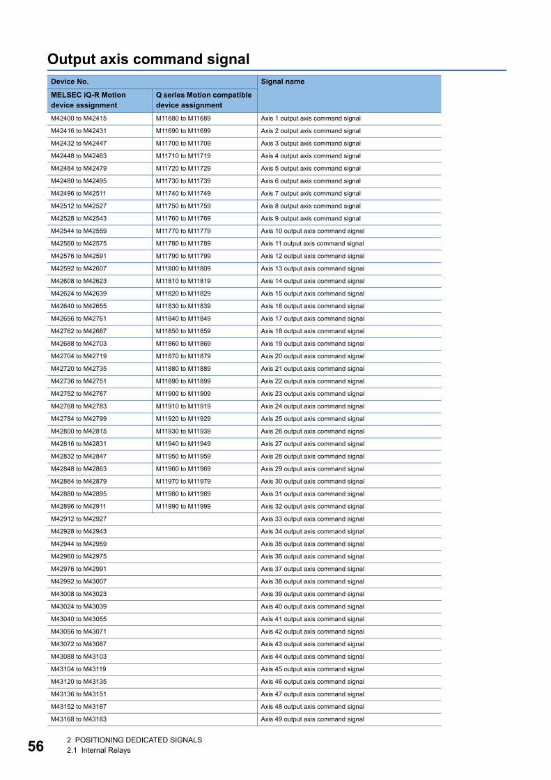
56
Output axis command signalDevice No. Signal name
MELSEC iQ-R Motion device assignment
Q series Motion compatible device assignment
M42400 to M42415 M11680 to M11689 Axis 1 output axis command signal
M42416 to M42431 M11690 to M11699 Axis 2 output axis command signal
M42432 to M42447 M11700 to M11709 Axis 3 output axis command signal
M42448 to M42463 M11710 to M11719 Axis 4 output axis command signal
M42464 to M42479 M11720 to M11729 Axis 5 output axis command signal
M42480 to M42495 M11730 to M11739 Axis 6 output axis command signal
M42496 to M42511 M11740 to M11749 Axis 7 output axis command signal
M42512 to M42527 M11750 to M11759 Axis 8 output axis command signal
M42528 to M42543 M11760 to M11769 Axis 9 output axis command signal
M42544 to M42559 M11770 to M11779 Axis 10 output axis command signal
M42560 to M42575 M11780 to M11789 Axis 11 output axis command signal
M42576 to M42591 M11790 to M11799 Axis 12 output axis command signal
M42592 to M42607 M11800 to M11809 Axis 13 output axis command signal
M42608 to M42623 M11810 to M11819 Axis 14 output axis command signal
M42624 to M42639 M11820 to M11829 Axis 15 output axis command signal
M42640 to M42655 M11830 to M11839 Axis 16 output axis command signal
M42656 to M42761 M11840 to M11849 Axis 17 output axis command signal
M42762 to M42687 M11850 to M11859 Axis 18 output axis command signal
M42688 to M42703 M11860 to M11869 Axis 19 output axis command signal
M42704 to M42719 M11870 to M11879 Axis 20 output axis command signal
M42720 to M42735 M11880 to M11889 Axis 21 output axis command signal
M42736 to M42751 M11890 to M11899 Axis 22 output axis command signal
M42752 to M42767 M11900 to M11909 Axis 23 output axis command signal
M42768 to M42783 M11910 to M11919 Axis 24 output axis command signal
M42784 to M42799 M11920 to M11929 Axis 25 output axis command signal
M42800 to M42815 M11930 to M11939 Axis 26 output axis command signal
M42816 to M42831 M11940 to M11949 Axis 27 output axis command signal
M42832 to M42847 M11950 to M11959 Axis 28 output axis command signal
M42848 to M42863 M11960 to M11969 Axis 29 output axis command signal
M42864 to M42879 M11970 to M11979 Axis 30 output axis command signal
M42880 to M42895 M11980 to M11989 Axis 31 output axis command signal
M42896 to M42911 M11990 to M11999 Axis 32 output axis command signal
M42912 to M42927 Axis 33 output axis command signal
M42928 to M42943 Axis 34 output axis command signal
M42944 to M42959 Axis 35 output axis command signal
M42960 to M42975 Axis 36 output axis command signal
M42976 to M42991 Axis 37 output axis command signal
M42992 to M43007 Axis 38 output axis command signal
M43008 to M43023 Axis 39 output axis command signal
M43024 to M43039 Axis 40 output axis command signal
M43040 to M43055 Axis 41 output axis command signal
M43056 to M43071 Axis 42 output axis command signal
M43072 to M43087 Axis 43 output axis command signal
M43088 to M43103 Axis 44 output axis command signal
M43104 to M43119 Axis 45 output axis command signal
M43120 to M43135 Axis 46 output axis command signal
M43136 to M43151 Axis 47 output axis command signal
M43152 to M43167 Axis 48 output axis command signal
M43168 to M43183 Axis 49 output axis command signal
2 POSITIONING DEDICATED SIGNALS2.1 Internal Relays
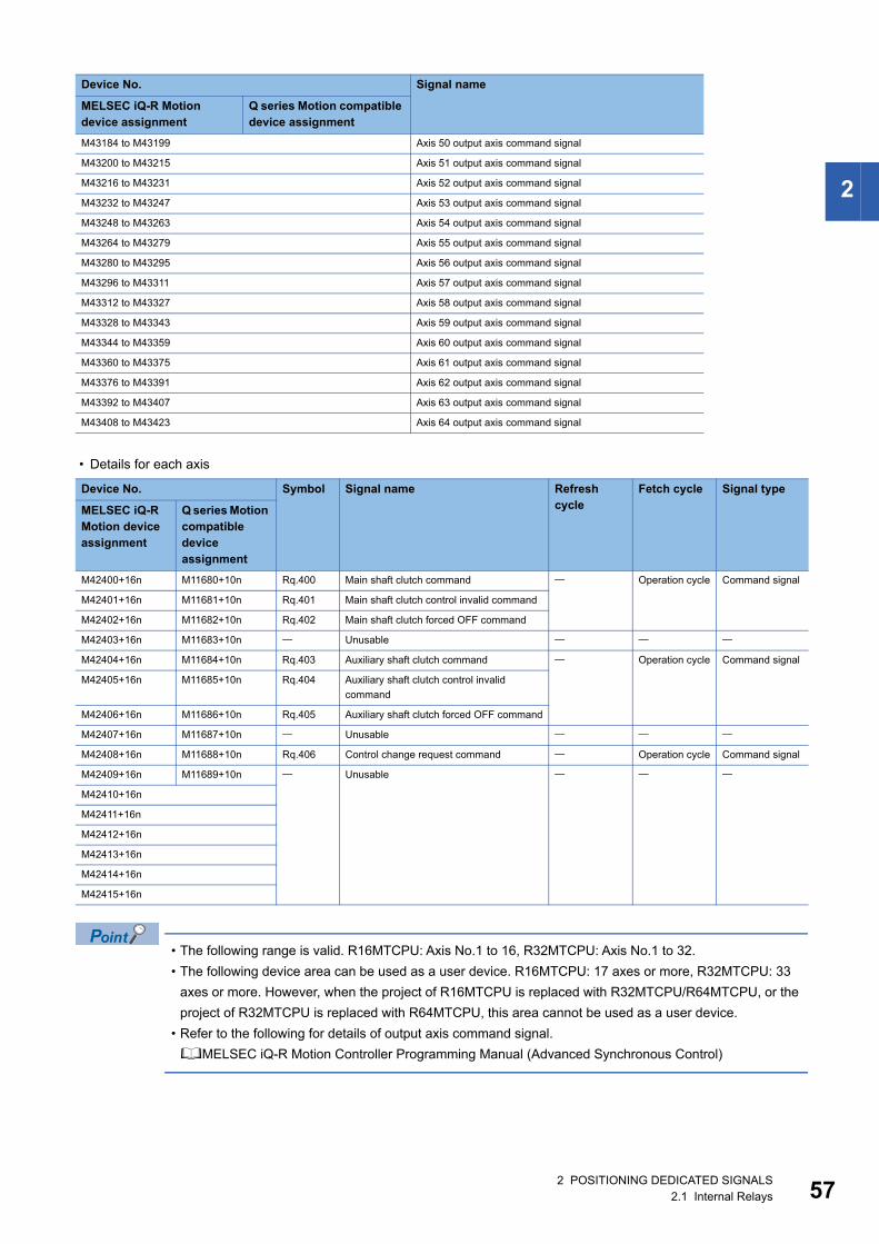
2
• Details for each axis
• The following range is valid. R16MTCPU: Axis No.1 to 16, R32MTCPU: Axis No.1 to 32.
• The following device area can be used as a user device. R16MTCPU: 17 axes or more, R32MTCPU: 33
axes or more. However, when the project of R16MTCPU is replaced with R32MTCPU/R64MTCPU, or the
project of R32MTCPU is replaced with R64MTCPU, this area cannot be used as a user device.
• Refer to the following for details of output axis command signal.
MELSEC iQ-R Motion Controller Programming Manual (Advanced Synchronous Control)
M43184 to M43199 Axis 50 output axis command signal
M43200 to M43215 Axis 51 output axis command signal
M43216 to M43231 Axis 52 output axis command signal
M43232 to M43247 Axis 53 output axis command signal
M43248 to M43263 Axis 54 output axis command signal
M43264 to M43279 Axis 55 output axis command signal
M43280 to M43295 Axis 56 output axis command signal
M43296 to M43311 Axis 57 output axis command signal
M43312 to M43327 Axis 58 output axis command signal
M43328 to M43343 Axis 59 output axis command signal
M43344 to M43359 Axis 60 output axis command signal
M43360 to M43375 Axis 61 output axis command signal
M43376 to M43391 Axis 62 output axis command signal
M43392 to M43407 Axis 63 output axis command signal
M43408 to M43423 Axis 64 output axis command signal
Device No. Symbol Signal name Refresh cycle
Fetch cycle Signal type
MELSEC iQ-R Motion device assignment
Q series Motion compatible device assignment
M42400+16n M11680+10n Rq.400 Main shaft clutch command Operation cycle Command signal
M42401+16n M11681+10n Rq.401 Main shaft clutch control invalid command
M42402+16n M11682+10n Rq.402 Main shaft clutch forced OFF command
M42403+16n M11683+10n Unusable
M42404+16n M11684+10n Rq.403 Auxiliary shaft clutch command Operation cycle Command signal
M42405+16n M11685+10n Rq.404 Auxiliary shaft clutch control invalid
command
M42406+16n M11686+10n Rq.405 Auxiliary shaft clutch forced OFF command
M42407+16n M11687+10n Unusable
M42408+16n M11688+10n Rq.406 Control change request command Operation cycle Command signal
M42409+16n M11689+10n Unusable
M42410+16n
M42411+16n
M42412+16n
M42413+16n
M42414+16n
M42415+16n
Device No. Signal name
MELSEC iQ-R Motion device assignment
Q series Motion compatible device assignment
2 POSITIONING DEDICATED SIGNALS2.1 Internal Relays 57
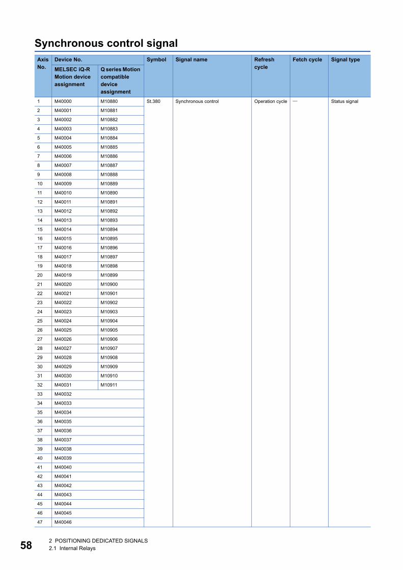
58
Synchronous control signalAxis No.
Device No. Symbol Signal name Refresh cycle
Fetch cycle Signal type
MELSEC iQ-R Motion device assignment
Q series Motion compatible device assignment
1 M40000 M10880 St.380 Synchronous control Operation cycle Status signal
2 M40001 M10881
3 M40002 M10882
4 M40003 M10883
5 M40004 M10884
6 M40005 M10885
7 M40006 M10886
8 M40007 M10887
9 M40008 M10888
10 M40009 M10889
11 M40010 M10890
12 M40011 M10891
13 M40012 M10892
14 M40013 M10893
15 M40014 M10894
16 M40015 M10895
17 M40016 M10896
18 M40017 M10897
19 M40018 M10898
20 M40019 M10899
21 M40020 M10900
22 M40021 M10901
23 M40022 M10902
24 M40023 M10903
25 M40024 M10904
26 M40025 M10905
27 M40026 M10906
28 M40027 M10907
29 M40028 M10908
30 M40029 M10909
31 M40030 M10910
32 M40031 M10911
33 M40032
34 M40033
35 M40034
36 M40035
37 M40036
38 M40037
39 M40038
40 M40039
41 M40040
42 M40041
43 M40042
44 M40043
45 M40044
46 M40045
47 M40046
2 POSITIONING DEDICATED SIGNALS2.1 Internal Relays

2
• The following range is valid. R16MTCPU: Axis No.1 to 16, R32MTCPU: Axis No.1 to 32.
• The following device area can be used as a user device. R16MTCPU: 17 axes or more, R32MTCPU: 33
axes or more. However, when the project of R16MTCPU is replaced with R32MTCPU/R64MTCPU, or the
project of R32MTCPU is replaced with R64MTCPU, this area cannot be used as a user device.
• Refer to the following for details of synchronous control signal.
MELSEC iQ-R Motion Controller Programming Manual (Advanced Synchronous Control)
48 M40047 St.380 Synchronous control Operation cycle Status signal
49 M40048
50 M40049
51 M40050
52 M40051
53 M40052
54 M40053
55 M40054
56 M40055
57 M40056
58 M40057
59 M40058
60 M40059
61 M40060
62 M40061
63 M40062
64 M40063
Axis No.
Device No. Symbol Signal name Refresh cycle
Fetch cycle Signal type
MELSEC iQ-R Motion device assignment
Q series Motion compatible device assignment
2 POSITIONING DEDICATED SIGNALS2.1 Internal Relays 59
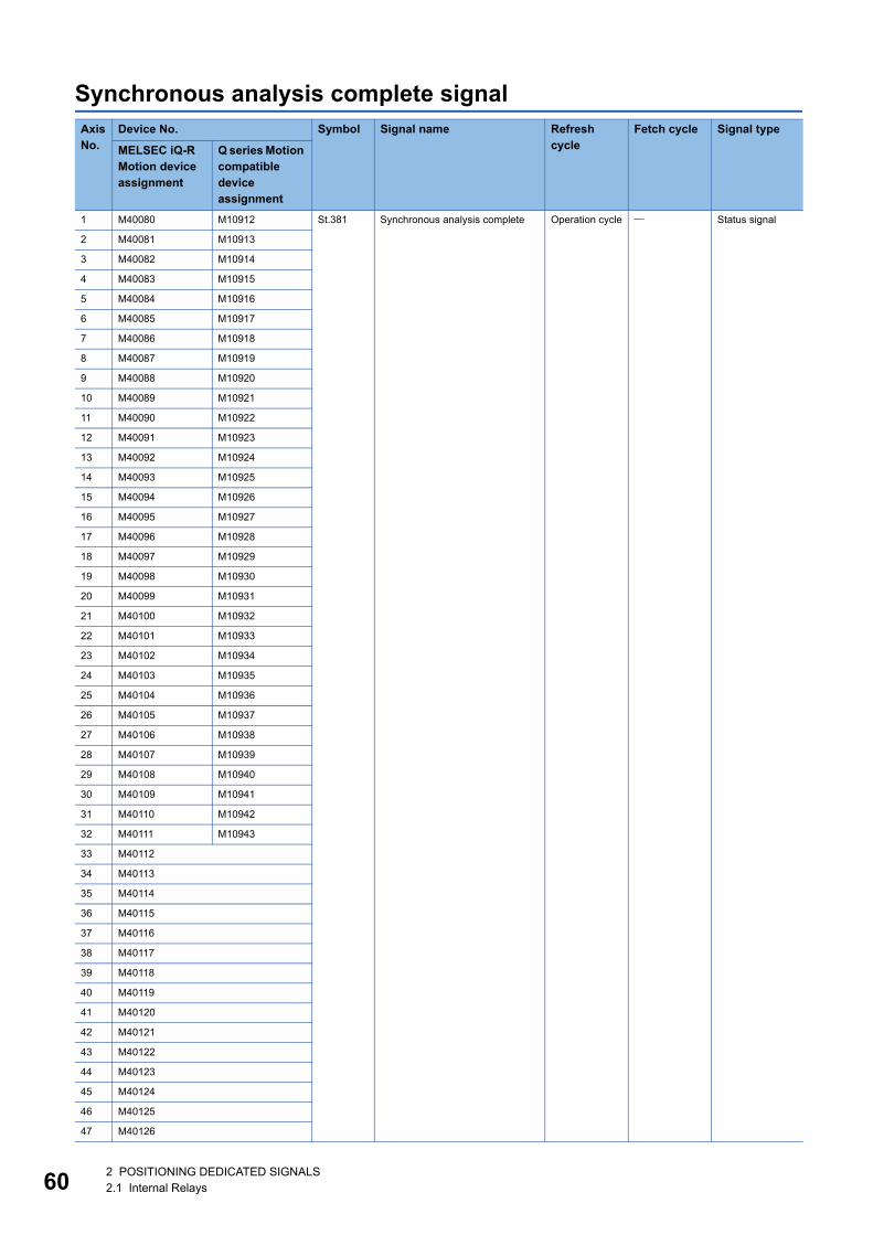
60
Synchronous analysis complete signalAxis No.
Device No. Symbol Signal name Refresh cycle
Fetch cycle Signal type
MELSEC iQ-R Motion device assignment
Q series Motion compatible device assignment
1 M40080 M10912 St.381 Synchronous analysis complete Operation cycle Status signal
2 M40081 M10913
3 M40082 M10914
4 M40083 M10915
5 M40084 M10916
6 M40085 M10917
7 M40086 M10918
8 M40087 M10919
9 M40088 M10920
10 M40089 M10921
11 M40090 M10922
12 M40091 M10923
13 M40092 M10924
14 M40093 M10925
15 M40094 M10926
16 M40095 M10927
17 M40096 M10928
18 M40097 M10929
19 M40098 M10930
20 M40099 M10931
21 M40100 M10932
22 M40101 M10933
23 M40102 M10934
24 M40103 M10935
25 M40104 M10936
26 M40105 M10937
27 M40106 M10938
28 M40107 M10939
29 M40108 M10940
30 M40109 M10941
31 M40110 M10942
32 M40111 M10943
33 M40112
34 M40113
35 M40114
36 M40115
37 M40116
38 M40117
39 M40118
40 M40119
41 M40120
42 M40121
43 M40122
44 M40123
45 M40124
46 M40125
47 M40126
2 POSITIONING DEDICATED SIGNALS2.1 Internal Relays

2
• The following range is valid. R16MTCPU: Axis No.1 to 16, R32MTCPU: Axis No.1 to 32.
• The following device area can be used as a user device. R16MTCPU: 17 axes or more, R32MTCPU: 33
axes or more. However, when the project of R16MTCPU is replaced with R32MTCPU/R64MTCPU, or the
project of R32MTCPU is replaced with R64MTCPU, this area cannot be used as a user device.
• Refer to the following for details of synchronous analysis complete signal.
MELSEC iQ-R Motion Controller Programming Manual (Advanced Synchronous Control)
48 M40127 St.381 Synchronous analysis complete Operation cycle Status signal
49 M40128
50 M40129
51 M40130
52 M40131
53 M40132
54 M40133
55 M40134
56 M40135
57 M40136
58 M40137
59 M40138
60 M40139
61 M40140
62 M40141
63 M40142
64 M40143
Axis No.
Device No. Symbol Signal name Refresh cycle
Fetch cycle Signal type
MELSEC iQ-R Motion device assignment
Q series Motion compatible device assignment
2 POSITIONING DEDICATED SIGNALS2.1 Internal Relays 61
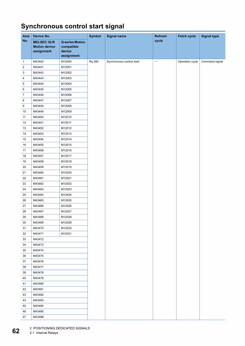
62
Synchronous control start signalAxis No.
Device No. Symbol Signal name Refresh cycle
Fetch cycle Signal type
MELSEC iQ-R Motion device assignment
Q series Motion compatible device assignment
1 M43440 M12000 Rq.380 Synchronous control start Operation cycle Command signal
2 M43441 M12001
3 M43442 M12002
4 M43443 M12003
5 M43444 M12004
6 M43445 M12005
7 M43446 M12006
8 M43447 M12007
9 M43448 M12008
10 M43449 M12009
11 M43450 M12010
12 M43451 M12011
13 M43452 M12012
14 M43453 M12013
15 M43454 M12014
16 M43455 M12015
17 M43456 M12016
18 M43457 M12017
19 M43458 M12018
20 M43459 M12019
21 M43460 M12020
22 M43461 M12021
23 M43462 M12022
24 M43463 M12023
25 M43464 M12024
26 M43465 M12025
27 M43466 M12026
28 M43467 M12027
29 M43468 M12028
30 M43469 M12029
31 M43470 M12030
32 M43471 M12031
33 M43472
34 M43473
35 M43474
36 M43475
37 M43476
38 M43477
39 M43478
40 M43479
41 M43480
42 M43481
43 M43482
44 M43483
45 M43484
46 M43485
47 M43486
2 POSITIONING DEDICATED SIGNALS2.1 Internal Relays
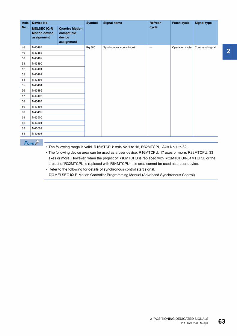
2
• The following range is valid. R16MTCPU: Axis No.1 to 16, R32MTCPU: Axis No.1 to 32.
• The following device area can be used as a user device. R16MTCPU: 17 axes or more, R32MTCPU: 33
axes or more. However, when the project of R16MTCPU is replaced with R32MTCPU/R64MTCPU, or the
project of R32MTCPU is replaced with R64MTCPU, this area cannot be used as a user device.
• Refer to the following for details of synchronous control start signal.
MELSEC iQ-R Motion Controller Programming Manual (Advanced Synchronous Control)
48 M43487 Rq.380 Synchronous control start Operation cycle Command signal
49 M43488
50 M43489
51 M43490
52 M43491
53 M43492
54 M43493
55 M43494
56 M43495
57 M43496
58 M43497
59 M43498
60 M43499
61 M43500
62 M43501
63 M40502
64 M40503
Axis No.
Device No. Symbol Signal name Refresh cycle
Fetch cycle Signal type
MELSEC iQ-R Motion device assignment
Q series Motion compatible device assignment
2 POSITIONING DEDICATED SIGNALS2.1 Internal Relays 63
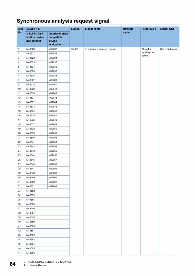
64
Synchronous analysis request signalAxis No.
Device No. Symbol Signal name Refresh cycle
Fetch cycle Signal type
MELSEC iQ-R Motion device assignment
Q series Motion compatible device assignment
1 M43520 M12032 Rq.381 Synchronous analysis request At start of
synchronous
control
Command signal
2 M43521 M12033
3 M43522 M12034
4 M43523 M12035
5 M43524 M12036
6 M43525 M12037
7 M43526 M12038
8 M43527 M12039
9 M43528 M12040
10 M43529 M12041
11 M43530 M12042
12 M43531 M12043
13 M43532 M12044
14 M43533 M12045
15 M43534 M12046
16 M43535 M12047
17 M43536 M12048
18 M43537 M12049
19 M43538 M12050
20 M43539 M12051
21 M43540 M12052
22 M43541 M12053
23 M43542 M12054
24 M43543 M12055
25 M43544 M12056
26 M43545 M12057
27 M43546 M12058
28 M43547 M12059
29 M43548 M12060
30 M43549 M12061
31 M43550 M12062
32 M43551 M12063
33 M43552
34 M43553
35 M43554
36 M43555
37 M43556
38 M43557
39 M43558
40 M43559
41 M43560
42 M43561
43 M43562
44 M43563
45 M43564
46 M43565
47 M43566
2 POSITIONING DEDICATED SIGNALS2.1 Internal Relays

2
• The following range is valid. R16MTCPU: Axis No.1 to 16, R32MTCPU: Axis No.1 to 32.
• The following device area can be used as a user device. R16MTCPU: 17 axes or more, R32MTCPU: 33
axes or more. However, when the project of R16MTCPU is replaced with R32MTCPU/R64MTCPU, or the
project of R32MTCPU is replaced with R64MTCPU, this area cannot be used as a user device.
• Refer to the following for details of synchronous analysis request signal.
MELSEC iQ-R Motion Controller Programming Manual (Advanced Synchronous Control)
48 M43567 Rq.381 Synchronous analysis request At start of
synchronous
control
Command signal
49 M43568
50 M43569
51 M43570
52 M43571
53 M43572
54 M43573
55 M43574
56 M43575
57 M43576
58 M43577
59 M43578
60 M43579
61 M43580
62 M43581
63 M43582
64 M43583
Axis No.
Device No. Symbol Signal name Refresh cycle
Fetch cycle Signal type
MELSEC iQ-R Motion device assignment
Q series Motion compatible device assignment
2 POSITIONING DEDICATED SIGNALS2.1 Internal Relays 65
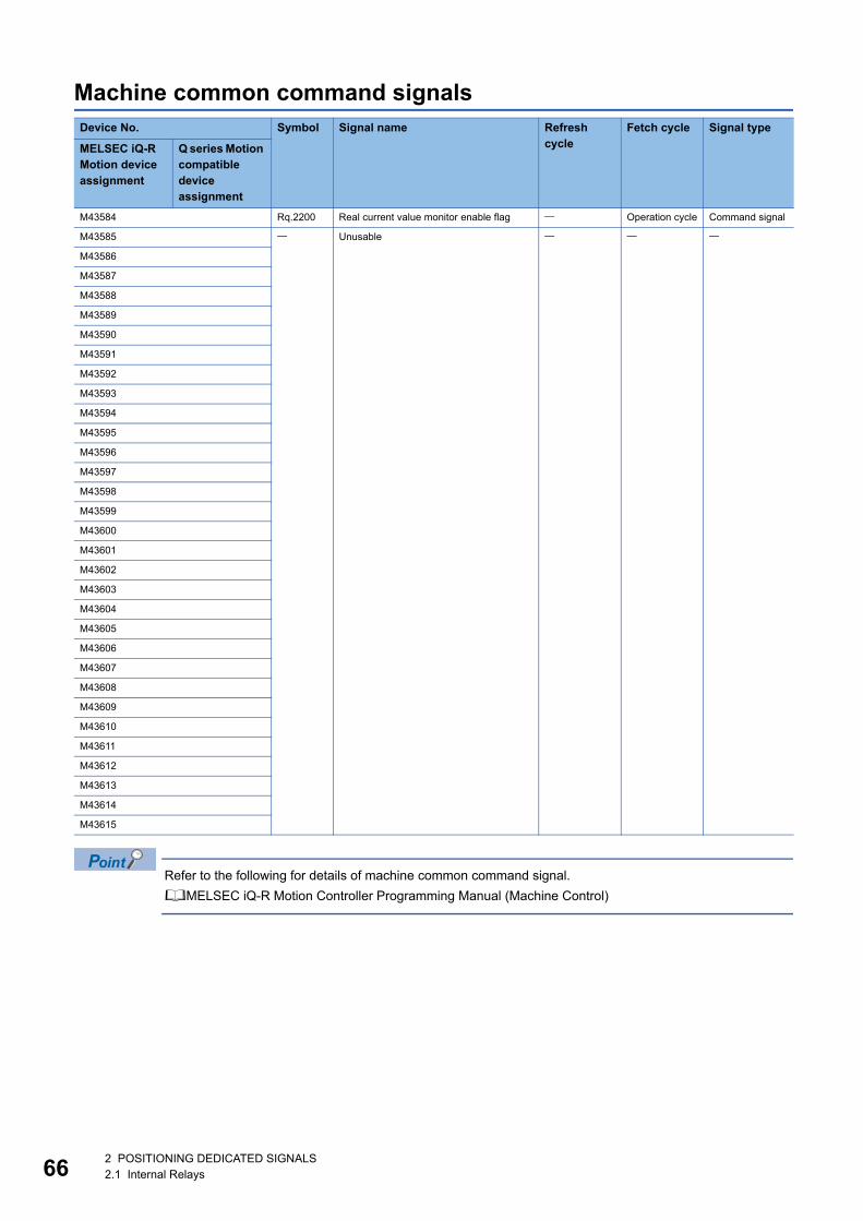
66
Machine common command signals
Refer to the following for details of machine common command signal.
MELSEC iQ-R Motion Controller Programming Manual (Machine Control)
Device No. Symbol Signal name Refresh cycle
Fetch cycle Signal type
MELSEC iQ-R Motion device assignment
Q series Motion compatible device assignment
M43584 Rq.2200 Real current value monitor enable flag Operation cycle Command signal
M43585 Unusable
M43586
M43587
M43588
M43589
M43590
M43591
M43592
M43593
M43594
M43595
M43596
M43597
M43598
M43599
M43600
M43601
M43602
M43603
M43604
M43605
M43606
M43607
M43608
M43609
M43610
M43611
M43612
M43613
M43614
M43615
2 POSITIONING DEDICATED SIGNALS2.1 Internal Relays
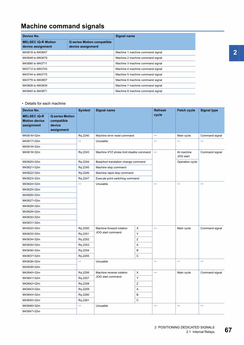
2
Machine command signals
• Details for each machine
Device No. Signal name
MELSEC iQ-R Motion device assignment
Q series Motion compatible device assignment
M43616 to M43647 Machine 1 machine command signal
M43648 to M43679 Machine 2 machine command signal
M43680 to M43711 Machine 3 machine command signal
M43712 to M43743 Machine 4 machine command signal
M43744 to M43775 Machine 5 machine command signal
M43776 to M43807 Machine 6 machine command signal
M43808 to M43839 Machine 7 machine command signal
M43840 to M43871 Machine 8 machine command signal
Device No. Symbol Signal name Refresh cycle
Fetch cycle Signal type
MELSEC iQ-R Motion device assignment
Q series Motion compatible device assignment
M43616+32m Rq.2240 Machine error reset command Main cycle Command signal
M43617+32m Unusable
M43618+32m
M43619+32m Rq.2243 Machine XYZ stroke limit disable command At machine
JOG start
Command signal
M43620+32m Rq.2244 Base/tool translation change command Operation cycle
M43621+32m Rq.2245 Machine stop command
M43622+32m Rq.2246 Machine rapid stop command
M43623+32m Rq.2247 Execute point switching command
M43624+32m Unusable
M43625+32m
M43626+32m
M43627+32m
M43628+32m
M43629+32m
M43630+32m
M43631+32m
M43632+32m Rq.2250 Machine forward rotation
JOG start command
X Main cycle Command signal
M43633+32m Rq.2251 Y
M43634+32m Rq.2252 Z
M43635+32m Rq.2253 A
M43636+32m Rq.2254 B
M43637+32m Rq.2255 C
M43638+32m Unusable
M43639+32m
M43640+32m Rq.2256 Machine reverse rotation
JOG start command
X Main cycle Command signal
M43641+32m Rq.2257 Y
M43642+32m Rq.2258 Z
M43643+32m Rq.2259 A
M43644+32m Rq.2260 B
M43645+32m Rq.2261 C
M43646+32m Unusable
M43647+32m
2 POSITIONING DEDICATED SIGNALS2.1 Internal Relays 67
68
Refer to the following for details of machine command signal.
MELSEC iQ-R Motion Controller Programming Manual (Machine Control)
2 POSITIONING DEDICATED SIGNALS2.1 Internal Relays
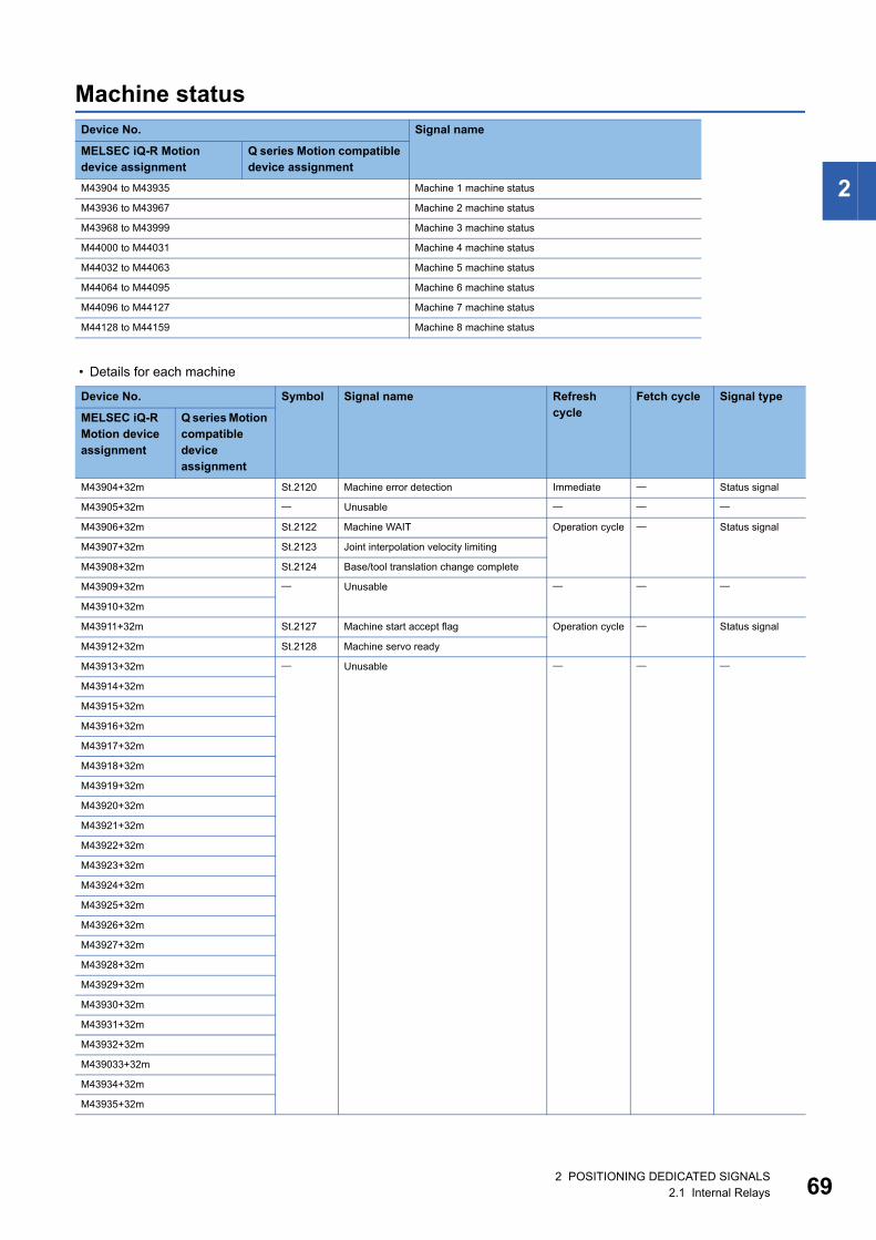
2
Machine status
• Details for each machine
Device No. Signal name
MELSEC iQ-R Motion device assignment
Q series Motion compatible device assignment
M43904 to M43935 Machine 1 machine status
M43936 to M43967 Machine 2 machine status
M43968 to M43999 Machine 3 machine status
M44000 to M44031 Machine 4 machine status
M44032 to M44063 Machine 5 machine status
M44064 to M44095 Machine 6 machine status
M44096 to M44127 Machine 7 machine status
M44128 to M44159 Machine 8 machine status
Device No. Symbol Signal name Refresh cycle
Fetch cycle Signal type
MELSEC iQ-R Motion device assignment
Q series Motion compatible device assignment
M43904+32m St.2120 Machine error detection Immediate Status signal
M43905+32m Unusable
M43906+32m St.2122 Machine WAIT Operation cycle Status signal
M43907+32m St.2123 Joint interpolation velocity limiting
M43908+32m St.2124 Base/tool translation change complete
M43909+32m Unusable
M43910+32m
M43911+32m St.2127 Machine start accept flag Operation cycle Status signal
M43912+32m St.2128 Machine servo ready
M43913+32m Unusable
M43914+32m
M43915+32m
M43916+32m
M43917+32m
M43918+32m
M43919+32m
M43920+32m
M43921+32m
M43922+32m
M43923+32m
M43924+32m
M43925+32m
M43926+32m
M43927+32m
M43928+32m
M43929+32m
M43930+32m
M43931+32m
M43932+32m
M439033+32m
M43934+32m
M43935+32m
2 POSITIONING DEDICATED SIGNALS2.1 Internal Relays 69
70
Refer to the following for details of machine status.
MELSEC iQ-R Motion Controller Programming Manual (Machine Control)
2 POSITIONING DEDICATED SIGNALS2.1 Internal Relays
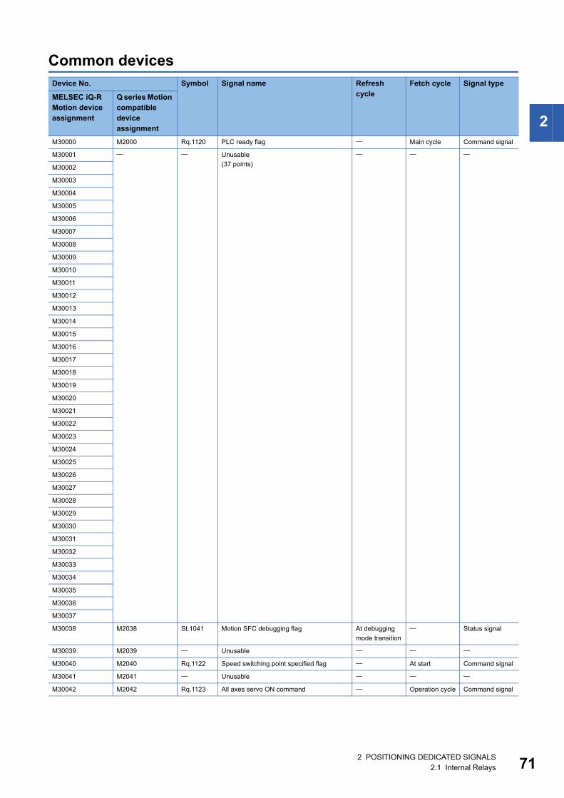
2
Common devicesDevice No. Symbol Signal name Refresh
cycleFetch cycle Signal type
MELSEC iQ-R Motion device assignment
Q series Motion compatible device assignment
M30000 M2000 Rq.1120 PLC ready flag Main cycle Command signal
M30001 Unusable
(37 points)
M30002
M30003
M30004
M30005
M30006
M30007
M30008
M30009
M30010
M30011
M30012
M30013
M30014
M30015
M30016
M30017
M30018
M30019
M30020
M30021
M30022
M30023
M30024
M30025
M30026
M30027
M30028
M30029
M30030
M30031
M30032
M30033
M30034
M30035
M30036
M30037
M30038 M2038 St.1041 Motion SFC debugging flag At debugging
mode transition
Status signal
M30039 M2039 Unusable
M30040 M2040 Rq.1122 Speed switching point specified flag At start Command signal
M30041 M2041 Unusable
M30042 M2042 Rq.1123 All axes servo ON command Operation cycle Command signal
2 POSITIONING DEDICATED SIGNALS2.1 Internal Relays 71
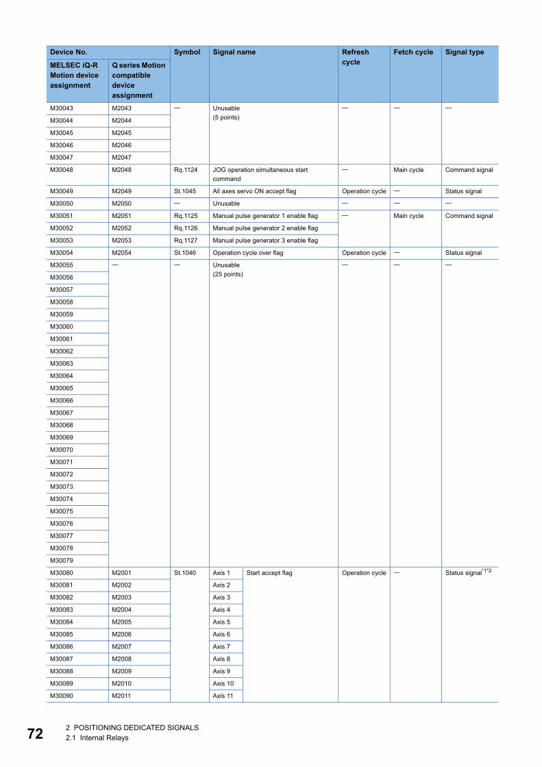
72
M30043 M2043 Unusable
(5 points)
M30044 M2044
M30045 M2045
M30046 M2046
M30047 M2047
M30048 M2048 Rq.1124 JOG operation simultaneous start
command
Main cycle Command signal
M30049 M2049 St.1045 All axes servo ON accept flag Operation cycle Status signal
M30050 M2050 Unusable
M30051 M2051 Rq.1125 Manual pulse generator 1 enable flag Main cycle Command signal
M30052 M2052 Rq.1126 Manual pulse generator 2 enable flag
M30053 M2053 Rq.1127 Manual pulse generator 3 enable flag
M30054 M2054 St.1046 Operation cycle over flag Operation cycle Status signal
M30055 Unusable
(25 points)
M30056
M30057
M30058
M30059
M30060
M30061
M30062
M30063
M30064
M30065
M30066
M30067
M30068
M30069
M30070
M30071
M30072
M30073
M30074
M30075
M30076
M30077
M30078
M30079
M30080 M2001 St.1040 Axis 1 Start accept flag Operation cycle Status signal*1*2
M30081 M2002 Axis 2
M30082 M2003 Axis 3
M30083 M2004 Axis 4
M30084 M2005 Axis 5
M30085 M2006 Axis 6
M30086 M2007 Axis 7
M30087 M2008 Axis 8
M30088 M2009 Axis 9
M30089 M2010 Axis 10
M30090 M2011 Axis 11
Device No. Symbol Signal name Refresh cycle
Fetch cycle Signal type
MELSEC iQ-R Motion device assignment
Q series Motion compatible device assignment
2 POSITIONING DEDICATED SIGNALS2.1 Internal Relays
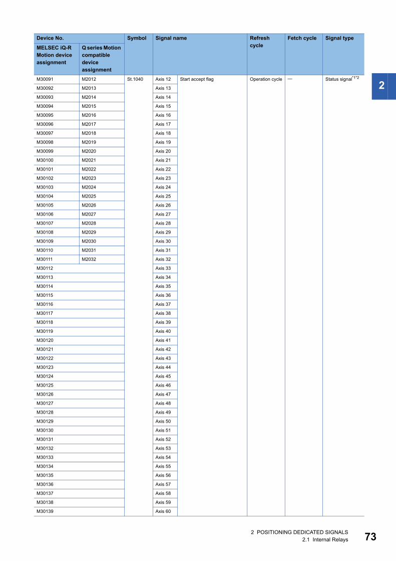
2
M30091 M2012 St.1040 Axis 12 Start accept flag Operation cycle Status signal*1*2M30092 M2013 Axis 13
M30093 M2014 Axis 14
M30094 M2015 Axis 15
M30095 M2016 Axis 16
M30096 M2017 Axis 17
M30097 M2018 Axis 18
M30098 M2019 Axis 19
M30099 M2020 Axis 20
M30100 M2021 Axis 21
M30101 M2022 Axis 22
M30102 M2023 Axis 23
M30103 M2024 Axis 24
M30104 M2025 Axis 25
M30105 M2026 Axis 26
M30106 M2027 Axis 27
M30107 M2028 Axis 28
M30108 M2029 Axis 29
M30109 M2030 Axis 30
M30110 M2031 Axis 31
M30111 M2032 Axis 32
M30112 Axis 33
M30113 Axis 34
M30114 Axis 35
M30115 Axis 36
M30116 Axis 37
M30117 Axis 38
M30118 Axis 39
M30119 Axis 40
M30120 Axis 41
M30121 Axis 42
M30122 Axis 43
M30123 Axis 44
M30124 Axis 45
M30125 Axis 46
M30126 Axis 47
M30127 Axis 48
M30128 Axis 49
M30129 Axis 50
M30130 Axis 51
M30131 Axis 52
M30132 Axis 53
M30133 Axis 54
M30134 Axis 55
M30135 Axis 56
M30136 Axis 57
M30137 Axis 58
M30138 Axis 59
M30139 Axis 60
Device No. Symbol Signal name Refresh cycle
Fetch cycle Signal type
MELSEC iQ-R Motion device assignment
Q series Motion compatible device assignment
2 POSITIONING DEDICATED SIGNALS2.1 Internal Relays 73
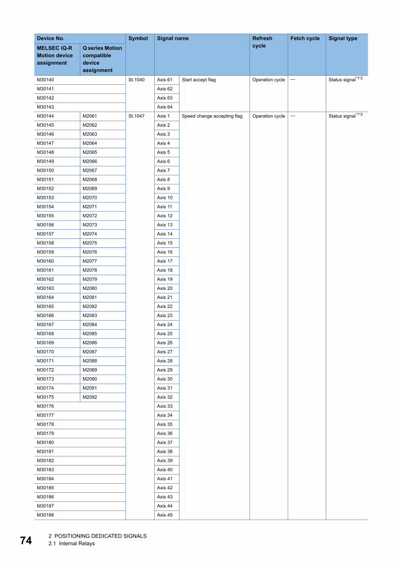
74
M30140 St.1040 Axis 61 Start accept flag Operation cycle Status signal*1*2
M30141 Axis 62
M30142 Axis 63
M30143 Axis 64
M30144 M2061 St.1047 Axis 1 Speed change accepting flag Operation cycle Status signal*1*2
M30145 M2062 Axis 2
M30146 M2063 Axis 3
M30147 M2064 Axis 4
M30148 M2065 Axis 5
M30149 M2066 Axis 6
M30150 M2067 Axis 7
M30151 M2068 Axis 8
M30152 M2069 Axis 9
M30153 M2070 Axis 10
M30154 M2071 Axis 11
M30155 M2072 Axis 12
M30156 M2073 Axis 13
M30157 M2074 Axis 14
M30158 M2075 Axis 15
M30159 M2076 Axis 16
M30160 M2077 Axis 17
M30161 M2078 Axis 18
M30162 M2079 Axis 19
M30163 M2080 Axis 20
M30164 M2081 Axis 21
M30165 M2082 Axis 22
M30166 M2083 Axis 23
M30167 M2084 Axis 24
M30168 M2085 Axis 25
M30169 M2086 Axis 26
M30170 M2087 Axis 27
M30171 M2088 Axis 28
M30172 M2089 Axis 29
M30173 M2090 Axis 30
M30174 M2091 Axis 31
M30175 M2092 Axis 32
M30176 Axis 33
M30177 Axis 34
M30178 Axis 35
M30179 Axis 36
M30180 Axis 37
M30181 Axis 38
M30182 Axis 39
M30183 Axis 40
M30184 Axis 41
M30185 Axis 42
M30186 Axis 43
M30187 Axis 44
M30188 Axis 45
Device No. Symbol Signal name Refresh cycle
Fetch cycle Signal type
MELSEC iQ-R Motion device assignment
Q series Motion compatible device assignment
2 POSITIONING DEDICATED SIGNALS2.1 Internal Relays
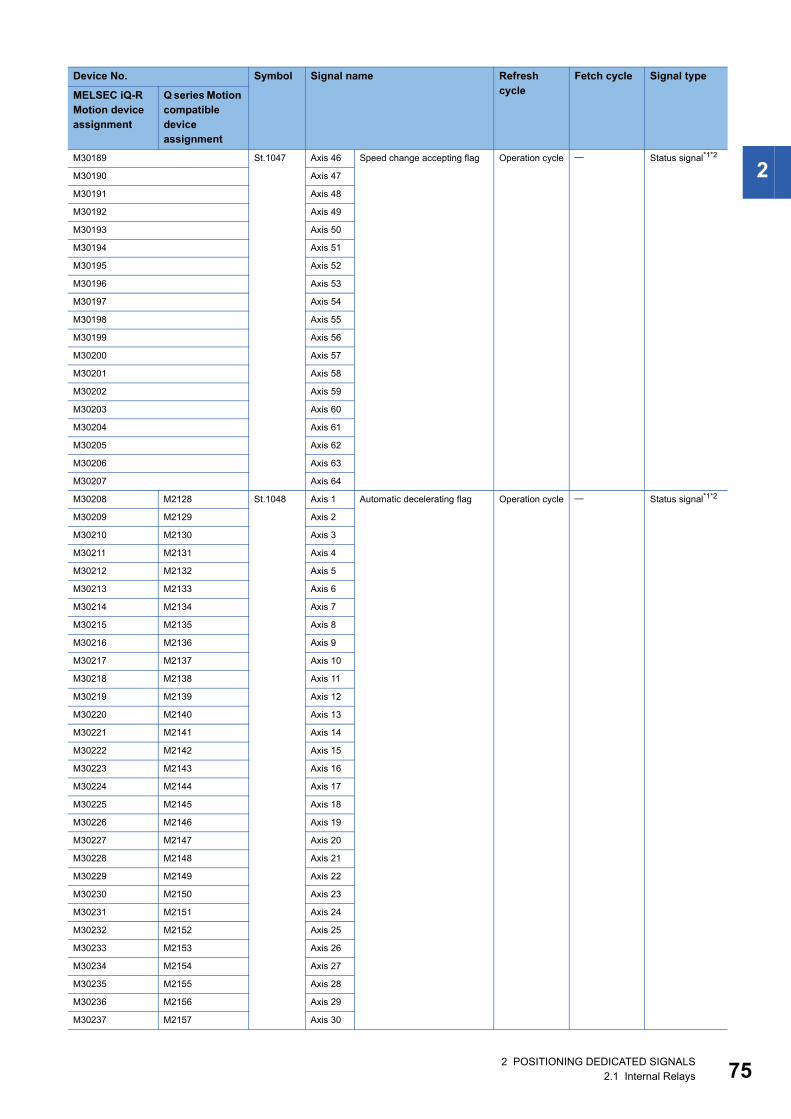
2
M30189 St.1047 Axis 46 Speed change accepting flag Operation cycle Status signal*1*2M30190 Axis 47
M30191 Axis 48
M30192 Axis 49
M30193 Axis 50
M30194 Axis 51
M30195 Axis 52
M30196 Axis 53
M30197 Axis 54
M30198 Axis 55
M30199 Axis 56
M30200 Axis 57
M30201 Axis 58
M30202 Axis 59
M30203 Axis 60
M30204 Axis 61
M30205 Axis 62
M30206 Axis 63
M30207 Axis 64
M30208 M2128 St.1048 Axis 1 Automatic decelerating flag Operation cycle Status signal*1*2
M30209 M2129 Axis 2
M30210 M2130 Axis 3
M30211 M2131 Axis 4
M30212 M2132 Axis 5
M30213 M2133 Axis 6
M30214 M2134 Axis 7
M30215 M2135 Axis 8
M30216 M2136 Axis 9
M30217 M2137 Axis 10
M30218 M2138 Axis 11
M30219 M2139 Axis 12
M30220 M2140 Axis 13
M30221 M2141 Axis 14
M30222 M2142 Axis 15
M30223 M2143 Axis 16
M30224 M2144 Axis 17
M30225 M2145 Axis 18
M30226 M2146 Axis 19
M30227 M2147 Axis 20
M30228 M2148 Axis 21
M30229 M2149 Axis 22
M30230 M2150 Axis 23
M30231 M2151 Axis 24
M30232 M2152 Axis 25
M30233 M2153 Axis 26
M30234 M2154 Axis 27
M30235 M2155 Axis 28
M30236 M2156 Axis 29
M30237 M2157 Axis 30
Device No. Symbol Signal name Refresh cycle
Fetch cycle Signal type
MELSEC iQ-R Motion device assignment
Q series Motion compatible device assignment
2 POSITIONING DEDICATED SIGNALS2.1 Internal Relays 75
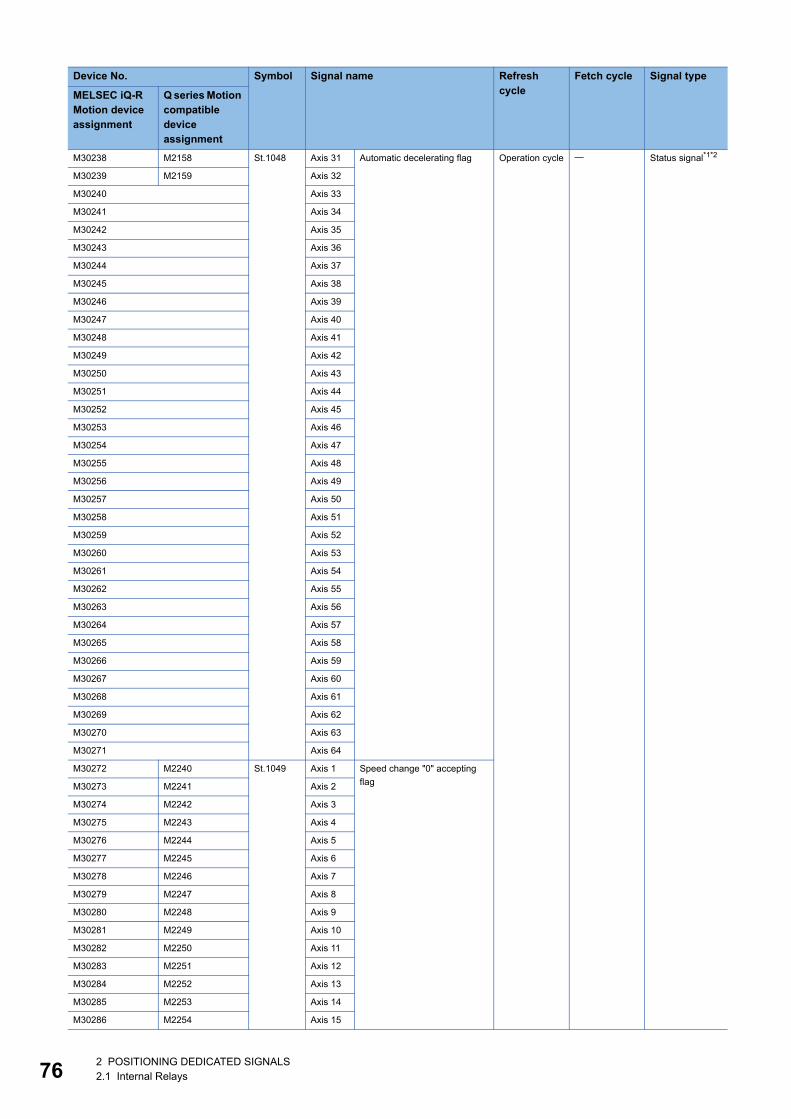
76
M30238 M2158 St.1048 Axis 31 Automatic decelerating flag Operation cycle Status signal*1*2
M30239 M2159 Axis 32
M30240 Axis 33
M30241 Axis 34
M30242 Axis 35
M30243 Axis 36
M30244 Axis 37
M30245 Axis 38
M30246 Axis 39
M30247 Axis 40
M30248 Axis 41
M30249 Axis 42
M30250 Axis 43
M30251 Axis 44
M30252 Axis 45
M30253 Axis 46
M30254 Axis 47
M30255 Axis 48
M30256 Axis 49
M30257 Axis 50
M30258 Axis 51
M30259 Axis 52
M30260 Axis 53
M30261 Axis 54
M30262 Axis 55
M30263 Axis 56
M30264 Axis 57
M30265 Axis 58
M30266 Axis 59
M30267 Axis 60
M30268 Axis 61
M30269 Axis 62
M30270 Axis 63
M30271 Axis 64
M30272 M2240 St.1049 Axis 1 Speed change "0" accepting
flagM30273 M2241 Axis 2
M30274 M2242 Axis 3
M30275 M2243 Axis 4
M30276 M2244 Axis 5
M30277 M2245 Axis 6
M30278 M2246 Axis 7
M30279 M2247 Axis 8
M30280 M2248 Axis 9
M30281 M2249 Axis 10
M30282 M2250 Axis 11
M30283 M2251 Axis 12
M30284 M2252 Axis 13
M30285 M2253 Axis 14
M30286 M2254 Axis 15
Device No. Symbol Signal name Refresh cycle
Fetch cycle Signal type
MELSEC iQ-R Motion device assignment
Q series Motion compatible device assignment
2 POSITIONING DEDICATED SIGNALS2.1 Internal Relays
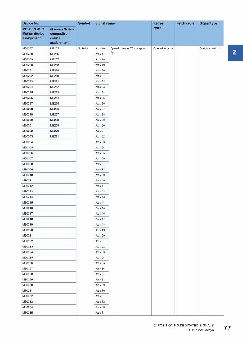
2
M30287 M2255 St.1049 Axis 16 Speed change "0" acceptingflag
Operation cycle Status signal*1*2
M30288 M2256 Axis 17
M30289 M2257 Axis 18
M30290 M2258 Axis 19
M30291 M2259 Axis 20
M30292 M2260 Axis 21
M30293 M2261 Axis 22
M30294 M2262 Axis 23
M30295 M2263 Axis 24
M30296 M2264 Axis 25
M30297 M2265 Axis 26
M30298 M2266 Axis 27
M30299 M2267 Axis 28
M30300 M2268 Axis 29
M30301 M2269 Axis 30
M30302 M2270 Axis 31
M30303 M2271 Axis 32
M30304 Axis 33
M30305 Axis 34
M30306 Axis 35
M30307 Axis 36
M30308 Axis 37
M30309 Axis 38
M30310 Axis 39
M30311 Axis 40
M30312 Axis 41
M30313 Axis 42
M30314 Axis 43
M30315 Axis 44
M30316 Axis 45
M30317 Axis 46
M30318 Axis 47
M30319 Axis 48
M30320 Axis 49
M30321 Axis 50
M30322 Axis 51
M30323 Axis 52
M30324 Axis 53
M30325 Axis 54
M30326 Axis 55
M30327 Axis 56
M30328 Axis 57
M30329 Axis 58
M30330 Axis 59
M30331 Axis 60
M30332 Axis 61
M30333 Axis 62
M30334 Axis 63
M30335 Axis 64
Device No. Symbol Signal name Refresh cycle
Fetch cycle Signal type
MELSEC iQ-R Motion device assignment
Q series Motion compatible device assignment
2 POSITIONING DEDICATED SIGNALS2.1 Internal Relays 77
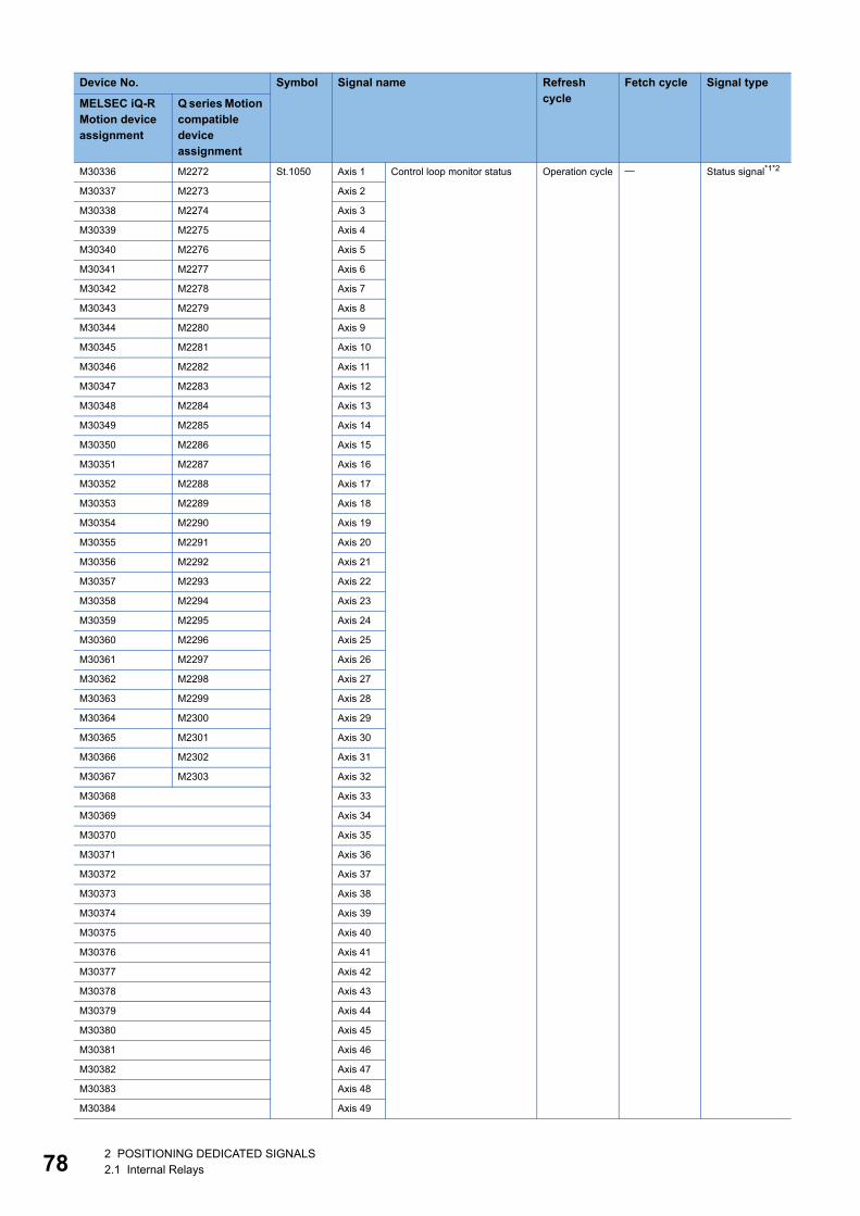
78
M30336 M2272 St.1050 Axis 1 Control loop monitor status Operation cycle Status signal*1*2
M30337 M2273 Axis 2
M30338 M2274 Axis 3
M30339 M2275 Axis 4
M30340 M2276 Axis 5
M30341 M2277 Axis 6
M30342 M2278 Axis 7
M30343 M2279 Axis 8
M30344 M2280 Axis 9
M30345 M2281 Axis 10
M30346 M2282 Axis 11
M30347 M2283 Axis 12
M30348 M2284 Axis 13
M30349 M2285 Axis 14
M30350 M2286 Axis 15
M30351 M2287 Axis 16
M30352 M2288 Axis 17
M30353 M2289 Axis 18
M30354 M2290 Axis 19
M30355 M2291 Axis 20
M30356 M2292 Axis 21
M30357 M2293 Axis 22
M30358 M2294 Axis 23
M30359 M2295 Axis 24
M30360 M2296 Axis 25
M30361 M2297 Axis 26
M30362 M2298 Axis 27
M30363 M2299 Axis 28
M30364 M2300 Axis 29
M30365 M2301 Axis 30
M30366 M2302 Axis 31
M30367 M2303 Axis 32
M30368 Axis 33
M30369 Axis 34
M30370 Axis 35
M30371 Axis 36
M30372 Axis 37
M30373 Axis 38
M30374 Axis 39
M30375 Axis 40
M30376 Axis 41
M30377 Axis 42
M30378 Axis 43
M30379 Axis 44
M30380 Axis 45
M30381 Axis 46
M30382 Axis 47
M30383 Axis 48
M30384 Axis 49
Device No. Symbol Signal name Refresh cycle
Fetch cycle Signal type
MELSEC iQ-R Motion device assignment
Q series Motion compatible device assignment
2 POSITIONING DEDICATED SIGNALS2.1 Internal Relays
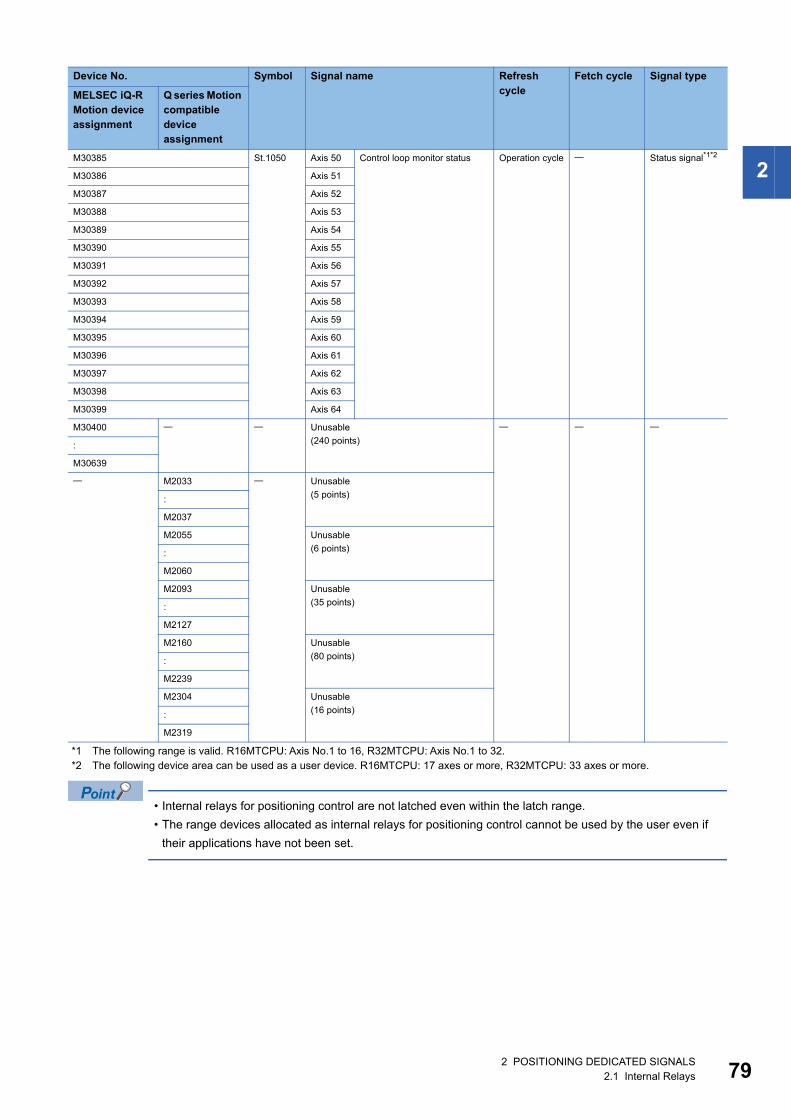
2
*1 The following range is valid. R16MTCPU: Axis No.1 to 16, R32MTCPU: Axis No.1 to 32.*2 The following device area can be used as a user device. R16MTCPU: 17 axes or more, R32MTCPU: 33 axes or more.
• Internal relays for positioning control are not latched even within the latch range.
• The range devices allocated as internal relays for positioning control cannot be used by the user even if
their applications have not been set.
M30385 St.1050 Axis 50 Control loop monitor status Operation cycle Status signal*1*2
M30386 Axis 51
M30387 Axis 52
M30388 Axis 53
M30389 Axis 54
M30390 Axis 55
M30391 Axis 56
M30392 Axis 57
M30393 Axis 58
M30394 Axis 59
M30395 Axis 60
M30396 Axis 61
M30397 Axis 62
M30398 Axis 63
M30399 Axis 64
M30400 Unusable
(240 points)
:
M30639
M2033 Unusable
(5 points):
M2037
M2055 Unusable
(6 points):
M2060
M2093 Unusable
(35 points):
M2127
M2160 Unusable
(80 points):
M2239
M2304 Unusable
(16 points):
M2319
Device No. Symbol Signal name Refresh cycle
Fetch cycle Signal type
MELSEC iQ-R Motion device assignment
Q series Motion compatible device assignment
2 POSITIONING DEDICATED SIGNALS2.1 Internal Relays 79
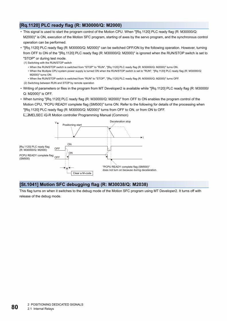
80
[Rq.1120] PLC ready flag (R: M30000/Q: M2000) • This signal is used to start the program control of the Motion CPU. When "[Rq.1120] PLC ready flag (R: M30000/Q:
M2000)" is ON, execution of the Motion SFC program, starting of axes by the servo program, and the synchronous control
operation can be performed.
• "[Rq.1120] PLC ready flag (R: M30000/Q: M2000)" can be switched OFF/ON by the following operation. However, turning
from OFF to ON of the "[Rq.1120] PLC ready flag (R: M30000/Q: M2000)" is ignored when the RUN/STOP switch is set to
"STOP" or during test mode.
• Writing of parameters or files in the program from MT Developer2 is available while "[Rq.1120] PLC ready flag (R: M30000/
Q: M2000)" is OFF.
• When turning "[Rq.1120] PLC ready flag (R: M30000/Q: M2000)" from OFF to ON enables the program control of the
Motion CPU, "PCPU READY complete flag (SM500)" turns ON. Refer to the following for details of the processing when
"[Rq.1120] PLC ready flag (R: M30000/Q: M2000)" turns from OFF to ON, or from ON to OFF.
MELSEC iQ-R Motion controller Programming Manual (Common)
[St.1041] Motion SFC debugging flag (R: M30038/Q: M2038)This flag turns on when it switches to the debug mode of the Motion SFC program using MT Developer2. It turns off with
release of the debug mode.
(1) Switching with the RUN/STOP switch
• When the RUN/STOP switch is switched from "STOP" to "RUN", "[Rq.1120] PLC ready flag (R: M30000/Q: M2000)" turns ON.
• When the Multiple CPU system power supply is turned ON when the RUN/STOP switch is set to "RUN", "[Rq.1120] PLC ready flag (R: M30000/Q:
M2000)" turns ON.
• When the RUN/STOP switch is switched from "RUN" to "STOP", "[Rq.1120] PLC ready flag (R: M30000/Q: M2000)" turns OFF.
(2) Switching between RUN and STOP by remote operation
Positioning start
"PCPU READY complete flag (SM500)"does not turn on because during deceleration.
Deceleration stop
OFFON
t
V
OFFON
[Rq.1120] PLC ready flag(R: M30000/Q: M2000)
PCPU READY complete flag(SM500)
Clear a M-code
2 POSITIONING DEDICATED SIGNALS2.1 Internal Relays
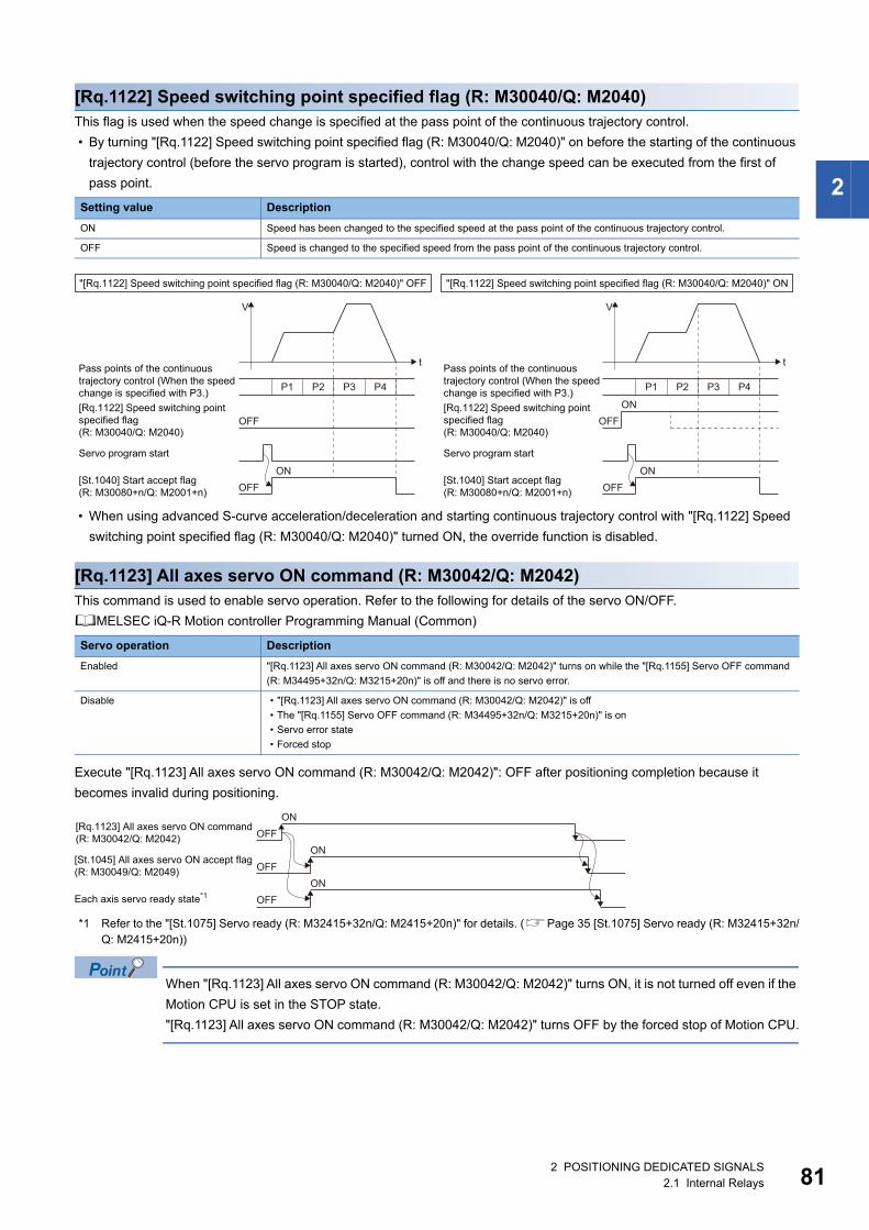
2
[Rq.1122] Speed switching point specified flag (R: M30040/Q: M2040)This flag is used when the speed change is specified at the pass point of the continuous trajectory control.
• By turning "[Rq.1122] Speed switching point specified flag (R: M30040/Q: M2040)" on before the starting of the continuous
trajectory control (before the servo program is started), control with the change speed can be executed from the first of
pass point.
• When using advanced S-curve acceleration/deceleration and starting continuous trajectory control with "[Rq.1122] Speed
switching point specified flag (R: M30040/Q: M2040)" turned ON, the override function is disabled.
[Rq.1123] All axes servo ON command (R: M30042/Q: M2042)This command is used to enable servo operation. Refer to the following for details of the servo ON/OFF.
MELSEC iQ-R Motion controller Programming Manual (Common)
Execute "[Rq.1123] All axes servo ON command (R: M30042/Q: M2042)": OFF after positioning completion because it
becomes invalid during positioning.
*1 Refer to the "[St.1075] Servo ready (R: M32415+32n/Q: M2415+20n)" for details. (Page 35 [St.1075] Servo ready (R: M32415+32n/Q: M2415+20n))
When "[Rq.1123] All axes servo ON command (R: M30042/Q: M2042)" turns ON, it is not turned off even if the
Motion CPU is set in the STOP state.
"[Rq.1123] All axes servo ON command (R: M30042/Q: M2042)" turns OFF by the forced stop of Motion CPU.
Setting value Description
ON Speed has been changed to the specified speed at the pass point of the continuous trajectory control.
OFF Speed is changed to the specified speed from the pass point of the continuous trajectory control.
Servo operation Description
Enabled "[Rq.1123] All axes servo ON command (R: M30042/Q: M2042)" turns on while the "[Rq.1155] Servo OFF command
(R: M34495+32n/Q: M3215+20n)" is off and there is no servo error.
Disable • "[Rq.1123] All axes servo ON command (R: M30042/Q: M2042)" is off
• The "[Rq.1155] Servo OFF command (R: M34495+32n/Q: M3215+20n)" is on
• Servo error state
• Forced stop
"[Rq.1122] Speed switching point specified flag (R: M30040/Q: M2040)" OFF
OFF
t
V
Servo program start
P1 P2 P3 P4
Pass points of the continuoustrajectory control (When the speedchange is specified with P3.)[Rq.1122] Speed switching pointspecified flag (R: M30040/Q: M2040)
[St.1040] Start accept flag(R: M30080+n/Q: M2001+n) OFF
ON
"[Rq.1122] Speed switching point specified flag (R: M30040/Q: M2040)" ON
Servo program start
Pass points of the continuoustrajectory control (When the speedchange is specified with P3.)[Rq.1122] Speed switching pointspecified flag (R: M30040/Q: M2040)
[St.1040] Start accept flag(R: M30080+n/Q: M2001+n)
OFF
t
V
P1 P2 P3 P4
OFFON
ON
[Rq.1123] All axes servo ON command(R: M30042/Q: M2042)
[St.1045] All axes servo ON accept flag(R: M30049/Q: M2049)
Each axis servo ready state*1
ONOFF
ONOFF
ONOFF
2 POSITIONING DEDICATED SIGNALS2.1 Internal Relays 81
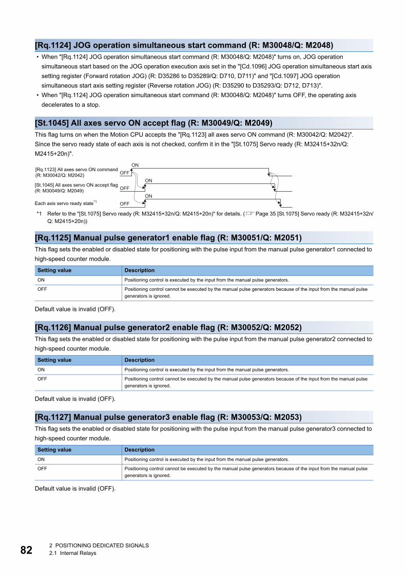
82
[Rq.1124] JOG operation simultaneous start command (R: M30048/Q: M2048) • When "[Rq.1124] JOG operation simultaneous start command (R: M30048/Q: M2048)" turns on, JOG operation
simultaneous start based on the JOG operation execution axis set in the "[Cd.1096] JOG operation simultaneous start axis
setting register (Forward rotation JOG) (R: D35286 to D35289/Q: D710, D711)" and "[Cd.1097] JOG operation
simultaneous start axis setting register (Reverse rotation JOG) (R: D35290 to D35293/Q: D712, D713)".
• When "[Rq.1124] JOG operation simultaneous start command (R: M30048/Q: M2048)" turns OFF, the operating axis
decelerates to a stop.
[St.1045] All axes servo ON accept flag (R: M30049/Q: M2049)This flag turns on when the Motion CPU accepts the "[Rq.1123] all axes servo ON command (R: M30042/Q: M2042)".
Since the servo ready state of each axis is not checked, confirm it in the "[St.1075] Servo ready (R: M32415+32n/Q:
M2415+20n)".
*1 Refer to the "[St.1075] Servo ready (R: M32415+32n/Q: M2415+20n)" for details. (Page 35 [St.1075] Servo ready (R: M32415+32n/Q: M2415+20n))
[Rq.1125] Manual pulse generator1 enable flag (R: M30051/Q: M2051)This flag sets the enabled or disabled state for positioning with the pulse input from the manual pulse generator1 connected to
high-speed counter module.
Default value is invalid (OFF).
[Rq.1126] Manual pulse generator2 enable flag (R: M30052/Q: M2052)This flag sets the enabled or disabled state for positioning with the pulse input from the manual pulse generator2 connected to
high-speed counter module.
Default value is invalid (OFF).
[Rq.1127] Manual pulse generator3 enable flag (R: M30053/Q: M2053)This flag sets the enabled or disabled state for positioning with the pulse input from the manual pulse generator3 connected to
high-speed counter module.
Default value is invalid (OFF).
Setting value Description
ON Positioning control is executed by the input from the manual pulse generators.
OFF Positioning control cannot be executed by the manual pulse generators because of the input from the manual pulse
generators is ignored.
Setting value Description
ON Positioning control is executed by the input from the manual pulse generators.
OFF Positioning control cannot be executed by the manual pulse generators because of the input from the manual pulse
generators is ignored.
Setting value Description
ON Positioning control is executed by the input from the manual pulse generators.
OFF Positioning control cannot be executed by the manual pulse generators because of the input from the manual pulse
generators is ignored.
[Rq.1123] All axes servo ON command(R: M30042/Q: M2042)
[St.1045] All axes servo ON accept flag(R: M30049/Q: M2049)
Each axis servo ready state*1
ONOFF
ONOFF
ONOFF
2 POSITIONING DEDICATED SIGNALS2.1 Internal Relays
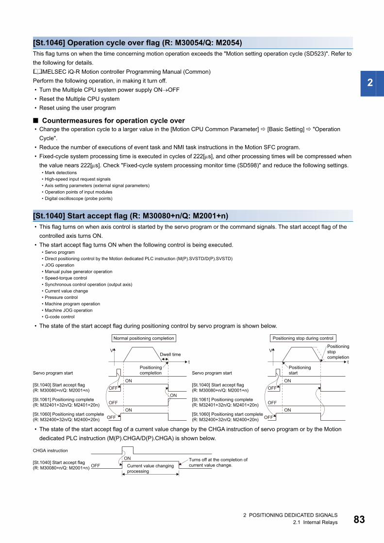
2
[St.1046] Operation cycle over flag (R: M30054/Q: M2054)This flag turns on when the time concerning motion operation exceeds the "Motion setting operation cycle (SD523)". Refer to
the following for details.
MELSEC iQ-R Motion controller Programming Manual (Common)
Perform the following operation, in making it turn off.
• Turn the Multiple CPU system power supply ONOFF
• Reset the Multiple CPU system
• Reset using the user program
■ Countermeasures for operation cycle over • Change the operation cycle to a larger value in the [Motion CPU Common Parameter] [Basic Setting] "Operation
Cycle".
• Reduce the number of executions of event task and NMI task instructions in the Motion SFC program.
• Fixed-cycle system processing time is executed in cycles of 222[s], and other processing times will be compressed when
the value nears 222[s]. Check "Fixed-cycle system processing monitor time (SD598)" and reduce the following settings.
[St.1040] Start accept flag (R: M30080+n/Q: M2001+n) • This flag turns on when axis control is started by the servo program or the command signals. The start accept flag of the
controlled axis turns ON.
• The start accept flag turns ON when the following control is being executed.
• The state of the start accept flag during positioning control by servo program is shown below.
• The state of the start accept flag of a current value change by the CHGA instruction of servo program or by the Motion
dedicated PLC instruction (M(P).CHGA/D(P).CHGA) is shown below.
• Mark detections
• High-speed input request signals
• Axis setting parameters (external signal parameters)
• Operation points of input modules
• Digital oscilloscope (probe points)
• Servo program
• Direct positioning control by the Motion dedicated PLC instruction (M(P).SVSTD/D(P).SVSTD)
• JOG operation
• Manual pulse generator operation
• Speed-torque control
• Synchronous control operation (output axis)
• Current value change
• Pressure control
• Machine program operation
• Machine JOG operation
• G-code control
OFFON
t
VDwell time
Servo program start
[St.1040] Start accept flag(R: M30080+n/Q: M2001+n)
OFFON
[St.1061] Positioning complete (R: M32401+32n/Q: M2401+20n)
OFFON
[St.1060] Positioning start complete(R: M32400+32n/Q: M2400+20n)
Positioningcompletion
Normal positioning completion
V
Servo program start
[St.1040] Start accept flag(R: M30080+n/Q: M2001+n)
[St.1061] Positioning complete (R: M32401+32n/Q: M2401+20n)
[St.1060] Positioning start complete(R: M32400+32n/Q: M2400+20n)
Positioningstart
Positioningstopcompletion
OFFON
t
OFF
OFFON
Positioning stop during control
Current value changingprocessing
CHGA instruction
Turns off at the completion ofcurrent value change.
ONOFF
[St.1040] Start accept flag(R: M30080+n/Q: M2001+n)
2 POSITIONING DEDICATED SIGNALS2.1 Internal Relays 83
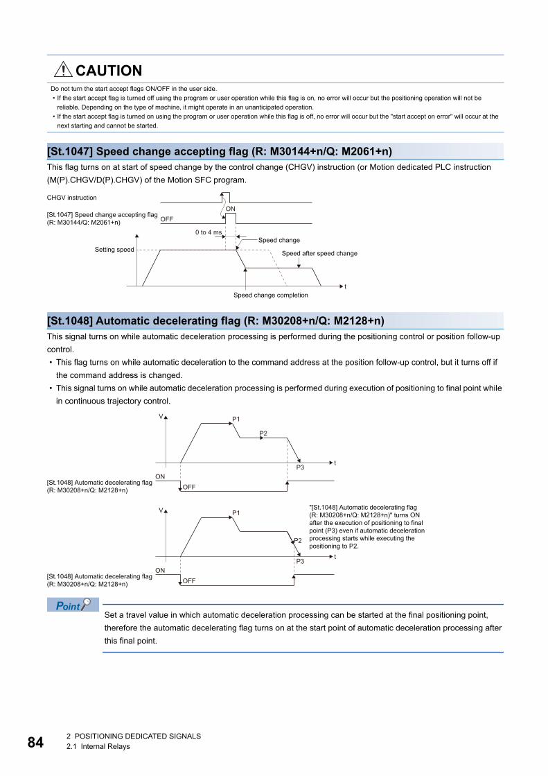
84
[St.1047] Speed change accepting flag (R: M30144+n/Q: M2061+n)This flag turns on at start of speed change by the control change (CHGV) instruction (or Motion dedicated PLC instruction
(M(P).CHGV/D(P).CHGV) of the Motion SFC program.
[St.1048] Automatic decelerating flag (R: M30208+n/Q: M2128+n)This signal turns on while automatic deceleration processing is performed during the positioning control or position follow-up
control.
• This flag turns on while automatic deceleration to the command address at the position follow-up control, but it turns off if
the command address is changed.
• This signal turns on while automatic deceleration processing is performed during execution of positioning to final point while
in continuous trajectory control.
Set a travel value in which automatic deceleration processing can be started at the final positioning point,
therefore the automatic decelerating flag turns on at the start point of automatic deceleration processing after
this final point.
CAUTIONDo not turn the start accept flags ON/OFF in the user side.
• If the start accept flag is turned off using the program or user operation while this flag is on, no error will occur but the positioning operation will not be
reliable. Depending on the type of machine, it might operate in an unanticipated operation.
• If the start accept flag is turned on using the program or user operation while this flag is off, no error will occur but the "start accept on error" will occur at the
next starting and cannot be started.
t
Setting speed
Speed change completion
Speed after speed change
Speed change0 to 4 ms
OFFON
CHGV instruction
[St.1047] Speed change accepting flag(R: M30144/Q: M2061+n)
"[St.1048] Automatic decelerating flag(R: M30208+n/Q: M2128+n)" turns ONafter the execution of positioning to finalpoint (P3) even if automatic decelerationprocessing starts while executing the positioning to P2.
t
V
OFFON
P2
P1
P3
[St.1048] Automatic decelerating flag(R: M30208+n/Q: M2128+n)
[St.1048] Automatic decelerating flag(R: M30208+n/Q: M2128+n)
t
V
OFFON
P2
P1
P3
2 POSITIONING DEDICATED SIGNALS2.1 Internal Relays
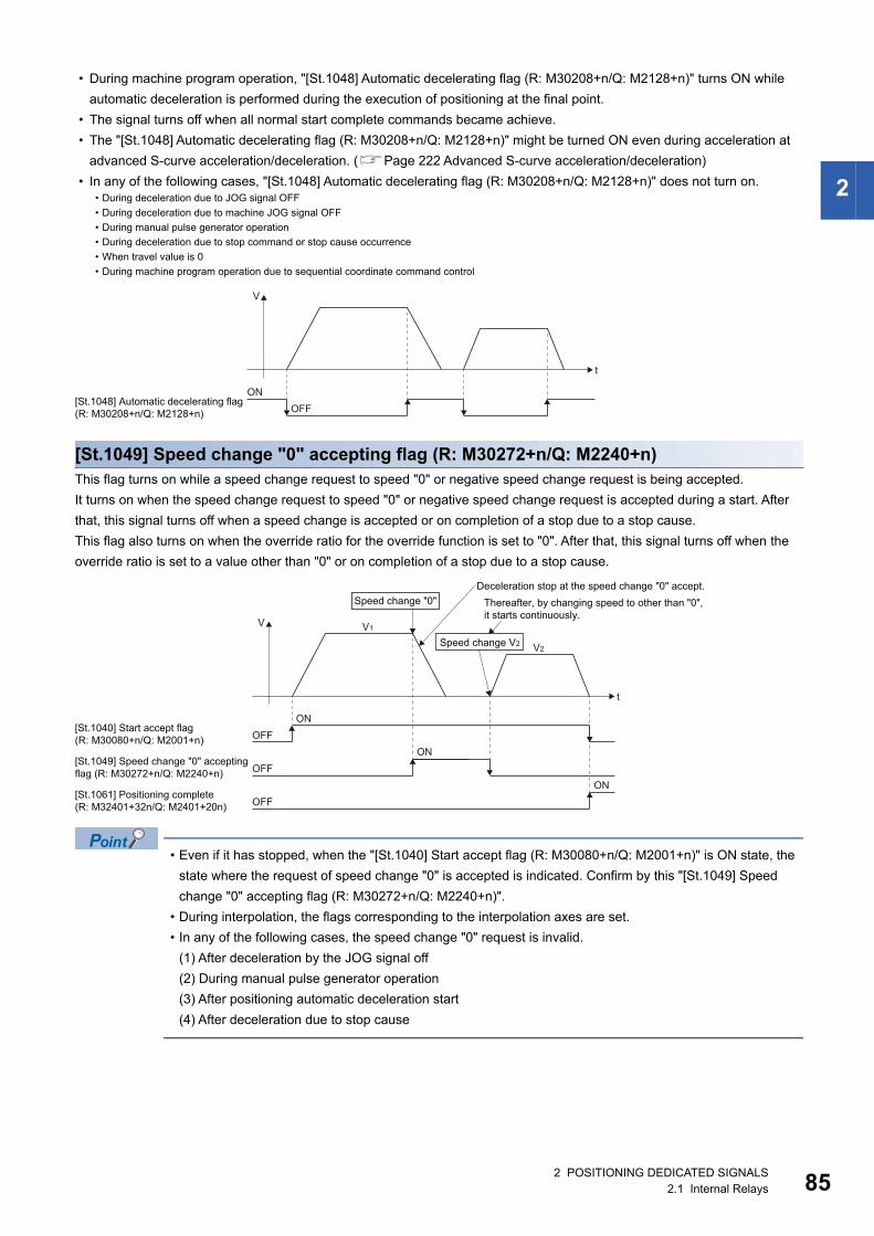
2
• During machine program operation, "[St.1048] Automatic decelerating flag (R: M30208+n/Q: M2128+n)" turns ON while
automatic deceleration is performed during the execution of positioning at the final point.
• The signal turns off when all normal start complete commands became achieve.
• The "[St.1048] Automatic decelerating flag (R: M30208+n/Q: M2128+n)" might be turned ON even during acceleration at
advanced S-curve acceleration/deceleration. (Page 222 Advanced S-curve acceleration/deceleration)
• In any of the following cases, "[St.1048] Automatic decelerating flag (R: M30208+n/Q: M2128+n)" does not turn on.
[St.1049] Speed change "0" accepting flag (R: M30272+n/Q: M2240+n)This flag turns on while a speed change request to speed "0" or negative speed change request is being accepted.
It turns on when the speed change request to speed "0" or negative speed change request is accepted during a start. After
that, this signal turns off when a speed change is accepted or on completion of a stop due to a stop cause.
This flag also turns on when the override ratio for the override function is set to "0". After that, this signal turns off when the
override ratio is set to a value other than "0" or on completion of a stop due to a stop cause.
• Even if it has stopped, when the "[St.1040] Start accept flag (R: M30080+n/Q: M2001+n)" is ON state, the
state where the request of speed change "0" is accepted is indicated. Confirm by this "[St.1049] Speed
change "0" accepting flag (R: M30272+n/Q: M2240+n)".
• During interpolation, the flags corresponding to the interpolation axes are set.
• In any of the following cases, the speed change "0" request is invalid.
(1) After deceleration by the JOG signal off
(2) During manual pulse generator operation
(3) After positioning automatic deceleration start
(4) After deceleration due to stop cause
• During deceleration due to JOG signal OFF
• During deceleration due to machine JOG signal OFF
• During manual pulse generator operation
• During deceleration due to stop command or stop cause occurrence
• When travel value is 0
• During machine program operation due to sequential coordinate command control
t
V
OFFON
[St.1048] Automatic decelerating flag(R: M30208+n/Q: M2128+n)
Thereafter, by changing speed to other than "0",it starts continuously.
Deceleration stop at the speed change "0" accept.
t
V
ONOFF
V1
V2
[St.1040] Start accept flag(R: M30080+n/Q: M2001+n)
ONOFF
[St.1049] Speed change "0" acceptingflag (R: M30272+n/Q: M2240+n)
ONOFF
[St.1061] Positioning complete(R: M32401+32n/Q: M2401+20n)
Speed change "0"
Speed change V2
2 POSITIONING DEDICATED SIGNALS2.1 Internal Relays 85
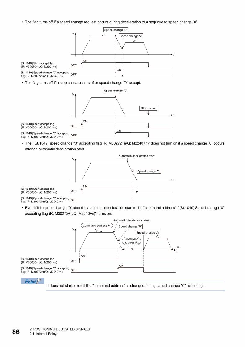
86
• The flag turns off if a speed change request occurs during deceleration to a stop due to speed change "0".
• The flag turns off if a stop cause occurs after speed change "0" accept.
• The "[St.1049] speed change "0" accepting flag (R: M30272+n/Q: M2240+n)" does not turn on if a speed change "0" occurs
after an automatic deceleration start.
• Even if it is speed change "0" after the automatic deceleration start to the "command address", "[St.1049] Speed change "0"
accepting flag (R: M30272+n/Q: M2240+n)" turns on.
It does not start, even if the "command address" is changed during speed change "0" accepting.
t
V
ONOFF
V1
V2
ONOFF
Speed change "0"
Speed change V2
[St.1040] Start accept flag(R: M30080+n/Q: M2001+n)
[St.1049] Speed change "0" acceptingflag (R: M30272+n/Q: M2240+n)
t
V
ONOFF
ONOFF
Speed change "0"
Stop cause
[St.1040] Start accept flag(R: M30080+n/Q: M2001+n)
[St.1049] Speed change "0" acceptingflag (R: M30272+n/Q: M2240+n)
Automatic deceleration start
t
V
ONOFF
OFF
Speed change "0"
[St.1040] Start accept flag(R: M30080+n/Q: M2001+n)
[St.1049] Speed change "0" acceptingflag (R: M30272+n/Q: M2240+n)
Automatic deceleration start
P2P1t
V
ONOFF
V1
V2
ONOFF
Speed change "0"
Speed change V2
Command address P1
[St.1040] Start accept flag(R: M30080+n/Q: M2001+n)
[St.1049] Speed change "0" acceptingflag (R: M30272+n/Q: M2240+n)
Commandaddress P2
2 POSITIONING DEDICATED SIGNALS2.1 Internal Relays
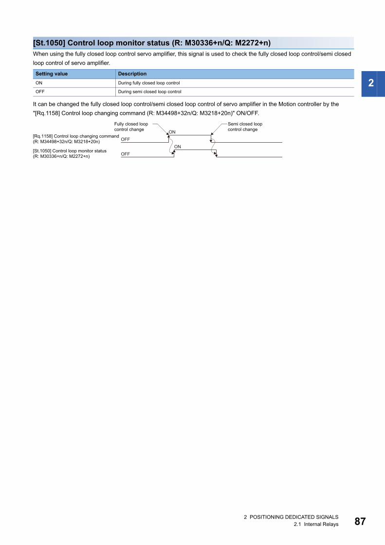
2
[St.1050] Control loop monitor status (R: M30336+n/Q: M2272+n)When using the fully closed loop control servo amplifier, this signal is used to check the fully closed loop control/semi closed
loop control of servo amplifier.
It can be changed the fully closed loop control/semi closed loop control of servo amplifier in the Motion controller by the
"[Rq.1158] Control loop changing command (R: M34498+32n/Q: M3218+20n)" ON/OFF.
Setting value Description
ON During fully closed loop control
OFF During semi closed loop control
ONOFF
[Rq.1158] Control loop changing command(R: M34498+32n/Q: M3218+20n)
Fully closed loop control change
Semi closed loop control change
ONOFF
[St.1050] Control loop monitor status(R: M30336+n/Q: M2272+n)
2 POSITIONING DEDICATED SIGNALS2.1 Internal Relays 87
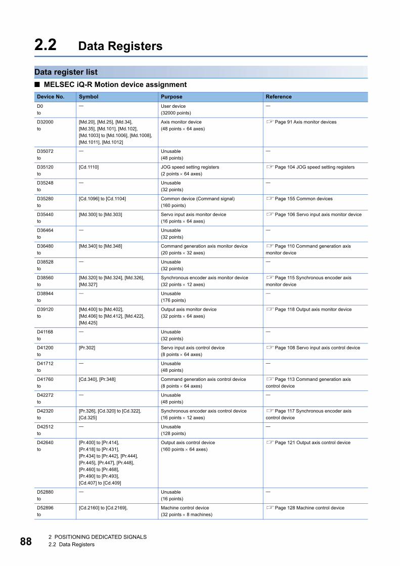
88
2.2 Data Registers
Data register list
■ MELSEC iQ-R Motion device assignment
Device No. Symbol Purpose Reference
D0
to
User device
(32000 points)
D32000
to
[Md.20], [Md.25], [Md.34],
[Md.35], [Md.101], [Md.102],
[Md.1003] to [Md.1006], [Md.1008],
[Md.1011], [Md.1012]
Axis monitor device
(48 points 64 axes)
Page 91 Axis monitor devices
D35072
to
Unusable
(48 points)
D35120
to
[Cd.1110] JOG speed setting registers
(2 points 64 axes)
Page 104 JOG speed setting registers
D35248
to
Unusable
(32 points)
D35280
to
[Cd.1096] to [Cd.1104] Common device (Command signal)
(160 points)
Page 155 Common devices
D35440
to
[Md.300] to [Md.303] Servo input axis monitor device
(16 points 64 axes)
Page 106 Servo input axis monitor device
D36464
to
Unusable
(32 points)
D36480
to
[Md.340] to [Md.348] Command generation axis monitor device
(20 points 32 axes)
Page 110 Command generation axis
monitor device
D38528
to
Unusable
(32 points)
D38560
to
[Md.320] to [Md.324], [Md.326],
[Md.327]
Synchronous encoder axis monitor device
(32 points 12 axes)
Page 115 Synchronous encoder axis
monitor device
D38944
to
Unusable
(176 points)
D39120
to
[Md.400] to [Md.402],
[Md.406] to [Md.412], [Md.422],
[Md.425]
Output axis monitor device
(32 points 64 axes)
Page 118 Output axis monitor device
D41168
to
Unusable
(32 points)
D41200
to
[Pr.302] Servo input axis control device
(8 points 64 axes)
Page 108 Servo input axis control device
D41712
to
Unusable
(48 points)
D41760
to
[Cd.340], [Pr.348] Command generation axis control device
(8 points 64 axes)
Page 113 Command generation axis
control device
D42272
to
Unusable
(48 points)
D42320
to
[Pr.326], [Cd.320] to [Cd.322],
[Cd.325]
Synchronous encoder axis control device
(16 points 12 axes)
Page 117 Synchronous encoder axis
control device
D42512
to
Unusable
(128 points)
D42640
to
[Pr.400] to [Pr.414],
[Pr.418] to [Pr.431],
[Pr.434] to [Pr.442], [Pr.444],
[Pr.445], [Pr.447], [Pr.448],
[Pr.460] to [Pr.468],
[Pr.490] to [Pr.493],
[Cd.407] to [Cd.409]
Output axis control device
(160 points 64 axes)
Page 121 Output axis control device
D52880
to
Unusable
(16 points)
D52896
to
[Cd.2160] to [Cd.2169], Machine control device
(32 points 8 machines)
Page 128 Machine control device
2 POSITIONING DEDICATED SIGNALS2.2 Data Registers
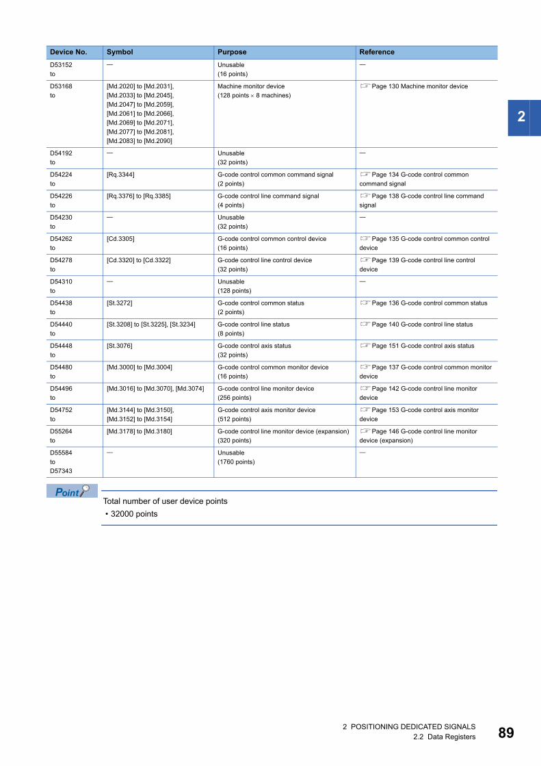
2
Total number of user device points
• 32000 points
D53152
to
Unusable
(16 points)
D53168
to
[Md.2020] to [Md.2031],
[Md.2033] to [Md.2045],
[Md.2047] to [Md.2059],
[Md.2061] to [Md.2066],
[Md.2069] to [Md.2071],
[Md.2077] to [Md.2081],
[Md.2083] to [Md.2090]
Machine monitor device
(128 points 8 machines)
Page 130 Machine monitor device
D54192
to
Unusable
(32 points)
D54224
to
[Rq.3344] G-code control common command signal
(2 points)
Page 134 G-code control common
command signal
D54226
to
[Rq.3376] to [Rq.3385] G-code control line command signal
(4 points)
Page 138 G-code control line command
signal
D54230
to
Unusable
(32 points)
D54262
to
[Cd.3305] G-code control common control device
(16 points)
Page 135 G-code control common control
device
D54278
to
[Cd.3320] to [Cd.3322] G-code control line control device
(32 points)
Page 139 G-code control line control
device
D54310
to
Unusable
(128 points)
D54438
to
[St.3272] G-code control common status
(2 points)
Page 136 G-code control common status
D54440
to
[St.3208] to [St.3225], [St.3234] G-code control line status
(8 points)
Page 140 G-code control line status
D54448
to
[St.3076] G-code control axis status
(32 points)
Page 151 G-code control axis status
D54480
to
[Md.3000] to [Md.3004] G-code control common monitor device
(16 points)
Page 137 G-code control common monitor
device
D54496
to
[Md.3016] to [Md.3070], [Md.3074] G-code control line monitor device
(256 points)
Page 142 G-code control line monitor
device
D54752
to
[Md.3144] to [Md.3150],
[Md.3152] to [Md.3154]
G-code control axis monitor device
(512 points)
Page 153 G-code control axis monitor
device
D55264
to
[Md.3178] to [Md.3180] G-code control line monitor device (expansion)
(320 points)
Page 146 G-code control line monitor
device (expansion)
D55584
to
D57343
Unusable
(1760 points)
Device No. Symbol Purpose Reference
2 POSITIONING DEDICATED SIGNALS2.2 Data Registers 89
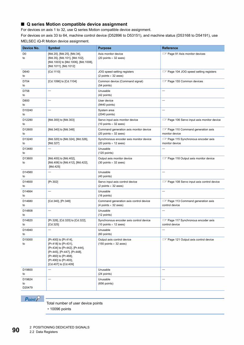
90
■ Q series Motion compatible device assignmentFor devices on axis 1 to 32, use Q series Motion compatible device assignment.
For devices on axis 33 to 64, machine control device (D52896 to D53151), and machine status (D53168 to D54191), use
MELSEC iQ-R Motion device assignment.
Total number of user device points
• 10096 points
Device No. Symbol Purpose Reference
D0
to
[Md.20], [Md.25], [Md.34],
[Md.35], [Md.101], [Md.102],
[Md.1003] to [Md.1006], [Md.1008],
[Md.1011], [Md.1012]
Axis monitor device
(20 points 32 axes)
Page 91 Axis monitor devices
D640
to
[Cd.1110] JOG speed setting registers
(2 points 32 axes)
Page 104 JOG speed setting registers
D704
to
[Cd.1096] to [Cd.1104] Common device (Command signal)
(54 points)
Page 155 Common devices
D758
to
Unusable
(42 points)
D800
to
User device
(9440 points)
D10240
to
System area
(2040 points)
D12280
to
[Md.300] to [Md.303] Servo input axis monitor device
(10 points 32 axes)
Page 106 Servo input axis monitor device
D12600
to
[Md.340] to [Md.348] Command generation axis monitor device
(20 points 32 axes)
Page 110 Command generation axis
monitor device
D13240
to
[Md.320] to [Md.324], [Md.326],
[Md.327]
Synchronous encoder axis monitor device
(20 points 12 axes)
Page 115 Synchronous encoder axis
monitor device
D13480
to
Unusable
(120 points)
D13600
to
[Md.400] to [Md.402],
[Md.406] to [Md.412], [Md.422],
[Md.425]
Output axis monitor device
(30 points 32 axes)
Page 118 Output axis monitor device
D14560
to
Unusable
(40 points)
D14600
to
[Pr.302] Servo input axis control device
(2 points 32 axes)
Page 108 Servo input axis control device
D14664
to
Unusable
(16 points)
D14680
to
[Cd.340], [Pr.348] Command generation axis control device
(4 points 32 axes)
Page 113 Command generation axis
control device
D14808
to
Unusable
(12 points)
D14820
to
[Pr.326], [Cd.320] to [Cd.322],
[Cd.325]
Synchronous encoder axis control device
(10 points 12 axes)
Page 117 Synchronous encoder axis
control device
D14940
to
Unusable
(60 points)
D15000
to
[Pr.400] to [Pr.414],
[Pr.418] to [Pr.431],
[Pr.434] to [Pr.442], [Pr.444],
[Pr.445], [Pr.447], [Pr.448],
[Pr.460] to [Pr.468],
[Pr.490] to [Pr.493],
[Cd.407] to [Cd.409]
Output axis control device
(150 points 32 axes)
Page 121 Output axis control device
D19800
to
Unusable
(24 points)
D19824
to
D20479
Unusable
(656 points)
2 POSITIONING DEDICATED SIGNALS2.2 Data Registers
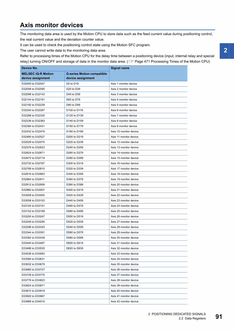
2
Axis monitor devicesThe monitoring data area is used by the Motion CPU to store data such as the feed current value during positioning control,
the real current value and the deviation counter value.
It can be used to check the positioning control state using the Motion SFC program.
The user cannot write data to the monitoring data area.
Refer to processing times of the Motion CPU for the delay time between a positioning device (input, internal relay and special
relay) turning ON/OFF and storage of data in the monitor data area. (Page 471 Processing Times of the Motion CPU)
Device No. Signal name
MELSEC iQ-R Motion device assignment
Q series Motion compatible device assignment
D32000 to D32047 D0 to D19 Axis 1 monitor device
D32048 to D32095 D20 to D39 Axis 2 monitor device
D32096 to D32143 D40 to D59 Axis 3 monitor device
D32144 to D32191 D60 to D79 Axis 4 monitor device
D32192 to D32239 D80 to D99 Axis 5 monitor device
D32240 to D32287 D100 to D119 Axis 6 monitor device
D32288 to D32335 D120 to D139 Axis 7 monitor device
D32336 to D32383 D140 to D159 Axis 8 monitor device
D32384 to D32431 D160 to D179 Axis 9 monitor device
D32432 to D32479 D180 to D199 Axis 10 monitor device
D32480 to D32527 D200 to D219 Axis 11 monitor device
D32528 to D32575 D220 to D239 Axis 12 monitor device
D32576 to D32623 D240 to D259 Axis 13 monitor device
D32624 to D32671 D260 to D279 Axis 14 monitor device
D32672 to D32719 D280 to D299 Axis 15 monitor device
D32720 to D32767 D300 to D319 Axis 16 monitor device
D32768 to D32815 D320 to D339 Axis 17 monitor device
D32816 to D32863 D340 to D359 Axis 18 monitor device
D32864 to D32911 D360 to D379 Axis 19 monitor device
D32912 to D32959 D380 to D399 Axis 20 monitor device
D32960 to D33007 D400 to D419 Axis 21 monitor device
D33008 to D33055 D420 to D439 Axis 22 monitor device
D33056 to D33103 D440 to D459 Axis 23 monitor device
D33104 to D33151 D460 to D479 Axis 24 monitor device
D33152 to D33199 D480 to D499 Axis 25 monitor device
D33200 to D33247 D500 to D519 Axis 26 monitor device
D33248 to D33295 D520 to D539 Axis 27 monitor device
D33296 to D33343 D540 to D559 Axis 28 monitor device
D33344 to D33391 D560 to D579 Axis 29 monitor device
D33392 to D33439 D580 to D599 Axis 30 monitor device
D33440 to D33487 D600 to D619 Axis 31 monitor device
D33488 to D33535 D620 to D639 Axis 32 monitor device
D33536 to D33583 Axis 33 monitor device
D33584 to D33631 Axis 34 monitor device
D33632 to D33679 Axis 35 monitor device
D33680 to D33727 Axis 36 monitor device
D33728 to D33775 Axis 37 monitor device
D33776 to D33823 Axis 38 monitor device
D33824 to D33871 Axis 39 monitor device
D33872 to D33919 Axis 40 monitor device
D33920 to D33967 Axis 41 monitor device
D33968 to D34015 Axis 42 monitor device
2 POSITIONING DEDICATED SIGNALS2.2 Data Registers 91
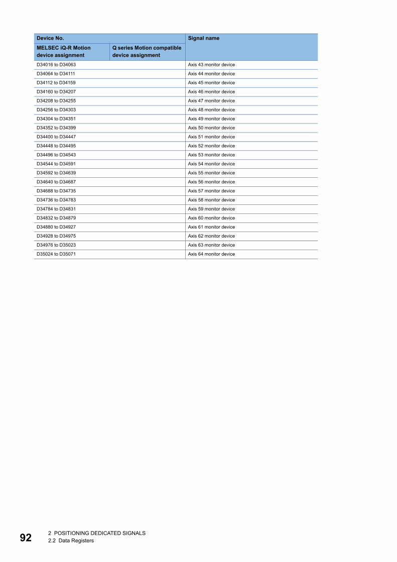
92
D34016 to D34063 Axis 43 monitor device
D34064 to D34111 Axis 44 monitor device
D34112 to D34159 Axis 45 monitor device
D34160 to D34207 Axis 46 monitor device
D34208 to D34255 Axis 47 monitor device
D34256 to D34303 Axis 48 monitor device
D34304 to D34351 Axis 49 monitor device
D34352 to D34399 Axis 50 monitor device
D34400 to D34447 Axis 51 monitor device
D34448 to D34495 Axis 52 monitor device
D34496 to D34543 Axis 53 monitor device
D34544 to D34591 Axis 54 monitor device
D34592 to D34639 Axis 55 monitor device
D34640 to D34687 Axis 56 monitor device
D34688 to D34735 Axis 57 monitor device
D34736 to D34783 Axis 58 monitor device
D34784 to D34831 Axis 59 monitor device
D34832 to D34879 Axis 60 monitor device
D34880 to D34927 Axis 61 monitor device
D34928 to D34975 Axis 62 monitor device
D34976 to D35023 Axis 63 monitor device
D35024 to D35071 Axis 64 monitor device
Device No. Signal name
MELSEC iQ-R Motion device assignment
Q series Motion compatible device assignment
2 POSITIONING DEDICATED SIGNALS2.2 Data Registers
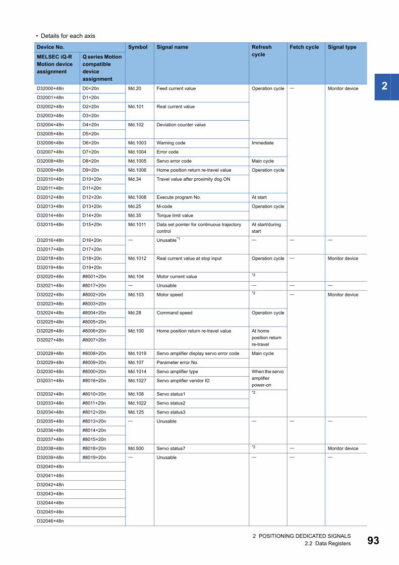
2
• Details for each axis
Device No. Symbol Signal name Refresh cycle
Fetch cycle Signal type
MELSEC iQ-R Motion device assignment
Q series Motion compatible device assignment
D32000+48n D0+20n Md.20 Feed current value Operation cycle Monitor device
D32001+48n D1+20n
D32002+48n D2+20n Md.101 Real current value
D32003+48n D3+20n
D32004+48n D4+20n Md.102 Deviation counter value
D32005+48n D5+20n
D32006+48n D6+20n Md.1003 Warning code Immediate
D32007+48n D7+20n Md.1004 Error code
D32008+48n D8+20n Md.1005 Servo error code Main cycle
D32009+48n D9+20n Md.1006 Home position return re-travel value Operation cycle
D32010+48n D10+20n Md.34 Travel value after proximity dog ON
D32011+48n D11+20n
D32012+48n D12+20n Md.1008 Execute program No. At start
D32013+48n D13+20n Md.25 M-code Operation cycle
D32014+48n D14+20n Md.35 Torque limit value
D32015+48n D15+20n Md.1011 Data set pointer for continuous trajectory
control
At start/during
start
D32016+48n D16+20n Unusable*1
D32017+48n D17+20n
D32018+48n D18+20n Md.1012 Real current value at stop input Operation cycle Monitor device
D32019+48n D19+20n
D32020+48n #8001+20n Md.104 Motor current value *2
D32021+48n #8017+20n Unusable
D32022+48n #8002+20n Md.103 Motor speed *2 Monitor device
D32023+48n #8003+20n
D32024+48n #8004+20n Md.28 Command speed Operation cycle
D32025+48n #8005+20n
D32026+48n #8006+20n Md.100 Home position return re-travel value At home
position return
re-travelD32027+48n #8007+20n
D32028+48n #8008+20n Md.1019 Servo amplifier display servo error code Main cycle
D32029+48n #8009+20n Md.107 Parameter error No.
D32030+48n #8000+20n Md.1014 Servo amplifier type When the servo
amplifier
power-onD32031+48n #8016+20n Md.1027 Servo amplifier vendor ID
D32032+48n #8010+20n Md.108 Servo status1 *2
D32033+48n #8011+20n Md.1022 Servo status2
D32034+48n #8012+20n Md.125 Servo status3
D32035+48n #8013+20n Unusable
D32036+48n #8014+20n
D32037+48n #8015+20n
D32038+48n #8018+20n Md.500 Servo status7 *2 Monitor device
D32039+48n #8019+20n Unusable
D32040+48n
D32041+48n
D32042+48n
D32043+48n
D32044+48n
D32045+48n
D32046+48n
2 POSITIONING DEDICATED SIGNALS2.2 Data Registers 93
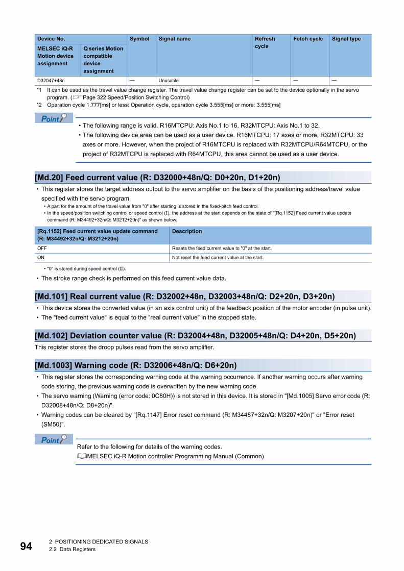
94
*1 It can be used as the travel value change register. The travel value change register can be set to the device optionally in the servo program. (Page 322 Speed/Position Switching Control)
*2 Operation cycle 1.777[ms] or less: Operation cycle, operation cycle 3.555[ms] or more: 3.555[ms]
• The following range is valid. R16MTCPU: Axis No.1 to 16, R32MTCPU: Axis No.1 to 32.
• The following device area can be used as a user device. R16MTCPU: 17 axes or more, R32MTCPU: 33
axes or more. However, when the project of R16MTCPU is replaced with R32MTCPU/R64MTCPU, or the
project of R32MTCPU is replaced with R64MTCPU, this area cannot be used as a user device.
[Md.20] Feed current value (R: D32000+48n/Q: D0+20n, D1+20n) • This register stores the target address output to the servo amplifier on the basis of the positioning address/travel value
specified with the servo program.
• The stroke range check is performed on this feed current value data.
[Md.101] Real current value (R: D32002+48n, D32003+48n/Q: D2+20n, D3+20n) • This device stores the converted value (in an axis control unit) of the feedback position of the motor encoder (in pulse unit).
• The "feed current value" is equal to the "real current value" in the stopped state.
[Md.102] Deviation counter value (R: D32004+48n, D32005+48n/Q: D4+20n, D5+20n)This register stores the droop pulses read from the servo amplifier.
[Md.1003] Warning code (R: D32006+48n/Q: D6+20n) • This register stores the corresponding warning code at the warning occurrence. If another warning occurs after warning
code storing, the previous warning code is overwritten by the new warning code.
• The servo warning (Warning (error code: 0C80H)) is not stored in this device. It is stored in "[Md.1005] Servo error code (R:
D32008+48n/Q: D8+20n)".
• Warning codes can be cleared by "[Rq.1147] Error reset command (R: M34487+32n/Q: M3207+20n)" or "Error reset
(SM50)".
Refer to the following for details of the warning codes.
MELSEC iQ-R Motion controller Programming Manual (Common)
D32047+48n Unusable
• A part for the amount of the travel value from "0" after starting is stored in the fixed-pitch feed control.
• In the speed/position switching control or speed control (), the address at the start depends on the state of "[Rq.1152] Feed current value update
command (R: M34492+32n/Q: M3212+20n)" as shown below.
[Rq.1152] Feed current value update command(R: M34492+32n/Q: M3212+20n)
Description
OFF Resets the feed current value to "0" at the start.
ON Not reset the feed current value at the start.
• "0" is stored during speed control ().
Device No. Symbol Signal name Refresh cycle
Fetch cycle Signal type
MELSEC iQ-R Motion device assignment
Q series Motion compatible device assignment
2 POSITIONING DEDICATED SIGNALS2.2 Data Registers
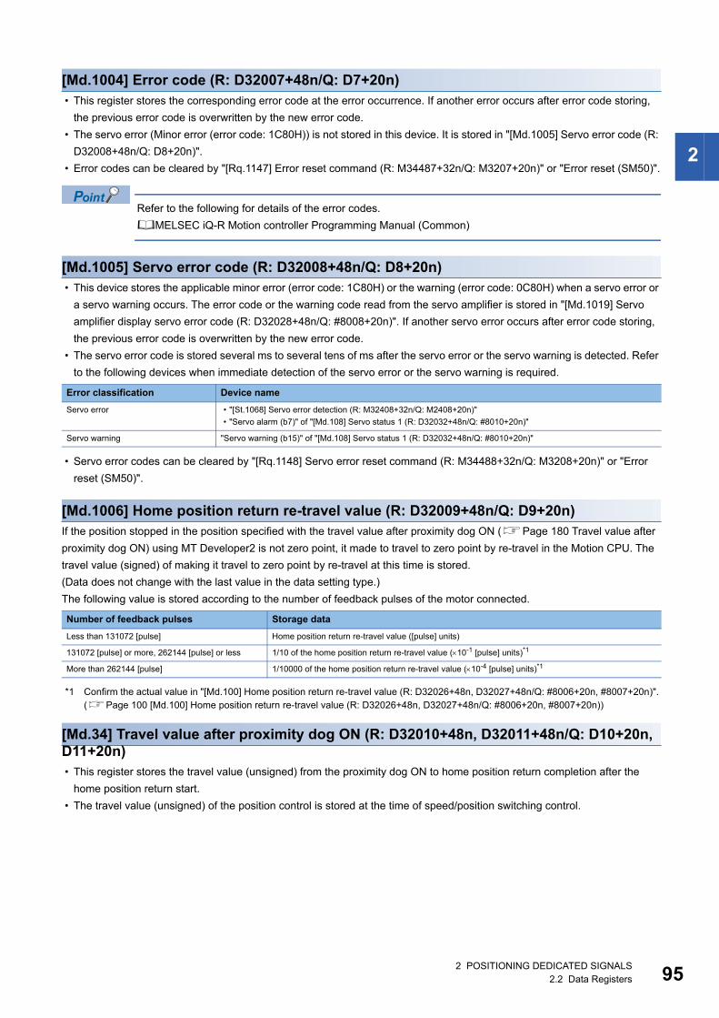
2
[Md.1004] Error code (R: D32007+48n/Q: D7+20n) • This register stores the corresponding error code at the error occurrence. If another error occurs after error code storing,
the previous error code is overwritten by the new error code.
• The servo error (Minor error (error code: 1C80H)) is not stored in this device. It is stored in "[Md.1005] Servo error code (R:
D32008+48n/Q: D8+20n)".
• Error codes can be cleared by "[Rq.1147] Error reset command (R: M34487+32n/Q: M3207+20n)" or "Error reset (SM50)".
Refer to the following for details of the error codes.
MELSEC iQ-R Motion controller Programming Manual (Common)
[Md.1005] Servo error code (R: D32008+48n/Q: D8+20n) • This device stores the applicable minor error (error code: 1C80H) or the warning (error code: 0C80H) when a servo error or
a servo warning occurs. The error code or the warning code read from the servo amplifier is stored in "[Md.1019] Servo
amplifier display servo error code (R: D32028+48n/Q: #8008+20n)". If another servo error occurs after error code storing,
the previous error code is overwritten by the new error code.
• The servo error code is stored several ms to several tens of ms after the servo error or the servo warning is detected. Refer
to the following devices when immediate detection of the servo error or the servo warning is required.
• Servo error codes can be cleared by "[Rq.1148] Servo error reset command (R: M34488+32n/Q: M3208+20n)" or "Error
reset (SM50)".
[Md.1006] Home position return re-travel value (R: D32009+48n/Q: D9+20n)If the position stopped in the position specified with the travel value after proximity dog ON (Page 180 Travel value after
proximity dog ON) using MT Developer2 is not zero point, it made to travel to zero point by re-travel in the Motion CPU. The
travel value (signed) of making it travel to zero point by re-travel at this time is stored.
(Data does not change with the last value in the data setting type.)
The following value is stored according to the number of feedback pulses of the motor connected.
*1 Confirm the actual value in "[Md.100] Home position return re-travel value (R: D32026+48n, D32027+48n/Q: #8006+20n, #8007+20n)". (Page 100 [Md.100] Home position return re-travel value (R: D32026+48n, D32027+48n/Q: #8006+20n, #8007+20n))
[Md.34] Travel value after proximity dog ON (R: D32010+48n, D32011+48n/Q: D10+20n, D11+20n) • This register stores the travel value (unsigned) from the proximity dog ON to home position return completion after the
home position return start.
• The travel value (unsigned) of the position control is stored at the time of speed/position switching control.
Error classification Device name
Servo error • "[St.1068] Servo error detection (R: M32408+32n/Q: M2408+20n)"
• "Servo alarm (b7)" of "[Md.108] Servo status 1 (R: D32032+48n/Q: #8010+20n)"
Servo warning "Servo warning (b15)" of "[Md.108] Servo status 1 (R: D32032+48n/Q: #8010+20n)"
Number of feedback pulses Storage data
Less than 131072 [pulse] Home position return re-travel value ([pulse] units)
131072 [pulse] or more, 262144 [pulse] or less 1/10 of the home position return re-travel value (10-1 [pulse] units)*1
More than 262144 [pulse] 1/10000 of the home position return re-travel value (10-4 [pulse] units)*1
2 POSITIONING DEDICATED SIGNALS2.2 Data Registers 95
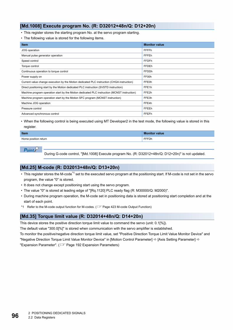
96
[Md.1008] Execute program No. (R: D32012+48n/Q: D12+20n) • This register stores the starting program No. at the servo program starting.
• The following value is stored for the following items.
• When the following control is being executed using MT Developer2 in the test mode, the following value is stored in this
register.
During G-code control, "[Md.1008] Execute program No. (R: D32012+48n/Q: D12+20n)" is not updated.
[Md.25] M-code (R: D32013+48n/Q: D13+20n) • This register stores the M-code*1 set to the executed servo program at the positioning start. If M-code is not set in the servo
program, the value "0" is stored.
• It does not change except positioning start using the servo program.
• The value "0" is stored at leading edge of "[Rq.1120] PLC ready flag (R: M30000/Q: M2000)".
• During machine program operation, the M-code set in positioning data is stored at positioning start completion and at the
start of each point.
*1 Refer to the M-code output function for M-codes. (Page 423 M-code Output Function)
[Md.35] Torque limit value (R: D32014+48n/Q: D14+20n)This device stores the positive direction torque limit value to command the servo (unit: 0.1[%]).
The default value "300.0[%]" is stored when communication with the servo amplifier is established.
To monitor the positive/negative direction torque limit value, set "Positive Direction Torque Limit Value Monitor Device" and
"Negative Direction Torque Limit Value Monitor Device" in [Motion Control Parameter] [Axis Setting Parameter]
"Expansion Parameter". (Page 192 Expansion Parameters)
Item Monitor value
JOG operation FFFFh
Manual pulse generator operation FFFEh
Speed control FFDFh
Torque control FFDEh
Continuous operation to torque control FFDDh
Power supply on FF00h
Current value change execution by the Motion dedicated PLC instruction (CHGA instruction) FFE0h
Direct positioning start by the Motion dedicated PLC instruction (SVSTD instruction) FFE1h
Machine program operation start by the Motion dedicated PLC instruction (MCNST instruction) FFE2h
Machine program operation start by the Motion SFC program (MCNST instruction) FFE3h
Machine JOG operation FFE4h
Pressure control FFEEh
Advanced synchronous control FFEFh
Item Monitor value
Home position return FFFDh
2 POSITIONING DEDICATED SIGNALS2.2 Data Registers
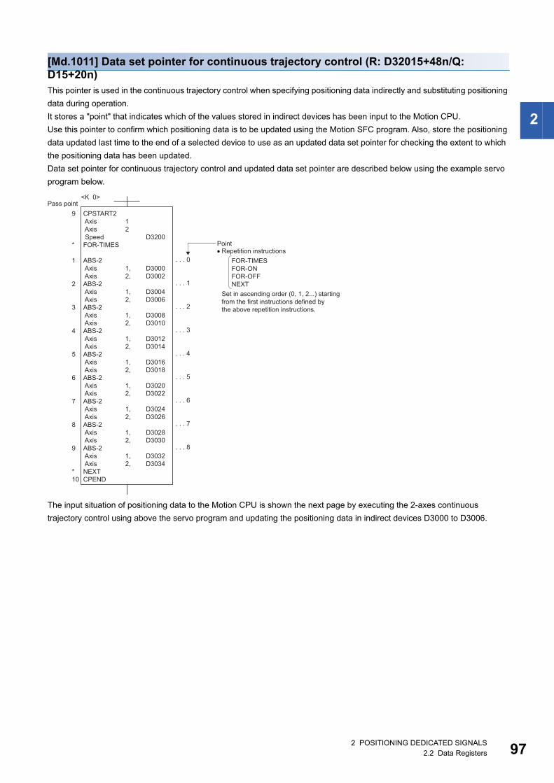
2
[Md.1011] Data set pointer for continuous trajectory control (R: D32015+48n/Q: D15+20n)This pointer is used in the continuous trajectory control when specifying positioning data indirectly and substituting positioning
data during operation.
It stores a "point" that indicates which of the values stored in indirect devices has been input to the Motion CPU.
Use this pointer to confirm which positioning data is to be updated using the Motion SFC program. Also, store the positioning
data updated last time to the end of a selected device to use as an updated data set pointer for checking the extent to which
the positioning data has been updated.
Data set pointer for continuous trajectory control and updated data set pointer are described below using the example servo
program below.
The input situation of positioning data to the Motion CPU is shown the next page by executing the 2-axes continuous
trajectory control using above the servo program and updating the positioning data in indirect devices D3000 to D3006.
CPSTART2 Axis Axis SpeedFOR-TIMES
ABS-2 Axis AxisABS-2 Axis AxisABS-2 Axis AxisABS-2 Axis AxisABS-2 Axis AxisABS-2 Axis AxisABS-2 Axis AxisABS-2 Axis AxisABS-2 Axis AxisNEXTCPEND
Repetition instructionsPoint
Pass point<K 0>
D3200
D3000D3002
D3004D3006
D3008D3010
D3012D3014
D3016D3018
D3020D3022
D3024D3026
D3028D3030
D3032D3034
12
1,2,
1,2,
1,2,
1,2,
1,2,
1,2,
1,2,
1,2,
1,2,
9
*
1
2
3
4
5
6
7
8
9
*10
. . . 0
. . . 1
. . . 2
. . . 3
. . . 4
. . . 5
. . . 6
. . . 7
. . . 8
Set in ascending order (0, 1, 2...) startingfrom the first instructions defined by the above repetition instructions.
FOR-TIMESFOR-ONFOR-OFFNEXT
2 POSITIONING DEDICATED SIGNALS2.2 Data Registers 97
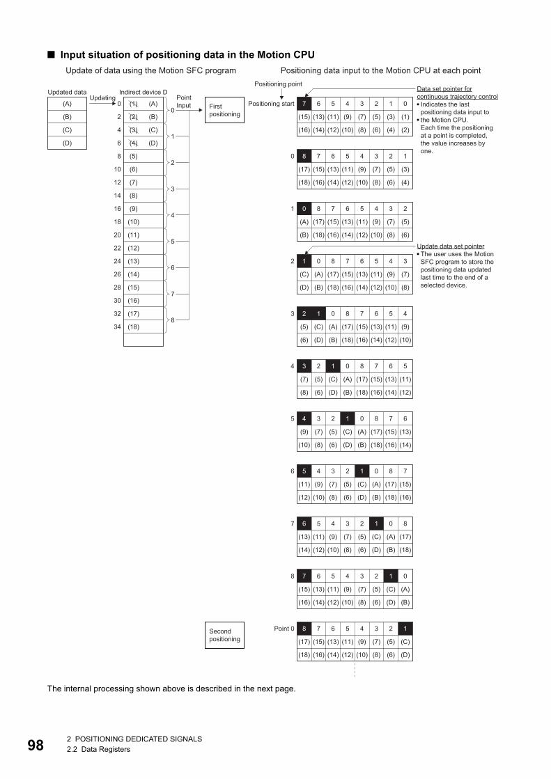
98
■ Input situation of positioning data in the Motion CPU
The internal processing shown above is described in the next page.
Data set pointer forcontinuous trajectory control
Indicates the lastpositioning data input tothe Motion CPU.Each time the positioningat a point is completed, the value increases byone.
Update data set pointerThe user uses the MotionSFC program to store thepositioning data updatedlast time to the end of aselected device.
Positioning point
PointInput Positioning start 5 4 3 2 1
(3)(5)
(4)
(7)
(6)
(9)
(8)
(11)
(10)(12)
(1)
0
(2)
7 6
(15)
(16)
(13)
(14)
5 4 3 2
(5)(7)
(6)
(9)
(8)
(11)
(10)(12)
0 678
(15)
(16)
(17)
(18)
(A)
(B)
(13)
(14)
5 4 3
(7)(9)
(8)
(11)
(10)(12)
1 6780
(15)
(16)
(17)
(18)
(A)
(B)
(C)
(D)
(13)
(14)
5 4
(9)(11)
(10)(12)
2 67801
(15)
(16)
(17)
(18)
(A)
(B)
(C)
(D)
(5)
(6)
(13)
(14)
5
(11)
(12)
3 67801
(15)
(16)
(17)
(18)
(A)
(B)
(C)
(D)
(5)
(6)
2
(7)
(8)
(13)
(14)
4 6780123
(15)
(16)
(17)
(18)
(A)
(B)
(C)
(D)
(5)
(6)
(7)
(8)
(9)
(10)
234
(7)
(8)
(9)
(10)
(11)
(12)
2345
(7)
(8)
(9)
(10)
(11)
(12)
(13)
(14)
2345
(7)
(8)
(9)
(10)
(11)
(12)
(13)
(14)
6
(15)
(16)
(13)
(14)
5 7801
(15)
(16)
(17)
(18)
(A)
(B)
(C)
(D)
(5)
(6)
6 801
(17)
(18)
(A)
(B)
(C)
(D)
(5)
(6)
1
5 4 3 2 1
(3)(5)
(4)
(7)
(6)
(9)
(8)
(11)
(10)(12)
8 6
(17)
(18)
7
(15)
(16)
(13)
(14)
5 4 3 2 1
(C)(5)
(D)
(7)
(6)
(9)
(8)
(11)
(10)(12)
8 6
(17)
(18)
7
(15)
(16)
(13)
(14)
0
2
3
4
5
6
7
7 01
(A)
(B)
(C)
(D)
(5)
(6)
8
Point 0Secondpositioning
First positioning
Indirect device D
0
2
4
6
8
10
12
14
16
18
20
22
24
26
28
30
Updated data
(C)
(D)
(A)
(B)
Updating
0
1
2
3
4
5
6
7
832
34
(A)
(B)
(C)
(D)
(5)
(6)
(7)
(8)
(9)
(10)
(11)
(12)
(13)
(14)
(15)
(16)
(17)
(18)
(1)
(2)
(3)
(4)
Update of data using the Motion SFC program Positioning data input to the Motion CPU at each point
2 POSITIONING DEDICATED SIGNALS2.2 Data Registers
2
■ Internal processing • The positioning data ((1) to (16)) of points 0 to 7 is input to the Motion CPU by the continuous trajectory control starting
process (before positioning start). The last point "7" of the input data to be input is stored in the data set pointer for
continuous trajectory control at this time. Because the positioning for point 0 starts immediately after, space opens in the
input area for positioning data and the Motion CPU inputs point 8 ((17) to (18)) positioning data. The last point "8" of the
input data is stored in the data set pointer for continuous trajectory control.
The "8" stored in the data set pointer for continuous trajectory control indicates that the second updating of the positioning
data stored in points 0 to 8 is possible.
• The positioning data ((1) to (4)) of points 0 to 1 is updated to positioning data ((A) to (D)) using the Motion SFC program.
The last point "1" of the updated positioning data is stored in the updated data set pointer (the user must create a Motion
SFC program) at this time. Positioning data of points 2 to 8 (data (5) to (18)) can still be updated.
However, the positioning data ((A) to (D)) of the updated points 0 to 1 can also be updated because at this point it has still
not been input to the Motion CPU.
• On completion of the positioning for point 0, point 1 positioning starts, the Motion CPU discards the positioning data ((3) to
(4)) of point 1, and inputs the positioning data ((A) to (B)) of point 0 (second positioning).
At this time, the value of the data set pointer for continuous trajectory control automatically proceeds and changes to "0".
• Hereafter, whenever positioning of each point is completed, the positioning data shifts one place.
The positioning data that can be updated is the data which has not yet been input to the Motion CPU.
Even if the values of the indirect devices D3008 and D3010 are updated by the Motion SFC program after the positioning
completion of the point 3, the positioning data of point 2 that is input to the Motion CPU will not be updated and the second
positioning will be executed using the unupdated data.
The data set pointer for continuous trajectory control has not yet been input to the Motion CPU, and indicates the
positioning data which a user can update using the Motion SFC program.
Number of points that can be defined by a repeat instruction
• The Motion CPU inputs up to 8 points ahead therefore create a servo program of at least 9 points.
• Even if there are 9 points or more, and they include pass points of few travel value, the positioning at each
point may be completed, and the data input to the Motion CPU, before the data has been updated using the
Motion SFC program.
• Create a sufficient number of points to ensure that data will not be input before the Motion CPU has updated
the values in the indirect devices.
[Md.1012] Real current value at STOP input (R: D32018+48n, D32019+48n/Q: D18+20n, D19+20n)The actual current value at the detection of a stop/rapid stop cause is stored in this area.
The value is not stored during advanced synchronous control, or G-code control.
[Md.104] Motor current value (R: D32020+48n/Q: #8001+20n)This register stores the motor current value (0.1 [%]) (signed) read from the servo amplifier.
[Md.103] Motor speed (R: D32022+48n, D32023+48n/Q: #8002+20n, #8003+20n)This register stores the motor speed (0.01 [r/min]) (signed) read from the servo amplifier.
The motor speed (0.01 [mm/s]) (signed) is stored at linear servo use.
[Md.28] Command speed (R: D32024+48n, D32025+48n/Q: #8004+20n, #8005+20n)This register stores the speed (signed) at which command value to the servo amplifier for every operation cycle is converted
into [pulse/s].
2 POSITIONING DEDICATED SIGNALS2.2 Data Registers 99
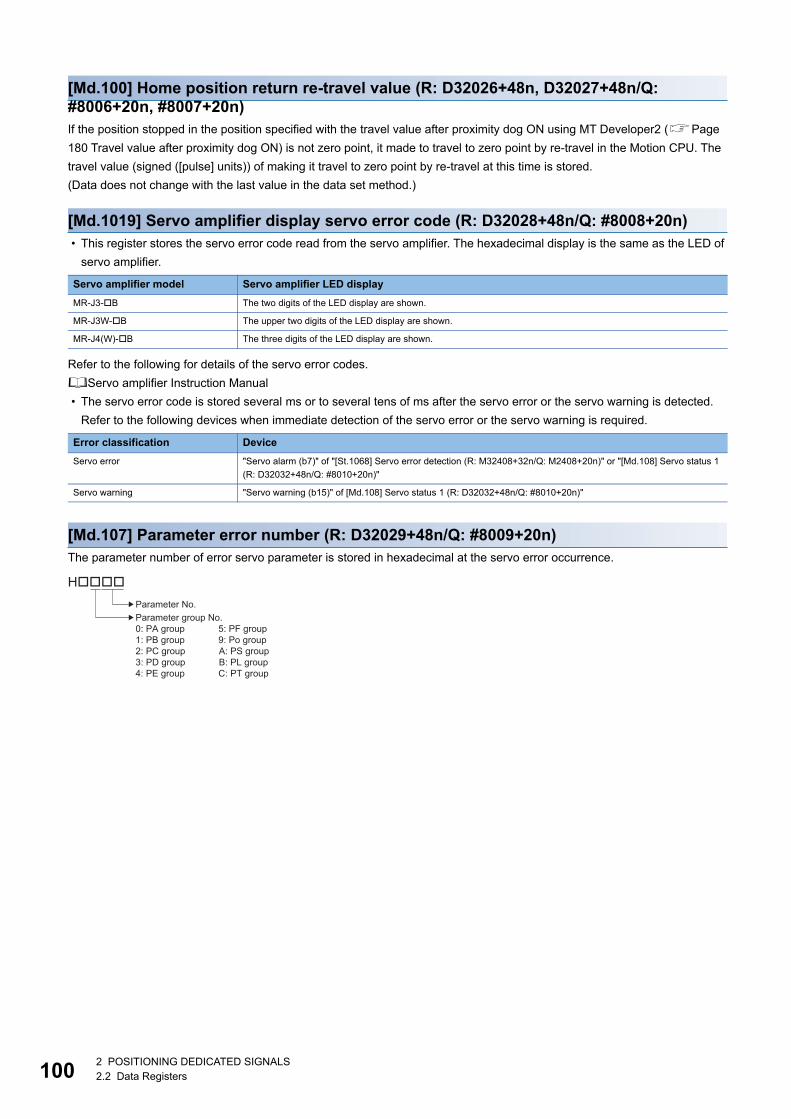
10
[Md.100] Home position return re-travel value (R: D32026+48n, D32027+48n/Q: #8006+20n, #8007+20n)If the position stopped in the position specified with the travel value after proximity dog ON using MT Developer2 (Page
180 Travel value after proximity dog ON) is not zero point, it made to travel to zero point by re-travel in the Motion CPU. The
travel value (signed ([pulse] units)) of making it travel to zero point by re-travel at this time is stored.
(Data does not change with the last value in the data set method.)
[Md.1019] Servo amplifier display servo error code (R: D32028+48n/Q: #8008+20n) • This register stores the servo error code read from the servo amplifier. The hexadecimal display is the same as the LED of
servo amplifier.
Refer to the following for details of the servo error codes.
Servo amplifier Instruction Manual
• The servo error code is stored several ms or to several tens of ms after the servo error or the servo warning is detected.
Refer to the following devices when immediate detection of the servo error or the servo warning is required.
[Md.107] Parameter error number (R: D32029+48n/Q: #8009+20n)The parameter number of error servo parameter is stored in hexadecimal at the servo error occurrence.
Servo amplifier model Servo amplifier LED display
MR-J3-B The two digits of the LED display are shown.
MR-J3W-B The upper two digits of the LED display are shown.
MR-J4(W)-B The three digits of the LED display are shown.
Error classification Device
Servo error "Servo alarm (b7)" of "[St.1068] Servo error detection (R: M32408+32n/Q: M2408+20n)" or "[Md.108] Servo status 1
(R: D32032+48n/Q: #8010+20n)"
Servo warning "Servo warning (b15)" of [Md.108] Servo status 1 (R: D32032+48n/Q: #8010+20n)"
Parameter No.
H����
Parameter group No.0: PA group 5: PF group1: PB group 9: Po group2: PC group A: PS group3: PD group B: PL group4: PE group C: PT group
02 POSITIONING DEDICATED SIGNALS2.2 Data Registers
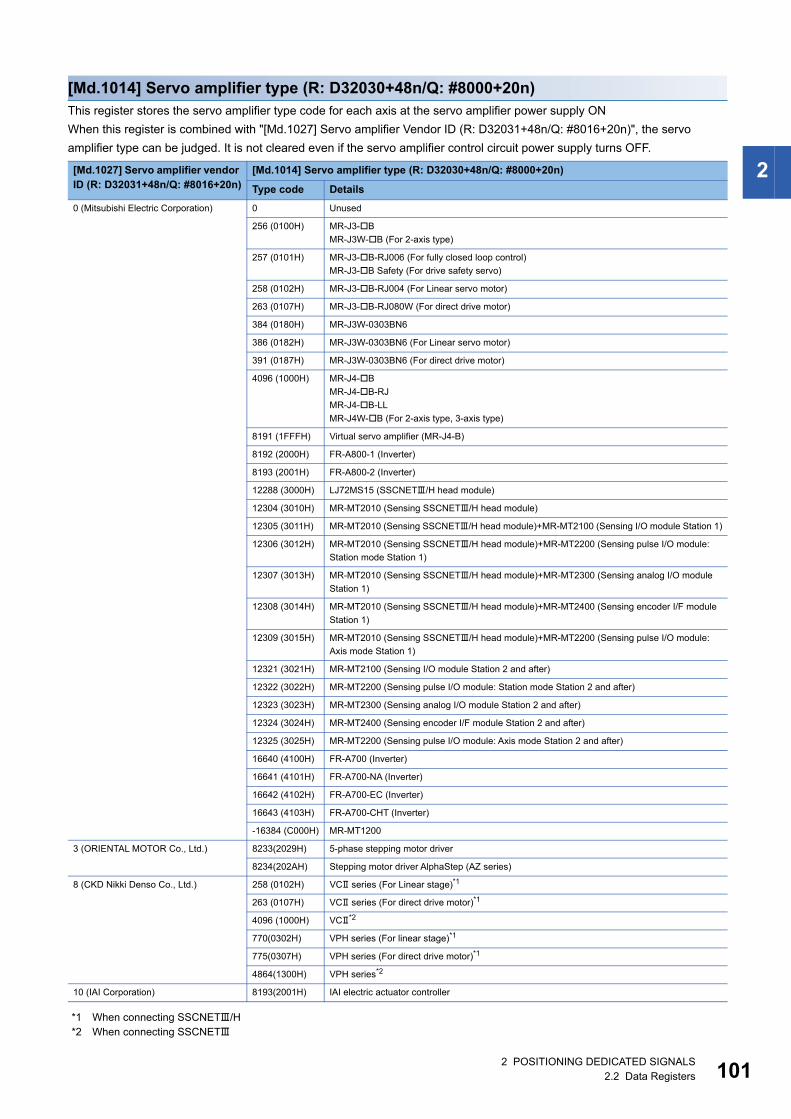
2
[Md.1014] Servo amplifier type (R: D32030+48n/Q: #8000+20n)This register stores the servo amplifier type code for each axis at the servo amplifier power supply ON
When this register is combined with "[Md.1027] Servo amplifier Vendor ID (R: D32031+48n/Q: #8016+20n)", the servo
amplifier type can be judged. It is not cleared even if the servo amplifier control circuit power supply turns OFF.
*1 When connecting SSCNET/H*2 When connecting SSCNET
[Md.1027] Servo amplifier vendor ID (R: D32031+48n/Q: #8016+20n)
[Md.1014] Servo amplifier type (R: D32030+48n/Q: #8000+20n)
Type code Details
0 (Mitsubishi Electric Corporation) 0 Unused
256 (0100H) MR-J3-B
MR-J3W-B (For 2-axis type)
257 (0101H) MR-J3-B-RJ006 (For fully closed loop control)
MR-J3-B Safety (For drive safety servo)
258 (0102H) MR-J3-B-RJ004 (For Linear servo motor)
263 (0107H) MR-J3-B-RJ080W (For direct drive motor)
384 (0180H) MR-J3W-0303BN6
386 (0182H) MR-J3W-0303BN6 (For Linear servo motor)
391 (0187H) MR-J3W-0303BN6 (For direct drive motor)
4096 (1000H) MR-J4-B
MR-J4-B-RJ
MR-J4-B-LL
MR-J4W-B (For 2-axis type, 3-axis type)
8191 (1FFFH) Virtual servo amplifier (MR-J4-B)
8192 (2000H) FR-A800-1 (Inverter)
8193 (2001H) FR-A800-2 (Inverter)
12288 (3000H) LJ72MS15 (SSCNET/H head module)
12304 (3010H) MR-MT2010 (Sensing SSCNET/H head module)
12305 (3011H) MR-MT2010 (Sensing SSCNET/H head module)+MR-MT2100 (Sensing I/O module Station 1)
12306 (3012H) MR-MT2010 (Sensing SSCNET/H head module)+MR-MT2200 (Sensing pulse I/O module:
Station mode Station 1)
12307 (3013H) MR-MT2010 (Sensing SSCNET/H head module)+MR-MT2300 (Sensing analog I/O module
Station 1)
12308 (3014H) MR-MT2010 (Sensing SSCNET/H head module)+MR-MT2400 (Sensing encoder I/F module
Station 1)
12309 (3015H) MR-MT2010 (Sensing SSCNET/H head module)+MR-MT2200 (Sensing pulse I/O module:
Axis mode Station 1)
12321 (3021H) MR-MT2100 (Sensing I/O module Station 2 and after)
12322 (3022H) MR-MT2200 (Sensing pulse I/O module: Station mode Station 2 and after)
12323 (3023H) MR-MT2300 (Sensing analog I/O module Station 2 and after)
12324 (3024H) MR-MT2400 (Sensing encoder I/F module Station 2 and after)
12325 (3025H) MR-MT2200 (Sensing pulse I/O module: Axis mode Station 2 and after)
16640 (4100H) FR-A700 (Inverter)
16641 (4101H) FR-A700-NA (Inverter)
16642 (4102H) FR-A700-EC (Inverter)
16643 (4103H) FR-A700-CHT (Inverter)
-16384 (C000H) MR-MT1200
3 (ORIENTAL MOTOR Co., Ltd.) 8233(2029H) 5-phase stepping motor driver
8234(202AH) Stepping motor driver AlphaStep (AZ series)
8 (CKD Nikki Denso Co., Ltd.) 258 (0102H) VC series (For Linear stage)*1
263 (0107H) VC series (For direct drive motor)*1
4096 (1000H) VC*2
770(0302H) VPH series (For linear stage)*1
775(0307H) VPH series (For direct drive motor)*1
4864(1300H) VPH series*2
10 (IAI Corporation) 8193(2001H) IAI electric actuator controller
2 POSITIONING DEDICATED SIGNALS2.2 Data Registers 101
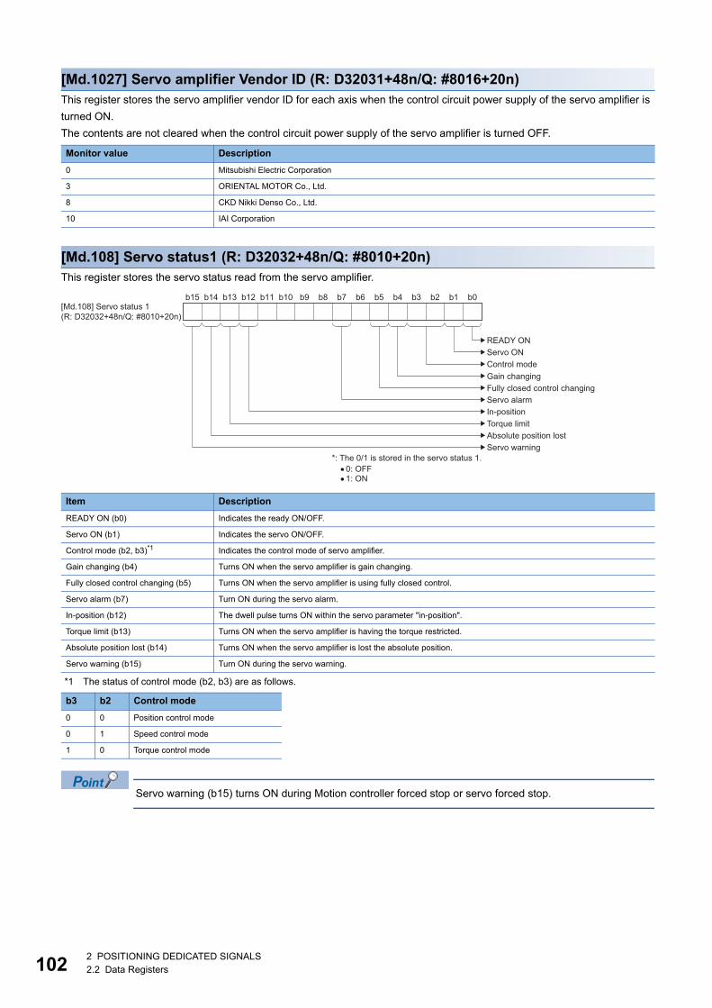
10
[Md.1027] Servo amplifier Vendor ID (R: D32031+48n/Q: #8016+20n)This register stores the servo amplifier vendor ID for each axis when the control circuit power supply of the servo amplifier is
turned ON.
The contents are not cleared when the control circuit power supply of the servo amplifier is turned OFF.
[Md.108] Servo status1 (R: D32032+48n/Q: #8010+20n)This register stores the servo status read from the servo amplifier.
*1 The status of control mode (b2, b3) are as follows.
Servo warning (b15) turns ON during Motion controller forced stop or servo forced stop.
Monitor value Description
0 Mitsubishi Electric Corporation
3 ORIENTAL MOTOR Co., Ltd.
8 CKD Nikki Denso Co., Ltd.
10 IAI Corporation
Item Description
READY ON (b0) Indicates the ready ON/OFF.
Servo ON (b1) Indicates the servo ON/OFF.
Control mode (b2, b3)*1 Indicates the control mode of servo amplifier.
Gain changing (b4) Turns ON when the servo amplifier is gain changing.
Fully closed control changing (b5) Turns ON when the servo amplifier is using fully closed control.
Servo alarm (b7) Turn ON during the servo alarm.
In-position (b12) The dwell pulse turns ON within the servo parameter "in-position".
Torque limit (b13) Turns ON when the servo amplifier is having the torque restricted.
Absolute position lost (b14) Turns ON when the servo amplifier is lost the absolute position.
Servo warning (b15) Turn ON during the servo warning.
b3 b2 Control mode
0 0 Position control mode
0 1 Speed control mode
1 0 Torque control mode
b14b15 b13 b12 b11 b10 b9 b8 b7 b6 b5 b4 b3 b2 b1 b0[Md.108] Servo status 1(R: D32032+48n/Q: #8010+20n)
READY ONServo ONControl modeGain changingFully closed control changingServo alarmIn-positionTorque limitAbsolute position lostServo warning
*: The 0/1 is stored in the servo status 1.0: OFF1: ON
22 POSITIONING DEDICATED SIGNALS2.2 Data Registers
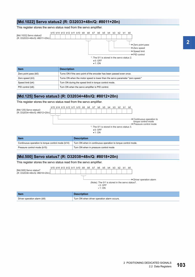
2
[Md.1022] Servo status2 (R: D32033+48n/Q: #8011+20n)This register stores the servo status read from the servo amplifier.
[Md.125] Servo status3 (R: D32034+48n/Q: #8012+20n)This register stores the servo status read from the servo amplifier.
[Md.500] Servo status7 (R: D32038+48n/Q: #8018+20n)This register stores the servo status read from the servo amplifier.
Item Description
Zero point pass (b0) Turns ON if the zero point of the encoder has been passed even once.
Zero speed (b3) Turns ON when the motor speed is lower than the servo parameter "zero speed."
Speed limit (b4) Turn ON during the speed limit in torque control mode.
PID control (b8) Turn ON when the servo amplifier is PID control.
Item Description
Continuous operation to torque control mode (b14) Turn ON when in continuous operation to torque control mode.
Pressure control mode (b15) Turn ON when in pressure control mode
Item Description
Driver operation alarm (b9) Turn ON when driver operation alarm occurs.
b14b15 b13 b12 b11 b10 b9 b8 b7 b6 b5 b4 b3 b2 b1 b0
Zero point passZero speedSpeed limitPID control
[Md.1022] Servo status2(R: D32033+48n/Q: #8011+20n)
*: The 0/1 is stored in the servo status 2.0: OFF1: ON
b14b15 b13 b12 b11 b10 b9 b8 b7 b6 b5 b4 b3 b2 b1 b0
Continuous operation to torque control mode
[Md.125] Servo status3(R: D32034+48n/Q: #8012+20n)
*: The 0/1 is stored in the servo status 3.0: OFF1: ON
Pressure control mode
b14b15 b13 b12 b11 b10 b9 b8 b7 b6 b5 b4 b3 b2 b1 b0
Driver operation alarm
[Md.500] Servo status7(R: D32038+48n/Q: #8018+20n)
(Note): The 0/1 is stored in the servo status7. 0: OFF 1: ON
2 POSITIONING DEDICATED SIGNALS2.2 Data Registers 103
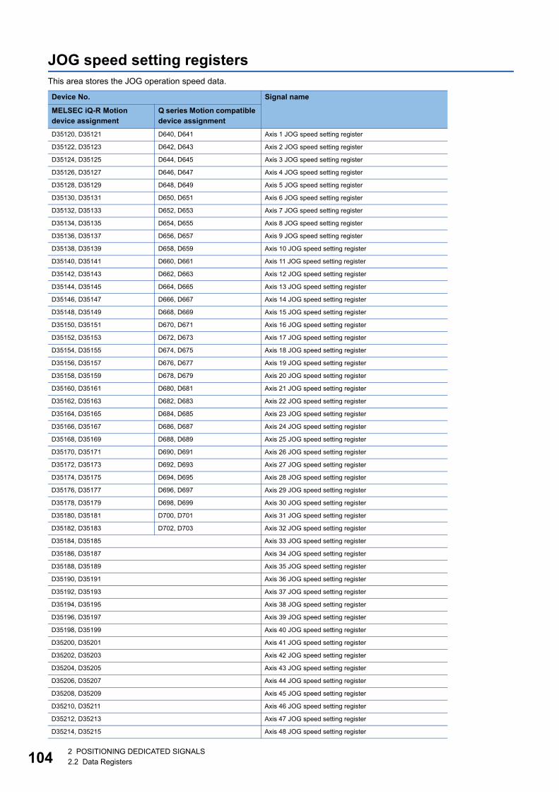
10
JOG speed setting registersThis area stores the JOG operation speed data.
Device No. Signal name
MELSEC iQ-R Motion device assignment
Q series Motion compatible device assignment
D35120, D35121 D640, D641 Axis 1 JOG speed setting register
D35122, D35123 D642, D643 Axis 2 JOG speed setting register
D35124, D35125 D644, D645 Axis 3 JOG speed setting register
D35126, D35127 D646, D647 Axis 4 JOG speed setting register
D35128, D35129 D648, D649 Axis 5 JOG speed setting register
D35130, D35131 D650, D651 Axis 6 JOG speed setting register
D35132, D35133 D652, D653 Axis 7 JOG speed setting register
D35134, D35135 D654, D655 Axis 8 JOG speed setting register
D35136, D35137 D656, D657 Axis 9 JOG speed setting register
D35138, D35139 D658, D659 Axis 10 JOG speed setting register
D35140, D35141 D660, D661 Axis 11 JOG speed setting register
D35142, D35143 D662, D663 Axis 12 JOG speed setting register
D35144, D35145 D664, D665 Axis 13 JOG speed setting register
D35146, D35147 D666, D667 Axis 14 JOG speed setting register
D35148, D35149 D668, D669 Axis 15 JOG speed setting register
D35150, D35151 D670, D671 Axis 16 JOG speed setting register
D35152, D35153 D672, D673 Axis 17 JOG speed setting register
D35154, D35155 D674, D675 Axis 18 JOG speed setting register
D35156, D35157 D676, D677 Axis 19 JOG speed setting register
D35158, D35159 D678, D679 Axis 20 JOG speed setting register
D35160, D35161 D680, D681 Axis 21 JOG speed setting register
D35162, D35163 D682, D683 Axis 22 JOG speed setting register
D35164, D35165 D684, D685 Axis 23 JOG speed setting register
D35166, D35167 D686, D687 Axis 24 JOG speed setting register
D35168, D35169 D688, D689 Axis 25 JOG speed setting register
D35170, D35171 D690, D691 Axis 26 JOG speed setting register
D35172, D35173 D692, D693 Axis 27 JOG speed setting register
D35174, D35175 D694, D695 Axis 28 JOG speed setting register
D35176, D35177 D696, D697 Axis 29 JOG speed setting register
D35178, D35179 D698, D699 Axis 30 JOG speed setting register
D35180, D35181 D700, D701 Axis 31 JOG speed setting register
D35182, D35183 D702, D703 Axis 32 JOG speed setting register
D35184, D35185 Axis 33 JOG speed setting register
D35186, D35187 Axis 34 JOG speed setting register
D35188, D35189 Axis 35 JOG speed setting register
D35190, D35191 Axis 36 JOG speed setting register
D35192, D35193 Axis 37 JOG speed setting register
D35194, D35195 Axis 38 JOG speed setting register
D35196, D35197 Axis 39 JOG speed setting register
D35198, D35199 Axis 40 JOG speed setting register
D35200, D35201 Axis 41 JOG speed setting register
D35202, D35203 Axis 42 JOG speed setting register
D35204, D35205 Axis 43 JOG speed setting register
D35206, D35207 Axis 44 JOG speed setting register
D35208, D35209 Axis 45 JOG speed setting register
D35210, D35211 Axis 46 JOG speed setting register
D35212, D35213 Axis 47 JOG speed setting register
D35214, D35215 Axis 48 JOG speed setting register
42 POSITIONING DEDICATED SIGNALS2.2 Data Registers
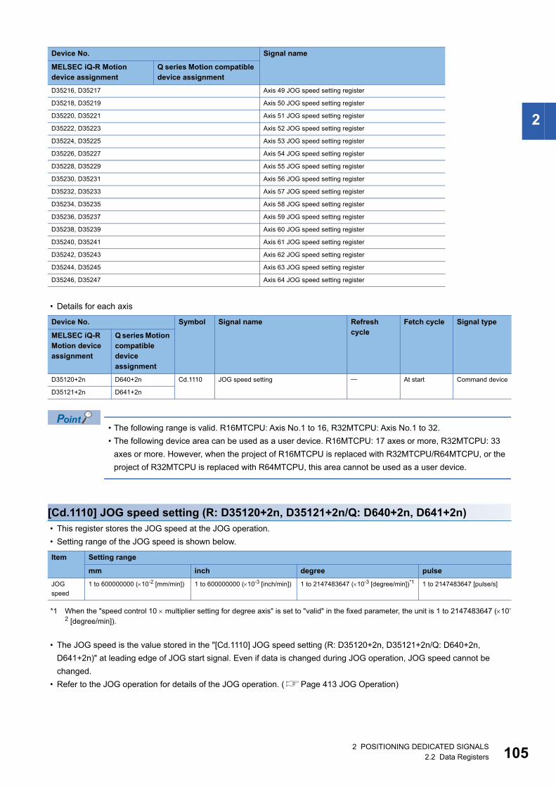
2
• Details for each axis
• The following range is valid. R16MTCPU: Axis No.1 to 16, R32MTCPU: Axis No.1 to 32.
• The following device area can be used as a user device. R16MTCPU: 17 axes or more, R32MTCPU: 33
axes or more. However, when the project of R16MTCPU is replaced with R32MTCPU/R64MTCPU, or the
project of R32MTCPU is replaced with R64MTCPU, this area cannot be used as a user device.
[Cd.1110] JOG speed setting (R: D35120+2n, D35121+2n/Q: D640+2n, D641+2n) • This register stores the JOG speed at the JOG operation.
• Setting range of the JOG speed is shown below.
*1 When the "speed control 10 multiplier setting for degree axis" is set to "valid" in the fixed parameter, the unit is 1 to 2147483647 (10-
2 [degree/min]).
• The JOG speed is the value stored in the "[Cd.1110] JOG speed setting (R: D35120+2n, D35121+2n/Q: D640+2n,
D641+2n)" at leading edge of JOG start signal. Even if data is changed during JOG operation, JOG speed cannot be
changed.
• Refer to the JOG operation for details of the JOG operation. (Page 413 JOG Operation)
D35216, D35217 Axis 49 JOG speed setting register
D35218, D35219 Axis 50 JOG speed setting register
D35220, D35221 Axis 51 JOG speed setting register
D35222, D35223 Axis 52 JOG speed setting register
D35224, D35225 Axis 53 JOG speed setting register
D35226, D35227 Axis 54 JOG speed setting register
D35228, D35229 Axis 55 JOG speed setting register
D35230, D35231 Axis 56 JOG speed setting register
D35232, D35233 Axis 57 JOG speed setting register
D35234, D35235 Axis 58 JOG speed setting register
D35236, D35237 Axis 59 JOG speed setting register
D35238, D35239 Axis 60 JOG speed setting register
D35240, D35241 Axis 61 JOG speed setting register
D35242, D35243 Axis 62 JOG speed setting register
D35244, D35245 Axis 63 JOG speed setting register
D35246, D35247 Axis 64 JOG speed setting register
Device No. Symbol Signal name Refresh cycle
Fetch cycle Signal type
MELSEC iQ-R Motion device assignment
Q series Motion compatible device assignment
D35120+2n D640+2n Cd.1110 JOG speed setting At start Command device
D35121+2n D641+2n
Item Setting range
mm inch degree pulse
JOG
speed
1 to 600000000 (10-2 [mm/min]) 1 to 600000000 (10-3 [inch/min]) 1 to 2147483647 (10-3 [degree/min])*1 1 to 2147483647 [pulse/s]
Device No. Signal name
MELSEC iQ-R Motion device assignment
Q series Motion compatible device assignment
2 POSITIONING DEDICATED SIGNALS2.2 Data Registers 105

10
Servo input axis monitor deviceDevice No. Signal name
MELSEC iQ-R Motion device assignment
Q series Motion compatible device assignment
D35440 to D35455 D12280 to D12289 Axis 1 servo input axis monitor device
D35456 to D35471 D12290 to D12299 Axis 2 servo input axis monitor device
D35472 to D35487 D12300 to D12309 Axis 3 servo input axis monitor device
D35488 to D35503 D12310 to D12319 Axis 4 servo input axis monitor device
D35504 to D35519 D12320 to D12329 Axis 5 servo input axis monitor device
D35520 to D35535 D12330 to D12339 Axis 6 servo input axis monitor device
D35536 to D35551 D12340 to D12349 Axis 7 servo input axis monitor device
D35552 to D35567 D12350 to D12359 Axis 8 servo input axis monitor device
D35568 to D35583 D12360 to D12369 Axis 9 servo input axis monitor device
D35584 to D35599 D12370 to D12379 Axis 10 servo input axis monitor device
D35600 to D35615 D12380 to D12389 Axis 11 servo input axis monitor device
D35616 to D35631 D12390 to D12399 Axis 12 servo input axis monitor device
D35632 to D35647 D12400 to D12409 Axis 13 servo input axis monitor device
D35648 to D35663 D12410 to D12419 Axis 14 servo input axis monitor device
D35664 to D35679 D12420 to D12429 Axis 15 servo input axis monitor device
D35680 to D35695 D12430 to D12439 Axis 16 servo input axis monitor device
D35696 to D35711 D12440 to D12449 Axis 17 servo input axis monitor device
D35712 to D35727 D12450 to D12459 Axis 18 servo input axis monitor device
D35728 to D35743 D12460 to D12469 Axis 19 servo input axis monitor device
D35744 to D35759 D12470 to D12479 Axis 20 servo input axis monitor device
D35760 to D35775 D12480 to D12489 Axis 21 servo input axis monitor device
D35776 to D35791 D12490 to D12499 Axis 22 servo input axis monitor device
D35792 to D35807 D12500 to D12509 Axis 23 servo input axis monitor device
D35808 to D35823 D12510 to D12519 Axis 24 servo input axis monitor device
D35824 to D35839 D12520 to D12529 Axis 25 servo input axis monitor device
D35840 to D35855 D12530 to D12539 Axis 26 servo input axis monitor device
D35856 to D35871 D12540 to D12549 Axis 27 servo input axis monitor device
D35872 to D35887 D12550 to D12559 Axis 28 servo input axis monitor device
D35888 to D35903 D12560 to D12569 Axis 29 servo input axis monitor device
D35904 to D35919 D12570 to D12579 Axis 30 servo input axis monitor device
D35920 to D35935 D12580 to D12589 Axis 31 servo input axis monitor device
D35936 to D35951 D12590 to D12599 Axis 32 servo input axis monitor device
D35952 to D35967 Axis 33 servo input axis monitor device
D35968 to D35983 Axis 34 servo input axis monitor device
D35984 to D35999 Axis 35 servo input axis monitor device
D36000 to D36015 Axis 36 servo input axis monitor device
D36016 to D36031 Axis 37 servo input axis monitor device
D36032 to D36047 Axis 38 servo input axis monitor device
D36048 to D36063 Axis 39 servo input axis monitor device
D36064 to D36079 Axis 40 servo input axis monitor device
D36080 to D36095 Axis 41 servo input axis monitor device
D36096 to D36111 Axis 42 servo input axis monitor device
D36112 to D36127 Axis 43 servo input axis monitor device
D36128 to D36143 Axis 44 servo input axis monitor device
D36144 to D36159 Axis 45 servo input axis monitor device
D36160 to D36175 Axis 46 servo input axis monitor device
D36176 to D36191 Axis 47 servo input axis monitor device
D36192 to D36207 Axis 48 servo input axis monitor device
D36208 to D36223 Axis 49 servo input axis monitor device
62 POSITIONING DEDICATED SIGNALS2.2 Data Registers
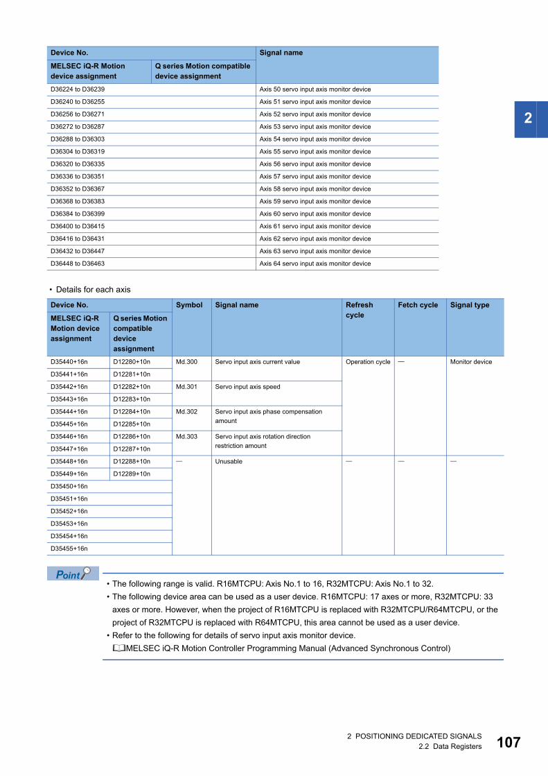
2
• Details for each axis
• The following range is valid. R16MTCPU: Axis No.1 to 16, R32MTCPU: Axis No.1 to 32.
• The following device area can be used as a user device. R16MTCPU: 17 axes or more, R32MTCPU: 33
axes or more. However, when the project of R16MTCPU is replaced with R32MTCPU/R64MTCPU, or the
project of R32MTCPU is replaced with R64MTCPU, this area cannot be used as a user device.
• Refer to the following for details of servo input axis monitor device.
MELSEC iQ-R Motion Controller Programming Manual (Advanced Synchronous Control)
D36224 to D36239 Axis 50 servo input axis monitor device
D36240 to D36255 Axis 51 servo input axis monitor device
D36256 to D36271 Axis 52 servo input axis monitor device
D36272 to D36287 Axis 53 servo input axis monitor device
D36288 to D36303 Axis 54 servo input axis monitor device
D36304 to D36319 Axis 55 servo input axis monitor device
D36320 to D36335 Axis 56 servo input axis monitor device
D36336 to D36351 Axis 57 servo input axis monitor device
D36352 to D36367 Axis 58 servo input axis monitor device
D36368 to D36383 Axis 59 servo input axis monitor device
D36384 to D36399 Axis 60 servo input axis monitor device
D36400 to D36415 Axis 61 servo input axis monitor device
D36416 to D36431 Axis 62 servo input axis monitor device
D36432 to D36447 Axis 63 servo input axis monitor device
D36448 to D36463 Axis 64 servo input axis monitor device
Device No. Symbol Signal name Refresh cycle
Fetch cycle Signal type
MELSEC iQ-R Motion device assignment
Q series Motion compatible device assignment
D35440+16n D12280+10n Md.300 Servo input axis current value Operation cycle Monitor device
D35441+16n D12281+10n
D35442+16n D12282+10n Md.301 Servo input axis speed
D35443+16n D12283+10n
D35444+16n D12284+10n Md.302 Servo input axis phase compensation
amountD35445+16n D12285+10n
D35446+16n D12286+10n Md.303 Servo input axis rotation direction
restriction amountD35447+16n D12287+10n
D35448+16n D12288+10n Unusable
D35449+16n D12289+10n
D35450+16n
D35451+16n
D35452+16n
D35453+16n
D35454+16n
D35455+16n
Device No. Signal name
MELSEC iQ-R Motion device assignment
Q series Motion compatible device assignment
2 POSITIONING DEDICATED SIGNALS2.2 Data Registers 107

10
Servo input axis control deviceDevice No. Signal name
MELSEC iQ-R Motion device assignment
Q series Motion compatible device assignment
D41200 to D41207 D14600, D14601 Axis 1 servo input axis control device
D41208 to D41215 D14602, D14603 Axis 2 servo input axis control device
D41216 to D41223 D14604, D14605 Axis 3 servo input axis control device
D41224 to D41231 D14606, D14607 Axis 4 servo input axis control device
D41232 to D41239 D14608, D14609 Axis 5 servo input axis control device
D41240 to D41247 D14610, D14611 Axis 6 servo input axis control device
D41248 to D41255 D14612, D14613 Axis 7 servo input axis control device
D41256 to D41263 D14614, D14615 Axis 8 servo input axis control device
D41264 to D41271 D14616, D14617 Axis 9 servo input axis control device
D41272 to D41279 D14618, D14619 Axis 10 servo input axis control device
D41280 to D41287 D14620, D14621 Axis 11 servo input axis control device
D41288 to D41295 D14622, D14623 Axis 12 servo input axis control device
D41296 to D41303 D14624, D14625 Axis 13 servo input axis control device
D41304 to D41311 D14626, D14627 Axis 14 servo input axis control device
D41312 to D41319 D14628, D14629 Axis 15 servo input axis control device
D41320 to D41327 D14630, D14631 Axis 16 servo input axis control device
D41328 to D41335 D14632, D14633 Axis 17 servo input axis control device
D41336 to D41343 D14634, D14635 Axis 18 servo input axis control device
D41344 to D41351 D14636, D14637 Axis 19 servo input axis control device
D41352 to D41359 D14638, D14639 Axis 20 servo input axis control device
D41360 to D41367 D14640, D14641 Axis 21 servo input axis control device
D41368 to D41375 D14642, D14643 Axis 22 servo input axis control device
D41376 to D41383 D14644, D14645 Axis 23 servo input axis control device
D41384 to D41391 D14646, D14647 Axis 24 servo input axis control device
D41392 to D41399 D14648, D14649 Axis 25 servo input axis control device
D41400 to D41407 D14650, D14651 Axis 26 servo input axis control device
D41408 to D41415 D14652, D14653 Axis 27 servo input axis control device
D41416 to D41423 D14654, D14655 Axis 28 servo input axis control device
D41424 to D41431 D14656, D14657 Axis 29 servo input axis control device
D41432 to D41439 D14658, D14659 Axis 30 servo input axis control device
D41440 to D41447 D14660, D14661 Axis 31 servo input axis control device
D41448 to D41455 D14662, D14663 Axis 32 servo input axis control device
D41456 to D41463 Axis 33 servo input axis control device
D41464 to D41471 Axis 34 servo input axis control device
D41472 to D41479 Axis 35 servo input axis control device
D41480 to D41487 Axis 36 servo input axis control device
D41488 to D41495 Axis 37 servo input axis control device
D41496 to D41503 Axis 38 servo input axis control device
D41504 to D41511 Axis 39 servo input axis control device
D41512 to D41519 Axis 40 servo input axis control device
D41520 to D41527 Axis 41 servo input axis control device
D41528 to D41535 Axis 42 servo input axis control device
D41536 to D41543 Axis 43 servo input axis control device
D41544 to D41551 Axis 44 servo input axis control device
D41552 to D41559 Axis 45 servo input axis control device
D41560 to D41567 Axis 46 servo input axis control device
D41568 to D41575 Axis 47 servo input axis control device
D41576 to D41583 Axis 48 servo input axis control device
D41584 to D41591 Axis 49 servo input axis control device
82 POSITIONING DEDICATED SIGNALS2.2 Data Registers
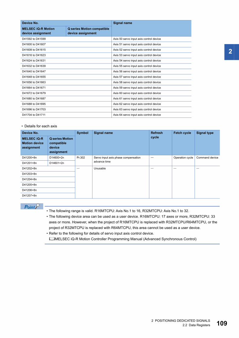
2
• Details for each axis
• The following range is valid. R16MTCPU: Axis No.1 to 16, R32MTCPU: Axis No.1 to 32.
• The following device area can be used as a user device. R16MTCPU: 17 axes or more, R32MTCPU: 33
axes or more. However, when the project of R16MTCPU is replaced with R32MTCPU/R64MTCPU, or the
project of R32MTCPU is replaced with R64MTCPU, this area cannot be used as a user device.
• Refer to the following for details of servo input axis control device.
MELSEC iQ-R Motion Controller Programming Manual (Advanced Synchronous Control)
D41592 to D41599 Axis 50 servo input axis control device
D41600 to D41607 Axis 51 servo input axis control device
D41608 to D41615 Axis 52 servo input axis control device
D41616 to D41623 Axis 53 servo input axis control device
D41624 to D41631 Axis 54 servo input axis control device
D41632 to D41639 Axis 55 servo input axis control device
D41640 to D41647 Axis 56 servo input axis control device
D41648 to D41655 Axis 57 servo input axis control device
D41656 to D41663 Axis 58 servo input axis control device
D41664 to D41671 Axis 59 servo input axis control device
D41672 to D41679 Axis 60 servo input axis control device
D41680 to D41687 Axis 61 servo input axis control device
D41688 to D41695 Axis 62 servo input axis control device
D41696 to D41703 Axis 63 servo input axis control device
D41704 to D41711 Axis 64 servo input axis control device
Device No. Symbol Signal name Refresh cycle
Fetch cycle Signal type
MELSEC iQ-R Motion device assignment
Q series Motion compatible device assignment
D41200+8n D14600+2n Pr.302 Servo input axis phase compensation
advance time
Operation cycle Command device
D41201+8n D14601+2n
D41202+8n Unusable
D41203+8n
D41204+8n
D41205+8n
D41206+8n
D41207+8n
Device No. Signal name
MELSEC iQ-R Motion device assignment
Q series Motion compatible device assignment
2 POSITIONING DEDICATED SIGNALS2.2 Data Registers 109
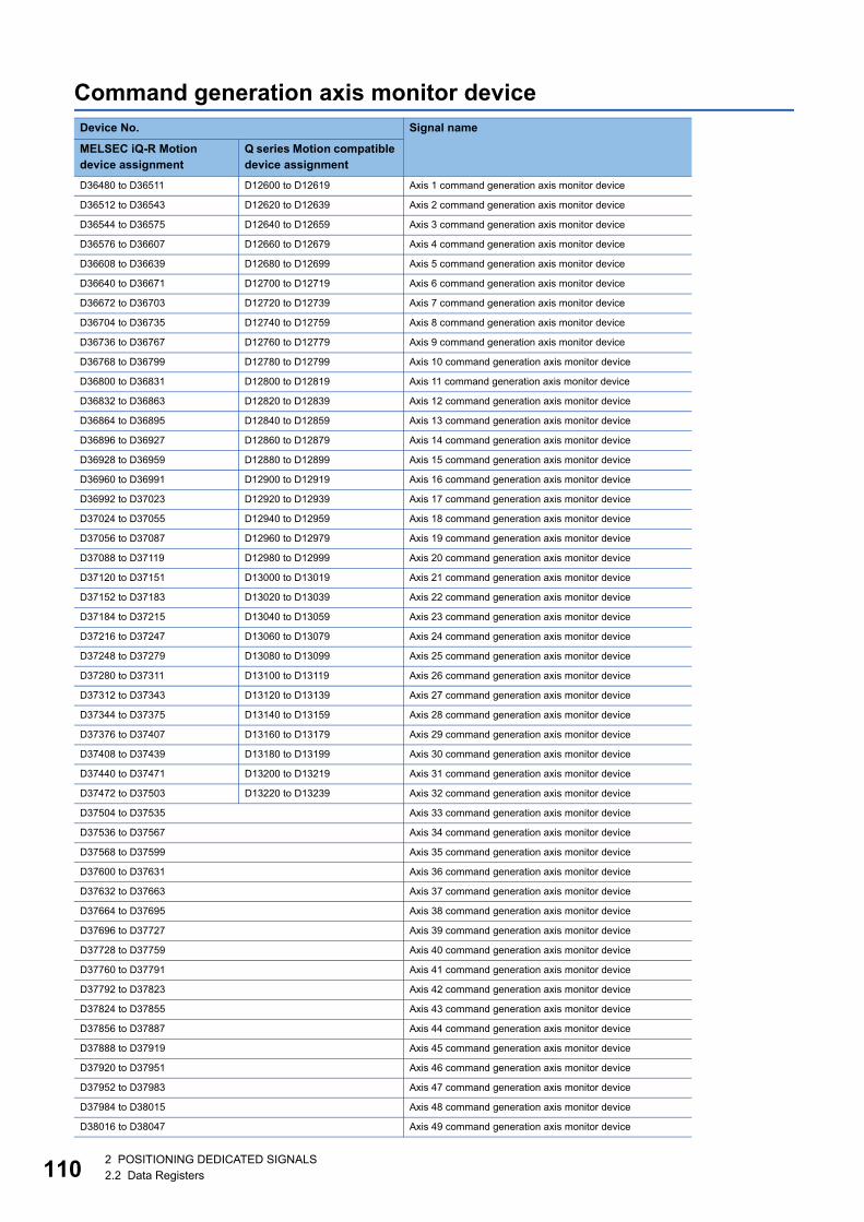
11
Command generation axis monitor deviceDevice No. Signal name
MELSEC iQ-R Motion device assignment
Q series Motion compatible device assignment
D36480 to D36511 D12600 to D12619 Axis 1 command generation axis monitor device
D36512 to D36543 D12620 to D12639 Axis 2 command generation axis monitor device
D36544 to D36575 D12640 to D12659 Axis 3 command generation axis monitor device
D36576 to D36607 D12660 to D12679 Axis 4 command generation axis monitor device
D36608 to D36639 D12680 to D12699 Axis 5 command generation axis monitor device
D36640 to D36671 D12700 to D12719 Axis 6 command generation axis monitor device
D36672 to D36703 D12720 to D12739 Axis 7 command generation axis monitor device
D36704 to D36735 D12740 to D12759 Axis 8 command generation axis monitor device
D36736 to D36767 D12760 to D12779 Axis 9 command generation axis monitor device
D36768 to D36799 D12780 to D12799 Axis 10 command generation axis monitor device
D36800 to D36831 D12800 to D12819 Axis 11 command generation axis monitor device
D36832 to D36863 D12820 to D12839 Axis 12 command generation axis monitor device
D36864 to D36895 D12840 to D12859 Axis 13 command generation axis monitor device
D36896 to D36927 D12860 to D12879 Axis 14 command generation axis monitor device
D36928 to D36959 D12880 to D12899 Axis 15 command generation axis monitor device
D36960 to D36991 D12900 to D12919 Axis 16 command generation axis monitor device
D36992 to D37023 D12920 to D12939 Axis 17 command generation axis monitor device
D37024 to D37055 D12940 to D12959 Axis 18 command generation axis monitor device
D37056 to D37087 D12960 to D12979 Axis 19 command generation axis monitor device
D37088 to D37119 D12980 to D12999 Axis 20 command generation axis monitor device
D37120 to D37151 D13000 to D13019 Axis 21 command generation axis monitor device
D37152 to D37183 D13020 to D13039 Axis 22 command generation axis monitor device
D37184 to D37215 D13040 to D13059 Axis 23 command generation axis monitor device
D37216 to D37247 D13060 to D13079 Axis 24 command generation axis monitor device
D37248 to D37279 D13080 to D13099 Axis 25 command generation axis monitor device
D37280 to D37311 D13100 to D13119 Axis 26 command generation axis monitor device
D37312 to D37343 D13120 to D13139 Axis 27 command generation axis monitor device
D37344 to D37375 D13140 to D13159 Axis 28 command generation axis monitor device
D37376 to D37407 D13160 to D13179 Axis 29 command generation axis monitor device
D37408 to D37439 D13180 to D13199 Axis 30 command generation axis monitor device
D37440 to D37471 D13200 to D13219 Axis 31 command generation axis monitor device
D37472 to D37503 D13220 to D13239 Axis 32 command generation axis monitor device
D37504 to D37535 Axis 33 command generation axis monitor device
D37536 to D37567 Axis 34 command generation axis monitor device
D37568 to D37599 Axis 35 command generation axis monitor device
D37600 to D37631 Axis 36 command generation axis monitor device
D37632 to D37663 Axis 37 command generation axis monitor device
D37664 to D37695 Axis 38 command generation axis monitor device
D37696 to D37727 Axis 39 command generation axis monitor device
D37728 to D37759 Axis 40 command generation axis monitor device
D37760 to D37791 Axis 41 command generation axis monitor device
D37792 to D37823 Axis 42 command generation axis monitor device
D37824 to D37855 Axis 43 command generation axis monitor device
D37856 to D37887 Axis 44 command generation axis monitor device
D37888 to D37919 Axis 45 command generation axis monitor device
D37920 to D37951 Axis 46 command generation axis monitor device
D37952 to D37983 Axis 47 command generation axis monitor device
D37984 to D38015 Axis 48 command generation axis monitor device
D38016 to D38047 Axis 49 command generation axis monitor device
02 POSITIONING DEDICATED SIGNALS2.2 Data Registers
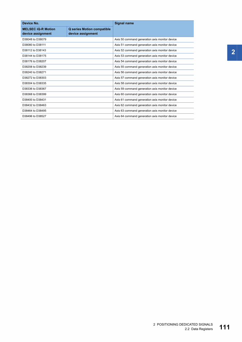
2
D38048 to D38079 Axis 50 command generation axis monitor device
D38080 to D38111 Axis 51 command generation axis monitor device
D38112 to D38143 Axis 52 command generation axis monitor device
D38144 to D38175 Axis 53 command generation axis monitor device
D38176 to D38207 Axis 54 command generation axis monitor device
D38208 to D38239 Axis 55 command generation axis monitor device
D38240 to D38271 Axis 56 command generation axis monitor device
D38272 to D38303 Axis 57 command generation axis monitor device
D38304 to D38335 Axis 58 command generation axis monitor device
D38336 to D38367 Axis 59 command generation axis monitor device
D38368 to D38399 Axis 60 command generation axis monitor device
D38400 to D38431 Axis 61 command generation axis monitor device
D38432 to D38463 Axis 62 command generation axis monitor device
D38464 to D38495 Axis 63 command generation axis monitor device
D38496 to D38527 Axis 64 command generation axis monitor device
Device No. Signal name
MELSEC iQ-R Motion device assignment
Q series Motion compatible device assignment
2 POSITIONING DEDICATED SIGNALS2.2 Data Registers 111
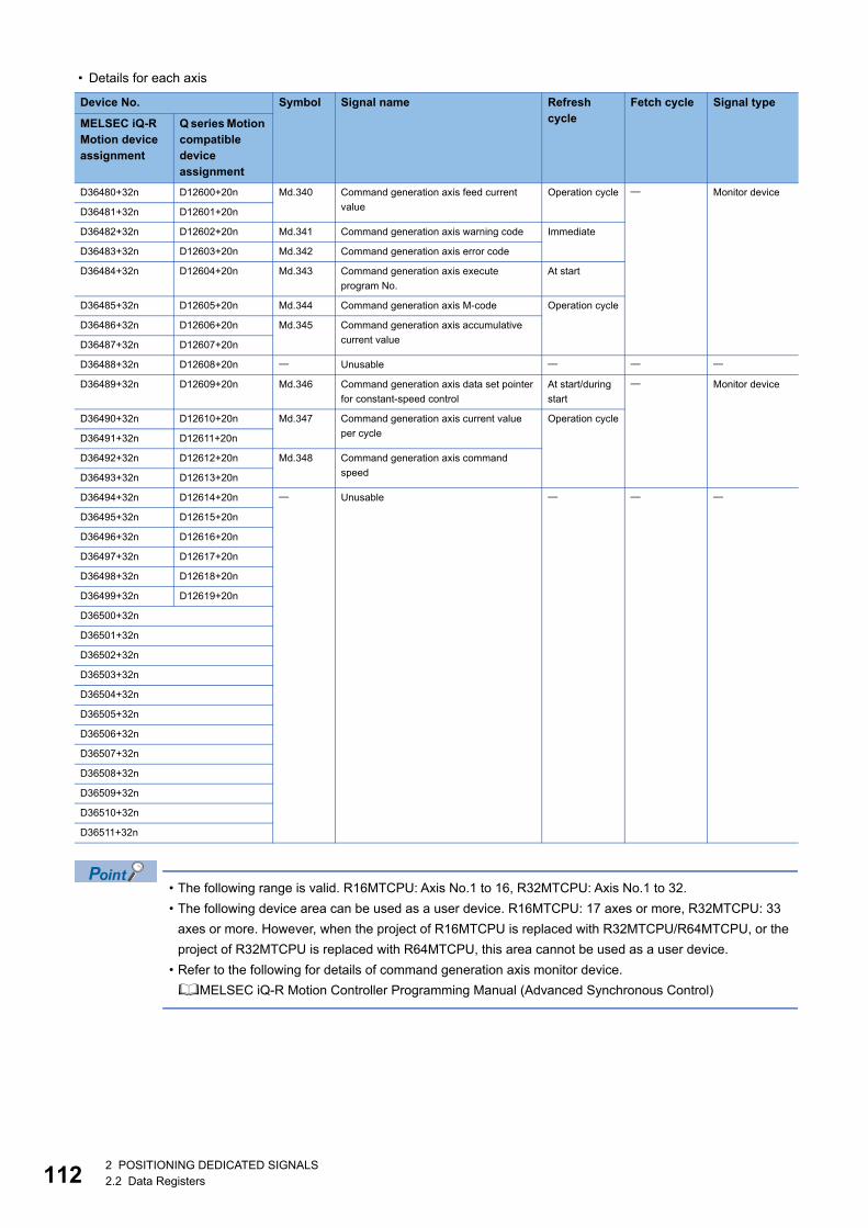
11
• Details for each axis
• The following range is valid. R16MTCPU: Axis No.1 to 16, R32MTCPU: Axis No.1 to 32.
• The following device area can be used as a user device. R16MTCPU: 17 axes or more, R32MTCPU: 33
axes or more. However, when the project of R16MTCPU is replaced with R32MTCPU/R64MTCPU, or the
project of R32MTCPU is replaced with R64MTCPU, this area cannot be used as a user device.
• Refer to the following for details of command generation axis monitor device.
MELSEC iQ-R Motion Controller Programming Manual (Advanced Synchronous Control)
Device No. Symbol Signal name Refresh cycle
Fetch cycle Signal type
MELSEC iQ-R Motion device assignment
Q series Motion compatible device assignment
D36480+32n D12600+20n Md.340 Command generation axis feed current
value
Operation cycle Monitor device
D36481+32n D12601+20n
D36482+32n D12602+20n Md.341 Command generation axis warning code Immediate
D36483+32n D12603+20n Md.342 Command generation axis error code
D36484+32n D12604+20n Md.343 Command generation axis execute
program No.
At start
D36485+32n D12605+20n Md.344 Command generation axis M-code Operation cycle
D36486+32n D12606+20n Md.345 Command generation axis accumulative
current valueD36487+32n D12607+20n
D36488+32n D12608+20n Unusable
D36489+32n D12609+20n Md.346 Command generation axis data set pointer
for constant-speed control
At start/during
start
Monitor device
D36490+32n D12610+20n Md.347 Command generation axis current value
per cycle
Operation cycle
D36491+32n D12611+20n
D36492+32n D12612+20n Md.348 Command generation axis command
speedD36493+32n D12613+20n
D36494+32n D12614+20n Unusable
D36495+32n D12615+20n
D36496+32n D12616+20n
D36497+32n D12617+20n
D36498+32n D12618+20n
D36499+32n D12619+20n
D36500+32n
D36501+32n
D36502+32n
D36503+32n
D36504+32n
D36505+32n
D36506+32n
D36507+32n
D36508+32n
D36509+32n
D36510+32n
D36511+32n
22 POSITIONING DEDICATED SIGNALS2.2 Data Registers
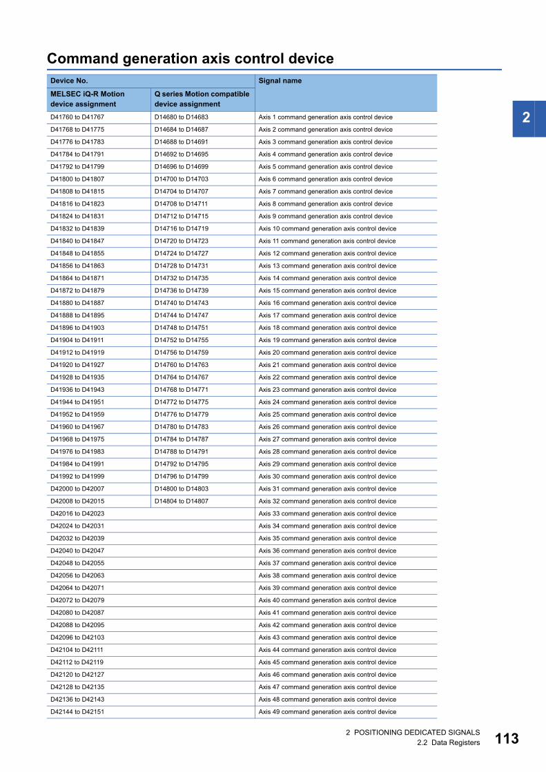
2
Command generation axis control deviceDevice No. Signal name
MELSEC iQ-R Motion device assignment
Q series Motion compatible device assignment
D41760 to D41767 D14680 to D14683 Axis 1 command generation axis control device
D41768 to D41775 D14684 to D14687 Axis 2 command generation axis control device
D41776 to D41783 D14688 to D14691 Axis 3 command generation axis control device
D41784 to D41791 D14692 to D14695 Axis 4 command generation axis control device
D41792 to D41799 D14696 to D14699 Axis 5 command generation axis control device
D41800 to D41807 D14700 to D14703 Axis 6 command generation axis control device
D41808 to D41815 D14704 to D14707 Axis 7 command generation axis control device
D41816 to D41823 D14708 to D14711 Axis 8 command generation axis control device
D41824 to D41831 D14712 to D14715 Axis 9 command generation axis control device
D41832 to D41839 D14716 to D14719 Axis 10 command generation axis control device
D41840 to D41847 D14720 to D14723 Axis 11 command generation axis control device
D41848 to D41855 D14724 to D14727 Axis 12 command generation axis control device
D41856 to D41863 D14728 to D14731 Axis 13 command generation axis control device
D41864 to D41871 D14732 to D14735 Axis 14 command generation axis control device
D41872 to D41879 D14736 to D14739 Axis 15 command generation axis control device
D41880 to D41887 D14740 to D14743 Axis 16 command generation axis control device
D41888 to D41895 D14744 to D14747 Axis 17 command generation axis control device
D41896 to D41903 D14748 to D14751 Axis 18 command generation axis control device
D41904 to D41911 D14752 to D14755 Axis 19 command generation axis control device
D41912 to D41919 D14756 to D14759 Axis 20 command generation axis control device
D41920 to D41927 D14760 to D14763 Axis 21 command generation axis control device
D41928 to D41935 D14764 to D14767 Axis 22 command generation axis control device
D41936 to D41943 D14768 to D14771 Axis 23 command generation axis control device
D41944 to D41951 D14772 to D14775 Axis 24 command generation axis control device
D41952 to D41959 D14776 to D14779 Axis 25 command generation axis control device
D41960 to D41967 D14780 to D14783 Axis 26 command generation axis control device
D41968 to D41975 D14784 to D14787 Axis 27 command generation axis control device
D41976 to D41983 D14788 to D14791 Axis 28 command generation axis control device
D41984 to D41991 D14792 to D14795 Axis 29 command generation axis control device
D41992 to D41999 D14796 to D14799 Axis 30 command generation axis control device
D42000 to D42007 D14800 to D14803 Axis 31 command generation axis control device
D42008 to D42015 D14804 to D14807 Axis 32 command generation axis control device
D42016 to D42023 Axis 33 command generation axis control device
D42024 to D42031 Axis 34 command generation axis control device
D42032 to D42039 Axis 35 command generation axis control device
D42040 to D42047 Axis 36 command generation axis control device
D42048 to D42055 Axis 37 command generation axis control device
D42056 to D42063 Axis 38 command generation axis control device
D42064 to D42071 Axis 39 command generation axis control device
D42072 to D42079 Axis 40 command generation axis control device
D42080 to D42087 Axis 41 command generation axis control device
D42088 to D42095 Axis 42 command generation axis control device
D42096 to D42103 Axis 43 command generation axis control device
D42104 to D42111 Axis 44 command generation axis control device
D42112 to D42119 Axis 45 command generation axis control device
D42120 to D42127 Axis 46 command generation axis control device
D42128 to D42135 Axis 47 command generation axis control device
D42136 to D42143 Axis 48 command generation axis control device
D42144 to D42151 Axis 49 command generation axis control device
2 POSITIONING DEDICATED SIGNALS2.2 Data Registers 113
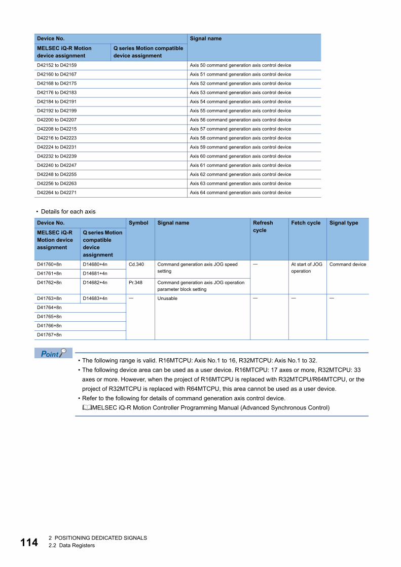
11
• Details for each axis
• The following range is valid. R16MTCPU: Axis No.1 to 16, R32MTCPU: Axis No.1 to 32.
• The following device area can be used as a user device. R16MTCPU: 17 axes or more, R32MTCPU: 33
axes or more. However, when the project of R16MTCPU is replaced with R32MTCPU/R64MTCPU, or the
project of R32MTCPU is replaced with R64MTCPU, this area cannot be used as a user device.
• Refer to the following for details of command generation axis control device.
MELSEC iQ-R Motion Controller Programming Manual (Advanced Synchronous Control)
D42152 to D42159 Axis 50 command generation axis control device
D42160 to D42167 Axis 51 command generation axis control device
D42168 to D42175 Axis 52 command generation axis control device
D42176 to D42183 Axis 53 command generation axis control device
D42184 to D42191 Axis 54 command generation axis control device
D42192 to D42199 Axis 55 command generation axis control device
D42200 to D42207 Axis 56 command generation axis control device
D42208 to D42215 Axis 57 command generation axis control device
D42216 to D42223 Axis 58 command generation axis control device
D42224 to D42231 Axis 59 command generation axis control device
D42232 to D42239 Axis 60 command generation axis control device
D42240 to D42247 Axis 61 command generation axis control device
D42248 to D42255 Axis 62 command generation axis control device
D42256 to D42263 Axis 63 command generation axis control device
D42264 to D42271 Axis 64 command generation axis control device
Device No. Symbol Signal name Refresh cycle
Fetch cycle Signal type
MELSEC iQ-R Motion device assignment
Q series Motion compatible device assignment
D41760+8n D14680+4n Cd.340 Command generation axis JOG speed
setting
At start of JOG
operation
Command device
D41761+8n D14681+4n
D41762+8n D14682+4n Pr.348 Command generation axis JOG operation
parameter block setting
D41763+8n D14683+4n Unusable
D41764+8n
D41765+8n
D41766+8n
D41767+8n
Device No. Signal name
MELSEC iQ-R Motion device assignment
Q series Motion compatible device assignment
42 POSITIONING DEDICATED SIGNALS2.2 Data Registers
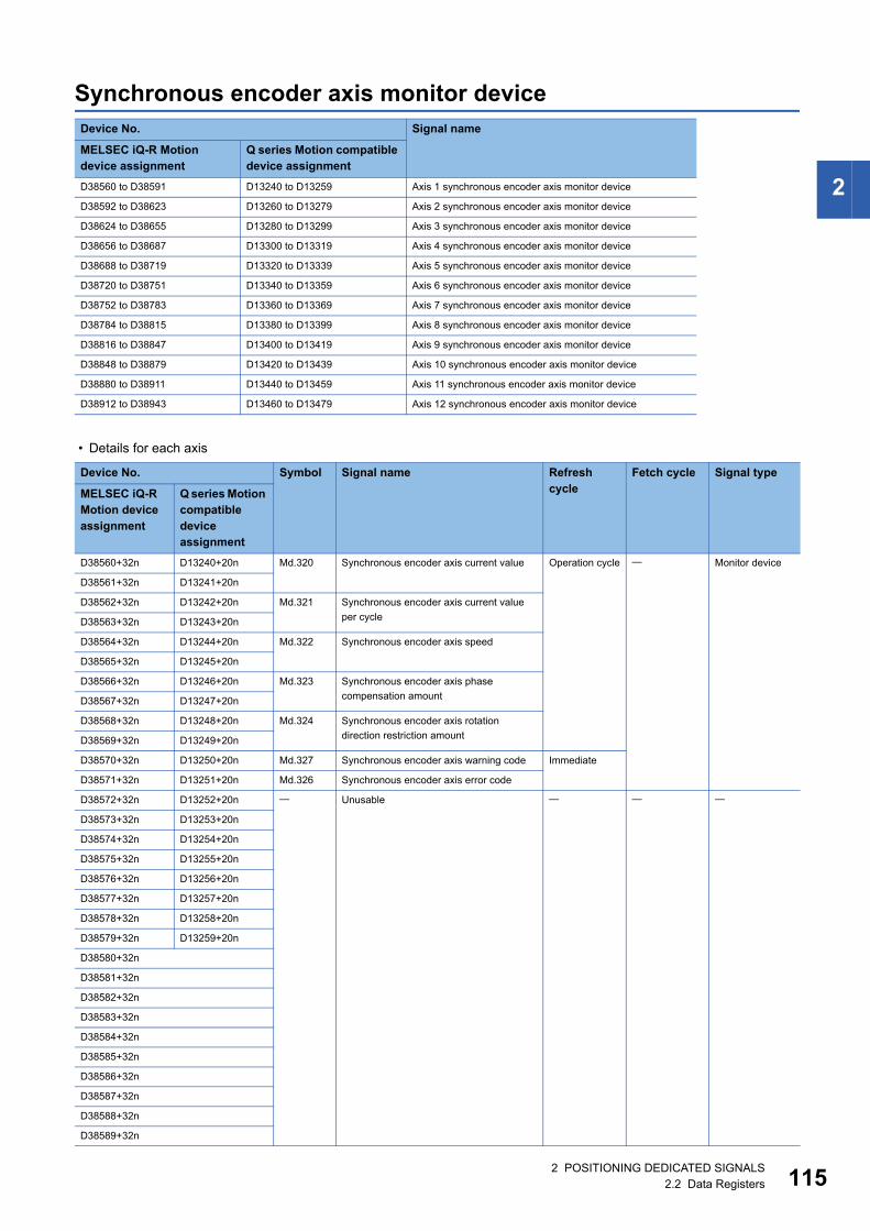
2
Synchronous encoder axis monitor device
• Details for each axis
Device No. Signal name
MELSEC iQ-R Motion device assignment
Q series Motion compatible device assignment
D38560 to D38591 D13240 to D13259 Axis 1 synchronous encoder axis monitor device
D38592 to D38623 D13260 to D13279 Axis 2 synchronous encoder axis monitor device
D38624 to D38655 D13280 to D13299 Axis 3 synchronous encoder axis monitor device
D38656 to D38687 D13300 to D13319 Axis 4 synchronous encoder axis monitor device
D38688 to D38719 D13320 to D13339 Axis 5 synchronous encoder axis monitor device
D38720 to D38751 D13340 to D13359 Axis 6 synchronous encoder axis monitor device
D38752 to D38783 D13360 to D13369 Axis 7 synchronous encoder axis monitor device
D38784 to D38815 D13380 to D13399 Axis 8 synchronous encoder axis monitor device
D38816 to D38847 D13400 to D13419 Axis 9 synchronous encoder axis monitor device
D38848 to D38879 D13420 to D13439 Axis 10 synchronous encoder axis monitor device
D38880 to D38911 D13440 to D13459 Axis 11 synchronous encoder axis monitor device
D38912 to D38943 D13460 to D13479 Axis 12 synchronous encoder axis monitor device
Device No. Symbol Signal name Refresh cycle
Fetch cycle Signal type
MELSEC iQ-R Motion device assignment
Q series Motion compatible device assignment
D38560+32n D13240+20n Md.320 Synchronous encoder axis current value Operation cycle Monitor device
D38561+32n D13241+20n
D38562+32n D13242+20n Md.321 Synchronous encoder axis current value
per cycleD38563+32n D13243+20n
D38564+32n D13244+20n Md.322 Synchronous encoder axis speed
D38565+32n D13245+20n
D38566+32n D13246+20n Md.323 Synchronous encoder axis phase
compensation amountD38567+32n D13247+20n
D38568+32n D13248+20n Md.324 Synchronous encoder axis rotation
direction restriction amountD38569+32n D13249+20n
D38570+32n D13250+20n Md.327 Synchronous encoder axis warning code Immediate
D38571+32n D13251+20n Md.326 Synchronous encoder axis error code
D38572+32n D13252+20n Unusable
D38573+32n D13253+20n
D38574+32n D13254+20n
D38575+32n D13255+20n
D38576+32n D13256+20n
D38577+32n D13257+20n
D38578+32n D13258+20n
D38579+32n D13259+20n
D38580+32n
D38581+32n
D38582+32n
D38583+32n
D38584+32n
D38585+32n
D38586+32n
D38587+32n
D38588+32n
D38589+32n
2 POSITIONING DEDICATED SIGNALS2.2 Data Registers 115
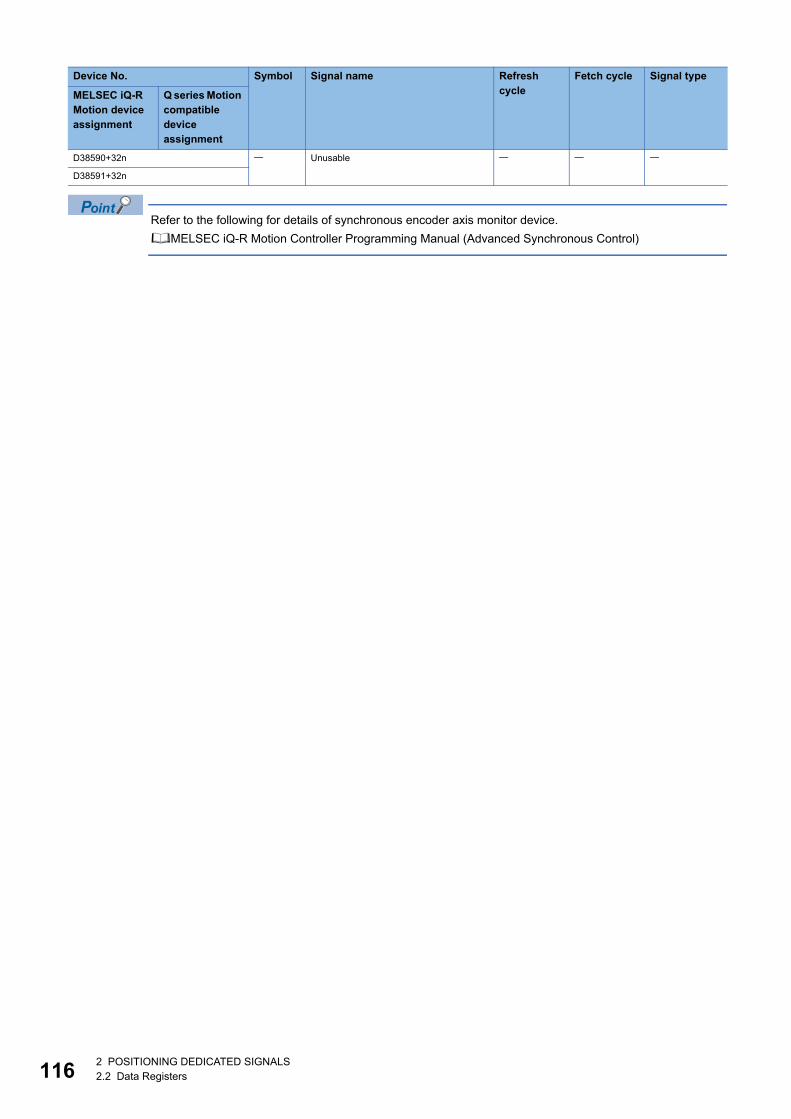
11
Refer to the following for details of synchronous encoder axis monitor device.
MELSEC iQ-R Motion Controller Programming Manual (Advanced Synchronous Control)
D38590+32n Unusable
D38591+32n
Device No. Symbol Signal name Refresh cycle
Fetch cycle Signal type
MELSEC iQ-R Motion device assignment
Q series Motion compatible device assignment
62 POSITIONING DEDICATED SIGNALS2.2 Data Registers
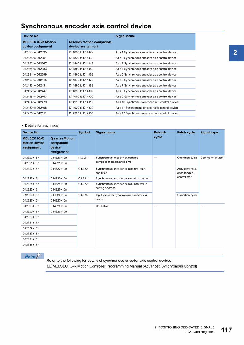
2
Synchronous encoder axis control device
• Details for each axis
Refer to the following for details of synchronous encoder axis control device.
MELSEC iQ-R Motion Controller Programming Manual (Advanced Synchronous Control)
Device No. Signal name
MELSEC iQ-R Motion device assignment
Q series Motion compatible device assignment
D42320 to D42335 D14820 to D14829 Axis 1 Synchronous encoder axis control device
D42336 to D42351 D14830 to D14839 Axis 2 Synchronous encoder axis control device
D42352 to D42367 D14840 to D14849 Axis 3 Synchronous encoder axis control device
D42368 to D42383 D14850 to D14859 Axis 4 Synchronous encoder axis control device
D42384 to D42399 D14860 to D14869 Axis 5 Synchronous encoder axis control device
D42400 to D42415 D14870 to D14879 Axis 6 Synchronous encoder axis control device
D42416 to D42431 D14880 to D14889 Axis 7 Synchronous encoder axis control device
D42432 to D42447 D14890 to D14899 Axis 8 Synchronous encoder axis control device
D42448 to D42463 D14900 to D14909 Axis 9 Synchronous encoder axis control device
D42464 to D42479 D14910 to D14919 Axis 10 Synchronous encoder axis control device
D42480 to D42495 D14920 to D14929 Axis 11 Synchronous encoder axis control device
D42496 to D42511 D14930 to D14939 Axis 12 Synchronous encoder axis control device
Device No. Symbol Signal name Refresh cycle
Fetch cycle Signal type
MELSEC iQ-R Motion device assignment
Q series Motion compatible device assignment
D42320+16n D14820+10n Pr.326 Synchronous encoder axis phase
compensation advance time
Operation cycle Command device
D42321+16n D14821+10n
D42322+16n D14822+10n Cd.320 Synchronous encoder axis control start
condition
At synchronous
encoder axis
control startD42323+16n D14823+10n Cd.321 Synchronous encoder axis control method
D42324+16n D14824+10n Cd.322 Synchronous encoder axis current value
setting addressD42325+16n D14825+10n
D42326+16n D14826+10n Cd.325 Input value for synchronous encoder via
device
Operation cycle
D42327+16n D14827+10n
D42328+16n D14828+10n Unusable
D42329+16n D14829+10n
D42330+16n
D42331+16n
D42332+16n
D42333+16n
D42334+16n
D42335+16n
2 POSITIONING DEDICATED SIGNALS2.2 Data Registers 117
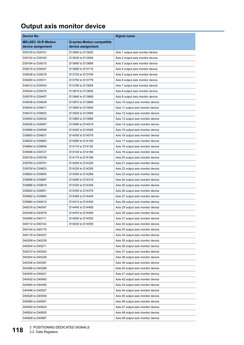
11
Output axis monitor deviceDevice No. Signal name
MELSEC iQ-R Motion device assignment
Q series Motion compatible device assignment
D39120 to D39151 D13600 to D13629 Axis 1 output axis monitor device
D39152 to D39183 D13630 to D13659 Axis 2 output axis monitor device
D39184 to D39215 D13660 to D13689 Axis 3 output axis monitor device
D39216 to D39247 D13690 to D13719 Axis 4 output axis monitor device
D39248 to D39279 D13720 to D13749 Axis 5 output axis monitor device
D39280 to D39311 D13750 to D13779 Axis 6 output axis monitor device
D39312 to D39343 D13780 to D13809 Axis 7 output axis monitor device
D39344 to D39375 D13810 to D13839 Axis 8 output axis monitor device
D39376 to D39407 D13840 to D13869 Axis 9 output axis monitor device
D39408 to D39439 D13870 to D13899 Axis 10 output axis monitor device
D39440 to D39471 D13900 to D13929 Axis 11 output axis monitor device
D39472 to D39503 D13930 to D13959 Axis 12 output axis monitor device
D39504 to D39535 D13960 to D13989 Axis 13 output axis monitor device
D39536 to D39567 D13990 to D14019 Axis 14 output axis monitor device
D39568 to D39599 D14020 to D14049 Axis 15 output axis monitor device
D39600 to D39631 D14050 to D14079 Axis 16 output axis monitor device
D39632 to D39663 D14080 to D14109 Axis 17 output axis monitor device
D39664 to D39695 D14110 to D14139 Axis 18 output axis monitor device
D39696 to D39727 D14140 to D14169 Axis 19 output axis monitor device
D39728 to D39759 D14170 to D14199 Axis 20 output axis monitor device
D39760 to D39791 D14200 to D14229 Axis 21 output axis monitor device
D39792 to D39823 D14230 to D14259 Axis 22 output axis monitor device
D39824 to D39855 D14260 to D14289 Axis 23 output axis monitor device
D39856 to D39887 D14290 to D14319 Axis 24 output axis monitor device
D39888 to D39919 D14320 to D14349 Axis 25 output axis monitor device
D39920 to D39951 D14350 to D14379 Axis 26 output axis monitor device
D39952 to D39983 D14380 to D14409 Axis 27 output axis monitor device
D39984 to D40015 D14410 to D14439 Axis 28 output axis monitor device
D40016 to D40047 D14440 to D14469 Axis 29 output axis monitor device
D40048 to D40079 D14470 to D14499 Axis 30 output axis monitor device
D40080 to D40111 D14500 to D14529 Axis 31 output axis monitor device
D40112 to D40143 D14530 to D14559 Axis 32 output axis monitor device
D40144 to D40175 Axis 33 output axis monitor device
D40176 to D40207 Axis 34 output axis monitor device
D40208 to D40239 Axis 35 output axis monitor device
D40240 to D40271 Axis 36 output axis monitor device
D40272 to D40303 Axis 37 output axis monitor device
D40304 to D40335 Axis 38 output axis monitor device
D40336 to D40367 Axis 39 output axis monitor device
D40368 to D40399 Axis 40 output axis monitor device
D40400 to D40431 Axis 41 output axis monitor device
D40432 to D40463 Axis 42 output axis monitor device
D40464 to D40495 Axis 43 output axis monitor device
D40496 to D40527 Axis 44 output axis monitor device
D40528 to D40559 Axis 45 output axis monitor device
D40560 to D40591 Axis 46 output axis monitor device
D40592 to D40623 Axis 47 output axis monitor device
D40624 to D40655 Axis 48 output axis monitor device
D40656 to D40687 Axis 49 output axis monitor device
82 POSITIONING DEDICATED SIGNALS2.2 Data Registers
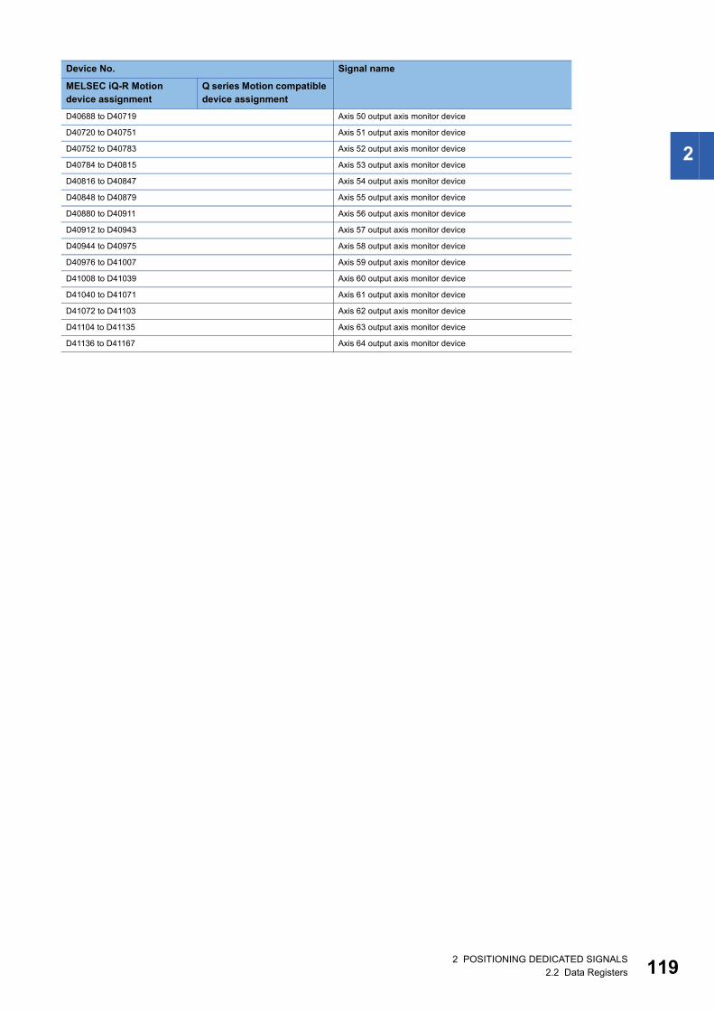
2
D40688 to D40719 Axis 50 output axis monitor device
D40720 to D40751 Axis 51 output axis monitor device
D40752 to D40783 Axis 52 output axis monitor device
D40784 to D40815 Axis 53 output axis monitor device
D40816 to D40847 Axis 54 output axis monitor device
D40848 to D40879 Axis 55 output axis monitor device
D40880 to D40911 Axis 56 output axis monitor device
D40912 to D40943 Axis 57 output axis monitor device
D40944 to D40975 Axis 58 output axis monitor device
D40976 to D41007 Axis 59 output axis monitor device
D41008 to D41039 Axis 60 output axis monitor device
D41040 to D41071 Axis 61 output axis monitor device
D41072 to D41103 Axis 62 output axis monitor device
D41104 to D41135 Axis 63 output axis monitor device
D41136 to D41167 Axis 64 output axis monitor device
Device No. Signal name
MELSEC iQ-R Motion device assignment
Q series Motion compatible device assignment
2 POSITIONING DEDICATED SIGNALS2.2 Data Registers 119
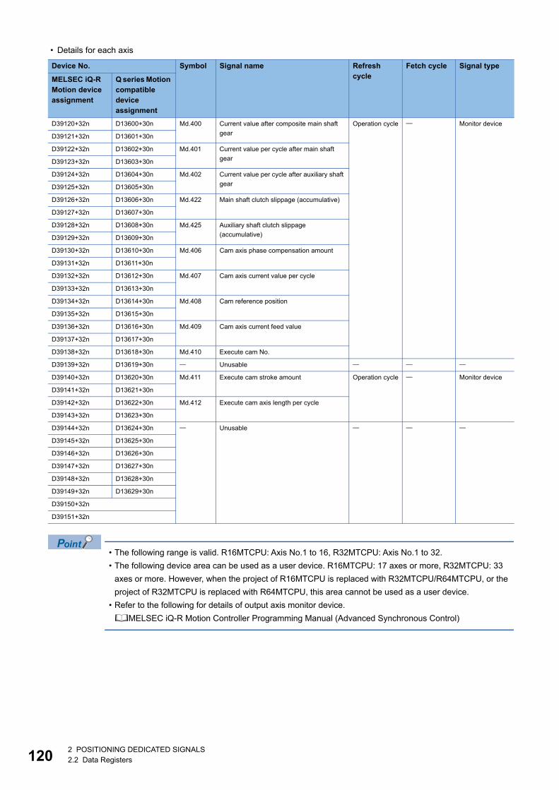
12
• Details for each axis
• The following range is valid. R16MTCPU: Axis No.1 to 16, R32MTCPU: Axis No.1 to 32.
• The following device area can be used as a user device. R16MTCPU: 17 axes or more, R32MTCPU: 33
axes or more. However, when the project of R16MTCPU is replaced with R32MTCPU/R64MTCPU, or the
project of R32MTCPU is replaced with R64MTCPU, this area cannot be used as a user device.
• Refer to the following for details of output axis monitor device.
MELSEC iQ-R Motion Controller Programming Manual (Advanced Synchronous Control)
Device No. Symbol Signal name Refresh cycle
Fetch cycle Signal type
MELSEC iQ-R Motion device assignment
Q series Motion compatible device assignment
D39120+32n D13600+30n Md.400 Current value after composite main shaft
gear
Operation cycle Monitor device
D39121+32n D13601+30n
D39122+32n D13602+30n Md.401 Current value per cycle after main shaft
gearD39123+32n D13603+30n
D39124+32n D13604+30n Md.402 Current value per cycle after auxiliary shaft
gearD39125+32n D13605+30n
D39126+32n D13606+30n Md.422 Main shaft clutch slippage (accumulative)
D39127+32n D13607+30n
D39128+32n D13608+30n Md.425 Auxiliary shaft clutch slippage
(accumulative)D39129+32n D13609+30n
D39130+32n D13610+30n Md.406 Cam axis phase compensation amount
D39131+32n D13611+30n
D39132+32n D13612+30n Md.407 Cam axis current value per cycle
D39133+32n D13613+30n
D39134+32n D13614+30n Md.408 Cam reference position
D39135+32n D13615+30n
D39136+32n D13616+30n Md.409 Cam axis current feed value
D39137+32n D13617+30n
D39138+32n D13618+30n Md.410 Execute cam No.
D39139+32n D13619+30n Unusable
D39140+32n D13620+30n Md.411 Execute cam stroke amount Operation cycle Monitor device
D39141+32n D13621+30n
D39142+32n D13622+30n Md.412 Execute cam axis length per cycle
D39143+32n D13623+30n
D39144+32n D13624+30n Unusable
D39145+32n D13625+30n
D39146+32n D13626+30n
D39147+32n D13627+30n
D39148+32n D13628+30n
D39149+32n D13629+30n
D39150+32n
D39151+32n
02 POSITIONING DEDICATED SIGNALS2.2 Data Registers
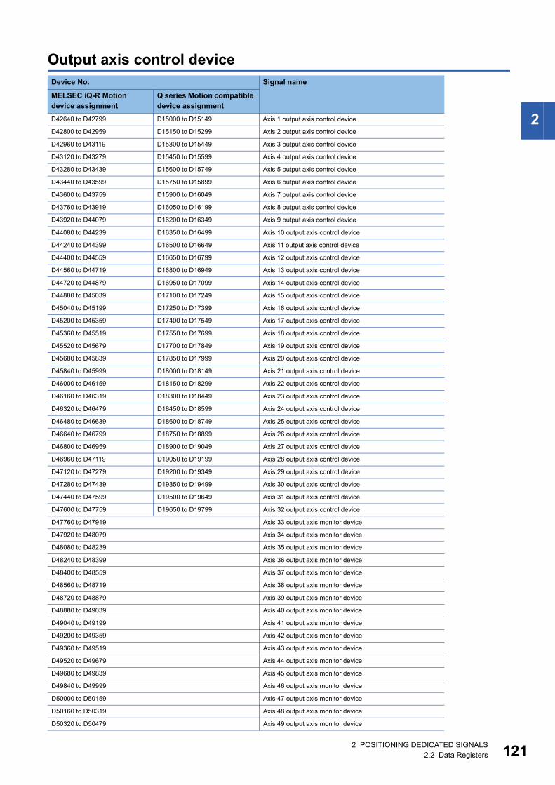
2
Output axis control deviceDevice No. Signal name
MELSEC iQ-R Motion device assignment
Q series Motion compatible device assignment
D42640 to D42799 D15000 to D15149 Axis 1 output axis control device
D42800 to D42959 D15150 to D15299 Axis 2 output axis control device
D42960 to D43119 D15300 to D15449 Axis 3 output axis control device
D43120 to D43279 D15450 to D15599 Axis 4 output axis control device
D43280 to D43439 D15600 to D15749 Axis 5 output axis control device
D43440 to D43599 D15750 to D15899 Axis 6 output axis control device
D43600 to D43759 D15900 to D16049 Axis 7 output axis control device
D43760 to D43919 D16050 to D16199 Axis 8 output axis control device
D43920 to D44079 D16200 to D16349 Axis 9 output axis control device
D44080 to D44239 D16350 to D16499 Axis 10 output axis control device
D44240 to D44399 D16500 to D16649 Axis 11 output axis control device
D44400 to D44559 D16650 to D16799 Axis 12 output axis control device
D44560 to D44719 D16800 to D16949 Axis 13 output axis control device
D44720 to D44879 D16950 to D17099 Axis 14 output axis control device
D44880 to D45039 D17100 to D17249 Axis 15 output axis control device
D45040 to D45199 D17250 to D17399 Axis 16 output axis control device
D45200 to D45359 D17400 to D17549 Axis 17 output axis control device
D45360 to D45519 D17550 to D17699 Axis 18 output axis control device
D45520 to D45679 D17700 to D17849 Axis 19 output axis control device
D45680 to D45839 D17850 to D17999 Axis 20 output axis control device
D45840 to D45999 D18000 to D18149 Axis 21 output axis control device
D46000 to D46159 D18150 to D18299 Axis 22 output axis control device
D46160 to D46319 D18300 to D18449 Axis 23 output axis control device
D46320 to D46479 D18450 to D18599 Axis 24 output axis control device
D46480 to D46639 D18600 to D18749 Axis 25 output axis control device
D46640 to D46799 D18750 to D18899 Axis 26 output axis control device
D46800 to D46959 D18900 to D19049 Axis 27 output axis control device
D46960 to D47119 D19050 to D19199 Axis 28 output axis control device
D47120 to D47279 D19200 to D19349 Axis 29 output axis control device
D47280 to D47439 D19350 to D19499 Axis 30 output axis control device
D47440 to D47599 D19500 to D19649 Axis 31 output axis control device
D47600 to D47759 D19650 to D19799 Axis 32 output axis control device
D47760 to D47919 Axis 33 output axis monitor device
D47920 to D48079 Axis 34 output axis monitor device
D48080 to D48239 Axis 35 output axis monitor device
D48240 to D48399 Axis 36 output axis monitor device
D48400 to D48559 Axis 37 output axis monitor device
D48560 to D48719 Axis 38 output axis monitor device
D48720 to D48879 Axis 39 output axis monitor device
D48880 to D49039 Axis 40 output axis monitor device
D49040 to D49199 Axis 41 output axis monitor device
D49200 to D49359 Axis 42 output axis monitor device
D49360 to D49519 Axis 43 output axis monitor device
D49520 to D49679 Axis 44 output axis monitor device
D49680 to D49839 Axis 45 output axis monitor device
D49840 to D49999 Axis 46 output axis monitor device
D50000 to D50159 Axis 47 output axis monitor device
D50160 to D50319 Axis 48 output axis monitor device
D50320 to D50479 Axis 49 output axis monitor device
2 POSITIONING DEDICATED SIGNALS2.2 Data Registers 121
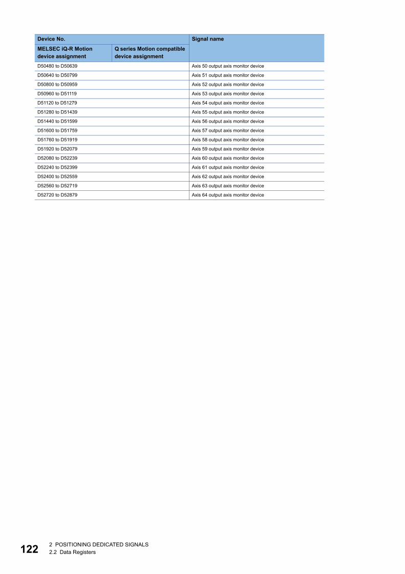
12
D50480 to D50639 Axis 50 output axis monitor device
D50640 to D50799 Axis 51 output axis monitor device
D50800 to D50959 Axis 52 output axis monitor device
D50960 to D51119 Axis 53 output axis monitor device
D51120 to D51279 Axis 54 output axis monitor device
D51280 to D51439 Axis 55 output axis monitor device
D51440 to D51599 Axis 56 output axis monitor device
D51600 to D51759 Axis 57 output axis monitor device
D51760 to D51919 Axis 58 output axis monitor device
D51920 to D52079 Axis 59 output axis monitor device
D52080 to D52239 Axis 60 output axis monitor device
D52240 to D52399 Axis 61 output axis monitor device
D52400 to D52559 Axis 62 output axis monitor device
D52560 to D52719 Axis 63 output axis monitor device
D52720 to D52879 Axis 64 output axis monitor device
Device No. Signal name
MELSEC iQ-R Motion device assignment
Q series Motion compatible device assignment
22 POSITIONING DEDICATED SIGNALS2.2 Data Registers
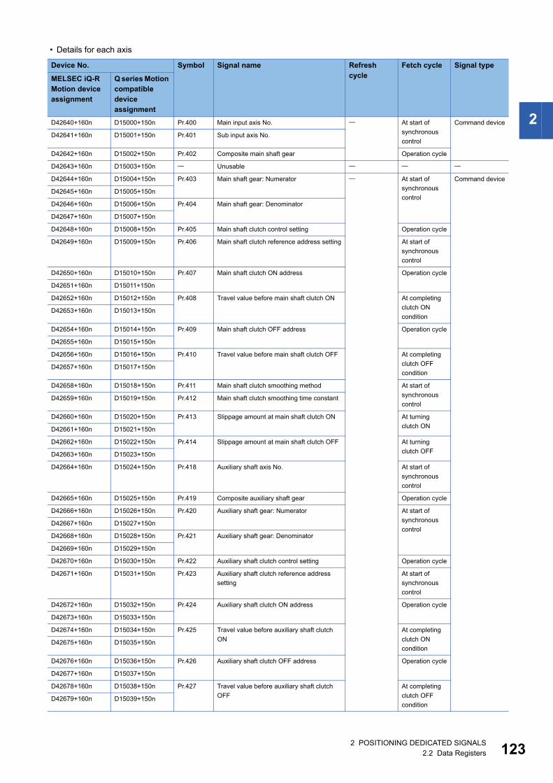
2
• Details for each axis
Device No. Symbol Signal name Refresh cycle
Fetch cycle Signal type
MELSEC iQ-R Motion device assignment
Q series Motion compatible device assignment
D42640+160n D15000+150n Pr.400 Main input axis No. At start of
synchronous
control
Command device
D42641+160n D15001+150n Pr.401 Sub input axis No.
D42642+160n D15002+150n Pr.402 Composite main shaft gear Operation cycle
D42643+160n D15003+150n Unusable
D42644+160n D15004+150n Pr.403 Main shaft gear: Numerator At start of
synchronous
control
Command device
D42645+160n D15005+150n
D42646+160n D15006+150n Pr.404 Main shaft gear: Denominator
D42647+160n D15007+150n
D42648+160n D15008+150n Pr.405 Main shaft clutch control setting Operation cycle
D42649+160n D15009+150n Pr.406 Main shaft clutch reference address setting At start of
synchronous
control
D42650+160n D15010+150n Pr.407 Main shaft clutch ON address Operation cycle
D42651+160n D15011+150n
D42652+160n D15012+150n Pr.408 Travel value before main shaft clutch ON At completing
clutch ON
conditionD42653+160n D15013+150n
D42654+160n D15014+150n Pr.409 Main shaft clutch OFF address Operation cycle
D42655+160n D15015+150n
D42656+160n D15016+150n Pr.410 Travel value before main shaft clutch OFF At completing
clutch OFF
conditionD42657+160n D15017+150n
D42658+160n D15018+150n Pr.411 Main shaft clutch smoothing method At start of
synchronous
controlD42659+160n D15019+150n Pr.412 Main shaft clutch smoothing time constant
D42660+160n D15020+150n Pr.413 Slippage amount at main shaft clutch ON At turning
clutch OND42661+160n D15021+150n
D42662+160n D15022+150n Pr.414 Slippage amount at main shaft clutch OFF At turning
clutch OFFD42663+160n D15023+150n
D42664+160n D15024+150n Pr.418 Auxiliary shaft axis No. At start of
synchronous
control
D42665+160n D15025+150n Pr.419 Composite auxiliary shaft gear Operation cycle
D42666+160n D15026+150n Pr.420 Auxiliary shaft gear: Numerator At start of
synchronous
controlD42667+160n D15027+150n
D42668+160n D15028+150n Pr.421 Auxiliary shaft gear: Denominator
D42669+160n D15029+150n
D42670+160n D15030+150n Pr.422 Auxiliary shaft clutch control setting Operation cycle
D42671+160n D15031+150n Pr.423 Auxiliary shaft clutch reference address
setting
At start of
synchronous
control
D42672+160n D15032+150n Pr.424 Auxiliary shaft clutch ON address Operation cycle
D42673+160n D15033+150n
D42674+160n D15034+150n Pr.425 Travel value before auxiliary shaft clutch
ON
At completing
clutch ON
conditionD42675+160n D15035+150n
D42676+160n D15036+150n Pr.426 Auxiliary shaft clutch OFF address Operation cycle
D42677+160n D15037+150n
D42678+160n D15038+150n Pr.427 Travel value before auxiliary shaft clutch
OFF
At completing
clutch OFF
conditionD42679+160n D15039+150n
2 POSITIONING DEDICATED SIGNALS2.2 Data Registers 123
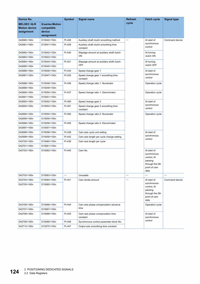
12
D42680+160n D15040+150n Pr.428 Auxiliary shaft clutch smoothing method At start of
synchronous
control
Command device
D42681+160n D15041+150n Pr.429 Auxiliary shaft clutch smoothing time
constant
D42682+160n D15042+150n Pr.430 Slippage amount at auxiliary shaft clutch
ON
At turning
clutch OND42683+160n D15043+150n
D42684+160n D15044+150n Pr.431 Slippage amount at auxiliary shaft clutch
OFF
At turning
clutch OFFD42685+160n D15045+150n
D42686+160n D15046+150n Pr.434 Speed change gear 1 At start of
synchronous
controlD42687+160n D15047+150n Pr.435 Speed change gear 1 smoothing time
constant
D42688+160n D15048+150n Pr.436 Speed change ratio 1: Numerator Operation cycle
D42689+160n D15049+150n
D42690+160n D15050+150n Pr.437 Speed change ratio 1: Denominator Operation cycle
D42691+160n D15051+150n
D42692+160n D15052+150n Pr.490 Speed change gear 2 At start of
synchronous
controlD42693+160n D15053+150n Pr.491 Speed change gear 2 smoothing time
constant
D42694+160n D15054+150n Pr.492 Speed change ratio 2: Numerator Operation cycle
D42695+160n D15055+150n
D42696+160n D15056+150n Pr.493 Speed change ratio 2: Denominator
D42697+160n D15057+150n
D42698+160n D15058+150n Pr.438 Cam axis cycle unit setting At start of
synchronous
controlD42699+160n D15059+150n Pr.442 Cam axis length per cycle change setting
D42700+160n D15060+150n Pr.439 Cam axis length per cycle
D42701+160n D15061+150n
D42702+160n D15062+150n Pr.440 Cam No. At start of
synchronous
control, At
passing
through the 0th
point of cam
data
D42703+160n D15063+150n Unusable
D42704+160n D15064+150n Pr.441 Cam stroke amount At start of
synchronous
control, At
passing
through the 0th
point of cam
data
Command device
D42705+160n D15065+150n
D42706+160n D15066+150n Pr.444 Cam axis phase compensation advance
time
Operation cycle
D42707+160n D15067+150n
D42708+160n D15068+150n Pr.445 Cam axis phase compensation time
constant
At start of
synchronous
controlD42709+160n D15069+150n Pr.448 Synchronous control parameter block No.
D42710+160n D15070+150n Pr.447 Output axis smoothing time constant
Device No. Symbol Signal name Refresh cycle
Fetch cycle Signal type
MELSEC iQ-R Motion device assignment
Q series Motion compatible device assignment
42 POSITIONING DEDICATED SIGNALS2.2 Data Registers
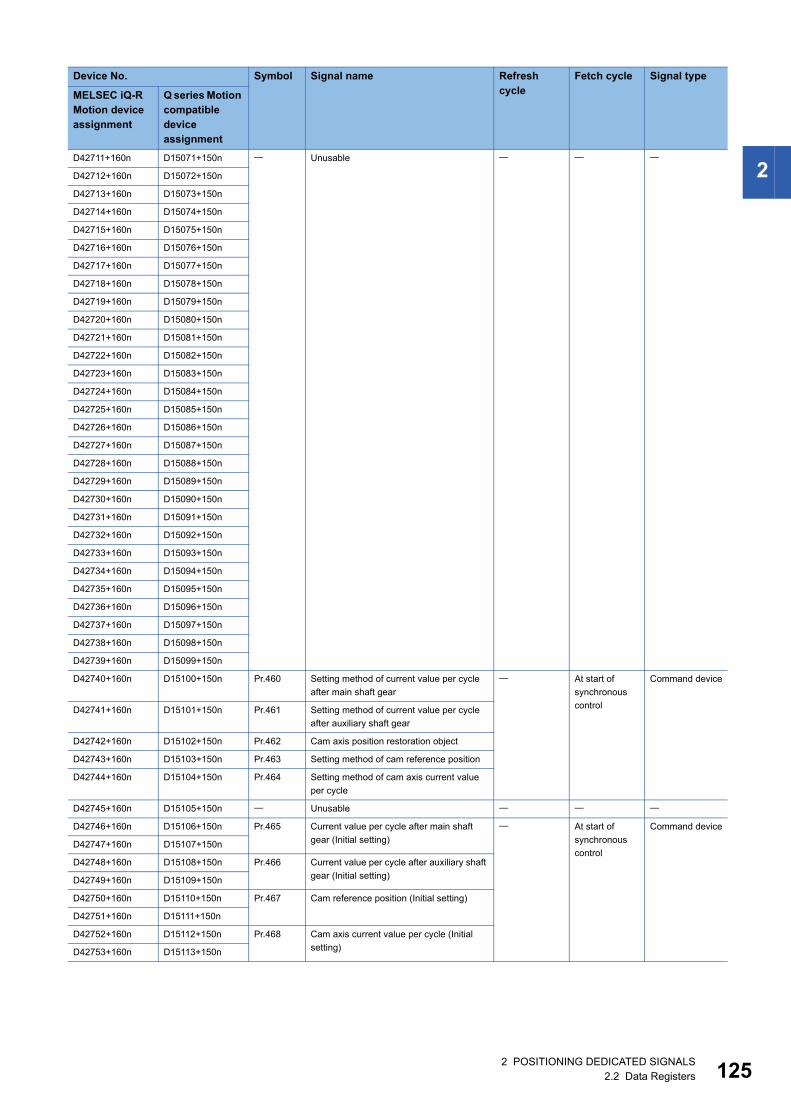
2
D42711+160n D15071+150n UnusableD42712+160n D15072+150n
D42713+160n D15073+150n
D42714+160n D15074+150n
D42715+160n D15075+150n
D42716+160n D15076+150n
D42717+160n D15077+150n
D42718+160n D15078+150n
D42719+160n D15079+150n
D42720+160n D15080+150n
D42721+160n D15081+150n
D42722+160n D15082+150n
D42723+160n D15083+150n
D42724+160n D15084+150n
D42725+160n D15085+150n
D42726+160n D15086+150n
D42727+160n D15087+150n
D42728+160n D15088+150n
D42729+160n D15089+150n
D42730+160n D15090+150n
D42731+160n D15091+150n
D42732+160n D15092+150n
D42733+160n D15093+150n
D42734+160n D15094+150n
D42735+160n D15095+150n
D42736+160n D15096+150n
D42737+160n D15097+150n
D42738+160n D15098+150n
D42739+160n D15099+150n
D42740+160n D15100+150n Pr.460 Setting method of current value per cycle
after main shaft gear
At start of
synchronous
control
Command device
D42741+160n D15101+150n Pr.461 Setting method of current value per cycle
after auxiliary shaft gear
D42742+160n D15102+150n Pr.462 Cam axis position restoration object
D42743+160n D15103+150n Pr.463 Setting method of cam reference position
D42744+160n D15104+150n Pr.464 Setting method of cam axis current value
per cycle
D42745+160n D15105+150n Unusable
D42746+160n D15106+150n Pr.465 Current value per cycle after main shaft
gear (Initial setting)
At start of
synchronous
control
Command device
D42747+160n D15107+150n
D42748+160n D15108+150n Pr.466 Current value per cycle after auxiliary shaft
gear (Initial setting)D42749+160n D15109+150n
D42750+160n D15110+150n Pr.467 Cam reference position (Initial setting)
D42751+160n D15111+150n
D42752+160n D15112+150n Pr.468 Cam axis current value per cycle (Initial
setting)D42753+160n D15113+150n
Device No. Symbol Signal name Refresh cycle
Fetch cycle Signal type
MELSEC iQ-R Motion device assignment
Q series Motion compatible device assignment
2 POSITIONING DEDICATED SIGNALS2.2 Data Registers 125
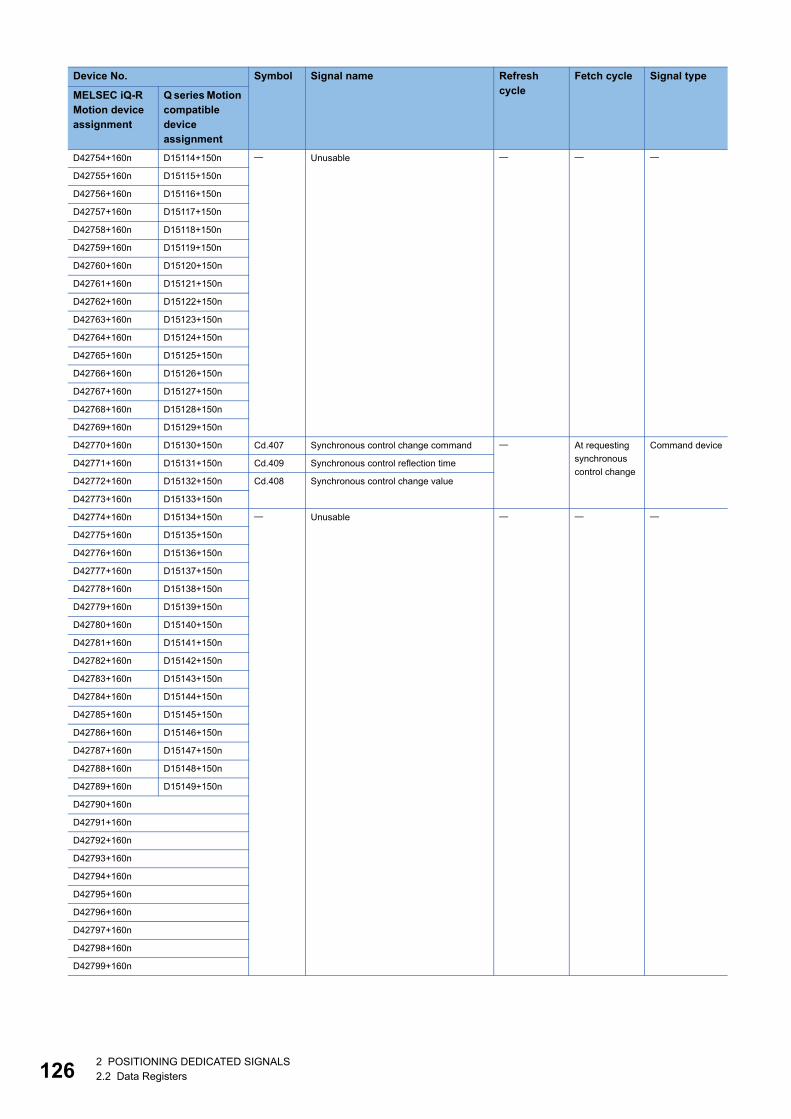
12
D42754+160n D15114+150n Unusable
D42755+160n D15115+150n
D42756+160n D15116+150n
D42757+160n D15117+150n
D42758+160n D15118+150n
D42759+160n D15119+150n
D42760+160n D15120+150n
D42761+160n D15121+150n
D42762+160n D15122+150n
D42763+160n D15123+150n
D42764+160n D15124+150n
D42765+160n D15125+150n
D42766+160n D15126+150n
D42767+160n D15127+150n
D42768+160n D15128+150n
D42769+160n D15129+150n
D42770+160n D15130+150n Cd.407 Synchronous control change command At requesting
synchronous
control change
Command device
D42771+160n D15131+150n Cd.409 Synchronous control reflection time
D42772+160n D15132+150n Cd.408 Synchronous control change value
D42773+160n D15133+150n
D42774+160n D15134+150n Unusable
D42775+160n D15135+150n
D42776+160n D15136+150n
D42777+160n D15137+150n
D42778+160n D15138+150n
D42779+160n D15139+150n
D42780+160n D15140+150n
D42781+160n D15141+150n
D42782+160n D15142+150n
D42783+160n D15143+150n
D42784+160n D15144+150n
D42785+160n D15145+150n
D42786+160n D15146+150n
D42787+160n D15147+150n
D42788+160n D15148+150n
D42789+160n D15149+150n
D42790+160n
D42791+160n
D42792+160n
D42793+160n
D42794+160n
D42795+160n
D42796+160n
D42797+160n
D42798+160n
D42799+160n
Device No. Symbol Signal name Refresh cycle
Fetch cycle Signal type
MELSEC iQ-R Motion device assignment
Q series Motion compatible device assignment
62 POSITIONING DEDICATED SIGNALS2.2 Data Registers
2
• The following range is valid. R16MTCPU: Axis No.1 to 16, R32MTCPU: Axis No.1 to 32.
• The following device area can be used as a user device. R16MTCPU: 17 axes or more, R32MTCPU: 33
axes or more. However, when the project of R16MTCPU is replaced with R32MTCPU/R64MTCPU, or the
project of R32MTCPU is replaced with R64MTCPU, this area cannot be used as a user device.
• Refer to the following for details of output axis monitor device.
MELSEC iQ-R Motion Controller Programming Manual (Advanced Synchronous Control)
2 POSITIONING DEDICATED SIGNALS2.2 Data Registers 127
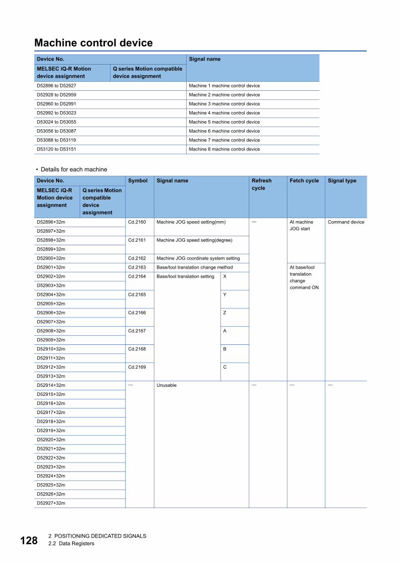
12
Machine control device
• Details for each machine
Device No. Signal name
MELSEC iQ-R Motion device assignment
Q series Motion compatible device assignment
D52896 to D52927 Machine 1 machine control device
D52928 to D52959 Machine 2 machine control device
D52960 to D52991 Machine 3 machine control device
D52992 to D53023 Machine 4 machine control device
D53024 to D53055 Machine 5 machine control device
D53056 to D53087 Machine 6 machine control device
D53088 to D53119 Machine 7 machine control device
D53120 to D53151 Machine 8 machine control device
Device No. Symbol Signal name Refresh cycle
Fetch cycle Signal type
MELSEC iQ-R Motion device assignment
Q series Motion compatible device assignment
D52896+32m Cd.2160 Machine JOG speed setting(mm) At machine
JOG start
Command device
D52897+32m
D52898+32m Cd.2161 Machine JOG speed setting(degree)
D52899+32m
D52900+32m Cd.2162 Machine JOG coordinate system setting
D52901+32m Cd.2163 Base/tool translation change method At base/tool
translation
change
command ON
D52902+32m Cd.2164 Base/tool translation setting X
D52903+32m
D52904+32m Cd.2165 Y
D52905+32m
D52906+32m Cd.2166 Z
D52907+32m
D52908+32m Cd.2167 A
D52909+32m
D52910+32m Cd.2168 B
D52911+32m
D52912+32m Cd.2169 C
D52913+32m
D52914+32m Unusable
D52915+32m
D52916+32m
D52917+32m
D52918+32m
D52919+32m
D52920+32m
D52921+32m
D52922+32m
D52923+32m
D52924+32m
D52925+32m
D52926+32m
D52927+32m
82 POSITIONING DEDICATED SIGNALS2.2 Data Registers

2
Refer to the following for details of machine command signal.
MELSEC iQ-R Motion Controller Programming Manual (Machine Control)
2 POSITIONING DEDICATED SIGNALS2.2 Data Registers 129
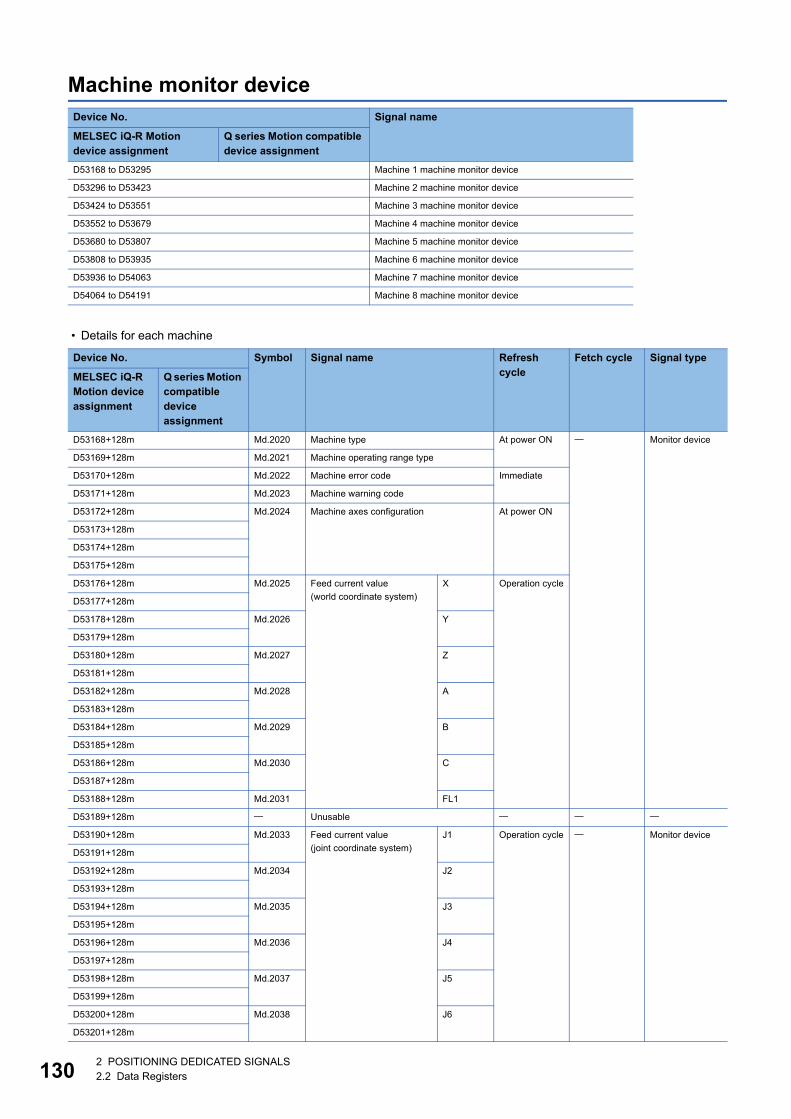
13
Machine monitor device
• Details for each machine
Device No. Signal name
MELSEC iQ-R Motion device assignment
Q series Motion compatible device assignment
D53168 to D53295 Machine 1 machine monitor device
D53296 to D53423 Machine 2 machine monitor device
D53424 to D53551 Machine 3 machine monitor device
D53552 to D53679 Machine 4 machine monitor device
D53680 to D53807 Machine 5 machine monitor device
D53808 to D53935 Machine 6 machine monitor device
D53936 to D54063 Machine 7 machine monitor device
D54064 to D54191 Machine 8 machine monitor device
Device No. Symbol Signal name Refresh cycle
Fetch cycle Signal type
MELSEC iQ-R Motion device assignment
Q series Motion compatible device assignment
D53168+128m Md.2020 Machine type At power ON Monitor device
D53169+128m Md.2021 Machine operating range type
D53170+128m Md.2022 Machine error code Immediate
D53171+128m Md.2023 Machine warning code
D53172+128m Md.2024 Machine axes configuration At power ON
D53173+128m
D53174+128m
D53175+128m
D53176+128m Md.2025 Feed current value
(world coordinate system)
X Operation cycle
D53177+128m
D53178+128m Md.2026 Y
D53179+128m
D53180+128m Md.2027 Z
D53181+128m
D53182+128m Md.2028 A
D53183+128m
D53184+128m Md.2029 B
D53185+128m
D53186+128m Md.2030 C
D53187+128m
D53188+128m Md.2031 FL1
D53189+128m Unusable
D53190+128m Md.2033 Feed current value
(joint coordinate system)
J1 Operation cycle Monitor device
D53191+128m
D53192+128m Md.2034 J2
D53193+128m
D53194+128m Md.2035 J3
D53195+128m
D53196+128m Md.2036 J4
D53197+128m
D53198+128m Md.2037 J5
D53199+128m
D53200+128m Md.2038 J6
D53201+128m
02 POSITIONING DEDICATED SIGNALS2.2 Data Registers
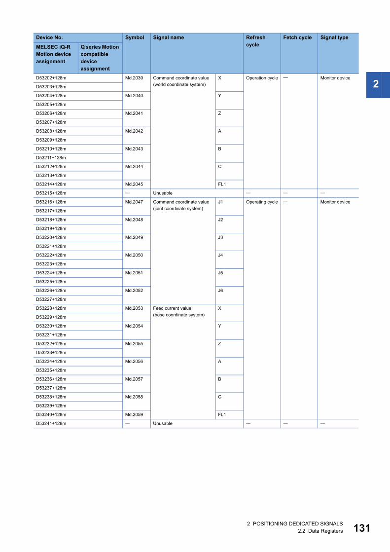
2
D53202+128m Md.2039 Command coordinate value(world coordinate system)
X Operation cycle Monitor device
D53203+128m
D53204+128m Md.2040 Y
D53205+128m
D53206+128m Md.2041 Z
D53207+128m
D53208+128m Md.2042 A
D53209+128m
D53210+128m Md.2043 B
D53211+128m
D53212+128m Md.2044 C
D53213+128m
D53214+128m Md.2045 FL1
D53215+128m Unusable
D53216+128m Md.2047 Command coordinate value
(joint coordinate system)
J1 Operating cycle Monitor device
D53217+128m
D53218+128m Md.2048 J2
D53219+128m
D53220+128m Md.2049 J3
D53221+128m
D53222+128m Md.2050 J4
D53223+128m
D53224+128m Md.2051 J5
D53225+128m
D53226+128m Md.2052 J6
D53227+128m
D53228+128m Md.2053 Feed current value
(base coordinate system)
X
D53229+128m
D53230+128m Md.2054 Y
D53231+128m
D53232+128m Md.2055 Z
D53233+128m
D53234+128m Md.2056 A
D53235+128m
D53236+128m Md.2057 B
D53237+128m
D53238+128m Md.2058 C
D53239+128m
D53240+128m Md.2059 FL1
D53241+128m Unusable
Device No. Symbol Signal name Refresh cycle
Fetch cycle Signal type
MELSEC iQ-R Motion device assignment
Q series Motion compatible device assignment
2 POSITIONING DEDICATED SIGNALS2.2 Data Registers 131
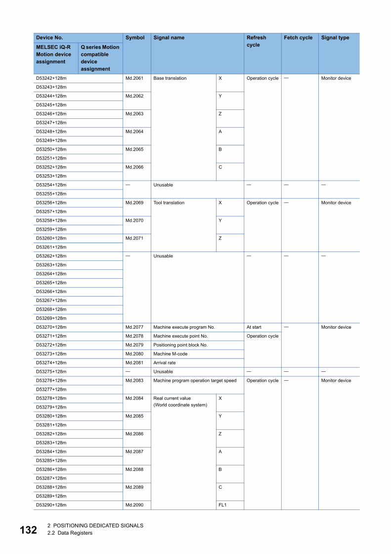
13
D53242+128m Md.2061 Base translation X Operation cycle Monitor device
D53243+128m
D53244+128m Md.2062 Y
D53245+128m
D53246+128m Md.2063 Z
D53247+128m
D53248+128m Md.2064 A
D53249+128m
D53250+128m Md.2065 B
D53251+128m
D53252+128m Md.2066 C
D53253+128m
D53254+128m Unusable
D53255+128m
D53256+128m Md.2069 Tool translation X Operation cycle Monitor device
D53257+128m
D53258+128m Md.2070 Y
D53259+128m
D53260+128m Md.2071 Z
D53261+128m
D53262+128m Unusable
D53263+128m
D53264+128m
D53265+128m
D53266+128m
D53267+128m
D53268+128m
D53269+128m
D53270+128m Md.2077 Machine execute program No. At start Monitor device
D53271+128m Md.2078 Machine execute point No. Operation cycle
D53272+128m Md.2079 Positioning point block No.
D53273+128m Md.2080 Machine M-code
D53274+128m Md.2081 Arrival rate
D53275+128m Unusable
D53276+128m Md.2083 Machine program operation target speed Operation cycle Monitor device
D53277+128m
D53278+128m Md.2084 Real current value
(World coordinate system)
X
D53279+128m
D53280+128m Md.2085 Y
D53281+128m
D53282+128m Md.2086 Z
D53283+128m
D53284+128m Md.2087 A
D53285+128m
D53286+128m Md.2088 B
D53287+128m
D53288+128m Md.2089 C
D53289+128m
D53290+128m Md.2090 FL1
Device No. Symbol Signal name Refresh cycle
Fetch cycle Signal type
MELSEC iQ-R Motion device assignment
Q series Motion compatible device assignment
22 POSITIONING DEDICATED SIGNALS2.2 Data Registers
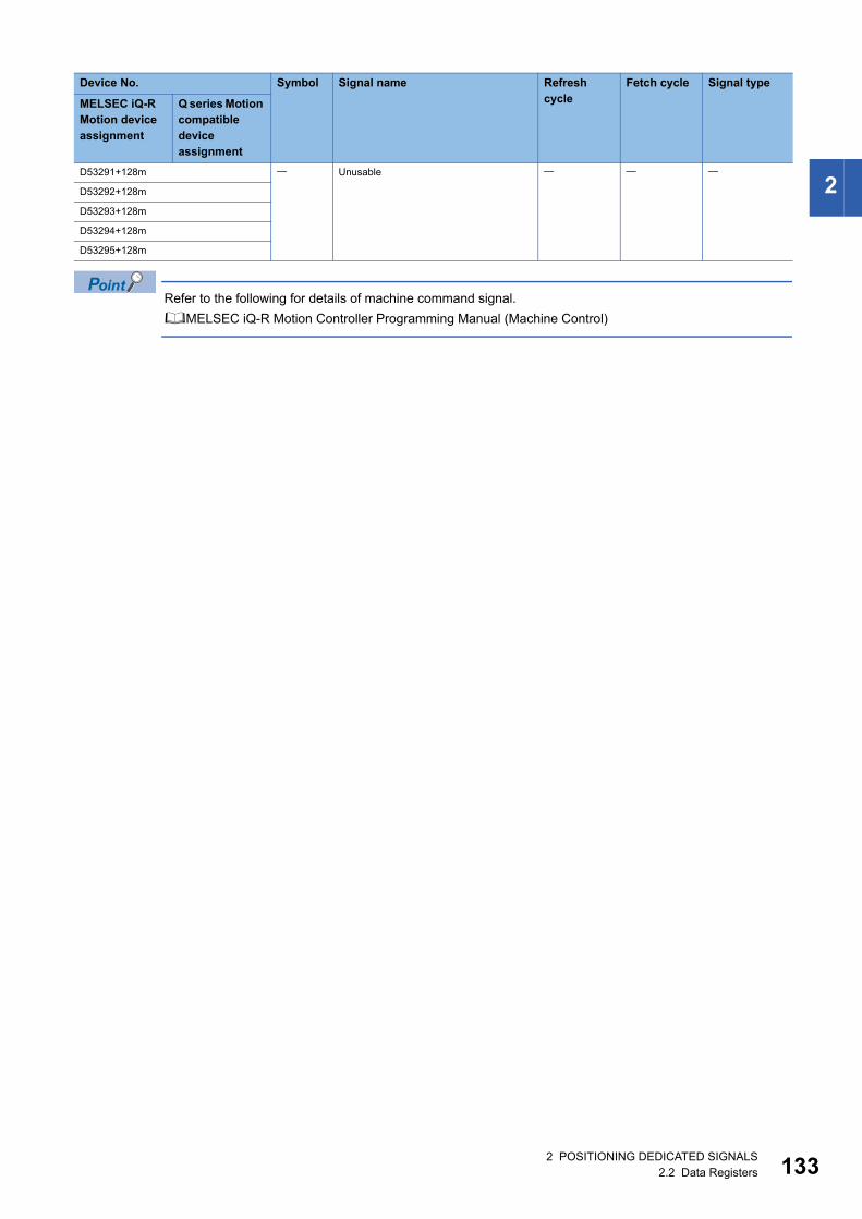
2
Refer to the following for details of machine command signal.
MELSEC iQ-R Motion Controller Programming Manual (Machine Control)
D53291+128m Unusable
D53292+128m
D53293+128m
D53294+128m
D53295+128m
Device No. Symbol Signal name Refresh cycle
Fetch cycle Signal type
MELSEC iQ-R Motion device assignment
Q series Motion compatible device assignment
2 POSITIONING DEDICATED SIGNALS2.2 Data Registers 133
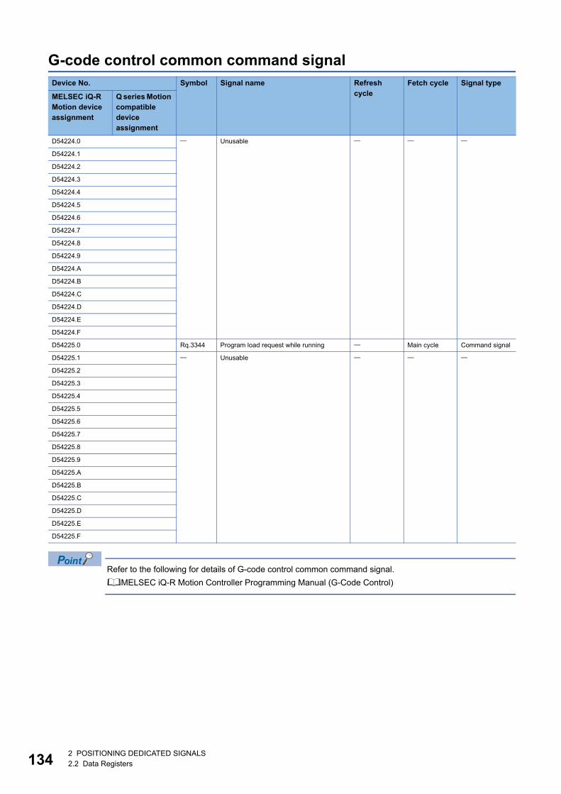
13
G-code control common command signal
Refer to the following for details of G-code control common command signal.
MELSEC iQ-R Motion Controller Programming Manual (G-Code Control)
Device No. Symbol Signal name Refresh cycle
Fetch cycle Signal type
MELSEC iQ-R Motion device assignment
Q series Motion compatible device assignment
D54224.0 Unusable
D54224.1
D54224.2
D54224.3
D54224.4
D54224.5
D54224.6
D54224.7
D54224.8
D54224.9
D54224.A
D54224.B
D54224.C
D54224.D
D54224.E
D54224.F
D54225.0 Rq.3344 Program load request while running Main cycle Command signal
D54225.1 Unusable
D54225.2
D54225.3
D54225.4
D54225.5
D54225.6
D54225.7
D54225.8
D54225.9
D54225.A
D54225.B
D54225.C
D54225.D
D54225.E
D54225.F
42 POSITIONING DEDICATED SIGNALS2.2 Data Registers
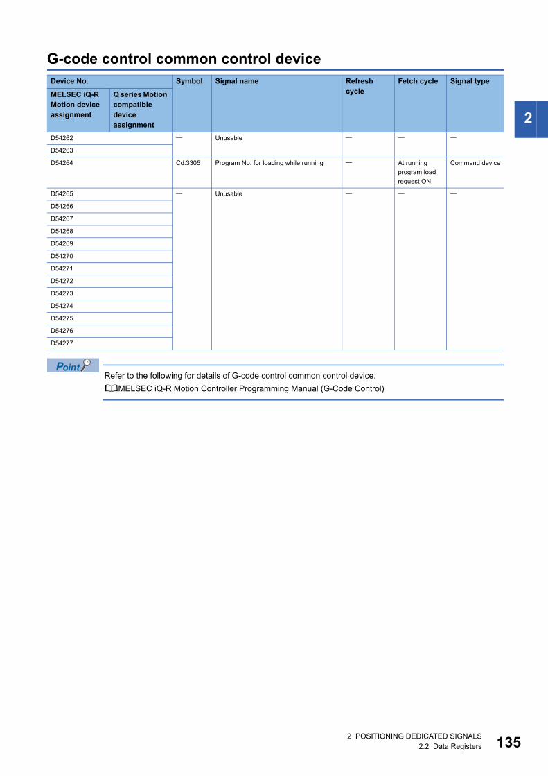
2
G-code control common control device
Refer to the following for details of G-code control common control device.
MELSEC iQ-R Motion Controller Programming Manual (G-Code Control)
Device No. Symbol Signal name Refresh cycle
Fetch cycle Signal type
MELSEC iQ-R Motion device assignment
Q series Motion compatible device assignment
D54262 Unusable
D54263
D54264 Cd.3305 Program No. for loading while running At running
program load
request ON
Command device
D54265 Unusable
D54266
D54267
D54268
D54269
D54270
D54271
D54272
D54273
D54274
D54275
D54276
D54277
2 POSITIONING DEDICATED SIGNALS2.2 Data Registers 135
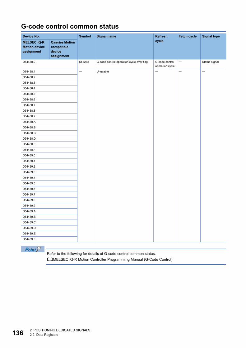
13
G-code control common status
Refer to the following for details of G-code control common status.
MELSEC iQ-R Motion Controller Programming Manual (G-Code Control)
Device No. Symbol Signal name Refresh cycle
Fetch cycle Signal type
MELSEC iQ-R Motion device assignment
Q series Motion compatible device assignment
D54438.0 St.3272 G-code control operation cycle over flag G-code control
operation cycle
Status signal
D54438.1 Unusable
D54438.2
D54438.3
D54438.4
D54438.5
D54438.6
D54438.7
D54438.8
D54438.9
D54438.A
D54438.B
D54438.C
D54438.D
D54438.E
D54438.F
D54439.0
D54439.1
D54439.2
D54439.3
D54439.4
D54439.5
D54439.6
D54439.7
D54439.8
D54439.9
D54439.A
D54439.B
D54439.C
D54439.D
D54439.E
D54439.F
62 POSITIONING DEDICATED SIGNALS2.2 Data Registers
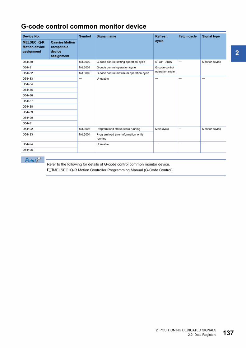
2
G-code control common monitor device
Refer to the following for details of G-code control common monitor device.
MELSEC iQ-R Motion Controller Programming Manual (G-Code Control)
Device No. Symbol Signal name Refresh cycle
Fetch cycle Signal type
MELSEC iQ-R Motion device assignment
Q series Motion compatible device assignment
D54480 Md.3000 G-code control setting operation cycle STOPRUN Monitor device
D54481 Md.3001 G-code control operation cycle G-code control
operation cycleD54482 Md.3002 G-code control maximum operation cycle
D54483 Unusable
D54484
D54485
D54486
D54487
D54488
D54489
D54490
D54491
D54492 Md.3003 Program load status while running Main cycle Monitor device
D54493 Md.3004 Program load error information while
running
D54494 Unusable
D54495
2 POSITIONING DEDICATED SIGNALS2.2 Data Registers 137
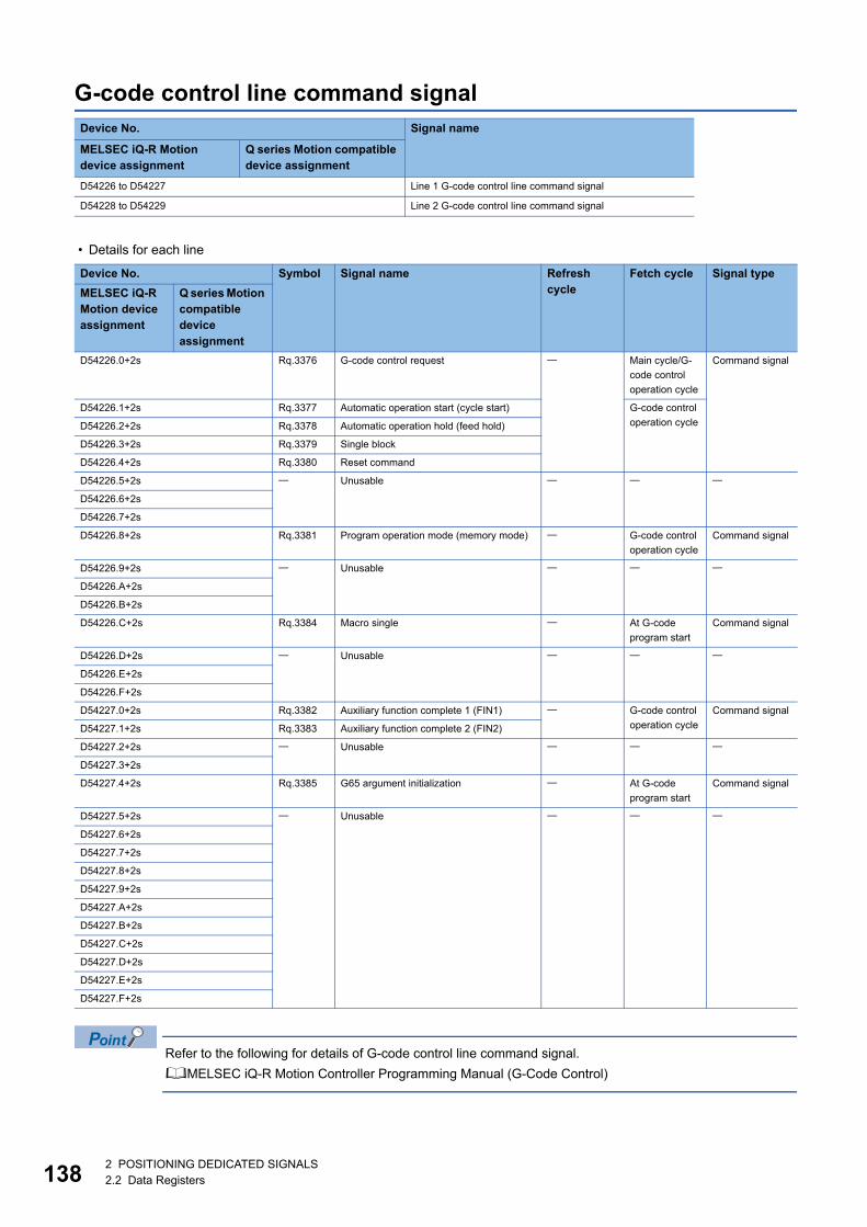
13
G-code control line command signal
• Details for each line
Refer to the following for details of G-code control line command signal.
MELSEC iQ-R Motion Controller Programming Manual (G-Code Control)
Device No. Signal name
MELSEC iQ-R Motion device assignment
Q series Motion compatible device assignment
D54226 to D54227 Line 1 G-code control line command signal
D54228 to D54229 Line 2 G-code control line command signal
Device No. Symbol Signal name Refresh cycle
Fetch cycle Signal type
MELSEC iQ-R Motion device assignment
Q series Motion compatible device assignment
D54226.0+2s Rq.3376 G-code control request Main cycle/G-
code control
operation cycle
Command signal
D54226.1+2s Rq.3377 Automatic operation start (cycle start) G-code control
operation cycleD54226.2+2s Rq.3378 Automatic operation hold (feed hold)
D54226.3+2s Rq.3379 Single block
D54226.4+2s Rq.3380 Reset command
D54226.5+2s Unusable
D54226.6+2s
D54226.7+2s
D54226.8+2s Rq.3381 Program operation mode (memory mode) G-code control
operation cycle
Command signal
D54226.9+2s Unusable
D54226.A+2s
D54226.B+2s
D54226.C+2s Rq.3384 Macro single At G-code
program start
Command signal
D54226.D+2s Unusable
D54226.E+2s
D54226.F+2s
D54227.0+2s Rq.3382 Auxiliary function complete 1 (FIN1) G-code control
operation cycle
Command signal
D54227.1+2s Rq.3383 Auxiliary function complete 2 (FIN2)
D54227.2+2s Unusable
D54227.3+2s
D54227.4+2s Rq.3385 G65 argument initialization At G-code
program start
Command signal
D54227.5+2s Unusable
D54227.6+2s
D54227.7+2s
D54227.8+2s
D54227.9+2s
D54227.A+2s
D54227.B+2s
D54227.C+2s
D54227.D+2s
D54227.E+2s
D54227.F+2s
82 POSITIONING DEDICATED SIGNALS2.2 Data Registers
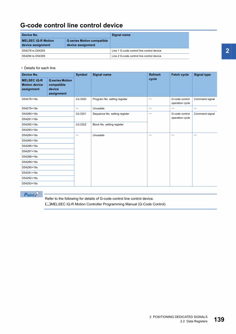
2
G-code control line control device
• Details for each line
Refer to the following for details of G-code control line control device.
MELSEC iQ-R Motion Controller Programming Manual (G-Code Control)
Device No. Signal name
MELSEC iQ-R Motion device assignment
Q series Motion compatible device assignment
D54278 to D54293 Line 1 G-code control line control device
D54294 to D54309 Line 2 G-code control line control device
Device No. Symbol Signal name Refresh cycle
Fetch cycle Signal type
MELSEC iQ-R Motion device assignment
Q series Motion compatible device assignment
D54278+16s Cd.3320 Program No. setting register G-code control
operation cycle
Command signal
D54279+16s Unusable
D54280+16s Cd.3321 Sequence No. setting register G-code control
operation cycle
Command signal
D54281+16s
D54282+16s Cd.3322 Block No. setting register
D54283+16s
D54284+16s Unusable
D54285+16s
D54286+16s
D54287+16s
D54288+16s
D54289+16s
D54290+16s
D54291+16s
D54292+16s
D54293+16s
2 POSITIONING DEDICATED SIGNALS2.2 Data Registers 139
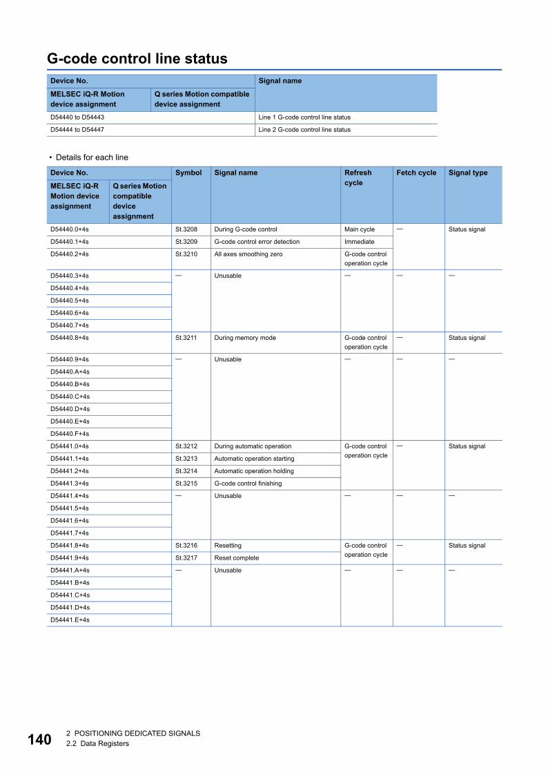
14
G-code control line status
• Details for each line
Device No. Signal name
MELSEC iQ-R Motion device assignment
Q series Motion compatible device assignment
D54440 to D54443 Line 1 G-code control line status
D54444 to D54447 Line 2 G-code control line status
Device No. Symbol Signal name Refresh cycle
Fetch cycle Signal type
MELSEC iQ-R Motion device assignment
Q series Motion compatible device assignment
D54440.0+4s St.3208 During G-code control Main cycle Status signal
D54440.1+4s St.3209 G-code control error detection Immediate
D54440.2+4s St.3210 All axes smoothing zero G-code control
operation cycle
D54440.3+4s Unusable
D54440.4+4s
D54440.5+4s
D54440.6+4s
D54440.7+4s
D54440.8+4s St.3211 During memory mode G-code control
operation cycle
Status signal
D54440.9+4s Unusable
D54440.A+4s
D54440.B+4s
D54440.C+4s
D54440.D+4s
D54440.E+4s
D54440.F+4s
D54441.0+4s St.3212 During automatic operation G-code control
operation cycle
Status signal
D54441.1+4s St.3213 Automatic operation starting
D54441.2+4s St.3214 Automatic operation holding
D54441.3+4s St.3215 G-code control finishing
D54441.4+4s Unusable
D54441.5+4s
D54441.6+4s
D54441.7+4s
D54441.8+4s St.3216 Resetting G-code control
operation cycle
Status signal
D54441.9+4s St.3217 Reset complete
D54441.A+4s Unusable
D54441.B+4s
D54441.C+4s
D54441.D+4s
D54441.E+4s
02 POSITIONING DEDICATED SIGNALS2.2 Data Registers
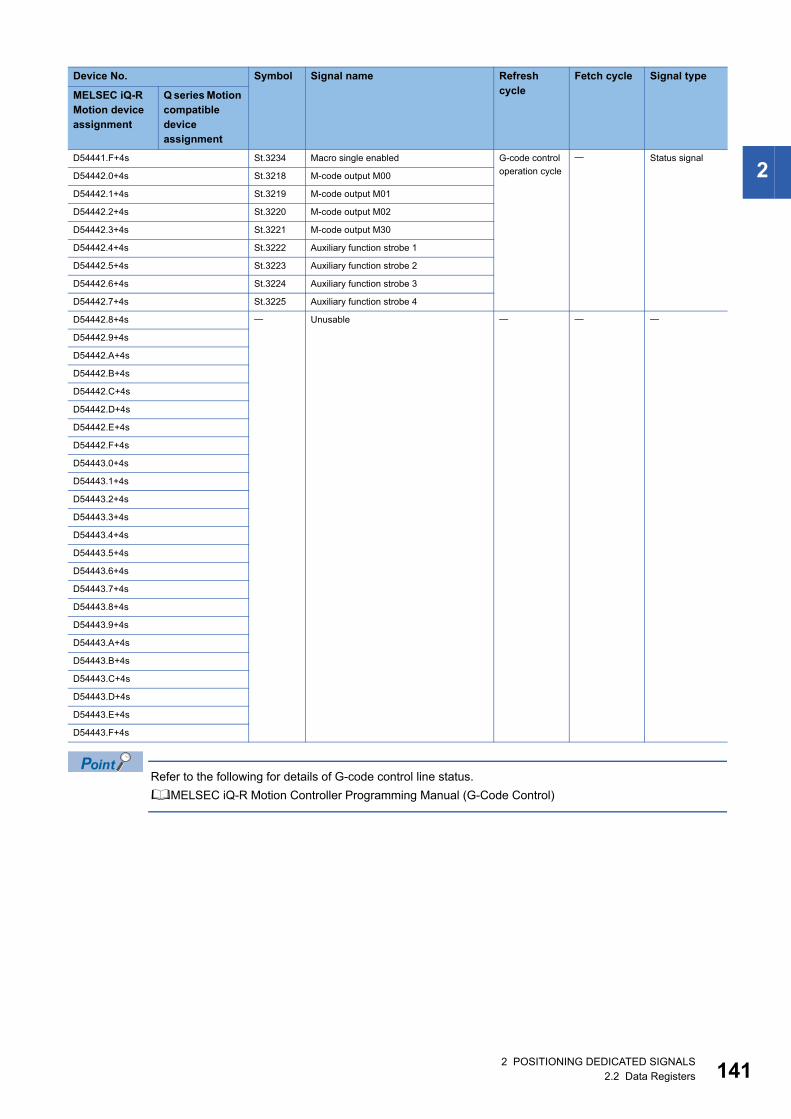
2
Refer to the following for details of G-code control line status.
MELSEC iQ-R Motion Controller Programming Manual (G-Code Control)
D54441.F+4s St.3234 Macro single enabled G-code control
operation cycle
Status signal
D54442.0+4s St.3218 M-code output M00
D54442.1+4s St.3219 M-code output M01
D54442.2+4s St.3220 M-code output M02
D54442.3+4s St.3221 M-code output M30
D54442.4+4s St.3222 Auxiliary function strobe 1
D54442.5+4s St.3223 Auxiliary function strobe 2
D54442.6+4s St.3224 Auxiliary function strobe 3
D54442.7+4s St.3225 Auxiliary function strobe 4
D54442.8+4s Unusable
D54442.9+4s
D54442.A+4s
D54442.B+4s
D54442.C+4s
D54442.D+4s
D54442.E+4s
D54442.F+4s
D54443.0+4s
D54443.1+4s
D54443.2+4s
D54443.3+4s
D54443.4+4s
D54443.5+4s
D54443.6+4s
D54443.7+4s
D54443.8+4s
D54443.9+4s
D54443.A+4s
D54443.B+4s
D54443.C+4s
D54443.D+4s
D54443.E+4s
D54443.F+4s
Device No. Symbol Signal name Refresh cycle
Fetch cycle Signal type
MELSEC iQ-R Motion device assignment
Q series Motion compatible device assignment
2 POSITIONING DEDICATED SIGNALS2.2 Data Registers 141
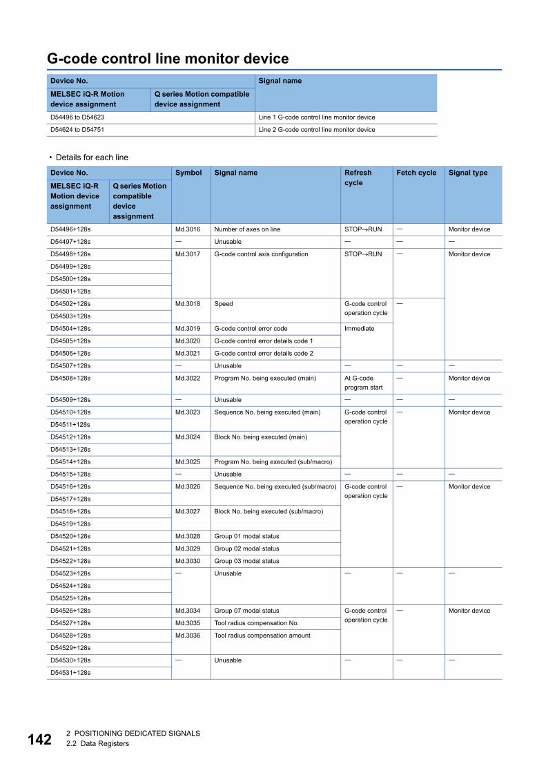
14
G-code control line monitor device
• Details for each line
Device No. Signal name
MELSEC iQ-R Motion device assignment
Q series Motion compatible device assignment
D54496 to D54623 Line 1 G-code control line monitor device
D54624 to D54751 Line 2 G-code control line monitor device
Device No. Symbol Signal name Refresh cycle
Fetch cycle Signal type
MELSEC iQ-R Motion device assignment
Q series Motion compatible device assignment
D54496+128s Md.3016 Number of axes on line STOPRUN Monitor device
D54497+128s Unusable
D54498+128s Md.3017 G-code control axis configuration STOPRUN Monitor device
D54499+128s
D54500+128s
D54501+128s
D54502+128s Md.3018 Speed G-code control
operation cycle
D54503+128s
D54504+128s Md.3019 G-code control error code Immediate
D54505+128s Md.3020 G-code control error details code 1
D54506+128s Md.3021 G-code control error details code 2
D54507+128s Unusable
D54508+128s Md.3022 Program No. being executed (main) At G-code
program start
Monitor device
D54509+128s Unusable
D54510+128s Md.3023 Sequence No. being executed (main) G-code control
operation cycle
Monitor device
D54511+128s
D54512+128s Md.3024 Block No. being executed (main)
D54513+128s
D54514+128s Md.3025 Program No. being executed (sub/macro)
D54515+128s Unusable
D54516+128s Md.3026 Sequence No. being executed (sub/macro) G-code control
operation cycle
Monitor device
D54517+128s
D54518+128s Md.3027 Block No. being executed (sub/macro)
D54519+128s
D54520+128s Md.3028 Group 01 modal status
D54521+128s Md.3029 Group 02 modal status
D54522+128s Md.3030 Group 03 modal status
D54523+128s Unusable
D54524+128s
D54525+128s
D54526+128s Md.3034 Group 07 modal status G-code control
operation cycle
Monitor device
D54527+128s Md.3035 Tool radius compensation No.
D54528+128s Md.3036 Tool radius compensation amount
D54529+128s
D54530+128s Unusable
D54531+128s
22 POSITIONING DEDICATED SIGNALS2.2 Data Registers
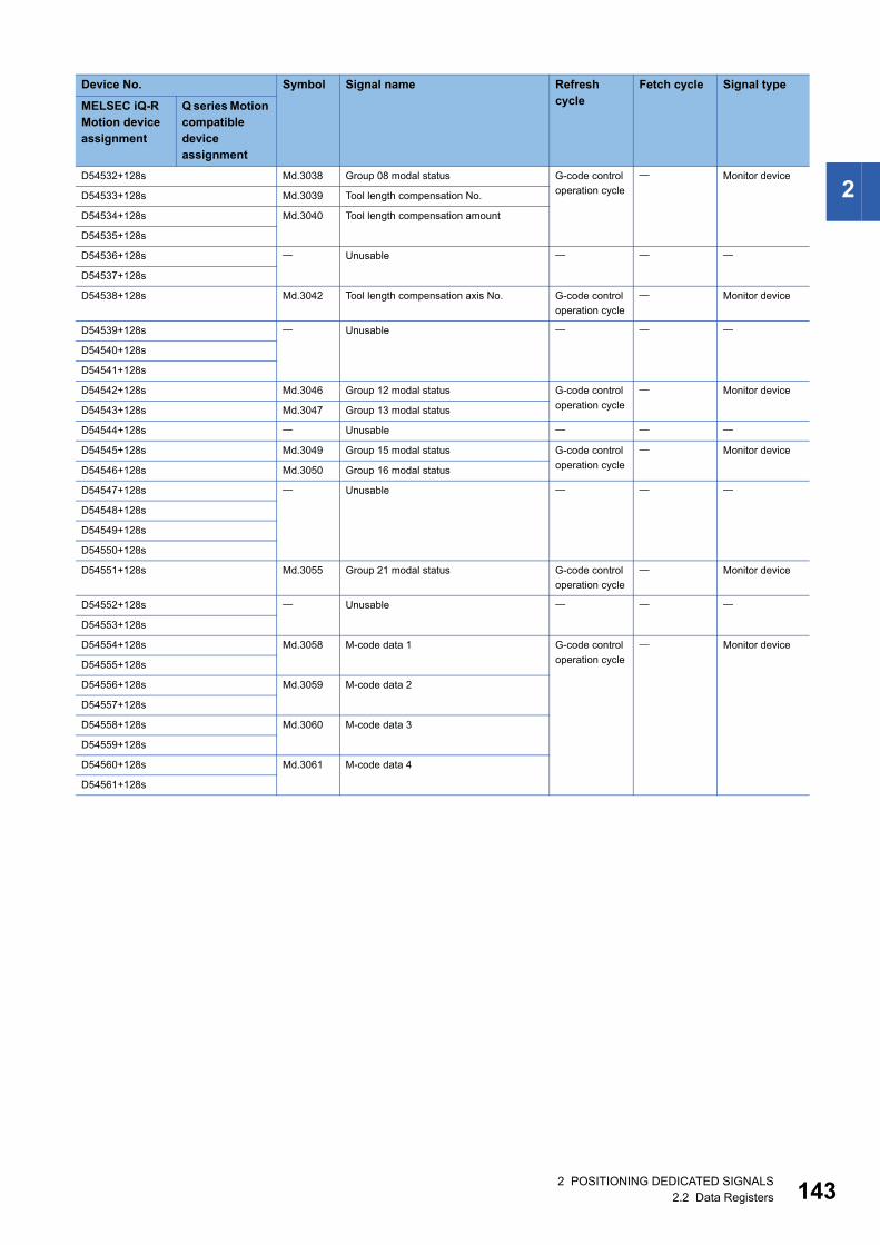
2
D54532+128s Md.3038 Group 08 modal status G-code controloperation cycle
Monitor device
D54533+128s Md.3039 Tool length compensation No.
D54534+128s Md.3040 Tool length compensation amount
D54535+128s
D54536+128s Unusable
D54537+128s
D54538+128s Md.3042 Tool length compensation axis No. G-code control
operation cycle
Monitor device
D54539+128s Unusable
D54540+128s
D54541+128s
D54542+128s Md.3046 Group 12 modal status G-code control
operation cycle
Monitor device
D54543+128s Md.3047 Group 13 modal status
D54544+128s Unusable
D54545+128s Md.3049 Group 15 modal status G-code control
operation cycle
Monitor device
D54546+128s Md.3050 Group 16 modal status
D54547+128s Unusable
D54548+128s
D54549+128s
D54550+128s
D54551+128s Md.3055 Group 21 modal status G-code control
operation cycle
Monitor device
D54552+128s Unusable
D54553+128s
D54554+128s Md.3058 M-code data 1 G-code control
operation cycle
Monitor device
D54555+128s
D54556+128s Md.3059 M-code data 2
D54557+128s
D54558+128s Md.3060 M-code data 3
D54559+128s
D54560+128s Md.3061 M-code data 4
D54561+128s
Device No. Symbol Signal name Refresh cycle
Fetch cycle Signal type
MELSEC iQ-R Motion device assignment
Q series Motion compatible device assignment
2 POSITIONING DEDICATED SIGNALS2.2 Data Registers 143
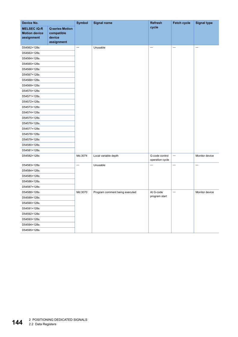
14
D54562+128s Unusable
D54563+128s
D54564+128s
D54565+128s
D54566+128s
D54567+128s
D54568+128s
D54569+128s
D54570+128s
D54571+128s
D54572+128s
D54573+128s
D54574+128s
D54575+128s
D54576+128s
D54577+128s
D54578+128s
D54579+128s
D54580+128s
D54581+128s
D54582+128s Md.3074 Local variable depth G-code control
operation cycle
Monitor device
D54583+128s Unusable
D54584+128s
D54585+128s
D54586+128s
D54587+128s
D54588+128s Md.3070 Program comment being executed At G-code
program start
Monitor device
D54589+128s
D54590+128s
D54591+128s
D54592+128s
D54593+128s
D54594+128s
D54595+128s
Device No. Symbol Signal name Refresh cycle
Fetch cycle Signal type
MELSEC iQ-R Motion device assignment
Q series Motion compatible device assignment
42 POSITIONING DEDICATED SIGNALS2.2 Data Registers
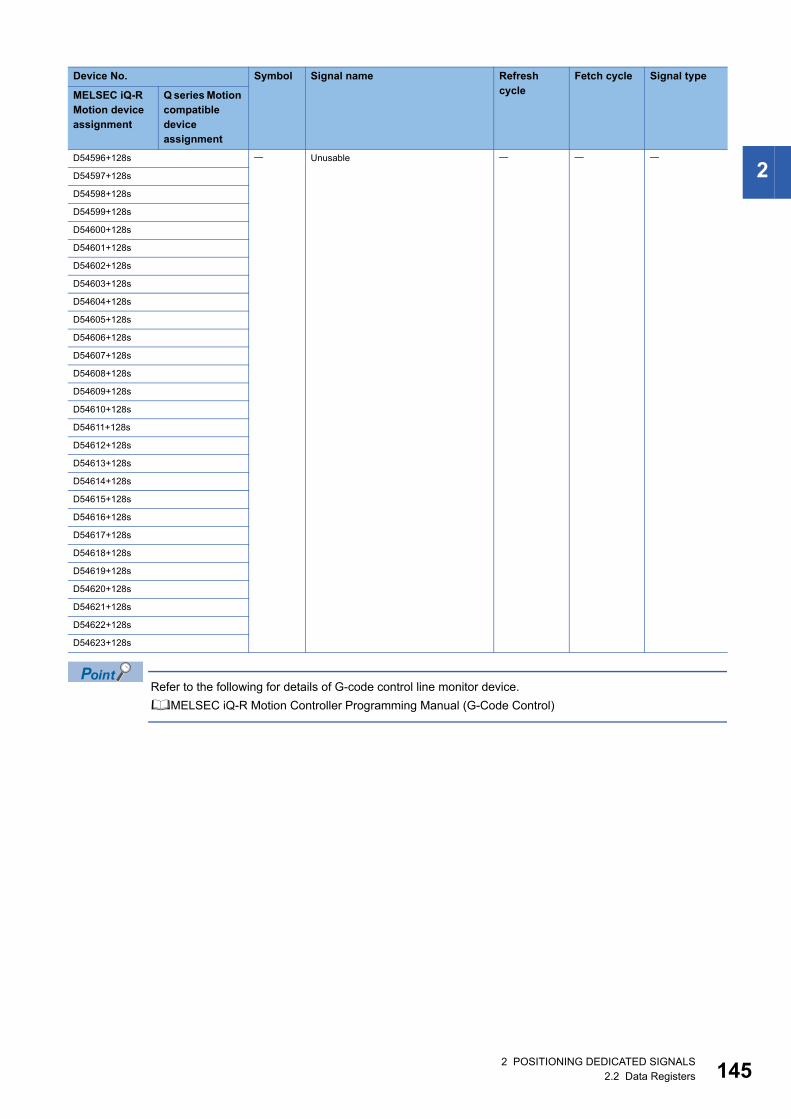
2
Refer to the following for details of G-code control line monitor device.
MELSEC iQ-R Motion Controller Programming Manual (G-Code Control)
D54596+128s Unusable
D54597+128s
D54598+128s
D54599+128s
D54600+128s
D54601+128s
D54602+128s
D54603+128s
D54604+128s
D54605+128s
D54606+128s
D54607+128s
D54608+128s
D54609+128s
D54610+128s
D54611+128s
D54612+128s
D54613+128s
D54614+128s
D54615+128s
D54616+128s
D54617+128s
D54618+128s
D54619+128s
D54620+128s
D54621+128s
D54622+128s
D54623+128s
Device No. Symbol Signal name Refresh cycle
Fetch cycle Signal type
MELSEC iQ-R Motion device assignment
Q series Motion compatible device assignment
2 POSITIONING DEDICATED SIGNALS2.2 Data Registers 145
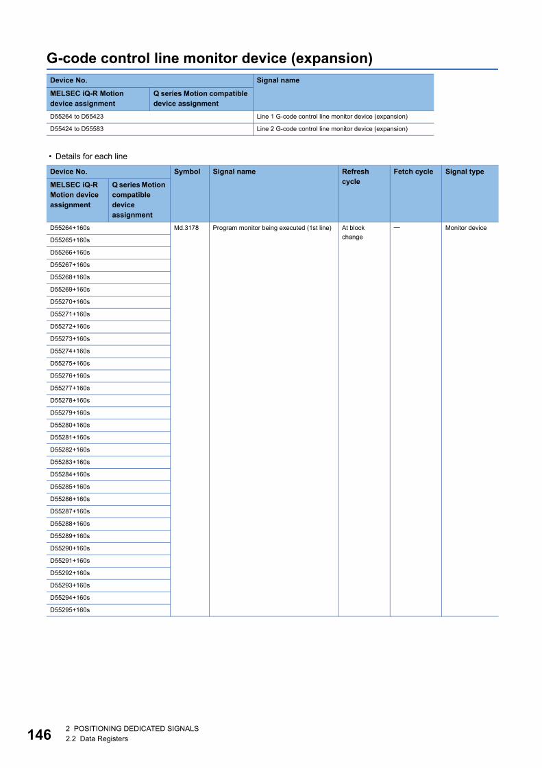
14
G-code control line monitor device (expansion)
• Details for each line
Device No. Signal name
MELSEC iQ-R Motion device assignment
Q series Motion compatible device assignment
D55264 to D55423 Line 1 G-code control line monitor device (expansion)
D55424 to D55583 Line 2 G-code control line monitor device (expansion)
Device No. Symbol Signal name Refresh cycle
Fetch cycle Signal type
MELSEC iQ-R Motion device assignment
Q series Motion compatible device assignment
D55264+160s Md.3178 Program monitor being executed (1st line) At block
change
Monitor device
D55265+160s
D55266+160s
D55267+160s
D55268+160s
D55269+160s
D55270+160s
D55271+160s
D55272+160s
D55273+160s
D55274+160s
D55275+160s
D55276+160s
D55277+160s
D55278+160s
D55279+160s
D55280+160s
D55281+160s
D55282+160s
D55283+160s
D55284+160s
D55285+160s
D55286+160s
D55287+160s
D55288+160s
D55289+160s
D55290+160s
D55291+160s
D55292+160s
D55293+160s
D55294+160s
D55295+160s
62 POSITIONING DEDICATED SIGNALS2.2 Data Registers
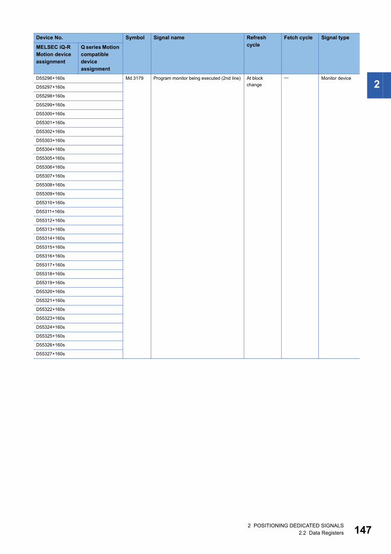
2
D55296+160s Md.3179 Program monitor being executed (2nd line) At blockchange
Monitor device
D55297+160s
D55298+160s
D55299+160s
D55300+160s
D55301+160s
D55302+160s
D55303+160s
D55304+160s
D55305+160s
D55306+160s
D55307+160s
D55308+160s
D55309+160s
D55310+160s
D55311+160s
D55312+160s
D55313+160s
D55314+160s
D55315+160s
D55316+160s
D55317+160s
D55318+160s
D55319+160s
D55320+160s
D55321+160s
D55322+160s
D55323+160s
D55324+160s
D55325+160s
D55326+160s
D55327+160s
Device No. Symbol Signal name Refresh cycle
Fetch cycle Signal type
MELSEC iQ-R Motion device assignment
Q series Motion compatible device assignment
2 POSITIONING DEDICATED SIGNALS2.2 Data Registers 147
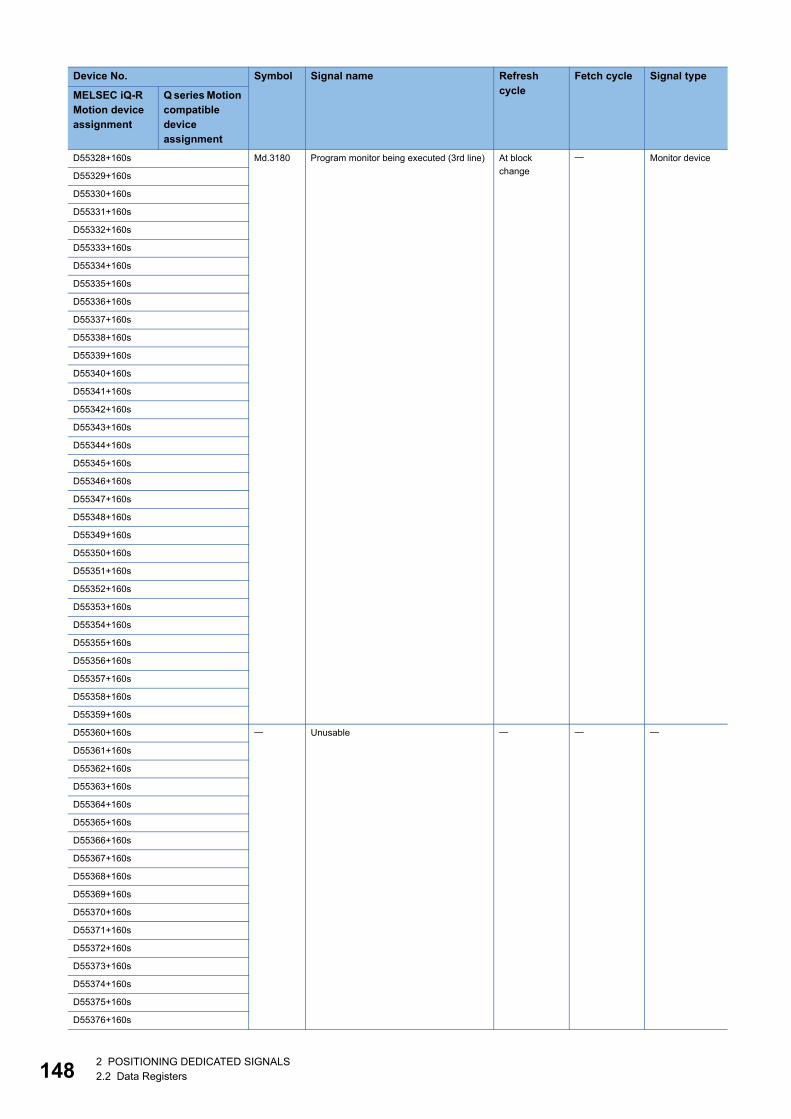
14
D55328+160s Md.3180 Program monitor being executed (3rd line) At block
change
Monitor device
D55329+160s
D55330+160s
D55331+160s
D55332+160s
D55333+160s
D55334+160s
D55335+160s
D55336+160s
D55337+160s
D55338+160s
D55339+160s
D55340+160s
D55341+160s
D55342+160s
D55343+160s
D55344+160s
D55345+160s
D55346+160s
D55347+160s
D55348+160s
D55349+160s
D55350+160s
D55351+160s
D55352+160s
D55353+160s
D55354+160s
D55355+160s
D55356+160s
D55357+160s
D55358+160s
D55359+160s
D55360+160s Unusable
D55361+160s
D55362+160s
D55363+160s
D55364+160s
D55365+160s
D55366+160s
D55367+160s
D55368+160s
D55369+160s
D55370+160s
D55371+160s
D55372+160s
D55373+160s
D55374+160s
D55375+160s
D55376+160s
Device No. Symbol Signal name Refresh cycle
Fetch cycle Signal type
MELSEC iQ-R Motion device assignment
Q series Motion compatible device assignment
82 POSITIONING DEDICATED SIGNALS2.2 Data Registers
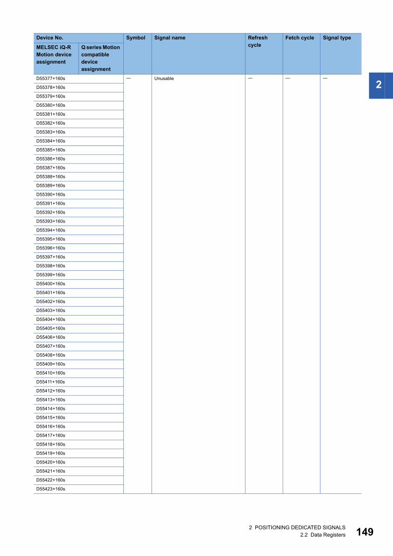
2
D55377+160s UnusableD55378+160s
D55379+160s
D55380+160s
D55381+160s
D55382+160s
D55383+160s
D55384+160s
D55385+160s
D55386+160s
D55387+160s
D55388+160s
D55389+160s
D55390+160s
D55391+160s
D55392+160s
D55393+160s
D55394+160s
D55395+160s
D55396+160s
D55397+160s
D55398+160s
D55399+160s
D55400+160s
D55401+160s
D55402+160s
D55403+160s
D55404+160s
D55405+160s
D55406+160s
D55407+160s
D55408+160s
D55409+160s
D55410+160s
D55411+160s
D55412+160s
D55413+160s
D55414+160s
D55415+160s
D55416+160s
D55417+160s
D55418+160s
D55419+160s
D55420+160s
D55421+160s
D55422+160s
D55423+160s
Device No. Symbol Signal name Refresh cycle
Fetch cycle Signal type
MELSEC iQ-R Motion device assignment
Q series Motion compatible device assignment
2 POSITIONING DEDICATED SIGNALS2.2 Data Registers 149
15
Refer to the following for details of G-code control line monitor device (expansion).
MELSEC iQ-R Motion Controller Programming Manual (G-Code Control)
02 POSITIONING DEDICATED SIGNALS2.2 Data Registers
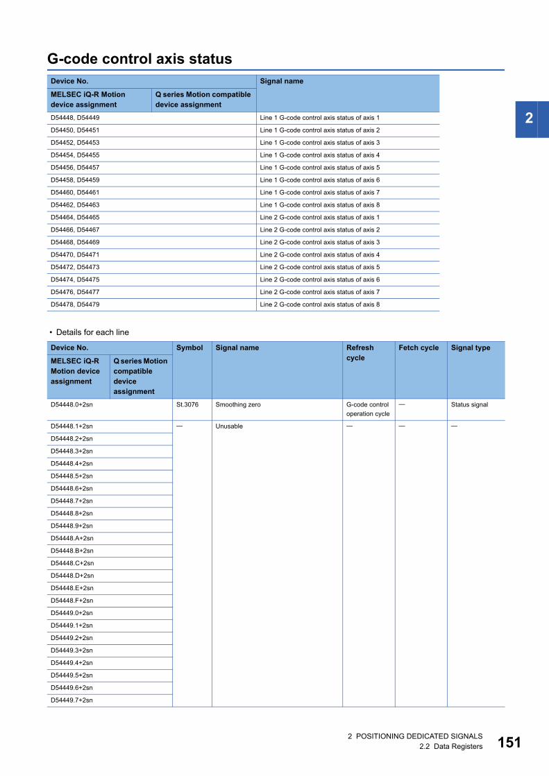
2
G-code control axis status
• Details for each line
Device No. Signal name
MELSEC iQ-R Motion device assignment
Q series Motion compatible device assignment
D54448, D54449 Line 1 G-code control axis status of axis 1
D54450, D54451 Line 1 G-code control axis status of axis 2
D54452, D54453 Line 1 G-code control axis status of axis 3
D54454, D54455 Line 1 G-code control axis status of axis 4
D54456, D54457 Line 1 G-code control axis status of axis 5
D54458, D54459 Line 1 G-code control axis status of axis 6
D54460, D54461 Line 1 G-code control axis status of axis 7
D54462, D54463 Line 1 G-code control axis status of axis 8
D54464, D54465 Line 2 G-code control axis status of axis 1
D54466, D54467 Line 2 G-code control axis status of axis 2
D54468, D54469 Line 2 G-code control axis status of axis 3
D54470, D54471 Line 2 G-code control axis status of axis 4
D54472, D54473 Line 2 G-code control axis status of axis 5
D54474, D54475 Line 2 G-code control axis status of axis 6
D54476, D54477 Line 2 G-code control axis status of axis 7
D54478, D54479 Line 2 G-code control axis status of axis 8
Device No. Symbol Signal name Refresh cycle
Fetch cycle Signal type
MELSEC iQ-R Motion device assignment
Q series Motion compatible device assignment
D54448.0+2sn St.3076 Smoothing zero G-code control
operation cycle
Status signal
D54448.1+2sn Unusable
D54448.2+2sn
D54448.3+2sn
D54448.4+2sn
D54448.5+2sn
D54448.6+2sn
D54448.7+2sn
D54448.8+2sn
D54448.9+2sn
D54448.A+2sn
D54448.B+2sn
D54448.C+2sn
D54448.D+2sn
D54448.E+2sn
D54448.F+2sn
D54449.0+2sn
D54449.1+2sn
D54449.2+2sn
D54449.3+2sn
D54449.4+2sn
D54449.5+2sn
D54449.6+2sn
D54449.7+2sn
2 POSITIONING DEDICATED SIGNALS2.2 Data Registers 151
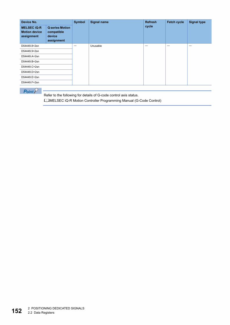
15
Refer to the following for details of G-code control axis status.
MELSEC iQ-R Motion Controller Programming Manual (G-Code Control)
D54449.8+2sn Unusable
D54449.9+2sn
D54449.A+2sn
D54449.B+2sn
D54449.C+2sn
D54449.D+2sn
D54449.E+2sn
D54449.F+2sn
Device No. Symbol Signal name Refresh cycle
Fetch cycle Signal type
MELSEC iQ-R Motion device assignment
Q series Motion compatible device assignment
22 POSITIONING DEDICATED SIGNALS2.2 Data Registers
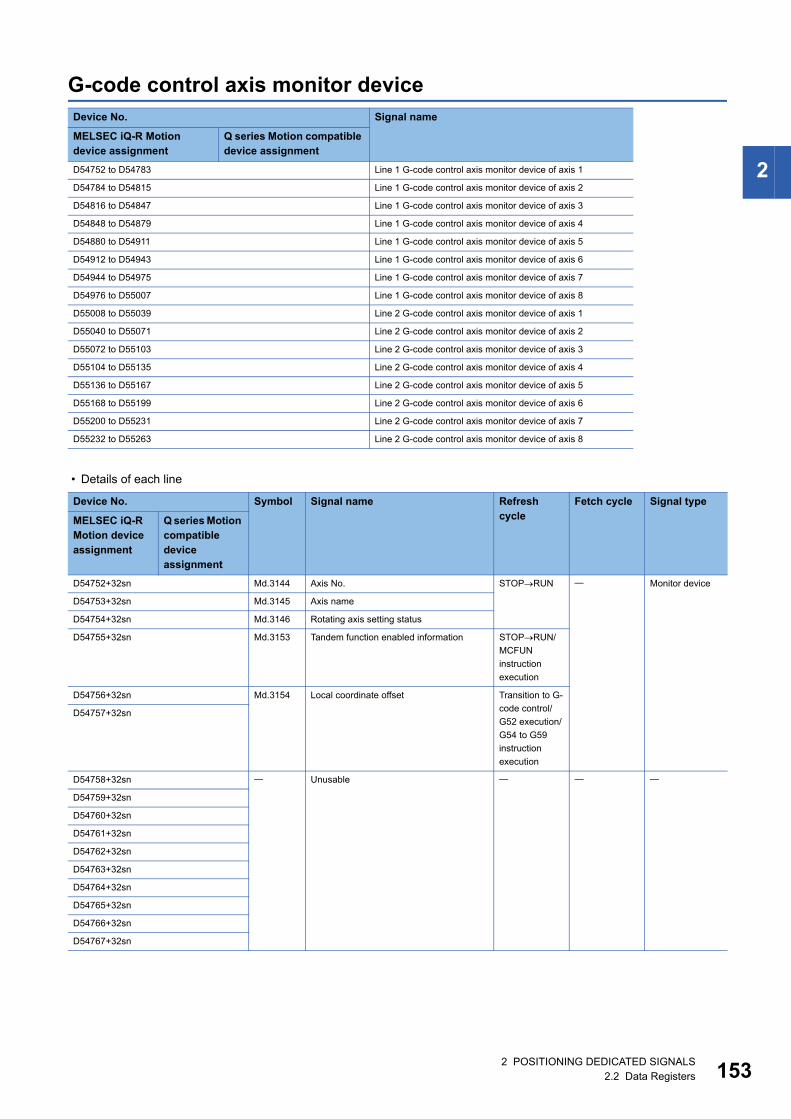
2
G-code control axis monitor device
• Details of each line
Device No. Signal name
MELSEC iQ-R Motion device assignment
Q series Motion compatible device assignment
D54752 to D54783 Line 1 G-code control axis monitor device of axis 1
D54784 to D54815 Line 1 G-code control axis monitor device of axis 2
D54816 to D54847 Line 1 G-code control axis monitor device of axis 3
D54848 to D54879 Line 1 G-code control axis monitor device of axis 4
D54880 to D54911 Line 1 G-code control axis monitor device of axis 5
D54912 to D54943 Line 1 G-code control axis monitor device of axis 6
D54944 to D54975 Line 1 G-code control axis monitor device of axis 7
D54976 to D55007 Line 1 G-code control axis monitor device of axis 8
D55008 to D55039 Line 2 G-code control axis monitor device of axis 1
D55040 to D55071 Line 2 G-code control axis monitor device of axis 2
D55072 to D55103 Line 2 G-code control axis monitor device of axis 3
D55104 to D55135 Line 2 G-code control axis monitor device of axis 4
D55136 to D55167 Line 2 G-code control axis monitor device of axis 5
D55168 to D55199 Line 2 G-code control axis monitor device of axis 6
D55200 to D55231 Line 2 G-code control axis monitor device of axis 7
D55232 to D55263 Line 2 G-code control axis monitor device of axis 8
Device No. Symbol Signal name Refresh cycle
Fetch cycle Signal type
MELSEC iQ-R Motion device assignment
Q series Motion compatible device assignment
D54752+32sn Md.3144 Axis No. STOPRUN Monitor device
D54753+32sn Md.3145 Axis name
D54754+32sn Md.3146 Rotating axis setting status
D54755+32sn Md.3153 Tandem function enabled information STOPRUN/
MCFUN
instruction
execution
D54756+32sn Md.3154 Local coordinate offset Transition to G-
code control/
G52 execution/
G54 to G59
instruction
execution
D54757+32sn
D54758+32sn Unusable
D54759+32sn
D54760+32sn
D54761+32sn
D54762+32sn
D54763+32sn
D54764+32sn
D54765+32sn
D54766+32sn
D54767+32sn
2 POSITIONING DEDICATED SIGNALS2.2 Data Registers 153
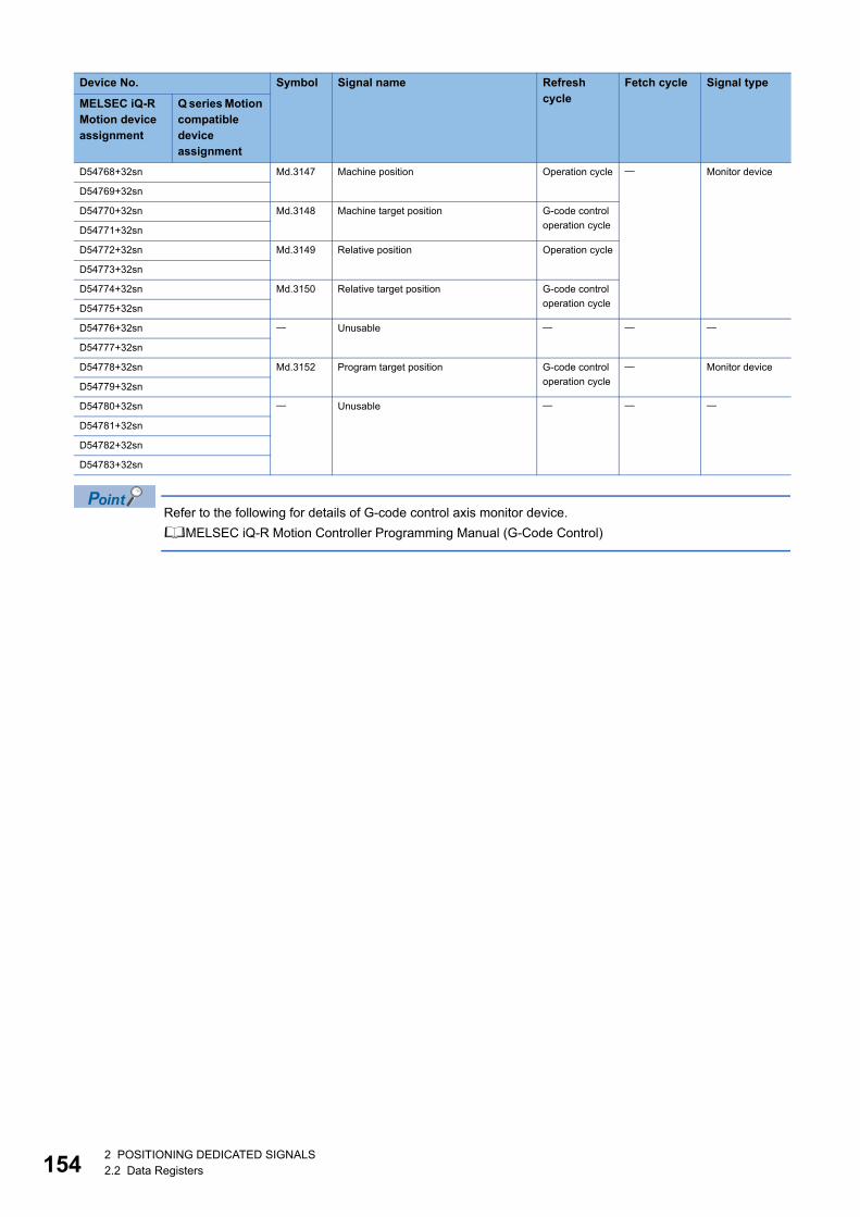
15
Refer to the following for details of G-code control axis monitor device.
MELSEC iQ-R Motion Controller Programming Manual (G-Code Control)
D54768+32sn Md.3147 Machine position Operation cycle Monitor device
D54769+32sn
D54770+32sn Md.3148 Machine target position G-code control
operation cycleD54771+32sn
D54772+32sn Md.3149 Relative position Operation cycle
D54773+32sn
D54774+32sn Md.3150 Relative target position G-code control
operation cycleD54775+32sn
D54776+32sn Unusable
D54777+32sn
D54778+32sn Md.3152 Program target position G-code control
operation cycle
Monitor device
D54779+32sn
D54780+32sn Unusable
D54781+32sn
D54782+32sn
D54783+32sn
Device No. Symbol Signal name Refresh cycle
Fetch cycle Signal type
MELSEC iQ-R Motion device assignment
Q series Motion compatible device assignment
42 POSITIONING DEDICATED SIGNALS2.2 Data Registers
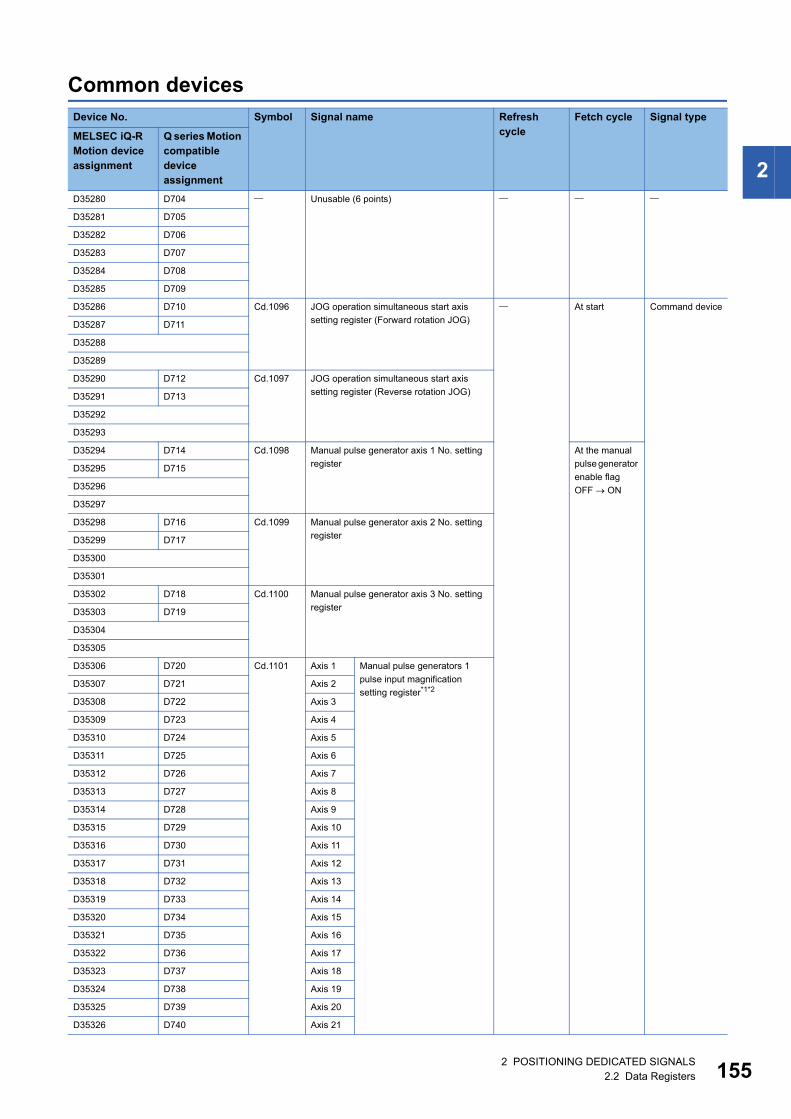
2
Common devicesDevice No. Symbol Signal name Refresh
cycleFetch cycle Signal type
MELSEC iQ-R Motion device assignment
Q series Motion compatible device assignment
D35280 D704 Unusable (6 points)
D35281 D705
D35282 D706
D35283 D707
D35284 D708
D35285 D709
D35286 D710 Cd.1096 JOG operation simultaneous start axis
setting register (Forward rotation JOG)
At start Command device
D35287 D711
D35288
D35289
D35290 D712 Cd.1097 JOG operation simultaneous start axis
setting register (Reverse rotation JOG)D35291 D713
D35292
D35293
D35294 D714 Cd.1098 Manual pulse generator axis 1 No. setting
register
At the manual
pulse generator
enable flag
OFF ON
D35295 D715
D35296
D35297
D35298 D716 Cd.1099 Manual pulse generator axis 2 No. setting
registerD35299 D717
D35300
D35301
D35302 D718 Cd.1100 Manual pulse generator axis 3 No. setting
registerD35303 D719
D35304
D35305
D35306 D720 Cd.1101 Axis 1 Manual pulse generators 1
pulse input magnification
setting register*1*2D35307 D721 Axis 2
D35308 D722 Axis 3
D35309 D723 Axis 4
D35310 D724 Axis 5
D35311 D725 Axis 6
D35312 D726 Axis 7
D35313 D727 Axis 8
D35314 D728 Axis 9
D35315 D729 Axis 10
D35316 D730 Axis 11
D35317 D731 Axis 12
D35318 D732 Axis 13
D35319 D733 Axis 14
D35320 D734 Axis 15
D35321 D735 Axis 16
D35322 D736 Axis 17
D35323 D737 Axis 18
D35324 D738 Axis 19
D35325 D739 Axis 20
D35326 D740 Axis 21
2 POSITIONING DEDICATED SIGNALS2.2 Data Registers 155
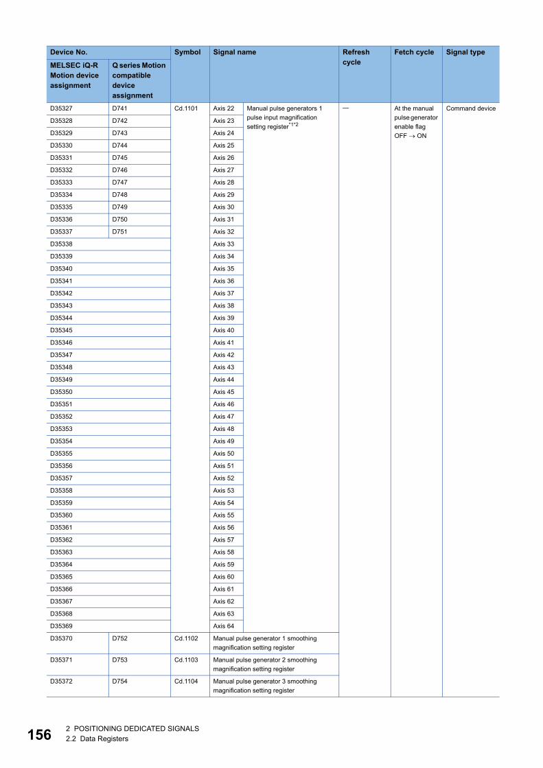
15
D35327 D741 Cd.1101 Axis 22 Manual pulse generators 1
pulse input magnification
setting register*1*2
At the manual
pulse generator
enable flag
OFF ON
Command device
D35328 D742 Axis 23
D35329 D743 Axis 24
D35330 D744 Axis 25
D35331 D745 Axis 26
D35332 D746 Axis 27
D35333 D747 Axis 28
D35334 D748 Axis 29
D35335 D749 Axis 30
D35336 D750 Axis 31
D35337 D751 Axis 32
D35338 Axis 33
D35339 Axis 34
D35340 Axis 35
D35341 Axis 36
D35342 Axis 37
D35343 Axis 38
D35344 Axis 39
D35345 Axis 40
D35346 Axis 41
D35347 Axis 42
D35348 Axis 43
D35349 Axis 44
D35350 Axis 45
D35351 Axis 46
D35352 Axis 47
D35353 Axis 48
D35354 Axis 49
D35355 Axis 50
D35356 Axis 51
D35357 Axis 52
D35358 Axis 53
D35359 Axis 54
D35360 Axis 55
D35361 Axis 56
D35362 Axis 57
D35363 Axis 58
D35364 Axis 59
D35365 Axis 60
D35366 Axis 61
D35367 Axis 62
D35368 Axis 63
D35369 Axis 64
D35370 D752 Cd.1102 Manual pulse generator 1 smoothing
magnification setting register
D35371 D753 Cd.1103 Manual pulse generator 2 smoothing
magnification setting register
D35372 D754 Cd.1104 Manual pulse generator 3 smoothing
magnification setting register
Device No. Symbol Signal name Refresh cycle
Fetch cycle Signal type
MELSEC iQ-R Motion device assignment
Q series Motion compatible device assignment
62 POSITIONING DEDICATED SIGNALS2.2 Data Registers
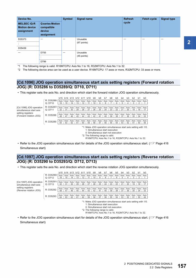
2
*1 The following range is valid. R16MTCPU: Axis No.1 to 16, R32MTCPU: Axis No.1 to 32.*2 The following device area can be used as a user device. R16MTCPU: 17 axes or more, R32MTCPU: 33 axes or more.
[Cd.1096] JOG operation simultaneous start axis setting registers (Forward rotation JOG) (R: D35286 to D35289/Q: D710, D711) • This register sets the axis No. and direction which start the forward rotation JOG operation simultaneously.
• Refer to the JOG operation simultaneous start for details of the JOG operation simultaneous start. (Page 416
Simultaneous start)
[Cd.1097] JOG operation simultaneous start axis setting registers (Reverse rotation JOG) (R: D35290 to D35293/Q: D712, D713) • This register sets the axis No. and direction which start the reverse rotation JOG operation simultaneously.
• Refer to the JOG operation simultaneous start for details of the JOG operation simultaneous start. (Page 416
Simultaneous start)
D35373 Unusable
(67 points)
:
D35439
D755 Unusable
(45 points):
D799
Device No. Symbol Signal name Refresh cycle
Fetch cycle Signal type
MELSEC iQ-R Motion device assignment
Q series Motion compatible device assignment
b15 b14 b13 b12 b11 b10 b9 b8 b7 b6 b5 b4 b3 b2 b1 b0Axis15
Axis14
Axis13
Axis12
Axis11
Axis10
Axis9
Axis8
Axis7
Axis6
Axis5
Axis4
Axis3
Axis2
Axis31
Axis30
Axis29
Axis28
Axis27
Axis26
Axis25
Axis24
Axis23
Axis22
Axis21
Axis20
Axis19
Axis18
Axis47
Axis46
Axis45
Axis44
Axis43
Axis42
Axis41
Axis40
Axis39
Axis38
Axis37
Axis36
Axis35
Axis34
Axis63
Axis62
Axis61
Axis60
Axis59
Axis58
Axis57
Axis56
Axis55
Axis54
Axis53
Axis52
Axis51
Axis50
Axis1
Axis16
Axis17
Axis32
Axis33
Axis48
Axis49
Axis64
R: D35287/Q: D711
R: D35286/Q: D710
R: D35288
R: D35289
[Cd.1096] JOG operationsimultaneous start axissetting registers (Forward rotation JOG)
*1: Make JOG operation simultaneous start axis setting with 1/0.1: Simultaneous start execution0: Simultaneous start not execution
*2: The following range is valid. R16MTCPU: Axis No.1 to 16, R32MTCPU: Axis No.1 to 32.
b15 b14 b13 b12 b11 b10 b9 b8 b7 b6 b5 b4 b3 b2 b1 b0Axis15
Axis14
Axis13
Axis12
Axis11
Axis10
Axis9
Axis8
Axis7
Axis6
Axis5
Axis4
Axis3
Axis2
Axis31
Axis30
Axis29
Axis28
Axis27
Axis26
Axis25
Axis24
Axis23
Axis22
Axis21
Axis20
Axis19
Axis18
Axis47
Axis46
Axis45
Axis44
Axis43
Axis42
Axis41
Axis40
Axis39
Axis38
Axis37
Axis36
Axis35
Axis34
Axis63
Axis62
Axis61
Axis60
Axis59
Axis58
Axis57
Axis56
Axis55
Axis54
Axis53
Axis52
Axis51
Axis50
Axis1
Axis16
Axis17
Axis32
Axis33
Axis48
Axis49
Axis64
R: D35291/Q: D713
[Cd.1097] JOG operation simultaneous start axis setting registers (Reverse rotation JOG)
R: D35290/Q: D712
R: D35292
R: D35293
*1: Make JOG operation simultaneous start axis setting with 1/0.1: Simultaneous start execution0: Simultaneous start not execution
*2: The following range is valid. R16MTCPU: Axis No.1 to 16, R32MTCPU: Axis No.1 to 32.
2 POSITIONING DEDICATED SIGNALS2.2 Data Registers 157
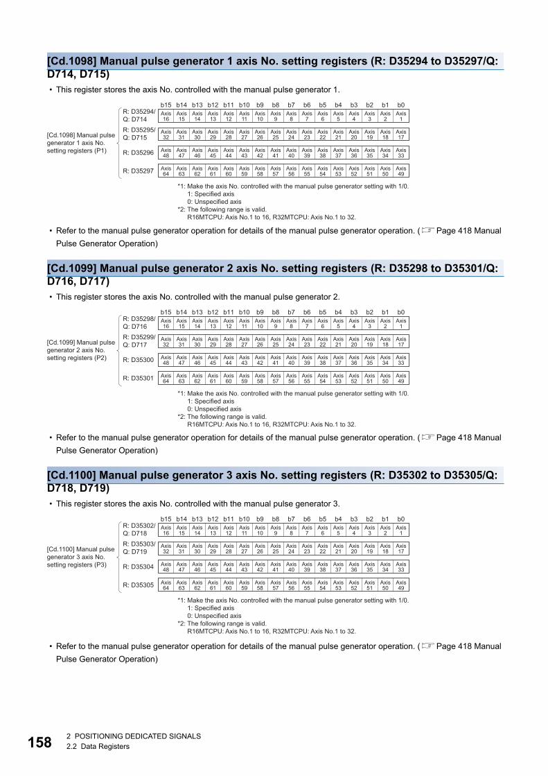
15
[Cd.1098] Manual pulse generator 1 axis No. setting registers (R: D35294 to D35297/Q: D714, D715) • This register stores the axis No. controlled with the manual pulse generator 1.
• Refer to the manual pulse generator operation for details of the manual pulse generator operation. (Page 418 Manual
Pulse Generator Operation)
[Cd.1099] Manual pulse generator 2 axis No. setting registers (R: D35298 to D35301/Q: D716, D717) • This register stores the axis No. controlled with the manual pulse generator 2.
• Refer to the manual pulse generator operation for details of the manual pulse generator operation. (Page 418 Manual
Pulse Generator Operation)
[Cd.1100] Manual pulse generator 3 axis No. setting registers (R: D35302 to D35305/Q: D718, D719) • This register stores the axis No. controlled with the manual pulse generator 3.
• Refer to the manual pulse generator operation for details of the manual pulse generator operation. (Page 418 Manual
Pulse Generator Operation)
b15 b14 b13 b12 b11 b10 b9 b8 b7 b6 b5 b4 b3 b2 b1 b0Axis15
Axis14
Axis13
Axis12
Axis11
Axis10
Axis9
Axis8
Axis7
Axis6
Axis5
Axis4
Axis3
Axis2
Axis31
Axis30
Axis29
Axis28
Axis27
Axis26
Axis25
Axis24
Axis23
Axis22
Axis21
Axis20
Axis19
Axis18
Axis47
Axis46
Axis45
Axis44
Axis43
Axis42
Axis41
Axis40
Axis39
Axis38
Axis37
Axis36
Axis35
Axis34
Axis63
Axis62
Axis61
Axis60
Axis59
Axis58
Axis57
Axis56
Axis55
Axis54
Axis53
Axis52
Axis51
Axis50
Axis1
Axis16
Axis17
Axis32
Axis33
Axis48
Axis49
Axis64
R: D35295/Q: D715
R: D35294/Q: D714
R: D35296
R: D35297
[Cd.1098] Manual pulsegenerator 1 axis No. setting registers (P1)
*1: Make the axis No. controlled with the manual pulse generator setting with 1/0.1: Specified axis0: Unspecified axis
*2: The following range is valid. R16MTCPU: Axis No.1 to 16, R32MTCPU: Axis No.1 to 32.
b15 b14 b13 b12 b11 b10 b9 b8 b7 b6 b5 b4 b3 b2 b1 b0Axis15
Axis14
Axis13
Axis12
Axis11
Axis10
Axis9
Axis8
Axis7
Axis6
Axis5
Axis4
Axis3
Axis2
Axis31
Axis30
Axis29
Axis28
Axis27
Axis26
Axis25
Axis24
Axis23
Axis22
Axis21
Axis20
Axis19
Axis18
Axis47
Axis46
Axis45
Axis44
Axis43
Axis42
Axis41
Axis40
Axis39
Axis38
Axis37
Axis36
Axis35
Axis34
Axis63
Axis62
Axis61
Axis60
Axis59
Axis58
Axis57
Axis56
Axis55
Axis54
Axis53
Axis52
Axis51
Axis50
Axis1
Axis16
Axis17
Axis32
Axis33
Axis48
Axis49
Axis64
R: D35299/Q: D717
R: D35298/Q: D716
R: D35300
R: D35301
[Cd.1099] Manual pulsegenerator 2 axis No. setting registers (P2)
*1: Make the axis No. controlled with the manual pulse generator setting with 1/0.1: Specified axis0: Unspecified axis
*2: The following range is valid. R16MTCPU: Axis No.1 to 16, R32MTCPU: Axis No.1 to 32.
b15 b14 b13 b12 b11 b10 b9 b8 b7 b6 b5 b4 b3 b2 b1 b0Axis15
Axis14
Axis13
Axis12
Axis11
Axis10
Axis9
Axis8
Axis7
Axis6
Axis5
Axis4
Axis3
Axis2
Axis31
Axis30
Axis29
Axis28
Axis27
Axis26
Axis25
Axis24
Axis23
Axis22
Axis21
Axis20
Axis19
Axis18
Axis47
Axis46
Axis45
Axis44
Axis43
Axis42
Axis41
Axis40
Axis39
Axis38
Axis37
Axis36
Axis35
Axis34
Axis63
Axis62
Axis61
Axis60
Axis59
Axis58
Axis57
Axis56
Axis55
Axis54
Axis53
Axis52
Axis51
Axis50
Axis1
Axis16
Axis17
Axis32
Axis33
Axis48
Axis49
Axis64
R: D35303/Q: D719
R: D35302/Q: D718
R: D35304
R: D35305
[Cd.1100] Manual pulsegenerator 3 axis No. setting registers (P3)
*1: Make the axis No. controlled with the manual pulse generator setting with 1/0.1: Specified axis0: Unspecified axis
*2: The following range is valid. R16MTCPU: Axis No.1 to 16, R32MTCPU: Axis No.1 to 32.
82 POSITIONING DEDICATED SIGNALS2.2 Data Registers
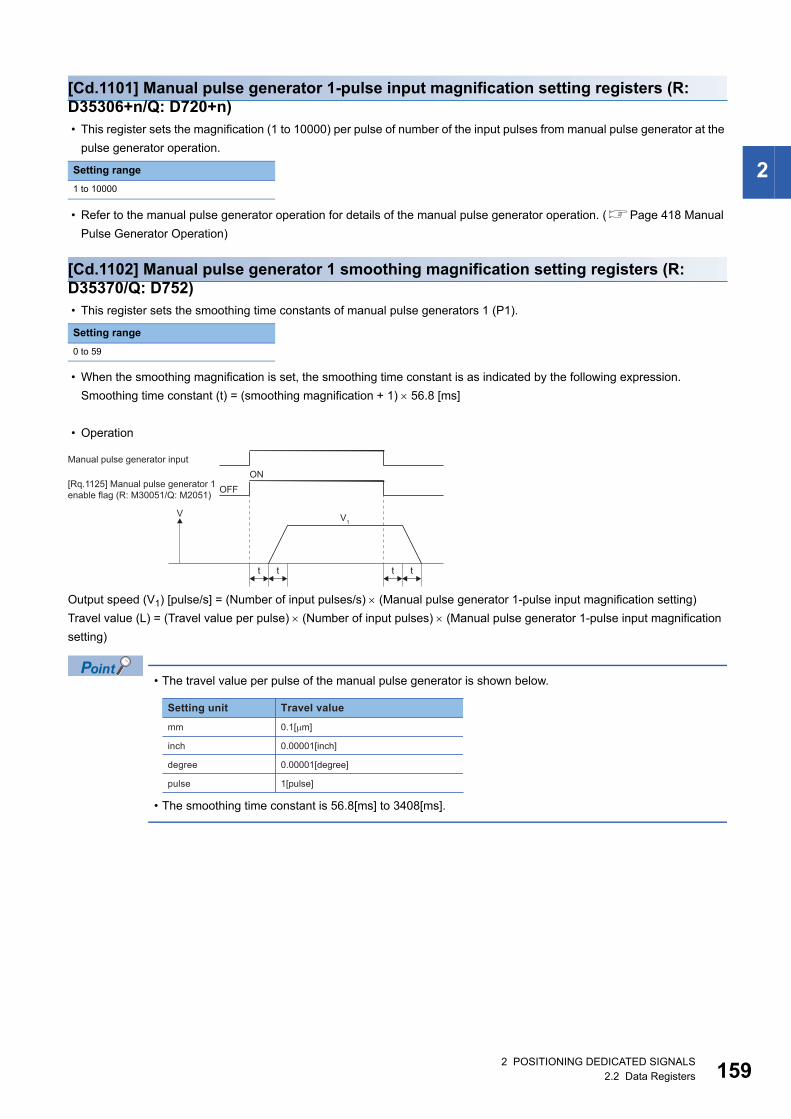
2
[Cd.1101] Manual pulse generator 1-pulse input magnification setting registers (R: D35306+n/Q: D720+n) • This register sets the magnification (1 to 10000) per pulse of number of the input pulses from manual pulse generator at the
pulse generator operation.
• Refer to the manual pulse generator operation for details of the manual pulse generator operation. (Page 418 Manual
Pulse Generator Operation)
[Cd.1102] Manual pulse generator 1 smoothing magnification setting registers (R: D35370/Q: D752) • This register sets the smoothing time constants of manual pulse generators 1 (P1).
• When the smoothing magnification is set, the smoothing time constant is as indicated by the following expression.
Smoothing time constant (t) = (smoothing magnification + 1) 56.8 [ms]
• Operation
Output speed (V1) [pulse/s] = (Number of input pulses/s) (Manual pulse generator 1-pulse input magnification setting)
Travel value (L) = (Travel value per pulse) (Number of input pulses) (Manual pulse generator 1-pulse input magnification
setting)
• The travel value per pulse of the manual pulse generator is shown below.
• The smoothing time constant is 56.8[ms] to 3408[ms].
Setting range
1 to 10000
Setting range
0 to 59
t t t t
V V1
Manual pulse generator input
[Rq.1125] Manual pulse generator 1enable flag (R: M30051/Q: M2051) OFF
ON
Setting unit
mm
inch
degree
pulse
Travel value
0.1[�m]
0.00001[inch]
0.00001[degree]
1[pulse]
2 POSITIONING DEDICATED SIGNALS2.2 Data Registers 159
16
[Cd.1103] Manual pulse generator 2 smoothing magnification setting registers (R: D35371/Q: D753) • This register sets the smoothing time constants of manual pulse generators 2 (P2).
The operation details are the same as "[Cd.1102] Manual pulse generator 1 smoothing magnification setting registers (R:
M35370/Q: D752)". (Page 159 [Cd.1102] Manual pulse generator 1 smoothing magnification setting registers (R:
D35370/Q: D752))
[Cd.1104] Manual pulse generator 3 smoothing magnification setting registers (R: D35372/Q: D754) • This register sets the smoothing time constants of manual pulse generators 3 (P3).
The operation details are the same as "[Cd.1102] Manual pulse generator 1 smoothing magnification setting registers (R:
M35370/Q: D752)". (Page 159 [Cd.1102] Manual pulse generator 1 smoothing magnification setting registers (R:
D35370/Q: D752))
Setting range
0 to 59
Setting range
0 to 59
02 POSITIONING DEDICATED SIGNALS2.2 Data Registers
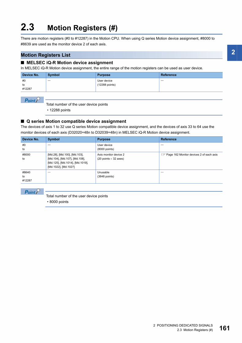
2
2.3 Motion Registers (#)There are motion registers (#0 to #12287) in the Motion CPU. When using Q series Motion device assignment, #8000 to
#8639 are used as the monitor device 2 of each axis.
Motion Registers List
■ MELSEC iQ-R Motion device assignment In MELSEC iQ-R Motion device assignment, the entire range of the motion registers can be used as user device.
Total number of the user device points
• 12288 points
■ Q series Motion compatible device assignmentThe devices of axis 1 to 32 use Q series Motion compatible device assignment, and the devices of axis 33 to 64 use the
monitor devices of each axis (D32020+48n to D32039+48n) in MELSEC iQ-R Motion device assignment.
Total number of the user device points
• 8000 points
Device No. Symbol Purpose Reference
#0
to
#12287
User device
(12288 points)
Device No. Symbol Purpose Reference
#0
to
User device
(8000 points)
#8000
to
[Md.28], [Md.100], [Md.103],
[Md.104], [Md.107], [Md.108],
[Md.125], [Md.1014], [Md.1019],
[Md.1022], [Md.1027]
Axis monitor device 2
(20 points 32 axes)
Page 162 Monitor devices 2 of each axis
#8640
to
#12287
Unusable
(3648 points)
2 POSITIONING DEDICATED SIGNALS2.3 Motion Registers (#) 161
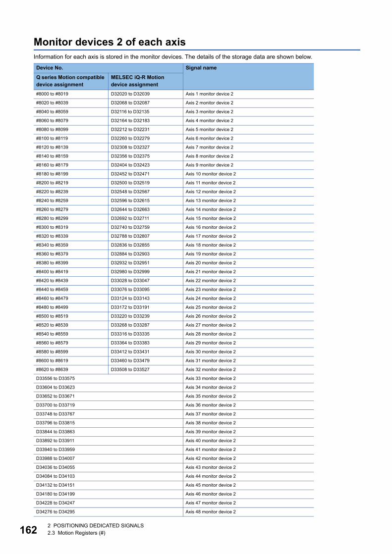
16
Monitor devices 2 of each axisInformation for each axis is stored in the monitor devices. The details of the storage data are shown below.
Device No. Signal name
Q series Motion compatible device assignment
MELSEC iQ-R Motion device assignment
#8000 to #8019 D32020 to D32039 Axis 1 monitor device 2
#8020 to #8039 D32068 to D32087 Axis 2 monitor device 2
#8040 to #8059 D32116 to D32135 Axis 3 monitor device 2
#8060 to #8079 D32164 to D32183 Axis 4 monitor device 2
#8080 to #8099 D32212 to D32231 Axis 5 monitor device 2
#8100 to #8119 D32260 to D32279 Axis 6 monitor device 2
#8120 to #8139 D32308 to D32327 Axis 7 monitor device 2
#8140 to #8159 D32356 to D32375 Axis 8 monitor device 2
#8160 to #8179 D32404 to D32423 Axis 9 monitor device 2
#8180 to #8199 D32452 to D32471 Axis 10 monitor device 2
#8200 to #8219 D32500 to D32519 Axis 11 monitor device 2
#8220 to #8239 D32548 to D32567 Axis 12 monitor device 2
#8240 to #8259 D32596 to D32615 Axis 13 monitor device 2
#8260 to #8279 D32644 to D32663 Axis 14 monitor device 2
#8280 to #8299 D32692 to D32711 Axis 15 monitor device 2
#8300 to #8319 D32740 to D32759 Axis 16 monitor device 2
#8320 to #8339 D32788 to D32807 Axis 17 monitor device 2
#8340 to #8359 D32836 to D32855 Axis 18 monitor device 2
#8360 to #8379 D32884 to D32903 Axis 19 monitor device 2
#8380 to #8399 D32932 to D32951 Axis 20 monitor device 2
#8400 to #8419 D32980 to D32999 Axis 21 monitor device 2
#8420 to #8439 D33028 to D33047 Axis 22 monitor device 2
#8440 to #8459 D33076 to D33095 Axis 23 monitor device 2
#8460 to #8479 D33124 to D33143 Axis 24 monitor device 2
#8480 to #8499 D33172 to D33191 Axis 25 monitor device 2
#8500 to #8519 D33220 to D33239 Axis 26 monitor device 2
#8520 to #8539 D33268 to D33287 Axis 27 monitor device 2
#8540 to #8559 D33316 to D33335 Axis 28 monitor device 2
#8560 to #8579 D33364 to D33383 Axis 29 monitor device 2
#8580 to #8599 D33412 to D33431 Axis 30 monitor device 2
#8600 to #8619 D33460 to D33479 Axis 31 monitor device 2
#8620 to #8639 D33508 to D33527 Axis 32 monitor device 2
D33556 to D33575 Axis 33 monitor device 2
D33604 to D33623 Axis 34 monitor device 2
D33652 to D33671 Axis 35 monitor device 2
D33700 to D33719 Axis 36 monitor device 2
D33748 to D33767 Axis 37 monitor device 2
D33796 to D33815 Axis 38 monitor device 2
D33844 to D33863 Axis 39 monitor device 2
D33892 to D33911 Axis 40 monitor device 2
D33940 to D33959 Axis 41 monitor device 2
D33988 to D34007 Axis 42 monitor device 2
D34036 to D34055 Axis 43 monitor device 2
D34084 to D34103 Axis 44 monitor device 2
D34132 to D34151 Axis 45 monitor device 2
D34180 to D34199 Axis 46 monitor device 2
D34228 to D34247 Axis 47 monitor device 2
D34276 to D34295 Axis 48 monitor device 2
22 POSITIONING DEDICATED SIGNALS2.3 Motion Registers (#)
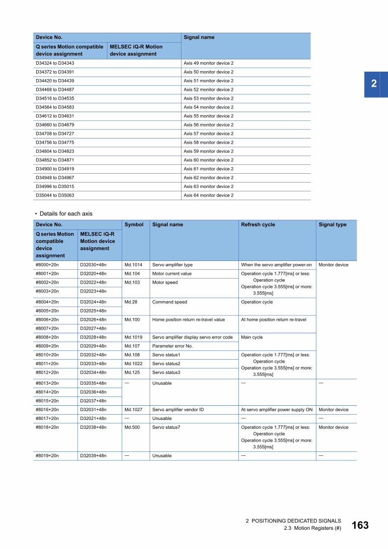
2
• Details for each axis
D34324 to D34343 Axis 49 monitor device 2
D34372 to D34391 Axis 50 monitor device 2
D34420 to D34439 Axis 51 monitor device 2
D34468 to D34487 Axis 52 monitor device 2
D34516 to D34535 Axis 53 monitor device 2
D34564 to D34583 Axis 54 monitor device 2
D34612 to D34631 Axis 55 monitor device 2
D34660 to D34679 Axis 56 monitor device 2
D34708 to D34727 Axis 57 monitor device 2
D34756 to D34775 Axis 58 monitor device 2
D34804 to D34823 Axis 59 monitor device 2
D34852 to D34871 Axis 60 monitor device 2
D34900 to D34919 Axis 61 monitor device 2
D34948 to D34967 Axis 62 monitor device 2
D34996 to D35015 Axis 63 monitor device 2
D35044 to D35063 Axis 64 monitor device 2
Device No. Symbol Signal name Refresh cycle Signal type
Q series Motion compatible device assignment
MELSEC iQ-R Motion device assignment
#8000+20n D32030+48n Md.1014 Servo amplifier type When the servo amplifier power-on Monitor device
#8001+20n D32020+48n Md.104 Motor current value Operation cycle 1.777[ms] or less:
Operation cycle
Operation cycle 3.555[ms] or more:
3.555[ms]
#8002+20n D32022+48n Md.103 Motor speed
#8003+20n D32023+48n
#8004+20n D32024+48n Md.28 Command speed Operation cycle
#8005+20n D32025+48n
#8006+20n D32026+48n Md.100 Home position return re-travel value At home position return re-travel
#8007+20n D32027+48n
#8008+20n D32028+48n Md.1019 Servo amplifier display servo error code Main cycle
#8009+20n D32029+48n Md.107 Parameter error No.
#8010+20n D32032+48n Md.108 Servo status1 Operation cycle 1.777[ms] or less:
Operation cycle
Operation cycle 3.555[ms] or more:
3.555[ms]
#8011+20n D32033+48n Md.1022 Servo status2
#8012+20n D32034+48n Md.125 Servo status3
#8013+20n D32035+48n Unusable
#8014+20n D32036+48n
#8015+20n D32037+48n
#8016+20n D32031+48n Md.1027 Servo amplifier vendor ID At servo amplifier power supply ON Monitor device
#8017+20n D32021+48n Unusable
#8018+20n D32038+48n Md.500 Servo status7 Operation cycle 1.777[ms] or less:
Operation cycle
Operation cycle 3.555[ms] or more:
3.555[ms]
Monitor device
#8019+20n D32039+48n Unusable
Device No. Signal name
Q series Motion compatible device assignment
MELSEC iQ-R Motion device assignment
2 POSITIONING DEDICATED SIGNALS2.3 Motion Registers (#) 163
16
• The following range is valid. R16MTCPU: Axis No.1 to 16, R32MTCPU: Axis No.1 to 32.
• The following device area can be used as a user device. R16MTCPU: 17 axes or more, R32MTCPU: 33
axes or more. However, when the project of R16MTCPU is replaced with R32MTCPU/R64MTCPU, or the
project of R32MTCPU is replaced with R64MTCPU, this area cannot be used as a user device.
• Refer to monitor device of each axis for details of monitor device 2 of each axis (#8000 to #8639).
(Page 91 Axis monitor devices)
2.4 Special Relays (SM)There are 4096 special relay points of SM0 to SM4095 in the Motion CPU.
Refer to the following for details of special relays.
MELSEC iQ-R Motion controller Programming Manual (Common)
2.5 Special Registers (SD)There are 4096 special register points of SD0 to SD4095 in the Motion CPU.
Refer to the following for details of special registers.
MELSEC iQ-R Motion controller Programming Manual (Common)
42 POSITIONING DEDICATED SIGNALS2.4 Special Relays (SM)
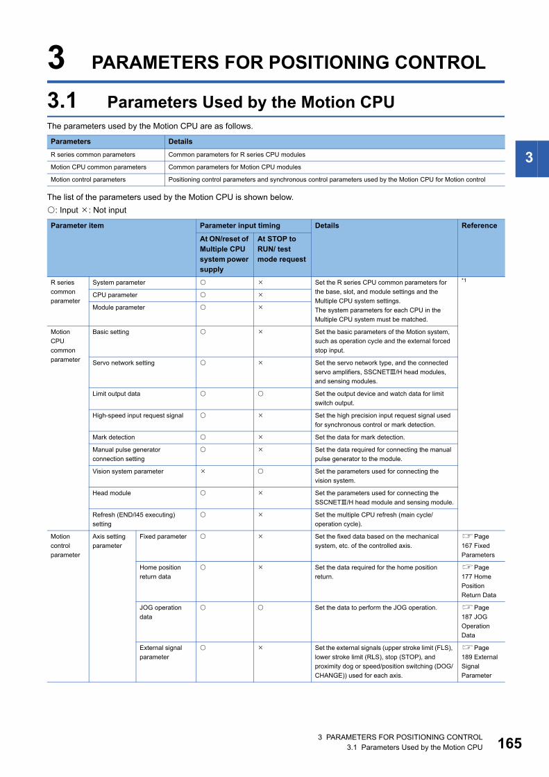
3
3 PARAMETERS FOR POSITIONING CONTROL
3.1 Parameters Used by the Motion CPUThe parameters used by the Motion CPU are as follows.
The list of the parameters used by the Motion CPU is shown below.
: Input : Not input
Parameters Details
R series common parameters Common parameters for R series CPU modules
Motion CPU common parameters Common parameters for Motion CPU modules
Motion control parameters Positioning control parameters and synchronous control parameters used by the Motion CPU for Motion control
Parameter item Parameter input timing Details Reference
At ON/reset of Multiple CPU system power supply
At STOP to RUN/ test mode request
R series
common
parameter
System parameter Set the R series CPU common parameters for
the base, slot, and module settings and the
Multiple CPU system settings.
The system parameters for each CPU in the
Multiple CPU system must be matched.
*1
CPU parameter
Module parameter
Motion
CPU
common
parameter
Basic setting Set the basic parameters of the Motion system,
such as operation cycle and the external forced
stop input.
Servo network setting Set the servo network type, and the connected
servo amplifiers, SSCNET/H head modules,
and sensing modules.
Limit output data Set the output device and watch data for limit
switch output.
High-speed input request signal Set the high precision input request signal used
for synchronous control or mark detection.
Mark detection Set the data for mark detection.
Manual pulse generator
connection setting
Set the data required for connecting the manual
pulse generator to the module.
Vision system parameter Set the parameters used for connecting the
vision system.
Head module Set the parameters used for connecting the
SSCNET/H head module and sensing module.
Refresh (END/I45 executing)
setting
Set the multiple CPU refresh (main cycle/
operation cycle).
Motion
control
parameter
Axis setting
parameter
Fixed parameter Set the fixed data based on the mechanical
system, etc. of the controlled axis.
Page
167 Fixed
Parameters
Home position
return data
Set the data required for the home position
return.
Page
177 Home
Position
Return Data
JOG operation
data
Set the data to perform the JOG operation. Page
187 JOG
Operation
Data
External signal
parameter
Set the external signals (upper stroke limit (FLS),
lower stroke limit (RLS), stop (STOP), and
proximity dog or speed/position switching (DOG/
CHANGE)) used for each axis.
Page
189 External
Signal
Parameter
3 PARAMETERS FOR POSITIONING CONTROL3.1 Parameters Used by the Motion CPU 165
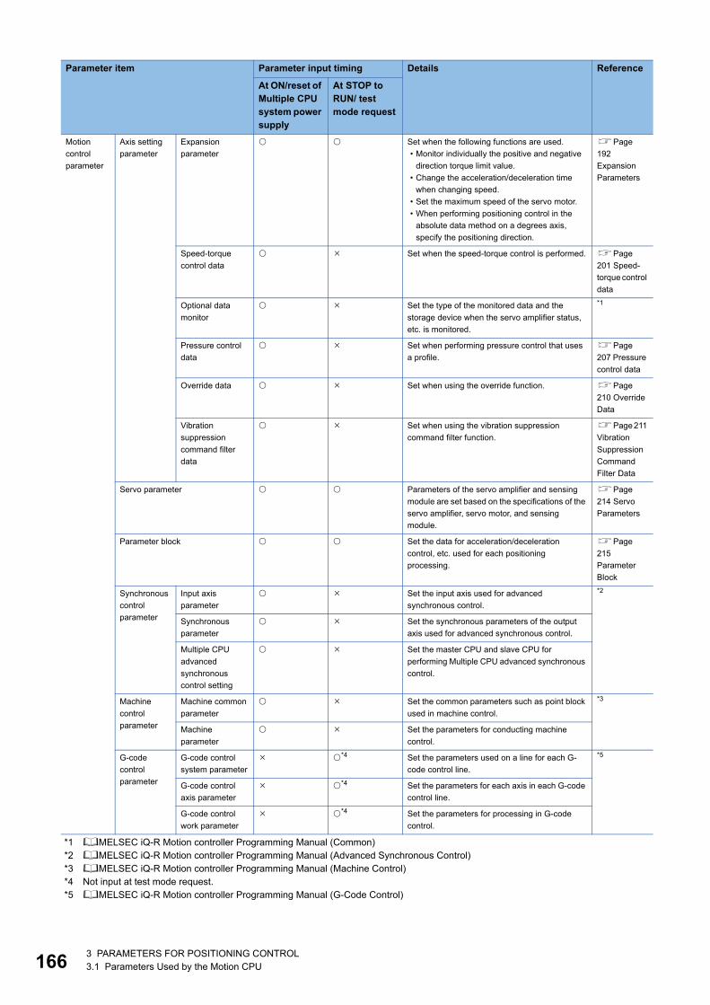
16
*1 MELSEC iQ-R Motion controller Programming Manual (Common)*2 MELSEC iQ-R Motion controller Programming Manual (Advanced Synchronous Control)*3 MELSEC iQ-R Motion controller Programming Manual (Machine Control)*4 Not input at test mode request.*5 MELSEC iQ-R Motion controller Programming Manual (G-Code Control)
Motion
control
parameter
Axis setting
parameter
Expansion
parameter
Set when the following functions are used.
• Monitor individually the positive and negative
direction torque limit value.
• Change the acceleration/deceleration time
when changing speed.
• Set the maximum speed of the servo motor.
• When performing positioning control in the
absolute data method on a degrees axis,
specify the positioning direction.
Page
192
Expansion
Parameters
Speed-torque
control data
Set when the speed-torque control is performed. Page
201 Speed-
torque control
data
Optional data
monitor
Set the type of the monitored data and the
storage device when the servo amplifier status,
etc. is monitored.
*1
Pressure control
data
Set when performing pressure control that uses
a profile.
Page
207 Pressure
control data
Override data Set when using the override function. Page
210 Override
Data
Vibration
suppression
command filter
data
Set when using the vibration suppression
command filter function.
Page 211
Vibration
Suppression
Command
Filter Data
Servo parameter Parameters of the servo amplifier and sensing
module are set based on the specifications of the
servo amplifier, servo motor, and sensing
module.
Page
214 Servo
Parameters
Parameter block Set the data for acceleration/deceleration
control, etc. used for each positioning
processing.
Page
215
Parameter
Block
Synchronous
control
parameter
Input axis
parameter
Set the input axis used for advanced
synchronous control.
*2
Synchronous
parameter
Set the synchronous parameters of the output
axis used for advanced synchronous control.
Multiple CPU
advanced
synchronous
control setting
Set the master CPU and slave CPU for
performing Multiple CPU advanced synchronous
control.
Machine
control
parameter
Machine common
parameter
Set the common parameters such as point block
used in machine control.
*3
Machine
parameter
Set the parameters for conducting machine
control.
G-code
control
parameter
G-code control
system parameter
*4 Set the parameters used on a line for each G-
code control line.
*5
G-code control
axis parameter
*4 Set the parameters for each axis in each G-code
control line.
G-code control
work parameter
*4 Set the parameters for processing in G-code
control.
Parameter item Parameter input timing Details Reference
At ON/reset of Multiple CPU system power supply
At STOP to RUN/ test mode request
63 PARAMETERS FOR POSITIONING CONTROL3.1 Parameters Used by the Motion CPU
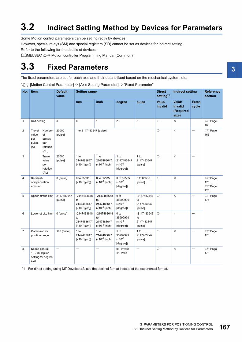
3
3.2 Indirect Setting Method by Devices for ParametersSome Motion control parameters can be set indirectly by devices.
However, special relays (SM) and special registers (SD) cannot be set as devices for indirect setting.
Refer to the following for the details of devices.
MELSEC iQ-R Motion controller Programming Manual (Common)
3.3 Fixed ParametersThe fixed parameters are set for each axis and their data is fixed based on the mechanical system, etc.
[Motion Control Parameter] [Axis Setting Parameter] "Fixed Parameter"
*1 For direct setting using MT Developer2, use the decimal format instead of the exponential format.
No. Item Default value
Setting range Direct setting*1
Indirect setting Reference section
mm inch degree pulse Valid/invalid
Valid/invalid (Required size)
Fetch cycle
1 Unit setting 3 0 1 2 3 Page
168
2 Travel
value
per
pulse
(A)
Number
of
pulses
per
rotation
(AP)
20000
[pulse]
1 to 2147483647 [pulse] Page
168
3 Travel
value
per
rotation
(AL)
20000
[pulse]
1 to
2147483647
(10-1 [m])
1 to
2147483647
(10-5 [inch])
1 to
2147483647
(10-5
[degree])
1 to
2147483647
[pulse]
4 Backlash
compensation
amount
0 [pulse] 0 to 65535
(10-1 [m])
0 to 65535
(10-5 [inch])
0 to 65535
(10-5
[degree])
0 to 65535
[pulse]
Page
170
Page
425
5 Upper stroke limit 2147483647
[pulse]
-2147483648
to
2147483647
(10-1 [m])
-2147483648
to
2147483647
(10-5 [inch])
0 to
35999999
(10-5
[degree])
-2147483648
to
2147483647
[pulse]
Page
171
6 Lower stroke limit 0 [pulse] -2147483648
to
2147483647
(10-1 [m])
-2147483648
to
2147483647
(10-5 [inch])
0 to
35999999
(10-5
[degree])
-2147483648
to
2147483647
[pulse]
7 Command in-
position range
100 [pulse] 1 to
2147483647
(10-1 [m])
1 to
2147483647
(10-5 [inch])
1 to
35999999
(10-5
[degree])
1 to
2147483647
[pulse]
Page
173
8 Speed control
10 multiplier
setting for degree
axis
0: Invalid
1: Valid
Page
173
3 PARAMETERS FOR POSITIONING CONTROL3.2 Indirect Setting Method by Devices for Parameters 167
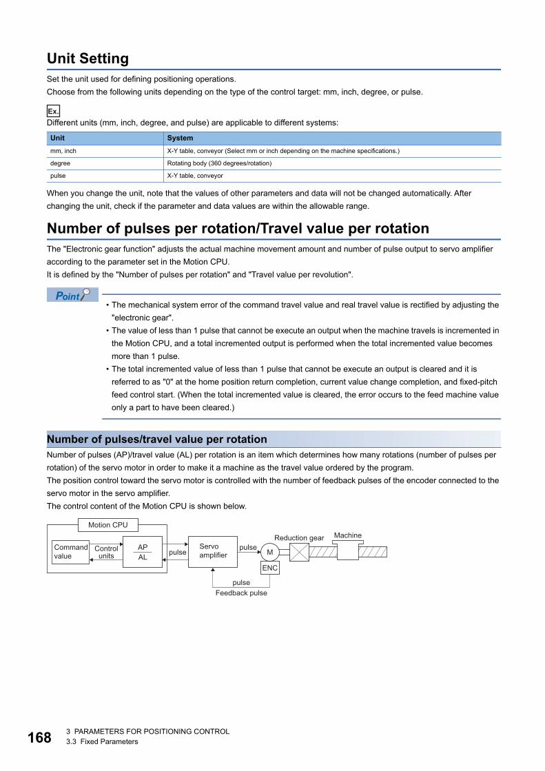
16
Unit SettingSet the unit used for defining positioning operations.
Choose from the following units depending on the type of the control target: mm, inch, degree, or pulse.
Ex.
Different units (mm, inch, degree, and pulse) are applicable to different systems:
When you change the unit, note that the values of other parameters and data will not be changed automatically. After
changing the unit, check if the parameter and data values are within the allowable range.
Number of pulses per rotation/Travel value per rotationThe "Electronic gear function" adjusts the actual machine movement amount and number of pulse output to servo amplifier
according to the parameter set in the Motion CPU.
It is defined by the "Number of pulses per rotation" and "Travel value per revolution".
• The mechanical system error of the command travel value and real travel value is rectified by adjusting the
"electronic gear".
• The value of less than 1 pulse that cannot be execute an output when the machine travels is incremented in
the Motion CPU, and a total incremented output is performed when the total incremented value becomes
more than 1 pulse.
• The total incremented value of less than 1 pulse that cannot be execute an output is cleared and it is
referred to as "0" at the home position return completion, current value change completion, and fixed-pitch
feed control start. (When the total incremented value is cleared, the error occurs to the feed machine value
only a part to have been cleared.)
Number of pulses/travel value per rotationNumber of pulses (AP)/travel value (AL) per rotation is an item which determines how many rotations (number of pulses per
rotation) of the servo motor in order to make it a machine as the travel value ordered by the program.
The position control toward the servo motor is controlled with the number of feedback pulses of the encoder connected to the
servo motor in the servo amplifier.
The control content of the Motion CPU is shown below.
Unit System
mm, inch X-Y table, conveyor (Select mm or inch depending on the machine specifications.)
degree Rotating body (360 degrees/rotation)
pulse X-Y table, conveyor
Motion CPU
APAL
Commandvalue
Controlunits pulse
pulseMachineReduction gear
Servo amplifier M
ENC
pulseFeedback pulse
83 PARAMETERS FOR POSITIONING CONTROL3.3 Fixed Parameters
3
For example, suppose that the servo motor was connected to the ball screw.
Because the travel value (S) of machine per motor rotation is [mm]/[inch] unit, the travel value (positioning address) set in
the program is commanded in [mm]/[inch] unit. However, the servo motor is positioning controlled by the servo amplifier in
pulse unit.
Therefore, AP/AL is set so that the following expression of relations may be materialized in order to convert the travel value of
[mm]/[inch] unit set in the program into a pulse.
Number of pulses per motor rotation = AP
Travel value of machine per motor rotation = AL
(There is a range which can be set in the numerical value set as AP/AL, so it is necessary to make the setting range of AP/AL
the value calculated from the above expression (reduced) of relations.)
Example of the real setting is shown below. Refer to the Number of pulses/travel value at linear servo use for the setting at
linear servo. (Page 170 Number of pulses/travel value at linear servo use)
■ For ball screwWhen the ball screw pitch is 20 [mm], the servo motor is HG-KR (4194304 [pulse/rev]) and direct connection (No reduction
gear) is set.
First, find how many millimeters the load (machine) will travel (AL) when the servo motor runs for one rotation (AP).
AP (Number of pulses per motor rotation) = 4194304 [pulse]
AL (Travel value of machine per rotation) = Ball screw pitch Reduction ratio = 20 [mm]
Substitute this for the above expression (1).
Although it becomes above, when a control unit is set to [mm] unit, the minimum unit of the command value in a program is
0.1 [m] and converted from 20 [mm] (20.0000 [mm]) to 20000.0 [m].
The travel value per motor rotation in this example is 0.0000047 [mm].
For example, when ordering the travel value of 19 [mm], it becomes 3984588.8 [pulse] and the fraction of 0.8 [pulse]. At this
time, the Motion CPU orders the travel value of 3984588 [pulse] to the servo motor and the fraction is memorized in the
Motion CPU. Positioning is performed by seasoning the travel value with this fraction at the next positioning.
Electronic gear = AP AL
. . . . . (1)
AP AL
=4194304 [pulse]
20 [mm]
AP AL
= 4194304 [pulse]20000.0 [μm]
3 PARAMETERS FOR POSITIONING CONTROL3.3 Fixed Parameters 169
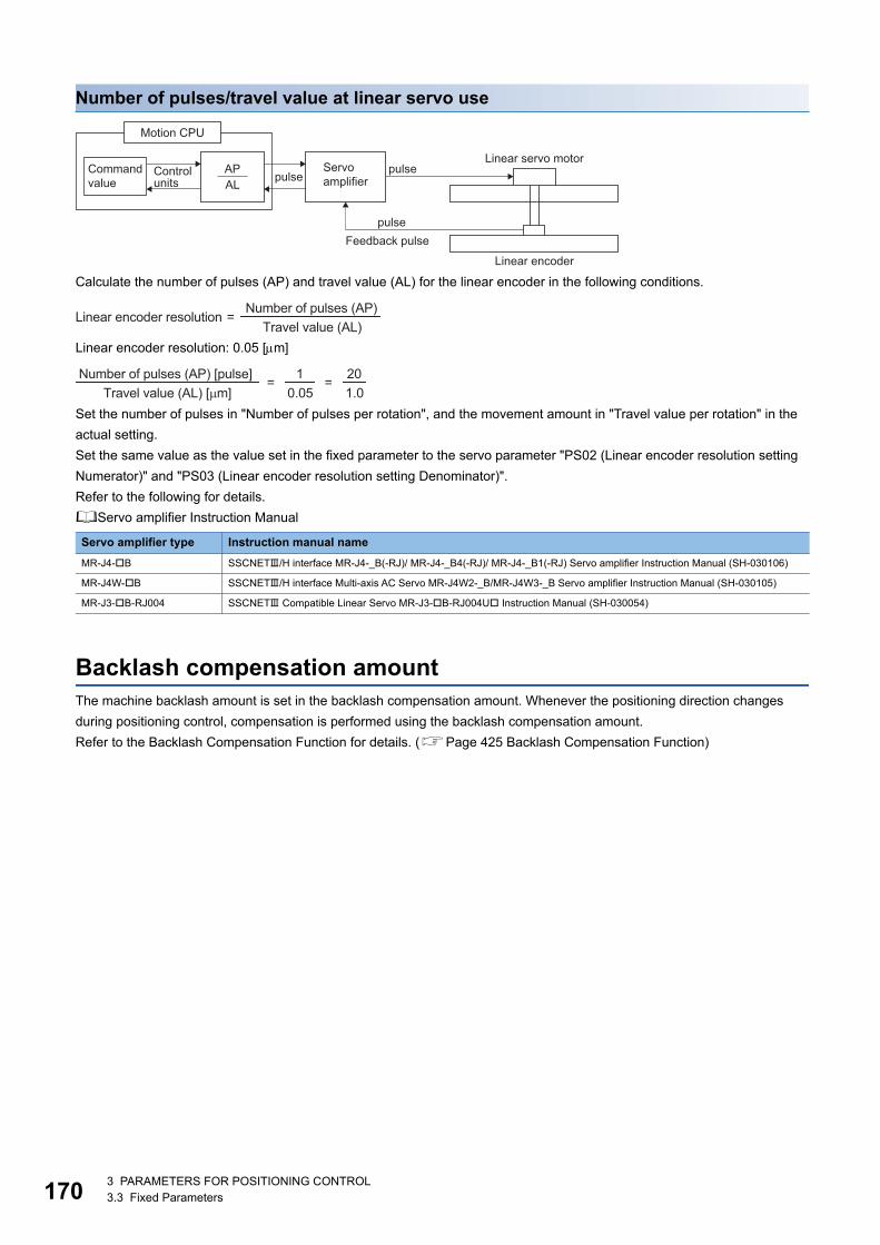
17
Number of pulses/travel value at linear servo use
Calculate the number of pulses (AP) and travel value (AL) for the linear encoder in the following conditions.
Linear encoder resolution: 0.05 [m]
Set the number of pulses in "Number of pulses per rotation", and the movement amount in "Travel value per rotation" in the
actual setting.
Set the same value as the value set in the fixed parameter to the servo parameter "PS02 (Linear encoder resolution setting
Numerator)" and "PS03 (Linear encoder resolution setting Denominator)".
Refer to the following for details.
Servo amplifier Instruction Manual
Backlash compensation amountThe machine backlash amount is set in the backlash compensation amount. Whenever the positioning direction changes
during positioning control, compensation is performed using the backlash compensation amount.
Refer to the Backlash Compensation Function for details. (Page 425 Backlash Compensation Function)
Servo amplifier type Instruction manual name
MR-J4-B SSCNET/H interface MR-J4-_B(-RJ)/ MR-J4-_B4(-RJ)/ MR-J4-_B1(-RJ) Servo amplifier Instruction Manual (SH-030106)
MR-J4W-B SSCNET/H interface Multi-axis AC Servo MR-J4W2-_B/MR-J4W3-_B Servo amplifier Instruction Manual (SH-030105)
MR-J3-B-RJ004 SSCNET Compatible Linear Servo MR-J3-B-RJ004U Instruction Manual (SH-030054)
Motion CPU
APAL
Commandvalue
Controlunits pulse
pulseServo amplifier
pulseFeedback pulse
Linear servo motor
Linear encoder
Linear encoder resolution =Number of pulses (AP)
Travel value (AL)
Number of pulses (AP) [pulse] Travel value (AL) [μm]
= 10.05
= 201.0
03 PARAMETERS FOR POSITIONING CONTROL3.3 Fixed Parameters
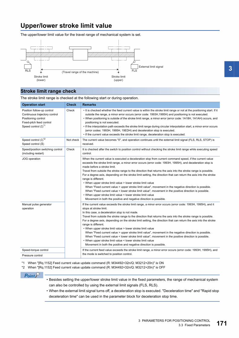
3
Upper/lower stroke limit valueThe upper/lower limit value for the travel range of mechanical system is set.
Stroke limit range checkThe stroke limit range is checked at the following start or during operation.
*1 When "[Rq.1152] Feed current value update command (R: M34492+32n/Q: M3212+20n)" is ON*2 When "[Rq.1152] Feed current value update command (R: M34492+32n/Q: M3212+20n)" is OFF
• Besides setting the upper/lower stroke limit value in the fixed parameters, the range of mechanical system
can also be controlled by using the external limit signals (FLS, RLS).
• When the external limit signal turns off, a deceleration stop is executed. "Deceleration time" and "Rapid stop
deceleration time" can be used in the parameter block for deceleration stop time.
Operation start Check Remarks
Position follow-up control
Continuous trajectory control
Positioning control
Fixed-pitch feed control
Speed control ()*1
Check • It is checked whether the feed current value is within the stroke limit range or not at the positioning start. If it
outside the range, a minor error occurs (error code: 1993H,1995H) and positioning is not executed.
• When positioning is outside of the stroke limit range, a minor error (error code: 1A18H, 1A1AH) occurs, and
positioning is not executed.
• If the interpolation path exceeds the stroke limit range during circular interpolation start, a minor error occurs
(error codes: 1993H, 1995H, 19EDH) and deceleration stop is executed.
• If the current value exceeds the stroke limit range, deceleration stop is executed.
Speed control ()*2
Speed control ()
Not check The current value becomes "0", and operation continues until the external limit signal (FLS, RLS, STOP) is
received.
Speed/position switching control
(including restart)
Check It is checked after the switch to position control without checking the stroke limit range while executing speed
control.
JOG operation When the current value is executed a deceleration stop from current command speed, if the current value
exceeds the stroke limit range, a minor error occurs (error code: 1993H, 1995H), and deceleration stop is
made before a stroke limit.
Travel from outside the stroke range to the direction that returns the axis into the stroke range is possible.
For a degree axis, depending on the stroke limit setting, the direction that can return the axis into the stroke
range is different.
• When upper stroke limit value > lower stroke limit value
When "Feed current value > upper stroke limit value", movement in the negative direction is possible.
When "Feed current value < lower stroke limit value", movement in the positive direction is possible.
• When upper stroke limit value < lower stroke limit value
Movement in both the positive and negative direction is possible.
Manual pulse generator
operation
If the current value exceeds the stroke limit range, a minor error occurs (error code: 1993H, 1995H), and it
stops at stroke limit.
In this case, a deceleration stop is not made.
Travel from outside the stroke range to the direction that returns the axis into the stroke range is possible.
For a degree axis, depending on the stroke limit setting, the direction that can return the axis into the stroke
range is different.
• When upper stroke limit value > lower stroke limit value
When "Feed current value > upper stroke limit value", movement in the negative direction is possible.
When "Feed current value < lower stroke limit value", movement in the positive direction is possible.
• When upper stroke limit value < lower stroke limit value
Movement in both the positive and negative direction is possible.
Speed-torque control If the current feed value exceeds the stroke limit range, a minor error occurs (error code: 1993H, 1995H), and
the mode is switched to position control.Pressure control
RLS FLSExternal limit signal
(Travel range of the machine)Stroke limit
(lower)Stroke limit
(upper)
3 PARAMETERS FOR POSITIONING CONTROL3.3 Fixed Parameters 171
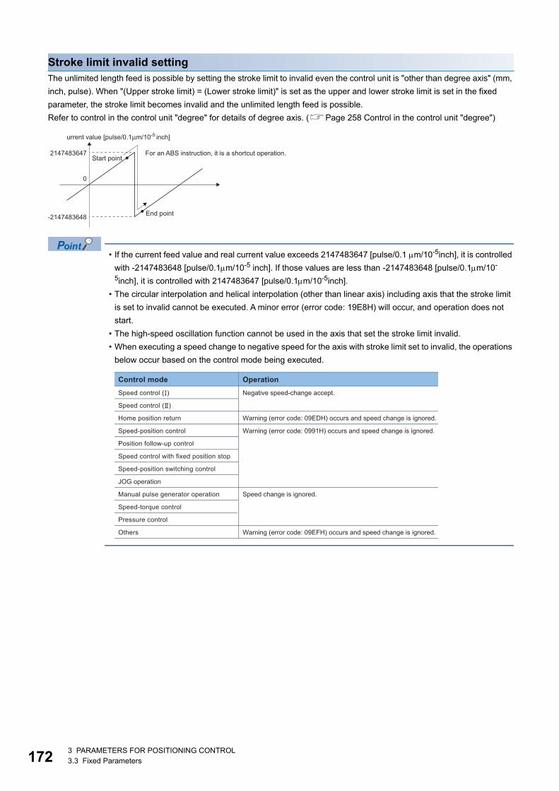
17
Stroke limit invalid settingThe unlimited length feed is possible by setting the stroke limit to invalid even the control unit is "other than degree axis" (mm,
inch, pulse). When "(Upper stroke limit) = (Lower stroke limit)" is set as the upper and lower stroke limit is set in the fixed
parameter, the stroke limit becomes invalid and the unlimited length feed is possible.
Refer to control in the control unit "degree" for details of degree axis. (Page 258 Control in the control unit "degree")
• If the current feed value and real current value exceeds 2147483647 [pulse/0.1 m/10-5inch], it is controlled
with -2147483648 [pulse/0.1m/10-5 inch]. If those values are less than -2147483648 [pulse/0.1m/10-
5inch], it is controlled with 2147483647 [pulse/0.1m/10-5inch].
• The circular interpolation and helical interpolation (other than linear axis) including axis that the stroke limit
is set to invalid cannot be executed. A minor error (error code: 19E8H) will occur, and operation does not
start.
• The high-speed oscillation function cannot be used in the axis that set the stroke limit invalid.
• When executing a speed change to negative speed for the axis with stroke limit set to invalid, the operations
below occur based on the control mode being executed.
0
-2147483648
2147483647Start point
End point
For an ABS instruction, it is a shortcut operation.
urrent value [pulse/0.1�m/10-5 inch]
Control mode OperationSpeed control (�) Negative speed-change accept.
Speed control (�)
Home position return Warning (error code: 09EDH) occurs and speed change is ignored.
Speed-position control Warning (error code: 0991H) occurs and speed change is ignored.
Position follow-up control
Speed control with fixed position stop
Speed-position switching control
JOG operation
Manual pulse generator operation Speed change is ignored.
Speed-torque control
Pressure control
Others Warning (error code: 09EFH) occurs and speed change is ignored.
23 PARAMETERS FOR POSITIONING CONTROL3.3 Fixed Parameters
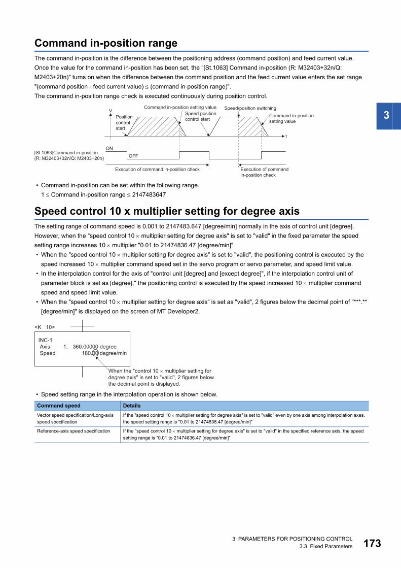
3
Command in-position rangeThe command in-position is the difference between the positioning address (command position) and feed current value.
Once the value for the command in-position has been set, the "[St.1063] Command in-position (R: M32403+32n/Q:
M2403+20n)" turns on when the difference between the command position and the feed current value enters the set range
"(command position - feed current value) (command in-position range)".
The command in-position range check is executed continuously during position control.
• Command in-position can be set within the following range.
1 Command in-position range 2147483647
Speed control 10 x multiplier setting for degree axisThe setting range of command speed is 0.001 to 2147483.647 [degree/min] normally in the axis of control unit [degree].
However, when the "speed control 10 multiplier setting for degree axis" is set to "valid" in the fixed parameter the speed
setting range increases 10 multiplier "0.01 to 21474836.47 [degree/min]".
• When the "speed control 10 multiplier setting for degree axis" is set to "valid", the positioning control is executed by the
speed increased 10 multiplier command speed set in the servo program or servo parameter, and speed limit value.
• In the interpolation control for the axis of "control unit [degree] and [except degree]", if the interpolation control unit of
parameter block is set as [degree]," the positioning control is executed by the speed increased 10 multiplier command
speed and speed limit value.
• When the "speed control 10 multiplier setting for degree axis" is set as "valid", 2 figures below the decimal point of "***.**
[degree/min]" is displayed on the screen of MT Developer2.
• Speed setting range in the interpolation operation is shown below.
Command speed Details
Vector speed specification/Long-axis
speed specification
If the "speed control 10 multiplier setting for degree axis" is set to "valid" even by one axis among interpolation axes,
the speed setting range is "0.01 to 21474836.47 [degree/min]"
Reference-axis speed specification If the "speed control 10 multiplier setting for degree axis" is set to "valid" in the specified reference axis, the speed
setting range is "0.01 to 21474836.47 [degree/min]"
ON
t
V
OFF
Command in-positionsetting value
Speed positioncontrol startPosition
controlstart
Command in-position setting value Speed/position switching
Execution of command in-position check Execution of commandin-position check
[St.1063]Command in-position(R: M32403+32n/Q: M2403+20n)
When the "control 10 � multiplier setting fordegree axis" is set to "valid", 2 figures belowthe decimal point is displayed.
<K 10>
INC-1 Axis 1, 360.00000 degree Speed 180.00 degree/min
3 PARAMETERS FOR POSITIONING CONTROL3.3 Fixed Parameters 173
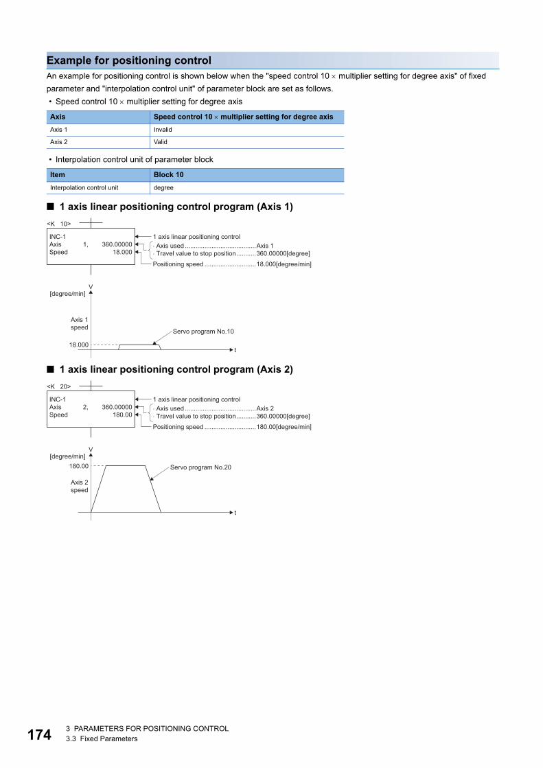
17
Example for positioning controlAn example for positioning control is shown below when the "speed control 10 multiplier setting for degree axis" of fixed
parameter and "interpolation control unit" of parameter block are set as follows.
• Speed control 10 multiplier setting for degree axis
• Interpolation control unit of parameter block
■ 1 axis linear positioning control program (Axis 1)
■ 1 axis linear positioning control program (Axis 2)
Axis Speed control 10 multiplier setting for degree axis
Axis 1 Invalid
Axis 2 Valid
Item Block 10
Interpolation control unit degree
� Axis used ........................................Axis 1� Travel value to stop position...........360.00000[degree]
V[degree/min]
Axis 1speed Servo program No.10
t
1 axis linear positioning control
Positioning speed .............................18.000[degree/min]
18.000
INC-1Axis 1,Speed
<K 10>
360.0000018.000
Servo program No.20180.00
� Axis used ........................................Axis 2� Travel value to stop position...........360.00000[degree]
V[degree/min]
Axis 2speed
t
1 axis linear positioning control
Positioning speed .............................180.00[degree/min]
INC-1Axis 2,Speed
<K 20>
360.00000180.00
43 PARAMETERS FOR POSITIONING CONTROL3.3 Fixed Parameters
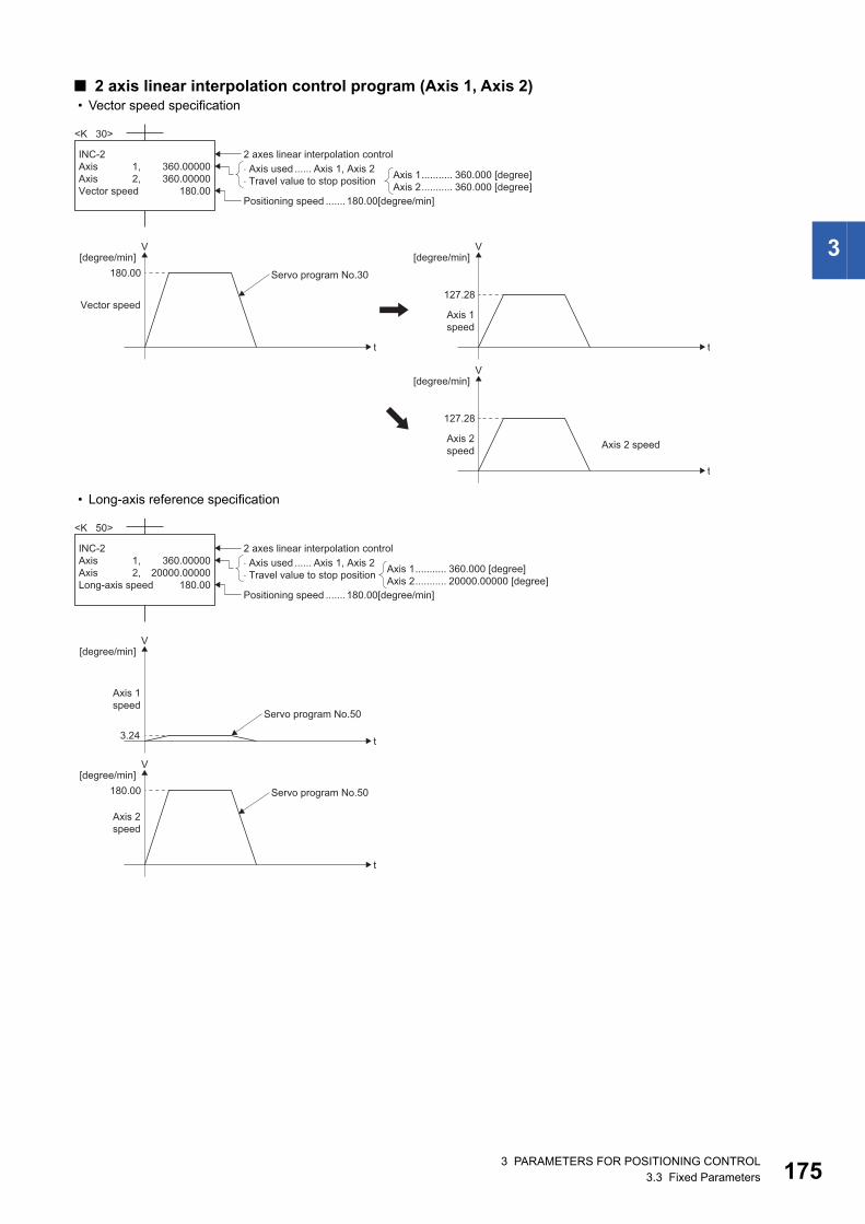
3
■ 2 axis linear interpolation control program (Axis 1, Axis 2) • Vector speed specification
• Long-axis reference specification
� Axis used ...... Axis 1, Axis 2� Travel value to stop position
2 axes linear interpolation control
Positioning speed .......180.00[degree/min]
INC-2Axis 1,Axis 2,Vector speed
360.00000360.00000
180.00
<K 30>
Axis 1........... 360.000 [degree]Axis 2........... 360.000 [degree]
Servo program No.30180.00
V[degree/min]
Vector speed
t
127.28
V[degree/min]
t
127.28
V[degree/min]
t
Axis 1speed
Axis 2speed Axis 2 speed
Servo program No.50
3.24
V[degree/min]
Axis 1speed
Axis 2speed
t
Servo program No.50180.00
V[degree/min]
t
� Axis used ...... Axis 1, Axis 2� Travel value to stop position
2 axes linear interpolation control
Positioning speed .......180.00[degree/min]
INC-2Axis 1,Axis 2,Long-axis speed
360.0000020000.00000
180.00
<K 50>
Axis 1........... 360.000 [degree]Axis 2........... 20000.00000 [degree]
3 PARAMETERS FOR POSITIONING CONTROL3.3 Fixed Parameters 175
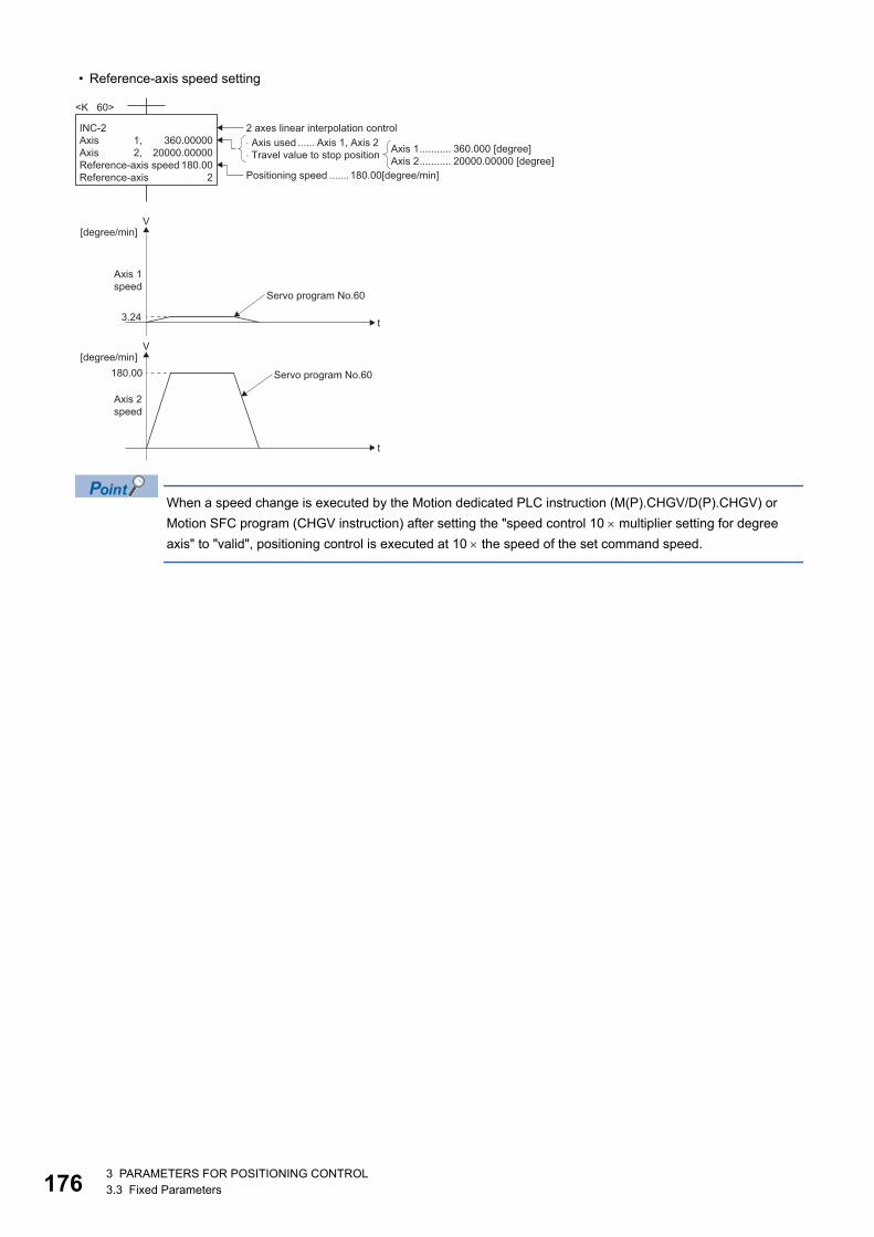
17
• Reference-axis speed setting
When a speed change is executed by the Motion dedicated PLC instruction (M(P).CHGV/D(P).CHGV) or
Motion SFC program (CHGV instruction) after setting the "speed control 10 multiplier setting for degree
axis" to "valid", positioning control is executed at 10 the speed of the set command speed.
Servo program No.60
3.24
V[degree/min]
Axis 1speed
Axis 2speed
t
Servo program No.60180.00
V[degree/min]
t
� Axis used ...... Axis 1, Axis 2� Travel value to stop position
2 axes linear interpolation control
Positioning speed .......180.00[degree/min]
INC-2Axis 1,Axis 2,Reference-axis speedReference-axis
360.0000020000.00000
180.002
<K 60>
Axis 1........... 360.000 [degree]Axis 2........... 20000.00000 [degree]
63 PARAMETERS FOR POSITIONING CONTROL3.3 Fixed Parameters
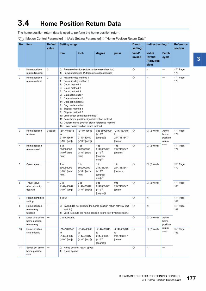
3
3.4 Home Position Return DataThe home position return data is used to perform the home position return.
[Motion Control Parameter] [Axis Setting Parameter] "Home Position Return Data"
No. Item Default value
Setting range Direct setting*1
Indirect setting*2 Reference section
mm inch degree pulse Valid/invalid
Valid/invalid(Required size)
Fetch cycle
1 Home position
return direction
0 0: Reverse direction (Address decrease direction)
1: Forward direction (Address increase direction)
Page
178
2 Home position
return method
2 0: Proximity dog method 1
4: Proximity dog method 2
1: Count method 1
5: Count method 2
6: Count method 3
2: Data set method 1
3: Data set method 2
14: Data set method 3
7: Dog cradle method
8: Stopper method 1
9: Stopper method 2
10: Limit switch combined method
11: Scale home position signal detection method
12: Dogless home position signal reference method
13: Driver home position return method
Page
179
3 Home position
address
0 [pulse] -2147483648
to
2147483647
(10-1 [m])
-2147483648
to
2147483647
(10-5 [inch])
0 to 35999999
(10-5
[degree])
-2147483648
to
2147483647
[pulse]
(2 word) At the
home
position
return
start
Page
179
4 Home position
return speed
1 to
600000000
(10-2 [mm/
min])
1 to
600000000
(10-3 [inch/
min])
1 to
2147483647
(10-3
[degree/
min])*3
1 to
2147483647
[pulse/s]
(2 word) Page
179
5 Creep speed 1 to
600000000
(10-2 [mm/
min])
1 to
600000000
(10-3 [inch/
min])
1 to
2147483647
(10-3
[degree/
min])*3
1 to
2147483647
[pulse/s]
(2 word) Page
179
6 Travel value
after proximity
dog ON
0 to
2147483647
(10-1 [m])
0 to
2147483647
(10-5 [inch])
0 to
2147483647
(10-5
[degree])
0 to
2147483647
[pulse]
(2 word) Page
180
7 Parameter block
setting
1 to 64 Page
181
8 Home position
return retry
function
0: Invalid (Do not execute the home position return retry by limit
switch.)
1: Valid (Execute the home position return retry by limit switch.)
Page
182
9 Dwell time at the
home position
return retry
0 to 5000 [ms] (1 word) At the
home
position
return
start10 Home position
shift amount
-2147483648
to
2147483647
(10-1 [m])
-2147483648
to
2147483647
(10-5 [inch])
-2147483648
to
2147483647
(10-5
[degree])
-2147483648
to
2147483647
[pulse]
(2 word) Page
183
11 Speed set at the
home position
shift
0: Home position return speed
1: Creep speed
3 PARAMETERS FOR POSITIONING CONTROL3.4 Home Position Return Data 177
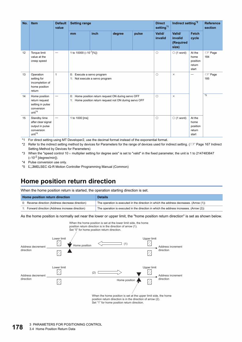
17
*1 For direct setting using MT Developer2, use the decimal format instead of the exponential format.*2 Refer to the indirect setting method by devices for Parameters for the range of devices used for indirect setting. (Page 167 Indirect
Setting Method by Devices for Parameters)*3 When the "speed control 10 multiplier setting for degree axis" is set to "valid" in the fixed parameter, the unit is 1 to 2147483647
(10-2 [degree/min]).*4 Pulse conversion use only.*5 MELSEC iQ-R Motion Controller Programming Manual (Common)
Home position return directionWhen the home position return is started, the operation starting direction is set.
As the home position is normally set near the lower or upper limit, the "home position return direction" is set as shown below.
12 Torque limit
value at the
creep speed
1 to 10000 (10-1[%]) (1 word) At the
home
position
return
start
Page
184
13 Operation
setting for
incompletion of
home position
return
1 0: Execute a servo program
1: Not execute a servo program
Page
185
14 Home position
return request
setting in pulse
conversion
unit*4
0: Home position return request ON during servo OFF
1: Home position return request not ON during servo OFF
*5
15 Standby time
after clear signal
output in pulse
conversion
unit*4
1 to 1000 [ms] (1 word) At the
home
position
return
start
Home position return direction Details
0: Reverse direction (Address decrease direction) The operation is executed in the direction in which the address decreases. (Arrow (1))
1: Forward direction (Address increase direction) The operation is executed in the direction in which the address increases. (Arrow (2))
No. Item Default value
Setting range Direct setting*1
Indirect setting*2 Reference section
mm inch degree pulse Valid/invalid
Valid/invalid(Required size)
Fetch cycle
Address incrementdirection
Address decrementdirection
Home position
Lower limit Upper limit
Lower limit Upper limit
(1)
When the home position is set at the lower limit side, the homeposition return direction is in the direction of arrow (1).Set “0” for home position return direction.
Address incrementdirection
Address decrementdirection Home position
(2)
When the home position is set at the upper limit side, the homeposition return direction is in the direction of arrow (2).Set “1” for home position return direction.
83 PARAMETERS FOR POSITIONING CONTROL3.4 Home Position Return Data
3
Home position return methodThe home position return method for executing home position return is set.
Refer to the following for details of the home position return methods.
Home position addressSet the address used as the reference point for positioning control (absolute data method).
(When the home position return is completed, the stop position address is changed to the set address. At the same time, it is
stored in the feed current value.)
Home position return speedSet the speed for home position return.
Set the home position return speed to the speed limit value or less.
If the speed limit value is exceeded, a minor error (error code: 1B04H) will occur, and home position return will not be
executed.
The home position return speed should be equal to or faster than the bias speed at start and creep speed.
Creep speedSet the creep speed after proximity dog ON (the low speed just before stopping after decelerating from the home position
return speed).
The creep speed is set within the following range.
Home position return speed Creep speed Bias speed at start
Home position return methods Reference
0: Proximity dog method 1 Page 378 Home position return by the proximity dog method 1
4: Proximity dog method 2 Page 380 Home position return by the proximity dog method 2
1: Count method 1 Page 382 Home position return by the count method 1
5: Count method 2 Page 383 Home position return by the count method 2
6: Count method 3 Page 384 Home position return by the count method 3
2: Data set method 1 Page 386 Home position return by the data set method 1
3: Data set method 2 Page 387 Home position return by the data set method 2
14: Data set method 3 Page 388 Home position return by the data set method 3
7: Dog cradle method Page 389 Home position return by the dog cradle method
8: Stopper method 1 Page 392 Home position return by the stopper method 1
9: Stopper method 2 Page 393 Home position return by the stopper method 2
10: Limit switch combined method Page 394 Home position return by the limit switch combined method
11: Scale home position signal detection method Page 396 Home position return by the scale home position signal detection method
12: Dogless home position signal reference method Page 398 Home position return by the dogless home position signal reference method
13: Driver home position return method Page 403 Home position return by the driver home position return method
3 PARAMETERS FOR POSITIONING CONTROL3.4 Home Position Return Data 179
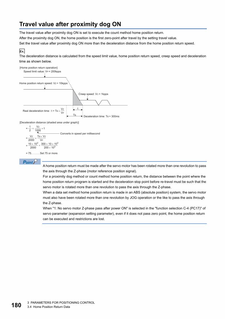
18
Travel value after proximity dog ONThe travel value after proximity dog ON is set to execute the count method home position return.
After the proximity dog ON, the home position is the first zero-point after travel by the setting travel value.
Set the travel value after proximity dog ON more than the deceleration distance from the home position return speed.
Ex.
The deceleration distance is calculated from the speed limit value, home position return speed, creep speed and deceleration
time as shown below.
A home position return must be made after the servo motor has been rotated more than one revolution to pass
the axis through the Z-phase (motor reference position signal).
For a proximity dog method or count method home position return, the distance between the point where the
home position return program is started and the deceleration stop point before re-travel must be such that the
servo motor is rotated more than one revolution to pass the axis through the Z-phase.
When a data set method home position return is made in an ABS (absolute position) system, the servo motor
must also have been rotated more than one revolution by JOG operation or the like to pass the axis through
the Z-phase.
When "1: No servo motor Z-phase pass after power ON" is selected in the "function selection C-4 (PC17)" of
servo parameter (expansion setting parameter), even if it does not pass zero point, the home position return
can be executed and restrictions are lost.
VZ
2000
TB VZ
VP
TB
t
Deceleration time: TB = 300ms
[Home position return operation]
Home position return speed: VZ = 10kpps
Speed limit value: VP = 200kpps
Creep speed: VC = 1kpps
Real deceleration time : t = TB VZ
VP
= t1
2
VZ
1000
=
10 103
2000
300 10 103
200 103=
= 75. . . . . . Set 75 or more
[Deceleration distance (shaded area under graph)]
Converts in speed per millisecond
03 PARAMETERS FOR POSITIONING CONTROL3.4 Home Position Return Data
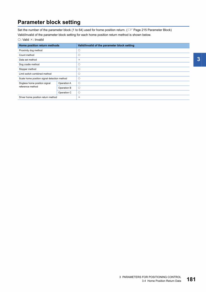
3
Parameter block settingSet the number of the parameter block (1 to 64) used for home position return. (Page 215 Parameter Block)
Valid/invalid of the parameter block setting for each home position return method is shown below.
: Valid : Invalid
Home position return methods Valid/invalid of the parameter block setting
Proximity dog method
Count method
Data set method
Dog cradle method
Stopper method
Limit switch combined method
Scale home position signal detection method
Dogless home position signal
reference method
Operation A
Operation B
Operation C
Driver home position return method
3 PARAMETERS FOR POSITIONING CONTROL3.4 Home Position Return Data 181
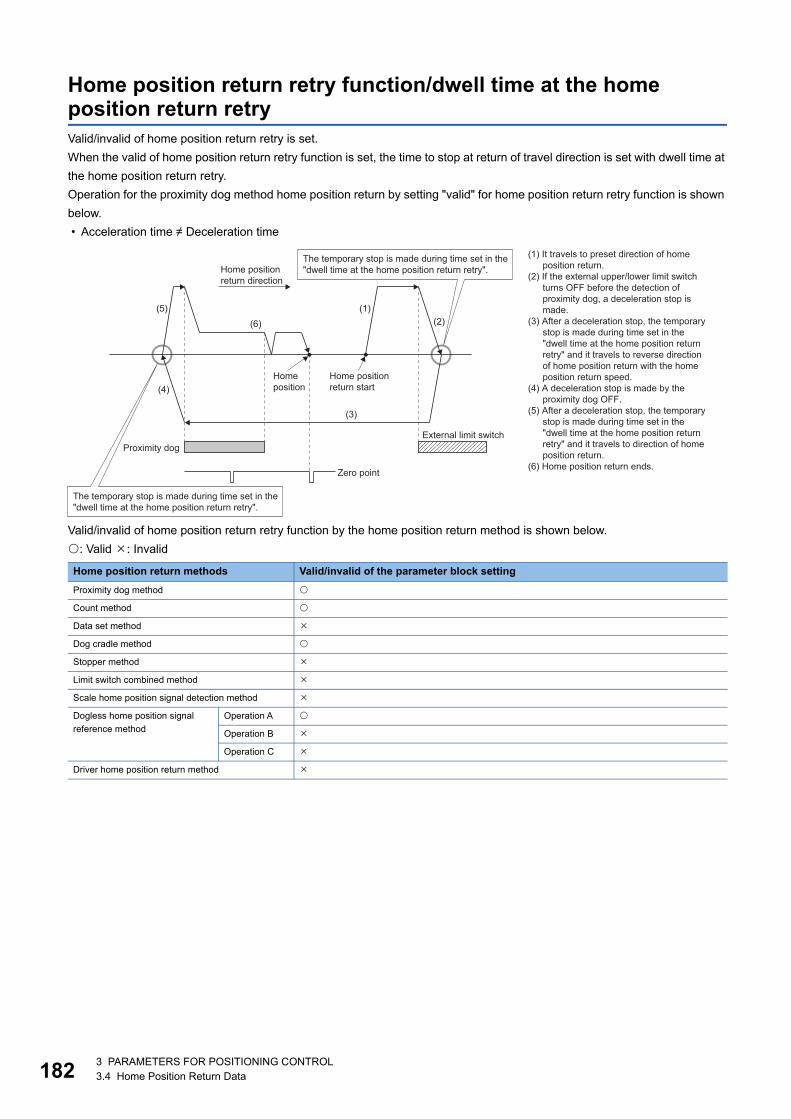
18
Home position return retry function/dwell time at the home position return retryValid/invalid of home position return retry is set.
When the valid of home position return retry function is set, the time to stop at return of travel direction is set with dwell time at
the home position return retry.
Operation for the proximity dog method home position return by setting "valid" for home position return retry function is shown
below.
• Acceleration time Deceleration time
Valid/invalid of home position return retry function by the home position return method is shown below.
: Valid : Invalid
Home position return methods Valid/invalid of the parameter block setting
Proximity dog method
Count method
Data set method
Dog cradle method
Stopper method
Limit switch combined method
Scale home position signal detection method
Dogless home position signal
reference method
Operation A
Operation B
Operation C
Driver home position return method
(1) It travels to preset direction of homeposition return.
(2) If the external upper/lower limit switchturns OFF before the detection ofproximity dog, a deceleration stop ismade.
(3) After a deceleration stop, the temporarystop is made during time set in the "dwell time at the home position returnretry" and it travels to reverse directionof home position return with the homeposition return speed.
(4) A deceleration stop is made by theproximity dog OFF.
(5) After a deceleration stop, the temporarystop is made during time set in the "dwell time at the home position returnretry" and it travels to direction of homeposition return.
(6) Home position return ends.
Home positionreturn start
External limit switch
Homeposition
Zero point
Home positionreturn direction
(6)
(3)
(5)
(4)
(1)(2)
Proximity dog
The temporary stop is made during time set in the"dwell time at the home position return retry".
The temporary stop is made during time set in the"dwell time at the home position return retry".
23 PARAMETERS FOR POSITIONING CONTROL3.4 Home Position Return Data
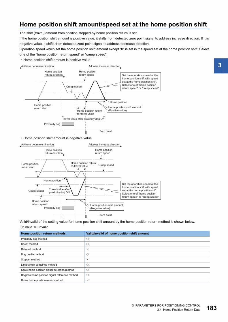
3
Home position shift amount/speed set at the home position shiftThe shift (travel) amount from position stopped by home position return is set.
If the home position shift amount is positive value, it shifts from detected zero point signal to address increase direction. If it is
negative value, it shifts from detected zero point signal to address decrease direction.
Operation speed which set the home position shift amount except "0" is set in the speed set at the home position shift. Select
one of the "home position return speed" or "creep speed".
• Home position shift amount is positive value
• Home position shift amount is negative value
Valid/invalid of the setting value for home position shift amount by the home position return method is shown below.
: Valid : Invalid
Home position return methods Valid/invalid of home position shift amount
Proximity dog method
Count method
Data set method
Dog cradle method
Stopper method
Limit switch combined method
Scale home position signal detection method
Dogless home position signal reference method
Driver home position return method
Address increase direction
Home positionreturn speed
Home positionreturn start
Home position
Address decrease direction
Proximity dog
Zero point
Creep speed
Home positionreturn direction
Travel value after proximity dog ON
Home position returnre-travel value
Home position shift amount(Positive value)
Set the operation speed at thehome position shift with speedset at the home position shift.Select one of "home positionreturn speed" or "creep speed".
Home positionreturn speed
Home position
Proximity dog
Zero point
Creep speed
Creep speed
Home positionreturn speed
Home positionreturn start
Address increase directionAddress decrease direction
Home positionreturn direction
Home position returnre-travel value
Home position shift amount(Negative value)
Set the operation speed at thehome position shift with speedset at the home position shift.Select one of "home positionreturn speed" or "creep speed".
Travel value afterproximity dog ON
3 PARAMETERS FOR POSITIONING CONTROL3.4 Home Position Return Data 183
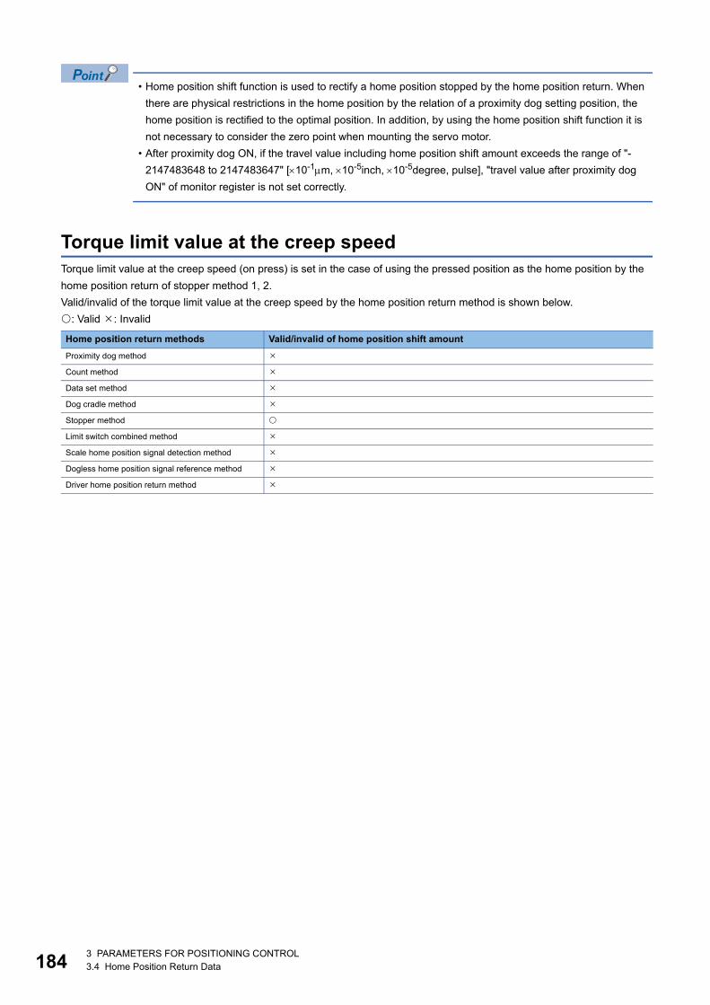
18
• Home position shift function is used to rectify a home position stopped by the home position return. When
there are physical restrictions in the home position by the relation of a proximity dog setting position, the
home position is rectified to the optimal position. In addition, by using the home position shift function it is
not necessary to consider the zero point when mounting the servo motor.
• After proximity dog ON, if the travel value including home position shift amount exceeds the range of "-
2147483648 to 2147483647" [10-1m, 10-5inch, 10-5degree, pulse], "travel value after proximity dog
ON" of monitor register is not set correctly.
Torque limit value at the creep speedTorque limit value at the creep speed (on press) is set in the case of using the pressed position as the home position by the
home position return of stopper method 1, 2.
Valid/invalid of the torque limit value at the creep speed by the home position return method is shown below.
: Valid : Invalid
Home position return methods Valid/invalid of home position shift amount
Proximity dog method
Count method
Data set method
Dog cradle method
Stopper method
Limit switch combined method
Scale home position signal detection method
Dogless home position signal reference method
Driver home position return method
43 PARAMETERS FOR POSITIONING CONTROL3.4 Home Position Return Data
3
Operation setting for incompletion of home position returnSet the operation for executing or not executing the servo program when the state of the home position return request signal
is ON.
When the home position return request signal is ON while G-code control is running, a minor error (error code: 1FC1H (details
code: 0116H)) occurs regardless of this setting.
Operation in selecting "1: Not execute servo program" • Servo program cannot be executed if the "[St.1069] Home position return request (R: M32409+32n/Q: M2409+20n)" is ON.
However, the servo program can be executed even if the "[St.1069] Home position return request (R: M32409+32n/Q:
M2409+20n)" is ON in the case of only servo program of home position return instruction (ZERO).
• At the time of servo program start, when "1: Not execute servo program" is selected in the operation setting for
incompletion of home position return and the axis which the "[St.1069] Home position return request (R: M32409+32n/Q:
M2409+20n)" is ON exists also with one axis, a minor error (error code: 19A6H) occurs and the servo program does not
start.
• JOG operation and manual pulse generator operation can be executed regardless of the "[St.1069] Home position return
request (R: M32409+32n/Q: M2409+20n)" ON/OFF.
• Same operation is executed regardless of absolute position system or not. When "1: Not execute servo program" is
selected in the case of not absolute position system, the "[St.1069] Home position return request (R: M32409+32n/Q:
M2409+20n)" turns ON at power supply ON or reset of Multiple CPU system and power supply ON of servo amplifier.
Therefore, it must be executed home position return before a servo program start.
• Same operation is executed in TEST mode.
Operation in selecting "0: Execute servo program" • Servo program can be executed even if the "[St.1069] Home position return request (R: M32409+32n/Q: M2409+20n)" is
ON.
CAUTION• Do not execute the positioning control in "[St.1069] Home position return request (R: M32409+32n/Q: M2409+20n)" is ON for the axis which uses in the
positioning control. Failure to observe this could lead to an accident such as a collision.
3 PARAMETERS FOR POSITIONING CONTROL3.4 Home Position Return Data 185
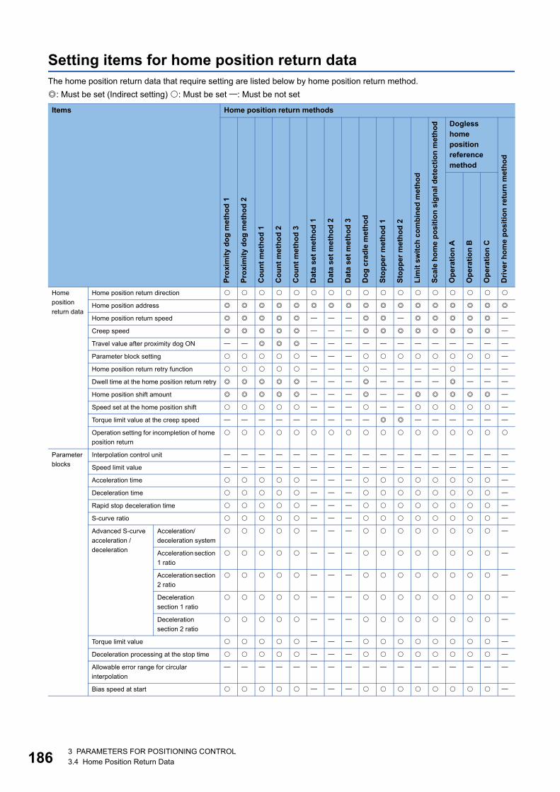
18
Setting items for home position return dataThe home position return data that require setting are listed below by home position return method.
: Must be set (Indirect setting) : Must be set : Must be not set
Items Home position return methods
Pro
xim
ity
do
g m
eth
od
1
Pro
xim
ity
do
g m
eth
od
2
Co
un
t m
eth
od
1
Co
un
t m
eth
od
2
Co
un
t m
eth
od
3
Dat
a se
t m
eth
od
1
Dat
a se
t m
eth
od
2
Dat
a se
t m
eth
od
3
Do
g c
rad
le m
eth
od
Sto
pp
er m
eth
od
1
Sto
pp
er m
eth
od
2
Lim
it s
wit
ch c
om
bin
ed m
eth
od
Sca
le h
om
e p
osi
tio
n s
ign
al d
etec
tio
n m
eth
od Dogless
home position reference method
Dri
ver
ho
me
po
siti
on
ret
urn
met
ho
d
Op
erat
ion
A
Op
erat
ion
B
Op
erat
ion
C
Home
position
return data
Home position return direction
Home position address
Home position return speed
Creep speed
Travel value after proximity dog ON
Parameter block setting
Home position return retry function
Dwell time at the home position return retry
Home position shift amount
Speed set at the home position shift
Torque limit value at the creep speed
Operation setting for incompletion of home
position return
Parameter
blocks
Interpolation control unit
Speed limit value
Acceleration time
Deceleration time
Rapid stop deceleration time
S-curve ratio
Advanced S-curve
acceleration /
deceleration
Acceleration/
deceleration system
Acceleration section
1 ratio
Acceleration section
2 ratio
Deceleration
section 1 ratio
Deceleration
section 2 ratio
Torque limit value
Deceleration processing at the stop time
Allowable error range for circular
interpolation
Bias speed at start
63 PARAMETERS FOR POSITIONING CONTROL3.4 Home Position Return Data
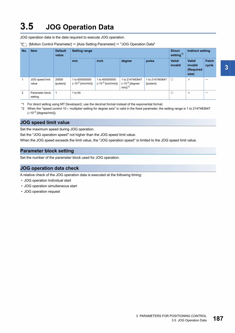
3
3.5 JOG Operation DataJOG operation data is the data required to execute JOG operation.
[Motion Control Parameter] [Axis Setting Parameter] "JOG Operation Data"
*1 For direct setting using MT Developer2, use the decimal format instead of the exponential format.*2 When the "speed control 10 multiplier setting for degree axis" is valid in the fixed parameter, the setting range is 1 to 2147483647
(10-2 [degree/min]).
JOG speed limit valueSet the maximum speed during JOG operation.
Set the "JOG operation speed" not higher than the JOG speed limit value.
When the JOG speed exceeds the limit value, the "JOG operation speed" is limited to the JOG speed limit value.
Parameter block settingSet the number of the parameter block used for JOG operation.
JOG operation data checkA relative check of the JOG operation data is executed at the following timing:
• JOG operation Individual start
• JOG operation simultaneous start
• JOG operation request
No. Item Default value
Setting range Direct setting*1
Indirect setting
mm inch degree pulse Valid/invalid
Valid/invalid(Required size)
Fetch cycle
1 JOG speed limit
value
20000
[pulse/s]
1 to 600000000
(10-2 [mm/min])
1 to 600000000
(10-3 [inch/min])
1 to 2147483647
(10-3 [degree/
min])*2
1 to 2147483647
[pulse/s]
2 Parameter block
setting
1 1 to 64
3 PARAMETERS FOR POSITIONING CONTROL3.5 JOG Operation Data 187
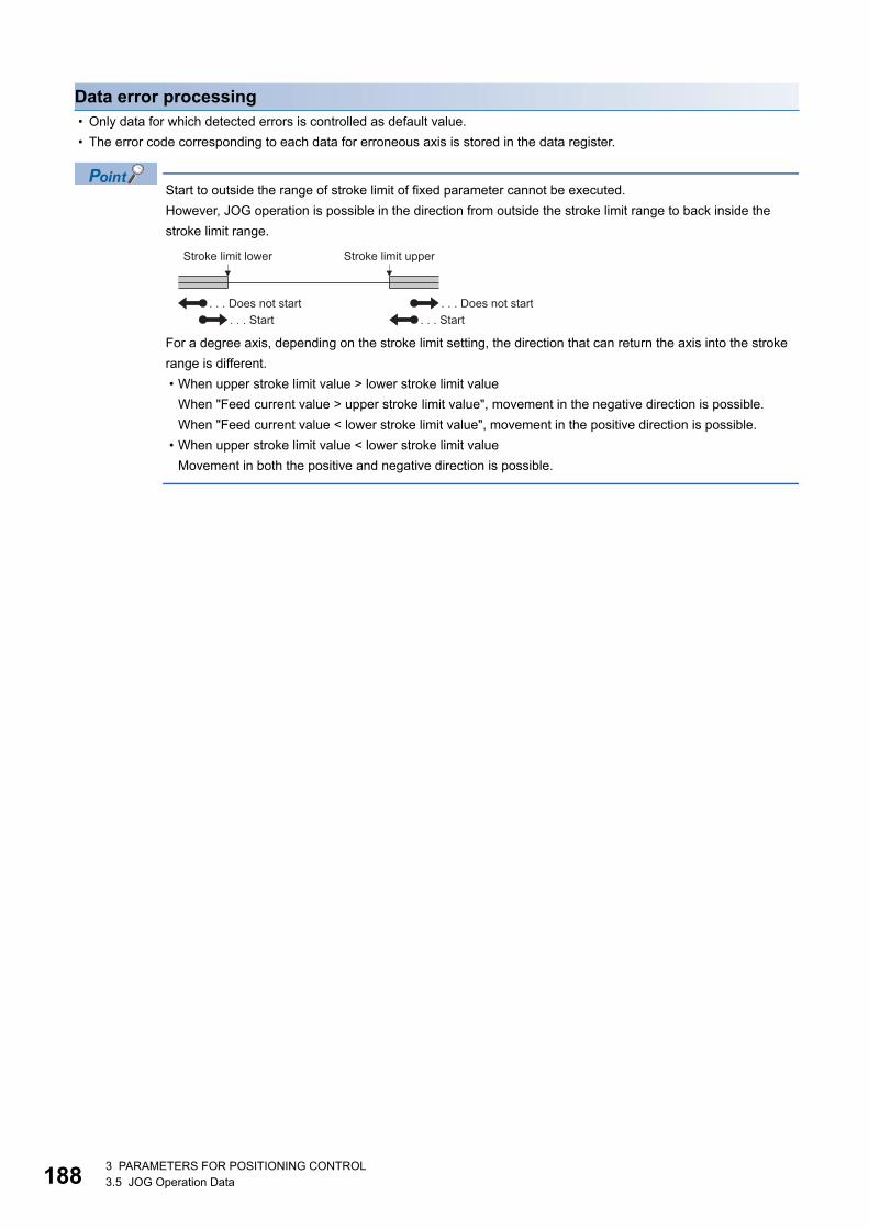
18
Data error processing • Only data for which detected errors is controlled as default value.
• The error code corresponding to each data for erroneous axis is stored in the data register.
Start to outside the range of stroke limit of fixed parameter cannot be executed.
However, JOG operation is possible in the direction from outside the stroke limit range to back inside the
stroke limit range.
For a degree axis, depending on the stroke limit setting, the direction that can return the axis into the stroke
range is different.
• When upper stroke limit value > lower stroke limit value
When "Feed current value > upper stroke limit value", movement in the negative direction is possible.
When "Feed current value < lower stroke limit value", movement in the positive direction is possible.
• When upper stroke limit value < lower stroke limit value
Movement in both the positive and negative direction is possible.
Stroke limit lower Stroke limit upper
. . . Does not start. . . Start. . . Start
. . . Does not start
83 PARAMETERS FOR POSITIONING CONTROL3.5 JOG Operation Data
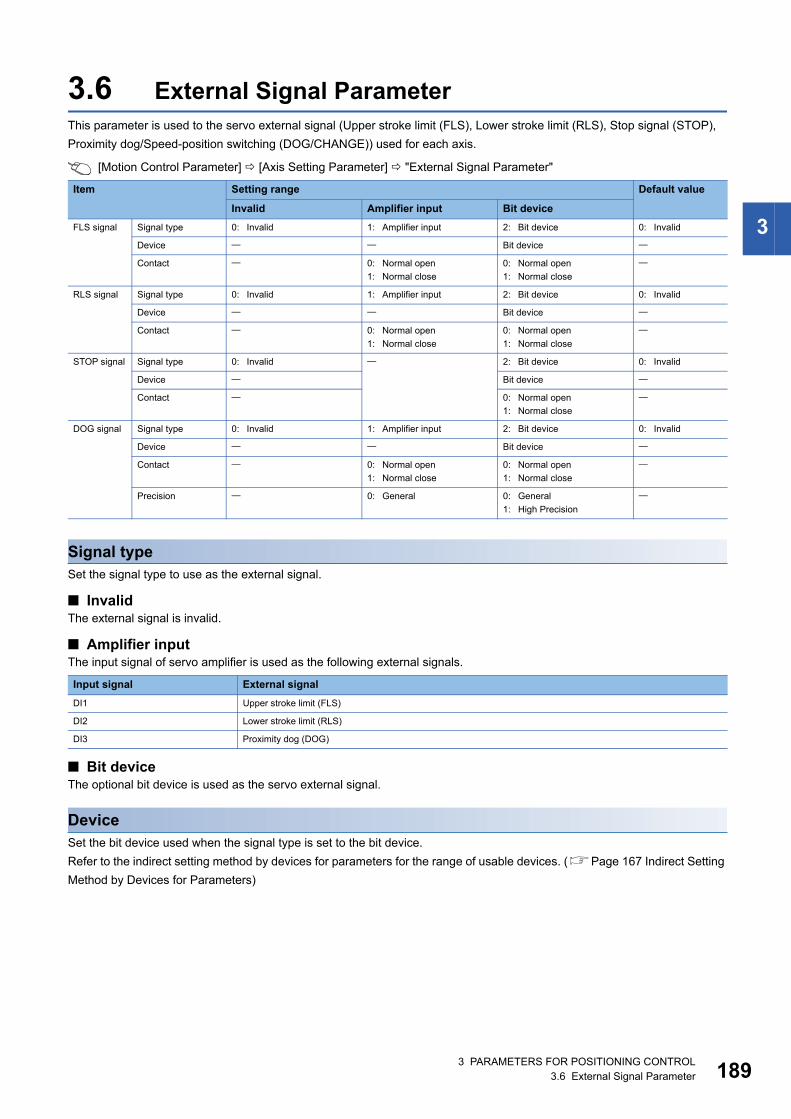
3
3.6 External Signal ParameterThis parameter is used to the servo external signal (Upper stroke limit (FLS), Lower stroke limit (RLS), Stop signal (STOP),
Proximity dog/Speed-position switching (DOG/CHANGE)) used for each axis.
[Motion Control Parameter] [Axis Setting Parameter] "External Signal Parameter"
Signal typeSet the signal type to use as the external signal.
■ InvalidThe external signal is invalid.
■ Amplifier inputThe input signal of servo amplifier is used as the following external signals.
■ Bit deviceThe optional bit device is used as the servo external signal.
DeviceSet the bit device used when the signal type is set to the bit device.
Refer to the indirect setting method by devices for parameters for the range of usable devices. (Page 167 Indirect Setting
Method by Devices for Parameters)
Item Setting range Default value
Invalid Amplifier input Bit device
FLS signal Signal type 0: Invalid 1: Amplifier input 2: Bit device 0: Invalid
Device Bit device
Contact 0: Normal open
1: Normal close
0: Normal open
1: Normal close
RLS signal Signal type 0: Invalid 1: Amplifier input 2: Bit device 0: Invalid
Device Bit device
Contact 0: Normal open
1: Normal close
0: Normal open
1: Normal close
STOP signal Signal type 0: Invalid 2: Bit device 0: Invalid
Device Bit device
Contact 0: Normal open
1: Normal close
DOG signal Signal type 0: Invalid 1: Amplifier input 2: Bit device 0: Invalid
Device Bit device
Contact 0: Normal open
1: Normal close
0: Normal open
1: Normal close
Precision 0: General 0: General
1: High Precision
Input signal External signal
DI1 Upper stroke limit (FLS)
DI2 Lower stroke limit (RLS)
DI3 Proximity dog (DOG)
3 PARAMETERS FOR POSITIONING CONTROL3.6 External Signal Parameter 189
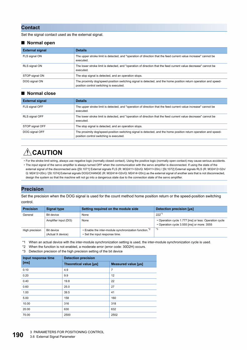
19
ContactSet the signal contact used as the external signal.
■ Normal open
■ Normal close
PrecisionSet the precision when the DOG signal is used for the count method home position return or the speed-position switching
control.
*1 When an actual device with the inter-module synchronization setting is used, the inter-module synchronization cycle is used.*2 When the function is not enabled, a moderate error (error code: 30D2H) occurs.*3 Detection precision of the high precision setting of the bit device
External signal Details
FLS signal ON The upper stroke limit is detected, and "operation of direction that the feed current value increase" cannot be
executed.
RLS signal ON The lower stroke limit is detected, and "operation of direction that the feed current value decrease" cannot be
executed.
STOP signal ON The stop signal is detected, and an operation stops.
DOG signal ON The proximity dog/speed-position switching signal is detected, and the home position return operation and speed-
position control switching is executed.
External signal Details
FLS signal OFF The upper stroke limit is detected, and "operation of direction that the feed current value increase" cannot be
executed.
RLS signal OFF The lower stroke limit is detected, and "operation of direction that the feed current value decrease" cannot be
executed.
STOP signal OFF The stop signal is detected, and an operation stops.
DOG signal OFF The proximity dog/speed-position switching signal is detected, and the home position return operation and speed-
position control switching is executed.
CAUTION• For the stroke limit wiring, always use negative logic (normally closed contact). Using the positive logic (normally open contact) may cause serious accidents.
• The input signal of the servo amplifier is always turned OFF when the communication with the servo amplifier is disconnected. If using the state of the
external signal of the disconnected axis ([St.1071] External signals FLS (R: M32411+32n/Q: M2411+20n) / [St.1072] External signals RLS (R: M32412+32n/
Q: M2412+20n) / [St.1074] External signals DOG/CHANGE (R: M32414+32n/Q: M2414+20n)) as the external signal of another axis that is not disconnected,
design the system so that the machine will not go into a dangerous state due to the connection state of the servo amplifier.
Precision Signal type Setting required on the module side Detection precision [μs]
General Bit device None 222*1
Amplifier input (DI3) None • Operation cycle 1.777 [ms] or less: Operation cycle
• Operation cycle 3.555 [ms] or more: 3555
High precision Bit device
(Actual X device)
• Enable the inter-module synchronization function.*2
• Set the input response time.
*3
Input response time [ms]
Detection precision
Theoretical value [μs] Measured value [μs]
0.10 4.9 7
0.20 9.9 12
0.40 19.8 22
0.60 25.0 27
1.00 39.5 41
5.00 158 160
10.00 316 318
20.00 630 632
70.00 2500 2502
03 PARAMETERS FOR POSITIONING CONTROL3.6 External Signal Parameter
3
■ GeneralThe detection precision is based on the fixed-cycle processing of the Motion CPU.
When the input module setting is "Inter-module synchronization valid" and the servo amplifier DI3 signal setting is "high
precision input", the general detection precision is applied.
■ High precisionWhen the input module setting is "Inter-module synchronization valid", the stopping precision of the count method home
position return or the speed-position switching control can be high by setting the DOG signal precision setting to "high
precision".
Refer to the following for the input module setting method.
MELSEC iQ-R Motion controller Programming Manual (Common)
When this setting is applied to a signal that does not support high precision input a moderate error (error code: 30D2H)
occurs.
3 PARAMETERS FOR POSITIONING CONTROL3.6 External Signal Parameter 191
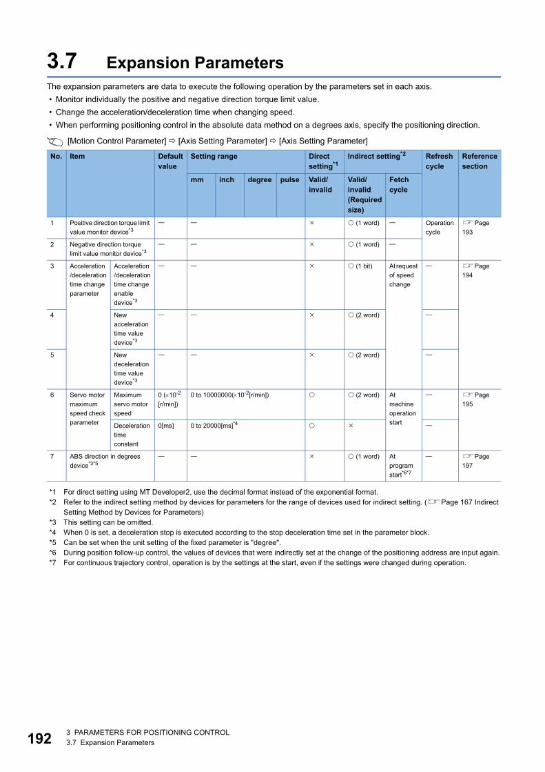
19
3.7 Expansion ParametersThe expansion parameters are data to execute the following operation by the parameters set in each axis.
• Monitor individually the positive and negative direction torque limit value.
• Change the acceleration/deceleration time when changing speed.
• When performing positioning control in the absolute data method on a degrees axis, specify the positioning direction.
[Motion Control Parameter] [Axis Setting Parameter] [Axis Setting Parameter]
*1 For direct setting using MT Developer2, use the decimal format instead of the exponential format.*2 Refer to the indirect setting method by devices for parameters for the range of devices used for indirect setting. (Page 167 Indirect
Setting Method by Devices for Parameters)*3 This setting can be omitted.*4 When 0 is set, a deceleration stop is executed according to the stop deceleration time set in the parameter block.*5 Can be set when the unit setting of the fixed parameter is "degree".*6 During position follow-up control, the values of devices that were indirectly set at the change of the positioning address are input again.*7 For continuous trajectory control, operation is by the settings at the start, even if the settings were changed during operation.
No. Item Default value
Setting range Direct setting*1
Indirect setting*2 Refresh cycle
Reference section
mm inch degree pulse Valid/invalid
Valid/invalid(Required size)
Fetch cycle
1 Positive direction torque limit
value monitor device*3 (1 word) Operation
cycle
Page
193
2 Negative direction torque
limit value monitor device*3 (1 word)
3 Acceleration
/deceleration
time change
parameter
Acceleration
/deceleration
time change
enable
device*3
(1 bit) At request
of speed
change
Page
194
4 New
acceleration
time value
device*3
(2 word)
5 New
deceleration
time value
device*3
(2 word)
6 Servo motor
maximum
speed check
parameter
Maximum
servo motor
speed
0 (10-2
[r/min])
0 to 10000000(10-2[r/min]) (2 word) At
machine
operation
start
Page
195
Deceleration
time
constant
0[ms] 0 to 20000[ms]*4
7 ABS direction in degrees
device*3*5 (1 word) At
program
start*6*7
Page
197
23 PARAMETERS FOR POSITIONING CONTROL3.7 Expansion Parameters
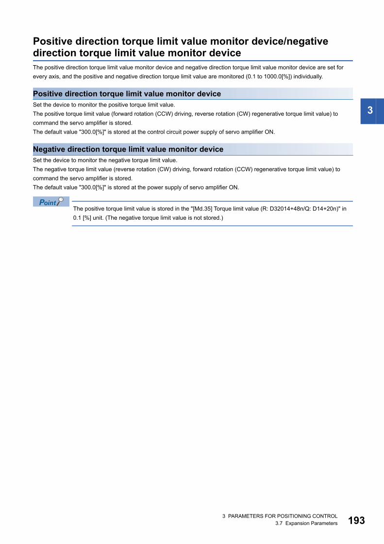
3
Positive direction torque limit value monitor device/negative direction torque limit value monitor deviceThe positive direction torque limit value monitor device and negative direction torque limit value monitor device are set for
every axis, and the positive and negative direction torque limit value are monitored (0.1 to 1000.0[%]) individually.
Positive direction torque limit value monitor deviceSet the device to monitor the positive torque limit value.
The positive torque limit value (forward rotation (CCW) driving, reverse rotation (CW) regenerative torque limit value) to
command the servo amplifier is stored.
The default value "300.0[%]" is stored at the control circuit power supply of servo amplifier ON.
Negative direction torque limit value monitor deviceSet the device to monitor the negative torque limit value.
The negative torque limit value (reverse rotation (CW) driving, forward rotation (CCW) regenerative torque limit value) to
command the servo amplifier is stored.
The default value "300.0[%]" is stored at the power supply of servo amplifier ON.
The positive torque limit value is stored in the "[Md.35] Torque limit value (R: D32014+48n/Q: D14+20n)" in
0.1 [%] unit. (The negative torque limit value is not stored.)
3 PARAMETERS FOR POSITIONING CONTROL3.7 Expansion Parameters 193
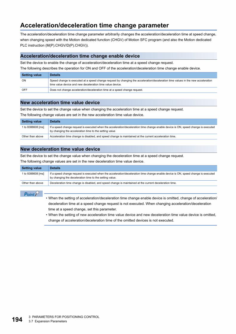
19
Acceleration/deceleration time change parameterThe acceleration/deceleration time change parameter arbitrarily changes the acceleration/deceleration time at speed change,
when changing speed with the Motion dedicated function (CHGV) of Motion SFC program (and also the Motion dedicated
PLC instruction (M(P).CHGV/D(P).CHGV)).
Acceleration/deceleration time change enable deviceSet the device to enable the change of acceleration/deceleration time at a speed change request.
The following describes the operation for ON and OFF of the acceleration/deceleration time change enable device.
New acceleration time value deviceSet the device to set the change value when changing the acceleration time at a speed change request.
The following change values are set in the new acceleration time value device.
New deceleration time value deviceSet the device to set the change value when changing the deceleration time at a speed change request.
The following change values are set in the new deceleration time value device.
• When the setting of acceleration/deceleration time change enable device is omitted, change of acceleration/
deceleration time at a speed change request is not executed. When changing acceleration/deceleration
time at a speed change, set this parameter.
• When the setting of new acceleration time value device and new deceleration time value device is omitted,
change of acceleration/deceleration time of the omitted devices is not executed.
Setting value Details
ON Speed change is executed at a speed change request by changing the acceleration/deceleration time values in the new acceleration
time value device and new deceleration time value device.
OFF Does not change acceleration/deceleration time at a speed change request.
Setting value Details
1 to 8388608 [ms] If a speed change request is executed when the acceleration/deceleration time change enable device is ON, speed change is executed
by changing the acceleration time to the setting value
Other than above Acceleration time change is disabled, and speed change is maintained at the current acceleration time.
Setting value Details
1 to 8388608 [ms] If a speed change request is executed when the acceleration/deceleration time change enable device is ON, speed change is executed
by changing the deceleration time to the setting value.
Other than above Deceleration time change is disabled, and speed change is maintained at the current deceleration time.
43 PARAMETERS FOR POSITIONING CONTROL3.7 Expansion Parameters
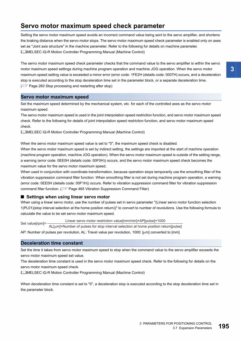
3
Servo motor maximum speed check parameterSetting the servo motor maximum speed avoids an incorrect command value being sent to the servo amplifier, and shortens
the braking distance when the servo motor stops. The servo motor maximum speed check parameter is enabled only on axes
set as "Joint axis structure" in the machine parameter. Refer to the following for details on machine parameter.
MELSEC iQ-R Motion Controller Programming Manual (Machine Control)
The servo motor maximum speed check parameter checks that the command value to the servo amplifier is within the servo
motor maximum speed settings during machine program operation and machine JOG operation. When the servo motor
maximum speed setting value is exceeded a minor error (error code: 1FE2H (details code: 0007H) occurs, and a deceleration
stop is executed according to the stop deceleration time set in the parameter block, or a separate deceleration time.
(Page 260 Stop processing and restarting after stop)
Servo motor maximum speedSet the maximum speed determined by the mechanical system, etc. for each of the controlled axes as the servo motor
maximum speed.
The servo motor maximum speed is used in the joint interpolation speed restriction function, and servo motor maximum speed
check. Refer to the following for details of joint interpolation speed restriction function, and servo motor maximum speed
check.
MELSEC iQ-R Motion Controller Programming Manual (Machine Control)
When the servo motor maximum speed value is set to "0", the maximum speed check is disabled.
When the servo motor maximum speed is set by indirect setting, the settings are imported at the start of machine operation
(machine program operation, machine JOG operation). When the servo motor maximum speed is outside of the setting range,
a warning (error code: 0EE0H (details code: 00F0H)) occurs, and the servo motor maximum speed check becomes the
maximum value for the servo motor maximum speed.
When used in conjunction with coordinate transformation, because operation stops temporarily use the smoothing filter of the
vibration suppression command filter function. When smoothing filter is not set during machine program operation, a warning
(error code: 0EE0H (details code: 00F1H)) occurs. Refer to vibration suppression command filter for vibration suppression
command filter function. (Page 465 Vibration Suppression Command Filter)
■ Settings when using linear servo motorWhen using a linear servo motor, use the number of pulses set in servo parameter "(Linear servo motor function selection
1(PL01)(stop interval selection at the home position return))" to convert to number of revolutions. Use the following formula to
calculate the value to be set servo motor maximum speed.
AP: Number of pulses per revolution, AL: Travel value per revolution, 1000: [m] converted to [mm]
Deceleration time constantSet the time it takes from servo motor maximum speed to stop when the command value to the servo amplifier exceeds the
servo motor maximum speed set value.
The deceleration time constant is used in the servo motor maximum speed check. Refer to the following for details on the
servo motor maximum speed check.
MELSEC iQ-R Motion Controller Programming Manual (Machine Control)
When deceleration time constant is set to "0", a deceleration stop is executed according to the stop deceleration time set in
the parameter block.
Set value[rpm]=Linear servo motor restriction value[mm/min]×AP[pulse]×1000
AL[μm]×Number of pulses for stop interval selection at home position return[pulse]
3 PARAMETERS FOR POSITIONING CONTROL3.7 Expansion Parameters 195
19
• Relationship between the servo motor maximum speed and speed limit value
When setting the servo motor maximum speed, make sure to set it so that the speed calculated from the
servo motor maximum speed([r/min]) is larger than the speed limit value. If the speed calculated from the
servo motor maximum speed is smaller than the speed limit value, the motor stops before reaching the
speed limit value.
• Servo motor maximum speed check during interpolation control
The servo motor maximum speed check during interpolation control is not valid for positioning speed at
interpolation control (Page 252 Positioning speed at the interpolation control), but for the positioning
speed of each axis.
When the servo motor speed exceeds the set value during interpolation control, stop processing is
performed on the interpolation axis.
63 PARAMETERS FOR POSITIONING CONTROL3.7 Expansion Parameters
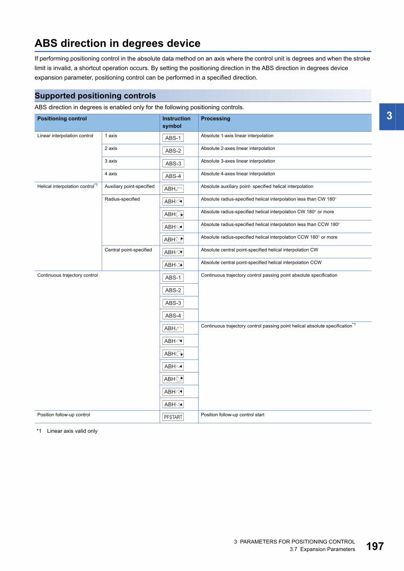
3
ABS direction in degrees deviceIf performing positioning control in the absolute data method on an axis where the control unit is degrees and when the stroke
limit is invalid, a shortcut operation occurs. By setting the positioning direction in the ABS direction in degrees device
expansion parameter, positioning control can be performed in a specified direction.
Supported positioning controlsABS direction in degrees is enabled only for the following positioning controls.
*1 Linear axis valid only
Positioning control Instruction symbol
Processing
Linear interpolation control 1 axis Absolute 1-axis linear interpolation
2 axis Absolute 2-axes linear interpolation
3 axis Absolute 3-axes linear interpolation
4 axis Absolute 4-axes linear interpolation
Helical interpolation control*1 Auxiliary point-specified Absolute auxiliary point- specified helical interpolation
Radius-specified Absolute radius-specified helical interpolation less than CW 180
Absolute radius-specified helical interpolation CW 180 or more
Absolute radius-specified helical interpolation less than CCW 180
Absolute radius-specified helical interpolation CCW 180 or more
Central point-specified Absolute central point-specified helical interpolation CW
Absolute central point-specified helical interpolation CCW
Continuous trajectory control Continuous trajectory control passing point absolute specification
Continuous trajectory control passing point helical absolute specification*1
Position follow-up control Position follow-up control start
ABS-1
ABS-2
ABS-3
ABS-4
ABH
ABH
ABH
ABH
ABH
ABH
ABH
ABS-1
ABS-2
ABS-3
ABS-4
ABH
ABH
ABH
ABH
ABH
ABH
ABH
PFSTART
3 PARAMETERS FOR POSITIONING CONTROL3.7 Expansion Parameters 197
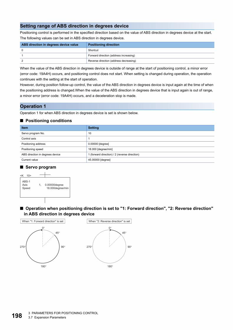
19
Setting range of ABS direction in degrees devicePositioning control is performed in the specified direction based on the value of ABS direction in degrees device at the start.
The following values can be set in ABS direction in degrees device.
When the value of the ABS direction in degrees device is outside of range at the start of positioning control, a minor error
(error code: 19A4H) occurs, and positioning control does not start. When setting is changed during operation, the operation
continues with the setting at the start of operation.
However, during position follow-up control, the value of the ABS direction in degrees device is input again at the time of when
the positioning address is changed.When the value of the ABS direction in degrees device that is input again is out of range,
a minor error (error code: 19A4H) occurs, and a deceleration stop is made.
Operation 1Operation 1 for when ABS direction in degrees device is set is shown below.
■ Positioning conditions
■ Servo program
■ Operation when positioning direction is set to "1: Forward direction", "2: Reverse direction" in ABS direction in degrees device
ABS direction in degrees device value Positioning direction
0 Shortcut
1 Forward direction (address increasing)
2 Reverse direction (address decreasing)
Item Setting
Servo program No. 10
Control axis 1
Positioning address 0.00000 [degree]
Positioning speed 18.000 [degree/min]
ABS direction in degrees device 1 (forward direction) / 2 (reverse direction)
Current value 45.00000 [degree]
ABS-1Axis 1,Speed
<K 10>
0.00000degree 18.000degree/min
90�270�
0�
45�
180�
90�270�
0�
45�
180�
When "1: Forward direction" is set When "2: Reverse direction" is set
83 PARAMETERS FOR POSITIONING CONTROL3.7 Expansion Parameters
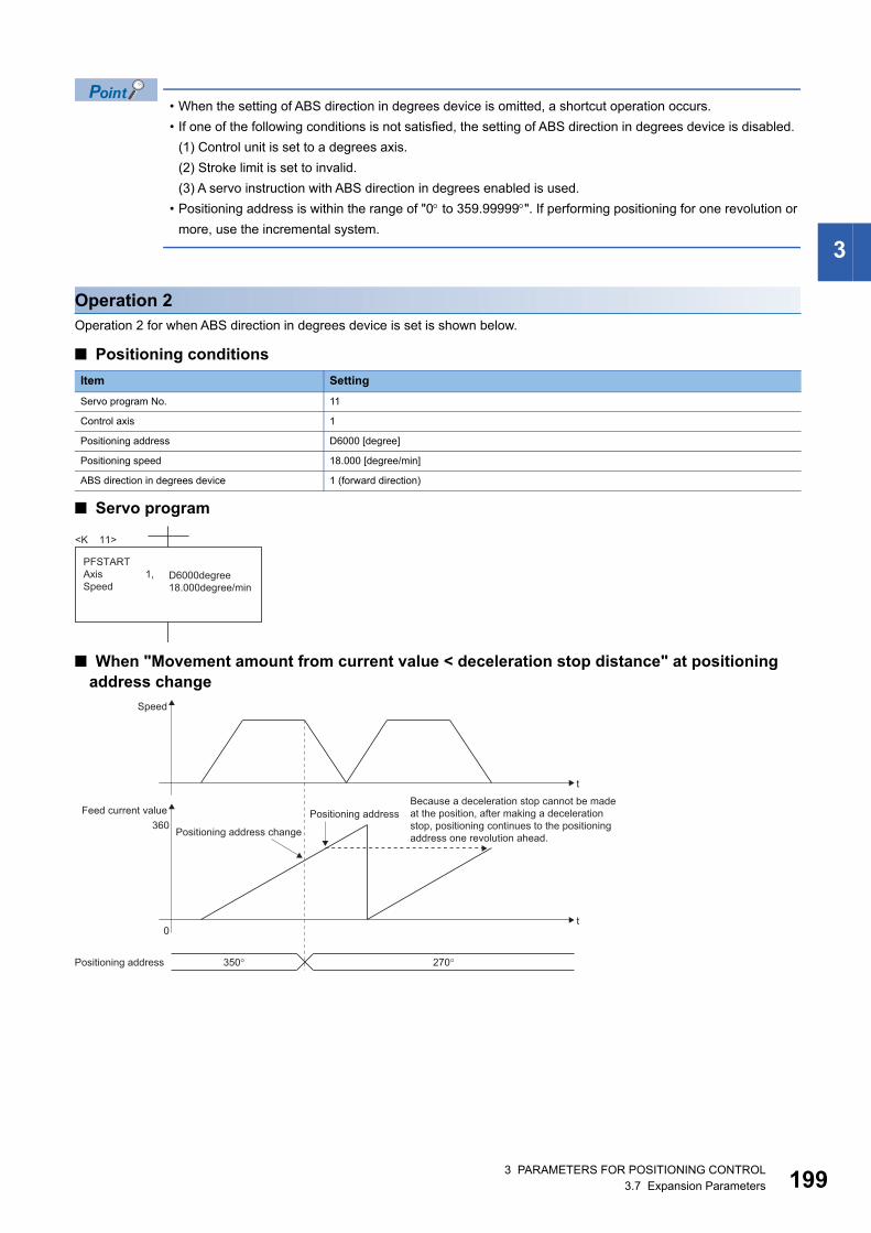
3
• When the setting of ABS direction in degrees device is omitted, a shortcut operation occurs.
• If one of the following conditions is not satisfied, the setting of ABS direction in degrees device is disabled.
(1) Control unit is set to a degrees axis.
(2) Stroke limit is set to invalid.
(3) A servo instruction with ABS direction in degrees enabled is used.
• Positioning address is within the range of "0 to 359.99999". If performing positioning for one revolution or
more, use the incremental system.
Operation 2Operation 2 for when ABS direction in degrees device is set is shown below.
■ Positioning conditions
■ Servo program
■ When "Movement amount from current value < deceleration stop distance" at positioning address change
Item Setting
Servo program No. 11
Control axis 1
Positioning address D6000 [degree]
Positioning speed 18.000 [degree/min]
ABS direction in degrees device 1 (forward direction)
PFSTARTAxis 1,Speed
D6000degree18.000degree/min
<K 11>
Speed
Because a deceleration stop cannot be madeat the position, after making a decelerationstop, positioning continues to the positioningaddress one revolution ahead.
Positioning address
Positioning address change
t
Feed current value
Positioning address
360
0t
350� 270�
3 PARAMETERS FOR POSITIONING CONTROL3.7 Expansion Parameters 199
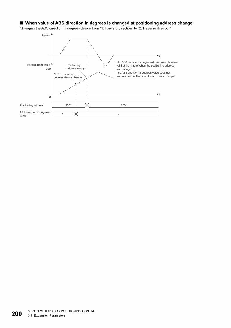
20
■ When value of ABS direction in degrees is changed at positioning address changeChanging the ABS direction in degrees device from "1: Forward direction" to "2: Reverse direction"
The ABS direction in degrees device value becomesvalid at the time of when the positioning addresswas changed.The ABS direction in degrees value does notbecome valid at the time of when it was changed.
Positioningaddress change
ABS direction indegrees device change
Speed
t
Feed current value
Positioning address
360
0t
350� 200�
ABS direction in degreesvalue 1 2
03 PARAMETERS FOR POSITIONING CONTROL3.7 Expansion Parameters
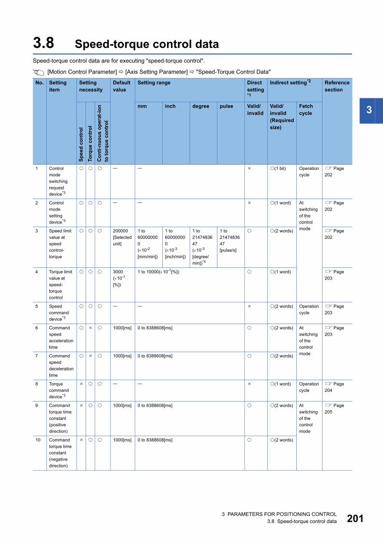
3
3.8 Speed-torque control dataSpeed-torque control data are for executing "speed-torque control".
[Motion Control Parameter] [Axis Setting Parameter] "Speed-Torque Control Data"
No. Setting item
Setting necessity
Default value
Setting range Direct setting*1
Indirect setting*2 Reference section
Sp
eed
co
ntr
ol
Torq
ue
con
tro
l
Co
nti
-nu
ou
s o
per
at-i
on
to t
orq
ue
con
tro
lmm inch degree pulse Valid/
invalidValid/ invalid(Required size)
Fetch cycle
1 Control
mode
switching
request
device*3
(1 bit) Operation
cycle
Page
202
2 Control
mode
setting
device*3
(1 word) At
switching
of the
control
mode
Page
202
3 Speed limit
value at
speed
control-
torque
200000
[Selected
unit]
1 to
60000000
0
(10-2
[mm/min])
1 to
60000000
0
(10-3
[inch/min])
1 to
21474836
47
(10-3
[degree/
min])*4
1 to
21474836
47
[pulse/s]
(2 words) Page
202
4 Torque limit
value at
speed-
torque
control
3000
(10-1
[%])
1 to 10000(10-1[%]) (1 word) Page
203
5 Speed
command
device*3
(2 words) Operation
cycle
Page
203
6 Command
speed
acceleration
time
1000[ms] 0 to 8388608[ms] (2 words) At
switching
of the
control
mode
Page
203
7 Command
speed
deceleration
time
1000[ms] 0 to 8388608[ms] (2 words)
8 Torque
command
device*3
(1 word) Operation
cycle
Page
204
9 Command
torque time
constant
(positive
direction)
1000[ms] 0 to 8388608[ms] (2 words) At
switching
of the
control
mode
Page
205
10 Command
torque time
constant
(negative
direction)
1000[ms] 0 to 8388608[ms] (2 words)
3 PARAMETERS FOR POSITIONING CONTROL3.8 Speed-torque control data 201
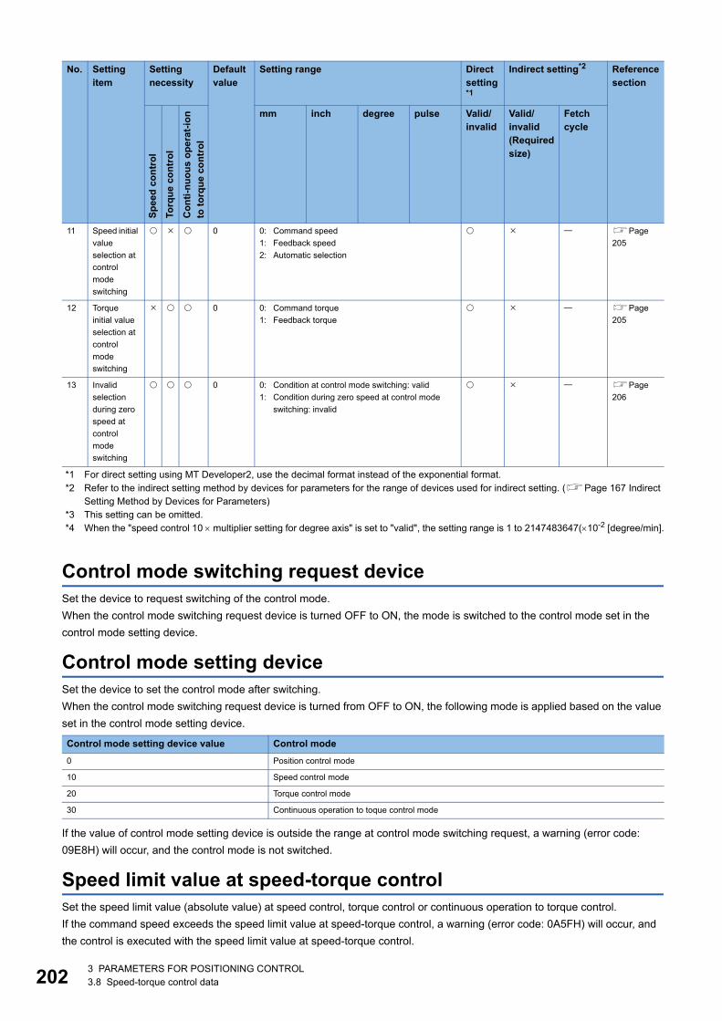
20
*1 For direct setting using MT Developer2, use the decimal format instead of the exponential format.*2 Refer to the indirect setting method by devices for parameters for the range of devices used for indirect setting. (Page 167 Indirect
Setting Method by Devices for Parameters)*3 This setting can be omitted.*4 When the "speed control 10 multiplier setting for degree axis" is set to "valid", the setting range is 1 to 2147483647(10-2 [degree/min].
Control mode switching request deviceSet the device to request switching of the control mode.
When the control mode switching request device is turned OFF to ON, the mode is switched to the control mode set in the
control mode setting device.
Control mode setting deviceSet the device to set the control mode after switching.
When the control mode switching request device is turned from OFF to ON, the following mode is applied based on the value
set in the control mode setting device.
If the value of control mode setting device is outside the range at control mode switching request, a warning (error code:
09E8H) will occur, and the control mode is not switched.
Speed limit value at speed-torque controlSet the speed limit value (absolute value) at speed control, torque control or continuous operation to torque control.
If the command speed exceeds the speed limit value at speed-torque control, a warning (error code: 0A5FH) will occur, and
the control is executed with the speed limit value at speed-torque control.
11 Speed initial
value
selection at
control
mode
switching
0 0: Command speed
1: Feedback speed
2: Automatic selection
Page
205
12 Torque
initial value
selection at
control
mode
switching
0 0: Command torque
1: Feedback torque
Page
205
13 Invalid
selection
during zero
speed at
control
mode
switching
0 0: Condition at control mode switching: valid
1: Condition during zero speed at control mode
switching: invalid
Page
206
Control mode setting device value Control mode
0 Position control mode
10 Speed control mode
20 Torque control mode
30 Continuous operation to toque control mode
No. Setting item
Setting necessity
Default value
Setting range Direct setting*1
Indirect setting*2 Reference section
Sp
eed
co
ntr
ol
Torq
ue
con
tro
l
Co
nti
-nu
ou
s o
per
at-i
on
to t
orq
ue
con
tro
l
mm inch degree pulse Valid/ invalid
Valid/ invalid(Required size)
Fetch cycle
23 PARAMETERS FOR POSITIONING CONTROL3.8 Speed-torque control data
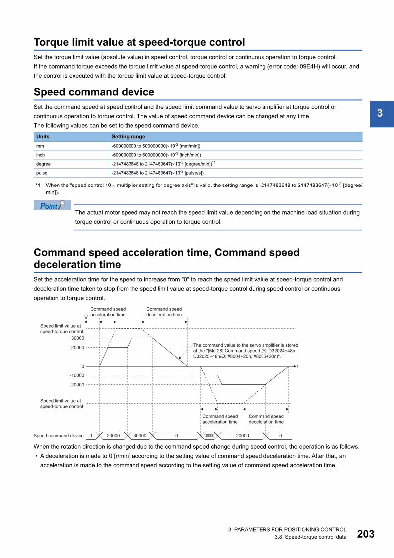
3
Torque limit value at speed-torque controlSet the torque limit value (absolute value) in speed control, torque control or continuous operation to torque control.
If the command torque exceeds the torque limit value at speed-torque control, a warning (error code: 09E4H) will occur, and
the control is executed with the torque limit value at speed-torque control.
Speed command deviceSet the command speed at speed control and the speed limit command value to servo amplifier at torque control or
continuous operation to torque control. The value of speed command device can be changed at any time.
The following values can be set to the speed command device.
*1 When the "speed control 10 multiplier setting for degree axis" is valid, the setting range is -2147483648 to 2147483647(10-2 [degree/min]).
The actual motor speed may not reach the speed limit value depending on the machine load situation during
torque control or continuous operation to torque control.
Command speed acceleration time, Command speed deceleration timeSet the acceleration time for the speed to increase from "0" to reach the speed limit value at speed-torque control and
deceleration time taken to stop from the speed limit value at speed-torque control during speed control or continuous
operation to torque control.
When the rotation direction is changed due to the command speed change during speed control, the operation is as follows.
• A deceleration is made to 0 [r/min] according to the setting value of command speed deceleration time. After that, an
acceleration is made to the command speed according to the setting value of command speed acceleration time.
Units Setting range
mm -600000000 to 600000000(10-2 [mm/min])
inch -600000000 to 600000000(10-3 [inch/min])
degree -2147483648 to 2147483647(10-3 [degree/min])*1
pulse -2147483648 to 2147483647(10-2 [pulse/s])
t0
-10000
-20000
20000
30000
Speed limit value atspeed-torque control
Speed limit value atspeed-torque control
Speed command device
V
The command value to the servo amplifier is storedat the "[Md.28] Command speed (R: D32024+48n,D32025+48n/Q: #8004+20n, #8005+20n)".
Command speedacceleration time
Command speedacceleration time
Command speeddeceleration time
Command speeddeceleration time
0 20000 30000 0 -10000 -20000 0
3 PARAMETERS FOR POSITIONING CONTROL3.8 Speed-torque control data 203
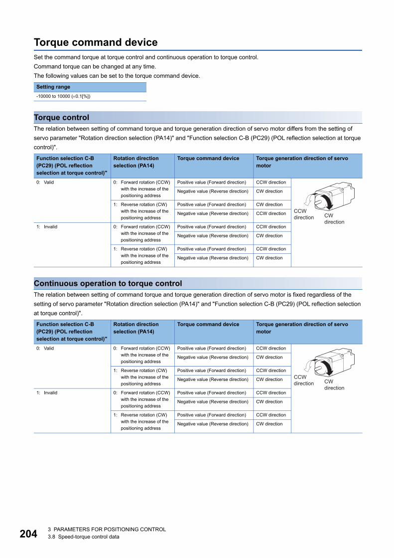
20
Torque command deviceSet the command torque at torque control and continuous operation to torque control.
Command torque can be changed at any time.
The following values can be set to the torque command device.
Torque controlThe relation between setting of command torque and torque generation direction of servo motor differs from the setting of
servo parameter "Rotation direction selection (PA14)" and "Function selection C-B (PC29) (POL reflection selection at torque
control)".
Continuous operation to torque controlThe relation between setting of command torque and torque generation direction of servo motor is fixed regardless of the
setting of servo parameter "Rotation direction selection (PA14)" and "Function selection C-B (PC29) (POL reflection selection
at torque control)".
Setting range
-10000 to 10000 (0.1[%])
Function selection C-B (PC29) (POL reflection selection at torque control)"
Rotation direction selection (PA14)
Torque command device Torque generation direction of servo motor
0: Valid 0: Forward rotation (CCW)
with the increase of the
positioning address
Positive value (Forward direction) CCW direction
Negative value (Reverse direction) CW direction
1: Reverse rotation (CW)
with the increase of the
positioning address
Positive value (Forward direction) CW direction
Negative value (Reverse direction) CCW direction
1: Invalid 0: Forward rotation (CCW)
with the increase of the
positioning address
Positive value (Forward direction) CCW direction
Negative value (Reverse direction) CW direction
1: Reverse rotation (CW)
with the increase of the
positioning address
Positive value (Forward direction) CCW direction
Negative value (Reverse direction) CW direction
Function selection C-B (PC29) (POL reflection selection at torque control)"
Rotation direction selection (PA14)
Torque command device Torque generation direction of servo motor
0: Valid 0: Forward rotation (CCW)
with the increase of the
positioning address
Positive value (Forward direction) CCW direction
Negative value (Reverse direction) CW direction
1: Reverse rotation (CW)
with the increase of the
positioning address
Positive value (Forward direction) CCW direction
Negative value (Reverse direction) CW direction
1: Invalid 0: Forward rotation (CCW)
with the increase of the
positioning address
Positive value (Forward direction) CCW direction
Negative value (Reverse direction) CW direction
1: Reverse rotation (CW)
with the increase of the
positioning address
Positive value (Forward direction) CCW direction
Negative value (Reverse direction) CW direction
CWdirection
CCWdirection
CWdirection
CCWdirection
43 PARAMETERS FOR POSITIONING CONTROL3.8 Speed-torque control data
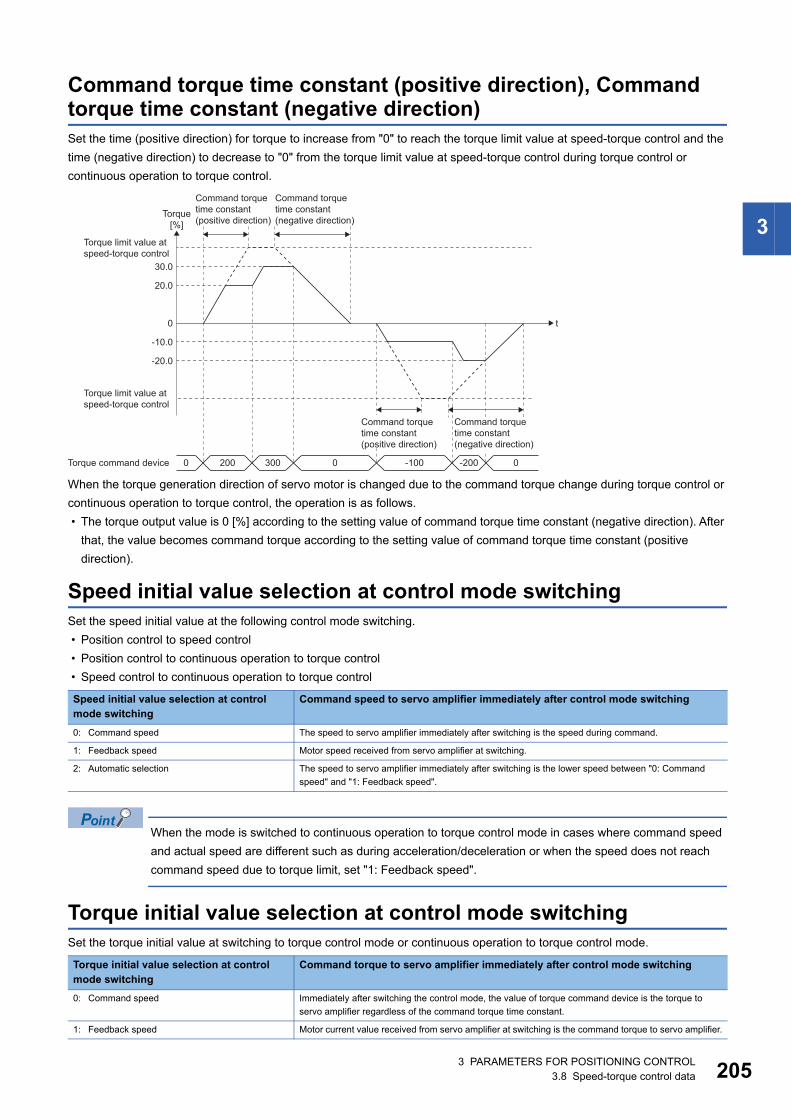
3
Command torque time constant (positive direction), Command torque time constant (negative direction)Set the time (positive direction) for torque to increase from "0" to reach the torque limit value at speed-torque control and the
time (negative direction) to decrease to "0" from the torque limit value at speed-torque control during torque control or
continuous operation to torque control.
When the torque generation direction of servo motor is changed due to the command torque change during torque control or
continuous operation to torque control, the operation is as follows.
• The torque output value is 0 [%] according to the setting value of command torque time constant (negative direction). After
that, the value becomes command torque according to the setting value of command torque time constant (positive
direction).
Speed initial value selection at control mode switchingSet the speed initial value at the following control mode switching.
• Position control to speed control
• Position control to continuous operation to torque control
• Speed control to continuous operation to torque control
When the mode is switched to continuous operation to torque control mode in cases where command speed
and actual speed are different such as during acceleration/deceleration or when the speed does not reach
command speed due to torque limit, set "1: Feedback speed".
Torque initial value selection at control mode switchingSet the torque initial value at switching to torque control mode or continuous operation to torque control mode.
Speed initial value selection at control mode switching
Command speed to servo amplifier immediately after control mode switching
0: Command speed The speed to servo amplifier immediately after switching is the speed during command.
1: Feedback speed Motor speed received from servo amplifier at switching.
2: Automatic selection The speed to servo amplifier immediately after switching is the lower speed between "0: Command
speed" and "1: Feedback speed".
Torque initial value selection at control mode switching
Command torque to servo amplifier immediately after control mode switching
0: Command speed Immediately after switching the control mode, the value of torque command device is the torque to
servo amplifier regardless of the command torque time constant.
1: Feedback speed Motor current value received from servo amplifier at switching is the command torque to servo amplifier.
t0
-10.0
-20.0
20.0
30.0
Torque limit value atspeed-torque control
Torque limit value atspeed-torque control
Torque command device
Torque[%]
Command torquetime constant(positive direction)
Command torquetime constant(negative direction)
0 200 300 0 -100 -200 0
Command torquetime constant(positive direction)
Command torquetime constant(negative direction)
3 PARAMETERS FOR POSITIONING CONTROL3.8 Speed-torque control data 205
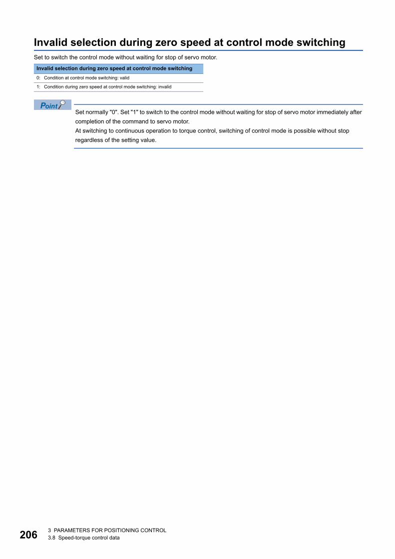
20
Invalid selection during zero speed at control mode switchingSet to switch the control mode without waiting for stop of servo motor.
Set normally "0". Set "1" to switch to the control mode without waiting for stop of servo motor immediately after
completion of the command to servo motor.
At switching to continuous operation to torque control, switching of control mode is possible without stop
regardless of the setting value.
Invalid selection during zero speed at control mode switching
0: Condition at control mode switching: valid
1: Condition during zero speed at control mode switching: invalid
63 PARAMETERS FOR POSITIONING CONTROL3.8 Speed-torque control data
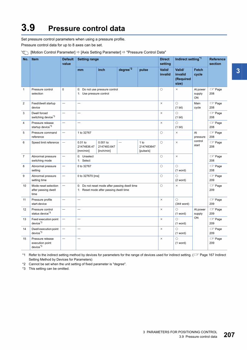
3
3.9 Pressure control dataSet pressure control parameters when using a pressure profile.
Pressure control data for up to 8 axes can be set.
[Motion Control Parameter] [Axis Setting Parameter] "Pressure Control Data"
*1 Refer to the indirect setting method by devices for parameters for the range of devices used for indirect setting. (Page 167 Indirect Setting Method by Devices for Parameters)
*2 Cannot be set when the unit setting of fixed parameter is "degree".*3 This setting can be omitted.
No. Item Default value
Setting range Direct setting
Indirect setting*1 Reference section
mm inch degree*2 pulse Valid/invalid
Valid/invalid (Required size)
Fetch cycle
1 Pressure control
selection
0 0: Do not use pressure control
1: Use pressure control
At power
supply
ON
Page
208
2 Feed/dwell startup
device
(1 bit)
Main
cycle
Page
208
3 Dwell forced
switching device*3
(1 bit)
Page
208
4 Pressure release
startup device*3
(1 bit)
Page
208
5 Pressure command
reference
1 to 32767 At
pressure
control
start
Page
208
6 Speed limit reference 0.01 to
21474836.47
[mm/min]
0.001 to
2147483.647
[inch/min]
1 to
2147483647
[pulse/s]
Page
208
7 Abnormal pressure
switching mode
0: Unselect
1: Select
Page
208
8 Abnormal pressure
setting
0 to 32767
(1 word)
Page
208
9 Abnormal pressure
setting time
0 to 327670 [ms]
(2 word)
Page
209
10 Mode reset selection
after passing dwell
time
0: Do not reset mode after passing dwell time
1: Reset mode after passing dwell time
Page
209
11 Pressure profile
start-device
(344 word)
Page
209
12 Pressure control
status device*3
(1 word)
At power
supply
ON
Page
209
13 Feed execution point
device*3
(1 word)
Page
209
14 Dwell execution point
device*3
(1 word)
Page
209
15 Pressure release
execution point
device*3
(1 word)
Page
209
3 PARAMETERS FOR POSITIONING CONTROL3.9 Pressure control data 207
20
Pressure control selectionSet whether to use pressure control, or not use pressure control. Pressure control data for up to 8 axes can be set.
When pressure control selection is enabled on an axis on a SSCNET line or the number of axes set to pressure control
selection enabled exceeds eight, a moderate error (error code: 30F7H) occurs.
Feed/dwell startup deviceSet the device to start feed/dwell operation.
When the feed/dwell start device turns OFF to ON, control switches to pressure control, and drives the system with the feed/
dwell operation.
When the feed/dwell startup device turns ON to OFF, the mode is reset, and switches from pressure control to positioning
control.
Dwell forced switching deviceSet the device to force the switch to dwell operation during feed operation.
Operation switches to dwell operation automatically by specifying a feed/dwell switching mode in the pressure profile.
However, by turning the force switch to dwell device OFF to ON, switch to dwell operation can be made even when conditions
for switching to dwell operation are not satisfied.
Pressure release startup deviceSet the device to start pressure release operation.
When the pressure release startup device turns OFF to ON, control switches to pressure control, and drives the system with
the pressure release operation. When load cell pressure drops below the set pressure, or when the pressure release startup
device turns ON to OFF, the mode is reset, and control switches from pressure control to positioning control.
Pressure command referenceSet the reference for the time constant of the pressure command.
The time constant of the pressure command is the time taken to reach the pressure command reference.
Speed limit referenceSet the reference for the time constant of the speed limit.
The time constant of the speed limit is the time taken to reach the speed limit reference from 0.
Abnormal pressure switching modeSet whether to switch to dwell mode or not when the pressure reaches the value set as abnormal pressure setting during feed
operation.
If "1: Select" is set, operation is forcibly switched from feed mode to dwell mode when the time in an abnormal state exceeds
the time that was set to abnormal pressure.
Abnormal pressure settingSet the abnormal pressure value.
Pressure control selection
0: Do not use pressure control
1: Use pressure control
Abnormal pressure switching mode
0: Unselect
1: Select
83 PARAMETERS FOR POSITIONING CONTROL3.9 Pressure control data
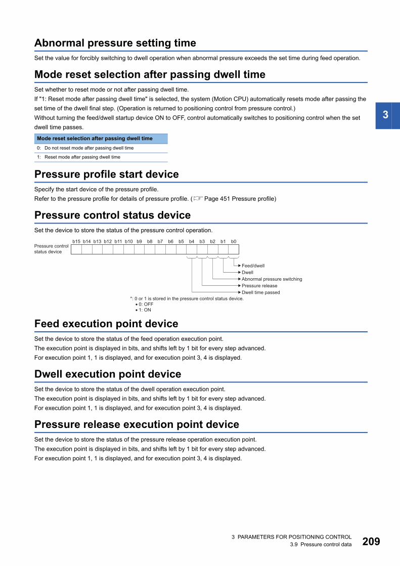
3
Abnormal pressure setting timeSet the value for forcibly switching to dwell operation when abnormal pressure exceeds the set time during feed operation.
Mode reset selection after passing dwell timeSet whether to reset mode or not after passing dwell time.
If "1: Reset mode after passing dwell time" is selected, the system (Motion CPU) automatically resets mode after passing the
set time of the dwell final step. (Operation is returned to positioning control from pressure control.)
Without turning the feed/dwell startup device ON to OFF, control automatically switches to positioning control when the set
dwell time passes.
Pressure profile start deviceSpecify the start device of the pressure profile.
Refer to the pressure profile for details of pressure profile. (Page 451 Pressure profile)
Pressure control status deviceSet the device to store the status of the pressure control operation.
Feed execution point deviceSet the device to store the status of the feed operation execution point.
The execution point is displayed in bits, and shifts left by 1 bit for every step advanced.
For execution point 1, 1 is displayed, and for execution point 3, 4 is displayed.
Dwell execution point deviceSet the device to store the status of the dwell operation execution point.
The execution point is displayed in bits, and shifts left by 1 bit for every step advanced.
For execution point 1, 1 is displayed, and for execution point 3, 4 is displayed.
Pressure release execution point deviceSet the device to store the status of the pressure release operation execution point.
The execution point is displayed in bits, and shifts left by 1 bit for every step advanced.
For execution point 1, 1 is displayed, and for execution point 3, 4 is displayed.
Mode reset selection after passing dwell time
0: Do not reset mode after passing dwell time
1: Reset mode after passing dwell time
b14b15 b13 b12 b11 b10 b9 b8 b7 b6 b5 b4 b3 b2 b1 b0
Feed/dwellDwellAbnormal pressure switchingPressure releaseDwell time passed
*: 0 or 1 is stored in the pressure control status device. • 0: OFF • 1: ON
Pressure controlstatus device
3 PARAMETERS FOR POSITIONING CONTROL3.9 Pressure control data 209
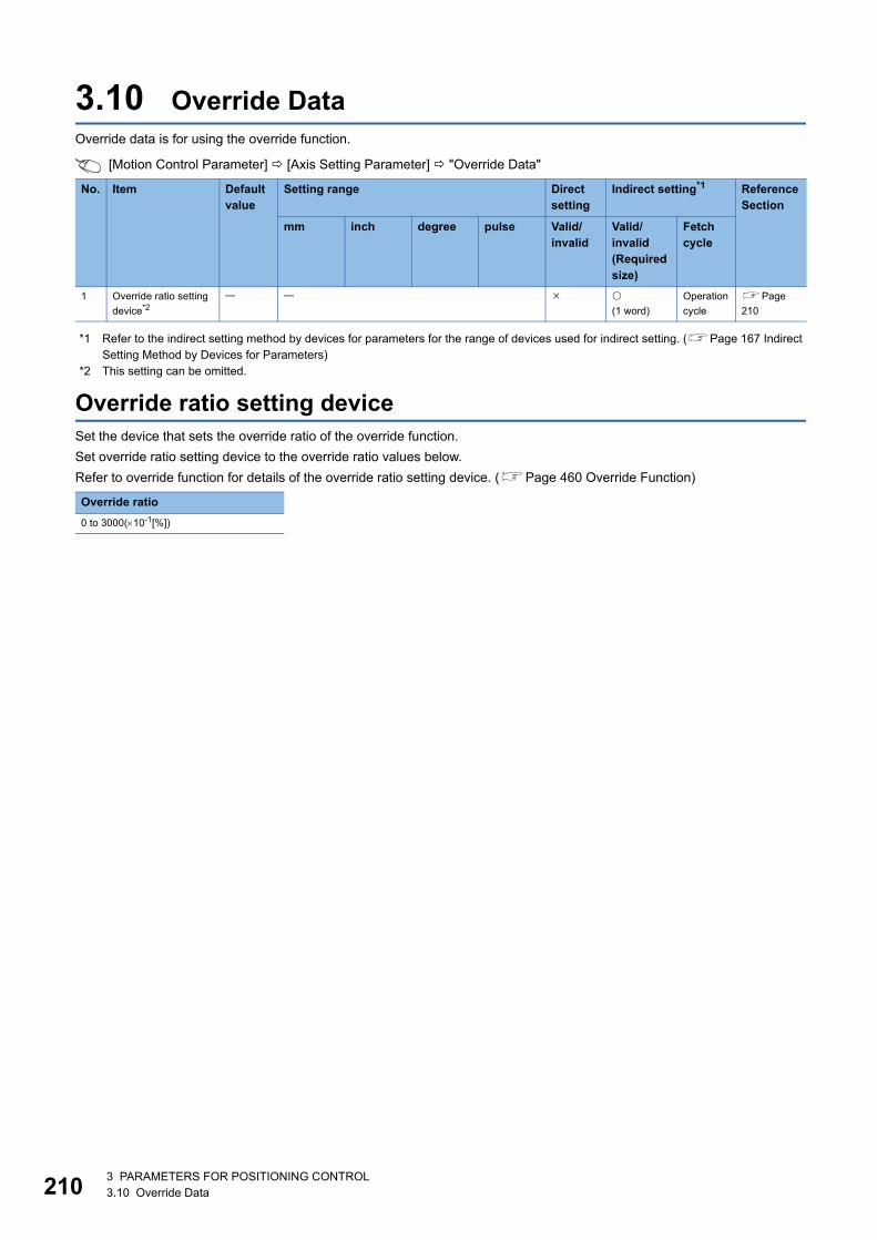
21
3.10 Override DataOverride data is for using the override function.
[Motion Control Parameter] [Axis Setting Parameter] "Override Data"
*1 Refer to the indirect setting method by devices for parameters for the range of devices used for indirect setting. (Page 167 Indirect Setting Method by Devices for Parameters)
*2 This setting can be omitted.
Override ratio setting deviceSet the device that sets the override ratio of the override function.
Set override ratio setting device to the override ratio values below.
Refer to override function for details of the override ratio setting device. (Page 460 Override Function)
No. Item Default value
Setting range Direct setting
Indirect setting*1 Reference Section
mm inch degree pulse Valid/invalid
Valid/invalid (Required size)
Fetch cycle
1 Override ratio setting
device*2
(1 word)
Operation
cycle
Page
210
Override ratio
0 to 3000(10-1[%])
03 PARAMETERS FOR POSITIONING CONTROL3.10 Override Data
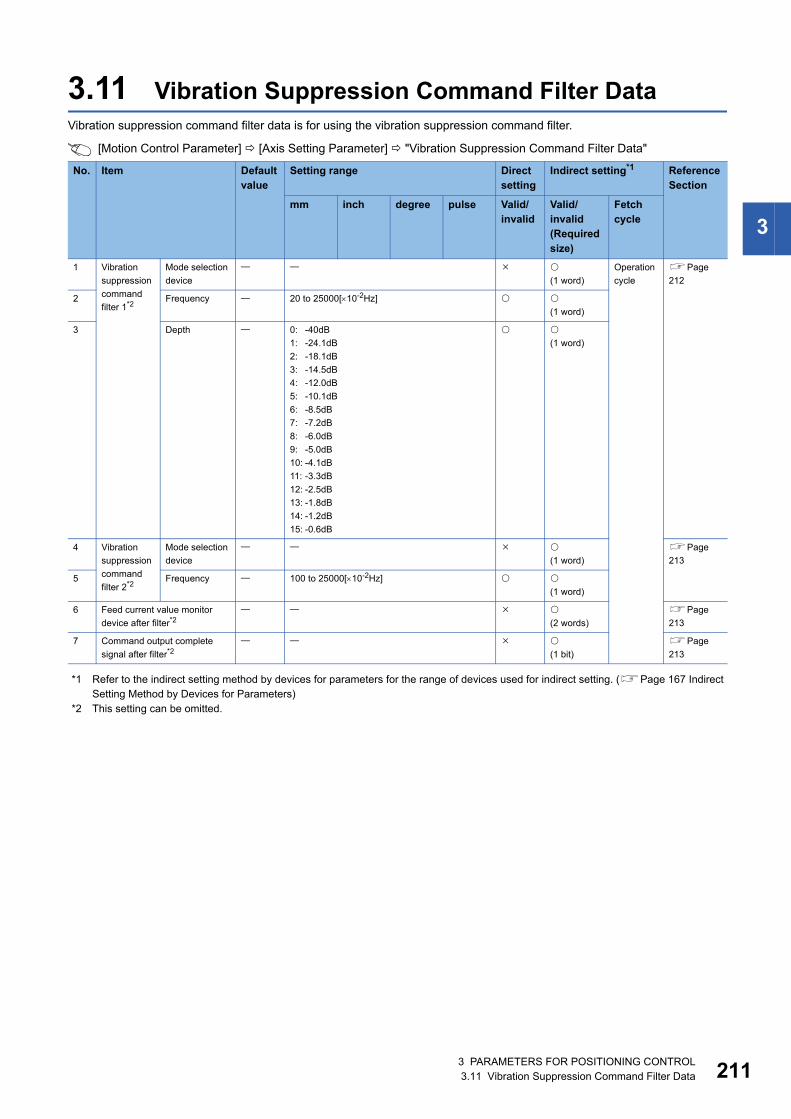
3
3.11 Vibration Suppression Command Filter DataVibration suppression command filter data is for using the vibration suppression command filter.
[Motion Control Parameter] [Axis Setting Parameter] "Vibration Suppression Command Filter Data"
*1 Refer to the indirect setting method by devices for parameters for the range of devices used for indirect setting. (Page 167 Indirect Setting Method by Devices for Parameters)
*2 This setting can be omitted.
No. Item Default value
Setting range Direct setting
Indirect setting*1 Reference Section
mm inch degree pulse Valid/invalid
Valid/invalid (Required size)
Fetch cycle
1 Vibration
suppression
command
filter 1*2
Mode selection
device
(1 word)
Operation
cycle
Page
212
2 Frequency 20 to 25000[10-2Hz]
(1 word)
3 Depth 0: -40dB
1: -24.1dB
2: -18.1dB
3: -14.5dB
4: -12.0dB
5: -10.1dB
6: -8.5dB
7: -7.2dB
8: -6.0dB
9: -5.0dB
10: -4.1dB
11: -3.3dB
12: -2.5dB
13: -1.8dB
14: -1.2dB
15: -0.6dB
(1 word)
4 Vibration
suppression
command
filter 2*2
Mode selection
device
(1 word)
Page
213
5 Frequency 100 to 25000[10-2Hz]
(1 word)
6 Feed current value monitor
device after filter*2
(2 words)
Page
213
7 Command output complete
signal after filter*2
(1 bit)
Page
213
3 PARAMETERS FOR POSITIONING CONTROL3.11 Vibration Suppression Command Filter Data 211
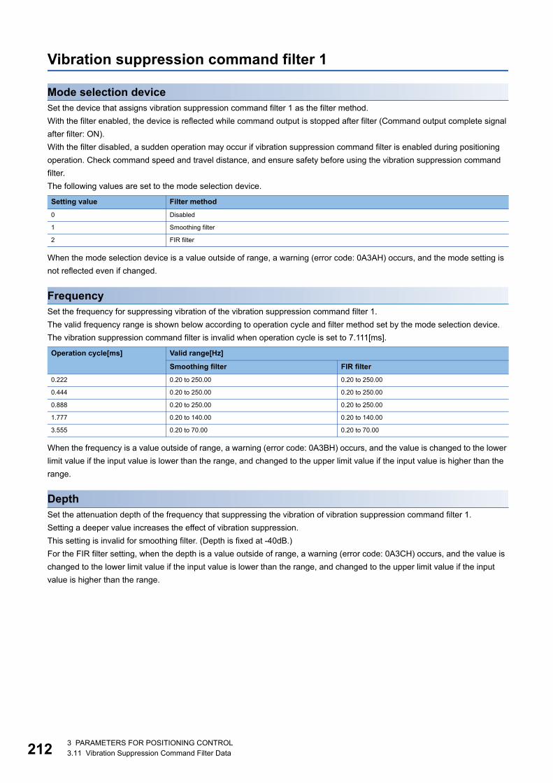
21
Vibration suppression command filter 1
Mode selection deviceSet the device that assigns vibration suppression command filter 1 as the filter method.
With the filter enabled, the device is reflected while command output is stopped after filter (Command output complete signal
after filter: ON).
With the filter disabled, a sudden operation may occur if vibration suppression command filter is enabled during positioning
operation. Check command speed and travel distance, and ensure safety before using the vibration suppression command
filter.
The following values are set to the mode selection device.
When the mode selection device is a value outside of range, a warning (error code: 0A3AH) occurs, and the mode setting is
not reflected even if changed.
FrequencySet the frequency for suppressing vibration of the vibration suppression command filter 1.
The valid frequency range is shown below according to operation cycle and filter method set by the mode selection device.
The vibration suppression command filter is invalid when operation cycle is set to 7.111[ms].
When the frequency is a value outside of range, a warning (error code: 0A3BH) occurs, and the value is changed to the lower
limit value if the input value is lower than the range, and changed to the upper limit value if the input value is higher than the
range.
DepthSet the attenuation depth of the frequency that suppressing the vibration of vibration suppression command filter 1.
Setting a deeper value increases the effect of vibration suppression.
This setting is invalid for smoothing filter. (Depth is fixed at -40dB.)
For the FIR filter setting, when the depth is a value outside of range, a warning (error code: 0A3CH) occurs, and the value is
changed to the lower limit value if the input value is lower than the range, and changed to the upper limit value if the input
value is higher than the range.
Setting value Filter method
0 Disabled
1 Smoothing filter
2 FIR filter
Operation cycle[ms] Valid range[Hz]
Smoothing filter FIR filter
0.222 0.20 to 250.00 0.20 to 250.00
0.444 0.20 to 250.00 0.20 to 250.00
0.888 0.20 to 250.00 0.20 to 250.00
1.777 0.20 to 140.00 0.20 to 140.00
3.555 0.20 to 70.00 0.20 to 70.00
23 PARAMETERS FOR POSITIONING CONTROL3.11 Vibration Suppression Command Filter Data
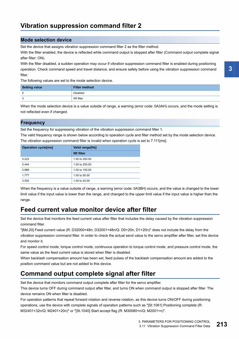
3
Vibration suppression command filter 2
Mode selection deviceSet the device that assigns vibration suppression command filter 2 as the filter method.
With the filter enabled, the device is reflected while command output is stopped after filter (Command output complete signal
after filter: ON).
With the filter disabled, a sudden operation may occur if vibration suppression command filter is enabled during positioning
operation. Check command speed and travel distance, and ensure safety before using the vibration suppression command
filter.
The following values are set to the mode selection device.
When the mode selection device is a value outside of range, a warning (error code: 0A3AH) occurs, and the mode setting is
not reflected even if changed.
FrequencySet the frequency for suppressing vibration of the vibration suppression command filter 1.
The valid frequency range is shown below according to operation cycle and filter method set by the mode selection device.
The vibration suppression command filter is invalid when operation cycle is set to 7.111[ms].
When the frequency is a value outside of range, a warning (error code: 0A3BH) occurs, and the value is changed to the lower
limit value if the input value is lower than the range, and changed to the upper limit value if the input value is higher than the
range.
Feed current value monitor device after filterSet the device that monitors the feed current value after filter that includes the delay caused by the vibration suppression
command filter.
"[Md.20] Feed current value (R: D32000+48n, D32001+48n/Q: D0+20n, D1+20n)" does not include the delay from the
vibration suppression command filter. In order to check the actual send value to the servo amplifier after filter, set this device
and monitor it.
For speed control mode, torque control mode, continuous operation to torque control mode, and pressure control mode, the
same value as the feed current value is stored when filter is disabled.
When backlash compensation amount has been set, feed pulses of the backlash compensation amount are added to the
position command value but are not added to this device.
Command output complete signal after filterSet the device that monitors command output complete after filter for the servo amplifier.
This device turns OFF during command output after filter, and turns ON when command output is stopped after filter. The
device remains ON when filter is disabled.
For operation patterns that repeat forward rotation and reverse rotation, as this device turns ON/OFF during positioning
operations, use the device with complete signals of operation patterns such as "[St.1061] Positioning complete (R:
M32401+32n/Q: M2401+20n)" or "[St.1040] Start accept flag (R: M30080+n/Q: M2001+n)".
Setting value Filter method
0 Disabled
3 IIR filter
Operation cycle[ms] Valid range[Hz]
IIR filter
0.222 1.00 to 250.00
0.444 1.00 to 200.00
0.888 1.00 to 100.00
1.777 1.00 to 50.00
3.555 1.00 to 25.00
3 PARAMETERS FOR POSITIONING CONTROL3.11 Vibration Suppression Command Filter Data 213
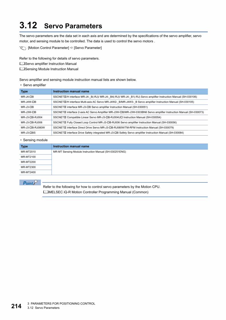
21
3.12 Servo ParametersThe servo parameters are the data set in each axis and are determined by the specifications of the servo amplifier, servo
motor, and sensing module to be controlled. The data is used to control the servo motors .
[Motion Control Parameter] [Servo Parameter]
Refer to the following for details of servo parameters.
Servo amplifier Instruction Manual
Sensing Module Instruction Manual
Servo amplifier and sensing module instruction manual lists are shown below.
• Servo amplifier
• Sensing module
Refer to the following for how to control servo parameters by the Motion CPU.
MELSEC iQ-R Motion Controller Programming Manual (Common)
Type Instruction manual name
MR-J4-B SSCNET/H interface MR-J4-_B(-RJ)/ MR-J4-_B4(-RJ)/ MR-J4-_B1(-RJ) Servo amplifier Instruction Manual (SH-030106)
MR-J4W-B SSCNET/H interface Multi-axis AC Servo MR-J4W2-_B/MR-J4W3-_B Servo amplifier Instruction Manual (SH-030105)
MR-J3-B SSCNET interface MR-J3-B Servo amplifier Instruction Manual (SH-030051)
MR-J3W-B SSCNET interface 2-axis AC Servo Amplifier MR-J3W-B/MR-J3W-0303BN6 Servo amplifier Instruction Manual (SH-030073)
MR-J3-B-RJ004 SSCNET Compatible Linear Servo MR-J3-B-RJ004U Instruction Manual (SH-030054)
MR-J3-B-RJ006 SSCNET Fully Closed Loop Control MR-J3-B-RJ006 Servo amplifier Instruction Manual (SH-030056)
MR-J3-B-RJ080W SSCNET interface Direct Drive Servo MR-J3-B-RJ080W/TM-RFM Instruction Manual (SH-030079)
MR-J3-BS SSCNET interface Drive Safety integrated MR-J3-B Safety Servo amplifier Instruction Manual (SH-030084)
Type Instruction manual name
MR-MT2010 MR-MT Sensing Module Instruction Manual (SH-030251ENG)
MR-MT2100
MR-MT2200
MR-MT2300
MR-MT2400
43 PARAMETERS FOR POSITIONING CONTROL3.12 Servo Parameters
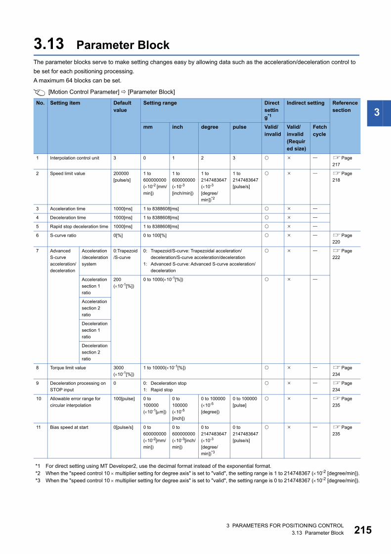
3
3.13 Parameter BlockThe parameter blocks serve to make setting changes easy by allowing data such as the acceleration/deceleration control to
be set for each positioning processing.
A maximum 64 blocks can be set.
[Motion Control Parameter] [Parameter Block]
*1 For direct setting using MT Developer2, use the decimal format instead of the exponential format.*2 When the "speed control 10 multiplier setting for degree axis" is set to "valid", the setting range is 1 to 214748367 (10-2 [degree/min]).*3 When the "speed control 10 multiplier setting for degree axis" is set to "valid", the setting range is 0 to 214748367 (10-2 [degree/min]).
No. Setting item Default value
Setting range Direct setting*1
Indirect setting Reference section
mm inch degree pulse Valid/invalid
Valid/invalid (Required size)
Fetch cycle
1 Interpolation control unit 3 0 1 2 3 Page
217
2 Speed limit value 200000
[pulse/s]
1 to
600000000
(10-2 [mm/
min])
1 to
600000000
(10-3
[inch/min])
1 to
2147483647
(10-3
[degree/
min])*2
1 to
2147483647
[pulse/s]
Page
218
3 Acceleration time 1000[ms] 1 to 8388608[ms]
4 Deceleration time 1000[ms] 1 to 8388608[ms]
5 Rapid stop deceleration time 1000[ms] 1 to 8388608[ms]
6 S-curve ratio 0[%] 0 to 100[%] Page
220
7 Advanced
S-curve
acceleration/
deceleration
Acceleration
/deceleration
system
0:Trapezoid
/S-curve
0: Trapezoid/S-curve: Trapezoidal acceleration/
deceleration/S-curve acceleration/deceleration
1: Advanced S-curve: Advanced S-curve acceleration/
deceleration
Page
222
Acceleration
section 1
ratio
200
(10-1[%])
0 to 1000(10-1[%])
Acceleration
section 2
ratio
Deceleration
section 1
ratio
Deceleration
section 2
ratio
8 Torque limit value 3000
(10-1[%])
1 to 10000(10-1[%]) Page
234
9 Deceleration processing on
STOP input
0 0: Deceleration stop
1: Rapid stop
Page
234
10 Allowable error range for
circular interpolation
100[pulse] 0 to
100000
(10-1[m])
0 to
100000
(10-5
[inch])
0 to 100000
(10-5
[degree])
0 to 100000
[pulse]
Page
235
11 Bias speed at start 0[pulse/s] 0 to
600000000
(10-2[mm/
min])
0 to
600000000
(10-3[inch/
min])
0 to
2147483647
(10-3
[degree/
min])*3
0 to
2147483647
[pulse/s]
Page
235
3 PARAMETERS FOR POSITIONING CONTROL3.13 Parameter Block 215
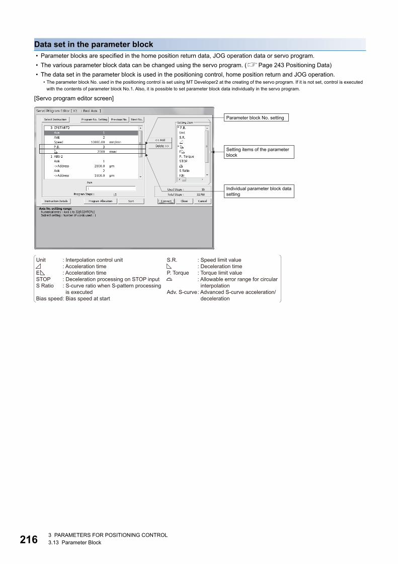
21
Data set in the parameter block • Parameter blocks are specified in the home position return data, JOG operation data or servo program.
• The various parameter block data can be changed using the servo program. (Page 243 Positioning Data)
• The data set in the parameter block is used in the positioning control, home position return and JOG operation.
[Servo program editor screen]
• The parameter block No. used in the positioning control is set using MT Developer2 at the creating of the servo program. If it is not set, control is executed
with the contents of parameter block No.1. Also, it is possible to set parameter block data individually in the servo program.
Parameter block No. setting
Individual parameter block datasetting
Setting items of the parameterblock
Unit : Interpolation control unit : Acceleration timeE : Acceleration timeSTOP : Deceleration processing on STOP inputS Ratio : S-curve ratio when S-pattern processing is executedBias speed : Bias speed at start
S.R. : Speed limit value : Deceleration timeP. Torque : Torque limit value : Allowable error range for circular interpolationAdv. S-curve : Advanced S-curve acceleration/ deceleration
63 PARAMETERS FOR POSITIONING CONTROL3.13 Parameter Block
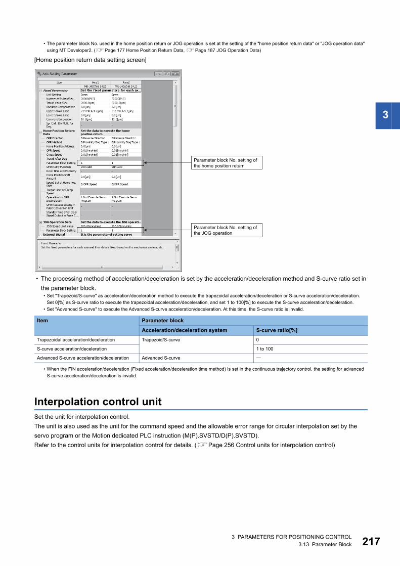
3
[Home position return data setting screen]
• The processing method of acceleration/deceleration is set by the acceleration/deceleration method and S-curve ratio set in
the parameter block.
Interpolation control unitSet the unit for interpolation control.
The unit is also used as the unit for the command speed and the allowable error range for circular interpolation set by the
servo program or the Motion dedicated PLC instruction (M(P).SVSTD/D(P).SVSTD).
Refer to the control units for interpolation control for details. (Page 256 Control units for interpolation control)
• The parameter block No. used in the home position return or JOG operation is set at the setting of the "home position return data" or "JOG operation data"
using MT Developer2. (Page 177 Home Position Return Data, Page 187 JOG Operation Data)
• Set "Trapezoid/S-curve" as acceleration/deceleration method to execute the trapezoidal acceleration/deceleration or S-curve acceleration/deceleration.
Set 0[%] as S-curve ratio to execute the trapezoidal acceleration/deceleration, and set 1 to 100[%] to execute the S-curve acceleration/deceleration.
• Set "Advanced S-curve" to execute the Advanced S-curve acceleration/deceleration. At this time, the S-curve ratio is invalid.
Item Parameter block
Acceleration/deceleration system S-curve ratio[%]
Trapezoidal acceleration/deceleration Trapezoid/S-curve 0
S-curve acceleration/deceleration 1 to 100
Advanced S-curve acceleration/deceleration Advanced S-curve
• When the FIN acceleration/deceleration (Fixed acceleration/deceleration time method) is set in the continuous trajectory control, the setting for advanced
S-curve acceleration/deceleration is invalid.
Parameter block No. setting ofthe JOG operation
Parameter block No. setting ofthe home position return
3 PARAMETERS FOR POSITIONING CONTROL3.13 Parameter Block 217
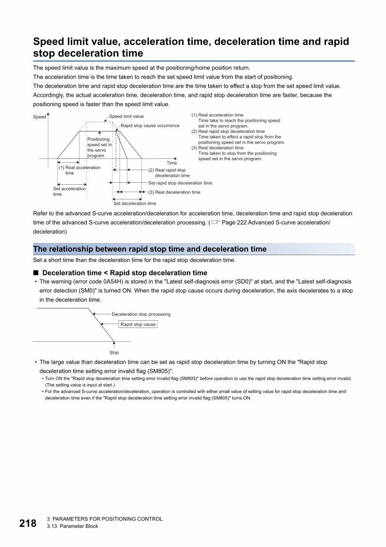
21
Speed limit value, acceleration time, deceleration time and rapid stop deceleration timeThe speed limit value is the maximum speed at the positioning/home position return.
The acceleration time is the time taken to reach the set speed limit value from the start of positioning.
The deceleration time and rapid stop deceleration time are the time taken to effect a stop from the set speed limit value.
Accordingly, the actual acceleration time, deceleration time, and rapid stop deceleration time are faster, because the
positioning speed is faster than the speed limit value.
Refer to the advanced S-curve acceleration/deceleration for acceleration time, deceleration time and rapid stop deceleration
time of the advanced S-curve acceleration/deceleration processing. (Page 222 Advanced S-curve acceleration/
deceleration)
The relationship between rapid stop time and deceleration timeSet a short time than the deceleration time for the rapid stop deceleration time.
■ Deceleration time < Rapid stop deceleration time • The warning (error code 0A54H) is stored in the "Latest self-diagnosis error (SD0)" at start, and the "Latest self-diagnosis
error detection (SM0)" is turned ON. When the rapid stop cause occurs during deceleration, the axis decelerates to a stop
in the deceleration time.
• The large value than deceleration time can be set as rapid stop deceleration time by turning ON the "Rapid stop
deceleration time setting error invalid flag (SM805)".• Turn ON the "Rapid stop deceleration time setting error invalid flag (SM805)" before operation to use the rapid stop deceleration time setting error invalid.
(The setting value is input at start.)
• For the advanced S-curve acceleration/deceleration, operation is controlled with either small value of setting value for rapid stop deceleration time and
deceleration time even if the "Rapid stop deceleration time setting error invalid flag (SM805)" turns ON.
Speed limit value
Rapid stop cause occurrence
(3) Real deceleration timeSet accelerationtime
Set deceleration time
Set rapid stop deceleration time
(2) Real rapid stop deceleration time
(1) Real acceleration timeTime take to reach the positioning speedset in the servo program.
(2) Real rapid stop deceleration timeTime taken to effect a rapid stop from thepositioning speed set in the servo program.
(3) Real deceleration timeTime taken to stop from the positioningspeed set in the servo program.
Positioningspeed set inthe servoprogram
Time
Speed
(1) Real accelerationtime
Deceleration stop processing
Stop
Rapid stop cause
83 PARAMETERS FOR POSITIONING CONTROL3.13 Parameter Block
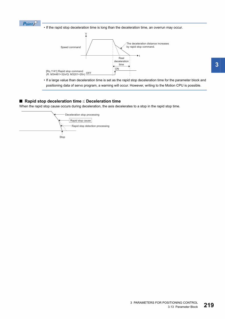
3
• If the rapid stop deceleration time is long than the deceleration time, an overrun may occur.
• If a large value than deceleration time is set as the rapid stop deceleration time for the parameter block and
positioning data of servo program, a warning will occur. However, writing to the Motion CPU is possible.
■ Rapid stop deceleration time Deceleration timeWhen the rapid stop cause occurs during deceleration, the axis decelerates to a stop in the rapid stop time.
V
tReal
decelerationtime
Speed command
[Rq.1141] Rapid stop command(R: M34481+32n/Q: M3201+20n)
The deceleration distance increasesby rapid stop command.
OFFON
Deceleration stop processing
Rapid stop detection processing
Stop
Rapid stop cause
3 PARAMETERS FOR POSITIONING CONTROL3.13 Parameter Block 219
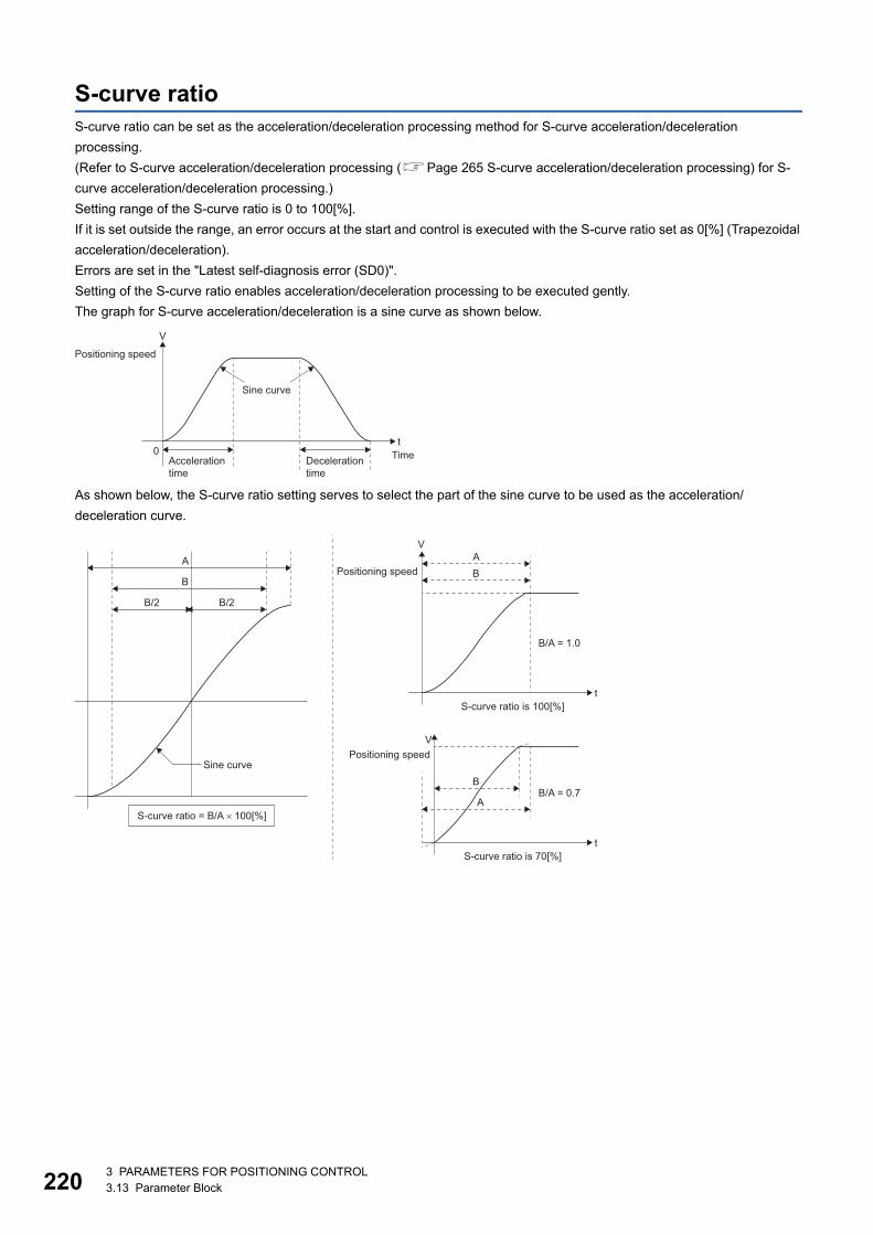
22
S-curve ratioS-curve ratio can be set as the acceleration/deceleration processing method for S-curve acceleration/deceleration
processing.
(Refer to S-curve acceleration/deceleration processing (Page 265 S-curve acceleration/deceleration processing) for S-
curve acceleration/deceleration processing.)
Setting range of the S-curve ratio is 0 to 100[%].
If it is set outside the range, an error occurs at the start and control is executed with the S-curve ratio set as 0[%] (Trapezoidal
acceleration/deceleration).
Errors are set in the "Latest self-diagnosis error (SD0)".
Setting of the S-curve ratio enables acceleration/deceleration processing to be executed gently.
The graph for S-curve acceleration/deceleration is a sine curve as shown below.
As shown below, the S-curve ratio setting serves to select the part of the sine curve to be used as the acceleration/
deceleration curve.
Positioning speed
Sine curve
0Accelerationtime
Decelerationtime
Timet
V
A
B
B/2 B/2
Sine curve
S-curve ratio = B/A × 100[%]
t
V
Positioning speed B
B/A = 1.0
S-curve ratio is 100[%]
A
t
VPositioning speed
B/A = 0.7
S-curve ratio is 70[%]
A
B
03 PARAMETERS FOR POSITIONING CONTROL3.13 Parameter Block
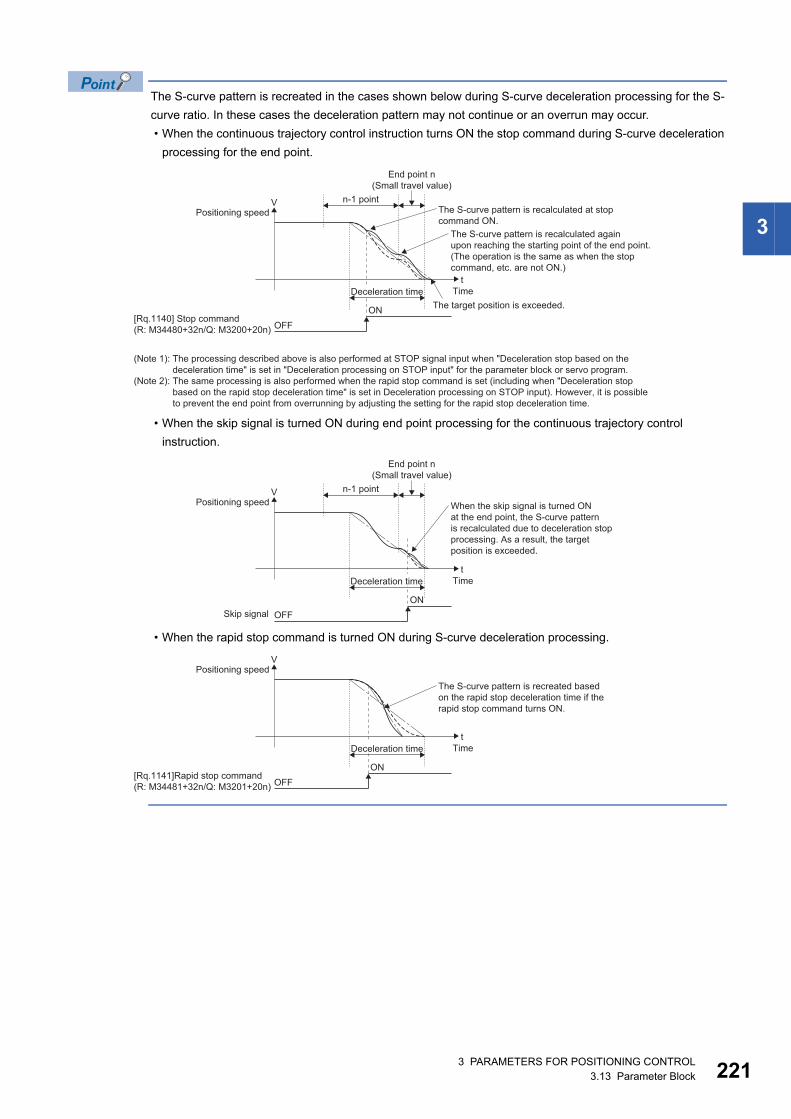
3
The S-curve pattern is recreated in the cases shown below during S-curve deceleration processing for the S-
curve ratio. In these cases the deceleration pattern may not continue or an overrun may occur.
• When the continuous trajectory control instruction turns ON the stop command during S-curve deceleration
processing for the end point.
• When the skip signal is turned ON during end point processing for the continuous trajectory control
instruction.
• When the rapid stop command is turned ON during S-curve deceleration processing.
V
tTime
n-1 point
End point n(Small travel value)
Positioning speed
[Rq.1140] Stop command(R: M34480+32n/Q: M3200+20n)
The S-curve pattern is recalculated at stop command ON.
The S-curve pattern is recalculated again upon reaching the starting point of the end point.(The operation is the same as when the stop command, etc. are not ON.)
The target position is exceeded.
OFFON
(Note 1): The processing described above is also performed at STOP signal input when "Deceleration stop based on the deceleration time" is set in "Deceleration processing on STOP input" for the parameter block or servo program.(Note 2): The same processing is also performed when the rapid stop command is set (including when "Deceleration stop based on the rapid stop deceleration time" is set in Deceleration processing on STOP input). However, it is possible to prevent the end point from overrunning by adjusting the setting for the rapid stop deceleration time.
Deceleration time
V
tTime
n-1 point
End point n(Small travel value)
Positioning speed
Skip signal
When the skip signal is turned ONat the end point, the S-curve patternis recalculated due to deceleration stopprocessing. As a result, the target position is exceeded.
OFFON
Deceleration time
V
tTime
Positioning speed
[Rq.1141]Rapid stop command(R: M34481+32n/Q: M3201+20n)
The S-curve pattern is recreated basedon the rapid stop deceleration time if therapid stop command turns ON.
OFFON
Deceleration time
3 PARAMETERS FOR POSITIONING CONTROL3.13 Parameter Block 221
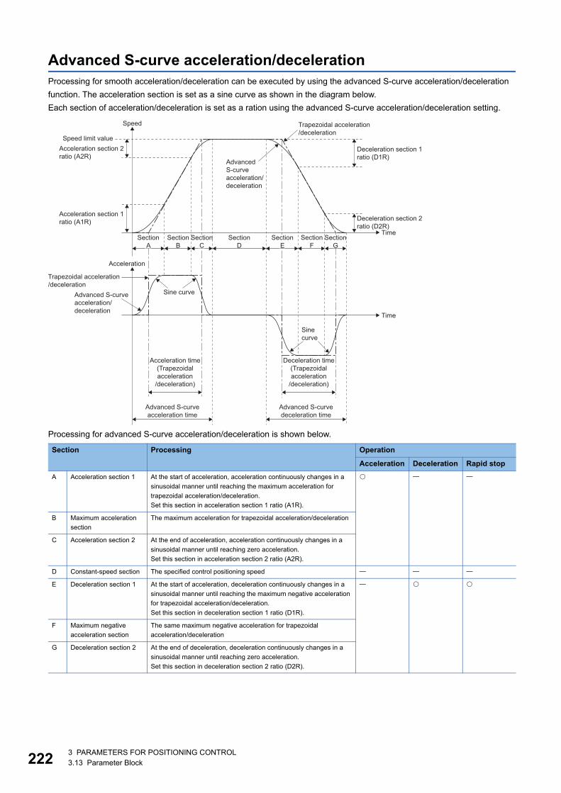
22
Advanced S-curve acceleration/decelerationProcessing for smooth acceleration/deceleration can be executed by using the advanced S-curve acceleration/deceleration
function. The acceleration section is set as a sine curve as shown in the diagram below.
Each section of acceleration/deceleration is set as a ration using the advanced S-curve acceleration/deceleration setting.
Processing for advanced S-curve acceleration/deceleration is shown below.
Section Processing Operation
Acceleration Deceleration Rapid stop
A Acceleration section 1 At the start of acceleration, acceleration continuously changes in a
sinusoidal manner until reaching the maximum acceleration for
trapezoidal acceleration/deceleration.
Set this section in acceleration section 1 ratio (A1R).
B Maximum acceleration
section
The maximum acceleration for trapezoidal acceleration/deceleration
C Acceleration section 2 At the end of acceleration, acceleration continuously changes in a
sinusoidal manner until reaching zero acceleration.
Set this section in acceleration section 2 ratio (A2R).
D Constant-speed section The specified control positioning speed
E Deceleration section 1 At the start of acceleration, deceleration continuously changes in a
sinusoidal manner until reaching the maximum negative acceleration
for trapezoidal acceleration/deceleration.
Set this section in deceleration section 1 ratio (D1R).
F Maximum negative
acceleration section
The same maximum negative acceleration for trapezoidal
acceleration/deceleration
G Deceleration section 2 At the end of deceleration, deceleration continuously changes in a
sinusoidal manner until reaching zero acceleration.
Set this section in deceleration section 2 ratio (D2R).
Trapezoidal acceleration/deceleration
Trapezoidal acceleration/deceleration
AdvancedS-curveacceleration/deceleration
Time
Time
Speed
Acceleration
Advanced S-curveacceleration/deceleration
Sine curve
Sinecurve
Speed limit valueAcceleration section 2ratio (A2R)
Deceleration section 1ratio (D1R)
Deceleration section 2ratio (D2R)
Acceleration section 1ratio (A1R)
SectionA
SectionB
SectionD
SectionF
Deceleration time(Trapezoidalacceleration
/deceleration)
Acceleration time(Trapezoidalacceleration
/deceleration)
Advanced S-curvedeceleration time
Advanced S-curveacceleration time
SectionE
SectionC
SectionG
23 PARAMETERS FOR POSITIONING CONTROL3.13 Parameter Block
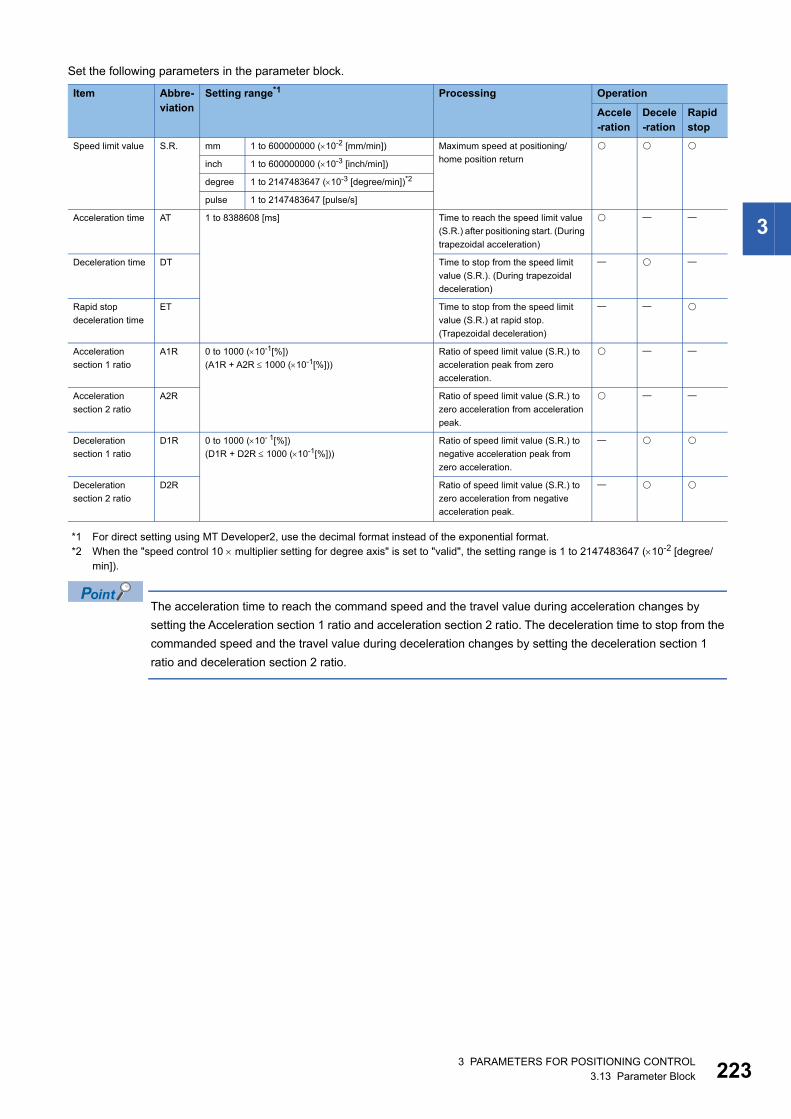
3
Set the following parameters in the parameter block.
*1 For direct setting using MT Developer2, use the decimal format instead of the exponential format.*2 When the "speed control 10 multiplier setting for degree axis" is set to "valid", the setting range is 1 to 2147483647 (10-2 [degree/
min]).
The acceleration time to reach the command speed and the travel value during acceleration changes by
setting the Acceleration section 1 ratio and acceleration section 2 ratio. The deceleration time to stop from the
commanded speed and the travel value during deceleration changes by setting the deceleration section 1
ratio and deceleration section 2 ratio.
Item Abbre-viation
Setting range*1 Processing Operation
Accele-ration
Decele-ration
Rapid stop
Speed limit value S.R. mm 1 to 600000000 (10-2 [mm/min]) Maximum speed at positioning/
home position return
inch 1 to 600000000 (10-3 [inch/min])
degree 1 to 2147483647 (10-3 [degree/min])*2
pulse 1 to 2147483647 [pulse/s]
Acceleration time AT 1 to 8388608 [ms] Time to reach the speed limit value
(S.R.) after positioning start. (During
trapezoidal acceleration)
Deceleration time DT Time to stop from the speed limit
value (S.R.). (During trapezoidal
deceleration)
Rapid stop
deceleration time
ET Time to stop from the speed limit
value (S.R.) at rapid stop.
(Trapezoidal deceleration)
Acceleration
section 1 ratio
A1R 0 to 1000 (10-1[%])
(A1R + A2R 1000 (10-1[%]))
Ratio of speed limit value (S.R.) to
acceleration peak from zero
acceleration.
Acceleration
section 2 ratio
A2R Ratio of speed limit value (S.R.) to
zero acceleration from acceleration
peak.
Deceleration
section 1 ratio
D1R 0 to 1000 (10- 1[%])
(D1R + D2R 1000 (10-1[%]))
Ratio of speed limit value (S.R.) to
negative acceleration peak from
zero acceleration.
Deceleration
section 2 ratio
D2R Ratio of speed limit value (S.R.) to
zero acceleration from negative
acceleration peak.
3 PARAMETERS FOR POSITIONING CONTROL3.13 Parameter Block 223
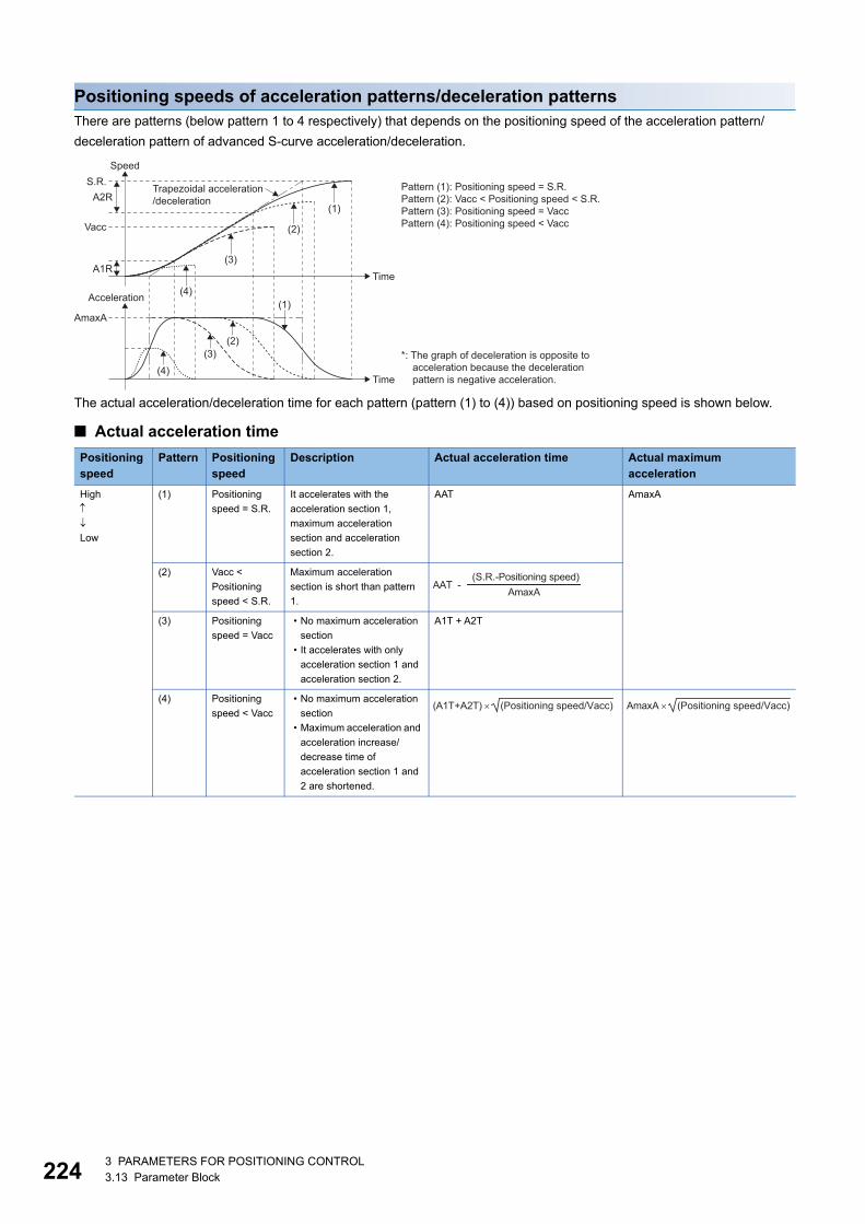
22
Positioning speeds of acceleration patterns/deceleration patternsThere are patterns (below pattern 1 to 4 respectively) that depends on the positioning speed of the acceleration pattern/
deceleration pattern of advanced S-curve acceleration/deceleration.
The actual acceleration/deceleration time for each pattern (pattern (1) to (4)) based on positioning speed is shown below.
■ Actual acceleration time
Positioning speed
Pattern Positioning speed
Description Actual acceleration time Actual maximum acceleration
High
Low
(1) Positioning
speed = S.R.
It accelerates with the
acceleration section 1,
maximum acceleration
section and acceleration
section 2.
AAT AmaxA
(2) Vacc <
Positioning
speed < S.R.
Maximum acceleration
section is short than pattern
1.
(3) Positioning
speed = Vacc
• No maximum acceleration
section
• It accelerates with only
acceleration section 1 and
acceleration section 2.
A1T + A2T
(4) Positioning
speed < Vacc
• No maximum acceleration
section
• Maximum acceleration and
acceleration increase/
decrease time of
acceleration section 1 and
2 are shortened.
Speed
A2R
A1R
S.R.
AmaxA
Vacc
Time
Acceleration
Time
(1)
(2)
(3)
(4)(1)
(2)(3)
(4)
Trapezoidal acceleration/deceleration
Pattern (1): Positioning speed = S.R.Pattern (2): Vacc < Positioning speed < S.R.Pattern (3): Positioning speed = VaccPattern (4): Positioning speed < Vacc
*: The graph of deceleration is opposite to acceleration because the deceleration pattern is negative acceleration.
AAT -(S.R.-Positioning speed)
AmaxA
(A1T+A2T) � (Positioning speed/Vacc) AmaxA � (Positioning speed/Vacc)
43 PARAMETERS FOR POSITIONING CONTROL3.13 Parameter Block
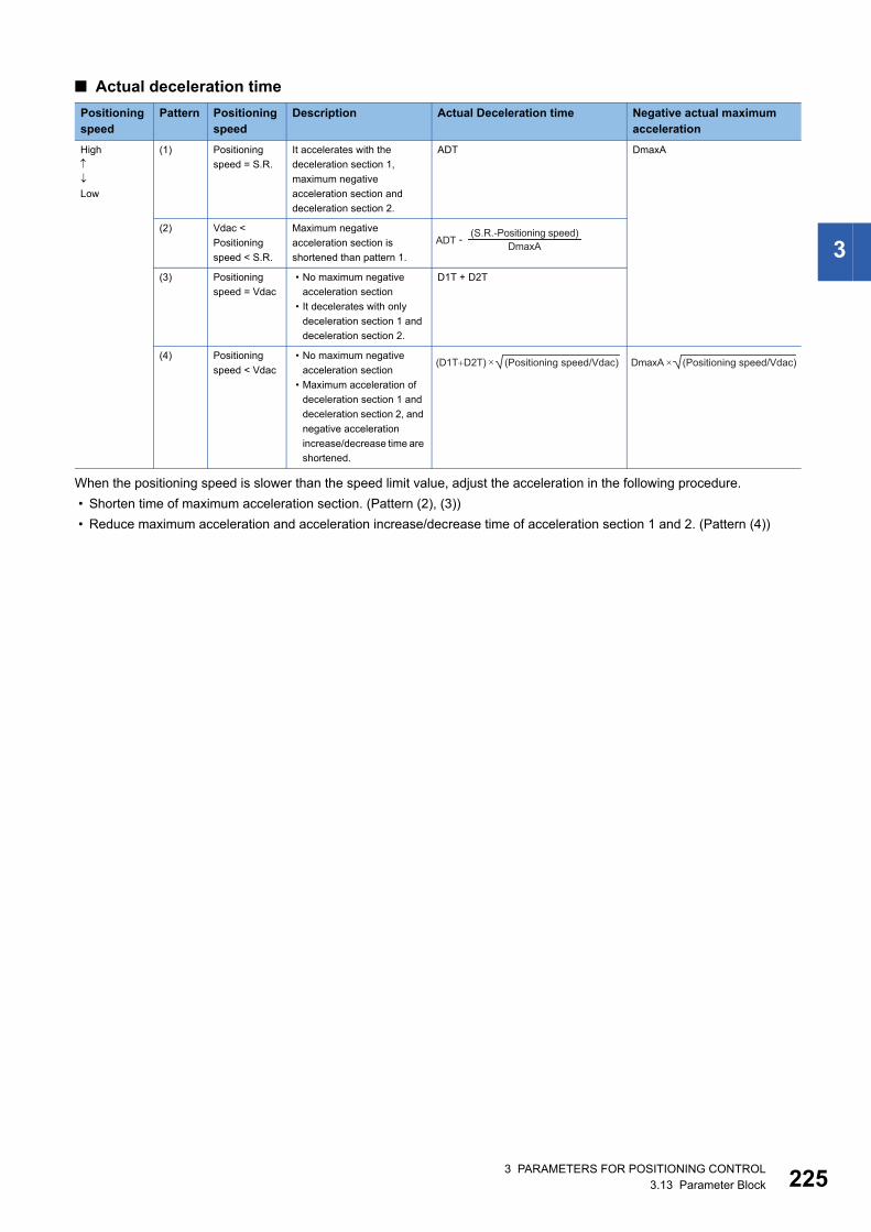
3
■ Actual deceleration time
When the positioning speed is slower than the speed limit value, adjust the acceleration in the following procedure.
• Shorten time of maximum acceleration section. (Pattern (2), (3))
• Reduce maximum acceleration and acceleration increase/decrease time of acceleration section 1 and 2. (Pattern (4))
Positioning speed
Pattern Positioning speed
Description Actual Deceleration time Negative actual maximum acceleration
High
Low
(1) Positioning
speed = S.R.
It accelerates with the
deceleration section 1,
maximum negative
acceleration section and
deceleration section 2.
ADT DmaxA
(2) Vdac <
Positioning
speed < S.R.
Maximum negative
acceleration section is
shortened than pattern 1.
(3) Positioning
speed = Vdac
• No maximum negative
acceleration section
• It decelerates with only
deceleration section 1 and
deceleration section 2.
D1T + D2T
(4) Positioning
speed < Vdac
• No maximum negative
acceleration section
• Maximum acceleration of
deceleration section 1 and
deceleration section 2, and
negative acceleration
increase/decrease time are
shortened.
ADT - (S.R.-Positioning speed)DmaxA
(D1T�D2T) � (Positioning speed/Vdac) DmaxA � (Positioning speed/Vdac)
3 PARAMETERS FOR POSITIONING CONTROL3.13 Parameter Block 225
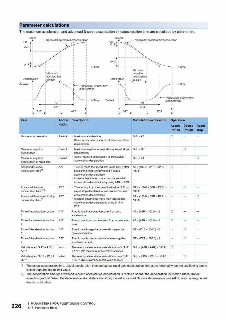
22
Parameter calculationsThe maximum acceleration and advanced S-curve acceleration time/deceleration time are calculated by parameters.
*1 The actual acceleration time, actual deceleration time and actual rapid stop deceleration time are shortened when the positioning speed is less than the speed limit value.
*2 The deceleration time for advanced S-curve acceleration/deceleration is rectified so that the deceleration inclination (deceleration speed) is gradual. When the deceleration stop distance is short, the set advanced S-curve deceleration time (ADT) may be lengthened due to rectification.
Item Abbre-viation
Description Calculation expression Operation
Accele-ration
Decele-ration
Rapid stop
Maximum acceleration AmaxA • Maximum acceleration
• Same acceleration as trapezoidal acceleration/
deceleration
S.R. AT
Maximum negative
acceleration
DmaxA • Maximum negative acceleration at (rapid stop)
deceleration
• Same negative acceleration as trapezoidal
acceleration/deceleration
S.R. DT
Maximum negative
acceleration at rapid stop
EmaxA S.R. ET
Advanced S-curve
acceleration time*1AAT • Time to reach the speed limit value (S.R.) after
positioning start. (At advanced S-curve
acceleration/deceleration)
• It can be lengthened more than trapezoidal
acceleration/deceleration by using A1R or A2R.
AT (100.0 + A1R + A2R)
100.0
Advanced S-curve
deceleration time*1*2ADT • Time to stop from the speed limit value (S.R.) at
(rapid stop) deceleration. (Advanced S-curve
acceleration/deceleration)
• It can be lengthened more than trapezoidal
acceleration/deceleration by using D1R or
D2R.
DT (100.0 + D1R + D2R)
100.0
Advanced S-curve rapid stop
deceleration time*1AET ET (100.0 + D1R + D2R)
100.0
Time of acceleration section
1
A1T Time to reach acceleration peak from zero
acceleration.
AT (A1R 100.0) 2
Time of acceleration section
2
A2T Time to reach zero acceleration from acceleration
peak.
AT (A2R 100.0) 2
Time of deceleration section
1
D1T Time to reach negative acceleration peak from
zero acceleration.
DT (D1R 100.0) 2
Time of deceleration section
2
D2T Time to reach zero acceleration from negative
acceleration peak.
DT (D2R 100.0) 2
Velocity when "AAT = A1T +
A2T"
Vacc The velocity when total acceleration is only "A1T
+ A2T". (No maximum acceleration section)
S.R. (A1R + A2R) 100.0
Velocity when "ADT = D1T +
D2T"
Vdac The velocity when total acceleration is only "D1T
+ D2T". (No maximum deceleration section)
S.R. (D1R + D2R) 100.0
Trapezoidal acceleration/decelerationSpeed
A2R
A1R
S.R.
AmaxA
Time
Acceleration
A1T A2T
ATAAT
Time
Trapezoidal acceleration/deceleration
Trapezoidal acceleration/deceleration
Speed
D2R
D1RS.R.
DmaxA
Time
Acceleration
D1T D2T
DTADT
Time
Trapezoidal acceleration/deceleration
Maximumaccelerationsection
Maximumnegativeaccelerationsection
63 PARAMETERS FOR POSITIONING CONTROL3.13 Parameter Block
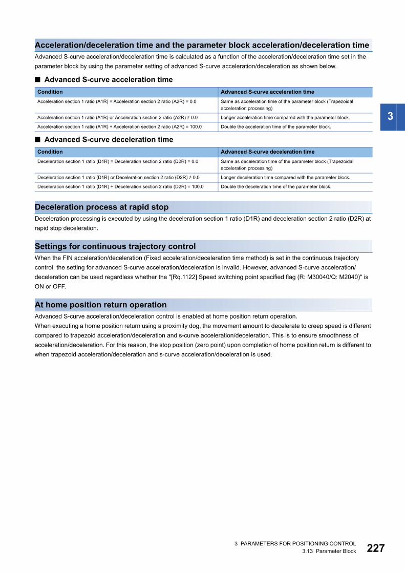
3
Acceleration/deceleration time and the parameter block acceleration/deceleration timeAdvanced S-curve acceleration/deceleration time is calculated as a function of the acceleration/deceleration time set in the
parameter block by using the parameter setting of advanced S-curve acceleration/deceleration as shown below.
■ Advanced S-curve acceleration time
■ Advanced S-curve deceleration time
Deceleration process at rapid stopDeceleration processing is executed by using the deceleration section 1 ratio (D1R) and deceleration section 2 ratio (D2R) at
rapid stop deceleration.
Settings for continuous trajectory controlWhen the FIN acceleration/deceleration (Fixed acceleration/deceleration time method) is set in the continuous trajectory
control, the setting for advanced S-curve acceleration/deceleration is invalid. However, advanced S-curve acceleration/
deceleration can be used regardless whether the "[Rq.1122] Speed switching point specified flag (R: M30040/Q: M2040)" is
ON or OFF.
At home position return operationAdvanced S-curve acceleration/deceleration control is enabled at home position return operation.
When executing a home position return using a proximity dog, the movement amount to decelerate to creep speed is different
compared to trapezoid acceleration/deceleration and s-curve acceleration/deceleration. This is to ensure smoothness of
acceleration/deceleration. For this reason, the stop position (zero point) upon completion of home position return is different to
when trapezoid acceleration/deceleration and s-curve acceleration/deceleration is used.
Condition Advanced S-curve acceleration time
Acceleration section 1 ratio (A1R) = Acceleration section 2 ratio (A2R) = 0.0 Same as acceleration time of the parameter block (Trapezoidal
acceleration processing)
Acceleration section 1 ratio (A1R) or Acceleration section 2 ratio (A2R) 0.0 Longer acceleration time compared with the parameter block.
Acceleration section 1 ratio (A1R) + Acceleration section 2 ratio (A2R) = 100.0 Double the acceleration time of the parameter block.
Condition Advanced S-curve deceleration time
Deceleration section 1 ratio (D1R) = Deceleration section 2 ratio (D2R) = 0.0 Same as deceleration time of the parameter block (Trapezoidal
acceleration processing)
Deceleration section 1 ratio (D1R) or Deceleration section 2 ratio (D2R) 0.0 Longer deceleration time compared with the parameter block.
Deceleration section 1 ratio (D1R) + Deceleration section 2 ratio (D2R) = 100.0 Double the deceleration time of the parameter block.
3 PARAMETERS FOR POSITIONING CONTROL3.13 Parameter Block 227
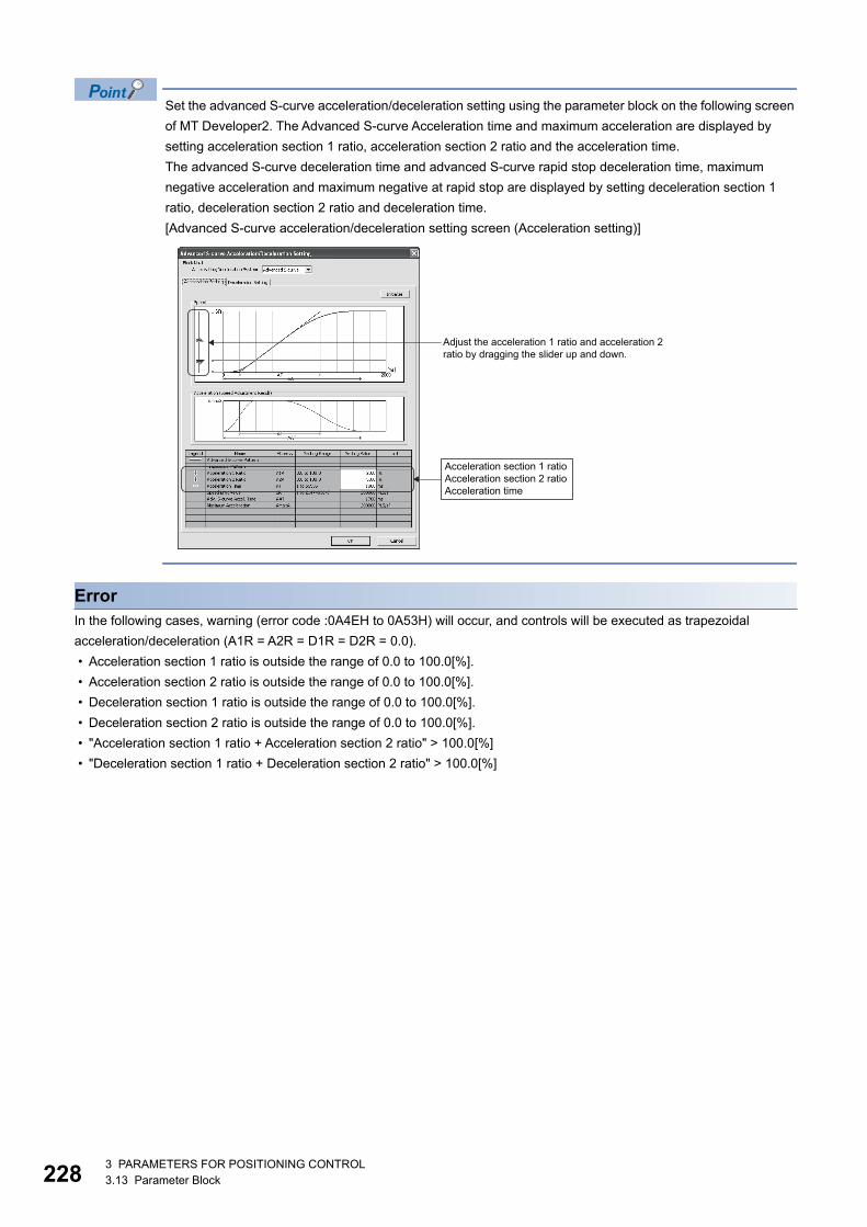
22
Set the advanced S-curve acceleration/deceleration setting using the parameter block on the following screen
of MT Developer2. The Advanced S-curve Acceleration time and maximum acceleration are displayed by
setting acceleration section 1 ratio, acceleration section 2 ratio and the acceleration time.
The advanced S-curve deceleration time and advanced S-curve rapid stop deceleration time, maximum
negative acceleration and maximum negative at rapid stop are displayed by setting deceleration section 1
ratio, deceleration section 2 ratio and deceleration time.
[Advanced S-curve acceleration/deceleration setting screen (Acceleration setting)]
ErrorIn the following cases, warning (error code :0A4EH to 0A53H) will occur, and controls will be executed as trapezoidal
acceleration/deceleration (A1R = A2R = D1R = D2R = 0.0).
• Acceleration section 1 ratio is outside the range of 0.0 to 100.0[%].
• Acceleration section 2 ratio is outside the range of 0.0 to 100.0[%].
• Deceleration section 1 ratio is outside the range of 0.0 to 100.0[%].
• Deceleration section 2 ratio is outside the range of 0.0 to 100.0[%].
• "Acceleration section 1 ratio + Acceleration section 2 ratio" > 100.0[%]
• "Deceleration section 1 ratio + Deceleration section 2 ratio" > 100.0[%]
Adjust the acceleration 1 ratio and acceleration 2ratio by dragging the slider up and down.
Acceleration section 1 ratio Acceleration section 2 ratio Acceleration time
83 PARAMETERS FOR POSITIONING CONTROL3.13 Parameter Block
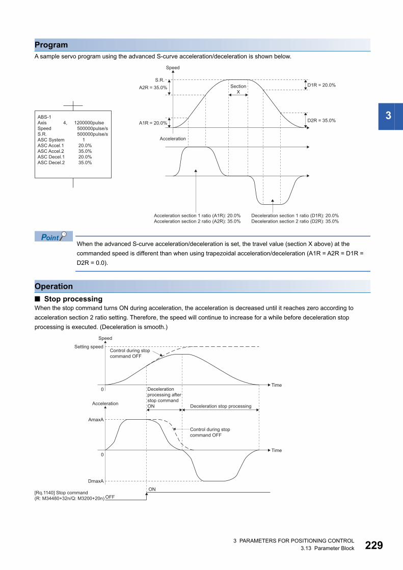
3
ProgramA sample servo program using the advanced S-curve acceleration/deceleration is shown below.
When the advanced S-curve acceleration/deceleration is set, the travel value (section X above) at the
commanded speed is different than when using trapezoidal acceleration/deceleration (A1R = A2R = D1R =
D2R = 0.0).
Operation
■ Stop processingWhen the stop command turns ON during acceleration, the acceleration is decreased until it reaches zero according to
acceleration section 2 ratio setting. Therefore, the speed will continue to increase for a while before deceleration stop
processing is executed. (Deceleration is smooth.)
Speed
Acceleration
SectionX
A2R = 35.0%S.R.
A1R = 20.0%
D1R = 20.0%
D2R = 35.0%
Deceleration section 1 ratio (D1R): 20.0%Deceleration section 2 ratio (D2R): 35.0%
Acceleration section 1 ratio (A1R): 20.0%Acceleration section 2 ratio (A2R): 35.0%
ABS-1Axis 4,SpeedS.R.ASC System ASC Accel.1ASC Accel.2ASC Decel.1ASC Decel.2
1200000pulse 500000pulse/s 500000pulse/s 1 20.0% 35.0% 20.0% 35.0%
0
0
Setting speed
Speed
Acceleration
AmaxA
DmaxA
Time
Time
OFFON
Control during stopcommand OFF
Control during stopcommand OFF
Decelerationprocessing afterstop commandON Deceleration stop processing
[Rq.1140] Stop command(R: M34480+32n/Q: M3200+20n)
3 PARAMETERS FOR POSITIONING CONTROL3.13 Parameter Block 229
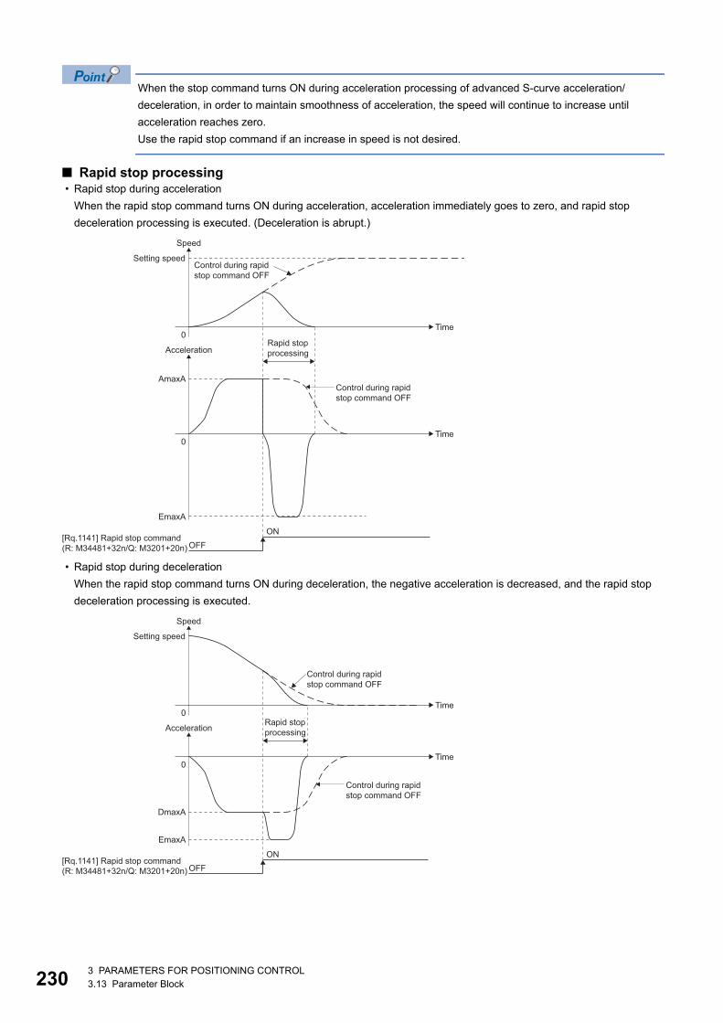
23
When the stop command turns ON during acceleration processing of advanced S-curve acceleration/
deceleration, in order to maintain smoothness of acceleration, the speed will continue to increase until
acceleration reaches zero.
Use the rapid stop command if an increase in speed is not desired.
■ Rapid stop processing • Rapid stop during acceleration
When the rapid stop command turns ON during acceleration, acceleration immediately goes to zero, and rapid stop
deceleration processing is executed. (Deceleration is abrupt.)
• Rapid stop during deceleration
When the rapid stop command turns ON during deceleration, the negative acceleration is decreased, and the rapid stop
deceleration processing is executed.
0
0
Setting speed
Speed
Acceleration
AmaxA
EmaxA
Time
Time
OFFON
Control during rapidstop command OFF
Control during rapidstop command OFF
Rapid stopprocessing
[Rq.1141] Rapid stop command(R: M34481+32n/Q: M3201+20n)
0
0
Setting speed
Speed
Acceleration
DmaxA
EmaxA
Time
Time
OFFON
Control during rapidstop command OFF
Control during rapidstop command OFF
Rapid stopprocessing
[Rq.1141] Rapid stop command(R: M34481+32n/Q: M3201+20n)
03 PARAMETERS FOR POSITIONING CONTROL3.13 Parameter Block
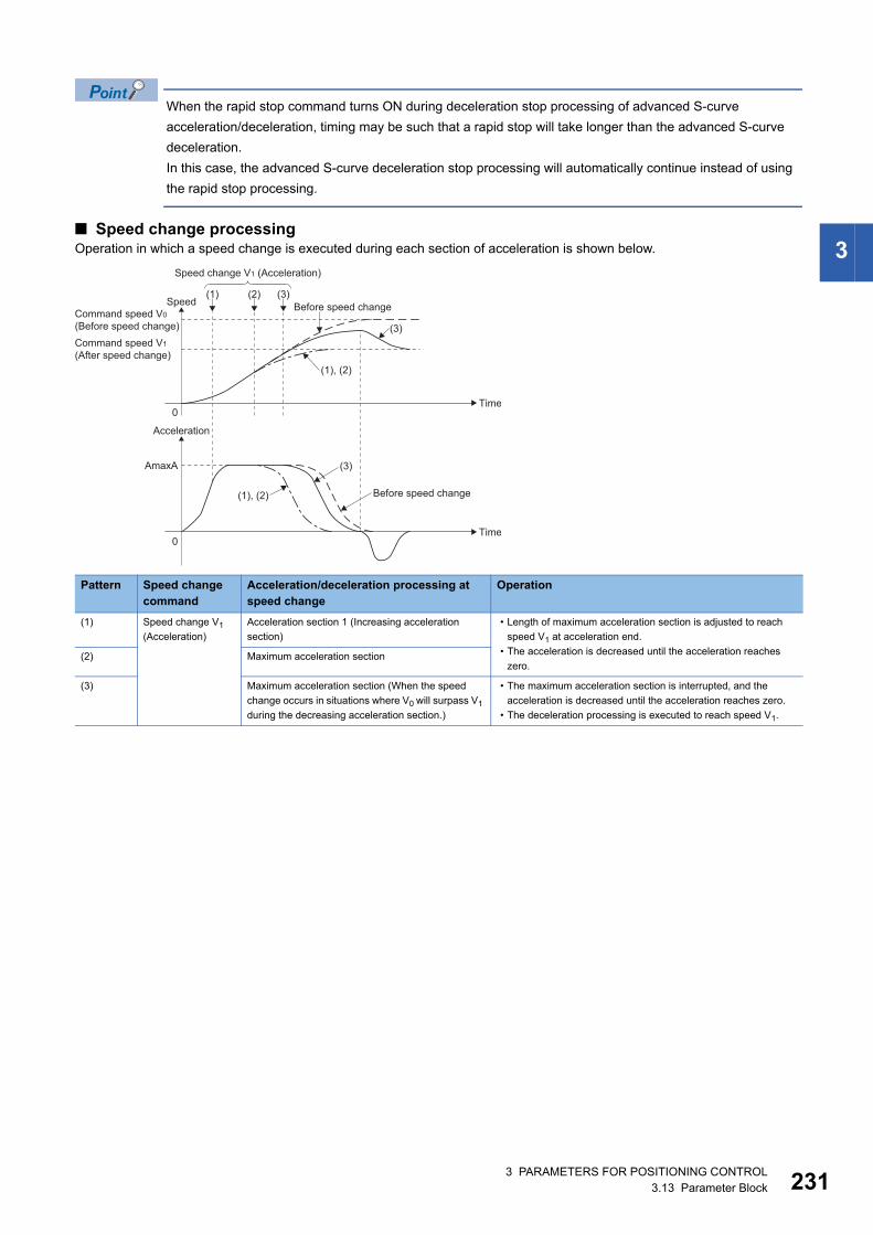
3
When the rapid stop command turns ON during deceleration stop processing of advanced S-curve
acceleration/deceleration, timing may be such that a rapid stop will take longer than the advanced S-curve
deceleration.
In this case, the advanced S-curve deceleration stop processing will automatically continue instead of using
the rapid stop processing.
■ Speed change processingOperation in which a speed change is executed during each section of acceleration is shown below.
Pattern Speed change command
Acceleration/deceleration processing at speed change
Operation
(1) Speed change V1
(Acceleration)
Acceleration section 1 (Increasing acceleration
section)
• Length of maximum acceleration section is adjusted to reach
speed V1 at acceleration end.
• The acceleration is decreased until the acceleration reaches
zero.(2) Maximum acceleration section
(3) Maximum acceleration section (When the speed
change occurs in situations where V0 will surpass V1
during the decreasing acceleration section.)
• The maximum acceleration section is interrupted, and the
acceleration is decreased until the acceleration reaches zero.
• The deceleration processing is executed to reach speed V1.
Command speed V0
(Before speed change)
0
0
(1), (2)
(1), (2)
(3)
(3)
Command speed V1
(After speed change)
Speed
Acceleration
AmaxA
Time
Time
(1) (2) (3)Before speed change
Before speed change
Speed change V1 (Acceleration)
3 PARAMETERS FOR POSITIONING CONTROL3.13 Parameter Block 231
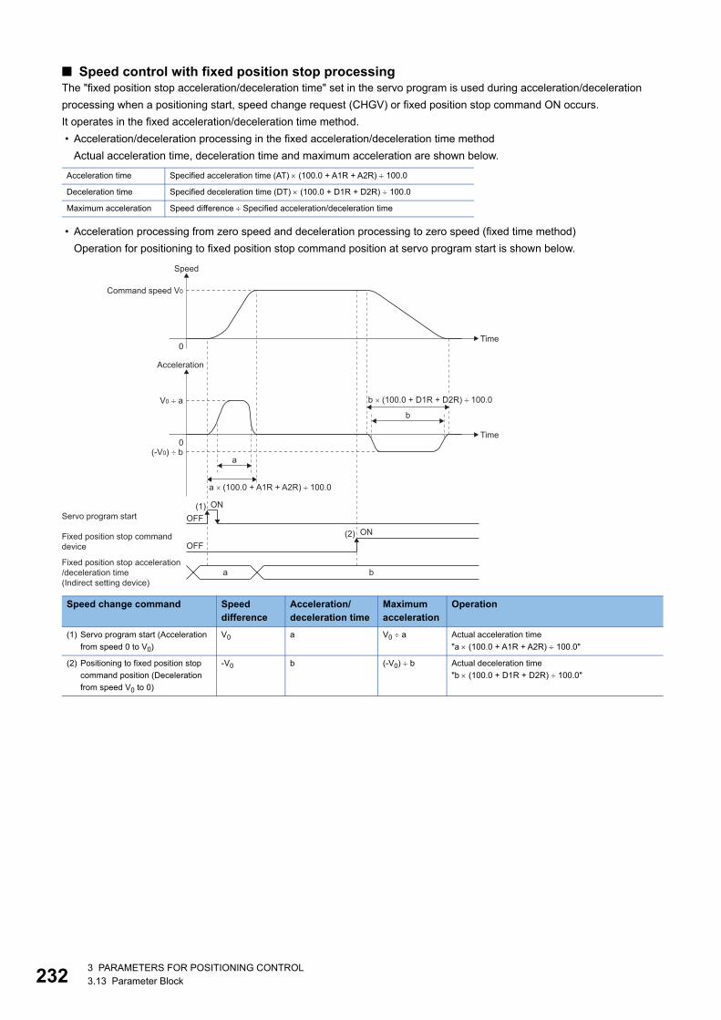
23
■ Speed control with fixed position stop processingThe "fixed position stop acceleration/deceleration time" set in the servo program is used during acceleration/deceleration
processing when a positioning start, speed change request (CHGV) or fixed position stop command ON occurs.
It operates in the fixed acceleration/deceleration time method.
• Acceleration/deceleration processing in the fixed acceleration/deceleration time method
Actual acceleration time, deceleration time and maximum acceleration are shown below.
• Acceleration processing from zero speed and deceleration processing to zero speed (fixed time method)
Operation for positioning to fixed position stop command position at servo program start is shown below.
Acceleration time Specified acceleration time (AT) (100.0 + A1R + A2R) 100.0
Deceleration time Specified deceleration time (DT) (100.0 + D1R + D2R) 100.0
Maximum acceleration Speed difference Specified acceleration/deceleration time
Speed change command Speed difference
Acceleration/deceleration time
Maximum acceleration
Operation
(1) Servo program start (Acceleration
from speed 0 to V0)
V0 a V0 a Actual acceleration time
"a (100.0 + A1R + A2R) 100.0"
(2) Positioning to fixed position stop
command position (Deceleration
from speed V0 to 0)
-V0 b (-V0) b Actual deceleration time
"b (100.0 + D1R + D2R) 100.0"
Speed
0
0
Time
Command speed V0
OFF(1) ON
Acceleration
Time
V0 ÷ a
(-V0) ÷ b
Servo program start
ONOFF
(2)Fixed position stop commanddevice
Fixed position stop acceleration/deceleration time(Indirect setting device)
a b
b
a
a × (100.0 + A1R + A2R) ÷ 100.0
b × (100.0 + D1R + D2R) ÷ 100.0
23 PARAMETERS FOR POSITIONING CONTROL3.13 Parameter Block
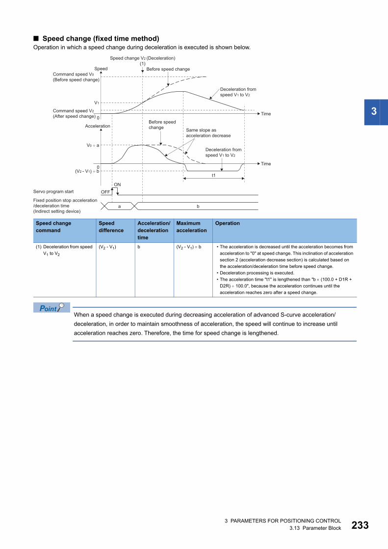
3
■ Speed change (fixed time method)Operation in which a speed change during deceleration is executed is shown below.
When a speed change is executed during decreasing acceleration of advanced S-curve acceleration/
deceleration, in order to maintain smoothness of acceleration, the speed will continue to increase until
acceleration reaches zero. Therefore, the time for speed change is lengthened.
Speed change command
Speed difference
Acceleration/deceleration time
Maximum acceleration
Operation
(1) Deceleration from speed
V1 to V2
(V2 - V1) b (V2 - V1) b • The acceleration is decreased until the acceleration becomes from
acceleration to "0" at speed change. This inclination of acceleration
section 2 (acceleration decrease section) is calculated based on
the acceleration/deceleration time before speed change.
• Deceleration processing is executed.
• The acceleration time "t1" is lengthened than "b (100.0 + D1R +
D2R) 100.0", because the acceleration continues until the
acceleration reaches zero after a speed change.
0
0
Speed change V2 (Deceleration)(1)
Before speed change
Deceleration fromspeed V1 to V2
Command speed V0
(Before speed change)
Speed
Acceleration
V1
Command speed V2
(After speed change)
V0 � a
(V2 - V1) � b
Time
Time
OFFON
t1
Servo program start
a bFixed position stop acceleration/deceleration time(Indirect setting device)
Same slope asacceleration decrease
Before speedchange
Deceleration fromspeed V1 to V2
3 PARAMETERS FOR POSITIONING CONTROL3.13 Parameter Block 233
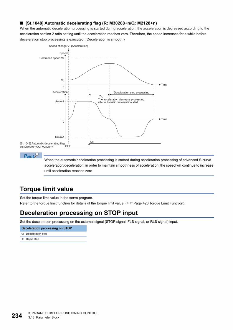
23
■ [St.1048] Automatic decelerating flag (R: M30208+n/Q: M2128+n)When the automatic deceleration processing is started during acceleration, the acceleration is decreased according to the
acceleration section 2 ratio setting until the acceleration reaches zero. Therefore, the speed increases for a while before
deceleration stop processing is executed. (Deceleration is smooth.)
When the automatic deceleration processing is started during acceleration processing of advanced S-curve
acceleration/deceleration, in order to maintain smoothness of acceleration, the speed will continue to increase
until acceleration reaches zero.
Torque limit valueSet the torque limit value in the servo program.
Refer to the torque limit function for details of the torque limit value. (Page 426 Torque Limit Function)
Deceleration processing on STOP inputSet the deceleration processing on the external signal (STOP signal, FLS signal, or RLS signal) input.
Deceleration processing on STOP
0: Deceleration stop
1: Rapid stop
0
0
Command speed V1
Speed
Acceleration
V0
AmaxA
DmaxA
Time
Time
OFFON
Deceleration stop processing
[St.1048] Automatic decelerating flag(R: M30208+n/Q: M2128+n)
Speed change V1 (Acceleration)
The acceleration decrease processingafter automatic deceleration start
43 PARAMETERS FOR POSITIONING CONTROL3.13 Parameter Block
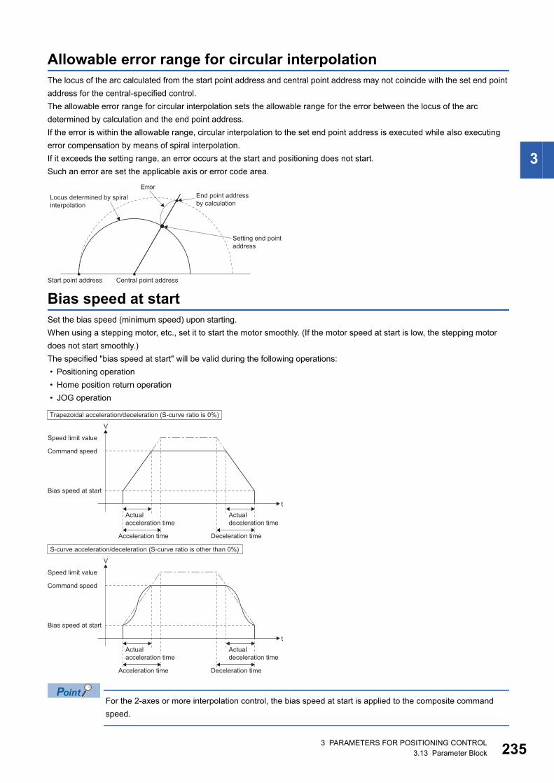
3
Allowable error range for circular interpolationThe locus of the arc calculated from the start point address and central point address may not coincide with the set end point
address for the central-specified control.
The allowable error range for circular interpolation sets the allowable range for the error between the locus of the arc
determined by calculation and the end point address.
If the error is within the allowable range, circular interpolation to the set end point address is executed while also executing
error compensation by means of spiral interpolation.
If it exceeds the setting range, an error occurs at the start and positioning does not start.
Such an error are set the applicable axis or error code area.
Bias speed at startSet the bias speed (minimum speed) upon starting.
When using a stepping motor, etc., set it to start the motor smoothly. (If the motor speed at start is low, the stepping motor
does not start smoothly.)
The specified "bias speed at start" will be valid during the following operations:
• Positioning operation
• Home position return operation
• JOG operation
For the 2-axes or more interpolation control, the bias speed at start is applied to the composite command
speed.
Locus determined by spiralinterpolation
Error
Start point address Central point address
End point addressby calculation
Setting end pointaddress
Speed limit value
Command speed
Bias speed at start
Bias speed at start
V
t
Acceleration time Deceleration time
Acceleration time Deceleration time
Trapezoidal acceleration/deceleration (S-curve ratio is 0%)
Speed limit value
Command speed
V
t
S-curve acceleration/deceleration (S-curve ratio is other than 0%)
Actualdeceleration time
Actualacceleration time
Actualdeceleration time
Actualacceleration time
3 PARAMETERS FOR POSITIONING CONTROL3.13 Parameter Block 235
23
Cautions • Bias speed at start is valid regardless of motor type. Set "0" when using the motor other than the stepping motor.
Otherwise, it may cause vibration or impact even though a warning does not occur.
• Set bias speed at start according to the specification of stepping motor driver. If the setting is outside the range, it may
cause the following troubles by rapid speed change or overload.
• Set the bias speed at start to a value not more than the speed limit value. If the bias speed at start is set to a value larger
than the speed limit value, a warning (error code: 0A4CH) occurs, and the bias speed at start is "0"
• The setting range for the command speed is "bias speed at start to speed limit value". When the command speed is out of
range by starting a servo program or executing a speed change instruction (M(P).CHGV/D(P).CHGV,CHGV), a warning
(error code: 0A4CH), or warning (error code: 0A5DH) occurs and speed change is not performed. When bias speed at start
is other than "0", a warning (error code: 0A5DH) occurs when a speed change to "0" is performed.
• When FIN acceleration/deceleration and advanced S-curve acceleration/deceleration methods are used with bias speed at
start, a warning (error code: 0A4DH) occurs, and the bias speed at start is "0".
• For servo programs where speed specification at a pass point is possible (CPSTART), if the speed at the pass point is set
to less than the bias speed at start, a warning (error code: 0A5AH) occurs, and the bias speed at start is "0" for the points
afterwards.
• Stepping motor steps out.
• An error occurs in the stepping motor driver.
63 PARAMETERS FOR POSITIONING CONTROL3.13 Parameter Block
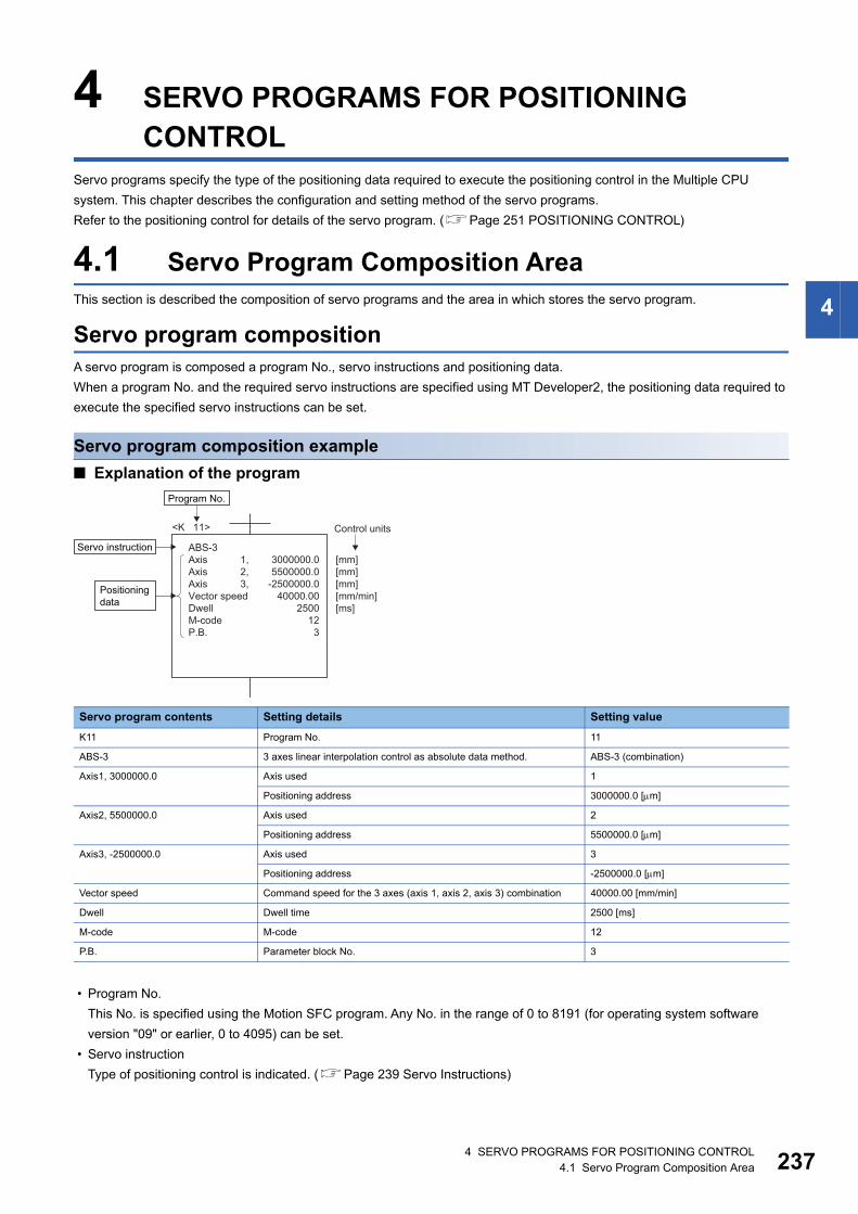
4
4 SERVO PROGRAMS FOR POSITIONING CONTROL
Servo programs specify the type of the positioning data required to execute the positioning control in the Multiple CPU
system. This chapter describes the configuration and setting method of the servo programs.
Refer to the positioning control for details of the servo program. (Page 251 POSITIONING CONTROL)
4.1 Servo Program Composition AreaThis section is described the composition of servo programs and the area in which stores the servo program.
Servo program compositionA servo program is composed a program No., servo instructions and positioning data.
When a program No. and the required servo instructions are specified using MT Developer2, the positioning data required to
execute the specified servo instructions can be set.
Servo program composition example
■ Explanation of the program
• Program No.
This No. is specified using the Motion SFC program. Any No. in the range of 0 to 8191 (for operating system software
version "09" or earlier, 0 to 4095) can be set.
• Servo instruction
Type of positioning control is indicated. (Page 239 Servo Instructions)
Servo program contents Setting details Setting value
K11 Program No. 11
ABS-3 3 axes linear interpolation control as absolute data method. ABS-3 (combination)
Axis1, 3000000.0 Axis used 1
Positioning address 3000000.0 [m]
Axis2, 5500000.0 Axis used 2
Positioning address 5500000.0 [m]
Axis3, -2500000.0 Axis used 3
Positioning address -2500000.0 [m]
Vector speed Command speed for the 3 axes (axis 1, axis 2, axis 3) combination 40000.00 [mm/min]
Dwell Dwell time 2500 [ms]
M-code M-code 12
P.B. Parameter block No. 3
3000000.05500000.0
-2500000.040000.00
250012
3
ABS-3Axis 1,Axis 2,Axis 3,Vector speedDwellM-codeP.B.
[mm][mm][mm][mm/min][ms]
<K 11> Control units
Program No.
Servo instruction
Positioningdata
4 SERVO PROGRAMS FOR POSITIONING CONTROL4.1 Servo Program Composition Area 237

23
• Positioning data
This is the data required to execute servo instructions. The data required to execute is fixed for each servo instruction.
(Page 243 Positioning Data)
The following table applies to the servo program shown above.
Setting condition Item
Items which must be set • Axis used and positioning address
• Command speed
Items which are set when required • Dwell time
• M-code
• P.B. (parameter block) (Controlled with the default value (Parameter block 1 if not set.)
84 SERVO PROGRAMS FOR POSITIONING CONTROL4.1 Servo Program Composition Area
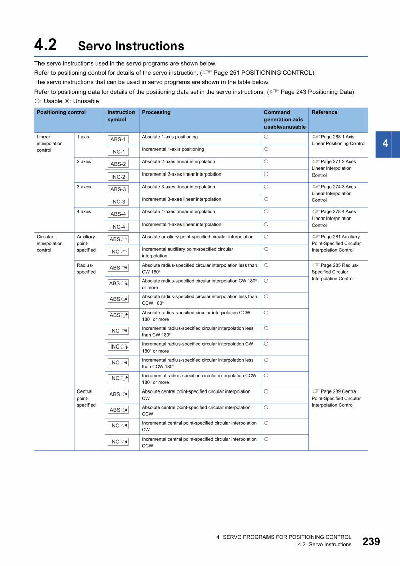
4
4.2 Servo InstructionsThe servo instructions used in the servo programs are shown below.
Refer to positioning control for details of the servo instruction. (Page 251 POSITIONING CONTROL)
The servo instructions that can be used in servo programs are shown in the table below.
Refer to positioning data for details of the positioning data set in the servo instructions. (Page 243 Positioning Data)
: Usable : Unusable
Positioning control Instruction symbol
Processing Command generation axis usable/unusable
Reference
Linear
interpolation
control
1 axis Absolute 1-axis positioning Page 268 1 Axis
Linear Positioning ControlIncremental 1-axis positioning
2 axes Absolute 2-axes linear interpolation Page 271 2 Axes
Linear Interpolation
ControlIncremental 2-axes linear interpolation
3 axes Absolute 3-axes linear interpolation Page 274 3 Axes
Linear Interpolation
ControlIncremental 3-axes linear interpolation
4 axes Absolute 4-axes linear interpolation Page 278 4 Axes
Linear Interpolation
ControlIncremental 4-axes linear interpolation
Circular
interpolation
control
Auxiliary
point-
specified
Absolute auxiliary point-specified circular interpolation Page 281 Auxiliary
Point-Specified Circular
Interpolation ControlIncremental auxiliary point-specified circular
interpolation
Radius-
specified
Absolute radius-specified circular interpolation less than
CW 180 Page 285 Radius-
Specified Circular
Interpolation ControlAbsolute radius-specified circular interpolation CW 180 or more
Absolute radius-specified circular interpolation less than
CCW 180
Absolute radius-specified circular interpolation CCW
180 or more
Incremental radius-specified circular interpolation less
than CW 180
Incremental radius-specified circular interpolation CW
180 or more
Incremental radius-specified circular interpolation less
than CCW 180
Incremental radius-specified circular interpolation CCW
180 or more
Central
point-
specified
Absolute central point-specified circular interpolation
CW
Page 289 Central
Point-Specified Circular
Interpolation ControlAbsolute central point-specified circular interpolation
CCW
Incremental central point-specified circular interpolation
CW
Incremental central point-specified circular interpolation
CCW
ABS-1
INC-1
ABS-2
INC-2
ABS-3
INC-3
ABS-4
INC-4
ABS
INC
ABS
ABS
ABS
ABS
INC
INC
INC
INC
ABS
ABS
INC
INC
4 SERVO PROGRAMS FOR POSITIONING CONTROL4.2 Servo Instructions 239
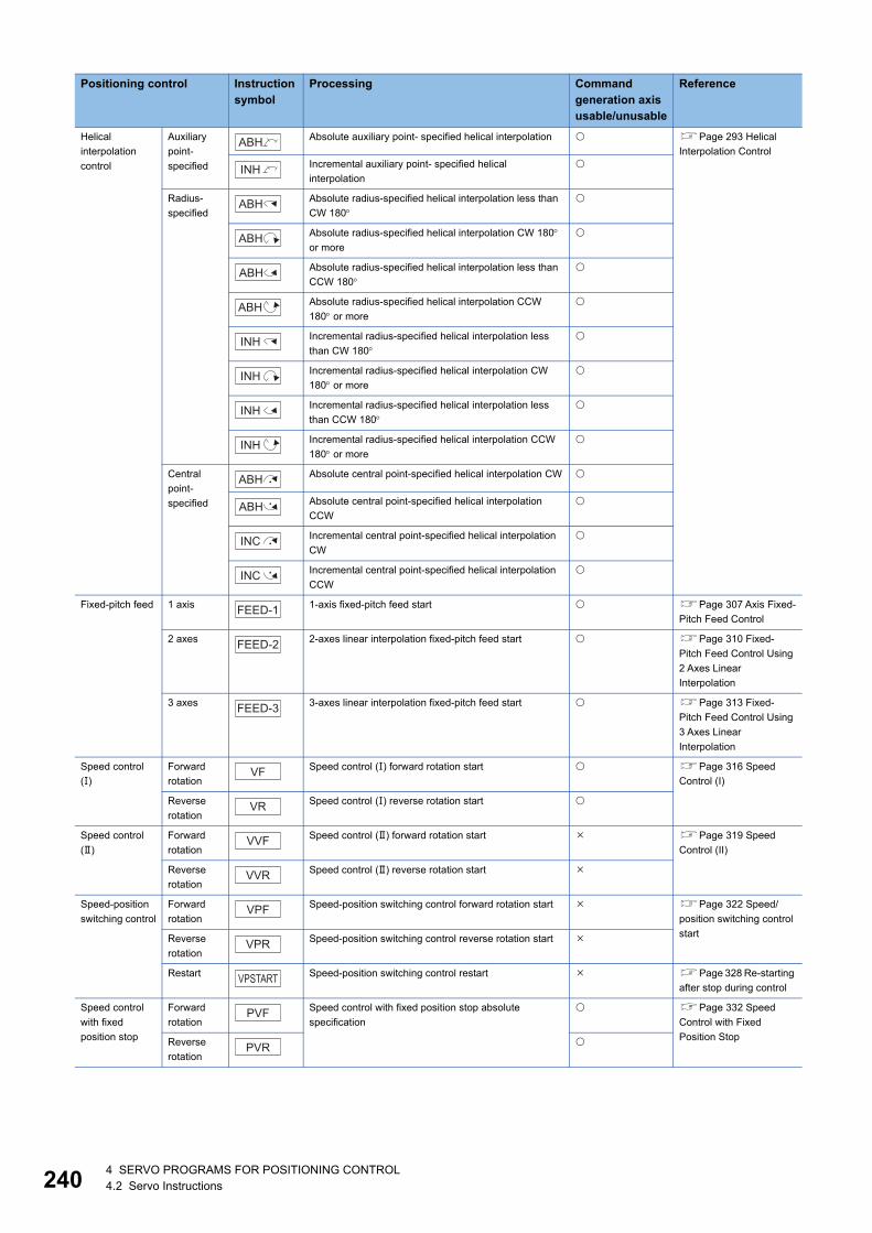
24
Helical
interpolation
control
Auxiliary
point-
specified
Absolute auxiliary point- specified helical interpolation Page 293 Helical
Interpolation ControlIncremental auxiliary point- specified helical
interpolation
Radius-
specified
Absolute radius-specified helical interpolation less than
CW 180
Absolute radius-specified helical interpolation CW 180 or more
Absolute radius-specified helical interpolation less than
CCW 180
Absolute radius-specified helical interpolation CCW
180 or more
Incremental radius-specified helical interpolation less
than CW 180
Incremental radius-specified helical interpolation CW
180 or more
Incremental radius-specified helical interpolation less
than CCW 180
Incremental radius-specified helical interpolation CCW
180 or more
Central
point-
specified
Absolute central point-specified helical interpolation CW
Absolute central point-specified helical interpolation
CCW
Incremental central point-specified helical interpolation
CW
Incremental central point-specified helical interpolation
CCW
Fixed-pitch feed 1 axis 1-axis fixed-pitch feed start Page 307 Axis Fixed-
Pitch Feed Control
2 axes 2-axes linear interpolation fixed-pitch feed start Page 310 Fixed-
Pitch Feed Control Using
2 Axes Linear
Interpolation
3 axes 3-axes linear interpolation fixed-pitch feed start Page 313 Fixed-
Pitch Feed Control Using
3 Axes Linear
Interpolation
Speed control
()
Forward
rotation
Speed control () forward rotation start Page 316 Speed
Control (I)
Reverse
rotation
Speed control () reverse rotation start
Speed control
()
Forward
rotation
Speed control () forward rotation start Page 319 Speed
Control (II)
Reverse
rotation
Speed control () reverse rotation start
Speed-position
switching control
Forward
rotation
Speed-position switching control forward rotation start Page 322 Speed/
position switching control
startReverse
rotation
Speed-position switching control reverse rotation start
Restart Speed-position switching control restart Page 328 Re-starting
after stop during control
Speed control
with fixed
position stop
Forward
rotation
Speed control with fixed position stop absolute
specification
Page 332 Speed
Control with Fixed
Position StopReverse
rotation
Positioning control Instruction symbol
Processing Command generation axis usable/unusable
Reference
ABH
INH
ABH
ABH
ABH
ABH
INH
INH
INH
INH
ABH
ABH
INC
INC
FEED-1
FEED-2
FEED-3
VF
VR
VVF
VVR
VPF
VPR
VPSTART
PVF
PVR
04 SERVO PROGRAMS FOR POSITIONING CONTROL4.2 Servo Instructions
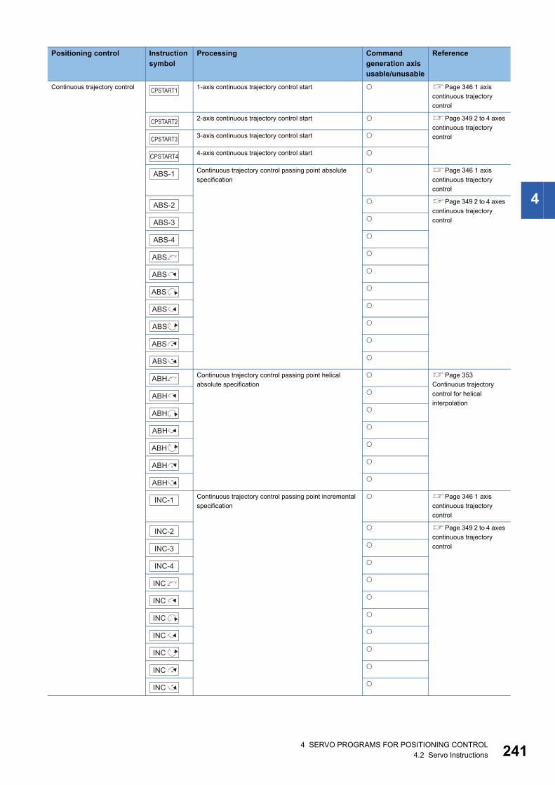
4
Continuous trajectory control 1-axis continuous trajectory control start Page 346 1 axis
continuous trajectory
control
2-axis continuous trajectory control start Page 349 2 to 4 axes
continuous trajectory
control3-axis continuous trajectory control start
4-axis continuous trajectory control start
Continuous trajectory control passing point absolute
specification
Page 346 1 axis
continuous trajectory
control
Page 349 2 to 4 axes
continuous trajectory
control
Continuous trajectory control passing point helical
absolute specification
Page 353
Continuous trajectory
control for helical
interpolation
Continuous trajectory control passing point incremental
specification
Page 346 1 axis
continuous trajectory
control
Page 349 2 to 4 axes
continuous trajectory
control
Positioning control Instruction symbol
Processing Command generation axis usable/unusable
Reference
CPSTART1
CPSTART2
CPSTART3
CPSTART4
ABS-1
ABS-2
ABS-3
ABS-4
ABS
ABS
ABS
ABS
ABS
ABS
ABS
ABH
ABH
ABH
ABH
ABH
ABH
ABH
INC-1
INC-2
INC-3
INC-4
INC
INC
INC
INC
INC
INC
INC
4 SERVO PROGRAMS FOR POSITIONING CONTROL4.2 Servo Instructions 241
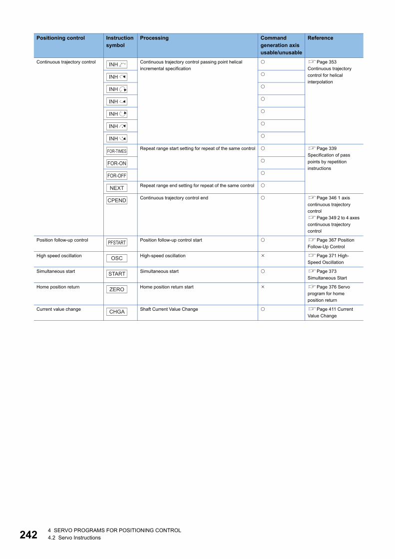
24
Continuous trajectory control Continuous trajectory control passing point helical
incremental specification
Page 353
Continuous trajectory
control for helical
interpolation
Repeat range start setting for repeat of the same control Page 339
Specification of pass
points by repetition
instructions
Repeat range end setting for repeat of the same control
Continuous trajectory control end Page 346 1 axis
continuous trajectory
control
Page 349 2 to 4 axes
continuous trajectory
control
Position follow-up control Position follow-up control start Page 367 Position
Follow-Up Control
High speed oscillation High-speed oscillation Page 371 High-
Speed Oscillation
Simultaneous start Simultaneous start Page 373
Simultaneous Start
Home position return Home position return start Page 376 Servo
program for home
position return
Current value change Shaft Current Value Change Page 411 Current
Value Change
Positioning control Instruction symbol
Processing Command generation axis usable/unusable
Reference
INH
INH
INH
INH
INH
INH
INH
FOR-TIMES
FOR-ON
FOR-OFF
NEXT
CPEND
PFSTART
OSC
START
ZERO
CHGA
24 SERVO PROGRAMS FOR POSITIONING CONTROL4.2 Servo Instructions
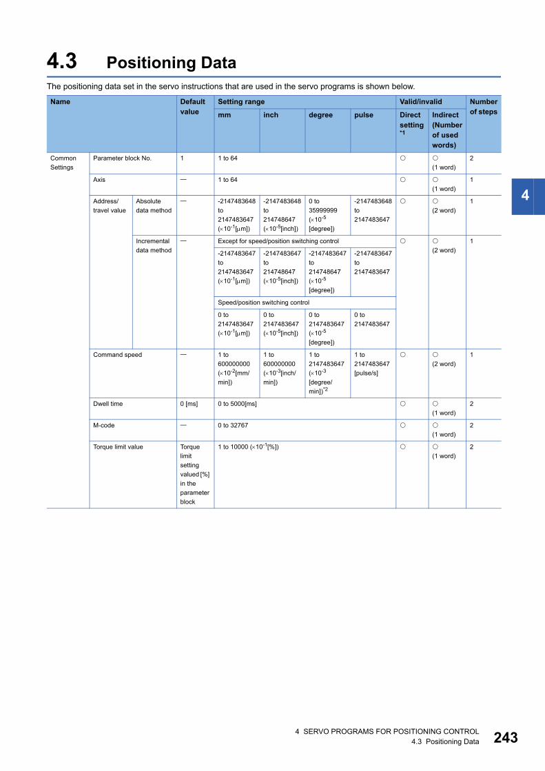
4
4.3 Positioning DataThe positioning data set in the servo instructions that are used in the servo programs is shown below.
Name Default value
Setting range Valid/invalid Number of stepsmm inch degree pulse Direct
setting*1
Indirect (Number of used words)
Common
Settings
Parameter block No. 1 1 to 64
(1 word)
2
Axis 1 to 64
(1 word)
1
Address/
travel value
Absolute
data method
-2147483648
to
2147483647
(10-1[m])
-2147483648
to
214748647
(10-5[inch])
0 to
35999999
(10-5
[degree])
-2147483648
to
2147483647
(2 word)
1
Incremental
data method
Except for speed/position switching control
(2 word)
1
-2147483647
to
2147483647
(10-1[m])
-2147483647
to
214748647
(10-5[inch])
-2147483647
to
214748647
(10-5
[degree])
-2147483647
to
2147483647
Speed/position switching control
0 to
2147483647
(10-1[m])
0 to
2147483647
(10-5[inch])
0 to
2147483647
(10-5
[degree])
0 to
2147483647
Command speed 1 to
600000000
(10-2[mm/
min])
1 to
600000000
(10-3[inch/
min])
1 to
2147483647
(10-3
[degree/
min])*2
1 to
2147483647
[pulse/s]
(2 word)
1
Dwell time 0 [ms] 0 to 5000[ms]
(1 word)
2
M-code 0 to 32767
(1 word)
2
Torque limit value Torque
limit
setting
valued [%]
in the
parameter
block
1 to 10000 (10-1[%])
(1 word)
2
4 SERVO PROGRAMS FOR POSITIONING CONTROL4.3 Positioning Data 243
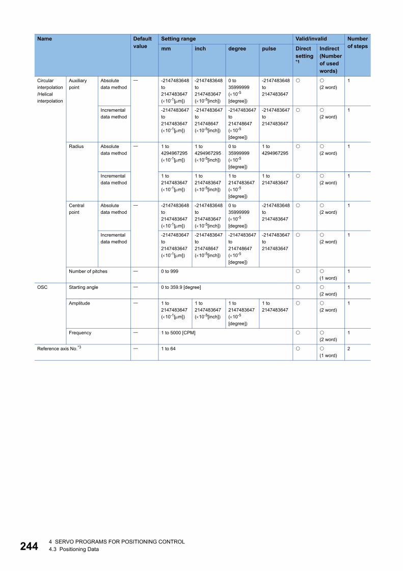
24
Circular
interpolation
/Helical
interpolation
Auxiliary
point
Absolute
data method
-2147483648
to
2147483647
(10-1[m])
-2147483648
to
2147483647
(10-5[inch])
0 to
35999999
(10-5
[degree])
-2147483648
to
2147483647
(2 word)
1
Incremental
data method
-2147483647
to
2147483647
(10-1[m])
-2147483647
to
214748647
(10-5[inch])
-2147483647
to
214748647
(10-5
[degree])
-2147483647
to
2147483647
(2 word)
1
Radius Absolute
data method
1 to
4294967295
(10-1[m])
1 to
4294967295
(10-5[inch])
0 to
35999999
(10-5
[degree])
1 to
4294967295
(2 word)
1
Incremental
data method
1 to
2147483647
(10-1[m])
1 to
2147483647
(10-5[inch])
1 to
2147483647
(10-5
[degree])
1 to
2147483647
(2 word)
1
Central
point
Absolute
data method
-2147483648
to
2147483647
(10-1[m])
-2147483648
to
2147483647
(10-5[inch])
0 to
35999999
(10-5
[degree])
-2147483648
to
2147483647
(2 word)
1
Incremental
data method
-2147483647
to
2147483647
(10-1[m])
-2147483647
to
214748647
(10-5[inch])
-2147483647
to
214748647
(10-5
[degree])
-2147483647
to
2147483647
(2 word)
1
Number of pitches 0 to 999
(1 word)
1
OSC Starting angle 0 to 359.9 [degree]
(2 word)
1
Amplitude 1 to
2147483647
(10-1[m])
1 to
2147483647
(10-5[inch])
1 to
2147483647
(10-5
[degree])
1 to
2147483647
(2 word)
1
Frequency 1 to 5000 [CPM]
(2 word)
1
Reference axis No.*3 1 to 64
(1 word)
2
Name Default value
Setting range Valid/invalid Number of stepsmm inch degree pulse Direct
setting*1
Indirect (Number of used words)
44 SERVO PROGRAMS FOR POSITIONING CONTROL4.3 Positioning Data
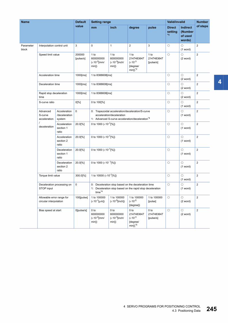
4
Parameter
block
Interpolation control unit 3 0 1 2 3
(1 word)
2
Speed limit value 200000
[pulse/s]
1 to
600000000
(10-2[mm/
min])
1 to
600000000
(10-3[inch/
min])
1 to
2147483647
(10-3
[degree/
min])*2
1 to
2147483647
[pulse/s]
(2 word)
2
Acceleration time 1000[ms] 1 to 8388608[ms]
(2 word)
2
Deceleration time 1000[ms] 1 to 8388608[ms]
(2 word)
2
Rapid stop deceleration
time
1000[ms] 1 to 8388608[ms]
(2 word)
2
S-curve ratio 0[%] 0 to 100[%]
(1 word)
2
Advanced
S-curve
acceleration
/
deceleration
Acceleration
/deceleration
system
0 0: Trapezoidal acceleration/deceleration/S-curve
acceleration/deceleration
1: Advanced S-curve acceleration/deceleration*4
(1 word)
2
Acceleration
section 1
ratio
20.0[%] 0 to 1000 (10-1[%])
(1 word)
2
Acceleration
section 2
ratio
20.0[%] 0 to 1000 (10-1[%])
(1 word)
2
Deceleration
section 1
ratio
20.0[%] 0 to 1000 (10-1[%])
(1 word)
2
Deceleration
section 2
ratio
20.0[%] 0 to 1000 (10- 1[%])
(1 word)
2
Torque limit value 300.0[%] 1 to 10000 (10-1[%])
(1 word)
2
Deceleration processing on
STOP input
0 0: Deceleration stop based on the deceleration time
1: Deceleration stop based on the rapid stop deceleration
time*4
(1 word)
2
Allowable error range for
circular interpolation
100[pulse] 1 to 100000
(10-1[m])
1 to 100000
(10-5[inch])
1 to 100000
(10-5
[degree])
1 to 100000
[pulse]
(2 word)
2
Bias speed at start 0[pulse/s] 0 to
600000000
(10-2[mm/
min])
0 to
600000000
(10-3[inch/
min])
0 to
2147483647
(10-3
[degree/
min])*5
0 to
2147483647
[pulse/s]
(2 word)
2
Name Default value
Setting range Valid/invalid Number of stepsmm inch degree pulse Direct
setting*1
Indirect (Number of used words)
4 SERVO PROGRAMS FOR POSITIONING CONTROL4.3 Positioning Data 245
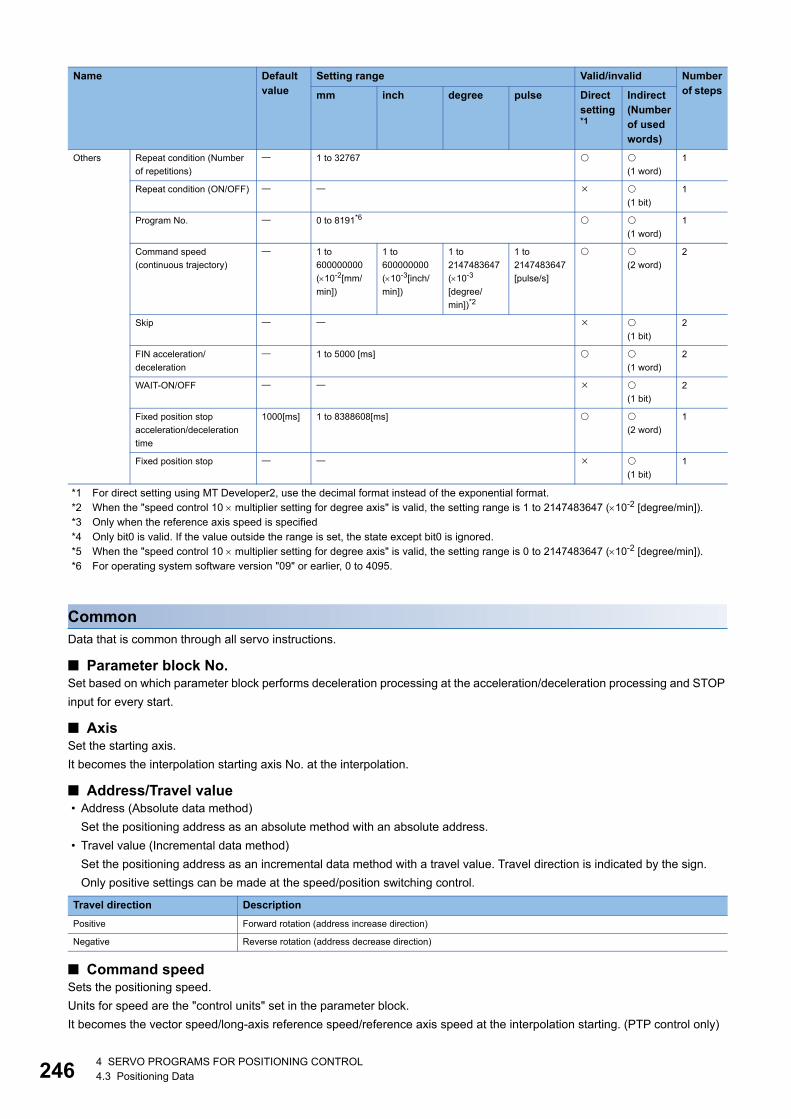
24
*1 For direct setting using MT Developer2, use the decimal format instead of the exponential format.*2 When the "speed control 10 multiplier setting for degree axis" is valid, the setting range is 1 to 2147483647 (10-2 [degree/min]).*3 Only when the reference axis speed is specified*4 Only bit0 is valid. If the value outside the range is set, the state except bit0 is ignored.*5 When the "speed control 10 multiplier setting for degree axis" is valid, the setting range is 0 to 2147483647 (10-2 [degree/min]).*6 For operating system software version "09" or earlier, 0 to 4095.
CommonData that is common through all servo instructions.
■ Parameter block No.Set based on which parameter block performs deceleration processing at the acceleration/deceleration processing and STOP
input for every start.
■ AxisSet the starting axis.
It becomes the interpolation starting axis No. at the interpolation.
■ Address/Travel value • Address (Absolute data method)
Set the positioning address as an absolute method with an absolute address.
• Travel value (Incremental data method)
Set the positioning address as an incremental data method with a travel value. Travel direction is indicated by the sign.
Only positive settings can be made at the speed/position switching control.
■ Command speedSets the positioning speed.
Units for speed are the "control units" set in the parameter block.
It becomes the vector speed/long-axis reference speed/reference axis speed at the interpolation starting. (PTP control only)
Others Repeat condition (Number
of repetitions)
1 to 32767
(1 word)
1
Repeat condition (ON/OFF)
(1 bit)
1
Program No. 0 to 8191*6
(1 word)
1
Command speed
(continuous trajectory)
1 to
600000000
(10-2[mm/
min])
1 to
600000000
(10-3[inch/
min])
1 to
2147483647
(10-3
[degree/
min])*2
1 to
2147483647
[pulse/s]
(2 word)
2
Skip
(1 bit)
2
FIN acceleration/
deceleration
1 to 5000 [ms]
(1 word)
2
WAIT-ON/OFF
(1 bit)
2
Fixed position stop
acceleration/deceleration
time
1000[ms] 1 to 8388608[ms]
(2 word)
1
Fixed position stop
(1 bit)
1
Travel direction Description
Positive Forward rotation (address increase direction)
Negative Reverse rotation (address decrease direction)
Name Default value
Setting range Valid/invalid Number of stepsmm inch degree pulse Direct
setting*1
Indirect (Number of used words)
64 SERVO PROGRAMS FOR POSITIONING CONTROL4.3 Positioning Data
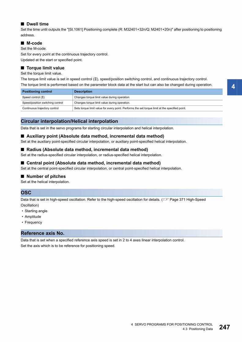
4
■ Dwell timeSet the time until outputs the "[St.1061] Positioning complete (R: M32401+32n/Q: M2401+20n)" after positioning to positioning
address.
■ M-codeSet the M-code.
Set for every point at the continuous trajectory control.
Updated at the start or specified point.
■ Torque limit valueSet the torque limit value.
The torque limit value is set in speed control (), speed/position switching control, and continuous trajectory control.
The torque limit is performed based on the parameter block data at the start but can also be changed during operation.
Circular interpolation/Helical interpolationData that is set in the servo programs for starting circular interpolation and helical interpolation.
■ Auxiliary point (Absolute data method, incremental data method)Set at the auxiliary point-specified circular interpolation, or auxiliary point-specified helical interpolation.
■ Radius (Absolute data method, incremental data method)Set at the radius-specified circular interpolation, or radius-specified helical interpolation.
■ Central point (Absolute data method, incremental data method)Set at the central point-specified circular interpolation, or central point-specified helical interpolation.
■ Number of pitchesSet at the helical interpolation.
OSCData that is set in high-speed oscillation. Refer to the high-speed oscillation for details. (Page 371 High-Speed
Oscillation)
• Starting angle
• Amplitude
• Frequency
Reference axis No.Data that is set when a specified reference axis speed is set in 2 to 4 axes linear interpolation control.
Set the axis which is to be reference for positioning speed.
Positioning control Description
Speed control () Changes torque limit value during operation.
Speed/position switching control Changes torque limit value during operation.
Continuous trajectory control Sets torque limit value for every point. Performs the set torque limit at the specified point.
4 SERVO PROGRAMS FOR POSITIONING CONTROL4.3 Positioning Data 247
24
Parameter blockSet when changing the parameter block (if not set, the default value) set in the servo program. (The data of the parameter
block is not changed.)
Only the data in the specified parameter block that is changed can be set.
Refer to Parameter block for details. (Page 215 Parameter Block)
• Interpolation control unit
• Speed limit value
• Acceleration time
• Deceleration time
• Rapid stop deceleration time
• S-curve ratio
• Advanced S-curve acceleration/deceleration (acceleration/deceleration system, acceleration section 1 ratio, acceleration
section 2 ratio, deceleration section 1 ratio, deceleration section 2 ratio)
• Torque limit value
• Deceleration processing on STOP input
• Allowable error range for circular interpolation
• Bias speed at start
Others
■ Repeat condition • Number of repetitions
Set the repeat conditions between FOR-TIMES instruction and NEXT instruction.
• ON/OFF
Set the repeat conditions between FOR-ON/OFF instruction and NEXT instruction.
■ Program No.Set the program No. for simultaneous start.
■ Command speed (continuous trajectory)Set the speed for points on the way in the servo program.
■ SkipSet to cancel positioning to pass point and execute the positioning to the next point by turning on the specified bit device
during positioning at each pass point for continuous trajectory control instruction.
■ FIN acceleration/decelerationSet to execute positioning to each pass point for continuous trajectory control instruction by turning on the FIN signal.
■ WAIT-ON/OFFSet to make state of the waiting for execution by continuous trajectory control and execute the positioning immediately by
turning on/off the command bit device.
■ Fixed position stop acceleration/deceleration timeSet the acceleration/deceleration time used in the starting of speed control with fixed position stop, speed change request
(CHGV) or fixed position stop command ON.
■ Fixed position stopSet the command bit device of fixed position stop.
84 SERVO PROGRAMS FOR POSITIONING CONTROL4.3 Positioning Data
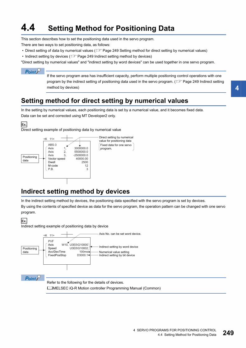
4
4.4 Setting Method for Positioning DataThis section describes how to set the positioning data used in the servo program.
There are two ways to set positioning data, as follows:
• Direct setting of data by numerical values (Page 249 Setting method for direct setting by numerical values)
• Indirect setting by devices (Page 249 Indirect setting method by devices)
"Direct setting by numerical values" and "indirect setting by word devices" can be used together in one servo program.
If the servo program area has insufficient capacity, perform multiple positioning control operations with one
program by the indirect setting of positioning data used in the servo program. (Page 249 Indirect setting
method by devices)
Setting method for direct setting by numerical valuesIn the setting by numerical values, each positioning data is set by a numerical value, and it becomes fixed data.
Data can be set and corrected using MT Developer2 only.
Ex.
Direct setting example of positioning data by numerical value
Indirect setting method by devicesIn the indirect setting method by devices, the positioning data specified with the servo program is set by devices.
By using the contents of specified device as data for the servo program, the operation pattern can be changed with one servo
program.
Ex.
Indirect setting example of positioning data by device
Refer to the following for the details of devices.
MELSEC iQ-R Motion controller Programming Manual (Common)
3000000.05500000.0
-2500000.040000.00
250012
3
ABS-3Axis 1,Axis 2,Axis 3,Vector speedDwellM-codeP.B.
<K 11>
Positioningdata
Fixed data for one servoprogram.
Direct setting by numerical value for positioning data
U3E0\G10000U3E0\G10002
100msD3000.1
<K 11>
Positioningdata
Axis No. can be set word device.
PVFAxis W10, SpeedAcc/DecTimeFixedPosStop
Indirect setting by word device
Numerical value settingIndirect setting by bit device
4 SERVO PROGRAMS FOR POSITIONING CONTROL4.4 Setting Method for Positioning Data 249
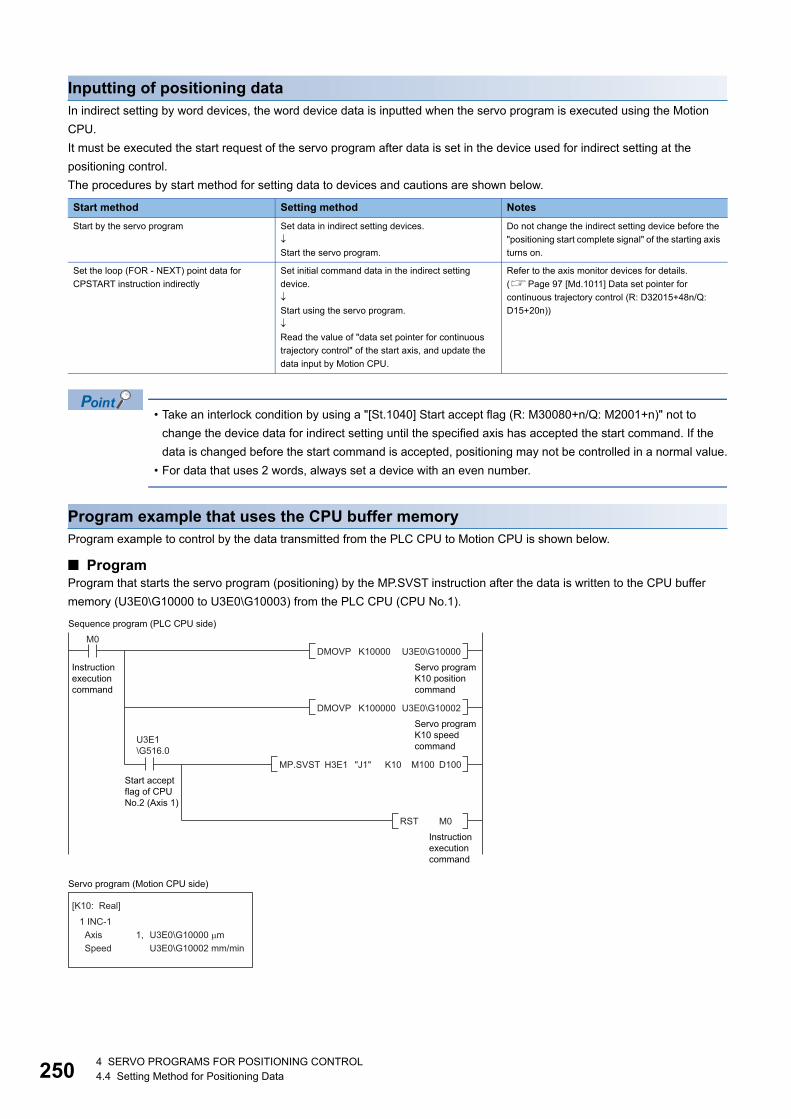
25
Inputting of positioning dataIn indirect setting by word devices, the word device data is inputted when the servo program is executed using the Motion
CPU.
It must be executed the start request of the servo program after data is set in the device used for indirect setting at the
positioning control.
The procedures by start method for setting data to devices and cautions are shown below.
• Take an interlock condition by using a "[St.1040] Start accept flag (R: M30080+n/Q: M2001+n)" not to
change the device data for indirect setting until the specified axis has accepted the start command. If the
data is changed before the start command is accepted, positioning may not be controlled in a normal value.
• For data that uses 2 words, always set a device with an even number.
Program example that uses the CPU buffer memoryProgram example to control by the data transmitted from the PLC CPU to Motion CPU is shown below.
■ ProgramProgram that starts the servo program (positioning) by the MP.SVST instruction after the data is written to the CPU buffer
memory (U3E0\G10000 to U3E0\G10003) from the PLC CPU (CPU No.1).
Start method Setting method Notes
Start by the servo program Set data in indirect setting devices.
Start the servo program.
Do not change the indirect setting device before the
"positioning start complete signal" of the starting axis
turns on.
Set the loop (FOR - NEXT) point data for
CPSTART instruction indirectly
Set initial command data in the indirect setting
device.
Start using the servo program.
Read the value of "data set pointer for continuous
trajectory control" of the start axis, and update the
data input by Motion CPU.
Refer to the axis monitor devices for details.
(Page 97 [Md.1011] Data set pointer for
continuous trajectory control (R: D32015+48n/Q:
D15+20n))
M0
Instructionexecutioncommand
U3E1\G516.0
Start acceptflag of CPUNo.2 (Axis 1)
Servo programK10 positioncommand
DMOVP K10000 U3E0\G10000
Servo programK10 speedcommand
Instructionexecutioncommand
DMOVP K100000 U3E0\G10002
D100
Sequence program (PLC CPU side)
Servo program (Motion CPU side)
"J1" K10 M100MP.SVST H3E1
M0RST
[K10: Real]
1 INC-1 Axis 1, Speed
U3E0\G10000 �mU3E0\G10002 mm/min
04 SERVO PROGRAMS FOR POSITIONING CONTROL4.4 Setting Method for Positioning Data
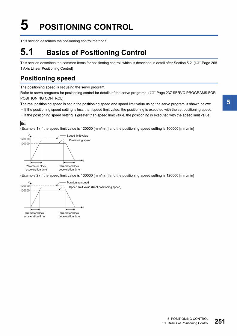
5
5 POSITIONING CONTROL
This section describes the positioning control methods.
5.1 Basics of Positioning ControlThis section describes the common items for positioning control, which is described in detail after Section 5.2. (Page 268
1 Axis Linear Positioning Control)
Positioning speedThe positioning speed is set using the servo program.
Refer to servo programs for positioning control for details of the servo programs. (Page 237 SERVO PROGRAMS FOR
POSITIONING CONTROL)
The real positioning speed is set in the positioning speed and speed limit value using the servo program is shown below:
• If the positioning speed setting is less than speed limit value, the positioning is executed with the set positioning speed.
• If the positioning speed setting is greater than speed limit value, the positioning is executed with the speed limit value.
Ex.
(Example 1) If the speed limit value is 120000 [mm/min] and the positioning speed setting is 100000 [mm/min]
(Example 2) If the speed limit value is 100000 [mm/min] and the positioning speed setting is 120000 [mm/min]
t
100000
Speed limit value120000
V
Parameter blockdeceleration time
Parameter blockacceleration time
Positioning speed
t
100000
Positioning speed120000
V
Parameter blockdeceleration time
Parameter blockacceleration time
Speed limit value (Real positioning speed)
5 POSITIONING CONTROL5.1 Basics of Positioning Control 251
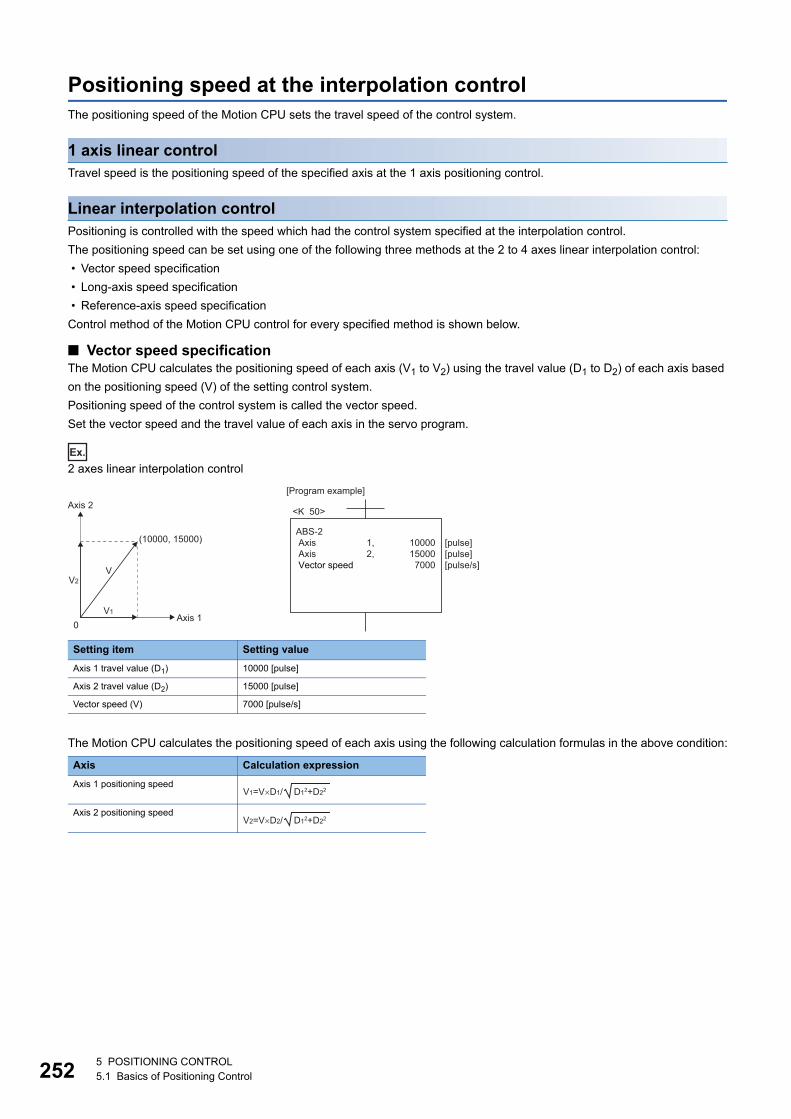
25
Positioning speed at the interpolation controlThe positioning speed of the Motion CPU sets the travel speed of the control system.
1 axis linear controlTravel speed is the positioning speed of the specified axis at the 1 axis positioning control.
Linear interpolation controlPositioning is controlled with the speed which had the control system specified at the interpolation control.
The positioning speed can be set using one of the following three methods at the 2 to 4 axes linear interpolation control:
• Vector speed specification
• Long-axis speed specification
• Reference-axis speed specification
Control method of the Motion CPU control for every specified method is shown below.
■ Vector speed specificationThe Motion CPU calculates the positioning speed of each axis (V1 to V2) using the travel value (D1 to D2) of each axis based
on the positioning speed (V) of the setting control system.
Positioning speed of the control system is called the vector speed.
Set the vector speed and the travel value of each axis in the servo program.
Ex.
2 axes linear interpolation control
The Motion CPU calculates the positioning speed of each axis using the following calculation formulas in the above condition:
Setting item Setting value
Axis 1 travel value (D1) 10000 [pulse]
Axis 2 travel value (D2) 15000 [pulse]
Vector speed (V) 7000 [pulse/s]
Axis Calculation expression
Axis 1 positioning speed
Axis 2 positioning speed
[Program example]
<K 50>
Axis 1
(10000, 15000)
Axis 2
V2
0V1
V
ABS-2 Axis Axis Vector speed
1000015000
7000
[pulse][pulse][pulse/s]
1,2,
V1=V�D1/ D12+D22
V2=V�D2/ D12+D22
25 POSITIONING CONTROL5.1 Basics of Positioning Control
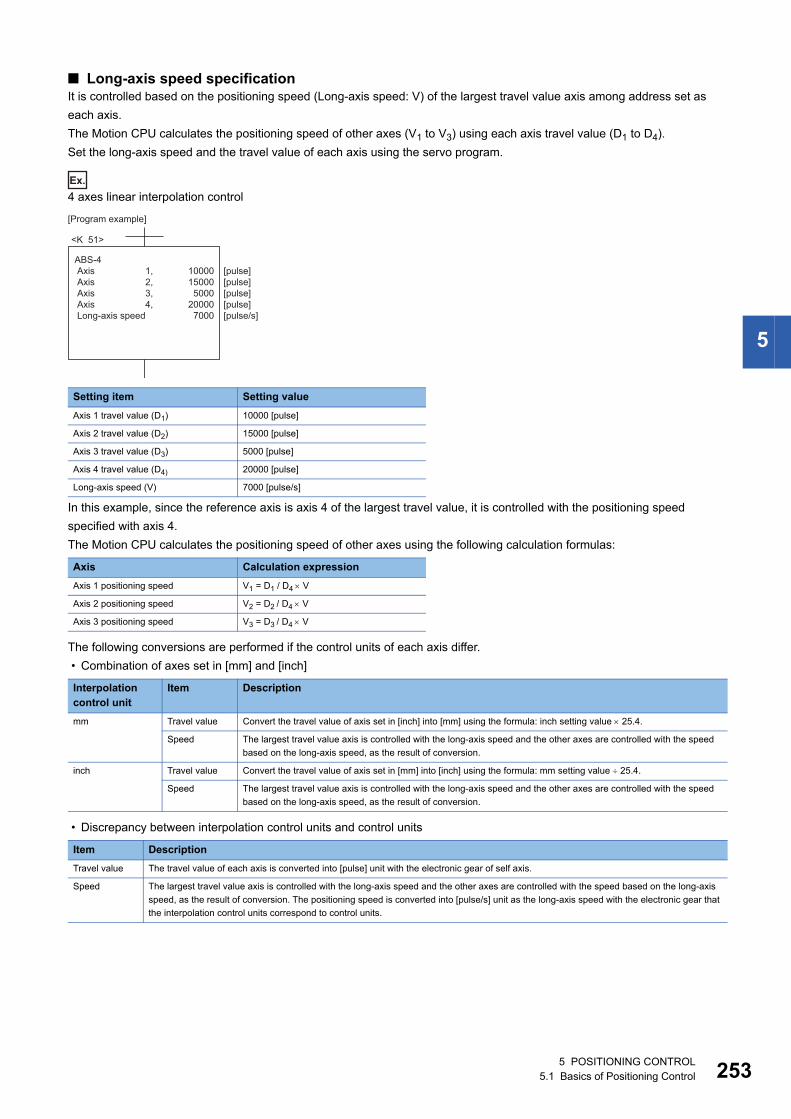
5
■ Long-axis speed specificationIt is controlled based on the positioning speed (Long-axis speed: V) of the largest travel value axis among address set as
each axis.
The Motion CPU calculates the positioning speed of other axes (V1 to V3) using each axis travel value (D1 to D4).
Set the long-axis speed and the travel value of each axis using the servo program.
Ex.
4 axes linear interpolation control
In this example, since the reference axis is axis 4 of the largest travel value, it is controlled with the positioning speed
specified with axis 4.
The Motion CPU calculates the positioning speed of other axes using the following calculation formulas:
The following conversions are performed if the control units of each axis differ.
• Combination of axes set in [mm] and [inch]
• Discrepancy between interpolation control units and control units
Setting item Setting value
Axis 1 travel value (D1) 10000 [pulse]
Axis 2 travel value (D2) 15000 [pulse]
Axis 3 travel value (D3) 5000 [pulse]
Axis 4 travel value (D4) 20000 [pulse]
Long-axis speed (V) 7000 [pulse/s]
Axis Calculation expression
Axis 1 positioning speed V1 = D1 / D4 V
Axis 2 positioning speed V2 = D2 / D4 V
Axis 3 positioning speed V3 = D3 / D4 V
Interpolation control unit
Item Description
mm Travel value Convert the travel value of axis set in [inch] into [mm] using the formula: inch setting value 25.4.
Speed The largest travel value axis is controlled with the long-axis speed and the other axes are controlled with the speed
based on the long-axis speed, as the result of conversion.
inch Travel value Convert the travel value of axis set in [mm] into [inch] using the formula: mm setting value 25.4.
Speed The largest travel value axis is controlled with the long-axis speed and the other axes are controlled with the speed
based on the long-axis speed, as the result of conversion.
Item Description
Travel value The travel value of each axis is converted into [pulse] unit with the electronic gear of self axis.
Speed The largest travel value axis is controlled with the long-axis speed and the other axes are controlled with the speed based on the long-axis
speed, as the result of conversion. The positioning speed is converted into [pulse/s] unit as the long-axis speed with the electronic gear that
the interpolation control units correspond to control units.
[Program example]
<K 51>
ABS-4 Axis Axis Axis Axis Long-axis speed
1000015000
500020000
7000
[pulse][pulse][pulse][pulse][pulse/s]
1,2,3,4,
5 POSITIONING CONTROL5.1 Basics of Positioning Control 253
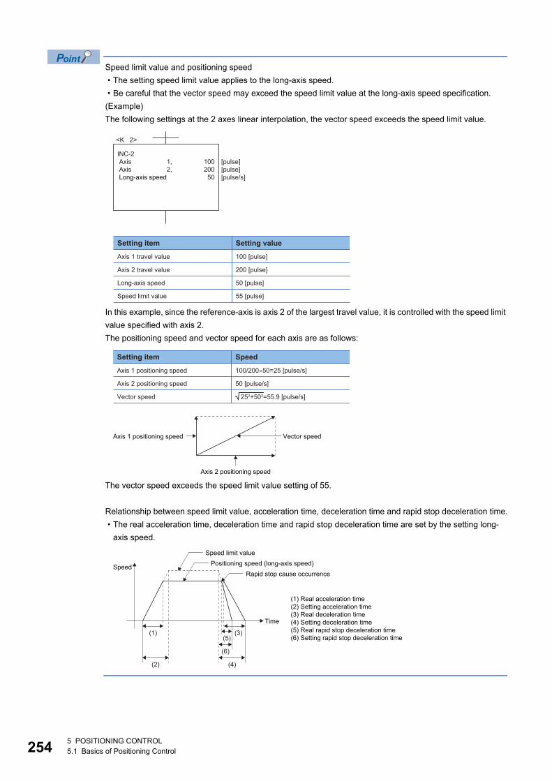
25
Speed limit value and positioning speed
• The setting speed limit value applies to the long-axis speed.
• Be careful that the vector speed may exceed the speed limit value at the long-axis speed specification.
(Example)
The following settings at the 2 axes linear interpolation, the vector speed exceeds the speed limit value.
In this example, since the reference-axis is axis 2 of the largest travel value, it is controlled with the speed limit
value specified with axis 2.
The positioning speed and vector speed for each axis are as follows:
The vector speed exceeds the speed limit value setting of 55.
Relationship between speed limit value, acceleration time, deceleration time and rapid stop deceleration time.
• The real acceleration time, deceleration time and rapid stop deceleration time are set by the setting long-
axis speed.
<K 2>
INC-2 Axis Axis Long-axis speed
100200
50
[pulse][pulse][pulse/s]
1,2,
Setting item
Axis 1 travel value
Setting value
100 [pulse]
Axis 2 travel value 200 [pulse]
Long-axis speed 50 [pulse]
Speed limit value 55 [pulse]
100/200�50=25 [pulse/s]
252+502=55.9 [pulse/s]
Setting item
Axis 1 positioning speed
Speed
Axis 2 positioning speed 50 [pulse/s]
Vector speed
Vector speed
Axis 2 positioning speed
Axis 1 positioning speed
Time
(1) Real acceleration time(2) Setting acceleration time(3) Real deceleration time(4) Setting deceleration time(5) Real rapid stop deceleration time(6) Setting rapid stop deceleration time
(1) (3)(5)
(6)
(4)(2)
Speed limit value
Speed Positioning speed (long-axis speed)Rapid stop cause occurrence
45 POSITIONING CONTROL5.1 Basics of Positioning Control
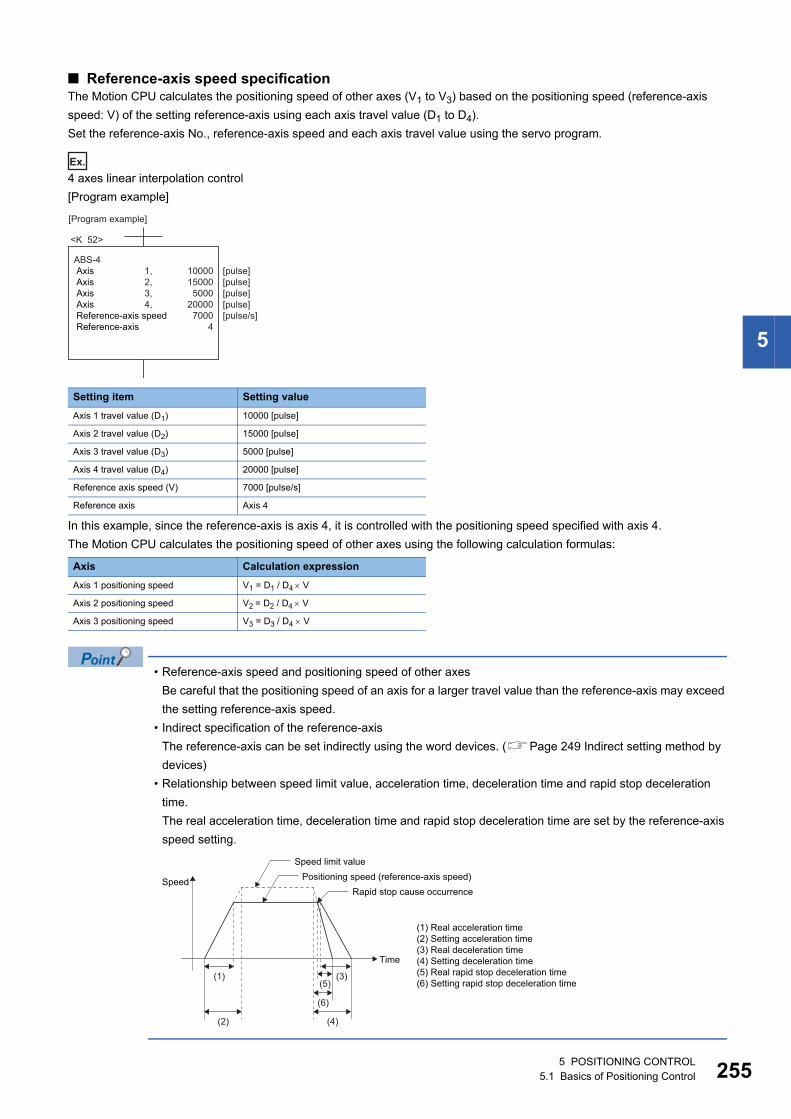
5
■ Reference-axis speed specificationThe Motion CPU calculates the positioning speed of other axes (V1 to V3) based on the positioning speed (reference-axis
speed: V) of the setting reference-axis using each axis travel value (D1 to D4).
Set the reference-axis No., reference-axis speed and each axis travel value using the servo program.
Ex.
4 axes linear interpolation control
[Program example]
In this example, since the reference-axis is axis 4, it is controlled with the positioning speed specified with axis 4.
The Motion CPU calculates the positioning speed of other axes using the following calculation formulas:
• Reference-axis speed and positioning speed of other axes
Be careful that the positioning speed of an axis for a larger travel value than the reference-axis may exceed
the setting reference-axis speed.
• Indirect specification of the reference-axis
The reference-axis can be set indirectly using the word devices. (Page 249 Indirect setting method by
devices)
• Relationship between speed limit value, acceleration time, deceleration time and rapid stop deceleration
time.
The real acceleration time, deceleration time and rapid stop deceleration time are set by the reference-axis
speed setting.
Setting item Setting value
Axis 1 travel value (D1) 10000 [pulse]
Axis 2 travel value (D2) 15000 [pulse]
Axis 3 travel value (D3) 5000 [pulse]
Axis 4 travel value (D4) 20000 [pulse]
Reference axis speed (V) 7000 [pulse/s]
Reference axis Axis 4
Axis Calculation expression
Axis 1 positioning speed V1 = D1 / D4 V
Axis 2 positioning speed V2 = D2 / D4 V
Axis 3 positioning speed V3 = D3 / D4 V
[Program example]
<K 52>
ABS-4 Axis Axis Axis Axis Reference-axis speed Reference-axis
1000015000
500020000
70004
[pulse][pulse][pulse][pulse][pulse/s]
1,2,3,4,
Time
(1) Real acceleration time(2) Setting acceleration time(3) Real deceleration time(4) Setting deceleration time(5) Real rapid stop deceleration time(6) Setting rapid stop deceleration time
(1) (3)(5)
(6)
(4)(2)
Speed limit value
Speed Positioning speed (reference-axis speed)Rapid stop cause occurrence
5 POSITIONING CONTROL5.1 Basics of Positioning Control 255
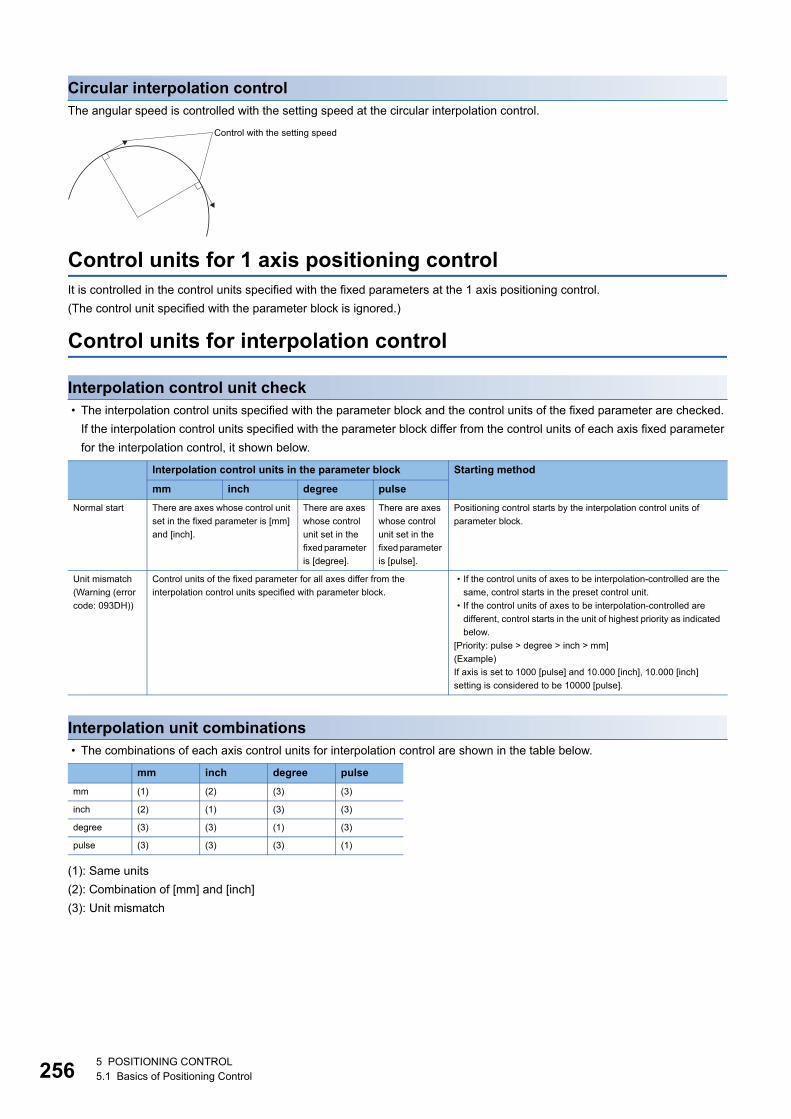
25
Circular interpolation controlThe angular speed is controlled with the setting speed at the circular interpolation control.
Control units for 1 axis positioning controlIt is controlled in the control units specified with the fixed parameters at the 1 axis positioning control.
(The control unit specified with the parameter block is ignored.)
Control units for interpolation control
Interpolation control unit check • The interpolation control units specified with the parameter block and the control units of the fixed parameter are checked.
If the interpolation control units specified with the parameter block differ from the control units of each axis fixed parameter
for the interpolation control, it shown below.
Interpolation unit combinations • The combinations of each axis control units for interpolation control are shown in the table below.
(1): Same units
(2): Combination of [mm] and [inch]
(3): Unit mismatch
Interpolation control units in the parameter block Starting method
mm inch degree pulse
Normal start There are axes whose control unit
set in the fixed parameter is [mm]
and [inch].
There are axes
whose control
unit set in the
fixed parameter
is [degree].
There are axes
whose control
unit set in the
fixed parameter
is [pulse].
Positioning control starts by the interpolation control units of
parameter block.
Unit mismatch
(Warning (error
code: 093DH))
Control units of the fixed parameter for all axes differ from the
interpolation control units specified with parameter block.
• If the control units of axes to be interpolation-controlled are the
same, control starts in the preset control unit.
• If the control units of axes to be interpolation-controlled are
different, control starts in the unit of highest priority as indicated
below.
[Priority: pulse > degree > inch > mm]
(Example)
If axis is set to 1000 [pulse] and 10.000 [inch], 10.000 [inch]
setting is considered to be 10000 [pulse].
mm inch degree pulse
mm (1) (2) (3) (3)
inch (2) (1) (3) (3)
degree (3) (3) (1) (3)
pulse (3) (3) (3) (1)
Control with the setting speed
65 POSITIONING CONTROL5.1 Basics of Positioning Control
5
Same units: (1)The position command is calculated with the setting address (travel value), positioning speed or electronic gear, the
positioning is executed.
If control units for one axis are "degree" at the circular interpolation control, use "degree" also for the other
axis.
Combination of [mm] and [inch]: (2) • If interpolation control units are [mm], positioning is controlled by calculating position commands from the address, travel
value, positioning speed and electronic gear, which have been converted to [mm] using the formula: inch setting value
25.4 = mm setting value.
• If interpolation control units are [inch], positioning is controlled by calculating position commands from the address, travel
value, positioning speed and electronic gear, which have been converted to [inch] using the formula: mm setting value
25.4 = inch setting value.
Discrepancy units: (3) • The travel value and positioning speed are calculated for each axis.
• If the interpolation control units match for two or more axes at the 3-axes or more linear interpolation, the positioning speed
is calculated with the electronic gear for the axis with the lowest No.
Although electric gear is not set for the command generation axis, the electric gear is set to "1" when
calculating the position command value or the positioning speed.
• The electronic gear converts the travel value for the axis to [pulse].
• For axis where the units match, the electronic gear converts the positioning speed to units of [pulse/s]. Positioning is conducted using position commands
calculated from travel values converted to [pulse] and speeds and electronic gear converted to [pulse/s].
5 POSITIONING CONTROL5.1 Basics of Positioning Control 257
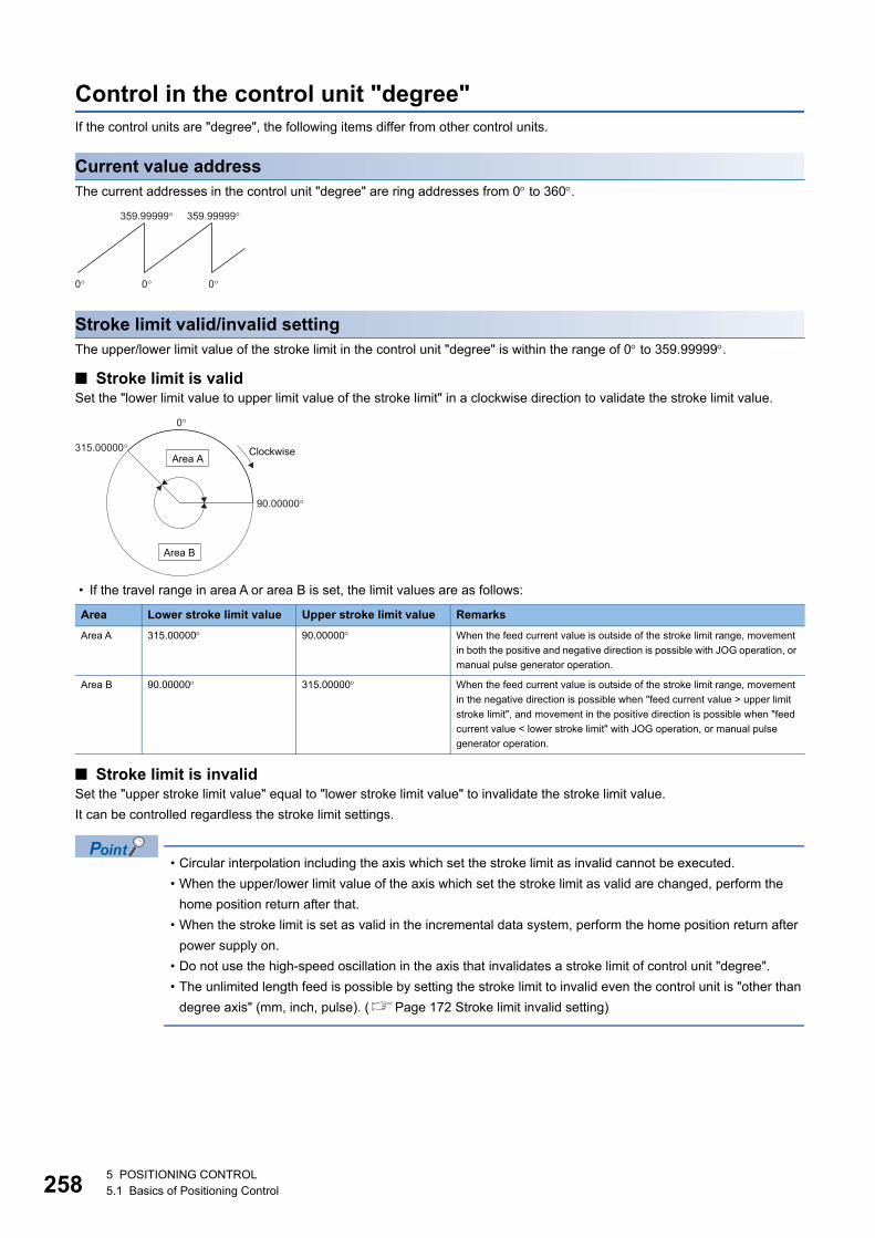
25
Control in the control unit "degree"If the control units are "degree", the following items differ from other control units.
Current value addressThe current addresses in the control unit "degree" are ring addresses from 0 to 360.
Stroke limit valid/invalid settingThe upper/lower limit value of the stroke limit in the control unit "degree" is within the range of 0 to 359.99999.
■ Stroke limit is validSet the "lower limit value to upper limit value of the stroke limit" in a clockwise direction to validate the stroke limit value.
• If the travel range in area A or area B is set, the limit values are as follows:
■ Stroke limit is invalidSet the "upper stroke limit value" equal to "lower stroke limit value" to invalidate the stroke limit value.
It can be controlled regardless the stroke limit settings.
• Circular interpolation including the axis which set the stroke limit as invalid cannot be executed.
• When the upper/lower limit value of the axis which set the stroke limit as valid are changed, perform the
home position return after that.
• When the stroke limit is set as valid in the incremental data system, perform the home position return after
power supply on.
• Do not use the high-speed oscillation in the axis that invalidates a stroke limit of control unit "degree".
• The unlimited length feed is possible by setting the stroke limit to invalid even the control unit is "other than
degree axis" (mm, inch, pulse). (Page 172 Stroke limit invalid setting)
Area Lower stroke limit value Upper stroke limit value Remarks
Area A 315.00000 90.00000 When the feed current value is outside of the stroke limit range, movement
in both the positive and negative direction is possible with JOG operation, or
manual pulse generator operation.
Area B 90.00000 315.00000 When the feed current value is outside of the stroke limit range, movement
in the negative direction is possible when "feed current value > upper limit
stroke limit", and movement in the positive direction is possible when "feed
current value < lower stroke limit" with JOG operation, or manual pulse
generator operation.
0� 0�
359.99999�
0�
359.99999�
0�
90.00000�
Clockwise315.00000�Area A
Area B
85 POSITIONING CONTROL5.1 Basics of Positioning Control
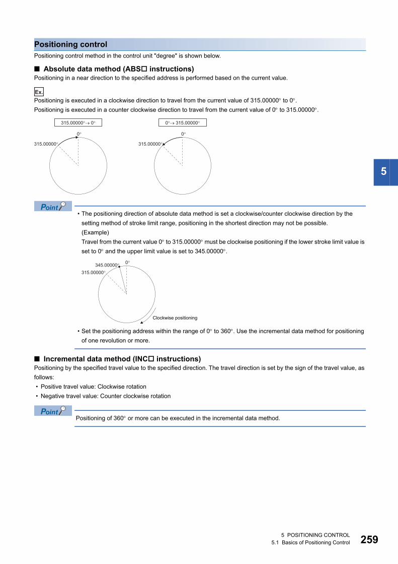
5
Positioning controlPositioning control method in the control unit "degree" is shown below.
■ Absolute data method (ABS instructions)Positioning in a near direction to the specified address is performed based on the current value.
Ex.
Positioning is executed in a clockwise direction to travel from the current value of 315.00000 to 0.
Positioning is executed in a counter clockwise direction to travel from the current value of 0 to 315.00000.
• The positioning direction of absolute data method is set a clockwise/counter clockwise direction by the
setting method of stroke limit range, positioning in the shortest direction may not be possible.
(Example)
Travel from the current value 0 to 315.00000 must be clockwise positioning if the lower stroke limit value is
set to 0 and the upper limit value is set to 345.00000.
• Set the positioning address within the range of 0 to 360. Use the incremental data method for positioning
of one revolution or more.
■ Incremental data method (INC instructions)Positioning by the specified travel value to the specified direction. The travel direction is set by the sign of the travel value, as
follows:
• Positive travel value: Clockwise rotation
• Negative travel value: Counter clockwise rotation
Positioning of 360 or more can be executed in the incremental data method.
0�
315.00000�
315.00000�� 0�
0�
315.00000�
0�� 315.00000�
0�
315.00000�
345.00000�
Clockwise positioning
5 POSITIONING CONTROL5.1 Basics of Positioning Control 259
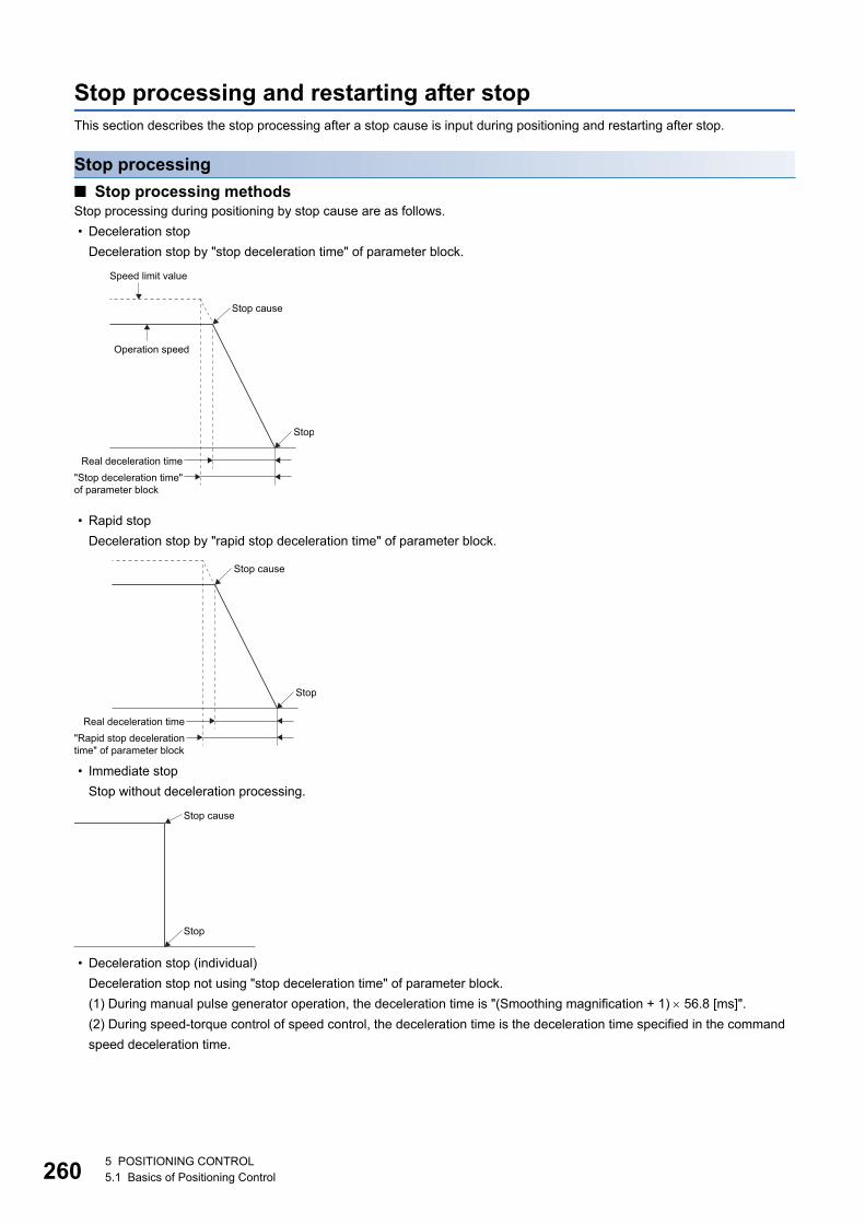
26
Stop processing and restarting after stopThis section describes the stop processing after a stop cause is input during positioning and restarting after stop.
Stop processing
■ Stop processing methodsStop processing during positioning by stop cause are as follows.
• Deceleration stop
Deceleration stop by "stop deceleration time" of parameter block.
• Rapid stop
Deceleration stop by "rapid stop deceleration time" of parameter block.
• Immediate stop
Stop without deceleration processing.
• Deceleration stop (individual)
Deceleration stop not using "stop deceleration time" of parameter block.
(1) During manual pulse generator operation, the deceleration time is "(Smoothing magnification + 1) 56.8 [ms]".
(2) During speed-torque control of speed control, the deceleration time is the deceleration time specified in the command
speed deceleration time.
Speed limit value
Stop cause
Operation speed
Real deceleration time"Stop deceleration time"of parameter block
Stop
Stop cause
Real deceleration time"Rapid stop decelerationtime" of parameter block
Stop
Stop cause
Stop
05 POSITIONING CONTROL5.1 Basics of Positioning Control
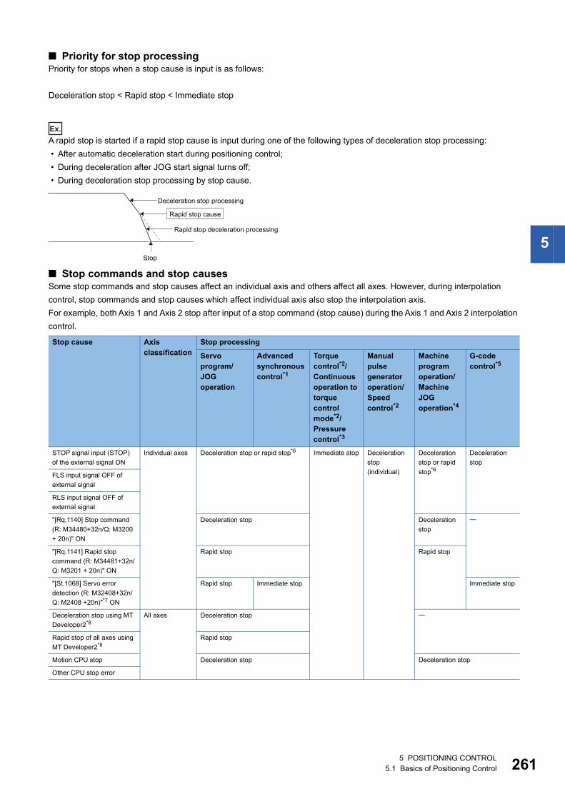
5
■ Priority for stop processingPriority for stops when a stop cause is input is as follows:
Deceleration stop < Rapid stop < Immediate stop
Ex.
A rapid stop is started if a rapid stop cause is input during one of the following types of deceleration stop processing:
• After automatic deceleration start during positioning control;
• During deceleration after JOG start signal turns off;
• During deceleration stop processing by stop cause.
■ Stop commands and stop causesSome stop commands and stop causes affect an individual axis and others affect all axes. However, during interpolation
control, stop commands and stop causes which affect individual axis also stop the interpolation axis.
For example, both Axis 1 and Axis 2 stop after input of a stop command (stop cause) during the Axis 1 and Axis 2 interpolation
control.
Stop cause Axis classification
Stop processing
Servo program/JOG operation
Advanced synchronous control*1
Torque control*2/Continuous operation to torque control mode*2/Pressure control*3
Manual pulse generator operation/Speed control*2
Machine program operation/Machine JOG operation*4
G-code control*5
STOP signal input (STOP)
of the external signal ON
Individual axes Deceleration stop or rapid stop*6 Immediate stop Deceleration
stop
(individual)
Deceleration
stop or rapid
stop*6
Deceleration
stop
FLS input signal OFF of
external signal
RLS input signal OFF of
external signal
"[Rq.1140] Stop command
(R: M34480+32n/Q: M3200
+ 20n)" ON
Deceleration stop Deceleration
stop
"[Rq.1141] Rapid stop
command (R: M34481+32n/
Q: M3201 + 20n)" ON
Rapid stop Rapid stop
"[St.1068] Servo error
detection (R: M32408+32n/
Q: M2408 +20n)"*7 ON
Rapid stop Immediate stop Immediate stop
Deceleration stop using MT
Developer2*8All axes Deceleration stop
Rapid stop of all axes using
MT Developer2*8Rapid stop
Motion CPU stop Deceleration stop Deceleration stop
Other CPU stop error
Deceleration stop processing
Rapid stop deceleration processing
Stop
Rapid stop cause
5 POSITIONING CONTROL5.1 Basics of Positioning Control 261
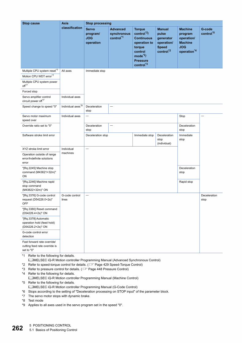
26
*1 Refer to the following for details.MELSEC iQ-R Motion controller Programming Manual (Advanced Synchronous Control)
*2 Refer to speed-torque control for details. (Page 429 Speed-Torque Control)*3 Refer to pressure control for details. (Page 448 Pressure Control)*4 Refer to the following for details.
MELSEC iQ-R Motion controller Programming Manual (Machine Control)*5 Refer to the following for details.
MELSEC iQ-R Motion controller Programming Manual (G-Code Control)*6 Stops according to the setting of "Deceleration processing on STOP input" of the parameter block.*7 The servo motor stops with dynamic brake.*8 Test mode*9 Applies to all axes used in the servo program set in the speed "0".
Multiple CPU system reset*7 All axes Immediate stop
Motion CPU WDT error*7
Multiple CPU system power
off*7
Forced stop
Servo amplifier control
circuit power off*7Individual axes
Speed change to speed "0" Individual axes*9 Deceleration
stop
Servo motor maximum
speed over
Individual axes Stop
Override ratio set to "0" Deceleration
stop
Deceleration
stop
Software stroke limit error Deceleration stop Immediate stop Deceleration
stop
(individual)
Immediate
stop
XYZ stroke limit error Individual
machines
Operation outside of range
error/Indefinite solutions
error
"[Rq.2245] Machine stop
command (M43621+32m)"
ON
Deceleration
stop
"[Rq.2246] Machine rapid
stop command
(M43622+32m)" ON
Rapid stop
"[Rq.3376] G-code control
request (D54226.0+2s)"
OFF
G-code control
lines
Deceleration
stop
"[Rq.3380] Reset command
(D54226.4+2s)" ON
"[Rq.3378] Automatic
operation hold (feed hold)
(D54226.2+2s)" ON
G-code control error
detection
Fast forward rate override/
cutting feed rate override is
set to "0"
Stop cause Axis classification
Stop processing
Servo program/JOG operation
Advanced synchronous control*1
Torque control*2/Continuous operation to torque control mode*2/Pressure control*3
Manual pulse generator operation/Speed control*2
Machine program operation/Machine JOG operation*4
G-code control*5
25 POSITIONING CONTROL5.1 Basics of Positioning Control
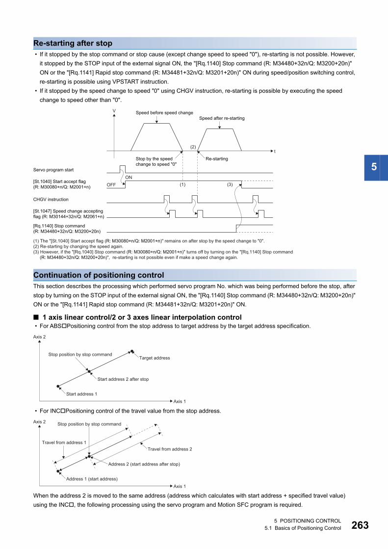
5
Re-starting after stop • If it stopped by the stop command or stop cause (except change speed to speed "0"), re-starting is not possible. However,
it stopped by the STOP input of the external signal ON, the "[Rq.1140] Stop command (R: M34480+32n/Q: M3200+20n)"
ON or the "[Rq.1141] Rapid stop command (R: M34481+32n/Q: M3201+20n)" ON during speed/position switching control,
re-starting is possible using VPSTART instruction.
• If it stopped by the speed change to speed "0" using CHGV instruction, re-starting is possible by executing the speed
change to speed other than "0".
Continuation of positioning controlThis section describes the processing which performed servo program No. which was being performed before the stop, after
stop by turning on the STOP input of the external signal ON, the "[Rq.1140] Stop command (R: M34480+32n/Q: M3200+20n)"
ON or the "[Rq.1141] Rapid stop command (R: M34481+32n/Q: M3201+20n)" ON.
■ 1 axis linear control/2 or 3 axes linear interpolation control • For ABSPositioning control from the stop address to target address by the target address specification.
• For INCPositioning control of the travel value from the stop address.
When the address 2 is moved to the same address (address which calculates with start address + specified travel value)
using the INC, the following processing using the servo program and Motion SFC program is required.
(1) The "[St.1040] Start accept flag (R: M30080+n/Q: M2001+n)" remains on after stop by the speed change to "0".(2) Re-starting by changing the speed again.(3) However, if the "[Rq.1040] Stop command (R: M30080+n/Q: M2001+n)" turns off by turning on the "[Rq.1140] Stop command
(R: M34480+32n/Q: M3200+20n)", re-starting is not possible even if make a speed change again.
t
V Speed before speed changeSpeed after re-starting
Servo program start
OFFON
CHGV instruction
[St.1040] Start accept flag (R: M30080+n/Q: M2001+n)
[St.1047] Speed change acceptingflag (R: M30144+32n/Q: M2061+n)
[Rq.1140] Stop command(R: M34480+32n/Q: M3200+20n)
Re-starting
(2)
(1) (3)
Stop by the speedchange to speed "0"
Axis 1
Axis 2
Start address 1
Start address 2 after stop
Target addressStop position by stop command
Axis 1
Axis 2 Stop position by stop command
Address 1 (start address)
Address 2 (start address after stop)
Travel from address 2Travel from address 1
5 POSITIONING CONTROL5.1 Basics of Positioning Control 263
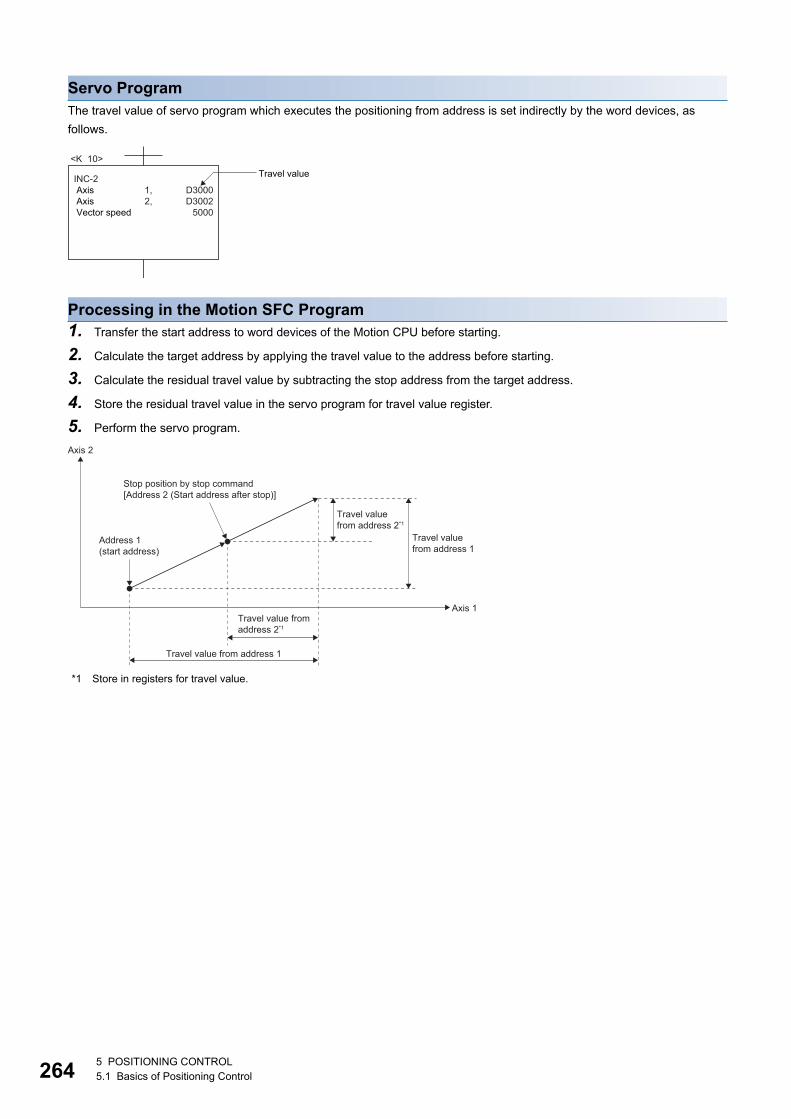
26
Servo ProgramThe travel value of servo program which executes the positioning from address is set indirectly by the word devices, as
follows.
Processing in the Motion SFC Program1. Transfer the start address to word devices of the Motion CPU before starting.
2. Calculate the target address by applying the travel value to the address before starting.
3. Calculate the residual travel value by subtracting the stop address from the target address.
4. Store the residual travel value in the servo program for travel value register.
5. Perform the servo program.
*1 Store in registers for travel value.
<K 10>
INC-2 Axis Axis Vector speed
D3000D3002
5000
1,2,
Travel value
Axis 1
Axis 2
Travel value fromaddress 2*1
Stop position by stop command[Address 2 (Start address after stop)]
Address 1(start address)
Travel value from address 1
Travel valuefrom address 2*1
Travel valuefrom address 1
45 POSITIONING CONTROL5.1 Basics of Positioning Control
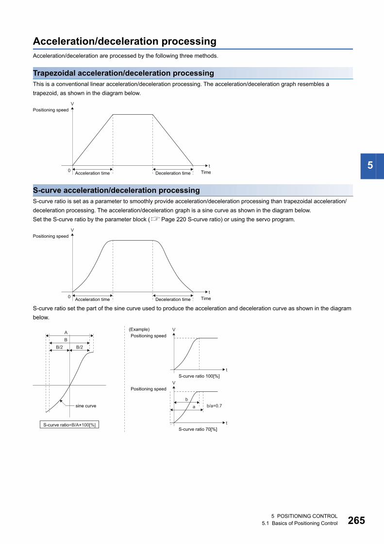
5
Acceleration/deceleration processingAcceleration/deceleration are processed by the following three methods.
Trapezoidal acceleration/deceleration processingThis is a conventional linear acceleration/deceleration processing. The acceleration/deceleration graph resembles a
trapezoid, as shown in the diagram below.
S-curve acceleration/deceleration processingS-curve ratio is set as a parameter to smoothly provide acceleration/deceleration processing than trapezoidal acceleration/
deceleration processing. The acceleration/deceleration graph is a sine curve as shown in the diagram below.
Set the S-curve ratio by the parameter block (Page 220 S-curve ratio) or using the servo program.
S-curve ratio set the part of the sine curve used to produce the acceleration and deceleration curve as shown in the diagram
below.
tTime
VPositioning speed
0 Acceleration time Deceleration time
tTime
VPositioning speed
0 Acceleration time Deceleration time
AB
B/2 B/2
sine curve
S-curve ratio=B/A×100[%]
bb/a=0.7a
tS-curve ratio 100[%]
VPositioning speed
(Example)
tS-curve ratio 70[%]
VPositioning speed
5 POSITIONING CONTROL5.1 Basics of Positioning Control 265
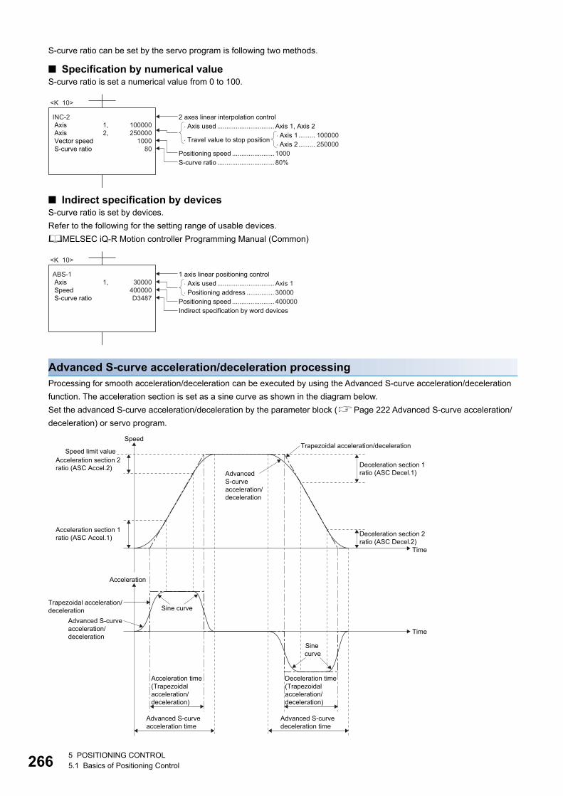
26
S-curve ratio can be set by the servo program is following two methods.
■ Specification by numerical valueS-curve ratio is set a numerical value from 0 to 100.
■ Indirect specification by devicesS-curve ratio is set by devices.
Refer to the following for the setting range of usable devices.
MELSEC iQ-R Motion controller Programming Manual (Common)
Advanced S-curve acceleration/deceleration processingProcessing for smooth acceleration/deceleration can be executed by using the Advanced S-curve acceleration/deceleration
function. The acceleration section is set as a sine curve as shown in the diagram below.
Set the advanced S-curve acceleration/deceleration by the parameter block (Page 222 Advanced S-curve acceleration/
deceleration) or servo program.
<K 10>
INC-2 Axis Axis Vector speed S-curve ratio
100000250000
100080
1,2,
2 axes linear interpolation control
Positioning speed ....................... 1000S-curve ratio ............................... 80%
�Axis used ............................... Axis 1, Axis 2
�Axis 2 ......... 250000�Axis 1 ......... 100000
�Travel value to stop position
<K 10>
ABS-1 Axis Speed S-curve ratio
30000
400000D3487
1,
1 axis linear positioning control� Axis used ............................... Axis 1� Positioning address ............... 30000
Positioning speed ....................... 400000Indirect specification by word devices
Trapezoidal acceleration/deceleration
Trapezoidal acceleration/deceleration
Advanced S-curveacceleration/deceleration
Time
Time
Speed
Acceleration
Advanced S-curveacceleration/deceleration
Sine curve
Sine curve
Speed limit valueAcceleration section 2 ratio (ASC Accel.2) Deceleration section 1
ratio (ASC Decel.1)
Deceleration section 2ratio (ASC Decel.2)
Acceleration section 1 ratio (ASC Accel.1)
Deceleration time (Trapezoidal acceleration/deceleration)
Acceleration time (Trapezoidal acceleration/deceleration)
Advanced S-curve deceleration time
Advanced S-curve acceleration time
65 POSITIONING CONTROL5.1 Basics of Positioning Control
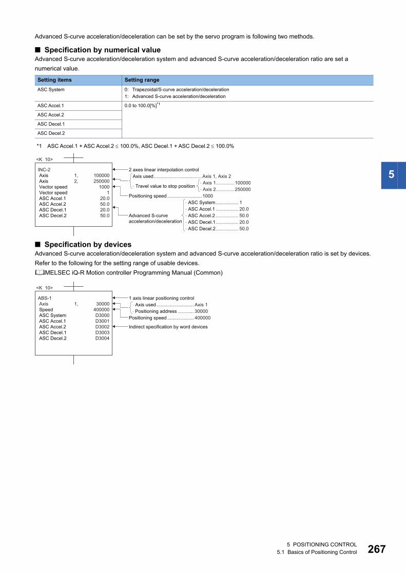
5
Advanced S-curve acceleration/deceleration can be set by the servo program is following two methods.
■ Specification by numerical valueAdvanced S-curve acceleration/deceleration system and advanced S-curve acceleration/deceleration ratio are set a
numerical value.
*1 ASC Accel.1 + ASC Accel.2 100.0%, ASC Decel.1 + ASC Decel.2 100.0%
■ Specification by devicesAdvanced S-curve acceleration/deceleration system and advanced S-curve acceleration/deceleration ratio is set by devices.
Refer to the following for the setting range of usable devices.
MELSEC iQ-R Motion controller Programming Manual (Common)
Setting items Setting range
ASC System 0: Trapezoidal/S-curve acceleration/deceleration
1: Advanced S-curve acceleration/deceleration
ASC Accel.1 0.0 to 100.0[%]*1
ASC Accel.2
ASC Decel.1
ASC Decel.2
<K 10>
INC-2 Axis Axis Vector speed Vector speed ASC Accel.1 ASC Accel.2 ASC Decel.1 ASC Decel.2
100000250000
10001
20.050.020.050.0
1,2,
2 axes linear interpolation control
Positioning speed ..........................1000
Axis used....................................Axis 1, Axis 2
�Axis 2..............250000�Axis 1..............100000�Travel value to stop position
� ASC Accel.1 ................. 20.0� ASC System................. 1
� ASC Decel.1................. 20.0� ASC Decel.2................. 50.0
� ASC Accel.2 ................. 50.0Advanced S-curveacceleration/deceleration
<K 10>
ABS-1 Axis Speed ASC System ASC Accel.1 ASC Accel.2 ASC Decel.1 ASC Decel.2
30000
400000D3000D3001D3002D3003D3004
1,
1 axis linear positioning control
Indirect specification by word devices
Positioning speed .................... 400000
� Axis used ............................ Axis 1�Positioning address ............ 30000
5 POSITIONING CONTROL5.1 Basics of Positioning Control 267
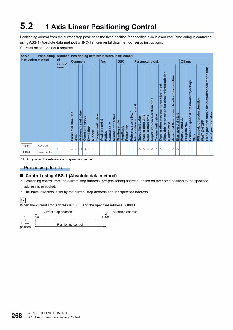
26
5.2 1 Axis Linear Positioning ControlPositioning control from the current stop position to the fixed position for specified axis is executed. Positioning is controlled
using ABS-1 (Absolute data method) or INC-1 (Incremental data method) servo instructions.
: Must be set, : Set if required
*1 Only when the reference axis speed is specified.
Processing details
■ Control using ABS-1 (Absolute data method) • Positioning control from the current stop address (pre-positioning address) based on the home position to the specified
address is executed.
• The travel direction is set by the current stop address and the specified address.
Ex.
When the current stop address is 1000, and the specified address is 8000.
Positioning data set in servo instructions
Common
Servo instruction
Positioning method
Number ofcontrol axes
Arc OSC Parameter block Others
Para
met
er b
lock
No.
Acc
eler
atio
n tim
eD
ecel
erat
ion
time
Rap
id S
top
dece
lera
tion
time
Torq
ue li
mit
valu
eD
ecel
erat
ion
proc
essi
ng o
n st
op in
put
Allo
wab
le e
rror
rang
e fo
r circ
ular
inte
rpol
atio
nS-
curv
e ra
tioA
dvan
ced
S-cu
rve
acce
lera
tion/
dece
lera
tion
Bia
s sp
eed
at s
tart
Rep
eat c
ondi
tion
Prog
ram
No.
Com
man
d sp
eed
(Con
tinuo
us tr
ajec
tory
)Sk
ipFI
N a
ccel
erat
ion/
dece
lera
tion
WA
IT-O
N/O
FF
Fixe
d po
sitio
n st
op
Axi
sA
ddre
ss/tr
avel
val
ueC
omm
and
spee
dD
wel
l tim
eM
-cod
eTo
rque
lim
it va
lue
Aux
iliar
y po
int
Rad
ius
Cen
tral
poi
ntN
umbe
r of p
itche
sSt
artin
g an
gle
Am
plitu
deFr
eque
ncy
Inte
rpol
atio
n co
ntro
l uni
tSp
eed
limit
valu
e
Ref
eren
ce a
xis
No.
*1
Fixe
d po
sitio
n st
op a
ccel
erat
ion/
dece
lera
tion
time
INC-1
ABS-1 Absolute
Incremental1 � � � � � � � � � �� � � � �
0
Homeposition
1000 8000
Positioning control
Current stop address Specified address
85 POSITIONING CONTROL5.2 1 Axis Linear Positioning Control
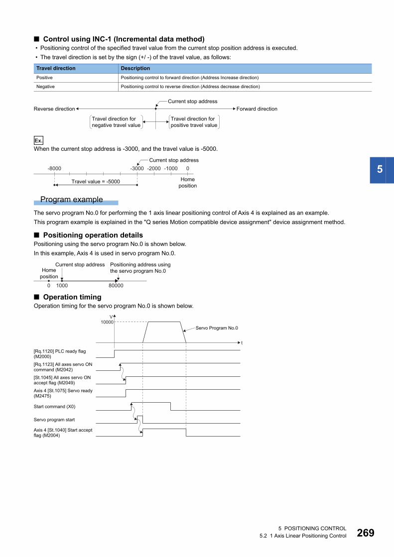
5
■ Control using INC-1 (Incremental data method) • Positioning control of the specified travel value from the current stop position address is executed.
• The travel direction is set by the sign (+/ -) of the travel value, as follows:
Ex.
When the current stop address is -3000, and the travel value is -5000.
Program example
The servo program No.0 for performing the 1 axis linear positioning control of Axis 4 is explained as an example.
This program example is explained in the "Q series Motion compatible device assignment" device assignment method.
■ Positioning operation detailsPositioning using the servo program No.0 is shown below.
In this example, Axis 4 is used in servo program No.0.
■ Operation timingOperation timing for the servo program No.0 is shown below.
Travel direction Description
Positive Positioning control to forward direction (Address Increase direction)
Negative Positioning control to reverse direction (Address decrease direction)
Forward directionReverse directionCurrent stop address
Travel direction for positive travel value
Travel direction for negative travel value
-8000
Homeposition
0-1000-2000-3000
Travel value = -5000
Current stop address
Homeposition
0 1000 80000
Positioning address using the servo program No.0
Current stop address
Axis 4 [St.1075] Servo ready (M2475)
Servo program start
t
V10000
[Rq.1120] PLC ready flag(M2000)
[Rq.1123] All axes servo ON command (M2042)
[St.1045] All axes servo ONaccept flag (M2049)
Start command (X0)
Axis 4 [St.1040] Start acceptflag (M2004)
Servo Program No.0
5 POSITIONING CONTROL5.2 1 Axis Linear Positioning Control 269
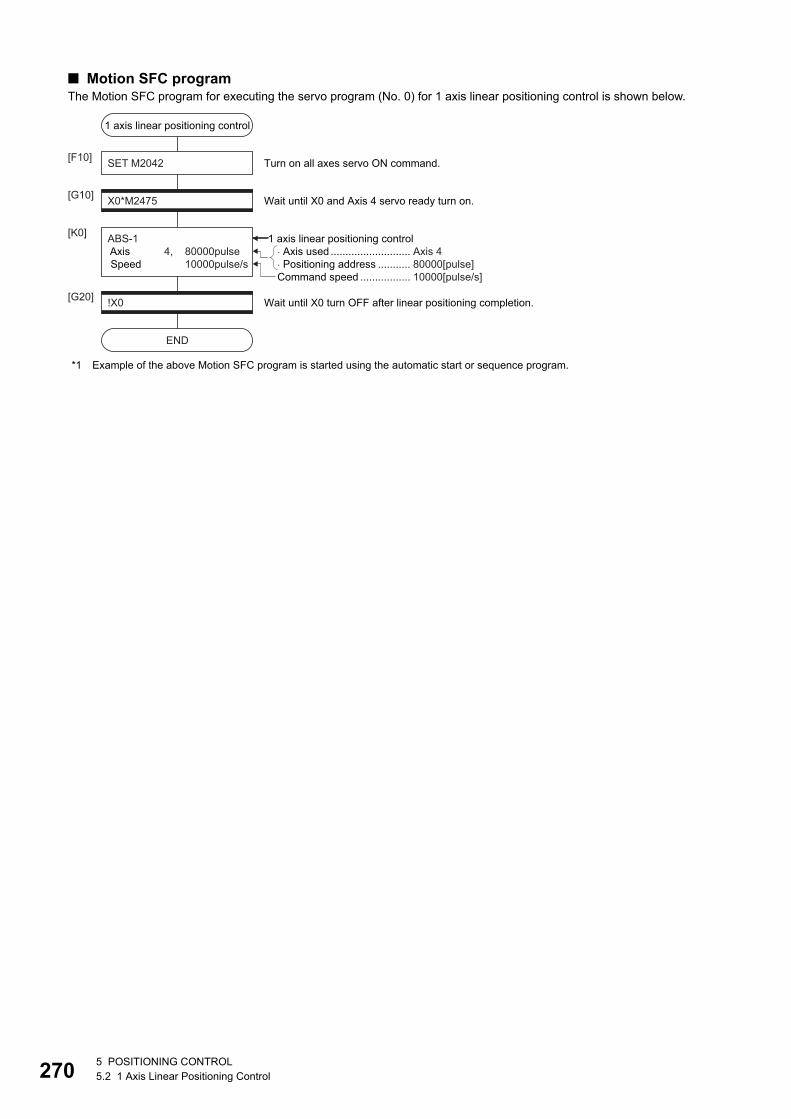
27
■ Motion SFC programThe Motion SFC program for executing the servo program (No. 0) for 1 axis linear positioning control is shown below.
*1 Example of the above Motion SFC program is started using the automatic start or sequence program.
� Axis used ........................... Axis 4� Positioning address ........... 80000[pulse]
1 axis linear positioning control
SET M2042[F10]
X0*M2475[G10]
ABS-1 Axis 4, 80000pulse Speed 10000pulse/s
[K0]
Wait until X0 and Axis 4 servo ready turn on.
Turn on all axes servo ON command.
!X0[G20]
END
Wait until X0 turn OFF after linear positioning completion.
1 axis linear positioning control
Command speed ................. 10000[pulse/s]
05 POSITIONING CONTROL5.2 1 Axis Linear Positioning Control
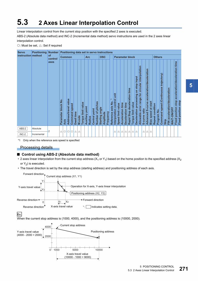
5
5.3 2 Axes Linear Interpolation ControlLinear interpolation control from the current stop position with the specified 2 axes is executed.
ABS-2 (Absolute data method) and INC-2 (Incremental data method) servo instructions are used in the 2 axes linear
interpolation control.
: Must be set, : Set if required
*1 Only when the reference axis speed is specified
Processing details
■ Control using ABS-2 (Absolute data method) • 2 axes linear interpolation from the current stop address (X1 or Y1) based on the home position to the specified address (X2
or Y2) is executed.
• The travel direction is set by the stop address (starting address) and positioning address of each axis.
Ex.
When the current stop address is (1000, 4000), and the positioning address is (10000, 2000).
Positioning data set in servo instructions
Common
Servo instruction
Positioning method
Number ofcontrol axes
Arc OSC Parameter block OthersPa
ram
eter
blo
ck N
o.
Acc
eler
atio
n tim
eD
ecel
erat
ion
time
Rap
id S
top
dece
lera
tion
time
Torq
ue li
mit
valu
eD
ecel
erat
ion
proc
essi
ng o
n st
op in
put
Allo
wab
le e
rror
rang
e fo
r circ
ular
inte
rpol
atio
nS-
curv
e ra
tioA
dvan
ced
S-cu
rve
acce
lera
tion/
dece
lera
tion
Bia
s sp
eed
at s
tart
Rep
eat c
ondi
tion
Prog
ram
No.
Com
man
d sp
eed
(Con
tinuo
us tr
ajec
tory
)Sk
ipFI
N a
ccel
erat
ion/
dece
lera
tion
WA
IT-O
N/O
FF
Fixe
d po
sitio
n st
op
Axi
sA
ddre
ss/tr
avel
val
ueC
omm
and
spee
dD
wel
l tim
eM
-cod
eTo
rque
lim
it va
lue
Aux
iliar
y po
int
Rad
ius
Cen
tral
poi
ntN
umbe
r of p
itche
sSt
artin
g an
gle
Am
plitu
deFr
eque
ncy
Inte
rpol
atio
n co
ntro
l uni
tSp
eed
limit
valu
e
Ref
eren
ce a
xis
No.
*1
Fixe
d po
sitio
n st
op a
ccel
erat
ion/
dece
lera
tion
time
INC-2
ABS-2 Absolute
Incremental2 � �� � � � � � � � �� � � � �
*: Indicates setting data.
Reverse direction
Forward direction
Reverse direction
0Forward direction
X-axis travel value
X1
Y1
Y2
X2
Y-axis travel value
Current stop address (X1, Y1)
Positioning address (X2, Y2)
Operation for X-axis, Y-axis linear interpolation
0
2000
4000
Y-axis travel value (4000 - 2000 = 2000)
Current stop address
Positioning address
5000X-axis travel value
(10000 - 1000 = 9000)
1000 10000
5 POSITIONING CONTROL5.3 2 Axes Linear Interpolation Control 271
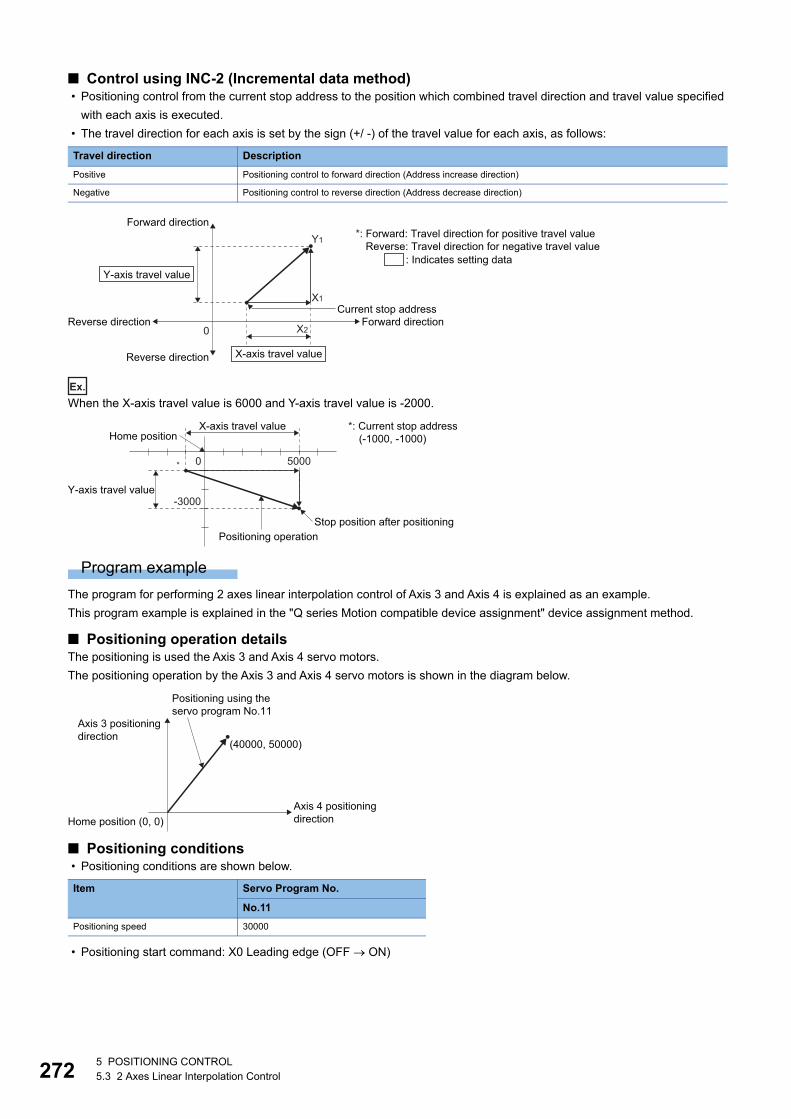
27
■ Control using INC-2 (Incremental data method) • Positioning control from the current stop address to the position which combined travel direction and travel value specified
with each axis is executed.
• The travel direction for each axis is set by the sign (+/ -) of the travel value for each axis, as follows:
Ex.
When the X-axis travel value is 6000 and Y-axis travel value is -2000.
Program example
The program for performing 2 axes linear interpolation control of Axis 3 and Axis 4 is explained as an example.
This program example is explained in the "Q series Motion compatible device assignment" device assignment method.
■ Positioning operation detailsThe positioning is used the Axis 3 and Axis 4 servo motors.
The positioning operation by the Axis 3 and Axis 4 servo motors is shown in the diagram below.
■ Positioning conditions • Positioning conditions are shown below.
• Positioning start command: X0 Leading edge (OFF ON)
Travel direction Description
Positive Positioning control to forward direction (Address increase direction)
Negative Positioning control to reverse direction (Address decrease direction)
Item Servo Program No.
No.11
Positioning speed 30000
Reverse direction
Forward direction
: Indicates setting data
*: Forward: Travel direction for positive travel valueReverse: Travel direction for negative travel value
Reverse direction
0Forward direction
X1
Y1
X2
X-axis travel value
Y-axis travel value
Current stop address
0
Y-axis travel value
Stop position after positioning
*: Current stop address(-1000, -1000)
Positioning operation
-3000
X-axis travel valueHome position
* 5000
Axis 3 positioning direction
Positioning using the servo program No.11
Home position (0, 0)
(40000, 50000)
Axis 4 positioningdirection
25 POSITIONING CONTROL5.3 2 Axes Linear Interpolation Control
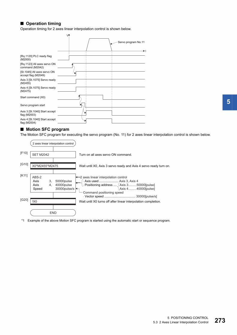
5
■ Operation timingOperation timing for 2 axes linear interpolation control is shown below.
■ Motion SFC programThe Motion SFC program for executing the servo program (No. 11) for 2 axes linear interpolation control is shown below.
*1 Example of the above Motion SFC program is started using the automatic start or sequence program.
Axis 4 [St.1075] Servo ready(M2475)
Servo program start
t
V
[Rq.1120] PLC ready flag(M2000)[Rq.1123] All axes servo ONcommand (M2042)[St.1045] All axes servo ONaccept flag (M2049)Axis 3 [St.1075] Servo ready(M2455)
Start command (X0)
Axis 4 [St.1040] Start acceptflag (M2004)
Axis 3 [St.1040] Start acceptflag (M2003)
Servo program No.11
2 axes linear interpolation control
SET M2042[F10]
X0*M2455*M2475[G10]
ABS-2 Axis 3, 50000pulse Axis 4, 40000pulse Speed 30000pulse/s
[K11]
Wait until X0, Axis 3 servo ready and Axis 4 servo ready turn on.
Turn on all axes servo ON command.
!X0[G20]
END
Wait until X0 turns off after linear interpolation completion.
�Axis used ...................... Axis 3, Axis 4�Positioning address .... Axis 3.........50000[pulse]
Axis 4.........40000[pulse]
2 axes linear interpolation control
Command positioning speed� Vector speed ................................... 30000[pulse/s]
5 POSITIONING CONTROL5.3 2 Axes Linear Interpolation Control 273
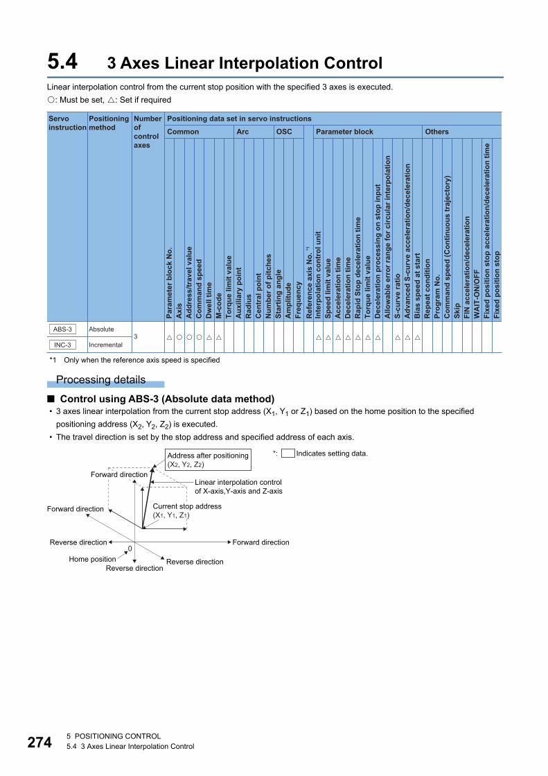
27
5.4 3 Axes Linear Interpolation ControlLinear interpolation control from the current stop position with the specified 3 axes is executed.
: Must be set, : Set if required
*1 Only when the reference axis speed is specified
Processing details
■ Control using ABS-3 (Absolute data method) • 3 axes linear interpolation from the current stop address (X1, Y1 or Z1) based on the home position to the specified
positioning address (X2, Y2, Z2) is executed.
• The travel direction is set by the stop address and specified address of each axis.
Positioning data set in servo instructions
Common
Servo instruction
Positioning method
Number ofcontrol axes
Arc OSC Parameter block Others
Para
met
er b
lock
No.
Acc
eler
atio
n tim
eD
ecel
erat
ion
time
Rap
id S
top
dece
lera
tion
time
Torq
ue li
mit
valu
eD
ecel
erat
ion
proc
essi
ng o
n st
op in
put
Allo
wab
le e
rror
rang
e fo
r circ
ular
inte
rpol
atio
nS-
curv
e ra
tioA
dvan
ced
S-cu
rve
acce
lera
tion/
dece
lera
tion
Bia
s sp
eed
at s
tart
Rep
eat c
ondi
tion
Prog
ram
No.
Com
man
d sp
eed
(Con
tinuo
us tr
ajec
tory
)Sk
ipFI
N a
ccel
erat
ion/
dece
lera
tion
WA
IT-O
N/O
FF
Fixe
d po
sitio
n st
op
Axi
sA
ddre
ss/tr
avel
val
ueC
omm
and
spee
dD
wel
l tim
eM
-cod
eTo
rque
lim
it va
lue
Aux
iliar
y po
int
Rad
ius
Cen
tral
poi
ntN
umbe
r of p
itche
sSt
artin
g an
gle
Am
plitu
deFr
eque
ncy
Inte
rpol
atio
n co
ntro
l uni
tSp
eed
limit
valu
e
Ref
eren
ce a
xis
No.
*1
Fixe
d po
sitio
n st
op a
ccel
erat
ion/
dece
lera
tion
time
INC-3
ABS-3 Absolute
Incremental3 � �� � � � � � � � �� � � � �
Reverse direction
Forward direction
Reverse directionReverse direction
0Home position
Forward direction
Address after positioning(X2, Y2, Z2)
Current stop address(X1, Y1, Z1)
Linear interpolation control of X-axis,Y-axis and Z-axis
*: Indicates setting data.
Forward direction
45 POSITIONING CONTROL5.4 3 Axes Linear Interpolation Control
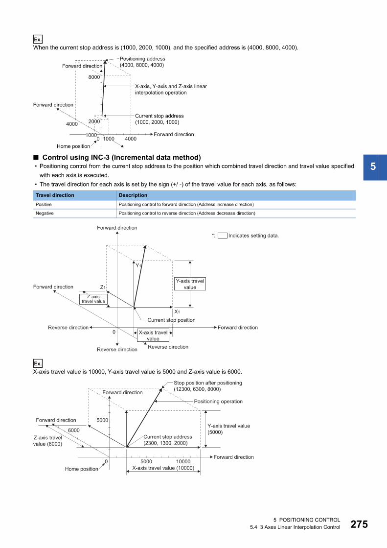
5
Ex.
When the current stop address is (1000, 2000, 1000), and the specified address is (4000, 8000, 4000).
■ Control using INC-3 (Incremental data method) • Positioning control from the current stop address to the position which combined travel direction and travel value specified
with each axis is executed.
• The travel direction for each axis is set by the sign (+/ -) of the travel value for each axis, as follows:
Ex.
X-axis travel value is 10000, Y-axis travel value is 5000 and Z-axis value is 6000.
Travel direction Description
Positive Positioning control to forward direction (Address increase direction)
Negative Positioning control to reverse direction (Address decrease direction)
Forward direction
0 10001000
4000
Home position
Forward direction
Positioning address (4000, 8000, 4000)
X-axis, Y-axis and Z-axis linearinterpolation operation
Current stop address (1000, 2000, 1000)
4000
2000
8000
Forward direction
Reverse direction
Forward direction
Forward direction
Reverse direction Reverse direction
0Forward direction
X1
Y1
Z1Y-axis travel
value
X-axis travelvalue
Z-axistravel value
Current stop position
*: Indicates setting data.
Forward direction
Forward direction
0Home position
Forward direction
Stop position after positioning(12300, 6300, 8000)
X-axis travel value (10000)
Z-axis travelvalue (6000)
Positioning operation
Current stop address(2300, 1300, 2000)
Y-axis travel value(5000)
5000 10000
5000
6000
5 POSITIONING CONTROL5.4 3 Axes Linear Interpolation Control 275
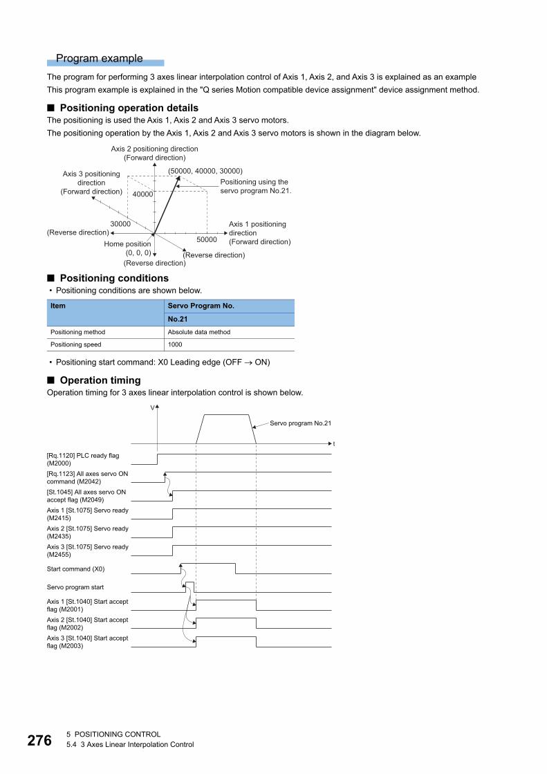
27
Program example
The program for performing 3 axes linear interpolation control of Axis 1, Axis 2, and Axis 3 is explained as an example
This program example is explained in the "Q series Motion compatible device assignment" device assignment method.
■ Positioning operation detailsThe positioning is used the Axis 1, Axis 2 and Axis 3 servo motors.
The positioning operation by the Axis 1, Axis 2 and Axis 3 servo motors is shown in the diagram below.
■ Positioning conditions • Positioning conditions are shown below.
• Positioning start command: X0 Leading edge (OFF ON)
■ Operation timingOperation timing for 3 axes linear interpolation control is shown below.
Item Servo Program No.
No.21
Positioning method Absolute data method
Positioning speed 1000
Home position(0, 0, 0)
Axis 1 positioningdirection(Forward direction)
Axis 2 positioning direction(Forward direction)
Axis 3 positioningdirection
(Forward direction)
(Reverse direction)
(Reverse direction)(Reverse direction)
(50000, 40000, 30000)Positioning using theservo program No.21.
50000
40000
30000
Axis 3 [St.1075] Servo ready(M2455)
Servo program start
t
V
[Rq.1123] All axes servo ONcommand (M2042)[St.1045] All axes servo ONaccept flag (M2049)
Axis 2 [St.1075] Servo ready(M2435)
Axis 1 [St.1075] Servo ready(M2415)
Start command (X0)
[Rq.1120] PLC ready flag(M2000)
Axis 3 [St.1040] Start acceptflag (M2003)
Axis 2 [St.1040] Start acceptflag (M2002)
Axis 1 [St.1040] Start acceptflag (M2001)
Servo program No.21
65 POSITIONING CONTROL5.4 3 Axes Linear Interpolation Control
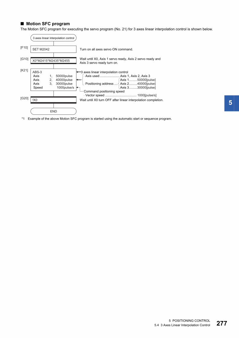
5
■ Motion SFC programThe Motion SFC program for executing the servo program (No. 21) for 3 axes linear interpolation control is shown below.
*1 Example of the above Motion SFC program is started using the automatic start or sequence program.
3 axes linear interpolation control
SET M2042[F10]
X0*M2415*M2435*M2455[G10]
ABS-3 Axis 1, 50000pulse Axis 2, 40000pulse Axis 3, 30000pulse Speed 1000pulse/s
[K21]
Wait until X0, Axis 1 servo ready, Axis 2 servo ready andAxis 3 servo ready turn on.
Turn on all axes servo ON command.
!X0[G20]
END
Wait until X0 turn OFF after linear interpolation completion.
�Axis used ...................... Axis 1, Axis 2, Axis 3
�Positioning address ....Axis 1.........50000[pulse]Axis 2.........40000[pulse]Axis 3.........30000[pulse]
3 axes linear interpolation control
Command positioning speed�Vector speed ................................... 1000[pulse/s]
5 POSITIONING CONTROL5.4 3 Axes Linear Interpolation Control 277
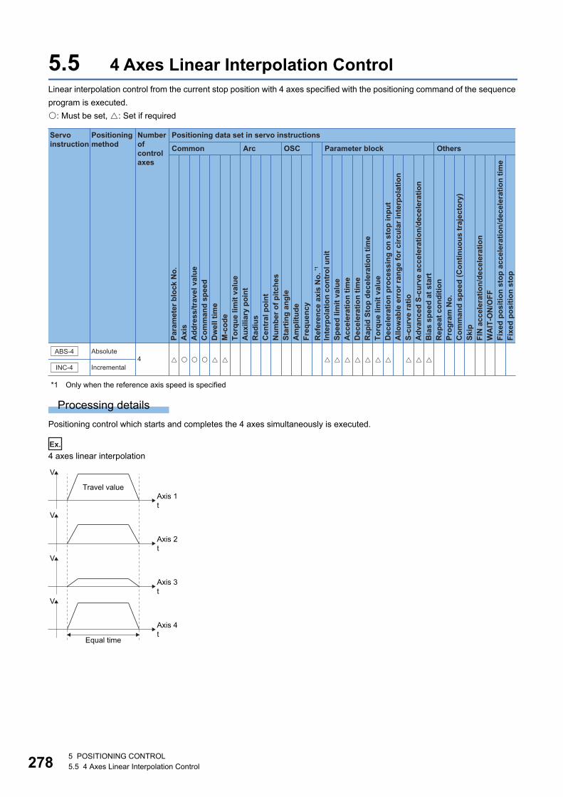
27
5.5 4 Axes Linear Interpolation ControlLinear interpolation control from the current stop position with 4 axes specified with the positioning command of the sequence
program is executed.
: Must be set, : Set if required
*1 Only when the reference axis speed is specified
Processing details
Positioning control which starts and completes the 4 axes simultaneously is executed.
Ex.
4 axes linear interpolation
Positioning data set in servo instructions
Common
Servo instruction
Positioning method
Number ofcontrol axes
Arc OSC Parameter block Others
Para
met
er b
lock
No.
Acc
eler
atio
n tim
eD
ecel
erat
ion
time
Rap
id S
top
dece
lera
tion
time
Torq
ue li
mit
valu
eD
ecel
erat
ion
proc
essi
ng o
n st
op in
put
Allo
wab
le e
rror
rang
e fo
r circ
ular
inte
rpol
atio
nS-
curv
e ra
tioA
dvan
ced
S-cu
rve
acce
lera
tion/
dece
lera
tion
Bia
s sp
eed
at s
tart
Rep
eat c
ondi
tion
Prog
ram
No.
Com
man
d sp
eed
(Con
tinuo
us tr
ajec
tory
)Sk
ipFI
N a
ccel
erat
ion/
dece
lera
tion
WA
IT-O
N/O
FF
Fixe
d po
sitio
n st
op
Axi
sA
ddre
ss/tr
avel
val
ueC
omm
and
spee
dD
wel
l tim
eM
-cod
eTo
rque
lim
it va
lue
Aux
iliar
y po
int
Rad
ius
Cen
tral
poi
ntN
umbe
r of p
itche
sSt
artin
g an
gle
Am
plitu
deFr
eque
ncy
Inte
rpol
atio
n co
ntro
l uni
tSp
eed
limit
valu
e
Ref
eren
ce a
xis
No.
*1
Fixe
d po
sitio
n st
op a
ccel
erat
ion/
dece
lera
tion
time
INC-4
ABS-4 Absolute
Incremental4 � �� � � � � � � � �� � � � �
Axis 1t
V
Axis 2t
V
Axis 3t
V
Axis 4t
V
Equal time
Travel value
85 POSITIONING CONTROL5.5 4 Axes Linear Interpolation Control
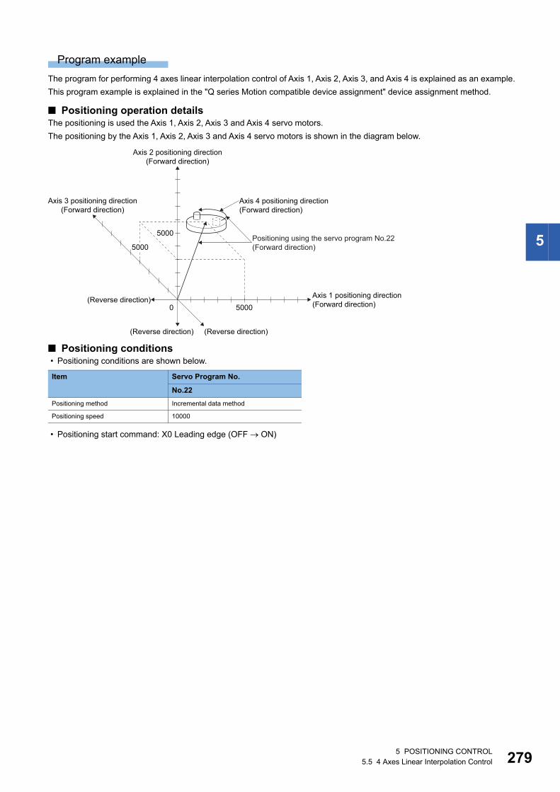
5
Program example
The program for performing 4 axes linear interpolation control of Axis 1, Axis 2, Axis 3, and Axis 4 is explained as an example.
This program example is explained in the "Q series Motion compatible device assignment" device assignment method.
■ Positioning operation detailsThe positioning is used the Axis 1, Axis 2, Axis 3 and Axis 4 servo motors.
The positioning by the Axis 1, Axis 2, Axis 3 and Axis 4 servo motors is shown in the diagram below.
■ Positioning conditions • Positioning conditions are shown below.
• Positioning start command: X0 Leading edge (OFF ON)
Item Servo Program No.
No.22
Positioning method Incremental data method
Positioning speed 10000
5000
5000
Axis 1 positioning direction(Forward direction)
(Reverse direction)
(Reverse direction)0
Axis 2 positioning direction(Forward direction)
Axis 4 positioning direction(Forward direction)
Axis 3 positioning direction(Forward direction)
(Reverse direction)
Positioning using the servo program No.22(Forward direction)5000
5 POSITIONING CONTROL5.5 4 Axes Linear Interpolation Control 279
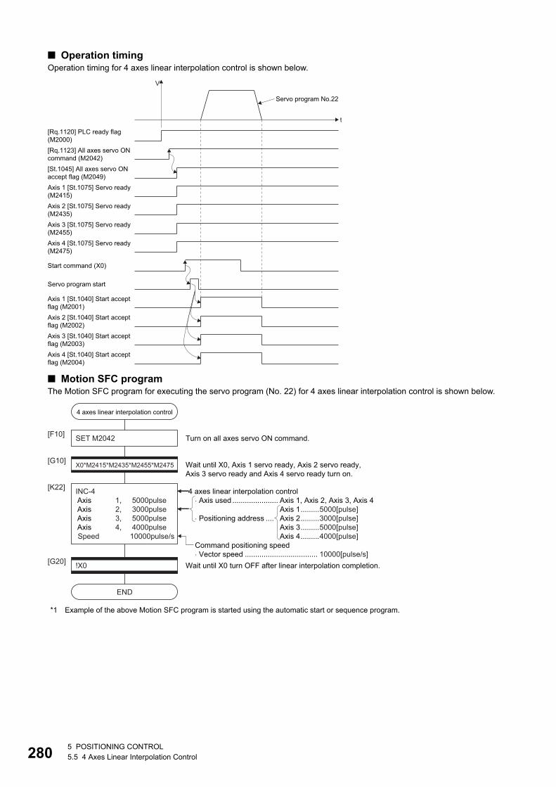
28
■ Operation timingOperation timing for 4 axes linear interpolation control is shown below.
■ Motion SFC programThe Motion SFC program for executing the servo program (No. 22) for 4 axes linear interpolation control is shown below.
*1 Example of the above Motion SFC program is started using the automatic start or sequence program.
Axis 3 [St.1075] Servo ready(M2455)Axis 4 [St.1075] Servo ready(M2475)
Servo program start
t
V
[Rq.1123] All axes servo ON command (M2042)[St.1045] All axes servo ONaccept flag (M2049)
Axis 2 [St.1075] Servo ready(M2435)
Axis 1 [St.1075] Servo ready(M2415)
Start command (X0)
[Rq.1120] PLC ready flag(M2000)
Axis 4 [St.1040] Start acceptflag (M2004)
Axis 2 [St.1040] Start acceptflag (M2002)
Axis 1 [St.1040] Start acceptflag (M2001)
Axis 3 [St.1040] Start acceptflag (M2003)
Servo program No.22
4 axes linear interpolation control
SET M2042[F10]
X0*M2415*M2435*M2455*M2475[G10]
INC-4 Axis 1, 5000pulse Axis 2, 3000pulse Axis 3, 5000pulse Axis 4, 4000pulse Speed 10000pulse/s
[K22]
Wait until X0, Axis 1 servo ready, Axis 2 servo ready, Axis 3 servo ready and Axis 4 servo ready turn on.
Turn on all axes servo ON command.
!X0[G20]
END
Wait until X0 turn OFF after linear interpolation completion.
� Axis used ...................... Axis 1, Axis 2, Axis 3, Axis 4
� Positioning address ....Axis 1.........5000[pulse]Axis 2.........3000[pulse]Axis 3.........5000[pulse]Axis 4.........4000[pulse]
4 axes linear interpolation control
Command positioning speed� Vector speed ................................... 10000[pulse/s]
05 POSITIONING CONTROL5.5 4 Axes Linear Interpolation Control
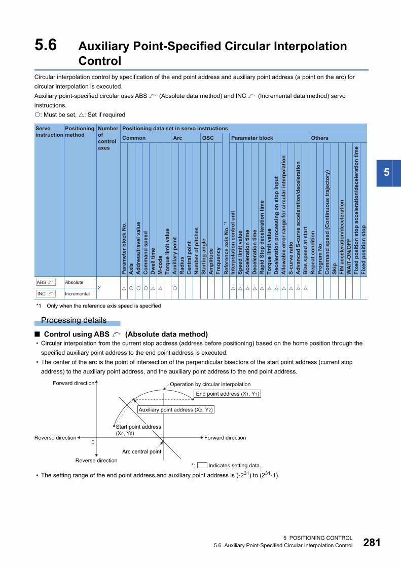
5
5.6 Auxiliary Point-Specified Circular Interpolation Control
Circular interpolation control by specification of the end point address and auxiliary point address (a point on the arc) for
circular interpolation is executed.
Auxiliary point-specified circular uses ABS (Absolute data method) and INC (Incremental data method) servo
instructions.
: Must be set, : Set if required
*1 Only when the reference axis speed is specified
Processing details
■ Control using ABS (Absolute data method) • Circular interpolation from the current stop address (address before positioning) based on the home position through the
specified auxiliary point address to the end point address is executed.
• The center of the arc is the point of intersection of the perpendicular bisectors of the start point address (current stop
address) to the auxiliary point address, and the auxiliary point address to the end point address.
• The setting range of the end point address and auxiliary point address is (-231) to (231-1).
Positioning data set in servo instructions
Common
Servo instruction
Positioning method
Number ofcontrol axes
Arc OSC Parameter block Others
Para
met
er b
lock
No.
Acc
eler
atio
n tim
eD
ecel
erat
ion
time
Rap
id S
top
dece
lera
tion
time
Torq
ue li
mit
valu
eD
ecel
erat
ion
proc
essi
ng o
n st
op in
put
Allo
wab
le e
rror
rang
e fo
r circ
ular
inte
rpol
atio
nS-
curv
e ra
tioA
dvan
ced
S-cu
rve
acce
lera
tion/
dece
lera
tion
Bia
s sp
eed
at s
tart
Rep
eat c
ondi
tion
Prog
ram
No.
Com
man
d sp
eed
(Con
tinuo
us tr
ajec
tory
)Sk
ipFI
N a
ccel
erat
ion/
dece
lera
tion
WA
IT-O
N/O
FF
Fixe
d po
sitio
n st
op
Axi
sA
ddre
ss/tr
avel
val
ueC
omm
and
spee
dD
wel
l tim
eM
-cod
eTo
rque
lim
it va
lue
Aux
iliar
y po
int
Rad
ius
Cen
tral
poi
ntN
umbe
r of p
itche
sSt
artin
g an
gle
Am
plitu
deFr
eque
ncy
Inte
rpol
atio
n co
ntro
l uni
tSp
eed
limit
valu
e
Ref
eren
ce a
xis
No.
*1
Fixe
d po
sitio
n st
op a
ccel
erat
ion/
dece
lera
tion
time
Absolute
Incremental2 � �� � � � � � � � � �� � � �� �
ABS
INC
Arc central point
Operation by circular interpolation
Reverse direction
Reverse direction
0Forward direction
Forward direction
Auxiliary point address (X2, Y2)
End point address (X1, Y1)
*: Indicates setting data.
Start point address(X0, Y0)
5 POSITIONING CONTROL5.6 Auxiliary Point-Specified Circular Interpolation Control 281
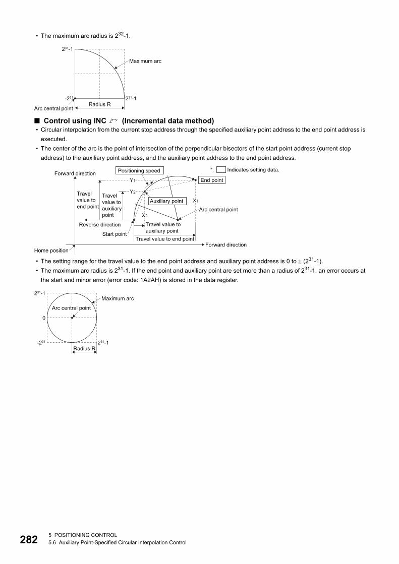
28
• The maximum arc radius is 232-1.
■ Control using INC (Incremental data method) • Circular interpolation from the current stop address through the specified auxiliary point address to the end point address is
executed.
• The center of the arc is the point of intersection of the perpendicular bisectors of the start point address (current stop
address) to the auxiliary point address, and the auxiliary point address to the end point address.
• The setting range for the travel value to the end point address and auxiliary point address is 0 to (231-1).
• The maximum arc radius is 231-1. If the end point and auxiliary point are set more than a radius of 231-1, an error occurs at
the start and minor error (error code: 1A2AH) is stored in the data register.
Arc central point
Maximum arc
Radius R231-1-231
231-1
*: Indicates setting data.
Reverse direction
Home position
Start point
Travel value toauxiliary point
Travel value to end pointForward direction
Forward directionEnd point
Positioning speed
Travel value toauxiliarypoint
Travel value to end point
Y1
X1
X2
Y2
Auxiliary pointArc central point
Maximum arc
Radius R231-1-231
0
231-1
Arc central point
25 POSITIONING CONTROL5.6 Auxiliary Point-Specified Circular Interpolation Control
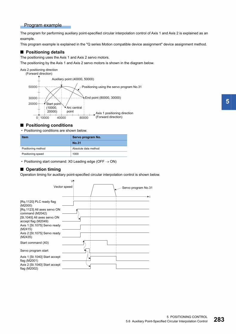
5
Program example
The program for performing auxiliary point-specified circular interpolation control of Axis 1 and Axis 2 is explained as an
example.
This program example is explained in the "Q series Motion compatible device assignment" device assignment method.
■ Positioning detailsThe positioning uses the Axis 1 and Axis 2 servo motors.
The positioning by the Axis 1 and Axis 2 servo motors is shown in the diagram below.
■ Positioning conditions • Positioning conditions are shown below.
• Positioning start command: X0 Leading edge (OFF ON)
■ Operation timingOperation timing for auxiliary point-specified circular interpolation control is shown below.
Item Servo program No.
No.31
Positioning method Absolute data method
Positioning speed 1000
0
Positioning using the servo program No.31
Arc central point
Auxiliary point (40000, 50000)
End point (80000, 30000)
Start point(10000, 20000)
40000 80000
20000
30000
50000
Axis 2 positioning direction(Forward direction)
Axis 1 positioning direction(Forward direction)10000
Axis 2 [St.1075] Servo ready(M2435)
Servo program start
t
V
Vector speed
[Rq.1123] All axes servo ON command (M2042)[St.1045] All axes servo ONaccept flag (M2049)Axis 1 [St.1075] Servo ready(M2415)
Start command (X0)
[Rq.1120] PLC ready flag(M2000)
Axis 2 [St.1040] Start acceptflag (M2002)
Axis 1 [St.1040] Start acceptflag (M2001)
Servo program No.31
5 POSITIONING CONTROL5.6 Auxiliary Point-Specified Circular Interpolation Control 283
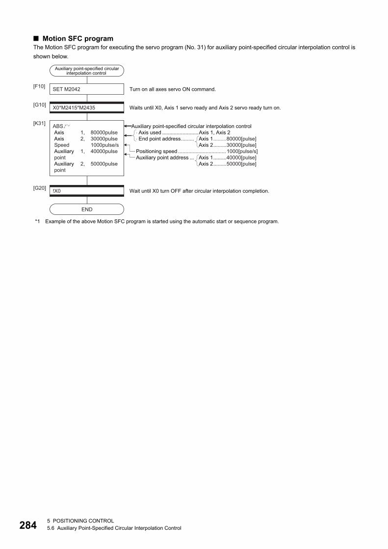
28
■ Motion SFC programThe Motion SFC program for executing the servo program (No. 31) for auxiliary point-specified circular interpolation control is
shown below.
*1 Example of the above Motion SFC program is started using the automatic start or sequence program.
Auxiliary point-specified circularinterpolation control
SET M2042[F10]
X0*M2415*M2435[G10]
ABS Axis 1, 80000pulse Axis 2, 30000pulse Speed 1000pulse/s Auxiliary 1, 40000pulse point Auxiliary 2, 50000pulse point
[K31]
Waits until X0, Axis 1 servo ready and Axis 2 servo ready turn on.
Turn on all axes servo ON command.
!X0[G20]
END
Wait until X0 turn OFF after circular interpolation completion.
�Axis used .........................Axis 1, Axis 2�End point address......... Axis 1.........80000[pulse]
Axis 2.........30000[pulse]
Auxiliary point address ... Axis 1.........40000[pulse]Axis 2.........50000[pulse]
Auxiliary point-specified circular interpolation control
Positioning speed ................................. 1000[pulse/s]
45 POSITIONING CONTROL5.6 Auxiliary Point-Specified Circular Interpolation Control
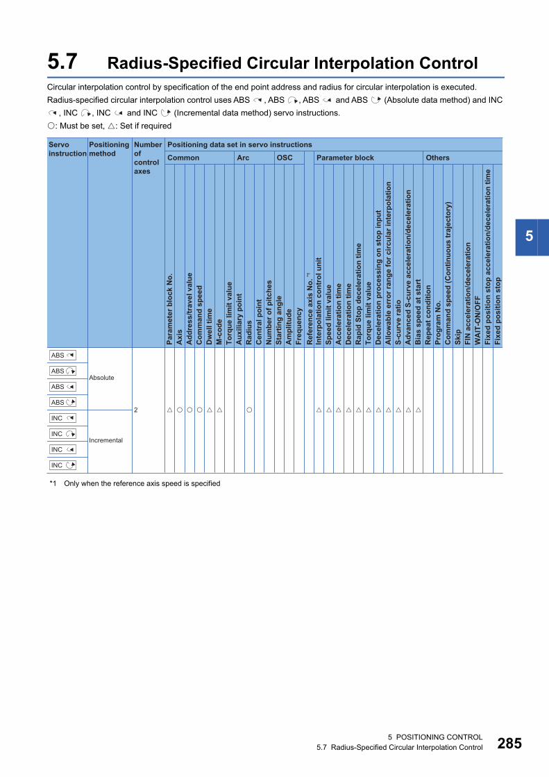
5
5.7 Radius-Specified Circular Interpolation ControlCircular interpolation control by specification of the end point address and radius for circular interpolation is executed.
Radius-specified circular interpolation control uses ABS , ABS , ABS and ABS (Absolute data method) and INC
, INC , INC and INC (Incremental data method) servo instructions.
: Must be set, : Set if required
*1 Only when the reference axis speed is specified
� ��� � � � ��� � � � � � � � �
Positioning data set in servo instructions
Common
Servo instruction
Positioning method
Number ofcontrol axes
Arc OSC Parameter block OthersPa
ram
eter
blo
ck N
o.
Acc
eler
atio
n tim
eD
ecel
erat
ion
time
Rap
id S
top
dece
lera
tion
time
Torq
ue li
mit
valu
eD
ecel
erat
ion
proc
essi
ng o
n st
op in
put
Allo
wab
le e
rror
rang
e fo
r circ
ular
inte
rpol
atio
nS-
curv
e ra
tioA
dvan
ced
S-cu
rve
acce
lera
tion/
dece
lera
tion
Bia
s sp
eed
at s
tart
Rep
eat c
ondi
tion
Prog
ram
No.
Com
man
d sp
eed
(Con
tinuo
us tr
ajec
tory
)Sk
ipFI
N a
ccel
erat
ion/
dece
lera
tion
WA
IT-O
N/O
FF
Fixe
d po
sitio
n st
op
Axi
sA
ddre
ss/tr
avel
val
ueC
omm
and
spee
dD
wel
l tim
eM
-cod
eTo
rque
lim
it va
lue
Aux
iliar
y po
int
Rad
ius
Cen
tral
poi
ntN
umbe
r of p
itche
sSt
artin
g an
gle
Am
plitu
deFr
eque
ncy
Inte
rpol
atio
n co
ntro
l uni
tSp
eed
limit
valu
e
Ref
eren
ce a
xis
No.
*1
Fixe
d po
sitio
n st
op a
ccel
erat
ion/
dece
lera
tion
time
Absolute
Incremental
2ABS
ABS
ABS
ABS
INC
INC
INC
INC
5 POSITIONING CONTROL5.7 Radius-Specified Circular Interpolation Control 285
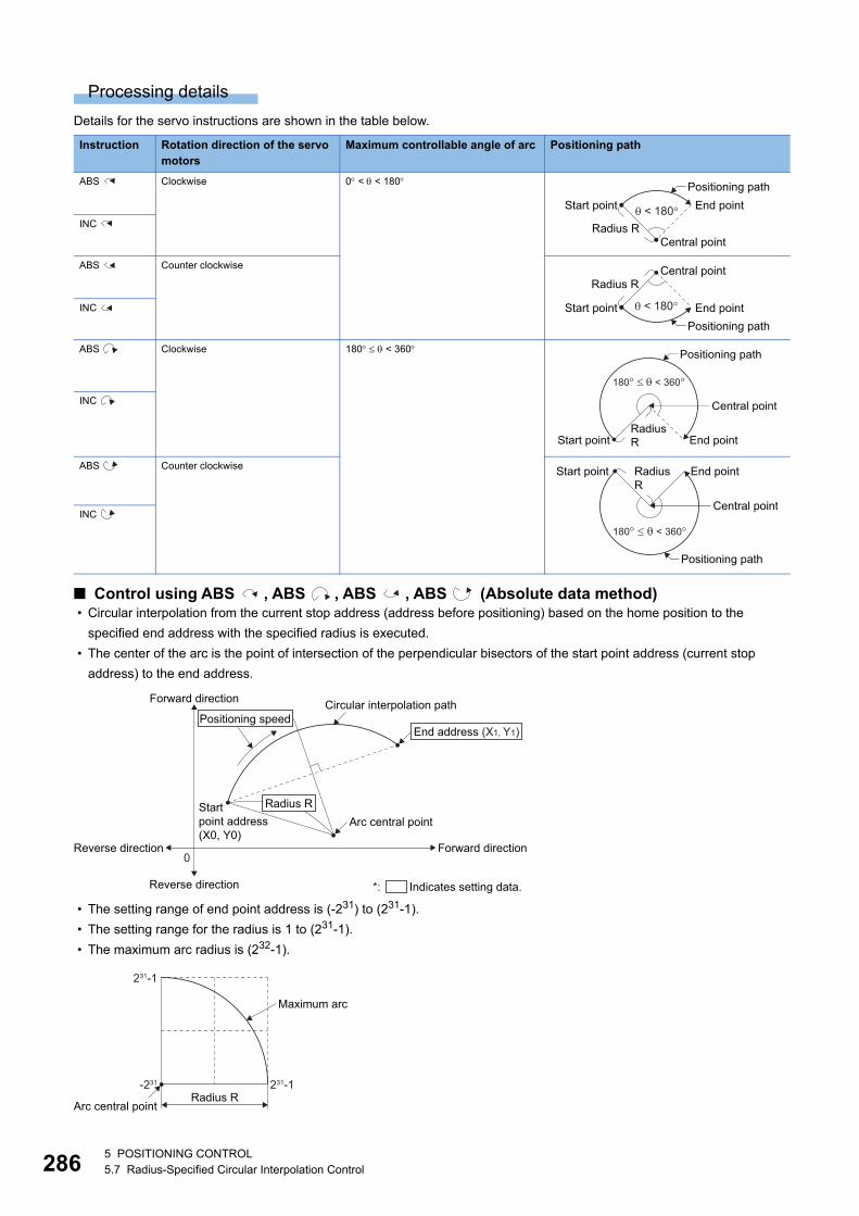
28
Processing details
Details for the servo instructions are shown in the table below.
■ Control using ABS , ABS , ABS , ABS (Absolute data method) • Circular interpolation from the current stop address (address before positioning) based on the home position to the
specified end address with the specified radius is executed.
• The center of the arc is the point of intersection of the perpendicular bisectors of the start point address (current stop
address) to the end address.
• The setting range of end point address is (-231) to (231-1).
• The setting range for the radius is 1 to (231-1).
• The maximum arc radius is (232-1).
Instruction Rotation direction of the servo motors
Maximum controllable angle of arc Positioning path
ABS Clockwise 0 < < 180
INC
ABS Counter clockwise
INC
ABS Clockwise 180 < 360
INC
ABS Counter clockwise
INC
Central point
Positioning pathEnd point
Radius R
Start point < 180�
Positioning path
Radius R
< 180�
Central point
End pointStart point
Central point
Positioning path
RadiusR End pointStart point
180��< 360�
End pointStart point
Central point
RadiusR
180� � < 360�
Positioning path
Startpoint address(X0, Y0)
Circular interpolation path
Arc central point
Reverse direction
Reverse direction
0Forward direction
Forward direction
End address (X1, Y1)Positioning speed
Radius R
*: Indicates setting data.
Arc central point
Maximum arc
Radius R231-1-231
231-1
65 POSITIONING CONTROL5.7 Radius-Specified Circular Interpolation Control
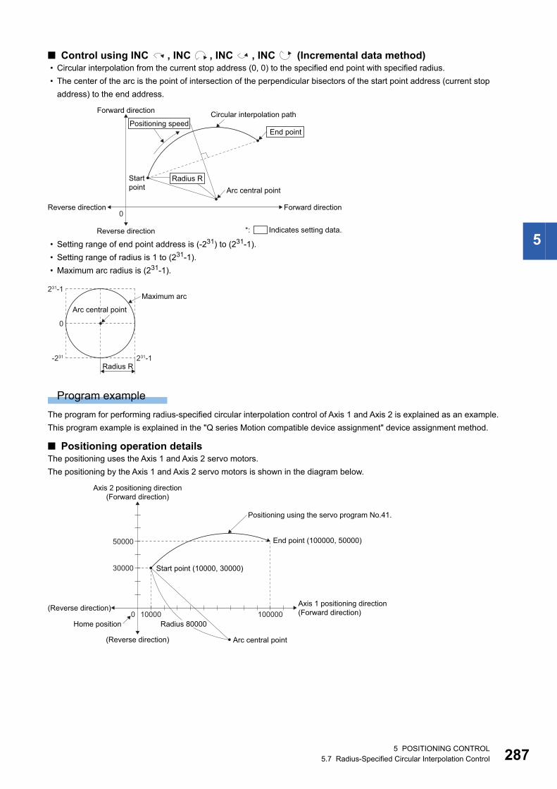
5
■ Control using INC , INC , INC , INC (Incremental data method) • Circular interpolation from the current stop address (0, 0) to the specified end point with specified radius.
• The center of the arc is the point of intersection of the perpendicular bisectors of the start point address (current stop
address) to the end address.
• Setting range of end point address is (-231) to (231-1).
• Setting range of radius is 1 to (231-1).
• Maximum arc radius is (231-1).
Program example
The program for performing radius-specified circular interpolation control of Axis 1 and Axis 2 is explained as an example.
This program example is explained in the "Q series Motion compatible device assignment" device assignment method.
■ Positioning operation detailsThe positioning uses the Axis 1 and Axis 2 servo motors.
The positioning by the Axis 1 and Axis 2 servo motors is shown in the diagram below.
Startpoint
Circular interpolation path
Arc central point
Reverse direction
Reverse direction
0Forward direction
Forward direction
End pointPositioning speed
Radius R
*: Indicates setting data.
Maximum arc
Radius R231-1-231
0
231-1
Arc central point
0
Positioning using the servo program No.41.
Arc central point
End point (100000, 50000)
Start point (10000, 30000)
100000
30000
50000
Axis 2 positioning direction(Forward direction)
(Reverse direction)
Axis 1 positioning direction(Forward direction)(Reverse direction)
10000Radius 80000Home position
5 POSITIONING CONTROL5.7 Radius-Specified Circular Interpolation Control 287
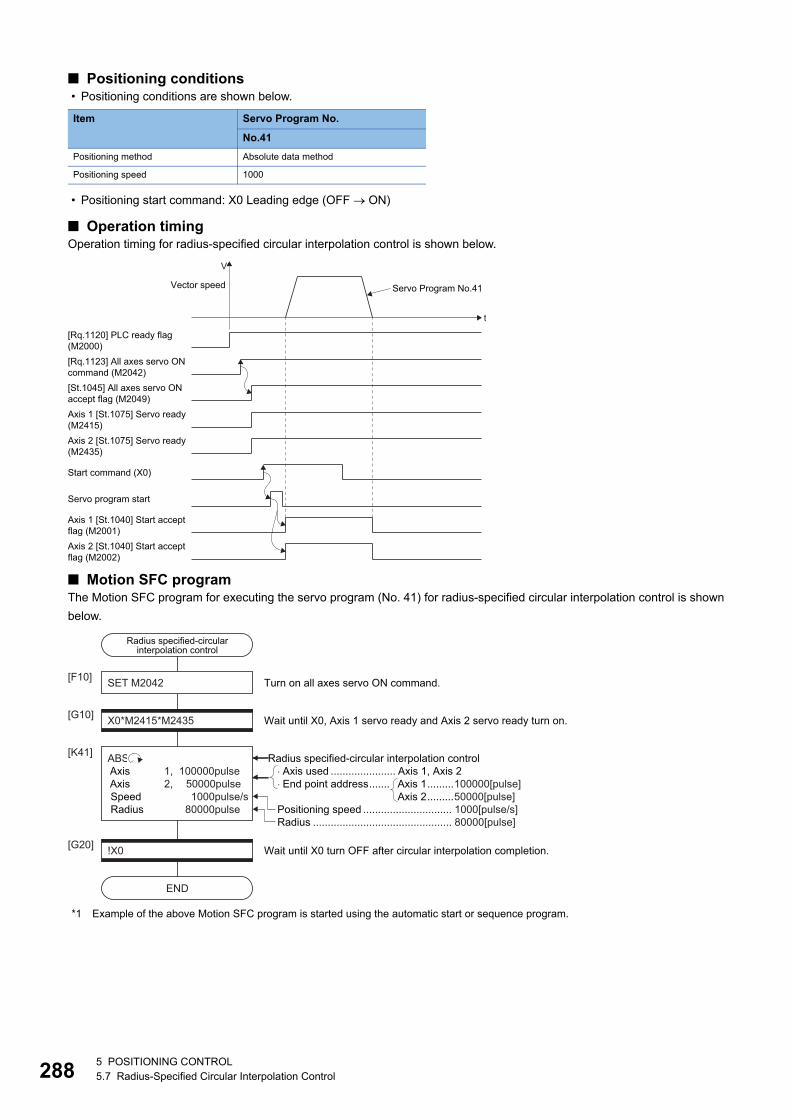
28
■ Positioning conditions • Positioning conditions are shown below.
• Positioning start command: X0 Leading edge (OFF ON)
■ Operation timingOperation timing for radius-specified circular interpolation control is shown below.
■ Motion SFC programThe Motion SFC program for executing the servo program (No. 41) for radius-specified circular interpolation control is shown
below.
*1 Example of the above Motion SFC program is started using the automatic start or sequence program.
Item Servo Program No.
No.41
Positioning method Absolute data method
Positioning speed 1000
Axis 2 [St.1075] Servo ready(M2435)
Servo program start
[Rq.1120] PLC ready flag(M2000)
t
V
Vector speed
[Rq.1123] All axes servo ON command (M2042)[St.1045] All axes servo ONaccept flag (M2049)Axis 1 [St.1075] Servo ready(M2415)
Start command (X0)
Axis 2 [St.1040] Start acceptflag (M2002)
Axis 1 [St.1040] Start acceptflag (M2001)
Servo Program No.41
Radius specified-circularinterpolation control
SET M2042[F10]
X0*M2415*M2435[G10]
ABS Axis 1, 100000pulse Axis 2, 50000pulse Speed 1000pulse/s Radius 80000pulse
[K41]
Wait until X0, Axis 1 servo ready and Axis 2 servo ready turn on.
Turn on all axes servo ON command.
!X0[G20]
END
Wait until X0 turn OFF after circular interpolation completion.
�Axis used ...................... Axis 1, Axis 2�End point address....... Axis 1.........100000[pulse]
Axis 2.........50000[pulse]
Radius ............................................... 80000[pulse]
Radius specified-circular interpolation control
Positioning speed .............................. 1000[pulse/s]
85 POSITIONING CONTROL5.7 Radius-Specified Circular Interpolation Control
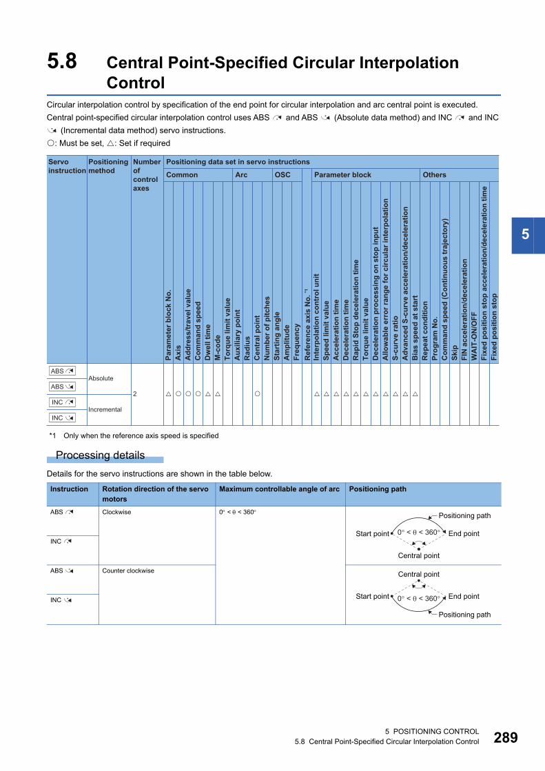
5
5.8 Central Point-Specified Circular Interpolation Control
Circular interpolation control by specification of the end point for circular interpolation and arc central point is executed.
Central point-specified circular interpolation control uses ABS and ABS (Absolute data method) and INC and INC
(Incremental data method) servo instructions.
: Must be set, : Set if required
*1 Only when the reference axis speed is specified
Processing details
Details for the servo instructions are shown in the table below.
Instruction Rotation direction of the servo motors
Maximum controllable angle of arc Positioning path
ABS Clockwise 0 < < 360
INC
ABS Counter clockwise
INC
Positioning data set in servo instructions
Common
Servo instruction
Positioning method
Number ofcontrol axes
Arc OSC Parameter block OthersPa
ram
eter
blo
ck N
o.
Acc
eler
atio
n tim
eD
ecel
erat
ion
time
Rap
id S
top
dece
lera
tion
time
Torq
ue li
mit
valu
eD
ecel
erat
ion
proc
essi
ng o
n st
op in
put
Allo
wab
le e
rror
rang
e fo
r circ
ular
inte
rpol
atio
nS-
curv
e ra
tioA
dvan
ced
S-cu
rve
acce
lera
tion/
dece
lera
tion
Bia
s sp
eed
at s
tart
Rep
eat c
ondi
tion
Prog
ram
No.
Com
man
d sp
eed
(Con
tinuo
us tr
ajec
tory
)Sk
ipFI
N a
ccel
erat
ion/
dece
lera
tion
WA
IT-O
N/O
FF
Fixe
d po
sitio
n st
op
Axi
sA
ddre
ss/tr
avel
val
ueC
omm
and
spee
dD
wel
l tim
eM
-cod
eTo
rque
lim
it va
lue
Aux
iliar
y po
int
Rad
ius
Cen
tral
poi
ntN
umbe
r of p
itche
sSt
artin
g an
gle
Am
plitu
deFr
eque
ncy
Inte
rpol
atio
n co
ntro
l uni
tSp
eed
limit
valu
e
Ref
eren
ce a
xis
No.
*1
Fixe
d po
sitio
n st
op a
ccel
erat
ion/
dece
lera
tion
time
Absolute
Incremental
2 � �� � � � � � � � � �� � � �� �
INC
ABS
INC
ABS
Central point
Positioning path
End pointStart point 0� < < 360�
0� < < 360�
Central point
Positioning path
End pointStart point
5 POSITIONING CONTROL5.8 Central Point-Specified Circular Interpolation Control 289
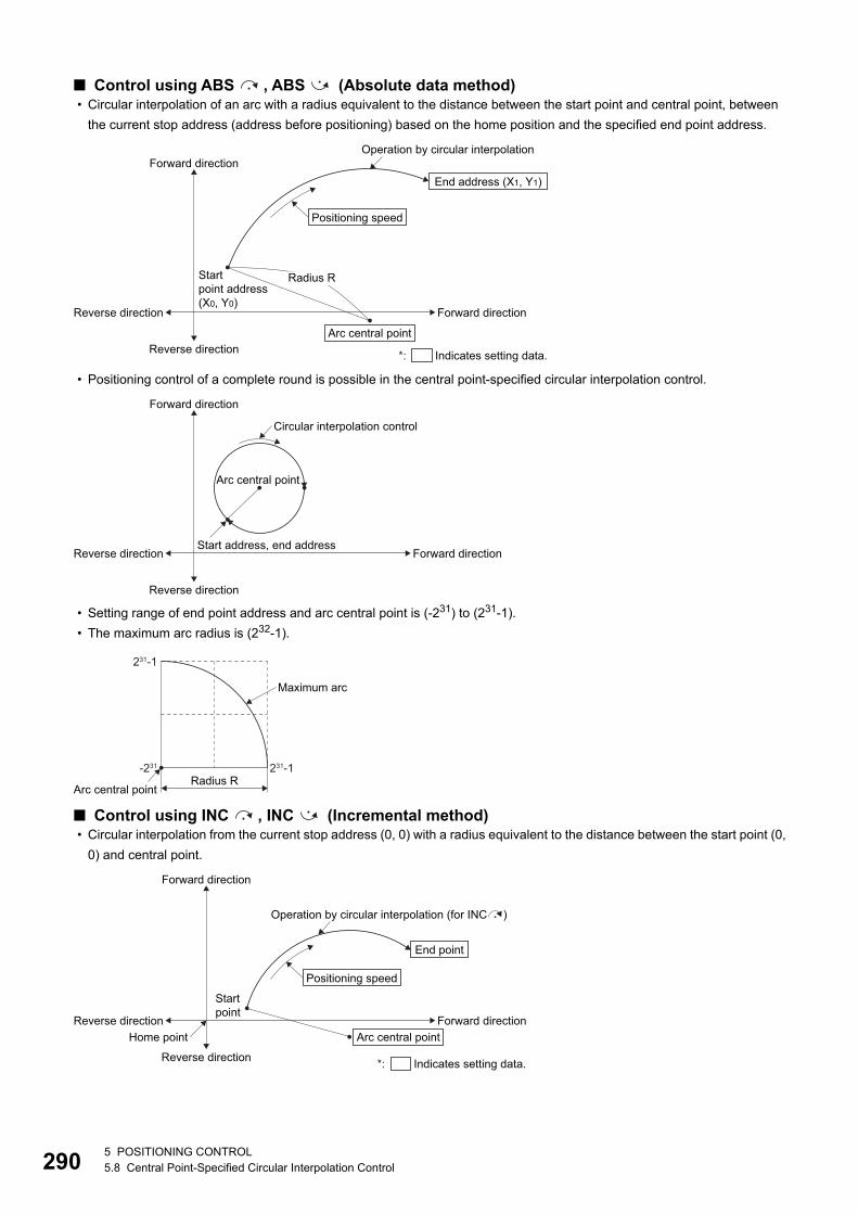
29
■ Control using ABS , ABS (Absolute data method) • Circular interpolation of an arc with a radius equivalent to the distance between the start point and central point, between
the current stop address (address before positioning) based on the home position and the specified end point address.
• Positioning control of a complete round is possible in the central point-specified circular interpolation control.
• Setting range of end point address and arc central point is (-231) to (231-1).
• The maximum arc radius is (232-1).
■ Control using INC , INC (Incremental method) • Circular interpolation from the current stop address (0, 0) with a radius equivalent to the distance between the start point (0,
0) and central point.
Startpoint address(X0, Y0)
Operation by circular interpolation
Reverse direction
Reverse direction
Forward direction
Forward directionEnd address (X1, Y1)
Positioning speed
Arc central point
Radius R
*: Indicates setting data.
Start address, end address
Circular interpolation control
Reverse direction
Reverse direction
Forward direction
Forward direction
Arc central point
Arc central point
Maximum arc
Radius R231-1-231
231-1
End point
Positioning speed
Arc central point
*: Indicates setting data.
Operation by circular interpolation (for INC )
Startpoint
Home pointReverse direction
Reverse direction
Forward direction
Forward direction
05 POSITIONING CONTROL5.8 Central Point-Specified Circular Interpolation Control
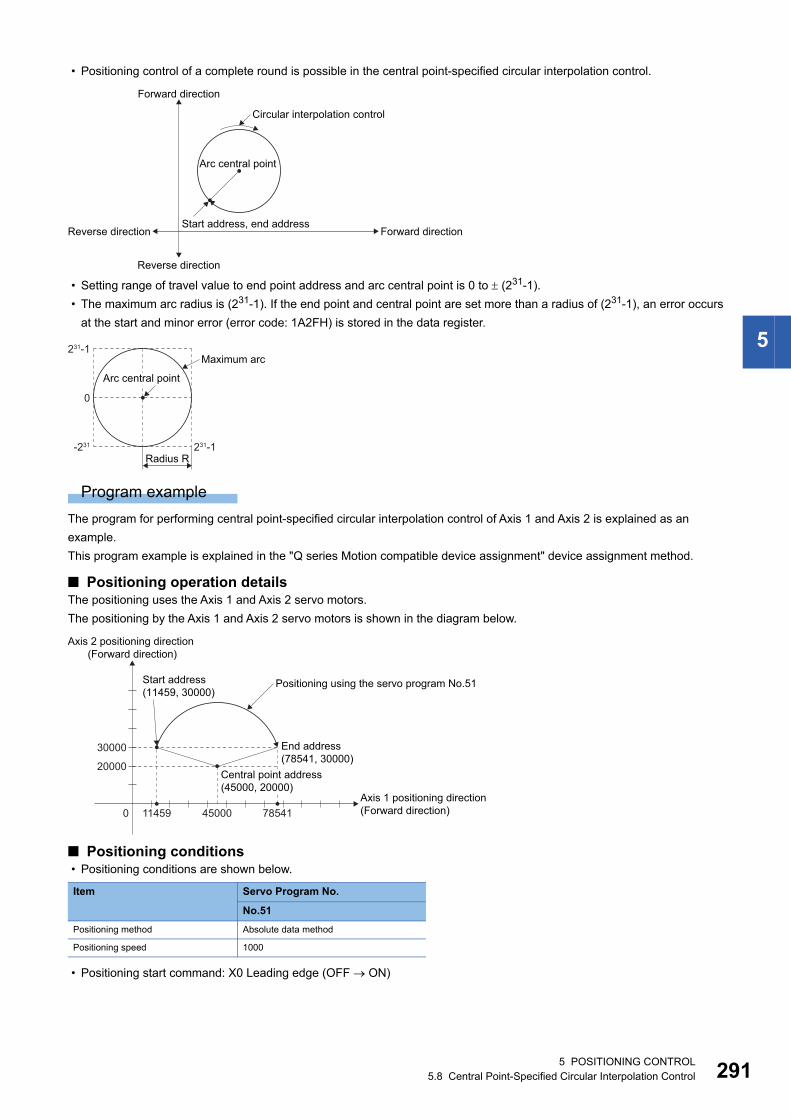
5
• Positioning control of a complete round is possible in the central point-specified circular interpolation control.
• Setting range of travel value to end point address and arc central point is 0 to (231-1).
• The maximum arc radius is (231-1). If the end point and central point are set more than a radius of (231-1), an error occurs
at the start and minor error (error code: 1A2FH) is stored in the data register.
Program example
The program for performing central point-specified circular interpolation control of Axis 1 and Axis 2 is explained as an
example.
This program example is explained in the "Q series Motion compatible device assignment" device assignment method.
■ Positioning operation detailsThe positioning uses the Axis 1 and Axis 2 servo motors.
The positioning by the Axis 1 and Axis 2 servo motors is shown in the diagram below.
■ Positioning conditions • Positioning conditions are shown below.
• Positioning start command: X0 Leading edge (OFF ON)
Item Servo Program No.
No.51
Positioning method Absolute data method
Positioning speed 1000
Start address, end address
Circular interpolation control
Reverse direction
Reverse direction
Forward direction
Forward direction
Arc central point
Maximum arc
Radius R231-1-231
0
231-1
Arc central point
0
Positioning using the servo program No.51
End address (78541, 30000)
Start address (11459, 30000)
30000
20000
Axis 2 positioning direction (Forward direction)
Axis 1 positioning direction (Forward direction)45000 7854111459
Central point address (45000, 20000)
5 POSITIONING CONTROL5.8 Central Point-Specified Circular Interpolation Control 291
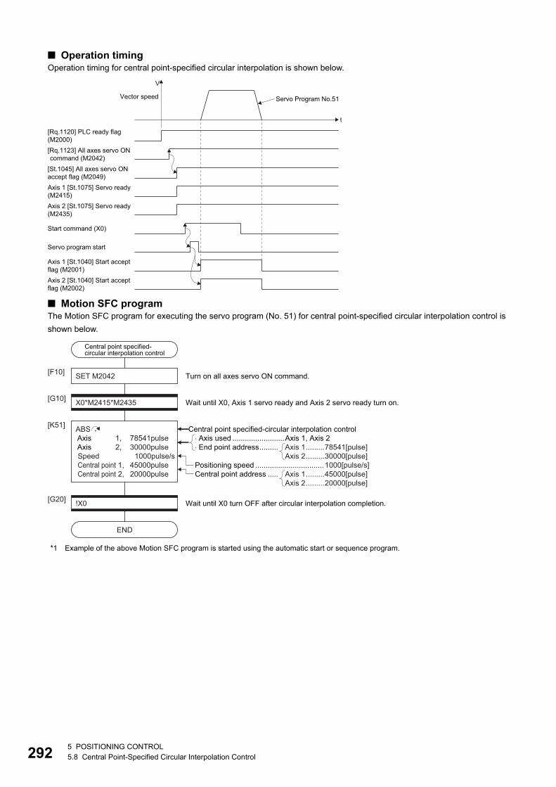
29
■ Operation timingOperation timing for central point-specified circular interpolation is shown below.
■ Motion SFC programThe Motion SFC program for executing the servo program (No. 51) for central point-specified circular interpolation control is
shown below.
*1 Example of the above Motion SFC program is started using the automatic start or sequence program.
Axis 2 [St.1075] Servo ready(M2435)
Servo program start
t
V
Vector speed
[Rq.1120] PLC ready flag(M2000)[Rq.1123] All axes servo ON command (M2042)
[St.1045] All axes servo ONaccept flag (M2049)Axis 1 [St.1075] Servo ready(M2415)
Start command (X0)
Axis 2 [St.1040] Start acceptflag (M2002)
Axis 1 [St.1040] Start acceptflag (M2001)
Servo Program No.51
Central point specified-circular interpolation control
SET M2042[F10]
X0*M2415*M2435[G10]
ABS Axis 1, 78541pulse Axis 2, 30000pulse Speed 1000pulse/s Central point 1, 45000pulse Central point 2, 20000pulse
[K51]
Wait until X0, Axis 1 servo ready and Axis 2 servo ready turn on.
Turn on all axes servo ON command.
!X0[G20]
END
Wait until X0 turn OFF after circular interpolation completion.
�Axis used .........................Axis 1, Axis 2 �End point address......... Axis 1.........78541[pulse]
Axis 2.........30000[pulse]
Central point address ..... Axis 1.........45000[pulse]Axis 2.........20000[pulse]
Central point specified-circular interpolation control
Positioning speed ................................. 1000[pulse/s]
25 POSITIONING CONTROL5.8 Central Point-Specified Circular Interpolation Control
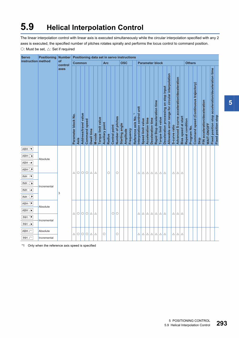
5
5.9 Helical Interpolation ControlThe linear interpolation control with linear axis is executed simultaneously while the circular interpolation specified with any 2
axes is executed, the specified number of pitches rotates spirally and performs the locus control to command position.
: Must be set, : Set if required
*1 Only when the reference axis speed is specified
Positioning data set in servo instructions
Common
Servo instruction
Positioning method
Number ofcontrol axes
Arc OSC Parameter block Others
Para
met
er b
lock
No.
Acc
eler
atio
n tim
eD
ecel
erat
ion
time
Rap
id S
top
dece
lera
tion
time
Torq
ue li
mit
valu
eD
ecel
erat
ion
proc
essi
ng o
n st
op in
put
Allo
wab
le e
rror
rang
e fo
r circ
ular
inte
rpol
atio
nS-
curv
e ra
tioA
dvan
ced
S-cu
rve
acce
lera
tion/
dece
lera
tion
Bia
s sp
eed
at s
tart
Rep
eat c
ondi
tion
Prog
ram
No.
Com
man
d sp
eed
(Con
tinuo
us tr
ajec
tory
)Sk
ipFI
N a
ccel
erat
ion/
dece
lera
tion
WA
IT-O
N/O
FF
Fixe
d po
sitio
n st
op
Axi
sA
ddre
ss/tr
avel
val
ueC
omm
and
spee
dD
wel
l tim
eM
-cod
eTo
rque
lim
it va
lue
Aux
iliar
y po
int
Rad
ius
Cen
tral
poi
ntN
umbe
r of p
itche
sSt
artin
g an
gle
Am
plitu
deFr
eque
ncy
Inte
rpol
atio
n co
ntro
l uni
tSp
eed
limit
valu
e
Ref
eren
ce a
xis
No.
*1
Fixe
d po
sitio
n st
op a
ccel
erat
ion/
dece
lera
tion
time
Absolute
Absolute
Absolute
Incremental
Incremental
Incremental
3
�� � � � � � � � �
�� � � � � � � � �
�� � � � � � � � �
� � � � � �
��
��
� �
� � � � � �
� � � � � �
ABH
ABH
ABH
ABH
INH
INH
INH
INH
INH
ABH
INH
ABH
ABH
INH
5 POSITIONING CONTROL5.9 Helical Interpolation Control 293
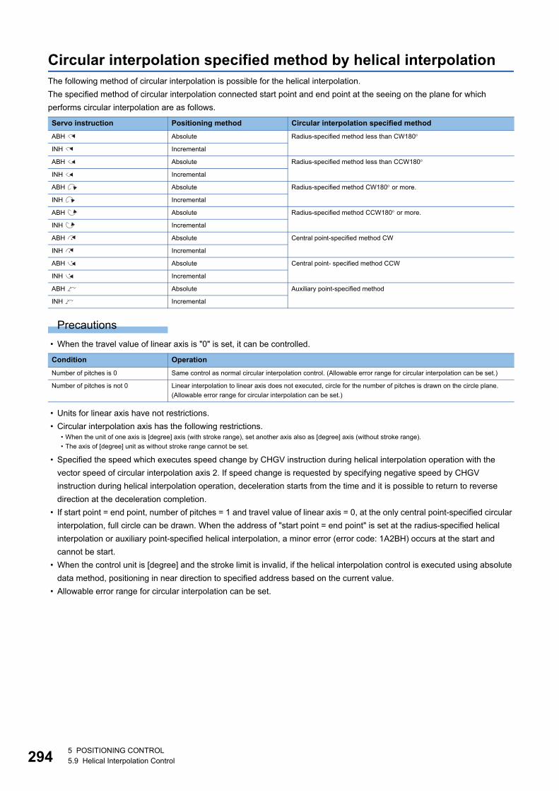
29
Circular interpolation specified method by helical interpolationThe following method of circular interpolation is possible for the helical interpolation.
The specified method of circular interpolation connected start point and end point at the seeing on the plane for which
performs circular interpolation are as follows.
Precautions
• When the travel value of linear axis is "0" is set, it can be controlled.
• Units for linear axis have not restrictions.
• Circular interpolation axis has the following restrictions.
• Specified the speed which executes speed change by CHGV instruction during helical interpolation operation with the
vector speed of circular interpolation axis 2. If speed change is requested by specifying negative speed by CHGV
instruction during helical interpolation operation, deceleration starts from the time and it is possible to return to reverse
direction at the deceleration completion.
• If start point = end point, number of pitches = 1 and travel value of linear axis = 0, at the only central point-specified circular
interpolation, full circle can be drawn. When the address of "start point = end point" is set at the radius-specified helical
interpolation or auxiliary point-specified helical interpolation, a minor error (error code: 1A2BH) occurs at the start and
cannot be start.
• When the control unit is [degree] and the stroke limit is invalid, if the helical interpolation control is executed using absolute
data method, positioning in near direction to specified address based on the current value.
• Allowable error range for circular interpolation can be set.
Servo instruction Positioning method Circular interpolation specified method
ABH Absolute Radius-specified method less than CW180
INH Incremental
ABH Absolute Radius-specified method less than CCW180
INH Incremental
ABH Absolute Radius-specified method CW180 or more.
INH Incremental
ABH Absolute Radius-specified method CCW180 or more.
INH Incremental
ABH Absolute Central point-specified method CW
INH Incremental
ABH Absolute Central point- specified method CCW
INH Incremental
ABH Absolute Auxiliary point-specified method
INH Incremental
Condition Operation
Number of pitches is 0 Same control as normal circular interpolation control. (Allowable error range for circular interpolation can be set.)
Number of pitches is not 0 Linear interpolation to linear axis does not executed, circle for the number of pitches is drawn on the circle plane.
(Allowable error range for circular interpolation can be set.)
• When the unit of one axis is [degree] axis (with stroke range), set another axis also as [degree] axis (without stroke range).
• The axis of [degree] unit as without stroke range cannot be set.
45 POSITIONING CONTROL5.9 Helical Interpolation Control
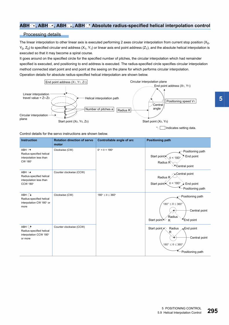
5
ABH , ABH , ABH , ABH Absolute radius-specified helical interpolation control
Processing details
The linear interpolation to other linear axis is executed performing 2 axes circular interpolation from current stop position (X0,
Y0, Z0) to specified circular end address (X1, Y1) or linear axis end point address (Z1), and the absolute helical interpolation is
executed so that it may become a spiral course.
It goes around on the specified circle for the specified number of pitches, the circular interpolation which had remainder
specified is executed, and positioning to end address is executed. The radius-specified circle specifies circular interpolation
method connected start point and end point at the seeing on the plane for which performs circular interpolation.
Operation details for absolute radius-specified helical interpolation are shown below.
Control details for the servo instructions are shown below.
Instruction Rotation direction of servo motor
Controllable angle of arc Positioning path
ABH
Radius-specified helical
interpolation less than
CW 180
Clockwise (CW) 0 < < 180
ABH
Radius-specified helical
interpolation less than
CCW 180
Counter clockwise (CCW)
ABH
Radius-specified helical
interpolation CW 180 or
more
Clockwise (CW) 180 360
ABH
Radius-specified helical
interpolation CCW 180 or more
Counter clockwise (CCW)
Start point (X0, Y0, Z0)
Number of pitches a
Helical interpolation pathLinear interpolation travel value = Z1-Z0
Circular interpolation plane
End point address (X1, Y1, Z1)
Start point (X0, Y0)
Radius R
Positioning speed V1
End point address (X1, Y1)Circular interpolation plane
Central angle
*: Indicates setting data.
Central point
Positioning pathEnd point
Radius R
Start point < 180�
Positioning path
Radius R
< 180�
Central point
End pointStart point
Central point
Positioning path
RadiusR End pointStart point
180��� 360�
End pointStart point
Central point
RadiusR
180� � � 360�
Positioning path
5 POSITIONING CONTROL5.9 Helical Interpolation Control 295
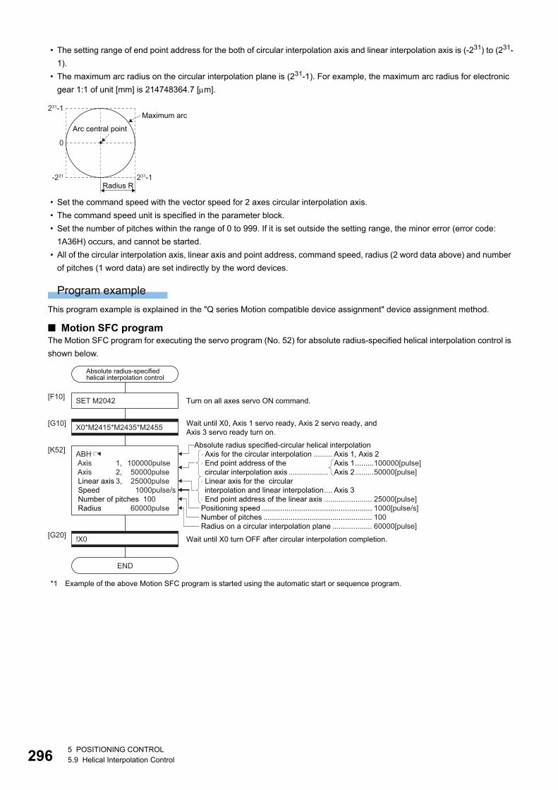
29
• The setting range of end point address for the both of circular interpolation axis and linear interpolation axis is (-231) to (231-
1).
• The maximum arc radius on the circular interpolation plane is (231-1). For example, the maximum arc radius for electronic
gear 1:1 of unit [mm] is 214748364.7 [m].
• Set the command speed with the vector speed for 2 axes circular interpolation axis.
• The command speed unit is specified in the parameter block.
• Set the number of pitches within the range of 0 to 999. If it is set outside the setting range, the minor error (error code:
1A36H) occurs, and cannot be started.
• All of the circular interpolation axis, linear axis and point address, command speed, radius (2 word data above) and number
of pitches (1 word data) are set indirectly by the word devices.
Program example
This program example is explained in the "Q series Motion compatible device assignment" device assignment method.
■ Motion SFC programThe Motion SFC program for executing the servo program (No. 52) for absolute radius-specified helical interpolation control is
shown below.
*1 Example of the above Motion SFC program is started using the automatic start or sequence program.
Maximum arc
Radius R231-1-231
0
231-1
Arc central point
Number of pitches .................................................... 100Radius on a circular interpolation plane ................... 60000[pulse]
Absolute radius-specified helical interpolation control
SET M2042[F10]
X0*M2415*M2435*M2455[G10]
ABH Axis 1, 100000pulse Axis 2, 50000pulse Linear axis 3, 25000pulse Speed 1000pulse/s Number of pitches 100 Radius 60000pulse
[K52]
Wait until X0, Axis 1 servo ready, Axis 2 servo ready, andAxis 3 servo ready turn on.
Turn on all axes servo ON command.
!X0[G20]
END
Wait until X0 turn OFF after circular interpolation completion.
Positioning speed ..................................................... 1000[pulse/s]
� Axis for the circular interpolation ......... Axis 1, Axis 2� End point address of the circular interpolation axis ...................
� Linear axis for the circular interpolation and linear interpolation.... Axis 3
� End point address of the linear axis ....................... 25000[pulse]
Axis 1.........100000[pulse]Axis 2.........50000[pulse]
Absolute radius specified-circular helical interpolation
65 POSITIONING CONTROL5.9 Helical Interpolation Control
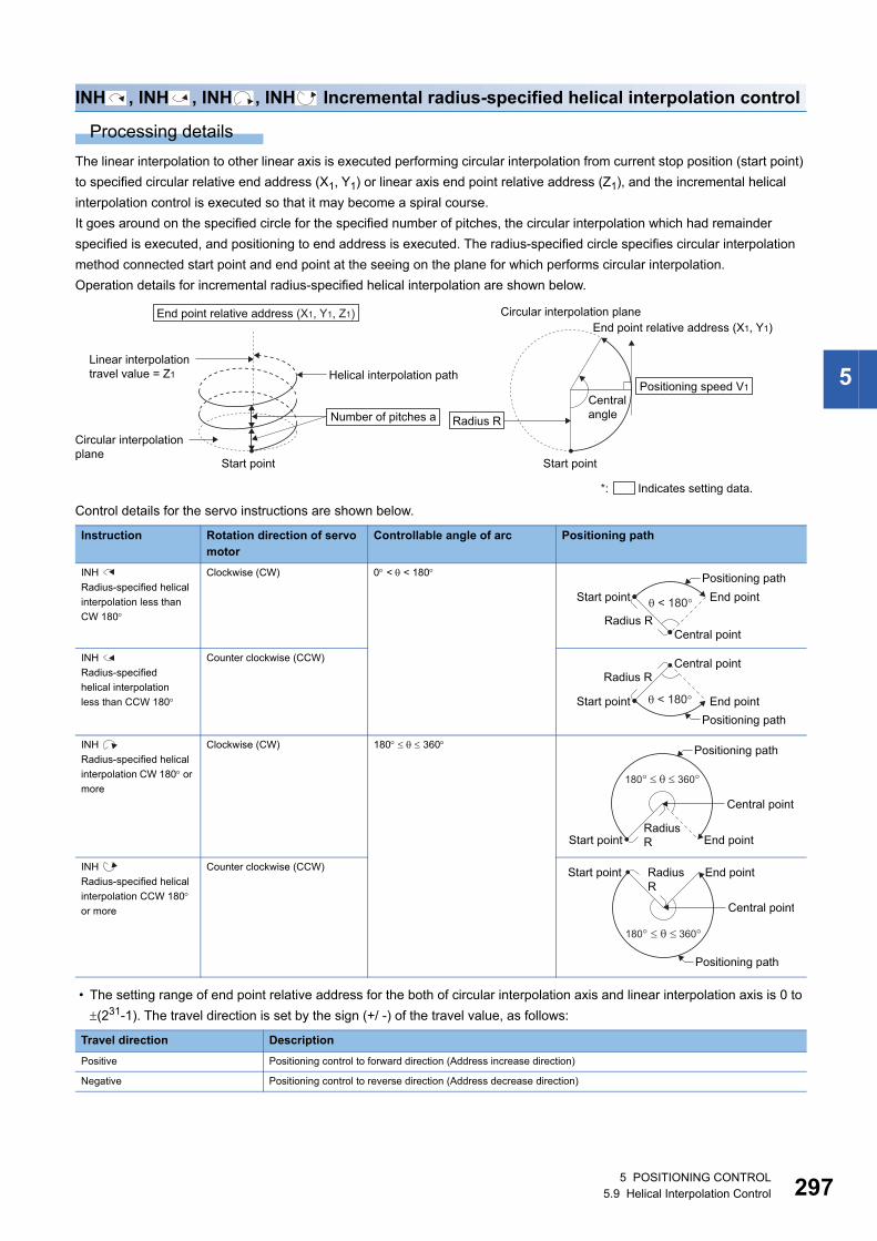
5
INH , INH , INH , INH Incremental radius-specified helical interpolation control
Processing details
The linear interpolation to other linear axis is executed performing circular interpolation from current stop position (start point)
to specified circular relative end address (X1, Y1) or linear axis end point relative address (Z1), and the incremental helical
interpolation control is executed so that it may become a spiral course.
It goes around on the specified circle for the specified number of pitches, the circular interpolation which had remainder
specified is executed, and positioning to end address is executed. The radius-specified circle specifies circular interpolation
method connected start point and end point at the seeing on the plane for which performs circular interpolation.
Operation details for incremental radius-specified helical interpolation are shown below.
Control details for the servo instructions are shown below.
• The setting range of end point relative address for the both of circular interpolation axis and linear interpolation axis is 0 to
(231-1). The travel direction is set by the sign (+/ -) of the travel value, as follows:
Instruction Rotation direction of servo motor
Controllable angle of arc Positioning path
INH
Radius-specified helical
interpolation less than
CW 180
Clockwise (CW) 0 < < 180
INH
Radius-specified
helical interpolation
less than CCW 180
Counter clockwise (CCW)
INH
Radius-specified helical
interpolation CW 180 or
more
Clockwise (CW) 180 360
INH
Radius-specified helical
interpolation CCW 180 or more
Counter clockwise (CCW)
Travel direction Description
Positive Positioning control to forward direction (Address increase direction)
Negative Positioning control to reverse direction (Address decrease direction)
Start point
Helical interpolation pathLinear interpolation travel value = Z1
Circular interpolation plane
Start point
End point relative address (X1, Y1)Circular interpolation plane
Number of pitches a
End point relative address (X1, Y1, Z1)
Radius R
Positioning speed V1Central angle
*: Indicates setting data.
Central point
Positioning pathEnd point
Radius R
Start point < 180�
Positioning path
Radius R
< 180�
Central point
End pointStart point
Central point
Positioning path
RadiusR End pointStart point
180��� 360�
End pointStart point
Central point
RadiusR
180� � � 360�
Positioning path
5 POSITIONING CONTROL5.9 Helical Interpolation Control 297
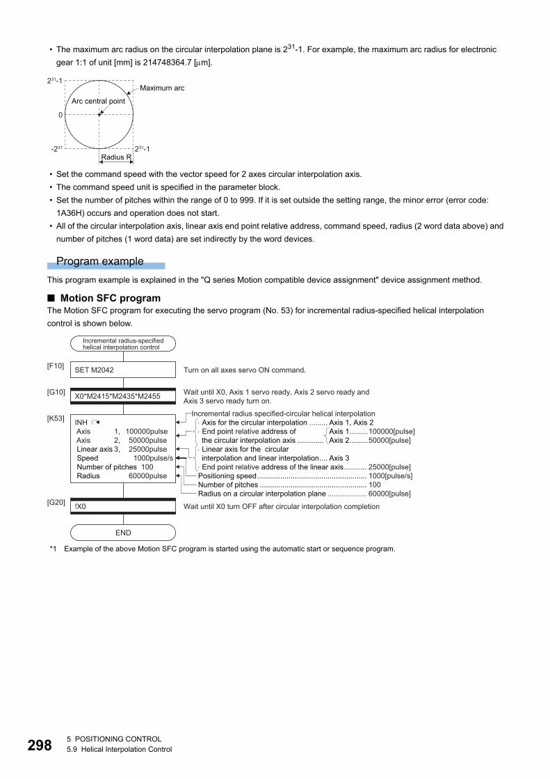
29
• The maximum arc radius on the circular interpolation plane is 231-1. For example, the maximum arc radius for electronic
gear 1:1 of unit [mm] is 214748364.7 [m].
• Set the command speed with the vector speed for 2 axes circular interpolation axis.
• The command speed unit is specified in the parameter block.
• Set the number of pitches within the range of 0 to 999. If it is set outside the setting range, the minor error (error code:
1A36H) occurs and operation does not start.
• All of the circular interpolation axis, linear axis end point relative address, command speed, radius (2 word data above) and
number of pitches (1 word data) are set indirectly by the word devices.
Program example
This program example is explained in the "Q series Motion compatible device assignment" device assignment method.
■ Motion SFC programThe Motion SFC program for executing the servo program (No. 53) for incremental radius-specified helical interpolation
control is shown below.
*1 Example of the above Motion SFC program is started using the automatic start or sequence program.
Maximum arc
Radius R231-1-231
0
231-1
Arc central point
SET M2042[F10]
[G10]
[K53]
Wait until X0, Axis 1 servo ready, Axis 2 servo ready andAxis 3 servo ready turn on.
Turn on all axes servo ON command.
!X0[G20]
END
Wait until X0 turn OFF after circular interpolation completion
Number of pitches .................................................... 100Radius on a circular interpolation plane ................... 60000[pulse]
INH Axis 1, 100000pulse Axis 2, 50000pulse Linear axis 3, 25000pulse Speed 1000pulse/s Number of pitches 100 Radius 60000pulse Positioning speed ..................................................... 1000[pulse/s]
Axis for the circular interpolation ......... Axis 1, Axis 2 End point relative address of the circular interpolation axis ............. Linear axis for the circularinterpolation and linear interpolation.... Axis 3 End point relative address of the linear axis........... 25000[pulse]
Axis 1.........100000[pulse]Axis 2.........50000[pulse]
Incremental radius specified-circular helical interpolation
X0*M2415*M2435*M2455
Incremental radius-specifiedhelical interpolation control
85 POSITIONING CONTROL5.9 Helical Interpolation Control
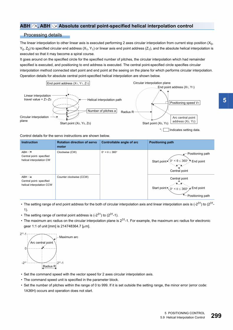
5
ABH , ABH Absolute central point-specified helical interpolation control
Processing details
The linear interpolation to other linear axis is executed performing 2 axes circular interpolation from current stop position (X0,
Y0, Z0) to specified circular end address (X1, Y1) or linear axis end point address (Z1), and the absolute helical interpolation is
executed so that it may become a spiral course.
It goes around on the specified circle for the specified number of pitches, the circular interpolation which had remainder
specified is executed, and positioning to end address is executed. The central point-specified circle specifies circular
interpolation method connected start point and end point at the seeing on the plane for which performs circular interpolation.
Operation details for absolute central point-specified helical interpolation are shown below.
Control details for the servo instructions are shown below.
• The setting range of end point address for the both of circular interpolation axis and linear interpolation axis is (-231) to (231-
1).
• The setting range of central point address is (-231) to (231-1).
• The maximum arc radius on the circular interpolation plane is 231-1. For example, the maximum arc radius for electronic
gear 1:1 of unit [mm] is 214748364.7 [m].
• Set the command speed with the vector speed for 2 axes circular interpolation axis.
• The command speed unit is specified in the parameter block.
• Set the number of pitches within the range of 0 to 999. If it is set outside the setting range, the minor error (error code:
1A36H) occurs and operation does not start.
Instruction Rotation direction of servo motor
Controllable angle of arc Positioning path
ABH
Central point- specified
helical interpolation CW
Clockwise (CW) 0 < 360
ABH
Central point- specified
helical interpolation CCW
Counter clockwise (CCW)
Start point (X0, Y0, Z0)
Helical interpolation pathLinear interpolationtravel value = Z1-Z0
Circular interpolation plane
Number of pitches a
End point address (X1, Y1, Z1)
Start point (X0, Y0)
Radius R
End point address (X1, Y1)Circular interpolation plane
Arc central pointaddress (X2, Y2)
Positioning speed V1
*: Indicates setting data.
Central point
Positioning path
End pointStart point 0 < θ 360
0 < 360
Central point
Positioning path
End pointStart point
Maximum arc
Radius R231-1-231
0
231-1
Arc central point
5 POSITIONING CONTROL5.9 Helical Interpolation Control 299
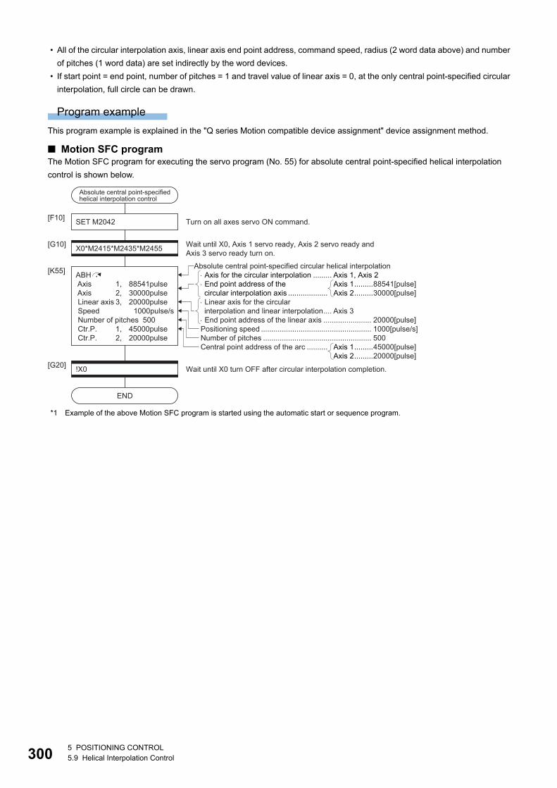
30
• All of the circular interpolation axis, linear axis end point address, command speed, radius (2 word data above) and number
of pitches (1 word data) are set indirectly by the word devices.
• If start point = end point, number of pitches = 1 and travel value of linear axis = 0, at the only central point-specified circular
interpolation, full circle can be drawn.
Program example
This program example is explained in the "Q series Motion compatible device assignment" device assignment method.
■ Motion SFC programThe Motion SFC program for executing the servo program (No. 55) for absolute central point-specified helical interpolation
control is shown below.
*1 Example of the above Motion SFC program is started using the automatic start or sequence program.
Number of pitches .................................................... 500Central point address of the arc ..........
SET M2042[F10]
[G10]X0*M2415*M2435*M2455
ABH Axis 1, 88541pulse Axis 2, 30000pulse Linear axis 3, 20000pulse Speed 1000pulse/s Number of pitches 500 Ctr.P. 1, 45000pulse Ctr.P. 2, 20000pulse
[K55]
Wait until X0, Axis 1 servo ready, Axis 2 servo ready andAxis 3 servo ready turn on.
Turn on all axes servo ON command.
!X0[G20]
END
Wait until X0 turn OFF after circular interpolation completion.
Axis for the circular interpolation ......... Axis 1, Axis 2 End point address of the circular interpolation axis ................... Linear axis for the circular interpolation and linear interpolation.... Axis 3 End point address of the linear axis ....................... 20000[pulse]
Axis 1.........88541[pulse]Axis 2.........30000[pulse]
Axis 1.........45000[pulse]Axis 2.........20000[pulse]
Absolute central point-specified circular helical interpolation
Positioning speed ..................................................... 1000[pulse/s]
Absolute central point-specifiedhelical interpolation control
05 POSITIONING CONTROL5.9 Helical Interpolation Control
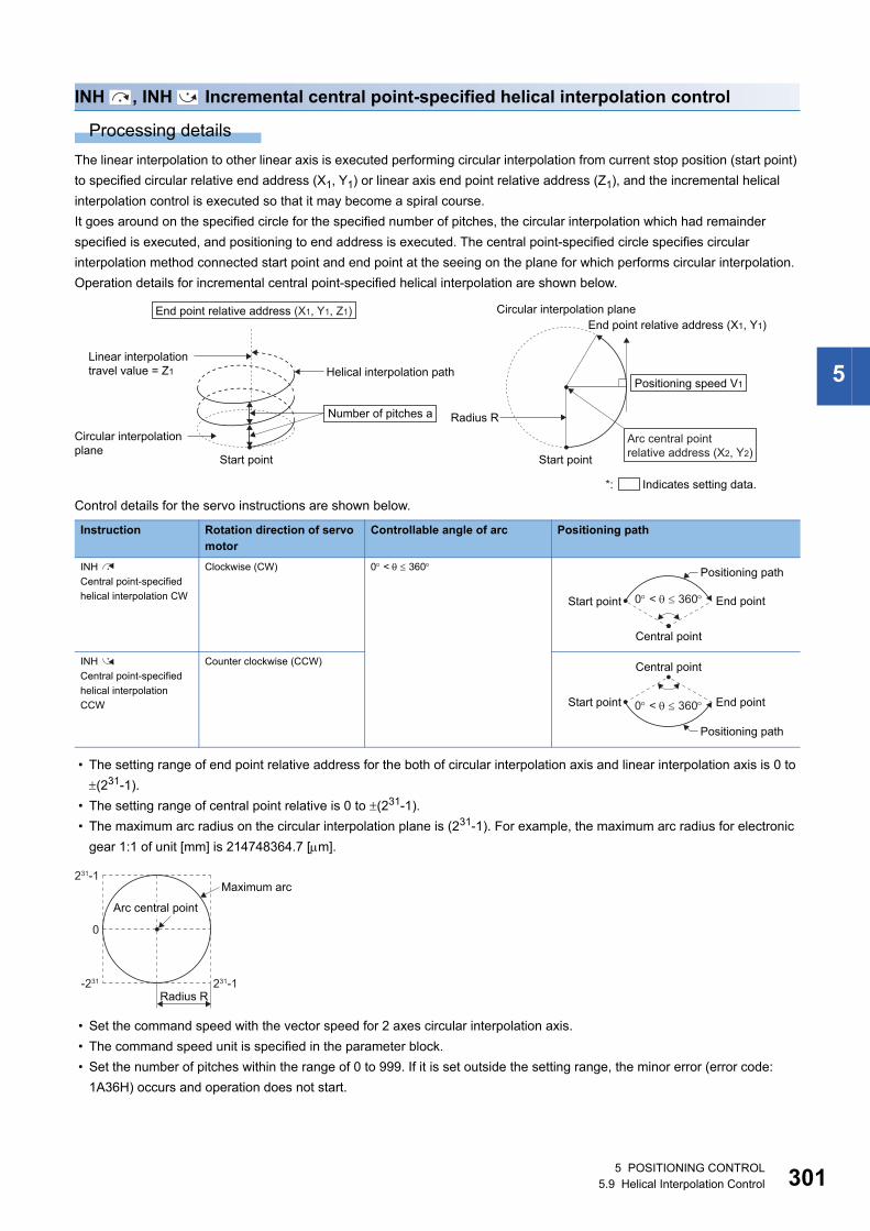
5
INH , INH Incremental central point-specified helical interpolation control
Processing details
The linear interpolation to other linear axis is executed performing circular interpolation from current stop position (start point)
to specified circular relative end address (X1, Y1) or linear axis end point relative address (Z1), and the incremental helical
interpolation control is executed so that it may become a spiral course.
It goes around on the specified circle for the specified number of pitches, the circular interpolation which had remainder
specified is executed, and positioning to end address is executed. The central point-specified circle specifies circular
interpolation method connected start point and end point at the seeing on the plane for which performs circular interpolation.
Operation details for incremental central point-specified helical interpolation are shown below.
Control details for the servo instructions are shown below.
• The setting range of end point relative address for the both of circular interpolation axis and linear interpolation axis is 0 to
(231-1).
• The setting range of central point relative is 0 to (231-1).
• The maximum arc radius on the circular interpolation plane is (231-1). For example, the maximum arc radius for electronic
gear 1:1 of unit [mm] is 214748364.7 [m].
• Set the command speed with the vector speed for 2 axes circular interpolation axis.
• The command speed unit is specified in the parameter block.
• Set the number of pitches within the range of 0 to 999. If it is set outside the setting range, the minor error (error code:
1A36H) occurs and operation does not start.
Instruction Rotation direction of servo motor
Controllable angle of arc Positioning path
INH
Central point-specified
helical interpolation CW
Clockwise (CW) 0 < 360
INH
Central point-specified
helical interpolation
CCW
Counter clockwise (CCW)
Start point
Helical interpolation pathLinear interpolation travel value = Z1
Circular interpolation plane
Start point
Radius R
End point relative address (X1, Y1)Circular interpolation plane
Arc central point relative address (X2, Y2)
Number of pitches a
End point relative address (X1, Y1, Z1)
Positioning speed V1
*: Indicates setting data.
Central point
Positioning path
End pointStart point 0 < 360
0 < 360
Central point
Positioning path
End pointStart point
Maximum arc
Radius R231-1-231
0
231-1
Arc central point
5 POSITIONING CONTROL5.9 Helical Interpolation Control 301

30
• All of the circular interpolation axis, linear axis end relative address, command speed, radius (2 word data above) and
number of pitches (1 word data) are set indirectly by the word devices.
• If start point = end point, number of pitches = 1 and travel value of linear axis = 0, at the only central point-specified circular
interpolation, full circle can be drawn.
Program example
This program example is explained in the "Q series Motion compatible device assignment" device assignment method.
■ Motion SFC programThe Motion SFC program for executing the servo program (No. 56) for incremental central point-specified helical interpolation
control is shown below.
*1 Example of the above Motion SFC program is started using the automatic start or sequence program.
SET M2042[F10]
[G10]X0*M2415*M2435*M2455
[K56]
Wait until X0, Axis 1 servo ready, Axis 2 servo ready and Axis 3 servo ready turn on.
Turn on all axes servo ON command.
!X0[G20]
END
Wait until X0 turn OFF after circular interpolation completion.
Number of pitches .................................................... 500Central point relative addressof the arc .............................................
INH Axis 1, 88541pulse Axis 2, 30000pulse Linear axis 3, 20000pulse Speed 1000pulse/s Number of pitches 500 Ctr.P. 1, 45000pulse Ctr.P. 2, 20000pulse
Axis for the circular interpolation ......... Axis 1, Axis 2 End point relative address of the circular interpolation axis ............. Linear axis for the circular interpolation and linear interpolation.... Axis 3 End point relative address of the linear axis........... 20000[pulse]
Axis 1.........88541[pulse]Axis 2.........30000[pulse]
Axis 1.........45000[pulse]Axis 2.........20000[pulse]
Incremental central point-specified helical interpolation control
Positioning speed ..................................................... 1000[pulse/s]
Incremental central point-specified helical interpolation control
25 POSITIONING CONTROL5.9 Helical Interpolation Control
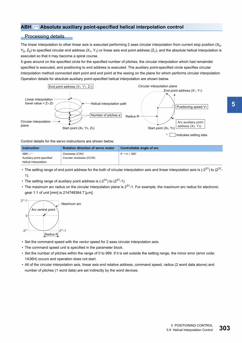
5
ABH Absolute auxiliary point-specified helical interpolation control
Processing details
The linear interpolation to other linear axis is executed performing 2 axes circular interpolation from current stop position (X0,
Y0, Z0) to specified circular end address (X1, Y1) or linear axis end point address (Z1), and the absolute helical interpolation is
executed so that it may become a spiral course.
It goes around on the specified circle for the specified number of pitches, the circular interpolation which had remainder
specified is executed, and positioning to end address is executed. The auxiliary point-specified circle specifies circular
interpolation method connected start point and end point at the seeing on the plane for which performs circular interpolation.
Operation details for absolute auxiliary point-specified helical interpolation are shown below.
Control details for the servo instructions are shown below.
• The setting range of end point address for the both of circular interpolation axis and linear interpolation axis is (-231) to (231-
1).
• The setting range of auxiliary point address is (-231) to (231-1).
• The maximum arc radius on the circular interpolation plane is 231-1. For example, the maximum arc radius for electronic
gear 1:1 of unit [mm] is 214748364.7 [m].
• Set the command speed with the vector speed for 2 axes circular interpolation axis.
• The command speed unit is specified in the parameter block.
• Set the number of pitches within the range of 0 to 999. If it is set outside the setting range, the minor error (error code:
1A36H) occurs and operation does not start.
• All of the circular interpolation axis, linear axis end relative address, command speed, radius (2 word data above) and
number of pitches (1 word data) are set indirectly by the word devices.
Instruction Rotation direction of servo motor Controllable angle of arc
ABH
Auxiliary point-specified
helical interpolation
Clockwise (CW)/
Counter clockwise (CCW)
0 < 360
Start point (X0, Y0, Z0)
Helical interpolation pathLinear interpolationtravel value = Z1-Z0
Circular interpolation plane
Number of pitches a
End point address (X1, Y1, Z1)
Start point (X0, Y0)
Radius R
End point address (X1, Y1)Circular interpolation plane
Positioning speed V1
*: Indicates setting data.
Arc auxiliary pointaddress (X2, Y2)
Maximum arc
Radius R231-1-231
0
231-1
Arc central point
5 POSITIONING CONTROL5.9 Helical Interpolation Control 303
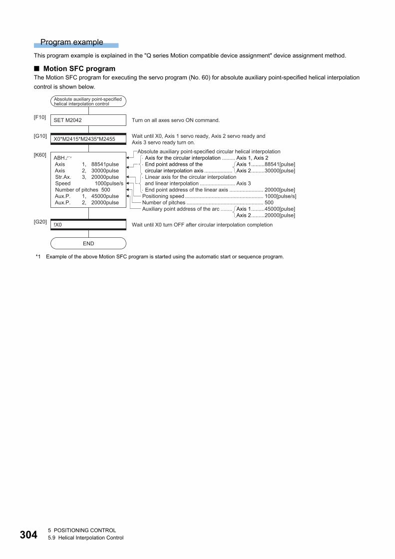
30
Program example
This program example is explained in the "Q series Motion compatible device assignment" device assignment method.
■ Motion SFC programThe Motion SFC program for executing the servo program (No. 60) for absolute auxiliary point-specified helical interpolation
control is shown below.
*1 Example of the above Motion SFC program is started using the automatic start or sequence program.
Number of pitches .................................................... 500Auxiliary point address of the arc ........
ABH Axis 1, 88541pulse Axis 2, 30000pulse Str.Ax. 3, 20000pulse Speed 1000pulse/s Number of pitches 500 Aux.P. 1, 45000pulse Aux.P. 2, 20000pulse
Axis for the circular interpolation ......... Axis 1, Axis 2 End point address of the circular interpolation axis ................... Linear axis for the circular interpolationand linear interpolation ........................ Axis 3 End point address of the linear axis ....................... 20000[pulse]
Axis 1.........88541[pulse]Axis 2.........30000[pulse]
Axis 1.........45000[pulse]Axis 2.........20000[pulse]
Absolute auxiliary point-specified circular helical interpolation
Positioning speed ..................................................... 1000[pulse/s]
SET M2042[F10]
[G10]X0*M2415*M2435*M2455
[K60]
Wait until X0, Axis 1 servo ready, Axis 2 servo ready andAxis 3 servo ready turn on.
Turn on all axes servo ON command.
!X0[G20]
END
Wait until X0 turn OFF after circular interpolation completion
Absolute auxiliary point-specified helical interpolation control
45 POSITIONING CONTROL5.9 Helical Interpolation Control
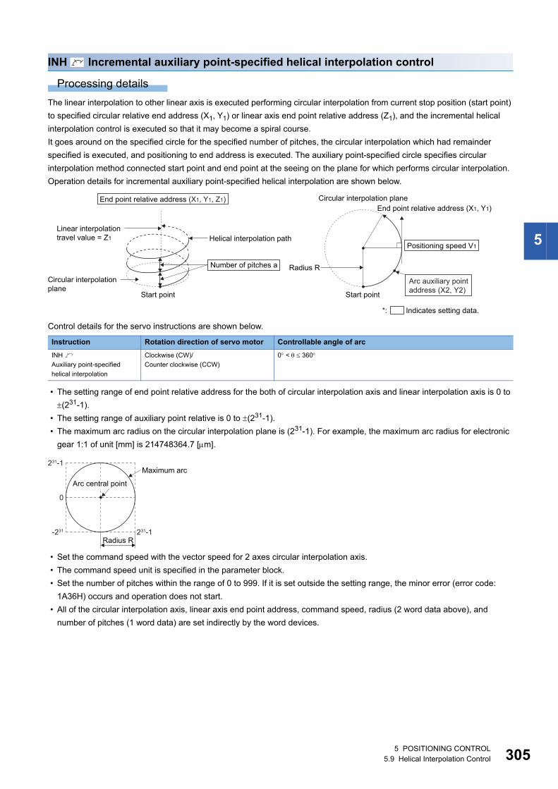
5
INH Incremental auxiliary point-specified helical interpolation control
Processing details
The linear interpolation to other linear axis is executed performing circular interpolation from current stop position (start point)
to specified circular relative end address (X1, Y1) or linear axis end point relative address (Z1), and the incremental helical
interpolation control is executed so that it may become a spiral course.
It goes around on the specified circle for the specified number of pitches, the circular interpolation which had remainder
specified is executed, and positioning to end address is executed. The auxiliary point-specified circle specifies circular
interpolation method connected start point and end point at the seeing on the plane for which performs circular interpolation.
Operation details for incremental auxiliary point-specified helical interpolation are shown below.
Control details for the servo instructions are shown below.
• The setting range of end point relative address for the both of circular interpolation axis and linear interpolation axis is 0 to
(231-1).
• The setting range of auxiliary point relative is 0 to (231-1).
• The maximum arc radius on the circular interpolation plane is (231-1). For example, the maximum arc radius for electronic
gear 1:1 of unit [mm] is 214748364.7 [m].
• Set the command speed with the vector speed for 2 axes circular interpolation axis.
• The command speed unit is specified in the parameter block.
• Set the number of pitches within the range of 0 to 999. If it is set outside the setting range, the minor error (error code:
1A36H) occurs and operation does not start.
• All of the circular interpolation axis, linear axis end point address, command speed, radius (2 word data above), and
number of pitches (1 word data) are set indirectly by the word devices.
Instruction Rotation direction of servo motor Controllable angle of arc
INH
Auxiliary point-specified
helical interpolation
Clockwise (CW)/
Counter clockwise (CCW)
0 < 360
Start point
Helical interpolation pathLinear interpolation travel value = Z1
Circular interpolation plane
Start point
Radius R
End point relative address (X1, Y1)Circular interpolation plane
Number of pitches a
End point relative address (X1, Y1, Z1)
Positioning speed V1
*: Indicates setting data.
Arc auxiliary pointaddress (X2, Y2)
Maximum arc
Radius R231-1-231
0
231-1
Arc central point
5 POSITIONING CONTROL5.9 Helical Interpolation Control 305
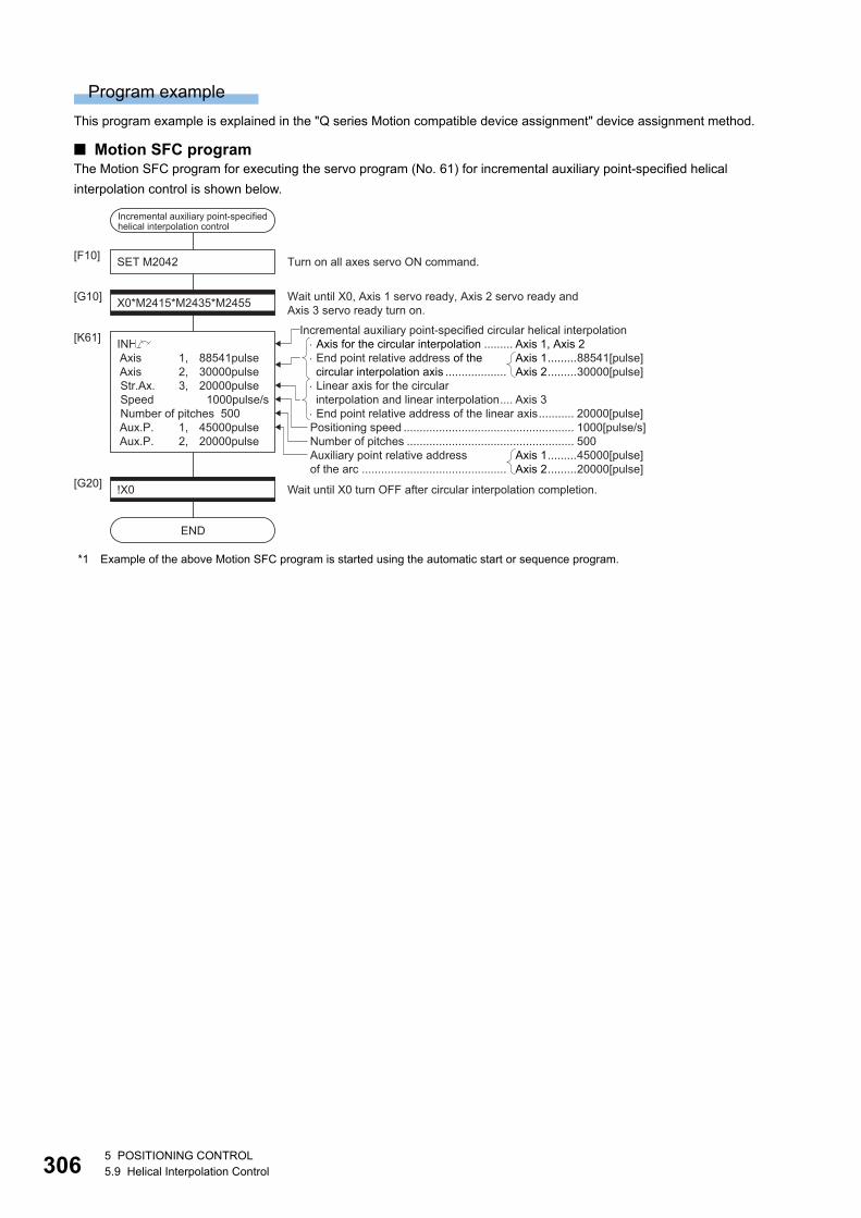
30
Program example
This program example is explained in the "Q series Motion compatible device assignment" device assignment method.
■ Motion SFC programThe Motion SFC program for executing the servo program (No. 61) for incremental auxiliary point-specified helical
interpolation control is shown below.
*1 Example of the above Motion SFC program is started using the automatic start or sequence program.
Number of pitches .................................................... 500Auxiliary point relative addressof the arc .............................................
INH Axis 1, 88541pulse Axis 2, 30000pulse Str.Ax. 3, 20000pulse Speed 1000pulse/s Number of pitches 500 Aux.P. 1, 45000pulse Aux.P. 2, 20000pulse
Axis for the circular interpolation ......... Axis 1, Axis 2 End point relative address of the circular interpolation axis ................... Linear axis for the circular interpolation and linear interpolation.... Axis 3 End point relative address of the linear axis........... 20000[pulse]
Axis 1.........88541[pulse]Axis 2.........30000[pulse]
Axis 1.........45000[pulse]Axis 2.........20000[pulse]
Incremental auxiliary point-specified circular helical interpolation
Positioning speed ..................................................... 1000[pulse/s]
SET M2042[F10]
[G10]X0*M2415*M2435*M2455
[K61]
Wait until X0, Axis 1 servo ready, Axis 2 servo ready and Axis 3 servo ready turn on.
Turn on all axes servo ON command.
!X0[G20]
END
Wait until X0 turn OFF after circular interpolation completion.
Incremental auxiliary point-specifiedhelical interpolation control
65 POSITIONING CONTROL5.9 Helical Interpolation Control
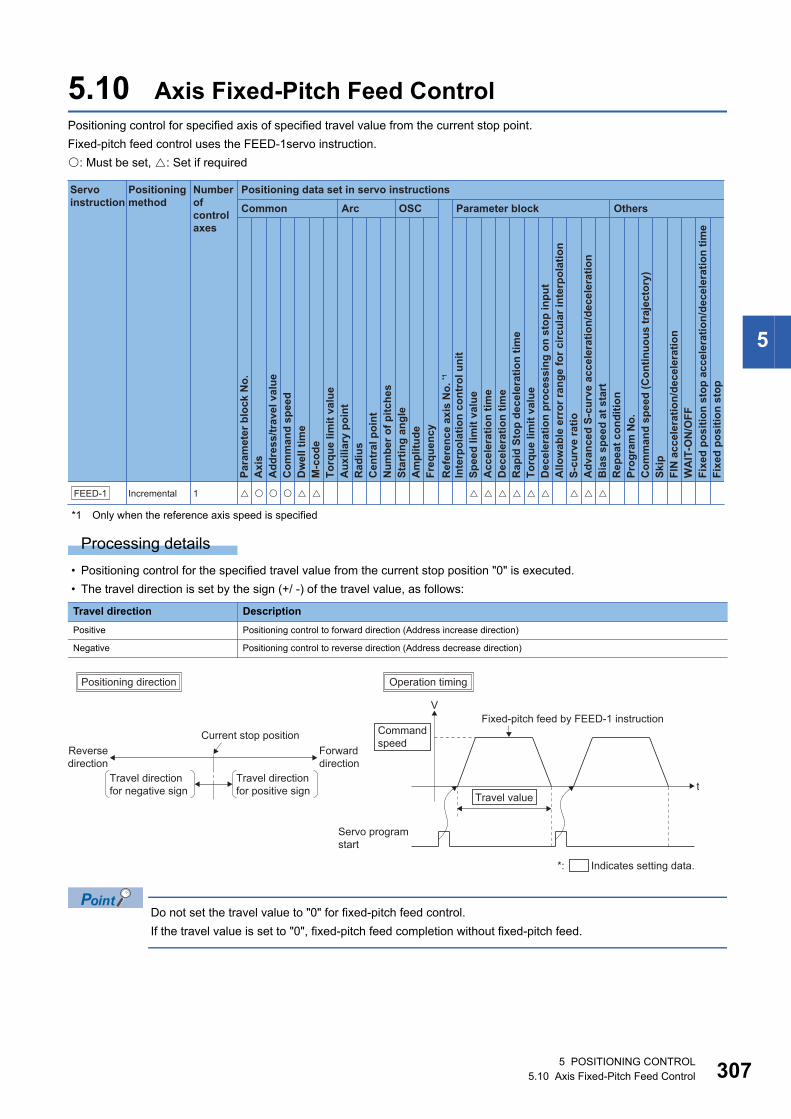
5
5.10 Axis Fixed-Pitch Feed ControlPositioning control for specified axis of specified travel value from the current stop point.
Fixed-pitch feed control uses the FEED-1servo instruction.
: Must be set, : Set if required
*1 Only when the reference axis speed is specified
Processing details
• Positioning control for the specified travel value from the current stop position "0" is executed.
• The travel direction is set by the sign (+/ -) of the travel value, as follows:
Do not set the travel value to "0" for fixed-pitch feed control.
If the travel value is set to "0", fixed-pitch feed completion without fixed-pitch feed.
Travel direction Description
Positive Positioning control to forward direction (Address increase direction)
Negative Positioning control to reverse direction (Address decrease direction)
Positioning data set in servo instructions
Common
Servo instruction
Positioning method
Number ofcontrol axes
Arc OSC Parameter block Others
Para
met
er b
lock
No.
Acc
eler
atio
n tim
eD
ecel
erat
ion
time
Rap
id S
top
dece
lera
tion
time
Torq
ue li
mit
valu
eD
ecel
erat
ion
proc
essi
ng o
n st
op in
put
Allo
wab
le e
rror
rang
e fo
r circ
ular
inte
rpol
atio
nS-
curv
e ra
tioA
dvan
ced
S-cu
rve
acce
lera
tion/
dece
lera
tion
Bia
s sp
eed
at s
tart
Rep
eat c
ondi
tion
Prog
ram
No.
Com
man
d sp
eed
(Con
tinuo
us tr
ajec
tory
)Sk
ipFI
N a
ccel
erat
ion/
dece
lera
tion
WA
IT-O
N/O
FF
Fixe
d po
sitio
n st
op
Axi
sA
ddre
ss/tr
avel
val
ueC
omm
and
spee
dD
wel
l tim
eM
-cod
eTo
rque
lim
it va
lue
Aux
iliar
y po
int
Rad
ius
Cen
tral
poi
ntN
umbe
r of p
itche
sSt
artin
g an
gle
Am
plitu
deFr
eque
ncy
Inte
rpol
atio
n co
ntro
l uni
tSp
eed
limit
valu
e
Ref
eren
ce a
xis
No.
*1
Fixe
d po
sitio
n st
op a
ccel
erat
ion/
dece
lera
tion
time
FEED-1 Incremental 1
t
VFixed-pitch feed by FEED-1 instruction
Reversedirection
Forwarddirection
Current stop position
Travel direction for positive sign
Travel direction for negative sign
Commandspeed
Operation timingPositioning direction
Travel value
Servo programstart
*: Indicates setting data.
5 POSITIONING CONTROL5.10 Axis Fixed-Pitch Feed Control 307
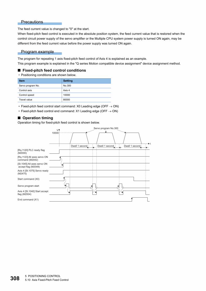
30
Precautions
The feed current value is changed to "0" at the start.
When fixed-pitch feed control is executed in the absolute position system, the feed current value that is restored when the
control circuit power supply of the servo amplifier or the Multiple CPU system power supply is turned ON again, may be
different from the feed current value before the power supply was turned ON again.
Program example
The program for repeating 1 axis fixed-pitch feed control of Axis 4 is explained as an example.
This program example is explained in the "Q series Motion compatible device assignment" device assignment method.
■ Fixed-pitch feed control conditions • Positioning conditions are shown below.
• Fixed-pitch feed control start command: X0 Leading edge (OFF ON)
• Fixed-pitch feed control end command: X1 Leading edge (OFF ON)
■ Operation timingOperation timing for fixed-pitch feed control is shown below.
Item Setting
Servo program No. No.300
Control axis Axis 4
Control speed 10000
Travel value 80000
Axis 4 [St.1075] Servo ready(M2475)
Servo program start
t
V10000
Dwell 1 second
[Rq.1120] PLC ready flag(M2000)
[Rq.1123] All axes servo ONcommand (M2042)
[St.1045] All axes servo ONaccept flag (M2049)
Start command (X0)
Axis 4 [St.1040] Start acceptflag (M2004)
End command (X1)
Servo program No.300
Dwell 1 second Dwell 1 second
85 POSITIONING CONTROL5.10 Axis Fixed-Pitch Feed Control
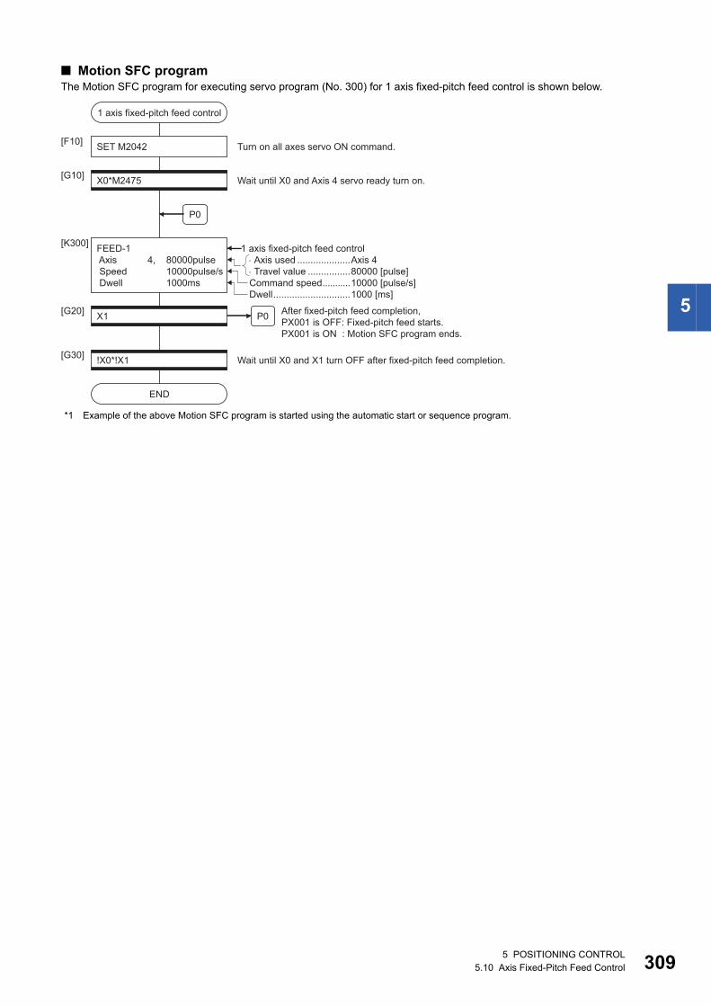
5
■ Motion SFC programThe Motion SFC program for executing servo program (No. 300) for 1 axis fixed-pitch feed control is shown below.
*1 Example of the above Motion SFC program is started using the automatic start or sequence program.
Axis used ....................Axis 4Travel value ................80000 [pulse]
1 axis fixed-pitch feed control
SET M2042
P0
[F10]
X0*M2475[G10]
FEED-1 Axis 4, 80000pulse Speed 10000pulse/s Dwell 1000ms
[K300]
Wait until X0 and Axis 4 servo ready turn on.
Turn on all axes servo ON command.
!X0*!X1[G30]
END
Wait until X0 and X1 turn OFF after fixed-pitch feed completion.
X1[G20] After fixed-pitch feed completion,
PX001 is OFF: Fixed-pitch feed starts.PX001 is ON : Motion SFC program ends.
1 axis fixed-pitch feed control
Dwell.............................1000 [ms]
P0
Command speed...........10000 [pulse/s]
5 POSITIONING CONTROL5.10 Axis Fixed-Pitch Feed Control 309
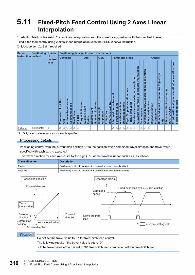
31
5.11 Fixed-Pitch Feed Control Using 2 Axes Linear Interpolation
Fixed-pitch feed control using 2 axes linear interpolation from the current stop position with the specified 2 axes.
Fixed-pitch feed control using 2 axes linear interpolation uses the FEED-2 servo instruction.
: Must be set, : Set if required
*1 Only when the reference axis speed is specified
Processing details
• Positioning control from the current stop position "0" to the position which combined travel direction and travel value
specified with each axis is executed.
• The travel direction for each axis is set by the sign (+/ -) of the travel value for each axis, as follows:
Do not set the travel value to "0" for fixed-pitch feed control.
The following results if the travel value is set to "0":
• If the travel value of both is set to "0", fixed-pitch feed completion without fixed-pitch feed.
Travel direction Description
Positive Positioning control to forward direction (Address increase direction)
Negative Positioning control to reverse direction (Address decrease direction)
Positioning data set in servo instructions
Common
Servo instruction
Positioning method
Number ofcontrol axes
Arc OSC Parameter block OthersPa
ram
eter
blo
ck N
o.
Acc
eler
atio
n tim
eD
ecel
erat
ion
time
Rap
id S
top
dece
lera
tion
time
Torq
ue li
mit
valu
eD
ecel
erat
ion
proc
essi
ng o
n st
op in
put
Allo
wab
le e
rror
rang
e fo
r circ
ular
inte
rpol
atio
nS-
curv
e ra
tioA
dvan
ced
S-cu
rve
acce
lera
tion/
dece
lera
tion
Bia
s sp
eed
at s
tart
Rep
eat c
ondi
tion
Prog
ram
No.
Com
man
d sp
eed
(Con
tinuo
us tr
ajec
tory
)Sk
ipFI
N a
ccel
erat
ion/
dece
lera
tion
WA
IT-O
N/O
FF
Fixe
d po
sitio
n st
op
Axi
sA
ddre
ss/tr
avel
val
ueC
omm
and
spee
dD
wel
l tim
eM
-cod
eTo
rque
lim
it va
lue
Aux
iliar
y po
int
Rad
ius
Cen
tral
poi
ntN
umbe
r of p
itche
sSt
artin
g an
gle
Am
plitu
deFr
eque
ncy
Inte
rpol
atio
n co
ntro
l uni
tSp
eed
limit
valu
e
Ref
eren
ce a
xis
No.
*1
Fixe
d po
sitio
n st
op a
ccel
erat
ion/
dece
lera
tion
time
FEED-2 Incremental 2
t
VFixed-pitch feed by FEED-2 instruction
Forward direction
Reverse direction
Current stopposition
Reverse direction
Forwarddirection
X-axis travel value
Y-axistravel value
Operation timingPositioning direction
*: Indicates setting data.
Commandspeed
Servo programstart
05 POSITIONING CONTROL5.11 Fixed-Pitch Feed Control Using 2 Axes Linear Interpolation
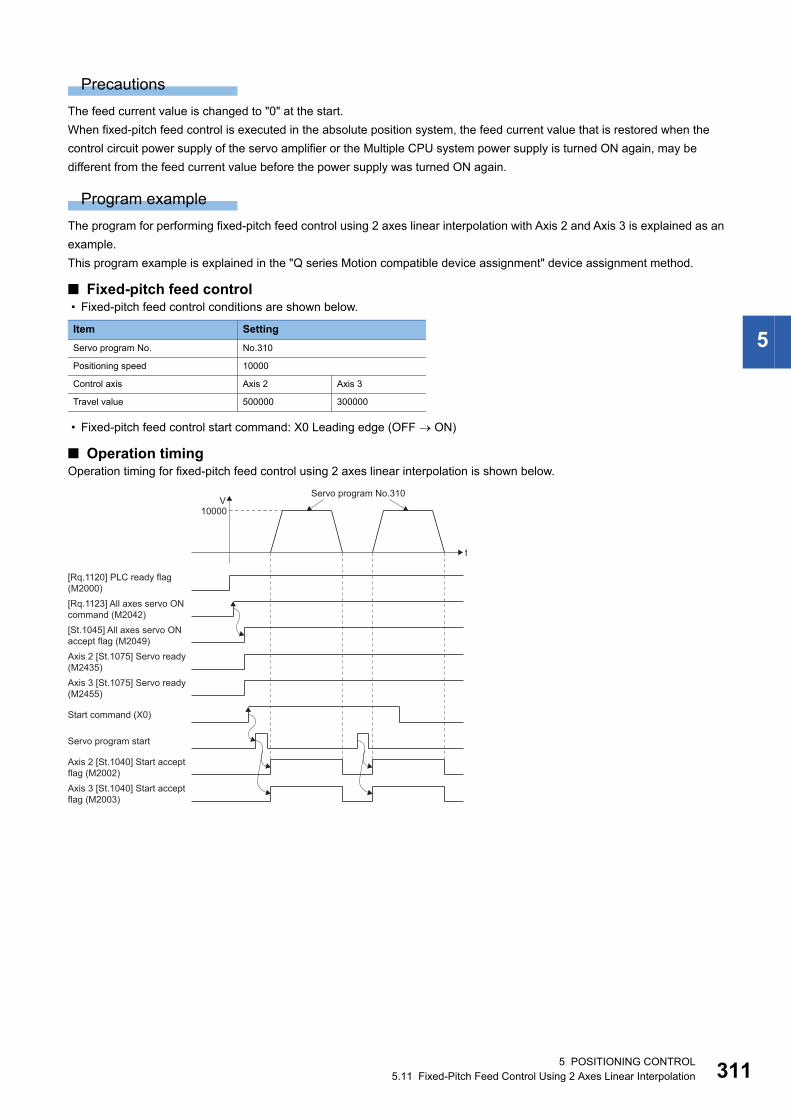
5
Precautions
The feed current value is changed to "0" at the start.
When fixed-pitch feed control is executed in the absolute position system, the feed current value that is restored when the
control circuit power supply of the servo amplifier or the Multiple CPU system power supply is turned ON again, may be
different from the feed current value before the power supply was turned ON again.
Program example
The program for performing fixed-pitch feed control using 2 axes linear interpolation with Axis 2 and Axis 3 is explained as an
example.
This program example is explained in the "Q series Motion compatible device assignment" device assignment method.
■ Fixed-pitch feed control • Fixed-pitch feed control conditions are shown below.
• Fixed-pitch feed control start command: X0 Leading edge (OFF ON)
■ Operation timingOperation timing for fixed-pitch feed control using 2 axes linear interpolation is shown below.
Item Setting
Servo program No. No.310
Positioning speed 10000
Control axis Axis 2 Axis 3
Travel value 500000 300000
Axis 2 [St.1075] Servo ready(M2435)
Servo program start
t
V10000
[Rq.1120] PLC ready flag (M2000)
[Rq.1123] All axes servo ON command (M2042)
[St.1045] All axes servo ON accept flag (M2049)
Axis 3 [St.1075] Servo ready(M2455)
Start command (X0)
Axis 2 [St.1040] Start accept flag (M2002)
Axis 3 [St.1040] Start accept flag (M2003)
Servo program No.310
5 POSITIONING CONTROL5.11 Fixed-Pitch Feed Control Using 2 Axes Linear Interpolation 311
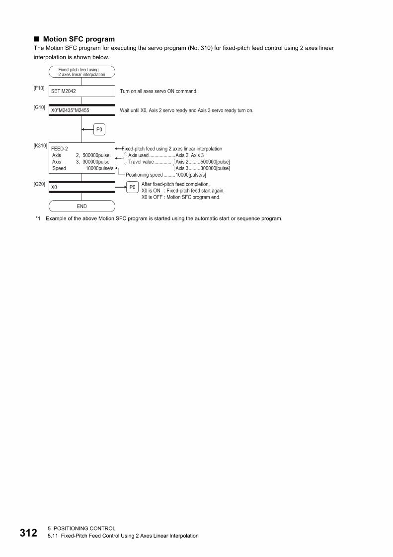
31
■ Motion SFC programThe Motion SFC program for executing the servo program (No. 310) for fixed-pitch feed control using 2 axes linear
interpolation is shown below.
*1 Example of the above Motion SFC program is started using the automatic start or sequence program.
SET M2042
P0
[F10]
X0*M2435*M2455[G10]
FEED-2 Axis 2, 500000pulse Axis 3, 300000pulse Speed 10000pulse/s
[K310]
Wait until X0, Axis 2 servo ready and Axis 3 servo ready turn on.
Turn on all axes servo ON command.
END
X0[G20] After fixed-pitch feed completion,
X0 is ON : Fixed-pitch feed start again.X0 is OFF : Motion SFC program end.
Fixed-pitch feed using 2 axes linear interpolation
Positioning speed .........10000[pulse/s]
P0
Axis used ....................Axis 2, Axis 3 Travel value ............. Axis 2.........500000[pulse]
Axis 3.........300000[pulse]
Fixed-pitch feed using2 axes linear interpolation
25 POSITIONING CONTROL5.11 Fixed-Pitch Feed Control Using 2 Axes Linear Interpolation
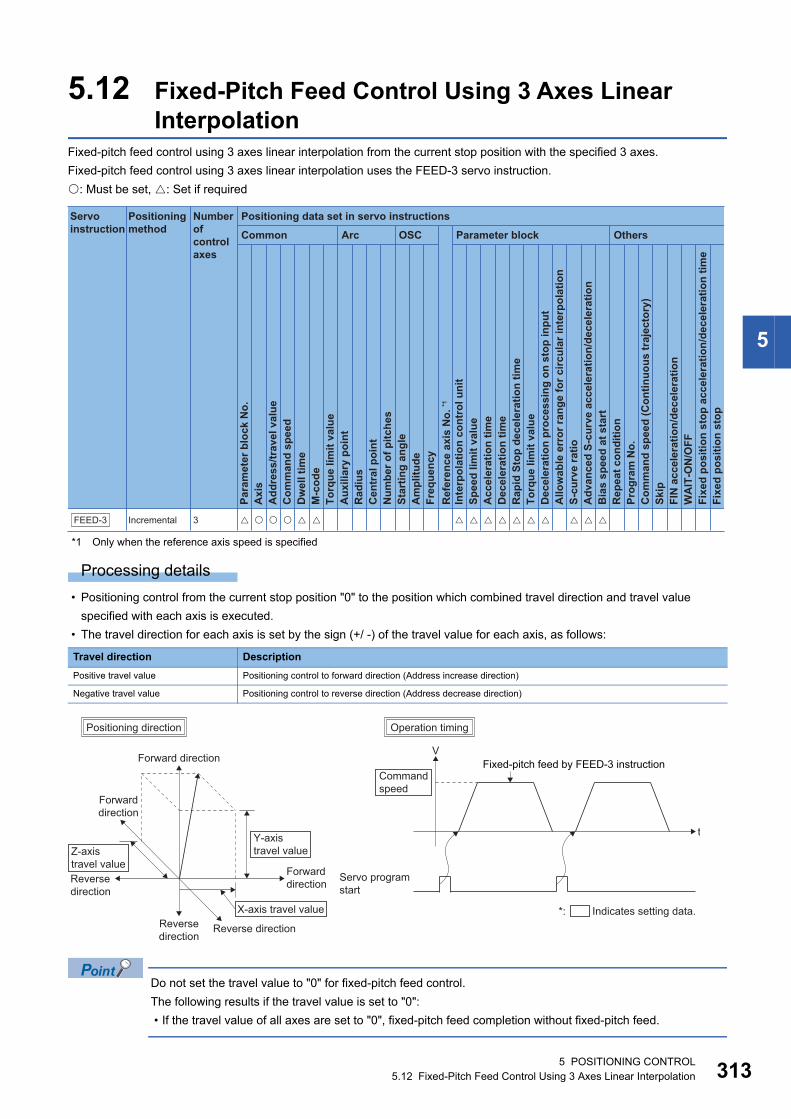
5
5.12 Fixed-Pitch Feed Control Using 3 Axes Linear Interpolation
Fixed-pitch feed control using 3 axes linear interpolation from the current stop position with the specified 3 axes.
Fixed-pitch feed control using 3 axes linear interpolation uses the FEED-3 servo instruction.
: Must be set, : Set if required
*1 Only when the reference axis speed is specified
Processing details
• Positioning control from the current stop position "0" to the position which combined travel direction and travel value
specified with each axis is executed.
• The travel direction for each axis is set by the sign (+/ -) of the travel value for each axis, as follows:
Do not set the travel value to "0" for fixed-pitch feed control.
The following results if the travel value is set to "0":
• If the travel value of all axes are set to "0", fixed-pitch feed completion without fixed-pitch feed.
Travel direction Description
Positive travel value Positioning control to forward direction (Address increase direction)
Negative travel value Positioning control to reverse direction (Address decrease direction)
Positioning data set in servo instructions
Common
Servo instruction
Positioning method
Number ofcontrol axes
Arc OSC Parameter block OthersPa
ram
eter
blo
ck N
o.
Acc
eler
atio
n tim
eD
ecel
erat
ion
time
Rap
id S
top
dece
lera
tion
time
Torq
ue li
mit
valu
eD
ecel
erat
ion
proc
essi
ng o
n st
op in
put
Allo
wab
le e
rror
rang
e fo
r circ
ular
inte
rpol
atio
nS-
curv
e ra
tioA
dvan
ced
S-cu
rve
acce
lera
tion/
dece
lera
tion
Bia
s sp
eed
at s
tart
Rep
eat c
ondi
tion
Prog
ram
No.
Com
man
d sp
eed
(Con
tinuo
us tr
ajec
tory
)Sk
ipFI
N a
ccel
erat
ion/
dece
lera
tion
WA
IT-O
N/O
FF
Fixe
d po
sitio
n st
op
Axi
sA
ddre
ss/tr
avel
val
ueC
omm
and
spee
dD
wel
l tim
eM
-cod
eTo
rque
lim
it va
lue
Aux
iliar
y po
int
Rad
ius
Cen
tral
poi
ntN
umbe
r of p
itche
sSt
artin
g an
gle
Am
plitu
deFr
eque
ncy
Inte
rpol
atio
n co
ntro
l uni
tSp
eed
limit
valu
e
Ref
eren
ce a
xis
No.
*1
Fixe
d po
sitio
n st
op a
ccel
erat
ion/
dece
lera
tion
time
FEED-3 Incremental 3 � �� � � � � � � � �� � � � �
t
VFixed-pitch feed by FEED-3 instructionForward direction
Reversedirection
Forwarddirection
Reverse direction
Reverse direction
Forwarddirection
X-axis travel value
Y-axistravel valueZ-axis
travel value
Operation timingPositioning direction
*: Indicates setting data.
Commandspeed
Servo programstart
5 POSITIONING CONTROL5.12 Fixed-Pitch Feed Control Using 3 Axes Linear Interpolation 313
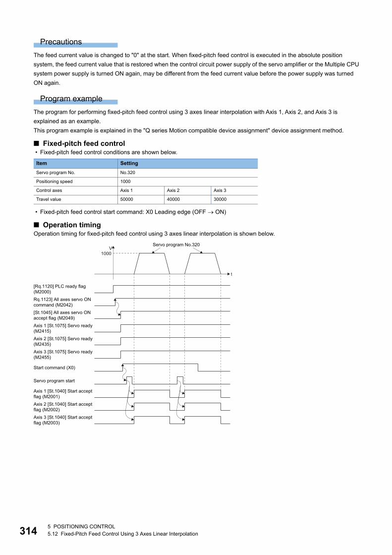
31
Precautions
The feed current value is changed to "0" at the start. When fixed-pitch feed control is executed in the absolute position
system, the feed current value that is restored when the control circuit power supply of the servo amplifier or the Multiple CPU
system power supply is turned ON again, may be different from the feed current value before the power supply was turned
ON again.
Program example
The program for performing fixed-pitch feed control using 3 axes linear interpolation with Axis 1, Axis 2, and Axis 3 is
explained as an example.
This program example is explained in the "Q series Motion compatible device assignment" device assignment method.
■ Fixed-pitch feed control • Fixed-pitch feed control conditions are shown below.
• Fixed-pitch feed control start command: X0 Leading edge (OFF ON)
■ Operation timingOperation timing for fixed-pitch feed control using 3 axes linear interpolation is shown below.
Item Setting
Servo program No. No.320
Positioning speed 1000
Control axes Axis 1 Axis 2 Axis 3
Travel value 50000 40000 30000
Axis 2 [St.1075] Servo ready(M2435)
Servo program start
t
V1000
[Rq.1120] PLC ready flag(M2000)Rq.1123] All axes servo ONcommand (M2042)[St.1045] All axes servo ONaccept flag (M2049)Axis 1 [St.1075] Servo ready(M2415)
Axis 3 [St.1075] Servo ready(M2455)
Start command (X0)
Axis 2 [St.1040] Start acceptflag (M2002)
Axis 1 [St.1040] Start acceptflag (M2001)
Axis 3 [St.1040] Start acceptflag (M2003)
Servo program No.320
45 POSITIONING CONTROL5.12 Fixed-Pitch Feed Control Using 3 Axes Linear Interpolation
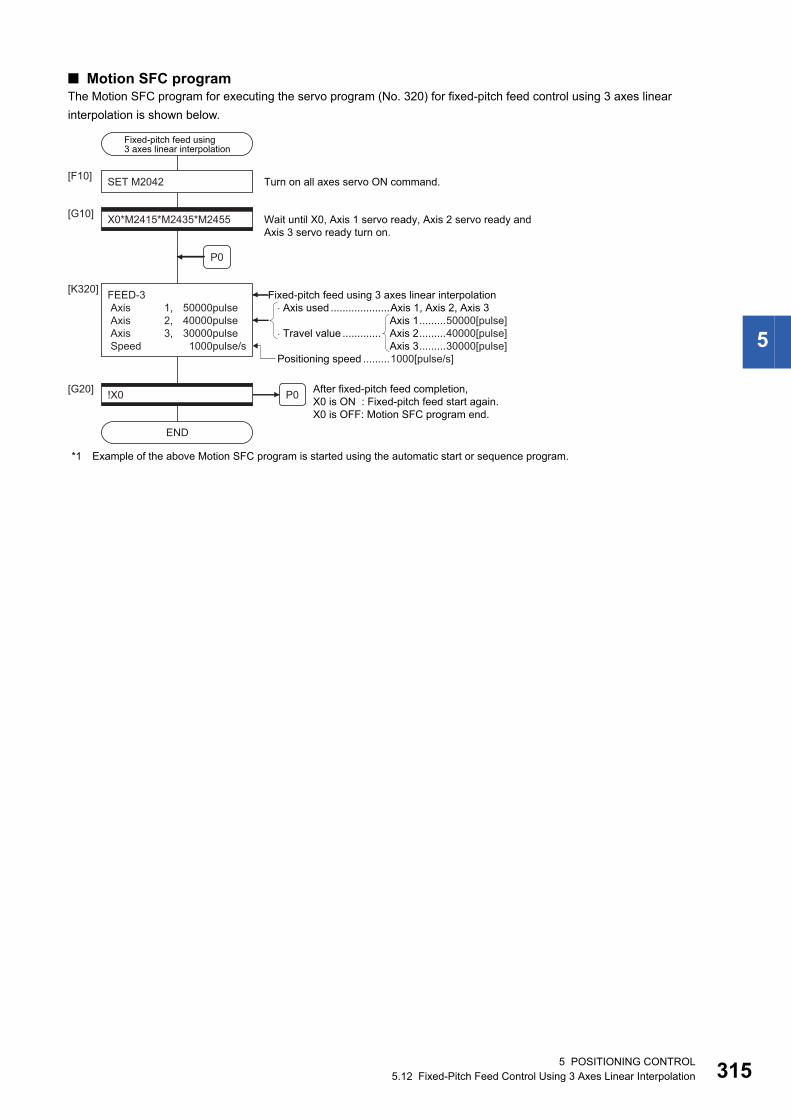
5
■ Motion SFC programThe Motion SFC program for executing the servo program (No. 320) for fixed-pitch feed control using 3 axes linear
interpolation is shown below.
*1 Example of the above Motion SFC program is started using the automatic start or sequence program.
Fixed-pitch feed using3 axes linear interpolation
SET M2042
P0
[F10]
X0*M2415*M2435*M2455[G10]
FEED-3 Axis 1, 50000pulse Axis 2, 40000pulse Axis 3, 30000pulse Speed 1000pulse/s
[K320]
Wait until X0, Axis 1 servo ready, Axis 2 servo ready andAxis 3 servo ready turn on.
Turn on all axes servo ON command.
END
!X0[G20] After fixed-pitch feed completion,X0 is ON : Fixed-pitch feed start again.X0 is OFF: Motion SFC program end.
Fixed-pitch feed using 3 axes linear interpolation
P0
Positioning speed .........1000[pulse/s]
� Axis used ....................Axis 1, Axis 2, Axis 3
� Travel value .............Axis 1.........50000[pulse]Axis 2.........40000[pulse]Axis 3.........30000[pulse]
5 POSITIONING CONTROL5.12 Fixed-Pitch Feed Control Using 3 Axes Linear Interpolation 315
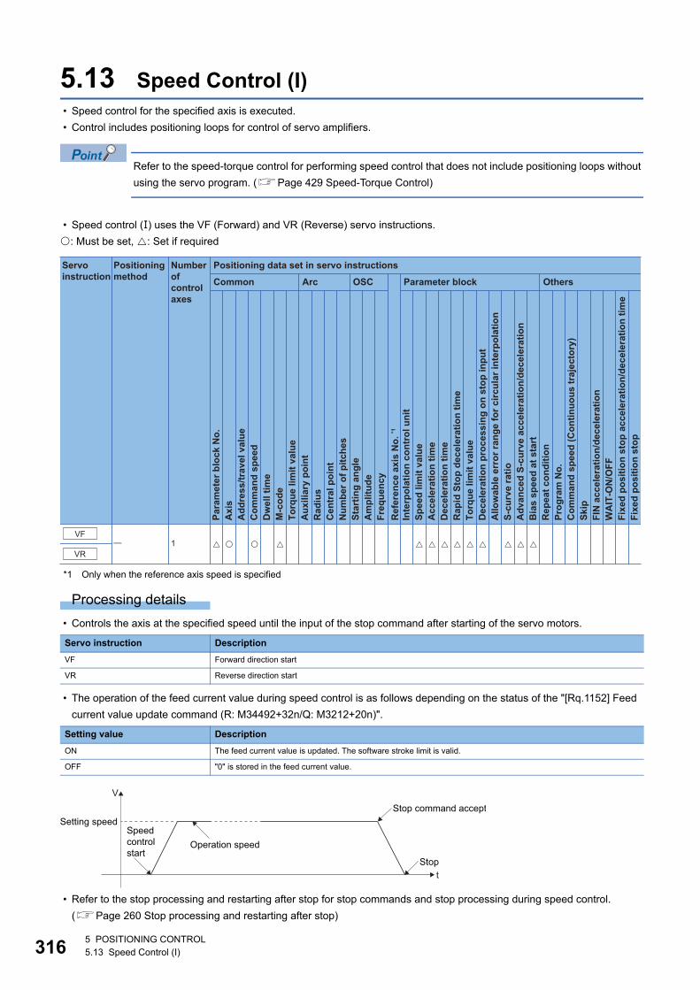
31
5.13 Speed Control (I) • Speed control for the specified axis is executed.
• Control includes positioning loops for control of servo amplifiers.
Refer to the speed-torque control for performing speed control that does not include positioning loops without
using the servo program. (Page 429 Speed-Torque Control)
• Speed control () uses the VF (Forward) and VR (Reverse) servo instructions.
: Must be set, : Set if required
*1 Only when the reference axis speed is specified
Processing details
• Controls the axis at the specified speed until the input of the stop command after starting of the servo motors.
• The operation of the feed current value during speed control is as follows depending on the status of the "[Rq.1152] Feed
current value update command (R: M34492+32n/Q: M3212+20n)".
• Refer to the stop processing and restarting after stop for stop commands and stop processing during speed control.
(Page 260 Stop processing and restarting after stop)
Servo instruction Description
VF Forward direction start
VR Reverse direction start
Setting value Description
ON The feed current value is updated. The software stroke limit is valid.
OFF "0" is stored in the feed current value.
Positioning data set in servo instructions
Common
Servo instruction
Positioning method
Number ofcontrol axes
Arc OSC Parameter block Others
Para
met
er b
lock
No.
Acc
eler
atio
n tim
eD
ecel
erat
ion
time
Rap
id S
top
dece
lera
tion
time
Torq
ue li
mit
valu
eD
ecel
erat
ion
proc
essi
ng o
n st
op in
put
Allo
wab
le e
rror
rang
e fo
r circ
ular
inte
rpol
atio
nS-
curv
e ra
tioA
dvan
ced
S-cu
rve
acce
lera
tion/
dece
lera
tion
Bia
s sp
eed
at s
tart
Rep
eat c
ondi
tion
Prog
ram
No.
Com
man
d sp
eed
(Con
tinuo
us tr
ajec
tory
)Sk
ipFI
N a
ccel
erat
ion/
dece
lera
tion
WA
IT-O
N/O
FF
Fixe
d po
sitio
n st
op
Axi
sA
ddre
ss/tr
avel
val
ueC
omm
and
spee
dD
wel
l tim
eM
-cod
eTo
rque
lim
it va
lue
Aux
iliar
y po
int
Rad
ius
Cen
tral
poi
ntN
umbe
r of p
itche
sSt
artin
g an
gle
Am
plitu
deFr
eque
ncy
Inte
rpol
atio
n co
ntro
l uni
tSp
eed
limit
valu
e
Ref
eren
ce a
xis
No.
*1
Fixe
d po
sitio
n st
op a
ccel
erat
ion/
dece
lera
tion
time
VR
VF� 1 � � � � � � � � � �� � �
t
V
Stop
Setting speedSpeedcontrolstart
Operation speed
Stop command accept
65 POSITIONING CONTROL5.13 Speed Control (I)
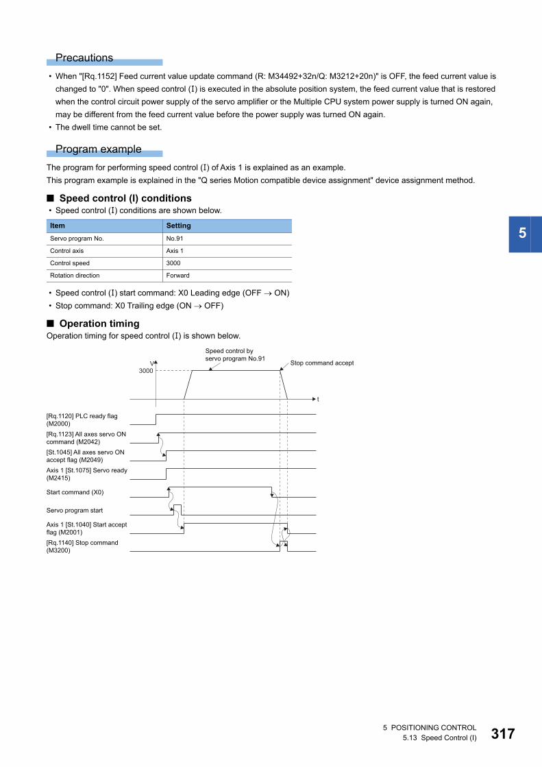
5
Precautions
• When "[Rq.1152] Feed current value update command (R: M34492+32n/Q: M3212+20n)" is OFF, the feed current value is
changed to "0". When speed control () is executed in the absolute position system, the feed current value that is restored
when the control circuit power supply of the servo amplifier or the Multiple CPU system power supply is turned ON again,
may be different from the feed current value before the power supply was turned ON again.
• The dwell time cannot be set.
Program example
The program for performing speed control () of Axis 1 is explained as an example.
This program example is explained in the "Q series Motion compatible device assignment" device assignment method.
■ Speed control (I) conditions • Speed control () conditions are shown below.
• Speed control () start command: X0 Leading edge (OFF ON)
• Stop command: X0 Trailing edge (ON OFF)
■ Operation timingOperation timing for speed control () is shown below.
Item Setting
Servo program No. No.91
Control axis Axis 1
Control speed 3000
Rotation direction Forward
Axis 1 [St.1075] Servo ready(M2415)
Servo program start
[Rq.1140] Stop command(M3200)
t
V3000
[Rq.1120] PLC ready flag(M2000)[Rq.1123] All axes servo ONcommand (M2042)[St.1045] All axes servo ONaccept flag (M2049)
Start command (X0)
Axis 1 [St.1040] Start acceptflag (M2001)
Speed control byservo program No.91
Stop command accept
5 POSITIONING CONTROL5.13 Speed Control (I) 317
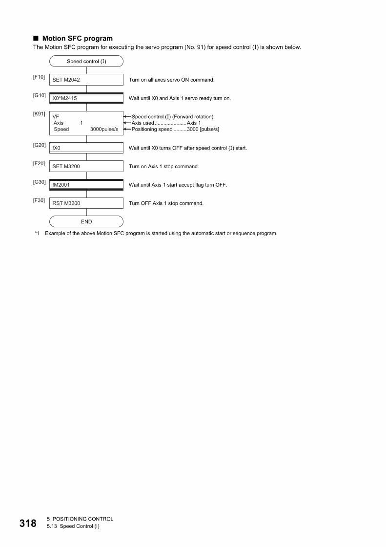
31
■ Motion SFC programThe Motion SFC program for executing the servo program (No. 91) for speed control () is shown below.
*1 Example of the above Motion SFC program is started using the automatic start or sequence program.
Speed control (�)
SET M2042[F10]
X0*M2415[G10]
VF Axis 1 Speed 3000pulse/s
[K91]
Wait until X0 and Axis 1 servo ready turn on.
Turn on all axes servo ON command.
RST M3200[F30]
END
Turn OFF Axis 1 stop command.
!M2001[G30] Wait until Axis 1 start accept flag turn OFF.
SET M3200[F20] Turn on Axis 1 stop command.
!X0[G20] Wait until X0 turns OFF after speed control (�) start.
Speed control (�) (Forward rotation)
Positioning speed .........3000 [pulse/s]Axis used......................Axis 1
85 POSITIONING CONTROL5.13 Speed Control (I)
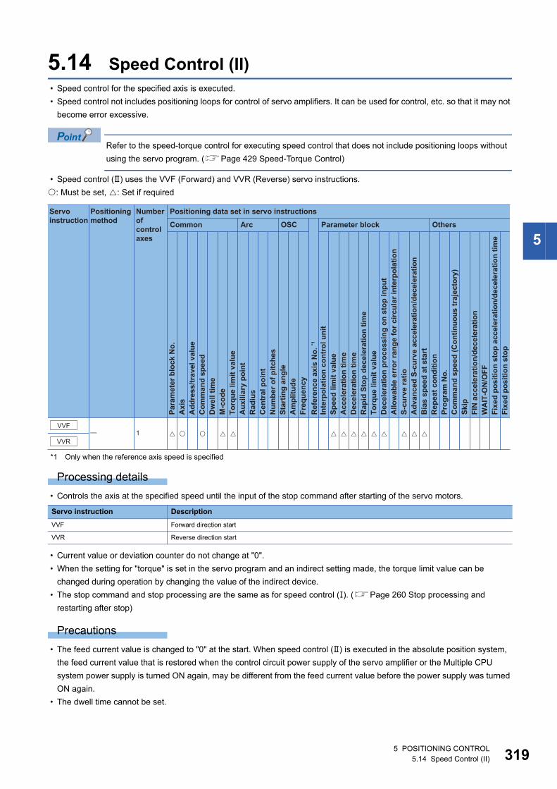
5
5.14 Speed Control (II) • Speed control for the specified axis is executed.
• Speed control not includes positioning loops for control of servo amplifiers. It can be used for control, etc. so that it may not
become error excessive.
Refer to the speed-torque control for executing speed control that does not include positioning loops without
using the servo program. (Page 429 Speed-Torque Control)
• Speed control () uses the VVF (Forward) and VVR (Reverse) servo instructions.
: Must be set, : Set if required
*1 Only when the reference axis speed is specified
Processing details
• Controls the axis at the specified speed until the input of the stop command after starting of the servo motors.
• Current value or deviation counter do not change at "0".
• When the setting for "torque" is set in the servo program and an indirect setting made, the torque limit value can be
changed during operation by changing the value of the indirect device.
• The stop command and stop processing are the same as for speed control (). (Page 260 Stop processing and
restarting after stop)
Precautions
• The feed current value is changed to "0" at the start. When speed control () is executed in the absolute position system,
the feed current value that is restored when the control circuit power supply of the servo amplifier or the Multiple CPU
system power supply is turned ON again, may be different from the feed current value before the power supply was turned
ON again.
• The dwell time cannot be set.
Servo instruction Description
VVF Forward direction start
VVR Reverse direction start
Positioning data set in servo instructions
Common
Servo instruction
Positioning method
Number ofcontrol axes
Arc OSC Parameter block Others
Para
met
er b
lock
No.
Acc
eler
atio
n tim
eD
ecel
erat
ion
time
Rap
id S
top
dece
lera
tion
time
Torq
ue li
mit
valu
eD
ecel
erat
ion
proc
essi
ng o
n st
op in
put
Allo
wab
le e
rror
rang
e fo
r circ
ular
inte
rpol
atio
nS-
curv
e ra
tioA
dvan
ced
S-cu
rve
acce
lera
tion/
dece
lera
tion
Bia
s sp
eed
at s
tart
Rep
eat c
ondi
tion
Prog
ram
No.
Com
man
d sp
eed
(Con
tinuo
us tr
ajec
tory
)Sk
ipFI
N a
ccel
erat
ion/
dece
lera
tion
WA
IT-O
N/O
FF
Fixe
d po
sitio
n st
op
Axi
sA
ddre
ss/tr
avel
val
ueC
omm
and
spee
dD
wel
l tim
eM
-cod
eTo
rque
lim
it va
lue
Aux
iliar
y po
int
Rad
ius
Cen
tral
poi
ntN
umbe
r of p
itche
sSt
artin
g an
gle
Am
plitu
deFr
eque
ncy
Inte
rpol
atio
n co
ntro
l uni
tSp
eed
limit
valu
e
Ref
eren
ce a
xis
No.
*1
Fixe
d po
sitio
n st
op a
ccel
erat
ion/
dece
lera
tion
time
VVR
VVF� 1 � � � � � � � � � �� � � �
5 POSITIONING CONTROL5.14 Speed Control (II) 319
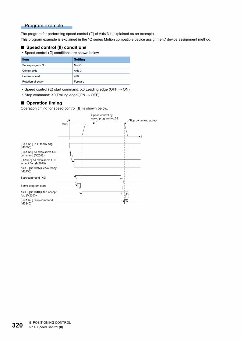
32
Program example
The program for performing speed control () of Axis 3 is explained as an example.
This program example is explained in the "Q series Motion compatible device assignment" device assignment method.
■ Speed control (II) conditions • Speed control () conditions are shown below.
• Speed control () start command: X0 Leading edge (OFF ON)
• Stop command: X0 Trailing edge (ON OFF)
■ Operation timingOperation timing for speed control () is shown below.
Item Setting
Servo program No. No.55
Control axis Axis 3
Control speed 4000
Rotation direction Forward
Axis 3 [St.1075] Servo ready(M2455)
Servo program start
[Rq.1140] Stop command(M3240)
t
V4000
[Rq.1120] PLC ready flag(M2000)[Rq.1123] All axes servo ONcommand (M2042)[St.1045] All axes servo ONaccept flag (M2049)
Start command (X0)
Axis 3 [St.1040] Start acceptflag (M2003)
Speed control byservo program No.55
Stop command accept
05 POSITIONING CONTROL5.14 Speed Control (II)
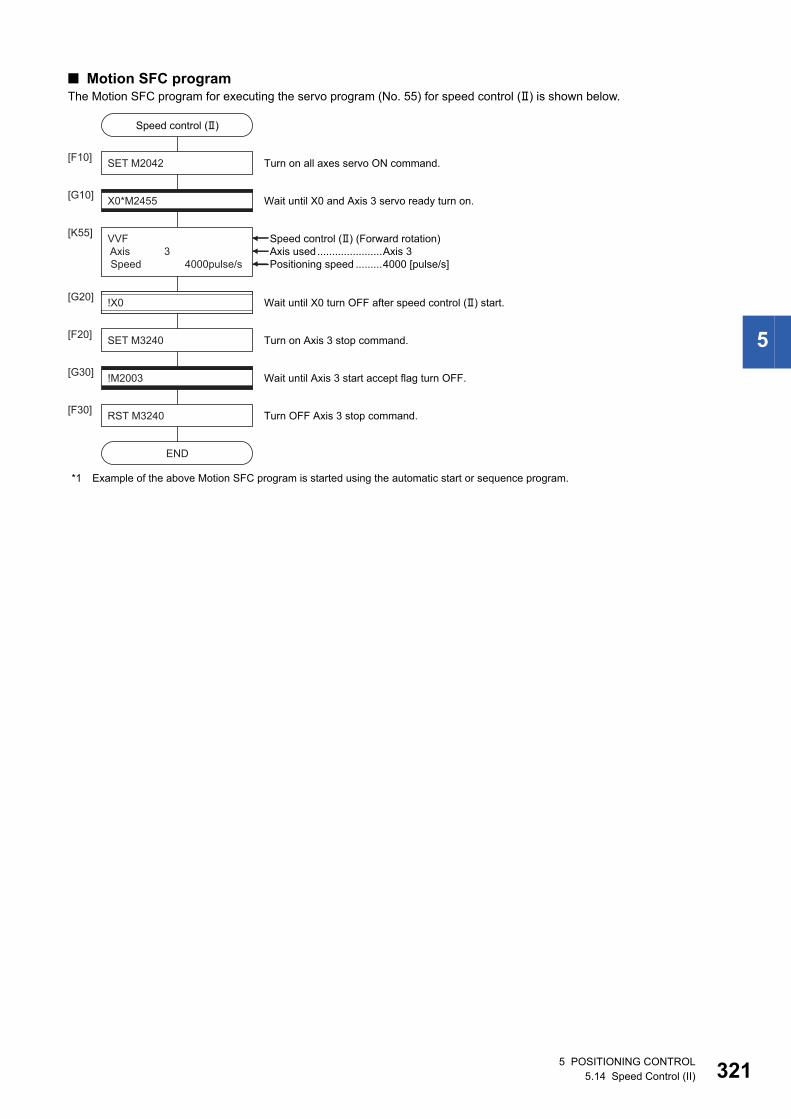
5
■ Motion SFC programThe Motion SFC program for executing the servo program (No. 55) for speed control () is shown below.
*1 Example of the above Motion SFC program is started using the automatic start or sequence program.
Speed control (�)
SET M2042[F10]
X0*M2455[G10]
VVF Axis 3 Speed 4000pulse/s
[K55]
Wait until X0 and Axis 3 servo ready turn on.
Turn on all axes servo ON command.
RST M3240[F30]
END
Turn OFF Axis 3 stop command.
!M2003[G30] Wait until Axis 3 start accept flag turn OFF.
SET M3240[F20] Turn on Axis 3 stop command.
!X0[G20] Wait until X0 turn OFF after speed control (�) start.
Speed control (�) (Forward rotation)
Positioning speed .........4000 [pulse/s]Axis used......................Axis 3
5 POSITIONING CONTROL5.14 Speed Control (II) 321
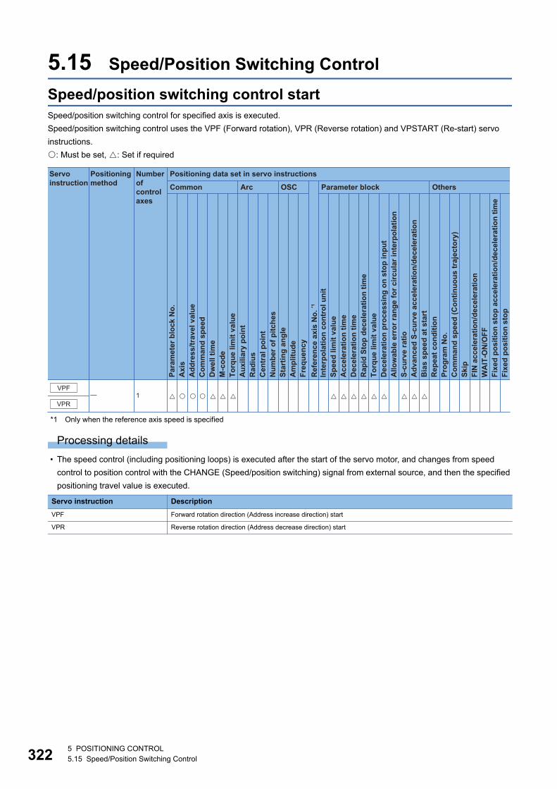
32
5.15 Speed/Position Switching Control
Speed/position switching control startSpeed/position switching control for specified axis is executed.
Speed/position switching control uses the VPF (Forward rotation), VPR (Reverse rotation) and VPSTART (Re-start) servo
instructions.
: Must be set, : Set if required
*1 Only when the reference axis speed is specified
Processing details
• The speed control (including positioning loops) is executed after the start of the servo motor, and changes from speed
control to position control with the CHANGE (Speed/position switching) signal from external source, and then the specified
positioning travel value is executed.
Servo instruction Description
VPF Forward rotation direction (Address increase direction) start
VPR Reverse rotation direction (Address decrease direction) start
Positioning data set in servo instructions
Common
Servo instruction
Positioning method
Number ofcontrol axes
Arc OSC Parameter block Others
Para
met
er b
lock
No.
Acc
eler
atio
n tim
eD
ecel
erat
ion
time
Rap
id S
top
dece
lera
tion
time
Torq
ue li
mit
valu
eD
ecel
erat
ion
proc
essi
ng o
n st
op in
put
Allo
wab
le e
rror
rang
e fo
r circ
ular
inte
rpol
atio
nS-
curv
e ra
tioA
dvan
ced
S-cu
rve
acce
lera
tion/
dece
lera
tion
Bia
s sp
eed
at s
tart
Rep
eat c
ondi
tion
Prog
ram
No.
Com
man
d sp
eed
(Con
tinuo
us tr
ajec
tory
)Sk
ipFI
N a
ccel
erat
ion/
dece
lera
tion
WA
IT-O
N/O
FF
Fixe
d po
sitio
n st
op
Axi
sA
ddre
ss/tr
avel
val
ueC
omm
and
spee
dD
wel
l tim
eM
-cod
eTo
rque
lim
it va
lue
Aux
iliar
y po
int
Rad
ius
Cen
tral
poi
ntN
umbe
r of p
itche
sSt
artin
g an
gle
Am
plitu
deFr
eque
ncy
Inte
rpol
atio
n co
ntro
l uni
tSp
eed
limit
valu
e
Ref
eren
ce a
xis
No.
*1
Fixe
d po
sitio
n st
op a
ccel
erat
ion/
dece
lera
tion
time
VPR
VPF� 1 � � � � � � � � � �� � � �� �
25 POSITIONING CONTROL5.15 Speed/Position Switching Control
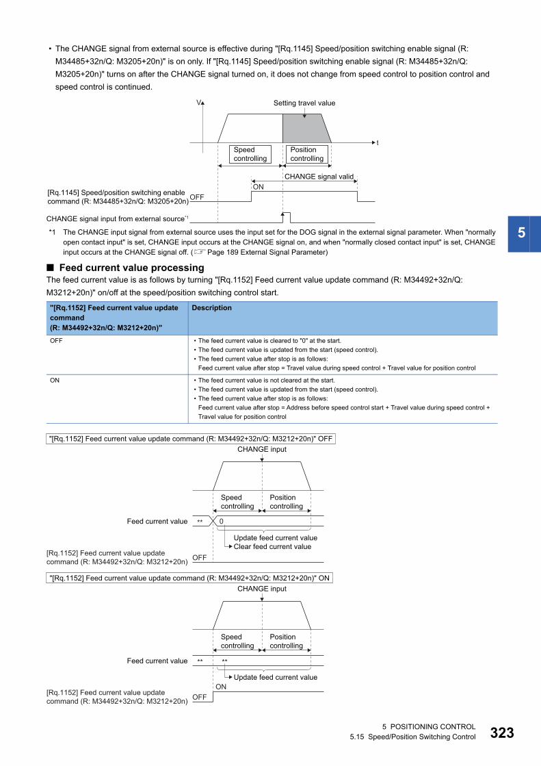
5
• The CHANGE signal from external source is effective during "[Rq.1145] Speed/position switching enable signal (R:
M34485+32n/Q: M3205+20n)" is on only. If "[Rq.1145] Speed/position switching enable signal (R: M34485+32n/Q:
M3205+20n)" turns on after the CHANGE signal turned on, it does not change from speed control to position control and
speed control is continued.
*1 The CHANGE input signal from external source uses the input set for the DOG signal in the external signal parameter. When "normally open contact input" is set, CHANGE input occurs at the CHANGE signal on, and when "normally closed contact input" is set, CHANGE input occurs at the CHANGE signal off. (Page 189 External Signal Parameter)
■ Feed current value processingThe feed current value is as follows by turning "[Rq.1152] Feed current value update command (R: M34492+32n/Q:
M3212+20n)" on/off at the speed/position switching control start.
"[Rq.1152] Feed current value update command(R: M34492+32n/Q: M3212+20n)"
Description
OFF • The feed current value is cleared to "0" at the start.
• The feed current value is updated from the start (speed control).
• The feed current value after stop is as follows:
Feed current value after stop = Travel value during speed control + Travel value for position control
ON • The feed current value is not cleared at the start.
• The feed current value is updated from the start (speed control).
• The feed current value after stop is as follows:
Feed current value after stop = Address before speed control start + Travel value during speed control +
Travel value for position control
t
V
[Rq.1145] Speed/position switching enablecommand (R: M34485+32n/Q: M3205+20n) OFF
ONCHANGE signal valid
Setting travel value
CHANGE signal input from external source*1
Positioncontrolling
Speedcontrolling
[Rq.1152] Feed current value updatecommand (R: M34492+32n/Q: M3212+20n)
CHANGE input
Feed current value
Feed current value
Speedcontrolling
Positioncontrolling
Speedcontrolling
Positioncontrolling
0
OFF
**
Update feed current valueClear feed current value
"[Rq.1152] Feed current value update command (R: M34492+32n/Q: M3212+20n)" OFF
"[Rq.1152] Feed current value update command (R: M34492+32n/Q: M3212+20n)" ON
[Rq.1152] Feed current value updatecommand (R: M34492+32n/Q: M3212+20n)
CHANGE input
**
OFFON
**
Update feed current value
5 POSITIONING CONTROL5.15 Speed/Position Switching Control 323
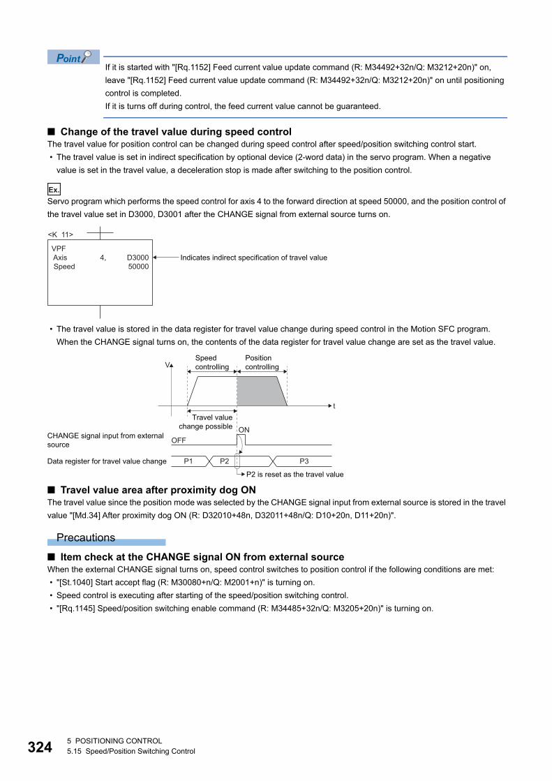
32
If it is started with "[Rq.1152] Feed current value update command (R: M34492+32n/Q: M3212+20n)" on,
leave "[Rq.1152] Feed current value update command (R: M34492+32n/Q: M3212+20n)" on until positioning
control is completed.
If it is turns off during control, the feed current value cannot be guaranteed.
■ Change of the travel value during speed controlThe travel value for position control can be changed during speed control after speed/position switching control start.
• The travel value is set in indirect specification by optional device (2-word data) in the servo program. When a negative
value is set in the travel value, a deceleration stop is made after switching to the position control.
Ex.
Servo program which performs the speed control for axis 4 to the forward direction at speed 50000, and the position control of
the travel value set in D3000, D3001 after the CHANGE signal from external source turns on.
• The travel value is stored in the data register for travel value change during speed control in the Motion SFC program.
When the CHANGE signal turns on, the contents of the data register for travel value change are set as the travel value.
■ Travel value area after proximity dog ONThe travel value since the position mode was selected by the CHANGE signal input from external source is stored in the travel
value "[Md.34] After proximity dog ON (R: D32010+48n, D32011+48n/Q: D10+20n, D11+20n)".
Precautions
■ Item check at the CHANGE signal ON from external sourceWhen the external CHANGE signal turns on, speed control switches to position control if the following conditions are met:
• "[St.1040] Start accept flag (R: M30080+n/Q: M2001+n)" is turning on.
• Speed control is executing after starting of the speed/position switching control.
• "[Rq.1145] Speed/position switching enable command (R: M34485+32n/Q: M3205+20n)" is turning on.
<K 11>
VPF Axis Speed
D300050000
4, Indicates indirect specification of travel value
Travel valuechange possible
t
VPositioncontrolling
Speedcontrolling
OFFON
Data register for travel value change P1 P2
CHANGE signal input from externalsource
P3
P2 is reset as the travel value
45 POSITIONING CONTROL5.15 Speed/Position Switching Control
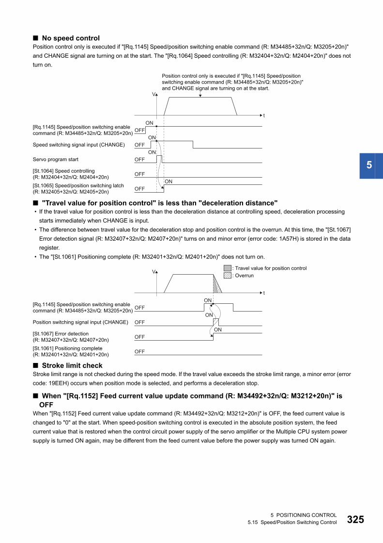
5
■ No speed controlPosition control only is executed if "[Rq.1145] Speed/position switching enable command (R: M34485+32n/Q: M3205+20n)"
and CHANGE signal are turning on at the start. The "[Rq.1064] Speed controlling (R: M32404+32n/Q: M2404+20n)" does not
turn on.
■ "Travel value for position control" is less than "deceleration distance" • If the travel value for position control is less than the deceleration distance at controlling speed, deceleration processing
starts immediately when CHANGE is input.
• The difference between travel value for the deceleration stop and position control is the overrun. At this time, the "[St.1067]
Error detection signal (R: M32407+32n/Q: M2407+20n)" turns on and minor error (error code: 1A57H) is stored in the data
register.
• The "[St.1061] Positioning complete (R: M32401+32n/Q: M2401+20n)" does not turn on.
■ Stroke limit checkStroke limit range is not checked during the speed mode. If the travel value exceeds the stroke limit range, a minor error (error
code: 19EEH) occurs when position mode is selected, and performs a deceleration stop.
■ When "[Rq.1152] Feed current value update command (R: M34492+32n/Q: M3212+20n)" is OFF
When "[Rq.1152] Feed current value update command (R: M34492+32n/Q: M3212+20n)" is OFF, the feed current value is
changed to "0" at the start. When speed-position switching control is executed in the absolute position system, the feed
current value that is restored when the control circuit power supply of the servo amplifier or the Multiple CPU system power
supply is turned ON again, may be different from the feed current value before the power supply was turned ON again.
Position control only is executed if "[Rq.1145] Speed/positionswitching enable command (R: M34485+32n/Q: M3205+20n)"and CHANGE signal are turning on at the start.
OFFON
t
V
OFFON
Speed switching signal input (CHANGE)
OFFON
Servo program start
OFF[St.1064] Speed controlling(R: M32404+32n/Q: M2404+20n)[St.1065] Speed/position switching latch(R: M32405+32n/Q: M2405+20n)
[Rq.1145] Speed/position switching enablecommand (R: M34485+32n/Q: M3205+20n)
OFFON
OFFON
t
V
OFFON
Position switching signal input (CHANGE)
OFFON
OFF[St.1061] Positioning complete(R: M32401+32n/Q: M2401+20n)
[St.1067] Error detection(R: M32407+32n/Q: M2407+20n)
[Rq.1145] Speed/position switching enablecommand (R: M34485+32n/Q: M3205+20n)
: Overrun: Travel value for position control
5 POSITIONING CONTROL5.15 Speed/Position Switching Control 325
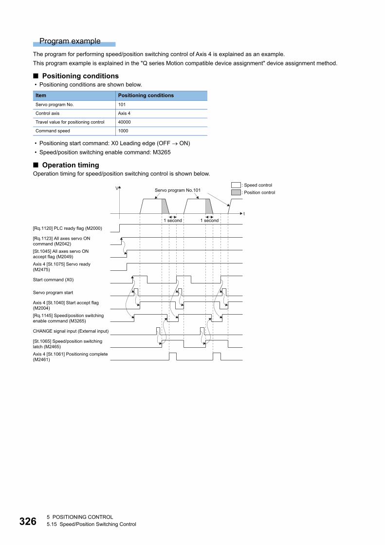
32
Program example
The program for performing speed/position switching control of Axis 4 is explained as an example.
This program example is explained in the "Q series Motion compatible device assignment" device assignment method.
■ Positioning conditions • Positioning conditions are shown below.
• Positioning start command: X0 Leading edge (OFF ON)
• Speed/position switching enable command: M3265
■ Operation timingOperation timing for speed/position switching control is shown below.
Item Positioning conditions
Servo program No. 101
Control axis Axis 4
Travel value for positioning control 40000
Command speed 1000
Axis 4 [St.1075] Servo ready(M2475)
Servo program start
[Rq.1145] Speed/position switchingenable command (M3265)
t
V
[Rq.1120] PLC ready flag (M2000)
[Rq.1123] All axes servo ON command (M2042)[St.1045] All axes servo ONaccept flag (M2049)
Start command (X0)
Axis 4 [St.1040] Start accept flag(M2004)
CHANGE signal input (External input)
Axis 4 [St.1061] Positioning complete(M2461)
[St.1065] Speed/position switching latch (M2465)
1 second 1 second
Servo program No.101: Speed control: Position control
65 POSITIONING CONTROL5.15 Speed/Position Switching Control
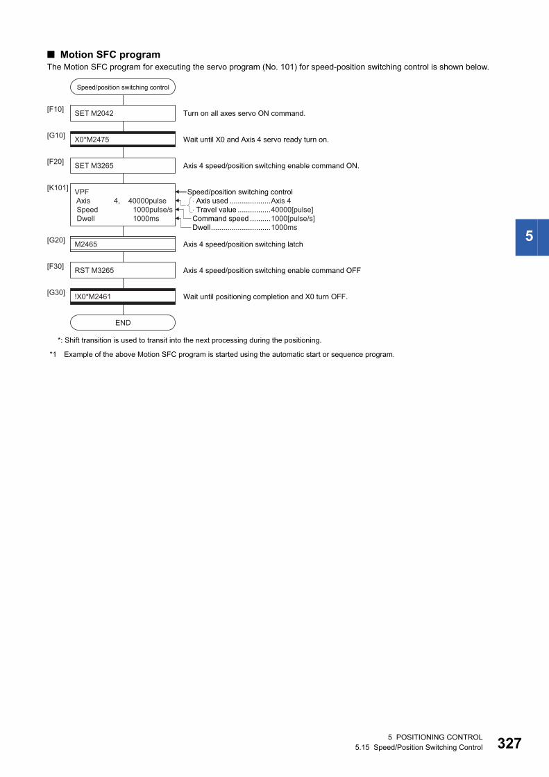
5
■ Motion SFC programThe Motion SFC program for executing the servo program (No. 101) for speed-position switching control is shown below.
*1 Example of the above Motion SFC program is started using the automatic start or sequence program.
SET M2042[F10]
X0*M2475[G10]
VPF Axis 4, 40000pulse Speed 1000pulse/s Dwell 1000ms
[K101]
Wait until X0 and Axis 4 servo ready turn on.
SET M3265[F20] Axis 4 speed/position switching enable command ON.
Turn on all axes servo ON command.
END
!X0*M2461[G30] Wait until positioning completion and X0 turn OFF.
RST M3265[F30] Axis 4 speed/position switching enable command OFF
M2465[G20] Axis 4 speed/position switching latch
Speed/position switching control
Dwell.............................1000msCommand speed ..........1000[pulse/s]
�Axis used ....................Axis 4�Travel value ................40000[pulse]
*: Shift transition is used to transit into the next processing during the positioning.
Speed/position switching control
5 POSITIONING CONTROL5.15 Speed/Position Switching Control 327
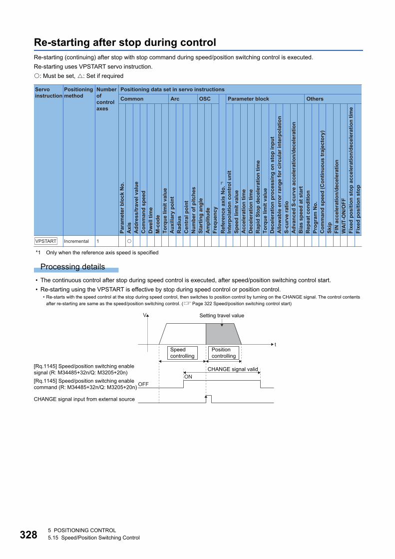
32
Re-starting after stop during controlRe-starting (continuing) after stop with stop command during speed/position switching control is executed.
Re-starting uses VPSTART servo instruction.
: Must be set, : Set if required
*1 Only when the reference axis speed is specified
Processing details
• The continuous control after stop during speed control is executed, after speed/position switching control start.
• Re-starting using the VPSTART is effective by stop during speed control or position control.• Re-starts with the speed control at the stop during speed control, then switches to position control by turning on the CHANGE signal. The control contents
after re-starting are same as the speed/position switching control. (Page 322 Speed/position switching control start)
Positioning data set in servo instructions
Common
Servo instruction
Positioning method
Number ofcontrol axes
Arc OSC Parameter block Others
Para
met
er b
lock
No.
Acc
eler
atio
n tim
eD
ecel
erat
ion
time
Rap
id S
top
dece
lera
tion
time
Torq
ue li
mit
valu
eD
ecel
erat
ion
proc
essi
ng o
n st
op in
put
Allo
wab
le e
rror
rang
e fo
r circ
ular
inte
rpol
atio
nS-
curv
e ra
tioA
dvan
ced
S-cu
rve
acce
lera
tion/
dece
lera
tion
Bia
s sp
eed
at s
tart
Rep
eat c
ondi
tion
Prog
ram
No.
Com
man
d sp
eed
(Con
tinuo
us tr
ajec
tory
)Sk
ipFI
N a
ccel
erat
ion/
dece
lera
tion
WA
IT-O
N/O
FF
Fixe
d po
sitio
n st
op
Axi
sA
ddre
ss/tr
avel
val
ueC
omm
and
spee
dD
wel
l tim
eM
-cod
eTo
rque
lim
it va
lue
Aux
iliar
y po
int
Rad
ius
Cen
tral
poi
ntN
umbe
r of p
itche
sSt
artin
g an
gle
Am
plitu
deFr
eque
ncy
Inte
rpol
atio
n co
ntro
l uni
tSp
eed
limit
valu
e
Ref
eren
ce a
xis
No.
*1
Fixe
d po
sitio
n st
op a
ccel
erat
ion/
dece
lera
tion
time
VPSTART Incremental 1 �
t
V
[Rq.1145] Speed/position switching enablecommand (R: M34485+32n/Q: M3205+20n) OFF
ONCHANGE signal valid
Setting travel value
CHANGE signal input from external source
[Rq.1145] Speed/position switching enablesignal (R: M34485+32n/Q: M3205+20n)
Positioncontrolling
Speedcontrolling
85 POSITIONING CONTROL5.15 Speed/Position Switching Control
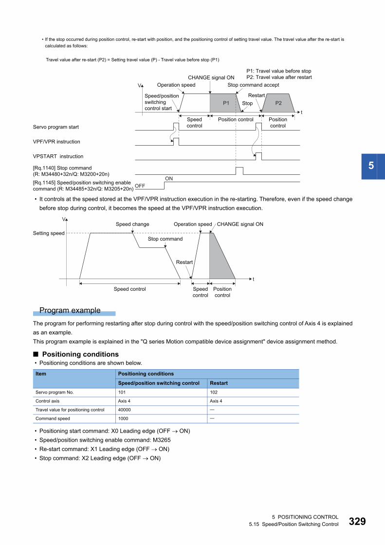
5
• It controls at the speed stored at the VPF/VPR instruction execution in the re-starting. Therefore, even if the speed change
before stop during control, it becomes the speed at the VPF/VPR instruction execution.
Program example
The program for performing restarting after stop during control with the speed/position switching control of Axis 4 is explained
as an example.
This program example is explained in the "Q series Motion compatible device assignment" device assignment method.
■ Positioning conditions • Positioning conditions are shown below.
• Positioning start command: X0 Leading edge (OFF ON)
• Speed/position switching enable command: M3265
• Re-start command: X1 Leading edge (OFF ON)
• Stop command: X2 Leading edge (OFF ON)
• If the stop occurred during position control, re-start with position, and the positioning control of setting travel value. The travel value after the re-start is
calculated as follows:
Travel value after re-start (P2) = Setting travel value (P) - Travel value before stop (P1)
Item Positioning conditions
Speed/position switching control Restart
Servo program No. 101 102
Control axis Axis 4 Axis 4
Travel value for positioning control 40000
Command speed 1000
P1 P2
t
V
VPF/VPR instruction
VPSTART instruction
Servo program start
[Rq.1140] Stop command (R: M34480+32n/Q: M3200+20n)[Rq.1145] Speed/position switching enablecommand (R: M34485+32n/Q: M3205+20n)
CHANGE signal ON Stop command accept
RestartStop
Operation speed
P1: Travel value before stopP2: Travel value after restart
Speed/positionswitchingcontrol start
OFFON
Speedcontrol
Positioncontrol
Position control
t
Setting speed
VSpeed change Operation speed CHANGE signal ON
Stop command
Restart
Speed control Speedcontrol
Positioncontrol
5 POSITIONING CONTROL5.15 Speed/Position Switching Control 329
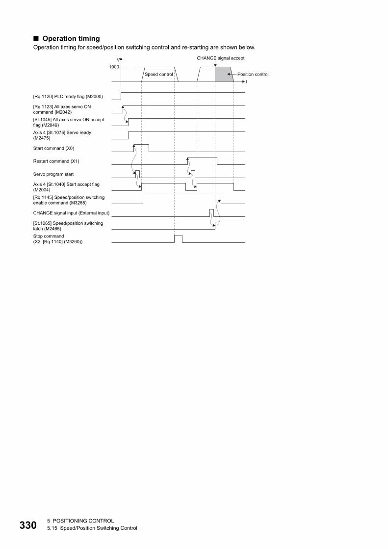
33
■ Operation timingOperation timing for speed/position switching control and re-starting are shown below.
Axis 4 [St.1075] Servo ready(M2475)
Servo program start
[Rq.1145] Speed/position switchingenable command (M3265)
t
V1000
[Rq.1120] PLC ready flag (M2000)
[Rq.1123] All axes servo ONcommand (M2042)[St.1045] All axes servo ON acceptflag (M2049)
Start command (X0)
Axis 4 [St.1040] Start accept flag(M2004)
CHANGE signal input (External input)
Stop command(X2, [Rq.1140] (M3260))
[St.1065] Speed/position switchinglatch (M2465)
Restart command (X1)
CHANGE signal accept
Speed control Position control
05 POSITIONING CONTROL5.15 Speed/Position Switching Control
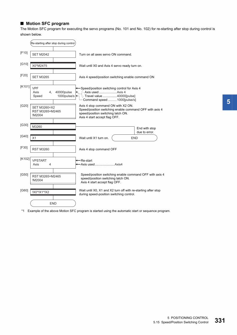
5
■ Motion SFC programThe Motion SFC program for executing the servo programs (No. 101 and No. 102) for re-starting after stop during control is
shown below.
*1 Example of the above Motion SFC program is started using the automatic start or sequence program.
SET M2042[F10]
X0*M2475[G10]
VPF Axis 4, 40000pulse Speed 1000pulse/s
VPSTART Axis 4
SET M3260=X2RST M3265=M2465!M2004
[K101]
[G20]
Wait until X0 and Axis 4 servo ready turn on.
SET M3265[F20] Axis 4 speed/position switching enable command ON
Turn on all axes servo ON command.
END
END
M3260[G30]
X1[G40] Wait until X1 turn on.
End with stopdue to error.
!X0*!X1*!X2[G60] Wait until X0, X1 and X2 turn off with re-starting after stopduring speed-position switching control.
RST M3260[F30] Axis 4 stop command OFF
[K102]
Axis 4 stop command ON with X2 ON.Speed/position switching enable command OFF with axis 4 speed/position switching latch ON. Axis 4 start accept flag OFF.
Speed/position switching control for Axis 4
Re-startAxis used......................Axis4
RST M3265=M2465!M2004
[G50] Speed/position switching enable command OFF with axis 4 speed/position switching latch ON. Axis 4 start accept flag OFF.
Command speed ..........1000[pulse/s]
�Axis used ....................Axis 4�Travel value ................40000[pulse]
Re-starting after stop during control
5 POSITIONING CONTROL5.15 Speed/Position Switching Control 331
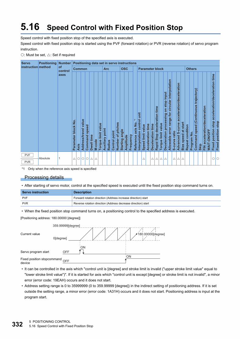
33
5.16 Speed Control with Fixed Position StopSpeed control with fixed position stop of the specified axis is executed.
Speed control with fixed position stop is started using the PVF (forward rotation) or PVR (reverse rotation) of servo program
instruction.
: Must be set, : Set if required
*1 Only when the reference axis speed is specified
Processing details
• After starting of servo motor, control at the specified speed is executed until the fixed position stop command turns on.
• When the fixed position stop command turns on, a positioning control to the specified address is executed.
• It can be controlled in the axis which "control unit is [degree] and stroke limit is invalid ("upper stroke limit value" equal to
"lower stroke limit value")". If it is started for axis which "control unit is except [degree] or stroke limit is not invalid", a minor
error (error code: 19EAH) occurs and it does not start.
• Address setting range is 0 to 35999999 (0 to 359.99999 [degree]) in the indirect setting of positioning address. If it is set
outside the setting range, a minor error (error code: 1A31H) occurs and it does not start. Positioning address is input at the
program start.
Servo instruction Description
PVF Forward rotation direction (Address increase direction) start
PVR Reverse rotation direction (Address decrease direction) start
Positioning data set in servo instructions
Common
Servo instruction
Positioning method
Number ofcontrol axes
Arc OSC Parameter block OthersPa
ram
eter
blo
ck N
o.
Acc
eler
atio
n tim
eD
ecel
erat
ion
time
Rap
id S
top
dece
lera
tion
time
Torq
ue li
mit
valu
eD
ecel
erat
ion
proc
essi
ng o
n st
op in
put
Allo
wab
le e
rror
rang
e fo
r circ
ular
inte
rpol
atio
nS-
curv
e ra
tioA
dvan
ced
S-cu
rve
acce
lera
tion/
dece
lera
tion
Bia
s sp
eed
at s
tart
Rep
eat c
ondi
tion
Prog
ram
No.
Com
man
d sp
eed
(Con
tinuo
us tr
ajec
tory
)Sk
ipFI
N a
ccel
erat
ion/
dece
lera
tion
WA
IT-O
N/O
FF
Fixe
d po
sitio
n st
op
Axi
sA
ddre
ss/tr
avel
val
ueC
omm
and
spee
dD
wel
l tim
eM
-cod
eTo
rque
lim
it va
lue
Aux
iliar
y po
int
Rad
ius
Cen
tral
poi
ntN
umbe
r of p
itche
sSt
artin
g an
gle
Am
plitu
deFr
eque
ncy
Inte
rpol
atio
n co
ntro
l uni
tSp
eed
limit
valu
e
Ref
eren
ce a
xis
No.
*1
Fixe
d po
sitio
n st
op a
ccel
erat
ion/
dece
lera
tion
time
PVR
PVFAbsolute 1 � � � � � � � � �� � � � �� �
Servo program start
[Positioning address: 180.00000 [degree]]
Current value0[degree]
359.99999[degree]
180.00000[degree]
ON
ONOFF
OFF
Fixed position stopcommanddevice
25 POSITIONING CONTROL5.16 Speed Control with Fixed Position Stop
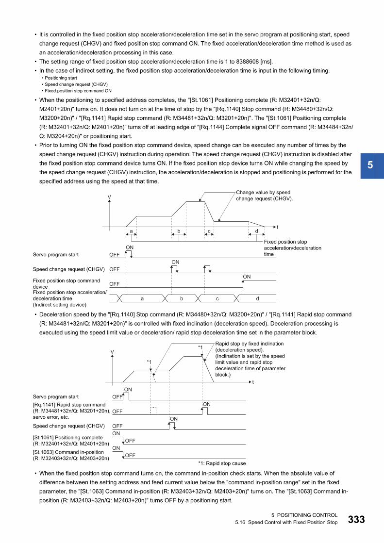
5
• It is controlled in the fixed position stop acceleration/deceleration time set in the servo program at positioning start, speed
change request (CHGV) and fixed position stop command ON. The fixed acceleration/deceleration time method is used as
an acceleration/deceleration processing in this case.
• The setting range of fixed position stop acceleration/deceleration time is 1 to 8388608 [ms].
• In the case of indirect setting, the fixed position stop acceleration/deceleration time is input in the following timing.
• When the positioning to specified address completes, the "[St.1061] Positioning complete (R: M32401+32n/Q:
M2401+20n)" turns on. It does not turn on at the time of stop by the "[Rq.1140] Stop command (R: M34480+32n/Q:
M3200+20n)" / "[Rq.1141] Rapid stop command (R: M34481+32n/Q: M3201+20n)". The "[St.1061] Positioning complete
(R: M32401+32n/Q: M2401+20n)" turns off at leading edge of "[Rq.1144] Complete signal OFF command (R: M34484+32n/
Q: M3204+20n)" or positioning start.
• Prior to turning ON the fixed position stop command device, speed change can be executed any number of times by the
speed change request (CHGV) instruction during operation. The speed change request (CHGV) instruction is disabled after
the fixed position stop command device turns ON. If the fixed position stop device turns ON while changing the speed by
the speed change request (CHGV) instruction, the acceleration/deceleration is stopped and positioning is performed for the
specified address using the speed at that time.
• Deceleration speed by the "[Rq.1140] Stop command (R: M34480+32n/Q: M3200+20n)" / "[Rq.1141] Rapid stop command
(R: M34481+32n/Q: M3201+20n)" is controlled with fixed inclination (deceleration speed). Deceleration processing is
executed using the speed limit value or deceleration/ rapid stop deceleration time set in the parameter block.
• When the fixed position stop command turns on, the command in-position check starts. When the absolute value of
difference between the setting address and feed current value below the "command in-position range" set in the fixed
parameter, the "[St.1063] Command in-position (R: M32403+32n/Q: M2403+20n)" turns on. The "[St.1063] Command in-
position (R: M32403+32n/Q: M2403+20n)" turns OFF by a positioning start.
• Positioning start
• Speed change request (CHGV)
• Fixed position stop command ON
t
V
Speed change request (CHGV)
Fixed position stop commanddevice
Servo program start
Fixed position stop acceleration/deceleration time(Indirect setting device)
Change value by speed change request (CHGV).
OFFON
OFFON
OFFON
a b c d
Fixed position stopacceleration/decelerationtime
a db c
t
V
Speed change request (CHGV)
Servo program start
[St.1063] Command in-position(R: M32403+32n/Q: M2403+20n)
[St.1061] Positioning complete(R: M32401+32n/Q: M2401+20n)
[Rq.1141] Rapid stop command(R: M34481+32n/Q: M3201+20n),servo error, etc.
Rapid stop by fixed inclination(deceleration speed).(Inclination is set by the speedlimit value and rapid stop deceleration time of parameterblock.)
OFFONOFF
ON
OFFON
OFFON
OFFON
*1
*1: Rapid stop cause
*1
5 POSITIONING CONTROL5.16 Speed Control with Fixed Position Stop 333
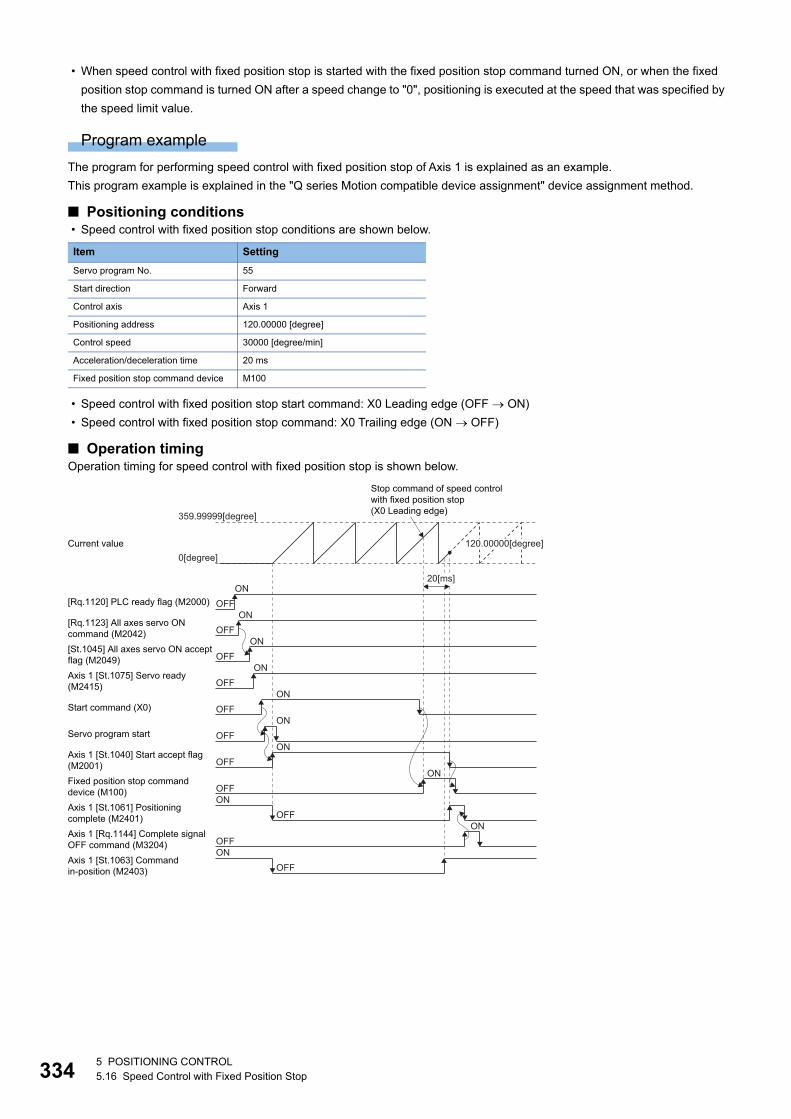
33
• When speed control with fixed position stop is started with the fixed position stop command turned ON, or when the fixed
position stop command is turned ON after a speed change to "0", positioning is executed at the speed that was specified by
the speed limit value.
Program example
The program for performing speed control with fixed position stop of Axis 1 is explained as an example.
This program example is explained in the "Q series Motion compatible device assignment" device assignment method.
■ Positioning conditions • Speed control with fixed position stop conditions are shown below.
• Speed control with fixed position stop start command: X0 Leading edge (OFF ON)
• Speed control with fixed position stop command: X0 Trailing edge (ON OFF)
■ Operation timingOperation timing for speed control with fixed position stop is shown below.
Item Setting
Servo program No. 55
Start direction Forward
Control axis Axis 1
Positioning address 120.00000 [degree]
Control speed 30000 [degree/min]
Acceleration/deceleration time 20 ms
Fixed position stop command device M100
Stop command of speed controlwith fixed position stop (X0 Leading edge)
Axis 1 [St.1075] Servo ready(M2415)
Servo program start
Fixed position stop commanddevice (M100)Axis 1 [St.1061] Positioningcomplete (M2401)Axis 1 [Rq.1144] Complete signalOFF command (M3204)Axis 1 [St.1063] Commandin-position (M2403)
Current value0[degree]
359.99999[degree]
120.00000[degree]
20[ms]ON
OFFON
OFFON
OFFON
OFFON
OFFON
OFFON
OFFON
OFFON
OFFON
OFFON
OFF
[Rq.1123] All axes servo ONcommand (M2042)[St.1045] All axes servo ON acceptflag (M2049)
Start command (X0)
[Rq.1120] PLC ready flag (M2000)
Axis 1 [St.1040] Start accept flag(M2001)
45 POSITIONING CONTROL5.16 Speed Control with Fixed Position Stop
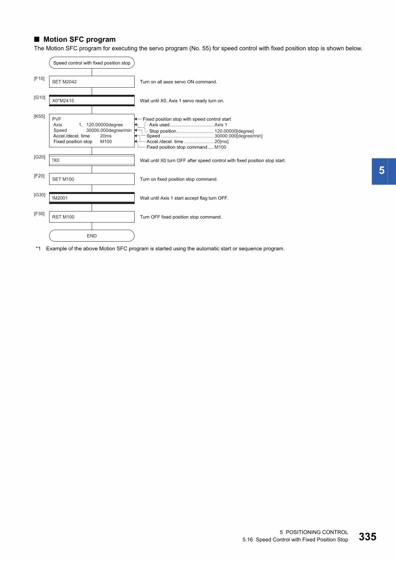
5
■ Motion SFC programThe Motion SFC program for executing the servo program (No. 55) for speed control with fixed position stop is shown below.
*1 Example of the above Motion SFC program is started using the automatic start or sequence program.
�Axis used..................................Axis 1�Stop position............................. 120.00000[degree]
SET M2042[F10]
X0*M2415[G10]
[K55]
Turn on all axes servo ON command.
Wait until X0, Axis 1 servo ready turn on.
RST M100[F30]
Turn OFF fixed position stop command.
!M2001[G30]
Wait until Axis 1 start accept flag turn OFF.
SET M100[F20]
Turn on fixed position stop command.
!X0[G20]
Wait until X0 turn OFF after speed control with fixed position stop start.
Fixed position stop with speed control start
Accel./decel. time ....................... 20[ms]Fixed position stop command.....M100
Speed .........................................30000.000[degree/min]
PVF Axis 1, 120.00000degree Speed 30000.000degree/min Accel./decel. time 20ms Fixed position stop M100
Speed control with fixed position stop
END
5 POSITIONING CONTROL5.16 Speed Control with Fixed Position Stop 335
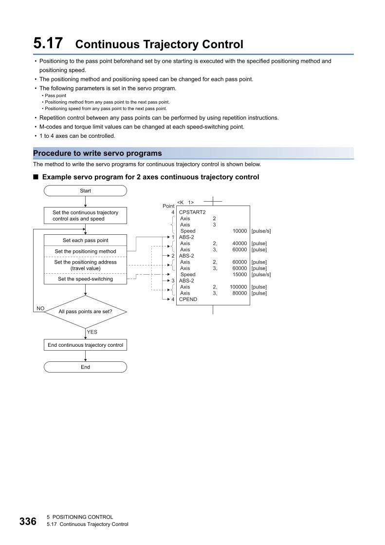
33
5.17 Continuous Trajectory Control • Positioning to the pass point beforehand set by one starting is executed with the specified positioning method and
positioning speed.
• The positioning method and positioning speed can be changed for each pass point.
• The following parameters is set in the servo program.
• Repetition control between any pass points can be performed by using repetition instructions.
• M-codes and torque limit values can be changed at each speed-switching point.
• 1 to 4 axes can be controlled.
Procedure to write servo programsThe method to write the servo programs for continuous trajectory control is shown below.
■ Example servo program for 2 axes continuous trajectory control
• Pass point
• Positioning method from any pass point to the next pass point.
• Positioning speed from any pass point to the next pass point.
Point4 1 2 3 4
End continuous trajectory control
Start
YES
NO
End
Set each pass point
Set the positioning method
Set the speed-switching
<K 1>
CPSTART2 Axis Axis SpeedABS-2 Axis AxisABS-2 Axis Axis SpeedABS-2 Axis AxisCPEND
10000
4000060000
600006000015000
10000080000
[pulse/s]
[pulse][pulse]
[pulse][pulse][pulse/s]
[pulse][pulse]
2 3
2,3,
2,3,
2,3,
Set the positioning address(travel value)
All pass points are set?
Set the continuous trajectorycontrol axis and speed
65 POSITIONING CONTROL5.17 Continuous Trajectory Control
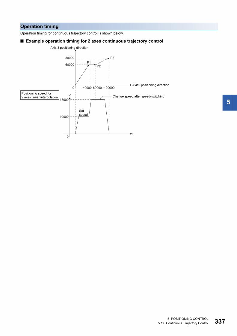
5
Operation timingOperation timing for continuous trajectory control is shown below.
■ Example operation timing for 2 axes continuous trajectory control
Axis2 positioning direction
Axis 3 positioning direction
60000
0
0
P1P2
P3
Change speed after speed-switching
80000
t
V
10000
15000
Setspeed
40000 60000 100000
Positioning speed for2 axes linear interpolation
5 POSITIONING CONTROL5.17 Continuous Trajectory Control 337
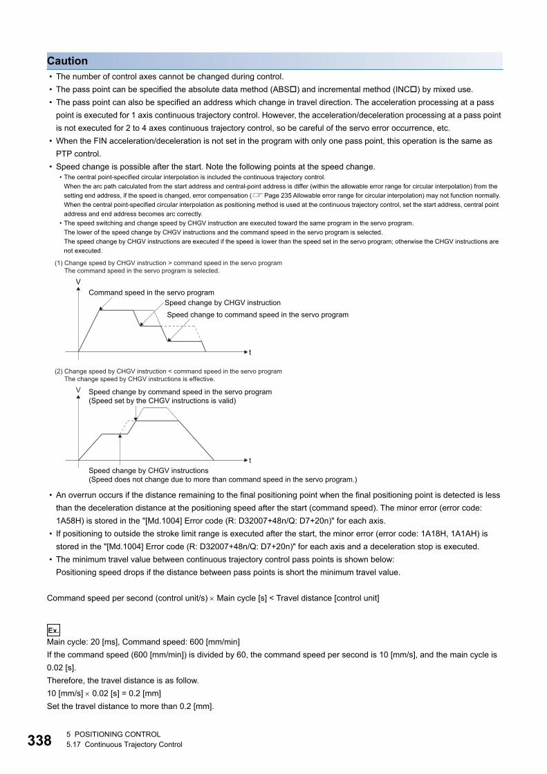
33
Caution • The number of control axes cannot be changed during control.
• The pass point can be specified the absolute data method (ABS) and incremental method (INC) by mixed use.
• The pass point can also be specified an address which change in travel direction. The acceleration processing at a pass
point is executed for 1 axis continuous trajectory control. However, the acceleration/deceleration processing at a pass point
is not executed for 2 to 4 axes continuous trajectory control, so be careful of the servo error occurrence, etc.
• When the FIN acceleration/deceleration is not set in the program with only one pass point, this operation is the same as
PTP control.
• Speed change is possible after the start. Note the following points at the speed change.
• An overrun occurs if the distance remaining to the final positioning point when the final positioning point is detected is less
than the deceleration distance at the positioning speed after the start (command speed). The minor error (error code:
1A58H) is stored in the "[Md.1004] Error code (R: D32007+48n/Q: D7+20n)" for each axis.
• If positioning to outside the stroke limit range is executed after the start, the minor error (error code: 1A18H, 1A1AH) is
stored in the "[Md.1004] Error code (R: D32007+48n/Q: D7+20n)" for each axis and a deceleration stop is executed.
• The minimum travel value between continuous trajectory control pass points is shown below:
Positioning speed drops if the distance between pass points is short the minimum travel value.
Command speed per second (control unit/s) Main cycle [s] < Travel distance [control unit]
Ex.
Main cycle: 20 [ms], Command speed: 600 [mm/min]
If the command speed (600 [mm/min]) is divided by 60, the command speed per second is 10 [mm/s], and the main cycle is
0.02 [s].
Therefore, the travel distance is as follow.
10 [mm/s] 0.02 [s] = 0.2 [mm]
Set the travel distance to more than 0.2 [mm].
• The central point-specified circular interpolation is included the continuous trajectory control.
When the arc path calculated from the start address and central-point address is differ (within the allowable error range for circular interpolation) from the
setting end address, if the speed is changed, error compensation (Page 235 Allowable error range for circular interpolation) may not function normally.
When the central point-specified circular interpolation as positioning method is used at the continuous trajectory control, set the start address, central point
address and end address becomes arc correctly.
• The speed switching and change speed by CHGV instruction are executed toward the same program in the servo program.
The lower of the speed change by CHGV instructions and the command speed in the servo program is selected.
The speed change by CHGV instructions are executed if the speed is lower than the speed set in the servo program; otherwise the CHGV instructions are
not executed.
(1) Change speed by CHGV instruction > command speed in the servo programThe command speed in the servo program is selected.
t
V
Speed change by CHGV instructionSpeed change to command speed in the servo program
Command speed in the servo program
(2) Change speed by CHGV instruction < command speed in the servo programThe change speed by CHGV instructions is effective.
t
V Speed change by command speed in the servo program(Speed set by the CHGV instructions is valid)
Speed change by CHGV instructions(Speed does not change due to more than command speed in the servo program.)
85 POSITIONING CONTROL5.17 Continuous Trajectory Control
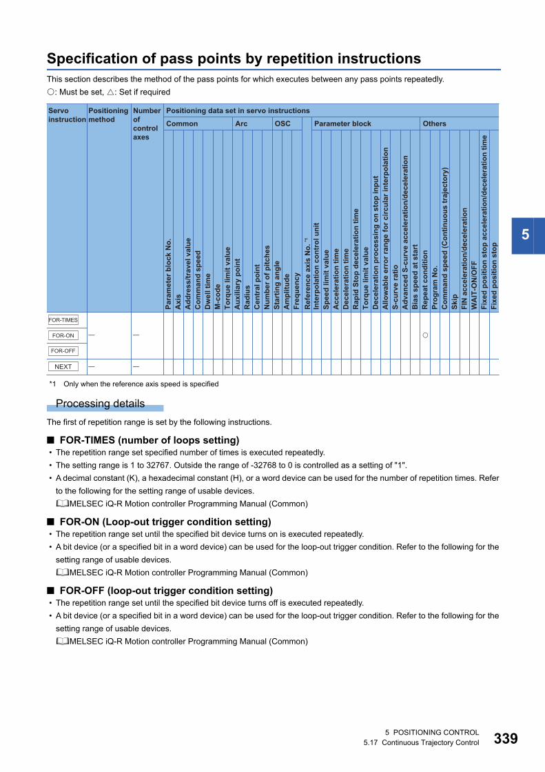
5
Specification of pass points by repetition instructionsThis section describes the method of the pass points for which executes between any pass points repeatedly.
: Must be set, : Set if required
*1 Only when the reference axis speed is specified
Processing details
The first of repetition range is set by the following instructions.
■ FOR-TIMES (number of loops setting) • The repetition range set specified number of times is executed repeatedly.
• The setting range is 1 to 32767. Outside the range of -32768 to 0 is controlled as a setting of "1".
• A decimal constant (K), a hexadecimal constant (H), or a word device can be used for the number of repetition times. Refer
to the following for the setting range of usable devices.
MELSEC iQ-R Motion controller Programming Manual (Common)
■ FOR-ON (Loop-out trigger condition setting) • The repetition range set until the specified bit device turns on is executed repeatedly.
• A bit device (or a specified bit in a word device) can be used for the loop-out trigger condition. Refer to the following for the
setting range of usable devices.
MELSEC iQ-R Motion controller Programming Manual (Common)
■ FOR-OFF (loop-out trigger condition setting) • The repetition range set until the specified bit device turns off is executed repeatedly.
• A bit device (or a specified bit in a word device) can be used for the loop-out trigger condition. Refer to the following for the
setting range of usable devices.
MELSEC iQ-R Motion controller Programming Manual (Common)
Positioning data set in servo instructions
Common
Servo instruction
Positioning method
Number ofcontrol axes
Arc OSC Parameter block Others
Para
met
er b
lock
No.
Acc
eler
atio
n tim
eD
ecel
erat
ion
time
Rap
id S
top
dece
lera
tion
time
Torq
ue li
mit
valu
eD
ecel
erat
ion
proc
essi
ng o
n st
op in
put
Allo
wab
le e
rror
rang
e fo
r circ
ular
inte
rpol
atio
nS-
curv
e ra
tioA
dvan
ced
S-cu
rve
acce
lera
tion/
dece
lera
tion
Bia
s sp
eed
at s
tart
Rep
eat c
ondi
tion
Prog
ram
No.
Com
man
d sp
eed
(Con
tinuo
us tr
ajec
tory
)Sk
ipFI
N a
ccel
erat
ion/
dece
lera
tion
WA
IT-O
N/O
FF
Fixe
d po
sitio
n st
op
Axi
sA
ddre
ss/tr
avel
val
ueC
omm
and
spee
dD
wel
l tim
eM
-cod
eTo
rque
lim
it va
lue
Aux
iliar
y po
int
Rad
ius
Cen
tral
poi
ntN
umbe
r of p
itche
sSt
artin
g an
gle
Am
plitu
deFr
eque
ncy
Inte
rpol
atio
n co
ntro
l uni
tSp
eed
limit
valu
e
Ref
eren
ce a
xis
No.
*1
Fixe
d po
sitio
n st
op a
ccel
erat
ion/
dece
lera
tion
time
FOR-TIMES
FOR-ON
FOR-OFF
NEXT
5 POSITIONING CONTROL5.17 Continuous Trajectory Control 339
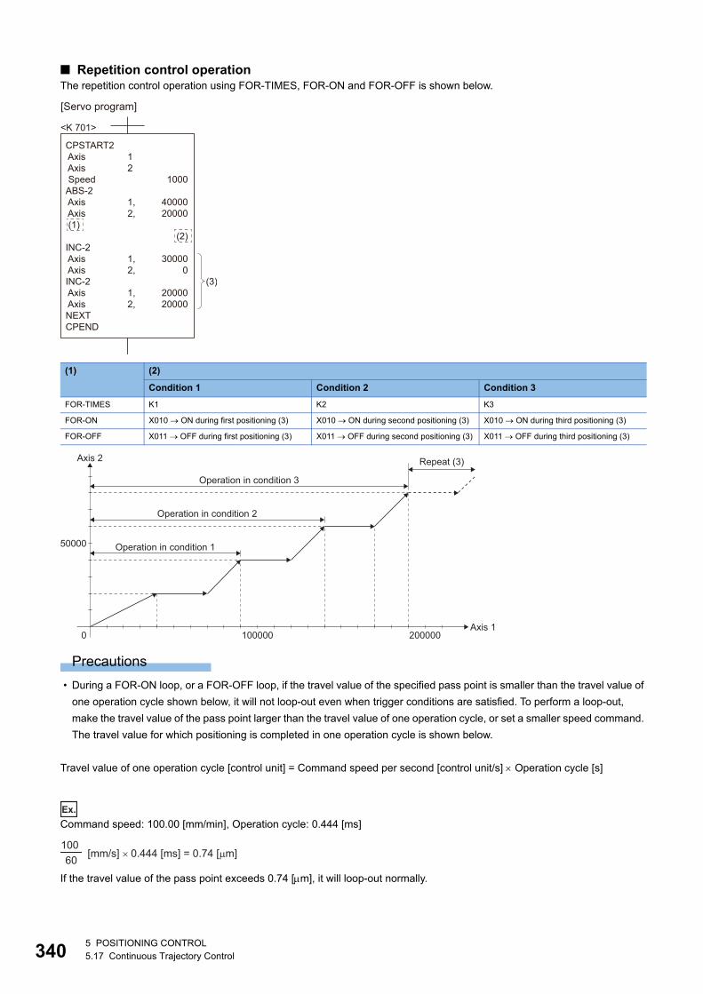
34
■ Repetition control operationThe repetition control operation using FOR-TIMES, FOR-ON and FOR-OFF is shown below.
Precautions
• During a FOR-ON loop, or a FOR-OFF loop, if the travel value of the specified pass point is smaller than the travel value of
one operation cycle shown below, it will not loop-out even when trigger conditions are satisfied. To perform a loop-out,
make the travel value of the pass point larger than the travel value of one operation cycle, or set a smaller speed command.
The travel value for which positioning is completed in one operation cycle is shown below.
Travel value of one operation cycle [control unit] = Command speed per second [control unit/s] Operation cycle [s]
Ex.
Command speed: 100.00 [mm/min], Operation cycle: 0.444 [ms]
If the travel value of the pass point exceeds 0.74 [m], it will loop-out normally.
(1) (2)
Condition 1 Condition 2 Condition 3
FOR-TIMES K1 K2 K3
FOR-ON X010 ON during first positioning (3) X010 ON during second positioning (3) X010 ON during third positioning (3)
FOR-OFF X011 OFF during first positioning (3) X011 OFF during second positioning (3) X011 OFF during third positioning (3)
[Servo program]
<K 701>
CPSTART2 Axis Axis SpeedABS-2 Axis Axis (1)
INC-2 Axis AxisINC-2 Axis AxisNEXTCPEND
1000
4000020000
(2)
30000
0
2000020000
1 2
1,2,
1,2,
1,2,
(3)
Axis 1
Axis 2
0 100000 200000
50000 Operation in condition 1
Operation in condition 2
Operation in condition 3
Repeat (3)
100 60 [mm/s] × 0.444 [ms] = 0.74 [μm]
05 POSITIONING CONTROL5.17 Continuous Trajectory Control
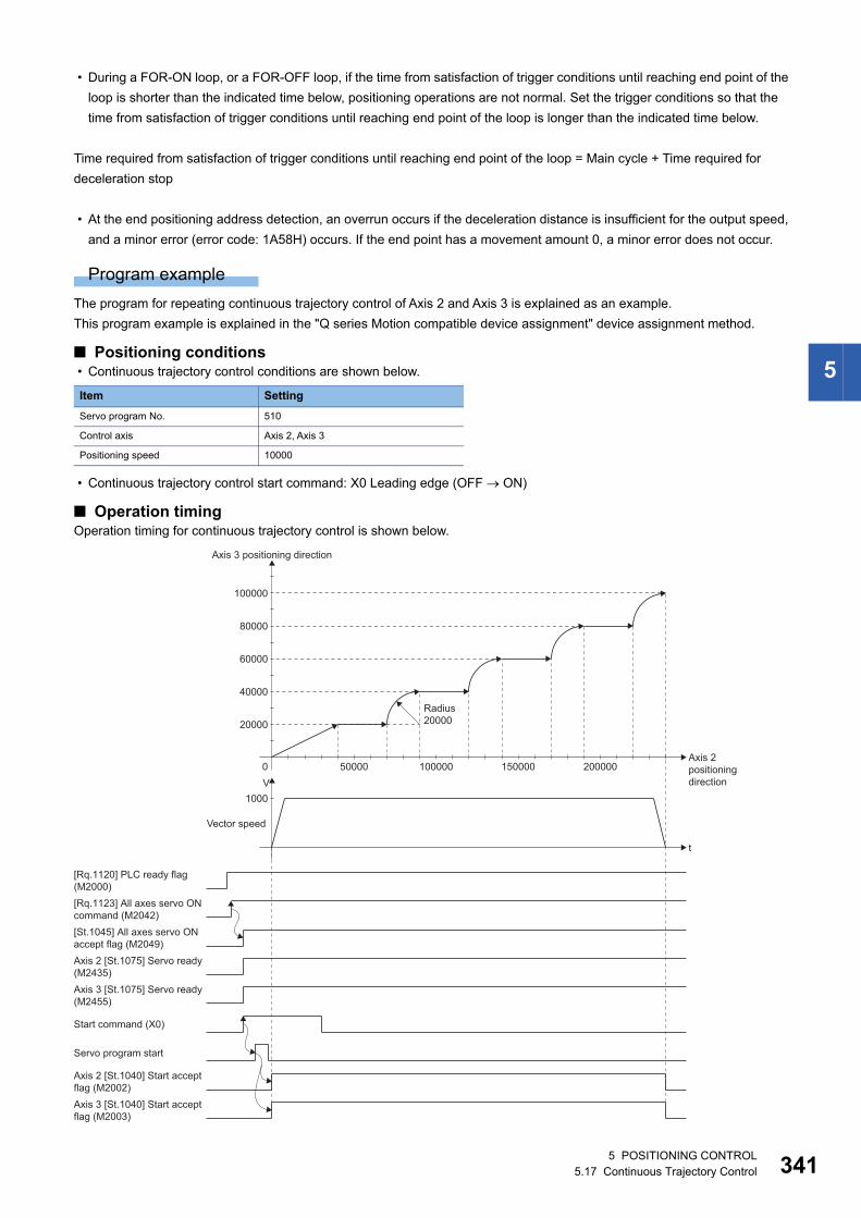
5
• During a FOR-ON loop, or a FOR-OFF loop, if the time from satisfaction of trigger conditions until reaching end point of the
loop is shorter than the indicated time below, positioning operations are not normal. Set the trigger conditions so that the
time from satisfaction of trigger conditions until reaching end point of the loop is longer than the indicated time below.
Time required from satisfaction of trigger conditions until reaching end point of the loop = Main cycle + Time required for
deceleration stop
• At the end positioning address detection, an overrun occurs if the deceleration distance is insufficient for the output speed,
and a minor error (error code: 1A58H) occurs. If the end point has a movement amount 0, a minor error does not occur.
Program example
The program for repeating continuous trajectory control of Axis 2 and Axis 3 is explained as an example.
This program example is explained in the "Q series Motion compatible device assignment" device assignment method.
■ Positioning conditions • Continuous trajectory control conditions are shown below.
• Continuous trajectory control start command: X0 Leading edge (OFF ON)
■ Operation timingOperation timing for continuous trajectory control is shown below.
Item Setting
Servo program No. 510
Control axis Axis 2, Axis 3
Positioning speed 10000
Axis 2 [St.1075] Servo ready(M2435)Axis 3 [St.1075] Servo ready(M2455)
Servo program start
t
V1000
Vector speed
[Rq.1120] PLC ready flag(M2000)[Rq.1123] All axes servo ONcommand (M2042)[St.1045] All axes servo ONaccept flag (M2049)
Start command (X0)
Axis 2 [St.1040] Start acceptflag (M2002)Axis 3 [St.1040] Start acceptflag (M2003)
Axis 2positioningdirection
Axis 3 positioning direction
20000
0
Radius20000
40000
60000
80000
100000
50000 100000 150000 200000
5 POSITIONING CONTROL5.17 Continuous Trajectory Control 341
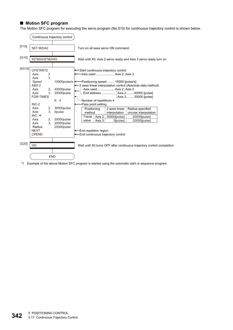
34
■ Motion SFC programThe Motion SFC program for executing the servo program (No.510) for continuous trajectory control is shown below.
*1 Example of the above Motion SFC program is started using the automatic start or sequence program.
Axis used ....................Axis 2, Axis 3End address ...............
!X0[G20]
END
Wait until X0 turns OFF after continuous trajectory control completion.
Continuous trajectory control
SET M2042[F10]
X0*M2435*M2455[G10]
CPSTART2 Axis 2 Axis 3 Speed 10000pulse/sABS-2 Axis 2, 40000pulse Axis 3, 20000pulseFOR-TIMES K 4INC-2 Axis 2, 30000pulse Axis 3, 0pulseINC Axis 2, 20000pulse Axis 3, 20000pulse Radius 20000pulseNEXTCPEND
[K510]
Wait until X0, Axis 2 servo ready and Axis 3 servo ready turn on.
Turn on all axes servo ON command.
Axis 2.........40000 [pulse]Axis 3.........20000 [pulse]
Start continuous trajectory control
End continuous trajectory controlEnd repetition region
Pass point settingNumber of repetitions 4
2 axes linear interpolation control (Absolute data method)Positioning speed .........10000 [pulse/s]
Axis used......................Axis 2, Axis 3
Travelvalue
Positioningmethod
Axis 2
Radius-specifiedcircular interpolation
20000[pulse]20000[pulse]
2 axes linearinterpolation30000[pulse]
0[pulse]Axis 3
25 POSITIONING CONTROL5.17 Continuous Trajectory Control
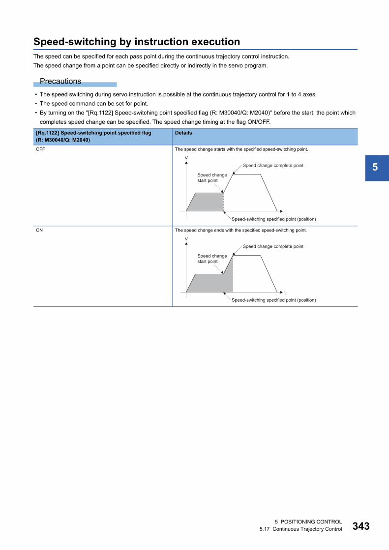
5
Speed-switching by instruction executionThe speed can be specified for each pass point during the continuous trajectory control instruction.
The speed change from a point can be specified directly or indirectly in the servo program.
Precautions
• The speed switching during servo instruction is possible at the continuous trajectory control for 1 to 4 axes.
• The speed command can be set for point.
• By turning on the "[Rq.1122] Speed-switching point specified flag (R: M30040/Q: M2040)" before the start, the point which
completes speed change can be specified. The speed change timing at the flag ON/OFF.
[Rq.1122] Speed-switching point specified flag(R: M30040/Q: M2040)
Details
OFF The speed change starts with the specified speed-switching point.
ON The speed change ends with the specified speed-switching point.
t
VSpeed change complete point
Speed-switching specified point (position)
Speed changestart point
t
VSpeed change complete point
Speed-switching specified point (position)
Speed changestart point
5 POSITIONING CONTROL5.17 Continuous Trajectory Control 343
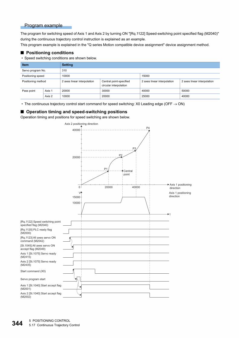
34
Program example
The program for switching speed of Axis 1 and Axis 2 by turning ON "[Rq.1122] Speed-switching point specified flag (M2040)"
during the continuous trajectory control instruction is explained as an example.
This program example is explained in the "Q series Motion compatible device assignment" device assignment method.
■ Positioning conditions • Speed switching conditions are shown below.
• The continuous trajectory control start command for speed switching: X0 Leading edge (OFF ON)
■ Operation timing and speed-switching positionsOperation timing and positions for speed switching are shown below.
Item Setting
Servo program No. 310
Positioning speed 10000 15000
Positioning method 2 axes linear interpolation Central point-specified
circular interpolation
2 axes linear interpolation 2 axes linear interpolation
Pass point Axis 1 20000 30000 40000 50000
Axis 2 10000 20000 25000 40000
Axis 1 positioningdirection
Axis 1 [St.1075] Servo ready (M2415)Axis 2 [St.1075] Servo ready (M2435)
Servo program start
t
V
10000
15000
[Rq.1120] PLC ready flag (M2000)
[Rq.1122] Speed switching pointspecified flag (M2040)
[Rq.1123] All axes servo ONcommand (M2042)[St.1045] All axes servo ONaccept flag (M2049)
Start command (X0)
Axis 1 [St.1040] Start accept flag(M2001)Axis 2 [St.1040] Start accept flag(M2002)
Axis 1 positioningdirection
Axis 2 positioning direction
0
20000
P1
P2
P3
P440000
20000 40000
Centralpoint
45 POSITIONING CONTROL5.17 Continuous Trajectory Control
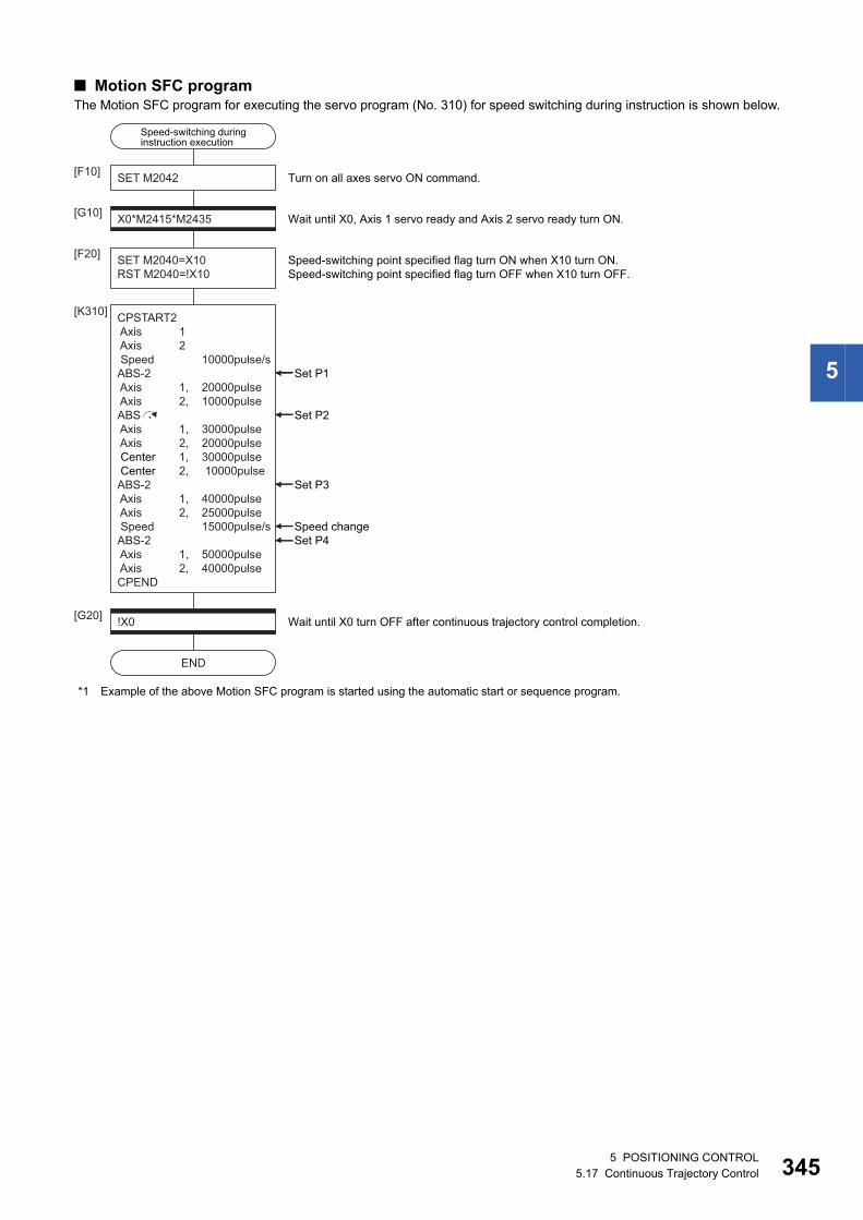
5
■ Motion SFC programThe Motion SFC program for executing the servo program (No. 310) for speed switching during instruction is shown below.
*1 Example of the above Motion SFC program is started using the automatic start or sequence program.
!X0[G20]
END
Wait until X0 turn OFF after continuous trajectory control completion.
SET M2042[F10]
X0*M2415*M2435[G10]
CPSTART2 Axis 1 Axis 2 Speed 10000pulse/sABS-2 Axis 1, 20000pulse Axis 2, 10000pulseABS Axis 1, 30000pulse Axis 2, 20000pulse Center 1, 30000pulse Center 2, 10000pulseABS-2 Axis 1, 40000pulse Axis 2, 25000pulse Speed 15000pulse/sABS-2 Axis 1, 50000pulse Axis 2, 40000pulseCPEND
[K310]
Wait until X0, Axis 1 servo ready and Axis 2 servo ready turn ON.
SET M2040=X10RST M2040=!X10
[F20] Speed-switching point specified flag turn ON when X10 turn ON.Speed-switching point specified flag turn OFF when X10 turn OFF.
Turn on all axes servo ON command.
Set P2
Set P3
Set P4Speed change
Set P1
Speed-switching duringinstruction execution
5 POSITIONING CONTROL5.17 Continuous Trajectory Control 345
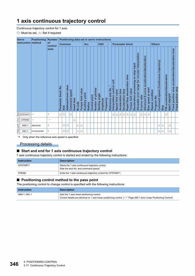
34
1 axis continuous trajectory controlContinuous trajectory control for 1 axis.
: Must be set, : Set if required
*1 Only when the reference axis speed is specified
Processing details
■ Start and end for 1 axis continuous trajectory control1 axis continuous trajectory control is started and ended by the following instructions:
■ Positioning control method to the pass pointThe positioning control to change control is specified with the following instructions:
Instruction Description
CPSTART1 Starts the 1 axis continuous trajectory control.
Sets the axis No. and command speed.
CPEND Ends the 1 axis continuous trajectory control for CPSTART1.
Instruction Description
ABS-1, INC-1 Sets the 1 axis linear positioning control.
Control details are identical to 1 axis linear positioning control. (Page 268 1 Axis Linear Positioning Control)
Positioning data set in servo instructions
Common
Servo instruction
Positioning method
Number ofcontrol axes
Arc OSC Parameter block Others
Para
met
er b
lock
No.
Acc
eler
atio
n tim
eD
ecel
erat
ion
time
Rap
id S
top
dece
lera
tion
time
Torq
ue li
mit
valu
eD
ecel
erat
ion
proc
essi
ng o
n st
op in
put
Allo
wab
le e
rror
rang
e fo
r circ
ular
inte
rpol
atio
nS-
curv
e ra
tioA
dvan
ced
S-cu
rve
acce
lera
tion/
dece
lera
tion
Bia
s sp
eed
at s
tart
Rep
eat c
ondi
tion
Prog
ram
No.
Com
man
d sp
eed
(Con
tinuo
us tr
ajec
tory
)Sk
ipFI
N a
ccel
erat
ion/
dece
lera
tion
WA
IT-O
N/O
FF
Fixe
d po
sitio
n st
op
Axi
sA
ddre
ss/tr
avel
val
ueC
omm
and
spee
dD
wel
l tim
eM
-cod
eTo
rque
lim
it va
lue
Aux
iliar
y po
int
Rad
ius
Cen
tral
poi
ntN
umbe
r of p
itche
sSt
artin
g an
gle
Am
plitu
deFr
eque
ncy
Inte
rpol
atio
n co
ntro
l uni
tSp
eed
limit
valu
e
Ref
eren
ce a
xis
No.
*1
Fixe
d po
sitio
n st
op a
ccel
erat
ion/
dece
lera
tion
time
Sta
rtE
ndP
ass
poin
t
INC-1
ABS-1
CPEND
CPSTART1
Absolute
Incremental
1
1
1
65 POSITIONING CONTROL5.17 Continuous Trajectory Control
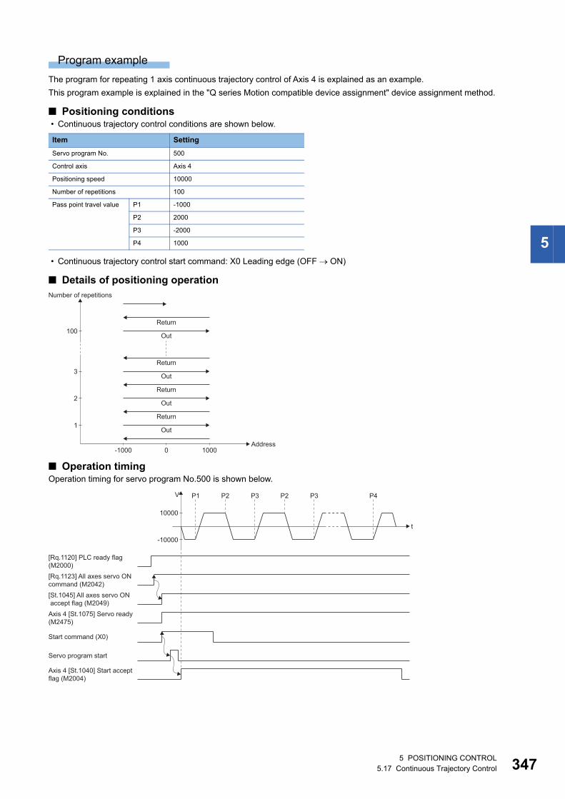
5
Program example
The program for repeating 1 axis continuous trajectory control of Axis 4 is explained as an example.
This program example is explained in the "Q series Motion compatible device assignment" device assignment method.
■ Positioning conditions • Continuous trajectory control conditions are shown below.
• Continuous trajectory control start command: X0 Leading edge (OFF ON)
■ Details of positioning operation
■ Operation timingOperation timing for servo program No.500 is shown below.
Item Setting
Servo program No. 500
Control axis Axis 4
Positioning speed 10000
Number of repetitions 100
Pass point travel value P1 -1000
P2 2000
P3 -2000
P4 1000
1
2
3
100
Number of repetitions
Address-1000 0
Out
1000
Out
Return
Return
Out
Return
Out
Return
Axis 4 [St.1075] Servo ready(M2475)
Servo program start
t
V
10000
P1
-10000
[Rq.1120] PLC ready flag(M2000)[Rq.1123] All axes servo ONcommand (M2042)[St.1045] All axes servo ONaccept flag (M2049)
Start command (X0)
Axis 4 [St.1040] Start acceptflag (M2004)
P2 P3 P2 P3 P4
5 POSITIONING CONTROL5.17 Continuous Trajectory Control 347
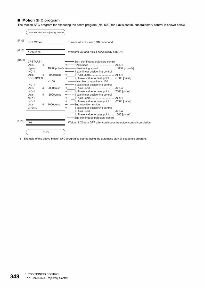
34
■ Motion SFC programThe Motion SFC program for executing the servo program (No. 500) for 1 axis continuous trajectory control is shown below.
*1 Example of the above Motion SFC program is started using the automatic start or sequence program.
�Axis used .................................Axis 4�Travel value to pass point........2000 [pulse]
�Axis used .................................Axis 4�Travel value to pass point........-2000 [pulse]
�Axis used .................................Axis 4�Travel value to pass point........1000 [pulse]
�Axis used .................................Axis 4�Travel value to pass point........-1000 [pulse]
!X0[G20]
END
Wait until X0 turn OFF after continuous trajectory control completion.
SET M2042[F10]
X0*M2475[G10]
CPSTART1 Axis 4 Speed 10000pulse/sINC-1 Axis 4, -1000pulseFOR-TIMES K 100INC-1 Axis 4, 2000pulseINC-1 Axis 4, -2000pulseNEXTINC-1 Axis 4, 1000pulseCPEND
[K500]
Wait until X0 and Axis 4 servo ready turn ON.
Turn on all axes servo ON command.
Start continuous trajectory control
1 axis linear positioning control
1 axis linear positioning control
End repetition region1 axis linear positioning control
End continuous trajectory control
1 axis linear positioning control
Number of repetitions 100
Axis used...................................Axis 4Positioning speed ......................10000 [pulse/s]
1 axis continuous trajectory control
85 POSITIONING CONTROL5.17 Continuous Trajectory Control
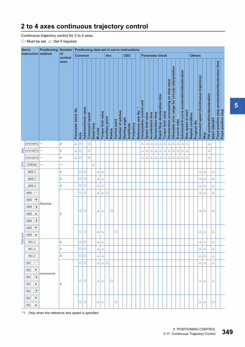
5
2 to 4 axes continuous trajectory controlContinuous trajectory control for 2 to 4 axes.
: Must be set, : Set if required
*1 Only when the reference axis speed is specified
Positioning data set in servo instructions
Common
Servo instruction
Positioning method
Number ofcontrol axes
Arc OSC Parameter block Others
Para
met
er b
lock
No.
Acc
eler
atio
n tim
eD
ecel
erat
ion
time
Rap
id S
top
dece
lera
tion
time
Torq
ue li
mit
valu
eD
ecel
erat
ion
proc
essi
ng o
n st
op in
put
Allo
wab
le e
rror
rang
e fo
r circ
ular
inte
rpol
atio
nS-
curv
e ra
tioA
dvan
ced
S-cu
rve
acce
lera
tion/
dece
lera
tion
Bia
s sp
eed
at s
tart
Rep
eat c
ondi
tion
Prog
ram
No.
Com
man
d sp
eed
(Con
tinuo
us tr
ajec
tory
)Sk
ipFI
N a
ccel
erat
ion/
dece
lera
tion
WA
IT-O
N/O
FF
Fixe
d po
sitio
n st
op
Axi
sA
ddre
ss/tr
avel
val
ueC
omm
and
spee
dD
wel
l tim
eM
-cod
eTo
rque
lim
it va
lue
Aux
iliar
y po
int
Rad
ius
Cen
tral
poi
ntN
umbe
r of p
itche
sSt
artin
g an
gle
Am
plitu
deFr
eque
ncy
Inte
rpol
atio
n co
ntro
l uni
tSp
eed
limit
valu
e
Ref
eren
ce a
xis
No.
*1
Fixe
d po
sitio
n st
op a
ccel
erat
ion/
dece
lera
tion
time
Sta
rtE
ndP
ass
poin
t
CPEND
CPSTART4
CPSTART3
CPSTART2
�
�
�
�
Absolute
Incremental
2
3
4
2
3
4
2
3
4
2
2
�
�
�
�
�
�
�
�
�
�
�
�� � � � � � � � � �
�� � � � � � � � � �
�� � � � � � � � � �
� �
� �
� �
� �
�
�
�
�
�
�
�
�
�
�
�
�
�
�
�
�
� �� � �
�
� � �� �� � �
�
� � �
� �
� �
� �
� �
�
�
�
�
� � �
� � �
� �
�
�
�
�
�
�
� �
� �
� �
� �
�
�
�
�
�
�
� �
� �
� �
�
�
�
�
�
ABS-2
ABS-3
ABS-4
ABS
ABS
ABS
ABS
ABS
ABS
ABS
INC-2
INC-3
INC-4
INC
INC
INC
INC
INC
INC
INC
5 POSITIONING CONTROL5.17 Continuous Trajectory Control 349
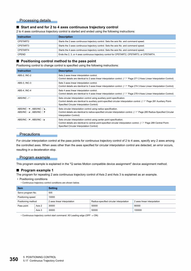
35
Processing details
■ Start and end for 2 to 4 axes continuous trajectory control2 to 4 axes continuous trajectory control is started and ended using the following instructions:
■ Positioning control method to the pass pointPositioning control to change control is specified using the following instructions:
Precautions
For circular interpolation control at the pass points for continuous trajectory control of 2 to 4 axes, specify any 2 axes among
the controlled axes. When axes other than the axes specified for circular interpolation control are detected, an error occurs,
resulting in a deceleration stop.
Program example
This program example is explained in the "Q series Motion compatible device assignment" device assignment method.
■ Program example 1The program for repeating 2 axis continuous trajectory control of Axis 2 and Axis 3 is explained as an example.
• Positioning conditions
Instruction Description
CPSTART2 Starts the 2 axes continuous trajectory control. Sets the axis No. and command speed.
CPSTART3 Starts the 3 axes continuous trajectory control. Sets the axis No. and command speed.
CPSTART4 Starts the 4 axes continuous trajectory control. Sets the axis No. and command speed.
CPEND Ends the 2, 3, or 4 axes continuous trajectory control for CPSTART2, CPSTART3, or CPSTART4.
Instruction Description
ABS-2, INC-2 Sets 2 axes linear interpolation control.
Control details are identical to 2 axes linear interpolation control. (Page 271 2 Axes Linear Interpolation Control)
ABS-3, INC-3 Sets 3 axes linear interpolation control.
Control details are identical to 3 axes linear interpolation control. (Page 274 3 Axes Linear Interpolation Control)
ABS-4, INC-4 Sets 4 axes linear interpolation control.
Control details are identical to 4 axes linear interpolation control. (Page 278 4 Axes Linear Interpolation Control)
ABS/INC Sets circular interpolation control using auxiliary point specification.
Control details are identical to auxiliary point-specified circular interpolation control. (Page 281 Auxiliary Point-
Specified Circular Interpolation Control)
ABS/INC , ABS/INC ,
ABS/INC , ABS/INC
Sets circular interpolation control using radius specification.
Control details are identical to radius-specified circular interpolation control. (Page 285 Radius-Specified Circular
Interpolation Control)
ABS/INC , ABS/INC Sets circular interpolation control using center point specification.
Control details are identical to central point-specified circular interpolation control. (Page 289 Central Point-
Specified Circular Interpolation Control)
• Continuous trajectory control conditions are shown below.
Item Setting
Servo program No. 505
Positioning speed 10000
Positioning method 2 axes linear interpolation Radius-specified circular interpolation 2 axes linear interpolation
Pass point Axis 2 30000 50000 90000
Axis 3 30000 50000 100000
• Continuous trajectory control start command: X0 Leading edge (OFF ON)
05 POSITIONING CONTROL5.17 Continuous Trajectory Control
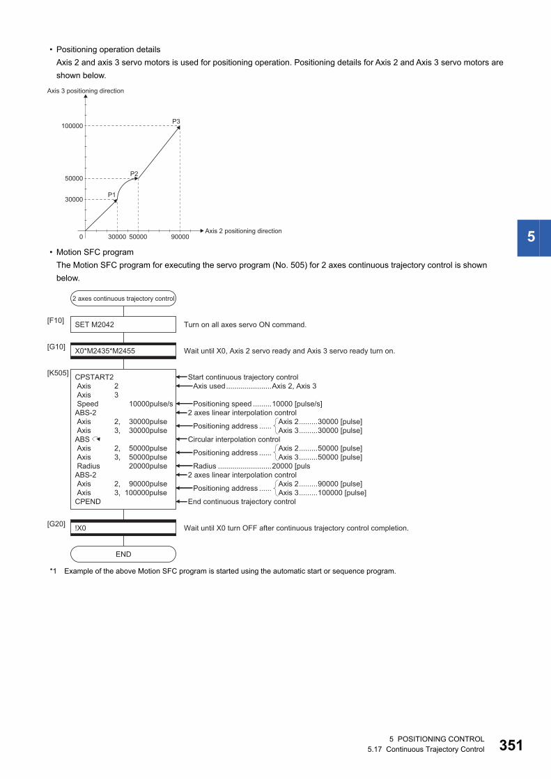
5
• Positioning operation details
Axis 2 and axis 3 servo motors is used for positioning operation. Positioning details for Axis 2 and Axis 3 servo motors are
shown below.
• Motion SFC program
The Motion SFC program for executing the servo program (No. 505) for 2 axes continuous trajectory control is shown
below.
*1 Example of the above Motion SFC program is started using the automatic start or sequence program.
Axis 2 positioning direction
Axis 3 positioning direction
0
50000
100000
30000P1
P2
P3
50000 9000030000
!X0[G20]
END
Wait until X0 turn OFF after continuous trajectory control completion.
SET M2042[F10]
X0*M2435*M2455[G10]
CPSTART2 Axis 2 Axis 3 Speed 10000pulse/sABS-2 Axis 2, 30000pulse Axis 3, 30000pulseABS Axis 2, 50000pulse Axis 3, 50000pulse Radius 20000pulseABS-2 Axis 2, 90000pulse Axis 3, 100000pulseCPEND
[K505]
Wait until X0, Axis 2 servo ready and Axis 3 servo ready turn on.
Turn on all axes servo ON command.
Axis 2.........30000 [pulse]Axis 3.........30000 [pulse]
Start continuous trajectory control
Radius ..........................20000 [puls
Positioning address ......
Axis 2.........50000 [pulse]Axis 3.........50000 [pulse]Positioning address ......
Axis 2.........90000 [pulse]Axis 3.........100000 [pulse]Positioning address ......
2 axes linear interpolation control
2 axes linear interpolation control
End continuous trajectory control
Circular interpolation control
Positioning speed .........10000 [pulse/s]
Axis used......................Axis 2, Axis 3
2 axes continuous trajectory control
5 POSITIONING CONTROL5.17 Continuous Trajectory Control 351
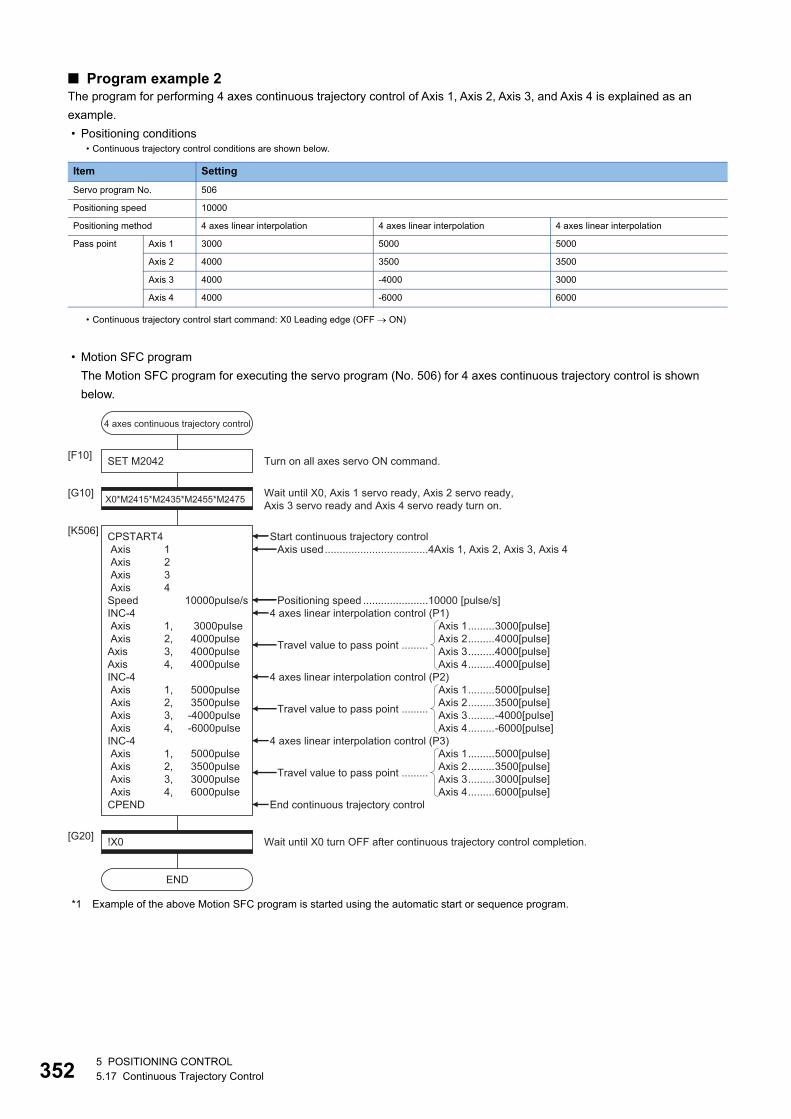
35
■ Program example 2The program for performing 4 axes continuous trajectory control of Axis 1, Axis 2, Axis 3, and Axis 4 is explained as an
example.
• Positioning conditions
• Motion SFC program
The Motion SFC program for executing the servo program (No. 506) for 4 axes continuous trajectory control is shown
below.
*1 Example of the above Motion SFC program is started using the automatic start or sequence program.
• Continuous trajectory control conditions are shown below.
Item Setting
Servo program No. 506
Positioning speed 10000
Positioning method 4 axes linear interpolation 4 axes linear interpolation 4 axes linear interpolation
Pass point Axis 1 3000 5000 5000
Axis 2 4000 3500 3500
Axis 3 4000 -4000 3000
Axis 4 4000 -6000 6000
• Continuous trajectory control start command: X0 Leading edge (OFF ON)
!X0[G20]
END
Wait until X0 turn OFF after continuous trajectory control completion.
SET M2042[F10]
X0*M2415*M2435*M2455*M2475[G10]
CPSTART4 Axis 1 Axis 2 Axis 3 Axis 4Speed 10000pulse/sINC-4 Axis 1, 3000pulse Axis 2, 4000pulseAxis 3, 4000pulseAxis 4, 4000pulseINC-4 Axis 1, 5000pulse Axis 2, 3500pulse Axis 3, -4000pulse Axis 4, -6000pulseINC-4 Axis 1, 5000pulse Axis 2, 3500pulse Axis 3, 3000pulse Axis 4, 6000pulseCPEND
[K506]
Wait until X0, Axis 1 servo ready, Axis 2 servo ready, Axis 3 servo ready and Axis 4 servo ready turn on.
Turn on all axes servo ON command.
Start continuous trajectory control
Axis 1.........5000[pulse]Axis 2.........3500[pulse]Axis 3.........3000[pulse]Axis 4.........6000[pulse]
Travel value to pass point .........
Axis 1.........5000[pulse]Axis 2.........3500[pulse]Axis 3.........-4000[pulse]Axis 4.........-6000[pulse]
Travel value to pass point .........
Axis 1.........3000[pulse]Axis 2.........4000[pulse]Axis 3.........4000[pulse]Axis 4.........4000[pulse]
Travel value to pass point .........
4 axes linear interpolation control (P3)
4 axes linear interpolation control (P2)
4 axes linear interpolation control (P1)
End continuous trajectory control
Axis used...................................4Axis 1, Axis 2, Axis 3, Axis 4
Positioning speed ......................10000 [pulse/s]
4 axes continuous trajectory control
25 POSITIONING CONTROL5.17 Continuous Trajectory Control
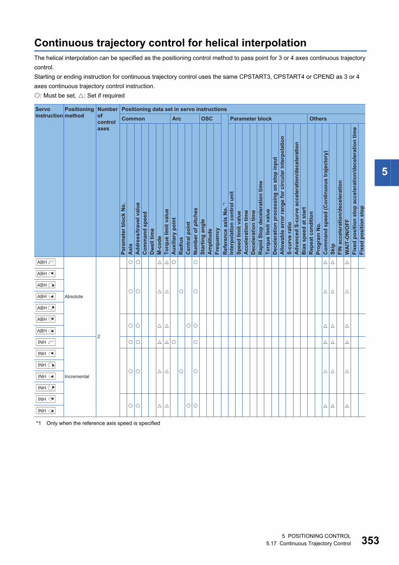
5
Continuous trajectory control for helical interpolationThe helical interpolation can be specified as the positioning control method to pass point for 3 or 4 axes continuous trajectory
control.
Starting or ending instruction for continuous trajectory control uses the same CPSTART3, CPSTART4 or CPEND as 3 or 4
axes continuous trajectory control instruction.
: Must be set, : Set if required
*1 Only when the reference axis speed is specified
ABH
ABH
ABH
ABH
ABH
ABH
ABH
INH
INH
INH
INH
INH
INH
INH
Positioning data set in servo instructions
Common
Servo instruction
Positioning method
Number ofcontrol axes
Arc OSC Parameter block OthersPa
ram
eter
blo
ck N
o.
Acc
eler
atio
n tim
eD
ecel
erat
ion
time
Rap
id S
top
dece
lera
tion
time
Torq
ue li
mit
valu
eD
ecel
erat
ion
proc
essi
ng o
n st
op in
put
Allo
wab
le e
rror
rang
e fo
r circ
ular
inte
rpol
atio
nS-
curv
e ra
tioA
dvan
ced
S-cu
rve
acce
lera
tion/
dece
lera
tion
Bia
s sp
eed
at s
tart
Rep
eat c
ondi
tion
Prog
ram
No.
Com
man
d sp
eed
(Con
tinuo
us tr
ajec
tory
)Sk
ipFI
N a
ccel
erat
ion/
dece
lera
tion
WA
IT-O
N/O
FF
Fixe
d po
sitio
n st
op
Axi
sA
ddre
ss/tr
avel
val
ueC
omm
and
spee
dD
wel
l tim
eM
-cod
eTo
rque
lim
it va
lue
Aux
iliar
y po
int
Rad
ius
Cen
tral
poi
ntN
umbe
r of p
itche
sSt
artin
g an
gle
Am
plitu
deFr
eque
ncy
Inte
rpol
atio
n co
ntro
l uni
tSp
eed
limit
valu
e
Ref
eren
ce a
xis
No.
*1
Fixe
d po
sitio
n st
op a
ccel
erat
ion/
dece
lera
tion
time
Absolute
Incremental
2
� �
� �
� �
� �
� �
� �
� � �
� � �
� � �
� � �
� � �
� � �
� � �
�
�
��
�
��
�
��
�
� �
� �
� �
� �
� �
5 POSITIONING CONTROL5.17 Continuous Trajectory Control 353
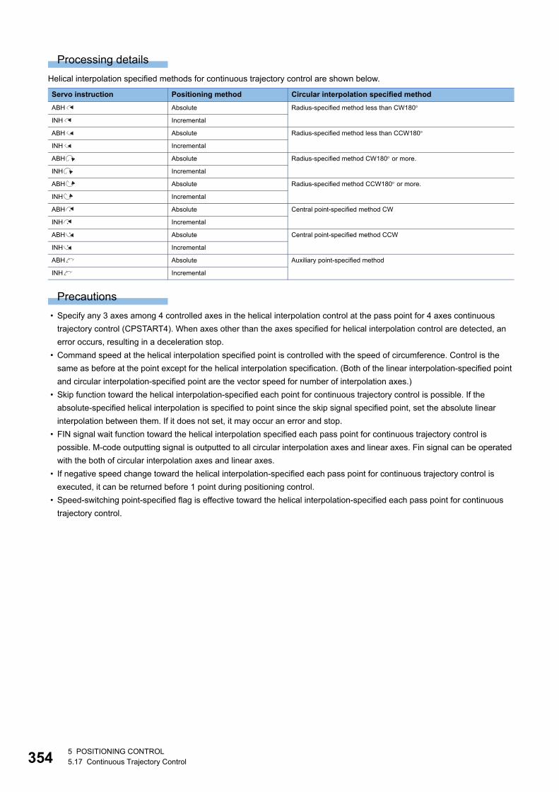
35
Processing details
Helical interpolation specified methods for continuous trajectory control are shown below.
Precautions
• Specify any 3 axes among 4 controlled axes in the helical interpolation control at the pass point for 4 axes continuous
trajectory control (CPSTART4). When axes other than the axes specified for helical interpolation control are detected, an
error occurs, resulting in a deceleration stop.
• Command speed at the helical interpolation specified point is controlled with the speed of circumference. Control is the
same as before at the point except for the helical interpolation specification. (Both of the linear interpolation-specified point
and circular interpolation-specified point are the vector speed for number of interpolation axes.)
• Skip function toward the helical interpolation-specified each point for continuous trajectory control is possible. If the
absolute-specified helical interpolation is specified to point since the skip signal specified point, set the absolute linear
interpolation between them. If it does not set, it may occur an error and stop.
• FIN signal wait function toward the helical interpolation specified each pass point for continuous trajectory control is
possible. M-code outputting signal is outputted to all circular interpolation axes and linear axes. Fin signal can be operated
with the both of circular interpolation axes and linear axes.
• If negative speed change toward the helical interpolation-specified each pass point for continuous trajectory control is
executed, it can be returned before 1 point during positioning control.
• Speed-switching point-specified flag is effective toward the helical interpolation-specified each pass point for continuous
trajectory control.
Servo instruction Positioning method Circular interpolation specified method
ABH Absolute Radius-specified method less than CW180
INH Incremental
ABH Absolute Radius-specified method less than CCW180
INH Incremental
ABH Absolute Radius-specified method CW180 or more.
INH Incremental
ABH Absolute Radius-specified method CCW180 or more.
INH Incremental
ABH Absolute Central point-specified method CW
INH Incremental
ABH Absolute Central point-specified method CCW
INH Incremental
ABH Absolute Auxiliary point-specified method
INH Incremental
45 POSITIONING CONTROL5.17 Continuous Trajectory Control
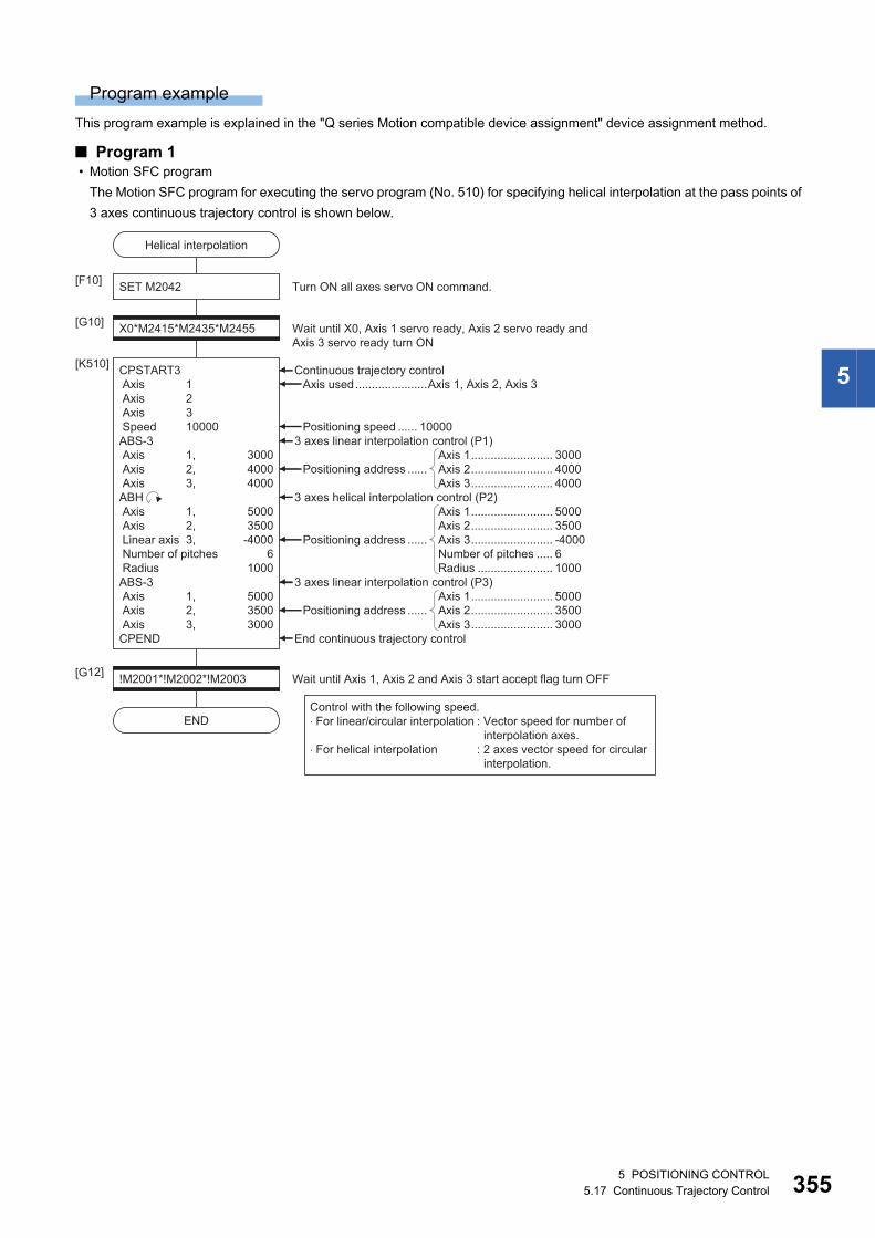
5
Program example
This program example is explained in the "Q series Motion compatible device assignment" device assignment method.
■ Program 1 • Motion SFC program
The Motion SFC program for executing the servo program (No. 510) for specifying helical interpolation at the pass points of
3 axes continuous trajectory control is shown below.
CPSTART3 Axis 1 Axis 2 Axis 3 Speed 10000ABS-3 Axis 1, 3000 Axis 2, 4000 Axis 3, 4000ABH Axis 1, 5000 Axis 2, 3500 Linear axis 3, -4000 Number of pitches 6 Radius 1000ABS-3 Axis 1, 5000 Axis 2, 3500 Axis 3, 3000CPEND
Helical interpolation
SET M2042[F10]
X0*M2415*M2435*M2455[G10]
[K510]
Wait until X0, Axis 1 servo ready, Axis 2 servo ready andAxis 3 servo ready turn ON
Turn ON all axes servo ON command.
!M2001*!M2002*!M2003[G12]
END
Wait until Axis 1, Axis 2 and Axis 3 start accept flag turn OFF
Continuous trajectory control
End continuous trajectory control
Positioning address ......
Positioning address ......
3 axes linear interpolation control (P3)
3 axes helical interpolation control (P2)
Positioning address ......
3 axes linear interpolation control (P1)Positioning speed ...... 10000
Axis used......................Axis 1, Axis 2, Axis 3
Axis 1......................... 5000Axis 2......................... 3500Axis 3......................... 3000
Axis 1......................... 5000Axis 2......................... 3500Axis 3......................... -4000Number of pitches ..... 6Radius ....................... 1000
Axis 1......................... 3000Axis 2......................... 4000Axis 3......................... 4000
Control with the following speed.�For linear/circular interpolation : Vector speed for number of
interpolation axes.�For helical interpolation : 2 axes vector speed for circular
interpolation.
5 POSITIONING CONTROL5.17 Continuous Trajectory Control 355
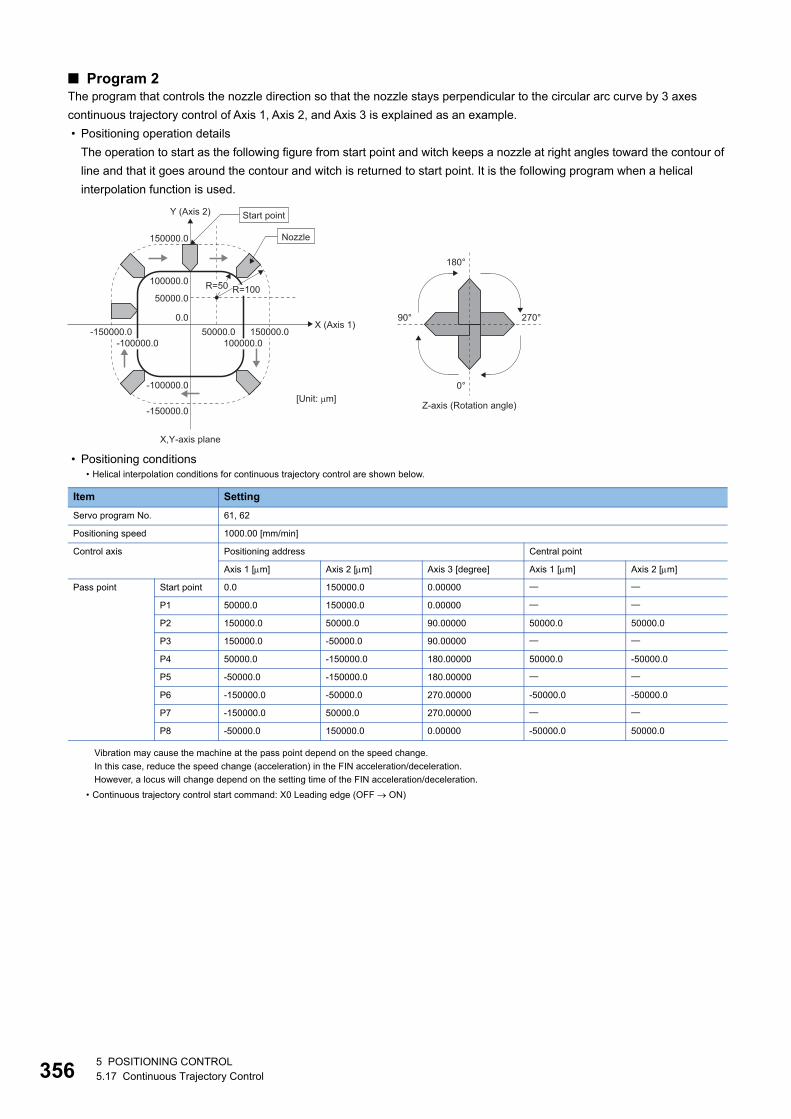
35
■ Program 2The program that controls the nozzle direction so that the nozzle stays perpendicular to the circular arc curve by 3 axes
continuous trajectory control of Axis 1, Axis 2, and Axis 3 is explained as an example.
• Positioning operation details
The operation to start as the following figure from start point and witch keeps a nozzle at right angles toward the contour of
line and that it goes around the contour and witch is returned to start point. It is the following program when a helical
interpolation function is used.
• Positioning conditions• Helical interpolation conditions for continuous trajectory control are shown below.
Item Setting
Servo program No. 61, 62
Positioning speed 1000.00 [mm/min]
Control axis Positioning address Central point
Axis 1 [m] Axis 2 [m] Axis 3 [degree] Axis 1 [m] Axis 2 [m]
Pass point Start point 0.0 150000.0 0.00000
P1 50000.0 150000.0 0.00000
P2 150000.0 50000.0 90.00000 50000.0 50000.0
P3 150000.0 -50000.0 90.00000
P4 50000.0 -150000.0 180.00000 50000.0 -50000.0
P5 -50000.0 -150000.0 180.00000
P6 -150000.0 -50000.0 270.00000 -50000.0 -50000.0
P7 -150000.0 50000.0 270.00000
P8 -50000.0 150000.0 0.00000 -50000.0 50000.0
Vibration may cause the machine at the pass point depend on the speed change.
In this case, reduce the speed change (acceleration) in the FIN acceleration/deceleration.
However, a locus will change depend on the setting time of the FIN acceleration/deceleration.
• Continuous trajectory control start command: X0 Leading edge (OFF ON)
X (Axis 1)
Y (Axis 2)
X,Y-axis plane
[Unit: �m]Z-axis (Rotation angle)
0.0 270°90°
180°
0°
100000.0
150000.0
50000.0
50000.0
R=50
100000.0
-100000.0
-150000.0
-150000.0-100000.0
Nozzle
Start point
150000.0
R=100
65 POSITIONING CONTROL5.17 Continuous Trajectory Control
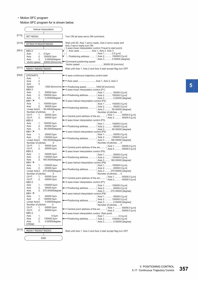
5
• Motion SFC program
Motion SFC program for is shown below.
CPSTART3 Axis 1 Axis 2 Axis 3 Speed 1000.00mm/minABS-3 Axis 1, 50000.0μm Axis 2, 150000.0μm Axis 3, 0.00000degreeABH Axis 1, 150000.0μm Axis 2, 50000.0μm Linear Axis 3, 90.00000degree Number of pitches 0 Ctr.P. 1, 50000.0μm Ctr.P. 2, 50000.0μmABS-3 Axis 1, 150000.0μm Axis 2, -50000.0μm Axis 3, 90.00000degreeABH Axis 1, 50000.0μm Axis 2, -150000.0μm Linear Axis 3, 180.00000degree Number of pitches 0 Ctr.P. 1, 50000.0μm Ctr.P. 2, -50000.0μmABS-3 Axis 1, -50000.0μm Axis 2, -150000.0μm Axis 3, 180.00000degreeABH Axis 1, -150000.0μm Axis 2, -50000.0μm Linear Axis 3, 270.00000degree Number of pitches 0 Ctr.P. 1, -50000.0μm Ctr.P. 2, -50000.0μmABS-3 Axis 1, -150000.0μm Axis 2, 50000.0μm Axis 3, 270.00000degreeABH Axis 1, -50000.0μm Axis 2, 150000.0μm Linear Axis 3, 0.00000degree Number of pitches 0 Ctr.P. 1, -50000.0μm Ctr.P. 2, 50000.0μmABS-3 Axis 1, 0.0μm Axis 2, 150000.0μm Axis 3, 0.00000degreeCPEND
[K62] 3 axes continuous trajectory control start
3 axes linear interpolation control (Travel to start point)
Command positioning speedVector speed ....................................30000.00 [mm/min]
Axis used........................... Axis 1, Axis 2, Axis 3
Positioning speed .............. 1000.00 [mm/min]3 axes linear interpolation control (P1)
3 axes helical interpolation control (P2)
3 axes linear interpolation control (P3)
3 axes helical interpolation control (P4)
3 axes linear interpolation control (P5)
3 axes helical interpolation control (P6)
3 axes linear interpolation control (P7)
3 axes helical interpolation control (P8)
3 axes linear interpolation control Start point
Positioning address ...........
Positioning address ...........Axis 1 .......... 150000.0 [m]Axis 2 ........... -50000.0 [m]Axis 3 .......... 90.00000 [degree]
Axis 1 ............ 50000.0 [m]Axis 2 .......... 150000.0 [m]Axis 3 ............ 0.00000 [degree]
Axis used .................. Axis 1, Axis 2, Axis 3
Positioning address .........Axis 1........... 0.0 [m]Axis 2........... 150000.0 [m]Axis 3........... 0.00000 [degree]
Positioning address ...........Axis 1 ........... -50000.0 [m]Axis 2 ......... -150000.0 [m]Axis 3 ........ 180.00000 [degree]
Positioning address ...........Axis 1 ......... -150000.0 [m]Axis 2 ............ 50000.0 [m]Axis 3 ........ 270.00000 [degree]
Positioning address ...........Axis 1 .................... 0.0 [m]Axis 2 .......... 150000.0 [m]Axis 3 ............ 0.00000 [degree]
Positioning address ...........
Axis 1 .......... 150000.0 [m]Axis 2 ............ 50000.0 [m]Axis 3 .......... 90.00000 [degree]Number of pitches .... 0
Positioning address ...........
Axis 1 ............ 50000.0 [m]Axis 2 ......... -150000.0 [m]Axis 3 ........ 180.00000 [degree]Number of pitches .... 0
Positioning address ...........
Axis 1 ......... -150000.0 [m]Axis 2 ........... -50000.0 [m]Axis 3 ........ 270.00000 [degree]Number of pitches .... 0
Positioning address ...........
Axis 1 ........... -50000.0 [m]Axis 2 .......... 150000.0 [m]Axis 3 ............ 0.00000 [degree]Number of pitches .... 0
!M2001*!M2002*!M2003[G12]Wait until Axis 1, Axis 2 and Axis 3 start accept flag turn OFF
Central point address of the arc .......Axis 1 .......... 50000.0 [m]Axis 2 .......... 50000.0 [m]
Central point address of the arc .......Axis 1 .......... 50000.0 [m]Axis 2 ......... -50000.0 [m]
Central point address of the arc .......Axis 1 ......... -50000.0 [m]Axis 2 ......... -50000.0 [m]
Central point address of the arc .......Axis 1 ......... -50000.0 [m]Axis 2 .......... 50000.0 [m]
SET M2042[F10]
X0*M2415*M2435*M2455[G10] Wait until X0, Axis 1 servo ready, Axis 2 servo ready and Axis 3 servo ready turn ON
!M2001*!M2002*!M2003[G11] Wait until Axis 1, Axis 2 and Axis 3 start accept flag turn OFF
[K61]
Turn ON all axes servo ON command.
ABS-3 Axis 1, 0.0μm Axis 2, 150000.0μm Axis 3, 0.00000degree Vectro speed 30000.00mm/min
Helical interpolation
END
5 POSITIONING CONTROL5.17 Continuous Trajectory Control 357
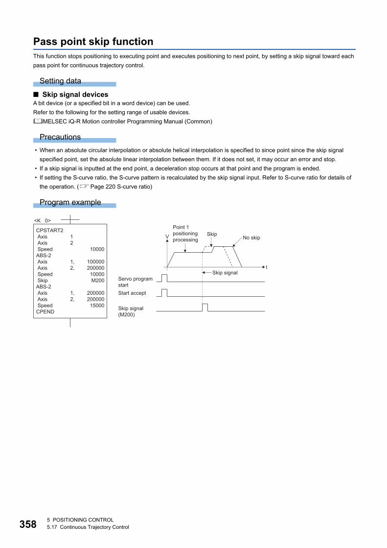
35
Pass point skip functionThis function stops positioning to executing point and executes positioning to next point, by setting a skip signal toward each
pass point for continuous trajectory control.
Setting data
■ Skip signal devicesA bit device (or a specified bit in a word device) can be used.
Refer to the following for the setting range of usable devices.
MELSEC iQ-R Motion controller Programming Manual (Common)
Precautions
• When an absolute circular interpolation or absolute helical interpolation is specified to since point since the skip signal
specified point, set the absolute linear interpolation between them. If it does not set, it may occur an error and stop.
• If a skip signal is inputted at the end point, a deceleration stop occurs at that point and the program is ended.
• If setting the S-curve ratio, the S-curve pattern is recalculated by the skip signal input. Refer to S-curve ratio for details of
the operation. (Page 220 S-curve ratio)
Program example
<K 0>
CPSTART2 Axis Axis SpeedABS-2 Axis Axis Speed SkipABS-2 Axis Axis SpeedCPEND
10000
100000200000
10000M200
200000200000
15000
1 2
1,2,
1,2,
t
V
Skip signal
No skipSkip
Point 1positioning processing
Servo programstartStart accept
Skip signal(M200)
85 POSITIONING CONTROL5.17 Continuous Trajectory Control
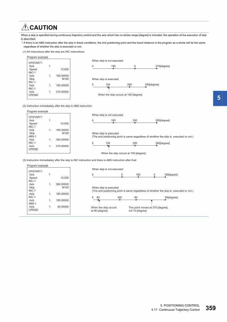
5
CAUTIONWhen a skip is specified during continuous trajectory control and the axis which has no stroke range [degree] is included, the operation at the execution of skip
is described.
• If there is an ABS instruction after the skip in these conditions, the end positioning point and the travel distance in the program as a whole will be the same
regardless of whether the skip is executed or not.
(1) All instructions after the skip are INC instructions:
Program example
CPSTART1 Axis SpeedINC-1 Axis SkipINC-1 AxisINC-1 AxisCPEND
10.000
180.00000M100
180.00000
270.00000
1
1,
1,
1,
0
When skip is not executed
180 0 270[degree]
0
When skip is executed
When the skip occurs at 100 [degree]
100 280 190[degree]
(2) Instruction immediately after the skip is ABS instruction:
Program example
CPSTART1 Axis SpeedINC-1 Axis SkipABS-1 AxisINC-1 AxisCPEND
10.000
180.00000M100
350.00000
270.00000
1
1,
1,
1,
0
When skip is not executed
180 350 260[degree]
0
When skip is executed(The end positioning point is same regardless of whether the skip is executed or not.)
When the skip occurs at 100 [degree]
100 350 260[degree]
(3) Instruction immediately after the skip is INC instruction and there is ABS instruction after that:
Program example
CPSTART1 Axis SpeedINC-1 Axis SkipINC-1 AxisINC-1 AxisABS-1 AxisCPEND
10.000
360.00000M100
180.00000
180.00000
90.00000
1
1,
1,
1,
1,
0
When skip is not executed
0 180 90[degree]0
0
When skip is executed(The end positioning point is same regardless of whether the skip is executed or not.)
This point moves at 370 [degree], not 10 [degree].
When the skip occursat 80 [degree]
80 80260 90[degree]
5 POSITIONING CONTROL5.17 Continuous Trajectory Control 359
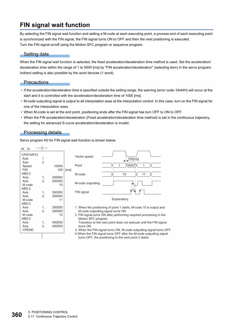
36
FIN signal wait functionBy selecting the FIN signal wait function and setting a M-code at each executing point, a process end of each executing point
is synchronized with the FIN signal, the FIN signal turns ON to OFF and then the next positioning is executed.
Turn the FIN signal on/off using the Motion SFC program or sequence program.
Setting data
When the FIN signal wait function is selected, the fixed acceleration/deceleration time method is used. Set the acceleration/
deceleration time within the range of 1 to 5000 [ms] by "FIN acceleration/deceleration" (selecting item) in the servo program.
Indirect setting is also possible by the word devices (1 word).
Precautions
• If the acceleration/deceleration time is specified outside the setting range, the warning (error code: 0A44H) will occur at the
start and it is controlled with the acceleration/deceleration time of 1000 [ms].
• M-code outputting signal is output to all interpolation axes at the interpolation control. In this case, turn on the FIN signal for
one of the interpolation axes.
• When M-code is set at the end point, positioning ends after the FIN signal has turn OFF to ON to OFF.
• When the FIN acceleration/deceleration (Fixed acceleration/deceleration time method) is set in the continuous trajectory,
the setting for advanced S-curve acceleration/deceleration is invalid.
Processing details
Servo program K0 for FIN signal wait function is shown below.
<K 0>
CPSTART2 Axis Axis Speed FINABS-2 Axis Axis M codeABS-2 Axis Axis M codeABS-2 Axis Axis M codeABS-2 Axis Axis CPEND
10000100
200000200000
10
300000250000
11
350000300000
12
400000400000
[ms]
1 2
1,2,
1,2,
1,2,
1,2,
M-code outputting
M-code
FIN signal
10
100[ms]
11
Point
Vector speed
1 WAIT 1
Explanatory
1. When the positioning of point 1 starts, M-code 10 is output andM-code outputting signal turns ON.
2. FIN signal turns ON after performing required processing in theMotion SFC program. Transition to the next point does not execute until the FIN signalturns ON.
3. When the FIN signal turns ON, M-code outputting signal turns OFF.4.When the FIN signal turns OFF after the M-code outputting signal
turns OFF, the positioning to the next point 2 starts.
05 POSITIONING CONTROL5.17 Continuous Trajectory Control
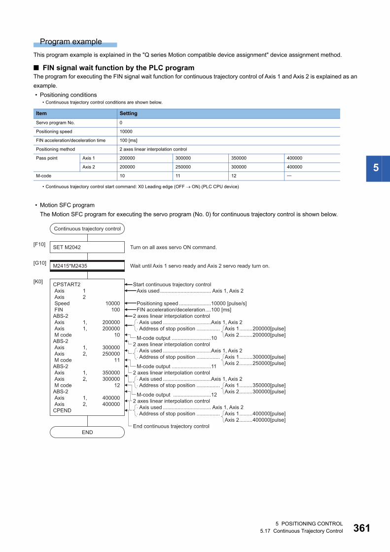
5
Program example
This program example is explained in the "Q series Motion compatible device assignment" device assignment method.
■ FIN signal wait function by the PLC programThe program for executing the FIN signal wait function for continuous trajectory control of Axis 1 and Axis 2 is explained as an
example.
• Positioning conditions
• Motion SFC program
The Motion SFC program for executing the servo program (No. 0) for continuous trajectory control is shown below.
• Continuous trajectory control conditions are shown below.
Item Setting
Servo program No. 0
Positioning speed 10000
FIN acceleration/deceleration time 100 [ms]
Positioning method 2 axes linear interpolation control
Pass point Axis 1 200000 300000 350000 400000
Axis 2 200000 250000 300000 400000
M-code 10 11 12
• Continuous trajectory control start command: X0 Leading edge (OFF ON) (PLC CPU device)
END
Continuous trajectory control
SET M2042[F10]
M2415*M2435[G10]
CPSTART2 Axis 1 Axis 2 Speed 10000 FIN 100ABS-2 Axis 1, 200000 Axis 1, 200000 M code 10ABS-2 Axis 1, 300000 Axis 2, 250000 M code 11ABS-2 Axis 1, 350000 Axis 2, 300000 M code 12ABS-2 Axis 1, 400000 Axis 2, 400000CPEND
[K0]
Wait until Axis 1 servo ready and Axis 2 servo ready turn on.
Turn on all axes servo ON command.
Start continuous trajectory control
2 axes linear interpolation control
2 axes linear interpolation control
2 axes linear interpolation control
FIN acceleration/deceleration....100 [ms]Positioning speed ......................10000 [pulse/s]
Axis used................................... Axis 1, Axis 2
� Axis used .................................Axis 1, Axis 2� Address of stop position ................ Axis 1.........200000[pulse]
Axis 2.........200000[pulse]M-code output ...........................10
2 axes linear interpolation control
� Axis used .................................Axis 1, Axis 2� Address of stop position ................ Axis 1.........300000[pulse]
Axis 2.........250000[pulse]M-code output ...........................11
M-code output ..........................12
� Axis used ................................. Axis 1, Axis 2� Address of stop position ................ Axis 1.........400000[pulse]
Axis 2.........400000[pulse]
� Axis used .................................Axis 1, Axis 2� Address of stop position ................ Axis 1.........350000[pulse]
Axis 2.........300000[pulse]
End continuous trajectory control
5 POSITIONING CONTROL5.17 Continuous Trajectory Control 361
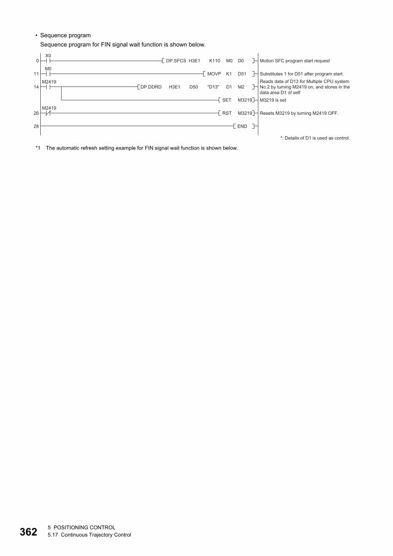
36
• Sequence program
Sequence program for FIN signal wait function is shown below.
*1 The automatic refresh setting example for FIN signal wait function is shown below.
0 Motion SFC program start request
Substitutes 1 for D51 after program start.Reads data of D13 for Multiple CPU systemNo.2 by turning M2419 on, and stores in thedata area D1 of self M3219 is set
Resets M3219 by turning M2419 OFF.
*: Details of D1 is used as control.
11
14
26
28
X0DP.SFCS H3E1 K110 M0 D0
M0MOVP K1 D51
M2419DP.DDRD H3E1 D50 "D13" D1 M2
SET M3219
M2419RST M3219
END
25 POSITIONING CONTROL5.17 Continuous Trajectory Control
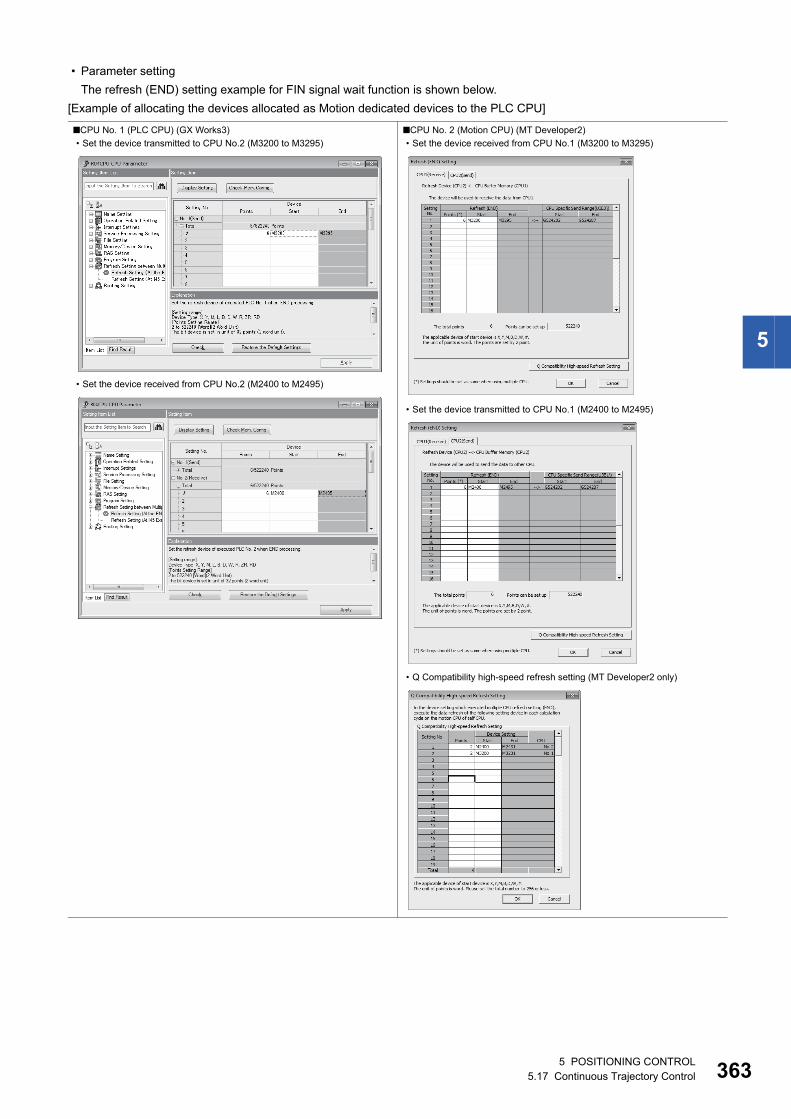
5
• Parameter setting
The refresh (END) setting example for FIN signal wait function is shown below.
[Example of allocating the devices allocated as Motion dedicated devices to the PLC CPU]
■CPU No. 1 (PLC CPU) (GX Works3)
• Set the device transmitted to CPU No.2 (M3200 to M3295)
• Set the device received from CPU No.2 (M2400 to M2495)
■CPU No. 2 (Motion CPU) (MT Developer2)
• Set the device received from CPU No.1 (M3200 to M3295)
• Set the device transmitted to CPU No.1 (M2400 to M2495)
• Q Compatibility high-speed refresh setting (MT Developer2 only)
5 POSITIONING CONTROL5.17 Continuous Trajectory Control 363
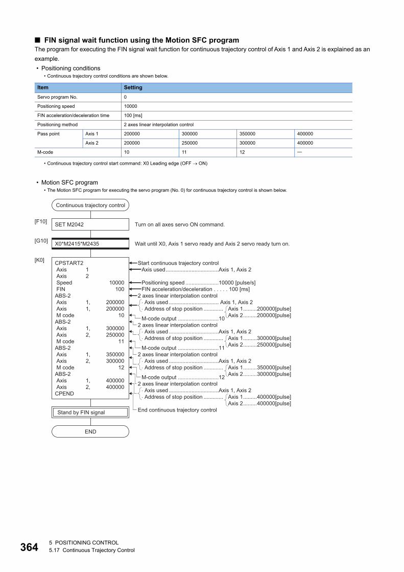
36
■ FIN signal wait function using the Motion SFC programThe program for executing the FIN signal wait function for continuous trajectory control of Axis 1 and Axis 2 is explained as an
example.
• Positioning conditions
• Motion SFC program
• Continuous trajectory control conditions are shown below.
Item Setting
Servo program No. 0
Positioning speed 10000
FIN acceleration/deceleration time 100 [ms]
Positioning method 2 axes linear interpolation control
Pass point Axis 1 200000 300000 350000 400000
Axis 2 200000 250000 300000 400000
M-code 10 11 12
• Continuous trajectory control start command: X0 Leading edge (OFF ON)
• The Motion SFC program for executing the servo program (No. 0) for continuous trajectory control is shown below.
END
Continuous trajectory control
SET M2042[F10]
Stand by FIN signal
X0*M2415*M2435[G10]
CPSTART2 Axis 1 Axis 2 Speed 10000 FIN 100ABS-2 Axis 1, 200000 Axis 1, 200000 M code 10ABS-2 Axis 1, 300000 Axis 2, 250000 M code 11ABS-2 Axis 1, 350000 Axis 2, 300000 M code 12ABS-2 Axis 1, 400000 Axis 2, 400000CPEND
[K0]
Wait until X0, Axis 1 servo ready and Axis 2 servo ready turn on.
Turn on all axes servo ON command.
Start continuous trajectory control
2 axes linear interpolation control
2 axes linear interpolation control
2 axes linear interpolation control
FIN acceleration/deceleration . . . . . 100 [ms]Positioning speed ......................10000 [pulse/s]
Axis used...................................Axis 1, Axis 2
� Axis used ................................. Axis 1, Axis 2� Address of stop position ............. Axis 1.........200000[pulse]
Axis 2.........200000[pulse]M-code output ...........................10
2 axes linear interpolation control
� Axis used .................................Axis 1, Axis 2� Address of stop position ............. Axis 1.........300000[pulse]
Axis 2.........250000[pulse]M-code output ...........................11
M-code output ...........................12
� Axis used .................................Axis 1, Axis 2� Address of stop position ............. Axis 1.........400000[pulse]
Axis 2.........400000[pulse]
� Axis used .................................Axis 1, Axis 2� Address of stop position ............. Axis 1.........350000[pulse]
Axis 2.........300000[pulse]
End continuous trajectory control
45 POSITIONING CONTROL5.17 Continuous Trajectory Control
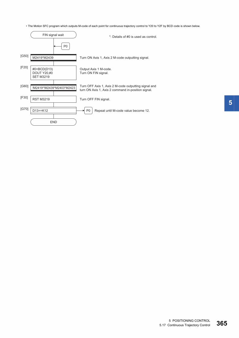
5
• The Motion SFC program which outputs M-code of each point for continuous trajectory control to Y20 to Y2F by BCD code is shown below.
END
FIN signal wait
P0
M2419*M2439[G50]
#0=BCD(D13)DOUT Y20,#0SET M3219
[F20] Output Axis 1 M-code.Turn ON FIN signal.
Turn ON Axis 1, Axis 2 M-code outputting signal.
*: Details of #0 is used as control.
!M2419*!M2439*M2403*M2423[G60] Turn OFF Axis 1, Axis 2 M-code outputting signal and turn ON Axis 1, Axis 2 command in-position signal.
RST M3219[F30] Turn OFF FIN signal.
D13==K12[G70] Repeat until M-code value become 12.P0
5 POSITIONING CONTROL5.17 Continuous Trajectory Control 365
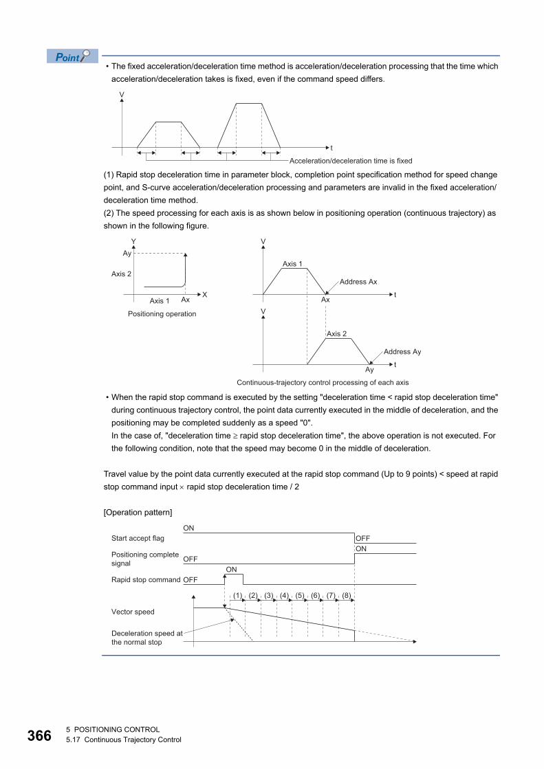
36
• The fixed acceleration/deceleration time method is acceleration/deceleration processing that the time which
acceleration/deceleration takes is fixed, even if the command speed differs.
(1) Rapid stop deceleration time in parameter block, completion point specification method for speed change
point, and S-curve acceleration/deceleration processing and parameters are invalid in the fixed acceleration/
deceleration time method.
(2) The speed processing for each axis is as shown below in positioning operation (continuous trajectory) as
shown in the following figure.
• When the rapid stop command is executed by the setting "deceleration time < rapid stop deceleration time"
during continuous trajectory control, the point data currently executed in the middle of deceleration, and the
positioning may be completed suddenly as a speed "0".
In the case of, "deceleration time rapid stop deceleration time", the above operation is not executed. For
the following condition, note that the speed may become 0 in the middle of deceleration.
Travel value by the point data currently executed at the rapid stop command (Up to 9 points) < speed at rapid
stop command input rapid stop deceleration time / 2
[Operation pattern]
t
V
Acceleration/deceleration time is fixed
Axt
V
Axis 1
Address Ax
X
YAy
Axis 1
Positioning operation
t
V
Axis 2
Address Ay
Ax
Ay
Continuous-trajectory control processing of each axis
Axis 2
ON
(1) (2) (3) (4) (5) (6) (7) (8)
OFF
ONOFF
ONStart accept flag
Rapid stop command
Positioning completesignal
Vector speed
Deceleration speed atthe normal stop
OFF
65 POSITIONING CONTROL5.17 Continuous Trajectory Control
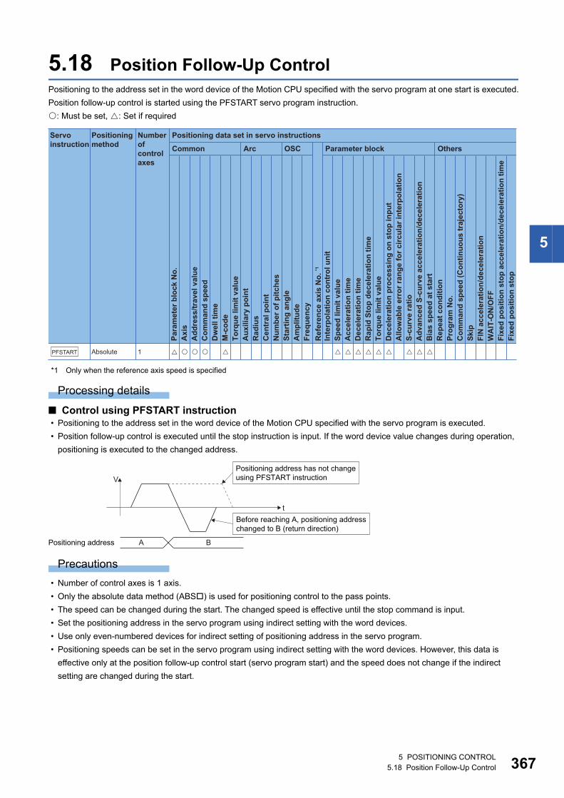
5
5.18 Position Follow-Up ControlPositioning to the address set in the word device of the Motion CPU specified with the servo program at one start is executed.
Position follow-up control is started using the PFSTART servo program instruction.
: Must be set, : Set if required
*1 Only when the reference axis speed is specified
Processing details
■ Control using PFSTART instruction • Positioning to the address set in the word device of the Motion CPU specified with the servo program is executed.
• Position follow-up control is executed until the stop instruction is input. If the word device value changes during operation,
positioning is executed to the changed address.
Precautions
• Number of control axes is 1 axis.
• Only the absolute data method (ABS) is used for positioning control to the pass points.
• The speed can be changed during the start. The changed speed is effective until the stop command is input.
• Set the positioning address in the servo program using indirect setting with the word devices.
• Use only even-numbered devices for indirect setting of positioning address in the servo program.
• Positioning speeds can be set in the servo program using indirect setting with the word devices. However, this data is
effective only at the position follow-up control start (servo program start) and the speed does not change if the indirect
setting are changed during the start.
Positioning data set in servo instructions
Common
Servo instruction
Positioning method
Number ofcontrol axes
Arc OSC Parameter block Others
Para
met
er b
lock
No.
Acc
eler
atio
n tim
eD
ecel
erat
ion
time
Rap
id S
top
dece
lera
tion
time
Torq
ue li
mit
valu
eD
ecel
erat
ion
proc
essi
ng o
n st
op in
put
Allo
wab
le e
rror
rang
e fo
r circ
ular
inte
rpol
atio
nS-
curv
e ra
tioA
dvan
ced
S-cu
rve
acce
lera
tion/
dece
lera
tion
Bia
s sp
eed
at s
tart
Rep
eat c
ondi
tion
Prog
ram
No.
Com
man
d sp
eed
(Con
tinuo
us tr
ajec
tory
)Sk
ipFI
N a
ccel
erat
ion/
dece
lera
tion
WA
IT-O
N/O
FF
Fixe
d po
sitio
n st
op
Axi
sA
ddre
ss/tr
avel
val
ueC
omm
and
spee
dD
wel
l tim
eM
-cod
eTo
rque
lim
it va
lue
Aux
iliar
y po
int
Rad
ius
Cen
tral
poi
ntN
umbe
r of p
itche
sSt
artin
g an
gle
Am
plitu
deFr
eque
ncy
Inte
rpol
atio
n co
ntro
l uni
tSp
eed
limit
valu
e
Ref
eren
ce a
xis
No.
*1
Fixe
d po
sitio
n st
op a
ccel
erat
ion/
dece
lera
tion
time
PFSTART Absolute 1 � � � � � � � � � �� � � �
V
Positioning address A B
t
Positioning address has not changeusing PFSTART instruction
Before reaching A, positioning addresschanged to B (return direction)
5 POSITIONING CONTROL5.18 Position Follow-Up Control 367
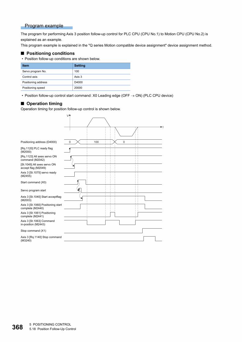
36
Program example
The program for performing Axis 3 position follow-up control for PLC CPU (CPU No.1) to Motion CPU (CPU No.2) is
explained as an example.
This program example is explained in the "Q series Motion compatible device assignment" device assignment method.
■ Positioning conditions • Position follow-up conditions are shown below.
• Position follow-up control start command: X0 Leading edge (OFF ON) (PLC CPU device)
■ Operation timingOperation timing for position follow-up control is shown below.
Item Setting
Servo program No. 100
Control axis Axis 3
Positioning address D4000
Positioning speed 20000
Axis 3 [St.1075] servo ready(M2455)
Servo program start
Axis 3 [St.1060] Positioning start complete (M2440)Axis 3 [St.1061] Positioningcomplete (M2441)Axis 3 [St.1063] Commandin-position (M2443)
t
V
[Rq.1120] PLC ready flag(M2000)
Positioning address (D4000) 0 100 0
[Rq.1123] All axes servo ON command (M2042)[St.1045] All axes servo ON accept flag (M2049)
Start command (X0)
Axis 3 [St.1040] Start acceptflag (M2003)
Stop command (X1)
Axis 3 [Rq.1140] Stop command (M3240)
85 POSITIONING CONTROL5.18 Position Follow-Up Control
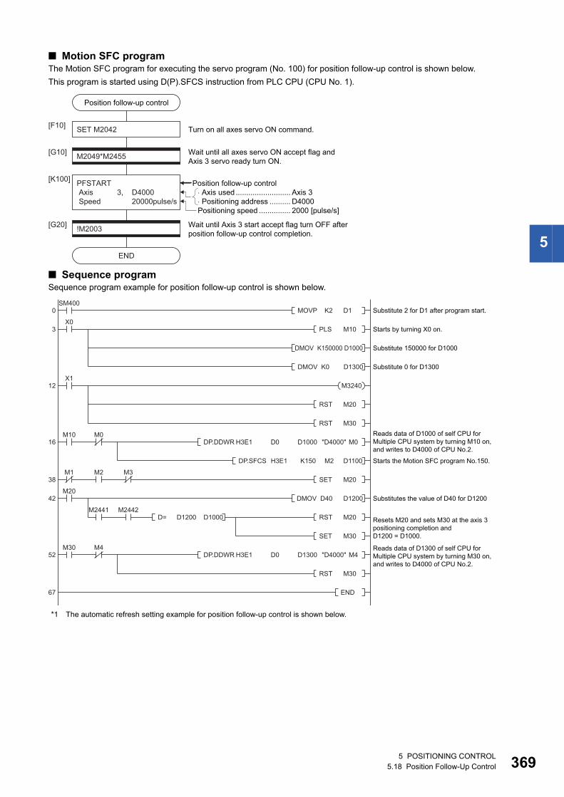
5
■ Motion SFC programThe Motion SFC program for executing the servo program (No. 100) for position follow-up control is shown below.
This program is started using D(P).SFCS instruction from PLC CPU (CPU No. 1).
■ Sequence programSequence program example for position follow-up control is shown below.
*1 The automatic refresh setting example for position follow-up control is shown below.
� Axis used .......................... Axis 3� Positioning address .......... D4000
Position follow-up control
SET M2042[F10]
M2049*M2455[G10]
PFSTART Axis 3, D4000 Speed 20000pulse/s
[K100]
Wait until all axes servo ON accept flag andAxis 3 servo ready turn ON.
Turn on all axes servo ON command.
!M2003[G20]
END
Wait until Axis 3 start accept flag turn OFF after position follow-up control completion.
Position follow-up control
Positioning speed ............... 2000 [pulse/s]
0 Substitute 2 for D1 after program start.
Starts by turning X0 on.
Substitute 150000 for D1000
Substitute 0 for D1300
Reads data of D1000 of self CPU for Multiple CPU system by turning M10 on, and writes to D4000 of CPU No.2.
Starts the Motion SFC program No.150.
Substitutes the value of D40 for D1200
Resets M20 and sets M30 at the axis 3 positioning completion and D1200 = D1000.
Reads data of D1300 of self CPU for Multiple CPU system by turning M30 on, and writes to D4000 of CPU No.2.
3
12
SM400
DP.SFCS H3E1 K150 M2 D1100
X0
X1
DMOV K150000 D1000
DMOV K0 D1300
DMOV D40 D1200
D= D1200 D1000
MOVP K2 D1
DP.DDWR H3E1 D0 D1000 "D4000" M0
DP.DDWR H3E1 D0 D1300 "D4000" M4
PLS M10
M1
M20
M2 M3
M2441 M2442
M0
RST M20
RST M30
SET M20
RST M20
SET M30
RST M30
16
38
42
52
67
M10
M4M30
END
M3240
5 POSITIONING CONTROL5.18 Position Follow-Up Control 369
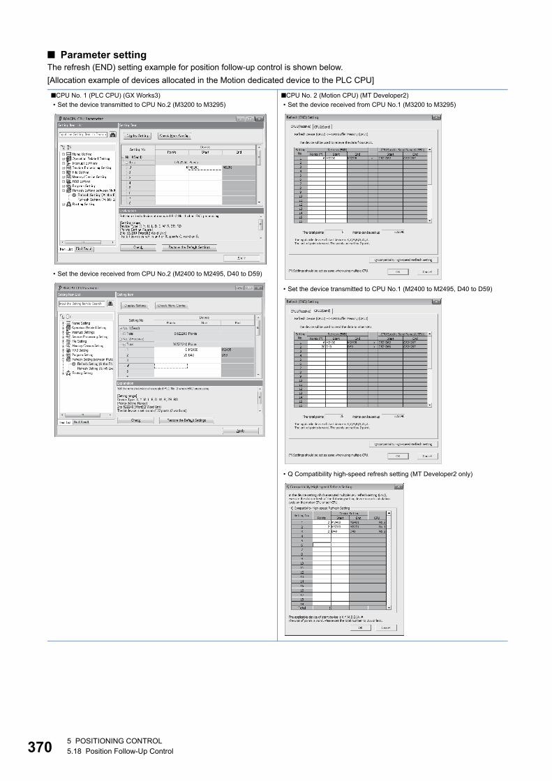
37
■ Parameter settingThe refresh (END) setting example for position follow-up control is shown below.
[Allocation example of devices allocated in the Motion dedicated device to the PLC CPU]
■CPU No. 1 (PLC CPU) (GX Works3)
• Set the device transmitted to CPU No.2 (M3200 to M3295)
• Set the device received from CPU No.2 (M2400 to M2495, D40 to D59)
■CPU No. 2 (Motion CPU) (MT Developer2)
• Set the device received from CPU No.1 (M3200 to M3295)
• Set the device transmitted to CPU No.1 (M2400 to M2495, D40 to D59)
• Q Compatibility high-speed refresh setting (MT Developer2 only)
05 POSITIONING CONTROL5.18 Position Follow-Up Control
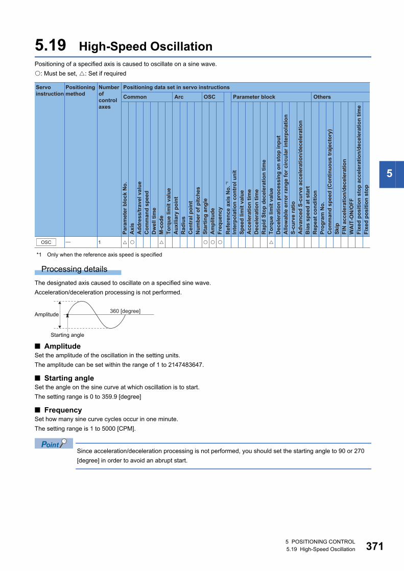
5
5.19 High-Speed OscillationPositioning of a specified axis is caused to oscillate on a sine wave.
: Must be set, : Set if required
*1 Only when the reference axis speed is specified
Processing details
The designated axis caused to oscillate on a specified sine wave.
Acceleration/deceleration processing is not performed.
■ AmplitudeSet the amplitude of the oscillation in the setting units.
The amplitude can be set within the range of 1 to 2147483647.
■ Starting angleSet the angle on the sine curve at which oscillation is to start.
The setting range is 0 to 359.9 [degree]
■ FrequencySet how many sine curve cycles occur in one minute.
The setting range is 1 to 5000 [CPM].
Since acceleration/deceleration processing is not performed, you should set the starting angle to 90 or 270
[degree] in order to avoid an abrupt start.
Positioning data set in servo instructions
Common
Servo instruction
Positioning method
Number ofcontrol axes
Arc OSC Parameter block Others
Para
met
er b
lock
No.
Acc
eler
atio
n tim
eD
ecel
erat
ion
time
Rap
id S
top
dece
lera
tion
time
Torq
ue li
mit
valu
eD
ecel
erat
ion
proc
essi
ng o
n st
op in
put
Allo
wab
le e
rror
rang
e fo
r circ
ular
inte
rpol
atio
nS-
curv
e ra
tioA
dvan
ced
S-cu
rve
acce
lera
tion/
dece
lera
tion
Bia
s sp
eed
at s
tart
Rep
eat c
ondi
tion
Prog
ram
No.
Com
man
d sp
eed
(Con
tinuo
us tr
ajec
tory
)Sk
ipFI
N a
ccel
erat
ion/
dece
lera
tion
WA
IT-O
N/O
FF
Fixe
d po
sitio
n st
op
Axi
sA
ddre
ss/tr
avel
val
ueC
omm
and
spee
dD
wel
l tim
eM
-cod
eTo
rque
lim
it va
lue
Aux
iliar
y po
int
Rad
ius
Cen
tral
poi
ntN
umbe
r of p
itche
sSt
artin
g an
gle
Am
plitu
deFr
eque
ncy
Inte
rpol
atio
n co
ntro
l uni
tSp
eed
limit
valu
e
Ref
eren
ce a
xis
No.
*1
Fixe
d po
sitio
n st
op a
ccel
erat
ion/
dece
lera
tion
time
OSC � 1 � �� � � ��
Starting angle
360 [degree]Amplitude
5 POSITIONING CONTROL5.19 High-Speed Oscillation 371
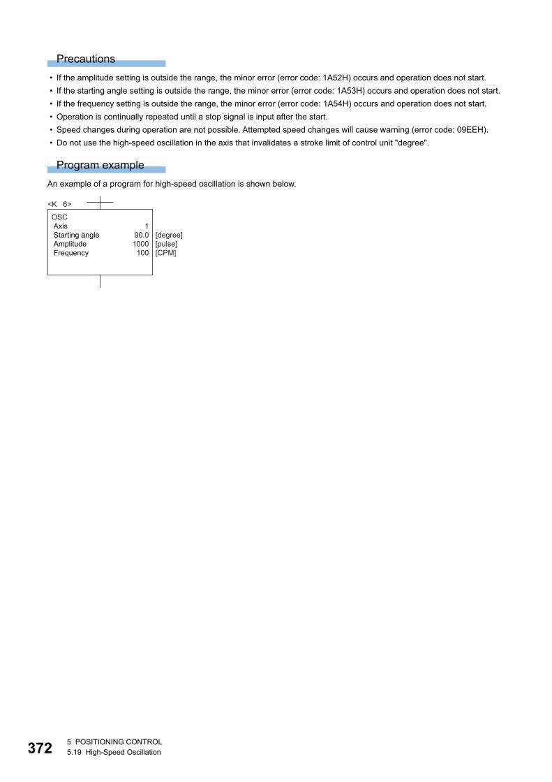
37
Precautions
• If the amplitude setting is outside the range, the minor error (error code: 1A52H) occurs and operation does not start.
• If the starting angle setting is outside the range, the minor error (error code: 1A53H) occurs and operation does not start.
• If the frequency setting is outside the range, the minor error (error code: 1A54H) occurs and operation does not start.
• Operation is continually repeated until a stop signal is input after the start.
• Speed changes during operation are not possible. Attempted speed changes will cause warning (error code: 09EEH).
• Do not use the high-speed oscillation in the axis that invalidates a stroke limit of control unit "degree".
Program example
An example of a program for high-speed oscillation is shown below.
OSC Axis 1 Starting angle 90.0 Amplitude 1000 Frequency 100
<K 6>
[degree][pulse][CPM]
25 POSITIONING CONTROL5.19 High-Speed Oscillation
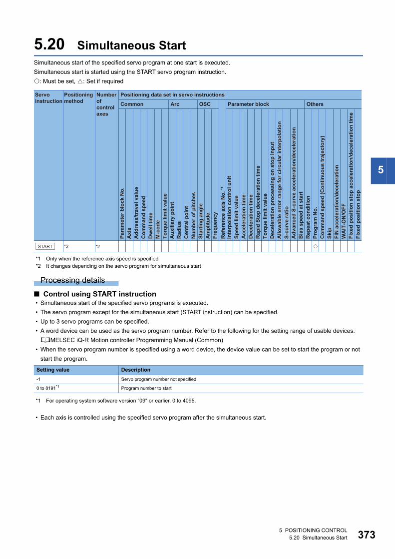
5
5.20 Simultaneous StartSimultaneous start of the specified servo program at one start is executed.
Simultaneous start is started using the START servo program instruction.
: Must be set, : Set if required
*1 Only when the reference axis speed is specified*2 It changes depending on the servo program for simultaneous start
Processing details
■ Control using START instruction • Simultaneous start of the specified servo programs is executed.
• The servo program except for the simultaneous start (START instruction) can be specified.
• Up to 3 servo programs can be specified.
• A word device can be used as the servo program number. Refer to the following for the setting range of usable devices.
MELSEC iQ-R Motion controller Programming Manual (Common)
• When the servo program number is specified using a word device, the device value can be set to start the program or not
start the program.
*1 For operating system software version "09" or earlier, 0 to 4095.
• Each axis is controlled using the specified servo program after the simultaneous start.
Setting value Description
-1 Servo program number not specified
0 to 8191*1 Program number to start
Positioning data set in servo instructions
Common
Servo instruction
Positioning method
Number ofcontrol axes
Arc OSC Parameter block Others
Para
met
er b
lock
No.
Acc
eler
atio
n tim
eD
ecel
erat
ion
time
Rap
id S
top
dece
lera
tion
time
Torq
ue li
mit
valu
eD
ecel
erat
ion
proc
essi
ng o
n st
op in
put
Allo
wab
le e
rror
rang
e fo
r circ
ular
inte
rpol
atio
nS-
curv
e ra
tioA
dvan
ced
S-cu
rve
acce
lera
tion/
dece
lera
tion
Bia
s sp
eed
at s
tart
Rep
eat c
ondi
tion
Prog
ram
No.
Com
man
d sp
eed
(Con
tinuo
us tr
ajec
tory
)Sk
ipFI
N a
ccel
erat
ion/
dece
lera
tion
WA
IT-O
N/O
FF
Fixe
d po
sitio
n st
op
Axi
sA
ddre
ss/tr
avel
val
ueC
omm
and
spee
dD
wel
l tim
eM
-cod
eTo
rque
lim
it va
lue
Aux
iliar
y po
int
Rad
ius
Cen
tral
poi
ntN
umbe
r of p
itche
sSt
artin
g an
gle
Am
plitu
deFr
eque
ncy
Inte
rpol
atio
n co
ntro
l uni
tSp
eed
limit
valu
e
Ref
eren
ce a
xis
No.
*1
Fixe
d po
sitio
n st
op a
ccel
erat
ion/
dece
lera
tion
time
START *2 *2 �
5 POSITIONING CONTROL5.20 Simultaneous Start 373
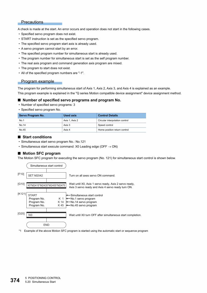
37
Precautions
A check is made at the start. An error occurs and operation does not start in the following cases.
• Specified servo program does not exist.
• START instruction is set as the specified servo program.
• The specified servo program start axis is already used.
• A servo program cannot start by an error.
• The specified program number for simultaneous start is already used.
• The program number for simultaneous start is set as the self program number.
• The real axis program and command generation axis program are mixed.
• The program to start does not exist.
• All of the specified program numbers are "-1".
Program example
The program for performing simultaneous start of Axis 1, Axis 2, Axis 3, and Axis 4 is explained as an example.
This program example is explained in the "Q series Motion compatible device assignment" device assignment method.
■ Number of specified servo programs and program No. • Number of specified servo programs: 3
• Specified servo program No.
■ Start conditions • Simultaneous start servo program No.: No.121
• Simultaneous start execute command: X0 Leading edge (OFF ON)
■ Motion SFC programThe Motion SFC program for executing the servo program (No. 121) for simultaneous start control is shown below.
*1 Example of the above Motion SFC program is started using the automatic start or sequence program
Servo Program No. Used axis Control Details
No.1 Axis 1, Axis 2 Circular interpolation control
No.14 Axis 3 Speed control
No.45 Axis 4 Home position return control
Simultaneous start control
SET M2042[F10]
X0*M2415*M2435*M2455*M2475[G10]
START Program No. K 1 Program No. K 14 Program No. K 45
[K121]
Wait until X0, Axis 1 servo ready, Axis 2 servo ready, Axis 3 servo ready and Axis 4 servo ready turn ON.
Turn on all axes servo ON command.
!X0[G20]
END
Wait until X0 turn OFF after simultaneous start completion.
Simultaneous start controlNo.1 servo programNo.14 servo programNo.45 servo program
45 POSITIONING CONTROL5.20 Simultaneous Start
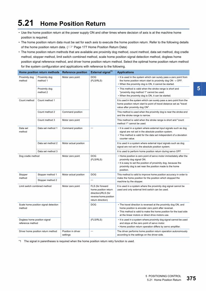
5
5.21 Home Position Return • Use the home position return at the power supply ON and other times where decision of axis is at the machine home
position is required.
• The home position return data must be set for each axis to execute the home position return. Refer to the following details
of the home position return data. (Page 177 Home Position Return Data)
• The home position return methods that are available are proximity dog method, count method, data set method, dog cradle
method, stopper method, limit switch combined method, scale home position signal detection method, dogless home
position signal reference method, and driver home position return method. Select the optimal home position return method
for the system configuration and applications with reference to the following.
*1 The signal in parentheses is required when the home position return retry function is used.
Home position return methods Reference position External signal*1 Applications
Proximity dog
method
Proximity dog
method 1
Motor zero point DOG
(FLS/RLS)
• It is used in the system which can surely pass a zero point from
the home position return start to proximity dog ON OFF.
• When the proximity dog is ON, it cannot be started.
Proximity dog
method 2
• This method is valid when the stroke range is short and
"proximity dog method 1" cannot be used.
• When the proximity dog is ON, it can be started.
Count method Count method 1 It is used in the system which can surely pass a zero point from the
home position return start to point of travel distance set as "travel
value after proximity dog ON".
Count method 2 Command position This method is used when the proximity dog is near the stroke end
and the stroke range is narrow.
Count method 3 Motor zero point This method is valid when the stroke range is short and "count
method 1" cannot be used.
Data set
method
Data set method 1 Command position • It is used in a system where external input signals such as dog
signal are not set in the absolute position system.
• This method is valid for the data set independent of a deviation
counter value.
Data set method 2 Motor actual position It is used in a system where external input signals such as dog
signal are not set in the absolute position system.
Data set method 3 It is used to perform home position return during servo OFF.
Dog cradle method Motor zero point DOG
(FLS/RLS)
• Home position is zero point of servo motor immediately after the
proximity dog signal ON.
• It is easy to set the position of proximity dog, because the
proximity dog is set near the position made to the home
position.
Stopper
method
Stopper method 1 Motor actual position DOG This method is valid to improve home position accuracy in order to
make the home position for the position which stopped the
machine by the stopper.Stopper method 2
Limit switch combined method Motor zero point FLS (for forward
home position return
direction)/RLS (for
reverse home position
return direction)
It is used in a system where the proximity dog signal cannot be
used and only external limit switch can be used.
Scale home position signal detection
method
DOG • The travel direction is reversed at the proximity dog ON, and
home position is encoder zero point after reversal.
• This method is valid to make the home position for the load side
at the linear motors or direct drive motors use.
Dogless home position signal
reference method
(FLS/RLS) • It is used in a system where proximity dog signal cannot be used
and stops at the zero point of servo motor.
• Home position return operation differs by servo amplifier.
Driver home position return method Position in driver
settings
The driver performs home position return operation autonomously
according to the settings on the driver-side.
5 POSITIONING CONTROL5.21 Home Position Return 375
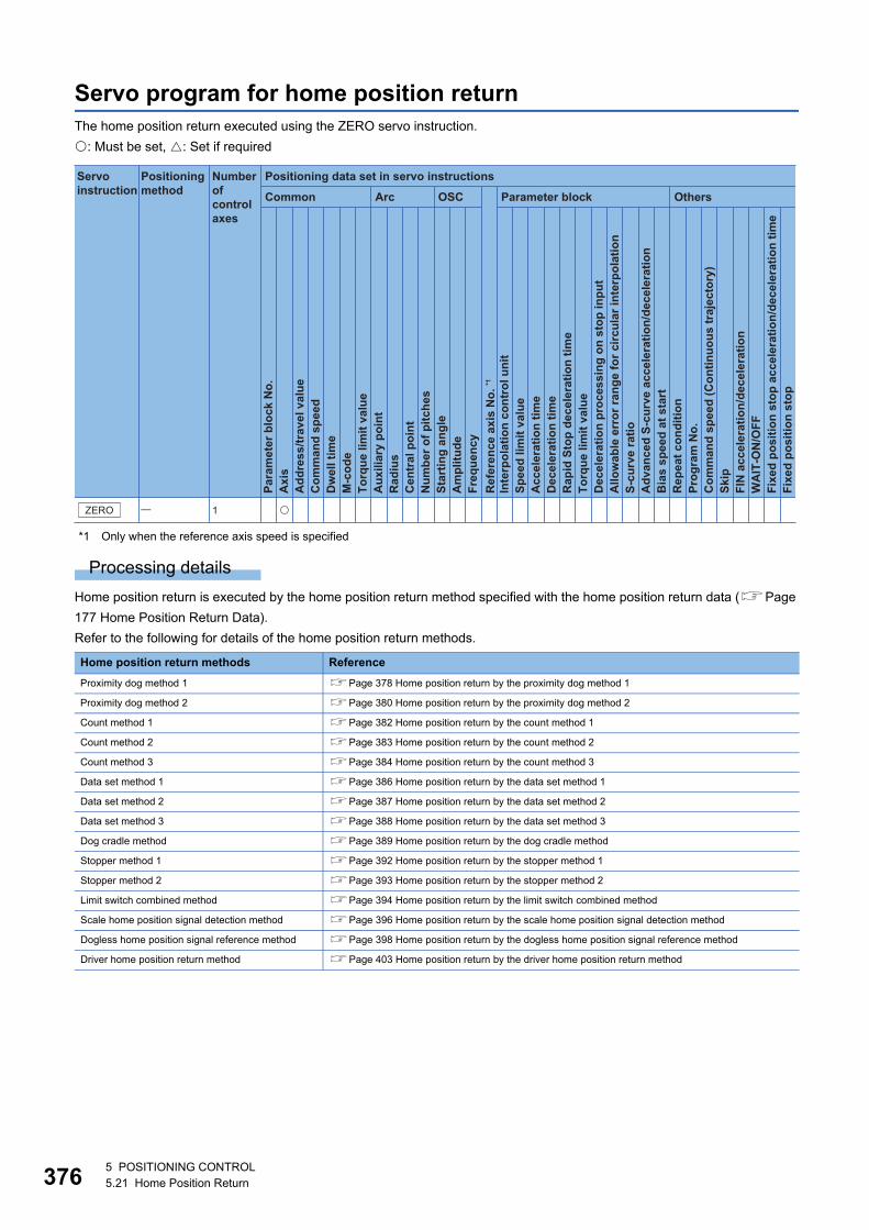
37
Servo program for home position returnThe home position return executed using the ZERO servo instruction.
: Must be set, : Set if required
*1 Only when the reference axis speed is specified
Processing details
Home position return is executed by the home position return method specified with the home position return data (Page
177 Home Position Return Data).
Refer to the following for details of the home position return methods.
Home position return methods Reference
Proximity dog method 1 Page 378 Home position return by the proximity dog method 1
Proximity dog method 2 Page 380 Home position return by the proximity dog method 2
Count method 1 Page 382 Home position return by the count method 1
Count method 2 Page 383 Home position return by the count method 2
Count method 3 Page 384 Home position return by the count method 3
Data set method 1 Page 386 Home position return by the data set method 1
Data set method 2 Page 387 Home position return by the data set method 2
Data set method 3 Page 388 Home position return by the data set method 3
Dog cradle method Page 389 Home position return by the dog cradle method
Stopper method 1 Page 392 Home position return by the stopper method 1
Stopper method 2 Page 393 Home position return by the stopper method 2
Limit switch combined method Page 394 Home position return by the limit switch combined method
Scale home position signal detection method Page 396 Home position return by the scale home position signal detection method
Dogless home position signal reference method Page 398 Home position return by the dogless home position signal reference method
Driver home position return method Page 403 Home position return by the driver home position return method
Positioning data set in servo instructions
Common
Servo instruction
Positioning method
Number ofcontrol axes
Arc OSC Parameter block Others
Para
met
er b
lock
No.
Acc
eler
atio
n tim
eD
ecel
erat
ion
time
Rap
id S
top
dece
lera
tion
time
Torq
ue li
mit
valu
eD
ecel
erat
ion
proc
essi
ng o
n st
op in
put
Allo
wab
le e
rror
rang
e fo
r circ
ular
inte
rpol
atio
nS-
curv
e ra
tioA
dvan
ced
S-cu
rve
acce
lera
tion/
dece
lera
tion
Bia
s sp
eed
at s
tart
Rep
eat c
ondi
tion
Prog
ram
No.
Com
man
d sp
eed
(Con
tinuo
us tr
ajec
tory
)Sk
ipFI
N a
ccel
erat
ion/
dece
lera
tion
WA
IT-O
N/O
FF
Fixe
d po
sitio
n st
op
Axi
sA
ddre
ss/tr
avel
val
ueC
omm
and
spee
dD
wel
l tim
eM
-cod
eTo
rque
lim
it va
lue
Aux
iliar
y po
int
Rad
ius
Cen
tral
poi
ntN
umbe
r of p
itche
sSt
artin
g an
gle
Am
plitu
deFr
eque
ncy
Inte
rpol
atio
n co
ntro
l uni
tSp
eed
limit
valu
e
Ref
eren
ce a
xis
No.
*1
Fixe
d po
sitio
n st
op a
ccel
erat
ion/
dece
lera
tion
time
ZERO � 1 �
65 POSITIONING CONTROL5.21 Home Position Return
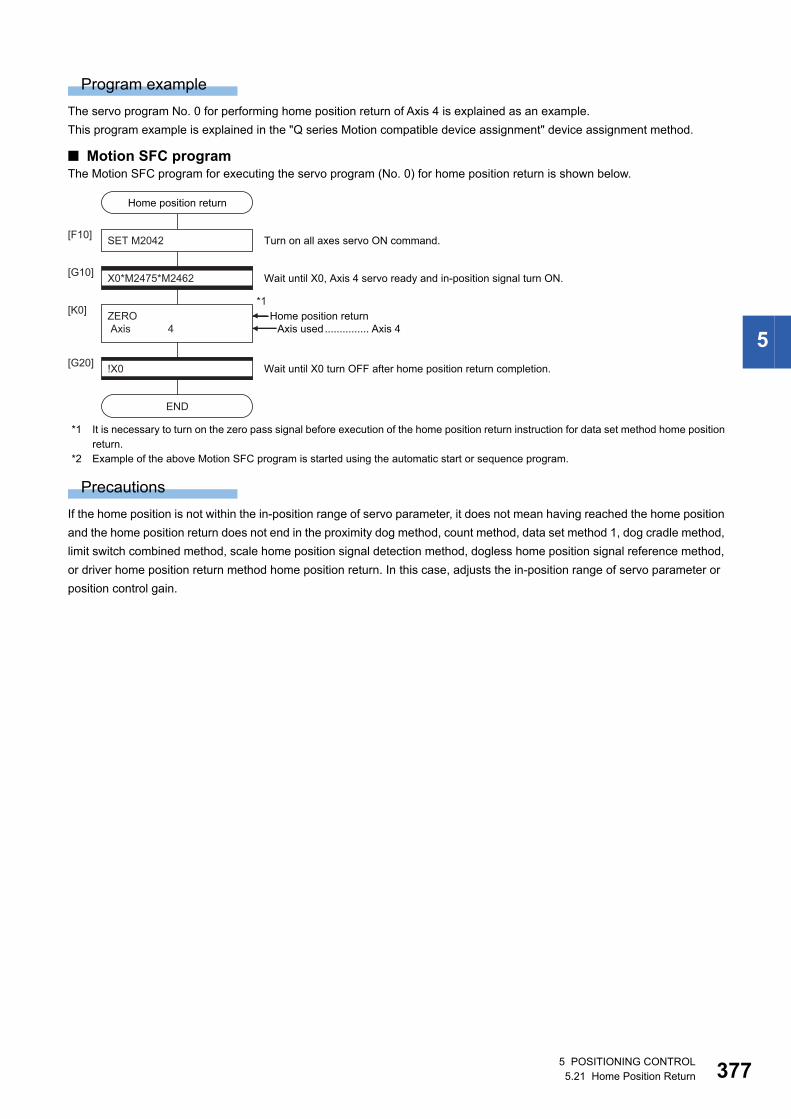
5
Program example
The servo program No. 0 for performing home position return of Axis 4 is explained as an example.
This program example is explained in the "Q series Motion compatible device assignment" device assignment method.
■ Motion SFC programThe Motion SFC program for executing the servo program (No. 0) for home position return is shown below.
*1 It is necessary to turn on the zero pass signal before execution of the home position return instruction for data set method home position return.
*2 Example of the above Motion SFC program is started using the automatic start or sequence program.
Precautions
If the home position is not within the in-position range of servo parameter, it does not mean having reached the home position
and the home position return does not end in the proximity dog method, count method, data set method 1, dog cradle method,
limit switch combined method, scale home position signal detection method, dogless home position signal reference method,
or driver home position return method home position return. In this case, adjusts the in-position range of servo parameter or
position control gain.
ZERO Axis 4
Home position return
SET M2042[F10]
X0*M2475*M2462[G10]
[K0]
Wait until X0, Axis 4 servo ready and in-position signal turn ON.
Turn on all axes servo ON command.
!X0[G20]
END
Wait until X0 turn OFF after home position return completion.
Home position return*1
Axis used............... Axis 4
5 POSITIONING CONTROL5.21 Home Position Return 377
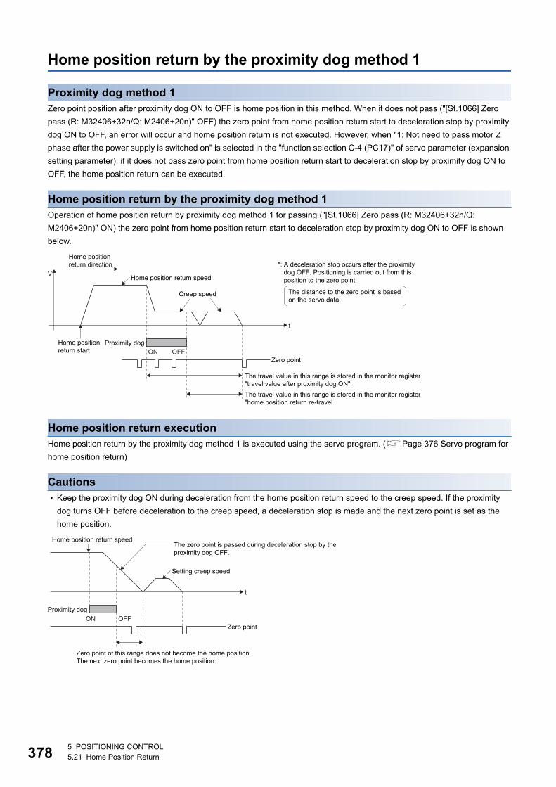
37
Home position return by the proximity dog method 1
Proximity dog method 1Zero point position after proximity dog ON to OFF is home position in this method. When it does not pass ("[St.1066] Zero
pass (R: M32406+32n/Q: M2406+20n)" OFF) the zero point from home position return start to deceleration stop by proximity
dog ON to OFF, an error will occur and home position return is not executed. However, when "1: Not need to pass motor Z
phase after the power supply is switched on" is selected in the "function selection C-4 (PC17)" of servo parameter (expansion
setting parameter), if it does not pass zero point from home position return start to deceleration stop by proximity dog ON to
OFF, the home position return can be executed.
Home position return by the proximity dog method 1Operation of home position return by proximity dog method 1 for passing ("[St.1066] Zero pass (R: M32406+32n/Q:
M2406+20n)" ON) the zero point from home position return start to deceleration stop by proximity dog ON to OFF is shown
below.
Home position return executionHome position return by the proximity dog method 1 is executed using the servo program. (Page 376 Servo program for
home position return)
Cautions • Keep the proximity dog ON during deceleration from the home position return speed to the creep speed. If the proximity
dog turns OFF before deceleration to the creep speed, a deceleration stop is made and the next zero point is set as the
home position.
t
V
Home position return start
Home position return speed
Creep speed
Proximity dogON OFF
Zero point
The travel value in this range is stored in the monitor register"travel value after proximity dog ON".The travel value in this range is stored in the monitor register"home position return re-travel
*: A deceleration stop occurs after the proximitydog OFF. Positioning is carried out from thisposition to the zero point.
The distance to the zero point is basedon the servo data.
Home positionreturn direction
t
Home position return speed
Proximity dogON OFF
Zero point
Zero point of this range does not become the home position. The next zero point becomes the home position.
The zero point is passed during deceleration stop by theproximity dog OFF.
Setting creep speed
85 POSITIONING CONTROL5.21 Home Position Return
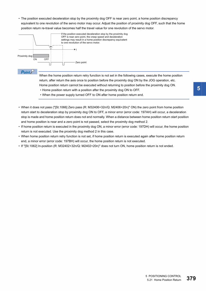
5
• The position executed deceleration stop by the proximity dog OFF is near zero point, a home position discrepancy
equivalent to one revolution of the servo motor may occur. Adjust the position of proximity dog OFF, such that the home
position return re-travel value becomes half the travel value for one revolution of the servo motor.
When the home position return retry function is not set in the following cases, execute the home position
return, after return the axis once to position before the proximity dog ON by the JOG operation, etc.
Home position return cannot be executed without returning to position before the proximity dog ON.
• Home position return with a position after the proximity dog ON to OFF.
• When the power supply turned OFF to ON after home position return end.
• When it does not pass ("[St.1066] Zero pass (R: M32406+32n/Q: M2406+20n)" ON) the zero point from home position
return start to deceleration stop by proximity dog ON to OFF, a minor error (error code: 197AH) will occur, a deceleration
stop is made and home position return does not end normally. When a distance between home position return start position
and home position is near and a zero point is not passed, select the proximity dog method 2.
• If home position return is executed in the proximity dog ON, a minor error (error code: 197DH) will occur, the home position
return is not executed. Use the proximity dog method 2 in this case.
• When home position return retry function is not set, if home position return is executed again after home position return
end, a minor error (error code: 197BH) will occur, the home position return is not executed.
• If "[St.1062] In-position (R: M32402+32n/Q: M2402+20n)" does not turn ON, home position return is not ended.
t
Proximity dogON OFF
Zero point
If the position executed deceleration stop by the proximity dogOFF is near zero point, the creep speed and decelerationsettings may result in a home position discrepancy equivalentto one revolution of the servo motor.
5 POSITIONING CONTROL5.21 Home Position Return 379
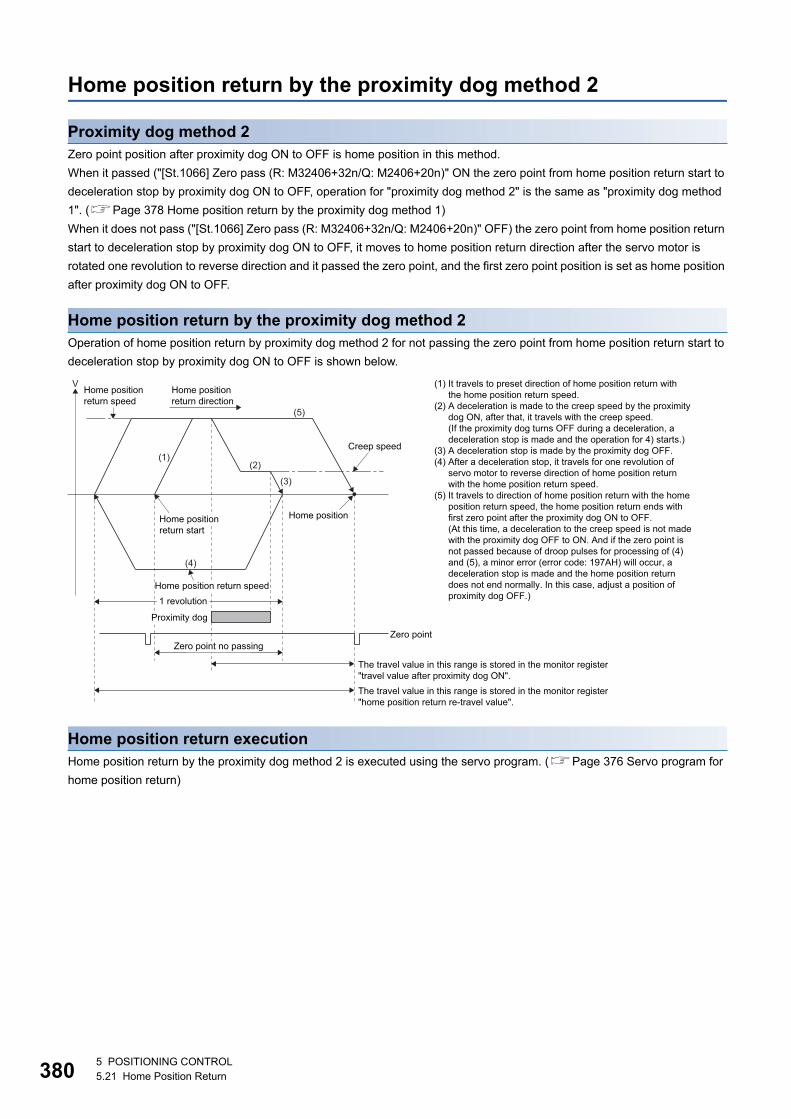
38
Home position return by the proximity dog method 2
Proximity dog method 2Zero point position after proximity dog ON to OFF is home position in this method.
When it passed ("[St.1066] Zero pass (R: M32406+32n/Q: M2406+20n)" ON the zero point from home position return start to
deceleration stop by proximity dog ON to OFF, operation for "proximity dog method 2" is the same as "proximity dog method
1". (Page 378 Home position return by the proximity dog method 1)
When it does not pass ("[St.1066] Zero pass (R: M32406+32n/Q: M2406+20n)" OFF) the zero point from home position return
start to deceleration stop by proximity dog ON to OFF, it moves to home position return direction after the servo motor is
rotated one revolution to reverse direction and it passed the zero point, and the first zero point position is set as home position
after proximity dog ON to OFF.
Home position return by the proximity dog method 2Operation of home position return by proximity dog method 2 for not passing the zero point from home position return start to
deceleration stop by proximity dog ON to OFF is shown below.
Home position return executionHome position return by the proximity dog method 2 is executed using the servo program. (Page 376 Servo program for
home position return)
VHome positionreturn direction
Home position
(2)
(3)
(5)
(1)
(4)
Home position return speed
Creep speed
The travel value in this range is stored in the monitor register"travel value after proximity dog ON".
(1) It travels to preset direction of home position return withthe home position return speed.
(2) A deceleration is made to the creep speed by the proximitydog ON, after that, it travels with the creep speed.(If the proximity dog turns OFF during a deceleration, adeceleration stop is made and the operation for 4) starts.)
(3) A deceleration stop is made by the proximity dog OFF.(4) After a deceleration stop, it travels for one revolution of
servo motor to reverse direction of home position returnwith the home position return speed.
(5) It travels to direction of home position return with the homeposition return speed, the home position return ends withfirst zero point after the proximity dog ON to OFF. (At this time, a deceleration to the creep speed is not madewith the proximity dog OFF to ON. And if the zero point isnot passed because of droop pulses for processing of (4)and (5), a minor error (error code: 197AH) will occur, adeceleration stop is made and the home position returndoes not end normally. In this case, adjust a position ofproximity dog OFF.)
Zero point
The travel value in this range is stored in the monitor register"home position return re-travel value".
Home position return start
Zero point no passing
Home position return speed1 revolution
Proximity dog
05 POSITIONING CONTROL5.21 Home Position Return
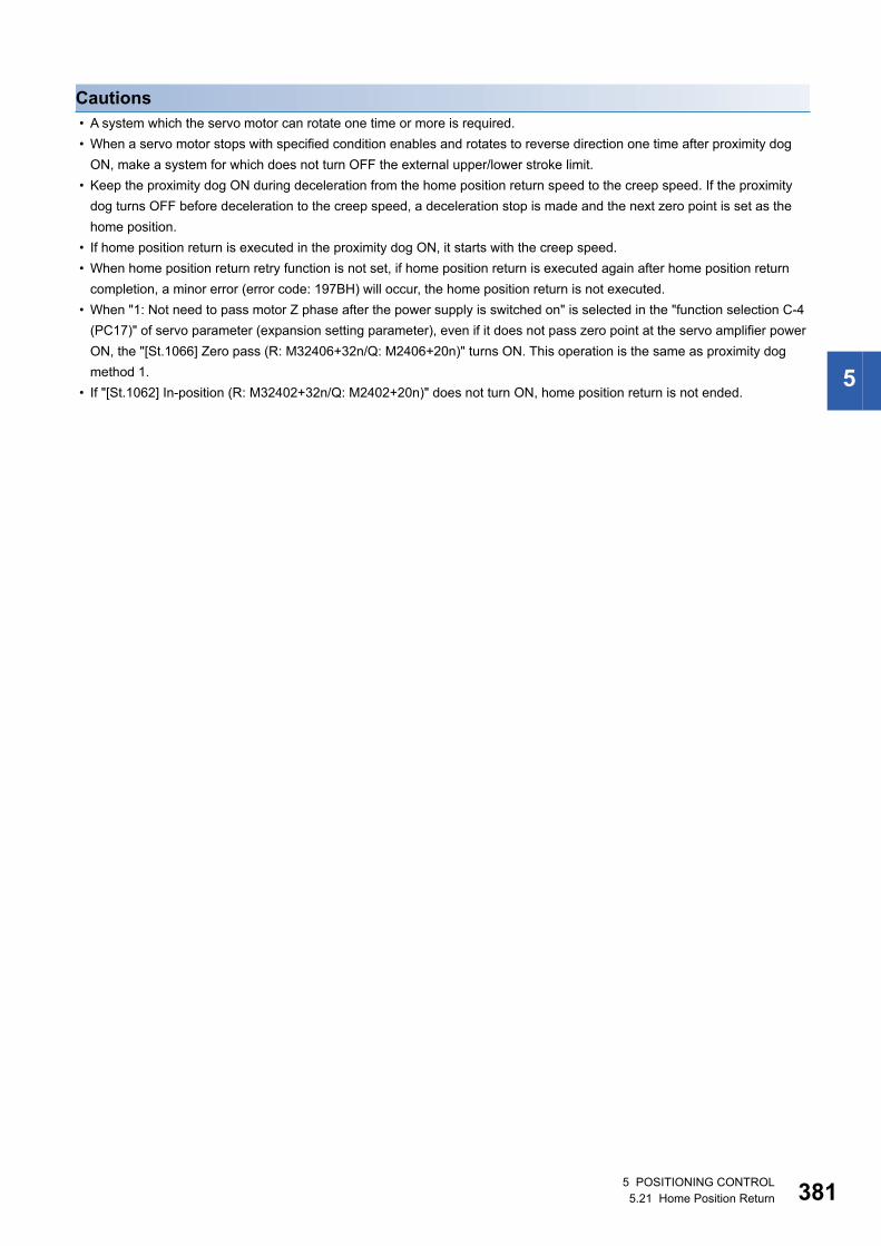
5
Cautions • A system which the servo motor can rotate one time or more is required.
• When a servo motor stops with specified condition enables and rotates to reverse direction one time after proximity dog
ON, make a system for which does not turn OFF the external upper/lower stroke limit.
• Keep the proximity dog ON during deceleration from the home position return speed to the creep speed. If the proximity
dog turns OFF before deceleration to the creep speed, a deceleration stop is made and the next zero point is set as the
home position.
• If home position return is executed in the proximity dog ON, it starts with the creep speed.
• When home position return retry function is not set, if home position return is executed again after home position return
completion, a minor error (error code: 197BH) will occur, the home position return is not executed.
• When "1: Not need to pass motor Z phase after the power supply is switched on" is selected in the "function selection C-4
(PC17)" of servo parameter (expansion setting parameter), even if it does not pass zero point at the servo amplifier power
ON, the "[St.1066] Zero pass (R: M32406+32n/Q: M2406+20n)" turns ON. This operation is the same as proximity dog
method 1.
• If "[St.1062] In-position (R: M32402+32n/Q: M2402+20n)" does not turn ON, home position return is not ended.
5 POSITIONING CONTROL5.21 Home Position Return 381
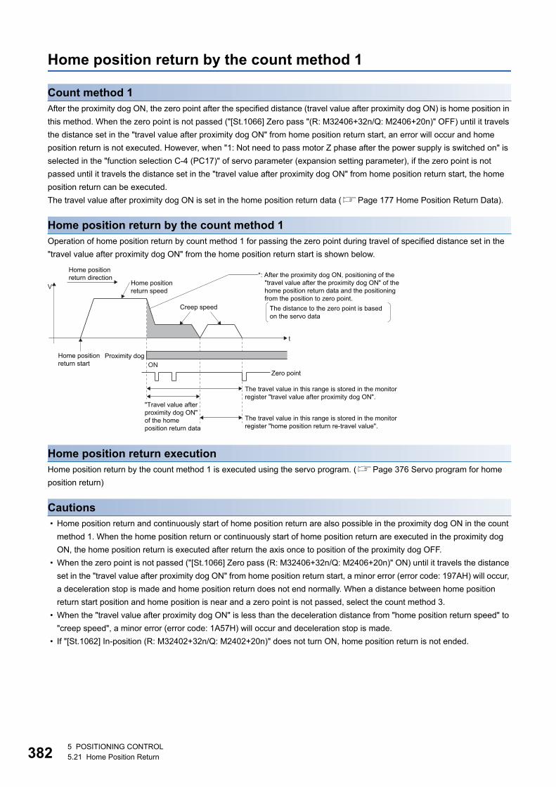
38
Home position return by the count method 1
Count method 1After the proximity dog ON, the zero point after the specified distance (travel value after proximity dog ON) is home position in
this method. When the zero point is not passed ("[St.1066] Zero pass "(R: M32406+32n/Q: M2406+20n)" OFF) until it travels
the distance set in the "travel value after proximity dog ON" from home position return start, an error will occur and home
position return is not executed. However, when "1: Not need to pass motor Z phase after the power supply is switched on" is
selected in the "function selection C-4 (PC17)" of servo parameter (expansion setting parameter), if the zero point is not
passed until it travels the distance set in the "travel value after proximity dog ON" from home position return start, the home
position return can be executed.
The travel value after proximity dog ON is set in the home position return data (Page 177 Home Position Return Data).
Home position return by the count method 1Operation of home position return by count method 1 for passing the zero point during travel of specified distance set in the
"travel value after proximity dog ON" from the home position return start is shown below.
Home position return executionHome position return by the count method 1 is executed using the servo program. (Page 376 Servo program for home
position return)
Cautions • Home position return and continuously start of home position return are also possible in the proximity dog ON in the count
method 1. When the home position return or continuously start of home position return are executed in the proximity dog
ON, the home position return is executed after return the axis once to position of the proximity dog OFF.
• When the zero point is not passed ("[St.1066] Zero pass (R: M32406+32n/Q: M2406+20n)" ON) until it travels the distance
set in the "travel value after proximity dog ON" from home position return start, a minor error (error code: 197AH) will occur,
a deceleration stop is made and home position return does not end normally. When a distance between home position
return start position and home position is near and a zero point is not passed, select the count method 3.
• When the "travel value after proximity dog ON" is less than the deceleration distance from "home position return speed" to
"creep speed", a minor error (error code: 1A57H) will occur and deceleration stop is made.
• If "[St.1062] In-position (R: M32402+32n/Q: M2402+20n)" does not turn ON, home position return is not ended.
t
V
Home position return start
Home positionreturn speed
Creep speed
Proximity dogON
Zero point
The travel value in this range is stored in the monitorregister "travel value after proximity dog ON".
*: After the proximity dog ON, positioning of the"travel value after the proximity dog ON" of thehome position return data and the positioningfrom the position to zero point.
The travel value in this range is stored in the monitorregister "home position return re-travel value".
"Travel value afterproximity dog ON"of the homeposition return data
The distance to the zero point is basedon the servo data
Home positionreturn direction
25 POSITIONING CONTROL5.21 Home Position Return
5
Home position return by the count method 2
Count method 2After the proximity dog ON, the position which traveled the specified distance (travel value after proximity dog ON) is home
position in this method.
It is not related for zero point pass or not pass.
A count method 2 is effective method when a zero point signal cannot be taken. (However, dispersions will occur to the stop
position at the home position return compared with the count method 1.)
The travel value after proximity dog ON is set in the home position return data (Page 177 Home Position Return Data).
Home position return by the count method 2Operation of home position return by count method 2 is shown below.
Home position return executionHome position return by the count method 2 is executed using the servo program. (Page 376 Servo program for home
position return)
Cautions • Home position return and continuously start of home position return are also possible in the proximity dog ON in the count
method 2. When the home position return and continuously start of home position return are executed in the proximity dog
ON, the home position return is executed after return the axis once to position of the proximity dog OFF.
• When the "travel value after proximity dog ON" is less than the deceleration distance from "home position return speed" to
"creep speed", a minor error (error code: 1A57H) will occur and deceleration stop is made.
• Command position is the home position.
• If "[St.1062] In-position (R: M32402+32n/Q: M2402+20n)" does not turn ON, home position return is not ended.
t
V
Home positionreturn start
Home position return speed
Creep speed
Proximity dog
The travel value in this range is stored in the monitorregister "travel value after proximity dog ON".
*: "Home position return re-travel value" = 0
*: After the proximity dog ON, a position whichtraveled the distance "travel value after proximitydog ON" of the home position return data is homeposition.
Home positionreturn direction
5 POSITIONING CONTROL5.21 Home Position Return 383
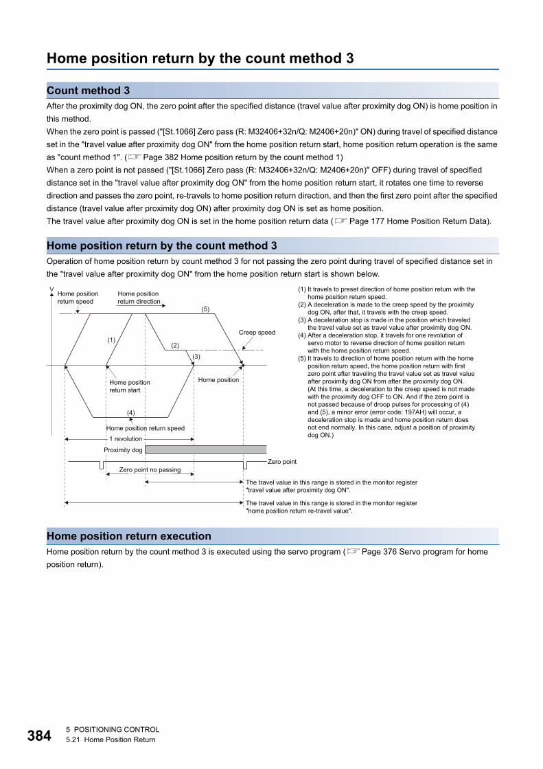
38
Home position return by the count method 3
Count method 3After the proximity dog ON, the zero point after the specified distance (travel value after proximity dog ON) is home position in
this method.
When the zero point is passed ("[St.1066] Zero pass (R: M32406+32n/Q: M2406+20n)" ON) during travel of specified distance
set in the "travel value after proximity dog ON" from the home position return start, home position return operation is the same
as "count method 1". (Page 382 Home position return by the count method 1)
When a zero point is not passed ("[St.1066] Zero pass (R: M32406+32n/Q: M2406+20n)" OFF) during travel of specified
distance set in the "travel value after proximity dog ON" from the home position return start, it rotates one time to reverse
direction and passes the zero point, re-travels to home position return direction, and then the first zero point after the specified
distance (travel value after proximity dog ON) after proximity dog ON is set as home position.
The travel value after proximity dog ON is set in the home position return data (Page 177 Home Position Return Data).
Home position return by the count method 3Operation of home position return by count method 3 for not passing the zero point during travel of specified distance set in
the "travel value after proximity dog ON" from the home position return start is shown below.
Home position return executionHome position return by the count method 3 is executed using the servo program (Page 376 Servo program for home
position return).
V
(2)
(3)
(5)
(1)
(4)
The travel value in this range is stored in the monitor register"travel value after proximity dog ON".
Zero point
The travel value in this range is stored in the monitor register"home position return re-travel value".
Home positionreturn direction
Home position
Home position return speed
Creep speed
(1) It travels to preset direction of home position return with thehome position return speed.
(2) A deceleration is made to the creep speed by the proximitydog ON, after that, it travels with the creep speed.
(3) A deceleration stop is made in the position which traveledthe travel value set as travel value after proximity dog ON.
(4) After a deceleration stop, it travels for one revolution of servo motor to reverse direction of home position returnwith the home position return speed.
(5) It travels to direction of home position return with the homeposition return speed, the home position return with firstzero point after traveling the travel value set as travel valueafter proximity dog ON from after the proximity dog ON. (At this time, a deceleration to the creep speed is not madewith the proximity dog OFF to ON. And if the zero point isnot passed because of droop pulses for processing of (4)and (5), a minor error (error code: 197AH) will occur, a deceleration stop is made and home position return doesnot end normally. In this case, adjust a position of proximitydog ON.)
Home position return start
Zero point no passing
Home position return speed1 revolution
Proximity dog
45 POSITIONING CONTROL5.21 Home Position Return
5
Cautions • A system which the servo motor can rotate one time or more is required.
• After the proximity dog ON, when a servo motor rotates one time to reverse direction after stop with travel value set in the
"travel value after proximity dog ON", make a system which does not turn OFF the external upper/lower stroke limit.
• Home position return and continuously start of home position return are also possible in the proximity dog ON in the count
method 3. When the home position return and continuously start of home position return are executed in the proximity dog
ON, the home position return is executed after return the axis once to position of the proximity dog OFF.
• When the "travel value after proximity dog ON" is less than the deceleration distance from "home position return speed" to
"creep speed", a minor error (error code: 1A57H) will occur and deceleration stop is made.
• When "1: Not need to pass motor Z phase after the power supply is switched on" is selected in the "function selection C-4
(PC17)" of servo parameter (expansion setting parameter), even if it does not pass zero point at the servo amplifier power
ON, the "[St.1066] Zero pass (R: M32406+32n/Q: M2406+20n)" turns ON. This operation is the same as count method 1.
• If "[St.1062] In-position (R: M32402+32n/Q: M2402+20n)" does not turn ON, home position return is not ended.
5 POSITIONING CONTROL5.21 Home Position Return 385
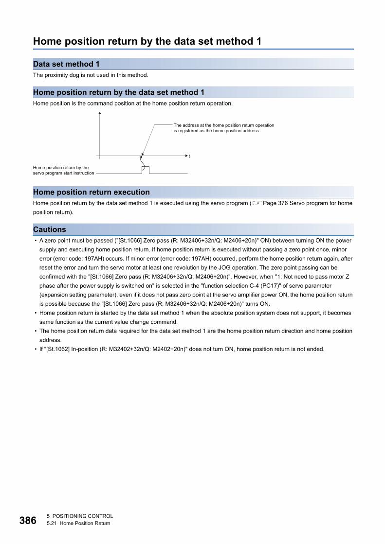
38
Home position return by the data set method 1
Data set method 1The proximity dog is not used in this method.
Home position return by the data set method 1Home position is the command position at the home position return operation.
Home position return executionHome position return by the data set method 1 is executed using the servo program (Page 376 Servo program for home
position return).
Cautions • A zero point must be passed ("[St.1066] Zero pass (R: M32406+32n/Q: M2406+20n)" ON) between turning ON the power
supply and executing home position return. If home position return is executed without passing a zero point once, minor
error (error code: 197AH) occurs. If minor error (error code: 197AH) occurred, perform the home position return again, after
reset the error and turn the servo motor at least one revolution by the JOG operation. The zero point passing can be
confirmed with the "[St.1066] Zero pass (R: M32406+32n/Q: M2406+20n)". However, when "1: Not need to pass motor Z
phase after the power supply is switched on" is selected in the "function selection C-4 (PC17)" of servo parameter
(expansion setting parameter), even if it does not pass zero point at the servo amplifier power ON, the home position return
is possible because the "[St.1066] Zero pass (R: M32406+32n/Q: M2406+20n)" turns ON.
• Home position return is started by the data set method 1 when the absolute position system does not support, it becomes
same function as the current value change command.
• The home position return data required for the data set method 1 are the home position return direction and home position
address.
• If "[St.1062] In-position (R: M32402+32n/Q: M2402+20n)" does not turn ON, home position return is not ended.
t
The address at the home position return operationis registered as the home position address.
Home position return by theservo program start instruction
65 POSITIONING CONTROL5.21 Home Position Return
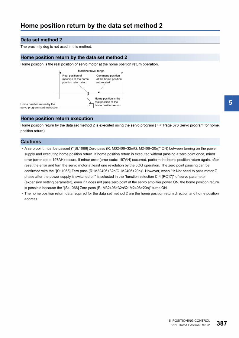
5
Home position return by the data set method 2
Data set method 2The proximity dog is not used in this method.
Home position return by the data set method 2Home position is the real position of servo motor at the home position return operation.
Home position return executionHome position return by the data set method 2 is executed using the servo program (Page 376 Servo program for home
position return).
Cautions • A zero point must be passed ("[St.1066] Zero pass (R: M32406+32n/Q: M2406+20n)" ON) between turning on the power
supply and executing home position return. If home position return is executed without passing a zero point once, minor
error (error code: 197AH) occurs. If minor error (error code: 197AH) occurred, perform the home position return again, after
reset the error and turn the servo motor at least one revolution by the JOG operation. The zero point passing can be
confirmed with the "[St.1066] Zero pass (R: M32406+32n/Q: M2406+20n)". However, when "1: Not need to pass motor Z
phase after the power supply is switched on" is selected in the "function selection C-4 (PC17)" of servo parameter
(expansion setting parameter), even if it does not pass zero point at the servo amplifier power ON, the home position return
is possible because the "[St.1066] Zero pass (R: M32406+32n/Q: M2406+20n)" turns ON.
• The home position return data required for the data set method 2 are the home position return direction and home position
address.
Command positionat the home positionreturn start
Real position ofmachine at the homeposition return start
Home position is thereal position at thehome position return Home position return by the
servo program start instruction
Machine travel range
5 POSITIONING CONTROL5.21 Home Position Return 387
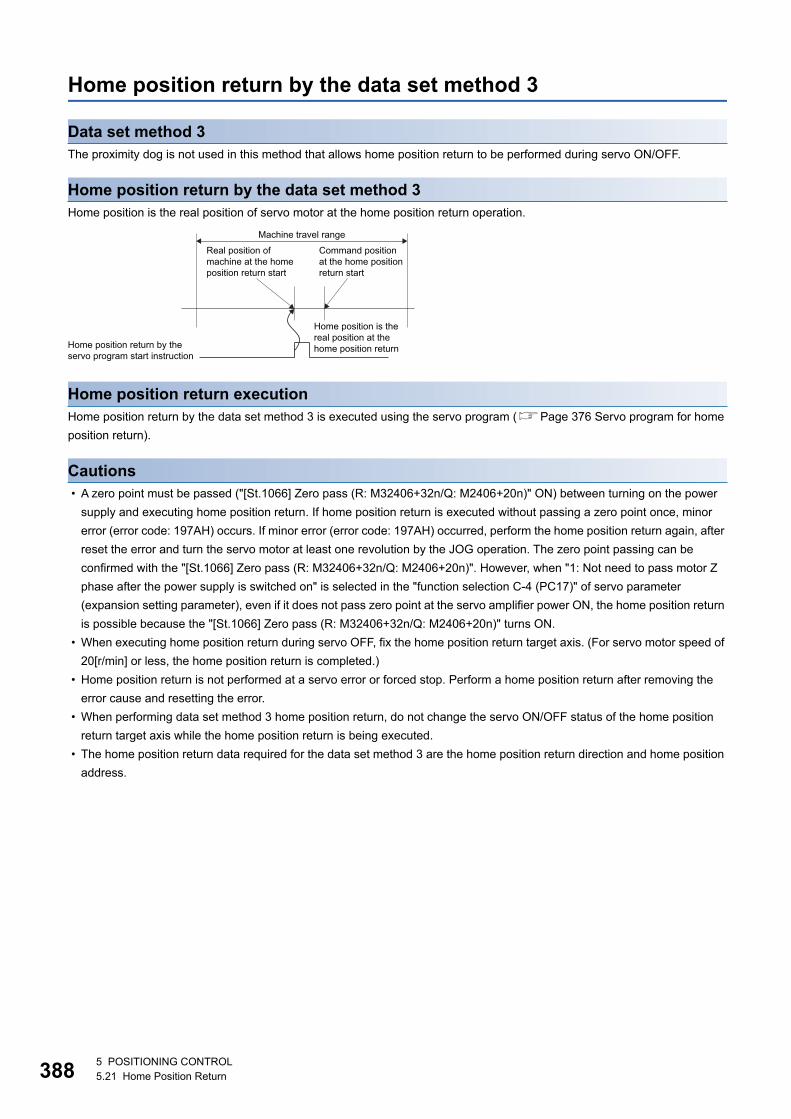
38
Home position return by the data set method 3
Data set method 3The proximity dog is not used in this method that allows home position return to be performed during servo ON/OFF.
Home position return by the data set method 3Home position is the real position of servo motor at the home position return operation.
Home position return executionHome position return by the data set method 3 is executed using the servo program (Page 376 Servo program for home
position return).
Cautions • A zero point must be passed ("[St.1066] Zero pass (R: M32406+32n/Q: M2406+20n)" ON) between turning on the power
supply and executing home position return. If home position return is executed without passing a zero point once, minor
error (error code: 197AH) occurs. If minor error (error code: 197AH) occurred, perform the home position return again, after
reset the error and turn the servo motor at least one revolution by the JOG operation. The zero point passing can be
confirmed with the "[St.1066] Zero pass (R: M32406+32n/Q: M2406+20n)". However, when "1: Not need to pass motor Z
phase after the power supply is switched on" is selected in the "function selection C-4 (PC17)" of servo parameter
(expansion setting parameter), even if it does not pass zero point at the servo amplifier power ON, the home position return
is possible because the "[St.1066] Zero pass (R: M32406+32n/Q: M2406+20n)" turns ON.
• When executing home position return during servo OFF, fix the home position return target axis. (For servo motor speed of
20[r/min] or less, the home position return is completed.)
• Home position return is not performed at a servo error or forced stop. Perform a home position return after removing the
error cause and resetting the error.
• When performing data set method 3 home position return, do not change the servo ON/OFF status of the home position
return target axis while the home position return is being executed.
• The home position return data required for the data set method 3 are the home position return direction and home position
address.
Command positionat the home positionreturn start
Real position ofmachine at the homeposition return start
Home position is thereal position at thehome position return Home position return by the
servo program start instruction
Machine travel range
85 POSITIONING CONTROL5.21 Home Position Return
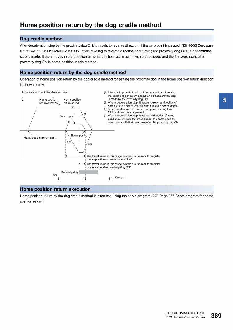
5
Home position return by the dog cradle method
Dog cradle methodAfter deceleration stop by the proximity dog ON, it travels to reverse direction. If the zero point is passed ("[St.1066] Zero pass
(R: M32406+32n/Q: M2406+20n)" ON) after traveling to reverse direction and turning the proximity dog OFF, a deceleration
stop is made. It then moves in the direction of home position return again with creep speed and the first zero point after
proximity dog ON is home position in this method.
Home position return by the dog cradle methodOperation of home position return by the dog cradle method for setting the proximity dog in the home position return direction
is shown below.
Home position return executionHome position return by the dog cradle method is executed using the servo program (Page 376 Servo program for home
position return).
V
(4)
(3)
(1)
(2)
Home position return speed
Creep speed
Proximity dogON
(1) It travels to preset direction of home position return withthe home position return speed, and a deceleration stopis made by the proximity dog ON.
(2) After a deceleration stop, it travels to reverse direction ofhome position return with the home position return speed.
(3) A deceleration stop is made when proximity dog turnsOFF and zero point is passed.
(4) After a deceleration stop, it travels to direction of homeposition return with the creep speed, the home positionreturn ends with first zero point after the proximity dog ON.
Zero point
The travel value in this range is stored in the monitor register"home position return re-travel value".The travel value in this range is stored in the monitor register"travel value after proximity dog ON".
Home position return start
Acceleration time � Deceleration time
Home positionreturn direction
Home position
5 POSITIONING CONTROL5.21 Home Position Return 389
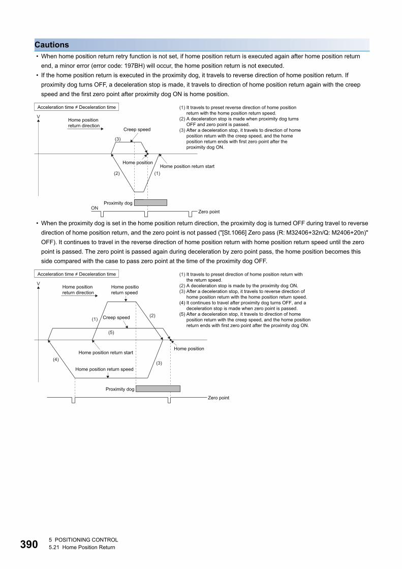
39
Cautions • When home position return retry function is not set, if home position return is executed again after home position return
end, a minor error (error code: 197BH) will occur, the home position return is not executed.
• If the home position return is executed in the proximity dog, it travels to reverse direction of home position return. If
proximity dog turns OFF, a deceleration stop is made, it travels to direction of home position return again with the creep
speed and the first zero point after proximity dog ON is home position.
• When the proximity dog is set in the home position return direction, the proximity dog is turned OFF during travel to reverse
direction of home position return, and the zero point is not passed ("[St.1066] Zero pass (R: M32406+32n/Q: M2406+20n)"
OFF). It continues to travel in the reverse direction of home position return with home position return speed until the zero
point is passed. The zero point is passed again during deceleration by zero point pass, the home position becomes this
side compared with the case to pass zero point at the time of the proximity dog OFF.
V
(3)
(2) (1)
Creep speed
Home position return start
Proximity dogON
Zero point
(1) It travels to preset reverse direction of home positionreturn with the home position return speed.
(2) A deceleration stop is made when proximity dog turnsOFF and zero point is passed.
(3) After a deceleration stop, it travels to direction of homeposition return with the creep speed, and the homeposition return ends with first zero point after theproximity dog ON.
Acceleration time � Deceleration time
Home positionreturn direction
Home position
V
Home position
(5)
(4)
(2)(1)
(3)Home position return speed
Home positioreturn speed
Creep speed
Home position return start
Proximity dog
Zero point
Home positionreturn direction
(1) It travels to preset direction of home position return withthe return speed.
(2) A deceleration stop is made by the proximity dog ON.(3) After a deceleration stop, it travels to reverse direction of
home position return with the home position return speed.(4) It continues to travel after proximity dog turns OFF, and a
deceleration stop is made when zero point is passed.(5) After a deceleration stop, it travels to direction of home
position return with the creep speed, and the home positionreturn ends with first zero point after the proximity dog ON.
Acceleration time � Deceleration time
05 POSITIONING CONTROL5.21 Home Position Return
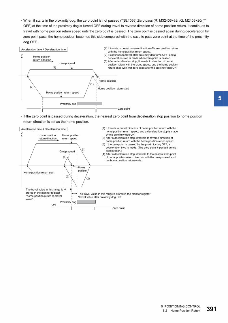
5
• When it starts in the proximity dog, the zero point is not passed ("[St.1066] Zero pass (R: M32406+32n/Q: M2406+20n)"
OFF) at the time of the proximity dog is turned OFF during travel to reverse direction of home position return. It continues to
travel with home position return speed until the zero point is passed. The zero point is passed again during deceleration by
zero point pass, the home position becomes this side compared with the case to pass zero point at the time of the proximity
dog OFF.
• If the zero point is passed during deceleration, the nearest zero point from deceleration stop position to home position
return direction is set as the home position.
V
Home position
(2)
(3)
(1)
Home position return speed
Creep speed
Home position return start
Proximity dog
Zero point
Acceleration time � Deceleration time
Home positionreturn direction
(1) It travels to preset reverse direction of home position returnwith the home position return speed.
(2) It continues to travel after proximity dog turns OFF, and adeceleration stop is made when zero point is passed.
(3) After a deceleration stop, it travels to direction of homeposition return with the creep speed, and the home positionreturn ends with first zero point after the proximity dog ON.
V
Homeposition
(4)
(3)
(1)
(2)
Home position return speed
Creep speed
ONZero point
The travel value in this range isstored in the monitor register"home position return re-travelvalue".
The travel value in this range is stored in the monitor register"travel value after proximity dog ON".
Home position return start
Proximity dog
Home positionreturn direction
Acceleration time � Deceleration time (1) It travels to preset direction of home position return with thehome position return speed, and a deceleration stop is madeby the proximity dog ON.
(2) After a deceleration stop, it travels to reverse direction ofhome position return with the home position return speed.
(3) If the zero point is passed by the proximity dog OFF, adeceleration stop is made. (The zero point is passed duringdeceleration.)
(4) After a deceleration stop, it travels to the nearest zero pointof home position return direction with the creep speed, andthe home position return ends.
5 POSITIONING CONTROL5.21 Home Position Return 391
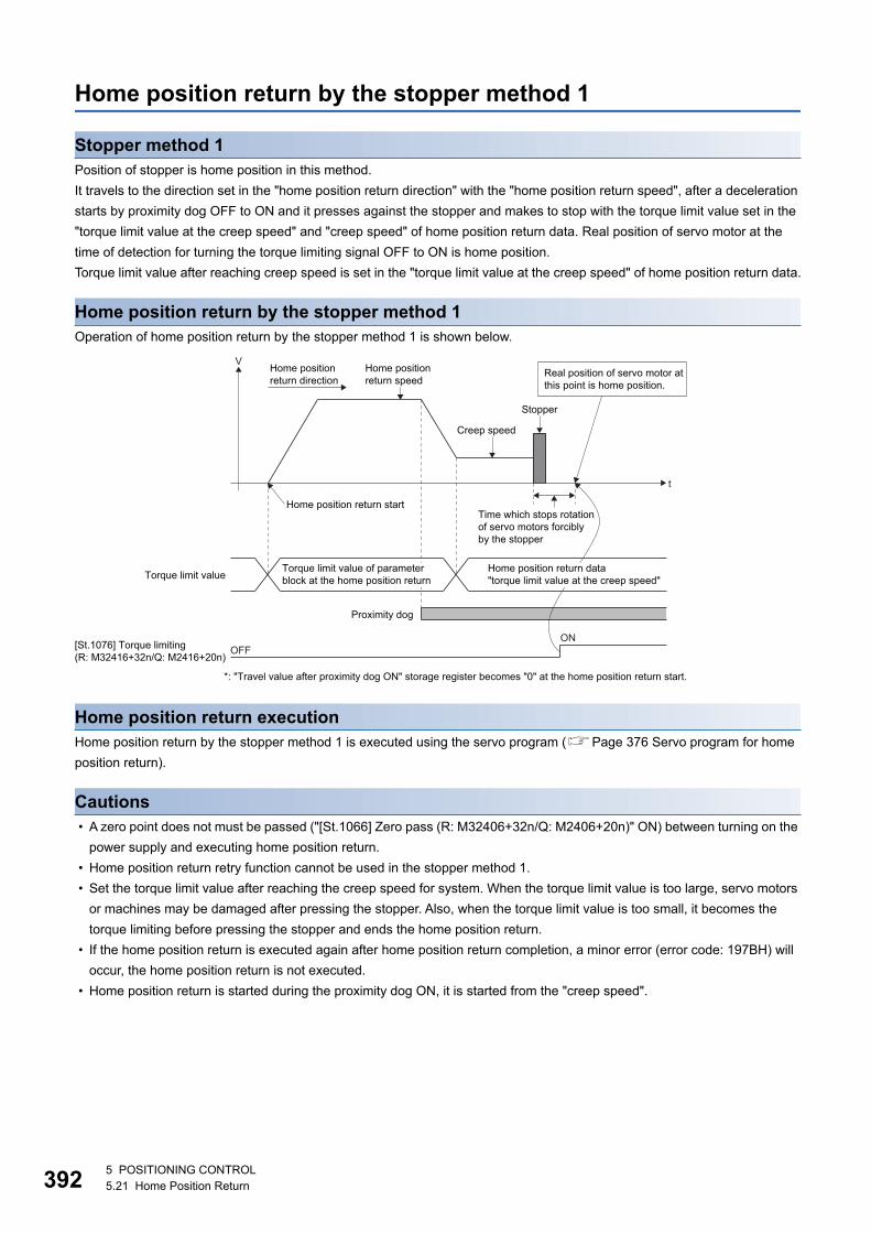
39
Home position return by the stopper method 1
Stopper method 1Position of stopper is home position in this method.
It travels to the direction set in the "home position return direction" with the "home position return speed", after a deceleration
starts by proximity dog OFF to ON and it presses against the stopper and makes to stop with the torque limit value set in the
"torque limit value at the creep speed" and "creep speed" of home position return data. Real position of servo motor at the
time of detection for turning the torque limiting signal OFF to ON is home position.
Torque limit value after reaching creep speed is set in the "torque limit value at the creep speed" of home position return data.
Home position return by the stopper method 1Operation of home position return by the stopper method 1 is shown below.
Home position return executionHome position return by the stopper method 1 is executed using the servo program (Page 376 Servo program for home
position return).
Cautions • A zero point does not must be passed ("[St.1066] Zero pass (R: M32406+32n/Q: M2406+20n)" ON) between turning on the
power supply and executing home position return.
• Home position return retry function cannot be used in the stopper method 1.
• Set the torque limit value after reaching the creep speed for system. When the torque limit value is too large, servo motors
or machines may be damaged after pressing the stopper. Also, when the torque limit value is too small, it becomes the
torque limiting before pressing the stopper and ends the home position return.
• If the home position return is executed again after home position return completion, a minor error (error code: 197BH) will
occur, the home position return is not executed.
• Home position return is started during the proximity dog ON, it is started from the "creep speed".
V
t
Home position return speed
Creep speed
Stopper
ONOFF[St.1076] Torque limiting
(R: M32416+32n/Q: M2416+20n)
Time which stops rotationof servo motors forciblyby the stopper
Home position return start
Proximity dog
*: "Travel value after proximity dog ON" storage register becomes "0" at the home position return start.
Torque limit value
Real position of servo motor atthis point is home position.
Home position return data "torque limit value at the creep speed"
Home positionreturn direction
Torque limit value of parameter block at the home position return
25 POSITIONING CONTROL5.21 Home Position Return
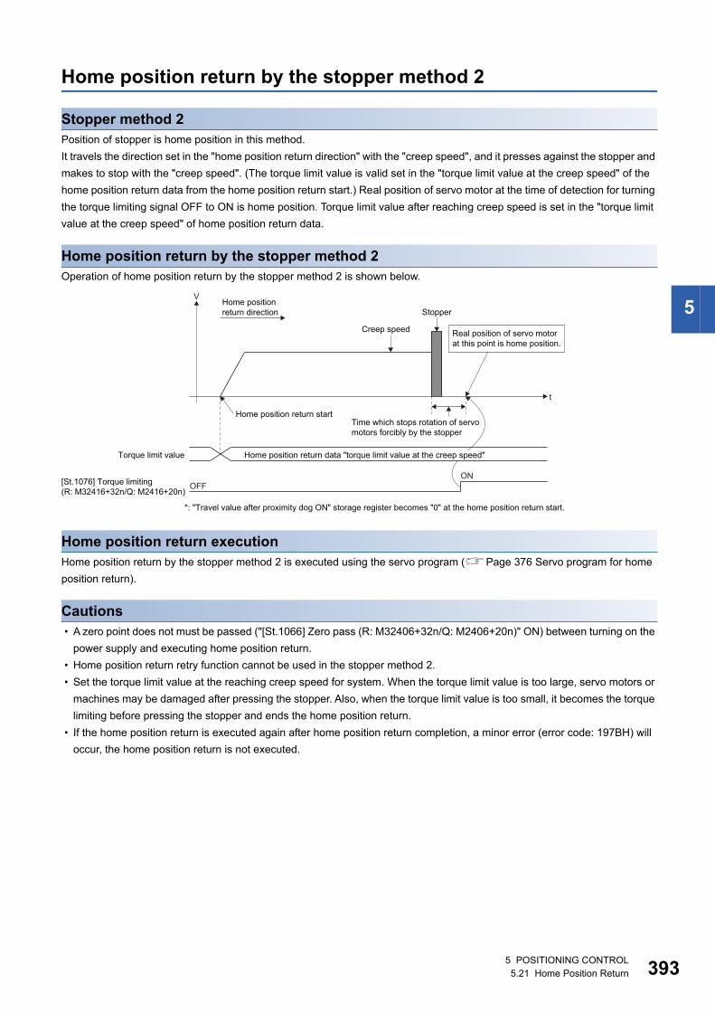
5
Home position return by the stopper method 2
Stopper method 2Position of stopper is home position in this method.
It travels the direction set in the "home position return direction" with the "creep speed", and it presses against the stopper and
makes to stop with the "creep speed". (The torque limit value is valid set in the "torque limit value at the creep speed" of the
home position return data from the home position return start.) Real position of servo motor at the time of detection for turning
the torque limiting signal OFF to ON is home position. Torque limit value after reaching creep speed is set in the "torque limit
value at the creep speed" of home position return data.
Home position return by the stopper method 2Operation of home position return by the stopper method 2 is shown below.
Home position return executionHome position return by the stopper method 2 is executed using the servo program (Page 376 Servo program for home
position return).
Cautions • A zero point does not must be passed ("[St.1066] Zero pass (R: M32406+32n/Q: M2406+20n)" ON) between turning on the
power supply and executing home position return.
• Home position return retry function cannot be used in the stopper method 2.
• Set the torque limit value at the reaching creep speed for system. When the torque limit value is too large, servo motors or
machines may be damaged after pressing the stopper. Also, when the torque limit value is too small, it becomes the torque
limiting before pressing the stopper and ends the home position return.
• If the home position return is executed again after home position return completion, a minor error (error code: 197BH) will
occur, the home position return is not executed.
V
t
Creep speed
Stopper
ONOFF[St.1076] Torque limiting
(R: M32416+32n/Q: M2416+20n)
Time which stops rotation of servomotors forcibly by the stopper
Home position return start
*: "Travel value after proximity dog ON" storage register becomes "0" at the home position return start.
Torque limit value
Real position of servo motorat this point is home position.
Home positionreturn direction
Home position return data "torque limit value at the creep speed"
5 POSITIONING CONTROL5.21 Home Position Return 393
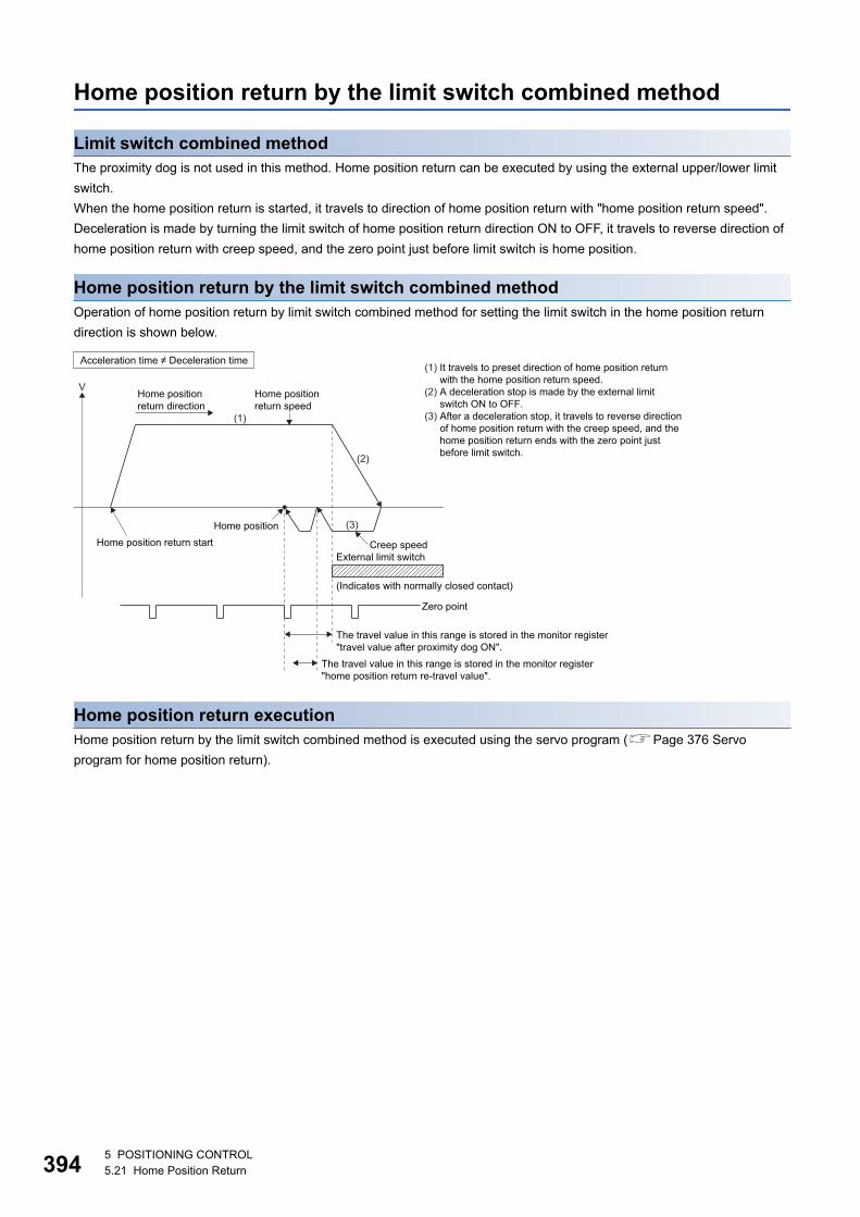
39
Home position return by the limit switch combined method
Limit switch combined methodThe proximity dog is not used in this method. Home position return can be executed by using the external upper/lower limit
switch.
When the home position return is started, it travels to direction of home position return with "home position return speed".
Deceleration is made by turning the limit switch of home position return direction ON to OFF, it travels to reverse direction of
home position return with creep speed, and the zero point just before limit switch is home position.
Home position return by the limit switch combined methodOperation of home position return by limit switch combined method for setting the limit switch in the home position return
direction is shown below.
Home position return executionHome position return by the limit switch combined method is executed using the servo program (Page 376 Servo
program for home position return).
V
Home position (3)
(2)
(1)
External limit switch
(Indicates with normally closed contact)
The travel value in this range is stored in the monitor register"travel value after proximity dog ON".
The travel value in this range is stored in the monitor register"home position return re-travel value".
Home position return start
Zero point
Creep speed
Home position return speed
Home positionreturn direction
Acceleration time � Deceleration time(1) It travels to preset direction of home position return
with the home position return speed. (2) A deceleration stop is made by the external limit
switch ON to OFF.(3) After a deceleration stop, it travels to reverse direction
of home position return with the creep speed, and thehome position return ends with the zero point justbefore limit switch.
45 POSITIONING CONTROL5.21 Home Position Return
5
Cautions • For the axis which executes the home position return by the limit switch combined method, if the external input signal has
not been set in [Motion Control Parameter] [Axis Setting Parameter] "External Signal Parameter", a minor error (error
code: 19ECH) will occur and home position return is not executed.
• When the limit switch reverse to home position return direction is turned ON to OFF, deceleration stop is made, home
position return is not completed and a minor error (error code: 1905H, 1907H) will occur.
• Home position return retry function cannot be used in the limit switch combined method.
• If the home position return is executed with the limit switch OFF, it is started to reverse direction of home position return with
creep speed.
• When it does not pass ("[St.1066] Zero pass (R: M32406+32n/Q: M2406+20n)" ON) the zero point from home position
return start to deceleration stop by limit switch OFF, a minor error (error code: 197AH) will occur, a deceleration stop is
made and home position return does not end normally. However, when "1: Not need to pass motor Z phase after the power
supply is switched on" is selected in the "function selection C-4 (PC17)" of servo parameter (expansion setting parameter),
if the zero point is not passed until from home position return start to deceleration stop by limit switch OFF, the home
position return can be executed.
• Deceleration stop is executed after the limit switch OFF. Set the limit switch in expectation of deceleration distance.
• If the "[St.1062] In-position (R: M32402+32n/Q: M2402+20n)" is turned ON, home position return is not ended.
• When the width is in a zero point, the home position differs from the home position return by the proximity dog method 1,
proximity dog method 2, count method 1, count method 3, dog cradle method and scale home position signal detection
method.
5 POSITIONING CONTROL5.21 Home Position Return 395
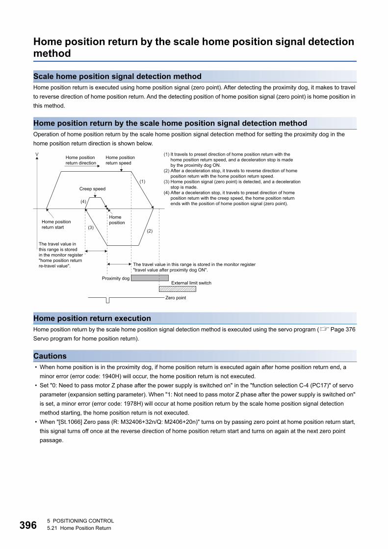
39
Home position return by the scale home position signal detection method
Scale home position signal detection methodHome position return is executed using home position signal (zero point). After detecting the proximity dog, it makes to travel
to reverse direction of home position return. And the detecting position of home position signal (zero point) is home position in
this method.
Home position return by the scale home position signal detection methodOperation of home position return by the scale home position signal detection method for setting the proximity dog in the
home position return direction is shown below.
Home position return executionHome position return by the scale home position signal detection method is executed using the servo program (Page 376
Servo program for home position return).
Cautions • When home position is in the proximity dog, if home position return is executed again after home position return end, a
minor error (error code: 1940H) will occur, the home position return is not executed.
• Set "0: Need to pass motor Z phase after the power supply is switched on" in the "function selection C-4 (PC17)" of servo
parameter (expansion setting parameter). When "1: Not need to pass motor Z phase after the power supply is switched on"
is set, a minor error (error code: 1978H) will occur at home position return by the scale home position signal detection
method starting, the home position return is not executed.
• When "[St.1066] Zero pass (R: M32406+32n/Q: M2406+20n)" turns on by passing zero point at home position return start,
this signal turns off once at the reverse direction of home position return start and turns on again at the next zero point
passage.
V
(4)
(3)
(1)
(2)
Creep speed
External limit switchProximity dog
Zero point
The travel value inthis range is storedin the monitor register"home position returnre-travel value".
Home position return start
Home position
The travel value in this range is stored in the monitor register"travel value after proximity dog ON".
Home positionreturn direction
Home position return speed
(1) It travels to preset direction of home position return with thehome position return speed, and a deceleration stop is madeby the proximity dog ON.
(2) After a deceleration stop, it travels to reverse direction of homeposition return with the home position return speed.
(3) Home position signal (zero point) is detected, and a decelerationstop is made.
(4) After a deceleration stop, it travels to preset direction of homeposition return with the creep speed, the home position returnends with the position of home position signal (zero point).
65 POSITIONING CONTROL5.21 Home Position Return
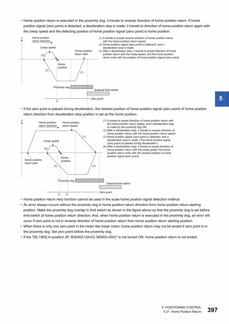
5
• Home position return is executed in the proximity dog, it travels to reverse direction of home position return. If home
position signal (zero point) is detected, a deceleration stop is made, it travels to direction of home position return again with
the creep speed and the detecting position of home position signal (zero point) is home position.
• If the zero point is passed during deceleration, the nearest position of home position signal (zero point) of home position
return direction from deceleration stop position is set as the home position.
• Home position return retry function cannot be used in the scale home position signal detection method.
• An error always occurs without the proximity dog in home position return direction from home position return starting
position. Make the proximity dog overlap in limit switch as shown in the figure above so that the proximity dog is set before
limit switch of home position return direction. And, when home position return is executed in the proximity dog, an error will
occur if zero point is not in reverse direction of home position return from home position return starting position.
• When there is only one zero point in the motor like linear motor, home position return may not be ended if zero point is in
the proximity dog. Set zero point before the proximity dog.
• If the "[St.1062] In-position (R: M32402+32n/Q: M2402+20n)" is not turned ON, home position return is not ended.
Home position return start
V
(3)
(2)(1)
Creep speed
Home position
External limit switchProximity dog
Zero point
Home positionreturn direction
(1) It travels to preset reverse direction of home position returnwith the home position return speed.
(2) Home position signal (zero point) is detected, and a deceleration stop is made.
(3) After a deceleration stop, it travels to preset direction of homeposition return with the creep speed, and the home positionreturn ends with the position of home position signal (zero point).
V
(4)
(3)
(1)
(2)
Creep speed
Home position return start
Home position
Zero point
External limit switchProximity dog
Home position return speed
Home positionreturn direction
(1) It travels to preset direction of home position return withthe home position return speed, and a deceleration stopis made by the proximity dog ON.
(2) After a deceleration stop, it travels to reverse direction ofhome position return with the home position return speed.
(3) Home position signal (zero point) is detected, and adeceleration stop is made. (The home position signal(zero point) is passed during deceleration.)
(4) After a deceleration stop, it travels to preset direction ofhome position return with the creep speed, the homeposition return ends with the nearest position of homeposition signal (zero point).
5 POSITIONING CONTROL5.21 Home Position Return 397
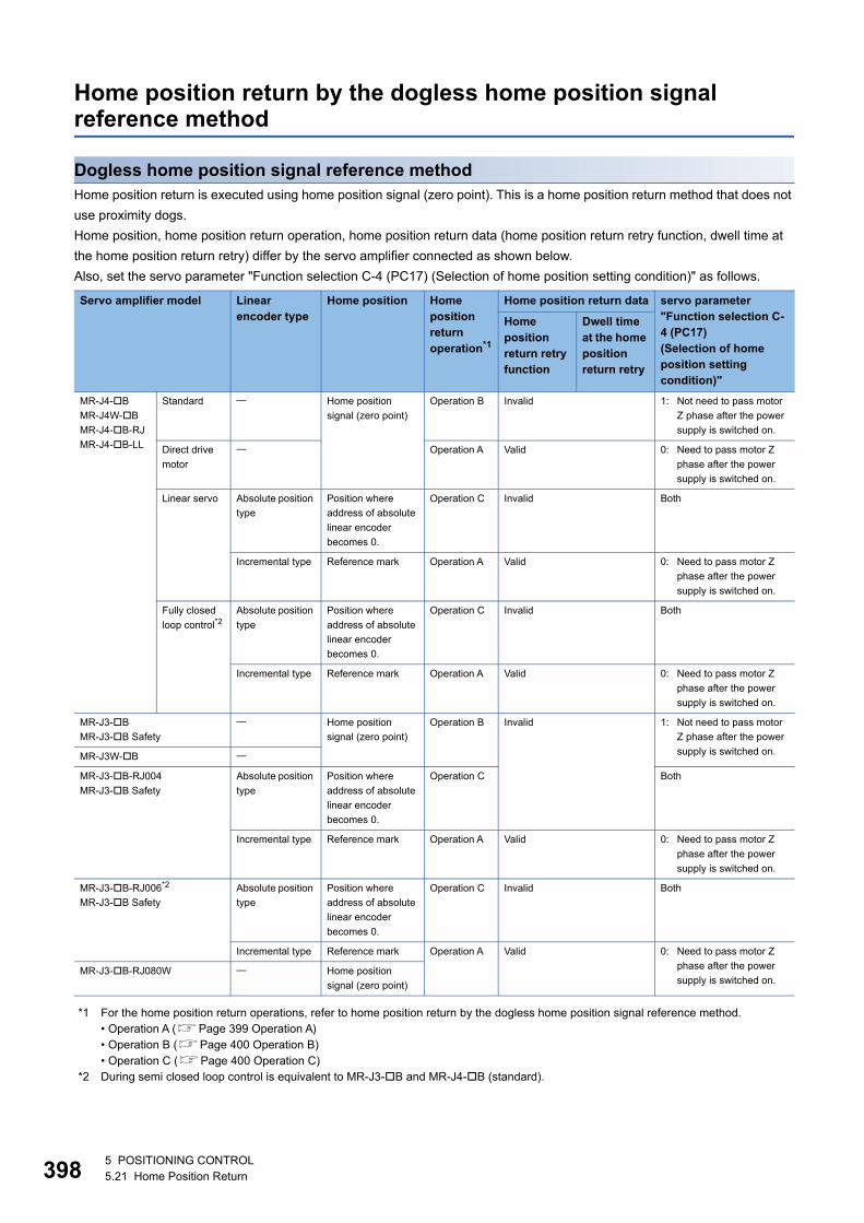
39
Home position return by the dogless home position signal reference method
Dogless home position signal reference methodHome position return is executed using home position signal (zero point). This is a home position return method that does not
use proximity dogs.
Home position, home position return operation, home position return data (home position return retry function, dwell time at
the home position return retry) differ by the servo amplifier connected as shown below.
Also, set the servo parameter "Function selection C-4 (PC17) (Selection of home position setting condition)" as follows.
*1 For the home position return operations, refer to home position return by the dogless home position signal reference method.• Operation A (Page 399 Operation A)• Operation B (Page 400 Operation B)• Operation C (Page 400 Operation C)
*2 During semi closed loop control is equivalent to MR-J3-B and MR-J4-B (standard).
Servo amplifier model Linear encoder type
Home position Home position return operation*1
Home position return data servo parameter"Function selection C-4 (PC17)(Selection of home position setting condition)"
Home position return retry function
Dwell time at the home position return retry
MR-J4-B
MR-J4W-B
MR-J4-B-RJ
MR-J4-B-LL
Standard Home position
signal (zero point)
Operation B Invalid 1: Not need to pass motor
Z phase after the power
supply is switched on.
Direct drive
motor
Operation A Valid 0: Need to pass motor Z
phase after the power
supply is switched on.
Linear servo Absolute position
type
Position where
address of absolute
linear encoder
becomes 0.
Operation C Invalid Both
Incremental type Reference mark Operation A Valid 0: Need to pass motor Z
phase after the power
supply is switched on.
Fully closed
loop control*2Absolute position
type
Position where
address of absolute
linear encoder
becomes 0.
Operation C Invalid Both
Incremental type Reference mark Operation A Valid 0: Need to pass motor Z
phase after the power
supply is switched on.
MR-J3-B
MR-J3-B Safety
Home position
signal (zero point)
Operation B Invalid 1: Not need to pass motor
Z phase after the power
supply is switched on.MR-J3W-B
MR-J3-B-RJ004
MR-J3-B Safety
Absolute position
type
Position where
address of absolute
linear encoder
becomes 0.
Operation C Both
Incremental type Reference mark Operation A Valid 0: Need to pass motor Z
phase after the power
supply is switched on.
MR-J3-B-RJ006*2
MR-J3-B Safety
Absolute position
type
Position where
address of absolute
linear encoder
becomes 0.
Operation C Invalid Both
Incremental type Reference mark Operation A Valid 0: Need to pass motor Z
phase after the power
supply is switched on.MR-J3-B-RJ080W Home position
signal (zero point)
85 POSITIONING CONTROL5.21 Home Position Return
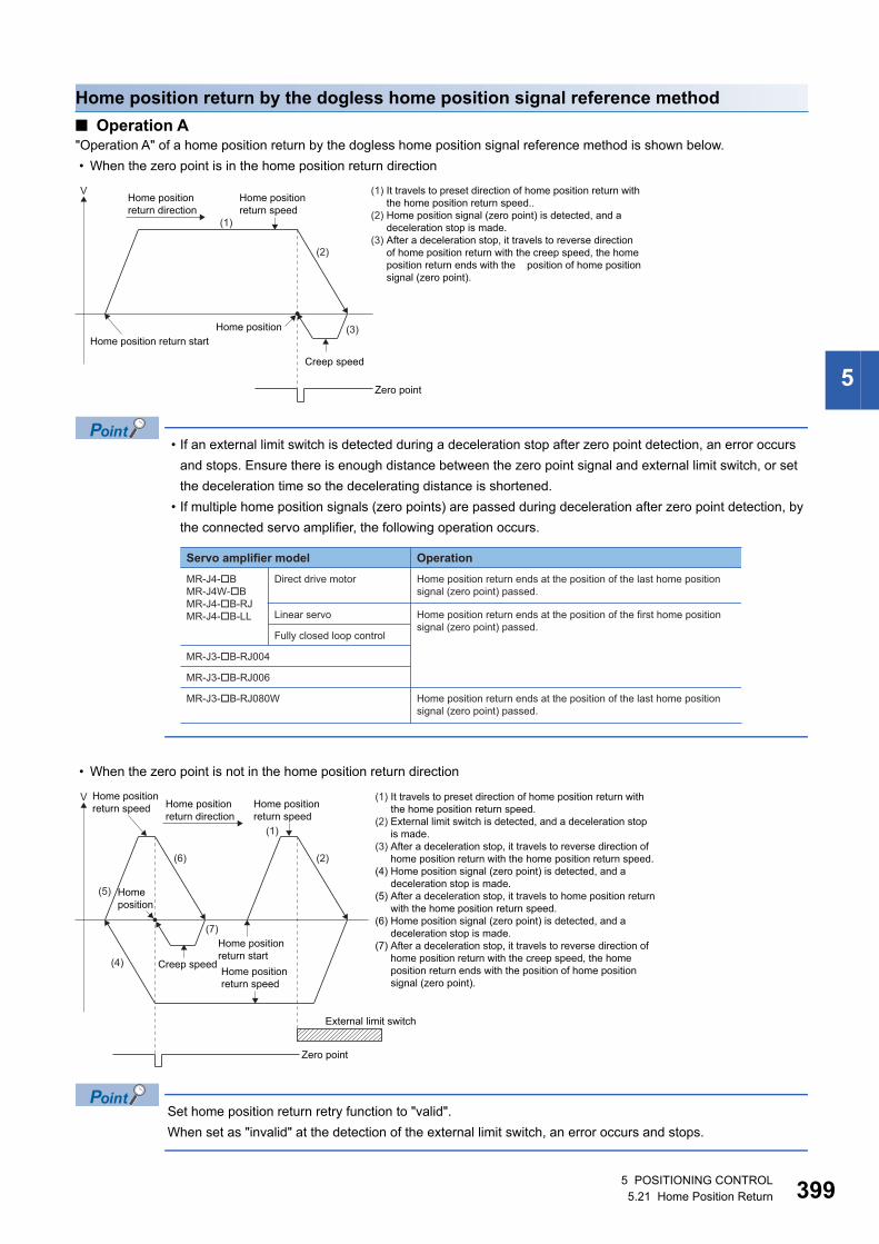
5
Home position return by the dogless home position signal reference method
■ Operation A"Operation A" of a home position return by the dogless home position signal reference method is shown below.
• When the zero point is in the home position return direction
• If an external limit switch is detected during a deceleration stop after zero point detection, an error occurs
and stops. Ensure there is enough distance between the zero point signal and external limit switch, or set
the deceleration time so the decelerating distance is shortened.
• If multiple home position signals (zero points) are passed during deceleration after zero point detection, by
the connected servo amplifier, the following operation occurs.
• When the zero point is not in the home position return direction
Set home position return retry function to "valid".
When set as "invalid" at the detection of the external limit switch, an error occurs and stops.
V
(2)
(1)
(3)
Zero point
Home position return startHome position
Creep speed
Home position return speed
Home positionreturn direction
(1) It travels to preset direction of home position return withthe home position return speed..
(2) Home position signal (zero point) is detected, and a deceleration stop is made.
(3) After a deceleration stop, it travels to reverse directionof home position return with the creep speed, the homeposition return ends with the position of home positionsignal (zero point).
Servo amplifier model Operation
MR-J4-�BMR-J4W-�BMR-J4-�B-RJMR-J4-�B-LL
Direct drive motor Home position return ends at the position of the last home position signal (zero point) passed.
Home position return ends at the position of the last home position signal (zero point) passed.
Linear servo Home position return ends at the position of the first home position signal (zero point) passed.
Fully closed loop control
MR-J3-�B-RJ004
MR-J3-�B-RJ006
MR-J3-�B-RJ080W
V
(5)
(7)
(2)
(1)
(4)
(6)
Creep speed
Home position return startHome positionreturn speed
Zero point
External limit switch
Homeposition
Home position return speed
Home position return speed Home position
return direction
(1) It travels to preset direction of home position return withthe home position return speed.
(2) External limit switch is detected, and a deceleration stopis made.
(3) After a deceleration stop, it travels to reverse direction ofhome position return with the home position return speed.
(4) Home position signal (zero point) is detected, and adeceleration stop is made.
(5) After a deceleration stop, it travels to home position returnwith the home position return speed.
(6) Home position signal (zero point) is detected, and adeceleration stop is made.
(7) After a deceleration stop, it travels to reverse direction ofhome position return with the creep speed, the homeposition return ends with the position of home positionsignal (zero point).
5 POSITIONING CONTROL5.21 Home Position Return 399
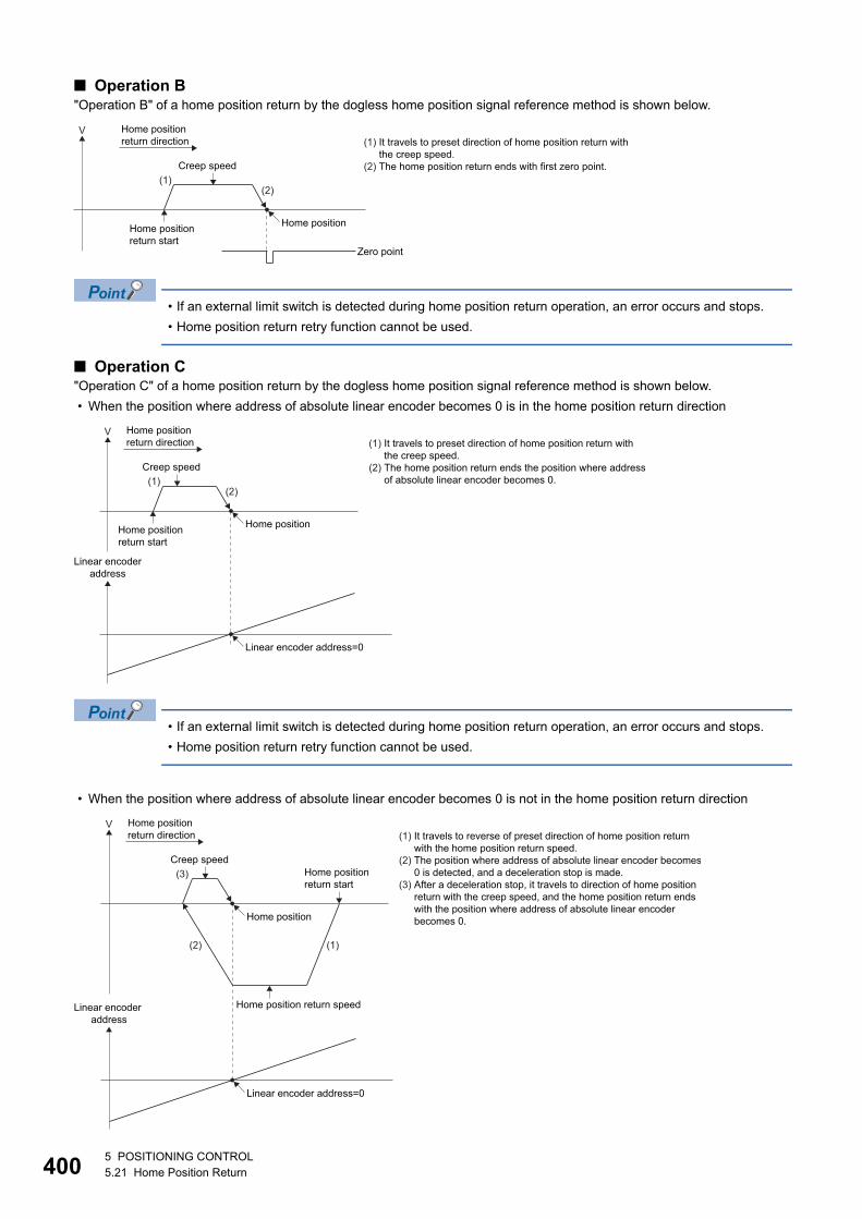
40
■ Operation B"Operation B" of a home position return by the dogless home position signal reference method is shown below.
• If an external limit switch is detected during home position return operation, an error occurs and stops.
• Home position return retry function cannot be used.
■ Operation C"Operation C" of a home position return by the dogless home position signal reference method is shown below.
• When the position where address of absolute linear encoder becomes 0 is in the home position return direction
• If an external limit switch is detected during home position return operation, an error occurs and stops.
• Home position return retry function cannot be used.
• When the position where address of absolute linear encoder becomes 0 is not in the home position return direction
V
(1)(2)
Home position return start
Creep speed
Zero point
Home position
Home positionreturn direction (1) It travels to preset direction of home position return with
the creep speed. (2) The home position return ends with first zero point.
V
(1)(2)
Home position return start
Creep speed
Linear encoder address=0
Linear encoderaddress
Home position
Home positionreturn direction (1) It travels to preset direction of home position return with
the creep speed.(2) The home position return ends the position where address
of absolute linear encoder becomes 0.
V
(3)
(2) (1)
Home position return speed
Creep speedHome position return start
Home position
Linear encoder address=0
Linear encoder address
Home positionreturn direction (1) It travels to reverse of preset direction of home position return
with the home position return speed. (2) The position where address of absolute linear encoder becomes
0 is detected, and a deceleration stop is made.(3) After a deceleration stop, it travels to direction of home position
return with the creep speed, and the home position return endswith the position where address of absolute linear encoderbecomes 0.
05 POSITIONING CONTROL5.21 Home Position Return
5
• If an external limit switch is detected during home position return operation, an error occurs and stops.
• Home position return retry function cannot be used.
Home position return executionHome position return by dogless home position signal reference method is executed using the servo program (Page 376
Servo program for home position return).
Cautions • If a home position return is started for an axis connected with servo amplifiers other than MR-J3(W)-B, MR-J4(W)-B, a
minor error (error code: 1979H) will occur and the home position return is not executed.
• If home position return is executed again after home position return end, a minor error (error code: 197BH) will occur, the
home position return is not executed.
• If connecting a rotational motor on the load side with a fully closed loop control servo amplifier (MR-J3-B-RJ006, MR-J4-
B), execute home position return in a semi closed loop control state. (The home position return operation becomes that of
"Operation B".)
If a home position return is performed in a fully closed loop control state, the home position return is at the
position of encoder current value of multiple revolution position=0, and single revolution position=0 (The home
position return operation becomes that of "Operation C"), and the motor might revolve more than necessary.
When connecting a rotational motor on the load side, execute home position return in a semi closed loop
control state.
• If executing home position return with a fully closed loop control servo amplifier (MR-J3-B-RJ006, MR-J4-B), do not
change fully closed loop control/semi closed loop control during home position return operation. When fully closed loop
control/semi closed loop control is changed during home position return operation, the home position return might not be
completed normally
• If performing home position return from zero point, depending on the actual motor position at the start, and it's relative
position to zero point, the home position return might be completed at the next zero point. It is recommended to move the
start of the home position return from the zero point to a position in the reverse direction of home position return direction.
• The operation for when home position return is executed during the operation of amplifier-less operation function is shown
below.
Servo amplifier Operation
MR-J3(W)-B Regardless of the servo amplifier model, home position return is executed by the home position return operation of
"Operation B".
MR-J4(W)-B Home position return is performed by the home position return operation that complies with the amplifier operation
mode that is set in [Motion CPU Common Parameter] [Servo Network Setting] "Amplifier Setting".
5 POSITIONING CONTROL5.21 Home Position Return 401
40
• The following describes precautions for the home position return operations for the home position return by dogless home
position signal reference method.
Home position return operation Cautions
Operation A • Set the servo parameter (expansion parameter) "Function selection C-4 (PC17)" to "0: Need to pass motor Z phase
after the power supply is switched on". If set to "1: Not need to pass motor Z phase after the power supply is
switched on", when home position return by dogless home position signal reference method (operation A) is
started, a minor error (error code: 1978H) will occur and the home position return is not executed.
• If the "[St.1066] Zero pass (R: M32406+32n/Q: M2046+20n)" was on at home position return start, this signal turns
off once at the home position return start and turns on again at the next zero point passage.
• If an external limit switch is detected during a deceleration stop after zero point detection, an error occurs and
stops. Ensure there is enough distance between the zero point signal and external limit switch, or set the
deceleration time so the decelerating distance is shortened.
• With home position return retry function valid, if zero point is detected during a deceleration stop after external limit
switch is detected, an error occurs and stops. Set the external limit switch in a position that puts the zero signal
inside the external limit switch.
Operation B • Set the servo parameter (expansion parameter) "Function selection C-4 (PC17)" to "1: Not need to pass motor Z
phase after the power supply is switched on". If set to "0: Need to pass motor Z phase after the power supply is
switched on", when home position return by dogless home position signal reference method (operation B) is
started, a minor error (error code: 1978H) will occur and the home position return is not executed.
• Home position return retry function cannot be used.
Operation C • If an external limit switch is detected during home position return operation, an error occurs and stops.
• Home position return retry function cannot be used.
25 POSITIONING CONTROL5.21 Home Position Return
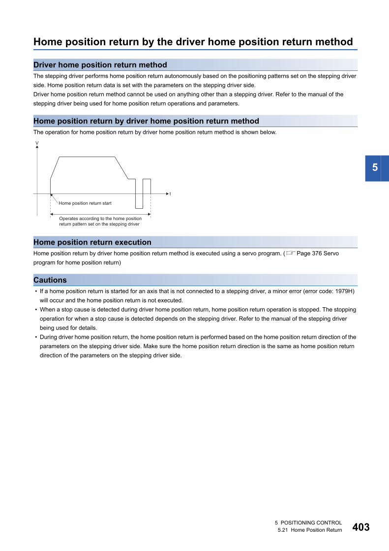
5
Home position return by the driver home position return method
Driver home position return methodThe stepping driver performs home position return autonomously based on the positioning patterns set on the stepping driver
side. Home position return data is set with the parameters on the stepping driver side.
Driver home position return method cannot be used on anything other than a stepping driver. Refer to the manual of the
stepping driver being used for home position return operations and parameters.
Home position return by driver home position return methodThe operation for home position return by driver home position return method is shown below.
Home position return executionHome position return by driver home position return method is executed using a servo program. (Page 376 Servo
program for home position return)
Cautions • If a home position return is started for an axis that is not connected to a stepping driver, a minor error (error code: 1979H)
will occur and the home position return is not executed.
• When a stop cause is detected during driver home position return, home position return operation is stopped. The stopping
operation for when a stop cause is detected depends on the stepping driver. Refer to the manual of the stepping driver
being used for details.
• During driver home position return, the home position return is performed based on the home position return direction of the
parameters on the stepping driver side. Make sure the home position return direction is the same as home position return
direction of the parameters on the stepping driver side.
V
t
Home position return start
Operates according to the home positionreturn pattern set on the stepping driver
5 POSITIONING CONTROL5.21 Home Position Return 403
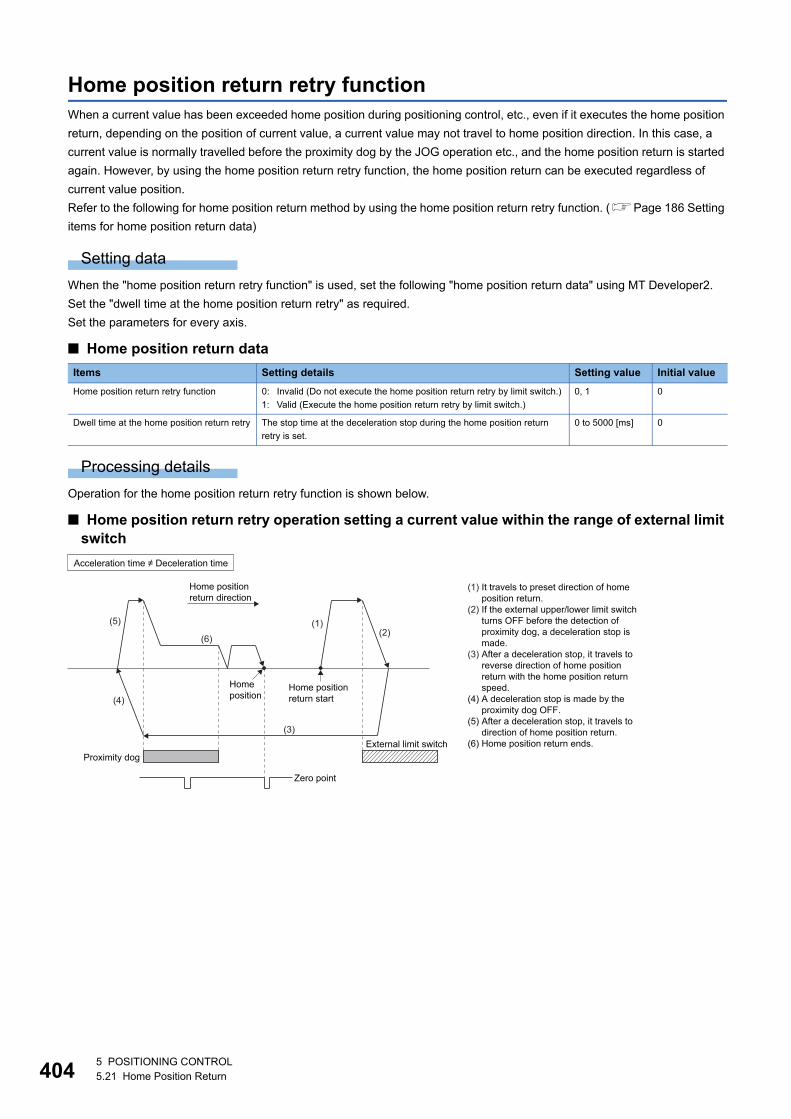
40
Home position return retry functionWhen a current value has been exceeded home position during positioning control, etc., even if it executes the home position
return, depending on the position of current value, a current value may not travel to home position direction. In this case, a
current value is normally travelled before the proximity dog by the JOG operation etc., and the home position return is started
again. However, by using the home position return retry function, the home position return can be executed regardless of
current value position.
Refer to the following for home position return method by using the home position return retry function. (Page 186 Setting
items for home position return data)
Setting data
When the "home position return retry function" is used, set the following "home position return data" using MT Developer2.
Set the "dwell time at the home position return retry" as required.
Set the parameters for every axis.
■ Home position return data
Processing details
Operation for the home position return retry function is shown below.
■ Home position return retry operation setting a current value within the range of external limit switch
Items Setting details Setting value Initial value
Home position return retry function 0: Invalid (Do not execute the home position return retry by limit switch.)
1: Valid (Execute the home position return retry by limit switch.)
0, 1 0
Dwell time at the home position return retry The stop time at the deceleration stop during the home position return
retry is set.
0 to 5000 [ms] 0
(5)
(4)
(3)
(6)
(1)(2)
Home position return start
Home position
External limit switch
Zero point
Proximity dog
Home positionreturn direction
Acceleration time � Deceleration time
(1) It travels to preset direction of homeposition return.
(2) If the external upper/lower limit switchturns OFF before the detection ofproximity dog, a deceleration stop ismade.
(3) After a deceleration stop, it travels toreverse direction of home positionreturn with the home position returnspeed.
(4) A deceleration stop is made by theproximity dog OFF.
(5) After a deceleration stop, it travels todirection of home position return.
(6) Home position return ends.
45 POSITIONING CONTROL5.21 Home Position Return
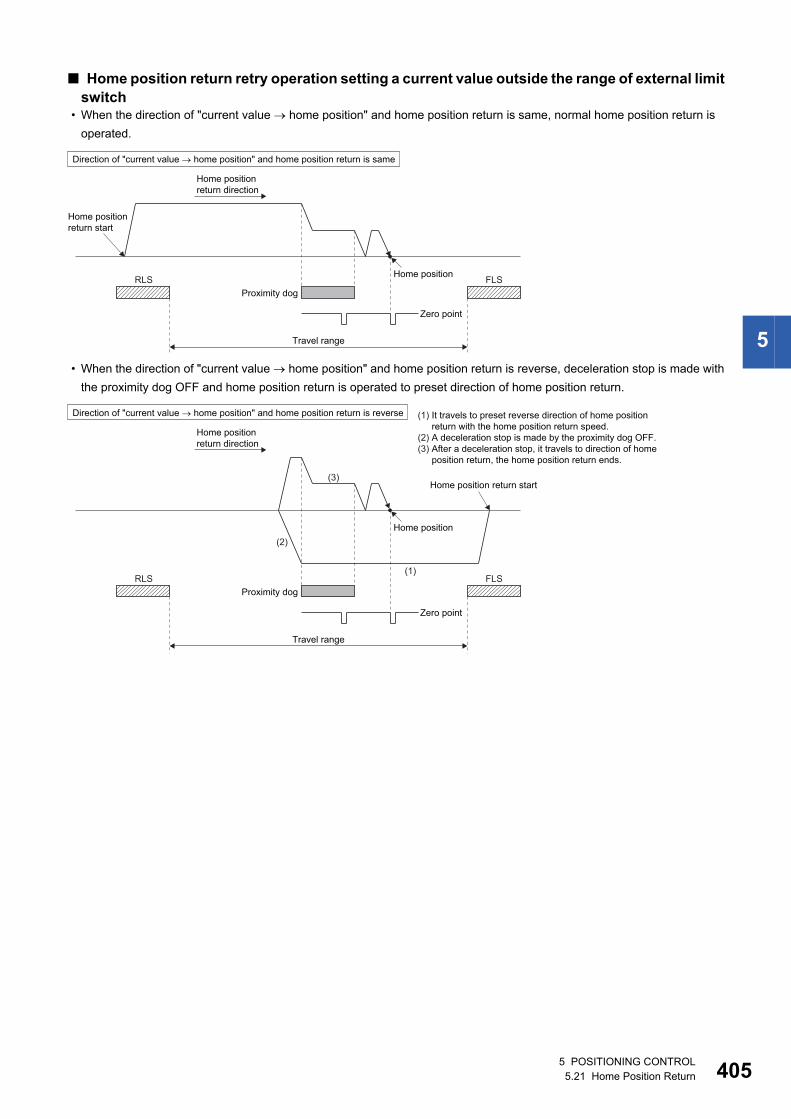
5
■ Home position return retry operation setting a current value outside the range of external limit switch
• When the direction of "current value home position" and home position return is same, normal home position return is
operated.
• When the direction of "current value home position" and home position return is reverse, deceleration stop is made with
the proximity dog OFF and home position return is operated to preset direction of home position return.
Home position return start
Home positionRLS FLSProximity dog
Zero point
Direction of "current value � home position" and home position return is same
Travel range
Home positionreturn direction
Home position
RLS FLS(1)
(2)
(3)
Zero point
Travel range
Home position return start
Proximity dog
Direction of "current value � home position" and home position return is reverse
Home positionreturn direction
(1) It travels to preset reverse direction of home positionreturn with the home position return speed.
(2) A deceleration stop is made by the proximity dog OFF.(3) After a deceleration stop, it travels to direction of home
position return, the home position return ends.
5 POSITIONING CONTROL5.21 Home Position Return 405
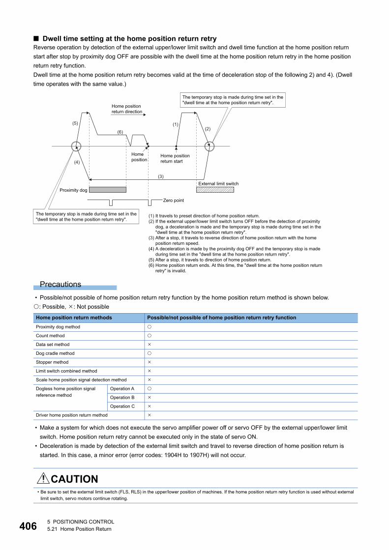
40
■ Dwell time setting at the home position return retryReverse operation by detection of the external upper/lower limit switch and dwell time function at the home position return
start after stop by proximity dog OFF are possible with the dwell time at the home position return retry in the home position
return retry function.
Dwell time at the home position return retry becomes valid at the time of deceleration stop of the following 2) and 4). (Dwell
time operates with the same value.)
Precautions
• Possible/not possible of home position return retry function by the home position return method is shown below.
: Possible, : Not possible
• Make a system for which does not execute the servo amplifier power off or servo OFF by the external upper/lower limit
switch. Home position return retry cannot be executed only in the state of servo ON.
• Deceleration is made by detection of the external limit switch and travel to reverse direction of home position return is
started. In this case, a minor error (error codes: 1904H to 1907H) will not occur.
Home position return methods Possible/not possible of home position return retry function
Proximity dog method
Count method
Data set method
Dog cradle method
Stopper method
Limit switch combined method
Scale home position signal detection method
Dogless home position signal
reference method
Operation A
Operation B
Operation C
Driver home position return method
CAUTION• Be sure to set the external limit switch (FLS, RLS) in the upper/lower position of machines. If the home position return retry function is used without external
limit switch, servo motors continue rotating.
(5)
(4)
(3)
(6)
(1)(2)
Home position return start
Home position
External limit switch
Zero point
Proximity dog
Home positionreturn direction
(1) It travels to preset direction of home position return. (2) If the external upper/lower limit switch turns OFF before the detection of proximity
dog, a deceleration is made and the temporary stop is made during time set in the"dwell time at the home position return retry".
(3) After a stop, it travels to reverse direction of home position return with the homeposition return speed.
(4) A deceleration is made by the proximity dog OFF and the temporary stop is madeduring time set in the "dwell time at the home position return retry".
(5) After a stop, it travels to direction of home position return.(6) Home position return ends. At this time, the "dwell time at the home position return
retry" is invalid.
The temporary stop is made during time set in the"dwell time at the home position return retry".
The temporary stop is made during time set in the"dwell time at the home position return retry".
65 POSITIONING CONTROL5.21 Home Position Return
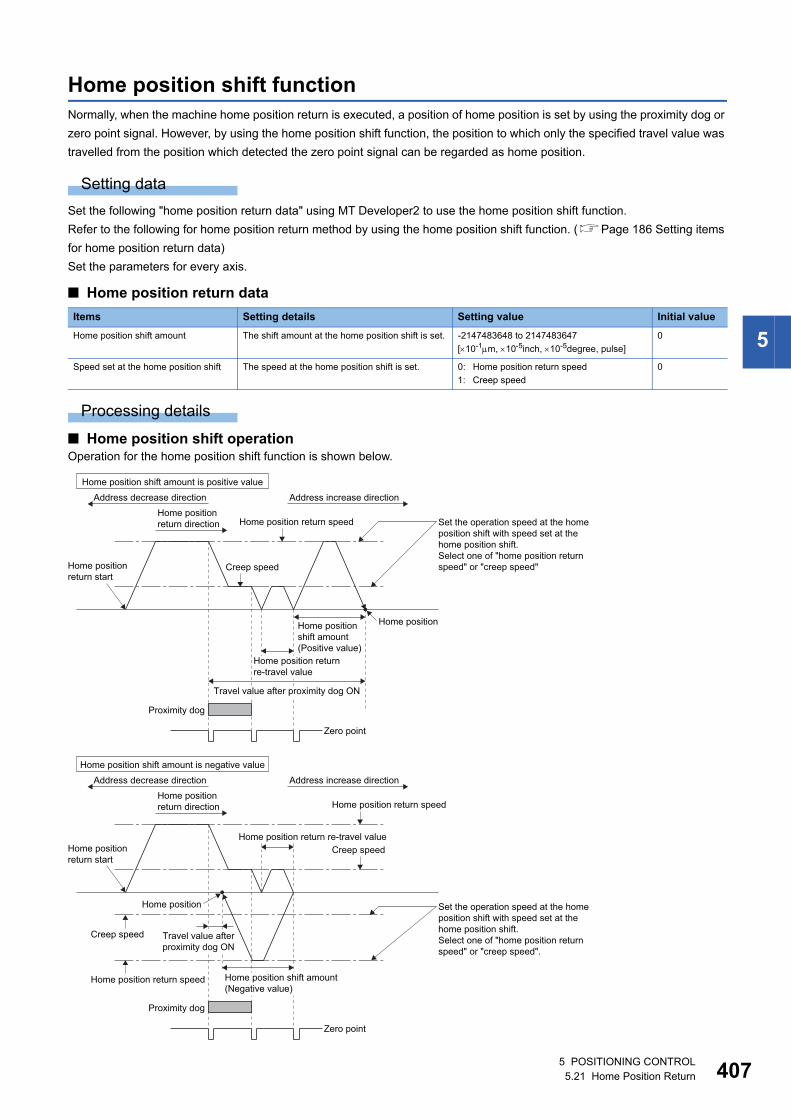
5
Home position shift functionNormally, when the machine home position return is executed, a position of home position is set by using the proximity dog or
zero point signal. However, by using the home position shift function, the position to which only the specified travel value was
travelled from the position which detected the zero point signal can be regarded as home position.
Setting data
Set the following "home position return data" using MT Developer2 to use the home position shift function.
Refer to the following for home position return method by using the home position shift function. (Page 186 Setting items
for home position return data)
Set the parameters for every axis.
■ Home position return data
Processing details
■ Home position shift operationOperation for the home position shift function is shown below.
Items Setting details Setting value Initial value
Home position shift amount The shift amount at the home position shift is set. -2147483648 to 2147483647
[10-1m, 10-5inch, 10-5degree, pulse]
0
Speed set at the home position shift The speed at the home position shift is set. 0: Home position return speed
1: Creep speed
0
Home position return start
Home position return start
Address increase directionAddress decrease direction
Home position return speed
Creep speed
Zero point
Proximity dog
Home position shift amount is positive value
Home position
Set the operation speed at the homeposition shift with speed set at thehome position shift.Select one of "home position returnspeed" or "creep speed"
Travel value after proximity dog ON
Home position returnre-travel value
Home position return speed
Creep speed
Home position return speed
Creep speed
Zero point
Proximity dog
Home position shift amount is negative value
Home position
Home position shift amount(Negative value)
Home position return re-travel value
Set the operation speed at the homeposition shift with speed set at thehome position shift. Select one of "home position returnspeed" or "creep speed".
Home positionshift amount (Positive value)
Home positionreturn direction
Address increase directionAddress decrease directionHome positionreturn direction
Travel value after proximity dog ON
5 POSITIONING CONTROL5.21 Home Position Return 407
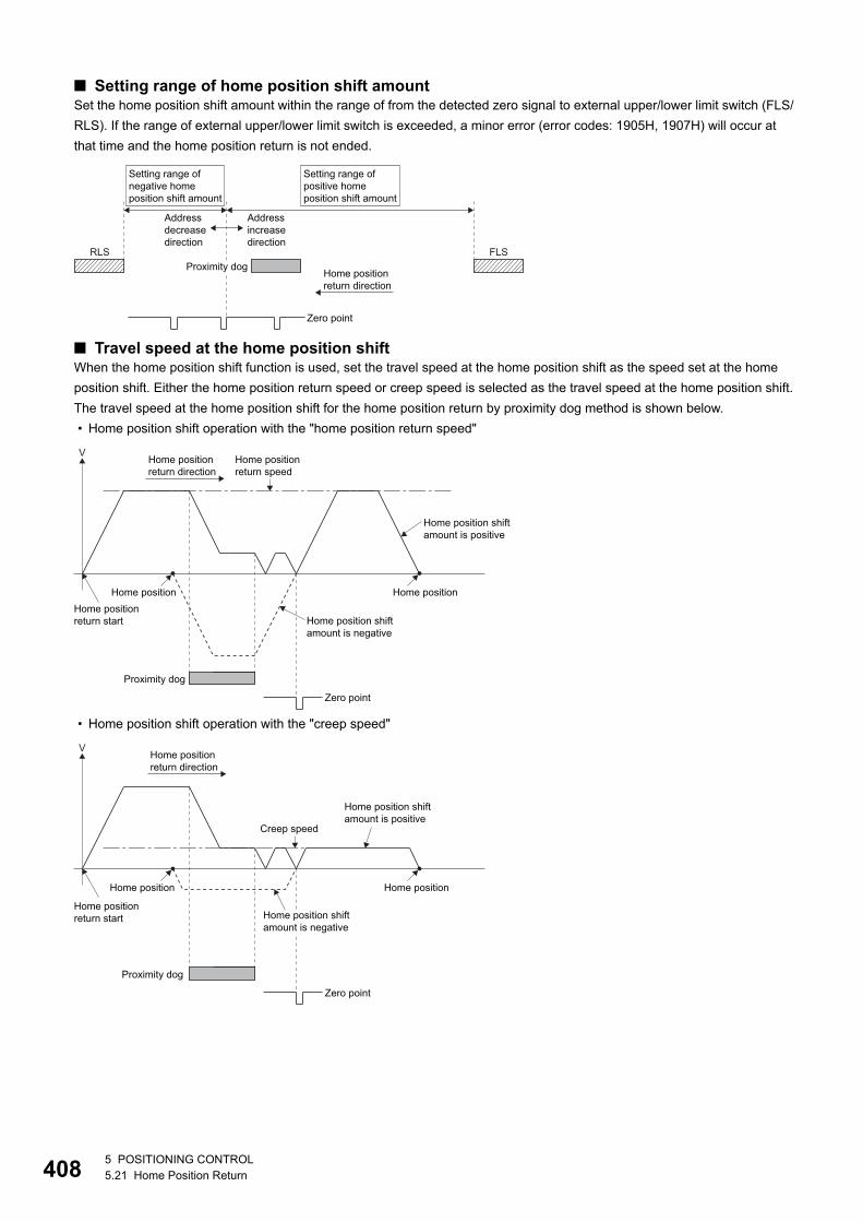
40
■ Setting range of home position shift amountSet the home position shift amount within the range of from the detected zero signal to external upper/lower limit switch (FLS/
RLS). If the range of external upper/lower limit switch is exceeded, a minor error (error codes: 1905H, 1907H) will occur at
that time and the home position return is not ended.
■ Travel speed at the home position shiftWhen the home position shift function is used, set the travel speed at the home position shift as the speed set at the home
position shift. Either the home position return speed or creep speed is selected as the travel speed at the home position shift.
The travel speed at the home position shift for the home position return by proximity dog method is shown below.
• Home position shift operation with the "home position return speed"
• Home position shift operation with the "creep speed"
Home position return direction
RLS FLSProximity dog
Zero point
Addressincrease direction
Address decreasedirection
Setting range of negative home position shift amount
Setting range of positive home position shift amount
V
Proximity dog
Zero point
Home position return start
Home position Home position
Home position shift amount is positive
Home position shift amount is negative
Home position return speed
Home positionreturn direction
Home position shift amount is positive
V
Creep speed
Proximity dog
Zero point
Home position return start
Home position Home position
Home positionreturn direction
Home position shift amount is negative
85 POSITIONING CONTROL5.21 Home Position Return
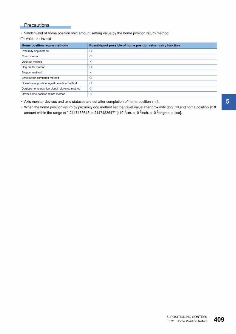
5
Precautions
• Valid/invalid of home position shift amount setting value by the home position return method.
: Valid, : Invalid
• Axis monitor devices and axis statuses are set after completion of home position shift.
• When the home position return by proximity dog method set the travel value after proximity dog ON and home position shift
amount within the range of "-2147483648 to 2147483647" [10-1m, 10-5inch, 10-5degree, pulse].
Home position return methods Possible/not possible of home position return retry function
Proximity dog method
Count method
Data set method
Dog cradle method
Stopper method
Limit switch combined method
Scale home position signal detection method
Dogless home position signal reference method
Driver home position return method
5 POSITIONING CONTROL5.21 Home Position Return 409
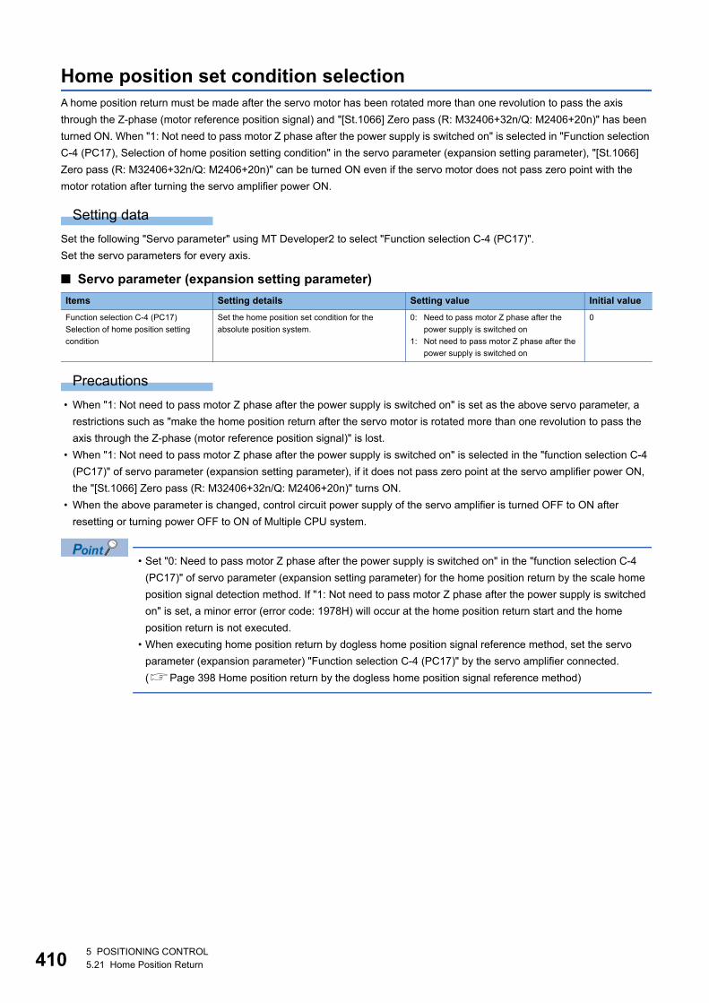
41
Home position set condition selectionA home position return must be made after the servo motor has been rotated more than one revolution to pass the axis
through the Z-phase (motor reference position signal) and "[St.1066] Zero pass (R: M32406+32n/Q: M2406+20n)" has been
turned ON. When "1: Not need to pass motor Z phase after the power supply is switched on" is selected in "Function selection
C-4 (PC17), Selection of home position setting condition" in the servo parameter (expansion setting parameter), "[St.1066]
Zero pass (R: M32406+32n/Q: M2406+20n)" can be turned ON even if the servo motor does not pass zero point with the
motor rotation after turning the servo amplifier power ON.
Setting data
Set the following "Servo parameter" using MT Developer2 to select "Function selection C-4 (PC17)".
Set the servo parameters for every axis.
■ Servo parameter (expansion setting parameter)
Precautions
• When "1: Not need to pass motor Z phase after the power supply is switched on" is set as the above servo parameter, a
restrictions such as "make the home position return after the servo motor is rotated more than one revolution to pass the
axis through the Z-phase (motor reference position signal)" is lost.
• When "1: Not need to pass motor Z phase after the power supply is switched on" is selected in the "function selection C-4
(PC17)" of servo parameter (expansion setting parameter), if it does not pass zero point at the servo amplifier power ON,
the "[St.1066] Zero pass (R: M32406+32n/Q: M2406+20n)" turns ON.
• When the above parameter is changed, control circuit power supply of the servo amplifier is turned OFF to ON after
resetting or turning power OFF to ON of Multiple CPU system.
• Set "0: Need to pass motor Z phase after the power supply is switched on" in the "function selection C-4
(PC17)" of servo parameter (expansion setting parameter) for the home position return by the scale home
position signal detection method. If "1: Not need to pass motor Z phase after the power supply is switched
on" is set, a minor error (error code: 1978H) will occur at the home position return start and the home
position return is not executed.
• When executing home position return by dogless home position signal reference method, set the servo
parameter (expansion parameter) "Function selection C-4 (PC17)" by the servo amplifier connected.
(Page 398 Home position return by the dogless home position signal reference method)
Items Setting details Setting value Initial value
Function selection C-4 (PC17)
Selection of home position setting
condition
Set the home position set condition for the
absolute position system.
0: Need to pass motor Z phase after the
power supply is switched on
1: Not need to pass motor Z phase after the
power supply is switched on
0
05 POSITIONING CONTROL5.21 Home Position Return
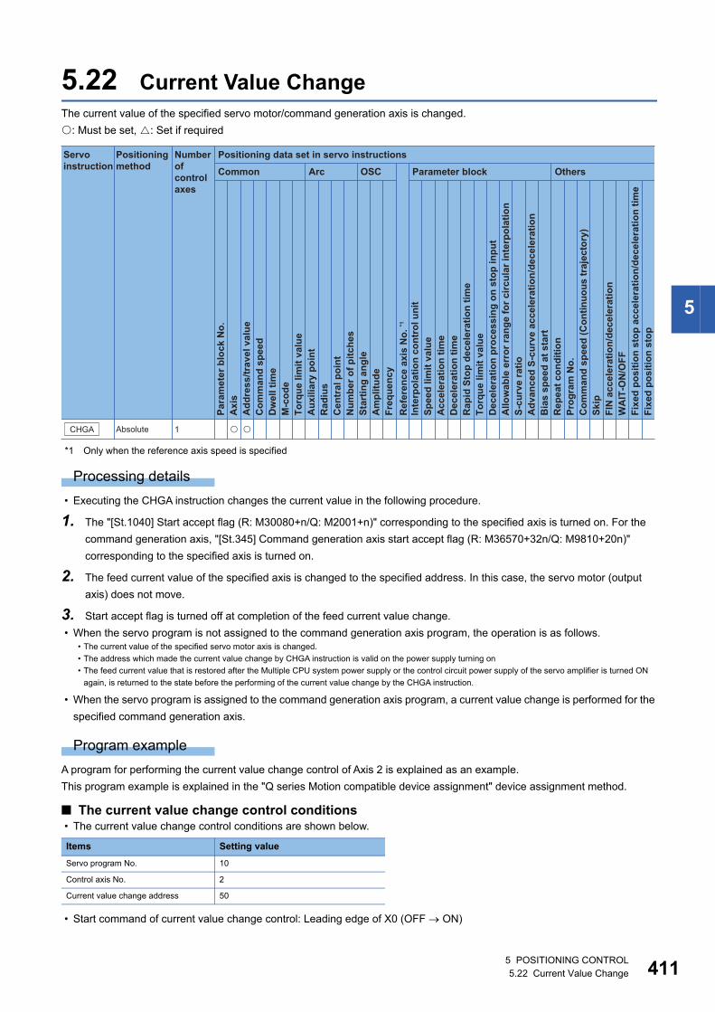
5
5.22 Current Value ChangeThe current value of the specified servo motor/command generation axis is changed.
: Must be set, : Set if required
*1 Only when the reference axis speed is specified
Processing details
• Executing the CHGA instruction changes the current value in the following procedure.
1. The "[St.1040] Start accept flag (R: M30080+n/Q: M2001+n)" corresponding to the specified axis is turned on. For the
command generation axis, "[St.345] Command generation axis start accept flag (R: M36570+32n/Q: M9810+20n)"
corresponding to the specified axis is turned on.
2. The feed current value of the specified axis is changed to the specified address. In this case, the servo motor (output
axis) does not move.
3. Start accept flag is turned off at completion of the feed current value change.
• When the servo program is not assigned to the command generation axis program, the operation is as follows.
• When the servo program is assigned to the command generation axis program, a current value change is performed for the
specified command generation axis.
Program example
A program for performing the current value change control of Axis 2 is explained as an example.
This program example is explained in the "Q series Motion compatible device assignment" device assignment method.
■ The current value change control conditions • The current value change control conditions are shown below.
• Start command of current value change control: Leading edge of X0 (OFF ON)
• The current value of the specified servo motor axis is changed.
• The address which made the current value change by CHGA instruction is valid on the power supply turning on
• The feed current value that is restored after the Multiple CPU system power supply or the control circuit power supply of the servo amplifier is turned ON
again, is returned to the state before the performing of the current value change by the CHGA instruction.
Items Setting value
Servo program No. 10
Control axis No. 2
Current value change address 50
Positioning data set in servo instructions
Common
Servo instruction
Positioning method
Number ofcontrol axes
Arc OSC Parameter block Others
Para
met
er b
lock
No.
Acc
eler
atio
n tim
eD
ecel
erat
ion
time
Rap
id S
top
dece
lera
tion
time
Torq
ue li
mit
valu
eD
ecel
erat
ion
proc
essi
ng o
n st
op in
put
Allo
wab
le e
rror
rang
e fo
r circ
ular
inte
rpol
atio
nS-
curv
e ra
tioA
dvan
ced
S-cu
rve
acce
lera
tion/
dece
lera
tion
Bia
s sp
eed
at s
tart
Rep
eat c
ondi
tion
Prog
ram
No.
Com
man
d sp
eed
(Con
tinuo
us tr
ajec
tory
)Sk
ipFI
N a
ccel
erat
ion/
dece
lera
tion
WA
IT-O
N/O
FF
Fixe
d po
sitio
n st
op
Axi
sA
ddre
ss/tr
avel
val
ueC
omm
and
spee
dD
wel
l tim
eM
-cod
eTo
rque
lim
it va
lue
Aux
iliar
y po
int
Rad
ius
Cen
tral
poi
ntN
umbe
r of p
itche
sSt
artin
g an
gle
Am
plitu
deFr
eque
ncy
Inte
rpol
atio
n co
ntro
l uni
tSp
eed
limit
valu
e
Ref
eren
ce a
xis
No.
*1
Fixe
d po
sitio
n st
op a
ccel
erat
ion/
dece
lera
tion
time
CHGA Absolute 1 � �
5 POSITIONING CONTROL5.22 Current Value Change 411
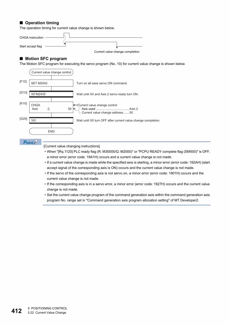
41
■ Operation timingThe operation timing for current value change is shown below.
■ Motion SFC programThe Motion SFC program for executing the servo program (No. 10) for current value change is shown below.
[Current value changing instructions]
• When "[Rq.1120] PLC ready flag (R: M30000/Q: M2000)" or "PCPU READY complete flag (SM500)" is OFF,
a minor error (error code: 19A1H) occurs and a current value change is not made.
• If a current value change is made while the specified axis is starting, a minor error (error code: 192AH) (start
accept signal of the corresponding axis is ON) occurs and the current value change is not made.
• If the servo of the corresponding axis is not servo on, a minor error (error code: 1901H) occurs and the
current value change is not made.
• If the corresponding axis is in a servo error, a minor error (error code: 1927H) occurs and the current value
change is not made.
• Set the current value change program of the command generation axis within the command generation axis
program No. range set in "Command generation axis program allocation setting" of MT Developer2.
CHGA instruction
Start accept flag
Current value change completion
�Axis used .......................................Axis 2�Current value change address ......50
Current value change control
SET M2042[F10]
X0*M2435[G10]
CHGA Axis 2, 50
[K10]
Wait until X0 and Axis 2 servo ready turn ON.
Turn on all axes servo ON command.
!X0[G20]
END
Wait until X0 turn OFF after current value change completion.
Current value change control
25 POSITIONING CONTROL5.22 Current Value Change
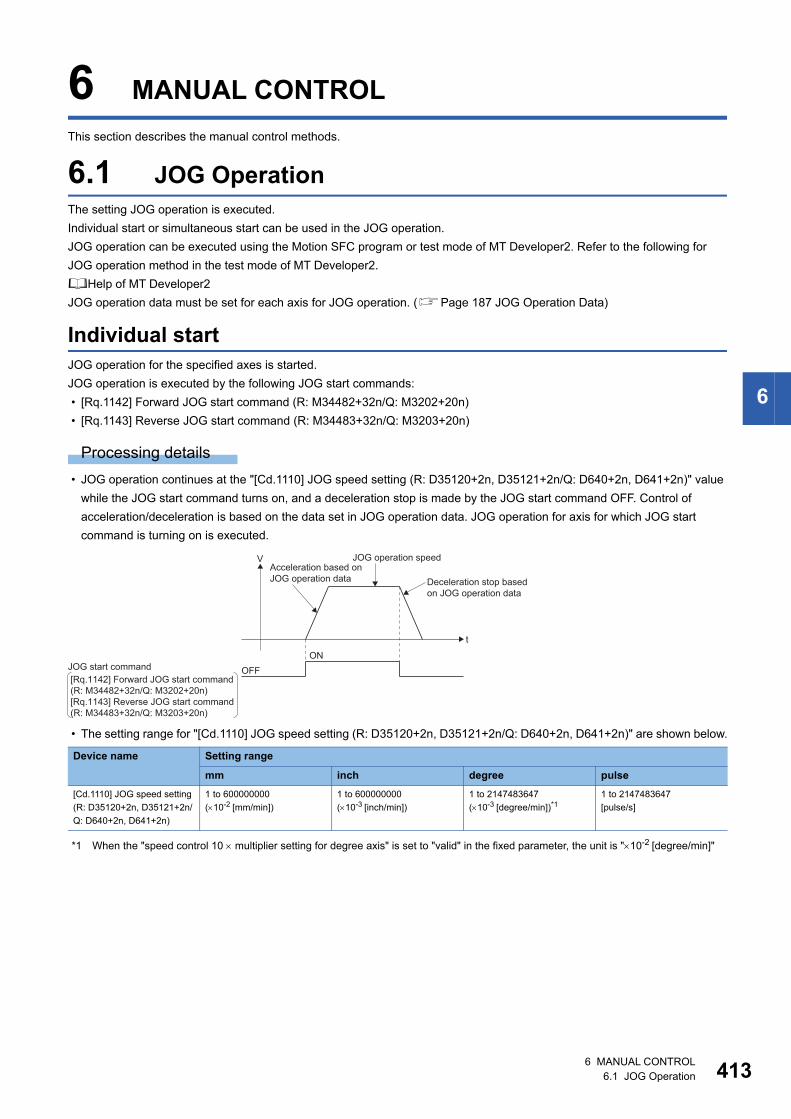
6
6 MANUAL CONTROL
This section describes the manual control methods.
6.1 JOG OperationThe setting JOG operation is executed.
Individual start or simultaneous start can be used in the JOG operation.
JOG operation can be executed using the Motion SFC program or test mode of MT Developer2. Refer to the following for
JOG operation method in the test mode of MT Developer2.
Help of MT Developer2
JOG operation data must be set for each axis for JOG operation. (Page 187 JOG Operation Data)
Individual startJOG operation for the specified axes is started.
JOG operation is executed by the following JOG start commands:
• [Rq.1142] Forward JOG start command (R: M34482+32n/Q: M3202+20n)
• [Rq.1143] Reverse JOG start command (R: M34483+32n/Q: M3203+20n)
Processing details
• JOG operation continues at the "[Cd.1110] JOG speed setting (R: D35120+2n, D35121+2n/Q: D640+2n, D641+2n)" value
while the JOG start command turns on, and a deceleration stop is made by the JOG start command OFF. Control of
acceleration/deceleration is based on the data set in JOG operation data. JOG operation for axis for which JOG start
command is turning on is executed.
• The setting range for "[Cd.1110] JOG speed setting (R: D35120+2n, D35121+2n/Q: D640+2n, D641+2n)" are shown below.
*1 When the "speed control 10 multiplier setting for degree axis" is set to "valid" in the fixed parameter, the unit is "10-2 [degree/min]"
Device name Setting range
mm inch degree pulse
[Cd.1110] JOG speed setting
(R: D35120+2n, D35121+2n/
Q: D640+2n, D641+2n)
1 to 600000000
(10-2 [mm/min])
1 to 600000000
(10-3 [inch/min])
1 to 2147483647
(10-3 [degree/min])*11 to 2147483647
[pulse/s]
Deceleration stop based on JOG operation data
OFFON
t
VAcceleration based onJOG operation data
JOG operation speed
JOG start command[Rq.1142] Forward JOG start command(R: M34482+32n/Q: M3202+20n)[Rq.1143] Reverse JOG start command(R: M34483+32n/Q: M3203+20n)
6 MANUAL CONTROL6.1 JOG Operation 413
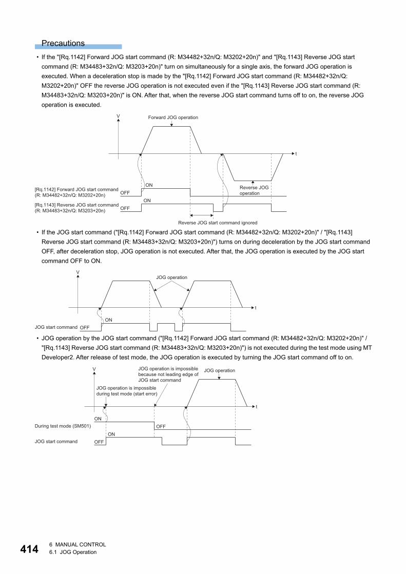
41
Precautions
• If the "[Rq.1142] Forward JOG start command (R: M34482+32n/Q: M3202+20n)" and "[Rq.1143] Reverse JOG start
command (R: M34483+32n/Q: M3203+20n)" turn on simultaneously for a single axis, the forward JOG operation is
executed. When a deceleration stop is made by the "[Rq.1142] Forward JOG start command (R: M34482+32n/Q:
M3202+20n)" OFF the reverse JOG operation is not executed even if the "[Rq.1143] Reverse JOG start command (R:
M34483+32n/Q: M3203+20n)" is ON. After that, when the reverse JOG start command turns off to on, the reverse JOG
operation is executed.
• If the JOG start command ("[Rq.1142] Forward JOG start command (R: M34482+32n/Q: M3202+20n)" / "[Rq.1143]
Reverse JOG start command (R: M34483+32n/Q: M3203+20n)") turns on during deceleration by the JOG start command
OFF, after deceleration stop, JOG operation is not executed. After that, the JOG operation is executed by the JOG start
command OFF to ON.
• JOG operation by the JOG start command ("[Rq.1142] Forward JOG start command (R: M34482+32n/Q: M3202+20n)" /
"[Rq.1143] Reverse JOG start command (R: M34483+32n/Q: M3203+20n)") is not executed during the test mode using MT
Developer2. After release of test mode, the JOG operation is executed by turning the JOG start command off to on.
OFFON
t
V Forward JOG operation
Reverse JOG start command ignored
Reverse JOGoperation
[Rq.1142] Forward JOG start command(R: M34482+32n/Q: M3202+20n)
OFFON
[Rq.1143] Reverse JOG start command(R: M34483+32n/Q: M3203+20n)
OFFON
t
JOG operation
JOG start command
V
JOG operation is impossiblebecause not leading edge ofJOG start command
JOG operation is impossibleduring test mode (start error)
OFFON
t
V
During test mode (SM501)
OFFON
JOG start command
JOG operation
46 MANUAL CONTROL6.1 JOG Operation
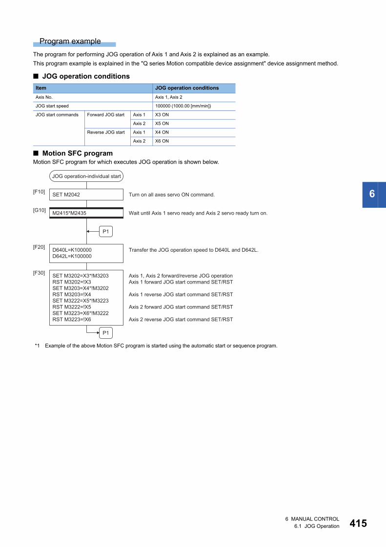
6
Program example
The program for performing JOG operation of Axis 1 and Axis 2 is explained as an example.
This program example is explained in the "Q series Motion compatible device assignment" device assignment method.
■ JOG operation conditions
■ Motion SFC programMotion SFC program for which executes JOG operation is shown below.
*1 Example of the above Motion SFC program is started using the automatic start or sequence program.
Item JOG operation conditions
Axis No. Axis 1, Axis 2
JOG start speed 100000 (1000.00 [mm/min])
JOG start commands Forward JOG start Axis 1 X3 ON
Axis 2 X5 ON
Reverse JOG start Axis 1 X4 ON
Axis 2 X6 ON
JOG operation-individual start
SET M2042[F10]
M2415*M2435[G10]
D640L=K100000D642L=K100000
[F20]
SET M3202=X3*!M3203RST M3202=!X3SET M3203=X4*!M3202RST M3203=!X4SET M3222=X5*!M3223RST M3222=!X5SET M3223=X6*!M3222RST M3223=!X6
[F30]
P1
P1
Turn on all axes servo ON command.
Wait until Axis 1 servo ready and Axis 2 servo ready turn on.
Transfer the JOG operation speed to D640L and D642L.
Axis 1, Axis 2 forward/reverse JOG operationAxis 1 forward JOG start command SET/RST
Axis 1 reverse JOG start command SET/RST
Axis 2 forward JOG start command SET/RST
Axis 2 reverse JOG start command SET/RST
6 MANUAL CONTROL6.1 JOG Operation 415
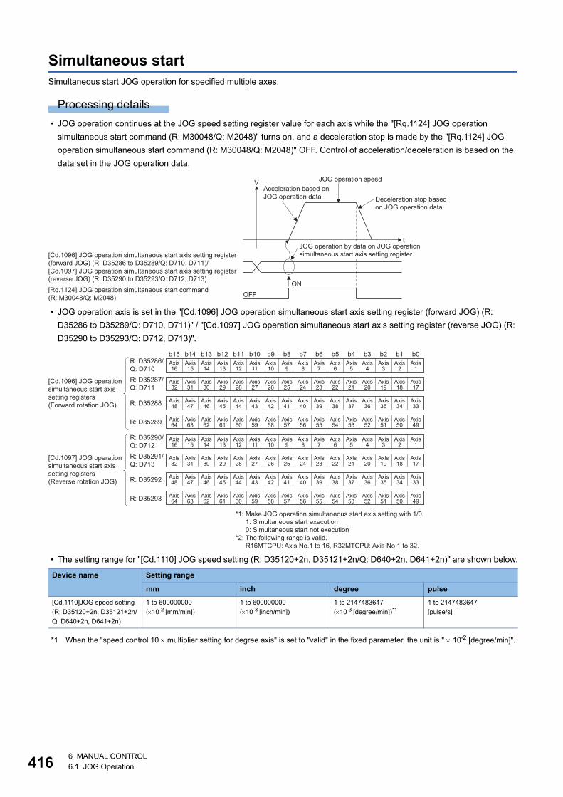
41
Simultaneous startSimultaneous start JOG operation for specified multiple axes.
Processing details
• JOG operation continues at the JOG speed setting register value for each axis while the "[Rq.1124] JOG operation
simultaneous start command (R: M30048/Q: M2048)" turns on, and a deceleration stop is made by the "[Rq.1124] JOG
operation simultaneous start command (R: M30048/Q: M2048)" OFF. Control of acceleration/deceleration is based on the
data set in the JOG operation data.
• JOG operation axis is set in the "[Cd.1096] JOG operation simultaneous start axis setting register (forward JOG) (R:
D35286 to D35289/Q: D710, D711)" / "[Cd.1097] JOG operation simultaneous start axis setting register (reverse JOG) (R:
D35290 to D35293/Q: D712, D713)".
• The setting range for "[Cd.1110] JOG speed setting (R: D35120+2n, D35121+2n/Q: D640+2n, D641+2n)" are shown below.
*1 When the "speed control 10 multiplier setting for degree axis" is set to "valid" in the fixed parameter, the unit is " 10-2 [degree/min]".
Device name Setting range
mm inch degree pulse
[Cd.1110]JOG speed setting
(R: D35120+2n, D35121+2n/
Q: D640+2n, D641+2n)
1 to 600000000
(10-2 [mm/min])
1 to 600000000
(10-3 [inch/min])
1 to 2147483647
(10-3 [degree/min])*11 to 2147483647
[pulse/s]
Deceleration stop based on JOG operation data
t
VAcceleration based onJOG operation data
JOG operation speed
OFFON
[Rq.1124] JOG operation simultaneous start command(R: M30048/Q: M2048)
[Cd.1096] JOG operation simultaneous start axis setting register(forward JOG) (R: D35286 to D35289/Q: D710, D711)/ [Cd.1097] JOG operation simultaneous start axis setting register(reverse JOG) (R: D35290 to D35293/Q: D712, D713)
JOG operation by data on JOG operationsimultaneous start axis setting register
b15 b14 b13 b12 b11 b10 b9 b8 b7 b6 b5 b4 b3 b2 b1 b0Axis15
Axis14
Axis13
Axis12
Axis11
Axis10
Axis9
Axis8
Axis7
Axis6
Axis5
Axis4
Axis3
Axis2
Axis31
Axis30
Axis29
Axis28
Axis27
Axis26
Axis25
Axis24
Axis23
Axis22
Axis21
Axis20
Axis19
Axis18
Axis47
Axis46
Axis45
Axis44
Axis43
Axis42
Axis41
Axis40
Axis39
Axis38
Axis37
Axis36
Axis35
Axis34
Axis63
Axis62
Axis61
Axis60
Axis59
Axis58
Axis57
Axis56
Axis55
Axis54
Axis53
Axis52
Axis51
Axis50
Axis1
Axis16
Axis17
Axis32
Axis33
Axis48
Axis49
Axis64
Axis15
Axis14
Axis13
Axis12
Axis11
Axis10
Axis9
Axis8
Axis7
Axis6
Axis5
Axis4
Axis3
Axis2
Axis31
Axis30
Axis29
Axis28
Axis27
Axis26
Axis25
Axis24
Axis23
Axis22
Axis21
Axis20
Axis19
Axis18
Axis47
Axis46
Axis45
Axis44
Axis43
Axis42
Axis41
Axis40
Axis39
Axis38
Axis37
Axis36
Axis35
Axis34
Axis63
Axis62
Axis61
Axis60
Axis59
Axis58
Axis57
Axis56
Axis55
Axis54
Axis53
Axis52
Axis51
Axis50
Axis1
Axis16
Axis17
Axis32
Axis33
Axis48
Axis49
Axis64
R: D35287/Q: D711
R: D35286/Q: D710
R: D35288
R: D35289
[Cd.1096] JOG operationsimultaneous start axissetting registers (Forward rotation JOG)
[Cd.1097] JOG operation simultaneous start axis setting registers (Reverse rotation JOG)
R: D35290/Q: D712R: D35291/Q: D713
R: D35292
R: D35293
*1: Make JOG operation simultaneous start axis setting with 1/0.1: Simultaneous start execution0: Simultaneous start not execution
*2: The following range is valid. R16MTCPU: Axis No.1 to 16, R32MTCPU: Axis No.1 to 32.
66 MANUAL CONTROL6.1 JOG Operation
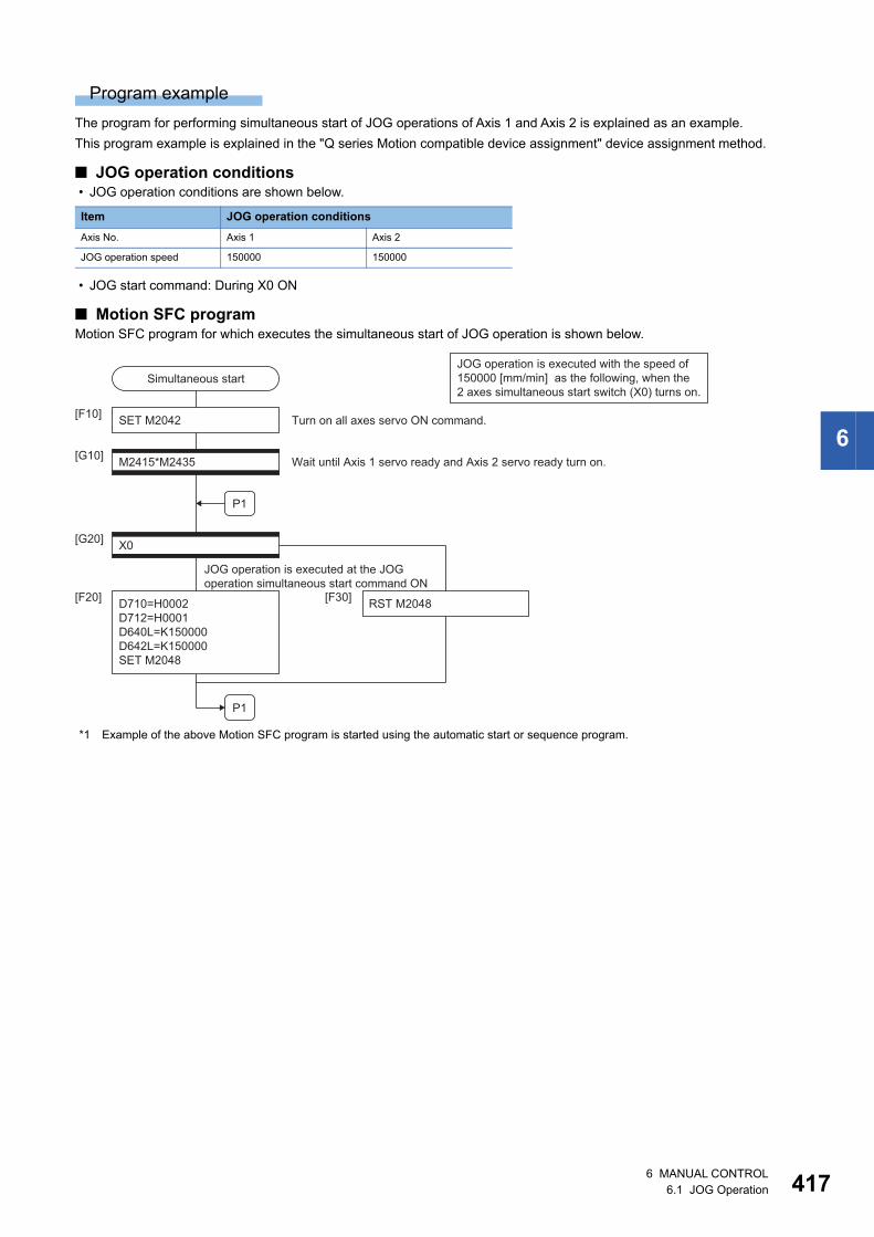
6
Program example
The program for performing simultaneous start of JOG operations of Axis 1 and Axis 2 is explained as an example.
This program example is explained in the "Q series Motion compatible device assignment" device assignment method.
■ JOG operation conditions • JOG operation conditions are shown below.
• JOG start command: During X0 ON
■ Motion SFC programMotion SFC program for which executes the simultaneous start of JOG operation is shown below.
*1 Example of the above Motion SFC program is started using the automatic start or sequence program.
Item JOG operation conditions
Axis No. Axis 1 Axis 2
JOG operation speed 150000 150000
JOG operation is executed with the speed of150000 [mm/min] as the following, when the2 axes simultaneous start switch (X0) turns on.
Simultaneous start
SET M2042[F10]
RST M2048[F30]
[G10] M2415*M2435
X0[G20]
D710=H0002D712=H0001D640L=K150000D642L=K150000SET M2048
[F20]
P1
P1
Turn on all axes servo ON command.
Wait until Axis 1 servo ready and Axis 2 servo ready turn on.
JOG operation is executed at the JOG operation simultaneous start command ON
6 MANUAL CONTROL6.1 JOG Operation 417
41
6.2 Manual Pulse Generator OperationPositioning control based on the number of pulses inputted from the manual pulse generator is executed.
Simultaneous operation for 1 to 3 axes is possible with one manual pulse generator, the number of connectable modules are
shown below.
Setting data
■ Usable modulesThe manual pulse generator is connected to a high-speed counter module controlled by the self CPU. The following high-
speed counter modules can be used.
■ Manual pulse generator connection settingSet the manual pulse generator to be connected (P1 to P3) in [Motion CPU common parameter] [manual pulse generator
connection setting]. Refer to the following for details of the pulse generator connection.
MELSEC iQ-R Motion controller Programming Manual (Common)
■ High-speed counter module settingSetting of the high-speed counter module for connecting the manual pulse generator is as follows.
• Setting of GX Works3
Set the self Motion CPU as the control CPU in control CPU setting.
[System Parameter] [I/O Assignment Setting] "Control CPU Setting".
• Setting of MT Developer2
Set the following in the detailed settings of the module.
[R Series Common Parameter] [Module Configuration List] "Setting item" "Detail" button
If a fault is detected when the above setting is checked during initialization of a Motion CPU, a moderate error (error code:
30D4H) is output and the Motion CPU does not run.
The count enable command (Y signal) is set to "Always ON" for the relevant channel of the high-speed
counter module for which the manual pulse generator is set to connect to.
Number of connectable to the manual pulse generator
3
Module Model
High-speed counter modules RD62P2
RD62D2
No. Item Setting Range
1 Validity setting 0: Invalid/1: Valid
2 Start XY 0000h to 0FF0h
3 Channel number 1 to 2
Setting item Details
Counter type Set to "Ring counter".
Counter operation mode Set to "Pulses counter mode".
86 MANUAL CONTROL6.2 Manual Pulse Generator Operation
6
Processing details
■ Manual pulse generator enable flag • Positioning of the axis set in the manual pulse generator axis setting register based on the pulse input from the manual
pulse generator. Manual pulse generator operation is only valid while the manual pulse generator enable flag turn ON.
■ Travel value and output speed for positioning controlThe travel value and output speed for positioning control based on the pulse input from manual pulse generator are shown
below.
• Travel value
The travel value based on the pulse input from a manual pulse generator is calculated using the following formula.
[Travel value] = [Travel value per pulse] [Number of input pulses] [Manual pulse generator 1-pulse input magnification
setting]
The travel value per pulse for manual pulse generator operation is shown below.
If units is [mm], the command travel value for input of one pulse is: (0.1 [m]) (1 [pulse]) (Manual pulse generator 1-pulse
input magnification setting)
• Output speed
The output speed is the positioning speed corresponding to the number of pulses input from a manual pulse generator in
unit time.
[Output speed] = [Number of input pulses per 1 [ms]] [Manual pulse generator 1-pulse input magnification setting]
■ Setting of the axis operated by the manual pulse generatorThe axis operated by the manual pulse generator is set in the following manual pulse generator axis setting register.
The bit corresponding to the axis controlled (1 to 64) is set.
• [Cd.1098] Manual pulse generator 1 axis No. setting register (R: D35294 to D35297/Q: D714, D715)
• [Cd.1099] Manual pulse generator 2 axis No. setting register (R: D35298 to D35301/Q: D716, D717)
• [Cd.1100] Manual pulse generator 3 axis No. setting register (R: D35302 to D35305/Q: D718, D719)
■ Manual pulse generator 1-pulse input magnification settingMake magnification setting for 1-pulse input from the manual pulse generator for each axis.
*1 The manual pulse generator does not have a speed limit value, so set the magnification setting within the rated speed of the servo motor.
Manual pulse generator connecting position
Manual pulse generator axis No. setting register Manual pulse generator enable flag
P1 [Cd.1098] Manual pulse generator 1 axis No. setting register
(R: D35294 to D35297/Q: D714, D715)
[Rq.1125] Manual pulse generator 1 enable flag
(R: M30051/Q: M2051)
P2 [Cd.1099] Manual pulse generator 2 axis No. setting register
(R: D35298 to D35301/Q: D716, D717)
[Rq.1126] Manual pulse generator 2 enable flag
(R: M30052/Q: M2052)
P3 [Cd.1100] Manual pulse generator 3 axis No. setting register
(R: D35302 to D35305/Q: D718, D719)
[Rq.1127] Manual pulse generator 3 enable flag
(R: M30053/Q: M2053)
Unit Travel value
mm 0.1 [m]
inch 0.00001 [inch]
degree 0.00001 [degree]
pulse 1 [pulse]
Device name Setting range
[Cd.1101] 1-pulse input magnification setting register (R: D35306+n/Q: D720+n) 1 to 10000
6 MANUAL CONTROL6.2 Manual Pulse Generator Operation 419
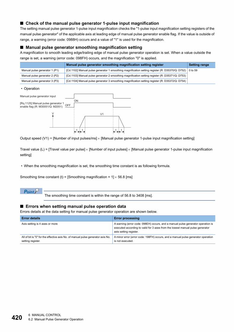
42
■ Check of the manual pulse generator 1-pulse input magnificationThe setting manual pulse generator 1-pulse input magnification checks the "1-pulse input magnification setting registers of the
manual pulse generator" of the applicable axis at leading edge of manual pulse generator enable flag. If the value is outside of
range, a warning (error code: 0988H) occurs and a value of "1" is used for the magnification.
■ Manual pulse generator smoothing magnification settingA magnification to smooth leading edge/trailing edge of manual pulse generator operation is set. When a value outside the
range is set, a warning (error code: 098FH) occurs, and the magnification "0" is applied.
• Operation
Output speed (V1) = [Number of input pulses/ms] [Manual pulse generator 1-pulse input magnification setting]
Travel value (L) = [Travel value per pulse] [Number of input pulses] [Manual pulse generator 1-pulse input magnification
setting]
• When the smoothing magnification is set, the smoothing time constant is as following formula.
Smoothing time constant (t) = [Smoothing magnification + 1] 56.8 [ms]
The smoothing time constant is within the range of 56.8 to 3408 [ms].
■ Errors when setting manual pulse operation dataErrors details at the data setting for manual pulse generator operation are shown below.
Manual pulse generator smoothing magnification setting register Setting range
Manual pulse generator 1 (P1) [Cd.1102] Manual pulse generator 1 smoothing magnification setting register (R: D35370/Q: D752) 0 to 59
Manual pulse generator 2 (P2) [Cd.1103] Manual pulse generator 2 smoothing magnification setting register (R: D35371/Q: D753)
Manual pulse generator 3 (P3) [Cd.1104] Manual pulse generator 3 smoothing magnification setting register (R: D35372/Q: D754)
Error details Error processing
Axis setting is 4 axes or more A warning (error code: 098EH) occurs, and a manual pulse generator operation is
executed according to valid for 3 axes from the lowest manual pulse generator
axis setting register.
All of bit is "0" for the effective axis No. of manual pulse generator axis No.
setting register.
A minor error (error code: 198FH) occurs, and a manual pulse generator operation
is not executed.
Manual pulse generator input
[Rq.1125] Manual pulse generator 1enable flag (R: M30051/Q: M2051)
ON
V V1
OFF
t t t t
06 MANUAL CONTROL6.2 Manual Pulse Generator Operation
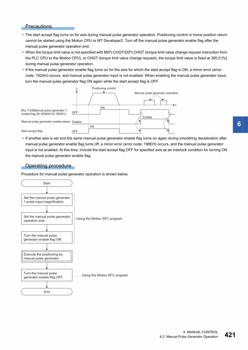
6
Precautions
• The start accept flag turns on for axis during manual pulse generator operation. Positioning control or home position return
cannot be started using the Motion CPU or MT Developer2. Turn off the manual pulse generator enable flag after the
manual pulse generator operation end.
• When the torque limit value is not specified with M(P).CHGT/D(P).CHGT (torque limit value change request instruction form
the PLC CPU to the Motion CPU), or CHGT (torque limit value change request), the torque limit value is fixed at 300.0 [%]
during manual pulse generator operation.
• If the manual pulse generator enable flag turns on for the axis for which the start accept flag is ON, a minor error (error
code: 192AH) occurs, and manual pulse generator input is not enabled. When enabling the manual pulse generator input,
turn the manual pulse generator flag ON again while the start accept flag is OFF.
• If another axis is set and the same manual pulse generator enable flag turns on again during smoothing deceleration after
manual pulse generator enable flag turns off, a minor error (error code: 198EH) occurs, and the manual pulse generator
input is not enabled. At this time, include the start accept flag OFF for specified axis as an interlock condition for turning ON
the manual pulse generator enable flag.
Operating procedure
Procedure for manual pulse generator operation is shown below.
OFFON
V
t
[Rq.1125]Manual pulse generator 1enable flag (R: M30051/Q: M2051)
DisableEnable
Manual pulse generator enable status
Manual pulse generator operationPositioning control
Start accept flag OFFON
Start
End
Set the manual pulse generator1-pulse input magnification
Execute the positioning by manual pulse generator
Turn the manual pulse generator enable flag OFF
Set the manual pulse generatoroperation axis
Turn the manual pulse generator enable flag ON
Using the Motion SFC program
. . . . . Using the Motion SFC program
6 MANUAL CONTROL6.2 Manual Pulse Generator Operation 421
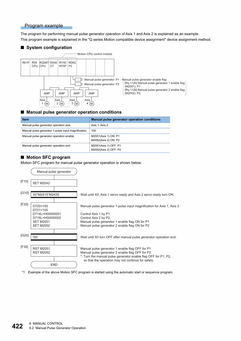
42
Program example
The program for performing manual pulse generator operation of Axis 1 and Axis 2 is explained as an example.
This program example is explained in the "Q series Motion compatible device assignment" device assignment method.
■ System configuration
■ Manual pulse generator operation conditions
■ Motion SFC programMotion SFC program for manual pulse generator operation is shown below.
*1 Example of the above Motion SFC program is started using the automatic start or sequence program.
Item Manual pulse generator operation conditions
Manual pulse generator operation axis Axis 1, Axis 2
Manual pulse generator 1-pulse input magnification 100
Manual pulse generator operation enable M2051(Axis 1) ON: P1
M2052(Axis 2) ON: P2
Manual pulse generator operation end M2051(Axis 1) OFF: P1
M2052(Axis 2) OFF: P2
R32MTCPU
R04CPU
RX40C7
RY40NT5P
RD62P2
R61P
M
AMP
M
AMP
M
AMP
M
AMP
Axis1
Axis2
Axis3
Axis4
Motion CPU control module
Manual pulse generator: P1Manual pulse generator: P2
�Manual pulse generator enable flag[Rq.1125] Manual pulse generator 1 enable flag(M2051): P1[Rq.1126] Manual pulse generator 2 enable flag(M2052): P2
!X0[G20]
Manual pulse generator
END
SET M2042[F10]
X0*M2415*M2435[G10]
D720=100D721=100D714L=H00000001D716L=H00000002SET M2051SET M2052
[F20]
RST M2051RST M2052
[F30]
Wait until X0, Axis 1 servo ready and Axis 2 servo ready turn ON.
Manual pulse generator 1-pulse input magnification for Axis 1, Axis 2. Control Axis 1 by P1.Control Axis 2 by P2.Manual pulse generator 1 enable flag ON for P1Manual pulse generator 2 enable flag ON for P2
Wait until X0 turn OFF after manual pulse generator operation end.
Manual pulse generator 1 enable flag OFF for P1Manual pulse generator 2 enable flag OFF for P2*: Turn the manual pulse generator enable flag OFF for P1, P2,
so that the operation may not continue for safety.
26 MANUAL CONTROL6.2 Manual Pulse Generator Operation
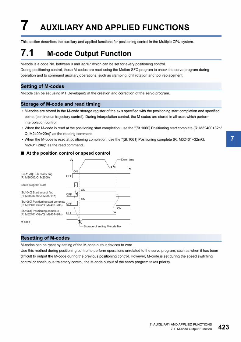
7
7 AUXILIARY AND APPLIED FUNCTIONS
This section describes the auxiliary and applied functions for positioning control in the Multiple CPU system.
7.1 M-code Output FunctionM-code is a code No. between 0 and 32767 which can be set for every positioning control.
During positioning control, these M-codes are read using the Motion SFC program to check the servo program during
operation and to command auxiliary operations, such as clamping, drill rotation and tool replacement.
Setting of M-codesM-code can be set using MT Developer2 at the creation and correction of the servo program.
Storage of M-code and read timing • M-codes are stored in the M-code storage register of the axis specified with the positioning start completion and specified
points (continuous trajectory control). During interpolation control, the M-codes are stored in all axes which perform
interpolation control.
• When the M-code is read at the positioning start completion, use the "[St.1060] Positioning start complete (R: M32400+32n/
Q: M2400+20n)" as the reading command.
• When the M-code is read at positioning completion, use the "[St.1061] Positioning complete (R: M32401+32n/Q:
M2401+20n)" as the read command.
■ At the position control or speed control
Resetting of M-codesM-codes can be reset by setting of the M-code output devices to zero.
Use this method during positioning control to perform operations unrelated to the servo program, such as when it has been
difficult to output the M-code during the previous positioning control. However, M-code is set during the speed switching
control or continuous trajectory control, the M-code output of the servo program takes priority.
[St.1060] Positioning start complete(R: M32400+32n/Q: M2400+20n)
[St.1040] Start accept flag (R: M30080+n/Q: M2001+n)
[Rq.1120] PLC ready flag (R: M30000/Q: M2000)
[St.1061] Positioning complete(R: M32401+32n/Q: M2401+20n) OFF
ON
M-codeStorage of setting M-code No.
OFFON
OFFON
OFFON
Servo program start
t
Dwell timeV
7 AUXILIARY AND APPLIED FUNCTIONS7.1 M-code Output Function 423
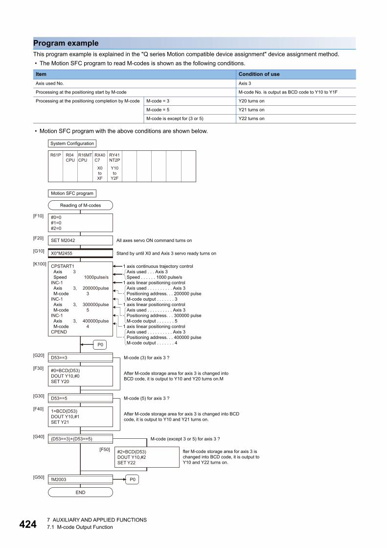
42
Program exampleThis program example is explained in the "Q series Motion compatible device assignment" device assignment method.
• The Motion SFC program to read M-codes is shown as the following conditions.
• Motion SFC program with the above conditions are shown below.
Item Condition of use
Axis used No. Axis 3
Processing at the positioning start by M-code M-code No. is output as BCD code to Y10 to Y1F
Processing at the positioning completion by M-code M-code = 3 Y20 turns on
M-code = 5 Y21 turns on
M-code is except for (3 or 5) Y22 turns on
CPSTART1 Axis 3 Speed 1000pulse/sINC-1 Axis 3, 200000pulse M-code 3INC-1 Axis 3, 300000pulse M-code 5INC-1 Axis 3, 400000pulse M-code 4CPEND
System Configuration
Motion SFC program
R61P R04CPU
R16MTCPU
RX40C7
RY41NT2P
X0toXF
Y10to
Y2F
Reading of M-codes
#0=0#1=0#2=0
SET M2042
P0
[F10]
[F20]
X0*M2455[G10]
[K100]
D53==3
#0=BCD(D53)DOUT Y10,#0SET Y20
[G20]
[F30]
All axes servo ON command turns on
Stand by until X0 and Axis 3 servo ready turns on
M-code (3) for axis 3 ?
After M-code storage area for axis 3 is changed intoBCD code, it is output to Y10 and Y20 turns on.M
END
P0
1=BCD(D53)DOUT Y10,#1SET Y21
[F40]
D53==5[G30]
#2=BCD(D53)DOUT Y10,#2SET Y22
[F50]
M-code (5) for axis 3 ?
(D53==3)+(D53==5)[G40]
!M2003[G50]
M-code (except 3 or 5) for axis 3 ?
After M-code storage area for axis 3 is changed into BCDcode, it is output to Y10 and Y21 turns on.
fter M-code storage area for axis 3 ischanged into BCD code, it is output toY10 and Y22 turns on.
1 axis continuous trajectory control
1 axis linear positioning control
1 axis linear positioning control
1 axis linear positioning control
Axis used . . . . . . . . . . Axis 3Positioning address. . . 200000 pulseM-code output . . . . . . . 3
Axis used . . . Axis 3Speed . . . . . . 1000 pulse/s
Axis used . . . . . . . . . . Axis 3Positioning address. . . 300000 pulseM-code output . . . . . . . 5
Axis used . . . . . . . . . . Axis 3Positioning address. . . 400000 pulseM-code output . . . . . . . 4
47 AUXILIARY AND APPLIED FUNCTIONS7.1 M-code Output Function
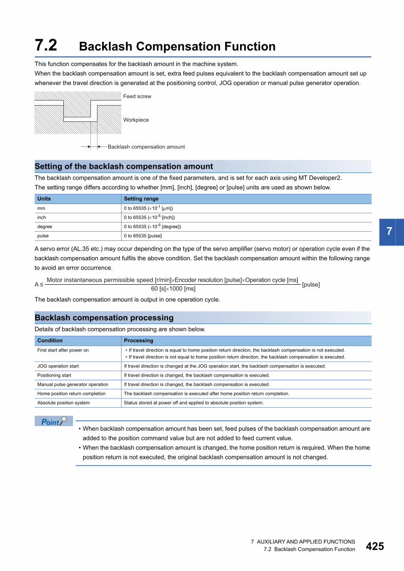
7
7.2 Backlash Compensation FunctionThis function compensates for the backlash amount in the machine system.
When the backlash compensation amount is set, extra feed pulses equivalent to the backlash compensation amount set up
whenever the travel direction is generated at the positioning control, JOG operation or manual pulse generator operation.
Setting of the backlash compensation amountThe backlash compensation amount is one of the fixed parameters, and is set for each axis using MT Developer2.
The setting range differs according to whether [mm], [inch], [degree] or [pulse] units are used as shown below.
A servo error (AL.35 etc.) may occur depending on the type of the servo amplifier (servo motor) or operation cycle even if the
backlash compensation amount fulfils the above condition. Set the backlash compensation amount within the following range
to avoid an error occurrence.
The backlash compensation amount is output in one operation cycle.
Backlash compensation processingDetails of backlash compensation processing are shown below.
• When backlash compensation amount has been set, feed pulses of the backlash compensation amount are
added to the position command value but are not added to feed current value.
• When the backlash compensation amount is changed, the home position return is required. When the home
position return is not executed, the original backlash compensation amount is not changed.
Units Setting range
mm 0 to 65535 (10-1 [m])
inch 0 to 65535 (10-5 [inch])
degree 0 to 65535 (10-5 [degree])
pulse 0 to 65535 [pulse]
Condition Processing
First start after power on • If travel direction is equal to home position return direction, the backlash compensation is not executed.
• If travel direction is not equal to home position return direction, the backlash compensation is executed.
JOG operation start If travel direction is changed at the JOG operation start, the backlash compensation is executed.
Positioning start If travel direction is changed, the backlash compensation is executed.
Manual pulse generator operation If travel direction is changed, the backlash compensation is executed.
Home position return completion The backlash compensation is executed after home position return completion.
Absolute position system Status stored at power off and applied to absolute position system.
Feed screw
Workpiece
Backlash compensation amount
A ≤Motor instantaneous permissible speed [r/min]�Encoder resolution [pulse]�Operation cycle [ms]
60 [s]�1000 [ms][pulse]
7 AUXILIARY AND APPLIED FUNCTIONS7.2 Backlash Compensation Function 425
42
7.3 Torque Limit FunctionThis function restricts the generating torque of the servo motor within the setting range.
If the torque required for control exceeds the torque limit value during positioning control, it restricts with the setting torque
limit value.
Default of the torque limit valueThe default 300.0[%] is set as torque limit value at the servo amplifier's control circuit power supply or Multiple CPU system's
power supply ON.
Even while the Multiple CPU system power supply is ON, the torque limit value is returned to the default value
of 300.0[%] when the control circuit power supply of the servo amplifier is turned ON again, or when the
SSCNET communication is disconnected or connected again. Set the torque control value again as required
using the Motion SFC program or the Motion dedicated PLC instruction.
Setting method of torque limit valueSet the torque limit value by the following method.
The positive direction of torque limit value restricts the forward rotation (CCW) driving and reverse rotation (CW) regenerative
torque of servo motor, and the negative direction of torque limit value restricts the reverse rotation (CW) driving and forward
rotation (CCW) regenerative torque.
*1 MELSEC iQ-R Motion Controller Programming Manual (Program Design)
Priority of torque limit value settingWhen the multiple torque limit values are set on the same axis, the latest torque limit value is valid. However, the setting of
torque limit value set in the parameter block or servo program is valid only if lower than the torque limit value set in the Motion
SFC program or Motion dedicated PLC instruction.
When the torque limit value is set individually for positive direction and negative direction in the Motion SFC
program or Motion dedicated PLC instruction, only either one of the positive direction or negative direction
may become valid depending on the setting value of servo program.
Setting method Setting details Setting range
Setting units
Reference
Parameter block Set the torque limit value in the parameter block. By setting the
parameter block No. used in the servo program, the torque limit
value of specified axis is changed to same value for both of positive
direction and negative direction for every positioning control.
1 to 10000 0.1[%] Page
215
Parameter
Block
Set the torque limit value in the parameter block. By setting the
parameter block in the home position return data and JOG operation
data for every axis, the torque limit value at home position return and
JOG operation is changed to same value for both of positive
direction and negative direction.
Servo program By setting the torque limit value in the servo program, the torque
limit value of specified axis at servo program execution is changed
to same value for both of positive direction and negative direction.
Page
243
Positioning
Data
Motion SFC
program
Torque limit value
change request (CHGT)
Executing the torque limit value change request (CHGT) in the
operating control step of Motion SFC program changes the torque
limit value of specified axis. A different value for positive direction
and negative direction can be specified.
*1
Motion dedicated
PLC instruction
Torque limit value
change request
instruction (M(P).CHGT/
D(P).CHGT) .
Executing the torque limit value change request instruction
(M(P).CHGT/D(P).CHGT) in the PLC CPU changes the torque limit
value of specified axis. A different value for positive direction and
negative direction can be specified.
67 AUXILIARY AND APPLIED FUNCTIONS7.3 Torque Limit Function
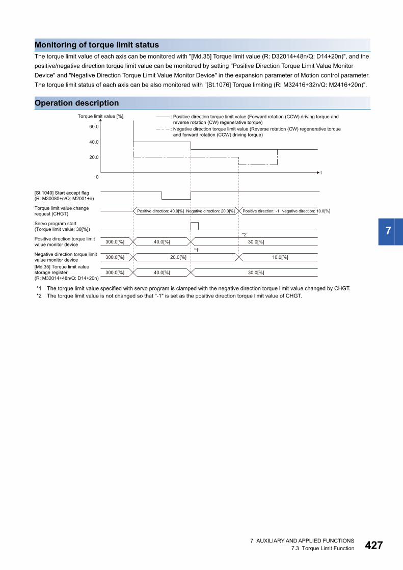
7
Monitoring of torque limit statusThe torque limit value of each axis can be monitored with "[Md.35] Torque limit value (R: D32014+48n/Q: D14+20n)", and the
positive/negative direction torque limit value can be monitored by setting "Positive Direction Torque Limit Value Monitor
Device" and "Negative Direction Torque Limit Value Monitor Device" in the expansion parameter of Motion control parameter.
The torque limit status of each axis can be also monitored with "[St.1076] Torque limiting (R: M32416+32n/Q: M2416+20n)".
Operation description
*1 The torque limit value specified with servo program is clamped with the negative direction torque limit value changed by CHGT.*2 The torque limit value is not changed so that "-1" is set as the positive direction torque limit value of CHGT.
[St.1040] Start accept flag(R: M30080+n/Q: M2001+n)
Servo program start(Torque limit value: 30[%])
Positive direction torque limitvalue monitor device
Torque limit value [%]
20.0
0
40.0
60.0
t
: Positive direction torque limit value (Forward rotation (CCW) driving torque and reverse rotation (CW) regenerative torque): Negative direction torque limit value (Reverse rotation (CW) regenerative torque and forward rotation (CCW) driving torque)
Torque limit value changerequest (CHGT)
300.0[%] 40.0[%] 30.0[%]
Negative direction torque limitvalue monitor device 300.0[%] 20.0[%]
*1
*2
10.0[%]
[Md.35] Torque limit valuestorage register(R: M32014+48n/Q: D14+20n)
300.0[%] 40.0[%] 30.0[%]
Positive direction: -1 Negative direction: 10.0[%]Positive direction: 40.0[%] Negative direction: 20.0[%]
7 AUXILIARY AND APPLIED FUNCTIONS7.3 Torque Limit Function 427
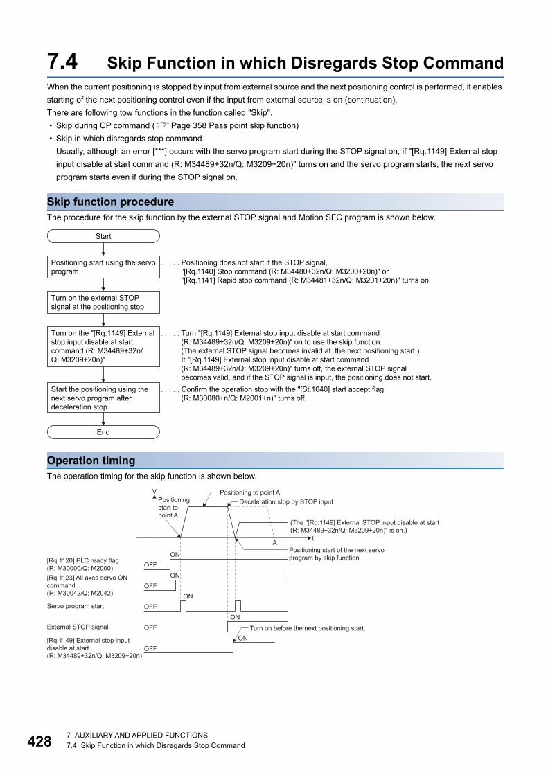
42
7.4 Skip Function in which Disregards Stop CommandWhen the current positioning is stopped by input from external source and the next positioning control is performed, it enables
starting of the next positioning control even if the input from external source is on (continuation).
There are following tow functions in the function called "Skip".
• Skip during CP command (Page 358 Pass point skip function)
• Skip in which disregards stop command
Usually, although an error [***] occurs with the servo program start during the STOP signal on, if "[Rq.1149] External stop
input disable at start command (R: M34489+32n/Q: M3209+20n)" turns on and the servo program starts, the next servo
program starts even if during the STOP signal on.
Skip function procedureThe procedure for the skip function by the external STOP signal and Motion SFC program is shown below.
Operation timingThe operation timing for the skip function is shown below.
Start
End
Positioning start using the servoprogram
. . . . . Positioning does not start if the STOP signal, "[Rq.1140] Stop command (R: M34480+32n/Q: M3200+20n)" or "[Rq.1141] Rapid stop command (R: M34481+32n/Q: M3201+20n)" turns on.
. . . . . Confirm the operation stop with the "[St.1040] start accept flag (R: M30080+n/Q: M2001+n)" turns off.
. . . . . Turn "[Rq.1149] External stop input disable at start command (R: M34489+32n/Q: M3209+20n)" on to use the skip function.(The external STOP signal becomes invalid at the next positioning start.)If "[Rq.1149] External stop input disable at start command (R: M34489+32n/Q: M3209+20n)" turns off, the external STOP signal becomes valid, and if the STOP signal is input, the positioning does not start.
Turn on the external STOP signal at the positioning stop
Turn on the "[Rq.1149] Externalstop input disable at start command (R: M34489+32n/Q: M3209+20n)"
Start the positioning using the next servo program after deceleration stop
Deceleration stop by STOP input
(The "[Rq.1149] External STOP input disable at start(R: M34489+32n/Q: M3209+20n)" is on.)
Positioning to point A
Positioning start of the next servoprogram by skip function
Positioningstart to point A
[Rq.1123] All axes servo ONcommand(R: M30042/Q: M2042)
[Rq.1120] PLC ready flag(R: M30000/Q: M2000)
[Rq.1149] External stop inputdisable at start(R: M34489+32n/Q: M3209+20n)
OFFON
OFFON
OFFON
OFFON
OFFON
Servo program start
External STOP signal
tA
Turn on before the next positioning start.
V
87 AUXILIARY AND APPLIED FUNCTIONS7.4 Skip Function in which Disregards Stop Command
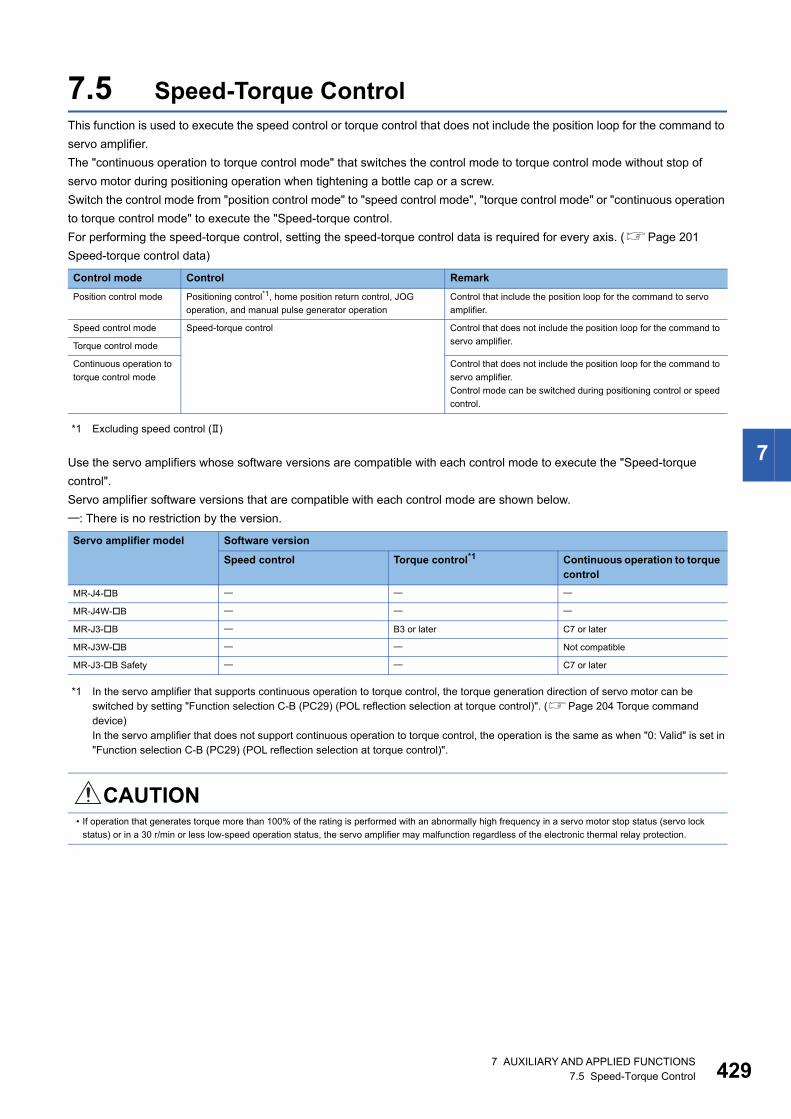
7
7.5 Speed-Torque ControlThis function is used to execute the speed control or torque control that does not include the position loop for the command to
servo amplifier.
The "continuous operation to torque control mode" that switches the control mode to torque control mode without stop of
servo motor during positioning operation when tightening a bottle cap or a screw.
Switch the control mode from "position control mode" to "speed control mode", "torque control mode" or "continuous operation
to torque control mode" to execute the "Speed-torque control.
For performing the speed-torque control, setting the speed-torque control data is required for every axis. (Page 201
Speed-torque control data)
*1 Excluding speed control ()
Use the servo amplifiers whose software versions are compatible with each control mode to execute the "Speed-torque
control".
Servo amplifier software versions that are compatible with each control mode are shown below.
: There is no restriction by the version.
*1 In the servo amplifier that supports continuous operation to torque control, the torque generation direction of servo motor can be switched by setting "Function selection C-B (PC29) (POL reflection selection at torque control)". (Page 204 Torque command device)In the servo amplifier that does not support continuous operation to torque control, the operation is the same as when "0: Valid" is set in "Function selection C-B (PC29) (POL reflection selection at torque control)".
Control mode Control Remark
Position control mode Positioning control*1, home position return control, JOG
operation, and manual pulse generator operation
Control that include the position loop for the command to servo
amplifier.
Speed control mode Speed-torque control Control that does not include the position loop for the command to
servo amplifier.Torque control mode
Continuous operation to
torque control mode
Control that does not include the position loop for the command to
servo amplifier.
Control mode can be switched during positioning control or speed
control.
Servo amplifier model Software version
Speed control Torque control*1 Continuous operation to torque control
MR-J4-B
MR-J4W-B
MR-J3-B B3 or later C7 or later
MR-J3W-B Not compatible
MR-J3-B Safety C7 or later
CAUTION• If operation that generates torque more than 100% of the rating is performed with an abnormally high frequency in a servo motor stop status (servo lock
status) or in a 30 r/min or less low-speed operation status, the servo amplifier may malfunction regardless of the electronic thermal relay protection.
7 AUXILIARY AND APPLIED FUNCTIONS7.5 Speed-Torque Control 429
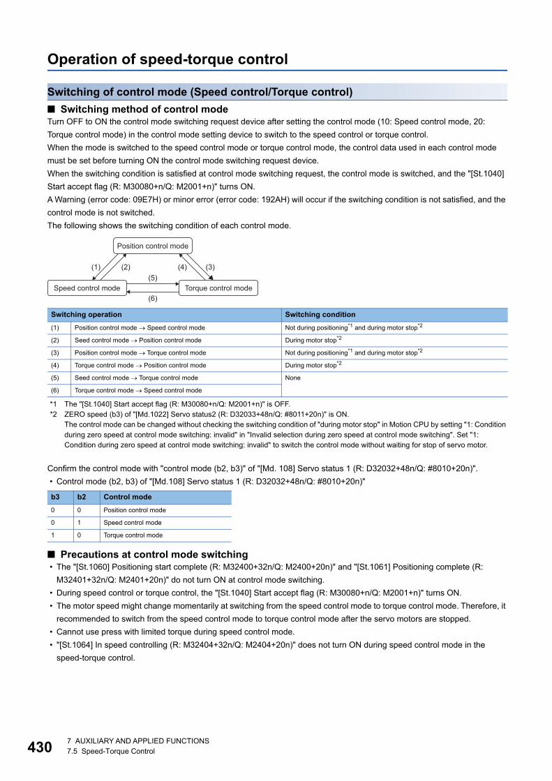
43
Operation of speed-torque control
Switching of control mode (Speed control/Torque control)
■ Switching method of control modeTurn OFF to ON the control mode switching request device after setting the control mode (10: Speed control mode, 20:
Torque control mode) in the control mode setting device to switch to the speed control or torque control.
When the mode is switched to the speed control mode or torque control mode, the control data used in each control mode
must be set before turning ON the control mode switching request device.
When the switching condition is satisfied at control mode switching request, the control mode is switched, and the "[St.1040]
Start accept flag (R: M30080+n/Q: M2001+n)" turns ON.
A Warning (error code: 09E7H) or minor error (error code: 192AH) will occur if the switching condition is not satisfied, and the
control mode is not switched.
The following shows the switching condition of each control mode.
*1 The "[St.1040] Start accept flag (R: M30080+n/Q: M2001+n)" is OFF.*2 ZERO speed (b3) of "[Md.1022] Servo status2 (R: D32033+48n/Q: #8011+20n)" is ON.
The control mode can be changed without checking the switching condition of "during motor stop" in Motion CPU by setting "1: Condition during zero speed at control mode switching: invalid" in "Invalid selection during zero speed at control mode switching". Set "1: Condition during zero speed at control mode switching: invalid" to switch the control mode without waiting for stop of servo motor.
Confirm the control mode with "control mode (b2, b3)" of "[Md. 108] Servo status 1 (R: D32032+48n/Q: #8010+20n)".
• Control mode (b2, b3) of "[Md.108] Servo status 1 (R: D32032+48n/Q: #8010+20n)"
■ Precautions at control mode switching • The "[St.1060] Positioning start complete (R: M32400+32n/Q: M2400+20n)" and "[St.1061] Positioning complete (R:
M32401+32n/Q: M2401+20n)" do not turn ON at control mode switching.
• During speed control or torque control, the "[St.1040] Start accept flag (R: M30080+n/Q: M2001+n)" turns ON.
• The motor speed might change momentarily at switching from the speed control mode to torque control mode. Therefore, it
recommended to switch from the speed control mode to torque control mode after the servo motors are stopped.
• Cannot use press with limited torque during speed control mode.
• "[St.1064] In speed controlling (R: M32404+32n/Q: M2404+20n)" does not turn ON during speed control mode in the
speed-torque control.
Switching operation Switching condition
(1) Position control mode Speed control mode Not during positioning*1 and during motor stop*2
(2) Seed control mode Position control mode During motor stop*2
(3) Position control mode Torque control mode Not during positioning*1 and during motor stop*2
(4) Torque control mode Position control mode During motor stop*2
(5) Seed control mode Torque control mode None
(6) Torque control mode Speed control mode
b3 b2 Control mode
0 0 Position control mode
0 1 Speed control mode
1 0 Torque control mode
Position control mode
Speed control mode Torque control mode(5)
(2)(1) (3)(4)
(6)
07 AUXILIARY AND APPLIED FUNCTIONS7.5 Speed-Torque Control
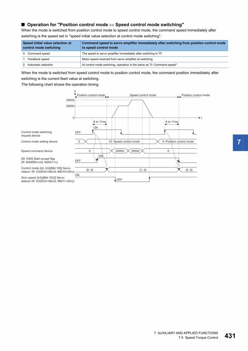
7
■ Operation for "Position control mode Speed control mode switching"When the mode is switched from position control mode to speed control mode, the command speed immediately after
switching is the speed set in "speed initial value selection at control mode switching".
When the mode is switched from speed control mode to position control mode, the command position immediately after
switching is the current feed value at switching.
The following chart shows the operation timing.
Speed initial value selection at control mode switching
Command speed to servo amplifier immediately after switching from position control mode to speed control mode
0: Command speed The speed to servo amplifier immediately after switching is "0".
1: Feedback speed Motor speed received from servo amplifier at switching.
2: Automatic selection At control mode switching, operation is the same as "0: Command speed".
t
V
0
20000
30000
Position control mode Position control modeSpeed control mode
Control mode switchingrequest device
Control mode setting device 0
Speed command device 0 20000 30000 0
[0, 0] [1, 0] [0, 0]
OFFON
6 to 11ms 6 to 11ms
[St.1040] Start accept flag(R: M30080+n/Q: M2001+n)
Control mode (b2, b3)([Md.108] Servostatus1 (R: D32032+48n/Q: #8010+20n))
Zero speed (b3)([Md.1022] Servostatus2 (R: D32033+48n/Q: #8011+20n))
OFFON
ONOFF
10: Speed control mode 0: Position control mode
7 AUXILIARY AND APPLIED FUNCTIONS7.5 Speed-Torque Control 431
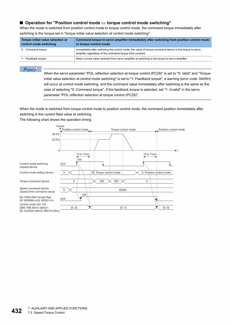
43
■ Operation for "Position control mode torque control mode switching"When the mode is switched from position control mode to torque control mode, the command torque immediately after
switching is the torque set in "torque initial value selection at control mode switching".
When the servo parameter "POL reflection selection at torque control (PC29)" is set to "0: Valid" and "Torque
initial value selection at control mode switching" is set to "1: Feedback torque", a warning (error code: 0A55H)
will occur at control mode switching, and the command value immediately after switching is the same as the
case of selecting "0: Command torque". If the feedback torque is selected, set "1: Invalid" in the servo
parameter "POL reflection selection at torque control (PC29)".
When the mode is switched from torque control mode to position control mode, the command position immediately after
switching is the current feed value at switching.
The following chart shows the operation timing.
Torque initial value selection at control mode switching
Command torque to servo amplifier immediately after switching from position control mode to torque control mode
0: Command torque Immediately after switching the control mode, the value of torque command device is the torque to servo
amplifier regardless of the command torque time constant.
1: Feedback torque Motor current value received from servo amplifier at switching is the torque to servo amplifier.
t
Torque
0
20.0%
30.0%
Position control mode Position control modeTorque control mode
Control mode switchingrequest device
Control mode setting device 0
Torque command device 0 200 300 0
0 50000
[0, 0] [0, 1] [0, 0]
OFFON
6 to 11ms 6 to 11ms
[St.1040] Start accept flag(R: M30080+n/Q: M2001+n)
Speed command device(Speed limit command value)
Control mode (b2, b3)([Md.108] Servo status1(R: D32032+48n/Q: #8010+20n))
OFFON
20: Torque control mode 0: Position control mode
27 AUXILIARY AND APPLIED FUNCTIONS7.5 Speed-Torque Control
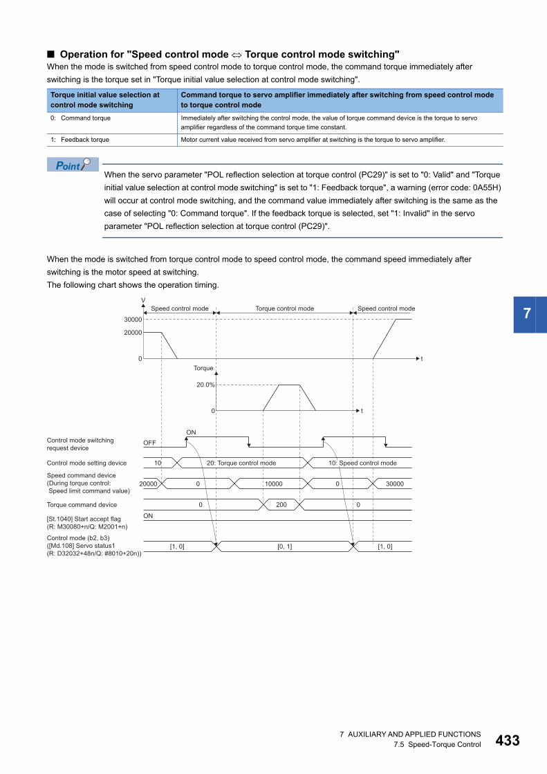
7
■ Operation for "Speed control mode Torque control mode switching"When the mode is switched from speed control mode to torque control mode, the command torque immediately after
switching is the torque set in "Torque initial value selection at control mode switching".
When the servo parameter "POL reflection selection at torque control (PC29)" is set to "0: Valid" and "Torque
initial value selection at control mode switching" is set to "1: Feedback torque", a warning (error code: 0A55H)
will occur at control mode switching, and the command value immediately after switching is the same as the
case of selecting "0: Command torque". If the feedback torque is selected, set "1: Invalid" in the servo
parameter "POL reflection selection at torque control (PC29)".
When the mode is switched from torque control mode to speed control mode, the command speed immediately after
switching is the motor speed at switching.
The following chart shows the operation timing.
Torque initial value selection at control mode switching
Command torque to servo amplifier immediately after switching from speed control mode to torque control mode
0: Command torque Immediately after switching the control mode, the value of torque command device is the torque to servo
amplifier regardless of the command torque time constant.
1: Feedback torque Motor current value received from servo amplifier at switching is the torque to servo amplifier.
t
t
V
0
20000
30000
Torque
0
20.0%
Speed control mode Speed control modeTorque control mode
Control mode switchingrequest device
Control mode setting device 10
Torque command device
20000 0 10000 0 30000
00 200
[1, 0] [0, 1] [1, 0]
OFFON
[St.1040] Start accept flag(R: M30080+n/Q: M2001+n)
Speed command device(During torque control: Speed limit command value)
Control mode (b2, b3)([Md.108] Servo status1(R: D32032+48n/Q: #8010+20n))
ON
20: Torque control mode 10: Speed control mode
7 AUXILIARY AND APPLIED FUNCTIONS7.5 Speed-Torque Control 433
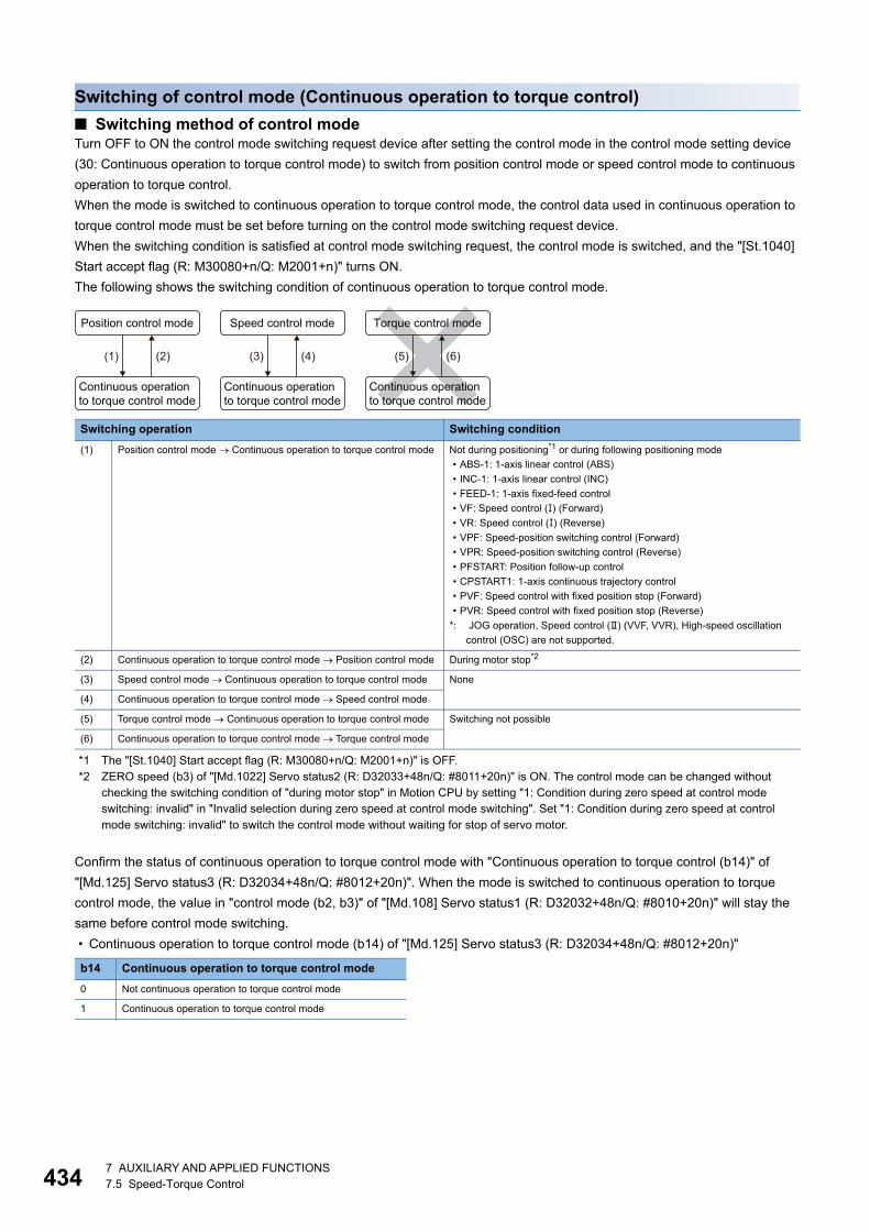
43
Switching of control mode (Continuous operation to torque control)
■ Switching method of control modeTurn OFF to ON the control mode switching request device after setting the control mode in the control mode setting device
(30: Continuous operation to torque control mode) to switch from position control mode or speed control mode to continuous
operation to torque control.
When the mode is switched to continuous operation to torque control mode, the control data used in continuous operation to
torque control mode must be set before turning on the control mode switching request device.
When the switching condition is satisfied at control mode switching request, the control mode is switched, and the "[St.1040]
Start accept flag (R: M30080+n/Q: M2001+n)" turns ON.
The following shows the switching condition of continuous operation to torque control mode.
*1 The "[St.1040] Start accept flag (R: M30080+n/Q: M2001+n)" is OFF.*2 ZERO speed (b3) of "[Md.1022] Servo status2 (R: D32033+48n/Q: #8011+20n)" is ON. The control mode can be changed without
checking the switching condition of "during motor stop" in Motion CPU by setting "1: Condition during zero speed at control mode switching: invalid" in "Invalid selection during zero speed at control mode switching". Set "1: Condition during zero speed at control mode switching: invalid" to switch the control mode without waiting for stop of servo motor.
Confirm the status of continuous operation to torque control mode with "Continuous operation to torque control (b14)" of
"[Md.125] Servo status3 (R: D32034+48n/Q: #8012+20n)". When the mode is switched to continuous operation to torque
control mode, the value in "control mode (b2, b3)" of "[Md.108] Servo status1 (R: D32032+48n/Q: #8010+20n)" will stay the
same before control mode switching.
• Continuous operation to torque control mode (b14) of "[Md.125] Servo status3 (R: D32034+48n/Q: #8012+20n)"
Switching operation Switching condition
(1) Position control mode Continuous operation to torque control mode Not during positioning*1 or during following positioning mode
• ABS-1: 1-axis linear control (ABS)
• INC-1: 1-axis linear control (INC)
• FEED-1: 1-axis fixed-feed control
• VF: Speed control () (Forward)
• VR: Speed control () (Reverse)
• VPF: Speed-position switching control (Forward)
• VPR: Speed-position switching control (Reverse)
• PFSTART: Position follow-up control
• CPSTART1: 1-axis continuous trajectory control
• PVF: Speed control with fixed position stop (Forward)
• PVR: Speed control with fixed position stop (Reverse)
*: JOG operation, Speed control () (VVF, VVR), High-speed oscillation
control (OSC) are not supported.
(2) Continuous operation to torque control mode Position control mode During motor stop*2
(3) Speed control mode Continuous operation to torque control mode None
(4) Continuous operation to torque control mode Speed control mode
(5) Torque control mode Continuous operation to torque control mode Switching not possible
(6) Continuous operation to torque control mode Torque control mode
b14 Continuous operation to torque control mode
0 Not continuous operation to torque control mode
1 Continuous operation to torque control mode
Position control mode
Continuous operationto torque control mode
Continuous operationto torque control mode
Continuous operationto torque control mode
(2)(1)
Speed control mode
(4)(3)
Torque control mode
(6)(5)
47 AUXILIARY AND APPLIED FUNCTIONS7.5 Speed-Torque Control
7
• When the mode is switched from position control mode to continuous operation to torque control mode, only
the switching from continuous operation to torque control mode to position control mode is possible. If the
mode is switched to other control modes, a warning (error code: 09E8H) will occur, and the control mode is
not switched.
• When the mode is switched from speed control mode to continuous operation to torque control mode, only
the switching from continuous operation to torque control mode to speed control mode is possible. If the
mode is switched to other control modes, a warning (error code: 09E8H) will occur, and the control mode is
not switched.
■ Precautions at control mode switching • The "[St.1060] Positioning start complete (R: M32400+32n/Q: M2400+20n)" and "[St.1061] Positioning complete (R:
M32401+32n/Q: M2401+20n)" do not turn ON at control mode switching.
• During continuous operation to torque control, the "[St.1040] start accept flag (R: M30080+n/Q: M2001+n)" turns ON.
• When using continuous operation to torque control mode, use the servo amplifiers that are compatible with continuous
operation to torque control. If servo amplifiers that are not compatible with continuous operation to torque control are used,
a minor error (error code: 19E7H) will occur at request of switching to continuous operation to torque control mode. (A
deceleration stop is made during the positioning control. The mode is switched to position control during the speed control,
and the operation immediately stops.)
■ Operation for "Position control mode Continuous operation to torque control mode switching
When the mode is switched from position control mode to continuous operation to torque control mode, the command torque
and command speed immediately after switching are the values set in "Torque initial value selection at control mode
switching" and "Speed initial value selection at control mode switching".
• Command torque
• Command speed
When the mode is switched to continuous operation to torque control mode in cases where command speed
and actual speed are different such as during acceleration/deceleration or when the speed does not reach
command speed due to torque limit, set "1: Feedback speed" in "Speed initial value selection at control mode
switching".
Torque initial value selection at control mode switching
Command torque to servo amplifier immediately after switching from position control mode to continuous operation to torque control mode
0: Command torque Immediately after switching the control mode, the value of torque command device is the torque to servo
amplifier regardless of the command torque time constant.
1: Feedback torque Motor current value received from servo amplifier at switching is the torque to servo amplifier.
Speed initial value selection at control mode switching
Command speed to servo amplifier immediately after switching from position control mode to continuous operation to torque control mode
0: Command speed The speed to servo amplifier immediately after switching is the speed during command.
1: Feedback speed Motor speed received from servo amplifier at switching.
2: Automatic selection The speed commanded to servo amplifier immediately after switching is the lower speed between "0: Command
speed" and "1: Feedback speed".
7 AUXILIARY AND APPLIED FUNCTIONS7.5 Speed-Torque Control 435
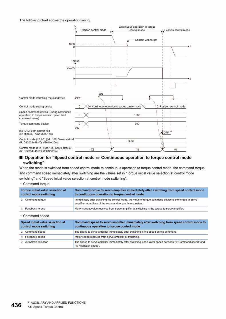
43
The following chart shows the operation timing.
■ Operation for "Speed control mode Continuous operation to torque control mode switching"
When the mode is switched from speed control mode to continuous operation to torque control mode, the command torque
and command speed immediately after switching are the values set in "Torque initial value selection at control mode
switching" and "Speed initial value selection at control mode switching".
• Command torque
• Command speed
Torque initial value selection at control mode switching
Command torque to servo amplifier immediately after switching from speed control mode to continuous operation to torque control mode
0: Command torque Immediately after switching the control mode, the value of torque command device is the torque to servo
amplifier regardless of the command torque time constant.
1: Feedback torque Motor current value received from servo amplifier at switching is the torque to servo amplifier.
Speed initial value selection at control mode switching
Command speed to servo amplifier immediately after switching from speed control mode to continuous operation to torque control mode
0: Command speed The speed to servo amplifier immediately after switching is the speed during command.
1: Feedback speed Motor speed received from servo amplifier at switching.
2: Automatic selection The speed to servo amplifier immediately after switching is the lower speed between "0: Command speed" and
"1: Feedback speed".
Contact with target
t
t
V
01000
Torque
0
30.0%
Position control mode Position control modeContinuous operation to torque
control mode
Control mode switching request device
Control mode setting device 0
0
Torque command device
Speed command device (During continuousoperation to torque control: Speed limitcommand value)
[0, 0]
OFFON
[St.1040] Start accept flag (R: M30080+n/Q: M2001+n)
Control mode (b2, b3) ([Md.108] Servo status1(R: D32032+48n/Q: #8010+20n))
[0] [1] [0]Control mode (b14) ([Md.125] Servo status3(R: D32034+48n/Q: #8012+20n))
ONOFF
1000
0 300
0: Position control mode30: Continuous operation to torque control mode
67 AUXILIARY AND APPLIED FUNCTIONS7.5 Speed-Torque Control
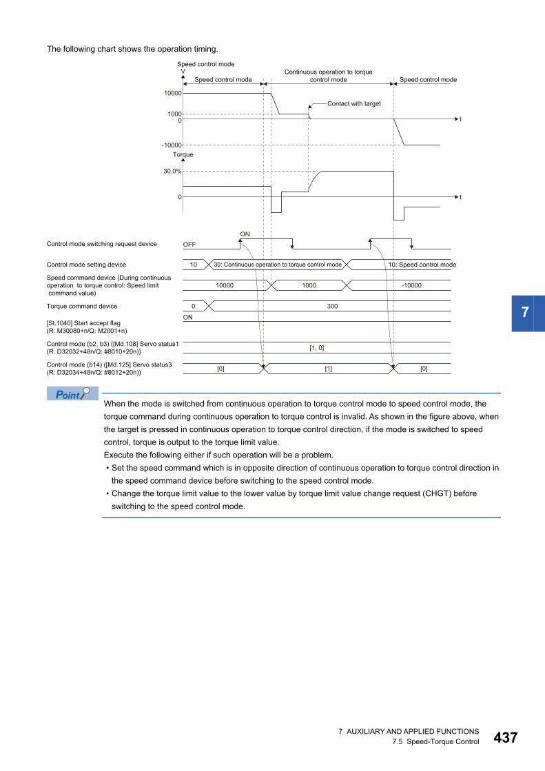
7
The following chart shows the operation timing.
When the mode is switched from continuous operation to torque control mode to speed control mode, the
torque command during continuous operation to torque control is invalid. As shown in the figure above, when
the target is pressed in continuous operation to torque control direction, if the mode is switched to speed
control, torque is output to the torque limit value.
Execute the following either if such operation will be a problem.
• Set the speed command which is in opposite direction of continuous operation to torque control direction in
the speed command device before switching to the speed control mode.
• Change the torque limit value to the lower value by torque limit value change request (CHGT) before
switching to the speed control mode.
Speed control mode
Contact with target
t
t
V
01000
-10000
10000
Torque
0
30.0%
Speed control mode Speed control modeContinuous operation to torque
control mode
Control mode switching request device
Control mode setting device 10
Torque command device
Speed command device (During continuousoperation to torque control: Speed limitcommand value)
[1, 0]
OFFON
[St.1040] Start accept flag (R: M30080+n/Q: M2001+n)
Control mode (b2, b3) ([Md.108] Servo status1(R: D32032+48n/Q: #8010+20n))
[0] [1] [0]Control mode (b14) ([Md.125] Servo status3(R: D32034+48n/Q: #8012+20n))
ON
10000 -100001000
0 300
10: Speed control mode30: Continuous operation to torque control mode
7 AUXILIARY AND APPLIED FUNCTIONS7.5 Speed-Torque Control 437
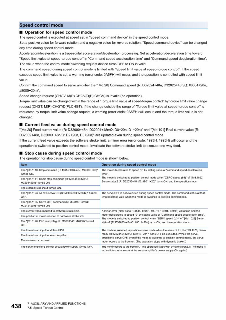
43
Speed control mode
■ Operation for speed control modeThe speed control is executed at speed set in "Speed command device" in the speed control mode.
Set a positive value for forward rotation and a negative value for reverse rotation. "Speed command device" can be changed
any time during speed control mode.
Acceleration/deceleration is a trapezoidal acceleration/deceleration processing. Set acceleration/deceleration time toward
"Speed limit value at speed-torque control" in "Command speed acceleration time" and "Command speed deceleration time".
The value when the control mode switching request device turns OFF to ON is valid.
The command speed during speed control mode is limited with "Speed limit value at speed-torque control". If the speed
exceeds speed limit value is set, a warning (error code: 0A5FH) will occur, and the operation is controlled with speed limit
value.
Confirm the command speed to servo amplifier the "[Md.28] Command speed (R: D32024+48n, D32025+48n/Q: #8004+20n,
#8005+20n)".
Speed change request (CHGV, M(P).CHGV/D(P).CHGV) is invalid (no operation).
Torque limit value can be changed within the range of "Torque limit value at speed-torque control" by torque limit value change
request (CHGT, M(P).CHGT/D(P).CHGT). If the change outside the range of "Torque limit value at speed-torque control" is
requested by torque limit value change request, a warning (error code: 0A5EH) will occur, and the torque limit value is not
changed.
■ Current feed value during speed control mode"[Md.20] Feed current value (R: D32000+48n, D32001+48n/Q: D0+20n, D1+20n)" and "[Md.101] Real current value (R:
D32002+48n, D32003+48n/Q: D2+20n, D3+20n)" are updated even during speed control mode.
If the current feed value exceeds the software stroke limit, a minor error (error code: 1993H, 1995H) will occur and the
operation is switched to position control mode. Invalidate the software stroke limit to execute one-way feed.
■ Stop cause during speed control modeThe operation for stop cause during speed control mode is shown below.
Item Operation during speed control mode
The "[Rq.1140] Stop command (R: M34480+32n/Q: M3200+20n)"
turned ON.
The motor decelerates to speed "0" by setting value of "command speed deceleration
time".
The mode is switched to position control mode when "ZERO speed (b3)" of "[Md.1022]
Servo status2 (R: D32033+48n/Q: #8011+20)" turns ON, and the operation stops.The "[Rq.1141] Rapid stop command (R: M34481+32n/Q:
M3201+20n)" turned ON.
The external stop input turned ON.
The "[Rq.1123] All axis servo ON (R: M30042/Q: M2042)" turned
OFF.
The servo OFF is not executed during speed control mode. The command status at that
time becomes valid when the mode is switched to position control mode.
The "[Rq.1155] Servo OFF command (R: M34495+32n/Q:
M3215+20n)" turned ON.
The current value reached to software stroke limit. A minor error (error code: 1900H, 1905H, 1907H, 1993H, 1995H) will occur, and the
motor decelerates to speed "0" by setting value of "Command speed deceleration time".
The mode is switched to position control when "ZERO speed (b3)" of "[Md.1022] Servo
status2 (R: D32033+48n/Q: #8011+20n) turns ON, and the operation stops.
The position of motor reached to hardware stroke limit
The "[Rq.1120] PLC ready flag (R: M30000/Q: M2000)" turned
OFF.
The forced stop input to Motion CPU. The mode is switched to position control mode when the servo OFF (The "[St.1075] Servo
ready (R: M32415+32n/Q: M2415+20n)" turns OFF) is executed. (While the servo
amplifier is servo OFF, even if the mode is switched to position control mode, the servo
motor occurs to the free run. (The operation stops with dynamic brake.))
The forced stop input to servo amplifier.
The servo error occurred.
The servo amplifier's control circuit power supply turned OFF. The motor occurs to the free run. (The operation stops with dynamic brake.) (The mode is
to position control mode at the servo amplifier's power supply ON again.)
87 AUXILIARY AND APPLIED FUNCTIONS7.5 Speed-Torque Control
7
Torque control mode
■ Operation for torque control modeThe torque control is executed at command torque set in "Torque command device" in the torque control mode.
Command torque can be changed any time during torque control mode.
Set time that reaches "Torque limit value at speed-torque control" from 0[%] in "Command torque time constant (Positive
direction)" and time that decreases 0[%] from "Torque limit value at speed-torque control" in "Command torque time constant
(Negative direction)". The value when the control mode switching request turns OFF to ON is valid for command torque time
constant (Positive direction) and command torque time constant (Negative direction). The command torque during torque
control mode is limited with "Torque limit value at speed-torque control". If the torque exceeds torque limit value is set, a
warning (error code: 09E4H) will occur, the operation is controlled with torque limit value at speed-torque control.
Speed change request (CHGV, M(P).CHGV/D(P).CHGV) is invalid (no operation).
Torque limit value to servo amplifier can be changed within the range of "Torque limit value at speed-torque control" by torque
limit value change request (CHGT, M(P).CHGT/D(P).CHGT) but the value is valid when the mode is switched to position
control mode. Command torque time constant is calculated based on the "Torque limit value at speed-torque control" at torque
control mode switching after the torque limit value is changed. If the change outside the range of "Torque limit value at speed-
torque control" is requested by torque limit value change request, a warning (error code: 0A5EH) will occur, and the torque
limit value is not changed.
■ Speed during torque control modeThe speed during torque control mode is controlled with the absolute value of value set in "Speed command device" as speed
limit command value. When the speed reaches the absolute value of "Speed command device", "Speed limit (b4)" of
"[Md.1022] Servo status2 (R: D32033+48n/Q: #8011+20n)" turns ON.
And, the value of "Speed command device" (speed limit command value for torque control) is limited with "Speed limit value at
speed-torque control". If the speed limit command value exceeds speed limit value at speed-torque control is set, a warning
(error code: 0A5FH) will occur, and the operation is controlled with speed limit value at speed-torque control.
The acceleration/deceleration processing is invalid for the value of "Speed command device".
The actual motor speed may not reach the speed limit command value depending on the machine load
situation during torque control.
■ Current feed value during torque control mode"[Md.20] Feed current value (R: D32000+48n, D32001+48n/Q: D0+20n, D1+20n)" and "[Md.101] Real current value (R:
D32002+48n, D32003+48n/Q: D2+20n, D3+20n)" are updated even in torque control.
If the current feed value exceeds the software stroke limit, a minor error (error code: 1993H, 1995H) will occur and the
operation is switched to position control mode. Invalidate the software stroke limit to execute one-way feed.
7 AUXILIARY AND APPLIED FUNCTIONS7.5 Speed-Torque Control 439
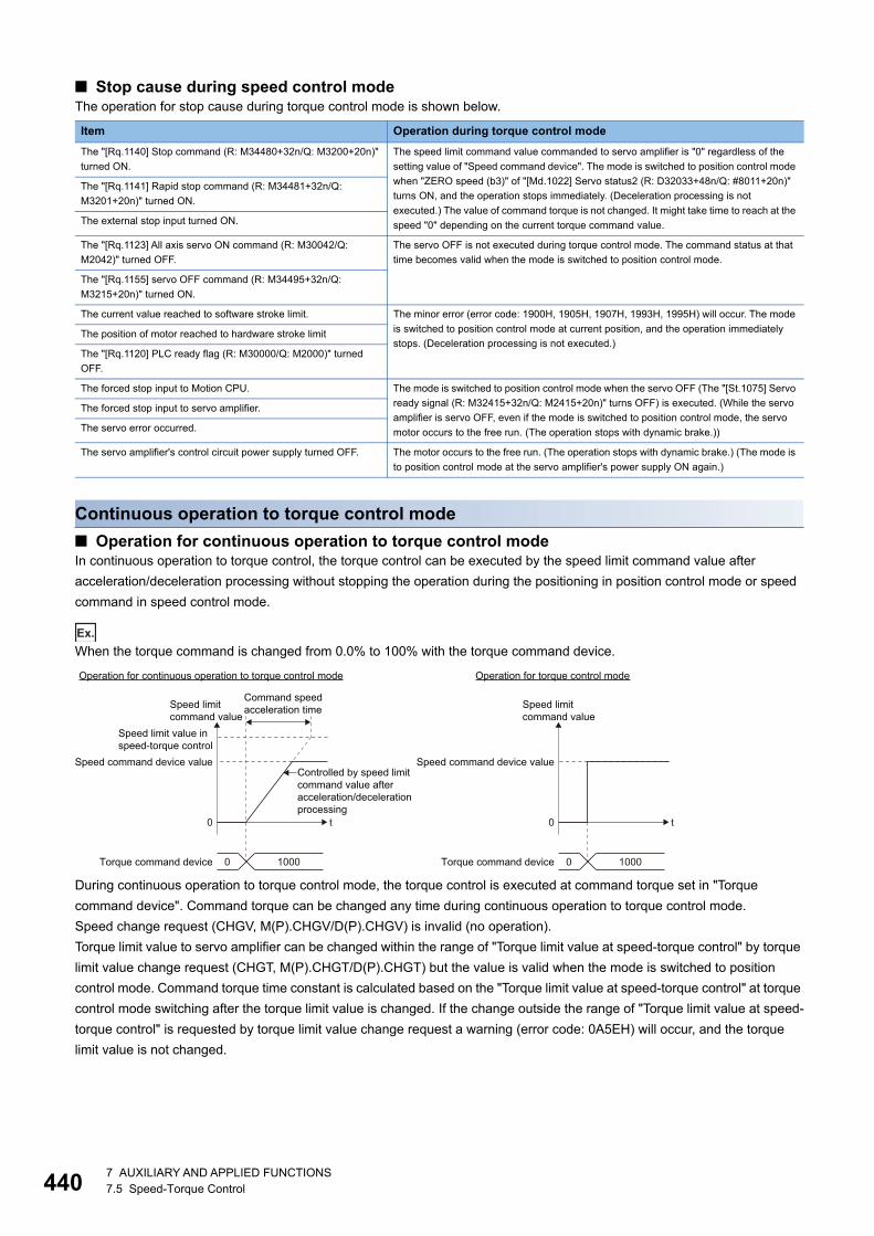
44
■ Stop cause during speed control modeThe operation for stop cause during torque control mode is shown below.
Continuous operation to torque control mode
■ Operation for continuous operation to torque control modeIn continuous operation to torque control, the torque control can be executed by the speed limit command value after
acceleration/deceleration processing without stopping the operation during the positioning in position control mode or speed
command in speed control mode.
Ex.
When the torque command is changed from 0.0% to 100% with the torque command device.
During continuous operation to torque control mode, the torque control is executed at command torque set in "Torque
command device". Command torque can be changed any time during continuous operation to torque control mode.
Speed change request (CHGV, M(P).CHGV/D(P).CHGV) is invalid (no operation).
Torque limit value to servo amplifier can be changed within the range of "Torque limit value at speed-torque control" by torque
limit value change request (CHGT, M(P).CHGT/D(P).CHGT) but the value is valid when the mode is switched to position
control mode. Command torque time constant is calculated based on the "Torque limit value at speed-torque control" at torque
control mode switching after the torque limit value is changed. If the change outside the range of "Torque limit value at speed-
torque control" is requested by torque limit value change request a warning (error code: 0A5EH) will occur, and the torque
limit value is not changed.
Item Operation during torque control mode
The "[Rq.1140] Stop command (R: M34480+32n/Q: M3200+20n)"
turned ON.
The speed limit command value commanded to servo amplifier is "0" regardless of the
setting value of "Speed command device". The mode is switched to position control mode
when "ZERO speed (b3)" of "[Md.1022] Servo status2 (R: D32033+48n/Q: #8011+20n)"
turns ON, and the operation stops immediately. (Deceleration processing is not
executed.) The value of command torque is not changed. It might take time to reach at the
speed "0" depending on the current torque command value.
The "[Rq.1141] Rapid stop command (R: M34481+32n/Q:
M3201+20n)" turned ON.
The external stop input turned ON.
The "[Rq.1123] All axis servo ON command (R: M30042/Q:
M2042)" turned OFF.
The servo OFF is not executed during torque control mode. The command status at that
time becomes valid when the mode is switched to position control mode.
The "[Rq.1155] servo OFF command (R: M34495+32n/Q:
M3215+20n)" turned ON.
The current value reached to software stroke limit. The minor error (error code: 1900H, 1905H, 1907H, 1993H, 1995H) will occur. The mode
is switched to position control mode at current position, and the operation immediately
stops. (Deceleration processing is not executed.)The position of motor reached to hardware stroke limit
The "[Rq.1120] PLC ready flag (R: M30000/Q: M2000)" turned
OFF.
The forced stop input to Motion CPU. The mode is switched to position control mode when the servo OFF (The "[St.1075] Servo
ready signal (R: M32415+32n/Q: M2415+20n)" turns OFF) is executed. (While the servo
amplifier is servo OFF, even if the mode is switched to position control mode, the servo
motor occurs to the free run. (The operation stops with dynamic brake.))
The forced stop input to servo amplifier.
The servo error occurred.
The servo amplifier's control circuit power supply turned OFF. The motor occurs to the free run. (The operation stops with dynamic brake.) (The mode is
to position control mode at the servo amplifier's power supply ON again.)
Operation for continuous operation to torque control mode
t0
Speed command device value
Speed limit value inspeed-torque control
Controlled by speed limitcommand value afteracceleration/decelerationprocessing
Speed limitcommand value
Speed limitcommand value
Command speedacceleration time
Torque command device 0 1000
Operation for torque control mode
t0
Speed command device value
Torque command device 0 1000
07 AUXILIARY AND APPLIED FUNCTIONS7.5 Speed-Torque Control
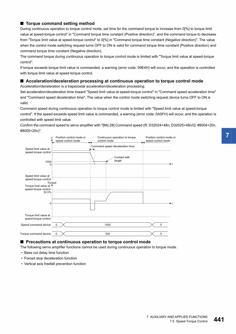
7
■ Torque command setting methodDuring continuous operation to torque control mode, set time for the command torque to increase from 0[%] to torque limit
value at speed-torque control" in "Command torque time constant (Positive direction)", and the command torque to decrease
from "Torque limit value at speed-torque control" to 0[%] in "Command torque time constant (Negative direction)". The value
when the control mode switching request turns OFF to ON is valid for command torque time constant (Positive direction) and
command torque time constant (Negative direction).
The command torque during continuous operation to torque control mode is limited with "Torque limit value at speed-torque
control".
If torque exceeds torque limit value is commanded, a warning (error code: 09E4H) will occur, and the operation is controlled
with torque limit value at speed-torque control.
■ Acceleration/deceleration processing at continuous operation to torque control modeAcceleration/deceleration is a trapezoidal acceleration/deceleration processing.
Set acceleration/deceleration time toward "Speed limit value at speed-torque control" in "Command speed acceleration time"
and "Command speed deceleration time". The value when the control mode switching request device turns OFF to ON is
valid.
Command speed during continuous operation to torque control mode is limited with "Speed limit value at speed-torque
control". If the speed exceeds speed limit value is commanded, a warning (error code: 0A5FH) will occur, and the operation is
controlled with speed limit value.
Confirm the command speed to servo amplifier with "[Md.28] Command speed (R: D32024+48n, D32025+48n/Q: #8004+20n,
#8005+20n)".
■ Precautions at continuous operation to torque control modeThe following servo amplifier functions cannot be used during continuous operation to torque mode.
• Base cut delay time function
• Forced stop deceleration function
• Vertical axis freefall prevention function
Position control mode or speed control mode
t
Torque
0
30.0%
Speed command device 0 1000 0
Torque command device 0 300 0
Contact withtarget
t
V
01000
Speed limit value atspeed-torque control
Torque limit value at speed-torque control
Torque limit value at speed-torque control
Speed limit value atspeed-torque control
Position control mode or speed control mode
Continuous operation to torquecontrol mode
Command speed deceleration time
7 AUXILIARY AND APPLIED FUNCTIONS7.5 Speed-Torque Control 441
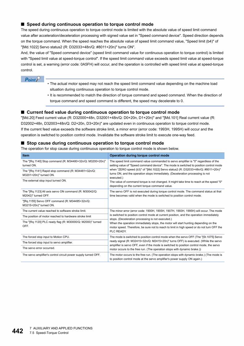
44
■ Speed during continuous operation to torque control modeThe speed during continuous operation to torque control mode is limited with the absolute value of speed limit command
value after acceleration/deceleration processing with signed value set in "Speed command device". Speed direction depends
on the torque command. When the speed reaches the absolute value of speed limit command value, "Speed limit (b4)" of
"[Md.1022] Servo status2 (R: D32033+48n/Q: #8011+20n)" turns ON".
And, the value of "Speed command device" (speed limit command value for continuous operation to torque control) is limited
with "Speed limit value at speed-torque control". If the speed limit command value exceeds speed limit value at speed-torque
control is set, a warning (error code: 0A5FH) will occur, and the operation is controlled with speed limit value at speed-torque
control.
• The actual motor speed may not reach the speed limit command value depending on the machine load
situation during continuous operation to torque control mode.
• It is recommended to match the direction of torque command and speed command. When the direction of
torque command and speed command is different, the speed may decelerate to 0.
■ Current feed value during continuous operation to torque control mode"[Md.20] Feed current value (R: D32000+48n, D32001+48n/Q: D0+20n, D1+20n)" and "[Md.101] Real current value (R:
D32002+48n, D32003+48n/Q: D2+20n, D3+20n)" are updated even in continuous operation to torque control mode.
If the current feed value exceeds the software stroke limit, a minor error (error code: 1993H, 1995H) will occur and the
operation is switched to position control mode. Invalidate the software stroke limit to execute one-way feed.
■ Stop cause during continuous operation to torque control modeThe operation for stop cause during continuous operation to torque control mode is shown below.
Item Operation during torque control mode
The "[Rq.1140] Stop command (R: M34480+32n/Q: M3200+20n)"
turned ON.
The speed limit command value commanded to servo amplifier is "0" regardless of the
setting value of "Speed command device". The mode is switched to position control mode
when "ZERO speed (b3)" of "[Md.1022] Servo status2 (R: D32033+48n/Q: #8011+20n)"
turns ON, and the operation stops immediately. (Deceleration processing is not
executed.)
The value of command torque is not changed. It might take time to reach at the speed "0"
depending on the current torque command value.
The "[Rq.1141] Rapid stop command (R: M34481+32n/Q:
M3201+20n)" turned ON.
The external stop input turned ON.
The "[Rq.1123] All axis servo ON command (R: M30042/Q:
M2042)" turned OFF.
The servo OFF is not executed during torque control mode. The command status at that
time becomes valid when the mode is switched to position control mode.
"[Rq.1155] Servo OFF command (R: M34495+32n/Q:
M3215+20n)" turned ON.
The current value reached to software stroke limit. The minor error (error code: 1900H, 1905H, 1907H, 1993H, 1995H) will occur. The mode
is switched to position control mode at current position, and the operation immediately
stops. (Deceleration processing is not executed.)
When the operation immediately stops, the motor will start hunting depending on the
motor speed. Therefore, be sure not to reach to limit in high speed or do not turn OFF the
PLC READY.
The position of motor reached to hardware stroke limit
The "[Rq.1120] PLC ready flag (R: M30000/Q: M2000)" turned
OFF.
The forced stop input to Motion CPU. The mode is switched to position control mode when the servo OFF (The "[St.1075] Servo
ready signal (R: M32415+32n/Q: M2415+20n)" turns OFF) is executed. (While the servo
amplifier is servo OFF, even if the mode is switched to position control mode, the servo
motor occurs to the free run. (The operation stops with dynamic brake.))
The forced stop input to servo amplifier.
The servo error occurred.
The servo amplifier's control circuit power supply turned OFF. The motor occurs to the free run. (The operation stops with dynamic brake.) (The mode is
to position control mode at the servo amplifier's power supply ON again.)
27 AUXILIARY AND APPLIED FUNCTIONS7.5 Speed-Torque Control
7
7.6 Acceleration/Deceleration Time Change FunctionThis function arbitrarily changes the acceleration/deceleration time at speed change, when changing speed with Motion
dedicated functions (CHGV, CHGVS) of Motion SFC program (and also the Motion dedicated PLC instruction M(P).CHGV/
D(P).CHGV, M(P).CHGVS/D(P).CHGVS).
Normally (speed change without changing the acceleration/deceleration time), the acceleration/deceleration time is controlled
by the positioning data of the servo program or the parameter block at the start. However, if a speed change is executed after
setting the acceleration/deceleration time change parameter, speed changes at the set acceleration/deceleration time.
"Acceleration/deceleration time after change" is the acceleration/deceleration time of positioning control being
executed. "Acceleration/deceleration time after change" is valid until the switching of the next positioning
point. (Automatic decelerating processing at positioning completion is also controlled by "Acceleration/
deceleration time after change".)
Speed change instructions for acceleration/deceleration time changeThe speed change instructions for acceleration/deceleration time change are shown below.
Control detailsAfter setting the acceleration/deceleration time change parameter, if speed change command is executed, the acceleration/
deceleration time changes. The acceleration/deceleration time change parameter is set for every axis in [Motion Control
Parameter] [Axis Setting Parameter] "Expansion Parameter" of MT Developer2. Refer to the Expansion Parameter for
details of acceleration/deceleration time change parameter. (Page 192 Expansion Parameters)
Refer to the following for details of command generation axis parameter.
MELSEC iQ-R Motion Controller Programming Manual (Advanced Synchronous Control)
• Set the change value of acceleration/deceleration time in the device set by acceleration time change value device/
deceleration time change value device.
• Device set by the acceleration/deceleration time change enable device turns ON (valid).
Classification Instruction Description
Motion SFC program
(Motion dedicated function)
CHGV Speed change request
CHGVS Command generation axis speed change request
Motion dedicated PLC instruction M(P).CHGV/D(P).CHGV Speed change request of the specified axis
M(P).CHGVS/D(P).CHGVS Speed change request of the specified command generation axis
Name Setting range
New acceleration time value device 1 to 8388608 [ms]
Other than above: Time change invalidNew deceleration time value device
7 AUXILIARY AND APPLIED FUNCTIONS7.6 Acceleration/Deceleration Time Change Function 443
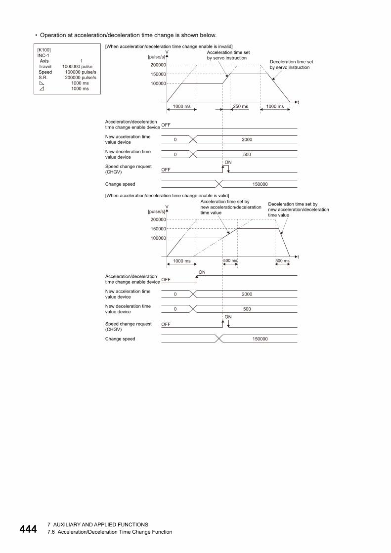
44
• Operation at acceleration/deceleration time change is shown below.
OFFAcceleration/decelerationtime change enable device
OFFON
Speed change request(CHGV)
Change speed
0 2000New acceleration timevalue device
t
100000
150000
200000
[pulse/s]V
1000 ms 250 ms 1000 ms
0 500New deceleration timevalue device
150000
Acceleration time setby servo instruction
Deceleration time setby servo instruction
OFFAcceleration/decelerationtime change enable device
OFFON
Speed change request(CHGV)
Change speed
0 2000New acceleration timevalue device
t
100000
150000
200000
[pulse/s]V
1000 ms 500 ms500 ms
[When acceleration/deceleration time change enable is valid]
ON
0 500New deceleration timevalue device
150000
Acceleration time set bynew acceleration/decelerationtime value
Deceleration time set by new acceleration/decelerationtime value
[When acceleration/deceleration time change enable is invalid][K100]INC-1 Axis Travel Speed S.R.
11000000 pulse 100000 pulse/s 200000 pulse/s 1000 ms 1000 ms
47 AUXILIARY AND APPLIED FUNCTIONS7.6 Acceleration/Deceleration Time Change Function
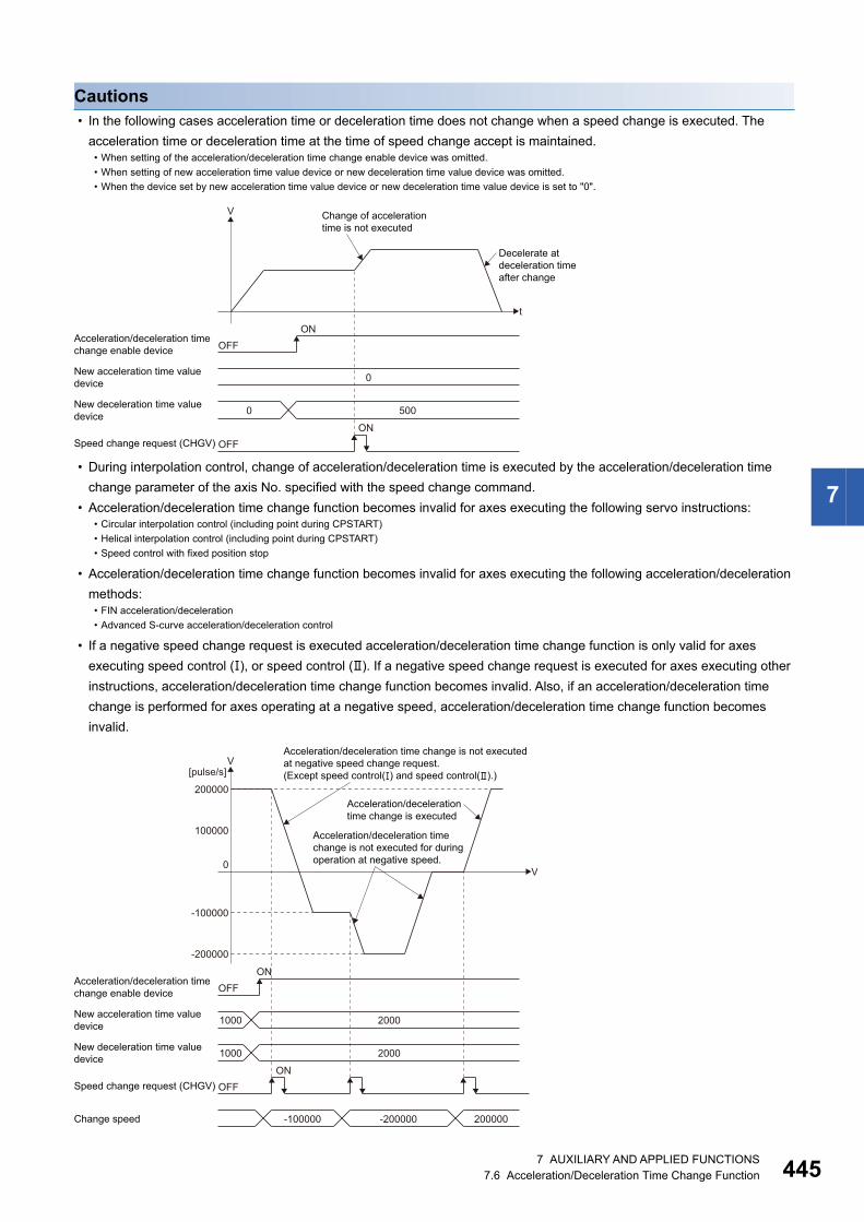
7
Cautions • In the following cases acceleration time or deceleration time does not change when a speed change is executed. The
acceleration time or deceleration time at the time of speed change accept is maintained.
• During interpolation control, change of acceleration/deceleration time is executed by the acceleration/deceleration time
change parameter of the axis No. specified with the speed change command.
• Acceleration/deceleration time change function becomes invalid for axes executing the following servo instructions:
• Acceleration/deceleration time change function becomes invalid for axes executing the following acceleration/deceleration
methods:
• If a negative speed change request is executed acceleration/deceleration time change function is only valid for axes
executing speed control (), or speed control (). If a negative speed change request is executed for axes executing other
instructions, acceleration/deceleration time change function becomes invalid. Also, if an acceleration/deceleration time
change is performed for axes operating at a negative speed, acceleration/deceleration time change function becomes
invalid.
• When setting of the acceleration/deceleration time change enable device was omitted.
• When setting of new acceleration time value device or new deceleration time value device was omitted.
• When the device set by new acceleration time value device or new deceleration time value device is set to "0".
• Circular interpolation control (including point during CPSTART)
• Helical interpolation control (including point during CPSTART)
• Speed control with fixed position stop
• FIN acceleration/deceleration
• Advanced S-curve acceleration/deceleration control
OFFAcceleration/deceleration timechange enable device
OFFON
Speed change request (CHGV)
0New acceleration time valuedevice
t
V
ON
0 500New deceleration time valuedevice
Change of accelerationtime is not executed
Decelerate atdeceleration timeafter change
Acceleration/deceleration time change is not executedat negative speed change request. (Except speed control(�) and speed control(�).)
OFFAcceleration/deceleration timechange enable device
OFFSpeed change request (CHGV)
Change speed
New acceleration time valuedevice
100000
0
-100000
-200000
200000
[pulse/s]V
V
1000 2000
1000 2000
ON
ON
New deceleration time valuedevice
-200000 200000-100000
Acceleration/deceleration timechange is not executed for duringoperation at negative speed.
Acceleration/decelerationtime change is executed
7 AUXILIARY AND APPLIED FUNCTIONS7.6 Acceleration/Deceleration Time Change Function 445
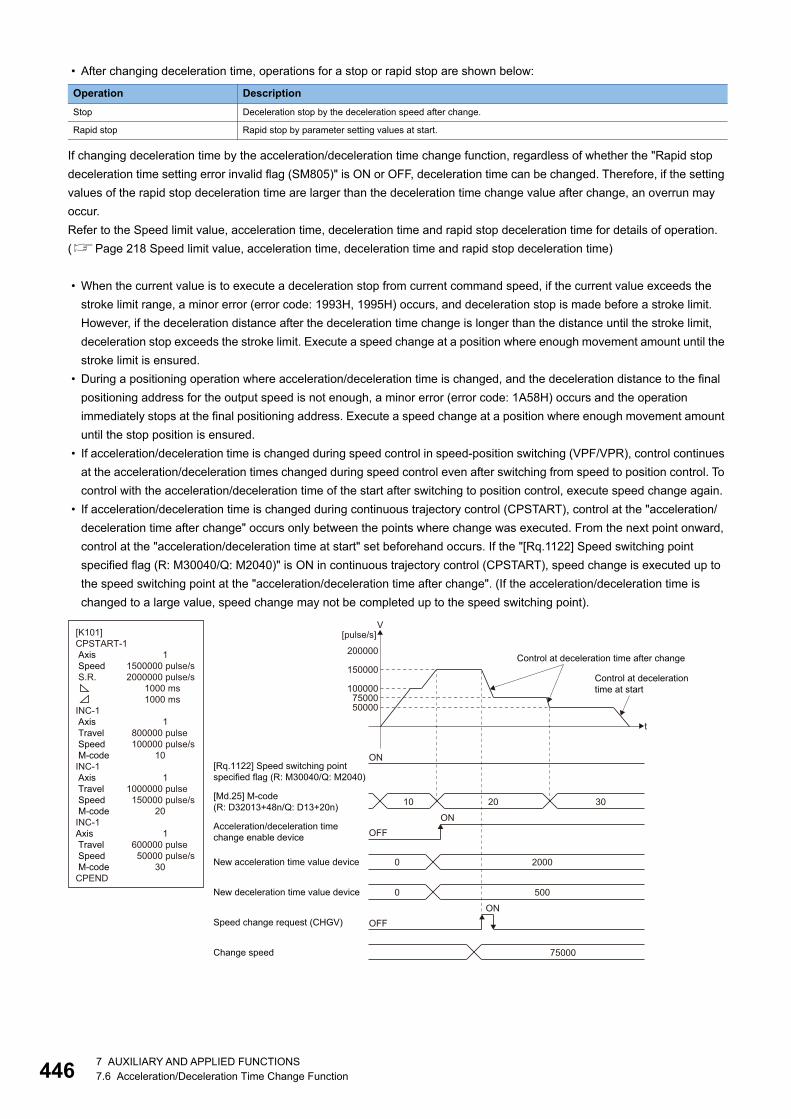
44
• After changing deceleration time, operations for a stop or rapid stop are shown below:
If changing deceleration time by the acceleration/deceleration time change function, regardless of whether the "Rapid stop
deceleration time setting error invalid flag (SM805)" is ON or OFF, deceleration time can be changed. Therefore, if the setting
values of the rapid stop deceleration time are larger than the deceleration time change value after change, an overrun may
occur.
Refer to the Speed limit value, acceleration time, deceleration time and rapid stop deceleration time for details of operation.
(Page 218 Speed limit value, acceleration time, deceleration time and rapid stop deceleration time)
• When the current value is to execute a deceleration stop from current command speed, if the current value exceeds the
stroke limit range, a minor error (error code: 1993H, 1995H) occurs, and deceleration stop is made before a stroke limit.
However, if the deceleration distance after the deceleration time change is longer than the distance until the stroke limit,
deceleration stop exceeds the stroke limit. Execute a speed change at a position where enough movement amount until the
stroke limit is ensured.
• During a positioning operation where acceleration/deceleration time is changed, and the deceleration distance to the final
positioning address for the output speed is not enough, a minor error (error code: 1A58H) occurs and the operation
immediately stops at the final positioning address. Execute a speed change at a position where enough movement amount
until the stop position is ensured.
• If acceleration/deceleration time is changed during speed control in speed-position switching (VPF/VPR), control continues
at the acceleration/deceleration times changed during speed control even after switching from speed to position control. To
control with the acceleration/deceleration time of the start after switching to position control, execute speed change again.
• If acceleration/deceleration time is changed during continuous trajectory control (CPSTART), control at the "acceleration/
deceleration time after change" occurs only between the points where change was executed. From the next point onward,
control at the "acceleration/deceleration time at start" set beforehand occurs. If the "[Rq.1122] Speed switching point
specified flag (R: M30040/Q: M2040)" is ON in continuous trajectory control (CPSTART), speed change is executed up to
the speed switching point at the "acceleration/deceleration time after change". (If the acceleration/deceleration time is
changed to a large value, speed change may not be completed up to the speed switching point).
Operation Description
Stop Deceleration stop by the deceleration speed after change.
Rapid stop Rapid stop by parameter setting values at start.
OFFAcceleration/deceleration timechange enable device
OFFSpeed change request (CHGV)
Change speed
0 2000New acceleration time value device
t
100000
5000075000
150000
200000
[pulse/s]V
ON[Rq.1122] Speed switching pointspecified flag (R: M30040/Q: M2040)
10 20 30[Md.25] M-code(R: D32013+48n/Q: D13+20n)
ON
ON
0 500New deceleration time value device
75000
[K101]CPSTART-1 Axis Speed S.R.
INC-1 Axis Travel Speed M-codeINC-1 Axis Travel Speed M-codeINC-1Axis Travel Speed M-codeCPEND
11500000 pulse/s2000000 pulse/s 1000 ms 1000 ms
1 800000 pulse 100000 pulse/s 10
11000000 pulse 150000 pulse/s 20
1 600000 pulse 50000 pulse/s 30
Control at decelerationtime at start
Control at deceleration time after change
67 AUXILIARY AND APPLIED FUNCTIONS7.6 Acceleration/Deceleration Time Change Function
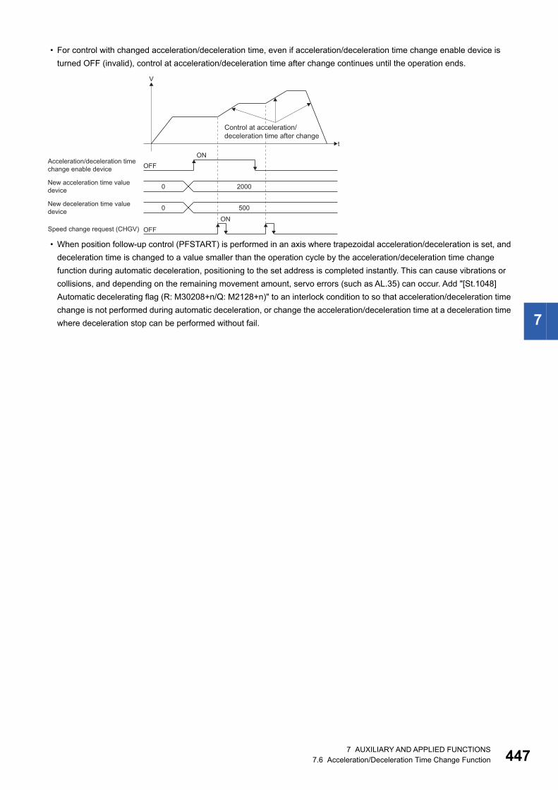
7
• For control with changed acceleration/deceleration time, even if acceleration/deceleration time change enable device is
turned OFF (invalid), control at acceleration/deceleration time after change continues until the operation ends.
• When position follow-up control (PFSTART) is performed in an axis where trapezoidal acceleration/deceleration is set, and
deceleration time is changed to a value smaller than the operation cycle by the acceleration/deceleration time change
function during automatic deceleration, positioning to the set address is completed instantly. This can cause vibrations or
collisions, and depending on the remaining movement amount, servo errors (such as AL.35) can occur. Add "[St.1048]
Automatic decelerating flag (R: M30208+n/Q: M2128+n)" to an interlock condition to so that acceleration/deceleration time
change is not performed during automatic deceleration, or change the acceleration/deceleration time at a deceleration time
where deceleration stop can be performed without fail.
OFFAcceleration/deceleration timechange enable device
OFFON
New acceleration time valuedevice
t
V
ON
2000
500New deceleration time valuedevice
Speed change request (CHGV)
0
0
Control at acceleration/deceleration time after change
7 AUXILIARY AND APPLIED FUNCTIONS7.6 Acceleration/Deceleration Time Change Function 447
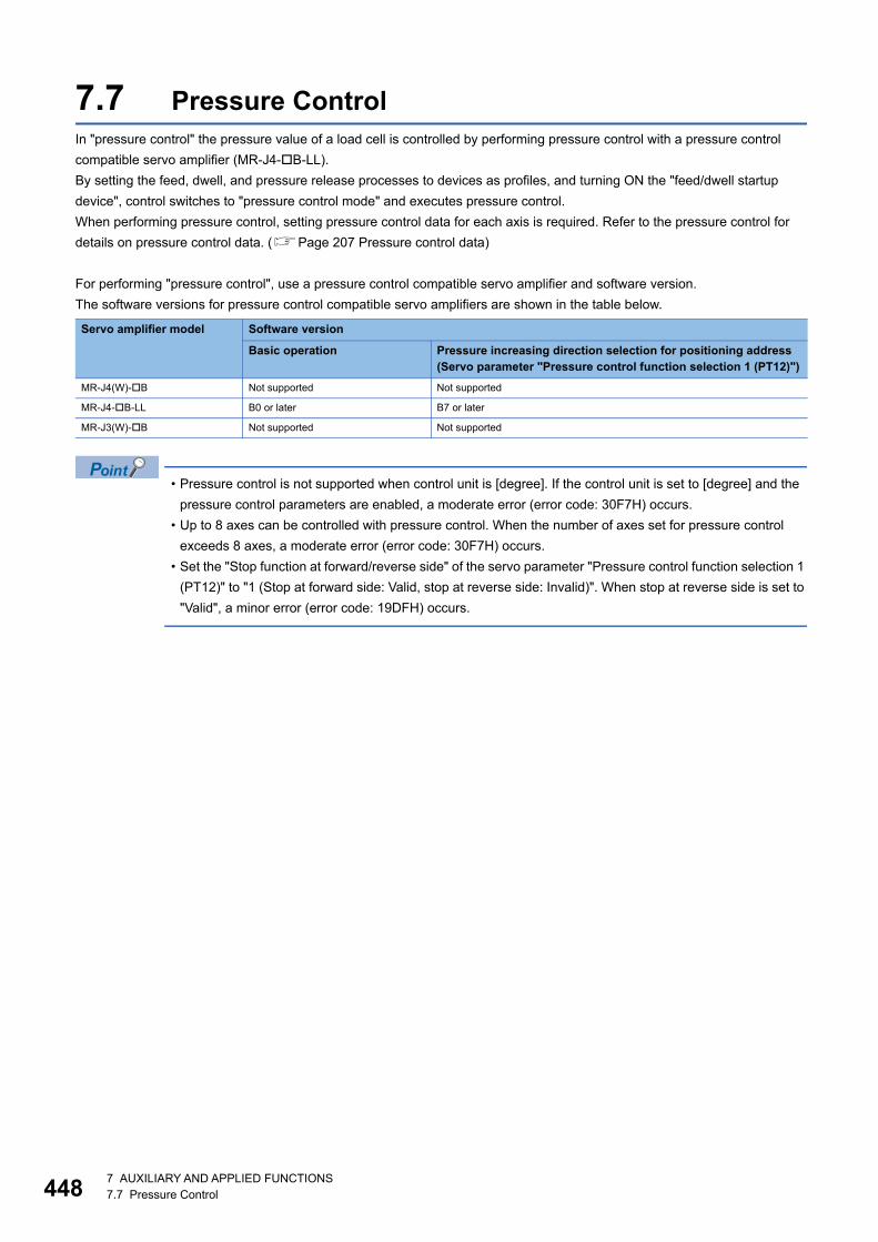
44
7.7 Pressure ControlIn "pressure control" the pressure value of a load cell is controlled by performing pressure control with a pressure control
compatible servo amplifier (MR-J4-B-LL).
By setting the feed, dwell, and pressure release processes to devices as profiles, and turning ON the "feed/dwell startup
device", control switches to "pressure control mode" and executes pressure control.
When performing pressure control, setting pressure control data for each axis is required. Refer to the pressure control for
details on pressure control data. (Page 207 Pressure control data)
For performing "pressure control", use a pressure control compatible servo amplifier and software version.
The software versions for pressure control compatible servo amplifiers are shown in the table below.
• Pressure control is not supported when control unit is [degree]. If the control unit is set to [degree] and the
pressure control parameters are enabled, a moderate error (error code: 30F7H) occurs.
• Up to 8 axes can be controlled with pressure control. When the number of axes set for pressure control
exceeds 8 axes, a moderate error (error code: 30F7H) occurs.
• Set the "Stop function at forward/reverse side" of the servo parameter "Pressure control function selection 1
(PT12)" to "1 (Stop at forward side: Valid, stop at reverse side: Invalid)". When stop at reverse side is set to
"Valid", a minor error (error code: 19DFH) occurs.
Servo amplifier model Software version
Basic operation Pressure increasing direction selection for positioning address(Servo parameter "Pressure control function selection 1 (PT12)")
MR-J4(W)-B Not supported Not supported
MR-J4-B-LL B0 or later B7 or later
MR-J3(W)-B Not supported Not supported
87 AUXILIARY AND APPLIED FUNCTIONS7.7 Pressure Control
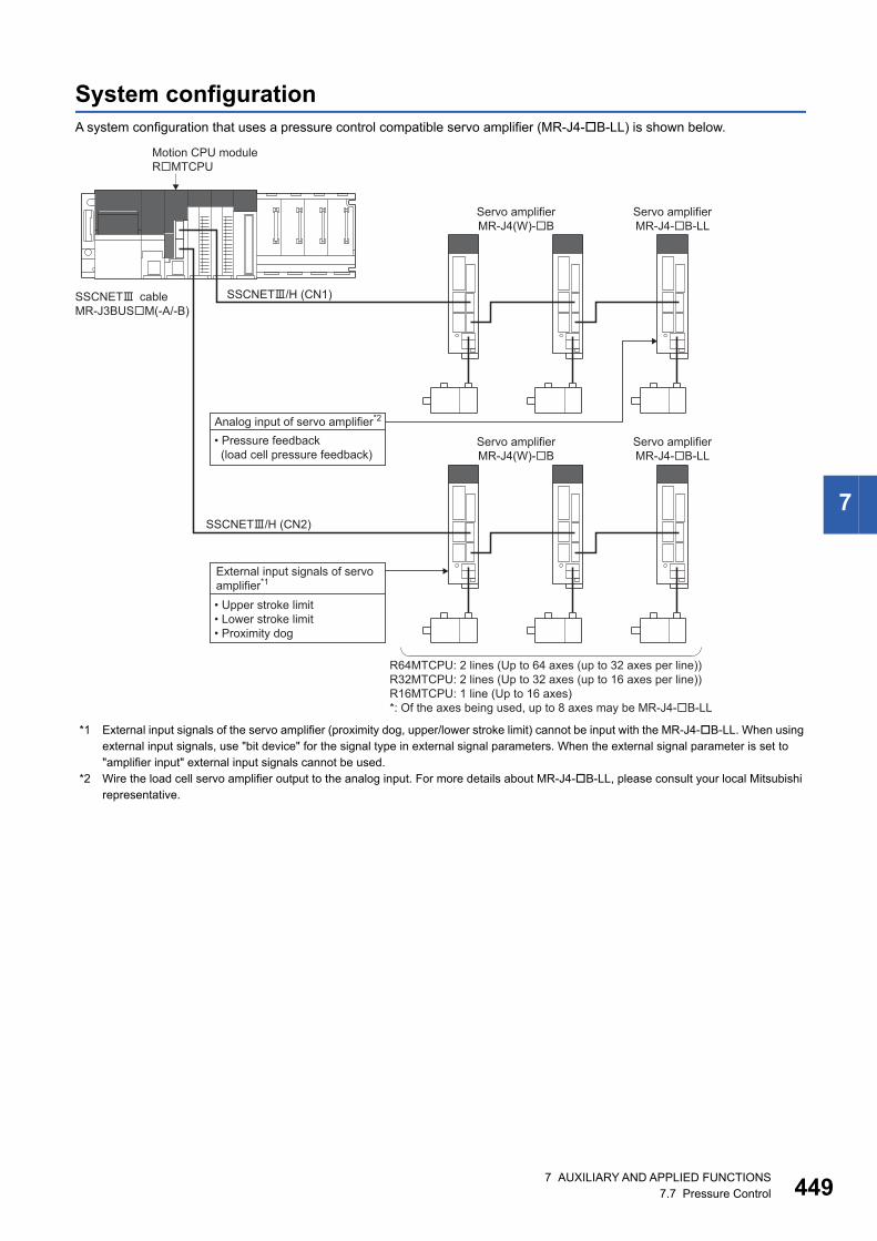
7
System configurationA system configuration that uses a pressure control compatible servo amplifier (MR-J4-B-LL) is shown below.
*1 External input signals of the servo amplifier (proximity dog, upper/lower stroke limit) cannot be input with the MR-J4-B-LL. When using external input signals, use "bit device" for the signal type in external signal parameters. When the external signal parameter is set to "amplifier input" external input signals cannot be used.
*2 Wire the load cell servo amplifier output to the analog input. For more details about MR-J4-B-LL, please consult your local Mitsubishi representative.
R64MTCPU: 2 lines (Up to 64 axes (up to 32 axes per line))R32MTCPU: 2 lines (Up to 32 axes (up to 16 axes per line))R16MTCPU: 1 line (Up to 16 axes)*: Of the axes being used, up to 8 axes may be MR-J4-B-LL
SSCNETcableMR-J3BUSM(-A/-B)
Servo amplifierMR-J4(W)-B
Servo amplifierMR-J4-B-LL
Servo amplifierMR-J4-B-LL
Servo amplifierMR-J4(W)-B
SSCNET/H (CN1)
SSCNET/H (CN2)
Motion CPU moduleRMTCPU
Analog input of servo amplifier*2
• Pressure feedback (load cell pressure feedback)
External input signals of servo amplifier*1
• Upper stroke limit• Lower stroke limit• Proximity dog
7 AUXILIARY AND APPLIED FUNCTIONS7.7 Pressure Control 449
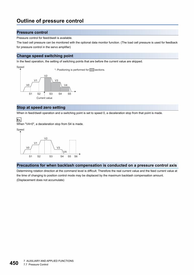
45
Outline of pressure control
Pressure controlPressure control for feed/dwell is available.
The load cell pressure can be monitored with the optional data monitor function. (The load cell pressure is used for feedback
for pressure control in the servo amplifier)
Change speed switching pointIn the feed operation, the setting of switching points that are before the current value are skipped.
Stop at speed zero settingWhen in feed/dwell operation and a switching point is set to speed 0, a deceleration stop from that point is made.
Ex.
When "V4=0", a deceleration stop from S4 is made.
Precautions for when backlash compensation is conducted on a pressure control axisDetermining rotation direction at the command level is difficult. Therefore the real current value and the feed current value at
the time of changing to position control mode may be displaced by the maximum backlash compensation amount.
(Displacement does not accumulate)
S1
Speed
V0
V1 V3
V4
V2
S2Current value
S3 S4 S5
*: Positioning is performed for sections.
S1
Speed
V0
V1
V3
V2
S2 S3 S4
V4
S5 S6
07 AUXILIARY AND APPLIED FUNCTIONS7.7 Pressure Control
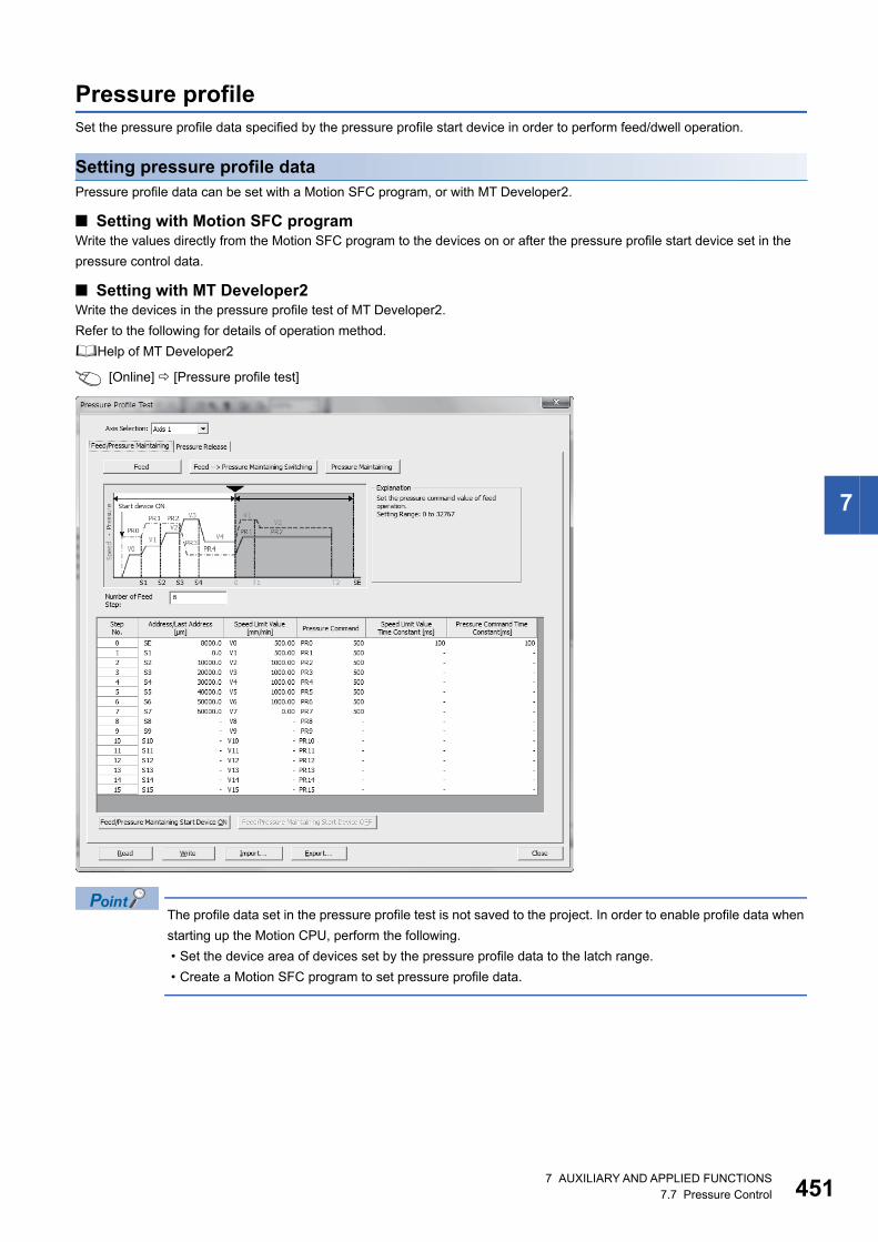
7
Pressure profileSet the pressure profile data specified by the pressure profile start device in order to perform feed/dwell operation.
Setting pressure profile dataPressure profile data can be set with a Motion SFC program, or with MT Developer2.
■ Setting with Motion SFC programWrite the values directly from the Motion SFC program to the devices on or after the pressure profile start device set in the
pressure control data.
■ Setting with MT Developer2Write the devices in the pressure profile test of MT Developer2.
Refer to the following for details of operation method.
Help of MT Developer2
[Online] [Pressure profile test]
The profile data set in the pressure profile test is not saved to the project. In order to enable profile data when
starting up the Motion CPU, perform the following.
• Set the device area of devices set by the pressure profile data to the latch range.
• Create a Motion SFC program to set pressure profile data.
7 AUXILIARY AND APPLIED FUNCTIONS7.7 Pressure Control 451
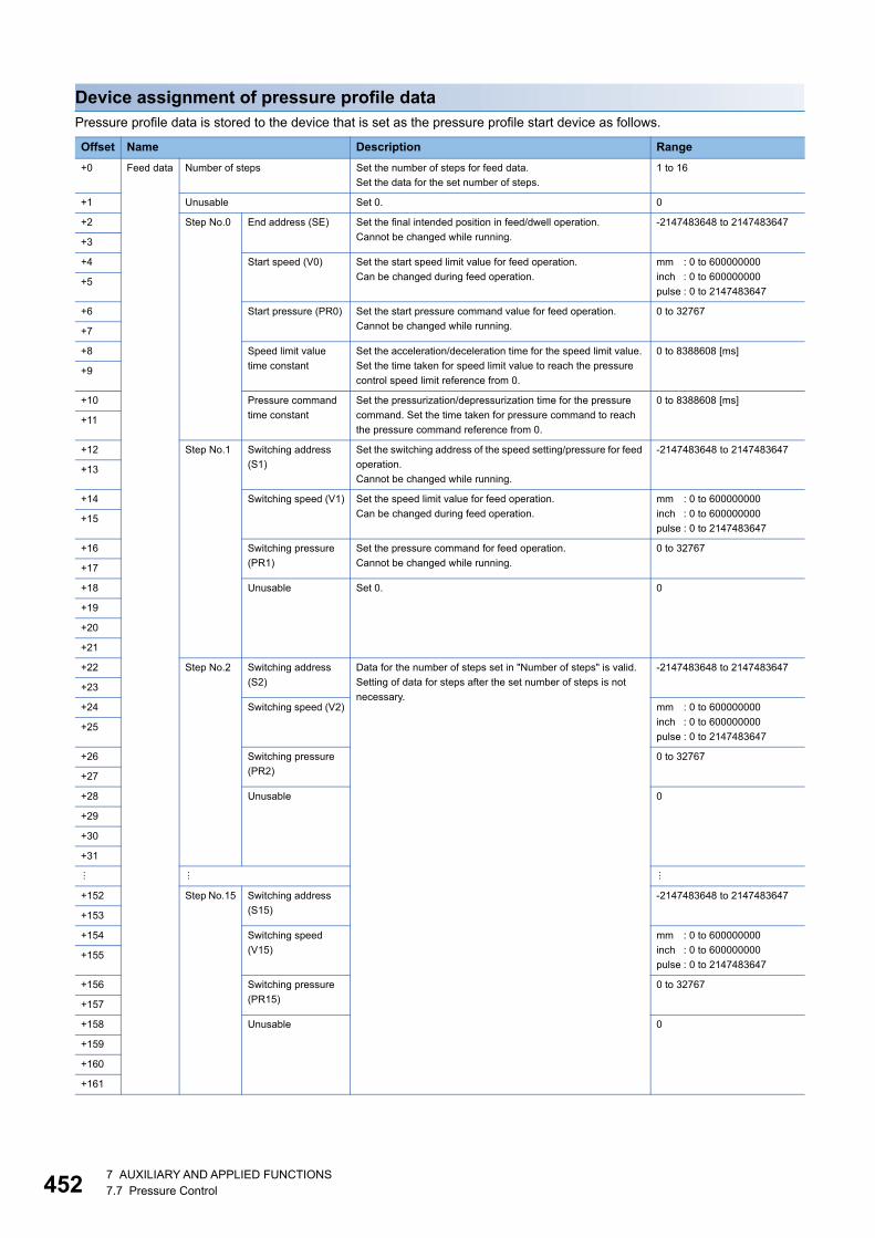
45
Device assignment of pressure profile dataPressure profile data is stored to the device that is set as the pressure profile start device as follows.
Offset Name Description Range
+0 Feed data Number of steps Set the number of steps for feed data.
Set the data for the set number of steps.
1 to 16
+1 Unusable Set 0. 0
+2 Step No.0 End address (SE) Set the final intended position in feed/dwell operation.
Cannot be changed while running.
-2147483648 to 2147483647
+3
+4 Start speed (V0) Set the start speed limit value for feed operation.
Can be changed during feed operation.
mm : 0 to 600000000
inch : 0 to 600000000
pulse : 0 to 2147483647+5
+6 Start pressure (PR0) Set the start pressure command value for feed operation.
Cannot be changed while running.
0 to 32767
+7
+8 Speed limit value
time constant
Set the acceleration/deceleration time for the speed limit value.
Set the time taken for speed limit value to reach the pressure
control speed limit reference from 0.
0 to 8388608 [ms]
+9
+10 Pressure command
time constant
Set the pressurization/depressurization time for the pressure
command. Set the time taken for pressure command to reach
the pressure command reference from 0.
0 to 8388608 [ms]
+11
+12 Step No.1 Switching address
(S1)
Set the switching address of the speed setting/pressure for feed
operation.
Cannot be changed while running.
-2147483648 to 2147483647
+13
+14 Switching speed (V1) Set the speed limit value for feed operation.
Can be changed during feed operation.
mm : 0 to 600000000
inch : 0 to 600000000
pulse : 0 to 2147483647+15
+16 Switching pressure
(PR1)
Set the pressure command for feed operation.
Cannot be changed while running.
0 to 32767
+17
+18 Unusable Set 0. 0
+19
+20
+21
+22 Step No.2 Switching address
(S2)
Data for the number of steps set in "Number of steps" is valid.
Setting of data for steps after the set number of steps is not
necessary.
-2147483648 to 2147483647
+23
+24 Switching speed (V2) mm : 0 to 600000000
inch : 0 to 600000000
pulse : 0 to 2147483647+25
+26 Switching pressure
(PR2)
0 to 32767
+27
+28 Unusable 0
+29
+30
+31
+152 Step No.15 Switching address
(S15)
-2147483648 to 2147483647
+153
+154 Switching speed
(V15)
mm : 0 to 600000000
inch : 0 to 600000000
pulse : 0 to 2147483647+155
+156 Switching pressure
(PR15)
0 to 32767
+157
+158 Unusable 0
+159
+160
+161
27 AUXILIARY AND APPLIED FUNCTIONS7.7 Pressure Control

7
+162 Feed to
dwell
switching
conditions
Switching address (SC) Specify the feed to dwell switching address. -2147483648 to 2147483647
+163
+164 Feed/dwell switching mode Specify the feed to dwell switching condition. 0: Address
1: Address & load cell
pressure+165
+166 Switching pressure (PRC) Specify the feed to dwell switching pressure value when "1:
Address & load cell pressure" is specified in feed/dwell
switching mode.
0 to 32767
+167
+168 Feed to dwell switching Speed limit
value time constant
Set the acceleration/deceleration time of the speed limit value
for when switching from feed to dwell. Set the time taken for
speed limit value to reach the pressure control speed limit
reference from 0.
0 to 8388608 [ms]
+169
+170 Feed to dwell switching Pressure
command time constant
Set the pressurization/depressurization time of position
command for when switching from feed to dwell. Set the time
taken for pressure command to reach the pressure command
reference from 0.
0 to 8388608 [ms]
+171
+172 Dwell
data
Number of steps Set the number of steps for dwell data.
Set the data for the set number of steps.
1 to 16
+173 Mode selection Set the dwell operation mode.
The time constant is valid for the speed limit value.
0: The time constant is valid
for the second step and
after
1: The time constant is invalid
and pressure command
points for the second step
and after are connected
with a straight line
+174 Step No.1 Set time (T1) Set the dwell speed/pressure switching time.
Cannot be changed while running.
0 to 999999 [ms]
+175
+176 Set speed (V1) Set the speed limit value for dwell operation.
Cannot be changed while running.
mm : 0 to 600000000
inch : 0 to 600000000
pulse : 0 to 2147483647+177
+178 Set pressure (PR1) Set the pressure command for dwell operation.
When mode selection is "0", can be changed during dwell
operation.
When mode selection is "1", cannot be changed during dwell
operation.
0 to 32767
+179
+180 Unusable Set 0. 0
+181
+182
+183
+184 Step No.2 Set time (T2) Data for the number of steps set in "Number of steps" is valid.
Setting of data for steps after the set number of steps is not
necessary.
0 to 999999 [ms]
+185
+186 Set speed (V2) mm : 0 to 600000000
inch : 0 to 600000000
pulse : 0 to 2147483647+187
+188 Set pressure (PR2) 0 to 32767
+189
+190 Unusable 0
+191
+192
+193
Offset Name Description Range
7 AUXILIARY AND APPLIED FUNCTIONS7.7 Pressure Control 453
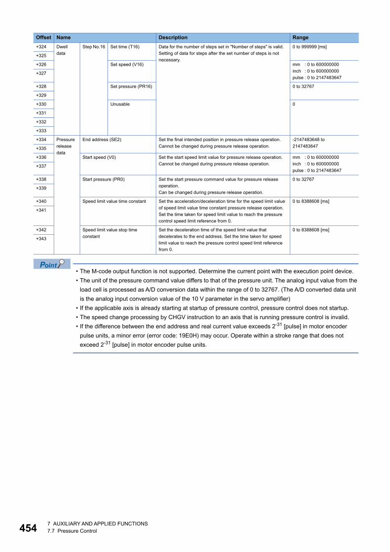
45
• The M-code output function is not supported. Determine the current point with the execution point device.
• The unit of the pressure command value differs to that of the pressure unit. The analog input value from the
load cell is processed as A/D conversion data within the range of 0 to 32767. (The A/D converted data unit
is the analog input conversion value of the 10 V parameter in the servo amplifier)
• If the applicable axis is already starting at startup of pressure control, pressure control does not startup.
• The speed change processing by CHGV instruction to an axis that is running pressure control is invalid.
• If the difference between the end address and real current value exceeds 2-31 [pulse] in motor encoder
pulse units, a minor error (error code: 19E0H) may occur. Operate within a stroke range that does not
exceed 2-31 [pulse] in motor encoder pulse units.
+324 Dwell
data
Step No.16 Set time (T16) Data for the number of steps set in "Number of steps" is valid.
Setting of data for steps after the set number of steps is not
necessary.
0 to 999999 [ms]
+325
+326 Set speed (V16) mm : 0 to 600000000
inch : 0 to 600000000
pulse : 0 to 2147483647+327
+328 Set pressure (PR16) 0 to 32767
+329
+330 Unusable 0
+331
+332
+333
+334 Pressure
release
data
End address (SE2) Set the final intended position in pressure release operation.
Cannot be changed during pressure release operation.
-2147483648 to
2147483647+335
+336 Start speed (V0) Set the start speed limit value for pressure release operation.
Cannot be changed during pressure release operation.
mm : 0 to 600000000
inch : 0 to 600000000
pulse : 0 to 2147483647+337
+338 Start pressure (PR0) Set the start pressure command value for pressure release
operation.
Can be changed during pressure release operation.
0 to 32767
+339
+340 Speed limit value time constant Set the acceleration/deceleration time for the speed limit value
of speed limit value time constant pressure release operation.
Set the time taken for speed limit value to reach the pressure
control speed limit reference from 0.
0 to 8388608 [ms]
+341
+342 Speed limit value stop time
constant
Set the deceleration time of the speed limit value that
decelerates to the end address. Set the time taken for speed
limit value to reach the pressure control speed limit reference
from 0.
0 to 8388608 [ms]
+343
Offset Name Description Range
47 AUXILIARY AND APPLIED FUNCTIONS7.7 Pressure Control
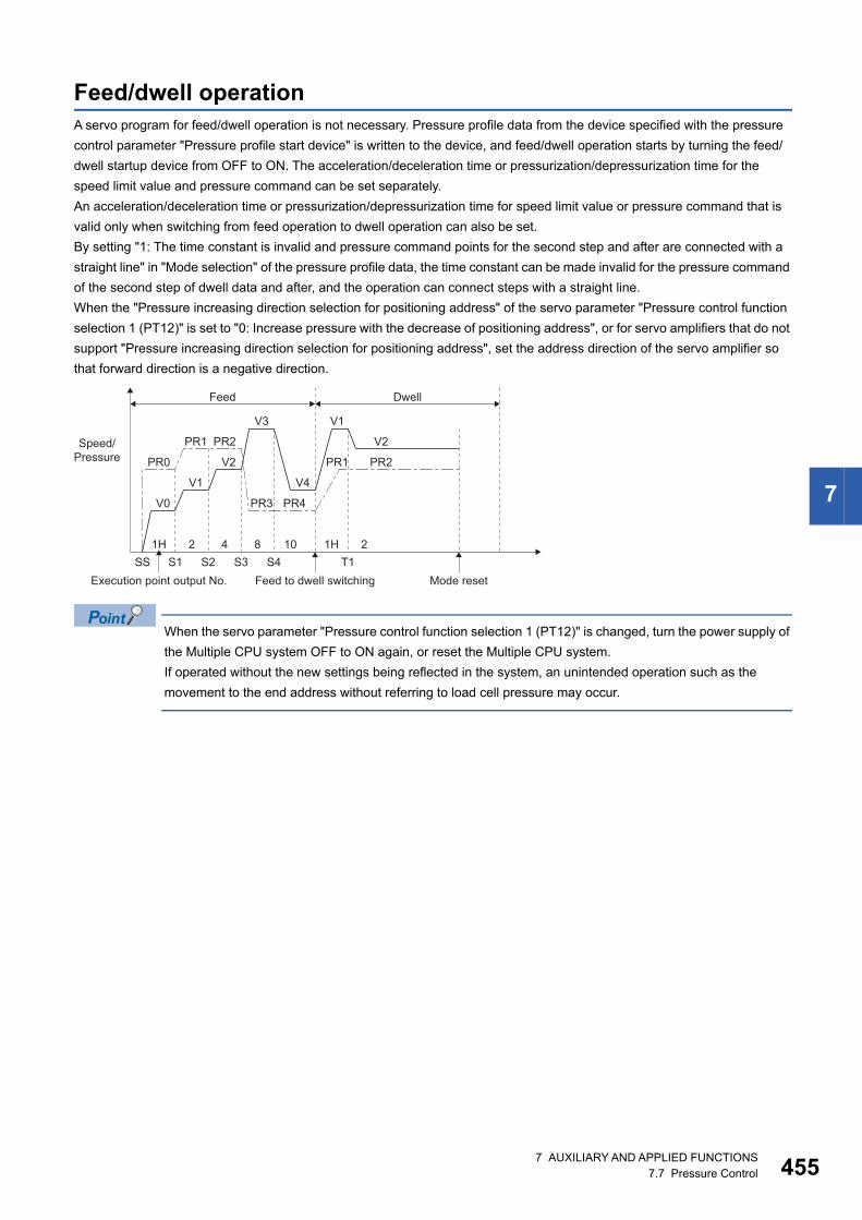
7
Feed/dwell operationA servo program for feed/dwell operation is not necessary. Pressure profile data from the device specified with the pressure
control parameter "Pressure profile start device" is written to the device, and feed/dwell operation starts by turning the feed/
dwell startup device from OFF to ON. The acceleration/deceleration time or pressurization/depressurization time for the
speed limit value and pressure command can be set separately.
An acceleration/deceleration time or pressurization/depressurization time for speed limit value or pressure command that is
valid only when switching from feed operation to dwell operation can also be set.
By setting "1: The time constant is invalid and pressure command points for the second step and after are connected with a
straight line" in "Mode selection" of the pressure profile data, the time constant can be made invalid for the pressure command
of the second step of dwell data and after, and the operation can connect steps with a straight line.
When the "Pressure increasing direction selection for positioning address" of the servo parameter "Pressure control function
selection 1 (PT12)" is set to "0: Increase pressure with the decrease of positioning address", or for servo amplifiers that do not
support "Pressure increasing direction selection for positioning address", set the address direction of the servo amplifier so
that forward direction is a negative direction.
When the servo parameter "Pressure control function selection 1 (PT12)" is changed, turn the power supply of
the Multiple CPU system OFF to ON again, or reset the Multiple CPU system.
If operated without the new settings being reflected in the system, an unintended operation such as the
movement to the end address without referring to load cell pressure may occur.
S11H 2 4 8 10
S2 S3 S4 T1SS
Speed/Pressure
V0
PR0
V1
PR1
V4
PR4
V2
PR2
V3
PR3
V1
V2
PR2PR1
1H 2
Feed to dwell switchingExecution point output No. Mode reset
Feed Dwell
7 AUXILIARY AND APPLIED FUNCTIONS7.7 Pressure Control 455
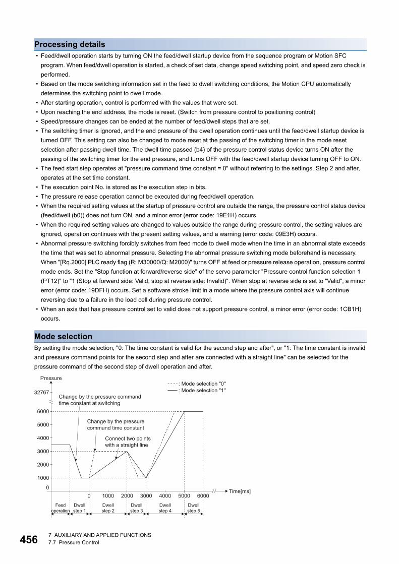
45
Processing details • Feed/dwell operation starts by turning ON the feed/dwell startup device from the sequence program or Motion SFC
program. When feed/dwell operation is started, a check of set data, change speed switching point, and speed zero check is
performed.
• Based on the mode switching information set in the feed to dwell switching conditions, the Motion CPU automatically
determines the switching point to dwell mode.
• After starting operation, control is performed with the values that were set.
• Upon reaching the end address, the mode is reset. (Switch from pressure control to positioning control)
• Speed/pressure changes can be ended at the number of feed/dwell steps that are set.
• The switching timer is ignored, and the end pressure of the dwell operation continues until the feed/dwell startup device is
turned OFF. This setting can also be changed to mode reset at the passing of the switching timer in the mode reset
selection after passing dwell time. The dwell time passed (b4) of the pressure control status device turns ON after the
passing of the switching timer for the end pressure, and turns OFF with the feed/dwell startup device turning OFF to ON.
• The feed start step operates at "pressure command time constant = 0" without referring to the settings. Step 2 and after,
operates at the set time constant.
• The execution point No. is stored as the execution step in bits.
• The pressure release operation cannot be executed during feed/dwell operation.
• When the required setting values at the startup of pressure control are outside the range, the pressure control status device
(feed/dwell (b0)) does not turn ON, and a minor error (error code: 19E1H) occurs.
• When the required setting values are changed to values outside the range during pressure control, the setting values are
ignored, operation continues with the present setting values, and a warning (error code: 09E3H) occurs.
• Abnormal pressure switching forcibly switches from feed mode to dwell mode when the time in an abnormal state exceeds
the time that was set to abnormal pressure. Selecting the abnormal pressure switching mode beforehand is necessary.
When "[Rq.2000] PLC ready flag (R: M30000/Q: M2000)" turns OFF at feed or pressure release operation, pressure control
mode ends. Set the "Stop function at forward/reverse side" of the servo parameter "Pressure control function selection 1
(PT12)" to "1 (Stop at forward side: Valid, stop at reverse side: Invalid)". When stop at reverse side is set to "Valid", a minor
error (error code: 19DFH) occurs. Set a software stroke limit in a mode where the pressure control axis will continue
reversing due to a failure in the load cell during pressure control.
• When an axis that has pressure control set to valid does not support pressure control, a minor error (error code: 1CB1H)
occurs.
Mode selectionBy setting the mode selection, "0: The time constant is valid for the second step and after", or "1: The time constant is invalid
and pressure command points for the second step and after are connected with a straight line" can be selected for the
pressure command of the second step of dwell operation and after.
Change by the pressure commandtime constant at switching
Connect two pointswith a straight line
Change by the pressurecommand time constant
Pressure
Time[ms]
1000
0
2000
3000
4000
5000
6000
0 1000 2000 3000 4000 5000 6000
32767: Mode selection "0": Mode selection "1"
Feedoperation
Dwellstep 1
Dwellstep 2
Dwellstep 3
Dwellstep 4
Dwellstep 5
67 AUXILIARY AND APPLIED FUNCTIONS7.7 Pressure Control
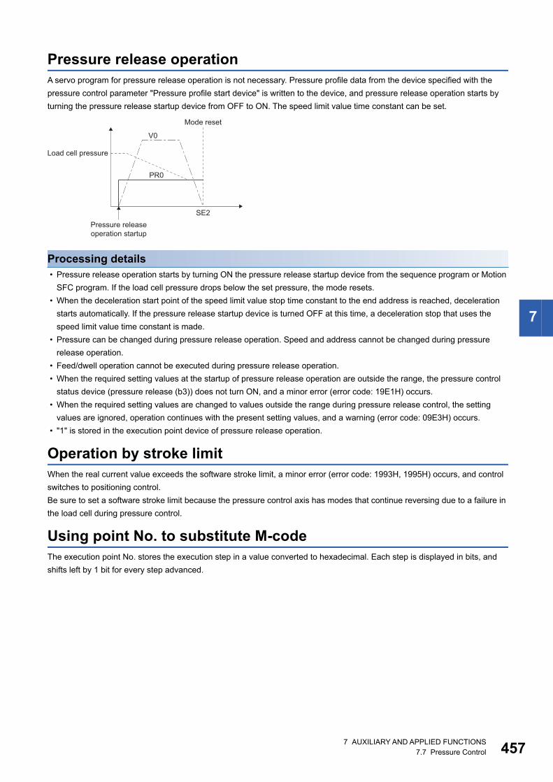
7
Pressure release operationA servo program for pressure release operation is not necessary. Pressure profile data from the device specified with the
pressure control parameter "Pressure profile start device" is written to the device, and pressure release operation starts by
turning the pressure release startup device from OFF to ON. The speed limit value time constant can be set.
Processing details • Pressure release operation starts by turning ON the pressure release startup device from the sequence program or Motion
SFC program. If the load cell pressure drops below the set pressure, the mode resets.
• When the deceleration start point of the speed limit value stop time constant to the end address is reached, deceleration
starts automatically. If the pressure release startup device is turned OFF at this time, a deceleration stop that uses the
speed limit value time constant is made.
• Pressure can be changed during pressure release operation. Speed and address cannot be changed during pressure
release operation.
• Feed/dwell operation cannot be executed during pressure release operation.
• When the required setting values at the startup of pressure release operation are outside the range, the pressure control
status device (pressure release (b3)) does not turn ON, and a minor error (error code: 19E1H) occurs.
• When the required setting values are changed to values outside the range during pressure release control, the setting
values are ignored, operation continues with the present setting values, and a warning (error code: 09E3H) occurs.
• "1" is stored in the execution point device of pressure release operation.
Operation by stroke limitWhen the real current value exceeds the software stroke limit, a minor error (error code: 1993H, 1995H) occurs, and control
switches to positioning control.
Be sure to set a software stroke limit because the pressure control axis has modes that continue reversing due to a failure in
the load cell during pressure control.
Using point No. to substitute M-codeThe execution point No. stores the execution step in a value converted to hexadecimal. Each step is displayed in bits, and
shifts left by 1 bit for every step advanced.
SE2
Load cell pressure
PR0
V0
Pressure releaseoperation startup
Mode reset
7 AUXILIARY AND APPLIED FUNCTIONS7.7 Pressure Control 457
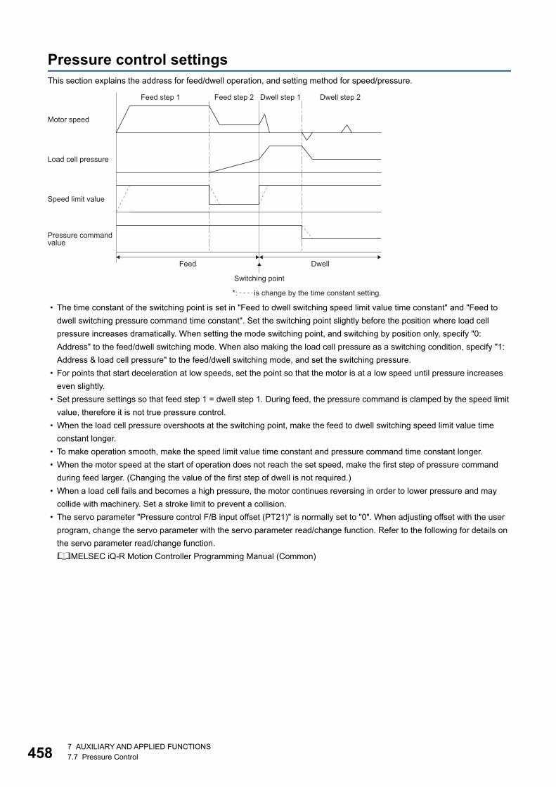
45
Pressure control settingsThis section explains the address for feed/dwell operation, and setting method for speed/pressure.
• The time constant of the switching point is set in "Feed to dwell switching speed limit value time constant" and "Feed to
dwell switching pressure command time constant". Set the switching point slightly before the position where load cell
pressure increases dramatically. When setting the mode switching point, and switching by position only, specify "0:
Address" to the feed/dwell switching mode. When also making the load cell pressure as a switching condition, specify "1:
Address & load cell pressure" to the feed/dwell switching mode, and set the switching pressure.
• For points that start deceleration at low speeds, set the point so that the motor is at a low speed until pressure increases
even slightly.
• Set pressure settings so that feed step 1 = dwell step 1. During feed, the pressure command is clamped by the speed limit
value, therefore it is not true pressure control.
• When the load cell pressure overshoots at the switching point, make the feed to dwell switching speed limit value time
constant longer.
• To make operation smooth, make the speed limit value time constant and pressure command time constant longer.
• When the motor speed at the start of operation does not reach the set speed, make the first step of pressure command
during feed larger. (Changing the value of the first step of dwell is not required.)
• When a load cell fails and becomes a high pressure, the motor continues reversing in order to lower pressure and may
collide with machinery. Set a stroke limit to prevent a collision.
• The servo parameter "Pressure control F/B input offset (PT21)" is normally set to "0". When adjusting offset with the user
program, change the servo parameter with the servo parameter read/change function. Refer to the following for details on
the servo parameter read/change function.
MELSEC iQ-R Motion Controller Programming Manual (Common)
Motor speed
Load cell pressure
Speed limit value
*: is change by the time constant setting.
Feed step 1 Dwell step 1 Dwell step 2Feed step 2
Pressure commandvalue
Feed
Switching point
Dwell
87 AUXILIARY AND APPLIED FUNCTIONS7.7 Pressure Control
7
Mode reset after passing dwell timeWhen "1: Reset mode after passing dwell time" is set in mode reset selection after passing dwell time, the system (Motion
CPU) automatically resets mode after passing the set time of the dwell final step. (Operation is returned to positioning control
from pressure control.)
Without turning the feed/dwell startup device OFF, control automatically returns to positioning control when the set dwell time
passes.
When "0: Do not reset mode after passing dwell time" is set, "[St.1040] Start accept flag (R: M30080+n/Q: M2001+n)" stays
turned ON even after passing the set time of the dwell final step.
Regardless of the setting for the mode reset selection after passing dwell time, if the real current value reaches the final
address, "[St.1040] Start accept flag (R: M30080+n/Q: M2001+n)" turns OFF, and the mode resets. (Returns to positioning
control from pressure control)
PrecautionsThe feed/dwell startup device is not turned OFF automatically.
Check if the control mode has been changed to position control mode by viewing the status of pressure control status devices
(feed/dwell (B0), dwell (B1)).
When starting pressure control again, turn OFF the feed/dwell startup device, and turn it back ON again to execute pressure
control.
Stop causes during pressure control modeThe following describes the operations for stop causes during pressure control mode.
Item Operation during torque control mode
The "[Rq.1140] Stop command (R: M34480+32n/Q: M3200+20n)"
turned ON
The speed limit command value commanded to servo amplifier is 0 regardless of the
setting value of "speed limit value". The mode is switched to position control mode when
"ZERO speed (b3)" of "[Md.1022] Servo status2 (R: D32033+48n/Q: #8011+20n)" turns
ON, and the operation stops immediately. (Deceleration processing is not executed.)The "[Rq.1141] Rapid stop command (R: M34481+32n/Q:
M3201+20n)" turned ON
The external stop input turned ON
The "[Rq.1123] All axis servo ON command (R: M30042/Q:
M2042)" turned OFF
The servo OFF is not executed during pressure control mode. The command status at
that time becomes valid when the mode is switched to position control mode.
The "[Rq.1155] servo OFF command (R: M34495+32n/Q:
M3215+20n)" turned ON
The software stroke limit is reached The minor error (error code: 1900H, 1905H, 1907H, 1993H, 1995H) will occur. The mode
is switched to position control mode at current position, and the operation immediately
stops. (Deceleration processing is not executed.)The hardware stroke limit is reached
The "[Rq.1120] PLC ready flag (R: M30000/Q: M2000)" turned
OFF.
The forced stop input to Motion CPU. The mode is switched to position control mode when the servo OFF (The "[St.1075] Servo
ready (R: M32415+32n/Q: M2415+20n)" turns OFF) is executed.
(While the servo amplifier is servo OFF, even if the mode is switched to position control
mode, the servo motor occurs to the free run. (The operation stops with dynamic brake.))
The forced stop input to servo amplifier.
The servo error occurred.
The servo amplifier's control circuit power supply turned OFF. The motor occurs to the free run. (The operation stops with dynamic brake.) (The mode is
to position control mode at the servo amplifier's power supply ON again.)
7 AUXILIARY AND APPLIED FUNCTIONS7.7 Pressure Control 459
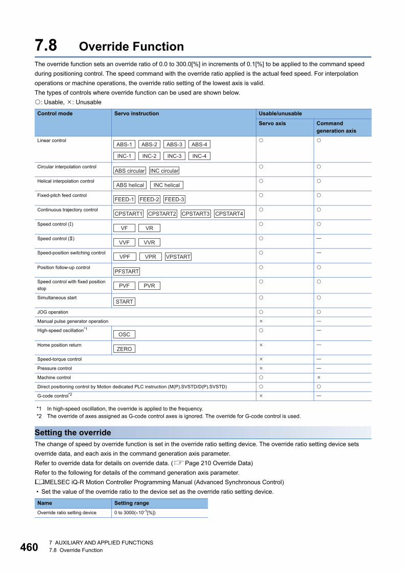
46
7.8 Override FunctionThe override function sets an override ratio of 0.0 to 300.0[%] in increments of 0.1[%] to be applied to the command speed
during positioning control. The speed command with the override ratio applied is the actual feed speed. For interpolation
operations or machine operations, the override ratio setting of the lowest axis is valid.
The types of controls where override function can be used are shown below.
: Usable, : Unusable
*1 In high-speed oscillation, the override is applied to the frequency.*2 The override of axes assigned as G-code control axes is ignored. The override for G-code control is used.
Setting the overrideThe change of speed by override function is set in the override ratio setting device. The override ratio setting device sets
override data, and each axis in the command generation axis parameter.
Refer to override data for details on override data. (Page 210 Override Data)
Refer to the following for details of the command generation axis parameter.
MELSEC iQ-R Motion Controller Programming Manual (Advanced Synchronous Control)
• Set the value of the override ratio to the device set as the override ratio setting device.
Control mode Servo instruction Usable/unusable
Servo axis Command generation axis
Linear control
Circular interpolation control
Helical interpolation control
Fixed-pitch feed control
Continuous trajectory control
Speed control ()
Speed control ()
Speed-position switching control
Position follow-up control
Speed control with fixed position
stop
Simultaneous start
JOG operation
Manual pulse generator operation
High-speed oscillation*1
Home position return
Speed-torque control
Pressure control
Machine control
Direct positioning control by Motion dedicated PLC instruction (M(P).SVSTD/D(P).SVSTD)
G-code control*2
Name Setting range
Override ratio setting device 0 to 3000(10-1[%])
ABS-1 ABS-2 ABS-3 ABS-4
INC-1 INC-2 INC-3 INC-4
ABS circular INC circular
ABS helical INC helical
FEED-1 FEED-2 FEED-3
CPSTART1 CPSTART2 CPSTART3 CPSTART4
VF VR
VVF VVR
VPF VPR VPSTART
PFSTART
PVF PVR
START
OSC
ZERO
07 AUXILIARY AND APPLIED FUNCTIONS7.8 Override Function
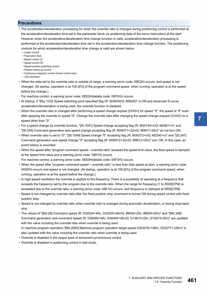
7
Precautions • The acceleration/deceleration processing for when the override ratio is changed during positioning control is performed at
the acceleration/deceleration time set in the parameter block (or positioning data of the servo instruction) at the start.
However when the acceleration/deceleration time change function is valid, acceleration/deceleration processing is
performed at the acceleration/deceleration time set in the acceleration/deceleration time change function. The positioning
controls for which acceleration/deceleration time change is valid are shown below.
• When the data set to the override ratio is outside of range, a warning (error code: 09E2H) occurs, and speed is not
changed. (At startup, operation is at 100.0[%] of the program command speed, when running, operation is at the speed
before the change.)
For machine control, a warning (error code: 0EE0H(details code: 00F2H)) occurs.
• At startup, if "[Rq.1122] Speed switching point specified flag (R: M30040/Q: M2040)" is ON and advanced S-curve
acceleration/deceleration is being used, the override function is disabled.
• When the override ratio is changed after performing a speed change request (CHGV) for speed "0", the speed is "0" even
after applying the override to speed "0". Change the override ratio after changing the speed change request (CHGV) to a
speed other than "0".
• For a speed change by override function, "[St.1047] Speed change accepting flag (R: M30144+n/Q: M2061+n)" and
"[St.346] Command generation axis speed change accepting flag (R: M36571+32n/Q: M9811+20n)" do not turn ON.
• When override ratio is set to "0", "[St.1049] Speed change "0" accepting flag (R: M30272+n/Q: M2240+n)" and "[St.347]
Command generation axis speed change "0" accepting flag (R: M36572+32n/Q: M9812+20n)" turn ON. In this case, an
event history is recorded.
• When the speed after "program command speed override ratio" exceeds the speed limit value, the feed speed is clamped
at the speed limit value and a warning (error code: 0991H) occurs.
For machine control, a warning (error code: 0EE0H(details code: 00F3H)) occurs.
• When the speed after "program command speed override ratio" is less than bias speed at start, a warning (error code:
0A5DH) occurs and speed is not changed. (At startup, operation is at 100.0[%] of the program command speed, when
running, operation is at the speed before the change.)
• In high-speed oscillation the override is applied to the frequency. There is a possibility of operating at a frequency that
exceeds the frequency set by the program due to the override ratio. When the range for frequency (1 to 5000[CPM) is
exceeded due to the override ratio, a warning (error code: 09E1H) occurs, and frequency is clamped at 5000[CPM].
• Speed is not changed by override ratio after the fixed position stop command is turned ON during speed control with fixed
position stop.
• Speed is not changed by override ratio when override ratio is changed during automatic deceleration, or during stop/rapid
stop.
• The values of "[Md.28] Command speed (R: D32024+48n, D32025+48n/Q: #8004+20n, #8005+20n)" and "[Md.348]
Command generation axis command speed (R: D36492+48n, D36493+48n/Q: D12612+20n, D12613+20n)" are updated
with the value including the override ratio when override is being used.
In machine program operation,"[Md.2083] Machine program operation target speed (D53276+128m, D53277+128m)" is
also updated with the value including the override ratio when override is being used.
• Override is disabled in the output axes of advanced synchronous control.
• Override is disabled in positioning control in test mode.
• Linear control
• Fixed-pitch feed
• Speed control ()
• Speed control ()
• Speed-position switching control
• Position follow-up control
• Continuous trajectory control (linear control only)
• JOG operation
7 AUXILIARY AND APPLIED FUNCTIONS7.8 Override Function 461
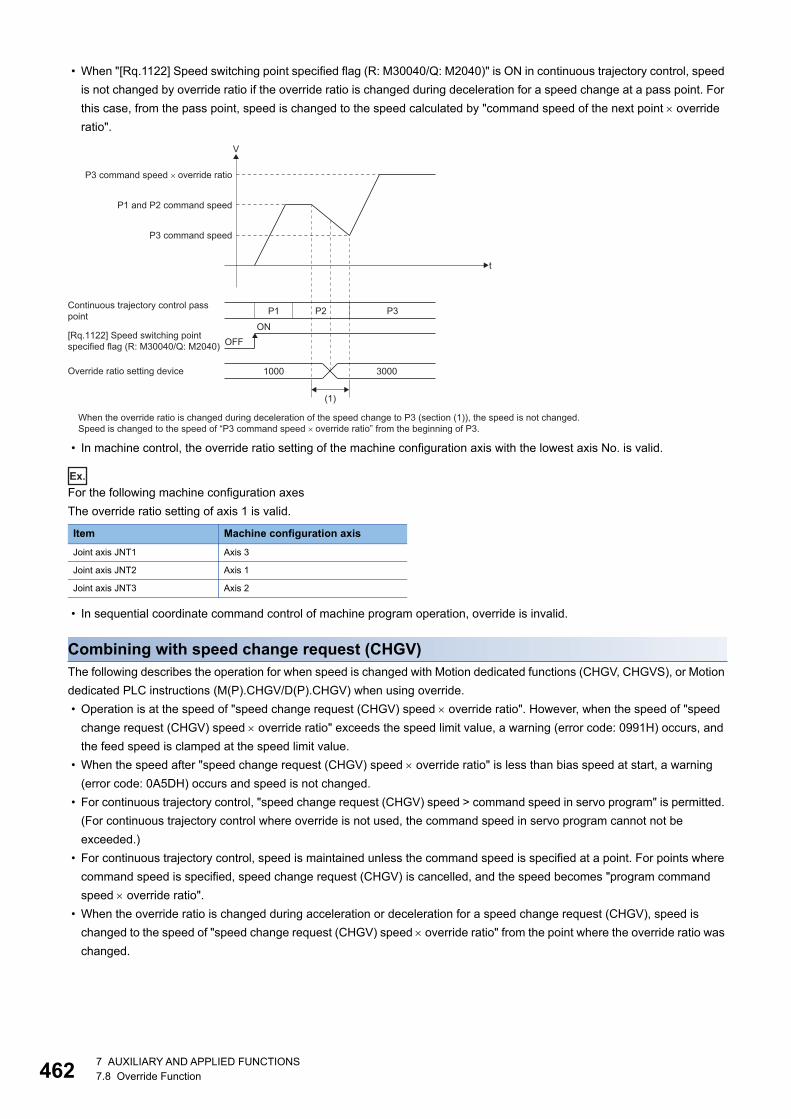
46
• When "[Rq.1122] Speed switching point specified flag (R: M30040/Q: M2040)" is ON in continuous trajectory control, speed
is not changed by override ratio if the override ratio is changed during deceleration for a speed change at a pass point. For
this case, from the pass point, speed is changed to the speed calculated by "command speed of the next point override
ratio".
• In machine control, the override ratio setting of the machine configuration axis with the lowest axis No. is valid.
Ex.
For the following machine configuration axes
The override ratio setting of axis 1 is valid.
• In sequential coordinate command control of machine program operation, override is invalid.
Combining with speed change request (CHGV)The following describes the operation for when speed is changed with Motion dedicated functions (CHGV, CHGVS), or Motion
dedicated PLC instructions (M(P).CHGV/D(P).CHGV) when using override.
• Operation is at the speed of "speed change request (CHGV) speed override ratio". However, when the speed of "speed
change request (CHGV) speed override ratio" exceeds the speed limit value, a warning (error code: 0991H) occurs, and
the feed speed is clamped at the speed limit value.
• When the speed after "speed change request (CHGV) speed override ratio" is less than bias speed at start, a warning
(error code: 0A5DH) occurs and speed is not changed.
• For continuous trajectory control, "speed change request (CHGV) speed > command speed in servo program" is permitted.
(For continuous trajectory control where override is not used, the command speed in servo program cannot not be
exceeded.)
• For continuous trajectory control, speed is maintained unless the command speed is specified at a point. For points where
command speed is specified, speed change request (CHGV) is cancelled, and the speed becomes "program command
speed override ratio".
• When the override ratio is changed during acceleration or deceleration for a speed change request (CHGV), speed is
changed to the speed of "speed change request (CHGV) speed override ratio" from the point where the override ratio was
changed.
Item Machine configuration axis
Joint axis JNT1 Axis 3
Joint axis JNT2 Axis 1
Joint axis JNT3 Axis 2
When the override ratio is changed during deceleration of the speed change to P3 (section (1)), the speed is not changed.Speed is changed to the speed of “P3 command speed �override ratio” from the beginning of P3.
t
P3 command speed
P1 and P2 command speed
P3 command speed �override ratio
V
OFFON
[Rq.1122] Speed switching pointspecified flag (R: M30040/Q: M2040)
Continuous trajectory control passpoint
(1)
1000Override ratio setting device 3000
P1 P2 P3
27 AUXILIARY AND APPLIED FUNCTIONS7.8 Override Function
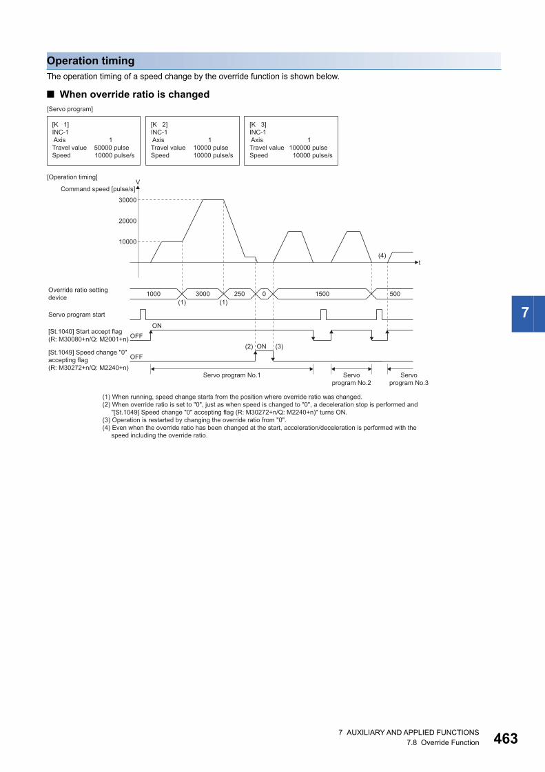
7
Operation timingThe operation timing of a speed change by the override function is shown below.
■ When override ratio is changed
(1) (1)
(2) (3)
(4)
1000Override ratio settingdevice
Servo program start
t
10000
20000
30000
Command speed [pulse/s]V
OFFON
[St.1040] Start accept flag(R: M30080+n/Q: M2001+n)
[K 1]INC-1 AxisTravel value Speed
[Servo program]
[Operation timing]
150000 pulse10000 pulse/s
[K 2]INC-1 AxisTravel value Speed
110000 pulse10000 pulse/s
[K 3]INC-1 AxisTravel value Speed
1100000 pulse 10000 pulse/s
OFFON
[St.1049] Speed change "0"accepting flag(R: M30272+n/Q: M2240+n)
Servoprogram No.2
Servoprogram No.3
Servo program No.1
3000 250 0 1500 500
(1) When running, speed change starts from the position where override ratio was changed.(2) When override ratio is set to "0", just as when speed is changed to "0", a deceleration stop is performed and "[St.1049] Speed change "0" accepting flag (R: M30272+n/Q: M2240+n)" turns ON.(3) Operation is restarted by changing the override ratio from "0".(4) Even when the override ratio has been changed at the start, acceleration/deceleration is performed with the speed including the override ratio.
7 AUXILIARY AND APPLIED FUNCTIONS7.8 Override Function 463
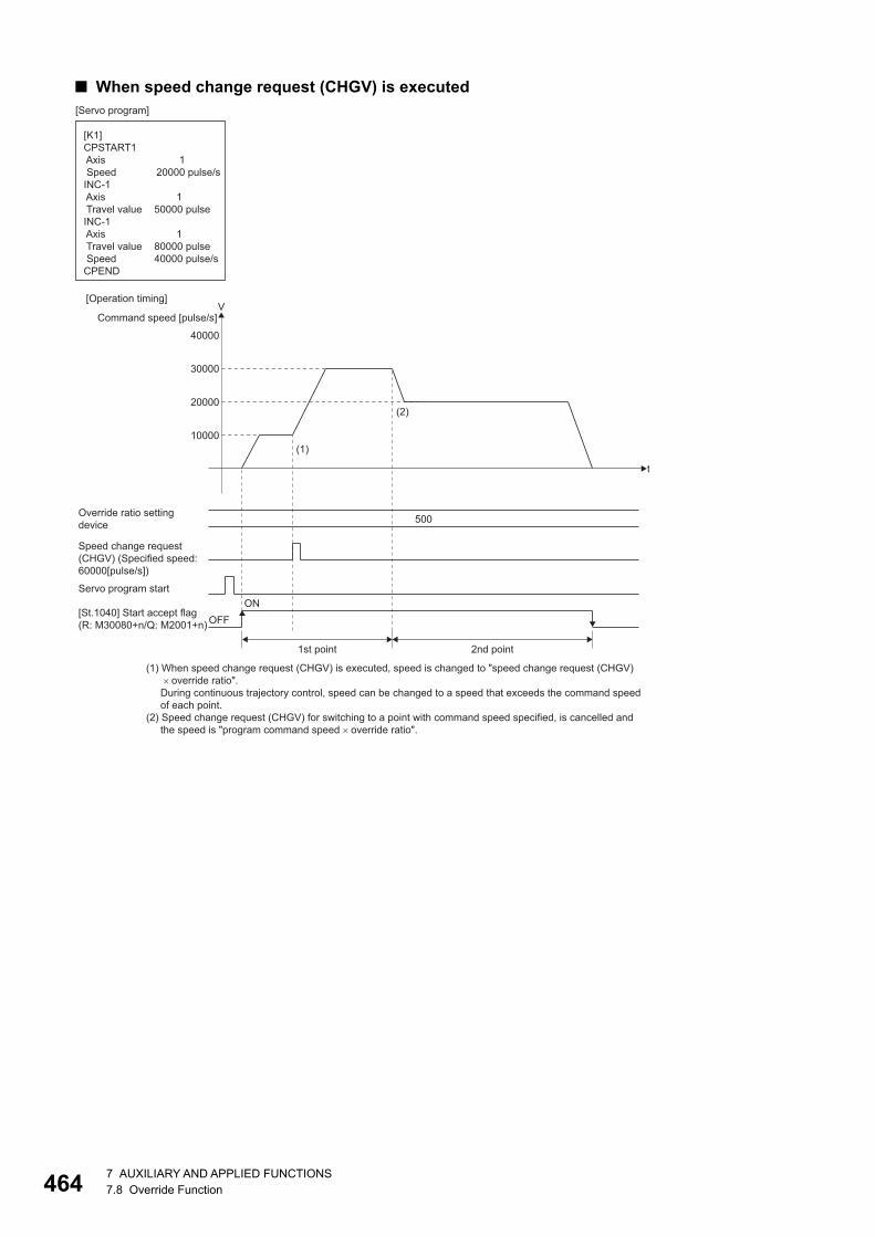
46
■ When speed change request (CHGV) is executed
(1)
(2)
Override ratio settingdevice
Speed change request(CHGV) (Specified speed:60000[pulse/s])
Servo program start
t
10000
20000
30000
40000
Command speed [pulse/s]V
[St.1040] Start accept flag(R: M30080+n/Q: M2001+n) OFF
ON
[K1]CPSTART1 Axis SpeedINC-1 Axis Travel valueINC-1 Axis Travel value SpeedCPEND
1 20000 pulse/s 1 50000 pulse 1 80000 pulse 40000 pulse/s
[Servo program]
[Operation timing]
1st point 2nd point
500
(1) When speed change request (CHGV) is executed, speed is changed to "speed change request (CHGV) �override ratio". During continuous trajectory control, speed can be changed to a speed that exceeds the command speed of each point.(2) Speed change request (CHGV) for switching to a point with command speed specified, is cancelled and the speed is "program command speed �override ratio".
47 AUXILIARY AND APPLIED FUNCTIONS7.8 Override Function
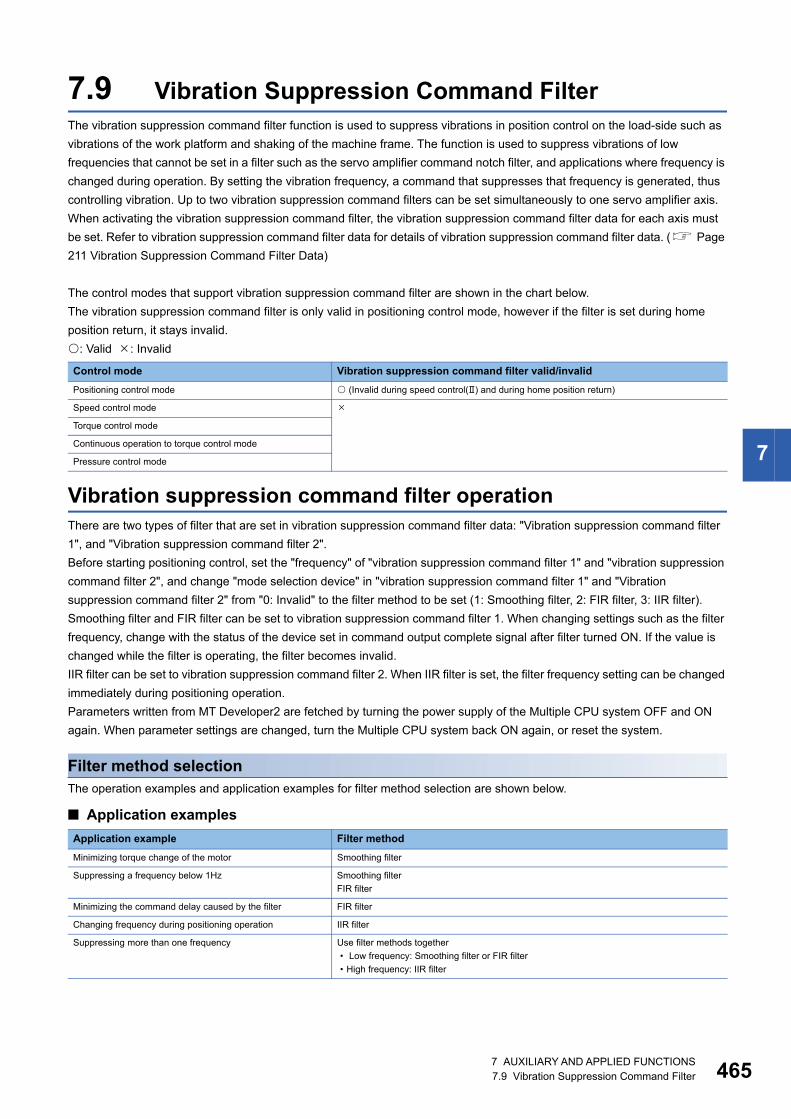
7
7.9 Vibration Suppression Command FilterThe vibration suppression command filter function is used to suppress vibrations in position control on the load-side such as
vibrations of the work platform and shaking of the machine frame. The function is used to suppress vibrations of low
frequencies that cannot be set in a filter such as the servo amplifier command notch filter, and applications where frequency is
changed during operation. By setting the vibration frequency, a command that suppresses that frequency is generated, thus
controlling vibration. Up to two vibration suppression command filters can be set simultaneously to one servo amplifier axis.
When activating the vibration suppression command filter, the vibration suppression command filter data for each axis must
be set. Refer to vibration suppression command filter data for details of vibration suppression command filter data. ( Page
211 Vibration Suppression Command Filter Data)
The control modes that support vibration suppression command filter are shown in the chart below.
The vibration suppression command filter is only valid in positioning control mode, however if the filter is set during home
position return, it stays invalid.
: Valid : Invalid
Vibration suppression command filter operationThere are two types of filter that are set in vibration suppression command filter data: "Vibration suppression command filter
1", and "Vibration suppression command filter 2".
Before starting positioning control, set the "frequency" of "vibration suppression command filter 1" and "vibration suppression
command filter 2", and change "mode selection device" in "vibration suppression command filter 1" and "Vibration
suppression command filter 2" from "0: Invalid" to the filter method to be set (1: Smoothing filter, 2: FIR filter, 3: IIR filter).
Smoothing filter and FIR filter can be set to vibration suppression command filter 1. When changing settings such as the filter
frequency, change with the status of the device set in command output complete signal after filter turned ON. If the value is
changed while the filter is operating, the filter becomes invalid.
IIR filter can be set to vibration suppression command filter 2. When IIR filter is set, the filter frequency setting can be changed
immediately during positioning operation.
Parameters written from MT Developer2 are fetched by turning the power supply of the Multiple CPU system OFF and ON
again. When parameter settings are changed, turn the Multiple CPU system back ON again, or reset the system.
Filter method selectionThe operation examples and application examples for filter method selection are shown below.
■ Application examples
Control mode Vibration suppression command filter valid/invalid
Positioning control mode (Invalid during speed control() and during home position return)
Speed control mode
Torque control mode
Continuous operation to torque control mode
Pressure control mode
Application example Filter method
Minimizing torque change of the motor Smoothing filter
Suppressing a frequency below 1Hz Smoothing filter
FIR filter
Minimizing the command delay caused by the filter FIR filter
Changing frequency during positioning operation IIR filter
Suppressing more than one frequency Use filter methods together
• Low frequency: Smoothing filter or FIR filter
• High frequency: IIR filter
7 AUXILIARY AND APPLIED FUNCTIONS7.9 Vibration Suppression Command Filter 465
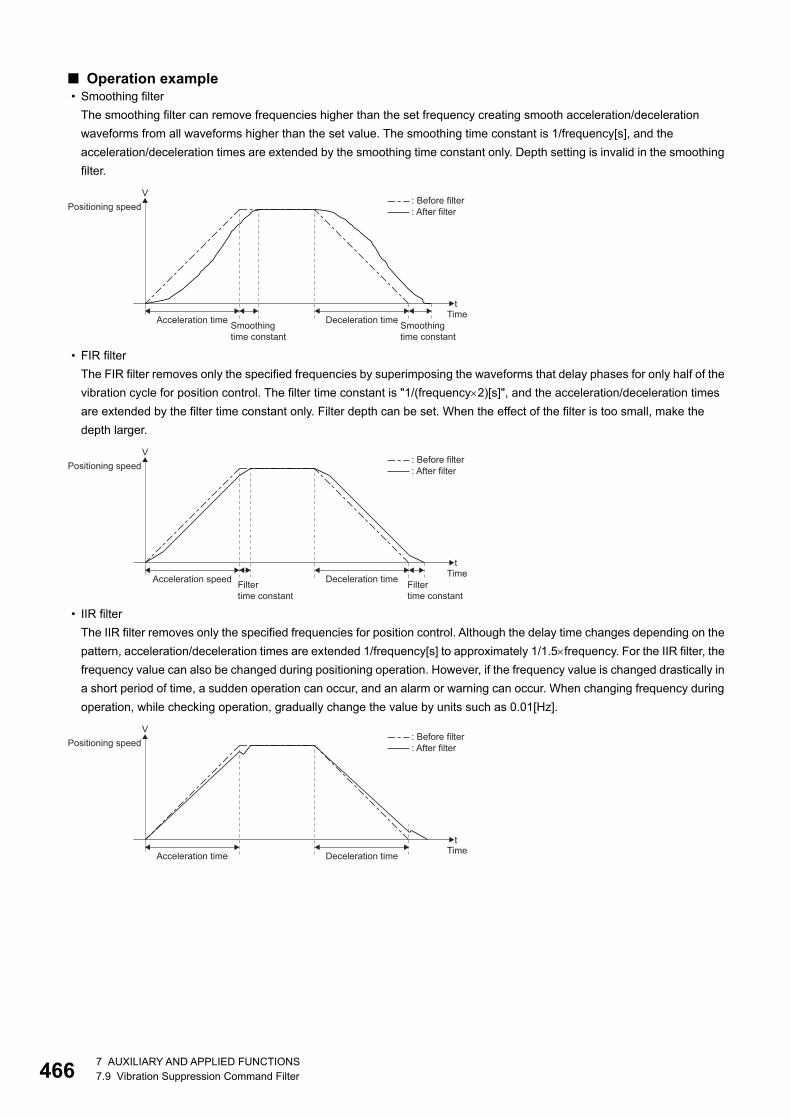
46
■ Operation example • Smoothing filter
The smoothing filter can remove frequencies higher than the set frequency creating smooth acceleration/deceleration
waveforms from all waveforms higher than the set value. The smoothing time constant is 1/frequency[s], and the
acceleration/deceleration times are extended by the smoothing time constant only. Depth setting is invalid in the smoothing
filter.
• FIR filter
The FIR filter removes only the specified frequencies by superimposing the waveforms that delay phases for only half of the
vibration cycle for position control. The filter time constant is "1/(frequency2)[s]", and the acceleration/deceleration times
are extended by the filter time constant only. Filter depth can be set. When the effect of the filter is too small, make the
depth larger.
• IIR filter
The IIR filter removes only the specified frequencies for position control. Although the delay time changes depending on the
pattern, acceleration/deceleration times are extended 1/frequency[s] to approximately 1/1.5frequency. For the IIR filter, the
frequency value can also be changed during positioning operation. However, if the frequency value is changed drastically in
a short period of time, a sudden operation can occur, and an alarm or warning can occur. When changing frequency during
operation, while checking operation, gradually change the value by units such as 0.01[Hz].
t
V
Acceleration time
Positioning speed
TimeSmoothingtime constant
Smoothingtime constant
Deceleration time
: Before filter: After filter
t
V
Acceleration speed
Positioning speed
TimeFiltertime constant
Filtertime constant
Deceleration time
: Before filter: After filter
t
V
Acceleration time
Positioning speed
TimeDeceleration time
: Before filter: After filter
67 AUXILIARY AND APPLIED FUNCTIONS7.9 Vibration Suppression Command Filter
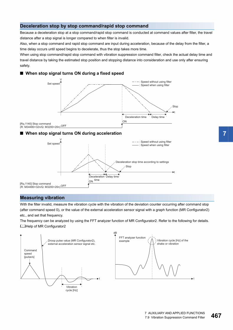
7
Deceleration stop by stop command/rapid stop commandBecause a deceleration stop at a stop command/rapid stop command is conducted at command values after filter, the travel
distance after a stop signal is longer compared to when filter is invalid.
Also, when a stop command and rapid stop command are input during acceleration, because of the delay from the filter, a
time delay occurs until speed begins to decelerate, thus the stop takes more time.
When using stop command/rapid stop command with vibration suppression command filter, check the actual delay time and
travel distance by taking the estimated stop position and stopping distance into consideration and use only after ensuring
safety.
■ When stop signal turns ON during a fixed speed
■ When stop signal turns ON during acceleration
Measuring vibrationWith the filter invalid, measure the vibration cycle with the vibration of the deviation counter occurring after command stop
(after command speed 0), or the value of the external acceleration sensor signal with a graph function (MR Configurator2)
etc., and set that frequency.
The frequency can be analyzed by using the FFT analyzer function of MR Configurator2. Refer to the following for details.
Help of MR Configurator2
t
VSet speed
Deceleration time Delay time
: Speed without using filter: Speed when using filter
[Rq.1140] Stop command(R: M34480+32n/Q: M3200+20n)
ONOFF
Stop
t
VSet speed
Decelerationtime
Delay time
: Speed without using filter: Speed when using filter
StopDeceleration stop time according to settings
[Rq.1140] Stop command(R: M34480+32n/Q: M3200+20n)
ONOFF
Vibration cycle [Hz] of theshake or vibration
FFT analyzer functionexampleDroop pulse value (MR Configurator2),
external acceleration sensor signal etc.
Vibrationcycle [Hz]
t t
dB
Commandspeed[pulse/s]
7 AUXILIARY AND APPLIED FUNCTIONS7.9 Vibration Suppression Command Filter 467
46
Monitor values when using vibration suppression command filterAlthough the positioning complete signal is turned ON after positioning control, because of the delay caused by the filter, the
actual positioning operation may not be complete. To check the completion of command outputs to the positioning address,
check the command output complete signal after the filter.
Each monitor value is as follows when filter is set.
Precautions when using vibration suppression command filter • The filter is performed when processing send commands to the servo amplifier and the results are reflected in "[Md.28]
Command speed (R: D32024+48n, D32025+48n/Q: #8004+20n, #8005+20n)", "feed current value monitor device after
filter", and "servo command value" in the optional data monitor, but values before filter are reflected in "[Md.20] Feed
current value (R: D32000+48n, D32001+48n/Q: D0+20n, D1+20n)", "[St.1063] Command in-position (R: M32403+32n/Q:
M2403+20n)", "[St.1040] Start accept flag (R: M30080+n/Q: M2001+n)", "[St.1061] Positioning complete (R: M32401+32n/
Q: M2401+20n)" etc. When checking the actual completion of positioning operation, use "[St.1062] In-position (R:
M32402+32n/Q: M2402+20n)" and "command output complete signal after filter" together.
• When using vibration suppression command filter 1, FIN acceleration/deceleration cannot be used. With mode selection
device set , and FIN acceleration/deceleration set in continuous trajectory control, a warning (error code: 0A39H) occurs
and FIN acceleration/deceleration is disabled. When using FIN acceleration/deceleration, do not set the mode selection
device of vibration suppression command filter 1.
• "[Md.20] Feed current value (R: D32000+48n, D32001+48n/Q: D0+20n, D1+20n)" is updated with the value before filter,
and "[St.1040] Start accept flag (R: M30080+n/Q: M2001+n)", "[St.1061] Positioning complete (R: M32401+32n/Q:
M2401+20n)", and "[St.1063] Command in-position (R: M32403+32n/Q: M2403+20n)" operate based on "[Md.20] Feed
current value (R: D32000+48n, D32001+48n/Q: D0+20n, D1+20n)". Check the positioning command being sent to the
servo amplifier with "feed current value monitor device after filter", or "servo command value" in the optional data monitor.
"[St.1040] Start accept flag (R: M30080+n/Q: M2001+n)" turns OFF with the value before filter, however at this stage the
command being sent to the servo amplifier may not have reached the target position. To confirm if the command has
reached the target position, check that the "command output complete signal after filter" is turned ON.
Monitor value for before filter Monitor value for after filter
• [St.1040] Start accept flag (R: M30080+n/Q: M20001+n)
• [St.1061] Positioning complete (R: M32401+32n/Q: M2401+20n)
• [St.1063] Command in-position (R: M32403+32n/Q: M2403+20n)
• [Md.20] Feed current value (R: D32000+48n, D32001+48n/Q: D0+20n,
D1+20n)
• [Pr.300] Servo input axis type (feed current value, servo command value)
• [St.1048] Automatic decelerating flag (R: M30208+n/Q: M2128+n)
• Feed current value monitor device after filter
• Command output complete signal after filter
• [Md.101] Real current value (R: D32002+48n, D32003+48n/Q: D2+20n,
D3+20n)
• [Md.102] Deviation counter value (R: D32004+48n, D32005+48n/Q:
D4+20n, D5+20n)
• [Md.28] Command speed (R: D32024+48n, D32025+48n/Q: #8004+20n,
#8005+20n)
• [Pr.300] Servo input axis type (real current value, feedback value)
• Optional data monitor (registered monitor: Servo command value)
• Mark detection data (servo command value)
• Limit output data (Watch data: Servo command value)
87 AUXILIARY AND APPLIED FUNCTIONS7.9 Vibration Suppression Command Filter
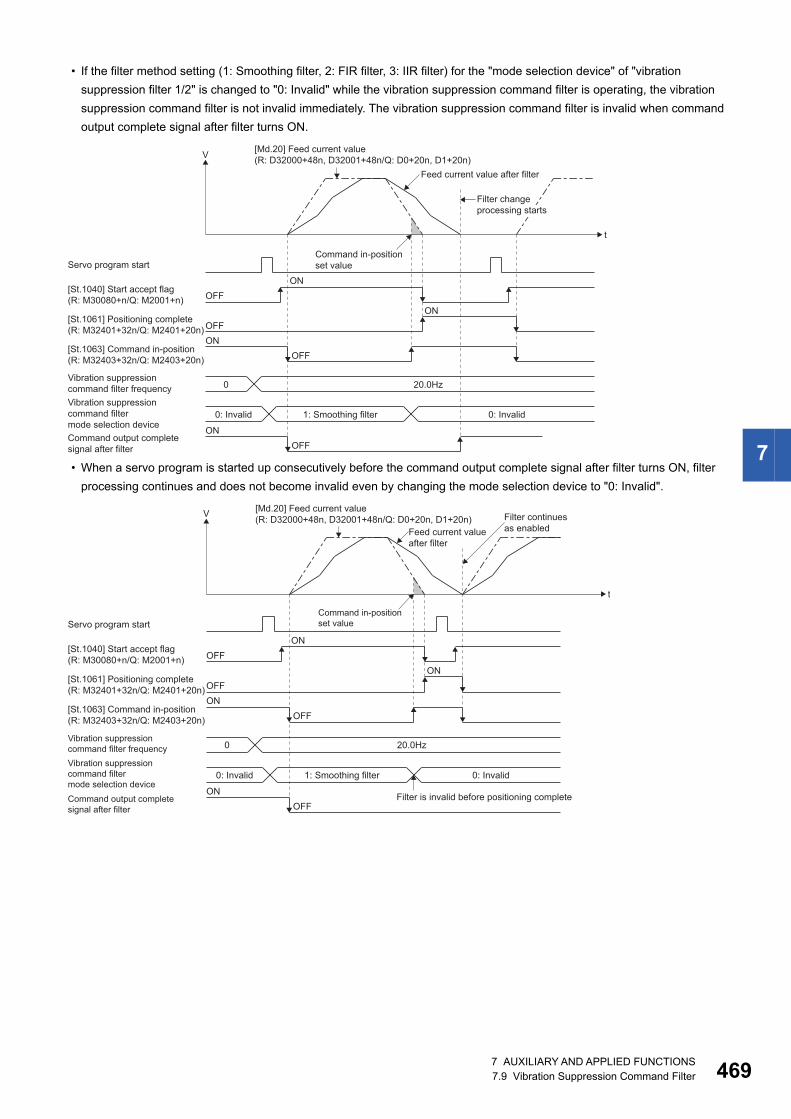
7
• If the filter method setting (1: Smoothing filter, 2: FIR filter, 3: IIR filter) for the "mode selection device" of "vibration
suppression filter 1/2" is changed to "0: Invalid" while the vibration suppression command filter is operating, the vibration
suppression command filter is not invalid immediately. The vibration suppression command filter is invalid when command
output complete signal after filter turns ON.
• When a servo program is started up consecutively before the command output complete signal after filter turns ON, filter
processing continues and does not become invalid even by changing the mode selection device to "0: Invalid".
t
V
Servo program start
Feed current value after filter
0: Invalid 1: Smoothing filter 0: Invalid
OFFON
OFFON
[St.1040] Start accept flag(R: M30080+n/Q: M2001+n)
[St.1061] Positioning complete(R: M32401+32n/Q: M2401+20n)
OFFON
OFFON
[St.1063] Command in-position(R: M32403+32n/Q: M2403+20n)
Command output completesignal after filter
0 20.0HzVibration suppressioncommand filter frequencyVibration suppressioncommand filtermode selection device
Command in-positionset value
Filter changeprocessing starts
[Md.20] Feed current value(R: D32000+48n, D32001+48n/Q: D0+20n, D1+20n)
t
V
Servo program start
[Md.20] Feed current value(R: D32000+48n, D32001+48n/Q: D0+20n, D1+20n)
Feed current valueafter filter
0: Invalid 1: Smoothing filter 0: Invalid
OFFON
OFFON
[St.1040] Start accept flag(R: M30080+n/Q: M2001+n)
[St.1061] Positioning complete(R: M32401+32n/Q: M2401+20n)
OFFON
OFFON
[St.1063] Command in-position(R: M32403+32n/Q: M2403+20n)
Command output completesignal after filter
0 20.0HzVibration suppressioncommand filter frequencyVibration suppressioncommand filtermode selection device
Filter is invalid before positioning complete
Command in-positionset value
Filter continuesas enabled
7 AUXILIARY AND APPLIED FUNCTIONS7.9 Vibration Suppression Command Filter 469
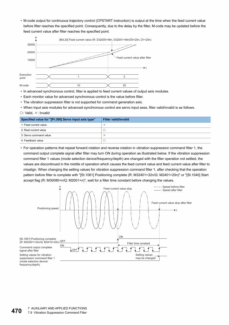
47
• M-code output for continuous trajectory control (CPSTART instruction) is output at the time when the feed current value
before filter reaches the specified point. Consequently, due to the delay by the filter, M-code may be updated before the
feed current value after filter reaches the specified point.
• In advanced synchronous control, filter is applied to feed current values of output axis modules.
• Each monitor value for advanced synchronous control is the value before filter.
• The vibration suppression filter is not supported for command generation axis.
• When input axis modules for advanced synchronous control are servo input axes, filter valid/invalid is as follows.
: Valid, : Invalid
• For operation patterns that repeat forward rotation and reverse rotation in vibration suppression command filter 1, the
command output complete signal after filter may turn ON during operation as illustrated below. If the vibration suppression
command filter 1 values (mode selection device/frequency/depth) are changed with the filter operation not settled, the
values are discontinued in the middle of operation which causes the feed current value and feed current value after filter to
misalign. When changing the setting values for vibration suppression command filter 1, after checking that the operation
pattern before filter is complete with "[St.1061] Positioning complete (R: M32401+32n/Q: M2401+20n)" or "[St.1040] Start
accept flag (R: M30080+n/Q: M2001+n)", wait for a filter time constant before changing the values.
Specified value for "[Pr.300] Servo input axis type" Filter valid/invalid
1: Feed current value
2: Real current value
3: Servo command value
4: Feedback value
t
P
10000
20000
30000
M-code
Executionpoint 1 2
2010
[Md.20] Feed current value (R: D32000+48n, D32001+48n/D0+20n, D1+20n)
Feed current value after filter
t
V
[St.1061] Positioning complete(R: M32401+32n/Q: M2410+20n)
Positioning speed
Command output completesignal after filter
Feed current value stop after filter
OFFONOFF
ON
Setting values for vibrationsuppression command filter 1(mode selection device/frequency/depth)
Feed current value stop
Setting valuesmay be changed
Filter time constant
: Speed before filter: Speed after filter
07 AUXILIARY AND APPLIED FUNCTIONS7.9 Vibration Suppression Command Filter
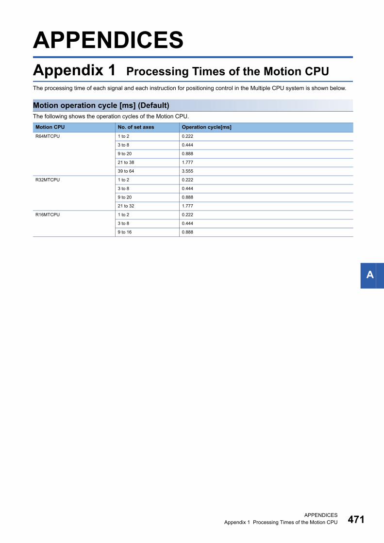
A
APPENDICESAppendix 1 Processing Times of the Motion CPUThe processing time of each signal and each instruction for positioning control in the Multiple CPU system is shown below.
Motion operation cycle [ms] (Default)The following shows the operation cycles of the Motion CPU.
Motion CPU No. of set axes Operation cycle[ms]
R64MTCPU 1 to 2 0.222
3 to 8 0.444
9 to 20 0.888
21 to 38 1.777
39 to 64 3.555
R32MTCPU 1 to 2 0.222
3 to 8 0.444
9 to 20 0.888
21 to 32 1.777
R16MTCPU 1 to 2 0.222
3 to 8 0.444
9 to 16 0.888
APPENDICESAppendix 1 Processing Times of the Motion CPU 471
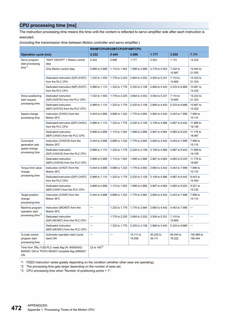
47
CPU processing time [ms]The instruction processing time means the time until the content is reflected to servo amplifier side after each instruction is
executed.
(Including the transmission time between Motion controller and servo amplifier.)
*1 FEED instruction varies greatly depending on the condition (whether other axes are operating).*2 The processing time gets larger depending on the number of axes set.*3 CPU processing time when "Number of positioning points = 1".
R64MTCPU/R32MTCPU/R16MTCPU
Operation cycle [ms] 0.222 0.444 0.888 1.777 3.555 7.111
Servo program
start processing
time*1
"WAIT ON/OFF" + Motion control
step
0.444 0.888 1.777 3.554 7.110 14.222
Only Motion control step 0.666 to 0.888 1.110 to 1.554 1.998 to 2.886 3.776 to 5.553 7.332 to
10.887
14.444 to
21.555
Dedicated instruction (D(P).SVST)
from the PLC CPU
1.332 to 1.554 1.776 to 2.220 2.664 to 3.552 3.554 to 5.331 7.110 to
10.665
14.222 to
21.333
Dedicated instruction (M(P).SVST)
from the PLC CPU
0.888 to 1.110 1.332 to 1.776 2.220 to 3.108 2.666 to 4.443 5.333 to 8.888 10.667 to
14.222
Direct positioning
start request
processing time
Dedicated instruction
(D(P).SVSTD) from the PLC CPU
1.332 to 1.554 1.776 to 2.220 2.664 to 3.552 3.554 to 5.331 7.110 to
10.665
14.222 to
21.333
Dedicated instruction
(M(P).SVSTD) from the PLC CPU
0.888 to 1.110 1.332 to 1.776 2.220 to 3.108 2.666 to 4.443 5.333 to 8.888 10.667 to
14.222
Speed change
processing time
Instruction (CHGV) from the
Motion SFC
0.444 to 0.888 0.888 to 1.332 1.776 to 2.664 2.665 to 4.442 4.443 to 7.998 7.999 to
15.110
Dedicated instruction (D(P).CHGV)
from the PLC CPU
0.888 to 1.110 1.332 to 1.776 2.220 to 3.108 3.109 to 4.886 4.887 to 8.442 11.998 to
19.109
Dedicated instruction
(M(P).CHGV) from the PLC CPU
0.666 to 0.888 1.110 to 1.554 1.998 to 2.886 2.887 to 4.664 4.665 to 8.220 11.776 to
18.887
Command
generation axis
speed change
processing time
Instruction (CHGVS) from the
Motion SFC
0.444 to 0.888 0.888 to 1.332 1.776 to 2.664 2.665 to 4.442 4.443 to 7.998 7.999 to
15.110
Dedicated instruction
(D(P).CHGVS) from the PLC CPU
0.888 to 1.110 1.332 to 1.776 2.220 to 3.108 3.109 to 4.886 4.887 to 8.442 11.998 to
19.109
Dedicated instruction
(M(P).CHGVS) from the PLC CPU
0.666 to 0.888 1.110 to 1.554 1.998 to 2.886 2.887 to 4.664 4.665 to 8.220 11.776 to
18.887
Torque limit value
change
processing time
Instruction (CHGT) from the
Motion SFC
0.444 to 0.888 0.888 to 1.332 1.776 to 2.664 2.665 to 4.442 4.443 to 7.998 7.999 to
15.110
Dedicated instruction (D(P).CHGT)
from the PLC CPU
0.888 to 1.110 1.332 to 1.776 2.220 to 3.108 3.109 to 4.886 4.887 to 8.442 8.443 to
15.554
Dedicated instruction
(M(P).CHGT) from the PLC CPU
0.666 to 0.888 1.110 to 1.554 1.998 to 2.886 2.887 to 4.664 4.665 to 8.220 8.221 to
15.332
Target position
change
processing time
Instruction (CHGP) from the
Motion SFC
0.444 to 0.888 0.888 to 1.332 1.776 to 2.664 2.665 to 4.442 4.443 to 7.998 7.999 to
15.110
Machine program
operation start
processing time*3
Instruction (MCNST) from the
Motion SFC
1.332 to 1.776 1.776 to 2.664 2.665 to 4.442 4.443 to 7.998
Dedicated instruction
(D(P).MCNST) from the PLC CPU
1.776 to 2.220 2.664 to 3.552 3.554 to 5.331 7.110 to
10.665
Dedicated instruction
(M(P).MCNST) from the PLC CPU
1.332 to 1.776 2.220 to 3.108 2.666 to 4.443 5.333 to 8.888
G-code control
program start
processing time
Automatic operation start (cycle
start) ON
15.111 to
19.556
30.222 to
39.111
60.444 to
78.222
120.889 to
156.444
Time from "[Rq.1120] PLC ready flag (R: M30000/Q:
M2000)" ON to "PCPU READY complete flag (SM500)"
ON
22 to 165*2
2APPENDICESAppendix 1 Processing Times of the Motion CPU

A
MEMO
APPENDICESAppendix 1 Processing Times of the Motion CPU 473
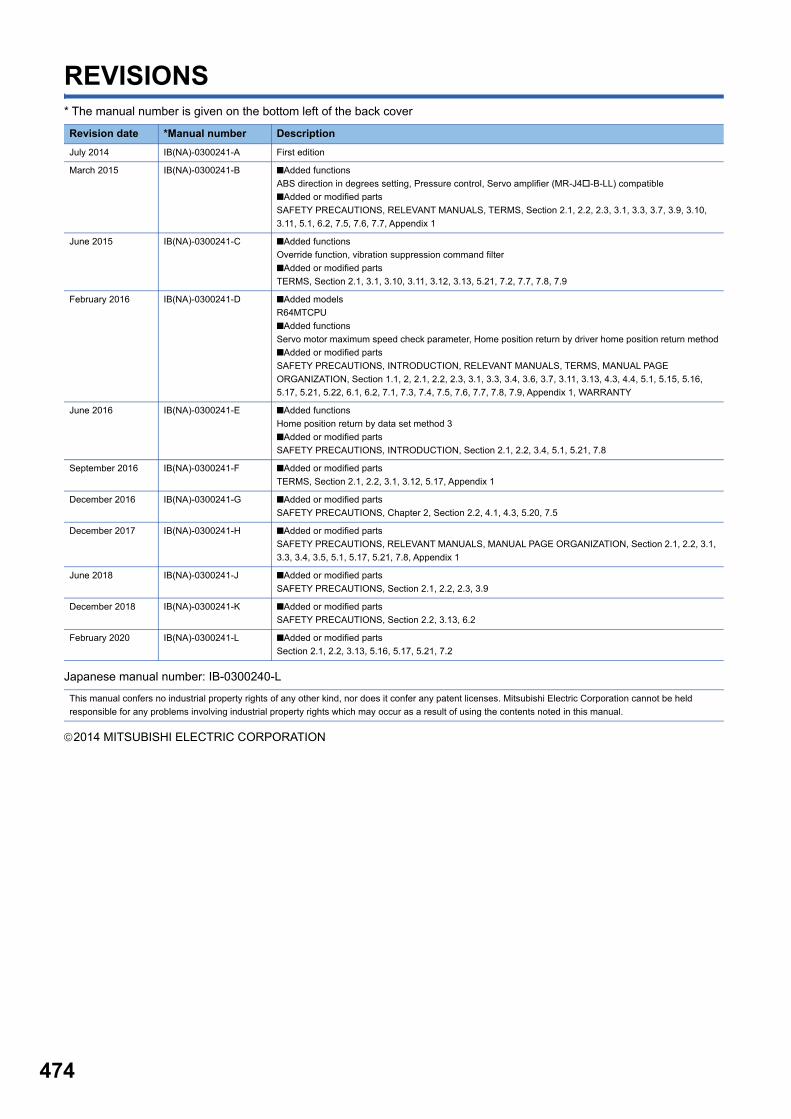
474
REVISIONS* The manual number is given on the bottom left of the back cover
Japanese manual number: IB-0300240-L
2014 MITSUBISHI ELECTRIC CORPORATION
Revision date *Manual number Description
July 2014 IB(NA)-0300241-A First edition
March 2015 IB(NA)-0300241-B ■Added functions
ABS direction in degrees setting, Pressure control, Servo amplifier (MR-J4-B-LL) compatible
■Added or modified parts
SAFETY PRECAUTIONS, RELEVANT MANUALS, TERMS, Section 2.1, 2.2, 2.3, 3.1, 3.3, 3.7, 3.9, 3.10,
3.11, 5.1, 6.2, 7.5, 7.6, 7.7, Appendix 1
June 2015 IB(NA)-0300241-C ■Added functions
Override function, vibration suppression command filter
■Added or modified parts
TERMS, Section 2.1, 3.1, 3.10, 3.11, 3.12, 3.13, 5.21, 7.2, 7.7, 7.8, 7.9
February 2016 IB(NA)-0300241-D ■Added models
R64MTCPU
■Added functions
Servo motor maximum speed check parameter, Home position return by driver home position return method
■Added or modified parts
SAFETY PRECAUTIONS, INTRODUCTION, RELEVANT MANUALS, TERMS, MANUAL PAGE
ORGANIZATION, Section 1.1, 2, 2.1, 2.2, 2.3, 3.1, 3.3, 3.4, 3.6, 3.7, 3.11, 3.13, 4.3, 4.4, 5.1, 5.15, 5.16,
5.17, 5.21, 5.22, 6.1, 6.2, 7.1, 7.3, 7.4, 7.5, 7.6, 7.7, 7.8, 7.9, Appendix 1, WARRANTY
June 2016 IB(NA)-0300241-E ■Added functions
Home position return by data set method 3
■Added or modified parts
SAFETY PRECAUTIONS, INTRODUCTION, Section 2.1, 2.2, 3.4, 5.1, 5.21, 7.8
September 2016 IB(NA)-0300241-F ■Added or modified parts
TERMS, Section 2.1, 2.2, 3.1, 3.12, 5.17, Appendix 1
December 2016 IB(NA)-0300241-G ■Added or modified parts
SAFETY PRECAUTIONS, Chapter 2, Section 2.2, 4.1, 4.3, 5.20, 7.5
December 2017 IB(NA)-0300241-H ■Added or modified parts
SAFETY PRECAUTIONS, RELEVANT MANUALS, MANUAL PAGE ORGANIZATION, Section 2.1, 2.2, 3.1,
3.3, 3.4, 3.5, 5.1, 5.17, 5.21, 7.8, Appendix 1
June 2018 IB(NA)-0300241-J ■Added or modified parts
SAFETY PRECAUTIONS, Section 2.1, 2.2, 2.3, 3.9
December 2018 IB(NA)-0300241-K ■Added or modified parts
SAFETY PRECAUTIONS, Section 2.2, 3.13, 6.2
February 2020 IB(NA)-0300241-L ■Added or modified parts
Section 2.1, 2.2, 3.13, 5.16, 5.17, 5.21, 7.2
This manual confers no industrial property rights of any other kind, nor does it confer any patent licenses. Mitsubishi Electric Corporation cannot be held
responsible for any problems involving industrial property rights which may occur as a result of using the contents noted in this manual.
475
WARRANTY
Please confirm the following product warranty details before using this product.
1. Gratis Warranty Term and Gratis Warranty RangeIf any faults or defects (hereinafter "Failure") found to be the responsibility of Mitsubishi occurs during use of the productwithin the gratis warranty term, the product shall be repaired at no cost via the sales representative or Mitsubishi ServiceCompany.However, if repairs are required onsite at domestic or overseas location, expenses to send an engineer will be solely atthe customer's discretion. Mitsubishi shall not be held responsible for any re-commissioning, maintenance, or testingon-site that involves replacement of the failed module.[Gratis Warranty Term]The gratis warranty term of the product shall be for one year after the date of purchase or delivery to a designated place.Note that after manufacture and shipment from Mitsubishi, the maximum distribution period shall be six (6) months, andthe longest gratis warranty term after manufacturing shall be eighteen (18) months. The gratis warranty term of repairparts shall not exceed the gratis warranty term before repairs.[Gratis Warranty Range](1) The range shall be limited to normal use within the usage state, usage methods and usage environment, etc., which
follow the conditions and precautions, etc., given in the instruction manual, user's manual and caution labels on theproduct.
(2) Even within the gratis warranty term, repairs shall be charged for in the following cases.1. Failure occurring from inappropriate storage or handling, carelessness or negligence by the user. Failure caused
by the user's hardware or software design.2. Failure caused by unapproved modifications, etc., to the product by the user.3. When the Mitsubishi product is assembled into a user's device, Failure that could have been avoided if functions
or structures, judged as necessary in the legal safety measures the user's device is subject to or as necessary byindustry standards, had been provided.
4. Failure that could have been avoided if consumable parts (battery, backlight, fuse, etc.) designated in theinstruction manual had been correctly serviced or replaced.
5. Failure caused by external irresistible forces such as fires or abnormal voltages, and Failure caused by forcemajeure such as earthquakes, lightning, wind and water damage.
6. Failure caused by reasons unpredictable by scientific technology standards at time of shipment from Mitsubishi.7. Any other failure found not to be the responsibility of Mitsubishi or that admitted not to be so by the user.
2. Onerous repair term after discontinuation of production(1) Mitsubishi shall accept onerous product repairs for seven (7) years after production of the product is discontinued.
Discontinuation of production shall be notified with Mitsubishi Technical Bulletins, etc.(2) Product supply (including repair parts) is not available after production is discontinued.
3. Overseas serviceOverseas, repairs shall be accepted by Mitsubishi's local overseas FA Center. Note that the repair conditions at each FA Center may differ.
4. Exclusion of loss in opportunity and secondary loss from warranty liabilityRegardless of the gratis warranty term, Mitsubishi shall not be liable for compensation to:(1) Damages caused by any cause found not to be the responsibility of Mitsubishi.(2) Loss in opportunity, lost profits incurred to the user by Failures of Mitsubishi products.(3) Special damages and secondary damages whether foreseeable or not, compensation for accidents, and
compensation for damages to products other than Mitsubishi products.(4) Replacement by the user, maintenance of on-site equipment, start-up test run and other tasks.
5. Changes in product specificationsThe specifications given in the catalogs, manuals or technical documents are subject to change without prior notice.

476
TRADEMARKSMicrosoft, Microsoft Access, Excel, SQL Server, Visual Basic, Visual C++, Visual Studio, Windows, Windows NT, Windows
Server, Windows Vista, and Windows XP are either registered trademarks or trademarks of Microsoft Corporation in the
United States and/or other countries.
The company names, system names and product names mentioned in this manual are either registered trademarks or
trademarks of their respective companies.
In some cases, trademark symbols such as '' or '' are not specified in this manual.
IB(NA)-0300241-L


IB(NA)-0300241-L(2002)MEE
MODEL: RMT-P-POS-E
MODEL CODE: 1XB008
Specifications subject to change without notice.
When exported from Japan, this manual does not require application to theMinistry of Economy, Trade and Industry for service transaction permission.
HEAD OFFICE : TOKYO BUILDING, 2-7-3 MARUNOUCHI, CHIYODA-KU, TOKYO 100-8310, JAPANNAGOYA WORKS : 1-14 , YADA-MINAMI 5-CHOME , HIGASHI-KU, NAGOYA , JAPAN
Related Documents