Welcome message from author
This document is posted to help you gain knowledge. Please leave a comment to let me know what you think about it! Share it to your friends and learn new things together.
Transcript

MELDAS is registered trademarks of Mitsubishi Electric Corporation. Other company and product names that appear in this manual are trademarks or registered trademarks of the respective companies.
Introduction This manual is a guide for using the MITSUBISHI CNC 700 Series. Programming is described in this manual, so read this manual thoroughly before starting programming. Thoroughly study the "Precautions for Safety" on the following page to ensure safe use of this NC unit. Details described in this manual
CAUTION
For items described as "Restrictions" or "Usable State" in this manual, the instruction manual issued by the machine tool builder takes precedence over this manual.
Items not described in this manual must be interpreted as "not possible". This manual is written on the assumption that all option functions are added.
Refer to the specifications issued by the machine tool builder before starting use. Refer to the Instruction Manual issued by each machine tool builder for details on each machine tool.
Some screens and functions may differ depending on the NC system (or its version), and some functions may not be possible. Please confirm the specifications before use.
General precautions (1) Refer to the following documents for details on handling MITSUBISHI CNC 700 Series Instruction Manual ................................. IB-1500042

Precautions for Safety Always read the specifications issued by the machine tool builder, this manual, related manuals and attached documents before installation, operation, programming, maintenance or inspection to ensure correct use. Understand this numerical controller, safety items and cautions before using the unit. This manual ranks the safety precautions into "DANGER", "WARNING" and "CAUTION".
When the user may be subject to imminent fatalities or major injuries if handling is mistaken. When the user may be subject to fatalities or major injuries if handling is mistaken. When the user may be subject to injuries or when physical damage may occur if handling is mistaken.
Note that even items ranked as " CAUTION", may lead to major results depending on the situation. In any case, important information that must always be observed is described.
DANGER
Not applicable in this manual.
WARNING
Not applicable in this manual.
CAUTION
1. Items related to product and manual For items described as "Restrictions" or "Usable State" in this manual, the instruction manual issued by the machine tool builder takes precedence over this manual.
Items not described in this manual must be interpreted as "not possible". This manual is written on the assumption that all option functions are added. Refer to the specifications issued by the machine tool builder before starting use.
Refer to the Instruction Manual issued by each machine tool builder for details on each machine tool.
Some screens and functions may differ depending on the NC system (or its version), and some functions may not be possible. Please confirm the specifications before use.
DANGER
WARNING
CAUTION
CAUTION
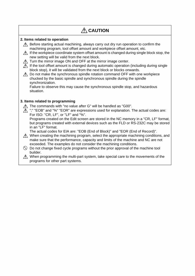
2. Items related to operation Before starting actual machining, always carry out dry run operation to confirm the machining program, tool offset amount and workpiece offset amount, etc.
If the workpiece coordinate system offset amount is changed during single block stop, the new setting will be valid from the next block.
Turn the mirror image ON and OFF at the mirror image center. If the tool offset amount is changed during automatic operation (including during single block stop), it will be validated from the next block or blocks onwards.
Do not make the synchronous spindle rotation command OFF with one workpiece chucked by the basic spindle and synchronous spindle during the spindle synchronization. Failure to observe this may cause the synchronous spindle stop, and hazardous situation.
3. Items related to programming The commands with "no value after G" will be handled as "G00". ";" "EOB" and "%" "EOR" are expressions used for explanation. The actual codes are: For ISO: "CR, LF", or "LF" and "%".
Programs created on the Edit screen are stored in the NC memory in a "CR, LF" format, but programs created with external devices such as the FLD or RS-232C may be stored in an "LF" format.
The actual codes for EIA are: "EOB (End of Block)" and "EOR (End of Record)". When creating the machining program, select the appropriate machining conditions, and make sure that the performance, capacity and limits of the machine and NC are not exceeded. The examples do not consider the machining conditions.
Do not change fixed cycle programs without the prior approval of the machine tool builder.
When programming the multi-part system, take special care to the movements of the programs for other part systems.

CONTENTS
1. Control Axes ................................................................................................................................. 1 1.1 Coordinate Word and Control Axes.......................................................................................... 1 1.2 Coordinate Systems and Coordinate Zero Point Symbols ....................................................... 2
2. Least Command Increments........................................................................................................ 3 2.1 Input Setting Units .................................................................................................................... 3 2.2 Indexing Increment ................................................................................................................... 5
3. Data Formats................................................................................................................................. 6 3.1 Tape Codes .............................................................................................................................. 6 3.2 Program Formats...................................................................................................................... 9 3.3 Tape Memory Format ............................................................................................................. 12 3.4 Optional Block Skip; / ............................................................................................................. 12 3.5 Program/Sequence/Block Nos.; O, N ..................................................................................... 13 3.6 Parity H/V ............................................................................................................................... 14 3.7 G Code Lists........................................................................................................................... 15 3.8 Precautions before Starting Machining................................................................................... 20
4. Buffer Register............................................................................................................................ 21 4.1 Input Buffer ............................................................................................................................. 21 4.2 Pre-read Buffers ..................................................................................................................... 22
5. Position Commands ................................................................................................................... 23 5.1 Incremental/Absolute Value Commands ................................................................................ 23 5.2 Radius/Diameter Commands ................................................................................................. 24 5.3 Inch/Metric Conversion; G20, G21 ......................................................................................... 25 5.4 Decimal Point Input ................................................................................................................ 27
6. Interpolation Functions.............................................................................................................. 31 6.1 Positioning (Rapid Traverse); G00 ......................................................................................... 31 6.2 Linear Interpolation; G01 ........................................................................................................ 38 6.3 Circular Interpolation; G02, G03............................................................................................. 41 6.4 R Specification Circular Interpolation; G02, G03.................................................................... 45 6.5 Plane Selection; G17, G18, G19 ............................................................................................47 6.6 Thread Cutting........................................................................................................................ 49
6.6.1 Constant Lead Thread Cutting; G33 ................................................................................ 49 6.6.2 Inch Thread Cutting; G33................................................................................................. 54 6.6.3 Continuous Thread Cutting .............................................................................................. 56 6.6.4 Variable Lead Thread Cutting; G34.................................................................................. 57 6.6.5 Circular Thread Cutting; G35, G36................................................................................... 60
6.7 Helical Interpolation; G17, G18, G19, and G02, G03 ............................................................. 64 6.8 Milling Interpolation; G12.1..................................................................................................... 67
6.8.1 Selecting Milling Mode ..................................................................................................... 69 6.8.2 Milling Interpolation Control and Command Axes ............................................................ 70 6.8.3 Selecting a Plane during the Milling Mode ....................................................................... 72 6.8.4 Setting Milling Coordinate System ................................................................................... 74 6.8.5 Preparatory Functions ...................................................................................................... 76 6.8.6 Switching from Milling Mode to Turning Mode; G13.1...................................................... 81 6.8.7 Feed Function .................................................................................................................. 81 6.8.8 Program Support Functions ............................................................................................. 81 6.8.9 Miscellaneous Functions .................................................................................................. 82 6.8.10 Tool Offset Functions ..................................................................................................... 83 6.8.11 Interference Check......................................................................................................... 99
6.9 Cylindrical Interpolation; G07.1 (6 and 7 only in G code list)................................................ 107 6.10 Polar Coordinate Interpolation; G12.1, G13.1/G112, G113 (Only 6, 7 in G code list) ........ 115 6.11 Exponential Interpolation; G02.3, G03.3 ............................................................................ 122
7. Feed Functions ......................................................................................................................... 128 7.1 Rapid Traverse Rate ............................................................................................................ 128 7.2 Cutting Feed Rate ................................................................................................................ 128 7.3 F1-digit Feed ........................................................................................................................ 129 7.4 Feed Per Minute/Feed Per Revolution (Asynchronous Feed/Synchronous Feed); G94, G95 .............................................................................................................................. 131 7.5 Feed Rate Designation and Effects on Control Axes ........................................................... 133 7.6 Thread Cutting Mode............................................................................................................ 137 7.7 Automatic Acceleration/Deceleration.................................................................................... 138 7.8 Speed Clamp........................................................................................................................ 138 7.9 Exact Stop Check; G09 ........................................................................................................ 139 7.10 Exact Stop Check Mode ; G61 ........................................................................................... 142 7.11 Deceleration Check ............................................................................................................ 143
7.11.1 G1 → G0 Deceleration Check...................................................................................... 145 7.11.2 G1 → G1 Deceleration Check...................................................................................... 146
7.12 Automatic Corner Override ; G62 ....................................................................................... 147 7.13 Tapping Mode ; G63........................................................................................................... 152 7.14 Cutting Mode ; G64 ............................................................................................................ 152
8. Dwell .......................................................................................................................................... 153 8.1 Per-second Dwell ; G04........................................................................................................ 153
9. Miscellaneous Functions ......................................................................................................... 155 9.1 Miscellaneous Functions (M8-digits BCD)............................................................................ 155 9.2 2nd Miscellaneous Functions (A8-digits, B8-digits or C8-digits) .......................................... 157 9.3 Index Table Indexing ............................................................................................................ 158
10. Spindle Functions................................................................................................................... 160 10.1 Spindle Functions (S2-digits BCD) ..... During Standard PLC Specifications..................... 160 10.2 Spindle Functions (S6-digits Analog) ................................................................................. 160 10.3 Spindle Functions (S8-digits).............................................................................................. 161 10.4 Constant Surface Speed Control; G96, G97 ...................................................................... 162 10.5 Spindle Clamp Speed Setting; G92.................................................................................... 163 10.6 Spindle/C Axis Control........................................................................................................ 164 10.7 Spindle Synchronization ..................................................................................................... 167
10.7.1 Spindle Synchronization Control I ................................................................................ 168 10.7.2 Spindle Synchronization II............................................................................................ 177 10.7.3 Precautions for Using Spindle Synchronization Control............................................... 182
10.8 Tool Spindle Synchronization IA (Spindle-Spindle, Polygon); G114.2 ............................... 184 10.9 Tool Spindle Synchronization IB (Spindle-Spindle, Polygon); G51.2 (Only 6 and 7 in G code list) .................................................................................. 192 10.10 Tool Spindle Synchronization IC (Spindle-NC Axis, Polygon); G51.2 (Only 6 and 7 in G code list) .................................................................................. 200 10.11 Multiple-spindle Control .................................................................................................... 203
10.11.1 Multiple-spindle Control I (multiple spindle command)............................................... 204 10.11.2 Multiple-spindle Control I (spindle selection command) ............................................. 205 10.11.3 Multiple-spindle Control II........................................................................................... 208
11. Tool Functions ........................................................................................................................ 211 11.1 Tool Functions (T8-digits BCD) .......................................................................................... 211
12. Tool Offset Functions............................................................................................................. 212 12.1 Tool Offset .......................................................................................................................... 212
12.1.1 Tool Offset Start ........................................................................................................... 213 12.1.2 Expanded Method at Starting Tool Offset .................................................................... 214
12.2 Tool Length Offset .............................................................................................................. 216 12.3 Tool Nose Wear Offset ....................................................................................................... 218 12.4 Tool Nose Radius Compensation; G40, G41, G42, G46.................................................... 219
12.4.1 Tool Nose Point and Compensation Directions............................................................ 221
12.4.2 Tool Nose Radius Compensation Operations .............................................................. 225 12.4.3 Other Operations during Tool Nose Radius Compensation ......................................... 243 12.4.4 G41/G42 Commands and I, J, K Designation .............................................................. 251 12.4.5 Interrupts during Tool Nose Radius Compensation ..................................................... 256 12.4.6 General Precautions for Tool Nose Radius Compensation.......................................... 258 12.4.7 Interference Check....................................................................................................... 259
12.5 Compensation Data Input by Program; G10, G11.............................................................. 264 12.6 Tool Life Management II..................................................................................................... 267
12.6.1 Counting the Tool Life .................................................................................................. 270
13. Program Support Functions ..................................................................................................272 13.1 Fixed Cycles for Turning Machining ................................................................................... 272
13.1.1 Longitudinal Cutting Cycle; G77................................................................................... 273 13.1.2 Thread Cutting Cycle; G78........................................................................................... 275 13.1.3 Face Cutting Cycle; G79 .............................................................................................. 278
13.2 Fixed Cycle for Turning Machining (MITSUBISHI CNC special format) ............................. 281 13.3 Compound Type Fixed Cycle for Turning Machining ......................................................... 282
13.3.1 Longitudinal Rough Cutting Cycle; G71 ....................................................................... 283 13.3.2 Face Rough Cutting Cycle; G72................................................................................... 299 13.3.3 Formed Material Rough Cutting Cycle; G73 ................................................................ 301 13.3.4 Finishing Cycle; G70 .................................................................................................... 305 13.3.5 Face Cut-off Cycle; G74............................................................................................... 306 13.3.6 Longitudinal Cut-off Cycle; G75 ................................................................................... 308 13.3.7 Compound Thread Cutting Cycle; G76 ........................................................................ 310 13.3.8 Precautions for Compound Type Fixed Cycle for Turning Machining; G70 to G76 ..... 314
13.4 Compound Type Fixed Cycle for Turning Machining (MITSUBISHI CNC special format) ................................................................................... 317 13.5 Fixed Cycle for Drilling; G80 to G89 ................................................................................... 322
13.5.1 Face Deep Hole Drilling Cycle 1; G83 (Longitudinal deep hole drilling cycle 1; G87).. 330 13.5.2 Face Tapping Cycle; G84 (Longitudinal tapping cycle; G88) / Face Reverse Tapping Cycle; G84.1 (Longitudinal reverse tapping cycle; G88.1)...... 331 13.5.3 Face Boring Cycle; G85 (Longitudinal boring cycle; G89) ........................................... 335 13.5.4 Deep Hole Drilling Cycle 2; G83.2................................................................................ 335 13.5.5 Fixed Cycle for Drilling Cancel; G80 ............................................................................ 338 13.5.6 Precautions When Using a Fixed Cycle for Drilling...................................................... 338
13.6 Fixed Cycle for Drilling; G80 to G89 (MITSUBISHI CNC special format) ........................... 340 13.6.1 Initial Point and R Point Level Return; G98, G99 ......................................................... 359 13.6.2 Setting of Workpiece Coordinates in Fixed Cycle Mode .............................................. 360
13.7 Subprogram Control; M98, M99, M198 .............................................................................. 361 13.7.1 Calling Subprogram with M98 and M99 Commands.................................................... 361 13.7.2 Calling Subprogram with M198 Commands................................................................. 366
13.8 Variable Commands ........................................................................................................... 367 13.9 User Macro ......................................................................................................................... 370
13.9.1 User Macro Commands; G65, G66, G66.1, G67 ......................................................... 370 13.9.2 Macro Call Instruction................................................................................................... 371 13.9.3 ASCII Code Macro .......................................................................................................379 13.9.4 Variables ...................................................................................................................... 384 13.9.5 Types of Variables........................................................................................................ 386 13.9.6 Operation Commands .................................................................................................. 424 13.9.7 Control Commands ...................................................................................................... 430 13.9.8 External Output Commands ......................................................................................... 433 13.9.9 Precautions .................................................................................................................. 435
13.10 Mirror Image for Facing Tool Posts .................................................................................. 437 13.11 Corner Chamfering/Corner Rounding I............................................................................. 447
13.11.1 Corner Chamfering ",C" (or "I_", "K_", "C_") ............................................................. 447 13.11.2 Corner Rounding ",R_" (or "R_") ................................................................................ 449 13.11.3 Corner Chamfering/Corner Rounding Expansion....................................................... 451

13.11.4 Interrupt during Corner Chamfering/Corner Rounding ............................................... 453 13.12 Corner Chamfering/Corner Rounding II............................................................................ 455
13.12.1 Corner Chamfering ",C_" (or "I_", "K_", "C_") ........................................................... 455 13.12.2 Corner Rounding ",R_" (or "R_") ................................................................................ 458 13.12.3 Corner Chamfering/Corner Rounding Expansion....................................................... 459 13.12.4 Interrupt during Corner Chamfering/Corner Rounding ............................................... 459
13.13 Linear Angle Command....................................................................................................460 13.14 Geometric ......................................................................................................................... 461
13.14.1 Geometric I................................................................................................................. 461 13.14.2 Geometric IB .............................................................................................................. 464
13.15 Parameter Input by Program; G10, G11........................................................................... 478 13.16 Macro Interruption ............................................................................................................ 479 13.17 Tool Change Position Return; G30.1 to G30.5................................................................. 487 13.18 Balance Cut; G15, G14 .................................................................................................... 490 13.19 Synchronizing Operation between Part Systems ............................................................. 494
13.19.1 Synchronization Standby Code (! code)..................................................................... 494 13.19.2 Start Point Designation Synchronizing (Type 1); G115.............................................. 497 13.19.3 Start Point Designation Synchronization (Type 2); G116........................................... 499 13.19.4 Synchronization Function Using M Codes ................................................................. 501
13.20 2-part System Synchronous Thread Cutting Cycle .......................................................... 504 13.20.1 Parameter Setting Command..................................................................................... 504 13.20.2 2-part System Synchronous Thread Cutting Cycle I; G76.1 ...................................... 505 13.20.3 2-part System Synchronous Thread Cutting Cycle II; G76.2 ..................................... 508
13.21 2-part System Simultaneous Thread-cutting Cycle (MELDAS special format)................. 512
14. Coordinate System Setting Functions.................................................................................. 514 14.1 Coordinate Words and Control Axes .................................................................................. 514 14.2 Basic Machine, Workpiece and Local Coordinate Systems ............................................... 515 14.3 Machine Zero Point and 2nd Reference Position (Zero point) ........................................... 516 14.4 Automatic Coordinate System Setting................................................................................ 517 14.5 Machine Coordinate System Selection; G53...................................................................... 518 14.6 Coordinate System Setting; G92 ........................................................................................ 519 14.7 Reference Position (Zero point) Return; G28, G29 ............................................................ 520 14.8 2nd, 3rd, and 4th Reference Position (Zero point) Return; G30......................................... 524 14.9 Reference Position Collation; G27 ..................................................................................... 527 14.10 Workpiece Coordinate System Setting and Offset; G54 to G59 (G54.1).......................... 528 14.11 Local Coordinate System Setting; G52 ............................................................................ 534 14.12 Workpiece Coordinate System Preset; G92.1.................................................................. 535 14.13 Coordinate System for Rotary Axis .................................................................................. 540
15. Protection Function................................................................................................................ 543 15.1 Chuck Barrier/Tailstock Barrier; G22, G23 ......................................................................... 543 15.2 Stored Stroke Limit ............................................................................................................. 548
16. Measurement Support Functions.......................................................................................... 550 16.1 Automatic Tool Length Measurement; G37........................................................................ 550 16.2 Skip Function; G31 ............................................................................................................. 554 16.3 Multiple-step Skip Function; G31.n, G04............................................................................ 560 16.4 Multiple-step Skip Function 2; G31..................................................................................... 562 16.5 Speed Change Skip............................................................................................................ 565 16.6 Programmable Current Limitation....................................................................................... 568
Appendix 1. Program Error......................................................................................................... 569
1. Control Axes 1.1 Coordinate Word and Control Axes
1
1. Control Axes 1.1 Coordinate Word and Control Axes
Function and purpose
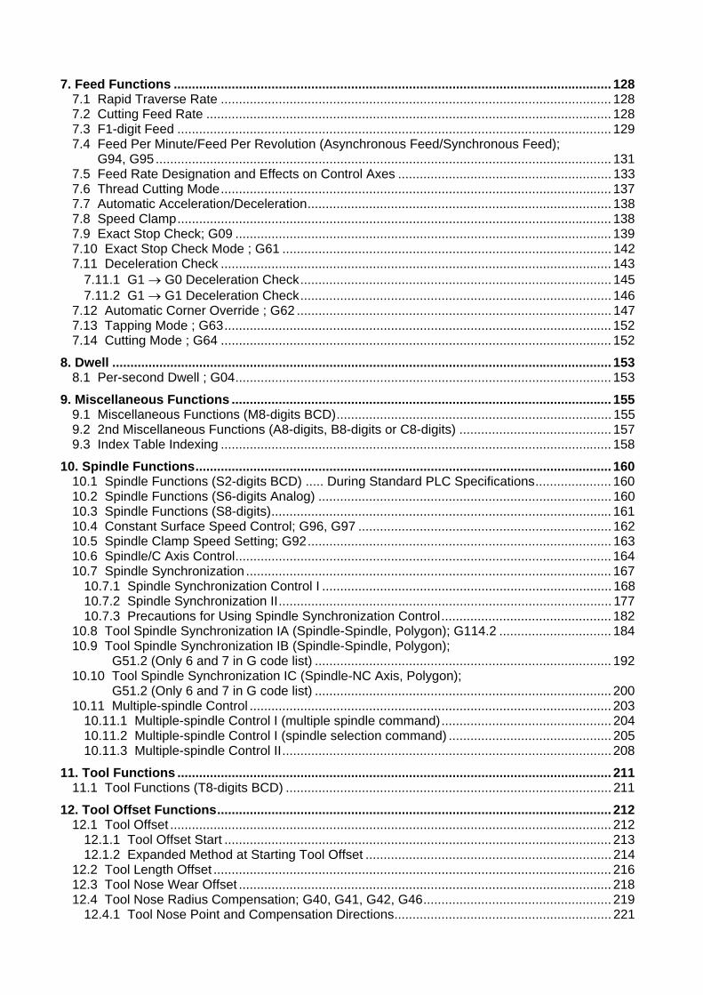
In the case of a lathe, the axis parallel to the spindle is known as the Z axis and its forward direction is the direction in which the turret moves away from the spindle stock while the axis at right angles to the Z axis is the X axis and its forward direction is the direction in which it moves away from the Z axis, as shown in the figure below.
Spindle stock
Tailstock
Tool
Turret +X +Y
+Z
Coordinate axes and polarities
Since coordinates based on the right hand rule are used with a lathe, the forward direction of the Y axis in the above figure which is at right angles to the X-Z plane is downward. It should be borne in mind that an arc on the X-Z plane is expressed as clockwise or counterclockwise as seen from the forward direction of the Y axis. (Refer to the section on circular interpolation.)
G54
G52
G58
G55
G59
G30
G28+X
(+Y)
+Z
Spindle nose
Machine zero point
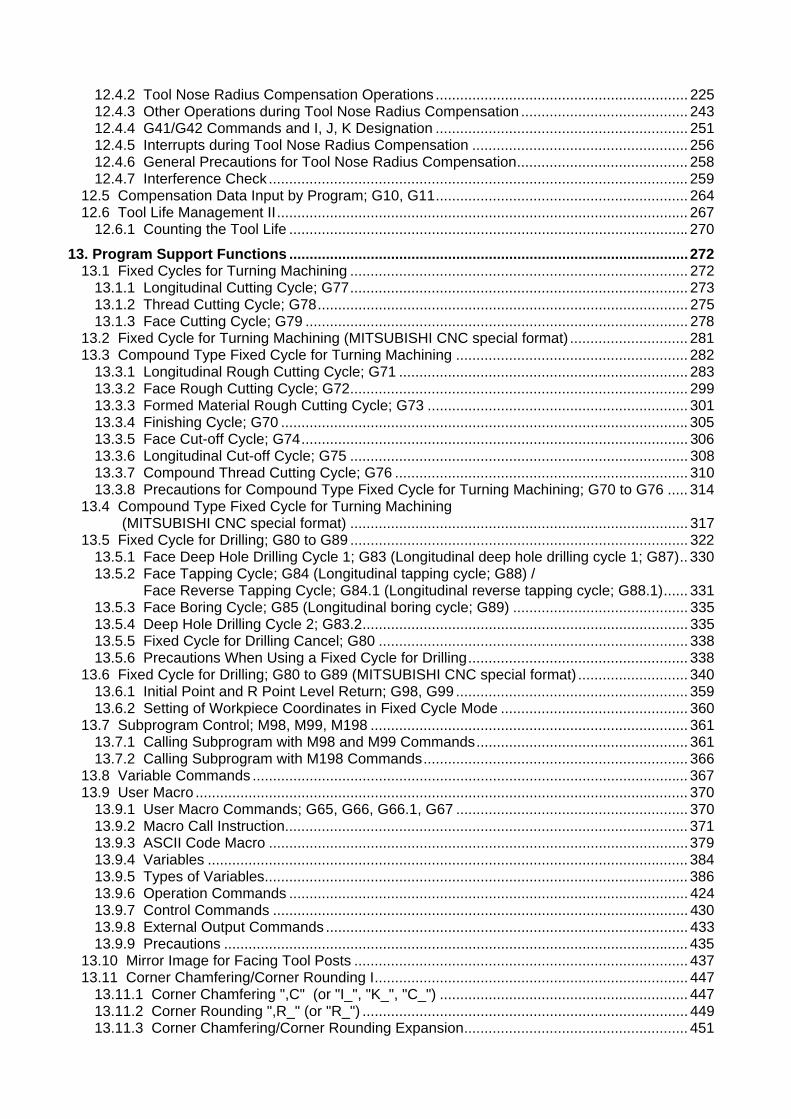
Workpiece zero points (G54 to G59)
Local coordinate system(Valid in G54 to G59)
2nd reference position
Reference position
Relationship between coordinates
1. Control Axes 1.2 Coordinate Systems and Coordinate Zero Point Symbols
2
1.2 Coordinate Systems and Coordinate Zero Point Symbols
Function and purpose
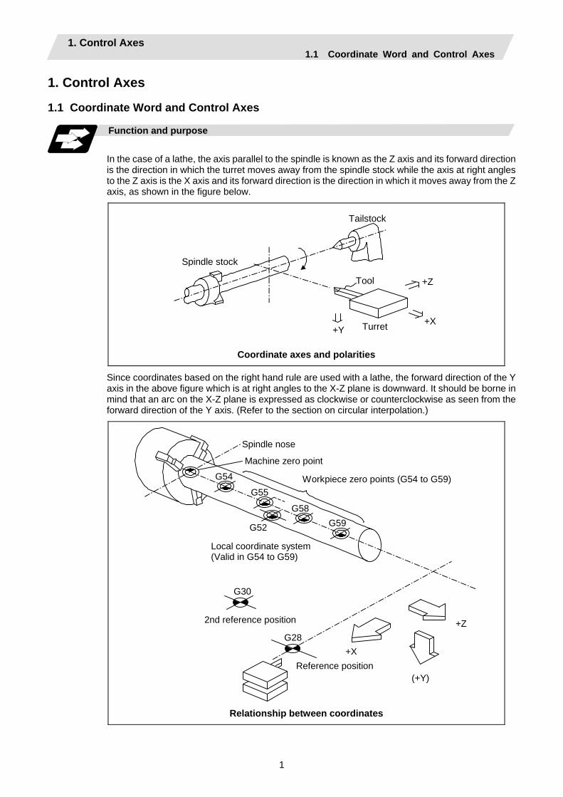
: Reference position
: Machine coordinate origin
: Workpiece coordinate zero points (G54 to G59)
Upon completion of the reference position return, the parameters are referred to and automatically set for the basic machine coordinate system and workpiece coordinate systems (G54 to G59). The basic machine coordinate system is set so that the first reference position is at the position designated by the parameter from the basic machine coordinate zero point (machine zero point).
X1
X3
+X
+Z
Z1
X2Z2
Hypothetical machinecoordinate system (shifted by G92)
Workpiececoordinatesystem 1 (G54)
Workpiececoordinatesystem 2 (G55)
Workpiececoordinatesystem 5 (G58)
Workpiece coordinate system6 (G59) Z 3
1st reference position
Machine zero pointBasic machine coordinate system
Local coordinatesystem (G52)
The local coordinate system (G52) is valid on the coordinate systems designated by the commands for the workpiece coordinate systems 1 to 6. Using the G92 command, the basic machine coordinate system can be shifted and made the hypothetical machine coordinate system. At the same time, workpiece coordinate systems 1 to 6 are also shifted.

2. Least Command Increments 2.1 Input Setting Units
3
2. Least Command Increments 2.1 Input Setting Units
Function and purpose
The input setting units are, as with the compensation amounts, the units of setting data used in common for all axes. The command units are the movement amounts in the program which are commanded with MDI inputs or command tape. These are expressed with mm, inch or degree (°) units. With the parameters, the command units can be selected from the following types for each axis, and the input setting units can be selected commonly for all axes. (For further details on settings, refer to the Instruction Manual.)
Linear axis Millimeter Inch
Parameters Diameter
commandRadius
commandDiameter command
Radius command
Rotation axis (°)
#1003 iunit = B 0.001 0.001 0.0001 0.0001 0.001 = C 0.0001 0.0001 0.00001 0.00001 0.0001 = D 0.00001 0.00001 0.000001 0.000001 0.00001
Input setting unit
= E 0.000001 0.000001 0.0000001 0.0000001 0.000001#1015 cunit = 0 Follow #1003 iunit = 10 0.001 0.001 0.0001 0.0001 0.001 = 100 0.0001 0.0001 0.00001 0.00001 0.0001 = 1000 0.00001 0.00001 0.000001 0.000001 0.00001
Command unit
= 10000 0.000001 0.000001 0.0000001 0.0000001 0.000001
(Note 1) Inch/metric changeover is performed in either of 2 ways: conversion from the parameter screen (#1041 I_inch: valid only when the power is turned ON) and conversion using the G command (G20 or G21).
However, when a G command is used for the conversion, the conversion applies only to the input command increments and not to the input setting units.
Consequently, the tool offset amounts and other compensation amounts as well as the variable data should be preset to correspond to inches or millimeters.
(Note 2) The millimeter and inch systems cannot be used together.
(Note 3) During circular interpolation on an axis where the input command increments are different, the center command (I, J, K) and the radius command (R) can be designated by the input setting units. (Use a decimal point to avoid confusion.)

2. Least Command Increments 2.1 Input Setting Units
4
Detailed description
(1) Units of various data
These input setting units determine the parameter setting unit, program command unit and the external interface unit for the PLC axis and handle pulse, etc. The following rules show how the unit of each data changes when the input setting unit is changed. This table applies to the NC axis and PLC axis.
Input setting unit Data Unit
system Setting value 1µm (B) 0.1µm (C) 10nm (D) 1nm (E)
20000 (mm/min) 20000 20000 20000 20000Milli- metre Setting range 1 to 999999 1 to 999999 1 to 999999 1 to 999999
2000 (inch/min) 20000 20000 20000 20000
Speed data Example: rapid Inch
Setting range 1 to 999999 1 to 999999 1 to 999999 1 to 999999123.123 (mm) 123.123 123.1230 123.12300 123.123000Milli-
metre Setting range ±99999.999 ±99999.9999 ±99999.99999 ±99999.99999912.1234 (inch) 12.1234 12.12340 12.123400 12.1234000
Position data Example: SoftLimit+ Inch
Setting range ±9999.9999 ±9999.99999 ±9999.999999 ±9999.99999991 (µm) 2 20 200 2000Milli-
metre Setting range ±9999 ±9999 ±9999 ±99990.0001 (inch) 2 20 200 2000
Interpolation unit data Inch
Setting range ±9999 ±9999 ±9999 ±9999 (2) Program command
The program command unit follows the above table. If the data has a decimal point, the number of digits in the integer section will remain and the number of digits in the decimal point section will increase as the input setting unit becomes smaller. When setting data with no decimal point, and which is a position command, the data will be affected by the input setting increment and input command increment. For the feed rate, as the input setting unit becomes smaller, the number of digits in the integer section will remain the same, but the number of digits in the decimal point section will increase.

2. Least Command Increments 2.2 Indexing Increment
5
2.2 Indexing Increment
Function and purpose
This function limits the command value for the rotary axis. This can be used for indexing the rotary table, etc. It is possible to cause a program error with a program command other than an indexing increment (parameter setting value).
Detailed description
When the indexing increment (parameter) for limiting the command value is set, the rotary axis can be positioned with that indexing increment. If a program other than the indexing increment setting value is commanded, a program error (P20) will occur. The indexing position will not be checked when the parameter is set to 0. (Example) When the indexing increment setting value is 2 degrees, only command with the
2-degree increment are possible.
G90 G01 C102. 000 ; … Moves to the 102 degree angle. G90 G01 C101. 000 : … Program error G90 G01 C102 ; … Moves to the 102 degree angle. (Decimal point type II)
The following axis specification parameters are used.
# Item Contents Setting range (unit)
2106 Index unit Indexing increment
Set the indexing increment to which the rotary axis can be positioned.
0 to 360 (° )
Precautions
• When the indexing increment is set, degree increment positioning takes place. • The indexing position is checked with the rotary axis, and is not checked with other axes. • When the indexing increment is set to 2 degrees, the rotary axis is set to the B axis, and the B axis
is moved with JOG to the 1.234 position, an indexing error will occur if "G90B5." or "G91B5." is commanded.
3. Data Formats 3.1 Tape Codes
6
3. Data Formats 3.1 Tape Codes
Function and purpose
The tape command codes used for this controller are combinations of alphabet letters (A, B, C, ... Z), numbers (0, 1, 2, ... 9) and signs (+, -, /, ...). These alphabet letters, numbers and signs are referred to as characters. Each character is represented by a combination of 8 holes which may, or may not, be present. These combinations make up what is called codes. This controller uses the ISO code (R-840).
(Note 1) If a code not given in the "Table of tape codes" is assigned during operation, a program
error (P32) will result.
(Note 2) For the sake of convenience, a " ; " has been used in the CNC display to indicate the End of Block (EOB/LF) which separates one block from another. Do not use the " ; " key, however, in actual programming but use the keys in the following table instead.
CAUTION " ; " "EOB" and " % " "EOR" are explanatory notations. The actual code is "Line feed" and "%".(ISO code (R-840)
Detailed description
(1) Use the keys in the following table for programming.
EOB/EOR keys and displays Code used
Key used ISO Screen display
End of Block LF or NL ; End of Record % %
(2) Significant data section (label skip function)
All data up to the first EOB ( ; ), after the power has been turned ON or after operation has been reset, are ignored during automatic operation based on tape, memory loading operation or during a search operation. In other words, the significant data section of a tape extends from the character or number code after the initial EOB ( ; ) code after resetting to the point where the reset command is issued.
3. Data Formats 3.1 Tape Codes
7
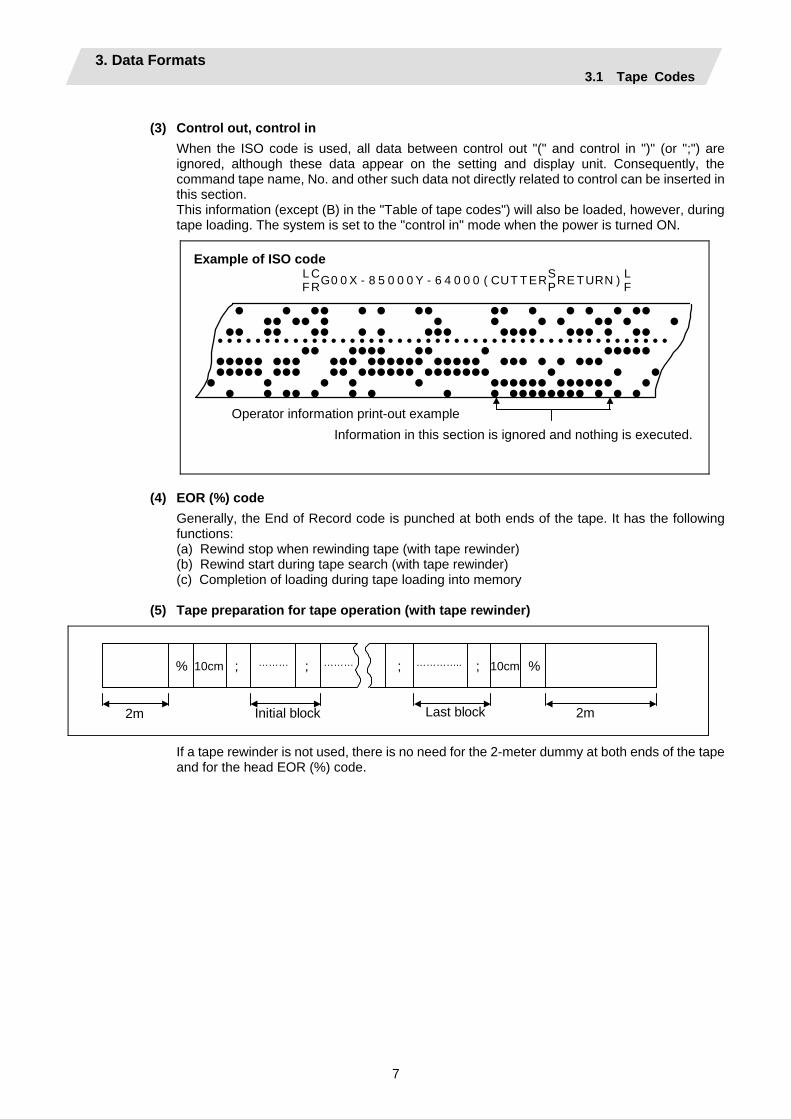
(3) Control out, control in
When the ISO code is used, all data between control out "(" and control in ")" (or ";") are ignored, although these data appear on the setting and display unit. Consequently, the command tape name, No. and other such data not directly related to control can be inserted in this section. This information (except (B) in the "Table of tape codes") will also be loaded, however, during tape loading. The system is set to the "control in" mode when the power is turned ON.
L C S L F RG0 0 X - 8 5 0 0 0 Y - 6 4 0 0 0 ( CUT T ERPRE T URN ) F
• • •• • • •• •• • • • • •• •• •• • • • • • •• • • •• •• •• • • ••• •••• ••• • •• • • • • • • • • • • • • • • • • • • • • • • • • • • • • • • • • • • • • • • • • • • • • • • • • •• •••• •• • ••••• ••••• ••• ••• •••••• ••••• ••• • • ••• ••••• ••• •• •••••• ••••••• • • •• • • • • •••••• •••••• •• • •• • • • • • •••••••• • • •Operator information print-out example
Information in this section is ignored and nothing is executed.
Example of ISO code
(4) EOR (%) code
Generally, the End of Record code is punched at both ends of the tape. It has the following functions: (a) Rewind stop when rewinding tape (with tape rewinder) (b) Rewind start during tape search (with tape rewinder) (c) Completion of loading during tape loading into memory
(5) Tape preparation for tape operation (with tape rewinder)
2m
10cm %
2m
10cm %; ;;;
Initial block Last block
……… ……… …………..
If a tape rewinder is not used, there is no need for the 2-meter dummy at both ends of the tape and for the head EOR (%) code.
3. Data Formats 3.1 Tape Codes
8
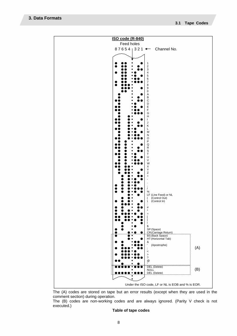
ISO code (R-840) Feed holes
8 7 6 5 4 3 2 1 Channel No.
• • • • • 1• •• • • 2 • • • •• 3• •• • • 4 • • • • • 5 •• • •• 6• • • • ••• 7• ••• • 8 • •• • • 9 •• • 0 • • • A • • • B•• • •• C • • • D•• • • • E•• • •• F • • ••• G • • • H•• • • • I•• • • • J • • • •• K•• • • • L • • • • • M • • • •• N•• • • ••• O • • • P•• • • • Q•• • • • R • • • •• S•• • • • T • • • • • U • • • •• V•• • • ••• W•• •• • X • •• • • Y • •• • • Z • • • •• + • • • • • - • • • •• .• • • • • ,• • • • ••• /• • • • • • % • • • LF (Line Feed) or NL • • • ( (Control Out)• • • • • ) (Control In) • •• • • :• • • •• #• • • • • *• ••• • • • =•• •• • •• [•• •• • • • ] • • • ! • • • $• • • SP (Space)• • • • • CR(Carriage Return) • • • BS (Back Space) • • • HT (Horizontal Tab) • • • •• & • • ••• ’ (Apostrophe)• • •• • •• ; ••• • • <• • •• • •• > ••• • ••• ?•• • @ • • • ”••••• • ••• DEL (Delete) • NULL••••• • ••• DEL (Delete) • •
(A)
(B)
Under the ISO code, LF or NL is EOB and % is EOR. The (A) codes are stored on tape but an error results (except when they are used in the comment section) during operation. The (B) codes are non-working codes and are always ignored. (Parity V check is not executed.)
Table of tape codes

3. Data Formats 3.2 Program Formats
9
3.2 Program Formats
Function and purpose
The prescribed arrangement used when assigning control information to the controller is known as the program format, and the format used with this controller is called the "word address format".
Detailed description
(1) Word and address
A word is a collection of characters arranged in a specific sequence. This entity is used as the unit for processing data and for causing the machine to execute specific operations. Each word used for this controller consists of an alphabet letter and a number of several digits. (A + or - sign may be attached to the head of a number.)
Alphabet (address)
Word
Numerals
Word configuration
*
The alphabet letter at the head of the word is the address. It defines the meaning of the numerical information which follows it. For details of the types of words and the number of significant digits of words used for this controller, refer to "Format details".
(2) Blocks
A block is a collection of words. It includes the information which is required for the machine to execute specific operations. One block unit constitutes a complete command. The end of each block is marked with an EOB (End of Block) code.
(3) Programs
A program is a collection of several blocks.
3. Data Formats 3.2 Program Formats
10
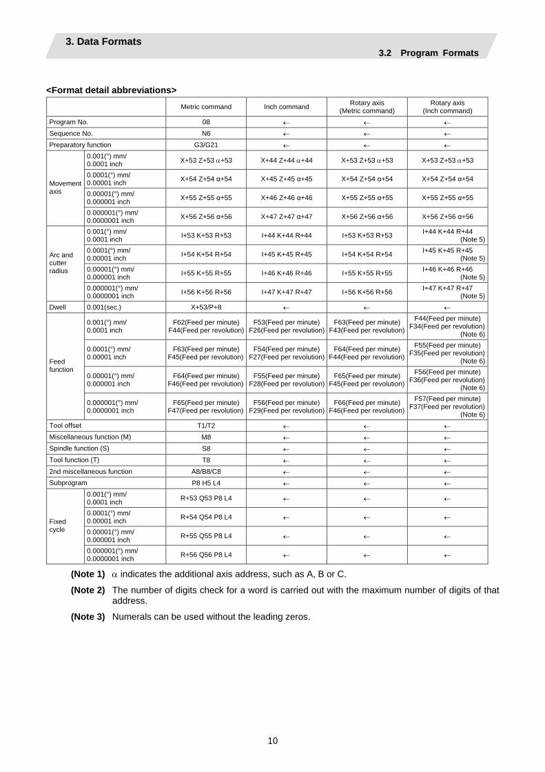
<Format detail abbreviations> Metric command Inch command Rotary axis
(Metric command) Rotary axis
(Inch command) Program No. 08 ← ← ← Sequence No. N6 ← ← ← Preparatory function G3/G21 ← ← ←
0.001(°) mm/ 0.0001 inch X+53 Z+53 α+53 X+44 Z+44 α+44 X+53 Z+53 α+53 X+53 Z+53 α+53
0.0001(°) mm/ 0.00001 inch X+54 Z+54 α+54 X+45 Z+45 α+45 X+54 Z+54 α+54 X+54 Z+54 α+54
0.00001(°) mm/ 0.000001 inch X+55 Z+55 α+55 X+46 Z+46 α+46 X+55 Z+55 α+55 X+55 Z+55 α+55
Movement axis
0.000001(°) mm/ 0.0000001 inch X+56 Z+56 α+56 X+47 Z+47 α+47 X+56 Z+56 α+56 X+56 Z+56 α+56
0.001(°) mm/ 0.0001 inch I+53 K+53 R+53 I+44 K+44 R+44 I+53 K+53 R+53 I+44 K+44 R+44
(Note 5)0.0001(°) mm/ 0.00001 inch I+54 K+54 R+54 I+45 K+45 R+45 I+54 K+54 R+54 I+45 K+45 R+45
(Note 5)0.00001(°) mm/ 0.000001 inch I+55 K+55 R+55 I+46 K+46 R+46 I+55 K+55 R+55 I+46 K+46 R+46
(Note 5)
Arc and cutter radius
0.000001(°) mm/ 0.0000001 inch I+56 K+56 R+56 I+47 K+47 R+47 I+56 K+56 R+56 I+47 K+47 R+47
(Note 5)Dwell 0.001(sec.) X+53/P+8 ← ← ←
0.001(°) mm/ 0.0001 inch
F62(Feed per minute)F44(Feed per revolution)
F53(Feed per minute)F26(Feed per revolution)
F63(Feed per minute) F43(Feed per revolution)
F44(Feed per minute)F34(Feed per revolution)
(Note 6)
0.0001(°) mm/ 0.00001 inch
F63(Feed per minute)F45(Feed per revolution)
F54(Feed per minute)F27(Feed per revolution)
F64(Feed per minute) F44(Feed per revolution)
F55(Feed per minute)F35(Feed per revolution)
(Note 6)
0.00001(°) mm/ 0.000001 inch
F64(Feed per minute)F46(Feed per revolution)
F55(Feed per minute)F28(Feed per revolution)
F65(Feed per minute) F45(Feed per revolution)
F56(Feed per minute)F36(Feed per revolution)
(Note 6)
Feed function
0.000001(°) mm/ 0.0000001 inch
F65(Feed per minute)F47(Feed per revolution)
F56(Feed per minute)F29(Feed per revolution)
F66(Feed per minute) F46(Feed per revolution)
F57(Feed per minute)F37(Feed per revolution)
(Note 6)Tool offset T1/T2 ← ← ← Miscellaneous function (M) M8 ← ← ← Spindle function (S) S8 ← ← ← Tool function (T) T8 ← ← ← 2nd miscellaneous function A8/B8/C8 ← ← ← Subprogram P8 H5 L4 ← ← ←
0.001(°) mm/ 0.0001 inch R+53 Q53 P8 L4 ← ← ←
0.0001(°) mm/ 0.00001 inch R+54 Q54 P8 L4 ← ← ←
0.00001(°) mm/ 0.000001 inch R+55 Q55 P8 L4 ← ← ←
Fixed cycle
0.000001(°) mm/ 0.0000001 inch R+56 Q56 P8 L4 ← ← ←
(Note 1) α indicates the additional axis address, such as A, B or C.
(Note 2) The number of digits check for a word is carried out with the maximum number of digits of that address.
(Note 3) Numerals can be used without the leading zeros.
3. Data Formats 3.2 Program Formats
11
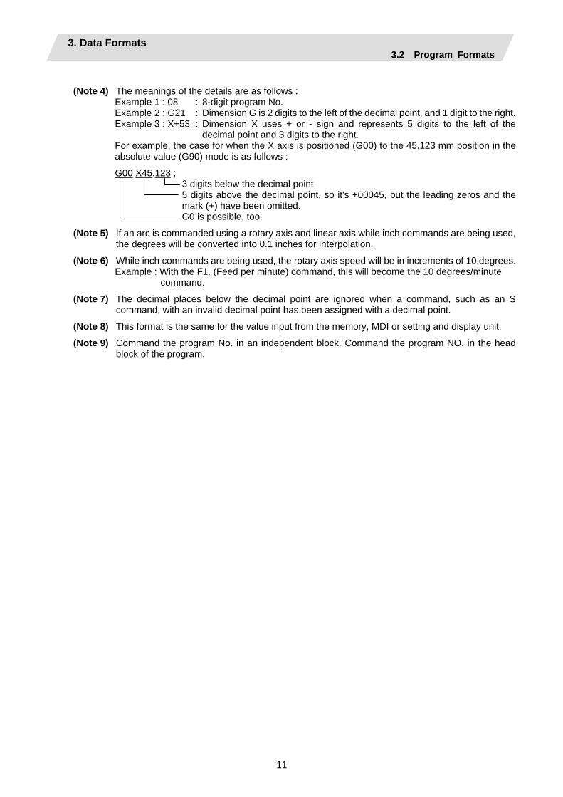
(Note 4) The meanings of the details are as follows :
Example 1 : 08 : 8-digit program No. Example 2 : G21 : Dimension G is 2 digits to the left of the decimal point, and 1 digit to the right. Example 3 : X+53 : Dimension X uses + or - sign and represents 5 digits to the left of the
decimal point and 3 digits to the right. For example, the case for when the X axis is positioned (G00) to the 45.123 mm position in the absolute value (G90) mode is as follows :
G00 X45.123 ; 3 digits below the decimal point 5 digits above the decimal point, so it's +00045, but the leading zeros and the mark (+) have been omitted. G0 is possible, too.
(Note 5) If an arc is commanded using a rotary axis and linear axis while inch commands are being used, the degrees will be converted into 0.1 inches for interpolation.
(Note 6) While inch commands are being used, the rotary axis speed will be in increments of 10 degrees. Example : With the F1. (Feed per minute) command, this will become the 10 degrees/minute
command.
(Note 7) The decimal places below the decimal point are ignored when a command, such as an S command, with an invalid decimal point has been assigned with a decimal point.
(Note 8) This format is the same for the value input from the memory, MDI or setting and display unit.
(Note 9) Command the program No. in an independent block. Command the program NO. in the head block of the program.
3. Data Formats 3.3 Tape Memory Format
12
3.3 Tape Memory Format
Function and purpose
(1) Storage tape and significant sections (ISO, EIA automatic judgment)
Both ISO and EIA tape codes can be stored in the memory in the same way as tape operation. After resetting, ISO/EIA is automatically judged by the EOB code at the head. The interval to be stored in the memory is from the next character after the head EOB to the EOR code after resetting. The significant codes listed in the "Table of tape code" in Section 3.1 "Tape codes", in the above significant section are actually stored into the memory. All other codes are ignored and are not stored. The data between control out "(" and control in ")" are stored into the memory.
3.4 Optional Block Skip; / Function and purpose
This function selectively ignores specific blocks in a machining program which starts with the "/" (slash) code.
Detailed description
(1) Provided that the optional block skip switch is ON, blocks starting with the "/" code are ignored.
They are executed if the switch is OFF. Parity check is valid regardless of whether the optional block skip switch is ON or OFF. When, for instance, all blocks are to be executed for one workpiece but specific block are not to be executed for another workpiece, the same command tape can be used to machine different parts by inserting the "/" code at the head of those specific blocks.
Precautions for using optional block skip
(1) Put the "/" code for optional block skip at the beginning of a block. If it is placed inside the block,
it is assumed as a user macro, a division instruction. (Example) N20 G1 X25. /Z25. ; ..........NG (User macro, a division instruction;
a program error results.) /N20 G1 X25. Z25. ; ..........OK (2) Parity checks (H and V) are conducted regardless of the optional block skip switch position. (3) The optional block skip is processed immediately before the pre-read buffer. Consequently, it is not possible to skip up to the block which has been read into the pre-read
buffer. (4) This function is valid even during a sequence No. search. (5) All blocks with the "/" code are also input and output during tape storing and tape output,
regardless of the position of the optional block skip switch.
3. Data Formats 3.5 Program/Sequence/Block Nos.; O, N
13
3.5 Program/Sequence/Block Nos.; O, N
Function and purpose
These Nos. are used for monitoring the execution of the machining programs and for calling both machining programs and specific stages in machining programs.
(1) Program Nos. are classified by workpiece correspondence or by subprogram units, and they are designated by the address "O" followed by a number with up to 8 digits.
(2) Sequence Nos. are attached where appropriate to command blocks which configure machining programs, and they are designated by the address "N" followed by a number with up to 6 digits.
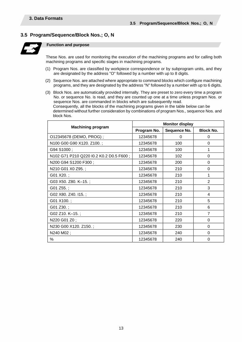
(3) Block Nos. are automatically provided internally. They are preset to zero every time a program No. or sequence No. is read, and they are counted up one at a time unless program Nos. or sequence Nos. are commanded in blocks which are subsequently read. Consequently, all the blocks of the machining programs given in the table below can be determined without further consideration by combinations of program Nos., sequence Nos. and block Nos.
Monitor display Machining program
Program No. Sequence No. Block No. O12345678 (DEMO, PROG) ; 12345678 0 0 N100 G00 G90 X120. Z100. ; 12345678 100 0 G94 S1000 ; 12345678 100 1 N102 G71 P210 Q220 I0.2 K0.2 D0.5 F600 ; 12345678 102 0 N200 G94 S1200 F300 ; 12345678 200 0 N210 G01 X0 Z95. ; 12345678 210 0 G01 X20. ; 12345678 210 1 G03 X50. Z80. K–15. ; 12345678 210 2 G01 Z55. ; 12345678 210 3 G02 X80. Z40. I15. ; 12345678 210 4 G01 X100. ; 12345678 210 5 G01 Z30. ; 12345678 210 6 G02 Z10. K–15. ; 12345678 210 7 N220 G01 Z0 ; 12345678 220 0 N230 G00 X120. Z150. ; 12345678 230 0 N240 M02 ; 12345678 240 0 % 12345678 240 0
3. Data Formats 3.6 Parity H/V
14
3.6 Parity H/V
Function and purpose
Parity check provides a mean of checking whether the tape has been correctly perforated or not. This involves checking for perforated code errors or, in other words, for perforation errors. There are two types of parity check: Parity H and Parity V.
(1) Parity H
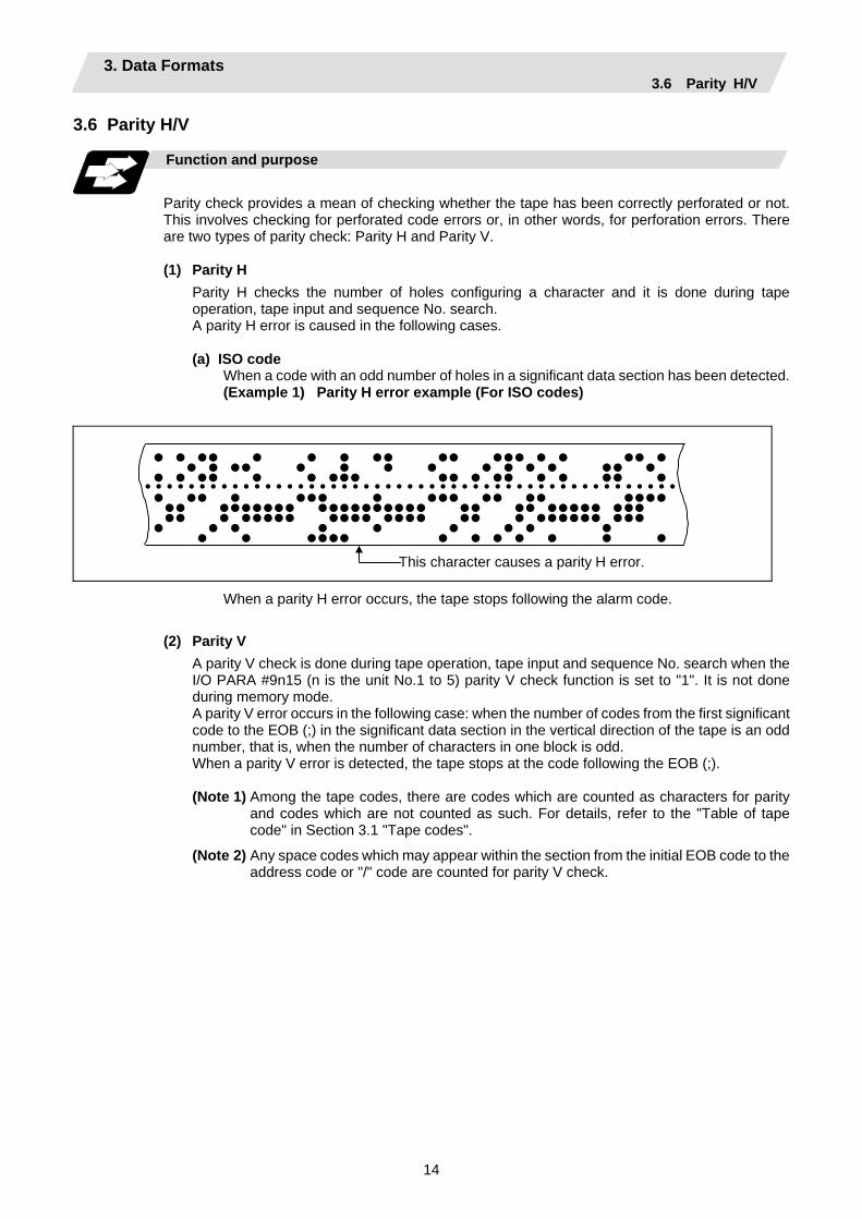
Parity H checks the number of holes configuring a character and it is done during tape operation, tape input and sequence No. search. A parity H error is caused in the following cases. (a) ISO code
When a code with an odd number of holes in a significant data section has been detected. (Example 1) Parity H error example (For ISO codes)
• • •• • • • •• •• ••• • • •• • • • •• • • • • • • • • •• • • • •• • • ••• •• • •• • • •• • • • • • • • • • • • • • • • • • • • • • • • • • • • • • • • • • • • • • • • • • • • • • • • • • • • •• • ••• • ••• •• •• •••• •• ••••••• •••••••••• •• •• ••••• ••• •• • ••••• •••• •••• •• • •••••• ••• • • • • • • • • • • • •••• • • • • • • •
This character causes a parity H error.
When a parity H error occurs, the tape stops following the alarm code.
(2) Parity V A parity V check is done during tape operation, tape input and sequence No. search when the I/O PARA #9n15 (n is the unit No.1 to 5) parity V check function is set to "1". It is not done during memory mode. A parity V error occurs in the following case: when the number of codes from the first significant code to the EOB (;) in the significant data section in the vertical direction of the tape is an odd number, that is, when the number of characters in one block is odd. When a parity V error is detected, the tape stops at the code following the EOB (;).
(Note 1) Among the tape codes, there are codes which are counted as characters for parity
and codes which are not counted as such. For details, refer to the "Table of tape code" in Section 3.1 "Tape codes".
(Note 2) Any space codes which may appear within the section from the initial EOB code to the address code or "/" code are counted for parity V check.

3. Data Formats 3.7 G Code Lists
15
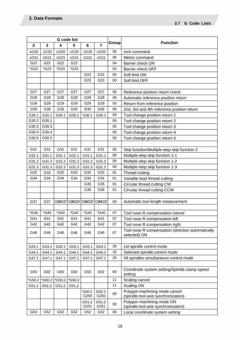
3.7 G Code Lists Function and purpose
G codes include the six G code lists 2, 3, 4, 5, 6 and 7. One list is selected by setting in parameter "#1037 cmdtyp".
cmdtyp G code list 3 List 2 4 List 3 5 List 4 6 List 5 7 List 6 8 List 7
G functions are explained using the G code list 3.
(Note 1) A program error (P34) will result if a G code that is not in the Table of G code lists is commanded.
(Note 2) An alarm will result if a G code without additional specifications is commanded.
Table of G code lists
G code list 2 3 4 5 6 7 Group Function
∆G00 ∆G00 ∆G00 ∆G00 ∆G00 ∆G00 01 Positioning ∆G01 ∆G01 ∆G01 ∆G01 ∆G01 ∆G01 01 Linear interpolation G02 G02 G02 G02 G02 G02 01 Circular interpolation CW G03 G03 G03 G03 G03 G03 01 Circular interpolation CCW
G02.3 G02.3 G02.3 G02.3 G02.3 G02.3 01 Exponential interpolation CW G03.3 G03.3 G03.3 G03.3 G03.3 G03.3 01 Exponential interpolation CCW G04 G04 G04 G04 G04 G04 00 Dwell
G07.1 G107
G07.1G107 19 Cylindrical interpolation
G09 G09 G09 G09 G09 G09 00 Exact stop check G10 G10 G10 G10 G10 G10 00 Parameter/Compensation data input by program/
Tool life management data registration G11 G11 G11 G11 G11 G11 00 Program parameter input / Tool life management
data registration mode cancel G12.1
G112 G12.1G112 19 Polar coordinate interpolation ON
G13.1 G113
G13.1G113 19 Polar coordinate interpolation cancel
G12.1 G12.1 G12.1 G12.1 19 Milling interpolation ON *G13.1 *G13.1 *G13.1 *G13.1 19 Milling interpolation cancel *G14 *G14 *G14 *G14 *G14 *G14 18 • Balance cut OFF G15 G15 G15 G15 G15 G15 18 • Balance cut ON
G16 G16 G16 G16 02 Milling interpolation plane selection Y-Z cylindrical plane
∆G17 ∆G17 ∆G17 ∆G17 ∆G17 ∆G17 02 Plane selection X-Y ∆G18 ∆G18 ∆G18 ∆G18 ∆G18 ∆G18 02 Plane selection Z-X ∆G19 ∆G19 ∆G19 ∆G19 ∆G19 ∆G19 02 Plane selection Y-Z
3. Data Formats 3.7 G Code Lists
16
G code list
2 3 4 5 6 7 Group Function
∆G20 ∆G20 ∆G20 ∆G20 ∆G20 ∆G20 06 Inch command ∆G21 ∆G21 ∆G21 ∆G21 ∆G21 ∆G21 06 Metric command G22 G22 G22 G22 04 Barrier check ON *G23 *G23 *G23 *G23 04 Barrier check OFF
G22 G22 00 Soft limit ON G23 G23 00 Soft limit OFF
G27 G27 G27 G27 G27 G27 00 Reference position return check G28 G28 G28 G28 G28 G28 00 Automatic reference position return G29 G29 G29 G29 G29 G29 00 Return from reference position G30 G30 G30 G30 G30 G30 00 2nd, 3rd and 4th reference position return
G30.1 G30.1 G30.1 G30.1 G30.1 G30.1 00 Tool change position return 1 G30.2 G30.2 00 Tool change position return 2 G30.3 G30.3 00 Tool change position return 3 G30.4 G30.4 00 Tool change position return 4 G30.5 G30.5 00 Tool change position return 5
G31 G31 G31 G31 G31 G31 00 Skip function/Multiple-step skip function 2
G31.1 G31.1 G31.1 G31.1 G31.1 G31.1 00 Multiple-step skip function 1-1 G31.2 G31.2 G31.2 G31.2 G31.2 G31.2 00 Multiple-step skip function 1-2 G31.3 G31.3 G31.3 G31.3 G31.3 G31.3 00 Multiple-step skip function 1-3 G32 G33 G32 G33 G32 G33 01 Thread cutting G34 G34 G34 G34 G34 G34 01 Variable lead thread cutting
G35 G35 01 Circular thread cutting CW G36 G36 01 Circular thread cutting CCW
G37 G37 G36/G37 G36/G37 G36/G37 G36/G37 00 Automatic tool length measurement
*G40 *G40 *G40 *G40 *G40 *G40 07 Tool nose R compensation cancel G41 G41 G41 G41 G41 G41 07 Tool nose R compensation left G42 G42 G42 G42 G42 G42 07 Tool nose R compensation right
G46 G46 G46 G46 G46 G46 07 Tool nose R compensation (direction automatically selected) ON
G43.1 G43.1 G43.1 G43.1 G43.1 G43.1 20 1st spindle control mode G44.1 G44.1 G44.1 G44.1 G44.1 G44.1 20 Selected spindle control mode G47.1 G47.1 G47.1 G47.1 G47.1 G47.1 20 All spindles simultaneous control mode
G50 G92 G50 G92 G50 G92 00 Coordinate system setting/Spindle clamp speed setting
*G50.2 *G50.2 *G50.2 *G50.2 11 Scaling cancel G51.2 G51.2 G51.2 G51.2 11 Scaling ON
G50.2 G250
G50.2G250 00 Polygon machining mode cancel
(spindle-tool axis synchronization)
G51.2 G251
G51.2G251 00 Polygon machining mode ON
(spindle-tool axis synchronization) G52 G52 G52 G52 G52 G52 00 Local coordinate system setting
3. Data Formats 3.7 G Code Lists
17
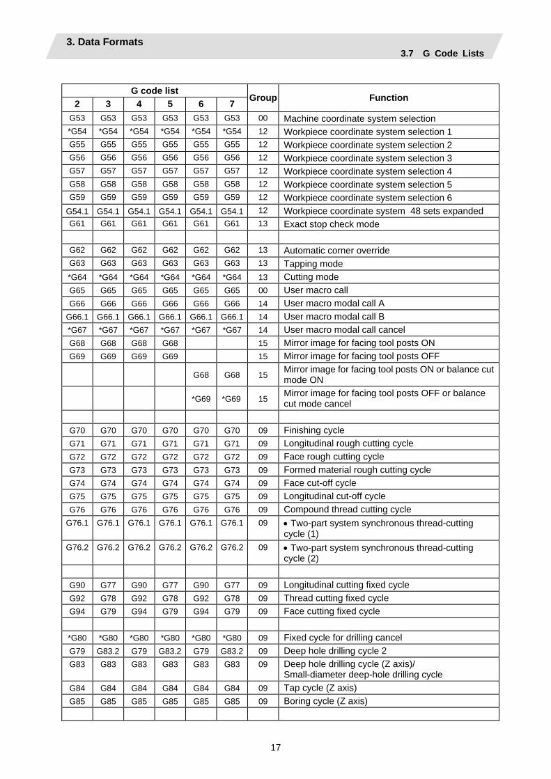
G code list
2 3 4 5 6 7 Group Function
G53 G53 G53 G53 G53 G53 00 Machine coordinate system selection *G54 *G54 *G54 *G54 *G54 *G54 12 Workpiece coordinate system selection 1 G55 G55 G55 G55 G55 G55 12 Workpiece coordinate system selection 2 G56 G56 G56 G56 G56 G56 12 Workpiece coordinate system selection 3 G57 G57 G57 G57 G57 G57 12 Workpiece coordinate system selection 4 G58 G58 G58 G58 G58 G58 12 Workpiece coordinate system selection 5 G59 G59 G59 G59 G59 G59 12 Workpiece coordinate system selection 6
G54.1 G54.1 G54.1 G54.1 G54.1 G54.1 12 Workpiece coordinate system 48 sets expanded G61 G61 G61 G61 G61 G61 13 Exact stop check mode
G62 G62 G62 G62 G62 G62 13 Automatic corner override G63 G63 G63 G63 G63 G63 13 Tapping mode *G64 *G64 *G64 *G64 *G64 *G64 13 Cutting mode G65 G65 G65 G65 G65 G65 00 User macro call G66 G66 G66 G66 G66 G66 14 User macro modal call A
G66.1 G66.1 G66.1 G66.1 G66.1 G66.1 14 User macro modal call B *G67 *G67 *G67 *G67 *G67 *G67 14 User macro modal call cancel G68 G68 G68 G68 15 Mirror image for facing tool posts ON G69 G69 G69 G69 15 Mirror image for facing tool posts OFF
G68 G68 15 Mirror image for facing tool posts ON or balance cut mode ON
*G69 *G69 15 Mirror image for facing tool posts OFF or balance cut mode cancel
G70 G70 G70 G70 G70 G70 09 Finishing cycle G71 G71 G71 G71 G71 G71 09 Longitudinal rough cutting cycle G72 G72 G72 G72 G72 G72 09 Face rough cutting cycle G73 G73 G73 G73 G73 G73 09 Formed material rough cutting cycle G74 G74 G74 G74 G74 G74 09 Face cut-off cycle G75 G75 G75 G75 G75 G75 09 Longitudinal cut-off cycle G76 G76 G76 G76 G76 G76 09 Compound thread cutting cycle
G76.1 G76.1 G76.1 G76.1 G76.1 G76.1 09 • Two-part system synchronous thread-cutting cycle (1)
G76.2 G76.2 G76.2 G76.2 G76.2 G76.2 09 • Two-part system synchronous thread-cutting cycle (2)
G90 G77 G90 G77 G90 G77 09 Longitudinal cutting fixed cycle G92 G78 G92 G78 G92 G78 09 Thread cutting fixed cycle G94 G79 G94 G79 G94 G79 09 Face cutting fixed cycle
*G80 *G80 *G80 *G80 *G80 *G80 09 Fixed cycle for drilling cancel G79 G83.2 G79 G83.2 G79 G83.2 09 Deep hole drilling cycle 2 G83 G83 G83 G83 G83 G83 09 Deep hole drilling cycle (Z axis)/
Small-diameter deep-hole drilling cycle G84 G84 G84 G84 G84 G84 09 Tap cycle (Z axis) G85 G85 G85 G85 G85 G85 09 Boring cycle (Z axis)
3. Data Formats 3.7 G Code Lists
18
G code list
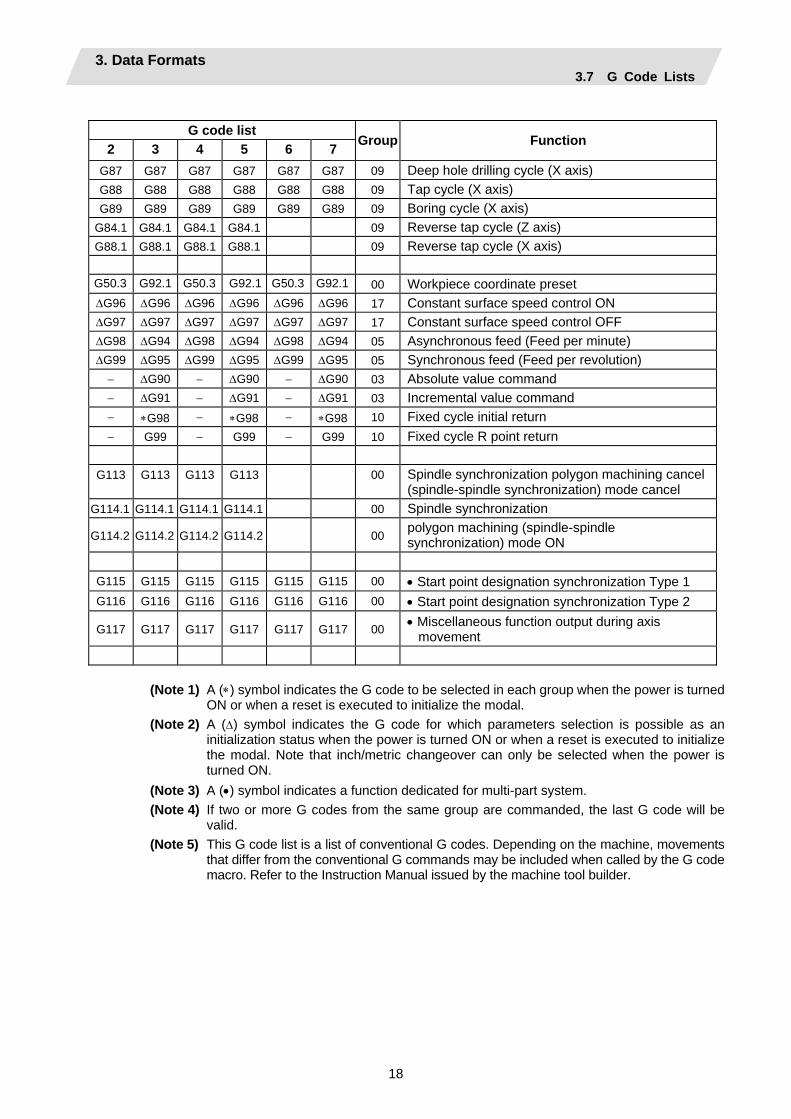
2 3 4 5 6 7 Group Function
G87 G87 G87 G87 G87 G87 09 Deep hole drilling cycle (X axis) G88 G88 G88 G88 G88 G88 09 Tap cycle (X axis) G89 G89 G89 G89 G89 G89 09 Boring cycle (X axis)
G84.1 G84.1 G84.1 G84.1 09 Reverse tap cycle (Z axis) G88.1 G88.1 G88.1 G88.1 09 Reverse tap cycle (X axis)
G50.3 G92.1 G50.3 G92.1 G50.3 G92.1 00 Workpiece coordinate preset ∆G96 ∆G96 ∆G96 ∆G96 ∆G96 ∆G96 17 Constant surface speed control ON ∆G97 ∆G97 ∆G97 ∆G97 ∆G97 ∆G97 17 Constant surface speed control OFF ∆G98 ∆G94 ∆G98 ∆G94 ∆G98 ∆G94 05 Asynchronous feed (Feed per minute) ∆G99 ∆G95 ∆G99 ∆G95 ∆G99 ∆G95 05 Synchronous feed (Feed per revolution)
− ∆G90 − ∆G90 − ∆G90 03 Absolute value command − ∆G91 − ∆G91 − ∆G91 03 Incremental value command − ∗G98 − ∗G98 − ∗G98 10 Fixed cycle initial return − G99 − G99 − G99 10 Fixed cycle R point return
G113 G113 G113 G113 00 Spindle synchronization polygon machining cancel (spindle-spindle synchronization) mode cancel
G114.1 G114.1 G114.1 G114.1 00 Spindle synchronization
G114.2 G114.2 G114.2 G114.2 00 polygon machining (spindle-spindle synchronization) mode ON
G115 G115 G115 G115 G115 G115 00 • Start point designation synchronization Type 1 G116 G116 G116 G116 G116 G116 00 • Start point designation synchronization Type 2
G117 G117 G117 G117 G117 G117 00 • Miscellaneous function output during axis movement
(Note 1) A (∗) symbol indicates the G code to be selected in each group when the power is turned ON or when a reset is executed to initialize the modal.
(Note 2) A (∆) symbol indicates the G code for which parameters selection is possible as an initialization status when the power is turned ON or when a reset is executed to initialize the modal. Note that inch/metric changeover can only be selected when the power is turned ON.
(Note 3) A (•) symbol indicates a function dedicated for multi-part system. (Note 4) If two or more G codes from the same group are commanded, the last G code will be
valid. (Note 5) This G code list is a list of conventional G codes. Depending on the machine, movements
that differ from the conventional G commands may be included when called by the G code macro. Refer to the Instruction Manual issued by the machine tool builder.
3. Data Formats 3.7 G Code Lists
19
(Note 6) Whether the modal is initialized differs for each reset input.
(1) "Reset 1" The modal is initialized when the reset initialization parameter (#1151 rstinit) is ON.
(2) "Reset 2 "and "Reset and Rewind" The modal is initialized when the signal is input.
(3) Reset at emergency stop release Conforms to "Reset 1".
(4) When an automatic reset is carried out at the start of individual functions, such as reference position return.
Conforms to "Reset and Rewind". (Note 7) Precautions for 6 and 7 in G code lists
(1) G68 and G69 When both the mirror image for facing tool posts option and balance cut option are valid,
G68 and G69 will be handled as the command to turn the mirror image for facing tool posts ON and OFF.
(The mirror image for facing tool posts has the priority.) (2) G36 G36 is used for the two functions, automatic tool length measurement and circular
thread cutting (CCW). The applied function follows the parameter "#1238 set10/bit0" (circular thread cutting) setting.
When "#1238 set10/bit0" is set to 0
G code Function G35 Circular thread cutting clockwise rotation (CW) G36 Automatic tool length measurement X G37 Automatic tool length measurement Z
When "#1238 set10/bit0" is set to 1
G code Function G35 Circular thread cutting clockwise rotation (CW) G36 Circular thread cutting counterclockwise rotation (CCW) G37 Automatic tool length measurement Z
CAUTION The commands with "no value after G" will be handled as "G00".

3. Data Formats 3.8 Precautions before Starting Machining
20
3.8 Precautions before Starting Machining
Precautions before machining
CAUTION When creating the machining program, select the appropriate machining conditions, and make sure that the performance, capacity and limits of the machine and NC are not exceeded. The examples do not consider the machining conditions.
Before starting actual machining, always carry out dry run operation to confirm the machining program, tool offset amount and workpiece offset amount, etc.
4. Buffer Register 4.1 Input Buffer
21
4. Buffer Register 4.1 Input Buffer
Function and purpose
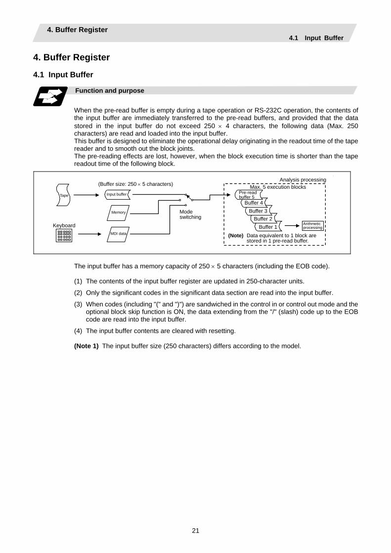
When the pre-read buffer is empty during a tape operation or RS-232C operation, the contents of the input buffer are immediately transferred to the pre-read buffers, and provided that the data stored in the input buffer do not exceed 250 × 4 characters, the following data (Max. 250 characters) are read and loaded into the input buffer. This buffer is designed to eliminate the operational delay originating in the readout time of the tape reader and to smooth out the block joints. The pre-reading effects are lost, however, when the block execution time is shorter than the tape readout time of the following block.
(Buffer size: 250 × 5 characters)
Input buffer
Memory
MDI data
Keyboard
Tape
Mode switching
Analysis processingMax. 5 execution blocks
Pre-read buffer 5
Buffer 4
Arithmetic processing
(Note) Data equivalent to 1 block are stored in 1 pre-read buffer.
Buffer 3Buffer 2
Buffer 1
The input buffer has a memory capacity of 250 × 5 characters (including the EOB code).
(1) The contents of the input buffer register are updated in 250-character units.
(2) Only the significant codes in the significant data section are read into the input buffer.
(3) When codes (including "(" and ")") are sandwiched in the control in or control out mode and the optional block skip function is ON, the data extending from the "/" (slash) code up to the EOB code are read into the input buffer.
(4) The input buffer contents are cleared with resetting.
(Note 1) The input buffer size (250 characters) differs according to the model.
4. Buffer Register 4.1 Input Buffer
22
4.2 Pre-read Buffers Function and purpose
During automatic processing, the contents of 1 block are normally pre-read so that program analysis processing is conducted smoothly. However, during nose R compensation, a maximum of 5 blocks are pre-read for the intersection point calculation including interference check. The specifications of the data in 1 block are as follows: (1) The data of 1 block are stored in this buffer.
(2) Only the significant codes in the significant data section are read into the pre-read buffer.
(3) When codes are sandwiched in the control in and control out, and the optional block skip function is ON, the data extending from the "/" (slash) code up to the EOB code are not read into the pre-read buffer.
(4) The pre-read buffer contents are cleared with resetting.
(5) When the single block function is ON during continuous operation, the pre-read buffer stores the following block data and then stops operation.
Other precautions
(1) Depending on whether the program is executed continuously or by single blocks, the timing of
the valid/invalid for the external control signals for the optional block skip and others will differ.
(2) If the external control signal such as optional block skip is turned ON/OFF with the M command, the external control operation will not be effective on the program pre-read with the buffer register.
(3) According to the M command that operates the external controls, it prohibits pre-reading, and the recalculation is as follows:
The M command that commands the external controls is distinguished at the PLC, and the "recalculation request" for PLC → NC interface table is turned ON.
(When the "recalculation request" is ON, the program that has been pre-read is reprocessed.)
5. Position Commands 5.1 Incremental/Absolute Value Commands
23
5. Position Commands 5.1 Incremental/Absolute Value Commands
Function and purpose
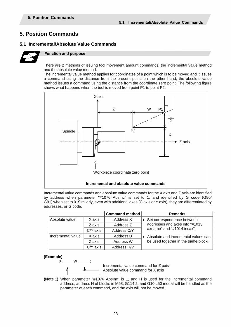
There are 2 methods of issuing tool movement amount commands: the incremental value method and the absolute value method. The incremental value method applies for coordinates of a point which is to be moved and it issues a command using the distance from the present point; on the other hand, the absolute value method issues a command using the distance from the coordinate zero point. The following figure shows what happens when the tool is moved from point P1 to point P2.
Workpiece coordinate zero point
Spindle
X axis
Z axis
Z W P1
P2
U 2
X
Incremental and absolute value commands
Incremental value commands and absolute value commands for the X axis and Z axis are identified by address when parameter "#1076 AbsInc" is set to 1, and identified by G code (G90/ G91) when set to 0. Similarly, even with additional axes (C axis or Y axis), they are differentiated by addresses, or G code.
Command method Remarks X axis Address X Z axis Address Z
Absolute value
C/Y axis Address C/Y X axis Address U Z axis Address W
Incremental value
C/Y axis Address H/V
• Set correspondence between addresses and axes into "#1013 axname" and "#1014 incax".
• Absolute and incremental values can be used together in the same block.
(Example) X_____ W _____ ;
Incremental value command for Z axis Absolute value command for X axis
(Note 1) When parameter "#1076 AbsInc" is 1, and H is used for the incremental command
address, address H of blocks in M98, G114.2, and G10 L50 modal will be handled as the parameter of each command, and the axis will not be moved.
5. Position Commands 5.2 Radius/Diameter Commands
24
5.2 Radius/Diameter Commands
Function and purpose
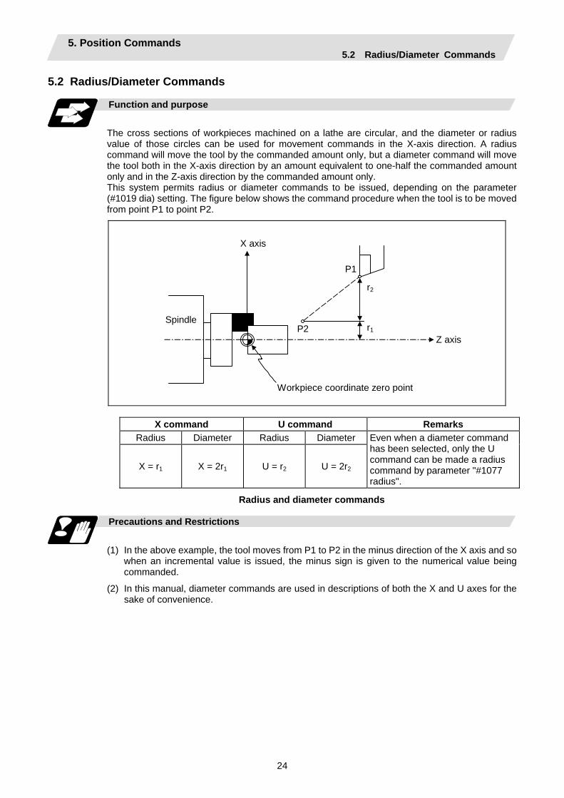
The cross sections of workpieces machined on a lathe are circular, and the diameter or radius value of those circles can be used for movement commands in the X-axis direction. A radius command will move the tool by the commanded amount only, but a diameter command will move the tool both in the X-axis direction by an amount equivalent to one-half the commanded amount only and in the Z-axis direction by the commanded amount only. This system permits radius or diameter commands to be issued, depending on the parameter (#1019 dia) setting. The figure below shows the command procedure when the tool is to be moved from point P1 to point P2.
Spindle
Workpiece coordinate zero point
P1
P2
r2
r1
X axis
Z axis
X command U command Remarks Radius Diameter Radius Diameter
X = r1 X = 2r1 U = r2 U = 2r2
Even when a diameter command has been selected, only the U command can be made a radius command by parameter "#1077 radius".
Radius and diameter commands
Precautions and Restrictions
(1) In the above example, the tool moves from P1 to P2 in the minus direction of the X axis and so
when an incremental value is issued, the minus sign is given to the numerical value being commanded.
(2) In this manual, diameter commands are used in descriptions of both the X and U axes for the sake of convenience.
5. Position Commands 5.3 Inch/Metric Conversion
25
5.3 Inch/Metric Conversion; G20, G21
Function and purpose
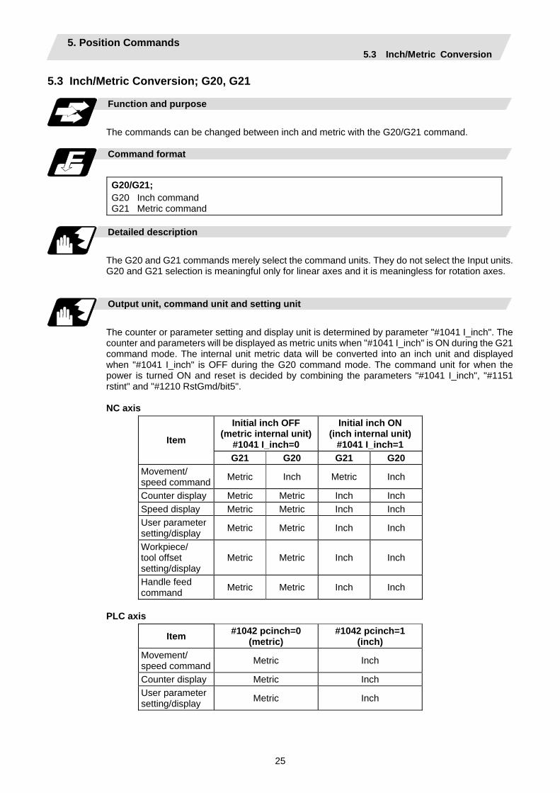
The commands can be changed between inch and metric with the G20/G21 command.
Command format
G20/G21; G20 Inch command G21 Metric command
Detailed description
The G20 and G21 commands merely select the command units. They do not select the Input units. G20 and G21 selection is meaningful only for linear axes and it is meaningless for rotation axes.
Output unit, command unit and setting unit
The counter or parameter setting and display unit is determined by parameter "#1041 I_inch". The counter and parameters will be displayed as metric units when "#1041 I_inch" is ON during the G21 command mode. The internal unit metric data will be converted into an inch unit and displayed when "#1041 I_inch" is OFF during the G20 command mode. The command unit for when the power is turned ON and reset is decided by combining the parameters "#1041 I_inch", "#1151 rstint" and "#1210 RstGmd/bit5".
NC axis
Initial inch OFF (metric internal unit)
#1041 I_inch=0
Initial inch ON (inch internal unit)
#1041 I_inch=1 Item
G21 G20 G21 G20 Movement/ speed command Metric Inch Metric Inch
Counter display Metric Metric Inch Inch Speed display Metric Metric Inch Inch User parameter setting/display Metric Metric Inch Inch
Workpiece/ tool offset setting/display
Metric Metric Inch Inch
Handle feed command Metric Metric Inch Inch
PLC axis
Item #1042 pcinch=0 (metric)
#1042 pcinch=1 (inch)
Movement/ speed command Metric Inch
Counter display Metric Inch User parameter setting/display Metric Inch
5. Position Commands 5.3 Inch/Metric Conversion
26
Precautions
(1) The parameter and tool data will be input/output with the "#1041 I_inch" setting unit.
If "#1041 I_inch" is not found in the parameter input data, the unit will follow the unit currently set to NC.
(2) The unit of read/write used in PLC window is fixed to metric unit regardless of a parameter and G20/G21 command modal.
(3) A program error (P33) will occur if G20/G21 command is issued in the same block as following G code. Command in a separate block. G7.1 (Cylindrical Interpolation) G12.1 (Polar coordinate interpolation)
5. Position Commands 5.4 Decimal Point Input
27
5.4 Decimal Point Input
Function and purpose
This function enables the decimal point to be input. It assigns the decimal point in millimeter or inch units for the machining program input information that defines the tool paths, distances and speeds. A parameter "#1078 Decpt2" selects whether minimum input command increment (type I) or zero point (type II) is to apply for the least significant digit of data without a decimal point.
Detailed description
(1) The decimal point command is valid for the distances, angles, times and speeds in machining
programs.
(2) Refer to the table rising the "Addresses used and valid/invalid decimal point commands" for details on the valid addresses for the decimal point commands.
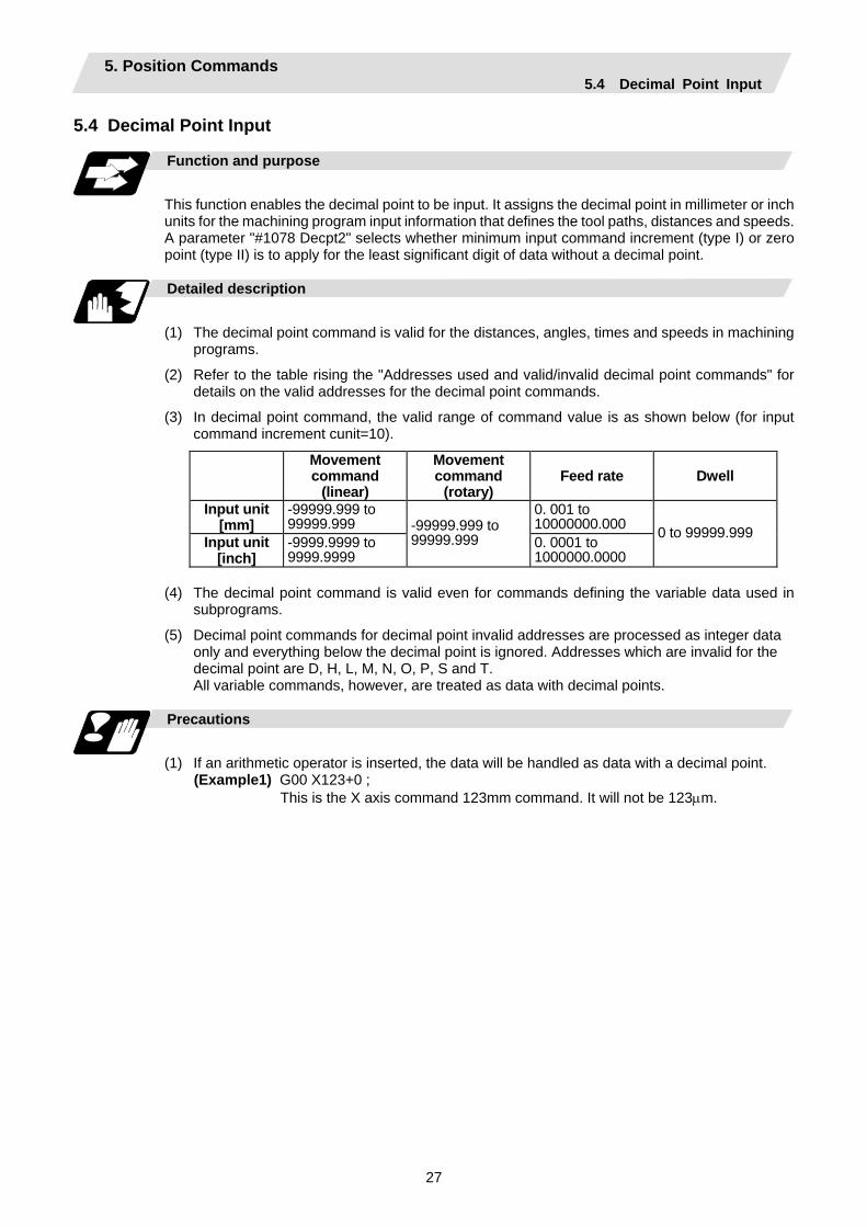
(3) In decimal point command, the valid range of command value is as shown below (for input command increment cunit=10).
Movement command
(linear)
Movement command
(rotary) Feed rate Dwell
Input unit [mm]
-99999.999 to 99999.999
0. 001 to 10000000.000
Input unit [inch]
-9999.9999 to 9999.9999
-99999.999 to 99999.999 0. 0001 to
1000000.0000
0 to 99999.999
(4) The decimal point command is valid even for commands defining the variable data used in
subprograms.
(5) Decimal point commands for decimal point invalid addresses are processed as integer data only and everything below the decimal point is ignored. Addresses which are invalid for the decimal point are D, H, L, M, N, O, P, S and T. All variable commands, however, are treated as data with decimal points.
Precautions
(1) If an arithmetic operator is inserted, the data will be handled as data with a decimal point.
(Example1) G00 X123+0 ; This is the X axis command 123mm command. It will not be 123µm.
5. Position Commands 5.4 Decimal Point Input
28
Example of program
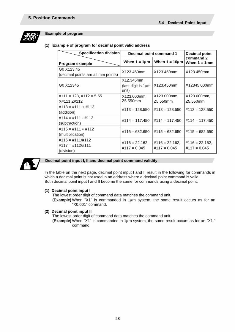
(1) Example of program for decimal point valid address
Decimal point command 1 Specification division Program example When 1 = 1µm When 1 = 10µm
Decimal point command 2 When 1 = 1mm
G0 X123.45 (decimal points are all mm points)
X123.450mm X123.450mm X123.450mm
G0 X12345 X12.345mm (last digit is 1µm unit)
X123.450mm X12345.000mm
#111 = 123, #112 = 5.55 X#111 Z#112
X123.000mm, Z5.550mm
X123.000mm, Z5.550mm
X123.000mm, Z5.550mm
#113 = #111 + #112 (addition)
#113 = 128.550 #113 = 128.550 #113 = 128.550
#114 = #111 - #112 (subtraction)
#114 = 117.450 #114 = 117.450 #114 = 117.450
#115 = #111 ∗ #112 (multiplication)
#115 = 682.650 #115 = 682.650 #115 = 682.650
#116 = #111/#112 #117 = #112/#111 (division)
#116 = 22.162, #117 = 0.045
#116 = 22.162, #117 = 0.045
#116 = 22.162, #117 = 0.045
Decimal point input I, II and decimal point command validity
In the table on the next page, decimal point input I and II result in the following for commands in which a decimal point is not used in an address where a decimal point command is valid. Both decimal point input I and II become the same for commands using a decimal point.
(1) Decimal point input I
The lowest order digit of command data matches the command unit. (Example) When "X1" is commanded in 1µm system, the same result occurs as for an
"X0.001" command.
(2) Decimal point input II The lowest order digit of command data matches the command unit. (Example) When "X1" is commanded in 1µm system, the same result occurs as for an "X1."
command.
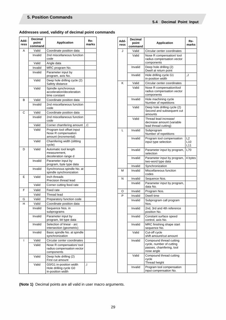
5. Position Commands 5.4 Decimal Point Input
29
Addresses used, validity of decimal point commands
Add-ress
Decimal point
command Application Re-
marks
Valid Coordinate position data Invalid 2nd miscellaneous function
code
Valid Angle data Invalid MRC program No. Invalid Parameter input by
program, axis No.
Valid Deep hole drilling cycle (2) Safety distance
A
Valid Spindle synchronous acceleration/deceleration time constant
Valid Coordinate position data B Invalid 2nd miscellaneous function
code
Valid Coordinate position data Invalid 2nd miscellaneous function
code
Valid Corner chamfering amount ,C Valid Program tool offset input
Nose R compensation amount (incremental)
C
Valid Chamfering width (slitting cycle)
Valid Automatic tool length measurement, deceleration range d
Invalid Parameter input by program, byte type data
D
Invalid Synchronous spindle No. at spindle synchronization
Valid Inch threads Precision thread lead
E
Valid Corner cutting feed rate
Valid Feed rate F Valid Thread lead
G Valid Preparatory function code Valid Coordinate position data
Invalid Sequence Nos. in subprograms
Invalid Parameter input by program, bit type data
Invalid Selection of linear - arc intersection (geometric)
H
Invalid Basic spindle No. at spindle synchronization
Valid Circular center coordinates Valid Nose R compensation/ tool
radius compensation vector components
Valid Deep hole drilling (2) First cut amount
I
Valid G0/G1 in-position width Hole drilling cycle G0 in-position width
,I
(Note 1) Decimal points are all valid in user macro arguments.
Add-ress
Decimal point
commandApplication Re-
marks
Valid Circular center coordinates Valid Nose R compensation/ tool
radius compensation vector components
Invalid Deep hole drilling (2) Dwell at return point
J
Invalid Hole drilling cycle G1 in-position width
,J
Valid Circular center coordinates Valid Nose R compensation/tool
radius compensation vector components
Invalid Hole machining cycle Number of repetitions
Valid Deep hole drilling cycle (2) Second and subsequent cut amounts
K
Valid Thread lead increase/ decrease amount (variable lead thread cutting)
Invalid Subprogram Number of repetitions
Invalid Program tool compensation input type selection
L2 L10 L11
Invalid Parameter input by program, selection
L70
Invalid Parameter input by program, two-word type data
4 bytes
L
Invalid Synchronization M Invalid Miscellaneous function
codes
Invalid Sequence Nos. N Invalid Parameter input by program,
data No.
O Invalid Program Nos. Invalid Dwell time Invalid Subprogram call program
Nos.
Invalid 2nd, 3rd and 4th reference position No.
Invalid Constant surface speed control, axis No.
Invalid MRC finishing shape start sequence No.
Valid Cut-off cycle shift amount/cut amount
Invalid Compound thread cutting cycle, number of cutting passes, chamfering, tool nose angle
Valid Compound thread cutting cycle Thread height
P
Invalid Program tool compensation input compensation No.

5. Position Commands 5.4 Decimal Point Input
30
Add- ress
Decimal point
command Application Re-
marks
Invalid Parameter input by program, section No.
Valid Coordinate position data Invalid Skip signal command Valid Arc center coordinates
(absolute value) (geometric)
P
Invalid Subprogram return destination sequence No.
Invalid Minimum spindle clamp rotation speed
Invalid MRC finishing shape end sequence No.
Valid Cut-off cycle Cut amount/shift amount
Valid Compound thread cutting cycle Minimum cut amount
Valid Compound thread cutting cycle First cut amount
Valid Deep hole drilling cycle 1 Cut amount of each pass
Invalid Program tool compensation input Hypothetical tool nose point No.
Invalid Deep hole drilling cycle (2) Dwell at cut point
Valid Arc center coordinates (absolute value) (geometric)
Q
Valid Thread cutting start shift angle
Valid R-designated arc radius Valid Corner rounding circular
radius ,R
Valid Automatic tool length measurement, deceleration range r
Valid MRC longitudinal/face escape amount
Invalid MRC shaping division No. Valid Cut-off cycle, return
amount
Valid Cut-off cycle, escape amount
Valid Compound thread cutting cycle, finishing allowance
Valid Compound thread cutting cycle/turning cycle, taper difference
R
Valid Hole drilling cycle/deep hole drilling cycle (2), distance to R point
(Note 1) Decimal points are all valid in user macro arguments.
Add-ress
Decimal point
commandApplication Re-
marks
Valid Program tool compensation input/nose R compensation amount
Valid Coordinate position data Valid Rough cutting cycle
(longitudinal) (face) pull amount
Valid Synchronous tap/ asynchronous tap changeover
,R
R
Valid Synchronous spindle phase shift amount
Invalid Spindle function codes Invalid Maximum spindle clamp
rotation speed
Invalid Constant surface speed control, surface speed
S
Invalid Parameter input by program, word type data
2 bytes
T Invalid Tool function codes Valid Coordinate position data Valid Program tool compensation
input
Valid Rough cutting cycle (longitudinal) cutting amount
U
Valid Dwell Valid Coordinate position data V Valid Program tool compensation
input
Valid Coordinate position data Valid Program tool compensation
input
W
Valid Rough cutting cycle (face) cutting amount
Valid Coordinate position data Valid Dwell
X
Valid Program tool compensation input
Valid Coordinate position data Y Valid Program tool compensation
input
Valid Coordinate position data Z Valid Program tool compensation
input
6. Interpolation Functions 6.1 Positioning (Rapid Traverse)
31
6. Interpolation Functions 6.1 Positioning (Rapid Traverse); G00
Function and purpose
This command is accompanied by coordinate words. It positions the tool along a linear or non-linear path from the present point as the start point to the end point which is specified by the coordinate words.
Command format
G00 Xx/Uu Zz/Ww ; x, u, z, w Coordinate values
The command addresses are valid for all additional axes.
Detailed description
(1) Once this command has been issued, the G00 mode is retained until it is changed by another
G function or until the G01, G02, G03, G33 or G34 command in the 01 group is issued. If the next command is G00, all that is required is simply that the coordinate words be specified.
(2) In he G00 mode, acceleration and deceleration are always carried out at the start point and end point of the block. After confirming that the current block command is 0, the next block is advanced to after confirming the state of the tracking error of the acceleration/deceleration circuit. The in-position width is set with the parameters.
(3) Any G command (G83 to G89) in the 09 group is cancelled (G80) by the G00 command.
(4) Whether the tool moves along a linear or non-linear path is determined by parameter, but the positioning time does not change.
(a) Linear path................. This is the same as linear interpolation (G01), and the speed is limited by the rapid traverse rate of each axis.
(b) Non-linear path .......... The tool is positioned at the rapid traverse rate independently for each axis.
(5) When no number following the G address, this is treated as G00.
CAUTION The commands with "no value after G" will be handled as "G00".
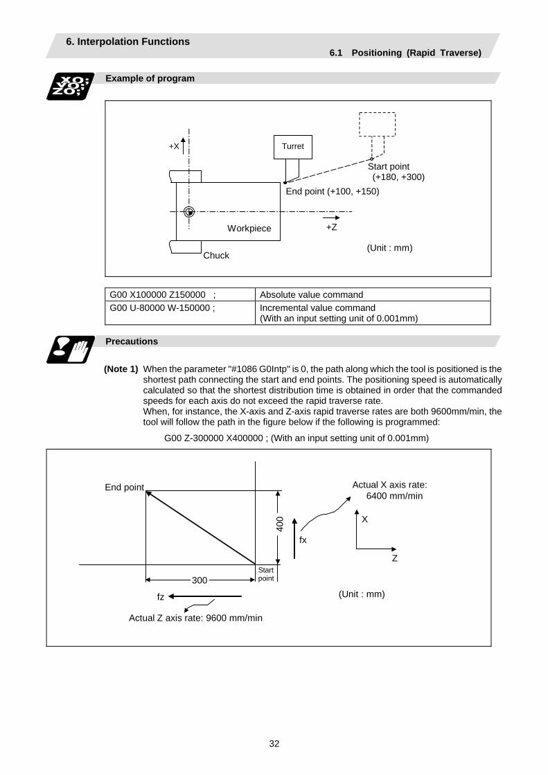
6. Interpolation Functions 6.1 Positioning (Rapid Traverse)
32
Example of program
Workpiece
Chuck
End point (+100, +150)
(Unit : mm)
+X
+Z
Start point (+180, +300)
Turret
G00 X100000 Z150000 ; Absolute value command G00 U-80000 W-150000 ; Incremental value command
(With an input setting unit of 0.001mm)
Precautions
(Note 1) When the parameter "#1086 G0Intp" is 0, the path along which the tool is positioned is the
shortest path connecting the start and end points. The positioning speed is automatically calculated so that the shortest distribution time is obtained in order that the commanded speeds for each axis do not exceed the rapid traverse rate.
When, for instance, the X-axis and Z-axis rapid traverse rates are both 9600mm/min, the tool will follow the path in the figure below if the following is programmed:
G00 Z-300000 X400000 ; (With an input setting unit of 0.001mm)
End point
(Unit : mm)
Start point
fz
fx
X
Z
300
400
Actual X axis rate: 6400 mm/min
Actual Z axis rate: 9600 mm/min

6. Interpolation Functions 6.1 Positioning (Rapid Traverse)
33
(Note 2) When parameter "#1086 G0Intp" is 1, the tool will move along the path from the start point
to the end point at the rapid traverse rate of each axis. When, for instance, the X-axis and Z-axis rapid traverse rates are both 9600 mm/min, the
tool will follow the path in the figure below if the following is programmed:
G00 Z − 300000 X400000 ; (With an input setting unit of 0.001mm)
fz
fx
X
Z
300 40
0
End point
Start point
(Unit : mm)
Actual X axis rate: 9600 mm/min
Actual Z axis rate: 9600 mm/min
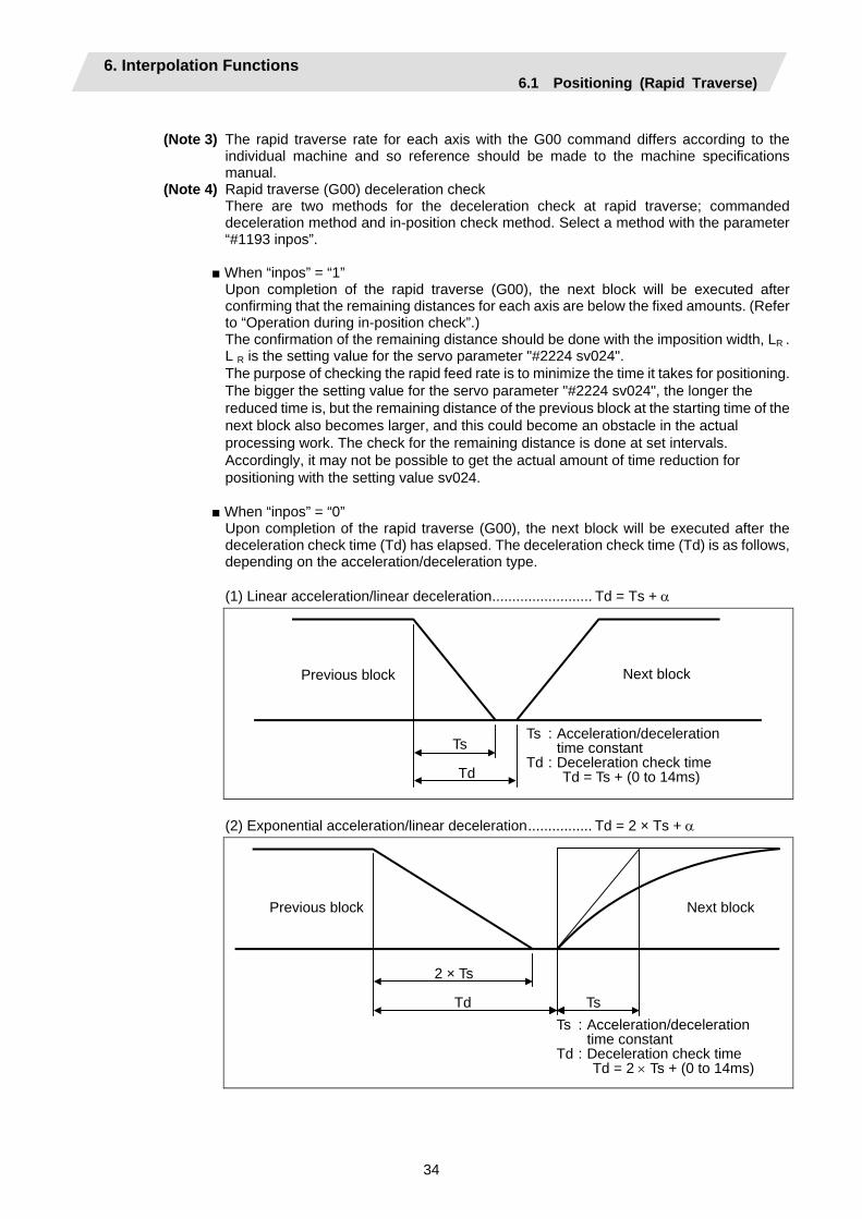
6. Interpolation Functions 6.1 Positioning (Rapid Traverse)
34
(Note 3) The rapid traverse rate for each axis with the G00 command differs according to the
individual machine and so reference should be made to the machine specifications manual.
(Note 4) Rapid traverse (G00) deceleration check There are two methods for the deceleration check at rapid traverse; commanded
deceleration method and in-position check method. Select a method with the parameter “#1193 inpos”.
When “inpos” = “1”
Upon completion of the rapid traverse (G00), the next block will be executed after confirming that the remaining distances for each axis are below the fixed amounts. (Refer to “Operation during in-position check”.)
The confirmation of the remaining distance should be done with the imposition width, LR . L R is the setting value for the servo parameter "#2224 sv024". The purpose of checking the rapid feed rate is to minimize the time it takes for positioning. The bigger the setting value for the servo parameter "#2224 sv024", the longer the reduced time is, but the remaining distance of the previous block at the starting time of the next block also becomes larger, and this could become an obstacle in the actual processing work. The check for the remaining distance is done at set intervals. Accordingly, it may not be possible to get the actual amount of time reduction for positioning with the setting value sv024.
When “inpos” = “0” Upon completion of the rapid traverse (G00), the next block will be executed after the
deceleration check time (Td) has elapsed. The deceleration check time (Td) is as follows, depending on the acceleration/deceleration type.
(1) Linear acceleration/linear deceleration......................... Td = Ts + α
Ts
Td
Previous block Next block
Ts : Acceleration/decelerationtime constant
Td : Deceleration check time Td = Ts + (0 to 14ms)
(2) Exponential acceleration/linear deceleration................ Td = 2 × Ts + α
2 × Ts
Td Ts
Previous block Next block
Ts : Acceleration/decelerationtime constant
Td : Deceleration check time Td = 2 × Ts + (0 to 14ms)
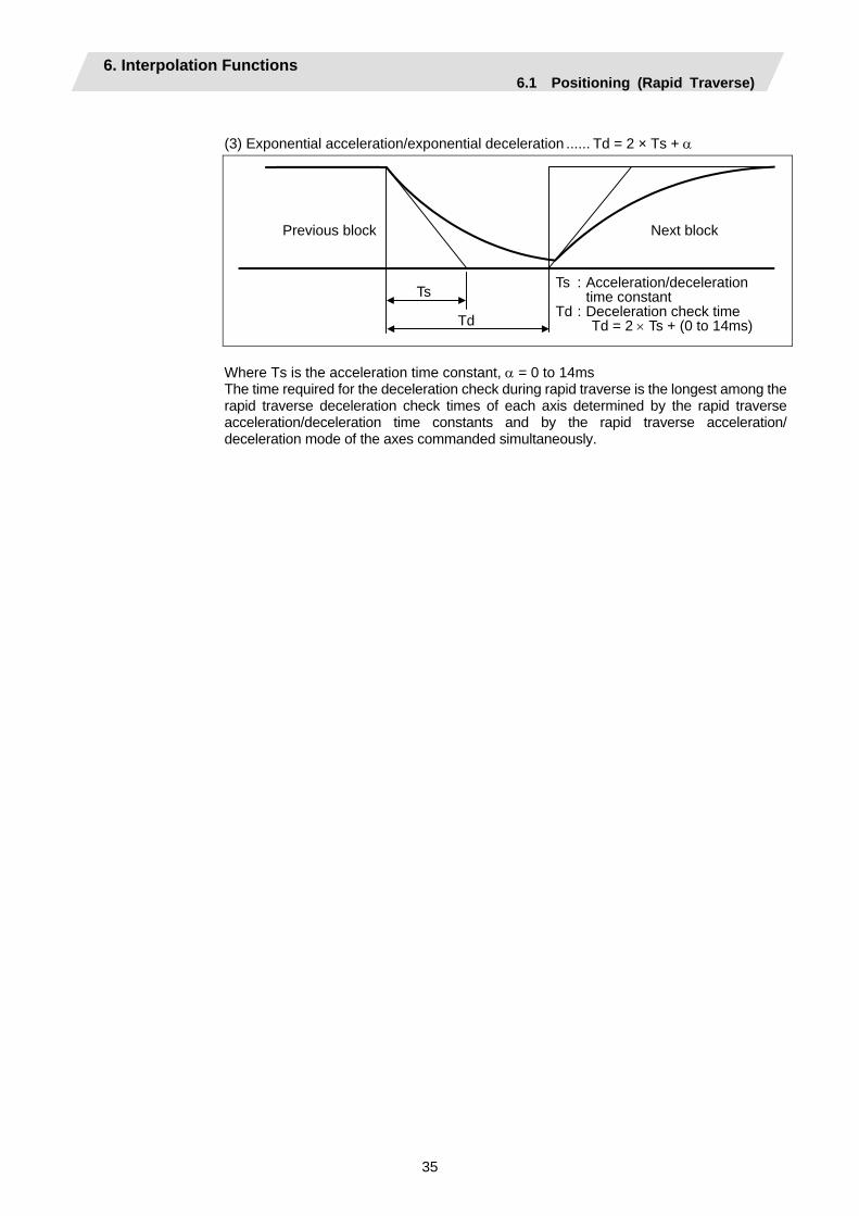
6. Interpolation Functions 6.1 Positioning (Rapid Traverse)
35
(3) Exponential acceleration/exponential deceleration ...... Td = 2 × Ts + α
Ts
Td
Previous block Next block
Ts : Acceleration/deceleration time constant
Td : Deceleration check time Td = 2 × Ts + (0 to 14ms)
Where Ts is the acceleration time constant, α = 0 to 14ms The time required for the deceleration check during rapid traverse is the longest among the
rapid traverse deceleration check times of each axis determined by the rapid traverse acceleration/deceleration time constants and by the rapid traverse acceleration/ deceleration mode of the axes commanded simultaneously.

6. Interpolation Functions 6.1 Positioning (Rapid Traverse)
36
Programmable in-position width command for positioning
This command commands the in-position width for the positioning command from the machining program. G00 X__ Z__ ,I__ ;
In-position width
Positioning coordinate value of each axis
Operation during in-position check
Execution of the next block starts after confirming that the position error amount of the positioning (rapid traverse: G00) command block and the block that carries out deceleration check with the linear interpolation (G01) command is less than the in-position width issued in this command. The in-position width in this command is valid only in the command block, so the deceleration check method set in base specification parameter "#1193 inpos" is used for blocks that do not have the in-position width command. When there are several movement axes, the system confirms that the position error amount of each movement axis in each part system is less than the in-position width issued in this command before executing the next block. The differences of when the in-position check is validated with the parameter (base specification parameter "#1193 inpos" set to 1; refer to next page for in-position width) and when validated with this command are shown below.
The differences of In-position check with parameter
In-position check with ",I" address command In-position check with parameter After starting deceleration of the command system, the position error amount and commanded in-position width are compared.
After starting deceleration of the command system, the servo system's position error amount and the parameter setting value (in-position width) are compared.
Servo Command In-position width(Error amount of command end point and machine position)
Start of in-position check with ",I" address command
Block being executed
Ts
Td
Servo Command In-position width (Servo system positionerror amount)
Start of in-position check with parameter
Block being executed
TsTd
Ts : Acceleration/deceleration time constant Td : Deceleration check time Td = Ts + (0 to 14ms)

6. Interpolation Functions 6.1 Positioning (Rapid Traverse)
37
G0/G1 in-position width setting
When the setting value of the servo parameter "#2224 SV024" is smaller than the setting value of the G0 in-position width "#2077 G0inps" and the G1 in-position width "#2078 G1inps", the in-position check is carried out with the G0 in-position width and the G1 in-position width.
In-position check using the "G0inps" value
Command to motor
Outline of motor movement
G0 in-position
SV024
A stop is judged here.
In-position check using the "G1inps" value
Command to motor
Outline of motor movement
G1 in-position
SV024
A stop is judged here.
When the SV024 value is larger, the in-position check is completed when the motor position becomes within the specified with SV024. The in-position check method depends on the method set in the deceleration check parameter.
(Note 1) The in-position width (programmable in-position check width) designated in the machining program has a priority over the in-position width set in the parameters (SV024, G0inps, G1inps).
(Note 2) When the SV024 setting value is larger than the G0 in-position width/G1 in-position width, the in-position check is carried out with the SV024 value.
(Note 3) When the error detection is ON, the in-position check is forcibly carried out.
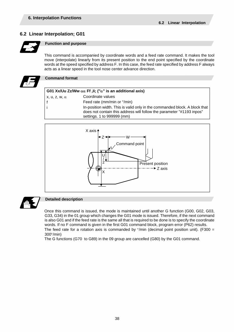
6. Interpolation Functions 6.2 Linear Interpolation
38
6.2 Linear Interpolation; G01
Function and purpose
This command is accompanied by coordinate words and a feed rate command. It makes the tool move (interpolate) linearly from its present position to the end point specified by the coordinate words at the speed specified by address F. In this case, the feed rate specified by address F always acts as a linear speed in the tool nose center advance direction.
Command format
G01 Xx/Uu Zz/Ww αα Ff ,Ii; ("α" is an additional axis) x, u, z, w, α f i
Coordinate values Feed rate (mm/min or °/min) In-position width. This is valid only in the commanded block. A block that does not contain this address will follow the parameter "#1193 inpos" settings. 1 to 999999 (mm)
X axis
Z axis X
Present position
U/2
Z W
Command point
Detailed description
Once this command is issued, the mode is maintained until another G function (G00, G02, G03, G33, G34) in the 01 group which changes the G01 mode is issued. Therefore, if the next command is also G01 and if the feed rate is the same all that is required to be done is to specify the coordinate words. If no F command is given in the first G01 command block, program error (P62) results. The feed rate for a rotation axis is commanded by °/min (decimal point position unit). (F300 = 300°/min) The G functions (G70 to G89) in the 09 group are cancelled (G80) by the G01 command.
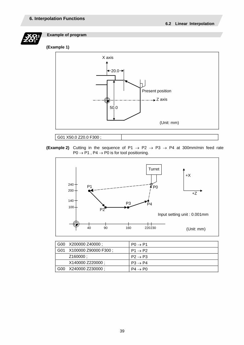
6. Interpolation Functions 6.2 Linear Interpolation
39
Example of program
(Example 1)
20.0
50.0
Z axis
Present position
X axis
(Unit: mm)
G01 X50.0 Z20.0 F300 ;
(Example 2) Cutting in the sequence of P1 → P2 → P3 → P4 at 300mm/min feed rate P0 → P1 , P4 → P0 is for tool positioning.
Turret
240
200
140
100
2209040 230160
P1
P2P3 P4
P0
+X
+Z
Input setting unit : 0.001mm
(Unit: mm)
G00 X200000 Z40000 ; P0 → P1 G01 X100000 Z90000 F300 ; P1 → P2 Z160000 ; P2 → P3 X140000 Z220000 ; P3 → P4 G00 X240000 Z230000 ; P4 → P0
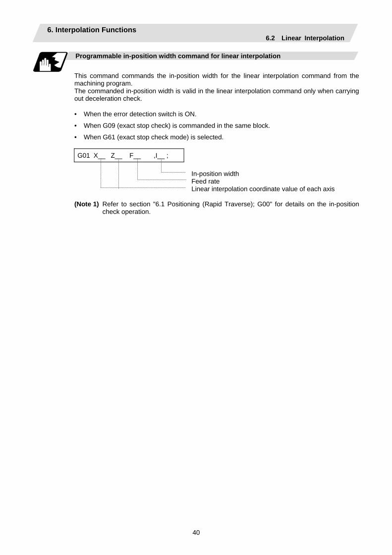
6. Interpolation Functions 6.2 Linear Interpolation
40
Programmable in-position width command for linear interpolation
This command commands the in-position width for the linear interpolation command from the machining program. The commanded in-position width is valid in the linear interpolation command only when carrying out deceleration check.
• When the error detection switch is ON.
• When G09 (exact stop check) is commanded in the same block.
• When G61 (exact stop check mode) is selected. G01 X__ Z__ F__ ,I__ ;
In-position width Feed rate Linear interpolation coordinate value of each axis
(Note 1) Refer to section "6.1 Positioning (Rapid Traverse); G00" for details on the in-position check operation.
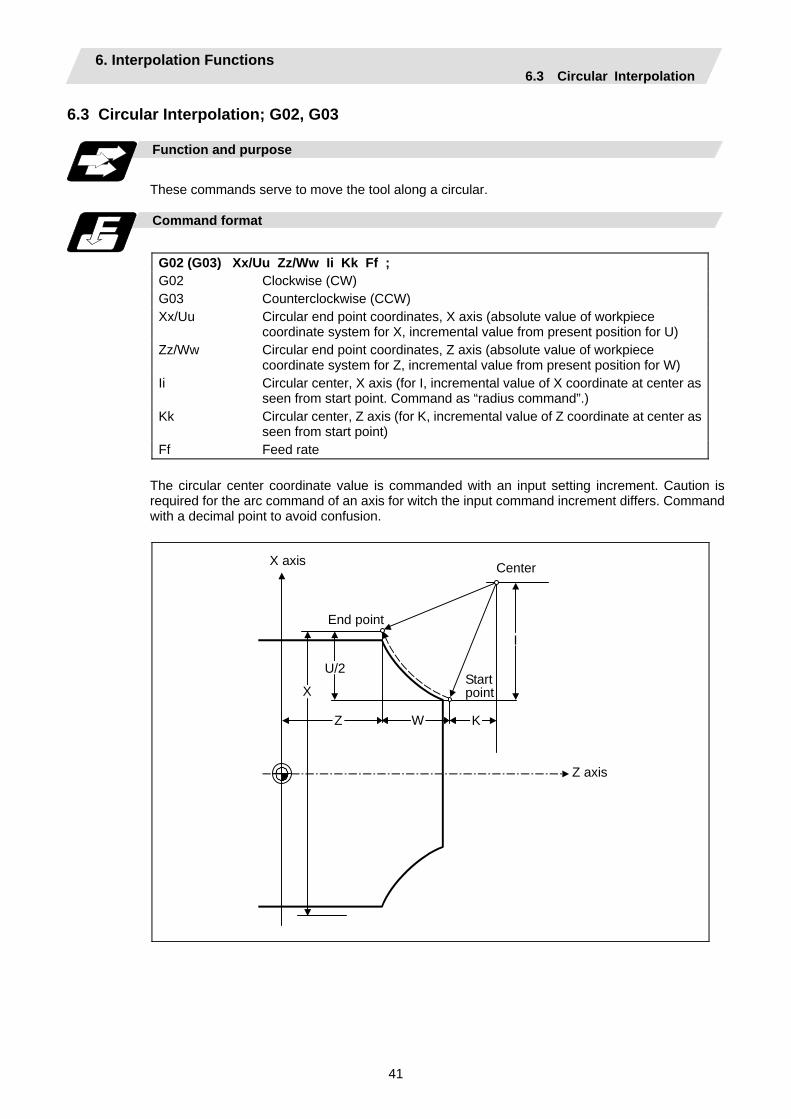
6. Interpolation Functions 6.3 Circular Interpolation
41
6.3 Circular Interpolation; G02, G03 Function and purpose
These commands serve to move the tool along a circular.
Command format
G02 (G03) Xx/Uu Zz/Ww Ii Kk Ff ; G02 Clockwise (CW) G03 Counterclockwise (CCW) Xx/Uu Circular end point coordinates, X axis (absolute value of workpiece
coordinate system for X, incremental value from present position for U) Zz/Ww Circular end point coordinates, Z axis (absolute value of workpiece
coordinate system for Z, incremental value from present position for W) Ii Circular center, X axis (for I, incremental value of X coordinate at center as
seen from start point. Command as “radius command”.) Kk Circular center, Z axis (for K, incremental value of Z coordinate at center as
seen from start point) Ff Feed rate
The circular center coordinate value is commanded with an input setting increment. Caution is required for the arc command of an axis for witch the input command increment differs. Command with a decimal point to avoid confusion.
X
Z KW
U/2
IEnd point
Start point
Z axis
CenterX axis
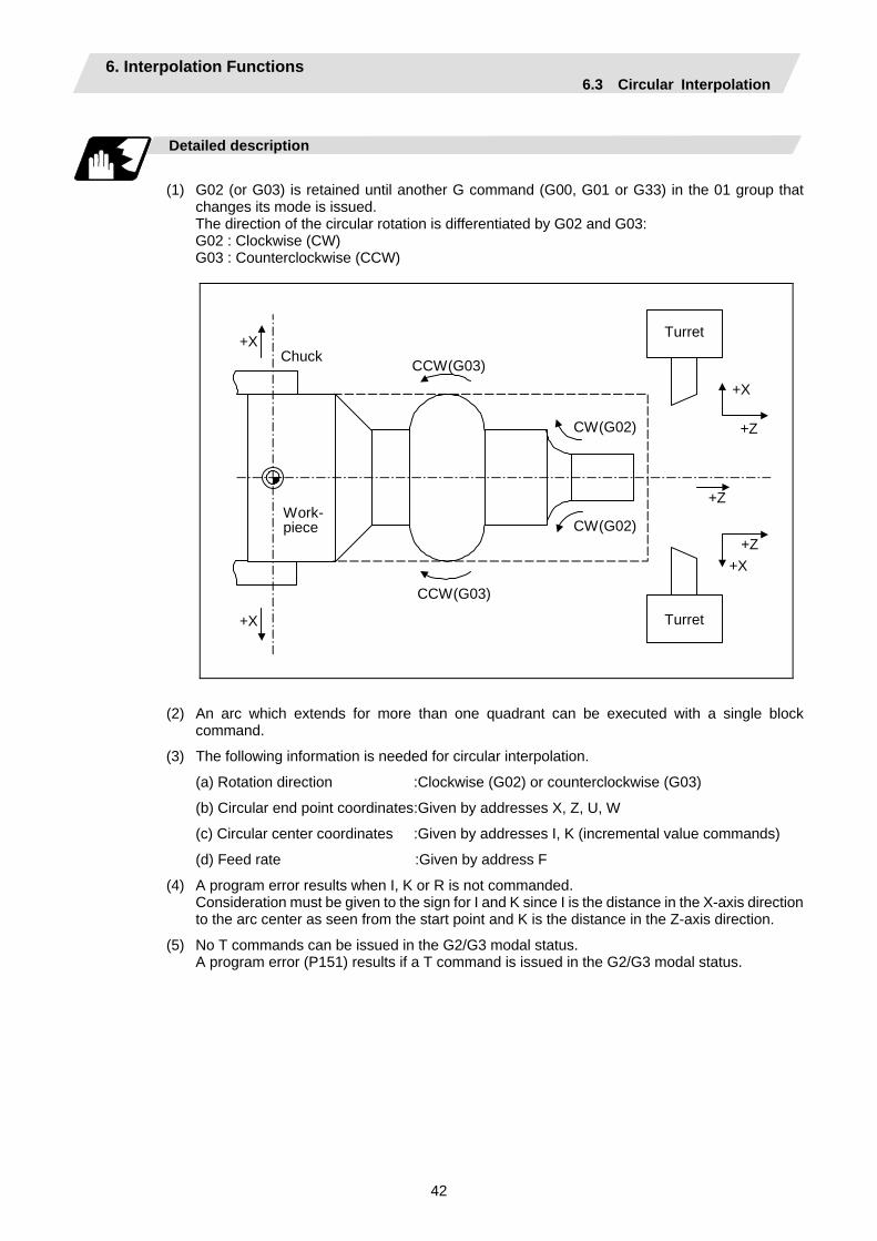
6. Interpolation Functions 6.3 Circular Interpolation
42
Detailed description
(1) G02 (or G03) is retained until another G command (G00, G01 or G33) in the 01 group that
changes its mode is issued. The direction of the circular rotation is differentiated by G02 and G03: G02 : Clockwise (CW) G03 : Counterclockwise (CCW)
Turret
Turret +X
+X
+X
+X
+Z
+Z
+Z
CCW(G03)
CCW(G03)
CW(G02)
CW(G02)
Chuck
Work- piece
(2) An arc which extends for more than one quadrant can be executed with a single block command.
(3) The following information is needed for circular interpolation.
(a) Rotation direction :Clockwise (G02) or counterclockwise (G03)
(b) Circular end point coordinates :Given by addresses X, Z, U, W
(c) Circular center coordinates :Given by addresses I, K (incremental value commands)
(d) Feed rate :Given by address F
(4) A program error results when I, K or R is not commanded. Consideration must be given to the sign for I and K since I is the distance in the X-axis direction to the arc center as seen from the start point and K is the distance in the Z-axis direction.
(5) No T commands can be issued in the G2/G3 modal status. A program error (P151) results if a T command is issued in the G2/G3 modal status.

6. Interpolation Functions 6.3 Circular Interpolation
43
Example of program
120.0
20.0
70.0 50.0
50.0
(Unit: mm)
Z axis
X axis
Workpiece coordinatezero point
G2 X120.0 Z70.0 I50.0 F200 ; Absolute value command G2 U100.0 W-50.0 I50.0 F200 ; Incremental value command
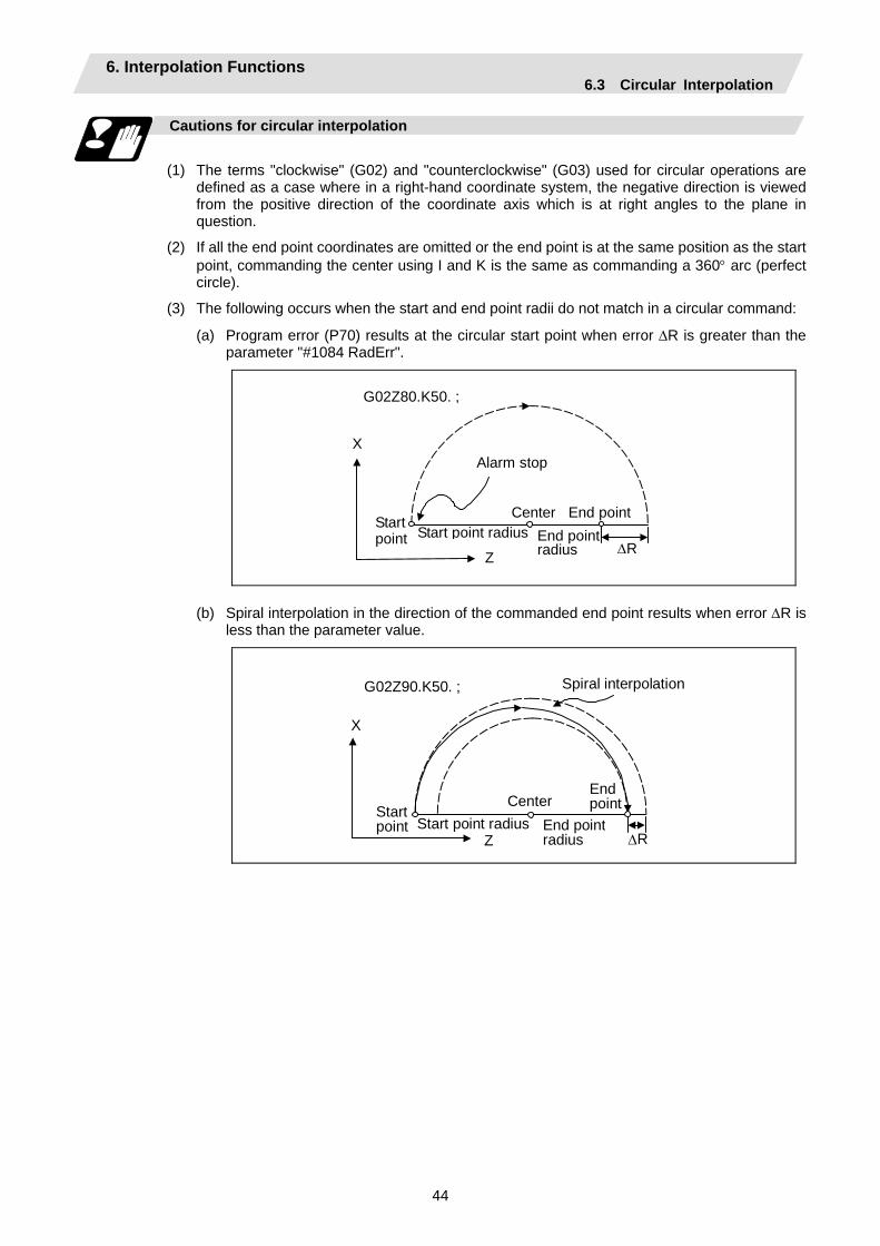
6. Interpolation Functions 6.3 Circular Interpolation
44
Cautions for circular interpolation
(1) The terms "clockwise" (G02) and "counterclockwise" (G03) used for circular operations are
defined as a case where in a right-hand coordinate system, the negative direction is viewed from the positive direction of the coordinate axis which is at right angles to the plane in question.
(2) If all the end point coordinates are omitted or the end point is at the same position as the start point, commanding the center using I and K is the same as commanding a 360° arc (perfect circle).
(3) The following occurs when the start and end point radii do not match in a circular command:
(a) Program error (P70) results at the circular start point when error ∆R is greater than the parameter "#1084 RadErr".
G02Z80.K50. ;
∆R
X
Z
Alarm stop
Start point radius End point radius
Center End point Start point
(b) Spiral interpolation in the direction of the commanded end point results when error ∆R is less than the parameter value.
Spiral interpolation
∆R
G02Z90.K50. ;
X
ZStart point radius End point
radius
CenterStart point
Endpoint
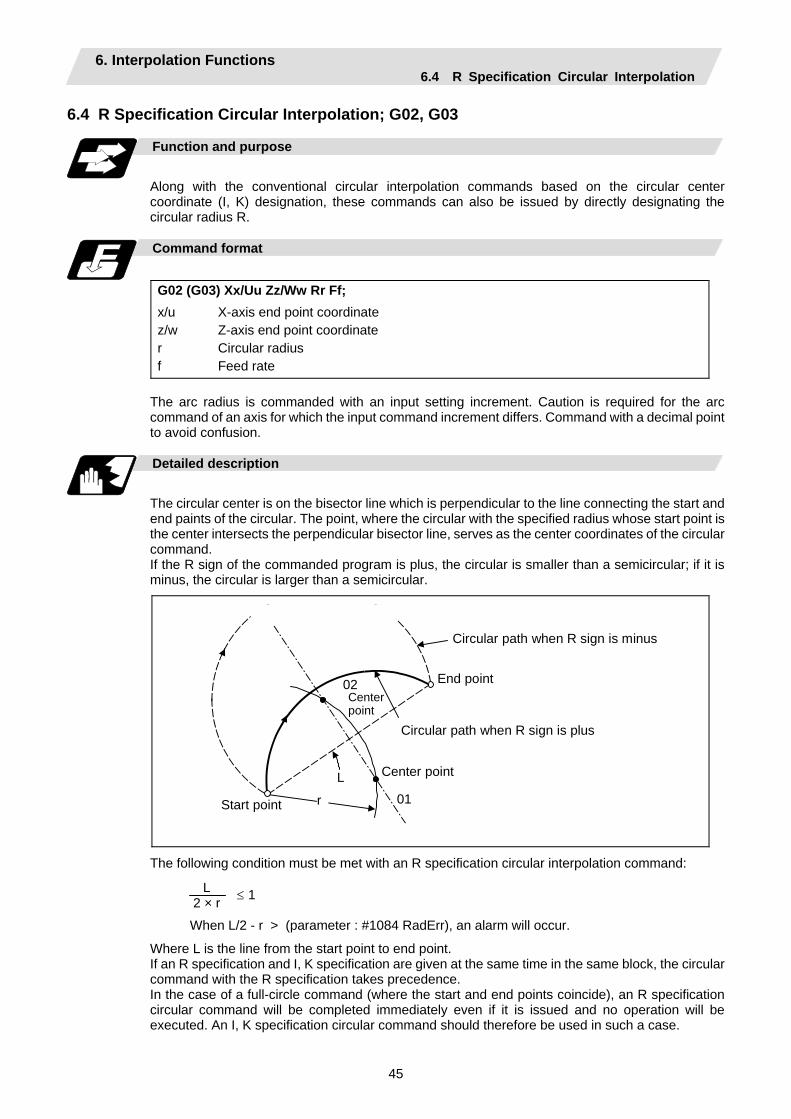
6. Interpolation Functions 6.4 R Specification Circular Interpolation
45
6.4 R Specification Circular Interpolation; G02, G03
Function and purpose
Along with the conventional circular interpolation commands based on the circular center coordinate (I, K) designation, these commands can also be issued by directly designating the circular radius R.
Command format
G02 (G03) Xx/Uu Zz/Ww Rr Ff; x/u z/w r f
X-axis end point coordinate Z-axis end point coordinate Circular radius Feed rate
The arc radius is commanded with an input setting increment. Caution is required for the arc command of an axis for which the input command increment differs. Command with a decimal point to avoid confusion.
Detailed description
The circular center is on the bisector line which is perpendicular to the line connecting the start and end paints of the circular. The point, where the circular with the specified radius whose start point is the center intersects the perpendicular bisector line, serves as the center coordinates of the circular command. If the R sign of the commanded program is plus, the circular is smaller than a semicircular; if it is minus, the circular is larger than a semicircular.
01
02
L
r
Circular path when R sign is minus
End point
Circular path when R sign is plus
Center point
Center point
Start point
The following condition must be met with an R specification circular interpolation command: ≤ 1
When L/2 - r > (parameter : #1084 RadErr), an alarm will occur.
Where L is the line from the start point to end point. If an R specification and I, K specification are given at the same time in the same block, the circular command with the R specification takes precedence. In the case of a full-circle command (where the start and end points coincide), an R specification circular command will be completed immediately even if it is issued and no operation will be executed. An I, K specification circular command should therefore be used in such a case.
L 2 × r
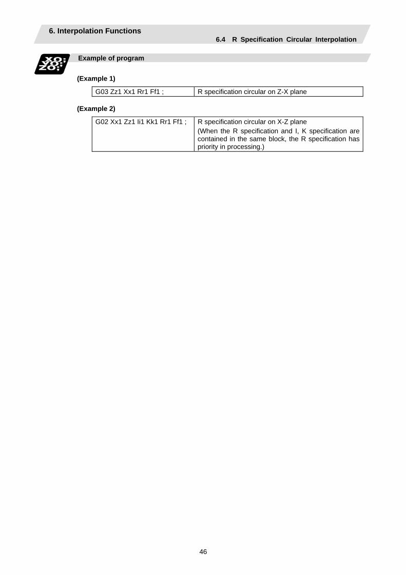
6. Interpolation Functions 6.4 R Specification Circular Interpolation
46
Example of program
(Example 1)
G03 Zz1 Xx1 Rr1 Ff1 ; R specification circular on Z-X plane
(Example 2)
G02 Xx1 Zz1 Ii1 Kk1 Rr1 Ff1 ; R specification circular on X-Z plane (When the R specification and I, K specification are contained in the same block, the R specification has priority in processing.)
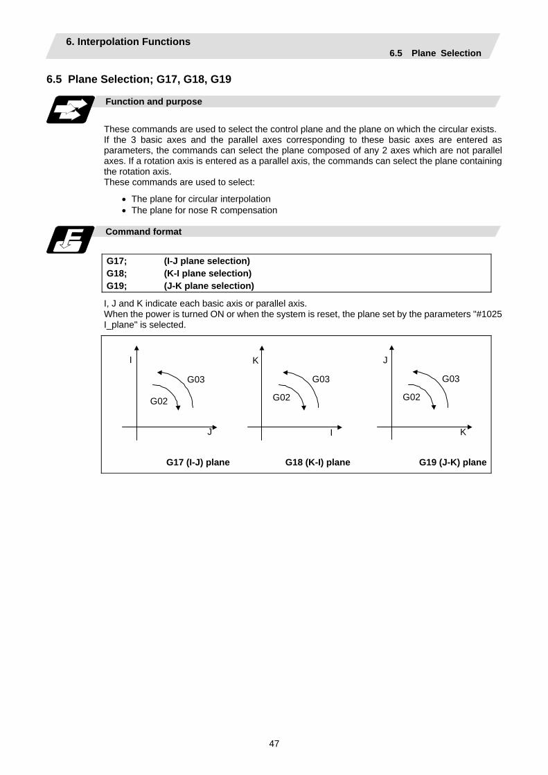
6. Interpolation Functions 6.5 Plane Selection
47
6.5 Plane Selection; G17, G18, G19
Function and purpose
These commands are used to select the control plane and the plane on which the circular exists. If the 3 basic axes and the parallel axes corresponding to these basic axes are entered as parameters, the commands can select the plane composed of any 2 axes which are not parallel axes. If a rotation axis is entered as a parallel axis, the commands can select the plane containing the rotation axis. These commands are used to select:
• The plane for circular interpolation • The plane for nose R compensation
Command format
G17; G18; G19;
(I-J plane selection) (K-I plane selection) (J-K plane selection)
I, J and K indicate each basic axis or parallel axis. When the power is turned ON or when the system is reset, the plane set by the parameters "#1025 I_plane" is selected.
I
J
G02
G03
I
K
G02
G03
K
J
G02
G03
G17 (I-J) plane G18 (K-I) plane G19 (J-K) plane
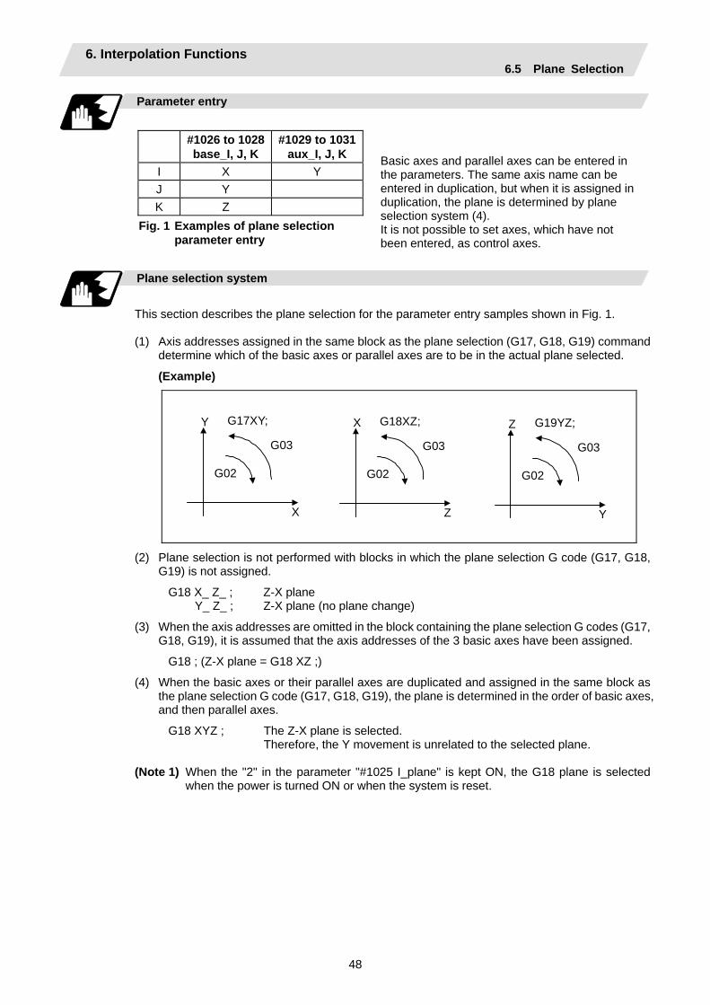
6. Interpolation Functions 6.5 Plane Selection
48
Parameter entry
#1026 to 1028
base_I, J, K #1029 to 1031
aux_I, J, K I X Y J Y K Z
Plane selection system
This section describes the plane selection for the parameter entry samples shown in Fig. 1.
(1) Axis addresses assigned in the same block as the plane selection (G17, G18, G19) command
determine which of the basic axes or parallel axes are to be in the actual plane selected.
(Example)
G17XY; Y
X
G02
G03
G18XZ; X
Z
G02
G03
G19YZ; Z
Y
G02
G03
(2) Plane selection is not performed with blocks in which the plane selection G code (G17, G18, G19) is not assigned.
G18 X_ Z_ ; Z-X plane Y_ Z_ ; Z-X plane (no plane change)
(3) When the axis addresses are omitted in the block containing the plane selection G codes (G17, G18, G19), it is assumed that the axis addresses of the 3 basic axes have been assigned.
G18 ; (Z-X plane = G18 XZ ;)
(4) When the basic axes or their parallel axes are duplicated and assigned in the same block as the plane selection G code (G17, G18, G19), the plane is determined in the order of basic axes, and then parallel axes.
G18 XYZ ; The Z-X plane is selected. Therefore, the Y movement is unrelated to the selected plane.
(Note 1) When the "2" in the parameter "#1025 I_plane" is kept ON, the G18 plane is selected
when the power is turned ON or when the system is reset.
Basic axes and parallel axes can be entered in the parameters. The same axis name can be entered in duplication, but when it is assigned in duplication, the plane is determined by plane selection system (4). It is not possible to set axes, which have not been entered, as control axes.
Fig. 1 Examples of plane selection parameter entry
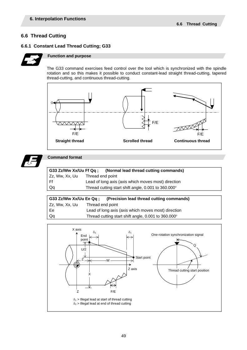
6. Interpolation Functions 6.6 Thread Cutting
49
6.6 Thread Cutting 6.6.1 Constant Lead Thread Cutting; G33
Function and purpose
The G33 command exercises feed control over the tool which is synchronized with the spindle rotation and so this makes it possible to conduct constant-lead straight thread-cutting, tapered thread-cutting, and continuous thread-cutting.
Straight thread Scrolled thread Continuous thread
F/E
F/E
F/E
Command format
G33 Zz/Ww Xx/Uu Ff Qq ; (Normal lead thread cutting commands) Zz, Ww, Xx, Uu Ff Qq
Thread end point Lead of long axis (axis which moves most) direction Thread cutting start shift angle, 0.001 to 360.000°
G33 Zz/Ww Xx/Uu Ee Qq ; (Precision lead thread cutting commands) Zz, Ww, Xx, Uu Ee Qq
Thread end point Lead of long axis (axis which moves most) direction Thread cutting start shift angle, 0.001 to 360.000°
Z
Z
U/2
X
Q
One-rotation synchronization signal
Thread cutting start position
W
δ2 δ1
δ1 > Illegal lead at start of thread cutting δ2 > Illegal lead at end of thread cutting
X axis
Start point
End point
Z axis
F/E

6. Interpolation Functions 6.6 Thread Cutting
50
Detailed description
(1) The E command is also used for the number of ridges in inch thread cutting, and whether the
number of ridges or precision lead is to be designated can be selected by parameter setting. (Parameter "#1229 set 01/bit" is set to "1" for precision lead designation.)
(2) The lead in the long axis direction is commanded for the taper thread lead.
When a < 45°, Lead is in Z-axis direction. When a > 45°, Lead is in X-axis direction. When a = 45°, Lead can be in either Z or X-axis direction.
U/2
W
a°
Tapered thread section
X axis
Start point
End point
Z axis
Thread cutting metric input
Input setting unit B (0.001mm) C (0.0001mm)
Command address F (mm/rev) E (mm/rev) E (ridges/inch) F (mm/rev) E (mm/rev) E (ridges/inch)
Least command increment
1 (=1.000), (1.=1.000)
1 (= 1.00000), (1.=1.00000)
1 (= 1.00), (1.=1.00)
1 (= 1.0000), (1.=1.0000)
1(=1.000000), (1.=1.000000)
1 (= 1.000), (1.=1.000)
Command range
0.001 to 999.999
0.00001 to 999.99999
0.03 to 999.99
0.0001 to 999.9999
0.000001 to 999.999999
0.255 to 999.999
Input
setting unit D (0.00001mm) E (0.000001mm)
Command address F (mm/rev) E (mm/rev) E (ridges/inch) F (mm/rev) E (mm/rev) E (ridges/inch)
Least command increment
1 (= 1.00000), (1.=1.00000)
1 (= 1.0000000),(1.=1.0000000)
1 (= 1.0000), (1.=1.0000)
1 (= 1.000000),(1.=1.000000)
1 (=1.00000000), (1.=1.00000000)
1 (= 1.00000), (1.=1.00000)
Command range
0.00001 to 999.99999
0.0000001 to 999.9999999
0.2550 to 999.9999
0.000001 to 999.999999
0.00000001 to 999.99999999
0.25500 to 999.99999
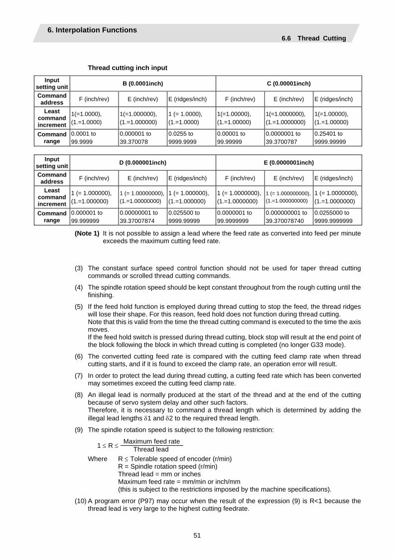
6. Interpolation Functions 6.6 Thread Cutting
51
Thread cutting inch input
Input setting unit B (0.0001inch) C (0.00001inch)
Command address F (inch/rev) E (inch/rev) E (ridges/inch) F (inch/rev) E (inch/rev) E (ridges/inch)
Least command increment
1(=1.0000), (1.=1.0000)
1(=1.000000), (1.=1.000000)
1 (= 1.0000), (1.=1.0000)
1(=1.00000), (1.=1.00000)
1(=1.0000000), (1.=1.0000000)
1(=1.00000), (1.=1.00000)
Command range
0.0001 to 99.9999
0.000001 to 39.370078
0.0255 to 9999.9999
0.00001 to 99.99999
0.0000001 to 39.3700787
0.25401 to 9999.99999
Input
setting unit D (0.000001inch) E (0.0000001inch)
Command address F (inch/rev) E (inch/rev) E (ridges/inch) F (inch/rev) E (inch/rev) E (ridges/inch)
Least command increment
1 (= 1.000000), (1.=1.000000)
1 (= 1.00000000),(1.=1.00000000)
1 (= 1.000000), (1.=1.000000)
1 (= 1.0000000),(1.=1.0000000)
1 (= 1.000000000), (1.=1.000000000)
1 (= 1.0000000),(1.=1.0000000)
Command range
0.000001 to 99.999999
0.00000001 to 39.37007874
0.025500 to 9999.99999
0.0000001 to 99.9999999
0.000000001 to 39.370078740
0.0255000 to 9999.9999999
(Note 1) It is not possible to assign a lead where the feed rate as converted into feed per minute exceeds the maximum cutting feed rate.
(3) The constant surface speed control function should not be used for taper thread cutting commands or scrolled thread cutting commands.
(4) The spindle rotation speed should be kept constant throughout from the rough cutting until the finishing.
(5) If the feed hold function is employed during thread cutting to stop the feed, the thread ridges will lose their shape. For this reason, feed hold does not function during thread cutting. Note that this is valid from the time the thread cutting command is executed to the time the axis moves. If the feed hold switch is pressed during thread cutting, block stop will result at the end point of the block following the block in which thread cutting is completed (no longer G33 mode).
(6) The converted cutting feed rate is compared with the cutting feed clamp rate when thread cutting starts, and if it is found to exceed the clamp rate, an operation error will result.
(7) In order to protect the lead during thread cutting, a cutting feed rate which has been converted may sometimes exceed the cutting feed clamp rate.
(8) An illegal lead is normally produced at the start of the thread and at the end of the cutting because of servo system delay and other such factors. Therefore, it is necessary to command a thread length which is determined by adding the illegal lead lengths δ1 and δ2 to the required thread length.
(9) The spindle rotation speed is subject to the following restriction:
1 ≤ R ≤ Maximum feed rate Thread lead
Where R ≤ Tolerable speed of encoder (r/min) R = Spindle rotation speed (r/min) Thread lead = mm or inches Maximum feed rate = mm/min or inch/mm (this is subject to the restrictions imposed by the machine specifications).
(10) A program error (P97) may occur when the result of the expression (9) is R<1 because the thread lead is very large to the highest cutting feedrate.

6. Interpolation Functions 6.6 Thread Cutting
52
(11) Dry run is valid for thread cutting but the feed rate based on dry run is not synchronized with the
spindle rotation. The dry run signal is checked at the start of thread cutting and any switching during thread
cutting is ignored.
(12) Synchronous feed applies for the thread cutting commands even with an asynchronous feed command (G94).
(13) Spindle override and cutting feed override are invalid and the speeds are fixed to 100% during thread cutting.
(14) When a thread cutting command is programmed during nose R compensation, the compensation is temporarily canceled and the thread cutting is executed.
(15) When the mode is switched to another automatic mode while G33 is executed, the following block which does not contain a thread cutting command is first executed and then the automatic operation stops.
(16) When the mode is switched to the manual mode while G33 is executed, the following block which does not contain a thread cutting command is first executed and then the automatic operation stops. In the case of a single block, the following block which does not contain a thread cutting command (When G33 mode is cancelled) is first executed and then the automatic operation stops. Note that automatic operation is stopped until the G33 command axis starts moving.
(17) The thread cutting command waits for the single rotation sync signal of the rotary encoder and starts movement. Note that carry out synchronization between part systems before issuing a thread cutting command with multiple part systems. For example, when using the 1-spindle specifications with multi-part systems, if one part system issues a thread cutting command during ongoing thread cutting by another part system, the movement will start without waiting for the rotary encoder single rotation sync signal.
(18) The thread cutting start shift angle is not a modal. If there is no Q command with G33, this will be handled as "Q0".
(19) The automatic handle interrupt/interruption is valid during thread cutting.
(20) If a value exceeding 360.000 is commanded with G33 Q, a program error (P35) will occur.
(21) G33 cuts one row with one cycle. To cut two rows, change the Q value, and issue the same command.
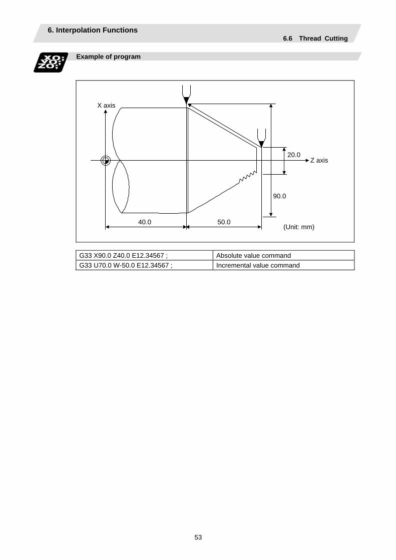
6. Interpolation Functions 6.6 Thread Cutting
53
Example of program
40.0 50.0
90.0
20.0 Z axis
X axis
(Unit: mm)
G33 X90.0 Z40.0 E12.34567 ; Absolute value command G33 U70.0 W-50.0 E12.34567 ; Incremental value command
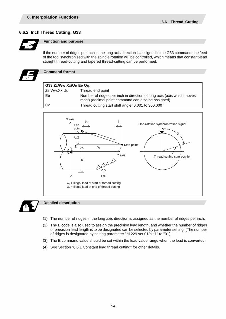
6. Interpolation Functions 6.6 Thread Cutting
54
6.6.2 Inch Thread Cutting; G33
Function and purpose
If the number of ridges per inch in the long axis direction is assigned in the G33 command, the feed of the tool synchronized with the spindle rotation will be controlled, which means that constant-lead straight thread-cutting and tapered thread-cutting can be performed.
Command format
G33 Zz/Ww Xx/Uu Ee Qq; Zz,Ww,Xx,Uu Ee Qq
Thread end point Number of ridges per inch in direction of long axis (axis which moves most) (decimal point command can also be assigned) Thread cutting start shift angle, 0.001 to 360.000°
Z
Z
U/2
X
Q
One-rotation synchronization signal
Thread cutting start position
W
δ2 δ1
δ1 > Illegal lead at start of thread cutting δ2 > Illegal lead at end of thread cutting
X axis
Start point
End point
Z axis
F/E
Detailed description
(1) The number of ridges in the long axis direction is assigned as the number of ridges per inch.
(2) The E code is also used to assign the precision lead length, and whether the number of ridges or precision lead length is to be designated can be selected by parameter setting. (The number of ridges is designated by setting parameter "#1229 set 01/bit 1" to "0".)
(3) The E command value should be set within the lead value range when the lead is converted.
(4) See Section "6.6.1 Constant lead thread cutting" for other details.
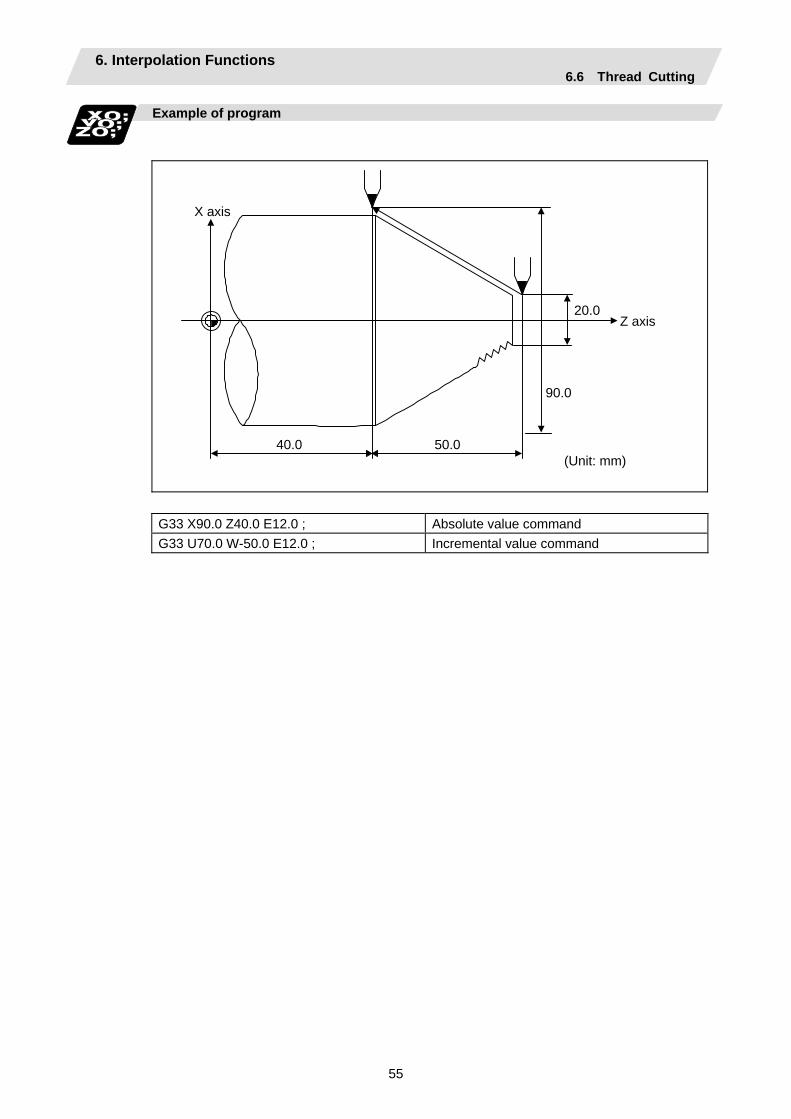
6. Interpolation Functions 6.6 Thread Cutting
55
Example of program
40.0 50.0
90.0
20.0 Z axis
X axis
(Unit: mm)
G33 X90.0 Z40.0 E12.0 ; Absolute value command G33 U70.0 W-50.0 E12.0 ; Incremental value command
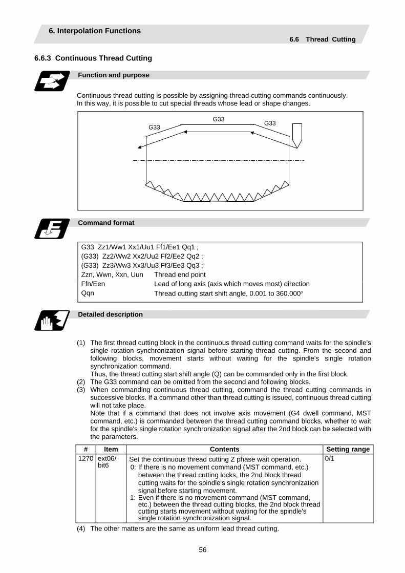
6. Interpolation Functions 6.6 Thread Cutting
56
6.6.3 Continuous Thread Cutting Function and purpose
Continuous thread cutting is possible by assigning thread cutting commands continuously. In this way, it is possible to cut special threads whose lead or shape changes.
G33G33
G33
Command format
G33 Zz1/Ww1 Xx1/Uu1 Ff1/Ee1 Qq1 ; (G33) Zz2/Ww2 Xx2/Uu2 Ff2/Ee2 Qq2 ; (G33) Zz3/Ww3 Xx3/Uu3 Ff3/Ee3 Qq3 ; Zzn, Wwn, Xxn, Uun Ffn/Een Qqn
Thread end point Lead of long axis (axis which moves most) direction Thread cutting start shift angle, 0.001 to 360.000°
Detailed description
(1) The first thread cutting block in the continuous thread cutting command waits for the spindle's single rotation synchronization signal before starting thread cutting. From the second and following blocks, movement starts without waiting for the spindle's single rotation synchronization command.
Thus, the thread cutting start shift angle (Q) can be commanded only in the first block. (2) The G33 command can be omitted from the second and following blocks. (3) When commanding continuous thread cutting, command the thread cutting commands in
successive blocks. If a command other than thread cutting is issued, continuous thread cutting will not take place.
Note that if a command that does not involve axis movement (G4 dwell command, MST command, etc.) is commanded between the thread cutting command blocks, whether to wait for the spindle's single rotation synchronization signal after the 2nd block can be selected with the parameters.
# Item Contents Setting range1270 ext06/
bit6 Set the continuous thread cutting Z phase wait operation. 0: If there is no movement command (MST command, etc.)
between the thread cutting locks, the 2nd block thread cutting waits for the spindle's single rotation synchronization signal before starting movement.
1: Even if there is no movement command (MST command, etc.) between the thread cutting blocks, the 2nd block thread cutting starts movement without waiting for the spindle's single rotation synchronization signal.
0/1
(4) The other matters are the same as uniform lead thread cutting.

6. Interpolation Functions 6.6 Thread Cutting
57
6.6.4 Variable Lead Thread Cutting; G34
Function and purpose
Variable lead thread cutting is enabled by a command specifying a lead increment or decrement amount per turn of the screw.
Command format
G34 Xx/Uu Zz/Ww Ff/Ee Kk ; Xx/Uu Zz/Ww Ff/Ee Kk
Thread end point Standard screw lead Lead increment or decrement amount per turn of the screw
F+3.5K
Non-lead axis
Lead axis
F+2.5K F+1.5K F+0.5K
Lead speedF+4K
F+3K F+2K F+K F
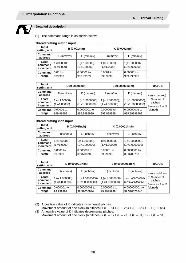
6. Interpolation Functions 6.6 Thread Cutting
58
Detailed description
(1) The command range is as shown below.
Thread cutting metric input
Input setting unit B (0.001mm) C (0.0001mm)
Command address F (mm/rev) E (mm/rev) F (mm/rev) E (mm/rev)
Least command increment
1 (=1.000), (1.=1.000)
1 (= 1.00000), (1.=1.00000)
1 (= 1.0000), (1.=1.0000)
1(=1.000000), (1.=1.000000)
Command range
0.001 to 999.999
0.00001 to 999.99999
0.0001 to 999.9999
0.000001 to 999.999999
Input setting unit D (0.00001mm) E (0.000001mm) B/C/D/E
Command address F (mm/rev) E (mm/rev) F (mm/rev) E (mm/rev)
Least command increment
1 (= 1.00000), (1.=1.00000)
1 (= 1.0000000),(1.=1.0000000)
1 (= 1.000000), (1.=1.000000)
1 (=1.00000000), (1.=1.00000000)
Command range
0.00001 to 999.99999
0.0000001 to 999.9999999
0.000001 to 999.999999
0.00000001 to 999.99999999
K (n ∗ mm/rev) n: Number of
pitches Same as F or E (signed)
Thread cutting inch input
Input setting unit B (0.0001inch) C (0.00001inch)
Command address F (inch/rev) E (inch/rev) F (inch/rev) E (inch/rev)
Least command increment
1(=1.0000), (1.=1.0000)
1(=1.000000), (1.=1.000000)
1(=1.00000), (1.=1.00000)
1(=1.0000000), (1.=1.0000000)
Command range
0.0001 to 99.9999
0.000001 to 39.370078
0.00001 to 99.99999
0.0000001 to 39.3700787
Input setting unit D (0.000001inch) E (0.0000001inch) B/C/D/E
Command address F (inch/rev) E (inch/rev) F (inch/rev) E (inch/rev)
Least command increment
1 (= 1.000000), (1.=1.000000)
1 (= 1.00000000),(1.=1.00000000)
1 (= 1.0000000),(1.=1.0000000)
1 (= 1.000000000), (1.=1.000000000)
Command range
0.000001 to 99.999999
0.00000001 to 39.37007874
0.0000001 to 99.9999999
0.000000001 to 39.370078740
K (n ∗ inch/rev)n: Number of
pitches Same as F or E (signed)
(2) A positive value of K indicates incremental pitches. Movement amount of one block (n pitches) = (F + K) + (F + 2K) + (F + 3K) + · · + (F + nK) (3) A negative value of K indicates decremental pitches. Movement amount of one block (n pitches) = (F – K) + (F – 2K) + (F – 3K) + · · + (F – nK)
6. Interpolation Functions 6.6 Thread Cutting
59
(4) A program error will occur if the thread lead is not set correctly.
Error No. Meaning Remedy
P93 Illegal pitch value (1) An invalid value is specified for F/E
or K in a thread cutting command. (2) The last lead goes outside of the F/E
command range.
Specify valid values for F/E and K. (Reference 1)
(Reference 1) Last lead = (F2+2KZ) Number of pitches = (–F + last lead)/K Z: Length of lead axis
(5) The other matters are the same as G33. Refer to section "6.6.1 Constant lead thread cutting; G33".
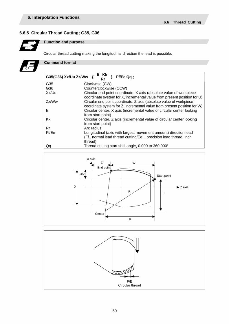
6. Interpolation Functions 6.6 Thread Cutting
60
6.6.5 Circular Thread Cutting; G35, G36
Function and purpose
Circular thread cutting making the longitudinal direction the lead is possible.
Command format
G35(G36) Xx/Uu Zz/Ww Ii Kk
Rr Ff/Ee Qq ;
G35 G36 Xx/Uu Zz/Ww Ii Kk Rr Ff/Ee Qq
Clockwise (CW) Counterclockwise (CCW) Circular end point coordinate, X axis (absolute value of workpiece coordinate system for X, incremental value from present position for U)Circular end point coordinate, Z axis (absolute value of workpiece coordinate system for Z, incremental value from present position for W)Circular center, X axis (incremental value of circular center looking from start point) Circular center, Z axis (incremental value of circular center looking from start point) Arc radius Longitudinal (axis with largest movement amount) direction lead (Ff.. normal lead thread cutting/Ee .. precision lead thread, inch thread) Thread cutting start shift angle, 0.000 to 360.000°
X axis
Z W End point
U/2
X R
Center
K
Z axis
l
Start point
F/E Circular thread

6. Interpolation Functions 6.6 Thread Cutting
61
Detailed description
(1) A program error (P33) will occur if the start point and end point match or if the arc center angle
is more than 180°.
(2) The following will occur if the start point radius and end point radius do not match.
• A program error (P70) will occur if the error ∆R is more than parameter "#1084 RadErr" (arc error).
• Interpolation will start from the arc center where the start point radius and end point radius match if the error ∆R is less than parameter "#1084 RadErr".
End point radius
End point
Center
Start point radius
Start point Obtained center
∆R
(3) A program error (P33) will occur if the R_ sign is negative.
(4) A program error (P33) will occur if there is no I_K_ command and R_ command.
(5) The R_ command will have the priority if the I_K_ command and R_ command are issued in the same block.
(6) If the arc center is (0,0), the arc command can be issued for two successive quadrants. A program error (P33) will occur if an arc with more than three quadrants is issued.
Z Z
X
Start point End point
X
When Z axis is long axis
1st and 4th quadrant 2nd and 3rd quadrant
Center
Start point End point
Center
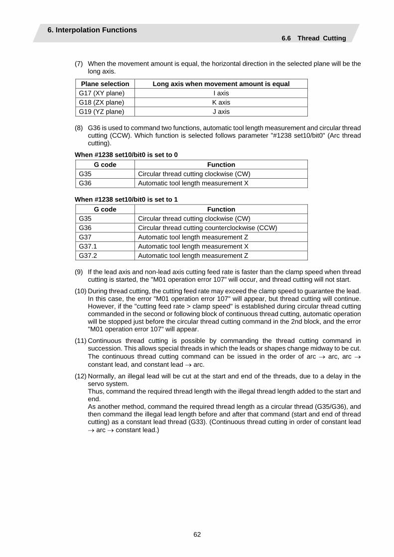
6. Interpolation Functions 6.6 Thread Cutting
62
(7) When the movement amount is equal, the horizontal direction in the selected plane will be the
long axis.
Plane selection Long axis when movement amount is equal G17 (XY plane) I axis G18 (ZX plane) K axis G19 (YZ plane) J axis
(8) G36 is used to command two functions, automatic tool length measurement and circular thread
cutting (CCW). Which function is selected follows parameter "#1238 set10/bit0" (Arc thread cutting).
When #1238 set10/bit0 is set to 0 G code Function
G35 Circular thread cutting clockwise (CW) G36 Automatic tool length measurement X
When #1238 set10/bit0 is set to 1
G code Function G35 Circular thread cutting clockwise (CW) G36 Circular thread cutting counterclockwise (CCW) G37 Automatic tool length measurement Z G37.1 Automatic tool length measurement X G37.2 Automatic tool length measurement Z
(9) If the lead axis and non-lead axis cutting feed rate is faster than the clamp speed when thread
cutting is started, the "M01 operation error 107" will occur, and thread cutting will not start.
(10) During thread cutting, the cutting feed rate may exceed the clamp speed to guarantee the lead. In this case, the error "M01 operation error 107" will appear, but thread cutting will continue. However, if the "cutting feed rate > clamp speed" is established during circular thread cutting commanded in the second or following block of continuous thread cutting, automatic operation will be stopped just before the circular thread cutting command in the 2nd block, and the error "M01 operation error 107" will appear.
(11) Continuous thread cutting is possible by commanding the thread cutting command in succession. This allows special threads in which the leads or shapes change midway to be cut.
The continuous thread cutting command can be issued in the order of arc → arc, arc → constant lead, and constant lead → arc.
(12) Normally, an illegal lead will be cut at the start and end of the threads, due to a delay in the servo system.
Thus, command the required thread length with the illegal thread length added to the start and end.
As another method, command the required thread length as a circular thread (G35/G36), and then command the illegal lead length before and after that command (start and end of thread cutting) as a constant lead thread (G33). (Continuous thread cutting in order of constant lead → arc → constant lead.)

6. Interpolation Functions 6.6 Thread Cutting
63
Relation with other functions
(1) A program error (P113) will occur if the G35/G36 command is issued to an axis not within the
selected plane.
(2) The thread cutting speed is not synchronized with the spindle rotation when dry run is valid. (The thread pitch is not guaranteed.)
(3) If the dry run switch is turned ON during thread cutting, the dry run signal will be ignored.
(4) If the FEEDHOLD switch is pressed during thread cutting, the block will stop at the end point of the block following that in which thread cutting is completed (when the thread cutting mode is exited).
(5) Circular thread cutting will function normally even during mirror image.
(6) A program error (P201) will occur if the G35/G36 circular thread cutting command is issued in the finish shape program of the compound type fixed cycle for turning machining.
(7) A program error (P385) will occur if thread cutting corner rounding or corner chamfering is commanded during circular thread cutting or the next block.
(8) Geometric and circular thread cutting cannot be commanded simultaneously. If commanded simultaneously, a program error (P395) or program error (P70) will occur.
(9) If thread cutting is commanded during nose R compensation, nose R compensation will be temporarily canceled, and thread cutting will be executed.
(10) Do not issue the circular thread cutting command during constant surface speed control. The thread will not be cut correctly because the spindle rotation speed will change during thread cutting.
Precautions
(1) Spindle override does not function during thread cutting.
(2) A program error (P39) will occur if G35/G36 is commanded when the additional specifications are not provided.
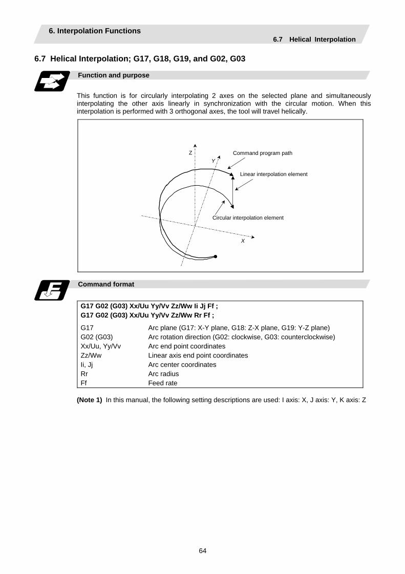
6. Interpolation Functions 6.7 Helical Interpolation
64
6.7 Helical Interpolation; G17, G18, G19, and G02, G03
Function and purpose
This function is for circularly interpolating 2 axes on the selected plane and simultaneously interpolating the other axis linearly in synchronization with the circular motion. When this interpolation is performed with 3 orthogonal axes, the tool will travel helically.
X
YZ Command program path
Linear interpolation element
Circular interpolation element
Command format
G17 G02 (G03) Xx/Uu Yy/Vv Zz/Ww Ii Jj Ff ; G17 G02 (G03) Xx/Uu Yy/Vv Zz/Ww Rr Ff ;
G17 Arc plane (G17: X-Y plane, G18: Z-X plane, G19: Y-Z plane) G02 (G03) Arc rotation direction (G02: clockwise, G03: counterclockwise) Xx/Uu, Yy/Vv Arc end point coordinates Zz/Ww Linear axis end point coordinates Ii, Jj Arc center coordinates Rr Arc radius Ff Feed rate
(Note 1) In this manual, the following setting descriptions are used: I axis: X, J axis: Y, K axis: Z
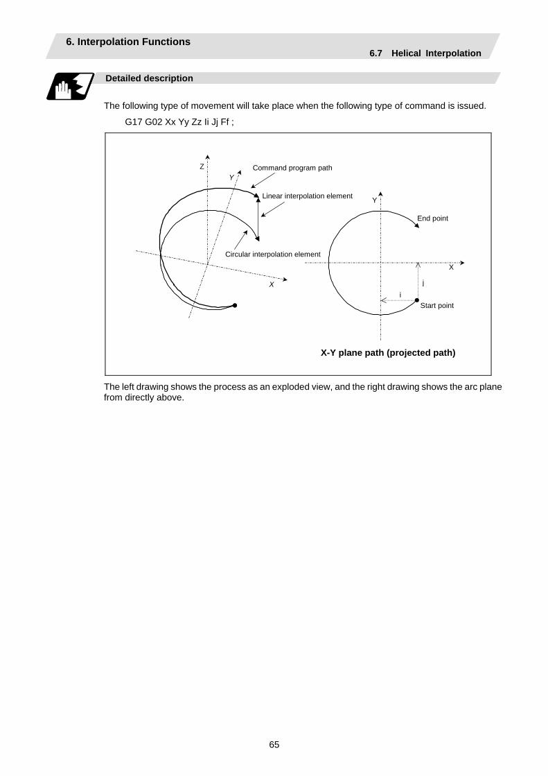
6. Interpolation Functions 6.7 Helical Interpolation
65
Detailed description
The following type of movement will take place when the following type of command is issued.
G17 G02 Xx Yy Zz Ii Jj Ff ;
Y
X
Start point
End point
X
YZ
X-Y plane path (projected path)
i
j
Command program path
Linear interpolation element
Circular interpolation element
The left drawing shows the process as an exploded view, and the right drawing shows the arc plane from directly above.
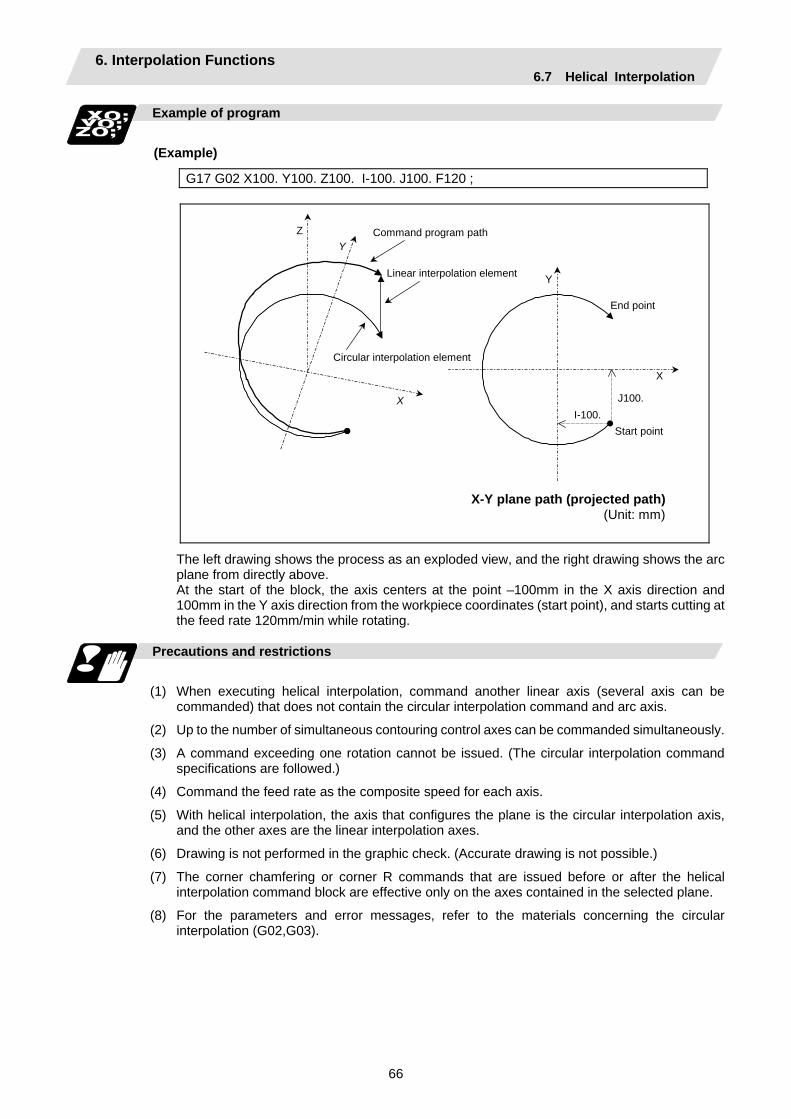
6. Interpolation Functions 6.7 Helical Interpolation
66
Example of program
(Example)
G17 G02 X100. Y100. Z100. I-100. J100. F120 ;
Y
X
Start point
End point
X
YZ
X-Y plane path (projected path)
I-100. J100.
Command program path
Linear interpolation element
Circular interpolation element
(Unit: mm)
The left drawing shows the process as an exploded view, and the right drawing shows the arc plane from directly above. At the start of the block, the axis centers at the point –100mm in the X axis direction and 100mm in the Y axis direction from the workpiece coordinates (start point), and starts cutting at the feed rate 120mm/min while rotating.
Precautions and restrictions
(1) When executing helical interpolation, command another linear axis (several axis can be
commanded) that does not contain the circular interpolation command and arc axis.
(2) Up to the number of simultaneous contouring control axes can be commanded simultaneously.
(3) A command exceeding one rotation cannot be issued. (The circular interpolation command specifications are followed.)
(4) Command the feed rate as the composite speed for each axis.
(5) With helical interpolation, the axis that configures the plane is the circular interpolation axis, and the other axes are the linear interpolation axes.
(6) Drawing is not performed in the graphic check. (Accurate drawing is not possible.)
(7) The corner chamfering or corner R commands that are issued before or after the helical interpolation command block are effective only on the axes contained in the selected plane.
(8) For the parameters and error messages, refer to the materials concerning the circular interpolation (G02,G03).
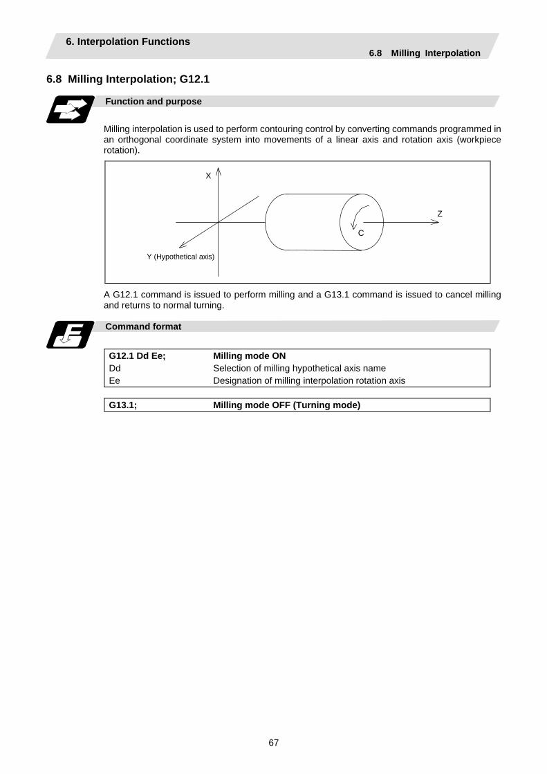
6. Interpolation Functions 6.8 Milling Interpolation
67
6.8 Milling Interpolation; G12.1
Function and purpose
Milling interpolation is used to perform contouring control by converting commands programmed in an orthogonal coordinate system into movements of a linear axis and rotation axis (workpiece rotation).
C
Z
Y (Hypothetical axis)
X
A G12.1 command is issued to perform milling and a G13.1 command is issued to cancel milling and returns to normal turning.
Command format
G12.1 Dd Ee; Milling mode ON Dd Selection of milling hypothetical axis name Ee Designation of milling interpolation rotation axis
G13.1; Milling mode OFF (Turning mode)

6. Interpolation Functions 6.8 Milling Interpolation
68
Address Meaning of address Command range (unit) Remarks
D Selection of milling hypothetical axis name
0: Y axis 1: Rotation axis
name
• If there is no D command, the milling hypothetical axis name will follow parameter (#1517 mill_C).
• If only the D command is issued, it will be handled as D0.
• A program error (P35) will occur if a value other than 0 or 1 is issued as the numerical command after the D command.
E Designation of milling interpolation rotation axis
G12.1 command system rotation axis command address
• If there is no E command, the parameter (#1516 mill_ax) will be followed.
• A program error (P33) will occur if only an E command is issued.
• A program error (P33) will occur if an axis address is not commanded after "E=".
• A program error (P300) will occur if an axis that does not exist in the command system is designated as the rotation axis name.
• A program error (P32) will occur if a value is commanded for the rotation axis name.
• To issue a program command after the "E= rotation axis name", delimit the "E= rotation axis name" and the other command with a comma (,). A program error (P33) will occur if there is no comma.
The following G codes are used to select milling and set the conditions.
G code Function Remarks G12.1 Milling mode ON Default is G13.1. G13.1 Milling mode OFF G16 Selection of Y-Z cylindrical plane G17 Selection of X-Y plane G19 Selection of Y-Z plane
One of G17, G16, and G19 can be defined as the default (when G12.1 is issued) by the parameter.
G41 Tool radius compensation left Default is G40. G42 Tool radius compensation right
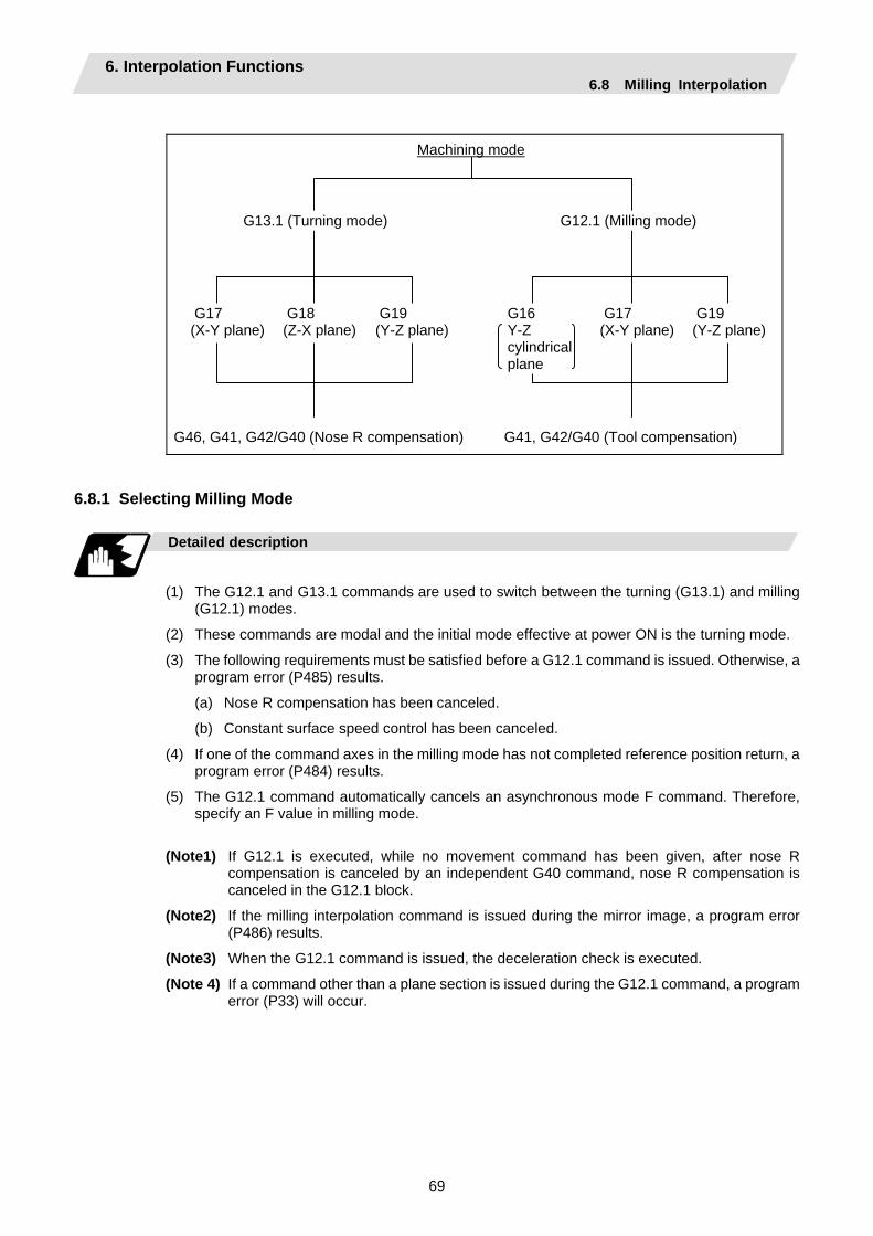
6. Interpolation Functions 6.8 Milling Interpolation
69
G46, G41, G42/G40 (Nose R compensation) G41, G42/G40 (Tool compensation)
6.8.1 Selecting Milling Mode
Detailed description
(1) The G12.1 and G13.1 commands are used to switch between the turning (G13.1) and milling
(G12.1) modes.
(2) These commands are modal and the initial mode effective at power ON is the turning mode.
(3) The following requirements must be satisfied before a G12.1 command is issued. Otherwise, a program error (P485) results.
(a) Nose R compensation has been canceled.
(b) Constant surface speed control has been canceled.
(4) If one of the command axes in the milling mode has not completed reference position return, a program error (P484) results.
(5) The G12.1 command automatically cancels an asynchronous mode F command. Therefore, specify an F value in milling mode.
(Note1) If G12.1 is executed, while no movement command has been given, after nose R compensation is canceled by an independent G40 command, nose R compensation is canceled in the G12.1 block.
(Note2) If the milling interpolation command is issued during the mirror image, a program error (P486) results.
(Note3) When the G12.1 command is issued, the deceleration check is executed.
(Note 4) If a command other than a plane section is issued during the G12.1 command, a program error (P33) will occur.
Machining mode
G13.1 (Turning mode) G12.1 (Milling mode)
G17 (X-Y plane)
G18 (Z-X plane)
G19 (Y-Z plane)
G16 Y-Z cylindrical plane
G17 (X-Y plane)
G19 (Y-Z plane)
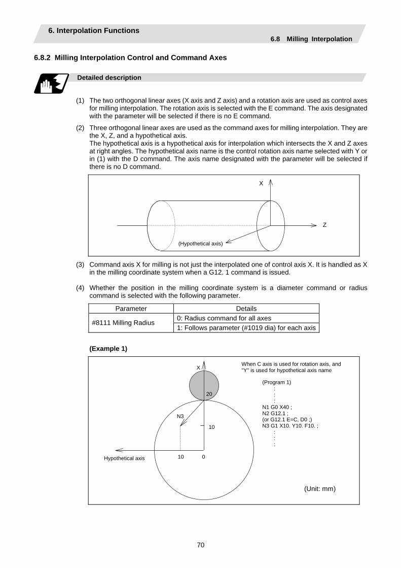
6. Interpolation Functions 6.8 Milling Interpolation
70
6.8.2 Milling Interpolation Control and Command Axes
Detailed description
(1) The two orthogonal linear axes (X axis and Z axis) and a rotation axis are used as control axes
for milling interpolation. The rotation axis is selected with the E command. The axis designated with the parameter will be selected if there is no E command.
(2) Three orthogonal linear axes are used as the command axes for milling interpolation. They are the X, Z, and a hypothetical axis.
The hypothetical axis is a hypothetical axis for interpolation which intersects the X and Z axes at right angles. The hypothetical axis name is the control rotation axis name selected with Y or in (1) with the D command. The axis name designated with the parameter will be selected if there is no D command.
Z
X
(Hypothetical axis)
(3) Command axis X for milling is not just the interpolated one of control axis X. It is handled as X in the milling coordinate system when a G12. 1 command is issued.
(4) Whether the position in the milling coordinate system is a diameter command or radius
command is selected with the following parameter.
Parameter Details 0: Radius command for all axes
#8111 Milling Radius 1: Follows parameter (#1019 dia) for each axis
(Example 1)
X
0 10 Hypothetical axis
N3
10
(Program 1) : : :
N1 G0 X40 ; N2 G12.1 ; (or G12.1 E=C, D0 ;) N3 G1 X10. Y10. F10. ;
: : :
When C axis is used for rotation axis, and "Y" is used for hypothetical axis name
20
(Unit: mm)
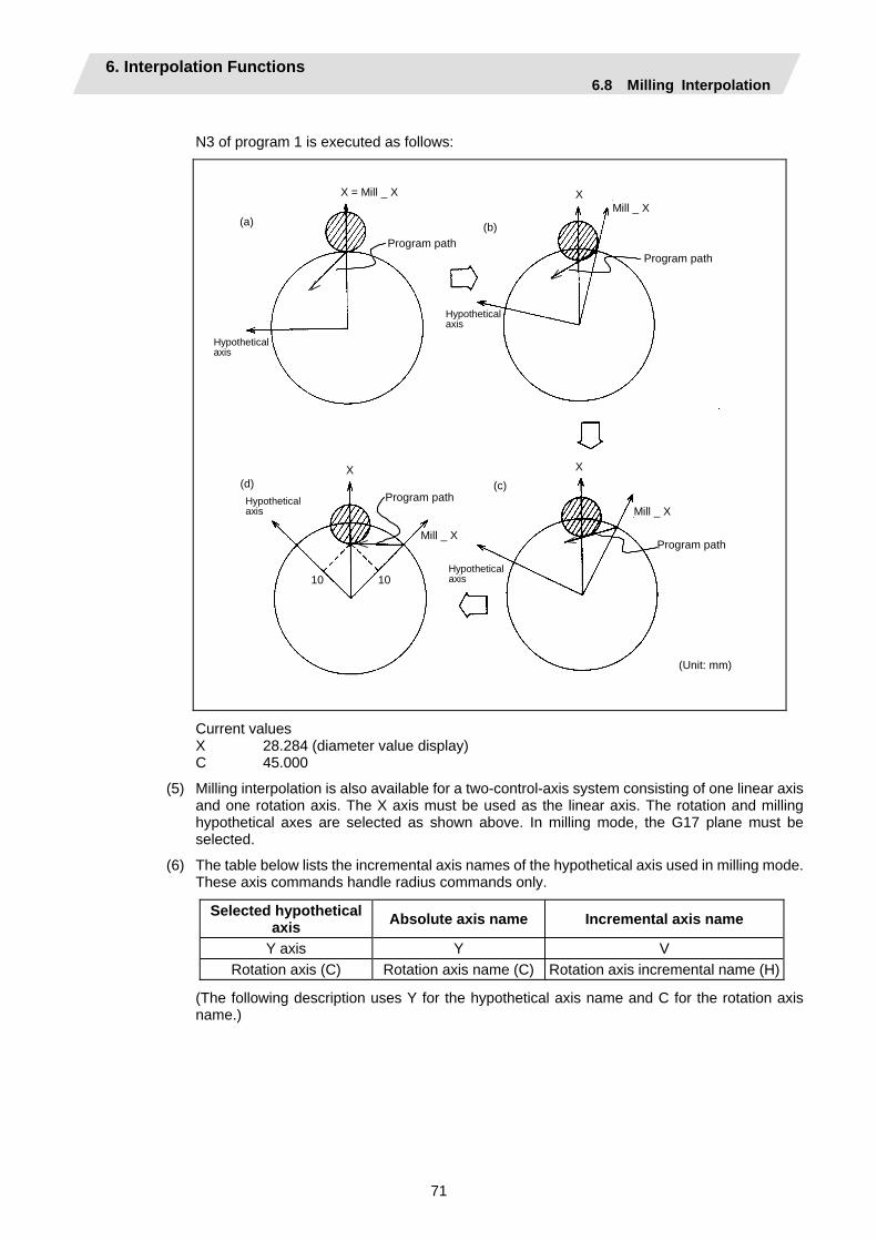
6. Interpolation Functions 6.8 Milling Interpolation
71
N3 of program 1 is executed as follows:
X = Mill _ X
Mill _ X
Mill _ X
(d) (c)
(b)(a) Mill _ X
X
X X
(Unit: mm)
Program path Program path
Program path
Program path
Hypothetical axis
Hypothetical axis
Hypothetical axis
Hypothetical axis
1010
Current values X 28.284 (diameter value display) C 45.000
(5) Milling interpolation is also available for a two-control-axis system consisting of one linear axis and one rotation axis. The X axis must be used as the linear axis. The rotation and milling hypothetical axes are selected as shown above. In milling mode, the G17 plane must be selected.
(6) The table below lists the incremental axis names of the hypothetical axis used in milling mode. These axis commands handle radius commands only.
Selected hypothetical axis Absolute axis name Incremental axis name
Y axis Y V Rotation axis (C) Rotation axis name (C) Rotation axis incremental name (H)
(The following description uses Y for the hypothetical axis name and C for the rotation axis name.)

6. Interpolation Functions 6.8 Milling Interpolation
72
6.8.3 Selecting a Plane during the Milling Mode
Function and purpose
A plane selection command decides the plane on which the tool moves for circular interpolation or tool radius compensation in milling mode.
Command format
G17/G19 ; G16 C_ ;
G16 Y-Z cylindrical plane C_ Cylindrical radius value G17 X-Y plane G19 Y-Z plane
(1) These G commands for plane selection are modal. The G17 plane is automatically selected as the default each time the turning mode is switched to the milling mode by a G12.1 command. When the milling mode is switched back to the turning mode by a G13.1 command, the plane that was selected before the milling mode is entered is restored.
(2) G16 or G19 can also be defined as the default effective when a G12.1 command is issued. A parameter is used for this.
(3) The three planes selected are explained below.
(a) G16 G16 indicates the plane obtained by developing a cylinder with its bottom radius X. This is useful to process the side face of a workpiece.
X
Z
Y
Y-Z cylindrical plane
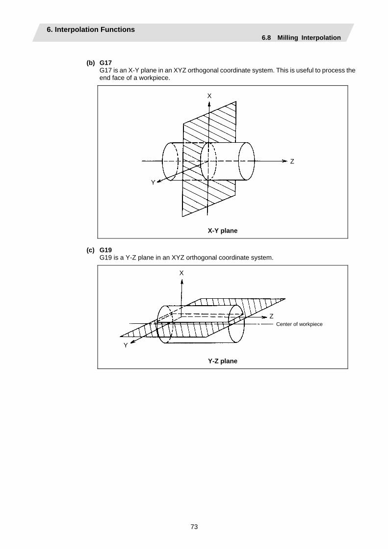
6. Interpolation Functions 6.8 Milling Interpolation
73
(b) G17
G17 is an X-Y plane in an XYZ orthogonal coordinate system. This is useful to process the end face of a workpiece.
X
Y
Z
X-Y plane
(c) G19
G19 is a Y-Z plane in an XYZ orthogonal coordinate system.
Center of workpiece
X
Y
Z
Y-Z plane
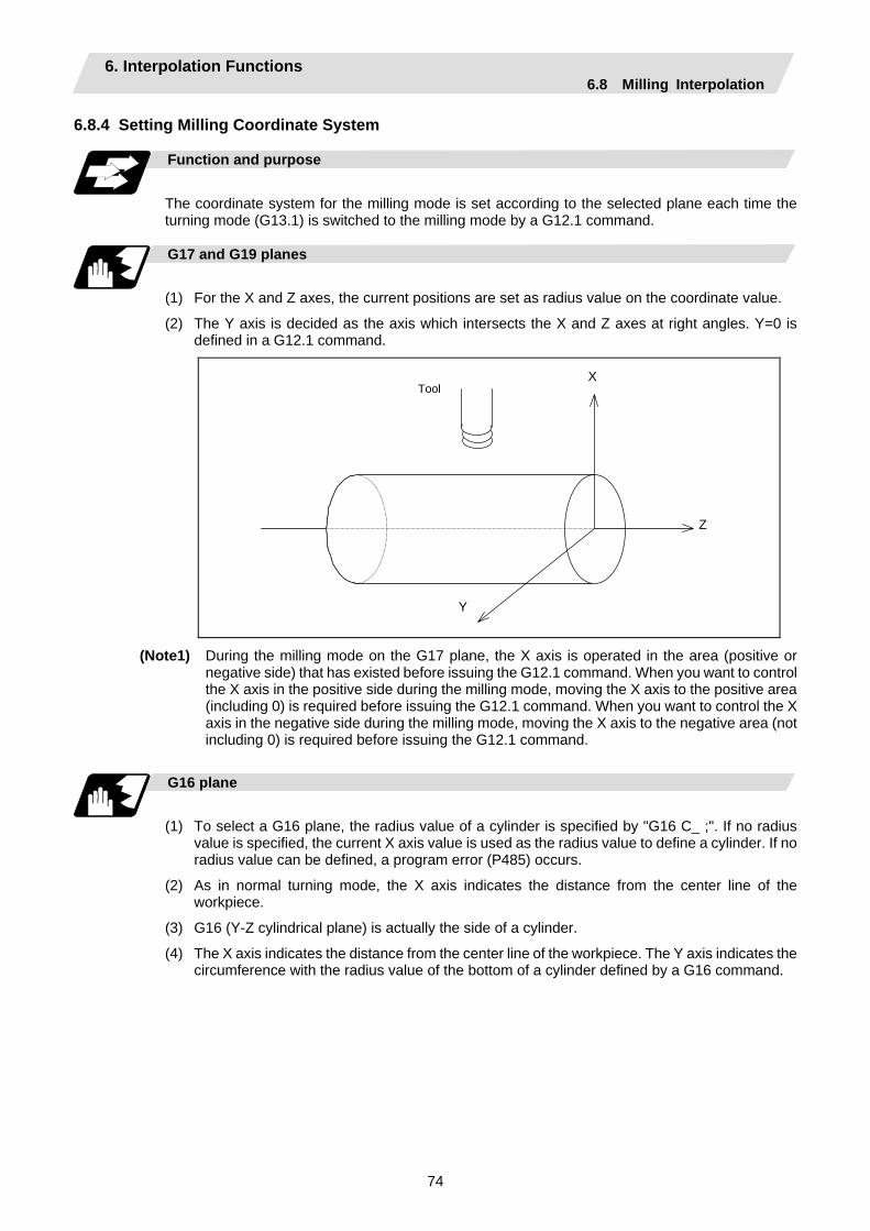
6. Interpolation Functions 6.8 Milling Interpolation
74
6.8.4 Setting Milling Coordinate System
Function and purpose
The coordinate system for the milling mode is set according to the selected plane each time the turning mode (G13.1) is switched to the milling mode by a G12.1 command.
G17 and G19 planes
(1) For the X and Z axes, the current positions are set as radius value on the coordinate value.
(2) The Y axis is decided as the axis which intersects the X and Z axes at right angles. Y=0 is defined in a G12.1 command.
Z
ToolX
Y
(Note1) During the milling mode on the G17 plane, the X axis is operated in the area (positive or negative side) that has existed before issuing the G12.1 command. When you want to control the X axis in the positive side during the milling mode, moving the X axis to the positive area (including 0) is required before issuing the G12.1 command. When you want to control the X axis in the negative side during the milling mode, moving the X axis to the negative area (not including 0) is required before issuing the G12.1 command.
G16 plane
(1) To select a G16 plane, the radius value of a cylinder is specified by "G16 C_ ;". If no radius
value is specified, the current X axis value is used as the radius value to define a cylinder. If no radius value can be defined, a program error (P485) occurs.
(2) As in normal turning mode, the X axis indicates the distance from the center line of the workpiece.
(3) G16 (Y-Z cylindrical plane) is actually the side of a cylinder.
(4) The X axis indicates the distance from the center line of the workpiece. The Y axis indicates the circumference with the radius value of the bottom of a cylinder defined by a G16 command.
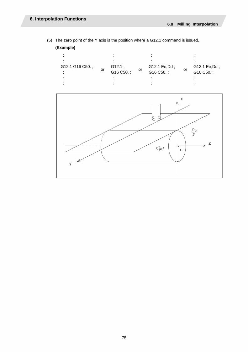
6. Interpolation Functions 6.8 Milling Interpolation
75
(5) The zero point of the Y axis is the position where a G12.1 command is issued.
(Example)
: : G12.1 G16 C50. ; : : :
or
: : G12.1 ; G16 C50. ; : :
or
: : G12.1 Ee,Dd ; G16 C50. ; : :
or
: : G12.1 Ee,Dd ; G16 C50. ; : :
Z
X
Y
r

6. Interpolation Functions 6.8 Milling Interpolation
76
6.8.5 Preparatory Functions
Valid G codes in milling mode
Classifi- cation
G code Function Classifi-cation
G code Function
∗ G00 Positioning G65 Macro call ∗ G01 Linear interpolation G66 Macro modal call A ∗ G02 Circular interpolation (CW) G66.1 Macro modal call B ∗ G03
Circular interpolation (CCW) G67 Macro modal call cancel
G04 Dwell G09 Exact stop check G80 Hole drilling cycle cancel G83 Deep hole drilling cycle (Z axis) G13.1 Turning mode G84 Tap cycle (Z axis) G85 Boring cycle (Z axis) G87 Deep hole drilling cycle (X axis) G16 Y-Z cylindrical plane selection G88 Tap cycle (X axis)
G17 X-Y plane selection G89 Boring cycle (X axis) G90 Absolute value command G19 Y-Z plane selection G91 Incremental value command G22 Barrier check ON G94 Asynchronous feed G23 Barrier check OFF G98 Hole drilling cycle initial point
return G99 Hole drilling cycle R point return G61 Exact stop mode G40 Tool radius compensation
cancel
G41 Tool radius compensation left G64 Turning mode G42 Tool radius compensation right
∗ : Milling interpolation command : G code effective only in milling mode
(1) If an invalid G code is issued in milling mode, a program error (P481) occurs.
If the milling interpolation is commanded in milling mode, a program error (P481) occurs.
(2) In milling mode, all movement commands are commanded with the coordinate system determined by the selected machining plane. The rotation axis thus cannot be moved by a direct command in milling mode. To perform milling at a specific position of a workpiece, therefore, positioning must have been made in turning mode.
(Example)
: : G0 X100. C180.; ⇒ Positioning before milling G12.1; (or G12.1 E=C,D0;) G0 X50.; : :
(3) If a command for an axis other than X, Z, and Y (rotation axis) is issued in milling mode, a program error (P481) occurs. The asynchronous tap can be used during the milling mode; however, the synchronous tap must not be commanded.
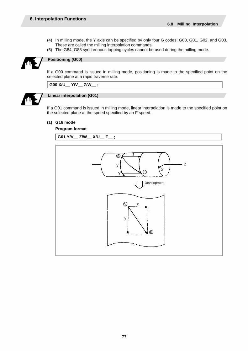
6. Interpolation Functions 6.8 Milling Interpolation
77
(4) In milling mode, the Y axis can be specified by only four G codes: G00, G01, G02, and G03.
These are called the milling interpolation commands. (5) The G84, G88 synchronous tapping cycles cannot be used during the milling mode.
Positioning (G00)
If a G00 command is issued in milling mode, positioning is made to the specified point on the selected plane at a rapid traverse rate.
G00 X/U__ Y/V__ Z/W__ ;
Linear interpolation (G01)
If a G01 command is issued in milling mode, linear interpolation is made to the specified point on the selected plane at the speed specified by an F speed. (1) G16 mode
Program format
G01 Y/V__ Z/W__ X/U__ F__ ;
Development
Z XE
zS
y
Y
S z
y
E
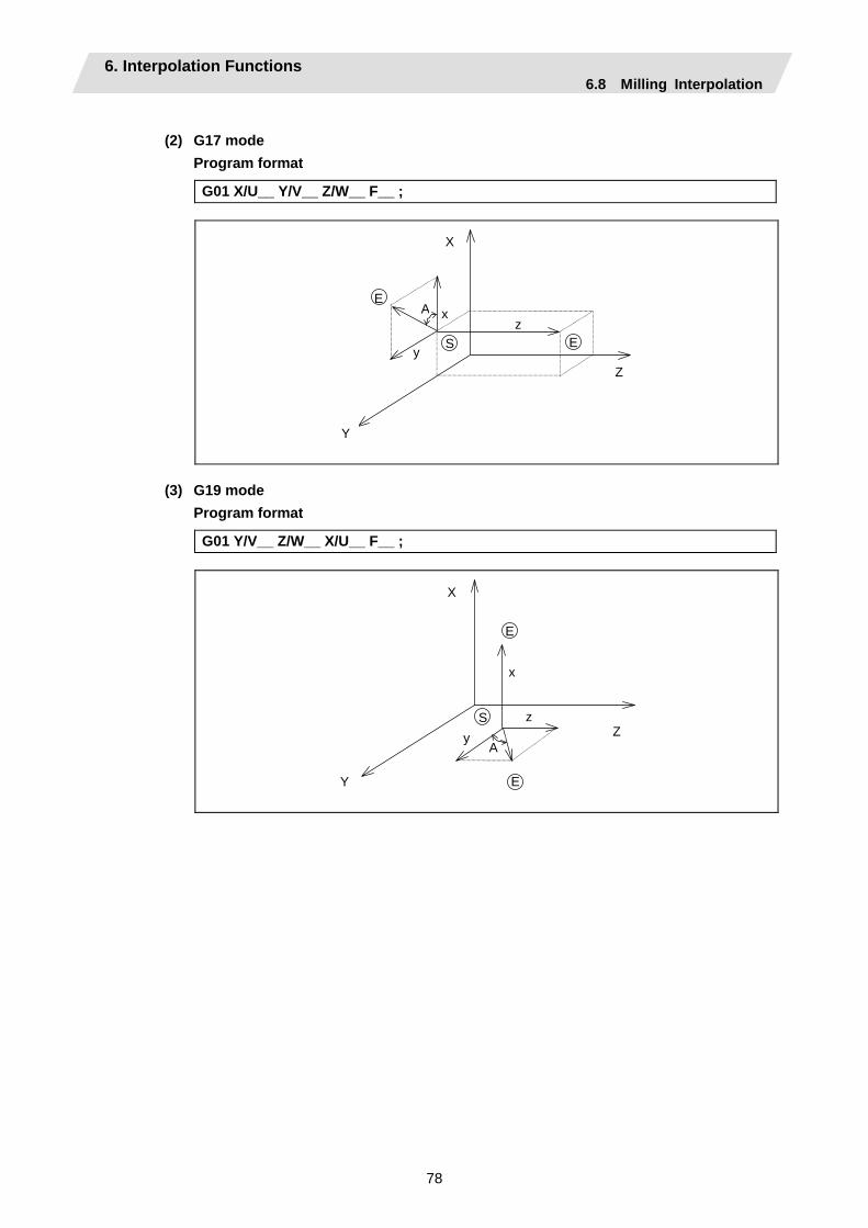
6. Interpolation Functions 6.8 Milling Interpolation
78
(2) G17 mode
Program format
G01 X/U__ Y/V__ Z/W__ F__ ;
A
Z
X
S
Y
x
y
zE
E
(3) G19 mode Program format
G01 Y/V__ Z/W__ X/U__ F__ ;
AZ
X
S
Y
x
yz
E
E
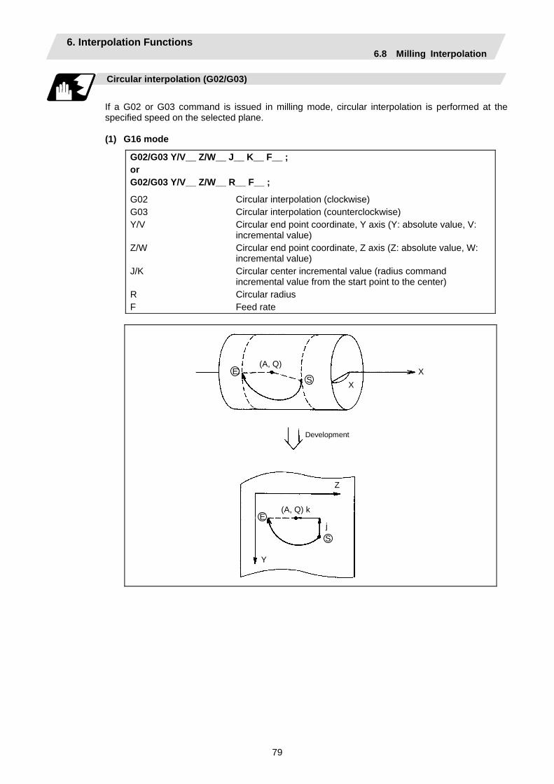
6. Interpolation Functions 6.8 Milling Interpolation
79
Circular interpolation (G02/G03)
If a G02 or G03 command is issued in milling mode, circular interpolation is performed at the specified speed on the selected plane.
(1) G16 mode
G02/G03 Y/V__ Z/W__ J__ K__ F__ ; or G02/G03 Y/V__ Z/W__ R__ F__ ;
G02 Circular interpolation (clockwise) G03 Circular interpolation (counterclockwise) Y/V Circular end point coordinate, Y axis (Y: absolute value, V:
incremental value) Z/W Circular end point coordinate, Z axis (Z: absolute value, W:
incremental value) J/K Circular center incremental value (radius command
incremental value from the start point to the center) R Circular radius F Feed rate
Development
S
(A, Q)E
XX
Z
(A, Q) k
j
Y
S
E
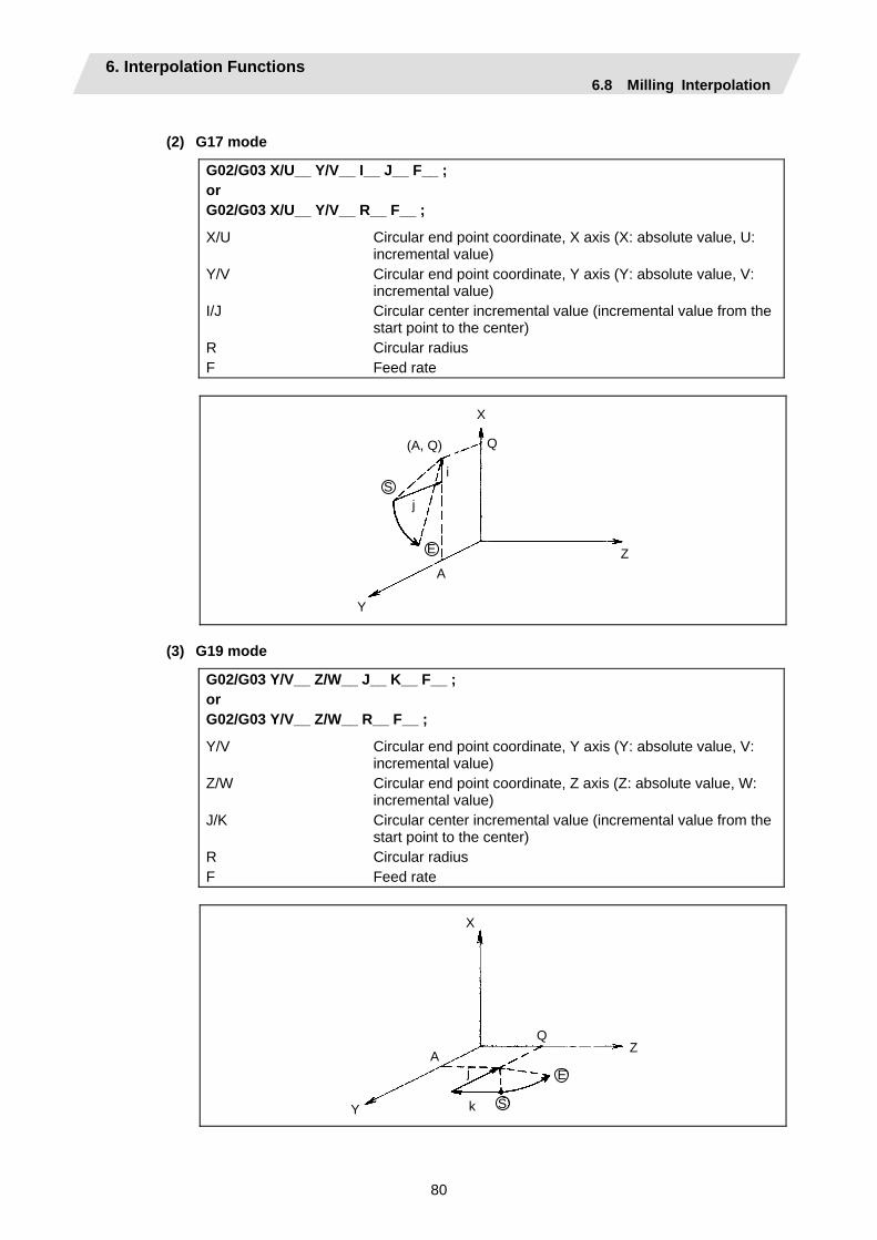
6. Interpolation Functions 6.8 Milling Interpolation
80
(2) G17 mode
G02/G03 X/U__ Y/V__ I__ J__ F__ ; or G02/G03 X/U__ Y/V__ R__ F__ ;
X/U Circular end point coordinate, X axis (X: absolute value, U: incremental value)
Y/V Circular end point coordinate, Y axis (Y: absolute value, V: incremental value)
I/J Circular center incremental value (incremental value from the start point to the center)
R Circular radius F Feed rate
Z
(A, Q)
S
E
X
Q
i
j
A
Y
(3) G19 mode
G02/G03 Y/V__ Z/W__ J__ K__ F__ ; or G02/G03 Y/V__ Z/W__ R__ F__ ;
Y/V Circular end point coordinate, Y axis (Y: absolute value, V: incremental value)
Z/W Circular end point coordinate, Z axis (Z: absolute value, W: incremental value)
J/K Circular center incremental value (incremental value from the start point to the center)
R Circular radius F Feed rate
Z
S
E
Q
X
A
Y k
j
6. Interpolation Functions 6.8 Milling Interpolation
81
6.8.6 Switching from Milling Mode to Turning Mode; G13.1
Detailed description
(1) A G13.1 command is used to cancel the milling mode and return to the turning mode.
(2) The G13.1 command is effective if the following requirement is met. If not, a program error (P485) occurs.
(a) Tool radius compensation has been canceled.
(3) The G13.1 command restores the plane selected before the preceding G12.1 command was issued.
(4) The G13.1 command restores the mode (synchronous or asynchronous) and the F value (if in asynchronous mode) selected before the preceding G12.1 command was issued.
(Note 1) If G13.1 is executed, while no movement command has been given, after cancellation by
an independent G40 command, tool radius compensation is canceled in the G13.1 block. (Note 2) When G13.1 command is issued, the deceleration check is executed. (Note 3) If another command is issued during the G13.1 command, a program error will occur.
6.8.7 Feed Function
Asynchronous cutting feed
An asynchronous feed mode (G94 command) can use F6.3 digits to specify the feed rate per minute in units of 0.001mm/min. The specifiable range is 0.001 to 999999.999mm/min. If the effective speed exceeds the cutting feed clamp speed, it is clamped by that clamp speed.
(Note 1) Whenever the turning mode is switched to the milling mode by a G12.1 command, the F
command modal value is canceled. After mode change, therefore, the feed rate must be set by an F command.
(Note 2) A G12.1 command forces the mode to shift to the asynchronous mode. (Note 3) When the milling mode is canceled by a G13.1 command, both the feed mode and F
command modal value return to the original state before the preceding G12.1 command was issued.
6.8.8 Program Support Functions
Relation with other functions
The following program support functions are effective in milling mode: (1) Linear angle command (2) Variable command (3) Automatic corner chamfering/corner rounding (4) Geometric function (5) Hole drilling cycle (6) Subprogram function (7) User macro
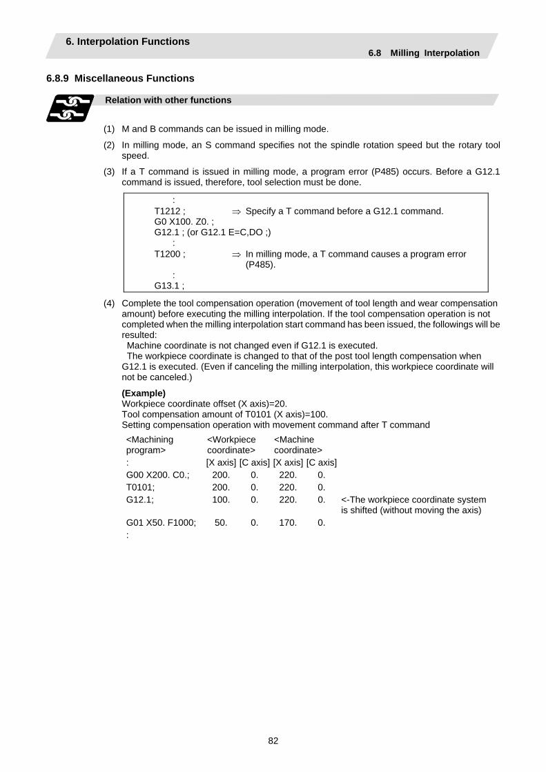
6. Interpolation Functions 6.8 Milling Interpolation
82
6.8.9 Miscellaneous Functions
Relation with other functions
(1) M and B commands can be issued in milling mode.
(2) In milling mode, an S command specifies not the spindle rotation speed but the rotary tool speed.
(3) If a T command is issued in milling mode, a program error (P485) occurs. Before a G12.1 command is issued, therefore, tool selection must be done.
: T1212 ; ⇒ Specify a T command before a G12.1 command. G0 X100. Z0. ; G12.1 ; (or G12.1 E=C,DO ;) : T1200 ; ⇒ In milling mode, a T command causes a program error (P485). : G13.1 ;
(4) Complete the tool compensation operation (movement of tool length and wear compensation amount) before executing the milling interpolation. If the tool compensation operation is not completed when the milling interpolation start command has been issued, the followings will be resulted: Machine coordinate is not changed even if G12.1 is executed. The workpiece coordinate is changed to that of the post tool length compensation when G12.1 is executed. (Even if canceling the milling interpolation, this workpiece coordinate will not be canceled.)
(Example) Workpiece coordinate offset (X axis)=20. Tool compensation amount of T0101 (X axis)=100. Setting compensation operation with movement command after T command
<Machining program>
<Workpiece coordinate>
<Machine coordinate>
: [X axis] [C axis] [X axis] [C axis] G00 X200. C0.; 200. 0. 220. 0. T0101; 200. 0. 220. 0. G12.1; 100. 0. 220. 0. <-The workpiece coordinate system
is shifted (without moving the axis) G01 X50. F1000; 50. 0. 170. 0. :
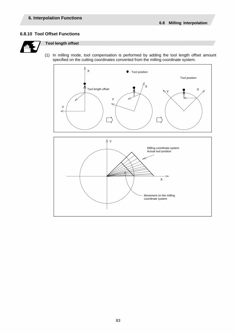
6. Interpolation Functions 6.8 Milling Interpolation
83
6.8.10 Tool Offset Functions
Tool length offset
(1) In milling mode, tool compensation is performed by adding the tool length offset amount
specified on the cutting coordinates converted from the milling coordinate system.
Tool length offset
Tool position
X X
Y
Y
Y
X : Tool position
Y X
Milling coordinate system Actual tool position
Movement on the milling coordinate system

6. Interpolation Functions 6.8 Milling Interpolation
84
(2) As in (1) on previous page, if the offset amount is different from the actual one, the shape is not
corrected normally.
(a) If the offset amount is larger than tool length:
Example: The actual tool length is 15.0 when tool length X = 20.0
Milling command
Actual shape
Tool movement
Y
X
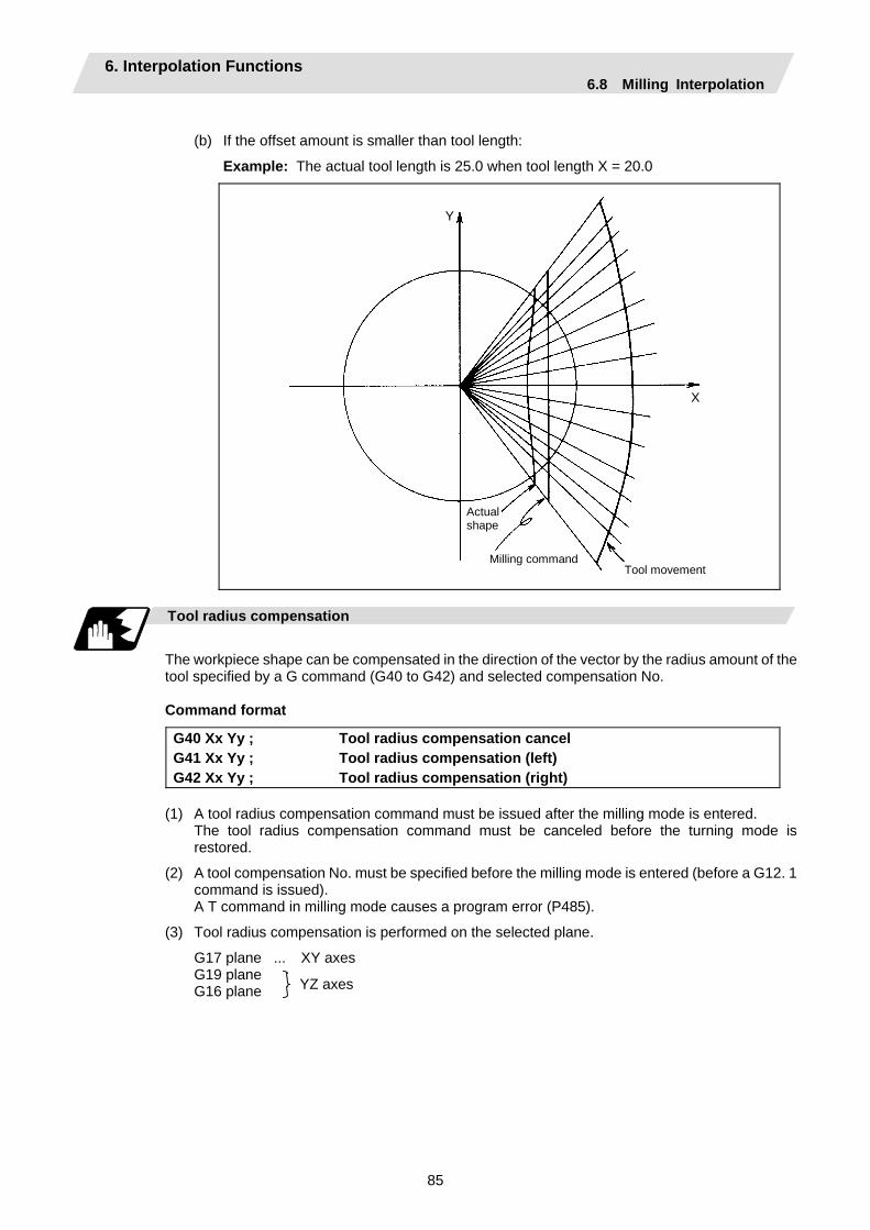
6. Interpolation Functions 6.8 Milling Interpolation
85
(b) If the offset amount is smaller than tool length:
Example: The actual tool length is 25.0 when tool length X = 20.0
Milling command
Actual shape
Tool movement
X
Y
Tool radius compensation
The workpiece shape can be compensated in the direction of the vector by the radius amount of the tool specified by a G command (G40 to G42) and selected compensation No.
Command format
G40 Xx Yy ; Tool radius compensation cancel G41 Xx Yy ; Tool radius compensation (left) G42 Xx Yy ; Tool radius compensation (right)
(1) A tool radius compensation command must be issued after the milling mode is entered. The tool radius compensation command must be canceled before the turning mode is
restored.
(2) A tool compensation No. must be specified before the milling mode is entered (before a G12. 1 command is issued).
A T command in milling mode causes a program error (P485).
(3) Tool radius compensation is performed on the selected plane.
G17 plane ... XY axes G19 plane G16 plane
YZ axes

6. Interpolation Functions 6.8 Milling Interpolation
86
Tool radius compensation cancel mode
Tool radius compensation is canceled under either of the following conditions: (1) While a G12.1 command is effective
(2) After a compensation cancel command (G40) is issued In the compensation cancel mode, the offset vector is 0 and the tool center path matches the programmed path. A program that contains tool radius compensation must end after the compensation is canceled.
Starting tool radius compensation (startup)
Tool radius compensation starts if all the following requirements are met in compensation cancel mode: (1) A G41 or G42 command is issued.
(2) The tool radius compensation No. is greater than 0 and equal to or less than the maximum compensation No.
(3) The movement command is not a circular command. Whether in continuous or single block operation, compensation always starts after reading three movement command blocks, or if three movement command blocks are not found, up to five continuous blocks. Similarly, in compensation mode, up to five blocks are pre-read for compensation operation.
Control state diagram
Starting to pre-read five blocks
T___; S___; G00___; G41___; G01___; G02___; Machining program
Pre-read buffer
Executed block
G02_; G01_;G41_;G00_;S_; T_;
G02_; G01_;
G02_; G01_;G41_;G00_;S_;T_;
There are two ways of starting tool radius compensation: type A and type B. The type depends on the selection of the control parameter "tool nose compensation type B". This type is used in common with the compensation cancel type. In the following explanatory figure, "S" denotes the single block stop point.
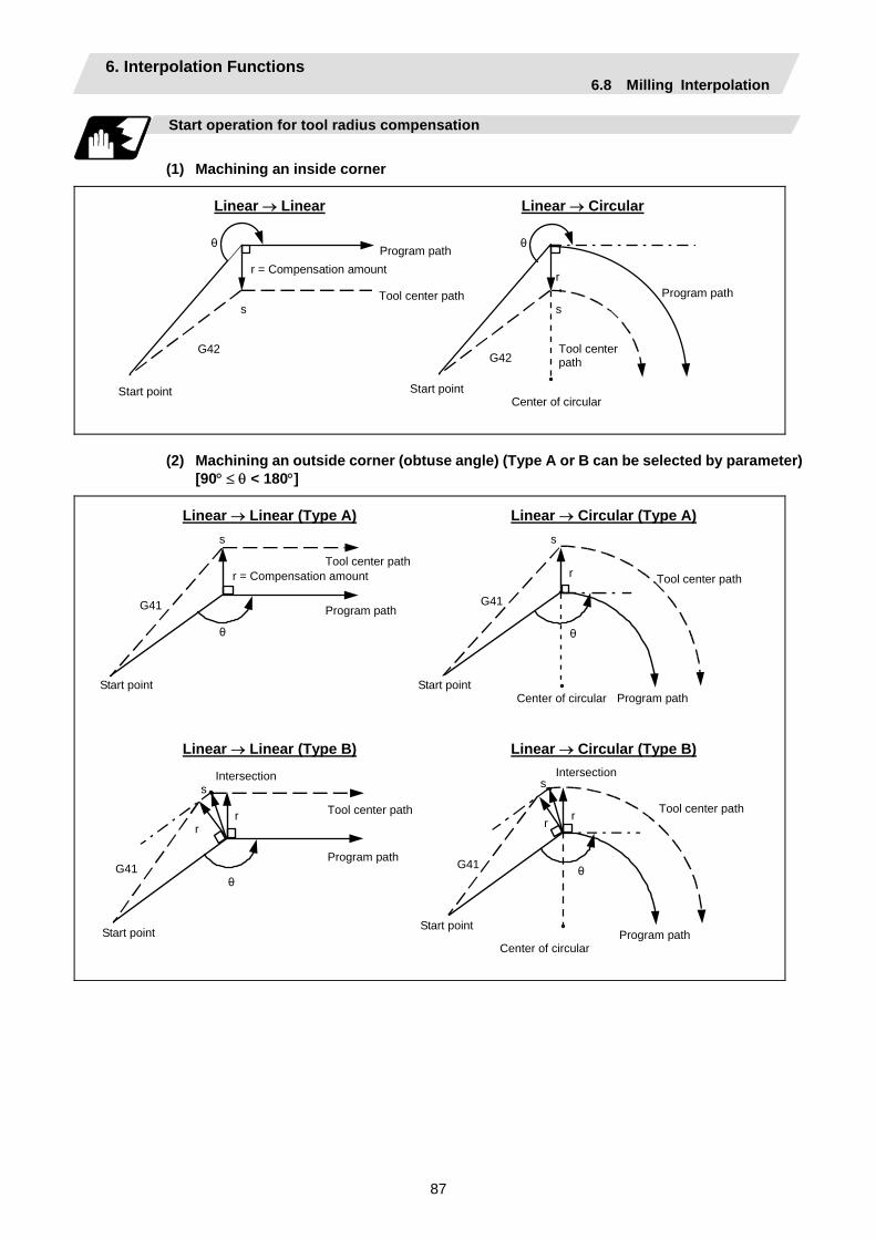
6. Interpolation Functions 6.8 Milling Interpolation
87
Start operation for tool radius compensation
(1) Machining an inside corner
Linear → Linear Linear → Circular
θ
Tool center path
Program path r = Compensation amount
s
G42
Start point
Program path
Tool center path
Center of circular
Start point
G42
s
r
θ
(2) Machining an outside corner (obtuse angle) (Type A or B can be selected by parameter) [90° ≤ θ < 180°]
Linear → Linear (Type A) Linear → Circular (Type A)
θ
Tool center path
Program path
r = Compensation amount
s
G41
Start point Program path
Tool center path
Center of circular
Start point
G41
s
r
θ
Linear → Linear (Type B) Linear → Circular (Type B)
Start point
θ
Tool center path
Program path
s
G41
Program path
Tool center path
Center of circular
Start point
G41
s
r
θ
r r r
Intersection Intersection

6. Interpolation Functions 6.8 Milling Interpolation
88
(3) Machining an outside corner (acute angle) (Type A or B can be selected by parameter)
[θ < 90°]
Linear → Linear (Type A) Linear → Circular (Type A)
Program path
Tool center path
Center of circular
Start point
G41
s
r
θ
Tool center path
Program path s
r
θ
Start point
G41
Linear → Linear (Type B) Linear → Circular (Type B)
Program path
Tool center path
Center of circular
Start point
G41
s
r
θ
Tool center path
Program path
s
r
θ
r
Start point
G41
r
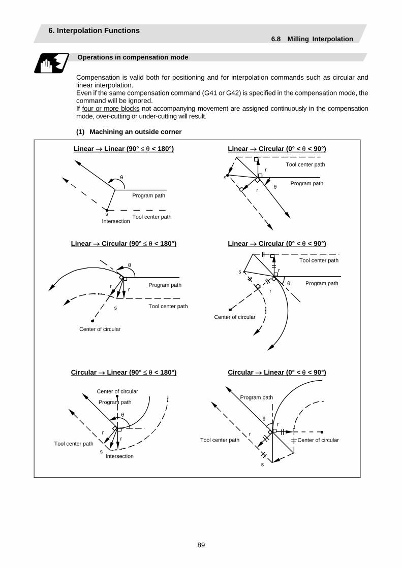
6. Interpolation Functions 6.8 Milling Interpolation
89
Operations in compensation mode
Compensation is valid both for positioning and for interpolation commands such as circular and linear interpolation. Even if the same compensation command (G41 or G42) is specified in the compensation mode, the command will be ignored. If four or more blocks not accompanying movement are assigned continuously in the compensation mode, over-cutting or under-cutting will result.
(1) Machining an outside corner
Linear → Linear (90° ≤ θ < 180°) Linear → Circular (0° < θ < 90°)
Program path
Tool center path Intersection
s
θProgram path
Tool center path
s
θ
r
r
Linear → Circular (90° ≤ θ < 180°) Linear → Circular (0° < θ < 90°)
Program path
Tool center path
Center of circular
s
θ
Program path
Tool center path
s
θ
r
rr r
Center of circular
Circular → Linear (90° ≤ θ < 180°) Circular → Linear (0° < θ < 90°)
Program path
Tool center path
Center of circular
s
θ
Program path
Tool center path
s
θ
r
r
rr
Center of circular
Intersection
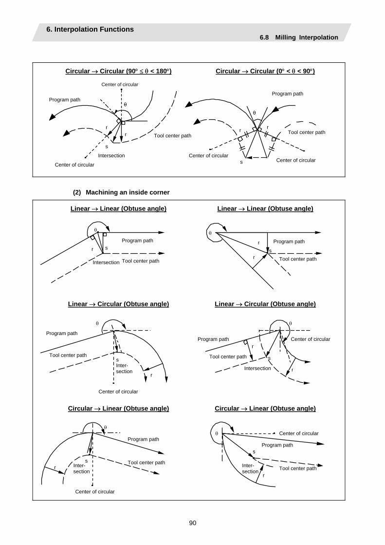
6. Interpolation Functions 6.8 Milling Interpolation
90
Circular → Circular (90° ≤ θ < 180°) Circular → Circular (0° < θ < 90°)
θ
r
s
r
θ
s
r r
Program path
Center of circular Center of circular
Tool center path Tool center path
Center of circular
Intersection
Program path
Center of circular
(2) Machining an inside corner
Linear → Linear (Obtuse angle) Linear → Linear (Obtuse angle)
r r
r
s s
θ θ
Program path
Tool center path Intersection
Program path
Tool center path
Linear → Circular (Obtuse angle) Linear → Circular (Obtuse angle)
θ
r
s
r
r
s
θ
Program path
Tool center path Inter- section
Center of circular
Tool center path
Center of circular
Intersection
Program path
Circular → Linear (Obtuse angle) Circular → Linear (Obtuse angle)
s r
θ θ
r
s
Program path
Tool center path
Center of circular
Program path
Tool center path Inter- section
Center of circular
Inter- section
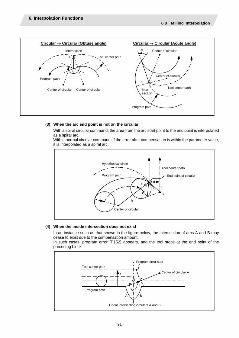
6. Interpolation Functions 6.8 Milling Interpolation
91
Circular → Circular (Obtuse angle) Circular → Circular (Acute angle)
Program path
Tool center path
Center of circular
s
θ
Program path
Tool center path
s
θ
r
r
Center of circular
Center of circular
Intersection
Inter- section
Center of circular
(3) When the arc end point is not on the circular
With a spiral circular command: the area from the arc start point to the end point is interpolated as a spiral arc. With a normal circular command: if the error after compensation is within the parameter value, it is interpolated as a spiral arc.
Program path
Tool center path
Center of circular
sr
End point of circular
Hypothetical circle
r
R
(4) When the inside intersection does not exist In an instance such as that shown in the figure below, the intersection of arcs A and B may cease to exist due to the compensation amount. In such cases, program error (P152) appears, and the tool stops at the end point of the preceding block.
Program path
Tool center path Center of circular A
A
r
B
r
Program error stop
Linear intersecting circulars A and B
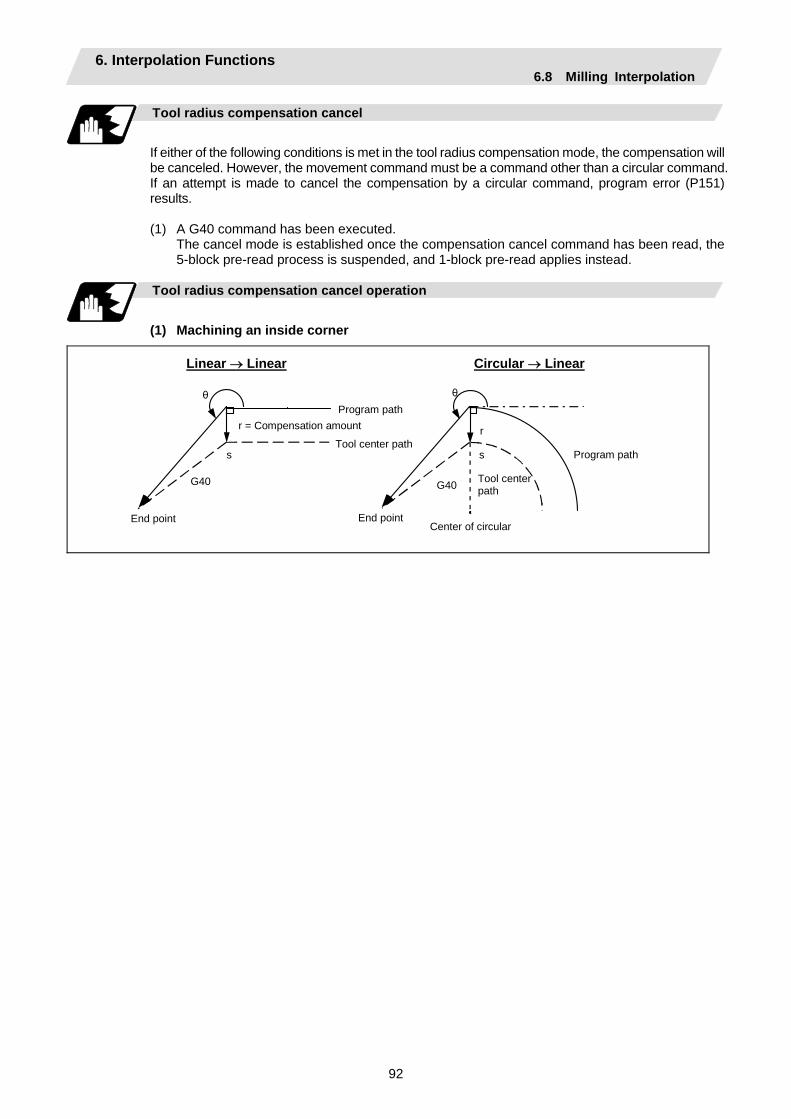
6. Interpolation Functions 6.8 Milling Interpolation
92
Tool radius compensation cancel
If either of the following conditions is met in the tool radius compensation mode, the compensation will be canceled. However, the movement command must be a command other than a circular command. If an attempt is made to cancel the compensation by a circular command, program error (P151) results.
(1) A G40 command has been executed.
The cancel mode is established once the compensation cancel command has been read, the 5-block pre-read process is suspended, and 1-block pre-read applies instead.
Tool radius compensation cancel operation
(1) Machining an inside corner
Linear → Linear Circular → Linear
Program path
Tool center path
End point
s
θ
r = Compensation amount
G40
Program path
Tool center path
Center of circular
s
θ
r
End point
G40
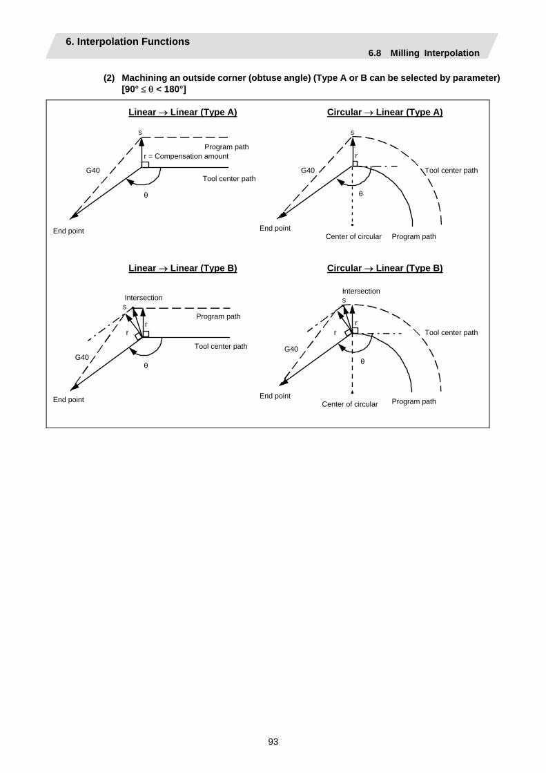
6. Interpolation Functions 6.8 Milling Interpolation
93
(2) Machining an outside corner (obtuse angle) (Type A or B can be selected by parameter) [90° ≤ θ < 180°]
Linear → Linear (Type A) Circular → Linear (Type A)
Program path
Tool center path
End point
s
θ
r = Compensation amount
G40
Program path
Tool center path
Center of circular
s
θ
r
End point
G40
Linear → Linear (Type B) Circular → Linear (Type B)
Program path
Tool center path
End point
s
θ G40
Program path
Tool center path
Center of circular
s
θ
r
End point
G40
r r
Intersection
r
Intersection
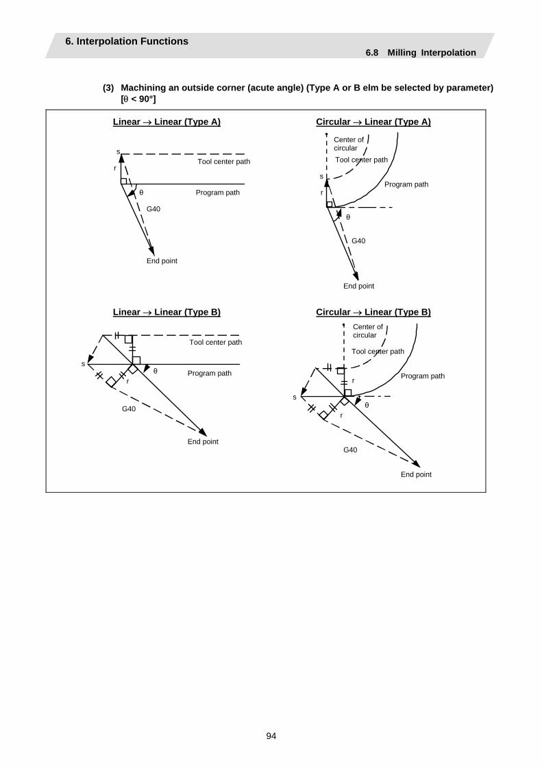
6. Interpolation Functions 6.8 Milling Interpolation
94
(3) Machining an outside corner (acute angle) (Type A or B elm be selected by parameter)
[θ < 90°]
Linear → Linear (Type A) Circular → Linear (Type A)
Program path
Tool center path
End point
s
θ
G40
Program path
Tool center path
Center of circular
s
θ
r
End point
G40
r
Linear → Linear (Type B) Circular → Linear (Type B)
Program path
Tool center path
End point
s θ
G40
Program path
Tool center path
Center of circular
sθ
r
End point
G40
r
r
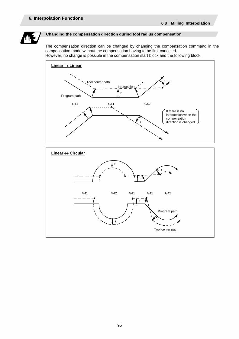
6. Interpolation Functions 6.8 Milling Interpolation
95
Changing the compensation direction during tool radius compensation
The compensation direction can be changed by changing the compensation command in the compensation mode without the compensation having to be first canceled. However, no change is possible in the compensation start block and the following block.
Linear → Linear
Program path
Tool center path
r
G41 G41 G42
r
r
Intersection
If there is no intersection when the compensation direction is changed.
Linear ↔ Circular
Program path
Tool center path
r
G41 G42 G41
r
r
G41 G42
r
r
r
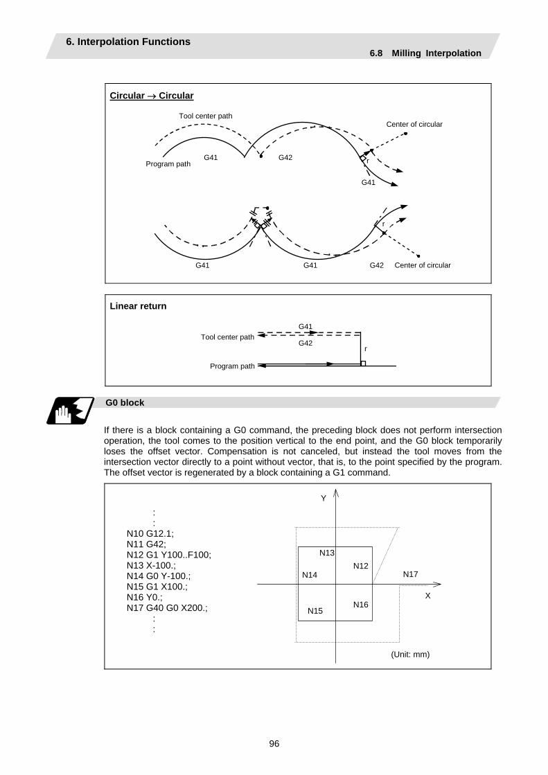
6. Interpolation Functions 6.8 Milling Interpolation
96
Circular → Circular
Program path
Tool center path
G41
G41 G42
r
Center of circular
Center of circular
G41
G41
G42
r
Linear return
Program path
Tool center path G42
G41
r
G0 block
If there is a block containing a G0 command, the preceding block does not perform intersection operation, the tool comes to the position vertical to the end point, and the G0 block temporarily loses the offset vector. Compensation is not canceled, but instead the tool moves from the intersection vector directly to a point without vector, that is, to the point specified by the program. The offset vector is regenerated by a block containing a G1 command.
N15
N17
N16
N12 N13
N14
Y
X
(Unit: mm)
: : N10 G12.1; N11 G42; N12 G1 Y100..F100; N13 X-100.; N14 G0 Y-100.; N15 G1 X100.; N16 Y0.; N17 G40 G0 X200.; : :
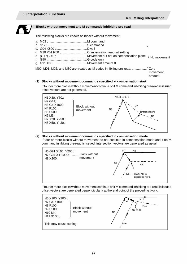
6. Interpolation Functions 6.8 Milling Interpolation
97
Blocks without movement and M commands inhibiting pre-read
The following blocks are known as blocks without movement;
a. M03 ; ............................................M command b. S12 ; .............................................S command c. G04 X500 ; ...................................Dwell d. G10 P01 R50 ;..............................Compensation amount setting e. (G17) Z40 ; ...................................Movement but not on compensation plane f. G90 ;.............................................G code only g. G91 X0 ; .......................................Movement amount 0
M00, M01, M02, and M30 are treated as M codes inhibiting pre-read. ................... Zero movement amount
(1) Blocks without movement commands specified at compensation start If four or more blocks without movement continue or if M command inhibiting pre-read is issued, offset vectors are not generated.
N1 X30. Y60.; N2 G41; N3 G4 X1000; N4 F100; N5 S500; N6 M3; N7 X20. Y–50.; N8 X50. Y–20.;
Block without movement
N2, 3, 4, 5, 6
N1N7
(Intersection) N8
(2) Blocks without movement commands specified in compensation mode If four or more blocks without movement do not continue in compensation mode and if no M command inhibiting pre-read is issued, intersection vectors are generated as usual.
N6 G91 X100. Y200.; N7 G04 X P1000; ....... N8 X200.;
Block without movement
N6N8
Block N7 is executed here.
N6
N7 N8
If four or more blocks without movement continue or if M command inhibiting pre-read is issued, offset vectors are generated perpendicularly at the end point of the preceding block.
This may cause cutting.
N6 X100. Y200.; N7 G4 X1000; N8 F100; N9 S500; N10 M4; N11 X100.;
Block without movement
N6
N6
N11
N7 to 10
N11
No movement

6. Interpolation Functions 6.8 Milling Interpolation
98
(3) Compensation cancel alone
(a) G1 precedes the block containing G40:
N10
N11
N12
Compensation is canceled by a movement command following G40.
(b) G0 precedes the block containing G40:
N20
N21
N22
Compensation is canceled by a G0 command before G40.
(Note) In program (a), if G13.1 is commanded after G40 without a movement command, cancellation is done at block G13.1.
Corner movement
When a multiple number of offset vectors are created at the joints between movement command blocks, the tool will move in a straight line between those vectors. This action is called corner movement. When the vectors do not match, the tool moves in order to turn the corner although this movement belongs to the next block. Consequently, operation in the single block mode will execute the previous block + corner movement as a single block and the remaining joining movement + next block will be executed as a single block in the following operation.
N2
N1Program path
Center of circular
Stop point in single block mode
θ r
rTool center path
This movement and feed rate are under block N2.
: N10 G1 X__ Y__; N11 G40; N12 G0 X__ Y__;
: N20 G1 X__ Y__; N21 G0 X__ Y__; N22 G40;
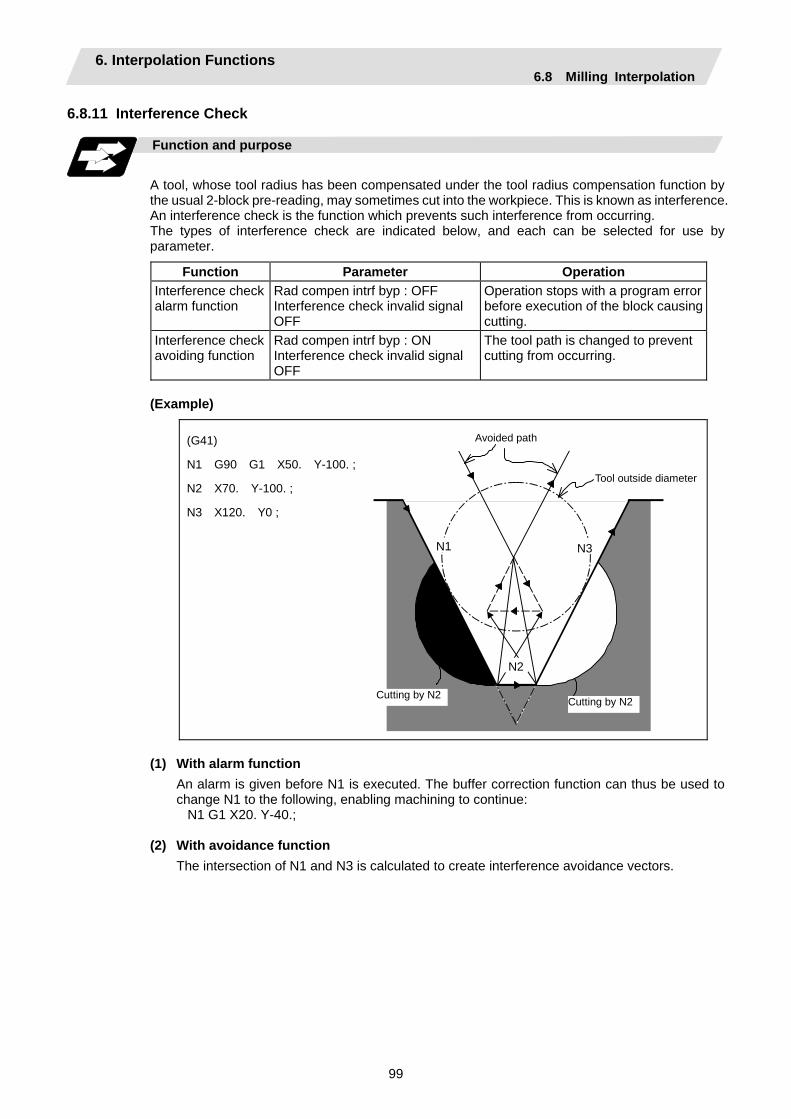
6. Interpolation Functions 6.8 Milling Interpolation
99
6.8.11 Interference Check
Function and purpose
A tool, whose tool radius has been compensated under the tool radius compensation function by the usual 2-block pre-reading, may sometimes cut into the workpiece. This is known as interference. An interference check is the function which prevents such interference from occurring. The types of interference check are indicated below, and each can be selected for use by parameter.
Function Parameter Operation Interference check alarm function
Rad compen intrf byp : OFF Interference check invalid signal OFF
Operation stops with a program error before execution of the block causing cutting.
Interference check avoiding function
Rad compen intrf byp : ON Interference check invalid signal OFF
The tool path is changed to prevent cutting from occurring.
(Example)
Avoided path
Tool outside diameter
N1 N3
N2
Cutting by N2
(G41)
N1 G90 G1 X50. Y-100. ;
N2 X70. Y-100. ;
N3 X120. Y0 ;
Cutting by N2
(1) With alarm function
An alarm is given before N1 is executed. The buffer correction function can thus be used to change N1 to the following, enabling machining to continue: N1 G1 X20. Y-40.;
(2) With avoidance function
The intersection of N1 and N3 is calculated to create interference avoidance vectors.
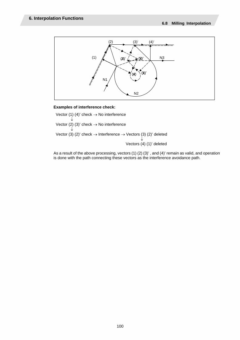
6. Interpolation Functions 6.8 Milling Interpolation
100
(4)’(3)’(2)
(1)’
(1)
N1
N3
N2
(4)
(2)’ (3)’
Examples of interference check:
Vector (1) (4)’ check → No interference ↓ Vector (2) (3)’ check → No interference ↓ Vector (3) (2)’ check → Interference → Vectors (3) (2)’ deleted ↓ Vectors (4) (1)’ deleted As a result of the above processing, vectors (1) (2) (3)’ , and (4)’ remain as valid, and operation is done with the path connecting these vectors as the interference avoidance path.
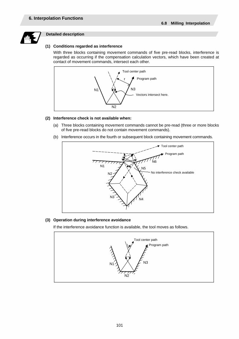
6. Interpolation Functions 6.8 Milling Interpolation
101
Detailed description
(1) Conditions regarded as interference
With three blocks containing movement commands of five pre-read blocks, interference is regarded as occurring if the compensation calculation vectors, which have been created at contact of movement commands, intersect each other.
N1 N3
N2
r
Tool center path
Program path
Vectors intersect here.
(2) Interference check is not available when:
(a) Three blocks containing movement commands cannot be pre-read (three or more blocks of five pre-read blocks do not contain movement commands).
(b) Interference occurs in the fourth or subsequent block containing movement commands.
N1
N3
N2
Program path
Tool center path
No interference check available
N4
N5
N6
(3) Operation during interference avoidance
If the interference avoidance function is available, the tool moves as follows.
N1 N3
N2
Program path Tool center path
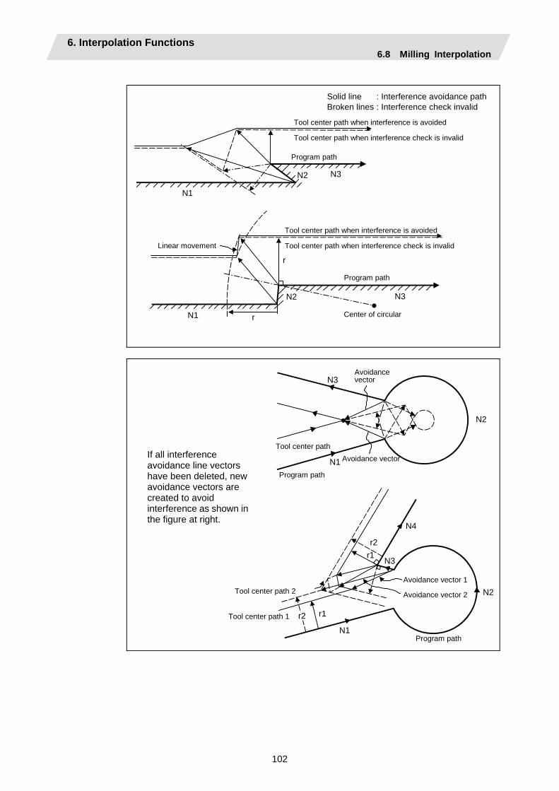
6. Interpolation Functions 6.8 Milling Interpolation
102
Program path
Center of circular
Linear movement
N1
N3
N1
N2
r
r
N2
N3
Tool center path when interference check is invalid
Tool center path when interference is avoided
Solid line : Interference avoidance path Broken lines : Interference check invalid
Program path
Tool center path when interference check is invalid
Tool center path when interference is avoided
Program path
Tool center path 2
Tool center path 1
N1
N3
N2
r1
N4
r2
r1r2
Avoidance vector 2
Avoidance vector 1
N1
N3
N2
Tool center path
Program path
Avoidance vector
Avoidance vector
If all interference avoidance line vectors have been deleted, new avoidance vectors are created to avoid interference as shown inthe figure at right.
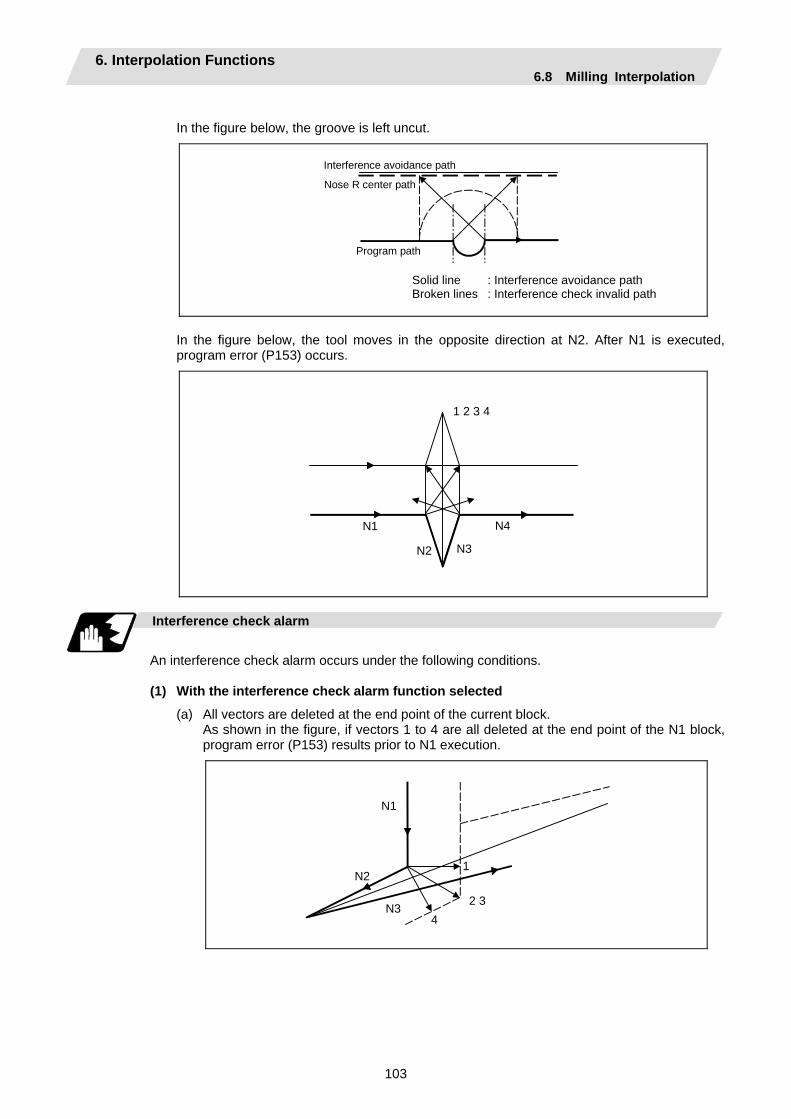
6. Interpolation Functions 6.8 Milling Interpolation
103
In the figure below, the groove is left uncut.
Nose R center path
Interference avoidance path
Program path
Solid line : Interference avoidance path Broken lines : Interference check invalid path
In the figure below, the tool moves in the opposite direction at N2. After N1 is executed, program error (P153) occurs.
N1
N2 N3
N4
1 2 3 4
Interference check alarm
An interference check alarm occurs under the following conditions.
(1) With the interference check alarm function selected
(a) All vectors are deleted at the end point of the current block. As shown in the figure, if vectors 1 to 4 are all deleted at the end point of the N1 block,
program error (P153) results prior to N1 execution.
N1
2 3
N21
N34
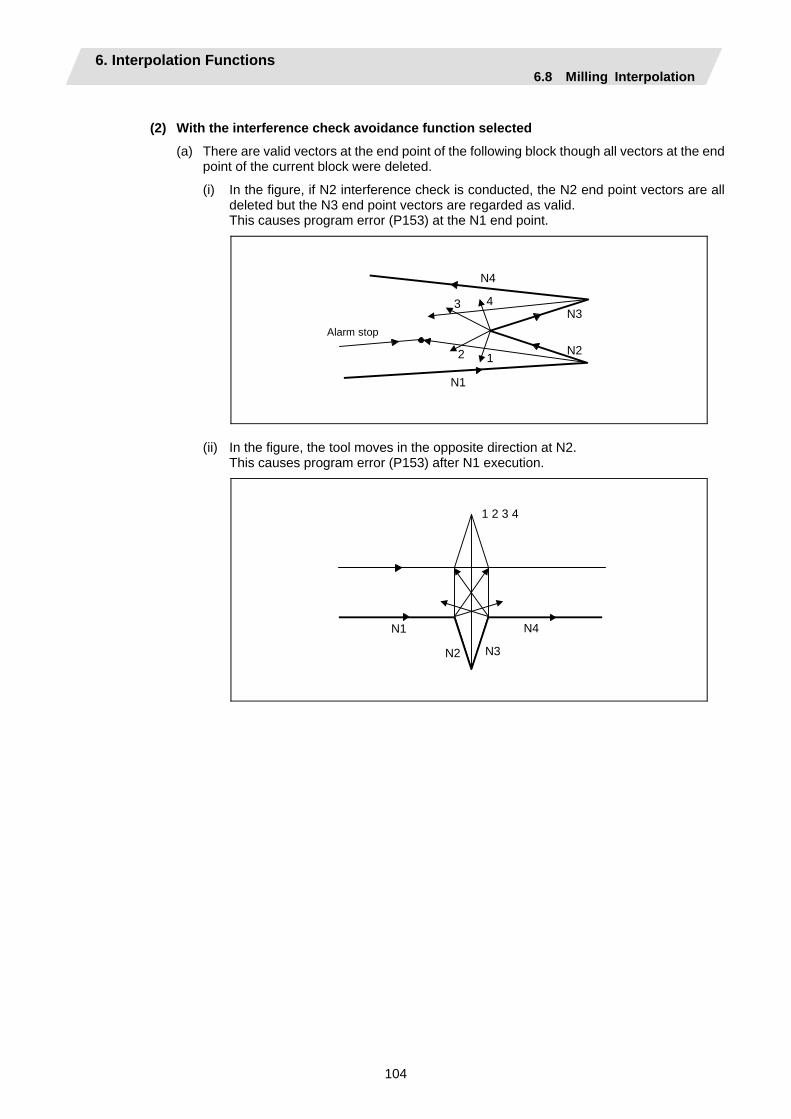
6. Interpolation Functions 6.8 Milling Interpolation
104
(2) With the interference check avoidance function selected
(a) There are valid vectors at the end point of the following block though all vectors at the end point of the current block were deleted.
(i) In the figure, if N2 interference check is conducted, the N2 end point vectors are all deleted but the N3 end point vectors are regarded as valid.
This causes program error (P153) at the N1 end point.
N1
2 N2 1
N3 43
N4
Alarm stop
(ii) In the figure, the tool moves in the opposite direction at N2. This causes program error (P153) after N1 execution.
N1
N2 N3
N4
1 2 3 4

6. Interpolation Functions 6.8 Milling Interpolation
105
(b) The avoidance vectors cannot be created. As shown in the figure, even when the conditions for creating avoidance vectors are met, it
may still be impossible to create avoidance vectors or the avoidance vectors may interfere with N3. Program error (P153) thus occurs at the N1 end point if the vectors intersect at an angle of 90° or more.
N1
N2
N3
N4
Alarm stop
N1
N2
N3
N4
Alarm stop
Angle of intersection
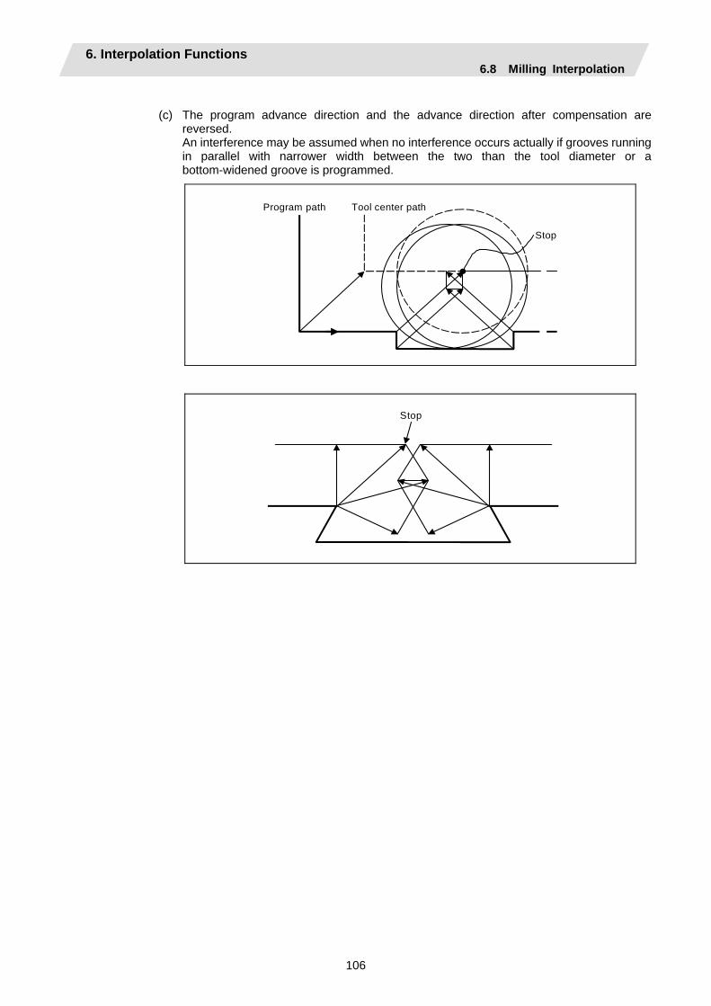
6. Interpolation Functions 6.8 Milling Interpolation
106
(c) The program advance direction and the advance direction after compensation are
reversed. An interference may be assumed when no interference occurs actually if grooves running
in parallel with narrower width between the two than the tool diameter or a bottom-widened groove is programmed.
Stop
Program path Tool center path
Stop
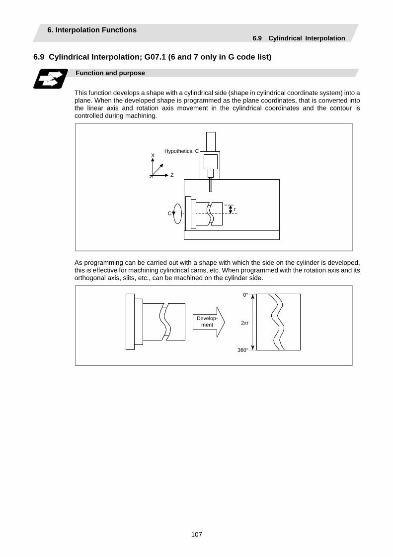
6. Interpolation Functions 6.9 Cylindrical Interpolation
107
6.9 Cylindrical Interpolation; G07.1 (6 and 7 only in G code list)
Function and purpose
This function develops a shape with a cylindrical side (shape in cylindrical coordinate system) into a plane. When the developed shape is programmed as the plane coordinates, that is converted into the linear axis and rotation axis movement in the cylindrical coordinates and the contour is controlled during machining.
X Hypothetical C
Z
C r
As programming can be carried out with a shape with which the side on the cylinder is developed, this is effective for machining cylindrical cams, etc. When programmed with the rotation axis and its orthogonal axis, slits, etc., can be machined on the cylinder side.
Develop-ment
0°
360°
2πr

6. Interpolation Functions 6.9 Cylindrical Interpolation
108
Command format
G07.1 Cc ; (Cylindrical interpolation mode start/cancel) Cc Cylinder radius value
• Radius value ≠ 0: Cylindrical interpolation mode start • Radius value = 0: Cylindrical interpolation mode cancel
(Note) The above format applies when the name of the rotation axis is "C". If the name is not "C",
command the name of the rotation axis being used instead of "C". (1) The coordinates commanded in the interval from the start to cancellation of the cylindrical
interpolation mode will be the cylindrical coordinate system. G07.1 C Cylinder radius value; Cylindrical interpolation mode start : (Cylindrical interpolation will start) : (The coordinate commands in this interval will be : the cylindrical coordinate system) G07.1 C0 ; Cylindrical interpolation mode cancel (Cylindrical interpolation will be canceled)
(2) G107 can be used instead of G07.1.
Detailed description
(1) Command G07.1 in an independent block. A program error (P33) will occur if this command is
issued in the same block as another G code.
(2) Program the rotation axis with an angle degree.
(3) Linear interpolation or circular interpolation can be commanded during the cylindrical interpolation mode. Note that the plane selection command must be issued just before the G07.1 block.
(4) The coordinates can be commanded with either an absolute command or incremental command.
(5) Tool radius compensation can be applied on the program command. Cylindrical interpolation will be executed on the path after tool radius compensation.
(6) Command the segment feed in the cylinder development with F. The F unit is mm/min or inch/min.
(7) Cylindrical interpolation accuracy In the cylindrical interpolation mode, the movement amount of the rotation axis commanded
with an angle is converted on the circle periphery, and after operating the linear and circular interpolation between the other axes, the amount is converted into an angle again.
Thus, the actual movement amount may differ from the commanded value such as when the cylinder radius is small.
Note that the error generated at this time is not cumulated.
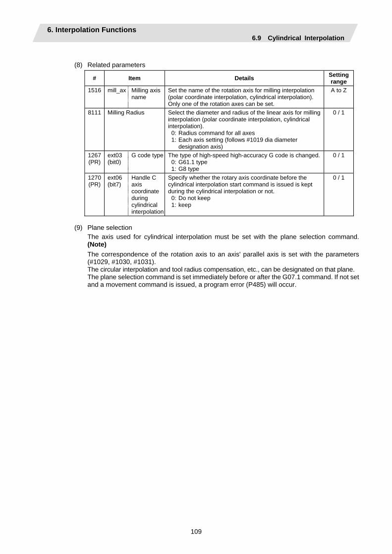
6. Interpolation Functions 6.9 Cylindrical Interpolation
109
(8) Related parameters
# Item Details Setting range
1516 mill_ax Milling axis name
Set the name of the rotation axis for milling interpolation (polar coordinate interpolation, cylindrical interpolation). Only one of the rotation axes can be set.
A to Z
8111 Milling Radius Select the diameter and radius of the linear axis for milling interpolation (polar coordinate interpolation, cylindrical interpolation). 0: Radius command for all axes 1: Each axis setting (follows #1019 dia diameter
designation axis)
0 / 1
1267 (PR)
ext03 (bit0)
G code type The type of high-speed high-accuracy G code is changed. 0: G61.1 type 1: G8 type
0 / 1
1270 (PR)
ext06 (bit7)
Handle C axis coordinate during cylindrical interpolation
Specify whether the rotary axis coordinate before the cylindrical interpolation start command is issued is kept during the cylindrical interpolation or not. 0: Do not keep 1: keep
0 / 1
(9) Plane selection
The axis used for cylindrical interpolation must be set with the plane selection command. (Note) The correspondence of the rotation axis to an axis' parallel axis is set with the parameters (#1029, #1030, #1031). The circular interpolation and tool radius compensation, etc., can be designated on that plane. The plane selection command is set immediately before or after the G07.1 command. If not set and a movement command is issued, a program error (P485) will occur.
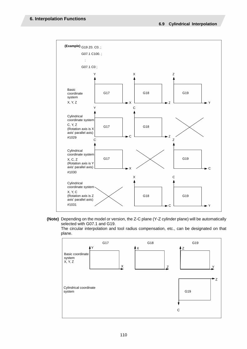
6. Interpolation Functions 6.9 Cylindrical Interpolation
110
(Example)
Basic coordinate system X, Y, Z
Cylindrical coordinate system C, Y, Z (Rotation axis is X axis' parallel axis) #1029
Cylindrical coordinate system X, C, Z (Rotation axis is Y axis' parallel axis) #1030
Cylindrical coordinate system X, Y, C (Rotation axis is Z axis' parallel axis) #1031
G17
Y
X
G18
Z
X
G19
Y
Z
G18
Z
C
G18
C
X
G19
C
Z
G19
Y
C
G17
X
C
G17
C
Y
G19 Z0. C0. ;
G07.1 C100. ;
:
G07.1 C0 ;
(Note) Depending on the model or version, the Z-C plane (Y-Z cylinder plane) will be automatically
selected with G07.1 and G19. The circular interpolation and tool radius compensation, etc., can be designated on that
plane.
G17 G18 G19 Y
X
X
Z
Z
Y
G19
Z
C
Basic coordinate system X, Y, Z
Cylindrical coordinate system

6. Interpolation Functions 6.9 Cylindrical Interpolation
111
Relation with other functions
(1) Circular interpolation
(a) Circular interpolation between the rotation axis and linear axis is possible during the cylindrical interpolation mode.
(b) An R specification command can be issued with circular interpolation. (I, J and K cannot be designated.)
(2) Tool radius compensation The tool radius can be compensated during the cylindrical interpolation mode.
(a) Command the plane selection in the same manner as circular interpolation. When using tool radius compensation, start up and cancel the compensation within the
cylindrical interpolation mode.
(b) A program error (P485) will occur if G07.1 is commanded during tool radius compensation.
(c) If the G07.1 command is issued with no movement command given after the tool radius compensation is canceled, the position of the axis in the G07.1 command block is interpreted as the position applied after the tool radius compensation is canceled and the following operations are performed.
(3) Cutting feed per minute (asynchronous feed)
(a) The feed per minute (asynchronous) mode is forcibly set when the cylindrical interpolation mode is started.
(b) When the cylindrical interpolation mode is canceled, the feed per revolution (synchronous) will return to the state before the cylindrical interpolation mode was started.
(4) Constant surface speed control
(a) A program error (P485) will occur if G07.1 is commanded in the constant surface speed control mode (G96).
(5) Miscellaneous functions
(a) The miscellaneous function (M) and 2nd miscellaneous function can be issued even in the cylindrical interpolation mode.
(b) The S command in the cylindrical interpolation mode issues the rotary tool's rotation speed instead of the spindle rotation speed.
(c) Issue the T command before cylindrical interpolation is started. A program error (P485) will occur if the T command is issued in the cylindrical interpolation mode.
: : T1212 ; ... T command before cylindrical interpolation → Valid T0 X100. Z0 ; G19 Z C ; G07.1 C100. ; : T1200 ; ... T command in cylindrical interpolation mode →Program error : G07.1 C0 ;
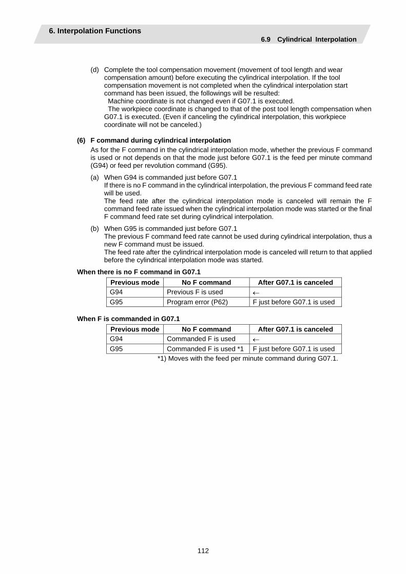
6. Interpolation Functions 6.9 Cylindrical Interpolation
112
(d) Complete the tool compensation movement (movement of tool length and wear compensation amount) before executing the cylindrical interpolation. If the tool compensation movement is not completed when the cylindrical interpolation start command has been issued, the followings will be resulted: Machine coordinate is not changed even if G07.1 is executed. The workpiece coordinate is changed to that of the post tool length compensation when G07.1 is executed. (Even if canceling the cylindrical interpolation, this workpiece coordinate will not be canceled.)
(6) F command during cylindrical interpolation As for the F command in the cylindrical interpolation mode, whether the previous F command
is used or not depends on that the mode just before G07.1 is the feed per minute command (G94) or feed per revolution command (G95).
(a) When G94 is commanded just before G07.1 If there is no F command in the cylindrical interpolation, the previous F command feed rate
will be used. The feed rate after the cylindrical interpolation mode is canceled will remain the F
command feed rate issued when the cylindrical interpolation mode was started or the final F command feed rate set during cylindrical interpolation.
(b) When G95 is commanded just before G07.1 The previous F command feed rate cannot be used during cylindrical interpolation, thus a
new F command must be issued. The feed rate after the cylindrical interpolation mode is canceled will return to that applied
before the cylindrical interpolation mode was started.
When there is no F command in G07.1 Previous mode No F command After G07.1 is canceled G94 Previous F is used ← G95 Program error (P62) F just before G07.1 is used
When F is commanded in G07.1
Previous mode No F command After G07.1 is canceled G94 Commanded F is used ← G95 Commanded F is used *1 F just before G07.1 is used
*1) Moves with the feed per minute command during G07.1.
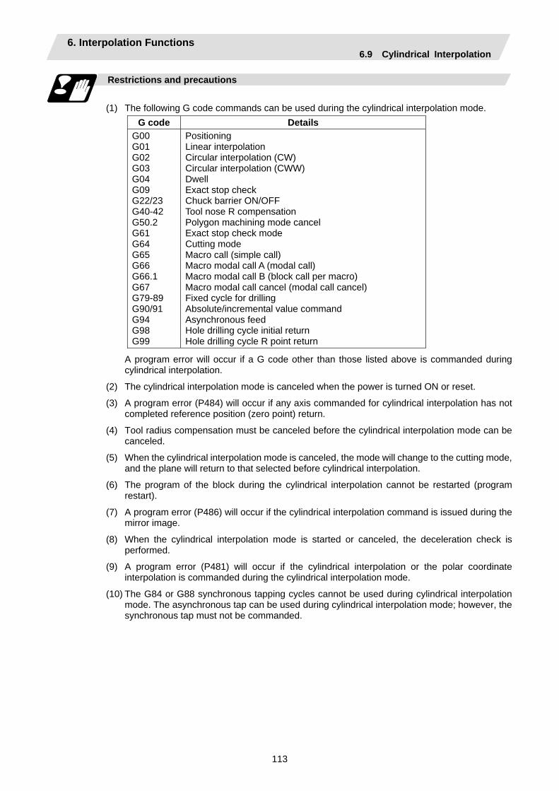
6. Interpolation Functions 6.9 Cylindrical Interpolation
113
Restrictions and precautions
(1) The following G code commands can be used during the cylindrical interpolation mode.
G code Details G00 G01 G02 G03 G04 G09 G22/23 G40-42 G50.2 G61 G64 G65 G66 G66.1 G67 G79-89 G90/91 G94 G98 G99
Positioning Linear interpolation Circular interpolation (CW) Circular interpolation (CWW) Dwell Exact stop check Chuck barrier ON/OFF Tool nose R compensation Polygon machining mode cancel Exact stop check mode Cutting mode Macro call (simple call) Macro modal call A (modal call) Macro modal call B (block call per macro) Macro modal call cancel (modal call cancel) Fixed cycle for drilling Absolute/incremental value command Asynchronous feed Hole drilling cycle initial return Hole drilling cycle R point return
A program error will occur if a G code other than those listed above is commanded during cylindrical interpolation.
(2) The cylindrical interpolation mode is canceled when the power is turned ON or reset.
(3) A program error (P484) will occur if any axis commanded for cylindrical interpolation has not completed reference position (zero point) return.
(4) Tool radius compensation must be canceled before the cylindrical interpolation mode can be canceled.
(5) When the cylindrical interpolation mode is canceled, the mode will change to the cutting mode, and the plane will return to that selected before cylindrical interpolation.
(6) The program of the block during the cylindrical interpolation cannot be restarted (program restart).
(7) A program error (P486) will occur if the cylindrical interpolation command is issued during the mirror image.
(8) When the cylindrical interpolation mode is started or canceled, the deceleration check is performed.
(9) A program error (P481) will occur if the cylindrical interpolation or the polar coordinate interpolation is commanded during the cylindrical interpolation mode.
(10) The G84 or G88 synchronous tapping cycles cannot be used during cylindrical interpolation mode. The asynchronous tap can be used during cylindrical interpolation mode; however, the synchronous tap must not be commanded.

6. Interpolation Functions 6.9 Cylindrical Interpolation
114
Example of program
<Parameter> #1029 aux_I #1030 aux_J C #1031 aux_K
Command of plane selection for cylindrical interpolation and command of two interpolation axes Cylindrical interpolation start Cylindrical interpolation cancel
<Program> N01 G28XZC; N02 T0202; N03 G97S100M23; N04 G00X50.Z0.; N05 G94G01X40.F100.; N06 G19C0Z0; N07 G07.1C20.; N08 G41; N09 G01Z-10.C80.F150; N10 Z-25.C90.; N11 Z-80.C225; N12 G03Z-75.C270.R55.; N13 G01Z-25; N14 G02Z-20.C280.R80.; N15 G01C360. N16 G40; N17 G07.1C0; N18 G01X50.; N19 G0X100.Z100.; N20 M25; N21 M30;
(Unit: mm)
50
100
150
200
250
300
350°
-20-40-60-80
C
Z
N09N10
N11
N12N13
N14
N15
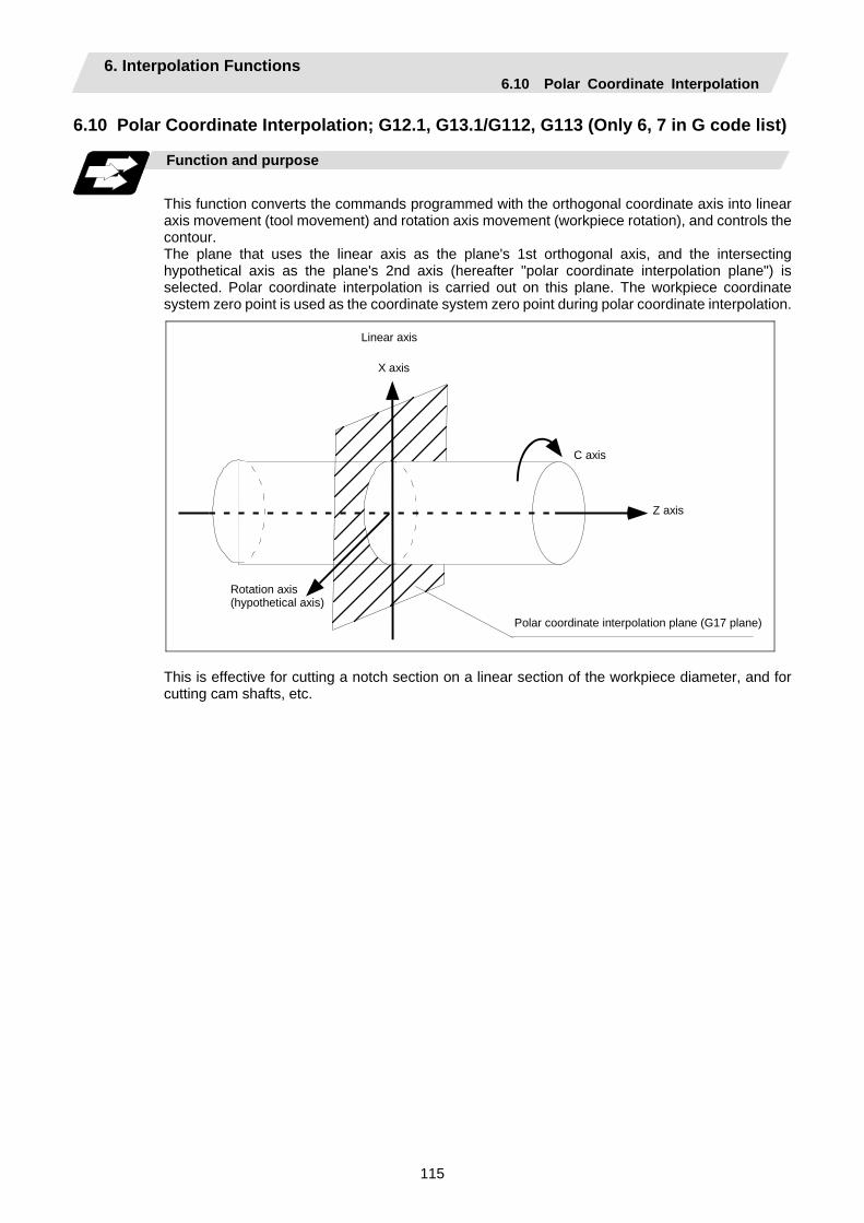
6. Interpolation Functions 6.10 Polar Coordinate Interpolation
115
6.10 Polar Coordinate Interpolation; G12.1, G13.1/G112, G113 (Only 6, 7 in G code list)
Function and purpose
This function converts the commands programmed with the orthogonal coordinate axis into linear axis movement (tool movement) and rotation axis movement (workpiece rotation), and controls the contour. The plane that uses the linear axis as the plane's 1st orthogonal axis, and the intersecting hypothetical axis as the plane's 2nd axis (hereafter "polar coordinate interpolation plane") is selected. Polar coordinate interpolation is carried out on this plane. The workpiece coordinate system zero point is used as the coordinate system zero point during polar coordinate interpolation.
Linear axis
X axis
C axis
Z axis
Rotation axis (hypothetical axis)
Polar coordinate interpolation plane (G17 plane)
This is effective for cutting a notch section on a linear section of the workpiece diameter, and for cutting cam shafts, etc.
6. Interpolation Functions 6.10 Polar Coordinate Interpolation
116
Command format
G12.1 ; Polar coordinate interpolation mode start G13.1 ; Polar coordinate interpolation mode cancel
(1) The coordinates commanded in the interval from the start to cancellation of the polar
coordinate interpolation mode will be the polar coordinate interpolation. G12.1 ; Polar coordinate interpolation mode start : (Polar coordinate interpolation will start) : (The coordinate commands in this interval will be the polar coordinate : interpolation) G13.1 ; Polar coordinate interpolation mode cancel (Polar coordinate interpolation is canceled)
(2) G112 and G113 can be used instead of G12.1 and G13.1.
(3) Command G12.1 and G13.1 in an independent block. A program error (P33) will occur if this command is issued in the same block as another G code.
(4) Linear interpolation or circular interpolation can be commanded during the polar coordinate interpolation mode.
(5) The coordinates can be commanded with either an absolute command or incremental command.
(6) Tool radius compensation can be applied on the program command. Polar coordinate interpolation will be executed on the path after tool radius compensation.
(7) Command the segment feed in the polar coordinate interpolation plane (orthogonal coordinate system) with F. The F unit is mm/min or inch/min.
(8) When the G12.1 and G13.1 commands are issued, the deceleration check is executed.
Detailed description
(1) Plane selection The linear axis and rotation axis used for polar coordinate interpolation must be set beforehand
with the parameters.
(a) Determine the deemed plane for carrying out polar coordinate interpolation with the parameter (#1533) for the linear axis used for polar coordinate interpolation.
#1533 setting value Deemed plane X G17 (XY plane) Y G19 (YZ plane) Z G18 (ZX plane)
Blank (no setting) G17 (XY plane)
(b) A program error (P485) will occur if the plane selection command (G16 to G19) is issued during the polar coordinate interpolation mode.
(Note) Depending on the model or version, parameter (#1533) may not be provided. In this case, the operation will be the same as if the parameter (#1533) is blank (no setting).
6. Interpolation Functions 6.10 Polar Coordinate Interpolation
117
(2) Related parameters
# Item Details Setting range
1516 mill_ax Milling axis name
Set the name of the rotation axis for milling interpolation (polar coordinate interpolation, cylindrical interpolation). Only one of the rotation axes can be set.
A to Z
1517 mill_c Milling interpolation hypothetical axis name
Select the hypothetical axis command name for milling interpolation (polar coordinate interpolation, cylindrical interpolation). 0: Y axis command 1: Command rotation axis name
0 / 1
8111 Milling Radius Select the diameter and radius of the linear axis for milling interpolation. 0: Radius command for all axes 1: Each axis setting (follows #1019 dia diameter
designation axis)
0 / 1
Relation with other functions
(1) Program commands during polar coordinate interpolation
(a) The program commands in the polar coordinate interpolation mode are commanded with the orthogonal coordinate value of the linear axis and rotation axis (hypothetical axis) on the polar coordinate interpolation plane.
The axis address of the rotation axis (C) is commanded as the axis address for the plane's 2nd axis (hypothetical axis) command.
The command unit is not deg (degree), and instead is the same unit (mm or inch) as the command issued with the axis address for the plane's 1st axis (linear axis).
(b) The hypothetical axis coordinate value will be set to "0" when G12.1 is commanded. In other words, the position where G12.1 is commanded will be interpreted as angle = 0, and the polar coordinate interpolation will start.
(2) Circular interpolation on polar coordinate plane The arc radius address for carrying out circular interpolation during the polar coordinate
interpolation mode is determined with the linear axis parameter (#1533). #1533 setting value Center designation command
X I, J (polar coordinate plane is interpreted as XY plane) Y J, K (polar coordinate plane is interpreted as YZ plane) Z K, I (polar coordinate plane is interpreted as ZX plane)
Blank (no setting) I, J (polar coordinate plane is interpreted as XY plane)
The arc radius can also be designated with the R command.
(Note) Depending on the model or version, parameter (#1533) may not be provided. In this case, the operation will be the same as if the parameter (#1533) is blank (no setting).
(3) Tool radius compensation The tool radius can be compensated during the polar coordinate interpolation mode.
(a) Command the plane selection in the same manner as polar coordinate interpolation. When using tool radius compensation, it must be started up and canceled within the polar
coordinate interpolation mode.
(b) A program error (P485) will occur if polar coordinate interpolation is executed during tool radius compensation.
(c) If the G12.1 and G13.1 commands are issued with no movement command given after the tool radius compensation is canceled, the position of the axis in the G12.1 and G13.1 commands block is interpreted as the position applied after the tool radius compensation is canceled and the following operations are performed.

6. Interpolation Functions 6.10 Polar Coordinate Interpolation
118
(4) Cutting asynchronous feed
(a) The asynchronous mode is forcibly set when the polar coordinate interpolation mode is started.
(b) When the polar coordinate interpolation mode is canceled, the synchronization mode will return to the state before the polar coordinate interpolation mode was started.
(c) A program error (P485) will occur if G12.1 is commanded in the constant surface speed control mode (G96).
(5) Miscellaneous functions
(a) The miscellaneous function (M) and 2nd miscellaneous function can be issued even in the polar coordinate interpolation mode.
(b) The S command in the polar coordinate interpolation mode issues the rotary tool's rotation speed instead of the spindle rotation speed.
(c) Issue the T command before polar coordinate interpolation is started. A program error (P485) will occur if the T command is issued in the polar coordinate interpolation mode.
: : T1212 ; ... T command before polar coordinate interpolation → Valid G0 X100. Z0 ; G12.1 ; : T1200 ; ... T command in polar coordinate interpolation mode → Program error : G13.1 ;
(d) Complete the tool compensation operation (movement of tool length and wear compensation amount) before executing the polar coordinate interpolation. If the tool compensation operation is not completed when the polar coordinate interpolation start command has been issued, the followings will be resulted: Machine coordinate is not changed even if G12.1 is executed. The workpiece coordinate is changed to that of the post tool length compensation when G12.1 is executed. (Even if canceling the polar coordinate interpolation, this workpiece coordinate will not be canceled.)
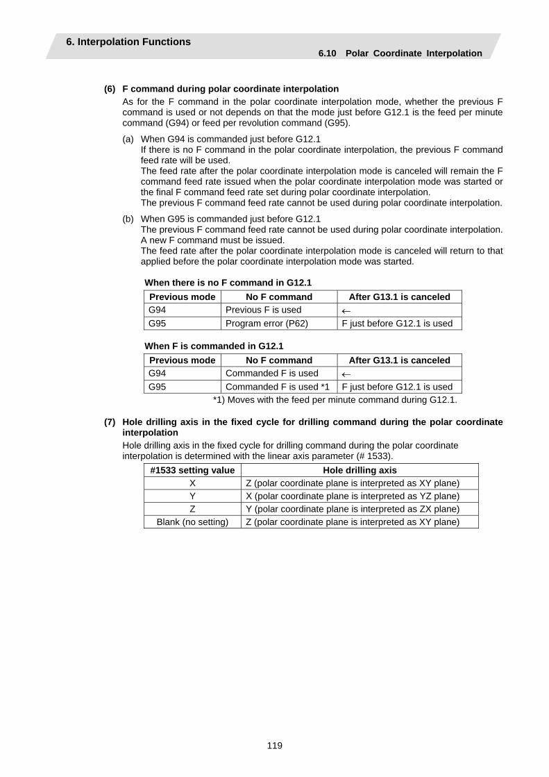
6. Interpolation Functions 6.10 Polar Coordinate Interpolation
119
(6) F command during polar coordinate interpolation
As for the F command in the polar coordinate interpolation mode, whether the previous F command is used or not depends on that the mode just before G12.1 is the feed per minute command (G94) or feed per revolution command (G95).
(a) When G94 is commanded just before G12.1 If there is no F command in the polar coordinate interpolation, the previous F command feed rate will be used. The feed rate after the polar coordinate interpolation mode is canceled will remain the F command feed rate issued when the polar coordinate interpolation mode was started or the final F command feed rate set during polar coordinate interpolation. The previous F command feed rate cannot be used during polar coordinate interpolation.
(b) When G95 is commanded just before G12.1 The previous F command feed rate cannot be used during polar coordinate interpolation. A new F command must be issued. The feed rate after the polar coordinate interpolation mode is canceled will return to that applied before the polar coordinate interpolation mode was started.
When there is no F command in G12.1 Previous mode No F command After G13.1 is canceled G94 Previous F is used ← G95 Program error (P62) F just before G12.1 is used
When F is commanded in G12.1 Previous mode No F command After G13.1 is canceled G94 Commanded F is used ← G95 Commanded F is used *1 F just before G12.1 is used
*1) Moves with the feed per minute command during G12.1.
(7) Hole drilling axis in the fixed cycle for drilling command during the polar coordinate interpolation Hole drilling axis in the fixed cycle for drilling command during the polar coordinate interpolation is determined with the linear axis parameter (# 1533).
#1533 setting value Hole drilling axis X Z (polar coordinate plane is interpreted as XY plane) Y X (polar coordinate plane is interpreted as YZ plane) Z Y (polar coordinate plane is interpreted as ZX plane)
Blank (no setting) Z (polar coordinate plane is interpreted as XY plane)

6. Interpolation Functions 6.10 Polar Coordinate Interpolation
120
Restrictions and precautions
(1) The following G code commands can be used during the polar coordinate interpolation mode.
G code Details G00 G01 G02 G03 G04 G09 G22/23 G40-42 G61 G64 G65 G66 G66.1 G67 G80-89 G90/91 G94 G98 G99
Positioning Linear interpolation Circular interpolation (CW) Circular interpolation (CWW) Dwell Exact stop check Chuck barrier ON/OFF Tool nose R compensation Exact stop check mode Cutting mode Macro call (simple call) Macro modal call A (modal call) Macro modal call B (block call per macro) Macro modal call cancel (modal call cancel) Fixed cycle for drilling Absolute/incremental value command Asynchronous feed Hole drilling cycle initial return Hole drilling cycle R point return
A program error (P481) may occur if a G code other than those listed above is commanded during polar coordinate interpolation.
(2) The program cannot be restarted (resumed) for a block in polar coordinate interpolation.
(3) Before commanding polar coordinate interpolation, set the workpiece coordinate system so that the center of the rotation axis is at the coordinate system zero point. Do not change the coordinate system during the polar coordinate interpolation mode. (G50, G52, G53, relative coordinate reset, G54 to G59, etc.)
(4) The feed rate during polar coordinate interpolation will be the interpolation speed on the polar coordinate interpolation plane (orthogonal coordinate system).
(The relative speed with the tool will be converted with polar coordinate conversion.) When passing near the center of the rotation axis on the polar coordinate interpolation plane
(orthogonal coordinate system), the rotation axis side feed rate after polar coordinate interpolation will be very high.
(5) The axis movement command outside of the plane during polar coordinate interpolation will move unrelated to the poler coordinate interpolation.
(6) The current position displays during polar coordinate interpolation will all indicate the actual coordinate value. However, the "remaining movement amount" will be the movement amount on the polar coordinate input plane.
(7) The polar coordinate interpolation mode will be canceled when the power is turned ON or reset.
(8) A program error (P484) will occur if any axis commanded for polar coordinate interpolation has not completed zero point return.
(9) Tool radius compensation must be canceled before the polar coordinate interpolation mode can be canceled.
(10) When the polar coordinate interpolation mode is canceled, the mode will change to the cutting mode, and the plane will return to that selected before polar coordinate interpolation.
(11) A program error (P486) will occur if the polar coordinate interpolation command is issued during the mirror image.
(12) A program error (P481) will occur if the cylindrical interpolation or the polar coordinate interpolation is commanded during the polar coordinate interpolation mode.
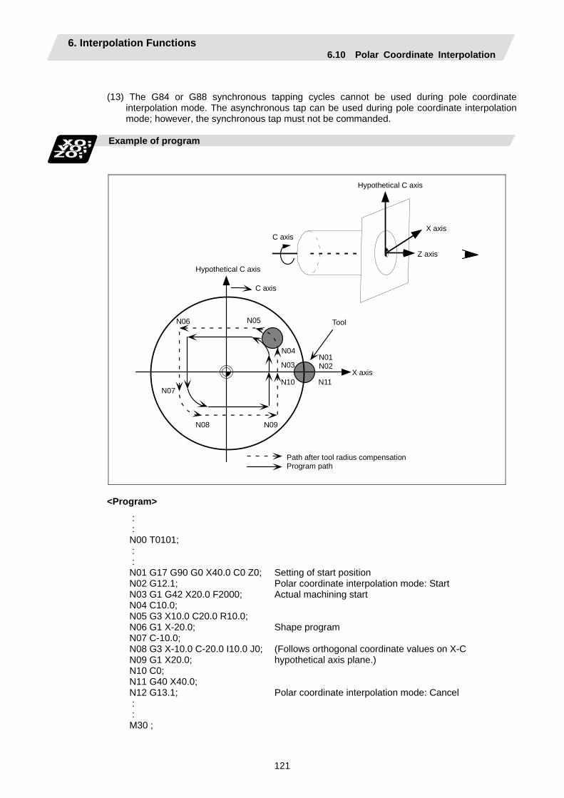
6. Interpolation Functions 6.10 Polar Coordinate Interpolation
121
(13) The G84 or G88 synchronous tapping cycles cannot be used during pole coordinate interpolation mode. The asynchronous tap can be used during pole coordinate interpolation mode; however, the synchronous tap must not be commanded.
Example of program
Hypothetical C axis
X axis
Z axis
C axis
Hypothetical C axis
C axis
Tool
X axis
N01 N02
N11
N05
N04
N03
N10
N09 N08
N07
N06
Path after tool radius compensation Program path
<Program>
: : N00 T0101; : : N01 G17 G90 G0 X40.0 C0 Z0;N02 G12.1; N03 G1 G42 X20.0 F2000; N04 C10.0; N05 G3 X10.0 C20.0 R10.0; N06 G1 X-20.0; N07 C-10.0; N08 G3 X-10.0 C-20.0 I10.0 J0;N09 G1 X20.0; N10 C0; N11 G40 X40.0; N12 G13.1; : : M30 ;
Setting of start position Polar coordinate interpolation mode: Start Actual machining start Shape program (Follows orthogonal coordinate values on X-C hypothetical axis plane.) Polar coordinate interpolation mode: Cancel

6. Interpolation Functions 6.11 Exponential Interpolation
122
6.11 Exponential Interpolation; G02.3, G03.3
Function and purpose
Exponential interpolation changes the rotation axis into an exponential function shape in respect to the linear axis movement. At this time, the other axes carry out linear interpolation between the linear axis. This allows a machining of a taper groove with constant torsion angle (helix angle) (uniform helix machining of taper shape). This function can be used for slotting or grinding a tool for use in an end mill, etc. • Uniform helix machining of taper shape
(Linear axis)
Torsion angle: J1=J2=J3
A axis (Rotation axis)
Z axis
X axisJ1 J2 J3
(G02.3/G03.3)
(G00)
(G01) (G01)
• Relation of linear axis and rotation axis
A axis (Rotation axis)
"Relation of linear axis and rotation axis"
X=B (eCA-1) B, C... constant X axis
(Linear axis)
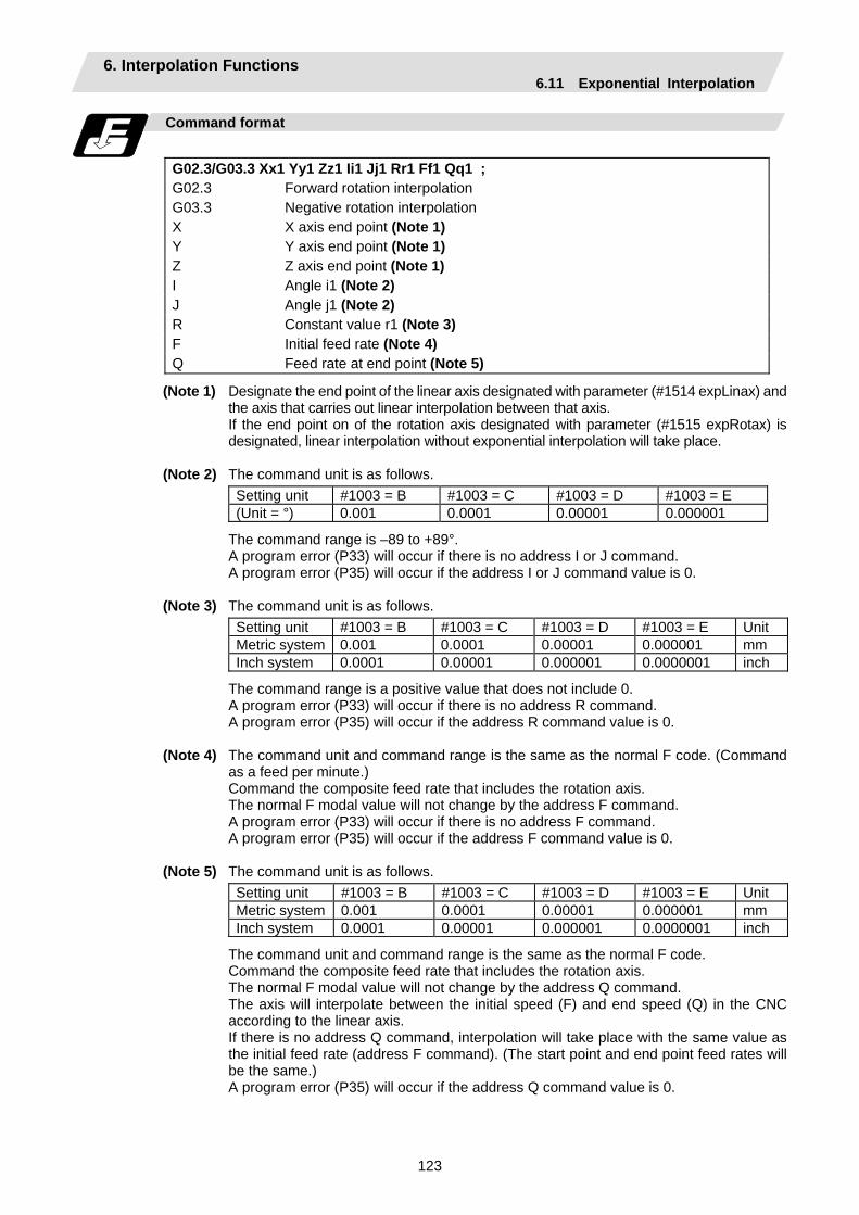
6. Interpolation Functions 6.11 Exponential Interpolation
123
Command format
G02.3/G03.3 Xx1 Yy1 Zz1 Ii1 Jj1 Rr1 Ff1 Qq1 ; G02.3 Forward rotation interpolation G03.3 Negative rotation interpolation X X axis end point (Note 1) Y Y axis end point (Note 1) Z Z axis end point (Note 1) I Angle i1 (Note 2) J Angle j1 (Note 2) R Constant value r1 (Note 3) F Initial feed rate (Note 4) Q Feed rate at end point (Note 5)
(Note 1) Designate the end point of the linear axis designated with parameter (#1514 expLinax) and the axis that carries out linear interpolation between that axis.
If the end point on of the rotation axis designated with parameter (#1515 expRotax) is designated, linear interpolation without exponential interpolation will take place.
(Note 2) The command unit is as follows.
Setting unit #1003 = B #1003 = C #1003 = D #1003 = E (Unit = °) 0.001 0.0001 0.00001 0.000001
The command range is –89 to +89°. A program error (P33) will occur if there is no address I or J command. A program error (P35) will occur if the address I or J command value is 0. (Note 3) The command unit is as follows.
Setting unit #1003 = B #1003 = C #1003 = D #1003 = E Unit Metric system 0.001 0.0001 0.00001 0.000001 mm Inch system 0.0001 0.00001 0.000001 0.0000001 inch
The command range is a positive value that does not include 0. A program error (P33) will occur if there is no address R command. A program error (P35) will occur if the address R command value is 0. (Note 4) The command unit and command range is the same as the normal F code. (Command
as a feed per minute.) Command the composite feed rate that includes the rotation axis. The normal F modal value will not change by the address F command. A program error (P33) will occur if there is no address F command. A program error (P35) will occur if the address F command value is 0. (Note 5) The command unit is as follows.
Setting unit #1003 = B #1003 = C #1003 = D #1003 = E Unit Metric system 0.001 0.0001 0.00001 0.000001 mm Inch system 0.0001 0.00001 0.000001 0.0000001 inch
The command unit and command range is the same as the normal F code. Command the composite feed rate that includes the rotation axis. The normal F modal value will not change by the address Q command. The axis will interpolate between the initial speed (F) and end speed (Q) in the CNC
according to the linear axis. If there is no address Q command, interpolation will take place with the same value as
the initial feed rate (address F command). (The start point and end point feed rates will be the same.)
A program error (P35) will occur if the address Q command value is 0.
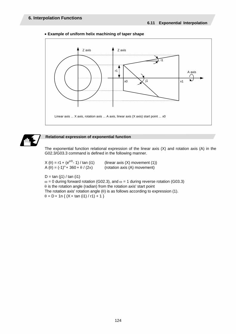
6. Interpolation Functions 6.11 Exponential Interpolation
124
• Example of uniform helix machining of taper shape
i1
j1 x1 x0
r1
Z axis Z axis
A axis
Linear axis ... X axis, rotation axis ... A axis, linear axis (X axis) start point ... x0
Relational expression of exponential function
The exponential function relational expression of the linear axis (X) and rotation axis (A) in the G02.3/G03.3 command is defined in the following manner. X (θ) = r1 ∗ (eθ/D- 1) / tan (i1) (linear axis (X) movement (1)) A (θ) = (-1)ω ∗ 360 ∗ θ / (2π) (rotation axis (A) movement) D = tan (j1) / tan (i1) ω = 0 during forward rotation (G02.3), and ω = 1 during reverse rotation (G03.3) θ is the rotation angle (radian) from the rotation axis' start point The rotation axis' rotation angle (θ) is as follows according to expression (1). θ = D ∗ 1n (X ∗ tan (i1) / r1) + 1
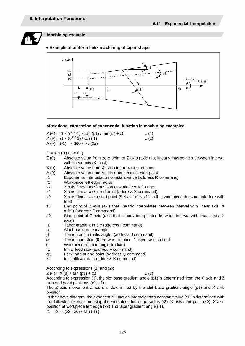
6. Interpolation Functions 6.11 Exponential Interpolation
125
Machining example
• Example of uniform helix machining of taper shape
i1
j1 x1 x0 x2
p1
A axis
r1 r2
z1 z2 z0
X axis
Z axis
<Relational expression of exponential function in machining example>
Z (θ) = r1 ∗ (eθ/D-1) ∗ tan (p1) / tan (i1) + z0 ... (1) X (θ) = r1 ∗ (eθ/D-1) / tan (i1) ... (2) A (θ) = (-1) ω ∗ 360 ∗ θ / (2π) D = tan (j1) / tan (i1) Z (θ) Absolute value from zero point of Z axis (axis that linearly interpolates between interval
with linear axis (X axis)) X (θ) Absolute value from X axis (linear axis) start point A (θ) Absolute value from A axis (rotation axis) start point r1 Exponential interpolation constant value (address R command) r2 Workpiece left edge radius x2 X axis (linear axis) position at workpiece left edge x1 X axis (linear axis) end point (address X command) x0 X axis (linear axis) start point (Set as "x0 ≤ x1" so that workpiece does not interfere with
tool) z1 End point of Z axis (axis that linearly interpolates between interval with linear axis (X
axis)) (address Z command) z0 Start point of Z axis (axis that linearly interpolates between interval with linear axis (X
axis)) i1 Taper gradient angle (address I command) p1 Slot base gradient angle j1 Torsion angle (helix angle) (address J command) ω Torsion direction (0: Forward rotation, 1: reverse direction) θ Workpiece rotation angle (radian) f1 Initial feed rate (address F command) q1 Feed rate at end point (address Q command) k1 Insignificant data (address K command) According to expressions (1) and (2): Z (θ) = X (θ) ∗ tan (p1) + z0 ... (3) According to expression (3), the slot base gradient angle (p1) is determined from the X axis and Z axis end point positions (x1, z1). The Z axis movement amount is determined by the slot base gradient angle (p1) and X axis position. In the above diagram, the exponential function interpolation's constant value (r1) is determined with the following expression using the workpiece left edge radius (r2), X axis start point (x0), X axis position at workpiece left edge (x2) and taper gradient angle (i1). r1 = r2 - (x2 - x0) ∗ tan (i1)
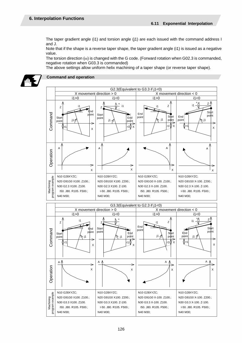
6. Interpolation Functions 6.11 Exponential Interpolation
126
The taper gradient angle (i1) and torsion angle (j1) are each issued with the command address I and J. Note that if the shape is a reverse taper shape, the taper gradient angle (i1) is issued as a negative value. The torsion direction (ω) is changed with the G code. (Forward rotation when G02.3 is commanded, negative rotation when G03.3 is commanded) The above settings allow uniform helix machining of a taper shape (or reverse taper shape).
Command and operation
G2.3(Equivalent to G3.3 if j1<0)
X movement direction > 0 X movement direction < 0
i1>0 i1<0 i1>0 i1<0
Com
man
d
i1
X
Z End point
j1
r1
Start point
-
X
Z+
j1
i1
r1
End point
Start point
X
Z
j1
i1
r1
Start point
End point
End point
Start point
X
Z+ -
j1
i1
r1
Ope
ratio
n
X
A
X
A
X
A
X
A
Mac
hini
ng
prog
ram
exa
mpl
e N10 G28XYZC;
N20 G91G0 X100. Z100.;
N30 G2.3 X100. Z100.
I50. J80. R105. F500.;
N40 M30;
N10 G28XYZC;
N20 G91G0 X100. Z200.;
N30 G2.3 X100. Z-100.
I-50. J80. R105. F500.;
N40 M30;
N10 G28XYZC;
N20 G91G0 X-100. Z100.;
N30 G2.3 X-100. Z100.
I50. J80. R105. F500.;
N40 M30;
N10 G28XYZC;
N20 G91G0 X-100. Z200.;
N30 G2.3 X-100. Z-100.
I-50. J80. R105. F500.;
N40 M30;
G3.3(Equivalent to G2.3 if j1<0)
X movement direction > 0 X movement direction < 0
i1>0 i1<0 i1>0 i1<0
Com
man
d
End point Start
point
X
Z
j1
i1
r1
End point
Start point
-
X
Z+
j1
r1
Start point
End point
X
Z
j1
i1
r1
End point
Start point
X
Z+ -
j1
i1
r1
Ope
ratio
n
X A
X
A
X A
X
A
Mac
hini
ng
prog
ram
exa
mpl
e N10 G28XYZC;
N20 G91G0 X100. Z100.;
N30 G3.3 X100. Z100.
I50. J80. R105. F500.;
N40 M30;
N10 G28XYZC;
N20 G91G0 X100. Z200.;
N30 G3.3 X100. Z-100.
I-50. J80. R105. F500.;
N40 M30;
N10 G28XYZC;
N20 G91G0 X-100. Z100.;
N30 G3.3 X-100. Z100.
I50. J80. R105. F500.;
N40 M30;
N10 G28XYZC;
N20 G91G0 X-100. Z200.;
N30 G3.3 X-100. Z-100.
I-50. J80. R105. F500.;
N40 M30;

6. Interpolation Functions 6.11 Exponential Interpolation
127
Precautions for programming
(1) When G02.3/G03.3 is commanded, interpolation takes place with the exponential function
relational expression using the start position of the linear axis and rotation axis as 0.
(2) Linear interpolation will take place in the following cases, even if in the G02.3/G03.3 mode. The feed rate for linear interpolation will be the F command in that block. (Note that the normal
F modal is not updated.) • The linear axis designated with the parameter (#1514 expLinax) is not commanded, or the
movement amount for that axis is 0. • The rotation axis designated with the parameter (#1515 expRotax) is commanded.
(3) Tool length offset and nose R compensation cannot be used during the G02.3/G03.3 mode. Note that the tool length offset started before interpolation is started before the G02.3/G03.3 mode will normally continue.
(4) A program error (P481) will occur if commands are issued during the polar coordinate interpolation, cylindrical interpolation or milling interpolation modes.
(5) Program error (P612) will occur if commands are issued during the mirror image.
(6) G02.3/G03.3 will function with feed per minute even during the feed per revolution mode.
(7) If the parameter "#1515 expRota" setting is the same axis name as the initial C axis, the axis selected with the C axis selection signal will interpolate as the rotation axis.

7. Feed Functions 7.1 Rapid Traverse Rate
128
7. Feed Functions 7.1 Rapid Traverse Rate
Function and purpose
The rapid traverse rate can be set independently for each axis. The speed range that can be set is 1mm/min to 10000000mm/min. Note that the upper limit speed is limited by the machine specification. Refer to the specifications manual of the machine for the rapid traverse rate settings. Two paths are available during positioning: the interpolation type where the area from the start point to the end point is linearly interpolated or the non-interpolation type where movement proceeds at the maximum speed of each axis. The type is selected by parameter "#1086 G0Intp". The positioning time is the same in each case.
(Note) Rapid traverse override Override can be applied by an external input signal for both manual and automatic rapid
traverse. There are 2 types which are determined by the PLC specifications. Type 1: Override in 4 steps: 1%, 25%, 50% and 100% Type 2: Override in 1% steps from 0% to 100%.
7.2 Cutting Feed Rate
Function and purpose
This function specifies the feed rate of the cutting commands, and a feed amount per spindle rotation or feed amount per minute is commanded. Once commanded, it is stored in the memory as a modal value. The feed rate modal is cleared to zero only when the power is turned ON. The maximum cutting feed rate is clamped by the cutting feed rate clamp parameter (whose setting range is the same as that for the cutting feed rate). The cutting feed rate is assigned with address F and 8-digit number. The F8 digits are assigned with a decimal point for a 5-digit integer and a 3-digit fraction. The cutting feed rate is valid for the G01, G02, G03, G33 and G34 commands.
Examples (asynchronous feed)
Feed rate G1 X100. Z100. F200 ; 200.0mm/min F200. or F200.000 gives the same rate.F1 X100. Z100. F123.4 ; 123.4mm/min F1 X100. Z100. F56.789 ; 56.789mm/min
Speed range that can be commanded (when input setting unit is 1µm)
Command mode Feed rate command range Remarks mm/min 0.001 to 10000000 mm/min inch/min 0.0001 to 1000000 inch/min
°/min 0.001 to 10000000 °/min
(Note 1) A program error (P62) results when there is no F command in the first cutting command (G01, G02, G03, G33, G34) after the power has been turned ON.
7. Feed Functions 7.3 F1-digit Feed
129
7.3 F1-digit Feed
Function and purpose
By setting the F1-digit feed parameter, the feed rate which has been set to correspond to the 1-digit number following the F address serves as the command value. When F0 is assigned, the rapid traverse rate is established and the speed is the same as for G00. (The G modal does not change, but the acceleration/deceleration method follows the rapid traverse setting.) When F1 to F5 is assigned, the feed rate set to correspond to the command serves as the command value. The command greater than F6 is considered to be the normal cutting feed rate. The F1-digit command is valid in a G01, G02, G03, G02.1 or G03.1 modal. The F1-digit command can also be used for fixed cycle.
Detailed description
The override function of the feed rate which is set in accordance to the F1-digit is performed by using the first manual handle. The feed rate cannot be changed with the 2nd and 3rd handle. The amount by which the feed rate can be increased or reduced is determined by the following formula.
±∆F = FM
K × (±number of manual handle pulse generator pulses)
Where "+" means increase, and "–" means reduction. K : Operation constant (This is the number of FM divisions, and is the calculated constant of
the increment/decrement speed per scale of the manual handle pulse generator.) This is set with the base specification parameter "#1507 F1_K".
FM : This is the clamp speed of F1 to F5 This is set with the base specification parameter "#1506 F1_FM".
Set the corresponding speed of F1 to F5 with the base specification parameters "#1185 spd_F1" to "#1189 spd_F5" respectively. The increase/reduction range is from "0" to the set value of the parameter "#1506 F1_FM". Operation alarm (104) will occur when the feed rate is 0. (1) Operation method
(a) Make the F1-digit command valid. (Set the base specification parameter "#1079 F1digt" to 1.)
(b) Set FM and K. Setting range K : 1 to 32767 (Base specification parameter "#1507 F1_K") FM : 0 to Fmax (mm/min) (Base specification parameter "#1506 F1_FM")
(c) Set F1 to F5. (Base specification parameter "1185 spd_F1" to "#1189 spd_F5")
7. Feed Functions 7.3 F1-digit Feed
130
(2) Special notes
(a) Use of both the F1-digit command and normal cutting feed rate command is possible when the F1-digit is valid.
(Example 1) F0 Rapid traverse rate F1 to F5 F1-digit F6 or more Normal cutting feed rate command
(b) F1 to F5 are invalid in the G00 mode and the rapid traverse rate is established instead.
(c) If F0 is used in the G02 or G03 mode, a program error (P121) will result.
(d) When F1. to F5. (with decimal point) are assigned, the 1mm/min to 5mm/min direct commands are established instead of the F1-digit command.
(e) When the commands are used with the millimeter or degree units, the feed rate set to correspond to F1 to F5 serves as the assigned speed mm (°)/min.
(f) When the commands are used with inch units, one-tenth of the feed rate set correspond to F1 to F5 serves at the assigned speed inch/min.
(g) The number of manual handle pulses is 1 pulse per scale unit regardless of the scaling factor.
(h) During a F1-digit command, the F1-digit number and F1-digit command signal are output as the PLC signals.
(i) Even if F1-digit feed is commanded during feed per revolution (G95), it will be executed as a normal F command (direct numerical value command).
(3) F1-digit and G commands
(a) 01 group G command in same block as F1-digit commands
Executed feed rate Modal display rate G modal G0F0 F0G0 Rapid traverse rate 0 G0
G0F1 F1G0 Rapid traverse rate 1 G0
G1F0 F0G1 Rapid traverse rate 0 G1
G1F1 F1G1 F1 contents 1 G1
(b) F1-digit and unmodal commands may be assigned in the same block. In this case, the unmodal command is executed and at the same time the F1-digit modal command is updated.
(4) Example of arithmetic constant K setting
When the handle scale unit is to be made ±10mm/min. FM is made 15000 mm/min:
∆F = 10 = 15000K
Therefore, K is 1500. The feed rate is made F (1 to 5) ±10 (mm/min) by rotating the handle through one scale unit.
(5) Valid manual handle conditions
The manual handle is valid during cutting feed (F1 to F5), automatic start, F1-digit valid and manual handle valid switch ON at the machine side as well as in the MDI mode, tape mode or memory mode provided that the machine lock (machine lock rapid traverse) or dry run status has not been established. The function cannot be used when the handle specifications have not been provided.

7. Feed Functions 7.4 Feed Per Minute/Feed Per Revolution (Asynchronous Feed/Synchronous Feed)
131
7.4 Feed Per Minute/Feed Per Revolution (Asynchronous Feed/Synchronous Feed); G94, G95
Function and purpose
Using the G95 command, it is possible to assign the feed amount per rotation with an F code. When this command is used, the rotary encoder must be attached to the spindle.
Command format
G94; G95; G94 Feed per minute (mm/min) (asynchronous feed) G95 Feed per revolution (mm/rev) (synchronous feed)
The G95 command is a modal command and so it is valid until the G94 command (feed per minute) is next assigned.
(1) The F code command range is as follows.
The movement amount per spindle rotation with synchronous feed (feed per revolution) is assigned by the F code and the command range is as shown in the table below.
Metric input
Input setting unit B (0.001mm) C (0.0001mm)
Command mode Feed per minute Feed per revolution Feed per minute Feed per revolution
Command address F (mm/min) F (mm/rev) F (mm/min) F (mm/rev)
Least command increment
1 (= 1.00), (1. = 1.00)
1 (= 0.0001), (1. = 1.00)
1 (= 1.000), (1. = 1.000)
1 (= 0.00001), (1. = 1.00)
Command range
0.01 to 1000000.00
0.0001 to 9999.9999
0.001 to 1000000.000
0.00001 to 9999.99999
Input setting
unit D (0.00001mm) E (0.000001mm)
Command mode Feed per minute Feed per revolution Feed per minute Feed per revolution
Command address F (mm/min) F (mm/rev) F (mm/min) F (mm/rev)
Least command increment
1 (= 1.0000), (1. = 1.0000)
1 (= 0.000001), (1. = 1.00)
1 (= 1.00000), (1. = 1.00000)
1 (= 0.0000001), (1. = 1.00)
Command range
0.0001 to 1000000.0000
0.000001 to 9999.999999
0.00001 to 1000000.00000
0.0000001 to 9999.9999999
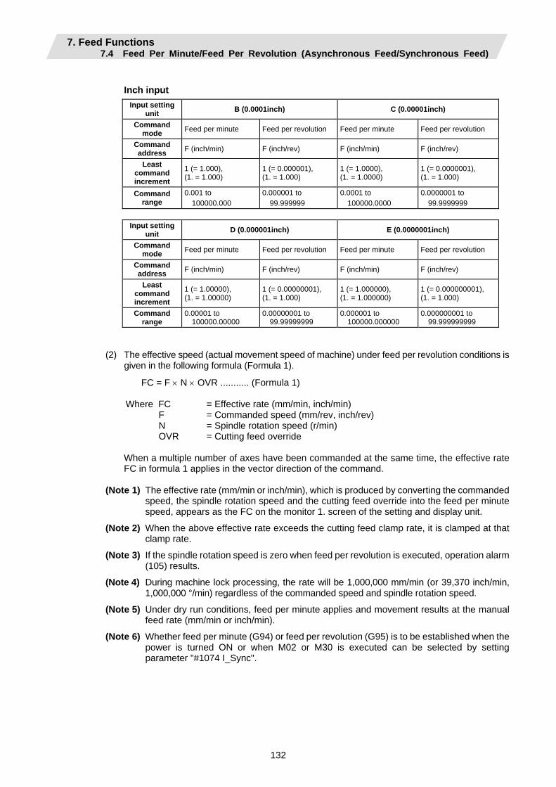
7. Feed Functions 7.4 Feed Per Minute/Feed Per Revolution (Asynchronous Feed/Synchronous Feed)
132
Inch input
Input setting unit B (0.0001inch) C (0.00001inch)
Command mode Feed per minute Feed per revolution Feed per minute Feed per revolution
Command address F (inch/min) F (inch/rev) F (inch/min) F (inch/rev)
Least command increment
1 (= 1.000), (1. = 1.000)
1 (= 0.000001), (1. = 1.000)
1 (= 1.0000), (1. = 1.0000)
1 (= 0.0000001), (1. = 1.000)
Command range
0.001 to 100000.000
0.000001 to 99.999999
0.0001 to 100000.0000
0.0000001 to 99.9999999
Input setting
unit D (0.000001inch) E (0.0000001inch)
Command mode Feed per minute Feed per revolution Feed per minute Feed per revolution
Command address F (inch/min) F (inch/rev) F (inch/min) F (inch/rev)
Least command increment
1 (= 1.00000), (1. = 1.00000)
1 (= 0.00000001), (1. = 1.000)
1 (= 1.000000), (1. = 1.000000)
1 (= 0.000000001), (1. = 1.000)
Command range
0.00001 to 100000.00000
0.00000001 to 99.99999999
0.000001 to 100000.000000
0.000000001 to 99.999999999
(2) The effective speed (actual movement speed of machine) under feed per revolution conditions is given in the following formula (Formula 1).
FC = F × N × OVR ........... (Formula 1)
Where FC = Effective rate (mm/min, inch/min) F = Commanded speed (mm/rev, inch/rev) N = Spindle rotation speed (r/min) OVR = Cutting feed override
When a multiple number of axes have been commanded at the same time, the effective rate FC in formula 1 applies in the vector direction of the command.
(Note 1) The effective rate (mm/min or inch/min), which is produced by converting the commanded
speed, the spindle rotation speed and the cutting feed override into the feed per minute speed, appears as the FC on the monitor 1. screen of the setting and display unit.
(Note 2) When the above effective rate exceeds the cutting feed clamp rate, it is clamped at that clamp rate.
(Note 3) If the spindle rotation speed is zero when feed per revolution is executed, operation alarm (105) results.
(Note 4) During machine lock processing, the rate will be 1,000,000 mm/min (or 39,370 inch/min, 1,000,000 °/min) regardless of the commanded speed and spindle rotation speed.
(Note 5) Under dry run conditions, feed per minute applies and movement results at the manual feed rate (mm/min or inch/min).
(Note 6) Whether feed per minute (G94) or feed per revolution (G95) is to be established when the power is turned ON or when M02 or M30 is executed can be selected by setting parameter "#1074 I_Sync".
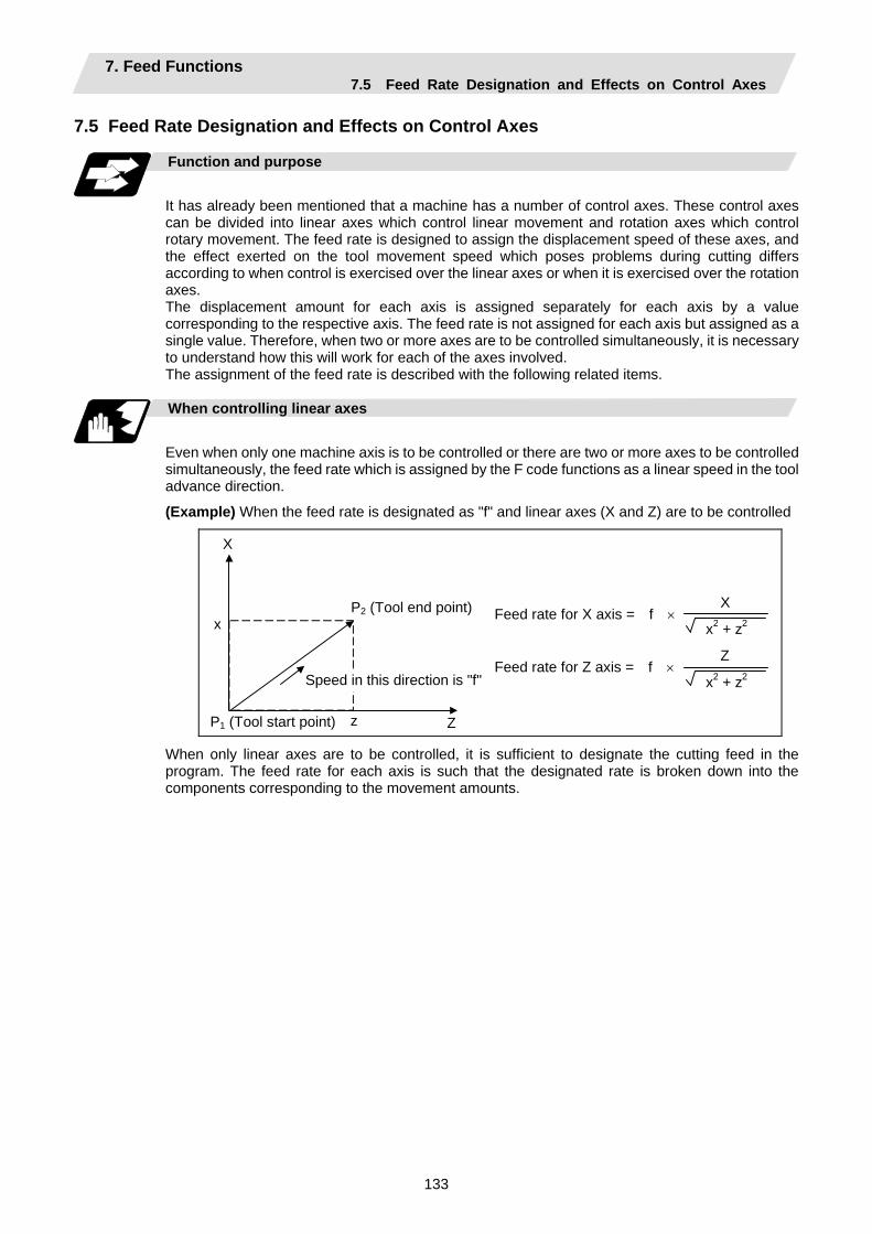
7. Feed Functions 7.5 Feed Rate Designation and Effects on Control Axes
133
7.5 Feed Rate Designation and Effects on Control Axes
Function and purpose
It has already been mentioned that a machine has a number of control axes. These control axes can be divided into linear axes which control linear movement and rotation axes which control rotary movement. The feed rate is designed to assign the displacement speed of these axes, and the effect exerted on the tool movement speed which poses problems during cutting differs according to when control is exercised over the linear axes or when it is exercised over the rotation axes. The displacement amount for each axis is assigned separately for each axis by a value corresponding to the respective axis. The feed rate is not assigned for each axis but assigned as a single value. Therefore, when two or more axes are to be controlled simultaneously, it is necessary to understand how this will work for each of the axes involved. The assignment of the feed rate is described with the following related items.
When controlling linear axes
Even when only one machine axis is to be controlled or there are two or more axes to be controlled simultaneously, the feed rate which is assigned by the F code functions as a linear speed in the tool advance direction.
(Example) When the feed rate is designated as "f" and linear axes (X and Z) are to be controlled
X
Zz
x P2 (Tool end point)
Speed in this direction is "f"
P1 (Tool start point)
Feed rate for X axis = f ×
Feed rate for Z axis = f ×
X x2 + z2
Z x2 + z2
When only linear axes are to be controlled, it is sufficient to designate the cutting feed in the program. The feed rate for each axis is such that the designated rate is broken down into the components corresponding to the movement amounts.

7. Feed Functions 7.5 Feed Rate Designation and Effects on Control Axes
134
(Note) When the circular interpolation function is used and the tool is moved along the circumference of an arc by the linear control axis, the rate in the tool advance direction, or in other words the tangential direction, will be the feedrate designated in the program.
x
z
X
Zi
P2
P1
Linear speed is "f"
(Example) When the feed rate is designated as "f" and the linear axes (X and Z) are to be
controlled using the circular interpolation function In this case, the feed rate of the X and Z axes will change along with the tool movement.
However, the combined speed will always be maintained at the constant value "f".
When controlling rotation axes
When rotation axes are to be controlled, the designated feed rate functions as the rotation speed of the rotation axes or, in other words, as an angular speed. Consequently, the cutting feed in the tool advance direction, or in other words the linear speed, varies according to the distance between the center of rotation and the tool. This distance must be borne in mind when designating the feedrate in the program. (Example) When the feed rate is designated as "f" and rotation axis (C) is to be controlled ("f" units
= °/min)
c
r
P2 (Tool end point)
Rotation center
Angular speed is "f"
P1 (Tool start point)
Linear speed is : π • r • f180
In this case, in order to make the cutting feed (linear speed) in the tool advance direction "fc":
fc = f ×
Therefore, the feed rate to be designated in the program must be: f = fc ×
π • r 180
180 π • r

7. Feed Functions 7.5 Feed Rate Designation and Effects on Control Axes
135
When linear and rotation axes are to be controlled at the same time
The NC unit proceeds in exactly the same way whether linear or rotation axes are to be controlled. When a rotation axis is to be controlled, the numerical value assigned by the coordinate words (C, H) is the angle and the numerical values assignees by the feed rate (F) are all handled as linear speeds. In other words, 1° of the rotation axis is treated as being equivalent to 1mm of the linear axis. Consequently, when both linear and rotation axes are to be controlled simultaneously, the components for each axis of the numerical values assigned by F will be the same as for section (1) above (applying when linear axes are to be controlled). However, although in this case both the size and direction of the speed components based on linear axis control do not vary, the direction of the speed components based on rotation axis control will change along with the tool movement (their size will not change). This means, as a result, that the combined tool advance direction feed rate with vary along with the tool movement.
(Example) When the feed rate is designated as "f" and linear (X) and rotation (C) axes are to be
controlled simultaneously If the X-axis incremental command value is "x" and the C-axis incremental command
value is "c":
P1
θ x
fc
c
fcft
fx
fx
ftr θ
P2
Size and direction are fixed for fx. Size is fixed for fc but direction varies. Both size and direction vary for ft.
Rotation center
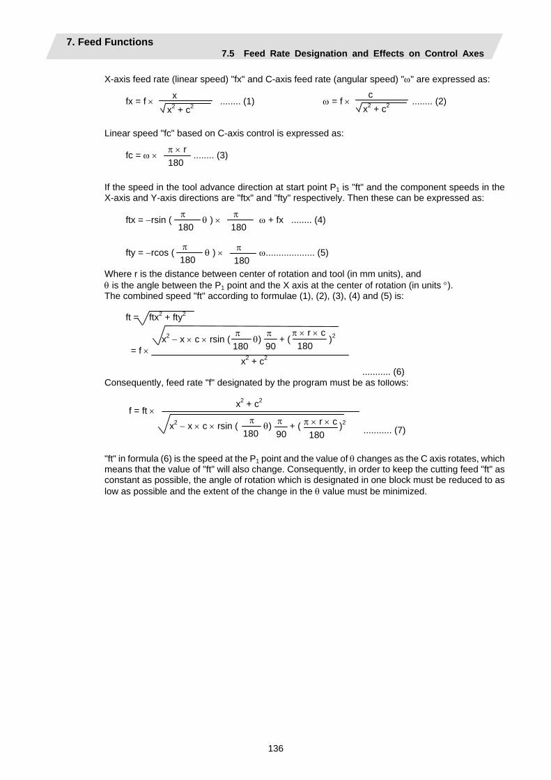
7. Feed Functions 7.5 Feed Rate Designation and Effects on Control Axes
136
X-axis feed rate (linear speed) "fx" and C-axis feed rate (angular speed) "ω" are expressed as: fx = f × ........ (1) ω = f × ........ (2) Linear speed "fc" based on C-axis control is expressed as: fc = ω × ........ (3) If the speed in the tool advance direction at start point P1 is "ft" and the component speeds in the X-axis and Y-axis directions are "ftx" and "fty" respectively. Then these can be expressed as: ftx = −rsin ( θ ) × ω + fx ........ (4) fty = −rcos ( θ ) × ω................... (5) Where r is the distance between center of rotation and tool (in mm units), and θ is the angle between the P1 point and the X axis at the center of rotation (in units °). The combined speed "ft" according to formulae (1), (2), (3), (4) and (5) is: ft = ftx2 + fty2 x2 − x × c × rsin ( θ) + ( )2 = f × x2 + c2 Consequently, feed rate "f" designated by the program must be as follows: x2 + c2 x2 − x × c × rsin ( θ) + ( )2 "ft" in formula (6) is the speed at the P1 point and the value of θ changes as the C axis rotates, which means that the value of "ft" will also change. Consequently, in order to keep the cutting feed "ft" as constant as possible, the angle of rotation which is designated in one block must be reduced to as low as possible and the extent of the change in the θ value must be minimized.
x x2 + c2
c x2 + c2
π × r 180
π 180
π 180
π 180
π 180
π 180
π90
π × r × c 180
π180
π90
π × r × c 180
f = ft ×
........... (6)
........... (7)
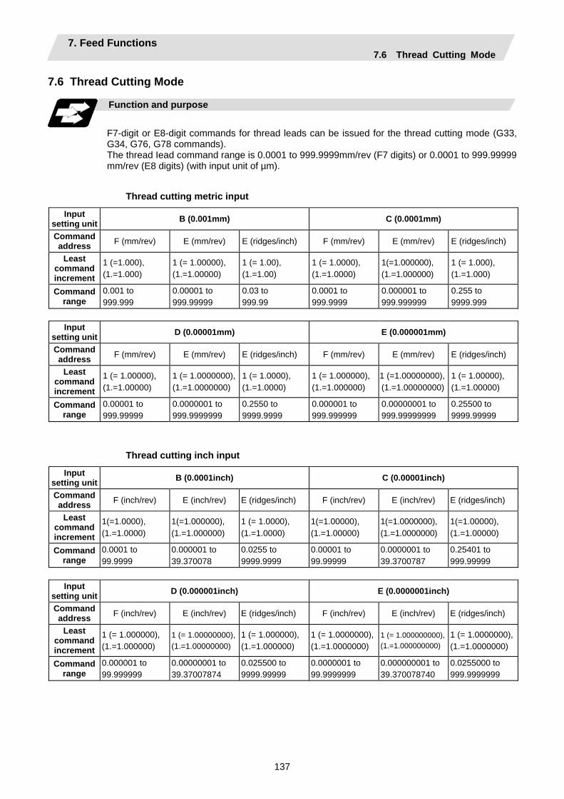
7. Feed Functions 7.6 Thread Cutting Mode
137
7.6 Thread Cutting Mode
Function and purpose
F7-digit or E8-digit commands for thread leads can be issued for the thread cutting mode (G33, G34, G76, G78 commands). The thread Iead command range is 0.0001 to 999.9999mm/rev (F7 digits) or 0.0001 to 999.99999 mm/rev (E8 digits) (with input unit of µm).
Thread cutting metric input
Input setting unit B (0.001mm) C (0.0001mm)
Command address F (mm/rev) E (mm/rev) E (ridges/inch) F (mm/rev) E (mm/rev) E (ridges/inch)
Least command increment
1 (=1.000), (1.=1.000)
1 (= 1.00000), (1.=1.00000)
1 (= 1.00), (1.=1.00)
1 (= 1.0000), (1.=1.0000)
1(=1.000000), (1.=1.000000)
1 (= 1.000), (1.=1.000)
Command range
0.001 to 999.999
0.00001 to 999.99999
0.03 to 999.99
0.0001 to 999.9999
0.000001 to 999.999999
0.255 to 9999.999
Input
setting unit D (0.00001mm) E (0.000001mm)
Command address F (mm/rev) E (mm/rev) E (ridges/inch) F (mm/rev) E (mm/rev) E (ridges/inch)
Least command increment
1 (= 1.00000), (1.=1.00000)
1 (= 1.0000000),(1.=1.0000000)
1 (= 1.0000), (1.=1.0000)
1 (= 1.000000),(1.=1.000000)
1 (=1.00000000), (1.=1.00000000)
1 (= 1.00000), (1.=1.00000)
Command range
0.00001 to 999.99999
0.0000001 to 999.9999999
0.2550 to 9999.9999
0.000001 to 999.999999
0.00000001 to 999.99999999
0.25500 to 9999.99999
Thread cutting inch input
Input setting unit B (0.0001inch) C (0.00001inch)
Command address F (inch/rev) E (inch/rev) E (ridges/inch) F (inch/rev) E (inch/rev) E (ridges/inch)
Least command increment
1(=1.0000), (1.=1.0000)
1(=1.000000), (1.=1.000000)
1 (= 1.0000), (1.=1.0000)
1(=1.00000), (1.=1.00000)
1(=1.0000000), (1.=1.0000000)
1(=1.00000), (1.=1.00000)
Command range
0.0001 to 99.9999
0.000001 to 39.370078
0.0255 to 9999.9999
0.00001 to 99.99999
0.0000001 to 39.3700787
0.25401 to 999.99999
Input
setting unit D (0.000001inch) E (0.0000001inch)
Command address F (inch/rev) E (inch/rev) E (ridges/inch) F (inch/rev) E (inch/rev) E (ridges/inch)
Least command increment
1 (= 1.000000), (1.=1.000000)
1 (= 1.00000000),(1.=1.00000000)
1 (= 1.000000), (1.=1.000000)
1 (= 1.0000000),(1.=1.0000000)
1 (= 1.000000000), (1.=1.000000000)
1 (= 1.0000000),(1.=1.0000000)
Command range
0.000001 to 99.999999
0.00000001 to 39.37007874
0.025500 to 9999.99999
0.0000001 to 99.9999999
0.000000001 to 39.370078740
0.0255000 to 999.9999999
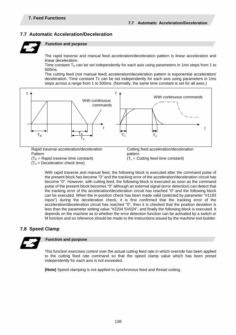
7. Feed Functions 7.7 Automatic Acceleration/Deceleration
138
7.7 Automatic Acceleration/Deceleration
Function and purpose
The rapid traverse and manual feed acceleration/deceleration pattern is linear acceleration and linear deceleration. Time constant TR can be set independently for each axis using parameters in 1ms steps from 1 to 500ms. The cutting feed (not manual feed) acceleration/deceleration pattern is exponential acceleration/ deceleration. Time constant Tc can be set independently for each axis using parameters in 1ms steps across a range from 1 to 500ms. (Normally, the same time constant is set for all axes.)
With continuous commands
With continuous commands
TR
f
t
TC
f
tTR Td
TC
Rapid traverse acceleration/deceleration Pattern (TR = Rapid traverse time constant) (Td = Deceleration check time)
Cutting feed acceleration/deceleration pattern (Tc = Cutting feed time constant)
With rapid traverse and manual feed, the following block is executed after the command pulse of the present block has become "0" and the tracking error of the acceleration/deceleration circuit has become "0". However, with cutting feed, the following block is executed as soon as the command pulse of the present block becomes "0" although an external signal (error detection) can detect that the tracking error of the acceleration/deceleration circuit has reached "0" and the following block can be executed. When the in-position check has been made valid (selected by parameter "#1193 inpos") during the deceleration check, it is first confirmed that the tracking error of the acceleration/deceleration circuit has reached "0", then it is checked that the position deviation is less than the parameter setting value "#2204 SV024", and finally the following block is executed. It depends on the machine as to whether the error detection function can be activated by a switch or M function and so reference should be made to the instructions issued by the machine tool builder.
7.8 Speed Clamp Function and purpose
This function exercises control over the actual cutting feed rate in which override has been applied to the cutting feed rate command so that the speed clamp value which has been preset independently for each axis is not exceeded. (Note) Speed clamping is not applied to synchronous feed and thread cutting.

7. Feed Functions 7.9 Exact Stop Check
139
7.9 Exact Stop Check; G09
Function and purpose
In order for roundness to be prevented during corner cutting and for machine shock to be alleviated when the tool feed rate changes suddenly, there are times when it is desirable to start the commands in the following block once the in-position state after the machine has decelerated and stopped or the elapsing of the deceleration check time has been checked. The exact stop check function is designed to accomplish this purpose. Whether to control with the deceleration check time or with the in-position state can be selected with the parameter. (Refer to the section "7.11 Deceleration check") The in-position width is set into parameter the servo parameter "#2224 sv024" or "#2077 G0inps", "#2078 G1inps".
Command format
G09 G01 (G02, G03) ;
The exact stop check command G09 has an effect only with the cutting command (G01 to G03) in its particular block.
Example of program
N001 G09 G01 X100.000 F150 ; The commands in the following block are started
once the deceleration check time or in-position state has been checked after the machine has decelerated and stopped.
N002 Z100.000 ;
N002
N001
Fig. 1 Exact stop check result
X axis
Z axis
f (Commanded speed)
Time
N001
N002Without G09
Tool
Solid line indicates speed pattern with G09 command.Broken line indicates speed pattern without G09 command.
With G09
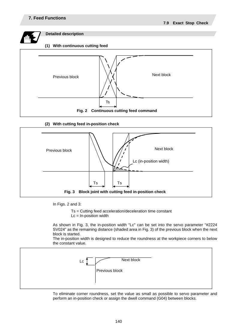
7. Feed Functions 7.9 Exact Stop Check
140
Detailed description
(1) With continuous cutting feed
Ts
Fig. 2 Continuous cutting feed command
Previous block Next block
(2) With cutting feed in-position check
Fig. 3 Block joint with cutting feed in-position check
Ts Ts
Previous block Next block
Lc (in-position width)
In Figs. 2 and 3:
Ts = Cutting feed acceleration/deceleration time constant Lc = In-position width As shown in Fig. 3, the in-position width "Lc" can be set into the servo parameter "#2224 SV024" as the remaining distance (shaded area in Fig. 3) of the previous block when the next block is started. The in-position width is designed to reduce the roundness at the workpiece corners to below the constant value.
Lc Next block
Previous block
To eliminate corner roundness, set the value as small as possible to servo parameter and perform an in-position check or assign the dwell command (G04) between blocks.

7. Feed Functions 7.9 Exact Stop Check
141
(3) With deceleration check
(a) With linear acceleration/deceleration
Ts
Td
Previous block Next block
Ts : Acceleration/deceleration time constant Td : Deceleration check time Td = Ts + ( 0 to 14ms)
(b) With exponential acceleration/deceleration
Ts
Td
Previous block Next block
Ts : Acceleration/deceleration time constant Td : Deceleration check time Td = 2 × Ts + ( 0 to 14ms)
(c) With exponential acceleration/linear deceleration
2 x Ts
Td Ts
Previous block Next block
Ts : Acceleration/deceleration time constant Td : Deceleration check time Td = 2 × Ts + ( 0 to 14ms)
The time required for the deceleration check during cutting feed is the longest among the cutting feed deceleration check times of each axis determined by the cutting feed acceleration/deceleration time constants and by the cutting feed acceleration/ deceleration mode of the axes commanded simultaneously. (Note 1) To execute exact stop check in a fixed cycle cutting block, insert command G09
into the fixed cycle subprogram.
7. Feed Functions 7.10 Exact Stop Check Mode
142
7.10 Exact Stop Check Mode ; G61
Function and purpose
Whereas the G09 exact stop check command checks the in-position status only for the block in which the command has been assigned, the G61 command functions as a modal. This means that deceleration will apply at the end points of each block to all the cutting commands (G01 to G03) subsequent to G61 and that the in-position status will be checked. G61 is released by automatic corner override (G62), tapping mode (G63), or cutting mode (G64).
Command format
G61 ;
In-position check is executed in the G61 block, and thereafter, the in-position check is executed at the end of the cutting command block is executed until the check mode is canceled.
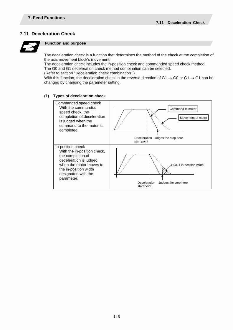
7. Feed Functions 7.11 Deceleration Check
143
7.11 Deceleration Check
Function and purpose
The deceleration check is a function that determines the method of the check at the completion of the axis movement block's movement. The deceleration check includes the in-position check and commanded speed check method. The G0 and G1 deceleration check method combination can be selected. (Refer to section "Deceleration check combination".) With this function, the deceleration check in the reverse direction of G1 → G0 or G1 → G1 can be changed by changing the parameter setting.
(1) Types of deceleration check
Commanded speed check With the commanded speed check, the completion of deceleration is judged when the command to the motor is completed.
Deceleration start point
Judges the stop here
Movement of motor
Command to motor
In-position check With the in-position check, the completion of deceleration is judged when the motor moves to the in-position width designated with the parameter.
Deceleration start point
Judges the stop here
G0/G1 in-position width
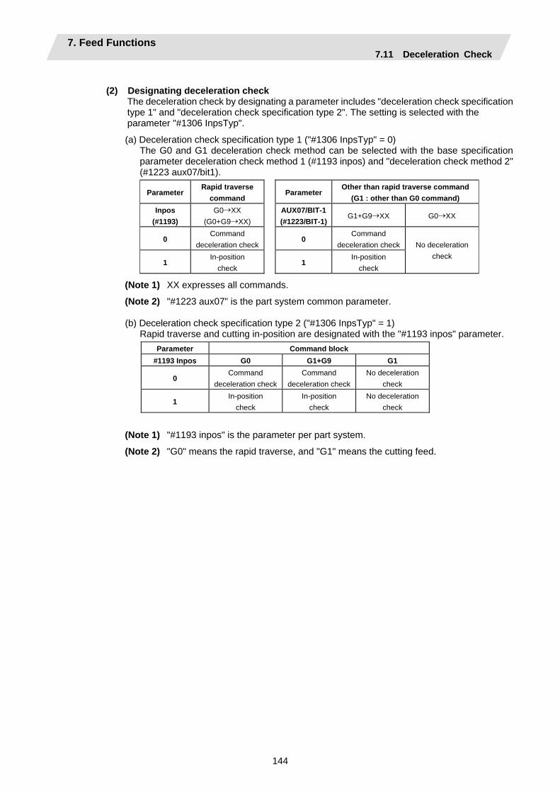
7. Feed Functions 7.11 Deceleration Check
144
(2) Designating deceleration check
The deceleration check by designating a parameter includes "deceleration check specification type 1" and "deceleration check specification type 2". The setting is selected with the parameter "#1306 InpsTyp".
(a) Deceleration check specification type 1 ("#1306 InpsTyp" = 0) The G0 and G1 deceleration check method can be selected with the base specification
parameter deceleration check method 1 (#1193 inpos) and "deceleration check method 2" (#1223 aux07/bit1).
Parameter Rapid traverse
command Parameter
Other than rapid traverse command (G1 : other than G0 command)
Inpos (#1193)
G0→XX (G0+G9→XX)
AUX07/BIT-1(#1223/BIT-1)
G1+G9→XX G0→XX
0 Command
deceleration check0
Command deceleration check
1 In-position
check 1
In-position check
No deceleration check
(Note 1) XX expresses all commands.
(Note 2) "#1223 aux07" is the part system common parameter.
(b) Deceleration check specification type 2 ("#1306 InpsTyp" = 1) Rapid traverse and cutting in-position are designated with the "#1193 inpos" parameter.
Parameter Command block #1193 Inpos G0 G1+G9 G1
0 Command
deceleration checkCommand
deceleration checkNo deceleration
check
1 In-position
check In-position
check No deceleration
check
(Note 1) "#1193 inpos" is the parameter per part system.
(Note 2) "G0" means the rapid traverse, and "G1" means the cutting feed.

7. Feed Functions 7.11 Deceleration Check
145
7.11.1 G1 → G0 Deceleration Check Detailed description
(1) In G1 → G0 continuous blocks, the parameter "#1502 G0Ipfg" can be changed to change the
deceleration check in the reverse direction.
Same direction Reverse direction
G0Ipfg: 0
G0Ipfg: 1
Command deceleration
Example of program
When there is a deceleration check in the movement of several axes:
(1) G91 G1 X100. Z100. F4000 ; G0 X-100. Z120. ;
A deceleration check is carried out, because the X axis moves in the reverse direction in the program above.
(2) G91 G1 X100. Z-100. F4000 ;
G0 X80. Z100. ; A deceleration check is carried out, because the Z axis moves in the reverse direction in the program above.
(3) G90 G1 X100. Z100. F4000 ;
G0 X80. Z120. ; (When the program start position is X0 Z0) A deceleration check is carried out, because the X axis moves in the reverse direction in the program above.
(4) G91 G1 X100. Z100. F4000 ;
G0 X100. Z100. ; A deceleration check is not carried out, because both the X axis and the Z axis move in the same direction in the program above.
(5) G91 G1 X100. Z80. F4000 ;
G0 X80. ; A deceleration check is not carried out, because the X axis moves in the same direction, and there is no Z axis movement command in the program above.
G1 G0
G1 G0
G0 G1
G0 G1
The acceleration rate is excessive due to the composite speed of G1 and G0.
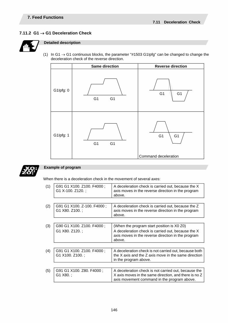
7. Feed Functions 7.11 Deceleration Check
146
7.11.2 G1 → G1 Deceleration Check Detailed description
(1) In G1 → G1 continuous blocks, the parameter "#1503 G1Ipfg" can be changed to change the
deceleration check of the reverse direction.
Same direction Reverse direction
G1Ipfg: 0
G1 G1
G1 G1
G1 G1
G1Ipfg: 1
G1 G1
Command deceleration
Example of program
When there is a deceleration check in the movement of several axes:
(1) G91 G1 X100. Z100. F4000 ; G1 X-100. Z120. ;
A deceleration check is carried out, because the X axis moves in the reverse direction in the program above.
(2) G91 G1 X100. Z-100. F4000 ;
G1 X80. Z100. ; A deceleration check is carried out, because the Z axis moves in the reverse direction in the program above.
(3) G90 G1 X100. Z100. F4000 ;
G1 X80. Z120. ; (When the program start position is X0 Z0) A deceleration check is carried out, because the X axis moves in the reverse direction in the program above.
(4) G91 G1 X100. Z100. F4000 ;
G1 X100. Z100. ; A deceleration check is not carried out, because both the X axis and the Z axis move in the same direction in the program above.
(5) G91 G1 X100. Z80. F4000 ;
G1 X80. ; A deceleration check is not carried out, because the X axis moves in the same direction, and there is no Z axis movement command in the program above.

7. Feed Functions 7.12 Automatic Corner Override
147
7.12 Automatic Corner Override ; G62
Function and purpose
With this command, when cutting with tool radius compensation, an override is automatically applied to the feed rate to reduce the load during inside corner cutting or during inside cutting of automatic corner R. Automatic corner override is valid until the nose R compensation cancel (G40), exact stop check mode (G61), tapping mode (G63), or cutting mode (G64) command is issued.
Command format
G62 ;
Machining inside corners
When cutting an inside corner as in Fig. 1, the machining allowance amount increases and a greater load is applied to the tool. To remedy this, override is applied automatically within the corner set range, the feed rate is reduced, the increase in the load is reduced and cutting is performed effectively. However, this function is valid only when finished shapes are programmed.
θ
Ci
Fig. 1
S
workpiece
Machining allowance
Machining allowanceProgrammed path(finished shape)
Workpiece surface shape
Nose R center path
Tool
θ : Max. angle at inside cornerCi : Deceleration range (IN)
Deceleration range
(1) (2)
(3)
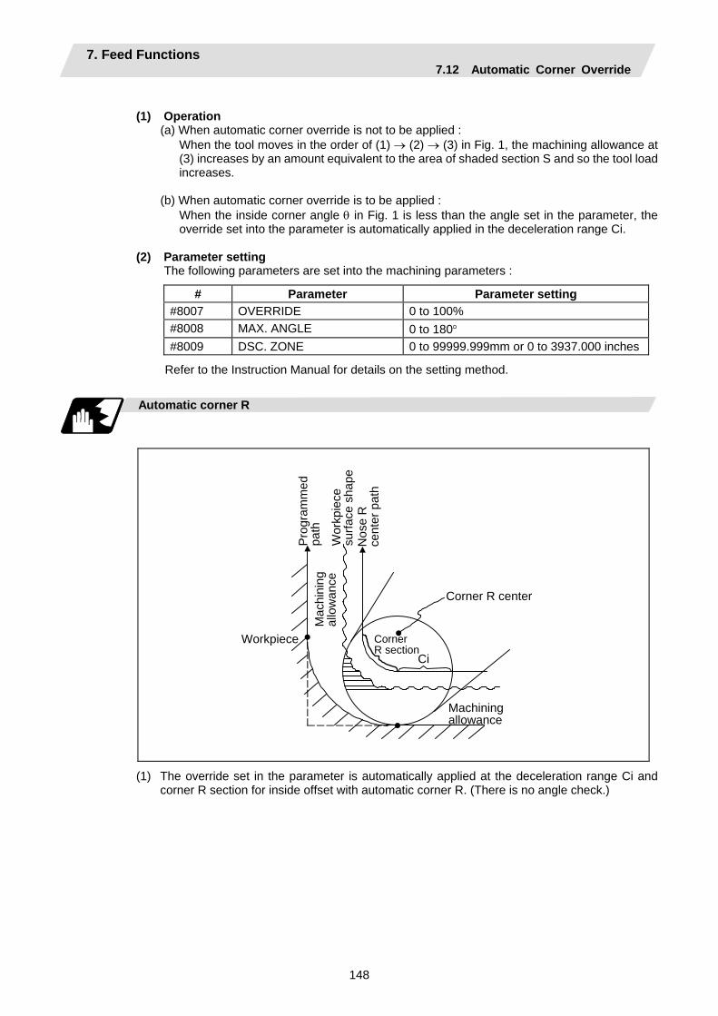
7. Feed Functions 7.12 Automatic Corner Override
148
(1) Operation
(a) When automatic corner override is not to be applied : When the tool moves in the order of (1) → (2) → (3) in Fig. 1, the machining allowance at
(3) increases by an amount equivalent to the area of shaded section S and so the tool load increases.
(b) When automatic corner override is to be applied :
When the inside corner angle θ in Fig. 1 is less than the angle set in the parameter, the override set into the parameter is automatically applied in the deceleration range Ci.
(2) Parameter setting
The following parameters are set into the machining parameters :
# Parameter Parameter setting #8007 OVERRIDE 0 to 100% #8008 MAX. ANGLE 0 to 180° #8009 DSC. ZONE 0 to 99999.999mm or 0 to 3937.000 inches
Refer to the Instruction Manual for details on the setting method.
Automatic corner R
CiWorkpiece
Pro
gram
med
pa
th
Mac
hini
ng
allo
wan
ce
Wor
kpie
ce
surfa
ce s
hape
N
ose
R
cent
er p
ath
Corner R section
Machining allowance
Corner R center
(1) The override set in the parameter is automatically applied at the deceleration range Ci and corner R section for inside offset with automatic corner R. (There is no angle check.)
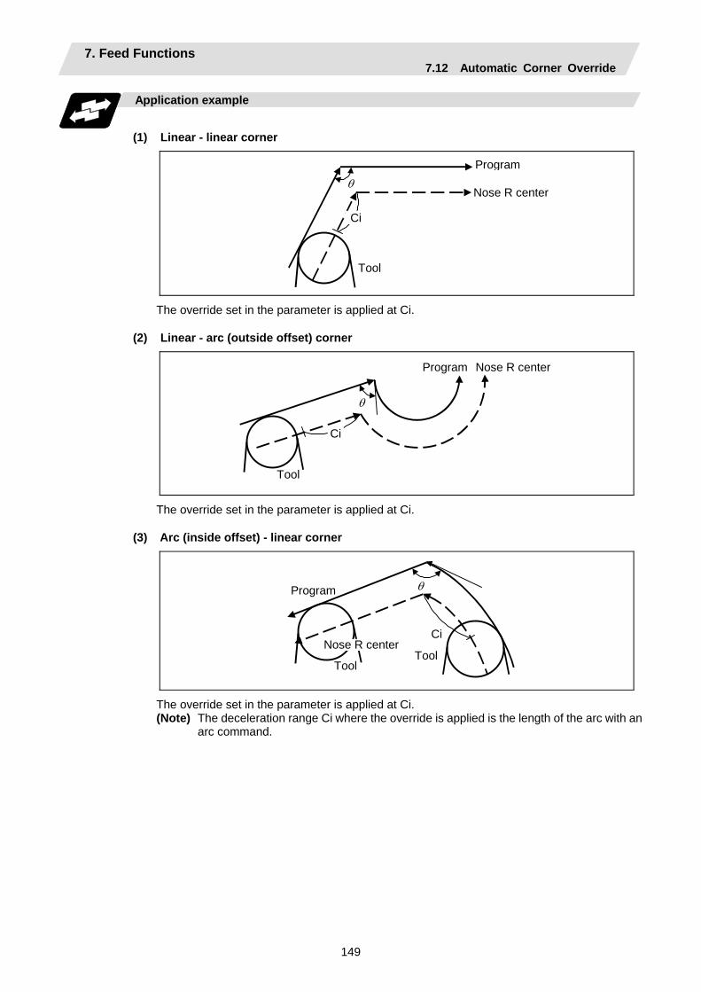
7. Feed Functions 7.12 Automatic Corner Override
149
Application example
(1) Linear - linear corner
θ
Ci
Program
Nose R center
Tool
The override set in the parameter is applied at Ci.
(2) Linear - arc (outside offset) corner
θ
Ci
Program Nose R center
Tool
The override set in the parameter is applied at Ci.
(3) Arc (inside offset) - linear corner
θ
Ci
Program
Nose R center
ToolTool
The override set in the parameter is applied at Ci. (Note) The deceleration range Ci where the override is applied is the length of the arc with an
arc command.
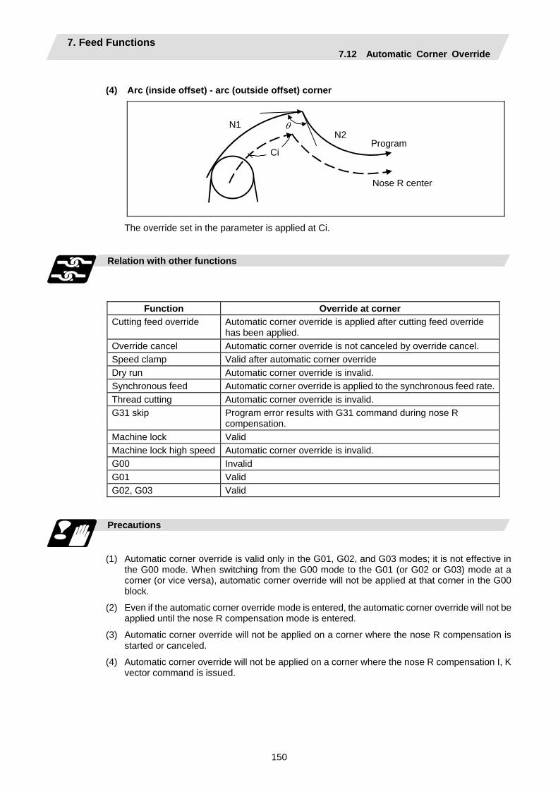
7. Feed Functions 7.12 Automatic Corner Override
150
(4) Arc (inside offset) - arc (outside offset) corner
θN1
Ci
N2Program
Nose R center
The override set in the parameter is applied at Ci.
Relation with other functions
Function Override at corner Cutting feed override Automatic corner override is applied after cutting feed override
has been applied. Override cancel Automatic corner override is not canceled by override cancel. Speed clamp Valid after automatic corner override Dry run Automatic corner override is invalid. Synchronous feed Automatic corner override is applied to the synchronous feed rate.Thread cutting Automatic corner override is invalid. G31 skip Program error results with G31 command during nose R
compensation. Machine lock Valid Machine lock high speed Automatic corner override is invalid. G00 Invalid G01 Valid G02, G03 Valid
Precautions
(1) Automatic corner override is valid only in the G01, G02, and G03 modes; it is not effective in
the G00 mode. When switching from the G00 mode to the G01 (or G02 or G03) mode at a corner (or vice versa), automatic corner override will not be applied at that corner in the G00 block.
(2) Even if the automatic corner override mode is entered, the automatic corner override will not be applied until the nose R compensation mode is entered.
(3) Automatic corner override will not be applied on a corner where the nose R compensation is started or canceled.
(4) Automatic corner override will not be applied on a corner where the nose R compensation I, K vector command is issued.

7. Feed Functions 7.12 Automatic Corner Override
151
(5) Automatic corner override will not be applied when intersection calculation cannot be executed.
Intersection calculation cannot be executed in the following case. (a) When the movement command block does not continue for four or more times.
(6) The deceleration range with an arc command is the length of the arc.
(7) The inside corner angle, as set by parameter, is the angle on the programmed path.
(8) Automatic corner override will not be applied when the maximum angle in the parameter is set to 0 or 180.
(9) Automatic corner override will not be applied when the override in the parameter is set to 0 or 100.

7. Feed Functions 7.13 Tapping Mode
152
7.13 Tapping Mode ; G63 Function and purpose
The G63 command allows the control mode best suited for tapping to be entered, as indicated below :
1. Cutting override is fixed at 100%. 2. Deceleration commands at joints between blocks are invalid. 3. Feed hold is invalid. 4. Single block is invalid. 5. In-tapping mode signal is output.
G63 is released by the exact stop check mode (G61), automatic corner override (G62), or cutting mode (G64) command.
Command format
G63 ; 7.14 Cutting Mode ; G64 Function and purpose
The G64 command allows the cutting mode in which smooth cutting surfaces are obtained to be established. Unlike the exact stop check mode (G61), the next block is executed continuously with the machine not decelerating and stopping between cutting feed blocks in this mode. G64 is released by the exact stop check mode (G61), high-accuracy control mode (G61.1), automatic corner override (G62), or tapping mode (G63) command.
This cutting mode is established in the initialized status.
Command format
G64 ;
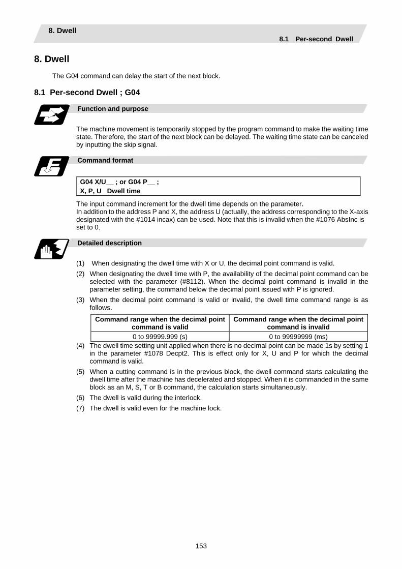
8. Dwell 8.1 Per-second Dwell
153
8. Dwell
The G04 command can delay the start of the next block. 8.1 Per-second Dwell ; G04
Function and purpose
The machine movement is temporarily stopped by the program command to make the waiting time state. Therefore, the start of the next block can be delayed. The waiting time state can be canceled by inputting the skip signal.
Command format
G04 X/U__ ; or G04 P__ ; X, P, U Dwell time
The input command increment for the dwell time depends on the parameter. In addition to the address P and X, the address U (actually, the address corresponding to the X-axis designated with the #1014 incax) can be used. Note that this is invalid when the #1076 AbsInc is set to 0.
Detailed description
(1) When designating the dwell time with X or U, the decimal point command is valid. (2) When designating the dwell time with P, the availability of the decimal point command can be
selected with the parameter (#8112). When the decimal point command is invalid in the parameter setting, the command below the decimal point issued with P is ignored.
(3) When the decimal point command is valid or invalid, the dwell time command range is as follows.
Command range when the decimal point command is valid
Command range when the decimal point command is invalid
0 to 99999.999 (s) 0 to 99999999 (ms) (4) The dwell time setting unit applied when there is no decimal point can be made 1s by setting 1
in the parameter #1078 Decpt2. This is effect only for X, U and P for which the decimal command is valid.
(5) When a cutting command is in the previous block, the dwell command starts calculating the dwell time after the machine has decelerated and stopped. When it is commanded in the same block as an M, S, T or B command, the calculation starts simultaneously.
(6) The dwell is valid during the interlock. (7) The dwell is valid even for the machine lock.
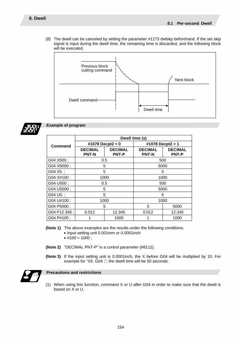
8. Dwell 8.1 Per-second Dwell
154
(8) The dwell can be canceled by setting the parameter #1173 dwlskp beforehand. If the set skip
signal is input during the dwell time, the remaining time is discarded, and the following block will be executed.
Previous block cutting command
Next block
Dwell command
Dwell time
Example of program
Dwell time (s)
#1078 Decpt2 = 0 #1078 Decpt2 = 1 Command DECIMAL
PNT-N DECIMAL
PNT-P DECIMAL
PNT-N DECIMAL
PNT-P G04 X500 ; 0.5 500 G04 X5000 ; 5 5000 G04 X5. ; 5 5 G04 X#100 ; 1000 1000 G04 U500 ; 0.5 500 G04 U5000 ; 5 5000 G04 U5. ; 5 5 G04 U#100 ; 1000 1000 G04 P5000 ; 5 5 5000 G04 P12.345 ; 0.012 12.345 0.012 12.345 G04 P#100 ; 1 1000 1 1000
(Note 1) The above examples are the results under the following conditions. • Input setting unit 0.001mm or 0.0001inch • #100 = 1000 ; (Note 2) "DECIMAL PNT-P" is a control parameter (#8112). (Note 3) If the input setting unit is 0.0001inch, the X before G04 will be multiplied by 10. For
example for "X5. G04 ;", the dwell time will be 50 seconds. Precautions and restrictions
(1) When using this function, command X or U after G04 in order to make sure that the dwell is
based on X or U.
9. Miscellaneous Functions 9.1 Miscellaneous Functions (M8-digits BCD)
155
9. Miscellaneous Functions 9.1 Miscellaneous Functions (M8-digits BCD)
Function and purpose
The miscellaneous (M) functions are also known as M functions, and they include such numerically controlled machine functions as spindle forward and reverse rotation, operation stop and coolant ON/OFF. These functions are designated by an 8-digit number (0 to 99999999) following the address M with this controller, and up to 4 groups can be commanded in a single block.
(Example) G00 Xx Mm1 Mm2 Mm3 Mm4 ;
When five or more commands are issued, only the last four will be valid. The output signal is an 8-digit BCD code and start signal. The eight commands of M00, M01, M02, M30, M96, M97, M98 and M99 are used as auxiliary commands for specific objectives and so they cannot be used as general auxiliary commands. This therefore leaves 92 miscellaneous functions which are usable as such commands. Reference should be made to the instructions issued by the machine tool builder for the actual correspondence between the functions and numerical values. When the M00, M01, M02, and M30 functions are used, the next block is not read into the pre-read buffer due to pre-read inhibiting. If the M function is designated in the same block as a movement command, the commands may be executed in either of the following two orders. The machine specifications determine which sequence applies.
(1) The M function is executed after the movement command.
(2) The M function is executed at the same time as the movement command. Which of these sequences actually applies depends on the machine specifications.
Processing and completion sequences are required in each case for all M commands except M96, M97, M98 and M99. The 8 M functions used for specific purposes will now be described.
Program stop : M00
When the tape reader has read this function, it stops reading the next block. As far as the NC system's functions are concerned, only the tape reading is stopped. Whether such machine functions as the spindle rotation and coolant supply are stopped or not differs according to the machine in question. Re-start is enabled by pressing the automatic start button on the machine operation board. Whether resetting can be initiated by M00 depends on the machine specifications.

9. Miscellaneous Functions 9.1 Miscellaneous Functions (M8-digits BCD)
156
Optional stop : M01
If the tape reader reads the M01 command when the optional stop switch on the machine operation board is ON, it will stop and the same effect as with the M00 function will apply. If the optional stop switch is OFF, the M01 command is ignored.
(Example)
~
Optional stop switch command is ignored.
N10 G00 X1000 ; N11 M01 ;
Stops at N11 when switch is ON Next command (N12) is executed without stopping at N11 when switch is OFF
N12 G01 X2000 Z3000 F600 ;
~
Program end : M02 or M30
This command is normally used in the final block for completing the machining, and so it is primarily used for tape rewinding. Whether the tape is actually rewound or not depends on the machine specifications. Depending on the machine specifications, the system is reset by the M02 or M30 command upon completion of tape rewinding and any other commands issued in the same block. (Although the contents of the command position display counter are not cleared by this reset action, the modal commands and compensation amounts are canceled.) The next operation stops when the rewinding operation is completed (the in-automatic operation lamp goes off). To restart the unit, the automatic start button must be pressed or similar steps must be taken.
(Note 1) Independent signals are also output respectively for the M00, M01, M02 and M30 commands and these outputs are each reset by pressing the reset key.
(Note 2) M02 or M30 can be assigned by manual data input (MDI). At this time, commands can be issued simultaneously with other commands just as with the tape.
Macro interruption : M96, M97
M96 and M97 are M codes for user macro interruption control. The M code for user macro interruption control is processed internally, and is not output externally. To use M96 and M97 as a miscellaneous function, change the setting to another M code with the parameter (#1109 subs_M and #1110 M96_M, #1111 M97_M).
Subprogram call/completion : M98, M99
These commands are used as the return instructions from branch destination subprograms and branches to subprograms. M98 and M99 are processed internally and so M code signals and strobe signals are not output.
Internal processing with M00/M01/M02/M30 commands
Internal processing suspends pre-reading when the M00, M01, M02 or M30 command has been read. Other tape rewinding operations and the initialization of modals by resetting differ according the machine specifications.
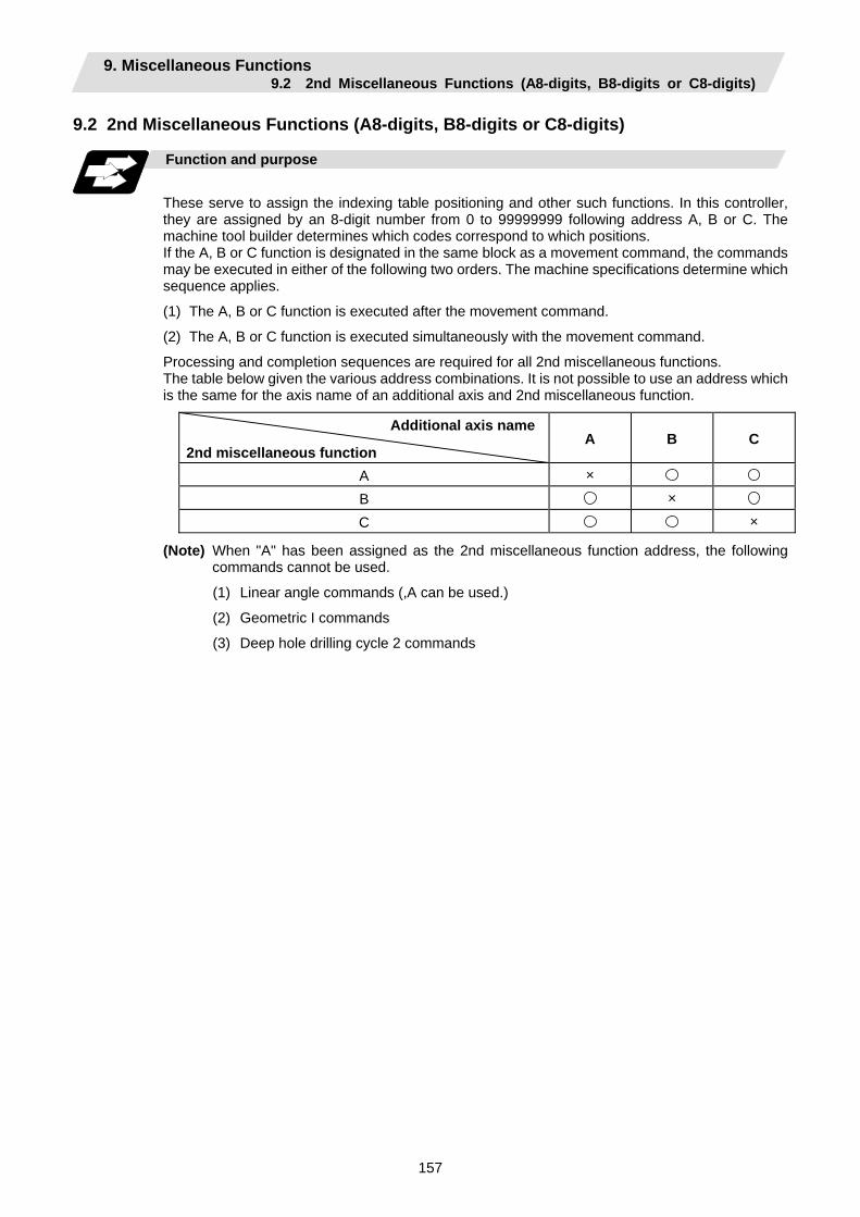
9. Miscellaneous Functions 9.2 2nd Miscellaneous Functions (A8-digits, B8-digits or C8-digits)
157
9.2 2nd Miscellaneous Functions (A8-digits, B8-digits or C8-digits)
Function and purpose
These serve to assign the indexing table positioning and other such functions. In this controller, they are assigned by an 8-digit number from 0 to 99999999 following address A, B or C. The machine tool builder determines which codes correspond to which positions. If the A, B or C function is designated in the same block as a movement command, the commands may be executed in either of the following two orders. The machine specifications determine which sequence applies.
(1) The A, B or C function is executed after the movement command.
(2) The A, B or C function is executed simultaneously with the movement command.
Processing and completion sequences are required for all 2nd miscellaneous functions. The table below given the various address combinations. It is not possible to use an address which is the same for the axis name of an additional axis and 2nd miscellaneous function.
Additional axis name
2nd miscellaneous function A B C
A × B × C ×
(Note) When "A" has been assigned as the 2nd miscellaneous function address, the following commands cannot be used.
(1) Linear angle commands (,A can be used.)
(2) Geometric I commands
(3) Deep hole drilling cycle 2 commands
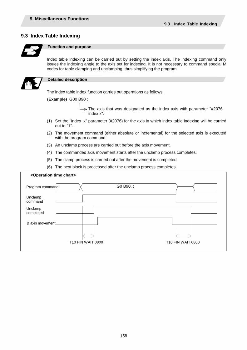
9. Miscellaneous Functions 9.3 Index Table Indexing
158
9.3 Index Table Indexing Function and purpose
Index table indexing can be carried out by setting the index axis. The indexing command only issues the indexing angle to the axis set for indexing. It is not necessary to command special M codes for table clamping and unclamping, thus simplifying the program.
Detailed description
The index table index function carries out operations as follows.
(Example) G00 B90 ;
The axis that was designated as the index axis with parameter "#2076index x".
(1) Set the "index_x" parameter (#2076) for the axis in which index table indexing will be carried out to "1".
(2) The movement command (either absolute or incremental) for the selected axis is executed with the program command.
(3) An unclamp process are carried out before the axis movement.
(4) The commanded axis movement starts after the unclamp process completes.
(5) The clamp process is carried out after the movement is completed.
(6) The next block is processed after the unclamp process completes.
T10 FIN WAIT 0800 T10 FIN WAIT 0800
B axis movement
Unclamp completed
Unclamp command
G0 B90. ;Program command
<Operation time chart>
9. Miscellaneous Functions 9.3 Index Table Indexing
159
Precautions
(1) Several axes can be set as index table indexing axes.
(2) The movement speed of index table indexing axes follows the feed rate of the modal (G0/G1) at that time.
(3) The unclamp process for the indexing axes is also issued when the index table indexing axes are commanded in the same block as other axes. Thus, the movement of other axes commanded in the same block is not carried out until the unclamp process completes.
Note that the movement of other axes commanded in the same block is carried out for non-interpolation commands.
(4) Index table indexing axes are used as normal rotation axes, but this function performs an unclamp process even for linear axes.
(5) If some error that makes unclamp command OFF occurs during indexing axis movement in automatic operation, the unclamp state will be remained, and the indexing axis will execute a deceleration stop.
Other axes commanded in the same block will also execute a deceleration stop, except for non-interpolation commands.
(6) If the axis movement is interrupted by an interlock, etc., during indexing axis movement, the unclamp state will be remained.
(7) The clamp and unclamp process are not executed when the movement commands of the index table indexing axis are continuous.
Note that the clamp and unclamp process are executed even when the movement commands are continued during single block operation.
(8) Make sure that the command position is at a position where clamping is possible.
10. Spindle Functions 10.1 Spindle Functions (S2-digits BCD)
160
10. Spindle Functions 10.1 Spindle Functions (S2-digits BCD) ..... During Standard PLC Specifications
Function and purpose
The spindle functions are also known simply as S functions and they assign the spindle rotation speed. In this controller, they are assigned with a 2-digit number following the address S ranging from 0 to 99, and 100 commands can be specified. Note that how many of these 100 types can be used, and which value corresponds to the actual rotation speed differs for each machine. Refer to the Instruction Manual issued by the machine tool builder for more details. When a number exceeding 2 digits is assigned, the last 2 digits will be valid. If the S function is designated in the same block as a movement command, the commands may be executed in either of the following two orders. The machine specifications determine which sequence applies.
(1) The S function is executed after the movement command.
(2) The S function is executed simultaneously with the movement command.
Processing and completion sequences are required for all S commands from S00 to S99. 10.2 Spindle Functions (S6-digits Analog)
Function and purpose
When the S6-digits function is added, a 6-digit value (0 to 999999) can be designated after the S code. Other commands conform to the S2-digits function. Always select S command binary output when using this function. In this function, the appropriate gear signal, voltage corresponding to the commanded spindle rotation speed, and start signal are output by the numeric command of the six digits following the S code. Processing and completion sequences are required for all S commands. The analog signal specifications are given below.
(1) Output voltage................. 0 to 10V
(2) Resolution......................... 1/4096 (2-12)
(3) Load conditions…………. 10kΩ
(4) Output impedance………. 220Ω If the parameters for up to 4 gear stages are set in advance, the gear stage corresponding to the S command will be selected and the gear signal will be output. The analog voltage is calculated in accordance with the input gear signal.
(1) Parameters corresponding to individual gears………… Limit rotation speed, maximum rotation speed, shift rotation speed and tapping rotation speed
(2) Parameters corresponding to all gears………………. Orientation rotation speed, minimum rotation speed

10. Spindle Functions 10.3 Spindle Functions (S8-digits)
161
10.3 Spindle Functions (S8-digits)
Function and purpose
These functions are assigned with an 8-digit (0 to 99999999) number following the address S, and one group can be assigned in one block. The output signal is a 32-bit binary data with sign and start signal. Processing and completion sequences are required for all S commands.
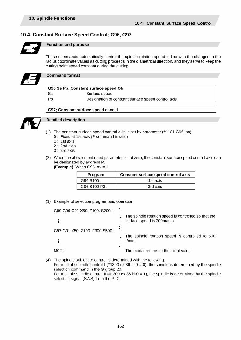
10. Spindle Functions 10.4 Constant Surface Speed Control
162
10.4 Constant Surface Speed Control; G96, G97
Function and purpose
These commands automatically control the spindle rotation speed in line with the changes in the radius coordinate values as cutting proceeds in the diametrical direction, and they serve to keep the cutting point speed constant during the cutting.
Command format
G96 Ss Pp; Constant surface speed ON Ss Pp
Surface speed Designation of constant surface speed control axis
G97; Constant surface speed cancel
Detailed description
(1) The constant surface speed control axis is set by parameter (#1181 G96_ax).
0 : Fixed at 1st axis (P command invalid) 1 : 1st axis 2 : 2nd axis 3 : 3rd axis
(2) When the above-mentioned parameter is not zero, the constant surface speed control axis can be designated by address P. (Example) When G96_ax = 1
Program Constant surface speed control axis G96 S100 ; 1st axis G96 S100 P3 ; 3rd axis
(3) Example of selection program and operation
G90 G96 G01 X50. Z100. S200 ;
~
The spindle rotation speed is controlled so that the surface speed is 200m/min.
G97 G01 X50. Z100. F300 S500 ; ~
The spindle rotation speed is controlled to 500 r/min.
M02 ; The modal returns to the initial value.
(4) The spindle subject to control is determined with the following. For multiple-spindle control I (#1300 ext36 bit0 = 0), the spindle is determined by the spindle
selection command in the G group 20. For multiple-spindle control II (#1300 ext36 bit0 = 1), the spindle is determined by the spindle
selection signal (SWS) from the PLC.
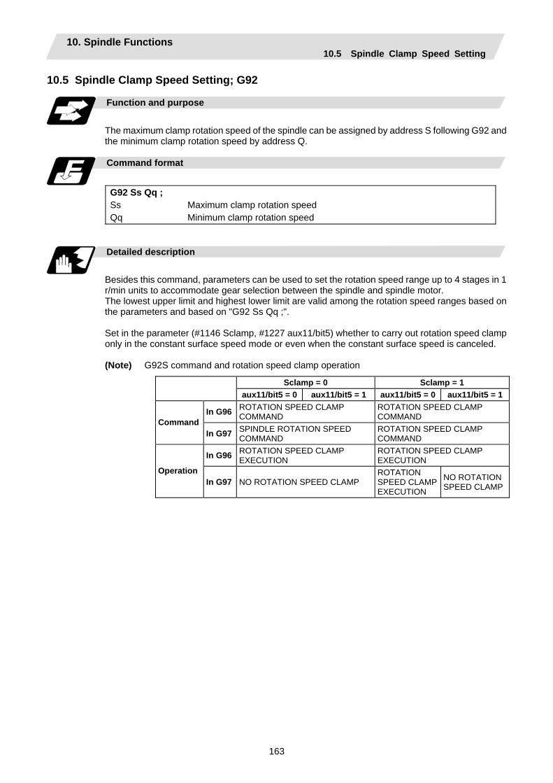
10. Spindle Functions 10.5 Spindle Clamp Speed Setting
163
10.5 Spindle Clamp Speed Setting; G92
Function and purpose
The maximum clamp rotation speed of the spindle can be assigned by address S following G92 and the minimum clamp rotation speed by address Q.
Command format
G92 Ss Qq ; Ss Qq
Maximum clamp rotation speed Minimum clamp rotation speed
Detailed description
Besides this command, parameters can be used to set the rotation speed range up to 4 stages in 1 r/min units to accommodate gear selection between the spindle and spindle motor. The lowest upper limit and highest lower limit are valid among the rotation speed ranges based on the parameters and based on "G92 Ss Qq ;".
Set in the parameter (#1146 Sclamp, #1227 aux11/bit5) whether to carry out rotation speed clamp only in the constant surface speed mode or even when the constant surface speed is canceled. (Note) G92S command and rotation speed clamp operation
Sclamp = 0 Sclamp = 1 aux11/bit5 = 0 aux11/bit5 = 1 aux11/bit5 = 0 aux11/bit5 = 1
In G96 ROTATION SPEED CLAMP COMMAND
ROTATION SPEED CLAMP COMMAND Command
In G97 SPINDLE ROTATION SPEED COMMAND
ROTATION SPEED CLAMP COMMAND
In G96 ROTATION SPEED CLAMP EXECUTION
ROTATION SPEED CLAMP EXECUTION
Operation In G97 NO ROTATION SPEED CLAMP
ROTATION SPEED CLAMP EXECUTION
NO ROTATION SPEED CLAMP
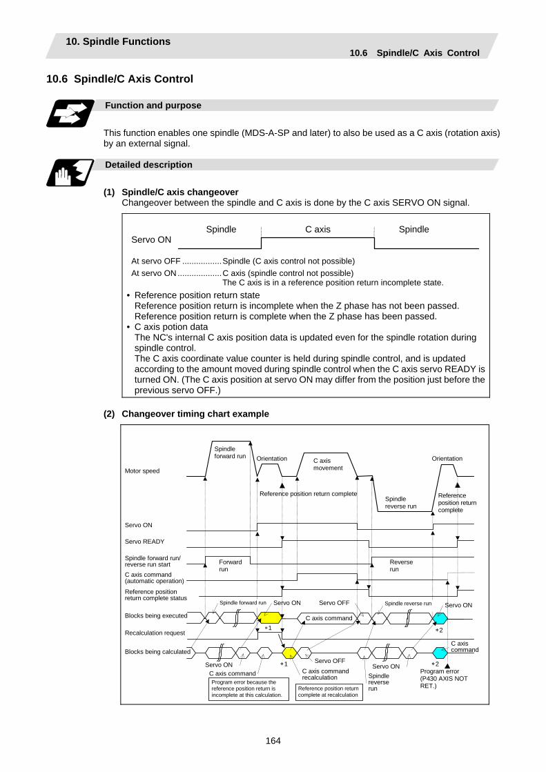
10. Spindle Functions 10.6 Spindle/C Axis Control
164
10.6 Spindle/C Axis Control Function and purpose
This function enables one spindle (MDS-A-SP and later) to also be used as a C axis (rotation axis) by an external signal.
Detailed description
(1) Spindle/C axis changeover
Changeover between the spindle and C axis is done by the C axis SERVO ON signal.
At servo OFF .................Spindle (C axis control not possible) At servo ON ...................C axis (spindle control not possible)
The C axis is in a reference position return incomplete state.
C axis Spindle Spindle Servo ON
• Reference position return state Reference position return is incomplete when the Z phase has not been passed. Reference position return is complete when the Z phase has been passed. • C axis potion data The NC's internal C axis position data is updated even for the spindle rotation during
spindle control. The C axis coordinate value counter is held during spindle control, and is updated
according to the amount moved during spindle control when the C axis servo READY is turned ON. (The C axis position at servo ON may differ from the position just before the previous servo OFF.)
(2) Changeover timing chart example
∗2
Recalculation request
Blocks being executed
Reference position return complete status
C axis command (automatic operation)
Spindle forward run/ reverse run start
Servo ON
Servo READY
Motor speed C axis movement
Program error (P430 AXIS NOT RET.)
Reference position return complete
Reference position return complete
OrientationOrientation
Spindle reverse run
Reverse run
∗2 ∗1
∗1
Forward run
Spindle forward run
C axis command
Servo ONC axis command C axis command
recalculation
Servo OFF
Spindle reverse run
C axis command
Spindle forward run Spindle reverse run Servo ON Servo OFF Servo ON
Servo ON
Program error because the reference position return is incomplete at this calculation.
Reference position return complete at recalculation
Blocks being calculated
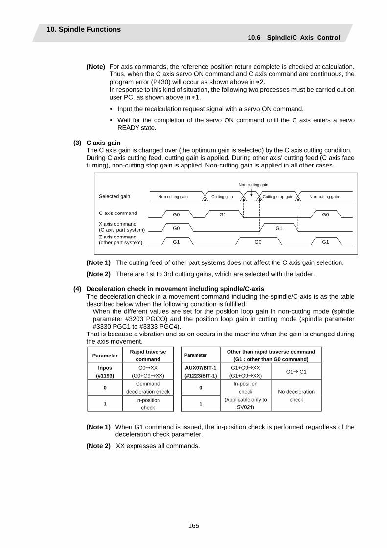
10. Spindle Functions 10.6 Spindle/C Axis Control
165
(Note) For axis commands, the reference position return complete is checked at calculation. Thus, when the C axis servo ON command and C axis command are continuous, the program error (P430) will occur as shown above in ∗2.
In response to this kind of situation, the following two processes must be carried out on user PC, as shown above in ∗1.
• Input the recalculation request signal with a servo ON command.
• Wait for the completion of the servo ON command until the C axis enters a servo READY state.
(3) C axis gain
The C axis gain is changed over (the optimum gain is selected) by the C axis cutting condition. During C axis cutting feed, cutting gain is applied. During other axis' cutting feed (C axis face turning), non-cutting stop gain is applied. Non-cutting gain is applied in all other cases.
Z axis command (other part system)
X axis command (C axis part system)
Selected gain
C axis command
Non-cutting gain
Non-cutting gainNon-cutting gain Cutting stop gain Cutting gain
G1
G1
G1G0
G0
G1
G0
G0
(Note 1) The cutting feed of other part systems does not affect the C axis gain selection.
(Note 2) There are 1st to 3rd cutting gains, which are selected with the ladder. (4) Deceleration check in movement including spindle/C-axis
The deceleration check in a movement command including the spindle/C-axis is as the table described below when the following condition is fulfilled.
When the different values are set for the position loop gain in non-cutting mode (spindle parameter #3203 PGCO) and the position loop gain in cutting mode (spindle parameter #3330 PGC1 to #3333 PGC4).
That is because a vibration and so on occurs in the machine when the gain is changed during the axis movement.
ParameterRapid traverse
command Parameter Other than rapid traverse command
(G1 : other than G0 command) Inpos
(#1193) G0→XX
(G0+G9→XX) AUX07/BIT-1(#1223/BIT-1)
G1+G9→XX (G1+G9→XX)
G1→ G1
0 Command
deceleration check0
1 In-position
check 1
In-position check
(Applicable only to SV024)
No deceleration check
(Note 1) When G1 command is issued, the in-position check is performed regardless of the deceleration check parameter.
(Note 2) XX expresses all commands.

10. Spindle Functions 10.6 Spindle/C Axis Control
166
Precautions and Restrictions
(1) The program error (P430) will occur if a C axis command is issued during servo OFF or during
orientation.
(2) Do not execute a servo OFF during a C axis command. The remaining C axis commands will be cleared at servo ON. (If servo OFF is executed during C axis control, the feed will stop and spindle control will
occur.)
(3) If servo ON is executed during spindle rotation, the rotation will stop and C axis control will occur.
(4) Dog-type reference position return is not possible for the C axis. Set the reference position return to the orientation method in the parameters (Spindle base
specifications parameters "#3106 zrn_typ/bit8" = 0), or set the axis to "Axis without reference position (zero point)" (Zero point return parameters "#2031 noref: 1").
10. Spindle Functions 10.7 Spindle Synchronization
167
10.7 Spindle Synchronization
Function and purpose
In a machine having two or more spindles, this function controls the rotation speed and phase of one spindle (basic spindle) in synchronization with the rotation of the other spindle (synchronous spindle). The function is used when the rotation speed of the two spindles must be matched, for example, if a workpiece grasped by the 1st spindle is to be grasped by a 2nd spindle, or if the spindle rotation speed has to be changed when one workpiece is grasped by both the 1st and 2nd spindles. There are two types of spindle synchronization: Spindle synchronization I and Spindle synchronization II.
The spindle synchronization control I
The designation of the synchronous spindle and start/stop of the synchronization are executed by commanding G codes in the machining program.
The spindle synchronization function II
The selections of the synchronized spindle and synchronization start, etc., are all designated from the PLC. Refer to the instruction manual issued by the machine tool builder for details.
Common setting for the spindle synchronization control I and II
When the spindle synchronization control is carried out, the followings must be set.
Chuck close Error temporary cancel Multi-speed acceleration/deceleration
For details, refer to the "10.7.3 Precautions for Using Spindle Synchronization Control".
10. Spindle Functions 10.7 Spindle Synchronization
168
10.7.1 Spindle Synchronization Control I
Function and purpose
With the spindle synchronization control I, the designation of the synchronous spindle and start/stop of the synchronization are executed by commanding G codes in the machining program.
Command format
(1) Spindle synchronization ON (G114.1)
This command designates the basic spindle and synchronous spindle, and synchronizes the two designated spindles. By commanding the synchronous spindle phase shift amount, the phases of the basic spindle and synchronous spindle can be aligned.
G114.1 H_ D_ R_ A_ ; H_ Basic spindle selection D_ Synchronous spindle selection R_ Synchronous spindle phase shift amount A_ Spindle synchronization acceleration/deceleration time constant
(2) Spindle synchronization cancel (G113)
This command cancels the synchronous state of the two spindles rotating in synchronization with the spindle synchronization command.
G113 ;
Add- ress
Meaning of address
Command range (unit) Remarks
H Basic spindle selection Select the No. of the spindle to be used as the basic spindle from the two spindles.
1 to 4 1: 1st spindle 2: 2nd spindle 3: 3rd spindle 4: 4th spindle
• A program error (P35) will occur if a value exceeding the command range or spindle No. without specifications is commanded.
• A program error (P33) will occur if there is no command.
• A program error (P700) will occur if a spindle not serially connected is commanded.
D Synchronous spindle selection Select the No. of the spindle to be synchronized with the basic spindle from the two spindles.
1 to 4 or -1 to -4 1: 1st spindle 2: 2nd spindle 3: 3rd spindle 4: 4th spindle
• A program error (P35) will occur if a value exceeding the command range is commanded.
• A program error (P33) will occur if there is no command.
• A program error (P33) will occur if the same spindle as that commanded for the basic spindle selection is designated.
• The rotation direction of the synchronous spindle in respect to the basic spindle is commanded with the D sign.
• A program error (P700) will occur if a spindle not serially connected is commanded.
10. Spindle Functions 10.7 Spindle Synchronization
169
Add- ress
Meaning of address
Command range (unit) Remarks
R Synchronous spindle phase shift amount Command the shift amount from the reference point (one rotation signal) of the synchronous spindle.
0 to 359.999 (° )or 0 to 35999 (° * 10-3)
• A program error (P35) will occur if a value exceeding the command range is commanded.
• The commanded shift amount is effective in the clockwise direction of the basic spindle.
• If there is no R command, the phases will not be aligned.
A Spindle synchronization acceleration/decele- ration time constant Command the acceleration/decele- ration time constant for when the spindle synchronization command rotation speed changes. (Command this to accelerate or decelerate at a speed slower than the time constant set in the parameters.)
0.001 to 9.999 (s)or 1 to 9999 (ms)
• A program error (P35) will occur if a value exceeding the command range is commanded.
• If the commanded value is smaller than the acceleration/deceleration time constant set with the parameters, the value set in the parameters will be applied.
Rotation speed and rotation direction
(1) The rotation speed and rotation direction of the basic spindle and synchronous spindle during
spindle synchronization are the rotation speed and rotation direction commanded for the basic spindle. Note that the rotation direction of the synchronous spindle can be reversed from the basic spindle through the program.
(2) The basic spindle's rotation speed and rotation direction can be changed during spindle synchronization.
(3) The synchronous spindle's rotation command is also valid during spindle synchronization. When spindle synchronization is commanded, if neither a forward run command nor reverse
run command is commanded for the synchronous spindle, the synchronization standby state will be entered without starting the synchronous spindle's rotation. If the forward run command or reverse run command is input in this state, the synchronous spindle will start rotation. The synchronous spindle's rotation direction will follow the direction commanded in the program.
If spindle stop is commanded for the synchronous spindle during spindle synchronization (when both the forward run and reverse run commands are turned OFF), the synchronous spindle rotation will stop.
(4) The rotation speed command (S command) and constant surface speed control are invalid for the synchronous spindle during spindle synchronization. Note that the modal is updated, so these will be validated when the spindle synchronization is canceled.
(5) The constant surface speed can be controlled by issuing a command to the basic spindle even during spindle synchronization.

10. Spindle Functions 10.7 Spindle Synchronization
170
Rotation synchronization
(1) When rotation synchronization control (command with no R address) is commanded with the
G114.1 command, the synchronous spindle rotating at an arbitrary rotation speed will accelerate or decelerate to the rotation speed commanded beforehand for the basic spindle, and will enter the rotation synchronization state.
(2) If the basic spindle's commanded rotation speed is changed during the rotation synchronization state, acceleration/deceleration will be carried out while maintaining the synchronization state following the spindle acceleration/deceleration time constants set in the parameters, and the commanded rotation speed will be achieved.
(3) In the rotation synchronization state, the basic spindle can be controlled to the constant surface speed even when two spindles are grasping one workpiece.
(4) Operation will take place in the following manner.
M23 S2=750 ; : M03 S1=1000 ; : G114.1 H1 D-2 ; : S1=500 ; : G113 ;
... Forward rotate 2nd spindle (synchronous spindle) at 750
r/min (speed command) ... Forward rotate 1st spindle (basic spindle) at 1000 r/min
(speed command) ... Synchronize 2nd spindle (synchronous spindle) to 1st
spindle (basic spindle) with reverse run ... Change 1st spindle (basic spindle) rotation speed to 500
r/min ... Cancel spindle synchronization
<Operation>
1000
750
500
0
–500
–750
–1000
2nd spindle (synchronous spindle) forward run
1st spindle (basic spindle) forward run
2nd spindle (synchronous spindle) reverse run synchronization
1st spindle (basic spindle) rotation speed change
Spindle synchronization cancel
Basic spindle Synchronous spindle
Forward run
Reverse run
Rotation speed (r/min)
10. Spindle Functions 10.7 Spindle Synchronization
171
Phase synchronization
(1) When phase synchronization (command with R address) is commanded with the G114.1
command, the synchronous spindle rotating at an arbitrary rotation speed will accelerate or decelerate to the rotation speed commanded beforehand for the basic spindle, and will enter the rotation synchronization state.
Then, the phase is aligned so that the rotation phase commanded with the R address is reached, and the phase synchronization state is entered.
(2) If the basic spindle's commanded rotation speed is changed during the phase synchronization state, acceleration/deceleration will be carried out while maintaining the synchronization state following the spindle acceleration/deceleration time constants set in the parameters, and the commanded rotation speed will be achieved.
(3) In the phase synchronization state, the basic spindle can be controlled to the constant surface speed even when two spindles are grasping one workpiece.
(4) Operation will take place in the following manner.
M23 S2=750 ; : M03 S1=1000 ; : G114.1 H1 D-2 Rxx ; : : S1=500 ; : G113 ;
... Forward rotate 2nd spindle (synchronous spindle) at 750
r/min (speed command) ... Forward rotate 1st spindle (basic spindle) at 1000 r/min
(speed command) ... Synchronize 2nd spindle (synchronous spindle) to 1st
spindle (basic spindle) with reverse run Shift phase of synchronous spindle by R command value
... Change 1st spindle (basic spindle) rotation speed to 500 r/min
... Cancel spindle synchronization
<Operation>
1000
750
500
0
–500
–750
–1000
Basic spindle Synchronous spindle
2nd spindle (synchronous spindle) forward run
1st spindle (basic spindle) forward run
2nd spindle (synchronous spindle) reverse run synchronization
1st spindle (basic spindle) rotation speed change
Spindle synchronization cancel
Forward run
Reverse run
Phase alignment
Rotation speed (r/min)
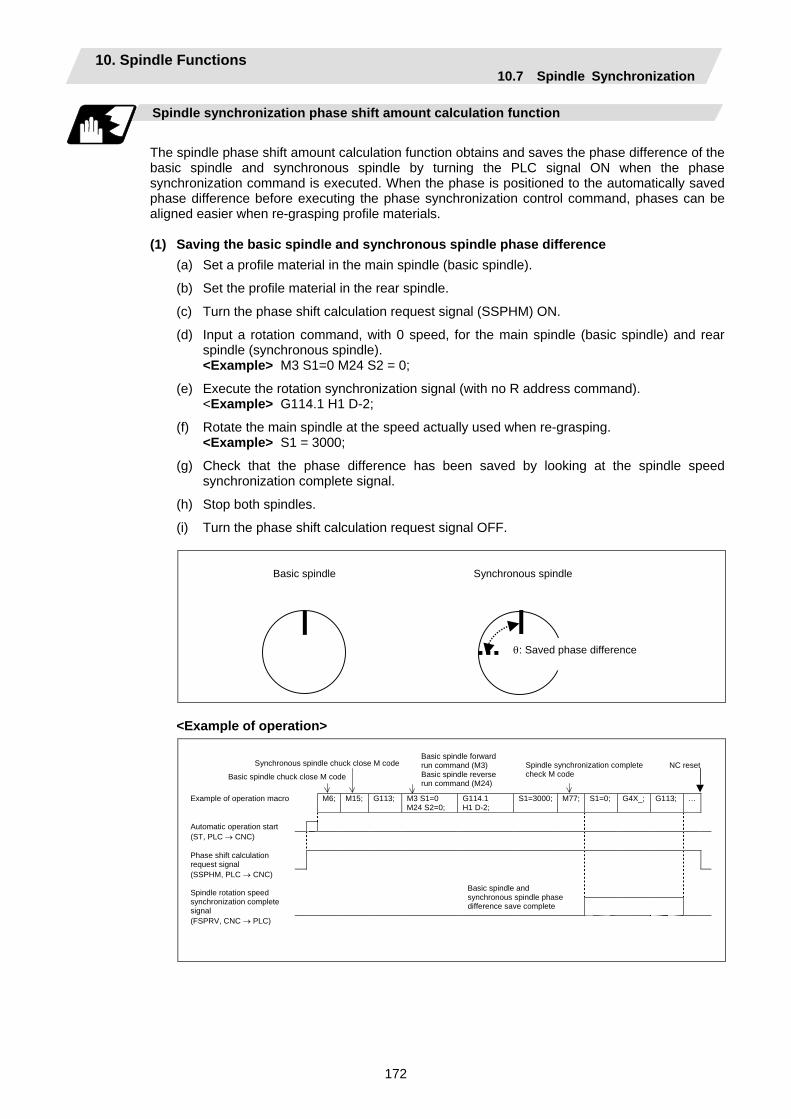
10. Spindle Functions 10.7 Spindle Synchronization
172
Spindle synchronization phase shift amount calculation function
The spindle phase shift amount calculation function obtains and saves the phase difference of the basic spindle and synchronous spindle by turning the PLC signal ON when the phase synchronization command is executed. When the phase is positioned to the automatically saved phase difference before executing the phase synchronization control command, phases can be aligned easier when re-grasping profile materials. (1) Saving the basic spindle and synchronous spindle phase difference
(a) Set a profile material in the main spindle (basic spindle).
(b) Set the profile material in the rear spindle.
(c) Turn the phase shift calculation request signal (SSPHM) ON.
(d) Input a rotation command, with 0 speed, for the main spindle (basic spindle) and rear spindle (synchronous spindle).
<Example> M3 S1=0 M24 S2 = 0;
(e) Execute the rotation synchronization signal (with no R address command). <Example> G114.1 H1 D-2;
(f) Rotate the main spindle at the speed actually used when re-grasping. <Example> S1 = 3000;
(g) Check that the phase difference has been saved by looking at the spindle speed synchronization complete signal.
(h) Stop both spindles.
(i) Turn the phase shift calculation request signal OFF.
Basic spindle Synchronous spindle
θ: Saved phase difference
<Example of operation>
Example of operation macro M6; M15; G113; M3 S1=0
M24 S2=0; G114.1 H1 D-2;
S1=3000; M77; S1=0; G4X_; G113; …
Automatic operation start (ST, PLC → CNC) Phase shift calculation request signal
(SSPHM, PLC → CNC)
Spindle rotation speed synchronization complete signal
(FSPRV, CNC → PLC)
Basic spindle and synchronous spindle phase difference save complete
Basic spindle chuck close M code
Synchronous spindle chuck close M code Spindle synchronization complete check M code
Basic spindle forward run command (M3) Basic spindle reverse run command (M24)
NC reset
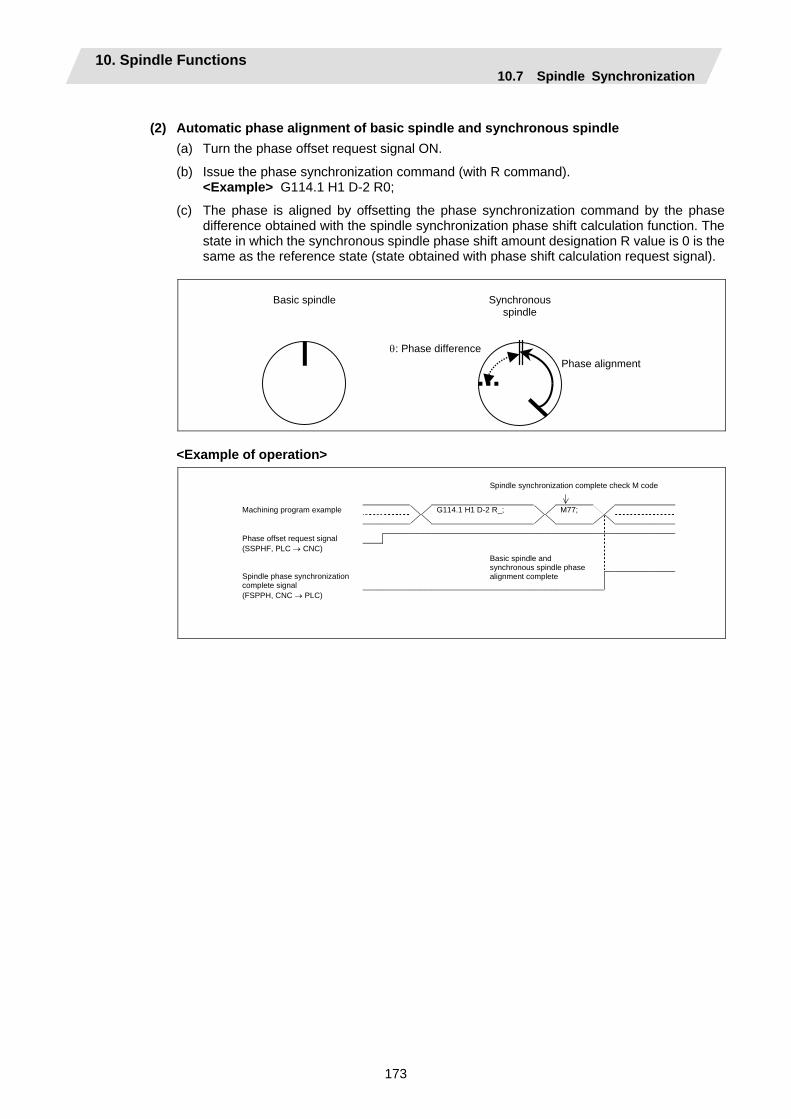
10. Spindle Functions 10.7 Spindle Synchronization
173
(2) Automatic phase alignment of basic spindle and synchronous spindle
(a) Turn the phase offset request signal ON.
(b) Issue the phase synchronization command (with R command). <Example> G114.1 H1 D-2 R0;
(c) The phase is aligned by offsetting the phase synchronization command by the phase difference obtained with the spindle synchronization phase shift calculation function. The state in which the synchronous spindle phase shift amount designation R value is 0 is the same as the reference state (state obtained with phase shift calculation request signal).
Basic spindle
Phase alignment
Synchronous spindle
θ: Phase difference
<Example of operation>
Machining program example G114.1 H1 D-2 R_; M77; Phase offset request signal (SSPHF, PLC → CNC) Spindle phase synchronization
complete signal
(FSPPH, CNC → PLC)
Basic spindle and synchronous spindle phase alignment complete
Spindle synchronization complete check M code
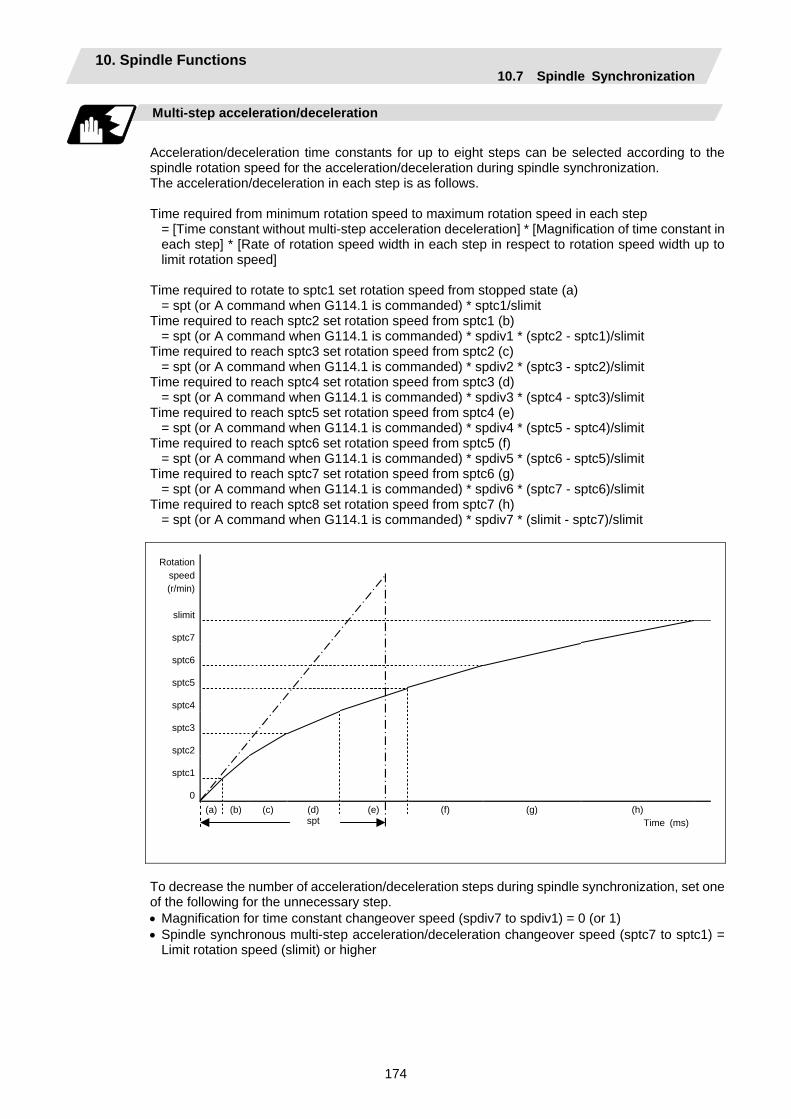
10. Spindle Functions 10.7 Spindle Synchronization
174
Multi-step acceleration/deceleration
Acceleration/deceleration time constants for up to eight steps can be selected according to the spindle rotation speed for the acceleration/deceleration during spindle synchronization. The acceleration/deceleration in each step is as follows. Time required from minimum rotation speed to maximum rotation speed in each step
= [Time constant without multi-step acceleration deceleration] * [Magnification of time constant in each step] * [Rate of rotation speed width in each step in respect to rotation speed width up to limit rotation speed]
Time required to rotate to sptc1 set rotation speed from stopped state (a)
= spt (or A command when G114.1 is commanded) * sptc1/slimit Time required to reach sptc2 set rotation speed from sptc1 (b)
= spt (or A command when G114.1 is commanded) * spdiv1 * (sptc2 - sptc1)/slimit Time required to reach sptc3 set rotation speed from sptc2 (c)
= spt (or A command when G114.1 is commanded) * spdiv2 * (sptc3 - sptc2)/slimit Time required to reach sptc4 set rotation speed from sptc3 (d)
= spt (or A command when G114.1 is commanded) * spdiv3 * (sptc4 - sptc3)/slimit Time required to reach sptc5 set rotation speed from sptc4 (e)
= spt (or A command when G114.1 is commanded) * spdiv4 * (sptc5 - sptc4)/slimit Time required to reach sptc6 set rotation speed from sptc5 (f)
= spt (or A command when G114.1 is commanded) * spdiv5 * (sptc6 - sptc5)/slimit Time required to reach sptc7 set rotation speed from sptc6 (g)
= spt (or A command when G114.1 is commanded) * spdiv6 * (sptc7 - sptc6)/slimit Time required to reach sptc8 set rotation speed from sptc7 (h)
= spt (or A command when G114.1 is commanded) * spdiv7 * (slimit - sptc7)/slimit
Rotation speed (r/min)
slimit
sptc7
sptc6
sptc5
sptc4
sptc3
sptc2
sptc1
0
(a) (b) (c) (d) (e) (f) (g) (h) spt Time (ms)
To decrease the number of acceleration/deceleration steps during spindle synchronization, set one of the following for the unnecessary step. • Magnification for time constant changeover speed (spdiv7 to spdiv1) = 0 (or 1) • Spindle synchronous multi-step acceleration/deceleration changeover speed (sptc7 to sptc1) =
Limit rotation speed (slimit) or higher
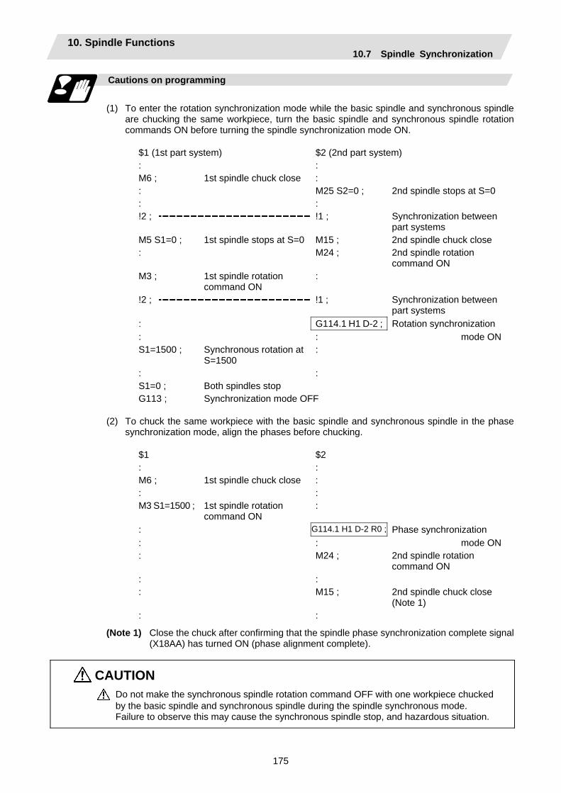
10. Spindle Functions 10.7 Spindle Synchronization
175
Cautions on programming
(1) To enter the rotation synchronization mode while the basic spindle and synchronous spindle
are chucking the same workpiece, turn the basic spindle and synchronous spindle rotation commands ON before turning the spindle synchronization mode ON.
$1 (1st part system) $2 (2nd part system) : : M6 ; 1st spindle chuck close : : M25 S2=0 ; 2nd spindle stops at S=0 : : !2 ; !1 ; Synchronization between
part systems M5 S1=0 ; 1st spindle stops at S=0 M15 ; 2nd spindle chuck close : M24 ; 2nd spindle rotation
command ON M3 ; 1st spindle rotation
command ON :
!2 ; !1 ; Synchronization between
part systems : G114.1 H1 D-2 ; Rotation synchronization : : mode ONS1=1500 ; Synchronous rotation at
S=1500 :
: : S1=0 ; G113 ;
Both spindles stop Synchronization mode OFF
(2) To chuck the same workpiece with the basic spindle and synchronous spindle in the phase
synchronization mode, align the phases before chucking.
$1 $2 : : M6 ; 1st spindle chuck close : : : M3 S1=1500 ; 1st spindle rotation
command ON :
: G114.1 H1 D-2 R0 ; Phase synchronization : : mode ON: M24 ; 2nd spindle rotation
command ON : : : M15 ; 2nd spindle chuck close
(Note 1) : :
(Note 1) Close the chuck after confirming that the spindle phase synchronization complete signal (X18AA) has turned ON (phase alignment complete).
CAUTION Do not make the synchronous spindle rotation command OFF with one workpiece chucked by the basic spindle and synchronous spindle during the spindle synchronous mode. Failure to observe this may cause the synchronous spindle stop, and hazardous situation.

10. Spindle Functions 10.7 Spindle Synchronization
176
Precautions and restrictions
(1) The spindle rotating with spindle synchronization will stop when emergency stop is applied. (2) The rotation speed clamp during spindle synchronization will follow the smaller clamp value set
for the basic spindle or synchronous spindle. (3) Orientation of the basic spindle and synchronous spindle is not possible during the spindle
synchronization mode. To carry out orientation, cancel the spindle synchronization mode first. (4) The rotation speed command (S command) is invalid for the synchronous spindle during the
spindle synchronization mode. Note that the modal will be updated, so this will be validated when spindle synchronization is canceled.
(5) The constant surface speed control is invalid for the synchronous spindle during the spindle synchronization mode. Note that the modal will be updated, so this will be validated when spindle synchronization is canceled.
(6) The rotation speed command (S command) and constant surface speed control for the synchronous spindle will be validated when spindle synchronization is canceled. Thus, the synchronous spindle may carry out different operations when this control is canceled.
(7) If the phase difference is not obtained with the phase shift calculation request signal and the phase synchronization command is executed by turning the phase offset request signal ON, the phase shift amount will not be calculated correctly.
(8) The spindle Z phase encoder position parameter (sppst) is invalid when using the spindle synchronous phase shift amount calculation function. (It is ignored)
The spindle Z phase encoder position parameter (sppst) is valid when the phase offset request signal is OFF.
(9) If the phase synchronization command (command with R address) is issued while the phase shift calculation request signal is ON, an operation error (1106) will occur.
(10) If the phase shift calculation request signal is ON and the basic spindle or synchronous spindle is rotation while rotation synchronization is commanded, an operation error (1106) will occur.
(11) If the phase synchronization command R0 (<Ex.> G114.1 H1 D-2 R0) is commanded while the phase offset request signal is ON, the basic spindle and synchronous spindle phases will be aligned to the phase error of the basic spindle and synchronous spindle saved in the NC memory.
(12) If a value other than the phase synchronization command R0 (<Ex.> G114.1 H1 D-2 R000) is commanded while the phase offset request signal is ON, the phase error obtained by adding the value commanded with the R address command to the phase difference of the basic spindle and synchronous spindle saved in the NC memory will be used to align the basic spindle and synchronous spindle.
(13) The phase offset request signal will be ignored when the phase shift calculation request signal is ON.
(14) The phase error of the basic spindle and synchronous spindle saved in the NC is valid only when the phase shift calculation signal is ON and for the combination of the basic spindle selection (H_) and synchronous spindle (D_) commanded with the rotation synchronization command (no R address).
For example, if the basic spindle and synchronous spindle phase error is saved as "G114.1 H1 D-2 ;", the saved phase error will be valid only when the phase offset request signal is ON and "G114.1 H1 D_2 R∗∗∗ ;" is commanded. If "G114.1 H2 D-1 R∗∗∗ ;" is commanded in this case, the phase shift amount will not be calculated correctly.
(15) The basic spindle and synchronous spindle phase difference saved in the NC is held until the next spindle synchronous phase shift calculation (rotation synchronization command is completed with phase shift calculation request signal ON).
(16) When the spindle synchronization commands are being issued with the PLC I/F method (#1300 ext36/bit7 OFF), a program error (P610) will occur if the spindle synchronization is commanded with G114.1/G113.
(17) Always set the "Chuck close". If the "Chuck close" is not set, an excessive load may be applied on the machine or an alarm may occur.
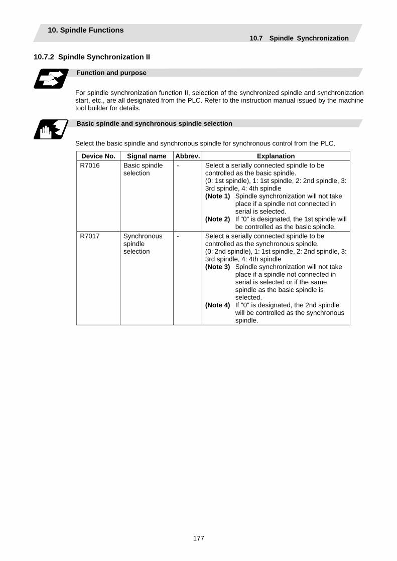
10. Spindle Functions 10.7 Spindle Synchronization
177
10.7.2 Spindle Synchronization II
Function and purpose
For spindle synchronization function II, selection of the synchronized spindle and synchronization start, etc., are all designated from the PLC. Refer to the instruction manual issued by the machine tool builder for details.
Basic spindle and synchronous spindle selection
Select the basic spindle and synchronous spindle for synchronous control from the PLC.
Device No. Signal name Abbrev. Explanation R7016 Basic spindle
selection - Select a serially connected spindle to be
controlled as the basic spindle. (0: 1st spindle), 1: 1st spindle, 2: 2nd spindle, 3: 3rd spindle, 4: 4th spindle (Note 1) Spindle synchronization will not take
place if a spindle not connected in serial is selected.
(Note 2) If "0" is designated, the 1st spindle will be controlled as the basic spindle.
R7017 Synchronous spindle selection
- Select a serially connected spindle to be controlled as the synchronous spindle. (0: 2nd spindle), 1: 1st spindle, 2: 2nd spindle, 3: 3rd spindle, 4: 4th spindle (Note 3) Spindle synchronization will not take
place if a spindle not connected in serial is selected or if the same spindle as the basic spindle is selected.
(Note 4) If "0" is designated, the 2nd spindle will be controlled as the synchronous spindle.
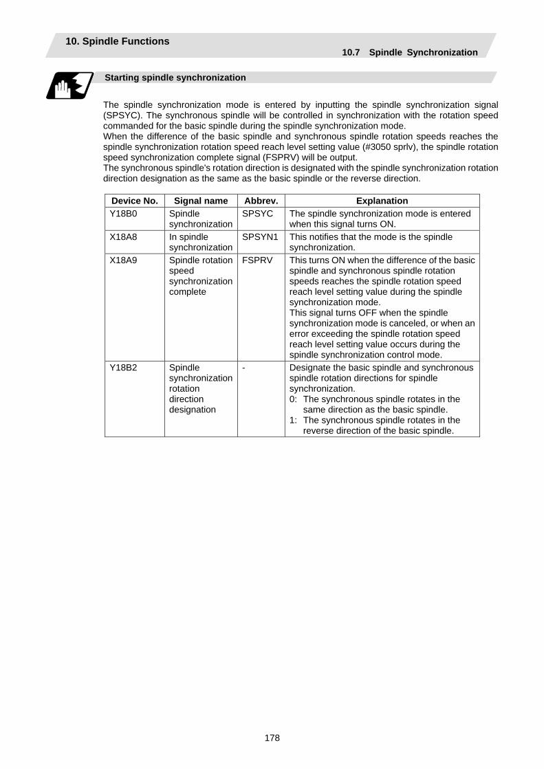
10. Spindle Functions 10.7 Spindle Synchronization
178
Starting spindle synchronization
The spindle synchronization mode is entered by inputting the spindle synchronization signal (SPSYC). The synchronous spindle will be controlled in synchronization with the rotation speed commanded for the basic spindle during the spindle synchronization mode. When the difference of the basic spindle and synchronous spindle rotation speeds reaches the spindle synchronization rotation speed reach level setting value (#3050 sprlv), the spindle rotation speed synchronization complete signal (FSPRV) will be output. The synchronous spindle's rotation direction is designated with the spindle synchronization rotation direction designation as the same as the basic spindle or the reverse direction.
Device No. Signal name Abbrev. Explanation Y18B0 Spindle
synchronizationSPSYC The spindle synchronization mode is entered
when this signal turns ON. X18A8 In spindle
synchronizationSPSYN1 This notifies that the mode is the spindle
synchronization. X18A9 Spindle rotation
speed synchronization complete
FSPRV This turns ON when the difference of the basic spindle and synchronous spindle rotation speeds reaches the spindle rotation speed reach level setting value during the spindle synchronization mode. This signal turns OFF when the spindle synchronization mode is canceled, or when an error exceeding the spindle rotation speed reach level setting value occurs during the spindle synchronization control mode.
Y18B2 Spindle synchronization rotation direction designation
- Designate the basic spindle and synchronous spindle rotation directions for spindle synchronization. 0: The synchronous spindle rotates in the
same direction as the basic spindle. 1: The synchronous spindle rotates in the
reverse direction of the basic spindle.

10. Spindle Functions 10.7 Spindle Synchronization
179
Spindle phase alignment
Spindle phase synchronization starts when the spindle phase synchronization signal (SPPHS) is input during the spindle synchronization mode. The spindle phase synchronization complete signal is output when the spindle synchronization phase reach level setting value (#3051 spplv) is reached. The synchronous spindle's phase shift amount can also be designated from the PLC.
Device No. Signal name Abbrev. Explanation Y18B1 Spindle phase
synchronization control
SPPHS Spindle phase synchronization starts when this signal is turned ON during the spindle synchronization mode. (Note 1) If this signal is turned ON in a mode
other than the spindle synchronization mode, it will be ignored.
X18AA Spindle phase synchronization complete
FSPPH This signal is output when the spindle synchronization phase reach level is reached after starting spindle phase synchronization.
R7018 Phase shift amount setting
- Designate the synchronous spindle's phase shift amount. Unit: 360°/4096
Spindle synchronization signal (Y18B0)
Spindle synchronization complete signal (X18A9)
In spindle synchronization signal (X18A8)
Spindle phase synchronization signal (Y18B1)
Spindle phase synchronization complete signal (X18AA)
Spindle phase synchronization complete ON
(Note 2)
Spindle phase synchronization ON
Spindle synchronization complete ON
Spindle synchronization OFF
Spindle synchronization ON
Spindle synchronization OFF
(Note 2) Turns OFF temporarily to change the rotation speed during phase synchronization.
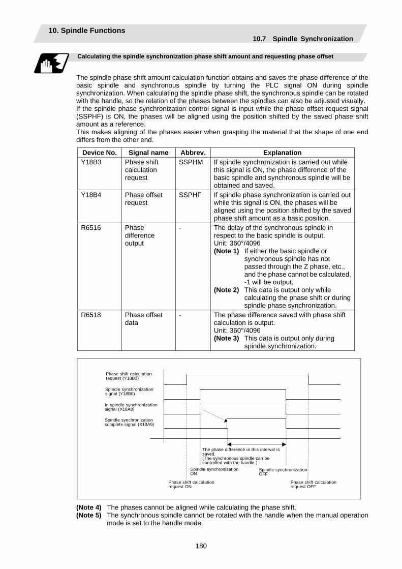
10. Spindle Functions 10.7 Spindle Synchronization
180
Calculating the spindle synchronization phase shift amount and requesting phase offset
The spindle phase shift amount calculation function obtains and saves the phase difference of the basic spindle and synchronous spindle by turning the PLC signal ON during spindle synchronization. When calculating the spindle phase shift, the synchronous spindle can be rotated with the handle, so the relation of the phases between the spindles can also be adjusted visually. If the spindle phase synchronization control signal is input while the phase offset request signal (SSPHF) is ON, the phases will be aligned using the position shifted by the saved phase shift amount as a reference. This makes aligning of the phases easier when grasping the material that the shape of one end differs from the other end.
Device No. Signal name Abbrev. Explanation Y18B3 Phase shift
calculation request
SSPHM If spindle synchronization is carried out while this signal is ON, the phase difference of the basic spindle and synchronous spindle will be obtained and saved.
Y18B4 Phase offset request
SSPHF If spindle phase synchronization is carried out while this signal is ON, the phases will be aligned using the position shifted by the saved phase shift amount as a basic position.
R6516 Phase difference output
- The delay of the synchronous spindle in respect to the basic spindle is output. Unit: 360°/4096 (Note 1) If either the basic spindle or
synchronous spindle has not passed through the Z phase, etc., and the phase cannot be calculated, -1 will be output.
(Note 2) This data is output only while calculating the phase shift or during spindle phase synchronization.
R6518 Phase offset data
- The phase difference saved with phase shift calculation is output. Unit: 360°/4096 (Note 3) This data is output only during
spindle synchronization.
Spindle synchronization signal (Y18B0)
Spindle synchronization complete signal (X18A9)
In spindle synchronization signal (X18A8)
Spindle synchronization ON
Phase shift calculation request (Y18B3)
The phase difference in this interval is saved. (The synchronous spindle can be controlled with the handle.)
Spindle synchronization OFF
Phase shift calculation request ON
Phase shift calculation request OFF
(Note 4) The phases cannot be aligned while calculating the phase shift. (Note 5) The synchronous spindle cannot be rotated with the handle when the manual operation
mode is set to the handle mode.
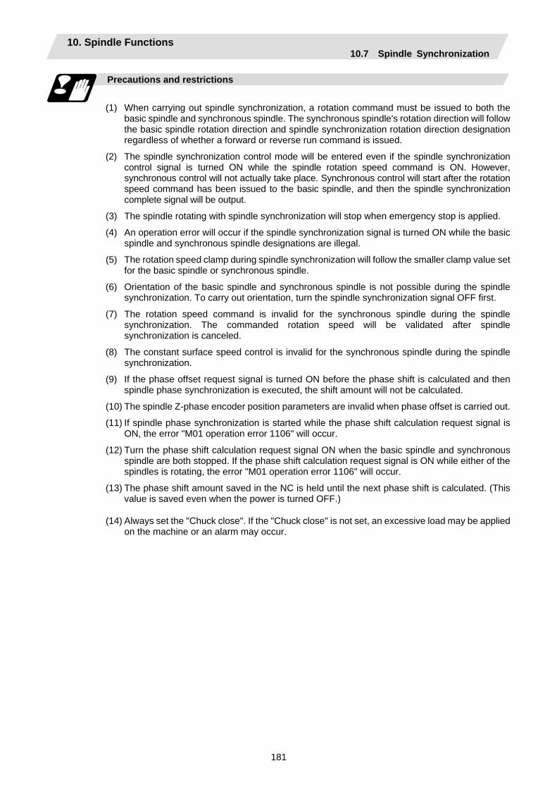
10. Spindle Functions 10.7 Spindle Synchronization
181
Precautions and restrictions
(1) When carrying out spindle synchronization, a rotation command must be issued to both the
basic spindle and synchronous spindle. The synchronous spindle's rotation direction will follow the basic spindle rotation direction and spindle synchronization rotation direction designation regardless of whether a forward or reverse run command is issued.
(2) The spindle synchronization control mode will be entered even if the spindle synchronization control signal is turned ON while the spindle rotation speed command is ON. However, synchronous control will not actually take place. Synchronous control will start after the rotation speed command has been issued to the basic spindle, and then the spindle synchronization complete signal will be output.
(3) The spindle rotating with spindle synchronization will stop when emergency stop is applied.
(4) An operation error will occur if the spindle synchronization signal is turned ON while the basic spindle and synchronous spindle designations are illegal.
(5) The rotation speed clamp during spindle synchronization will follow the smaller clamp value set for the basic spindle or synchronous spindle.
(6) Orientation of the basic spindle and synchronous spindle is not possible during the spindle synchronization. To carry out orientation, turn the spindle synchronization signal OFF first.
(7) The rotation speed command is invalid for the synchronous spindle during the spindle synchronization. The commanded rotation speed will be validated after spindle synchronization is canceled.
(8) The constant surface speed control is invalid for the synchronous spindle during the spindle synchronization.
(9) If the phase offset request signal is turned ON before the phase shift is calculated and then spindle phase synchronization is executed, the shift amount will not be calculated.
(10) The spindle Z-phase encoder position parameters are invalid when phase offset is carried out.
(11) If spindle phase synchronization is started while the phase shift calculation request signal is ON, the error "M01 operation error 1106" will occur.
(12) Turn the phase shift calculation request signal ON when the basic spindle and synchronous spindle are both stopped. If the phase shift calculation request signal is ON while either of the spindles is rotating, the error "M01 operation error 1106" will occur.
(13) The phase shift amount saved in the NC is held until the next phase shift is calculated. (This value is saved even when the power is turned OFF.)
(14) Always set the "Chuck close". If the "Chuck close" is not set, an excessive load may be applied on the machine or an alarm may occur.
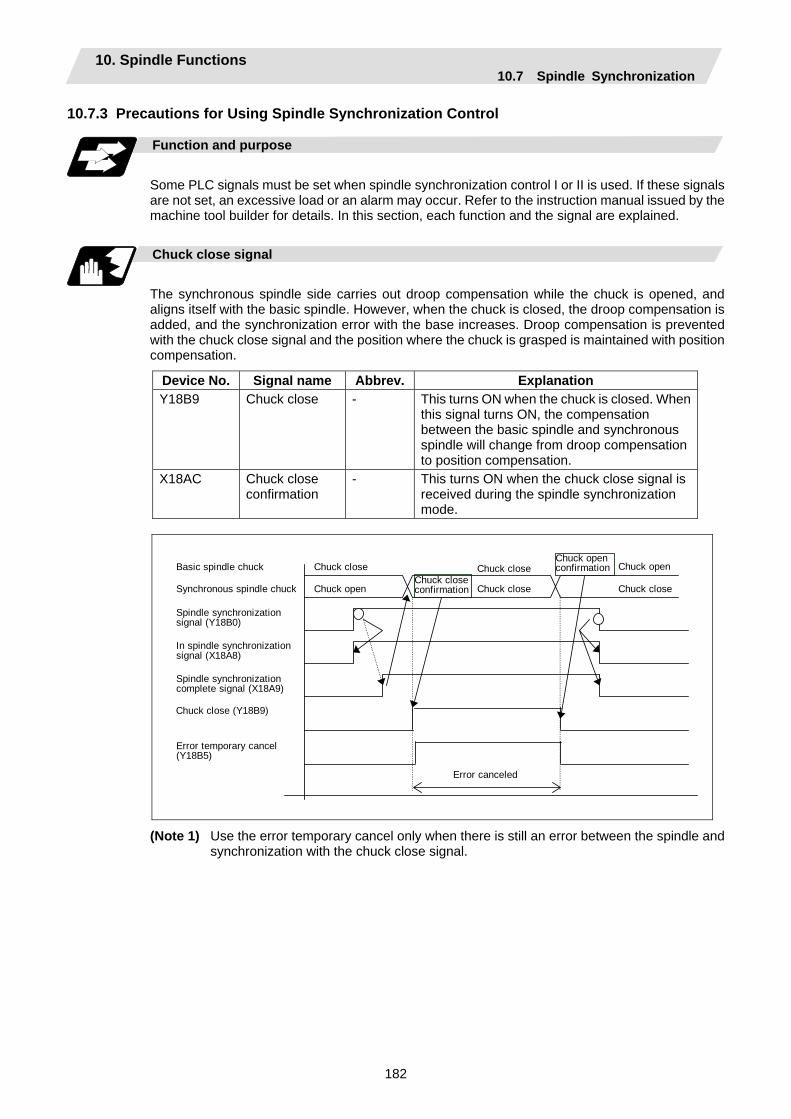
10. Spindle Functions 10.7 Spindle Synchronization
182
10.7.3 Precautions for Using Spindle Synchronization Control
Function and purpose
Some PLC signals must be set when spindle synchronization control I or II is used. If these signals are not set, an excessive load or an alarm may occur. Refer to the instruction manual issued by the machine tool builder for details. In this section, each function and the signal are explained.
Chuck close signal
The synchronous spindle side carries out droop compensation while the chuck is opened, and aligns itself with the basic spindle. However, when the chuck is closed, the droop compensation is added, and the synchronization error with the base increases. Droop compensation is prevented with the chuck close signal and the position where the chuck is grasped is maintained with position compensation.
Device No. Signal name Abbrev. Explanation Y18B9 Chuck close - This turns ON when the chuck is closed. When
this signal turns ON, the compensation between the basic spindle and synchronous spindle will change from droop compensation to position compensation.
X18AC Chuck close confirmation
- This turns ON when the chuck close signal is received during the spindle synchronization mode.
Chuck open Chuck closeChuck close
Spindle synchronization signal (Y18B0)
Error temporary cancel (Y18B5)
In spindle synchronization signal (X18A8)
Error canceled
Synchronous spindle chuck
Spindle synchronization complete signal (X18A9)
Basic spindle chuck Chuck close Chuck close Chuck openChuck close confirmation
Chuck open confirmation
Chuck close (Y18B9)
(Note 1) Use the error temporary cancel only when there is still an error between the spindle and synchronization with the chuck close signal.
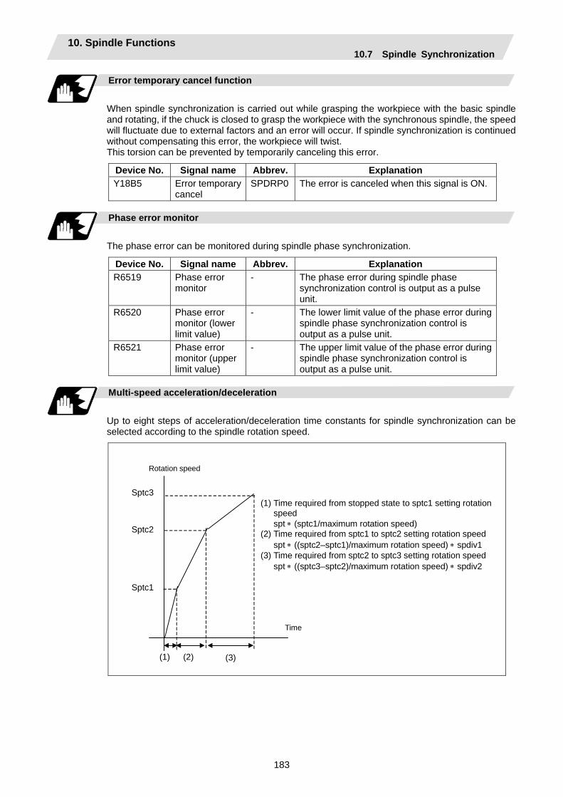
10. Spindle Functions 10.7 Spindle Synchronization
183
Error temporary cancel function
When spindle synchronization is carried out while grasping the workpiece with the basic spindle and rotating, if the chuck is closed to grasp the workpiece with the synchronous spindle, the speed will fluctuate due to external factors and an error will occur. If spindle synchronization is continued without compensating this error, the workpiece will twist. This torsion can be prevented by temporarily canceling this error.
Device No. Signal name Abbrev. Explanation Y18B5 Error temporary
cancel SPDRP0 The error is canceled when this signal is ON.
Phase error monitor
The phase error can be monitored during spindle phase synchronization.
Device No. Signal name Abbrev. Explanation R6519 Phase error
monitor - The phase error during spindle phase
synchronization control is output as a pulse unit.
R6520 Phase error monitor (lower limit value)
- The lower limit value of the phase error during spindle phase synchronization control is output as a pulse unit.
R6521 Phase error monitor (upper limit value)
- The upper limit value of the phase error during spindle phase synchronization control is output as a pulse unit.
Multi-speed acceleration/deceleration
Up to eight steps of acceleration/deceleration time constants for spindle synchronization can be selected according to the spindle rotation speed.
Sptc1
Sptc2
Sptc3
(1) (2) (3)
Rotation speed
Time
(1) Time required from stopped state to sptc1 setting rotation speed
spt ∗ (sptc1/maximum rotation speed) (2) Time required from sptc1 to sptc2 setting rotation speed spt ∗ ((sptc2–sptc1)/maximum rotation speed) ∗ spdiv1 (3) Time required from sptc2 to sptc3 setting rotation speed spt ∗ ((sptc3–sptc2)/maximum rotation speed) ∗ spdiv2

10. Spindle Functions 10.8 Tool Spindle Synchronization IA (Spindle-Spindle, Polygon)
184
10.8 Tool Spindle Synchronization IA (Spindle-Spindle, Polygon); G114.2
Function and purpose
In a machine having a rotary tool controlled with a serial connection and having a spindle controlled with a serial connection as the workpiece axis, polygon machining can be carried out by controlling the workpiece axis rotation in synchronized with the rotation of the rotary tool axis. The serial connection control of spindle and rotary tool axis can be carried out with MDS-∗-SP or MDS-∗-SPJ2.
Command format
(1) Tool spindle synchronization IA (Spindle-Spindle, Polygon) ON (G114.2)
This command sets the polygon machining mode that rotates the two axes in synchronized with differing speeds by designating the rotary tool axis and workpiece axes and the rotation ratio (Number of the rotary tool gear teeth and workpiece corners) of the two designated axes (spindle and spindle).
G114.2 H_ D_ E_ L_ R_ ; H_ Rotary tool axis (Basic spindle) D_ Workpiece axis (Synchronous spindle) E_ Rotary tool axis rotation ratio L_ Workpiece axis rotation ratio R_ Synchronous spindle phase shift amount
(2) Spindle synchronization cancel (G113)
This command cancels the synchronization state of rotating two spindles by the spindle synchronization command.
G113 ;
Address Meaning of address Command range (unit) Remarks H Rotary tool axis
Of the two spindles, the spindle No. of the select rotation axis.
1 to number of spindles 1: 1st spindle 2: 2nd spindle 3: 3rd spindle 4: 4th spindle
• If a value exceeding the command range is commanded, a program error (P35) will occur.
• If there is no command, a program error (P33) will occur.
• If the same value as the D command is commanded, a program error (P33) will occur.
• If a spindle that is not serially connected is selected, a program error (P700) will occur.
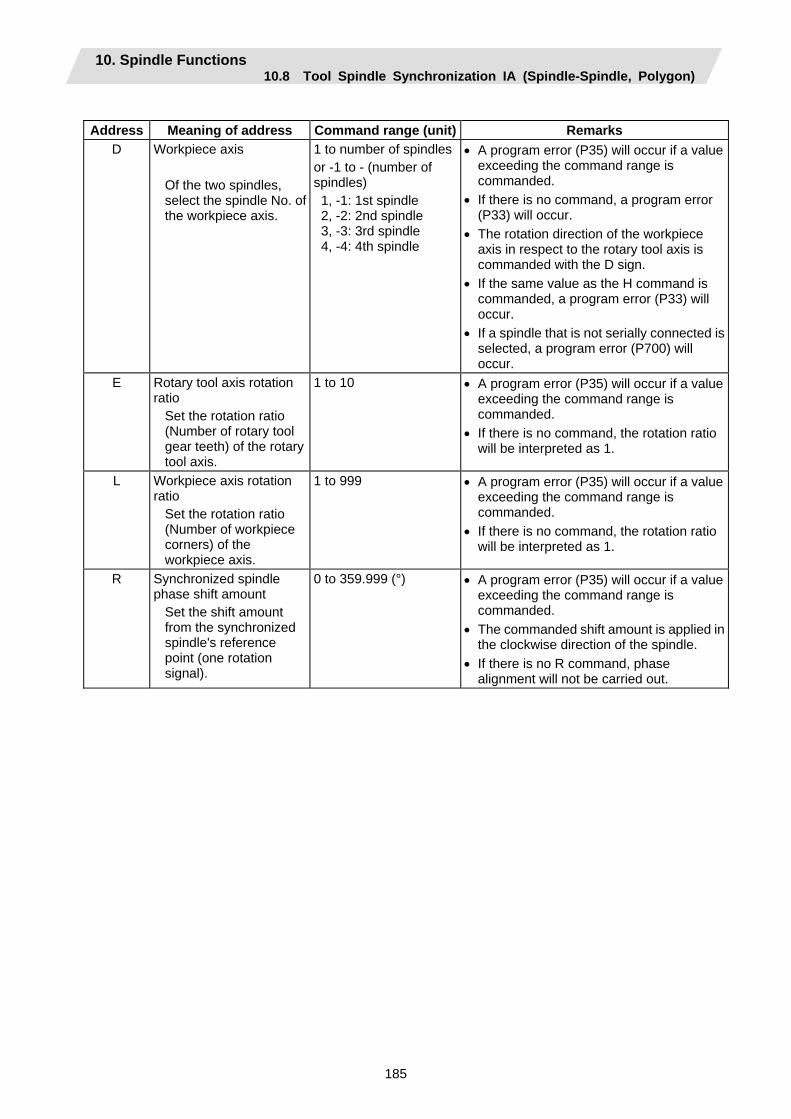
10. Spindle Functions 10.8 Tool Spindle Synchronization IA (Spindle-Spindle, Polygon)
185
Address Meaning of address Command range (unit) Remarks
D Workpiece axis Of the two spindles, select the spindle No. of the workpiece axis.
1 to number of spindlesor -1 to - (number of spindles) 1, -1: 1st spindle 2, -2: 2nd spindle 3, -3: 3rd spindle 4, -4: 4th spindle
• A program error (P35) will occur if a value exceeding the command range is commanded.
• If there is no command, a program error (P33) will occur.
• The rotation direction of the workpiece axis in respect to the rotary tool axis is commanded with the D sign.
• If the same value as the H command is commanded, a program error (P33) will occur.
• If a spindle that is not serially connected is selected, a program error (P700) will occur.
E Rotary tool axis rotation ratio
Set the rotation ratio (Number of rotary tool gear teeth) of the rotary tool axis.
1 to 10 • A program error (P35) will occur if a value exceeding the command range is commanded.
• If there is no command, the rotation ratio will be interpreted as 1.
L Workpiece axis rotation ratio
Set the rotation ratio (Number of workpiece corners) of the workpiece axis.
1 to 999 • A program error (P35) will occur if a value exceeding the command range is commanded.
• If there is no command, the rotation ratio will be interpreted as 1.
R Synchronized spindle phase shift amount
Set the shift amount from the synchronized spindle's reference point (one rotation signal).
0 to 359.999 (°) • A program error (P35) will occur if a value exceeding the command range is commanded.
• The commanded shift amount is applied in the clockwise direction of the spindle.
• If there is no R command, phase alignment will not be carried out.
10. Spindle Functions 10.8 Tool Spindle Synchronization IA (Spindle-Spindle, Polygon)
186
Rotation axis and rotation direction
The rotary tool axis and workpiece axis rotation speed and rotation direction during tool spindle synchronization IA (Polygon) command are as follows.
(1) The rotation speed and rotation direction of the rotary tool axis are the rotation speed
commanded with the S command and the rotation direction commanded with the M command, etc., for the spindle selected as the rotary tool axis.
(2) The workpiece axis rotation speed is determined by the number of the rotary tool gear teeth workpiece corners commanded with G114.2.
Sw = Sh ∗
Sw : Workpiece axis rotation speed (r/min) Sh : Rotary tool axis rotation speed (r/min) L : Rotary tool axis rotation ratio (Number of rotary tool gear teeth) E : Workpiece axis rotation ratio (Number of workpiece corners)
(3) The workpiece axis rotation direction is determined by the sign of the address D commanded
with G114.2. In other words, when the D sign is "+", the workpiece axis rotates in the same direction as the rotary tool axis, and when "-", the workpiece axis rotates in the reverse direction of the rotary tool axis.
(4) After tool spindle synchronization IA (Polygon) mode is commanded, the relation of the rotary tool axis and workpiece axis rotation is held in all automatic or manual operation modes until spindle synchronization cancel (G113) is commanded, the spindle synchronization cancel signal is input, or reset (reset 1, reset 2, reset & rewind) is executed when "#1239 set11/bit3" is set to 1.
Even during feed hold, the rotary tool axis and workpiece axis synchronization state is held.
Operation for spindle-spindle polygon
The workpiece axis will be controlled in the following manner.
(1) When the spindle synchronization IA (polygon machining) mode is commanded, if neither a
forward run command nor a reverse run command is input for the workpiece axis, the workpiece axis will not start rotating even if the polygon axis is rotating, and instead will wait for synchronization. If a forward run command or reverse run command is input for the workpiece axis in this state, the workpiece axis will start rotation.
(2) If spindle stop is commanded (both forward run command and reverse run command are turned OFF) in respect to the workpiece axis during the spindle synchronization IA (polygon machining) mode, the workpiece axis rotation will stop even when the rotary tool axis is rotating.
(3) The rotation command (S command) and constant surface speed control are invalid in respect to the workpiece axis during the tool spindle synchronization IA (polygon) mode. Note that the modal will be updated, so these will be effective after the spindle synchronization is canceled.
(4) If a rotary tool axis rotation speed that exceeds the workpiece axis maximum rotation speed is commanded, the rotary tool axis rotation speed will be clamped so that the workpiece axis rotation speed does not exceed the workpiece axis maximum rotation speed.
L E
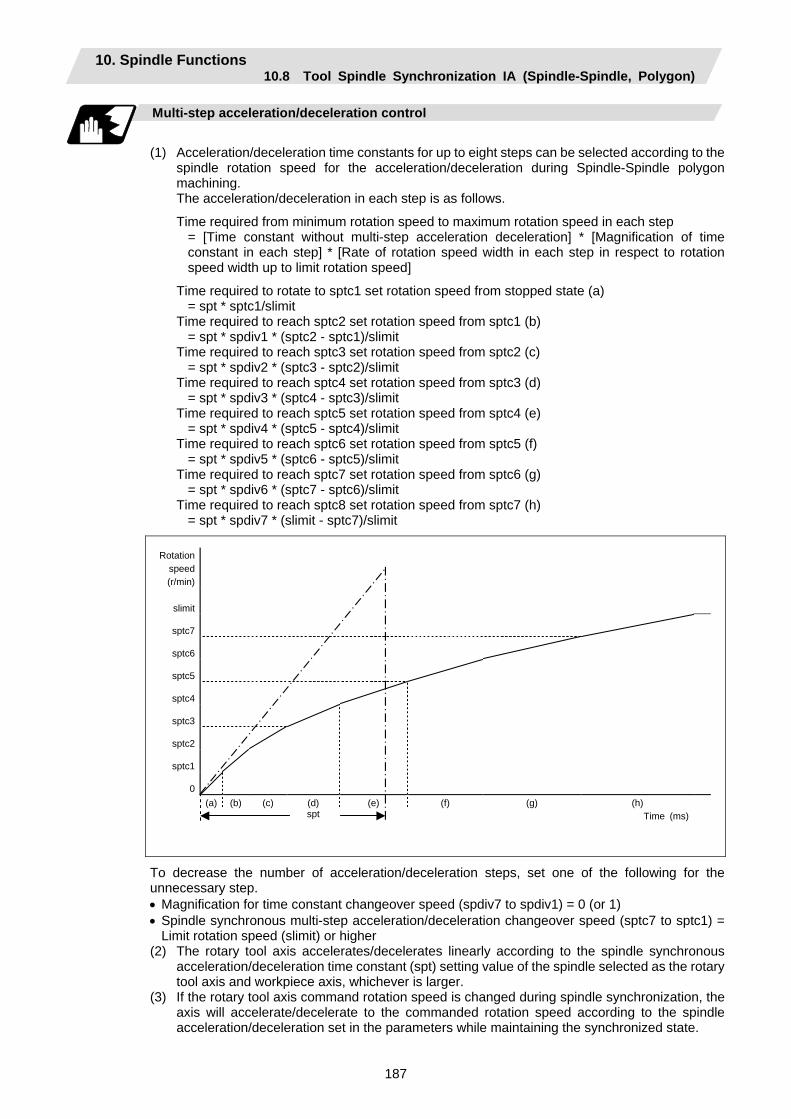
10. Spindle Functions 10.8 Tool Spindle Synchronization IA (Spindle-Spindle, Polygon)
187
Multi-step acceleration/deceleration control
(1) Acceleration/deceleration time constants for up to eight steps can be selected according to the
spindle rotation speed for the acceleration/deceleration during Spindle-Spindle polygon machining.
The acceleration/deceleration in each step is as follows.
Time required from minimum rotation speed to maximum rotation speed in each step = [Time constant without multi-step acceleration deceleration] * [Magnification of time constant in each step] * [Rate of rotation speed width in each step in respect to rotation speed width up to limit rotation speed]
Time required to rotate to sptc1 set rotation speed from stopped state (a) = spt * sptc1/slimit
Time required to reach sptc2 set rotation speed from sptc1 (b) = spt * spdiv1 * (sptc2 - sptc1)/slimit
Time required to reach sptc3 set rotation speed from sptc2 (c) = spt * spdiv2 * (sptc3 - sptc2)/slimit
Time required to reach sptc4 set rotation speed from sptc3 (d) = spt * spdiv3 * (sptc4 - sptc3)/slimit
Time required to reach sptc5 set rotation speed from sptc4 (e) = spt * spdiv4 * (sptc5 - sptc4)/slimit
Time required to reach sptc6 set rotation speed from sptc5 (f) = spt * spdiv5 * (sptc6 - sptc5)/slimit
Time required to reach sptc7 set rotation speed from sptc6 (g) = spt * spdiv6 * (sptc7 - sptc6)/slimit
Time required to reach sptc8 set rotation speed from sptc7 (h) = spt * spdiv7 * (slimit - sptc7)/slimit
Rotation speed (r/min)
slimit
sptc7
sptc6
sptc5
sptc4
sptc3
sptc2
sptc1
0
(a) (b) (c) (d) (e) (f) (g) (h) spt Time (ms)
To decrease the number of acceleration/deceleration steps, set one of the following for the unnecessary step. • Magnification for time constant changeover speed (spdiv7 to spdiv1) = 0 (or 1) • Spindle synchronous multi-step acceleration/deceleration changeover speed (sptc7 to sptc1) =
Limit rotation speed (slimit) or higher (2) The rotary tool axis accelerates/decelerates linearly according to the spindle synchronous
acceleration/deceleration time constant (spt) setting value of the spindle selected as the rotary tool axis and workpiece axis, whichever is larger.
(3) If the rotary tool axis command rotation speed is changed during spindle synchronization, the axis will accelerate/decelerate to the commanded rotation speed according to the spindle acceleration/deceleration set in the parameters while maintaining the synchronized state.
10. Spindle Functions 10.8 Tool Spindle Synchronization IA (Spindle-Spindle, Polygon)
188
Phase alignment control
(1) If the tool spindle synchronization IA command (with R designation) is commanded with the
G114.2 command, the synchronous spindle rotating at an arbitrary rotation speed will accelerate or decelerate to the rotation speed following the basic spindle and synchronous spindle rotation ratio command, and the spindle synchronization state will be entered. After that, the phase will be aligned to match the rotation phase commanded with the R address.
(2) The spindle synchronization phase shift amount is commanded as the shift amount from the synchronous spindle's (workpiece axis) reference point (one rotation signal). There is no shift amount in respect to the basic spindle (rotary tool axis).
(3) If the basic spindle's (rotary tool axis) commanded rotation speed is changed during the spindle synchronization state, acceleration/deceleration will be carried out following the spindle acceleration/deceleration set in the parameters while maintaining the synchronization state, and will reach the commanded rotation speed.
(4) The following type of operation will take place.
M03 S1=0 ;
• Txx00 ; M83 S4=500 ;
• G114.2 H4 D1 E1 L5 Rxx ;
• •
G113 ;
……Carries out forward run (speed command) 1st spindle
(synchronous spindle) ……Rotary tool selection ……Carries out forward run (speed command) 4th spindle
(basic spindle) ……Carries out forward run 1st spindle (synchronous spindle)
and synchronizes with 4th spindle (basic spindle). Shifts synchronous spindle phase by amount of R command value.
……Cancels tool-spindle synchronization IA

10. Spindle Functions 10.8 Tool Spindle Synchronization IA (Spindle-Spindle, Polygon)
189
Time
Cancels Spindle synchronization
Basic spindle
Synchronous spindle
600
<Operation>
Rotation speed
500
400
300
200
100
0
Phase alignment
No. 1 spindle (synchronous spindle) forward run synchronization
No. 4 spindle (basic spindle) forward run
No. 1 spindle (synchronous spindle) forward run
10. Spindle Functions 10.8 Tool Spindle Synchronization IA (Spindle-Spindle, Polygon)
190
Example of program
•
•
•
M03 S1=0 ; 1st spindle forward run Txx00 ; Rotary tool selection M83 S4=500 ; 4th spindle forward run G00 X40.Z-5. ;
G114.2 H4 D1 E1 L10 R0 ;
Tool spindle synchronization IA (Spindle-Spindle, Polygon mode) ON
Rotary tool axis : 4th spindle Workpiece axis : 1st spindle Number of rotary tool gear teeth : 1 Rotation ratio : Number of workpiece corners as 10Synchronous spindle phase shift amount : 0°
S1 starts rotating by forward run in synchronization with S4. The phase is aligned with shift amount 0°. The S1 rotation speed is 50 r/min (S2:S1 = 10:1).
G99 ; Synchronous feed mode selection
G00 X18. ; G01 Z20. F0.1 ; G00 X40. ;
Z-5. ;
1st cut in Z axis feed rate is 0.1mm per workpiece axis rotation
•
•
•
G00 X14. ; G01 Z20. F0.1 ; G00 X40. ;
Z-5. ;
Final cut in Z axis feed rate is 0.1mm per workpiece axis rotation
G113 ;
Spindle synchronization cancel M85 ; 4th spindle stop
M05 ; 1st spindle stop • •
10. Spindle Functions 10.8 Tool Spindle Synchronization IA (Spindle-Spindle, Polygon)
191
Precautions for programming
(1) The axis address (X, Z, C) command in the same block as G114.2 will be ignored.
ex. G114.2 X_ ; Ignored.
(2) If a modal is commanded in the same block as G114.2, the modal will be updated. ex. G114.2 G01 ; The group 01 modal is set to G01.
(3) If a miscellaneous command (M, S, T) is commanded in the same block as G114.2, the miscellaneous command will be executed simultaneously with the change to the rotary tool machining mode. ex. G114.2 M03 ; M03 is executed simultaneously with G114.2.
(4) If there is a group 00 G code command in the same block as G114.2, the G code commanded last in the block will have the priority. ex. G114.2 G4 P30 ; G4 P30. is executed.
0
Precautions and Restrictions
(1) Restrictions regarding phase alignment control
(a) Make sure that the rotation ratio of spindle (and rotary tool axis spindle) actual rotation speed and encoder rotation speed has the following relation.
Spindle rotation speed/encoder rotation speed = n ("n" is an integer of 1 or more)
If this relation is not established, the encoder’s reference position will not stay at a constant position of the spindle, and thus the phase (position) will deviate with each phase alignment command. Note that even in this case, if the number of rotary tool gear teeth (Number of workpiece corners) is equivalent to the rotation ratio, the blade and workpiece phase (position) will not deviate. (Following relation)
(Rotary tool axis spindle rotation speed ∗ Number of rotary tool gear teeth) / encoder rotation speed = n ("n" is an integer of 1 or more)
(b) During phase alignment control, phase alignment is carried out following each spindle encoder's reference position, so if the positional relation of the workpiece and reference position (rotary tool and reference position) deviates when the power is turned OFF/ON or when the tool is changed, etc., the phase will deviate.
(2) If S is commanded in the same block as G114.2, the synchronization speed will be created at
the previous S command until the S command ends, so the spindle speed may fluctuate momentarily. Thus, do not command S in the same block if possible.
(3) Always command G114.2 in an independent block. (4) The tool spindle synchronization 1 (Spindle-Spindle, Polygon) mode cannot be commanded
during the spindle synchronization mode commanded with G114.*. "M01 Operation error 1005" will occur.
(5) If Spindle-Spindle polygon machining is commanded while the phase shift calculation request signal SSPHM is ON, "M01 Operation error 1106" will occur.
(6) Spindle-Spindle polygon machining cannot be executed by designating a spindle being used for synchronous tapping with the G114.2 command. "M01 Operation error 1007" will occur.
(7) When the spindle/C-axis is used for the Spindle-Spindle-spindle polygon machining cannot be executed by designating the C axis mode spindle with the G114.2 command. "M01 Operation error 1026" will occur.
(8) After G114.2 is commanded, the cutting feed block will not start until synchronization is established. Operation will stop with "M01 Operation error 1033".
10. Spindle Functions 10.9 Tool Spindle Synchronization IB (Spindle-Spindle, Polygon)
192
10.9 Tool Spindle Synchronization IB (Spindle-Spindle, Polygon); G51.2 (Only 6 and 7 in G code list)
Function and purpose
In machines having a serial connection-controlled workpiece axis, and furthermore having a serial connection-controlled spindle as a rotary tool axis, Spindle-Spindle polygon machining can be carried out by controlling the rotation of the rotary tool axis rotation in synchronization with the workpiece axis. The mode can be changed between polygon machining and Spindle-Spindle polygon machining with parameter #1501.
#1501 polyax = 0 : Spindle-Spindle polygon machining Other than 0 : NC axis- spindle polygon machining
The workpiece axis and rotary tool axis can be serially connected and controlled with MDS-∗-SP or MDS-∗-SPJ2. This function is valid when the G code system is 6 or 7.
Command format
(1) Polygon machining mode command
This command designates the rotary tool axis and workpiece axis, and enters the polygon machining mode that enables synchronized rotation of two axes at differing speeds. It does this by designating the rotation ratio (number of rotary tool teeth and workpiece corners) of the two designated spindles (spindle and spindle).
G51.2 H_ D_ P_ Q_ R_ ; Tool spindle synchronization IB (Spindle-Spindle, Polygon mode) ON G51.2 (or G251) H D P Q R
Polygon machining command Workpiece axis selection (Basic spindle) Rotary tool axis selection (Synchronous spindle) Rotary tool axis rotation ratio designation Workpiece axis rotation ratio designation Synchronous spindle phase shift amount
(2) Polygon machining mode cancel command
The synchronous state of the two spindles rotating in synchronization with the tool spindle synchronization command is canceled.
G50.2 ; Tool spindle synchronization IB (Spindle-Spindle, Polygon mode) OFF
The Spindle-Spindle polygon machining mode is also canceled in the following cases. • Power OFF • Emergency stop • Reset (reset 1, reset 2, reset & rewind) (only when #1239 set11/bit3 = 1) • Spindle-Spindle polygon machining cancel signal
10. Spindle Functions 10.9 Tool Spindle Synchronization IB (Spindle-Spindle, Polygon)
193
Address Meaning of address Command range (unit) Remarks H Workpiece axis selection
Command the spindle No. of the workpiece axis.
1 to number of spindles
• A program error (P35) will occur if a value exceeding the command range is commanded.
• A program error (P33) will occur if the same value as the D command is commanded.
• A program error (P33) will occur if a spindle not serially connected is commanded.
• The spindle No. set in the parameters will be applied if omitted.
D Rotary tool axis selection Command the spindle No. of the rotary tool axis.
1 to number of spindles
• A program error (P35) will occur if a value exceeding the command range is commanded.
• A program error (P33) will occur if the same value as the H command is commanded.
• A program error (P33) will occur if a spindle not serially connected is commanded.
• The spindle No. set in the parameters will be applied if omitted.
P Workpiece axis rotation ratio designation Command the workpiece axis rotation ratio (number of workpiece corners).
1 to 999 • A program error (P35) will occur if a value exceeding the command range is commanded.
Q Rotary tool axis rotation ratio designation Command the rotary tool axis rotation ratio (number of tool teeth).
1 to 999 –1 to –999
• A program error (P35) will occur if a value exceeding the command range is commanded.
• If a negative sign is commanded, the rotary tool axis will rotate in the direction opposite the workpiece axis.
R Synchronous spindle phase shift amount designation Command the shift amount from the reference point (one rotation signal) of the rotary tool axis spindle.
0 to 359.999 (° )
• A program error (P35) will occur if a value exceeding the command range is commanded.
• The commanded shift amount will be applied in the clockwise direction in respect to the spindle.
• If there is no R command, the phase will be handled as R0.
(#1239 set11/bit4=0)
10. Spindle Functions 10.9 Tool Spindle Synchronization IB (Spindle-Spindle, Polygon)
194
Rotation and rotation direction
The workpiece axis and rotary tool axis rotation speed and rotation direction during spindle- spindle polygon machining are as follows.
(1) The workpiece axis rotation speed and rotation direction are rotation speed commanded with
the S command and the rotation direction commanded with the M command, etc., for the spindle selected as the workpiece axis.
(2) The rotary tool axis rotation speed is determined by the number of rotary tool teeth and number of workpiece corners commanded with G51.2.
Sw = Sh ∗ Sw : Rotary tool axis rotation speed (r/min) Sh : Workpiece axis rotation speed (r/min) P : Workpiece axis rotation ratio (number of workpiece corners) Q : Rotary tool axis rotation ratio (number of rotary tool teeth)
(3) The rotary tool axis rotation direction is determined by the sign of the rotary tool axis selection Q commanded with G51.2.
If the Q sign is "+", the rotary tool axis will rotate in the same direction as the workpiece axis. If the Q sign is "-", the rotary tool axis will rotate in the direction opposite the workpiece axis.
(4) After Spindle-Spindle polygon machining is commanded, the relation of the workpiece axis and rotary tool axis rotation is held until Spindle-Spindle polygon machining cancel (G50.2) is commanded, the Spindle-Spindle polygon machining cancel signal is input, or until the reset or emergency stop signal is input.
The workpiece axis and rotary tool axis synchronization states are held even at feed hold.
Polygon machining with rotary tool axis
(1) When the Spindle-Spindle polygon machining mode is commanded, even if neither the forward
run nor reverse run command is input for the rotary tool axis, the rotary tool axis will start rotating.
(2) If spindle stop is commanded to a rotary tool axis during the Spindle-Spindle polygon machining mode (when the spindle stop signal is ON), the rotary tool axis will stop rotating even if the workpiece axis is rotating.
(3) The rotation speed command (S command) and constant surface speed control are invalid for the rotary tool axis during the Spindle-Spindle polygon machining mode. Note that the modal is updated, so these will be validated when the Spindle-Spindle polygon machining is canceled.
(4) If a workpiece axis rotation speed that exceeds the rotary tool axis's maximum rotation speed is commanded, the workpiece axis rotation speed will be clamped so that the rotary tool axis rotation does not exceed the rotary tool axis's maximum rotation speed.
Q P
10. Spindle Functions 10.9 Tool Spindle Synchronization IB (Spindle-Spindle, Polygon)
195
Acceleration/deceleration control
(1) Acceleration/deceleration of the workpiece axis will be carried out linearly according to the
spindle synchronization acceleration/deceleration time constant (spt) of the spindle selected as the workpiece axis.
(2) By setting the spindle synchronization multi-speed acceleration/deceleration time constant changeover speed (spdct1 to 7) and the scale for the time constant changeover speed (spddiv 1 to 7), the acceleration/deceleration time can be changed in up to eight steps.
(3) If the workpiece axis command rotation speed is changed during the spindle synchronization state, the commanded speed will be reached by accelerating or decelerating according to the spindle acceleration/deceleration set in the parameters while maintaining the synchronized state.
Phase alignment control
(1) If the Spindle-Spindle polygon command (R=0 with no R command) is commanded with G51.2,
the workpiece axis spindle rotating at an arbitrary rotation speed will accelerate/ decelerate to the rotation speed following the rotation ratio command of the workpiece axis spindle and rotary tool axis spindle. The spindles will then enter the spindle synchronization state. After that, the phases will be aligned to realize the rotation phase commanded with the R address.
(2) The spindle synchronization phase shift amount commands the shift amount from the rotary tool axis spindle's reference point (one rotation signal). This is not the shift amount for the workpiece axis.
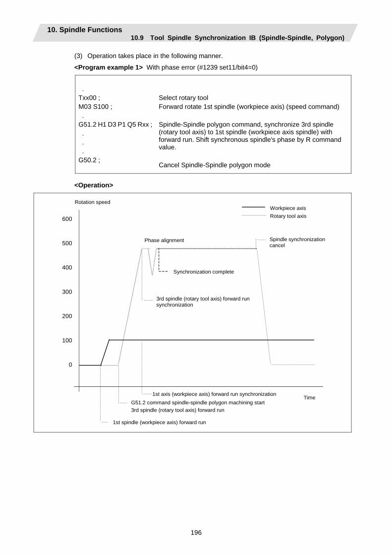
10. Spindle Functions 10.9 Tool Spindle Synchronization IB (Spindle-Spindle, Polygon)
196
(3) Operation takes place in the following manner.
<Program example 1> With phase error (#1239 set11/bit4=0)
. Txx00 ; M03 S100 ; . G51.2 H1 D3 P1 Q5 Rxx ; . . . G50.2 ;
Select rotary tool Forward rotate 1st spindle (workpiece axis) (speed command) Spindle-Spindle polygon command, synchronize 3rd spindle (rotary tool axis) to 1st spindle (workpiece axis spindle) with forward run. Shift synchronous spindle's phase by R command value. Cancel Spindle-Spindle polygon mode
<Operation>
Time
Phase alignment
1st axis (workpiece axis) forward run synchronization
1st spindle (workpiece axis) forward run
G51.2 command spindle-spindle polygon machining start 3rd spindle (rotary tool axis) forward run
Spindle synchronizationcancel
Workpiece axis Rotary tool axis
3rd spindle (rotary tool axis) forward run synchronization
Synchronization complete
Rotation speed
600
500
400
300
200
100
0
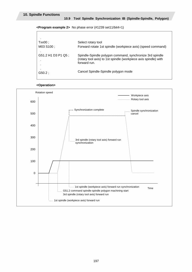
10. Spindle Functions 10.9 Tool Spindle Synchronization IB (Spindle-Spindle, Polygon)
197
<Program example 2> No phase error (#1239 set11/bit4=1)
. Txx00 ; M03 S100 ; . G51.2 H1 D3 P1 Q5 ; . . . G50.2 ;
Select rotary tool Forward rotate 1st spindle (workpiece axis) (speed command) Spindle-Spindle polygon command, synchronize 3rd spindle (rotary tool axis) to 1st spindle (workpiece axis spindle) with forward run. Cancel Spindle-Spindle polygon mode
<Operation>
600
500
400
300
200
100
0
Time
Synchronization complete
1st spindle (workpiece axis) forward run synchronization
1st spindle (workpiece axis) forward run
G51.2 command spindle-spindle polygon machining start 3rd spindle (rotary tool axis) forward run
Spindle synchronizationcancel
Workpiece axis Rotary tool axis
3rd spindle (rotary tool axis) forward run synchronization
Rotation speed
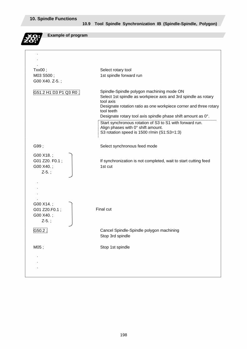
10. Spindle Functions 10.9 Tool Spindle Synchronization IB (Spindle-Spindle, Polygon)
198
Example of program
. . .
Txx00 ; Select rotary tool M03 S500 ; G00 X40. Z-5. ;
1st spindle forward run
G51.2 H1 D3 P1 Q3 R0 ;
Spindle-Spindle polygon machining mode ON Select 1st spindle as workpiece axis and 3rd spindle as rotary tool axis Designate rotation ratio as one workpiece corner and three rotarytool teeth Designate rotary tool axis spindle phase shift amount as 0°.
Start synchronous rotation of S3 to S1 with forward run. Align phases with 0° shift amount. S3 rotation speed is 1500 r/min (S1:S3=1:3)
G99 ; Select synchronous feed mode
G00 X18. ; G01 Z20. F0.1 ; G00 X40. ;
Z-5. ;
If synchronization is not completed, wait to start cutting feed 1st cut
. . . .
G00 X14. ; G01 Z20.F0.1 ; G00 X40. ;
Z-5. ;
Final cut
G50.2 ;
Cancel Spindle-Spindle polygon machining Stop 3rd spindle
M05 ; Stop 1st spindle
. . .

10. Spindle Functions 10.9 Tool Spindle Synchronization IB (Spindle-Spindle, Polygon)
199
Cautions for programming
(1) Always command G51.2 and G50.2 in independent blocks.
(2) The R command can be omitted when entering the Spindle-Spindle polygon mode, but the P and Q commands must always be issued. Failure to do so will cause a program error (P33).
(3) To change the P, Q or R modal value while in the Spindle-Spindle polygon mode, command G51.2 again. In this case, R can be commanded independently. However, if either P or Q is also changed, always command P and Q again.
(4) Commands can be issued to each part system, but two part systems cannot be used simultaneously. The part system commanded first will be valid, and the operation error 1005 will occur for that commanded last.
(5) The spindle No. designated in the parameters will be used if D_H_ is omitted from the G51.2 command.
(6) A program error (P610) will occur if the workpiece axis No. (#1518) and rotary tool axis No. (#1519) are the same as the value set in the parameters. Program error (P33) will occur if the spindle is not serially connected.
(7) The cutting feed block will not start until synchronization is established after the G51.2 command. (Operation will stop with the operation error 1033.)
Precautions and restrictions
(1) Limits to phase alignment control
(a) Make sure that the spindle (and workpiece axis spindle) actual rotation speed and encoder rotation speed's rotation ratio has the following relation.
Spindle rotation speed/encoder rotation speed = n (n is an integer higher than 1)
If this relation is not established, the encoder's reference position will not be set at a set spindle position. Thus, the phase (position) will deviate each time the phase alignment command is executed.
Note that even in this case, if the number of workpiece corners (number of rotary tool teeth) corresponds to the rotation ratio, the phase (position) of the blade and workpiece will not deviate. (Following relation)
(Workpiece axis spindle rotation speed ∗ number of workpiece teeth)/ encoder rotation speed = n (n is an integer higher than 1)
(b) During phase alignment control, the phases are aligned to the reference position of each spindle's encoder. Thus, if the positional relation of the workpiece and reference position (workpiece and reference position) deviates when the power is turned ON/OFF or the tool is replaced, etc., the phase will deviate.
(c) When the spindle speed is reached, the speed may decelerate momentarily because of phase synchronization separately from the above phase alignment control.
10. Spindle Functions 10.10 Tool Spindle Synchronization IC (Spindle-NC Axis, Polygon)
200
10.10 Tool Spindle Synchronization IC (Spindle-NC Axis, Polygon); G51.2 (Only 6 and 7 in G code list)
Function and purpose
This function carries out polygon machining by controlling the workpiece (spindle) and tool axis (NC servo axis) to rotate in synchronization at the commanded ratio.
Command format
(1) Polygon machining mode ON
G51.2 P_Q_ ; Spindle synchronization start (Start of polygon machining mode) P,Q
Spindle and rotary tool axis rotation ratio (P_:Q_) P : Spindle Q : Rotary tool axis Command range : Integer value between 1 and 9, –1 and –9 The rotation direction is designated with a sign. (+) : Forward rotation (–) : Reverse rotation
(2) Polygon machining mode OFF
G50.2 ; Spindle synchronization cancel (Polygon machining mode cancel)
Explanation of operation
Program Operation
S1000 ; The spindle rotation speed (workpiece rotation speed) is commanded G51.2 P1 Q2 ;
The polygon machining mode is entered with the G51.2 command. The spindle and rotary tool axis start rotating, and control is applied so that the spindle rotation speed and tool axis rotation speed are the commanded ratio (P:Q).
Cutting into workpiece
G50.2 ; The polygon machining mode between the spindle and rotary tool axis is canceled by the G50.2 command, and the spindle and rotary tool axis rotation stop.
The rotary tool axis is designated with the base specifications parameters "#1501 polyax".
Canceling the polygon machining mode
The polygon machining mode is canceled in the following cases.
• G50.2 command • Power OFF • Emergency stop • Reset (Reset 1, Reset 2, Reset & Rewind)
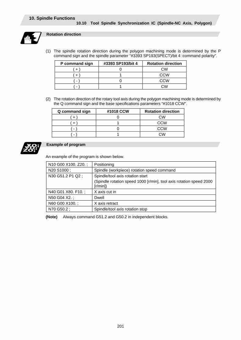
10. Spindle Functions 10.10 Tool Spindle Synchronization IC (Spindle-NC Axis, Polygon)
201
Rotation direction
(1) The spindle rotation direction during the polygon machining mode is determined by the P command sign and the spindle parameter "#3393 SP193(SPECT)/bit 4 :command polarity".
P command sign #3393 SP193/bit 4 Rotation direction ( + ) 0 CW ( + ) 1 CCW ( - ) 0 CCW ( - ) 1 CW
(2) The rotation direction of the rotary tool axis during the polygon machining mode is determined by
the Q command sign and the base specifications parameters "#1018 CCW".
Q command sign #1018 CCW Rotation direction ( + ) 0 CW ( + ) 1 CCW ( - ) 0 CCW ( - ) 1 CW
Example of program
An example of the program is shown below.
N10 G00 X100. Z20. ; Positioning N20 S1000 ; Spindle (workpiece) rotation speed command N30 G51.2 P1 Q2 ; Spindle/tool axis rotation start
(Spindle rotation speed 1000 [r/min], tool axis rotation speed 2000 [r/min])
N40 G01 X80. F10. ; X axis cut in N50 G04 X2. ; Dwell N60 G00 X100. ; X axis retract N70 G50.2 ; Spindle/tool axis rotation stop
(Note) Always command G51.2 and G50.2 in independent blocks.

10. Spindle Functions 10.10 Tool Spindle Synchronization IC (Spindle-NC Axis, Polygon)
202
Precautions
(1) The "spindle synchronization (Polygon)" specifications must be provided to use this function.
If G51.2 or G50.2 is commanded without the specifications, the program error (P39) will occur.
(2) Always command G51.2 and G50.2 in independent blocks. • If the G51.2 (G50.2) command and group 0 G code are commanded in the same block, the
G code commanded last in the block will have the priority. • If the G51.2 (G50.2) command and G code other than a group 0 code are commanded in
the same block, the program error (P33) will occur.
(3) While in the polygon machining mode, a movement command cannot be issued in the machining program for a servo axis set as the rotary tool axis. If a movement command is issued to the rotary tool axis during the polygon machining mode, the program error (P32) will occur.
(4) The servo axis set as the rotary tool axis can be used as a feed axis in modes other than the polygon machining mode.
(5) The following functions are invalid for the rotary tool axis during the polygon machining mode. • Override • Feed hold • Stored stroke limit
(6) The spindle rotation speed can be changed with the S command even during the polygon machining mode. The spindle override and spindle rotation speed clamp are also valid. If the spindle rotation speed is changed, the rotary tool axis rotation speed will also change so that the spindle and rotary tool axis establish the P:Q ratio.
(7) The forward run/reverse run commands are invalid for the spindle during the polygon machining mode.
(8) If the feed rate for the rotary tool axis exceeds the rapid traverse rate (axis specifications parameters "#2001 rapid") during the polygon machining mode, the speed will be clamped at the rapid traverse rate. If the rotary tool axis is clamped at the rapid traverse rate, the spindle speed will also be set to lower than the command speed so that the spindle and rotary tool axis establish the P:Q ratio.
(9) The position loop gain for the rotary tool axis will be the value set in the axis specifications parameters "#2017 tap_g" during the polygon machining mode. The position loop gain for the spindle will be the spindle parameters "#13002 PGN" setting value.
(10) The following functions cannot be used simultaneously with polygon machining. • Synchronous tap • Thread cutting
(11) If an axis other than the rotary tool axis reaches the stroke end during the polygon machining mode, the axis other than the rotary tool axis will stop moving, but the rotary tool axis and spindle rotation will not stop.
(12) If the rotary tool axis reaches the stroke end during the polygon machining mode, the rotary tool axis and spindle rotation will stop, and the movement of axes other than the rotary tool axis will also stop.
(13) By setting the spindle basic specifications parameters "#3106 zrn_typ/bit4" to "0", the polygon machining will start after the spindle returns to the zero point.
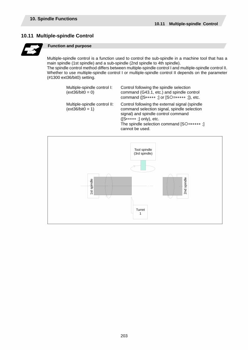
10. Spindle Functions 10.11 Multiple-spindle Control
203
10.11 Multiple-spindle Control
Function and purpose
Multiple-spindle control is a function used to control the sub-spindle in a machine tool that has a main spindle (1st spindle) and a sub-spindle (2nd spindle to 4th spindle). The spindle control method differs between multiple-spindle control I and multiple-spindle control II. Whether to use multiple-spindle control I or multiple-spindle control II depends on the parameter (#1300 ext36/bit0) setting.
Multiple-spindle control I: (ext36/bit0 = 0)
Control following the spindle selection command (G43.1, etc.) and spindle control command ([S∗∗∗∗∗ ;] or [S =∗∗∗∗∗ ;]), etc.
Multiple-spindle control II: (ext36/bit0 = 1)
Control following the external signal (spindle command selection signal, spindle selection signal) and spindle control command ([S∗∗∗∗∗ ;] only), etc. The spindle selection command [S =∗∗∗∗∗ ;] cannot be used.
Turret 1
1st s
pind
le
Tool spindle(3rd spindle)
2nd
spin
dle
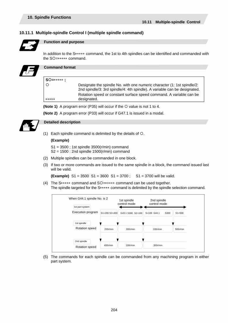
10. Spindle Functions 10.11 Multiple-spindle Control
204
10.11.1 Multiple-spindle Control I (multiple spindle command)
Function and purpose
In addition to the S∗∗∗∗∗ command, the 1st to 4th spindles can be identified and commanded with the S =∗∗∗∗∗ command.
Command format
S =∗∗∗∗∗ ;
∗∗∗∗∗
Designate the spindle No. with one numeric character (1: 1st spindle/2: 2nd spindle/3: 3rd spindle/4: 4th spindle). A variable can be designated. Rotation speed or constant surface speed command. A variable can be designated.
(Note 1) A program error (P35) will occur if the value is not 1 to 4.
(Note 2) A program error (P33) will occur if G47.1 is issued in a modal.
Detailed description
(1) Each spindle command is delimited by the details of .
(Example)
S1 = 3500 ; 1st spindle 3500(r/min) command S2 = 1500 : 2nd spindle 1500(r/min) command
(2) Multiple spindles can be commanded in one block.
(3) If two or more commands are issued to the same spindle in a block, the command issued last will be valid.
(Example) S1 = 3500 S1 = 3600 S1 = 3700 ; S1 = 3700 will be valid.
(4) The S∗∗∗∗∗ command and S =∗∗∗∗∗ command can be used together. The spindle targeted for the S∗∗∗∗∗ command is delimited by the spindle selection command.
1st part system
Execution program S1=200 S2=400 G43.1 S300 S2=100
Rotation speed
1st spindle
G44.1 S300
200r/min 300r/min
400r/min
S=100
100r/min
S1=500
500r/min
100r/min 300r/min
1st spindle control mode
2nd spindle control mode
When G44.1 spindle No. is 2
2nd spindle
Rotation speed
(5) The commands for each spindle can be commanded from any machining program in either part system.

10. Spindle Functions 10.11 Multiple-spindle Control
205
10.11.2 Multiple-spindle Control I (spindle selection command)
Function and purpose
The following S commands (S∗∗∗∗) can be changed for the 1st spindle to 4th spindle by issuing the spindle selection command (G43.1, etc. [G group 20]).
Command format
G43.1; G44.1; G47.1;
1st spindle control mode ON Selected spindle control mode ON (Selected spindle No. is set with SnG44.1) All spindles simultaneous control mode ON
Detailed description
(1) The selected spindle No. is set with the parameter (#1534 SnG44.1).
(2) The spindle selection commands are modal G codes.
(3) A program error (P33) will occur if the spindle selection command is issued while the multiple-spindle control II mode is valid.
(4) The spindle control mode entered when the power is turned ON or reset can be set with the parameters for each part system. The state when the power is turned ON or reset is as follows.
G group 20 modal state Set with setup parameter "#1199 Sselect". 0:G43.1 1:G44.1 2:G47.1
G44.1 spindle No. Set with setup parameter "#1534 SnG44.1". 0:2nd spindle 1:1st spindle 2:2nd spindle 3:3rd spindle 4:4th spindle
(5) If the S command is issued in the same block as the spindle selection command, it will be valid
for the spindle switched to with the spindle selection command.
Example) G43.1 S100 ; S200 G44.1 S300 ; (SnG44.1=2)
→ →
Command 100 rotations for 1st spindle. After commanding 200 rotations for 1st spindle, command 300 rotations for 2nd spindle.
(6) If a spindle that does not exist is set, the 2nd spindle will be used. Note that if there is only one spindle, the 1st spindle will be used.
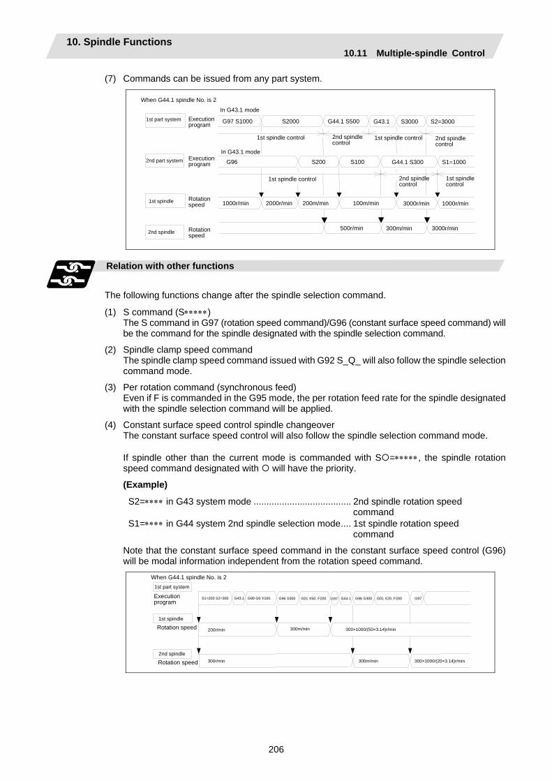
10. Spindle Functions 10.11 Multiple-spindle Control
206
(7) Commands can be issued from any part system.
1st part system Execution program G97 S1000 S2000
In G43.1 mode
G44.1 S500 G43.1 S3000 S2=3000
G96 S200 S100 G44.1 S300 S1=1000
Rotation speed 1000r/min 2000r/min 200m/min 100m/min 3000r/min 1000r/min
1st spindle control 2nd spindle control
500r/min 300m/min 3000r/min
1st spindle
When G44.1 spindle No. is 2
2nd part system
2nd spindle
Execution program
Rotation speed
In G43.1 mode
1st spindle control 2nd spindle control
1st spindle control 1st spindle control
2nd spindle control
Relation with other functions
The following functions change after the spindle selection command.
(1) S command (S∗∗∗∗∗) The S command in G97 (rotation speed command)/G96 (constant surface speed command) will
be the command for the spindle designated with the spindle selection command.
(2) Spindle clamp speed command The spindle clamp speed command issued with G92 S_Q_ will also follow the spindle selection
command mode.
(3) Per rotation command (synchronous feed) Even if F is commanded in the G95 mode, the per rotation feed rate for the spindle designated
with the spindle selection command will be applied.
(4) Constant surface speed control spindle changeover The constant surface speed control will also follow the spindle selection command mode. If spindle other than the current mode is commanded with S =∗∗∗∗∗, the spindle rotation
speed command designated with will have the priority.
(Example)
S2=∗∗∗∗ in G43 system mode ...................................... 2nd spindle rotation speed command S1=∗∗∗∗ in G44 system 2nd spindle selection mode.... 1st spindle rotation speed command
Note that the constant surface speed command in the constant surface speed control (G96) will be modal information independent from the rotation speed command.
1st part system
Execution program
S1=200 S2=300 G43.1 G90 G0 X100. G96 S300 G01 X50. F200 G97
Rotation speed 1st spindle
G44.1 G96 S300 G01 X20. F200
200r/min 300m/min 300×1000/(50×3.14)r/min
G97
300r/min 300m/min 300×1000/(20×3.14)r/min
When G44.1 spindle No. is 2
Rotation speed 2nd spindle

10. Spindle Functions 10.11 Multiple-spindle Control
207
Spindle control rights
If the constant surface speed control, S command and spindle related M command are commanded arbitrarily from each part system to one spindle, the spindle may not operate correctly. For example, if S is commanded (feed per minute) during constant surface speed control with 1st part system, the rotation speed will not change from the 1st part system side, and the actual rotation speed will relay on 2nd part system from which S was commanded last. These commands must be commanded from only one part system, or commanded simultaneously while using standby, etc.
1st part system Execution program G43.1 G01 X10. . . .
1st spindlerotation speed
200r/min
S100
0r/min 100r/min
G0 X50.
G43.1 G01 X30. . . . G0 X50. S200 G01 X10.
After this, 1st part system will machine S200 even if it appears to be S100
2nd part system
1st part system
2nd part system
Execution program
1st spindlecontrol rights
[Spindle control rights transfer conditions] When G44.1 spindle No. is 2
(1) The part system that commanded the S command last has the spindle control rights.
G97 S1000 G44.1 S500 G43.1 S3000 S2=3000
G0 X50. G43.1 G96 S200 S100 G44.1 S300 S1=1000
G43.11st part system Execution program
1st spindle control rights
2nd part system Execution program
2nd spindle control rights
1st part system
1st part system 1st part system
2nd part system
2nd part system
2nd part system 1st part system
(2) If different S commands are executed simultaneously in two part systems, the part system with the larger part system No. will have the priority. That part system will also have the control rights.
G43.1
G43.1 S200
S100
. . .
. . .
200r/min
S200
S300
200r/min
. . .
300r/min
1st part system Execution program
1st spindlerotation speed
1st spindlecontrol rights
2nd part system Execution program
1st part system
2nd part system
1st part system
2nd part system
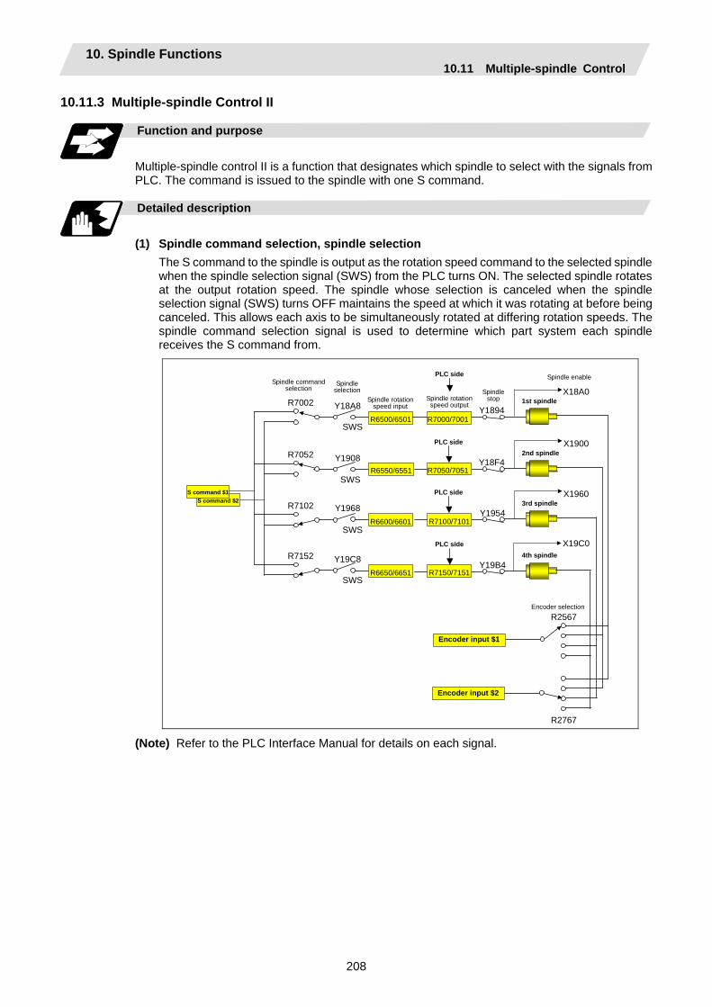
10. Spindle Functions 10.11 Multiple-spindle Control
208
10.11.3 Multiple-spindle Control II
Function and purpose
Multiple-spindle control II is a function that designates which spindle to select with the signals from PLC. The command is issued to the spindle with one S command.
Detailed description
(1) Spindle command selection, spindle selection The S command to the spindle is output as the rotation speed command to the selected spindle
when the spindle selection signal (SWS) from the PLC turns ON. The selected spindle rotates at the output rotation speed. The spindle whose selection is canceled when the spindle selection signal (SWS) turns OFF maintains the speed at which it was rotating at before being canceled. This allows each axis to be simultaneously rotated at differing rotation speeds. The spindle command selection signal is used to determine which part system each spindle receives the S command from.
S command $2 S command $1
Y18A8 Y1894
Y1908
Y1968
Y19C8
1st spindle
R6500/6501
R6550/6551Y18F4
2nd spindle
Y1954 3rd spindle
R6600/6601
R6650/6651Y19B4
4th spindle
X18A0
X1900
X1960
X19C0
R7002
R7052
R7102
R7152
Encoder input $2
Encoder input $1
R2567
R2767
R7000/7001
R7050/7051
R7100/7101
R7150/7151
PLC side
PLC side
PLC side
PLC side
Spindle rotation speed output
Spindle stop
Encoder selection
Spindle command selection Spindle
selection
Spindle enable
SWS
SWS
SWS
SWS
Spindle rotation speed input
(Note) Refer to the PLC Interface Manual for details on each signal.

10. Spindle Functions 10.11 Multiple-spindle Control
209
Relation with other functions
(1) Spindle clamp speed setting (G92) This is valid only on the spindle selected with the spindle selection signal (SWS). The spindle not selected with the spindle selection signal (SWS) maintains the speed at which
it was rotating at before being canceled. (The spindle clamp speed is maintained with the G92 command.)
(2) Constant surface speed control Constant surface speed control can be applied on all spindles. The spindle rotation speed is automatically controlled during constant surface speed control, so
when machining with constant surface speed, the spindle selection signal (SWS) for that spindle must be left ON.
The spindle not selected with the spindle selection signal (SWS) maintains the speed at which it was rotating at before being canceled.
(3) Thread cutting/synchronous feed The threads are cut with the spindle selected with the spindle selection signal (SWS). The
encoder feedback selected with the encoder selection signal is used.
(4) Polygon machining (servo-spindle) The polygon machining spindle is selected with the spindle selection signal (SWS). Do not
select the polygon machining spindle multiple times, and do not change the polygon machining spindle selection signal during the polygon machining mode.
If a C axis mode command is issued to the polygon machining spindle, the "M01 operation error 1026" will occur. When the C axis command is canceled, the error will be canceled and machining will resume.
If synchronous tap is commanded during polygon machining, a program error (P34) will occur.
(5) Synchronous tap The synchronous tap spindle is selected with the spindle selection signal (SWS). Select the synchronous tap spindle before issuing the synchronous tap command. Do not
change the synchronous tap spindle selection signal during the synchronous tapping mode. If a C axis mode command is issued to the synchronous tap spindle, the "M01 operation error
1026" will occur. When the C axis command is canceled, the error will be canceled and machining will resume.
If a polygon machining command is issued to the synchronous tap spindle, the "M01 operation error 1026" will occur. When the polygon machining command is canceled, the error will be canceled and machining will resume.
(6) Asynchronous tap The asynchronous tap spindle is selected with the spindle selection signal (SWS). Select the asynchronous tap spindle before issuing the tap command. Input a calculation request
to change the asynchronous tap spindle selection. Do not change the asynchronous tap spindle selection signal during the asynchronous tapping mode.
(7) Tapping retract The tapping retract spindle is selected with the spindle selection signal (SWS). Select the spindle for which the tap cycle execution in stopped before turning the tapping
retract signal ON. If tapping retract is executed when a different spindle is selected, the "M01 operation error
1032" will occur. Do not change the spindle selection signal during tapping retract.
10. Spindle Functions 10.11 Multiple-spindle Control
210
Restrictions
(1) The S manual numerical value command is invalid when multiple-spindle control II is valid.
(2) Setup parameter "#1199 Sselect" is invalid when multiple-spindle control II is valid.
(3) The spindle control mode changeover G code cannot be used when multiple-spindle control II is valid. A program error (P34) will occur.
(4) The "S1=∗∗∗" and "S2=∗∗∗" commands are invalid when multiple-spindle control II is valid. A program error (P33) will occur.
(5) The spindle gear shift command output signal (GR1/GR2) is not output when multiple-spindle control II is valid.
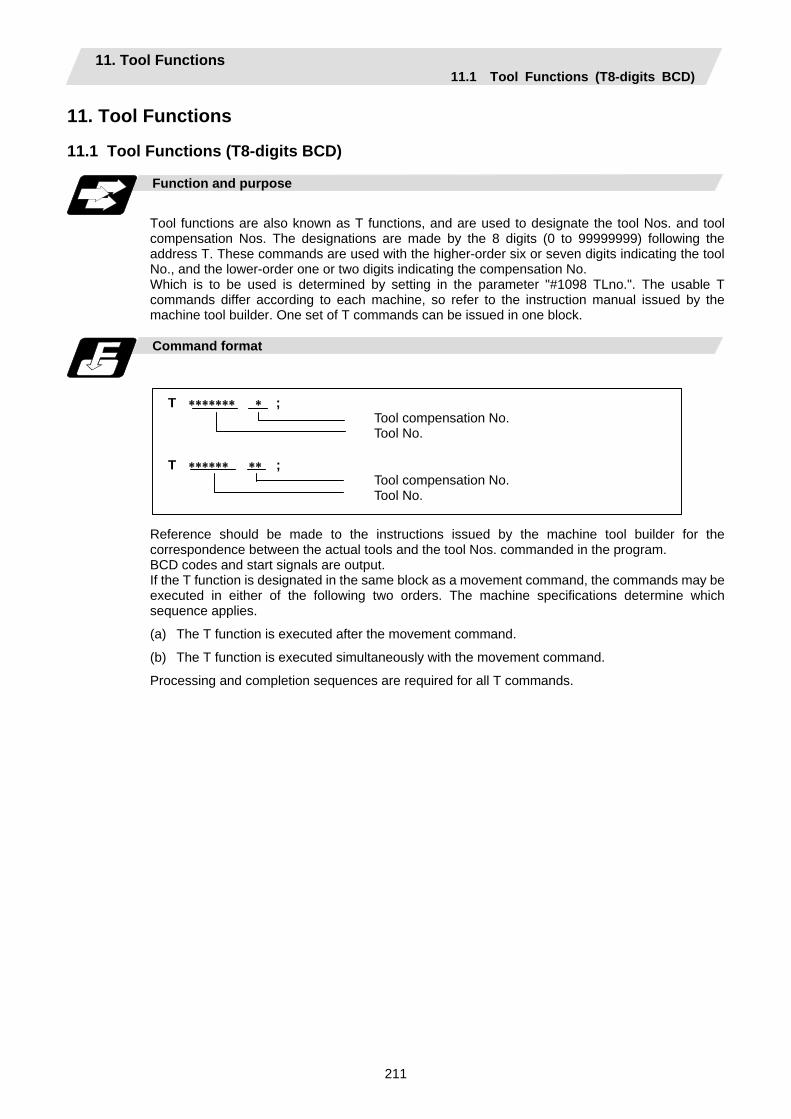
11. Tool Functions 11.1 Tool Functions (T8-digits BCD)
211
11. Tool Functions 11.1 Tool Functions (T8-digits BCD)
Function and purpose
Tool functions are also known as T functions, and are used to designate the tool Nos. and tool compensation Nos. The designations are made by the 8 digits (0 to 99999999) following the address T. These commands are used with the higher-order six or seven digits indicating the tool No., and the lower-order one or two digits indicating the compensation No. Which is to be used is determined by setting in the parameter "#1098 TLno.". The usable T commands differ according to each machine, so refer to the instruction manual issued by the machine tool builder. One set of T commands can be issued in one block.
Command format
T ∗∗∗∗∗∗∗ ∗ ; Tool compensation No. Tool No.
T ∗∗∗∗∗∗ ∗∗ ;
Tool compensation No. Tool No.
Reference should be made to the instructions issued by the machine tool builder for the correspondence between the actual tools and the tool Nos. commanded in the program. BCD codes and start signals are output. If the T function is designated in the same block as a movement command, the commands may be executed in either of the following two orders. The machine specifications determine which sequence applies.
(a) The T function is executed after the movement command.
(b) The T function is executed simultaneously with the movement command.
Processing and completion sequences are required for all T commands.
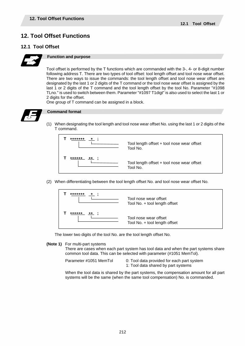
12. Tool Offset Functions 12.1 Tool Offset
212
12. Tool Offset Functions
12.1 Tool Offset
Function and purpose
Tool offset is performed by the T functions which are commanded with the 3-, 4- or 8-digit number following address T. There are two types of tool offset: tool length offset and tool nose wear offset. There are two ways to issue the commands: the tool length offset and tool nose wear offset are designated by the last 1 or 2 digits of the T command or the tool nose wear offset is assigned by the last 1 or 2 digits of the T command and the tool length offset by the tool No. Parameter "#1098 TLno." is used to switch between them. Parameter "#1097 T1digt" is also used to select the last 1 or 2 digits for the offset. One group of T command can be assigned in a block.
Command format
(1) When designating the tool length and tool nose wear offset No. using the last 1 or 2 digits of the
T command.
T ∗∗∗∗∗∗∗ ∗ ; Tool length offset + tool nose wear offset Tool No.
T ∗∗∗∗∗∗ ∗∗ ;
Tool length offset + tool nose wear offset Tool No.
(2) When differentiating between the tool length offset No. and tool nose wear offset No.
T ∗∗∗∗∗∗∗ ∗ ; Tool nose wear offset Tool No. + tool length offset
T ∗∗∗∗∗∗ ∗∗ ;
Tool nose wear offset Tool No. + tool length offset
The lower two digits of the tool No. are the tool length offset No.
(Note 1) For multi-part systems
There are cases when each part system has tool data and when the part systems share common tool data. This can be selected with parameter (#1051 MemTol).
Parameter #1051 MemTol 0: Tool data provided for each part system 1: Tool data shared by part systems
When the tool data is shared by the part systems, the compensation amount for all part systems will be the same (when the same tool compensation) No. is commanded.
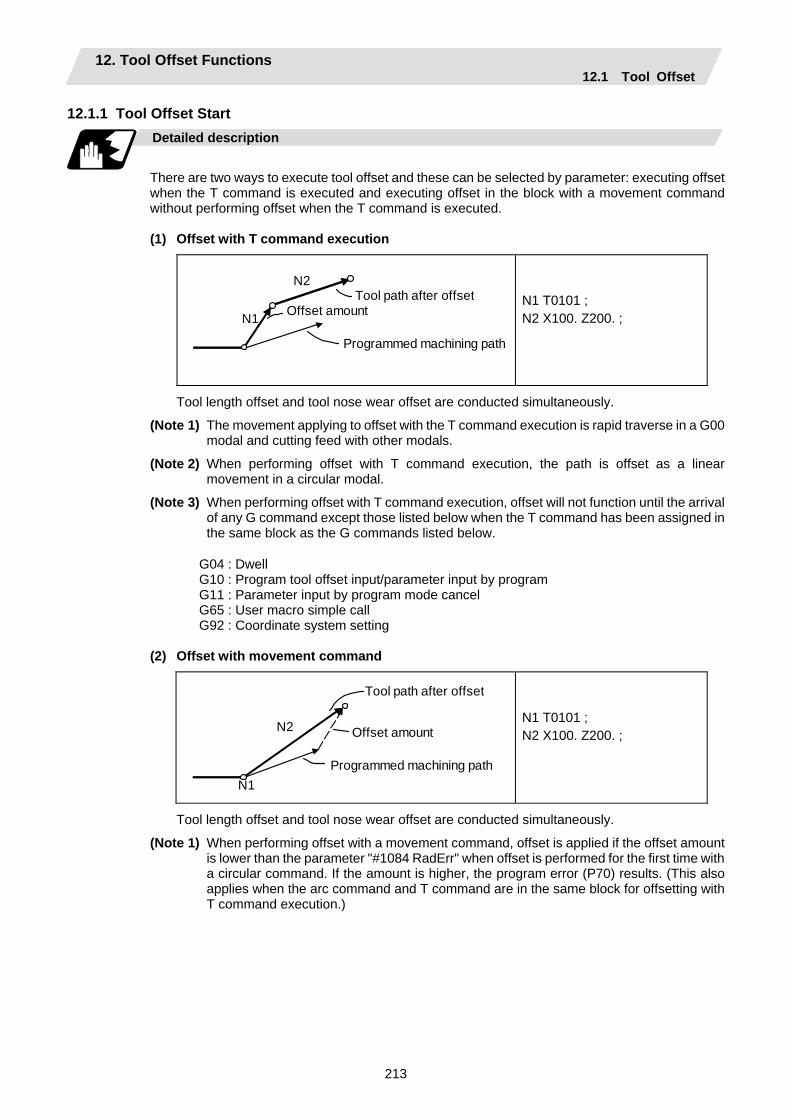
12. Tool Offset Functions 12.1 Tool Offset
213
12.1.1 Tool Offset Start
Detailed description
There are two ways to execute tool offset and these can be selected by parameter: executing offset when the T command is executed and executing offset in the block with a movement command without performing offset when the T command is executed.
(1) Offset with T command execution
N1
N2 Tool path after offset
Offset amount
Programmed machining path
N1 T0101 ; N2 X100. Z200. ;
Tool length offset and tool nose wear offset are conducted simultaneously.
(Note 1) The movement applying to offset with the T command execution is rapid traverse in a G00 modal and cutting feed with other modals.
(Note 2) When performing offset with T command execution, the path is offset as a linear movement in a circular modal.
(Note 3) When performing offset with T command execution, offset will not function until the arrival of any G command except those listed below when the T command has been assigned in the same block as the G commands listed below.
G04 : Dwell G10 : Program tool offset input/parameter input by program G11 : Parameter input by program mode cancel G65 : User macro simple call G92 : Coordinate system setting
(2) Offset with movement command
N1
N2
Tool path after offset
Offset amount
Programmed machining path
N1 T0101 ; N2 X100. Z200. ;
Tool length offset and tool nose wear offset are conducted simultaneously.
(Note 1) When performing offset with a movement command, offset is applied if the offset amount is lower than the parameter "#1084 RadErr" when offset is performed for the first time with a circular command. If the amount is higher, the program error (P70) results. (This also applies when the arc command and T command are in the same block for offsetting with T command execution.)
12. Tool Offset Functions 12.1 Tool Offset
214
12.1.2 Expanded Method at Starting Tool Offset
Function and purpose
By setting the parameter "#1100 Tmove", the offset operation when T is commanded is selected whether that is carried out when the T command is executed or carried out with superimposed on the movement command. In addition to these two methods, a type to compensate only the wear amount when the T command is executed and to compensate the tool length superimposed on the movement command can be selected with the parameter.
Detailed description
To select the type to compensate only the wear amount when the T command is executed and to compensate the tool length superimposed on the movement command, set the "#1100 Tmove" to 2. When 2 is set, the length offset will follow setting 1 (superimposed on movement command), and the wear offset will follow setting 0 (move when T is commanded). The offset operation for each "#1100 Tmove" setting is as shown below.
When Length offset amount: 7.000mm Wear offset amount: 0.500mm
Machining program example Machine value
#1100 Tmove = 0 #1100 Tmove = 1 #1100 Tmove = 2 G28 X. ; 0.000 0.000 0.000 G0 T116. ; 7.500 0.000 0.500 G0 X100. ; 107.500 107.500 107.500 :
(Note 1) If the following G commands are issued in the same block as the T command, the wear will not be compensated in that block.
Same block compensation standby: G04, G10, G11, G65, G92 The wear amount will be compensated in a block where other G commands are issued.
(All axes)
(Note 2) After the offset amount is temporarily canceled, the offset amount will return for each movement command axis. The movement at this time will follow parameter "#1101 Tabsmv" for both length offset and wear offset.
G command involving temporary cancel: G28, G30, G53
(1) Relation with "#1101 Tabsmv" (tool offset amount superimposition during absolute command) When "#1100 Tmove" is set to 2, the offset operation will follow the "#1101 Tabsmv" setting.
12. Tool Offset Functions 12.1 Tool Offset
215
(2) Parameters
# Items Details Setting range
1100 Tmove Designate the timing to perform tool length offset and wear offset.
0: Compensates when T command is executed. 1: Superimposes and compensates with the movement
command in the block where the T command is located. If there is no movement command in the same block‚ compensation will be executed after the movement command is superimposed in the next movement command block.
2: Compensates wear amount when the T command is executed. Superimposes and compensates a tool length offset amount with the movement command in the same block. If there is no movement command in the same block, compensation will be executed after the movement command is superimposed in the next movement command block.
0 to 2
1101 Tabsmv Designate the type of movement command superimposed when #1100 Tmove is set to 1 or 2.
0: Compensates regardless of the movement command type.
1: Compensates only at the movement command in the absolute value command.
0,1
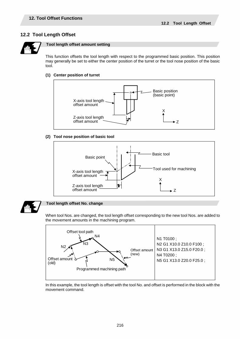
12. Tool Offset Functions 12.2 Tool Length Offset
216
12.2 Tool Length Offset
Tool length offset amount setting
This function offsets the tool length with respect to the programmed basic position. This position may generally be set to either the center position of the turret or the tool nose position of the basic tool.
(1) Center position of turret
X
Z
Basic position (basic point)
X-axis tool length offset amount
Z-axis tool lengthoffset amount
(2) Tool nose position of basic tool
X
Z
Basic point
Tool used for machining X-axis tool lengthoffset amount
Z-axis tool lengthoffset amount
Basic tool
Tool length offset No. change
When tool Nos. are changed, the tool length offset corresponding to the new tool Nos. are added to the movement amounts in the machining program.
N5
N2 N3
N4
Offset amount (old)
Programmed machining path
Offset amount(new)
Offset tool path
N1 T0100 ; N2 G1 X10.0 Z10.0 F100 ; N3 G1 X13.0 Z15.0 F20.0 ; N4 T0200 ; N5 G1 X13.0 Z20.0 F25.0 ;
In this example, the tool length is offset with the tool No. and offset is performed in the block with the movement command.
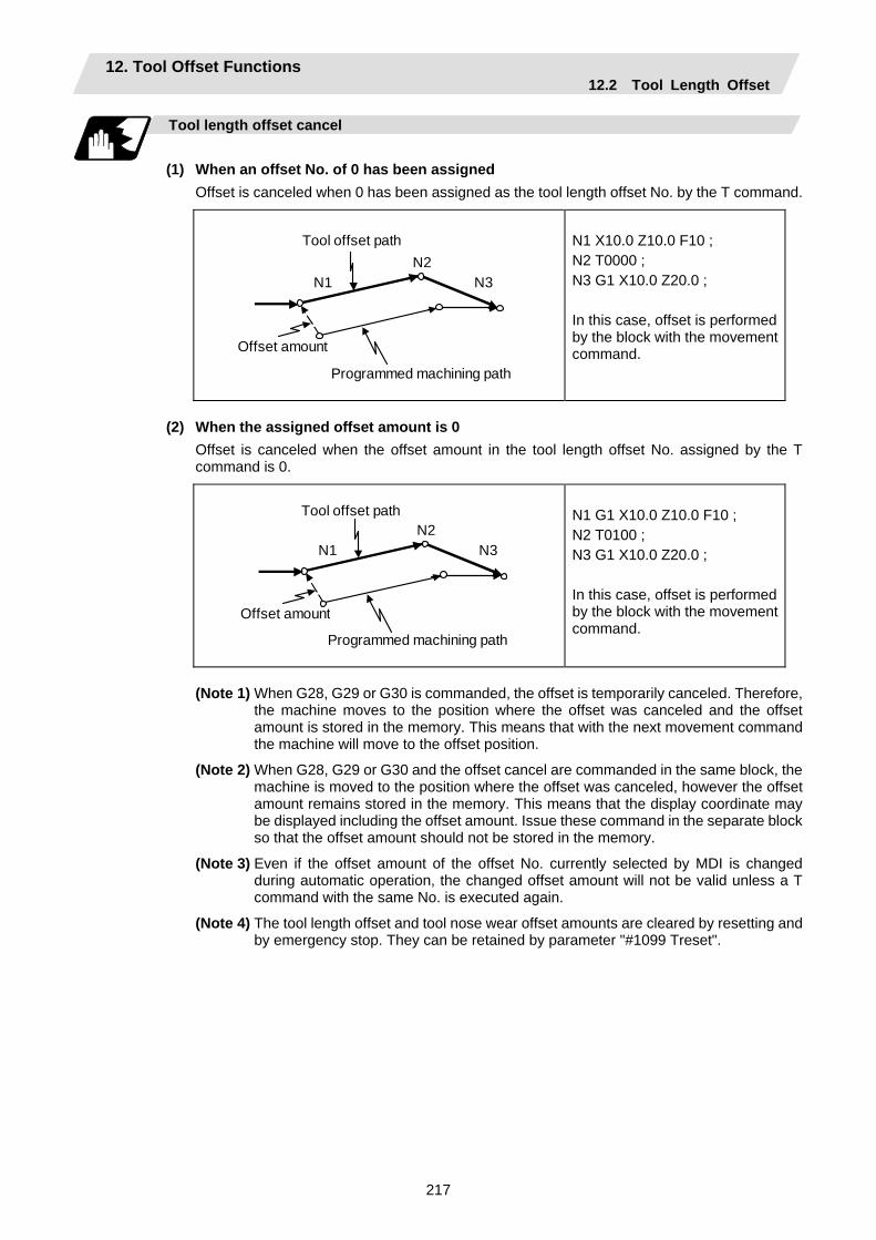
12. Tool Offset Functions 12.2 Tool Length Offset
217
Tool length offset cancel
(1) When an offset No. of 0 has been assigned
Offset is canceled when 0 has been assigned as the tool length offset No. by the T command.
N2N3N1
Tool offset path
Offset amount
Programmed machining path
N1 X10.0 Z10.0 F10 ; N2 T0000 ; N3 G1 X10.0 Z20.0 ; In this case, offset is performed by the block with the movement command.
(2) When the assigned offset amount is 0
Offset is canceled when the offset amount in the tool length offset No. assigned by the T command is 0.
N2
N3N1
Tool offset path
Offset amount
Programmed machining path
N1 G1 X10.0 Z10.0 F10 ; N2 T0100 ; N3 G1 X10.0 Z20.0 ; In this case, offset is performed by the block with the movement command.
(Note 1) When G28, G29 or G30 is commanded, the offset is temporarily canceled. Therefore,
the machine moves to the position where the offset was canceled and the offset amount is stored in the memory. This means that with the next movement command the machine will move to the offset position.
(Note 2) When G28, G29 or G30 and the offset cancel are commanded in the same block, the machine is moved to the position where the offset was canceled, however the offset amount remains stored in the memory. This means that the display coordinate may be displayed including the offset amount. Issue these command in the separate block so that the offset amount should not be stored in the memory.
(Note 3) Even if the offset amount of the offset No. currently selected by MDI is changed during automatic operation, the changed offset amount will not be valid unless a T command with the same No. is executed again.
(Note 4) The tool length offset and tool nose wear offset amounts are cleared by resetting and by emergency stop. They can be retained by parameter "#1099 Treset".
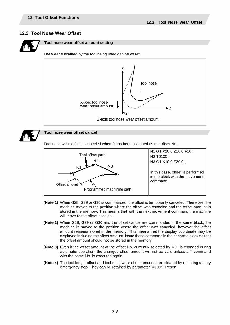
12. Tool Offset Functions 12.3 Tool Nose Wear Offset
218
12.3 Tool Nose Wear Offset
Tool nose wear offset amount setting
The wear sustained by the tool being used can be offset.
X
Z
Tool nose
X-axis tool nose wear offset amount
Z-axis tool nose wear offset amount
Tool nose wear offset cancel
Tool nose wear offset is canceled when 0 has been assigned as the offset No.
N2
N3N1
Tool offset path
Offset amount Programmed machining path
N1 G1 X10.0 Z10.0 F10 ; N2 T0100 ; N3 G1 X10.0 Z20.0 ; In this case, offset is performed in the block with the movement command.
(Note 1) When G28, G29 or G30 is commanded, the offset is temporarily canceled. Therefore, the
machine moves to the position where the offset was canceled and the offset amount is stored in the memory. This means that with the next movement command the machine will move to the offset position.
(Note 2) When G28, G29 or G30 and the offset cancel are commanded in the same block, the machine is moved to the position where the offset was canceled, however the offset amount remains stored in the memory. This means that the display coordinate may be displayed including the offset amount. Issue these command in the separate block so that the offset amount should not be stored in the memory.
(Note 3) Even if the offset amount of the offset No. currently selected by MDI is changed during automatic operation, the changed offset amount will not be valid unless a T command with the same No. is executed again.
(Note 4) The tool length offset and tool nose wear offset amounts are cleared by resetting and by emergency stop. They can be retained by parameter "#1099 Treset".

12. Tool Offset Functions 12.4 Tool Nose Radius Compensation
219
12.4 Tool Nose Radius Compensation; G40, G41, G42, G46
Function and purpose
The tool nose is generally rounded and so a hypothetical tool nose point is treated as the tool nose for programming purposes. When this is done, an error caused by the tool nose rounding arises during taper cutting or circular cutting between the actually programmed shape and the cutting shape. Tool nose radius compensation is a function for automatically calculating and offsetting this error by setting the tool nose radius value. The command codes enable the offset direction to be fixed or automatically identified.
R
Actual machining shape
Machining shape commanded in program
Hypothetical tool nose point
Tool nose center path at programmed machining shape
Tool nose center
Functions and command formats
Code Function Command format G40 Tool nose radius compensation mode cancel G40 (Xx/Uu Zz/Ww Ii Kk) ; G41 Tool nose radius compensation left mode ON G41 (Xx/Uu Zz/Ww) ; G42 Tool nose radius compensation right mode ON G42 (Xx/Uu Zz/Ww) ; G46 Tool nose radius compensation automatic
direction identification mode ON G46 (Xx/Uu Zz/Ww) ;
(Note 1) By means of the preset hypothetical tool nose point and movement commands in the
machining program, the G46 tool nose radius compensation function automatically identifies the compensation direction and provides tool nose radius compensation.
(Note 2) G40 serves to cancel the tool nose radius compensation mode.
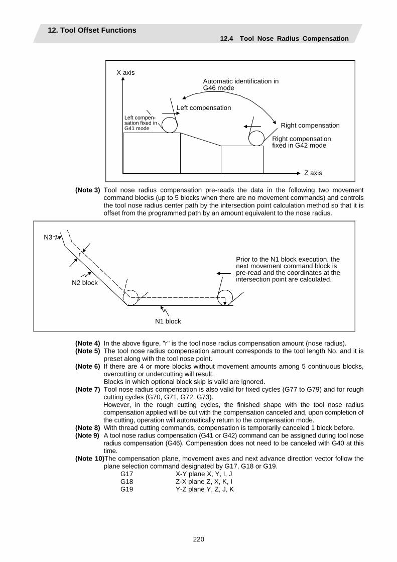
12. Tool Offset Functions 12.4 Tool Nose Radius Compensation
220
Right compensation
Right compensation fixed in G42 mode
Z axis
Automatic identification in G46 mode
Left compensationLeft compen- sation fixed in G41 mode
X axis
(Note 3) Tool nose radius compensation pre-reads the data in the following two movement command blocks (up to 5 blocks when there are no movement commands) and controls the tool nose radius center path by the intersection point calculation method so that it is offset from the programmed path by an amount equivalent to the nose radius.
r Prior to the N1 block execution, the next movement command block is pre-read and the coordinates at the intersection point are calculated.
N3
N2 block
N1 block
(Note 4) In the above figure, "r" is the tool nose radius compensation amount (nose radius). (Note 5) The tool nose radius compensation amount corresponds to the tool length No. and it is
preset along with the tool nose point. (Note 6) If there are 4 or more blocks without movement amounts among 5 continuous blocks,
overcutting or undercutting will result. Blocks in which optional block skip is valid are ignored. (Note 7) Tool nose radius compensation is also valid for fixed cycles (G77 to G79) and for rough
cutting cycles (G70, G71, G72, G73). However, in the rough cutting cycles, the finished shape with the tool nose radius
compensation applied will be cut with the compensation canceled and, upon completion of the cutting, operation will automatically return to the compensation mode.
(Note 8) With thread cutting commands, compensation is temporarily canceled 1 block before. (Note 9) A tool nose radius compensation (G41 or G42) command can be assigned during tool nose
radius compensation (G46). Compensation does not need to be canceled with G40 at this time.
(Note 10)The compensation plane, movement axes and next advance direction vector follow the plane selection command designated by G17, G18 or G19.
G17 X-Y plane X, Y, I, J G18 Z-X plane Z, X, K, I G19 Y-Z plane Y, Z, J, K
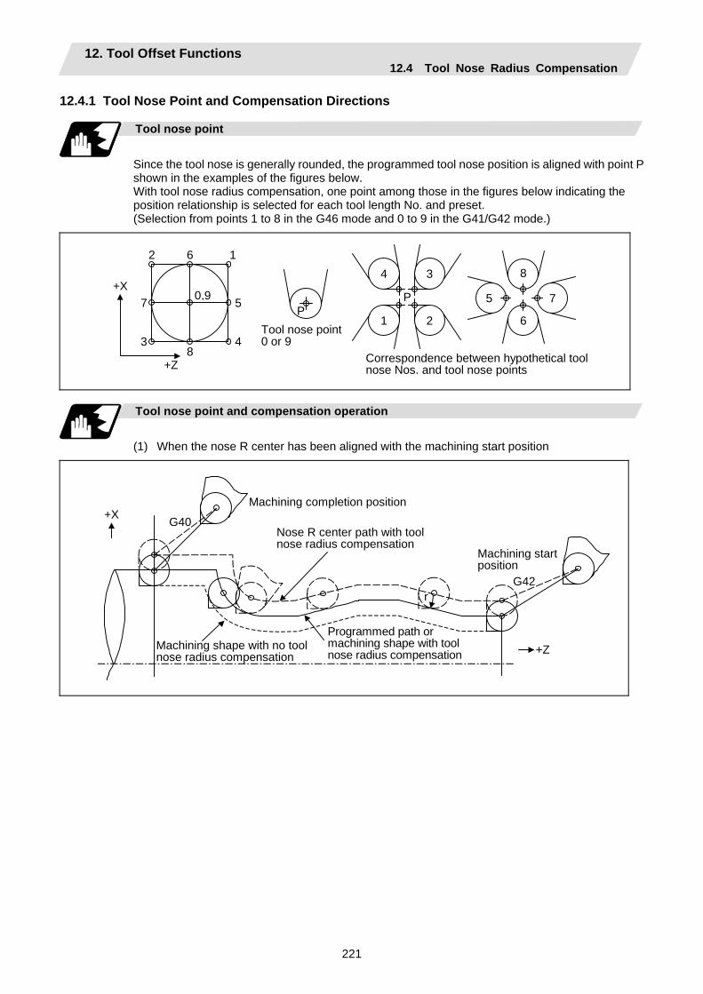
12. Tool Offset Functions 12.4 Tool Nose Radius Compensation
221
12.4.1 Tool Nose Point and Compensation Directions
Tool nose point
Since the tool nose is generally rounded, the programmed tool nose position is aligned with point P shown in the examples of the figures below. With tool nose radius compensation, one point among those in the figures below indicating the position relationship is selected for each tool length No. and preset. (Selection from points 1 to 8 in the G46 mode and 0 to 9 in the G41/G42 mode.)
PP
1 2
3 4
5
6
7
8
+X 0,9
+Z
1 2
34
5
6
7
8
Tool nose point 0 or 9
Correspondence between hypothetical tool nose Nos. and tool nose points
Tool nose point and compensation operation
(1) When the nose R center has been aligned with the machining start position
+X
+Z
G42
G40
r
Machining completion position
Nose R center path with tool nose radius compensation
Machining start position
Machining shape with no toolnose radius compensation
Programmed path ormachining shape with tool nose radius compensation
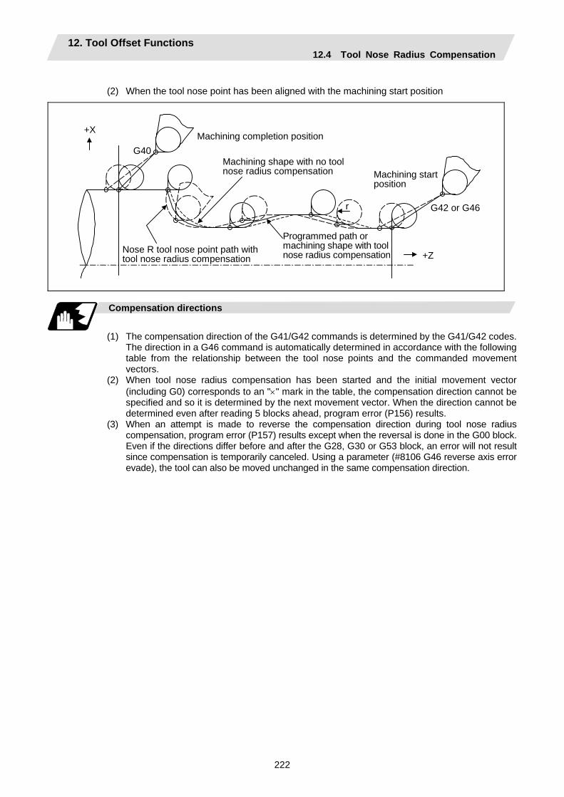
12. Tool Offset Functions 12.4 Tool Nose Radius Compensation
222
(2) When the tool nose point has been aligned with the machining start position
+X
+Z
G40
r
Machining completion position
Machining shape with no tool nose radius compensation Machining start
position
Nose R tool nose point path withtool nose radius compensation
Programmed path ormachining shape with tool nose radius compensation
G42 or G46
Compensation directions
(1) The compensation direction of the G41/G42 commands is determined by the G41/G42 codes.
The direction in a G46 command is automatically determined in accordance with the following table from the relationship between the tool nose points and the commanded movement vectors.
(2) When tool nose radius compensation has been started and the initial movement vector (including G0) corresponds to an "×" mark in the table, the compensation direction cannot be specified and so it is determined by the next movement vector. When the direction cannot be determined even after reading 5 blocks ahead, program error (P156) results.
(3) When an attempt is made to reverse the compensation direction during tool nose radius compensation, program error (P157) results except when the reversal is done in the G00 block. Even if the directions differ before and after the G28, G30 or G53 block, an error will not result since compensation is temporarily canceled. Using a parameter (#8106 G46 reverse axis error evade), the tool can also be moved unchanged in the same compensation direction.

12. Tool Offset Functions 12.4 Tool Nose Radius Compensation
223
(4) When the compensation direction during tool nose radius compensation coincides with an "×"
in the table below, the direction complied with the previous compensation direction. Determining the compensation direction by the movement vectors and tool nose point in command G46
Tool nose points Compensation
direction of tool nose
Direction of tool nose advance
Compensation direction of tool nose
Direction of tool nose advance
Right Right Left Left Right Left
Right Left Left Right Right Left
Left Right Right Left Left Right
Left Right Left Left Right Right
Left Left Right Right Left Right
Left Right Right Left Left Right
Right Left Left Right Right Left
Move- ment vector (tool nose points 1 to 4)
Right Left Right Right Left Left
Move- ment vector (tool nose points 5 to 8)
(Note 1) An "×" mark in the tables indicates that the compensation direction is not determined from
the movement vector (tool nose points).
(Note 2) The " " mark denotes a movement vector in the 45° direction. (The other movement vectors are based on this.)
(Note 3) The " " mark denotes a movement vector with a range larger than 45° and smaller than 135°. (The other movement vectors are based on this.)
2 3 4 5 6 7 8 1
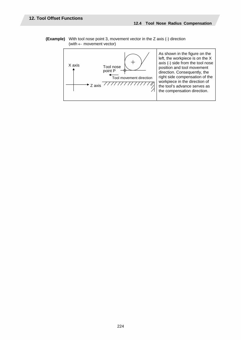
12. Tool Offset Functions 12.4 Tool Nose Radius Compensation
224
(Example) With tool nose point 3, movement vector in the Z axis (-) direction (with ← movement vector)
X axis Tool nosepoint P
Tool movement direction
Z axis
As shown in the figure on the left, the workpiece is on the X axis (-) side from the tool nose position and tool movement direction. Consequently, the right side compensation of the workpiece in the direction of the tool’s advance serves as the compensation direction.

12. Tool Offset Functions 12.4 Tool Nose Radius Compensation
225
12.4.2 Tool Nose Radius Compensation Operations
Tool nose radius compensation cancel mode
The tool nose radius compensation cancel mode is established by any of the following conditions.
(1) After the power has been turned ON
(2) After the reset button on the setting and display unit has been pressed
(3) After the M02 or M30 command with reset function has been executed
(4) After the compensation cancel command (G40) has been executed
(5) After tool No. 0 has been selected (T00 has been executed)
The offset vectors are zero in the compensation cancel mode, and the tool nose point path coincides with the program path. Programs including tool nose radius compensation must be terminated in the compensation cancel mode.
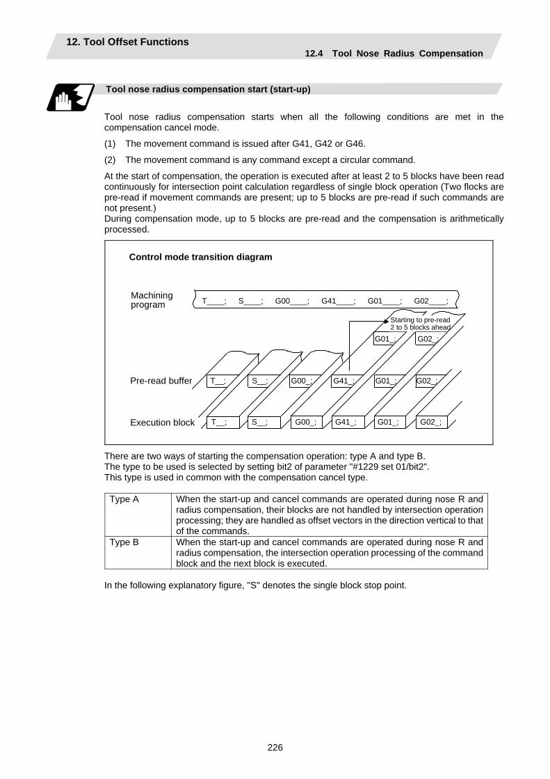
12. Tool Offset Functions 12.4 Tool Nose Radius Compensation
226
Tool nose radius compensation start (start-up)
Tool nose radius compensation starts when all the following conditions are met in the compensation cancel mode.
(1) The movement command is issued after G41, G42 or G46.
(2) The movement command is any command except a circular command.
At the start of compensation, the operation is executed after at least 2 to 5 blocks have been read continuously for intersection point calculation regardless of single block operation (Two flocks are pre-read if movement commands are present; up to 5 blocks are pre-read if such commands are not present.) During compensation mode, up to 5 blocks are pre-read and the compensation is arithmetically processed.
T__; S__;
T__; S__;
G00_;
G00_; G41_; G01_; G02_;
G02_; G01_; G41_;
Control mode transition diagram
T____; S____; G00____; G41____; G01____; G02____;
G01_; G02_;
Machining program
Pre-read buffer
Execution block
Starting to pre-read 2 to 5 blocks ahead
There are two ways of starting the compensation operation: type A and type B. The type to be used is selected by setting bit2 of parameter "#1229 set 01/bit2". This type is used in common with the compensation cancel type.
Type A When the start-up and cancel commands are operated during nose R and radius compensation, their blocks are not handled by intersection operation processing; they are handled as offset vectors in the direction vertical to that of the commands.
Type B When the start-up and cancel commands are operated during nose R and radius compensation, the intersection operation processing of the command block and the next block is executed.
In the following explanatory figure, "S" denotes the single block stop point.
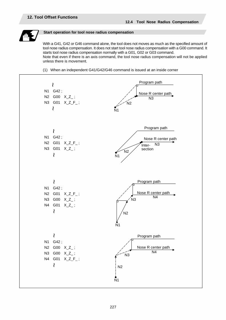
12. Tool Offset Functions 12.4 Tool Nose Radius Compensation
227
Start operation for tool nose radius compensation
With a G41, G42 or G46 command alone, the tool does not moves as much as the specified amount of tool nose radius compensation. It does not start tool nose radius compensation with a G00 command. It starts tool nose radius compensation normally with a G01, G02 or G03 command. Note that even if there is an axis command, the tool nose radius compensation will not be applied unless there is movement.
(1) When an independent G41/G42/G46 command is issued at an inside corner
N1 G42 ; N2 G00 X_Z_ ; N3 G01 X_Z_F_ ;
N1 G42 ; N2 G01 X_Z_F_ ; N3 G01 X_Z_ ;
N1 G42 ; N2 G01 X_Z_F_ ; N3 G00 X_Z_ ; N4 G01 X_Z_ ;
N1 G42 ; N2 G00 X_Z_ ; N3 G00 X_Z_ ; N4 G01 X_Z_F_ ;
N1
N2N3
N1N2
N3
N1
N2
N3 N4
N1
N2
N3N4
~~
~~
~~
~~
Program path
Nose R center path
Program path
Nose R center path
Program path
Nose R center path
Program path
Nose R center path
Inter-section
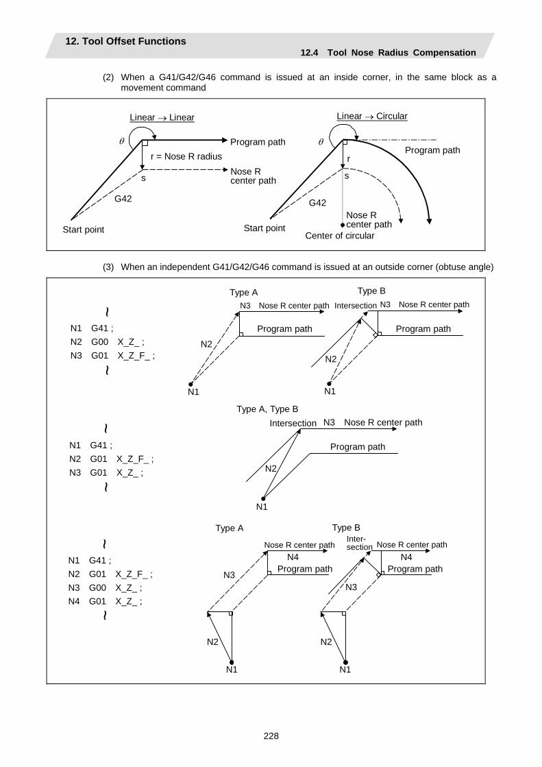
12. Tool Offset Functions 12.4 Tool Nose Radius Compensation
228
(2) When a G41/G42/G46 command is issued at an inside corner, in the same block as a movement command
G42
s s
G42
θ θ
r
Center of circular
Program path
Linear → Linear Linear → Circular
Program path
Start point Start point
r = Nose R radius
Nose R center path
Nose R center path
(3) When an independent G41/G42/G46 command is issued at an outside corner (obtuse angle)
N1
N2
N1 G41 ; N2 G00 X_Z_ ; N3 G01 X_Z_F_ ;
N1 G41 ; N2 G01 X_Z_F_ ; N3 G01 X_Z_ ;
N1 G41 ; N2 G01 X_Z_F_ ; N3 G00 X_Z_ ; N4 G01 X_Z_ ;
N1
N2
N3
N4
N1
N2
N1
N2
N1
N2
N3
N4
~~
~~
~~
Type AN3 Nose R center path Intersection
Program path
Type B N3 Nose R center path
Program path
IntersectionType A, Type B
Program path
N3 Nose R center path
Inter-section
Type B
Nose R center path
Program path
Type A
Nose R center path
Program path
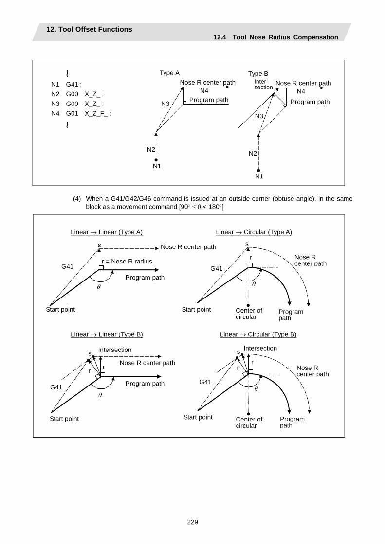
12. Tool Offset Functions 12.4 Tool Nose Radius Compensation
229
N1 G41 ; N2 G00 X_Z_ ; N3 G00 X_Z_ ; N4 G01 X_Z_F_ ;
N3
N1
N2
N4
N3
N1
N2
N4
~~
Inter-section
Type BNose R center path
Program path
Type ANose R center path
Program path
(4) When a G41/G42/G46 command is issued at an outside corner (obtuse angle), in the same
block as a movement command [90° ≤ θ < 180°]
Linear → Linear (Type A)
G41
s
θ
Linear → Circular (Type A)
G41
r
s
θ
Linear → Circular (Type B)
G41
r r
s
θ
Linear → Linear (Type B)
G41
r r
s
θ
Start point Start point
r = Nose R radius
Program path
Nose R center path
Program path
Center of circular
Nose R center path
Start point Start point
Nose R center path
Program path
Intersection Intersection
Program path
Center of circular
Nose R center path
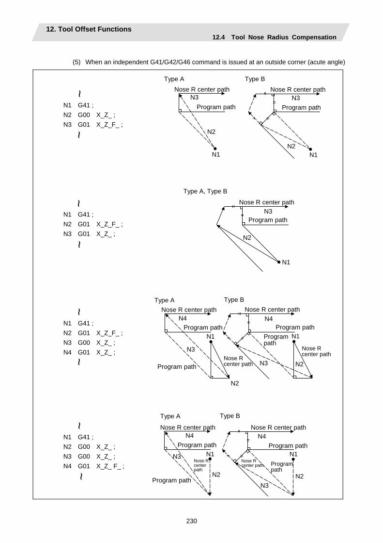
12. Tool Offset Functions 12.4 Tool Nose Radius Compensation
230
(5) When an independent G41/G42/G46 command is issued at an outside corner (acute angle)
N1 G41 ; N2 G00 X_Z_ ; N3 G01 X_Z_F_ ;
N1 G41 ; N2 G01 X_Z_F_ ; N3 G01 X_Z_ ;
N1 G41 ; N2 G01 X_Z_F_ ; N3 G00 X_Z_ ; N4 G01 X_Z_ ;
N1 G41 ; N2 G00 X_Z_ ; N3 G00 X_Z_ ; N4 G01 X_Z_ F_ ;
N2
N2 N1 N1
N2
N1
N2
N1
N3
N2
N1
N3
N2
N1N3
N2
N1
N3
N3 N3
N3
~ ~
~ ~
~ ~
~ ~
Type BNose R center path
Program path
Type ANose R center path
Program path
Type A, Type B
Nose R center path
Program path
Type BNose R center path
Program path
Type ANose R center path
Program pathProgram path
Nose R center pathProgram path
Nose R center path
N4 N4
N4 N4
Type B
Nose R center path
Type A
Nose R center path
Program path
Program path
Nose R center path
Program path
Nose R center path Program
path
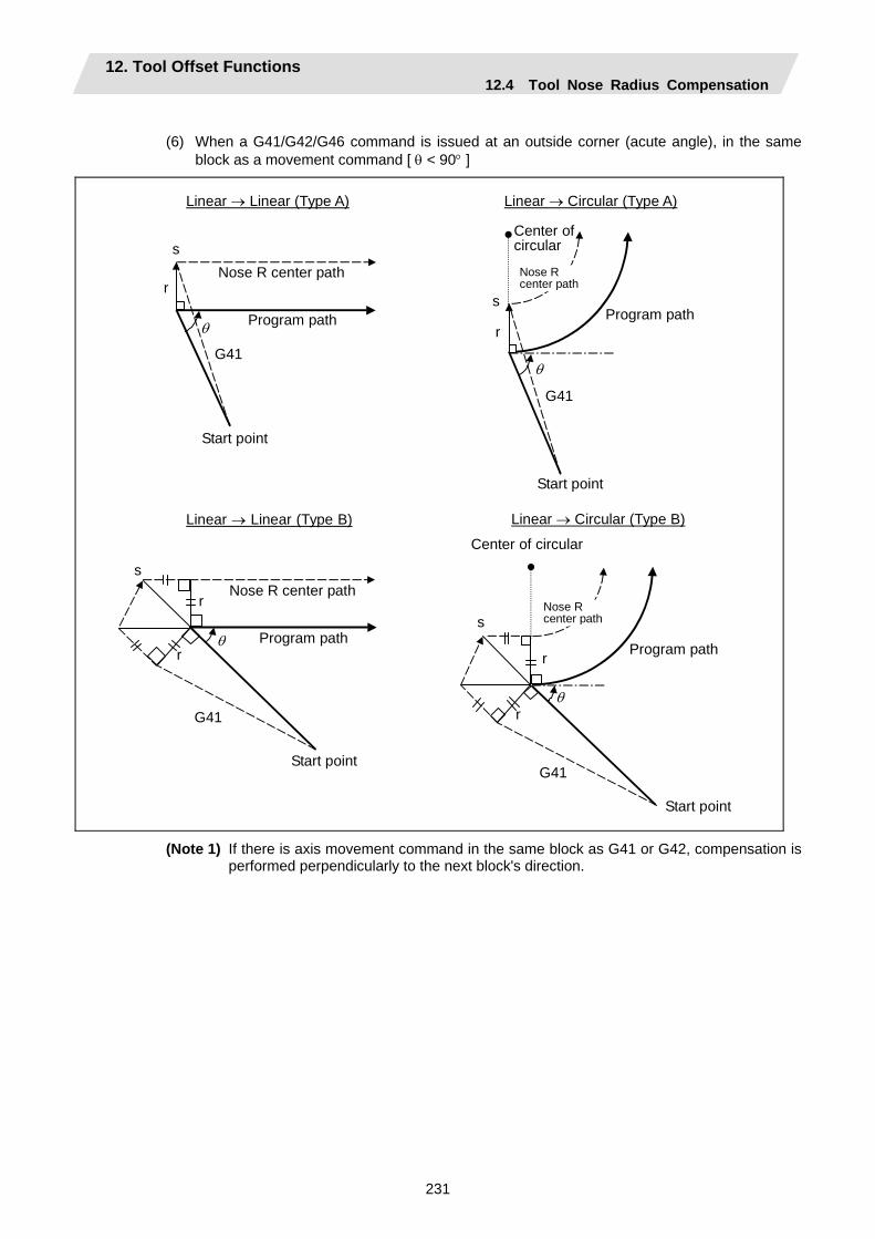
12. Tool Offset Functions 12.4 Tool Nose Radius Compensation
231
(6) When a G41/G42/G46 command is issued at an outside corner (acute angle), in the same
block as a movement command [ θ < 90° ]
G41
r
r
s
θ
Linear → Circular (Type B)
Linear → Linear (Type A)
G41
r
s
θ
Linear → Circular (Type A)
G41
r
s
θ
Linear → Linear (Type B)
G41
r
r
s
θ
Start point
Nose R center path
Program path
Start point
Program path
Nose R center path
Center of circular
Nose R center path
Program path
Start point
Start point
Program path
Nose R center path
Center of circular
(Note 1) If there is axis movement command in the same block as G41 or G42, compensation is performed perpendicularly to the next block's direction.
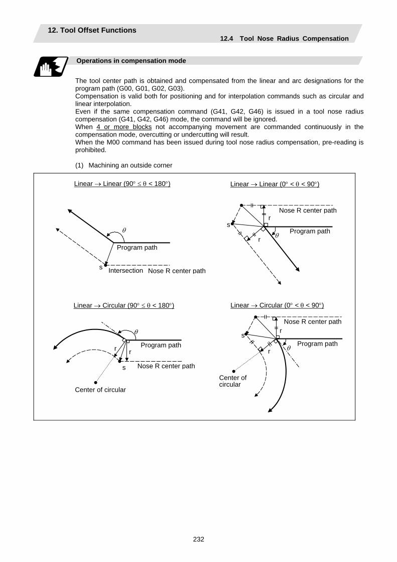
12. Tool Offset Functions 12.4 Tool Nose Radius Compensation
232
Operations in compensation mode
The tool center path is obtained and compensated from the linear and arc designations for the program path (G00, G01, G02, G03). Compensation is valid both for positioning and for interpolation commands such as circular and linear interpolation. Even if the same compensation command (G41, G42, G46) is issued in a tool nose radius compensation (G41, G42, G46) mode, the command will be ignored. When 4 or more blocks not accompanying movement are commanded continuously in the compensation mode, overcutting or undercutting will result. When the M00 command has been issued during tool nose radius compensation, pre-reading is prohibited.
(1) Machining an outside corner
Linear → Linear (90° ≤ θ < 180°)
s
θ
Linear → Linear (0° < θ < 90°)
r
r
s θ
Intersection Nose R center path
Program path
Nose R center path
Program path
r
r θ
s
Linear → Circular (0° < θ < 90°)
s
r
θ
r
Linear → Circular (90° ≤ θ < 180°)
Nose R center path
Program path
Center of circular
Center of circular
Program path
Nose R center path
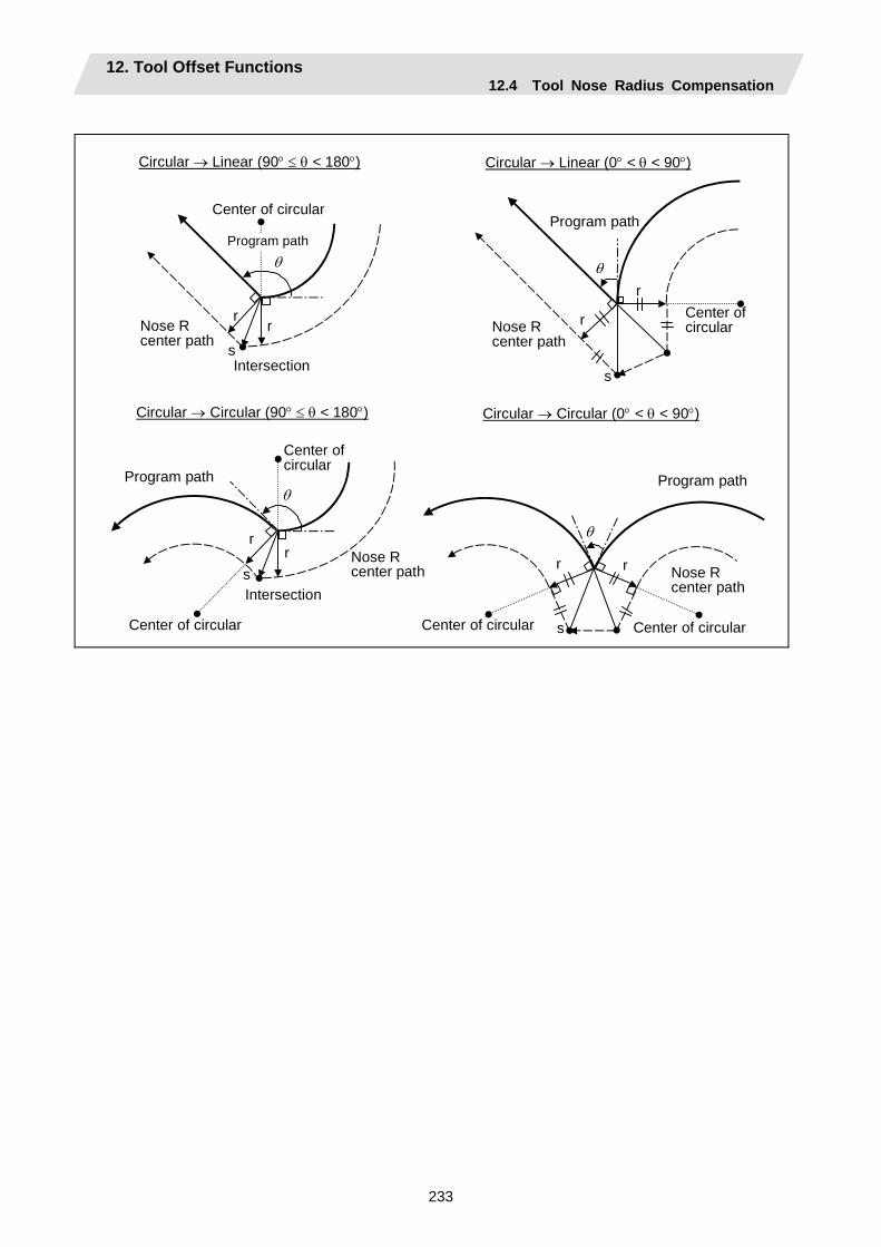
12. Tool Offset Functions 12.4 Tool Nose Radius Compensation
233
Circular → Linear (0° < θ < 90°)
r
r
s
θ
Circular → Linear (90° ≤ θ < 180°)
r r
s
θ
Nose R center path
Program path
Center of circular Nose R
center path
Intersection
Program path
Center of circular
Circular → Circular (90° ≤ θ < 180°)
r r
s
θ
Circular → Circular (0° < θ < 90°)
r r
s
θ
Center of circular
Nose R center path
Program path
Center of circular
Center of circular
Program path
Center of circular
Nose R center pathIntersection
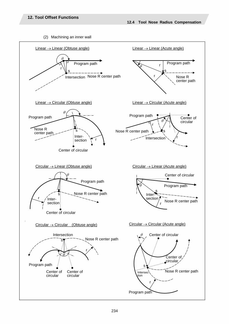
12. Tool Offset Functions 12.4 Tool Nose Radius Compensation
234
(2) Machining an inner wall
Linear → Linear (Obtuse angle)
r s
θ
Linear → Linear (Acute angle)
r
r s
θ
r
Linear → Circular (Obtuse angle)
s
θ
r
r
Linear → Circular (Acute angle)
s
θ
r
Circular → Linear (Acute angle)
s θ
r
Circular → Linear (Obtuse angle)
θ
s
Program path
Nose R center path
Program path
Program pathProgram path
Program path
Nose R center pathIntersection
Program path
Nose R center path
Nose R center path
Center of circular
Nose R center path
Intersection
Center of circular
Nose R center pathInter- section
Center of circular
Center of circular
Inter-section
Inter- section
Circular → Circular (Obtuse angle)
r
s
θ
Circular → Circular (Acute angle)
r
s
θ
Program path
Center of circular
Nose R center pathIntersection
Center of circular
Intersec-tion
Center of circular
Center of circular
Nose R center path
Program path

12. Tool Offset Functions 12.4 Tool Nose Radius Compensation
235
(3) When the arc end point is not on the arc
If the error applying after compensation is within the parameter (#1084 RadErr), the area from the arc start point to the end point is interpolated as a spiral arc.
r
r s
R
Nose R center path
End point of circularProgram path
Center of circular
Hypothetical circle
(4) When the inner intersection point does not exist
In an instance such as that shown in the figure below, the intersection point of circulars A and B may cease to exist due to the offset amount. In such cases, program error (P152) appears and the tool stops at the end point of the previous block.
r
r
A B
Nose R center path
Program error stop
Program path
Center of circular A
Line intersecting circulars A, B
12. Tool Offset Functions 12.4 Tool Nose Radius Compensation
236
Tool nose radius compensation cancel
If either of the following conditions is met in the tool nose radius compensation mode, the compensation will be canceled. However, the movement command must be a command which is not a circular command. If the compensation is canceled by a circular command, program error (P151) results.
(1) The G40 command has been executed.
(2) The T00 tool No. has been executed.
The cancel mode is established once the compensation cancel command has been read, 5-block pre-reading is suspended and 1-block pre-reading is applies instead.
Tool nose radius compensation cancel operation
Issuing a tool nose radius compensation cancel command results in the following.
(1) If the command before G40 is G00 after the tool nose radius compensation is completed, the tool nose radius compensation is temporarily stopped, and the tool nose radius compensation is canceled in that state by an independent G40 command.
(2) If there is an interpolation command before G40 after the tool nose radius compensation is completed, the tool nose radius compensation is not canceled by the independent G40 command, so the nose R center can stop in a vertical position. Instead, the tool nose radius compensation is canceled by the first axis movement command after G40. The nose radius compensation will not be canceled by the axis command if there is no axis movement. If there is no axis movement command after G40, and the program finishes by M02, etc., the tool nose radius compensation will remain valid. Resetting will cancel the tool nose radius compensation, but the operation will not be canceled.
(3) When an independent T00 command is issued in a block, a tool nose radius cancel mode will result in that block, and the axis will move to the tool nose radius cancel position.
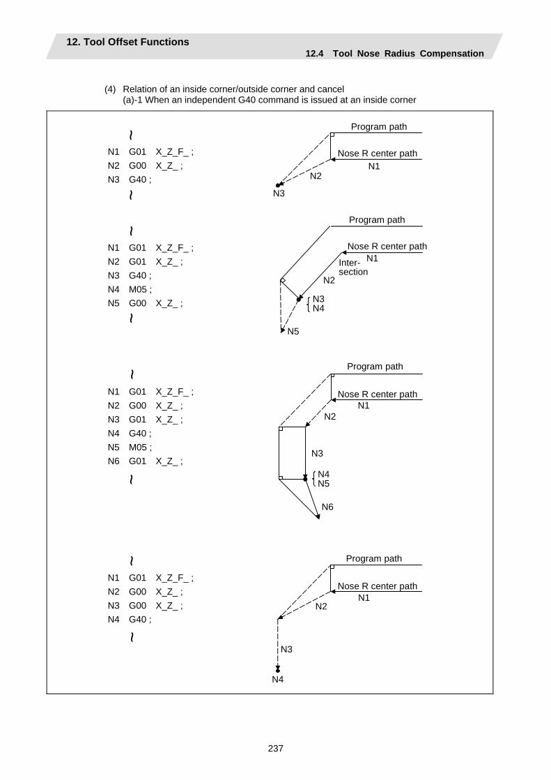
12. Tool Offset Functions 12.4 Tool Nose Radius Compensation
237
(4) Relation of an inside corner/outside corner and cancel
(a)-1 When an independent G40 command is issued at an inside corner
N1 G01 X_Z_F_ ; N2 G00 X_Z_ ; N3 G40 ;
N1 G01 X_Z_F_ ; N2 G01 X_Z_ ; N3 G40 ; N4 M05 ; N5 G00 X_Z_ ;
N1 G01 X_Z_F_ ; N2 G00 X_Z_ ; N3 G01 X_Z_ ; N4 G40 ; N5 M05 ; N6 G01 X_Z_ ;
N1 G01 X_Z_F_ ; N2 G00 X_Z_ ; N3 G00 X_Z_ ; N4 G40 ;
N1N2
N3
N5
N2
N3N4
N1
N4N5
N2
N3
N1
N6
N2
N3
N1
N4
~~
~~
~~
~~
Nose R center path
Program path
Inter-section
Nose R center path
Program path
Nose R center path
Program path
Program path
Nose R center path

12. Tool Offset Functions 12.4 Tool Nose Radius Compensation
238
(a)-2 When a G40 command is issued at an inside corner, in the same block as a movement
command
Linear → Linear
s
θ
G40 G40
Circular → Linear
r
s
θ
End point
r = Nose R radius
Nose R center path
Program path
End point
Nose R center path
Program path
Center of circular
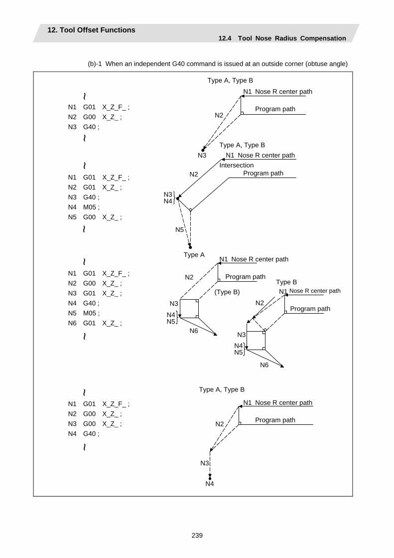
12. Tool Offset Functions 12.4 Tool Nose Radius Compensation
239
(b)-1 When an independent G40 command is issued at an outside corner (obtuse angle)
N1 G01 X_Z_F_ ; N2 G00 X_Z_ ; N3 G40 ;
N1 G01 X_Z_F_ ; N2 G01 X_Z_ ; N3 G40 ; N4 M05 ; N5 G00 X_Z_ ;
N1 G01 X_Z_F_ ; N2 G00 X_Z_ ; N3 G01 X_Z_ ; N4 G40 ; N5 M05 ; N6 G01 X_Z_ ;
N1 G01 X_Z_F_ ; N2 G00 X_Z_ ; N3 G00 X_Z_ ; N4 G40 ;
N1
N3
N2
N2
N3N4
N5
N2
N4N5
N3
N6
N2
N4N5
N3
N6
N3
N2
N4
~~
~~
~~
~~
Nose R center path
Program path
Type A, Type B
Type A, Type BN1 Nose R center path
Program path Intersection
Type A N1 Nose R center path
Program pathType B
(Type B) N1 Nose R center path
Program path
N1 Nose R center path
Program path
Type A, Type B
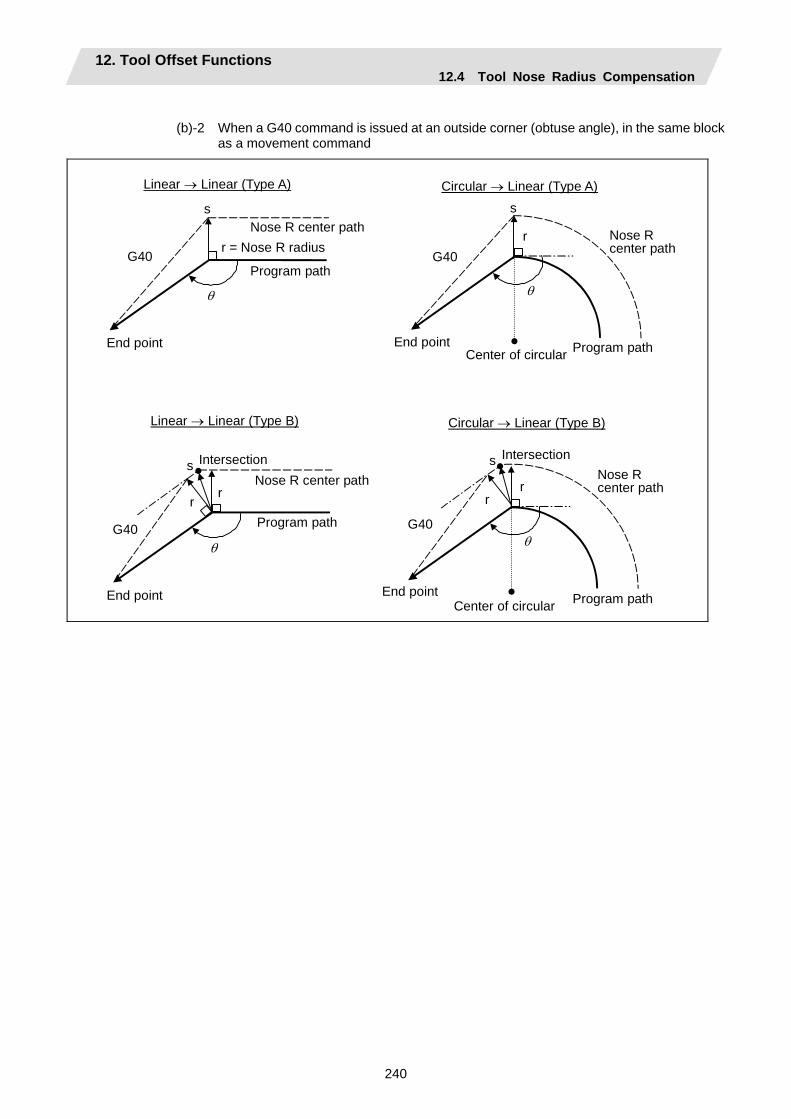
12. Tool Offset Functions 12.4 Tool Nose Radius Compensation
240
(b)-2 When a G40 command is issued at an outside corner (obtuse angle), in the same block
as a movement command
Center of circular
Linear → Linear (Type A)
s
θ
G40
Circular → Linear (Type A)
G40r
s
θ
r
s
θ G40
r
G40
r
s
θ
r
Linear → Linear (Type B) Circular → Linear (Type B)
End pointCenter of circular
Nose R center path
Program path
r = Nose R radius Nose R center path
Program path
Program path
Program path
Nose R center path
Nose R center path
End point
End point
Intersection Intersection
End point

12. Tool Offset Functions 12.4 Tool Nose Radius Compensation
241
(c)-1 When an independent G40 command is issued at an outside corner (acute angle)
N1 G01 X_Z_F_ ; N2 G00 X_Z_ ; N3 G40 ;
N1 G01 X_Z_F_ ; N2 G01 X_Z_ ; N3 G40 ; N4 M05 ; N5 G00 X_Z_ ;
N1 G01 X_Z_F_ ; N2 G00 X_Z_ ; N3 G01 X_Z_ ; N4 G40 ; N5 M05 ; N6 G01 X_Z_ ;
N1 G01 X_Z_F_ ; N2 G00 X_Z_ ; N3 G00 X_Z_ ; N4 G40 ;
N3
N2
N3N4
N2N5
N2 N4
N4N5N2
N3
N6N4N5
N2N3
N6
N3
~~
~~
~~
~~
N1 Nose R center path
Program path
Type A, Type B
Type A, Type B
N1 Nose R center path
Program path
N1 Nose R center path
Program path
Type A Type B
N1 Nose R center path
Program path
Nose R center path
N1 Nose R center path
Program path
Type A, Type B
(Type A, Type B)
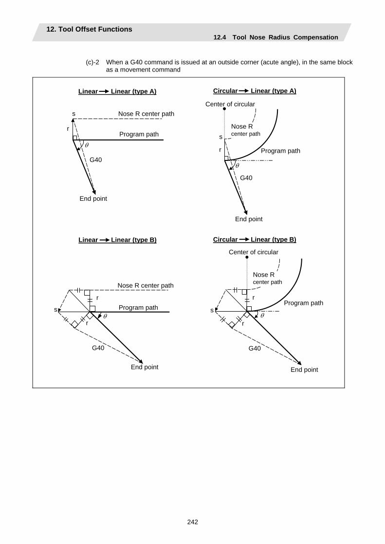
12. Tool Offset Functions 12.4 Tool Nose Radius Compensation
242
(c)-2 When a G40 command is issued at an outside corner (acute angle), in the same block
as a movement command
Nose R center path
End point
Program path
Linear Linear (type A)
r
s
θ
G40
Circular Linear (type A)
s
G40
r
θ
Nose R center path
Program path
End point
Center of circular
Linear Linear (type B)
r
s θ
G40
r
Nose R center path
End point
Program path
Circular Linear (type B)
r
sθ
G40
r
Nose R center path
Program path
Center of circular
End point
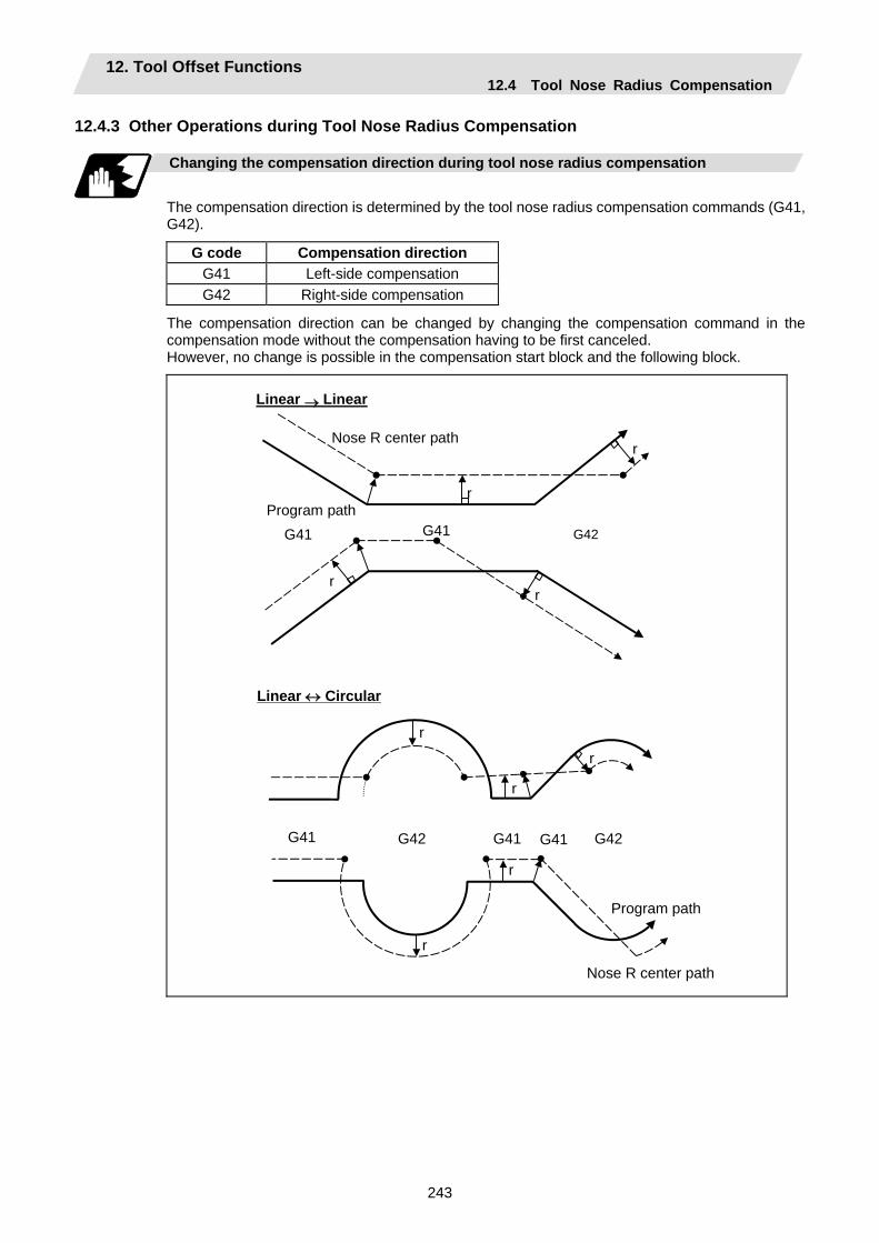
12. Tool Offset Functions 12.4 Tool Nose Radius Compensation
243
12.4.3 Other Operations during Tool Nose Radius Compensation Changing the compensation direction during tool nose radius compensation
The compensation direction is determined by the tool nose radius compensation commands (G41, G42).
G code Compensation direction G41 Left-side compensation G42 Right-side compensation
The compensation direction can be changed by changing the compensation command in the compensation mode without the compensation having to be first canceled. However, no change is possible in the compensation start block and the following block.
r
G41
r
Linear → Linear
G41 G42
r
r
Nose R center path
Program path
Linear ↔ Circular
Nose R center path
G41
r
G41 G42 G41 G42
r
r
r
r
Program path
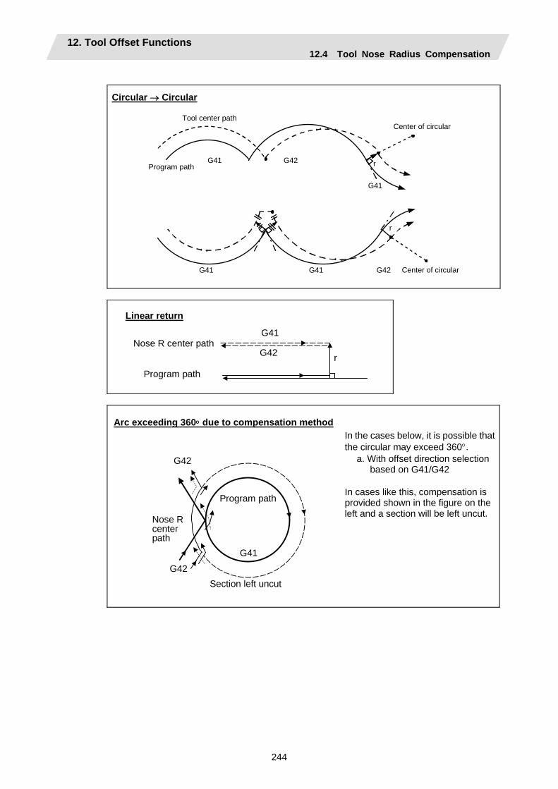
12. Tool Offset Functions 12.4 Tool Nose Radius Compensation
244
Circular → Circular
Program path
Tool center path
G41
G41 G42
r
Center of circular
Center of circular
G41
G41
G42
r
Linear return
G41
G42 r Nose R center path
Program path
Arc exceeding 360° due to compensation method
G41
G42
G42
Program path
Nose R center path
Section left uncut
In the cases below, it is possible that the circular may exceed 360°.
a. With offset direction selection based on G41/G42
In cases like this, compensation is provided shown in the figure on the left and a section will be left uncut.
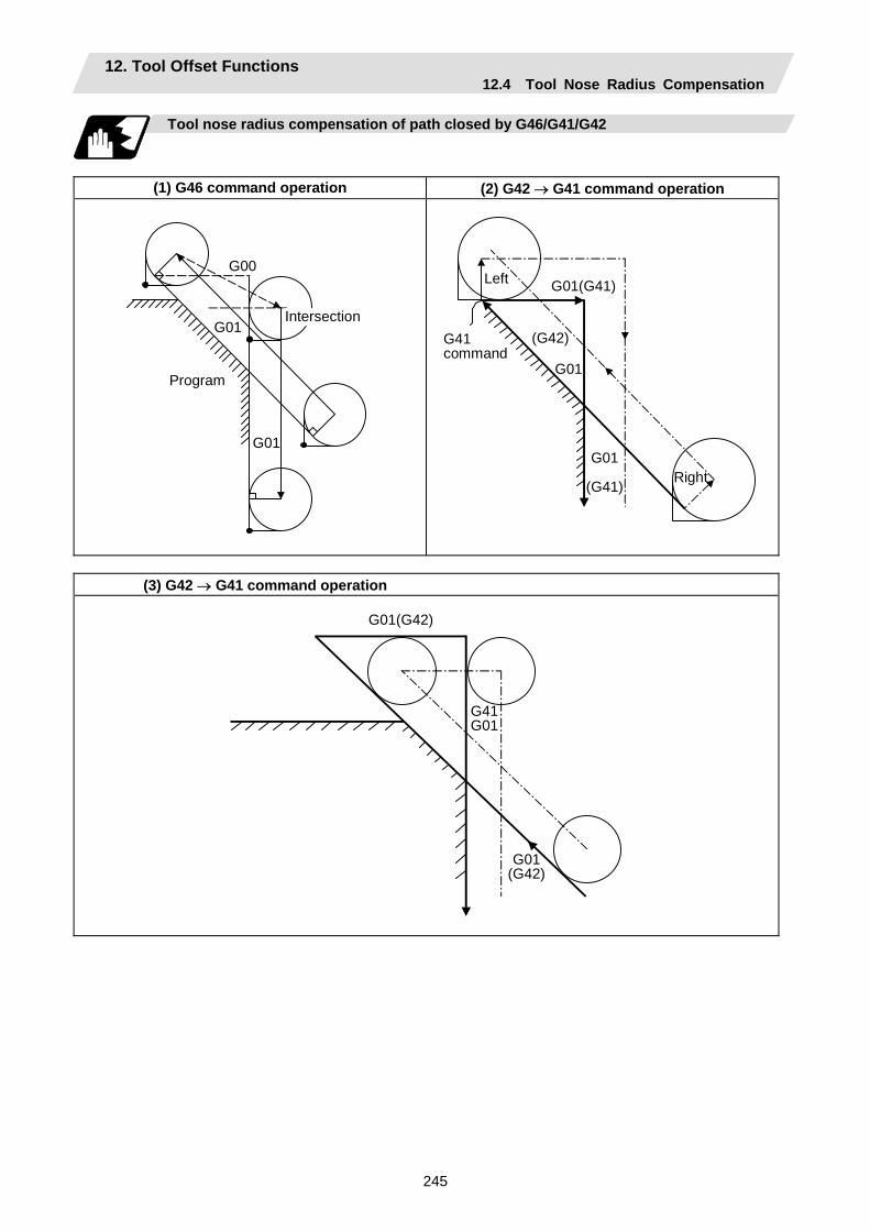
12. Tool Offset Functions 12.4 Tool Nose Radius Compensation
245
Tool nose radius compensation of path closed by G46/G41/G42
(1) G46 command operation (2) G42 → G41 command operation
G00
G01
G01
Program
Intersection
G01(G41)
G01
(G41)
(G42)
G01
G41command
Left
Right
(3) G42 → G41 command operation
G01(G42)
G41G01
G01(G42)
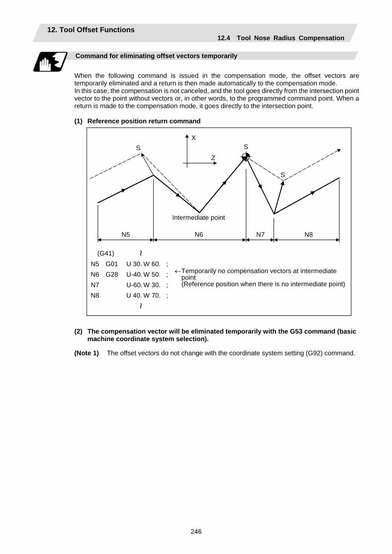
12. Tool Offset Functions 12.4 Tool Nose Radius Compensation
246
Command for eliminating offset vectors temporarily
When the following command is issued in the compensation mode, the offset vectors are temporarily eliminated and a return is then made automatically to the compensation mode. In this case, the compensation is not canceled, and the tool goes directly from the intersection point vector to the point without vectors or, in other words, to the programmed command point. When a return is made to the compensation mode, it goes directly to the intersection point. (1) Reference position return command
X
ZS S
S
N5 N6 N7 N8
(G41) N5 G01 U 30. W 60. ; N6 G28 U-40. W 50. ; N7 U-60. W 30. ; N8 U 40. W 70. ;
~
Intermediate point
←Temporarily no compensation vectors at intermediate point (Reference position when there is no intermediate point)
~
(2) The compensation vector will be eliminated temporarily with the G53 command (basic
machine coordinate system selection).
(Note 1) The offset vectors do not change with the coordinate system setting (G92) command.
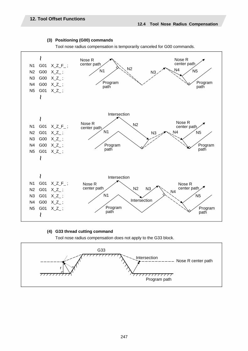
12. Tool Offset Functions 12.4 Tool Nose Radius Compensation
247
(3) Positioning (G00) commands
Tool nose radius compensation is temporarily canceled for G00 commands.
N3N2N1 N4 N5
N3
N2
N1 N4 N5
N3N2N1
N4N5
N1 G01 X_Z_F_ ; N2 G00 X_Z_ ; N3 G00 X_Z_ ; N4 G00 X_Z_ ; N5 G01 X_Z_ ;
N1 G01 X_Z_F_ ; N2 G01 X_Z_ ; N3 G01 X_Z_ ; N4 G00 X_Z_ ; N5 G01 X_Z_ ;
N1 G01 X_Z_F_ ; N2 G01 X_Z_ ; N3 G00 X_Z_ ; N4 G00 X_Z_ ; N5 G01 X_Z_ ;
~~
~~
~~
Nose R center path
Program path
Nose R center path
Program path
Nose R center path
Nose R center path
Nose R center path
Program path
Nose R center path
Program path
Program path
Program path
Intersection
Intersection
Intersection
(4) G33 thread cutting command
Tool nose radius compensation does not apply to the G33 block.
r
G33
Nose R center path
Program path
Intersection
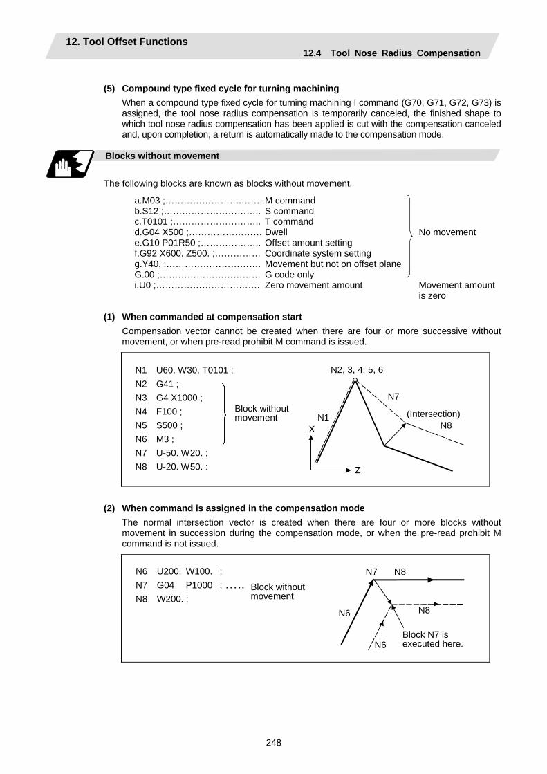
12. Tool Offset Functions 12.4 Tool Nose Radius Compensation
248
(5) Compound type fixed cycle for turning machining
When a compound type fixed cycle for turning machining I command (G70, G71, G72, G73) is assigned, the tool nose radius compensation is temporarily canceled, the finished shape to which tool nose radius compensation has been applied is cut with the compensation canceled and, upon completion, a return is automatically made to the compensation mode.
Blocks without movement
The following blocks are known as blocks without movement.
a.M03 ;…………………….…….b.S12 ;…………………………..c.T0101 ;………………………..d.G04 X500 ;……………………e.G10 P01R50 ;………………..f.G92 X600. Z500. ;……………g.Y40. ;………………………….G.00 ;……………………………i.U0 ;…………………………….
M command S command T command Dwell Offset amount setting Coordinate system setting Movement but not on offset plane G code only Zero movement amount
No movement Movement amount is zero
(1) When commanded at compensation start
Compensation vector cannot be created when there are four or more successive without movement, or when pre-read prohibit M command is issued.
N1 U60. W30. T0101 ; N2 G41 ; N3 G4 X1000 ; N4 F100 ; N5 S500 ; N6 M3 ; N7 U-50. W20. ; N8 U-20. W50. ;
N1
N2, 3, 4, 5, 6
N7
N8 X
Z
Block withoutmovement (Intersection)
(2) When command is assigned in the compensation mode The normal intersection vector is created when there are four or more blocks without movement in succession during the compensation mode, or when the pre-read prohibit M command is not issued.
N6 U200. W100. ; N7 G04 P1000 ; ….. N8 W200. ; N8 N6
N7
N6
N8
Block N7 is executed here.
Block withoutmovement
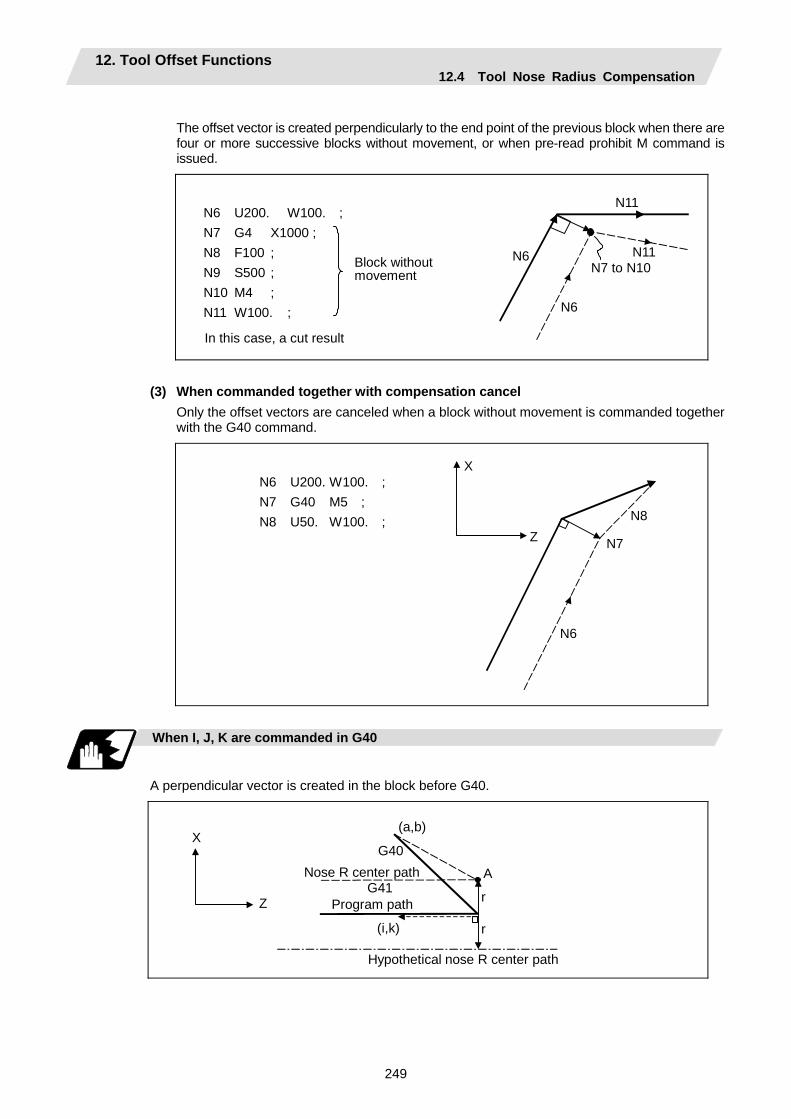
12. Tool Offset Functions 12.4 Tool Nose Radius Compensation
249
The offset vector is created perpendicularly to the end point of the previous block when there are four or more successive blocks without movement, or when pre-read prohibit M command is issued.
N6 U200. W100. ; N7 G4 X1000 ; N8 F100 ; N9 S500 ; N10 M4 ; N11 W100. ;
N11
N6N7 to N10
N6
N11
In this case, a cut result
Block withoutmovement
(3) When commanded together with compensation cancel Only the offset vectors are canceled when a block without movement is commanded together with the G40 command.
N6 U200. W100. ; N7 G40 M5 ; N8 U50. W100. ;
N6
N7
N8
X
Z
When I, J, K are commanded in G40
A perpendicular vector is created in the block before G40.
r
G40
(i,k)
A
(a,b)
r G41
X
Z
Nose R center path
Program path
Hypothetical nose R center path

12. Tool Offset Functions 12.4 Tool Nose Radius Compensation
250
Corner movement
When a multiple number of compensation vectors are created at the joints between movement command blocks, the tool will move in a linear between those vectors. This action is called corner movement. When the vectors do not coincide, the tool moves in order to machine the corner. Consequently, operation in the single block mode will execute the previous block + corner movement as a single block and the remaining joining movement + following block will be executed as a single block in the following operation.
r
N1
N2θ
r
Stop point with single block
Nose R center path
Program path
Center of circular
This movement and feed rate fall under block N2.

12. Tool Offset Functions 12.4 Tool Nose Radius Compensation
251
12.4.4 G41/G42 Commands and I, J, K Designation
Function and purpose
The compensation direction can be intentionally changed by issuing the G41/G42 command and I, J, K in the same block.
Command format
G18 (Z-X plane) G41/G42 X Z I K ;
Assign a linear command (G00, G01) in a movement mode.
I, K type vectors (G18 X-Z plane selection)
The new I, K type vector (G18 plane) created by this command is now described. (Similar descriptions apply to vector I, J for the G17 plane and to J, K for the G19 plane.) As shown in the figures below, the vectors with a size equivalent to the offset amount are made to serve as the I, K type compensation vector perpendicularly to the direction designated by I, K without the intersection point of the programmed path being calculated. The I, K vector can be commanded even in the mode (G41/G42 mode in the block before) and even at the compensation start (G40 mode in the block before). (1) When I, K is commanded at compensation start
N150
N100
X
Z
N110 N120 N130 N140
T0101
Program pathNose R center path
(G40) N100 G41 U100. W100. K150. T0101 ;N110 G04 X1000 ; N120 G01 F1000 ; N130 S500 ; N140 M03 ; N150 Z150. ;
~ ~
(2) When there are no movement commands at the compensation start
(G40) N1 G41 K150. T0101 ; N2 U100. W100. ; N3 W150. ;
~N3
N2
X
Z
T0101 N1
~
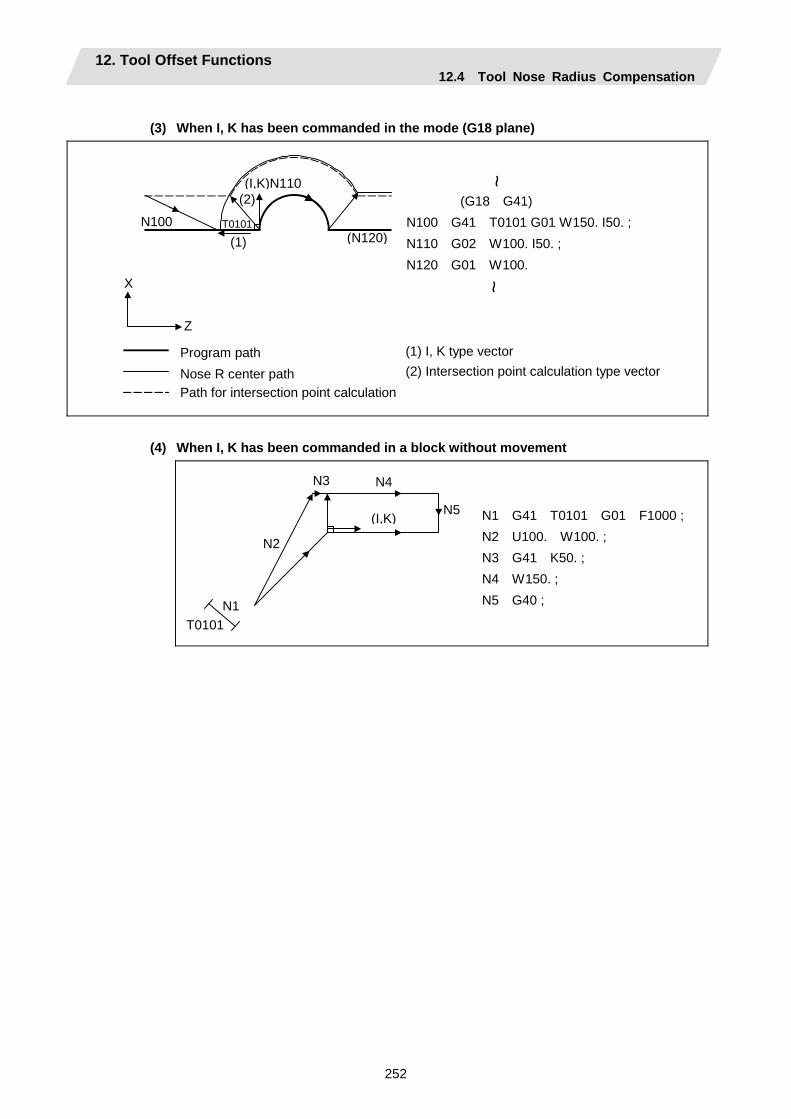
12. Tool Offset Functions 12.4 Tool Nose Radius Compensation
252
(3) When I, K has been commanded in the mode (G18 plane)
X Z
~
(G18 G41) N100 G41 T0101 G01 W150. I50. ; N110 G02 W100. I50. ; N120 G01 W100. ~
(1) I, K type vector (2) Intersection point calculation type vector
Program path Nose R center path Path for intersection point calculation
N100
(I,K)N110
(N120)T0101
(2)
(1)
(4) When I, K has been commanded in a block without movement
N1T0101
N2
N3 N4
N5(I,K) N1 G41 T0101 G01 F1000 ; N2 U100. W100. ; N3 G41 K50. ; N4 W150. ; N5 G40 ;
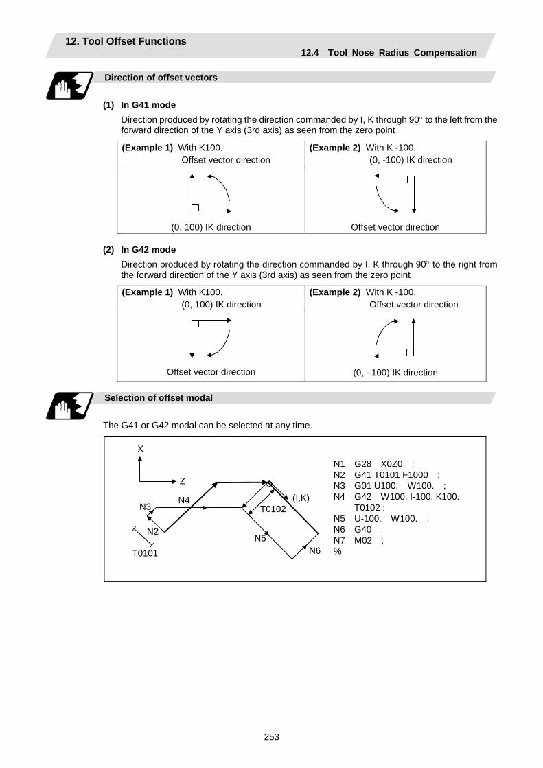
12. Tool Offset Functions 12.4 Tool Nose Radius Compensation
253
Direction of offset vectors
(1) In G41 mode
Direction produced by rotating the direction commanded by I, K through 90° to the left from the forward direction of the Y axis (3rd axis) as seen from the zero point
(Example 1) With K100. Offset vector direction
(Example 2) With K -100. (0, -100) IK direction
(0, 100) IK direction Offset vector direction
(2) In G42 mode Direction produced by rotating the direction commanded by I, K through 90° to the right from the forward direction of the Y axis (3rd axis) as seen from the zero point
(Example 1) With K100. (0, 100) IK direction
(Example 2) With K -100. Offset vector direction
Offset vector direction (0, −100) IK direction
Selection of offset modal
The G41 or G42 modal can be selected at any time.
N1 G28 X0Z0 ; N2 G41 T0101 F1000 ; N3 G01 U100. W100. ; N4 G42 W100. I-100. K100.
T0102 ; N5 U-100. W100. ; N6 G40 ; N7 M02 ; %
N3
Z
T0101
N2
N6
(I,K)
N5
X
N4 T0102
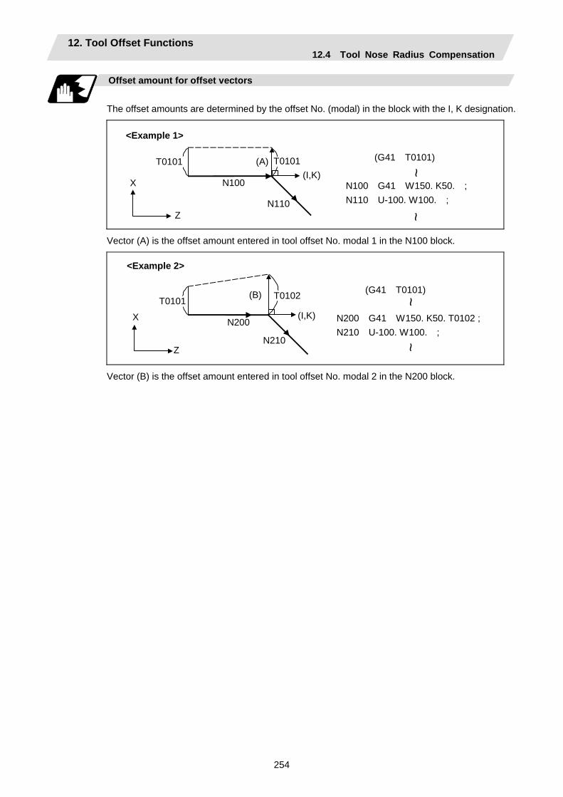
12. Tool Offset Functions 12.4 Tool Nose Radius Compensation
254
Offset amount for offset vectors
The offset amounts are determined by the offset No. (modal) in the block with the I, K designation.
(G41 T0101) N100 G41 W150. K50. ;N110 U-100. W100. ;
Z N110
(I,K) (A)
X N100
T0101T0101 ~
~
<Example 1>
Vector (A) is the offset amount entered in tool offset No. modal 1 in the N100 block.
(G41 T0101) N200 G41 W150. K50. T0102 ;N210 U-100. W100. ;
Z N210
(I,K)
(B)
X N200
T0102 T0101
~~
<Example 2>
Vector (B) is the offset amount entered in tool offset No. modal 2 in the N200 block.
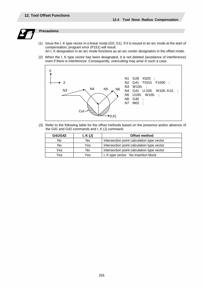
12. Tool Offset Functions 12.4 Tool Nose Radius Compensation
255
Precautions
(1) Issue the I, K type vector in a linear mode (G0, G1). If it is issued in an arc mode at the start of
compensation, program error (P151) will result. An I, K designation in an arc mode functions as an arc center designation in the offset mode.
(2) When the I, K type vector has been designated, it is not deleted (avoidance of interference) even if there is interference. Consequently, overcutting may arise in such a case.
Cut
N1 G28 X0Z0 ; N2 G41 T0101 F1000 ; N3 W100. ; N4 G41 U-100. W100. K10. ;N5 U100. W100. ; N6 G40 ; N7 M02 ;
N3 N4 N5 N6
(I,K)
X
Z
(3) Refer to the following table for the offset methods based on the presence and/or absence of the G41 and G42 commands and I, K (J) command.
G41/G42 I, K (J) Offset method No No Intersection point calculation type vector No Yes Intersection point calculation type vector Yes No Intersection point calculation type vector Yes Yes I, K type vector No insertion block
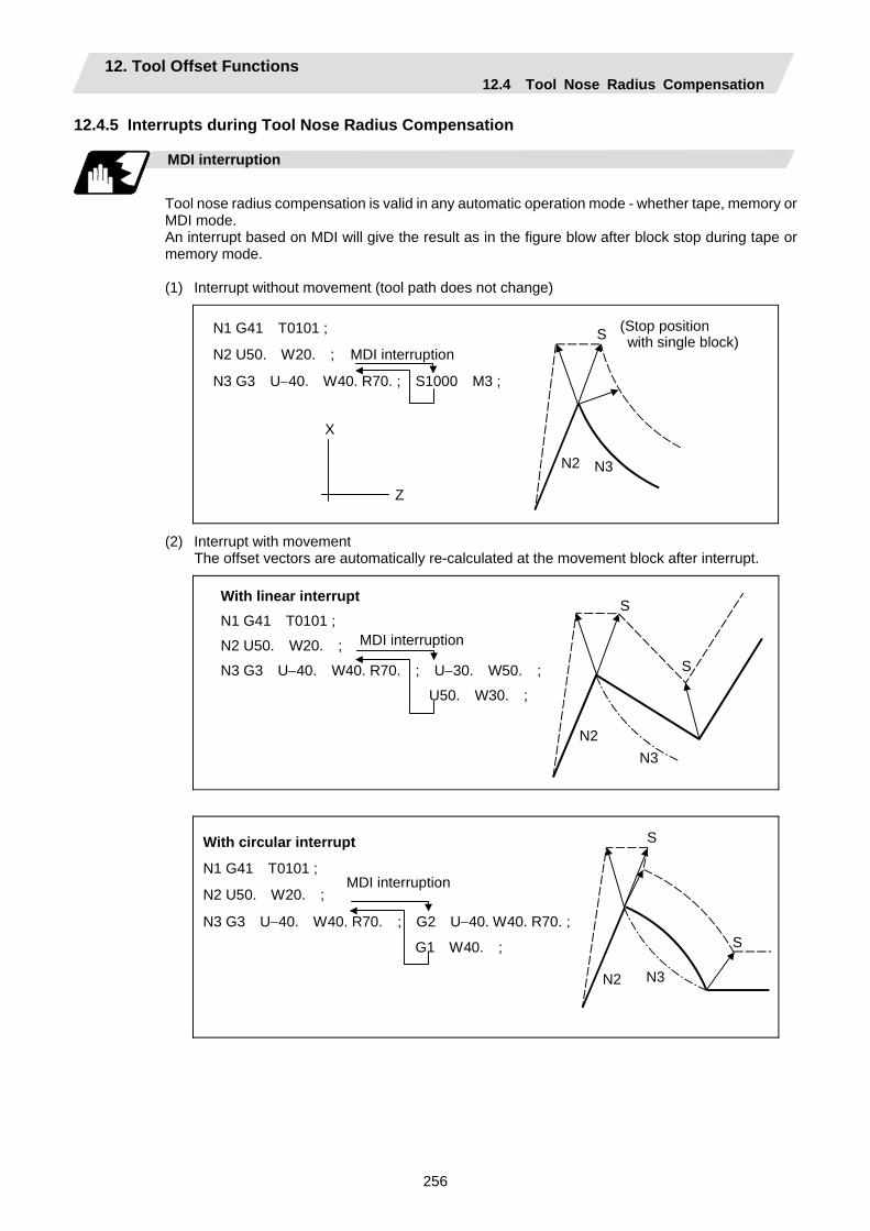
12. Tool Offset Functions 12.4 Tool Nose Radius Compensation
256
12.4.5 Interrupts during Tool Nose Radius Compensation
MDI interruption
Tool nose radius compensation is valid in any automatic operation mode - whether tape, memory or MDI mode. An interrupt based on MDI will give the result as in the figure blow after block stop during tape or memory mode. (1) Interrupt without movement (tool path does not change)
X
Z
N1 G41 T0101 ;
N2 U50. W20. ;
N3 G3 U−40. W40. R70. ; S1000 M3 ;
MDI interruption
N2 N3
(Stop position with single block)S
(2) Interrupt with movement The offset vectors are automatically re-calculated at the movement block after interrupt.
S
S
N2N3
MDI interruption
With linear interrupt N1 G41 T0101 ;
N2 U50. W20. ;
N3 G3 U−40. W40. R70. ; U−30. W50. ;
U50. W30. ;
S
S
N2 N3
With circular interrupt
N1 G41 T0101 ;
N2 U50. W20. ;
N3 G3 U−40. W40. R70. ; G2 U−40. W40. R70. ;
G1 W40. ;
MDI interruption
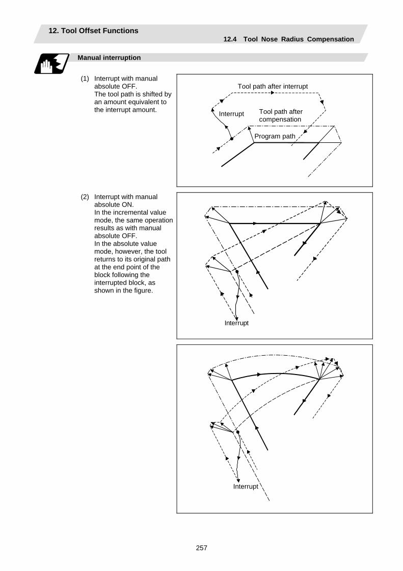
12. Tool Offset Functions 12.4 Tool Nose Radius Compensation
257
Manual interruption
(1) Interrupt with manual
absolute OFF. The tool path is shifted by an amount equivalent to the interrupt amount.
Interrupt
Program path
Tool path after compensation
Tool path after interrupt
(2) Interrupt with manual absolute ON. In the incremental value mode, the same operation results as with manual absolute OFF. In the absolute value mode, however, the tool returns to its original path at the end point of the block following the interrupted block, as shown in the figure.
Interrupt
Interrupt

12. Tool Offset Functions 12.4 Tool Nose Radius Compensation
258
12.4.6 General Precautions for Tool Nose Radius Compensation Assigning the compensation amounts
(1) The compensation amount is normally assigned by designating the No. of the compensation
amount by the last 1 or 2 digits of the T code. Depending on the machine specifications, the high-order digits may be used. The T code will remain valid once designated until another T code is subsequently commanded.
Besides being used to designate the compensation amounts for tool nose radius compensation, the T codes are also used to designate the offset amounts for tool length offset.
(2) The compensation amounts are normally changed when a different tool has been selected in the compensation cancel mode. However, when an amount is changed in the compensation mode, the vectors at the end point of the block are calculated using the compensation amount designated in that block.
Errors during tool nose radius compensation
(1) An error results when any of the following commands are programmed during tool nose radius
compensation.
G17, G18, G19 ("P112" when a plane differing from that applying during the compensation has been commanded) G31 ("P608") G74, G75, G76 ("P155") G81 to G89 ("P155")
(2) An error ("P158") results when a tool nose point other than 1 to 8 has been designated in the G46 mode.
(3) An error ("P156") results when the compensation direction is not determined by the movement vector of the initial cutting command even when the tool nose radius compensation operation has started in the G46 mode and 5 blocks have been pre-read.
(4) An error ("P151") results when a circular command is issued in the first or last block of the tool nose radius compensation.
(5) A program error ("P157") results when the offset direction is reversed in the G46 mode. A parameter can be set to move the tool in the same compensation direction. (Control parameter "#8106 G46 NO REV-ERR")
(6) A program error ("P152") results during tool nose radius compensation when the intersection point is not determined with single block skip in the interference block processing.
(7) A program error results when there is an error in one of the pre-read blocks during tool nose radius compensation.
(8) A program error ("P153") results when interference arises under no interference avoidance conditions during tool nose radius compensation.
(9) A program error ("P150") results when a tool nose radius compensation command is issued even though the tool nose radius compensation specification has not been provided.

12. Tool Offset Functions 12.4 Tool Nose Radius Compensation
259
12.4.7 Interference Check
Function and purpose
A tool, whose tool nose has been compensated under the tool nose radius compensation function by the usual 2-block pre-read, may sometimes cut into the workpiece. This is known as interference, and interference check is the function which prevents this from occurring. There are three types of interference check, as indicated below, and each can be selected for use by parameter.
Function Parameter Operation Interference check alarm function
Interference check avoidance OFFInterference check invalid OFF
A program error results before the execution of the block in which the cut arises, and operation stops.
Interference check avoidance function
Interference check avoidance ON Interference check invalid OFF
The tool path is changed so that workpiece is not cut into.
Interference check invalid function
Interference check invalid ON Cutting continues as is, even if the workpiece is cut into. Use in the fine segment program.
(Note) #8102 Interference avoidance
#8103 Interference check invalid
Detailed description
(Example)
Avoidance path
Outer diameter of tool nose R
(G41) N1 G1 X100. Z50. ; N2 Z70. ; N3 X300. Z120. ;
N1 N3
N2
X
Z
Cutting with N2 Cutting with N2
(1) With alarm function The alarm occurs before N1 is executed and so, using the edit function, N1 can be changed as
below and machining can be continued: N1 G1 X−100. Z−20. ;
(2) With avoidance function The intersection point of N1 and N3 is calculated and the interference avoidance vectors are
created.
(3) With interference check invalid function The tool passes while cutting into the straight line between N1 and N3.
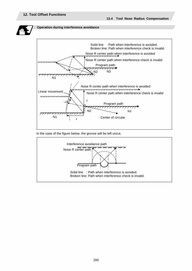
12. Tool Offset Functions 12.4 Tool Nose Radius Compensation
260
Operation during interference avoidance
Linear movement
Center of circular
Nose R center path when interference is avoided
Program path
Nose R center path when interference check is invalid
Nose R center path when interference is avoided
Program pathNose R center path when interference check is invalid
N2
N3
N1
N3
N2
N1
r
r
Solid line : Path when interference is avoided. Broken line: Path when interference check is invalid.
In the case of the figure below, the groove will be left uncut.
Interference avoidance path
Nose R center path
Program path
Solid line : Path when interference is avoided. Broken line: Path when interference check is invalid.

12. Tool Offset Functions 12.4 Tool Nose Radius Compensation
261
Interference check alarm
The interference check alarm occurs under the following conditions.
(1) When the interference check alarm function has been selected (a) When all the vectors at the end block of its own block have been deleted
When, as shown in the figure on the right, vectors 1 to 4 at the end point of the N1 block have all been deleted, program error (P153) results prior to N1 execution.
N1
2 3 N2
1
N34
(2) When the interference check avoidance function has been selected
(a) When there are valid vectors at the end point of the following block even when all the vectors at the end point of its own block have been deleted
(i) When, in the figure on the right, the N2 in interference check is conducted, the N2 end point vectors are all deleted but the N3 end point vectors are regarded as valid. Program error (P153) now occurs at the N1 end point.
Alarm stop
N1 2
N2
1
N3
4
3
N4
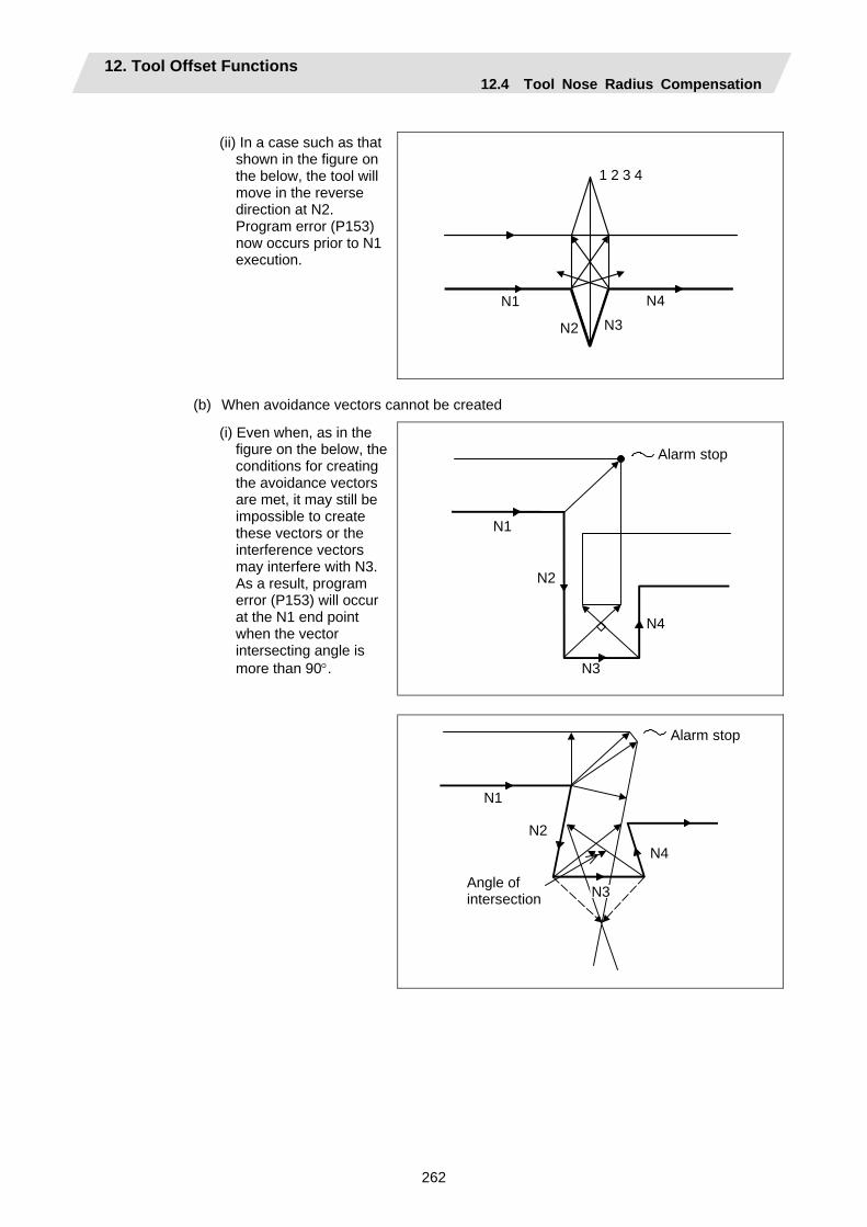
12. Tool Offset Functions 12.4 Tool Nose Radius Compensation
262
(ii) In a case such as that
shown in the figure on the below, the tool will move in the reverse direction at N2. Program error (P153) now occurs prior to N1 execution.
N1
N2 N3
N4
1 2 3 4
(b) When avoidance vectors cannot be created
(i) Even when, as in the figure on the below, the conditions for creating the avoidance vectors are met, it may still be impossible to create these vectors or the interference vectors may interfere with N3. As a result, program error (P153) will occur at the N1 end point when the vector intersecting angle is more than 90°.
N1
N2
N3
N4
Alarm stop
Alarm stop
N1
N2
N3
N4
Angle of intersection
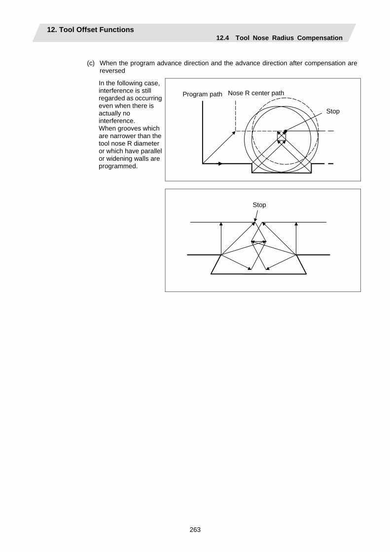
12. Tool Offset Functions 12.4 Tool Nose Radius Compensation
263
(c) When the program advance direction and the advance direction after compensation are
reversed
In the following case, interference is still regarded as occurring even when there is actually no interference. When grooves which are narrower than the tool nose R diameter or which have parallel or widening walls are programmed.
Program path Nose R center path
Stop
Stop
12. Tool Offset Functions 12.5 Compensation Data Input by Program
264
12.5 Compensation Data Input by Program; G10, G11
Function and purpose
The amount of tool offset and workpiece offset can be set or changed by the G10 command. When commanded with absolute values (X,Z,R), the commanded offset amounts serve as the new amounts; when commanded with incremental values (U,W,C), the new offset amounts are equivalent to the commanded amounts plus the current offset amount settings.
Command format
(1) Workpiece offset input (L2)
G10 L2 P X (U )Z (W ) ; P X U Z W
Offset No. X-axis offset amount (absolute) X-axis offset amount (incremental) Z-axis offset amount (absolute) Z-axis offset amount (incremental)
(2) Tool length offset input (L10)
G10 L10 P X (U )Z (W )R (C )Q ; P X U Z W R C Q
Offset No. X-axis offset amount (absolute) X-axis offset amount (incremental) Z-axis offset amount (absolute) Z-axis offset amount (incremental) Tool nose radius compensation amount (absolute) Tool nose radius compensation amount (incremental) Hypothetical tool nose point
(3) Tool nose wear offset input (L11)
G10 L11 P X (U )Z (W )R (C )Q ; P X U Z W R C Q
Offset No. X-axis offset amount (absolute) X-axis offset amount (incremental) Z-axis offset amount (absolute) Z-axis offset amount (incremental) Tool nose radius compensation amount (absolute) Tool nose radius compensation amount (incremental) Hypothetical tool nose point
(4) When there is no L command with tool length offset input (L10) or tool nose wear offset input
(L11) Tool length offset input command : P = 10000 + offset No. Tool nose wear offset input command : P = offset No.
(5) Offset input cancel
G11;
12. Tool Offset Functions 12.5 Compensation Data Input by Program
265
Detailed description
(1) The following table shows the offset Nos. and the setting ranges of the hypothetical tool nose
points.
Setting range Address
Significance of address L2 L10 L11
P Offset Nos.
0:External workpiece offset
1:G54 workpiece offset2:G55 workpiece offset3:G56 workpiece offset4:G57 workpiece offset5:G58 workpiece offset6:G59 workpiece offset
When L command is present:
1 to Max. number of tool offset sets
When L command is not present:
10001 to 10000 + Max. number of tool offset sets
When L command is/is not present:
1 to Max. number of tool offset sets
Q Hypothetical tool nose point
— 0 to 9
(Note1) The maximum number of tool offset sets for P (offset No.) with tool offset input (L10 or L11) is up to a total of 80 with the addition of options.
(The number of sets will differ according to the model so check the specifications.) (2) The setting range for the offset amount is given blow.
Program error (P35) occurs for any value not listed in the table after command unit conversion. With an incremental value command, the setting range for the offset amount is the sum of the present setting and command value.
Tool length offset amount Wear offset amount Setting Metric system Inch system Metric system Inch system
#1003 = B ±99999.999 (mm)
±9999.9999 (inch)
±999.999 (mm)
±99.9999 (inch)
#1003 = C ±99999.9999 (mm)
±9999.99999 (inch)
±999.9999 (mm)
±99.99999 (inch)
#1003 = D ±99999.99999 (mm)
±9999.999999 (inch)
±999.99999 (mm)
±99.999999 (inch)
#1003 = E ±99999.999999 (mm)
±9999.9999999 (inch)
±999.999999 (mm)
±99.9999999 (inch)
12. Tool Offset Functions 12.5 Compensation Data Input by Program
266
Precautions and Restrictions
(1) Offset amount setting range check
The maximum value of the wear offset amount and the maximum additional value for the wear offset input check respectively take precedence for a single-time offset amount in the maximum value and incremental value command of the wear offset amount, and when an amount greater than these values has been commanded, program error (P35) results.
(2) G10 is an unmodal command and is valid only in the commanded block.
(3) Offset input can be performed similarly for the third axis but even when the C axis has been designated as the third axis, address C is treated as an incremental command value of the tool nose radius in the L10 or L11 command.
(4) If an illegal L No. or tool compensation No. is commanded, program error (P172 or P170) will result, respectably.
(5) When the P command is omitted, it will be handled as the currently selected workpiece offset input.
(6) Program error (P35) results when the offset amount exceeds the setting range.
(7) X, Z and U, W are input together in a single block but when an address that commands the same offset input (X, U or Z, W) is commanded, the address which is input last is valid.
(8) Offset will be input if even one address following G10 L(2/10/11) P_ is commanded. Program error (P33) results when not even a single command has been assigned.
(Example) G10 L10 P3 Z50. ; ↓ [Tool length data]
# Z 3 50.000 Input as per left
(9) Decimal points are valid for offset amounts.
(10) G40 to G42 are ignored when they have been commanded in the same block as G10.
(11) Do not command G10 in the same block as fixed cycles and subprogram call commands. This will cause malfunctioning and program errors.
(12) When a T command has been issued in the same block as G10 with parameter "#1100 Tmove" as zero, the offset will be accomplished in the following block.
(13) For the multiple C-axis system, both C axis workpiece offsets are rewritten with the workpiece offset input.
12. Tool Offset Functions 12.6 Tool Life Management II
267
12.6 Tool Life Management II
Function and purpose
Tool life management divides the tools being used into several groups, and manages the life (usage time, number of uses) of the tools in each group. When the life is reached, a similar spare tool in the same group will be selected in order. This tool life management function with spare tools allows unmanned operation over a long time. (1) Number of life-managed tools 1-part system : Maximum 80 tools,
Multi-part system : Maximum 40 tools/part system (2) Number of groups 1-part system : Maximum 80 groups,
Multi-part system : Maximum 40 groups/part system (3) Group No. 1 to 9999 (4) Number of tools in one group Maximum 16 tools (5) Life time 0 to 999999 minutes (approx. 16667 hours) (6) Number of lives 0 to 999999 times The tool life management data can be set from the NC program or from the Tool Life Management screen. Refer to the Operation manual for the method of setting from the Tool Life Management screen. When using the NC program, register the data with the same method as compensation data input by program.
Command format
G10 L3 ; P_ L_ N_ ;T_ ; T_ ;
Life management data registration start Registration of group No., life per tool, method Registration of tool No.;
First group
P_ L_ N_ ;T_ ; T_ ;
Registration of next group No., life per tool, method Registration of tool No.;
Next group
G11 ; End of life management data registration
P L N T
Group No., (1 to 9999) Life per tool (0 to 999999 minutes, or 0 to 999999 times) Method (0:Time management, 1: Number of times management) Tool No.; the spare tool is selected in the order registered here. (Tool No. 1 to 999999. Compensation No. 1 to 80) Tn follows the specifications.
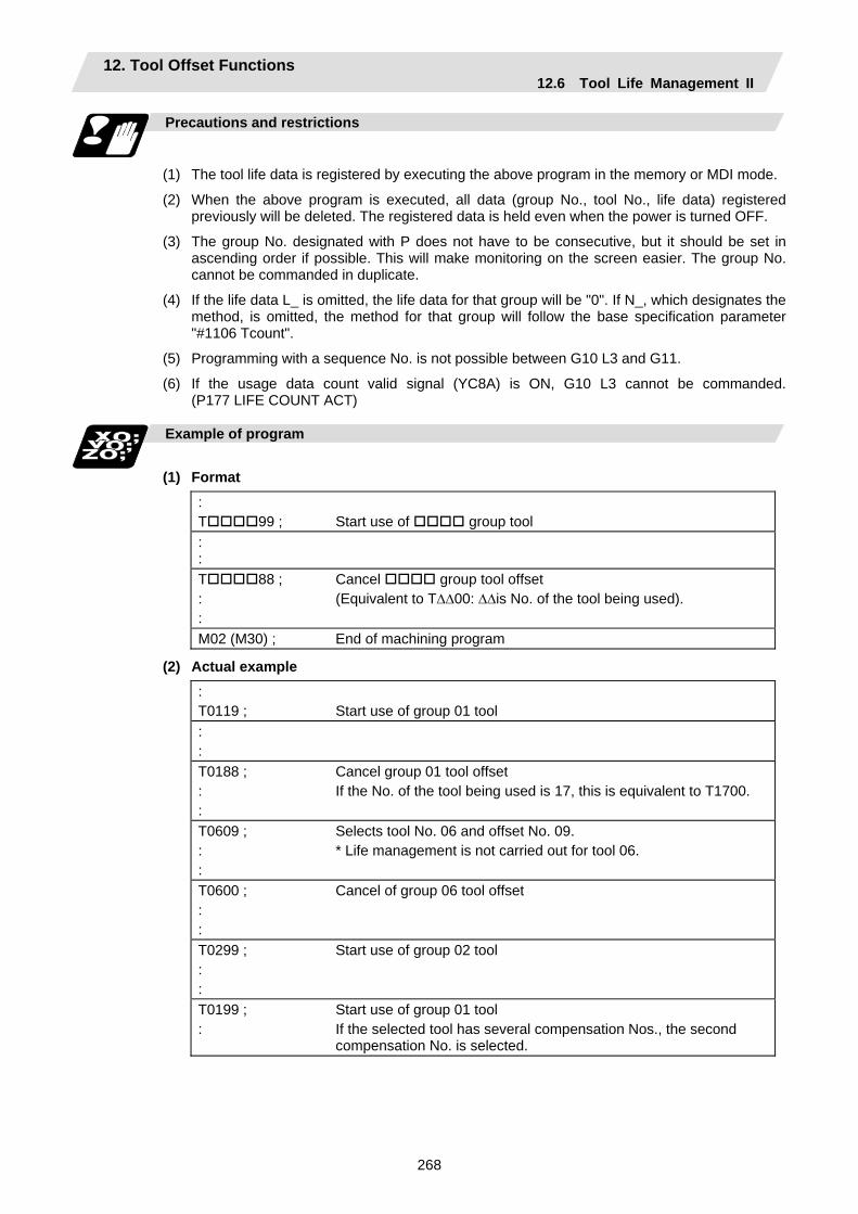
12. Tool Offset Functions 12.6 Tool Life Management II
268
Precautions and restrictions
(1) The tool life data is registered by executing the above program in the memory or MDI mode.
(2) When the above program is executed, all data (group No., tool No., life data) registered previously will be deleted. The registered data is held even when the power is turned OFF.
(3) The group No. designated with P does not have to be consecutive, but it should be set in ascending order if possible. This will make monitoring on the screen easier. The group No. cannot be commanded in duplicate.
(4) If the life data L_ is omitted, the life data for that group will be "0". If N_, which designates the method, is omitted, the method for that group will follow the base specification parameter "#1106 Tcount".
(5) Programming with a sequence No. is not possible between G10 L3 and G11.
(6) If the usage data count valid signal (YC8A) is ON, G10 L3 cannot be commanded. (P177 LIFE COUNT ACT)
Example of program
(1) Format
: T 99 ;
Start use of group tool
: :
T 88 ; : :
Cancel group tool offset (Equivalent to T∆∆00: ∆∆is No. of the tool being used).
M02 (M30) ; End of machining program
(2) Actual example : T0119 ;
Start use of group 01 tool
: :
T0188 ; : :
Cancel group 01 tool offset If the No. of the tool being used is 17, this is equivalent to T1700.
T0609 ; : :
Selects tool No. 06 and offset No. 09. * Life management is not carried out for tool 06.
T0600 ; : :
Cancel of group 06 tool offset
T0299 ; : :
Start use of group 02 tool
T0199 ; :
Start use of group 01 tool If the selected tool has several compensation Nos., the second compensation No. is selected.
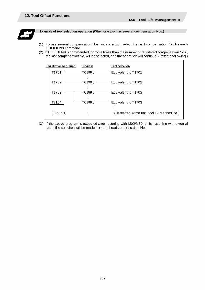
12. Tool Offset Functions 12.6 Tool Life Management II
269
Example of tool selection operation (When one tool has several compensation Nos.)
(1) To use several compensation Nos. with one tool, select the next compensation No. for each
T 99 command. (2) If T 99 is commanded for more times than the number of registered compensation Nos.,
the last compensation No. will be selected, and the operation will continue. (Refer to following.)
Registration to group 1 Program Tool selection
T1701 T0199 ; Equivalent to T1701 : T1702 T0199 ; Equivalent to T1702 : T1703 T0199 ; Equivalent to T1703 : T2104 T0199 ; Equivalent to T1703
: :
(Group 1) : :(Hereafter, same until tool 17 reaches life.)
(3) If the above program is executed after resetting with M02/M30, or by resetting with external reset, the selection will be made from the head compensation No.
12. Tool Offset Functions 12.6 Tool Life Management II
270
12.6.1 Counting the Tool Life
Function and purpose
The tool life can be counted with the time-count type or number of uses-count type. The count method and timing for the number of uses-count type can be changed to type 2 with the parameter setting (#1277 ext13/bit0). If the usage data is equivalent to or more than the life data as a result of the count up, a spare tool in the group will be selected with the next group selection command (T 99), and the newly selected tool will be counted. When all tools in the group have reached their lives and a spare tool cannot be selected, the count will continue.
(1) Counting the time of uses when the time-count type method is selected
In the cutting mode (G01, G02, G03, G31, G33, etc.), the time that the tool is used is counted with 100ms units. The time is not counted during dwell, machine lock, miscellaneous function lock or dry run. Whether to count or not for a single block can be changed by setting the parameter.
(Note) • The maximum value for the life is 999999 minutes.
• The data is displayed as a minute unit on the Tool Life Management screen.
12. Tool Offset Functions 12.6 Tool Life Management II
271
(2) Counting the number of uses when the number of uses-count type method is selected
(a) Type 1 (#1277 ext13/bit0: 0) The number of uses is counted when the No. of the tool being used is changed with the tool selection command (T 99) and when the program is in the cutting mode (excluding machine lock, miscellaneous function lock and dry run states). The use is not counted if the cutting mode is not entered even once after the No. changes. Whether to count or not during single block can be changed with the parameter setting.
(Note) • The maximum value for the life is 999999 times. • If only the compensation No. of the tool being used changes, a count will not be
made.
Example: When T code of tool being used is T12345678
T 1 2 3 4 5 6 7 8 Compensation No.: No count even when changed.Tool No.: Counted when changed.
<<Operation example>>
Program
Program
T0199........ 1 : T0199 : T0199
T0199......... 1 : T0299 : T0199......... 2 : T0299 : T0199......... 3
Group 01 has been used one time.
Group 01 has been used three times.
* The number of uses is for one program execution. If the program is executed again after resetting, it will be counted.
(b) Type 2 (#1277 ext13/bit0: 1)
(i) Only the group used for cutting from when the machining program starts to when it is reset is incremented by "1". The count is made at the reset.
(ii) If recount M is commanded, the group used up to that point will be incremented by "1" in the counter.
(Note 1) A count is not made in the machine lock, miscellaneous function lock or dry run
states.
(Note 2) During single block, select whether to count with the parameter.
(Note 3) The maximum value of the life is 999999 times.
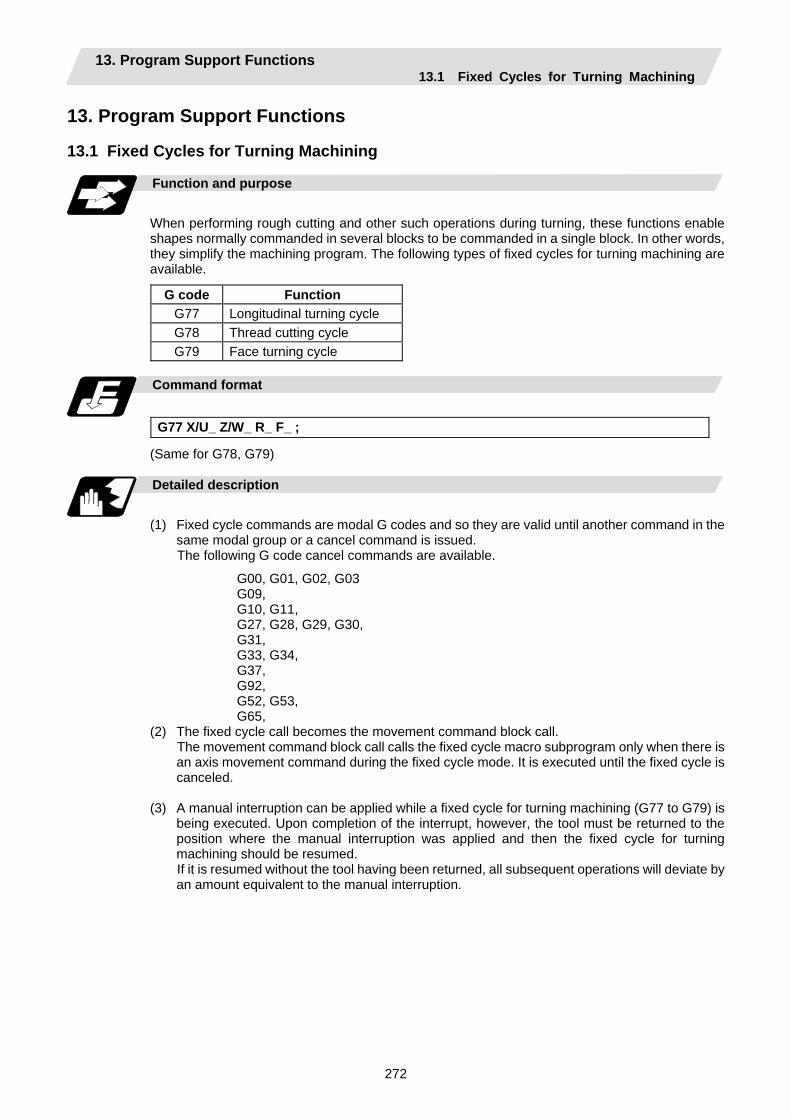
13. Program Support Functions 13.1 Fixed Cycles for Turning Machining
272
13. Program Support Functions
13.1 Fixed Cycles for Turning Machining
Function and purpose
When performing rough cutting and other such operations during turning, these functions enable shapes normally commanded in several blocks to be commanded in a single block. In other words, they simplify the machining program. The following types of fixed cycles for turning machining are available.
G code Function G77 Longitudinal turning cycle G78 Thread cutting cycle G79 Face turning cycle
Command format
G77 X/U_ Z/W_ R_ F_ ;
(Same for G78, G79)
Detailed description
(1) Fixed cycle commands are modal G codes and so they are valid until another command in the
same modal group or a cancel command is issued. The following G code cancel commands are available.
G00, G01, G02, G03 G09, G10, G11, G27, G28, G29, G30, G31, G33, G34, G37, G92, G52, G53, G65,
(2) The fixed cycle call becomes the movement command block call. The movement command block call calls the fixed cycle macro subprogram only when there is an axis movement command during the fixed cycle mode. It is executed until the fixed cycle is canceled.
(3) A manual interruption can be applied while a fixed cycle for turning machining (G77 to G79) is
being executed. Upon completion of the interrupt, however, the tool must be returned to the position where the manual interruption was applied and then the fixed cycle for turning machining should be resumed. If it is resumed without the tool having been returned, all subsequent operations will deviate by an amount equivalent to the manual interruption.
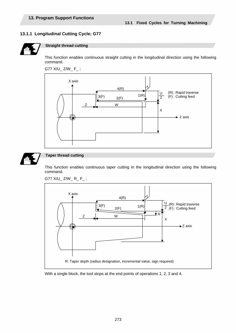
13. Program Support Functions 13.1 Fixed Cycles for Turning Machining
273
13.1.1 Longitudinal Cutting Cycle; G77
Straight thread cutting
This function enables continuous straight cutting in the longitudinal direction using the following command.
G77 X/U_ Z/W_ F_ ;
X axis
Z axis
XZ W
U2
(R) : Rapid traverse(F) : Cutting feed 3(F) 2(F)
4(R)
1(R)
Taper thread cutting
This function enables continuous taper cutting in the longitudinal direction using the following command.
G77 X/U_ Z/W_ R_ F_ ;
X axis
Z axis
X Z W
3(F)2(F)
4(R)
1(R)
R
U 2
(R) : Rapid traverse(F) : Cutting feed
R: Taper depth (radius designation, incremental value, sign required)
With a single block, the tool stops at the end points of operations 1, 2, 3 and 4.

13. Program Support Functions 13.1 Fixed Cycles for Turning Machining
274
Depending on the U, W and R signs, the following shapes are created.
(1) U < 0, W < 0, R < 0 (2) U < 0, W < 0, R > 0
W
R
X
Z
U 2 1
2
3
4
W
R
X
Z
U 2
1
2 3
4
(3) U > 0, W < 0, R < 0 (4) U > 0, W < 0, R > 0
W
R
X Z
U 2
1
2 3
4
W
R
X
Z
U 2 1
2
3
4
Program error (P191) results with shapes (2) and (3) unless the following condition is satisfied.
|u/2 | ≥ | r |
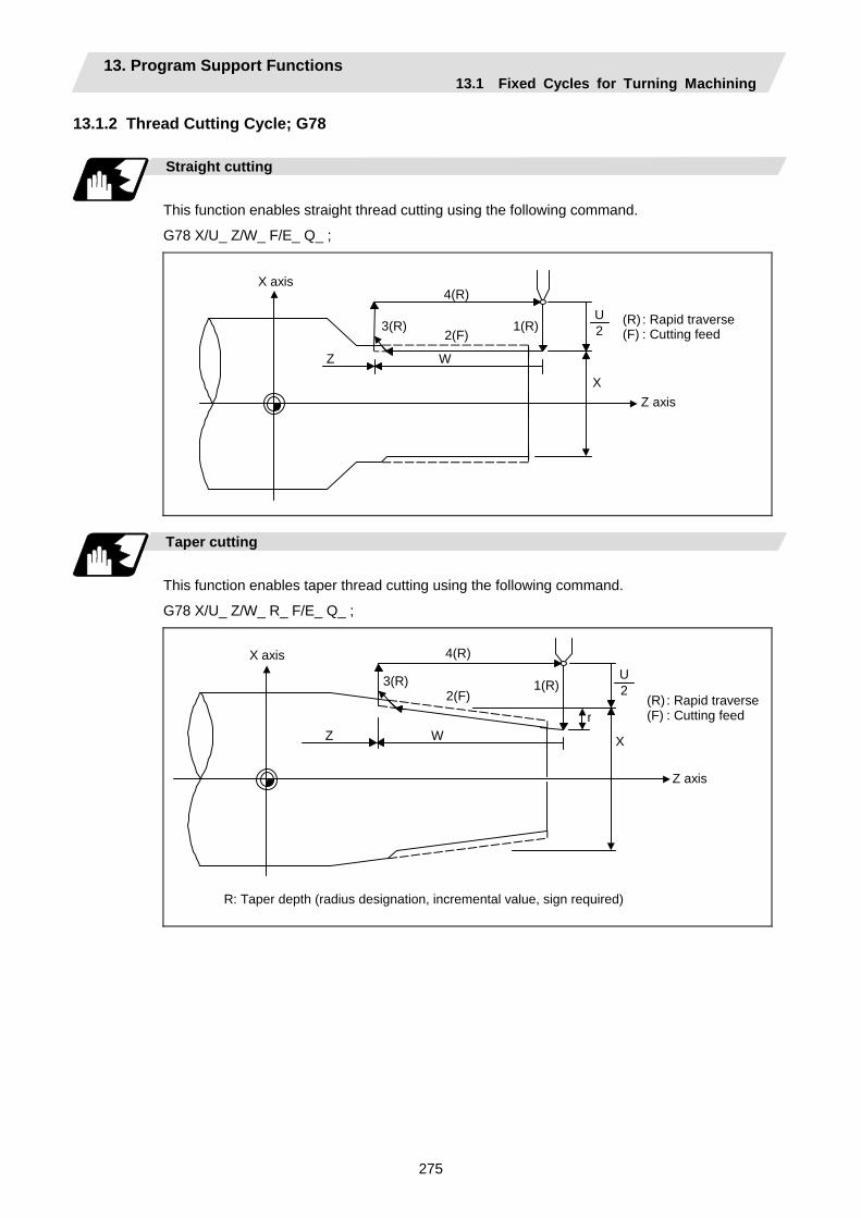
13. Program Support Functions 13.1 Fixed Cycles for Turning Machining
275
13.1.2 Thread Cutting Cycle; G78
Straight cutting
This function enables straight thread cutting using the following command.
G78 X/U_ Z/W_ F/E_ Q_ ;
X axis
Z axis X
Z W
3(R)2(F)
4(R)
1(R)U2
(R) : Rapid traverse(F) : Cutting feed
Taper cutting
This function enables taper thread cutting using the following command.
G78 X/U_ Z/W_ R_ F/E_ Q_ ;
X axis
Z axis
X Z W
3(R)2(F)
4(R)
1(R)
r
U 2
(R) : Rapid traverse(F) : Cutting feed
R: Taper depth (radius designation, incremental value, sign required)

13. Program Support Functions 13.1 Fixed Cycles for Turning Machining
276
Details for chamfering
α
θ
α : Chamfering amount of thread If the thread lead is assumed to be L,
then the parameter can be set in 0.1L units from 0 to 12.7L.
θ : Chamfering angle of thread The parameter can be set in 1° units
from 0 to 89°
With a single block, the tool stops at the end points of operations 1, 3 and 4. When the feed hold function is applied during a thread cutting cycle, automatic operation will stop if no thread is then being cut, or if applied in the interval from the execution of the thread cutting command to the axis movement. If thread cutting is proceeding when the function is applied, the operation stops at the next movement completion position (completion of operation 3) of the thread cutting. The dry run valid/invalid status does not change during thread cutting.
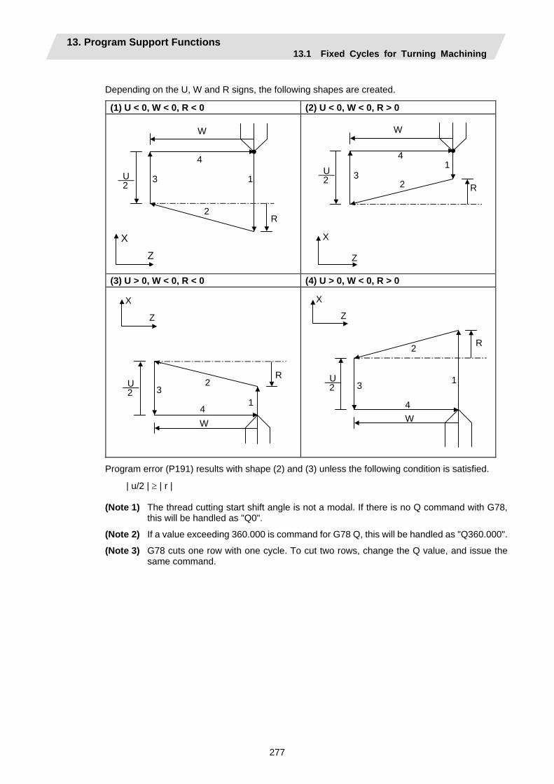
13. Program Support Functions 13.1 Fixed Cycles for Turning Machining
277
Depending on the U, W and R signs, the following shapes are created.
(1) U < 0, W < 0, R < 0 (2) U < 0, W < 0, R > 0
W
R
X
Z
U 2
1
2
3
4
W
R
X
Z
U 2
1
2 3
4
(3) U > 0, W < 0, R < 0 (4) U > 0, W < 0, R > 0
W
R
X
Z
U 2
1
2 3
4
W
R
X
Z
U 2
1
2
3
4
Program error (P191) results with shape (2) and (3) unless the following condition is satisfied.
| u/2 | ≥ | r |
(Note 1) The thread cutting start shift angle is not a modal. If there is no Q command with G78, this will be handled as "Q0".
(Note 2) If a value exceeding 360.000 is command for G78 Q, this will be handled as "Q360.000".
(Note 3) G78 cuts one row with one cycle. To cut two rows, change the Q value, and issue the same command.

13. Program Support Functions 13.1 Fixed Cycles for Turning Machining
278
13.1.3 Face Cutting Cycle; G79
Straight cutting
This function enables continuous straight cutting in the face direction using the following command.
G79 X/U_ Z/W_ F_ ;
X axis
Z axis X
Z W
3(F)
2(F) 4(R)
1(R)
U2
(R) : Rapid traverse(F) : Cutting feed
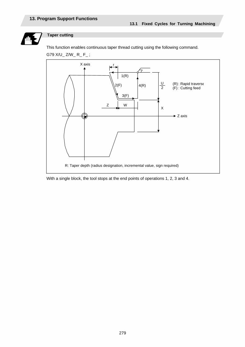
13. Program Support Functions 13.1 Fixed Cycles for Turning Machining
279
Taper cutting
This function enables continuous taper thread cutting using the following command.
G79 X/U_ Z/W_ R_ F_ ;
X axis
Z axis
XZ W
3(F)
2(F) 4(R)
1(R)
r
U2
(R) : Rapid traverse(F) : Cutting feed
R: Taper depth (radius designation, incremental value, sign required)
With a single block, the tool stops at the end points of operations 1, 2, 3 and 4.
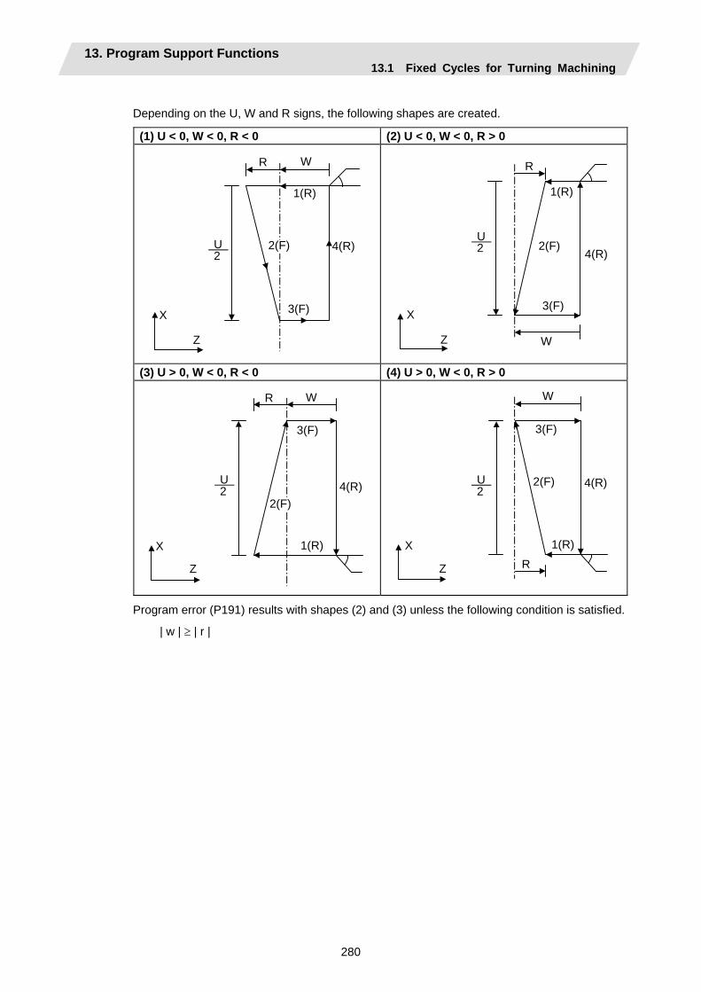
13. Program Support Functions 13.1 Fixed Cycles for Turning Machining
280
Depending on the U, W and R signs, the following shapes are created.
(1) U < 0, W < 0, R < 0 (2) U < 0, W < 0, R > 0
WR
X
Z
U 2
1(R)
3(F)
4(R)2(F)
W
R
X
Z
U 2
1(R)
2(F)
3(F)
4(R)
(3) U > 0, W < 0, R < 0 (4) U > 0, W < 0, R > 0
WR
X
Z
U 2
1(R)
3(F)
4(R)2(F)
W
R
X
Z
U 2
1(R)
2(F)
3(F)
4(R)
Program error (P191) results with shapes (2) and (3) unless the following condition is satisfied.
| w | ≥ | r |
13. Program Support Functions 13.2 Fixed Cycle for Turning Machining (MITSUBISHI CNC special format)
281
13.2 Fixed Cycle for Turning Machining (MITSUBISHI CNC special format)
Function and purpose
When performing rough cutting and other such operations during turning, these functions enable shapes normally commanded in several blocks to be commanded in a single block. In other words, they simplify the machining program. When using the MITSUBISHI CNC special format (#1265 ext01/bit1 ON), some addresses differ from the normal format. The sections that differ from the normal format are shown below. Refer to section "13.1 Fixed cycle for turning machining" for details on the fixed cycles for turning machining.
Command format
G77 X(U)_ Z(W)_ I_ F_ ; (The same for G78) G79 X(U)_ Z(W)_ K_ F_ ;
Detailed description
(1) Comparison of MITSUBISHI CNC special format and normal format
Some addresses in the MITSUBISHI CNC special format differ from the normal format.
Function MITSUBISHI CNC special format Normal format Difference from normal
format Longitudinal turning cycle
G77 X Z I F ; or G77 U W I F ;
G77 X Z R F ; or G77 U W R F ;
Taper depth Designate with R → I
Thread cutting cycle
G78 X Z I F ; or G78 U W I F ;
G78 X Z R F ; or G78 U W R F ;
Taper depth Designate with R → I
Face turning cycle
G79 X Z K F ; or G79 U W K F ;
G79 X Z R F ; or G79 U W R F ;
Taper depth Designate with R → K
13. Program Support Functions 13.3 Compound Type Fixed Cycle for Turning Machining
282
13.3 Compound Type Fixed Cycle for Turning Machining
Function and purpose
These functions enable prepared fixed cycle to be executed by commanding the corresponding program in a block. The types of fixed cycles are listed below.
G code Function G70 Finishing cycle G71 Longitudinal rough cutting cycle (finished shape chamfering) G72 Face rough cutting cycle (finished shape chamfering) G73 Formed material rough cutting cycle
Compound type fixed cycle for turning machining I
G74 Face cut-off cycle G75 Longitudinal cut-off cycle G76 Compound thread cutting cycle
Compound type fixed cycle for turning machining II
If, with any of the above functions for the compound type fixed cycle I (G70 to G73), the finished shape program has not been entered in the memory, the function cannot be used.
Command format
G70 A_ P_ Q_ ; G71 U_ R_ ; G71 A_ P_ Q_ U_ W_ F_ S_ T_ ; G72 W_ R_ ; G72 A_ P_ Q_ U_ W_ F_ S_ T_ ; G73 U_ W_ R_ ; G73 A_ P_ Q_ U_ W_ F_ S_ T_ ; G74 R_ ; G74 X (U)_ Z (W)_ P_ Q_ R_ F_ ; (Same for G75) G76 P_ R_ ; G76 X (U)_ Z (W)_ P_ Q_ R_ F_ ;
Detailed description
(1) The A, P and Q commands of the compound type fixed cycles I are described below.
(a) When the A command is not present, P and Q in the program now being executed are called. When the A command is present and the P command is not present, the head block of the program designated by the A command is treated as the P command.
(b) When the Q command is not present, operation continues until the M99 command is located. When both the Q and M99 commands are not present, operation continues until the final block in the finished shape program.
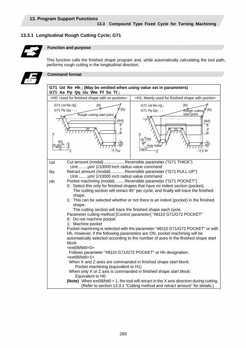
13. Program Support Functions 13.3 Compound Type Fixed Cycle for Turning Machining
283
13.3.1 Longitudinal Rough Cutting Cycle; G71
Function and purpose
This function calls the finished shape program and, while automatically calculating the tool path, performs rough cutting in the longitudinal direction.
Command format
G71 Ud Re Hh ; (May be omitted when using value set in parameters) G71 Aa Pp Qq Uu Ww Ff Ss Tt ; <H0: Used for finished shape with no pockets> <H1: Mainly used for finished shape with pocket>
G71 Ud Re H0 ; G71 Pp Qq . . ;
Rough cutting start point q
(R) (R)
(R/f)
d
u/2pw
(f)
(R) (f)
(f) e Z
X
45°
G71 Ud Re H1 ; G71 Pp Qq . . ; Rough cutting
start point q
(R) (R)
(R/f)
d
u/2p w
(f)
(R)(f)
e Z
X
Hole base
Ud Re Hh
Cut amount (modal) ..................Reversible parameter ("G71 THICK") Unit ....... µm/ 1/10000 inch radius value command Retract amount (modal)............Reversible parameter ("G71 PULL UP") Unit ....... µm/ 1/10000 inch radius value command Pocket machining (modal) ........Reversible parameter ("G71 POCKET") 0: Select this only for finished shapes that have no indent section (pocket). The cutting section will retract 45° per cycle, and finally will trace the finished
shape. 1: This can be selected whether or not there is an indent (pocket) in the finished
shape. The cutting section will trace the finished shape each cycle. Parameter cutting method [Control parameter] "#8110 G71/G72 POCKET" 0: Do not machine pocket 1: Machine pocket Pocket machining is selected with the parameter "#8110 G71/G72 POCKET" or with Hh. However, if the following parameters are ON, pocket machining will be automatically selected according to the number of axes in the finished shape start block. <ext08/bit0=0> Follows parameter "#8110 G71/G72 POCKET" or Hh designation.
<ext08/bit0=1> When X and Z axes are commanded in finished shape start block:
Pocket machining (equivalent to H1) When only X or Z axis is commanded in finished shape start block:
Equivalent to H0 (Note) When ext08/bit0 = 1, the tool will retract in the X axis direction during cutting. (Refer to section 13.3.1 "Cutting method and retract amount" for details.)
13. Program Support Functions 13.3 Compound Type Fixed Cycle for Turning Machining
284
Aa Pp Qq Uu Ww Ff Ss,Tt
Finished shape program No. (Program being executed when omitted) If the A command is omitted, the P and Q commands in the program being executed will be used. If A is omitted, the program will be executed in the order of G71 and then the program following Qq (finished shape end sequence No.) A file name can be designated instead of address A by enclosing the file name in brackets <>. (The file name can have up to 32 characters, including the extension.)Finished shape start sequence No. (Head of program when omitted) Finished shape end sequence No. (To end of program when omitted) Even when Q is commanded, if M99 is commanded first the program will continue to M99. X axis direction finishing allowance (When omitted, X axis direction finishing allowance is handled as 0.) Unit ..... µm/ Follows 1/10000ich diameter/radius value command (#1019 dia). Z axis direction finishing allowance (When omitted, Z axis direction finishing allowance is handled as 0.) Unit ..... µm/ Follows 1/10000ich radius value command Cutting speed (Follows cutting speed (modal) before G71 when omitted) Spindle command, tool command
Validity of pocket machining
(1) Validity of pocket section
It is judged that there is a pocket section when down cutting (finished shape block in which previous movement block has no X axis movement command, or the X axis moves in the reverse direction as the hole base and then moves toward the hole base) is issued between the block following the finished shape start block and the end block. (Note) During tool nose radius compensation, the validity of the pocket section is judged in respect to the finished shape after tool nose radius compensation.
(2) Selection of pocket machining
Execution of pocket machining is designated with Hh, but can also be set with the parameters. Pocket machining is executed when the two axes X and Z are designated in the first movement block of the finished shape program.
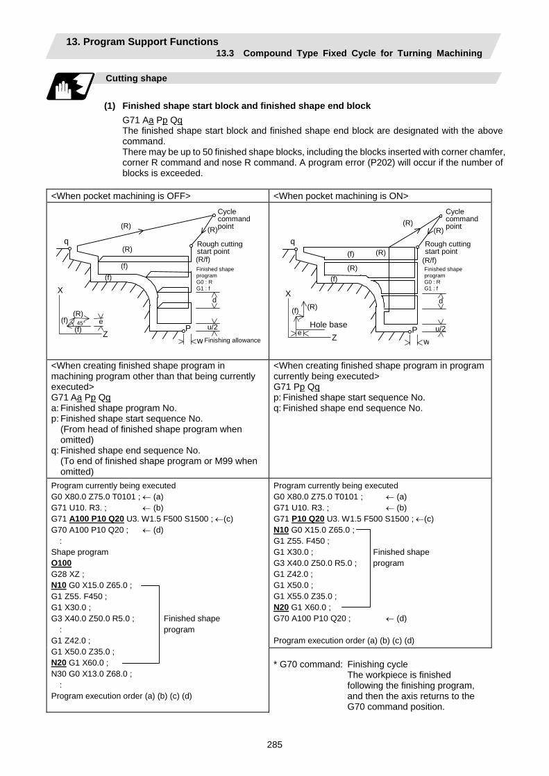
13. Program Support Functions 13.3 Compound Type Fixed Cycle for Turning Machining
285
Cutting shape
(1) Finished shape start block and finished shape end block
G71 Aa Pp Qq The finished shape start block and finished shape end block are designated with the above command. There may be up to 50 finished shape blocks, including the blocks inserted with corner chamfer, corner R command and nose R command. A program error (P202) will occur if the number of blocks is exceeded.
<When pocket machining is OFF> <When pocket machining is ON>
(R) (f)
(f) e Z
X
45°
q
(R)
(R)
(R)
(R/f)
(f) (f)
Cycle command point
Rough cutting start point
Finished shape program G0 : R G1 : f
P
d
u/2 w Finishing allowance
q
(R)
(R)
(R)
(R/f)
(f)
(f)
P
d
u/2 w
(R)
(R)(f)
e Z
X
Hole base
Cycle command point
Rough cutting start point
Finished shape program G0 : R G1 : f
<When creating finished shape program in machining program other than that being currently executed> G71 Aa Pp Qq a: Finished shape program No. p: Finished shape start sequence No. (From head of finished shape program when
omitted) q: Finished shape end sequence No. (To end of finished shape program or M99 when
omitted)
<When creating finished shape program in program currently being executed> G71 Pp Qq p: Finished shape start sequence No. q: Finished shape end sequence No.
Program currently being executed G0 X80.0 Z75.0 T0101 ; ← (a) G71 U10. R3. ; ← (b) G71 P10 Q20 U3. W1.5 F500 S1500 ; ←(c) N10 G0 X15.0 Z65.0 ; G1 Z55. F450 ; G1 X30.0 ; Finished shape G3 X40.0 Z50.0 R5.0 ; program G1 Z42.0 ; G1 X50.0 ; G1 X55.0 Z35.0 ; N20 G1 X60.0 ; G70 A100 P10 Q20 ; ← (d) Program execution order (a) (b) (c) (d)
Program currently being executed G0 X80.0 Z75.0 T0101 ; ← (a) G71 U10. R3. ; ← (b) G71 A100 P10 Q20 U3. W1.5 F500 S1500 ; ←(c)G70 A100 P10 Q20 ; ← (d) : Shape program O100 G28 XZ ; N10 G0 X15.0 Z65.0 ; G1 Z55. F450 ; G1 X30.0 ; G3 X40.0 Z50.0 R5.0 ; Finished shape : program G1 Z42.0 ; G1 X50.0 Z35.0 ; N20 G1 X60.0 ; N30 G0 X13.0 Z68.0 ; : Program execution order (a) (b) (c) (d)
* G70 command: Finishing cycle The workpiece is finished
following the finishing program, and then the axis returns to the G70 command position.
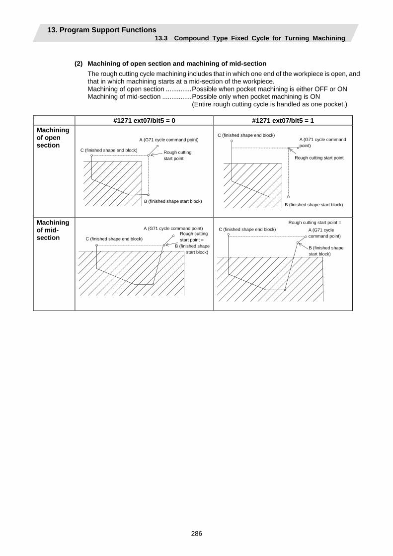
13. Program Support Functions 13.3 Compound Type Fixed Cycle for Turning Machining
286
(2) Machining of open section and machining of mid-section
The rough cutting cycle machining includes that in which one end of the workpiece is open, and that in which machining starts at a mid-section of the workpiece. Machining of open section ..............Possible when pocket machining is either OFF or ON Machining of mid-section ................Possible only when pocket machining is ON (Entire rough cutting cycle is handled as one pocket.)
#1271 ext07/bit5 = 0 #1271 ext07/bit5 = 1
Machining of open section
B (finished shape start block)
C (finished shape end block)
A (G71 cycle command point)
Rough cutting start point
B (finished shape start block)
C (finished shape end block)A (G71 cycle command point)
Rough cutting start point
Machining of mid- section
B (finished shape start block)
C (finished shape end block)
A (G71 cycle command point)Rough cutting start point =
B (finished shape start block)
C (finished shape end block) A (G71 cycle command point)
Rough cutting start point =
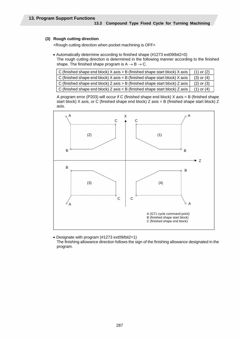
13. Program Support Functions 13.3 Compound Type Fixed Cycle for Turning Machining
287
(3) Rough cutting direction
<Rough cutting direction when pocket machining is OFF> • Automatically determine according to finished shape (#1273 ext09/bit2=0)
The rough cutting direction is determined in the following manner according to the finished shape. The finished shape program is A → B → C.
C (finished shape end block) X axis > B (finished shape start block) X axis (1) or (2) C (finished shape end block) X axis < B (finished shape start block) X axis (3) or (4) C (finished shape end block) Z axis > B (finished shape start block) Z axis (2) or (3) C (finished shape end block) Z axis < B (finished shape start block) Z axis (1) or (4)
A program error (P203) will occur if C (finished shape end block) X axis = B (finished shape start block) X axis, or C (finished shape end block) Z axis = B (finished shape start block) Z axis.
X
Z
A
A
A
A
B B
B B
C
C C
C
(2) (1)
(3) (4)
A (G71 cycle command point) B (finished shape start block) C (finished shape end block)
• Designate with program (#1273 ext09/bit2=1)
The finishing allowance direction follows the sign of the finishing allowance designated in the program.
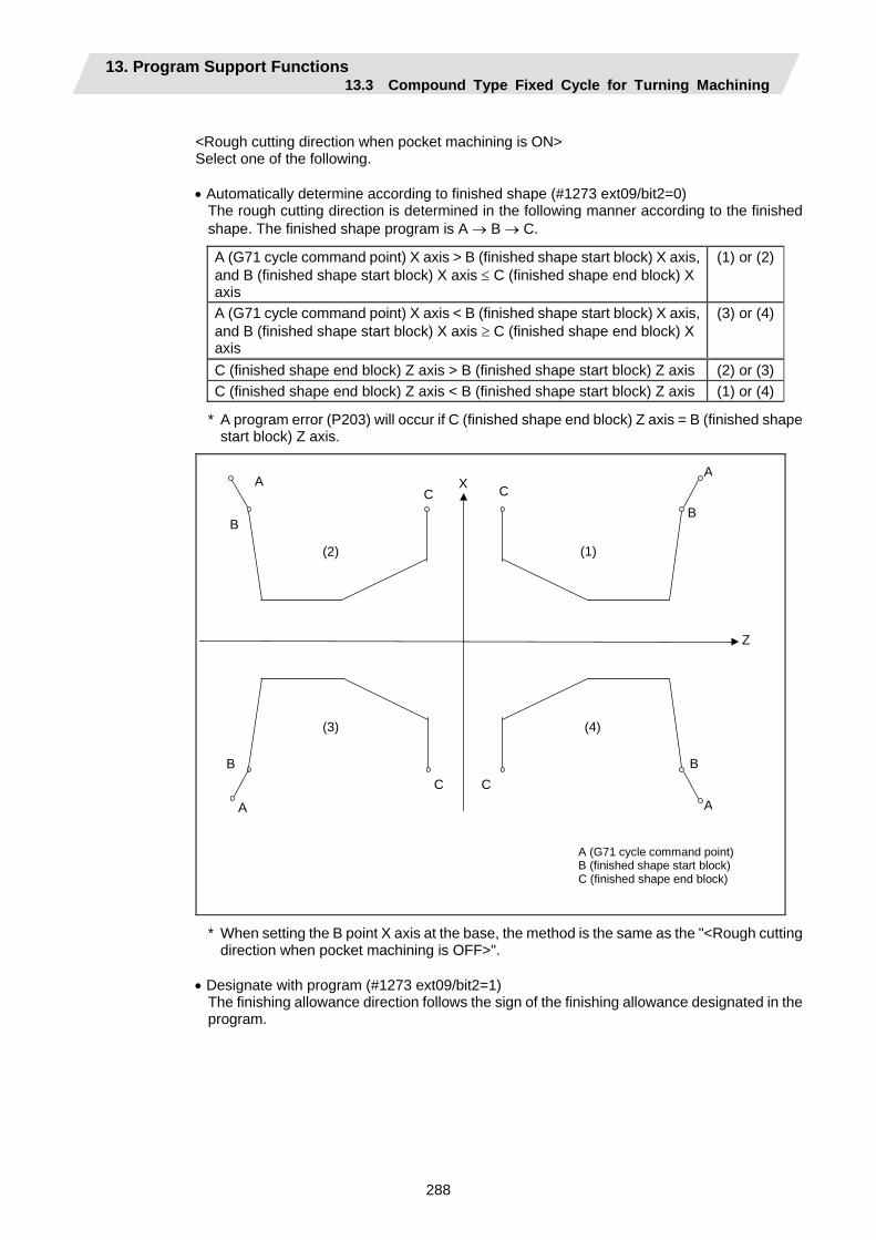
13. Program Support Functions 13.3 Compound Type Fixed Cycle for Turning Machining
288
<Rough cutting direction when pocket machining is ON> Select one of the following. • Automatically determine according to finished shape (#1273 ext09/bit2=0)
The rough cutting direction is determined in the following manner according to the finished shape. The finished shape program is A → B → C.
A (G71 cycle command point) X axis > B (finished shape start block) X axis, and B (finished shape start block) X axis ≤ C (finished shape end block) X axis
(1) or (2)
A (G71 cycle command point) X axis < B (finished shape start block) X axis, and B (finished shape start block) X axis ≥ C (finished shape end block) X axis
(3) or (4)
C (finished shape end block) Z axis > B (finished shape start block) Z axis (2) or (3)C (finished shape end block) Z axis < B (finished shape start block) Z axis (1) or (4)
* A program error (P203) will occur if C (finished shape end block) Z axis = B (finished shape start block) Z axis.
X
Z
A
A
A
A
B B
B B
C
C C
C
(2) (1)
(3) (4)
A (G71 cycle command point) B (finished shape start block) C (finished shape end block)
* When setting the B point X axis at the base, the method is the same as the "<Rough cutting direction when pocket machining is OFF>".
• Designate with program (#1273 ext09/bit2=1)
The finishing allowance direction follows the sign of the finishing allowance designated in the program.
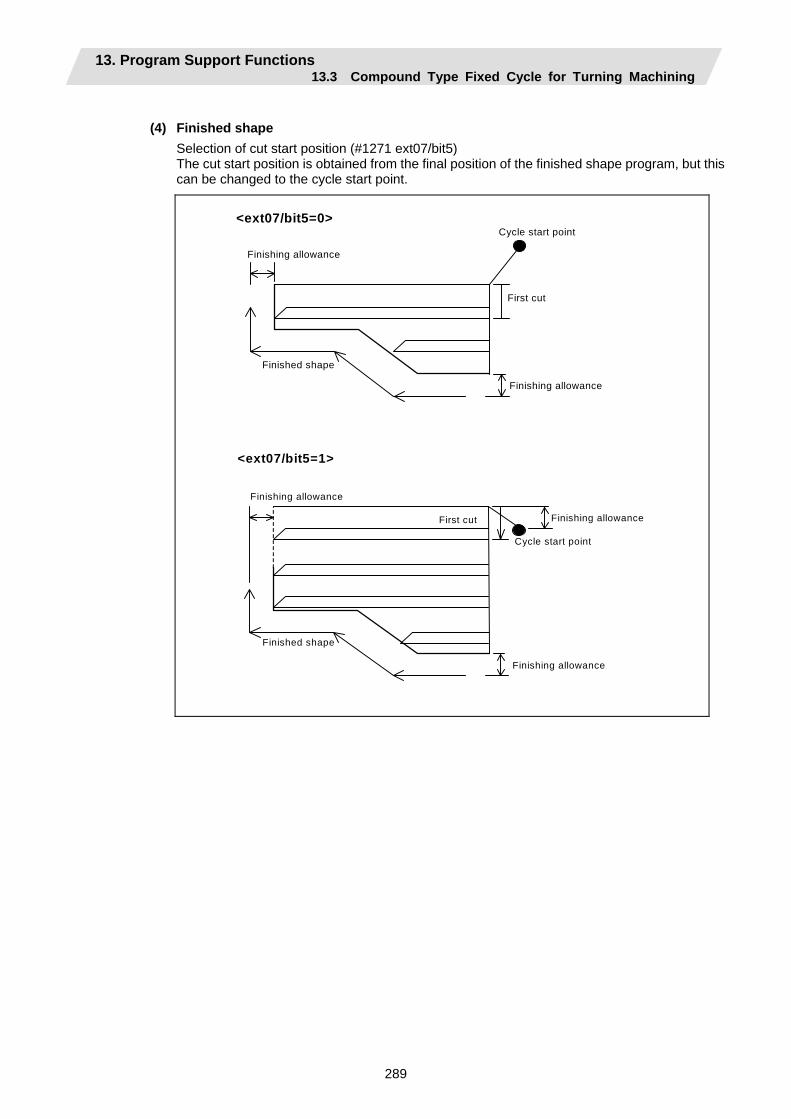
13. Program Support Functions 13.3 Compound Type Fixed Cycle for Turning Machining
289
(4) Finished shape
Selection of cut start position (#1271 ext07/bit5) The cut start position is obtained from the final position of the finished shape program, but this can be changed to the cycle start point.
<ext07/bit5=0>
Finishing allowance
Cycle start point
First cut
Finished shape
Finishing allowance
<ext07/bit5=1>
Finishing allowance
Cycle start point
First cut
Finished shape
Finishing allowance
Finishing allowance
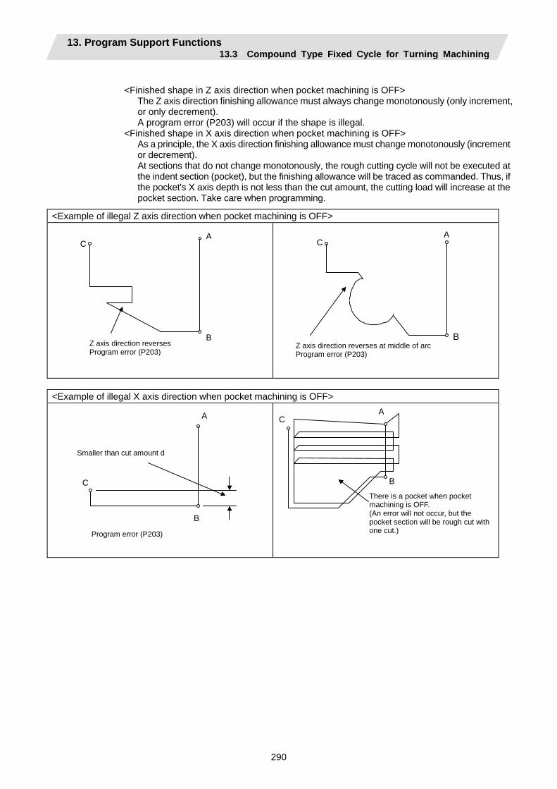
13. Program Support Functions 13.3 Compound Type Fixed Cycle for Turning Machining
290
<Finished shape in Z axis direction when pocket machining is OFF>
The Z axis direction finishing allowance must always change monotonously (only increment, or only decrement). A program error (P203) will occur if the shape is illegal.
<Finished shape in X axis direction when pocket machining is OFF> As a principle, the X axis direction finishing allowance must change monotonously (increment or decrement). At sections that do not change monotonously, the rough cutting cycle will not be executed at the indent section (pocket), but the finishing allowance will be traced as commanded. Thus, if the pocket's X axis depth is not less than the cut amount, the cutting load will increase at the pocket section. Take care when programming.
<Example of illegal Z axis direction when pocket machining is OFF>
Z axis direction reverses Program error (P203)
A C
B
Z axis direction reverses at middle of arc Program error (P203)
A C
B
<Example of illegal X axis direction when pocket machining is OFF>
Smaller than cut amount d
A
B
C
Program error (P203)
AC
B
There is a pocket when pocket machining is OFF. (An error will not occur, but the pocket section will be rough cut with one cut.)
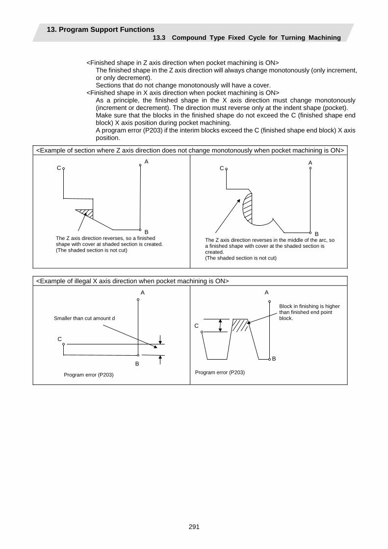
13. Program Support Functions 13.3 Compound Type Fixed Cycle for Turning Machining
291
<Finished shape in Z axis direction when pocket machining is ON>
The finished shape in the Z axis direction will always change monotonously (only increment, or only decrement). Sections that do not change monotonously will have a cover.
<Finished shape in X axis direction when pocket machining is ON> As a principle, the finished shape in the X axis direction must change monotonously (increment or decrement). The direction must reverse only at the indent shape (pocket). Make sure that the blocks in the finished shape do not exceed the C (finished shape end block) X axis position during pocket machining. A program error (P203) if the interim blocks exceed the C (finished shape end block) X axis position.
<Example of section where Z axis direction does not change monotonously when pocket machining is ON>
The Z axis direction reverses, so a finished shape with cover at shaded section is created. (The shaded section is not cut)
A C
B
The Z axis direction reverses in the middle of the arc, soa finished shape with cover at the shaded section is created. (The shaded section is not cut)
A C
B
<Example of illegal X axis direction when pocket machining is ON>
Smaller than cut amount d
A
B
C
Program error (P203)
Block in finishing is higher than finished end point block.
A
C
B
Program error (P203)
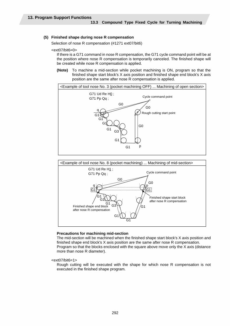
13. Program Support Functions 13.3 Compound Type Fixed Cycle for Turning Machining
292
(5) Finished shape during nose R compensation
Selection of nose R compensation (#1271 ext07/bit6)
<ext07/bit6=0> If there is a G71 command in nose R compensation, the G71 cycle command point will be at the position where nose R compensation is temporarily canceled. The finished shape will be created while nose R compensation is applied.
(Note) To machine a mid-section while pocket machining is ON, program so that the finished shape start block's X axis position and finished shape end block's X axis position are the same after nose R compensation is applied.
<Example of tool nose No. 3 (pocket machining OFF) ... Machining of open section>
G0G0
G0
G1
G1
G1 G3
G1
G1G1
q
p
G71 Ud Re H0 ; G71 Pp Qq ; Cycle command point
Rough cutting start point
<Example of tool nose No. 8 (pocket machining) ... Machining of mid-section>
G0G0
G1
G1
G1G1
G3
G1
G1
q p
G71 Ud Re H1 ; G71 Pp Qq ;
Finished shape end block after nose R compensation
Finished shape start block after nose R compensation
G1 G1
Cycle command point
Precautions for machining mid-section The mid-section will be machined when the finished shape start block's X axis position and finished shape end block's X axis position are the same after nose R compensation. Program so that the blocks enclosed with the square above move only the X axis (distance more than nose R diameter).
<ext07/bit6=1> Rough cutting will be executed with the shape for which nose R compensation is not executed in the finished shape program.

13. Program Support Functions 13.3 Compound Type Fixed Cycle for Turning Machining
293
Cut amount
(1) The cut amount is designated by Ud. However, it is possible to change the cut amount with
each cutting pass by setting the cut change amount (∆d) using a parameter.
Cut amount designation (#1271 ext07/bit7)
<ext07/bit7=0> If the amount of one cut commanded in the program is deeper than the cutting depth of the finished shape (d < ∆d), a program error (P204) occurred.
<ext07/bit7=1> A program error will not occur even if the amount designated for one cut is deeper than the cutting depth of the finished shape, and the command will be executed as one cut. Note that the amount of one cut must be commanded between 0 and 99.999mm. A program error will occur if a value exceeding this range is commanded.
(2) The end of the cutting is the cut amount, but if this value is smaller than the value set in the parameters, cutting will not be carried out, and instead finishing rough cutting will be executed. Parameter Cut amount (d) [Machining parameter] "#8051 G71 THICK"
0 to 99.999mm Cutting change amount (∆d) [Machining parameter] "#8017 G71 DELTA-D"
0 to 99.999mm Minimum cut amount for final cut [Machining parameter] "#8016 G71 MINIMUM"
0 to 99.999mm
1st d + ∆d
2nd d
3rd d – ∆d
4th d + ∆d
Final margin
d + ∆d
d
d – ∆d
d + ∆d
Margin

13. Program Support Functions 13.3 Compound Type Fixed Cycle for Turning Machining
294
Cutting method and retract amount
(1) The cutting method differs according to whether pocket machining is ON or OFF. Pocket machining OFF.............Retracts in 45° direction in respect to workpiece Pocket machining ON ..............Traces shape
(2) The retract amount is designated with Re, but the retract amount can also be set by designating the amount in the parameters.
Pocket machining OFF.............Retracts in 45° direction in respect to workpiece Parameter retract amount (e) [Machining parameter] "#8052 G71 PULL UP" 0 to 99.999mm
Cut-in amount designation [Base specification parameter] "#1272 ext08/bit0" 0: The pull up direction is Z axis direction when pocket machining is ON 1: The pull up direction is X axis direction when pocket machining is ON
#1272 ext08 <When pocket machining is OFF> <When pocket machining is ON>
bit0 = 0
(R) (f)
e
X
Hole base
Z
bit0 = 1
(R)(f)
(f)
e
Z
X
45°
(R)
(f) e
X
Hole base
Z
(Note) ext08/bit0 is also used to select whether to automatically determine pocket machining. (Refer to the explanation of "Hh" in Command format.)

13. Program Support Functions 13.3 Compound Type Fixed Cycle for Turning Machining
295
Finishing margin
When the finishing allowance is designated, the Uu/Ww section will be left uncut from the finished shape.
X axis finishing allowance ...... The finishing allowance is left uncut in the rough cutting start point direction.
Z axis finishing allowance ...... The finishing allowance is left uncut in the rough cutting start point direction. Note that if down cutting (block commanded in direction in which X axis faces hole base) is executed when pocket machining is ON and then cutting is started from the middle of the longitudinal direction, the Z axis finishing allowance direction will be reversed.
<Finishing allowance when pocket machining is OFF or finishing allowance of open section when pocket machining is ON (finished shape start block X axis is at base)>
G71 Ud Re H0 (or H1) ; G71 Pp Qq ... ;
q
u/2p
w
(f)
Cycle command point
Rough cutting start point
Finished shape end block
Finished shape start block
<Finishing allowance of mid-section when pocket machining is ON (Finished shape start block X axis = finished shape end block X axis)>
The block that starts cutting from the middle of the longitudinal direction will have a reversed Z axis finishing allowance direction. (Note) During nose R compensation, program so that
the p and q X axis positions after nose R compensation have the same value. (Refer to "Cutting shape" (5).)
The block that executes down cut has a reversed Z axis finishing allowance direction.
G71 Ud Re H1; (Valid when pocket machining is ON)G71 Pp Qq ... ;
q
u/2
p
w
Cycle command point
Rough cutting start point
Finished shape end block
Finished shape start block
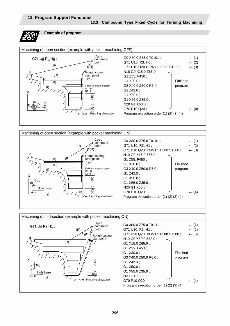
13. Program Support Functions 13.3 Compound Type Fixed Cycle for Turning Machining
296
Example of program
Machining of open section (example with pocket machining OFF)
(R) (f)
(f) e Z
X
45°
q
(R)
(R)
(R)
(R/f)
(f) (f)
P
d
u/2 w
G71 Ud Re H0 ; G0 X80.0 Z75.0 T0101 ; ← (1)G71 U10. R3. H0 ; ← (2)G71 P10 Q20 U3.W1.5 F500 S1500 ; ← (3)N10 G0 X15.0 Z65.0 ; G1 Z55. F450 ; G1 X30.0 ; Finished G3 X40.0 Z50.0 R5.0 ; program G1 Z42.0 ; G1 X50.0 ; G1 X55.0 Z35.0 ; N20 G1 X60.0 ; G70 P10 Q20 ; ← (4)Program execution order (1) (2) (3) (4)
Cycle command point
Rough cutting start point
Finished shape programG0 : R G1 : f
Finishing allowance
Machining of open section (example with pocket machining ON)
G0 X80.0 Z75.0 T0101 ; ← (1)G71 U10. R3. H1 ; ← (2)G71 P10 Q20 U3.W1.5 F500 S1500 ; ← (3)N10 G0 X15.0 Z65.0 ; G1 Z55. F450 ; G1 X30.0 ; Finished G3 X40.0 Z50.0 R5.0 ; program G1 Z42.0 ; G1 X50.0 ; G1 X55.0 Z35.0 ; N20 G1 X60.0 ; G70 P10 Q20 ; ← (4)Program execution order (1) (2) (3) (4)
q
(R)
(R)
(R)
(f)
(f)
P
d
u/2 w
(R)
(R) (f)
e Z
X
Hole base
(R/f)
Cycle command point
Rough cutting start point
Finished shape programG0 : R G1 : f
Finishing allowance
Machining of mid-section (example with pocket machining ON)
q
(R)
(R)
(R)
(f) (f)
P
d
u/2
w
(R) (f)
e Z
X
Hole base
G71 Ud Re H1 ; G0 X80.0 Z75.0 T0101 ; ← (1)G71 U10. R3. H1 ; ← (2)G71 P10 Q20 U3.W1.5 F500 S1500 ; ← (3)N10 G0 X60.0 Z73.0 ; G1 X15.0 Z65.0 ; G1 Z55. F450 ; G1 X30.0 ; Finished G3 X40.0 Z50.0 R5.0 ; program G1 Z42.0 ; G1 X50.0 ; G1 X55.0 Z35.0 ; N20 G1 X60.0 ; G70 P10 Q20 ; ← (4)Program execution order (1) (2) (3) (4)
Cycle command point
Rough cutting start point
Finishing allowance
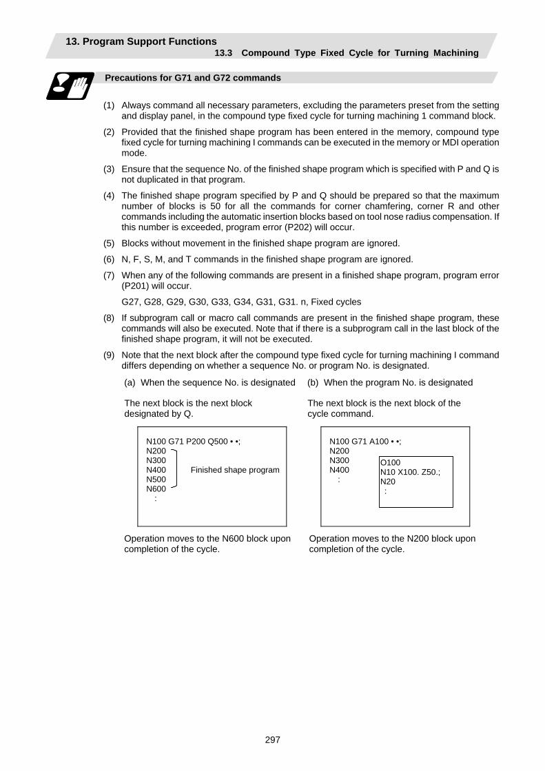
13. Program Support Functions 13.3 Compound Type Fixed Cycle for Turning Machining
297
Precautions for G71 and G72 commands
(1) Always command all necessary parameters, excluding the parameters preset from the setting
and display panel, in the compound type fixed cycle for turning machining 1 command block.
(2) Provided that the finished shape program has been entered in the memory, compound type fixed cycle for turning machining I commands can be executed in the memory or MDI operation mode.
(3) Ensure that the sequence No. of the finished shape program which is specified with P and Q is not duplicated in that program.
(4) The finished shape program specified by P and Q should be prepared so that the maximum number of blocks is 50 for all the commands for corner chamfering, corner R and other commands including the automatic insertion blocks based on tool nose radius compensation. If this number is exceeded, program error (P202) will occur.
(5) Blocks without movement in the finished shape program are ignored.
(6) N, F, S, M, and T commands in the finished shape program are ignored.
(7) When any of the following commands are present in a finished shape program, program error (P201) will occur.
G27, G28, G29, G30, G33, G34, G31, G31. n, Fixed cycles
(8) If subprogram call or macro call commands are present in the finished shape program, these commands will also be executed. Note that if there is a subprogram call in the last block of the finished shape program, it will not be executed.
(9) Note that the next block after the compound type fixed cycle for turning machining I command differs depending on whether a sequence No. or program No. is designated.
(a) When the sequence No. is designated (b) When the program No. is designated
The next block is the next block designated by Q.
The next block is the next block of the cycle command.
N100 G71 P200 Q500 • •; N200 N300 N400 Finished shape programN500 N600 :
N100 G71 A100 • •; N200 N300 N400 :
O100 N10 X100. Z50.; N20 :
Operation moves to the N600 block upon completion of the cycle.
Operation moves to the N200 block upon completion of the cycle.
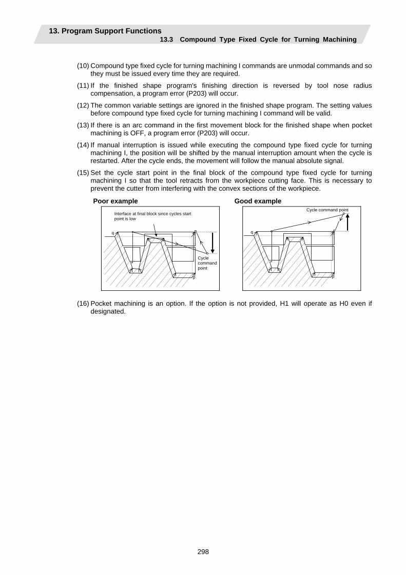
13. Program Support Functions 13.3 Compound Type Fixed Cycle for Turning Machining
298
(10) Compound type fixed cycle for turning machining I commands are unmodal commands and so
they must be issued every time they are required.
(11) If the finished shape program's finishing direction is reversed by tool nose radius compensation, a program error (P203) will occur.
(12) The common variable settings are ignored in the finished shape program. The setting values before compound type fixed cycle for turning machining I command will be valid.
(13) If there is an arc command in the first movement block for the finished shape when pocket machining is OFF, a program error (P203) will occur.
(14) If manual interruption is issued while executing the compound type fixed cycle for turning machining I, the position will be shifted by the manual interruption amount when the cycle is restarted. After the cycle ends, the movement will follow the manual absolute signal.
(15) Set the cycle start point in the final block of the compound type fixed cycle for turning machining I so that the tool retracts from the workpiece cutting face. This is necessary to prevent the cutter from interfering with the convex sections of the workpiece.
Poor example Good example
Interface at final block since cycles start point is low
Cycle command point
q
p
Cycle command point
q
p
(16) Pocket machining is an option. If the option is not provided, H1 will operate as H0 even if
designated.
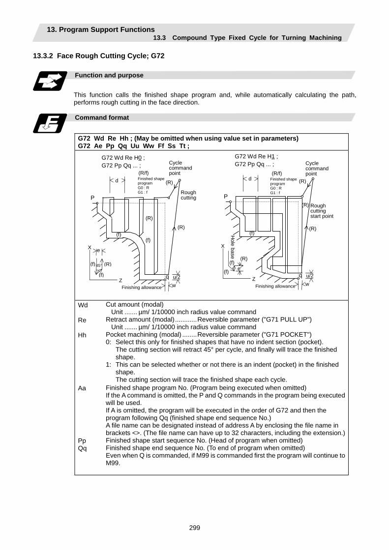
13. Program Support Functions 13.3 Compound Type Fixed Cycle for Turning Machining
299
13.3.2 Face Rough Cutting Cycle; G72
Function and purpose
This function calls the finished shape program and, while automatically calculating the path, performs rough cutting in the face direction.
Command format
G72 Wd Re Hh ; (May be omitted when using value set in parameters) G72 Ae Pp Qq Uu Ww Ff Ss Tt ;
G72 Wd Re H0 ; G72 Pp Qq ... ;
(R/f) (R)d
P
(R) (R)
(f) (f)
e X
(R) (f) (f)
45°
qZ u/2
w
Cycle command point
Rough cutting
Finished shape program G0 : R G1 : f
Finishing allowance
G72 Wd Re H1 ; G72 Pp Qq ... ;
(R/f) (R) d
P(R)
(R) (f)
e
X
(R)(f)
(f) q Z u/2
w
Hole base
Cycle command point
Roughcutting start point
Finished shape program G0 : R G1 : f
Finishing allowance
Wd Re Hh Aa Pp Qq
Cut amount (modal) Unit ....... µm/ 1/10000 inch radius value command Retract amount (modal)............Reversible parameter ("G71 PULL UP") Unit ....... µm/ 1/10000 inch radius value command Pocket machining (modal) ........Reversible parameter ("G71 POCKET") 0: Select this only for finished shapes that have no indent section (pocket). The cutting section will retract 45° per cycle, and finally will trace the finished
shape. 1: This can be selected whether or not there is an indent (pocket) in the finished
shape. The cutting section will trace the finished shape each cycle. Finished shape program No. (Program being executed when omitted) If the A command is omitted, the P and Q commands in the program being executed will be used. If A is omitted, the program will be executed in the order of G72 and then the program following Qq (finished shape end sequence No.) A file name can be designated instead of address A by enclosing the file name in brackets <>. (The file name can have up to 32 characters, including the extension.)Finished shape start sequence No. (Head of program when omitted) Finished shape end sequence No. (To end of program when omitted) Even when Q is commanded, if M99 is commanded first the program will continue to M99.
13. Program Support Functions 13.3 Compound Type Fixed Cycle for Turning Machining
300
Uu Ww Ff Ss,Tt
X axis direction finishing allowance (When omitted, X axis direction finishing allowance is handled as 0.) Unit ..... µm/ Follows 1/10000ich diameter/radius value command (#1019 dia). Z axis direction finishing allowance (When omitted, Z axis direction finishing allowance is handled as 0.) Unit ..... µm/ Follows 1/10000ich radius value command Cutting speed (Follows cutting speed (modal) before G72 when omitted) Spindle command, tool command
* The other detailed functions are the same as "13.3.1 Longitudinal rough cutting cycle".
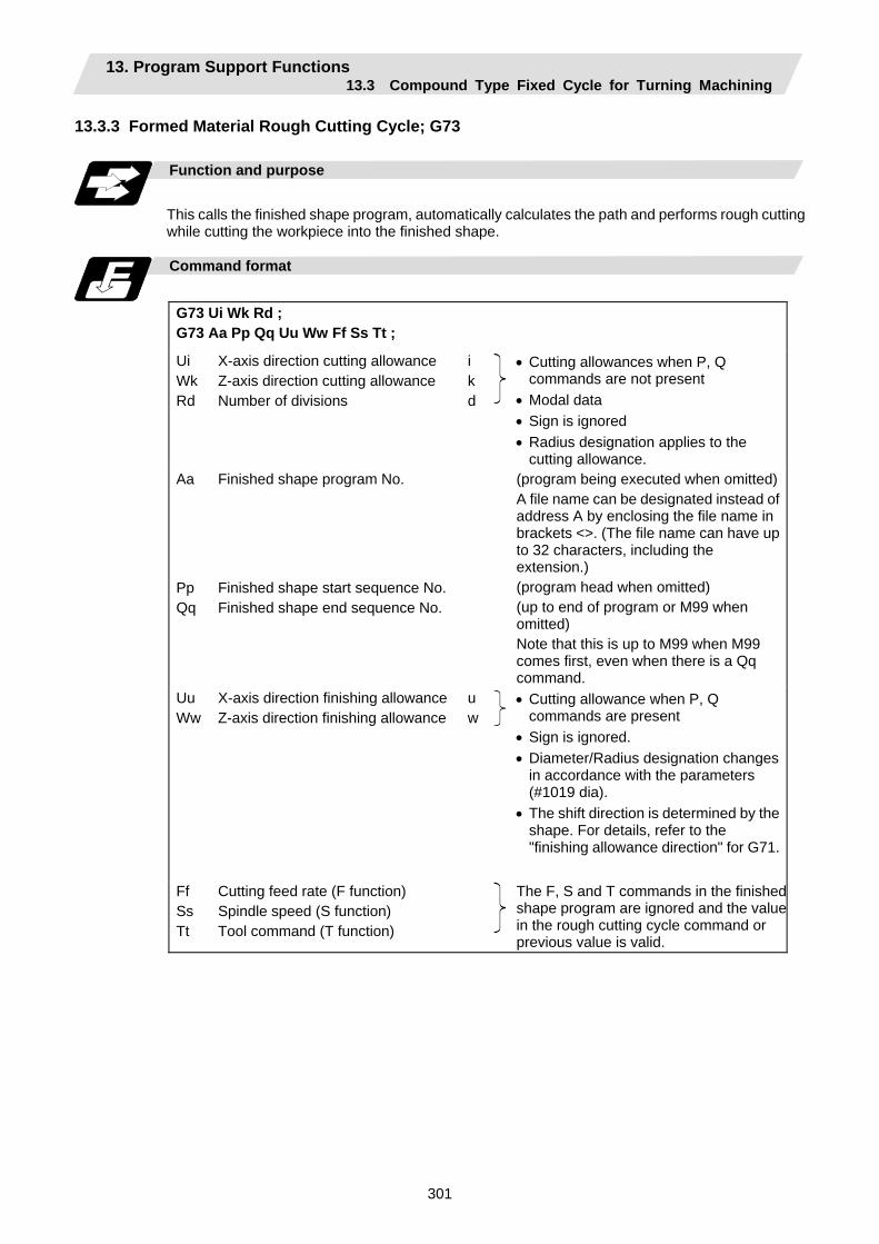
13. Program Support Functions 13.3 Compound Type Fixed Cycle for Turning Machining
301
13.3.3 Formed Material Rough Cutting Cycle; G73
Function and purpose
This calls the finished shape program, automatically calculates the path and performs rough cutting while cutting the workpiece into the finished shape.
Command format
G73 Ui Wk Rd ; G73 Aa Pp Qq Uu Ww Ff Ss Tt ;
Ui Wk Rd
X-axis direction cutting allowance Z-axis direction cutting allowance Number of divisions
ikd
• Cutting allowances when P, Q commands are not present
• Modal data • Sign is ignored • Radius designation applies to the
cutting allowance. Aa
Pp Qq
Finished shape program No.
Finished shape start sequence No. Finished shape end sequence No.
(program being executed when omitted)A file name can be designated instead of address A by enclosing the file name in brackets <>. (The file name can have up to 32 characters, including the extension.) (program head when omitted) (up to end of program or M99 when omitted) Note that this is up to M99 when M99 comes first, even when there is a Qq command.
Uu Ww
X-axis direction finishing allowanceZ-axis direction finishing allowance
uw
• Cutting allowance when P, Q commands are present
• Sign is ignored. • Diameter/Radius designation changes
in accordance with the parameters (#1019 dia).
• The shift direction is determined by the shape. For details, refer to the "finishing allowance direction" for G71.
Ff Ss Tt
Cutting feed rate (F function) Spindle speed (S function) Tool command (T function)
The F, S and T commands in the finishedshape program are ignored and the valuein the rough cutting cycle command or previous value is valid.

13. Program Support Functions 13.3 Compound Type Fixed Cycle for Turning Machining
302
k + w
X
Z
S1 S2
S3
S
i + u/2
u/2 wA
E
2
34
56
7
8
910
1112
13
14
1516
1718
19
1
(Note) With a single block, operation stops at the end point of each block.

13. Program Support Functions 13.3 Compound Type Fixed Cycle for Turning Machining
303
Finished shape
In the program, S → A → E in the previous page are commanded. The section between A and E must be a shape with monotonous changes in both the X axis and Z axis directions.
1 cycle configuration
A cycle is configured as shown below.
1
1
1 1
1
2(R)
S
E
A
Operation 1 : Based on shape program with shape profiling Operation 2 : Rapid traverse on return
Cut amount
The cut amount is the value produced by dividing the cutting allowances (i, k) by the number of divisions (d−1).
X axis direction i/(d−1) Z axis direction k/(d−1)
When divisions cannot be made, chamfering is performed and adjustment is made at the final pass.
i(d-1)
i(d-1)
i(d-1)
Remainder
k kRemainder (d-1) (d-1)
k (d-1)
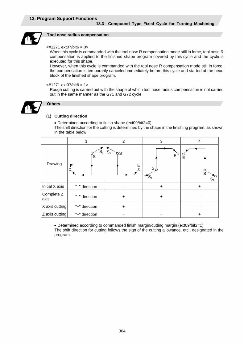
13. Program Support Functions 13.3 Compound Type Fixed Cycle for Turning Machining
304
Tool nose radius compensation
<#1271 ext07/bit6 = 0>
When this cycle is commanded with the tool nose R compensation mode still in force, tool nose R compensation is applied to the finished shape program covered by this cycle and the cycle is executed for this shape. However, when this cycle is commanded with the tool nose R compensation mode still in force, the compensation is temporarily canceled immediately before this cycle and started at the head block of the finished shape program.
<#1271 ext07/bit6 = 1>
Rough cutting is carried out with the shape of which tool nose radius compensation is not carried out in the same manner as the G71 and G72 cycle.
Others
(1) Cutting direction
• Determined according to finish shape (ext09/bit2=0) The shift direction for the cutting is determined by the shape in the finishing program, as shown in the table below.
1 2 3 4
Drawing
E
S S1
E
SS1
E
S
S1
E
SS1
Initial X axis "−" direction − + +
Complete Z axis "−" direction + + −
X axis cutting "+" direction + − −
Z axis cutting "+" direction − − +
• Determined according to commanded finish margin/cutting margin (ext09/bit2=1) The shift direction for cutting follows the sign of the cutting allowance, etc., designated in the program.
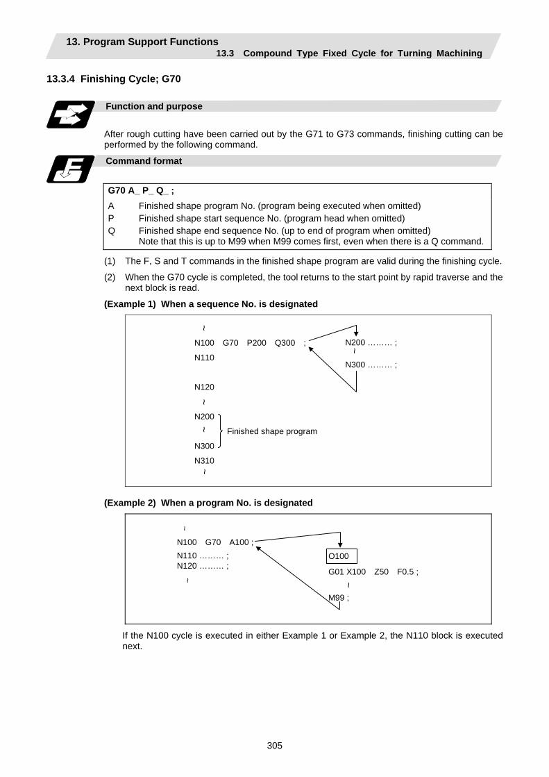
13. Program Support Functions 13.3 Compound Type Fixed Cycle for Turning Machining
305
13.3.4 Finishing Cycle; G70
Function and purpose
After rough cutting have been carried out by the G71 to G73 commands, finishing cutting can be performed by the following command.
Command format
G70 A_ P_ Q_ ; A P Q
Finished shape program No. (program being executed when omitted) Finished shape start sequence No. (program head when omitted) Finished shape end sequence No. (up to end of program when omitted) Note that this is up to M99 when M99 comes first, even when there is a Q command.
(1) The F, S and T commands in the finished shape program are valid during the finishing cycle.
(2) When the G70 cycle is completed, the tool returns to the start point by rapid traverse and the next block is read.
(Example 1) When a sequence No. is designated
N200 ……… ; N300 ……… ;
N100 G70 P200 Q300 ;
N110
N120
N200
Finished shape program
N300
N310
~~
~
~
~
(Example 2) When a program No. is designated
N100 G70 A100 ; N110 ……… ; N120 ……… ;
~~
O100
G01 X100 Z50 F0.5 ; M99 ;
~
If the N100 cycle is executed in either Example 1 or Example 2, the N110 block is executed next.

13. Program Support Functions 13.3 Compound Type Fixed Cycle for Turning Machining
306
13.3.5 Face Cut-off Cycle; G74
Function and purpose
The G74 fixed cycle automatically enters a groove in the face direction of the workpiece by commanding the coordinates of the groove end point, cut amount, cutter shift amount and cutter escape at the bottom of the cut. The machining program commands are as follows.
Command format
G74 Re ; C74 X/(U)x Z/(w)z Pi Qk Rd Ff ; Re X/Ux Z/Wz Pi Qk
Return amount (no X/U, P commands) (modal) B point X coordinate (absolute/incremental value) B point Z coordinate (absolute/incremental value) Tool shift amount (radius designation, incremental value, sign not required) Cut amount (radius designation, incremental value, sign not required)
Rd
Escape at the bottom of the cut
When there is no sign, escapes even at the bottom of the first cut. When a - sign is attached, the tool escapes from the second cut without escaping the first cut.
Ff Feed rate
k k k kx
u/2
(1)(2)(3)(4)
(5)(6)(7)(8)
(9)(10)
(11)
(12)i
d
e
wz
B
• Operation (9) as well as operation (12) immediately before the final cycle are executed with the remainderamount.
• Operations (2), (4), (6), (8), (10), (11) and (12) are executed at the rapid traverse rate.
S (Start point)
13. Program Support Functions 13.3 Compound Type Fixed Cycle for Turning Machining
307
Single block stop
Operation stops at each block from (1) to (12).
Others
(1) When X/U and P are omitted or when the values of "x" and "i" are zero, operation will apply to
the Z axis only. Note that when there is an Rd command and no sign, the tool will escape at the bottom of the cut.
(2) A case where the X/U or Z/W command is not present is treated as the assignment of a parameter setting command (G74 Re). Even when G74 Pi Qk Rd ; is commanded, Rd is regarded as Re, and the return amount is set.
(3) The escape direction does not change when a - sign is attached to the Rd command, or when there is no sign.
(4) A program error (P204) results in the following cases.
(a) When " i " is zero or P has not been commanded even though X/U has been commanded.
(b) When tool shift amount " i " is greater than the "x" movement amount.
(c) When the escape amount "d" is greater than the shift amount " i ".
(d) When the return amount "e" is greater than the cut amount "k".
(e) When the cut in amount "k" is larger than the hole depth "w".
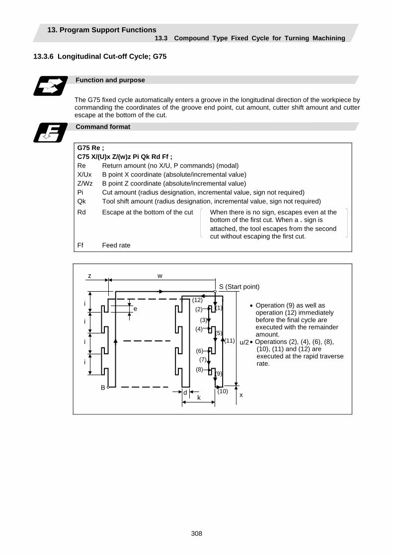
13. Program Support Functions 13.3 Compound Type Fixed Cycle for Turning Machining
308
13.3.6 Longitudinal Cut-off Cycle; G75
Function and purpose
The G75 fixed cycle automatically enters a groove in the longitudinal direction of the workpiece by commanding the coordinates of the groove end point, cut amount, cutter shift amount and cutter escape at the bottom of the cut.
Command format
G75 Re ; C75 X/(U)x Z/(w)z Pi Qk Rd Ff ; Re X/Ux Z/Wz Pi Qk
Return amount (no X/U, P commands) (modal) B point X coordinate (absolute/incremental value) B point Z coordinate (absolute/incremental value) Cut amount (radius designation, incremental value, sign not required) Tool shift amount (radius designation, incremental value, sign not required)
Rd
Escape at the bottom of the cut When there is no sign, escapes even at the bottom of the first cut. When a - sign is attached, the tool escapes from the second cut without escaping the first cut.
Ff Feed rate
k x
u/2
(1)(2)
(3)(4)
(5)
(6)(7)
(8)(9)
(10)
(11)
(12)i
d
e
w z
B
S (Start point)
• Operation (9) as well as operation (12) immediately before the final cycle are executed with the remainder amount.
• Operations (2), (4), (6), (8), (10), (11) and (12) are executed at the rapid traverserate.
i
i
i

13. Program Support Functions 13.3 Compound Type Fixed Cycle for Turning Machining
309
Single block stop
Operation stops at each block from (1) to (12).
Others
(1) When Z/W and Q are omitted or when the values of "z" and "k" are zero, operation will apply to
the X axis only (slitting). Note that when there is an Rd command and no sign, the tool will escape at the bottom of the cut.
(2) A case where both the X/U and Z/W commands are not present is treated as the assignment of a parameter setting command (G75 Re). Even when G75 Pi Qk Rd ; is commanded, Rd is regarded as Re, and the return amount is set.
(3) The escape direction does not change when a - sign is attached to the Rd command, or when there is no sign.
(4) A program error (P204) results in the following cases.
(a) When "k" is zero or Q has not been commanded even though Z/W has been commanded.
(b) When tool shift amount "k" is greater than the "z" movement amount.
(c) When the escape amount "d" is greater than the shift amount "k".
(d) When the return amount "e" is greater than the cut amount " i ".
(e) When the cut in amount "i" is larger than the hole depth "u/2".

13. Program Support Functions 13.3 Compound Type Fixed Cycle for Turning Machining
310
13.3.7 Compound Thread Cutting Cycle; G76
Function and purpose
The G76 fixed cycle enables the workpiece to be cut at the desired angle by designating the thread cutting start point and end point, and it automatically cuts so that the cutting cross section (cutting torque) per cutting pass is constant. Various longitudinal direction threads can be cut by bearing in mind the command value for the thread end point coordinate and taper height component.
Command format
G76 Pmra Q∆dmin Rd ; G76 X/U Z/W Ri Pk Q∆d Fl ; m Number of cutting passes for finishing: 00 to 99 (times) (modal) r
Chamfering amount: 00 to 99 (0.1mm/rev) (modal) The chamfering width based on thread lead "l" is designated by a 2-digit integer without decimal point from 0.0 to 9.9.
a
Tool nose angle (thread angle): 00 to 99 (°) (modal) The angle from 0° to 99° is assigned in 1° units. "m", "r" and "a" are commanded in succession in address P. (Example) When m=5, r=1.5 and a=0° P is 051500 and the leading and trailing
zeroes cannot be omitted. ∆dmin Minimum cut amount
If the calculated cut amount is smaller than ∆dmin, it is clamped by ∆dmin. d Finishing allowance 0 to 9999 (µm) (modal) X/U
X-axis end point coordinate of thread The X coordinate of the end point for the thread is commanded by an absolute or incremental value.
Z/W
Z-axis end point coordinate of thread The Z coordinate of the end point for the thread is commanded by an absolute or incremental value.
i Taper height component (radius value) for thread straight thread when "i" is zero k Thread height
This is commanded by a positive radial value. ∆d
Cut amount The cut amount of the first cutting pass is commanded by a positive radius value.
l Thread lead
(Note 1) The two above G76 commands cannot be placed in the same block. The data commanded by P, Q and R are automatically identified according to the
presence or absence of the X/U and Z/W axis addresses.
(Note 2) Parameter settings can be used for the above "r" modal data but these parameter (#8014 chamfer amount) settings are rewritten by the program commands.
(Note 3) The chamfering amount designation is valid even for thread cutting fixed cycles.
(Note 4) Program error (P204) results in the following cases.
(a) When "a" is outside the rating
(b) When both the X and Z commands have not been issued or when the start and end point coordinates are the same for either the X or Z command.
(c) When the thread is greater than the movement of the X axis at the thread bottom
(Note 5) The precautions for the thread cutting command (G33) and thread cutting cycle (G78) should be observed.
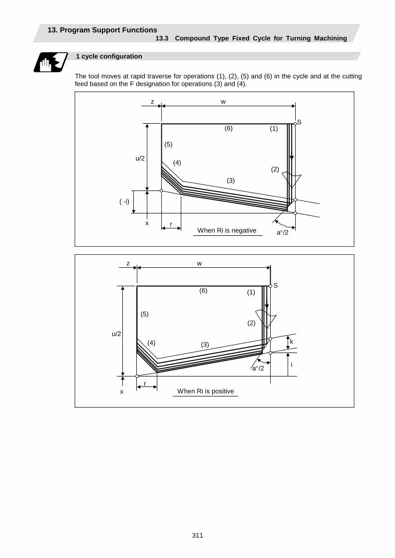
13. Program Support Functions 13.3 Compound Type Fixed Cycle for Turning Machining
311
1 cycle configuration
The tool moves at rapid traverse for operations (1), (2), (5) and (6) in the cycle and at the cutting feed based on the F designation for operations (3) and (4).
When Ri is negative rx
( -i)
z w
S
u/2
(1)
(2)
(3)
(4)
(5)
(6)
a°/2
When Ri is positiver
x
i
k
z w
S
u/2
(1)
(2)
(3)(4)
(5)
(6)
a°/2
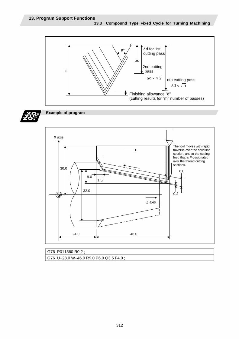
13. Program Support Functions 13.3 Compound Type Fixed Cycle for Turning Machining
312
k
a° ∆d for 1st cutting pass
2nd cutting pass
∆d × √ 2 nth cutting pass ∆d × √ n
Finishing allowance "d" (cutting results for "m" number of passes)
Example of program
30.0
24.0 46.0
6.0
0.2
9.0
32.0
1.5l
The tool moves with rapid traverse over the solid line section, and at the cutting feed that is F-designated over the thread cutting sections.
Z axis
X axis
G76 P011560 R0.2 ; G76 U−28.0 W−46.0 R9.0 P6.0 Q3.5 F4.0 ;

13. Program Support Functions 13.3 Compound Type Fixed Cycle for Turning Machining
313
Interrupt operation
(1) When the feed hold button is pressed while G76 is being executed, automatic operation will
stop upon completion of a block without thread cutting if thread cutting is ongoing. (The automatic operation pause lamp lights immediately in the feed hold mode and it goes off when automatic operation stops.) If feed hold is applied when no thread is then being cut, or if applied in the interval from the execution of the thread cutting command to the axis movement, the automatic operation pause lamp will turn ON, and the automatic operation will pause.
(2) The tool stops upon completion of operations (1), (4) and (5) when the mode is switched to another automatic operation mode during the G76 command execution, when automatic operation is changed to manual operations or when single block operation is conducted.
(3) The dry run valid/invalid status during G76 execution does not change during thread cutting.
13. Program Support Functions 13.3 Compound Type Fixed Cycle for Turning Machining
314
13.3.8 Precautions for Compound Type Fixed Cycle for Turning Machining; G70 to G76
Precautions
(1) Command all required parameters in a compound type fixed cycle for turning machining
command block.
(2) Provided that the finished shape program has been entered in the memory, compound type fixed cycle for turning machining I commands can be executed in the memory, MDI or tape operation mode.
(3) When executing a G70 to G73 command, ensure that the sequence No. of the finished shape program which is stop with P and Q is not duplicated in that program.
(4) The finished shape program specified by P and Q in the G71 to G73 blocks should be prepared so that the maximum number of blocks is 200 for all the commands for corner chamfering, corner rounding and other commands including the automatic insertion blocks based on tool nose R compensation. If this number is exceeded, program error (P202) results.
If the cutting start position is the cycle start position (#1271 ext07/bit5 =1), the finished shape program can have up to 199 blocks. (When the cycle start point is on the other side of the finished shape program's final position.)
(5) The finished shape program which is designated by the G71 to G73 blocks should be a program with monotonous changes (increases or reductions only) for both the X and Z axes.
(6) Blocks without movement in the finished shape program are ignored.
(7) N, F, S, M, and T commands in the finished shape program are ignored.
(8) When any of the following commands are present in a finished shape program, program error (P201) results.
(a) Commands related to reference position return (G27, G28, G29, G30)
(b) Thread cutting (G33)
(c) Fixed cycles
(d) Skip functions (G31, G37)
(9) If subprogram call or macro call commands are present in the finished shape program, these commands will also be executed.
(10) Except for thread cutting cycles, operation stops at the end (start) point of each block in the single block mode.
13. Program Support Functions 13.3 Compound Type Fixed Cycle for Turning Machining
315
(11) Remember that, depending on whether the sequence or program No. is designated, the next
block upon completion of the G71, G72 or G73 command will differ.
(a) When the sequence No. is designated (b) When the program No. is designated The next block is the next block designated by Q.
The next block is the next block of the cycle command.
N100 G71P200 Q500 U_W_ ….. ;N200 N300 N400 N500 N600
~
Finished shapeprogram
N100 G71 A100 U_W_ ….. ;
N200
N300
N400
~
O100
N10 X100. Z50. ;
N20
Operation moves to the N600 block upon completion of the cycle.
Operation moves to the N200 block upon completion of the cycle.
(12) The next block applying upon completion of the G70 command is the next block of the command block.
N100 ...... ; N200 ; N300 ; N400 ; N500 ; N1000 G70 P200 Q500 ; (or G70 A100 ;) N1100 ...... ;
~
~
~
Operation moves to the N1100 block upon completion of the G70 command.
(13) It is possible to apply a manual interruption while a compound type fixed cycle for turning machining command (G70 to G76) is being executed. However, upon completion of the interrupt, the tool must first be returned to the position where the interrupt was applied and then the compound type fixed cycle for turning machining must be restarted.
If it is restarted without the tool having been returned, all subsequent movements will deviate by an amount equivalent to the manual interruption amount.
(14) Compound type fixed cycle for turning machining commands are unmodal commands and so they must be issued every time they are required.
(15) Program error (P203) results with the G71 and G72 commands even when, because of tool nose R compensation, there is no further movement of the Z axis in the second block or the Z axis has moved in the opposite direction.
(16) A program error (P204) will occur if the finished shape program is issued in the same program with G70 to G73 and both P and Q are not designated.
Note that if A, P and Q are all not designated in G71 to G73, this will be interpreted as the first block for the compound type fixed cycle for turning machining I, and an error will not occur.
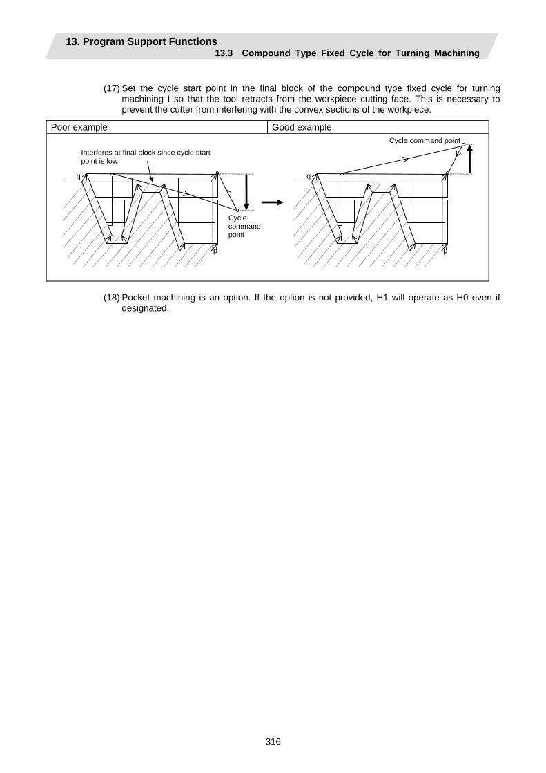
13. Program Support Functions 13.3 Compound Type Fixed Cycle for Turning Machining
316
(17) Set the cycle start point in the final block of the compound type fixed cycle for turning
machining I so that the tool retracts from the workpiece cutting face. This is necessary to prevent the cutter from interfering with the convex sections of the workpiece.
Poor example Good example
Interferes at final block since cycle start point is low
Cycle command point
q
p
q
p
Cycle command point
(18) Pocket machining is an option. If the option is not provided, H1 will operate as H0 even if
designated.
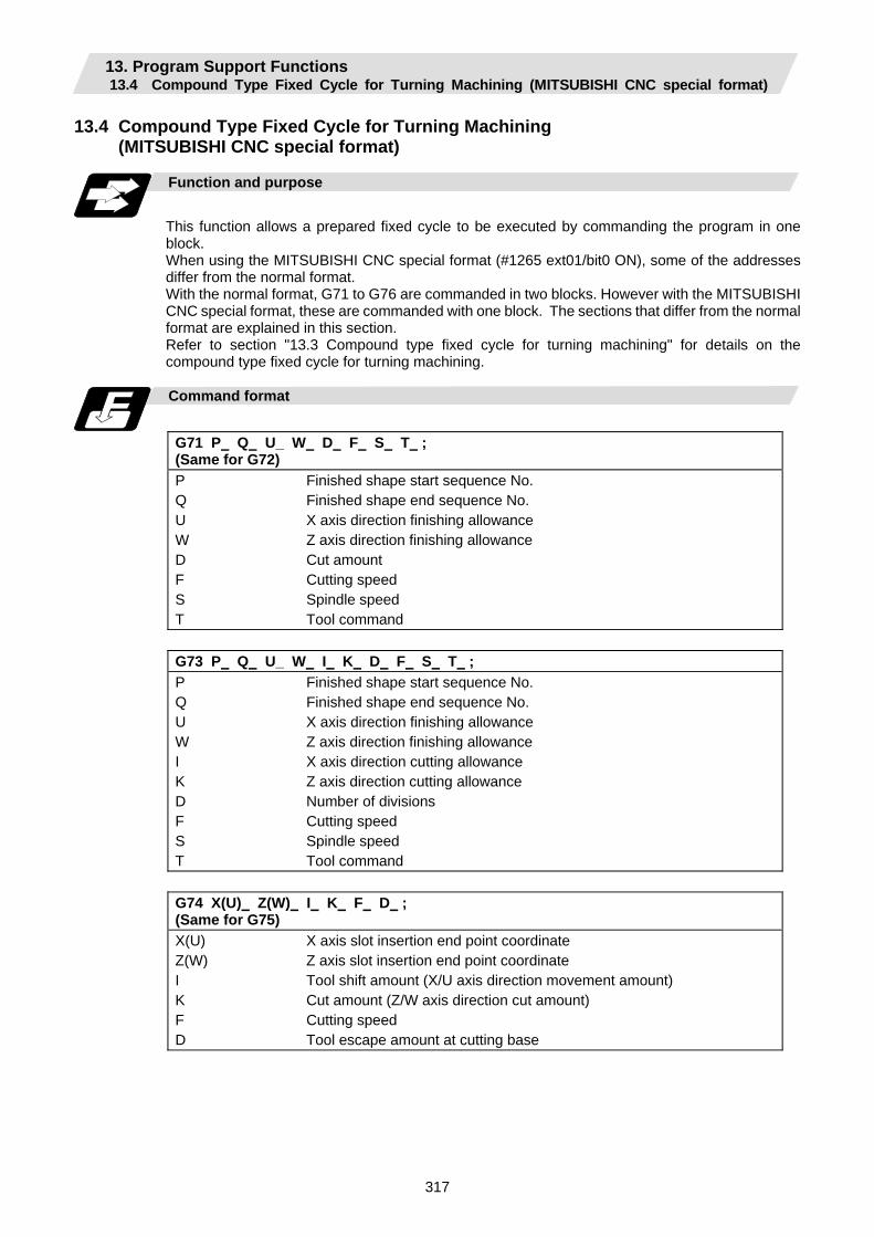
13. Program Support Functions 13.4 Compound Type Fixed Cycle for Turning Machining (MITSUBISHI CNC special format)
317
13.4 Compound Type Fixed Cycle for Turning Machining (MITSUBISHI CNC special format)
Function and purpose
This function allows a prepared fixed cycle to be executed by commanding the program in one block. When using the MITSUBISHI CNC special format (#1265 ext01/bit0 ON), some of the addresses differ from the normal format. With the normal format, G71 to G76 are commanded in two blocks. However with the MITSUBISHI CNC special format, these are commanded with one block. The sections that differ from the normal format are explained in this section. Refer to section "13.3 Compound type fixed cycle for turning machining" for details on the compound type fixed cycle for turning machining.
Command format
G71 P Q U_ W D F S T ; (Same for G72) P Q U W D F S T
Finished shape start sequence No. Finished shape end sequence No. X axis direction finishing allowance Z axis direction finishing allowance Cut amount Cutting speed Spindle speed Tool command
G73 P Q U_ W I K D F S T ; P Q U W I K D F S T
Finished shape start sequence No. Finished shape end sequence No. X axis direction finishing allowance Z axis direction finishing allowance X axis direction cutting allowance Z axis direction cutting allowance Number of divisions Cutting speed Spindle speed Tool command
G74 X(U) Z(W) I K F D ; (Same for G75) X(U) Z(W) I K F D
X axis slot insertion end point coordinate Z axis slot insertion end point coordinate Tool shift amount (X/U axis direction movement amount) Cut amount (Z/W axis direction cut amount) Cutting speed Tool escape amount at cutting base
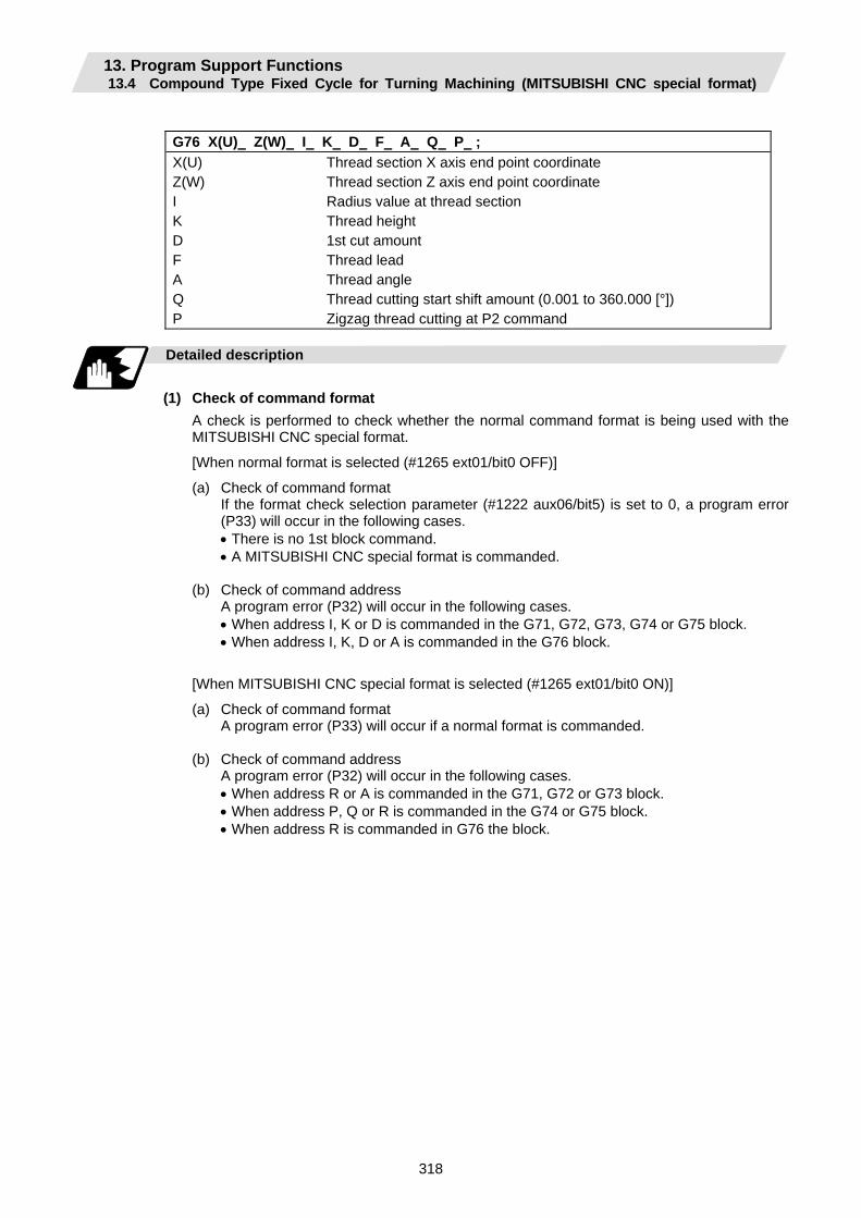
13. Program Support Functions 13.4 Compound Type Fixed Cycle for Turning Machining (MITSUBISHI CNC special format)
318
G76 X(U) Z(W) I K D F A Q P ; X(U) Z(W) I K D F A Q P
Thread section X axis end point coordinate Thread section Z axis end point coordinate Radius value at thread section Thread height 1st cut amount Thread lead Thread angle Thread cutting start shift amount (0.001 to 360.000 [°]) Zigzag thread cutting at P2 command
Detailed description
(1) Check of command format A check is performed to check whether the normal command format is being used with the
MITSUBISHI CNC special format.
[When normal format is selected (#1265 ext01/bit0 OFF)]
(a) Check of command format If the format check selection parameter (#1222 aux06/bit5) is set to 0, a program error
(P33) will occur in the following cases. • There is no 1st block command. • A MITSUBISHI CNC special format is commanded. (b) Check of command address A program error (P32) will occur in the following cases. • When address I, K or D is commanded in the G71, G72, G73, G74 or G75 block. • When address I, K, D or A is commanded in the G76 block.
[When MITSUBISHI CNC special format is selected (#1265 ext01/bit0 ON)]
(a) Check of command format A program error (P33) will occur if a normal format is commanded. (b) Check of command address A program error (P32) will occur in the following cases. • When address R or A is commanded in the G71, G72 or G73 block. • When address P, Q or R is commanded in the G74 or G75 block. • When address R is commanded in G76 the block.
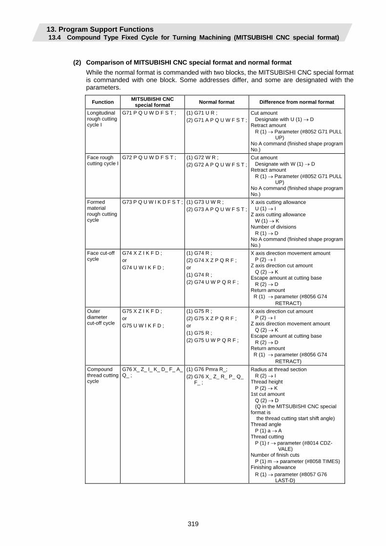
13. Program Support Functions 13.4 Compound Type Fixed Cycle for Turning Machining (MITSUBISHI CNC special format)
319
(2) Comparison of MITSUBISHI CNC special format and normal format
While the normal format is commanded with two blocks, the MITSUBISHI CNC special format is commanded with one block. Some addresses differ, and some are designated with the parameters.
Function MITSUBISHI CNC special format Normal format Difference from normal format
Longitudinal rough cutting cycle I
G71 P Q U W D F S T ; (1) G71 U R ; (2) G71 A P Q U W F S T ;
Cut amount Designate with U (1) → D Retract amount R (1) → Parameter (#8052 G71 PULL UP) No A command (finished shape program No.)
Face rough cutting cycle I
G72 P Q U W D F S T ; (1) G72 W R ; (2) G72 A P Q U W F S T ;
Cut amount Designate with W (1) → D Retract amount R (1) → Parameter (#8052 G71 PULL UP) No A command (finished shape program No.)
Formed material rough cutting cycle
G73 P Q U W I K D F S T ; (1) G73 U W R ; (2) G73 A P Q U W F S T ;
X axis cutting allowance U (1) → I Z axis cutting allowance W (1) → K Number of divisions R (1) → D No A command (finished shape program No.)
Face cut-off cycle
G74 X Z I K F D ; or G74 U W I K F D ;
(1) G74 R ; (2) G74 X Z P Q R F ; or (1) G74 R ; (2) G74 U W P Q R F ;
X axis direction movement amount P (2) → I Z axis direction cut amount Q (2) → K Escape amount at cutting base R (2) → D Return amount R (1) → parameter (#8056 G74 RETRACT)
Outer diameter cut-off cycle
G75 X Z I K F D ; or G75 U W I K F D ;
(1) G75 R ; (2) G75 X Z P Q R F ; or (1) G75 R ; (2) G75 U W P Q R F ;
X axis direction cut amount P (2) → I Z axis direction movement amount Q (2) → K Escape amount at cutting base R (2) → D Return amount R (1) → parameter (#8056 G74 RETRACT)
Compound thread cutting cycle
G76 X_ Z_ I_ K_ D_ F_ A_ Q_ ;
(1) G76 Pmra R_; (2) G76 X_ Z_ R_ P_ Q_
F_ ;
Radius at thread section R (2) → I Thread height P (2) → K 1st cut amount Q (2) → D (Q in the MITSUBISHI CNC special format is the thread cutting start shift angle) Thread angle P (1) a → A Thread cutting P (1) r → parameter (#8014 CDZ- VALE) Number of finish cuts P (1) m → parameter (#8058 TIMES)Finishing allowance R (1) → parameter (#8057 G76 LAST-D)
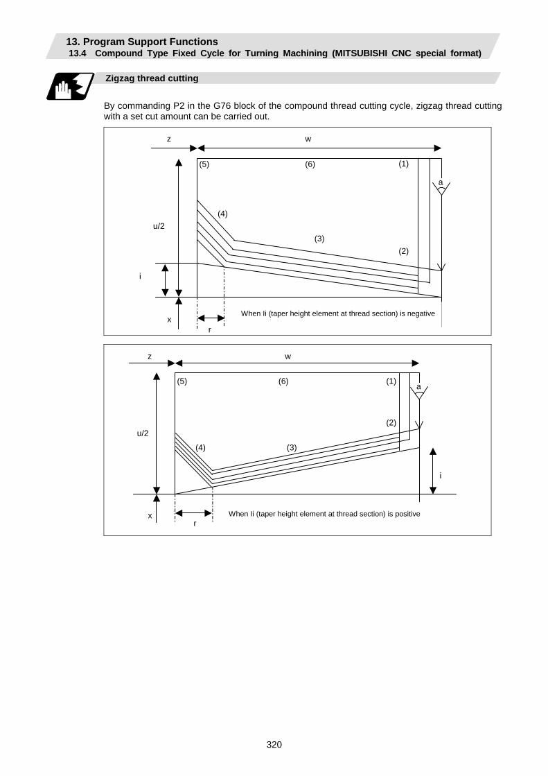
13. Program Support Functions 13.4 Compound Type Fixed Cycle for Turning Machining (MITSUBISHI CNC special format)
320
Zigzag thread cutting
By commanding P2 in the G76 block of the compound thread cutting cycle, zigzag thread cutting with a set cut amount can be carried out.
r
u/2
i
wz
x When Ii (taper height element at thread section) is negative
(1)
(2) (3)
(4)
(5) (6)
a
r
u/2
i
wz
x
(1)
(2)
(3) (4)
(5) (6)
When Ii (taper height element at thread section) is positive
a
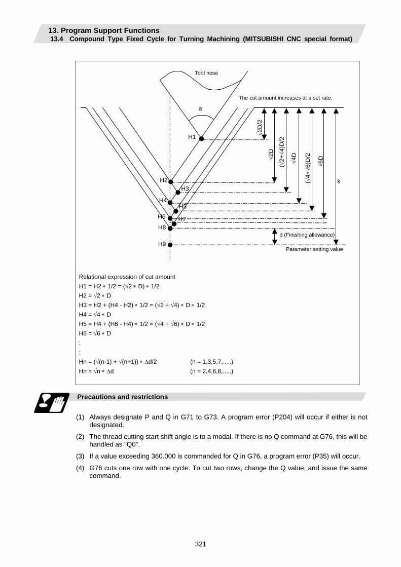
13. Program Support Functions 13.4 Compound Type Fixed Cycle for Turning Machining (MITSUBISHI CNC special format)
321
Tool nose
k
a
d (Finishing allowance)
H1
H2
H9
H8
H6
H4
H3
H5
H7
The cut amount increases at a set rate.
Parameter setting value
√2D
/2
√4D
√2D
( √2+
√4)D
/2
( √4+
√6)D
/2
√6D
Relational expression of cut amount H1 = H2 ∗ 1/2 = (√2 ∗ D) ∗ 1/2 H2 = √2 ∗ D H3 = H2 + (H4 - H2) ∗ 1/2 = (√2 + √4) ∗ D ∗ 1/2 H4 = √4 ∗ D H5 = H4 + (H6 - H4) ∗ 1/2 = (√4 + √6) ∗ D ∗ 1/2 H6 = √6 ∗ D : : Hn = (√(n-1) + √(n+1)) ∗ ∆d/2 (n = 1,3,5,7,.....) Hn = √n ∗ ∆d (n = 2,4,6,8,.....)
Precautions and restrictions
(1) Always designate P and Q in G71 to G73. A program error (P204) will occur if either is not
designated.
(2) The thread cutting start shift angle is to a modal. If there is no Q command at G76, this will be handled as "Q0".
(3) If a value exceeding 360.000 is commanded for Q in G76, a program error (P35) will occur.
(4) G76 cuts one row with one cycle. To cut two rows, change the Q value, and issue the same command.

13. Program Support Functions 13.5 Fixed Cycle for Drilling
322
13.5 Fixed Cycle for Drilling; G80 to G89
Function and purpose
These fixed cycles are used for predetermined sequences of machining operations such as normal positioning, hole drilling, boring and tapping which are specified in a block. The various sequences available using these functions are listed in the table below.
(Note) The X axis is designated as the hole drilling axis by longitudinal hole drilling fixed cycle. The Y axis can be designated as the hole drilling axis by using the longitudinal hole drilling axis selection function. "Type II" in the table explains detail when using the longitudinal hole drilling axis selection function.
Type II
G code Hole
drilling axis
Hole drilling start
Operation at hole bottom
Return operation Application
Longitudinal hole drilling
axis selectionsignal ON/OFF
Hole drilling
axis
G80 - - - - Cancel - - ON Z
G83 Z Cutting feed, intermittent feed
In-position check Dwell
Rapid traverse
Deep hole drilling cycle 1 OFF
ON Z
G84 (G84.1) Z Cutting feed
In-position check Dwell, spindle reverse rotation
Cutting feed
Tapping cycle (Note 1) (Reverse tap cycle)
OFF
ON Z G85 Z Cutting feed
In-position check Dwell
Cutting feed Boring cycle
OFF
ON Y G87 X Cutting feed,
intermittent feed
In-position check Dwell
Rapid traverse
Deep hole drilling cycle 1 OFF X
ON Y
G88 (G88.1) X Cutting feed
In-position check Dwell, spindle reverse rotation
Cutting feed
Tapping cycle (Note 1) (Reverse tap cycle)
OFF X
ON Y G89 X Cutting feed
In-position check Dwell
Cutting feed Boring cycle OFF X
ON Z/X G83.2 Z/X Cutting feed,
intermittent feed
In-position check Dwell
Rapid traverse
Deep hole drilling cycle 2 OFF
A fixed cycle mode is canceled when the G80 or any G command in the 01 group is issued. The various data will also be cleared simultaneously to zero.
(Note 1) Whether to set the reverse tap cycle G codes to G84.1/G88.1 or G84/G88 (address D value is minus) is determined according to the base specification parameter "#1309 Gtype".
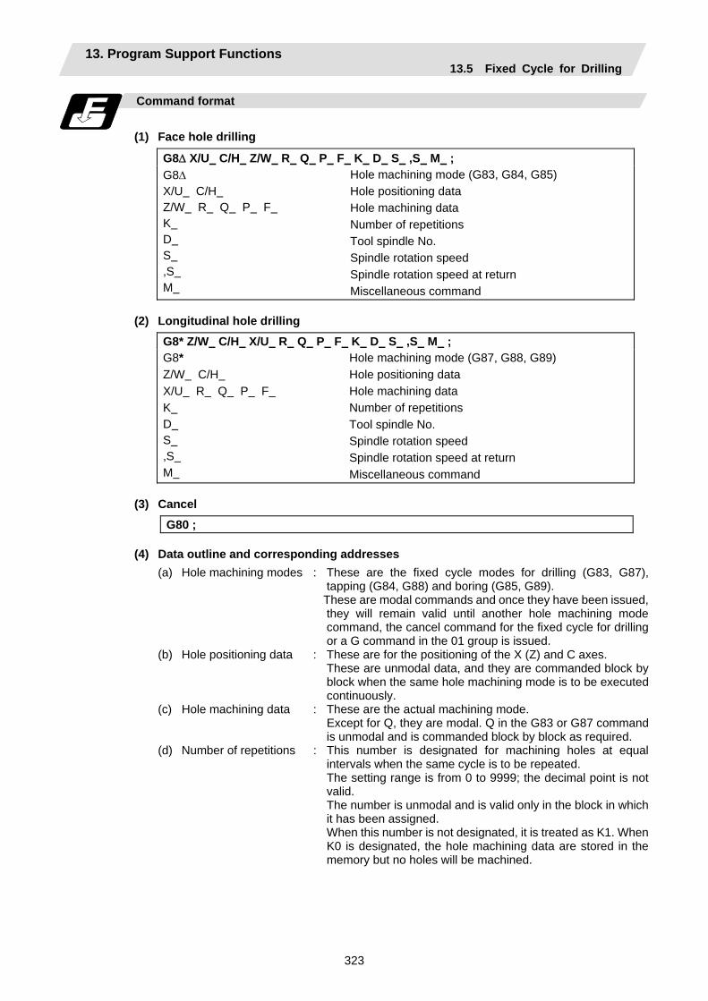
13. Program Support Functions 13.5 Fixed Cycle for Drilling
323
Command format
(1) Face hole drilling
G8∆ X/U C/H Z/W R Q P F K D S ,S M ; G8∆ X/U C/H Z/W R Q P F K D S ,S M
Hole machining mode (G83, G84, G85) Hole positioning data Hole machining data Number of repetitions Tool spindle No. Spindle rotation speed Spindle rotation speed at return Miscellaneous command
(2) Longitudinal hole drilling
G8* Z/W C/H X/U R Q P F K D S ,S M ; G8* Z/W C/H X/U R Q P F K D S ,S M
Hole machining mode (G87, G88, G89) Hole positioning data Hole machining data Number of repetitions Tool spindle No. Spindle rotation speed Spindle rotation speed at return Miscellaneous command
(3) Cancel
G80 ;
(4) Data outline and corresponding addresses (a) Hole machining modes : These are the fixed cycle modes for drilling (G83, G87),
tapping (G84, G88) and boring (G85, G89). These are modal commands and once they have been issued,
they will remain valid until another hole machining mode command, the cancel command for the fixed cycle for drilling or a G command in the 01 group is issued.
(b) Hole positioning data : These are for the positioning of the X (Z) and C axes. These are unmodal data, and they are commanded block by
block when the same hole machining mode is to be executed continuously.
(c) Hole machining data : These are the actual machining mode. Except for Q, they are modal. Q in the G83 or G87 command
is unmodal and is commanded block by block as required. (d) Number of repetitions : This number is designated for machining holes at equal
intervals when the same cycle is to be repeated. The setting range is from 0 to 9999; the decimal point is not
valid. The number is unmodal and is valid only in the block in which
it has been assigned. When this number is not designated, it is treated as K1. When
K0 is designated, the hole machining data are stored in the memory but no holes will be machined.
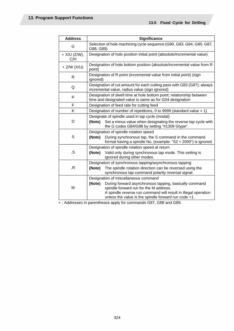
13. Program Support Functions 13.5 Fixed Cycle for Drilling
324
Address Significance
G Selection of hole machining cycle sequence (G80, G83, G84, G85, G87, G88, G89)
∗ X/U (Z/W), C/H
Designation of hole position initial point (absolute/incremental value)
∗ Z/W (X/U) Designation of hole bottom position (absolute/incremental value from R point)
R Designation of R point (incremental value from initial point) (sign ignored)
Q Designation of cut amount for each cutting pass with G83 (G87); always incremental value, radius value (sign ignored)
P Designation of dwell time at hole bottom point; relationship between time and designated value is same as for G04 designation
F Designation of feed rate for cutting feed K Designation of number of repetitions, 0 to 9999 (standard value = 1)
D Designate of spindle used in tap cycle (modal) (Note) Set a minus value when designating the reverse tap cycle with
the G codes G84/G88 by setting "#1309 Gtype".
S Designation of spindle rotation speed (Note) During synchronous tap, the S command in the command
format having a spindle No. (example: "S2 = 2000") is ignored.
,S Designation of spindle rotation speed at return (Note) Valid only during synchronous tap mode. This setting is
ignored during other modes.
,R Designation of synchronous tapping/asynchronous tapping (Note) The spindle rotation direction can be reversed using the
synchronous tap command polarity reversal signal.
M
Designation of miscellaneous command (Note) During forward asynchronous tapping, basically command
spindle forward run for the M address. A spindle reverse run command will result in illegal operation unless the value is the spindle forward run code +1.
∗ : Addresses in parentheses apply for commands G87, G88 and G89.
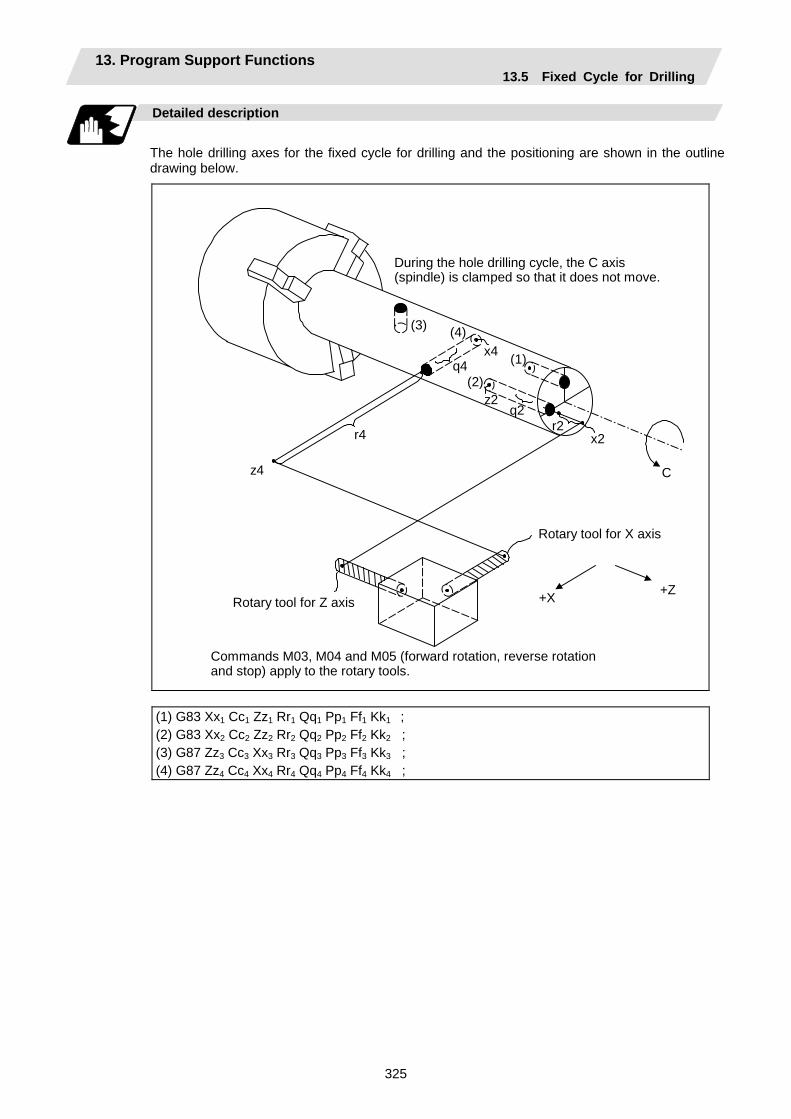
13. Program Support Functions 13.5 Fixed Cycle for Drilling
325
Detailed description
The hole drilling axes for the fixed cycle for drilling and the positioning are shown in the outline drawing below.
+X +Z
r4
z4 C
x2 r2
q2z2
q4x4 (1)
(2)
(3) (4)
Commands M03, M04 and M05 (forward rotation, reverse rotation and stop) apply to the rotary tools.
During the hole drilling cycle, the C axis (spindle) is clamped so that it does not move.
Rotary tool for X axis
Rotary tool for Z axis
(1) G83 Xx1 Cc1 Zz1 Rr1 Qq1 Pp1 Ff1 Kk1 ; (2) G83 Xx2 Cc2 Zz2 Rr2 Qq2 Pp2 Ff2 Kk2 ; (3) G87 Zz3 Cc3 Xx3 Rr3 Qq3 Pp3 Ff3 Kk3 ; (4) G87 Zz4 Cc4 Xx4 Rr4 Qq4 Pp4 Ff4 Kk4 ;
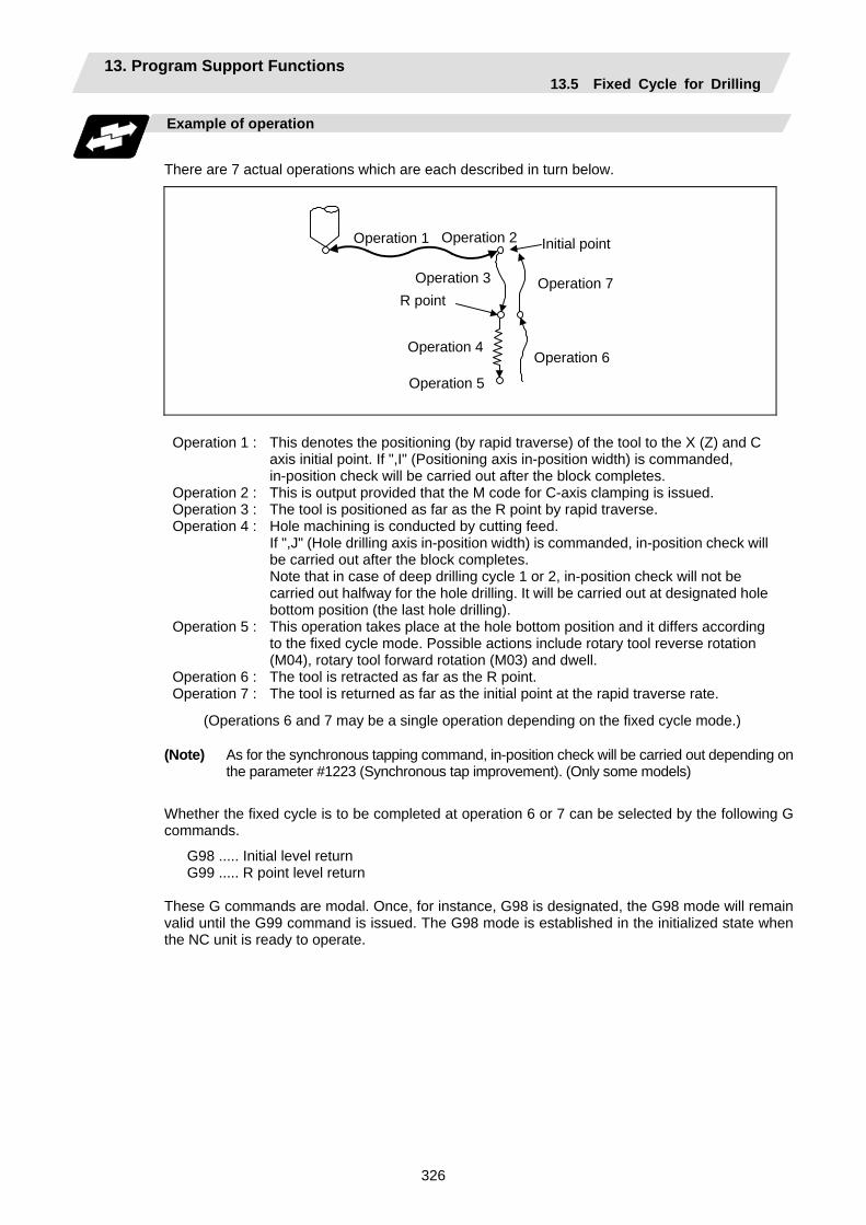
13. Program Support Functions 13.5 Fixed Cycle for Drilling
326
Example of operation
There are 7 actual operations which are each described in turn below.
Operation 1 Operation 2
Operation 4
Operation 3
Operation 5
Operation 6
Operation 7 R point
Initial point
Operation 1 : This denotes the positioning (by rapid traverse) of the tool to the X (Z) and C axis initial point. If ",I" (Positioning axis in-position width) is commanded, in-position check will be carried out after the block completes.
Operation 2 : This is output provided that the M code for C-axis clamping is issued. Operation 3 : The tool is positioned as far as the R point by rapid traverse. Operation 4 : Hole machining is conducted by cutting feed.
If ",J" (Hole drilling axis in-position width) is commanded, in-position check will be carried out after the block completes. Note that in case of deep drilling cycle 1 or 2, in-position check will not be carried out halfway for the hole drilling. It will be carried out at designated hole bottom position (the last hole drilling).
Operation 5 : This operation takes place at the hole bottom position and it differs according to the fixed cycle mode. Possible actions include rotary tool reverse rotation (M04), rotary tool forward rotation (M03) and dwell.
Operation 6 : The tool is retracted as far as the R point. Operation 7 : The tool is returned as far as the initial point at the rapid traverse rate.
(Operations 6 and 7 may be a single operation depending on the fixed cycle mode.)
(Note) As for the synchronous tapping command, in-position check will be carried out depending on the parameter #1223 (Synchronous tap improvement). (Only some models)
Whether the fixed cycle is to be completed at operation 6 or 7 can be selected by the following G commands.
G98 ..... Initial level return G99 ..... R point level return
These G commands are modal. Once, for instance, G98 is designated, the G98 mode will remain valid until the G99 command is issued. The G98 mode is established in the initialized state when the NC unit is ready to operate.
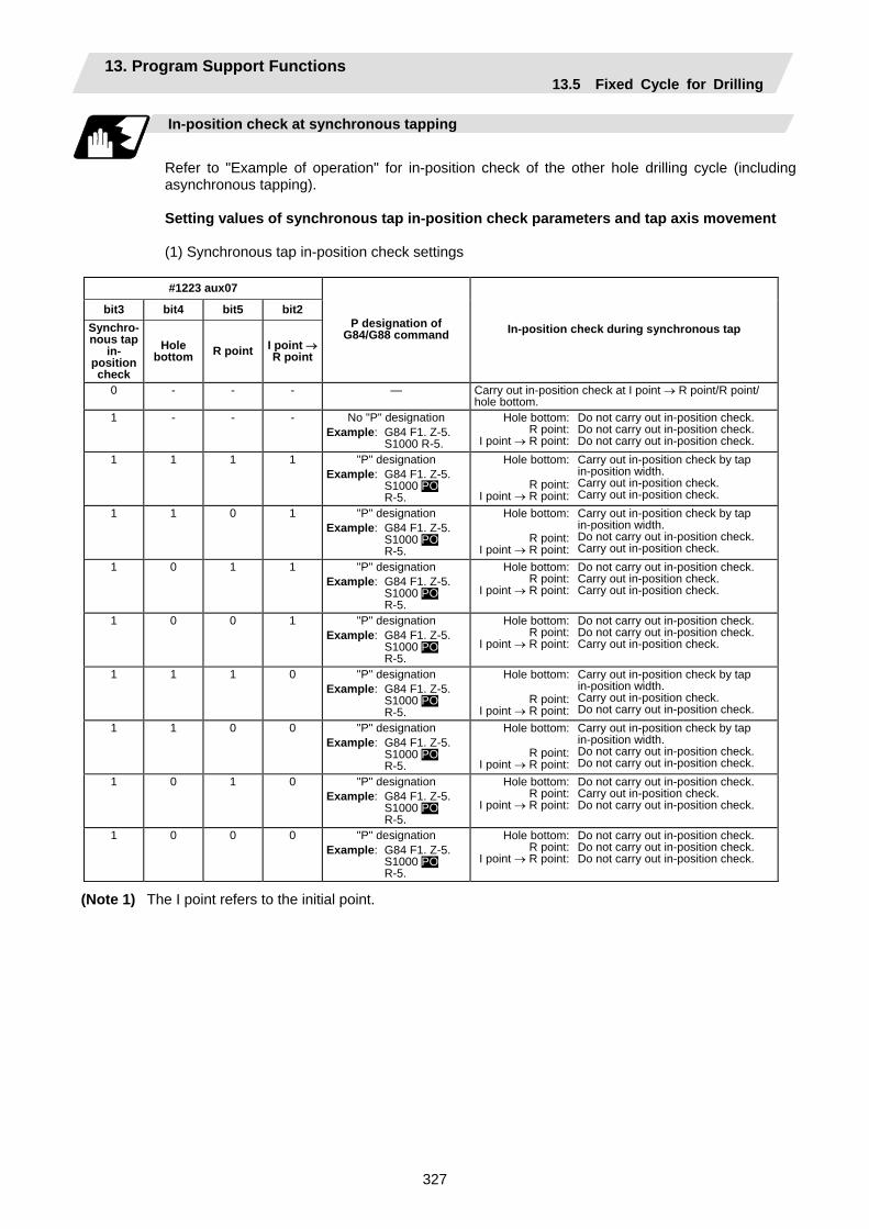
13. Program Support Functions 13.5 Fixed Cycle for Drilling
327
In-position check at synchronous tapping
Refer to "Example of operation" for in-position check of the other hole drilling cycle (including asynchronous tapping). Setting values of synchronous tap in-position check parameters and tap axis movement (1) Synchronous tap in-position check settings
#1223 aux07
bit3 bit4 bit5 bit2 Synchro-nous tap
in- position check
Hole bottom R point I point →
R point
P designation of G84/G88 command In-position check during synchronous tap
0 - - - — Carry out in-position check at I point → R point/R point/ hole bottom.
1 - - - No "P" designation Example: G84 F1. Z-5. S1000 R-5.
Hole bottom:R point:
I point → R point:
Do not carry out in-position check. Do not carry out in-position check. Do not carry out in-position check.
1 1 1 1 "P" designation Example: G84 F1. Z-5. S1000 PO R-5.
Hole bottom:
R point:I point → R point:
Carry out in-position check by tap in-position width. Carry out in-position check. Carry out in-position check.
1 1 0 1 "P" designation Example: G84 F1. Z-5. S1000 PO R-5.
Hole bottom:
R point:I point → R point:
Carry out in-position check by tap in-position width. Do not carry out in-position check. Carry out in-position check.
1 0 1 1 "P" designation Example: G84 F1. Z-5. S1000 PO R-5.
Hole bottom:R point:
I point → R point:
Do not carry out in-position check. Carry out in-position check. Carry out in-position check.
1 0 0 1 "P" designation Example: G84 F1. Z-5. S1000 PO R-5.
Hole bottom:R point:
I point → R point:
Do not carry out in-position check. Do not carry out in-position check. Carry out in-position check.
1 1 1 0 "P" designation Example: G84 F1. Z-5. S1000 PO R-5.
Hole bottom:
R point:I point → R point:
Carry out in-position check by tap in-position width. Carry out in-position check. Do not carry out in-position check.
1 1 0 0 "P" designation Example: G84 F1. Z-5. S1000 PO R-5.
Hole bottom:
R point:I point → R point:
Carry out in-position check by tap in-position width. Do not carry out in-position check. Do not carry out in-position check.
1 0 1 0 "P" designation Example: G84 F1. Z-5. S1000 PO R-5.
Hole bottom:R point:
I point → R point:
Do not carry out in-position check. Carry out in-position check. Do not carry out in-position check.
1 0 0 0 "P" designation Example: G84 F1. Z-5. S1000 PO R-5.
Hole bottom:R point:
I point → R point:
Do not carry out in-position check. Do not carry out in-position check. Do not carry out in-position check.
(Note 1) The I point refers to the initial point.
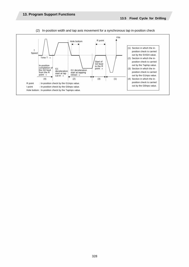
13. Program Support Functions 13.5 Fixed Cycle for Drilling
328
(2) In-position width and tap axis movement for a synchronous tap in-position check
Time T →
↑ Speed
Hole bottom
FINR point
(2) (4) (3) (1)
In-position completion of the G0 feed from the R point →
G1 deceleration start at tapping retract →
Start of G0 feed to the R point →G1
deceleration start at tap cut-in →
R point : In-position check by the G1inps value. I point : In-position check by the G0inps value. Hole bottom : In-position check by the Tapinps value.
(1) Section in which the in- position check is carried out by the SV024 value.
(2) Section in which the in- position check is carried out by the TapInp value.
(3) Section in which the in- position check is carried out by the G1inps value.
(4) Section in which the in- position check is carried out by the G0inps value.
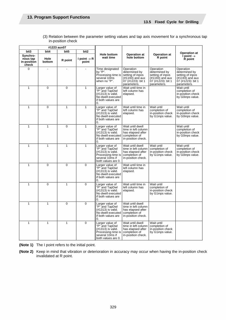
13. Program Support Functions 13.5 Fixed Cycle for Drilling
329
(3) Relation between the parameter setting values and tap axis movement for a synchronous tap
in-position check #1223 aux07
bit3 bit4 bit5 bit2 Synchro- nous tap
in-position check
Hole bottom R point I point → R
point
Hole bottom wait time
Operation at hole bottom
Operation at R point
Operation at I point → R point
0 - - - Time designated by "P". Processing time is several 10ms when no "P".
Operation determined by setting of inpos (#1193) and aux 07 (#1223): bit 1 parameters.
Operation determined by setting of inpos (#1193) and aux 07 (#1223): bit 1 parameters.
Operation determined by setting of inpos (#1193) and aux 07 (#1223): bit 1 parameters.
1 0 0 1 Larger value of "P" and TapDwl (#1313) is valid. No dwell executed if both values are 0.
Wait until time in left column has elapsed.
Wait until completion of in-position check by G0inps value.
1 0 1 1 Larger value of "P" and TapDwl (#1313) is valid. No dwell executed if both values are 0.
Wait until time in left column has elapsed.
Wait until completion of in-position check by G1inps value.
Wait until completion of in-position check by G0inps value.
1 1 0 1 Larger value of "P" and TapDwl (#1313) is valid. No dwell executed if both values are 0.
Wait until dwell time in left column has elapsed after completion of in-position check.
Wait until completion of in-position check by G0inps value.
1 1 1 1 Larger value of "P" and TapDwl (#1313) is valid. Processing time is several 10ms if both values are 0.
Wait until dwell time in left column has elapsed after completion of in-position check.
Wait until completion of in-position check by G1inps value.
Wait until completion of in-position check by G0inps value.
1 0 0 0 Larger value of "P" and TapDwl (#1313) is valid. No dwell executed if both values are 0.
Wait until time in left column has elapsed.
1 0 1 0 Larger value of "P" and TapDwl (#1313) is valid. No dwell executed if both values are 0.
Wait until time in left column has elapsed.
Wait until completion of in-position check by G1inps value.
1 1 0 0 Larger value of "P" and TapDwl (#1313) is valid. No dwell executed if both values are 0.
Wait until dwell time in left column has elapsed after completion of in-position check.
1 1 1 0 Larger value of "P" and TapDwl (#1313) is valid. Processing time is several 10ms if both values are 0.
Wait until dwell time in left column has elapsed after completion of in-position check.
Wait until completion of in-position check by G1inps value.
(Note 1) The I point refers to the initial point.
(Note 2) Keep in mind that vibration or deterioration in accuracy may occur when having the in-position check invalidated at R point.
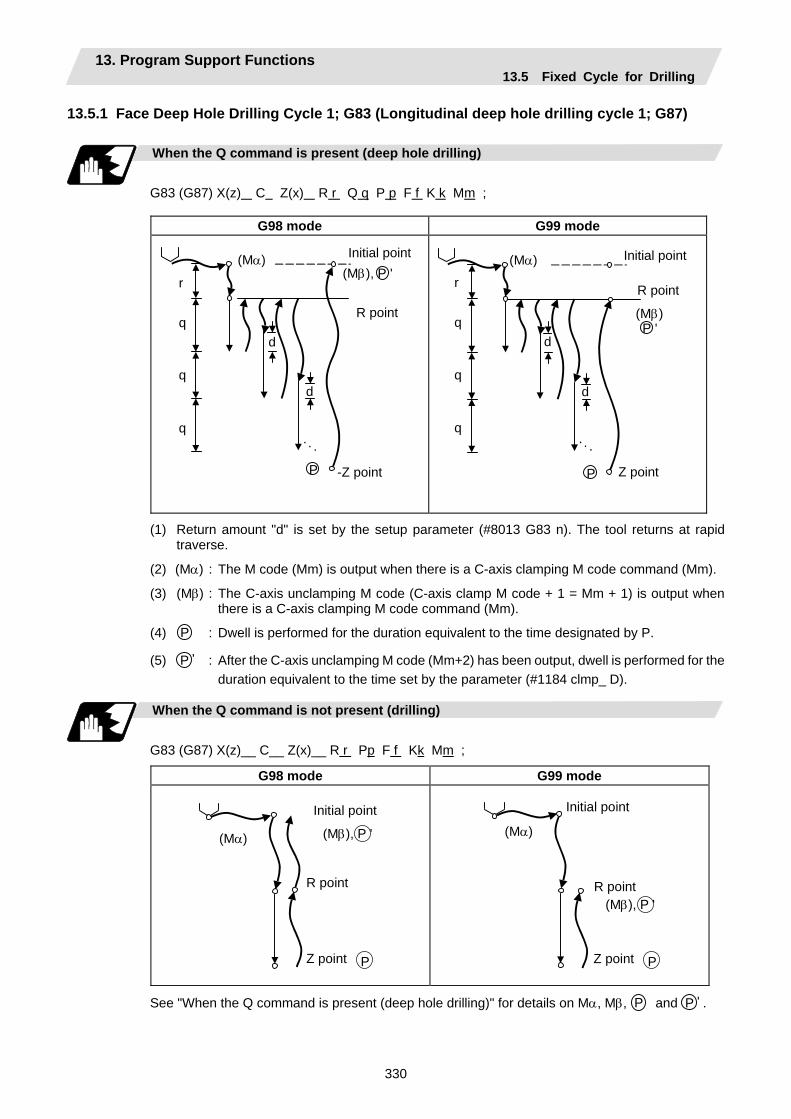
13. Program Support Functions 13.5 Fixed Cycle for Drilling
330
13.5.1 Face Deep Hole Drilling Cycle 1; G83 (Longitudinal deep hole drilling cycle 1; G87)
When the Q command is present (deep hole drilling)
G83 (G87) X(z) C Z(x) R r Q q P p F f K k Mm ;
G98 mode G99 mode
Initial point
R point
-Z point
r
d
q
q
q
d
(Mα)
P
(Mβ), P '
. . .
Initial point
R point
Z point
r
d
q
q
q
d
P
(Mβ) P '
. . .
(Mα)
(1) Return amount "d" is set by the setup parameter (#8013 G83 n). The tool returns at rapid traverse.
(2) (Mα) : The M code (Mm) is output when there is a C-axis clamping M code command (Mm).
(3) (Mβ) : The C-axis unclamping M code (C-axis clamp M code + 1 = Mm + 1) is output when there is a C-axis clamping M code command (Mm).
(4) P : Dwell is performed for the duration equivalent to the time designated by P.
(5) P ' : After the C-axis unclamping M code (Mm+2) has been output, dwell is performed for the duration equivalent to the time set by the parameter (#1184 clmp_ D).
When the Q command is not present (drilling)
G83 (G87) X(z)__ C__ Z(x)__ R r Pp F f Kk Mm ;
G98 mode G99 mode
(Mα)
P
Initial point
R point
Z point
(Mβ), P '
(Mα)
P
Initial point
R point
Z point
(Mβ), P '
See "When the Q command is present (deep hole drilling)" for details on Mα, Mβ, P and P ' .
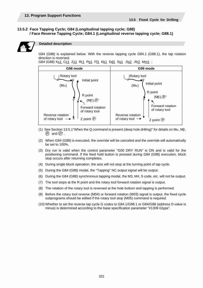
13. Program Support Functions 13.5 Fixed Cycle for Drilling
331
13.5.2 Face Tapping Cycle; G84 (Longitudinal tapping cycle; G88) / Face Reverse Tapping Cycle; G84.1 (Longitudinal reverse tapping cycle; G88.1)
Detailed description
G84 (G88) is explained below. With the reverse tapping cycle G84.1 (G88.1), the tap rotation direction is reversed. G84 (G88) Xx1 Cc1 Zz1 Rr1 Pp1 Ff1 Kk1 Dd1 Ss1 ,Ss2 ,Rr2 Mm1 ;
G98 mode G99 mode
Initial point
R point
Z point
(Mα)
P
(Mβ), P '
Rotary tool
Forward rotationof rotary tool
Reverse rotation of rotary tool
Initial point
R point
Z point
(Mα)
P
(Mβ), P '
Rotary tool
Forward rotationof rotary tool
Reverse rotationof rotary tool
(1) See Section 13.5.1"When the Q command is present (deep hole drilling)" for details on Mα, Mβ, P and P ' .
(2) When G84 (G88) is executed, the override will be canceled and the override will automatically be set to 100%.
(3) Dry run is valid when the control parameter "G00 DRY RUN" is ON and is valid for the positioning command. If the feed hold button is pressed during G84 (G88) execution, block stop occurs after returning completes.
(4) During single block operation, the axis will not stop at the turning point of tap cycle.
(5) During the G84 (G88) modal, the "Tapping" NC output signal will be output.
(6) During the G84 (G88) synchronous tapping modal, the M3, M4, S code, etc. will not be output.
(7) The tool stops at the R point and the rotary tool forward rotation signal is output.
(8) The rotation of the rotary tool is reversed at the hole bottom and tapping is performed.
(9) Before the rotary tool reverse (M04) or forward rotation (M03) signal is output, the fixed cycle subprograms should be edited if the rotary tool stop (M05) command is required.
(10) Whether to set the reverse tap cycle G codes to G84.1/G88.1 or G84/G88 (address D value is minus) is determined according to the base specification parameter "#1309 Gtype".
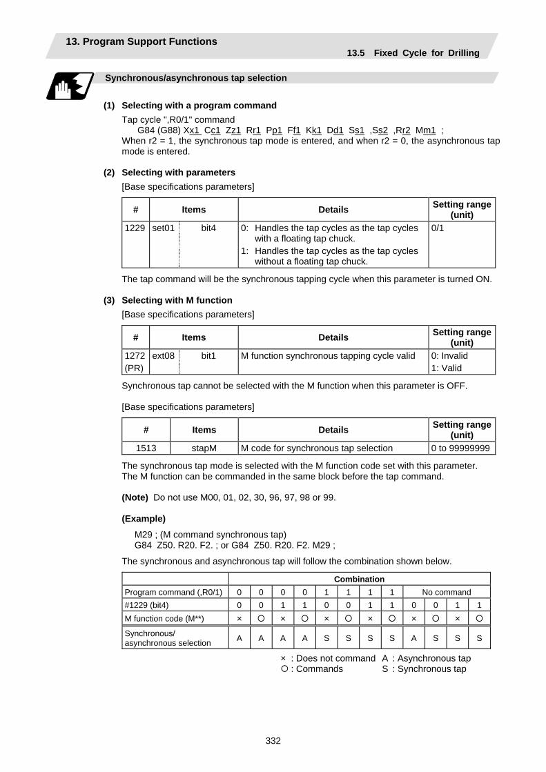
13. Program Support Functions 13.5 Fixed Cycle for Drilling
332
Synchronous/asynchronous tap selection
(1) Selecting with a program command
Tap cycle ",R0/1" command G84 (G88) Xx1 Cc1 Zz1 Rr1 Pp1 Ff1 Kk1 Dd1 Ss1 ,Ss2 ,Rr2 Mm1 ;
When r2 = 1, the synchronous tap mode is entered, and when r2 = 0, the asynchronous tap mode is entered.
(2) Selecting with parameters
[Base specifications parameters]
# Items Details Setting range (unit)
1229 set01 bit4 0: Handles the tap cycles as the tap cycles with a floating tap chuck.
1: Handles the tap cycles as the tap cycles without a floating tap chuck.
0/1
The tap command will be the synchronous tapping cycle when this parameter is turned ON. (3) Selecting with M function
[Base specifications parameters]
# Items Details Setting range (unit)
1272 (PR)
ext08 bit1 M function synchronous tapping cycle valid 0: Invalid 1: Valid
Synchronous tap cannot be selected with the M function when this parameter is OFF. [Base specifications parameters]
# Items Details Setting range (unit)
1513 stapM M code for synchronous tap selection 0 to 99999999
The synchronous tap mode is selected with the M function code set with this parameter. The M function can be commanded in the same block before the tap command. (Note) Do not use M00, 01, 02, 30, 96, 97, 98 or 99.
(Example)
M29 ; (M command synchronous tap) G84 Z50. R20. F2. ; or G84 Z50. R20. F2. M29 ;
The synchronous and asynchronous tap will follow the combination shown below.
Combination Program command (,R0/1) 0 0 0 0 1 1 1 1 No command #1229 (bit4) 0 0 1 1 0 0 1 1 0 0 1 1 M function code (M**) × × × × × ×Synchronous/ asynchronous selection A A A A S S S S A S S S
× : Does not command A : Asynchronous tap : Commands S : Synchronous tap
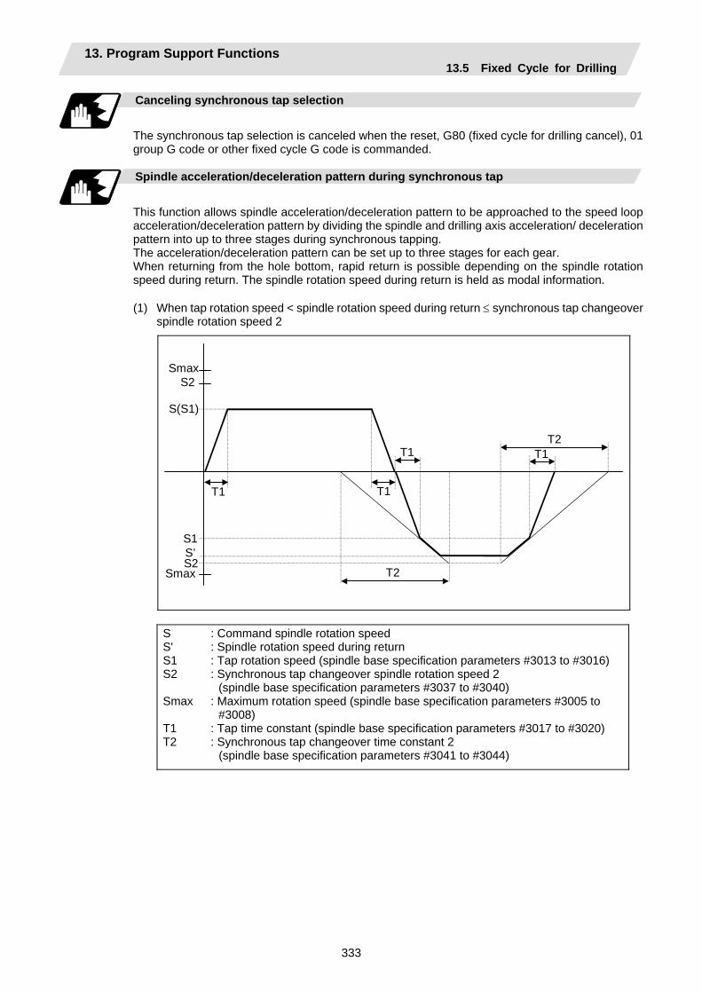
13. Program Support Functions 13.5 Fixed Cycle for Drilling
333
Canceling synchronous tap selection
The synchronous tap selection is canceled when the reset, G80 (fixed cycle for drilling cancel), 01 group G code or other fixed cycle G code is commanded.
Spindle acceleration/deceleration pattern during synchronous tap
This function allows spindle acceleration/deceleration pattern to be approached to the speed loop acceleration/deceleration pattern by dividing the spindle and drilling axis acceleration/ deceleration pattern into up to three stages during synchronous tapping. The acceleration/deceleration pattern can be set up to three stages for each gear. When returning from the hole bottom, rapid return is possible depending on the spindle rotation speed during return. The spindle rotation speed during return is held as modal information.
(1) When tap rotation speed < spindle rotation speed during return ≤ synchronous tap changeover
spindle rotation speed 2
Smax S2
S(S1)
S1 S’ S2
Smax
T1
T1 T1
T1
T2
T2
S S' S1 S2 Smax T1 T2
: Command spindle rotation speed : Spindle rotation speed during return : Tap rotation speed (spindle base specification parameters #3013 to #3016) : Synchronous tap changeover spindle rotation speed 2
(spindle base specification parameters #3037 to #3040) : Maximum rotation speed (spindle base specification parameters #3005 to
#3008) : Tap time constant (spindle base specification parameters #3017 to #3020) : Synchronous tap changeover time constant 2
(spindle base specification parameters #3041 to #3044)
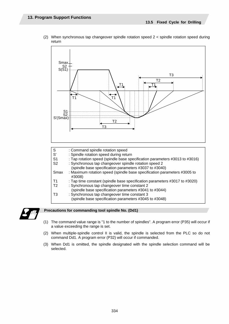
13. Program Support Functions 13.5 Fixed Cycle for Drilling
334
(2) When synchronous tap changeover spindle rotation speed 2 < spindle rotation speed during
return
Smax S2 S(S1)
S1S2
S'(Smax)
T1
T2T1T1
T1
T2
T3
T3
S S' S1 S2 Smax T1 T2 T3
: Command spindle rotation speed : Spindle rotation speed during return : Tap rotation speed (spindle base specification parameters #3013 to #3016) : Synchronous tap changeover spindle rotation speed 2
(spindle base specification parameters #3037 to #3040) : Maximum rotation speed (spindle base specification parameters #3005 to
#3008) : Tap time constant (spindle base specification parameters #3017 to #3020) : Synchronous tap changeover time constant 2
(spindle base specification parameters #3041 to #3044) : Synchronous tap changeover time constant 3
(spindle base specification parameters #3045 to #3048)
Precautions for commanding tool spindle No. (Dd1)
(1) The command value range is "1 to the number of spindles". A program error (P35) will occur if
a value exceeding the range is set.
(2) When multiple-spindle control II is valid, the spindle is selected from the PLC so do not command Dd1. A program error (P32) will occur if commanded.
(3) When Dd1 is omitted, the spindle designated with the spindle selection command will be selected.
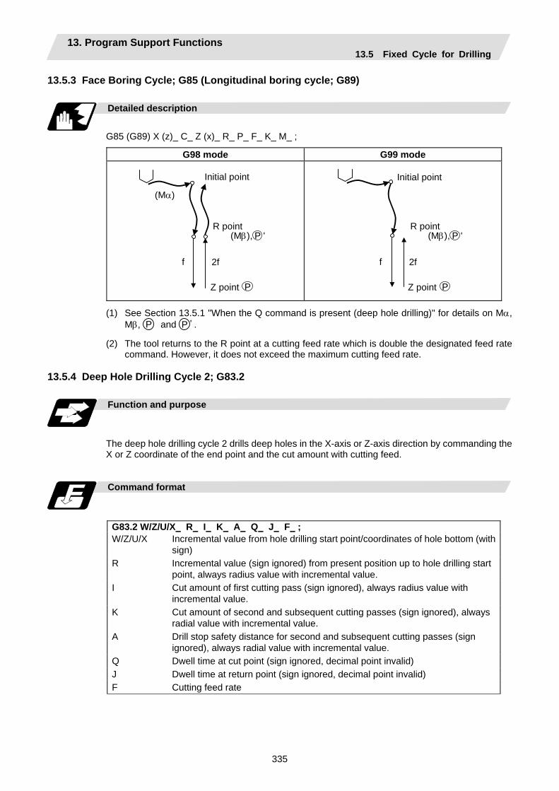
13. Program Support Functions 13.5 Fixed Cycle for Drilling
335
13.5.3 Face Boring Cycle; G85 (Longitudinal boring cycle; G89)
Detailed description
G85 (G89) X (z)_ C_ Z (x)_ R_ P_ F_ K_ M_ ;
G98 mode G99 mode
2f f
Initial point
R point
Z point
(Mα)
P
(Mβ), P '
2f f
Initial point
R point
Z point P
(Mβ), P '
(1) See Section 13.5.1 "When the Q command is present (deep hole drilling)" for details on Mα, Mβ, P and P ' .
(2) The tool returns to the R point at a cutting feed rate which is double the designated feed rate command. However, it does not exceed the maximum cutting feed rate.
13.5.4 Deep Hole Drilling Cycle 2; G83.2
Function and purpose
The deep hole drilling cycle 2 drills deep holes in the X-axis or Z-axis direction by commanding the X or Z coordinate of the end point and the cut amount with cutting feed.
Command format
G83.2 W/Z/U/X R I K A Q J F ; W/Z/U/X Incremental value from hole drilling start point/coordinates of hole bottom (with
sign) R Incremental value (sign ignored) from present position up to hole drilling start
point, always radius value with incremental value. I Cut amount of first cutting pass (sign ignored), always radius value with
incremental value. K Cut amount of second and subsequent cutting passes (sign ignored), always
radial value with incremental value. A Drill stop safety distance for second and subsequent cutting passes (sign
ignored), always radial value with incremental value. Q Dwell time at cut point (sign ignored, decimal point invalid) J Dwell time at return point (sign ignored, decimal point invalid) F Cutting feed rate
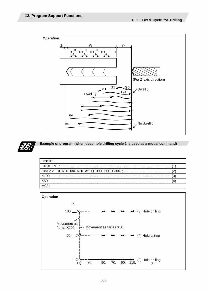
13. Program Support Functions 13.5 Fixed Cycle for Drilling
336
Operation
Dwell QDwell J
No dwell J
(For Z-axis direction)
A K
Z RI
G1 G0G0
W
A A AK K
Example of program (when deep hole drilling cycle 2 is used as a modal command)
G28 XZ ; G0 X0. Z0. ;................................................................................................................. (1) G83.2 Z110. R20. I30. K20. A5. Q1000 J500. F300. ;................................................ (2) X100. ;......................................................................................................................... (3) X50. ; ........................................................................................................................... (4) M02 ;
Operation
Movement as far as X50.
X
100.
50.
20. 50. 70. 90. 110.(1)
Movement as far as X100.
(3) Hole drilling
(4) Hole drilling
(2) Hole drilling Z
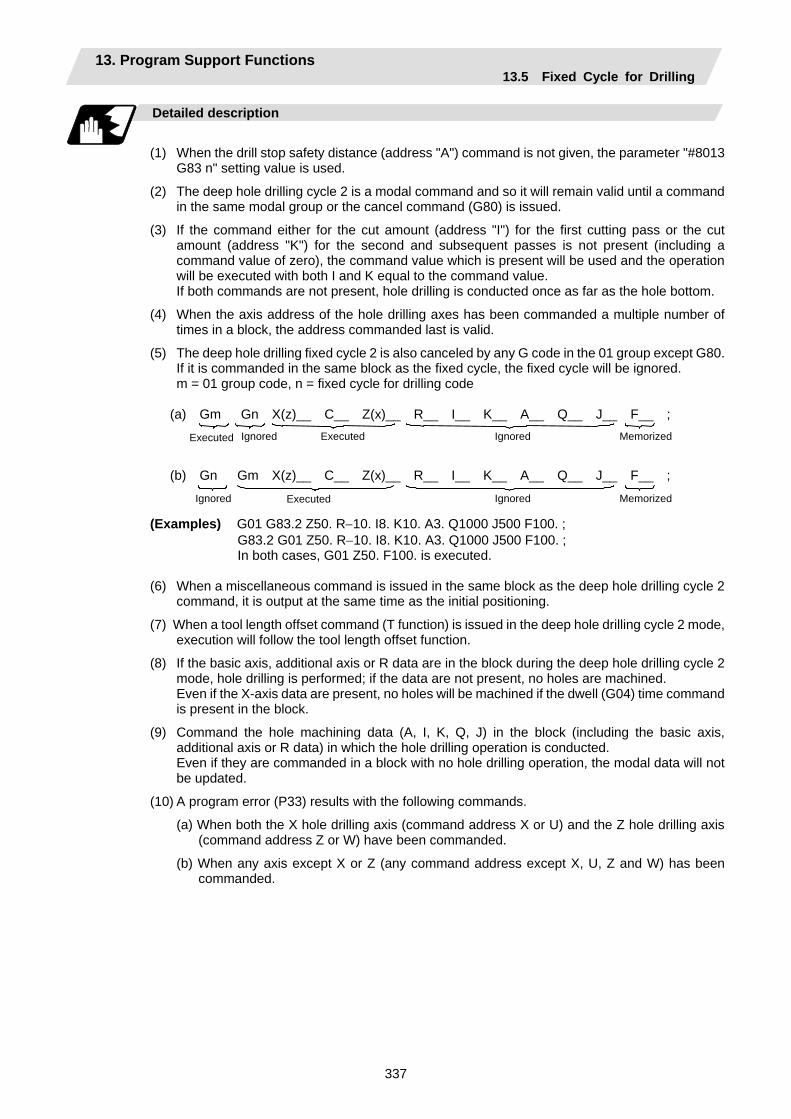
13. Program Support Functions 13.5 Fixed Cycle for Drilling
337
Detailed description
(1) When the drill stop safety distance (address "A") command is not given, the parameter "#8013
G83 n" setting value is used.
(2) The deep hole drilling cycle 2 is a modal command and so it will remain valid until a command in the same modal group or the cancel command (G80) is issued.
(3) If the command either for the cut amount (address "I") for the first cutting pass or the cut amount (address "K") for the second and subsequent passes is not present (including a command value of zero), the command value which is present will be used and the operation will be executed with both I and K equal to the command value.
If both commands are not present, hole drilling is conducted once as far as the hole bottom.
(4) When the axis address of the hole drilling axes has been commanded a multiple number of times in a block, the address commanded last is valid.
(5) The deep hole drilling fixed cycle 2 is also canceled by any G code in the 01 group except G80. If it is commanded in the same block as the fixed cycle, the fixed cycle will be ignored.
m = 01 group code, n = fixed cycle for drilling code
(a) Gm Gn X(z)__ C__ Z(x)__ R__ I__ K__ A__ Q__ J__ F__ ; (b) Gn Gm X(z)__ C__ Z(x)__ R__ I__ K__ A__ Q__ J__ F__ ;
Executed Ignored Executed Ignored Memorized
Ignored Executed Ignored Memorized
(Examples) G01 G83.2 Z50. R−10. I8. K10. A3. Q1000 J500 F100. ; G83.2 G01 Z50. R−10. I8. K10. A3. Q1000 J500 F100. ; In both cases, G01 Z50. F100. is executed.
(6) When a miscellaneous command is issued in the same block as the deep hole drilling cycle 2
command, it is output at the same time as the initial positioning.
(7) When a tool length offset command (T function) is issued in the deep hole drilling cycle 2 mode, execution will follow the tool length offset function.
(8) If the basic axis, additional axis or R data are in the block during the deep hole drilling cycle 2 mode, hole drilling is performed; if the data are not present, no holes are machined.
Even if the X-axis data are present, no holes will be machined if the dwell (G04) time command is present in the block.
(9) Command the hole machining data (A, I, K, Q, J) in the block (including the basic axis, additional axis or R data) in which the hole drilling operation is conducted.
Even if they are commanded in a block with no hole drilling operation, the modal data will not be updated.
(10) A program error (P33) results with the following commands.
(a) When both the X hole drilling axis (command address X or U) and the Z hole drilling axis (command address Z or W) have been commanded.
(b) When any axis except X or Z (any command address except X, U, Z and W) has been commanded.
13. Program Support Functions 13.5 Fixed Cycle for Drilling
338
(11) When the feed hold button is pressed while the deep hole drilling cycle 2 is being executed, feed hold results at that point, and when automatic operation is restarted, the remainder is executed.
(12) When an interrupt based on manual operation is performed during the feed hold (manual absolute switch ON), the operation in the deep hole drilling cycle 2 modal is shifted from the automatic operation restart by an amount equivalent to the movement caused by the interrupt.
(13) With single block operation, block stop results upon completion of the deep hole drilling cycle 2 command.
13.5.5 Fixed Cycle for Drilling Cancel; G80
Detailed description
This cancels the fixed cycle for drilling (G83, G84, G85, G87, G88, G89). The hole machining mode and hole machining data are both canceled.
13.5.6 Precautions When Using a Fixed Cycle for Drilling
Precautions
(1) When a G84 or G88 fixed cycle is commanded, the rotary tool must be rotated in the specified
direction beforehand by the previous miscellaneous functions (M3, M4).
(2) If there is data for the basic axis, additional axis or R in the same block during fixed cycle mode, hole drilling is carried out. If there is no data, the hole drilling is not carried out. Note that even with X axis data, if that block is a dwell (G04) time command, the hole drilling is not carried out.
(3) Command hole machining data (Q, P) in the block in which hole drilling is carried out (block containing data for the basic axis, additional axis or R).
The modal data is not updated in blocks without hole drilling, even if these data are commanded.
(4) The F modal may change when a reset is applied during execution of G85 (G89).
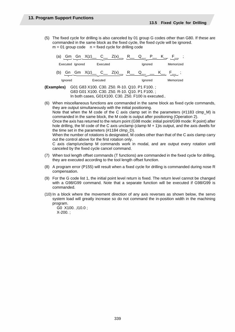
13. Program Support Functions 13.5 Fixed Cycle for Drilling
339
(5) The fixed cycle for drilling is also canceled by 01 group G codes other than G80. If these are
commanded in the same block as the fixed cycle, the fixed cycle will be ignored. m = 01 group code n = fixed cycle for drilling code
(a) Gm Gn X(z)__ C__ Z(x)__ R__ Q__ P__ K__ F__ ;
(b) Gn Gm X(z)__ C__ Z(x)__ R__ Q__ __ K__ F__ ;
Executed Ignored Executed Ignored Memorized
Ignored Executed Ignored Memorized
(Examples) G01 G83 X100. C30. Z50. R-10. Q10. P1 F100. ; G83 G01 X100. C30. Z50. R-10. Q10. P1 F100. ; In both cases, G01X100. C30. Z50. F100 is executed..
(6) When miscellaneous functions are commanded in the same block as fixed cycle commands, they are output simultaneously with the initial positioning.
Note that when the M code of the C axis clamp set in the parameters (#1183 clmp_M) is commanded in the same block, the M code is output after positioning (Operation 2).
Once the axis has returned to the return point (G98 mode: initial point/G99 mode: R point) after hole drilling, the M code of the C axis unclamp (clamp M + 1)is output, and the axis dwells for the time set in the parameters (#1184 clmp_D).
When the number of rotations is designated, M codes other than that of the C axis clamp carry out the control above for the first rotation only.
C axis clamp/unclamp M commands work in modal, and are output every rotation until canceled by the fixed cycle cancel command.
(7) When tool length offset commands (T functions) are commanded in the fixed cycle for drilling, they are executed according to the tool length offset function.
(8) A program error (P155) will result when a fixed cycle for drilling is commanded during nose R compensation.
(9) For the G code list 1, the initial point level return is fixed. The return level cannot be changed with a G98/G99 command. Note that a separate function will be executed if G98/G99 is commanded.
(10) In a block where the movement direction of any axis reverses as shown below, the servo system load will greatly increase so do not command the in-position width in the machining program. G0 X100. ,I10.0 ; X-200. ;
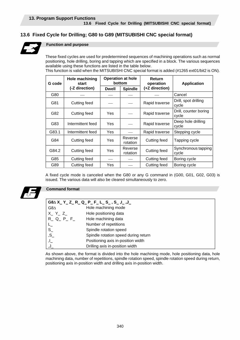
13. Program Support Functions 13.6 Fixed Cycle for Drilling (MITSUBISHI CNC special format)
340
13.6 Fixed Cycle for Drilling; G80 to G89 (MITSUBISHI CNC special format)
Function and purpose
These fixed cycles are used for predetermined sequences of machining operations such as normal positioning, hole drilling, boring and tapping which are specified in a block. The various sequences available using these functions are listed in the table below. This function is valid when the MITSUBISHI CNC special format is added (#1265 ext01/bit2 is ON).
Operation at hole bottom G code
Hole machining start
(-Z direction) Dwell Spindle
Return operation
(+Z direction)Application
G80 ⎯ ⎯ ⎯ ⎯ Cancel
G81 Cutting feed ⎯ ⎯ Rapid traverse Drill, spot drilling cycle
G82 Cutting feed Yes ⎯ Rapid traverse Drill, counter boring cycle
G83 Intermittent feed Yes ⎯ Rapid traverse Deep hole drilling cycle
G83.1 Intermittent feed Yes ⎯ Rapid traverse Stepping cycle
G84 Cutting feed Yes Reverse rotation Cutting feed Tapping cycle
G84.2 Cutting feed Yes Reverse rotation Cutting feed Synchronous tapping
cycle G85 Cutting feed ⎯ ⎯ Cutting feed Boring cycle G89 Cutting feed Yes ⎯ Cutting feed Boring cycle
A fixed cycle mode is canceled when the G80 or any G command in (G00, G01, G02, G03) is issued. The various data will also be cleared simultaneously to zero.
Command format
G8∆ X Y Z R Q P F L S , S ,I ,J G8∆ Hole machining mode X Y Z R Q P F L S ,S ,I ,J
Hole positioning data Hole machining data Number of repetitions Spindle rotation speed Spindle rotation speed during return Positioning axis in-position width Drilling axis in-position width
As shown above, the format is divided into the hole machining mode, hole positioning data, hole machining data, number of repetitions, spindle rotation speed, spindle rotation speed during return, positioning axis in-position width and drilling axis in-position width.
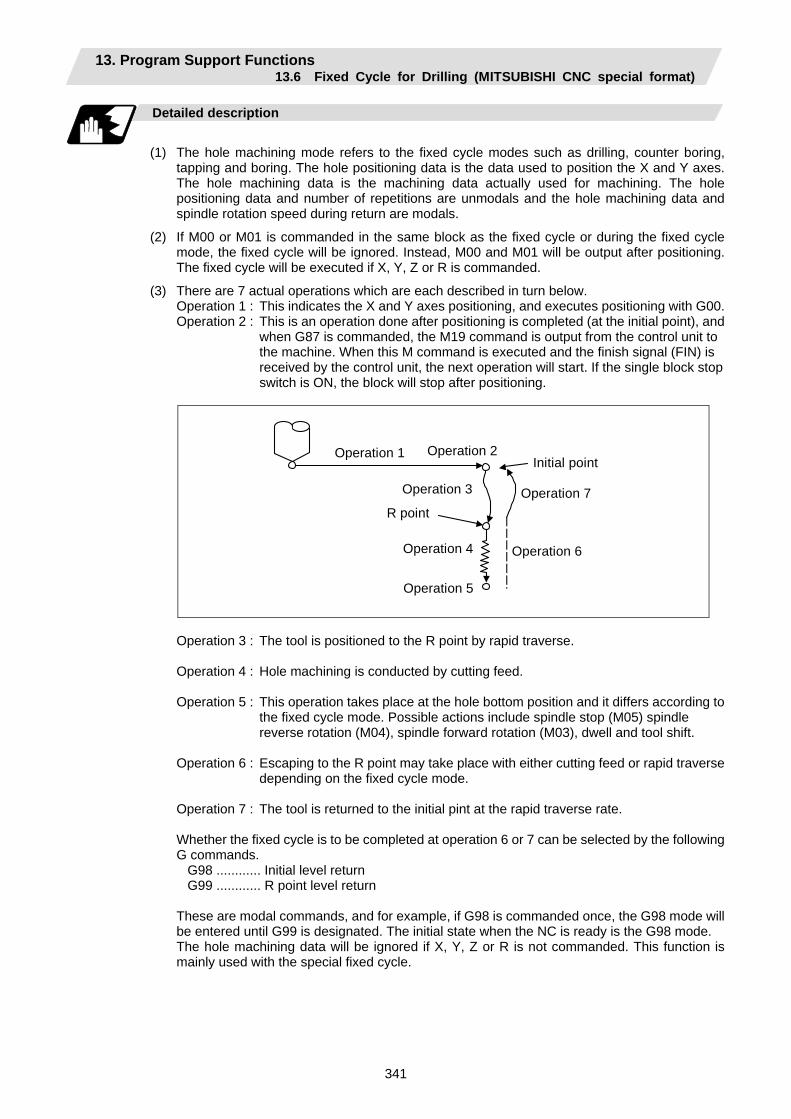
13. Program Support Functions 13.6 Fixed Cycle for Drilling (MITSUBISHI CNC special format)
341
Detailed description
(1) The hole machining mode refers to the fixed cycle modes such as drilling, counter boring,
tapping and boring. The hole positioning data is the data used to position the X and Y axes. The hole machining data is the machining data actually used for machining. The hole positioning data and number of repetitions are unmodals and the hole machining data and spindle rotation speed during return are modals.
(2) If M00 or M01 is commanded in the same block as the fixed cycle or during the fixed cycle mode, the fixed cycle will be ignored. Instead, M00 and M01 will be output after positioning. The fixed cycle will be executed if X, Y, Z or R is commanded.
(3) There are 7 actual operations which are each described in turn below. Operation 1 : This indicates the X and Y axes positioning, and executes positioning with G00. Operation 2 : This is an operation done after positioning is completed (at the initial point), and
when G87 is commanded, the M19 command is output from the control unit to the machine. When this M command is executed and the finish signal (FIN) is received by the control unit, the next operation will start. If the single block stop switch is ON, the block will stop after positioning.
Operation 1
R point
Initial point Operation 2
Operation 3
Operation 4
Operation 5
Operation 6
Operation 7
Operation 3 : The tool is positioned to the R point by rapid traverse. Operation 4 : Hole machining is conducted by cutting feed. Operation 5 : This operation takes place at the hole bottom position and it differs according to
the fixed cycle mode. Possible actions include spindle stop (M05) spindle reverse rotation (M04), spindle forward rotation (M03), dwell and tool shift.
Operation 6 : Escaping to the R point may take place with either cutting feed or rapid traverse
depending on the fixed cycle mode. Operation 7 : The tool is returned to the initial pint at the rapid traverse rate.
Whether the fixed cycle is to be completed at operation 6 or 7 can be selected by the following G commands. G98 ............ Initial level return G99 ............ R point level return These are modal commands, and for example, if G98 is commanded once, the G98 mode will be entered until G99 is designated. The initial state when the NC is ready is the G98 mode. The hole machining data will be ignored if X, Y, Z or R is not commanded. This function is mainly used with the special fixed cycle.

13. Program Support Functions 13.6 Fixed Cycle for Drilling (MITSUBISHI CNC special format)
342
(4) Fixed cycle addresses and meanings
Address Significance G Selection of fixed cycle for drilling sequence (G80 to G89) X Designation of hole drilling position (absolute value or incremental value) Y Designation of hole drilling position (absolute value or incremental value) Z Designation of hole bottom position (absolute value or incremental value)
P Designation of dwell time at hole bottom position (decimal points will be ignored)
Q Designation of cut amount for each cutting pass with G83, or designation of the shift amount at G87 (incremental value)
R Designation of R point (absolute value) F Designation of feed rate for cutting feed L Designation of number of repetitions. 0 to 9999 S Designation of spindle rotation speed
,S Designation of spindle rotation speed at return (Note) Valid only during synchronous tap mode. This setting is ignored during
other modes. ,I In-position width (position error amount) ,J In-position width for hole drilling axis in fixed cycle (position error amount)
(5) Difference between absolute value command and incremental value command
For absolute value
R point +r +r
-z
-z
For incremental value
Workpiece Workpiece
R point
(6) Feed rate for tapping cycle and tapping retract
The feed rate for the tapping cycle and tapping retract are as shown below.
(a) Selection of asynchronous tapping cycle feed rate
G94/G95 Control parameterF1-digit value F command value Feed designation
OFF F designation Other than F0 to F8
Feed per minute G94
ON F0 to F8 (no decimal point) F1-digit feed
G95 ⎯ F designation Feed per revolution − is irrelevant to the setting
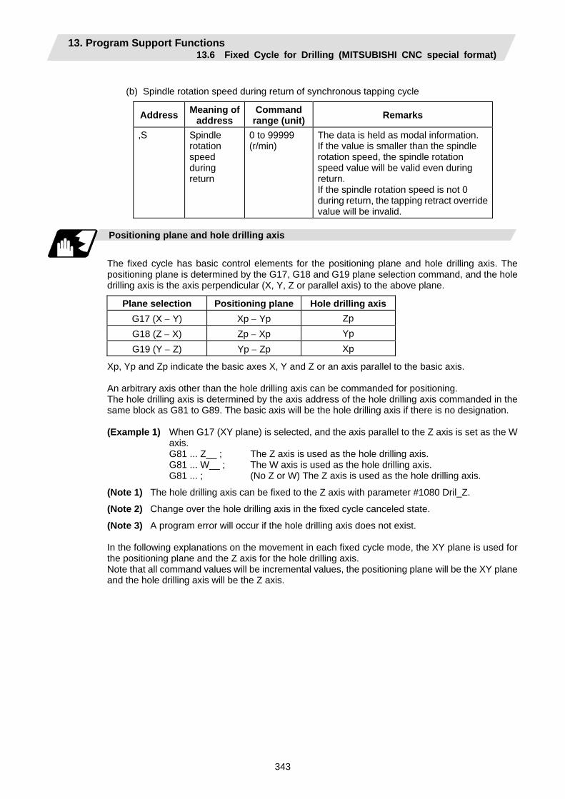
13. Program Support Functions 13.6 Fixed Cycle for Drilling (MITSUBISHI CNC special format)
343
(b) Spindle rotation speed during return of synchronous tapping cycle
Address Meaning of address
Command range (unit) Remarks
,S Spindle rotation speed during return
0 to 99999 (r/min)
The data is held as modal information. If the value is smaller than the spindle rotation speed, the spindle rotation speed value will be valid even during return. If the spindle rotation speed is not 0 during return, the tapping retract override value will be invalid.
Positioning plane and hole drilling axis
The fixed cycle has basic control elements for the positioning plane and hole drilling axis. The positioning plane is determined by the G17, G18 and G19 plane selection command, and the hole drilling axis is the axis perpendicular (X, Y, Z or parallel axis) to the above plane.
Plane selection Positioning plane Hole drilling axis G17 (X − Y) Xp − Yp Zp G18 (Z − X) Zp − Xp Yp G19 (Y − Z) Yp − Zp Xp
Xp, Yp and Zp indicate the basic axes X, Y and Z or an axis parallel to the basic axis. An arbitrary axis other than the hole drilling axis can be commanded for positioning. The hole drilling axis is determined by the axis address of the hole drilling axis commanded in the same block as G81 to G89. The basic axis will be the hole drilling axis if there is no designation.
(Example 1) When G17 (XY plane) is selected, and the axis parallel to the Z axis is set as the W
axis. G81 ... Z__ ; The Z axis is used as the hole drilling axis. G81 ... W__ ; The W axis is used as the hole drilling axis. G81 ... ; (No Z or W) The Z axis is used as the hole drilling axis.
(Note 1) The hole drilling axis can be fixed to the Z axis with parameter #1080 Dril_Z.
(Note 2) Change over the hole drilling axis in the fixed cycle canceled state.
(Note 3) A program error will occur if the hole drilling axis does not exist. In the following explanations on the movement in each fixed cycle mode, the XY plane is used for the positioning plane and the Z axis for the hole drilling axis. Note that all command values will be incremental values, the positioning plane will be the XY plane and the hole drilling axis will be the Z axis.
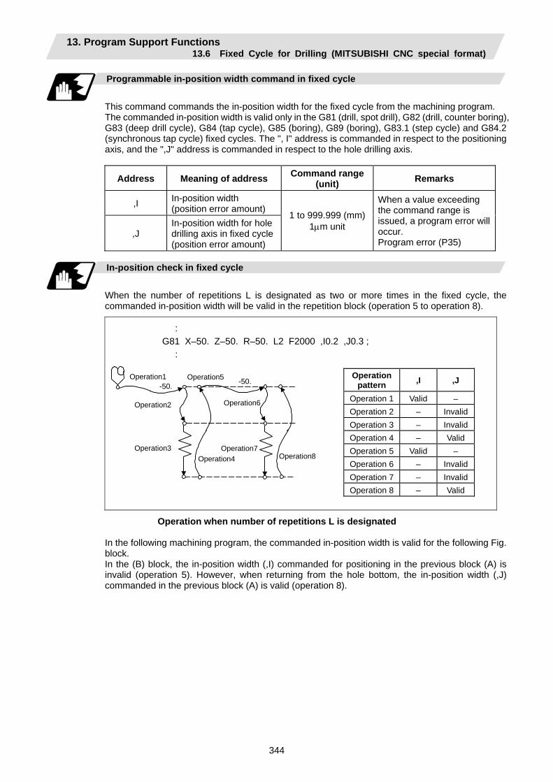
13. Program Support Functions 13.6 Fixed Cycle for Drilling (MITSUBISHI CNC special format)
344
Programmable in-position width command in fixed cycle
This command commands the in-position width for the fixed cycle from the machining program. The commanded in-position width is valid only in the G81 (drill, spot drill), G82 (drill, counter boring), G83 (deep drill cycle), G84 (tap cycle), G85 (boring), G89 (boring), G83.1 (step cycle) and G84.2 (synchronous tap cycle) fixed cycles. The ", I" address is commanded in respect to the positioning axis, and the ",J" address is commanded in respect to the hole drilling axis.
Address Meaning of address Command range (unit) Remarks
,I In-position width (position error amount)
,J In-position width for hole drilling axis in fixed cycle (position error amount)
1 to 999.999 (mm)1µm unit
When a value exceeding the command range is issued, a program error will occur. Program error (P35)
In-position check in fixed cycle
When the number of repetitions L is designated as two or more times in the fixed cycle, the commanded in-position width will be valid in the repetition block (operation 5 to operation 8).
: G81 X–50. Z–50. R–50. L2 F2000 ,I0.2 ,J0.3 ; :
Operation1 -50.
Operation5
Operation2
Operation3 Operation4
Operation7 Operation8
Operation6
-50.Operation
pattern ,I ,J
Operation 1 Valid – Operation 2 – InvalidOperation 3 – InvalidOperation 4 – Valid Operation 5 Valid – Operation 6 – InvalidOperation 7 – InvalidOperation 8 – Valid
Operation when number of repetitions L is designated
In the following machining program, the commanded in-position width is valid for the following Fig. block. In the (B) block, the in-position width (,I) commanded for positioning in the previous block (A) is invalid (operation 5). However, when returning from the hole bottom, the in-position width (,J) commanded in the previous block (A) is valid (operation 8).

13. Program Support Functions 13.6 Fixed Cycle for Drilling (MITSUBISHI CNC special format)
345
In the following machining program, the commanded in-position width is valid for the following Fig. block. In the (B) block, the in-position width (, I) commanded for positioning in the previous block (A) is invalid (operation 5). However, when returning from the hole bottom, the in-position width (, J) commanded in the previous block (A) is valid (operation 8). To validate the in-position width for positioning, command again as shown in block (C) (Operation 9).
: G81 X-50. Z-50. R-50. F2000 ,I0.2 ,J0.3 ; ............. (A) X-10. ; .......................................................................... (B) X-10. ,I0.2 ; .................................................................. (C) :
Operation1
Operation4
Opera-tion7
Opera-tion6
Operation5 -10.
Opera-tion12 Operation8
Opera-tion11
Opera-tion10
Operation9 -10.
Operation2
Operation3
-50.
Operation pattern ,I ,J
Operation 1 Valid – Operation 2 – InvalidOperation 3 – InvalidOperation 4 – Valid Operation 5 Invalid – Operation 6 – InvalidOperation 7 – InvalidOperation 8 – Valid Operation 9 Valid –
Operation 10 – InvalidOperation 11 – InvalidOperation 12 – Valid
Operation in fixed cycle modal

13. Program Support Functions 13.6 Fixed Cycle for Drilling (MITSUBISHI CNC special format)
346
Setting values of synchronous tap in-position check parameters and tap axis movement
(1) Synchronous tap in-position check settings
#1223 aux07 bit3 bit4 bit5 bit2
Synchro-nous tap
in- position check
Hole bottom R point
I point → R point
"P" designation of G84/G74 command In-position check during synchronous tap
0 — — — — Carry out in-position check at I point → R point/R point/hole bottom.
1 — — — No "P" designation Example: G84 F1. Z-5. S1000 R-5.
Hole bottom:R point:
I point → R point:
Do not carry out in-position check.Do not carry out in-position check.Do not carry out in-position check.
1 1 1 1 "P" designation Example: G84 F1. Z-5. S1000 PO R-5.
Hole bottom:
R point:I point → R point:
Carry out in-position check by tap in-position width. Carry out in-position check. Carry out in-position check.
1 1 0 1 "P" designation Example: G84 F1. Z-5. S1000 PO R-5.
Hole bottom:
R point:I point → R point:
Carry out in-position check by tap in-position width. Do not carry out in-position check.Carry out in-position check.
1 0 1 1 "P" designation Example: G84 F1. Z-5. S1000 PO R-5.
Hole bottom:R point:
I point → R point:
Do not carry out in-position check.Carry out in-position check. Carry out in-position check.
1 0 0 1 "P" designation Example: G84 F1. Z-5. S1000 PO R-5.
Hole bottom:R point:
I point → R point:
Do not carry out in-position check.Do not carry out in-position check.Carry out in-position check.
1 1 1 0 "P" designation Example: G84 F1. Z-5. S1000 PO R-5.
Hole bottom:
R point:I point → R point:
Carry out in-position check by tap in-position width. Carry out in-position check. Do not carry out in-position check.
1 1 0 0 "P" designation Example: G84 F1. Z-5. S1000 PO R-5.
Hole bottom:
R point:I point → R point:
Carry out in-position check by tap in-position width. Do not carry out in-position check.Do not carry out in-position check.
1 0 1 0 "P" designation Example: G84 F1. Z-5. S1000 PO R-5.
Hole bottom:R point:
I point → R point:
Do not carry out in-position check.Carry out in-position check. Do not carry out in-position check.
1 0 0 0 "P" designation Example: G84 F1. Z-5. S1000 PO R-5.
Hole bottom:R point:
I point → R point:
Do not carry out in-position check.Do not carry out in-position check.Do not carry out in-position check.
(Note 1) The I point refers to the initial point.
(2) Relation between the in-position width and tap axis movement for a synchronous tap in-position check
Time T →
↑ Speed
Hole bottom
FINR point
(2) (4) (3) (1)
In-position completion of the G0 feed from the R point →
G1 deceleration start at tapping retract →
Start of G0 feed to the R point →G1
deceleration start at tap cut-in →
R point : In-position check by the G1inps value. I point : In-position check by the G0inps value. Hole bottom : In-position check by the Tapinps value.
(1) Section in which the in- position check is carried out by the SV024 value.
(2) Section in which the in- position check is carried out by the TapInp value.
(3) Section in which the in- position check is carried out by the G1inps value.
(4) Section in which the in- position check is carried out by the G0inps value.
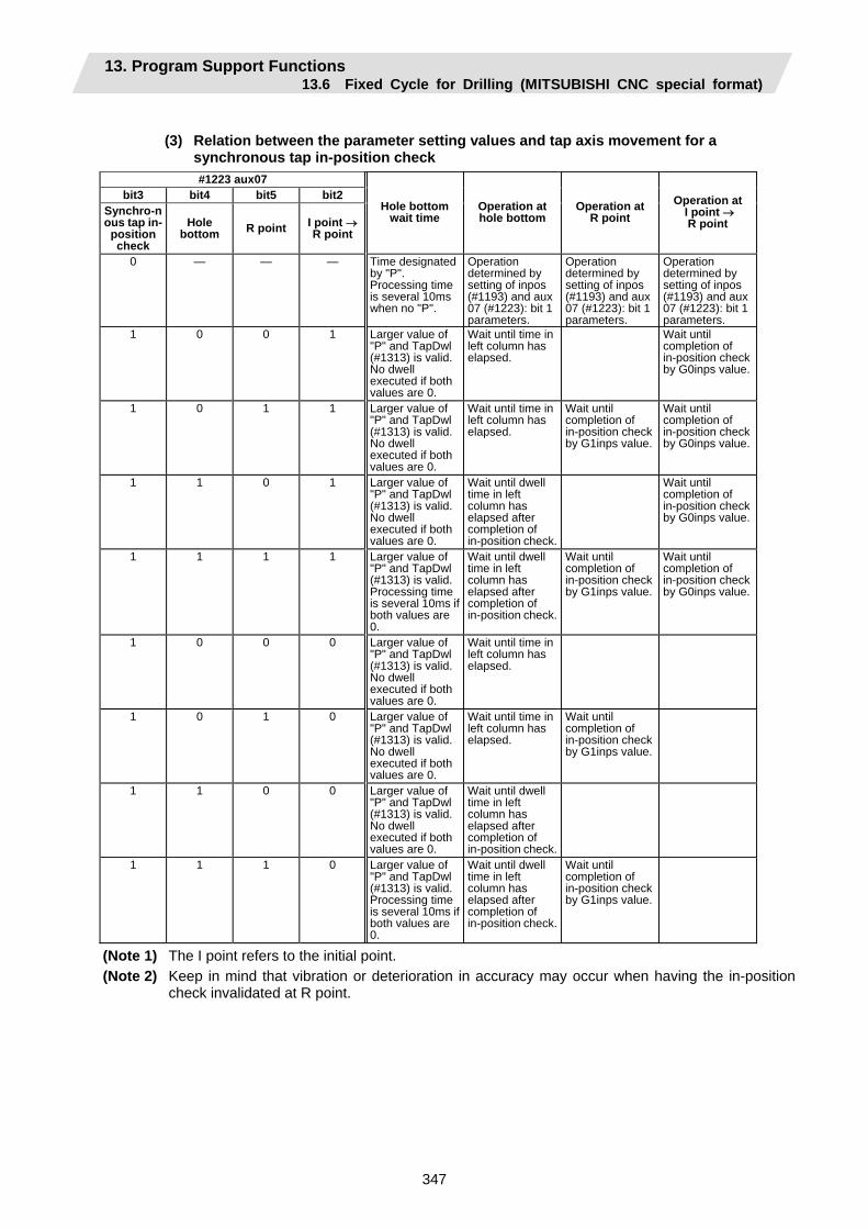
13. Program Support Functions 13.6 Fixed Cycle for Drilling (MITSUBISHI CNC special format)
347
(3) Relation between the parameter setting values and tap axis movement for a
synchronous tap in-position check #1223 aux07
bit3 bit4 bit5 bit2 Synchro-nous tap in-
position check
Hole bottom R point I point →
R point
Hole bottom wait time
Operation at hole bottom
Operation at R point
Operation at I point → R point
0 — — — Time designated by "P". Processing time is several 10ms when no "P".
Operation determined by setting of inpos (#1193) and aux 07 (#1223): bit 1 parameters.
Operation determined by setting of inpos (#1193) and aux 07 (#1223): bit 1 parameters.
Operation determined by setting of inpos (#1193) and aux 07 (#1223): bit 1 parameters.
1 0 0 1 Larger value of "P" and TapDwl (#1313) is valid. No dwell executed if both values are 0.
Wait until time in left column has elapsed.
Wait until completion of in-position check by G0inps value.
1 0 1 1 Larger value of "P" and TapDwl (#1313) is valid. No dwell executed if both values are 0.
Wait until time in left column has elapsed.
Wait until completion of in-position check by G1inps value.
Wait until completion of in-position check by G0inps value.
1 1 0 1 Larger value of "P" and TapDwl (#1313) is valid. No dwell executed if both values are 0.
Wait until dwell time in left column has elapsed after completion of in-position check.
Wait until completion of in-position check by G0inps value.
1 1 1 1 Larger value of "P" and TapDwl (#1313) is valid. Processing time is several 10ms if both values are 0.
Wait until dwell time in left column has elapsed after completion of in-position check.
Wait until completion of in-position check by G1inps value.
Wait until completion of in-position check by G0inps value.
1 0 0 0 Larger value of "P" and TapDwl (#1313) is valid. No dwell executed if both values are 0.
Wait until time in left column has elapsed.
1 0 1 0 Larger value of "P" and TapDwl (#1313) is valid. No dwell executed if both values are 0.
Wait until time in left column has elapsed.
Wait until completion of in-position check by G1inps value.
1 1 0 0 Larger value of "P" and TapDwl (#1313) is valid. No dwell executed if both values are 0.
Wait until dwell time in left column has elapsed after completion of in-position check.
1 1 1 0 Larger value of "P" and TapDwl (#1313) is valid. Processing time is several 10ms if both values are 0.
Wait until dwell time in left column has elapsed after completion of in-position check.
Wait until completion of in-position check by G1inps value.
(Note 1) The I point refers to the initial point. (Note 2) Keep in mind that vibration or deterioration in accuracy may occur when having the in-position
check invalidated at R point.
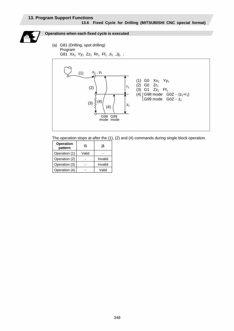
13. Program Support Functions 13.6 Fixed Cycle for Drilling (MITSUBISHI CNC special format)
348
Operations when each fixed cycle is executed
(a) G81 (Drilling, spot drilling) Program G81 Xx1 Yy1 Zz1 Rr1 Ff1 ,Ii1 ,Jj1 ;
(1) G0 Xx1 Yy1 (2) G0 Zr1 (3) G1 Zz1 Ff1 (4) G98 mode G0Z − (z1+r1) G99 mode G0Z − z1
G98 G99mode mode
(1)
(2)
(3) (4)
x1 , y1
z1
r1
(4)
The operation stops at after the (1), (2) and (4) commands during single block operation. Operation
pattern i1 j1
Operation (1) Valid - Operation (2) - Invalid Operation (3) - Invalid Operation (4) - Valid
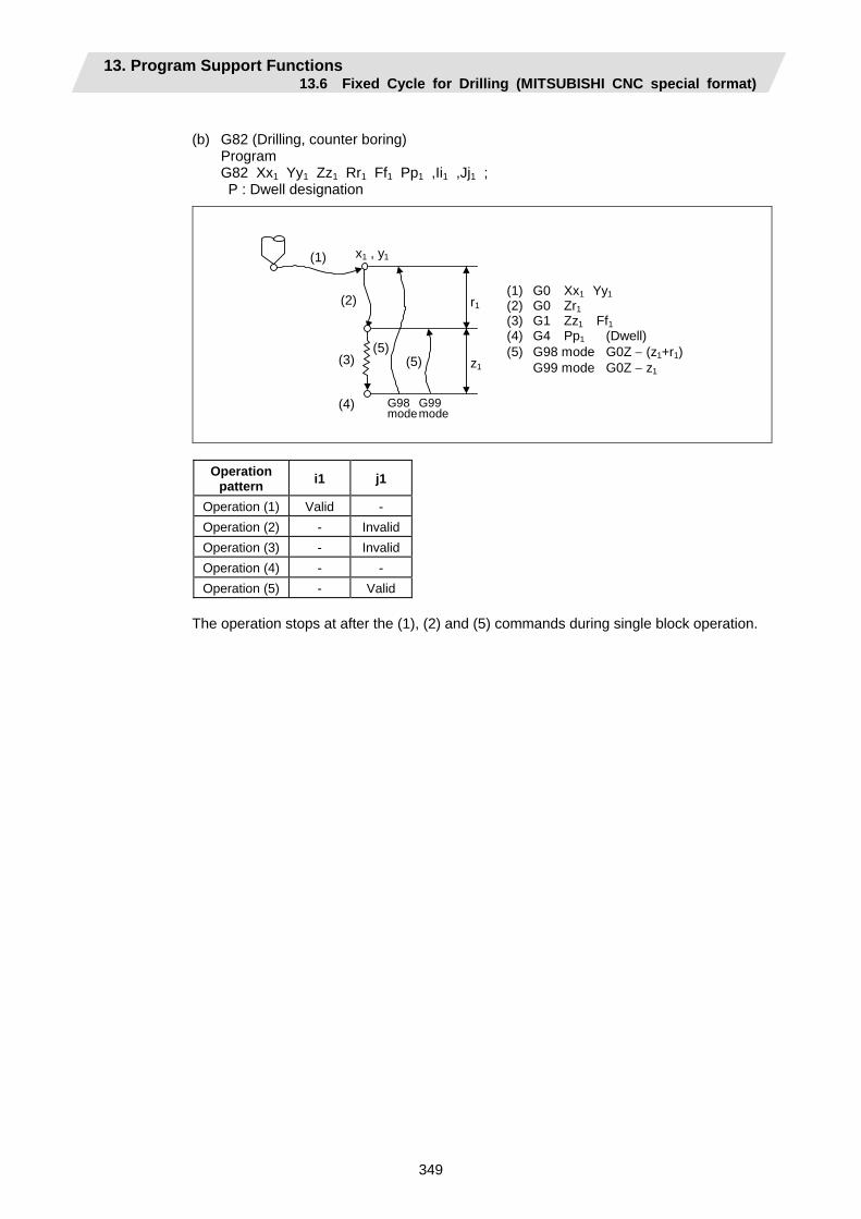
13. Program Support Functions 13.6 Fixed Cycle for Drilling (MITSUBISHI CNC special format)
349
(b) G82 (Drilling, counter boring) Program G82 Xx1 Yy1 Zz1 Rr1 Ff1 Pp1 ,Ii1 ,Jj1 ; P : Dwell designation
(1) G0 Xx1 Yy1 (2) G0 Zr1 (3) G1 Zz1 Ff1 (4) G4 Pp1 (Dwell) (5) G98 mode G0Z − (z1+r1) G99 mode G0Z − z1
G98 G99 mode mode
(1) x1 , y1
z1
r1(2)
(3)
(4)
(5)(5)
Operation pattern i1 j1
Operation (1) Valid - Operation (2) - InvalidOperation (3) - InvalidOperation (4) - - Operation (5) - Valid
The operation stops at after the (1), (2) and (5) commands during single block operation.
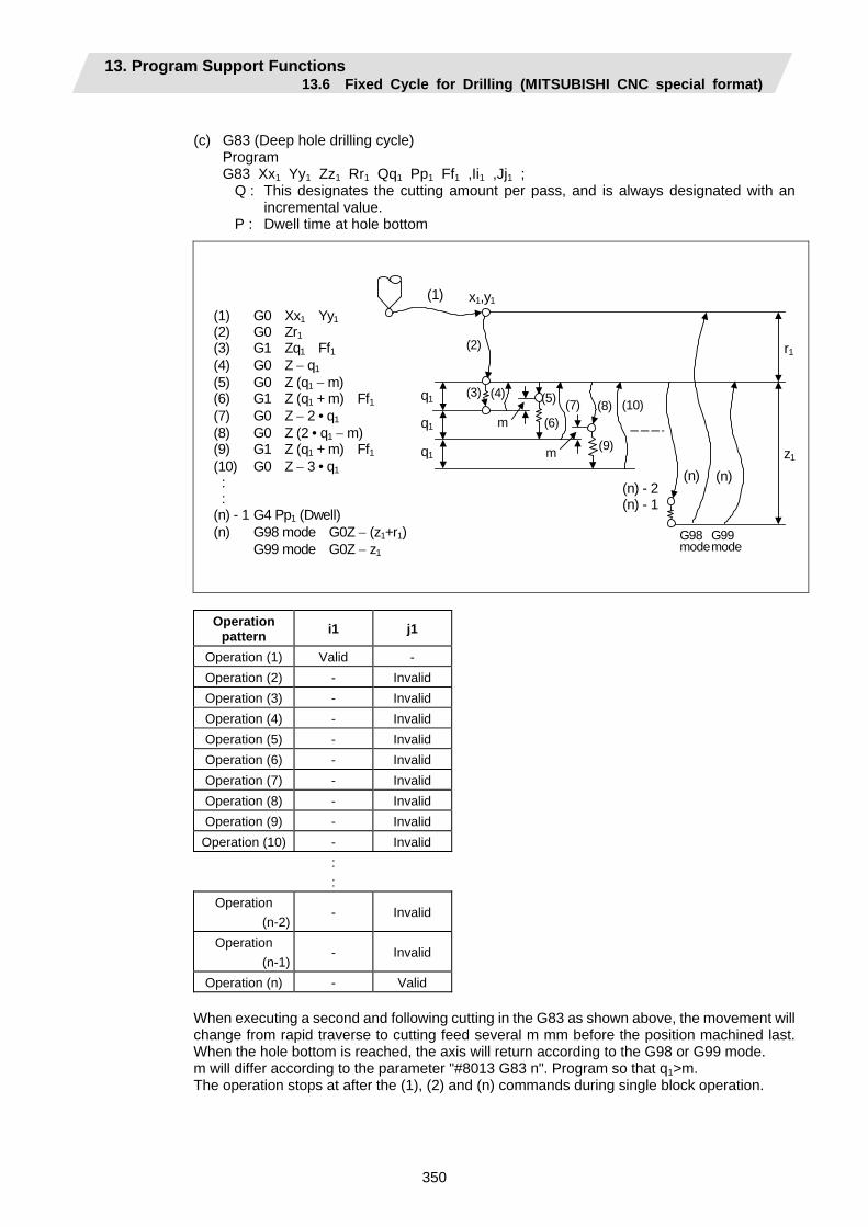
13. Program Support Functions 13.6 Fixed Cycle for Drilling (MITSUBISHI CNC special format)
350
(c) G83 (Deep hole drilling cycle) Program G83 Xx1 Yy1 Zz1 Rr1 Qq1 Pp1 Ff1 ,Ii1 ,Jj1 ;
Q : This designates the cutting amount per pass, and is always designated with an incremental value.
P : Dwell time at hole bottom
(1) G0 Xx1 Yy1 (2) G0 Zr1 (3) G1 Zq1 Ff1 (4) G0 Z − q1 (5) G0 Z (q1 − m) (6) G1 Z (q1 + m) Ff1 (7) G0 Z − 2 • q1 (8) G0 Z (2 • q1 − m) (9) G1 Z (q1 + m) Ff1 (10) G0 Z − 3 • q1
: :
(n) - 1 G4 Pp1 (Dwell) (n) G98 mode G0Z − (z1+r1) G99 mode G0Z − z1
G98 G99 mode mode
(1)
(n)(n) - 2 (n) - 1
x1,y1
q1
q1
q1
r1
z1
m
m
(3) (4) (5)
(6)(7) (8)
(9)
(10)
(2)
(n)
Operation
pattern i1 j1
Operation (1) Valid - Operation (2) - Invalid Operation (3) - Invalid Operation (4) - Invalid Operation (5) - Invalid Operation (6) - Invalid Operation (7) - Invalid Operation (8) - Invalid Operation (9) - Invalid Operation (10) - Invalid
: :
Operation (n-2)
- Invalid
Operation (n-1)
- Invalid
Operation (n) - Valid
When executing a second and following cutting in the G83 as shown above, the movement will change from rapid traverse to cutting feed several m mm before the position machined last. When the hole bottom is reached, the axis will return according to the G98 or G99 mode. m will differ according to the parameter "#8013 G83 n". Program so that q1>m. The operation stops at after the (1), (2) and (n) commands during single block operation.
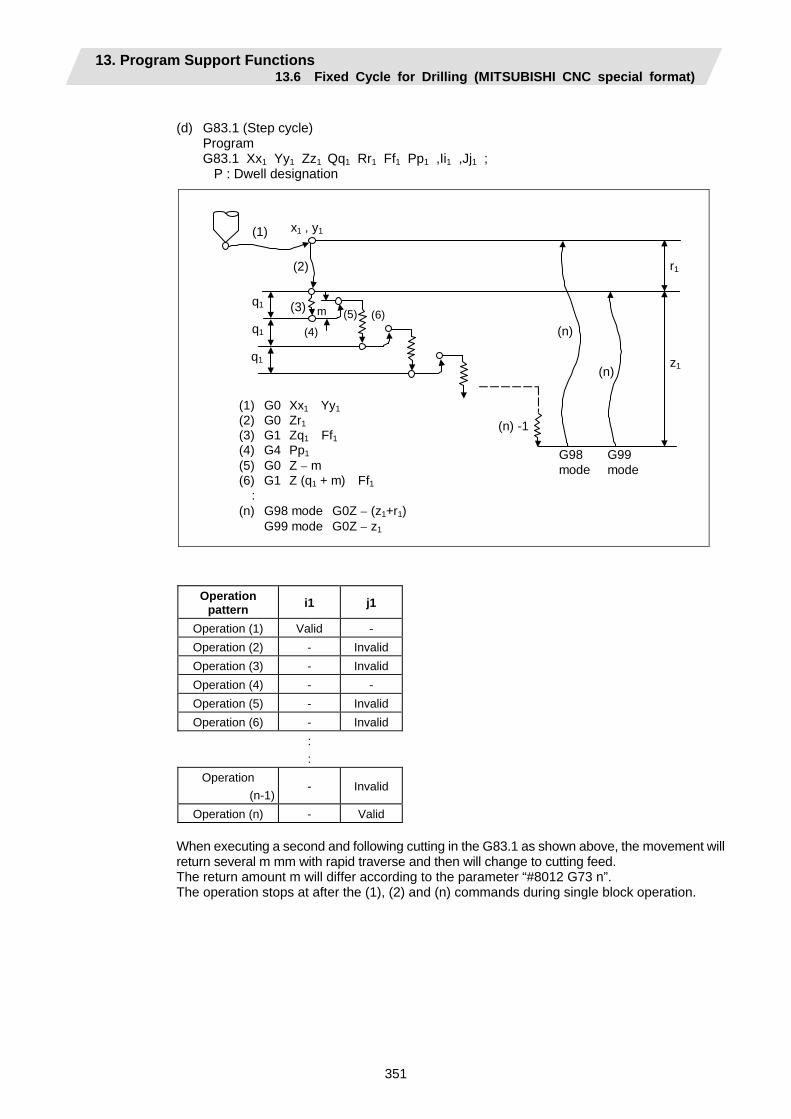
13. Program Support Functions 13.6 Fixed Cycle for Drilling (MITSUBISHI CNC special format)
351
(d) G83.1 (Step cycle) Program G83.1 Xx1 Yy1 Zz1 Qq1 Rr1 Ff1 Pp1 ,Ii1 ,Jj1 ; P : Dwell designation
G98 G99 mode mode
(1) G0 Xx1 Yy1 (2) G0 Zr1 (3) G1 Zq1 Ff1 (4) G4 Pp1 (5) G0 Z − m (6) G1 Z (q1 + m) Ff1 : (n) G98 mode G0Z − (z1+r1) G99 mode G0Z − z1
(1)
(3)
x1 , y1
z1
r1
q1
q1
q1
(n) m
(n) -1
(2)
(4)(5) (6)
(n)
Operation
pattern i1 j1
Operation (1) Valid - Operation (2) - Invalid Operation (3) - Invalid Operation (4) - - Operation (5) - Invalid Operation (6) - Invalid
: :
Operation (n-1)
- Invalid
Operation (n) - Valid
When executing a second and following cutting in the G83.1 as shown above, the movement will return several m mm with rapid traverse and then will change to cutting feed. The return amount m will differ according to the parameter “#8012 G73 n”. The operation stops at after the (1), (2) and (n) commands during single block operation.
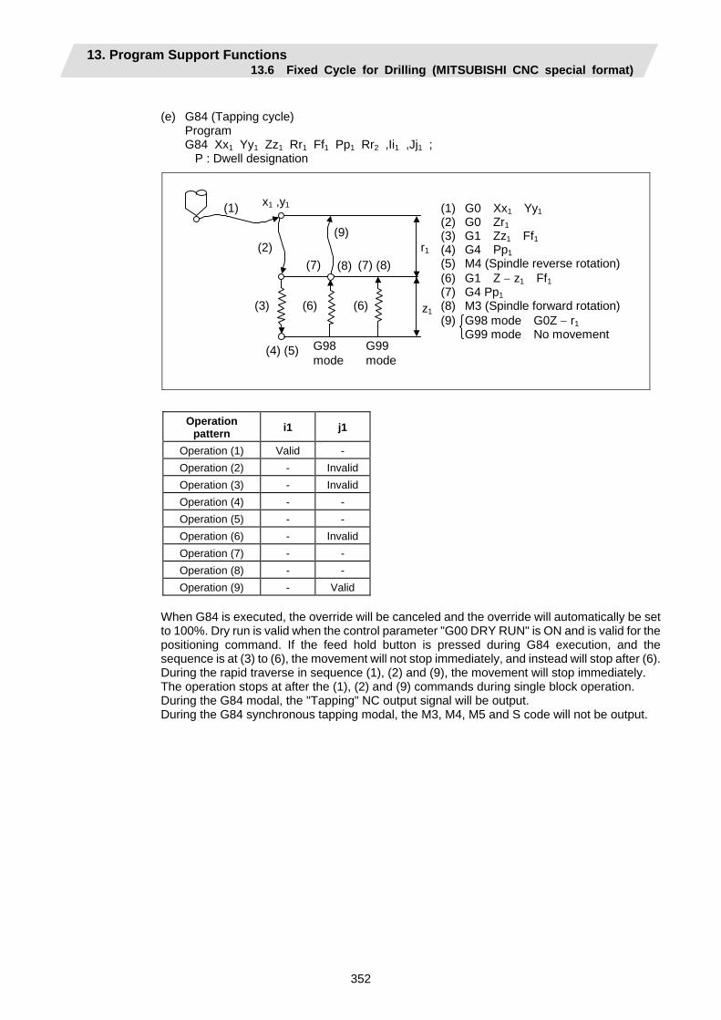
13. Program Support Functions 13.6 Fixed Cycle for Drilling (MITSUBISHI CNC special format)
352
(e) G84 (Tapping cycle) Program G84 Xx1 Yy1 Zz1 Rr1 Ff1 Pp1 Rr2 ,Ii1 ,Jj1 ; P : Dwell designation
(1) G0 Xx1 Yy1 (2) G0 Zr1 (3) G1 Zz1 Ff1 (4) G4 Pp1 (5) M4 (Spindle reverse rotation)(6) G1 Z − z1 Ff1 (7) G4 Pp1 (8) M3 (Spindle forward rotation)(9) G98 mode G0Z − r1 G99 mode No movement
G98 G99 mode mode
(4) (5)
r1
z1
(1) x1 ,y1
(2)
(3) (6)
(7) (8)
(9)
(6)
(7) (8)
Operation pattern i1 j1
Operation (1) Valid - Operation (2) - Invalid Operation (3) - Invalid Operation (4) - - Operation (5) - - Operation (6) - Invalid Operation (7) - - Operation (8) - - Operation (9) - Valid
When G84 is executed, the override will be canceled and the override will automatically be set to 100%. Dry run is valid when the control parameter "G00 DRY RUN" is ON and is valid for the positioning command. If the feed hold button is pressed during G84 execution, and the sequence is at (3) to (6), the movement will not stop immediately, and instead will stop after (6). During the rapid traverse in sequence (1), (2) and (9), the movement will stop immediately. The operation stops at after the (1), (2) and (9) commands during single block operation. During the G84 modal, the "Tapping" NC output signal will be output. During the G84 synchronous tapping modal, the M3, M4, M5 and S code will not be output.
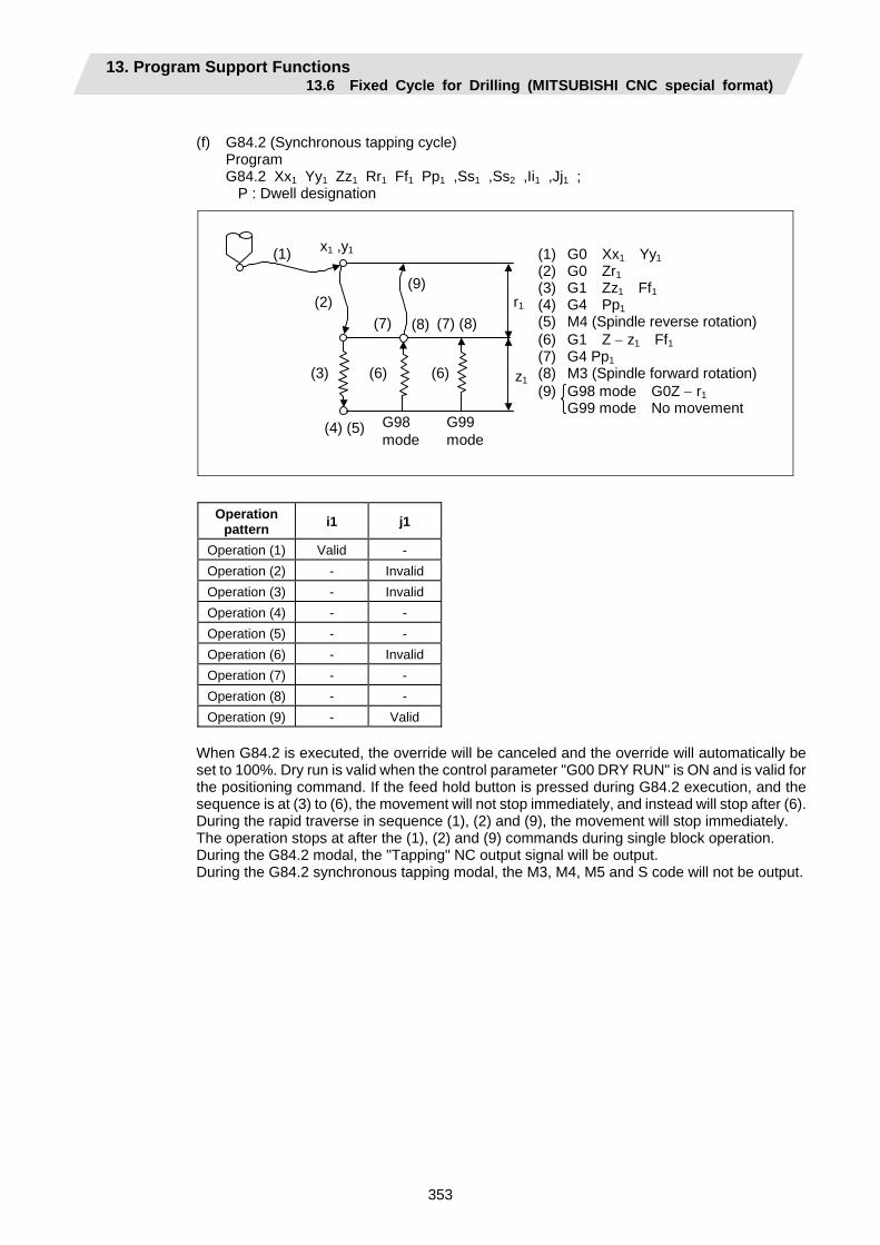
13. Program Support Functions 13.6 Fixed Cycle for Drilling (MITSUBISHI CNC special format)
353
(f) G84.2 (Synchronous tapping cycle) Program G84.2 Xx1 Yy1 Zz1 Rr1 Ff1 Pp1 ,Ss1 ,Ss2 ,Ii1 ,Jj1 ; P : Dwell designation
(1) G0 Xx1 Yy1 (2) G0 Zr1 (3) G1 Zz1 Ff1 (4) G4 Pp1 (5) M4 (Spindle reverse rotation)(6) G1 Z − z1 Ff1 (7) G4 Pp1 (8) M3 (Spindle forward rotation)(9) G98 mode G0Z − r1 G99 mode No movement
G98 G99 mode mode
(4) (5)
r1
z1
(1) x1 ,y1
(2)
(3) (6)
(7) (8)
(9)
(6)
(7) (8)
Operation pattern i1 j1
Operation (1) Valid - Operation (2) - Invalid Operation (3) - Invalid Operation (4) - - Operation (5) - - Operation (6) - Invalid Operation (7) - - Operation (8) - - Operation (9) - Valid
When G84.2 is executed, the override will be canceled and the override will automatically be set to 100%. Dry run is valid when the control parameter "G00 DRY RUN" is ON and is valid for the positioning command. If the feed hold button is pressed during G84.2 execution, and the sequence is at (3) to (6), the movement will not stop immediately, and instead will stop after (6). During the rapid traverse in sequence (1), (2) and (9), the movement will stop immediately. The operation stops at after the (1), (2) and (9) commands during single block operation. During the G84.2 modal, the "Tapping" NC output signal will be output. During the G84.2 synchronous tapping modal, the M3, M4, M5 and S code will not be output.
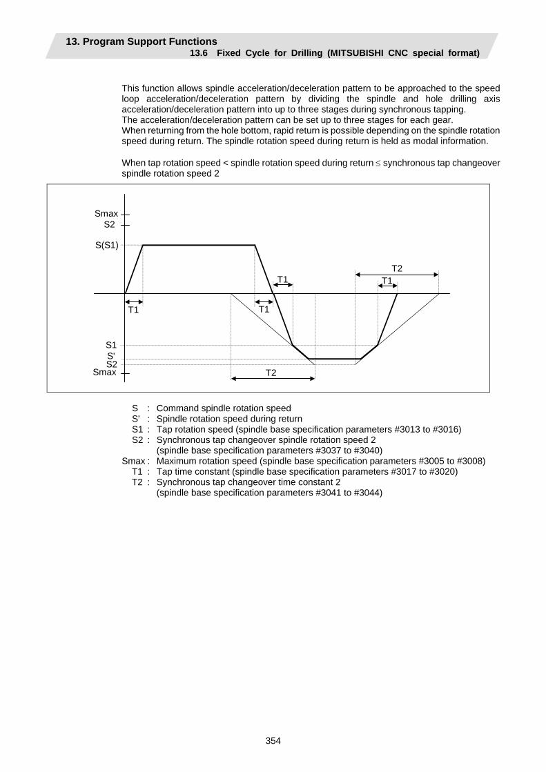
13. Program Support Functions 13.6 Fixed Cycle for Drilling (MITSUBISHI CNC special format)
354
This function allows spindle acceleration/deceleration pattern to be approached to the speed loop acceleration/deceleration pattern by dividing the spindle and hole drilling axis acceleration/deceleration pattern into up to three stages during synchronous tapping. The acceleration/deceleration pattern can be set up to three stages for each gear. When returning from the hole bottom, rapid return is possible depending on the spindle rotation speed during return. The spindle rotation speed during return is held as modal information. When tap rotation speed < spindle rotation speed during return ≤ synchronous tap changeover spindle rotation speed 2
Smax S2
S(S1)
S1 S' S2
Smax
T1
T1 T1
T1
T2
T2
S : Command spindle rotation speed S' : Spindle rotation speed during return S1 : Tap rotation speed (spindle base specification parameters #3013 to #3016) S2 : Synchronous tap changeover spindle rotation speed 2 (spindle base specification parameters #3037 to #3040) Smax : Maximum rotation speed (spindle base specification parameters #3005 to #3008) T1 : Tap time constant (spindle base specification parameters #3017 to #3020) T2 : Synchronous tap changeover time constant 2 (spindle base specification parameters #3041 to #3044)
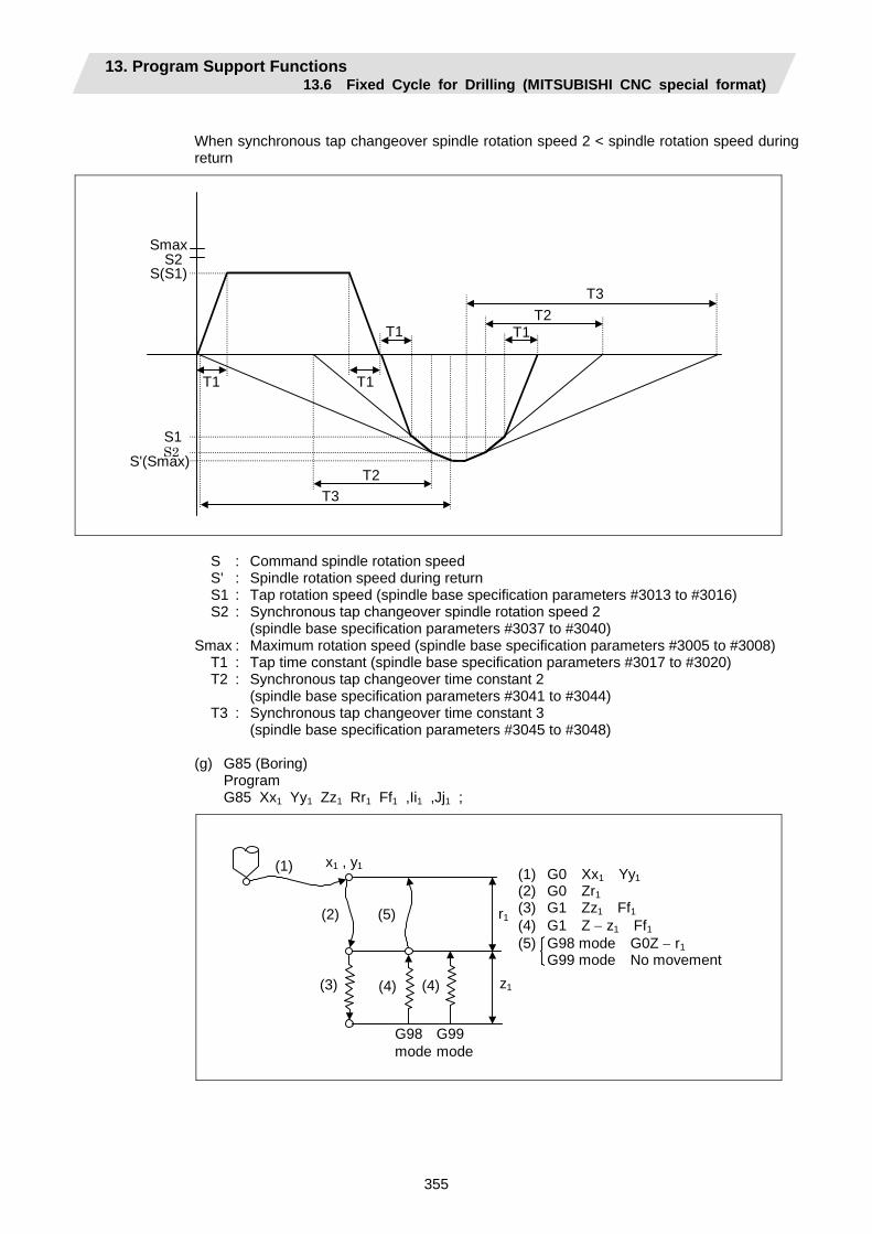
13. Program Support Functions 13.6 Fixed Cycle for Drilling (MITSUBISHI CNC special format)
355
When synchronous tap changeover spindle rotation speed 2 < spindle rotation speed during return
Smax S2 S(S1)
S1 S2 S'(Smax)
T1
T2T1T1
T1
T2
T3
T3
S : Command spindle rotation speed S' : Spindle rotation speed during return S1 : Tap rotation speed (spindle base specification parameters #3013 to #3016) S2 : Synchronous tap changeover spindle rotation speed 2 (spindle base specification parameters #3037 to #3040) Smax : Maximum rotation speed (spindle base specification parameters #3005 to #3008) T1 : Tap time constant (spindle base specification parameters #3017 to #3020) T2 : Synchronous tap changeover time constant 2 (spindle base specification parameters #3041 to #3044) T3 : Synchronous tap changeover time constant 3 (spindle base specification parameters #3045 to #3048)
(g) G85 (Boring) Program G85 Xx1 Yy1 Zz1 Rr1 Ff1 ,Ii1 ,Jj1 ;
(1) G0 Xx1 Yy1 (2) G0 Zr1 (3) G1 Zz1 Ff1 (4) G1 Z − z1 Ff1 (5) G98 mode G0Z − r1 G99 mode No movement
G98 G99 mode mode
r1
z1
(1) x1 , y1
(2)
(3)
(5)
(4) (4)
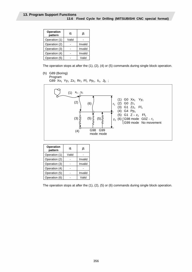
13. Program Support Functions 13.6 Fixed Cycle for Drilling (MITSUBISHI CNC special format)
356
Operation
pattern i1 j1
Operation (1) Valid - Operation (2) - InvalidOperation (3) - InvalidOperation (4) - InvalidOperation (5) - Valid
The operation stops at after the (1), (2), (4) or (5) commands during single block operation.
(h) G89 (Boring) Program G89 Xx1 Yy1 Zz1 Rr1 Ff1 Pp1, Ii1, Jj1 ;
(1) G0 Xx1 Yy1 (2) G0 Zr1 (3) G1 Zz1 Ff1 (4) G4 Pp1 (5) G1 Z − z1 Ff1 (6) G98 mode G0Z − r1 G99 mode No movement
G98 G99mode mode
r1
z1
(1)
(6)
x1 , y1
(2)
(3)
(4)
(5) (5)
Operation pattern i1 j1
Operation (1) Valid - Operation (2) - InvalidOperation (3) - InvalidOperation (4) - - Operation (5) - InvalidOperation (6) - Valid
The operation stops at after the (1), (2), (5) or (6) commands during single block operation.
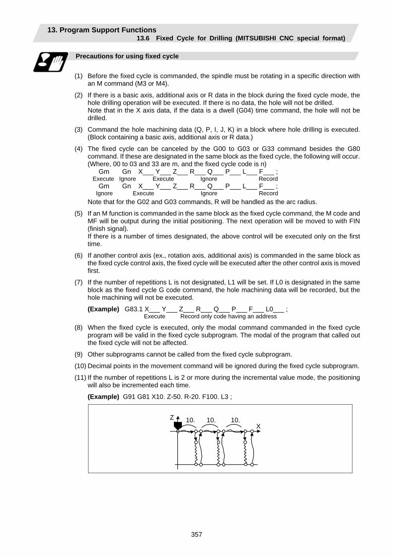
13. Program Support Functions 13.6 Fixed Cycle for Drilling (MITSUBISHI CNC special format)
357
Precautions for using fixed cycle
(1) Before the fixed cycle is commanded, the spindle must be rotating in a specific direction with
an M command (M3 or M4).
(2) If there is a basic axis, additional axis or R data in the block during the fixed cycle mode, the hole drilling operation will be executed. If there is no data, the hole will not be drilled.
Note that in the X axis data, if the data is a dwell (G04) time command, the hole will not be drilled.
(3) Command the hole machining data (Q, P, I, J, K) in a block where hole drilling is executed. (Block containing a basic axis, additional axis or R data.)
(4) The fixed cycle can be canceled by the G00 to G03 or G33 command besides the G80 command. If these are designated in the same block as the fixed cycle, the following will occur.
(Where, 00 to 03 and 33 are m, and the fixed cycle code is n) Gm Gn X___ Y___ Z___ R___ Q___ P___ L___ F___ ; Execute Ignore Execute Ignore Record Gm Gn X___ Y___ Z___ R___ Q___ P___ L___ F___ ; Ignore Execute Ignore Record Note that for the G02 and G03 commands, R will be handled as the arc radius.
(5) If an M function is commanded in the same block as the fixed cycle command, the M code and MF will be output during the initial positioning. The next operation will be moved to with FIN (finish signal).
If there is a number of times designated, the above control will be executed only on the first time.
(6) If another control axis (ex., rotation axis, additional axis) is commanded in the same block as the fixed cycle control axis, the fixed cycle will be executed after the other control axis is moved first.
(7) If the number of repetitions L is not designated, L1 will be set. If L0 is designated in the same block as the fixed cycle G code command, the hole machining data will be recorded, but the hole machining will not be executed.
(Example) G83.1 X___ Y___ Z___ R___ Q___ P___ F___ L0___ ; Execute Record only code having an address
(8) When the fixed cycle is executed, only the modal command commanded in the fixed cycle program will be valid in the fixed cycle subprogram. The modal of the program that called out the fixed cycle will not be affected.
(9) Other subprograms cannot be called from the fixed cycle subprogram.
(10) Decimal points in the movement command will be ignored during the fixed cycle subprogram.
(11) If the number of repetitions L is 2 or more during the incremental value mode, the positioning will also be incremented each time.
(Example) G91 G81 X10. Z-50. R-20. F100. L3 ;
X
Z 10. 10. 10.
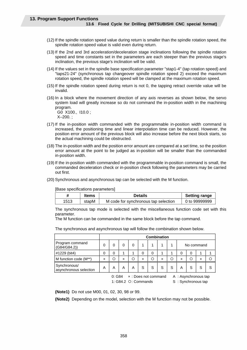
13. Program Support Functions 13.6 Fixed Cycle for Drilling (MITSUBISHI CNC special format)
358
(12) If the spindle rotation speed value during return is smaller than the spindle rotation speed, the
spindle rotation speed value is valid even during return.
(13) If the 2nd and 3rd acceleration/deceleration stage inclinations following the spindle rotation speed and time constants set in the parameters are each steeper than the previous stage's inclination, the previous stage's inclination will be valid.
(14) If the values set in the spindle base specification parameter "stap1-4" (tap rotation speed) and "taps21-24" (synchronous tap changeover spindle rotation speed 2) exceed the maximum rotation speed, the spindle rotation speed will be clamped at the maximum rotation speed.
(15) If the spindle rotation speed during return is not 0, the tapping retract override value will be invalid.
(16) In a block where the movement direction of any axis reverses as shown below, the servo system load will greatly increase so do not command the in-position width in the machining program.
G0 X100., I10.0 ; X–200. ;
(17) If the in-position width commanded with the programmable in-position width command is increased, the positioning time and linear interpolation time can be reduced. However, the position error amount of the previous block will also increase before the next block starts, so the actual machining could be obstructed.
(18) The in-position width and the position error amount are compared at a set time, so the position error amount at the point to be judged as in-position will be smaller than the commanded in-position width.
(19) If the in-position width commanded with the programmable in-position command is small, the commanded deceleration check or in-position check following the parameters may be carried out first.
(20) Synchronous and asynchronous tap can be selected with the M function.
[Base specifications parameters] # Items Details Setting range
1513 stapM M code for synchronous tap selection 0 to 99999999
The synchronous tap mode is selected with the miscellaneous function code set with this parameter. The M function can be commanded in the same block before the tap command.
The synchronous and asynchronous tap will follow the combination shown below.
Combination Program command (G84/G84.2)) 0 0 0 0 1 1 1 1 No command
#1229 (bit4) 0 0 1 1 0 0 1 1 0 0 1 1M function code (M**) × × × × × ×
Synchronous/ asynchronous selection A A A A S S S S A S S S
0: G84 × : Does not command A : Asynchronous tap 1: G84.2 : Commands S : Synchronous tap
(Note1) Do not use M00, 01, 02, 30, 98 or 99.
(Note2) Depending on the model, selection with the M function may not be possible.
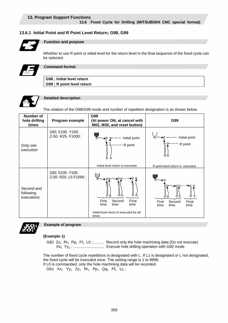
13. Program Support Functions 13.6 Fixed Cycle for Drilling (MITSUBISHI CNC special format)
359
13.6.1 Initial Point and R Point Level Return; G98, G99
Function and purpose
Whether to use R point or initial level for the return level in the final sequence of the fixed cycle can be selected.
Command format
G98 ; Initial level return G99 ; R point level return
Detailed description
The relation of the G98/G99 mode and number of repetition designation is as shown below.
Number of hole drilling
times Program example
G98 (At power ON, at cancel with M02, M30, and reset button)
G99
Only one execution
G81 X100. Y100. Z-50. R25. F1000 ;
Initial point
R point
Initial level return is executed.
Initial point
R point
R point level return is executed.
Second and following executions
G81 X100. Y100. Z-50. R25. L5 F1000 ;
Second time
Final time
First time
Initial level return is executed for all times.
Second time
Final time
First time
Example of program
(Example 1)
G82 Zz1 Rr1 Pp1 Ff1 L0 ;.......... Record only the hole machining data (Do not execute) Xx1 Yy1 ; ............................. Execute hole drilling operation with G82 mode
The number of fixed cycle repetitions is designated with L. If L1 is designated or L not designated, the fixed cycle will be executed once. The setting range is 1 to 9999. If L0 is commanded, only the hole machining data will be recorded. G8∆ Xx1 Yy1 Zz1 Rr1 Pp1 Qq1 Ff1 Ll1 ;
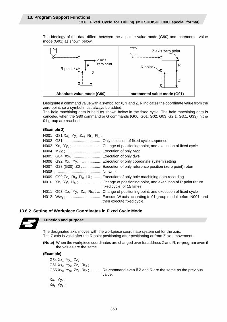
13. Program Support Functions 13.6 Fixed Cycle for Drilling (MITSUBISHI CNC special format)
360
The ideology of the data differs between the absolute value mode (G90) and incremental value mode (G91) as shown below.
Z axis zero point
R point R
Z
R point R
Z
Z axis zero point
Absolute value mode (G90) Incremental value mode (G91)
Designate a command value with a symbol for X, Y and Z. R indicates the coordinate value from the zero point, so a symbol must always be added. The hole machining data is held as shown below in the fixed cycle. The hole machining data is canceled when the G80 command or G commands (G00, G01, G02, G03, G2.1, G3.1, G33) in the 01 group are reached.
(Example 2) N001 G81 Xx1 Yy1 Zz1 Rr1 Ff1 ; N002 G81 ; ................................ Only selection of fixed cycle sequence N003 Xx2 Yy2 ; .......................... Change of positioning point, and execution of fixed cycle N004 M22 ; ................................ Execution of only M22 N005 G04 Xx3 ; ......................... Execution of only dwell N006 G92 Xx4 Yy4 ; ................. Execution of only coordinate system setting N007 G28 (G30) Z0 ; ................ Execution of only reference position (zero point) return N008 ; ........................................ No work N009 G99 Zz2 Rr2 Ff2 L0 ; ...... Execution of only hole machining data recording N010 Xx5 Yy5 Ll5 ; .................... Change of positioning point, and execution of R point return
fixed cycle for 15 times N011 G98 Xx6 Yy6 Zz6 Rr6 ; ... Change of positioning point, and execution of fixed cycle N012 Ww1 ; ................................ Execute W axis according to 01 group modal before N001, and
then execute fixed cycle 13.6.2 Setting of Workpiece Coordinates in Fixed Cycle Mode
Function and purpose
The designated axis moves with the workpiece coordinate system set for the axis. The Z axis is valid after the R point positioning after positioning or from Z axis movement.
(Note) When the workpiece coordinates are changed over for address Z and R, re-program even if the values are the same.
(Example) G54 Xx1 Yy1 Zz1 ; G81 Xx2 Yy2 Zz2 Rr2 ; G55 Xx3 Yy3 Zz2 Rr2 ; .......... Re-command even if Z and R are the same as the previous
value. Xx4 Yy4 ; Xx5 Yy5 ;
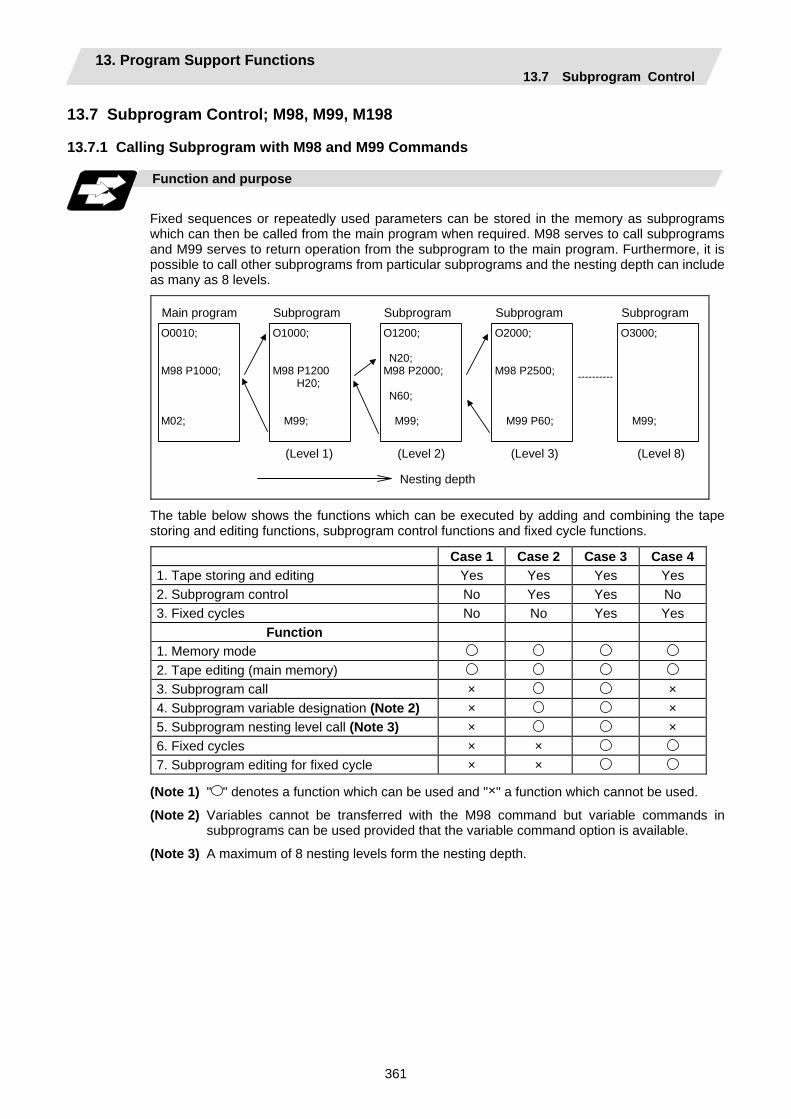
13. Program Support Functions 13.7 Subprogram Control
361
13.7 Subprogram Control; M98, M99, M198 13.7.1 Calling Subprogram with M98 and M99 Commands
Function and purpose
Fixed sequences or repeatedly used parameters can be stored in the memory as subprograms which can then be called from the main program when required. M98 serves to call subprograms and M99 serves to return operation from the subprogram to the main program. Furthermore, it is possible to call other subprograms from particular subprograms and the nesting depth can include as many as 8 levels.
Main programO0010; M98 P1000; M02;
Subprogram O1000; M98 P1200
H20; M99;
(Level 1)
Subprogram O1200; N20; M98 P2000; N60; M99;
Subprogram O2000; M98 P2500; M99 P60;
Subprogram O3000; M99;
(Level 2) (Level 3) (Level 8)
Nesting depth
The table below shows the functions which can be executed by adding and combining the tape storing and editing functions, subprogram control functions and fixed cycle functions.
Case 1 Case 2 Case 3 Case 41. Tape storing and editing Yes Yes Yes Yes 2. Subprogram control No Yes Yes No 3. Fixed cycles No No Yes Yes
Function 1. Memory mode 2. Tape editing (main memory) 3. Subprogram call × × 4. Subprogram variable designation (Note 2) × × 5. Subprogram nesting level call (Note 3) × × 6. Fixed cycles × × 7. Subprogram editing for fixed cycle × ×
(Note 1) " " denotes a function which can be used and "×" a function which cannot be used.
(Note 2) Variables cannot be transferred with the M98 command but variable commands in subprograms can be used provided that the variable command option is available.
(Note 3) A maximum of 8 nesting levels form the nesting depth.
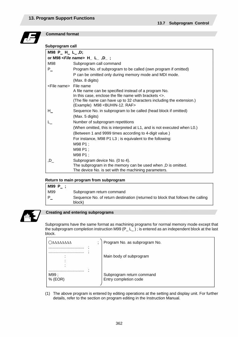
13. Program Support Functions 13.7 Subprogram Control
362
Command format
Subprogram call
M98 P H L ,D; or M98 <File name> H_ L_ ,D_ ; M98 Subprogram call command P_ Program No. of subprogram to be called (own program if omitted)
P can be omitted only during memory mode and MDI mode. (Max. 8 digits)
<File name> File name A file name can be specified instead of a program No. In this case, enclose the file name with brackets <>. (The file name can have up to 32 characters including the extension.) (Example) M98 <BUHIN-12. RAF>
H_ Sequence No. in subprogram to be called (head block if omitted) (Max. 5 digits)
L_ Number of subprogram repetitions (When omitted, this is interpreted at L1, and is not executed when L0.) (Between 1 and 9999 times according to 4-digit value.) For instance, M98 P1 L3 ; is equivalent to the following: M98 P1 ; M98 P1 ; M98 P1 ;
,D_ Subprogram device No. (0 to 4). The subprogram in the memory can be used when ,D is omitted. The device No. is set with the machining parameters.
Return to main program from subprogram
M99 P ; M99 Subprogram return command P_ Sequence No. of return destination (returned to block that follows the calling
block)
Creating and entering subprograms
Subprograms have the same format as machining programs for normal memory mode except that the subprogram completion instruction M99 (P_ L_ ) ; is entered as an independent block at the last block.
∆∆∆∆∆∆∆∆ ; Program No. as subprogram No. ................................ ; ................................ ; : Main body of subprogram : : ................................ ; M99 ; Subprogram return command % (EOR) Entry completion code
(1) The above program is entered by editing operations at the setting and display unit. For further details, refer to the section on program editing in the Instruction Manual.
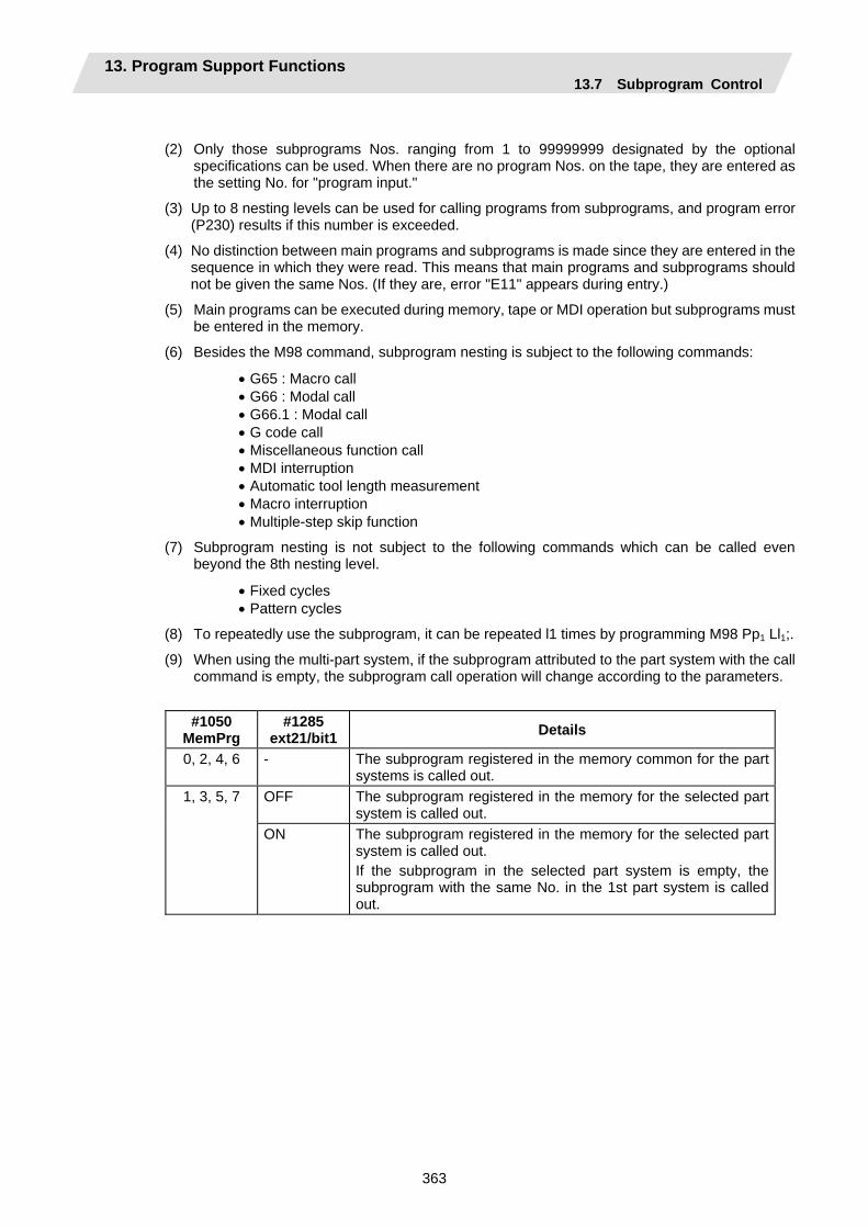
13. Program Support Functions 13.7 Subprogram Control
363
(2) Only those subprograms Nos. ranging from 1 to 99999999 designated by the optional specifications can be used. When there are no program Nos. on the tape, they are entered as the setting No. for "program input."
(3) Up to 8 nesting levels can be used for calling programs from subprograms, and program error (P230) results if this number is exceeded.
(4) No distinction between main programs and subprograms is made since they are entered in the sequence in which they were read. This means that main programs and subprograms should not be given the same Nos. (If they are, error "E11" appears during entry.)
(5) Main programs can be executed during memory, tape or MDI operation but subprograms must be entered in the memory.
(6) Besides the M98 command, subprogram nesting is subject to the following commands:
• G65 : Macro call • G66 : Modal call • G66.1 : Modal call • G code call • Miscellaneous function call • MDI interruption • Automatic tool length measurement • Macro interruption • Multiple-step skip function
(7) Subprogram nesting is not subject to the following commands which can be called even beyond the 8th nesting level.
• Fixed cycles • Pattern cycles
(8) To repeatedly use the subprogram, it can be repeated l1 times by programming M98 Pp1 Ll1;.
(9) When using the multi-part system, if the subprogram attributed to the part system with the call command is empty, the subprogram call operation will change according to the parameters.
#1050 MemPrg
#1285 ext21/bit1 Details
0, 2, 4, 6 - The subprogram registered in the memory common for the part systems is called out.
1, 3, 5, 7 OFF The subprogram registered in the memory for the selected part system is called out.
ON The subprogram registered in the memory for the selected part system is called out. If the subprogram in the selected part system is empty, the subprogram with the same No. in the 1st part system is called out.
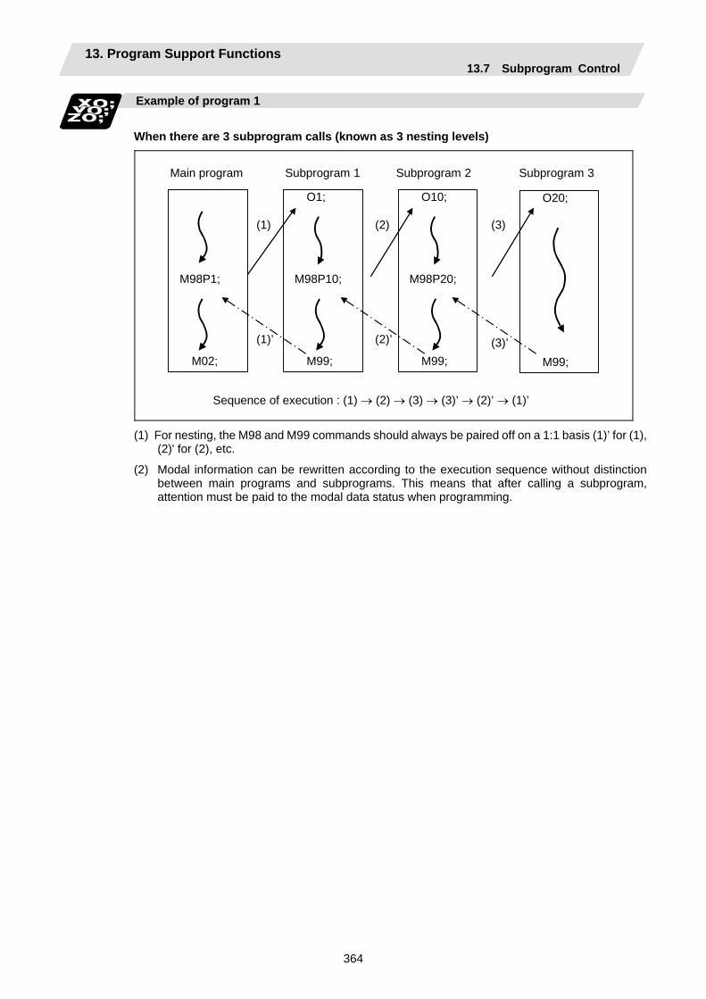
13. Program Support Functions 13.7 Subprogram Control
364
Example of program 1
When there are 3 subprogram calls (known as 3 nesting levels)
M98P1;
M02;
Main program Subprogram 1 Subprogram 2 Subprogram 3
Sequence of execution : (1) → (2) → (3) → (3)’ → (2)’ → (1)’
(1)
O1; M98P10;
M99;
O10; M98P20;
M99;
O20;
M99;
(1)’
(2)
(2)’
(3)
(3)’
(1) For nesting, the M98 and M99 commands should always be paired off on a 1:1 basis (1)’ for (1), (2)' for (2), etc.
(2) Modal information can be rewritten according to the execution sequence without distinction between main programs and subprograms. This means that after calling a subprogram, attention must be paid to the modal data status when programming.

13. Program Support Functions 13.7 Subprogram Control
365
Example of program 2
The M98 H_ ; M99 P_ ; commands designate the sequence Nos. in a program with a call instruction.
M98H3;
N3___;
M99;
M98H__ ;
N100___;
M98P123; N200_; N300___; N400___;
O123; M99P200;
M99P__ ;
Sea
rch
Precautions
(1) Program error (P232) results when the designated P (program No.) is not located.
(2) Single block stop does not occur with the M98 P_ ; M99 ; block. If any address except O, N, P, L or H is used, single block stop can be executed. (With X100. M98 P100 ;, operation branches to O100 after X100. is executed.)
(3) When M99 is commanded by the main program, operation returns to the head. (This is same for MDI.)
(4) Branching from tape and BTR operation to the subprogram with M98 P_ is possible, but the return destination sequence No. cannot be designated with M99 P_ ;. (P_ is ignored).
(5) Bear in mind that the search operation will take time when the sequence No. is designated by M99 P_ ;.
(6) When using a file name for the subprogram, specify the file name with 32 characters or less, including the extension. If a file name exceeding 32 characters is specified, a program error (P232) will occur.
(7) All the programs are registered as files. For example, when calling the file "0100" as a subprogram, "0100" cannot be searched with M98P100 or M98P0100. When a value is specified following P, reading 0 is omitted; therefore, it is assumed that the program No. (file) "100" was specified in this case. When wishing the program like "0100" to be called, specify the file name using the M98<0100> format.
13. Program Support Functions 13.7 Subprogram Control
366
13.7.2 Calling Subprogram with M198 Commands
Function and purpose
Programs saved in the data server can be called as subprograms. To call a program in the data server as a subprogram, command in the main program as shown below.
Command format
M198 P L ; or M198 <File name> L_ ; M198 Subprogram call command P_ Program No. in data server to be called as subprogram. (Max. 8 digits) <File name> File name
A file name can be specified instead of a program No. In this case, enclose the file name with brackets <>. (The file name can have up to 32 characters including the extension.)
L_ Number of subprogram repetitions. (Max. 4 digits) • This can be omitted. (In this case, the subprogram will be called once.)
When "L0" is designated, the subprogram call will not be executed. (Note) Sequence No. call (M198 H***) cannot be commanded.
Detailed description
(1) The subprogram can be called with the M198 command once in the subprogram nest. The
subprogram can be called only from the memory or MDI program.
(2) The section from the head of the program to the first LF (carriage return code, 0x0A hexadecimal) is invalid, and is not run or displayed. Note that if the head starts with a 0 No., the program will be valid from the head.
(3) A program registered in an IC card can be executed from only one part system. A program error will occur if it is attempted to execute the programs in the IC card simultaneously by two or more part systems. When reset is applied on all the part systems in this time, the programs of the part systems will be displayed as only "%" other than that of the part system that was called first.
(4) Refer to "13.7.1 Calling subprogram with M98 and M99 commands" for <file name>.

13. Program Support Functions 13.8 Variable Commands
367
13.8 Variable Commands
Function and purpose
Programming can be endowed with flexibility and general-purpose capabilities by designating variables, instead of giving direct numerical values to particular addresses in a program, and by assigning the values or those variables as required when executing a program.
Command format
#∆∆∆ = or #∆∆∆ = [formula]
Detailed description
(1) Variable expressions Example
(a) #m ............. m = value consisting of 0 to 9 #100
(b) # [f] ............. f = one of the following in the formula # [- #120] Numerical value m 123 Variable #543 Formula Operator Formula #110 + #119 - (minus) formula - # 120 [Formula] [#119] Function [formula] SIN [#110]
(Note 1) The 4 standard operators are +, -, ∗ and / .
(Note 2) Functions cannot be used unless the user macro specifications are available.
(Note 3) Error (P241) results when a variable No. is negative.
(Note 4) Examples of incorrect variable expressions are given below.
Incorrect Correct #6/2 → # [6/2] (Note that expression such as "#6/2" is regarded as
"[#6]/2".)] # - - 5 → # [ - [ -5 ] ] # - [# 1] → # [ - #1 ]
13. Program Support Functions 13.8 Variable Commands
368
(2) Types of variables
The following table gives the types of variables.
Type of variable No. Function Common variables Common
variables 1 Common variables 2
100 sets 500 to 549 100 to 149 200 sets 500 to 599 100 to 199 300 sets 500 to 699 100 to 199
1st part system
600 sets 500 to 999 100 to 199
50 + 50 * numberof part systems sets 500 to 549
100 to 149 * number of part systems
100 + 100 * numberof part systems sets 500 to 599
100 to 199 * number of part systems
Multi-part system
400 + 100 * numberof part systems sets 500 to 899
100 to 199 * number of part systems
• Can be used in common throughout main, sub and macro programs.
• When using common variables in the multi-partsystem, common variables can be shared between the part systems by setting the following parameter. #1303 V1comN #100 to setting value #1304 V0comN #500 to setting value
Local variables 1 to 33 Can be used for local variables in macro programs.
System variables From 1000 Application is fixed by system.
Fixed cycle variables 1 to 32 Local variables in fixed cycle programs.
(Note 1) All common variables are retained even when the power is turned OFF.
(Note 2) When the power is turned OFF or reset, the common variables can be set to <null> by setting the parameter (#1128 RstVC1, #1129 PwrVC1).
(Note 3) The common variables are divided into the following two types. Common variables 1 : Used in common through all part systems Common variables 2 : Used in common in the programs of the part system
(3) Variable quotations
Variables can be used for all addresses accept O, N and / (slash).
(a) When the variable value is used directly: X#1................................. Value of #1 is used as the X value.
(b) When the complement of the variable value is used: X−#2............................... Value with the #2 sign changed is used as the X value.
(c) When defining variables: #3 = #5 ........................... Variable #3 uses the equivalent value of variable #5. #1 = 1000 ....................... Variable #1 uses the equivalent value 1000 (which is treated as
1000.).
(d) When defining the variable arithmetic formula: #1 = #3 + #2 − 100......... The value of the operation result of #3 + #2 − 100. is used as the
#1 value. X [#1 + #3 + 1000] ......... The value of the operation result of #1 + #3 + 1000 is used as the
X value.
(Note 1) A variable cannot be defined in the same block as an address. It must be defined in a separate block.
Incorrect Correct X #1= #3 + 100 ; → #1= #3 + 100 ;
X#1 ;
13. Program Support Functions 13.8 Variable Commands
369
(Note 2) Up to five sets of square parentheses [ ] may be used.
#543 = − [ [ [ [ [ #120]/2 + 15.]∗3 − #100]/#520 + #125 + #128]∗#130 + #132] ;
(Note 3) There are no restrictions on the number of characters and number of variables for variable definition.
(Note 4) The variable values should be within a range from 0 to ±99999999. If this range is exceeded, the operations may not be conducted properly.
(Note 5) The variable definitions are valid from the moment that the variables are actually defined.
#1 = 100 ; .............................#1 = 100 #1 = 200 #2 = #1 + 200 ;......#1 = 200, #2 = 400 #3 = #1 + 300 ; .....................#3 = 500
(Note 6) Variable quotations are always regarded as having a decimal point at the end.
When #100 = 10, then X#100 ; is treated as X10.
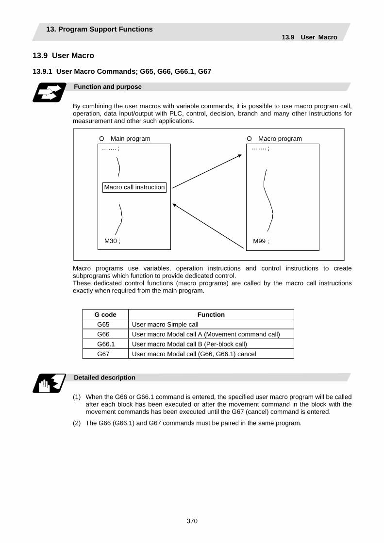
13. Program Support Functions 13.9 User Macro
370
13.9 User Macro 13.9.1 User Macro Commands; G65, G66, G66.1, G67
Function and purpose
By combining the user macros with variable commands, it is possible to use macro program call, operation, data input/output with PLC, control, decision, branch and many other instructions for measurement and other such applications.
; M99 ;
; M30 ;
O Main program O Macro program
Macro call instruction
……. …….
Macro programs use variables, operation instructions and control instructions to create subprograms which function to provide dedicated control. These dedicated control functions (macro programs) are called by the macro call instructions exactly when required from the main program.
G code Function G65 User macro Simple call G66 User macro Modal call A (Movement command call) G66.1 User macro Modal call B (Per-block call) G67 User macro Modal call (G66, G66.1) cancel
Detailed description
(1) When the G66 or G66.1 command is entered, the specified user macro program will be called
after each block has been executed or after the movement command in the block with the movement commands has been executed until the G67 (cancel) command is entered.
(2) The G66 (G66.1) and G67 commands must be paired in the same program.
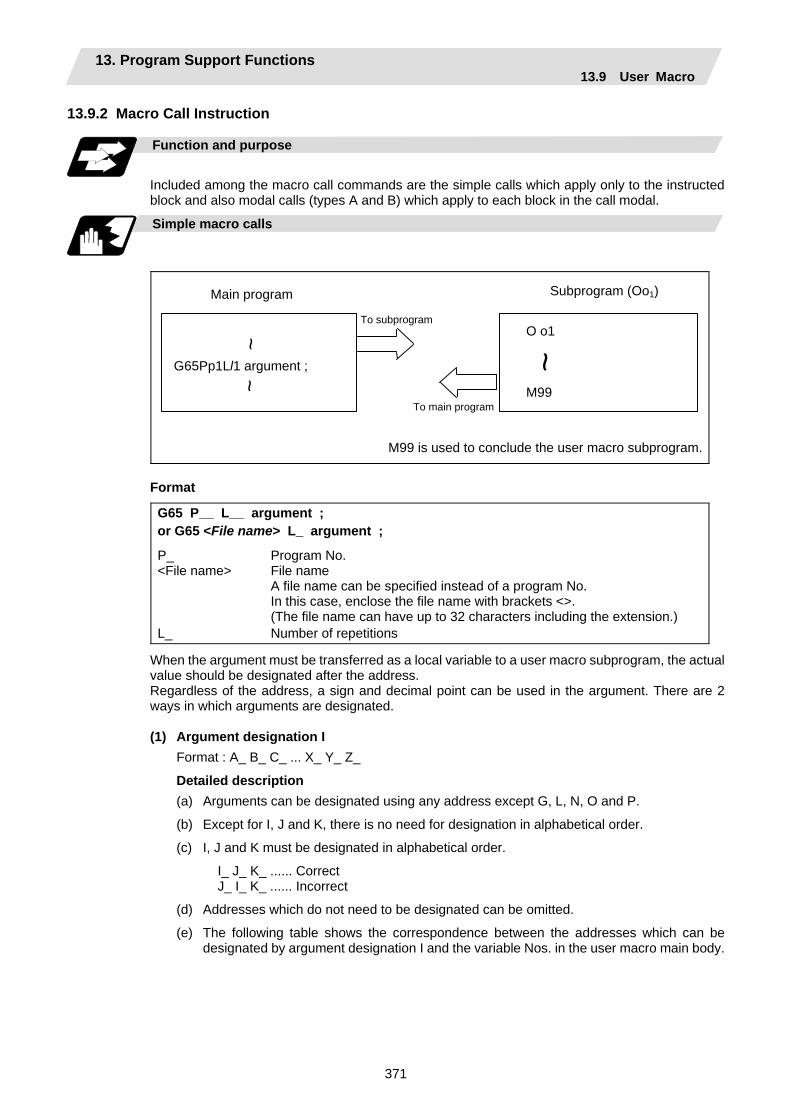
13. Program Support Functions 13.9 User Macro
371
13.9.2 Macro Call Instruction
Function and purpose
Included among the macro call commands are the simple calls which apply only to the instructed block and also modal calls (types A and B) which apply to each block in the call modal.
Simple macro calls
O o1 M99
~
To subprogram
To main program
Main program Subprogram (Oo1)
G65Pp1Ll1 argument ;
~ ~
M99 is used to conclude the user macro subprogram.
Format
G65 P__ L__ argument ; or G65 <File name> L_ argument ;
P_ Program No. <File name> File name
A file name can be specified instead of a program No. In this case, enclose the file name with brackets <>. (The file name can have up to 32 characters including the extension.)
L_ Number of repetitions
When the argument must be transferred as a local variable to a user macro subprogram, the actual value should be designated after the address. Regardless of the address, a sign and decimal point can be used in the argument. There are 2 ways in which arguments are designated. (1) Argument designation I
Format : A_ B_ C_ ... X_ Y_ Z_
Detailed description (a) Arguments can be designated using any address except G, L, N, O and P.
(b) Except for I, J and K, there is no need for designation in alphabetical order.
(c) I, J and K must be designated in alphabetical order.
I_ J_ K_ ...... Correct J_ I_ K_ ...... Incorrect
(d) Addresses which do not need to be designated can be omitted.
(e) The following table shows the correspondence between the addresses which can be designated by argument designation I and the variable Nos. in the user macro main body.
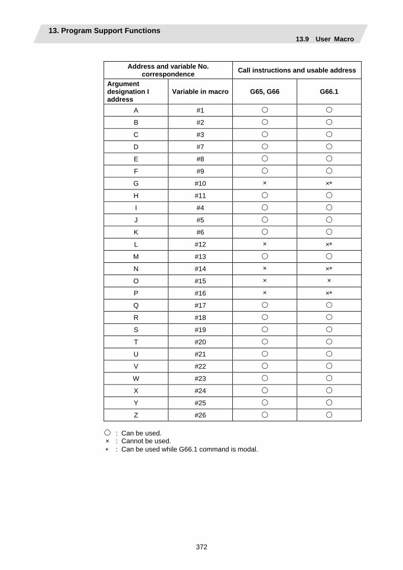
13. Program Support Functions 13.9 User Macro
372
Address and variable No.
correspondence Call instructions and usable address
Argument designation I address
Variable in macro G65, G66 G66.1
A #1 B #2 C #3 D #7 E #8 F #9 G #10 × ×∗ H #11 I #4 J #5 K #6 L #12 × ×∗ M #13 N #14 × ×∗ O #15 × × P #16 × ×∗ Q #17 R #18 S #19 T #20 U #21 V #22 W #23 X #24 Y #25 Z #26
: Can be used. × : Cannot be used. ∗ : Can be used while G66.1 command is modal.
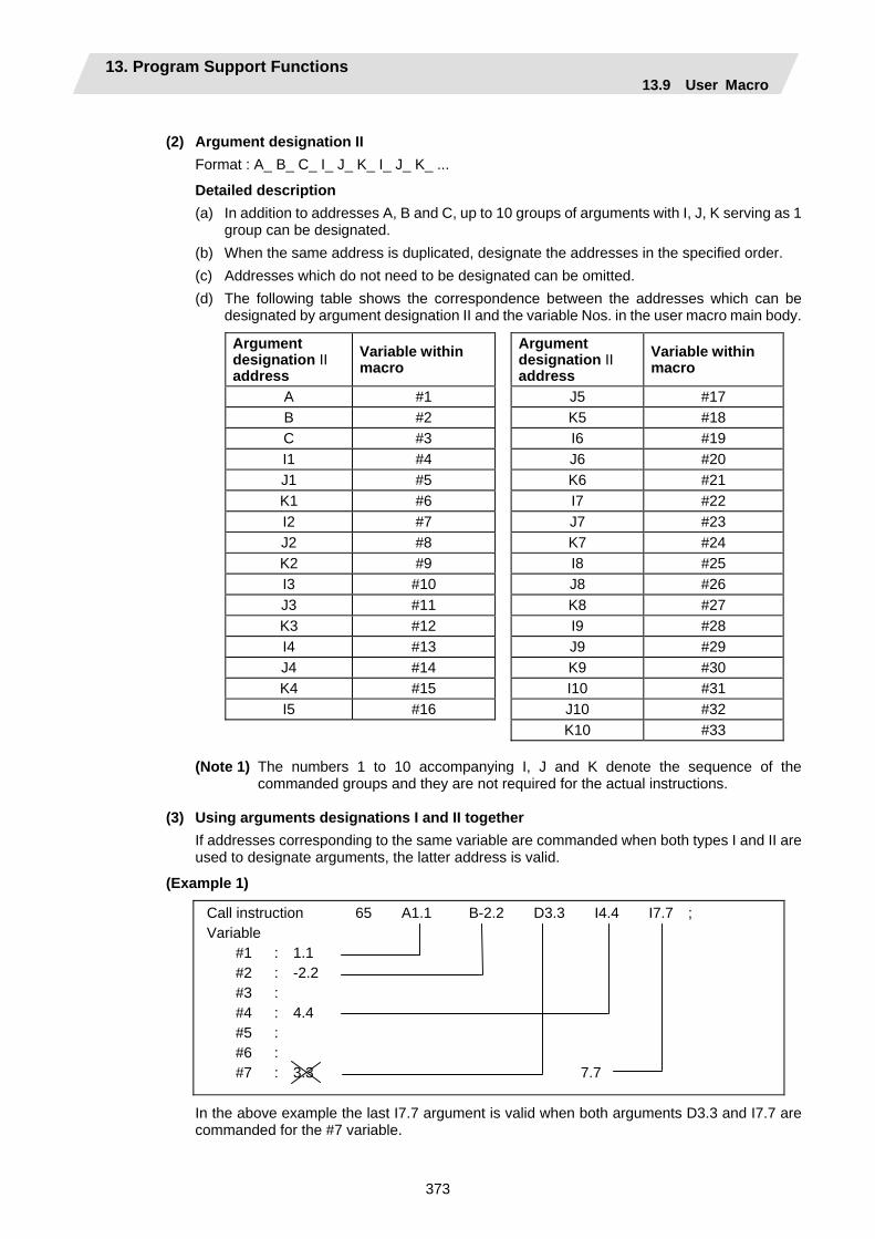
13. Program Support Functions 13.9 User Macro
373
(2) Argument designation II
Format : A_ B_ C_ I_ J_ K_ I_ J_ K_ ...
Detailed description (a) In addition to addresses A, B and C, up to 10 groups of arguments with I, J, K serving as 1
group can be designated. (b) When the same address is duplicated, designate the addresses in the specified order. (c) Addresses which do not need to be designated can be omitted. (d) The following table shows the correspondence between the addresses which can be
designated by argument designation II and the variable Nos. in the user macro main body.
Argument designation II address
Variable within macro
Argument designation II address
Variable within macro
A #1 J5 #17 B #2 K5 #18 C #3 I6 #19 I1 #4 J6 #20 J1 #5 K6 #21 K1 #6 I7 #22 I2 #7 J7 #23 J2 #8 K7 #24 K2 #9 I8 #25 I3 #10 J8 #26 J3 #11 K8 #27 K3 #12 I9 #28 I4 #13 J9 #29 J4 #14 K9 #30 K4 #15 I10 #31 I5 #16 J10 #32 K10 #33
(Note 1) The numbers 1 to 10 accompanying I, J and K denote the sequence of the
commanded groups and they are not required for the actual instructions.
(3) Using arguments designations I and II together If addresses corresponding to the same variable are commanded when both types I and II are used to designate arguments, the latter address is valid.
(Example 1)
Call instruction 65 A1.1 B-2.2 D3.3 I4.4 I7.7 ; Variable
#1 : 1.1 #2 : -2.2 #3 : #4 : 4.4 #5 : #6 : #7 : 3.3 7.7
In the above example the last I7.7 argument is valid when both arguments D3.3 and I7.7 are commanded for the #7 variable.

13. Program Support Functions 13.9 User Macro
374
Modal call A (movement command call)
Oo1 M99 ; ~
~
To subprogram
To main program
Main program Subprogram
G66 Pp1 Ll1 argument ;
~ G67 ;
~ To subprogram
:::
When the block with a movement command is commanded between G66 and G67, the movement command is first executed and then the designated user macro subprogram is executed. The number of times the subprogram is executed is l1 times with each call. The argument is the same as for a simple call.
Format
G66 P__ L__ argument ; or G66 <File name> L_ argument ;
P_ Program No. <File name> File name
A file name can be specified instead of a program No. In this case, enclose the file name with brackets <>. (The file name can have up to 32 characters including the extension.)
L_ Number of repetitions
Detailed description (1) When the G66 command is entered, the designated user macro subprogram will be called after
the movement command in the block with the movement commands has been executed until the G67 (cancel) command is entered.
(2) The G66 and G67 commands must be paired in the same program. A program error will result when G67 is issued without the G66 command.

13. Program Support Functions 13.9 User Macro
375
Modal call B (for each block)
The designated user macro subprogram is unconditionally called at each command block commanded between G66.1 and G67, and is executed the number of times designated with L. The argument is the same as for a simple call. Format
G66.1 P__ L__ argument ; or G66.1 <File name> L_ argument ;
P_ Program No. <File name> File name
A file name can be specified instead of a program No. In this case, enclose the file name with brackets <>. (The file name can have up to 32 characters including the extension.)
L_ Number of repetitions
Detailed description (1) In the G66.1 mode, everything except the O, N and G codes in the various command blocks
which are read are handled as the argument without being executed. Note that the G code designated last, or the N code commanded after other than O and N is the argument.
(2) The same applies as when G65 P_ is assigned at the head of a block for all significant blocks in the G66.1 mode.
(Example 1) N100 G01 G90 X100. Z200. F400 R1000 ; in the G66.1 P1000 ; mode is the same as: N100 G65 P1000 G01 G90 X100. Z200. F400 R1000 ;
(Note 1) The call is performed even in the G66.1 command block in the G66.1 mode and the correspondence between the argument address and the variable No. is the same as for G65 (simple call).
(3) The range of the G and N command values which can be used new as variables in the G66.1 mode is subject to the restrictions applying to value as normal NC command values.
(4) Program No. O, sequence Nos. N and modal G code are updated as modal information.
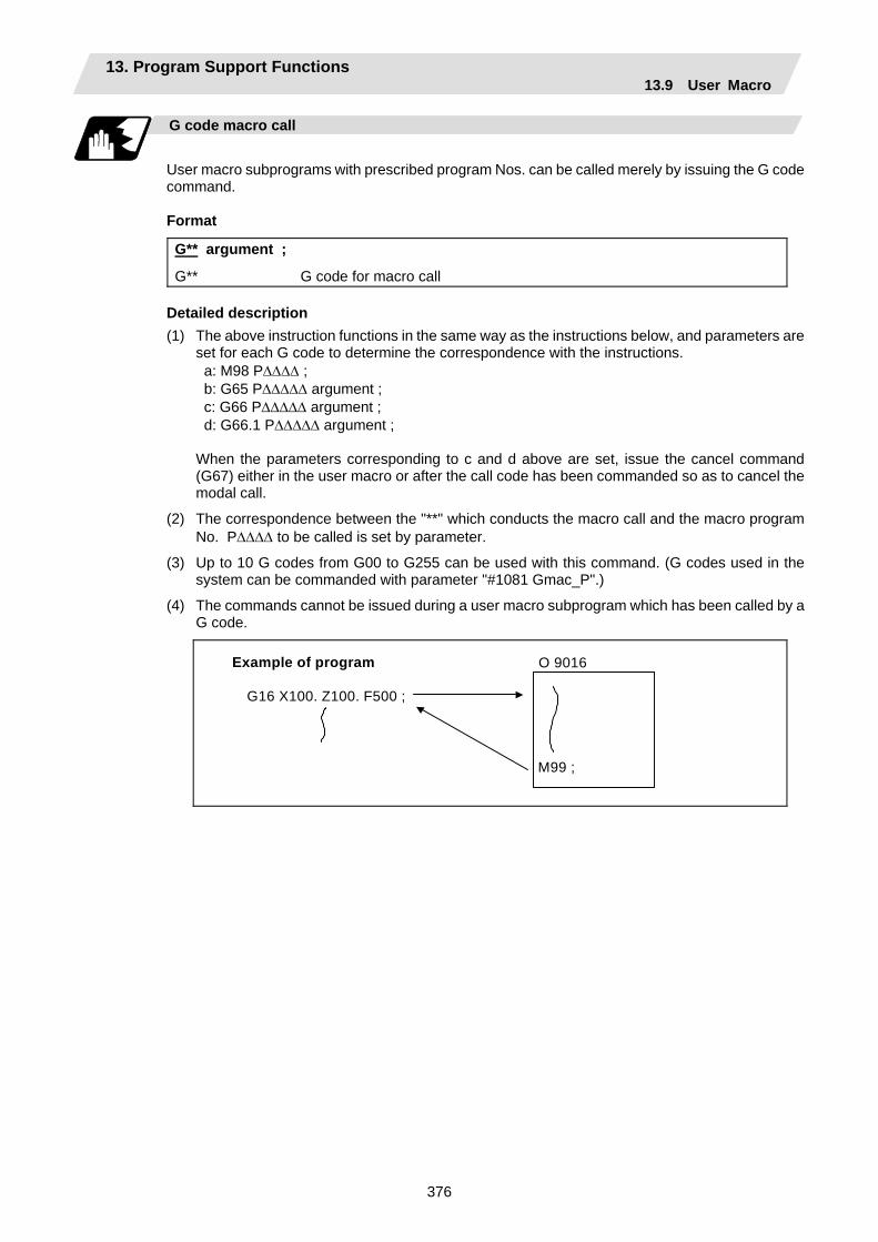
13. Program Support Functions 13.9 User Macro
376
G code macro call
User macro subprograms with prescribed program Nos. can be called merely by issuing the G code command.
Format
G** argument ;
G** G code for macro call Detailed description (1) The above instruction functions in the same way as the instructions below, and parameters are
set for each G code to determine the correspondence with the instructions. a: M98 P∆∆∆∆ ; b: G65 P∆∆∆∆∆ argument ; c: G66 P∆∆∆∆∆ argument ; d: G66.1 P∆∆∆∆∆ argument ;
When the parameters corresponding to c and d above are set, issue the cancel command (G67) either in the user macro or after the call code has been commanded so as to cancel the modal call.
(2) The correspondence between the "**" which conducts the macro call and the macro program No. P∆∆∆∆ to be called is set by parameter.
(3) Up to 10 G codes from G00 to G255 can be used with this command. (G codes used in the system can be commanded with parameter "#1081 Gmac_P".)
(4) The commands cannot be issued during a user macro subprogram which has been called by a G code.
Example of program
G16 X100. Z100. F500 ; M99 ;
O 9016

13. Program Support Functions 13.9 User Macro
377
Miscellaneous command macro call (for M, S, T, B code macro call)
The user macro subprograms of the specified program No. can be called merely by issuing an M (or S, T, B) code. (Only entered codes apply for M but all S, T and B codes apply.)
Format
M** ; (or S** ;, T** ;, B** ;)
M** M code for macro call (or S, T, B code) Detailed description (1) The above instruction functions in the same way as the instructions below, and parameters are
set for each M code to determine the correspondence with the instructions. (Same for S, T and B codes)
a: M98 P∆∆∆∆ ; b: G65 P∆∆∆∆ M** ; c: G66 P∆∆∆∆ M** ; d: G66.1 P∆∆∆∆ M** ;
M98, M** are not output
When the parameters corresponding to c and d above are set, issue the cancel command (G67) either in the user macro or after the call code has been commanded so as to cancel the modal call.
(2) The correspondence between the "M**" which conducts the macro call and the macro program No. P∆∆∆∆ to be called is set by parameter. Up to 10 M codes from M00 to M95 can be entered. Any code except the codes basically required by the machine and the M0, M1, M2, M30 and M96 to M99 codes can be entered.
(3) As with M98, the display appears on the CRT screen of the setting and display unit but the M codes and MF are not output.
(4) Even if the miscellaneous command entered above is issued during a user macro subprogram called by the M code, macro call will not result and it will be handled as an ordinary miscellaneous command. (This also applies for the S, T and B codes.)
(5) All S, T and B codes call the subprograms in the prescribed program Nos. of the corresponding S, T and B functions.
(6) Up to 10 M codes can be set, but set the parameter in the following manner when they will not all be used.
M[01] 20 0 8000 M[02] 21 0 8001 M[03] 9999 0 199999999 M[04] 9999 0 199999999 M[05] 9999 0 199999999 : : : : : : M[10] 9999 0 199999999
For M20 commands, set to call O8000 in type 0 (M98 type)For M21 commands, set to call O8001 in type 0 (M98 type)
Set parameters that will not be used as shown at the left.
[MACRO FILE (1)] <CODE> <TYPE> <PROGRAM-No.>
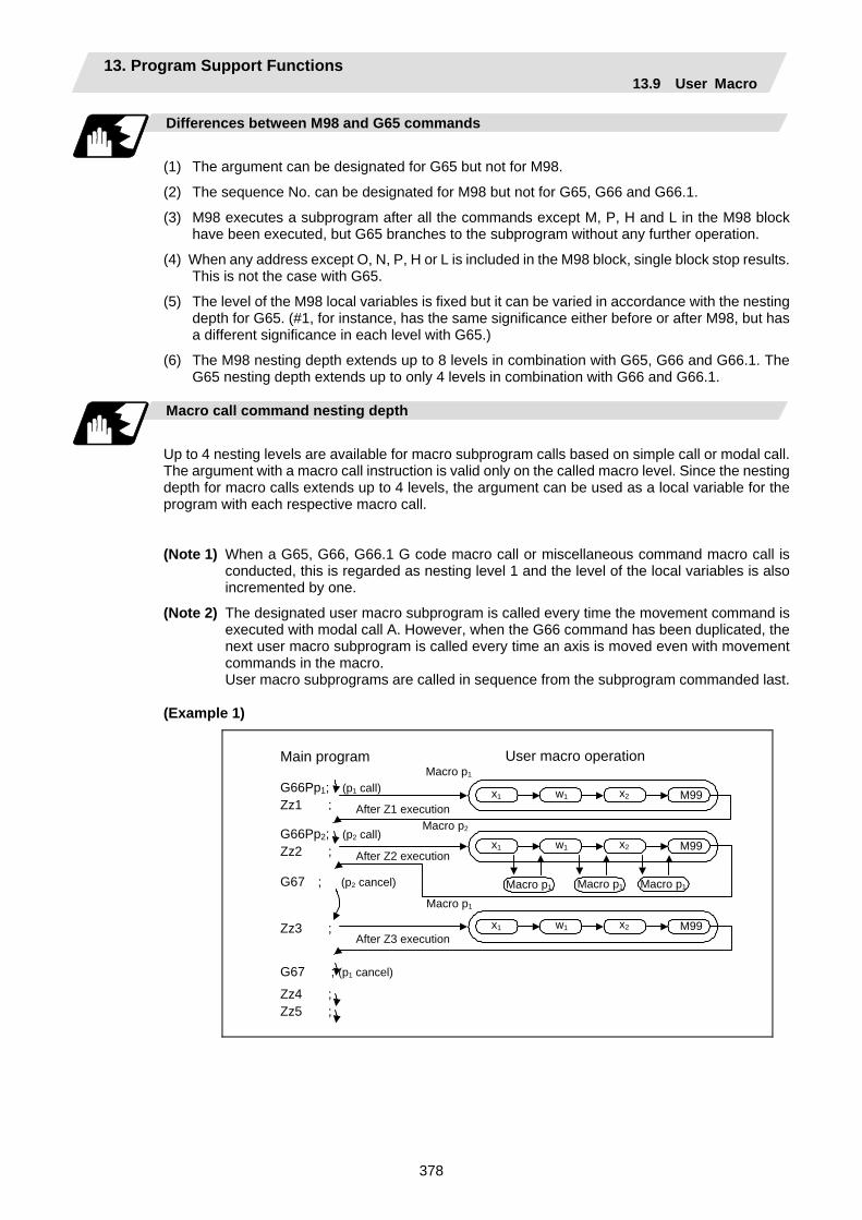
13. Program Support Functions 13.9 User Macro
378
Differences between M98 and G65 commands
(1) The argument can be designated for G65 but not for M98.
(2) The sequence No. can be designated for M98 but not for G65, G66 and G66.1.
(3) M98 executes a subprogram after all the commands except M, P, H and L in the M98 block have been executed, but G65 branches to the subprogram without any further operation.
(4) When any address except O, N, P, H or L is included in the M98 block, single block stop results. This is not the case with G65.
(5) The level of the M98 local variables is fixed but it can be varied in accordance with the nesting depth for G65. (#1, for instance, has the same significance either before or after M98, but has a different significance in each level with G65.)
(6) The M98 nesting depth extends up to 8 levels in combination with G65, G66 and G66.1. The G65 nesting depth extends up to only 4 levels in combination with G66 and G66.1.
Macro call command nesting depth
Up to 4 nesting levels are available for macro subprogram calls based on simple call or modal call. The argument with a macro call instruction is valid only on the called macro level. Since the nesting depth for macro calls extends up to 4 levels, the argument can be used as a local variable for the program with each respective macro call.
(Note 1) When a G65, G66, G66.1 G code macro call or miscellaneous command macro call is
conducted, this is regarded as nesting level 1 and the level of the local variables is also incremented by one.
(Note 2) The designated user macro subprogram is called every time the movement command is executed with modal call A. However, when the G66 command has been duplicated, the next user macro subprogram is called every time an axis is moved even with movement commands in the macro.
User macro subprograms are called in sequence from the subprogram commanded last.
(Example 1)
Main program
G66Pp1; (p1 call) Zz1 ;
x1 w1 x2 M99
x1 w1 x2 M99
x1 w1 x2 M99
G66Pp2; (p2 call) Zz2 ;
G67 ; (p2 cancel)
Zz3 ;
G67 ; (p1 cancel)
Zz4 ; Zz5 ;
User macro operation Macro p1
Macro p2
Macro p1 Macro p1 Macro p1 Macro p1
After Z2 execution
After Z1 execution
After Z3 execution

13. Program Support Functions 13.9 User Macro
379
13.9.3 ASCII Code Macro
Function and purpose
A macro program can be called out by setting the correspondence of a subprogram (macro program) preregistered with the parameters to codes, and then commanding the ASCII code in the machining program. This function can be used in addition to the G, M, S, T and B miscellaneous command macro call function. (Execution example 1) M98 type
Main program Subprogram
O0002 ; : D2000 ; : M30 ;
O200 : : : M99 ;
After outputting 2000 to common variable #146, theprogram No. 200 subprogram is called with the M98 subprogram call type.
#7401 (ASCII [01] Valid/Invalid) 1 (Valid) #7402 (ASCII [01] Code) D #7403 (ASCII [01] Type) 0 (M98 type) #7404 (ASCII [01] Program No.) 200 #7405 (ASCII [01] Variable) 146
Parameter
(Execution example 2) G65 type
Main program Subprogram
O0003 ; : A500 ; : M30 ;
O3000 : : : M99 ;
After outputting 500 to local variable #1, the program No. 3000 subprogram is called out with the G65 macro call type.
#7411 (ASCII [02] Valid/Invalid) 1 (Valid) #7412 (ASCII [02] Code) A #7413 (ASCII [02] Type) 0 (G65 type) #7414 (ASCII [02] Program No.) 3000 #7415 (ASCII [02] Variable) 100 (Not used)
Parameter

13. Program Support Functions 13.9 User Macro
380
Command format
∗∗∗∗; Designates the address and code
∗∗∗∗ ASCII code for calling out macro (one character) Value or expression output to variable (Setting range: ±999999.9999)
Detailed description
(1) The command above functions in the same way as that below. The correspondence of
commands is set for each ASCII code with the parameters. 0: M98 P∆∆∆∆ ; 1: G65 P∆∆∆∆ <Argument> ; 2: G66 P∆∆∆∆ <Argument> ; 3: G66.1 P∆∆∆∆ <Argument> ; When parameters are set for 2 and 3 above, the modal call will be canceled. Thus, command
the cancel command (G67) after commanding the call code or the during the user macro.
(2) The ASCII code for calling the macro with the ASCII codes and the program No. P∆∆∆∆ to be called are set with the parameters.
Up to two ASCII codes can be registered.
(3) The code section is output to the variables, but the output destination differs according to the call type and address.
(a) For M98 type The code section is output to the common variable, and the variable No. is set with the parameters. When corresponding to the first address (parameter #7401), the section is output to the common variable that indicates the first variable No. (parameter #7404).
(b) For G65/G66/G66.1 type The code section is output to the local variable. The variable No. differs according to the address, and corresponds to the following table.
Address # Address # Address #
A 1 K 6 U 21 B 2 L 12 V 22 C 3 M 13 W 23 D 7 N 14 X 24 E 8 O 15 Y 25 F 9 P 16 Z 26 G 10 Q 17 H 11 R 18 I 4 S 19 J 5 T 20
(Note) The following addresses can be used.
A, B, D, F, H, I, J, K, M, Q, R, S, T
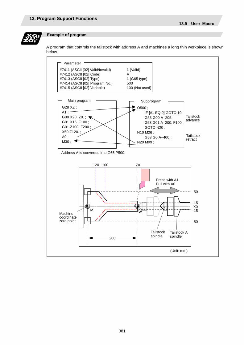
13. Program Support Functions 13.9 User Macro
381
Example of program
A program that controls the tailstock with address A and machines a long thin workpiece is shown below.
#7411 (ASCII [02] Valid/Invalid) 1 (Valid) #7412 (ASCII [02] Code) A #7413 (ASCII [02] Type) 1 (G65 type) #7414 (ASCII [02] Program No.) 500 #7415 (ASCII [02] Variable) 100 (Not used)
Parameter
G28 XZ ; A1 ; G00 X20. Z0. ; G01 X15. F100 ; G01 Z100. F200 ; X50 Z120. ; A0 ; M30 ;
O500 ; IF [#1 EQ 0] GOTO 10 ;
G53 G00 A–205. ; G53 G01 A–200. F100 ; GOTO N20 ; N10 M26 ; G53 G0 A–400. ; N20 M99 ;
Subprogram Main program
Tailstock advance
Tailstock retract
Address A is converted into G65 P500.
120 100 Z0
50
15X0
–15
–50
200
M WMachine coordinate zero point
Tailstock spindle
Tailstock A spindle
Press with A1 Pull with A0
(Unit: mm)

13. Program Support Functions 13.9 User Macro
382
Restrictions
(1) Calling a macro with an ASCII code from a program macro-called with an ASCII code A macro cannot be called with an ASCII code from a program macro-called with an ASCII
code. The other patterns are shown below. If it is determined that the macro cannot be called, the command will be handled as a normal
command.
Called side ASCII GMSTB
macro G65/66/66.1 M98
ASCII × × GMSTB macro × × G65/66/66.1
Calling side
M98
(2) Nest level of macro call command The macro subprogram can be called in up to four levels using simple call (G65) and modal call
(G66/G66.1). The macro call command's argument is valid only in the called macro level. Since the macro call nest level is four levels, the argument for each macro call can be used in
the program as a local variable.
(3) Nest level of subprogram call Counting the main program as 0, up to eight levels of subprograms can be called (M98) from a
subprogram. The following commands are used for subprogram nesting.
(a) M98
(b) G65 G66 G66.1
(c) G code call Miscellaneous function call (M/S/T/B)
(d) MDI interruption
(e) Automatic tool length measurement
(f) Multiple-step skip function The following commands can be commanded regardless of nesting.
(g) Fixed cycle
(h) Macro interruption

13. Program Support Functions 13.9 User Macro
383
(4) Order of command priority If "M" is designated for the ASCII code address, the codes basically necessary for that
machine will be overlapped. In this case, commands will be identified with the following priority using code values.
(a) M98, M99 (subprogram call command) M00 (program stop command), M01 (optional stop command) M02, M30, M198, M199 (end command) M96, M97 (macro interruption command)
(b) When corresponding to ASCII code macro command
(c) Used as normal command "S", "T" and "B" will also overlap with the miscellaneous command macro call. However, if
these commands do not correspond to the identification, the ASCII code macro will be executed.
If the other addresses do not correspond to the ASCII code macro command, they will be identified as normal commands. If the command to be used overlaps with an ASCII code macro command, it must be commanded in the program macro-called with the ASCII code.
Note that there are cases when the command will be unconditionally handled as a normal command, as explained in (5) below.
(5) Conditions for handling address set in ASCII code macro command as normal command
(a) When there is a data setting command (G10) in the same block.
(b) When ASCII code macro call is executed after the G code macro call command in the same block (also applies for M, S, T, B and ASCII)
Example) When address "D" (G65 type) is set in the ASCII code macro, and M50 is set in the macro call (G65 type).
M50 D200 ; Execute M code macro with argument (200 set in #7)
(c) When inputting parameters
(d) When there is a comma (,) before the address. Example) ,D ,R, etc.
(e) When commanded in fixed cycle
(f) When commanded in macro subprogram called with G code macro call (Also applies when macro is called with M, S, T, B or ASCII)

13. Program Support Functions 13.9 User Macro
384
13.9.4 Variables
Function and purpose
Both the variable specifications and user macro specifications are required for the variables which are used with the user macros. The offset amounts of the local, common and system variables among the variables for this NC unit are retained even when the unit's power is turned OFF. (Common variables can also be set to < Blank > in parameter "#1129PwrVC1")
Use of multiple variable
When the user macro specifications apply, variable Nos. can be turned into variables (multiple use of variables) or replaced by <formula>. Only one of the arithmetical (+, -, ×, ÷) operations can be conducted with <formula>.
(Example 1) Multiple use of variables
#1 = 10 #10 = 20 #20 = 30 ; # [# [#1] ] = # [#10] from #1 = 10. #5 = # [# [#1] ] ; # [#10] = #20 from #10 = 20. Therefore, #5 = #20 or #5 = 30.
#1 = 10 #10 = 20 #20 = 30 #5 = 1000 ; # [# [#1] ] = # [#10] from #1 = 10. # [# [#1]] = #5 ; # [#10] = #20 from #10 = 20. Therefore, #20 = #5 or #20 = 1000.
(Example 2) Replacing variable Nos. with <formula>
#10 = 5 ; # [#10 + 1] = 1000 ; In which case, #6 = 1000. # [#10 - 1] = -1000 ; In which case, #4 = -1000. # [#10∗3] = 100 ; In which case, #15 = 100. # [#10/2] = -100 ; In which case, #3 = -100. (fraction rounded up)
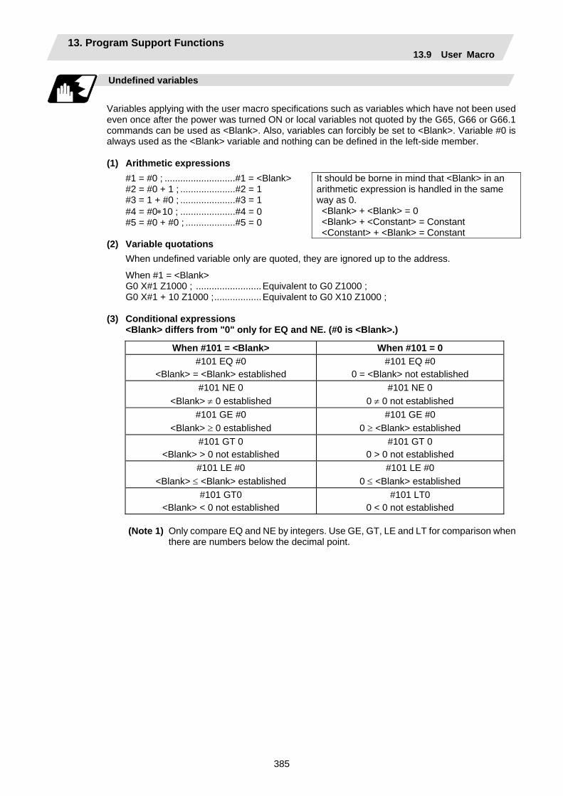
13. Program Support Functions 13.9 User Macro
385
Undefined variables
Variables applying with the user macro specifications such as variables which have not been used even once after the power was turned ON or local variables not quoted by the G65, G66 or G66.1 commands can be used as <Blank>. Also, variables can forcibly be set to <Blank>. Variable #0 is always used as the <Blank> variable and nothing can be defined in the left-side member.
(1) Arithmetic expressions
#1 = #0 ; ...........................#1 = <Blank> #2 = #0 + 1 ; .....................#2 = 1 #3 = 1 + #0 ; .....................#3 = 1 #4 = #0∗10 ; .....................#4 = 0 #5 = #0 + #0 ; ...................#5 = 0
It should be borne in mind that <Blank> in an arithmetic expression is handled in the same way as 0. <Blank> + <Blank> = 0 <Blank> + <Constant> = Constant <Constant> + <Blank> = Constant
(2) Variable quotations When undefined variable only are quoted, they are ignored up to the address.
When #1 = <Blank> G0 X#1 Z1000 ; .........................Equivalent to G0 Z1000 ; G0 X#1 + 10 Z1000 ;..................Equivalent to G0 X10 Z1000 ;
(3) Conditional expressions
<Blank> differs from "0" only for EQ and NE. (#0 is <Blank>.)
When #101 = <Blank> When #101 = 0 #101 EQ #0
<Blank> = <Blank> established #101 EQ #0
0 = <Blank> not established #101 NE 0
<Blank> ≠ 0 established #101 NE 0
0 ≠ 0 not established #101 GE #0
<Blank> ≥ 0 established #101 GE #0
0 ≥ <Blank> established #101 GT 0
<Blank> > 0 not established #101 GT 0
0 > 0 not established #101 LE #0
<Blank> ≤ <Blank> established #101 LE #0
0 ≤ <Blank> established #101 GT0
<Blank> < 0 not established #101 LT0
0 < 0 not established
(Note 1) Only compare EQ and NE by integers. Use GE, GT, LE and LT for comparison when there are numbers below the decimal point.
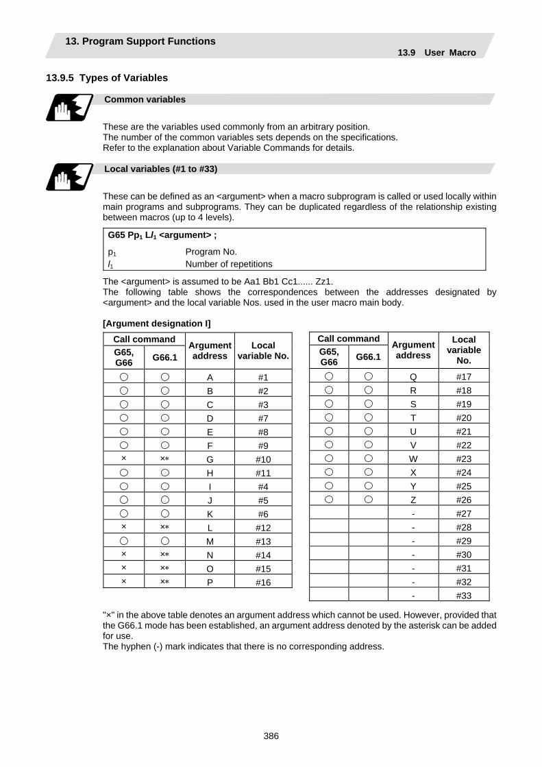
13. Program Support Functions 13.9 User Macro
386
13.9.5 Types of Variables
Common variables
These are the variables used commonly from an arbitrary position. The number of the common variables sets depends on the specifications. Refer to the explanation about Variable Commands for details.
Local variables (#1 to #33)
These can be defined as an <argument> when a macro subprogram is called or used locally within main programs and subprograms. They can be duplicated regardless of the relationship existing between macros (up to 4 levels).
G65 Pp1 Ll1 <argument> ;
p1 Program No. l1 Number of repetitions
The <argument> is assumed to be Aa1 Bb1 Cc1...... Zz1. The following table shows the correspondences between the addresses designated by <argument> and the local variable Nos. used in the user macro main body. [Argument designation I]
Call command G65, G66 G66.1
Argument address
Local variable No.
A #1B #2C #3D #7E #8F #9
× ×∗ G #10H #11I #4J #5K #6
× ×∗ L #12M #13
× ×∗ N #14× ×∗ O #15× ×∗ P #16
"×" in the above table denotes an argument address which cannot be used. However, provided that the G66.1 mode has been established, an argument address denoted by the asterisk can be added for use. The hyphen (-) mark indicates that there is no corresponding address.
Call commandG65, G66 G66.1
Argument address
Local variable
No.
Q #17R #18S #19T #20U #21V #22W #23X #24Y #25Z #26- #27- #28- #29- #30- #31- #32- #33
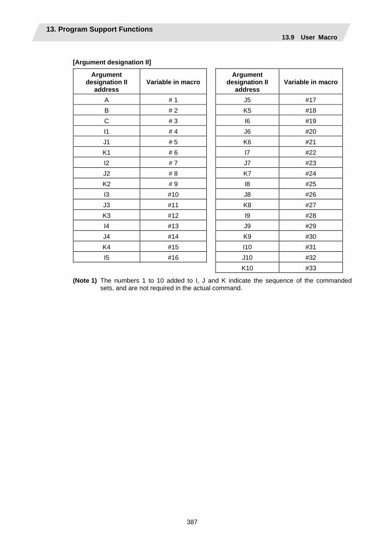
13. Program Support Functions 13.9 User Macro
387
[Argument designation II]
Argument designation II
address Variable in macro
Argument designation II
address Variable in macro
A # 1 J5 #17 B # 2 K5 #18 C # 3 I6 #19 I1 # 4 J6 #20 J1 # 5 K6 #21 K1 # 6 I7 #22 I2 # 7 J7 #23 J2 # 8 K7 #24 K2 # 9 I8 #25 I3 #10 J8 #26 J3 #11 K8 #27 K3 #12 I9 #28 I4 #13 J9 #29 J4 #14 K9 #30 K4 #15 I10 #31 I5 #16 J10 #32 K10 #33
(Note 1) The numbers 1 to 10 added to I, J and K indicate the sequence of the commanded sets, and are not required in the actual command.
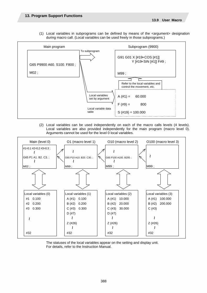
13. Program Support Functions 13.9 User Macro
388
(1) Local variables in subprograms can be defined by means of the <argument> designation
during macro call. (Local variables can be used freely in those subprograms.)
Main program Subprogram (9900)
G65 P9900 A60. S100. F800 ; M02 ;
G91 G01 X [#19∗COS [#1]] Y [#19∗SIN [#1]] F#9 ; M99 ;
To subprogram
A (#1) = 60.000 F (#9) = 800 S (#19) = 100.000
Refer to the local variables and control the movement, etc.
Local variables set by argument
Local variable data table
(2) Local variables can be used independently on each of the macro calls levels (4 levels). Local variables are also provided independently for the main program (macro level 0). Arguments cannot be used for the level 0 local variables.
Main (level 0)
#1=0.1 #2=0.2 #3=0.3 ; G65 P1 A1. B2. C3. ; M02 ;
~ ~
O1 (macro level 1)
G65 P10 A10. B20. C30. ;
M99 ;
O10 (macro level 2)
G65 P100 A100. B200. ;
M99 ;
O100 (macro level 3)
M99 ;
Local variables (0) #1 0.100 #2 0.200 #3 0.300 #32
Local variables (1) A (#1) 0.100 B (#2) 0.200 C (#3) 0.300 D (#7) Z (#26) #32
~ ~
~ ~
~
~ ~ ~
~ ~
Local variables (2) A (#1) 10.000 B (#2) 20.000 C (#3) 30.000 D (#7) Z (#26) #32
Local variables (3) A (#1) 100.000 B (#2) 200.000 C (#3) Z (#26) #32
~ ~
~ ~
~ ~
The statuses of the local variables appear on the setting and display unit. For details, refer to the Instruction Manual.
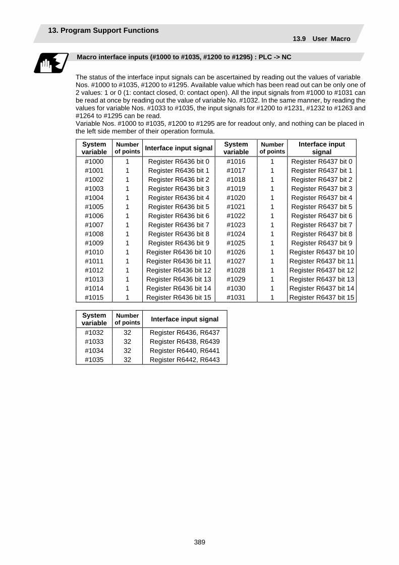
13. Program Support Functions 13.9 User Macro
389
Macro interface inputs (#1000 to #1035, #1200 to #1295) : PLC -> NC
The status of the interface input signals can be ascertained by reading out the values of variable Nos. #1000 to #1035, #1200 to #1295. Available value which has been read out can be only one of 2 values: 1 or 0 (1: contact closed, 0: contact open). All the input signals from #1000 to #1031 can be read at once by reading out the value of variable No. #1032. In the same manner, by reading the values for variable Nos. #1033 to #1035, the input signals for #1200 to #1231, #1232 to #1263 and #1264 to #1295 can be read. Variable Nos. #1000 to #1035, #1200 to #1295 are for readout only, and nothing can be placed in the left side member of their operation formula.
System variable
Number of points Interface input signal System
variable Number of points
Interface input signal
#1000 1 Register R6436 bit 0 #1016 1 Register R6437 bit 0#1001 1 Register R6436 bit 1 #1017 1 Register R6437 bit 1#1002 1 Register R6436 bit 2 #1018 1 Register R6437 bit 2#1003 1 Register R6436 bit 3 #1019 1 Register R6437 bit 3#1004 1 Register R6436 bit 4 #1020 1 Register R6437 bit 4#1005 1 Register R6436 bit 5 #1021 1 Register R6437 bit 5#1006 1 Register R6436 bit 6 #1022 1 Register R6437 bit 6#1007 1 Register R6436 bit 7 #1023 1 Register R6437 bit 7#1008 1 Register R6436 bit 8 #1024 1 Register R6437 bit 8#1009 1 Register R6436 bit 9 #1025 1 Register R6437 bit 9#1010 1 Register R6436 bit 10 #1026 1 Register R6437 bit 10#1011 1 Register R6436 bit 11 #1027 1 Register R6437 bit 11#1012 1 Register R6436 bit 12 #1028 1 Register R6437 bit 12#1013 1 Register R6436 bit 13 #1029 1 Register R6437 bit 13#1014 1 Register R6436 bit 14 #1030 1 Register R6437 bit 14#1015 1 Register R6436 bit 15 #1031 1 Register R6437 bit 15
System variable
Number of points Interface input signal
#1032 32 Register R6436, R6437 #1033 32 Register R6438, R6439 #1034 32 Register R6440, R6441 #1035 32 Register R6442, R6443
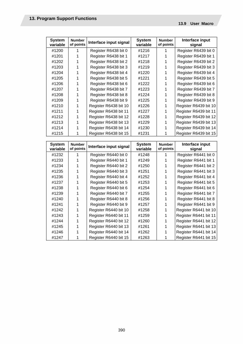
13. Program Support Functions 13.9 User Macro
390
System variable
Number of points Interface input signal System
variable Number of points
Interface input signal
#1200 #1201 #1202 #1203 #1204 #1205 #1206 #1207 #1208 #1209 #1210 #1211 #1212 #1213 #1214 #1215
1 1 1 1 1 1 1 1 1 1 1 1 1 1 1 1
Register R6438 bit 0Register R6438 bit 1Register R6438 bit 2Register R6438 bit 3Register R6438 bit 4Register R6438 bit 5Register R6438 bit 6Register R6438 bit 7Register R6438 bit 8Register R6438 bit 9
Register R6438 bit 10Register R6438 bit 11Register R6438 bit 12Register R6438 bit 13Register R6438 bit 14Register R6438 bit 15
#1216 #1217 #1218 #1219 #1220 #1221 #1222 #1223 #1224 #1225 #1226 #1227 #1228 #1229 #1230 #1231
1 1 1 1 1 1 1 1 1 1 1 1 1 1 1 1
Register R6439 bit 0Register R6439 bit 1Register R6439 bit 2Register R6439 bit 3Register R6439 bit 4Register R6439 bit 5Register R6439 bit 6Register R6439 bit 7Register R6439 bit 8Register R6439 bit 9
Register R6439 bit 10Register R6439 bit 11Register R6439 bit 12Register R6439 bit 13Register R6439 bit 14Register R6439 bit 15
System variable
Number of points Interface input signal System
variable Number of points
Interface input signal
#1232 #1233 #1234 #1235 #1236 #1237 #1238 #1239 #1240 #1241 #1242 #1243 #1244 #1245 #1246 #1247
1 1 1 1 1 1 1 1 1 1 1 1 1 1 1 1
Register R6440 bit 0Register R6440 bit 1Register R6440 bit 2Register R6440 bit 3Register R6440 bit 4Register R6440 bit 5Register R6440 bit 6Register R6440 bit 7Register R6440 bit 8Register R6440 bit 9
Register R6440 bit 10Register R6440 bit 11Register R6440 bit 12Register R6440 bit 13Register R6440 bit 14Register R6440 bit 15
#1248 #1249 #1250 #1251 #1252 #1253 #1254 #1255 #1256 #1257 #1258 #1259 #1260 #1261 #1262 #1263
1 1 1 1 1 1 1 1 1 1 1 1 1 1 1 1
Register R6441 bit 0Register R6441 bit 1Register R6441 bit 2Register R6441 bit 3Register R6441 bit 4Register R6441 bit 5Register R6441 bit 6Register R6441 bit 7Register R6441 bit 8Register R6441 bit 9
Register R6441 bit 10Register R6441 bit 11Register R6441 bit 12Register R6441 bit 13Register R6441 bit 14Register R6441 bit 15
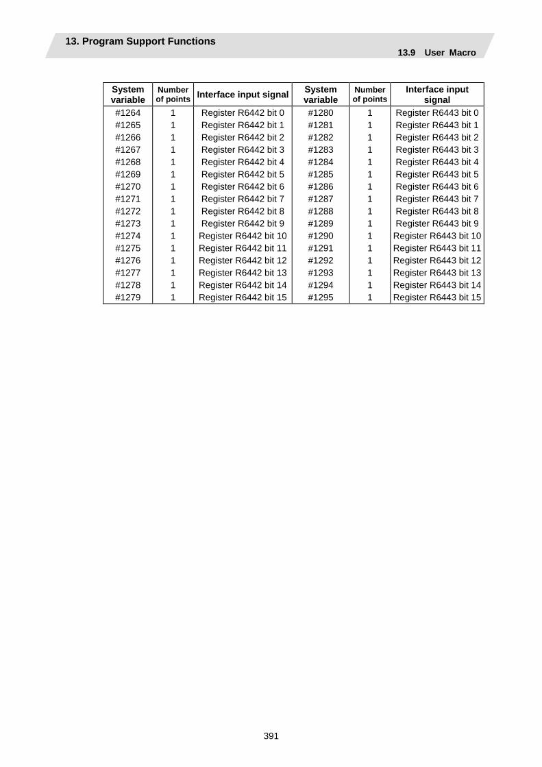
13. Program Support Functions 13.9 User Macro
391
System variable
Number of points Interface input signal System
variable Number of points
Interface input signal
#1264 #1265 #1266 #1267 #1268 #1269 #1270 #1271 #1272 #1273 #1274 #1275 #1276 #1277 #1278 #1279
1 1 1 1 1 1 1 1 1 1 1 1 1 1 1 1
Register R6442 bit 0Register R6442 bit 1Register R6442 bit 2Register R6442 bit 3Register R6442 bit 4Register R6442 bit 5Register R6442 bit 6Register R6442 bit 7Register R6442 bit 8Register R6442 bit 9
Register R6442 bit 10Register R6442 bit 11Register R6442 bit 12Register R6442 bit 13Register R6442 bit 14Register R6442 bit 15
#1280 #1281 #1282 #1283 #1284 #1285 #1286 #1287 #1288 #1289 #1290 #1291 #1292 #1293 #1294 #1295
1 1 1 1 1 1 1 1 1 1 1 1 1 1 1 1
Register R6443 bit 0Register R6443 bit 1Register R6443 bit 2Register R6443 bit 3Register R6443 bit 4Register R6443 bit 5Register R6443 bit 6Register R6443 bit 7Register R6443 bit 8Register R6443 bit 9
Register R6443 bit 10Register R6443 bit 11Register R6443 bit 12Register R6443 bit 13Register R6443 bit 14Register R6443 bit 15
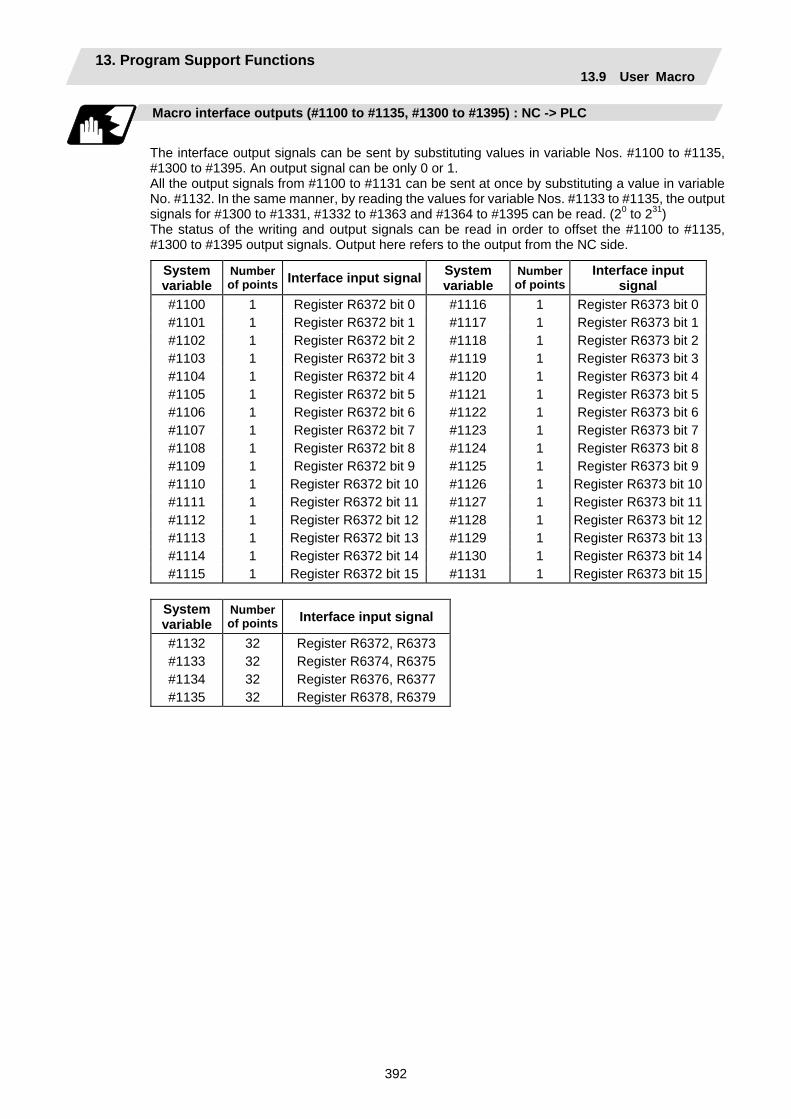
13. Program Support Functions 13.9 User Macro
392
Macro interface outputs (#1100 to #1135, #1300 to #1395) : NC -> PLC
The interface output signals can be sent by substituting values in variable Nos. #1100 to #1135, #1300 to #1395. An output signal can be only 0 or 1. All the output signals from #1100 to #1131 can be sent at once by substituting a value in variable No. #1132. In the same manner, by reading the values for variable Nos. #1133 to #1135, the output signals for #1300 to #1331, #1332 to #1363 and #1364 to #1395 can be read. (20 to 231) The status of the writing and output signals can be read in order to offset the #1100 to #1135, #1300 to #1395 output signals. Output here refers to the output from the NC side.
System variable
Number of points Interface input signal System
variable Number of points
Interface input signal
#1100 1 Register R6372 bit 0 #1116 1 Register R6373 bit 0#1101 1 Register R6372 bit 1 #1117 1 Register R6373 bit 1#1102 1 Register R6372 bit 2 #1118 1 Register R6373 bit 2#1103 1 Register R6372 bit 3 #1119 1 Register R6373 bit 3#1104 1 Register R6372 bit 4 #1120 1 Register R6373 bit 4#1105 1 Register R6372 bit 5 #1121 1 Register R6373 bit 5#1106 1 Register R6372 bit 6 #1122 1 Register R6373 bit 6#1107 1 Register R6372 bit 7 #1123 1 Register R6373 bit 7#1108 1 Register R6372 bit 8 #1124 1 Register R6373 bit 8#1109 1 Register R6372 bit 9 #1125 1 Register R6373 bit 9#1110 1 Register R6372 bit 10 #1126 1 Register R6373 bit 10#1111 1 Register R6372 bit 11 #1127 1 Register R6373 bit 11#1112 1 Register R6372 bit 12 #1128 1 Register R6373 bit 12#1113 1 Register R6372 bit 13 #1129 1 Register R6373 bit 13#1114 1 Register R6372 bit 14 #1130 1 Register R6373 bit 14#1115 1 Register R6372 bit 15 #1131 1 Register R6373 bit 15
System variable
Number of points Interface input signal
#1132 #1133 #1134 #1135
32 32 32 32
Register R6372, R6373 Register R6374, R6375 Register R6376, R6377 Register R6378, R6379
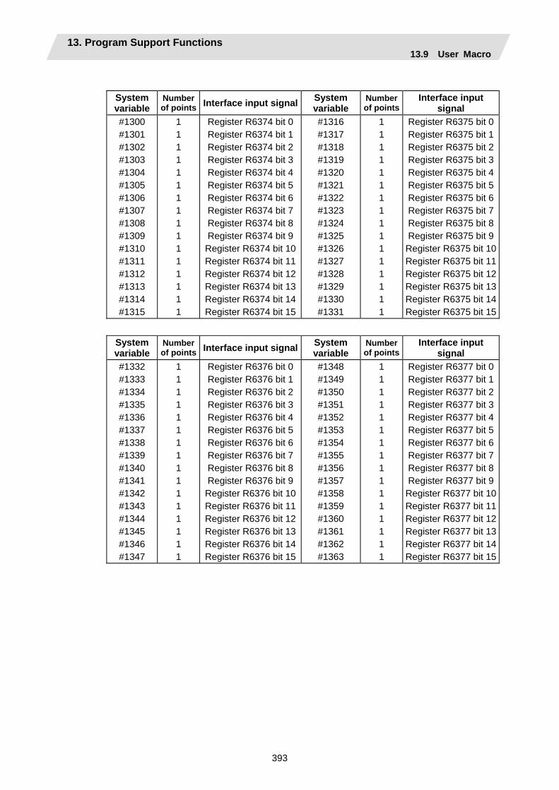
13. Program Support Functions 13.9 User Macro
393
System variable
Number of points Interface input signal System
variable Number of points
Interface input signal
#1300 #1301 #1302 #1303 #1304 #1305 #1306 #1307 #1308 #1309 #1310 #1311 #1312 #1313 #1314 #1315
1 1 1 1 1 1 1 1 1 1 1 1 1 1 1 1
Register R6374 bit 0Register R6374 bit 1Register R6374 bit 2Register R6374 bit 3Register R6374 bit 4Register R6374 bit 5Register R6374 bit 6Register R6374 bit 7Register R6374 bit 8Register R6374 bit 9
Register R6374 bit 10Register R6374 bit 11Register R6374 bit 12Register R6374 bit 13Register R6374 bit 14Register R6374 bit 15
#1316 #1317 #1318 #1319 #1320 #1321 #1322 #1323 #1324 #1325 #1326 #1327 #1328 #1329 #1330 #1331
1 1 1 1 1 1 1 1 1 1 1 1 1 1 1 1
Register R6375 bit 0Register R6375 bit 1Register R6375 bit 2Register R6375 bit 3Register R6375 bit 4Register R6375 bit 5Register R6375 bit 6Register R6375 bit 7Register R6375 bit 8Register R6375 bit 9
Register R6375 bit 10Register R6375 bit 11Register R6375 bit 12Register R6375 bit 13Register R6375 bit 14Register R6375 bit 15
System variable
Number of points Interface input signal System
variable Number of points
Interface input signal
#1332 #1333 #1334 #1335 #1336 #1337 #1338 #1339 #1340 #1341 #1342 #1343 #1344 #1345 #1346 #1347
1 1 1 1 1 1 1 1 1 1 1 1 1 1 1 1
Register R6376 bit 0Register R6376 bit 1Register R6376 bit 2Register R6376 bit 3Register R6376 bit 4Register R6376 bit 5Register R6376 bit 6Register R6376 bit 7Register R6376 bit 8Register R6376 bit 9
Register R6376 bit 10Register R6376 bit 11Register R6376 bit 12Register R6376 bit 13Register R6376 bit 14Register R6376 bit 15
#1348 #1349 #1350 #1351 #1352 #1353 #1354 #1355 #1356 #1357 #1358 #1359 #1360 #1361 #1362 #1363
1 1 1 1 1 1 1 1 1 1 1 1 1 1 1 1
Register R6377 bit 0Register R6377 bit 1Register R6377 bit 2Register R6377 bit 3Register R6377 bit 4Register R6377 bit 5Register R6377 bit 6Register R6377 bit 7Register R6377 bit 8Register R6377 bit 9
Register R6377 bit 10Register R6377 bit 11Register R6377 bit 12Register R6377 bit 13Register R6377 bit 14Register R6377 bit 15
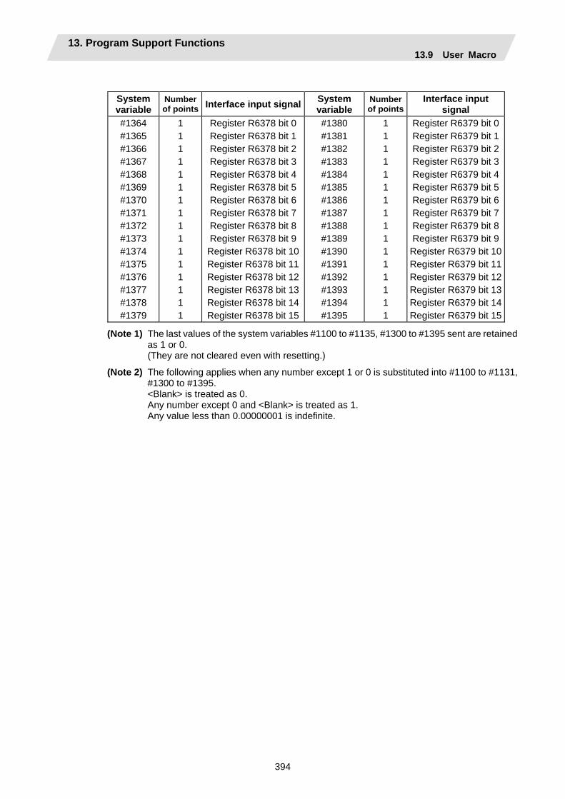
13. Program Support Functions 13.9 User Macro
394
System variable
Number of points Interface input signal System
variable Number of points
Interface input signal
#1364 #1365 #1366 #1367 #1368 #1369 #1370 #1371 #1372 #1373 #1374 #1375 #1376 #1377 #1378 #1379
1 1 1 1 1 1 1 1 1 1 1 1 1 1 1 1
Register R6378 bit 0Register R6378 bit 1Register R6378 bit 2Register R6378 bit 3Register R6378 bit 4Register R6378 bit 5Register R6378 bit 6Register R6378 bit 7Register R6378 bit 8Register R6378 bit 9
Register R6378 bit 10Register R6378 bit 11Register R6378 bit 12Register R6378 bit 13Register R6378 bit 14Register R6378 bit 15
#1380 #1381 #1382 #1383 #1384 #1385 #1386 #1387 #1388 #1389 #1390 #1391 #1392 #1393 #1394 #1395
1 1 1 1 1 1 1 1 1 1 1 1 1 1 1 1
Register R6379 bit 0Register R6379 bit 1Register R6379 bit 2Register R6379 bit 3Register R6379 bit 4Register R6379 bit 5Register R6379 bit 6Register R6379 bit 7Register R6379 bit 8Register R6379 bit 9
Register R6379 bit 10Register R6379 bit 11Register R6379 bit 12Register R6379 bit 13Register R6379 bit 14Register R6379 bit 15
(Note 1) The last values of the system variables #1100 to #1135, #1300 to #1395 sent are retained as 1 or 0.
(They are not cleared even with resetting.)
(Note 2) The following applies when any number except 1 or 0 is substituted into #1100 to #1131, #1300 to #1395.
<Blank> is treated as 0. Any number except 0 and <Blank> is treated as 1. Any value less than 0.00000001 is indefinite.

13. Program Support Functions 13.9 User Macro
395
Mac
ro in
stru
ctio
ns
#1000
#1031
#1032 (R6436,R6437)
#1200
#1231
#1033 (R6438,R6439)
#1232
#1263
#1034 (R6440,R6441)
#1264
#1295
#1035 (R6442,R6443)
#1132 (R6372,R6373)
#1133 (R6374,R6375)
#1134 (R6376,R6377)
#1135 (R6378,R6379)
#1300
#1331
#1332
#1363
#1364
#1395
#1100
#1131
Input signal Output signal
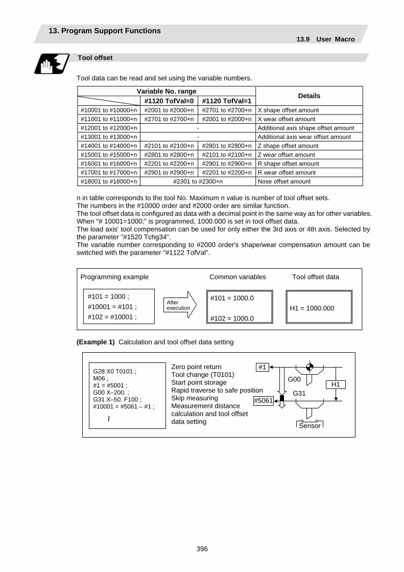
13. Program Support Functions 13.9 User Macro
396
Tool offset
Tool data can be read and set using the variable numbers.
Variable No. range #1120 TofVal=0 #1120 TofVal=1
Details
#10001 to #10000+n #2001 to #2000+n #2701 to #2700+n X shape offset amount #11001 to #11000+n #2701 to #2700+n #2001 to #2000+n X wear offset amount #12001 to #12000+n - Additional axis shape offset amount #13001 to #13000+n - Additional axis wear offset amount #14001 to #14000+n #2101 to #2100+n #2801 to #2800+n Z shape offset amount #15001 to #15000+n #2801 to #2800+n #2101 to #2100+n Z wear offset amount #16001 to #16000+n #2201 to #2200+n #2901 to #2900+n R shape offset amount #17001 to #17000+n #2901 to #2900+n #2201 to #2200+n R wear offset amount #18001 to #18000+n #2301 to #2300+n Nose offset amount
n in table corresponds to the tool No. Maximum n value is number of tool offset sets. The numbers in the #10000 order and #2000 order are similar function. The tool offset data is configured as data with a decimal point in the same way as for other variables. When "# 10001=1000;" is programmed, 1000.000 is set in tool offset data. The load axis' tool compensation can be used for only either the 3rd axis or 4th axis. Selected by the parameter "#1520 Tchg34". The variable number corresponding to #2000 order's shape/wear compensation amount can be switched with the parameter "#1122 TofVal".
Programming example Common variables Tool offset data
#101 = 1000 ; #10001 = #101 ; #102 = #10001 ;
After execution
#101 = 1000.0 #102 = 1000.0
H1 = 1000.000
(Example 1) Calculation and tool offset data setting
H1
Sensor
G00
G31
#1
#5061
~
G28 X0 T0101 ; M06 ; #1 = #5001 ; G00 X–200. ; G31 X–50. F100 ; #10001 = #5061 – #1 ;
Zero point return Tool change (T0101) Start point storage Rapid traverse to safe positionSkip measuring Measurement distance calculation and tool offset data setting

13. Program Support Functions 13.9 User Macro
397
(Note 1) In (Example 1) no consideration is given to the delay in the skip sensor signal. #5001 is the X-axis start point position and #5061 is the X-axis skip coordinates, and
indicated is the position at which the skip signal is input while G31 is being executed.
(Note 2) For multi-part system There are cases when each part system has tool data and when the part systems share
common tool data. This can be selected with parameter (#1051 MemTol).
Parameter #1051 MemTol 0 : Tool data provided for each part system 1 : Tool data shared by part systems
When the tool data is shared by the part systems, the read amount and substitution amount for all part systems' tool offset variables will be the same (when the same variable No. is commanded).
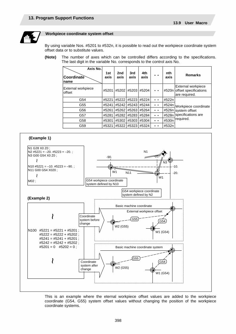
13. Program Support Functions 13.9 User Macro
398
Workpiece coordinate system offset
By using variable Nos. #5201 to #532n, it is possible to read out the workpiece coordinate system offset data or to substitute values.
(Note) The number of axes which can be controlled differs according to the specifications. The last digit in the variable No. corresponds to the control axis No.
Axis No.
Coordinate name
1st axis
2nd axis
3rd axis
4th axis • •
nth axis Remarks
External workpiece offset #5201 #5202 #5203 #5204 • • #520n
External workpiece offset specifications are required.
G54 #5221 #5222 #5223 #5224 • • #522n G55 #5241 #5242 #5243 #5244 • • #524n G56 #5261 #5262 #5263 #5264 • • #526n G57 #5281 #5282 #5283 #5284 • • #528n G58 #5301 #5302 #5303 #5304 • • #530n G59 #5321 #5322 #5323 #5324 • • #532n
Workpiece coordinate system offset specifications are required.
(Example 1)
N1 G28 X0 Z0 ; N2 #5221 = –20. #5223 = –20. ; N3 G00 G54 X0 Z0 ; N10 #5221 = –10. #5223 = –90. ; N11 G00 G54 X020 ; M02 ;
~ ~
G54 workpiece coordinate system defined by N2
G54 workpiece coordinate system defined by N10
N100 #5221 = #5221 + #5201 ; #5222 = #5222 + #5202 ; #5241 = #5241 + #5201 ; #5242 = #5242 + #5202 ; #5201 = 0 #5202 = 0 ;
~~
(Example 2)
Coordinate system after change
Coordinate system before change
-90. -20.
-20.
-10.
N1
N3
W1
W1 N11
Basic machine coordinate
External workpiece offset
W1 (G54)
W2 (G55)
G55G54
Basic machine coordinate system
W2 (G55)
W1 (G54)
G54G55
This is an example where the eternal workpiece offset values are added to the workpiece coordinate (G54, G55) system offset values without changing the position of the workpiece coordinate systems.
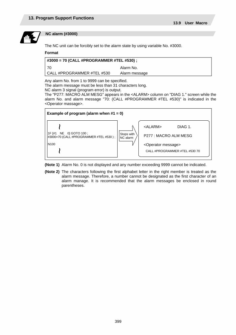
13. Program Support Functions 13.9 User Macro
399
NC alarm (#3000)
The NC unit can be forcibly set to the alarm state by using variable No. #3000.
Format
#3000 = 70 (CALL #PROGRAMMER #TEL #530) ;
70 Alarm No. CALL #PROGRAMMER #TEL #530 Alarm message
Any alarm No. from 1 to 9999 can be specified. The alarm message must be less than 31 characters long. NC alarm 3 signal (program error) is output. The "P277: MACRO ALM MESG" appears in the <ALARM> column on "DIAG 1." screen while the alarm No. and alarm message "70: (CALL #PROGRAMMER #TEL #530)" is indicated in the <Operator massage>.
Example of program (alarm when #1 = 0)
Stops with NC alarm
1F [#1 NE 0] GOTO 100 ; #3000=70 (CALL #PROGRAMMER #TEL #530 ) ; N100
<ALARM> DIAG 1. P277 : MACRO ALM MESG <Operator message> CALL #PROGRAMMER #TEL #530 70
~~
(Note 1) Alarm No. 0 is not displayed and any number exceeding 9999 cannot be indicated.
(Note 2) The characters following the first alphabet letter in the right member is treated as the alarm message. Therefore, a number cannot be designated as the first character of an alarm manage. It is recommended that the alarm messages be enclosed in round parentheses.

13. Program Support Functions 13.9 User Macro
400
Integrating time (#3001, #3002)
The integrating time can be read when the power is turned ON or automatic start or values can be substituted by using variable Nos. #3001 and #3002.
Type Variable No. Unit Contents when power
is switched on Initialization of contents Count conditions
Power ON 3001 At all times while power is ON
Automatic start 3002
1ms Same as when power is turned OFF
Value substituted for variable In-automatic start
The integrating time returns to zero in about 2.44 × 10¹¹ ms (approximately 7.7 years).
G65 P9010T (allowable time) ms ;
~ ~
To subprogram
#3001=0 ; WHILE [#3001LE#20] DO1 ; END1 ; M99 ;
O9010
Local variable Allowable time portion: DO1 to END1 is repeated and when allowable time is reached, operations jumps to M99.
Entered in local variable #20 T#20 ———
Suppression of single block stop and miscellaneous function finish signal waiting
By substituting the values below in variable No. #3003, it is possible to suppress single block stop in the subsequent blocks or to advance to the next block without waiting for the miscellaneous function (M, S, T, B) finish (FIN) signal.
#3003 Single block stop Miscellaneous function finish signal0 Not suppressed Wait 1 Suppressed Wait 2 Not suppressed No wait 3 Suppressed No wait
(Note 1) #3003 is cleared to zero by resetting.
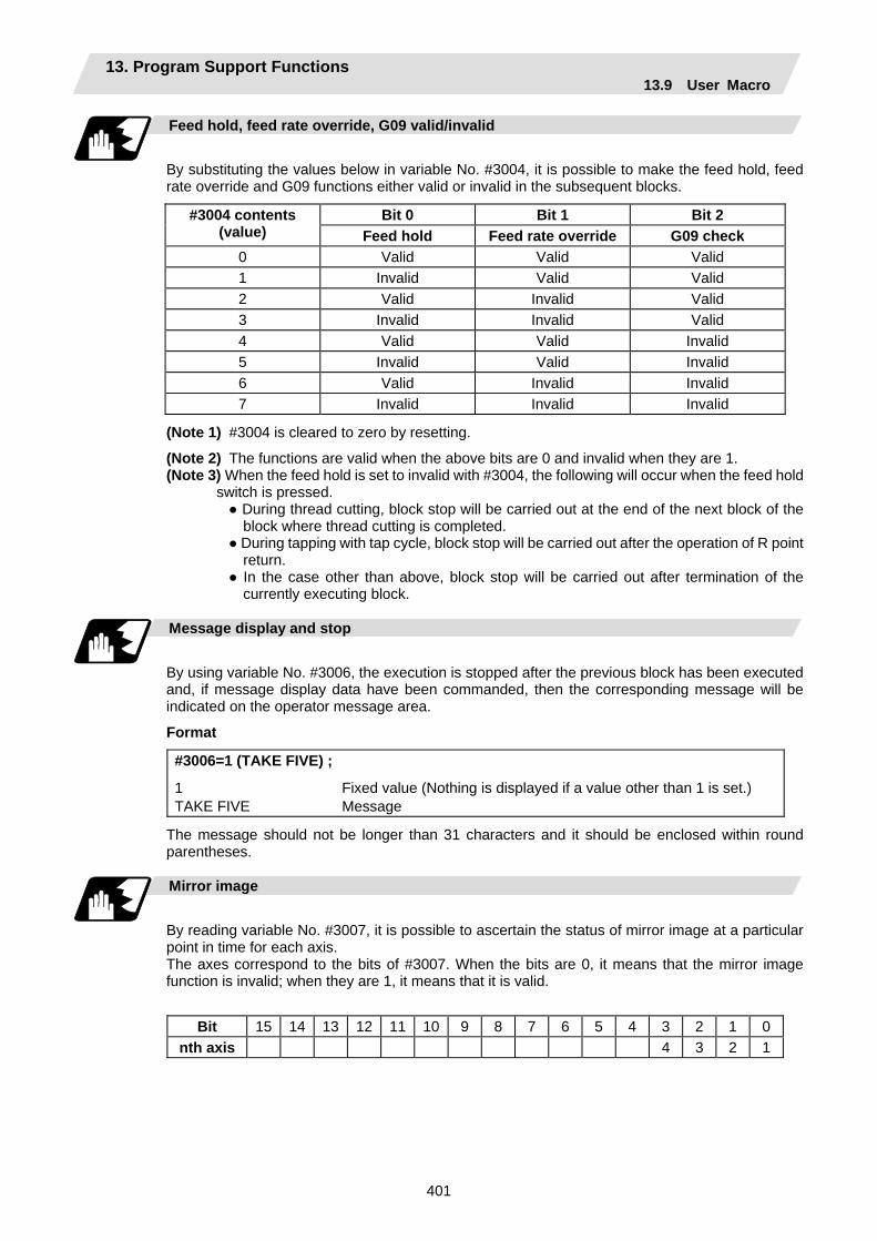
13. Program Support Functions 13.9 User Macro
401
Feed hold, feed rate override, G09 valid/invalid
By substituting the values below in variable No. #3004, it is possible to make the feed hold, feed rate override and G09 functions either valid or invalid in the subsequent blocks.
Bit 0 Bit 1 Bit 2 #3004 contents (value) Feed hold Feed rate override G09 check
0 Valid Valid Valid 1 Invalid Valid Valid 2 Valid Invalid Valid 3 Invalid Invalid Valid 4 Valid Valid Invalid 5 Invalid Valid Invalid 6 Valid Invalid Invalid 7 Invalid Invalid Invalid
(Note 1) #3004 is cleared to zero by resetting.
(Note 2) The functions are valid when the above bits are 0 and invalid when they are 1. (Note 3) When the feed hold is set to invalid with #3004, the following will occur when the feed hold
switch is pressed. During thread cutting, block stop will be carried out at the end of the next block of the
block where thread cutting is completed. During tapping with tap cycle, block stop will be carried out after the operation of R point
return. In the case other than above, block stop will be carried out after termination of the
currently executing block.
Message display and stop
By using variable No. #3006, the execution is stopped after the previous block has been executed and, if message display data have been commanded, then the corresponding message will be indicated on the operator message area.
Format
#3006=1 (TAKE FIVE) ;
1 Fixed value (Nothing is displayed if a value other than 1 is set.) TAKE FIVE Message
The message should not be longer than 31 characters and it should be enclosed within round parentheses.
Mirror image
By reading variable No. #3007, it is possible to ascertain the status of mirror image at a particular point in time for each axis. The axes correspond to the bits of #3007. When the bits are 0, it means that the mirror image function is invalid; when they are 1, it means that it is valid.
Bit 15 14 13 12 11 10 9 8 7 6 5 4 3 2 1 0nth axis 4 3 2 1
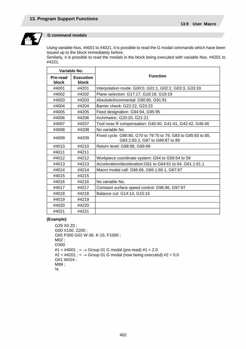
13. Program Support Functions 13.9 User Macro
402
G command modals
Using variable Nos. #4001 to #4021, it is possible to read the G modal commands which have been issued up to the block immediately before. Similarly, it is possible to read the medals in the block being executed with variable Nos. #4201 to #4221.
Variable No. Pre-read
block Execution
block Function
#4001 #4201 Interpolation mode: G00:0, G01:1, G02:2, G03:3, G33:33 #4002 #4202 Plane selection: G17:17, G18:18, G19:19 #4003 #4203 Absolute/incremental: G90:90, G91:91 #4004 #4204 Barrier check: G22:22, G23:23 #4005 #4205 Feed designation: G94:94, G95:95 #4006 #4206 Inch/metric: G20:20, G21:21 #4007 #4207 Tool nose R compensation: G40:40, G41:41, G42:42, G46:46 #4008 #4208 No variable No.
#4009 #4209 Fixed cycle: G80:80, G70 to 79:70 to 79, G83 to G85:83 to 85, G83.2:83.2, G87 to G89:87 to 89
#4010 #4210 Return level: G98:98, G99:99 #4011 #4211 #4012 #4212 Workpiece coordinate system: G54 to G59:54 to 59 #4013 #4213 Acceleration/deceleration:G61 to G64:61 to 64, G61.1:61.1 #4014 #4214 Macro modal call: G66:66, G66.1:66.1, G67:67 #4015 #4215 #4016 #4216 No variable No. #4017 #4217 Constant surface speed control: G96:96, G97:97 #4018 #4218 Balance cut: G14:14, G15:15 #4019 #4219 #4020 #4220 #4021 #4221
(Example) G29 X0 Z0 ; G00 X150. Z200 ; G65 P300 G02 W-30. K-15. F1000 ; M02 ; O300 #1 = #4001 ; = → Group 01 G modal (pre-read) #1 = 2.0 #2 = #4201 ; = → Group 01 G modal (now being executed) #2 = 0.0 G#1 W#24 ; M99 ; %

13. Program Support Functions 13.9 User Macro
403
Other modals
Using variable Nos. #4101 to #4120, it is possible to read the modal commands assigned up to the block immediately before. Similarly, it is possible to read the medals in the block being executed with variable Nos. #4301 to #4320.
Variable No. Pre-read Execution
Modal information
#4101 #4301 #4102 #4302 #4103 #4303 #4104 #4304 #4105 #4305 #4106 #4306 #4107 #4307 #4108 #4308 #4109 #4309 Feed rate F #4110 #4310
Position information
Using variable Nos. #5001 to #5104, it is possible to read the servo deviation amounts, tool position offset amount, skip coordinates, work coordinates, machine coordinates and end point coordinates in the block immediately before.
Position information
Axis No.
End point coordinate
of block immediately
before
Machine coordinate
Workpiece coordinate
Skip coordinate
Tool position
offset amount
Servo deviation amount
1 #5001 #5021 #5041 #5061 #5081 #5101 2 #5002 #5022 #5042 #5062 #5082 #5102 3 #5003 #5023 #5043 #5063 #5083 #5203 4 #5004 #5024 #5044 #5064 #5084 #5104 : : : : : : : n #5000+n #5020+n #5040+n #5060+n #5080+n #5100+n
Remarks (reading during movement) Yes No No Yes No Yes
(Note) The number of axes which can be controlled differs according to the specifications. The last digit of the variable No. corresponds to the control axis No.
Variable No. Pre-read Execution
Modal information
#4111 #4311 #4112 #4312 #4113 #4313 Miscellaneous function M#4114 #4314 Sequence No. N #4115 #4315 Program No. O #4116 #4316 #4117 #4317 #4118 #4318 #4119 #4319 Spindle function S #4120 #4320 Tool function T
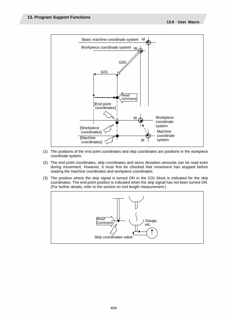
13. Program Support Functions 13.9 User Macro
404
W
M
M
W
G01
Workpiece coordinate system Machine coordinate system
G00
Basic machine coordinate system
Workpiece coordinate system
Readcommand
[End pointcoordinates]
[Machinecoordinates]
[Workpiececoordinates]
(1) The positions of the end point coordinates and skip coordinates are positions in the workpiece coordinate system.
(2) The end point coordinates, skip coordinates and servo deviation amounts can be read even during movement. However, it must first be checked that movement has stopped before reading the machine coordinates and workpiece coordinates.
(3) The position where the skip signal is turned ON in the G31 block is indicated for the skip coordinates. The end point position is indicated when the skip signal has not been turned ON. (For further details, refer to the section on tool length measurement.)
Gauge, etc.
Read Command
Skip coordinates value

13. Program Support Functions 13.9 User Macro
405
(4) The tool nose position where the tool offset and other such factors are not considered is
indicated as the end point coordinates. The tool basic position with consideration given to tool offset is indicated for the machine coordinates, workpiece coordinates and skip coordinates.
G31
W
M
F (feed rate)
Skip signal
Machine coordinatesystem
[Workpiece coordinates]
[Machine coordinates]
[Input coordinates of skip signal]
Workpiece coordinate system
For " ", check stop and then proceed to read.For " ", reading is possible during movement.
The position of the skip signal input coordinate value is the position in the workpiece coordinate system. The coordinate value in variable Nos. #5061 to #5064 memorize the moments when the skip input signal during movement was input and so they can be read at any subsequent time. For further details, reference should be made to the section on the skip function.
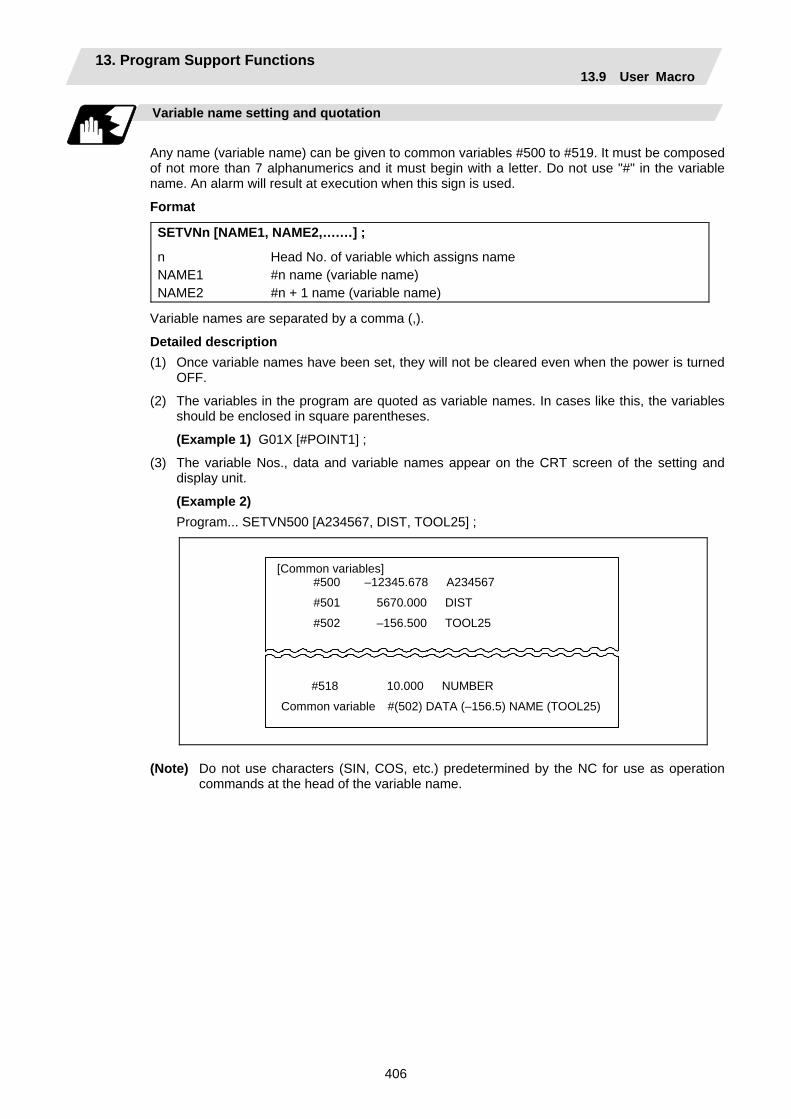
13. Program Support Functions 13.9 User Macro
406
Variable name setting and quotation
Any name (variable name) can be given to common variables #500 to #519. It must be composed of not more than 7 alphanumerics and it must begin with a letter. Do not use "#" in the variable name. An alarm will result at execution when this sign is used.
Format
SETVNn [NAME1, NAME2,….…] ;
n Head No. of variable which assigns name NAME1 #n name (variable name) NAME2 #n + 1 name (variable name)
Variable names are separated by a comma (,).
Detailed description (1) Once variable names have been set, they will not be cleared even when the power is turned
OFF.
(2) The variables in the program are quoted as variable names. In cases like this, the variables should be enclosed in square parentheses.
(Example 1) G01X [#POINT1] ;
(3) The variable Nos., data and variable names appear on the CRT screen of the setting and display unit.
(Example 2) Program... SETVN500 [A234567, DIST, TOOL25] ;
[Common variables] #500 –12345.678 A234567
#501 5670.000 DIST
#502 –156.500 TOOL25
#518 10.000 NUMBER
Common variable #(502) DATA (–156.5) NAME (TOOL25)
(Note) Do not use characters (SIN, COS, etc.) predetermined by the NC for use as operation
commands at the head of the variable name.
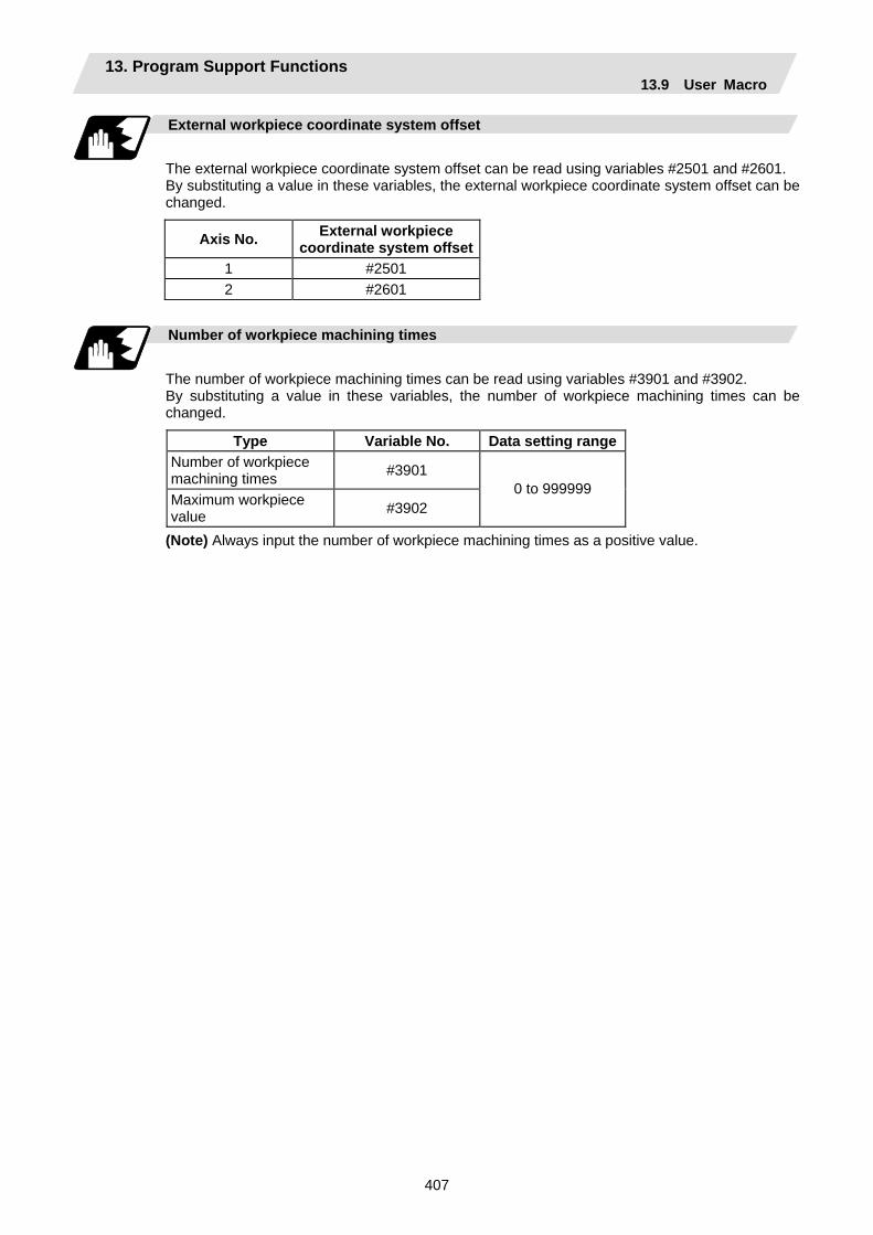
13. Program Support Functions 13.9 User Macro
407
External workpiece coordinate system offset
The external workpiece coordinate system offset can be read using variables #2501 and #2601. By substituting a value in these variables, the external workpiece coordinate system offset can be changed.
Axis No. External workpiece coordinate system offset
1 #2501 2 #2601
Number of workpiece machining times
The number of workpiece machining times can be read using variables #3901 and #3902. By substituting a value in these variables, the number of workpiece machining times can be changed.
Type Variable No. Data setting rangeNumber of workpiece machining times #3901
Maximum workpiece value #3902
0 to 999999
(Note) Always input the number of workpiece machining times as a positive value.
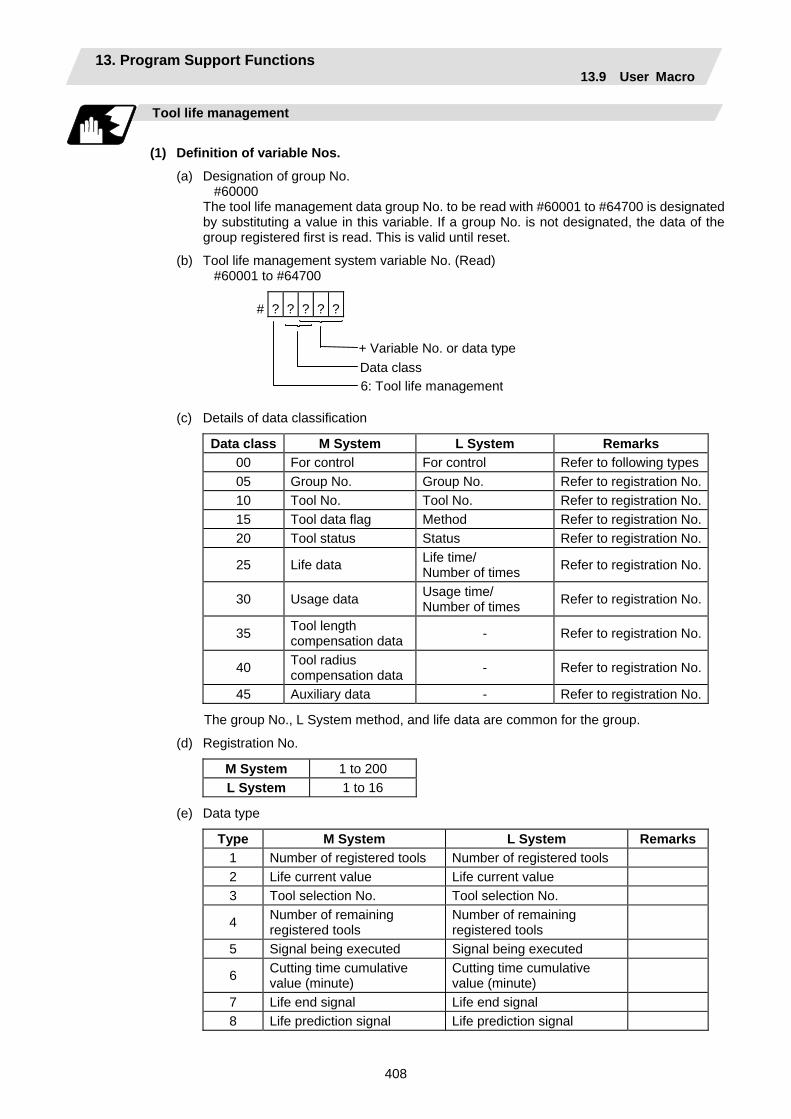
13. Program Support Functions 13.9 User Macro
408
Tool life management
(1) Definition of variable Nos.
(a) Designation of group No. #60000
The tool life management data group No. to be read with #60001 to #64700 is designated by substituting a value in this variable. If a group No. is not designated, the data of the group registered first is read. This is valid until reset.
(b) Tool life management system variable No. (Read) #60001 to #64700
# ? ? ? ? ?
+ Variable No. or data typeData class6: Tool life management
(c) Details of data classification
Data class M System L System Remarks 00 For control For control Refer to following types05 Group No. Group No. Refer to registration No.10 Tool No. Tool No. Refer to registration No.15 Tool data flag Method Refer to registration No.20 Tool status Status Refer to registration No.
25 Life data Life time/ Number of times Refer to registration No.
30 Usage data Usage time/ Number of times Refer to registration No.
35 Tool length compensation data - Refer to registration No.
40 Tool radius compensation data - Refer to registration No.
45 Auxiliary data - Refer to registration No.
The group No., L System method, and life data are common for the group.
(d) Registration No.
M System 1 to 200 L System 1 to 16
(e) Data type
Type M System L System Remarks1 Number of registered tools Number of registered tools 2 Life current value Life current value 3 Tool selection No. Tool selection No.
4 Number of remaining registered tools
Number of remaining registered tools
5 Signal being executed Signal being executed
6 Cutting time cumulative value (minute)
Cutting time cumulative value (minute)
7 Life end signal Life end signal 8 Life prediction signal Life prediction signal
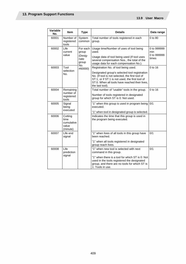
13. Program Support Functions 13.9 User Macro
409
Variable
No. Item Type Details Data range
60001 Number of registered tools
System common
Total number of tools registered in each group.
0 to 80
60002 Life current value
Usage time/Number of uses of tool being used.
Usage data of tool being used (If tool uses several compensation Nos., the total of the usage data for each compensation No.).
0 to 999999 min 0 to 999999 times
60003 Tool selection No.
Registration No. of tool being used.
Designated group's selected tool registration No. (If tool is not selected, the first tool of ST:1, or if ST:1 is not used, the first tool of ST:0. When all tools have reached their lives, the last tool).
0 to 16
60004 Remaining number of registered tools
Total number of "usable" tools in the group.
Number of tools registered in designated group for which ST is 0: Not used.
0 to 16
60005 Signal being executed
"1" when this group is used in program being executed.
"1" when tool in designated group is selected.
0/1
60006 Cutting time cumulative value (minute)
Indicates the time that this group is used in the program being executed.
60007 Life end signal
"1" when lives of all tools in this group have been reached.
"1" when all tools registered in designated group reach lives.
0/1
60008 Life prediction signal
For each group (Desig- nate group No. #60000)
"1" when new tool is selected with next command in this group.
"1" when there is a tool for which ST is 0: Not used in the tools registered the designated group, and there are no tools for which ST is 1: Tools in use.
0/1

13. Program Support Functions 13.9 User Macro
410
Variable
No. Item Type Details Data range
60500 +***
Group No. This group's No. 1 to 9999
61000 +***
Tool No. Tool's No. and compensation No.
Tool No. + compensation No. (When tool No. = 22 and compensation No. = 01, 2201=899H)
0 to 9999
61500 +***
Method Whether to management this group's life as time or number of uses.
0: Time, 1: Number of uses
0/1
62000 +***
Status Tool usage state
0: Not used tool 1: Tool being used 2: Normal life tool 3: Tool skip tool
0 to 3
62500 +***
Life time/ Number of uses
This group's tool life value 0 to 999999 min 0 to 999999 times
63000 +***
Usage time/ Number of uses
Each group/ registra-tion No.(Group No. #60000/ registra-tion No. *** is desig- nated.) Note the group No., method and life are common for the groups. 0 to 999999
min 0 to 999999 times
63500 +***
–
64000 +***
–
64500 +***
–
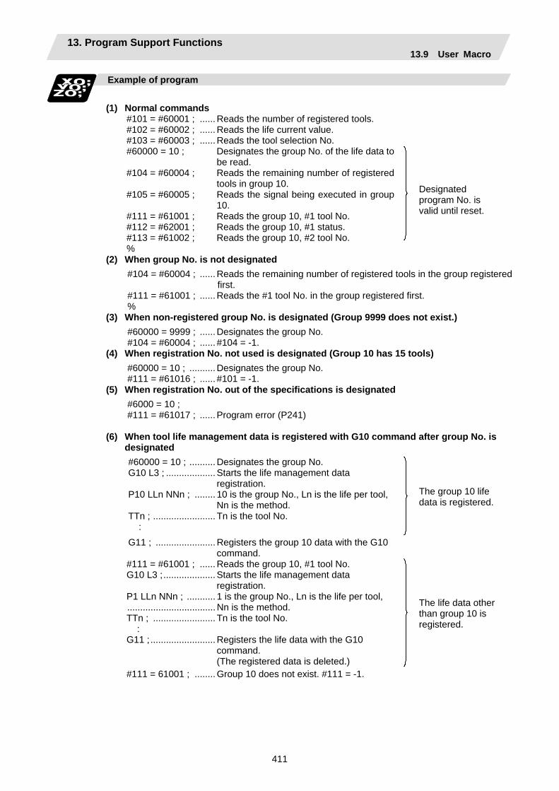
13. Program Support Functions 13.9 User Macro
411
Example of program
(1) Normal commands
#101 = #60001 ; ...... Reads the number of registered tools. #102 = #60002 ; ...... Reads the life current value. #103 = #60003 ; ...... Reads the tool selection No.
#60000 = 10 ; Designates the group No. of the life data to be read.
#104 = #60004 ; Reads the remaining number of registered tools in group 10.
#105 = #60005 ; Reads the signal being executed in group 10.
#111 = #61001 ; Reads the group 10, #1 tool No. #112 = #62001 ; Reads the group 10, #1 status. #113 = #61002 ; Reads the group 10, #2 tool No. %
Designated program No. is valid until reset.
(2) When group No. is not designated #104 = #60004 ; ......Reads the remaining number of registered tools in the group registered
first. #111 = #61001 ; ......Reads the #1 tool No. in the group registered first. %
(3) When non-registered group No. is designated (Group 9999 does not exist.) #60000 = 9999 ; ......Designates the group No. #104 = #60004 ; ...... #104 = -1.
(4) When registration No. not used is designated (Group 10 has 15 tools) #60000 = 10 ; ..........Designates the group No. #111 = #61016 ; ...... #101 = -1.
(5) When registration No. out of the specifications is designated #6000 = 10 ; #111 = #61017 ; ......Program error (P241)
(6) When tool life management data is registered with G10 command after group No. is
designated #60000 = 10 ; .......... Designates the group No. G10 L3 ; ................... Starts the life management data
registration. P10 LLn NNn ; ........ 10 is the group No., Ln is the life per tool,
Nn is the method. TTn ; ........................ Tn is the tool No. :
The group 10 life data is registered.
G11 ; ....................... Registers the group 10 data with the G10 command.
#111 = #61001 ; ...... Reads the group 10, #1 tool No. G10 L3 ;.................... Starts the life management data
registration. P1 LLn NNn ; ........... 1 is the group No., Ln is the life per tool, .................................. Nn is the method. TTn ; ........................ Tn is the tool No. : G11 ;......................... Registers the life data with the G10
command. (The registered data is deleted.)
The life data other than group 10 is registered.
#111 = 61001 ; ........ Group 10 does not exist. #111 = -1.

13. Program Support Functions 13.9 User Macro
412
Precautions
(1) If the tool life management system variable is commanded without designating a group No.,
the data of the group registered at the head of the registered data will be read.
(2) If a non-registered group No. is designated and the tool life management system variable is commanded, "-1" will be read as the data.
(3) If an unused registration No. tool life management system variable is commanded, "-1" will be read as the data.
(4) Once commanded, the group No. is valid until NC reset.
(5) When the tool life control I specifications are provided with the L System, the tool life management system variable specifications are not provided. Program error (P241) will occur if commanded.
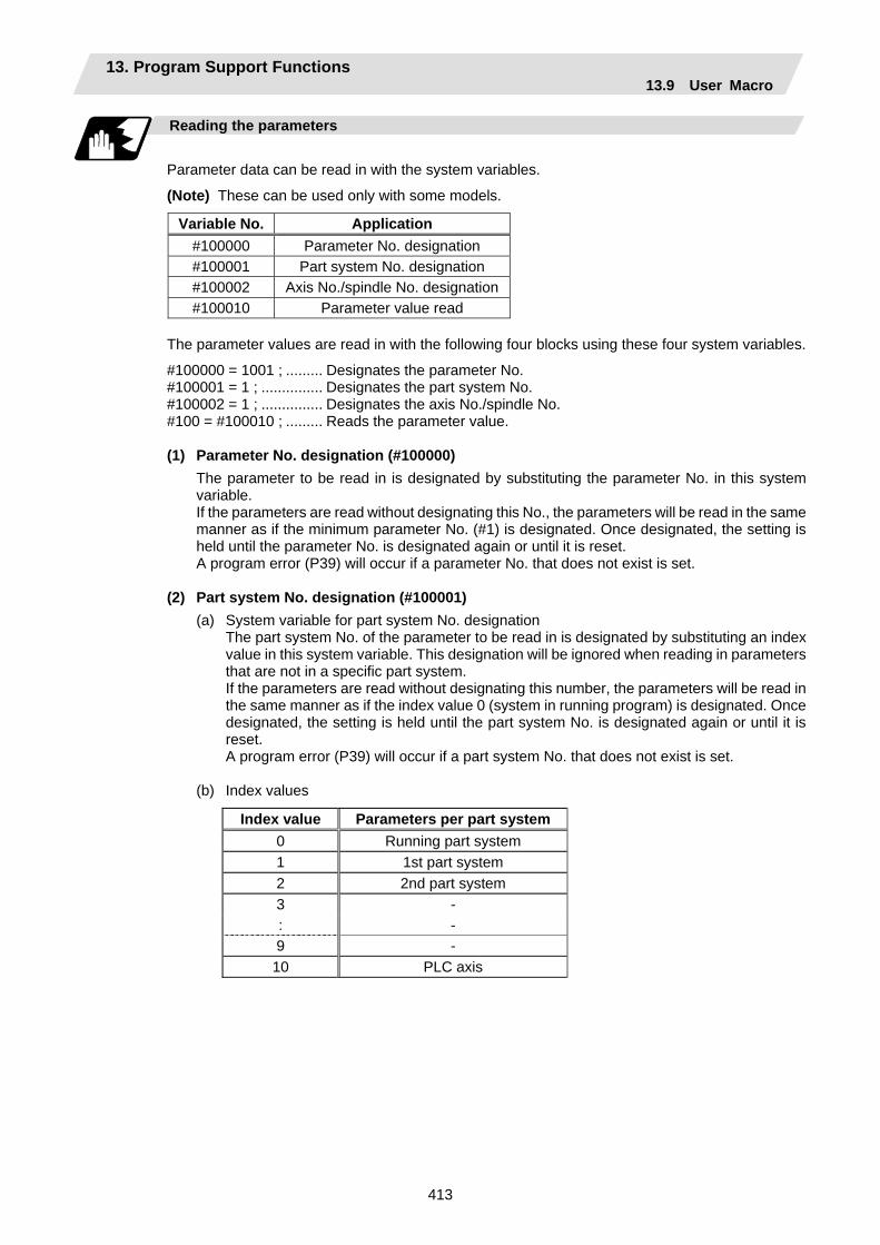
13. Program Support Functions 13.9 User Macro
413
Reading the parameters
Parameter data can be read in with the system variables.
(Note) These can be used only with some models.
Variable No. Application #100000 Parameter No. designation #100001 Part system No. designation #100002 Axis No./spindle No. designation#100010 Parameter value read
The parameter values are read in with the following four blocks using these four system variables.
#100000 = 1001 ; ......... Designates the parameter No. #100001 = 1 ; ............... Designates the part system No. #100002 = 1 ; ............... Designates the axis No./spindle No. #100 = #100010 ; ......... Reads the parameter value. (1) Parameter No. designation (#100000)
The parameter to be read in is designated by substituting the parameter No. in this system variable. If the parameters are read without designating this No., the parameters will be read in the same manner as if the minimum parameter No. (#1) is designated. Once designated, the setting is held until the parameter No. is designated again or until it is reset. A program error (P39) will occur if a parameter No. that does not exist is set.
(2) Part system No. designation (#100001)
(a) System variable for part system No. designation The part system No. of the parameter to be read in is designated by substituting an index value in this system variable. This designation will be ignored when reading in parameters that are not in a specific part system. If the parameters are read without designating this number, the parameters will be read in the same manner as if the index value 0 (system in running program) is designated. Once designated, the setting is held until the part system No. is designated again or until it is reset. A program error (P39) will occur if a part system No. that does not exist is set.
(b) Index values
Index value Parameters per part system 0 Running part system 1 1st part system 2 2nd part system 3 - : - 9 - 10 PLC axis
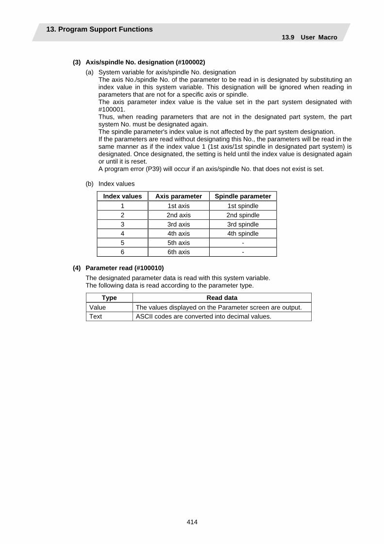
13. Program Support Functions 13.9 User Macro
414
(3) Axis/spindle No. designation (#100002)
(a) System variable for axis/spindle No. designation The axis No./spindle No. of the parameter to be read in is designated by substituting an index value in this system variable. This designation will be ignored when reading in parameters that are not for a specific axis or spindle. The axis parameter index value is the value set in the part system designated with #100001. Thus, when reading parameters that are not in the designated part system, the part system No. must be designated again. The spindle parameter's index value is not affected by the part system designation. If the parameters are read without designating this No., the parameters will be read in the same manner as if the index value 1 (1st axis/1st spindle in designated part system) is designated. Once designated, the setting is held until the index value is designated again or until it is reset. A program error (P39) will occur if an axis/spindle No. that does not exist is set.
(b) Index values
Index values Axis parameter Spindle parameter1 1st axis 1st spindle 2 2nd axis 2nd spindle 3 3rd axis 3rd spindle 4 4th axis 4th spindle 5 5th axis - 6 6th axis -
(4) Parameter read (#100010)
The designated parameter data is read with this system variable. The following data is read according to the parameter type.
Type Read data Value The values displayed on the Parameter screen are output. Text ASCII codes are converted into decimal values.
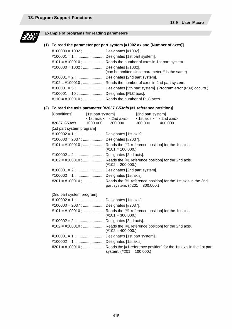
13. Program Support Functions 13.9 User Macro
415
Example of programs for reading parameters
(1) To read the parameter per part system [#1002 axisno (Number of axes)]
#100000 = 1002 ; .....................Designates [#1002]. #100001 = 1 ; ...........................Designates [1st part system]. #101 = #100010 ; .....................Reads the number of axes in 1st part system. #100000 = 1002 ; .....................Designates [#1002]. (can be omitted since parameter # is the same) #100001 = 2 ; ...........................Designates [2nd part system]. #102 = #100010 ; .....................Reads the number of axes in 2nd part system. #100001 = 5 ; ...........................Designates [5th part system]. (Program error (P39) occurs.) #100001 = 10 ; .........................Designates [PLC axis]. #110 = #100010 ; .....................Reads the number of PLC axes.
(2) To read the axis parameter [#2037 G53ofs (#1 reference position)] [Conditions] [1st part system] [2nd part system] <1st axis> <2nd axis> <1st axis> <2nd axis> #2037 G53ofs 1000.000 200.000 300.000 400.000 [1st part system program] #100002 = 1 ; ...........................Designates [1st axis]. #100000 = 2037 ; .....................Designates [#2037]. #101 = #100010 ; .....................Reads the [#1 reference position] for the 1st axis. (#101 = 100.000.) #100002 = 2 ; ...........................Designates [2nd axis]. #102 = #100010 ; .....................Reads the [#1 reference position] for the 2nd axis. (#102 = 200.000.) #100001 = 2 ; ...........................Designates [2nd part system]. #100002 = 1 ; ...........................Designates [1st axis]. #201 = #100010 ; .....................Reads the [#1 reference position] for the 1st axis in the 2nd
part system. (#201 = 300.000.)
[2nd part system program] #100002 = 1 ; ...........................Designates [1st axis]. #100000 = 2037 ; .....................Designates [#2037]. #101 = #100010 ; .....................Reads the [#1 reference position] for the 1st axis. (#101 = 300.000.) #100002 = 2 ; ...........................Designates [2nd axis]. #102 = #100010 ; .....................Reads the [#1 reference position] for the 2nd axis. (#102 = 400.000.) #100001 = 1 ; ...........................Designates [1st part system]. #100002 = 1 ; ...........................Designates [1st axis]. #201 = #100010 ; .....................Reads the [#1 reference position] for the 1st axis in the 1st part
system. (#201 = 100.000.)
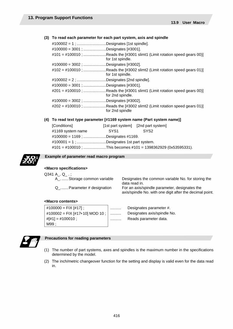
13. Program Support Functions 13.9 User Macro
416
(3) To read each parameter for each part system, axis and spindle
#100002 = 1 ; ...........................Designates [1st spindle]. #100000 = 3001 ; .....................Designates [#3001]. #101 = #100010 ; .....................Reads the [#3001 slimt1 (Limit rotation speed gears 00)] for 1st spindle. #100000 = 3002 ; .....................Designates [#3002]. #102 = #100010 ; .....................Reads the [#3002 slimt2 (Limit rotation speed gears 01)] for 1st spindle. #100002 = 2 ; ...........................Designates [2nd spindle]. #100000 = 3001 ; .....................Designates [#3001]. #201 = #100010 ; .....................Reads the [#3001 slimt1 (Limit rotation speed gears 00)] for 2nd spindle. #100000 = 3002 ; .....................Designates [#3002]. #202 = #100010 ; .....................Reads the [#3002 slimt2 (Limit rotation speed gears 01)] for 2nd spindle
(4) To read text type parameter [#1169 system name (Part system name)]
[Conditions] [1st part system] [2nd part system] #1169 system name SYS1 SYS2 #100000 = 1169 ; .....................Designates #1169. #100001 = 1 ; ...........................Designates 1st part system. #101 = #100010 ; .....................This becomes #101 = 1398362929 (0x53595331).
Example of parameter read macro program
<Macro specifications> Q341 A_. Q_ . ; A_. ...... Storage common variable Designates the common variable No. for storing the
data read in. Q_....... Parameter # designation For an axis/spindle parameter, designates the
axis/spindle No. with one digit after the decimal point. <Macro contents>
#100000 = FIX [#17] ; .......... Designates parameter #. #100002 = FIX [#17∗10] MOD 10 ; .......... Designates axis/spindle No. #[#1] = #100010 ; .......... Reads parameter data. M99 ;
Precautions for reading parameters
(1) The number of part systems, axes and spindles is the maximum number in the specifications
determined by the model.
(2) The inch/metric changeover function for the setting and display is valid even for the data read in.
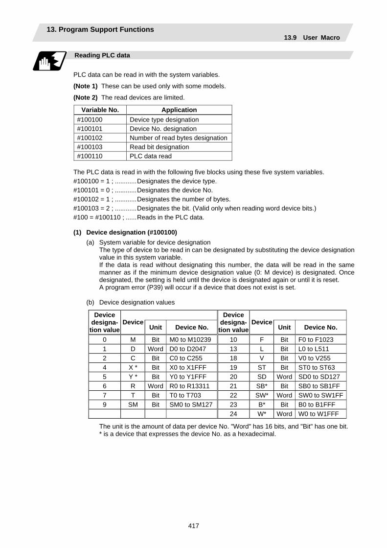
13. Program Support Functions 13.9 User Macro
417
Reading PLC data
PLC data can be read in with the system variables.
(Note 1) These can be used only with some models.
(Note 2) The read devices are limited.
Variable No. Application #100100 Device type designation #100101 Device No. designation #100102 Number of read bytes designation#100103 Read bit designation #100110 PLC data read
The PLC data is read in with the following five blocks using these five system variables. #100100 = 1 ; ............Designates the device type. #100101 = 0 ; ............Designates the device No. #100102 = 1 ; ............Designates the number of bytes. #100103 = 2 ; ............Designates the bit. (Valid only when reading word device bits.) #100 = #100110 ; ......Reads in the PLC data. (1) Device designation (#100100)
(a) System variable for device designation The type of device to be read in can be designated by substituting the device designation value in this system variable. If the data is read without designating this number, the data will be read in the same manner as if the minimum device designation value (0: M device) is designated. Once designated, the setting is held until the device is designated again or until it is reset. A program error (P39) will occur if a device that does not exist is set.
(b) Device designation values
Device designa-tion value
Device Unit Device No.
Device designa-tion value
DeviceUnit Device No.
0 M Bit M0 to M10239 10 F Bit F0 to F1023 1 D Word D0 to D2047 13 L Bit L0 to L511 2 C Bit C0 to C255 18 V Bit V0 to V255 4 X * Bit X0 to X1FFF 19 ST Bit ST0 to ST63 5 Y * Bit Y0 to Y1FFF 20 SD Word SD0 to SD127 6 R Word R0 to R13311 21 SB* Bit SB0 to SB1FF 7 T Bit T0 to T703 22 SW* Word SW0 to SW1FF9 SM Bit SM0 to SM127 23 B* Bit B0 to B1FFF 24 W* Word W0 to W1FFF
The unit is the amount of data per device No. "Word" has 16 bits, and "Bit" has one bit. * is a device that expresses the device No. as a hexadecimal.
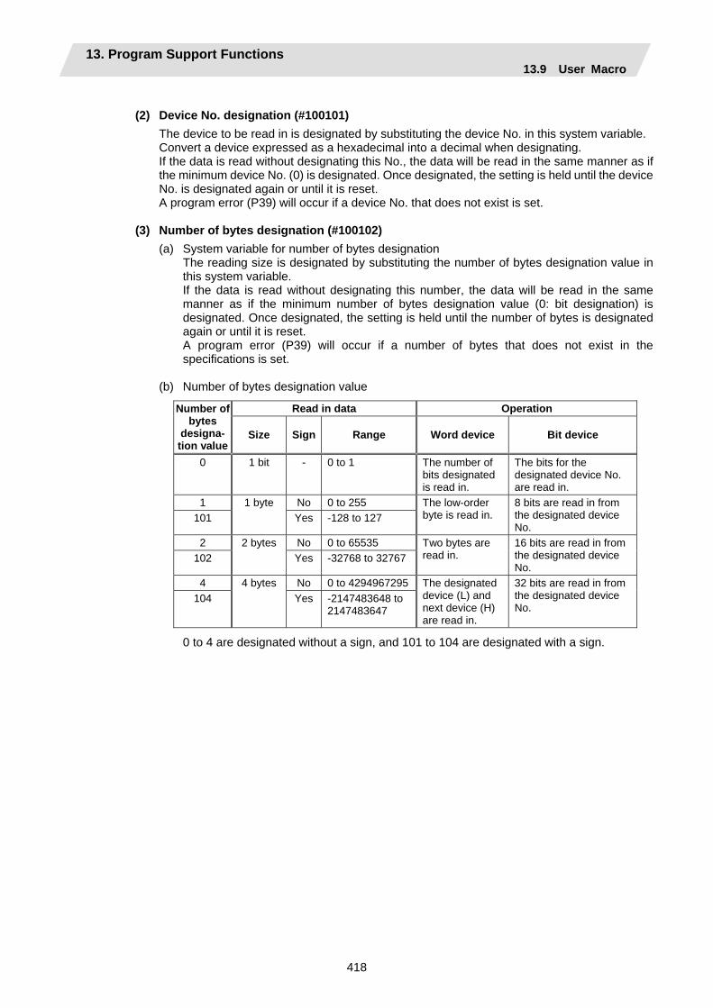
13. Program Support Functions 13.9 User Macro
418
(2) Device No. designation (#100101)
The device to be read in is designated by substituting the device No. in this system variable. Convert a device expressed as a hexadecimal into a decimal when designating. If the data is read without designating this No., the data will be read in the same manner as if the minimum device No. (0) is designated. Once designated, the setting is held until the device No. is designated again or until it is reset. A program error (P39) will occur if a device No. that does not exist is set.
(3) Number of bytes designation (#100102)
(a) System variable for number of bytes designation The reading size is designated by substituting the number of bytes designation value in this system variable. If the data is read without designating this number, the data will be read in the same manner as if the minimum number of bytes designation value (0: bit designation) is designated. Once designated, the setting is held until the number of bytes is designated again or until it is reset. A program error (P39) will occur if a number of bytes that does not exist in the specifications is set.
(b) Number of bytes designation value
Read in data Operation Number of bytes
designa- tion value
Size Sign Range Word device Bit device
0 1 bit - 0 to 1 The number of bits designated is read in.
The bits for the designated device No. are read in.
1 1 byte No 0 to 255 101 Yes -128 to 127
The low-order byte is read in.
8 bits are read in from the designated device No.
2 2 bytes No 0 to 65535 102 Yes -32768 to 32767
Two bytes are read in.
16 bits are read in from the designated device No.
4 4 bytes No 0 to 4294967295104 Yes -2147483648 to
2147483647
The designated device (L) and next device (H) are read in.
32 bits are read in from the designated device No.
0 to 4 are designated without a sign, and 101 to 104 are designated with a sign.

13. Program Support Functions 13.9 User Macro
419
(4) Bit designation (#100103)
(a) System variable for bit designation The bit to be read in is designated by substituting the bit designation value in this system variable. This designation is valid only when reading the bits for a 16-bit device, and is invalid in all other cases. If the data is read without designating this number, the data will be read in the same manner as if the minimum bit designation value (0: bit 0) is designated. Once designated, the setting is held until the bit is designated again or until it is reset. A program error (P39) will occur if a bit that does not exist is set.
(b) Bit designation values
Bit designation value Read in bit
0 Bit 0 1 Bit 1 : :
15 Bit 15
(5) PLC data read (#100110) The data for the designated device is read in with this system variable. Refer to the table for number of bytes designation for details on the range of data read in.
13. Program Support Functions 13.9 User Macro
420
Examples of programs for reading PLC data
(1) To read a bit device
#100100 = 0 ; ............Designates [M device]. #100101 = 0 ; ............Designates [Device No. 0]. #100102 = 0 ; ............Designates [Bit]. #100 = #100110 ; ......Reads M0 (one bit). #100102 = 1 ; ............Designates [1 byte]. #101 = #100110 ; ......Reads M0 to M7 (eight bits). (If M7 to M0 is 0001 0010, this will be #102 = 18 (0x12).) #100102 = 102 ; ........Designates [Signed two bytes]. #102 = #100110 ; .....Reads M0 to M15 (16 bits). (If M15 to M0 is 1111 1110 1101 1100, this will be #102 = –292 (0xFEDC).) #100102 = 4 ; ............Designates [4 bytes]. #104 = #100110 ; .....Reads M0 to M31 (32 bits). (If M31 to M0 is 0001 0010 0011 0100 0101 0110 0111 1000, this will be #104 = 305419896 (0x12345678).)
(2) To read a word device #100100 = 1 ; ............Designates [D device]. #100101 = 0 ; ............Designates [Device No. 0]. #100102 = 0 ; ............Designates [Bit]. #100103 = 1 ; ............Designates [Bit 1]. #100 = #100110 ; ......Reads the D0 bit 1. (If D0 = 0x0102, this will be #101 =1.) #100102 = 1 ; ............Designates [1 byte]. #101 = #100110 ; .....Reads the low-order byte of D0. (If D0 = 0x0102, this will be #101 =2.) #100102 = 2 ; ............Designates [2 bytes]. #102 = #100110 ; .....Reads D0. (If D0 = 0x0102, this will be #102 =258.) #100102 = 104 ; ........Designates [Signed four bytes]. #104 = #100110 ; .....Reads D0 and D1. (If D0 = 0xFFFE and D1 = 0xFFFF, this will be #104 =–2.)
13. Program Support Functions 13.9 User Macro
421
Examples of using macro program for reading PLC data
<Macro specifications> G340 F_. A_. Q_. H_. ; F_. ...........Number of bytes designation F0...... Designates bit. F1...... Designates one byte. F2...... Designates two bytes. A_. ............Device designation A0 ..... Designates M. A1 ..... Designates D. A2 ..... Designates C. A3 ..... Designates X. A4 ..... Designates Y. A5 ..... Designates R. A6 ..... Designates T. A7 ..... Designates ST. Q_.............Device No. designation For a bit, designates the bit with two digits after the decimal point. For a byte, a decimal value is not designated. H_. ............Storage common variable Designates the common variable No. for storing the read data. <Macro contents>
#100100 = #1 ; ....... Designates device. #100101 = FIX [#17] ; ....... Designates device No. #100102 = #9 ; ....... Designates number of bytes. #100103 = FIX [#17∗100] MOD 100 ; ....... Designates bit. #[#11] = #100110 ; ....... Reads PLC data. M99 ;
Precautions for reading PLC data
(1) As the PLC data is read asynchronously from the ladder execution, the data is not necessarily
from the running program. Take care when reading devices that change.
(2) If reading of a device that does not exist is attempted by designating the device No. and number of bytes, the 0 value will be read in only for the sections that do not exist.
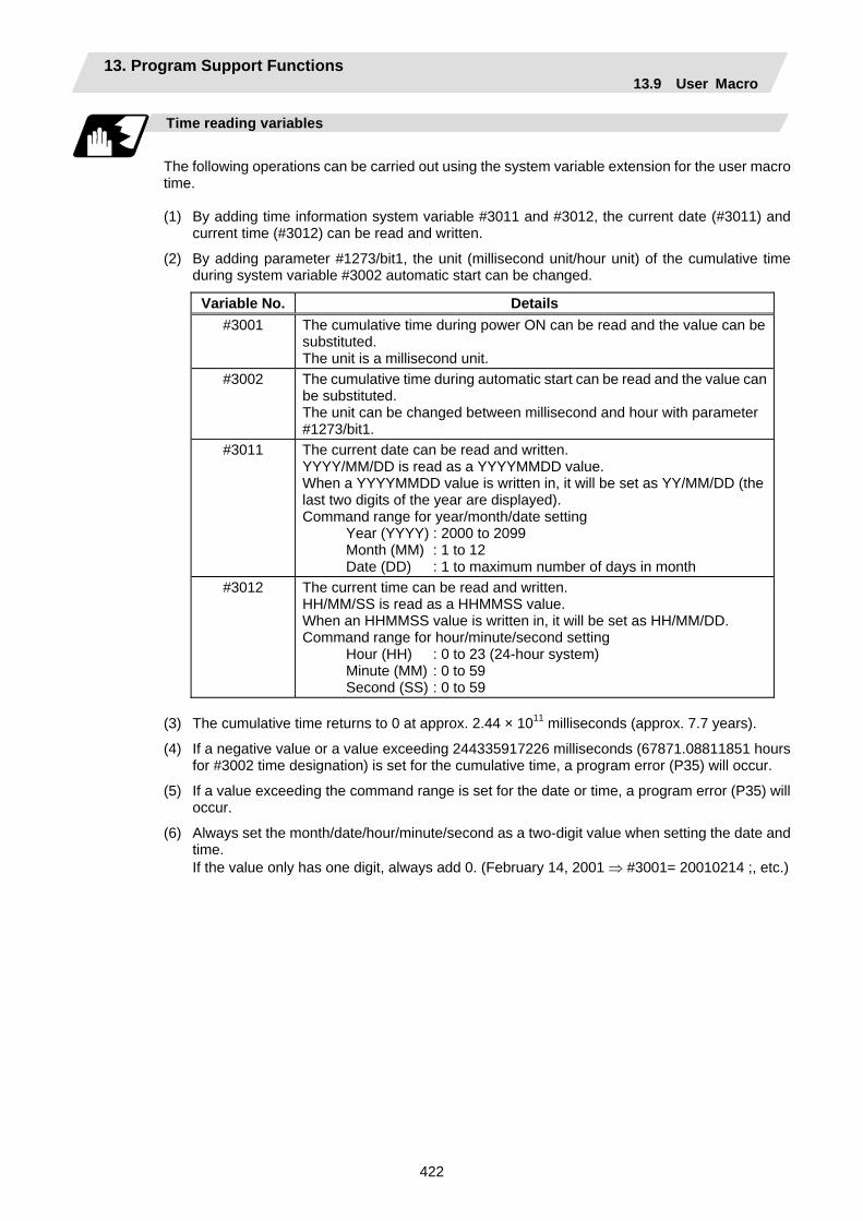
13. Program Support Functions 13.9 User Macro
422
Time reading variables
The following operations can be carried out using the system variable extension for the user macro time. (1) By adding time information system variable #3011 and #3012, the current date (#3011) and
current time (#3012) can be read and written.
(2) By adding parameter #1273/bit1, the unit (millisecond unit/hour unit) of the cumulative time during system variable #3002 automatic start can be changed.
Variable No. Details #3001 The cumulative time during power ON can be read and the value can be
substituted. The unit is a millisecond unit.
#3002 The cumulative time during automatic start can be read and the value can be substituted. The unit can be changed between millisecond and hour with parameter #1273/bit1.
#3011 The current date can be read and written. YYYY/MM/DD is read as a YYYYMMDD value. When a YYYYMMDD value is written in, it will be set as YY/MM/DD (the last two digits of the year are displayed). Command range for year/month/date setting Year (YYYY) : 2000 to 2099 Month (MM) : 1 to 12 Date (DD) : 1 to maximum number of days in month
#3012 The current time can be read and written. HH/MM/SS is read as a HHMMSS value. When an HHMMSS value is written in, it will be set as HH/MM/DD. Command range for hour/minute/second setting Hour (HH) : 0 to 23 (24-hour system) Minute (MM) : 0 to 59 Second (SS) : 0 to 59
(3) The cumulative time returns to 0 at approx. 2.44 × 10¹¹ milliseconds (approx. 7.7 years).
(4) If a negative value or a value exceeding 244335917226 milliseconds (67871.08811851 hours for #3002 time designation) is set for the cumulative time, a program error (P35) will occur.
(5) If a value exceeding the command range is set for the date or time, a program error (P35) will occur.
(6) Always set the month/date/hour/minute/second as a two-digit value when setting the date and time.
If the value only has one digit, always add 0. (February 14, 2001 ⇒ #3001= 20010214 ;, etc.)

13. Program Support Functions 13.9 User Macro
423
Examples of using time reading variable
(Example 1) To read the current date (February 14, 2001) in common variable #100 #100 = #3011 ; (20010214 is inserted in #100)
(Example 2) To write current time (18 hours, 13 minutes, 6 seconds) into system variable #3012 #3012 = 181306 ; (The command value cumulative time #2: time is set to 18:13:06.)
(Example 3) By setting the following type of program, the machining start/end time (year/month/date/hour/minute/second) can be viewed.
#100=#3011 ; ⇒ Machining start year/month/date #101=#3012 ; ⇒ Machining start hour/minute/second G28 X0 Y0 Z0 ; G92 ; G0 X50. ; . . . #102=#3011 ; ⇒ Machining end year/month/date #103=#3012 ; ⇒ Machining end hour/minute/second M30 ;
Limits and precautions for using time reading variable
(1) #3011 reads the date as an eight-digit value, so the difference of the two dates read in will not
be the difference of days.
(2) #3012 reads the time as a six-digit value, so the difference of the two times read in will not be the difference of hours.
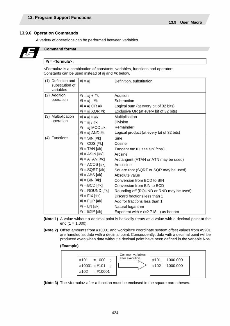
13. Program Support Functions 13.9 User Macro
424
13.9.6 Operation Commands A variety of operations can be performed between variables.
Command format
#i = <formula> ;
<Formula> is a combination of constants, variables, functions and operators. Constants can be used instead of #j and #k below.
(1) Definition and substitution of variables
#i = #j Definition, substitution
(2) Addition operation
#i = #j + #k #i = #j - #k #i = #j OR #k #i = #j XOR #k
Addition Subtraction Logical sum (at every bit of 32 bits) Exclusive OR (at every bit of 32 bits)
(3) Multiplication operation
#i = #j ∗ #k #i = #j / #k #i = #j MOD #k #i = #j AND #k
Multiplication Division Remainder Logical product (at every bit of 32 bits)
(4) Functions
#i = SIN [#k] #i = COS [#k] #i = TAN [#k] #i = ASIN [#k] #i = ATAN [#k] #i = ACOS [#k] #i = SQRT [#k] #i = ABS [#k] #i = BIN [#k] #i = BCD [#k] #i = ROUND [#k] #i = FIX [#k] #i = FUP [#k] #i = LN [#k] #i = EXP [#k]
Sine Cosine Tangent tan θ uses sinθ/cosθ. Arcsine Arctangent (ATAN or ATN may be used) Arccosine Square root (SQRT or SQR may be used) Absolute value Conversion from BCD to BIN Conversion from BIN to BCD Rounding off (ROUND or RND may be used) Discard fractions less than 1 Add for fractions less than 1 Natural logarithm Exponent with e (=2.718...) as bottom
(Note 1) A value without a decimal point is basically treats as a value with a decimal point at the end (1 = 1.000).
(Note 2) Offset amounts from #10001 and workpiece coordinate system offset values from #5201 are handled as data with a decimal point. Consequently, data with a decimal point will be produced even when data without a decimal point have been defined in the variable Nos.
(Example)
#101 = 1000 ; #10001 = #101 ; #102 = #10001
#101 1000.000 #102 1000.000
Common variables after execution
(Note 3) The <formula> after a function must be enclosed in the square parentheses.
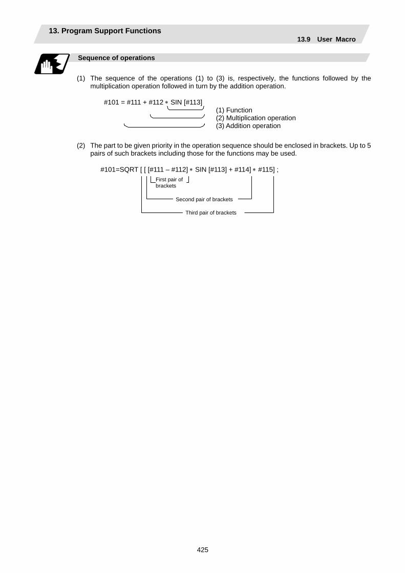
13. Program Support Functions 13.9 User Macro
425
Sequence of operations
(1) The sequence of the operations (1) to (3) is, respectively, the functions followed by the
multiplication operation followed in turn by the addition operation.
#101 = #111 + #112 ∗ SIN [#113] (1) Function (2) Multiplication operation (3) Addition operation
(2) The part to be given priority in the operation sequence should be enclosed in brackets. Up to 5 pairs of such brackets including those for the functions may be used.
#101=SQRT [ [ [#111 – #112] ∗ SIN [#113] + #114] ∗ #115] ;
First pair of brackets
Second pair of brackets
Third pair of brackets

13. Program Support Functions 13.9 User Macro
426
Examples of operation commands
(1) Main program and argument designation
G65 P100 A10 B20. ; #101=100.000 #102=200.000 ;
#1 #2 #101 #102
10.000 20.000
100.000 200.000
(2) Definition and substitution (=)
#1=1000 #2=1000. #3=#101 #4=#102 #5=#10001 (#10001=-10.)
#1 #2 #3 #4 #5
1000.000 1000.000
100.000 200.000 -10.000
···
(3) Addition and subtraction (+, -)
#11=#1+1000 #12=#2-50. #13=#101+#1 #14=#10001-3. (#10001 = -10.)#15=#10001+#102
#11 #12 #13 #14 #15
2000.000 950.000
1100.000 -13.000 190.000
(4) Multiplication and division (∗, /)
#21=100∗100 #22=100.∗100 #23=100∗100 #24=100.∗100. #25=100/100 #26=100./100 #27=100/100. #28=100./100. #29=#10001∗#101
( #10001 = -10.) #30=#10001/#102
#21 #22 #23 #24 #25 #26 #27 #28 #29 #30
10000.000 10000.000 10000.000 10000.000
1.000 1.000 1.000 1.000
-1000.000
-0.050
(5) Remainder (MOD)
#19=48 #20=9 #31=#19 MOD #20
#19/#20 = 48/9 = 5 with 3 over #31 = 3 #3 = 01100100 (binary) 14 = 00001110 (binary)
(6) Logical sum (OR)
#3=100 #4=#3 OR 14
#4 = 01101110 = 110 #3 = 01100100 (binary) 14 = 00001110 (binary)
(7) Exclusive OR (XOR)
#3=100 #4=#3 XOR 14
#4 = 01101010 = 106 (8) Logical
product (AND) #9=100 #10=#9 AND 15
#9 = 01100100 (binary) 15 = 00001111 (binary)
#10 = 00000100 = 4
From common variables
From offset amount
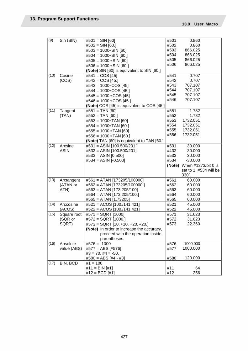
13. Program Support Functions 13.9 User Macro
427
(9) Sin (SIN) #501 = SIN [60]
#502 = SIN [60.] #503 = 1000∗SIN [60] #504 = 1000∗SIN [60.] #505 = 1000.∗SIN [60] #506 = 1000.∗SIN [60.] (Note) SIN [60] is equivalent to SIN [60.]
#501 #502 #503 #504 #505 #506
0.860 0.860
866.025 866.025 866.025 866.025
(10) Cosine (COS)
#541 = COS [45] #542 = COS [45.] #543 = 1000∗COS [45] #544 = 1000∗COS [45.] #545 = 1000.∗COS [45] #546 = 1000.∗COS [45.] (Note) COS [45] is equivalent to COS [45.]
#541 #542 #543 #544 #545 #546
0.707 0.707
707.107 707.107 707.107 707.107
(11) Tangent (TAN)
#551 = TAN [60] #552 = TAN [60.] #553 = 1000∗TAN [60] #554 = 1000∗TAN [60.] #555 = 1000.∗TAN [60] #556 = 1000.∗TAN [60.] (Note) TAN [60] is equivalent to TAN [60.]
#551 #552 #553 #554 #555 #556
1.732 1.732
1732.051 1732.051 1732.051 1732.051
#531 #432 #533 #534
30.000 30.000 30.000
-30.000
(12) Arcsine ASIN
#531 = ASIN [100.500/201.] #532 = ASIN [100.500/201] #533 = ASIN [0.500] #534 = ASIN [-0.500]
(Note) When #1273/bit 0 is set to 1, #534 will be 330º.
(13) Arctangent (ATAN or ATN)
#561 = ATAN [173205/100000] #562 = ATAN [173205/100000.] #563 = ATAN [173.205/100] #564 = ATAN [173.205/100.] #565 = ATAN [1.73205]
#561 #562 #563 #564 #565
60.000 60.000 60.000 60.000 60.000
(14) Arccosine (ACOS)
#521 = ACOS [100./141.421] #522 = ACOS [100./141.421]
#521 #522
45.000 45.000
(15) Square root (SQR or SQRT)
#571 = SQRT [1000] #572 = SQRT [1000.] #573 = SQRT [10. ∗10. +20. ∗20.] (Note) In order to increase the accuracy,
proceed with the operation inside parentheses.
#571 #572 #573
31.623 31.623 22.360
(16) Absolute value (ABS)
#576 = -1000 #577 = ABS [#576] #3 = 70. #4 = -50. #580 = ABS [#4 - #3]
#576 #577 #580
-1000.000 1000.000
120.000
(17) BIN, BCD #1 = 100 #11 = BIN [#1] #12 = BCD [#1]
#11 #12
64
256
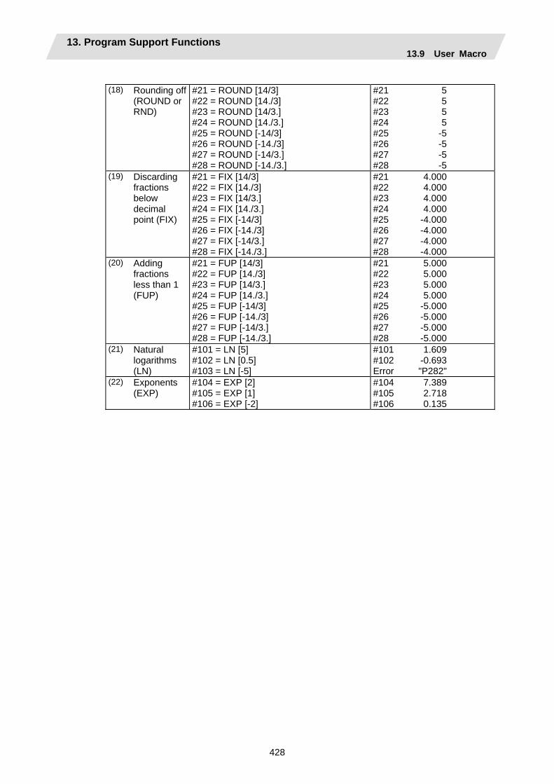
13. Program Support Functions 13.9 User Macro
428
(18) Rounding off
(ROUND or RND)
#21 = ROUND [14/3] #22 = ROUND [14./3] #23 = ROUND [14/3.] #24 = ROUND [14./3.] #25 = ROUND [-14/3] #26 = ROUND [-14./3] #27 = ROUND [-14/3.] #28 = ROUND [-14./3.]
#21 #22 #23 #24 #25 #26 #27 #28
5 5 5 5
-5 -5 -5 -5
(19) Discarding fractions below decimal point (FIX)
#21 = FIX [14/3] #22 = FIX [14./3] #23 = FIX [14/3.] #24 = FIX [14./3.] #25 = FIX [-14/3] #26 = FIX [-14./3] #27 = FIX [-14/3.] #28 = FIX [-14./3.]
#21 #22 #23 #24 #25 #26 #27 #28
4.000 4.000 4.000 4.000
-4.000 -4.000 -4.000 -4.000
(20) Adding fractions less than 1 (FUP)
#21 = FUP [14/3] #22 = FUP [14./3] #23 = FUP [14/3.] #24 = FUP [14./3.] #25 = FUP [-14/3] #26 = FUP [-14./3] #27 = FUP [-14/3.] #28 = FUP [-14./3.]
#21 #22 #23 #24 #25 #26 #27 #28
5.000 5.000 5.000 5.000
-5.000 -5.000 -5.000 -5.000
(21) Natural logarithms (LN)
#101 = LN [5] #102 = LN [0.5] #103 = LN [-5]
#101 #102 Error
1.609 -0.693 "P282"
(22) Exponents (EXP)
#104 = EXP [2] #105 = EXP [1] #106 = EXP [-2]
#104 #105 #106
7.389 2.718 0.135
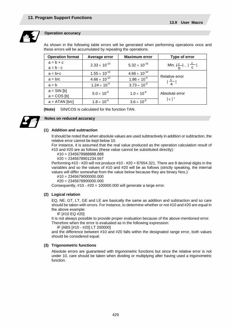
13. Program Support Functions 13.9 User Macro
429
Operation accuracy
As shown in the following table errors will be generated when performing operations once and these errors will be accumulated by repeating the operations.
Operation format Average error Maximum error Type of error a = b + c a = b - c 2.33 × 10⁻¹⁰ 5.32 × 10⁻¹⁰ Min. | | , | |
a = b∗c 1.55 × 10⁻¹⁰ 4.66 × 10⁻¹⁰ a = b/c 4.66 × 10⁻¹⁰ 1.86 × 10⁻⁹ a = b 1.24 × 10⁻⁹ 3.73 × 10⁻⁹
Relative error | |
a = SIN [b] a = COS [b] 5.0 × 10⁻⁹ 1.0 × 10⁻⁸
a = ATAN [b/c] 1.8 × 10⁻⁶ 3.6 × 10⁻⁶
Absolute error | ε | °
(Note) SIN/COS is calculated for the function TAN.
Notes on reduced accuracy
(1) Addition and subtraction
It should be noted that when absolute values are used subtractively in addition or subtraction, the relative error cannot be kept below 10. For instance, it is assumed that the real value produced as the operation calculation result of #10 and #20 are as follows (these value cannot be substituted directly):
#10 = 2345678988888.888 #20 = 2345678901234.567
Performing #10 - #20 will not produce #10 - #20 = 87654.321. There are 8 decimal digits in the variables and so the values of #10 and #20 will be as follows (strictly speaking, the internal values will differ somewhat from the value below because they are binary Nos.):
#10 = 2345679000000.000 #20 = 2345678900000.000
Consequently, #10 - #20 = 100000.000 will generate a large error.
(2) Logical relation EQ, NE, GT, LT, GE and LE are basically the same as addition and subtraction and so care should be taken with errors. For instance, to determine whether or not #10 and #20 are equal in the above example:
IF [#10 EQ #20] It is not always possible to provide proper evaluation because of the above-mentioned error. Therefore when the error is evaluated as in the following expression:
IF [ABS [#10 - #20] LT 200000] and the difference between #10 and #20 falls within the designated range error, both values should be considered equal.
(3) Trigonometric functions
Absolute errors are guaranteed with trigonometric functions but since the relative error is not under 10, care should be taken when dividing or multiplying after having used a trigonometric function.
ε b
ε c
ε a

13. Program Support Functions 13.9 User Macro
430
13.9.7 Control Commands
The flow of programs can be controlled by IF [conditional expression] GOTO n ; and WHILE [conditional expression] DOm ;
Branching
Format
IF [conditional expression] GOTO n ; (where n = sequence No. in the program)
When the condition is satisfied, control branches to "n" and when it is not satisfied, the next block is executed. IF [conditional expression] can be omitted and, when it is, control passes to "n" unconditionally. The following types of [conditional expressions] are available.
#i EQ #j = When #i and #j are equal #i NE #j ≠ When #i and #j are not equal #i GT #j > When #i is greater than #j #i LT #j < When #i is less than #j #i GE #j ≥ When #i is #j or more #i LE #j ≤ When #i is #j or less
"n" of "GOTO n" must always be in the same program. Program error (P231) will result if it is not. A formula or variable can be used instead of #i, #j and "n". In the block with sequence No. "n" which will be executed after a "GOTO n" command, the sequence No. Nn must always be at the head of the block. Otherwise, program error (P231) will result. If "/" is at the head of the block and Nn follows, control can be branched to the sequence No.
N10 #22=#20 #23=#21 ; IF [#2 EQ1] GOTO100 ; #22=#20–#3 ; #23=#21–#4 ; N100 X#22 Z#23 ; #1=#1+#1 ;
~ ~
~
Branching to N100 when content of #2 is 1
Bra
nch
sear
ch
N100
Branch search
With N10
To head
(Note 1) When the sequence No. of the branch destination is searched, the search is conducted up to the end of the program (% code) from the block following "IF….. ;" and if it is not found, it is conducted up to the block before "IF ..... ;". Therefore, branch searches in the opposite direction to the program flow will take longer to execute compared with branch searches in the forward direction.
(Note 2) Only compare EQ and NE by integers. Use GE, GT, LE and LT for comparison when there are numbers below the decimal point.

13. Program Support Functions 13.9 User Macro
431
Repetition
Format
WHILE [conditional expression] DOm ; (m =1, 2, 3 ..... 127) END m ;
While the conditional expression is established, the blocks from the following block to ENDm are repeatedly executed; when it is not established, execution moves to the block after ENDm. DOm may come before WHILE. "WHILE [conditional expression] DOm" and "ENDm" must be used as a pair. If "WHILE [conditional expression]" is omitted, these blocks will be repeatedly ad infinitum. The repeating identification Nos. range from 1 to 127 (DO1, DO2, DO3, ..... DO127). Up to 27 nesting levels can be used.
(1) Same identification No. can be used any number of times.
(2) Any number may be used for the WHILE~DOm identification No.
WHILE ~ DO1 ;
END1 ;
WHILE ~ DO1 ; END1 ;
Possible
Possible
WHILE ~ DO1 ;
END1 ;
~
WHILE ~ DO3 ; END3 ;
~~
WHILE ~ DO2 ; END2 ;
~~
WHILE ~ DO1 ; END1 ;
~~
Possible
(3) Up to 27 nesting levels for WHILE~DOm. "m" is any number form 1 to 127 for the nesting depth.
(4) The number of WHILE~DOm nesting levels cannot exceed 27.
Possible
DO2
DO1
DO27
END1 ;
WHILE ~ DO1 ;
WHILE ~ DO2 ;
WHILE~DO27 ;
END2 ;
END27 ;
: :
: :
(Note) With nesting, "m" which has been used once cannot be used.
WHILE ~ DO1 ;
WHILE ~ DO2 ;
WHILE ~ DO3 ;
WHILE ~ DO28 ;
END3 ;
END28 ;
~~
~~
END2 ; :
END1 ;
~
:
Not possible
~
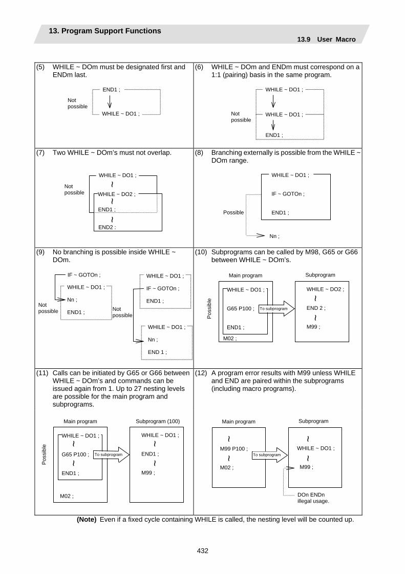
13. Program Support Functions 13.9 User Macro
432
(5) WHILE ~ DOm must be designated first and
ENDm last. (6) WHILE ~ DOm and ENDm must correspond on a
1:1 (pairing) basis in the same program.
END1 ;
WHILE ~ DO1 ;
Not possible
Not possible
WHILE ~ DO1 ;
END1 ;
WHILE ~ DO1 ;
(7) Two WHILE ~ DOm’s must not overlap. (8) Branching externally is possible from the WHILE ~ DOm range.
END2 ;
END1 ;
WHILE ~ DO2 ;
WHILE ~ DO1 ;
Not possible
~ ~
~
Nn ;
WHILE ~ DO1 ; IF ~ GOTOn ; END1 ; Possible
(9) No branching is possible inside WHILE ~ DOm.
(10) Subprograms can be called by M98, G65 or G66 between WHILE ~ DOm’s.
Not possible Not
possible
WHILE ~ DO1 ; Nn ; END1 ;
IF ~ GOTOn ;
WHILE ~ DO1 ; Nn ; END 1 ;
WHILE ~ DO1 ; IF ~ GOTOn ; END1 ;
WHILE ~ DO2 ; END 2 ; M99 ;
WHILE ~ DO1 ; G65 P100 ; END1 ;
SubprogramMain program
Pos
sibl
e
To subprogram
~ ~
M02 ;
(11) Calls can be initiated by G65 or G66 between WHILE ~ DOm’s and commands can be issued again from 1. Up to 27 nesting levels are possible for the main program and subprograms.
(12) A program error results with M99 unless WHILE and END are paired within the subprograms (including macro programs).
WHILE ~ DO1 ; END1 ; M99 ;
WHILE ~ DO1 ; G65 P100 ; END1 ;
Subprogram (100) Main program
Pos
sibl
e
To subprogram
M02 ;
~ ~
~ ~
WHILE ~ DO1 ; M99 ;
M99 P100 ; M02 ;
Subprogram Main program
To subprogram
DOn ENDn illegal usage.
~ ~
~ ~
(Note) Even if a fixed cycle containing WHILE is called, the nesting level will be counted up.
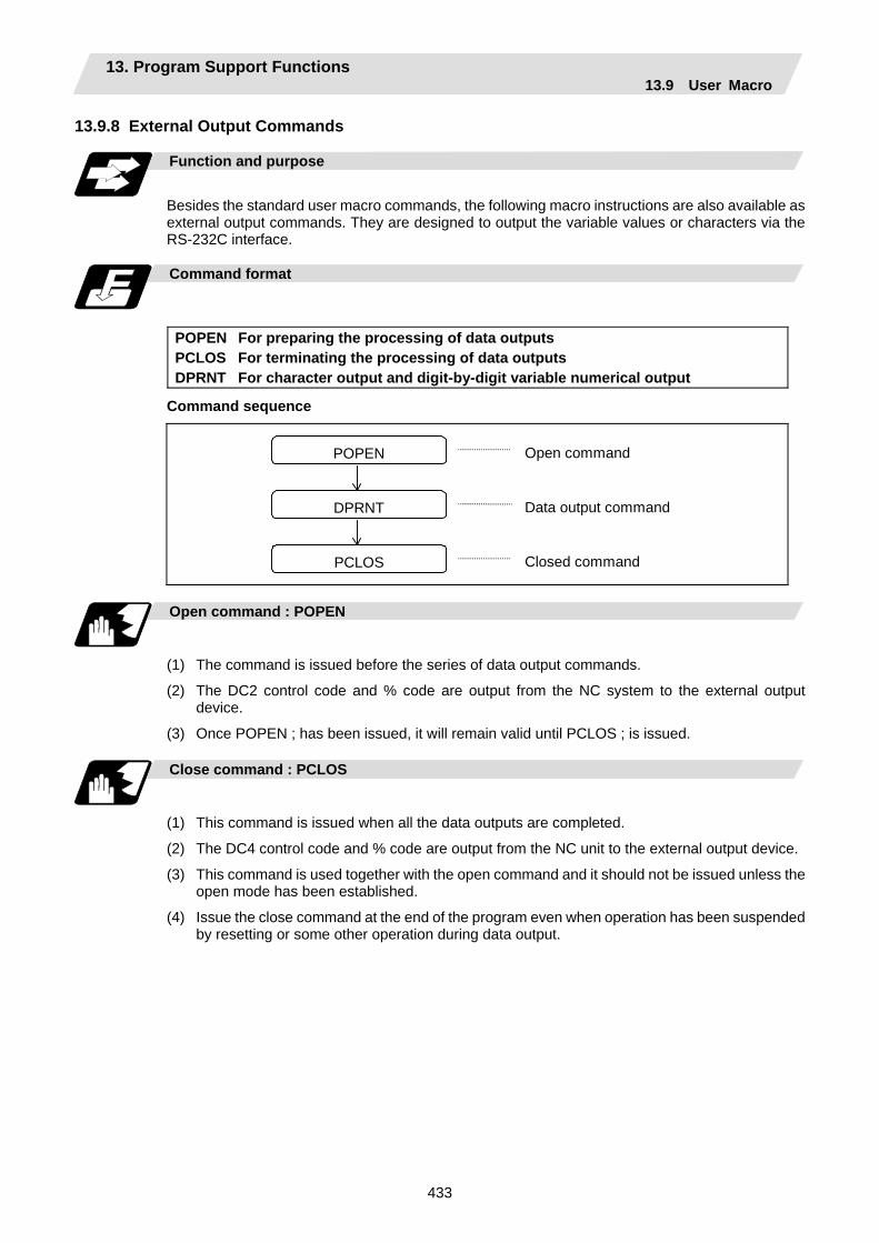
13. Program Support Functions 13.9 User Macro
433
13.9.8 External Output Commands
Function and purpose
Besides the standard user macro commands, the following macro instructions are also available as external output commands. They are designed to output the variable values or characters via the RS-232C interface.
Command format
POPEN For preparing the processing of data outputs PCLOS For terminating the processing of data outputs DPRNT For character output and digit-by-digit variable numerical output
Command sequence
POPEN
DPRNT
PCLOS
Open command
Data output command
Closed command
Open command : POPEN
(1) The command is issued before the series of data output commands.
(2) The DC2 control code and % code are output from the NC system to the external output device.
(3) Once POPEN ; has been issued, it will remain valid until PCLOS ; is issued. Close command : PCLOS
(1) This command is issued when all the data outputs are completed.
(2) The DC4 control code and % code are output from the NC unit to the external output device.
(3) This command is used together with the open command and it should not be issued unless the open mode has been established.
(4) Issue the close command at the end of the program even when operation has been suspended by resetting or some other operation during data output.
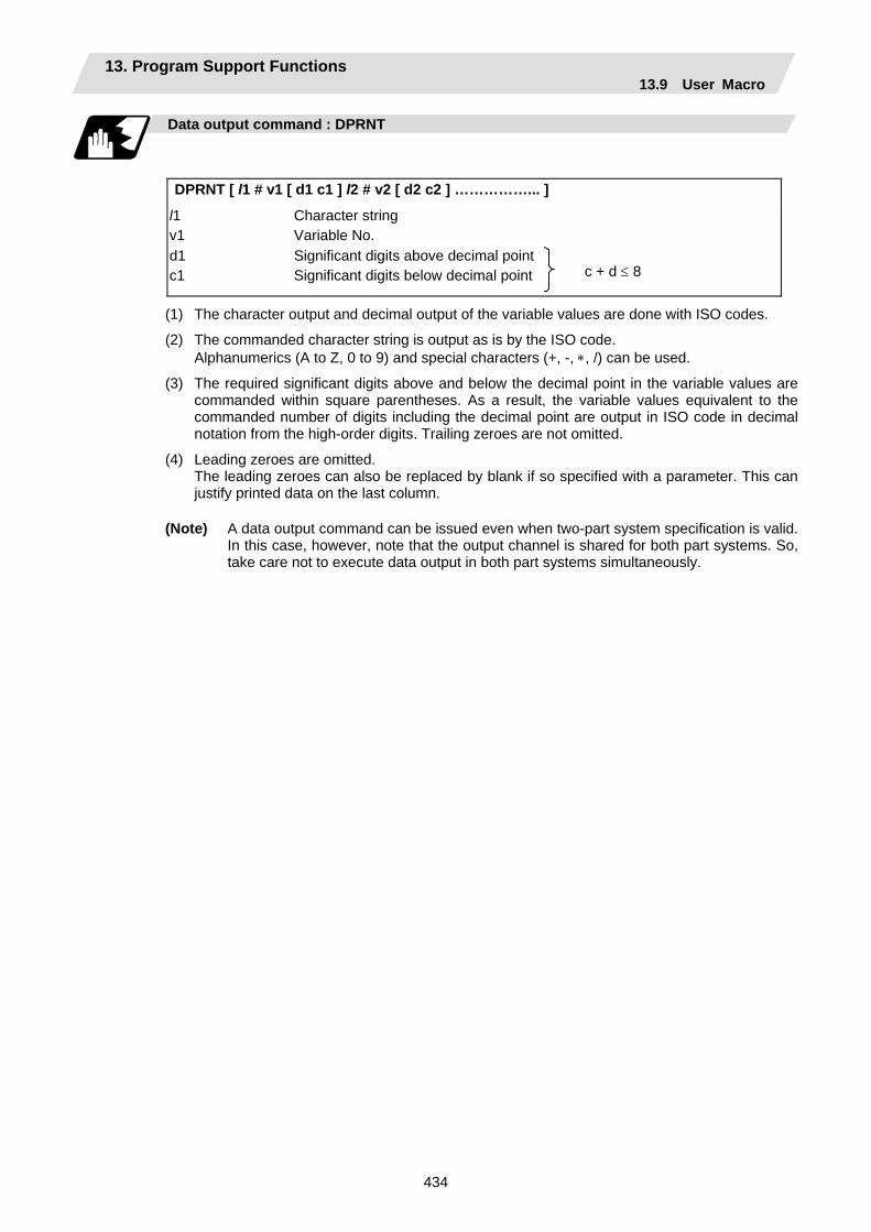
13. Program Support Functions 13.9 User Macro
434
Data output command : DPRNT
DPRNT [ l1 # v1 [ d1 c1 ] l2 # v2 [ d2 c2 ] ……………... ]
l1 v1
Character string Variable No.
d1 c1
Significant digits above decimal pointSignificant digits below decimal point
c + d ≤ 8
(1) The character output and decimal output of the variable values are done with ISO codes.
(2) The commanded character string is output as is by the ISO code. Alphanumerics (A to Z, 0 to 9) and special characters (+, -, ∗, /) can be used.
(3) The required significant digits above and below the decimal point in the variable values are commanded within square parentheses. As a result, the variable values equivalent to the commanded number of digits including the decimal point are output in ISO code in decimal notation from the high-order digits. Trailing zeroes are not omitted.
(4) Leading zeroes are omitted. The leading zeroes can also be replaced by blank if so specified with a parameter. This can
justify printed data on the last column.
(Note) A data output command can be issued even when two-part system specification is valid. In this case, however, note that the output channel is shared for both part systems. So, take care not to execute data output in both part systems simultaneously.

13. Program Support Functions 13.9 User Macro
435
13.9.9 Precautions
Precautions
(1) When the user macro commands are employed, it is possible to use the M, S, T and other
control commands together with the operation, decision, branching and other macro commands for creating the machining programs. When the former commands are made into executable statements and the latter commands into macro statements, the macro statement processing should be accomplished as quickly as possible in order to minimize the machining time, because such processing is not directly related to machine control. As a result, the parameter (#8101 MACRO SINGLE on the parameter screen) can be decided upon and the macro statements can be processed in parallel with the execution of the executable statement. (The parameter can be set OFF during normal machining to process all the macro statements together or set ON during a program check to execute the macro statements block by block. This enables the setting to be made in accordance with the intended objective in mind.)
Example of program
G91G28X0 Z0 ; ⋅ ⋅ ⋅ ⋅ ⋅ ⋅(1)
G92X0 Z0 ; ⋅ ⋅ ⋅ ⋅ ⋅ ⋅(2)
G00X–100. Z–100. ; ⋅ ⋅ ⋅ ⋅ ⋅ ⋅(3)
#101=100.∗COS [210,] ; ⋅ ⋅ ⋅ ⋅ ⋅ ⋅(4)
#103=100.∗SIN [210.] ; ⋅ ⋅ ⋅ ⋅ ⋅ ⋅(5)
G01 X#101 Z #103 F800 ; ⋅ ⋅ ⋅ ⋅ ⋅ ⋅(6)
Macro statement
Macro statements are:
(a) Operation commands (blocks including "=")
(b) Control commands (blocks including GOTO, DO to END, etc.)
(c) Macro call commands (including macro calls based on G codes and cancel command (G65. G66. G66.1, G67))
Execution statements refer to statements other than macro statements.
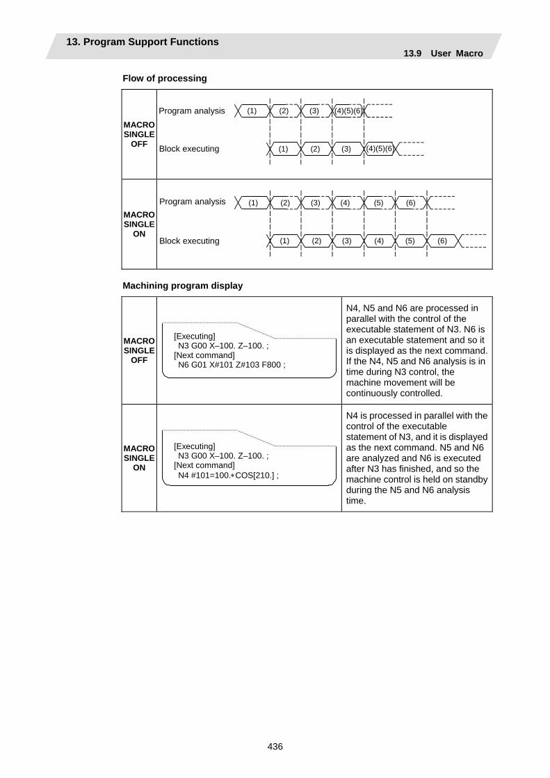
13. Program Support Functions 13.9 User Macro
436
Flow of processing
MACRO SINGLE
OFF
Program analysis
Block executing
(1) (2) (4)(5)(6)(3)
(1) (2) (4)(5)(6) (3)
MACRO SINGLE
ON
Program analysis
Block executing
(1) (2) (3)
(1) (2) (3)
(4) (5) (6)
(4) (5) (6)
Machining program display
MACRO SINGLE
OFF
[Executing] N3 G00 X–100. Z–100. ; [Next command] N6 G01 X#101 Z#103 F800 ;
N4, N5 and N6 are processed in parallel with the control of the executable statement of N3. N6 is an executable statement and so it is displayed as the next command. If the N4, N5 and N6 analysis is in time during N3 control, the machine movement will be continuously controlled.
MACRO SINGLE
ON
[Executing] N3 G00 X–100. Z–100. ; [Next command] N4 #101=100.∗COS[210.] ;
N4 is processed in parallel with the control of the executable statement of N3, and it is displayed as the next command. N5 and N6 are analyzed and N6 is executed after N3 has finished, and so the machine control is held on standby during the N5 and N6 analysis time.

13. Program Support Functions 13.10 Mirror Image for Facing Tool Posts
437
13.10 Mirror Image for Facing Tool Posts
Function and purpose
In a machine in which the base turret and facing turret are integrated, this function is used to cut with the facing turret cutter using a program created with the base turret side. The distance between the two turrets is set in the parameters beforehand.
Command format
G68 Mirror image for facing tool posts ON G69 Mirror image for facing tool posts cancel
[T command mirror image for facing tool posts]
The mirror image for facing tool posts can be turned ON and OFF with the T command instead of the G68/G69 command. The T command for the G68 mode and the G69 mode is determined for each tool No. with the following base specification parameters.
# Item Details Setting range (unit)
1119 Tmiron Select the mirror image of each facing turret with T command
Selects whether the mirror image for facing tool posts with the T command is valid or invalid.
0: Invalid 1: Valid
1203 TmirS1 Select turret as facing turret with T command
The turret selection for the T command mirror image for facing tool posts corresponding to tool No. 1 to 32 is set.
0 to FFFFFFFF
1204 TmirS2 Select turret as facing turret with T command
The turret selection for the T command mirror image for facing tool posts corresponding to tool No. 33 to 64 is set.
0 to FFFFFFFF
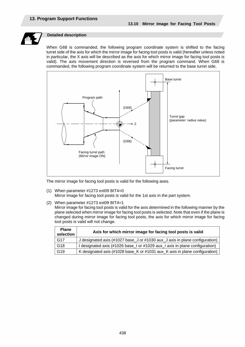
13. Program Support Functions 13.10 Mirror Image for Facing Tool Posts
438
Detailed description
When G68 is commanded, the following program coordinate system is shifted to the facing turret side of the axis for which the mirror image for facing tool posts is valid (hereafter unless noted in particular, the X axis will be described as the axis for which mirror image for facing tool posts is valid). The axis movement direction is reversed from the program command. When G69 is commanded, the following program coordinate system will be returned to the base turret side.
Program path
Facing turret path (Mirror image ON)
(G69)
Z
(G68)
Base turret
Facing turret
Turret gap (parameter: radius value)
The mirror image for facing tool posts is valid for the following axes. (1) When parameter #1273 ext09 BIT4=0 Mirror image for facing tool posts is valid for the 1st axis in the part system.
(2) When parameter #1273 ext09 BIT4=1 Mirror image for facing tool posts is valid for the axis determined in the following manner by the
plane selected when mirror image for facing tool posts is selected. Note that even if the plane is changed during mirror image for facing tool posts, the axis for which mirror image for facing tool posts is valid will not change.
Plane selection Axis for which mirror image for facing tool posts is valid
G17 J designated axis (#1027 base_J or #1030 aux_J axis in plane configuration)G18 I designated axis (#1026 base_I or #1029 aux_I axis in plane configuration)G19 K designated axis (#1028 base_K or #1031 aux_K axis in plane configuration)

13. Program Support Functions 13.10 Mirror Image for Facing Tool Posts
439
Absolute value command/incremental value command
(1) Absolute value command
The command position for the Z axis is reversed symmetrically, and the base turret moves to the position shifted by the distance between cutters.
Program Base turret path
Base turret
Distance between cutters
Facing turret
Facing turret path
Path for reversing program
* This figure does not incorporate the tool length
T0101 ; G00 X0. ; G68 ; T0202 ; G00 X10. Z0. ; G01 Z-50. F400 ;
X20. ;
Mirror image for facing tool posts ON Facing turret selection
(2) Incremental value command
The commanded X axis direction reverses, and the base turret moves.
Program Base turret
Facing turret
Facing turret path
Base turret path (Path for reversing program)
* This figure does not incorporate the tool length
T0101 ; G00 X0. ; G68 ; T0202 ; G00 U10. W-30. ; G01 W-50. F400 ;
U10. ;
Mirror image for facing tool posts ON Facing turret selection
(3) Changing from an incremental value command to an absolute value command
After changing to the absolute value, the same operation as “(1) Absolute value command” takes place.
ProgramBase
turret path
Base turret
Distance between cutters
Facing turret Facing turret path
Path for reversing program
* This figure does not incorporate the tool length
T0101 ; G00 X0. ; G68 ; T0202 ; G00 U10. W-30. ; G01 W-50. F400 ;
X20. Z-80. ;
Mirror image for facing tool posts ON Facing turret selection

13. Program Support Functions 13.10 Mirror Image for Facing Tool Posts
440
Displaying the workpiece coordinate values
The workpiece coordinate values of the axis for which mirror image for facing tool posts is valid are displayed in the following manner.
#1273 ext09/bit3 = 0 #1273 ext09/bit3 = 1 In mirror image for facing tool posts mode
The workpiece coordinate values are at the position where the program command value sign has been reversed, and increases/decreases in the same manner as the actual movement, that is, movement on the machine coordinate system. (Indicates coordinate values for facing turret side.)
The workpiece coordinate values are the same as the program command value, and increases/decreases opposite the actual movement, that is, movement on the machine coordinate system.
At startup Workpiece coordinate value = Workpiece coordinate value before mirror image for facing tool posts starts - distance between cutters
Workpiece coordinate value = Workpiece coordinate value before mirror image for facing tool posts starts - distance between cutters × (-1)
When movement is commanded while valid
Workpiece coordinate value = Workpiece coordinate value before movement + movement amount
Workpiece coordinate value = Workpiece coordinate value before movement - movement amount
When canceled Workpiece coordinate value = Workpiece coordinate value before mirror image for facing tool posts is canceled + distance between cutters
Workpiece coordinate value = Workpiece coordinate value before mirror image for facing tool posts is canceled × (-1) + distance between cutters

13. Program Support Functions 13.10 Mirror Image for Facing Tool Posts
441
Example of program and operation
T0101 ; G00 X10. Z0. ; G01 Z-40. F400 ;
X20. ;
Base turret selection
Machining with base turret .......A
G68 ; T0202 ; G00 X20. Z-40. ; G01 Z-80. F200 ;
X30. ;
Mirror image for facing tool posts ON Facing turret selection
Machining with facing turret......B
G69 ; T0101 ; G00 X30. Z-80. ; G01 Z-120. F400 ;
Mirror image for facing tool posts cancel Base turret selection
Machining with base turret .......C
Base turret
Facing turret
Z
A
X
B
C

13. Program Support Functions 13.10 Mirror Image for Facing Tool Posts
442
Tool compensation of double-turret
X tool length
Workpiece coordinate zero point
Workpiece offset
Z
X
Z tool length
X tool length
Tool length basic point Facing turret
Z tool length
Wear amount
2 6 1
7 0 5
3 8 4
Turret distance (parameter: radius value, X axis only)
Z tool length
2 6 1
7 0 5
3 8 4
X to
ol le
ngth
X
tool
leng
th
Wear amount
Z tool length Base turret
Tool length basic point
The original tool direction for the facing turret is shown in the drawing. To set the facing turret tool to the same direction as the base turret tool, set the base specification parameter "#1118 mirr_A" to "1".
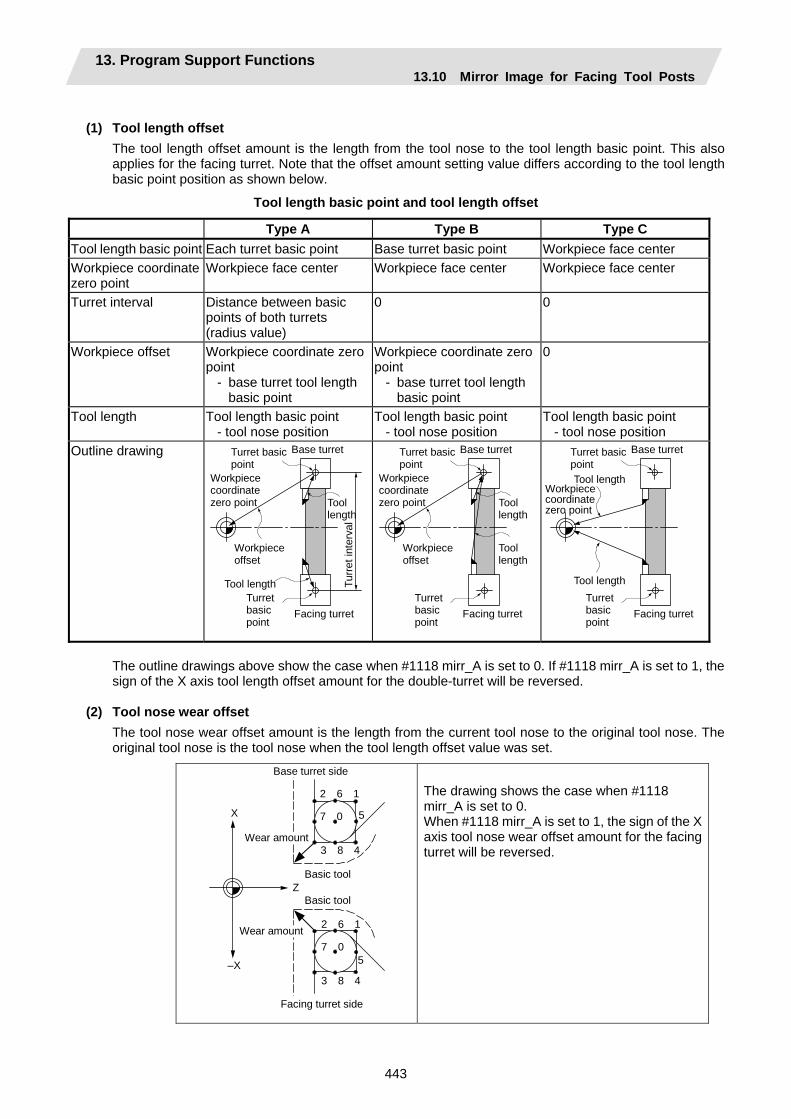
13. Program Support Functions 13.10 Mirror Image for Facing Tool Posts
443
(1) Tool length offset
The tool length offset amount is the length from the tool nose to the tool length basic point. This also applies for the facing turret. Note that the offset amount setting value differs according to the tool length basic point position as shown below.
Tool length basic point and tool length offset
Type A Type B Type C Tool length basic point Each turret basic point Base turret basic point Workpiece face center Workpiece coordinate zero point
Workpiece face center Workpiece face center Workpiece face center
Turret interval Distance between basic points of both turrets (radius value)
0 0
Workpiece offset Workpiece coordinate zero point
- base turret tool length basic point
Workpiece coordinate zero point
- base turret tool length basic point
0
Tool length Tool length basic point - tool nose position
Tool length basic point - tool nose position
Tool length basic point - tool nose position
Outline drawing Base turret
Facing turret
Turret basic point
Workpiece coordinate zero point
Workpiece offset
Turret basic point
Tool length Turre
t int
erva
l
Tool length
Base turret
Facing turret
Turret basic point
Workpiece coordinate zero point
Workpiece offset
Turret basic point
Tool length
Tool length
Base turret
Facing turret
Turret basic point
Workpiece coordinate zero point
Turret basic point
Tool length
Tool length
The outline drawings above show the case when #1118 mirr_A is set to 0. If #1118 mirr_A is set to 1, the sign of the X axis tool length offset amount for the double-turret will be reversed.
(2) Tool nose wear offset
The tool nose wear offset amount is the length from the current tool nose to the original tool nose. The original tool nose is the tool nose when the tool length offset value was set.
Base turret side
Facing turret side
X
Z
–X
Wear amount
Wear amount
Basic tool
Basic tool
2 6 1
7 0 5
3 8 4
2 6 1
7 0 5
3 8 4
The drawing shows the case when #1118 mirr_A is set to 0. When #1118 mirr_A is set to 1, the sign of the X axis tool nose wear offset amount for the facing turret will be reversed.
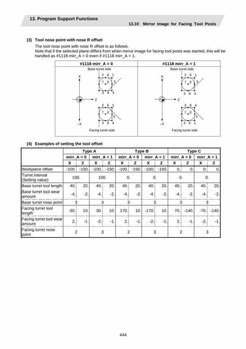
13. Program Support Functions 13.10 Mirror Image for Facing Tool Posts
444
(3) Tool nose point with nose R offset
The tool nose point with nose R offset is as follows. Note that if the selected plane differs from when mirror image for facing tool posts was started, this will be handled as #1118 mirr_A = 0 even if #1118 mirr_A = 1.
#1118 mirr_A = 0 #1118 mirr_A = 1
Base turret side
Facing turret side
X
Z
–X
2 6 1
7 0 5
3 8 4
2 6 1
7 0 5
3 8 4
Base turret side
Facing turret side
X
Z
–X
2 6 1
7 0 5
3 8 4
3 8 4
7 0 5
2 6 1
(4) Examples of setting the tool offset
Type A Type B Type C mirr_A = 0 mirr_A = 1 mirr_A = 0 mirr_A = 1 mirr_A = 0 mirr_A = 1 X Z X Z X Z X Z X Z X Z Workpiece offset -100. -150. -100. -150. -100. -150. -100. -150. 0. 0. 0. 0.Turret interval (Setting value) 100. 100. 0. 0. 0. 0.
Base turret tool length 40. 20. 40. 20. 40. 20. 40. 20. 40. 20. 40. 20.Base turret tool wear amount -4. -2. -4. -2. -4. -2. -4. -2. -4. -2. -4. -2.
Base turret nose point 3 3 3 3 3 3 Facing turret tool length -30. 10. 30. 10. 170. 10. -170. 10. 70. -140. -70. -140.
Facing turret tool wear amount 2. -1. -2. -1. 2. -1. -2. -1. 2. -1. -2. -1.
Facing turret nose point 2 3 2 3 2 3
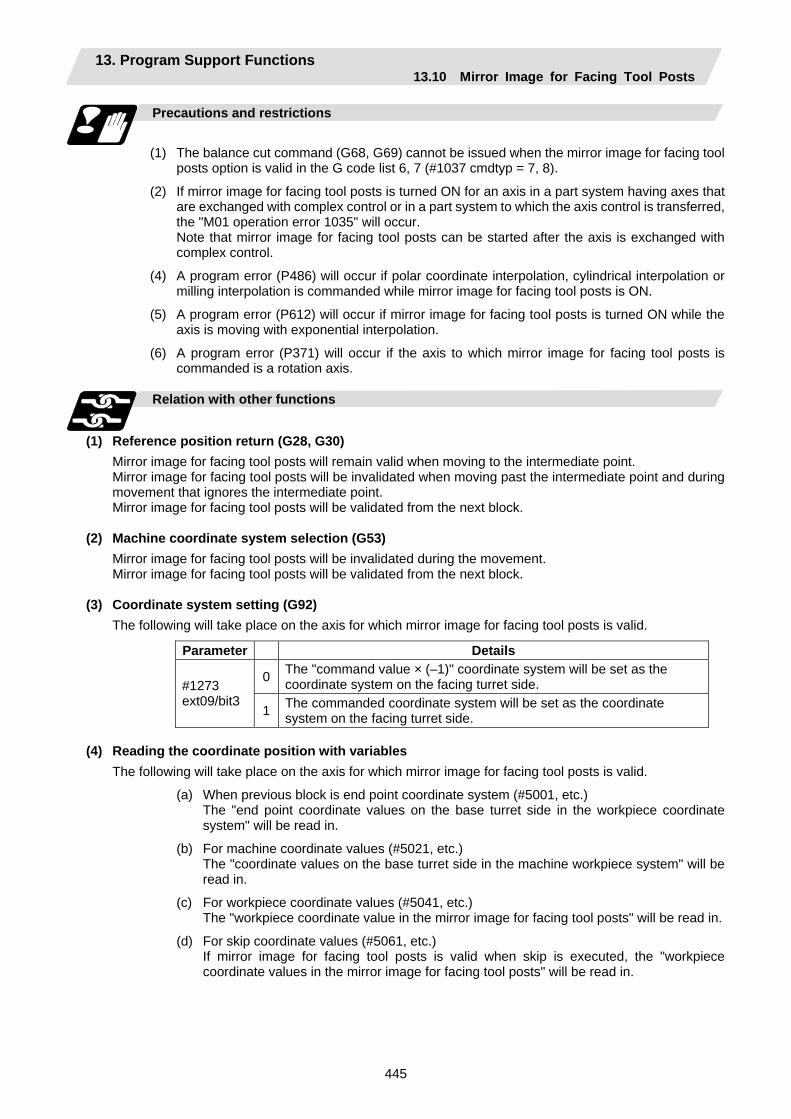
13. Program Support Functions 13.10 Mirror Image for Facing Tool Posts
445
Precautions and restrictions
(1) The balance cut command (G68, G69) cannot be issued when the mirror image for facing tool
posts option is valid in the G code list 6, 7 (#1037 cmdtyp = 7, 8).
(2) If mirror image for facing tool posts is turned ON for an axis in a part system having axes that are exchanged with complex control or in a part system to which the axis control is transferred, the "M01 operation error 1035" will occur.
Note that mirror image for facing tool posts can be started after the axis is exchanged with complex control.
(4) A program error (P486) will occur if polar coordinate interpolation, cylindrical interpolation or milling interpolation is commanded while mirror image for facing tool posts is ON.
(5) A program error (P612) will occur if mirror image for facing tool posts is turned ON while the axis is moving with exponential interpolation.
(6) A program error (P371) will occur if the axis to which mirror image for facing tool posts is commanded is a rotation axis.
Relation with other functions
(1) Reference position return (G28, G30)
Mirror image for facing tool posts will remain valid when moving to the intermediate point. Mirror image for facing tool posts will be invalidated when moving past the intermediate point and during movement that ignores the intermediate point. Mirror image for facing tool posts will be validated from the next block.
(2) Machine coordinate system selection (G53) Mirror image for facing tool posts will be invalidated during the movement. Mirror image for facing tool posts will be validated from the next block.
(3) Coordinate system setting (G92) The following will take place on the axis for which mirror image for facing tool posts is valid.
Parameter Details
0 The "command value × (–1)" coordinate system will be set as the coordinate system on the facing turret side. #1273
ext09/bit3 1 The commanded coordinate system will be set as the coordinate
system on the facing turret side.
(4) Reading the coordinate position with variables The following will take place on the axis for which mirror image for facing tool posts is valid.
(a) When previous block is end point coordinate system (#5001, etc.) The "end point coordinate values on the base turret side in the workpiece coordinate
system" will be read in.
(b) For machine coordinate values (#5021, etc.) The "coordinate values on the base turret side in the machine workpiece system" will be
read in.
(c) For workpiece coordinate values (#5041, etc.) The "workpiece coordinate value in the mirror image for facing tool posts" will be read in.
(d) For skip coordinate values (#5061, etc.) If mirror image for facing tool posts is valid when skip is executed, the "workpiece
coordinate values in the mirror image for facing tool posts" will be read in.
13. Program Support Functions 13.10 Mirror Image for Facing Tool Posts
446
(5) Resetting
(a) When parameter #1210 RstGmd/bit14 = 0 The mirror image for facing tool posts will be canceled when reset.
(b) When parameter #1210 RstGmd/bit14 = 1 The mirror image for facing tool posts state will be maintained even if reset.
(6) External mirror image, parameter mirror image (a) A program error (P371) will occur if mirror image for facing tool posts is applied on the axis
during external mirror image or parameter mirror image.
(b) The "M01 operation error 1036" alarm will occur if external mirror image or parameter mirror image is applied on the axis during mirror image for facing tool posts.
(7) Manual interruption
(a) When manual absolute is OFF If manual interruption is applied on an axis for which mirror image for facing tool posts is
valid, the mirror image will not be applied on the interrupt amount. The interrupt movement amount will not be added to the workpiece coordinate values.
(b) When manual absolute is ON If manual interruption is applied on an axis for which mirror image for facing tool posts is
valid, the mirror image will not be applied on the interrupt amount. The interrupt movement amount will be added to the workpiece coordinate values.

13. Program Support Functions 13.11 Corner Chamfering/Corner Rounding I
447
13.11 Corner Chamfering/Corner Rounding I
Chamfering at any angle or corner rounding is performed automatically by adding ",C_" or ",R_" to the end of the block to be commanded first among those command blocks which shape the corner with lines only. By setting the parameters, "I_", "K_", "C_" can be set for the chamfer instead of ",C_", and "R_" can be set for rounding instead of ",R_".
13.11.1 Corner Chamfering ",C" (or "I_", "K_", "C_")
Function and purpose
The corner is chamfered in such a way that the positions produced by subtracting the lengths commanded by ",C_" (or "I_", "K_", "C_") from the hypothetical starting and final corners which would apply if no chamfering were to be performed, are connected.
Command format
N100 G01 X__ Z__ ,C__ (or I_ / K_ / C_) ; N200 G01 X__ Z__ ; ,C_ / I_ / K_ / C_ Length up to chamfering starting point or end point from hypothetical
corner
Chamfering is performed at the point where N100 and N200 intersect.
Example of program
G01 W100. ,C10. F100 ; U280. W100. ;
100.0 100.0
10.0
10.0
140
Z axis
Chamferingend point
Hypothetical cornerintersection point
Chamfering start point
X axis

13. Program Support Functions 13.11 Corner Chamfering/Corner Rounding I
448
Detailed description
(1) The start point of the block following the corner chamfering serves as the hypothetical corner
intersection point.
(2) If the base specification parameter "#1272 ext08/bit6" is "0", the ",C" command will be interpreted as a C command if there is no "," (comma).
(3) If there are multiple or duplicate corner chamfering commands in the same block, the command issued last will be valid.
(4) When both corner chamfering and corner rounding are commanded in the same block, the latter command is valid.
(5) Tool offset is calculated for the shape which has already been subjected to corner chamfering.
(6) When the block following a command with corner chamfering does not contain a linear command, a corner chamfering/corner rounding II function results.
(7) Program error (P383) results when the movement amount in the block commanding corner chamfering is less than the chamfering amount.
(8) Program error (P384) results when the movement amount in the block following the block commanding corner chamfering is less than the chamfering amount.
(9) A program error (P382) results when a movement command is not issued in the block following the corner chamfering I command.
(10) If "C" is used as the axis name or 2nd miscellaneous function, corner chamfering cannot be commanded with "C".
(11) Corner chamfering cannot be commanded with "I" or "K" in an arc command block. "I" and "K" are the arc center commands.
Precautions
(1) Corner chamfering and corner rounding can be commanded with "I", "K", "R" only when the 1st
block of the corner chamfering/corner rounding command is linear.
(2) Corner chamfering with "I", "K", and corner rounding with "R" can be commanded when the 1st block of the corner chamfering/corner rounding command is linear and the 2nd block is an arc command. "I", "K" in the 2nd block are the arc center commands.
N100 G01 Xx Zz Ii ;.................. Ii corner chamfering length N200 G02 Xx Zz Ii Kk ;............. Ii, Kk arc center command
(3) If ",C_", ",R_" or "I_", "K_", "C_", "R_" are commanded in the same block, ",C_", ",R_" will have the priority.

13. Program Support Functions 13.11 Corner Chamfering/Corner Rounding I
449
13.11.2 Corner Rounding ",R_" (or "R_")
Function and purpose
Corner rounding of the hypothetical starting and final corners when corner is assumed as not rounded is performed at the radius of the arc commanded in ",R_" (or "R_")
Command format
N100 G01 X__ Z__ ,R__ (or R_) ; N200 G01 X__ Z__ ; ,R_ / R_ Arc radius of corner rounding
Corner rounding is performed at the point where N100 and N200 intersect.
Example of program
G01 W100. ,R10. F100 ; U280. W100. ;
100.0 100.0
140
R10.0
Corner rounding end point
Corner roundingstart point
Hypothetical corner intersection point
Z axis
X axis
13. Program Support Functions 13.11 Corner Chamfering/Corner Rounding I
450
Detailed description
(1) The start point of the block following the corner rounding serves as the hypothetical corner
intersection point.
(2) If the base specification parameter "#1272 ext08/bit6" is "0", the ",R" command will be interpreted as a R command if there is no "," (comma).
(3) When both corner chamfering and corner rounding are commanded in the same block the latter command is valid.
(4) Tool offset is calculated for the shape which has already been subjected to corner rounding.
(5) When the block following a command with corner rounding does not contain a linear command, a corner chamfering/corner rounding II function results.
(6) Program error (P383) results when the movement amount in the block commanding corner rounding is less than the R value.
(7) Program error (P384) results when the movement amount in the block following corner rounding is less than the R value.
(8) A program error (P382) will occur if a movement command is not issued in the block following corner rounding.
(9) Corner rounding cannot be commanded with "R" in an arc command block. "R" is the arc radius command.
Precautions
(1) Corner chamfering and corner rounding can be commanded with "I", "K", "R" only when the 1st
block of the corner chamfering/corner rounding command is linear.
(2) Corner chamfering with "I", "K", and corner rounding with "R" can be commanded when the 1st block of the corner chamfering/corner rounding command is linear and the 2nd block is an arc command. "I", "K" in the 2nd block are the arc center commands.
N100 G01 Xx Zz Ii ;.................. Ii corner chamfering length N200 G02 Xx Zz Ii Kk ;............. Ii, Kk arc center command
(3) If ",C_", ",R_" or "I_", "K_", "C_", "R_" are commanded in the same block, ",C_", ",R_" will have the priority.

13. Program Support Functions 13.11 Corner Chamfering/Corner Rounding I
451
13.11.3 Corner Chamfering/Corner Rounding Expansion
Function and purpose
Using an E command, the feed rate can be designated for the corner chamfering and corner rounding section. In this way the corner section can be cut to the correct shape.
Example
F200.
F200.
F200.
XF200.
(G94) G01 U70. ,C30. F200. E100. ; W–110. ;
(G94) G01 U70. ,R30. F200. E100. ; W–110. ;
Z
E100.
E100.
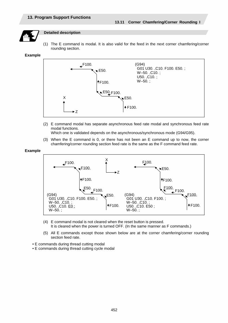
13. Program Support Functions 13.11 Corner Chamfering/Corner Rounding I
452
Detailed description
(1) The E command is modal. It is also valid for the feed in the next corner chamfering/corner
rounding section.
Example
(G94) G01 U30. ,C10. F100. E50. ; W–50. ,C10. ; U50. ,C10. ; W–50. ;
F100.
F100.
F100.
E50.
E50.E50.
F100.
X
Z
(2) E command modal has separate asynchronous feed rate modal and synchronous feed rate modal functions.
Which one is validated depends on the asynchronous/synchronous mode (G94/G95).
(3) When the E command is 0, or there has not been an E command up to now, the corner chamfering/corner rounding section feed rate is the same as the F command feed rate.
Example
F100. F100.
F100.
F100.
F100.
F100.
F100.
F100. F100.
F100.
F100.
E50.
E50.
E50.
X
Z
(G94) G01 U30. ,C10. F100. E50. ; W–50. ,C10. ; U50. ,C10. E0 ; W–50. ;
(G94) G01 U30. ,C10. F100. ; W–50. ,C10. ; U50. ,C10. E50 ; W–50. ;
(4) E command modal is not cleared when the reset button is pressed. It is cleared when the power is turned OFF. (In the same manner as F commands.)
(5) All E commands except those shown below are at the corner chamfering/corner rounding section feed rate.
• E commands during thread cutting modal • E commands during thread cutting cycle modal
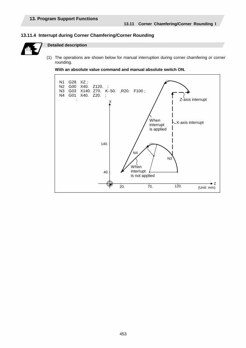
13. Program Support Functions 13.11 Corner Chamfering/Corner Rounding I
453
13.11.4 Interrupt during Corner Chamfering/Corner Rounding
Detailed description
(1) The operations are shown below for manual interruption during corner chamfering or corner
rounding.
With an absolute value command and manual absolute switch ON.
20.
X
40.
140.
Z
N4N3
70. 120. (Unit: mm)
N1 G28 XZ ; N2 G00 X40. Z120. ; N3 G03 X140. Z70. K−50. ,R20. F100 ;N4 G01 X40. Z20. ; : Z-axis interrupt
Wheninterrupt is applied
X-axis interrupt
When interrupt is not applied
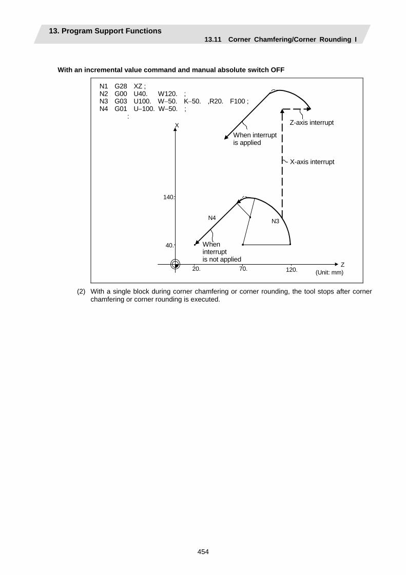
13. Program Support Functions 13.11 Corner Chamfering/Corner Rounding I
454
With an incremental value command and manual absolute switch OFF
20.
X
40.
140.
Z70. 120.
N4 N3
(Unit: mm)
N1 G28 XZ ; N2 G00 U40. W120. ; N3 G03 U100. W−50. K−50. ,R20. F100 ; N4 G01 U−100. W−50. ;
: Z-axis interrupt
When interruptis applied
X-axis interrupt
When interrupt is not applied
(2) With a single block during corner chamfering or corner rounding, the tool stops after corner chamfering or corner rounding is executed.
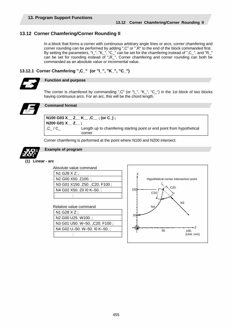
13. Program Support Functions 13.12 Corner Chamfering/Corner Rounding II
455
13.12 Corner Chamfering/Corner Rounding II
In a block that forms a corner with continuous arbitrary angle lines or arcs, corner chamfering and corner rounding can be performed by adding ",C" or ",R" to the end of the block commanded first. By setting the parameters, "I_", "K_", "C_" can be set for the chamfering instead of ",C_", and "R_" can be set for rounding instead of ",R_". Corner chamfering and corner rounding can both be commanded as an absolute value or incremental value.
13.12.1 Corner Chamfering ",C_" (or "I_", "K_", "C_")
Function and purpose
The corner is chamfered by commanding ",C" (or "I_", "K_", "C_") in the 1st block of two blocks having continuous arcs. For an arc, this will be the chord length.
Command format
N100 G03 X__ Z__ K__ ,C__ ; (or C_) ; N200 G01 X__ Z__ ; ,C_ / C_ Length up to chamfering starting point or end point from hypothetical
corner
Corner chamfering is performed at the point where N100 and N200 intersect.
Example of program
(1) Linear - arc
Absolute value command N1 G28 X Z ; N2 G00 X50. Z100. ; N3 G01 X150. Z50. ,C20. F100 ; N4 G02 X50. Z0 I0 K–50. ;
: Relative value command
N1 G28 X Z ; N2 G00 U25. W100. ; N3 G01 U50. W–50. ,C20. F100 ; N4 G02 U–50. W–50. I0 K–50. ;
:
Hypothetical corner intersection point
(Unit: mm)
Z
N3
C20.
C20.
N4
50 100.
50
150
X
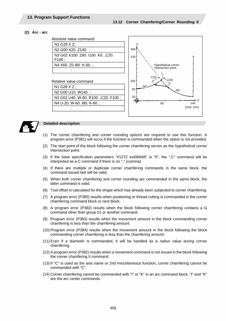
13. Program Support Functions 13.12 Corner Chamfering/Corner Rounding II
456
(2) Arc - arc Absolute value command
N1 G28 X Z; N2 G00 X20. Z140. ; N3 G02 X100. Z60. I100. K0. ,C20. F100 ; N4 X60. Z0 I80. K-60. ;
: Relative value command
N1 G28 X Z ; N2 G00 U10. W140. ; N3 G02 U40. W-80. R100. ,C20. F100 ; N4 U-20. W-60. I80. K-60. ;
:
Hypothetical corner intersection point
(Unit: mm)
Z
N3
C20. C20.
N4
60 140
60.
260.X
220.
100.
20.
Detailed description
(1) The corner chamfering and corner rounding options are required to use this function. A
program error (P381) will occur if the function is commanded when the option is not provided.
(2) The start point of the block following the corner chamfering serves as the hypothetical corner intersection point.
(3) If the base specification parameters "#1272 ext08/bit6" is "0", the ",C" command will be interpreted as a C command if there is no "," (comma).
(4) If there are multiple or duplicate corner chamfering commands in the same block, the command issued last will be valid.
(5) When both corner chamfering and corner rounding are commanded in the same block, the latter command is valid.
(6) Tool offset is calculated for the shape which has already been subjected to corner chamfering.
(7) A program error (P385) results when positioning or thread cutting is commanded in the corner chamfering command block or next block.
(8) A program error (P382) results when the block following corner chamfering contains a G command other than group 01 or another command.
(9) Program error (P383) results when the movement amount in the block commanding corner chamfering is less than the chamfering amount.
(10) Program error (P384) results when the movement amount in the block following the block commanding corner chamfering is less than the chamfering amount.
(11) Even if a diameter is commanded, it will be handled as a radius value during corner chamfering.
(12) A program error (P382) results when a movement command is not issued in the block following the corner chamfering II command.
(13) If "C" is used as the axis name or 2nd miscellaneous function, corner chamfering cannot be commanded with "C".
(14) Corner chamfering cannot be commanded with "I" or "K" in an arc command block. "I" and "K" are the arc center commands.

13. Program Support Functions 13.12 Corner Chamfering/Corner Rounding II
457
Precautions
(1) Corner chamfering and corner rounding can be commanded with "I", "K", "R" only when the 1st
block of the corner chamfering/corner rounding command is linear.
(2) Corner chamfering with "I", "K", and corner rounding with "R" can be commanded when the 1st block of the corner chamfering/corner rounding command is linear and the 2nd block is an arc command. "I", "K" in the 2nd block are the arc center commands.
N100 G01 Xx Zz Ii ;.................. Ii corner chamfering length N200 G02 Xx Zz Ii Kk ;............. Ii, Kk arc center command
(3) If ",C_", ",R_" or "I_", "K_", "C_", "R_" are commanded in the same block, ",C_", ",R_" will have the priority.
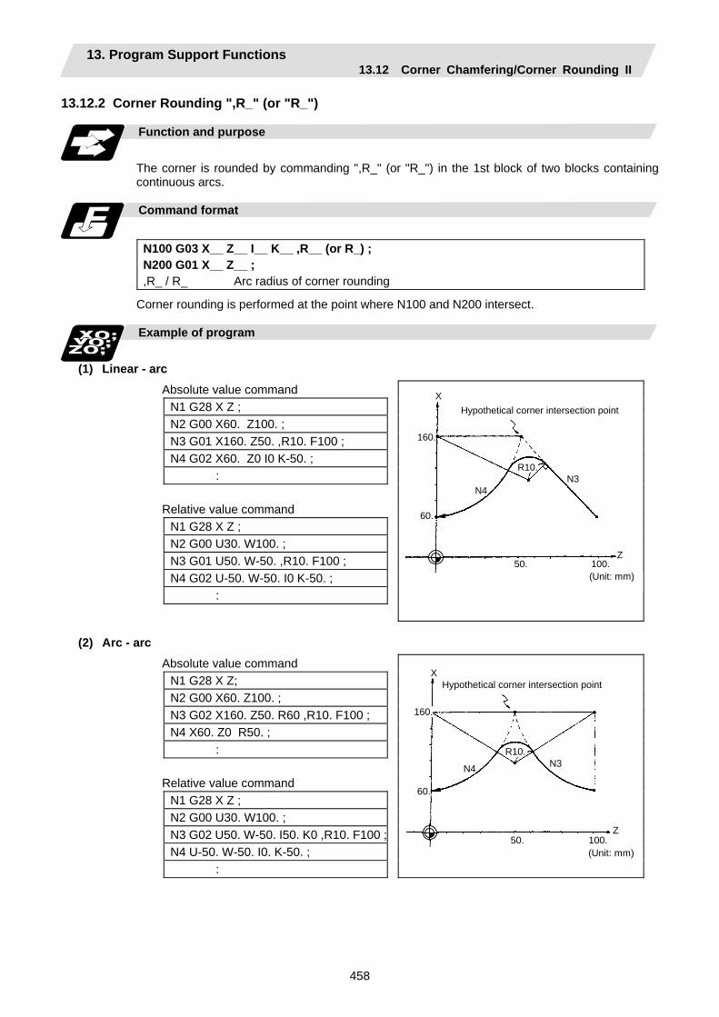
13. Program Support Functions 13.12 Corner Chamfering/Corner Rounding II
458
13.12.2 Corner Rounding ",R_" (or "R_")
Function and purpose
The corner is rounded by commanding ",R_" (or "R_") in the 1st block of two blocks containing continuous arcs.
Command format
N100 G03 X__ Z__ I__ K__ ,R__ (or R_) ; N200 G01 X__ Z__ ; ,R_ / R_ Arc radius of corner rounding
Corner rounding is performed at the point where N100 and N200 intersect.
Example of program
(1) Linear - arc
Absolute value command N1 G28 X Z ; N2 G00 X60. Z100. ; N3 G01 X160. Z50. ,R10. F100 ; N4 G02 X60. Z0 I0 K-50. ; : Relative value command N1 G28 X Z ; N2 G00 U30. W100. ; N3 G01 U50. W-50. ,R10. F100 ; N4 G02 U-50. W-50. I0 K-50. ; :
Hypothetical corner intersection point
Z
160.
X
60.
N4N3
R10.
50. 100.(Unit: mm)
(2) Arc - arc
Absolute value command N1 G28 X Z; N2 G00 X60. Z100. ; N3 G02 X160. Z50. R60 ,R10. F100 ; N4 X60. Z0 R50. ; : Relative value command N1 G28 X Z ; N2 G00 U30. W100. ; N3 G02 U50. W-50. I50. K0 ,R10. F100 ; N4 U-50. W-50. I0. K-50. ; :
Hypothetical corner intersection point
Z
160.
X
60.
N4 N3 R10.
50. 100.(Unit: mm)
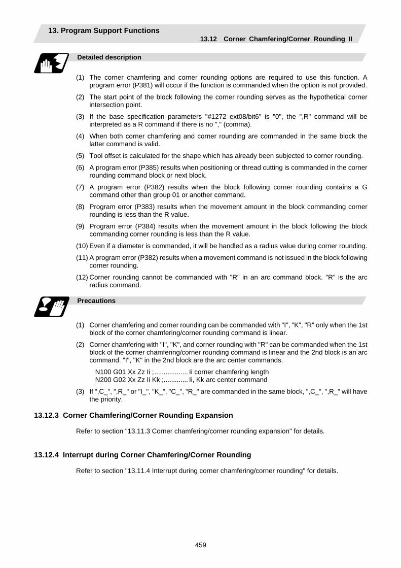
13. Program Support Functions 13.12 Corner Chamfering/Corner Rounding II
459
Detailed description
(1) The corner chamfering and corner rounding options are required to use this function. A
program error (P381) will occur if the function is commanded when the option is not provided.
(2) The start point of the block following the corner rounding serves as the hypothetical corner intersection point.
(3) If the base specification parameters "#1272 ext08/bit6" is "0", the ",R" command will be interpreted as a R command if there is no "," (comma).
(4) When both corner chamfering and corner rounding are commanded in the same block the latter command is valid.
(5) Tool offset is calculated for the shape which has already been subjected to corner rounding.
(6) A program error (P385) results when positioning or thread cutting is commanded in the corner rounding command block or next block.
(7) A program error (P382) results when the block following corner rounding contains a G command other than group 01 or another command.
(8) Program error (P383) results when the movement amount in the block commanding corner rounding is less than the R value.
(9) Program error (P384) results when the movement amount in the block following the block commanding corner rounding is less than the R value.
(10) Even if a diameter is commanded, it will be handled as a radius value during corner rounding.
(11) A program error (P382) results when a movement command is not issued in the block following corner rounding.
(12) Corner rounding cannot be commanded with "R" in an arc command block. "R" is the arc radius command.
Precautions
(1) Corner chamfering and corner rounding can be commanded with "I", "K", "R" only when the 1st
block of the corner chamfering/corner rounding command is linear.
(2) Corner chamfering with "I", "K", and corner rounding with "R" can be commanded when the 1st block of the corner chamfering/corner rounding command is linear and the 2nd block is an arc command. "I", "K" in the 2nd block are the arc center commands.
N100 G01 Xx Zz Ii ;.................. Ii corner chamfering length N200 G02 Xx Zz Ii Kk ;............. Ii, Kk arc center command
(3) If ",C_", ",R_" or "I_", "K_", "C_", "R_" are commanded in the same block, ",C_", ",R_" will have the priority.
13.12.3 Corner Chamfering/Corner Rounding Expansion
Refer to section "13.11.3 Corner chamfering/corner rounding expansion" for details.
13.12.4 Interrupt during Corner Chamfering/Corner Rounding Refer to section "13.11.4 Interrupt during corner chamfering/corner rounding" for details.
13. Program Support Functions 13.13 Linear Angle Command
460
13.13 Linear Angle Command
Function and purpose
The end point coordinates are calculated automatically by commanding the linear angle and one of the end point coordinate axes.
Command format
N1 G01 Xx1 (Zz1) Aa1; N1 G01 Xx2 (Zz2) A-a2; (A-a2 can also be set as Aa 3.) or N1 G01 Xx1 (Zz1) ,Aa1; N1 G01 Xx2 (Zz2) ,A-a2;
This designates the angle and the X or Z axis coordinates. Select the command plane with G17 to G19.
X
x2
x1 (z1,x1)
N1
Z
N2
a1
a2
a3
(z2,x2)
Detailed description
(1) The angle is from the + direction of the horizontal axis on the selected plane. The counter-
clockwise (CCW) direction is considered to be + and the clockwise direction (CW) -.
(2) Either of the axes on the selected plane is commanded for the end point.
(3) The angle is ignored when the angle and the coordinates of both axes are commanded.
(4) When only the angle has been commanded, this is treated as a geometric command.
(5) The angle of either the start point (a1) or end point (a2) may be used.
(6) This function is valid only for the G01 command; it is not valid for other interpolation or positioning commands.
(7) The range of slope "a" is −360.000 ≤ a ≤ 360.000. When a value outside this range is commanded, it will be divided by 360 (degrees) and the
remainder will be commanded.
(Example) If 400 is commanded, 40° (remainder of 400/360) will become the command angle.
(8) If address A is used for the axis name or 2nd miscellaneous function, use ",A" as the angle.
(9) If "A" and ",A" are commanded in the same block, ",A" will be interpreted as the angle.
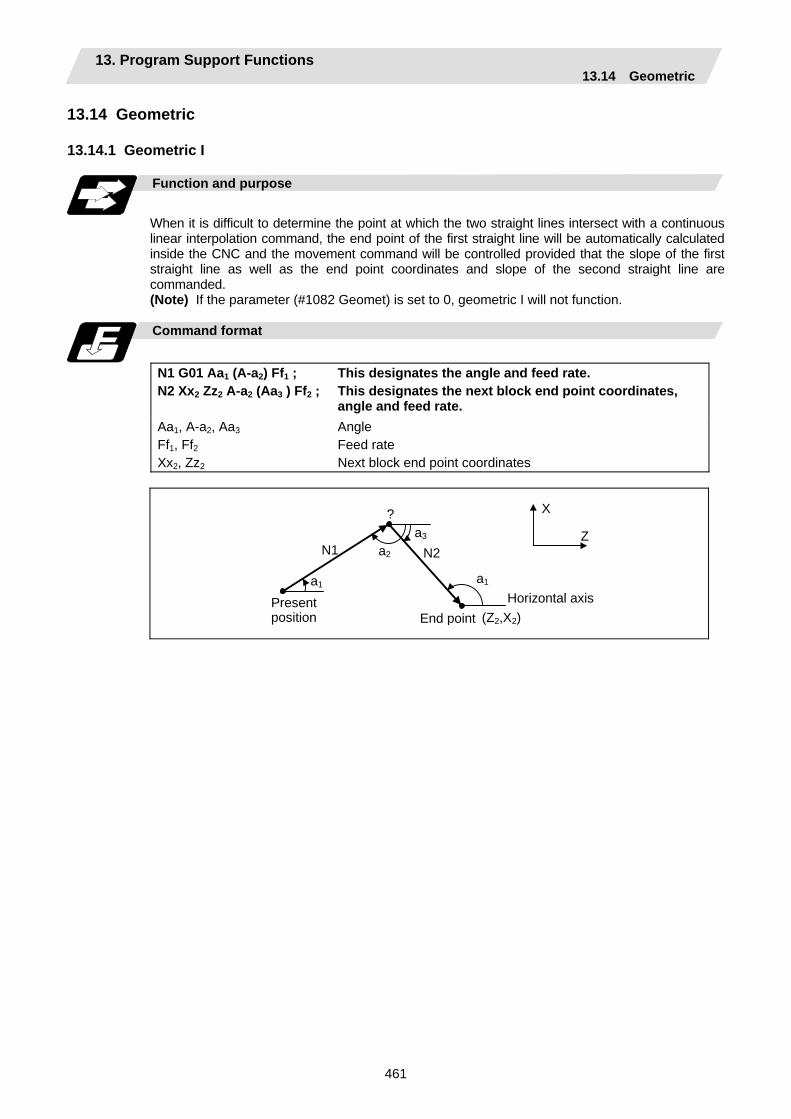
13. Program Support Functions 13.14 Geometric
461
13.14 Geometric 13.14.1 Geometric I Function and purpose
When it is difficult to determine the point at which the two straight lines intersect with a continuous linear interpolation command, the end point of the first straight line will be automatically calculated inside the CNC and the movement command will be controlled provided that the slope of the first straight line as well as the end point coordinates and slope of the second straight line are commanded. (Note) If the parameter (#1082 Geomet) is set to 0, geometric I will not function.
Command format
N1 G01 Aa1 (A-a2) Ff1 ; N2 Xx2 Zz2 A-a2 (Aa3 ) Ff2 ;
This designates the angle and feed rate. This designates the next block end point coordinates, angle and feed rate.
Aa1, A-a2, Aa3
Ff1, Ff2
Xx2, Zz2
Angle Feed rate Next block end point coordinates
a1
X
Z N1 N2a2
a3
a1
(Z2,X2)Present position
Horizontal axis
?
End point
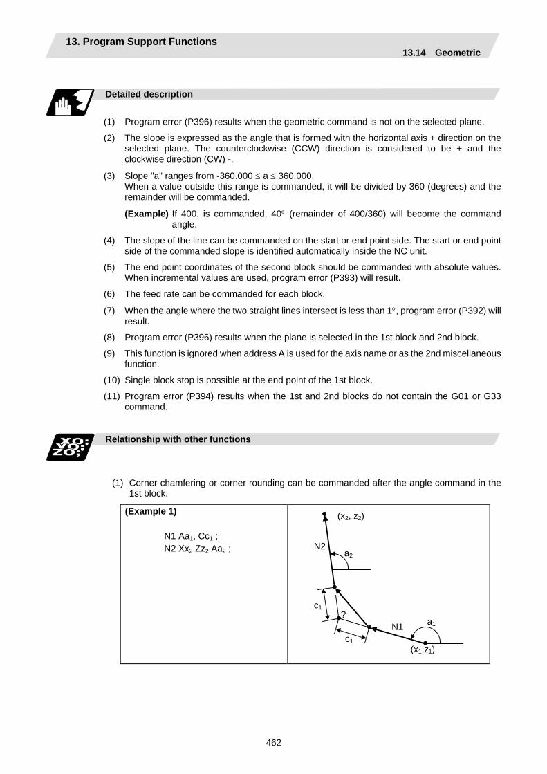
13. Program Support Functions 13.14 Geometric
462
Detailed description
(1) Program error (P396) results when the geometric command is not on the selected plane.
(2) The slope is expressed as the angle that is formed with the horizontal axis + direction on the selected plane. The counterclockwise (CCW) direction is considered to be + and the clockwise direction (CW) -.
(3) Slope "a" ranges from -360.000 ≤ a ≤ 360.000. When a value outside this range is commanded, it will be divided by 360 (degrees) and the remainder will be commanded.
(Example) If 400. is commanded, 40° (remainder of 400/360) will become the command angle.
(4) The slope of the line can be commanded on the start or end point side. The start or end point side of the commanded slope is identified automatically inside the NC unit.
(5) The end point coordinates of the second block should be commanded with absolute values. When incremental values are used, program error (P393) will result.
(6) The feed rate can be commanded for each block.
(7) When the angle where the two straight lines intersect is less than 1°, program error (P392) will result.
(8) Program error (P396) results when the plane is selected in the 1st block and 2nd block.
(9) This function is ignored when address A is used for the axis name or as the 2nd miscellaneous function.
(10) Single block stop is possible at the end point of the 1st block.
(11) Program error (P394) results when the 1st and 2nd blocks do not contain the G01 or G33 command.
Relationship with other functions
(1) Corner chamfering or corner rounding can be commanded after the angle command in the 1st block.
(Example 1) N1 Aa1, Cc1 ; N2 Xx2 Zz2 Aa2 ;
?
N2
N1
(x2, z2)
a2
a1
c1
c1
(x1,z1)

13. Program Support Functions 13.14 Geometric
463
(Example 2) N1 Aa1, Rr1 ; N2 Xx2 Zz2 Aa2 ;
N2
N1
(x2, z2)
a1
a2
r1
?
(x1, z1)
(2) The geometric command I can be issued after the corner chamfering or corner rounding command.
(Example 3) N1 Xx2 Zz2 ,Cc1 ; N2 Aa1 ; N3 Xx3 Zz3 Aa2 ;
N2
N1 (x2, z2)
(x3, z3) a2
a1
c1
c1
(x1, z1)
N3
?
(3) The geometric command I can be issued after the linear angle command.
(Example 4) N1 Xx2 Aa1 ; N2 Aa2 ; N3 Xx3 Zz3 Aa3 ;
N2
N1 (x2, z2)
(x3, z3) a3
a2
(x1, z1)
N3
a1
?
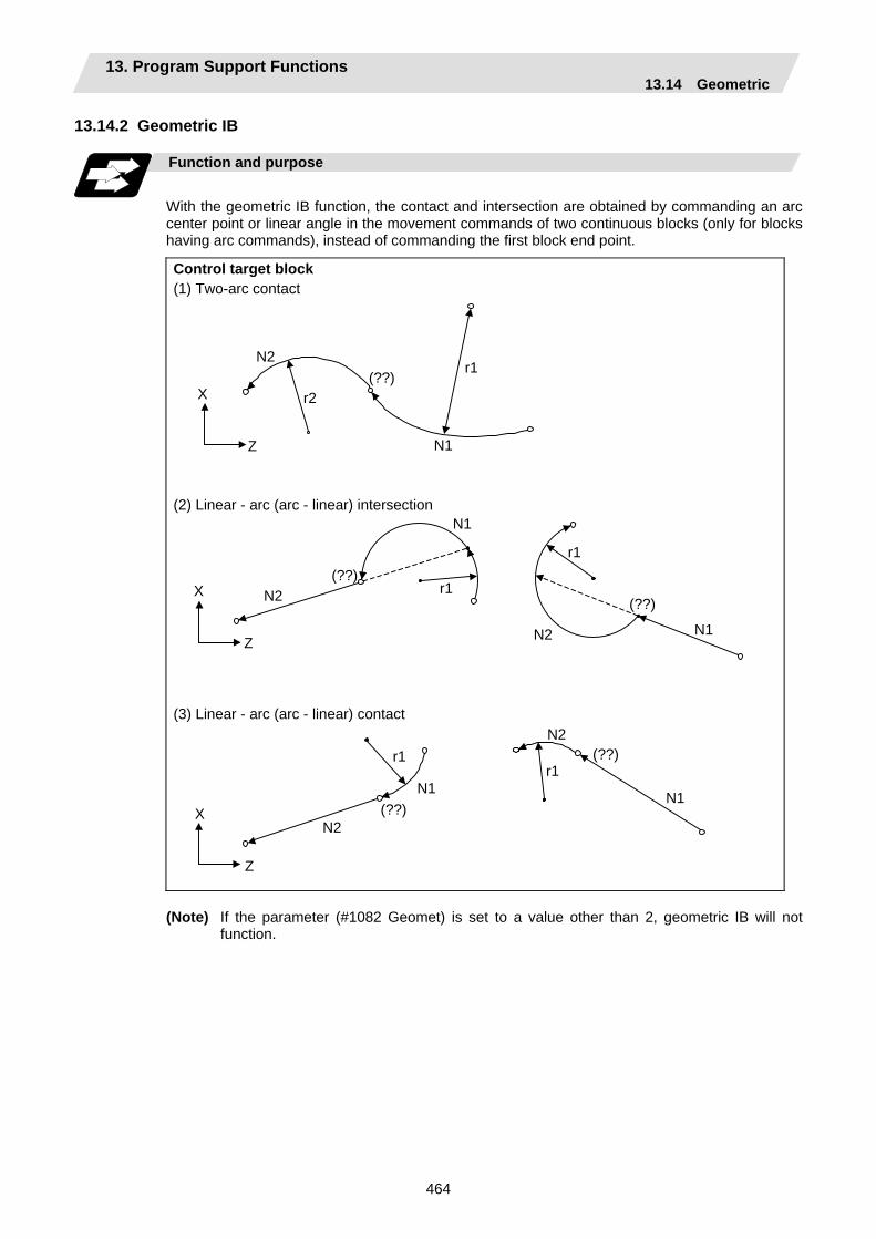
13. Program Support Functions 13.14 Geometric
464
13.14.2 Geometric IB Function and purpose
With the geometric IB function, the contact and intersection are obtained by commanding an arc center point or linear angle in the movement commands of two continuous blocks (only for blocks having arc commands), instead of commanding the first block end point.
Control target block (1) Two-arc contact
N2
N1
r2
r1(??)
X
Z (2) Linear - arc (arc - linear) intersection
N2
N2 N1
N1
(??)
(??) X
Z
r1
r1
(3) Linear - arc (arc - linear) contact
N2
N2
N1 N1
r1r1
(??)
X
Z
(??)
(Note) If the parameter (#1082 Geomet) is set to a value other than 2, geometric IB will not function.
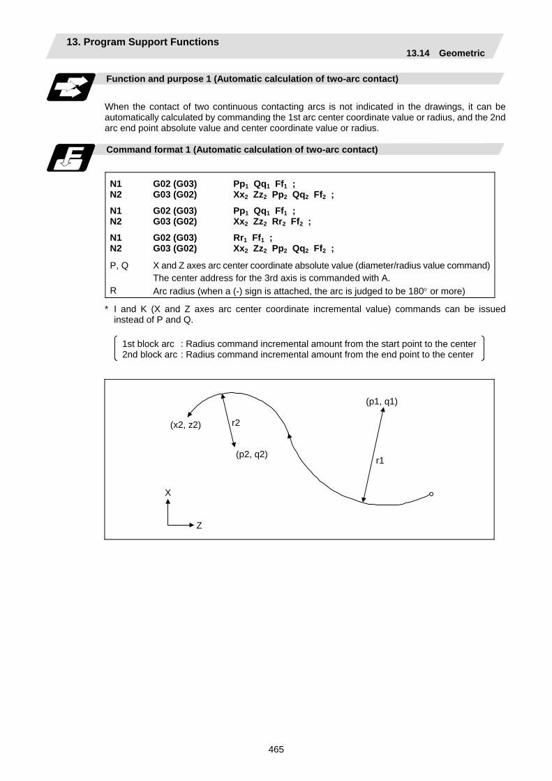
13. Program Support Functions 13.14 Geometric
465
Function and purpose 1 (Automatic calculation of two-arc contact)
When the contact of two continuous contacting arcs is not indicated in the drawings, it can be automatically calculated by commanding the 1st arc center coordinate value or radius, and the 2nd arc end point absolute value and center coordinate value or radius.
Command format 1 (Automatic calculation of two-arc contact)
N1 N2
N1 N2
N1 N2
G02 (G03) G03 (G02)
G02 (G03) G03 (G02)
G02 (G03) G03 (G02)
Pp1 Qq1 Ff1 ; Xx2 Zz2 Pp2 Qq2 Ff2 ;
Pp1 Qq1 Ff1 ; Xx2 Zz2 Rr2 Ff2 ;
Rr1 Ff1 ; Xx2 Zz2 Pp2 Qq2 Ff2 ;
P, Q R
X and Z axes arc center coordinate absolute value (diameter/radius value command)The center address for the 3rd axis is commanded with A. Arc radius (when a (-) sign is attached, the arc is judged to be 180° or more)
* I and K (X and Z axes arc center coordinate incremental value) commands can be issued instead of P and Q.
1st block arc : Radius command incremental amount from the start point to the center 2nd block arc : Radius command incremental amount from the end point to the center
r2
r1
(x2, z2)
X
Z
(p2, q2)
(p1, q1)
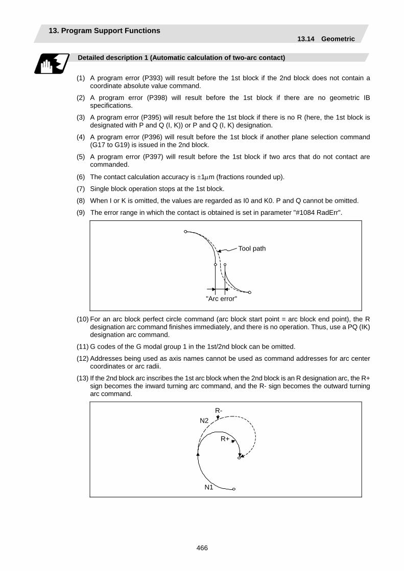
13. Program Support Functions 13.14 Geometric
466
Detailed description 1 (Automatic calculation of two-arc contact)
(1) A program error (P393) will result before the 1st block if the 2nd block does not contain a
coordinate absolute value command.
(2) A program error (P398) will result before the 1st block if there are no geometric IB specifications.
(3) A program error (P395) will result before the 1st block if there is no R (here, the 1st block is designated with P and Q (I, K)) or P and Q (I, K) designation.
(4) A program error (P396) will result before the 1st block if another plane selection command (G17 to G19) is issued in the 2nd block.
(5) A program error (P397) will result before the 1st block if two arcs that do not contact are commanded.
(6) The contact calculation accuracy is ±1µm (fractions rounded up).
(7) Single block operation stops at the 1st block.
(8) When I or K is omitted, the values are regarded as I0 and K0. P and Q cannot be omitted.
(9) The error range in which the contact is obtained is set in parameter "#1084 RadErr".
Tool path
"Arc error"
(10) For an arc block perfect circle command (arc block start point = arc block end point), the R designation arc command finishes immediately, and there is no operation. Thus, use a PQ (IK) designation arc command.
(11) G codes of the G modal group 1 in the 1st/2nd block can be omitted.
(12) Addresses being used as axis names cannot be used as command addresses for arc center coordinates or arc radii.
(13) If the 2nd block arc inscribes the 1st arc block when the 2nd block is an R designation arc, the R+ sign becomes the inward turning arc command, and the R- sign becomes the outward turning arc command.
R-
R+
N2
N1
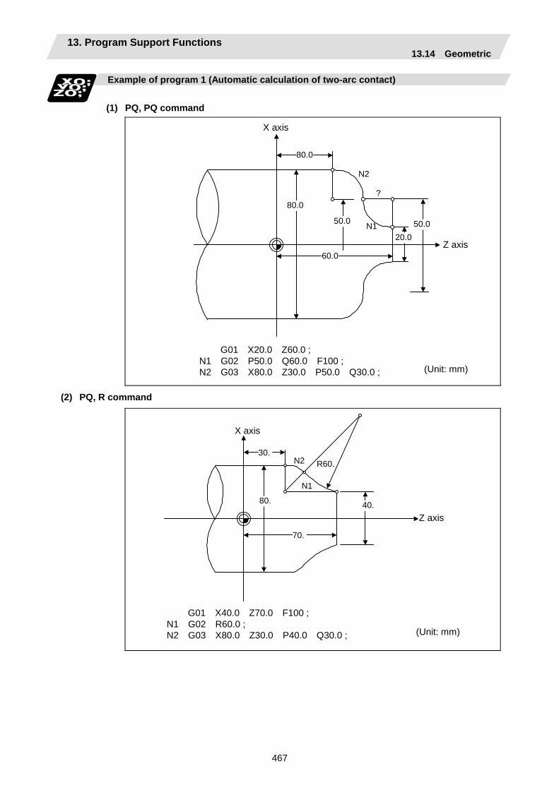
13. Program Support Functions 13.14 Geometric
467
Example of program 1 (Automatic calculation of two-arc contact)
(1) PQ, PQ command
N2
N1
?
80.0
80.0
60.0
50.0 50.0 20.0
Z axis
X axis
G01 X20.0 Z60.0 ; N1 G02 P50.0 Q60.0 F100 ; N2 G03 X80.0 Z30.0 P50.0 Q30.0 ; (Unit: mm)
(2) PQ, R command
30.
80.
70.
40.
N2
N1
R60.
(Unit: mm)
Z axis
X axis
G01 X40.0 Z70.0 F100 ; N1 G02 R60.0 ; N2 G03 X80.0 Z30.0 P40.0 Q30.0 ;

13. Program Support Functions 13.14 Geometric
468
Relation with other functions 1 (Automatic calculation of two-arc contact)
Command Tool path Geometric IB + corner chamfering II N1 G03 P__ Q__ ; N2 G02 X__ Z__ R__ ,C__ ; G02 X__ Z__ R__ ;
N2
N1
Z
X
Geometric IB + corner rounding II N1 G03 P__ Q__ ; N2 G02 X__ Z__ R__ ,R__ ; G02 X__ Z__ R__ ;
N2
N1
Z
X
Geometric IB + corner chamfering II N1 G03 P__ Q__ ; N2 G02 X__ Z__ R__ ,C__ ; G01 X__ Z__ ;
Z
X
N2
N1
Geometric IB + corner rounding II N1 G03 P__ Q__ ; N2 G02 X__ Z__ R__ ,R__ ; G02 X__ Z__ ;
Z
X
N2
N1
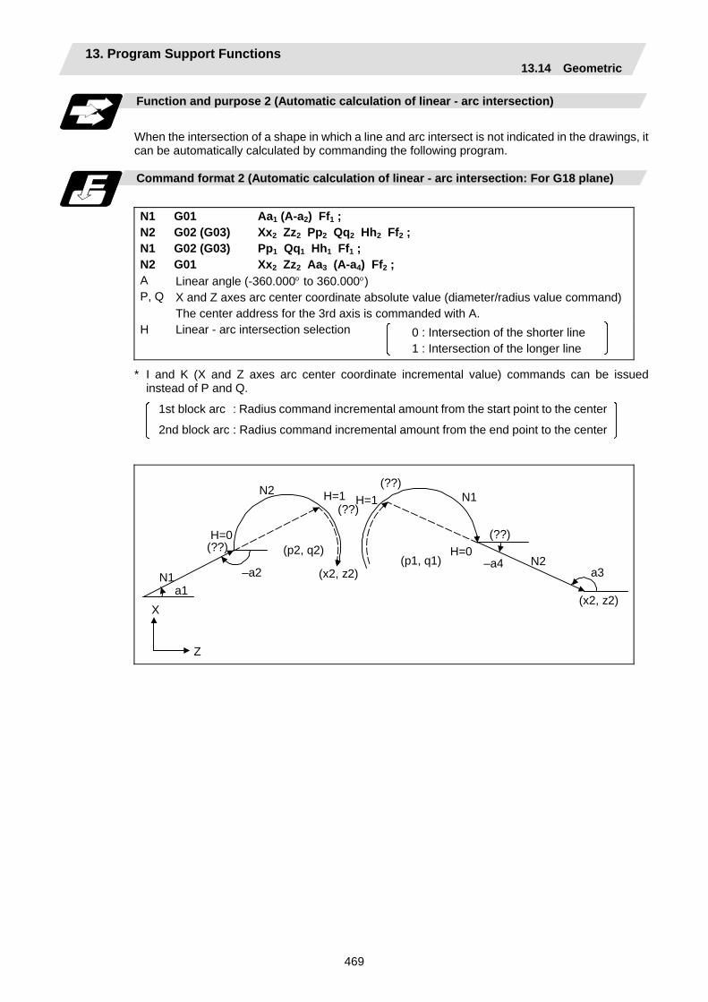
13. Program Support Functions 13.14 Geometric
469
Function and purpose 2 (Automatic calculation of linear - arc intersection)
When the intersection of a shape in which a line and arc intersect is not indicated in the drawings, it can be automatically calculated by commanding the following program.
Command format 2 (Automatic calculation of linear - arc intersection: For G18 plane)
N1 N2 N1 N2
G01 G02 (G03) G02 (G03) G01
Aa1 (A-a2) Ff1 ; Xx2 Zz2 Pp2 Qq2 Hh2 Ff2 ; Pp1 Qq1 Hh1 Ff1 ; Xx2 Zz2 Aa3 (A-a4) Ff2 ;
A P, Q
Linear angle (-360.000° to 360.000°) X and Z axes arc center coordinate absolute value (diameter/radius value command) The center address for the 3rd axis is commanded with A.
H
Linear - arc intersection selection
0 : Intersection of the shorter line 1 : Intersection of the longer line
* I and K (X and Z axes arc center coordinate incremental value) commands can be issued instead of P and Q.
1st block arc : Radius command incremental amount from the start point to the center
2nd block arc : Radius command incremental amount from the end point to the center
H=1 H=1
H=0
N2 N1
H=0
N1 a1
N2 a3
–a4 –a2
(??)
(??)
(??) (??) (p2, q2)
(x2, z2)(p1, q1)
(x2, z2)X
Z
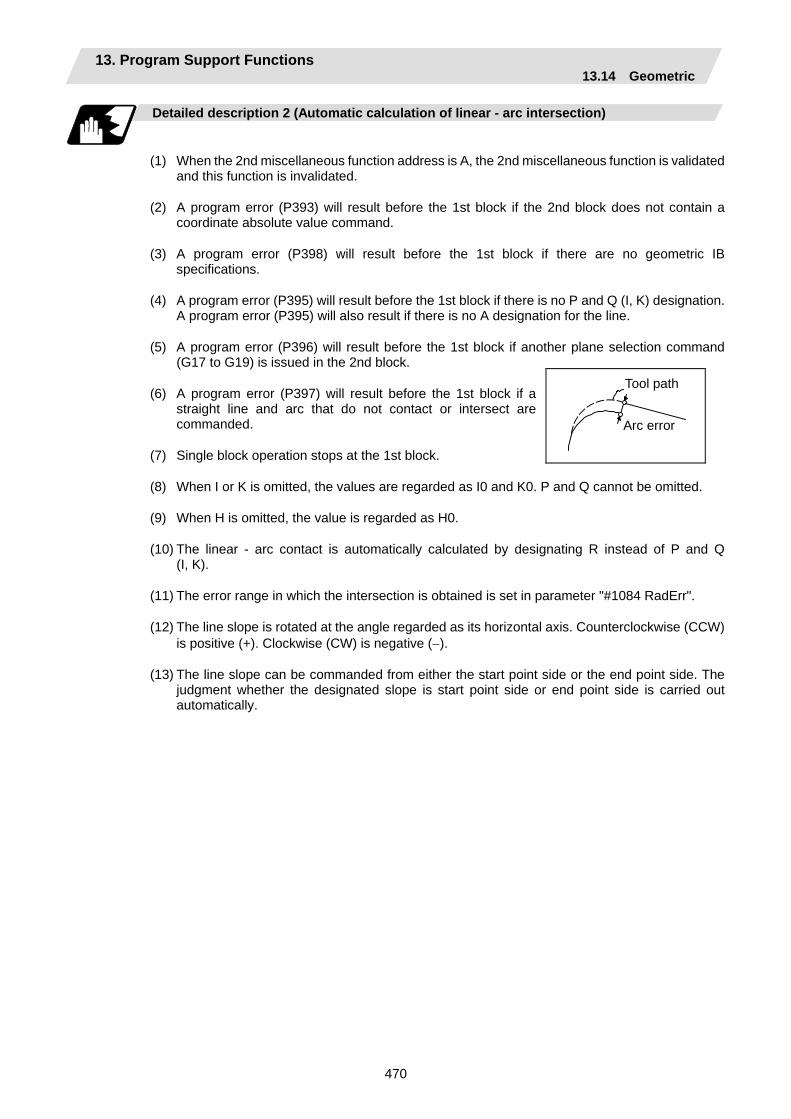
13. Program Support Functions 13.14 Geometric
470
Detailed description 2 (Automatic calculation of linear - arc intersection)
(1) When the 2nd miscellaneous function address is A, the 2nd miscellaneous function is validated
and this function is invalidated.
(2) A program error (P393) will result before the 1st block if the 2nd block does not contain a coordinate absolute value command.
(3) A program error (P398) will result before the 1st block if there are no geometric IB specifications.
(4) A program error (P395) will result before the 1st block if there is no P and Q (I, K) designation. A program error (P395) will also result if there is no A designation for the line.
(5) A program error (P396) will result before the 1st block if another plane selection command (G17 to G19) is issued in the 2nd block.
(6) A program error (P397) will result before the 1st block if a straight line and arc that do not contact or intersect are commanded.
(7) Single block operation stops at the 1st block.
(8) When I or K is omitted, the values are regarded as I0 and K0. P and Q cannot be omitted.
(9) When H is omitted, the value is regarded as H0.
(10) The linear - arc contact is automatically calculated by designating R instead of P and Q (I, K).
(11) The error range in which the intersection is obtained is set in parameter "#1084 RadErr".
(12) The line slope is rotated at the angle regarded as its horizontal axis. Counterclockwise (CCW) is positive (+). Clockwise (CW) is negative (−).
(13) The line slope can be commanded from either the start point side or the end point side. The judgment whether the designated slope is start point side or end point side is carried out automatically.
Tool path
Arc error
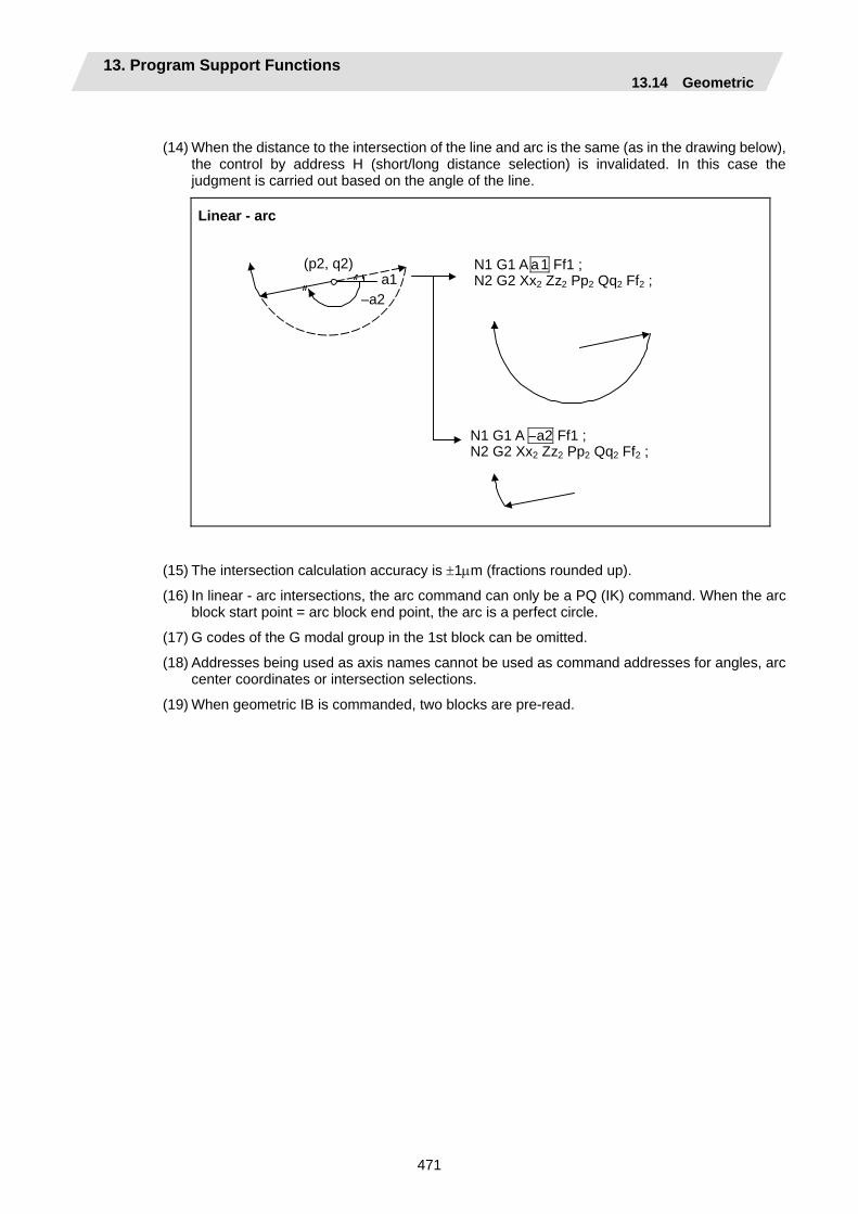
13. Program Support Functions 13.14 Geometric
471
(14) When the distance to the intersection of the line and arc is the same (as in the drawing below), the control by address H (short/long distance selection) is invalidated. In this case the judgment is carried out based on the angle of the line.
Linear - arc
N1 G1 A a1 Ff1 ;N2 G2 Xx2 Zz2 Pp2 Qq2 Ff2 ;
N1 G1 A –a2 Ff1 ;N2 G2 Xx2 Zz2 Pp2 Qq2 Ff2 ;
(p2, q2)
–a2a1
(15) The intersection calculation accuracy is ±1µm (fractions rounded up).
(16) In linear - arc intersections, the arc command can only be a PQ (IK) command. When the arc block start point = arc block end point, the arc is a perfect circle.
(17) G codes of the G modal group in the 1st block can be omitted.
(18) Addresses being used as axis names cannot be used as command addresses for angles, arc center coordinates or intersection selections.
(19) When geometric IB is commanded, two blocks are pre-read.

13. Program Support Functions 13.14 Geometric
472
Example of program 2 (Automatic calculation of linear - arc intersection)
X axis
Z axis
N2
N1
180°
100.0
50.080.0
G01 X80.0 Z50.0 F100 ; N1 G01 A180.0 ; N2 G03 X100.0 Z0 P0 Q0 ;
?
(Unit: mm)
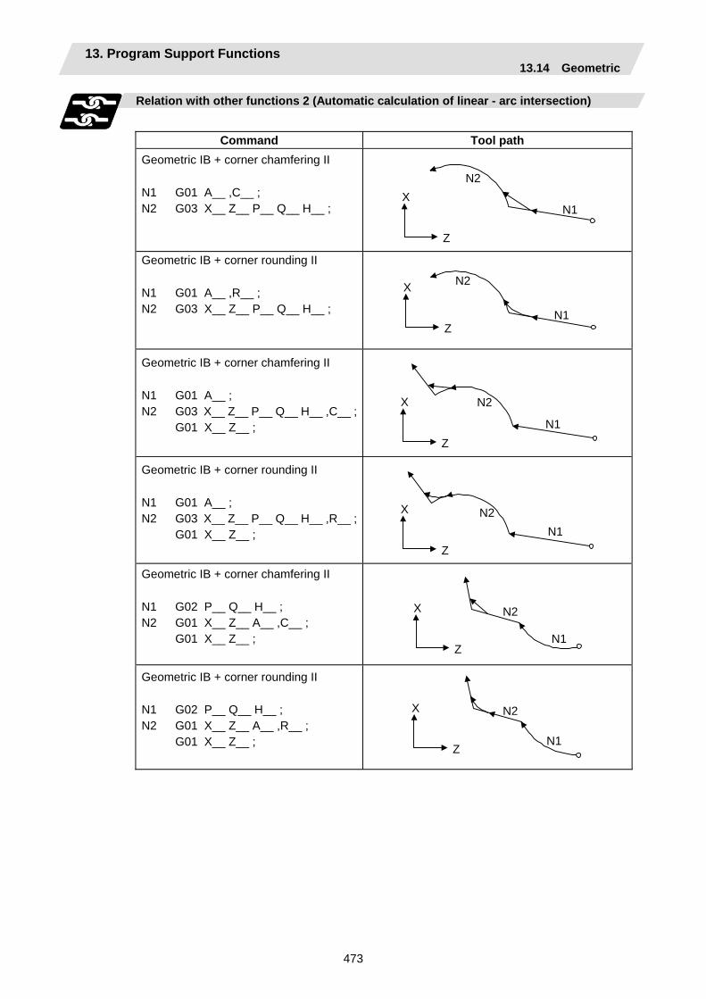
13. Program Support Functions 13.14 Geometric
473
Relation with other functions 2 (Automatic calculation of linear - arc intersection)
Command Tool path
Geometric IB + corner chamfering II N1 G01 A__ ,C__ ; N2 G03 X__ Z__ P__ Q__ H__ ;
N2
N1
Z
X
Geometric IB + corner rounding II N1 G01 A__ ,R__ ; N2 G03 X__ Z__ P__ Q__ H__ ;
N2
N1 Z
X
Geometric IB + corner chamfering II N1 G01 A__ ; N2 G03 X__ Z__ P__ Q__ H__ ,C__ ; G01 X__ Z__ ;
N2
N1 Z
X
Geometric IB + corner rounding II N1 G01 A__ ; N2 G03 X__ Z__ P__ Q__ H__ ,R__ ; G01 X__ Z__ ;
N2N1
Z
X
Geometric IB + corner chamfering II N1 G02 P__ Q__ H__ ; N2 G01 X__ Z__ A__ ,C__ ; G01 X__ Z__ ;
N2
N1 Z
X
Geometric IB + corner rounding II N1 G02 P__ Q__ H__ ; N2 G01 X__ Z__ A__ ,R__ ; G01 X__ Z__ ;
N2
N1 Z
X
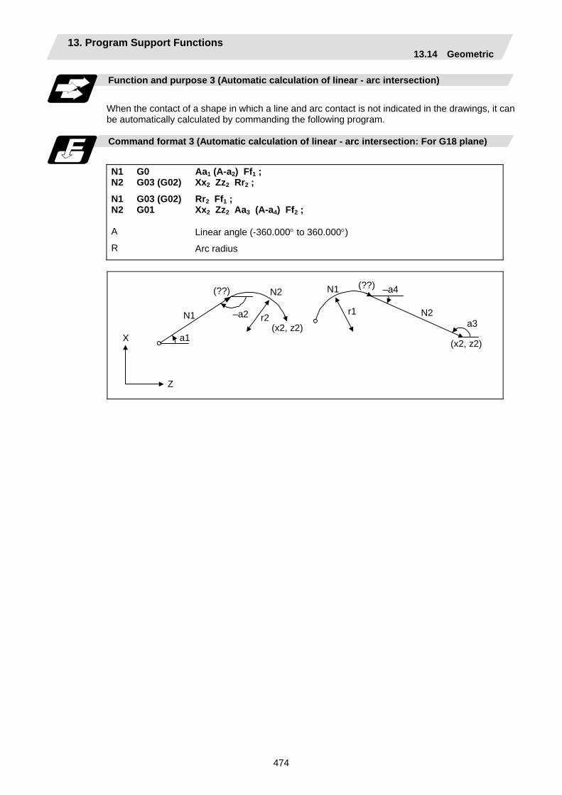
13. Program Support Functions 13.14 Geometric
474
Function and purpose 3 (Automatic calculation of linear - arc intersection)
When the contact of a shape in which a line and arc contact is not indicated in the drawings, it can be automatically calculated by commanding the following program.
Command format 3 (Automatic calculation of linear - arc intersection: For G18 plane)
N1 N2
N1 N2
G0 G03 (G02)
G03 (G02) G01
Aa1 (A-a2) Ff1 ; Xx2 Zz2 Rr2 ;
Rr2 Ff1 ; Xx2 Zz2 Aa3 (A-a4) Ff2 ;
A
R
Linear angle (-360.000° to 360.000°)
Arc radius
X
Z
N1
(x2, z2)
(??) N1N2
N2(x2, z2)
(??)
a3
–a4
–a2 r2r1
a1
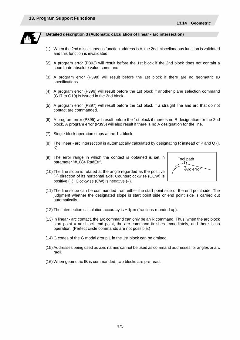
13. Program Support Functions 13.14 Geometric
475
Detailed description 3 (Automatic calculation of linear - arc intersection)
(1) When the 2nd miscellaneous function address is A, the 2nd miscellaneous function is validated
and this function is invalidated.
(2) A program error (P393) will result before the 1st block if the 2nd block does not contain a coordinate absolute value command.
(3) A program error (P398) will result before the 1st block if there are no geometric IB specifications.
(4) A program error (P396) will result before the 1st block if another plane selection command (G17 to G19) is issued in the 2nd block.
(5) A program error (P397) will result before the 1st block if a straight line and arc that do not contact are commanded.
(6) A program error (P395) will result before the 1st block if there is no R designation for the 2nd block. A program error (P395) will also result if there is no A designation for the line.
(7) Single block operation stops at the 1st block.
(8) The linear - arc intersection is automatically calculated by designating R instead of P and Q (I, K).
(9) The error range in which the contact is obtained is set in parameter "#1084 RadErr".
(10) The line slope is rotated at the angle regarded as the positive (+) direction of its horizontal axis. Counterclockwise (CCW) is positive (+). Clockwise (CW) is negative (−).
(11) The line slope can be commanded from either the start point side or the end point side. The judgment whether the designated slope is start point side or end point side is carried out automatically.
(12) The intersection calculation accuracy is ± 1µm (fractions rounded up).
(13) In linear - arc contact, the arc command can only be an R command. Thus, when the arc block start point = arc block end point, the arc command finishes immediately, and there is no operation. (Perfect circle commands are not possible.)
(14) G codes of the G modal group 1 in the 1st block can be omitted.
(15) Addresses being used as axis names cannot be used as command addresses for angles or arc radii.
(16) When geometric IB is commanded, two blocks are pre-read.
Tool path
Arc error
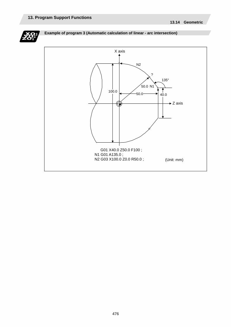
13. Program Support Functions 13.14 Geometric
476
Example of program 3 (Automatic calculation of linear - arc intersection)
N1
?
100.050.0
50.0
135°
40.0
N2
(Unit: mm)
Z axis
X axis
G01 X40.0 Z50.0 F100 ; N1 G01 A135.0 ; N2 G03 X100.0 Z0.0 R50.0 ;
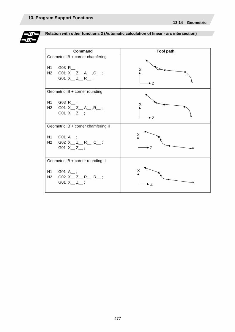
13. Program Support Functions 13.14 Geometric
477
Relation with other functions 3 (Automatic calculation of linear - arc intersection)
Command Tool path Geometric IB + corner chamfering N1 G03 R__ ; N2 G01 X__ Z__ A__ ,C__ ; G01 X__ Z__ R__ ;
Z
X
Geometric IB + corner rounding N1 G03 R__ ; N2 G01 X__ Z__ A__ ,R__ ; G01 X__ Z__ ;
Z
X
Geometric IB + corner chamfering II N1 G01 A__ ; N2 G02 X__ Z__ R__ ,C__ ; G01 X__ Z__ ;
Z
X
Geometric IB + corner rounding II N1 G01 A__ ; N2 G02 X__ Z__ R__ ,R__ ; G01 X__ Z__ ;
Z
X

13. Program Support Functions 13.15 Parameter Input by Program; G10, G11
478
13.15 Parameter Input by Program; G10, G11
Function and purpose
The parameters set from the setting and display unit can be changed in the machining programs. The range of command data depends on the parameter setting range described in the Setup Manual. The data format used for the data setting is as follows.
Command format
G10 L70 ; Data setting start command P parameter No. S part system No. H data ; …………..P parameter No. S part system No. D data ; …………....P parameter No. S part system No. <character string>.
Bit parameter Numerical value parameterCharacter string parameter
G11.1 Data setting end command
(Note 1) The sequence of addresses in a block must be as shown above. When an address is commanded two or more times, the last command will be valid.
(Note 2) The part system No. is set in the following manner: "1" for 1st part system, "2" for 2nd part system, and so forth. If the address S is omitted, the part system of the executing program will be applied As for the parameters common to part systems, the command of part system No. will be ignored.
(Note 3) The axis No. is set in the following manner: "1" for 1st axis, "2" for 2nd axis, and so forth. If the address A is omitted, the 1st axis will be applied. As for the parameters common to axes, the command of axis No. will be ignored.
(Note 4) Address H is commanded with the combination of setting data (0 or 1) and the bit designation ( ) (0 to 7).
(Note 5) Only the decimal number can be commanded with the address D. The value that is smaller than the input setting increment (#1003 iunit) will be round off to the nearest increment.
(Note 6) The character string must be put in angled brackets "<" and ">". If these brackets are not provided, the program error (P33) will occur. Up to 63 characters can be set.
(Note 7) Command G10L70, G11 in independent blocks. A program error (P33, P421) will occur if not commanded in independent blocks.
Example of program
(Example)
G10 L70; P6401 H71 ; Sets "1" to "#6401 bit7". P8204 S1 A2 D1.234 ; Sets "1.234" to #8204 of the 1st part system 2nd axis. P8621 <X> ; Sets "x" to "#8621". G11.1

13. Program Support Functions 13.16 Macro Interruption
479
13.16 Macro Interruption
Function and purpose
A user macro interruption signal (UIT) is input from the machine to interrupt the program being currently executed and instead call another program and execute it. This is called the user macro interruption function. Use of this function allows the program to operate flexibly enough to meet varying conditions.
Command format
M96 P__ H__ ; User macro interruption enable or M96 <File name> H_ ; M96 P_ <File name> H_
User macro interruption command Interrupt program No. File name A file name can be specified instead of a program No. In this case, enclose the file name with brackets <>. (The file name can have up to 32 characters including the extension.) Interrupt sequence No.
M97 ; User macro interruption disable M97 User macro interruption end command
The user macro interruption function is enabled and disabled by the M96 and M97 commands programmed to make the user macro interrupt signal (UIT) valid or invalid. That is, if an interrupt signal (UIT) is input from the machine side in a user macro interruption enable period from when M96 is issued to when M97 is issued or the NC is reset, a user macro interruption is caused to execute the program specified by P__ instead of the one being executed currently. Another interrupt signal (UIT) is ignored while one user macro interruption is being in service. It is also ignored in a user macro interrupt disable state such as after an M97 command is issued or the system is reset. M96 and M97 are processed internally as user macro interruption control M codes.
Interrupt enable conditions
A user macro interruption is enabled only during execution of a program. The requirements for the user macro interrupt are as follows:
(1) An automatic operation mode or MDI has been selected.
(2) The system is running in automatic mode.
(3) No user macro interruption is being processed.
(Note 1) A macro interruption is disabled in manual operation mode (JOG, STEP, HANDLE, etc.)
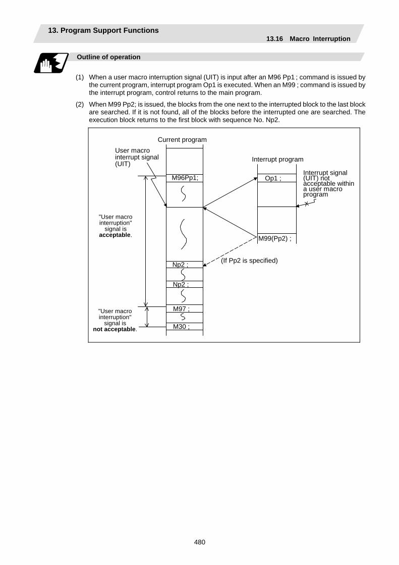
13. Program Support Functions 13.16 Macro Interruption
480
Outline of operation
(1) When a user macro interruption signal (UIT) is input after an M96 Pp1 ; command is issued by
the current program, interrupt program Op1 is executed. When an M99 ; command is issued by the interrupt program, control returns to the main program.
(2) When M99 Pp2; is issued, the blocks from the one next to the interrupted block to the last block are searched. If it is not found, all of the blocks before the interrupted one are searched. The execution block returns to the first block with sequence No. Np2.
Current programUser macro interrupt signal (UIT)
Interrupt program
M96Pp1;
Np2 ;
M97 ;
Op1 ;
M99(Pp2) ;
Interrupt signal (UIT) not acceptable withina user macro program
(If Pp2 is specified)
Np2 ;
"User macro interruption"
signal is acceptable.
"User macro interruption"
signal is not acceptable. M30 ;
13. Program Support Functions 13.16 Macro Interruption
481
Interrupt type
Interrupt types 1 and 2 can be selected by the parameter "#1113 INT_2". [Type 1] • When an interrupt signal (UIT) is input, the system immediately stops moving the tool and
interrupts dwell, then permits the interrupt program to run.
• If the interrupt program contains a move or miscellaneous function (MSTB) command, the commands in the interrupted block are lost. After the interrupt program completes, the main program resumes operation from the block next to the interrupted one.
• If the interrupted program contains no move and miscellaneous (MSTB) commands, it resumes operation, after completion of the interrupt program, from the point in the block where the interrupt was caused.
If an interrupt signal (UIT) is input during execution of a miscellaneous function (MSTB) command, the NC system waits for a completion signal (FIN). The system thus executes a move or miscellaneous function (MSTB) command in the interrupt program only after input of FIN.
[Type 2] • When an interrupt signal (UIT) is input, the interrupt program will be executed in parallel with the
executing block.
• If the interrupt program contains a move or miscellaneous function (MSTB) command, the commands in the interrupted block are completed, then, these commands will be executed.
• If the interrupt program contains no move and miscellaneous function (MSTB) commands, the interrupt program is executed without interrupting execution of the current program.
However, if the interrupt program has not ended even after the execution of the original block is completed, the system may stop machining temporarily.
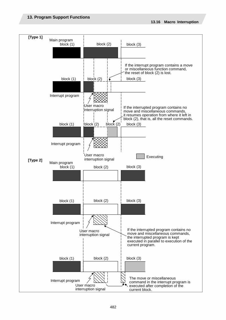
13. Program Support Functions 13.16 Macro Interruption
482
block (2)
User macro interruption signal
block (2) block (2)
block (2)Main program
block (1) block (3)
block (1) block (3)
block (1) block (3)
[Type 1]
[Type 2]
block (2)Main program
block (1) block (3)
block (1)
Interrupt program
Interrupt program
block (1)
block (2)
block (2)
block (3)
block (3)
User macrointerruption signal
Interrupt program
Executing
If the interrupt program contains a move or miscellaneous function command, the reset of block (2) is lost.
If the interrupted program contains nomove and miscellaneous commands, it resumes operation from where it left inblock (2), that is, all the reset commands.
Interrupt program
User macro interruption signal
If the interrupted program contains nomove and miscellaneous commands,the interrupted program is kept executed in parallel to execution of thecurrent program.
The move or miscellaneous command in the interrupt program isexecuted after completion of the current block.
User macrointerruption signal

13. Program Support Functions 13.16 Macro Interruption
483
Calling method
User macro interruption is classified into the following two types depending on the way an interrupt program is called. These two types of interrupt are selected by parameter "#1229 set01/bit0".
a. Subprogram type interrupt b. Macro type interrupt
Both types of interrupt are included in calculation of the nest level. The subprograms and user macros called in the interrupt program are also included in calculation of the nest level.
Subprogram type interrupt
The user macro interruption program is called as a subprogram. As with calling by M98, the local variable level remains unchanged before and after an interrupt.
Macro type interrupt
The user macro interruption program is called as a user macro. As with calling by G65, the local variable level changes before and after an interrupt. No arguments in the main program can be passed to the interrupt program.
Acceptance of user macro interruption signal (UIT)
A user macro interruption signal (UIT) is accepted in the following two modes. These two modes are selected by a parameter "#1112 S_TRG".
a. Status trigger mode b. Edge trigger mode
Status trigger mode
The user macro interruption signal (UIT) is accepted as valid when it is ON.If the interrupt signal (UIT) is ON when the user macro interrupt function is enabled by M96, the interrupt program is activated. By keeping the interrupt signal (UIT) ON, the interrupt program can be executed repeatedly.
Edge trigger mode
The user macro interruption signal (UIT) is accepted as valid at its rising edge, that is, at the instance it turns ON. This mode is useful to execute an interrupt program once.
User macro interruption signal (UIT)
ON
OFF
(Status trigger mode)
User macro interruption
(Edge trigger mode)
Accepting user macro interruption signal (UIT)
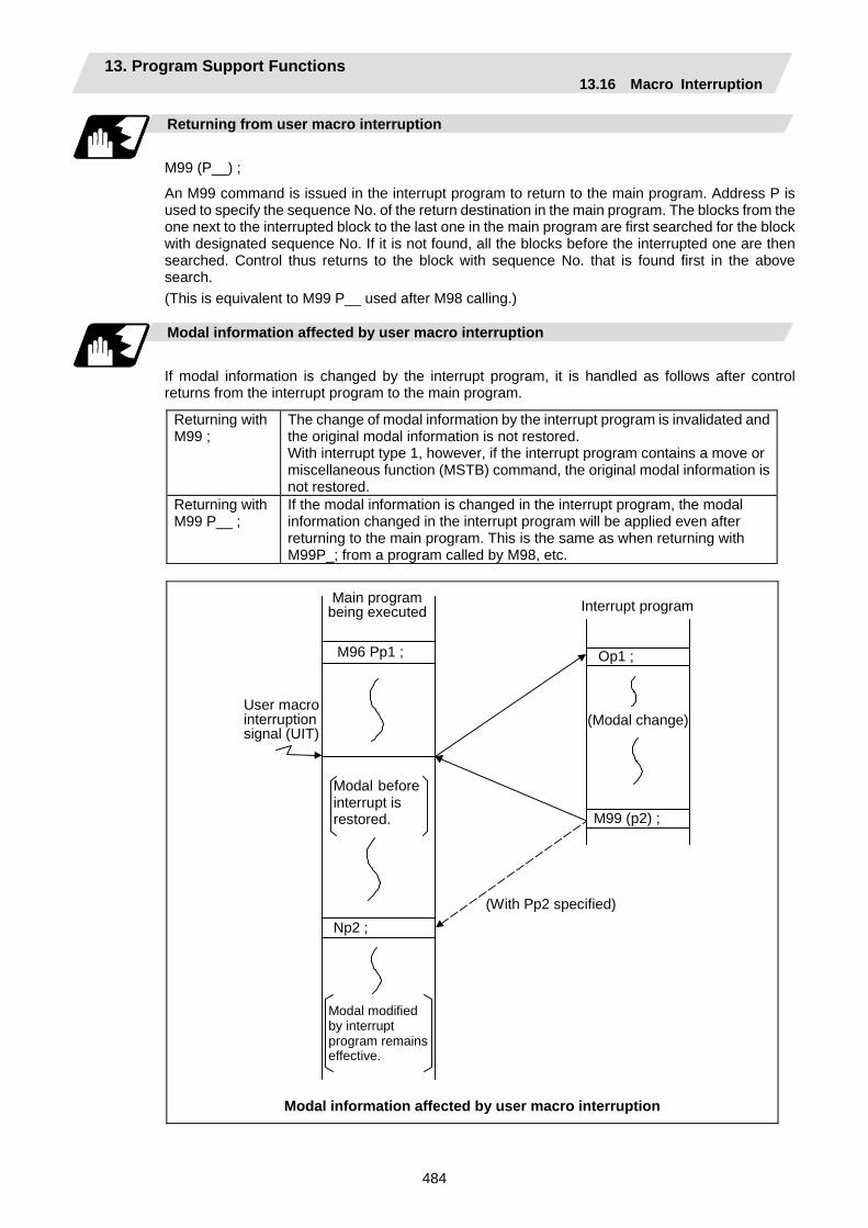
13. Program Support Functions 13.16 Macro Interruption
484
Returning from user macro interruption
M99 (P__) ;
An M99 command is issued in the interrupt program to return to the main program. Address P is used to specify the sequence No. of the return destination in the main program. The blocks from the one next to the interrupted block to the last one in the main program are first searched for the block with designated sequence No. If it is not found, all the blocks before the interrupted one are then searched. Control thus returns to the block with sequence No. that is found first in the above search. (This is equivalent to M99 P__ used after M98 calling.)
Modal information affected by user macro interruption
If modal information is changed by the interrupt program, it is handled as follows after control returns from the interrupt program to the main program.
Returning with M99 ;
The change of modal information by the interrupt program is invalidated and the original modal information is not restored. With interrupt type 1, however, if the interrupt program contains a move or miscellaneous function (MSTB) command, the original modal information is not restored.
Returning with M99 P__ ;
If the modal information is changed in the interrupt program, the modal information changed in the interrupt program will be applied even after returning to the main program. This is the same as when returning with M99P_; from a program called by M98, etc.
Modal modifiedby interrupt program remainseffective.
User macro interruption signal (UIT)
Interrupt program
M96 Pp1 ; Op1 ;
M99 (p2) ;
Np2 ;
(Modal change)
Modal beforeinterrupt is restored.
Main program being executed
(With Pp2 specified)
Modal information affected by user macro interruption

13. Program Support Functions 13.16 Macro Interruption
485
Modal information variables (#4401 to #4520)
Modal information when control passes to the user macro interruption program can be known by reading system variables #4401 to #4520. The unit specified with a command applies.
System variable Modal information
#4401 to #4421 G code (group 01 to group 21) Some groups are not used.#4507 D code #4509 F code #4511 H code #4513 M code #4514 Sequence No. #4515 Program No. (Note 1) #4519 S code #4520 T code
The above system variables are available only in the user macro interruption program. If they are used in other programs, program error (P241) results. (Note 1) The programs are registered as files. When the program No. (file name) is read with
#4515, the character string will be converted to a value. (Example 1) The file name "123" is the character string 0×31, 0×32, 0×33, so the value
will be (0×31–0×30)*100 + (0×32–0×30)*10 + (0×33–0×30) = 123.0. Note that if the file name contains characters other than numbers, it will be
"blank". (Example 2) If the file name is "123ABC", it contains characters other than numbers, so
the result will be "blank".
M code for control of user macro interruption
The user macro interruption is controlled by M96 and M97. However, these commands may have been used for other operation. To be prepared for such case, these command functions can be assigned to other M codes. (This invalidates program compatibility.) User macro interruption control with alternate M codes is possible by setting the alternate M code in parameters "#1110 M96_M" and "#1111 M97_M" and by validating the setting by selecting parameter "#1109 subs_M". (M codes 03 to 97 except 30 are available for this purpose.) If the parameter "#1109 subs_M" used to enable the alternate M codes is not selected, the M96 and M97 codes remain effective for user macro interruption control. In either case, the M codes for user macro interruption control are processed internally and not output to the outside.
13. Program Support Functions 13.16 Macro Interruption
486
Parameters
(1) Subprogram call validity "#1229 set01/bit 0"
1 : Subprogram type user macro interruption 0 : Macro type user macro interruption
(2) Status trigger mode validity "#1112 S_TRG"
1 : Status trigger mode 0 : Edge trigger mode
(3) Interrupt type 2 validity "#1113 INT_2"
1 : The executable statements in the interrupt program are executed after completion of execution of the current block. (Type 2)
0 : The executable statements in the interrupt program are executed before completion of execution of the current block. (Type 1)
(4) Validity of alternate M code for user macro interruption control "#1109 subs_M"
1 : Valid 0 : Invalid
(5) Alternate M codes for user macro interruption
Interrupt enable M code (equivalent to M96) "#1110 M96_M" Interrupt disable M code (equivalent to M97) "#1111 M97_M"
Restrictions
(1) If the user macro interruption program uses system variables #5001 and after (position
information) to read coordinates, the coordinates pre-read in the buffer are used.
(2) If an interrupt is caused during execution of the tool diameter compensation, a sequence No. (M99 P__ ;) must be specified with a command to return from the user macro interruption program. If no sequence No. is specified, control cannot return to the main program normally.
13. Program Support Functions 13.17 Tool Change Position Return
487
13.17 Tool Change Position Return; G30.1 to G30.5
Function and purpose
By specifying the tool change position in a parameter “#8206 tool change” and also specifying a tool change position return command in a machining program, the tool can be changed at the most appropriate position. The axes that are going to return to the tool change position and the order in which the axes begin to return can be changed by commands.
Command format
(1) The format of tool change position return commands is as follows.
G30.n ; n = 1 to 5 Specify the axes that return to the tool change position and the order in which
they return.
Commands and return order
Command Return order G30.1 X axis only ( → additional axis) G30.2 Z axis only ( → additional axis) G30.3 X axis → Z axis ( → additional axis) G30.4 Z axis → X axis ( → additional axis) G30.5 X axis • Z axis ( → additional axis)
(Note 1) An arrow ( → ) indicates the order of axes that begin to return. A period ( • ) indicates that the axes begin to return simultaneously. Example : "Z axis → X axis" indicate that the Z axis returns to the tool change
position, then the X axis does.
(2) The tool change position return on/off for the additional axis can be set with parameter "#1092 Tchg_A" for the additional axis. For the order for returning to the tool change position, the axes return after the standard axis completes the return to the tool change position (refer to above table). For specifications having two additional axes, the two additional axes simultaneously return to the tool change position after the standard axis has finished its return to the tool change position.
The additional axis alone cannot return to the tool change position. (3) When the axis address is commanded in the same block as the tool change position return
command, the program error (P33) will occur.
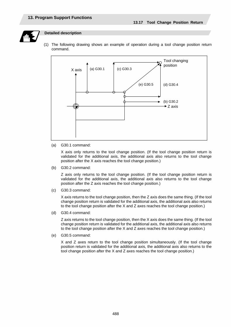
13. Program Support Functions 13.17 Tool Change Position Return
488
Detailed description
(1) The following drawing shows an example of operation during a tool change position return
command.
(a) G30.1 (c) G30.3
(e) G30.5 (d) G30.4
(b) G30.2
Tool changing position
X axis
Z axis
(a) G30.1 command:
X axis only returns to the tool change position. (If the tool change position return is validated for the additional axis, the additional axis also returns to the tool change position after the X axis reaches the tool change position.)
(b) G30.2 command:
Z axis only returns to the tool change position. (If the tool change position return is validated for the additional axis, the additional axis also returns to the tool change position after the Z axis reaches the tool change position.)
(c) G30.3 command:
X axis returns to the tool change position, then the Z axis does the same thing. (If the tool change position return is validated for the additional axis, the additional axis also returns to the tool change position after the X and Z axes reaches the tool change position.)
(d) G30.4 command:
Z axis returns to the tool change position, then the X axis does the same thing. (If the tool change position return is validated for the additional axis, the additional axis also returns to the tool change position after the X and Z axes reaches the tool change position.)
(e) G30.5 command:
X and Z axes return to the tool change position simultaneously. (If the tool change position return is validated for the additional axis, the additional axis also returns to the tool change position after the X and Z axes reaches the tool change position.)
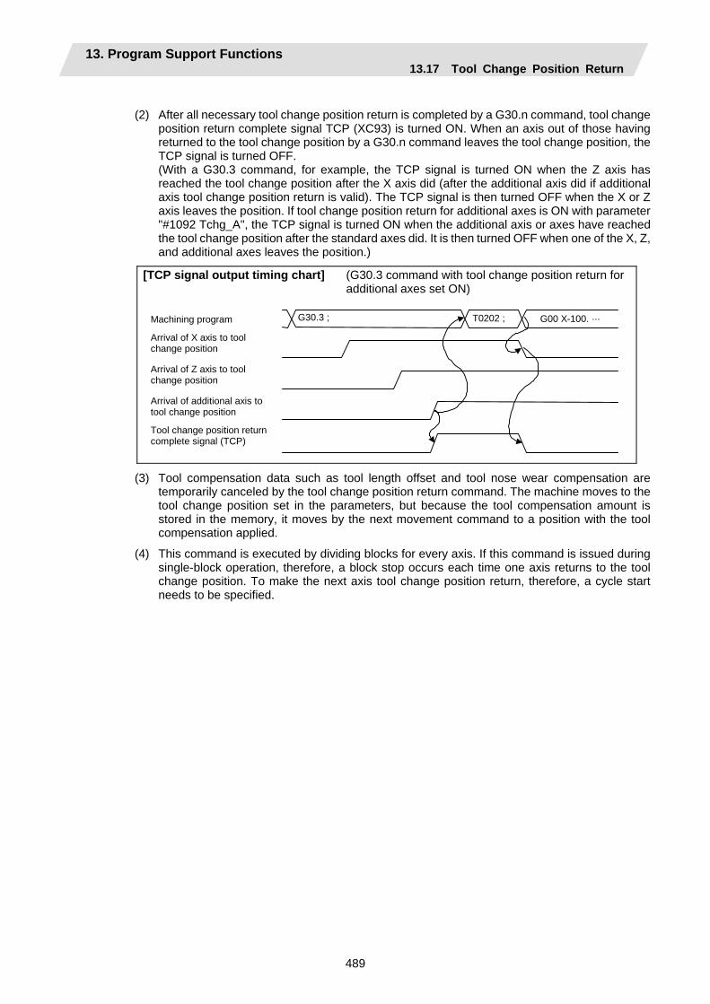
13. Program Support Functions 13.17 Tool Change Position Return
489
(2) After all necessary tool change position return is completed by a G30.n command, tool change
position return complete signal TCP (XC93) is turned ON. When an axis out of those having returned to the tool change position by a G30.n command leaves the tool change position, the TCP signal is turned OFF.
(With a G30.3 command, for example, the TCP signal is turned ON when the Z axis has reached the tool change position after the X axis did (after the additional axis did if additional axis tool change position return is valid). The TCP signal is then turned OFF when the X or Z axis leaves the position. If tool change position return for additional axes is ON with parameter "#1092 Tchg_A", the TCP signal is turned ON when the additional axis or axes have reached the tool change position after the standard axes did. It is then turned OFF when one of the X, Z, and additional axes leaves the position.)
[TCP signal output timing chart] (G30.3 command with tool change position return for additional axes set ON)
Machining program
Arrival of X axis to tool change position
Arrival of Z axis to tool change position
Arrival of additional axis to tool change position
Tool change position return complete signal (TCP)
G30.3 ; T0202 ; G00 X-100. ···
(3) Tool compensation data such as tool length offset and tool nose wear compensation are temporarily canceled by the tool change position return command. The machine moves to the tool change position set in the parameters, but because the tool compensation amount is stored in the memory, it moves by the next movement command to a position with the tool compensation applied.
(4) This command is executed by dividing blocks for every axis. If this command is issued during single-block operation, therefore, a block stop occurs each time one axis returns to the tool change position. To make the next axis tool change position return, therefore, a cycle start needs to be specified.
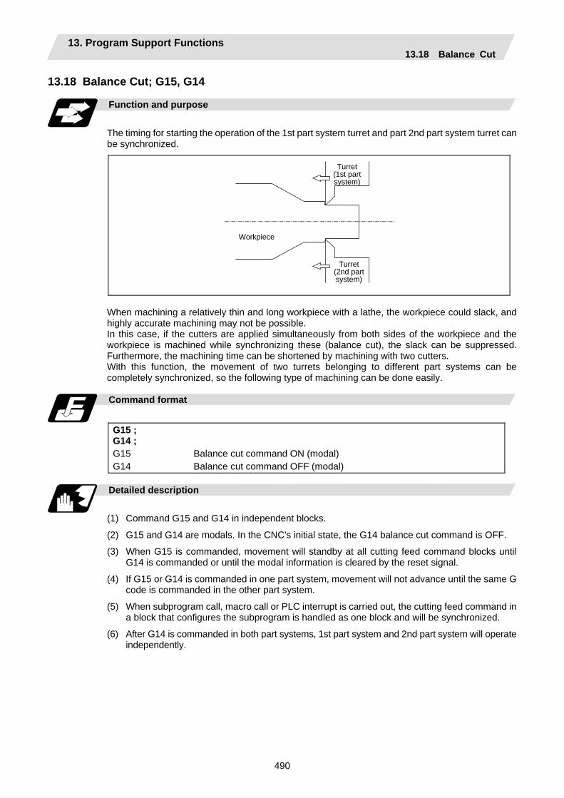
13. Program Support Functions 13.18 Balance Cut
490
13.18 Balance Cut; G15, G14
Function and purpose
The timing for starting the operation of the 1st part system turret and part 2nd part system turret can be synchronized.
Workpiece
Turret(1st part system)
Turret(2nd part system)
When machining a relatively thin and long workpiece with a lathe, the workpiece could slack, and highly accurate machining may not be possible. In this case, if the cutters are applied simultaneously from both sides of the workpiece and the workpiece is machined while synchronizing these (balance cut), the slack can be suppressed. Furthermore, the machining time can be shortened by machining with two cutters. With this function, the movement of two turrets belonging to different part systems can be completely synchronized, so the following type of machining can be done easily.
Command format
G15 ; G14 ; G15 G14
Balance cut command ON (modal) Balance cut command OFF (modal)
Detailed description
(1) Command G15 and G14 in independent blocks.
(2) G15 and G14 are modals. In the CNC's initial state, the G14 balance cut command is OFF.
(3) When G15 is commanded, movement will standby at all cutting feed command blocks until G14 is commanded or until the modal information is cleared by the reset signal.
(4) If G15 or G14 is commanded in one part system, movement will not advance until the same G code is commanded in the other part system.
(5) When subprogram call, macro call or PLC interrupt is carried out, the cutting feed command in a block that configures the subprogram is handled as one block and will be synchronized.
(6) After G14 is commanded in both part systems, 1st part system and 2nd part system will operate independently.

13. Program Support Functions 13.18 Balance Cut
491
Example of operation
1st part system
2nd part system
100 45
40
40
(3)(4) (5)
<1st part system>: G15 S200 G00 X40. Z-2. G01 W47. F10. G01 U40. W55. G14 G00 X100. : :
<2nd part system> : G15 G00 X40. Z-2. G01 W47. F5. G01 X80. Z100. F10.G14 G00 X100. : :
...(1)...(2)...(3)...(4)...(5)...(6)...(7)
1st part system 2nd part system
(1) (2) (3) (4) (5) (6) (7)
(1) (3) (4) (5) (6) (7)
Synchronized section Synchronizing
(1) Balance cut is turned ON with the G15 command.
(2) (3) The S command and rapid traverse command are not synchronized, so the operation will wait at (4).
(4) 1st part system will finish first, but since the next block is a cutting feed command, the operation will wait at the head of (5).
(5) Cutting will start with 1st part system and 2nd part system together.
(6) Balance cut is turned OFF with the G14 command.
(7) Each part system will operate independently after this.

13. Program Support Functions 13.18 Balance Cut
492
Example of program
An example of a program for machining with a 1-spindle 2-turret CNC lathe while simultaneously applying the cutters from the top and bottom of a thin long workpiece using balance cut is shown below.
Workpiece zero pointZ0
+Z
+X
+Z
+X
2nd part system
1st part system
1st part system
2nd part system
120 100
50
-50
15
-15X0
1st part system program G28 XZ ; S100 T0101 ; G15 ; G00 X15 Z-3 ; G01 Z100 F0.2 ; X50 Z120 ; X52 ; G14 ; G28 XZ ; M30 ;
2nd part system program G28 XZ ; T0101 ; G15 ; G00 X15 Z-3 ; G01 Z100 F0.2 ; X50 Z120 ; X52 ; G14 ; G28 XZ ; M30 ;
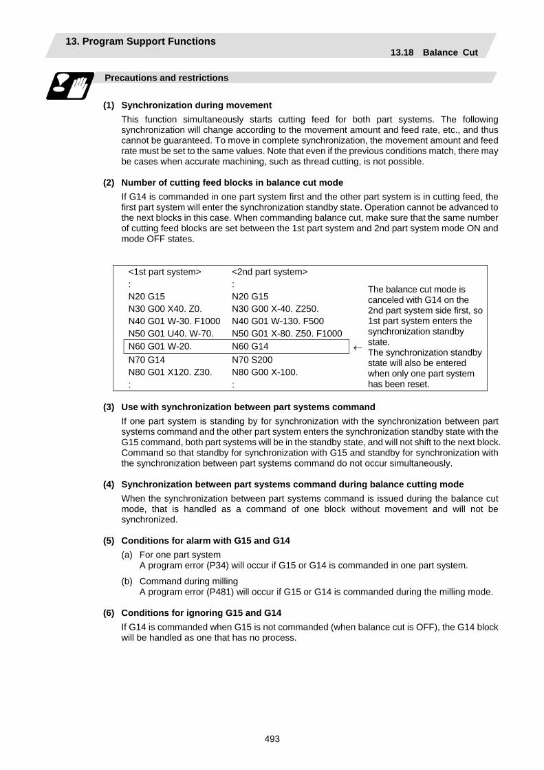
13. Program Support Functions 13.18 Balance Cut
493
Precautions and restrictions
(1) Synchronization during movement
This function simultaneously starts cutting feed for both part systems. The following synchronization will change according to the movement amount and feed rate, etc., and thus cannot be guaranteed. To move in complete synchronization, the movement amount and feed rate must be set to the same values. Note that even if the previous conditions match, there may be cases when accurate machining, such as thread cutting, is not possible.
(2) Number of cutting feed blocks in balance cut mode
If G14 is commanded in one part system first and the other part system is in cutting feed, the first part system will enter the synchronization standby state. Operation cannot be advanced to the next blocks in this case. When commanding balance cut, make sure that the same number of cutting feed blocks are set between the 1st part system and 2nd part system mode ON and mode OFF states.
<1st part system> : N20 G15 N30 G00 X40. Z0. N40 G01 W-30. F1000 N50 G01 U40. W-70.
<2nd part system> : N20 G15 N30 G00 X-40. Z250. N40 G01 W-130. F500 N50 G01 X-80. Z50. F1000
N60 G01 W-20. N60 G14 ← N70 G14
N80 G01 X120. Z30. :
N70 S200 N80 G00 X-100. :
The balance cut mode is canceled with G14 on the 2nd part system side first, so 1st part system enters the synchronization standby state. The synchronization standby state will also be entered when only one part system has been reset.
(3) Use with synchronization between part systems command
If one part system is standing by for synchronization with the synchronization between part systems command and the other part system enters the synchronization standby state with the G15 command, both part systems will be in the standby state, and will not shift to the next block. Command so that standby for synchronization with G15 and standby for synchronization with the synchronization between part systems command do not occur simultaneously.
(4) Synchronization between part systems command during balance cutting mode When the synchronization between part systems command is issued during the balance cut mode, that is handled as a command of one block without movement and will not be synchronized.
(5) Conditions for alarm with G15 and G14 (a) For one part system A program error (P34) will occur if G15 or G14 is commanded in one part system.
(b) Command during milling A program error (P481) will occur if G15 or G14 is commanded during the milling mode.
(6) Conditions for ignoring G15 and G14 If G14 is commanded when G15 is not commanded (when balance cut is OFF), the G14 block will be handled as one that has no process.
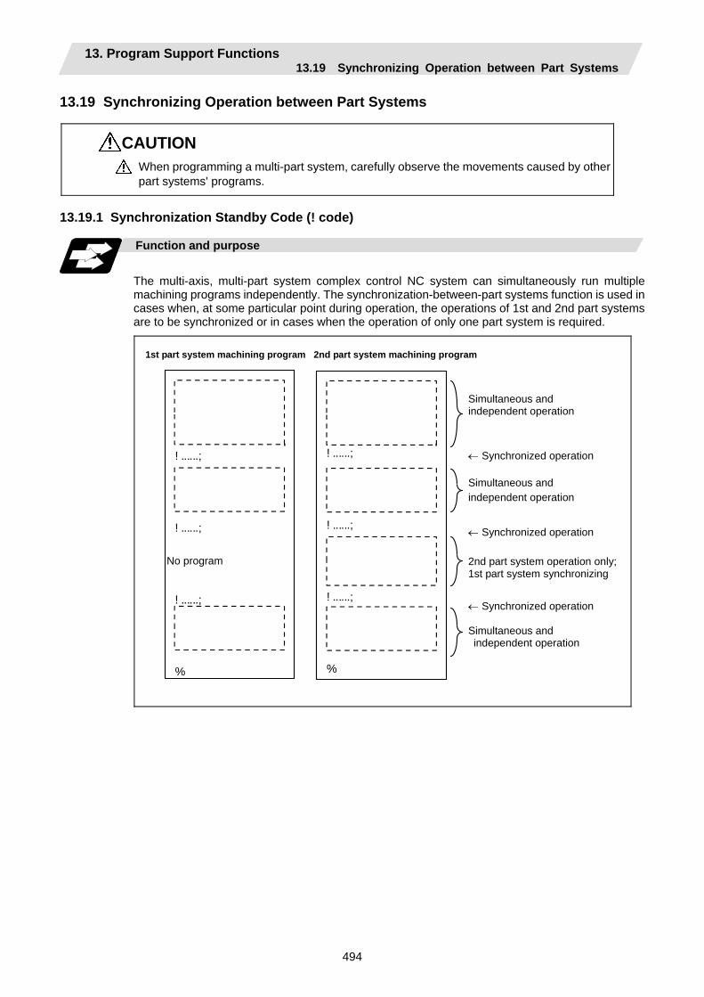
13. Program Support Functions 13.19 Synchronizing Operation between Part Systems
494
13.19 Synchronizing Operation between Part Systems
CAUTION When programming a multi-part system, carefully observe the movements caused by other part systems' programs.
13.19.1 Synchronization Standby Code (! code)
Function and purpose
The multi-axis, multi-part system complex control NC system can simultaneously run multiple machining programs independently. The synchronization-between-part systems function is used in cases when, at some particular point during operation, the operations of 1st and 2nd part systems are to be synchronized or in cases when the operation of only one part system is required.
! ......;
! ......;
! ......;
%
! ......;
! ......;
! ......;
%
Simultaneous and independent operation
← Synchronized operation Simultaneous and independent operation
← Synchronized operation 2nd part system operation only;1st part system synchronizing
← Synchronized operation Simultaneous and independent operation
2nd part system machining program1st part system machining program
No program
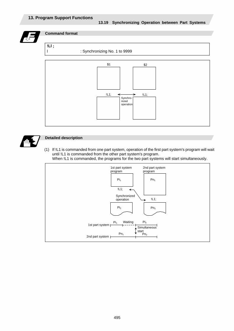
13. Program Support Functions 13.19 Synchronizing Operation between Part Systems
495
Command format
!Ll ; l : Synchronizing No. 1 to 9999
$1 $2
!L1; !L1;Synchro- nized operation
Detailed description
(1) If !L1 is commanded from one part system, operation of the first part system's program will wait
until !L1 is commanded from the other part system's program. When !L1 is commanded, the programs for the two part systems will start simultaneously.
1st part systemprogram
2nd part systemprogram
Pi1 Pn1
Pn2Pi2
Pn1
Pi1 Pi2
Pn2
1st part system
2nd part system
Waiting
Simultaneousstart
Synchronizedoperation
!L1;
!L1;

13. Program Support Functions 13.19 Synchronizing Operation between Part Systems
496
(2) Program error (P35) occurs when an illegal part system No. has been issued.
(3) The synchronizing command is normally issued in a single block. However, if a movement command or M, S or T command is issued in the same block, whether to synchronize after the movement command or M, S or T command or to execute the movement command or M, S or T command after synchronization will depend on the parameter (#1093 Wmvfin).
#1093 Wmvfin 0: Synchronize before executing movement command. 1: Synchronize after executing movement command.
(4) If there is no movement command in the same block as the synchronizing command, when the next block movement starts, synchronization may not be secured between the part systems. To synchronize the part systems when movement starts after synchronization, issue the movement command in the same block as the synchronizing command.
(5) Synchronizing is done only while the part system to be synchronized is operating automatically. If this is not possible, the synchronizing command will be ignored and operation will advance to the next block.
(6) The L command is the synchronizing identification No. The same Nos. are synchronized but when they are omitted, the Nos. are handled as L0.
(7) "SYN" will appear in the operation status section during synchronization. The synchronizing signal will be output to the PLC I/F.
Example of synchronization between part systems
$1 $2
P11
!L1;
P12
!L2;
P13
P21
!L1;
P22
P23
!L2;
P24
The above programs are executed as follows:
$2
$1 P11
P21
L1 L2
P12 P13
P24P23P22
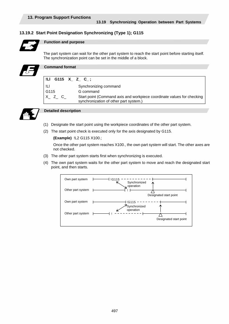
13. Program Support Functions 13.19 Synchronizing Operation between Part Systems
497
13.19.2 Start Point Designation Synchronizing (Type 1); G115
Function and purpose
The part system can wait for the other part system to reach the start point before starting itself. The synchronization point can be set in the middle of a block.
Command format
!Ll G115 X_ Z_ C_ ;
!Ll Synchronizing command G115 G command X_ Z_ C_ Start point (Command axis and workpiece coordinate values for checking
synchronization of other part system.)
Detailed description
(1) Designate the start point using the workpiece coordinates of the other part system.
(2) The start point check is executed only for the axis designated by G115.
(Example) !L2 G115 X100.;
Once the other part system reaches X100., the own part system will start. The other axes are not checked.
(3) The other part system starts first when synchronizing is executed.
(4) The own part system waits for the other part system to move and reach the designated start point, and then starts.
!G115
!
!G115
!
Own part system Other part system Own part system Other part system
Designated start point
Designated start point
Synchronized operation
Synchronized operation

13. Program Support Functions 13.19 Synchronizing Operation between Part Systems
498
(5) When the start point designated by G115 is not on the next block movement path of the other part system, the own part system starts once the other part system has reached all of the start point axis coordinates.
X also has passed
Z has passed
Example:
: Movement : Command point : Actual start point
X
Z
(6) The waiting status continues when the G115 command has been duplicated between part systems.
Own part system !L1 G115
!L1 G115 Other part system
Waiting
(7) The single block stop function does not apply for the G115 block.
(8) A program error (P32) will occur if an address other than an axis is designated in G115 command block.
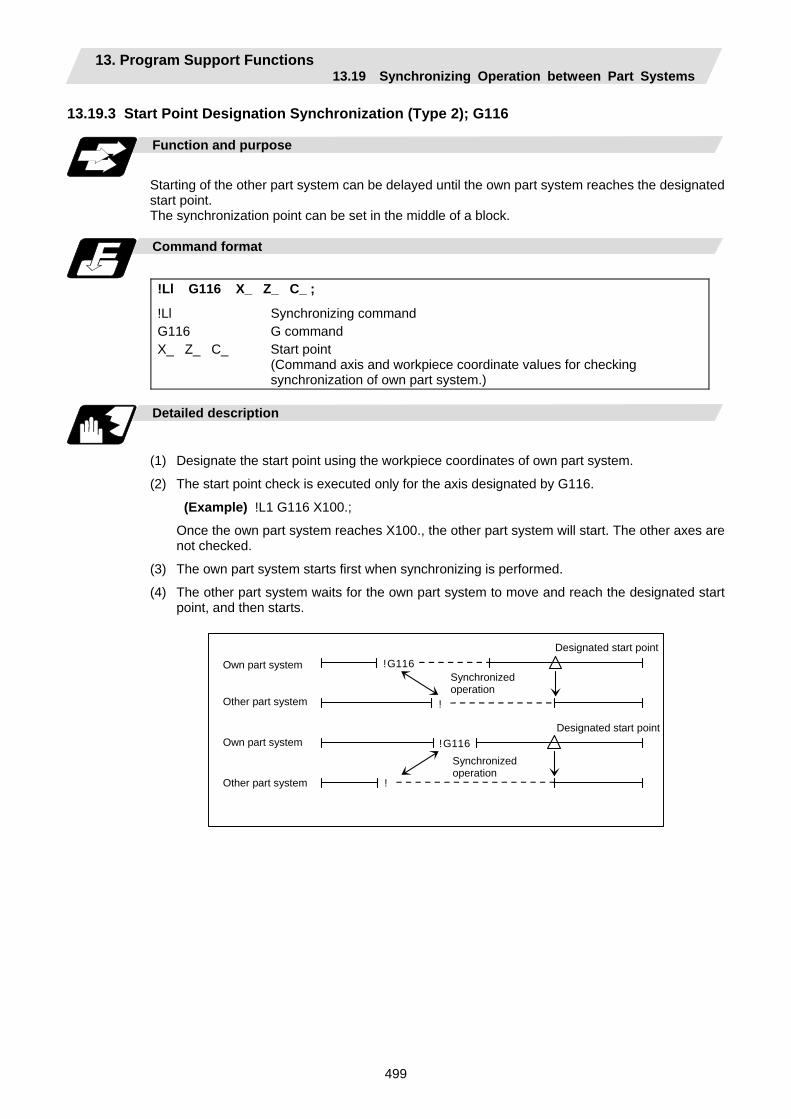
13. Program Support Functions 13.19 Synchronizing Operation between Part Systems
499
13.19.3 Start Point Designation Synchronization (Type 2); G116
Function and purpose
Starting of the other part system can be delayed until the own part system reaches the designated start point. The synchronization point can be set in the middle of a block.
Command format
!Ll G116 X_ Z_ C_ ;
!Ll Synchronizing command G116 G command X_ Z_ C_ Start point
(Command axis and workpiece coordinate values for checking synchronization of own part system.)
Detailed description
(1) Designate the start point using the workpiece coordinates of own part system.
(2) The start point check is executed only for the axis designated by G116.
(Example) !L1 G116 X100.;
Once the own part system reaches X100., the other part system will start. The other axes are not checked.
(3) The own part system starts first when synchronizing is performed.
(4) The other part system waits for the own part system to move and reach the designated start point, and then starts.
!G116
!
!G116
!
Own part system Other part system Own part system Other part system
Designated start point
Designated start point
Synchronized operation
Synchronized operation
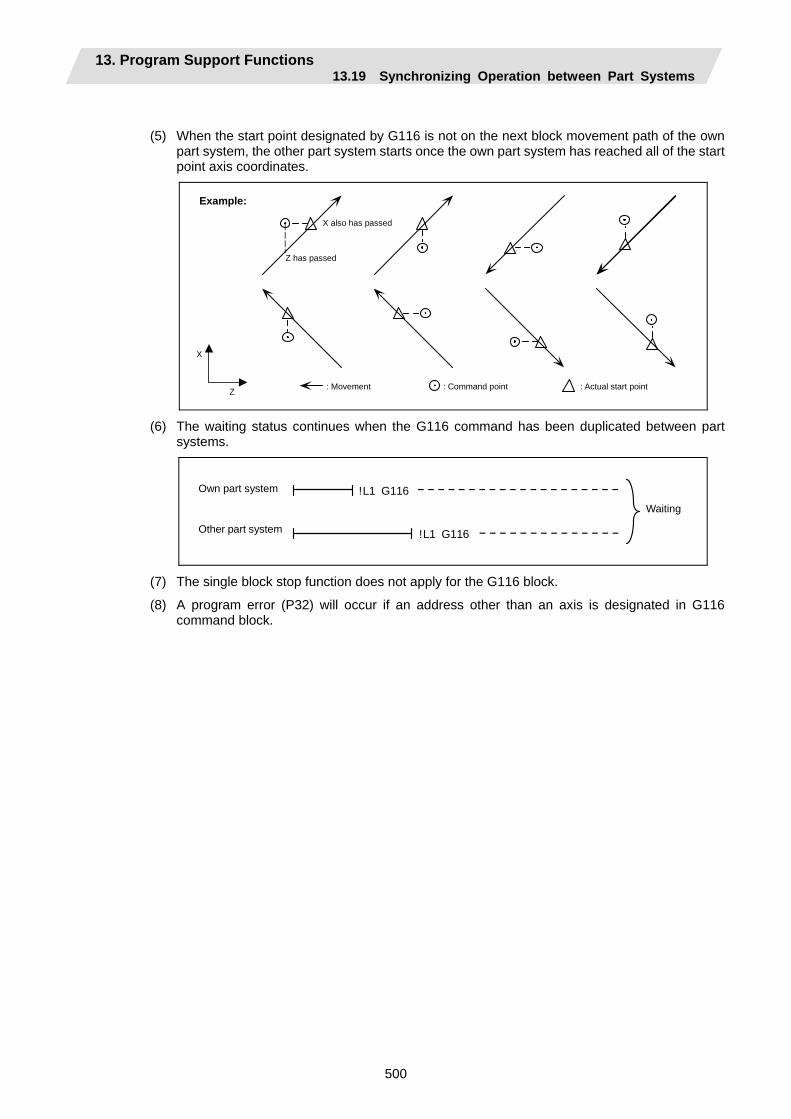
13. Program Support Functions 13.19 Synchronizing Operation between Part Systems
500
(5) When the start point designated by G116 is not on the next block movement path of the own part system, the other part system starts once the own part system has reached all of the start point axis coordinates.
X also has passed
X
Z
Z has passed
Example:
: Movement : Command point : Actual start point
(6) The waiting status continues when the G116 command has been duplicated between part systems.
!L1 G116
!L1 G116
Waiting
Own part system Other part system
(7) The single block stop function does not apply for the G116 block.
(8) A program error (P32) will occur if an address other than an axis is designated in G116 command block.
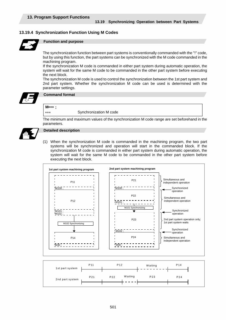
13. Program Support Functions 13.19 Synchronizing Operation between Part Systems
501
13.19.4 Synchronization Function Using M Codes
Function and purpose
The synchronization function between part systems is conventionally commanded with the "!" code, but by using this function, the part systems can be synchronized with the M code commanded in the machining program. If the synchronization M code is commanded in either part system during automatic operation, the system will wait for the same M code to be commanded in the other part system before executing the next block. The synchronization M code is used to control the synchronization between the 1st part system and 2nd part system. Whether the synchronization M code can be used is determined with the parameter settings.
Command format
M∗∗∗ ; ∗∗∗ Synchronization M code
The minimum and maximum values of the synchronization M code range are set beforehand in the parameters.
Detailed description
(1) When the synchronization M code is commanded in the machining program, the two part
systems will be synchronized and operation will start in the commanded block. If the synchronization M code is commanded in either part system during automatic operation, the system will wait for the same M code to be commanded in the other part system before executing the next block.
1st part system machining program
P11 P21
M100 ; M100 ;
P12
P22
M101 ;
M101 ; M102 ;
P23
M102 ;
P14 P24
M30 ; M30 ;
Simultaneous and independent operation
2nd part system operation only;1st part system waits
Synchronized operation
Synchronized operation
Synchronized operation
M101 Synchronizing
M102 Synchronizing
2nd part system machining program
Simultaneous and independent operation
Simultaneous and independent operation
1st part system
2nd part sys tem
P 11 P 12 P 14
P21 P22 P 24 P 23
W aiting
W aiting
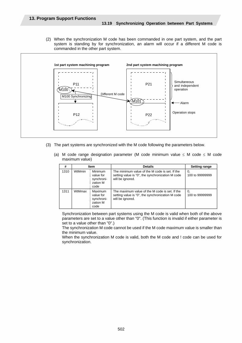
13. Program Support Functions 13.19 Synchronizing Operation between Part Systems
502
(2) When the synchronization M code has been commanded in one part system, and the part
system is standing by for synchronization, an alarm will occur if a different M code is commanded in the other part system.
1st part system machining program 2nd part system machining program
P11 P21M100 ;
M101 ;
P12 P22
Simultaneous and independentoperation
Alarm
Operation stops
M100 Synchronizing Different M code
(3) The part systems are synchronized with the M code following the parameters below.
(a) M code range designation parameter (M code minimum value ≤ M code ≤ M code maximum value)
# Item Details Setting range 1310 WtMmin Minimum
value for synchroni- zation M code
The minimum value of the M code is set. If the setting value is "0", the synchronization M code will be ignored.
0, 100 to 99999999
1311 WtMmax Maximum value for synchroni- zation M code
The maximum value of the M code is set. If the setting value is "0", the synchronization M code will be ignored.
0, 100 to 99999999
Synchronization between part systems using the M code is valid when both of the above parameters are set to a value other than "0". (This function is invalid if either parameter is set to a value other than "0".)
The synchronization M code cannot be used if the M code maximum value is smaller than the minimum value.
When the synchronization M code is valid, both the M code and ! code can be used for synchronization.
13. Program Support Functions 13.19 Synchronizing Operation between Part Systems
503
(b) Synchronization method parameters
# Item Details Setting range 1279 (PR)
ext15 (bit0)
Method for synchroni- zation between part systems
Select an operation for synchronization between part systems. 0: If one of the part systems is not in automatic
operation, ignore the synchronization command and execute the next block.
1: Operate according to the synchronization ignore signal. If the synchronization ignore signal is "1", the synchronization command will be ignored. If "0", the part systems will be synchronized.
0 / 1
Depending on the synchronization method selection parameter and synchronization ignore signal combination, the synchronization operation will be determined by the parameters, regardless of the command format ("!" code and M code).
(c) Synchronization method pattern
# Item Details Setting range 1093 Wmvfin Method for
synchroni- zation between part systems
Designate the synchronization between part systems method when using multi-part systems. When there is a movement command in the synchronization command (!, M) block: 0: Synchronize before executing movement
command 1: Synchronize after executing movement
command
0 / 1
Precautions and restrictions
(1) When synchronizing with the M code, always command the M code in an independent block.
(2) When standing by after commanding the synchronization M code in one part system, an alarm will occur if a different M code is commanded in the other part system. Operation will stop in both part systems.
(3) The M code in the machining program can be ignored with the synchronization ignore signal. Operation with a single part system is possible without deleting the M code in the machining program.
(4) When the M code can be used, both the M code and ! code can be used.
(5) While the synchronization M code is valid, if one part system is standing by with an M code, an alarm will occur if there is a ! code synchronization command in the other part system.
(6) While the synchronization M code is valid, if one part system is standing by with a ! code, an alarm will occur if there is an M code synchronization command in the other part system.
(7) The G115 and G116 commands cannot be used when synchronizing with the M code.
(8) If the M code command Nos. are overlapped, the order of priority will be M code macro, M command synchronous tap, synchronization M code and normal M code.
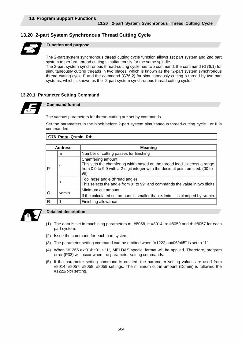
13. Program Support Functions 13.20 2-part System Synchronous Thread Cutting Cycle
504
13.20 2-part System Synchronous Thread Cutting Cycle
Function and purpose
The 2-part system synchronous thread cutting cycle function allows 1st part system and 2nd part system to perform thread cutting simultaneously for the same spindle. The 2-part system synchronous thread-cutting cycle has two command; the command (G76.1) for simultaneously cutting threads in two places, which is known as the "2-part system synchronous thread cutting cycle I" and the command (G76.2) for simultaneously cutting a thread by two part systems, which is known as the "2-part system synchronous thread cutting cycle II"
13.20.1 Parameter Setting Command
Command format
The various parameters for thread-cutting are set by commands.
Set the parameters in the block before 2-part system simultaneous thread-cutting cycle I or II is commanded.
G76 Pmra Q∆min Rd;
Address Meaning m Number of cutting passes for finishing
r
Chamfering amount This sets the chamfering width based on the thread lead 1 across a range from 0.0 to 9.9 with a 2-digit integer with the decimal point omitted. (00 to 99)
P
a Tool nose angle (thread angle) This selects the angle from 0° to 99° and commands the value in two digits.
Q ∆dmin Minimum cut amount If the calculated cut amount is smaller than ∆dmin, it is clamped by ∆dmin.
R d Finishing allowance
Detailed description
(1) The data is set in machining parameters m: #8058, r: #8014, a: #8059 and d: #8057 for each
part system.
(2) Issue the command for each part system.
(3) The parameter setting command can be omitted when "#1222 aux06/bit5" is set to "1".
(4) When "#1265 ext01/bit0" is "1", MELDAS special format will be applied. Therefore, program error (P33) will occur when the parameter setting commands.
(5) If the parameter setting command is omitted, the parameter setting values are used from #8014, #8057, #8058, #8059 settings. The minimum cut-in amount (Ddmin) is followed the #1222/bit4 setting.

13. Program Support Functions 13.20 2-part System Synchronous Thread Cutting Cycle
505
13.20.2 2-part System Synchronous Thread Cutting Cycle I; G76.1
Command format
G76.1 X/U Z/W Ri Pk Q∆d Fl;
X/U X-axis end point coordinates of thread section ... The X-axis coordinates of the end point at the thread section are
commanded with absolute or incremental values. Z/W Z-axis end point coordinates of thread section ... The Z-axis coordinates of the end point at the thread section are
commanded with absolute or incremental values. i Taper height component (radial value) at thread section ... A straight thread is created when i = 0. k Thread height ... The thread height is commanded with a positive radial value. ∆d Cut amount ... The cut amount for the first cutting pass is commanded with a
positive radial value. l Thread lead
Detailed description
(1) When G76.1 is issued by 1st part system and 2nd part system, synchronized operation is done
until the command is issued to another part system. The thread-cutting cycle starts when the commands are aligned properly.
$1 $2
G00X_ Z_ ;
G76.1… ; G00X_ Z_ ;
G76.1… ;
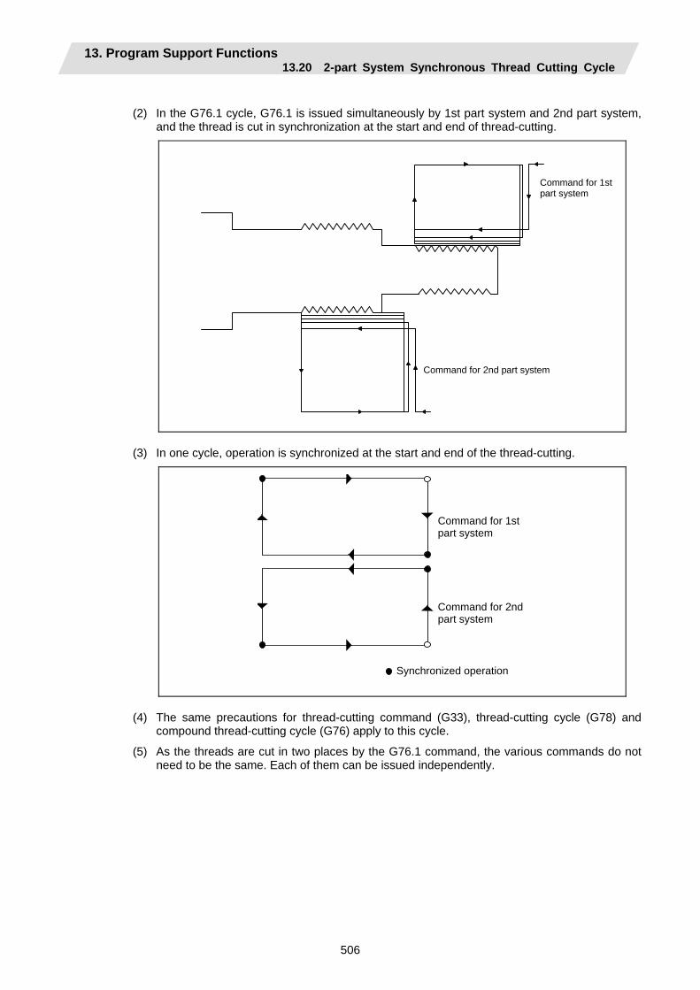
13. Program Support Functions 13.20 2-part System Synchronous Thread Cutting Cycle
506
(2) In the G76.1 cycle, G76.1 is issued simultaneously by 1st part system and 2nd part system,
and the thread is cut in synchronization at the start and end of thread-cutting.
Command for 1st part system
Command for 2nd part system
(3) In one cycle, operation is synchronized at the start and end of the thread-cutting.
Synchronized operation
Command for 1st part system
Command for 2nd part system
(4) The same precautions for thread-cutting command (G33), thread-cutting cycle (G78) and
compound thread-cutting cycle (G76) apply to this cycle.
(5) As the threads are cut in two places by the G76.1 command, the various commands do not need to be the same. Each of them can be issued independently.
13. Program Support Functions 13.20 2-part System Synchronous Thread Cutting Cycle
507
(6) Thread cutting controls the Z axis position while tracking the spindle encoder rotation. Thus, the relative relation of the spindle position detected by the spindle encoder and the Z axis will change with the following elements.
(a) Z axis feed rate (spindle rotation speed ∗ screw pitch)
(b) Cutting feed acceleration/deceleration time constant
(c) Position loop gain
Thus, when cutting a multi-thread screw, the above conditions must be the same from the start to end of machining.
(7) This function is unmodal. So it needs to be commanded each time.
(8) G group 1 modal (G00, G01, G02, G03, G02.3, G03.3 etc.) is canceled temporarily during 2-part system synchronous thread cutting.
(9) Thread cutting start shift angle is not available in G76.1. A program error (P32) will occur if commanded.
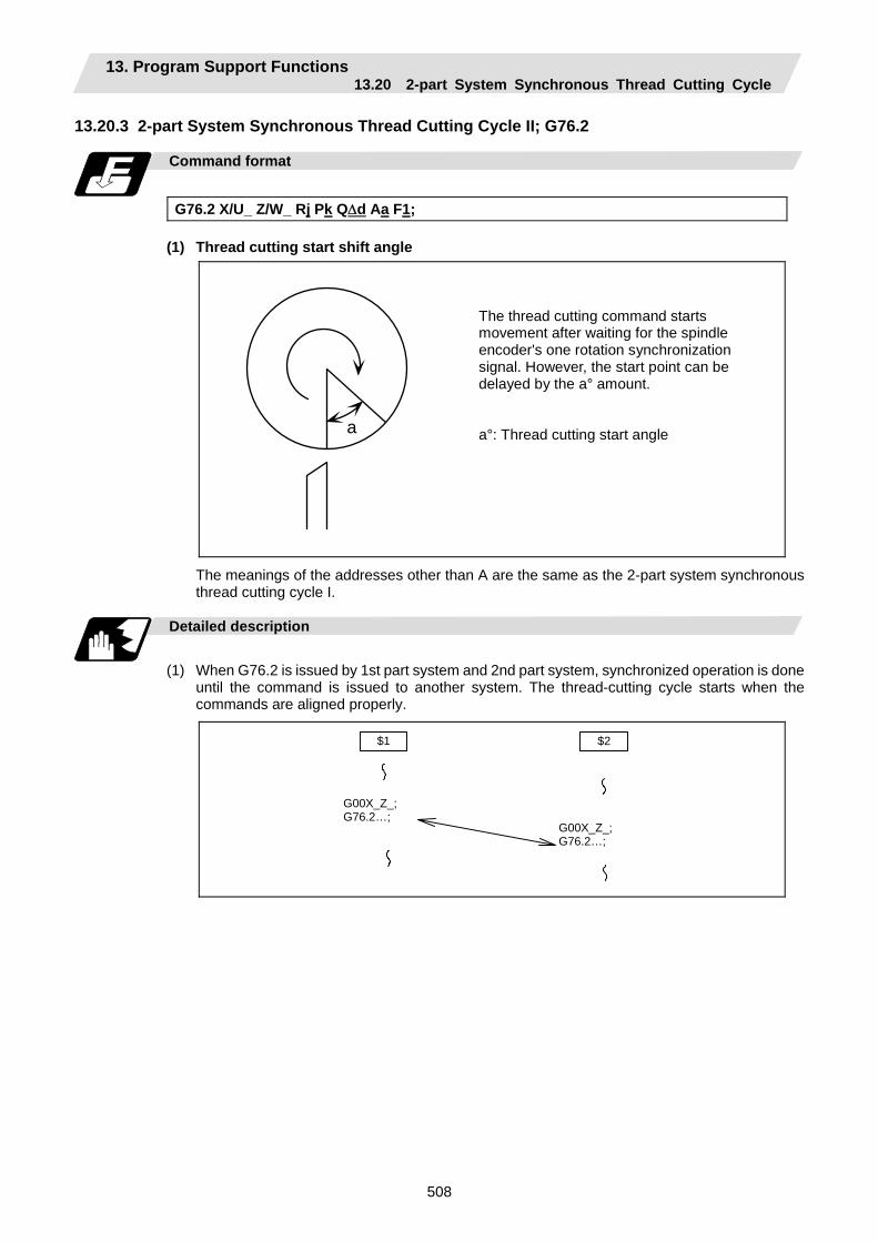
13. Program Support Functions 13.20 2-part System Synchronous Thread Cutting Cycle
508
13.20.3 2-part System Synchronous Thread Cutting Cycle II; G76.2
Command format
G76.2 X/U_ Z/W_ Rj Pk Q∆d Aa F1;
(1) Thread cutting start shift angle
a
The thread cutting command starts movement after waiting for the spindle encoder's one rotation synchronization signal. However, the start point can be delayed by the a° amount. a°: Thread cutting start angle
The meanings of the addresses other than A are the same as the 2-part system synchronous thread cutting cycle I.
Detailed description
(1) When G76.2 is issued by 1st part system and 2nd part system, synchronized operation is done
until the command is issued to another system. The thread-cutting cycle starts when the commands are aligned properly.
$1 $2
G00X_Z_; G76.2…;
G00X_Z_; G76.2…;

13. Program Support Functions 13.20 2-part System Synchronous Thread Cutting Cycle
509
(2) G76.2 assumes the same thread cutting, and deeply cuts in with the cutting amount using 1st
part system and 2nd part system alternately.
K
a°
Finishing allowance d
(1).......Cutting with 1st part system
(2).......Cutting with 2nd part system
(1) (1) (1) (1) (1) (2) (2) (2) (2)(2)
d
d × n
d × 2
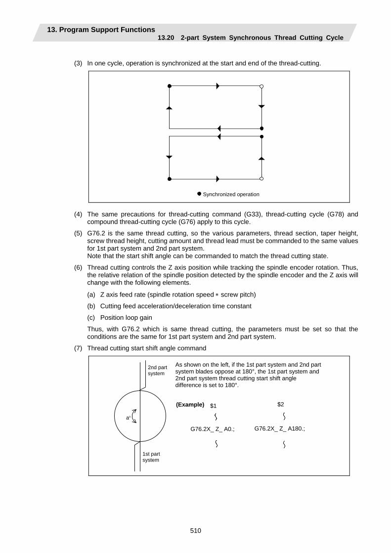
13. Program Support Functions 13.20 2-part System Synchronous Thread Cutting Cycle
510
(3) In one cycle, operation is synchronized at the start and end of the thread-cutting.
Synchronized operation (4) The same precautions for thread-cutting command (G33), thread-cutting cycle (G78) and
compound thread-cutting cycle (G76) apply to this cycle.
(5) G76.2 is the same thread cutting, so the various parameters, thread section, taper height, screw thread height, cutting amount and thread lead must be commanded to the same values for 1st part system and 2nd part system.
Note that the start shift angle can be commanded to match the thread cutting state.
(6) Thread cutting controls the Z axis position while tracking the spindle encoder rotation. Thus, the relative relation of the spindle position detected by the spindle encoder and the Z axis will change with the following elements.
(a) Z axis feed rate (spindle rotation speed ∗ screw pitch)
(b) Cutting feed acceleration/deceleration time constant
(c) Position loop gain
Thus, with G76.2 which is same thread cutting, the parameters must be set so that the conditions are the same for 1st part system and 2nd part system.
(7) Thread cutting start shift angle command
a°
2nd part system
1st part system
As shown on the left, if the 1st part system and 2nd part system blades oppose at 180°, the 1st part system and 2nd part system thread cutting start shift angle difference is set to 180°.
(Example) $1 $2
G76.2X_ Z_ A0.; G76.2X_ Z_ A180.;

13. Program Support Functions 13.20 2-part System Synchronous Thread Cutting Cycle
511
(8) When G76.2 and G76.1 are commanded The part systems, in which each are commanded, will carry out the G76.1 and G76.2
movements. However, the part system in which G76.2 is commanded will assume that the other part system is using G76.2 when cutting the threads, so the thread grooves will not be guaranteed.
(9) This function is unmodal. So it needs to be commanded each time.
(10) G group 1 modal (G00, G01, G02, G03, G02.3, G03.3 etc.) is canceled temporarily during 2-part system synchronous thread cutting.
(11) Reset simultaneously for 1st part system and 2nd part system during 2-part system synchronous thread cutting cycle II (G76.2). If reset is individually executed for each part system, the part system is not in automatic operation. Thus, the other part system keeps moving according to #1279 setting.

13. Program Support Functions 13.21 2-part System Simultaneous Thread-cutting Cycle (MELDAS special format)
512
13.21 2-part System Simultaneous Thread-cutting Cycle (MELDAS special format)
Function and purpose
The 2-part system simultaneous thread-cutting cycle function allows 1st part system and 2nd part system to perform thread-cutting simultaneously for the same spindle. Featured in this cycle is the command (G76.1) for simultaneously cutting threads in two places, which is known as the "2-part system simultaneous thread-cutting cycle I". When using the MELDAS special format (#1265 ext01/bit1 ON), some addresses differ from the normal format. The sections that differ from the normal format are shown below. Refer to section "13.21 2-part System Simultaneous Thread-cutting Cycle" for details on the 2-part system simultaneous thread-cutting cycle.
Command format
G76.1 X/U Z/W Ii Kk D∆d Fl Aa; G76.1 X/U Z/W Ii Kk D∆d Qq Fl Aa;
X/U : X-axis end point coordinates of thread section The X-axis coordinates of the end point at the thread section are commanded with absolute or incremental values.
Z/W : Z-axis end point coordinates of thread section The Z-axis coordinates of the end point at the thread section are commanded with absolute or incremental values.
i : Taper height component (radial value) at thread section A straight thread is created when i = 0.
k : Thread height The thread height is commanded with a positive radial value.
∆d : Cut amount The cut amount for the first cutting pass is commanded with a positive radial value.
q : Thread cutting start shift angle l : Thread lead a : Tool nose angle (thread angle)
(Note 1) This is 1 block command. It is not necessary to command "G76P__Q_R_" immediately before.
Precautions and restrictions
(1) The switch of MELDAS special format and a normal format can be selected by setting
"#1265/bit0". (0: Nonal format, 1: MELDAS special format)
(2) A program error (P33) will occur if a G76 P__Q_R_ command or a normal format is commanded when MELDAS special format is selected.
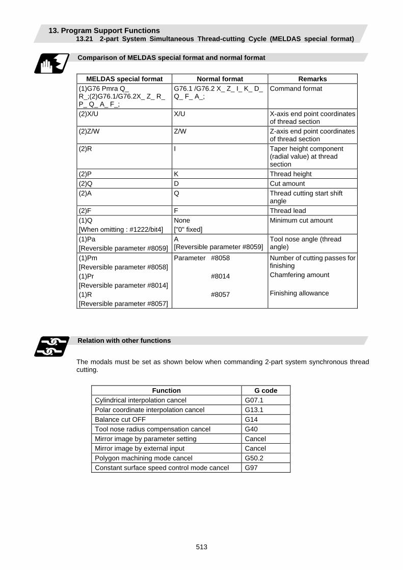
13. Program Support Functions 13.21 2-part System Simultaneous Thread-cutting Cycle (MELDAS special format)
513
Comparison of MELDAS special format and normal format
MELDAS special format Normal format Remarks
(1)G76 Pmra Q_ R_;(2)G76.1/G76.2X_ Z_ R_ P_ Q_ A_ F_;
G76.1 /G76.2 X_ Z_ I_ K_ D_ Q_ F_ A_;
Command format
(2)X/U X/U X-axis end point coordinates of thread section
(2)Z/W Z/W Z-axis end point coordinates of thread section
(2)R I Taper height component (radial value) at thread section
(2)P K Thread height (2)Q D Cut amount (2)A Q Thread cutting start shift
angle (2)F F Thread lead (1)Q [When omitting : #1222/bit4]
None ["0" fixed]
Minimum cut amount
(1)Pa [Reversible parameter #8059]
A [Reversible parameter #8059]
Tool nose angle (thread angle)
(1)Pm [Reversible parameter #8058](1)Pr [Reversible parameter #8014](1)R [Reversible parameter #8057]
Parameter #8058 #8014 #8057
Number of cutting passes for finishing Chamfering amount Finishing allowance
Relation with other functions
The modals must be set as shown below when commanding 2-part system synchronous thread cutting.
Function G code Cylindrical interpolation cancel G07.1 Polar coordinate interpolation cancel G13.1 Balance cut OFF G14 Tool nose radius compensation cancel G40 Mirror image by parameter setting Cancel Mirror image by external input Cancel Polygon machining mode cancel G50.2 Constant surface speed control mode cancel G97
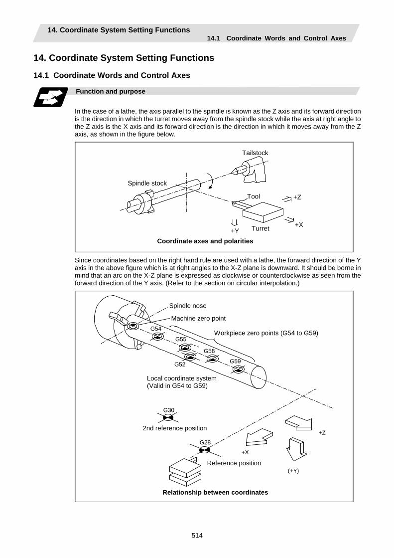
14. Coordinate System Setting Functions 14.1 Coordinate Words and Control Axes
514
14. Coordinate System Setting Functions 14.1 Coordinate Words and Control Axes
Function and purpose
In the case of a lathe, the axis parallel to the spindle is known as the Z axis and its forward direction is the direction in which the turret moves away from the spindle stock while the axis at right angle to the Z axis is the X axis and its forward direction is the direction in which it moves away from the Z axis, as shown in the figure below.
Spindle stock
Tailstock
Tool
Turret +X +Y
+Z
Coordinate axes and polarities
Since coordinates based on the right hand rule are used with a lathe, the forward direction of the Y axis in the above figure which is at right angles to the X-Z plane is downward. It should be borne in mind that an arc on the X-Z plane is expressed as clockwise or counterclockwise as seen from the forward direction of the Y axis. (Refer to the section on circular interpolation.)
G54
G52
G58
G55
G59
G30
G28
+X
(+Y)
+Z
Spindle nose
Machine zero point
Workpiece zero points (G54 to G59)
Local coordinate system(Valid in G54 to G59)
2nd reference position
Reference position
Relationship between coordinates
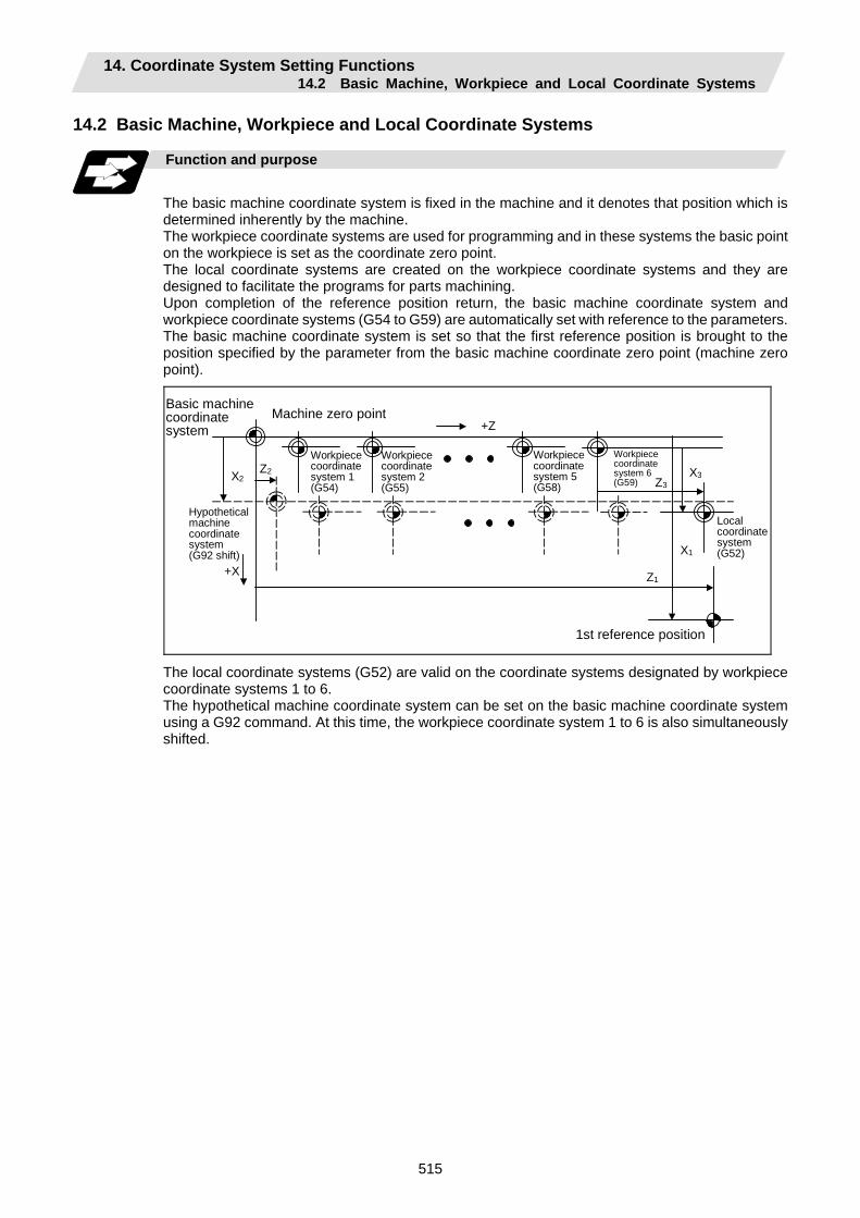
14. Coordinate System Setting Functions 14.2 Basic Machine, Workpiece and Local Coordinate Systems
515
14.2 Basic Machine, Workpiece and Local Coordinate Systems
Function and purpose
The basic machine coordinate system is fixed in the machine and it denotes that position which is determined inherently by the machine. The workpiece coordinate systems are used for programming and in these systems the basic point on the workpiece is set as the coordinate zero point. The local coordinate systems are created on the workpiece coordinate systems and they are designed to facilitate the programs for parts machining. Upon completion of the reference position return, the basic machine coordinate system and workpiece coordinate systems (G54 to G59) are automatically set with reference to the parameters. The basic machine coordinate system is set so that the first reference position is brought to the position specified by the parameter from the basic machine coordinate zero point (machine zero point).
X1
X3
+X
+Z
Z1
X2 Z2
1st reference position
Basic machinecoordinate system
Workpiececoordinatesystem 1 (G54)
Workpiececoordinatesystem 2 (G55)
Workpiececoordinatesystem 5 (G58)
Workpiece coordinate system 6 (G59)
Machine zero point
Hypothetical machine coordinate system (G92 shift)
Local coordinate system (G52)
Z3
The local coordinate systems (G52) are valid on the coordinate systems designated by workpiece coordinate systems 1 to 6. The hypothetical machine coordinate system can be set on the basic machine coordinate system using a G92 command. At this time, the workpiece coordinate system 1 to 6 is also simultaneously shifted.
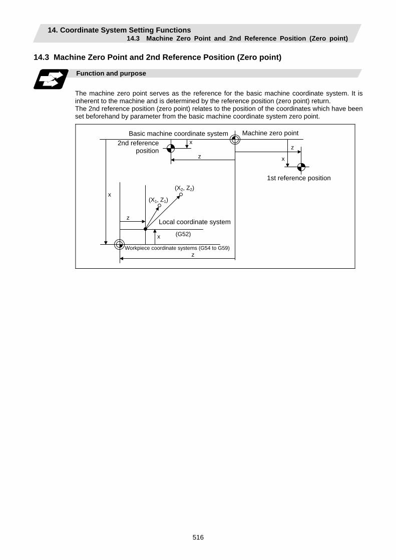
14. Coordinate System Setting Functions 14.3 Machine Zero Point and 2nd Reference Position (Zero point)
516
14.3 Machine Zero Point and 2nd Reference Position (Zero point)
Function and purpose
The machine zero point serves as the reference for the basic machine coordinate system. It is inherent to the machine and is determined by the reference position (zero point) return. The 2nd reference position (zero point) relates to the position of the coordinates which have been set beforehand by parameter from the basic machine coordinate system zero point.
(X1, Z1)
(G52)
x
z
x
z
x
z
(X2, Z2)
x
z
Machine zero point
Local coordinate system
Workpiece coordinate systems (G54 to G59)
Basic machine coordinate system2nd reference
position
1st reference position
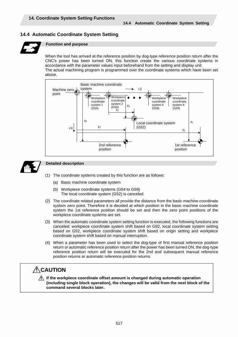
14. Coordinate System Setting Functions 14.4 Automatic Coordinate System Setting
517
14.4 Automatic Coordinate System Setting
Function and purpose
When the tool has arrived at the reference position by dog-type reference position return after the CNC's power has been turned ON, this function create the various coordinate systems in accordance with the parameter values input beforehand from the setting and display unit. The actual machining program is programmed over the coordinate systems which have been set above.
+Z
x3
+X
z3
z2
x2
z1
x1
1st reference position
Workpiececoordinatesystem 1(G54)
Local coordinate system (G52)
Basic machine coordinate system
Workpiece coordinate system 2(G55)
Workpiececoordinatesystem 5(G58)
Workpiece coordinate system 6 (G59)
2nd reference position
Machine zero point
Detailed description
(1) The coordinate systems created by this function are as follows:
(a) Basic machine coordinate system
(b) Workpiece coordinate systems (G54 to G59) The local coordinate system (G52) is canceled.
(2) The coordinate related parameters all provide the distance from the basic machine coordinate system zero point. Therefore it is decided at which position in the basic machine coordinate system the 1st reference position should be set and then the zero point positions of the workpiece coordinate systems are set.
(3) When the automatic coordinate system setting function is executed, the following functions are canceled: workpiece coordinate system shift based on G92, local coordinate system setting based on G52, workpiece coordinate system shift based on origin setting and workpiece coordinate system shift based on manual interruption.
(4) When a parameter has been used to select the dog-type of first manual reference position return or automatic reference position return after the power has been turned ON, the dog-type reference position return will be executed for the 2nd and subsequent manual reference position returns or automatic reference position returns.
CAUTION If the workpiece coordinate offset amount is changed during automatic operation (including single block operation), the changes will be valid from the next block of the command several blocks later.
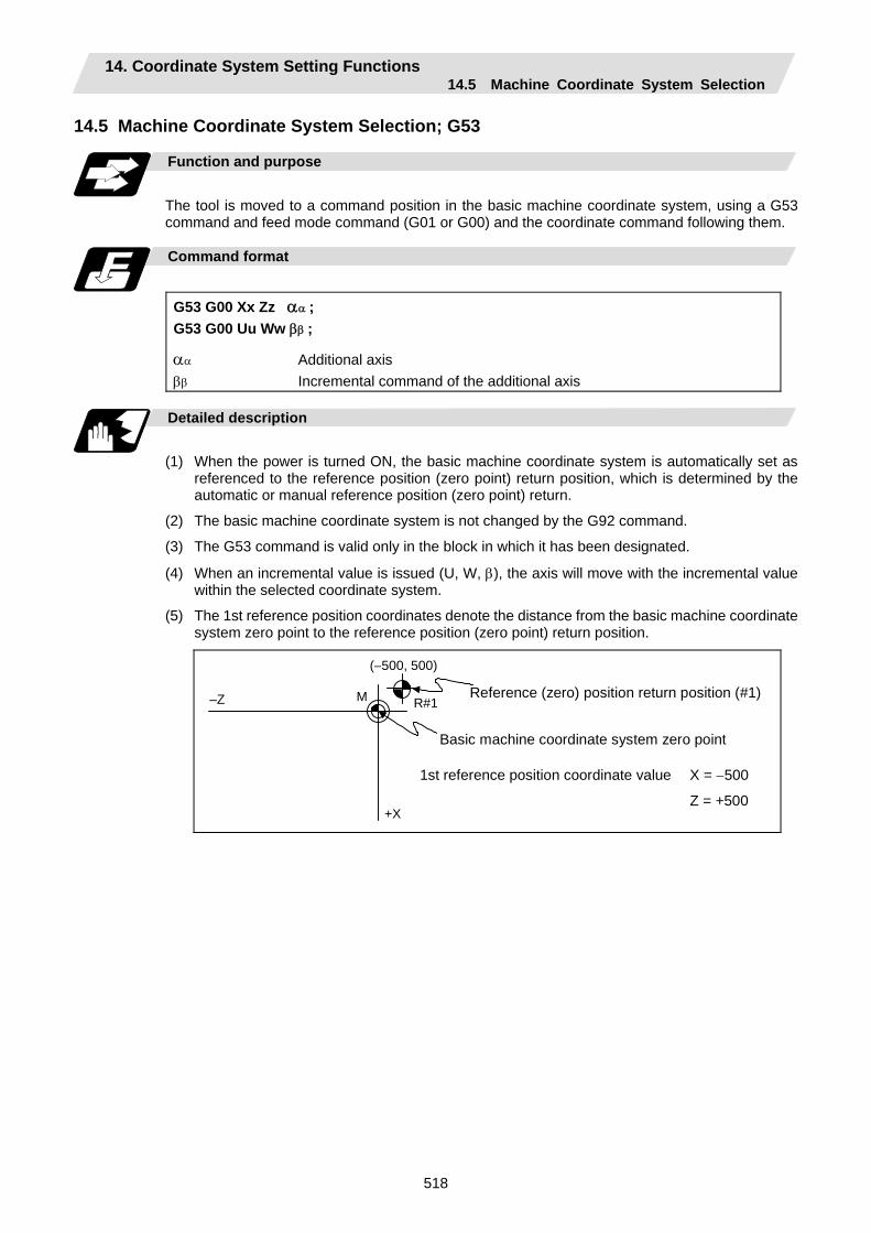
14. Coordinate System Setting Functions 14.5 Machine Coordinate System Selection
518
14.5 Machine Coordinate System Selection; G53
Function and purpose
The tool is moved to a command position in the basic machine coordinate system, using a G53 command and feed mode command (G01 or G00) and the coordinate command following them.
Command format
G53 G00 Xx Zz αα ; G53 G00 Uu Ww ββ ;
αα Additional axis ββ Incremental command of the additional axis
Detailed description
(1) When the power is turned ON, the basic machine coordinate system is automatically set as
referenced to the reference position (zero point) return position, which is determined by the automatic or manual reference position (zero point) return.
(2) The basic machine coordinate system is not changed by the G92 command.
(3) The G53 command is valid only in the block in which it has been designated.
(4) When an incremental value is issued (U, W, β), the axis will move with the incremental value within the selected coordinate system.
(5) The 1st reference position coordinates denote the distance from the basic machine coordinate system zero point to the reference position (zero point) return position.
(–500, 500)
+X
–Z R#1M Reference (zero) position return position (#1)
Basic machine coordinate system zero point
1st reference position coordinate value X = −500
Z = +500
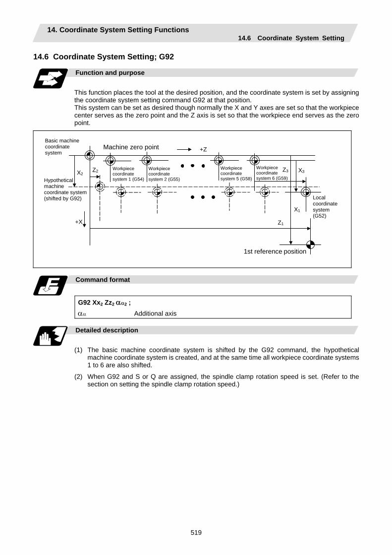
14. Coordinate System Setting Functions 14.6 Coordinate System Setting
519
14.6 Coordinate System Setting; G92
Function and purpose
This function places the tool at the desired position, and the coordinate system is set by assigning the coordinate system setting command G92 at that position. This system can be set as desired though normally the X and Y axes are set so that the workpiece center serves as the zero point and the Z axis is set so that the workpiece end serves as the zero point.
+Z
+X
Z2
Z1
X1
X2 Z3 X3 Workpiece coordinate system 1 (G54)
Workpiece coordinate system 2 (G55)
Workpiece coordinate system 5 (G58)
Workpiece coordinate system 6 (G59)
1st reference position
Machine zero point
Local coordinate system (G52)
Hypothetical machine coordinate system (shifted by G92)
Basic machine coordinate system
Command format
G92 Xx2 Zz2 αα2 ; αα Additional axis
Detailed description
(1) The basic machine coordinate system is shifted by the G92 command, the hypothetical
machine coordinate system is created, and at the same time all workpiece coordinate systems 1 to 6 are also shifted.
(2) When G92 and S or Q are assigned, the spindle clamp rotation speed is set. (Refer to the section on setting the spindle clamp rotation speed.)

14. Coordinate System Setting Functions 14.7 Reference Position (Zero point) Return
520
14.7 Reference Position (Zero point) Return; G28, G29
Function and purpose
(1) After the commanded axes have been positioned by G0, they are returned respectively at rapid
traverse to the 1st reference position (zero point) when G28 is commanded.
(2) By commanding G29, the axes are first positioned independently at high speed to the G28 or G30 intermediate point and then positioned by G0 at the commanded position.
Intermediate point (x1, z1, α1)
Machine zero point
Start point
2nd reference position
Start point
G30
(x3, z3, α3)
(x2, z2, α2)
G29 G30
G28 G29
G28 (0, 0)
1st reference position
Command format
G28 Xx1 Zz1 αα1 ; Additional axis Automatic reference position return G29 Xx2 Zz2 αα2 ; Additional axis Start position return
αα1/αα2 Additional axis
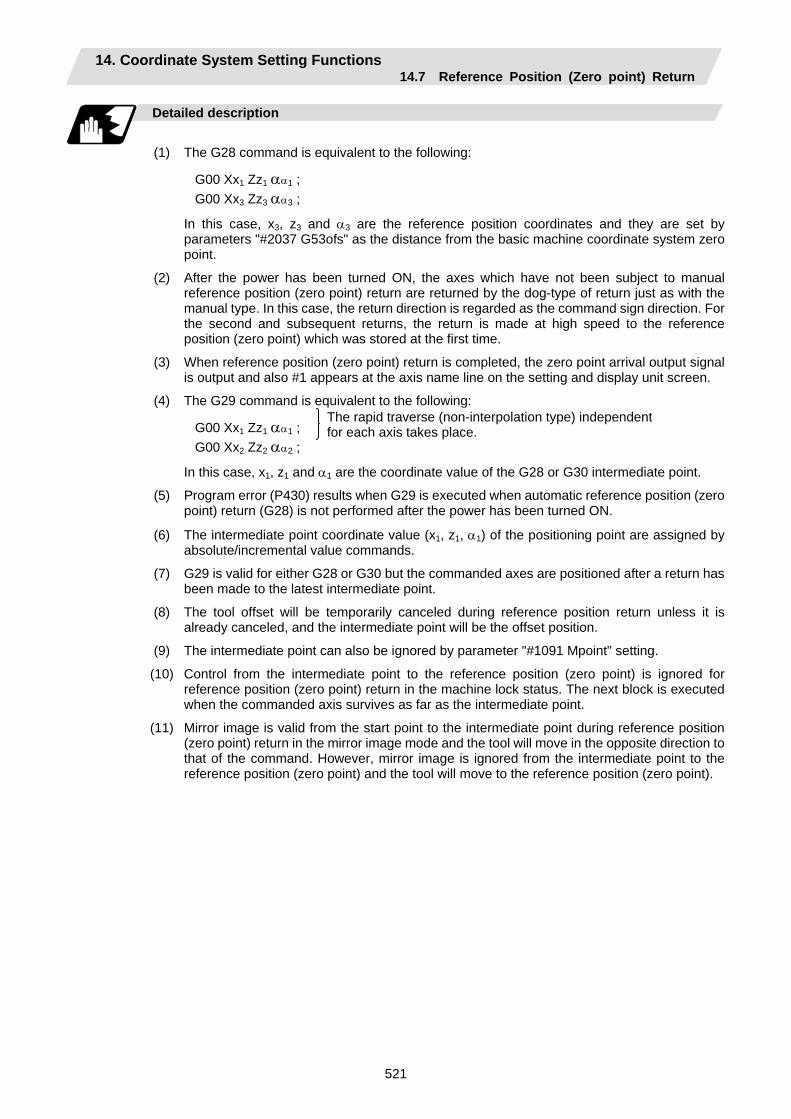
14. Coordinate System Setting Functions 14.7 Reference Position (Zero point) Return
521
Detailed description
(1) The G28 command is equivalent to the following:
G00 Xx1 Zz1 αα1 ; G00 Xx3 Zz3 αα3 ;
In this case, x3, z3 and α3 are the reference position coordinates and they are set by parameters "#2037 G53ofs" as the distance from the basic machine coordinate system zero point.
(2) After the power has been turned ON, the axes which have not been subject to manual reference position (zero point) return are returned by the dog-type of return just as with the manual type. In this case, the return direction is regarded as the command sign direction. For the second and subsequent returns, the return is made at high speed to the reference position (zero point) which was stored at the first time.
(3) When reference position (zero point) return is completed, the zero point arrival output signal is output and also #1 appears at the axis name line on the setting and display unit screen.
(4) The G29 command is equivalent to the following:
G00 Xx1 Zz1 αα1 ; G00 Xx2 Zz2 αα2 ;
In this case, x1, z1 and α1 are the coordinate value of the G28 or G30 intermediate point.
(5) Program error (P430) results when G29 is executed when automatic reference position (zero point) return (G28) is not performed after the power has been turned ON.
(6) The intermediate point coordinate value (x1, z1, α1) of the positioning point are assigned by absolute/incremental value commands.
(7) G29 is valid for either G28 or G30 but the commanded axes are positioned after a return has been made to the latest intermediate point.
(8) The tool offset will be temporarily canceled during reference position return unless it is already canceled, and the intermediate point will be the offset position.
(9) The intermediate point can also be ignored by parameter "#1091 Mpoint" setting.
(10) Control from the intermediate point to the reference position (zero point) is ignored for reference position (zero point) return in the machine lock status. The next block is executed when the commanded axis survives as far as the intermediate point.
(11) Mirror image is valid from the start point to the intermediate point during reference position (zero point) return in the mirror image mode and the tool will move in the opposite direction to that of the command. However, mirror image is ignored from the intermediate point to the reference position (zero point) and the tool will move to the reference position (zero point).
The rapid traverse (non-interpolation type) independent for each axis takes place.
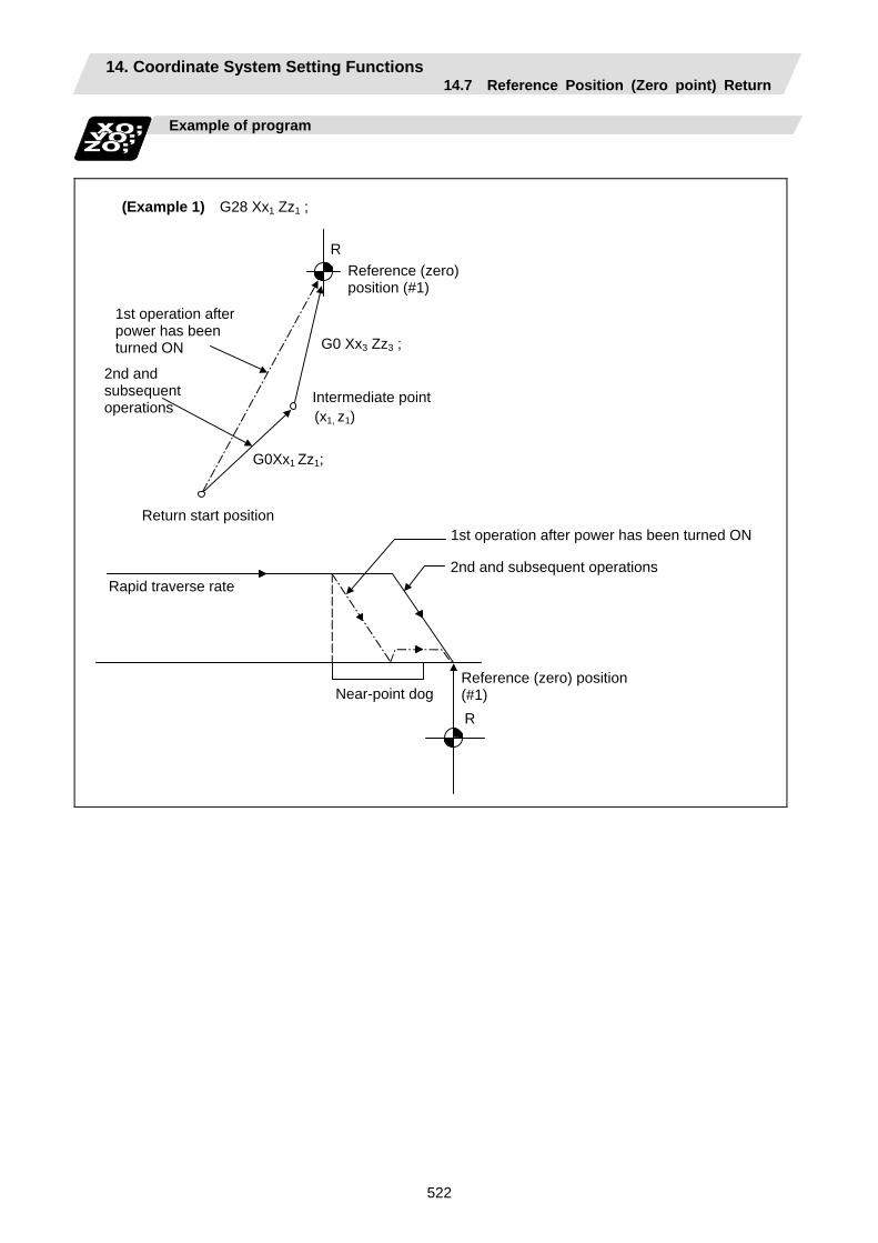
14. Coordinate System Setting Functions 14.7 Reference Position (Zero point) Return
522
Example of program
Near-point dog
Intermediate point
1st operation after power has been turned ON
Reference (zero) position (#1)
Rapid traverse rate
2nd and subsequent operations
Return start position
(Example 1) G28 Xx1 Zz1 ;
R
R
G0 Xx3 Zz3 ;
G0Xx1 Zz1;
1st operation after power has been turned ON
2nd and subsequent operations
Reference (zero) position (#1)
(x1, z1)

14. Coordinate System Setting Functions 14.7 Reference Position (Zero point) Return
523
Present position
G28, G30 intermediate point (x1, z1)
(Example 2) G29 Xx2 Zz2 ; R
(G0) Xx1 Zz1 ;
G0 Xx2 Zz2 ;
(x2, z2)
(Example 3) G28 Xx1 Zz1 ; : (From point A to reference (zero) position)
G30 Xx2 Zz2 ;
: (From point B to 2nd reference (zero) position)
G29 Xx3 Zz3 ; (From point C to point D)
(x1, z1)
C
G29B
G28
A
DG30
(x2, z2)
(x3, z3)R2
Reference (zero) position (#1) Present position New intermediate point
Old intermediate point2nd reference (zero) position (#2)
R1

14. Coordinate System Setting Functions 14.8 2nd, 3rd, and 4th Reference Position (Zero point) Return
524
14.8 2nd, 3rd, and 4th Reference Position (Zero point) Return; G30
Function and purpose
The tool can return to the 2nd, 3rd, or 4th reference position (zero point) by specifying G30 P2 (P3 or P4).
Start point
Reference position
3rd reference position
Intermediate point
4th reference position
2nd reference position
G28
G29
G29
G30
G30P3G30P4
G30P
(x1, z1, α1)
G28
R#2
R#4 R#3
Command format
G30 P2 (P3, P4) Xx1 Zz1 αα1 ;
αα1 Additional axis
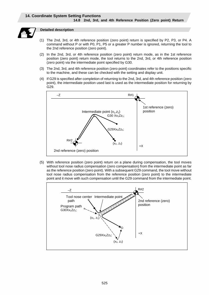
14. Coordinate System Setting Functions 14.8 2nd, 3rd, and 4th Reference Position (Zero point) Return
525
Detailed description
(1) The 2nd, 3rd, or 4th reference position (zero point) return is specified by P2, P3, or P4. A
command without P or with P0, P1, P5 or a greater P number is ignored, returning the tool to the 2nd reference position (zero point).
(2) In the 2nd, 3rd, or 4th reference position (zero point) return mode, as in the 1st reference position (zero point) return mode, the tool returns to the 2nd, 3rd, or 4th reference position (zero point) via the intermediate point specified by G30.
(3) The 2nd, 3rd, and 4th reference position (zero point) coordinates refer to the positions specific to the machine, and these can be checked with the setting and display unit.
(4) If G29 is specified after completion of returning to the 2nd, 3rd, and 4th reference position (zero point), the intermediate position used last is used as the intermediate position for returning by G29.
R#2 (x2, z2)
G29Xx2Zz2;
R#1
Intermediate point (x1,z1) G30 Xx1Zz1;
–Z
+X
1st reference (zero) position
2nd reference (zero) position (5) With reference position (zero point) return on a plane during compensation, the tool moves
without tool nose radius compensation (zero compensation) from the intermediate point as far as the reference position (zero point). With a subsequent G29 command, the tool move without tool nose radius compensation from the reference position (zero point) to the intermediate point and it move with such compensation until the G29 command from the intermediate point.
R#2
(x2, z2)
G29Xx2Zz2;
(x1, z1)
+X
–Z
Program path G30Xx1Zz1;
Tool nose center path
Intermediate point 2nd reference (zero) position
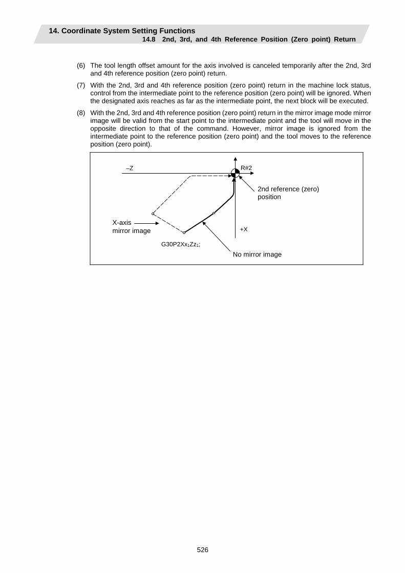
14. Coordinate System Setting Functions 14.8 2nd, 3rd, and 4th Reference Position (Zero point) Return
526
(6) The tool length offset amount for the axis involved is canceled temporarily after the 2nd, 3rd
and 4th reference position (zero point) return.
(7) With the 2nd, 3rd and 4th reference position (zero point) return in the machine lock status, control from the intermediate point to the reference position (zero point) will be ignored. When the designated axis reaches as far as the intermediate point, the next block will be executed.
(8) With the 2nd, 3rd and 4th reference position (zero point) return in the mirror image mode mirror image will be valid from the start point to the intermediate point and the tool will move in the opposite direction to that of the command. However, mirror image is ignored from the intermediate point to the reference position (zero point) and the tool moves to the reference position (zero point).
R#2
+X
–Z
G30P2Xx1Zz1;
2nd reference (zero) position
X-axis mirror image
No mirror image
14. Coordinate System Setting Functions 14.9 Reference Position Collation
527
14.9 Reference Position Collation; G27
Function and purpose
This command first positions the tool at the position assigned by the program and then, if that positioning point is the 1st reference position, it outputs the reference position arrival signal to the machine in the same way as with the G28 command. Therefore, when a machining program is prepared so that the tool will depart from the 1st reference position and return to the 1st reference position, it is possible to check whether the tool has returned to the reference position after the program has been run.
Command format
G27 Xx1 Zz1 αα1 Pp1 ;
G27 Collation command Xx1 Zz1 αα1 Return control axis Pp1 Collation No.
P1 : 1st reference position collation P2 : 2nd reference position collation
P3 : 3rd reference position collation P4 : 4th reference position collation
Detailed description
(1) If the P command has been omitted, the 1st reference position will be collated.
(2) The number of axes whose reference positions can be collated simultaneously depends on the number of axes which can be controlled simultaneously.
(3) An alarm will occur if the reference position is not reached after the command is completed.
14. Coordinate System Setting Functions 14.10 Workpiece Coordinate System Setting and Offset
528
14.10 Workpiece Coordinate System Setting and Offset; G54 to G59 (G54.1)
Function and purpose
(1) The workpiece coordinate systems facilitate the programming on the workpiece, serving the
basic point of the machining workpiece as the zero point.
(2) These commands enable the tool to move to the positions in the workpiece coordinate system. There are 6 workpiece coordinate systems which are used by the programmer for programming. (G54 to G59)
In addition to the six sets of workpiece coordinate systems between G54 and G59, there are 48 additional workpiece coordinate system sets. (The 48 sets are options.)
(3) Among the workpiece coordinate systems currently selected by these commands, any workpiece coordinate system with coordinates which have been commanded by the present position of the tool is reset. (The "present position of the tool" includes the offset amounts for nose R, tool length and tool position offset.)
(4) An hypothetical machine coordinate system with coordinates which have been commanded by the present position of the tool is set by this command. (The "present position of the tool" includes the offset amounts for nose radius, tool length and tool position offset.) (G54 to G92)
Command format
(1) Workpiece coordinate system selection (G54 to G59)
G54 Xx1 Zz1 αα1 ;
αα1 Additional axis
(2) Workpiece coordinate system setting (G54 to G59) (G54) G92 Xx1 Zz1 αα1 ;
αα1 Additional axis
(3) Workpiece coordinate system selection (P1 to P48) G54.1 Pn ;
(4) Workpiece coordinate system setting (P1 to P48)
G54.1 Pn ; G92 Xx Zz ;
(5) Workpiece coordinate system offset amount setting (P1 to P48)
G10 L20 Pn Xx Zz ;
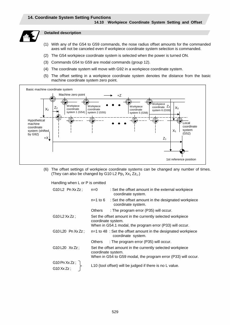
14. Coordinate System Setting Functions 14.10 Workpiece Coordinate System Setting and Offset
529
Detailed description
(1) With any of the G54 to G59 commands, the nose radius offset amounts for the commanded
axes will not be canceled even if workpiece coordinate system selection is commanded.
(2) The G54 workpiece coordinate system is selected when the power is turned ON.
(3) Commands G54 to G59 are modal commands (group 12).
(4) The coordinate system will move with G92 in a workpiece coordinate system.
(5) The offset setting in a workpiece coordinate system denotes the distance from the basic machine coordinate system zero point.
+Z
+X
Z2
Z1
X1
X2 Z3 X3
Hypothetical machine coordinate system (shifted by G92)
Machine zero point
Local coordinate system (G52)
1st reference position
Basic machine coordinate system
Workpiece coordinate system 1 (G54)
Workpiece coordinate system 2 (G55)
Workpiece coordinate system 5 (G58)
Workpiece coordinate system 6 (G59)
(6) The offset settings of workpiece coordinate systems can be changed any number of times. (They can also be changed by G10 L2 Pp1 Xx1 Zz1.)
Handling when L or P is omitted
G10 L2 Pn Xx Zz ; n=0 : Set the offset amount in the external workpiece coordinate system.
n=1 to 6 : Set the offset amount in the designated workpiece coordinate system.
Others : The program error (P35) will occur. G10 L2 Xx Zz ; Set the offset amount in the currently selected workpiece
coordinate system. When in G54.1 modal, the program error (P33) will occur.
G10 L20 Pn Xx Zz ; n=1 to 48 : Set the offset amount in the designated workpiece coordinate system.
Others : The program error (P35) will occur. G10 L20 Xx Zz ; Set the offset amount in the currently selected workpiece
coordinate system. When in G54 to G59 modal, the program error (P33) will occur.
G10 Pn Xx Zz ; G10 Xx Zz ;
L10 (tool offset) will be judged if there is no L value.
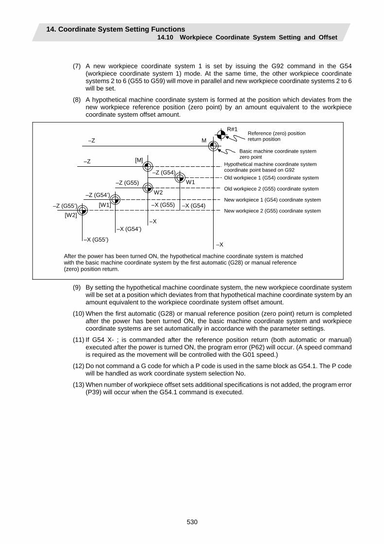
14. Coordinate System Setting Functions 14.10 Workpiece Coordinate System Setting and Offset
530
(7) A new workpiece coordinate system 1 is set by issuing the G92 command in the G54 (workpiece coordinate system 1) mode. At the same time, the other workpiece coordinate systems 2 to 6 (G55 to G59) will move in parallel and new workpiece coordinate systems 2 to 6 will be set.
(8) A hypothetical machine coordinate system is formed at the position which deviates from the new workpiece reference position (zero point) by an amount equivalent to the workpiece coordinate system offset amount.
R#1
–Z
–Z (G54)
–Z
–Z (G54’)
–Z (G55)
–Z (G55’) –X (G54)
–X
–X (G55)
–X
–X (G54’)
–X (G55’)
W2
W1
[W2]
[W1]
M
[M]
After the power has been turned ON, the hypothetical machine coordinate system is matched with the basic machine coordinate system by the first automatic (G28) or manual reference (zero) position return.
Hypothetical machine coordinate system coordinate point based on G92 Old workpiece 1 (G54) coordinate system
Old workpiece 2 (G55) coordinate system
New workpiece 1 (G54) coordinate system
New workpiece 2 (G55) coordinate system
Reference (zero) position return position
Basic machine coordinate system zero point
(9) By setting the hypothetical machine coordinate system, the new workpiece coordinate system will be set at a position which deviates from that hypothetical machine coordinate system by an amount equivalent to the workpiece coordinate system offset amount.
(10) When the first automatic (G28) or manual reference position (zero point) return is completed after the power has been turned ON, the basic machine coordinate system and workpiece coordinate systems are set automatically in accordance with the parameter settings.
(11) If G54 X- ; is commanded after the reference position return (both automatic or manual) executed after the power is turned ON, the program error (P62) will occur. (A speed command is required as the movement will be controlled with the G01 speed.)
(12) Do not command a G code for which a P code is used in the same block as G54.1. The P code will be handled as work coordinate system selection No.
(13) When number of workpiece offset sets additional specifications is not added, the program error (P39) will occur when the G54.1 command is executed.
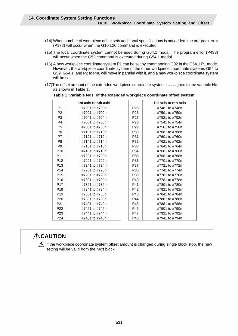
14. Coordinate System Setting Functions 14.10 Workpiece Coordinate System Setting and Offset
531
(14) When number of workpiece offset sets additional specifications is not added, the program error (P172) will occur when the G10 L20 command is executed.
(15) The local coordinate system cannot be used during G54.1 modal. The program error (P438) will occur when the G52 command is executed during G54.1 modal.
(16) A new workpiece coordinate system P1 can be set by commanding G92 in the G54.1 P1 mode. However, the workpiece coordinate system of the other workpiece coordinate systems G54 to G59, G54.1, and P2 to P48 will move in parallel with it, and a new workpiece coordinate system will be set.
(17)The offset amount of the extended workpiece coordinate system is assigned to the variable No. as shown in Table 1. Table 1 Variable Nos. of the extended workpiece coordinate offset system
1st axis to nth axis 1st axis to nth axis P1 #7001 to #700n P25 #7481 to #748n P2 #7021 to #702n P26 #7501 to #750n P3 #7041 to #704n P27 #7521 to #752n P4 #7061 to #706n P28 #7541 to #754n P5 #7081 to #708n P29 #7561 to #756n P6 #7101 to #710n P30 #7581 to #758n P7 #7121 to #712n P31 #7601 to #760n P8 #7141 to #714n P32 #7621 to #762n P9 #7161 to #716n P33 #7641 to #764n P10 #7181 to #718n P34 #7661 to #766n P11 #7201 to #720n P35 #7681 to #768n P12 #7221 to #722n P36 #7701 to #770n P13 #7241 to #724n P37 #7721 to #772n P14 #7261 to #726n P38 #7741 to #774n P15 #7281 to #728n P39 #7761 to #776n P16 #7301 to #730n P40 #7781 to #778n P17 #7321 to #732n P41 #7801 to #780n P18 #7341 to #734n P42 #7821 to #782n P19 #7361 to #736n P43 #7841 to #784n P20 #7381 to #738n P44 #7861 to #786n P21 #7401 to #740n P45 #7881 to #788n P22 #7421 to #742n P46 #7901 to #790n P23 #7441 to #744n P47 #7921 to #792n P24 #7461 to #746n P48 #7941 to #794n
CAUTION If the workpiece coordinate system offset amount is changed during single block stop, the new setting will be valid from the next block.
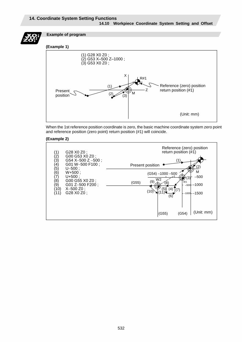
14. Coordinate System Setting Functions 14.10 Workpiece Coordinate System Setting and Offset
532
Example of program
(Example 1)
R#1
(1)
M(2) (3)Z
X
(1) G28 X0 Z0 ; (2) G53 X–500 Z–1000 ; (3) G53 X0 Z0 ;
Present position
Reference (zero) positionreturn position (#1)
(Unit: mm)
When the 1st reference position coordinate is zero, the basic machine coordinate system zero point and reference position (zero point) return position (#1) will coincide.
(Example 2)
(1) G28 X0 Z0 ; (2) G00 G53 X0 Z0 ; (3) G54 X−500 Z −500 ; (4) G01 W−500 F100 ; (5) U−500 ; (6) W+500 ; (7) U+500 ; (8) G00 G55 X0 Z0 ; (9) G01 Z−500 F200 ; (10) X−500 Z0 ; (11) G28 X0 Z0 ;
M –500
–1000
–1500
(G55)
(G54) –1000 –500
(G54) (G55)
W2W1 –500
–1000(11)(6)
(5) (4)
(3)
(2)
(1)
(10) (7)
(8)(9)
Present position
(Unit: mm)
Reference (zero) positionreturn position (#1)
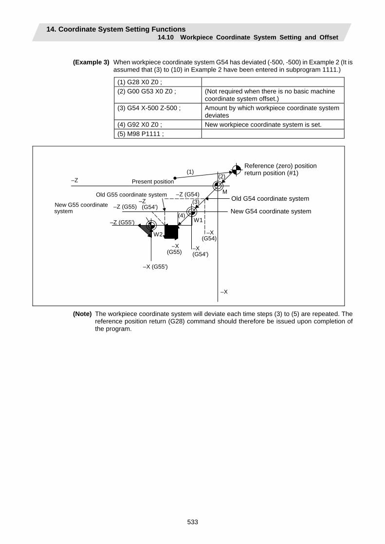
14. Coordinate System Setting Functions 14.10 Workpiece Coordinate System Setting and Offset
533
(Example 3) When workpiece coordinate system G54 has deviated (-500, -500) in Example 2 (It is
assumed that (3) to (10) in Example 2 have been entered in subprogram 1111.)
(1) G28 X0 Z0 ; (2) G00 G53 X0 Z0 ; (Not required when there is no basic machine
coordinate system offset.) (3) G54 X-500 Z-500 ; Amount by which workpiece coordinate system
deviates (4) G92 X0 Z0 ; New workpiece coordinate system is set. (5) M98 P1111 ;
M
–Z (G55) –Z (G54')
–X(G54)
–X(G55)
–Z (G55')
–X(G54')
–X (G55')
–X
–Z
–Z (G54)
W2
W1(4)
(3)
(2)(1)
Reference (zero) position return position (#1)
Old G54 coordinate system
New G54 coordinate system
Old G55 coordinate system
Present position
New G55 coordinate system
(Note) The workpiece coordinate system will deviate each time steps (3) to (5) are repeated. The reference position return (G28) command should therefore be issued upon completion of the program.

14. Coordinate System Setting Functions 14.11 Local Coordinate System Setting
534
14.11 Local Coordinate System Setting; G52
Function and purpose
The local coordinate systems can be set independently on the G54 to G59 workpiece coordinate systems using the G52 command so that the commanded position serves as the programmed zero point. The G52 command can also be used instead of the G92 command to change the deviation between the zero point in the machining program and the machining workpiece zero point.
Command format
G54 (G54 to G59) G52 Xx1 Zz1 ;
Detailed description
(1) The G52 command is valid until a new G52 command is issued and the tool does not move.
This command comes in handy for employing another coordinate system without changing the zero point positions of the workpiece coordinate systems (G54 to G59).
(2) The local coordinate system offset is cleared by the reference position (zero point) return or dog-type manual reference position (zero point) return after the power is turned ON.
(3) The local coordinate system is canceled by (G54 to G59) G52 X0 Z0 ;.
(4) Coordinate commands in the absolute value cause the tool to move to the local coordinate system position.
Reference position
Incremental value
Absolute value
Workpiece coordinate system offset (Screen setting, G10 G54 X__ Z__ ; )
External workpiece coordinate system offset (Screen setting, G10 P0 X__ Z__ ; )
Absolute value
Machine coordinate system
Ln
Ln
Ln
R
M
G52 U_ W_ ;
Wn (n=1 to 6)
Local coordinate system
Workpiece coordinate system
G52 X_ Z_ ;
(Note) If the program is executed repeatedly, the workpiece coordinate system will deviate each
time. Thus, when the program is completed, the reference position return operation must be commanded.
14. Coordinate System Setting Functions 14.12 Workpiece Coordinate System Preset
535
14.12 Workpiece Coordinate System Preset; G92.1
Function and purpose
(1) This function presets the workpiece coordinate system shifted with the program command
during manual operation to the workpiece coordinate system offset from the machine zero point by the workpiece coordinate offset amount by the program command (G92.1).
(2) The set workpiece coordinate system will be shifted from the machine coordinate system when the following type of operation or program command is executed. • When manual interrupt is executed while manual absolute is OFF • When movement command is issued in machine lock state • When axis is moved with handle interrupt • When operation is started with mirror image • When local coordinate system is set with G52 • When workpiece coordinate system is shifted with G92
This function presets the shifted workpiece coordinate system to the workpiece coordinate system offset from the machine zero point by the workpiece coordinate offset amount. This takes place in the same manner as manual reference position return. Whether to preset the relative coordinates or not can be selected with the parameters.
Command format
G92.1 X0 Y0 Z0 α0 ; (G50.3) α0 Additional axis
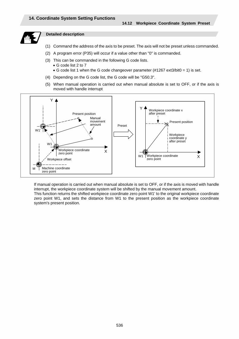
14. Coordinate System Setting Functions 14.12 Workpiece Coordinate System Preset
536
Detailed description
(1) Command the address of the axis to be preset. The axis will not be preset unless commanded.
(2) A program error (P35) will occur if a value other than "0" is commanded.
(3) This can be commanded in the following G code lists. • G code list 2 to 7 • G code list 1 when the G code changeover parameter (#1267 ext3/bit0 = 1) is set.
(4) Depending on the G code list, the G code will be "G50.3".
(5) When manual operation is carried out when manual absolute is set to OFF, or if the axis is moved with handle interrupt
Manual movement amount
Present position Workpiece coordinate x after preset
X
Y
Workpiece coordinate zero point
X
Y
Preset
W1
W1’
W1
M Machine coordinate zero point
Workpiece offset
Present position
Workpiece coordinate zero point
Workpiece coordinate y after preset
If manual operation is carried out when manual absolute is set to OFF, or if the axis is moved with handle interrupt, the workpiece coordinate system will be shifted by the manual movement amount. This function returns the shifted workpiece coordinate zero point W1' to the original workpiece coordinate zero point W1, and sets the distance from W1 to the present position as the workpiece coordinate system's present position.
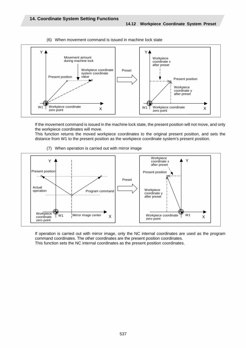
14. Coordinate System Setting Functions 14.12 Workpiece Coordinate System Preset
537
(6) When movement command is issued in machine lock state
Movement amount during machine lock
X
Y
X
Y
Preset
W1 W1
Workpiece coordinate system coordinate value Present position
Workpiece coordinate zero point
Workpiece coordinate x after preset
Workpiece coordinate y after preset
Workpiece coordinate zero point
Present position
If the movement command is issued in the machine lock state, the present position will not move, and only the workpiece coordinates will move. This function returns the moved workpiece coordinates to the original present position, and sets the distance from W1 to the present position as the workpiece coordinate system's present position.
(7) When operation is carried out with mirror image
Mirror image center X
Y
Program command
X
Y
Actual operation
W1 W1
Preset
Present position
Workpiece coordinate zero point
Workpiece coordinate zero point
Present position
Workpiece coordinate x after preset
Workpiece coordinate y after preset
If operation is carried out with mirror image, only the NC internal coordinates are used as the program command coordinates. The other coordinates are the present position coordinates. This function sets the NC internal coordinates as the present position coordinates.
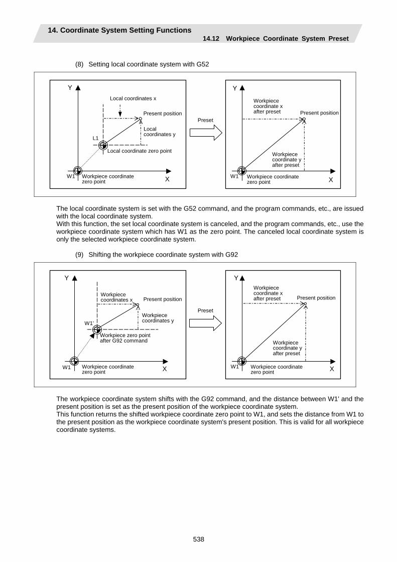
14. Coordinate System Setting Functions 14.12 Workpiece Coordinate System Preset
538
(8) Setting local coordinate system with G52
Local coordinate zero point
X
Y
X
YLocal coordinates x
W1
L1
W1
Present position
Workpiece coordinate zero point
Workpiece coordinate x after preset Present position
Workpiece coordinate zero point
Local coordinates y
Workpiece coordinate y after preset
Preset
The local coordinate system is set with the G52 command, and the program commands, etc., are issued with the local coordinate system. With this function, the set local coordinate system is canceled, and the program commands, etc., use the workpiece coordinate system which has W1 as the zero point. The canceled local coordinate system is only the selected workpiece coordinate system.
(9) Shifting the workpiece coordinate system with G92
Workpiece zero point after G92 command
X
Y
X
Y
W1
W1’
W1
Present position
Workpiece coordinate zero point
Workpiece coordinate x after preset
Preset
Workpiece coordinate y after preset
Present positionWorkpiece coordinates x
Workpiece coordinates y
Workpiece coordinate zero point
The workpiece coordinate system shifts with the G92 command, and the distance between W1' and the present position is set as the present position of the workpiece coordinate system. This function returns the shifted workpiece coordinate zero point to W1, and sets the distance from W1 to the present position as the workpiece coordinate system's present position. This is valid for all workpiece coordinate systems.
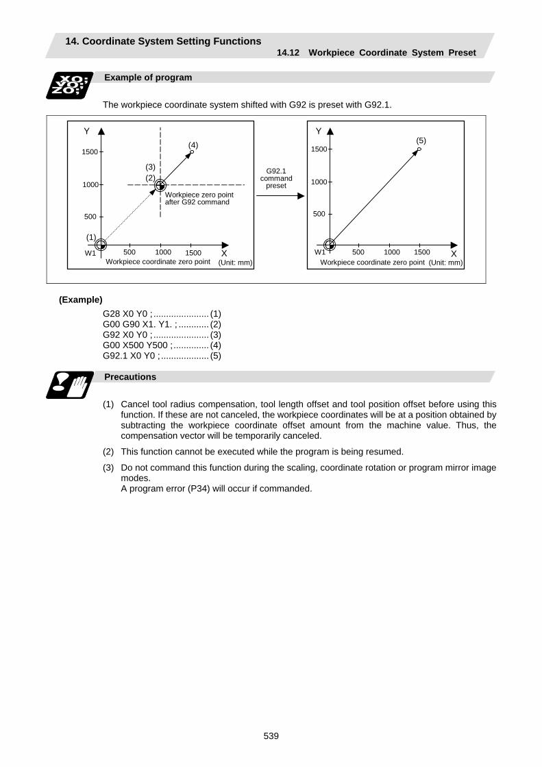
14. Coordinate System Setting Functions 14.12 Workpiece Coordinate System Preset
539
Example of program
The workpiece coordinate system shifted with G92 is preset with G92.1.
X
Y
X
Y
W1
(1)
W1
(2) (3)
(4) (5)
500
1000
1500
500 1000 1500
500
1000
1500
500 1000 1500
Workpiece zero point after G92 command
Workpiece coordinate zero point Workpiece coordinate zero point
G92.1 command
preset
(Unit: mm) (Unit: mm)
(Example) G28 X0 Y0 ; ...................... (1) G00 G90 X1. Y1. ; ............ (2) G92 X0 Y0 ; ...................... (3) G00 X500 Y500 ;.............. (4) G92.1 X0 Y0 ; ................... (5)
Precautions
(1) Cancel tool radius compensation, tool length offset and tool position offset before using this
function. If these are not canceled, the workpiece coordinates will be at a position obtained by subtracting the workpiece coordinate offset amount from the machine value. Thus, the compensation vector will be temporarily canceled.
(2) This function cannot be executed while the program is being resumed.
(3) Do not command this function during the scaling, coordinate rotation or program mirror image modes.
A program error (P34) will occur if commanded.
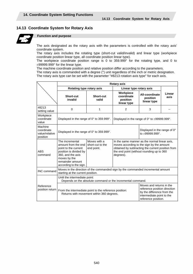
14. Coordinate System Setting Functions 14.13 Coordinate System for Rotary Axis
540
14.13 Coordinate System for Rotary Axis
Function and purpose
The axis designated as the rotary axis with the parameters is controlled with the rotary axis' coordinate system. The rotary axis includes the rotating type (short-cut valid/invalid) and linear type (workpiece coordinate position linear type, all coordinate position linear type). The workpiece coordinate position range is 0 to 359.999° for the rotating type, and 0 to ±99999.999° for the linear type. The machine coordinate position and relative position differ according to the parameters. The rotary axis is commanded with a degree (°) unit regardless of the inch or metric designation. The rotary axis type can be set with the parameter "#8213 rotation axis type" for each axis.
Rotary axis
Rotating type rotary axis Linear type rotary axis
Short-cut invalid
Short-cut valid
Workpiece coordinate
position linear type
All-coordinate position
linear type
Linear axis
#8213 setting value 0 1 2 3 --
Workpiece coordinate value
Displayed in the range of 0° to 359.999°. Displayed in the range of 0° to ±99999.999°.
Machine coordinate value/relative position
Displayed in the range of 0° to 359.999°. Displayed in the range of 0° to ±99999.999°.
ABS command
The incremental amount from the end point to the current position is divided by 360, and the axis moves by the remainder amount according to the sign.
Moves with a short-cut to the end point.
In the same manner as the normal linear axis, moves according to the sign by the amount obtained by subtracting the current position from the end point (without rounding up to 360 degrees).
INC command Moves in the direction of the commanded sign by the commanded incremental amount starting at the current position. Until the intermediate point: Depends on the absolute command or the incremental command.
Reference position return From the intermediate point to the reference position:
Returns with movement within 360 degrees.
Moves and returns in the reference position direction by the difference from the intermediate point to the reference position.

14. Coordinate System Setting Functions 14.13 Coordinate System for Rotary Axis
541
Example of operation
Examples of differences in the operation and counter displays according to the type of rotation coordinate are given below. (The workpiece offset is set as 0°.) (1) Rotary type (short-cut invalid)
(a) The machine coordinate position, workpiece coordinate position and current position are displayed in the range of 0 to 359.999°.
(b) For the absolute command, the axis moves according to the sign by the excessive amount obtained by dividing by 360°.
Program Workpiece coordinate
counter
Machine coordinate
counter G28 C0. N1 G90 C-270. 90.000 90.000 N2 C405. 45.000 45.000 N3 G91 C180 225.000 225.000
90°
45°
0°
N3
N2
N1
(2) Rotation type (short-cut valid)
(a) The machine coordinate position, workpiece coordinate position and current position are displayed in the range of 0 to 359.999°.
(b) For the absolute command, the axis rotates to the direction having less amount of movement to the end point.
Program Workpiece coordinate
counter
Machine coordinate counter
G28 C0. N1 G90 C-270. 90.000 90.000 N2 C405. 45.000 45.000 N3 G91 C180 225.000 225.000
90°
45°
0°
N3 N2
N1
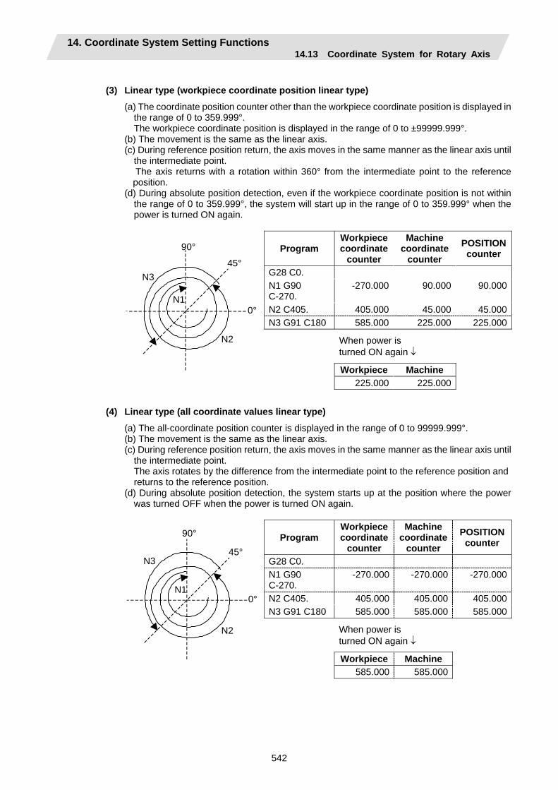
14. Coordinate System Setting Functions 14.13 Coordinate System for Rotary Axis
542
(3) Linear type (workpiece coordinate position linear type)
(a) The coordinate position counter other than the workpiece coordinate position is displayed in the range of 0 to 359.999°. The workpiece coordinate position is displayed in the range of 0 to ±99999.999°.
(b) The movement is the same as the linear axis. (c) During reference position return, the axis moves in the same manner as the linear axis until
the intermediate point. The axis returns with a rotation within 360° from the intermediate point to the reference position.
(d) During absolute position detection, even if the workpiece coordinate position is not within the range of 0 to 359.999°, the system will start up in the range of 0 to 359.999° when the power is turned ON again.
Program Workpiece coordinate
counter
Machine coordinate
counter POSITION counter
G28 C0. N1 G90 C-270.
-270.000 90.000 90.000
N2 C405. 405.000 45.000 45.000N3 G91 C180 585.000 225.000 225.000
When power is turned ON again ↓
Workpiece Machine
90°
45°
0°
N3
N2
N1
225.000 225.000
(4) Linear type (all coordinate values linear type)
(a) The all-coordinate position counter is displayed in the range of 0 to 99999.999°. (b) The movement is the same as the linear axis. (c) During reference position return, the axis moves in the same manner as the linear axis until
the intermediate point. The axis rotates by the difference from the intermediate point to the reference position and returns to the reference position.
(d) During absolute position detection, the system starts up at the position where the power was turned OFF when the power is turned ON again.
Program Workpiece coordinate
counter
Machine coordinate
counter POSITION
counter
G28 C0. N1 G90 C-270.
-270.000 -270.000 -270.000
N2 C405. 405.000 405.000 405.000N3 G91 C180 585.000 585.000 585.000
When power is turned ON again ↓
Workpiece Machine
90°
45°
0°
N3
N2
N1
585.000 585.000
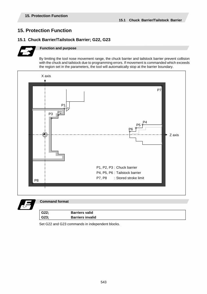
15. Protection Function 15.1 Chuck Barrier/Tailstock Barrier
543
15. Protection Function 15.1 Chuck Barrier/Tailstock Barrier; G22, G23
Function and purpose
By limiting the tool nose movement range, the chuck barrier and tailstock barrier prevent collision with the chuck and tailstock due to programming errors. If movement is commanded which exceeds the region set in the parameters, the tool will automatically stop at the barrier boundary.
X axis
Z axis
P1
P2P3
P8
P7
P4 P5
P6
P1, P2, P3 : Chuck barrier P4, P5, P6 : Tailstock barrier P7, P8 : Stored stroke limit
Command format
G22; Barriers valid G23; Barriers invalid
Set G22 and G23 commands in independent blocks.
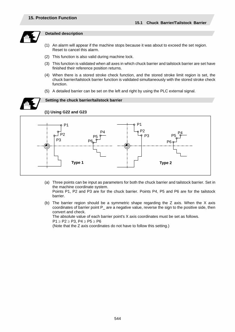
15. Protection Function 15.1 Chuck Barrier/Tailstock Barrier
544
Detailed description
(1) An alarm will appear if the machine stops because it was about to exceed the set region. Reset to cancel this alarm.
(2) This function is also valid during machine lock.
(3) This function is validated when all axes in which chuck barrier and tailstock barrier are set have finished their reference position returns.
(4) When there is a stored stroke check function, and the stored stroke limit region is set, the chuck barrier/tailstock barrier function is validated simultaneously with the stored stroke check function.
(5) A detailed barrier can be set on the left and right by using the PLC external signal.
Setting the chuck barrier/tailstock barrier
(1) Using G22 and G23
P1P2
P3P6
P5 P4
Type 2
P1
P2 P3
P4P5
P6
Type 1
(a) Three points can be input as parameters for both the chuck barrier and tailstock barrier. Set in
the machine coordinate system. Points P1, P2 and P3 are for the chuck barrier. Points P4, P5 and P6 are for the tailstock
barrier.
(b) The barrier region should be a symmetric shape regarding the Z axis. When the X axis coordinates of barrier point P_ are a negative value, reverse the sign to the positive side, then convert and check.
The absolute value of each barrier point's X axis coordinates must be set as follows. P1 ≥ P2 ≥ P3, P4 ≥ P5 ≥ P6 (Note that the Z axis coordinates do not have to follow this setting.)
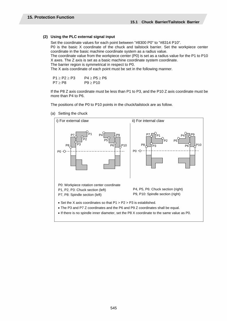
15. Protection Function 15.1 Chuck Barrier/Tailstock Barrier
545
(2) Using the PLC external signal input
Set the coordinate values for each point between "#8300 P0" to "#8314 P10". P0 is the basic X coordinate of the chuck and tailstock barrier. Set the workpiece center coordinate in the basic machine coordinate system as a radius value. The coordinate value from the workpiece center (P0) is set as a radius value for the P1 to P10 X axes. The Z axis is set as a basic machine coordinate system coordinate. The barrier region is symmetrical in respect to P0. The X axis coordinate of each point must be set in the following manner. P1 ≥ P2 ≥ P3 P4 ≥ P5 ≥ P6 P7 ≥ P8 P9 ≥ P10 If the P8 Z axis coordinate must be less than P1 to P3, and the P10 Z axis coordinate must be more than P4 to P6. The positions of the P0 to P10 points in the chuck/tailstock are as follow. (a) Setting the chuck
i) For external claw ii) For internal claw
P0
P1 P2
P3
P7
P8
P4P5
P6
P9
P10
P0
P1
P2
P3
P7
P8
P4
P5
P6
P9
P10
P0: Workpiece rotation center coordinate P1, P2, P3: Chuck section (left) P7, P8: Spindle section (left)
P4, P5, P6: Chuck section (right) P9, P10: Spindle section (right)
• Set the X axis coordinates so that P1 > P2 > P3 is established. • The P3 and P7 Z coordinates and the P6 and P9 Z coordinates shall be equal. • If there is no spindle inner diameter, set the P8 X coordinate to the same value as P0.
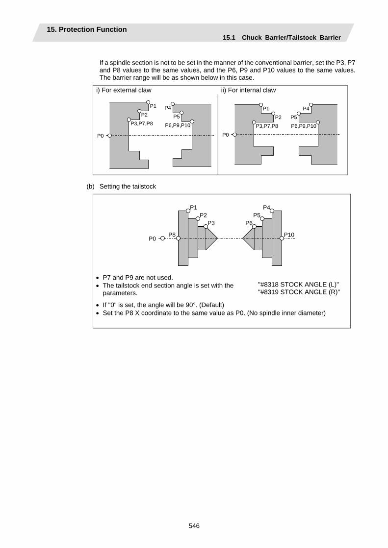
15. Protection Function 15.1 Chuck Barrier/Tailstock Barrier
546
If a spindle section is not to be set in the manner of the conventional barrier, set the P3, P7 and P8 values to the same values, and the P6, P9 and P10 values to the same values. The barrier range will be as shown below in this case.
i) For external claw ii) For internal claw
P0
P1
P2
P3,P7,P8
P4
P5
P6,P9,P10
P0
P1
P2
P3,P7,P8
P4
P5
P6,P9,P10
(b) Setting the tailstock
P0
P1P2
P3
P8
P4P5
P6
P10
• P7 and P9 are not used. • The tailstock end section angle is set with the
parameters.
"#8318 STOCK ANGLE (L)" "#8319 STOCK ANGLE (R)"
• If "0" is set, the angle will be 90°. (Default) • Set the P8 X coordinate to the same value as P0. (No spindle inner diameter)
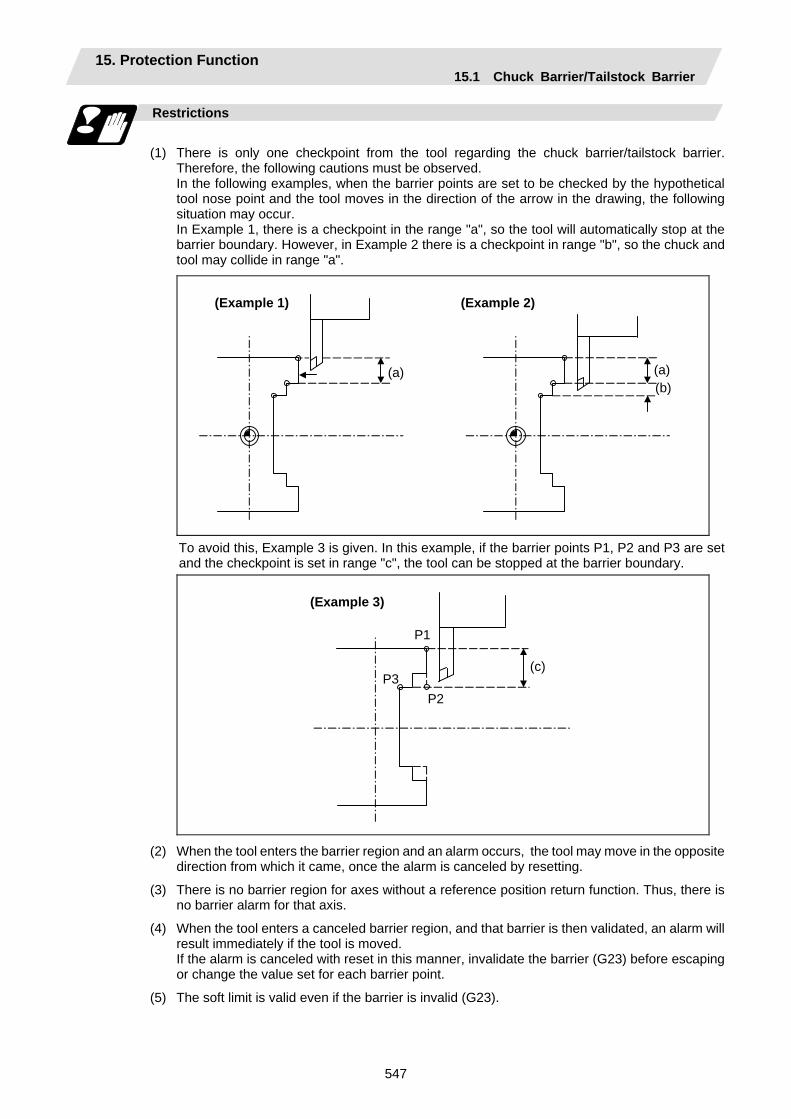
15. Protection Function 15.1 Chuck Barrier/Tailstock Barrier
547
Restrictions
(1) There is only one checkpoint from the tool regarding the chuck barrier/tailstock barrier.
Therefore, the following cautions must be observed. In the following examples, when the barrier points are set to be checked by the hypothetical
tool nose point and the tool moves in the direction of the arrow in the drawing, the following situation may occur.
In Example 1, there is a checkpoint in the range "a", so the tool will automatically stop at the barrier boundary. However, in Example 2 there is a checkpoint in range "b", so the chuck and tool may collide in range "a".
(Example 1)
(a)
(Example 2)
(a) (b)
To avoid this, Example 3 is given. In this example, if the barrier points P1, P2 and P3 are set and the checkpoint is set in range "c", the tool can be stopped at the barrier boundary.
(Example 3)
(c)
P1
P2P3
(2) When the tool enters the barrier region and an alarm occurs, the tool may move in the opposite direction from which it came, once the alarm is canceled by resetting.
(3) There is no barrier region for axes without a reference position return function. Thus, there is no barrier alarm for that axis.
(4) When the tool enters a canceled barrier region, and that barrier is then validated, an alarm will result immediately if the tool is moved.
If the alarm is canceled with reset in this manner, invalidate the barrier (G23) before escaping or change the value set for each barrier point.
(5) The soft limit is valid even if the barrier is invalid (G23).
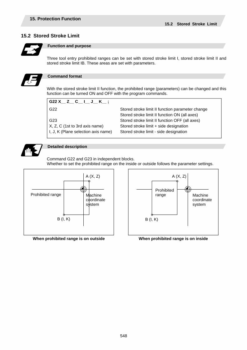
15. Protection Function 15.2 Stored Stroke Limit
548
15.2 Stored Stroke Limit
Function and purpose
Three tool entry prohibited ranges can be set with stored stroke limit I, stored stroke limit II and stored stroke limit IB. These areas are set with parameters.
Command format
With the stored stroke limit II function, the prohibited range (parameters) can be changed and this function can be turned ON and OFF with the program commands.
G22 X__ Z__ C__ I__ J__ K__ ;
G22 G23 X, Z, C (1st to 3rd axis name) I, J, K (Plane selection axis name)
Stored stroke limit II function parameter change Stored stroke limit II function ON (all axes) Stored stroke limit II function OFF (all axes) Stored stroke limit + side designation Stored stroke limit - side designation
Detailed description
Command G22 and G23 in independent blocks. Whether to set the prohibited range on the inside or outside follows the parameter settings.
Machine coordinatesystem
A (X, Z)
B (I, K)
Prohibited range
Machine coordinatesystem
A (X, Z)
B (I, K)
Prohibited range
When prohibited range is on outside When prohibited range is on inside
15. Protection Function 15.2 Stored Stroke Limit
549
Precautions
(1) If the maximum value and minimum value of the stored stroke limit's prohibited range are set to
the same value, the following will occur.
(a) When the maximum value and minimum value are set to 0, if the outside is the prohibited range, the entire range will be prohibited. If the inside is the prohibited range, the entire range will be the moveable range.
(b) If data other than 0 is set for the maximum value and minimum value, the entire range will be the moveable range.
(2) The settings (G22, G23) with the stored stroke limit II program command are valid at the G code list 6 and 7 (cmdtyp = 7, 8).
(3) G22 and G23 are unmodal (group 0), and are valid only in the commanded block.

16. Measurement Support Functions 16.1 Automatic Tool Length Measurement
550
16. Measurement Support Functions 16.1 Automatic Tool Length Measurement; G37
Function and purpose
These functions issue the command values from the measuring start position as far as the measurement time, move the tool in the direction of the measurement position, stop the machine once the tool has arrived at the sensor, cause the NC system to calculate automatically the difference between the coordinate values at that time and the coordinate values of the commanded measurement position and provide this difference as the tool offset amount. When offset is already being applied to a tool, it moves the tool toward the measurement position with the offset still applied, and if a further offset amount is generated as a result of the measurement and calculation, it provides further compensation of the present wear offset amount.
Command format
G37 α_ R_ D_ F_ ;
G37 Automatic tool length measurement command α Measuring axis address and coordinates of measurement position .........X, Z R This commands the distance between the measurement position and point
where the movement is to start at the measuring speed (Radius value fixed, incremental value)
D This commands the range within which the tool is to stop. (Radius value fixed, incremental value)
F This commands the measuring speed. When R_, D_ or F_ is omitted, the value set in the parameter is used
instead. <Parameter> ("TLM" on machining parameter screen) • #8004 Measuring feed rate (Fp) : 0 to 60000 (mm/min) • #8005 Deceleration range r : 0 to 99999.999 (mm) • #8006 Measurement range d : 0 to 99999.999 (mm)

16. Measurement Support Functions 16.1 Automatic Tool Length Measurement
551
Detailed description
(1) Operation with G37 command
D(d) D(d)F(Fp)
R(r)
(a) (b) (c) (d)
Speed Rapid traverse rate
Measurement allowable range
Distance
Operation 1
Operation 2
Operation 3
Offset amount
Normal completion Alarm stop (P607) Alarm stop (P607)
Measuring position Stop point Sensor output
Or no detection
(2) The sensor signal (measuring position arrival signal) is used in common with the skip signal.
(3) The feed rate will be 1mm/min if the F command and parameter measurement speed are 0.
(4) During the synchronous feed mode, the axis will move at the synchronous feed rate [mm/rev].
(5) An updated offset amount is valid unless it is assigned from the following T command of the G37 command.
(6) Excluding the delay at the PLC side, the delay and fluctuations in the sensor signal processing range from 0 to 0.2ms. As a result, the measuring error shown below is caused.
Maximum measuring error [mm] = Measuring speed [mm/min] × 1/60 × 0.2 [ms]/1000
(7) The machine position coordinates at that point in time are ready by sensor signal detection, and the machine will overtravel and stop at a position equivalent to the servo droop.
Maximum overtravel [mm] = Measuring speed [mm/min] × 1/60 × 1/Position loop gain [1/s]
The standard position loop gain is 33 [1/s].
16. Measurement Support Functions 16.1 Automatic Tool Length Measurement
552
Precautions
(1) Program error (P600) results if G37 is commanded when the automatic tool length
measurement function is not provided.
(2) Program error (P604) results when no axis has been commanded in the G37 block or when two or more axes have been commanded.
(3) Program error (P605) results when the T code is commanded in the G37 block. If the low-order digit or two digits is 0, the (4) error will occur.
(4) Program error (P606) results when T code is not commanded prior to the G37 block. When the low-order digit or two digits is 0, the program error (P606) will occur even if T is commanded.
(5) Program error (P607) results when the sensor signal was input outside the allowable measuring range or when the sensor signal was not detected even upon arrival at the end point. If the sensor signal stays ON during operation 3 in "Detailed description" (1), it will be judged as a normal measurement even when the (b) region is not present.
(6) When a manual interruption is applied while the tool is moving at the measuring speed, a return must be made to the position prior to the interrupt and then operation must be resumed.
(7) The data commanded in G37 or the parameter setting data must meet the following conditions:
|Measurement point - start point| > R command or parameter r > D command or parameter d
(8) When the D address and parameter d in (7) above are zero, operation will be completed normally only when the commanded measurement point and sensor signal detection point coincide. Otherwise, program error (P607) will results.
(9) When the R and D address as well as parameters r and d in (7) above are all zero, program error (P607) will result regardless of whether the sensor signal is present or not after the tool has been positioned at the commanded measurement point.
(10) When the measurement command distance < measurement allowable range, it becomes the measurement allowable range for all axes.

16. Measurement Support Functions 16.1 Automatic Tool Length Measurement
553
(11) When the measurement command distance < measurement speed movement distance, all axes move at the measurement speed.
(12) When the measurement allowable range > measurement speed movement distance, the axis moves in the measurement allowable range at the measurement speed.
(13) Always cancel nose R compensation before commanding G37.
(14) Calculate the tool length offset amount without regard for the nose R value and tool nose point No., even if the nose R compensation option is attached.
To set the tool nose point No. to 0, subtract the nose R value from the measured tool length offset amount and set.
When the tool nose point No. (tool nose shape) is 5, 6, 7, or 8, measure the tool length at the tool tip.
X axis tool length offset value with nose R value subtracted
Tool nose point 0 Measured X axis
tool length offset amount
Z axis tool length offset amount with nose R value subtracted
Measured Z axis tool length offset amountTip of tool nose
Toolnose point 8
Measured X axis tool length offset amount
Measured Z axis tool length offset amount
16. Measurement Support Functions 16.2 Skip Function
554
16.2 Skip Function; G31
Function and purpose
When the skip signal is input externally during linear interpolation based on the G31 command, the machine feed is stopped immediately, the remaining distance is discarded and the command in the following block is executed.
Command format
G31 Xx/Uu Zz/Ww Ff ;
x, z, u, w Axis coordinate value; they are commanded as absolute or incremental values.
f Feed rate (mm/min)
Linear interpolation can be executed using this function. If the skip signal is input externally while this command is being executed, the machine will stop, the remaining commands will be canceled and operation will be executed from the next block.
Detailed description
(1) If Ff is commanded as the feed rate, command speed f will apply; if it not commanded, the
value set in the parameter "#1174 skip_F" will serve as the feed rate. In either case, the F modal will not be updated.
(2) The machine will not automatically accelerate and decelerate with the G31 block.
(3) Override is invalid with the G31 command, and it is fixed at 100%. Dry run is also invalid. The stop conditions (feed hold, interlock, override zero and stroke end) are valid. External deceleration is also valid.
(4) The G31 command is unmodal and so it needs to be commanded each time.
(5) If the skip signal is input during G31 command start, the G31 command will be completed immediately. When a skip signal has not been input until the G31 block completion, the G31 command will also be completed upon completion of the movement commands.
(6) When the G31 command is issued during nose R compensation, program error (P608) will result.
(7) When there is no F command in the G31 command and the parameter speed is also zero, program error (P603) will result.
(8) If only the Z axis is commanded when the machine lock is ON or the Z axis cancel switch is ON, the skip signal will be ignored and execution will continue as far as the end of the block.
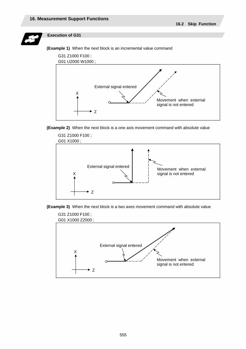
16. Measurement Support Functions 16.2 Skip Function
555
Execution of G31
(Example 1) When the next block is an incremental value command
G31 Z1000 F100 ; G01 U2000 W1000 ;
X
Z
External signal entered
Movement when external signal is not entered
(Example 2) When the next block is a one axis movement command with absolute value
G31 Z1000 F100 ; G01 X1000 ;
X
Z
External signal entered Movement when external signal is not entered
(Example 3) When the next block is a two axes movement command with absolute value
G31 Z1000 F100 ; G01 X1000 Z2000 ;
X
Z
External signal entered
Movement when external signal is not entered

16. Measurement Support Functions 16.2 Skip Function
556
Detailed description (Readout of skip coordinates)
As the skip signal inputting coordinate positions have been stored in the system variables #5061 (1st axis) to #506n (n-th axis), it is possible to use them with user macro.
G00 X-100. ; G31 X-200. F60 ; #101 = #5061
~
~ Skip command Skip signal input coordinate values (workpiece coordinate system) are readout to #101.
Detailed description (G31 coasting)
The amount of coasting from when the skip signal is input during the G31 command until the machine stops differs according to the parameter “#1174 skip_F” or F command in G31. The time to start deceleration to a stop after responding to the skip signal is short, so the machine can be stopped precisely with a small coasting amount. The coasting amount can be calculated from the following formula.
δ0 = F60 × Tp +
F60 × ( t1 ± t2 ) =
F60 × ( Tp + t1 ) ±
F60 × t2
δ1 δ2
δ0 : Coasting amount (mm) F : G31 skip speed (mm/min) Tp : Position loop time constant (s) = (position loop gain)-1
t1 : Response delay time (s) = (Time from when skip signal is detected, PC is passed, and control unit is reached.)
t2 : Response error time 0.001 (s)
When G31 is used for calculation, the value calculated from the section indicated by δ1 in the above equation can be compensated, however, δ2 results in calculation error.
Skip signal input
Stop pattern with skip signal input
Area inside shaded section denotes coasting amount δ0.
Time (S) Tp t1±t2
F
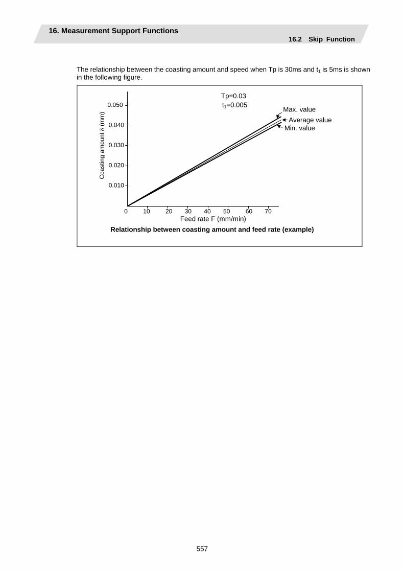
16. Measurement Support Functions 16.2 Skip Function
557
The relationship between the coasting amount and speed when Tp is 30ms and t1 is 5ms is shown in the following figure.
C
oast
ing
amou
nt δ
(mm
)
Average value
Feed rate F (mm/min) Relationship between coasting amount and feed rate (example)
Max. value
Min. value
Tp=0.03t1=0.0050.050
0.040
0.030
0.020
0.010
0 10 20 30 40 50 60 70

16. Measurement Support Functions 16.2 Skip Function
558
Detailed description (Skip coordinate readout error mm)
(1) Skip signal input coordinate readout
The coasting amount based on the position loop time constant Tp and cutting feed time constant Ts is not included in the skip signal input coordinate values. Therefore, the workpiece coordinate values applying when the skip signal is input can be read out across the error range in the following formula as the skip signal input coordinate values. However, coasting based on response delay time t1 results in a measurement error and so compensation must be provided.
ε : Readout error (mm) F : Feed rate (mm/min) t2 : Response error time 0.001 (s)
Rea
dout
erro
r ε ( µ
m)
Readout error of skip input coordinates
Readout error of skip signal input coordinates Readout error with a 60mm/min feed rate is as follows:
ε = ± 6060 × 0.001 = ±0.001 (mm)
Measurement value is within readout error range of ±1 µm.
ε = ± F60 × t2
+1
0
-1 Measurement value comes
within shaded section.
60 Feed rate (mm/min)
(2) Readout of other coordinates
The readout coordinate values include the coasting amount. Therefore, when coordinate values are required with skip signal input, refer to the section on the G31 coasting amount to compensate the coordinate value. As in the case of (1), the coasting amount based on the delay error time t2 cannot be calculated, and this generates a measuring error.
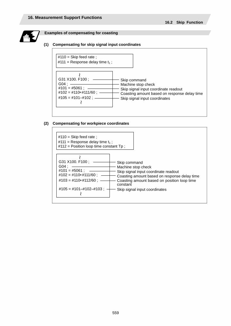
16. Measurement Support Functions 16.2 Skip Function
559
Examples of compensating for coasting
(1) Compensating for skip signal input coordinates
Skip signal input coordinates
Machine stop check G04 ; Skip command G31 X100. F100 ;
#111 = Response delay time t1 ;#110 = Skip feed rate ;
#105 = #101–#102 ; Coasting amount based on response delay time #102 = #110∗#111/60 ; Skip signal input coordinate readout #101 = #5061 ;
~ ~
(2) Compensating for workpiece coordinates
Coasting amount based on position loop timeconstant
Machine stop check Skip command
Coasting amount based on response delay time Skip signal input coordinate readout
Skip signal input coordinates
G04 ; G31 X100. F100 ;
#111 = Response delay time t1 ;#110 = Skip feed rate ;
#105 = #101–#102–#103 ;
#102 = #110∗#111/60 ; #101 = #5061 ;
~ ~
#112 = Position loop time constant Tp ;
#103 = #110∗#112/60 ;
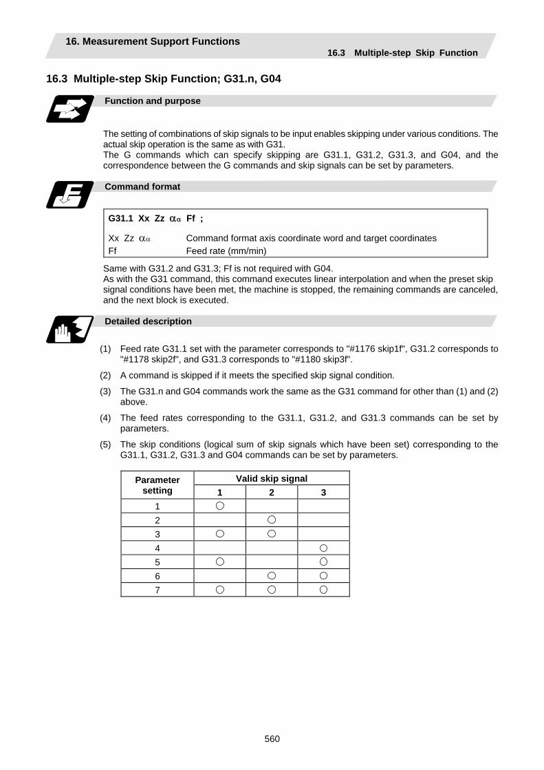
16. Measurement Support Functions 16.3 Multiple-step Skip Function
560
16.3 Multiple-step Skip Function; G31.n, G04
Function and purpose
The setting of combinations of skip signals to be input enables skipping under various conditions. The actual skip operation is the same as with G31. The G commands which can specify skipping are G31.1, G31.2, G31.3, and G04, and the correspondence between the G commands and skip signals can be set by parameters.
Command format
G31.1 Xx Zz αα Ff ;
Xx Zz αα Command format axis coordinate word and target coordinates Ff Feed rate (mm/min)
Same with G31.2 and G31.3; Ff is not required with G04. As with the G31 command, this command executes linear interpolation and when the preset skip signal conditions have been met, the machine is stopped, the remaining commands are canceled, and the next block is executed.
Detailed description
(1) Feed rate G31.1 set with the parameter corresponds to "#1176 skip1f", G31.2 corresponds to
"#1178 skip2f", and G31.3 corresponds to "#1180 skip3f".
(2) A command is skipped if it meets the specified skip signal condition.
(3) The G31.n and G04 commands work the same as the G31 command for other than (1) and (2) above.
(4) The feed rates corresponding to the G31.1, G31.2, and G31.3 commands can be set by parameters.
(5) The skip conditions (logical sum of skip signals which have been set) corresponding to the G31.1, G31.2, G31.3 and G04 commands can be set by parameters.
Valid skip signal Parameter
setting 1 2 3 1 2 3 4 5 6 7

16. Measurement Support Functions 16.3 Multiple-step Skip Function
561
Operation
(1) The multiple-step skip function enables the following control, thereby improving measurement
accuracy and shortening the time required for measurement.
Parameter settings : Skip condition Skip speed
G31.1 : 7 20.0mm/min (f1) G31.2 : 3 5.0mm/min (f2) G31.3 : 1 1.0mm/min (f3)
Program example
N10 G31.1 X200.0 ; N20 G31.2 X40.0 ; N30 G31.3 X1.0 ;
Operation
Skip speed
Measurement distance
N10
f
N20
N30
(f1)
(f2)
(f3)
t
Input of skip signal 3Input of skip signal 2 Input of skip signal 1
(Note 1) If skip signal 1 is input before skip signal 2 in the above operation, N20 is skipped at that point and N30 is also ignored.
(2) If a skip signal with the condition set during G04 (dwell) is input, the remaining dwell time is canceled and the following block is executed.

16. Measurement Support Functions 16.4 Multiple-step Skip Function 2
562
16.4 Multiple-step Skip Function 2; G31
Function and purpose
During linear interpolation, command operation is skipped if skip signal parameter Pp specified with a skip command (G31), which indicates external skip signals 1 to 8, is met. If multiple-step skip commands are issued simultaneously in different part systems, both part systems perform skip operation simultaneously if the input skip signals are the same, or they perform skip operation separately according to the earlier skip signal if the input skip signals are different. The skip operation is the same as with a normal skip command (G31 without P command).
X1
X2
Z
1st p
art s
yste
m
2nd
part
syst
em
Skip signal 1
Skip signal 1
Same skip signals input in both 1st and 2nd part systems
X1
X2
1st p
art s
yste
m
2nd
part
syst
em Z
Skip signal 1
Skip signal 2
Different skip signals input in 1st and 2nd part systems
If the skip condition specified by the parameter "#1173 dwlskp" (indicating external skip signals 1 to 8) is met during execution of a dwell command (G04), the remaining dwell time is canceled and the following block is executed. Similarly, if the skip condition is met during speed dwelling, the remaining speed is canceled and the following block is executed.
Command format
G31 Xx Zz αα Pp Ff ;
Xx Zz αα Command format axis coordinate word and target coordinates Pp Skip signal command Ff Feed rate (mm/min)
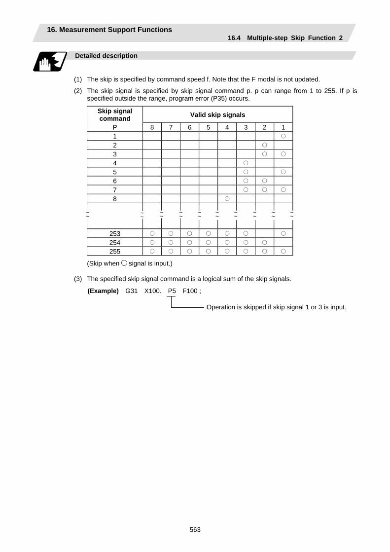
16. Measurement Support Functions 16.4 Multiple-step Skip Function 2
563
Detailed description
(1) The skip is specified by command speed f. Note that the F modal is not updated.
(2) The skip signal is specified by skip signal command p. p can range from 1 to 255. If p is specified outside the range, program error (P35) occurs.
Skip signal command Valid skip signals
P 8 7 6 5 4 3 2 1 1 2 3 4 5 6 7 8
253 254 255
(Skip when signal is input.)
(3) The specified skip signal command is a logical sum of the skip signals.
(Example) G31 X100. P5 F100 ;
Operation is skipped if skip signal 1 or 3 is input.
~ ~
~~
~~
~~
~~
~~
~~
~~
~ ~~
~

16. Measurement Support Functions 16.4 Multiple-step Skip Function 2
564
(4) If skip signal command Pp is not specified, the skip condition specified by the G31 command
works. If speed command Ff is not specified, the skip speed specified by the G31 command parameter works.
Table 2 Relations between skip and multiple-step skip
Skip specifications × Condition Speed Condition Speed G31 X100 ; (Without P and F) Program error (P601) Skip 1 Parameter
G31 X100 P5 ; (Without F) Program error (P602) Command value Parameter
G31 X100 F100 ; (Without P) Program error (P601) Skip 1 Command value
G31 X100 P5 F100 ; Program error (P602) Command value Command value
(Note) "Parameter" in the above table indicates that specified with a skip command (G31).
(5) If skip specification is effective and P is specified as an axis address, skip signal command P is given priority and axis address P is ignored.
(Example) G31 P500. F100 ;
This is regarded as a skip signal command andprogram error (P35) results.
(6) Those items other than (1) to (5) are the same with the ordinary skip function (G31 without P).

16. Measurement Support Functions 16.5 Speed Change Skip
565
16.5 Speed Change Skip
Function and purpose
When the skip signal is detected during linear interpolation by the skip command (G31), the feed rate is changed.
Command format
G31 Xx Yy Zz αα Ff F1=f1 ... Fn=fn ;
(n is the skip signal 1 to 8) G31 Skip command Xx Yy Zz αα Command format axis coordinate word and target coordinates Ff Feed rate when starting the cutting feed (mm/min) Fn Feed rate after detecting the skip signal (mm/min)
fn=0: Movement stop fn≠0: Changing the feed rate to fn
F1=Feed rate after inputting the skip signal 1 :
F8=Feed rate after inputting the skip signal 8
Detailed description
(1) When the skip signal for which the feed rate fn≠0 is commanded, the speed is changed to the
command speed corresponding to the skip signal.
(2) When the skip signal for which the feed rate fn=0 is commanded, the movement is stopped. The acceleration and deceleration time constant at the movement stop does not follow the skip time constant, but the normal G31 skip. After the movement is stopped, the remaining movement commands are canceled and the following block executed.
(3) When the skip signal has not been input until the G31 block completion, the G31 command will be also completed upon completion of the movement command.
(4) When the skip retract is valid, the return operation by the skip signal detection is executed after the movement is stopped.
(5) Even if the acceleration and deceleration with the inclination constant G1 (#1201 G1_acc) is valid, the speed change skip will be the operation of the time constant acceleration and deceleration.
(6) When the feed rate command (Fn=fn) is not specified after detecting the skip signal, the normal G31 skip operation will be applied.
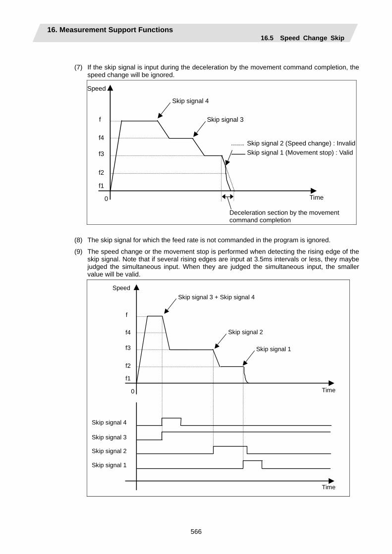
16. Measurement Support Functions 16.5 Speed Change Skip
566
(7) If the skip signal is input during the deceleration by the movement command completion, the speed change will be ignored.
f4
f
Speed
Time
f3
f2
0
Skip signal 4
Skip signal 3
f1
Deceleration section by the movement command completion
Skip signal 2 (Speed change) : InvalidSkip signal 1 (Movement stop) : Valid
(8) The skip signal for which the feed rate is not commanded in the program is ignored.
(9) The speed change or the movement stop is performed when detecting the rising edge of the skip signal. Note that if several rising edges are input at 3.5ms intervals or less, they maybe judged the simultaneous input. When they are judged the simultaneous input, the smaller value will be valid.
f4
f
Speed
Time
f3
f2
0
Skip signal 3 + Skip signal 4
f1
Skip signal 1
Time
Skip signal 2
Skip signal 4
Skip signal 3
Skip signal 2
Skip signal 1

16. Measurement Support Functions 16.5 Speed Change Skip
567
(10) If the G31 block is started with the skip signal input, that signal is considered to rise at the same time as the block start.
(11) If the skip signals for changing the speed and for stopping the movement are simultaneously input, the skip signal for stopping the movement will be valid regardless of the size of the No.
(12) If the skip time constant "#2102 skip_tL" is illegal, the "Y51 PARAMETER ERROR 15" will occur, and if the "#2103 skip_t1" is illegal, the "Y51 PARAMETER ERROR 16" will occur.
(13) The items other than (1) to (12) are the same with the G31 command. Example of operation
Example of program
G31 X100. Ff F1=0 F2=f2 F3=f3 F4=f4 ; Operation
f4
f
Speed
Time
f3
f2
0
Skip time constant
Skip signal 4
Skip signal 3
Skip signal 2
Skip signal 1
f1
Position loop time constant (Position loop gain-1)
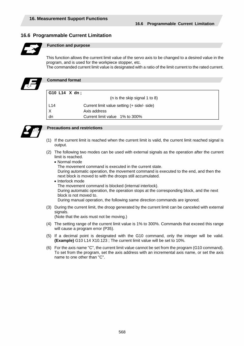
16. Measurement Support Functions 16.6 Programmable Current Limitation
568
16.6 Programmable Current Limitation
Function and purpose
This function allows the current limit value of the servo axis to be changed to a desired value in the program, and is used for the workpiece stopper, etc. The commanded current limit value is designated with a ratio of the limit current to the rated current.
Command format
G10 L14 X dn ;
(n is the skip signal 1 to 8)
L14 Current limit value setting (+ side/- side) X Axis address dn Current limit value 1% to 300%
Precautions and restrictions
(1) If the current limit is reached when the current limit is valid, the current limit reached signal is
output.
(2) The following two modes can be used with external signals as the operation after the current limit is reached.
• Normal mode The movement command is executed in the current state. During automatic operation, the movement command is executed to the end, and then the next block is moved to with the droops still accumulated.
• Interlock mode The movement command is blocked (internal interlock). During automatic operation, the operation stops at the corresponding block, and the next block is not moved to. During manual operation, the following same direction commands are ignored.
(3) During the current limit, the droop generated by the current limit can be canceled with external signals. (Note that the axis must not be moving.)
(4) The setting range of the current limit value is 1% to 300%. Commands that exceed this range will cause a program error (P35).
(5) If a decimal point is designated with the G10 command, only the integer will be valid. (Example) G10 L14 X10.123 ; The current limit value will be set to 10%.
(6) For the axis name "C", the current limit value cannot be set from the program (G10 command). To set from the program, set the axis address with an incremental axis name, or set the axis name to one other than "C".
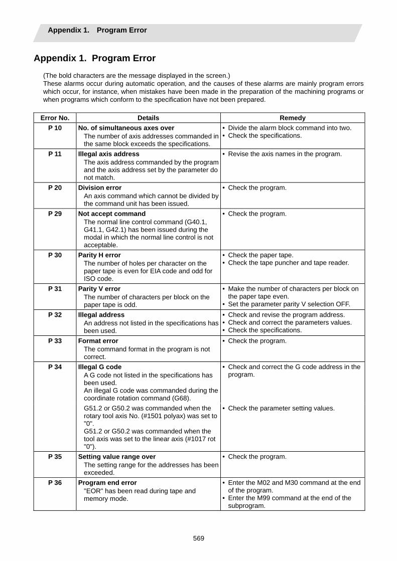
Appendix 1. Program Error
569
Appendix 1. Program Error (The bold characters are the message displayed in the screen.) These alarms occur during automatic operation‚ and the causes of these alarms are mainly program errors which occur‚ for instance‚ when mistakes have been made in the preparation of the machining programs or when programs which conform to the specification have not been prepared.
Error No. Details Remedy
P 10 No. of simultaneous axes over The number of axis addresses commanded in the same block exceeds the specifications.
• Divide the alarm block command into two. • Check the specifications.
P 11 Illegal axis address The axis address commanded by the program and the axis address set by the parameter do not match.
• Revise the axis names in the program.
P 20 Division error An axis command which cannot be divided by the command unit has been issued.
• Check the program.
P 29 Not accept command The normal line control command (G40.1, G41.1, G42.1) has been issued during the modal in which the normal line control is not acceptable.
• Check the program.
P 30 Parity H error The number of holes per character on the paper tape is even for EIA code and odd for ISO code.
• Check the paper tape. • Check the tape puncher and tape reader.
P 31 Parity V error The number of characters per block on the paper tape is odd.
• Make the number of characters per block on the paper tape even.
• Set the parameter parity V selection OFF. P 32 Illegal address
An address not listed in the specifications has been used.
• Check and revise the program address. • Check and correct the parameters values. • Check the specifications.
P 33 Format error The command format in the program is not correct.
• Check the program.
Illegal G code A G code not listed in the specifications has been used. An illegal G code was commanded during the coordinate rotation command (G68).
• Check and correct the G code address in the program.
P 34
G51.2 or G50.2 was commanded when the rotary tool axis No. (#1501 polyax) was set to "0". G51.2 or G50.2 was commanded when the tool axis was set to the linear axis (#1017 rot "0").
• Check the parameter setting values.
P 35 Setting value range over The setting range for the addresses has been exceeded.
• Check the program.
P 36 Program end error "EOR" has been read during tape and memory mode.
• Enter the M02 and M30 command at the end of the program.
• Enter the M99 command at the end of the subprogram.
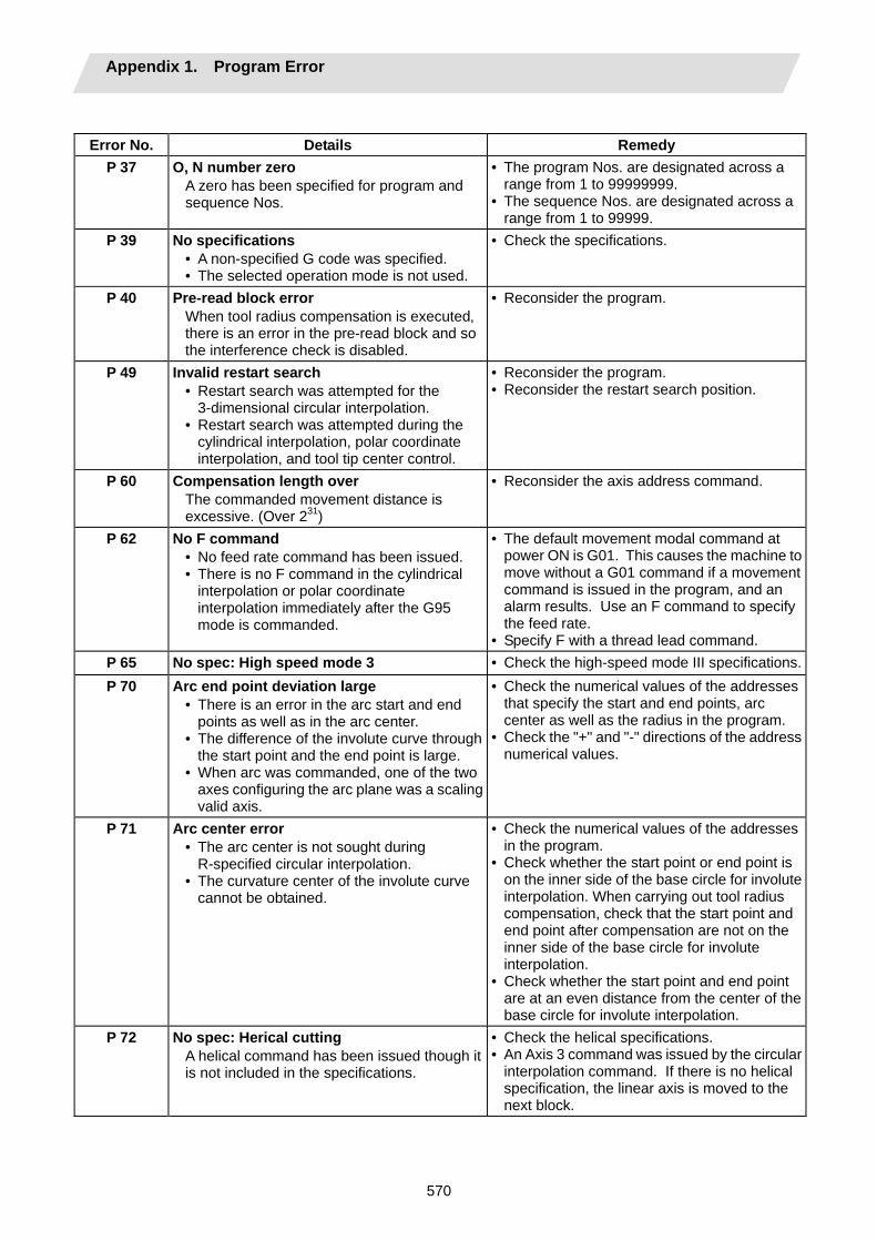
Appendix 1. Program Error
570
Error No. Details Remedy
P 37 O, N number zero A zero has been specified for program and sequence Nos.
• The program Nos. are designated across a range from 1 to 99999999.
• The sequence Nos. are designated across a range from 1 to 99999.
P 39 No specifications • A non-specified G code was specified. • The selected operation mode is not used.
• Check the specifications.
P 40 Pre-read block error When tool radius compensation is executed‚ there is an error in the pre-read block and so the interference check is disabled.
• Reconsider the program.
P 49 Invalid restart search • Restart search was attempted for the
3-dimensional circular interpolation. • Restart search was attempted during the
cylindrical interpolation, polar coordinate interpolation, and tool tip center control.
• Reconsider the program. • Reconsider the restart search position.
P 60 Compensation length over The commanded movement distance is excessive. (Over 231)
• Reconsider the axis address command.
P 62 No F command • No feed rate command has been issued. • There is no F command in the cylindrical
interpolation or polar coordinate interpolation immediately after the G95 mode is commanded.
• The default movement modal command at power ON is G01. This causes the machine to move without a G01 command if a movement command is issued in the program, and an alarm results. Use an F command to specify the feed rate.
• Specify F with a thread lead command. P 65 No spec: High speed mode 3 • Check the high-speed mode III specifications.P 70 Arc end point deviation large
• There is an error in the arc start and end points as well as in the arc center.
• The difference of the involute curve through the start point and the end point is large.
• When arc was commanded, one of the two axes configuring the arc plane was a scaling valid axis.
• Check the numerical values of the addresses that specify the start and end points, arc center as well as the radius in the program.
• Check the "+" and "-" directions of the address numerical values.
P 71 Arc center error • The arc center is not sought during
R-specified circular interpolation. • The curvature center of the involute curve
cannot be obtained.
• Check the numerical values of the addresses in the program.
• Check whether the start point or end point is on the inner side of the base circle for involute interpolation. When carrying out tool radius compensation, check that the start point and end point after compensation are not on the inner side of the base circle for involute interpolation.
• Check whether the start point and end point are at an even distance from the center of the base circle for involute interpolation.
P 72 No spec: Herical cutting A helical command has been issued though it is not included in the specifications.
• Check the helical specifications. • An Axis 3 command was issued by the circular
interpolation command. If there is no helical specification, the linear axis is moved to the next block.
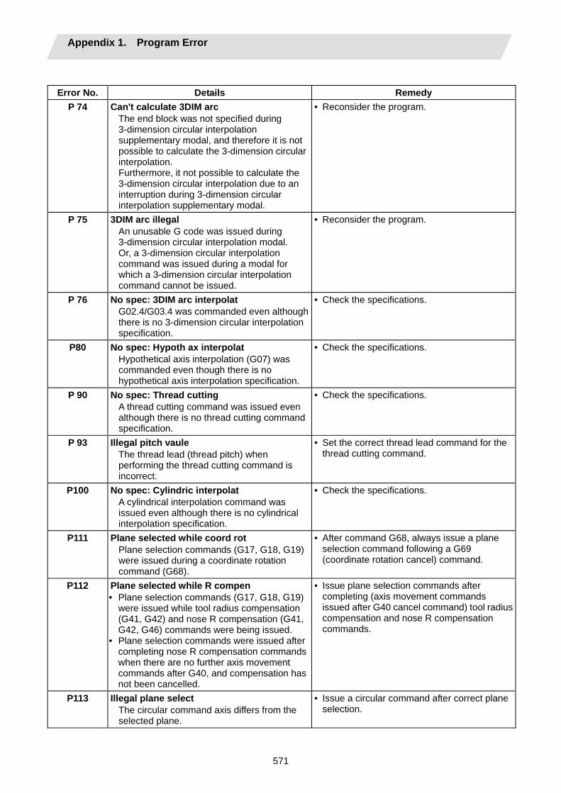
Appendix 1. Program Error
571
Error No. Details Remedy
P 74 Can't calculate 3DIM arc The end block was not specified during 3-dimension circular interpolation supplementary modal, and therefore it is not possible to calculate the 3-dimension circular interpolation. Furthermore, it not possible to calculate the 3-dimension circular interpolation due to an interruption during 3-dimension circular interpolation supplementary modal.
• Reconsider the program.
P 75 3DIM arc illegal An unusable G code was issued during 3-dimension circular interpolation modal. Or, a 3-dimension circular interpolation command was issued during a modal for which a 3-dimension circular interpolation command cannot be issued.
• Reconsider the program.
P 76 No spec: 3DIM arc interpolat G02.4/G03.4 was commanded even although there is no 3-dimension circular interpolation specification.
• Check the specifications.
P80 No spec: Hypoth ax interpolat Hypothetical axis interpolation (G07) was commanded even though there is no hypothetical axis interpolation specification.
• Check the specifications.
P 90 No spec: Thread cutting A thread cutting command was issued even although there is no thread cutting command specification.
• Check the specifications.
P 93 Illegal pitch vaule The thread lead (thread pitch) when performing the thread cutting command is incorrect.
• Set the correct thread lead command for the thread cutting command.
P100 No spec: Cylindric interpolat A cylindrical interpolation command was issued even although there is no cylindrical interpolation specification.
• Check the specifications.
P111 Plane selected while coord rot Plane selection commands (G17, G18, G19) were issued during a coordinate rotation command (G68).
• After command G68, always issue a plane selection command following a G69 (coordinate rotation cancel) command.
P112 Plane selected while R compen • Plane selection commands (G17, G18, G19)
were issued while tool radius compensation (G41, G42) and nose R compensation (G41, G42, G46) commands were being issued.
• Plane selection commands were issued after completing nose R compensation commands when there are no further axis movement commands after G40, and compensation has not been cancelled.
• Issue plane selection commands after completing (axis movement commands issued after G40 cancel command) tool radius compensation and nose R compensation commands.
P113 Illegal plane select The circular command axis differs from the selected plane.
• Issue a circular command after correct plane selection.
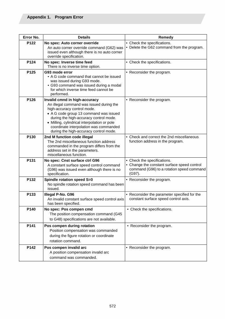
Appendix 1. Program Error
572
Error No. Details Remedy
P122 No spec: Auto corner override An auto corner override command (G62) was issued even although there is no auto corner override specification.
• Check the specifications. • Delete the G62 command from the program.
P124 No spec: Inverse time feed There is no inverse time option.
• Check the specifications.
P125 G93 mode error • A G code command that cannot be issued
was issued during G93 mode. • G93 command was issued during a modal
for which inverse time feed cannot be performed.
• Reconsider the program.
P126 Invalid cmnd in high-accuracy An illegal command was issued during the high-accuracy control mode. • A G code group 13 command was issued
during the high-accuracy control mode. • Milling, cylindrical interpolation or pole
coordinate interpolation was commanded during the high-accuracy control mode.
• Reconsider the program.
P130 2nd M function code illegal The 2nd miscellaneous function address commanded in the program differs from the address set in the parameters. miscellaneous function.
• Check and correct the 2nd miscellaneous function address in the program.
P131 No spec: Cnst surface ctrl G96 A constant surface speed control command (G96) was issued even although there is no specification.
• Check the specifications. • Change the constant surface speed control
command (G96) to a rotation speed command (G97).
P132 Spindle rotation speed S=0 No spindle rotation speed command has been issued.
• Reconsider the program.
P133 Illegal P-No. G96 An invalid constant surface speed control axis has been specified.
• Reconsider the parameter specified for the constant surface speed control axis.
P140 No spec: Pos compen cmd The position compensation command (G45 to G48) specifications are not available.
• Check the specifications.
P141 Pos compen during rotation Position compensation was commanded during the figure rotation or coordinate rotation command.
• Reconsider the program.
P142 Pos compen invalid arc A position compensation invalid arc command was commanded.
• Reconsider the program.
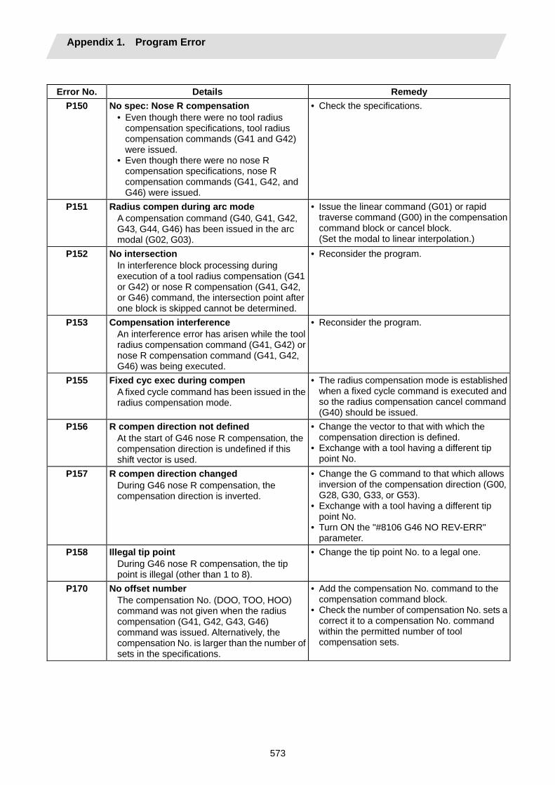
Appendix 1. Program Error
573
Error No. Details Remedy
P150 No spec: Nose R compensation • Even though there were no tool radius
compensation specifications, tool radius compensation commands (G41 and G42) were issued.
• Even though there were no nose R compensation specifications, nose R compensation commands (G41, G42, and G46) were issued.
• Check the specifications.
P151 Radius compen during arc mode A compensation command (G40‚ G41‚ G42‚ G43‚ G44‚ G46) has been issued in the arc modal (G02‚ G03).
• Issue the linear command (G01) or rapid traverse command (G00) in the compensation command block or cancel block. (Set the modal to linear interpolation.)
P152 No intersection In interference block processing during execution of a tool radius compensation (G41 or G42) or nose R compensation (G41‚ G42‚ or G46) command‚ the intersection point after one block is skipped cannot be determined.
• Reconsider the program.
P153 Compensation interference An interference error has arisen while the tool radius compensation command (G41‚ G42) or nose R compensation command (G41‚ G42‚ G46) was being executed.
• Reconsider the program.
P155 Fixed cyc exec during compen A fixed cycle command has been issued in the radius compensation mode.
• The radius compensation mode is established when a fixed cycle command is executed and so the radius compensation cancel command (G40) should be issued.
P156 R compen direction not defined At the start of G46 nose R compensation‚ the compensation direction is undefined if this shift vector is used.
• Change the vector to that with which the compensation direction is defined.
• Exchange with a tool having a different tip point No.
P157 R compen direction changed During G46 nose R compensation‚ the compensation direction is inverted.
• Change the G command to that which allows inversion of the compensation direction (G00‚ G28‚ G30‚ G33‚ or G53).
• Exchange with a tool having a different tip point No.
• Turn ON the "#8106 G46 NO REV-ERR" parameter.
P158 Illegal tip point During G46 nose R compensation‚ the tip point is illegal (other than 1 to 8).
• Change the tip point No. to a legal one.
P170 No offset number The compensation No. (DOO‚ TOO‚ HOO) command was not given when the radius compensation (G41‚ G42‚ G43‚ G46) command was issued. Alternatively‚ the compensation No. is larger than the number of sets in the specifications.
• Add the compensation No. command to the compensation command block.
• Check the number of compensation No. sets a correct it to a compensation No. command within the permitted number of tool compensation sets.
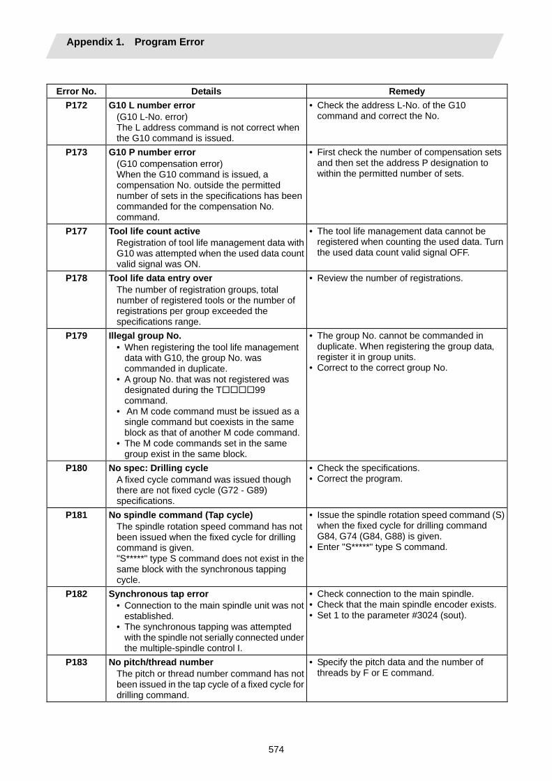
Appendix 1. Program Error
574
Error No. Details Remedy
P172 G10 L number error (G10 L-No. error) The L address command is not correct when the G10 command is issued.
• Check the address L-No. of the G10 command and correct the No.
P173 G10 P number error (G10 compensation error) When the G10 command is issued‚ a compensation No. outside the permitted number of sets in the specifications has been commanded for the compensation No. command.
• First check the number of compensation sets and then set the address P designation to within the permitted number of sets.
P177 Tool life count active Registration of tool life management data with G10 was attempted when the used data count valid signal was ON.
• The tool life management data cannot be registered when counting the used data. Turn the used data count valid signal OFF.
P178 Tool life data entry over The number of registration groups‚ total number of registered tools or the number of registrations per group exceeded the specifications range.
• Review the number of registrations.
P179 Illegal group No. • When registering the tool life management
data with G10‚ the group No. was commanded in duplicate.
• A group No. that was not registered was designated during the T 99 command.
• An M code command must be issued as a single command but coexists in the same block as that of another M code command.
• The M code commands set in the same group exist in the same block.
• The group No. cannot be commanded in duplicate. When registering the group data‚ register it in group units.
• Correct to the correct group No.
P180 No spec: Drilling cycle A fixed cycle command was issued though there are not fixed cycle (G72 - G89) specifications.
• Check the specifications. • Correct the program.
P181 No spindle command (Tap cycle) The spindle rotation speed command has not been issued when the fixed cycle for drilling command is given. "S*****" type S command does not exist in the same block with the synchronous tapping cycle.
• Issue the spindle rotation speed command (S) when the fixed cycle for drilling command G84‚ G74 (G84‚ G88) is given.
• Enter "S*****" type S command.
P182 Synchronous tap error • Connection to the main spindle unit was not
established. • The synchronous tapping was attempted
with the spindle not serially connected under the multiple-spindle control I.
• Check connection to the main spindle. • Check that the main spindle encoder exists. • Set 1 to the parameter #3024 (sout).
P183 No pitch/thread number The pitch or thread number command has not been issued in the tap cycle of a fixed cycle for drilling command.
• Specify the pitch data and the number of threads by F or E command.

Appendix 1. Program Error
575
Error No. Details Remedy
P184 Pitch/thread number error • The pitch or the number of threads per inch
is illegal in the tap cycle of the fixed cycle for drilling command.
• The pitch is too small for the spindle rotation speed.
• The thread number is too large for the spindle rotation speed.
• Check the pitch or the number of threads per inch.
P186 Illegal S cmnd in synchro tap S command was issued during synchronous tapping modal.
• Cancel the synchronous tapping before issuing the S command.
P190 No spec: Turning cycle A lathe cutting cycle command was input although the lathe cutting cycle was undefined in the specification.
• Check the specification. • Delete the lathe cutting cycle command.
P191 Taper length error In the lathe cutting cycle‚ the specified length of taper section is illegal.
• The radius set value in the lathe cycle command must be smaller than the axis shift amount.
P192 Chamfering error Chamfering in the thread cutting cycle is illegal.
• Set a chamfering amount not exceeding the cycle.
P200 No spec: MRC cycle The compound type fixed cycle for turning machining I (G70 to G73) was commanded when the compound type fixed cycle for turning machining I specifications were not provided.
• Check the specification.
P201 Program error (MRC) • When called with a compound type fixed
cycle for turning machining I command, the subprogram contained at least one of the following commands:
• Reference position return command (G27, G28, G29, G30)
• Thread cutting (G33, G34) • Fixed cycle skip-function (G31, G31.n)
• The first move block of the finish shape program in compound type fixed cycle for turning machining I contains an arc command.
• Delete the following G codes from this subprogram that is called with the compound type fixed cycle for turning machining I commands (G70 to G73): G27‚ G28‚ G29, G30‚ G31‚ G33‚ G34, and fixed cycle G codes.
• Remove G2 and G3 from the first move block of the finish shape program in compound type fixed cycle for turning machining I.
P202 Block over (MRC) The number of blocks in the shape program of the compound type fixed cycle for turning machining I is over 50 or 200 (this differs according to the model).
• Specify 50 or a less value. The number of blocks in the shape program called by the compound type fixed cycle for turning machining I commands (G70 to G73) must be decreased below 50 or 200 (this differs according to the model).
P203 D cmnd figure error (MRC) The compound type fixed cycle for turning machining I (G70 to G73) shape program could not cut the work normally because it defined an abnormal shape.
• Check the compound type fixed cycle for turning machining I (G70 to G73) shape program.
P204 E cmnd fixed cycle error A command value of the compound type fixed cycle for turning machining (G70 to G76) is illegal.
• Check the compound type fixed cycle for turning machining (G70 to G76) command value.
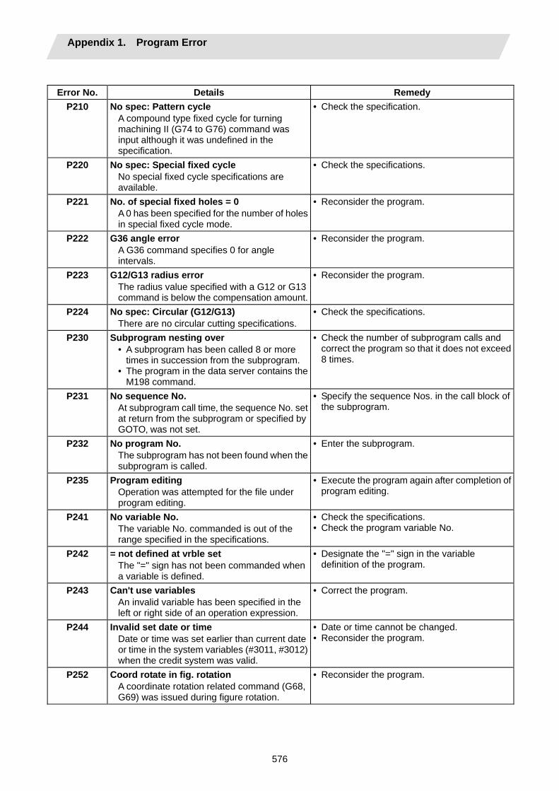
Appendix 1. Program Error
576
Error No. Details Remedy
P210 No spec: Pattern cycle A compound type fixed cycle for turning machining II (G74 to G76) command was input although it was undefined in the specification.
• Check the specification.
P220 No spec: Special fixed cycle No special fixed cycle specifications are available.
• Check the specifications.
P221 No. of special fixed holes = 0 A 0 has been specified for the number of holes in special fixed cycle mode.
• Reconsider the program.
P222 G36 angle error A G36 command specifies 0 for angle intervals.
• Reconsider the program.
P223 G12/G13 radius error The radius value specified with a G12 or G13 command is below the compensation amount.
• Reconsider the program.
P224 No spec: Circular (G12/G13) There are no circular cutting specifications.
• Check the specifications.
P230 Subprogram nesting over • A subprogram has been called 8 or more
times in succession from the subprogram. • The program in the data server contains the
M198 command.
• Check the number of subprogram calls and correct the program so that it does not exceed 8 times.
P231 No sequence No. At subprogram call time‚ the sequence No. set at return from the subprogram or specified by GOTO‚ was not set.
• Specify the sequence Nos. in the call block of the subprogram.
P232 No program No. The subprogram has not been found when the subprogram is called.
• Enter the subprogram.
P235 Program editing Operation was attempted for the file under program editing.
• Execute the program again after completion of program editing.
P241 No variable No. The variable No. commanded is out of the range specified in the specifications.
• Check the specifications. • Check the program variable No.
P242 = not defined at vrble set The "=" sign has not been commanded when a variable is defined.
• Designate the "=" sign in the variable definition of the program.
P243 Can't use variables An invalid variable has been specified in the left or right side of an operation expression.
• Correct the program.
P244 Invalid set date or time Date or time was set earlier than current date or time in the system variables (#3011, #3012) when the credit system was valid.
• Date or time cannot be changed. • Reconsider the program.
P252 Coord rotate in fig. rotation A coordinate rotation related command (G68, G69) was issued during figure rotation.
• Reconsider the program.
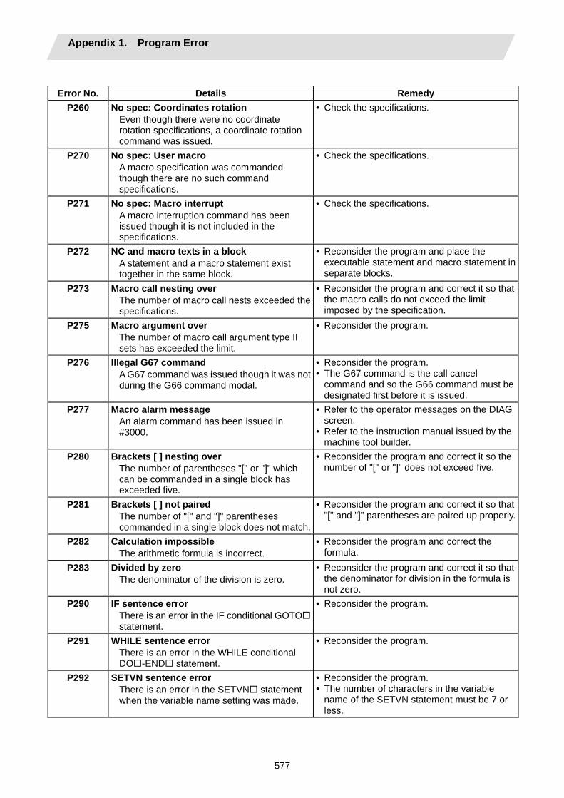
Appendix 1. Program Error
577
Error No. Details Remedy
P260 No spec: Coordinates rotation Even though there were no coordinate rotation specifications, a coordinate rotation command was issued.
• Check the specifications.
P270 No spec: User macro A macro specification was commanded though there are no such command specifications.
• Check the specifications.
P271 No spec: Macro interrupt A macro interruption command has been issued though it is not included in the specifications.
• Check the specifications.
P272 NC and macro texts in a block A statement and a macro statement exist together in the same block.
• Reconsider the program and place the executable statement and macro statement in separate blocks.
P273 Macro call nesting over The number of macro call nests exceeded the specifications.
• Reconsider the program and correct it so that the macro calls do not exceed the limit imposed by the specification.
P275 Macro argument over The number of macro call argument type II sets has exceeded the limit.
• Reconsider the program.
P276 Illegal G67 command A G67 command was issued though it was not during the G66 command modal.
• Reconsider the program. • The G67 command is the call cancel
command and so the G66 command must be designated first before it is issued.
P277 Macro alarm message An alarm command has been issued in #3000.
• Refer to the operator messages on the DIAG screen.
• Refer to the instruction manual issued by the machine tool builder.
P280 Brackets [ ] nesting over The number of parentheses "[" or "]" which can be commanded in a single block has exceeded five.
• Reconsider the program and correct it so the number of "[" or "]" does not exceed five.
P281 Brackets [ ] not paired The number of "[" and "]" parentheses commanded in a single block does not match.
• Reconsider the program and correct it so that "[" and "]" parentheses are paired up properly.
P282 Calculation impossible The arithmetic formula is incorrect.
• Reconsider the program and correct the formula.
P283 Divided by zero The denominator of the division is zero.
• Reconsider the program and correct it so that the denominator for division in the formula is not zero.
P290 IF sentence error There is an error in the IF conditional GOTOstatement.
• Reconsider the program.
P291 WHILE sentence error There is an error in the WHILE conditional DO -END statement.
• Reconsider the program.
P292 SETVN sentence error There is an error in the SETVN statement when the variable name setting was made.
• Reconsider the program. • The number of characters in the variable
name of the SETVN statement must be 7 or less.
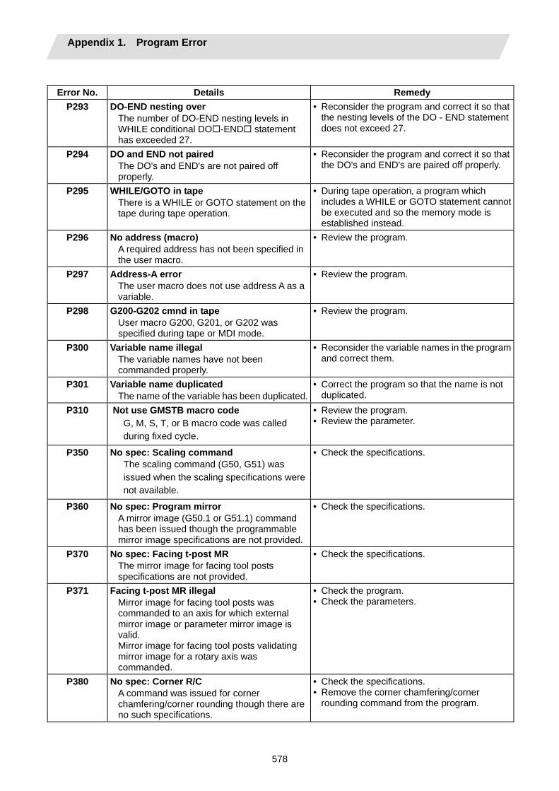
Appendix 1. Program Error
578
Error No. Details Remedy
P293 DO-END nesting over The number of DO-END nesting levels in WHILE conditional DO -END statement has exceeded 27.
• Reconsider the program and correct it so that the nesting levels of the DO - END statement does not exceed 27.
P294 DO and END not paired The DO's and END's are not paired off properly.
• Reconsider the program and correct it so that the DO's and END's are paired off properly.
P295 WHILE/GOTO in tape There is a WHILE or GOTO statement on the tape during tape operation.
• During tape operation‚ a program which includes a WHILE or GOTO statement cannot be executed and so the memory mode is established instead.
P296 No address (macro) A required address has not been specified in the user macro.
• Review the program.
P297 Address-A error The user macro does not use address A as a variable.
• Review the program.
P298 G200-G202 cmnd in tape User macro G200‚ G201‚ or G202 was specified during tape or MDI mode.
• Review the program.
P300 Variable name illegal The variable names have not been commanded properly.
• Reconsider the variable names in the program and correct them.
P301 Variable name duplicated The name of the variable has been duplicated.
• Correct the program so that the name is not duplicated.
P310 Not use GMSTB macro code G, M, S, T, or B macro code was called during fixed cycle.
• Review the program. • Review the parameter.
P350 No spec: Scaling command The scaling command (G50, G51) was issued when the scaling specifications were not available.
• Check the specifications.
P360 No spec: Program mirror A mirror image (G50.1 or G51.1) command has been issued though the programmable mirror image specifications are not provided.
• Check the specifications.
P370 No spec: Facing t-post MR The mirror image for facing tool posts specifications are not provided.
• Check the specifications.
P371 Facing t-post MR illegal Mirror image for facing tool posts was commanded to an axis for which external mirror image or parameter mirror image is valid. Mirror image for facing tool posts validating mirror image for a rotary axis was commanded.
• Check the program. • Check the parameters.
P380 No spec: Corner R/C A command was issued for corner chamfering/corner rounding though there are no such specifications.
• Check the specifications. • Remove the corner chamfering/corner
rounding command from the program.
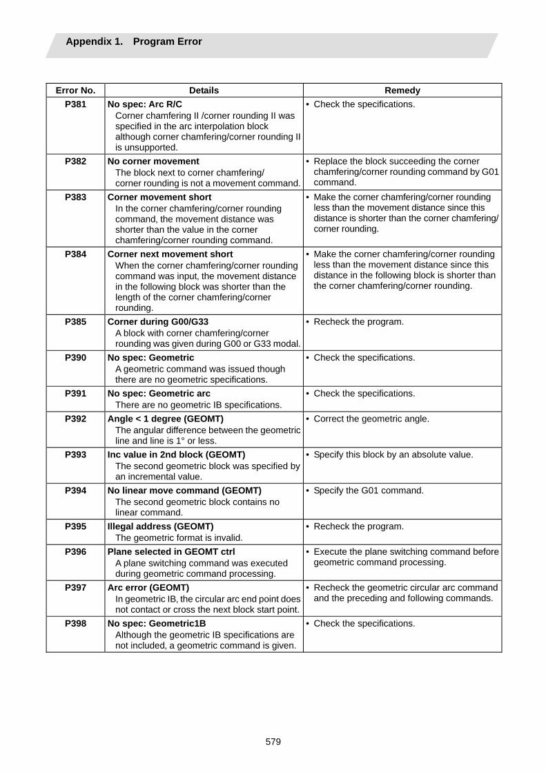
Appendix 1. Program Error
579
Error No. Details Remedy
P381 No spec: Arc R/C Corner chamfering II /corner rounding II was specified in the arc interpolation block although corner chamfering/corner rounding II is unsupported.
• Check the specifications.
P382 No corner movement The block next to corner chamfering/ corner rounding is not a movement command.
• Replace the block succeeding the corner chamfering/corner rounding command by G01 command.
P383 Corner movement short In the corner chamfering/corner rounding command‚ the movement distance was shorter than the value in the corner chamfering/corner rounding command.
• Make the corner chamfering/corner rounding less than the movement distance since this distance is shorter than the corner chamfering/corner rounding.
P384 Corner next movement short When the corner chamfering/corner rounding command was input‚ the movement distance in the following block was shorter than the length of the corner chamfering/corner rounding.
• Make the corner chamfering/corner rounding less than the movement distance since this distance in the following block is shorter than the corner chamfering/corner rounding.
P385 Corner during G00/G33 A block with corner chamfering/corner rounding was given during G00 or G33 modal.
• Recheck the program.
P390 No spec: Geometric A geometric command was issued though there are no geometric specifications.
• Check the specifications.
P391 No spec: Geometric arc There are no geometric IB specifications.
• Check the specifications.
P392 Angle < 1 degree (GEOMT) The angular difference between the geometric line and line is 1° or less.
• Correct the geometric angle.
P393 Inc value in 2nd block (GEOMT) The second geometric block was specified by an incremental value.
• Specify this block by an absolute value.
P394 No linear move command (GEOMT) The second geometric block contains no linear command.
• Specify the G01 command.
P395 Illegal address (GEOMT) The geometric format is invalid.
• Recheck the program.
P396 Plane selected in GEOMT ctrl A plane switching command was executed during geometric command processing.
• Execute the plane switching command before geometric command processing.
P397 Arc error (GEOMT) In geometric IB‚ the circular arc end point does not contact or cross the next block start point.
• Recheck the geometric circular arc command and the preceding and following commands.
P398 No spec: Geometric1B Although the geometric IB specifications are not included‚ a geometric command is given.
• Check the specifications.
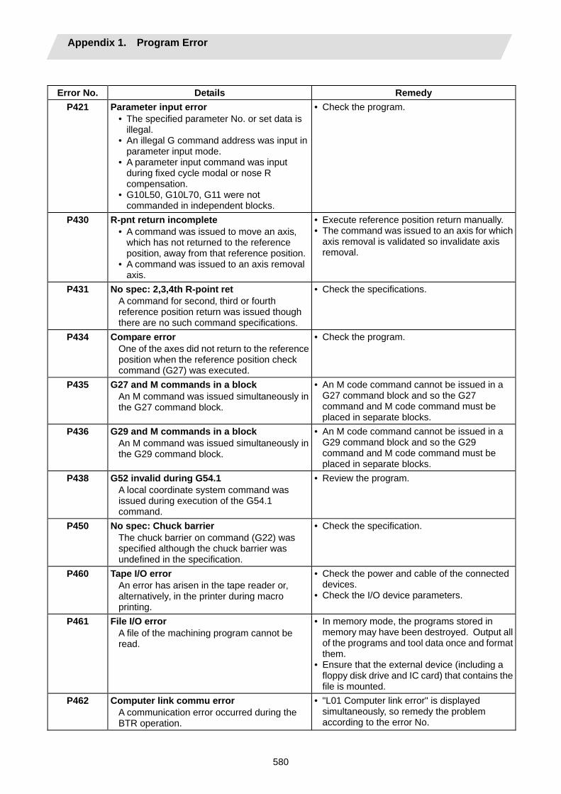
Appendix 1. Program Error
580
Error No. Details Remedy
P421 Parameter input error • The specified parameter No. or set data is
illegal. • An illegal G command address was input in
parameter input mode. • A parameter input command was input
during fixed cycle modal or nose R compensation.
• G10L50, G10L70, G11 were not commanded in independent blocks.
• Check the program.
P430 R-pnt return incomplete • A command was issued to move an axis‚
which has not returned to the reference position‚ away from that reference position.
• A command was issued to an axis removal axis.
• Execute reference position return manually. • The command was issued to an axis for which
axis removal is validated so invalidate axis removal.
P431 No spec: 2,3,4th R-point ret A command for second‚ third or fourth reference position return was issued though there are no such command specifications.
• Check the specifications.
P434 Compare error One of the axes did not return to the reference position when the reference position check command (G27) was executed.
• Check the program.
P435 G27 and M commands in a block An M command was issued simultaneously in the G27 command block.
• An M code command cannot be issued in a G27 command block and so the G27 command and M code command must be placed in separate blocks.
P436 G29 and M commands in a block An M command was issued simultaneously in the G29 command block.
• An M code command cannot be issued in a G29 command block and so the G29 command and M code command must be placed in separate blocks.
P438
G52 invalid during G54.1 A local coordinate system command was issued during execution of the G54.1 command.
• Review the program.
P450 No spec: Chuck barrier The chuck barrier on command (G22) was specified although the chuck barrier was undefined in the specification.
• Check the specification.
P460 Tape I/O error An error has arisen in the tape reader or‚ alternatively‚ in the printer during macro printing.
• Check the power and cable of the connected devices.
• Check the I/O device parameters.
P461 File I/O error A file of the machining program cannot be read.
• In memory mode, the programs stored in memory may have been destroyed. Output all of the programs and tool data once and format them.
• Ensure that the external device (including a floppy disk drive and IC card) that contains the file is mounted.
P462 Computer link commu error A communication error occurred during the BTR operation.
• "L01 Computer link error" is displayed simultaneously, so remedy the problem according to the error No.

Appendix 1. Program Error
581
Error No. Details Remedy
P480 No spec: Milling • Milling was commanded when the milling
specifications were not provided. • Polar coordinate interpolation was
commanded when the polar coordinate interpolation specifications were not provided.
• Check the specification.
P481 Illegal G code (mill) • An illegal G code was used during the
milling mode. • An illegal G code was used during
cylindrical interpolation or polar coordinate interpolation.
• The G07.1 command was issued during the tool radius compensation.
• Check the program.
P482 Illegal axis (mill) • A rotary axis was commanded during the
milling mode. • Milling was executed even though an illegal
value was set for the milling axis No. • Cylindrical interpolation or polar coordinate
interpolation was commanded during mirror image.
• Cylindrical interpolation or polar coordinate interpolation was commanded before the tool compensation was completed after the T command.
• G07.1 was commanded when cylindrical interpolation was not possible (there is no rotary axis, or external mirror image is ON).
• An axis other than a cylindrical coordinate system axis was commanded during cylindrical interpolation.
• Check the machining program, parameters and PLC I/F signal.
P484 R-pnt ret incomplete (mill) • Movement was commanded to an axis that
had not completed reference position return during the milling mode.
• Movement was commanded to an axis that had not completed reference position return during cylindrical interpolation or polar coordinate interpolation.
• Carry out manual reference position return.
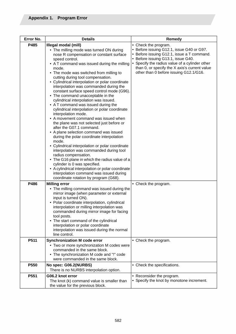
Appendix 1. Program Error
582
Error No. Details Remedy
P485 Illegal modal (mill) • The milling mode was turned ON during
nose R compensation or constant surface speed control.
• A T command was issued during the milling mode.
• The mode was switched from milling to cutting during tool compensation.
• Cylindrical interpolation or polar coordinate interpolation was commanded during the constant surface speed control mode (G96).
• The command unacceptable in the cylindrical interpolation was issued.
• A T command was issued during the cylindrical interpolation or polar coordinate interpolation mode.
• A movement command was issued when the plane was not selected just before or after the G07.1 command.
• A plane selection command was issued during the polar coordinate interpolation mode.
• Cylindrical interpolation or polar coordinate interpolation was commanded during tool radius compensation.
• The G16 plane in which the radius value of a cylinder is 0 was specified.
• A cylindrical interpolation or polar coordinate interpolation command was issued during coordinate rotation by program (G68).
• Check the program. • Before issuing G12.1, issue G40 or G97. • Before issuing G12.1, issue a T command. • Before issuing G13.1, issue G40. • Specify the radius value of a cylinder other
than 0, or specify the X axis's current value other than 0 before issuing G12.1/G16.
P486 Milling error • The milling command was issued during the
mirror image (when parameter or external input is turned ON).
• Polar coordinate interpolation, cylindrical interpolation or milling interpolation was commanded during mirror image for facing tool posts.
• The start command of the cylindrical interpolation or polar coordinate interpolation was issued during the normal line control.
• Check the program.
P511 Synchronization M code error • Two or more synchronization M codes were
commanded in the same block. • The synchronization M code and "!" code
were commanded in the same block.
• Check the program.
P550 No spec: G06.2(NURBS) There is no NURBS interpolation option.
• Check the specifications.
P551 G06.2 knot error The knot (k) command value is smaller than the value for the previous block.
• Reconsider the program. • Specify the knot by monotone increment.

Appendix 1. Program Error
583
Error No. Details Remedy
P552 Start point of 1st G06.2 err The block end point immediately before the G06.2 command and the G06.2 first block command value do not match.
• Match the G06.2 first block coordinate command value with the previous block end point.
P554 Invld manual interrupt in G6.2 Manual interruption using a block was performed while in G06.2 mode.
• Perform for blocks other than G06.2 mode when manually interrupting.
P555 Invalid restart during G06.2 Restart was attempted from the block in G06.2 mode.
• Restart from the block other than in G06.2 mode.
P600 No spec: Auto TLM An automatic tool length measurement command (G37) was execute though there are no such command specifications.
• Check the specifications.
P601 No spec: Skip A skip command (G31) was issued though there are no such command specifications.
• Check the specifications.
P602 No spec: Multi skip A multiple skip command (G31.1‚ G31.2 or G31.3) was issued though there are no such command specifications.
• Check the specifications.
P603 Skip speed 0 The skip speed is 0.
• Specify the skip speed.
P604 TLM illegal axis No axis or more than one axis was specified inthe automatic tool length measurement block.
• Specify only one axis.
P605 T & TLM command in a block The T code is in the same block as the automatic tool length measurement block.
• Specify this T code before the block.
P606 T cmnd not found before TLM The T code was not yet specified in automatic tool length measurement.
• Specify this T code before the block.
P607 TLM illegal signal Before the area specified by the D command or decelerating area parameter d‚ the measurement position arrival signal went ON. The signal remains OFF to the end.
• Check the program.
P608 Skip during radius compen A skip command was specified during radius compensation processing.
• Specify a radius compensation cancel (G40) command or remove the skip command.
P610 Illegal parameter • The parameter setting is not correct. • G114.1 was commanded when the spindle
synchronization with PLC I/F command was selected.
• G113 was commanded when the spindle-spindle polygon machining option was OFF and the spindle synchronization with PLC I/F command was selected.
• Check whether "#1549 Iv0vR1" to "#1553 Iv0vR5" are set in descending order (in order of large values).
• Check whether "#1554 Iv0rd2" to "#1557 Iv0rd5" are set in descending order.
• Check and correct "#1514 expLinax" and "#1515 expRotax".
• Check the program. • Check the parameter.
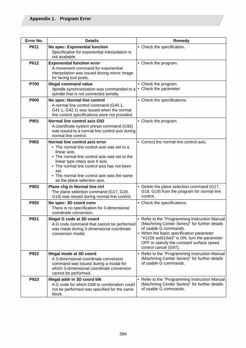
Appendix 1. Program Error
584
Error No. Details Remedy
P611 No spec: Exponential function Specification for exponential interpolation is not available.
• Check the specification.
P612 Exponential function error A movement command for exponential interpolation was issued during mirror image for facing tool posts.
• Check the program.
P700 Illegal command value Spindle synchronization was commanded to a spindle that is not connected serially.
• Check the program. • Check the parameter.
P900 No spec: Normal line control A normal line control command (G40.1, G41.1, G42.1) was issued when the normal line control specifications were not provided.
• Check the specifications.
P901 Normal line control axis G92 A coordinate system preset command (G92) was issued to a normal line control axis during normal line control.
• Check the program.
P902 Normal line control axis error • The normal line control axis was set to a
linear axis. • The normal line control axis was set to the
linear type rotary axis II axis. • The normal line control axis has not been
set. • The normal line control axis was the same
as the plane selection axis.
• Correct the normal line control axis.
P903 Plane chg in Normal line ctrl The plane selection command (G17, G18, G19) was issued during normal line control.
• Delete the plane selection command (G17, G18, G19) from the program for normal line control.
P920 No spec: 3D coord conv There is no specification for 3-dimensional coordinate conversion.
• Check the specifications.
P921 Illegal G code at 3D coord A G code command that cannot be performed was made during 3-dimensional coordinate conversion modal.
• Refer to the "Programming Instruction Manual (Machining Center Series)" for further details of usable G commands.
• When the basic specification parameter "#1229 set01/bit3" is ON, turn the parameter OFF or specify the constant surface speed control cancel (G97).
P922 Illegal mode at 3D coord A 3-dimensional coordinate conversion command was issued during a modal for which 3-dimensional coordinate conversion cannot be performed.
• Refer to the "Programming Instruction Manual (Machining Center Series)" for further details of usable G commands.
P923 Illegal addr in 3D coord blk A G code for which G68 to combination could not be performed was specified for the same block.
• Refer to the "Programming Instruction Manual (Machining Center Series)" for further details of usable G commands.
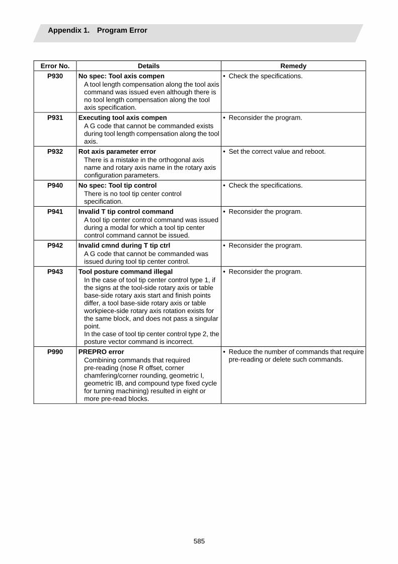
Appendix 1. Program Error
585
Error No. Details Remedy
P930 No spec: Tool axis compen A tool length compensation along the tool axis command was issued even although there is no tool length compensation along the tool axis specification.
• Check the specifications.
P931 Executing tool axis compen A G code that cannot be commanded exists during tool length compensation along the tool axis.
• Reconsider the program.
P932 Rot axis parameter error There is a mistake in the orthogonal axis name and rotary axis name in the rotary axis configuration parameters.
• Set the correct value and reboot.
P940 No spec: Tool tip control There is no tool tip center control specification.
• Check the specifications.
P941 Invalid T tip control command A tool tip center control command was issued during a modal for which a tool tip center control command cannot be issued.
• Reconsider the program.
P942 Invalid cmnd during T tip ctrl A G code that cannot be commanded was issued during tool tip center control.
• Reconsider the program.
P943 Tool posture command illegal In the case of tool tip center control type 1, if the signs at the tool-side rotary axis or table base-side rotary axis start and finish points differ, a tool base-side rotary axis or table workpiece-side rotary axis rotation exists for the same block, and does not pass a singular point. In the case of tool tip center control type 2, the posture vector command is incorrect.
• Reconsider the program.
P990 PREPRO error Combining commands that required pre-reading (nose R offset‚ corner chamfering/corner rounding‚ geometric I‚ geometric IB‚ and compound type fixed cycle for turning machining) resulted in eight or more pre-read blocks.
• Reduce the number of commands that require pre-reading or delete such commands.
Revision History
Date of revision Manual No. Revision details
Jun. 2004 IB(NA)1500057-A First edition created.
Sep. 2004 IB(NA)1500057-B • Contents were revised to correspond to Mitsubishi CNC700 Series software version A.
• Section "2.1 Input Command Increments" was deleted. • Section "2.2 Indexing Increment" was added. • Section "3.3 Program Address Check Function" was deleted. • Section "14.9 Simple Zero Point Return" was deleted. • Section "14.13 Coordinate System for Rotary Axis" was added. • Mistakes were corrected.
Sep. 2005 IB(NA)1500057-C • Contents were revised to correspond to Mitsubishi CNC700 Series software version B3.
• Section "13.15 Parameter Input by Program" was revised wholly. • Section "13.21 2-part System Simultaneous Thread-cutting Cycle (MELDAS
special format)" was added. • Section "Appendix 1. Parameter Input by Program N No. Correspondence" was
deleted. • Other contents were added/revised/deleted according to specification.
Global service network
NORTH AMERICA FA Center EUROPEAN FA Center
ASEAN FA Center
CHINA FA Center
TAIWAN FA Center
HONG KONG FA Center
KOREAN FA Center
North America FA Center (MITSUBISHI ELECTRIC AUTOMATION INC.)
Illinois CNC Service Center 500 CORPORATE WOODS PARKWAY, VERNON HILLS, IL. 60061, U.S.A. TEL: +1-847-478-2500 (Se FAX: +1-847-478-2650 (Se California CNC Service Center 5665 PLAZA DRIVE, CYPRESS, CA. 90630, U.S.A. TEL: +1-714-220-4796 FAX: +1-714-229-3818 Georgia CNC Service Center 2810 PREMIERE PARKWAY SUITE 400, DULUTH, GA., 30097, U.S.A. TEL: +1-678-258-4500 FAX: +1-678-258-4519 New Jersey CNC Service Center 200 COTTONTAIL LANE SOMERSET, NJ. 08873, U.S.A. TEL: +1-732-560-4500 FAX: +1-732-560-4531 Kentucky CNC Service Satellite 8025 PRODUCTION DRIVE, FLORENCE, KY., 41042, U.S.A. TEL: +1-859-342-1700 FAX: +1-859-342-1578 Michigan CNC Service Satellite 2545 38TH STREET, ALLEGAN, MI., 49010, U.S.A. TEL: +1-847-478-2500 FAX: +1-269-673-4092 Ohio CNC Service Satellite 62 W. 500 S., ANDERSON, IN., 46013, U.S.A. TEL: +1-847-478-2608 FAX: +1-847-478-2690 Texas CNC Service Satellite 1000, NOLEN DRIVE SUITE 200, GRAPEVINE, TX. 76051, U.S.A. TEL: +1-817-251-7468 FAX: +1-817-416-1439 Canada CNC Service Center 4299 14TH AVENUE MARKHAM, ON. L3R OJ2, CANADA TEL: +1-905-475-7728 FAX: +1-905-475-7935 Mexico CNC Service Center MARIANO ESCOBEDO 69 TLALNEPANTLA, 54030 EDO. DE MEXICO TEL: +52-55-9171-7662 FAX: +52-55-9171-7698 Monterrey CNC Service Satellite ARGENTINA 3900, FRACC. LAS TORRES, MONTERREY, N.L., 64720, MEXICO TEL: +52-81-8365-4171 FAX: +52-81-8365-4171 Brazil MITSUBISHI CNC Agent Service Center (AUTOMOTION IND. COM. IMP. E EXP. LTDA.) ACESSO JOSE SARTORELLI, KM 2.1 18550-000 BOITUVA – SP, BRAZIL TEL: +55-15-3363-9900 FAX: +55-15-3363-9911
European FA Center (MITSUBISHI ELECTRIC EUROPE B.V.)
Germany CNC Service Center GOTHAER STRASSE 8, 40880 RATINGEN, GERMANY TEL: +49-2102-486-0 FAX:+49-2102486-591 South Germany CNC Service Center KURZE STRASSE. 40, 70794 FILDERSTADT-BONLANDEN, GERMANY TEL: +49-711-3270-010 FAX: +49-711-3270-0141 France CNC Service Center 25, BOULEVARD DES BOUVETS, 92741 NANTERRE CEDEX FRANCE TEL: +33-1-41-02-83-13 FAX: +33-1-49-01-07-25 Lyon CNC Service Satellite U.K CNC Service Center TRAVELLERS LANE, HATFIELD, HERTFORDSHIRE, AL10 8XB, U.K. TEL: +44-1707-282-846 FAX:-44-1707-278-992 Italy CNC Service Center ZONA INDUSTRIALE VIA ARCHIMEDE 35 20041 AGRATE BRIANZA, MILANO ITALY TEL: +39-039-60531-342 FAX: +39-039-6053-206 Spain CNC Service Satellite CTRA. DE RUBI, 76-80 -APDO.420 08190 SAINT CUGAT DEL VALLES, BARCELONA SPAINTEL: +34-935-65-2236 FAX: Turkey MITSUBISHI CNC Agent Service Center (GENEL TEKNIK SISTEMLER LTD. STI.) DARULACEZE CAD. FAMAS IS MERKEZI A BLOCK NO.43 KAT2 80270 OKMEYDANI ISTANBUL, TURKEY TEL: +90-212-320-1640 FAX: +90-212-320-1649 Poland MITSUBISHI CNC Agent Service Center (MPL Technology Sp. z. o. o) UL SLICZNA 34, 31-444 KRAKOW, POLAND TEL: +48-12-632-28-85 FAX: Wroclaw MITSUBISHI CNC Agent Service Satellite (MPL Technology Sp. z. o. o) UL KOBIERZYCKA 23, 52-315 WROCLAW, POLAND TEL: +48-71-333-77-53 FAX: +48-71-333-77-53 Czech MITSUBISHI CNC Agent Service Center (AUTOCONT CONTROL SYSTEM S.R.O. ) NEMOCNICNI 12, 702 00 OSTRAVA 2 CZECH REPUBLIC TEL: +420-596-152-426 FAX: +420-596-152-112
ASEAN FA Center (MITSUBISHI ELECTRIC ASIA PTE. LTD.) Singapore CNC Service Center 307 ALEXANDRA ROAD #05-01/02 MITSUBISHI ELECTRIC BUILDING SINGAPORE 159943 TEL: +65-6473-2308 FAX: +65-6476-7439 Thailand MITSUBISHI CNC Agent Service Center (F. A. TECH CO., LTD) 898/19,20,21,22 S.V. CITY BUILDING OFFICE TOWER 1 FLOOR 12,14 RAMA III RD BANGPONGPANG, YANNAWA, BANGKOK 10120. THAILAND TEL: +66-2-682-6522 FAX: +66-2-682-6020 Malaysia MITSUBISHI CNC Agent Service Center (FLEXIBLE AUTOMATION SYSTEM SDN. BHD.) 60, JALAN USJ 10/1B 47620 UEP SUBANG JAYA SELANGOR DARUL EHSAN MALAYSIA TEL: +60-3-5631-7605 FAX: +60-3-5631-7636 JOHOR MITSUBISHI CNC Agent Service Satellite (FLEXIBLE AUTOMATION SYSTEM SDN. BHD.) NO. 16, JALAN SHAHBANDAR 1, TAMAN UNGKU TUN AMINAH, 81300 SKUDAI, JOHOR MALAYSIATEL: +60-7-557-8218 FAX: +60-7-557-3404 Indonesia MITSUBISHI CNC Agent Service Center (PT. AUTOTEKNINDO SUMBER MAKMUR) WISMA NUSANTARA 14TH FLOOR JL. M.H. THAMRIN 59, JAKARTA 10350 INDONESIA TEL: +62-21-3917-144 FAX: +62-21-3917-164 India MITSUBISHI CNC Agent Service Center (MESSUNG SALES & SERVICES PVT. LTD.)B-36FF, PAVANA INDUSTRIAL PREMISES M.I.D.C., BHOASRI PUNE 411026, INDIA TEL: +91-20-2711-9484 FAX: +91-20-2712-8115 BANGALORE MITSUBISHI CNC Agent Service Satellite (MESSUNG SALES & SERVICES PVT. LTD.) S 615, 6TH FLOOR, MANIPAL CENTER, BANGALORE 560001, INDIA TEL: +91-80-509-2119 FAX: +91-80-532-0480 Delhi MITSUBISHI CNC Agent Parts Center (MESSUNG SALES & SERVICES PVT. LTD.) 1197, SECTOR 15 PART-2, OFF DELHI-JAIPUR HIGHWAY BEHIND 32ND MILESTONE GURGAON 122001, INDIA TEL: +91-98-1024-8895 FAX: Philippines MITSUBISHI CNC Agent Service Center (FLEXIBLE AUTOMATION SYSTEM CORPORATION) UNIT No.411, ALABAMG CORPORATE CENTER KM 25. WEST SERVICE ROAD SOUTH SUPERHIGHWAY, ALABAMG MUNTINLUPA METRO MANILA, PHILIPPINES 1771 TEL: +63-2-807-2416 FAX: +63-2-807-2417 Vietnam MITSUBISHI CNC Agent Service Center (SA GIANG TECHNO CO., LTD) 47-49 HOANG SA ST. DAKAO WARD, DIST.1 HO CHI MINH CITY, VIETNAM TEL: +84-8-910-4763 FAX: +84-8-910-2593
China FA Center (MITSUBISHI ELECTRIC AUTOMATION (SHANGHAI) LTD.)
China CNC Service Center 2/F., BLOCK 5 BLDG.AUTOMATION INSTRUMENTATION PLAZA, 103 CAOBAO RD. SHANGHAI 200233, CHINA TEL: +86-21-6120-0808 FAX: +86-21-6494-0178 Shenyang CNC Service Center TEL: +86-24-2397-0184 FAX: +86-24-2397-0185 Beijing CNC Service Satellite 9/F, OFFICE TOWER1, HENDERSON CENTER, 18 JIANGUOMENNEI DAJIE, DONGCHENG DISTRICT, BEIJING 100005, CHINA TEL: +86-10-6518-8830 FAX: +86-10-6518-8030 China MITSUBISHI CNC Agent Service Center (BEIJING JIAYOU HIGHTECH TECHNOLOGY DEVELOPMENT CO.) RM 709, HIGH TECHNOLOGY BUILDING NO.229 NORTH SI HUAN ZHONG ROAD, HAIDIAN DISTRICT , BEIJING 100083, CHINA TEL: +86-10-8288-3030 FAX: +86-10-6518-8030 Tianjin CNC Service Satellite RM909, TAIHONG TOWER, NO220 SHIZILIN STREET, HEBEI DISTRICT, TIANJIN, CHINA 300143 TEL: -86-22-2653-9090 FAX: +86-22-2635-9050 Shenzhen CNC Service Satellite RM02, UNIT A, 13/F, TIANAN NATIONAL TOWER, RENMING SOUTH ROAD, SHENZHEN, CHINA 518005 TEL: +86-755-2515-6691 FAX: +86-755-8218-4776 Changchun Service Satellite TEL: +86-431-50214546 FAX: +86-431-5021690 Hong Kong CNC Service Center UNIT A, 25/F RYODEN INDUSTRIAL CENTRE, 26-38 TA CHUEN PING STREET, KWAI CHUNG, NEW TERRITORIES, HONG KONG TEL: +852-2619-8588 FAX: +852-2784-1323
Taiwan FA Center (MITSUBISHI ELECTRIC TAIWAN CO., LTD.) Taichung CNC Service Center NO.8-1, GONG YEH 16TH RD., TAICHUNG INDUSTIAL PARK TAICHUNG CITY, TAIWAN R.O.C. TEL: +886-4-2359-0688 FAX: +886-4-2359-0689 Taipei CNC Service Satellite TEL: +886-4-2359-0688 FAX: +886-4-2359-0689 Tainan CNC Service Satellite TEL: +886-4-2359-0688 FAX: +886-4-2359-0689
Korean FA Center (MITSUBISHI ELECTRIC AUTOMATION KOREA CO., LTD.)
Korea CNC Service Center DONGSEO GAME CHANNEL BLDG. 2F. 660-11, DEUNGCHON-DONG KANGSEO-KU SEOUL, 157-030 KOREA TEL: +82-2-3660-9607 FAX: +82-2-3663-0475
Notice
Every effort has been made to keep up with software and hardware revisions in the contents described in this manual. However, please understand that in some unavoidable cases simultaneous revision is not possible. Please contact your Mitsubishi Electric dealer with any questions or comments regarding the use of this product.
Duplication Prohibited This manual may not be reproduced in any form, in part or in whole, without written permission from Mitsubishi Electric Corporation.
© 2004-2005 MITSUBISHI ELECTRIC CORPORATION ALL RIGHTS RESERVED.

Related Documents