Welcome message from author
This document is posted to help you gain knowledge. Please leave a comment to let me know what you think about it! Share it to your friends and learn new things together.
Transcript


MELDAS is a registered trademark of Mitsubishi Electric Corporation. Other company and product names that appear in this manual are trademarks or registered trademarks of their respective companies.


Introduction Thank you for selecting the Mitsubishi numerical control unit. This instruction manual describes the handling and caution points for using this AC servo/spindle. Incorrect handling may lead to unforeseen accidents, so always read this instruction manual thoroughly to ensure correct usage. Make sure that this instruction manual is delivered to the end user. Always store this manual in a safe place. In order to confirm if all function specifications described in this manual are applicable, refer to the specifications for each CNC.
Notes on Reading This Manual
(1) Since the description of this specification manual deals with NC in general, for the specifications of individual machine tools, refer to the manuals issued by the respective machine manufacturers. The "restrictions" and "available functions" described in the manuals issued by the machine manufacturers have precedence to those in this manual.
(2) This manual describes as many special operations as possible, but it should be kept in mind that items not mentioned in this manual cannot be performed.


Precautions for safety Please read this manual and auxiliary documents before starting installation, operation, maintenance or inspection to ensure correct usage. Thoroughly understand the device, safety information and precautions before starting operation.
The safety precautions in this instruction manual are ranked as "WARNING" and "CAUTION".
DANGER
When there is a potential risk of fatal or serious injuries if handling is mistaken.
WARNING When a dangerous situation, or fatal or serious injuries may occur if handling is mistaken.
CAUTION When a dangerous situation may occur if handling is mistaken leading to medium or minor injuries, or physical damage.
Note that some items described as CAUTION may lead to major results depending on the situation. In any case, important information that must be observed is described.
The signs indicating prohibited and mandatory matters are explained below.
Indicates a prohibited matter. For example, "Fire Prohibited" is indicated as .
Indicates a mandatory matter. For example, grounding is indicated as .
After reading this specifications and instructions manual, store it where the user can access it easily for reference.
The numeric control unit is configured of the control unit, operation board, servo drive unit, spindle drive unit, power supply, servomotor and spindle motor, etc.
In this section "Precautions for safety", the following items are generically called the "motor".
• Servomotor • Linear servomotor • Spindle motor
In this section "Precautions for safety", the following items are generically called the "unit". • Servo drive unit • Spindle drive unit • Power supply unit • Scale interface unit • Magnetic pole detection unit
POINT Important matters that should be understood for operation of this machine are indicated as a POINT in this manual.

WARNING 1. Electric shock prevention
Do not open the front cover while the power is ON or during operation. Failure to observe this could lead to electric shocks. Do not operate the unit with the front cover removed. The high voltage terminals and charged sections will be exposed, and can cause electric shocks. Do not remove the front cover and connector even when the power is OFF unless carrying out wiring work or periodic inspections. The inside of the units is charged, and can cause electric shocks. Since the high voltage is supplied to the main circuit connector while the power is ON or during operation, do not touch the main circuit connector with an adjustment screwdriver or the pen tip. Failure to observe this could lead to electric shocks. Wait at least 15 minutes after turning the power OFF, confirm that the CHARGE lamp has gone out, and check the voltage between P and N terminals with a tester, etc., before starting wiring, maintenance or inspections. Failure to observe this could lead to electric shocks. Ground the unit and motor following the standards set forth by each country. Wiring, maintenance and inspection work must be done by a qualified technician. Wire the servo drive unit and servomotor after installation. Failure to observe this could lead to electric shocks. Do not touch the switches with wet hands. Failure to observe this could lead to electric shocks. Do not damage, apply forcible stress, place heavy items on the cables or get them caught. Failure to observe this could lead to electric shocks.
2. Injury prevention
The linear servomotor uses a powerful magnet on the secondary side, and could adversely affect pacemakers, etc.
During installation and operation of the machine, do not place portable items that could malfunction or fail due to the influence of the linear servomotor's magnetic force. Take special care not to pinch fingers, etc., when installing (and unpacking) the linear servomotor. In the system where the optical communication with CNC is executed, do not see directly the light generated from CN1A/CN1B connector of drive unit or the end of cable. When the light gets into eye, you may feel something is wrong for eye. (The light source of optical communication corresponds to class1 defined in JISC6802 or IEC60825-1.)

CAUTION 1. Fire prevention
Install the units, motors and regenerative resistor on non-combustible material. Direct installation on combustible material or near combustible materials could lead to fires. Always install a circuit protector and contactor on the servo drive unit power input as explained in this manual. Refer to this manual and select the correct circuit protector and contactor. An incorrect selection could result in fire. Shut off the power on the unit side if a fault occurs in the units. Fires could be caused if a large current continues to flow. When using a regenerative resistor, provide a sequence that shuts off the power with the regenerative resistor's error signal. The regenerative resistor could abnormally overheat and cause a fire due to a fault in the regenerative transistor, etc. The battery unit could heat up, ignite or rupture if submerged in water, or if the poles are incorrectly wired.
Cut off the main circuit power with the contactor when an alarm or emergency stop occurs.
2. Injury prevention Do not apply a voltage other than that specified in this manual, on each terminal. Failure to
observe this item could lead to ruptures or damage, etc.
Do not mistake the terminal connections. Failure to observe this item could lead to ruptures or damage, etc.
Do not mistake the polarity ( + , – ). Failure to observe this item could lead to ruptures or damage, etc.
Do not touch the radiation fin on unit back face, regenerative resistor or motor, etc., or place parts (cables, etc.) while the power is turned ON or immediately after turning the power OFF. These parts may reach high temperatures, and can cause burns or part damage.
Structure the cooling fan on the unit back face, etc., etc so that it cannot be touched after installation. Touching the cooling fan during operation could lead to injuries.

CAUTION 3. Various precautions
Observe the following precautions. Incorrect handling of the unit could lead to faults, injuries and electric shocks, etc.
(1) Transportation and installation
Correctly transport the product according to its weight. Use the motor's hanging bolts only when transporting the motor. Do not transport the machine when the motor is installed on the machine. Do not stack the products above the tolerable number. Follow this manual and install the unit or motor in a place where the weight can be borne. Do not get on top of or place heavy objects on the unit.
Do not hold the cables, axis or detector when transporting the motor.
Do not hold the connected wires or cables when transporting the units. Do not hold the front cover when transporting the unit. The unit could drop. Always observe the installation directions of the units or motors. Secure the specified distance between the units and control panel, or between the servo drive unit and other devices. Do not install or run a unit or motor that is damaged or missing parts. Do not block the intake or exhaust ports of the motor provided with a cooling fan. Do not let foreign objects enter the units or motors. In particular, if conductive objects such as screws or metal chips, etc., or combustible materials such as oil enter, rupture or breakage could occur. The units and motors are precision devices, so do not drop them or apply strong impacts to them.

CAUTION Store and use the units under the following environment conditions. Environment Unit Motor
Ambient temperature
Operation: 0 to 55°C (with no freezing), Storage / Transportation: -15°C to 70°C
(with no freezing)
Operation: 0 to 40°C (with no freezing), Storage: -15°C to 70°C (Note 2) (with no freezing)
Ambient humidity
Operation: 90%RH or less (with no dew condensation)
Storage / Transportation: 90%RH or less (with no dew condensation)
Operation: 80%RH or less (with no dew condensation),
Storage: 90%RH or less (with no dew condensation)
Atmosphere Indoors (no direct sunlight)
With no corrosive gas, inflammable gas, oil mist, dust or conductive fine particles
Altitude
Operation/Storage: 1000 meters or less above sea level,
Transportation: 13000 meters or less above sea level
Operation: 1000 meters or less above sea level,Storage: 10000 meters or less above sea level
Vibration/impact According to each unit or motor specification (Note 1) For details, confirm each unit or motor specifications in addition. (Note 2) -15°C to 55°C for linear servomotor.
Securely fix the servomotor to the machine. Insufficient fixing could lead to the servomotor slipping off during operation. Always install the servomotor with reduction gear in the designated direction. Failure to do so could lead to oil leaks. Structure the rotary sections of the motor so that it can never be touched during operation. Install a cover, etc., on the shaft. When installing a coupling to a servomotor shaft end, do not apply an impact by hammering, etc. The detector could be damaged. Do not apply a load exceeding the tolerable load onto the servomotor shaft. The shaft could break. Store the motor in the package box. When inserting the shaft into the built-in IPM motor, do not heat the rotor higher than 130°C. The magnet could be demagnetized, and the specifications characteristics will not be ensured. Always use a nonmagnetic tool (explosion-proof beryllium copper alloy safety tool: NGK Insulators, etc.) when installing the linear servomotor. Always provide a mechanical stopper on the end of the linear servomotor's travel path. If the unit has been stored for a long time, always check the operation before starting actual operation. Please contact the Service Center, Service Station, Sales Office or delayer.

CAUTION (2) Wiring
Correctly and securely perform the wiring. Failure to do so could lead to abnormal operation of
the motor. Do not install a condensing capacitor, surge absorber or radio noise filter on the output side of the drive unit. Correctly connect the output side of the drive unit (terminals U, V, W). Failure to do so could lead to abnormal operation of the motor. When using a power regenerative power supply unit, always install an AC reactor for each power supply unit. In the main circuit power supply side of the unit, always install an appropriate circuit protector or contactor for each unit. Circuit protector or contactor cannot be shared by several units. Always connect the motor to the drive unit's output terminals (U, V, W). Do not directly connect a commercial power supply to the servomotor. Failure to observe this could result in a fault. When using an inductive load such as a relay, always connect a diode as a noise measure parallel to the load. When using a capacitance load such as a lamp, always connect a protective resistor as a noise measure serial to the load.
Do not reverse the direction of a diode which connect to a DC relay for the control output signals such as contractor and motor brake output, etc. to suppress a surge. Connecting it backwards could cause the drive unit to malfunction so that signals are not output, and emergency stop and other safety circuits are inoperable.
COM(24VDC)
Control outputsignal
Servodrive unit
RA
COM(24VDC)
Servodrive unit
RAControl outputsignal
Do not connect/disconnect the cables connected between the units while the power is ON. Securely tighten the cable connector fixing screw or fixing mechanism. An insecure fixing could cause the cable to fall off while the power is ON. When using a shielded cable instructed in the instruction manual, always ground the cable with a cable clamp, etc. Always separate the signals wires from the drive wire and power line. Use wires and cables that have a wire diameter, heat resistance and flexibility that conforms to the system.

CAUTION (3) Trial operation and adjustment
Check and adjust each program and parameter before starting operation. Failure to do so could lead to unforeseen operation of the machine. Do not make remarkable adjustments and changes of parameter as the operation could become unstable. The usable motor and unit combination is predetermined. Always check the models before starting trial operation. If the axis is unbalanced due to gravity, etc., balance the axis using a counterbalance, etc. The linear servomotor does not have a stopping device such as magnetic brakes. Install a stopping device on the machine side.
(4) Usage methods
In abnormal state, install an external emergency stop circuit so that the operation can be stopped and power shut off immediately. Turn the power OFF immediately if smoke, abnormal noise or odors are generated from the unit or motor.
Do not disassemble or repair this product. Never make modifications.
When an alarm occurs, the machine will start suddenly if an alarm reset (RST) is carried out while an operation start signal (ST) is being input. Always confirm that the operation signal is OFF before carrying out an alarm reset. Failure to do so could lead to accidents or injuries.
Reduce magnetic damage by installing a noise filter. The electronic devices used near the unit could be affected by magnetic noise. Install a line noise filter, etc., if there is a risk of magnetic noise. Use the unit, motor and regenerative resistor with the designated combination. Failure to do so could lead to fires or trouble. The brake (magnetic brake) of the servomotor are for holding, and must not be used for normal braking. There may be cases when holding is not possible due to the magnetic brake's life, the machine construction (when ball screw and servomotor are coupled via a timing belt, etc.) or the magnetic brake’s failure. Install a stop device to ensure safety on the machine side. After changing the programs/parameters or after maintenance and inspection, always test the operation before starting actual operation. Do not enter the movable range of the machine during automatic operation. Never place body parts near or touch the spindle during rotation. Follow the power supply specification conditions given in each specification for the power (input voltage, input frequency, tolerable sudden power failure time, etc.). Set all bits to "0" if they are indicated as not used or empty in the explanation on the bits. Do not use the dynamic brakes except during the emergency stop. Continued use of the dynamic brakes could result in brake damage. If a circuit protector for the main circuit power supply is shared by several units, the circuit protector may not activate when a short-circuit fault occurs in a small capacity unit. This is dangerous, so never share the circuit protector.

CAUTION (5) Troubleshooting
If a hazardous situation is predicted during power failure or product trouble, use a servomotor with magnetic brakes or install an external brake mechanism.
Use a double circuit configuration that allows the operation circuit for the magnetic brakes to be operated even by the external emergency stop signal.
MBR
24VDC
EMG
Magneticbrake
Servomotor
Shut off with the servomotorbrake control output.
Shut off with NC brakecontrol PLC output.
Always turn the input power OFF when an alarm occurs. If an alarm occurs, remove the cause, and secure the safety before resetting the alarm. Never go near the machine after restoring the power after a power failure, as the machine could start suddenly. (Design the machine so that personal safety can be ensured even if the machine starts suddenly.)
(6) Maintenance, inspection and part replacement Always backup the programs and parameters before starting maintenance or inspections.
The capacity of the electrolytic capacitor will drop over time due to self-discharging, etc. To prevent secondary disasters due to failures, replacing this part every five years when used under a normal environment is recommended. Contact the Service Center, Service Station, Sales Office or delayer for repairs or part replacement. Do not perform a megger test (insulation resistance measurement) during inspections. If the battery low warning is issued, back up the machining programs, tool data and parameters with an input/output unit, and then replace the battery. Do not short circuit, charge, overheat, incinerate or disassemble the battery. The heat radiating fin used in some units contains substitute Freon as the refrigerant.Take care not to damage the heat radiating fin during maintenance and replacement work.
(7) Disposal
Do not dispose of this type of unit as general industrial waste. Always contact the Service Center, Service Station, Sales Office or delayer for repairs or part replacement. Do not disassemble the unit or motor. Dispose of the battery according to local laws.
Always return the secondary side (magnet side) of the linear servomotor to the Service Center or Service Station.
When incinerating optical communication cable, hydrogen fluoride gas or hydrogen chloride gas which is corrosive and harmful may be generated. For disposal of optical communication cable, request for specialized industrial waste disposal services that has incineration facility for disposing hydrogen fluoride gas or hydrogen chloride gas.

CAUTION (8) Transportation
The unit and motor are precision parts and must be handled carefully.
According to a United Nations Advisory, the battery unit and battery must be transported according to the rules set forth by the International Civil Aviation Organization (ICAO), International Air Transportation Association (IATA), International Maritime Organization (IMO), and United States Department of Transportation (DOT), etc.
(9) General precautions
The drawings given in this manual show the covers and safety partitions, etc., removed to provide a clearer explanation. Always return the covers or partitions to their respective places before starting operation, and always follow the instructions given in this manual.

Treatment of waste The following two laws will apply when disposing of this product. Considerations must be made to each law. The following laws are in effect in Japan. Thus, when using this product overseas, the local laws will have a priority. If necessary, indicate or notify these laws to the final user of the product.
1. Requirements for "Law for Promotion of Effective Utilization of Resources" (1) Recycle as much of this product as possible when finished with use. (2) When recycling, often parts are sorted into steel scraps and electric parts, etc., and sold to scrap
contractors. Mitsubishi recommends sorting the product and selling the members to appropriate contractors.
2. Requirements for "Law for Treatment of Waste and Cleaning"
(1) Mitsubishi recommends recycling and selling the product when no longer needed according to item (1) above. The user should make an effort to reduce waste in this manner.
(2) When disposing a product that cannot be resold, it shall be treated as a waste product. (3) The treatment of industrial waste must be commissioned to a licensed industrial waste treatment
contractor, and appropriate measures, including a manifest control, must be taken. (4) Batteries correspond to "primary batteries", and must be disposed of according to local disposal
laws.

Compliance to European EC Directives 1. European EC Directives
The European EC Directives were issued to unify Standards within the EU Community and to smooth the distribution of products of which the safety is guaranteed. In the EU Community, the attachment of a CE mark (CE marking) to the product being sold is mandatory to indicate that the basic safety conditions of the Machine Directives (issued Jan. 1995), EMC Directives (issued Jan. 1996) and the Low-voltage Directives (issued Jan. 1997) are satisfied. The machines and devices in which the servo is assembled are a target for CE marking. The servo is a component designed not to function as a single unit but to be used with a combination of machines and devices. Thus, it is not subject to the EMC Directives, and instead the machines and devices in which the servo is assembled are targeted. This servo complies with the Standards related to the Low-voltage Directives in order to make CE marking of the assembled machines and devices easier. The EMC INSTALLATION GUIDELINES (IB (NA) 67303) which explain the servo drive unit installation method and control panel manufacturing method, etc., has been prepared to make compliance to the EMC Directives easier. Contact Mitsubishi or your dealer for more information.
2. Cautions of compliance
Use the standard servo drive unit and EN Standards compliance part (some standard models are compliant) for the servomotor. In addition to the items described in this specifications and instruction manual, observe the items described below.
(1) Environment
The servo drive unit must be used within an environment having a Pollution Class of 2 or more (Pollution Class 1 or 2) as stipulated in the IEC664. For this, install the servo amplifier in a control panel having a structure (IP54) into which water, oil, carbon and dust cannot enter.
(2) Power supply ① The servo drive unit must be used with the overvoltage category III conditions stipulated in
IEC664. For this, prepare a reinforced insulated transformer that is IEC or EN Standards complying at the power input section.
② When supplying the control signal input/output power supply from an external source, use a 24 VDC power supply of which the input and output have been reinforced insulated.
(3) Installation ① To prevent electric shocks, always connect the servo drive unit protective earth (PE) terminal
(terminal with mark) to the protective earth (PE) on the control panel. ② When connecting the earthing wire to the protective earth (PE) terminal, do not tighten the wire
terminals together. Always connect one wire to one terminal.
PE terminal PE terminal
(4) Wiring
① Always use crimp terminals with insulation tubes so that the wires connected to the servo drive unit terminal block do not contact the neighboring terminals.
Crimp terminal
Insulation tube
Wire

(5) Peripheral devices
① Use a circuit protector and magnetic contactor that comply with the EN/IEC Standards described in "Chapter 4 Options and Peripheral Devices".
② The wires sizes must follow the conditions below. When using other conditions, follow Table 5 of EN60204 and the Appendix C.
• Ambient temperature: 40°C • Sheath: PVC (polyvinyl chloride) • Install on wall or open table tray
(6) Servomotor As a standard, the HF-P/HF-SP series complies with the EN Standards. Refer to "Chapter 4 Options and Peripheral Devices" for the connectors and detector cables, and use the EN Standards compatible parts.
(7) Miscellaneous The EMC test for a machine or device incorporating a servo drive unit must match the magnetism compatibility (immunity and emission) standards in the state that the working environment and electric device specifications are satisfied. Refer to the EMC INSTALLATION GUIDELINES (IB (NA) 67303) for other EMC Directive measures related to the servo drive unit.
Compliance to Transportation Restrictions for Lithium Batteries 1. Restriction for packing
The United Nations Dangerous Goods Regulations "Article 12" became effective from 2003. When transporting lithium batteries with means subject to the UN Regulations, such as by air transport, measures corresponding to the Regulations must be taken. The UN Regulations classify the batteries as dangerous goods (Class 9) or not dangerous goods according to the lithium content. To ensure safety during transportation, lithium batteries (battery unit) directly exported from Mitsubishi are packaged in a dedicated container (UN package) for which safety has been confirmed. When the customer is transporting these products with means subject to the UN Regulations, such as air transport, the shipper must follow the details explained in the section "1-2 Handling by user".
1-1 Target products
The following Mitsubishi NC products use lithium batteries. The UN Regulations classify the batteries as dangerous goods (Class 9) or not dangerous goods according to the lithium content. If the batteries subjected to hazardous materials are incorporated in a device and shipped, a dedicated packaging (UN packaging) is not required. However, the item must be packed and shipped following the Packing Instruction 912 specified in the IATA DGR (Dangerous Goods Regulation) book. Also, all lithium battery products incorporated in a machinery or device must be fixed securely in accordance with the Packing Instruction 900 and shipped with protection in a way as to prevent damage or short-circuits.
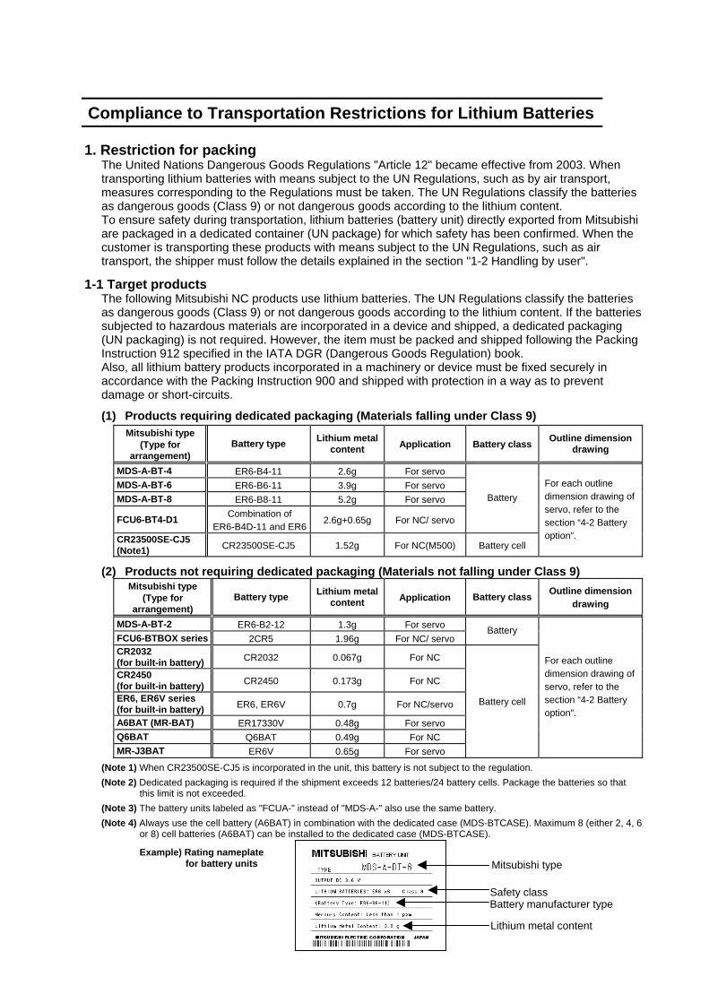
(1) Products requiring dedicated packaging (Materials falling under Class 9)
Mitsubishi type (Type for
arrangement) Battery type Lithium metal
content Application Battery class Outline dimension drawing
MDS-A-BT-4 ER6-B4-11 2.6g For servo MDS-A-BT-6 ER6-B6-11 3.9g For servo MDS-A-BT-8 ER6-B8-11 5.2g For servo
FCU6-BT4-D1 Combination of ER6-B4D-11 and ER6
2.6g+0.65g For NC/ servo
Battery
CR23500SE-CJ5 (Note1) CR23500SE-CJ5 1.52g For NC(M500) Battery cell
For each outline dimension drawing of servo, refer to the section “4-2 Battery option”.
(2) Products not requiring dedicated packaging (Materials not falling under Class 9)
Mitsubishi type (Type for
arrangement) Battery type Lithium metal
content Application Battery class Outline dimension drawing
MDS-A-BT-2 ER6-B2-12 1.3g For servo FCU6-BTBOX series 2CR5 1.96g For NC/ servo
Battery
CR2032 (for built-in battery) CR2032 0.067g For NC
CR2450 (for built-in battery) CR2450 0.173g For NC
ER6, ER6V series (for built-in battery) ER6, ER6V 0.7g For NC/servo
A6BAT (MR-BAT) ER17330V 0.48g For servo Q6BAT Q6BAT 0.49g For NC MR-J3BAT ER6V 0.65g For servo
Battery cell
For each outline dimension drawing of servo, refer to the section “4-2 Battery option”.
(Note 1) When CR23500SE-CJ5 is incorporated in the unit, this battery is not subject to the regulation. (Note 2) Dedicated packaging is required if the shipment exceeds 12 batteries/24 battery cells. Package the batteries so that
this limit is not exceeded. (Note 3) The battery units labeled as "FCUA-" instead of "MDS-A-" also use the same battery. (Note 4) Always use the cell battery (A6BAT) in combination with the dedicated case (MDS-BTCASE). Maximum 8 (either 2, 4, 6
or 8) cell batteries (A6BAT) can be installed to the dedicated case (MDS-BTCASE). Example) Rating nameplate
for battery units
Mitsubishi type
Safety class Battery manufacturer type
Lithium metal content

1-2 Handling by user
The following technical opinion is solely Mitsubishi's opinion. The shipper must confirm the latest IATA Dangerous Goods Regulations, IMDG Codes and laws and orders of the corresponding export country. These should be checked by the company commissioned for the actual transportation.
IATA : International Air Transport Association IMDG Code : A uniform international code for the transport of dangerous goods by seas
determined by IMO (International Maritime Organization).
■ When shipping isolated lithium battery products (Packing Instruction 903)
(1) Reshipping in Mitsubishi UN packaging Mitsubishi packing applies the isolated battery's safety test and packaging specifications complying with the UN Regulations (Packing Instruction 903). The user only needs to add the following details before shipping. (Consult with the shipping company for details.)
(a) Indication of container usage mark on exterior box (Label with following details
recorded.) • Proper shipping name (Lithium batteries) • UN NO. (UN3090 for isolated battery, UN3091 for battery incorporated in a device or
included) • Shipper and consignee's address and name
(b) Preparation of shipping documents (Declaration of dangerous goods)
(Refer to "3. Example of hazardous goods declaration list" in this section.)
(2) When packaged by user The user must follow UN Regulations when packing, preparing for shipping and preparing the indications, etc.
(a) Packing a lithium battery falling under Class 9
• Consult with The Ship Equipment Inspection Society of Japan for details on packaging. • Prepare for shipping as explained in "(1) Reshipping in Mitsubishi UN packaging". The Ship Equipment Inspection Society of Japan
Headquarters Telephone: 03-3261-6611 Fax: 03-3261-6979
(b) Packing a lithium battery not falling under Class 9 • Cells and batteries are separated so as to prevent short circuits and are stored in a strong
outer packaging. (12 or less batteries, 24 or less cells.) • Prepare for the certificates or test results showing compliance to battery safety test.
The safety test results have been obtained from the battery manufacturer. (Consult with Mitsubishi when the safety test results are required.)
• Prepare for shipping as explained in "(1) Reshipping in Mitsubishi UN packaging".
Example of completing form
Consignee information Shipper information
■ When shipping lithium batteries upon incorporating in a machinery or device
(Packing Instruction 900) Pack and prepare for shipping the item in accordance with the Packing Instruction 900 specified in the IATA DGR (Dangerous Goods Regulation) book. (Securely fix the batteries that comply with the UN Manual of Tests and Criteria to a machinery or device, and protect in a way as to prevent damage or short-circuit.) Note that all the lithium batteries provided by Mitsubishi have cleared the UN recommended safety test; fixing the battery units or cable wirings securely to the machinery or device will be the user’s responsibility. Check with your shipping company for details on packing and transportation.
■ When shipping a device with lithium batteries incorporated (Packing Instruction 912) A device incorporating lithium batteries does not require a dedicated packaging (UN packaging). However, the item must be packed, prepared for shipping and labeled following the Packing Instruction 912 specified in the IATA DGR (Dangerous Goods Regulation) book. Check with your shipping company for details on packing and transportation. The outline of the Packing Instruction 912 is as follows:
• All the items in the packing instructions for shipping the isolated lithium battery products (Packing Instruction 903) must be satisfied, except for the items related to container, short-circuit, and fixation.
• A device incorporating lithium batteries has to be stored in a strong water-proofed outer packaging.
• To prevent an accidental movement during shipment, securely store the item in an outer packaging.
• Lithium content per device should be not more than 12g for cell and 500g for battery. • Lithium battery mass per device should be not more than 5kg.
1-3 Reference
Refer to the following materials for details on the regulations and responses. Guidelines regarding transportation of lithium batteries and lithium ion batteries (Edition 2)
• • • • • Battery Association of Japan

2. Issuing domestic law of the United State for primary lithium battery
transportation Federal Aviation Administration (FAA) and Research and Special Programs Administration (RSPA) announced an additional regulation (interim final rule) for the primary lithium batteries transportation restrictions item in "Federal Register" on Dec.15 2004. This regulation became effective from Dec.29, 2004. This law is a domestic law of the United States, however if also applies to the domestic flight and international flight departing from or arriving in the United States. Therefore, when transporting lithium batteries to the United State, or within the United State, the shipper must take measures required to transport lithium batteries. Refer to the Federal Register and the code of Federal Regulation ("2-4 Reference”) for details.
2-1 Outline of regulation (1) Transporting primary lithium battery by passenger aircraft is forbidden.
• Excluding primary lithium battery for personal use in a carry-on or checked luggage (Lithium metal content should be not more than 5g for cell and 25g for battery. For details on the lithium metal content, refer to "1-1 Target products".)
(2) When transporting primary lithium battery by cargo aircraft, indicate that transportation by
passenger aircraft is forbidden on the exterior box.
2-2 Target products All NC products for which the lithium batteries are used are subject to the regulation. (Refer to the table "1-1 Target products".)
2-3 Handling by user
The "2-1 Outline of regulation" described above is solely Mitsubishi's opinion. The shipper must confirm orders of "2-4 Reference" described below for transportation method corresponding the regulation. Actually, these should be checked by the company commissioned for the actual lithium buttery transportation.
(1) Indication of exterior box
When transporting primary lithium battery by cargo aircraft, indicate that transportation by passenger aircraft is forbidden on the exterior box. Display example
PRIMARY LITHIUM BATTERIES FORBIDDEN FOR TRANSPORT ABOARD PASSENGER AIRCRAFT.
• The character color must be displayed with contrast. (black characters against white
background, black characters against yellow background, etc.) • The height (size) of characters to be displayed is prescribed depending on the packaging mass.
When the total mass is over 30kg: at least 12mm When the total mass is less than 30kg: at least 6mm
2-4 Reference
(1) Federal Register (Docket No. RSPA-2004-19884 (HM-224E) ) PDF format
http://www.regulations.gov/fredpdfs/05-11765.pdf (2) 49CFR (Code of Federal Regulation, Title49) (173.185 Lithium batteries and cells.)
http://www.access.gpo.gov/nara/cfr/waisidx_00/49cfr173_00.html (3) DOT regulation body (Department of Transportation)
http://hazmat.dot.gov/regs/rules/final/69fr/docs/69fr-75207.pdf

3. Example of hazardous goods declaration list
This section describes a general example of the hazardous goods declaration list. For details, please inquire each transportation company. This will be applied only to the batteries described in "1. Restriction for Packing". (1) Outline of hazard
Principal hazard and effect Not found. Specific hazard As the chemical substance is stored in a sealed metal container, the battery itself is
not hazardous. But when the internal lithium metal attaches to human skin, it causes a chemical skin burn. As a reaction of lithium with water, it may ignite or forms flammable hydrogen gas.
Environmental effect Not found. Possible state of emergency Damages or short-circuits may occur due to external mechanical or electrical
pressures. (2) First-aid measure
Inhalation If a person inhales the vapor of the substance due to the battery damage, move the person immediately to fresh air. If the person feels sick, consult a doctor immediately.
Skin contact If the content of the battery attaches to human skin, wash off immediately with water and soap. If skin irritation persists, consult a doctor.
Eye contact In case of contact with eyes due to the battery damage, rinse immediately with a plenty of water for at least 15 minutes and then consult a doctor.
Ingestion If swallowed, consult a doctor immediately. (3) Fire-fighting measure
Appropriate fire-extinguisher Dry sand, dry chemical, graphite powder or carbon dioxide gas Special fire-fighting measure Keep the battery away from the fireplace to prevent fire spreading. Protectors against fire Fire-protection gloves, eye/face protector (face mask), body/skin protective cloth
(4) Measure for leakage
Environmental precaution Dispose of them immediately because strong odors are produced when left for a long time.
How to remove Get them absorbed into dry sand and then collect the sand in an empty container. (5) Handling and storage
Handling
Cautions for safety handling
Do not peel the external tube or damage it. Do not dispose of the battery in fire or expose it to heat. Do not immerse the battery in water or get it wet. Do not throw the battery. Do not disassemble, modify or transform the battery. Do not short-circuit the battery.
Appropriate storage condition
Avoid direct sunlight, high temperature and high humidity. (Recommended temp. range: +5 to +35 oC, humidity: 70%RH or less) Storage
Material to avoid Flammable or conductive material (Metal: may cause a short-circuit) (6) Physical/chemical properties
Physical form Solid Shape Cylinder type Smell Odorless pH Not applicable (insoluble) Appear-
ance Boiling point/Boiling range, Melting point, Decomposition temperature, Flash point
No information

(7) Stability and reactivity
Stability Stable under normal handling condition. Condition to avoid Do not mix multiple batteries with their terminals uninsulated. This may cause a
short-circuit, resulting in heating, bursting or ignition. Hazardous decomposition products
Irritative or toxic gas is emitted in the case of fire.
(8) Toxicological information
As the chemical substance is stored in a sealed metal container, the battery has no harmfulness. Just for reference, the table below describes the main substance of the battery.
(Lithium metal) Acute toxicity No information Local effect Corrosive action in case of skin contact
(9) Ecological information
Mobility, Persistence/Decomposability, Bio-accumulation potential, Ecological toxicity
Not found.
(10) Caution for disposal
Dispose of the battery following local laws or regulations. Pack the battery properly to prevent a short-circuit and avoid contact with water.

Compliance with Restrictions in China 1. Compliance with China CCC certification system 1-1 Outline of China CCC certification system
The Safety Certification enforced in China included the "CCIB Certification (certification system based on the "Law of the People’s Republic of China on Import and Export Commodity Inspection" and "Regulations on Implementation of the Import Commodities Subject to the Safety and Quality Licensing System" enforced by the State Administration of Import and Export Commodity Inspection (SACI) on import/export commodities, and the "CCEE Certification" (certification system based on "Product Quality Certification Management Ordinance" set forth by the China Commission for Conformity Certification of Electrical Equipment (CCEE) on commodities distributed through China. CCIB Certification and CCEE Certification were merged when China joined WTO (November 2001), and were replaced by the "China Compulsory Product Certification" (hereinafter, CCC Certification) monitored by the State General Administration of Quality Supervision, Inspection and Quarantine (AQSIQ) of the People's Republic of China. The CCC Certification system was partially enforced from May 2002, and was fully enforced from May 2003. Target commodities which do not have CCC Certification cannot be imported to China or sold in China. (Indication of the CCIB or CCEE mark has been eliminated from May 1, 2003.)
CCIB : China Commodity Inspection Bureau CCEE : China Commission for Conformity Certification of Electrical Equipment CCC : China Compulsory Certification
1-2 First catalogue of products subject to compulsory product certification
The First Catalogue of Products subject to Compulsory Product Certification, covering 132 items (19 categories) based on the CCIB products (104 items), CCEE products (107 items) and CEMC products (Compulsory EMC Certification products) was designated on December 3, 2001.
Class Product catalogue Class Product catalogue 1 Electric Wires and Cables (5 items) 5 Electric tools (16 items) 2 Switches, Installation protective and connection devices (6 items) 6 Welding machines (15 items)
Low-voltage Electrical Apparatus (9 items) Compulsory Certification Regulations
7 Household and similar electrical appliances
(18 items)
Circuit-breakers (including RCCB, RCBO, MCB) 8 Audio and video equipment (16 items) 9 Information technology
equipment (12 items)
10 Lighting apparatus (2 items)
Low-voltage switchers (disconnectors, switch-disconnectors, and fuse-combination devices.
11 Telecommunication terminal equipment
(9 items)
12 Motor vehicles and Safety Parts
(4 items)
13 Tyres (4 items) 14 Safety Glasses (3 items)
Other protective equipment for circuits (Current limiting devices, circuits protective devices, over current protective devices, thermal protectors, over load relays, low-voltage electromechanical contactors and motor starters) 15 Agricultural Machinery (1 item)
Relays (36V < Voltage ≤ 1000V) 16 Latex Products (1 item) 17 Medical Devices (7 items) 18 Fire Fighting Equipment (3 items) 19 Detectors for Intruder Alarm
Systems (1 item)
Other switches (Switches for appliances, vacuum switches, pressure switches, proximity switches, foot switches, thermal sensitive switches, hydraulic switches, push-button switches, position limit switches, micro-gap switches, temperature sensitive switches, travel switches, change-over switches, auto-change-over switches, knife switches)
Other devices (contactors, motor starters, indicator lights, auxiliary contact assemblies, master controllers, A.C. Semiconductor motor controllers and starters)
Earth leakage protectors Fuses
CNCA -01C -011: 2001 (Switch and Control Equipment)
CNCA -01C -012: 2001 (Installation Protective Equipment)
3
Low-voltage switchgear CNCA-01C-010:2001 (Low-voltage switchgear)
4 Small power motors (1 item) (Note)
CNCA-01C-013:2001 (Small power motors)
(Note) When the servomotor or the spindle motor of which output is 1.1kW or less (at 1500 r/min) is used, NC could have been considered as a small power motor. However, CQC (China Quality Certification Center) judged it is not.

1-3 Precautions for shipping products
As indicated in 1-2, NC products are not included in the First Catalogue of Products subject to Compulsory Product Certification. However, the Customs Officer in China may judge that the product is subject to CCC Certification just based on the HS Code.Note 2 NC cannot be imported if its HS code is used for the product subject to CCC Certification. Thus, the importer must apply for a "Certification of Exemption" with CNCA.Note 3 Refer to 1-4 Application for Exemption for details on applying for an exemption. (Note 1) The First Catalogue of Products subject to Compulsory Product Certification (Target HS
Codes) can be confirmed at http://www.cqc.com.cn/Center/html/60gonggao.htm. (Note 2) HS Code: Internationally unified code (up to 6 digits) assigned to each product and used for
customs. (Note 3) CNCA: Certification and Accreditation Administration of People's Republic of China (Management and monitoring of certification duties)

1-4 Application for exemption
Following "Announcement 8" issued by the Certification and Accreditation Administration of the People's Republic of China (CNCA) in May 2002, a range of products for which application for CCC Certification is not required or which are exempt from CCC marking has been approved for special circumstances in production, export and management activities. An application must be submitted together with materials which prove that the corresponding product complies with the exemption conditions. Upon approval, a "Certification of Exemption" shall be issued. <Range of products for which application is exempt>
Range of products not requiring application
(a) Items brought into China for the personal use by the foreign embassies, consulates, business agencies and visitors
(Excluding products purchased from Service Company for Exporters) (b) Products presented on a government-to-government basis, presents (c) Exhibition products (products not for sale) (d) Special purpose products (e.g., for military use) Products not requiring application for CCC Certification are not required to be CCC marked or
certified. Range of products for which application is exempted
(e) Products imported or manufactured for research and development and testing purposes (f) Products shipped into China for integration into other equipment destined for 100% re-export to a
destination outside of China (g) Products for 100% export according to a foreign trade contract (Excluding when selling partially
in China or re-importing into China for sales) (h) Components used for the evaluation of an imported product line (i) The products imported or manufactured for the service (service and repairs) to the end-user. Or
the spare parts for the service (service and repairs) of discontinued products. (j) Products imported or manufactured for research and development, testing or measurements (k) Other special situations
The following documents must be prepared to apply for an exemption of the "Import Commodity Safety and Quality License" and "CCC Certification". (1) Formal Application
(a) Relevant introduction and description of the company. (b) The characteristics of the products to be exempted. (c) The reason for exemption and its evidence (ex. customs handbook). (d) The name, trademark, quantity, model and specification of the products to be exempted.
(Attach a detail listing of these items for a large quantity of products. When importing materials for processing and repair equipments, submit a list of the importing materials for each month and repair equipments.)
(e) Guarantee for the safety of the products; self-declaration to be responsible for the safety during the manufacturing and use.
(f) To be responsible for the authenticity and legitimacy of the submitted documents. Commitment to assist CNCA to investigate on the authenticity of the documents (When CNCA finds it necessary to investigate on the authenticity of the documents.)
(2) Business license of the company (Copy) (3) Product compliance declaration
Indicate which standard’s requirements the products comply with or submit a test report (Copy is acceptable. The report can be prepared in a manufacturer’s laboratory either at home or overseas.)
(4) Import license (Only if an import license is needed for this product. Copy is acceptable.) (5) Quota certificate (Only if a quota certificate is needed for this product. Copy is acceptable.) (6) Commercial contract (Copy is acceptable.) (7) If one of item (4), (5) or (6) cannot be provided, alternative documents, such as bill of lading, the
invoice, and other evidential documents must be submitted.

1-5 Mitsubishi NC product subject to/not subject to CCC certification
The state whether or not Mitsubishi NC products are subject to the CCC Certification is indicated below, based on the "First Catalogue of Products subject to Compulsory Product Certification" issued by the State General Administration of Quality Supervision, Inspection and Quarantine (AQSIQ) of the People's Republic of China and the Certification and Accreditation Administration of the People's Republic of China (CNCA) on July 1, 2002.
Model China HS Code (Note 1) Judgment on whether or not subject to CCC Certification
Power supply unit Servo/spindle drive unit
85044090 85371010 Not subject to CCC Certification
Servo/spindle 85015100 85015200 Not subject to CCC Certification
NC – Not subject to CCC Certification Display unit – Not subject to CCC Certification
(Note 1) The China HS Code is determined by the customs officer when importing to China. The
above HS Codes are set based on the HS Codes used normally when exporting from Japan.
(Note 2) Reference IEC Standards are used as the actual IEC Standards may not match the GB Standards in part depending on the model.
Whether or not the NC products are subject to CCC Certification was judged based on the following five items. (a) Announcement 33 (Issued by AQSIQ and CNCA in December 2001) (b) HS Codes for the products subject to CCC Certification (Export Customs Codes) * HS Codes are supplementary materials used to determine the applicable range. The applicable
range may not be determined only by these HS Codes. (c) GB Standards (This is based on the IEC Conformity, so check the IEC. Note that some parts are
deviated.) (d) Enforcement regulations, and products specified in applicable range of applicable standards
within (e) "Products Excluded from Compulsory Certification Catalogue" (Issued by CNCA, November
2003)
Reference • Outline of China's New Certification System (CCC Mark for Electric Products), Japan Electrical
Manufacturers' Association • Outline of China's New Certification System (CCC Mark for Electric Products) and Electric
Control Equipment, Nippon Electric Control Equipment Industries Association

2. Response to the China environment restrictions 2-1 Outline of the law on the pollution prevention and control for electronic information
products Ministry of Information Industry (information industry ministry) issued this law on Feb.28, 2006 (Note) (effective from Mar.1, 2007.) in order to protect the environment and the health of the people with restricting and reducing the environmental pollution caused by the electronic information product wastes. The restrictions are applied to containing lead (Pb), hydrargyrum (Hg), cadmium (Cd), hexavalent chromium (Cr (VI)), polybrominated biphenyl (PBB) and polybrominated diphenyl ether (PBDE) in two stages. (Note) For the details, refer to the following.
http://www.mii.gov.cn/art/2006/03/02/art_524_7343.html
(1) First stage: Requirement of indicating contained substance The producer and importer of the electronic information product are required to indicate the hazardous substance. The concrete categories of the products belonging in the following eleven main categories are described as subjected product list (electronic information product category note). • Radar device • Communication device • Radio/TV device industry product • Computer product • Consumer-electronics device • Electronic measuring apparatus • Electronics industry dedicated device • Electronic parts • Electronics device • Electronics application product • Electronics dedicated material
(2) Second stage: Suppressing the amount of contained substances and compulsory CCC
Certification The product listed in the “Electronic information product pollution priority control list” cannot be sold in China unless it conforms to the Compulsory Product Certification System (CCC Certification) and its cadmium usage is suppressed to 0.01w% and other substances usage less than 0.1w%. Note that the timing when this is effective is unmentioned.
2-2 Response to the drive product for Mitsubishi NC
The drive product for NC has no items falling under the subjected product list (electronic information product category note). However, for use with the drive product included in the subjected product or for treating the product properly, information based on the law on the pollution prevention and control for electronic information products” are described in the section “2-3” for reference.
2-3 Indication based on “Pollution suppression marking request for electronic information product”
(1) Electronic information product pollution suppression marking
Note: This symbol mark is
for China only.
This marking indicates the environmental protection expiration date applied to the electronic information products sold in China according to the law on the pollution prevention and control for electronic information products issued on Feb.28, 2006. As long as you keep safety for this product and follow the precautions for use, there are no serious effects on the environment pollution, human body or property within its term reckoned from the manufacturing date. (Note) Equate the environmental protection expiration date of
consumables, such as enclosed battery and cooling fan, with the product life. When disposing the product after using it properly, obey each local laws and restrictions for collecting and recycling of the electronic information product.

(2) The names of contained six hazardous substances and the parts containing them
The names of six substances contained in this product and the parts containing them are shown below.
Toxic/hazardous substance or element
Parts name Lead (Pb)
Hydrargyrum(Hg)
Cadmium(Cd)
Hexavalent chromium (Cr(VI))
(PBB) (PBDE)
Drive unit × ○ ○ ○ ○ ○ Servo motor/spindle motor × ○ ○ ○ ○ ○ Dedicated options (cable/connector) × ○ ○ × ○ ○ Dedicated Options (detector/AC reactor)
× ○ ○ × ○ ○
Dedicated Options (battery) × ○ ○ ○ ○ ○ ○: This mark means that toxic/hazardous substance content in all homogeneous materials of corresponding parts does not
exceed the standard specified in the standard of SJ/T11363-2006. ×: This mark means that toxic/hazardous substance content in the homogeneous materials of corresponding parts exceeds the
standard specified in the standard of SJ/T11363-2006.

I
CONTENTS
Chapter 1 Preface 1-1 Inspection at purchase ..................................................................................................................... 1-2
1-1-1 Package contents ...................................................................................................................... 1-2 1-1-2 Explanation of types .................................................................................................................. 1-2
1-2 Explanation of each part................................................................................................................... 1-4 1-2-1 Explanation of each servo drive unit part .................................................................................. 1-4 1-2-2 Explanation of each servomotor part......................................................................................... 1-6
1-3 Basic configuration ........................................................................................................................... 1-7 1-3-1 Examples of MR-J2S-200CT4 or less basic configurations ...................................................... 1-7 1-3-2 Examples of MR-J2S-350CT4 basic configurations.................................................................. 1-8
1-4 Combinations of servo drive unit and servomotor capacities........................................................... 1-9 1-5 Outline of built-in function ............................................................................................................... 1-10
1-5-1 Axis control function................................................................................................................. 1-10 1-5-2 Servo control function.............................................................................................................. 1-10 1-5-3 Feed function ........................................................................................................................... 1-10 1-5-4 Coordinate system setting function ......................................................................................... 1-10 1-5-5 Command method ................................................................................................................... 1-11 1-5-6 Operation function ................................................................................................................... 1-11 1-5-7 Absolute position detection function........................................................................................ 1-12 1-5-8 Machine compensation function .............................................................................................. 1-12 1-5-9 Protective functions ................................................................................................................. 1-12 1-5-10 Operation auxiliary function ................................................................................................... 1-12 1-5-11 Diagnosis function ................................................................................................................. 1-12
Chapter 2 Wiring and Connection 2-1 System connection diagram ............................................................................................................. 2-3 2-2 Servo drive unit main circuit connection part, control circuit connection part .................................. 2-4
2-2-1 Names and application of main circuit connection part and control circuit connection part signals ................................................................................................................................ 2-4
2-3 NC and servo drive unit connection ................................................................................................. 2-7 2-4 Motor and detector connection......................................................................................................... 2-8
2-4-1 Connection of HF-P534JW04,HF-P734JW04,HF-SP524JW04 to HF-SP2024JW04 ......... 2-8 2-4-2 Connection of HF-SP3524JW04 ............................................................................................... 2-8
2-5 Connection of power supply ............................................................................................................. 2-9 2-5-1 Example of connection when controlling the contactor with the MR-J2S-CT4 ......................... 2-9
2-6 Connection of regenerative resistor ............................................................................................... 2-10 2-6-1 Standard built-in regenerative resistor .................................................................................... 2-10 2-6-2 External option regenerative resistor....................................................................................... 2-10
2-7 Connection of digital input/output (DIO) signals............................................................................. 2-11 2-7-1 Types and functions of digital input/output (DIO) signals........................................................ 2-11 2-7-2 Wiring of digital input/output (DIO) signals .............................................................................. 2-12
2-8 Connection with personal computer ............................................................................................... 2-17 Chapter 3 Installation 3-1 Installation of the servo drive unit ..................................................................................................... 3-2
3-1-1 Environmental conditions .......................................................................................................... 3-2 3-1-2 Installation direction and clearance ........................................................................................... 3-3 3-1-3 Prevention of entering of foreign matter .................................................................................... 3-4
3-2 Installation of servomotor ................................................................................................................. 3-5 3-2-1 Environmental conditions .......................................................................................................... 3-5 3-2-2 Cautions for mounting load (prevention of impact on shaft)...................................................... 3-6 3-2-3 Installation direction ................................................................................................................... 3-6 3-2-4 Tolerable load of axis................................................................................................................. 3-6 3-2-5 Oil and waterproofing measures................................................................................................ 3-7 3-2-6 Cable stress............................................................................................................................... 3-9
3-3 Noise measures.............................................................................................................................. 3-10

II
Chapter 4 Options and Peripheral Devices 4-1 Regenerative option ......................................................................................................................... 4-2
4-1-1 Combinations with servo drive units .......................................................................................... 4-2 4-1-2 Outline dimension drawing of option regenerative resistor ....................................................... 4-3
4-2 Battery option (MDS-A-BT, A6BAT) ................................................................................................. 4-5 4-3 Relay terminal block ....................................................................................................................... 4-12 4-4 Cables and connectors................................................................................................................... 4-13
4-4-1 Cable option list ....................................................................................................................... 4-14 4-4-2 Connector outline dimension drawings ................................................................................... 4-17 4-4-3 Cable wire and assembly ........................................................................................................ 4-21 4-4-4 Option cable connection diagram............................................................................................ 4-22
4-5 Setup software................................................................................................................................ 4-25 4-5-1 Setup software specifications .................................................................................................. 4-25 4-5-2 System configuration ............................................................................................................... 4-25
4-6 Selection of wire ............................................................................................................................. 4-26 4-7 Selection of circuit protector ........................................................................................................... 4-28
4-7-1 Selection of circuit protector .................................................................................................... 4-28 4-8 Selection of contactor ..................................................................................................................... 4-29 4-9 Selection of earth leakage breaker................................................................................................. 4-30 4-10 Control circuit related.................................................................................................................... 4-31
4-10-1 Circuit protector ..................................................................................................................... 4-31 4-10-2 Relays.................................................................................................................................... 4-31 4-10-3 Surge absorber ...................................................................................................................... 4-32
Chapter 5 Operation Control Signal 5-1 System configuration ........................................................................................................................ 5-2
5-1-1 Built-in indexing function............................................................................................................ 5-2 5-1-2 Parameters ................................................................................................................................ 5-3
5-2 R register .......................................................................................................................................... 5-4 5-3 Explanation of operation commands (NC → servo drive unit) ....................................................... 5-5 5-4 Explanation of operation status signals (servo drive unit → NC) ................................................. 5-11 Chapter 6 Setup and Operation 6-1 Setup of servo drive unit................................................................................................................... 6-2
6-1-1 Parameter initialization .............................................................................................................. 6-2 6-1-2 Transition of LED display after power is turned ON .................................................................. 6-2 6-1-3 Servo parameter default settings............................................................................................... 6-3 6-1-4 Operation parameter group default settings.............................................................................. 6-4 6-1-5 Setting during emergency stops ................................................................................................ 6-8
6-2 Test operation................................................................................................................................. 6-10 6-2-1 Test operation.......................................................................................................................... 6-10 6-2-2 JOG operation ......................................................................................................................... 6-11 6-2-3 Incremental feed operation...................................................................................................... 6-12 6-2-4 Handle feed operation ............................................................................................................. 6-12
6-3 Setting the coordinate zero point.................................................................................................... 6-13 6-3-1 Dog-type reference point return............................................................................................... 6-13 6-3-2 Adjusting the dog-type reference point return ......................................................................... 6-15 6-3-3 Memory-type reference point return ........................................................................................ 6-17 6-3-4 Mode with no reference point .................................................................................................. 6-17
6-4 Positioning operations by the station method................................................................................. 6-18 6-4-1 Setting the station .................................................................................................................... 6-18 6-4-2 Setting linear axis stations....................................................................................................... 6-20 6-4-3 Automatic operation................................................................................................................. 6-22 6-4-4 Manual operation ..................................................................................................................... 6-25
6-5 Stopper positioning operation......................................................................................................... 6-26 6-5-1 Operation sequence ................................................................................................................ 6-26 6-5-2 Setting the parameters ............................................................................................................ 6-29

III
6-6 Machine compensation and protection functions ........................................................................... 6-30 6-6-1 Backlash compensation........................................................................................................... 6-30 6-6-2 Interlock function...................................................................................................................... 6-30 6-6-3 Soft limit ................................................................................................................................... 6-31 6-6-4 Servo OFF ............................................................................................................................... 6-32 6-6-5 READY OFF ............................................................................................................................ 6-33 6-6-6 Data protect ............................................................................................................................. 6-33
6-7 Miscellaneous functions ................................................................................................................. 6-34 6-7-1 Feedrate override .................................................................................................................... 6-34 6-7-2 Position switches ..................................................................................................................... 6-34
Chapter 7 Absolute Position Detection System 7-1 Setting of absolute position detection system .................................................................................. 7-2
7-1-1 Starting the system.................................................................................................................... 7-2 7-1-2 Initialization methods ................................................................................................................. 7-2
7-2 Setting up the absolute position detection system ........................................................................... 7-3 7-2-1 Reference point return method.................................................................................................. 7-3 7-2-2 Machine stopper method ........................................................................................................... 7-3 7-2-3 Reference point setting method................................................................................................. 7-4
Chapter 8 Servo Adjustment 8-1 Measuring the adjustment data ........................................................................................................ 8-2
8-1-1 D/A output .................................................................................................................................. 8-2 8-1-2 Graph display............................................................................................................................. 8-2
8-2 Automatic tuning............................................................................................................................... 8-3 8-2-1 Model adaptive control............................................................................................................... 8-3 8-2-2 Automatic tuning specifications ................................................................................................. 8-3 8-2-3 Adjusting the automatic tuning .................................................................................................. 8-4
8-3 Manual adjustment ........................................................................................................................... 8-6 8-3-1 Setting the model inertia ............................................................................................................ 8-6 8-3-2 Adjusting the gain ...................................................................................................................... 8-7
8-4 Characteristics improvements .......................................................................................................... 8-8 8-4-1 Vibration suppression measures ............................................................................................... 8-8 8-4-2 Overshooting measures .......................................................................................................... 8-11
8-5 Adjusting the acceleration/deceleration operation ......................................................................... 8-12 8-5-1 Setting the operation speed..................................................................................................... 8-12 8-5-2 Setting the acceleration/deceleration time constant................................................................ 8-12
Chapter 9 Inspections 9-1 Inspections........................................................................................................................................ 9-2 9-2 Life parts ........................................................................................................................................... 9-2
Chapter 10 Troubleshooting 10-1 Troubleshooting at start up........................................................................................................... 10-2 10-2 Displays and countermeasures for various alarms ...................................................................... 10-2
10-2-1 Drive unit LED display during alarm ...................................................................................... 10-2 10-2-2 Alarm/warning list .................................................................................................................. 10-3
10-3 Detailed explanations and countermeasures of alarms ............................................................... 10-4 10-3-1 Detailed explanations and countermeasures for servo alarms ............................................. 10-4 10-3-2 Detailed explanations and countermeasures for system alarms ........................................ 10-10 10-3-3 Detailed explanations and countermeasures for operation alarms..................................... 10-11
Chapter 11 Characteristics 11-1 Overload protection characteristics .............................................................................................. 11-2 11-2 Servo drive unit generation loss ................................................................................................... 11-3
11-2-1 Servo drive unit calorific value............................................................................................... 11-3 11-2-2 Heat radiation area of fully closed type control panel ........................................................... 11-4

IV
11-3 Magnetic brake characteristics..................................................................................................... 11-5 11-3-1 Motor with magnetic brakes................................................................................................... 11-5 11-3-2 Magnetic brake characteristics .............................................................................................. 11-6 11-3-3 Magnetic brake power supply................................................................................................ 11-7
11-4 Dynamic brake characteristics ..................................................................................................... 11-8 11-4-1 Deceleration torque ............................................................................................................... 11-8 11-4-2 Coasting amount.................................................................................................................... 11-9
11-5 Vibration class ............................................................................................................................ 11-10 Chapter 12 Specifications 12-1 Servo drive units ........................................................................................................................... 12-2
12-1-1 List of specifications............................................................................................................... 12-2 12-1-2 Outline dimension drawings .................................................................................................. 12-3
12-2 Servomotor ................................................................................................................................... 12-5 12-2-1 List of specifications............................................................................................................... 12-5 12-2-2 Torque characteristic drawings ............................................................................................. 12-6 12-2-3 Outline dimension drawings .................................................................................................. 12-7 12-2-4 Special axis servomotor ...................................................................................................... 12-12
Chapter 13 Selection 13-1 Outline .......................................................................................................................................... 13-2
13-1-1 Servomotor ............................................................................................................................ 13-2 13-1-2 Regeneration methods .......................................................................................................... 13-3
13-2 Selection of servomotor series ..................................................................................................... 13-4 13-2-1 HF-P/HF-SP motor series characteristics ............................................................................. 13-4 13-2-2 HF-P/HF-SP servomotor precision........................................................................................ 13-4
13-3 Selection of servomotor capacity ................................................................................................. 13-5 13-3-1 Load inertia ratio .................................................................................................................... 13-5 13-3-2 Short time characteristics ...................................................................................................... 13-5 13-3-3 Continuous characteristics .................................................................................................... 13-6
13-4 Selection of regenerative resistor................................................................................................. 13-8 13-4-1 Calculation of regenerative energy........................................................................................ 13-8 13-4-2 Calculation of positioning frequency.................................................................................... 13-10
13-5 Example of servo selection......................................................................................................... 13-11 13-5-1 Motor selection calculation .................................................................................................. 13-11 13-5-2 Regenerative resistor selection calculation ......................................................................... 13-15 13-5-3 Servo selection results ........................................................................................................ 13-15
13-6 Motor shaft conversion load torque ............................................................................................ 13-16 13-7 Expressions for load inertia calculation...................................................................................... 13-17
Appendix Parameter Lists

1 - 1
Chapter 1 Preface 1-1 Inspection at purchase ..................................................................................................................... 1-2
1-1-1 Package contents ...................................................................................................................... 1-2 1-1-2 Explanation of types .................................................................................................................. 1-2
1-2 Explanation of each part................................................................................................................... 1-4 1-2-1 Explanation of each servo drive unit part .................................................................................. 1-4 1-2-2 Explanation of each servomotor part......................................................................................... 1-6
1-3 Basic configuration ........................................................................................................................... 1-7 1-3-1 Examples of MR-J2S-200CT4 or less basic configurations ...................................................... 1-7 1-3-2 Examples of MR-J2S-350CT4 basic configurations.................................................................. 1-8
1-4 Combinations of servo drive unit and servomotor capacities........................................................... 1-9 1-5 Outline of built-in function ............................................................................................................... 1-10
1-5-1 Axis control function................................................................................................................. 1-10 1-5-2 Servo control function .............................................................................................................. 1-10 1-5-3 Feed function ........................................................................................................................... 1-10 1-5-4 Coordinate system setting function ......................................................................................... 1-10 1-5-5 Command method ................................................................................................................... 1-11 1-5-6 Operation function ................................................................................................................... 1-11 1-5-7 Absolute position detection function ........................................................................................ 1-12 1-5-8 Machine compensation function .............................................................................................. 1-12 1-5-9 Protective functions ................................................................................................................. 1-12 1-5-10 Operation auxiliary function ................................................................................................... 1-12 1-5-11 Diagnosis function ................................................................................................................. 1-12
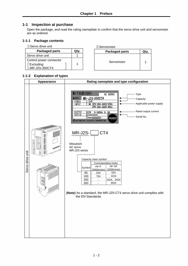
Chapter 1 Preface
1 - 2
1-1 Inspection at purchase Open the package, and read the rating nameplate to confirm that the servo drive unit and servomotor are as ordered.
1-1-1 Package contents ①Servo drive unit
Packaged parts Qty.Servo drive unit 1 Control power connector
Excluding MR-J2S-350CT4
1
1-1-2 Explanation of types
Appearance Rating nameplate and type configuration
Ser
vo d
rive
unit
MITSUBISHIMR-J2S-350CT4
MITSUBISHI ELECTRIC CORPORATION
AC SERVO
PASSED
POWER :INPUT :
OUTPUT :SERIAL :
3.5kW7.9A 3PH 380-480V 50Hz
323V 0-360Hz 8 .6A
3PH 380-480V 60Hz
AZ*******T****AAAAG5*
Type Capacity Applicable power supply
Serial No. Rated output current
MODEL
(Note) As a standard, the MR-J2S-CT4 servo drive unit complies with
the EN Standards.
②Servomotor Packaged parts Qty.
Servomotor
1
Mitsubishi AC servo MR-J2S series
MR-J2S- CT4
Capacity class symbol Corresponding motor
10060
Symbol
350200
1024
HF-SP (2000r/min)
524
35241524,2024
734
HF-P (3000r/min)
534
--

Chapter 1 Preface
1 - 3
Appearance Rating nameplate and type configuration
Ser
vom
otor
HF-P Series • Low inertia • Auxiliary axis, for
general industrial machines
HF-SP Series • Medium inertia • Auxiliary axis, for
general industrial machines
Serial No.Rated speed
Type
Rated output
MITSUBISHI
SER.No.XXXX
2000r/min IP67 CI.F 8.5kg OUTPUT 1kW IEC60034-1 ’99 INPUT 3AC 259V 2.9A HF-SP1024BJTW04
AC SERVO MOTOR
MITSUBISHI ELECTRICMADE IN JAPAN
HF-SP2024, 3524 are compatible only with the straight axis specifications.
(4)(3)(2)
Motor series Symbol(1) Motor series
HF-SPHF-P
Medium inertia, medium capacity Low inertia, small capacity
None Symbol Magnetic brake
B With magnetic brake
(3) Magnetic brake
None
Rating 3000r/minHF-P Series
(2) Rated output and rated speed
1.5kW 2.0kW 3.5kW
15210252
Rating 2000r/min Symbol
1.0kW 0.5kW Rating
202352
73 53
Symbol
0.7kW0.5kWRating
Shaft end shapeNone
Symbol(4) Shaft end shape
T Taper Straight
(1) 4 J W04
HF-SP Series
(Note) As a standard, the HF-P, HF-SP motor complies with the EN Standards.

Chapter 1 Preface
1 - 4
1-2 Explanation of each part 1-2-1 Explanation of each servo drive unit part
(1) MR-J2S-200CT4 or less
Name/Application Battery connector (CON1)
Used to connect the battery for absolute position data backup.
Battery holder Contains the battery for absolute position data backup.
Display The two-digit, seven-segment LED shows the servo status and alarm No.
Axis selection switch (SW1) SW1
Used to set the axis No. of the servo drive unit.
Charge lamp Lit to indicate that the main circuit is charged. While this lamp is lit, do not reconnect the cable.
Main circuit connector (CNP1) Used to connect the input power supply.
Bus cable connector (CN1A) Used to connect the servo system controller or preceding axis servo drive unit.
Bus cable connector (CN1B) Used to connect the subsequent axis servo drive unit or termination connector (MR-A-TM).
Detector connector (CN2) Connector for connection of the servo motor detector.
Communication connector (CN3) Used to connect the personal computer (RS-422/RS-232C) and output analog monitor data.
Rating plate
Regeneration connector (CNP2) Used to connect the regenerative option.
Control circuit power supply connector (CN4) Used to connect the control circuit power supply.
Motor power supply connector (CNP3) Used to connect the servomotor.
Protective earth (PE) terminal ( ) Ground terminal. Cooling fan Installation
hole (4 places)
01 F2 E
4 C3 D
5 B6 A7 98
CHARGE LED2 LED1 SW1
0 1 F 2 E
4 C 3 D
5 B 6 A 7 9 8
drive unit

Chapter 1 Preface
1 - 5
(2) MR-J2S-350CT4
LED2 LED1 SW1
Installation hole (4 places)
Cooling fan
Name/Application Battery connector (CON1)
Used to connect the battery for absolute position data backup.
Battery holder Contains the battery for absolute position data backup.
Display The two-digit, seven-segment LED shows the servo status and alarm No.
Axis selection switch (SW1) SW1
Used to set the axis No. of the servo drive unit.
Bus cable connector (CN1A) Used to connect the servo system controller or preceding axis servo drive unit.
Bus cable connector (CN1B) Used to connect the subsequent axis servo drive unit or termination connector (MR-A-TM).
Communication connector (CN3) Used to connect the personal computer (RS-422/RS-232C) and output analog monitor data.
Detector connector (CN2) Connector for connection of the servo motor detector.
Charge lamp Lit to indicate that the main circuit is charged. While this lamp is lit, do not reconnect the cables.
Control circuit terminal block (TE2) Used to connect the control circuit power supply.
Main circuit terminal block (TE1) Used to connect the input power supply, servomotor and regenerative option.
Rating plate
Protective earth (PE) terminal ( ) Ground terminal
01 F2 E
4 C3 D
5 B6 A7 98
0 1 F 2 E
4 C 3 D
5 B 6 A 7 9 8
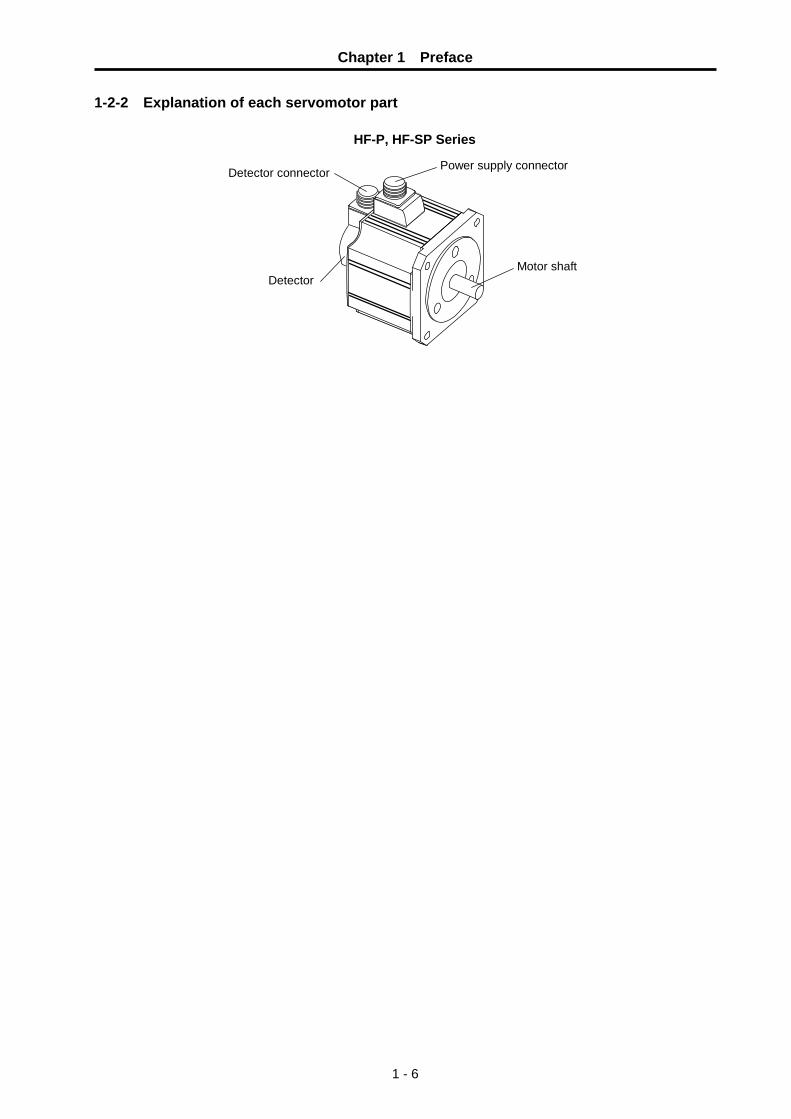
Chapter 1 Preface
1 - 6
1-2-2 Explanation of each servomotor part
HF-P, HF-SP Series Detector connector Power supply connector
Detector Motor shaft

Chapter 1 Preface
1 - 7
1-3 Basic configuration The MR-J2S-CT4 is a Mitsubishi NC auxiliary axis servo drive unit with an indexing function for the rotation axis built in. The MR-J2S-CT4 is used with a high-speed serial bus connection to the Mitsubishi NC. The run command to the MR-J2S-CT4 is issued from the PLC built into the NC.
1-3-1 Examples of MR-J2S-200CT4 or less basic configurations
P
C
To CN1A
To CN1B
To CN3
Circuit protector 24V•L11
0V•L21-+ 24VDC
Powersupply
To CN2
3-phase 380 to 480VAC power supply
To CN4U V W
PE
L1
Circuit protector or
fuse
Magnetic contactor (MC)
Power factor improving reactor (FA-BAL)
Regenerative option
NC controller or preceding axis
unit
Subsequent axis unit CN1A or terminal connector
Setup softwarePersonal computer
L2 L3
Servomotor HF-P, HF-SP series
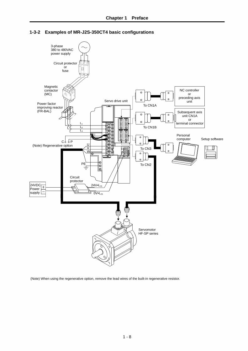
Chapter 1 Preface
1 - 8
1-3-2 Examples of MR-J2S-350CT4 basic configurations
PE
To CN3
Servo drive unit
To CN2
U V W
C P
To CN1A
24VDC Power supply
+ -
To CN1B
Circuit protector
24V•L11
0V•L21
3-phase 380 to 480VAC power supply
L1
Circuit protector or
fuse
Magnetic contactor (MC)
Power factor improving reactor (FR-BAL)
(Note) Regenerative option
NC controller or
preceding axis unit
Subsequent axis unit CN1A
or terminal connector
Setup softwarePersonal computer
L2 L3
(Note) When using the regenerative option, remove the lead wires of the built-in regenerative resistor.
Servomotor HF-SP series

Chapter 1 Preface
1 - 9
1-4 Combinations of servo drive unit and servomotor capacities Top line : Rated output, Middle line : Rated speed (Max. speed), Bottom line : Max. torque
MR-J2S-60CT4 MR-J2S-100CT4 MR-J2S-200CT4 MR-J2S-350CT4
HF-P534JW04 500W 3000(4000)r/m 4.77 N•m
Small capacityLow inertia (IP67)
HF-P734JW04 750W 3000(4000)r/m 7.17 N•m
HF-SP524JW04 500W 2000(3000)r/m 7.16 N・m
HF-SP1024JW04 1000W 2000(3000)r/m 14.3 N・m
HF-SP1524JW04 1500W 2000(3000)r/m 21.5 N•m
HF-SP2024JW04 2000W 2000(3000)r/m 28.6 N•m
Medium capacityMedium inertia (IP67)
HF-SP3524JW04 3500W 2000(3000)r/m 50.1 N•m
(Note 1) Blank boxes in the table indicate that no combinations are available.

Chapter 1 Preface
1 - 10
1-5 Outline of built-in function 1-5-1 Axis control function
No. of control axes : 1 axis Command and setting unit : 0.001° Positioning resolution : Follows No. of detector pulses and gear ratio. <Example>
When using an HF-P/HF-SP motor (No. of detector pulses: 262144 pulses/rev) motor and a gear ratio of 1:10, the positioning resolution will be: (Refer to Chapter 13)
Positioning resolution =
Detector resolution × 2 = 360° × 2 262144 × 10
= 0.000275°
Servo OFF function : The power to the motor can be randomly cut off (motor
free run) using commands. Follow up function : The axis movement is monitored even during servo OFF
or emergency stop, and the machine position counter is updated.
Torque limit function : The motor's output torque can be limited. Four random limit values can be set, and one selected with a command.
1-5-2 Servo control function Control method : The real-time automatic tuning function with model
adaptive control is incorporated. The servo's characteristic gain does not need to be adjusted.
Vibration suppressing function : The vibration caused by machine resonance can be suppressed with a notch filter and jitter compensation.
1-5-3 Feed function Feedrate designation : Four per-minute feeds can be set with a °/min unit
(rotation axis) or mm/min (linear axis), and one selected with a command. The feedrate command range is 1 to 100000.
Acceleration/deceleration method : The inclined constant acceleration/deceleration is automatically controlled. The linear acceleration/deceleration or soft acceleration/deceleration can be selected.
Acceleration/deceleration pattern : Four acceleration/deceleration patterns can be set, and designation method one selected with a command. Short-cut control : When using the rotation axis, the rotation direction with
least movement distance is automatically judged and the axis is rotated. The rotation direction can be designated with a command.
1-5-4 Coordinate system setting function Coordinate system : Corresponds to the rotation axis coordinates (0° to 360°)
and the linear coordinates. Coordinate system shift function : The machine coordinates can be shifted.

Chapter 1 Preface
1 - 11
1-5-5 Command method Station method (for rotation axis) : A point (station) obtained by equally dividing the rotation
axis can be selected with a command, and positioned to. The max. No. of divisions is 360.
<When eight stations are set (8 divisions)>
1
2
3
4
5
6
7
8
ステーション番号
ステーション
Station method (for linear axis) : The equal division points (stations) are determined by the
valid stroke length and No. of stations. The Max. No. of stations is 360.
<When five stations are set>
原点
ステーション番号
ステーション
1 2 3 4 5
有効ストローク長
• The zero point is station 1, and the final end of the valid stroke is station 5.
• When using a linear axis, the No. of equal divisions is "No. of stations -1".
Uneven station method : When the positioning positions (stations) are not at an
equal pitch, up to eight coordinate points can be randomly set to determine the station coordinates. This can be used for either the rotation axis or linear axis.
Random coordinate designation method : Random coordinates (absolute coordinates using zero
point as reference) can be transferred from the PLC and used for positioning.
1-5-6 Operation function The following seven operation modes can be used. The operation mode is changed with commands from the PLC. Automatic mode : This mode carries out positioning to the designated station No. with the
start signal. If the start signal turns OFF before the positioning is finished, the axis will be positioned to the nearest station position.
Positioning to random coordinates is also possible. Manual mode : This mode rotates at a set speed in the designated direction while the
start signal is ON. If the start signal turns OFF, the axis will be positioned to the nearest
station position. JOG mode : This mode rotates at a set speed in the designated direction while the
start signal is ON. Incremental feed mode : This feed mode moves only the designated movement amount at each
start. Manual handle mode : This mode moves the axis with the pulse command (manual handle
signal) transferred from the NC.
Station No. Station
Zero point
Station No.
Station Valid stroke length

Chapter 1 Preface
1 - 12
Reference point return mode : This mode positions to the reference point. The dog switch method, or the method to position to the reference point registered in the memory can be used.
Stopper positioning mode : This mode positions by pressing against the machine end, etc. The approach amount, pressing amount, pressing speed, and pressing torque limit amount can be set.
1-5-7 Absolute position detection function The detector monitors the machine movement even when the power is turned OFF. After turning the power ON, automatic operation can be started immediately without returning to the reference point (zero point).
1-5-8 Machine compensation function Electronic gears : By setting the gear ratio and ball screw pitch (for linear axis), the
commanded position and speed will be automatically converted to the motor's rotation angle and speed. All settings can be made with the machine end movement amount and speed without considering the weight of one detector pulse.
Backlash compensation : The positioning error caused by backlash of the gear or ball screw, etc., can be compensated.
1-5-9 Protective functions Emergency stop function : A hot line can be established with the NC allowing the external
emergency stop signal to be directly input. During an emergency stop, the axis can be stopped with the dynamic brakes built in the drive unit, or by decelerating to a stop.
Excessive error monitor function : The max. tolerable amount of the axis tracking delay (droop) can be monitored during feed. If a droop exceeding the tolerable value occurs, the servomotor will emergency stop.
Interlock : Movement of the axis in a specific direction can be prohibited. Edit lock : Rewriting of the parameters can be prohibited.
1-5-10 Operation auxiliary function PSW : Eight sets of position switches using software processing are mounted. Using these, the
axis movement state can be monitored even without mechanical switches.
1-5-11 Diagnosis function Self diagnosis : The various alarms are displayed on the main unit's 7-segment LED display, and
output to the NC and personal computer. Servo monitor : The operation state (speed, current, etc.) is output to the NC and personal
computer. The personal computer requires dedicated setup software. Signal monitor : The commands sent to the personal computer from the PLC and the status output
signal to the PLC can be monitored. The personal computer requires dedicated setup software.
Test operation : Commands from the personal computer can be fed and operated. The personal computer requires dedicated setup software.
Analog monitor : The operation state (speed, current, etc.) to the drive unit CN3 connector are analog output. Two channels can be used simultaneously.
Alarm history : The past six alarms can be recorded and output to the NC or personal computer.

2 - 1
Chapter 2 Wiring and Connection 2-1 System connection diagram ............................................................................................................. 2-3 2-2 Servo drive unit main circuit connection part, control circuit connection part .................................. 2-4
2-2-1 Names and application of main circuit connection part and control circuit connection part signals ....................................................................................................................................... 2-4
2-3 NC and servo drive unit connection ................................................................................................. 2-7 2-4 Motor and detector connection......................................................................................................... 2-8
2-4-1 Connection of HF-P534JW04,HF-P734JW04,HF-SP524JW04 to HF-SP2024JW04 ......... 2-8 2-4-2 Connection of HF-SP3524JW04 ............................................................................................... 2-8
2-5 Connection of power supply ............................................................................................................. 2-9 2-5-1 Example of connection when controlling the contactor with the MR-J2S-CT4 ......................... 2-9
2-6 Connection of regenerative resistor ............................................................................................... 2-10 2-6-1 Standard built-in regenerative resistor .................................................................................... 2-10 2-6-2 External option regenerative resistor....................................................................................... 2-10
2-7 Connection of digital input/output (DIO) signals............................................................................. 2-11 2-7-1 Types and functions of digital input/output (DIO) signals........................................................ 2-11 2-7-2 Wiring of digital input/output (DIO) signals .............................................................................. 2-12
2-8 Connection with personal computer ............................................................................................... 2-17
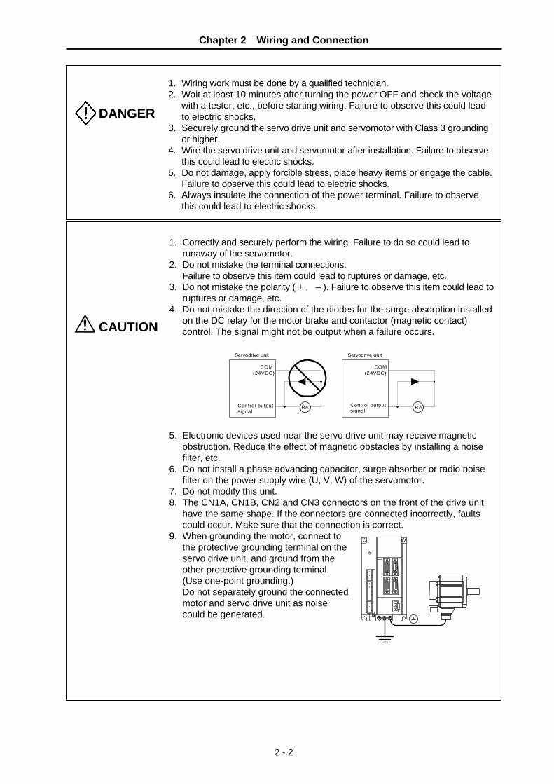
Chapter 2 Wiring and Connection
2 - 2
DANGER
1. Wiring work must be done by a qualified technician. 2. Wait at least 10 minutes after turning the power OFF and check the voltage
with a tester, etc., before starting wiring. Failure to observe this could lead to electric shocks.
3. Securely ground the servo drive unit and servomotor with Class 3 grounding or higher.
4. Wire the servo drive unit and servomotor after installation. Failure to observe this could lead to electric shocks.
5. Do not damage, apply forcible stress, place heavy items or engage the cable. Failure to observe this could lead to electric shocks.
6. Always insulate the connection of the power terminal. Failure to observe this could lead to electric shocks.
CAUTION
1. Correctly and securely perform the wiring. Failure to do so could lead to runaway of the servomotor.
2. Do not mistake the terminal connections. Failure to observe this item could lead to ruptures or damage, etc. 3. Do not mistake the polarity ( + , – ). Failure to observe this item could lead to
ruptures or damage, etc. 4. Do not mistake the direction of the diodes for the surge absorption installed
on the DC relay for the motor brake and contactor (magnetic contact) control. The signal might not be output when a failure occurs.
COM(24VDC)
Control outputsignal
Servodrive unit
RA
COM(24VDC)
Servodrive unit
RAControl outputsignal
5. Electronic devices used near the servo drive unit may receive magnetic
obstruction. Reduce the effect of magnetic obstacles by installing a noise filter, etc.
6. Do not install a phase advancing capacitor, surge absorber or radio noise filter on the power supply wire (U, V, W) of the servomotor.
7. Do not modify this unit. 8. The CN1A, CN1B, CN2 and CN3 connectors on the front of the drive unit
have the same shape. If the connectors are connected incorrectly, faults could occur. Make sure that the connection is correct.
9. When grounding the motor, connect to the protective grounding terminal on the servo drive unit, and ground from the other protective grounding terminal.
(Use one-point grounding.) Do not separately ground the connected
motor and servo drive unit as noise could be generated.

Chapter 2 Wiring and Connection
2 - 3
2-1 System connection diagram
Notes) 1. The total length of the SH21 cable must be within 30 m. 2. The motor side connections following the 2nd axis have been omitted. 3. This is a motor with magnetic brakes. The power connected to the magnetic brake does not have a polarity. 4. The connection method will differ according to the motor. 5. When using as an absolute position detector, connect MR-BAT or MDS-A-BT-□ instead of the terminator
connector. 6. Do not mistake the diode direction. If connected in reverse, the drive unit will fail and the signal will not be
output. 7. For MR-J2S-350CT4, CNP1 to CNP3 and CN4 serve as terminal blocks

Chapter 2 Wiring and Connection
2 - 4
2-2 Servo drive unit main circuit connection part, control circuit connection part 2-2-1 Names and application of main circuit connection part and control circuit
connection part signals
(1) Servo drive unit terminal The layouts of connection parts and signals vary depending on the servo drive unit capacity. Refer to "12-1-2 Outline dimension drawings" for details.
Name Signal name Description
L1·L2·L3 Main circuit power supply
Main circuit power supply input terminal Connect a 3-phase 380 to 480VAC, 50/60Hz power supply.
L11·L12 Control circuit power supply
Control circuit power supply input terminal Connect a 24VDC±10%, 50/60Hz power supply. Connect the same power supply phase for L11 and L1, and L21 and L2.
P·C·D Regenerative option
Regenerative option connection terminal. P to D is wired at shipment. When using the regenerative option, disconnect the wire between P and D and wire the regenerative option between P and C.
(N) Main circuit reference potential
This is not used normally. (This is the reference potential for the main circuit DC voltage.)
U·V·W Servomotor output
Servomotor power supply output terminal The servomotor power supply terminal (U, V, W) is connected.
Protective grounding (PE)
Grounding terminal The servomotor grounding terminal is connected and grounded.
DANGER Never connect anything to the main circuit reference voltage (N). Failure to observe this could lead to electric shock or servo drive unit damage.
CAUTION
When using a standard built-in regenerative resistor, connect it between the P and D terminals. (Shipment state.) When using an external option regenerative resistor, disconnect the wiring between the P and D terminals, and connect between P and C. Standard built-in regenerative resistors cannot be used in combination with an external option regenerative resistor.
CAUTION Do not apply a voltage other than that specified in Instruction Manual on each terminal. Failure to observe this item could lead to ruptures or damage, etc.

Chapter 2 Wiring and Connection
2 - 5
(2) Power-ON sequence
(a) Power-ON procedure (i) Switch ON the control circuit power supply L11, L21 simultaneously with the main circuit power
supply or before switching ON the main circuit power supply. If the main circuit power supply is not ON under the servo-ON state, the display shows the corresponding warning. However, by switching ON the main circuit power supply, the warning disappears and the servo drive unit will operate properly.
(ii) The servo drive unit can accept the servo-ON command after 3s or more since the main
circuit power supply has been switched ON. (Refer to (b) in this section.)
(b) Timing chart
SON accepted
ONOFF
Main circuit Control circuit
ONOFF
Servo-ON command(from controller)
power
(3s)
Timing chart for power-ON
(3) Connectors
POINT The following applies to the MR-J2S-200CT4 or less. For MR-J2S-350CT4 servo drive unit, terminal blocks are applied.
The following connectors are required for wiring to CNP1, CNP2, CNP3 and CN4. The connectors are
supplied as standard. (Made by Phoenix)
Servo drive unit
CNP1
CNP2
CNP3 CN4
♦ Main circuit power supply connector GFKC2.5/3-ST-7.62(2P) (Insertion type)
♦ Regeneration connector GFKC2.5/5-ST-7.62 (Insertion type)
♦ Motor power supply connector GFKC2.5/3-ST-7.62(1P) (Insertion type)
♦ Control circuit power supply connector FK-MCP1.5/2-STF-3.81 (Insertion type)
Servo drive unit connectors (CNP1, CNP2, CNP3, CN4) wiring method

Chapter 2 Wiring and Connection
2 - 6
(a) Termination of the cable
10mm
Use the cable after stripping the sheath and twisting the core. The core must be 10mm (±1mm) long. At this time, take care not to short-circuit in the adjacent pole due to the loose wires of the core. Do not solder the core as it may cause a contact fault. Alternatively, a bar terminal may be used to put the wires together.
Cable size Bar terminal type
[mm2] AWG For 1 cable Crimping tool Manufacturer
1.25/1.5 16 AI1.5-10BK CRIMPFOX-UD6 Phoenix Contact 2/2.5 14 AI2.5-10BU CRIMPFOX-UD6 Phoenix Contact
(b) How to insert the cable into the connector Push the opening lever with a flat-blade screwdrivera,etc., and insert the core of the cable 10mm into the round hole. When inserting the cable, push it 10mm into the hole securely. Releasing the opening lever connects the cable. After insertion, make sure that there are no loose wires coming out of the hole. Such wires can cause a short circuit.
Round hole
Wire
Opening lever
Flat-blade screwdriver
Connector

Chapter 2 Wiring and Connection
2 - 7
2-3 NC and servo drive unit connection
The NC bus cables are connected from the NC to each servo drive unit so that they run in a straight line from the NC to the terminator connector (battery unit). The NC bus is dedicated for the MR-J2S- CT4 Series, so other servo drive units, etc., cannot be connected to the same NC bus. Up to seven axes can be connected per system. (Note that the number of connected axes is limited by the NC. The following drawing shows an example with three axes connected.)
< Connection >
CN1A : CN1B connector of NC side drive unit or NC output CN1B : CN1A connector of terminator connector side drive unit or terminator connector (battery
unit)
CN1B CN1ACN1B CN1A CN1B CN1A
SH21 cableConnect to the battery unit with a terminator connectoror SH21 cable.
MR-J2S-CT4 3rd axis (final axis)
MR-J2S-CT4 2nd axis
MR-J2S-CT4 1st axis
Connected to the NC MR-J2S-CT4 dedicated output
Refer to the instruction manual of each NC for details.
Max. length of 30m from the NC to the terminator connector.
CAUTION Arrange the NC and servo drive units so that the NC bus cable length from the NC to the terminator connector (battery unit) is 30m or less.
POINT Axis Nos. are determined by the rotary switch for setting the axis No. (Refer to section "6-1-1 Setting the rotary switches".) The axis No. has no relation to the order for connecting to the NC.

Chapter 2 Wiring and Connection
2 - 8
2-4 Motor and detector connection 2-4-1 Connection of HF-P534JW04,HF-P734JW04,HF-SP524JW04 to HF-SP2024JW04 MR-J2S-60CT4 to
MR-J2S-200CT4
Option cable: (Refer to Chapter 4 for details on the cable treatment)
Pin No.
Detector connector : CN2
No.1
No.10
Max. 50m
10 BAT 9 8
MR 7 MD 6 5 4 3
LG 2 LG 1
Signal Pin
20P5(+5V)19P5(+5V)18
MRR 17MDR 16
15 14 13
LG 12LG 11
SignalPin
Detector connector CM10-R10P
8 4 5 7 6
9 10
1 2 3
SHD 10 9
P5(+5V) 8 SD* 7 SD 6
LG(GND) 5 BAT 4 CNT 3(Note) RQ* 2 RQ 1
Signal Pin
(Refer to section "2-7-2 Wiring of digital input/output (DIO) signals ".)
Motor magnetic brake wiring
Brake connector CM10-R2P
1 2
24VDC with no polarity
B2 2 B1 1
Signal Pin
A
BC
D
Power supply connector
GroundingDW CV BU A
SignalPin(Note) Connect a pin of No.3 (CNT) with LG.
(Refer to Chapter 4 for details on selecting the wire.) Power wire and grounding wire
No.11 No.20
2-4-2 Connection of HF-SP3524JW04 MR-J2S-350CT4
Motor magnetic brake wiring
Pin No.
Detector connector : CN2
No.1
No.10
10 BAT 9 8
MR 7 MD 6 5 4 3
LG 2 LG 1
Signal Pin
20 P5(+5V)19 P5(+5V)18
MRR 17 MDR 16
15 14 13
LG 12 LG 11
SignalPin
No.11 No.20
(Refer to Chapter 4 for details on selecting the wire.)Power wire and grounding wire
A
BC
D
Power supply connector
GroundingDW CV BU A
SignalPin
Brake connector CM10-R2P
1 2
24VDC with no polarity
B2 2 B1 1
Signal Pin
Detector connector CM10-R10P
8 4 5 7 6
9 10
1 2 3
SHD 10 9
P5(+5V) 8 SD* 7 SD 6
LG(GND) 5 BAT 4 CNT 3(Note) RQ* 2 RQ 1
Signal Pin
Option cable: (Refer to Chapter 4 for details on the cable treatment)
Max. 50m
(Refer to section "2-7-2 Wiring of digital input/output (DIO) signals ".)
(Note) Connect a pin of No.3 (CNT) with LG.

Chapter 2 Wiring and Connection
2 - 9
2-5 Connection of power supply
CAUTION
1. Make sure that the power supply voltage is within the specified range of the
servo drive unit. Failure to observe this could lead to damage or faults. 2. For safety purposes, always install a circuit protector, and make sure that
the circuit is cut off when an error occurs or during inspections. Refer to Chapter 4 and select the circuit protector.
3. The wire size will differ according to the drive unit capacity. Refer to Chapter 4 and select the size.
4. For safety purposes, always install a contactor (magnetic contactor) on the main circuit power supply input. Large rush currents will flow when the power is turned ON. Refer to Chapter 4 and select the correct contactor.
5. When the MR-J2S-CT4 emergency stop sequence is separated from other drive units using a parameter setting, always install a contactor dedicated for that axis.
2-5-1 Example of connection when controlling the contactor with the MR-J2S-CT4
Drive the contactor via the relay from the contactor control output of the (MC) CN3 connector. There are also some types of contactors that can be directly driven with 24VDC.
There are also types that are built into the contactor.
Circuit protector
Contactor
Mitsubishi NC
Class 3 grounding or higher
SH21 cable
3-phase 380 to 480V
L11 L21
L1 L2 L3
MR-J2S-CT4
CN1A CN1BSH21 cable
L11L21
L1L2L3
MR-J2S-CT4
CN1A CN1B
Terminator connector (A-TM) or battery unit (MDS-A-BT- )
MC 15 COM 5 VDD 10
MC15COM5VDD10
Contactor
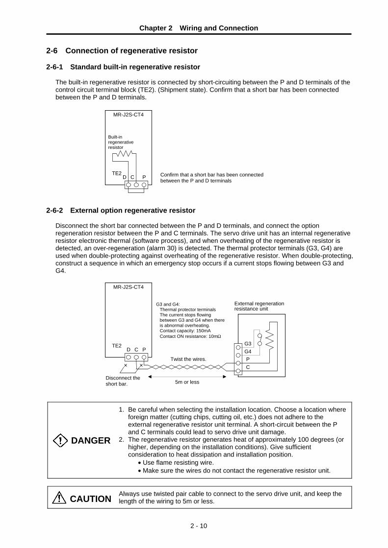
Chapter 2 Wiring and Connection
2 - 10
2-6 Connection of regenerative resistor 2-6-1 Standard built-in regenerative resistor
The built-in regenerative resistor is connected by short-circuiting between the P and D terminals of the control circuit terminal block (TE2). (Shipment state). Confirm that a short bar has been connected between the P and D terminals.
2-6-2 External option regenerative resistor
Disconnect the short bar connected between the P and D terminals, and connect the option regeneration resistor between the P and C terminals. The servo drive unit has an internal regenerative resistor electronic thermal (software process), and when overheating of the regenerative resistor is detected, an over-regeneration (alarm 30) is detected. The thermal protector terminals (G3, G4) are used when double-protecting against overheating of the regenerative resistor. When double-protecting, construct a sequence in which an emergency stop occurs if a current stops flowing between G3 and G4.
DANGER
1. Be careful when selecting the installation location. Choose a location where foreign matter (cutting chips, cutting oil, etc.) does not adhere to the external regenerative resistor unit terminal. A short-circuit between the P and C terminals could lead to servo drive unit damage.
2. The regenerative resistor generates heat of approximately 100 degrees (or higher, depending on the installation conditions). Give sufficient consideration to heat dissipation and installation position.
• Use flame resisting wire. • Make sure the wires do not contact the regenerative resistor unit.
CAUTION Always use twisted pair cable to connect to the servo drive unit, and keep the length of the wiring to 5m or less.
MR-J2S-CT4
TE2 P C D
Built-in regenerative resistor
Confirm that a short bar has been connected between the P and D terminals
MR-J2S-CT4
TE2
PC
G4G3
P C D
× ×
External regeneration resistance unit
Disconnect the short bar.
G3 and G4: Thermal protector terminals The current stops flowing between G3 and G4 when there is abnormal overheating. Contact capacity: 150mA Contact ON resistance: 10mΩ
Twist the wires.
5m or less

Chapter 2 Wiring and Connection
2 - 11
2-7 Connection of digital input/output (DIO) signals 2-7-1 Types and functions of digital input/output (DIO) signals
The digital input/output (DIO) signals are assigned to the connector CN3, and have the following functions.
Signal name Abbrev. Connector pin No. Function and application I/O
classMagnetic brake control
MBR CN3-13 This is the motor magnetic brake control output signal. The brakes are released by the SERVO ON signal (motor power ON), and operated by the SERVO OFF (motor power OFF) signal.
DO
Contactor control MC CN3-15 Contactor control output signal. The contactor is turned ON by the READY ON signal, and turned OFF by the READY OFF signal.
DO
Near-point dog DOG CN3-19 This inputs a near-point signal when executing dog-type zero point return.
DI
Emergency stop EMGX CN3-20 This is the external emergency stop signal input. DI
POINT
1. The MBR and MC pin Nos. are set to the default parameter settings. The output pin No. can be changed with the MBR and MC signals by parameter setting. (Refer to the table below.)
2. The external emergency stop input (EMGX) is invalid when the parameters are set to their default values. Set parameter #103.bit0 to "0" to use this function.
No. Abbrev. Parameter name Description
HEX setting parameter. Set bits without a description to their default values. bit F E D C B A 9 8 7 6 5 4 3 2 1 0
Default value 0 0 0 0 0 0 0 0 1 0 0 0 0 1 1 0
bit Meaning when "0" is set. Meaning when "1" is set. 1 Error not corrected at servo OFF Error corrected at servo OFF 2 Linear axis Rotation axis 3 Station assignment direction CW Station assignment direction
CCW 4 Uniform indexing Non-uniform indexing 5 DO channel standard assignment DO channel reverse
assignment 6 2-wire detector communication 4-wire detector communication7 Incremental detection Absolute position detection
#102 ∗Cont2 Control parameter 2
SH21 cable
9
Signal
MO1
LG RxD
COM
SG
2
VDD
5
1 Pin
6
4 3
10
7 8
DOG19
Signal
MO2
LGTxD
MC
MBR12
EMGX
15
11Pin
16
1413
20
1718
Connector for DIO : CN3
PE SG MC MBR
VDD COM EMG DOG
LG
MO1 MO2
LG
CN3 CN3 CN3
To personal computer etc.
Each model I/F
Relay terminal : MR-J2CN3TM (Option)
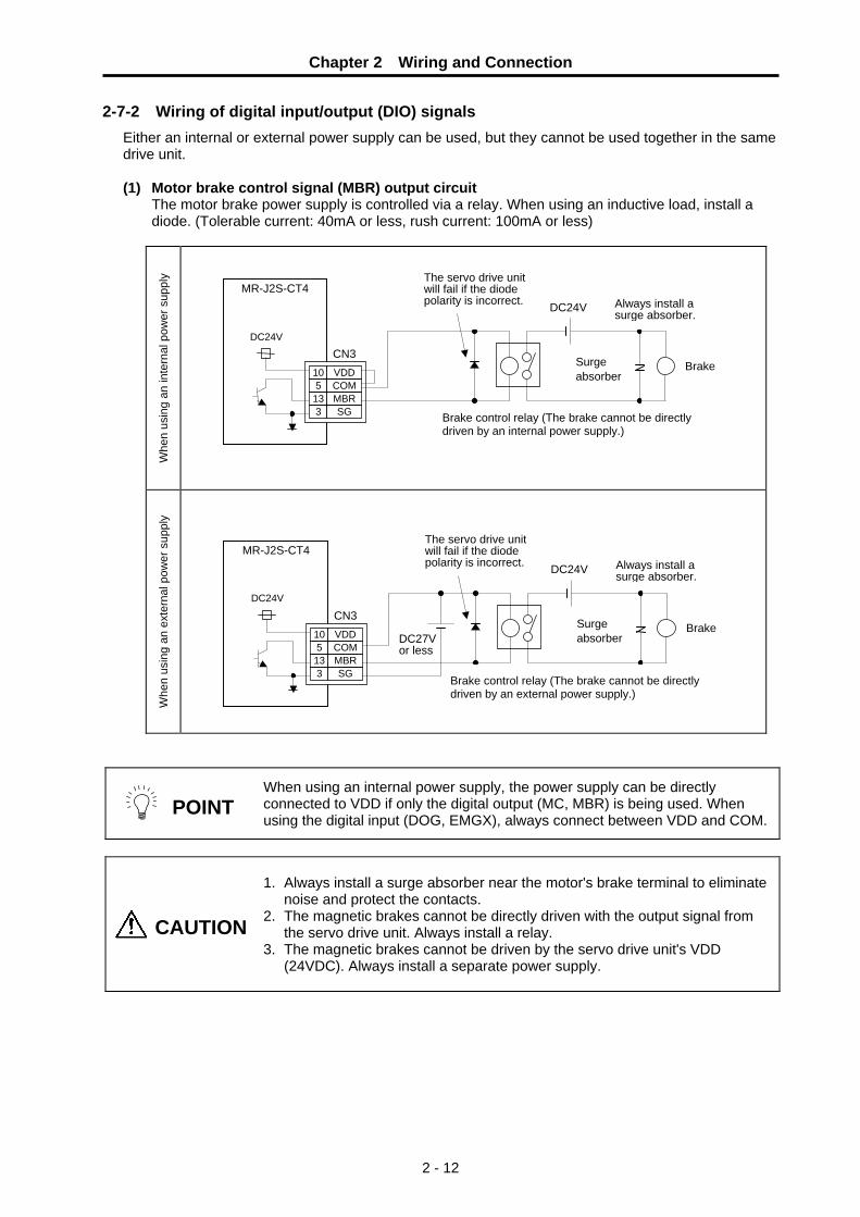
Chapter 2 Wiring and Connection
2 - 12
2-7-2 Wiring of digital input/output (DIO) signals Either an internal or external power supply can be used, but they cannot be used together in the same drive unit.
(1) Motor brake control signal (MBR) output circuit
The motor brake power supply is controlled via a relay. When using an inductive load, install a diode. (Tolerable current: 40mA or less, rush current: 100mA or less)
Whe
n us
ing
an in
tern
al p
ower
sup
ply
Whe
n us
ing
an e
xter
nal p
ower
sup
ply
POINT When using an internal power supply, the power supply can be directly connected to VDD if only the digital output (MC, MBR) is being used. When using the digital input (DOG, EMGX), always connect between VDD and COM.
CAUTION
1. Always install a surge absorber near the motor's brake terminal to eliminate
noise and protect the contacts. 2. The magnetic brakes cannot be directly driven with the output signal from
the servo drive unit. Always install a relay. 3. The magnetic brakes cannot be driven by the servo drive unit's VDD
(24VDC). Always install a separate power supply.
Brake control relay (The brake cannot be directly driven by an internal power supply.)
Always install a surge absorber.
Brake
MR-J2S-CT4
10 VDD 5 COM
13 MBR3 SG
CN3
DC24V
Surge absorber
The servo drive unit will fail if the diode polarity is incorrect.
DC24V
Always install a surge absorber.
Brake
MR-J2S-CT4
10 VDD5 COM
13 MBR3 SG
CN3
DC24V
DC27V or less
Surge absorber
The servo drive unit will fail if the diode polarity is incorrect.
DC24V
Brake control relay (The brake cannot be directly driven by an external power supply.)

Chapter 2 Wiring and Connection
2 - 13
<Brake sequence>
The Sequence related to the motor brake output signal is explained in this section. Pay careful attention because its operation differs depending on the situations when an emergency stop was input, servo OFF command was input, or an alarm occurred.
(a) When Emergency stop occurred at motor stop
Emergency stop released Emergency stop
Emergency stop
Magnetic brake actual operation
Motor brake output(MBR)
Servo ready
Brake contact output invalid valid
Magnetic brake invalid valid
Ready ON OFF
Magnetic brake delay time
(b) When servo OFF command is input at motor stop
Servo ON/OFF command
Magnetic brake actual operation
Motor brake output(MBR)
Servo ready
Brake contact output invalid valid
Magnetic brake invalid valid
Ready ON OFF
Servo invalid valid
Vertical axis drop prevention time (#013)
Magnetic brake delay time
(c) When emergency stop occurred when an alarm on which axes can decelerate to stop
occurred.
Emergency stop or
alarm occurrence
Motor brake output(MBR)
Motor rotation speed
Magnetic brake actual operation
Brake contact output invalid valid
Emergency stop releasedand no alarm.
Emergency stop or alarm occurred.
Servo ready Ready ON OFF
Magnetic brake invalid valid
Magnetic brake delay time

Chapter 2 Wiring and Connection
2 - 14
(d) When servo OFF command is input while motor rotation.
Servo command
Motor brake output(MBR)
Movement command
Magnetic brake actual operation
Brake contact output invalid valid
Servo ready Ready ON OFF
Magnetic brake invalid valid
Servo ON OFF
Motor rotation speed
In-position
Magnetic brake delay time
Vertical axis drop prevention time (#013)
(e) When an alarm on which the axes cannot decelerate to stop occurred.
Alarm
Motor brake output(MBR)
Motor rotation speed
Magnetic brake actual operation
Brake contact output invalid valid
Servo ready Ready ON OFF
Magnetic brake invalid valid
Alarm: not occurred occurred
Dynamic brake
Dynamic brake + Magnetic brake

Chapter 2 Wiring and Connection
2 - 15
(2) Contactor control signal (MC) output circuit A relay or photocoupler can be driven with this circuit. When using an inductive load, install a diode. (Tolerable current: 40mA or less, rush current: 100mA or less)
W
hen
usin
g an
inte
rnal
pow
er s
uppl
y
Whe
n us
ing
an e
xter
nal p
ower
sup
ply
POINT When using an internal power supply, the power supply can be directly connected to VDD if only the digital output (MC, MBR) is being used. When using the digital input (DOG, EMGX), always connect between VDD and COM.
Contactor
MR-J2S-CT4
10 VDD5 COM
15 MC3 SG
CN3
Contactor control relay (There are also types that are built into the contactor.)
The servo drive unit will fail if the diode polarity is incorrect.
DC24V
Contactor
MR-J2S-CT4
10 VDD5 COM
15 MC3 SG
CN3
Contactor control relay (There are also types that are built into the contactor.)
DC27V or less
The servo drive unit will fail if the diode polarity is incorrect.
DC24V

Chapter 2 Wiring and Connection
2 - 16
(3) Near point dog signal (DOG) input circuit Issue a signal using a relay or open-collector transistor.
W
hen
usin
g an
inte
rnal
pow
er s
uppl
y
Whe
n us
ing
an e
xter
nal p
ower
sup
ply
(4) External emergency stop signal (EMGX) input circuit Issue a signal using a relay or open-collector transistor.
Whe
n us
ing
an in
tern
al p
ower
sup
ply
Whe
n us
ing
an e
xter
nal p
ower
sup
ply
MR-J2S-CT4
10 VDD5 COM
3 SG19 DOG
CN3 Current directionapproximately 5mA
Near-point dog canceled by closing.
When using a transistor: VCES≦1.0V I CEO≦100μA
Near-point dog 4.7k
DC24V
MR-J2S-CT4
10 VDD5 COM
19 DOG3 SG
CN3 DC27V or less
4.7k
DC24V
Current direction
Near-point dog canceled by closing.
When using a transistor: VCES≦1.0V I CEO≦100μA
Near-point dog
MR-J2S-CT4
10 VDD5 COM
3 SG20 EMGX
CN3
Emergency stop canceled by closing.
External emergency stop4.7k
DC24V
Current direction approximately 5mA
When using a transistor: VCES≦1.0V I CEO≦100μA
MR-J2S-CT4
10 VDD5 COM
20 EMGX3 SG
CN3 DC27V or less
4.7k
DC24V
Emergency stop canceled by closing.
External emergency stop
Current direction
When using a transistor: VCES≦1.0V I CEO≦100μA

Chapter 2 Wiring and Connection
2 - 17
2-8 Connection with personal computer
RS-232C is used for connection with the commercial personal computer. The connector is CN3.
or
Relay terminal block MR-J2-CN3TM (option)
SH21 cable
Optional cableMR-CPCATCBL (for DOS/V)
CN3
PE SG MC MBR
VDD COM EMG DOG
LG
MO1 MO2
LG
CN3 CN3 CN3
Commercial personal computer + Windows 95/98/2000/XP
Setup software
&


3 - 1
Chapter 3 Installation 3-1 Installation of the servo drive unit ..................................................................................................... 3-2
3-1-1 Environmental conditions .......................................................................................................... 3-2 3-1-2 Installation direction and clearance ........................................................................................... 3-3 3-1-3 Prevention of entering of foreign matter .................................................................................... 3-4
3-2 Installation of servomotor ................................................................................................................. 3-5 3-2-1 Environmental conditions .......................................................................................................... 3-5 3-2-2 Cautions for mounting load (prevention of impact on shaft)...................................................... 3-6 3-2-3 Installation direction ................................................................................................................... 3-6 3-2-4 Tolerable load of axis................................................................................................................. 3-6 3-2-5 Oil and waterproofing measures................................................................................................ 3-7 3-2-6 Cable stress............................................................................................................................... 3-9
3-3 Noise measures.............................................................................................................................. 3-10

Chapter 3 Installation
3 - 2
3-1 Installation of the servo drive unit 3-1-1 Environmental conditions
Environment Conditions Ambient temperature 0°C to +55°C (with no freezing) Ambient humidity 90% RH or less (with no dew condensation) Storage temperature –20°C to +65°C (with no freezing) Storage humidity 90% RH or less (with no dew condensation) Atmosphere Indoors (Where unit is not subject to direct sunlight)
With no corrosive gas, combustible gas, oil mist or dust Altitude 1000m or less above sea level Vibration 5.9m/s2 (0.6G) or less
CAUTION
1. Install the unit on noncombustible material. Direct installation on combustible material or near combustible materials could lead to fires.
2. Follow this Instruction Manual and install the unit in a place where the weight can be borne.
3. Do not get on top of or place heavy objects on the unit. Failure to observe this could lead to injuries. 4. Always use the unit within the designated environment conditions. 5. Do not let conductive objects such as screws or metal chips, etc., or
combustible materials such as oil enter the servo drive unit or servomotor. 6. Do not block the servo drive unit intake and outtake ports. Doing so could
lead to failure. 7. The servo drive unit and servomotor are precision devices, so do not drop
them or apply strong impacts to them. 8. Do not install or run a servo drive unit or servomotor that is damaged or
missing parts. 9. When storing for a long time, please contact your dealer.
CAUTION
1. Always observe the installation directions. Failure to observe this could lead tofaults.
2. Secure the specified distance between the servo drive unit and control panel, or between the servo drive unit and other devices. Failure to observe this could lead to faults.

Chapter 3 Installation
3 - 3
3-1-2 Installation direction and clearance Install the servo drive unit so that the front side is visible. Refer to the following drawings for the heat dissipation and wiring of each unit, and secure sufficient space for ventilation.
(1) Installation of one servo drive unit
40mm or more
10mm or more
120mm or more
10mm or more
Servo drive unit
Control box
Top
Bottom
Wiring allowance
70mm or more
Control box
(2) Installation of two or more servo drive units Leave a large clearance between the top of the servo drive unit and the internal surface of the control box, and install a fan to prevent the internal temperature of the control box from exceeding the environmental conditions.
Control box
30mm or more
30mm or more
100mm or more
120mm or more
10mm ore more
(3) Others
When using heat generating equipments such as regenerative option, install them with full consideration of heat generation so that the servo drive unit will not be affected. Install the servo drive unit on a perpendicular wall in the correct vertical direction.

Chapter 3 Installation
3 - 4
CAUTION
1. Always observe the installation directions. Failure to observe this could lead to faults.
2. Secure the specified distance between the servo drive unit and control panel, or between the servo drive unit and other devices. Failure to observe this could lead to faults.
3. The ambient temperature condition for the servo drive unit is 55°C or less. Because heat can easily accumulate in the upper portion of the drive unit, give sufficient consideration to heat dissipation when designing the power distribution panel. If required, install a fan in the power distribution panel to agitate the heat in the upper portion of the drive unit.
3-1-3 Prevention of entering of foreign matter
Treat the cabinet with the following items.
• Make sure that the cable inlet is dust and oil proof by using packing, etc.
• Make sure that the external air does not enter inside by using head radiating holes, etc.
• Close all clearances. • Securely install door packing. • If there is a rear cover, always apply packing. • Oil will tend to accumulate on the top. Take special
measures such as oil-proofing the top so that oil does not enter the cabinet from the screw holds.
• After installing each unit, avoid machining in the periphery. If cutting chips, etc., stick onto the electronic parts, trouble may occur.

Chapter 3 Installation
3 - 5
3-2 Installation of servomotor 3-2-1 Environmental conditions
Environment Conditions Ambient temperature 0°C to +40°C (with no freezing) Ambient humidity 80% RH or less (with no dew condensation) Storage temperature –15°C to +70°C (with no freezing) Storage humidity 90% RH or less (with no dew condensation)
Atmosphere • Indoors (Where unit is not subject to direct sunlight) • With no corrosive gas or combustible gas, mist or dust
Altitude 1000m or less above sea level
Vibration HF-P HF-SP
X: 24.5 m/s2 (2.5G) Y: 24.5 m/s2 (2.5G) or less
The vibration conditions are as shown below.
200
10080
60
50
40 30
20
1000 2000 30000
Speed (r/min)
μV
ibra
tion
ampl
itude
(do
uble
-sw
ay w
idth
) (
m
)
CAUTION
1. Do not hold the cables, axis or detector when transporting the servomotor. Failure to observe this could lead to faults or injuries.
2. Securely fix the servomotor to the machine. Insufficient fixing could lead to the servomotor deviating during operation. Failure to observe this could lead to injuries.
3. When coupling to a servomotor shaft end, do not apply an impact by hammering, etc. The detector could be damaged.
4. Never touch the rotary sections of the servomotor during operations. Install a cover, etc., on the shaft.
5. Do not apply a load exceeding the tolerable load onto the servomotor shaft. The shaft could break.
6. Do not connect or disconnect any of the connectors while the power is ON.

Chapter 3 Installation
3 - 6
3-2-2 Cautions for mounting load (prevention of impact on shaft) ① When using the servomotor with key way, use the screw hole
at the end of the shaft to mount the pulley onto the shaft. To install, first place the double-end stud into the shaft screw holes, contact the coupling end surface against the washer, and press in as if tightening with a nut. When the shaft does not have a key way, use a frictional coupling, etc.
② When removing the pulley, use a pulley remover, and make sure not to apply an impact on the shaft.
③ Install a protective cover on the rotary sections such as the pulley installed on the shaft to ensure safety.
④ The direction of the detector installation on the servomotor cannot be changed.
CAUTION Never hammer the end of the shaft during assembly.
3-2-3 Installation direction
There are no restrictions on the installation direction. Installation in any direction is possible, but as a standard the servomotor is installed so that the motor power supply wire and detector cable cannon plugs (lead-in wires) face downward. Installation in the standard direction is effective against dripping. Measure against oil and water must be taken when not installing in the standard direction. Refer to section "3-2-5 Oil and waterproofing measures" and take appropriate measures. The brake plates may make a sliding sound when a servomotor with magnetic brake is installed with the shaft facing upward, but this is not a fault.
3-2-4 Tolerable load of axis
There are limits to the load that can be applied to the motor shaft. When mounting the motor on a machine, make sure the loads applied in the radial direction and thrust direction are less than the tolerable values shown in the table below. These loads can cause motor output torque, so this point should be carefully considered when designing the machine.
Servomotor Tolerable radial load Tolerable thrust load
HF-P534JTW04, 734JTW04 (taper shaft) 245N (L=33) 147N HF-P534JW04, 734JW04 (straight shaft) 245N (L=33) 147N HF-SP524JTW04, 1024JTW04, 1524JTW04 (taper shaft) 392N (L=58) 490N
HF-SP524JW04, 1024JW04, 1524JW04 (straight shaft) 980N (L=55) 490N
HF-SP2024JW04, 3524JW04 (straight shaft) 2058N (L=79) 980N
Servom otorDouble-end stud
Nut
W asherPu lley
Up
Down
Standard installation direction
L
Thrust load
Radial load
L : Length from flange isntallation surface to center of load weight [mm]

Chapter 3 Installation
3 - 7
CAUTION
1. Use a flexible coupling when connecting with a ball screw, etc., and keep the shaft center deviation to below the tolerable radial load of the shaft.
2. When directly installing the gears on the motor shaft, the radial load increases as the diameter of the gear decreases. This should be carefully considered when designing the machine.
3. When directly installing the pulley on the motor shaft, carefully consider so that the radial load (double the tension) generated from the timing belt tension is less than the values shown in the table above.
4. In machines where thrust loads such as a worm gear are applied, carefully consider providing separate bearings, etc., on the machine side so that loads exceeding the tolerable thrust loads are not applied to the motor.
5. Do not use a rigid coupling as an excessive bending load will be applied on the shaft and could cause the shaft to break.
3-2-5 Oil and waterproofing measures
① A form based on IEC standards (IP types) is displayed as the servomotor protective form (Refer to "12-2-1 List of Specifications."). However, these standards are short-term performance specifications. They do not guarantee continuous environmental protection characteristics. Measures such as covers, etc., must be provided if there is any possibility that oil or water will fall on the motor, or the motor will be constantly wet and permeated by water. Note that IP-type motors are not indicated as corrosion-resistant.
② When a gear box is installed on the servomotor, make sure that the oil level height from the center of the shaft is higher than the values given below. Open a breathing hole on the gear box so that the inner pressure does not rise.
Servomotor Oil level (mm)
HF-P534JW04, 734JW04 15 HF-SP524JW04, 1024JW04, 1524JW04 22.5 HF-SP2024JW04, 3524JW04 30
③ When installing the servomotor horizontally, set the power cable and detector cable to face downward.
When installing vertically or on an inclination, provide a cable trap.
ServomotorGear
Lip
Oil level
V-ring
Oil or water
Servomotor
Cable trap

Chapter 3 Installation
3 - 8
④ Do not use the unit with the cable submerged in oil or water.
(Refer to right drawing.)
CAUTION
1. Do not allow oil or water to constantly contact the motor, enter the motor, or accumulate on the motor. Oil can also enter the motor through cutting chip accumulation, so be careful of this also.
2. When the motor is installed facing upwards, take measures on the machine side so that gear oil, etc., does not flow onto the motor shaft.
3. Do not remove the detector from the motor. (The detector installation screw is treated for sealing.)
⑤ Make sure that oil and water do not flow along the cable into the motor or detector. (Refer to right drawing.)
⑥ When installing on the top of the shaft end, make sure that oil from the gear box, etc., does not enter the servomotor. The servomotor does not have a waterproof structure.
Cover
Servomotor
Oil/wateraccumulation
<Fault> Capillary tube phenomenon
Cover
Servomotor
<Fault> Breathing action
Gear
Lubricating oil
Servomotor

Chapter 3 Installation
3 - 9
3-2-6 Cable stress ① Sufficiently consider the cable clamping method so that bending stress and the stress from the
cable's own weight is not applied on the cable connection. ② In applications where the servomotor moves, make sure that excessive stress is not applied on
the cable. If the detector cable and servomotor wiring are stored in a cable bear and the servomotor moves,
make sure that the cable bending section is within the range of the optional detector cable. Fix the detector cable and power cable enclosed with the servomotor. ③ Make sure that the cable sheathes will not be cut by sharp cutting chips, worn by contacting the
machine corners, or stepped on by workers or vehicles. ④ The bending life of the detector cable is as shown below. Regard this with a slight allowance. If the
servomotor is installed on a machine that moves, make the bending radius as large as possible.
4 7 10 20 40 70 100 200
1×10⁸
5×10⁷
2×10⁷
1×10⁷
5×10⁶
2×10⁶
1×10⁶
5×10⁵
2×10⁵
1×10⁵
5×10⁴
3×10⁴
No.
of b
ends
(tim
es)
Bending radius (mm)
Detector cable bending life (The optional detector cable and wire of our company: A14B2343)
Note: The values in this graph are calculated values and are not guaranteed.
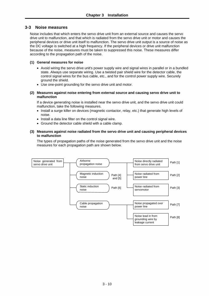
Chapter 3 Installation
3 - 10
3-3 Noise measures Noise includes that which enters the servo drive unit from an external source and causes the servo drive unit to malfunction, and that which is radiated from the servo drive unit or motor and causes the peripheral devices or drive unit itself to malfunction. The servo drive unit output is a source of noise as the DC voltage is switched at a high frequency. If the peripheral devices or drive unit malfunction because of the noise, measures must be taken to suppressed this noise. These measures differ according to the propagation path of the noise.
(1) General measures for noise
• Avoid wiring the servo drive unit's power supply wire and signal wires in parallel or in a bundled state. Always use separate wiring. Use a twisted pair shield wire for the detector cable, the control signal wires for the bus cable, etc., and for the control power supply wire. Securely ground the shield.
• Use one-point grounding for the servo drive unit and motor.
(2) Measures against noise entering from external source and causing servo drive unit to malfunction If a device generating noise is installed near the servo drive unit, and the servo drive unit could malfunction, take the following measures. • Install a surge killer on devices (magnetic contactor, relay, etc.) that generate high levels of
noise. • Install a data line filter on the control signal wire. • Ground the detector cable shield with a cable clamp.
(3) Measures against noise radiated from the servo drive unit and causing peripheral devices
to malfunction The types of propagation paths of the noise generated from the servo drive unit and the noise measures for each propagation path are shown below.
Noise generated from servo drive unit
Noise directly radiated from servo drive unit
Airborne propagation noise Path [1]
Noise radiated from power line
Magnetic induction noise
Path [2]Path [4]and [5]
Noise radiated from servomotor
Static induction noise
Path [3]Path [6]
Noise propagated over power line
Cable propagation noise
Path [7]
Noise lead in from grounding wire by leakage current
Path [8]

Chapter 3 Installation
3 - 11
[1]
[2]
[3]
[4]
[5]
[6]
[7]
[8]
Servodrive unit
Sensor
Servomotor
Receiver Instru- ment
[2][7]
Sensor power supply
SM
Generated noise of drive system
Noise propaga-tion path Measures
[1] [2] [3]
When devices such as instruments, receivers or sensors, which handle minute signals and are easily affected by noise, or the signal wire of these devices, are stored in the same panel as the servo drive unit and the wiring is close, the device could malfunction due to airborne propagation of the noise. In this case, take the following measures. (a) Install devices easily affected as far away from the servo drive unit as possible. (b) Lay the signals wires easily affected as far away from the input wire with the
servo drive unit. (c) Avoid parallel wiring or bundled wiring of the signal wire and power wire. (d) Insert a line noise filter on the input/output wire or a radio noise filter on the input
to suppress noise radiated from the wires. (e) Use a shield wire for the signal wire and power wire, or place in separate metal
ducts.
[4] [5] [6]
If the signal wire is laid in parallel to the power wire, or if it is bundled with the power wire, the noise could be propagated to the signal wire and cause malfunction because of the magnetic induction noise or static induction noise. In this case, take the following measures. (a) Install devices easily affected as far away from the servo drive unit as possible. (b) Lay the signals wires easily affected as far away from the input wire with the
servo drive unit. (c) Avoid parallel wiring or bundled wiring of the signal wire and power wire. (d) Use a shield wire for the signal wire and power wire, or place in separate metal
ducts.
[7]
If the power supply for the peripheral devices is connected to the power supply in the same system as the servo drive unit, the noise generated from the servo drive unit could back flow over the power supply wire and cause the devices to malfunction. In this case, take the following measures. (a) Install a radio noise filter on the servo drive unit's power wire. (b) Install a line noise filter on the servo drive unit's power wire.
[8] If a closed loop is structured by the peripheral device and servo drive unit's grounding wires, the leakage current could penetrate and cause the devices to malfunction. In this case, change the device grounding methods and the grounding place.

4 - 1
Chapter 4 Options and Peripheral Devices 4-1 Regenerative option ......................................................................................................... 4-2
4-1-1 Combinations with servo drive units........................................................................... 4-2 4-1-2 Outline dimension drawing of option regenerative resistor ........................................ 4-3
4-2 Battery option (MDS-A-BT, A6BAT) ................................................................................. 4-5 4-3 Relay terminal block ....................................................................................................... 4-12 4-4 Cables and connectors................................................................................................... 4-13
4-4-1 Cable option list ....................................................................................................... 4-14 4-4-2 Connector outline dimension drawings .................................................................... 4-17 4-4-3 Cable wire and assembly ......................................................................................... 4-21 4-4-4 Option cable connection diagram ............................................................................ 4-22
4-5 Setup software................................................................................................................ 4-25 4-5-1 Setup software specifications .................................................................................. 4-25 4-5-2 System configuration................................................................................................ 4-25
4-6 Selection of wire ............................................................................................................. 4-26 4-7 Selection of circuit protector ........................................................................................... 4-28
4-7-1 Selection of circuit protector..................................................................................... 4-28 4-8 Selection of contactor ..................................................................................................... 4-29 4-9 Selection of earth leakage breaker................................................................................. 4-30 4-10 Control circuit related.................................................................................................... 4-31
4-10-1 Circuit protector...................................................................................................... 4-31 4-10-2 Relays .................................................................................................................... 4-31 4-10-3 Surge absorber ...................................................................................................... 4-32
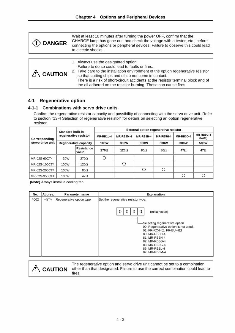
Chapter 4 Options and Peripheral Devices
4 - 2
DANGER
Wait at least 10 minutes after turning the power OFF, confirm that the CHARGE lamp has gone out, and check the voltage with a tester, etc., before connecting the options or peripheral devices. Failure to observe this could lead to electric shocks.
CAUTION
1. Always use the designated option. Failure to do so could lead to faults or fires. 2. Take care to the installation environment of the option regenerative resistor
so that cutting chips and oil do not come in contact. There is a risk of short-circuit accidents at the resistor terminal block and of
the oil adhered on the resistor burning. These can cause fires. 4-1 Regenerative option 4-1-1 Combinations with servo drive units
Confirm the regenerative resistor capacity and possibility of connecting with the servo drive unit. Refer to section "13-4 Selection of regenerative resistor" for details on selecting an option regenerative resistor.
External option regenerative resistor Standard built-in regenerative resistor MR-RB1L-4 MR-RB3M-4 MR-RB3H-4 MR-RB5H-4 MR-RB3G-4 MR-RB5G-4
(Note)
Regenerative capacity 100W 300W 300W 500W 300W 500W Corresponding servo drive unit
Resistance value 270Ω 120Ω 80Ω 80Ω 47Ω 47Ω
MR-J2S-60CT4 30W 270Ω
MR-J2S-100CT4 100W 120Ω
MR-J2S-200CT4 100W 80Ω
MR-J2S-350CT4 100W 47Ω
(Note) Always install a cooling fan.
No. Abbrev. Parameter name Explanation #002 ∗RTY Regenerative option type Set the regenerative resistor type.
(Initial value) 0 0 0 0
Selecting regenerative option 00: Regenerative option is not used. 01: FR-RC-H , FR-BU-H 80: MR-RB3H-4 81: MR-RB5H-4 82: MR-RB3G-4 83: MR-RB5G-4 86: MR-RB1L-4 87: MR-RB3M-4
CAUTION The regenerative option and servo drive unit cannot be set to a combination other than that designated. Failure to use the correct combination could lead to fires.

Chapter 4 Options and Peripheral Devices
4 - 3
4-1-2 Outline dimension drawing of option regenerative resistor
<MR-RB1L-4> [Unit: mm]
• Terminal block
Terminal screw: M3
Tightening torque: 0.5 to 0.6[N•m]G4
G3
P
C
• Mounting screw Screw: M5 Tightening torque: 3.24[N•m]
Regenerative
option Mass [kg]
MR-RB1L-4 1.1
6
6
36
(24) 211
173
149
144
15
40
(6)
156
168
Ø 6 Mounting hole
P G
4 G
3 C
<MR-RB3M-4 • MR-RB3H-4 • MR-RB3G-4 • MR-RB34-4> [Unit: mm]
• Terminal block
Terminal screw: M4
Tightening torque: 1.2[N•m]C
P
G3
G4
• Mounting screw Screw: M6 Tightening torque: 5.4[N•m]
Regenerative
option Mass [kg]
MR-RB3M-4 MR-RB3H-4 MR-RB3G-4 MR-RB34-4
2.9
FAN mounting screw(2-M3 screw)
100 90 10
7
8.5
8.5
125
150
142
23 318
341
79
G4
G3
C
P

Chapter 4 Options and Peripheral Devices
4 - 4
<MR-RB5H-4 • MR-RB5G-4 • MR-RB54-4> [Unit: mm]
• Terminal block
Terminal screw: M4
Tightening torque: 1.2[N•m]C
P
G3
G4
• Mounting screw Screw: M6 Tightening torque: 5.4[N•m]
Regenerative
option Mass [kg]
MR-RB5H-4 MR-RB5G-4 MR-RB54-4
5.6
49 82.5
200 223
2.3 108120
127
(30)8
12.5
35
0 16
2.5
133
82.5
162.
5
7x14 slot
FAN mounting screw (2-M3 screw) Installed on the opposite side 12
.5
23
Blows in the arrow direction
G4
G3
C P
<GRZG400-5Ω • GRZG400-2.5Ω • GRZG400-2Ω (standard accessories)> [Unit: mm]
40
350
46
384410
Ø 5.5 hole
40
9
79
Terminal block

Chapter 4 Options and Peripheral Devices
4 - 5
4-2 Battery option (MDS-A-BT, A6BAT)
This battery option may be required to establish absolute position system. Select a battery option from the table below depending on the servo system.
Type A6BAT (MR-BAT) A6BAT (MR-BAT) MDS-A-BT- □□
Installation type Drive unit with battery holder type Dedicated case type Unit and battery integration typeHazard class
Not applicable Not applicable
(24 or less) Class9
(excluding MDS-A-BT-2) Number of connectable axes
1 axis Up to 8 axes
(When using dedicated case) 2 to 8 axes
Battery change Possible Possible Not possible
(1) (2) (3) Appearance
Battery MR-BAT
Dedicated caseMDS-BTCASE
BatteryA6BAT
(MR-BAT)
(1) Cell battery ( A6BAT )
< Specifications > Cell battery
Battery option type A6BAT (MR-BAT)
Lithium battery series ER17330V Nominal voltage 3.6V Nominal capacity 1700mAh Battery Hazard class - safety Battery shape Single battery
Number of batteries used A6BAT (MR-BAT) ×1
Lithium alloy content 0.48g
Mercury content 1g or less Number of connectable axes 1 axis / (per 1 battery) Battery continuous backup time Approx. 10000 hours Battery useful life (From date of unit manufacture) 5 years
Data save time in battery replacement
HF-P/HF-SP series: approx. 20 hours at time of delivery, approx. 10 hours after 5 years
Back up time from battery warning to alarm occurrence (Note)
Approx. 80 hours
Mass 17g
(Note) This time is a guideline, so does not guarantee the back up time. Replace the battery with a new battery as soon as a battery warning occurs.

Chapter 4 Options and Peripheral Devices
4 - 6
< Installing the cell battery >
CAUTION
The internal circuit of the servo drive unit can be damaged by static electricity. Always observe the following points. ① Always ground the body and work table. ② Never touch the conductive parts such as the connector pins or electrical
parts by hand.
Mount the battery into the servo drive unit with the following procedure. ① Open the operation section window. (For the MR-J2S-350CT4, also remove the front cover.) ② Mount the battery into the battery holder. ③ Insert the battery connector into CON1 until a click is heard.
Battery Battery holder
Battery connector
CON1
< Outline dimension drawings >
HNC2-2.5S-2HNC-2.5-C-B02
Battery connector
φ16.5±0.5 34.5±1
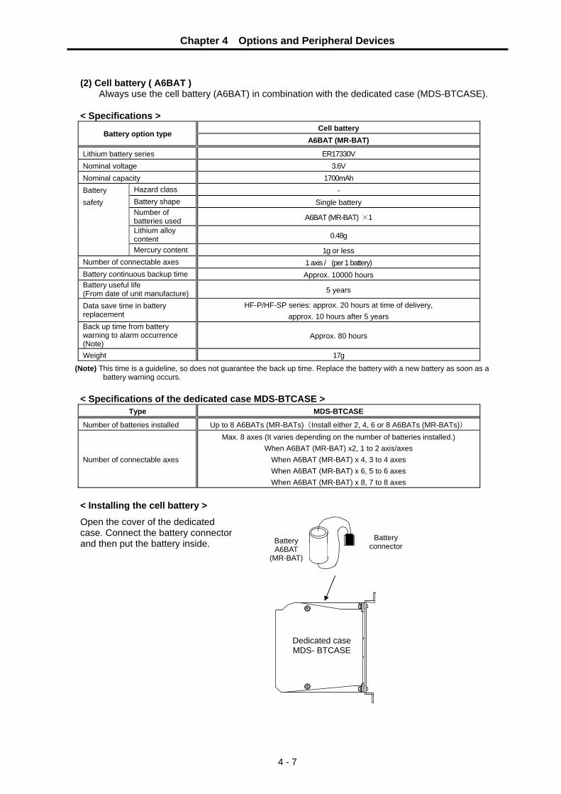
Chapter 4 Options and Peripheral Devices
4 - 7
(2) Cell battery ( A6BAT )
Always use the cell battery (A6BAT) in combination with the dedicated case (MDS-BTCASE).
< Specifications > Cell battery
Battery option type A6BAT (MR-BAT)
Lithium battery series ER17330V Nominal voltage 3.6V Nominal capacity 1700mAh Battery Hazard class - safety Battery shape Single battery
Number of batteries used A6BAT (MR-BAT) ×1
Lithium alloy content 0.48g
Mercury content 1g or less Number of connectable axes 1 axis / (per 1 battery) Battery continuous backup time Approx. 10000 hours Battery useful life (From date of unit manufacture) 5 years
Data save time in battery replacement
HF-P/HF-SP series: approx. 20 hours at time of delivery, approx. 10 hours after 5 years
Back up time from battery warning to alarm occurrence (Note)
Approx. 80 hours
Weight 17g
(Note) This time is a guideline, so does not guarantee the back up time. Replace the battery with a new battery as soon as a battery warning occurs.
< Specifications of the dedicated case MDS-BTCASE >
Type MDS-BTCASE
Number of batteries installed Up to 8 A6BATs (MR-BATs)(Install either 2, 4, 6 or 8 A6BATs (MR-BATs))
Number of connectable axes
Max. 8 axes (It varies depending on the number of batteries installed.) When A6BAT (MR-BAT) x2, 1 to 2 axis/axes
When A6BAT (MR-BAT) x 4, 3 to 4 axes When A6BAT (MR-BAT) x 6, 5 to 6 axes When A6BAT (MR-BAT) x 8, 7 to 8 axes
< Installing the cell battery >
Open the cover of the dedicated case. Connect the battery connector and then put the battery inside. Battery
A6BAT(MR-BAT)
Battery connector
Dedicated case MDS- BTCASE

Chapter 4 Options and Peripheral Devices
4 - 8
< Installing A6BAT (MR-BAT) to battery case > (a) Incorporate batteries in order, from the connector CON1 on the top of the case.
In the same way, install batteries to holders in order, from the holder on the top.
Example of incorporated batteries (Photo: 8 batteries incorporated)
CON1
CON8
CON2
A6BAT (MR-BAT)
A6BAT (MR-BAT)
CN1A
CON1
CON8
A6BAT (MR-BAT)
A6BAT (MR-BAT)
CN1A
CON6
CN1A
CON1
CON8
A6BAT(MR-BAT)
A6BAT (MR-BAT)
Corresponding to MDS-A-BT-2
Corresponding to MDS-A-BT-6
CON1
CON8
A6BAT(MR-BAT)
A6BAT (MR-BAT)
CN1A
CON4
Corresponding to MDS-A-BT-4
Corresponding to MDS-A-BT-8
(b) Attach a seal indicating the number of incorporated batteries to the part shown below.
Attach the seal here.
(Attach only numbers)

Chapter 4 Options and Peripheral Devices
4 - 9
< Outline dimension drawing of the dedicated case MDS-BTCASE >
2-M5screw
25
6
16.8
15
30
R3
50.7
160
145
136
145
(15)130
130
130
7.5
(160
)
Panel drawing
[Unit:mm]

Chapter 4 Options and Peripheral Devices
4 - 10
(3) Battery unit (MDS-A-BT-□)
< Specifications > Battery unit
Battery option type MDS-A-BT-2 MDS-A-BT-4 MDS-A-BT-6 MDS-A-BT-8
Lithium battery series ER6V Nominal voltage 3.6V Nominal capacity 4000mAh 8000mAh 12000mAh 16000mAh Battery Hazard class Class 9 safety Battery shape Set battery
Number of batteries used ER6V x 2 ER6V x 4 ER6V x 6 ER6V x 8
Lithium alloy content 1.3g 2.6g 3.9g 5.2g Mercury content 1g or less Number of connectable axes Up to 2 axes Up to 4 axes Up to 6 axes Up to 8 axes Battery continuous backup time Approx. 12000 hours Battery useful life (From date of unit manufacture) 7 years
Data save time in battery replacement
HF-P/HF-SP series: approx. 20 hours at time of delivery, approx. 10 hours after 5 years
Back up time from battery warning to alarm occurrence (Note)
Approx. 100 hours
Mass 600g
(Note) This time is a guideline, so does not guarantee the back up time. Replace the battery with a new battery as soon as a battery warning occurs.
< Outline dimension drawings > • MDS-A-BT-2/-4/-6/-8
[Unit: mm]
100
Use an M5 screw for the ø6 mounting hole
30
15
6
145
160
135
17
52
R3

Chapter 4 Options and Peripheral Devices
4 - 11
<Connection>
The battery unit is connected with a bus cable (SH21) between the amplifiers instead of the terminator.
CAUTION
1. On January 1, 2003, new United Nations requirements, "United Nations Dangerous Goods Regulations Article 12", became effective regarding the transportation of lithium batteries. The lithium batteries are classified as hazardous materials (Class 9) depending on the unit. (Refer to "Transportation restrictions for lithium batteries".)
2. The lithium battery must be transported according to the rules set forth by the International Civil Aviation Organization (ICAO), International Air Transportation Association (IATA), International Maritime Organization (IMO), and United States Department of Transportation (DOT), etc. The packaging methods, correct transportation methods, and special regulations are specified according to the quantity of lithium alloys. The battery unit exported from Mitsubishi is packaged in a container (UN approved part) satisfying the standards set forth in this UN Advisory.
3. To protect the absolute value, do not shut off the servo drive unit control power supply if the battery voltage becomes low (warning 9F).
4. Contact the Service Center when replacing the MDS-A-BT Series and cell battery.
5. The battery life (backup time) is greatly affected by the working ambient temperature. The above data is the theoretical value for when the battery is used 8 hours a day/240 days a year at an ambient temperature of 25°C. Generally, if the ambient temperature increases, the backup time and useful life will both decrease.
Battery unit MDS-A-BT-2 MDS-A-BT-4 MDS-B-BT-6 MDS-A-BT-8
CNC
SH21 cable SH21 cable SH21 cable
MR-J2S-CT4 MR-J2S-CT4

Chapter 4 Options and Peripheral Devices
4 - 12
4-3 Relay terminal block Signals input/output from the CN3 connector on the front of the servo drive unit can be sent to the terminal block. Connect the terminal block to the CN3 connector with an SH21 cable.
Abbrev. Name Descriptions CN3A Connector 3 input/output ACN3B Connector 3 input/output B
CN3C Connector 3 input/output C
Connect from the CN3 connector with an SH21 cable. Common for any connector, so each signal will pass through. Generally when the CN3 control signal is being used, each signal can be output from the relay terminal block by relaying through these connectors.
VDD Internal power supply output
This is the 24V power supply output in the drive unit. When using an internal power supply, use relayed once through the COM terminal.
COM Common power supply Connect VDD when using the drive unit internal power supply. Connect the + side of the external power supply when using an external power supply.
EMG External emergency stop input This is the input terminal for external emergency stops.
DOG Dog Input the near-point dog signal when carrying out a dog-type zero point return.
MO1 Monitor output 1 This is the D/A output ch.1. Measure the voltage across MO1-LG.
MO2 Monitor output 2 This is the D/A output ch.2. Measure the voltage across MO2-LG.
PE Plate ground This has the same potential as the drive unit FG or cable shield.
SG 24V power supply ground This is the ground when using digital input/output. MC Contactor control output This is the output terminal for contactor control.
MBR Motor brake control output This is the output terminal for motor brake control. LG 5V power supply ground This is the ground when using D/A output.
< Outline dimension drawing > MR-J2CN3TM
PE SG MC MBR
VDD COM EMG DOG
LG
MO1 MO2
LG
CN3A CN3B CN3C
100
88
41.5
3
75
37.5
2-φ5.3(Installation hole) [Unit:mm]

Chapter 4 Options and Peripheral Devices
4 - 13
4-4 Cables and connectors The cables and connectors that can be ordered from Mitsubishi Electric Corp. as option parts are shown below. Cables can only be ordered in the designated lengths shown on the following pages. Purchase a connector set, etc., to create special length cables when required.
HF-P HF-SP
(5) Power supply connector
(6) Brake connector
(3) Detector cable connector set
Relay terminal block Personal computer
NC
(1)
Battery unit
(2) Terminator
MR-J2S-CT4 MR-J2S-CT4
(1) (1) NC bus cable
connector set
(1)
(4) Cable for personal computer

Chapter 4 Options and Peripheral Devices
4 - 14
4-4-1 Cable option list (1) Cables
Part name Type Descriptions Communication cable for NC unit - Drive unit Drive unit - Drive unit
Servo drive unit side connector (Sumitomo 3M) Connector: 10120-6000EL Shell kit: 10320-3210-000
Servo drive unit side connector (Sumitomo 3M) Connector: 10120-6000EL Shell kit: 10320-3210-000
SH21 Length:
0.35, 0.5, 0.7, 1, 1.5, 2, 2.5, 3, 3.5, 4, 4.5, 5, 6, 7, 8, 9, 10, 15, 20, 30m FCUA-R000 and MR-J2HBUS□M can also be used.
Terminator connector
For CN1A, CN1B
Terminator connector A-TM
Servo drive unit side connector (3M) Connector: 10120-3000VE Shell kit: 10320-52F0-008
Servomotor detector side connector (DDK) Plug: CM10-SP10S-M Contact: CM10-#22SC
IP65 and EN Standard compati-ble
Straight CNV2E-T1P-□M Length :
2, 3, 4, 5, 7, 10, 15, 20, 25, 30m
Servo drive unit side connector (3M) Connector: 10120-3000VE Shell kit: 10320-52F0-008
Servomotor detector side connector (DDK) Plug: CM10-AP10S-M Contact: CM10-#22SC
For CN2
(3) Detector cable for HF-P, HF-SP
IP65 and EN Standard compati- ble
Angle CNV2E-T2P-□M Length :
2, 3, 4, 5, 7, 10, 15, 20, 25, 30m
Servo drive unit side connector (3M or equivalent part) Connector: 10120-6000EL Shell kit: 10320-3210-000
DOS/V series Personal computer side connector GM-9LM (Honda Tsushin)
For CN3
(4) Communication cable for DOS/V
MR-CPCATCBL3M Length : 3m
(Note) The connector maker may change without notice.

Chapter 4 Options and Peripheral Devices
4 - 15
(2) Connector sets
Part name Type Descriptions (1) Communication connector set for
NC - Drive unit Drive unit - Drive unit
FCUA-CS000 Servo drive unit side connector (Sumitomo 3M) Connector: 10120-3000VE Shell kit: 10320-52F0-008
Servo drive unit side connector (Sumitomo 3M) Connector: 10120-3000VE Shell kit: 10320-52F0-008
For CN1A, CN1B
CNE10-R10S(9)
Servomotor detector side connector (DDK) Plug: CM10-SP10S-M Contact: CM10-#22SC
(3) Detector connector set for HF-P, HF-SP (Detector side)
IP65 and EN Standard compati-ble
Straight
Compliant cableoutside diameter ∅6.0 to 9.0mm
CNE10-R10L(9) Servomotor detector side connector (DDK) Plug: CM10-AP10S-M Contact: CM10-#22SC
For CN2
IP65 and EN Standard compati-ble
Angle
Compliant cableoutside diameter ∅6.0 to 9.0mm
(3) Detector connector set for HF-P, HF-SP (Unit side)
CNU9S (AWG28)
Servo drive unit side connector (Sumitomo 3M) Connector: 10120-3000VE Shell kit: 10320-52F0-008
CNP18-10S(14) Servomotor side power supply
connector (DDK) Plug: CE05-6A18-10SD-C-BSS Clamp: CE3057-10A-1(D240)
Compliant cable outside diameter ∅10.5 to 14mm
CNP18-10L(14) Servomotor side power supply connector (DDK) Plug: CE05-8A18-10SD-C-BAS Clamp: CE3057-10A-1(D240)
(5) Power supply connector for HF-P534JW04, 734JW04 HF-SP524JW04, 1024JW04, 1524JW04
Compliant cable outside diameter ∅10.5 to 14mm
CNP22-22S(16) Servomotor side power supply connector (DDK) Plug: CE05-6A22-22SD-C-BSS Clamp: CE3057-12A-1(D240)
Compliant cable outside diameter ∅12.5 to 16mm
CNP22-22L(16) Servomotor side power supply connector (DDK) Plug: CE05-8A22-22SD-C-BAS Clamp: CE3057-12A-1(D240)
For motor power supply
(5) Power supply connector for HF-SP2024JW04, 3524JW04
Compliant cable outside diameter ∅12.5 to 16mm

Chapter 4 Options and Peripheral Devices
4 - 16
Part name Type Descriptions
CNB10-R2S(6) Servomotor side brake connector (DDK) Plug: CM10-SP2S-S Contact: CM10-#22SC-S2
Compliant cable outside diameter ∅4.0 to 6.0mm
CNB10-R2L(6) Servomotor side brake connector (DDK) Plug: CM10-AP2S-S Contact: CM10-#22SC-S2
For motor brake
(6) Brake connector for HF-P534BJW04, 734BJW04 HF-SP524BJW04, 1024BJW04, 1524BJW04, 3524BJW04
Compliant cable outside diameter ∅4.0 to 6.0mm
(Note) The connector maker may change without notice.

Chapter 4 Options and Peripheral Devices
4 - 17
4-4-2 Connector outline dimension drawings
Servo drive unit CN2 connector Maker: Sumitomo 3M <Type> Connector: 10120-3000VE Shell kit: 10320-52F0-008
[Unit: mm]
22.0
39.
0
33.3 12.7
14.0
23.
8
12.0
10.0
Maker: Sumitomo 3M <Type> Connector: 10120-6000EL Shell kit: 10320-3210-000 Because this connector is an integrated molding part of the cable, it is not an option setting in the connector set. The terminator connector (A-TM) also has the same outline.
[Unit: mm]
20.9
29.7
33.0
42.
011
.5
D-SUB connector for personal computer Maker: Honda Tsushin <Type> For PC98: GM-25L (25 pins) For DOS/V: GM-9L (9 pins)
[Unit: mm]
C A F
D
B
φE (Cable entry)
Type A B C D E F
GM-9L 33 24.99 18.5 33 6 17.9 GM-25L 55 47.04 40 46 10 20.6

Chapter 4 Options and Peripheral Devices
4 - 18
Detector connector for HF-P, HF-SP Manufacturer: DDK <Type> Plug: CM10-SP10S-M
[Unit: mm]
ø21
ø18.
9
(51.4)
Manufacturer: DDK <Type> Plug: CM10-AP10S-M
[Unit: mm]
34
32.5ø1
8.9
or
less
ø21
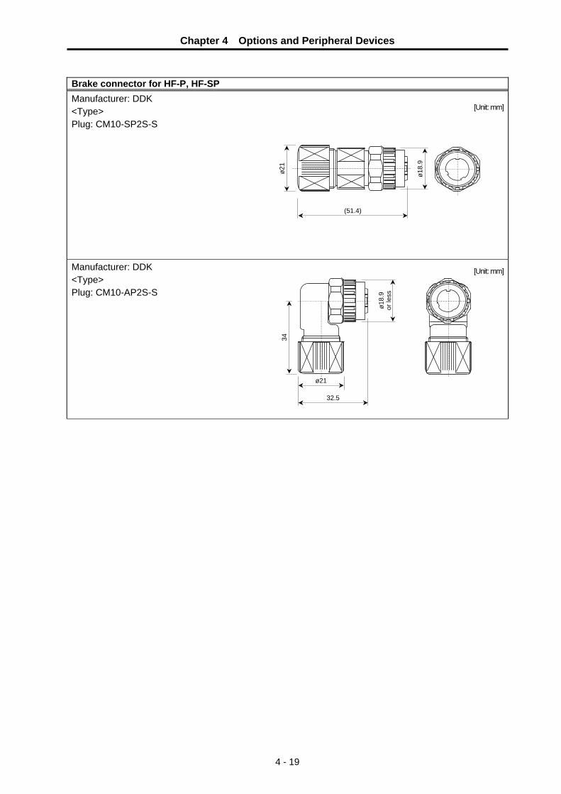
Chapter 4 Options and Peripheral Devices
4 - 19
Brake connector for HF-P, HF-SP Manufacturer: DDK <Type> Plug: CM10-SP2S-S
[Unit: mm]
ø21
ø18.
9
(51.4)
Manufacturer: DDK <Type> Plug: CM10-AP2S-S
[Unit: mm]
34
32.5
ø18.
9
or le
ss
ø21

Chapter 4 Options and Peripheral Devices
4 - 20
Motor power connector Manufacturer: DDK
Plug: [Unit: mm]
Type A B +0 −0.38 C±0.8 D or less W
CE05-6A18-10SD-C-BSS 11/8-18UNEF-2B 34.13 32.1 57 1-20UNEF-2A CE05-6A22-22SD-C-BSS 13/8-18UNEF-2B 40.48 38.3 61 13/16-18UNEF-2A Manufacturer: DDK
Plug: [Unit: mm]
Type A B+0−0.38
D or less W R±0.7 U±0.7 (S)±1 Y or
more
CE05-8A18-10SD-C-BAS 11/8-18UNEF-2B 34.13 69.5 1-20UNEF-2A 13.2 30.2 43.4 7.5 CE05-8A22-22SD-C-BAS 13/8-18UNEF-2B 40.48 75.5 13/16-18UNEF-2A 16.3 33.3 49.6 7.5 Manufacturer: DDK
Clamp: [Unit: mm]
Total length
Outer dia.
Avail. screw length
Fitting screw
Type Shell
size A B C D E F G H V
Bushing Applicable cable
CE3057-10A-1(D240) 18 23.8 30.1 10.3 41.3 15.9 14.1 31.7 3.2 1-20UNEF-2B CE3420-10-1 ø 10.5~ø 14.1
CE3057-12A-1(D240) 20 23.8 35 10.3 41.3 19 16.0 37.3 4 13/16-18UNEF-2B CE3420-12-1 ø 12.5~ø 16.0
(Movable range of one side)
øE(Inner diameter of cable clamp)
H
G±0
.7
CA
V screw1.6
(Bus
hing
inne
r di
amet
er) øF
(D)
B±0.
7
D or less
7.85 or moreW A
øC±
0.8
-0.38
+0
øB
D or less
R±
0.7
U±
0.7
(S)
±1
Y o
r
mor
e
W
A
-0.38
+0
øB

Chapter 4 Options and Peripheral Devices
4 - 21
4-4-3 Cable wire and assembly
(1) Detector cable (a) Heat resistant specifications cable
Wire characteristics Wire type
(special order part)
Finish outer
diameter
Sheath material
No. of pairs Configura-
tion Conductive
resistor Withstand
voltage Insulation resistance
Heat resistance
temperature Flexibility
2 (0.5mm2)
100 strands/ 0.08mm
40.7Ω/kmor less
BD20288 Compound 6-pair shielded cable Specification No. Bangishi-17145 (Note 1)
8.7mm Heat
resistant PVC 4
(0.2mm2)40 strands/
0.08mm103Ω/kmor less
500VAC/1min
1000MΩ/km or more 105°C
70×104 times or more at
R200
(b) General-purpose heat resistant specifications cable
Wire characteristics Wire type
(special order part)
Finish outer
diameter
Sheath material
No. of pairs Configura-
tion Conductive
resistor Withstand
voltage Insulation resistance
Heat resistance
temperature Flexibility
2 (0.5mm2)
100 strands/ 0.08mm
40.7Ω/kmor less
BD20032 Compound 6-pair shielded cable Specification No. Bangishi-16903
Revision No. 3 (Note 2)
8.7mm PVC
4 (0.2mm2)
40 strands/ 0.08mm
103Ω/kmor less
500VAC/1min
1000MΩ/km or more 60°C
100×104 times or more at
R200
(Note 1) Bando Electric Wire (Contact: 81+48-461-0561 http://www.bew.co.jp) (Note 2) The Mitsubishi standard cable is the (a) Heat resistant specifications cable. For
MDS-C1/CH series, (b) or equivalent is used as the standard cable.
Sheath
Mesh shield
Intervening wire
Tape
A1
A2 B2
B1 B4
B3Cable core
Conductor Insulator
L2 L1
Compound 6-pair cable structure drawing
Core identification
Insulator color Pair No. L1 L2
A1 (0.5mm2) Red White A2 (0.5mm2) Black White B1 (0.2mm2) Brown OrangeB2 (0.2mm2) Blue Green B3 (0.2mm2) Purple White B4 (0.2mm2) Yellow White
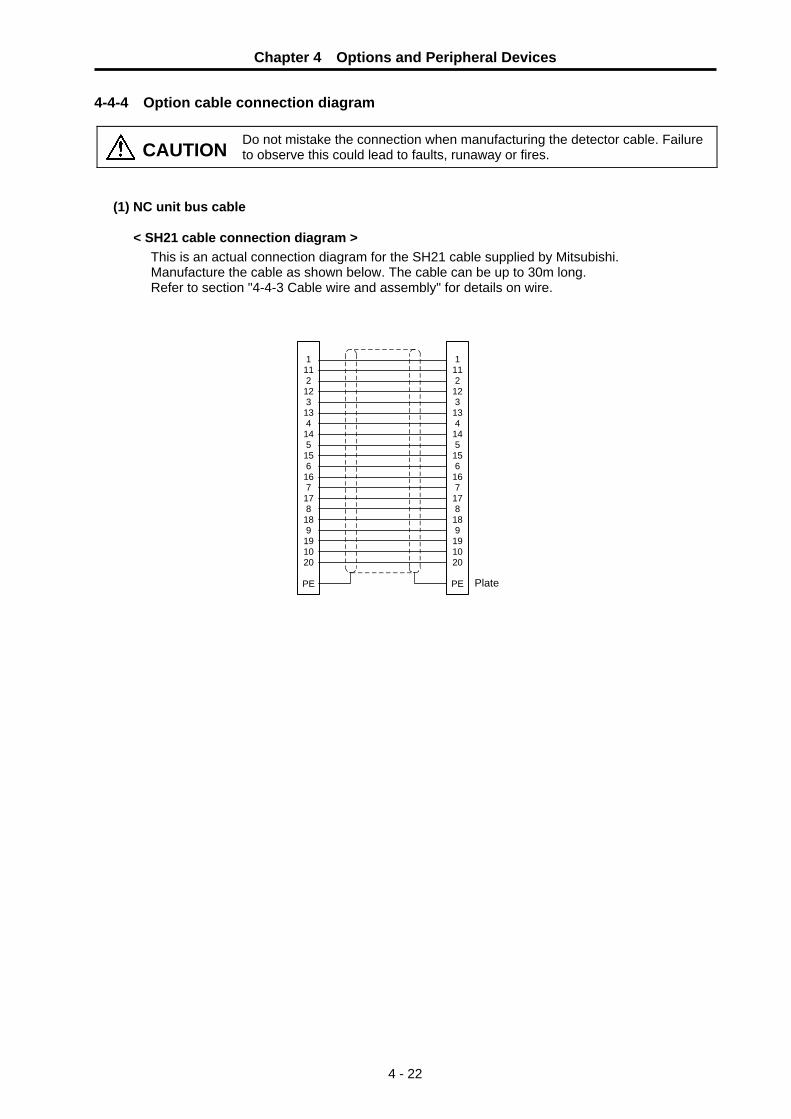
Chapter 4 Options and Peripheral Devices
4 - 22
4-4-4 Option cable connection diagram
CAUTION Do not mistake the connection when manufacturing the detector cable. Failure to observe this could lead to faults, runaway or fires.
(1) NC unit bus cable
< SH21 cable connection diagram > This is an actual connection diagram for the SH21 cable supplied by Mitsubishi. Manufacture the cable as shown below. The cable can be up to 30m long. Refer to section "4-4-3 Cable wire and assembly" for details on wire.
1112123134145156167178189191020
PE
1112123134145156167178189191020
PE Plate

Chapter 4 Options and Peripheral Devices
4 - 23
(2) HF-P, HF-SP detector cable
<CNV2E-T1P,CNV2E-T2P cable connection diagram>
191
1196
167
17
PE
8 5 3 4 6 7 1 2 10
P5(+5V)LG
BTSD
SD*RQ
RQ*
P5(+5V) LG CNT BT SD SD* RQ RQ* SHD
0.5mm2
Case grounding
0.2mm2
0.2mm2
0.2mm2
Servomotor detector side connector Plug: CM10-SP10S-M (straight)
CM10-AP10S-M (angle) Contact: CM10-#22SC
Servo drive unit side connector Connector: 10120-3000VEShell kit: 10320-52F0-008
0.2mm2
<For 15m or less>
191
2011
96
167
17
PE
8 5 3 4 6 7 1 2 10
P5(+5V)LG
P5(+5V)LG
BTSD
SD*RQ
RQ*
P5(+5V) LG CNT BT SD SD* RQ RQ* SHD
0.5mm2
Case grounding
0.2mm2
0.5mm2
0.2mm2
0.2mm2
Servomotor detector side connector Plug: CM10-SP10S-M (straight)
CM10-AP10S-M (angle) Contact: CM10-#22SC
Servo drive unit side connector Connector: 10120-3000VEShell kit: 10320-52F0-008
0.2mm2
<For 15 to 30m>
No. Abbreviation Parameter name Explanation #102 *Cont2 Control
parameter 2 Set the following parameters for the 4-wire detector communication.
CAUTION 1. Do not connect the pins that have no particular description. (Leave these
OPEN.) 2. Consult with Mitsubishi when manufacturing a cable longer than 30m.
Bit F E D C B A 9 8 7 6 5 4 3 2 1 0Defalut value 0 0 0 0 0 0 0 0 1 1 0 0 0 1 1 0
bit Meaning when set to "0" Meaning when set to "1"
6 Setting not possible Standard setting (4-wire type detector communication)
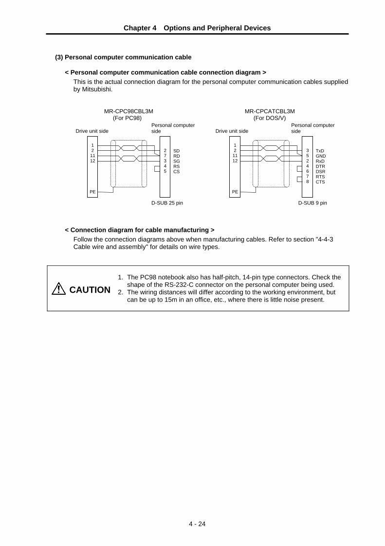
Chapter 4 Options and Peripheral Devices
4 - 24
(3) Personal computer communication cable
< Personal computer communication cable connection diagram >
This is the actual connection diagram for the personal computer communication cables supplied by Mitsubishi.
MR-CPC98CBL3M MR-CPCATCBL3M (For PC98) (For DOS/V)
< Connection diagram for cable manufacturing > Follow the connection diagrams above when manufacturing cables. Refer to section "4-4-3 Cable wire and assembly" for details on wire types.
CAUTION
1. The PC98 notebook also has half-pitch, 14-pin type connectors. Check the
shape of the RS-232-C connector on the personal computer being used. 2. The wiring distances will differ according to the working environment, but
can be up to 15m in an office, etc., where there is little noise present.
SD RD SG RS CS
27345
1 2 11 12
PE
TxD GND RxD DTR DSR RTS CTS
3 5 2 4 6 7 8
121112
PE
Drive unit side Personal computer side Drive unit side
Personal computer side
D-SUB 25 pin D-SUB 9 pin

Chapter 4 Options and Peripheral Devices
4 - 25
4-5 Setup software The setup software is used to set and change the parameters, check the operation state and carry out test operation from the personal computer using the servo drive unit's communication function.
4-5-1 Setup software specifications
Item Details (Note 1) Type Japanese: FWS-B02B022 Ver.B0 or above
English : FWS-B05B023 Ver.B0 or above MR-J2S-CT4 is compatible only with the above 32bit version. It is not compatible with Japanese: FWS-B02B012 and English: FWS-B05B013(16bit version).
Communication signal RS-232C compliance Transmission speed 9600bps Monitor Batch display, high-speed display, graphic display Alarm Alarm display, alarm history Diagnosis Input/output signal display, power ON cumulative display, automatic tuning
status display, absolute position monitor Parameter Data setting list display, change list display, detailed information display Test operation Automatic operation, manual operation, jog operation, reference point
return, absolute position reference point setting File operation Data write, save, print
(Note 1) This software may not run correctly depending on the personal computer being used.
(Note 2) Refer to "Setup Software Instruction Manual (BNP-B2208)" for details. 4-5-2 System configuration
The following items are required to use this software.
Model Details OS Windows 95/98/2000/XP Display 640 × 400 or more color, or 16 tone monochrome,
Windows 95/98/2000/XP compatible Keyboard Compatible with personal computer Mouse Windows 95/98/2000/XP compatible. Note that a serial mouse cannot be
used. Printer Windows 95/98/2000/XP compatible Communication cable MR-CPCATCBL3M
When not using this cable, refer to section 4-4-5 (4), and manufacture a cable.
(Note) Windows is a registered trademark of Microsoft Corporation.
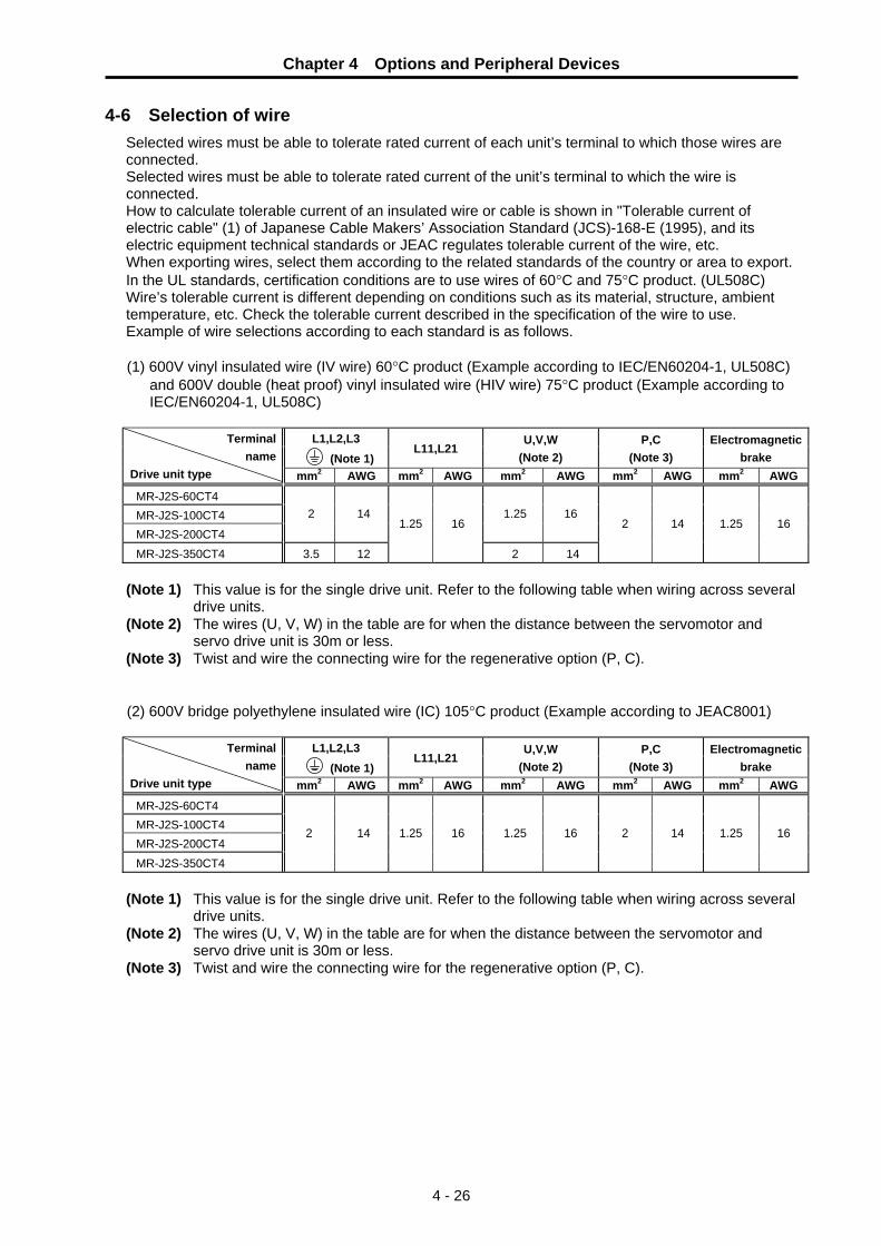
Chapter 4 Options and Peripheral Devices
4 - 26
4-6 Selection of wire Selected wires must be able to tolerate rated current of each unit’s terminal to which those wires are connected. Selected wires must be able to tolerate rated current of the unit’s terminal to which the wire is connected. How to calculate tolerable current of an insulated wire or cable is shown in "Tolerable current of electric cable" (1) of Japanese Cable Makers’ Association Standard (JCS)-168-E (1995), and its electric equipment technical standards or JEAC regulates tolerable current of the wire, etc. When exporting wires, select them according to the related standards of the country or area to export. In the UL standards, certification conditions are to use wires of 60°C and 75°C product. (UL508C) Wire’s tolerable current is different depending on conditions such as its material, structure, ambient temperature, etc. Check the tolerable current described in the specification of the wire to use. Example of wire selections according to each standard is as follows. (1) 600V vinyl insulated wire (IV wire) 60°C product (Example according to IEC/EN60204-1, UL508C)
and 600V double (heat proof) vinyl insulated wire (HIV wire) 75°C product (Example according to IEC/EN60204-1, UL508C)
L1,L2,L3
(Note 1) L11,L21
U,V,W (Note 2)
P,C (Note 3)
Electromagnetic brake
Terminal name
Drive unit type mm2 AWG mm2 AWG mm2 AWG mm2 AWG mm2 AWGMR-J2S-60CT4 MR-J2S-100CT4 MR-J2S-200CT4
2 14 1.25 16
MR-J2S-350CT4 3.5 12
1.25 16
2 14
2 14 1.25 16
(Note 1) This value is for the single drive unit. Refer to the following table when wiring across several
drive units. (Note 2) The wires (U, V, W) in the table are for when the distance between the servomotor and
servo drive unit is 30m or less. (Note 3) Twist and wire the connecting wire for the regenerative option (P, C). (2) 600V bridge polyethylene insulated wire (IC) 105°C product (Example according to JEAC8001)
L1,L2,L3 (Note 1)
L11,L21 U,V,W
(Note 2) P,C
(Note 3) Electromagnetic
brake Terminal
name Drive unit type mm2 AWG mm2 AWG mm2 AWG mm2 AWG mm2 AWGMR-J2S-60CT4 MR-J2S-100CT4 MR-J2S-200CT4 MR-J2S-350CT4
2 14 1.25 16 1.25 16 2 14 1.25 16
(Note 1) This value is for the single drive unit. Refer to the following table when wiring across several
drive units. (Note 2) The wires (U, V, W) in the table are for when the distance between the servomotor and
servo drive unit is 30m or less. (Note 3) Twist and wire the connecting wire for the regenerative option (P, C).

Chapter 4 Options and Peripheral Devices
4 - 27
When wiring L1, L2, L3 and the ground wire across several servo drive units, use the following table and select the wire size from the total capacity of the motors connected downward.
Total motor capacity 6.5kW or less 9.0kW or less 12kW or less IV wire 60°C product/ HIV wire 75°C product
2 (AWG14)
3.5 (AWG12)
5.5 (AWG10) Wire size
(mm2) IC wire 105°C product
2 (AWG14)
2 (AWG14)
3.5 (AWG12)
(Note) Compare with the choice of a single drive unit, and choose the thicker one.
CAUTION
1. Selection conditions follow ICE/EN60204-1, UL508C, JEAC8001. • Ambient temperature is maximum 40°C • Cable installed on walls without ducts or conduits.
To use the wire under conditions other than above, check the standards you are supposed to follow.
2.The maximum wiring length to the motor is 30m. If the wiring distance between the drive unit and motor is 20m or longer, use a thick wire so that the cable voltage drop is 2% or less.
3.Always wire the grounding wire.
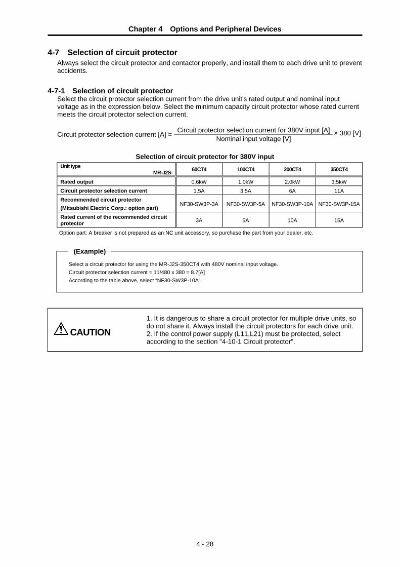
Chapter 4 Options and Peripheral Devices
4 - 28
4-7 Selection of circuit protector Always select the circuit protector and contactor properly, and install them to each drive unit to prevent accidents.
4-7-1 Selection of circuit protector Select the circuit protector selection current from the drive unit's rated output and nominal input voltage as in the expression below. Select the minimum capacity circuit protector whose rated current meets the circuit protector selection current.
Circuit protector selection current for 380V input [A] Circuit protector selection current [A] = Nominal input voltage [V] × 380 [V]
Selection of circuit protector for 380V input
Unit type MR-J2S- 60CT4 100CT4 200CT4 350CT4
Rated output 0.6kW 1.0kW 2.0kW 3.5kW Circuit protector selection current 1.5A 3.5A 6A 11A Recommended circuit protector (Mitsubishi Electric Corp.: option part)
NF30-SW3P-3A NF30-SW3P-5A NF30-SW3P-10A NF30-SW3P-15A
Rated current of the recommended circuit protector 3A 5A 10A 15A
Option part: A breaker is not prepared as an NC unit accessory, so purchase the part from your dealer, etc.
(Example)
Select a circuit protector for using the MR-J2S-350CT4 with 480V nominal input voltage. Circuit protector selection current = 11/480 x 380 = 8.7[A] According to the table above, select “NF30-SW3P-10A”.
CAUTION
1. It is dangerous to share a circuit protector for multiple drive units, so do not share it. Always install the circuit protectors for each drive unit. 2. If the control power supply (L11,L21) must be protected, select according to the section "4-10-1 Circuit protector".

Chapter 4 Options and Peripheral Devices
4 - 29
4-8 Selection of contactor Select the contactor selection current from the rated output and the nominal input voltage as in the expression below. Select the size of contactor whose free-air thermal current meets the contactor selection current.
Contactor selection current for 380V input [A] Contactor selection current [A] = Nominal input voltage [V] × 380 [V]
Selection of contactor for 380V input [A] Unit type
MR-J2S- 60CT4 100CT4 200CT4 350CT4
Rated output 0.6KW 1.0KW 2.0KW 3.5KW Contactor selection current 1.5A 3.5A 6A 11A Recommended contactor (Mitsubishi Electric Corp.: option part)
S-N12-400VAC S-N12-400VAC S-N12-400VAC S-N12-400VAC
Free-air thermal current of the recommended contactor
20A 20A 20A 20A
Option part: A breaker is not prepared as an NC unit accessory, so purchase the part from your dealer, etc.
POINT Select a contactor whose excitation coil does not operate at 15mA or less.

Chapter 4 Options and Peripheral Devices
4 - 30
4-9 Selection of earth leakage breaker When installing an earth leakage breaker, select the breaker on the following basis to prevent the breaker from malfunctioning by the higher frequency earth leakage current generated in the servo or spindle drive unit.
(1) Selection
Obtaining the earth leakage current for all drive units referring to the following table, select an earth leakage breaker within the "rated non-operation sensitivity current". Usually use an earth leakage breaker for inverter products that function at a leakage current within the commercial frequency range (50 to 60Hz). If a product sensitive to higher frequencies is used, the breaker could malfunction at a level less than the maximum earth leakage current value.
Earth leakage current for each drive unit
Drive unit Earth leakage current
MR-J2S-60CT4 to 200CT4 2.5mA MR-J2S-350CT4 1.3mA
(2) Measurement of eath leakage current
When actually measuring the earth leakage current, use a product that is not easily affected by the higher frequency earth leakage current. The measurement range should be 50 to 60Hz.
POINT
1. The earth leakage current tends to increase as the motor capacity increases.2. A higher frequency earth leakage current will always be generated because
the inverter circuit in the drive unit switches the transistor at high speed. Always ground to reduce the higher frequency earth leakage current as much as possible. Do not ground drive unit and motor separately (grounding at two points); ground them together at the drive unit side. (grounding at one point)
3. An earth leakage current containing higher frequency may reach approx. several hundreds of mA. According to IEC479-2, this level is not hazardous to the human body.
4. A PWM-controlled higher frequency chopper current flows to the AC servo. The higher frequency current is larger than the motor operated with a commercially available power supply. In order to reduce the earth leakage current, arrange so that the input and output cables are wired close, while they are wired in the furthest possible distance from the ground. (Approx. 30cm)

Chapter 4 Options and Peripheral Devices
4 - 31
4-10 Control circuit related 4-10-1 Circuit protector
This breaker is used to switch the control power supply, as well as to provide overload and short-circuit protection. A circuit protector with inertial delay and an operation delayed type breaker are available to prevent unnecessary tripping. Select the product to be used according to the machine specifications.
Recommended circuit protector (Mitsubishi Electric Corp.: Option part) CP30-BA2P1M3A, etc.
Rated current of circuit protector 1.0A per axis
Separately ordered parts: These parts are not handled by either the NC Dept. or dealers.
(Note) No built-in rush current control resistor is available for the control circuit power supply. It depends on the characteristics of the connecting 24VDC power supply.
POINT When collectively protecting the control circuit power for multiple units, select a circuit protector or breaker that satisfies the total sum of the rush current Ip. The largest value is used for the rush conductivity time T.
4-10-2 Relays
Use the following relays for the input/output interface (motor brake output: MBR, contactor output: MC, near point dog : DOG external emergency stop : EMGX.)
Interface name Selection example For digital input signal (DOG, EMGX) Use a minute signal relay (twin contact) to prevent a contact
defect. <Example> OMRON: G2A type, MY type
For digital output signal (MBR, MC) Use a compact relay with 24VDC, 40mA or less. <Example> OMRON: MY type
Contact: OMRON Corporation http://www.omron.co.jp/

Chapter 4 Options and Peripheral Devices
4 - 32
4-10-3 Surge absorber When controlling a magnetic brake of a servomotor in DC OFF circuit, a surge absorber must be installed to protect the relay contacts and brakes. Commonly a varistor is used.
(1) Selection of varistor
When a varistor is installed in parallel with the coil, the surge voltage can be adsorbed as heat to protect a circuit. Commonly a 120V product is applied. When the brake operation time is delayed, use a 220V product. Always confirm the operation with an actual machine.
(2) Specifications Select a varistor with the following or equivalent specifications. To prevent short-circuiting, attach a flame resistant insulation tube, etc., onto the leads as shown in the following outline dimension drawing.
Varistor specifications
Rating Varistor voltage rating
(range)
Tolerable circuit voltage
Surge current withstand level
(A)
Energy withstand level
(J) Power
Max. limit
voltage
Electrostaticcapacity
(reference value)
Varistor type
(V) AC(V) DC(V) 1 time 2 times 10 /1000us 2ms (W) (V) (pF)
ERZV10D121 TND10V-121K
120 (108 to 132)
75 100 3500 2500 20 14.5 0.4 200 1400
ERZV10D221 TND10V-221K
220 (198 to 242)
140 180 3500 2500 39 27.5 0.4 360 410
(Note 1) Selection condition: When ON/OFF frequency is 10 times/min or less, and exciting current is 2A or less
(Note 2) ERZV10D121 and ERZV10D221 are manufactured by Panasonic Electronic Devices Co.,Ltd.
TND10V-121K,TND10V-221K are manufactured by Nippon Chemi-Con Corporation
Contact: Panasonic Electronic Devices Co.,Ltd. : http://panasonic.co.jp/ped/
Nippon Chemi-Con Corporation : http://www.chemi-con.co.jp/
(3) Outline dimension drawing • ERZV10D121, ERZV10D221
POINT
Normally use a product with 120V varistor voltage. If there is no allowance for the brake operation time, use the 220V product. A varistor whose voltage exceeds 220V cannot be used, as such varistor will exceed the specifications of the relay in the
[Unit: mm]
Insulation tube
11.5
20.0

5 - 1
Chapter 5 Operation Control Signal 5-1 System configuration ........................................................................................................................ 5-2
5-1-1 Built-in indexing function............................................................................................................ 5-2 5-1-2 Parameters ................................................................................................................................ 5-3
5-2 R register .......................................................................................................................................... 5-4 5-3 Explanation of operation commands (NC → servo drive unit) ....................................................... 5-5 5-4 Explanation of operation status signals (servo drive unit → NC) ................................................. 5-11

Chapter 5 Operation Control Signal
5 - 2
5-1 System configuration 5-1-1 Built-in indexing function
Conventional NC servo drive units received acceleration/deceleration commands to the target position from the NC and controlled the motor. With the MR-J2S-CT4, the acceleration/deceleration commands that were until now received from the NC are created in the drive unit, and the motor is controlled. The operation commands for the MR-J2S-CT4 are all carried out from the user PLC via the R-register. The response signals from the MR-J2S-CT4 indicating the operation status are also returned to the user PLC R-register. These signals are automatically communicated with the MR-J2S-CT4 by the NC via high-speed serial communication.
NC system processing Parameters and monitor screen
User PLC processing
F⊿T F⊿T, commands
Position FB, status
NC feed axis servo drive unitMDS-B-SVJ2/MDS-B-Vx, etc.
Acceleration/deceleration pattern generation
Motor control
NC feed axis motor
Conventional servo control system
NC system processing Auxiliary axis parameters and auxiliary axis monitor screen Target values, start
signals
Completion signals, alarms User PLC processing
R-register
Servo drive unit with built-in indexing function
MR-J2S-CT4
Motor control
Auxiliary axis motor
Acceleration/deceleration pattern generated in the CT4
F⊿T
Communication Processing I/F
MR-J2S-CT4 servo control system
POINT
1. The MR-J2S-CT4 carries out position control as a single drive unit; it is a positioning-dedicated servo drive unit. Use a conventional servo drive unit (MDS-B-SVJ2, MDS-B-Vx Series) when interpolation control is required.
2. The connections between the NC and MR-J2S-CT4, monitor screens, parameter input methods, etc., differ according to the NC, so refer to the appropriate instruction manual for the NC being used.

Chapter 5 Operation Control Signal
5 - 3
5-1-2 Parameters
All parameters, including absolute position data, are saved in the MR-J2S-CT4. Using separately sold setup software, it is possible to rewrite the parameters and set the reference point from the personal computer using RS-232C serial communication, and adjustment, test operation, etc., of individual auxiliary axes is supported. Note that because the parameters and absolute position data are saved in the drive unit, this data must be written to the new drive unit when the drive unit is replaced. When replacing the drive unit, first upload the parameters from the old drive unit and store them in the memory of the NC, then download them into the new drive unit. The absolute position data is constantly backed up in the NC, so download that data into the new drive unit. This function is mounted on all NC's supporting MR-J2S-CT4 drive units. Refer to the appropriate instruction manual of the NC being used for information on the operation method. If the parameters cannot be uploaded from the old drive unit, download the NC backup parameters. Note that because the parameters are reset by the auto-tuning function, the control immediately after drive unit replacement may be unstable. However, if the drive unit continues to be used in that condition the auto-tuning will cause the parameters to reach a convergent value, and the characteristics will improve.
High-speed serial communication
NC internal memory • Parameters • Backup reference point
data Operation is necessary to backup parameters.
MR-J2S-CT4
MR-J2S-CT4 internal memory • Parameters • Reference point data • Alarm history
• Parameter revision • Reference point setting • Various monitoring
RS-232C serial communication
Personal computer (setup software)

Chapter 5 Operation Control Signal
5 - 4
5-2 R register
The MR-J2S-CT4 is controlled by the input/output from the PLC program to the R-registers in the table below. The R-register addresses differ according to the NC type and MR-J2S-CT4 axis No. settings. (The order in the table below is an example.) (1) List of operation commands (NC → servo drive unit)
bit7 bit6 bit5 bit4 bit3 bit2 bit1 bit0 bitF bitE bitD bitC bitB bitA bit9 bit8
H RDF ∗IT− ∗IT+ MRST ∗PRT1 QEMG ∗SVF Handle feed operation mode selection
READY OFF Interlock (−) Interlock (+) Master reset Data protect PLC emergency stop
Servo OFF
S ZST AZS ZRN J MAN AUT
Control command 1
(CTCM1) Incremental feed operation mode selection
Reference point setting
Reference point default setting mode selection
Reference point return mode selection
JOG operation mode selection
Manual operation mode selection
Automatic operation mode selection
PR2 PR1 MP2 MP1 PUS STS DIR ST Operation parameter selection 2
Operation parameter selection 1
Incremental feed magnification factor 2
Incremental feed magnification factor 1
Stopper positioning commands valid
Random point feed commands valid
Rotation direction
Operation start
Control command 2
(CTCM2)
ST128 ST64 ST32 ST16 ST8 ST4 ST2 ST1 Station selection 128
Station selection 64
Station selection 32
Station selection 16
Station selection 8
Station selection 4
Station selection 2
Station selection 1
ST256
Control command 3
(CTCM3)
Station selection 256
OVR OV64 OV32 OV16 OV8 OV4 OV2 OV1 Speed override valid
Speed override 64
Speed override 32
Speed override 16
Speed override 8
Speed override 4
Speed override 2
Speed override 1
Control command 4
(CTCM4)
Position command (CTCML) Position
command (CTCMH)
Command position when random point feed commands are valid. (32bit)
(2) List of operation status signals (servo drive unit → NC)
bit7 bit6 bit5 bit4 bit3 bit2 bit1 bit0 bitF bitE bitD bitC bitB bitA bit9 bit8
ADJ TLQ MVN MVP AX1 SMZ INP RDY Machine being adjusted
Torque limited Axis moving (−)
Axis moving (+)
Axis selection output
Smoothing zero
In-position Servo READY
NEAR JST JSTA SA MA HO RST ZP
Status 1
(CTST1)
Near set position
Set position reached
Automatic set position reached
Servo READY Controller ready
In handle feed operation mode
Resetting Reference point reached
SO AZSO DOG ZRNO ARNN JO MANO AUTO In incremental feed operation mode
In reference point default setting mode
Near-point dog In reference point return mode
Returning to reference point
In JOG operation mode
In manual operation mode
In automatic operation mode
ZSE ZSF ZSN ABS BAT AL4 AL2 AL1
Status 2
(CTST2)
Default setting error finished
Default setting completed
Absolute position data loss
Absolute position power off movement exceeded
Battery voltage low
Alarm 4 Alarm 2 Alarm 1
STO128 STO64 STO32 STO16 STO8 STO4 STO2 STO1 Station position 128
Station position 64
Station position 32
Station position 16
Station position 8
Station position 4
Station position 2
Station position 1
STO256
Status 3
(CTST3)
Station position 256
PSW8 PSW7 PSW6 PSW5 PSW4 PSW3 PSW2 PSW1 Position switch 8
Position switch 7
Position switch 6
Position switch 5
Position switch 4
Position switch 3
Position switch 2
Position switch 1
J2S PSI PFN PMV
Status 4
(CTST4)
Model judgment
In stopper Positioning completed
In positioning operation
CAUTION
1. The array of R-register addresses in the table is an example. The R-register assignments differ for each NC, so refer to the appropriate instruction manual for the NC being used.
2. Signals indicated with an asterisk (∗) are handled as B contacts (Valid at OFF "0").
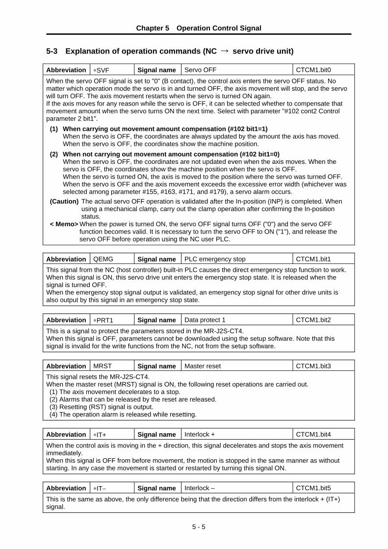
Chapter 5 Operation Control Signal
5 - 5
5-3 Explanation of operation commands (NC → servo drive unit) Abbreviation ∗SVF Signal name Servo OFF CTCM1.bit0
When the servo OFF signal is set to "0" (B contact), the control axis enters the servo OFF status. No matter which operation mode the servo is in and turned OFF, the axis movement will stop, and the servo will turn OFF. The axis movement restarts when the servo is turned ON again. If the axis moves for any reason while the servo is OFF, it can be selected whether to compensate that movement amount when the servo turns ON the next time. Select with parameter "#102 cont2 Control parameter 2 bit1".
(1) When carrying out movement amount compensation (#102 bit1=1) When the servo is OFF, the coordinates are always updated by the amount the axis has moved. When the servo is OFF, the coordinates show the machine position.
(2) When not carrying out movement amount compensation (#102 bit1=0) When the servo is OFF, the coordinates are not updated even when the axis moves. When the servo is OFF, the coordinates show the machine position when the servo is OFF. When the servo is turned ON, the axis is moved to the position where the servo was turned OFF. When the servo is OFF and the axis movement exceeds the excessive error width (whichever was selected among parameter #155, #163, #171, and #179), a servo alarm occurs.
(Caution) The actual servo OFF operation is validated after the In-position (INP) is completed. When using a mechanical clamp, carry out the clamp operation after confirming the In-position status.
< Memo> When the power is turned ON, the servo OFF signal turns OFF ("0") and the servo OFF function becomes valid. It is necessary to turn the servo OFF to ON ("1"), and release the servo OFF before operation using the NC user PLC.
Abbreviation QEMG Signal name PLC emergency stop CTCM1.bit1 This signal from the NC (host controller) built-in PLC causes the direct emergency stop function to work. When this signal is ON, this servo drive unit enters the emergency stop state. It is released when the signal is turned OFF. When the emergency stop signal output is validated, an emergency stop signal for other drive units is also output by this signal in an emergency stop state. Abbreviation ∗PRT1 Signal name Data protect 1 CTCM1.bit2
This is a signal to protect the parameters stored in the MR-J2S-CT4. When this signal is OFF, parameters cannot be downloaded using the setup software. Note that this signal is invalid for the write functions from the NC, not from the setup software. Abbreviation MRST Signal name Master reset CTCM1.bit3 This signal resets the MR-J2S-CT4. When the master reset (MRST) signal is ON, the following reset operations are carried out. (1) The axis movement decelerates to a stop. (2) Alarms that can be released by the reset are released. (3) Resetting (RST) signal is output. (4) The operation alarm is released while resetting. Abbreviation ∗IT+ Signal name Interlock + CTCM1.bit4
When the control axis is moving in the + direction, this signal decelerates and stops the axis movement immediately. When this signal is OFF from before movement, the motion is stopped in the same manner as without starting. In any case the movement is started or restarted by turning this signal ON. Abbreviation ∗IT− Signal name Interlock – CTCM1.bit5
This is the same as above, the only difference being that the direction differs from the interlock + (IT+) signal.

Chapter 5 Operation Control Signal
5 - 6
Abbreviation RDF Signal name READY OFF CTCM1.bit6 This is a signal to turn OFF the READY status. When put into a READY OFF status, the power supply to the servomotor is shut off, and the contactor control output is simultaneously turned OFF. If the motor is in operation, it will stop by a dynamic brake stop or a deceleration control stop. Servo ready complete (SA) and Servo ready (RDY) are also turned OFF, but an alarm does not occur. When this signal is turned OFF, the machine immediately returns to the original state. Abbreviation H Signal name Handle mode selection CTCM1.bit7 This signal selects the handle feed mode. The axis will move for the amount determined by input pulse multiplied by feed magnification after this signal is turned ON, each signal [operation parameter selection (PR1, PR2), and incremental feed magnification (MP1, MP2)] is determined, and the handle pulse is input.
(Caution 1) Turning this signal ON when other operation modes are ON will result in a "M01 0101 No operation mode" type operation alarm.
(Caution 2) The handle mode acceleration/deceleration time is the acceleration/deceleration time constant 2 linear acceleration/deceleration of the selected operation parameter group.
Abbreviation AUT Signal name Automatic operation mode selection CTCM1.bit8 This signal selects the automatic operation mode. When the station No. is designated and the operation start (ST) is ON, the movement toward the designated station begins.
(Caution) Turning the manual operation mode selection signal ON when other operation mode selection signals are ON will result in a "M01 0101 No operation mode" type operation alarm.
Abbreviation MAN Signal name Manual operation mode selection CTCM1.bit9 This signal selects the manual operation mode. When the rotation direction is designated and the operation start signal (ST) is turned ON, the axis will begin moving, and the rotation will continue in the designated direction until the operation start signal (ST) is turned OFF. When the operation start signal (ST) turns OFF, the axis will be positioned to the nearest station.
(Caution) Turning the JOG mode selection signal ON when other operation mode selection signals are ON will result in a "No operation mode" type operation alarm.
Abbreviation J Signal name JOG mode selection CTCM1.bitA This signal selects the JOG mode. When the rotation direction is designated and the operation start signal (ST) is turned ON, the axis will begin moving, and the rotation will continue in the designated direction until the operation start signal (ST) is turned OFF. Unlike the manual operation mode, when the operation start signal (ST) is turned OFF, the axis immediately decelerate to a stop.
(Caution) Turning the JOG mode selection signal ON when other operation mode selection signals are ON will result in a "No operation mode" type operation alarm.
Abbreviation ZRN Signal name Reference point return mode
selection CTCM1.bitB
This signal selects the reference point return mode. When the reference point return mode signal (ZRN) is ON, the mode is designated for reference point return. After the reference point return mode signal is turned ON, and the operation parameter group is selected, the reference point return is begun by turning the operation start signal (ST) ON. In the incremental specifications, the first reference point return after turning the power ON will be dog-type. However, after the first time, the dog-type or memory-type reference point return will be set by the parameter "#101 cont1 Control parameter bit1". When the absolute position coordinate system is established in the absolute position specifications, the reference point return will be memory-type every time.

Chapter 5 Operation Control Signal
5 - 7
Abbreviation AZS Signal name Reference point initialization mode
selection CTCM1.bitD
This signal selects the mode that initializes the reference point for the absolute position detection system.When this signal is turned ON, the reference point initialization mode is held until the NC power is turned OFF. (Cannot be canceled) When the stopper method is selected, the operation parameter group 4 torque limit value and the excessive error detection width are automatically selected. Abbreviation ZST Signal name Reference point set CTCM1.bitE This signal turns ON when designating the reference point position with the reference point initialization for the absolute position detection system. When this signal is turned ON by the initialization mode of the reference point system, that position is set as the absolute position reference point. Abbreviation S Signal name Incremental feed mode selection CTCM1.bitF This signal selects the incremental feed mode. The axis movement will begin after this signal is turned ON, each signal [operation parameter selection (PR1, PR2), incremental feed magnification (MP1, MP2), and rotation direction (DIR)] is determined, and the operation start signal (ST) is turned ON.
(Caution 1) Turning this signal ON when other operation modes are ON will result in a "No operation mode" type operation alarm.
(Caution 2) In the incremental mode, the axis will inch, even if the start signal ST is OFF.
インクリメンタルモード選択(s)信号
インクリメンタル送り倍率選択(MP1、MP2)信号
動作パラメータ選択(PR1、PR2)信号
回転方向選択(DIR)信号
リセット(RST)
起動信号(ST)
軸の移動
Incremental mode selection (s)
Incremental feed magnification selection (MP1, MP2)
Operation parameter selection (PR1, PR2)
Rotation direction selection (DIR)
Reset (RST)
Start signal (ST)
Axis movement

Chapter 5 Operation Control Signal
5 - 8
Abbreviation ST Signal name Operation start CTCM2.bit0 This signal starts the operation in each operation mode. When this signal is turned ON, the operation will start. The operation start signal (hereafter "start signal") is handled as a status, so the ON status must be maintained until the operation is finished. [Operation movement in each operation mode] (1) Automatic operation mode
The station selection signal (ST1 to ST256) and operation parameter selection (PR1, PR2) are established before inputting the operation start signal. These signals are read in by the startup of the start signal, so they are held even if they are changed after the startup. When the start signal is input, the output signals related to the set position all turn OFF. The station position output will be output as 0. Because the automatic set position (JSTA) and set position (JST) is output when the positioning is completed, the operation start signal turns OFF. Even when the start signal turns OFF, the output signal related to the set position is held as it is. When the start signal ST is turned OFF during axis movement, the axis will stop at the nearest station. Note that for a linear axis, if there is not a nearest point in the movement direction, the commanded station becomes the nearest point. < Memo> When the shortcut function is OFF for the rotating axis, the positioning direction can be
designated with the rotation direction (DIR). (2) Manual operation mode
The rotation direction (DIR) and operation parameter selection (PR1, PR2) are established before inputting the operation start signal. These signals are read in by the startup of the start signal, so they are held even if they are changed after the startup. When the start signal is input, the output signals related to the set position all turn OFF. The station position output will be output as 0. While the start signal is ON, the rotation direction continues in the designated direction. When the start signal is turned OFF, positioning is carried out to the nearest station that can be stopped at in the rotation direction. Note that for a linear axis, if there is no nearest point in the movement direction, the axis will immediately decelerate to a stop. When positioning is completed, a set position (JST) is output. < Memo> The automatic set position (JSTA) will not be output.
Station selection
Operation start
Automatic set position
Set position
Near set position
Station position
Axis movement
Output 0 (zero)
Rotation direction
Operation start
Automatic set position
Set position
Near set position
Station position
Axis movement
Output 0 (zero)

Chapter 5 Operation Control Signal
5 - 9
Abbreviation ST Signal name Operation start CTCM2.bit0
(3) JOG operation mode
The rotation direction (DIR) and operation parameter selection (PR1, PR2) are established before inputting the operation start signal. These signals are read in by the startup of the start signal, so they are held even if they are changed after the startup. When the start signal is input, the output signals related to the set position all turn OFF. The station position output will be output as 0. While the start signal is ON, the rotation direction continues in the designated direction. When the start signal is turned OFF, the axis decelerates to a stop. The set position (JST) and near set position (NEAR) are output if the axis is stopped within each tolerable width from the station position.
Abbreviation DIR Signal name Rotation direction designation CTCM2.bit1 This signal designates the rotation direction of the operation in each operation mode. It is input before the operation start (ST), to designate the rotation direction. This signal is invalid in the automatic operation mode when the shortcut control is set and selected by the parameter. When the shortcut control is not selected, positioning is carried out according to the direction designated by this signal. This signal is read in at the operation start (ST). Consequently, it is ignored after starting, even if the signal changes. The actual motor rotation direction is reversed by changing the setting of parameter #102.bit3.
DIR signal Axis rotation direction Station movement direction 0 Forward run Direction of increasing station No. 1 Reverse run Direction of decreasing station No. Abbreviation STS Signal name Random point feed command valid CTCM2.bit2
This signal selects the mode that executes the positioning in 0.001° units toward the random position (coordinate) transferred from the NC. When the random point feed command valid is executed, it is necessary to turn ON the automatic operation mode selection (AUT) simultaneously. Abbreviation PUS Signal name Pressing positioning command valid CTCM2.bit3 This signal selects the mode that executes random point feed including pressing operation. The positioning coordinates are the random position (coordinates) transferred from the NC as with the random point feed command. When the random coordinate command is executed, it is necessary to simultaneously turn ON the automatic operation mode select (AUT). It is not necessary to simultaneously turn ON the random point feed command valid (STS). (An operation error will occur)
Rotation direction
Operation start
Automatic set position
Set position
Near set position
Station position
Axis movement
Output 0 (zero)

Chapter 5 Operation Control Signal
5 - 10
Abbreviation MP1, MP2 Signal name Incremental feed magnification 1
and 2 CTCM2.bit4 to 5
This signal selects the incremental feed amount, and the handle feed magnification. In the handle feed, the selection is the movement amount per handle notch. MR2 signal MR1 signal Feed amount 0 0 0.001° 0 1 0.01° 1 0 0.1° 1 1 1° Abbreviation PR1, PR2 Signal name Operation parameter selection 1,
2 CTCM2.bit6 to 7
This signal selects one set of parameter group to actually be used from the four sets of parameter group 4 that designate the axis feed operation. The operation group cannot be changed while the operation start (ST) signal is input (The group is held in the drive unit.)
Operation parameters (four sets) PR2 signal PR1 signal Selected operation parameter group 0 0 1 0 1 2 1 0 3 1 1 4 Abbreviation ST1 to ST256 Signal name Station selection 1~256 CTCM3.bit0 to 8 This signal designates the index station No. in the automatic operation mode. The index station No. is input before operation start (ST) is input in the automatic operation mode. This signal is input with as a 9-digit binary. Input 000000001 corresponds to station No. 1. This signal is read in at the startup of the operation Start (ST). Consequently, it is ignored after starting, even if the signal changes. When this signal is set to 000000000, and the automatic operation is started, a one station rotation special command will result. (Note that this cannot be used when the station positions are determined in non-uniform assignments.) Abbreviation OV1 to OV64 Signal name Speed override 1 to 64 CTCM4.bit0 to 6 This signal designates the override value added to the selected feedrate. The override value is designated by a binary.
Effective feedrate = Selected speed × speed override100
Abbreviation OVR Signal name Speed override valid CTCM4.bit7 This is a signal to validate the speed override. When this signal is turned OFF, the set feedrate becomes the operation speed without calculating the override.
Operation parameter group 1 • Automatic feedrate • Manual feedrate • Acceleration/deceleration time constant 1• Acceleration/deceleration time constant 2• Torque limit • Excessive error detection width • Set position detection width • Near set position detection width
Operation parameter group 2Operation parameter group 3
Operation parameter group 4
Operation parameter
• Automatic feedrate • Manual feedrate • Acceleration/deceleration time constant 1• Acceleration/deceleration time constant 2• Torque limit • Excessive error detection width • Set position detection width • Near set position detection width
Selection

Chapter 5 Operation Control Signal
5 - 11
5-4 Explanation of operation status signals (servo drive unit → NC) Abbreviation RDY Signal name Servo READY CTST1.bit0 This signal indicates that the servo system is in an operable status. This signal turns ON in the following situations:
(1) When the servo system diagnosis is normally completed after turning the power ON. (2) After a servo alarm occurrence, when that alarm has been released by the reset (MRST). (3) When the emergency stop has been released. (4) When the READY OFF (RDF) and servo OFF (∗SVF) has been released.
This signal turns OFF in the following situations: (1) When the servo READY (SA) signal is turned OFF. (2) When the servo OFF signal is input, and the drive unit is in a servo OFF state.
Abbreviation INP Signal name In-position CTST1.bit1 This signal notifies that the control axis is in-position. This signal turns ON in the following situation:
(1) When the smoothing zero (SMZ) signal is turned ON, and the droop is within the range set in the parameters.
This signal turns OFF in the following situations: (1) When the smoothing zero (SMZ) signal is turned OFF. (When there is a movement command.) (2) When the droop exceeds the range set in the parameters.
(Caution 1) The "in-position (INP)" signal may turn ON, even during movement, when the axis is moving at extremely low speeds.
(Caution 2) The in-position detection range is set in the parameter "#006 INP In-position detection width".
(Caution 3) On the servo ready OFF state, smoothing zero (SMZ) signal turns OFF when the travel amount of servomotor is detected, Therefore, in-position signal (INP) also turns OFF, too. "Axis moving +" signal (MVP) or "axis moving -" signal (MVN) turns ON depending on the detected movement direction. Note that the "smoothing zero" signal (SMZ), "axis moving +" signal (MVP) or "axis moving -" signal (MVN) will not change on the servo OFF state without error correction setting because detected servomotor travel amount becomes a droop amount.
Abbreviation SMZ Signal name Smoothing zero CTST1.bit2 This signal indicates that the acceleration/deceleration process in the built-in controller is finished, and that no command to the control section remains.
Acceleration/ deceleration delay process Position loop process
Acceleration/deceleration delay Servo droop

Chapter 5 Operation Control Signal
5 - 12
Abbreviation AX1 Signal name Axis selection output CTST1.bit3 This signal indicates that the control axis has received the movement command. This signal turns ON in the following cases, and turns OFF after smoothing zero (SMZ) is detected. [In automatic operation mode]
The operation start (ST) turns ON, and is ON while the axis is moving. [In manual operation mode]
The operation start (ST) turns ON, and is ON while the axis is moving. [In JOG mode]
The operation start (ST) turns ON, and is ON while the axis is moving. [In reference point return mode]
This signal turns ON while the operation start (ST) signal is ON, and the axis is moving. Note that after the near-point dog is detected and the axis slows to creep speed, the axis selection output signal remains ON until the reference point is reached, even if the feed selection signal is turned OFF. When the interlock is applied, this signal remains ON even when the servo is OFF. This signal will turn OFF during emergency stop.
Abbreviation MVP Signal name In Axis movement + CTST1.bit4 This signal turns ON when the axis starts moving in the + direction, and turns OFF after smoothing zero (SMZ) is detected or the axis starts moving in the − direction. Abbreviation MVN Signal name In Axis movement – CTST1.bit5
This signal turns ON when the axis starts moving in the − direction, and turns OFF after smoothing zero (SMZ) is detected or the axis starts moving in the + direction. Abbreviation TLQ Signal name Torque limited CTST1.bit6 This signal turns ON when the motor output torque (motor current) is limited at the torque limit value of the selected operation parameter group. Abbreviation ADJ Signal name Adjusting machine CTST1.bit7 This signal indicates that the machine is being adjusted by the setup software adjusting function. When this signal turns ON, the signal from the setup software is validated and the control signal from the NC side cannot be received. Abbreviation ZP Signal name Reference point reached CTST1.bit8 This signal indicates that the control axis is on the reference point. This signal turns ON in the following situation:
(1) When the reference point is reached in the reference point return mode. The signal will not turn ON when the reference point is reached by another mode or command.
This signal turns OFF in the following situations: (1) When moved from the reference point by a movement command, etc. (2) When the machine is in an emergency stop status due to an emergency stop or servo alarm
occurrence, etc. (3) When the axis moved by the servo OFF.
Feed selection +, – (+J, –J) Axis movement Axis selection output (AX1)

Chapter 5 Operation Control Signal
5 - 13
Abbreviation RST Signal name Resetting CTST1.bit9 This signal indicates that the built-in controller is being reset. This signal turns ON in the following situations:
(1) When the MRST signal turns ON. (2) When the MRST signal is turned ON, and the built-in controller is being reset. (3) When in an emergency stop status.
Abbreviation HO Signal name In handle mode CTST1.bitA This signal indicates that the handle mode has been selected. Abbreviation MA Signal name Controller preparation complete CTST1.bitB This signal notifies that the positioning controller built in the drive unit is in a status to carry out normal operation. This signal turns ON in the following situation:
(1) When normal operation has begun after turning the power ON. The signal turns OFF in the following situations:
(1) When the power is turned OFF. (2) When an MR-J2-CT error such as a CPU error, or memory error, etc. is detected. (3) When a servo error that cannot be released unless the MR-J2-CT is first turned OFF occurs.
Abbreviation SA Signal name Servo preparation complete CTST1.bitC This signal indicates that the servo system is in a status to carry out normal operation. Conversely, when this signal is not ON, it shows that the servo (position control) is not operating. This signal turns ON in the following situations:
(1) When the servo system diagnosis is normally completed after turning the power ON. (2) After a servo alarm occurrence, when that alarm has been released by the master reset (MRST). (3) When the emergency stop has been released. (4) When the READY OFF (RDF) signal is turned OFF.
This signal turns OFF in the following situations: (1) When the controller READY (MA) signal is turned OFF. (2) When a servo alarm occurs. (3) When the machine is in an emergency stop status. (4) When the READY OFF (RDF) signal is turned ON.
When an MR-J2-,CT error such as a CPU error, or memory error, etc. is detected.
(Caution 1) With the servo OFF (∗SVF), the servo preparation complete (SA) will not turn OFF as long as there are no separate conditions for turning the SA OFF.
(Caution 2) In OFF condition (3), all I/O output points will turn OFF.

Chapter 5 Operation Control Signal
5 - 14
Abbreviation JSTA Signal name Automatic set position reached CTST1.bitD In the automatic operation, this signal notifies that the positioning to the commanded station No. is complete. The same tolerable ON width is as set position reached is used. This signal turns ON in the following situation:
(1) In the automatic operation mode, when the positioning to the designated station No. is complete. The signal actually turns ON before the positioning is complete, when the tolerable width is entered.
The signal turns OFF in the following situations: (1) When the start signal is input in any of the operation modes. (2) When the axis deviates outside the tolerable width. (Caution 1) In automatic operation, this signal will not turn ON when positioning to the nearest station
is carried out by the start signal OFF. (Caution 2) When this signal is ON, it will not turn OFF if the same station No. index is started. (Caution 3) When the positioning to the station is completed by the manual mode, if the same station
No. index is started, this signal will turn ON. However, there will be no movement. (Caution 4) Once turned OFF, this signal will not turn ON again even if the tolerable width is returned
to. Abbreviation JST Signal name Set position reached CTST1.bitE This signal notifies that the positioning to the station position is complete. It is ON when the machine position is at any of the station positions. The tolerable ON width is set beforehand as a parameter. This signal turns ON in the following situations:
(1) When the positioning to the station is complete in automatic or manual operation. The signal actually turns ON before the positioning is complete, when the tolerable width is entered.
(2) When the stop position after JOG operation is the station position or within the tolerable width. (3) When the reference point return position corresponds to those of the stop position in (2).
Other than the above conditions, this signal normally monitors the machine position, and carries out comparisons between stations. Therefore, this signal is output even when the machine moves to a station position outside the operation. This signal turns OFF in the following situations:
(1) When the start signal is input in any of the operation modes. When the operation is started by a start signal, this signal will not turn ON, even when a station position is passed during operation.
(2) When the axis deviates outside the tolerable width. Abbreviation NEAR Signal name Near set position CTST1.bitF This signal notifies that the machine position is near the station. It operates in the same manner as the set position (JST), but the tolerable width setting is treated separately. Generally, the tolerable width setting values are set larger than those for the set position, and a mechanical clamp operation is begun just before completion of the positioning, etc. Abbreviation AUTO Signal name In automatic operation mode CTST2.bit0 This signal indicates that the automatic operation mode has been selected. Abbreviation MANO Signal name In manual operation mode CTST2.bit1 This signal indicates that the manual operation mode has been selected. Abbreviation JO Signal name In JOG operation mode CTST2.bit2 This signal indicates that the JOG operation mode has been selected. Abbreviation ARNN Signal name In reference point return CTST2.bit3 This signal indicates that the machine is in dog-type reference point return.

Chapter 5 Operation Control Signal
5 - 15
Abbreviation ZRNO Signal name In reference point return mode CTST2.bit4 This signal indicates that the reference point return mode has been selected. Abbreviation DOG Signal name Near-point dog CTST2.bit5 The input status of the near-point dog for the reference point return is output as is. This is used to confirm the near-point dog signal. (The near-point dog signal is input from connector CN3.) Abbreviation AZSO Signal name Reference point initialization mode CTST2.bit6 This signal indicates that the reference point initialization mode has been selected. Before switching from another mode to the absolute position reference point initialization mode, smoothing zero (command acceleration/deceleration delay is zero) is confirmed. Abbreviation SO Signal name In incremental feed operation mode CTST2.bit7 This signal indicates that the incremental mode has been selected. Abbreviation AL1 Signal name Alarm 1 CTST2.bit8 This signal indicates that an alarm has occurred requiring the power to be turned ON again after the cause is removed. Abbreviation AL2 Signal name Alarm 2 CTST2.bit9 This signal indicates that an alarm has occurred which can be released by the master reset signal after the cause is removed. Abbreviation AL4 Signal name Alarm 4 CTST2.bitA This signal indicates that an operation alarm or absolute position alarm has occurred. Abbreviation BAT Signal name Battery voltage low CTST2.bitB This signal indicates that the voltage of the absolute position system battery is low. Abbreviation ABS Signal name Absolute position power OFF
movement exceeded CTST2.bitC
This signal indicates that the axis moved beyond the tolerable amount while the control power was OFF in the absolute position system. Abbreviation ZSN Signal name Absolute position loss CTST2.bitD This signal indicates that the absolute position data has been lost in the absolute position system. Abbreviation ZSF Signal name Initialization error completed CTST2.bitE This signal indicates that in the absolute position system the reference point initialization has completed normally, and that the absolute position coordinates have been established. Abbreviation ZSE Signal name Initialization set error finished CTST2.bitF This signal indicates that the reference point initialization has not finished normally in the absolute position system.

Chapter 5 Operation Control Signal
5 - 16
Abbreviation STO1 to STO256 Signal name Station position 1 to 256 CTST3.bit0 to 8 This signal shows the present station No. in as a 9-digit binary. This signal outputs the station position when the set position reached (JST) signal is ON, and outputs a "0" when the set position reached signal is OFF. Abbreviation PSW1 to 8 Signal name Position switch 1 to 8 CTST4.bit0 to 7 This signal turns ON when the axis is within the setting range of the respective position switches. Abbreviation PMV Signal name In positioning operation CTST4.bit8 This signal indicates that the positioning is being carried out in the pressing positioning mode operation. The positioning finishes, smoothing zero is confirmed, and the signal turns OFF. Abbreviation PFN Signal name Positioning complete CTST4.bit9 This signal indicates that the positioning is finished in the pressing positioning mode operation. This signal turns ON when the "In positioning operation" (PMV) turns OFF. It is held until the next start. Abbreviation PSI Signal name Pressing in CTST4.bitA This signal is ON while moving the set pressing amount in operation in the pressing positioning mode. Abbreviation J2S Signal name Model judgment CTST4.bitF This signal judges that the servo system is the MR-J2S-CT4 series. If the servo system is the MR-J2S-CT4 series, this signal is turned ON. If the servo system is the MR-J2-CT series, this signal is turned OFF.

6 - 1
Chapter 6 Setup and Operation 6-1 Setup of servo drive unit................................................................................................................... 6-2
6-1-1 Parameter initialization .............................................................................................................. 6-2 6-1-2 Transition of LED display after power is turned ON .................................................................. 6-2 6-1-3 Servo parameter default settings............................................................................................... 6-3 6-1-4 Operation parameter group default settings.............................................................................. 6-4 6-1-5 Setting during emergency stops ................................................................................................ 6-8
6-2 Test operation................................................................................................................................. 6-10 6-2-1 Test operation.......................................................................................................................... 6-10 6-2-2 JOG operation ......................................................................................................................... 6-11 6-2-3 Incremental feed operation...................................................................................................... 6-12 6-2-4 Handle feed operation ............................................................................................................. 6-12
6-3 Setting the coordinate zero point.................................................................................................... 6-13 6-3-1 Dog-type reference point return............................................................................................... 6-13 6-3-2 Adjusting the dog-type reference point return ......................................................................... 6-15 6-3-3 Memory-type reference point return ........................................................................................ 6-17 6-3-4 Mode with no reference point .................................................................................................. 6-17
6-4 Positioning operations by the station method................................................................................. 6-18 6-4-1 Setting the station .................................................................................................................... 6-18 6-4-2 Setting linear axis stations....................................................................................................... 6-20 6-4-3 Automatic operation................................................................................................................. 6-22 6-4-4 Manual operation ..................................................................................................................... 6-25
6-5 Stopper positioning operation......................................................................................................... 6-26 6-5-1 Operation sequence ................................................................................................................ 6-26 6-5-2 Setting the parameters ............................................................................................................ 6-29
6-6 Machine compensation and protection functions ........................................................................... 6-30 6-6-1 Backlash compensation........................................................................................................... 6-30 6-6-2 Interlock function...................................................................................................................... 6-30 6-6-3 Soft limit ................................................................................................................................... 6-31 6-6-4 Servo OFF ............................................................................................................................... 6-32 6-6-5 READY OFF ............................................................................................................................ 6-33 6-6-6 Data protect ............................................................................................................................. 6-33
6-7 Miscellaneous functions ................................................................................................................. 6-34 6-7-1 Feedrate override .................................................................................................................... 6-34 6-7-2 Position switches ..................................................................................................................... 6-34

Chapter 6 Setup and Operation
6 - 2
6-1 Setup of servo drive unit 6-1-1 Parameter initialization When starting up MR-J2S-CT4 with a machine for the first time, initialize the parameters first. Then, set and adjust the machine specifications. To initialize the parameters, open the window on the top of the drive unit, and set the axis No. setting rotary switch to "7". Then turn the drive unit control power ON. When the drive unit LEDs change from a "dot display (..)" to an "end display (En)", the parameter initialization has been completed. (With software version C4 and below, the initialization is completed when the display changes to the "alarm display".) Set the axis No. setting rotary switch to the specified axis No., turn the drive unit control power ON again and connect with the NC. When the parameters are initialized, the absolute position data will also be initialized, so "Zero Point Initialization Incomplete (Z70 0001)" will always occur when the power is turned ON next.
Rotary switch setting Set axis No. 0 1st axis 1 2nd axis 2 3rd axis 3 4th axis 4 5th axis 5 6th axis 6 7th axis 7 Parameter initialization8 9 A B C D E
Setting prohibited
Display section The operation status and alarms aredisplayed.
Setting section Axis No. setting rotary switch
F Test operation mode
6-1-2 Transition of LED display after power is turned ON
When the axis No. is set, and the servo drive unit power and NC power are turned ON, the servo drive unit will carry out a self-diagnosis, and the initial signal with the NC will start. The LEDs on the front of the servo drive unit will change as shown below according to the progression of these processes. If an alarm occurs, the alarm No. will appear on the LEDs. Refer to "Chapter 10 Troubleshooting" for details on the alarm displays.
CAUTION 1. Be aware that if the power is turned ON during parameter initialization
(rotary switch = 7), absolute position data and all parameters will be lost. 2. The test operation mode is a mode commanded from the personal
computer setup software. Commands and emergency stop signals from the NC are ignored.
Servo drive unit power ON
Standing by for NC power to be turned ON.
NC power OFF
Servo drive unit self-diagnosis and internal initialization completed.
In initial communication execution with the NC.
In normal operation (servo OFF). • Displays the set axis No. (1st axis)
In normal operation (servo ON). • Displays the set axis No. (1st axis)
LED display
NC power ON

Chapter 6 Setup and Operation
6 - 3
6-1-3 Servo parameter default settings "Servo parameters" mainly mean the parameters (#001 to #099) related to servo control. Because the motor type and detector resolution are automatically set in the MR-J2S-CT4, set the parameters related to the following specifications first when setting up. The servo gain is automatically adjusted by the auto-tuning. The operation when starting may be unstable. However, the gain will gradually be tuned to the optimum value by the acceleration/deceleration operation of the servomotor. The adjusted parameters will be saved even when the power is turned OFF.
No. Abbrev. Parameter name Default
value Unit Explanation Setting range
#0002 ∗RTY Regenerative option type 0000 Set the regenerative resistor type when an external option regenerative resistor is used. Do not set values that have no description.
(Initial value) 0 0 0 0
Selecting regenerative option 00: Regenerative option is not used. 01: FR-RC-H , FR-BU-H 80: MR-RB3H-4 81: MR-RB5H-4 82: MR-RB3G-4 83: MR-RB5G-4 86: MR-RB1L-4 87: MR-RB3M-4
#0003 ∗PC1 Motor side gear ratio (machine rotation ratio)
1 1 ~ 32767
#0004 ∗PC2 Machine side gear ratio (motor rotation ratio)
1
Set as an integer expressing the reduced fraction of the No. of gear teeth on the motor side and the No. of gear teeth on the machine side. If there are multiple gear levels, set the total gear ratio. For rotation axes, set the No. of motor rotations per one machine rotation.
1 ~ 32767
#0005 ∗PIT Feed pitch 360 ° (mm)
Set 360 for rotation axes. (Default value). Set the feed lead for linear axes.
1 ~ 32767
(1) Setting the gear ratio Set the No. of gear teeth on the motor side in PC1, and the No. of gear teeth on the machine side in PC2. If there are multiple gear levels, set the total gear ratio in a form reduced to its lowest terms. PC2/PC1 becomes the motor speed when the axis is moved the amount set in the feed pitch parameter ( PIT). The final axis rotation becomes 360° for rotation axes. For example, with the magazine shown in the drawing at the right, one magazine cycle is 360°, and the gear ratio is the No. of motor rotations required to rotate the magazine one cycle. For the drawing at the right, the parameter default values are as follows.
∗ PC1 = 1 ∗ PC2 = 50 ∗ PIT = 360
POINT For rotation axes, set the motor speed required to rotate the axis end one rotation (position the axis 360°) in the gear ratio.
(2) Setting the feed pitch Set the feed pitch to 360 for rotation axes. Set the ball screw lead for linear axes that use a ball screw. For rack and pinion, etc., structures, set the movement amount per final gear (final step of the rotation system) rotation. In this case, set the deceleration ratio to the final gear for the gear ratio.
40-magazine gear ratio setting = 1/50
Final gearMotor side gear
Gear deceleration ratio =1/10
Final gear vs. magazine cycle deceleration ratio = 8/40 = 1/5

Chapter 6 Setup and Operation
6 - 4
6-1-4 Operation parameter group default settings (1) Operation parameter group
There are eight types of parameters related to feed control such as feedrate and acceleration/ deceleration time constants of the axes in each operation mode. When these are put together in a set, they are called an operation parameter group. A total of four operation parameter groups can be set. By selecting any set of operation parameter selections 1 and 2 (PR1, PR2) from the PLC and operating, the operating conditions can be changed to match the machine status each time. There are also operation modes such as stopper positioning control, in which the drive unit automatically selects the operation parameter group and controls the machine.
Parameters determining the operation pattern
(2) Setting the feedrate The machine side speed is set as a feedrate in a parameter separately for automatic operation and manual operation. Because the electronic gear automatically calculates the motor speed, etc., setting can be done without being concerned with gear ratio, pitch, detector resolution, etc. Moreover, the parameter #150 automatic operation speed operation parameter group 1 (Aspeed1) as a clamp speed (feedrate upper limit value). The axis feedrate will be limited at the value set in Aspeed1, even if a higher speed than this is set in another parameter.
No. Abbrev. Parameter name Default value Unit Explanation Setting
range #150 Aspeed1 Operation parameter 1
Automatic operation speed #158 Aspeed2 Operation parameter 2
Automatic operation speed #166 Aspeed3 Operation parameter 3
Automatic operation speed #174 Aspeed4 Operation parameter 4
Automatic operation speed
5000 °/min (mm/min)
Set the feedrate during automatic operation when each operation parameter group is selected. #150 Aspeed1 functions as the clamp value for the automatic operation speeds and manual operation speeds of all operation groups. A speed exceeding Aspeed1 cannot be commanded, even if set in the parameters.
1~100000
#151 Mspeed1 Operation parameter group 1Manual operation speed
#159 Mspeed2 Operation parameter group 2Manual operation speed
#167 Mspeed3 Operation parameter group 3Manual operation speed
#175 Mspeed4 Operation parameter group 4Manual operation speed
2000 °/min (mm/min)
Set the feedrate during manual operation and JOG operation when each operation parameter group is selected.
1~100000
POINT The operation parameter group 1 automatic operation speed (Aspeed1) works as the clamp speed for all operation speeds. A feedrate exceeding Aspeed1 cannot be commanded.
Four sets
Parameter name Function Automatic operation speed Automatic operation feedrate Manual operation speed Manual/JOG operation feedrate Acceleration/deceleration time constant 1
Linear sections of acceleration/deceleration time constant of all operation modes
Acceleration/deceleration time constant 2
Non-linear sections of acceleration/deceleration time constant of all operation modes
Torque limit value Torque (current) limit value Excessive error detection width
Tolerable position droop (tracking delay) value
Set position output width Tolerable set position signal output value Near set position output width Tolerable near set position output value
Operation parameter group 1 PR1 = 0, PR2 = 0
Operation parameter group 2 PR1 = 1, PR2 = 0
Operation parameter group 3 PR1 = 0, PR2 = 1
Operation parameter group 4 PR1 = 1, PR2 = 1

Chapter 6 Setup and Operation
6 - 5
(3) Setting the acceleration/deceleration pattern and acceleration/deceleration time constant A constant inclination acceleration/deceleration operation is carried out for all axis movement (In the handle feed operation mode, a constant time linear acceleration/deceleration operation is carried out). As for the acceleration/deceleration time constants, set all linear acceleration/ deceleration times for clamp speed (Aspeed1) in acceleration/deceleration time constant 1 (timeN.1). When operating at speeds less than the clamp speed, the axis will accelerate/decelerate at the same inclination. At this time, set 1 (default value) in the acceleration/deceleration time constant 2 (timeN.2). S-character (soft) acceleration/deceleration operation is carried out if any value other than 1 is set in the acceleration/deceleration time constant 2 (timeN.2). In this case, set the time of the linear part for acceleration/deceleration time constant 1, and the total time of the non-linear parts (same as the non-linear time at acceleration start and finish) for acceleration/deceleration time constant 2. Thus, the total acceleration/deceleration time becomes the sum of the acceleration/deceleration time constant 1 and acceleration/deceleration time constant 2. In the handle feed operation mode, only acceleration/deceleration time constant 2 (timeN.2) is used, and a linear acceleration/deceleration operation is carried out.
No. Abbrev. Parameter name Default value Unit Explanation Setting
range#152 time1.1 Operation parameter group 1
Acceleration/deceleration time constant 1
#160 time2.1 Operation parameter group 2Acceleration/deceleration time constant 1
#168 time3.1 Operation parameter group 3Acceleration/deceleration time constant 1
#176 time4.1 Operation parameter group 4Acceleration/deceleration time constant 1
100 ms Set the linear acceleration/deceleration time for the operation parameter group 1 automatic operation speed (clamp speed) when each operation parameter group is selected. When operating at speeds less than the clamp speed, the axis will linearly accelerate/decelerate at the inclination determined above. When this is set together with acceleration/deceleration time constant 2, S-character acceleration/deceleration is carried out. In this case, set the acceleration/deceleration time of the linear part in this parameter.
1 ~ 9999
#153 time1.2 Operation parameter group 1Acceleration/deceleration time constant 2
#161 time2.2 Operation parameter group 2Acceleration/deceleration time constant 2
#169 time3.2 Operation parameter group 3Acceleration/deceleration time constant 2
#177 time4.2 Operation parameter group 4Acceleration/deceleration time constant 2
1 ms Set the linear acceleration/deceleration time constant in the handle feed operation mode when each operation parameter group is selected. When S-character acceleration/deceleration is carried out, set the total time of the non-linear parts. When 1 is set in this parameter, linear acceleration/deceleration is carried out.
1 ~ 9999
POINT
Set the acceleration/deceleration time constant as the acceleration/deceleration time for the clamp speed (Aspeed1). When operating at speeds less that the clamp speed, the acceleration/ deceleration operation is carried out at the same inclination as when operating at clamp speed.
Parameter #150 Automatic operation speed (clamp)
Linear section setting: Acceleration/deceleration time constant 1
Time
Speed
All acceleration/deceleration time is the sum of acceleration/deceleration time 1 + acceleration/deceleration time 2
Non-linear section setting: Half each of acceleration/deceleration time constant 2

Chapter 6 Setup and Operation
6 - 6
(4) Setting the torque limit value Each operation parameter group has an individual torque limit value (current limit value). When set to the default value 500, the torque is automatically limited at the maximum torque determined in the motor specifications. Operate with the default value when not especially limiting the torque.
No. Abbrev. Parameter name Default value Unit Explanation Setting
range
#154 TL1 Operation parameter group 1 Torque limit value
#162 TL2 Operation parameter group 2Torque limit value
#172 TL3 Operation parameter group 3Torque limit value
#178 TL4 Operation parameter group 4Torque limit value
500 % Set the motor output torque limit value when each operation parameter group is selected. At the default value of 500, the torque is limited at the maximum torque of the motor specifications. Set the default value when torque limiting is not especially required. The set value is the value on the assumption that rating torque is 100%. Motor current value is limited so that the motor output torque becomes the set value, but the value cannot always match the current limit value according to each motor's torque characteristics.
1 ~ 500
(5) Setting the excessive error detection width
Each operation parameter group has an individual excessive error alarm (S03 0052). An alarm is detected when the position droop (position command - position FB) exceeds the setting value. The standard setting value is calculated from the feedrate using the following equation. Excessive error alarms can occur easily when the load inertia is large or the auto-tuning response is lowered, so raise the excessive error detection width in these cases.
OD (N) = Aspeed (N)1000
(° or mm)
No. Abbrev. Parameter name Default value Unit Explanation Setting
range #155 OD1 Operation parameter group 1
Excessive error detection width
#163 OD2 Operation parameter group 2Excessive error detection width
#171 OD3 Operation parameter group 3Excessive error detection width
#179 OD4 Operation parameter group 4Excessive error detection width
100 ° (mm)
Set the excessive error detection width when each operation parameter group is selected. An excessive error alarm (S03 0052) is detected when the position droop becomes larger than this setting value.
0 ~ 32767

Chapter 6 Setup and Operation
6 - 7
(6) Setting the output width of signals related to the set position Set the respective detection widths of the set position reached (JST) and automatic set position reached (JSTA) signals that indicate that the machine positioning is completed. Also set the detection width for the near set position (NEAR) signal that indicates that the machine position is near each station.
No. Abbrev. Parameter name Default value Unit Explanation Setting
range #156 just1 Operation parameter group 1
Set position output width #164 just2 Operation parameter group 2
Set position output width
#172 just3 Operation parameter group 3Set position output width
#180 just4 Operation parameter group 4Set position output width
0.500 ° (mm)
The signal indicating that the machine position is at any one of the stations is the set position reached (JST) signal. During automatic operation, the automatic set position reached (JSTA) signal is detected under the same conditions. Set the tolerable values at which these signals are output when each operation parameter group is selected. These signals turn OFF when the machine position is separated from the station by more than this value.
0.000 ~ 99999.999
#157 near1 Operation parameter group 1Near set position output width
#165 near2 Operation parameter group 2Near set position output width
#173 near3 Operation parameter group 3Near set position output width
#181 near4 Operation parameter group 4Near set position output width
1.000 ° (mm)
The signal indicating that the machine position is near any one of the station positions is the near set position (NEAR) signal. Set the tolerable values at which these signals are output when each operation parameter group is selected. These values are generally set wider than the set position output width. In terms of operations, this is related to special commands when the station selection is 0. Refer to section "6-4-3 Automatic operation."
0.000 ~ 99999.999
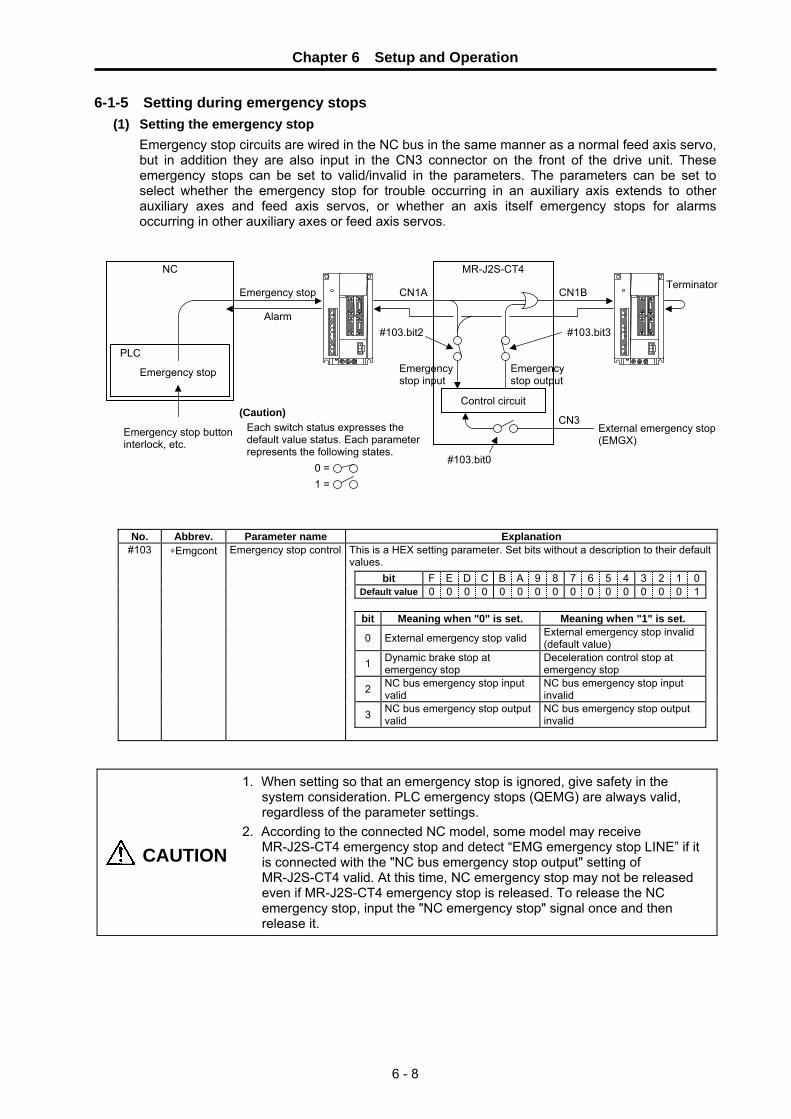
Chapter 6 Setup and Operation
6 - 8
6-1-5 Setting during emergency stops (1) Setting the emergency stop
Emergency stop circuits are wired in the NC bus in the same manner as a normal feed axis servo, but in addition they are also input in the CN3 connector on the front of the drive unit. These emergency stops can be set to valid/invalid in the parameters. The parameters can be set to select whether the emergency stop for trouble occurring in an auxiliary axis extends to other auxiliary axes and feed axis servos, or whether an axis itself emergency stops for alarms occurring in other auxiliary axes or feed axis servos.
No. Abbrev. Parameter name Explanation This is a HEX setting parameter. Set bits without a description to their default values.
bit F E D C B A 9 8 7 6 5 4 3 2 1 0Default value 0 0 0 0 0 0 0 0 0 0 0 0 0 0 0 1 bit Meaning when "0" is set. Meaning when "1" is set.
0 External emergency stop valid External emergency stop invalid (default value)
1 Dynamic brake stop at emergency stop
Deceleration control stop at emergency stop
2 NC bus emergency stop input valid
NC bus emergency stop input invalid
3 NC bus emergency stop output valid
NC bus emergency stop output invalid
#103 ∗Emgcont Emergency stop control
CAUTION
1. When setting so that an emergency stop is ignored, give safety in the system consideration. PLC emergency stops (QEMG) are always valid, regardless of the parameter settings.
2. According to the connected NC model, some model may receive MR-J2S-CT4 emergency stop and detect “EMG emergency stop LINE” if it is connected with the "NC bus emergency stop output" setting of MR-J2S-CT4 valid. At this time, NC emergency stop may not be released even if MR-J2S-CT4 emergency stop is released. To release the NC emergency stop, input the "NC emergency stop" signal once and then release it.
MR-J2S-CT4 NC
Emergency stop
Alarm
PLC
CN1A
External emergency stop (EMGX)
Emergency stop
Control circuit
CN3
CN1B Terminator
Emergency stop buttoninterlock, etc.
#103.bit0
#103.bit2 #103.bit3
Emergency stop input
Emergency stop output
(Caution) Each switch status expresses the default value status. Each parameter represents the following states.
0 = 1 =

Chapter 6 Setup and Operation
6 - 9
(2) Deceleration control during emergency stops The method by which the motor stops during emergency stops can be set in the parameters. Either a dynamic brake method or a deceleration control method can be selected. Consider the characteristics in the following table, and select the method appropriate for the machine being used.
Deceleration stop method during emergency stop Deceleration control Dynamic brake
Stopping distance A shorter stopping distance is possible than with a dynamic brake.
The stopping distance is longer than with deceleration control.
Deceleration torque Because the stop is carried out using software control, the deceleration torque (deceleration time constant) can be freely set.
The deceleration torque cannot be limited. The deceleration torque also becomes smaller as the speed drops.
During alarm occurrence When an alarm occurs in which motor control itself becomes impossible, the machine stops by a dynamic brake.
The machine can stop by a dynamic brake for all alarm occurrences.
SW The software is interposed in the motor stop control after an emergency stop occurs (software stop).
The software is not interposed in the motor stop control after an emergency stop occurs (hardware stop).
No. Abbrev. Parameter name Default
value Unit Explanation Setting range
#010 EMGt Deceleration control time constant
500 ms Set the deceleration time from the clamp speed (Aspeed1). Set the same value as the acceleration/deceleration time constant for normal rapid traverse.
0 ~ 32768
POINT When a dynamic brake stop is selected, the software does not play any part in the motor stop control after the emergency stop occurs.
Chapter 6 Setup and Operation
6 - 10
6-2 Test operation Operation using the following mode is also possible before the coordinate zero point (reference point) is confirmed (zero point initial setting incomplete: Z70 0001 occurring.).
6-2-1 Test operation
Operation of only the servo drive unit can be carried out without communicating with the NC. The connected personal computer setup software substitutes for the NC commands. In the test operation mode, operation is possible in all operation modes except the handle mode. (Note that automatic operation and manual operation are not possible before the reference point is set.) Absolute position initialization can also be carried out.
(1) Starting the test operation
When the rotary switch that sets the axis No. is set to F, and the power is turned ON, the machine changes to test operation mode. When the test operation menu from the setup software is selected, and the communication is begun, a servo ON signal is automatically output, and the test operation is prepared for.
(2) Operating the test operation
Operation is conducted in the following manner: In the setup software, select the operation mode, operation parameters, and other selections (in incremental feed, the feed magnification, etc.). Click on the forward run or reverse run button. A start signal will be input, and the operation will begin.
(3) Test operation during normal operation
It is possible to conduct test operation with the setup software, even when normally connected to the NC. It is possible to change from the setup software to the test operation mode. In this case, when the test operation mode is switched to, the various signals from the NC are temporarily intercepted, and the commands from the setup software take priority. However, the following signals from the NC are valid.
Abbreviation Signal name QEMG PLC emergency stop MRST Master reset
∗IT+, ∗IT– Interlock
POINT Refer to the "Setup Software Instruction Manual (BNP-B2208)" for information on how to use the setup software.

Chapter 6 Setup and Operation
6 - 11
6-2-2 JOG operation When the rotation direction is designated and the start signal is input, rotation begins in the designated direction, and continues until the start signal turns OFF. The machine immediately decelerates to a stop when the start signal turns OFF.
(1) Setting the JOG operation mode
Set the following signals before inputting an operation start (ST) signal. The settings are validated when the operation start signal is input.
Abbrev. Signal name Explanation
JOG JOG operation mode selection
Select the JOG operation mode. "M01 0101 No operation mode" will occur if the selected mode duplicates another operation mode. Always leave this signal ON during JOG operation.
DIR Rotation direction The rotation direction can also be reversed using the parameter #102.bit3 setting.
PR1, PR2 Operation parameter selection 1 and 2
The machine is operated at the manual operation speed (Mspeed) of the selected operation group.
(2) Starting the JOG operation Turn ON the "Operation start (ST)" signal. Because this signal is treated as a status, the rotation will continue until the signal turns OFF. When the start signal turns OFF, the machine will immediately decelerate to a stop.
POINT
1. If the position where the motor stops is coincidentally within the set position output width of a particular station, a set position reached (JST) signal and that station position (ST01 to 256) will be output.
2. In the JOG operation mode, the automatic set position reached (JSTA) signal does not turn ON even if the machine is positioned on the station.
JOG operation mode selection (J) Rotation direction Operation parameter selection (PR1, 2) Operation start (ST) Movement command (speed command) In JOG operation mode (JO) Station position (STO1 to 256)
Smoothing zero (SMZ)
Near set position (NEAR)
Set position reached (JST) Automatic set position reached (JSTA)
Axis selection output (AX1)
Axis moving (+) (MVP)
Axis moving (−) (MVN)
"0" is output.
Value is validated at ST ON.
Output if within the range set in the parameters.

Chapter 6 Setup and Operation
6 - 12
6-2-3 Incremental feed operation In this mode a constant amount of feed is executed each time a start signal is input.
(1) Setting the incremental feed operation mode
Set the following signals before inputting an operation start (ST) signal. The settings are validated when the operation start signal is input.
Abbrev. Signal name Explanation
S Incremental feed operation mode selection
Select the incremental feed operation mode. "M01 0101 No operation mode" will occur if the selected mode duplicates another operation mode.
DIR Rotation direction The rotation direction can also be reversed using the parameter #102.bit3 setting.
PR1, PR2 Operation parameter selection 1 and 2
The acceleration/deceleration is carried out with the acceleration/deceleration time constant of the selected operation group.
MP1, MP2 Incremental feed magnification factor 1 and 2 Select the feed amount for each time the operation is started.
(2) Starting the incremental feed operation mode
Turn ON the operation start (ST) signal. The axis will move the designated feed amount and stop, even if this signal is turned OFF during movement.
6-2-4 Handle feed operation
In this mode the axis feed is carried out in response to the amount of handle pulses transferred from the NC via a high-speed serial bus. The axis feed can be carried out using the pulse generator attached to new model NCs.
(1) Setting the handle feed operation mode
Set the following signals.
Abbrev. Signal name Explanation
H Handle feed operation mode selection
Select the handle feed operation mode. "M01 0101 No operation mode" will occur if the selected mode duplicates another operation mode. The handle input is prioritized for the auxiliary axis (MR-J2S-CT4) by turning this signal ON.
PR1, PR2 Operation parameter selection 1 and 2
The acceleration/deceleration is carried out with the acceleration/deceleration time constant 2 of the selected operation group. In this case, constant time acceleration/deceleration is carried out.
MP1, MP2 Incremental feed magnification factor 1 and 2 Select the movement amount per handle 1 pulse (1 notch).
(2) Starting the handle feed operation mode
The handle pulse input is prioritized for the auxiliary axis (MR-J2S-CT4) by inputting the handle feed operation mode selection (H). Confirm the in handle feed operation mode (HO) signal before inputting the handle pulses.
Incremental feed operation Handle feed operation
CAUTION DIR signal is invalid on the handle feed operation.
Incremental feed operation mode selection (S) Operation parameter selection (PR1, 2) Incremental feed magnification factor (MP1, 2) Operation start (ST) Movement command (speed command) In incremental feed operation mode (SO) Smoothing zero (SMZ)
Value is validated at ST ON.
Validated only at startup
Handle feed operation mode selection (S) Operation parameter selection (PR1, 2) Incremental feed magnification factor (MP1, 2) Handle pulse input Movement command (speed command) In handle feed operation mode (HO) Smoothing zero (SMZ)

Chapter 6 Setup and Operation
6 - 13
6-3 Setting the coordinate zero point It is necessary to determine the coordinate zero point before positioning operation. The index function built into the MR-J2S-CT4 carries out positioning with the coordinate zero point as a reference.
POINT Refer to Chapter 7 "Absolute position detection system" for the setting method of the absolute position system coordinate zero point.
6-3-1 Dog-type reference point return
The dog-type reference point return is a method for establishing the coordinate zero point in an incremental system. The coordinate zero point is determined with the electrically determined reference point (machine specific point) used as a reference. This reference point is determined by the signals (near-point dog signals) turned ON/OFF by the near-point dog and limit switch. In the motor side position detector there is a Z phase signal that is output once per rotation. Looking from the movable section of the machine driven by the motor, a Z phase signal is output for every set movement amount. The position at which this Z phase is output is called the grid. One specific point of these grid points is recognized as the electrical zero point by the servo drive unit. The dog signal is used as a means to designate/recognize which grid point is the electrical zero point in the servo drive unit.
Electrical zero point → Reference point → Coordinate zero point
Determined by the electrical zero point and reference point shift amount (ZRNshift). The default shift amount is 0, and the electrical zero point and reference point are in the same position.
Determined by the reference point and the offset amount. The default offset amount is 0, and the electrical zero point, reference point, and coordinate zero point are in the same position.
(1) Operation principle The operation to determine the electrical zero point is explained below. The dog signal is OFF when the limit switch is on the near-point dog. The dog signal is a B contact that is ON, when the limit switch is not on the near-point dog.
(1)
When the machine movable parts are moved, the dog signal limit switch is ON from the near-point dog, and the dog signal is OFF.
(2)
When the machine movable parts are moved further in the same direction, the limit switch leaves the dog, and the dog signal turns ON.
(3)
The servo drive unit recognizes the first grid point after the dog signal turns ON as the electrical zero point.
△ △ △ ▲ △
Direction of machine movement
Electrical zero point
△ △ △ ▲ △
Stop
Electrical zero point
Direction of machine movement
Limit switch
Near-point dog△ △ △ ▲ △ ←
Electrical zero pointGrid

Chapter 6 Setup and Operation
6 - 14
(2) Execution procedure The execution procedure for dog-type reference point return is shown below.
(1) Initial setting
Confirm that the parameter "#101 cont1.bit D No zero point" setting is to 0 (zero). < Memo > When "#101 cont1 bit-D No zero point"= 1, the specification will be that there
is no reference point. The machine position when the power is turned ON becomes the reference point.
(2) Set the speed
Set the parameters that designate the axis feedrate during reference point return "#110 ZRNspeed Reference point return speed" and "#111 ZRNcreep Reference point return creep speed". < Memo > If the reference point return speed is too fast, it may not be able to decelerate
fully when the limit switch is ON, and a "dog length insufficient alarm" may occur. If this alarm occurs, decrease the reference point return speed.
Determine the motor rotation direction for reference point return execution with parameter "#101 cont1.bit8 Reference point return direction".
#101 cont1. bit8 Reference point return direction Approach direction
0 Motor rotates CW and approaches 1 Motor rotates CCW and approaches
(3) Designate the reference point return direction
(4) Select the
reference point mode
When the "reference point return mode (ZRN)" signal is turned ON, and the start signal is turned ON, reference point return will be executed. The axis automatically stops at the electrical zero point. < Memo > The default settings are electrical zero point = reference point = coordinate
zero point. Refer to the next section when setting the reference point and coordinate zero point to a different position than the electrical zero point.
No. Abbrev. Parameter name Default
value Unit Explanation Setting range
This is a HEX setting parameter. Set bits without a description to their default values.
bit F E D C B A 9 8 7 6 5 4 3 2 1 0Default value 0 0 0 0 0 0 1 0 0 0 0 0 0 0 0 0 bit Meaning when "0" is set. Meaning when "1" is set.
1 High-speed zero point return after zero point establishment
Dog-type method for each zero point return operation
8 Reference point return direction (+)
Reference point return direction (−)
9 Rotation direction determined by DIR
Rotation direction in the shortcut direction
A Machine reference position becomes the reference point
Electrical zero point becomes the reference position
D Coordinate zero point creation valid
Zero point established at power supply ON position
E Rotation direction in DIR or in the shortcut direction
Rotation direction in the random position command sign direction
F Stopper direction is positioning direction
Stopper direction is for the stopper amount in the sign direction
#101 ∗Cont1 Control parameter 1
#110 ZRNspeed Reference point return
speed 1000 °/min
(mm/min)Set the clamp value for the feedrate when a reference point return is carried out. The feedrate becomes the manual operation speed of the parameter group selected at that time, but it is clamped by this parameter setting value.
1~100000
#111 ZRNcreep Reference point return creep speed
200 °/min (mm/min)
Set the approach speed to the reference point after dog detection during a reference point return.
1~65535
ZRNcreep Reference point return creep speed
Machine feedrate ZRNspeed Reference point return speed
Grid Electrical zero point
Near-point dog
△ △ △ ▲ △ ←
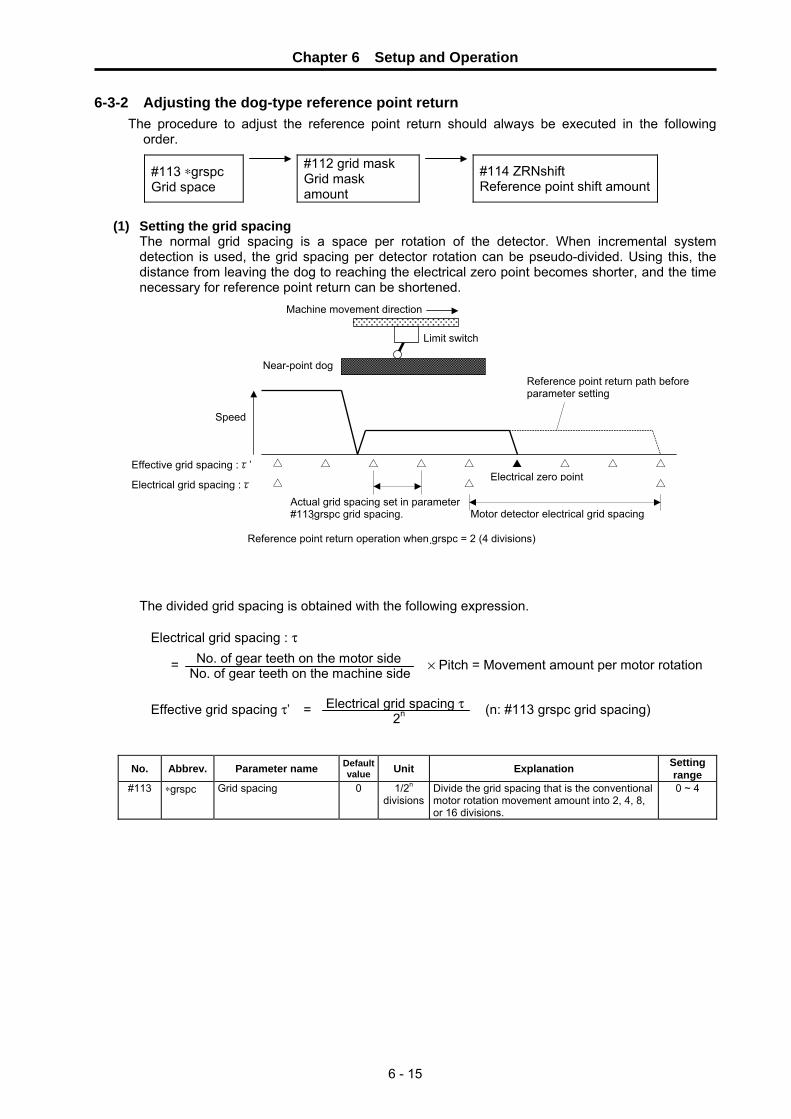
Chapter 6 Setup and Operation
6 - 15
6-3-2 Adjusting the dog-type reference point return The procedure to adjust the reference point return should always be executed in the following
order.
#113 ∗grspc Grid space
#112 grid mask Grid mask amount
#114 ZRNshift Reference point shift amount
(1) Setting the grid spacing
The normal grid spacing is a space per rotation of the detector. When incremental system detection is used, the grid spacing per detector rotation can be pseudo-divided. Using this, the distance from leaving the dog to reaching the electrical zero point becomes shorter, and the time necessary for reference point return can be shortened.
The divided grid spacing is obtained with the following expression.
Electrical grid spacing : τ
= No. of gear teeth on the motor sideNo. of gear teeth on the machine side × Pitch = Movement amount per motor rotation
Effective grid spacing τ’ = Electrical grid spacing τ 2n (n: #113 grspc grid spacing)
No. Abbrev. Parameter name Default value Unit Explanation Setting
range #113 ∗grspc Grid spacing 0 1/2n
divisionsDivide the grid spacing that is the conventional motor rotation movement amount into 2, 4, 8, or 16 divisions.
0 ~ 4
Motor detector electrical grid spacing
Effective grid spacing :τ’ Electrical zero point
△ △ △ △ △ ▲ △ △ △
△ △ △Electrical grid spacing :τ Actual grid spacing set in parameter #113 grspc grid spacing.
Machine movement direction
Limit switch
Near-point dog
Speed
Reference point return path before parameter setting
Reference point return operation when grspc = 2 (4 divisions)

Chapter 6 Setup and Operation
6 - 16
(2) Setting the grid mask After leaving the dog, the first grid point becomes the reference point. However, if the position where the dog is left and the grid point are close, the second grid encountered may accidentally become the reference point. This is due to variation in the time the limit switch contact takes to turn OFF. Ideally, the position where the dog is left should be in the center of the grid spacing. The dog installation can be changed and this can be adjusted. However, by pseudo-extending the dog length with the parameter "#112 grid mask Grid mask amount", the dog OFF point can be simply and ideally adjusted.
No. Abbrev. Parameter name Default value Unit Explanation Setting
range #112 grid mask Grid mask amount 0
1/1000° (μm)
Set the amount that the dog is artificially extended. Set 1/2 the grid spacing as a standard.
0 ~ 65536
(3) Setting the reference point shift amount To set the reference point (machine zero point) to a random position, outside the equally spaced grid points, set the shift amount in the parameter "#114 ZRNshift Reference point shift amount".
No. Abbrev. Parameter name Default value Unit Explanation Setting
range #114 ZRNshift Reference point shift
amount 0
1/1000° (μm)
Set the shift amount in a dog-type reference point return from the electric zero point determined on the grid to the reference point.
0 ~ 65536
(4) Adjusting the reference point return speed When the near-point dog signal is turned OFF in dog-type reference point returns, the machine stops temporarily, the distance to the electric zero point is obtained, and the movement at creep speed begins. If the near-point dog is short at this time, the machine is not able to stop within the dog, and the changeover to the creep speed occurs away from the dog. Because of this, the initial grid may not be read. In this case, lower the reference point return speed, and adjust so the changeover to creep speed occurs within the dog.
No. Abbrev. Parameter name Default
value Unit Explanation Setting range
#110 ZRNspeed Reference point return speed
1000
°/min (mm/min)
Set the clamp value of the feedrate during a reference point return.
1~100000
Machine movement direction
Grid → △ △ ▲ △▲
The dog length is artificially extended by the grid mask.
△ △ △ △ ▲
Speed
Reference point is unstable
Limit switch
Near-point dog
Machine movement direction
Limit switch
Near-point dog
Electrical zero point
#114 ZRNshift Reference point shift amount
→ △△ ▲
Machine movement direction
Grid
Speed
Reference point (machine zero point)
Limit switch
Near-point dog
Electrical zero point
→ △ ▲ ▲
Machine movement direction
Grid
Speed
Limit switch
Near-point dog
Grid cannot be detected

Chapter 6 Setup and Operation
6 - 17
6-3-3 Memory-type reference point return This function registers the reference point in the controller of the incremental system, and executes rapid reference point return. Only the first reference point return after the power is turned ON is with the dog-type method. All subsequent returns after the first time are carried out with the memory method. Set parameter "#101 Cont1.bit1" to "1" to have the machine carry out dog-type reference point returns subsequent to the first return also.
#101 Cont1.bit1 Explanation
0
A dog-type reference point index operation is carried out before the reference point is determined (first time), but after the reference point is determined positioning to the reference point is carried out at high speed (without being clamped at the ZRNspeed).
1 For reference point return operations, reference point index operations are carried out each time with the dog-type method regardless of the reference point determination.
6-3-4 Mode with no reference point
In this mode the position when the machine is turned ON in the incremental system becomes the reference point. It can be changed by the parameter "#101 Cont1.bit D.
#101 Cont1.bit D Explanation
0 A dog-type reference point return operation is required to determine the reference point.
1 The position where the power was turned ON becomes the reference point. A dog-type reference point return operation is not required.
No. Abbrev. Parameter name Default
value Unit Explanation Setting range
This is a HEX setting parameter. Set bits without a description to their default values.
bit F E D C B A 9 8 7 6 5 4 3 2 1 0Default value 0 0 0 0 0 0 1 0 0 0 0 0 0 0 0 0 bit Meaning when "0" is set. Meaning when "1" is set.
1 High-speed zero point return after zero point establishment
Dog-type method for each zero point return operation
8 Reference point return direction (+)
Reference point return direction (−)
9 Rotation direction determined by DIR
Rotation direction in the shortcut direction
A Machine reference position becomes the reference point
Electrical zero point becomes the reference position
D Coordinate zero point creation valid
Zero point established at power supply ON position
E Rotation direction in DIR or in the shortcut direction
Rotation direction in the random position command sign direction
F Stopper direction is positioning direction
Stopper direction is for the stopper amount in the sign direction
#101 ∗Cont1 Control parameter 1
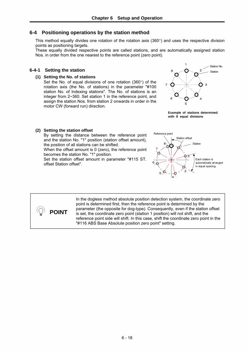
Chapter 6 Setup and Operation
6 - 18
6-4 Positioning operations by the station method This method equally divides one rotation of the rotation axis (360°) and uses the respective division points as positioning targets. These equally divided respective points are called stations, and are automatically assigned station Nos. in order from the one nearest to the reference point (zero point).
6-4-1 Setting the station
(1) Setting the No. of stations Set the No. of equal divisions of one rotation (360°) of the rotation axis (the No. of stations) in the parameter "#100 station No. of Indexing stations". The No. of stations is an integer from 2~360. Set station 1 in the reference point, and assign the station Nos. from station 2 onwards in order in the motor CW (forward run) direction.
(2) Setting the station offset By setting the distance between the reference point and the station No. "1" position (station offset amount), the position of all stations can be shifted. When the offset amount is 0 (zero), the reference point becomes the station No. "1" position. Set the station offset amount in parameter "#115 ST. offset Station offset".
POINT
In the dogless method absolute position detection system, the coordinate zero point is determined first, then the reference point is determined by the parameter (the opposite for dog-type). Consequently, even if the station offset is set, the coordinate zero point (station 1 position) will not shift, and the reference point side will shift. In this case, shift the coordinate zero point in the "#116 ABS Base Absolute position zero point" setting.
1
2
3
4
5
6
7
8
Station No.
Station
Example of stations determinedwith 8 equal divisions
1
2
3
45
6
7
8
Station offset
Each station isautomatically arrangedin equal spacing.
Reference point
Station

Chapter 6 Setup and Operation
6 - 19
(3) Setting the station No. automatic assignment direction The station No. assignment direction can be selected with parameters.
#102 Cont1.bit3 Explanation
0 Assign the station Nos. in the motor rotation CW direction. When forward run is selected in rotation direction (DIR), the motor rotates in the CW direction (in the direction of increasing station Nos.).
1 Assign the station Nos. in the motor rotation CCW direction. When forward run is selected in rotation direction (DIR), the motor rotates in the CCW direction (in the direction of increasing station Nos.).
No. Abbrev. Parameter name Default
value Unit Explanation Setting range
#100 ∗station Index No. of stations 2 Set the No. of stations. In linear axes, the No. of divisions = No. of stations − 1.
2 ~ 360
This is a HEX setting parameter. Set bits without a description to their default values.
bit F E D C B A 9 8 7 6 5 4 3 2 1 0Default value 0 0 0 0 0 0 0 0 1 0 0 0 0 1 1 0 bit Meaning when "0" is set. Meaning when "1" is set.
1 Error not corrected at servo OFF Error corrected at servo OFF
2 Linear axis Rotation axis
3 Station assignment direction CW
Station assignment direction CCW
4 Uniform index Non-uniform index
5 DO channel standard assignment DO channel reverse assignment
6 2-wire detector communication 4-wire detector communication 7 Incremental detection Absolute position detection
#102 ∗Cont2 Control parameter 2
#115 ST.offset Station offset 0.000 ° (mm) Set the distance (offset) from the reference
point to station 1. −99999.999~ 9999.999

Chapter 6 Setup and Operation
6 - 20
6-4-2 Setting linear axis stations (1) For uniform assignment
In linear axes, determine the spacing between stations from the stroke length and No. of stations, and assign stations at uniform spacing. Station 1 is assigned to the coordinate zero point (coordinate position = 0). Set the station Nos. in order following the assignment direction parameter (#102.bit3). Thus, the final station is set at the coordinates separated from station 1 by only the linear axis stroke length (#104 tleng).
Linear axis when the No. of stations = 8 (No. of divisions is 7)
No. Abbrev. Parameter name Default
value Unit Explanation Setting range
#100 ∗station Index No. of stations 2 Set the No. of stations. In linear axes, the No. of divisions = No. of stations − 1.
2 ~ 360
This is a HEX setting parameter. Set bits without a description to their default values.
bit F E D C B A 9 8 7 6 5 4 3 2 1 0Default value 0 0 0 0 0 0 0 0 1 0 0 0 0 1 1 0 bit Meaning when "0" is set. Meaning when "1" is set.
1 Error not corrected at servo OFF Error corrected at servo OFF
2 Linear axis Rotation axis
3 Station assignment direction CW
Station assignment direction CCW
4 Uniform index Non-uniform index
5 DO channel standard assignment DO channel reverse assignment
6 2-wire detector communication 4-wire detector communication 7 Incremental detection Absolute position detection
#102 ∗Cont2 Control parameter 2
#104 ∗tleng Linear axis stroke length 100.00 mm Set the movement stroke length for linear
axes. This is meaningless when setting non-uniform assignments or commanding random positions.
0.001 ~ 9999.999
#115 ST.offset Station offset 0.000 ° (mm)
Set the distance (offset) from the reference point to station 1.
−99999.999 ~99999.999
POINT
Set the distance from the reference point (#116 ABS base absolute position zero point) after determining the reference point in the absolute position system, and determine the linear coordinate zero point (station 1).
The reference point is not especially used in the coordinate zero point creation process. However, by setting "0" (default value) in the #115 ST.offset station offset, it is generally used as "reference point = coordinate zero point." In this case, the reference point return operation becomes a positioning operation to the coordinate zero point.
CAUTION When the station offset (#115 ST.offset) is set, the coordinates of all stations move only the setting value.
Coordinate zero point Reference point
Station offset
#115 ST.offset
#104 tleng linear axis stroke length
#102 Cont2.bit3 station assignment direction
2 1 3 4 5 6 7 8 Station No.

Chapter 6 Setup and Operation
6 - 21
(2) For non-uniform assignment When the required positioning coordinates are not uniformly spaced, set the station positions at the respective coordinate positions. Station 1 is assigned to the coordinate zero point (coordinate position = 0). Up to 9 stations including station 1 can be assigned to random coordinates. This can also be used for rotation axes. Set parameter "#102 cont2 control parameter 2 bit.4" to "1", select non-uniform assignment, and set the coordinate values of stations 2 to 9 in "#190 stops 2 to #197 stops9".
Up to 9 stations can be set (station 1 is fixed at the coordinate zero point)
No. Abbrev. Parameter name Default value Unit Explanation Setting
range #190 stpos2 Station 2 coordinate
value #191 stpos3 Station 3 coordinate
value #192 stpos4 Station 4 coordinate
value #193 stpos5 Station 5 coordinate
value #194 stpos6 Station 6 coordinate
value #195 stpos7 Station 7 coordinate
value #196 stpos8 Station 8 coordinate
value #197 stpos9 Station 9 coordinate
value
0.000 ° (mm)
Set the coordinate value of each station when non-uniform assignment is selected. The station 1 coordinate value is fixed at 0.000 (machine coordinate zero point).
−99999.999 ~99999.999
POINT
1. Setting is also possible for rotation axes. 2. The station Nos. do not have to be arrayed in increasing order. 3. Commands are designated with the station Nos. (1 to 9), in the same
manner as normal indexing. 4. Station No. 0 designated special feed commands cannot be used. 5. If the required positioning coordinates exceed 9 locations, carry out
positioning with a random point feed command.
CAUTION
1. The coordinates of all stations move only the setting value when the station offset (#115 ST.offset) is set, even if setting non-uniform assignments.
2. If the coordinate setting of two or more stations duplicates, the smallest station number that falls under the duplication is output when axes stop around the station besides the automatic operation. In addition, if the current position is at the same distance from plural stations, the smallest station number that falls under the case is output as the same manner. When coordinates of one station approached the other one very much, the nearer station number is output.
#115 ST.offset
1 2
stpos2
3
stpos3
4
stpos4
5
stpos5
6
stpos6
9
stpos9
8
stpos8
7
stpos7
Coordinate zero point Reference point
Station offset
Station No.

Chapter 6 Setup and Operation
6 - 22
6-4-3 Automatic operation In this operation mode the automatic positioning is carried out to the designated station No. When the station No. is designated and the operation start is input, positioning is carried out to the station of the designated No. When the positioning is completed, each of the following signals are output: Automatic set position reached (JSTA), Set position reached (JST), Near set position (NEAR), and the station No. (STO1 to STO256). Shortcut rotation direction or direction rotation can be selected using the parameters.
(1) Setting the automatic operation mode
Set the following signals before inputting an operation start signal. The settings are validated when the operation start signal (ST) is input.
Abbrev. Signal name Explanation
AUT Automatic operation mode selection
Select the automatic operation mode. "M01 0101 No operation mode" will occur if the selected mode duplicates another operation mode. Always leave this signal ON during automatic operation.
DIR Rotation direction Set the station No. assignment direction to "standard". This is meaningless for shortcut rotation setting.
PR1, PR2 Operation parameter selection 1 and 2
The operation is carried out with the automatic operation speed (Aspeed) and acceleration/deceleration time constant (timeN.1, timeN.2) of the selected operation group.
ST1 ~ ST256 Station selection 1 to 256
Set the station No. to which the positioning is carried out. Setting to "0" will result in a special command.
(2) Starting the automatic operation mode
Start the operation by turning ON the operation start (ST) signal. The operation start is held until positioning is completed.
POINT
1. A settling time is required from when the movement commands become zero (SMZ=1) until the positioning is completed. The settling time will lengthen if a set position output width narrower than required is set, so set the required positioning accuracy in the set position output width.
2. If the start signal is turned OFF during positioning, the positioning will be carried out to the nearest station. In this case, an automatic set position reached (JSTA) signal will not be output.
CAUTION
The control axis rotation direction is determined by a combination of the following: Operation mode, input control signal "rotation direction (DIR)", parameter "#101 cont1 control parameter 1.bit9 rotation direction shortcut", and "#102 cont2 control parameter 2. bit3 station assignment direction CCW". At operation start, pay careful attention to the motor rotation direction. When operating the servomotor for the first time, the motor should be operated as a single unit to confirm the operation, etc.
Automatic operation mode selection (AUT) Rotation direction (DIR) Operation parameter selection (PR1, 2) Station selection (ST1 to 256)
Operation start (ST) Movement command (speed command) Automatic operation mode selection (AUTO) Station position (STO1 to 256) Smoothing position (SMZ)
Near set position (NEAR)
Set position reached (JST) Automatic set position reached (JSTA)
Axis selection output (AX1)
Axis moving (+) (MVP)
Axis moving (−) (MVN)
"0" is output. "0" is output.
Value is validated at ST ON.
Settling time
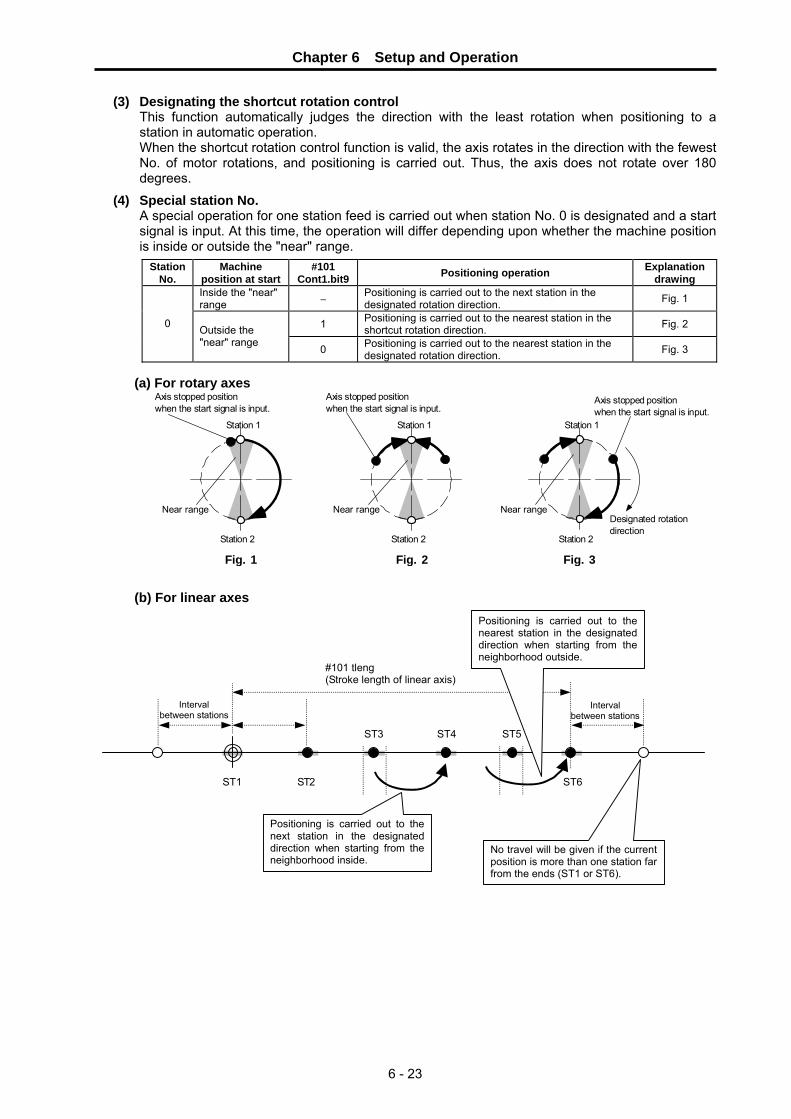
Chapter 6 Setup and Operation
6 - 23
(3) Designating the shortcut rotation control This function automatically judges the direction with the least rotation when positioning to a station in automatic operation. When the shortcut rotation control function is valid, the axis rotates in the direction with the fewest No. of motor rotations, and positioning is carried out. Thus, the axis does not rotate over 180 degrees.
(4) Special station No. A special operation for one station feed is carried out when station No. 0 is designated and a start signal is input. At this time, the operation will differ depending upon whether the machine position is inside or outside the "near" range.
Station No.
Machine position at start
#101 Cont1.bit9 Positioning operation Explanation
drawing Inside the "near" range − Positioning is carried out to the next station in the
designated rotation direction. Fig. 1
1 Positioning is carried out to the nearest station in the shortcut rotation direction. Fig. 2 0 Outside the
"near" range 0 Positioning is carried out to the nearest station in the
designated rotation direction. Fig. 3
(a) For rotary axes
Axis stopped positionwhen the start signal is input.
Station 1
Near rangeDesignated rotationdirection
Fig. 1
Axis stopped positionwhen the start signal is input.
Station 1
Near range
Fig. 2
Axis stopped positionwhen the start signal is input.
Station 1
Near range
Fig. 3
Station 2 Station 2 Station 2
(b) For linear axes
ST1 ST2
ST3 ST4 ST5
ST6
#101 tleng (Stroke length of linear axis)
Positioning is carried out to thenext station in the designateddirection when starting from theneighborhood inside.
Positioning is carried out to the nearest station in the designated direction when starting from the neighborhood outside.
No travel will be given if the current position is more than one station far from the ends (ST1 or ST6).
Interval between stations
Interval between stations

Chapter 6 Setup and Operation
6 - 24
(5) Random position command operation
In this mode the positioning coordinates are directly commanded from the PLC in 0.001° (mm) units, and positioning is carried out to a random position other than a station. In addition to the settings during normal automatic operation, set the following signals before inputting an operation start signal. For rotation axes, when #101 Cont1.bitE = 1 is set to "1", the axis rotates in the sign direction of the random position command, and positioning is carried out to coordinates having a plus value separate from the rotation sign. If a command exceeding 360° is issued, the integer expressing "command value/360" becomes the No. of rotations, and the fraction becomes the positioning coordinates.
Abbrev. Signal name Explanation
STS Random point feed command valid The positioning position input from the PLC is validated. Always turn ON during the random position command operation.
No. Abbrev. Parameter name Default value Unit Explanation Setting
range This is a HEX setting parameter. Set bits without a description to their default values.
bit F E D C B A 9 8 7 6 5 4 3 2 1 0Default value 0 0 0 0 0 0 1 0 0 0 0 0 0 0 0 0 bit Meaning when "0" is set. Meaning when "1" is set.
1 High-speed zero point return after zero point establishment
Dog-type method for each zero point return operation
8 Reference point return direction (+) Reference point return direction (−)
9 Rotation direction determined by DIR
Rotation direction in the shortcut direction
A Machine reference position becomes the reference point
Electrical zero point becomes the reference position
D Coordinate zero point creation valid Zero point established at power supply ON position
E Rotation direction in DIR or in the shortcut direction
Rotation direction in the random position command sign direction
F Stopper direction is positioning direction
Stopper direction is for the stopper amount in the sign direction
#101 ∗Cont1 Control parameter 1
POINT
1. When operation start signal (ST) was turned OFF in the middle of positioning by an arbitrary point feed command, the axes decelerate to stop immediately.
2. In the case of an arbitrary point feed command, “automatic arrival at rated position (JSTA)” signal, “arrival at rated position (JST)” signal, and “rated position around (NEAR)” signal are output.
3. When “arbitrary point feed command effective” signal (STS) was turned OFF in the middle of positioning by an arbitrary point feed command, the positioning will be continued. However, as for the output signals (JSTA,JST,NEAR) that are related to the rated position, they changes to be output by a normal station method. Therefore, keep the “arbitrary point feed command effective” signal (STS) an “ON” state till positioning completion.

Chapter 6 Setup and Operation
6 - 25
6-4-4 Manual operation In this operation mode, for the rotary axis, the axis is moved only while the operation start signal is being input. Positioning is carried out to the nearest station after the operation start signal turns OFF. When the positioning is completed, the following signals are output: Set position reached (JST), Near set position (NEAR), and the station No. (STO1 to STO256).
(1) Setting the manual operation mode
Set the following signals before inputting an operation start signal. The settings are validated when the operation start signal (ST) is input.
Abbrev. Signal name Explanation
MAN Manual operation mode selection
Select the manual operation mode. "M01 0101 No operation mode" will occur if the selected mode duplicates another operation mode. Always leave this signal ON during manual operation.
DIR Rotation direction Set the station No. assignment direction to "standard".
PR1, PR2 Operation parameter selection 1 and 2
The operation is carried out with the manual operation speed (Mspeed) and acceleration/deceleration time constant (timeN.1, timeN.2) of the selected operation group.
(2) Starting the manual operation mode
Start the operation by turning ON the operation start (ST) signal. The operation start is held until positioning is completed.
POINT In the manual operation mode, the automatic set position reached (JSTA) signal does not turn ON, even when positioning is carried out to a station.
CAUTION This function is effective for only the rotary axis. In the case of a linear axis, use a JOG function.
Manual operation mode selection (MAN) Rotation direction (DIR) Operation parameter selection (PR1, 2) Station selection (ST1 to 256)
Operation start (ST) Movement command (speed command) Manual operation mode selection (MANO) Station position (STO1 to 256) Smoothing position (SMZ)
Near set position (NEAR)
Set position reached (JST) Automatic set position reached (JSTA)
Axis selection output (AX1)
Axis moving (+) (MVP)
Axis moving (−) (MVN)
"0" is output. "0" is output.
Value is validated at ST ON.
Positioned to nearest station after ST OFF also.

Chapter 6 Setup and Operation
6 - 26
6-5 Stopper positioning operation In this operation mode, positioning is carried out with the axis presses against a stopper, etc. This operation mode is an expansion function of random position designation automatic operation. Besides normal random point positioning, stopper operation and torque control are automatically carried out.
POINT The station method is not used in stopper positioning operations. Commands are carried out with random position command operations.
6-5-1 Operation sequence
(1) Setting the stopper positioning operation mode Set the following signals before the operation start signal. When the stopper positioning command valid (PUS) signal is turned ON, and random position positioning is carried out to the stopper starting coordinates, stopper positioning is carried out after positioning is completed, following the value set in the parameters.
Abbrev. Signal name Explanation
AUT Automatic operation mode selection
Select the automatic operation mode. "M01 0101 No operation mode" will occur if the selected mode duplicates another operation mode.
PUS Stopper positioning command valid
Select the stopper positioning mode. When this signal is turned ON and the positioning is started, execute the stopper positioning sequence.
POINT 1. The rotation direction (DIR) signal setting is meaningless. 2. The operation parameter group to be used is automatically selected in each
operation.

Chapter 6 Setup and Operation
6 - 27
(2) Explanation of operation in the stopper positioning operation mode The stopper positioning operation is as follows.
Operation Explanation Related parameter ① Stopper starting
coordinate positioning When the operation start (ST) signal is input in the stopper positioning mode, positioning is carried out to the command coordinates (stopper starting coordinates). This operation is carried out with operation parameter group 1. A positioning operation using shortcut control can be carried out by parameter setting. During positioning, the In positioning operation (PMV) signal is output. The positioning completed (PFN) signal turns ON when the positioning is completed.
< Operation group 1 >
② Stopper standby After the positioning operation deceleration stops, the operation will stop for the time set in the parameter (#221 stopper standby time). If the parameter value is 0, the operation will immediately move to the next stopper operation after deceleration stopping.
< Operation group 2 >#221 pusht1
③ Stopper After stopper standby, the stopper operation is executed. The stopper amount is set in the parameters (#220 stopper amount). At this time, the positioning operation is carried out using the speed, time constant, and torque limit value of operation parameter 2. During stopper operation, an in stopper (PSI) signal is output.
< Operation group 2 >#220 push
④ Pressing torque changeover
After the stopper operation finishes and the parameter (#222 stopper torque release time) time has lapsed, the torque changes over to the pressing torque. The pressing torque is the torque limit value of operation parameter group 3.
< Operation group 3 >#222 pusht2
⑤ Set position related signal output
The automatic set position reached (JSTA) signal and the position reached signal are turned ON after the axis stops within the range set by parameter (#172 just3), the stopper operation is completed and the time set in the parameter (#223 set position signal output delay time) has lapsed. The near set position (NEAR) signal is turned ON after the axis stops within the range set by parameter (#173 near), the stopper operation is completed and the time set in the parameter (#223 set position signal output delay time) has lapsed. This status is held until the rising edge of the next operation start signal.
< Operation group 3 >#172 just3 #173 near3 #223 pusht3
Automatic operation mode selection (AUT) Stopper positioning command valid (PUSR) Operation start (ST) Movement command (speed command) Torque limit value In positioning operation (PMV) Positioning completed (PFN) In stopper (PSI) Set position related signals (JSTA, JST, NEAR)
Operation parameter group 1
#221 stopper standby time
#220 stopper amount
Stopper
Machine stop
#223 set position signal output delay time
#222 Stopper torque release time
Stopper torque limited Pressing torque limitedPositioning torque limited
Stopper positioning completed
0
Operation parameter group 2 Operation parameter group 3

Chapter 6 Setup and Operation
6 - 28
POINT
1. Set point related signals (automatic set position, set position, and near set position) are output for pressing positions. At that time, operation parameter group 3 becomes valid.
2. After the pressing is completed, and the pressing torque limit has been switched, this torque limit value (TL3) will be held until the next operation start (ST) startup, or until the pressing positioning command valid (PUSR) is turned OFF.
3. The station position (STO1 to 256) normally outputs as 0. 4. The manual mode cannot be selected in the pressing positioning command
mode. When the operation start is turned ON with the manual mode, an operation error "M01 0164" will result. It is possible to select other operation modes.
5. If the start signal is turned OFF before a series of operations finishes, a deceleration stop will occur at that position. At that time, the automatic set position signal will not turn ON. If this happens during positioning, the positioning complete signal also will not turn ON.
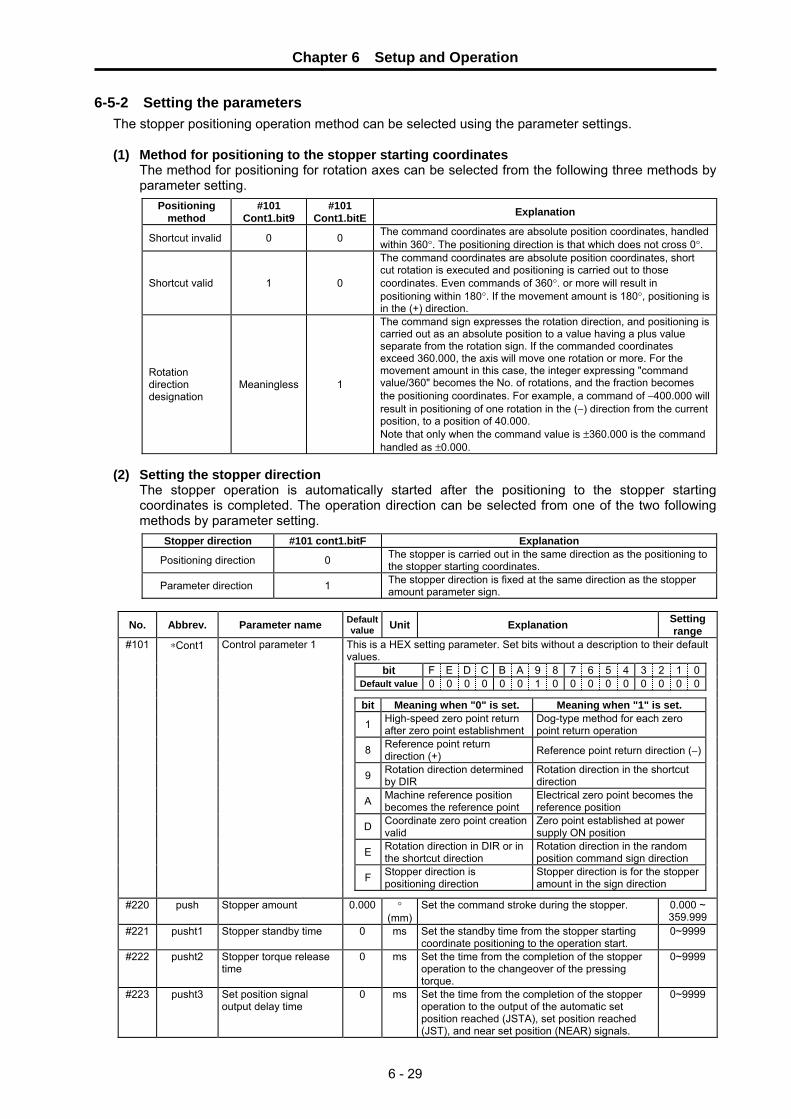
Chapter 6 Setup and Operation
6 - 29
6-5-2 Setting the parameters The stopper positioning operation method can be selected using the parameter settings.
(1) Method for positioning to the stopper starting coordinates
The method for positioning for rotation axes can be selected from the following three methods by parameter setting.
Positioning method
#101 Cont1.bit9
#101 Cont1.bitE Explanation
Shortcut invalid 0 0 The command coordinates are absolute position coordinates, handled within 360°. The positioning direction is that which does not cross 0°.
Shortcut valid 1 0
The command coordinates are absolute position coordinates, short cut rotation is executed and positioning is carried out to those coordinates. Even commands of 360°. or more will result in positioning within 180°. If the movement amount is 180°, positioning is in the (+) direction.
Rotation direction designation
Meaningless 1
The command sign expresses the rotation direction, and positioning is carried out as an absolute position to a value having a plus value separate from the rotation sign. If the commanded coordinates exceed 360.000, the axis will move one rotation or more. For the movement amount in this case, the integer expressing "command value/360" becomes the No. of rotations, and the fraction becomes the positioning coordinates. For example, a command of −400.000 will result in positioning of one rotation in the (−) direction from the current position, to a position of 40.000. Note that only when the command value is ±360.000 is the command handled as ±0.000.
(2) Setting the stopper direction
The stopper operation is automatically started after the positioning to the stopper starting coordinates is completed. The operation direction can be selected from one of the two following methods by parameter setting.
Stopper direction #101 cont1.bitF Explanation
Positioning direction 0 The stopper is carried out in the same direction as the positioning to the stopper starting coordinates.
Parameter direction 1 The stopper direction is fixed at the same direction as the stopper amount parameter sign.
No. Abbrev. Parameter name Default value Unit Explanation Setting
range This is a HEX setting parameter. Set bits without a description to their default values.
bit F E D C B A 9 8 7 6 5 4 3 2 1 0Default value 0 0 0 0 0 0 1 0 0 0 0 0 0 0 0 0 bit Meaning when "0" is set. Meaning when "1" is set.
1 High-speed zero point return after zero point establishment
Dog-type method for each zero point return operation
8 Reference point return direction (+) Reference point return direction (−)
9 Rotation direction determined by DIR
Rotation direction in the shortcut direction
A Machine reference position becomes the reference point
Electrical zero point becomes the reference position
D Coordinate zero point creation valid
Zero point established at power supply ON position
E Rotation direction in DIR or in the shortcut direction
Rotation direction in the random position command sign direction
F Stopper direction is positioning direction
Stopper direction is for the stopper amount in the sign direction
#101 ∗Cont1 Control parameter 1
#220 push Stopper amount 0.000 °
(mm)Set the command stroke during the stopper. 0.000 ~
359.999#221 pusht1 Stopper standby time 0 ms Set the standby time from the stopper starting
coordinate positioning to the operation start. 0~9999
#222 pusht2 Stopper torque release time
0 ms Set the time from the completion of the stopper operation to the changeover of the pressing torque.
0~9999
#223 pusht3 Set position signal output delay time
0 ms Set the time from the completion of the stopper operation to the output of the automatic set position reached (JSTA), set position reached (JST), and near set position (NEAR) signals.
0~9999

Chapter 6 Setup and Operation
6 - 30
6-6 Machine compensation and protection functions 6-6-1 Backlash compensation
This function compensates the error (backlash) in the machine system when the movement direction is reversed. When the axis movement direction is reversed, the compensation amount set in the parameter is automatically added. The compensation amount is not added to the machine position coordinates. This function compensates the actual machine position.
No. Abbrev. Parameter name Default
value Unit Explanation Setting range
#130 backlash Backlash compensation amount
0 1/1000°(μm)
Set the backlash compensation amount. 0 ~ 9999
6-6-2 Interlock function
This function interrupts the axis movement with a signal input, and immediately causes the servomotor to deceleration stop. For feed in the plus direction, the axis movement is interrupted and the motor is deceleration stopped when the interlock (+) ( IT+) is turned ON. For feed in the plus direction, the same occurs when the interlock (−) ( IT−) is turned ON (B contact). The movement will start again when the interlock is turned OFF. The speed and acceleration/deceleration time constant at this time follows the setting of the selected operation parameter group.
Backlash
Operation start (ST)
Rotation direction (DIR) Interlock (+) ( IT+)
Interlock (−) (IT−) Axis movement (speed FB)
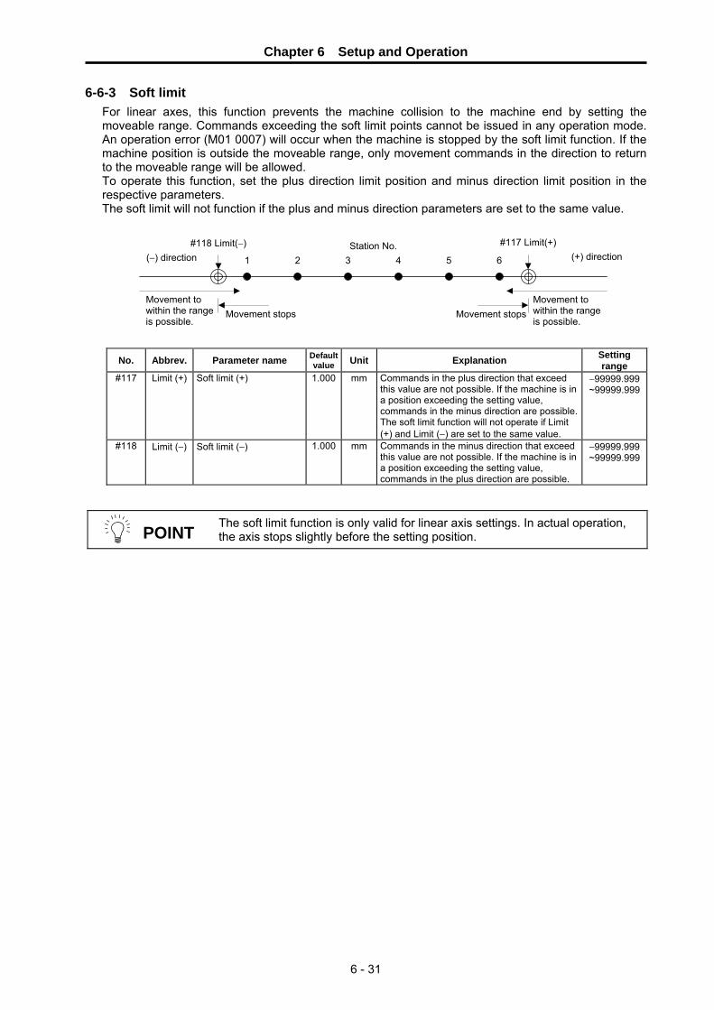
Chapter 6 Setup and Operation
6 - 31
6-6-3 Soft limit For linear axes, this function prevents the machine collision to the machine end by setting the moveable range. Commands exceeding the soft limit points cannot be issued in any operation mode. An operation error (M01 0007) will occur when the machine is stopped by the soft limit function. If the machine position is outside the moveable range, only movement commands in the direction to return to the moveable range will be allowed. To operate this function, set the plus direction limit position and minus direction limit position in the respective parameters. The soft limit will not function if the plus and minus direction parameters are set to the same value.
No. Abbrev. Parameter name Default value Unit Explanation Setting
range #117 Limit (+) Soft limit (+) 1.000 mm Commands in the plus direction that exceed
this value are not possible. If the machine is in a position exceeding the setting value, commands in the minus direction are possible. The soft limit function will not operate if Limit (+) and Limit (−) are set to the same value.
−99999.999 ~99999.999
#118 Limit (−) Soft limit (−) 1.000 mm Commands in the minus direction that exceed this value are not possible. If the machine is in a position exceeding the setting value, commands in the plus direction are possible.
−99999.999 ~99999.999
POINT The soft limit function is only valid for linear axis settings. In actual operation, the axis stops slightly before the setting position.
Movement stops
#118 Limit(−)
21 3 4 5 6Station No. #117 Limit(+)
Movement stopsMovement to within the range is possible.
Movement to within the range is possible.
(+) direction(−) direction

Chapter 6 Setup and Operation
6 - 32
6-6-4 Servo OFF This function releases the servo lock. When locking the machine with an external force, such as a mechanical clamp, the servo control is turned OFF, and torque is not output for the deflection that occurs due to the external force. When the servo OFF state is entered, servo READY (RDY) turns OFF. The motor brake braking control (MBR) also turns OFF, and the motor brakes are activated. By using the vertical axis drop prevention function, READY OFF can be delayed from the servo OFF command input by the time set with the parameters. With this, dropping of the axis is prevented by a delay in the brake operation. Set the time to delay READY OFF in "#013 MBR Vertical axis drop prevention time". Input the servo OFF while confirming the position, and set the minimum delay time at which the axis does not drop. If the servo is turned OFF during machine movement, the speed command will decelerate to a stop. When the in-position is detected, the servo OFF state will be entered. If the operation is still starting, operation will resume after servo OFF is canceled.
The amount of movement during servo OFF is constantly monitored, so there is no coordinate deviation. The handling for this movement amount can be selected from the following two methods by parameter setting.
During servo OFF #102 Cont2.bit1 Explanation
Error not corrected 0
The movement amount during servo OFF becomes the droop. When the servo is turned ON again, the machine will return to the position where the servo was turned OFF. An alarm will occur if the droop that occurs during servo OFF exceeds the excessive error detection width.
Error corrected 1 Even if the machine moves during servo OFF, the machine position (command position) is updated without this amount becoming the droop. Thus, at the next servo ON the machine will stop at the position to which it moved.
No. Abbrev. Parameter name Defaul
t value Unit Explanation Setting range
#006 INP In-position detection width
100 1/1000°(μm)
The in-position is detected when the position droop becomes equal to or less than this setting value.
1 ~ 32767
#013 MBR Vertical axis drop prevention time
0 ms Input the time to delay servo OFF when the servo OFF command is input. Increment in 100ms units, and set the min. value at which the axis does not drop.
0 ~ 1000
This is a HEX setting parameter. Set bits without a description to their default values.
bit F E D C B A 9 8 7 6 5 4 3 2 1 0Default value 0 0 0 0 0 0 0 0 1 0 0 0 0 1 1 0 bit Meaning when "0" is set. Meaning when "1" is set.
1 Error not corrected at servo OFF Error corrected at servo OFF
2 Linear axis Rotation axis
3 Station assignment direction CW
Station assignment direction CCW
4 Uniform index Non-uniform index
5 DO channel standard assignment DO channel reverse assignment
6 2-wire detector communication 4-wire detector communication 7 Incremental detection Absolute position detection
#102 ∗Cont2 Control parameter 2
CAUTION
Do not set a vertical axis drop prevention time longer than required. Doing so could cause the servo control and brakes to collide, the overload alarm to occur and the drive unit to be damaged. There will be no problem if the overlapping time is within 100ms.
Operation start (ST) Servo OFF (SVF) Movement command (speed command)
In-position (INP) Motor brake control output (MBR) (CN3 output) Servo READY (RDY)
Brake release
MBR Vertical axis drop prevention time

Chapter 6 Setup and Operation
6 - 33
6-6-5 READY OFF This is a function to turn OFF the main circuit power to each drive unit. When the drive unit enters a READY OFF state, the servo READY (RDY) and servo READY (SA) signals turn OFF, and the CN3 connector motor brake control output (MBR) and contactor control output (MC) signals turn OFF. When starting the operation again after the READY OFF is canceled, carry out an operation start.
CAUTION
1. Always install an independent contactor in the servo drive unit in which the READY OFF is commanded, and carry out control with that drive unit's contactor control output.
2. For safety, issue the READY OFF command after confirming that the motor has stopped.
6-6-6 Data protect
This function protects the parameters stored in the drive unit main unit. When the data protect ( PRT1) signal is ON (B contact), the downloading of parameters from the personal computer setup software is prohibited. Parameter downloading from the NC screen is not prohibited.
Brakes activation
Contactor OFF (main circuit input shut off)
READY OFF (RDF)
Servo READY (SA)
Servo READY (RDY)
Contactor control output (MC) (CN3 output) Motor brake control output (MBR) (CN3 output)

Chapter 6 Setup and Operation
6 - 34
6-7 Miscellaneous functions 6-7-1 Feedrate override
The effective feedrate is the speed set in the parameters multiplied by the override (%). The override range is from 0 to 100%, which can be commanded in 1% units. This override is valid for all movement except that in the handle mode. The override is invalidated when the override valid (OVR) signal is turned OFF, and the set speed will become the effective feedrate as is. The override command is designated by a 7-bit binary (OV1 to OV64). The override is handled as 100% if the command exceeds 100%. If a 0% override is commanded, the axis will deceleration stop, and an operation error "M01 0103 feedrate zero" will occur.
6-7-2 Position switches
There are eight types of position switches (PSW1 to PSW8) that indicate that the machine is in the designated region. The region where each position switch outputs ON is set in the parameters. The machine position to be judged can be selected from the machine position of the command system without consideration of the droop, or from the machine FB position (actual machine position) which includes the droop.
No. Abbrev. Parameter name Default
value Unit Explanation Setting range
This is a HEX setting parameter. Set bits without a description to their default values.
bit F E D C B A 9 8 7 6 5 4 3 2 1 0Default value 0 0 0 0 0 0 0 0 0 0 0 0 0 0 0 0 bit position
switch Meaning when "0" is
set. Meaning when "1" is
set. 0 PSW1 1 PSW2 2 PSW3 3 PSW4 4 PSW5 5 PSW6 6 PSW7 7 PSW8
The position switch output is judged by the machine position of the command system.
The position switch output is judged by the machine FB position (actual position).
#200 PSWcheck PSW detection method
#201 #202
PSW1dog1 PSW1dog2
PSW1 region setting 1PSW1 region setting 2
#203 #204
PSW2dog1 PSW2dog2
PSW2 region setting 1PSW2 region setting 2
#205 #206
PSW3dog1 PSW3dog2
PSW3 region setting 1PSW3 region setting 2
#207 #208
PSW4dog1 PSW4dog2
PSW4 region setting 1PSW4 region setting 2
#209 #210
PSW5dog1 PSW5dog2
PSW5 region setting 1PSW5 region setting 2
#211 #212
PSW6dog1 PSW6dog2
PSW6 region setting 1PSW6 region setting 2
#213 #214
PSW7dog1 PSW7dog2
PSW7 region setting 1PSW7 region setting 2
#215 #216
PSW8dog1 PSW8dog2
PSW8 region setting 1PSW8 region setting 2
0.000 ° (mm) When the machine is in the region between region settings 1 and 2, the position switch of each No. will turn ON. The size of the setting value for region setting 1 and 2 does not affect the position switch operation. For rotation axes, the output turns ON at the region not including 0.000°.
−99999.999 ~99999.999

7 - 1
Chapter 7 Absolute Position Detection System 7-1 Setting of absolute position detection system .................................................................................. 7-2
7-1-1 Starting the system.................................................................................................................... 7-2 7-1-2 Initialization methods ................................................................................................................. 7-2
7-2 Setting up the absolute position detection system ........................................................................... 7-3 7-2-1 Reference point return method.................................................................................................. 7-3 7-2-2 Machine stopper method ........................................................................................................... 7-3 7-2-3 Reference point setting method................................................................................................. 7-4
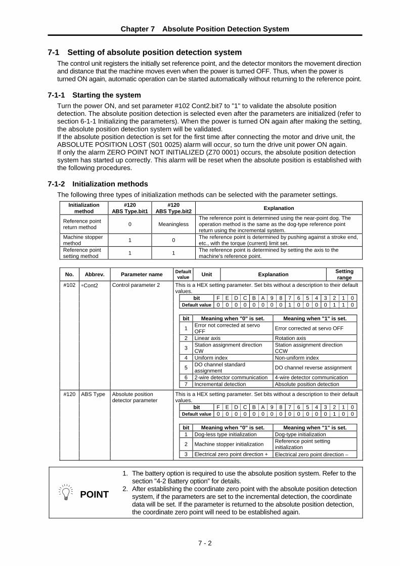
Chapter 7 Absolute Position Detection System
7 - 2
7-1 Setting of absolute position detection system The control unit registers the initially set reference point, and the detector monitors the movement direction and distance that the machine moves even when the power is turned OFF. Thus, when the power is turned ON again, automatic operation can be started automatically without returning to the reference point.
7-1-1 Starting the system
Turn the power ON, and set parameter #102 Cont2.bit7 to "1" to validate the absolute position detection. The absolute position detection is selected even after the parameters are initialized (refer to section 6-1-1 Initializing the parameters). When the power is turned ON again after making the setting, the absolute position detection system will be validated. If the absolute position detection is set for the first time after connecting the motor and drive unit, the ABSOLUTE POSITION LOST (S01 0025) alarm will occur, so turn the drive unit power ON again. If only the alarm ZERO POINT NOT INITIALIZED (Z70 0001) occurs, the absolute position detection system has started up correctly. This alarm will be reset when the absolute position is established with the following procedures.
7-1-2 Initialization methods
The following three types of initialization methods can be selected with the parameter settings. Initialization
method #120
ABS Type.bit1 #120
ABS Type.bit2 Explanation
Reference point return method 0 Meaningless
The reference point is determined using the near-point dog. The operation method is the same as the dog-type reference point return using the incremental system.
Machine stopper method 1 0 The reference point is determined by pushing against a stroke end,
etc., with the torque (current) limit set. Reference point setting method 1 1 The reference point is determined by setting the axis to the
machine's reference point.
No. Abbrev. Parameter name Default value Unit Explanation Setting
range This is a HEX setting parameter. Set bits without a description to their default values.
bit F E D C B A 9 8 7 6 5 4 3 2 1 0Default value 0 0 0 0 0 0 0 0 1 0 0 0 0 1 1 0 bit Meaning when "0" is set. Meaning when "1" is set.
1 Error not corrected at servo OFF Error corrected at servo OFF
2 Linear axis Rotation axis
3 Station assignment direction CW
Station assignment direction CCW
4 Uniform index Non-uniform index
5 DO channel standard assignment DO channel reverse assignment
6 2-wire detector communication 4-wire detector communication 7 Incremental detection Absolute position detection
#102 ∗Cont2 Control parameter 2
This is a HEX setting parameter. Set bits without a description to their default values.
bit F E D C B A 9 8 7 6 5 4 3 2 1 0Default value 0 0 0 0 0 0 0 0 0 0 0 0 0 1 0 0 bit Meaning when "0" is set. Meaning when "1" is set. 1 Dog-less type initialization Dog-type initialization
2 Machine stopper initialization Reference point setting initialization
3 Electrical zero point direction + Electrical zero point direction −
#120 ABS Type Absolute position detector parameter
POINT
1. The battery option is required to use the absolute position system. Refer to the section "4-2 Battery option" for details.
2. After establishing the coordinate zero point with the absolute position detection system, if the parameters are set to the incremental detection, the coordinate data will be set. If the parameter is returned to the absolute position detection, the coordinate zero point will need to be established again.
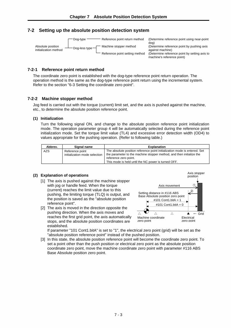
Chapter 7 Absolute Position Detection System
7 - 3
7-2 Setting up the absolute position detection system
Dog-type Reference point return method (Determine reference point using near-point dog)
Absolute position initialization method Dog-less type Machine stopper method (Determine reference point by pushing axis
against machine) Reference point setting method (Determine reference point by setting axis to
machine's reference point) 7-2-1 Reference point return method
The coordinate zero point is established with the dog-type reference point return operation. The operation method is the same as the dog-type reference point return using the incremental system. Refer to the section "6-3 Setting the coordinate zero point".
7-2-2 Machine stopper method
Jog feed is carried out with the torque (current) limit set, and the axis is pushed against the machine, etc., to determine the absolute position reference point.
(1) Initialization
Turn the following signal ON, and change to the absolute position reference point initialization mode. The operation parameter group 4 will be automatically selected during the reference point initialization mode. Set the torque limit value (TL4) and excessive error detection width (OD4) to values appropriate for the pushing operation. (Refer to following table.)
Abbrev. Signal name Explanation
AZS Reference point initialization mode selection
The absolute position reference point initialization mode is entered. Set the parameter to the machine stopper method, and then initialize the reference zero point. This mode is held until the NC power is turned OFF.
(2) Explanation of operations [1] The axis is pushed against the machine stopper
with jog or handle feed. When the torque (current) reaches the limit value due to this pushing, the limiting torque (TLQ) is output, and the position is saved as the "absolute position reference point".
[2] The axis is moved in the direction opposite the pushing direction. When the axis moves and reaches the first grid point, the axis automatically stops, and the absolute position coordinates are established.
If parameter "101 Cont1.bitA" is set to "1", the electrical zero point (grid) will be set as the "absolute position reference point" instead of the pushed position.
[3] In this state, the absolute position reference point will become the coordinate zero point. To set a point other than the push position or electrical zero point as the absolute position coordinate zero point, move the machine coordinate zero point with parameter #116 ABS Base Absolute position zero point.
#101 Cont1.bitA = 1
②Setting distance in #116 ABS Base Absolute position zero point
Axis stopper position
Machine coordinate zero point
①
← Grid
Axis movement
△ △ ▲ Electrical zero point
△
#101 Cont1.bitA = 0

Chapter 7 Absolute Position Detection System
7 - 4
No. Abbrev. Parameter name Default
value Unit Explanation Setting range
This is a HEX setting parameter. Set bits without a description to their default values.
bit F E D C B A 9 8 7 6 5 4 3 2 1 0Default value 0 0 0 0 0 0 1 0 0 0 0 0 0 0 0 0 bit Meaning when "0" is set. Meaning when "1" is set.
1 High-speed zero point return after zero point establishment
Dog-type method for each zero point return operation
8 Reference point return direction (+)
Reference point return direction (−)
9 Rotation direction determined by DIR
Rotation direction in the shortcut direction
A Machine reference position becomes the reference point
Electrical zero point becomes the reference position
D Coordinate zero point creation valid
Zero point established at power supply ON position
E Rotation direction in DIR or in the shortcut direction
Rotation direction in the random position command sign direction
F Stopper direction is positioning direction
Stopper direction is for the stopper amount in the sign direction
#101 ∗Cont1 Control parameter 1
#178 TL4 Operation parameter
group 4 Torque limit value
500 % Set so that the torque limit is not reached with the acceleration to the pushing speed, and so that the value is less than 100%.
1 ~ 500
#179 OD4 Operation parameter group 4 Excessive error detection width
100 ° (mm) Set a value that will not cause an excessive error alarm when pushing.
0 ~ 32767
7-2-3 Reference point setting method
The absolute position reference point is determined by setting the axis to the machine's reference point.
(1) Initialization
Turn the following signal ON, and change to the absolute position reference point initialization mode. Set the direction from the position to carry out reference point setting to the grid to be used as the electrical zero point in parameter #120 ABS Type Absolute position detection parameter bit3.
Abbrev. Signal name Explanation
AZS Reference point initialization mode selection
The absolute position reference point initialization mode is entered. Set the parameter to the reference point setting method, and then initialize the reference zero point. This mode is held until the NC power is turned OFF.
+ direction
Reference point setting position
▲ ▲
Electrical zero point when bit3 = 0
Electrical zero point when ABS Type. bit3 = 1
− direction

Chapter 7 Absolute Position Detection System
7 - 5
(2) Explanation of operation ① Using jog, handle or incremental feed, set
the axis position to the position to become the "absolute position reference point".
② Turn the reference point setting (ZST) signal ON.
③ Using jog, handle or incremental feed, move the axis in the direction of the grid to be the electrical zero point. When the axis reaches the grid to be the electrical zero point, it will automatically stop, and the absolute position coordinates will be established.
If parameter #101 Cont1.bitA is set to "1", the electrical zero point (grid) will be set as the "absolute position reference point" instead of the position where reference point setting was turned ON.
③ In this state, the absolute position reference point will become the coordinate zero point. To set a point other than the position where reference point setting (ZST) was turned ON or the electrical zero point as the absolute position coordinate zero point, move the machine coordinate zero point with parameter #116 ABS Base Absolute position zero point.
No. Abbrev. Parameter name Default value Unit Explanation Setting
range This is a HEX setting parameter. Set bits without a description to their default values.
bit F E D C B A 9 8 7 6 5 4 3 2 1 0Default value 0 0 0 0 0 0 1 0 0 0 0 0 0 0 0 0 bit Meaning when "0" is set. Meaning when "1" is set.
1 High-speed zero point return after zero point establishment
Dog-type method for each zero point return operation
8 Reference point return direction (+)
Reference point return direction (−)
9 Rotation direction determined by DIR
Rotation direction in the shortcut direction
A Machine reference position becomes the reference point
Electrical zero point becomes the reference position
D Coordinate zero point creation valid
Zero point established at power supply ON position
E Rotation direction in DIR or in the shortcut direction
Rotation direction in the random position command sign direction
F Stopper direction is positioning direction
Stopper direction is for the stopper amount in the sign direction
#101 ∗Cont1 Control parameter 1
#116 ABS base Absolute position zero
point 0.000 °
(mm)Set the movement amount when the machine coordinate zero point is to be moved from the reference point during absolute position initialization.
−99999.999 ~99999.999
This is a HEX setting parameter. Set bits without a description to their default values.
bit F E D C B A 9 8 7 6 5 4 3 2 1 0Default value 0 0 0 0 0 0 0 0 0 0 0 0 0 1 0 0 bit Meaning when "0" is set. Meaning when "1" is set. 1 Dog-less type initialization Dog-type initialization
2 Machine stopper initialization Reference point setting initialization
3 Electrical zero point direction + Electrical zero point direction −
#120 ABS Type Absolute position detector parameter
Reference point initialization mode selection
③ Setting distance in #116 ABS Base Absolute position zero point
①
△ △ ▲ △
#101 Cont1.bitA = 1 #101 Cont1.bitA = 0
Grid△
Machine coordinate zero point
Axis movement
Electrical zero point

8 - 1
Chapter 8 Servo Adjustment 8-1 Measuring the adjustment data ........................................................................................................ 8-2
8-1-1 D/A output .................................................................................................................................. 8-2 8-1-2 Graph display............................................................................................................................. 8-2
8-2 Automatic tuning............................................................................................................................... 8-3 8-2-1 Model adaptive control............................................................................................................... 8-3 8-2-2 Automatic tuning specifications ................................................................................................. 8-3 8-2-3 Adjusting the automatic tuning .................................................................................................. 8-4
8-3 Manual adjustment ........................................................................................................................... 8-6 8-3-1 Setting the model inertia ............................................................................................................ 8-6 8-3-2 Adjusting the gain ...................................................................................................................... 8-7
8-4 Characteristics improvements .......................................................................................................... 8-8 8-4-1 Vibration suppression measures ............................................................................................... 8-8 8-4-2 Overshooting measures .......................................................................................................... 8-11
8-5 Adjusting the acceleration/deceleration operation ......................................................................... 8-12 8-5-1 Setting the operation speed..................................................................................................... 8-12 8-5-2 Setting the acceleration/deceleration time constant................................................................ 8-12
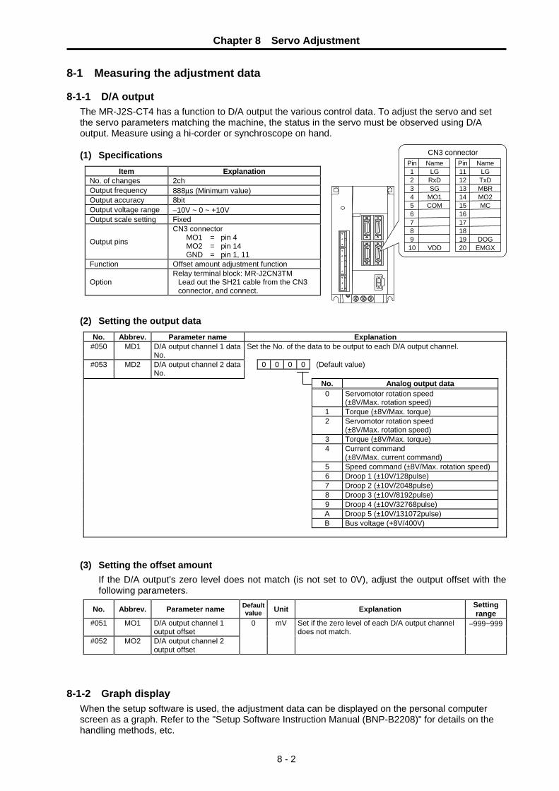
Chapter 8 Servo Adjustment
8 - 2
8-1 Measuring the adjustment data 8-1-1 D/A output
The MR-J2S-CT4 has a function to D/A output the various control data. To adjust the servo and set the servo parameters matching the machine, the status in the servo must be observed using D/A output. Measure using a hi-corder or synchroscope on hand.
(1) Specifications
Item Explanation No. of changes 2ch Output frequency 888μs (Minimum value) Output accuracy 8bit Output voltage range −10V ~ 0 ~ +10V Output scale setting Fixed
Output pins
CN3 connector MO1 = pin 4 MO2 = pin 14 GND = pin 1, 11
Function Offset amount adjustment function
Option Relay terminal block: MR-J2CN3TM
Lead out the SH21 cable from the CN3 connector, and connect.
(2) Setting the output data
No. Abbrev. Parameter name Explanation #050 MD1 D/A output channel 1 data
No. Set the No. of the data to be output to each D/A output channel.
0 0 0 0 (Default value) #053 MD2 D/A output channel 2 data No.
No. Analog output data 0 Servomotor rotation speed
(±8V/Max. rotation speed) 1 Torque (±8V/Max. torque) 2 Servomotor rotation speed
(±8V/Max. rotation speed) 3 Torque (±8V/Max. torque) 4 Current command
(±8V/Max. current command) 5 Speed command (±8V/Max. rotation speed)6 Droop 1 (±10V/128pulse) 7 Droop 2 (±10V/2048pulse) 8 Droop 3 (±10V/8192pulse) 9 Droop 4 (±10V/32768pulse) A Droop 5 (±10V/131072pulse)
B Bus voltage (+8V/400V)
(3) Setting the offset amount If the D/A output's zero level does not match (is not set to 0V), adjust the output offset with the following parameters.
No. Abbrev. Parameter name Default value Unit Explanation Setting
range #051 MO1 D/A output channel 1
output offset #052 MO2 D/A output channel 2
output offset
0 mV Set if the zero level of each D/A output channel does not match.
−999~999
8-1-2 Graph display
When the setup software is used, the adjustment data can be displayed on the personal computer screen as a graph. Refer to the "Setup Software Instruction Manual (BNP-B2208)" for details on the handling methods, etc.
9
Name
MO1
LG RxD
COM
SG
2
VDD
5
1 Pin
6
4 3
10
7 8
CN3 connector
DOG19
Name
MO2
LGTxD
MC
MBR12
EMGX
15
11Pin
16
1413
20
1718
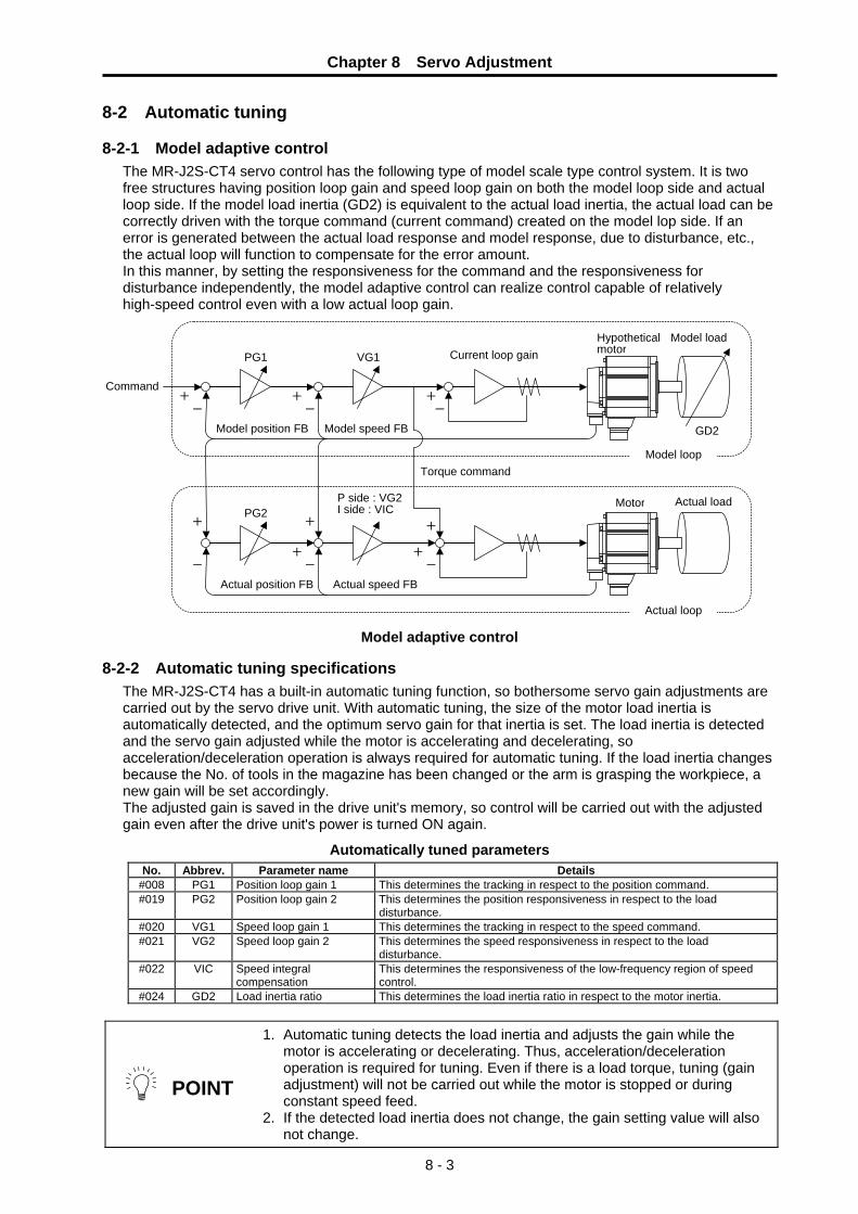
Chapter 8 Servo Adjustment
8 - 3
8-2 Automatic tuning 8-2-1 Model adaptive control
The MR-J2S-CT4 servo control has the following type of model scale type control system. It is two free structures having position loop gain and speed loop gain on both the model loop side and actual loop side. If the model load inertia (GD2) is equivalent to the actual load inertia, the actual load can be correctly driven with the torque command (current command) created on the model lop side. If an error is generated between the actual load response and model response, due to disturbance, etc., the actual loop will function to compensate for the error amount. In this manner, by setting the responsiveness for the command and the responsiveness for disturbance independently, the model adaptive control can realize control capable of relatively high-speed control even with a low actual loop gain.
Model adaptive control 8-2-2 Automatic tuning specifications
The MR-J2S-CT4 has a built-in automatic tuning function, so bothersome servo gain adjustments are carried out by the servo drive unit. With automatic tuning, the size of the motor load inertia is automatically detected, and the optimum servo gain for that inertia is set. The load inertia is detected and the servo gain adjusted while the motor is accelerating and decelerating, so acceleration/deceleration operation is always required for automatic tuning. If the load inertia changes because the No. of tools in the magazine has been changed or the arm is grasping the workpiece, a new gain will be set accordingly. The adjusted gain is saved in the drive unit's memory, so control will be carried out with the adjusted gain even after the drive unit's power is turned ON again.
Automatically tuned parameters No. Abbrev. Parameter name Details
#008 PG1 Position loop gain 1 This determines the tracking in respect to the position command. #019 PG2 Position loop gain 2 This determines the position responsiveness in respect to the load
disturbance. #020 VG1 Speed loop gain 1 This determines the tracking in respect to the speed command. #021 VG2 Speed loop gain 2 This determines the speed responsiveness in respect to the load
disturbance. #022 VIC Speed integral
compensation This determines the responsiveness of the low-frequency region of speed control.
#024 GD2 Load inertia ratio This determines the load inertia ratio in respect to the motor inertia.
POINT
1. Automatic tuning detects the load inertia and adjusts the gain while the motor is accelerating or decelerating. Thus, acceleration/deceleration operation is required for tuning. Even if there is a load torque, tuning (gain adjustment) will not be carried out while the motor is stopped or during constant speed feed.
2. If the detected load inertia does not change, the gain setting value will also not change.
+
+
-+
Model load
PG1
Command
VG1
Actual loadPG2
P side : VG2I side : VIC
GD2
Motor
Hypothetical motor
--
- -
-
+
+
++
+
Model speed FBModel position FB
Actual speed FBActual position FB
Torque command
Current loop gain
Model loop
Actual loop

Chapter 8 Servo Adjustment
8 - 4
8-2-3 Adjusting the automatic tuning Automatic tuning detects the load inertia and automatically sets the servo gain. However, whether to set a generally higher gain (high response) or a lower gain (low response) is adjusted with the parameters. Set a low responsiveness if the load vibrates easily, and set a high responsiveness to shorten the settling time and thereby reduce the positioning time. If no problems occur with the standard setting, there is no need to change the parameters.
Machine operation Ideal machine operation Setting method
Machine resonance occurs The machine gears can be heard
Suppress the machine resonance.Reduce the gear noise.
Decrease the responsiveness setting value.
The machine overshoots when stopping
Reduce the overshooting. Increase the friction characteristic selection. Decrease the responsiveness setting value.
The stop settling time is long (Note) Reduce the stop settling time. Increase the responsiveness setting value.
(Note) Stop settling time: Time for servomotor to stop after command changes to zero.
POINT
1. Automatic tuning sets the various gain to match the load inertia or with the optimum balance. Note that the machine rigidity must be determined and set by the operator.
2. The automatic tuning responsiveness can be increased by using the vibration suppressing function.
No. Abbrev. Parameter name Explanation
Set the adjustment parameters for automatic tuning. Do not set the values having no explanation.
#007 ATU Automatic tuning
Slight vibration suppression control selection This is validated when manual mode 2 is selected for the gain adjustment mode. 0: Invalid 1: Valid
(Initial value)0 1 0 2
Setting value
MR-J2S-CT4 series
MR-J2-CT series
(referance)
Response level
Machine response frequency
1 - Low 15Hz 2 1 20Hz 3 - 25Hz 4 - 30Hz 5 - 35Hz 6 2 45Hz 7 - 55Hz 8 3 70Hz 9 4 85Hz A 5 105Hz B - 130Hz C - 160Hz D - 200Hz E - 240Hz F - High 300Hz
Setting value Gain adjustment mode Remarks
0 Interpolation mode #008 PG1(position loop gain 1) is fixed.
1 Mode 1 Ordinary auto tuning
3* Auto tuning
Mode 2 #024 GD2(load inertia ratio) is fixed. Response level setting is valid.
4* Manual mode 1 Simple manual adjustment
2
Auto tuning invalid Manual
mode 2 Manual adjustment of all gains
Response level setting
Gain adjustment mode selection
(*) Setting value 3 and 4 are the modes added to MR-J2-CT.

Chapter 8 Servo Adjustment
8 - 5
(1) Gain adjustment mode explanation
Gain adjustment
mode Parameter No. 7bit8 to B setting
Estimation of load inertia moment ratio
Automatically set parameters Manually set parameters
Auto tuning mode 1 (initial value)
1 Always estimated GD2(parameter No.24)PG1(parameter No.8) VG1(parameter No.20)PG2(parameter No.19)VG2(parameter No.21)VIC(parameter No.22)
ATU(parameter No.7, bit0 to 3)
Auto tuning mode 2 3 PG1(parameter No.8) VG1(parameter No.20)PG2(parameter No.19)VG2(parameter No.21)VIC(parameter No.22)
GD2(parameter No.24) ATU(parameter No.7, bit0 to 3)
Manual mode 1 4 VG1(parameter No.20)PG2(parameter No.19)
GD2(parameter No.24) PG1(parameter No.8) VG2(parameter No.21) VIC(parameter No.22)
Manual mode 2 2
Fixed to parameter No.24 value
GD2(parameter No.24) PG1(parameter No.8) VG1(parameter No.20) PG2(parameter No.19) VG2(parameter No.21) VIC(parameter No.22)
Interpolation mode 0 Always estimated GD2(parameter No.24)PG2(parameter No.19)VG2(parameter No.21)VIC(parameter No.22)
PG1(parameter No.8) VG1(parameter No.20)

Chapter 8 Servo Adjustment
8 - 6
8-3 Manual adjustment With automatic tuning, the model loop load inertia (GD2) is set to the actual load inertia, and the optimum gain is automatically set according to the size of that inertia. The method of manually setting (inputting the parameters) each gain is explained in this section.
8-3-1 Setting the model inertia
Manual adjustment is carried out when sufficient characteristics cannot be obtained with automatic tuning. This often occurs when the load inertia is not correctly detected. If the load inertia ratio on the MONITOR screen greatly differs from the calculated value, or if it is unstable, manually set only the load inertia ratio. Then, set the gain for that load inertia ratio to the optimum value with automatic tuning.
Machine characteristics Monitor's load inertia ratio (GD2) phenomenon Explanation
The machine friction is large The difference between the value after acceleration and the value after deceleration is large.
The load inertia is detected while the motor is accelerating or decelerating, so if the friction is large, a large inertia will be detected during acceleration, and a small inertia will be detected during deceleration. The average value obtained from the values after acceleration and deceleration is the true load inertia ratio.
Cam drive (The load inertia changes during constant speed operation)
The value is extremely small compared to the calculated value.
The detected load inertia is the load inertia during acceleration/deceleration. Normally, the inertia during the lightest load is detected, so this can be improved by setting the inertia to math the load during actual drive. In this case, the load inertia itself will not change, so improvements can also be made by increasing the automatic tuning responsiveness. (Set a higher gain for the same load inertia.)
Step Operation Explanation
1 Set parameter "#007 ATU" to 0102. Start the automatic tuning with a low response.
2 Set the load inertia ratio in parameter "#024 GD2".
When the load inertia is set, the following parameter will be set to the set load inertia. Do not drive the motor at this time.
#008 PG1 : Position loop gain 1 #019 PG2 : Position loop gain 2 #020 VG1 : Speed loop gain 1 #021 VG2 : Speed loop gain 2 #022 VIC : Speed integral compensation
3 Set parameter "#007 ATU" to 0202. Stop the automatic tuning, and fix the set gain.
4 Confirm the operation, and if vibration, etc., is not occurring, raise the automatic tuning responsiveness, and repeat (Step 1) to (Step 3).
The optimum value is just before the vibration increases.
+
+
-+
PG1 VG1
PG2
GD2
--
- -
-
+
+
++
+
Model load
Command
Actual loadP side : VG2I side : VIC Motor
Hypothetical motor
Model speed FBModel position FB
Actual speed FBActual position FB
Torque command
Current loop gain
Model loop
Actual loop

Chapter 8 Servo Adjustment
8 - 7
8-3-2 Adjusting the gain If the balance of the various gains set with automatic tuning does not match the machine, the gains must be adjusted individually. Adjust with the following procedure. (1) GD2: Load inertia ratio
Set the model load inertia to be used in the model loop. If the model load inertia and actual load inertia match, the model section operation will approach the actual operation. Thus, there is no need to raise the actual loop gain PG2 or VG2 more than necessary. Even when adjusting manually, adjust the following gain using the gain determined in section "8-2-1 Setting the model inertia" as the default value.
GD2 = JL
JM (JL: Load inertia, JM: Motor inertia)
(2) VG2: Speed loop gain 2 The speed lop gain dominates the response dumping. If this gain is extremely low, vibration will occur at the PG2 frequency, and if too high, machine resonance will be induced. To adjust, gradually raise VG2, and set at 70% of the max. value where the machine resonance does not occur. The VG2 unit is the response frequency, but in actual use, it is the response setting including the load inertia. Thus, the actual response frequency (rad/s) will be the value divided by the load inertia rate (1+JL/Jm).
(3) VG2: Position loop gain 2 PG2 determines the position response in respect to disturbance. Normally it is set with the following equation. Adjust PG1 to shorten the settling time.
PG2 = 6 × VG21 + (JL/JM) (rad/s)
(4) VIC: Speed integral compensation If the load torque fluctuation is large or the machine friction is large, uneven rotation or overshooting during position settling will increase. In this case, the position and speed fluctuation can be reduced by reducing VIC. However, if it is too low, vibration will occur. Adjust with the load inertia ratio while referring to the following table.
Load inertia ratio 1 3 5 10 20 30 or moreSpeed integral compensation (ms) 20 30 40 60 100 200
(5) VG1: Speed loop gain 1
(6) PG1: Position loop gain 1 These are the model loop side gains that determine the responsiveness in respect to the command. The model side makes an ideal response, so no mater how high these gains are set, the model system will not resonate. However, the impact to the machine during acceleration/deceleration will increase, so the vibration during acceleration/deceleration and the overshooting when stopping will increase. Adjust to the optimum value while actually driving the machine and maintaining the relation given in the following equation. PG1 is directly related to the target response characteristics, so if this gain is increased, the settling time will be shortened.
PG1 = VG14 (rad/s)
No. Abbrev. Parameter name Default value Unit Explanation Setting
range #008 PG1 Position loop gain 1 70 rad/s Set the position loop gain for the model loop.
This determines the tracking in respect to the position command.
4 ~ 1000
#019 PG2 Position loop gain 2 25 rad/s Set the position loop gain for the actual loop. This determines the position responsiveness in respect to disturbance.
1 ~ 500
#020 VG1 Speed loop gain 1 1200 rad/s Set the speed loop gain for the model loop. This determines the tracking in respect to the speed command.
20 ~ 5000
#021 VG2 Speed loop gain 2 600 rad/s Set the speed loop gain for the actual loop. This determines the speed responsiveness in respect to disturbance.
20 ~ 8000
#022 VIC Speed integral compensation
20 ms This determines the responsiveness of the low-frequency region of speed control.
1 ~ 1000
#024 GD2 Load inertia ratio 2.0 fold This determines the load inertia ratio in respect to the motor inertia.
0.0 ~ 50.0

Chapter 8 Servo Adjustment
8 - 8
8-4 Characteristics improvements 8-4-1 Vibration suppression measures
If a mechanical system has a unique resonance point, increasing the servo system response level may cause the mechanical system to produce resonance (vibration or unusual noise) at that resonance frequency. Using the mechanical resonance suppression filter and adaptive vibration suppression control functions can suppress the resonance of the mechanical system.
+ -
Speed control Servo motor
Detector
Current command
Low-pass filter
Parameter ParameterNo.16
Parameter No.14
Mechanical resonance
suppression filter 1
Adaptive vibration suppression
control
No.16
1
1 or 2
Except 00
00 0 0
(1) Notch filter The resonance elimination filter operates at the set frequency. Observe the FB torque (current FB) waveform using the monitor output function or setup software graph display function, etc., and measure the resonance frequency. Note that the resonance frequency that can be observed is approx. 0 to 500Hz. Directly observe the phase current using a current probe, etc., for resonance exceeding 500Hz. Note that when the filter is set, other frequency resonance could occur.
(a) Mechanical resonance suppression filter
The mechanical resonance suppression filter is a filter function (notch filter) that can suppress the resonance of the mechanical system by decreasing the gain of specific frequency. You can set the gain decreasing frequency (notch frequency) and gain decreasing depth.
Mechanical resonance point
Notch frequencyFrequency
Frequency
Mechanical system response level
Notch depth
POINT The mechanical resonance suppression filter is a delay factor for the servo system. Hence, vibration may increase if you set a wrong resonance frequency or a too deep notch.

Chapter 8 Servo Adjustment
8 - 9
No. Abbrev. Parameter name Explanation
#014 NCH Notch filter No. Set the frequency of the machine resonance suppressing filter. Do not set the values having no explanation.
Notch frequency selection
Notch depth selection
(Initial value)0 0 0 0
Setting Frequency Setting Frequency Setting Frequency Setting Frequency
00 Invalid 08 562.5 10 281.3 18 187.501 4500 09 500 11 264.7 19 180 02 2250 0A 450 12 250 1A 173.103 1500 0B 409.1 13 236.8 1B 166.704 1125 0C 375 14 225 1C 160.105 900 0D 346.2 15 214.3 1D 155.206 750 0E 321.4 16 204.5 1E 150 07 642.9 0F 300 17 195.7 1F 145.2
Setting Depth Gain0 Deep -40dB1 -14dB2
to -8dB
3 Shallow -4dB
POINT
1. If the frequency of mechanical resonance is unknown, decrease the notch frequency from higher to lower ones in order. The optimum notch frequency is set at the point where vibration is minimal.
2. A deeper notch has a higher effect on mechanical resonance suppression but increases a phase delay, which may result in greater vibration.

Chapter 8 Servo Adjustment
8 - 10
(2) Low-pass filter • adaptive vibration suppression control
(a) Adaptive vibration suppression control
Adaptive vibration suppression control is a function that can supress the vibration of the mechanical system by the servo drive unit’s detecting mechanical resonance and automatically setting the filter characteristics. Since the filter characteristics (frequency, depth) are set automatically, you need not to be conscious of the resonance frequency of a mechanical system. Also, while adaptive vibration suppression control is valid, the servo drive unit always detects machine resonance, and if the resonance frequency changes, it changes the filter characteristics in response to that frequency.
Mechanical resonance point
Notch frequencyFrequency
Frequency
Mechanical resonance point
Notch frequency Frequency
Frequency
Notch depth
When mechanical resonance is large and frequency is low
When mechanical resonance is small and frequency is high
Notch depth
Mechanical system response level
Mechanical system response level
POINT
1. The mechanical resonance frequency of which adaptive vibration suppression control can respond to is about 150 to 500Hz. Adaptive vibration suppression control has no effect on the resonance frequency outside this range. Use the mechanical resonance suppression filter for the machine resonance of such frequency.
2. Adaptive vibration suppression control may provide no effect on a mechanical system which has complex resonance characteristics or has too large resonance.
3. Under the operating conditions in which sudden disturbance torque is imposed during operation, the detection of the resonance frequency may malfunction temporarily, causing machine vibration. In such a case, set adaptive vibration suppression control to be "held" (parameter No.16 :
2 ) to fix the characteristics of the adaptive vibration suppression control filter.
(b) Low-pass filter
When a ball screw or the like is used, resonance of high frequency may occur as the response level of the servo system is increased. To prevent this, the low-pass filter is factory-set to be valid for a torque command. The filter frequency of this low-pass filter is automatically adjusted to the value in the following expression:
For 1kW or less:
Filter frequency (Hz) = Speed control gain 2 set value x 10
2π x (1 + set value of load inertia moment ratio to servo motor x 0.1)
For 2kW or more:
Filter frequency (Hz) = Speed control gain 2 set value x 5
2π x (1 + set value of load inertia moment ratio to servo motor x 0.1)

Chapter 8 Servo Adjustment
8 - 11
No. Abbrev. Parameter name Explanation
#016 JIT Low-pass filter•adaptive vibration suppression control
Low-pass filter•adaptive vibration suppression control Select low-pass filter•adaptive vibration suppression control.
For 2kW or more:
Selecting adaptive vibration suppression control 0: Invalid 1: Valid
Constantly detect frequency of the mechanical resonance, and generate a resonance filter to suppress the vibration of the machine.
2: Held Stop detecting mechanical resonance, holding the filter characteristics generated up to this point.
Selecting adaptive vibration suppression control sensitivity Set the sensitivity of detecting mechanical resonance.0: Normal 1: Highly sensitive
VG2 setting value x 10 2π x (1+GD2 setting value x 0.1)
[Hz]
Selecting low-pass filter 0: Valid (automatic adjustment) 1: Invalid When valid is selected, the filter in the range indicated with the following expressions is automatically set. For 1kW or less:
(Initial value)0 0 0 0
VG2 setting value x 5 2π x (1+GD2 setting value x 0.1)
[Hz]
POINT
1. Adaptive vibration suppression control is factory-set to be "invalid" (Parameter No. 16: 0000)
2. By selecting adaptive vibration suppression control sensitivity, the sensitivity of detecting mechanical resonance can be changed. When "large sensitivity" is selected, a smaller mechanical resonance is detected and a filter is generated to suppress machine vibration. However, since a phase delay will also increase, the response of the servo system may not be increased.
3. In a mechanical system where rigidity is extremely high and resonance is difficult to occur, setting the low-pass filter to be "invalid" may increase the servo system response to shorten the settling time.
8-4-2 Overshooting measures
(1) Speed differential compensation With normal PI control, the torque when the position droop reaches zero is held while the motor is stopped. However, with a machine having a large frictional torque, the holding toque will increase, and thus overshooting may occur. By lowering the speed differential compensation from the standard value, overshooting can be compensated.
No. Abbrev. Parameter name Default
value Unit Explanation Setting range
#024 VDC Speed differential compensation
1000 When the default value 1000 is set, the normal PI control will be applied. Adjust the overshooting amount by reducing this value in units of 20.
0 ~ 1000

Chapter 8 Servo Adjustment
8 - 12
8-5 Adjusting the acceleration/deceleration operation 8-5-1 Setting the operation speed
The operation speed is set to match the motor speed to the machine specifications within a range less than the max. speed. The operation speed is set for each operation group, but the operation group used with each operation mode is determined with the PLC group structure. The operation speed can be set freely for each operation group, but operation at a speed exceeding the operation parameter group 1 automatic operation speed (#150: Aspeed1) is not possible.
POINT The parameter #150 (Aspeed1) operation parameter group 1 automatic operation speed will be the clamp value (max. limit speed) for the automatic operation speed and manual operation speed in all operation groups.
8-5-2 Setting the acceleration/deceleration time constant
For the acceleration/deceleration time constant, the linear acceleration/deceleration time in respect to the operation parameter group 1 automatic operation speed is set with an ms unit. Even if the operation group is not 1, the acceleration/deceleration inclination will be set with the time to accelerate to #150:Aspeed1. The acceleration/deceleration time constant for rapid traverse (speed used for positioning at the highest speed) is set so that the max. current during rapid traverse acceleration/deceleration is within the range given below (this applies to only when the operation speed is less than the rated speed). The max. current can be confirmed with the MAX CURRENT 2 display on the NC auxiliary axis monitor or the peak load rate display in the setup software. With the setup software, the command torque can be displayed in a graph and confirmed. Set the acceleration/deceleration time constants for the operation modes to a value higher than the acceleration/deceleration time constant for rapid traverse. When using deceleration control to control the stopping of the motor during an emergency stop, set the same value as the rapid traverse acceleration/deceleration time constant in the deceleration control time constant (#010: EMGt). If the operation speed exceeds the motor's rated speed, adjust the acceleration/deceleration time constant so that the output torque at the high speed region is within the motor's specification range. The output torque is especially limited if the servomotor is at a speed higher than the rated speed. An insufficient torque will occur easily if the drive unit input voltage is low (342 to 380V), and can cause an excessive error to occur during acceleration or deceleration. The S-character acceleration/deceleration function is effective for reducing the acceleration/deceleration torque in high speed regions. Max. current for acceleration/deceleration
Max. current for acceleration/deceleration
HF-P series HF-SP series Motor type Max. current
during adjustment Motor type Max. current
during adjustment HF-P534JW04 240 to 270% HF-SP524JW04 257 to 290% HF-P734JW04 240 to 270% HF-SP1024JW04 257 to 290%
HF-SP1524JW04 257 to 290% HF-SP2024JW04 257 to 290% HF-SP3524JW04 257 to 290%
POINT The acceleration deceleration time constants of all operation groups will be set to the acceleration/deceleration time constant in respect to the speed set in parameter #150 (Aspeed1).
°
CAUTION
When using at a region higher than the rated speed, take special care to the acceleration/deceleration torque. If the drive unit's input voltage is low (342 to 380V), an excessive error could occur easily during acceleration/deceleration. When adjusting, determine the acceleration/deceleration time constant from the motor's speed - torque characteristics so that the acceleration/deceleration torque is within the specifications. The output torque at high speed regions can be reduced by using the S-character acceleration/deceleration function.

9 - 1
Chapter 9 Inspections 9-1 Inspections........................................................................................................................................ 9-2 9-2 Life parts ........................................................................................................................................... 9-2

Chapter 9 Inspections
9 - 2
9-1 Inspections
Periodically inspecting the following points is recommended. ① Are any screws on the terminal block loose? Tighten if loose. ② Is there any abnormal noise from the servomotor bearings or the brakes? ③ Are any of the cables damaged or cracked? If the cable moves with the machine, carry out a
periodic inspection according to the usage conditions. ④ Is the axis at the load coupling section misaligned?
9-2 Life parts
The guidelines for the part replacement interval are as shown below. These will differ according to the usage methods and environmental conditions, of if an abnormality is found, the part must be replaced. Contact your dealer for repairs and part replacements.
Part name Standard replacement time Remarks
Smoothing capacity 10 years Relay – Cooling fan 10,000 to 30,000 hours
(2 to 3 years)
Servo drive unit
Battery 10,000 hours Bearings 20,000 to 30,000 hours Detector 20,000 to 30,000 hours
Servomotor
Oil seal, V-ring 5,000 hours
The standard replacement time is a reference time. If an abnormality is found before the standard replacement time is reached, the part must be replaced.
①Smoothing capacitor : The smoothing capacitor characteristics will deteriorate due to the effect
of the ripple current, etc. The capacitor life will be greatly affected by the ambient temperature and usage conditions, but when run continuously in a normal air-conditioned environment, the life will be reached in 10 years.
②Relays : Contact defects will occur due to contact wear caused by the switching current. This will differ according to the power capacity, but the life will be reached at a No. of cumulative switches (switching life) of 100,000 times.
③ Servomotor bearings : When used at the rated speed and rated load, replace the bearings after about 20,000 to 30,000 hours. This will differ according to the operation state, but if abnormal noise or vibration is found during the inspection, the bearings must be replaced.
④ Servomotor oil seal, V-ring: These parts must be replaced after about 5,000 hours of operation at the rated speed. This will differ according to the operation state, but these parts must be replaced if oil leaks, etc., are found during the inspection.
DANGER
1. Wait at least 10 minutes after turning the power OFF and check that the input/output and voltage are zero with a tester, etc., before starting wiring or inspections. Failure to observe this could lead to electric shocks.
2. Only qualified persons must carry out the inspections. Failure to observe this could lead to electric shocks. Contact your dealer for repairs or part replacements.
CAUTION 3. Do not perform a megger test (insulation resistance measurement) on the
servo drive unit. Failure to observe this could lead to faults. 4. Never disassemble or modify the unit.

10 - 1
Chapter 10 Troubleshooting 10-1 Troubleshooting at start up........................................................................................................... 10-2 10-2 Displays and countermeasures for various alarms ...................................................................... 10-2
10-2-1 Drive unit LED display during alarm ...................................................................................... 10-2 10-2-2 Alarm/warning list .................................................................................................................. 10-3
10-3 Detailed explanations and countermeasures of alarms ............................................................... 10-4 10-3-1 Detailed explanations and countermeasures for servo alarms ............................................. 10-4 10-3-2 Detailed explanations and countermeasures for system alarms ........................................ 10-10 10-3-3 Detailed explanations and countermeasures for operation alarms..................................... 10-11

Chapter 10 Troubleshooting
10 - 2
10-1 Troubleshooting at start up
No. Start up flow Fault item Investigation item Assumed cause
1 Power ON The LED does not light.
Does not improve even when connectors CN1A, CN1B, CN2 and CN3 are disconnected.
① Power voltage defect ② Servo drive unit fault
Improved when connectors CN1A, CN1B and CN3 are disconnected.
The power supply of the CN1A, CN1B or CN3 cable wiring is short circuited.
Improved when connector CN2 is disconnected.
① The power supply of the detector cable is short circuited.
② Detector fault An alarm occurs. Refer to section 10-3 and remove the cause.
2 Servo ON An alarm occurs. Refer to section 10-3 and remove the cause. The servo does
not lock. (The motor shaft is free.)
① Confirm whether the NC is outputting a servo ON signal.
② Confirm whether the servo drive unit is receiving the servo ON signal. (A personal computer and setup software are required.)
NC side sequence program defect.
3 Servo adjustment
The speed is inconsistent at low speeds.
Adjust the gain with the following procedure. ① Increase the automatic tuning
responsiveness. ② Carry out acceleration/
deceleration to complete automatic tuning.
Incorrect gain adjustment.
10-2 Displays and countermeasures for various alarms 10-2-1 Drive unit LED display during alarm
The MR-J2S-□CT4 has various self diagnosis functions built in. If these self diagnosis functions detect an error, the alarm classification code and alarm No. will be displayed on the 7-segment LED on the upper front of the drive unit. The 7-segment LED displays in the following order.
CAUTION Excessive adjustment and changes of the parameters will cause unstable operation, so do not carry out. The fault items that might occur when starting up, and countermeasures for these faults are shown below. Remedy according to each item.
AL displays when an alarm occurs.
The total No. of the occurring alarm displays.
The class of occurring alarrm displays.
The No.of the occurring alarm displays.
The class of occurring alarrm displays.
The No.of the occurring alarm displays.
Repetitive display 1st alarm display 2nd alarm display
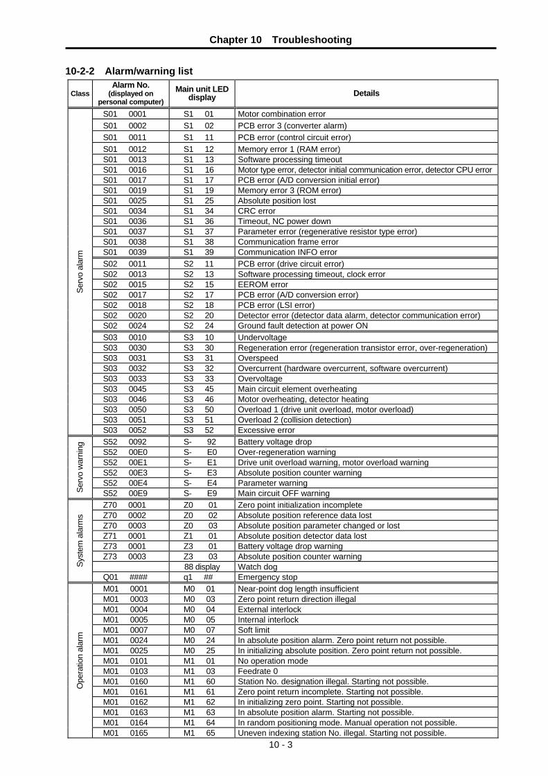
Chapter 10 Troubleshooting
10 - 3
10-2-2 Alarm/warning list
Class Alarm No.
(displayed on personal computer)
Main unit LED display Details
S01 0001 S1 01 Motor combination error S01 0002 S1 02 PCB error 3 (converter alarm) S01 0011 S1 11 PCB error (control circuit error) S01 0012 S1 12 Memory error 1 (RAM error) S01 0013 S1 13 Software processing timeout S01 0016 S1 16 Motor type error, detector initial communication error, detector CPU error S01 0017 S1 17 PCB error (A/D conversion initial error) S01 0019 S1 19 Memory error 3 (ROM error) S01 0025 S1 25 Absolute position lost S01 0034 S1 34 CRC error S01 0036 S1 36 Timeout, NC power down S01 0037 S1 37 Parameter error (regenerative resistor type error) S01 0038 S1 38 Communication frame error S01 0039 S1 39 Communication INFO error S02 0011 S2 11 PCB error (drive circuit error) S02 0013 S2 13 Software processing timeout, clock error S02 0015 S2 15 EEROM error S02 0017 S2 17 PCB error (A/D conversion error) S02 0018 S2 18 PCB error (LSI error) S02 0020 S2 20 Detector error (detector data alarm, detector communication error) S02 0024 S2 24 Ground fault detection at power ON S03 0010 S3 10 Undervoltage S03 0030 S3 30 Regeneration error (regeneration transistor error, over-regeneration) S03 0031 S3 31 Overspeed S03 0032 S3 32 Overcurrent (hardware overcurrent, software overcurrent) S03 0033 S3 33 Overvoltage S03 0045 S3 45 Main circuit element overheating S03 0046 S3 46 Motor overheating, detector heating S03 0050 S3 50 Overload 1 (drive unit overload, motor overload) S03 0051 S3 51 Overload 2 (collision detection)
Serv
o al
arm
S03 0052 S3 52 Excessive error S52 0092 S- 92 Battery voltage drop S52 00E0 S- E0 Over-regeneration warning S52 00E1 S- E1 Drive unit overload warning, motor overload warning S52 00E3 S- E3 Absolute position counter warning S52 00E4 S- E4 Parameter warning
Serv
o w
arni
ng
S52 00E9 S- E9 Main circuit OFF warning Z70 0001 Z0 01 Zero point initialization incomplete Z70 0002 Z0 02 Absolute position reference data lost Z70 0003 Z0 03 Absolute position parameter changed or lost Z71 0001 Z1 01 Absolute position detector data lost Z73 0001 Z3 01 Battery voltage drop warning Z73 0003 Z3 03 Absolute position counter warning 88 display Watch dog Sy
stem
ala
rms
Q01 #### q1 ## Emergency stop M01 0001 M0 01 Near-point dog length insufficient M01 0003 M0 03 Zero point return direction illegal M01 0004 M0 04 External interlock M01 0005 M0 05 Internal interlock M01 0007 M0 07 Soft limit M01 0024 M0 24 In absolute position alarm. Zero point return not possible. M01 0025 M0 25 In initializing absolute position. Zero point return not possible. M01 0101 M1 01 No operation mode M01 0103 M1 03 Feedrate 0 M01 0160 M1 60 Station No. designation illegal. Starting not possible. M01 0161 M1 61 Zero point return incomplete. Starting not possible. M01 0162 M1 62 In initializing zero point. Starting not possible. M01 0163 M1 63 In absolute position alarm. Starting not possible. M01 0164 M1 64 In random positioning mode. Manual operation not possible.
Ope
ratio
n al
arm
M01 0165 M1 65 Uneven indexing station No. illegal. Starting not possible.
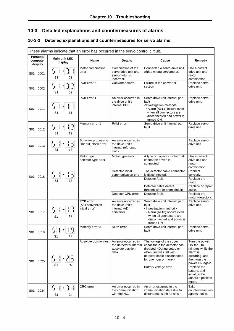
Chapter 10 Troubleshooting
10 - 4
10-3 Detailed explanations and countermeasures of alarms 10-3-1 Detailed explanations and countermeasures for servo alarms These alarms indicate that an error has occurred in the servo control circuit.
Personal computer
display
Main unit LED display Name Details Cause Remedy
S01 0001
01S1
Motor combination error
Combination of the servo drive unit and servomotor is incorrect.
Connected a servo drive unit with a wrong servomotor.
Use a correct drive unit and motor combination.
S01 0002
02S1
PCB error 3 Converter alarm Failure in the converter section
Replace servo drive unit.
S01 0011
11S1
PCB error 1 An error occurred in the drive unit's internal PCB.
Servo drive unit internal part fault <Investigation method> • Alarm (AL11) occurs even when all connectors are disconnected and power is turned ON.
Replace servo drive unit.
S01 0012
12S1
Memory error 1 RAM error Servo drive unit internal part fault
Replace servo drive unit.
S01 0013 S1 13
Software processing timeout, clock error
An error occurred in the drive unit's internal reference clock.
Replace servo drive unit.
Motor type, detector type error
Motor type error A type or capacity motor that cannot be driven is connected.
Use a correct drive unit and motor combination.
Detector initial communication error.
The detector cable connector is disconnected.
Connect correctly.
Detector fault. Replace the motor.
Detector cable defect (broken wire or short circuit)
Replace or repair cable.
S01 0016 S1 16
Detector CPU error Detector fault. Replace the motor (detector).
S01 0017 17S1
PCB error (A/D conversion initial error)
An error occurred in the drive unit's internal A/D converter.
Servo drive unit internal part fault <Investigation method> • Alarm (AL10) occurs even
when all connectors are disconnected and power is turned ON.
Replace servo drive unit.
S01 0019 19S1
Memory error 3 ROM error Servo drive unit internal part fault
Replace servo drive unit.
Absolute position lost An error occurred in the detector's internal absolute position data.
The voltage of the super capacitor in the detector has dropped. (During setup or when unit was left with detector cable disconnected for one hour or more.)
Turn the power ON for 2 to 3 minutes while the alarm is occurring, and then turn the power ON again.S01 0025
S1 25 Battery voltage drop Replace the battery, and initialize the absolute position again.
S01 0034 S1 34
CRC error An error occurred in the communication with the NC.
An error occurred in the communication data due to disturbance such as noise.
Take countermeasures against noise.

Chapter 10 Troubleshooting
10 - 5
These alarms indicate that an error has occurred in the servo control circuit.
Personal computer
display
Main unit LED display Name Details Cause Remedy
Communication timeout, NC down
Communication with the NC was cut off.
The bus cable (SH21) connection was disconnected.
Connect correctly.
The NC power was turned OFF.
Turn the NC power ON. S01 0036
S1 36 The drive unit or NC is faulty. Replace the drive unit or NC.
S01 0037 S1 37
Parameter error The parameter setting value is incorrect.
An external regenerative resistor that is not combined was designated with parameter #002.
Set the parameter correctly.
S01 0038 S1 38
Frame error An error occurred in the communication with the NC.
An error occurred in the communication data due to disturbance such as noise.
Take countermeasures against noise.
S01 0039
S1 39
INFO error Undefined data was transferred from the NC.
An incompatible NC is connected to.
Change the NC software version to a compatible version.

Chapter 10 Troubleshooting
10 - 6
These alarms indicate that an error has occurred in the servo control circuit. Personal computer
display
Main unit LED display Name Details Cause Remedy
S02 0011 11S2
PCB error 1 (drive circuit error)
An error occurred in the drive unit's internal PCB.
Servo drive unit internal part fault <Investigation method> • Alarm (AL11) occurs even
when all connectors are disconnected and power is turned ON.
Replace servo drive unit.
S02 0013 13S2
Software processing timeout, clock error
An error occurred in the drive unit's internal reference clock.
Replace servo drive unit.
S02 0015 15S2
EEROM error A write error occurred to the EEROM in the drive unit.
EEROM defect Replace servo drive unit.
S02 0017
17S2
PCB error (A/D conversion error)
An error occurred in the drive unit's internal A/D converter.
Servo drive unit internal part fault <Investigation method> • Alarm (AL17) occurs even
when all connectors are disconnected and power is turned ON.
Replace servo drive unit.
S02 0018 18S2
PCB error (LSI error) An error occurred in the drive unit's internal LSI.
Servo drive unit internal part fault <Investigation method> • Alarm (AL18) occurs even
when all connectors are disconnected and power is turned ON.
Replace servo drive unit.
• The detector cable connection is disconnected.
Connect correctly.
S02 0020
20S2
Detector error An error occurred in the communication between the servo drive unit and detector. • Detector cable defect
(broken wire or short circuit)
Replace or repair cable.
S02 0024
24S2
Ground fault detection
A ground fault of the output was detected when the power was turned ON.
• There is a ground fault in the output wire or the in the motor.
Repair the ground fault section. Replace the cable or motor.

Chapter 10 Troubleshooting
10 - 7
These alarms indicate that an error has occurred in the servo control circuit. Personal computer
display
Main unit LED display Name Details Cause Remedy
The power voltage is low. Review the power supply.
A momentary power failure lasting 15ms or longer occurred.
The power capacity is insufficient causing a power voltage drop when starting.
The power was turned ON immediately after turning the power OFF.
S03 0010 10 S3
Undervoltage The power voltage is 380V or less.
Servo drive unit internal part fault <Investigation method> • Alarm (AL10) occurs even when all
connectors are disconnected and power is turned ON.
Replace the servo drive unit.
Parameter #002 setting is incorrect. Set correctly. The external regenerative option is not connected, or the TE2 short cable is not connected.
Connect correctly.
The tolerable regeneration power was exceeded due to high frequency operation or continuous regeneration operation.
Lower the positioning frequency. Change the regenerative option to a larger capacity. Lower the load.
The tolerable regeneration power of the internal regenerative resistor or external regenerative option was exceeded.
The power voltage was 535V or more. Review the power supply.
S03 0030 30S3
Regeneration error
Regenerative transistor error
The regenerative transistor in the servo drive unit is faulty. <Investigation method> The alarm occurs even when the external regenerative option and TE2 short cable is disconnected.
Replace the servo drive unit.
The acceleration/deceleration time constant is small casing a large overshoot.
Increase the acceleration/deceleration time constant.
The electronic gear ratio is large. Review the gear ratio.
S03 0031 31 S3
Overspeed The motor's speed exceeded the tolerable momentary speed.
Detector fault. Replace the detector.
The servo drive unit's output U, V and W phases are short circuited.
Repair the wiring.
The servo drive unit's output U, V and W phases ground faulted during operation.
Replace the servo drive unit.
Correct the wiring.
S03 0032 32S3
Overcurrent A current exceeding the servo drive unit's tolerable current flowed.
The overcurrent detection circuit malfunctioned due to external noise. The servo drive unit's power module is faulty. <Investigation method> Alarm 32 occurs even when the servo drive unit output (terminal block TE1's U, V, W) is disconnected.
Take countermeasures against noise.
The TE2 short cable or external regenerative resistor lead wire is broken or disconnected.
Wire correctly.
The regenerative resistance transistor is faulty.
Replace the servo drive unit.
S03 0033 33S3
Overvoltage The voltage of the converter in the servo drive unit was 800V or more.
The internal regenerative resistor or external regenerative option has a broken wire.
For the internal regenerative resistor, replace the drive unit. For the external regenerative option, replace the regenerative option.

Chapter 10 Troubleshooting
10 - 8
These alarms indicate that an error has occurred in the servo control circuit. Personal computer
display
Main unit LED display Name Details Cause Remedy
Failure in the servo drive unit Replace servo drive unit.
The power was repeatedly turned ON/OFF in the overloaded state.
Review the operation method.
S03 0045 45S3
Main circuit element overheating
The main circuit was abnormally overheated.
The servo drive unit’s cooling fan is not working.
Replace servo drive unit or cooling fan. Lower the ambient temperature.
The servomotor is in the overload state.
Reduce the motor load. Review the operation pattern.S03 0046
46S3
Motor overheating An operation state causing the motor to overheat continued.
The thermal protector in the detector is faulty.
Replace the detector.
The servomotor's continuous output exceeded the rated output.
The servo drive unit output exceeded the tolerable instantaneous output.
Reduce the motor load. Review the operation pattern. Change to a motor or drive unit with large output.
The servo system is unstable, and hunting is occurring.
Change the setting of the automatic tuning response characteristics.
The motor connection is incorrect.
Correct the connection.
S03 0050 50S3
Overload 1 The servo drive unit or servo overload protection function activated. (Refer to the graph in 11-1 Overload protection characteristics.)
The detector is faulty. Replace the servomotor.
The machine stopper or others was collided against.
Review the operation pattern.
The motor connection is incorrect.
Correct the connection.
The servo system is unstable, and hunting is occurring.
Change the setting of the automatic tuning response characteristics.
S03 0051 51S3
Overload 2 The max. output current flowed for several seconds due to a machine collision or overload.
The detector is faulty. Replace the servomotor.
The acceleration/deceleration time constant is too low.
Increase the acceleration/ deceleration time constant.
The torque limit value is too low.
Increase the torque limit value.
Starting is not possible due to low torque caused by power voltage drop.
Review the power facility capacity. Use a motor with a large output.
The machine stopper or others was collided against.
Review the operation pattern.
The detector is faulty. Replace the servomotor.
The motor connection is incorrect.
Connect correctly.
S03 0052 52 S3
Excessive error A position deflection exceeding the excessive error detection setting value occurred.
Communication cable defect (broken wire or short circuit)
Repair or replace the cable.

Chapter 10 Troubleshooting
10 - 9
These alarms indicate that an error has occurred in the servo control circuit. Personal computer
display
Main unit LED display Name Details Cause Remedy
The battery is not mounted. Mount a battery.
S52 0092 92S-
Battery voltage drop The absolute position detection battery voltage dropped. Battery life Replace the
battery and initialize the absolute position.
S52 00E0 E0S-
Over-regeneration warning
The regeneration power may have exceeded the tolerable range of the built-in regenerative resistor or external regenerative option.
A level 85% or more of the built-in regenerative resistor or external regenerative option's tolerable regeneration power was reached.
1. Lower the positioning frequency.
2. Change the regenerative option to a larger one.
3. Lower the load.
S52 00E1 E1S-
Overload warning
The overload 1 alarm could occur.
85% or more of the overload 1 alarm occurrence level was reached.
Refer to the items for S03 0050.
1. Noise entered the detector. Take countermeasures against noise. S52 00E3
E3S-
Absolute position counter warning
There is an error in the absolute position detector internal data. 2. Detector fault. Replace the
servomotor.
S52 00E4 E4S-
Parameter warning The parameter is outside the setting range.
Value outside the setting range was set to the parameter.
Set the parameter correctly.
S52 00E9 E9S-
Main circuit OFF warning
The servo ON signal was input while the main circuit power was OFF. The contactor operation is faulty.
Turn ON the main circuit power.

Chapter 10 Troubleshooting
10 - 10
10-3-2 Detailed explanations and countermeasures for system alarms
Personal computer
display
Main unit LED display Name Cause Remedy
Z70 0001
01Z0
Zero point initializa-tion incomplete
The zero point (reference point) has not been initialized in the absolute position system.
Initialize the zero point (reference point).
Z70 0002
02Z0
Absolute position reference data lost
The absolute position reference coordinate data in the drive unit has been lost.
Initialize the zero point (reference point).
Z70 0003
03Z0
Absolute position system related parameter error
The absolute position system related parameters have been changed or lost.
Correctly set the parameters and then initialize the zero point (reference point).
Z71 0001
Z1 01
Absolute position detector data lost
The data in the detector has been lost due to a battery voltage drop. Battery voltage drop Detector cable wire breakage or looseness
Check the battery and detector cable and then initialize the zero point (reference point).
Z73 0001
01Z3
Absolute position memory battery voltage warning
Battery voltage drop Detector cable wire breakage or looseness
Check the battery and detector cable. The zero point does not need to be initialized.
Z73 0003
03Z3
Absolute position counter warning
An error occurred in the detector's absolute position counter.
Replace the detector.
88
Watch dog An error occurred in the drive unit's control circuit.
Replace the drive unit.
Q01 ####
##Q1
Emergency stop An emergency stop occurred due to a cause other than bus emergency stop input or external emergency stop input.
The emergency stop cause is displayed with bit correspondence in ##, so check the cause.
E7
Emergency stop A bus emergency stop or external emergency stop was input.
Check the NC emergency stop and external emergency stop.
4
5
6
7 H/W非常停止
制御信号非常停止
外部非常停止信号
0
1
2
3 バスALM0信号入力
バスEMGI信号入力
バッテリー低下
サーボアラーム・通信異常
非常停止要因の詳細
<Details of emergency stop causes> Each bit data is displayed as a hexadecimal.
Servo alarm
Absolute position lost
Bus emergency stop high-order input
Bus emergency stop low-order input
External emergency stop
PLC emergency stop
Other cause
bit 0
bit 1
bit 2
bit 3
bit 4
bit 5
bit 6
bit 7

Chapter 10 Troubleshooting
10 - 11
10-3-3 Detailed explanations and countermeasures for operation alarms
These alarms indicate that there is a mistake in the operation or in the operation command. Personal computer
display
Main unit LED display Name Cause Remedy
M01 0001
01M0
Near-point dog length insufficient
When executing dog-type reference point, the zero point return speed is too fast or the dog length is too short.
Lower the zero point return speed or increase the dog length.
M01 0003
03M0
Reference point return direction illegal
When executing reference point return, the axis was moved in the opposite of the designated direction.
Move the axis in the correct direction.
M01 0004
04M0
External interlock The axis interlock function is valid. Cancel the interlock signal
M01 0005
05M0
Internal interlock An interlock was established by the servo OFF function.
Cancel the servo OFF.
M01 0007
M0 07
Soft limit The soft limit was reached. Check the soft limit setting and machine position
M01 0024
24M0
In absolute position alarm. Reference point return not possible.
Reference point return was executed during an absolute position alarm.
Initialize the absolute position reference point and then fix the absolute position coordinates.
M01 0025
25M0
In initializing absolute position. Reference point return not possible.
Reference point return was executing while initializing the absolute position.
Initialize the absolute position reference point and then fix the absolute position coordinates.
M01 0101
01M1
No operation mode The operation mode is not designated, or the operation mode was changed during axis movement.
Correctly designate the operation mode.
M01 0103
03M1
Feedrate 0 The operation parameter's feedrate setting is zero. The operation parameter feedrate setting is zero. Or, the override is valid, and the override value is zero.
Set a value other than zero in the feedrate setting or over-ride value.
M01 0160
60M1
Station No. designa-tion illegal. Starting not possible.
A station No. exceeding the No. of indexed divisions was designated.
Correctly designate the station No.
M01 0161
61M1
Reference point return incomplete. Starting not possible.
Automatic/manual operation was started before reference point return was executed with the incremental system.
Execute the reference point return.
M01 0162
62M1
In initializing refer-ence point. Starting not possible.
The start signal was input while initializing the absolute position reference point.
Complete the absolute position reference point initialization.
M01 0163
63M1
In absolute position alarm. Starting not possible.
The start signal was input during an absolute position alarm.
Initialize the absolute position reference point and then fix the absolute position coordinates.
M01 0164
64M1
In random positioning mode. Manual opera-tion not possible.
The manual operation mode was started during the random positioning mode.
Turn the random positioning mode OFF before switching to the manual operation mode.
M01 0165
65M1
Uneven indexing station No. illegal. Starting not possible.
During uneven indexing, the commanded station No. exceeded the number of indexing stations or 9.
Check the commanded station No. and #100 No. of indexing stations.


11 - 1
Chapter 11 Characteristics 11-1 Overload protection characteristics .............................................................................................. 11-2 11-2 Servo drive unit generation loss ................................................................................................... 11-3
11-2-1 Servo drive unit calorific value............................................................................................... 11-3 11-2-2 Heat radiation area of fully closed type control panel............................................................ 11-4
11-3 Magnetic brake characteristics..................................................................................................... 11-5 11-3-1 Motor with magnetic brakes................................................................................................... 11-5 11-3-2 Magnetic brake characteristics .............................................................................................. 11-6 11-3-3 Magnetic brake power supply................................................................................................ 11-7
11-4 Dynamic brake characteristics ..................................................................................................... 11-8 11-4-1 Deceleration torque ............................................................................................................... 11-8 11-4-2 Coasting amount.................................................................................................................... 11-9
11-5 Vibration class ............................................................................................................................ 11-10

Chapter 11 Characteristics
11 - 2
11-1 Overload protection characteristics The servo drive unit has an electronic thermal relay to protect the servomotor and servo drive unit from overloads. The operation characteristics of the electronic thermal relay are shown below. If overload operation over the electronic thermal relay protection curve shown below is carried out, overload 1 alarm (AL.50) will occur. If the maximum current flows continuously for several seconds due to a machine collision, etc., overload 2 alarm (AL.51) will occur. Use within the region to the left of the solid or dotted line in the graph. In a machine like the one for vertical lift application where unbalanced torque will be produced, it is recommended to use the machine so that the unbalanced torque is 70% or less of the rated torque.
(a) MR-J2S-60CT4 • MR-J2S-100CT4
1000
100
10
1
0.1 0 50 150 200 250 300
During operation
At servo lock
100
(b) MR-J2S-200CT4 • MR-J2S-350CT4
300250200 150 100 5000.1
1000
100
10
1
During operation
At servo lock
Ope
ratio
n tim
e [s
]
Ope
ratio
n tim
e [s
]
(Note) Load rate [%] (Note) Load rate [%]
(Note) Stopping servomotor while torque of 100% or more of the rating is occurring, or executing low
speed (30r/min or less) operation more frequently than designed may cause the servo drive unit a failure even in the state where electronic thermal protection does not occur.
Fig. 11-1 Overload protection characteristics of MR-J2S-CT4

Chapter 11 Characteristics
11 - 3
11-2 Servo drive unit generation loss 11-2-1 Servo drive unit calorific value
The servo drive unit calorific value is determined from the following table by the motor with which the servo drive unit is combined. The calorific value for the actual machine will be a value between the calorific values at the stall torque (at the rated torque) and the zero torque according to the frequency during operation. Consider the worst usage conditions for the thermal design of the fully closed type control panel, and use the values given below. Even when the servomotor is run below the maximum speed, the servo drive unit calorific value will not change if the generated torque is the same.
Table 11-1 Servo drive unit calorific values
Calorific value (W) Drive unit type Motor type
At rated torque At zero torque
Area required for heat
radiation (m2)
HF-P534JW04 MR-J2S-60CT4 HF-SP524JW04
40 15 0.8
HF-P734JW04 MR-J2S-100CT4
HF-SP1024JW04 50 15 1.0
HF-SP1524JW04 MR-J2S-200CT4
HF-SP2024JW04 90 20 1.8
MR-J2S-350CT4 HF-SP3524JW04 130 20 2.7
POINT
1. The heat generated by the regeneration resistor is not included in the servo drive unit calorific value. Refer to section "13-4 Selection of regenerative resistor" and calculate the calorific value of the regenerative resistor using the regeneration load and positioning frequency.
2. The area required for heat radiation is the heat radiation area (guideline) of the fully closed type control panel storing the servo drive unit when using the unit at an ambient temperature of 40°C and stall (rated) load.

Chapter 11 Characteristics
11 - 4
11-2-2 Heat radiation area of fully closed type control panel Set the temperature in the fully closed type control panel (hereafter control panel) in which the servo drive unit is stored so that the ambient temperature is 40°C +10°C or less. (Provide a 5°C allowance in respect to the maximum working environmental conditions temperature of 55°C.) The control panel heat radiation area is usually calculated with the following expression.
A = P K • △T .............. (11-1)
A : Heat radiation area [m2] P : Loss generated in control panel △T : Temperature difference between
control panel and outside air [°C] K : Heat radiation coefficient (5 ~ 6)
When calculating the heat radiation area with the above expression (11-1), use P as the total loss generated in the control panel. Refer to the table in section "11-2-1 Servo drive unit calorific value" for the servo drive unit calorific values. A indicates the area effective for heat radiation, so if the control panel is directly installed on a heat insulating wall, etc., provide the control panel's surface area as an allowance. The required heat radiation area will also differ according to the conditions in the control panel. If the convection in the control panel is poor, effective heat radiation will not be possible. In this case, when designing the control panel, consider the placement of devices in the control panel, and mixing the air with a fan, etc.
(Outside air)
(Inside panel)
Temperature
Air flow
Fig. 11-2 Fully closed type control panel temperature gradient When air flows along the outside of the panel, the temperature slope will become sudden, and an effective heat exchange will be possible both inside and outside of the fully closed control type panel.
Chapter 11 Characteristics
11 - 5
11-3 Magnetic brake characteristics
CAUTION
1. The axis will not be mechanically held even when the dynamic brakes are used. If the machine could drop when the power fails, use a servomotor with magnetic brakes or provide an external brake mechanism as holding means to prevent dropping.
2. The magnetic brakes are used for holding, and must not be used for normal braking. There may be cases when holding is not possible due to the life or machine structure (when ball screw and servomotor are coupled with a timing belt, etc.). Provide a stop device on the machine side to ensure safety. When releasing the brakes, always confirm that the servo is ON first.
3. When operating the brakes, always turn the servo OFF (or ready OFF). When releasing the brakes, always confirm that the servo is ON first. Sequence control considering this condition is possible if the drive unit motor brake control signal (MBR) is used.
4. When the vertical axis drop prevention function is used, the drop of the vertical axis at the servo OFF command input can be suppressed to a minimum.
11-3-1 Motor with magnetic brakes
(1) Types The motor with magnetic brakes is set for each motor. The "B" following the standard motor type indicates the motor with brakes.
(2) Applications
When this type of motor is used for the vertical feed axis in a machining center, etc., slipping and dropping of the spindle head can be prevented even when the hydraulic balancer's hydraulic pressure reaches zero when the power turns OFF. When used with a robot, deviation of the posture when the power is turned OFF can be prevented. When used for the feed axis of a grinding machine, a double safety measures is formed with the deceleration stop (dynamic brake stop), and the risks of colliding with the grinding stone and scattering can be prevented. This motor cannot be used for purposes other than holding and braking during a power failure (emergency stop). (This cannot be used for normal deceleration, etc.)
(3) Features
①The magnetic brakes use a DC excitation method, thus: • The brake mechanism is simple and the reliability is high. • There is no need to change the brake tap between 50 Hz and 60 Hz. • There is no rush current when the excitation occurs, and shock does not occur. • The brake section is not larger than the motor section.
②The magnetic brakes are built into the motor, and the installation dimensions (flange size) are the same as the motor without brakes.

Chapter 11 Characteristics
11 - 6
11-3-2 Magnetic brake characteristics
HF-P series HF-SP series Motor type
Item 534BJW04 734BJW04
524BJW04 1024BJW04 1524BJW04
2024BJW04 3524BJW04
Type (Note 1) Spring-closed non-excitation magnetic brakes
[for holding and emergency braking] Rated voltage 24VDC Rated current at 20°C (A) 0.38 0.8 1.4 Capacity (W) 9 19 34 Static friction torque (N•m) 2.4 8.3 43.1 Inertia (Note 2) (kg•cm2) 0.2 2.2 9.7 Release delay time (Note 3) (s) 0.03 0.04 0.1 Braking delay time (DC OFF) (Note 3) (s) 0.03 0.03 0.03
Per braking (J) 64 400 4,500 Tolerable braking work amount
Per hour (J) 640 4,000 45,000
Brake play at motor axis (degree) 0.1 to 0.9 0.2 to 0.6 0.2 to 0.6 No. of braking operations
(times) 20,000 20,000 20,000 Brake life (Note 4) Braking amount per
braking (J) 32 200 1,000
Notes:
1. There is no manual release mechanism. If handling is required such as during the machine core alignment work, prepare a separate 24 VDC power supply, and electrically release the brakes.
2. These are the values added to the servomotor without brakes. 3. This is the value for 20°C at the initial attraction gap. 4. The brake gap will widen through brake lining wear caused by braking. However, the gap cannot be adjusted.
Thus, the brake life is reached when adjustments are required. 5. The internal power output (VDD) 24 VDC for digital output cannot be used. Always prepare a separate power
supply. 6. A leakage flux will be generated at the shaft end of the servomotor with magnetic brakes. 7. When operating in low speed regions, the sound of loose brake lining may be heard. However, this is not a
problem in terms of function.
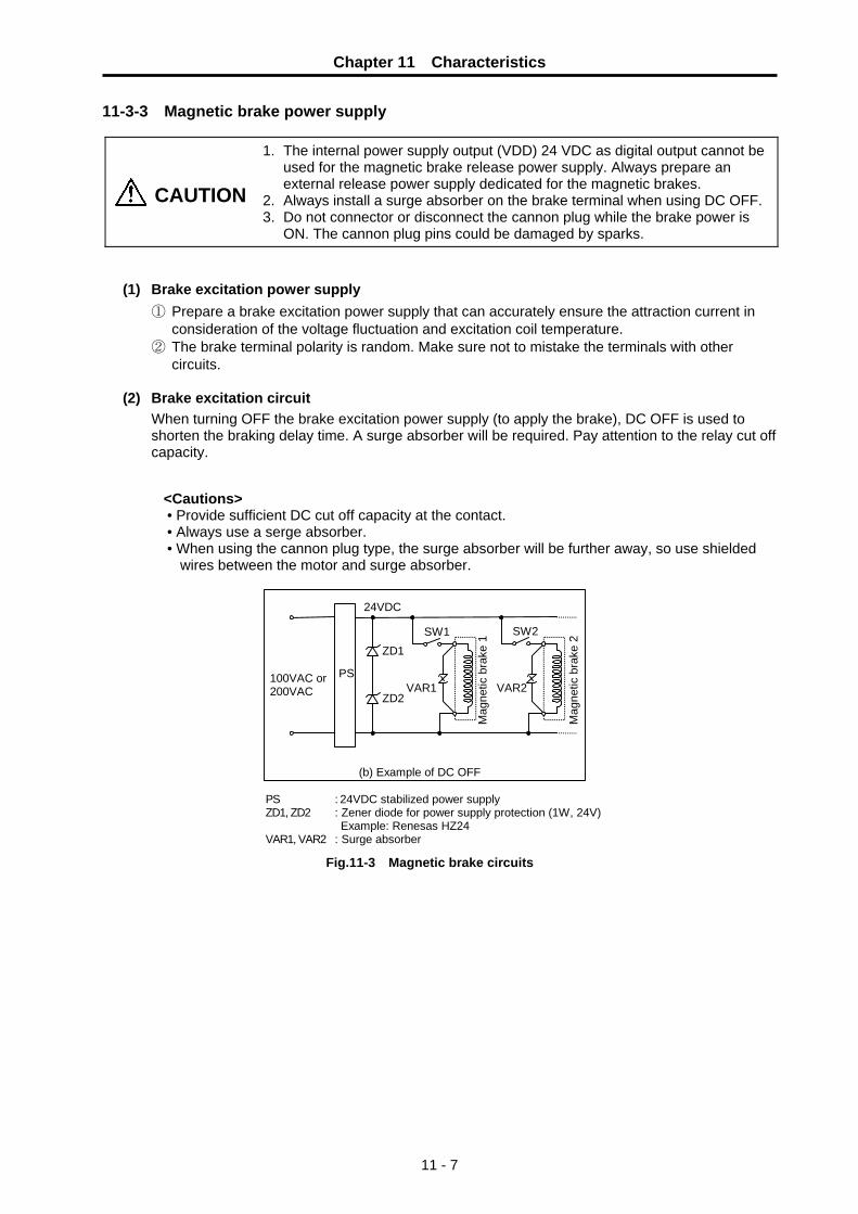
Chapter 11 Characteristics
11 - 7
11-3-3 Magnetic brake power supply
CAUTION
1. The internal power supply output (VDD) 24 VDC as digital output cannot be used for the magnetic brake release power supply. Always prepare an external release power supply dedicated for the magnetic brakes.
2. Always install a surge absorber on the brake terminal when using DC OFF. 3. Do not connector or disconnect the cannon plug while the brake power is
ON. The cannon plug pins could be damaged by sparks.
(1) Brake excitation power supply ① Prepare a brake excitation power supply that can accurately ensure the attraction current in
consideration of the voltage fluctuation and excitation coil temperature. ② The brake terminal polarity is random. Make sure not to mistake the terminals with other
circuits.
(2) Brake excitation circuit When turning OFF the brake excitation power supply (to apply the brake), DC OFF is used to shorten the braking delay time. A surge absorber will be required. Pay attention to the relay cut off capacity.
<Cautions> • Provide sufficient DC cut off capacity at the contact. • Always use a serge absorber. • When using the cannon plug type, the surge absorber will be further away, so use shielded
wires between the motor and surge absorber.
24VDC
PS
SW2
VAR2
SW1
VAR1
ZD1
ZD2
PS ZD1, ZD2 VAR1, VAR2
: 24VDC stabilized power supply : Zener diode for power supply protection (1W, 24V) Example: Renesas HZ24 : Surge absorber
(b) Example of DC OFF
Mag
netic
bra
ke 1
100VAC or 200VAC
Mag
netic
bra
ke 2
Fig.11-3 Magnetic brake circuits

Chapter 11 Characteristics
11 - 8
11-4 Dynamic brake characteristics When an emergency stop occurs due to an alarm occurrence, the dynamic brakes will activate and the motor will stop. (A deceleration control stop can also be selected with the parameter setting.)
11-4-1 Deceleration torque
The dynamic brakes use the motor as a generator, and obtains the deceleration torque by consuming that energy with the dynamic brake resistance. The characteristics of this deceleration torque have a maximum deceleration torque (Tdp) regarding the motor speed as shown in the following drawing. The torque for each motor is shown in the following table.
Tdp
Ndp
Decelerationtorque
Motor speed
0
Fig. 11-4 Deceleration torque characteristics of a dynamic brake stop
Table 11-3 Max. deceleration toque of a dynamic brake
Motor type Rated torque
(N•m) Tdp
(N•m) Ndp
(r/min) Motor type
Rated torque (N•m)
Tdp (N•m)
Ndp
(r/min)
HF-P534JW04 1.59 5.11 1254 HF-SP524JW04 2.39 3.96 478 HF-P734JW04 2.39 10.19 1071 HF-SP1024JW04 4.77 10.04 409
HF-SP1524JW04 7.16 15.04 343 HF-SP2024JW04 9.55 15.83 210 HF-SP3524JW04 16.70 37.35 1603

Chapter 11 Characteristics
11 - 9
11-4-2 Coasting amount The motor coasting amount when stopped by a dynamic brake can be approximated using the following expression.
CMAX = No60 • te + ( 1 + JL
JM ) • (A • No3 + B • No)
CMAX : Maximum motor coasting amount (turn) No : Initial motor speed (r/min) JM : Motor inertia (kg•cm2) JL : Motor shaft conversion load inertia (kg•cm2) te : Brake drive relay delay time (s) (Normally, 0.03s) A : Coefficient A (Refer to the table below) B : Coefficient B (Refer to the table below)
Fig. 11-5 Dynamic brake braking diagram
Table 11-4 Coasting amount calculation coefficients
Motor type JM
(kg・cm2) A B Motor type
JM (kg・cm2)
A B
HF-P534JW04 2.6 1.18×10⁻¹¹ 5.57×10⁻⁵ HF-SP524JW04 6.1 9.36×10⁻¹¹ 6.42×10⁻⁵
HF-P734JW04 5.1 1.36×10⁻¹¹ 4.68×10⁻⁵ HF-SP1024JW04 11.9 8.44×10⁻¹¹ 4.23×10⁻⁵
HF-SP1524JW04 17.8 10.03×10⁻¹¹ 3.54×10⁻⁵
HF-SP2024JW04 38.3 33.45×10⁻¹¹ 4.44×10⁻⁵
HF-SP3524JW04 75.0 3.64×10⁻¹¹ 28.08×10⁻⁵
OFFON
te
OFFON
OFFON
Emergency stop (EMG)
Motor brake actual operation
Initial speed: No
Time
Motor speed
Coasting amount
Motor brake control output (MBR)

Chapter 11 Characteristics
11 - 10
11-5 Vibration class The vibration class of the servomotor is V-10 at the rated speed. The servomotor installation posture and measurement position to be used when measuring the vibration are shown below.
Fig. 11-6 Servomotor vibration measurement conditions
Top
Bottom
Servomotor
Measurementposition

12 - 1
Chapter 12 Specifications 12-1 Servo drive units ........................................................................................................................... 12-2
12-1-1 List of specifications............................................................................................................... 12-2 12-1-2 Outline dimension drawings .................................................................................................. 12-3
12-2 Servomotor ................................................................................................................................... 12-5 12-2-1 List of specifications............................................................................................................... 12-5 12-2-2 Torque characteristic drawings.............................................................................................. 12-6 12-2-3 Outline dimension drawings .................................................................................................. 12-7 12-2-4 Special axis servomotor ...................................................................................................... 12-12

Chapter 12 Specifications
12 - 2
12-1 Servo drive units 12-1-1 List of specifications
Servo drive unit type MR-J2S- 60CT4 100CT4 200CT4 350CT4
Voltage, frequency 3-phase 380 to 480VAC/50, 60Hz
Tolerable voltage fluctuation 3-phase 323 to 528VAC/50, 60Hz Power
supply Tolerable frequency fluctuation
Within ±5%
Method Sine wave PWM control, current control method Dynamic brakes Built-in Regenerative resistor Built-in or external option External digital input External emergency stop input, near-point dog input External digital output Contactor control output, motor brake control output External analog output ±10V, 2ch
Protective function
Overcurrent cut off, over voltage cut off, overload cut off (electronic thermal), servomotor overheating protection, detector error protection, regeneration error protection, under voltage/instantaneous power failure protection, overspeed protection, excessive error protection
Structure Fan cooling, open (IP00) Environmental conditions To follow section 3-1-1 Environmental conditions Mass [kg] 2.1 2.2 2.2 5

Chapter 12 Specifications
12 - 3
12-1-2 Outline dimension drawings
• MR-J2S-60CT4, MR-J2S-100CT4, MR-J2S-200CT4 [Unit: mm]
6
6
90
168
(70) 195
6 78
156
6 6
2-Ø6mounting hole
Terminal signal layout
CNP1
L1
L2
L3
CNP3
CN4
U
V
W
24V • L11
0V • L21
CNP2
P
C
D
N
PE terminal
Terminal screw : M4 Tightening torque: 1.2[N • m]

Chapter 12 Specifications
12 - 4
• MR-J2S-350CT4
[Unit: mm]
66
130
250
(70) 200
6 118
235
7.5
7.5
2-Ø6mounting hole
(20) 5
Inlet
Terminal signal layout
TE1
L1
L2
L3
TE2
U
V
W
24V • L11
0V • L21
PE Terminal
P
C
Terminal screw : M4 Tightening torque: 1.2[N・m]
N
Terminal screw : M4 Tightening torque: 1.2[N・m]
Terminal screw : M3.5 Tightening torque: 1.0[N・m]
Bult-in regenerative brake resistor lead terminal fixing screw

Chapter 12 Specifications
12 - 5
12-2 Servomotor
12-2-1 List of specifications
HF-P series (3000r/min rating) Absolute position standard Servomotor type
HF-P534JW04 HF-P734JW04 Corresponding servo drive unit type MR-J2S-60CT4 MR-J2S-100CT4
Rated output [kW] 0.5 0.75 Rated current [A] 1.35 1.88
Continuous characteristics
Rated torque [N·m] 1.59 2.39 Rated speed [r/min] 3000 Max. speed [r/min] 4000 Max. current [A] 4.0 5.6 Max. torque [N·m] 4.77 7.17 Motor inertia [kg·cm2] 2.6 5.1 Motor inertia (with brakes) [kg·cm2] 2.8 5.3 Recommended motor shaft conversion load inertia rate 10-times or less of motor inertia
Power facility capacity [kVA] 1.0 1.7 Speed/position detector Resolution per motor rotation 262,144 (pulse/rev) Structure Fully closed, self-cooling (protection method: IP67) Environmental conditions To follow section 3-2-1 Environmental conditions Mass With/without brakes [kg] 2.5/3.9 4.3/5.7 Armature insulation class Class F
(Note) The above characteristic values are the central values. The maximum current and maximum torque are the values when
combined with the drive unit.
HF-SP series (2000r/min rating) Absolute position standard Servomotor type
HF-SP524JW04 HF-SP1024JW04 HF-SP1524JW04 HF-SP2024JW04 HF-SP3524JW04
Corresponding servo drive unit type MR-J2S-60CT4 MR-J2S-100CT4 MR-J2S-200CT4 MR-J2S-350CT4Rated output [kW] 0.5 1.0 1.5 2.0 3.5 Rated current [A] 1.55 2.9 4.1 5.0 8.4
Continuous characteristics
Rated torque [N·m] 2.39 4.77 7.16 9.55 16.7 Rated speed [r/min] 2000 Max. speed [r/min] 3000 Max. current [A] 5.0 9.3 13.2 16.0 27.0 Max. torque [N·m] 7.16 14.3 21.5 28.6 50.1 Motor inertia [kg·cm2] 6.1 11.9 17.8 38.3 75.0 Motor inertia (with brakes) [kg·cm2] 8.3 14.1 20.0 48.0 84.7 Recommended motor shaft conversion load inertia rate 10-times or less of motor inertia
Power facility capacity [kVA] 1.0 1.7 2.5 3.5 5.5 Speed/position detector Resolution per motor rotation 262,144 (pulse/rev) Structure Fully closed, self-cooling (protection method: IP67) Environmental conditions To follow section 3-2-1 Environmental conditions Mass With/without brakes [kg] 4.8/6.7 6.5/8.5 8.3/10.3 12.0/18.0 19.0/25.0 Armature insulation class Class F
(Note) The above characteristic values are the central values. The maximum current and maximum torque are the values when
combined with the drive unit.

Chapter 12 Specifications
12 - 6
12-2-2 Torque characteristic drawings (1) HF-P Series
0 1000 2000 4000
Speed [r/min]
0
1
3
6[ HF-P534JW04 ]
Torq
ue [N
•m]
Short-time operation
2
4
5
3000 0 1000 2000 4000
Speed [r/min]
0
2
6
10[ HF-P734JW04 ]
Torq
ue [N
•m]
Short-time operation
4
8
3000
Continuous operation
Continuous operation
(2) HF-SP Series
0 1000 2000 3000
Speed [r/min]
0
2
6
10[ HF-SP524JW04 ]
Torq
ue [N
•m]
4
8
Short-time operation
0 1000 2000 3000
Speed [r/min]
0
5
15
20[ HF-SP1024JW04 ]
Torq
ue [N
•m]
10Short-time operation
0 1000 2000 3000
Speed [r/min]
0
5
15
30[ HF-SP1524JW04 ]
Torq
ue [N
•m]
10
20
Short-time operation
25
0 1000 2000 3000
Speed [r/min]
0
10
30
40[ HF-SP2024JW04 ]
Torq
ue [N
•m]
20Short-time operation
Continuous operation
0 1000 2000 3000
Speed [r/min]
0
40
60[ HF-SP3524JW04 ]
Torq
ue [N
•m]
20Short-time operation
Continuous operation
Continuous operation
Continuous operation
Continuous operation
(Note) The data in these characteristics is for an input voltage of 380VAC.

Chapter 12 Specifications
12 - 7
12-2-3 Outline dimension drawings • HF-P534JW04 • HF-P734JW04 • HF-P534JTW04 • HF-P734JTW04
[Unit: mm]
Power connector
MS3102A18-10P
Detector connector
Oil seal
50.9
KL
21
13
CM10-R10P
L
38 7.5 3
33
25 Ø14
h6
Ø80
h7
45°
90
Ø118
88.5
54
4-Ø6.6 mounting holeUse a hexagon socket bolt.
Ø36
5.5
Ø100
45°
90
Ø118
88.5
54
4-Ø6.6 mounting holeUse a hexagon socket bolt.
Ø100
Ø14
Oil seal Ø18
3
18
5.314
14
12
Plain washer 8
U nut M8×1.0
Taper 1/10
A
A
Ø80
h7
Ø36
M8×
1.0
scr
ew
8.9
44
5
Cross section A-A
3.55
5
0 -0
.03
0 -0.03
Servomotor type L KL HF-P534J W04 126.5 61 HF-P734J W04 162.5 97
(Note 1) Use a friction coupling (Spun ring, etc.) to connect with the load. (Note 2) Attach the cannon connector facing downward to improve the splash-proof performance.

Chapter 12 Specifications
12 - 8
• HF-P534BJW04 • HF-P734BJW04 • HF-P534BJTW04 • HF-P734BJTW04
[Unit: mm]
45°
90
Ø118
88.5
54
4-Ø6.6 mounting holeUse a hexagon socket bolt.
Ø100
12.5
Power connector MS3102A18-10P
Oil seal
KL
21
L
7.5 3
33
25 Ø14
h6
Ø80
h7
Ø36
5.5
Detector connector
50.9
13
CM10-R10P
38
63.4
66
Brake connector CM10-R2P
45°
90
Ø118
88.5
54
4-Ø6.6 mounting holeUse a hexagon socket bolt.
Ø100
Ø14
Oil seal Ø18
3
18
5.314
14
12
Plain washer 8
U nut M8×1.0
Taper 1/10
A
A
Ø80
h7
Ø36
M8×
1.0
scr
ew
8.9
445
Cross section A-A
3.55
5
0 -0
.03
0 -0.03
Servomotor type L KL HF-P534BJ□W04 167.5 61 HF-P734BJ□W04 203.5 97
(Note 1) Use a friction coupling (Spun ring, etc.) to connect with the load. (Note 2) Attach the cannon connector facing downward to improve the splash-proof performance.

Chapter 12 Specifications
12 - 9
• HF-SP524JW04 • HF-SP1024JW04 • HF-SP1524JW04 • HF-SP524JTW04 • HF-SP1024JTW04 • HF-SP1524JTW04
[Unit: mm]
Power connector
MS3102A18-10P
Detector connector Oil seal
50.9
KL
20.9
13
CM10-R10P
L 38.2
12 3
55 50
Ø24
h6
Ø11
0h7
Ø145
45°
130
Ø165
112.
5
58
13.5
4-Ø9 mounting holeUse a hexagon socket bolt.
A
A
M10
×1.
25 s
crew
Plain washer 10
Cross section A-A
5
4.3 5
Oil seal
25
58
Ø16
Taper1/10
U nut M10×1.25 Tightening torque 23 to 30Nm
3
Ø11
0h7
28 1218
0 -0
.03 0
-0.03
Ø145
45°
130
Ø165
112.
5
58
13.5
4-Ø9 mounting holeUse a hexagon socket bolt.
Servomotor type L KL HF-SP524J W04 118.5 57.8 HF-SP1024J W04 140.5 79.8 HF-SP1524J W04 162.5 101.8
(Note 1) Use a friction coupling (Spun ring, etc.) to connect with the load. (Note 2) Attach the cannon connector facing downward to improve the splash-proof performance.

Chapter 12 Specifications
12 - 10
• HF-SP524BJW04 • HF-SP1024BJW04 • HF-SP1524BJW04 • HF-SP524BJTW04 • HF-SP1024BJTW04 • HF-SP1524BJTW04
[Unit: mm]
CM10-R10P
112.
5
Ø145
45°
130
Ø165
58
13.5
4-Ø9 mounting holeUse a hexagon socket bolt.
Power connector MS3102A18-10P
Detector connector Oil seal
50.9
KL 20.9
13
L 43.5
12 3
55 50
Ø24
h6
Ø11
0h7
Brake connector CM10-R2P
79.9
59
29
Cross section A-A
5
4.3 5
0 -0
.03 0
-0.03
M10
×1.
25 s
crew
Oil seal
25
58
Ø16
Taper1/10
Plain washer 10
U nut M10×1.25 Tightening torque 23 to 30Nm
3Ø
110h
7
28 12
A
A
18
112.
5
Ø145
45°
130
Ø165
58
13.5
4-Ø9 mounting holeUse a hexagon socket
29
Servomotor type L KL HF-SP524BJ W04 153 57.8 HF-SP1024BJ W04 175 79.8 HF-SP1524BJ W04 197 101.8
(Note 1) Use a friction coupling (Spun ring, etc.) to connect with the load. (Note 2) Attach the cannon connector facing downward to improve the splash-proof performance.

Chapter 12 Specifications
12 - 11
• HF-SP2024JW04 • HF-SP3524JW04 [Unit: mm]
4-Ø13.5 mounting holeUse a hexagon socket bolt.
3 18
Power connector
MS3102A22-22P
Detector connector Oil seal
50.9
KL
24.8
13
CM10-R10P
L 38.5
79 75
Ø35
Ø11
4.3
Ø200
45°
176
Ø230
140.
9
82
0 -0
.025
+0.0
10
0
Servomotor type L KL
HF-SP2024JW04 143.5 79.8 HF-SP3524JW04 183.5 119.8
(Note 1) Use a friction coupling (Spun ring, etc.) to connect with the load. (Note 2) Attach the cannon connector facing downward to improve the splash-proof performance.
• HF-SP2024BJW04 • HF-SP3524BJW04 [Unit: mm]
CM10-R10P
Power connector
4-Ø13.5 mounting holeUse a hexagon socket bolt.
3 18
MS3102A22-22P
Detector connector Oil seal
50.9
KL
24.8
13
L
45.5
79
75
Ø35
Ø11
4.3
Ø200
45°
176
Ø230
140.
9
82
0 -0
.025
+0.0
10
0
Brake connectorCM10-R2P
96.9
66.5
Servomotor type L KL
HF-SP2024BJW04 193 79.8 HF-SP3524BJW04 233 119.8
(Note 1) Use a friction coupling (Spun ring, etc.) to connect with the load. (Note 2) Attach the cannon connector facing downward to improve the splash-proof performance.

Chapter 12 Specifications
12 - 12
12-2-4 Special axis servomotor The servomotors have a straight axis (without keyway) as a standard. However, for some servomotors, keyway axis has been prepared as special shaft shape.
(1) Corresponding servomotor type
Model Corresponding servomotor sries Flange size Capacity / Rated speed
With no brake With brake
0.5kW/2000r/min HF-SP524JKW04 HF-SP524BJKW04
1.0kW/2000r/min HF-SP1024JKW04 HF-SP1024BJKW04 □130mm
1.5kW/2000r/min HF-SP1524JKW04 HF-SP1524BJKW04
2.0kW/2000r/min HF-SP2024JKW04 HF-SP2024BJKW04
HF-SP Series
□176mm 3.5kW/2000r/min HF-SP3524JKW04 HF-SP3524BJKW04
CAUTION HF-P Series (Flange size 90mm) is not available. Use a straight axis or taper axis.
(2) Dimension drawing of keyway axis Keyway
Changed dimensions table (Unit: mm)
Changed dimensions Servomotor type S R Q W QK QL U r Y
0 +0.2
HF-SP524JKW04 HF-SP1024JKW04 HF-SP1524JKW04 HF-SP524BJKW04 HF-SP1024BJKW04 HF-SP1524BJKW04
24h6 55 50 8-0.036 36 5 4 0 4 M8 screwDepth 20
+0.01 0 +0.2
HF-SP2024JKW04 HF-SP3524JKW04 HF-SP2024BJKW04 HF-SP3524BJKW04
35 0 79 75 10-0.036 55 5 5 0 5 M8 screwDepth 20
R
U
W
QLQK
Q
φS
Cross section A-A
r
A
A Y
CAUTION 1. Do not use it in an application where frequent positioning is executed. Failure
to observe this could lead to shaft damage caused by key backlash. 2. With no key. It must be prepare by user.

13 - 1
Chapter 13 Selection 13-1 Outline .......................................................................................................................................... 13-2
13-1-1 Servomotor ............................................................................................................................ 13-2 13-1-2 Regeneration methods .......................................................................................................... 13-3
13-2 Selection of servomotor series ..................................................................................................... 13-4 13-2-1 HF-P/HF-SP motor series characteristics ............................................................................. 13-4 13-2-2 HF-P/HF-SP servomotor precision........................................................................................ 13-4
13-3 Selection of servomotor capacity ................................................................................................. 13-5 13-3-1 Load inertia ratio .................................................................................................................... 13-5 13-3-2 Short time characteristics ...................................................................................................... 13-5 13-3-3 Continuous characteristics .................................................................................................... 13-6
13-4 Selection of regenerative resistor................................................................................................. 13-8 13-4-1 Calculation of regenerative energy........................................................................................ 13-8 13-4-2 Calculation of positioning frequency.................................................................................... 13-10
13-5 Example of servo selection......................................................................................................... 13-11 13-5-1 Motor selection calculation .................................................................................................. 13-11 13-5-2 Regenerative resistor selection calculation ......................................................................... 13-15 13-5-3 Servo selection results ........................................................................................................ 13-15
13-6 Motor shaft conversion load torque ............................................................................................ 13-16 13-7 Expressions for load inertia calculation...................................................................................... 13-17

Chapter 13 Selection
13 - 2
13-1 Outline 13-1-1 Servomotor
It important to select a servomotor matched to the purpose of the machine that will be installed. If the servomotor and machine to be installed do not match, the motor performance cannot be fully realized, and it will also be difficult to adjust the parameters. Be sure to understand the servomotor characteristics in this chapter to select the correct motor.
(1) Motor inertia
The servomotor has an optimum load inertia scale. If the load inertia exceeds the optimum range, the control becomes unstable and the servo parameters become difficult to adjust. When the load inertia is too large, decelerate with the gears (The motor axis conversion load inertia is proportional to the square of the deceleration ratio.), or change to a motor with a large inertia.
(2) Rated speed
Even with motors having the same capacity, the rated speed will differ according to the motor. The motor's rated output is designed to be generated at the rated speed, and the output P (W) is expressed with expression (13-1). Thus, even when the motors have the same capacity, the rated torque will differ according to the rated speed.
P = 2πNT (W) .................................................. (13-1) N : Motor speed (1/s)
T : Output torque (N⋅m)
In other words, even with motors having the same capacities, the one with the lower rated speed will generate a larger torque. When actually mounted on the machine, if the positioning distance is short and the motor cannot reach the maximum speed, the motor with the lower rated speed will have a shorter positioning time. When selecting the motor, consider the axis stroke and usage methods, and select the motor with the optimum rated speed. Due to the relation with the above expression, the continuous characteristic torque will be less than the rated torque in the range from the rated speed to the maximum speed.
Chapter 13 Selection
13 - 3
13-1-2 Regeneration methods When the servomotor decelerates, rotating load inertia or the operation energy of the moving object is returned to the servo drive unit through the servomotor as electrical power. This is called "regeneration". The three general methods of processing regeneration energy are shown below.
Table 13-2 Servo drive unit regeneration methods
Regeneration method Explanation 1. Condenser regeneration
method This is a regeneration method for small-capacity drive units. The regeneration energy is charged to the condenser in the drive unit, and this energy is used during the next acceleration. The regeneration capacity decreases as the power supply voltage becomes higher.
2. Resistance regeneration method
If the condenser voltage rises too high when regenerating with the condenser only, the regenerative electrical power is consumed using the resistance. If the regeneration energy is small, it will only be charged to the condenser. Because regeneration energy becomes heat due to resistance, heat radiation must be considered.In large capacity servo drive units the regenerative resistance becomes large and this is not practical.
3. Power supply regeneration method
This is a method to return the regeneration energy to the power supply. The regeneration energy does not become heat as in regenerative resistance. (Heat is generated due to regeneration efficiency problems.) The circuit becomes complicated, but in large capacity servo drive units having large regeneration capacity this method is more advantageous than resistance regeneration.
The condenser regeneration method and resistance regeneration method are used in the MR-J2S-CT4. For drive units (60CT4 and higher) of 600W or more, the regenerative resistor is mounted in the drive unit as a standard. If the regenerative capacity becomes large, an option regenerative resistor is connected externally to the drive unit. (Combined use with the built-in resistor is not possible.)

Chapter 13 Selection
13 - 4
13-2 Selection of servomotor series 13-2-1 HF-P/HF-SP motor series characteristics
Characteristics of HF-P/HF-SP motor series are described below. Table 13-3 HF-P/HF-SP motor series characteristics
Motor series
Capacity (rated speed)
Detector resolution Characteristics
HF-P 0.5, 0.75kW (3000r/min) 262144p/rev
This is a motor for low inertia and small capacity. It is suitable for high speed positioning of light loads such as for tool changers and turrets. It is drip-proofed against cutting oil entering the unit, and it clears IP67 specifications for environmental resistance performance.
HF-SP 0.5 to 3.5kW (2000r/min) 262144p/rev
This is a motor for medium inertia and medium capacity. It is suitable for comparatively heavy load positioning such as for pallet changers, etc. It is drip-proofed against cutting oil entering the unit, and it clears IP67 specifications for environmental resistance performance.
13-2-2 HF-P/HF-SP servomotor precision
The control precision of the servomotor is determined by the detector resolution, motor characteristics and parameter adjustment. This section examines the following three types of servomotor control precision when the servo parameters are adjusted. When selecting a servo, confirm that these types of precision satisfy the machine specifications before determining the servomotor series.
(1) Theoretic precision: Δε This value is determined from the motor detector precision, and is the control resolution per machine side rotation.
(2) Positioning precision : Δεp This value expresses the machine positioning precision. When the motor is a single unit, this matches with the theoretic precision Δε. However, when the motor is actually installed on a machine, the positioning precision Δε becomes 1 to 2 times the theoretic precision Δε. This is due to the effect on the motor control by the machine rigidity, etc. Furthermore, the value to which the error from the motor shaft to the machine is added becomes the actual machine positioning precision Δεp.
(3) Absolute position repeatability : Δεa This is the precision outline that affects the absolute position system machine, and expresses the repeatability of the position before the power was shut off and the position when the power is turned on again. With the single motor unit, the precision is 1 to 2 times the theoretic precision Δε. Note that the absolute position repeatability Δεa is the difference from when the power was turned off last and returned on. This error is not cumulated.
Table 13-4 Precision by motor series
Motor series Control resolution RNG (pulse/rev)
Theoretic precision Δε (°)
Positioning precisionΔεp(°)
Absolute position repeatability Δεa(°)
HF-P 262144
HF-SP 262144
360 × ∗PC1RNG × ∗PC2
Δε ~ 2Δε Δε ~ 2Δε
(Note 1) PC1: Motor side gear ratio, PC2: Machine side gear ratio (Note 2) The calculation expression in the table expresses the approximate precision at the motor end. The actual precision
at the machine side is obtained by adding the machine precision to this value.
Chapter 13 Selection
13 - 5
13-3 Selection of servomotor capacity The following three elements are used to determine the servomotor capacity.
1. Load inertia ratio 2. Short time characteristics (acceleration/deceleration torque) 3. Continuous characteristics (continuous effective load torque)
Carry out appropriate measures, such as increasing the motor capacity, if any of the above conditions is not fulfilled.
13-3-1 Load inertia ratio
Each servomotor has an appropriate load inertia ratio (load inertia/motor inertia). The control becomes unstable when the load inertia ratio is too large, and the positioning time cannot be shortened due to the lengthening of the settling time. If the load inertia ratio exceeds the recommended value in the servomotor list of specifications, increase the motor capacity or change to a motor series with a large inertia. Note that the recommended value for the load inertia ratio is strictly one guideline. This does not mean that controlling a load with inertia exceeding the recommended value is impossible.
13-3-2 Short time characteristics
In addition to the rated output, the servomotor has an output range that can only be used for short times such as acceleration/deceleration. This range is expressed at the maximum torque. The maximum torque differs for each motor even at the same capacity, so confirm the torque in section "12-2 Servomotor". The maximum torque affects the acceleration/deceleration time constant that can be driven. The linear acceleration/deceleration time constant ta can be approximated from the machine specifications using expression (13-2). Determine the maximum motor torque required from this expression, and select the motor capacity. The same selection can also be made by using the "Simple motor capacity selection diagrams" on the page 13-8.
ta = (JL + JM) × N95.5 × (0.8 × TMAX − TL) (ms) .................................................. (13-2)
N : Motor reach speed (r/min) JL : Motor shaft conversion load inertia (kg·cm2) JM : Motor inertia (kg·cm2) TMAX : Maximum motor torque (N·m) TL : Motor shaft conversion load (friction, unbalance) torque (N·m)

Chapter 13 Selection
13 - 6
13-3-3 Continuous characteristics A typical operation pattern is assumed, and the motor's continuous effective load torque (Trms) is calculated from the motor shaft conversion and load torque. If numbers ① to ⑧ in the following drawing were considered a one cycle operation pattern, the continuous effective load torque is obtained from the root mean square of the torque during each operation, as shown in the expression (13-3).
Motortorque
Motorspeed 0
0T3
T2
t1 t2 t3 t4
t0
T1
Time
T4
T5T6
T7
T8
t5 t6 t7 t8
① ② ③ ④ ⑤ ⑥ ⑦ ⑧
Fig. 13-1 Continuous operation pattern
Trms = T12·t1 + T22·t2 + T32·t3 + T42·t4 + T52·t5 + T62·t6 + T72·t7 + T82·t8 t0
.................. (13-3)
Select a motor so that the continuous effective load torque (Trms) is 80% or less of the motor rated torque (Tra).
Trms ≤ 0.8 • Tra .................................................. (13-4) The amount of acceleration torque (Ta) shown in tables 13-5 and 13-6 is the torque to accelerate the load inertia in a frictionless state. It can be calculated by the expression (13-5). (For linear acceleration/deceleration)
Ta = (JL + JM) × N95.5 × ta (N·m) .................................................. (13-5)
N : Motor reach speed (r/min) JL : Motor shaft conversion load inertia (kg·cm2) JM : Motor inertia (kg·cm2) ta : Linear acceleration/deceleration time constant (ms)
In case of axis with imbalance torque. Select a motor so that a motor shaft conversion load torque (TL) (friction torque + unbalance torque) is 60% or less of the motor rated torque (Tra).
TL ≤ 0.6 • Tra .................................................. (13-6)

Chapter 13 Selection
13 - 7
(1) Horizontal axis load torque When operations ① to ⑧ are for a horizontal axis, calculate so that the following torques are required in each period.
Table 13-5 Load torques of horizontal axes
Period Load torque calculation method Explanation
① (Amount of acceleration torque) + (Kinetic friction torque)
Normally the acceleration/deceleration time constant is calculated so this torque is 80% of the maximum torque of the motor.
② (Kinetic friction torque)
③ (Amount of deceleration torque) + (Kinetic friction torque)
The signs for the amount of acceleration torque and amount of deceleration torque are reversed when the absolute value is the same value.
④ (Static friction torque) Calculate so that the static friction torque is always required during a stop.
⑤ − (Amount of acceleration torque) − (Kinetic friction torque)
The signs are reversed with period ① when the kinetic friction does not change according to movement direction.
⑥ − (Kinetic friction torque) The signs are reversed with period ② when the kinetic friction does not change according to movement direction.
⑦ − (Amount of deceleration torque) − (Kinetic friction torque)
The signs are reversed with period ③ when the kinetic friction does not change according to movement direction.
⑧ − (Static friction torque) Calculate so that the static friction torque is always required during a stop.
(2) Unbalance axis load torque When operations ① to ⑧ are for an unbalance axis, calculate so that the following torques are required in each period. Note that the forward speed shall be an upward movement.
Table 13-6 Load torques of unbalance axes
Period Load torque calculation method Explanation
① (Amount of acceleration torque) + (Kinetic friction torque) + (Unbalance torque)
Normally the acceleration/deceleration time constant is calculated so this torque is 80% of the maximum torque of the motor.
② (Kinetic friction torque) + (Unbalance torque)
③ (Amount of deceleration torque) + (Kinetic friction torque) + (Unbalance torque)
The signs for the amount of acceleration torque and amount of deceleration torque are reversed when the absolute value is the same value.
④ (Static friction torque) + (Unbalance torque)
The holding torque during a stop becomes fairly large. (Upward stop)
⑤ − (Amount of acceleration torque) − (Kinetic friction torque) + (Unbalance torque)
⑥ − (Kinetic friction torque) + (Unbalance torque)
The generated torque may be in the reverse of the movement direction, depending on the size of the unbalance torque.
⑦ − (Amount of deceleration torque) − (Kinetic friction torque) + (Unbalance torque)
⑧ − (Static friction torque) + (Unbalance torque)
The holding torque becomes smaller than the upward stop. (Downward stop)
POINT
During a stop, the static friction torque may constantly be applied. The static friction torque and unbalance torque may particularly become larger during an unbalance upward stop, and the torque during a stop may become extremely large. Therefore, caution is advised.

Chapter 13 Selection
13 - 8
13-4 Selection of regenerative resistor To select the regenerative resistor, first the regenerative energy from when each axis stops (is positioned) is calculated. A regenerative resistor having a capacity to satisfy the positioning frequency, determined from the machine specifications, is selected.
13-4-1 Calculation of regenerative energy
(1) For horizontal axis For the horizontal axis, the regenerative energy ER consumed by the regenerative resistor can be calculated with the expression (13-7). If the ER value is negative, all of the regenerative energy is absorbed (condenser regeneration) by the capacitor on the drive unit, and the energy consumption by the regenerative resistor is zero (ER = 0).
ER = 5.48 × 10⁻⁷ · η · (JL + JM) · N2 – Ec (J) .................................................. (13-7)
η : Motor reverse effect JL : Motor inertia (kg·cm2) JM : Load inertia (kg·cm2) N : Motor speed (r/min) Ec : Drive unit charging energy (J)
(Example)
The regeneration energy for when the axis stops from the max. speed (3000r/min) is obtained while a load of the same inertia as the motor is connected to the HF-SP524JW04 motor. Regeneration energy ER is calculated using expression (13-7) below.
ER = 5.48 x 10-7 x 0.85 x (6.1+6.1) x 30002 - 11 = 40.1 (J)
Table 13-7 Servomotor reverse effect and drive unit charging energy
Servomotor Motor reverse effect η
Charging energy Ec (J) Servomotor Motor reverse
effect η Charging energy
Ec (J) HF-P534JW04 0.85 11 HF-SP524JW04 0.85 11 HF-P734JW04 0.80 18 HF-SP1024JW04 0.80 18 HF-SP1524JW04 0.85 40 HF-SP2024JW04 0.85 40 HF-SP3524JW04 0.85 40
POINT
The regenerative energy is the value for when the drive unit input power voltage is 380 V. If the input voltage is higher than this, the charging energy will decrease and the regeneration energy will increase.

Chapter 13 Selection
13 - 9
(2) For an unbalance axis (for linear axes) The regenerative energy differs in the upward stop and downward stop for an unbalance axis. A constant regeneration state results during downward movement if the unbalance torque is the same as or larger than the friction torque. Regeneration energy
A regeneration state only occurs when deceleration torque (downward torque) is generated. ERU = 5.24 × 10⁻⁵ · η · Tdu · N · td − Ec (J)................................................................. (13-8)
Upw
ard
stop
η : Motor reverse efficiency Tdu : Upward stop deceleration torque (N·m) N : Motor speed (r/min) td : Deceleration time (time constant) (ms) Ec : Drive unit charging energy (J)
A regeneration state occurs even during constant rate feed when the upward torque Ts during dropping is generated. Calculated so that Ts = 0 when Ts is downward.
ERD = 2π · η · Ts · LΔS
+ 5.24 × 10⁻⁵ · η · Tdd · N · td − Ec (J)................................ (13-9)
Dow
nwar
d st
op
η : Motor reverse efficiency Ts : Upward torque during dropping (N·m) L : Constant rate travel (mm) ΔS : Travel per motor rotation (mm) Tdd : Downward stop deceleration torque (N·m) N : Motor speed (r/min) td : Deceleration time (time constant) (ms) Ec : Drive unit charging energy (J)
One return is assumed to be one cycle, and the regeneration energy per cycle (ER) is obtained using expression (13-10). ER = ERU + ERD (J) ........................................... (13-10)
In a vertical axis driven by an HF-SP524JW04 motor, a return operation is executed at an acceleration/deceleration time constant of 50ms. The operation is executed with a feed of 20000mm/min for a distance of 200mm. The regenerative energy per return operation is obtained at this time.
Note the following : Travel per upward motor rotation : 10mm Upward stop deceleration torque : 5N·m Downward stop deceleration torque : 8N·m Upward torque during downward movement : 0.5N·m
Using expression (13-8), the upward stop regeneration energy ERU is as follows : ERU = 5.24 × 10−5 × 0.85 × 5 × 2000 × 50 − 11 = 11.3 (J)
The acceleration/deceleration distance required to accelerate at the 50ms acceleration/ deceleration time constant to 20000mm/min. is as follows:
20000 × 502 × 60 × 1000 = 8.3 (mm)
Therefore, the constant speed travel is 183.4mm. The downward stop regeneration energy ERD is obtained using the following expression (13-9).
ERD = 2π × 0.85 × 0.5 × 183.410
+ 5.24 × 10−5 × 0.85 × 8 × 2000 × 50 − 11 = 73.6 (J)
Thus, the regeneration energy per return operation ER is as follows : ER = 11.3 + 73.6 = 84.9 (J)
(Example)
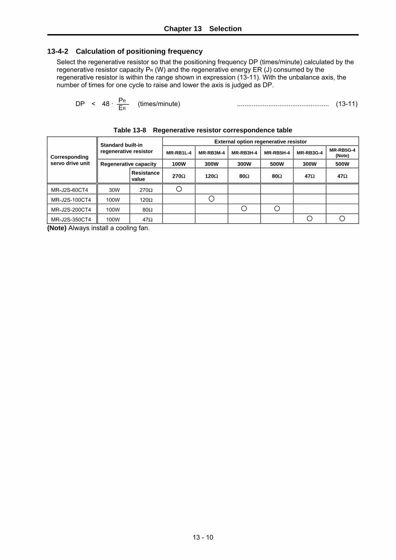
Chapter 13 Selection
13 - 10
13-4-2 Calculation of positioning frequency Select the regenerative resistor so that the positioning frequency DP (times/minute) calculated by the regenerative resistor capacity PR (W) and the regenerative energy ER (J) consumed by the regenerative resistor is within the range shown in expression (13-11). With the unbalance axis, the number of times for one cycle to raise and lower the axis is judged as DP.
DP < 48 · PR
ER (times/minute) .................................................. (13-11)
Table 13-8 Regenerative resistor correspondence table External option regenerative resistor Standard built-in
regenerative resistor MR-RB1L-4 MR-RB3M-4 MR-RB3H-4 MR-RB5H-4 MR-RB3G-4 MR-RB5G-4 (Note)
Regenerative capacity 100W 300W 300W 500W 300W 500W Corresponding servo drive unit
Resistance value 270Ω 120Ω 80Ω 80Ω 47Ω 47Ω
MR-J2S-60CT4 30W 270Ω
MR-J2S-100CT4 100W 120Ω
MR-J2S-200CT4 100W 80Ω
MR-J2S-350CT4 100W 47Ω (Note) Always install a cooling fan.

Chapter 13 Selection
13 - 11
13-5 Example of servo selection A servomotor is selected using a magazine with the following specifications as an example.
Specification item Unit Magazine axis
Axis type Rotation No. of mounting tools tools 40 Tool spacing mm 100 Magazine circumferential speed mm/min 40000
Maximum tool weight kg 10 Chain drive frictional force kgf 80 Motor deceleration ratio 1/200 Motor shaft conversion load inertia (with no tools) kg·cm2 20.0
Positioning time ms Within 4000Positioning frequency time/min 3 Motor brakes Available
13-5-1 Motor selection calculation
(1) Obtaining load inertia The load inertia in the selection is always judged as the maximum value. Because the load inertia without tools is provided by the specifications, the load inertia at maximum load when all tools are attached is obtained. The tool inertia for a chain-driven magazine can be calculated as the object of linear movement. Due to this, the motor shaft conversion load inertia of one tool weighing the maximum 10kg is obtained.
• Motor shaft conversion load inertia per tool: JT
Obtain the tool movement amount per motor rotation ΔS before calculating the inertia.
ΔS = Chain circumference × deceleration ratio = (40 × 100) · 1200 = 20 (mm)
Conversion to the motor shaft by the deceleration ratio is included in the movement amount per motor rotation. Refer to "13-7 Calculation of load inertia".
JT = W · ( ΔS20π )2 = 10 · ( 20
20π )2 = 1.013 (kg·cm2)
• Motor shaft conversion total load inertia: JL This is the sum of the load inertia with no tools and the tool inertia.
JL = 20.0 + 40 × 1.013 = 60.5 (kg·cm2)
(2) Obtaining unbalance torque The unbalance torque is the largest when all the tools are in the unbalance occurrence area on the left side of Fig. 13-2, and no tools are on the vertical movement area on the right side. For simplification purposes here, if it is assumed all seven tools in the unbalance occurrence area are in a part where they move vertically, then an unbalance weight of 70kg would act upon the magazine chain. If the magazine and motor are likened to 4000mm and 20mm circumference pulleys, as in Fig. 13-3, 70kg of unbalance weight acts upon the motor side pulley. Thus, the unbalance torque is obtained as follows:
TU = 70 × g × ((motor side pulley radius )1000mm = 70 × 9.8 × 20
1000 × 2π = 2.2 (N·m)
Fig. 13-2 40-magazine configuration
Circumferential speed = 40000mm/min
Tool spacing = 100mm
Position = 0° (change position)
Position = 180° (farthest point)
Unbalance occurrence area
Up
Down
Magazine side circumference : 4000mm
Motor side circumference
: 20mm
70kg
70kg
Deceleration ratio = 1/200
Fig. 13-3 Unbalance torque
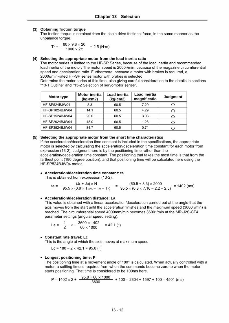
Chapter 13 Selection
13 - 12
(3) Obtaining friction torque The friction torque is obtained from the chain drive frictional force, in the same manner as the unbalance torque.
TF = 80 × 9.8 × 201000 × 2π = 2.5 (N·m)
(4) Selecting the appropriate motor from the load inertia ratio
The motor series is limited to the HF-SP Series, because of the load inertia and recommended load inertia of the motor. The motor speed is 2000r/min, because of the magazine circumferential speed and deceleration ratio. Furthermore, because a motor with brakes is required, a 2000r/min-rated HF-SP series motor with brakes is selected. Determine the motor series at this time, also giving careful consideration to the details in sections "13-1 Outline" and "13-2 Selection of servomotor series".
Motor type Motor inertia(kg•cm2)
Load inertia(kg•cm2)
Load inertia magnificatio Judgment
HF-SP524BJW04 8.3 60.5 7.29
HF-SP1024BJW04 14.1 60.5 4.29
HF-SP1524BJW04 20.0 60.5 3.03
HF-SP2024BJW04 48.0 60.5 1.26
HF-SP3524BJW04 84.7 60.5 0.71
(5) Selecting the appropriate motor from the short time characteristics
If the acceleration/deceleration time constant is included in the specifications, the appropriate motor is selected by calculating the acceleration/deceleration time constant for each motor from expression (13-2). Judgment here is by the positioning time rather than the acceleration/deceleration time constant. The positioning that takes the most time is that from the farthest point (180 degree position), and that positioning time will be calculated here using the HF-SP524BJW04 motor. • Acceleration/deceleration time constant: ta
This is obtained from expression (13-2).
ta = (JL + JM) × N95.5 × (0.8 × TMAX − TU − TF) =
(60.5 + 8.3) × 2000 95.5 × (0.8 × 7.16 − 2.2 − 2.5) = 1402 (ms)
• Acceleration/deceleration distance: La
This value is obtained with a linear acceleration/deceleration carried out at the angle that the axis moves from the start until the acceleration finishes and the maximum speed (3600°/min) is reached. The circumferential speed 4000mm/min becomes 3600°/min at the MR-J2S-CT4 parameter settings (angular speed setting).
La = 12 ×
3600 × 140260 × 1000 = 42.1 (°)
• Constant rate travel: Lc
This is the angle at which the axis moves at maximum speed.
Lc = 180 − 2 × 42.1 = 95.8 (°) • Longest positioning time: P
The positioning time at a movement angle of 180° is calculated. When actually controlled with a motor, a settling time is required from when the commands become zero to when the motor starts positioning. That time is considered to be 100ms here.
P = 1402 × 2 + 95.8 × 60 × 1000
3600 + 100 = 2804 + 1597 + 100 = 4501 (ms)

Chapter 13 Selection
13 - 13
The following table shows the results when these values are calculated for other motors in the same manner. The acceleration/deceleration time constants of the HF-SP1524BJW04 and HF-SP2024BJW04 motors do not change much. This is because the inertia of the motor itself greatly increases due to the larger flange sizes on HF-SP2024BJW04 or higher rated motors. An HF-SP1024BJW04 or higher rated motor satisfies the specifications (4000ms).
Motor type
Acceleration/ deceleration
time constant (ms)
Constant ratetravel distance
(°)
Constant rate travel time
(ms)
Longest positioning time (ms)
Judgment
HF-SP524BJW04 1402 95.9 1598 4502 HF-SP1024BJW04 232 166.1 2768 3332 HF-SP1524BJW04 135 171.9 2865 3235 HF-SP2024BJW04 125 172.5 2875 3225 HF-SP3524BJW04 86 174.8 2914 3186

Chapter 13 Selection
13 - 14
(6) Selecting the appropriate motor from the continuous characteristics The torque generated in each state is obtained using the HF-SP1024BJW04 motor as an example. In rotation axes, because the direction of the unbalance torque differs from that of linear axes and cannot be defined, the torque is always obtained as if it acts in the direction of the load. Because there is always a possibility that friction torque and unbalance torque act also when the motor is stopped, these are also considered in the calculation.
• Acceleration torque: Ta
Ta = 0.8 · TMAX = 0.8 × 14.1 = 11.3 (N·m) • Torque during constant rate travel
Tc = TU + TF = 2.2 + 2.5 = 4.7 (N·m) • Deceleration torque
Td = Ta − 2 × TF = 11.3 − 2 × 2.5 = 6.3 (N·m) • Torque during stop
Ts = TU + TF = 2.2 + 2.5 = 4.7 (N·m)
Following the specifications, the continuous effective load torque is obtained when positioning is carried out three times per minute.
Trms = 11.32 × 232 × 3 + 4.72 × 2768 × 3 + 6.32 × 232 × 3 + 4.72 × 50304
60 × 1000 = 4.85 (N·m)
The following table shows the results when the continuous effective load torque is obtained for other motors in the same manner. An HF-SP1524BJW04 or higher rated motor satisfies the expression (13-4).
During
acceleration During constant
rate travel During
deceleration During stop Motor type
Rated torque (N・m) Torque
(N•m) Time(ms)
Torque(N•m)
Time(ms)
Torque(N•m)
Time(ms)
Torque (N•m)
Time (ms)
Effectiveload
torque(N•m)
Judg-ment
HF-SP1024BJW04 4.77 11.3 696 4.7 8304 6.3 696 4.7 50304 4.85 HF-SP1524BJW04 7.16 17.2 405 4.7 8595 12.2 405 4.7 50595 4.98 HF-SP2024BJW04 9.55 22.9 375 4.7 8625 17.9 375 4.7 50625 5.21 HF-SP3524BJW04 16.7 40.1 258 4.7 8742 35.1 258 4.7 50742 5.84
As a result of the selection calculations above, the motors that satisfy conditions (4) to (6) are the HF-SP1524BJW04 to HF-SP3524BJW04 models. Thus, the appropriate motor for this magazine axis is the HF-SP1524BJW04 (MR-J2S-200CT4).
POINT Because there is always a possibility that friction torque and unbalance torque act also when the motor is stopped, the sum of these is calculated as the torque during stop.

Chapter 13 Selection
13 - 15
13-5-2 Regenerative resistor selection calculation Because unbalance torque occurs in this magazine axis, the regenerative load should be calculated as an unbalance axis. However, because the direction of the unbalance torque generation cannot be defined, the regenerative load is calculated from the load inertia only (as a horizontal axis).
(1) Obtaining the regeneration energy
The regeneration energy per braking is obtained from expression (13-7) for MR-J2S-200CT4+HF-SP1524BJW04.
ER = 5.48 × 10−7 × 0.85 × (60.5 + 20.0) × 20002 − 40 = 110.0 (J)
(2) Obtaining the tolerable No. of positionings The tolerable cycle operation frequency per minute DP is calculated for a standard built-in regenerative resistor. Refer to expression (13-11).
DP = 48 · PR
ER = 48 ×
100110.0 = 43.6 (times)
Because the No. of positionings shown in the specifications is 3 times/min., the standard built-in regenerative resistor can be judged to be sufficient.
POINT Try to choose a resistor with some allowance, because the regeneration load can easily become large compared to a horizontal axis.
13-5-3 Servo selection results
As a result of calculating the servo selection, the servo specifications for this magazine axis have been determined.
Item Type
Servo drive unit MR-J2S-200CT4 Servomotor HF-SP1524BJW04 Regenerative resistor Built-in
The shape of the motor shaft (selecting taper/straight) will be determined based on separate machine specifications.
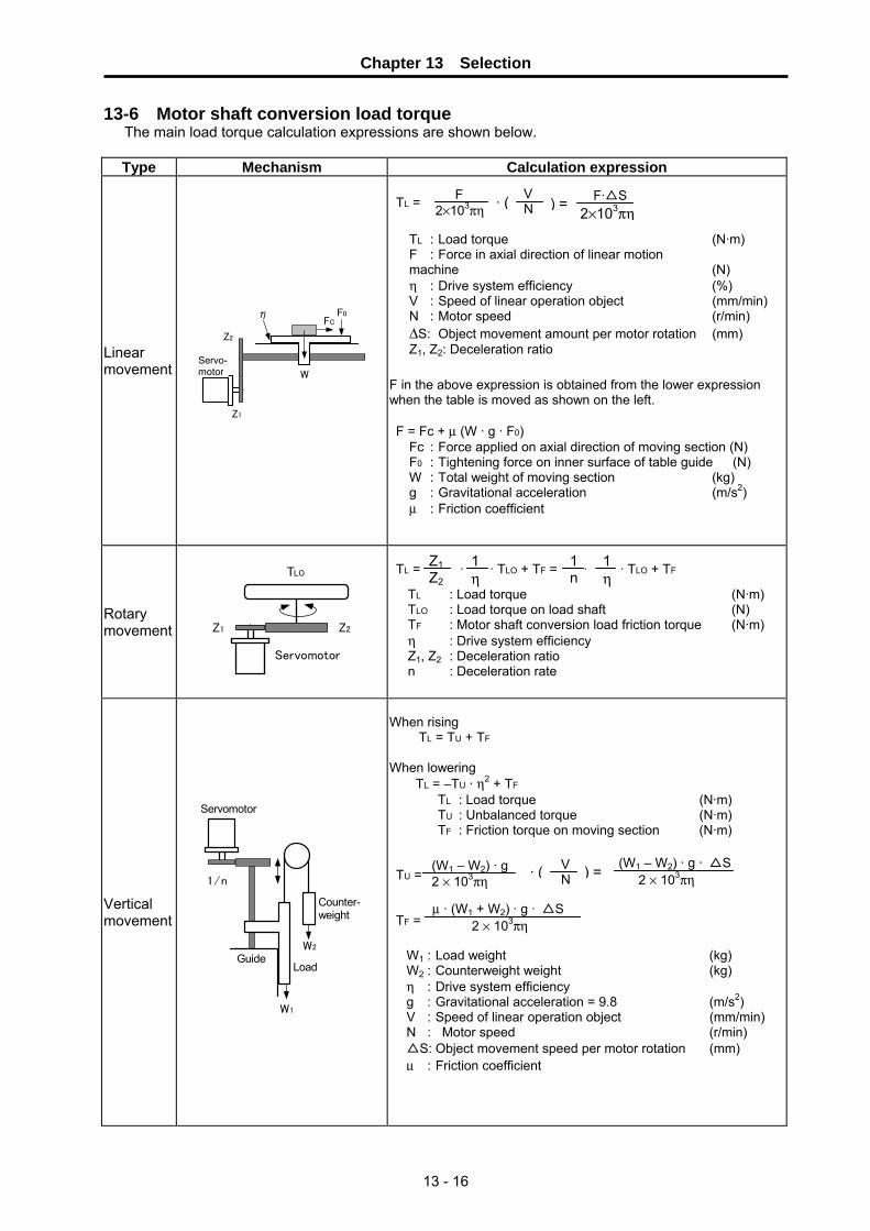
Chapter 13 Selection
13 - 16
13-6 Motor shaft conversion load torque The main load torque calculation expressions are shown below.
Type Mechanism Calculation expression
Linear movement W
Z1
Z2
FCF0η
Servo-motor
TL = F in the above expression is obtained from the lower expression when the table is moved as shown on the left. F = Fc + μ (W · g · F0)
Rotary movement
Servomotor
TLO
Z1 Z2
TL = · · TLO + TF = · · TLO + TF
Vertical movement
W2
W1
1/n
Servomotor
Guide
Counter-weight
Load
When rising TL = TU + TF When lowering TL = –TU · η2 + TF TU = TF =
F·△S 2×10³πη
VN
F 2×10³πη · ( ) =
Fc : Force applied on axial direction of moving section (N) F0 : Tightening force on inner surface of table guide (N) W : Total weight of moving section (kg) g : Gravitational acceleration (m/s2) μ : Friction coefficient
TL : Load torque (N·m) F : Force in axial direction of linear motion machine (N) η : Drive system efficiency (%) V : Speed of linear operation object (mm/min)N : Motor speed (r/min) ΔS: Object movement amount per motor rotation (mm) Z1, Z2: Deceleration ratio
TL : Load torque (N·m) TLO : Load torque on load shaft (N) TF : Motor shaft conversion load friction torque (N·m) η : Drive system efficiency Z1, Z2 : Deceleration ratio n : Deceleration rate
1n
1η
Z1Z2
1η
TL : Load torque (N·m)TU : Unbalanced torque (N·m)TF : Friction torque on moving section (N·m)
VN· ( ) =(W1 − W2) · g
2 × 10³πη (W1 – W2) · g · △S 2 × 10³πη
μ · (W1 + W2) · g · △S 2 × 10³πη
W1 : Load weight (kg) W2 : Counterweight weight (kg) η : Drive system efficiency g : Gravitational acceleration = 9.8 (m/s2) V : Speed of linear operation object (mm/min) N : Motor speed (r/min) △S: Object movement speed per motor rotation (mm) μ : Friction coefficient

Chapter 13 Selection
13 - 17
13-7 Expressions for load inertia calculation The calculation method for a representative load inertia is shown. Type Mechanism Calculation expression
Rotary shaft
φD1.
φD2.
JL = (D1
4 – D24) = (D1
2 – D22)
Cylinder When rotary shaft and cylinder shaft are deviated
D
Rotary shaft
R
JL = (D2 + 8R2)
Column a
ab
b
Rotary shaft
R
JL = W ( + R2 )
Object that moves linearly
W
V
N
Servomotor
JL = W ( · )2 = W ( )2
Suspended object
D
W
JL = W ( )2 + JP
Converted load Servomotor
Load AJA
N2
N1
N1
J11
J21
J31
Load BJBN3
J22
JL = J11 + (J21 + J22 + JA) · ( )2 + (J31 + JB) · ( )2
JL : Load inertia [kg·cm2] W : Weight of object that moves linearly [kg] N : Motor speed [r/min] V : Speed of object that moves linearly [mm/min]
W8
D2
N3 N1
N2 N1
a2 + b2
3
V 10
1 2πN
△S 20π
JL : Load inertia [kg·cm2] W : Weight of cylinder [kg] D : Outer diameter of cylinder [cm] R : Distance between rotary axis and cylinder axis [cm]
JL : Load inertia [kg·cm2] W : Weight of cylinder [kg] a.b.R : Left diagram [cm]
JL : Load inertia [kg·cm2] W : Weighty of object [kg] D : Diameter of pulley [cm] JP : Inertia of pulley [kg·cm2]
JL : Load inertia [kg·cm2] JA,JB : Inertia of load A, B [kg·cm2] J11~J31 : Inertia [kg·cm2] N1~N3 : Each shaft’s speed [r/min]
JL : Load inertia [kg·cm2] ρ : Density of cylinder material[kg·cm2] L : Length of cylinder [cm] D1 : Outer diameter of cylinder [cm] D2 : Inner diameter of cylinder [cm] W : Weight of cylinder [kg]
Reference data Material densities Iron ..... 7.80×10⁻³ [kg/cm3] Aluminum ..... 2.70×10⁻³ [kg/cm3]
Copper ..... 8.96×10⁻³ [kg/cm3]
Rotary shaft is cylinder center
π · ρ ·L 32
W 8


Appendix - 1
Appendix Parameter Lists

Appendix Parameter Lists
Appendix - 2
No. Abbrev. Parameter name Default value Unit Explanation Setting
range #001 ∗MSR Motor series 0000 Set the motor series. This is automatically
judged by the system when the default value (0000) is set.
#002 ∗RTY Regeneration option type Set the regenerative resistor type. Do not set values without a description.
(Initial value) 0 0 0 0
Selecting regenerative option 00: Regenerative option is not used. 01: FR-RC-H , FR-BU-H 80: MR-RB3H-4 81: MR-RB5H-4 82: MR-RB3G-4 83: MR-RB5G-4 86: MR-RB1L-4 87: MR-RB3M-4
#003 ∗PC1 Motor side gear ratio
(machine rotation ratio) 1 1 ~ 32767
#004 ∗PC2 Machine side gear ratio (motor rotation ratio)
1
Set the No. of gear teeth on the motor side and the No. of gear teeth on the machine side as an integer reduced to its lowest terms. Set the total gear ratio if there are multiple gear levels. For rotation axes, set the No. of motor rotations per machine rotation.
1 ~ 32767
#005 ∗PIT Feed pitch 360 ° (mm) Set 360 (default value) for rotation axes. Set the feed lead for linear axes.
1 ~ 32767
#006 INP In-position detection width 100 1/1000 ° (μm)
In-position is detected when the position droop becomes this setting value or less.
1 ~ 32767

Appendix Parameter Lists
Appendix - 3
No. Abbrev. Parameter name Default
value Unit Explanation Setting range
#007 ATU Auto-tuning Set the adjustment of the auto-tuning. Do not set values without a description.
Slight vibration suppression control selection This is validated when manual mode 2 is selected for the gain adjustment mode. 0: Invalid 1: Valid
(Initial value)0 1 0 2
Setting value
MR-J2S-CT4 series
MR-J2-CT series
(referance)
Response level
Machine response frequency
1 - Low 15Hz 2 1 20Hz 3 - 25Hz 4 - 30Hz 5 - 35Hz 6 2 45Hz 7 - 55Hz 8 3 70Hz 9 4 85Hz A 5 105Hz B - 130Hz C - 160Hz D - 200Hz E - 240Hz F - High 300Hz
Setting value Gain adjustment mode Remarks
0 Interpolation mode #008 PG1(position loop gain 1) is fixed.
1 Mode 1 Ordinary auto tuning
3* Auto tuning
Mode 2 #024 GD2(load inertia ratio) is fixed. Response level setting is valid.
4* Manual mode 1 Simple manual adjustment
2
Auto tuning invalid Manual
mode 2 Manual adjustment of all gains
Response level setting
Gain adjustment mode selection
(*) Setting value 3 and 4 are the modes added to MR-J2-CT.
#008 PG1 Position loop gain 1 70 rad/s Set the position loop gain of the model loop.
Determine the tracking ability regarding the position commands.
4 ~ 1000
#009 0 Not used. #010 EMGt Deceleration control time
constant 500 ms Set the deceleration time from the clamp
speed (Aspeed1). For normal rapid traverse, set the same value as the acceleration/deceleration time constant.
0 ~ 32768

Appendix Parameter Lists
Appendix - 4
No. Abbrev. Parameter name Default value Unit Explanation Setting
range #011 0 Not used. #012 0 Not used. #013 MBR Vertical axis drop
prevention time 0 ms Input the time to delay servo OFF when the
servo OFF command is input. Increase the setting by 100ms at a time and set the minimum value where the axis does not drop.
0 ~ 1000
#014 NCH Notch filter No. Set the frequency of the mechanical resonance control filter. Do not set values without a description.
Notch frequency selection
Notch depth selection
(Initial value)0 0 0 0
Setting Frequency Setting Frequency Setting Frequency Setting Frequency
00 Invalid 08 562.5 10 281.3 18 187.501 4500 09 500 11 264.7 19 180 02 2250 0A 450 12 250 1A 173.103 1500 0B 409.1 13 236.8 1B 166.704 1125 0C 375 14 225 1C 160.105 900 0D 346.2 15 214.3 1D 155.206 750 0E 321.4 16 204.5 1E 150 07 642.9 0F 300 17 195.7 1F 145.2
Setting Depth Gain0 Deep -40dB1 -14dB2
to -8dB
3 Shallow -4dB
#015 50 Not used #016 JIT Low-pass filter • adaptive
vibration suppression control
Low-pass filter•adaptive vibration suppression control Select low-pass filter•adaptive vibration suppression control.
For 2kW or more:
Selecting adaptive vibration suppression control 0: Invalid 1: Valid
Constantly detect frequency of the mechanical resonance, and generate a resonance filter to suppress the vibration of the machine.
2: Held Stop detecting mechanical resonance, holding the filter characteristics generated up to this point.
Selecting adaptive vibration suppression control sensitivity Set the sensitivity of detecting mechanical resonance.0: Normal 1: Highly sensitive
VG2 setting value x 10 2π x (1+GD2 setting value x 0.1)
[Hz]
Selecting low-pass filter 0: Valid (automatic adjustment) 1: Invalid When valid is selected, the filter in the range indicated with the following expressions is automatically set. For 1kW or less:
(Initial value)0 0 0 0
VG2 setting value x 5 2π x (1+GD2 setting value x 0.1)
[Hz]
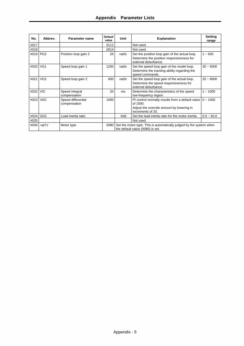
Appendix Parameter Lists
Appendix - 5
No. Abbrev. Parameter name Default
value Unit Explanation Setting range
#017 0111 Not used. #018 0014 Not used. #019 PG2 Position loop gain 2 25 rad/s Set the position loop gain of the actual loop.
Determine the position responsiveness for external disturbance.
1 ~ 500
#020 VG1 Speed loop gain 1 1200 rad/s Set the speed loop gain of the model loop. Determine the tracking ability regarding the speed commands.
20 ~ 5000
#021 VG2 Speed loop gain 2 600 rad/s Set the speed loop gain of the actual loop. Determine the speed responsiveness for external disturbance.
20 ~ 8000
#022 VIC Speed integral compensation
20 ms Determine the characteristics of the speed low-frequency region.
1 ~ 1000
#023 VDC Speed differential compensation
1000 PI control normally results from a default value of 1000. Adjust the override amount by lowering in increments of 20.
0 ~ 1000
#024 GD2 Load inertia ratio -fold Set the load inertia ratio for the motor inertia. 0.0 ~ 50.0 #025 Not used #030 ∗MTY Motor type 0080 Set the motor type. This is automatically judged by the system when
the default value (0080) is set.

Appendix Parameter Lists
Appendix - 6
No. Abbrev. Parameter name Defaul
t value Unit Explanation Setting range
#050 MD1 D/A output channel 1 data Set the Nos. of the data to be output on D/A output channel 1.
Nos. 0 0 0 0 (Default setting value)
No. Analog output data
0Servomotor rotation speed (±8V/Max. rotation speed)
1 Torque (±8V/Max. torque)
2Servomotor rotation speed (±8V/Max. rotation speed)
3 Torque (±8V/Max. torque)
4Current command (±8V/Max. current command)
5 Speed command (±8V/Max. rotation speed) 6 Droop 1 (±10V/128pulse) 7 Droop 2 (±10V/2048pulse) 8 Droop 3 (±10V/8192pulse) 9 Droop 4 (±10V/32768pulse) A Droop 5 (±10V/131072pulse) B Bus voltage (+8V/400V)
#051 MO1 D/A output channel 1 output
offset 0 mV Set this value when the zero level of D/A
output channel 1 is not suitable. −999 ~ 999
#052 0 Not used #053 MD2 D/A output channel 2 data
No. Set the Nos. of the data to be output on D/A output channel 2. The descriptions are the same as those of #050 MD1D/A output channel data No. 1.
#054 MO2 D/A output channel 2 output offset
0 mV Set this value when the zero level of D/A output channel 2 is not suitable.
−999 ~ 999
#055 0 Not used #100 ∗station No. of indexing stations 2 Set the No. of stations. For linear axes, this
value is expressed by: No. of divisions = No. of stations − 1.
2 ~ 360
#101 ∗Cont1 Control parameter 1 This is a HEX setting parameter. Set bits without a description to their default values.
bit F E D C B A 9 8 7 6 5 4 3 2 1 0 Default value 0 0 0 0 0 0 1 0 0 0 0 0 0 0 0 0
bit Meaning when "0" is set. Meaning when "1" is set. 0 1 High-speed zero point return after
establishment of zero point. Dog-type return for each zero point return operation.
2 3 4 5 6 7 8 Reference point return direction
(+) Reference point return direction (−)
9 Rotation direction determined by DIR
Rotation direction in the shortcut direction
A Machine reference position becomes the reference point
Electrical zero point becomes the reference position
B C D Coordinate zero point creation
valid Zero point established at power supply ON position
E Rotation direction in DIR or in the shortcut direction
Rotation direction in the random position command sign direction
F Stopper direction is positioning direction
Stopper direction is in the sign direction of the stopper amount

Appendix Parameter Lists
Appendix - 7
No. Abbrev. Parameter name Defaul
t value Unit Explanation Setting range
#102 ∗Cont2 Control parameter 2 This is a HEX setting parameter. Set bits without a description to their default values.
bit F E D C B A 9 8 7 6 5 4 3 2 1 0 Default value 0 0 0 0 0 0 0 0 1 0 0 0 0 1 1 0
bit Meaning when "0" is set. Meaning when "1" is set. 0 1 Error not corrected at servo OFF Error corrected at servo OFF 2 Linear axis Rotation axis
3 Station assignment direction CW Station assignment direction CCW
4 Uniform index Non-uniform index 5 DO channel standard assignment DO channel reverse assignment 6 2-wire detector communication 4-wire detector communication 7 Incremental detection Absolute position detection 8 9 A B C D E
F
#103 ∗Emgcont Emergency stop control
bit F E D C B A 9 8 7 6 5 4 3 2 1 0 Default value 0 0 0 0 0 0 0 0 0 0 0 0 0 0 0 1
bit Meaning when "0" is set. Meaning when "1" is set.
0 External emergency stop valid External emergency stop invalid (default value)
1 Dynamic brake stop at emergency stop
Deceleration control stop at emergency stop
2 CNC bus emergency stop input valid
CNC bus emergency stop input invalid
3 CNC bus emergency stop output valid
CNC bus emergency stop output invalid
4 5 6 7 8 9 A B C D E
F
#104 ∗tleng Linear axis stroke length 100.000 mm Set the movement stroke length for linear axes. This is meaningless when setting non-uniform assignments or commanding random positions.
0.001 ~ 99999.999
#110 ZRNspeed Reference point return speed
1000 °/min (mm/min)
Set the clamp value of the feedrate when a reference point return is carried out. The feedrate becomes the manual operation speed of the parameter group selected at that time, but it is clamped by this parameter setting value.
1 ~ 100000
#111 ZRNcreep Reference point return creep speed
200 °/min (mm/min)
Set the approach speed to the reference point after dog detection during a reference point return.
1 ~ 65535

Appendix Parameter Lists
Appendix - 8
No. Abbrev. Parameter name Default
value Unit Explanation Setting range
#112 grid mask Grid mask 0 1/1000 ° (μm)
Set the amount that the dog is artificially extended. Set 1/2 the grid spacing as a standard.
0 ~ 65536
#113 ∗ grspc Grid spacing 0 1/2n divisions
Divide the grid spacing that is the conventional motor rotation movement amount into 2, 4, 8, or 16 divisions.
0 ~ 4
#114 ZRNshift Reference point shift amount
0 1/1000 ° (μm)
Set the shift amount in a dog-type reference point return from the electric zero point determined on the grid to the reference point.
0 ~ 65536
#115 ST.offset Station offset 0.000 ° (mm) Set the distance (offset) from the reference point to station 1.
−99999.999 ~99999.999
#116 ∗ABS Base Absolute position zero point 0.000 ° (mm) When movement of the machine coordinate zero point from the reference point is required during absolute position default setting, set that movement amount.
−99999.999 ~99999.999
#117 Limit (+) Soft limit (+) 1.000 mm Commands in the plus direction that exceed this setting value are not possible. If the machine is in a position exceeding the setting value, commands in the minus direction are possible. The soft limit function will not operate if Limit (+) and Limit (−) are set to the same value.
−99999.999 ~99999.999
#118 Limit (−) Soft limit (−) 1.000 mm Commands in the minus direction that exceed this value are not possible. If the machine is in a position exceeding the setting value, commands in the plus direction are possible.
−99999.999 ~99999.999
#120 ABS type Absolute position detection parameter
This is a HEX setting parameter. Set bits without a description to their default values.
bit F E D C B A 9 8 7 6 5 4 3 2 1 0 Default value 0 0 0 0 0 0 0 0 0 0 0 0 0 1 0 0
bit Meaning when "0" is set. Meaning when "1" is set. 0 1 Dogless-type method default
setting Dog-type method default setting
2 Mechanical stopper method default setting
Reference point matching method default setting
3 Electrical zero point direction (+) Electrical zero point direction (−) 4 5 6 7 8 9 A B C D E
F
#123 ABS check Absolute position power OFF tolerable movement value
0.000 ° (mm) Set the value for the tolerable amount of movement for a machine that moved during power OFF in an absolute position detection system. The "Absolute position power OFF movement exceeded (ABS)" signal will turn ON if the machine moves more that this setting value during while the power is OFF. The movement amount is not checked when this parameter is set to 0.000.
0.000 ~ 99999.999
#130 backlash Backlash compensation amount
0 1/1000 ° (μm)
Set the backlash compensation amount. 0 ~ 9999
#132 0 Not used #133 0 Not used #134 0 Not used #135 0 Not used

Appendix Parameter Lists
Appendix - 9
< Operation parameter group 1 >
No. Abbrev. Parameter name Default value Unit Explanation Setting
range #150 Aspeed1 Operation parameter group 1
Automatic operation speed 5000 ° /min
(mm/min)Set the feedrate during automatic operation when operation parameter group 1 is selected. This parameter functions as the clamp value for the automatic operation speeds and manual operation speeds of all operation groups. A speed exceeding Aspeed1 cannot be commanded, even if set in the parameters.
1 ~ 100000
#151 Mspeed1 Operation parameter group 1 Manual operation speed
2000 ° /min (mm/min)
Set the feedrate during manual operation and JOG operation when operation parameter group 1 is selected.
1 ~ 100000
#152 time1.1 Operation parameter group 1 Acceleration/deceleration time constant 1
100 ms Set the linear acceleration/deceleration time for the operation parameter group 1 automatic operation speed (clamp speed) when operation parameter group 1 is selected. When operating at speeds less than the clamp speed, the axis will linearly accelerate/decelerate at the inclination determined above. When this is set together with acceleration/deceleration time constant 2, S-character acceleration/deceleration is carried out. In this case, set the acceleration/deceleration time of the linear part in this parameter.
1 ~ 9999
#153 time1.2 Operation parameter group 1 Acceleration/deceleration time constant 2
1 ms Set this parameter when carrying out S-character acceleration/deceleration. When S-character acceleration/deceleration is carried out, set the total time of the non-linear parts. When 1 is set in this parameter, linear acceleration/deceleration is carried out. For the handle feed operation mode, this becomes the linear acceleration/deceleration that is the acceleration/deceleration time constant.
1 ~ 9999
#154 TL1 Operation parameter group 1 Torque limit value
500 % Set the motor output torque limit value when operation parameter group 1 is selected. At the default value, the torque is limited at the maximum torque of the motor specifications. Set the default value when torque limiting is not especially required. In the stopper positioning operation mode, this becomes the torque limit value when positioning to the stopper starting coordinates.
1 ~ 500
#155 OD1 Operation parameter group 1 Excessive error detection width
100 ° (mm) Set the excessive error detection width when operation parameter group 1 is selected. An excessive error alarm (S03 0052) is detected when the position droop becomes larger than this setting value.
0 ~ 32767
#156 just1 Operation parameter group 1 Set position output width
0.500 ° (mm) The signal indicating that the machine position is at any one of the stations is the set position reached (JST) signal. During automatic operation, the automatic set position reached (JSTA) signal is also output under the same conditions. Set the tolerable values at which these signals are output when operation parameter group 1 is selected. These signals turn OFF when the machine position is separated from the station by more than this value.
0.000 ~ 99999.999
#157 near1 Operation parameter group 1 Near set position output width
1.000 ° (mm) The signal indicating that the machine position is near any one of the station positions is the near set position (NEAR) signal. Set the tolerable values at which these signals are output when operation parameter group 1 is selected. These values are generally set wider than the set position output width. During operations, this is related to special commands when the station selection is 0. Refer to section "6-4-3 Automatic operation."
0.000 ~ 99999.999

Appendix Parameter Lists
Appendix - 10
< Operation parameter group 2 >
No. Abbrev. Parameter name Default value Unit Explanation Setting
range #158 Aspeed2 Operation parameter group 2
Automatic operation speed 5000 ° /min
(mm/min)Set the feedrate during automatic operation when operation parameter group 2 is selected.
1 ~ 100000
#159 Mspeed2 Operation parameter group 2 Manual operation speed
2000 ° /min (mm/min)
Set the feedrate during manual operation and JOG operation when operation parameter group 2 is selected.
1 ~ 100000
#160 time2.1 Operation parameter group 2 Acceleration/deceleration time constant 1
100 ms Set the linear acceleration/deceleration time for the operation parameter group 1 automatic operation speed (clamp speed) when operation parameter group 2 is selected. When operating at speeds less than the clamp speed, the axis will linearly accelerate/decelerate at the inclination determined above. When this is set together with acceleration/deceleration time constant 2, S-character acceleration/deceleration is carried out. In this case, set the acceleration/deceleration time of the linear part in this parameter.
1 ~ 9999
#161 time2.2 Operation parameter group 2 Acceleration/deceleration time constant 2
1 ms Set this parameter when carrying out S-character acceleration/deceleration. When S-character acceleration/deceleration is carried out, set the total time of the non-linear parts. When 1 is set in this parameter, linear acceleration/deceleration is carried out. For the handle feed operation mode, this becomes the linear acceleration/deceleration that is the acceleration/deceleration time constant.
1 ~ 9999
#162 TL2 Operation parameter group 2 Torque limit value
500 % Set the motor output torque limit value when operation parameter group 2 is selected. At the default value, the torque is limited at the maximum torque of the motor specifications. In the stopper positioning operation mode, this becomes the torque limit value during stopper operation.
1 ~ 500
#163 OD2 Operation parameter group 2 Excessive error detection width
100 ° (mm) Set the excessive error detection width when operation parameter group 2 is selected. An excessive error alarm (S03 0052) is detected when the position droop becomes larger than this setting value. In the stopper positioning operation mode, this becomes the torque limit value excessive error detection width during stopper operation.
0 ~ 32767
#164 just2 Operation parameter group 2 Set position output width
0.500 ° (mm) The signal indicating that the machine position is at any one of the stations is the set position reached (JST) signal. During automatic operation, the automatic set position reached (JSTA) signal is also output under the same conditions. Set the tolerable values at which these signals are output when operation parameter group 2 is selected. These signals turn OFF when the machine position is separated from the station by more than this value.
0.000 ~ 99999.999
#165 near2 Operation parameter group 2 Near set position output width
1.000 ° (mm) The signal indicating that the machine position is near any one of the station positions is the near set position (NEAR) signal. Set the tolerable values at which these signals are output when operation parameter group 2 is selected. These values are generally set wider than the set position output width. During operations, this is related to special commands when the station selection is 0. Refer to section "6-4-3 Automatic operation."
0.000 ~ 99999.999

Appendix Parameter Lists
Appendix - 11
< Operation parameter group 3 >
No. Abbrev. Parameter name Default value Unit Explanation Setting
range #166 Aspeed3 Operation parameter group 3
Automatic operation speed 5000 ° /min
(mm/min)Set the feedrate during automatic operation when operation parameter group 3 is selected.
1 ~ 100000
#167 Mspeed3 Operation parameter group 3 Manual operation speed
2000 ° /min (mm/min)
Set the feedrate during manual operation and JOG operation when operation parameter group 3 is selected.
1 ~ 100000
#168 time3.1 Operation parameter group 3 Acceleration/deceleration time constant 1
100 ms Set the linear acceleration/deceleration time for the operation parameter group 1 automatic operation speed (clamp speed) when operation parameter group 3 is selected. When operating at speeds less than the clamp speed, the axis will linearly accelerate/decelerate at the inclination determined above. When this is set together with acceleration/deceleration time constant 2, S-character acceleration/deceleration is carried out. In this case, set the acceleration/deceleration time of the linear part in this parameter.
1 ~ 9999
#169 time3.2 Operation parameter group 3 Acceleration/deceleration time constant 2
1 ms Set this parameter when carrying out S-character acceleration/deceleration. When S-character acceleration/deceleration is carried out, set the total time of the non-linear parts. When 1 is set in this parameter, linear acceleration/deceleration is carried out. For the handle feed operation mode, this becomes the linear acceleration/deceleration that is the acceleration/deceleration time constant.
1 ~ 9999
#170 TL3 Operation parameter group 3 Torque limit value
500 % Set the motor output torque limit value when operation parameter group 3 is selected. At the default value, the torque is limited at the maximum torque of the motor specifications. In the stopper positioning operation mode, this becomes the pressing torque limit value after completion of the positioning.
1 ~ 500
#171 OD3 Operation parameter group 3 Excessive error detection width
100 ° (mm) Set the excessive error detection width when operation parameter group 3 is selected. An excessive error alarm (S03 0052) is detected when the position droop becomes larger than this setting value. In the stopper positioning operation mode, this becomes the excessive error detection width during pressing after completion of the positioning.
0 ~ 32767
#172 just3 Operation parameter group 3 Set position output width
0.500 ° (mm) The signal indicating that the machine position is at any one of the stations is the set position reached (JST) signal. During automatic operation, the automatic set position reached (JSTA) signal is also output under the same conditions. Set the tolerable values at which these signals are output when operation parameter group 3 is selected. These signals turn OFF when the machine position is separated from the station by more than this value.
0.000 ~ 99999.999
#173 near3 Operation parameter group 3 Near set position output width
1.000 ° (mm) The signal indicating that the machine position is near any one of the station positions is the near set position (NEAR) signal. Set the tolerable values at which these signals are output when operation parameter group 3 is selected. These values are generally set wider than the set position output width. During operations, this is related to special commands when the station selection is 0. Refer to section "6-4-3 Automatic operation."
0.000 ~ 99999.999
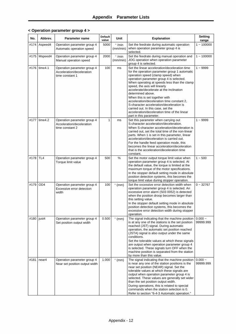
Appendix Parameter Lists
Appendix - 12
< Operation parameter group 4 >
No. Abbrev. Parameter name Default value Unit Explanation Setting
range #174 Aspeed4 Operation parameter group 4
Automatic operation speed 5000 ° /min
(mm/min)Set the feedrate during automatic operation when operation parameter group 4 is selected.
1 ~ 100000
#175 Mspeed4 Operation parameter group 4 Manual operation speed
2000 ° /min (mm/min)
Set the feedrate during manual operation and JOG operation when operation parameter group 4 is selected.
1 ~ 100000
#176 time4.1 Operation parameter group 4 Acceleration/deceleration time constant 1
100 ms Set the linear acceleration/deceleration time for the operation parameter group 1 automatic operation speed (clamp speed) when operation parameter group 4 is selected. When operating at speeds less than the clamp speed, the axis will linearly accelerate/decelerate at the inclination determined above. When this is set together with acceleration/deceleration time constant 2, S-character acceleration/deceleration is carried out. In this case, set the acceleration/deceleration time of the linear part in this parameter.
1 ~ 9999
#177 time4.2 Operation parameter group 4 Acceleration/deceleration time constant 2
1 ms Set this parameter when carrying out S-character acceleration/deceleration. When S-character acceleration/deceleration is carried out, set the total time of the non-linear parts. When 1 is set in this parameter, linear acceleration/deceleration is carried out. For the handle feed operation mode, this becomes the linear acceleration/deceleration that is the acceleration/deceleration time constant.
1 ~ 9999
#178 TL4 Operation parameter group 4 Torque limit value
500 % Set the motor output torque limit value when operation parameter group 4 is selected. At the default value, the torque is limited at the maximum torque of the motor specifications. In the stopper default setting mode in absolute position detection systems, this becomes the torque limit value during stopper operation.
1 ~ 500
#179 OD4 Operation parameter group 4 Excessive error detection width
100 ° (mm) Set the excessive error detection width when operation parameter group 4 is selected. An excessive error alarm (S03 0052) is detected when the position droop becomes larger than this setting value. In the stopper default setting mode in absolute position detection systems, this becomes the excessive error detection width during stopper operation.
0 ~ 32767
#180 just4 Operation parameter group 4 Set position output width
0.500 ° (mm) The signal indicating that the machine position is at any one of the stations is the set position reached (JST) signal. During automatic operation, the automatic set position reached (JSTA) signal is also output under the same conditions. Set the tolerable values at which these signals are output when operation parameter group 4 is selected. These signals turn OFF when the machine position is separated from the station by more than this value.
0.000 ~ 99999.999
#181 near4 Operation parameter group 4 Near set position output width
1.000 ° (mm) The signal indicating that the machine position is near any one of the station positions is the near set position (NEAR) signal. Set the tolerable values at which these signals are output when operation parameter group 4 is selected. These values are generally set wider than the set position output width. During operations, this is related to special commands when the station selection is 0. Refer to section "6-4-3 Automatic operation."
0.000 ~ 99999.999

Appendix Parameter Lists
Appendix - 13
No. Abbrev. Parameter name Default
value Unit Explanation Setting range
#190 stops2 Station 2 coordinate value #191 stops3 Station 3 coordinate value #192 stops4 Station 4 coordinate value #193 stops5 Station 5 coordinate value #194 stops6 Station 6 coordinate value #195 stops7 Station 7 coordinate value #196 stops8 Station 8 coordinate value #197 stops9 Station 9 coordinate value
0.000 ° (mm) Set the coordinate value of each station when non-uniform assignment is selected. The station 1 coordinate value is fixed at 0.000 (machine coordinate zero point).
−99999.999 ~99999.999
#200 PSWcheck PSW detection method This is a HEX setting parameter. Set bits without a description to their default values.
bit F E D C B A 9 8 7 6 5 4 3 2 1 0 Default value 0 0 0 0 0 0 0 0 0 0 0 0 0 0 0 0
bit position
switch Meaning when "0" is set. Meaning when "1" is set.
0 PSW1 1 PSW2 2 PSW3 3 PSW4 4 PSW5 5 PSW6 6 PSW7 7 PSW8
The position switch output is judged by the machine position of the command system.
The position switch output is judged by the machine FB position (actual position).
8 9 A B C D E
F
#201 #202
PSW1dog1 PSW1dog2
PSW1 region setting 1 PSW1 region setting 2
#203 #204
PSW2dog1 PSW2dog2
PSW2 region setting 1 PSW2 region setting 2
#205 #206
PSW3dog1 PSW3dog2
PSW3 region setting 1 PSW3 region setting 2
#207 #208
PSW4dog1 PSW4dog2
PSW4 region setting 1 PSW4 region setting 2
#209 #210
PSW5dog1 PSW5dog2
PSW5 region setting 1 PSW5 region setting 2
#211 #212
PSW6dog1 PSW6dog2
PSW6 region setting 1 PSW6 region setting 2
#213 #214
PSW7dog1 PSW7dog2
PSW7 region setting 1 PSW7 region setting 2
#215 #216
PSW8dog1 PSW8dog2
PSW8 region setting 1 PSW8 region setting 2
0.000 ° (mm) When the machine position is in the region between region settings 1 and 2, the position switch of each No. will turn ON. The size of the setting value for region setting 1 and 2 does not affect the position switch operation. For rotation axes, the output turns ON at the region not including 0.000°
−99999.999 ~99999.999
#220 push Stopper amount 0.000 ° (mm) Set the command stroke of the stopper operation during stopper positioning operations.
0.000 ~ 359.999
#221 pusht1 Stopper standby time 0 ms Set the standby time from the stopper starting coordinate positioning to the stopper operation start during stopper positioning operations.
0 ~ 9999
#222 pusht2 Stopper torque release time 0 ms Set the time from the completion of the stopper operation to the changeover of the pressing torque during stopper positioning operations.
0 ~ 9999

Appendix Parameter Lists
Appendix - 14
No. Abbrev. Parameter name Default
value Unit Explanation Setting range
#223 pusht3 Set position signal output delay time
0 ms Set the time from the completion of the stopper operation to the output of the automatic set position reached (JSTA), set position reached (JST), and near set position (NEAR) signals during stopper positioning operations.
0 ~ 9999

Revision History
Date of revision Manual No. Revision details
Dec. 2005 IB(NA)1500149-A First edition created.
Mar. 2006 IB(NA)1500149-B The section "11-4-2 Coasting amount" was revised.
Mar. 2007 IB(NA)1500149-C • "Transportation restrictions for lithium batteries" was revised. • "Compliance with Restrictions in China" was revised. • The type names of the detector cable for the servomotor and its
connector set were added. • Descriptions of the compliant OS for the setup software were changed. • "Global service network" was revised.
May. 2007 IB(NA)1500149-D • "Introduction" and "Precautions for safety" were revised. • Method to insert a cable into the main circuit connector and control
circuit connector was changed. • "BTCASE" was added to the battery option. • "4-2 Battery option (MDS-A-BT, MR-BAT)" was revised. • "4-10-3 Surge absorber" was revised. • "Global service network" was revised.


Global service network
NORTH AMERICA FA Center EUROPEAN FA Center
ASEAN FA Center
CHINA FA Center
TAIWAN FA Center
HONG KONG FA Center
KOREAN FA Center
North America FA Center (MITSUBISHI ELECTRIC AUTOMATION INC.)
Illinois CNC Service Center 500 CORPORATE WOODS PARKWAY, VERNON HILLS, IL. 60061, U.S.A. TEL: +1-847-478-2500 (Se FAX: +1-847-478-2650 (Se California CNC Service Center 5665 PLAZA DRIVE, CYPRESS, CA. 90630, U.S.A. TEL: +1-714-220-4796 FAX: +1-714-229-3818 Georgia CNC Service Center 2810 PREMIERE PARKWAY SUITE 400, DULUTH, GA., 30097, U.S.A. TEL: +1-678-258-4500 FAX: +1-678-258-4519 New Jersey CNC Service Center 200 COTTONTAIL LANE SOMERSET, NJ. 08873, U.S.A. TEL: +1-732-560-4500 FAX: +1-732-560-4531 Michigan CNC Service Satellite 2545 38TH STREET, ALLEGAN, MI., 49010, U.S.A. TEL: +1-847-478-2500 FAX: +1-269-673-4092 Ohio CNC Service Satellite 62 W. 500 S., ANDERSON, IN., 46013, U.S.A. TEL: +1-847-478-2608 FAX: +1-847-478-2690 Texas CNC Service Satellite 1000, NOLEN DRIVE SUITE 200, GRAPEVINE, TX. 76051, U.S.A. TEL: +1-817-251-7468 FAX: +1-817-416-1439 Canada CNC Service Center 4299 14TH AVENUE MARKHAM, ON. L3R OJ2, CANADA TEL: +1-905-475-7728 FAX: +1-905-475-7935 Mexico CNC Service Center MARIANO ESCOBEDO 69 TLALNEPANTLA, 54030 EDO. DE MEXICO TEL: +52-55-9171-7662 FAX: +52-55-9171-7698 Monterrey CNC Service Satellite ARGENTINA 3900, FRACC. LAS TORRES, MONTERREY, N.L., 64720, MEXICO TEL: +52-81-8365-4171 FAX: +52-81-8365-4171 Brazil MITSUBISHI CNC Agent Service Center (AUTOMOTION IND. COM. IMP. E EXP. LTDA.) ACESSO JOSE SARTORELLI, KM 2.1 18550-000 BOITUVA – SP, BRAZIL TEL: +55-15-3363-9900 FAX: +55-15-3363-9911
European FA Center (MITSUBISHI ELECTRIC EUROPE B.V.)
Germany CNC Service Center GOTHAER STRASSE 8, 40880 RATINGEN, GERMANY TEL: +49-2102-486-0 FAX:+49-2102486-591 South Germany CNC Service Center KURZE STRASSE. 40, 70794 FILDERSTADT-BONLANDEN, GERMANY TEL: +49-711-3270-010 FAX: +49-711-3270-0141 France CNC Service Center 25, BOULEVARD DES BOUVETS, 92741 NANTERRE CEDEX FRANCE TEL: +33-1-41-02-83-13 FAX: +33-1-49-01-07-25 Lyon CNC Service Satellite U.K CNC Service Center TRAVELLERS LANE, HATFIELD, HERTFORDSHIRE, AL10 8XB, U.K. TEL: +44-1707-282-846 FAX:-44-1707-278-992 Italy CNC Service Center ZONA INDUSTRIALE VIA ARCHIMEDE 35 20041 AGRATE BRIANZA, MILANO ITALY TEL: +39-039-60531-342 FAX: +39-039-6053-206 Spain CNC Service Satellite CTRA. DE RUBI, 76-80 -APDO.420 08190 SAINT CUGAT DEL VALLES, BARCELONA SPAIN TEL: +34-935-65-2236 FAX: Turkey MITSUBISHI CNC Agent Service Center (GENEL TEKNIK SISTEMLER LTD. STI.) DARULACEZE CAD. FAMAS IS MERKEZI A BLOCK NO.43 KAT2 80270 OKMEYDANI ISTANBUL, TURKEY TEL: +90-212-320-1640 FAX: +90-212-320-1649 Poland MITSUBISHI CNC Agent Service Center (MPL Technology Sp. z. o. o) UL SLICZNA 34, 31-444 KRAKOW, POLAND TEL: +48-12-632-28-85 FAX: Wroclaw MITSUBISHI CNC Agent Service Satellite (MPL Technology Sp. z. o. o) UL KOBIERZYCKA 23, 52-315 WROCLAW, POLAND TEL: +48-71-333-77-53 FAX: +48-71-333-77-53 Czech MITSUBISHI CNC Agent Service Center (AUTOCONT CONTROL SYSTEM S.R.O. ) NEMOCNICNI 12, 702 00 OSTRAVA 2 CZECH REPUBLIC TEL: +420-596-152-426 FAX: +420-596-152-112
ASEAN FA Center (MITSUBISHI ELECTRIC ASIA PTE. LTD.) Singapore CNC Service Center 307 ALEXANDRA ROAD #05-01/02 MITSUBISHI ELECTRIC BUILDING SINGAPORE 159943 TEL: +65-6473-2308 FAX: +65-6476-7439 Thailand MITSUBISHI CNC Agent Service Center (F. A. TECH CO., LTD) 898/19,20,21,22 S.V. CITY BUILDING OFFICE TOWER 1 FLOOR 12,14 RAMA III RD BANGPONGPANG, YANNAWA, BANGKOK 10120. THAILAND TEL: +66-2-682-6522 FAX: +66-2-682-6020 Malaysia MITSUBISHI CNC Agent Service Center (FLEXIBLE AUTOMATION SYSTEM SDN. BHD.) 60, JALAN USJ 10/1B 47620 UEP SUBANG JAYA SELANGOR DARUL EHSAN MALAYSIA TEL: +60-3-5631-7605 FAX: +60-3-5631-7636 JOHOR MITSUBISHI CNC Agent Service Satellite (FLEXIBLE AUTOMATION SYSTEM SDN. BHD.) NO. 16, JALAN SHAHBANDAR 1, TAMAN UNGKU TUN AMINAH, 81300 SKUDAI, JOHOR MALAYSIA TEL: +60-7-557-8218 FAX: +60-7-557-3404 Indonesia MITSUBISHI CNC Agent Service Center (PT. AUTOTEKNINDO SUMBER MAKMUR) WISMA NUSANTARA 14TH FLOOR JL. M.H. THAMRIN 59, JAKARTA 10350 INDONESIA TEL: +62-21-3917-144 FAX: +62-21-3917-164 India MITSUBISHI CNC Agent Service Center (MESSUNG SALES & SERVICES PVT. LTD.) B-36FF, PAVANA INDUSTRIAL PREMISES M.I.D.C., BHOASRI PUNE 411026, INDIA TEL: +91-20-2711-9484 FAX: +91-20-2712-8115 BANGALORE MITSUBISHI CNC Agent Service Satellite (MESSUNG SALES & SERVICES PVT. LTD.) S 615, 6TH FLOOR, MANIPAL CENTER, BANGALORE 560001, INDIA TEL: +91-80-509-2119 FAX: +91-80-532-0480 Delhi MITSUBISHI CNC Agent Parts Center (MESSUNG SALES & SERVICES PVT. LTD.) 1197, SECTOR 15 PART-2, OFF DELHI-JAIPUR HIGHWAY BEHIND 32ND MILESTONE GURGAON 122001, INDIA TEL: +91-98-1024-8895 FAX: Philippines MITSUBISHI CNC Agent Service Center (FLEXIBLE AUTOMATION SYSTEM CORPORATION) UNIT No.411, ALABAMG CORPORATE CENTER KM 25. WEST SERVICE ROAD SOUTH SUPERHIGHWAY, ALABAMG MUNTINLUPA METRO MANILA, PHILIPPINES 1771 TEL: +63-2-807-2416 FAX: +63-2-807-2417 Vietnam MITSUBISHI CNC Agent Service Center (SA GIANG TECHNO CO., LTD) 47-49 HOANG SA ST. DAKAO WARD, DIST.1 HO CHI MINH CITY, VIETNAM TEL: +84-8-910-4763 FAX: +84-8-910-2593
China FA Center (MITSUBISHI ELECTRIC AUTOMATION (SHANGHAI) LTD.)
China CNC Service Center 2/F., BLOCK 5 BLDG.AUTOMATION INSTRUMENTATION PLAZA, 103 CAOBAO RD. SHANGHAI 200233, CHINA TEL: +86-21-6120-0808 FAX: +86-21-6494-0178 Shenyang CNC Service Center TEL: +86-24-2397-0184 FAX: +86-24-2397-0185 Beijing CNC Service Satellite 9/F, OFFICE TOWER1, HENDERSON CENTER, 18 JIANGUOMENNEI DAJIE, DONGCHENG DISTRICT, BEIJING 100005, CHINA TEL: +86-10-6518-8830 FAX: +86-10-6518-8030 China MITSUBISHI CNC Agent Service Center (BEIJING JIAYOU HIGHTECH TECHNOLOGY DEVELOPMENT CO.) RM 709, HIGH TECHNOLOGY BUILDING NO.229 NORTH SI HUAN ZHONG ROAD, HAIDIAN DISTRICT , BEIJING 100083, CHINA TEL: +86-10-8288-3030 FAX: +86-10-6518-8030 Tianjin CNC Service Satellite RM909, TAIHONG TOWER, NO220 SHIZILIN STREET, HEBEI DISTRICT, TIANJIN, CHINA 300143 TEL: -86-22-2653-9090 FAX: +86-22-2635-9050 Shenzhen CNC Service Satellite RM02, UNIT A, 13/F, TIANAN NATIONAL TOWER, RENMING SOUTH ROAD, SHENZHEN, CHINA 518005 TEL: +86-755-2515-6691 FAX: +86-755-8218-4776 Changchun Service Satellite TEL: +86-431-50214546 FAX: +86-431-5021690 Hong Kong CNC Service Center UNIT A, 25/F RYODEN INDUSTRIAL CENTRE, 26-38 TA CHUEN PING STREET, KWAI CHUNG, NEW TERRITORIES, HONG KONG TEL: +852-2619-8588 FAX: +852-2784-1323
Taiwan FA Center (MITSUBISHI ELECTRIC TAIWAN CO., LTD.) Taichung CNC Service Center NO.8-1, GONG YEH 16TH RD., TAICHUNG INDUSTIAL PARK TAICHUNG CITY, TAIWAN R.O.C. TEL: +886-4-2359-0688 FAX: +886-4-2359-0689 Taipei CNC Service Satellite TEL: +886-4-2359-0688 FAX: +886-4-2359-0689 Tainan CNC Service Satellite TEL: +886-4-2359-0688 FAX: +886-4-2359-0689
Korean FA Center (MITSUBISHI ELECTRIC AUTOMATION KOREA CO., LTD.)
Korea CNC Service Center 1480-6, GAYANG-DONG, GANGSEO-GU SEOUL 157-200, KOREA TEL: +82-2-3660-9631 FAX: +82-2-3664-8668

Notice Every effort has been made to keep up with software and hardware revisions in the contents described in this manual. However, please understand that in some unavoidable cases simultaneous revision is not possible. Please contact your Mitsubishi Electric dealer with any questions or comments regarding the use of this product.
Duplication Prohibited This manual may not be reproduced in any form, in part or in whole, without written permission from Mitsubishi Electric Corporation. © 2005-2007 Mitsubishi Electric Corporation ALL RIGHTS RESERVED

Related Documents