PARAMETER MANUAL 600L Series BNP-B2233∗-(ENG)

Welcome message from author
This document is posted to help you gain knowledge. Please leave a comment to let me know what you think about it! Share it to your friends and learn new things together.
Transcript

PARAMETER MANUAL
600L Series
BNP-B2233∗ -(ENG)
Introduction
This Parameter Manual has been prepared with all the information needed in order tooperate the MELDAS 600L Series, software-fixed type of CNC (hereafter NC) systemswhich are designed to execute high-performance contour control with lathe.This manual contains details on all the functions of MELDAS 600L Series but the systemactually ordered may not necessarily be provided with all the options mentioned. Whenthe system is used, therefore, not all the options may necessarily be operational and, inany event, reference should be made to the Specifications Manual issued by themachine maker.
Points to be observed when reading this manual
(1) This manual contains general descriptions as seen from the standpoint of NC(numerical control) and thus reference should be made to the Instruction Manualissued by the machine maker for descriptions of individual machine tools.For items described as "Restrictions" or "Usable State" in this manual, the instructionmanual issued by the machine maker takes precedence over this manual.
(2) An effort has been made to describe special handling of this machine, but items thatare not described must be interpreted as "not possible".
CAUTION
For items described as "Restrictions" or "Usable State" in this manual, the instructionmanual issued by the machine maker takes precedence over this manual.
An effort has been made to describe special handling of this machine, but items that arenot described must be interpreted as "not possible".
This manual is written on the assumption that all option functions are added. Refer to theSpecifications Manual issued by the machine maker before starting use.
Some screens and functions may differ or may not be usable depending on the NCversion.
Refer to the instruction manual issued by each machine maker for details on each machine tool.
Precautions for Safety
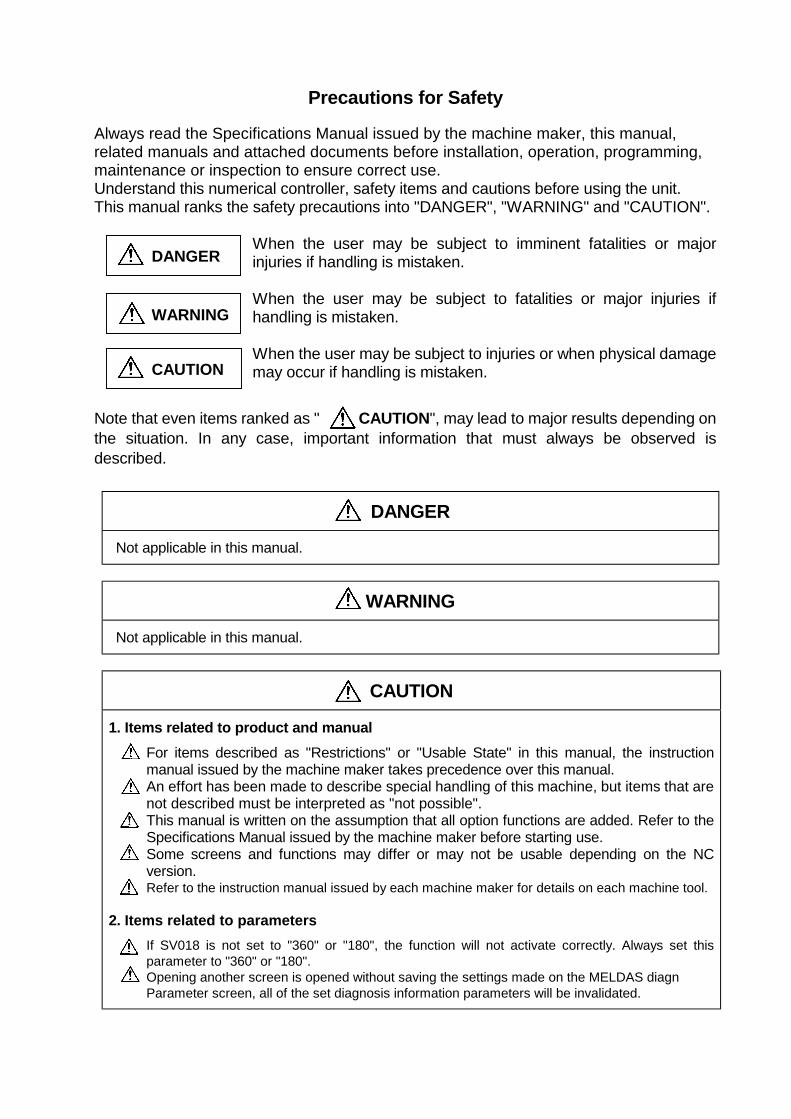
Always read the Specifications Manual issued by the machine maker, this manual,related manuals and attached documents before installation, operation, programming,maintenance or inspection to ensure correct use.Understand this numerical controller, safety items and cautions before using the unit.This manual ranks the safety precautions into "DANGER", "WARNING" and "CAUTION".
When the user may be subject to imminent fatalities or majorinjuries if handling is mistaken.
When the user may be subject to fatalities or major injuries ifhandling is mistaken.
When the user may be subject to injuries or when physical damagemay occur if handling is mistaken.
Note that even items ranked as " CAUTION", may lead to major results depending onthe situation. In any case, important information that must always be observed isdescribed.
DANGER
Not applicable in this manual.
WARNING
Not applicable in this manual.
CAUTION
1. Items related to product and manualFor items described as "Restrictions" or "Usable State" in this manual, the instructionmanual issued by the machine maker takes precedence over this manual.An effort has been made to describe special handling of this machine, but items that arenot described must be interpreted as "not possible".This manual is written on the assumption that all option functions are added. Refer to theSpecifications Manual issued by the machine maker before starting use.Some screens and functions may differ or may not be usable depending on the NCversion.Refer to the instruction manual issued by each machine maker for details on each machine tool.
2. Items related to parametersIf SV018 is not set to "360" or "180", the function will not activate correctly. Always set thisparameter to "360" or "180".Opening another screen is opened without saving the settings made on the MELDAS diagnParameter screen, all of the set diagnosis information parameters will be invalidated.
DANGER
WARNING
CAUTION
i
CONTENTS
1. SCREEN CONFIGURATION......................................................................................... 1-11.1 Screen Transition Diagram................................................................................... 1-1
2. CONTROL PARAMETER.............................................................................................. 2-1
3. PARAMETERS (USER) ............................................................................................ 3-13.1 Axis Parameters............................................................................................... 3-13.2 Setup Parameters ............................................................................................ 3-23.3 Input/Output Parameters.................................................................................... 3-8
3.3.1 RS-232C I/O device parameter setting examples and cable connections ............ 3-113.4 Barrier Data...................................................................................................... 3-12
4. MACHINE PARAMETERS ........................................................................................ 4-14.1 Selecting the Machine Parameters................................................................... 4-14.2 Base Axis Parameters ..................................................................................... 4-24.3 Base System Parameters................................................................................. 4-44.4 Base Common Parameters .............................................................................. 4-74.5 Axis Specification Parameters.......................................................................... 4-184.6 Zero (Reference) Point Return Parameters...................................................... 4-244.7 Servo Parameters ............................................................................................ 4-27
4.7.1 Servo Parameters..................................................................................... 4-284.7.2 Supplementary Explanation (MDS-B-V1/V2)............................................. 4-544.7.3 Intelligent Servo D/A Output Function....................................................... 4-574.7.4 Standard Parameters Setting (MDS-B-V1/V2, intelligent servo)................ 4-60
4.8 Spindle Parameters.......................................................................................... 4-754.8.1 Spindle NC Parameters ............................................................................ 4-754.8.2 Spindle Parameters .................................................................................. 4-824.8.3 Supplementary Explanation (for D/A output functions).............................. 4-1184.8.4 Spindle-Type Servo Parameters ............................................................... 4-121
4.9 PLC Constants ................................................................................................. 4-1224.9.1 PLC Constants.......................................................................................... 4-1224.9.2 PLC Timer ................................................................................................ 4-1234.9.3 PLC Counter ............................................................................................. 4-1244.9.4 Selecting the PLC Bit ................................................................................ 4-124
4.10 Custom Variables ........................................................................................... 4-1244.11 Macro List....................................................................................................... 4-1254.12 Position Switch ............................................................................................... 4-1284.13 Machine Error Compensation ......................................................................... 4-130
4.13.1 Function Outline...................................................................................... 4-1304.13.2 Setting Compensation Data .................................................................... 4-1334.13.3 Example in Using a Linear Axis as the Base Axis ................................... 4-1354.13.4 Example in Using a Rotation Axis as the Base Axis................................ 4-137
5. ABSOLUTE POSITION SETTING PARAMETERS ................................................... 5-15.1 Absolute Position Set ....................................................................................... 5-2
6. MELDAS DIAGNOSIS PARAMETERS..................................................................... 6-1
1.1 Screen Transition Diagram
1-1
1. SCREEN CONFIGURATION
1.1 Screen Transition Diagram
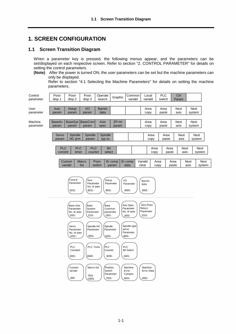
When a parameter key is pressed, the following menus appear, and the parameters can beset/displayed on each respective screen. Refer to section "2. CONTROL PARAMETER" for details onsetting the control parameters.(Note) After the power is turned ON, the user parameters can be set but the machine parameters can
only be displayed.Refer to section "4.1 Selecting the Machine Parameters" for details on setting the machineparameters.
Controlparameter
Posndisp 1
Posndisp 2
Posndisp 3
Operatesearch Graphic Common
variablLocalvariabl
PLCswitch
CtrlParam
Userparameter
Axisparam
Setupparam
I/Oparam
Barrierdata
Areacopy
Areapaste
Nextaxis
Nextsystem
Machineparameter
BaseAxparam
BaseSysparam
BaseComparam
Axisspec
ZP-rtnparam
Areacopy
Areapaste
Nextaxis
Nextsystem
Servoparam
SpindleNC prm
Spindleparam
Spindletyp sv
Areacopy
Areapaste
Nextaxis
Nextsystem
PLCconstnt
PLCtimer
PLCcounter
Bitselect
Areacopy
Areapaste
Nextaxis
Nextsystem
Customvariabl
Macrolist
Posnswitch
Er compparam
Er compdata
Variablclear
Areacopy
Areapaste
Nextaxis
Nextsystem
1001-
Base AxisParameterNo. of axes
1101-
BaseSystemParameter
1301-
BaseCommonparameter
2001-
Axis Spec.ParameterNo. of axes
SetupParameter
8001-
ControlParameter
8101-
AxisParameterNo. of axes 8201-
Spindle typeservoParameter
Zero PointReturnParameter 2101-
I/OParameter
SpindleParameter
Spindle NCParameter
6500-
PLC Timer
6200-
PLCCounter
6401-
PLCBit Select
PLCConstant
6301-
Customvariabl
Macro list
7001- 10001
ServoParameterNo. of axes
7501-
PositionSwitchParameter
4001-
MachineErrorCompen
4301-
MachineError Data
Barrierdata
8301-9000-
3601- 3201- 3001- 2201-
800-
2. CONTROL PARAMETER
2-1
2. CONTROL PARAMETER
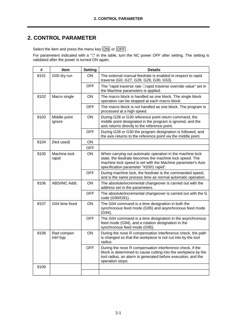
Select the item and press the menu key ON or OFF .For parameters indicated with a "∗ " in the table, turn the NC power OFF after setting. The setting isvalidated after the power is turned ON again.
# Item Setting Details8101 G00 dry run ON The external manual feedrate is enabled in respect to rapid
traverse (G0, G27, G28, G29, G30, G53).OFF The "rapid traverse rate ∗ rapid traverse override value" set in
the Machine parameters is applied.8102 Macro single ON The macro block is handled as one block. The single block
operation can be stopped at each macro block.OFF The macro block is not handled as one block. The program is
processed at a high speed.8103 Middle point
ignoreON During G28 or G30 reference point return command, the
middle point designated in the program is ignored, and theaxis returns directly to the reference point.
OFF During G28 or G30 the program designation is followed, andthe axis returns to the reference point via the middle point.
ON8104 (Not used)OFF
8105 Machine lockrapid
ON When carrying out automatic operation in the machine lockstate, the feedrate becomes the machine lock speed. Themachine lock speed is set with the Machine parameter's Axisspecification parameter "#2001 rapid".
OFF During machine lock, the feedrate is the commanded speed,and is the same process time as normal automatic operation.
8106 ABS/INC Addr. ON The absolute/incremental changeover is carried out with theaddress set in the parameters.
OFF The absolute/incremental changeover is carried out with the Gcode (G90/G91).
8107 G04 time fixed ON The G04 command is a time designation in both thesynchronous feed mode (G95) and asynchronous feed mode(G94).
OFF The G04 command is a time designation in the asynchronousfeed mode (G94), and a rotation designation in thesynchronous feed mode (G95).
8108 Rad compenintrf byp
ON During the nose R compensation interference check, the pathis changed so that the workpiece is not cut into by the toolradius.
OFF During the nose R compensation interference check, if theblock is determined to cause cutting into the workpiece by thetool radius, an alarm is generated before execution, and theoperation stops.
8109
2. CONTROL PARAMETER
2-2
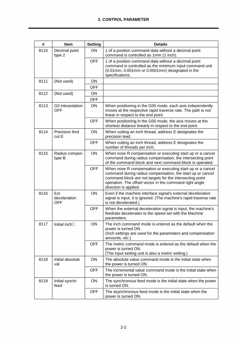
# Item Setting Details8110 Decimal point
type 2ON 1 of a position command data without a decimal point
command is controlled as 1mm (1 inch).OFF 1 of a position command data without a decimal point
command is controlled as the minimum input command unit(0.01mm, 0.001mm or 0.0001mm) designated in thespecifications.
ON8111 (Not used)OFFON8112 (Not used)OFF
8113 G0 interpolationOFF
ON When positioning in the G00 mode, each axis independentlymoves at the respective rapid traverse rate. The path is notlinear in respect to the end point.
OFF When positioning in the G00 mode, the axis moves at theshortest distance linearly in respect to the end point.
8114 Precision thrdcut E
ON When cutting an inch thread, address E designates theprecision lead.
OFF When cutting an inch thread, address E designates thenumber of threads per inch.
8115 Radius compentype B
ON When nose R compensation or executing start up or a cancelcommand during radius compensation, the intersecting pointof the command block and next command block is operated.
OFF When nose R compensation or executing start up or a cancelcommand during radius compensation, the start up or cancelcommand block are not targets for the intersecting pointoperation. The offset vector in the command right angledirection is applied.
8116 ExtdecelerationOFF
ON Even if the machine interface signal's external decelerationsignal is input, it is ignored. (The machine's rapid traverse rateis not decelerated.)
OFF When the external deceleration signal is input, the machine'sfeedrate decelerates to the speed set with the Machineparameters.
8117 Initial inch∗ ON The inch command mode is entered as the default when thepower is turned ON.(Inch settings are used for the parameters and compensationamounts, etc.)
OFF The metric command mode is entered as the default when thepower is turned ON.(The input setting unit is also a metric setting.)
8118 Initial absoluteval
ON The absolute value command mode is the initial state whenthe power is turned ON.
OFF The incremental value command mode is the initial state whenthe power is turned ON.
8119 Initial synchrfeed
ON The synchronous feed mode is the initial state when the poweris turned ON.
OFF The asynchronous feed mode is the initial state when thepower is turned ON.
2. CONTROL PARAMETER
2-3
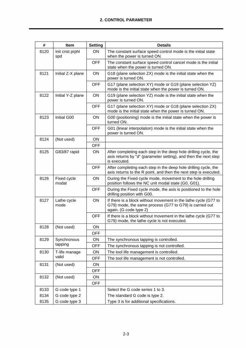
# Item Setting Details8120 Init cnst prphl
spdON The constant surface speed control mode is the initial state
when the power is turned ON.OFF The constant surface speed control cancel mode is the initial
state when the power is turned ON.8121 Initial Z-X plane ON G18 (plane selection ZX) mode is the initial state when the
power is turned ON.OFF G17 (plane selection XY) mode or G19 (plane selection YZ)
mode is the initial state when the power is turned ON.8122 Initial Y-Z plane ON G19 (plane selection YZ) mode is the initial state when the
power is turned ON.OFF G17 (plane selection XY) mode or G18 (plane selection ZX)
mode is the initial state when the power is turned ON.8123 Initial G00 ON G00 (positioning) mode is the initial state when the power is
turned ON.OFF G01 (linear interpolation) mode is the initial state when the
power is turned ON.ON8124 (Not used)OFFON After completing each step in the deep hole drilling cycle, the
axis returns by "d" (parameter setting), and then the next stepis executed.
8125 G83/87 rapid
OFF After completing each step in the deep hole drilling cycle, theaxis returns to the R point, and then the next step is executed.
8126 Fixed cyclemodal
ON During the Fixed cycle mode, movement to the hole drillingposition follows the NC unit modal state (G0, G01).
OFF During the Fixed cycle mode, the axis is positioned to the holedrilling position with G00.
8127 Lathe cyclemode
ON If there is a block without movement in the lathe cycle (G77 toG79) mode, the same process (G77 to G79) is carried outagain. (G code type 2)
OFF If there is a block without movement in the lathe cycle (G77 toG79) mode, the lathe cycle is not executed.
ON8128 (Not used)OFFON The synchronous tapping is controlled.8129 Synchronous
tapping OFF The synchronous tapping is not controlled.8130 ON The tool life management is controlled.T-life manage
valid OFF The tool life management is not controlled.ON8131 (Not used)OFFON8132 (Not used)OFF
8133 G code type 1 Select the G code series 1 to 3.8134 G code type 2 The standard G code is type 2.8135 G code type 3 Type 3 is for additional specifications.
2. CONTROL PARAMETER
2-4
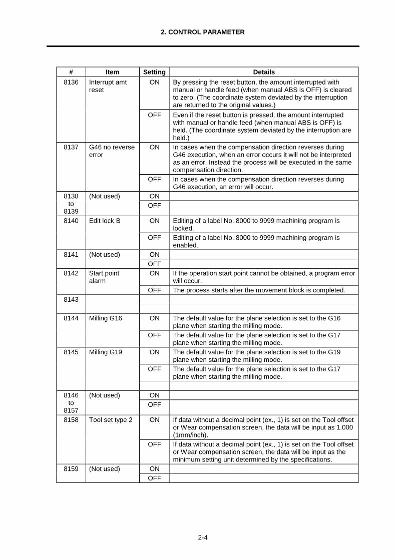
# Item Setting Details8136 Interrupt amt
resetON By pressing the reset button, the amount interrupted with
manual or handle feed (when manual ABS is OFF) is clearedto zero. (The coordinate system deviated by the interruptionare returned to the original values.)
OFF Even if the reset button is pressed, the amount interruptedwith manual or handle feed (when manual ABS is OFF) isheld. (The coordinate system deviated by the interruption areheld.)
8137 G46 no reverseerror
ON In cases when the compensation direction reverses duringG46 execution, when an error occurs it will not be interpretedas an error. Instead the process will be executed in the samecompensation direction.
OFF In cases when the compensation direction reverses duringG46 execution, an error will occur.
ON8138to
8139
(Not used)OFF
ON Editing of a label No. 8000 to 9999 machining program islocked.
8140 Edit lock B
OFF Editing of a label No. 8000 to 9999 machining program isenabled.
ON8141 (Not used)OFFON If the operation start point cannot be obtained, a program error
will occur.8142 Start point
alarmOFF The process starts after the movement block is completed.
8143
ON The default value for the plane selection is set to the G16plane when starting the milling mode.
8144 Milling G16
OFF The default value for the plane selection is set to the G17plane when starting the milling mode.
ON The default value for the plane selection is set to the G19plane when starting the milling mode.
OFF The default value for the plane selection is set to the G17plane when starting the milling mode.
8145 Milling G19
ON8146to
8157
(Not used)OFF
ON If data without a decimal point (ex., 1) is set on the Tool offsetor Wear compensation screen, the data will be input as 1.000(1mm/inch).
8158 Tool set type 2
OFF If data without a decimal point (ex., 1) is set on the Tool offsetor Wear compensation screen, the data will be input as theminimum setting unit determined by the specifications.
ON8159 (Not used)OFF
3.1 Axis Parameters
3-1
3. PARAMETERS (USER)
3.1 Axis Parameters
Set the necessary parameters for each axis.For parameters indicated with a "∗ " in the table, turn the NC power OFF after setting. The setting isvalidated after the power is turned ON again.
# Item Details Setting range(unit)
8201 Mirror image In memory and MDI operation, this highlights thesymbol for the next block movement data(incremental amount).
0 : Mirror image invalid1 : Mirror image valid
8202 Automaticdog type
The first reference point return is always dog-type,but this selects either dog-type or high-speed(memory type) for the second and subsequentreference point returns.
0 : High-speed return1 : Dog-type return
8203 Manual dogtype
This sets the manual reference point return methodfor the function above.
0 : High-speed return1 : Dog-type return
8204 Axis removal Not used. 08205
to82068207 Soft limit
invalidThe values set for parameters No.8208 and No.8209are ignored.
0: Soft limit valid1: Soft limit invalid
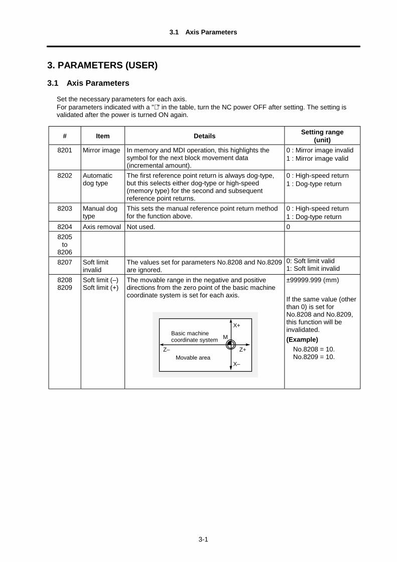
82088209
Soft limit (–)Soft limit (+)
The movable range in the negative and positivedirections from the zero point of the basic machinecoordinate system is set for each axis.
M
X+
Z+
X–
Z–
Basic machinecoordinate system
Movable area
±99999.999 (mm)
If the same value (otherthan 0) is set forNo.8208 and No.8209,this function will beinvalidated.(Example) No.8208 = 10. No.8209 = 10.
3.2 Setup Parameters
3-2
3.2 Setup Parameters
This screen is configured of two pages.For parameters indicated with a "∗ " in the table, turn the NC power OFF after setting. The setting isvalidated after the power is turned ON again.
# Item Details Setting range(unit)
800180028003
Plane <I><J><K>
These set the control axis addresses corresponding tothe plane selection.The tool compensation axis becomes the axis set in I,J, and K.
800480058006
Aux-plane <I><J><K>
These set the parallel axis addresses correspondingto the above setting axes.
X, Z, Y and othercontrol axisaddresses
8007800880098010 G02/03 Error This sets the tolerance for the radial error at the end
point of the circular command.0 to 0.100 (mm)
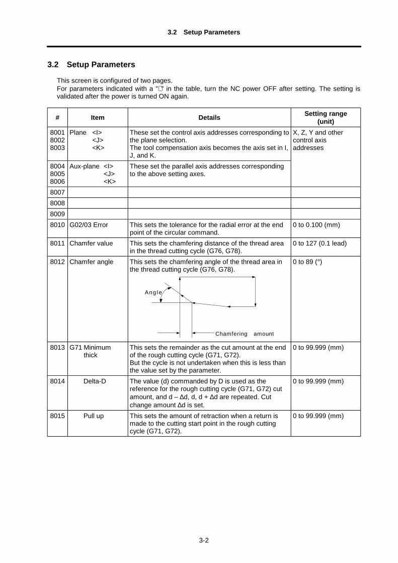
8011 Chamfer value This sets the chamfering distance of the thread areain the thread cutting cycle (G76, G78).
0 to 127 (0.1 lead)
8012 Chamfer angle This sets the chamfering angle of the thread area inthe thread cutting cycle (G76, G78).
Chamfering amount
Ang le
0 to 89 (°)
8013 G71 Minimumthick
This sets the remainder as the cut amount at the endof the rough cutting cycle (G71, G72).But the cycle is not undertaken when this is less thanthe value set by the parameter.
0 to 99.999 (mm)
8014 Delta-D The value (d) commanded by D is used as thereference for the rough cutting cycle (G71, G72) cutamount, and d – ∆d, d, d + ∆d are repeated. Cutchange amount ∆d is set.
0 to 99.999 (mm)
8015 Pull up This sets the amount of retraction when a return ismade to the cutting start point in the rough cuttingcycle (G71, G72).
0 to 99.999 (mm)
3.2 Setup Parameters
3-3
# Item Details Setting range(unit)
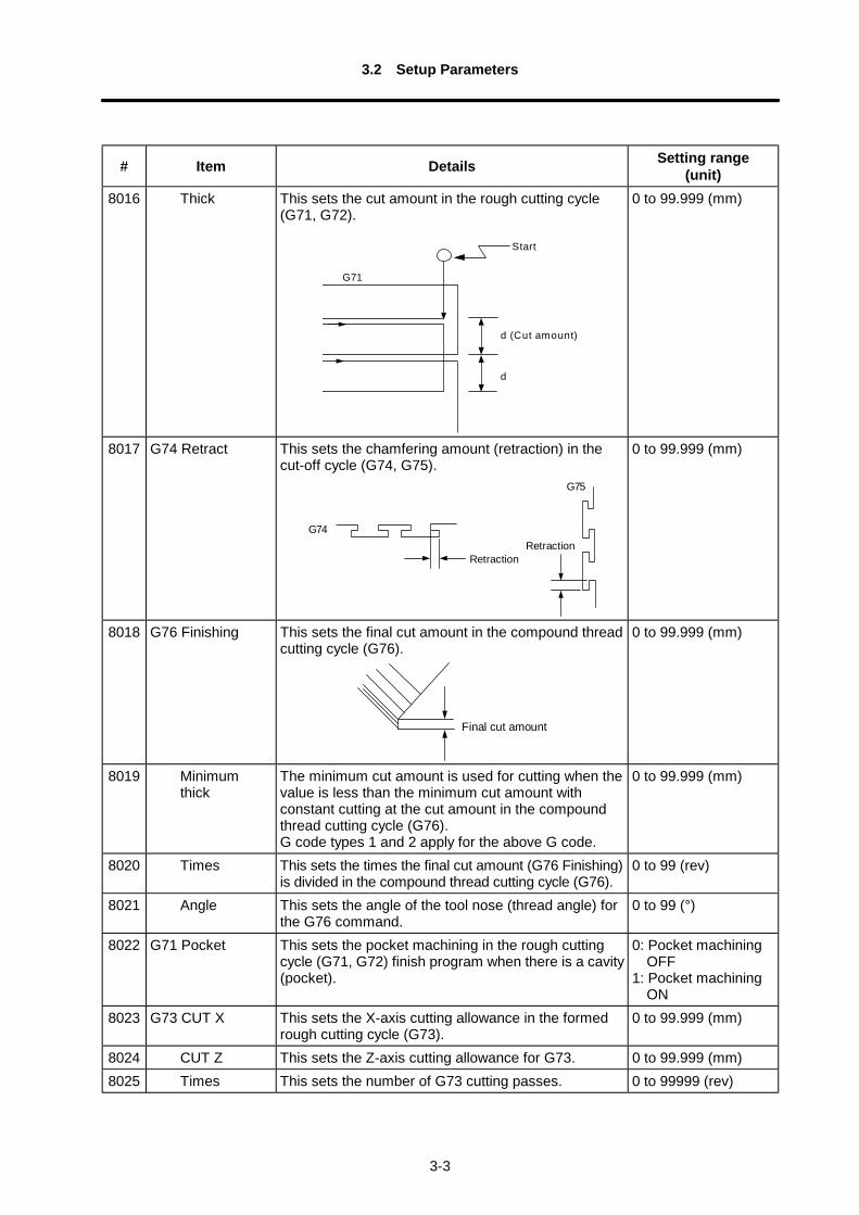
8016 Thick This sets the cut amount in the rough cutting cycle(G71, G72).
G71
Start
d (Cut amount)
d
0 to 99.999 (mm)
8017 G74 Retract This sets the chamfering amount (retraction) in thecut-off cycle (G74, G75).
Retraction
G74
G75
Retraction
0 to 99.999 (mm)
8018 G76 Finishing This sets the final cut amount in the compound threadcutting cycle (G76).
Final cut amount
0 to 99.999 (mm)
8019 Minimumthick
The minimum cut amount is used for cutting when thevalue is less than the minimum cut amount withconstant cutting at the cut amount in the compoundthread cutting cycle (G76).G code types 1 and 2 apply for the above G code.
0 to 99.999 (mm)
8020 Times This sets the times the final cut amount (G76 Finishing)is divided in the compound thread cutting cycle (G76).
0 to 99 (rev)
8021 Angle This sets the angle of the tool nose (thread angle) forthe G76 command.
0 to 99 (°)
8022 G71 Pocket This sets the pocket machining in the rough cuttingcycle (G71, G72) finish program when there is a cavity(pocket).
0: Pocket machining OFF1: Pocket machining ON
8023 G73 CUT X This sets the X-axis cutting allowance in the formedrough cutting cycle (G73).
0 to 99.999 (mm)
8024 CUT Z This sets the Z-axis cutting allowance for G73. 0 to 99.999 (mm)8025 Times This sets the number of G73 cutting passes. 0 to 99999 (rev)
3.2 Setup Parameters
3-4
# Item Details Setting range(unit)
8026 G83 Retract With the second and subsequent cutting passes in thedeep hole drilling cycle (G83). This moves the tool byrapid traverse from the position machined immediatelybefore by the amount equivalent to the setting, andthen establishes cutting feed.
0 to 99.999 (mm)
8027to
80308031 Tool wear max This sets the maximum value check data in the input
data when the tool wear data is set.0 to 99.999 (mm)
8032 inc max This sets the maximum value check data in the inputdata when the tool wear data is added.(Note)When the setting is "0", the maximum value
check is not performed.
0 to 99.999 (mm)
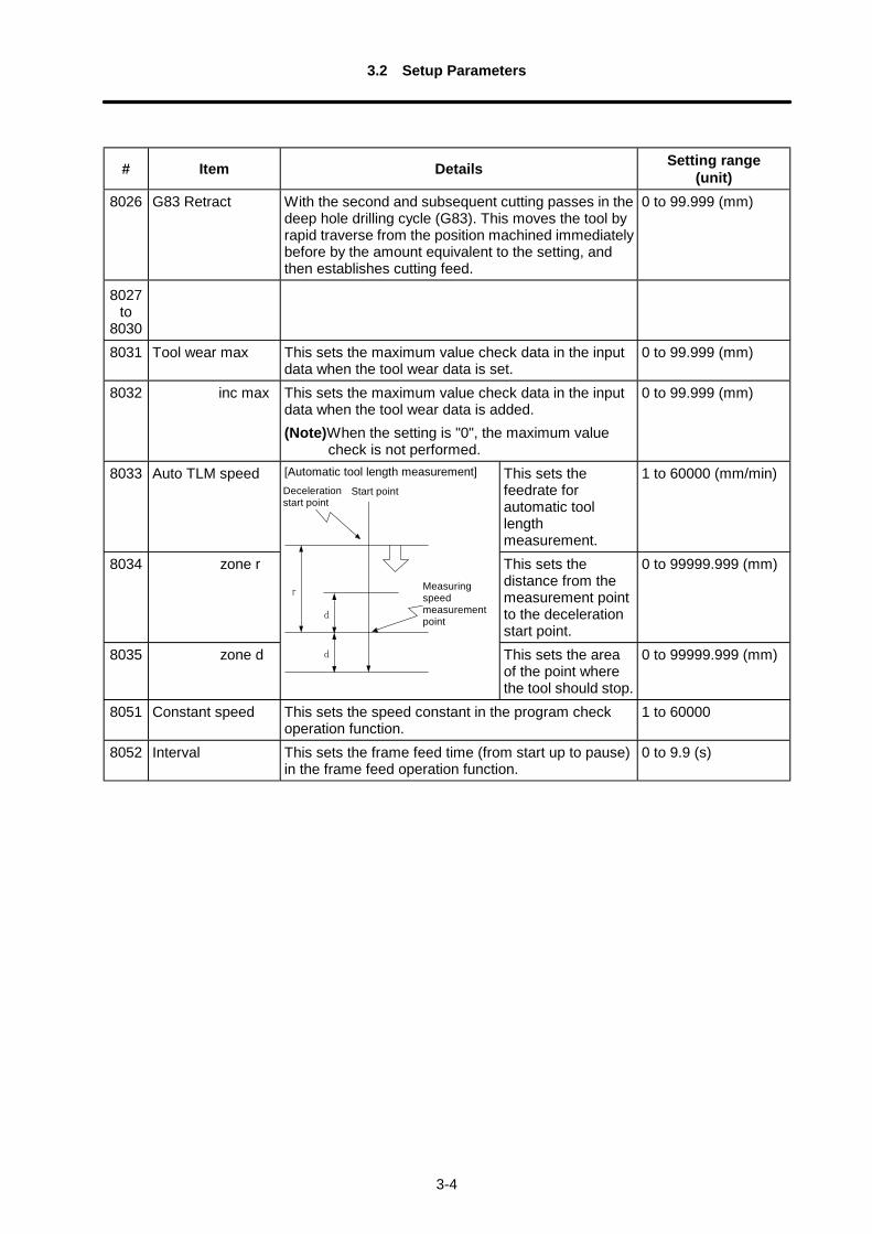
8033 Auto TLM speed This sets thefeedrate forautomatic toollengthmeasurement.
1 to 60000 (mm/min)
8034 zone r This sets thedistance from themeasurement pointto the decelerationstart point.
0 to 99999.999 (mm)
8035 zone d
[Automatic tool length measurement]
d
r
d
計測速度測定点
減速開始点開始点
This sets the areaof the point wherethe tool should stop.
0 to 99999.999 (mm)
8051 Constant speed This sets the speed constant in the program checkoperation function.
1 to 60000
8052 Interval This sets the frame feed time (from start up to pause)in the frame feed operation function.
0 to 9.9 (s)
Decelerationstart point
Start point
Measuringspeedmeasurementpoint
3.2 Setup Parameters
3-5
# Item Details Setting range(unit)
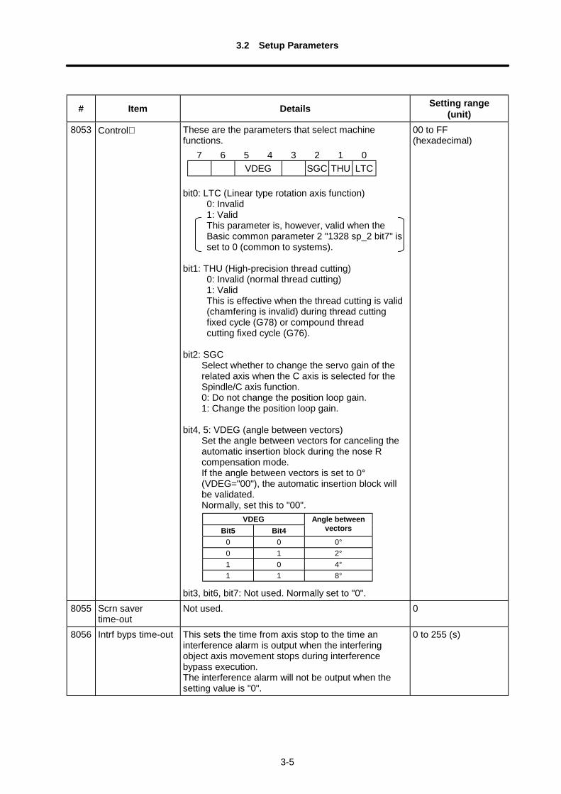
8053 Control∗ These are the parameters that select machinefunctions.
bit0: LTC (Linear type rotation axis function) 0: Invalid 1: Valid This parameter is, however, valid when the Basic common parameter 2 "1328 sp_2 bit7" is set to 0 (common to systems). bit1: THU (High-precision thread cutting) 0: Invalid (normal thread cutting) 1: Valid This is effective when the thread cutting is valid (chamfering is invalid) during thread cutting fixed cycle (G78) or compound thread cutting fixed cycle (G76).
bit2: SGCSelect whether to change the servo gain of therelated axis when the C axis is selected for theSpindle/C axis function.0: Do not change the position loop gain.1: Change the position loop gain.
bit4, 5: VDEG (angle between vectors)Set the angle between vectors for canceling theautomatic insertion block during the nose Rcompensation mode.If the angle between vectors is set to 0°(VDEG="00"), the automatic insertion block willbe validated.Normally, set this to "00".
bit3, bit6, bit7: Not used. Normally set to "0".
00 to FF(hexadecimal)
8055 Scrn savertime-out
Not used. 0
8056 Intrf byps time-out This sets the time from axis stop to the time aninterference alarm is output when the interferingobject axis movement stops during interferencebypass execution.The interference alarm will not be output when thesetting value is "0".
0 to 255 (s)
7 6 5 4 3 2 1 0VDEG SGC THU LTC
VDEGBit5 Bit4
Angle betweenvectors
0 0 0°0 1 2°1 0 4°1 1 8°
3.2 Setup Parameters
3-6
# Item Details Setting range(unit)
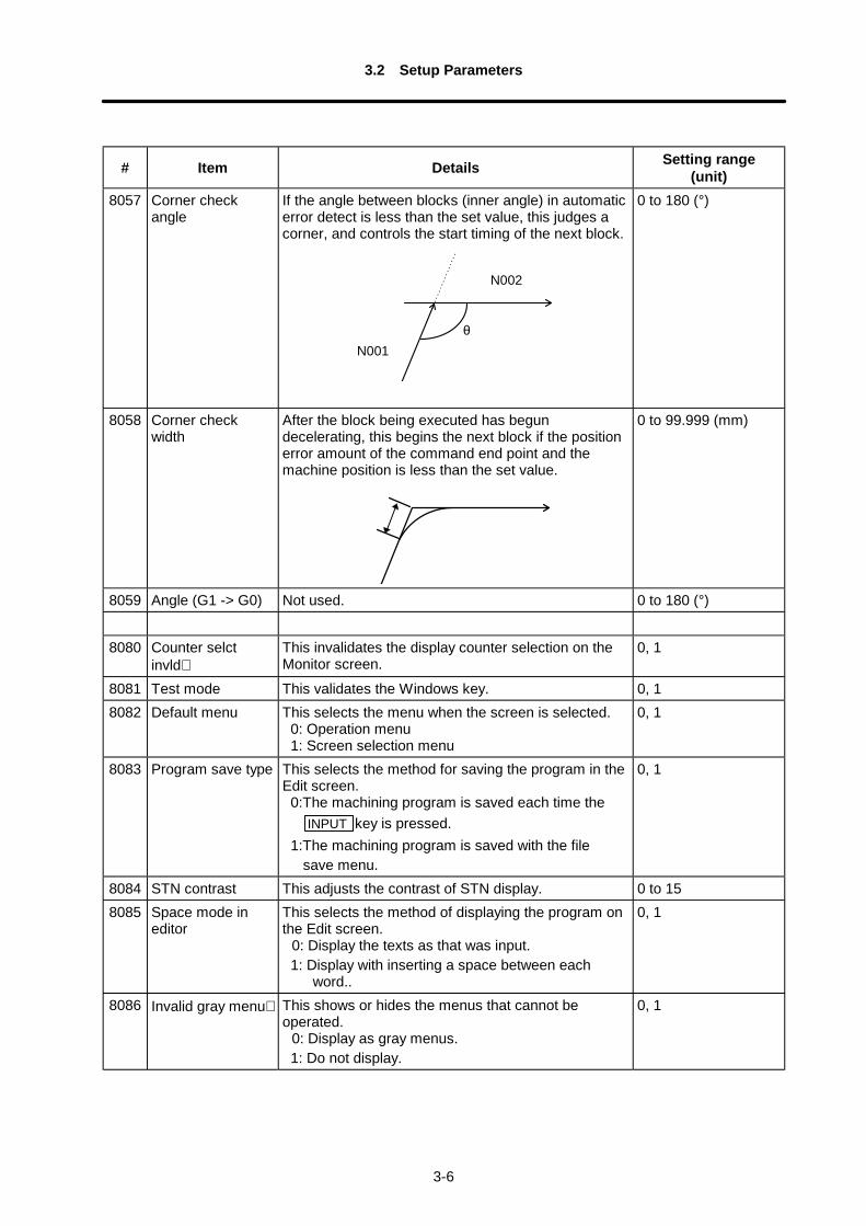
8057 Corner checkangle
If the angle between blocks (inner angle) in automaticerror detect is less than the set value, this judges acorner, and controls the start timing of the next block.
θ
N002
N001
0 to 180 (°)
8058 Corner checkwidth
After the block being executed has begundecelerating, this begins the next block if the positionerror amount of the command end point and themachine position is less than the set value.
0 to 99.999 (mm)
8059 Angle (G1 -> G0) Not used. 0 to 180 (°)
8080 Counter selctinvld∗
This invalidates the display counter selection on theMonitor screen.
0, 1
8081 Test mode This validates the Windows key. 0, 18082 Default menu This selects the menu when the screen is selected.
0: Operation menu1: Screen selection menu
0, 1
8083 Program save type This selects the method for saving the program in theEdit screen.
0:The machining program is saved each time theINPUT key is pressed.
1:The machining program is saved with the filesave menu.
0, 1
8084 STN contrast This adjusts the contrast of STN display. 0 to 158085 Space mode in
editorThis selects the method of displaying the program onthe Edit screen.
0: Display the texts as that was input.1: Display with inserting a space between each
word..
0, 1
8086 Invalid gray menu∗ This shows or hides the menus that cannot beoperated.
0: Display as gray menus.1: Do not display.
0, 1
3.2 Setup Parameters
3-7
# Item Details Setting range(unit)
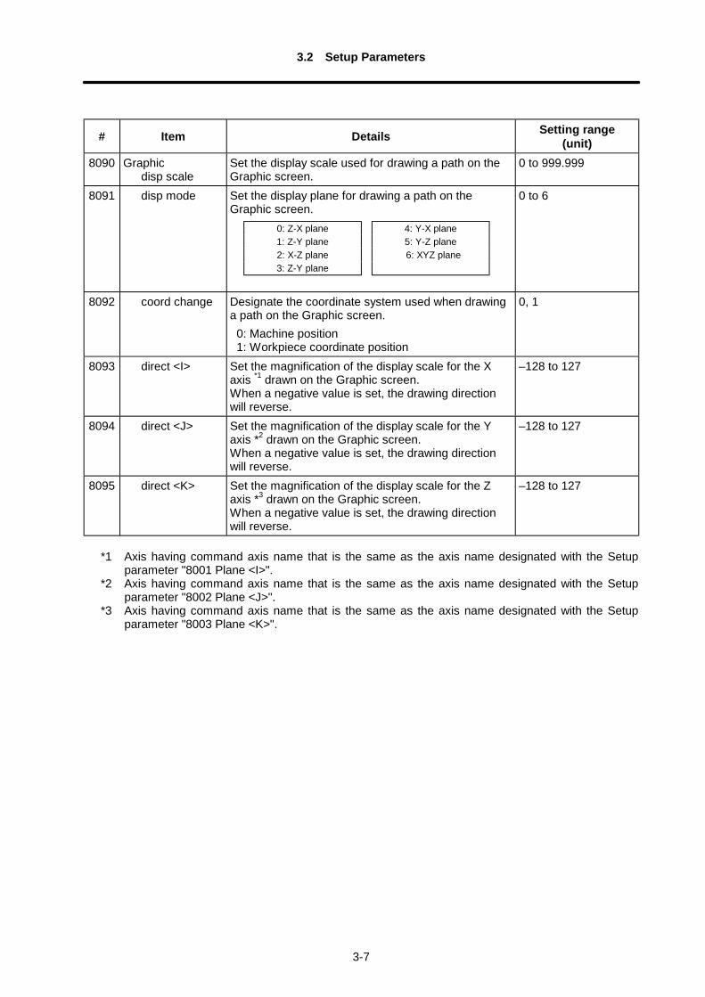
8090 Graphic disp scale
Set the display scale used for drawing a path on theGraphic screen.
0 to 999.999
8091 disp mode Set the display plane for drawing a path on theGraphic screen.
0 to 6
8092 coord change Designate the coordinate system used when drawinga path on the Graphic screen.
0: Machine position1: Workpiece coordinate position
0, 1
8093 direct <I> Set the magnification of the display scale for the Xaxis *1 drawn on the Graphic screen.When a negative value is set, the drawing directionwill reverse.
–128 to 127
8094 direct <J> Set the magnification of the display scale for the Yaxis *2 drawn on the Graphic screen.When a negative value is set, the drawing directionwill reverse.
–128 to 127
8095 direct <K> Set the magnification of the display scale for the Zaxis *3 drawn on the Graphic screen.When a negative value is set, the drawing directionwill reverse.
–128 to 127
*1 Axis having command axis name that is the same as the axis name designated with the Setupparameter "8001 Plane <I>".
*2 Axis having command axis name that is the same as the axis name designated with the Setupparameter "8002 Plane <J>".
*3 Axis having command axis name that is the same as the axis name designated with the Setupparameter "8003 Plane <K>".
4: Y-X plane5: Y-Z plane6: XYZ plane
0: Z-X plane1: Z-Y plane2: X-Z plane3: Z-Y plane
3.3 Input/Output Parameters
3-8
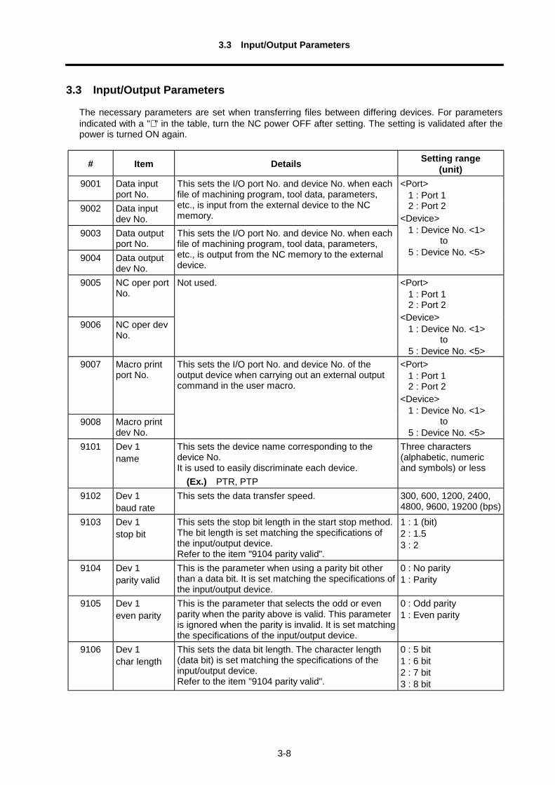
3.3 Input/Output Parameters
The necessary parameters are set when transferring files between differing devices. For parametersindicated with a "∗ " in the table, turn the NC power OFF after setting. The setting is validated after thepower is turned ON again.
# Item Details Setting range(unit)
9001 Data inputport No.
9002 Data inputdev No.
This sets the I/O port No. and device No. when eachfile of machining program, tool data, parameters,etc., is input from the external device to the NCmemory.
9003 Data outputport No.
9004 Data outputdev No.
This sets the I/O port No. and device No. when eachfile of machining program, tool data, parameters,etc., is output from the NC memory to the externaldevice.
<Port>1 : Port 12 : Port 2
<Device>1 : Device No. <1>
to5 : Device No. <5>
9005 NC oper portNo.
9006 NC oper devNo.
Not used. <Port>1 : Port 12 : Port 2
<Device>1 : Device No. <1>
to5 : Device No. <5>
9007 Macro printport No.
9008 Macro printdev No.
This sets the I/O port No. and device No. of theoutput device when carrying out an external outputcommand in the user macro.
<Port>1 : Port 12 : Port 2
<Device>1 : Device No. <1>
to5 : Device No. <5>
9101 Dev 1name
This sets the device name corresponding to thedevice No.It is used to easily discriminate each device. (Ex.) PTR, PTP
Three characters(alphabetic, numericand symbols) or less
9102 Dev 1baud rate
This sets the data transfer speed. 300, 600, 1200, 2400,4800, 9600, 19200 (bps)
9103 Dev 1stop bit
This sets the stop bit length in the start stop method.The bit length is set matching the specifications ofthe input/output device.Refer to the item "9104 parity valid".
1 : 1 (bit)2 : 1.53 : 2
9104 Dev 1parity valid
This is the parameter when using a parity bit otherthan a data bit. It is set matching the specifications ofthe input/output device.
0 : No parity1 : Parity
9105 Dev 1even parity
This is the parameter that selects the odd or evenparity when the parity above is valid. This parameteris ignored when the parity is invalid. It is set matchingthe specifications of the input/output device.
0 : Odd parity1 : Even parity
9106 Dev 1char length
This sets the data bit length. The character length(data bit) is set matching the specifications of theinput/output device.Refer to the item "9104 parity valid".
0 : 5 bit1 : 6 bit2 : 7 bit3 : 8 bit
3.3 Input/Output Parameters
3-9
# Item Details Setting range(unit)
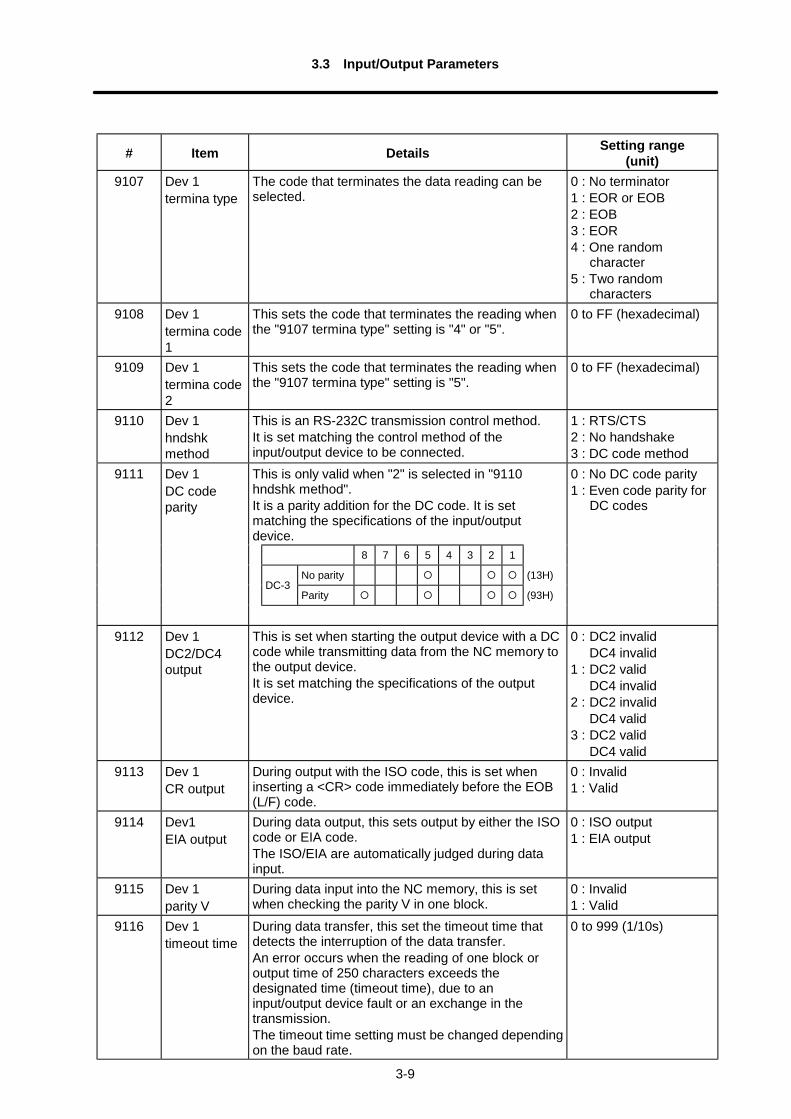
9107 Dev 1termina type
The code that terminates the data reading can beselected.
0 : No terminator1 : EOR or EOB2 : EOB3 : EOR4 : One random
character5 : Two random
characters9108 Dev 1
termina code1
This sets the code that terminates the reading whenthe "9107 termina type" setting is "4" or "5".
0 to FF (hexadecimal)
9109 Dev 1termina code2
This sets the code that terminates the reading whenthe "9107 termina type" setting is "5".
0 to FF (hexadecimal)
9110 Dev 1hndshkmethod
This is an RS-232C transmission control method.It is set matching the control method of theinput/output device to be connected.
1 : RTS/CTS2 : No handshake3 : DC code method
This is only valid when "2" is selected in "9110hndshk method".It is a parity addition for the DC code. It is setmatching the specifications of the input/outputdevice.
0 : No DC code parity1 : Even code parity for
DC codes
8 7 6 5 4 3 2 1
No parity (13H)DC-3
Parity (93H)
9111 Dev 1DC codeparity
9112 Dev 1DC2/DC4output
This is set when starting the output device with a DCcode while transmitting data from the NC memory tothe output device.It is set matching the specifications of the outputdevice.
0 : DC2 invalidDC4 invalid
1 : DC2 validDC4 invalid
2 : DC2 invalidDC4 valid
3 : DC2 validDC4 valid
9113 Dev 1CR output
During output with the ISO code, this is set wheninserting a <CR> code immediately before the EOB(L/F) code.
0 : Invalid1 : Valid
9114 Dev1EIA output
During data output, this sets output by either the ISOcode or EIA code.The ISO/EIA are automatically judged during datainput.
0 : ISO output1 : EIA output
9115 Dev 1parity V
During data input into the NC memory, this is setwhen checking the parity V in one block.
0 : Invalid1 : Valid
9116 Dev 1timeout time
During data transfer, this set the timeout time thatdetects the interruption of the data transfer.An error occurs when the reading of one block oroutput time of 250 characters exceeds thedesignated time (timeout time), due to aninput/output device fault or an exchange in thetransmission.The timeout time setting must be changed dependingon the baud rate.
0 to 999 (1/10s)
3.3 Input/Output Parameters
3-10
# Item Details Setting range(unit)
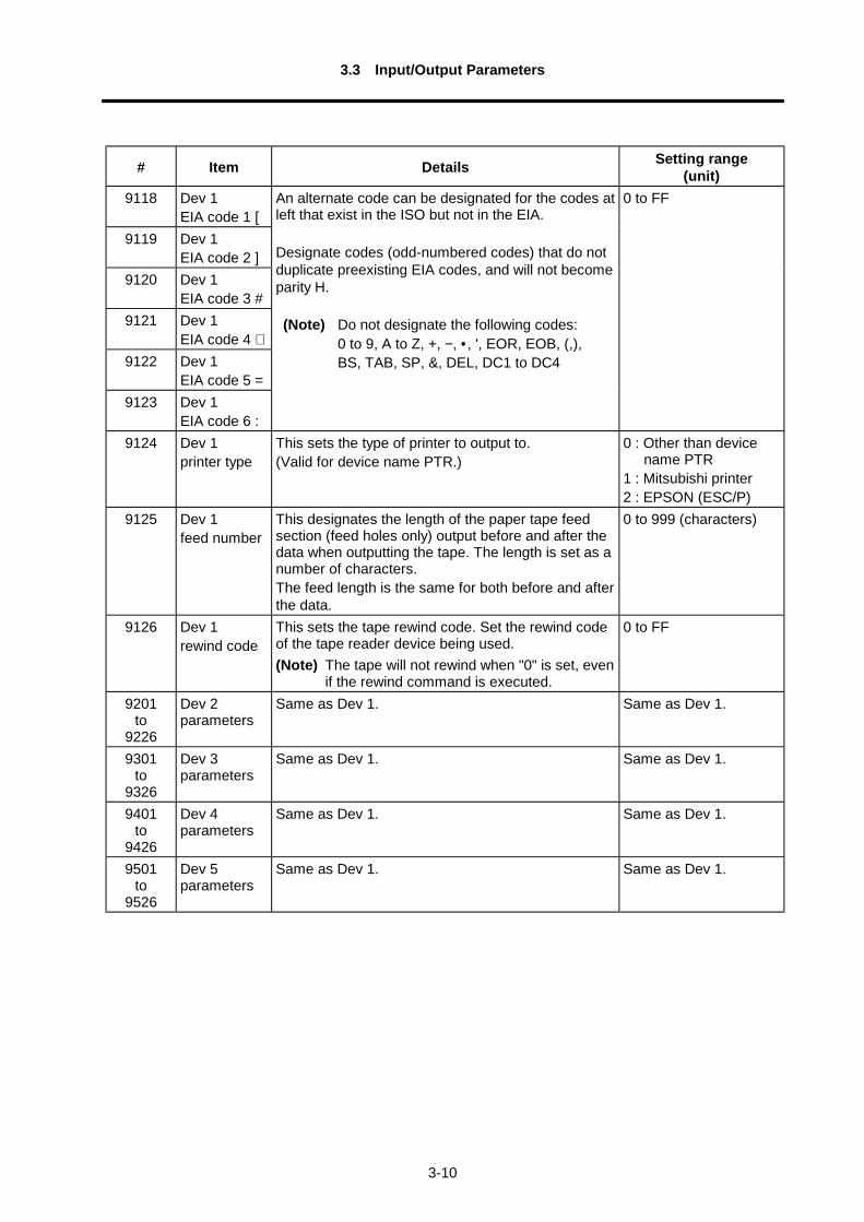
9118 Dev 1EIA code 1 [
9119 Dev 1EIA code 2 ]
9120 Dev 1EIA code 3 #
9121 Dev 1EIA code 4 ∗
9122 Dev 1EIA code 5 =
9123 Dev 1EIA code 6 :
An alternate code can be designated for the codes atleft that exist in the ISO but not in the EIA.
Designate codes (odd-numbered codes) that do notduplicate preexisting EIA codes, and will not becomeparity H.
(Note) Do not designate the following codes:0 to 9, A to Z, +, −, • , ', EOR, EOB, (,),BS, TAB, SP, &, DEL, DC1 to DC4
0 to FF
9124 Dev 1printer type
This sets the type of printer to output to.(Valid for device name PTR.)
0 : Other than devicename PTR
1 : Mitsubishi printer2 : EPSON (ESC/P)
9125 Dev 1feed number
This designates the length of the paper tape feedsection (feed holes only) output before and after thedata when outputting the tape. The length is set as anumber of characters.The feed length is the same for both before and afterthe data.
0 to 999 (characters)
9126 Dev 1rewind code
This sets the tape rewind code. Set the rewind codeof the tape reader device being used.(Note) The tape will not rewind when "0" is set, even
if the rewind command is executed.
0 to FF
9201to
9226
Dev 2parameters
Same as Dev 1. Same as Dev 1.
9301to
9326
Dev 3parameters
Same as Dev 1. Same as Dev 1.
9401to
9426
Dev 4parameters
Same as Dev 1. Same as Dev 1.
9501to
9526
Dev 5parameters
Same as Dev 1. Same as Dev 1.
3.3 Input/Output Parameters
3-11
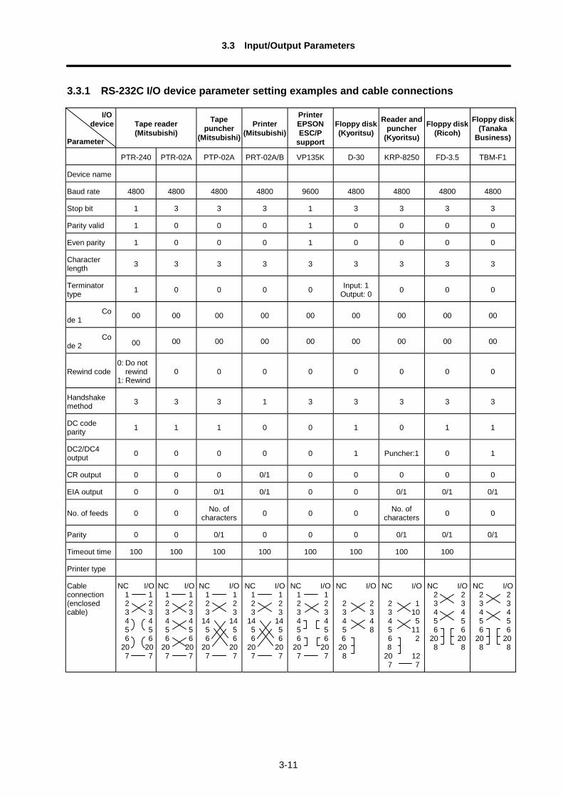
3.3.1 RS-232C I/O device parameter setting examples and cable connections
I/O device
Parameter
Tape reader(Mitsubishi)
Tapepuncher
(Mitsubishi)
Printer(Mitsubishi)
PrinterEPSONESC/P
support
Floppy disk(Kyoritsu)
Reader andpuncher
(Kyoritsu)
Floppy disk(Ricoh)
Floppy disk(Tanaka
Business)
PTR-240 PTR-02A PTP-02A PRT-02A/B VP135K D-30 KRP-8250 FD-3.5 TBM-F1
Device name
Baud rate 4800 4800 4800 4800 9600 4800 4800 4800 4800
Stop bit 1 3 3 3 1 3 3 3 3
Parity valid 1 0 0 0 1 0 0 0 0
Even parity 1 0 0 0 1 0 0 0 0
Characterlength 3 3 3 3 3 3 3 3 3
Terminatortype 1 0 0 0 0 Input: 1
Output: 0 0 0 0
Code 1 00 00 00 00 00 00 00 00 00
Code 2 00 00 00 00 00 00 00 00 00
Rewind code0: Do not
rewind1: Rewind
0 0 0 0 0 0 0 0
Handshakemethod 3 3 3 1 3 3 3 3 3
DC codeparity 1 1 1 0 0 1 0 1 1
DC2/DC4output 0 0 0 0 0 1 Puncher:1 0 1
CR output 0 0 0 0/1 0 0 0 0 0
EIA output 0 0 0/1 0/1 0 0 0/1 0/1 0/1
No. of feeds 0 0 No. ofcharacters 0 0 0 No. of
characters 0 0
Parity 0 0 0/1 0 0 0 0/1 0/1 0/1
Timeout time 100 100 100 100 100 100 100 100
Printer type
Cableconnection(enclosedcable)
NC I/O 1 1 2 2 3 3 4 4 5 5 6 6 20 20 7 7
NC I/O 1 1 2 2 3 3 4 4 5 5 6 6 20 20 7 7
NC I/O 1 1 2 2 3 3 14 14 5 5 6 6 20 20 7 7
NC I/O 1 1 2 2 3 3 14 14 5 5 6 6 20 20 7 7
NC I/O 1 1 2 2 3 3 4 4 5 5 6 6 20 20 7 7
NC I/O
2 2 3 3 4 4 5 8
6 20 8
NC I/O
2 1 3 10 4 5 5 11 6 2
8 20 12 7 7
NC I/O 2 2 3 3 4 4 5 5 6 6 20 20 8 8
NC I/O 2 2 3 3 4 4 5 5 6 6 20 20 8 8
3.4 Barrier Data
3-12
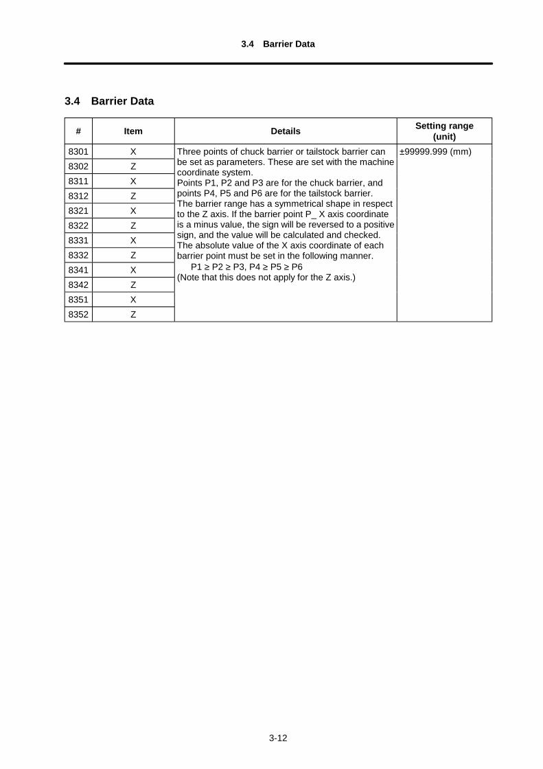
3.4 Barrier Data
# Item Details Setting range(unit)
8301 X8302 Z8311 X8312 Z8321 X8322 Z8331 X8332 Z8341 X8342 Z8351 X8352 Z
Three points of chuck barrier or tailstock barrier canbe set as parameters. These are set with the machinecoordinate system.Points P1, P2 and P3 are for the chuck barrier, andpoints P4, P5 and P6 are for the tailstock barrier.The barrier range has a symmetrical shape in respectto the Z axis. If the barrier point P_ X axis coordinateis a minus value, the sign will be reversed to a positivesign, and the value will be calculated and checked.The absolute value of the X axis coordinate of eachbarrier point must be set in the following manner. P1 ≥ P2 ≥ P3, P4 ≥ P5 ≥ P6(Note that this does not apply for the Z axis.)
±99999.999 (mm)
4.1 Selecting the Machine Parameters
4-1
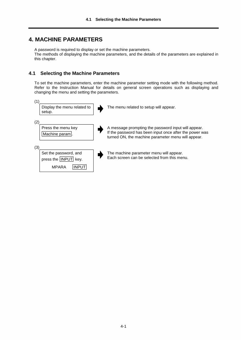
4. MACHINE PARAMETERSA password is required to display or set the machine parameters.The methods of displaying the machine parameters, and the details of the parameters are explained inthis chapter.
4.1 Selecting the Machine Parameters
To set the machine parameters, enter the machine parameter setting mode with the following method.Refer to the Instruction Manual for details on general screen operations such as displaying andchanging the menu and setting the parameters.
(1)Display the menu related tosetup.
The menu related to setup will appear.
(2)Press the menu keyMachine param .
A message prompting the password input will appear.If the password has been input once after the power wasturned ON, the machine parameter menu will appear.
(3)Set the password, andpress the INPUT key.
MPARA INPUT
The machine parameter menu will appear.Each screen can be selected from this menu.
4.2 Base Axis Parameters
4-2
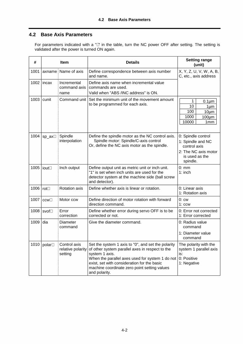
4.2 Base Axis Parameters
For parameters indicated with a "∗ " in the table, turn the NC power OFF after setting. The setting isvalidated after the power is turned ON again.
# Item Details Setting range(unit)
1001 axname Name of axis Define correspondence between axis numberand name.
1002 incax Incrementalcommand axisname
Define axis name when incremental valuecommands are used.Valid when "ABS /INC address" is ON.
X, Y, Z, U, V, W, A, B,C, etc., axis address
1003 cunit Command unit Set the minimum unit of the movement amountto be programmed for each axis.
1004 sp_ax∗ Spindleinterpolation
Define the spindle motor as the NC control axis.Spindle motor: Spindle/C-axis control
Or, define the NC axis motor as the spindle.
0: Spindle control1: Spindle and NC
control axis2: The NC axis motor
is used as thespindle.
1005 iout∗ Inch output Define output unit as metric unit or inch unit."1" is set when inch units are used for thedetector system at the machine side (ball screwand detector).
0: mm1: inch
1006 rot∗ Rotation axis Define whether axis is linear or rotation. 0: Linear axis1: Rotation axis
1007 ccw∗ Motor ccw Define direction of motor rotation with forwarddirection command.
0: cw1: ccw
1008 svof∗ Errorcorrection
Define whether error during servo OFF is to becorrected or not.
0: Error not corrected1: Error corrected
1009 dia Diametercommand
Give the diameter command. 0: Radius valuecommand
1: Diameter valuecommand
1010 polar∗ Control axisrelative polaritysetting
Set the system 1 axis to "0", and set the polarityof other system parallel axes in respect to thesystem 1 axis.When the parallel axes used for system 1 do notexist, set with consideration for the basicmachine coordinate zero point setting valuesand polarity.
The polarity with thesystem 1 parallel axisis:0: Positive1: Negative
1 0.1µm10 1µm
100 10µm1000 100µm
10000 1mm
4.2 Base Axis Parameters
4-3
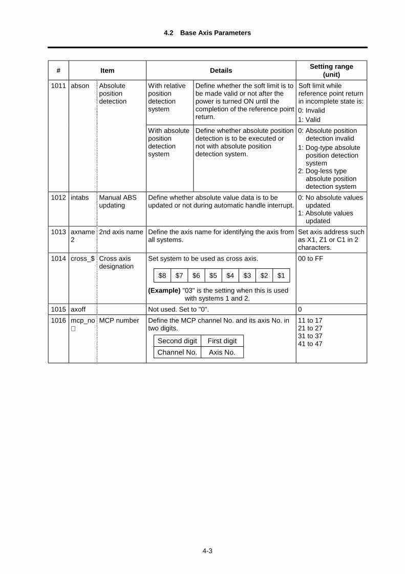
# Item Details Setting range(unit)
With relativepositiondetectionsystem
Define whether the soft limit is tobe made valid or not after thepower is turned ON until thecompletion of the reference pointreturn.
Soft limit whilereference point returnin incomplete state is:0: Invalid1: Valid
1011 abson Absolutepositiondetection
With absolutepositiondetectionsystem
Define whether absolute positiondetection is to be executed ornot with absolute positiondetection system.
0: Absolute positiondetection invalid
1: Dog-type absoluteposition detectionsystem
2: Dog-less typeabsolute positiondetection system
1012 intabs Manual ABSupdating
Define whether absolute value data is to beupdated or not during automatic handle interrupt.
0: No absolute valuesupdated
1: Absolute valuesupdated
1013 axname2
2nd axis name Define the axis name for identifying the axis fromall systems.
Set axis address suchas X1, Z1 or C1 in 2characters.
1014 cross_$ Cross axisdesignation
Set system to be used as cross axis.
(Example) "03" is the setting when this is usedwith systems 1 and 2.
00 to FF
1015 axoff Not used. Set to "0". 01016 mcp_no
∗MCP number Define the MCP channel No. and its axis No. in
two digits.
Second digit First digitChannel No. Axis No.
11 to 1721 to 2731 to 3741 to 47
$8 $7 $6 $5 $4 $3 $2 $1
4.3 Base System Parameters
4-4
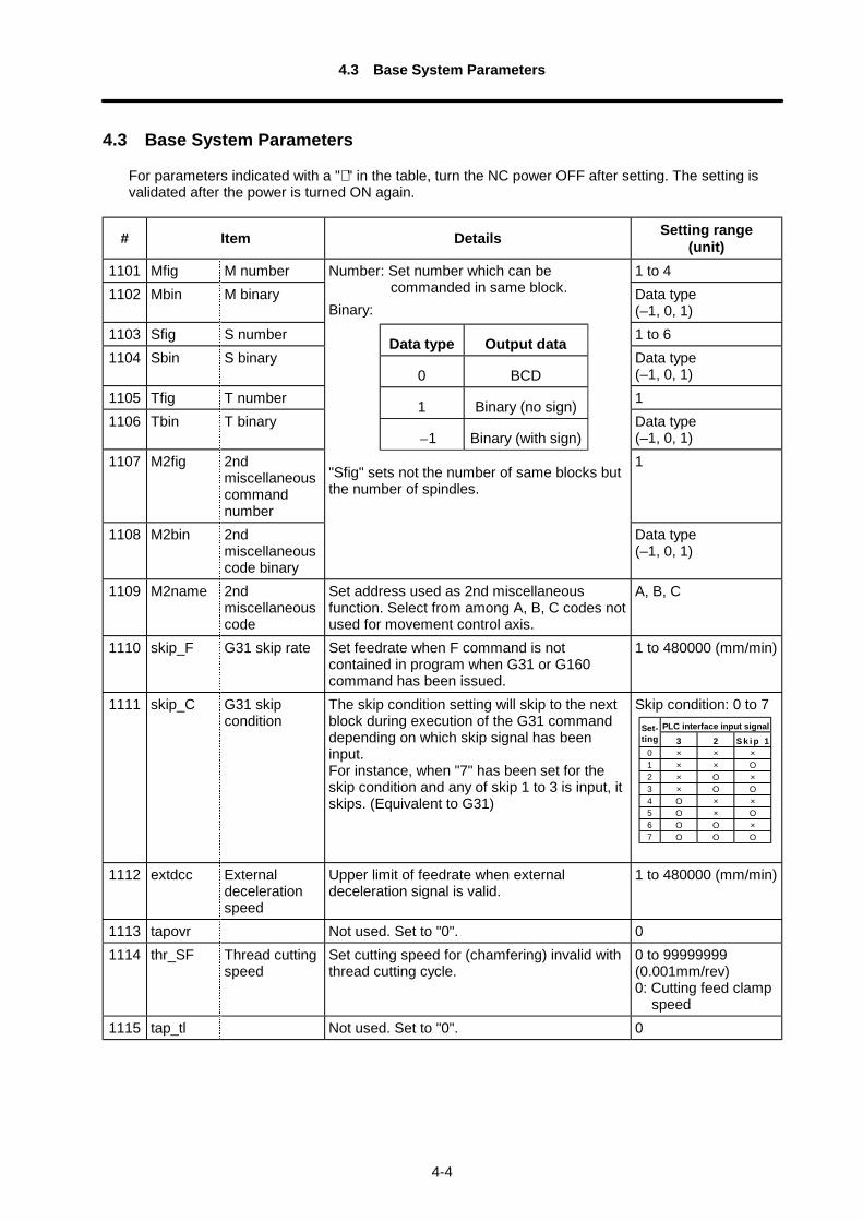
4.3 Base System Parameters
For parameters indicated with a "∗ " in the table, turn the NC power OFF after setting. The setting isvalidated after the power is turned ON again.
# Item Details Setting range(unit)
1101 Mfig M number 1 to 41102 Mbin M binary Data type
(–1, 0, 1)1103 Sfig S number 1 to 61104 Sbin S binary Data type
(–1, 0, 1)1105 Tfig T number 11106 Tbin T binary Data type
(–1, 0, 1)1107 M2fig 2nd
miscellaneouscommandnumber
1
1108 M2bin 2ndmiscellaneouscode binary
Number: Set number which can becommanded in same block.
Binary:
Data type Output data
0 BCD
1 Binary (no sign)
–1 Binary (with sign)
"Sfig" sets not the number of same blocks butthe number of spindles.
Data type(–1, 0, 1)
1109 M2name 2ndmiscellaneouscode
Set address used as 2nd miscellaneousfunction. Select from among A, B, C codes notused for movement control axis.
A, B, C
1110 skip_F G31 skip rate Set feedrate when F command is notcontained in program when G31 or G160command has been issued.
1 to 480000 (mm/min)
1111 skip_C G31 skipcondition
The skip condition setting will skip to the nextblock during execution of the G31 commanddepending on which skip signal has beeninput.For instance, when "7" has been set for theskip condition and any of skip 1 to 3 is input, itskips. (Equivalent to G31)
Skip condition: 0 to 7PLC interface input signalSet-
ting 3 2 S k i p 10 × × ×1 × × Ο2 × Ο ×3 × Ο Ο4 Ο × ×5 Ο × Ο6 Ο Ο ×7 Ο Ο Ο
1112 extdcc Externaldecelerationspeed
Upper limit of feedrate when externaldeceleration signal is valid.
1 to 480000 (mm/min)
1113 tapovr Not used. Set to "0". 01114 thr_SF Thread cutting
speedSet cutting speed for (chamfering) invalid withthread cutting cycle.
0 to 99999999(0.001mm/rev)0: Cutting feed clamp
speed1115 tap_tl Not used. Set to "0". 0
4.3 Base System Parameters
4-5
# Item Details Setting range(unit)
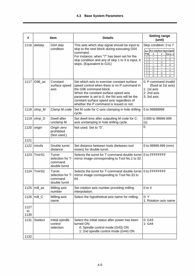
1116 dwlskp G04 skipcondition
This sets which skip signal should be input toskip to the next block during executing G04command.For instance, when "7" has been set for theskip condition and any of skip 1 to 3 is input, itskips. (Equivalent to G31)
Skip condition: 0 to 7PLC interface input signalSet-
ting 3 2 S k i p 10 × × ×1 × × Ο2 × Ο ×3 × Ο Ο4 Ο × ×5 Ο × Ο6 Ο Ο ×7 Ο Ο Ο
1117 G96_ax Constantsurface speedaxis
Set which axis to exercise constant surfacespeed control when there is no P command inthe G96 command block.When the constant surface speed axisparameter is set to 0, the fist axis will be theconstant surface speed axis regardless ofwhether the P command is issued or not.
0: P command invalid (fixed at 1st axis)1: 1st axis2: 2nd axis3: 3rd axis
1118 clmp_M Clamp M code Set M code for C-axis clamping in hole drillingcycle.
0 to 99999999
1119 clmp_D Dwell afterunclamp M
Set dwell time after outputting M code for C-axis unclamping in hole drilling cycle.
0.000 to 99999.999(s)
1120 origin Origin zeroprohibited(Not used.)
Not used. Set to "0". 0
11211122 mirofs Double turret
distanceSet distance between tools (between toolnoses) for double turret.
0 to 99999.999 (mm)
1123 TmirS1 Turretselection for T-commanddouble turret
Selects the turret for T-command double turretmirror image corresponding to Tool No.1 to 32.
0 to FFFFFFFF
1124 TmirS2 Turretselection for T-commanddouble turret
Selects the turret for T-command double turretmirror image corresponding to Tool No.33 to64.
0 to FFFFFFFF
1125 mill_ax Milling axisnumber
Set rotation axis number providing millinginterpolation.
0 to 4
1126 mill_C Milling axisname
Select the hypothetical axis name for milling. 0: Y1: Rotation axis name
1127to
11301131 Sselect Initial spindle
controlselection
Select the initial status after power has beenturned ON. 0: Spindle control mode (G43) ON 1: 2nd spindle control mode (G44) ON
0: G431: G44
1132
4.3 Base System Parameters
4-6
# Item Details Setting range(unit)
11331134113511361137
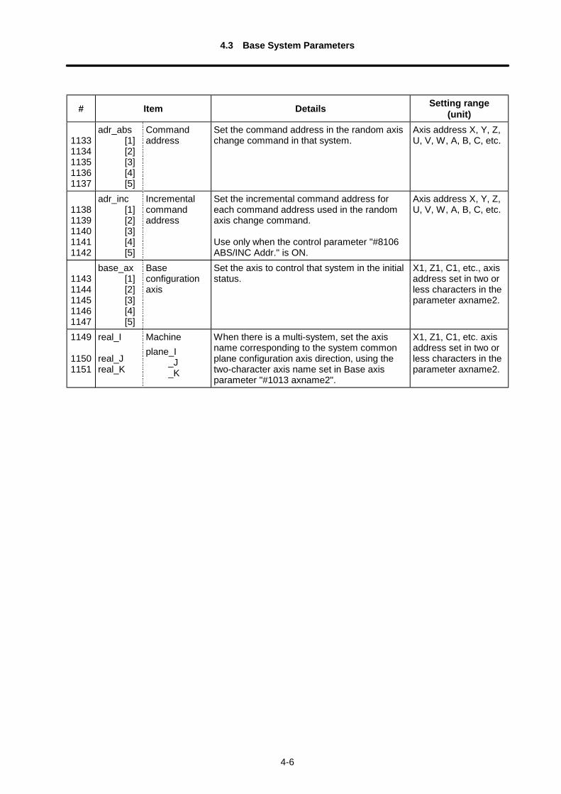
adr_abs[1][2][3][4][5]
Commandaddress
Set the command address in the random axischange command in that system.
Axis address X, Y, Z,U, V, W, A, B, C, etc.
11381139114011411142
adr_inc[1][2][3][4][5]
Incrementalcommandaddress
Set the incremental command address foreach command address used in the randomaxis change command.
Use only when the control parameter "#8106ABS/INC Addr." is ON.
Axis address X, Y, Z,U, V, W, A, B, C, etc.
11431144114511461147
base_ax[1][2][3][4][5]
Baseconfigurationaxis
Set the axis to control that system in the initialstatus.
X1, Z1, C1, etc., axisaddress set in two orless characters in theparameter axname2.
1149
11501151
real_I
real_Jreal_K
Machineplane_I
_J_K
When there is a multi-system, set the axisname corresponding to the system commonplane configuration axis direction, using thetwo-character axis name set in Base axisparameter "#1013 axname2".
X1, Z1, C1, etc. axisaddress set in two orless characters in theparameter axname2.

4.4 Base Common Parameters
4-7
4.4 Base Common Parameters
For parameters indicated with a "∗ " in the table, turn the NC power OFF after setting. The setting isvalidated after the power is turned ON again.
# Item Details Setting range(unit)
1301 Mmac∗ M call macro Set whether macro call based on M commandis to be executed or not when user macrospecifications are valid.
0: Invalid1: Valid
1302 Smac∗ S call macro Set whether macro call based on S commandis to be executed or not when user macrospecifications are valid.
0: Invalid1: Valid
1303 Tmac∗ T call macro Set whether macro call based on T commandis to be executed or not when user macrospecifications are valid.
0: Invalid1: Valid
1304 M2mac∗ 2nd miscella-neous codecall macro
Set whether macro call is to be executed or notwith 2nd miscellaneous command when usermacro specifications are valid.
0: Invalid1: Valid
1305 M_inch∗ Constant inchinput
Select unit used for machine parameter data. 0: mm1: inch
1306 fix_P Fixed cycleediting(Not used.)
Not used. Set to "0". 0
1307 edlk_C Program lockC
Set "0" to input/output or edit the label number9000 to 9999 machining programs.The data including the fixed cycle program willappear on the Data Input/Output screen, Editscreen and Program List, etc. Return thesetting to "1" to input/output or edit a usermachining program.
0: Invalid1: Valid
1308 Pinc∗ Machine errorcompensationamountincrementalamountsystem
Designate incremental or absolute amountsystem for machine error compensation datasetting.
0: Absolute amountsystem
1: Incrementalamount system
1309 DPRINT Arrangementof digit forDPRINT(Not used.)
Not used. Set to "0". 0
1310 ofsfix ToolcompensationNo. fixed
Selects whether the #No. should be countedup by pressing [INPUT] key or not when toolcompensation is set .
0: Counted up1: Not counted up
1311 Tmiron T commandopposite turretmirror imageselection
Selects whether the opposite turret minorimage by T command is valid or not.
0: Invalid1: Valid
1312 G96_G0 Rapid traversecontrol duringconstantsurface speed
Select whether to calculate at all timesconstant surface speed for rapid traversecommand or to calculate surface speed at endpoint of block.
0: Calculation at alltimes
1: Calculation at endpoint
4.4 Base Common Parameters
4-8
# Item Details Setting range(unit)
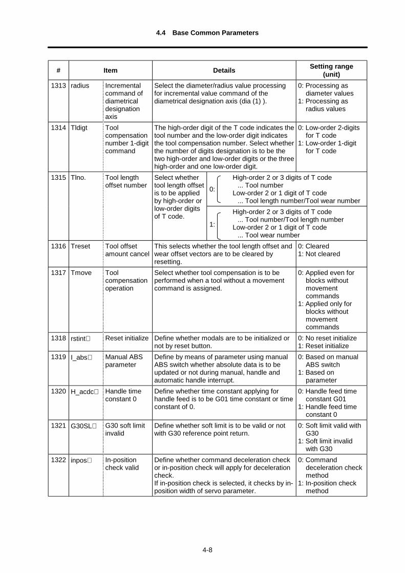
1313 radius Incrementalcommand ofdiametricaldesignationaxis
Select the diameter/radius value processingfor incremental value command of thediametrical designation axis (dia (1) ).
0: Processing asdiameter values
1: Processing asradius values
1314 Tldigt Toolcompensationnumber 1-digitcommand
The high-order digit of the T code indicates thetool number and the low-order digit indicatesthe tool compensation number. Select whetherthe number of digits designation is to be thetwo high-order and low-order digits or the threehigh-order and one low-order digit.
0: Low-order 2-digitsfor T code
1: Low-order 1-digitfor T code
High-order 2 or 3 digits of T code... Tool number
Low-order 2 or 1 digit of T code... Tool length number/Tool wear number
1315 Tlno. Tool lengthoffset number
Select whethertool length offsetis to be appliedby high-order orlow-order digitsof T code. High-order 2 or 3 digits of T code
... Tool number/Tool length number Low-order 2 or 1 digit of T code
... Tool wear number1316 Treset Tool offset
amount cancelThis selects whether the tool length offset andwear offset vectors are to be cleared byresetting.
0: Cleared1: Not cleared
1317 Tmove Toolcompensationoperation
Select whether tool compensation is to beperformed when a tool without a movementcommand is assigned.
0: Applied even forblocks withoutmovementcommands
1: Applied only forblocks withoutmovementcommands
1318 rstint∗ Reset initialize Define whether modals are to be initialized ornot by reset button.
0: No reset initialize1: Reset initialize
1319 I_abs∗ Manual ABSparameter
Define by means of parameter using manualABS switch whether absolute data is to beupdated or not during manual, handle andautomatic handle interrupt.
0: Based on manualABS switch
1: Based onparameter
1320 H_acdc∗ Handle timeconstant 0
Define whether time constant applying forhandle feed is to be G01 time constant or timeconstant of 0.
0: Handle feed timeconstant G01
1: Handle feed timeconstant 0
1321 G30SL∗ G30 soft limitinvalid
Define whether soft limit is to be valid or notwith G30 reference point return.
0: Soft limit valid withG30
1: Soft limit invalidwith G30
1322 inpos∗ In-positioncheck valid
Define whether command deceleration checkor in-position check will apply for decelerationcheck.If in-position check is selected, it checks by in-position width of servo parameter.
0: Commanddeceleration checkmethod
1: In-position checkmethod
1:
0:
4.4 Base Common Parameters
4-9
# Item Details Setting range(unit)
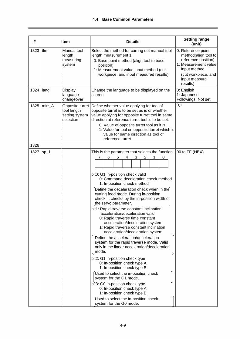
1323 tlm Manual toollengthmeasuringsystem
Select the method for carring out manual toollength measurement 1.
0: Base point method (align tool to baseposition)
1: Measurement value input method (cutworkpiece, and input measured results)
0: Reference pointmethod(align tool toreference position)
1: Measurement valueinput method(cut workpiece, andinput measureresults)
1324 lang Displaylanguagechangeover
Change the language to be displayed on thescreen.
0: English1: JapaneseFollowings: Not set
1325 mirr_A Opposite turrettool lengthsetting systemselection
Define whether value applying for tool ofopposite turret is to be set as is or whethervalue applying for opposite turret tool in samedirection at reference turret tool is to be set.
0: Value of opposite turret tool as it is1: Value for tool on opposite turret which is
value for same direction as tool ofreference turret
0,1
13261327 sp_1 This is the parameter that selects the function.
bit0: G1 in-position check valid0: Command deceleration check method1: In-position check method
Define the deceleration check when in thecutting feed mode. During in-positioncheck, it checks by the in-position width ofthe servo parameter.
bit1: Rapid traverse constant inclinationacceleration/deceleration valid
0: Rapid traverse time constantacceleration/deceleration system
1: Rapid traverse constant inclinationacceleration/deceleration system
Define the acceleration/decelerationsystem for the rapid traverse mode. Validonly in the linear acceleration/decelerationmode.
bit2: G1 in-position check type0: In-position check type A1: In-position check type B
Used to select the in-position checksystem for the G1 mode.
bit3: G0 in-position check type0: In-position check type A1: In-position check type B
Used to select the in-position checksystem for the G0 mode.
00 to FF (HEX)7 6 5 4 3 2 1 0
4.4 Base Common Parameters
4-10
# Item Details Setting range(unit)
bit4 : Tool command control0: It always makes hand-shake (TF-FIN
output) between NC and PLC whenTool command is assigned.
1: It makes hand-shake between NC andPLC only if a command of Tool No.exists in the Tool command.
(Note) Command of Tool No.#1314 T1digit: 0 → The No. is more than high-
order 3 digits of T-codevalue.
1 → The No. is more than high-order 2 digits of T-codevalue.
bit5: Diameter command for manual randomfeed:
0: Moves regarding as a data fixed inradius value.
1: Moves following the machineparameter diameter/radius command.
Bit7: Axis position monitor function validity0: Do not monitor axis position (invalid)1: Monitor axis position (valid)
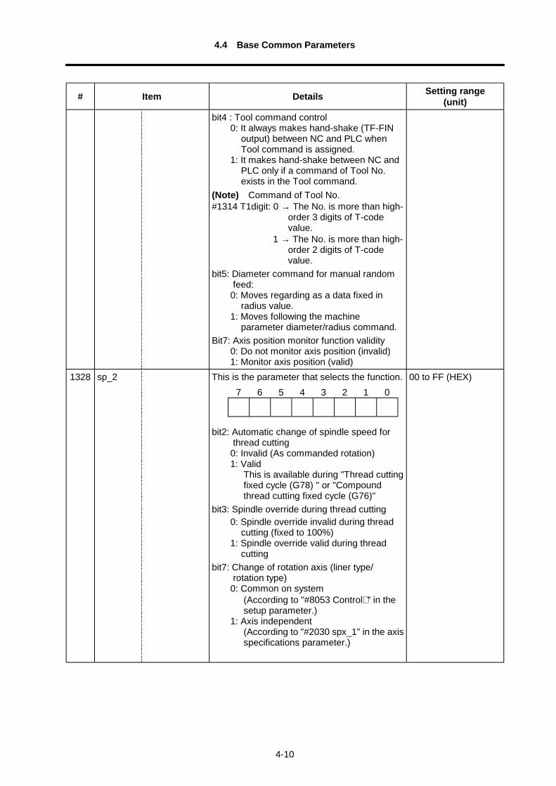
1328 sp_2 This is the parameter that selects the function.
bit2: Automatic change of spindle speed forthread cutting
0: Invalid (As commanded rotation)1: Valid
This is available during "Thread cuttingfixed cycle (G78) " or "Compoundthread cutting fixed cycle (G76)"
bit3: Spindle override during thread cutting0: Spindle override invalid during thread
cutting (fixed to 100%)1: Spindle override valid during thread
cuttingbit7: Change of rotation axis (liner type/
rotation type)0: Common on system
(According to "#8053 Control∗ " in thesetup parameter.)
1: Axis independent(According to "#2030 spx_1" in the axisspecifications parameter.)
00 to FF (HEX)7 6 5 4 3 2 1 0
4.4 Base Common Parameters
4-11
# Item Details Setting range(unit)
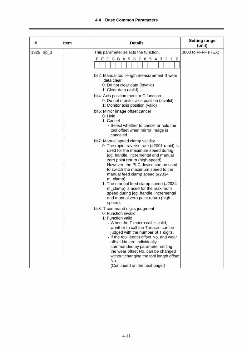
1329 sp_3 This parameter selects the function.
bit2: Manual tool length measurement II weardata clear
0: Do not clear data (invalid)1: Clear data (valid)
bit4: Axis position monitor C function0: Do not monitor axis position (invalid)1: Monitor axis position (valid)
bit6: Mirror image offset cancel0: Hold1: Cancel
• Select whether to cancel or hold thetool offset when mirror image iscanceled.
bit7: Manual speed clamp validity0: The rapid traverse rate (#2001 rapid) is
used for the maximum speed duringjog, handle, incremental and manualzero point return (high-speed).However, the PLC device can be usedto switch the maximum speed to themanual feed clamp speed (#2034m_clamp).
1: The manual feed clamp speed (#2034m_clamp) is used for the maximumspeed during jog, handle, incrementaland manual zero point return (high-speed).
bit8: T command digits judgment0: Function invalid1: Function valid
• When the T macro call is valid,whether to call the T macro can bejudged with the number of T digits.
• If the tool length offset No. and wearoffset No. are individuallycommanded by parameter setting,the wear offset No. can be changedwithout changing the tool length offsetNo.
(Continued on the next page.)
0000 to FFFF (HEX)F E D C B A 9 8 7 6 5 4 3 2 1 0
4.4 Base Common Parameters
4-12
# Item Details Setting range(unit)
(Continued from the previous page.)bit9: Wear offset amount hold
0: Function invalid1: Function valid
• The tool length offset No. can becommanded while the wear offset No.is held with T∆∆97. (∆∆ is a randomtool length offset No.)(Note) Each function can be used
only when the high-order twodigits of the T command arethe tool length offset No., andthe low-order two digits arethe wear offset No.
bitA to bitD: Use prohibited. (Used by system)bitE: G53 tool compensation amount
temporary cancel0: Temporarily cancel1: Do not temporarily cancel
bitF: Use prohibited. (Used by system)1330 sp_4 Thread cutting delay time:
Set delay time for thread cutting while high-precision thread cutting is valid (when controlparameter/bit1 is ON).Setting this time long can make the length ofuseful screw long. However, when the timeis too long, thread cutting may rotate at thesame height around the screw.(Note) The value more than 255 can be
set, but it is valid the quotient whenthe set value is divided by 256.
0 to 255
1331 sp_5 Error width of reach after auto-changing thespindle speed:
If it is effective auto-changing the threadcutting spindle speed (when sp_2/bit2 is ON)the thread cutting starts when the differencebecomes smaller than this parameter value;the difference between the spindlecommanded speed after auto-changing andthe spindle axis actual speed.(Note) The value more than 100 can be
set, in such a case, it clamps at 100,but the display does not clamp.
0 to 100 (r/min)
4.4 Base Common Parameters
4-13
# Item Details Setting range(unit)
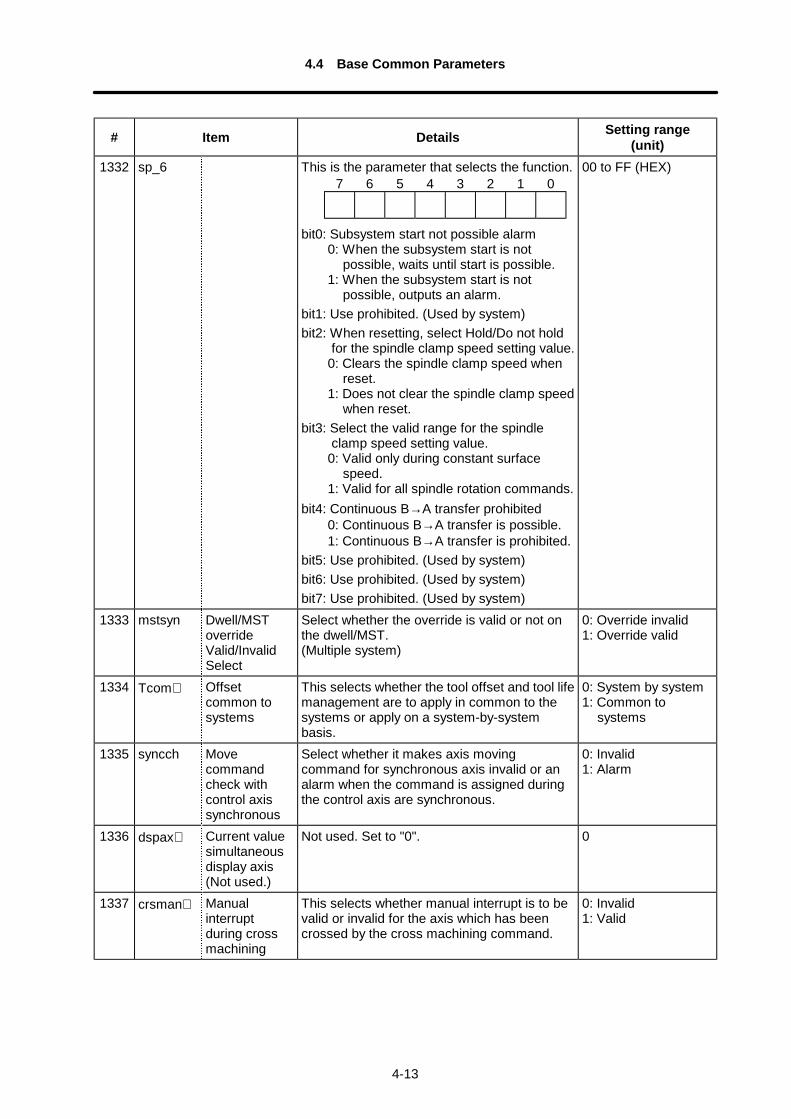
1332 sp_6 This is the parameter that selects the function.
bit0: Subsystem start not possible alarm0: When the subsystem start is not
possible, waits until start is possible.1: When the subsystem start is not
possible, outputs an alarm.bit1: Use prohibited. (Used by system)bit2: When resetting, select Hold/Do not hold
for the spindle clamp speed setting value.0: Clears the spindle clamp speed when
reset.1: Does not clear the spindle clamp speed
when reset.bit3: Select the valid range for the spindle
clamp speed setting value.0: Valid only during constant surface
speed.1: Valid for all spindle rotation commands.
bit4: Continuous B→A transfer prohibited0: Continuous B→A transfer is possible.1: Continuous B→A transfer is prohibited.
bit5: Use prohibited. (Used by system)bit6: Use prohibited. (Used by system)bit7: Use prohibited. (Used by system)
00 to FF (HEX)
1333 mstsyn Dwell/MSToverrideValid/InvalidSelect
Select whether the override is valid or not onthe dwell/MST.(Multiple system)
0: Override invalid1: Override valid
1334 Tcom∗ Offsetcommon tosystems
This selects whether the tool offset and tool lifemanagement are to apply in common to thesystems or apply on a system-by-systembasis.
0: System by system1: Common to
systems
1335 syncch Movecommandcheck withcontrol axissynchronous
Select whether it makes axis movingcommand for synchronous axis invalid or analarm when the command is assigned duringthe control axis are synchronous.
0: Invalid1: Alarm
1336 dspax∗ Current valuesimultaneousdisplay axis(Not used.)
Not used. Set to "0". 0
1337 crsman∗ Manualinterruptduring crossmachining
This selects whether manual interrupt is to bevalid or invalid for the axis which has beencrossed by the cross machining command.
0: Invalid1: Valid
7 6 5 4 3 2 1 0
4.4 Base Common Parameters
4-14
# Item Details Setting range(unit)
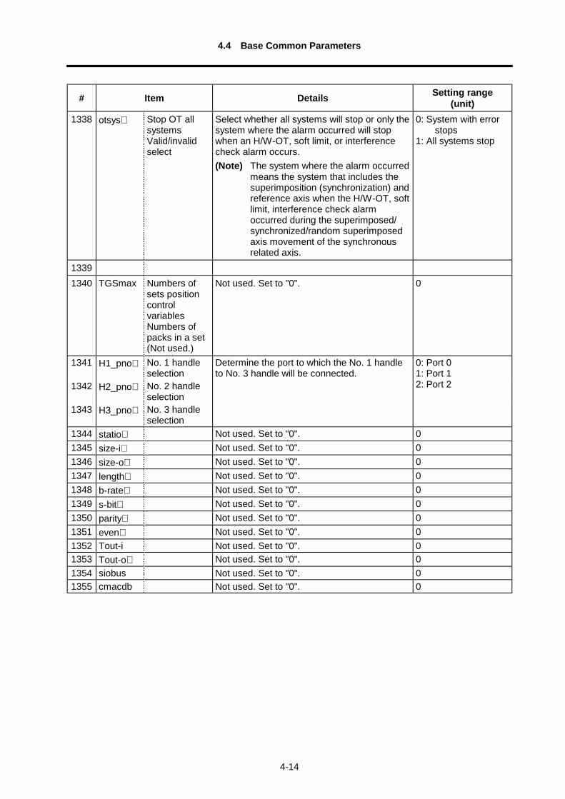
1338 otsys∗ Stop OT allsystemsValid/invalidselect
Select whether all systems will stop or only thesystem where the alarm occurred will stopwhen an H/W-OT, soft limit, or interferencecheck alarm occurs.(Note) The system where the alarm occurred
means the system that includes thesuperimposition (synchronization) andreference axis when the H/W-OT, softlimit, interference check alarmoccurred during the superimposed/synchronized/random superimposedaxis movement of the synchronousrelated axis.
0: System with error stops1: All systems stop
13391340 TGSmax Numbers of
sets positioncontrolvariablesNumbers ofpacks in a set(Not used.)
Not used. Set to "0". 0
1341 H1_pno∗ No. 1 handleselection
Determine the port to which the No. 1 handleto No. 3 handle will be connected.
1342 H2_pno∗ No. 2 handleselection
1343 H3_pno∗ No. 3 handleselection
0: Port 01: Port 12: Port 2
1344 statio∗ Not used. Set to "0". 01345 size-i∗ Not used. Set to "0". 01346 size-o∗ Not used. Set to "0". 01347 length∗ Not used. Set to "0". 01348 b-rate∗ Not used. Set to "0". 01349 s-bit∗ Not used. Set to "0". 01350 parity∗ Not used. Set to "0". 01351 even∗ Not used. Set to "0". 01352 Tout-i Not used. Set to "0". 01353 Tout-o∗ Not used. Set to "0". 01354 siobus Not used. Set to "0". 01355 cmacdb Not used. Set to "0". 0
4.4 Base Common Parameters
4-15
# Item Details Setting range(unit)
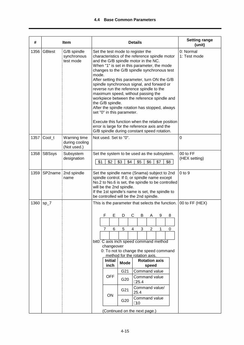
1356 GBtest G/B spindlesynchronoustest mode
Set the test mode to register thecharacteristics of the reference spindle motorand the G/B spindle motor in the NC.When "1" is set in this parameter, the modechanges to the G/B spindle synchronous testmode.After setting this parameter, turn ON the G/Bspindle synchronous signal, and forward orreverse run the reference spindle to themaximum speed, without passing theworkpiece between the reference spindle andthe G/B spindle.After the spindle rotation has stopped, alwaysset "0" in this parameter.
Execute this function when the relative positionerror is large for the reference axis and theG/B spindle during constant speed rotation.
0: Normal1: Test mode
1357 Cool_t Warning timeduring cooling(Not used.)
Not used. Set to "0". 0
1358 SBSsys Subsystemdesignation
Set the system to be used as the subsystem. 00 to FF(HEX setting)
1359 SP2name 2nd spindlename
Set the spindle name (Snama) subject to 2ndspindle control. If 0, or spindle name exceptNo.2 to No.6 is set, the spindle to be controlledwill be the 2nd spindle.If the 1st spindle's name is set, the spindle tobe controlled will be the 2nd spindle.
0 to 9
1360 sp_7 This is the parameter that selects the function.
bit0: C axis inch speed command methodchangeover
0: To not to change the speed commandmethod for the rotation axis.
(Continued on the next page.)
00 to FF (HEX)
Initialinch Mode Rotation axis
speedG21 Command value
OFFG20 Command value
∗ 25.4
G21 Command value/25.4
ONG20 Command value
∗ 10
F E D C B A 9 8
7 6 5 4 3 2 1 0
$1 $2 $3 $4 $5 $6 $7 $8
4.4 Base Common Parameters
4-16
# Item Details Setting range(unit)
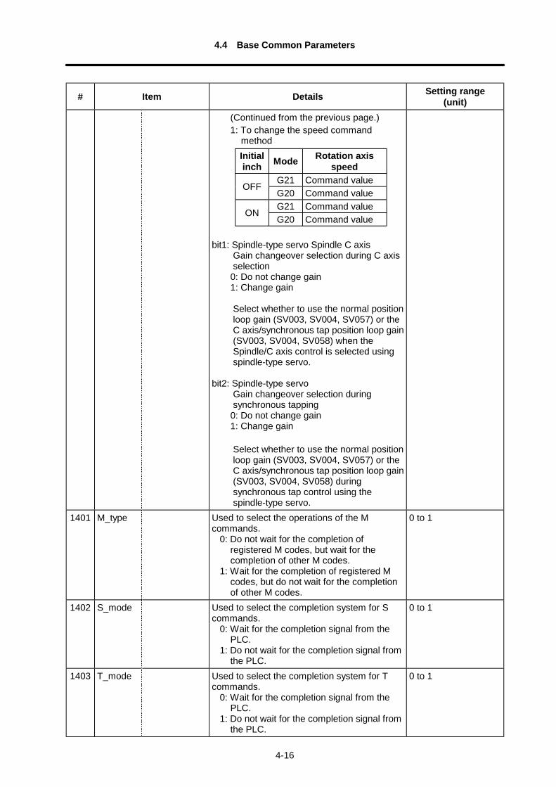
(Continued from the previous page.)1: To change the speed command
method
bit1: Spindle-type servo Spindle C axisGain changeover selection during C axisselection
0: Do not change gain1: Change gain
Select whether to use the normal positionloop gain (SV003, SV004, SV057) or theC axis/synchronous tap position loop gain(SV003, SV004, SV058) when theSpindle/C axis control is selected usingspindle-type servo.
bit2: Spindle-type servoGain changeover selection duringsynchronous tapping
0: Do not change gain1: Change gain
Select whether to use the normal positionloop gain (SV003, SV004, SV057) or theC axis/synchronous tap position loop gain(SV003, SV004, SV058) duringsynchronous tap control using thespindle-type servo.
1401 M_type Used to select the operations of the Mcommands.
0: Do not wait for the completion ofregistered M codes, but wait for thecompletion of other M codes.
1: Wait for the completion of registered Mcodes, but do not wait for the completionof other M codes.
0 to 1
1402 S_mode Used to select the completion system for Scommands.
0: Wait for the completion signal from thePLC.
1: Do not wait for the completion signal fromthe PLC.
0 to 1
1403 T_mode Used to select the completion system for Tcommands.
0: Wait for the completion signal from thePLC.
1: Do not wait for the completion signal fromthe PLC.
0 to 1
Initialinch Mode Rotation axis
speedG21 Command value
OFFG20 Command valueG21 Command value
ONG20 Command value
4.4 Base Common Parameters
4-17
# Item Details Setting range(unit)
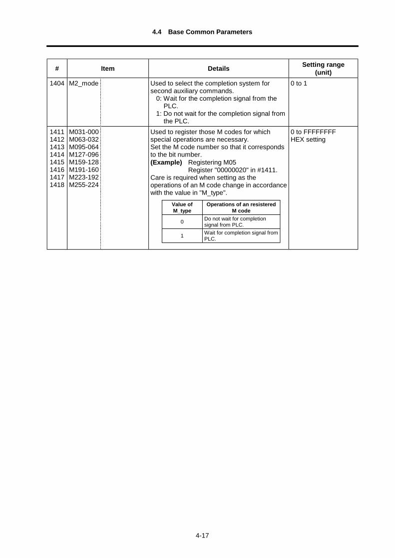
1404 M2_mode Used to select the completion system forsecond auxiliary commands.
0: Wait for the completion signal from thePLC.
1: Do not wait for the completion signal fromthe PLC.
0 to 1
14111412141314141415141614171418
M031-000M063-032M095-064M127-096M159-128M191-160M223-192M255-224
Used to register those M codes for whichspecial operations are necessary.Set the M code number so that it correspondsto the bit number.(Example) Registering M05
Register "00000020" in #1411.Care is required when setting as theoperations of an M code change in accordancewith the value in "M_type".
0 to FFFFFFFFHEX setting
Value ofM_type
Operations of an resisteredM code
0 Do not wait for completionsignal from PLC.
1 Wait for completion signal fromPLC.
4.5 Axis Specification Parameters
4-18
4.5 Axis Specification Parameters
For parameters indicated with a "∗ " in the table, turn the NC power OFF after setting. The setting isvalidated after the power is turned ON again.
# Item Details Setting range(unit)
2001 rapid Rapid traverserate
Set rapid traverse rate for each axis; maximumsetting depends on machine system and socare is required in this respect.
1 to 480000 (mm/min)
2002 clamp Cutting feedclamp speed
Define maximum cutting feedrate for eachaxis.
1 to 480000 (mm/min)
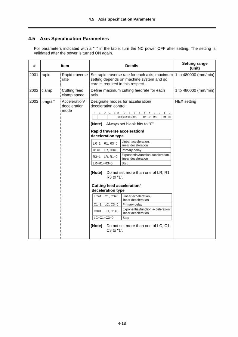
2003 smgst∗ Acceleration/decelerationmode
Designate modes for acceleration/deceleration control;
(Note) Always set blank bits to "0".
(Note) Do not set more than one of LR, R1,R3 to "1".
(Note) Do not set more than one of LC, C1,C3 to "1".
HEX setting
F E D C B A 9 8 7 6 5 4 3 2 1 00T3 0T2 0T1 C3 C1 LC R3 R1 LR
Cutting feed acceleration/deceleration type
LC=1 C1, C3=0 Linear acceleration,linear deceleration
C1=1 LC, C3=0 Primary delay
C3=1 LC, C1=0 Exponential/function acceleration,linear deceleration
LC=C1=C3=0 Step
Rapid traverse acceleration/deceleration type
LR=1 R1, R3=0 Linear acceleration,linear deceleration
R1=1 LR, R3=0 Primary delay
R3=1 LR, R1=0 Exponential/function acceleration,linear deceleration
LR=R1=R3=0 Step
4.5 Axis Specification Parameters
4-19
# Item Details Setting range(unit)
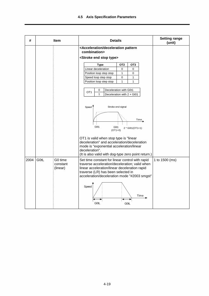
<Acceleration/deceleration patterncombination>
<Stroke end stop type>
G0t1
Speed
G0t1(OT1=0)
Stroke end signal
Time
2 * G0t1(OT1=1)
OT1 is valid when stop type is "lineardeceleration" and acceleration/decelerationmode is "exponential acceleration/lineardeceleration".(It is also valid with dog-type zero point return.)
2004 G0tL G0 timeconstant(linear)
Set time constant for linear control with rapidtraverse acceleration/deceleration; valid whenlinear acceleration/linear deceleration rapidtraverse (LR) has been selected inacceleration/deceleration mode "#2003 smgst"
G0tL
Speed
G0tL
Time
1 to 1500 (ms)
Type OT2 OT3Linear deceleration 0 0Position loop step stop 1 0Speed loop step stop 0 1Position loop step stop 1 1
0 Deceleration with G0t1OT1
1 Deceleration with 2 × Gt01
4.5 Axis Specification Parameters
4-20
# Item Details Setting range(unit)
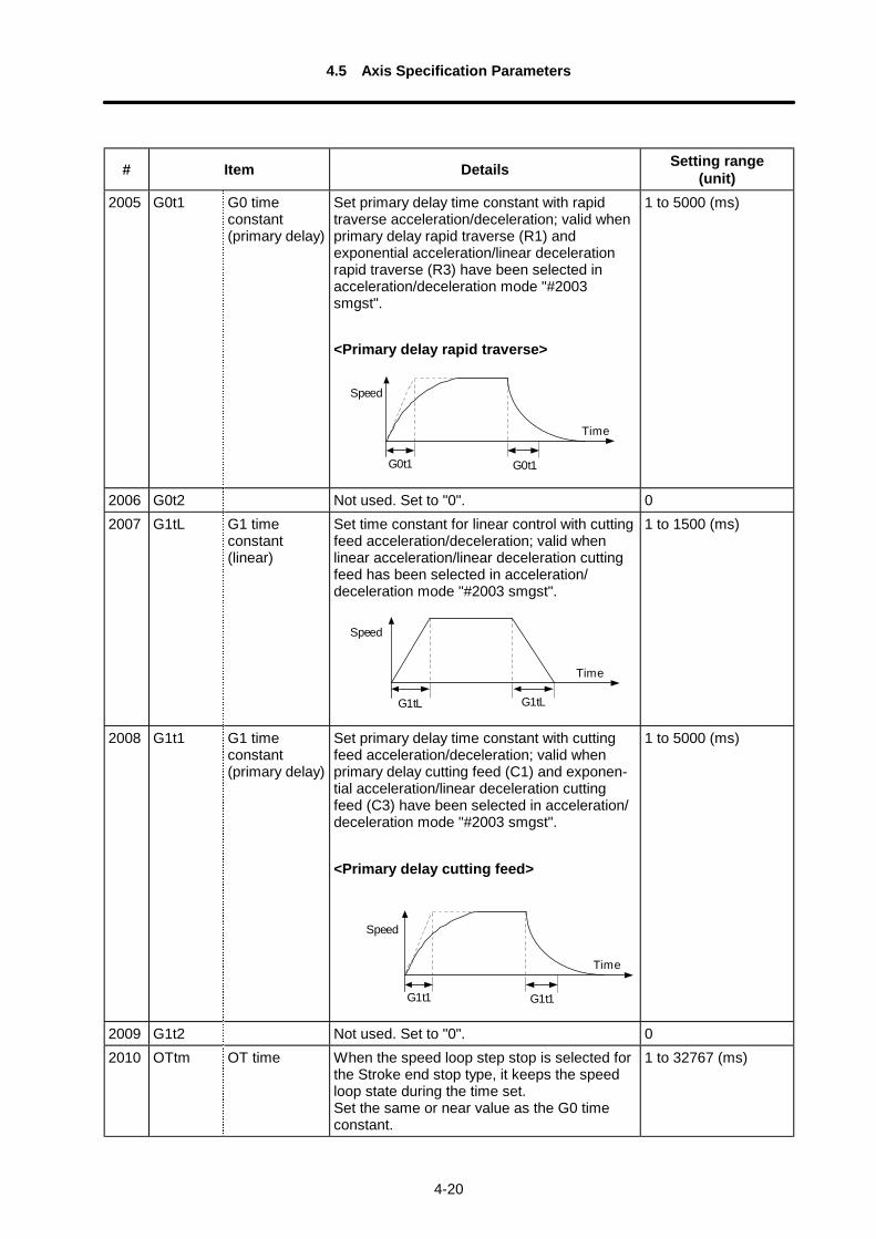
2005 G0t1 G0 timeconstant(primary delay)
Set primary delay time constant with rapidtraverse acceleration/deceleration; valid whenprimary delay rapid traverse (R1) andexponential acceleration/linear decelerationrapid traverse (R3) have been selected inacceleration/deceleration mode "#2003smgst".
<Primary delay rapid traverse>
G0t1
Speed
Time
G0t1
1 to 5000 (ms)
2006 G0t2 Not used. Set to "0". 02007 G1tL G1 time
constant(linear)
Set time constant for linear control with cuttingfeed acceleration/deceleration; valid whenlinear acceleration/linear deceleration cuttingfeed has been selected in acceleration/deceleration mode "#2003 smgst".
G1tL
Speed
G1tL
Time
1 to 1500 (ms)
2008 G1t1 G1 timeconstant(primary delay)
Set primary delay time constant with cuttingfeed acceleration/deceleration; valid whenprimary delay cutting feed (C1) and exponen-tial acceleration/linear deceleration cuttingfeed (C3) have been selected in acceleration/deceleration mode "#2003 smgst".
<Primary delay cutting feed>
G1t1 G1t1
Speed
Time
1 to 5000 (ms)
2009 G1t2 Not used. Set to "0". 02010 OTtm OT time When the speed loop step stop is selected for
the Stroke end stop type, it keeps the speedloop state during the time set.Set the same or near value as the G0 timeconstant.
1 to 32767 (ms)
4.5 Axis Specification Parameters
4-21
# Item Details Setting range(unit)
2011 G0back G0 backlash Set backlash compensation amount withmovement command in rapid traverse modeor with reverse direction in manual mode.
–9999 to 9999(command unit/2)
2012 G1back G1 backlash Set backlash compensation amount withreverse direction when movement commandhas been issued in cutting feed mode.
–9999 to 9999(command unit/2)
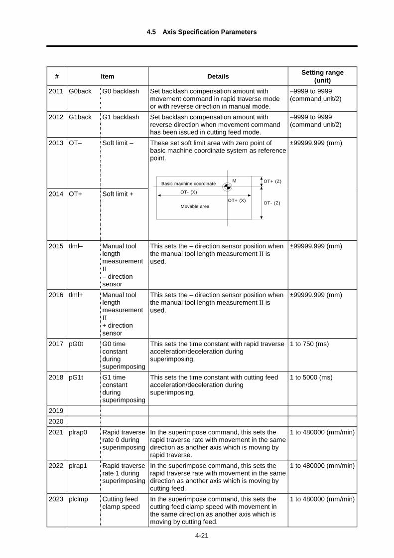
2013 OT– Soft limit –
2014 OT+ Soft limit +
These set soft limit area with zero point ofbasic machine coordinate system as referencepoint.
M OT+ (Z)
OT- (Z)OT+ (X)
OT- (X)
Basic machine coordinate
Movable area
±99999.999 (mm)
2015 tlml– Manual toollengthmeasurementII– directionsensor
This sets the – direction sensor position whenthe manual tool length measurement II isused.
±99999.999 (mm)
2016 tlml+ Manual toollengthmeasurementII+ directionsensor
This sets the – direction sensor position whenthe manual tool length measurement II isused.
±99999.999 (mm)
2017 pG0t G0 timeconstantduringsuperimposing
This sets the time constant with rapid traverseacceleration/deceleration duringsuperimposing.
1 to 750 (ms)
2018 pG1t G1 timeconstantduringsuperimposing
This sets the time constant with cutting feedacceleration/deceleration duringsuperimposing.
1 to 5000 (ms)
201920202021 plrap0 Rapid traverse
rate 0 duringsuperimposing
In the superimpose command, this sets therapid traverse rate with movement in the samedirection as another axis which is moving byrapid traverse.
1 to 480000 (mm/min)
2022 plrap1 Rapid traverserate 1 duringsuperimposing
In the superimpose command, this sets therapid traverse rate with movement in the samedirection as another axis which is moving bycutting feed.
1 to 480000 (mm/min)
2023 plclmp Cutting feedclamp speed
In the superimpose command, this sets thecutting feed clamp speed with movement inthe same direction as another axis which ismoving by cutting feed.
1 to 480000 (mm/min)
4.5 Axis Specification Parameters
4-22
# Item Details Setting range(unit)
2024 offset Tool offsetselect(Not used.)
Not used. Set to "0". 0
2025 G0fwdg G0 feedforward gain
Set the feed forward gain value for rapidtraverse mode (G0) in automatic operations.
0 to 200 (%)Standard value:
70 (%)2026 fwd_g G1 feed
forward gainSet feed forward gain for cutting feed mode(G1, G2, G3) in automatic operation.
0 to 200 (%)Standard value:
70 (%)2027 vir_ax Hypothetical
axisSet whether the axis is treated as hypotheticalaxis or not.
0: Not treated ashypothetical axis
1: Treated ashypothetical axis
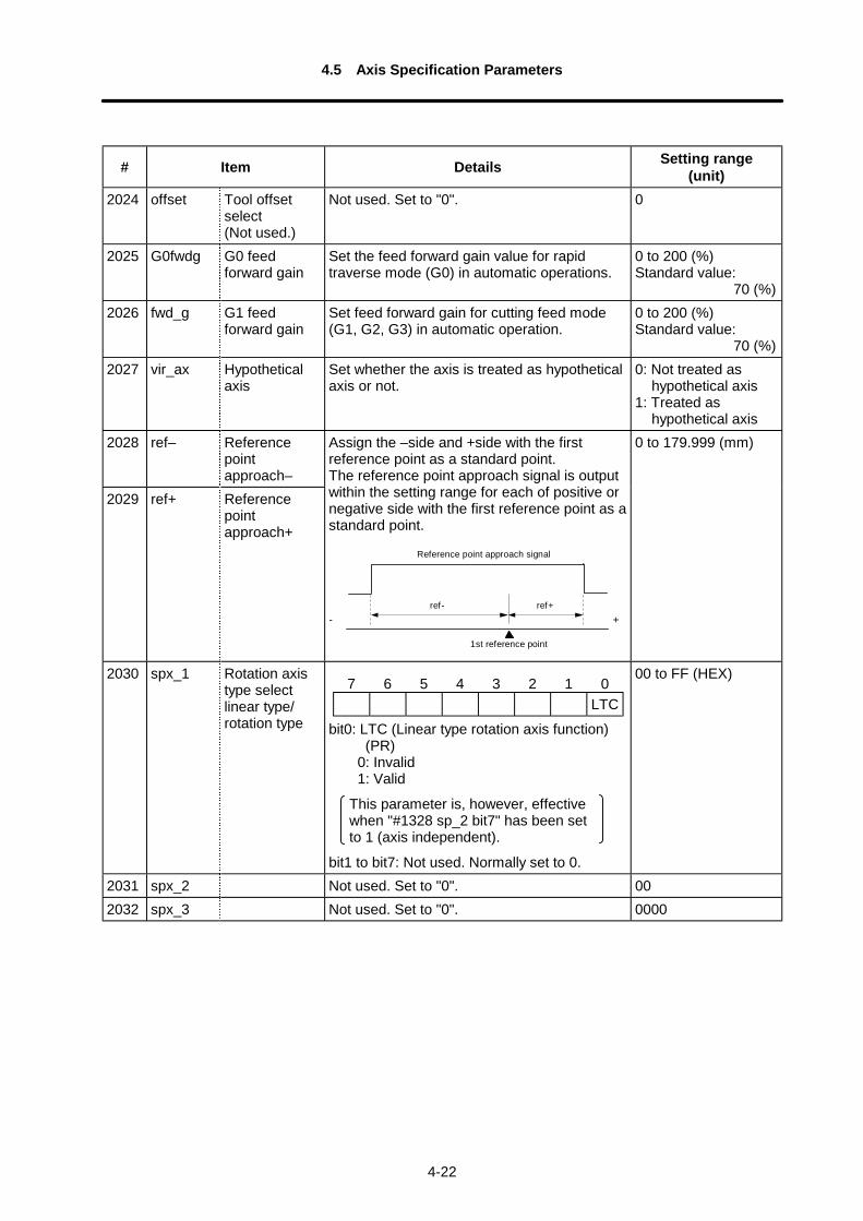
2028 ref– Referencepointapproach–
2029 ref+ Referencepointapproach+
Assign the –side and +side with the firstreference point as a standard point.The reference point approach signal is outputwithin the setting range for each of positive ornegative side with the first reference point as astandard point.
Reference point approach signal
1st reference point
- +ref- ref+
0 to 179.999 (mm)
2030 spx_1 Rotation axistype selectlinear type/rotation type bit0: LTC (Linear type rotation axis function)
(PR)0: Invalid1: Valid
This parameter is, however, effectivewhen "#1328 sp_2 bit7" has been setto 1 (axis independent).
bit1 to bit7: Not used. Normally set to 0.
00 to FF (HEX)
2031 spx_2 Not used. Set to "0". 002032 spx_3 Not used. Set to "0". 0000
7 6 5 4 3 2 1 0LTC
4.5 Axis Specification Parameters
4-23
# Item Details Setting range(unit)
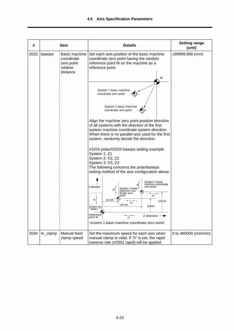
2033 baseps Basic machinecoordinatezero pointrelativedistance
Set each axis position of the basic machinecoordinate zero point having the randomreference point M on the machine as areference point.
M
System 1 basic machinecoordinate zero point
System 2 basic machinecoordinate zero point
Align the machine zero point position directionof all systems with the direction of the firstsystem machine coordinate system direction.When there is no parallel axis used for the firstsystem, randomly decide the direction.
#1010 polar/#2033 baseps setting exampleSystem 1: Z1System 2: X2, Z2System 3: X3, Z3The following concerns the polar/basepssetting method of the axis configuration above.
100.000
250.000120.000
80.000
X1+
-
Z1+-
X2+
-
Z2+-
X3
+
-
Z3+-
±99999.999 (mm)
2034 m_clamp Manual feedclamp speed
Set the maximum speed for each axis whenmanual clamp is valid. If "0" is set, the rapidtraverse rate (#2001 rapid) will be applied.
0 to 480000 (mm/min)
Z direction
X direction
(system 1 basic machine coordinate zero point)
Referencepoint M
System 3 basicmachine coordinatezero pointSystem 2 basic
machine coor-dinate zeropoint
(Does not exist )
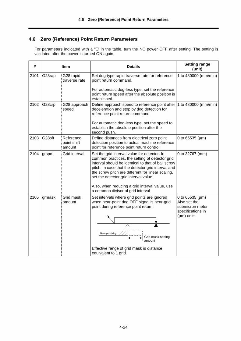
4.6 Zero (Reference) Point Return Parameters
4-24
4.6 Zero (Reference) Point Return Parameters
For parameters indicated with a "∗ " in the table, turn the NC power OFF after setting. The setting isvalidated after the power is turned ON again.
# Item Details Setting range(unit)
2101 G28rap G28 rapidtraverse rate
Set dog-type rapid traverse rate for referencepoint return command.
For automatic dog-less type, set the referencepoint return speed after the absolute position isestablished.
1 to 480000 (mm/min)
2102 G28crp G28 approachspeed
Define approach speed to reference point afterdeceleration and stop by dog detection forreference point return command.
For automatic dog-less type, set the speed toestablish the absolute position after thesecond push.
1 to 480000 (mm/min)
2103 G28sft Referencepoint shiftamount
Define distances from electrical zero pointdetection position to actual machine referencepoint for reference point return control.
0 to 65535 (µm)
2104 grspc Grid interval Set the grid interval value for detector. Incommon practices, the setting of detector gridinterval should be identical to that of ball screwpitch. In case that the detector grid interval andthe screw pitch are different for linear scaling,set the detector grid interval value.
Also, when reducing a grid interval value, usea common divisor of grid interval.
0 to 32767 (mm)
2105 grmask Grid maskamount
Set intervals where grid points are ignoredwhen near-point dog OFF signal is near-gridpoint during reference point return.
Effective range of grid mask is distanceequivalent to 1 grid.
0 to 65535 (µm)Also set thesubmicron meterspecifications in(µm) units.
Grid mask settingamount
Near-point dog
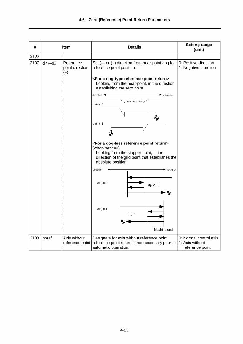
4.6 Zero (Reference) Point Return Parameters
4-25
# Item Details Setting range(unit)
21062107 dir (–)∗ Reference
point direction(–)
Set (–) or (+) direction from near-point dog forreference point position.
<For a dog-type reference point return>Looking from the near-point, in the directionestablishing the zero point.
dir(-)=0
dir(-)=1
<For a dog-less reference point return>(when base=0)
Looking from the stopper point, in thedirection of the grid point that establishes theabsolute position
dir(-)=0
dir(-)=1
rfp 0
rfp 0
>=
<=
0: Positive direction1: Negative direction
2108 noref Axis withoutreference point
Designate for axis without reference point;reference point return is not necessary prior toautomatic operation.
0: Normal control axis1: Axis without
reference point
Near-point dog
+direction-direction
Machine end
+direction-direction
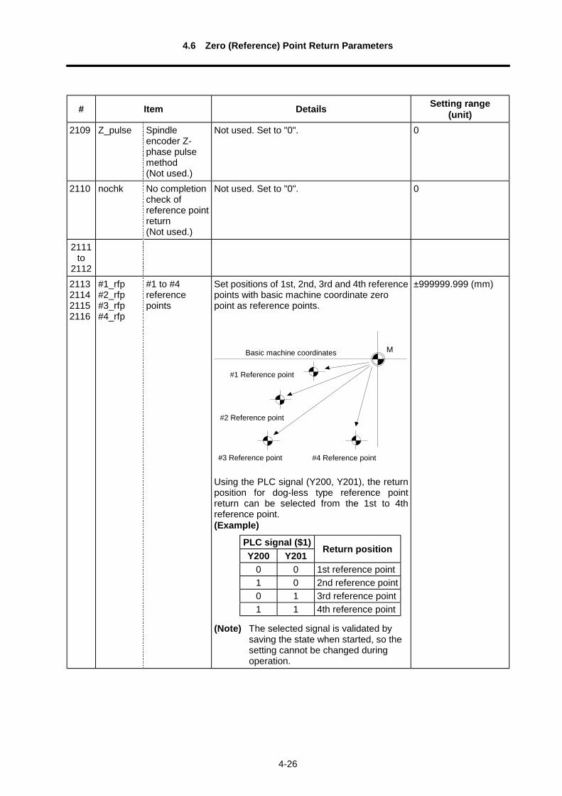
4.6 Zero (Reference) Point Return Parameters
4-26
# Item Details Setting range(unit)
2109 Z_pulse Spindleencoder Z-phase pulsemethod(Not used.)
Not used. Set to "0". 0
2110 nochk No completioncheck ofreference pointreturn(Not used.)
Not used. Set to "0". 0
2111to
21122113211421152116
#1_rfp#2_rfp#3_rfp#4_rfp
#1 to #4referencepoints
Set positions of 1st, 2nd, 3rd and 4th referencepoints with basic machine coordinate zeropoint as reference points.
M
Using the PLC signal (Y200, Y201), the returnposition for dog-less type reference pointreturn can be selected from the 1st to 4threference point.(Example)
(Note) The selected signal is validated bysaving the state when started, so thesetting cannot be changed duringoperation.
±999999.999 (mm)
#1 Reference point
Basic machine coordinates
#3 Reference point
#2 Reference point
#4 Reference point
PLC signal ($1)Y200 Y201
Return position
0 0 1st reference point1 0 2nd reference point0 1 3rd reference point1 1 4th reference point
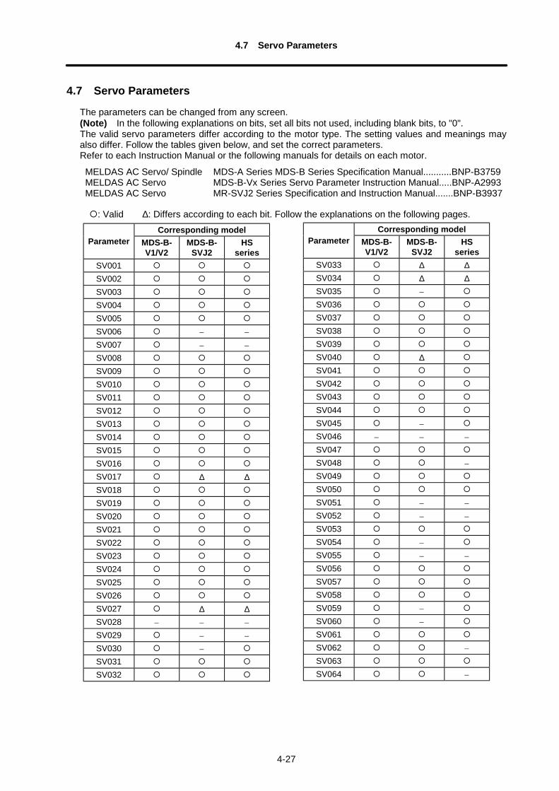
4.7 Servo Parameters
4-27
4.7 Servo Parameters
The parameters can be changed from any screen.(Note) In the following explanations on bits, set all bits not used, including blank bits, to "0".The valid servo parameters differ according to the motor type. The setting values and meanings mayalso differ. Follow the tables given below, and set the correct parameters.Refer to each Instruction Manual or the following manuals for details on each motor.
MELDAS AC Servo/ Spindle MDS-A Series MDS-B Series Specification Manual...........BNP-B3759MELDAS AC Servo MDS-B-Vx Series Servo Parameter Instruction Manual.....BNP-A2993MELDAS AC Servo MR-SVJ2 Series Specification and Instruction Manual.......BNP-B3937
: Valid ∆: Differs according to each bit. Follow the explanations on the following pages.Corresponding model
Parameter MDS-B-V1/V2
MDS-B-SVJ2
HSseries
SV001SV002SV003SV004SV005SV006 – –
SV007 – –
SV008SV009SV010SV011SV012SV013SV014SV015SV016SV017 ∆ ∆SV018SV019SV020SV021SV022SV023SV024SV025SV026SV027 ∆ ∆SV028 – – –
SV029 – –
SV030 –
SV031SV032
Corresponding modelParameter MDS-B-
V1/V2MDS-B-
SVJ2HS
seriesSV033 ∆ ∆SV034 ∆ ∆SV035 –
SV036SV037SV038SV039SV040 ∆SV041SV042SV043SV044SV045 –
SV046 – – –
SV047SV048 –
SV049SV050SV051 – –
SV052 – –
SV053SV054 –
SV055 – –
SV056SV057SV058SV059 –
SV060 –
SV061SV062 –
SV063SV064 –
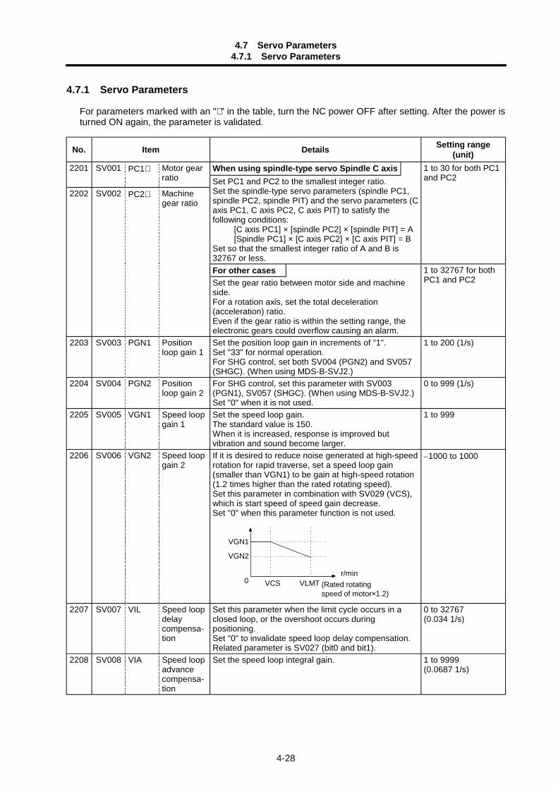
4.7 Servo Parameters4.7.1 Servo Parameters
4-28
4.7.1 Servo Parameters
For parameters marked with an "∗ " in the table, turn the NC power OFF after setting. After the power isturned ON again, the parameter is validated.
No. Item Details Setting range(unit)
When using spindle-type servo Spindle C axis2201 SV001 PC1∗ Motor gearratio
1 to 30 for both PC1and PC2
2202 SV002 PC2∗ Machinegear ratio
Set PC1 and PC2 to the smallest integer ratio.Set the spindle-type servo parameters (spindle PC1,spindle PC2, spindle PIT) and the servo parameters (Caxis PC1, C axis PC2, C axis PIT) to satisfy thefollowing conditions: [C axis PC1] × [spindle PC2] × [spindle PIT] = A [Spindle PC1] × [C axis PC2] × [C axis PIT] = BSet so that the smallest integer ratio of A and B is32767 or less.For other casesSet the gear ratio between motor side and machineside.For a rotation axis, set the total deceleration(acceleration) ratio.Even if the gear ratio is within the setting range, theelectronic gears could overflow causing an alarm.
1 to 32767 for bothPC1 and PC2
2203 SV003 PGN1 Positionloop gain 1
Set the position loop gain in increments of "1".Set "33" for normal operation.For SHG control, set both SV004 (PGN2) and SV057(SHGC). (When using MDS-B-SVJ2.)
1 to 200 (1/s)
2204 SV004 PGN2 Positionloop gain 2
For SHG control, set this parameter with SV003(PGN1), SV057 (SHGC). (When using MDS-B-SVJ2.)Set "0" when it is not used.
0 to 999 (1/s)
2205 SV005 VGN1 Speed loopgain 1
Set the speed loop gain.The standard value is 150.When it is increased, response is improved butvibration and sound become larger.
1 to 999
2206 SV006 VGN2 Speed loopgain 2
If it is desired to reduce noise generated at high-speedrotation for rapid traverse, set a speed loop gain(smaller than VGN1) to be gain at high-speed rotation(1.2 times higher than the rated rotating speed).Set this parameter in combination with SV029 (VCS),which is start speed of speed gain decrease.Set "0" when this parameter function is not used.
r/minVCS VLMT
VGN1
VGN2
0 (Rated rotatingspeed of motor×1.2)
–1000 to 1000
2207 SV007 VIL Speed loopdelaycompensa-tion
Set this parameter when the limit cycle occurs in aclosed loop, or the overshoot occurs duringpositioning.Set "0" to invalidate speed loop delay compensation.Related parameter is SV027 (bit0 and bit1).
0 to 32767(0.034 1/s)
2208 SV008 VIA Speed loopadvancecompensa-tion
Set the speed loop integral gain. 1 to 9999(0.0687 1/s)
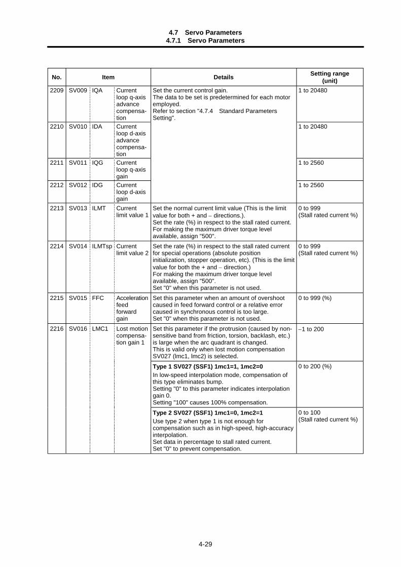
4.7 Servo Parameters4.7.1 Servo Parameters
4-29
No. Item Details Setting range(unit)
2209 SV009 IQA Currentloop q-axisadvancecompensa-tion
1 to 20480
2210 SV010 IDA Currentloop d-axisadvancecompensa-tion
1 to 20480
2211 SV011 IQG Currentloop q-axisgain
1 to 2560
2212 SV012 IDG Currentloop d-axisgain
Set the current control gain.The data to be set is predetermined for each motoremployed.Refer to section "4.7.4 Standard ParametersSetting".
1 to 2560
2213 SV013 ILMT Currentlimit value 1
Set the normal current limit value (This is the limitvalue for both + and – directions.).Set the rate (%) in respect to the stall rated current.For making the maximum driver torque levelavailable, assign "500".
0 to 999(Stall rated current %)
2214 SV014 ILMTsp Currentlimit value 2
Set the rate (%) in respect to the stall rated currentfor special operations (absolute positioninitialization, stopper operation, etc). (This is the limitvalue for both the + and – direction.)For making the maximum driver torque levelavailable, assign "500".Set "0" when this parameter is not used.
0 to 999(Stall rated current %)
2215 SV015 FFC Accelerationfeedforwardgain
Set this parameter when an amount of overshootcaused in feed forward control or a relative errorcaused in synchronous control is too large.Set "0" when this parameter is not used.
0 to 999 (%)
Set this parameter if the protrusion (caused by non-sensitive band from friction, torsion, backlash, etc.)is large when the arc quadrant is changed.This is valid only when lost motion compensationSV027 (lmc1, lmc2) is selected.
–1 to 200
Type 1 SV027 (SSF1) 1mc1=1, 1mc2=0In low-speed interpolation mode, compensation ofthis type eliminates bump.Setting "0" to this parameter indicates interpolationgain 0.Setting "100" causes 100% compensation.
0 to 200 (%)
2216 SV016 LMC1 Lost motioncompensa-tion gain 1
Type 2 SV027 (SSF1) 1mc1=0, 1mc2=1Use type 2 when type 1 is not enough forcompensation such as in high-speed, high-accuracyinterpolation.Set data in percentage to stall rated current.Set "0" to prevent compensation.
0 to 100(Stall rated current %)
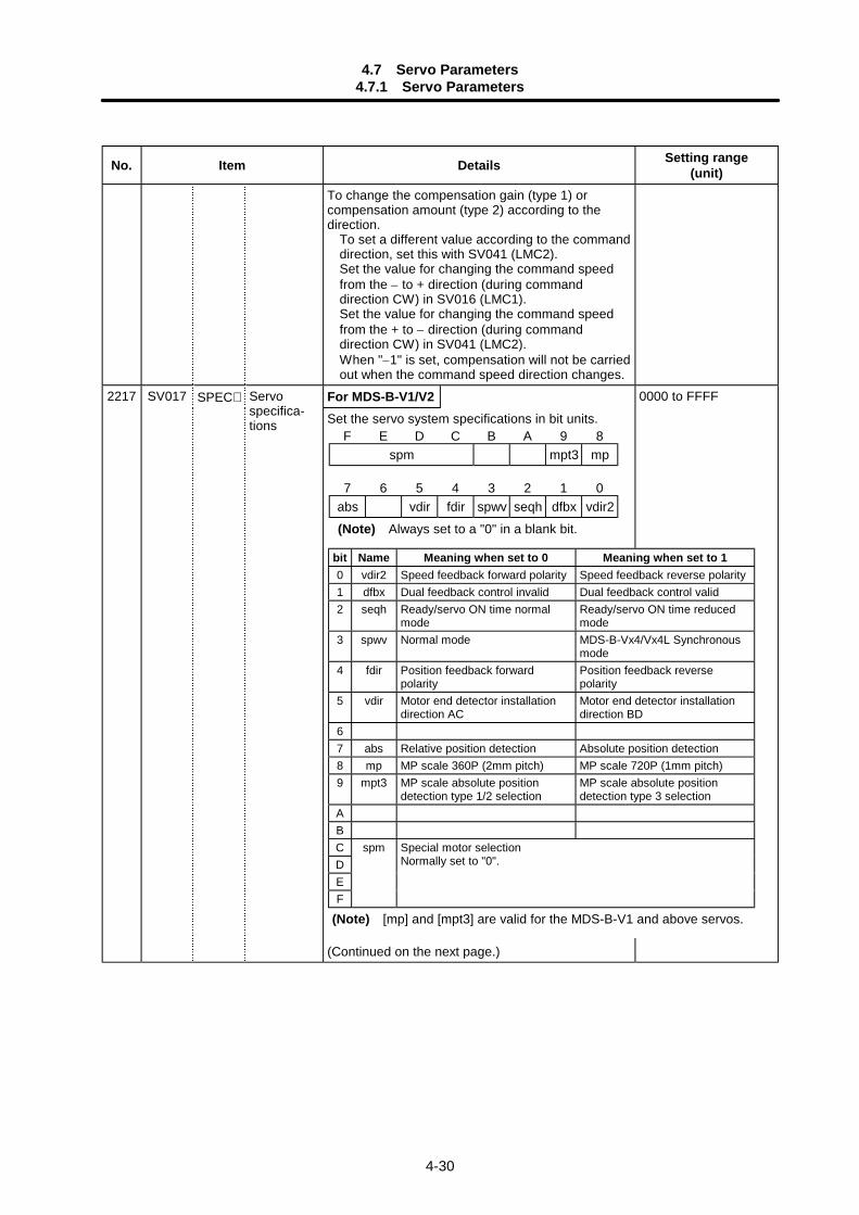
4.7 Servo Parameters4.7.1 Servo Parameters
4-30
No. Item Details Setting range(unit)
To change the compensation gain (type 1) orcompensation amount (type 2) according to thedirection.
To set a different value according to the commanddirection, set this with SV041 (LMC2).Set the value for changing the command speedfrom the – to + direction (during commanddirection CW) in SV016 (LMC1).Set the value for changing the command speedfrom the + to – direction (during commanddirection CW) in SV041 (LMC2).When "–1" is set, compensation will not be carriedout when the command speed direction changes.
For MDS-B-V1/V22217 SV017 SPEC∗ Servospecifica-tions Set the servo system specifications in bit units.
(Continued on the next page.)
0000 to FFFF
bit Name Meaning when set to 0 Meaning when set to 10 vdir2 Speed feedback forward polarity Speed feedback reverse polarity1 dfbx Dual feedback control invalid Dual feedback control valid2 seqh Ready/servo ON time normal
modeReady/servo ON time reducedmode
3 spwv Normal mode MDS-B-Vx4/Vx4L Synchronousmode
4 fdir Position feedback forwardpolarity
Position feedback reversepolarity
5 vdir Motor end detector installationdirection AC
Motor end detector installationdirection BD
67 abs Relative position detection Absolute position detection8 mp MP scale 360P (2mm pitch) MP scale 720P (1mm pitch)9 mpt3 MP scale absolute position
detection type 1/2 selectionMP scale absolute positiondetection type 3 selection
ABCDEF
spm Special motor selectionNormally set to "0".
(Note) [mp] and [mpt3] are valid for the MDS-B-V1 and above servos.
F E D C B A 9 8spm mpt3 mp
7 6 5 4 3 2 1 0abs vdir fdir spwv seqh dfbx vdir2
(Note) Always set to a "0" in a blank bit.
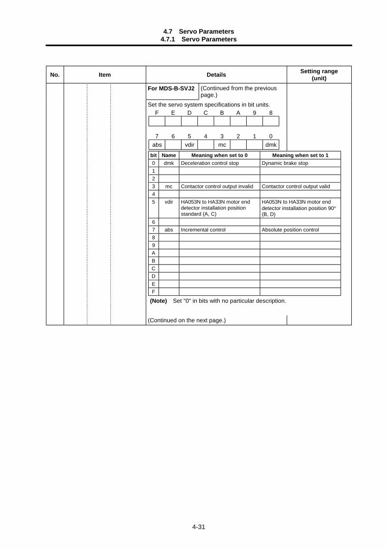
4.7 Servo Parameters4.7.1 Servo Parameters
4-31
No. Item Details Setting range(unit)
For MDS-B-SVJ2 (Continued from the previouspage.)
Set the servo system specifications in bit units.
(Continued on the next page.)
bit Name Meaning when set to 0 Meaning when set to 10 dmk Deceleration control stop Dynamic brake stop123 mc Contactor control output invalid Contactor control output valid45 vdir HA053N to HA33N motor end
detector installation positionstandard (A, C)
HA053N to HA33N motor enddetector installation position 90°(B, D)
67 abs Incremental control Absolute position control89ABCDEF
(Note) Set "0" in bits with no particular description.
F E D C B A 9 8
7 6 5 4 3 2 1 0abs vdir mc dmk
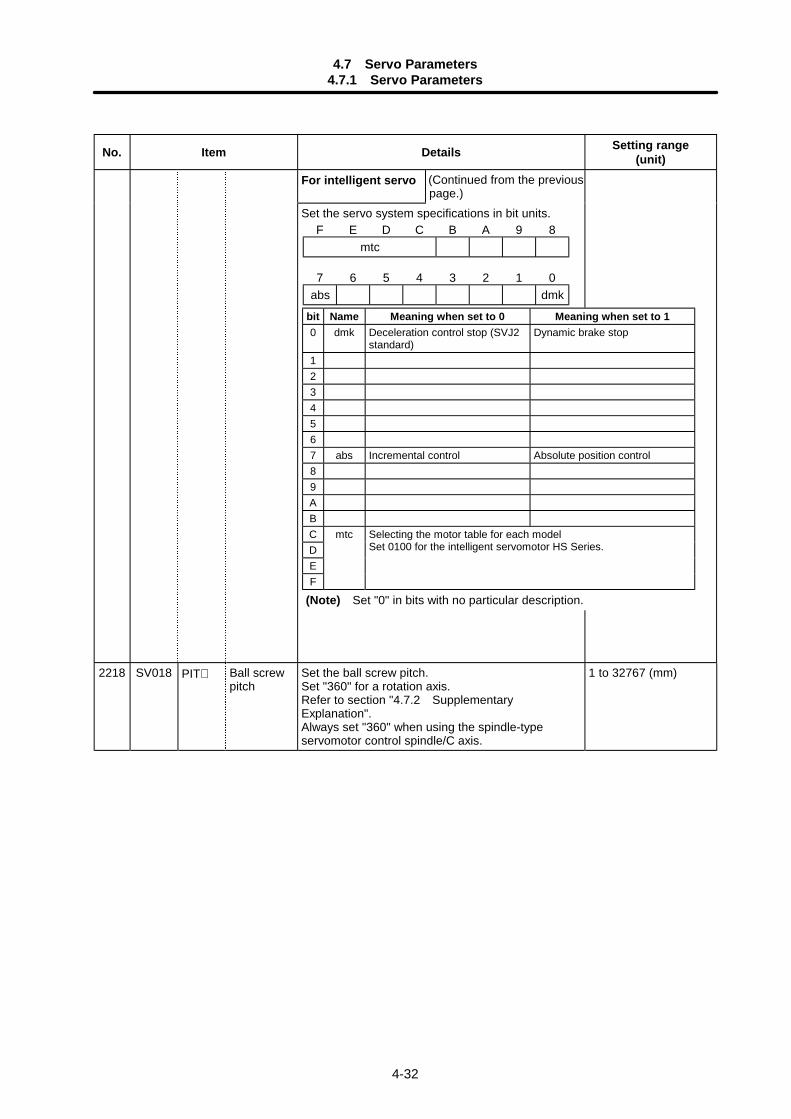
4.7 Servo Parameters4.7.1 Servo Parameters
4-32
No. Item Details Setting range(unit)
For intelligent servo (Continued from the previouspage.)
Set the servo system specifications in bit units.
2218 SV018 PIT∗ Ball screwpitch
Set the ball screw pitch.Set "360" for a rotation axis.Refer to section "4.7.2 SupplementaryExplanation".Always set "360" when using the spindle-typeservomotor control spindle/C axis.
1 to 32767 (mm)
bit Name Meaning when set to 0 Meaning when set to 10 dmk Deceleration control stop (SVJ2
standard)Dynamic brake stop
1234567 abs Incremental control Absolute position control89ABCDEF
mtc Selecting the motor table for each modelSet 0100 for the intelligent servomotor HS Series.
(Note) Set "0" in bits with no particular description.
F E D C B A 9 8mtc
7 6 5 4 3 2 1 0abs dmk
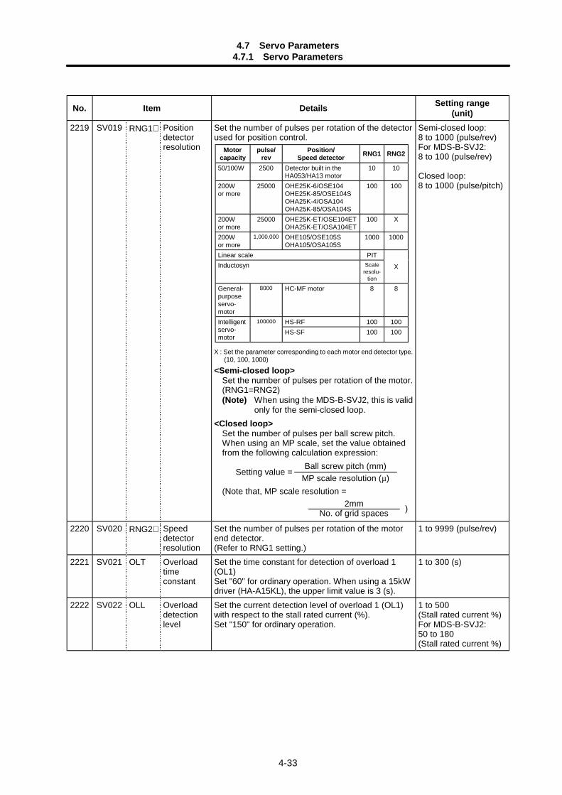
4.7 Servo Parameters4.7.1 Servo Parameters
4-33
No. Item Details Setting range(unit)
2219 SV019 RNG1∗ Positiondetectorresolution
Set the number of pulses per rotation of the detectorused for position control.
X : Set the parameter corresponding to each motor end detector type.(10, 100, 1000)
<Semi-closed loop>Set the number of pulses per rotation of the motor.(RNG1=RNG2)(Note) When using the MDS-B-SVJ2, this is valid
only for the semi-closed loop.<Closed loop>
Set the number of pulses per ball screw pitch.When using an MP scale, set the value obtainedfrom the following calculation expression:
Setting value =
(Note that, MP scale resolution =
Semi-closed loop:8 to 1000 (pulse/rev)For MDS-B-SVJ2:8 to 100 (pulse/rev)
Closed loop:8 to 1000 (pulse/pitch)
2220 SV020 RNG2∗ Speeddetectorresolution
Set the number of pulses per rotation of the motorend detector.(Refer to RNG1 setting.)
1 to 9999 (pulse/rev)
2221 SV021 OLT Overloadtimeconstant
Set the time constant for detection of overload 1(OL1)Set "60" for ordinary operation. When using a 15kWdriver (HA-A15KL), the upper limit value is 3 (s).
1 to 300 (s)
2222 SV022 OLL Overloaddetectionlevel
Set the current detection level of overload 1 (OL1)with respect to the stall rated current (%).Set "150" for ordinary operation.
1 to 500(Stall rated current %)For MDS-B-SVJ2:50 to 180(Stall rated current %)
Motorcapacity
pulse/rev
Position/Speed detector RNG1 RNG2
50/100W 2500 Detector built in theHA053/HA13 motor
10 10
200Wor more
25000 OHE25K-6/OSE104OHE25K-85/OSE104SOHA25K-4/OSA104OHA25K-85/OSA104S
100 100
200Wor more
25000 OHE25K-ET/OSE104ETOHA25K-ET/OSA104ET
100 X
200Wor more
1,000,000 OHE105/OSE105SOHA105/OSA105S
1000 1000
Linear scale PITInductosyn Scale
resolu-tion
X
General-purposeservo-motor
8000 HC-MF motor 8 8
HS-RF 100 100Intelligentservo-motor
100000
HS-SF 100 100
Ball screw pitch (mm)MP scale resolution (µ)
2mmNo. of grid spaces )
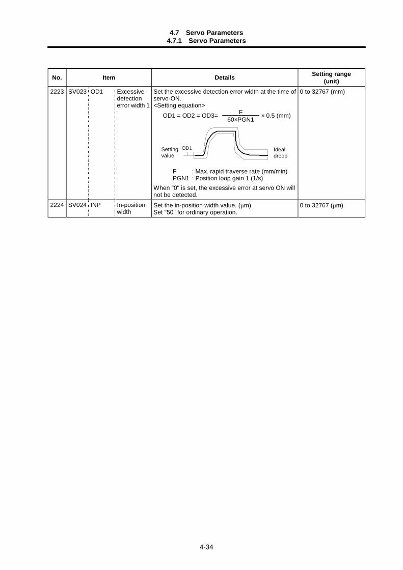
4.7 Servo Parameters4.7.1 Servo Parameters
4-34
No. Item Details Setting range(unit)
2223 SV023 OD1 Excessivedetectionerror width 1
Set the excessive detection error width at the time ofservo-ON.<Setting equation> OD1 = OD2 = OD3= × 0.5 (mm)
OD1
F : Max. rapid traverse rate (mm/min)PGN1 : Position loop gain 1 (1/s)
When "0" is set, the excessive error at servo ON willnot be detected.
0 to 32767 (mm)
2224 SV024 INP In-positionwidth
Set the in-position width value. (µm)Set "50" for ordinary operation.
0 to 32767 (µm)
F60×PGN1
Idealdroop
Settingvalue
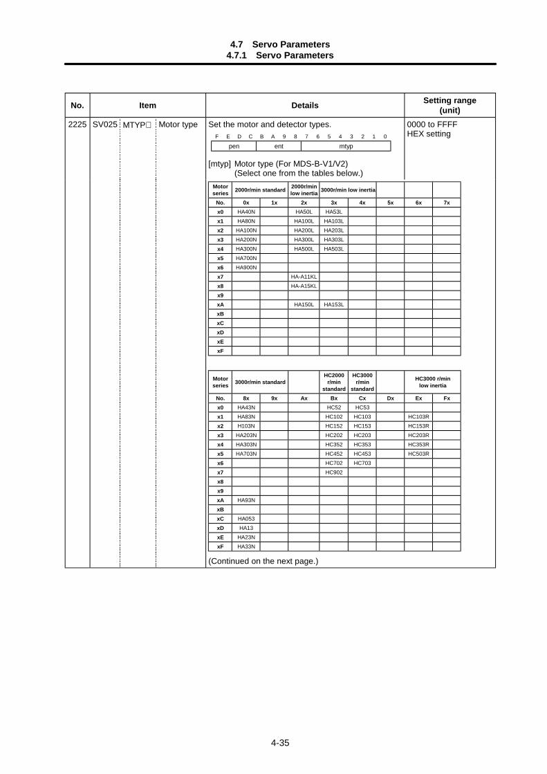
4.7 Servo Parameters4.7.1 Servo Parameters
4-35
No. Item Details Setting range(unit)
2225 SV025 MTYP∗ Motor type Set the motor and detector types.
[mtyp] Motor type (For MDS-B-V1/V2)(Select one from the tables below.)
0000 to FFFFHEX setting
Motorseries 2000r/min standard 2000r/min
low inertia 3000r/min low inertia
No. 0x 1x 2x 3x 4x 5x 6x 7xx0 HA40N HA50L HA53Lx1 HA80N HA100L HA103Lx2 HA100N HA200L HA203Lx3 HA200N HA300L HA303Lx4 HA300N HA500L HA503Lx5 HA700Nx6 HA900Nx7 HA-A11KLx8 HA-A15KLx9xA HA150L HA153LxBxCxDxExF
Motorseries 3000r/min standard
HC2000r/min
standard
HC3000r/min
standard
HC3000 r/minlow inertia
No. 8x 9x Ax Bx Cx Dx Ex Fxx0 HA43N HC52 HC53x1 HA83N HC102 HC103 HC103Rx2 H103N HC152 HC153 HC153Rx3 HA203N HC202 HC203 HC203Rx4 HA303N HC352 HC353 HC353Rx5 HA703N HC452 HC453 HC503Rx6 HC702 HC703x7 HC902x8x9xA HA93NxBxC HA053xD HA13xE HA23NxF HA33N
(Continued on the next page.)
F E D C B A 9 8 7 6 5 4 3 2 1 0
pen ent mtyp
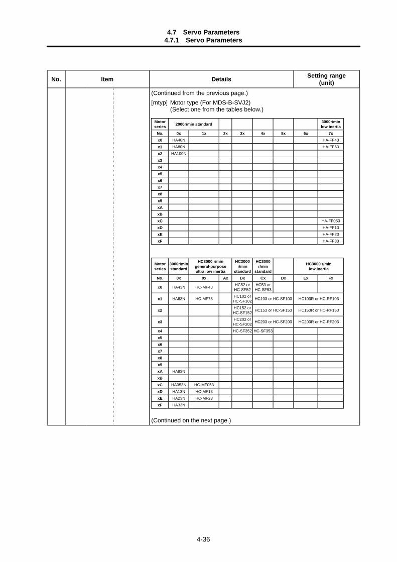
4.7 Servo Parameters4.7.1 Servo Parameters
4-36
No. Item Details Setting range(unit)
(Continued from the previous page.)[mtyp] Motor type (For MDS-B-SVJ2)
(Select one from the tables below.)
Motorseries 2000r/min standard 3000r/min
low inertiaNo. 0x 1x 2x 3x 4x 5x 6x 7xx0 HA40N HA-FF43x1 HA80N HA-FF63x2 HA100Nx3x4x5x6x7x8x9xAxBxC HA-FF053xD HA-FF13xE HA-FF23xF HA-FF33
Motorseries
3000r/minstandard
HC3000 r/mingeneral-purposeultra low inertia
HC2000r/min
standard
HC3000r/min
standard
HC3000 r/minlow inertia
No. 8x 9x Ax Bx Cx Dx Ex Fx
x0 HA43N HC-MF43 HC52 orHC-SF52
HC53 orHC-SF53
x1 HA83N HC-MF73 HC102 orHC-SF102 HC103 or HC-SF103 HC103R or HC-RF103
x2 HC152 orHC-SF152 HC153 or HC-SF153 HC153R or HC-RF153
x3 HC202 orHC-SF202 HC203 or HC-SF203 HC203R or HC-RF203
x4 HC-SF352 HC-SF353x5x6x7x8x9xA HA93NxBxC HA053N HC-MF053xD HA13N HC-MF13xE HA23N HC-MF23xF HA33N
(Continued on the next page.)
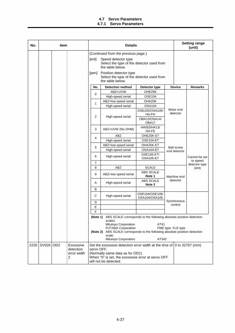
4.7 Servo Parameters4.7.1 Servo Parameters
4-37
No. Item Details Setting range(unit)
(Continued from the previous page.)[ent] Speed detector type
Select the type of the detector used fromthe table below.
[pen] Position detector typeSelect the type of the detector used fromthe table below.
2226 SV026 OD2 Excessivedetectionerror width2
Set the excessive detection error width at the time ofservo OFF.(Normally same data as for OD1)When "0" is set, the excessive error at servo OFFwill not be detected.
0 to 32767 (mm)
No. Detection method Detector type Device RemarksABZ+UVW OHE25K
0High-speed serial OSE104
ABZ+low speed serial OHA25K1
High-speed serial OSA104OSE105/OSA105/
HA-FH2 High-speed serial
OBA13/OSA14/OBA17
3 ABZ+UVW (No OHM) HA053/HA13/HA-FE
Motor enddetector
ABZ OHE25K-ET4
High-speed serial OSE104-ETABZ+low speed serial OHA25K-ET
5High-speed serial OSA104-ET
6 High-speed serial OSE105-ET/OSA105-ET
7
Ball screwend detector
8 ABZ SCALE
9 ABZ+low speed serial ABS SCALENote 1
A High-speed serial ABS SCALENote 2
B
Machine enddetector
Cannot be setto speed
detector type(ent)
C High-speed serial OSE104/OSE105/OSA104/OSA105
DEF
Synchronouscontrol
(Note 1) ABS SCALE corresponds to the following absolute position detectionscales.Mitutoyo Corporation AT41FUTABA Corporation FME type, FLE type
(Note 2) ABS SCALE corresponds to the following absolute position detectionscale.Mitutoyo Corporation AT342
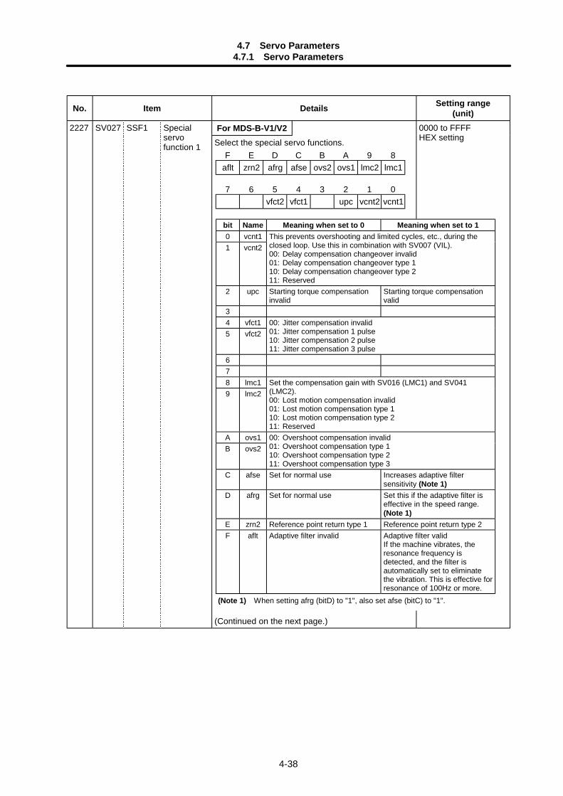
4.7 Servo Parameters4.7.1 Servo Parameters
4-38
No. Item Details Setting range(unit)
For MDS-B-V1/V22227 SV027 SSF1 Specialservofunction 1 Select the special servo functions.
(Continued on the next page.)
0000 to FFFFHEX setting
F E D C B A 9 8aflt zrn2 afrg afse ovs2 ovs1 lmc2 lmc1
7 6 5 4 3 2 1 0vfct2 vfct1 upc vcnt2 vcnt1
bit Name Meaning when set to 0 Meaning when set to 10 vcnt11 vcnt2
This prevents overshooting and limited cycles, etc., during theclosed loop. Use this in combination with SV007 (VIL).00: Delay compensation changeover invalid01: Delay compensation changeover type 110: Delay compensation changeover type 211: Reserved
2 upc Starting torque compensationinvalid
Starting torque compensationvalid
34 vfct15 vfct2
00: Jitter compensation invalid01: Jitter compensation 1 pulse10: Jitter compensation 2 pulse11: Jitter compensation 3 pulse
678 lmc19 lmc2
Set the compensation gain with SV016 (LMC1) and SV041(LMC2).00: Lost motion compensation invalid01: Lost motion compensation type 110: Lost motion compensation type 211: Reserved
A ovs1B ovs2
00: Overshoot compensation invalid01: Overshoot compensation type 110: Overshoot compensation type 211: Overshoot compensation type 3
C afse Set for normal use Increases adaptive filtersensitivity (Note 1)
D afrg Set for normal use Set this if the adaptive filter iseffective in the speed range.(Note 1)
E zrn2 Reference point return type 1 Reference point return type 2F aflt Adaptive filter invalid Adaptive filter valid
If the machine vibrates, theresonance frequency isdetected, and the filter isautomatically set to eliminatethe vibration. This is effective forresonance of 100Hz or more.
(Note 1) When setting afrg (bitD) to "1", also set afse (bitC) to "1".
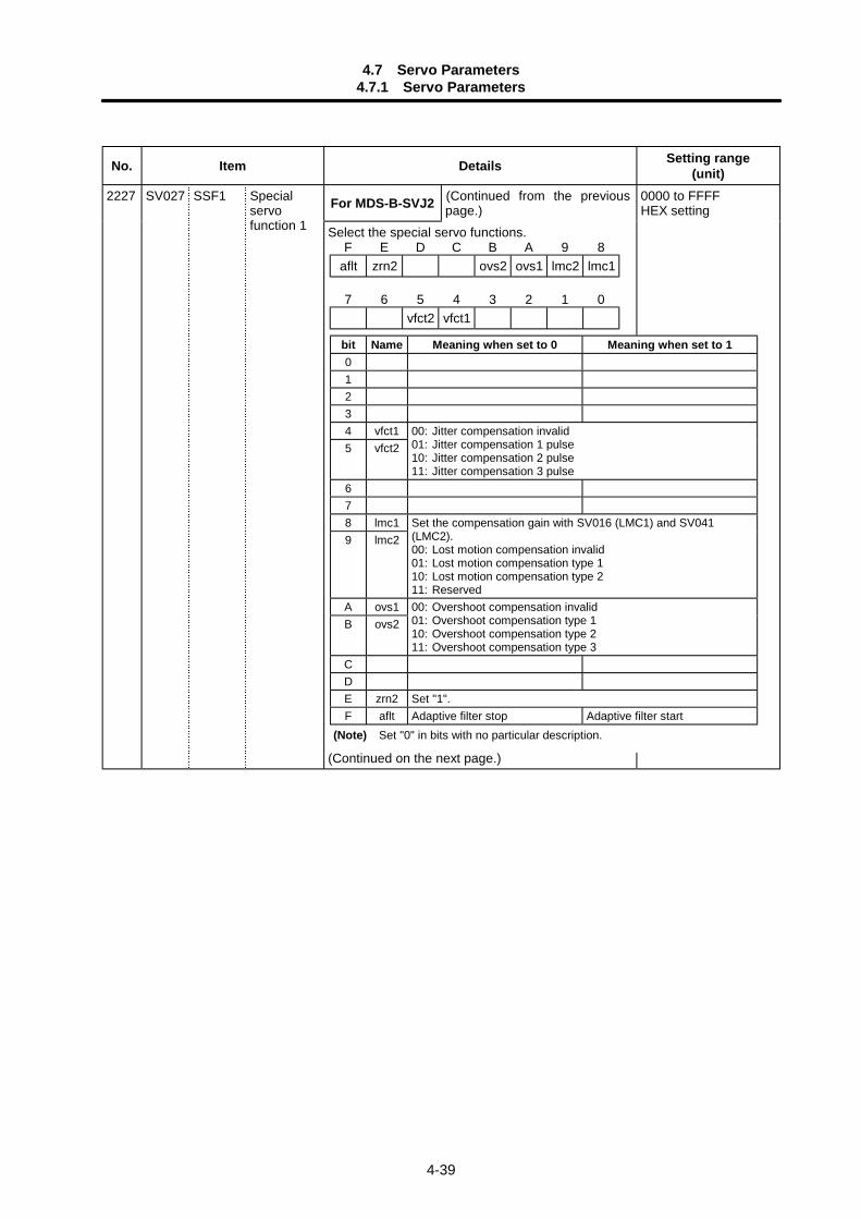
4.7 Servo Parameters4.7.1 Servo Parameters
4-39
No. Item Details Setting range(unit)
For MDS-B-SVJ2 (Continued from the previouspage.)
2227 SV027 SSF1 Specialservofunction 1 Select the special servo functions.
(Continued on the next page.)
0000 to FFFFHEX setting
F E D C B A 9 8aflt zrn2 ovs2 ovs1 lmc2 lmc1
7 6 5 4 3 2 1 0vfct2 vfct1
bit Name Meaning when set to 0 Meaning when set to 101234 vfct15 vfct2
00: Jitter compensation invalid01: Jitter compensation 1 pulse10: Jitter compensation 2 pulse11: Jitter compensation 3 pulse
678 lmc19 lmc2
Set the compensation gain with SV016 (LMC1) and SV041(LMC2).00: Lost motion compensation invalid01: Lost motion compensation type 110: Lost motion compensation type 211: Reserved
A ovs1B ovs2
00: Overshoot compensation invalid01: Overshoot compensation type 110: Overshoot compensation type 211: Overshoot compensation type 3
CDE zrn2 Set "1".F aflt Adaptive filter stop Adaptive filter start
(Note) Set "0" in bits with no particular description.
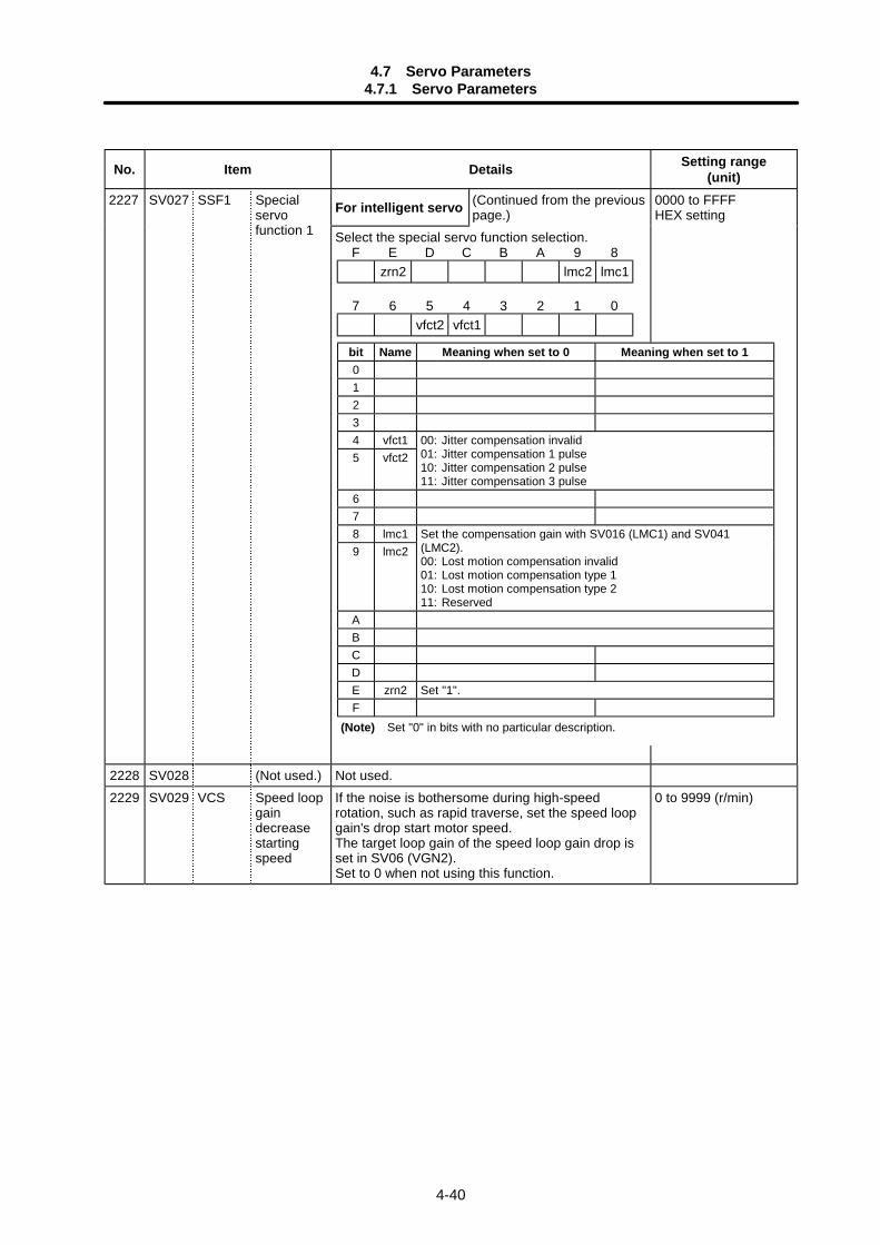
4.7 Servo Parameters4.7.1 Servo Parameters
4-40
No. Item Details Setting range(unit)
For intelligent servo (Continued from the previouspage.)
2227 SV027 SSF1 Specialservofunction 1 Select the special servo function selection.
0000 to FFFFHEX setting
2228 SV028 (Not used.) Not used.2229 SV029 VCS Speed loop
gaindecreasestartingspeed
If the noise is bothersome during high-speedrotation, such as rapid traverse, set the speed loopgain's drop start motor speed.The target loop gain of the speed loop gain drop isset in SV06 (VGN2).Set to 0 when not using this function.
0 to 9999 (r/min)
F E D C B A 9 8zrn2 lmc2 lmc1
7 6 5 4 3 2 1 0vfct2 vfct1
bit Name Meaning when set to 0 Meaning when set to 101234 vfct15 vfct2
00: Jitter compensation invalid01: Jitter compensation 1 pulse10: Jitter compensation 2 pulse11: Jitter compensation 3 pulse
678 lmc19 lmc2
Set the compensation gain with SV016 (LMC1) and SV041(LMC2).00: Lost motion compensation invalid01: Lost motion compensation type 110: Lost motion compensation type 211: Reserved
ABCDE zrn2 Set "1".F
(Note) Set "0" in bits with no particular description.
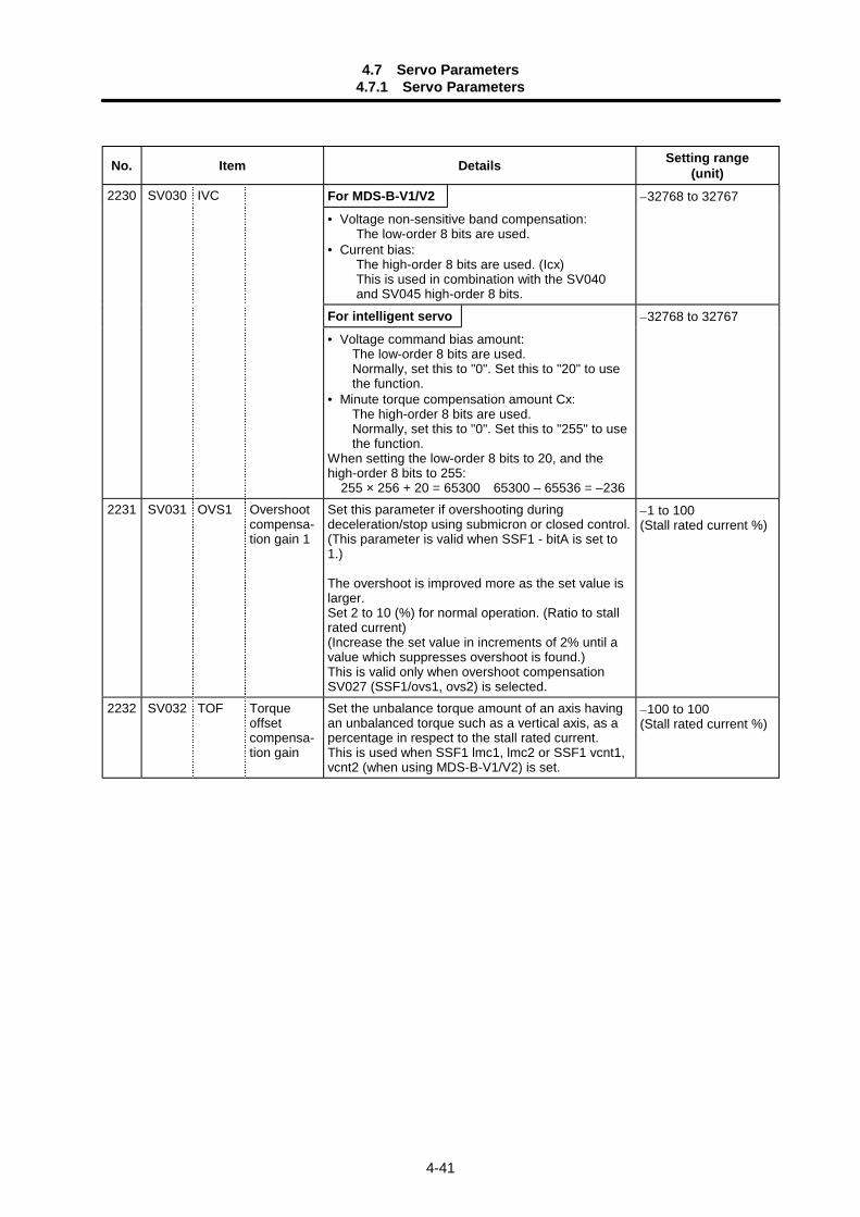
4.7 Servo Parameters4.7.1 Servo Parameters
4-41
No. Item Details Setting range(unit)
For MDS-B-V1/V2 –32768 to 32767
• Voltage non-sensitive band compensation:The low-order 8 bits are used.
• Current bias:The high-order 8 bits are used. (Icx)This is used in combination with the SV040and SV045 high-order 8 bits.
For intelligent servo –32768 to 32767
2230 SV030 IVC
• Voltage command bias amount:The low-order 8 bits are used.Normally, set this to "0". Set this to "20" to usethe function.
• Minute torque compensation amount Cx:The high-order 8 bits are used.Normally, set this to "0". Set this to "255" to usethe function.
When setting the low-order 8 bits to 20, and thehigh-order 8 bits to 255: 255 × 256 + 20 = 65300 65300 – 65536 = –236
2231 SV031 OVS1 Overshootcompensa-tion gain 1
Set this parameter if overshooting duringdeceleration/stop using submicron or closed control.(This parameter is valid when SSF1 - bitA is set to1.)
The overshoot is improved more as the set value islarger.Set 2 to 10 (%) for normal operation. (Ratio to stallrated current)(Increase the set value in increments of 2% until avalue which suppresses overshoot is found.)This is valid only when overshoot compensationSV027 (SSF1/ovs1, ovs2) is selected.
–1 to 100(Stall rated current %)
2232 SV032 TOF Torqueoffsetcompensa-tion gain
Set the unbalance torque amount of an axis havingan unbalanced torque such as a vertical axis, as apercentage in respect to the stall rated current.This is used when SSF1 lmc1, lmc2 or SSF1 vcnt1,vcnt2 (when using MDS-B-V1/V2) is set.
–100 to 100(Stall rated current %)
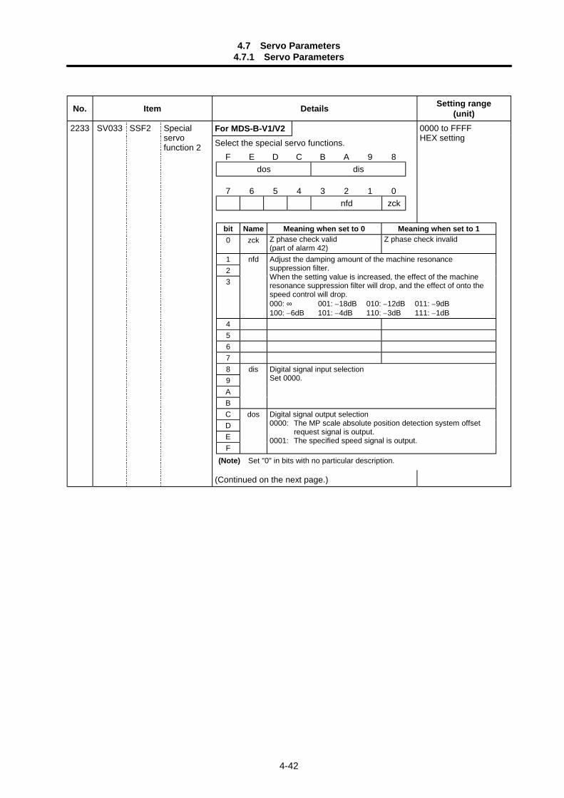
4.7 Servo Parameters4.7.1 Servo Parameters
4-42
No. Item Details Setting range(unit)
For MDS-B-V1/V22233 SV033 SSF2 Specialservofunction 2 Select the special servo functions.
(Continued on the next page.)
0000 to FFFFHEX setting
F E D C B A 9 8dos dis
7 6 5 4 3 2 1 0nfd zck
bit Name Meaning when set to 0 Meaning when set to 10 zck Z phase check valid
(part of alarm 42)Z phase check invalid
1 nfd23
Adjust the damping amount of the machine resonancesuppression filter.When the setting value is increased, the effect of the machineresonance suppression filter will drop, and the effect of onto thespeed control will drop.000: ∞ 001: –18dB 010: –12dB 011: –9dB100: –6dB 101: –4dB 110: –3dB 111: –1dB
45678 dis9
Digital signal input selectionSet 0000.
ABC dosDEF
Digital signal output selection0000: The MP scale absolute position detection system offset
request signal is output.0001: The specified speed signal is output.
(Note) Set "0" in bits with no particular description.
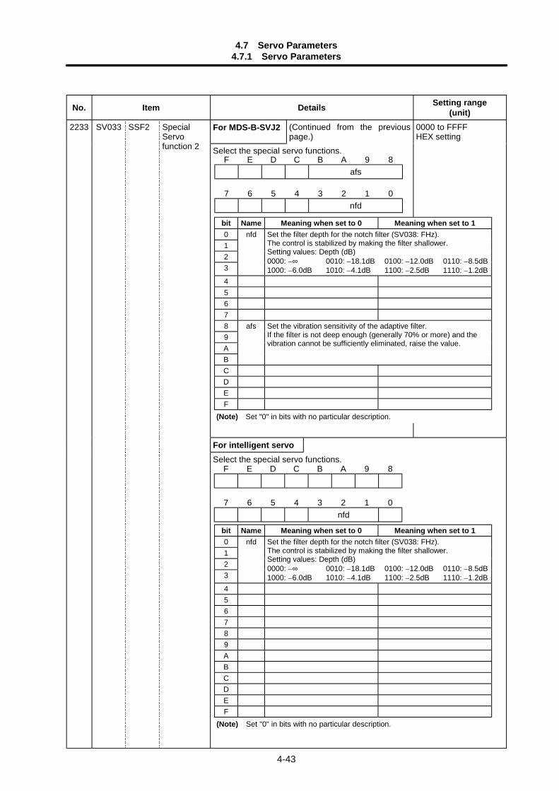
4.7 Servo Parameters4.7.1 Servo Parameters
4-43
No. Item Details Setting range(unit)
For MDS-B-SVJ2 (Continued from the previouspage.)
2233 SV033 SSF2 SpecialServofunction 2 Select the special servo functions.
0000 to FFFFHEX setting
For intelligent servoSelect the special servo functions.
F E D C B A 9 8afs
7 6 5 4 3 2 1 0nfd
bit Name Meaning when set to 0 Meaning when set to 10 nfd123
Set the filter depth for the notch filter (SV038: FHz).The control is stabilized by making the filter shallower.Setting values: Depth (dB)0000: –∞ 0010: –18.1dB 0100: –12.0dB 0110: –8.5dB1000: –6.0dB 1010: –4.1dB 1100: –2.5dB 1110: –1.2dB
45678 afs9AB
Set the vibration sensitivity of the adaptive filter.If the filter is not deep enough (generally 70% or more) and thevibration cannot be sufficiently eliminated, raise the value.
CDEF
(Note) Set "0" in bits with no particular description.
F E D C B A 9 8
7 6 5 4 3 2 1 0nfd
bit Name Meaning when set to 0 Meaning when set to 10 nfd123
Set the filter depth for the notch filter (SV038: FHz).The control is stabilized by making the filter shallower.Setting values: Depth (dB)0000: –∞ 0010: –18.1dB 0100: –12.0dB 0110: –8.5dB1000: –6.0dB 1010: –4.1dB 1100: –2.5dB 1110: –1.2dB
456789ABCDEF
(Note) Set "0" in bits with no particular description.
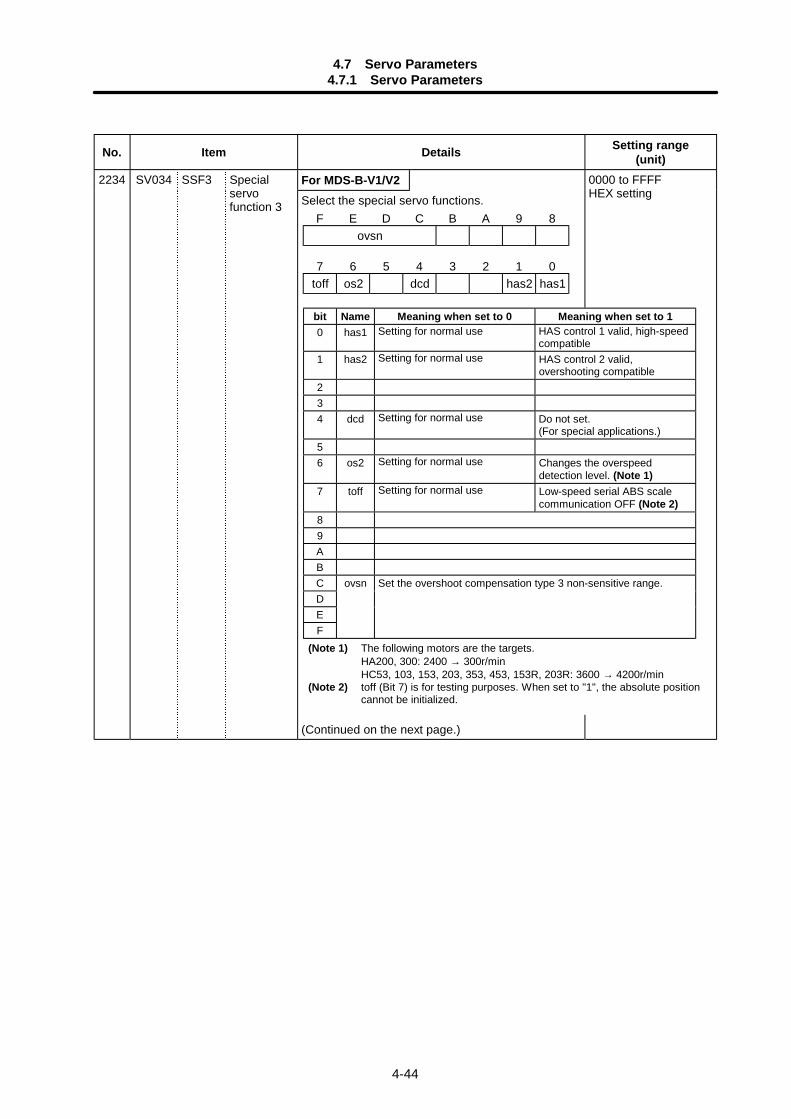
4.7 Servo Parameters4.7.1 Servo Parameters
4-44
No. Item Details Setting range(unit)
For MDS-B-V1/V22234 SV034 SSF3 Specialservofunction 3 Select the special servo functions.
(Continued on the next page.)
0000 to FFFFHEX setting
F E D C B A 9 8ovsn
7 6 5 4 3 2 1 0toff os2 dcd has2 has1
bit Name Meaning when set to 0 Meaning when set to 10 has1 Setting for normal use HAS control 1 valid, high-speed
compatible1 has2 Setting for normal use HAS control 2 valid,
overshooting compatible234 dcd Setting for normal use Do not set.
(For special applications.)56 os2 Setting for normal use Changes the overspeed
detection level. (Note 1)7 toff Setting for normal use Low-speed serial ABS scale
communication OFF (Note 2)89ABC ovsnDEF
Set the overshoot compensation type 3 non-sensitive range.
(Note 1) The following motors are the targets.HA200, 300: 2400 → 300r/minHC53, 103, 153, 203, 353, 453, 153R, 203R: 3600 → 4200r/min
(Note 2) toff (Bit 7) is for testing purposes. When set to "1", the absolute positioncannot be initialized.

4.7 Servo Parameters4.7.1 Servo Parameters
4-45
No. Item Details Setting range(unit)
For MDS-B-SVJ2 (Continued from the previouspage.)
2234 SV034 SSF3 Specialservofunction 3 Select the special servo functions.
(Continued on the next page.)
0000 to FFFFHEX setting
F E D C B A 9 8
7 6 5 4 3 2 1 0daf2 daf1 dac2 dac1 mon
bit Name Meaning when set to 0 Meaning when set to 10 mon123
NC servo monitor MAX current display data changeover.
4 dac1 D/A output ch.1 overflow setting D/A output ch.1 clamp setting5 dac2 D/A output ch.2 overflow setting D/A output ch.2 clamp setting6 daf1 D/A output ch.1 no filter D/A output ch.1 filter setting7 daf2 D/A output ch.2 no filter D/A output ch.2 filter setting89ABCDEF
(Note) Set "0" in bits with no particular description.
MAX current 1 MAX current 2
0Max. current commandvalue (%) when power isturned ON
Max. current commandvalue (%) for 1 second
1 Max. current commandvalue (%) for 1 second
Max. current FB value (%)for 1 second
2 Max. current FB value (%)when power is turned ON
Max. current FB value (%)for 1 second
3 – –
4 Adaptive filter operationfrequency (Hz)
Adaptive filter operationgain (%)
5 PN bus voltage (V)Regenerative operationfrequency monitor(times/s)
6 – –7 – –
8 to F Setting prohibited
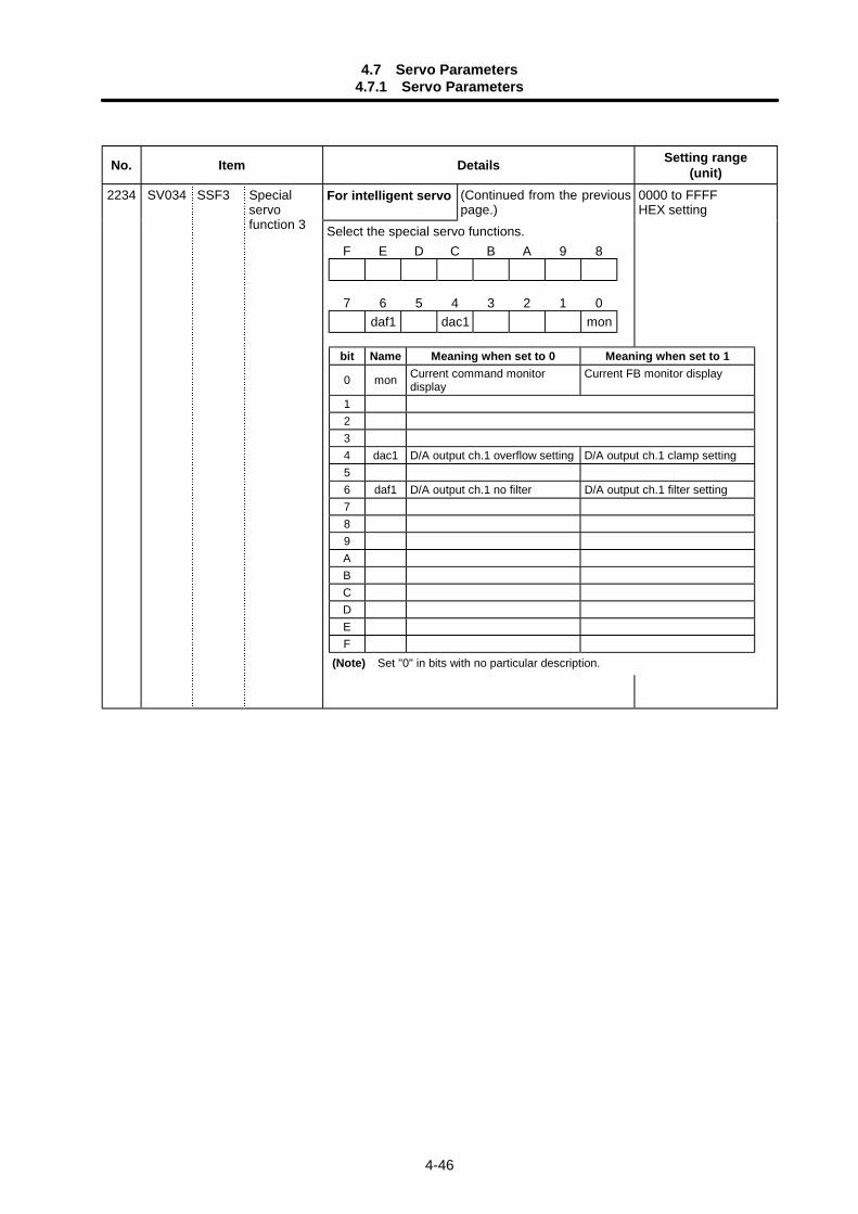
4.7 Servo Parameters4.7.1 Servo Parameters
4-46
No. Item Details Setting range(unit)
For intelligent servo (Continued from the previouspage.)
2234 SV034 SSF3 Specialservofunction 3 Select the special servo functions.
0000 to FFFFHEX setting
F E D C B A 9 8
7 6 5 4 3 2 1 0daf1 dac1 mon
bit Name Meaning when set to 0 Meaning when set to 1
0 mon Current command monitordisplay
Current FB monitor display
1234 dac1 D/A output ch.1 overflow setting D/A output ch.1 clamp setting56 daf1 D/A output ch.1 no filter D/A output ch.1 filter setting789ABCDEF
(Note) Set "0" in bits with no particular description.
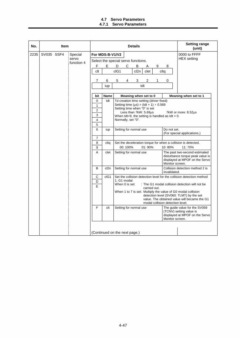
4.7 Servo Parameters4.7.1 Servo Parameters
4-47
No. Item Details Setting range(unit)
For MDS-B-V1/V22235 SV035 SSF4 Specialservofunction 4 Select the special servo functions.
(Continued on the next page.)
0000 to FFFFHEX setting
F E D C B A 9 8clt clG1 cl2n clet cltq
7 6 5 4 3 2 1 0iup tdt
bit Name Meaning when set to 0 Meaning when set to 10 tdt12345
Td creation time setting (driver fixed)Setting time (µs) = (tdt + 1) × 0.569Setting time when "0" is set
Less than 7kW: 5.69µs 7kW or more: 8.52µsWhen tdt<9, the setting is handled as tdt = 0.Normally, set "0".
6 iup Setting for normal use Do not set.(For special applications.)
78 cltq9
Set the deceleration torque for when a collision is detected. 00: 100% 01: 90% 10: 80% 11: 70%
A clet Setting for normal use The past two-second estimateddisturbance torque peak value isdisplayed at MPOF on the ServoMonitor screen.
B cl2n Setting for normal use Collision detection method 2 isinvalidated.
C clG1DE
Set the collision detection level for the collision detection method1, G1 modal.When 0 is set : The G1 modal collision detection will not be
carried out.When 1 to 7 is set: Multiply the value of G0 modal collision
detection level (SV060: TLMT) by the setvalue. The obtained value will became the G1modal collision detection level.
F clt Setting for normal use The guide value for the SV059(TCNV) setting value isdisplayed at MPOF on the ServoMonitor screen.
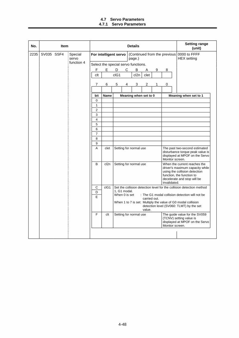
4.7 Servo Parameters4.7.1 Servo Parameters
4-48
No. Item Details Setting range(unit)
For intelligent servo (Continued from the previouspage.)
2235 SV035 SSF4 Specialservofunction 4 Select the special servo functions.
0000 to FFFFHEX setting
F E D C B A 9 8clt clG1 cl2n clet
7 6 5 4 3 2 1 0
bit Name Meaning when set to 0 Meaning when set to 10123456789A clet Setting for normal use The past two-second estimated
disturbance torque peak value isdisplayed at MPOF on the ServoMonitor screen.
B cl2n Setting for normal use When the current reaches thedriver's maximum capacity whileusing the collision detectionfunction, the function todecelerate and stop will beinvalidated.
C clG1DE
Set the collision detection level for the collision detection method1, G1 modal.When 0 is set : The G1 modal collision detection will not be
carried out.When 1 to 7 is set: Multiply the value of G0 modal collision
detection level (SV060: TLMT) by the setvalue.
F clt Setting for normal use The guide value for the SV059(TCNV) setting value isdisplayed at MPOF on the ServoMonitor screen.

4.7 Servo Parameters4.7.1 Servo Parameters
4-49
No. Item Details Setting range(unit)
For MDS-B-V1/V22236 SV036 PTYP∗ Powersupply type When this unit is a signal connection axis with power
supply unit, set this parameter.Set "0" for this parameter for the unit which is not asignal connection axis.When setting this parameter, refer to the tableshown below.
(Continued on the next page.)
0000 to FFFFHEX setting
F E D C B A 9 8amp rtyp
7 6 5 4 3 2 1 0ptyp
bit Name Meaning when set to 0 Meaning when set to 101234567
ptyp Set the power supply type. (Select the type from the following tableand set.)
89AB
rtyp Set "0" if the power supply unit is a current regeneration type.If the power supply unit is a resistance regeneration type, set thetype of resistor being used. (Select the type from the followingtable and set.)
C ampDEF
Set the driver model number.0: MDS-B-V1/V2/SP, MDS-A-V1/V2/SP1: MDS-A-SVJ2: MDS-A-SPJ
ptyp Power supply type ptyp Power supply type00040608111519222630374555
Not connectedCV-37CV-55CV-75CV-110CV-150CV-185CV-220CV-260CV-300CV-370CV-450CV-550
81828384868889
CR-10CR-15CR-22CR-37CR-55CR-75CR-90
rtyp External regenerativeresistor type
Resistancevalue (ΩΩΩΩ)
Watts(W)
00010203040506070809
Not connected power supplyGZG200W260HMJGZG300W130HMJ∗ 2MR-RB30MR-RB50GZG200W200HMJ∗ 3GZG300W200HMJ∗ 3R-UNIT-1R-UNIT-2R-UNIT-3
–262613136.76.7301515
–80
1503005003505007007002.1k
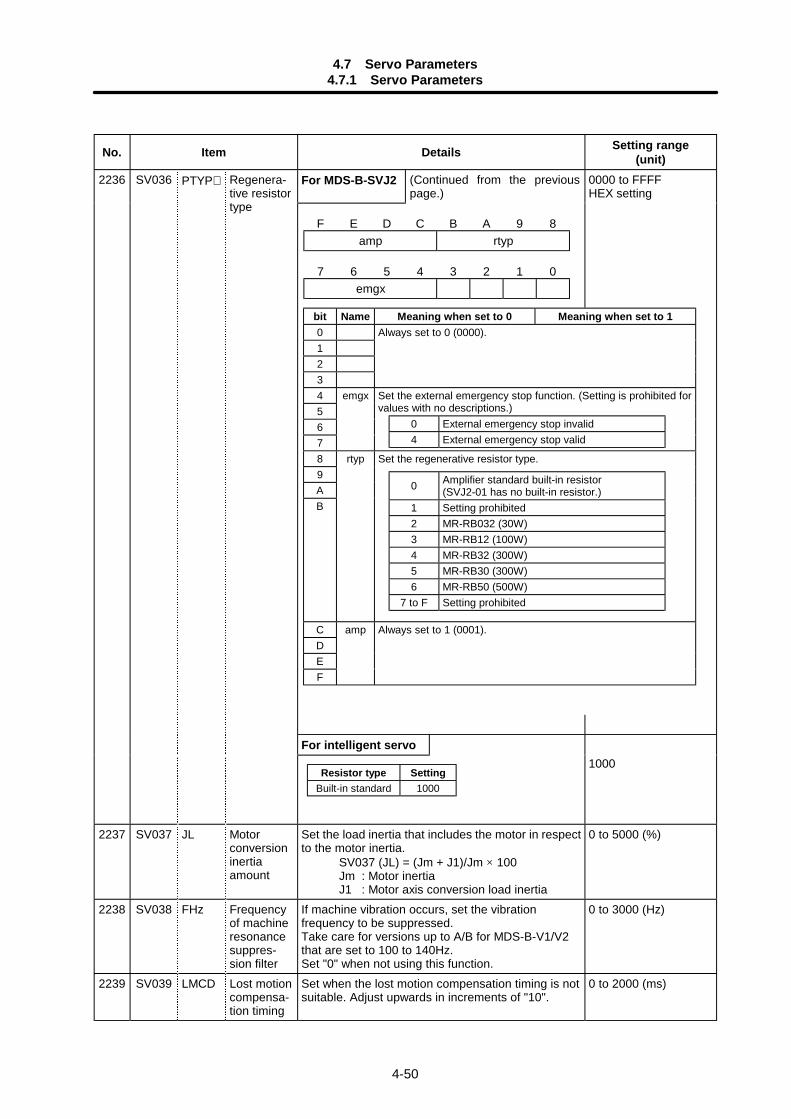
4.7 Servo Parameters4.7.1 Servo Parameters
4-50
No. Item Details Setting range(unit)
For MDS-B-SVJ2 (Continued from the previouspage.)
0000 to FFFFHEX setting
For intelligent servo
2236 SV036 PTYP∗ Regenera-tive resistortype
Resistor type SettingBuilt-in standard 1000
1000
2237 SV037 JL Motorconversioninertiaamount
Set the load inertia that includes the motor in respectto the motor inertia.
SV037 (JL) = (Jm + J1)/Jm × 100Jm : Motor inertiaJ1 : Motor axis conversion load inertia
0 to 5000 (%)
2238 SV038 FHz Frequencyof machineresonancesuppres-sion filter
If machine vibration occurs, set the vibrationfrequency to be suppressed.Take care for versions up to A/B for MDS-B-V1/V2that are set to 100 to 140Hz.Set "0" when not using this function.
0 to 3000 (Hz)
2239 SV039 LMCD Lost motioncompensa-tion timing
Set when the lost motion compensation timing is notsuitable. Adjust upwards in increments of "10".
0 to 2000 (ms)
F E D C B A 9 8amp rtyp
7 6 5 4 3 2 1 0emgx
bit Name Meaning when set to 0 Meaning when set to 10123
Always set to 0 (0000).
4567
emgx Set the external emergency stop function. (Setting is prohibited forvalues with no descriptions.)
89AB
rtyp Set the regenerative resistor type.
C ampDEF
Always set to 1 (0001).
0 Amplifier standard built-in resistor(SVJ2-01 has no built-in resistor.)
1 Setting prohibited2 MR-RB032 (30W)3 MR-RB12 (100W)4 MR-RB32 (300W)5 MR-RB30 (300W)6 MR-RB50 (500W)
7 to F Setting prohibited
0 External emergency stop invalid4 External emergency stop valid

4.7 Servo Parameters4.7.1 Servo Parameters
4-51
No. Item Details Setting range(unit)
Lost motioncompensa-tion deadzone (low-order 8 bits)
The lost motion compensation dead zone can onlybe set during feed forward control. Set in the low-order 8 bits.When set to "0", 2µm will actually be set. Adjustupwards in increments of 1µm.
Currentbias (high-order 8 bits)
This is used in combination with high-order 8 bitsSV030 and SV045.
–32768 to 32767(Note) The setting
range of thelow-order 8 bitsis 0 to 100 (µm).
2240 SV040 LMCT
Feedforwardcontrol non-sensitiveband
This is valid only during feed forward control.When "0" is set, 2µm will be actually set. Adjust inincrements of 1µm.(This is valid only when using SVJ2.)
0 to 100 (µm)
2241 SV041 LMC2 Lost motioncompensa-tion gain 2
Normally set this to "0".Set this with SV016 (LMC1) only when setting thelost motion compensation's gain (type 1) orcompensation amount (type 2) to different valuesaccording to the command direction.• Set the value for changing the command speed
from the – to + direction (during commanddirection CW) in SV016 (LMC1).
• Set the value for changing the command speedfrom the + to – direction (during commanddirection CW) in SV041 (LMC2).
• When "–1" is set, compensation will not be carriedout when the command speed direction changes.
This is valid only when lost motion compensation(SV027: lmc1, lmc2) is selected.
–1 to 200(Stall rated current %)
2242 SV042 OVS2 Overshootcompensa-tion gain 2
Overshoot compensation 2Set the overshoot compensation amount forunidirectional movement (command direction CW).When "0" is set, the value set for SV031 (0VS1) willbe set.When "–1" is set, compensation will not be carriedout during unidirectional movement.This is valid only when overshoot compensationSV027 (SSF1/OVS1) is selected.
–1 to 200(Stall rated current %)
2243 SV043 OBS1 Observer 1 Set the pole of the observer. Normally setapproximately "628" (rad).To operate the observer function, also set the SV037(JL) and SV044 (OBS2).Set to "0" when not used.
0 to 1000 (rad)
2244 SV044 OBS2 Observer 2 Set the execution gain of the observer. Normally setto "100".To operate the observer function, also set the SV037(JL) and SV043 (OBS1).Set to "0" when not used.
0 to 500 (%)For MDS-B-SVJ2:0 to 1000 (%)
Frictiontorque(low-order 8bits)
When using the collision detection function, set thefriction torque in the low-order 8 bits with a rate (%)for the stall rated current.Set to "0" when not using the collision detectionfunction.
2245 SV045 TRUB
Currentbias (high-order 8 bits)
This is used in combination with high-order 8 bits ofSV030 and SV040.
–32768 to 32767(Note) The setting
range of thelow-order 8 bitsis 0 to 100(Stall ratedcurrent %).
2246 SV046 Not used. Set to "0". 0
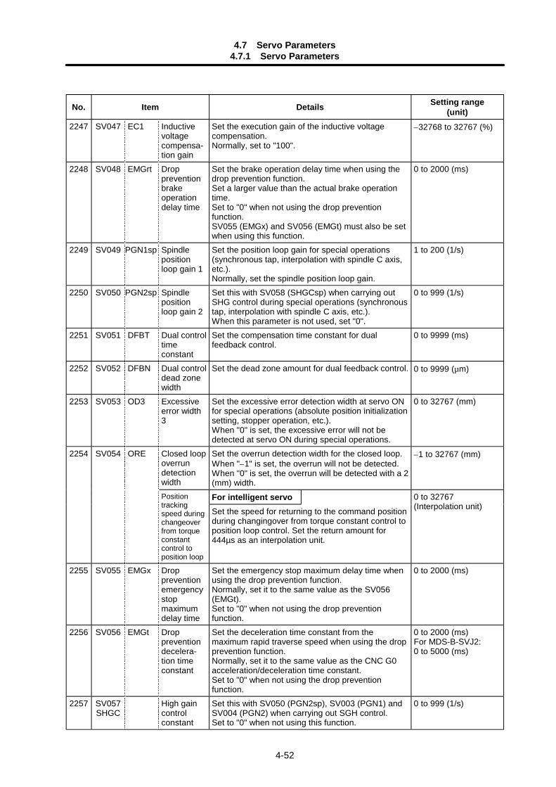
4.7 Servo Parameters4.7.1 Servo Parameters
4-52
No. Item Details Setting range(unit)
2247 SV047 EC1 Inductivevoltagecompensa-tion gain
Set the execution gain of the inductive voltagecompensation.Normally, set to "100".
–32768 to 32767 (%)
2248 SV048 EMGrt Droppreventionbrakeoperationdelay time
Set the brake operation delay time when using thedrop prevention function.Set a larger value than the actual brake operationtime.Set to "0" when not using the drop preventionfunction.SV055 (EMGx) and SV056 (EMGt) must also be setwhen using this function.
0 to 2000 (ms)
2249 SV049 PGN1sp Spindlepositionloop gain 1
Set the position loop gain for special operations(synchronous tap, interpolation with spindle C axis,etc.).Normally, set the spindle position loop gain.
1 to 200 (1/s)
2250 SV050 PGN2sp Spindlepositionloop gain 2
Set this with SV058 (SHGCsp) when carrying outSHG control during special operations (synchronoustap, interpolation with spindle C axis, etc.).When this parameter is not used, set "0".
0 to 999 (1/s)
2251 SV051 DFBT Dual controltimeconstant
Set the compensation time constant for dualfeedback control.
0 to 9999 (ms)
2252 SV052 DFBN Dual controldead zonewidth
Set the dead zone amount for dual feedback control. 0 to 9999 (µm)
2253 SV053 OD3 Excessiveerror width3
Set the excessive error detection width at servo ONfor special operations (absolute position initializationsetting, stopper operation, etc.).When "0" is set, the excessive error will not bedetected at servo ON during special operations.
0 to 32767 (mm)
Closed loopoverrundetectionwidth
Set the overrun detection width for the closed loop.When "–1" is set, the overrun will not be detected.When "0" is set, the overrun will be detected with a 2(mm) width.
–1 to 32767 (mm)
For intelligent servo
2254 SV054 ORE
Positiontrackingspeed duringchangeoverfrom torqueconstantcontrol toposition loop
Set the speed for returning to the command positionduring changingover from torque constant control toposition loop control. Set the return amount for444µs as an interpolation unit.
0 to 32767(Interpolation unit)
2255 SV055 EMGx Droppreventionemergencystopmaximumdelay time
Set the emergency stop maximum delay time whenusing the drop prevention function.Normally, set it to the same value as the SV056(EMGt).Set to "0" when not using the drop preventionfunction.
0 to 2000 (ms)
2256 SV056 EMGt Droppreventiondecelera-tion timeconstant
Set the deceleration time constant from themaximum rapid traverse speed when using the dropprevention function.Normally, set it to the same value as the CNC G0acceleration/deceleration time constant.Set to "0" when not using the drop preventionfunction.
0 to 2000 (ms)For MDS-B-SVJ2:0 to 5000 (ms)
2257 SV057SHGC
High gaincontrolconstant
Set this with SV050 (PGN2sp), SV003 (PGN1) andSV004 (PGN2) when carrying out SGH control.Set to "0" when not using this function.
0 to 999 (1/s)
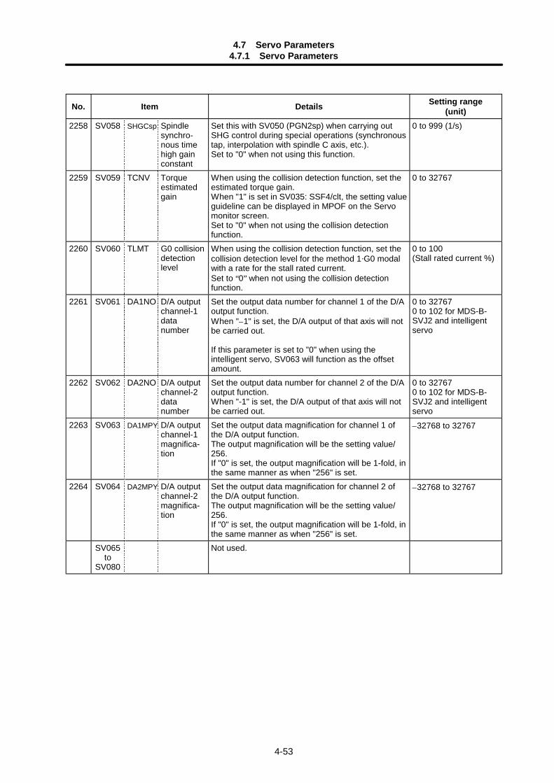
4.7 Servo Parameters4.7.1 Servo Parameters
4-53
No. Item Details Setting range(unit)
2258 SV058 SHGCsp Spindlesynchro-nous timehigh gainconstant
Set this with SV050 (PGN2sp) when carrying outSHG control during special operations (synchronoustap, interpolation with spindle C axis, etc.).Set to "0" when not using this function.
0 to 999 (1/s)
2259 SV059 TCNV Torqueestimatedgain
When using the collision detection function, set theestimated torque gain.When "1" is set in SV035: SSF4/clt, the setting valueguideline can be displayed in MPOF on the Servomonitor screen.Set to "0" when not using the collision detectionfunction.
0 to 32767
2260 SV060 TLMT G0 collisiondetectionlevel
When using the collision detection function, set thecollision detection level for the method 1·G0 modalwith a rate for the stall rated current.Set to “0” when not using the collision detectionfunction.
0 to 100(Stall rated current %)
2261 SV061 DA1NO D/A outputchannel-1datanumber
Set the output data number for channel 1 of the D/Aoutput function.When "–1" is set, the D/A output of that axis will notbe carried out.
If this parameter is set to "0" when using theintelligent servo, SV063 will function as the offsetamount.
0 to 327670 to 102 for MDS-B-SVJ2 and intelligentservo
2262 SV062 DA2NO D/A outputchannel-2datanumber
Set the output data number for channel 2 of the D/Aoutput function.When "-1" is set, the D/A output of that axis will notbe carried out.
0 to 327670 to 102 for MDS-B-SVJ2 and intelligentservo
2263 SV063 DA1MPY D/A outputchannel-1magnifica-tion
Set the output data magnification for channel 1 ofthe D/A output function.The output magnification will be the setting value/256.If "0" is set, the output magnification will be 1-fold, inthe same manner as when "256" is set.
–32768 to 32767
2264 SV064 DA2MPY D/A outputchannel-2magnifica-tion
Set the output data magnification for channel 2 ofthe D/A output function.The output magnification will be the setting value/256.If "0" is set, the output magnification will be 1-fold, inthe same manner as when "256" is set.
–32768 to 32767
SV065to
SV080
Not used.

4.7 Servo Parameters4.7.2 Supplementary Explanation (MDS-B-V1/V2)
4-54
4.7.2 Supplementary Explanation (MDS-B-V1/V2)
(1) Command polarityWhen the motor rotates in the clockwise direction (looking from the load side) at the command forthe + direction, the command direction is CW. Conversely, when the motor rotates in thecounterclockwise direction, the command direction is CCW.This rotation direction can be set with the NC machine parameters. Note that the meaning of the ±direction will be reversed for some servo parameters according to the motor rotation direction. Theservo parameters affected by CW/CCW are shown below.
SV016 (LMC1), SV041 (LMC2) (When different values are set for SV016 and SV041)SV031 (OVS1), SV042 (OVS2) (When different values are set for SV031 and SV042)
<Example> If the lost motion compensation amount is to be changed according to the direction,the compensation amount at the quadrant changeover point of each arc where thelost motion compensation is applied will be as shown below according to thecommand polarity.
CW CCWA X: SV041 X: SV016B Y: SV016 Y: SV041C X: SV016 X: SV041D Y: SV041 Y: SV016
+Y
–X +X
–Y
C:The X axis commanddirection changes fromthe – to + direction.
B:The Y axis commanddirection changes fromthe – to + direction.
A:The X axis commanddirection changes fromthe + to – direction.
D:The Y axis commanddirection changes fromthe + to – direction.
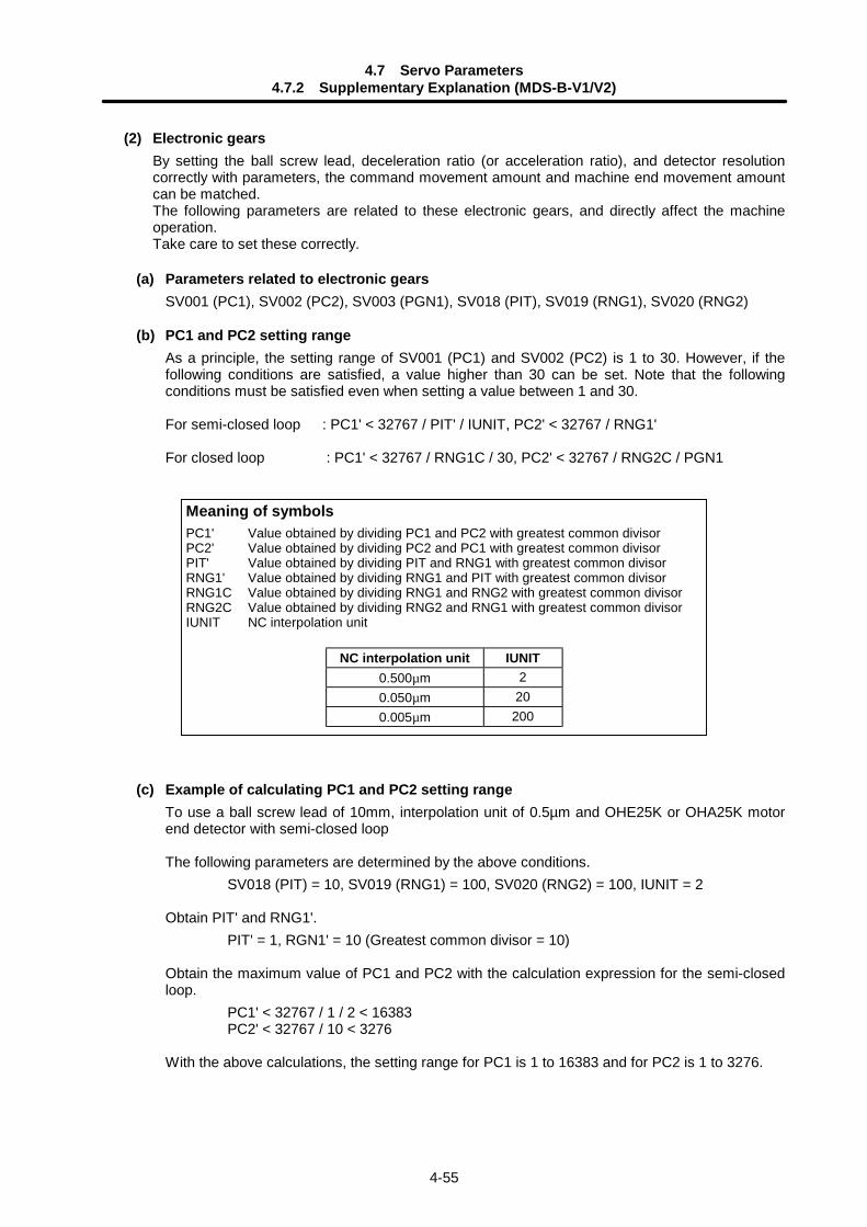
4.7 Servo Parameters4.7.2 Supplementary Explanation (MDS-B-V1/V2)
4-55
(2) Electronic gearsBy setting the ball screw lead, deceleration ratio (or acceleration ratio), and detector resolutioncorrectly with parameters, the command movement amount and machine end movement amountcan be matched.The following parameters are related to these electronic gears, and directly affect the machineoperation.Take care to set these correctly.
(a) Parameters related to electronic gearsSV001 (PC1), SV002 (PC2), SV003 (PGN1), SV018 (PIT), SV019 (RNG1), SV020 (RNG2)
(b) PC1 and PC2 setting rangeAs a principle, the setting range of SV001 (PC1) and SV002 (PC2) is 1 to 30. However, if thefollowing conditions are satisfied, a value higher than 30 can be set. Note that the followingconditions must be satisfied even when setting a value between 1 and 30.
For semi-closed loop : PC1' < 32767 / PIT' / IUNIT, PC2' < 32767 / RNG1'
For closed loop : PC1' < 32767 / RNG1C / 30, PC2' < 32767 / RNG2C / PGN1
Meaning of symbolsPC1' Value obtained by dividing PC1 and PC2 with greatest common divisorPC2' Value obtained by dividing PC2 and PC1 with greatest common divisorPIT' Value obtained by dividing PIT and RNG1 with greatest common divisorRNG1' Value obtained by dividing RNG1 and PIT with greatest common divisorRNG1C Value obtained by dividing RNG1 and RNG2 with greatest common divisorRNG2C Value obtained by dividing RNG2 and RNG1 with greatest common divisorIUNIT NC interpolation unit
NC interpolation unit IUNIT0.500µm 20.050µm 200.005µm 200
(c) Example of calculating PC1 and PC2 setting rangeTo use a ball screw lead of 10mm, interpolation unit of 0.5µm and OHE25K or OHA25K motorend detector with semi-closed loop
The following parameters are determined by the above conditions.SV018 (PIT) = 10, SV019 (RNG1) = 100, SV020 (RNG2) = 100, IUNIT = 2
Obtain PIT' and RNG1'.PIT' = 1, RGN1' = 10 (Greatest common divisor = 10)
Obtain the maximum value of PC1 and PC2 with the calculation expression for the semi-closedloop.
PC1' < 32767 / 1 / 2 < 16383PC2' < 32767 / 10 < 3276
With the above calculations, the setting range for PC1 is 1 to 16383 and for PC2 is 1 to 3276.
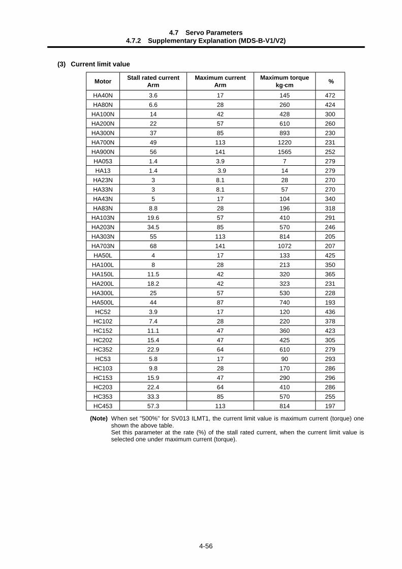
4.7 Servo Parameters4.7.2 Supplementary Explanation (MDS-B-V1/V2)
4-56
(3) Current limit value
Motor Stall rated currentArm
Maximum currentArm
Maximum torquekg····cm %
HA40N 3.6 17 145 472HA80N 6.6 28 260 424
HA100N 14 42 428 300HA200N 22 57 610 260HA300N 37 85 893 230HA700N 49 113 1220 231HA900N 56 141 1565 252HA053 1.4 3.9 7 279HA13 1.4 3.9 14 279
HA23N 3 8.1 28 270HA33N 3 8.1 57 270HA43N 5 17 104 340HA83N 8.8 28 196 318
HA103N 19.6 57 410 291HA203N 34.5 85 570 246HA303N 55 113 814 205HA703N 68 141 1072 207HA50L 4 17 133 425
HA100L 8 28 213 350HA150L 11.5 42 320 365HA200L 18.2 42 323 231HA300L 25 57 530 228HA500L 44 87 740 193HC52 3.9 17 120 436
HC102 7.4 28 220 378HC152 11.1 47 360 423HC202 15.4 47 425 305HC352 22.9 64 610 279HC53 5.8 17 90 293
HC103 9.8 28 170 286HC153 15.9 47 290 296HC203 22.4 64 410 286HC353 33.3 85 570 255HC453 57.3 113 814 197
(Note) When set "500%" for SV013 ILMT1, the current limit value is maximum current (torque) oneshown the above table.Set this parameter at the rate (%) of the stall rated current, when the current limit value isselected one under maximum current (torque).
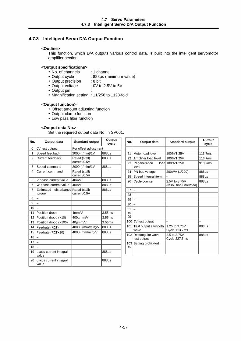
4.7 Servo Parameters4.7.3 Intelligent Servo D/A Output Function
4-57
4.7.3 Intelligent Servo D/A Output Function
<Outline>This function, which D/A outputs various control data, is built into the intelligent servomotoramplifier section.
<Output specifications> No. of channels : 1 channel Output cycle : 888µs (minimum value) Output precision : 8 bit Output voltage : 0V to 2.5V to 5V Output pin : Magnification setting : ±1/256 to ±128-fold
<Output function> Offset amount adjusting function Output clamp function Low pass filter function
<Output data No.>Set the required output data No. in SV061.
No. Output data Standard output Outputcycle
0 0V test output For offset adjustment1 Speed feedback 2000 (r/min)/1V 888µs2 Current feedback Rated (stall)
current/0.5V888µs
3 Speed command 2000 (r/min)/1V 888µs4 Current command Rated (stall)
current/0.5V5 V phase current value 40A/V 888µs6 W phase current value 40A/V 888µs7 Estimated disturbance
torqueRated (stall)current/0.5V
888µs
8 –9 –
10 –11 Position droop 4mm/V 3.55ms12 Position droop (×10) 400µmm/V 3.55ms13 Position droop (×100) 40µmm/V 3.55ms14 Feedrate (F∆T) 40000 (mm/min)/V 888µs15 Feedrate (F∆T×10) 4000 (mm/min)/V 888µs16 –17 –18 –19 q axis current integral
value888µs
20 d axis current integralvalue
888µs
No. Output data Standard output Outputcycle
21 Motor load level 100%/1.25V 113.7ms22 Amplifier load level 100%/1.25V 113.7ms23 Regeneration load
level100%/1.25V 910.2ms
24 PN bus voltage 200V/V (1/200) 888µs25 Speed integral item – 888µs26 Cycle counter 2.5V to 3.75V
(resolution unrelated)888µs
27 –28 –29 –30 –31to99
–
100 5V test output – –101 Test output sawtooth
wave1.25 to 3.75VCycle 113.7ms
888µs
102 Rectangular wavetest output
2.5 to 3.75VCycle 227.5ms
888µs
103to
Setting prohibited
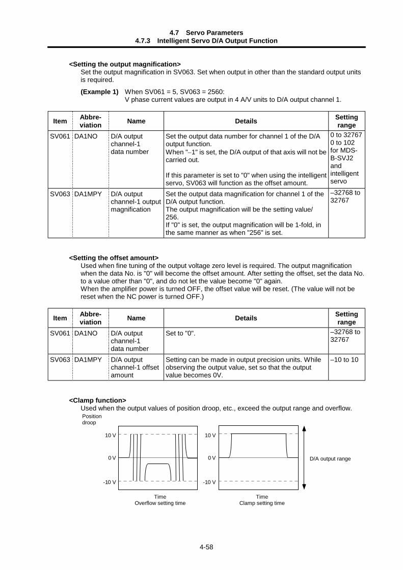
4.7 Servo Parameters4.7.3 Intelligent Servo D/A Output Function
4-58
<Setting the output magnification>Set the output magnification in SV063. Set when output in other than the standard output unitsis required.
(Example 1) When SV061 = 5, SV063 = 2560:V phase current values are output in 4 A/V units to D/A output channel 1.
Item Abbre-viation Name Details Setting
rangeSV061 DA1NO D/A output
channel-1data number
Set the output data number for channel 1 of the D/Aoutput function.When "–1" is set, the D/A output of that axis will not becarried out.
If this parameter is set to "0" when using the intelligentservo, SV063 will function as the offset amount.
0 to 327670 to 102for MDS-B-SVJ2andintelligentservo
SV063 DA1MPY D/A outputchannel-1 outputmagnification
Set the output data magnification for channel 1 of theD/A output function.The output magnification will be the setting value/256.If "0" is set, the output magnification will be 1-fold, inthe same manner as when "256" is set.
–32768 to32767
<Setting the offset amount>Used when fine tuning of the output voltage zero level is required. The output magnificationwhen the data No. is "0" will become the offset amount. After setting the offset, set the data No.to a value other than "0", and do not let the value become "0" again.When the amplifier power is turned OFF, the offset value will be reset. (The value will not bereset when the NC power is turned OFF.)
Item Abbre-viation Name Details Setting
rangeSV061 DA1NO D/A output
channel-1data number
Set to "0". –32768 to32767
SV063 DA1MPY D/A outputchannel-1 offsetamount
Setting can be made in output precision units. Whileobserving the output value, set so that the outputvalue becomes 0V.
–10 to 10
<Clamp function>Used when the output values of position droop, etc., exceed the output range and overflow.
0 V
10 V
-10 V
0 V
10 V
-10 V
TimeClamp setting time
TimeOverflow setting time
Position droop
D/A output range
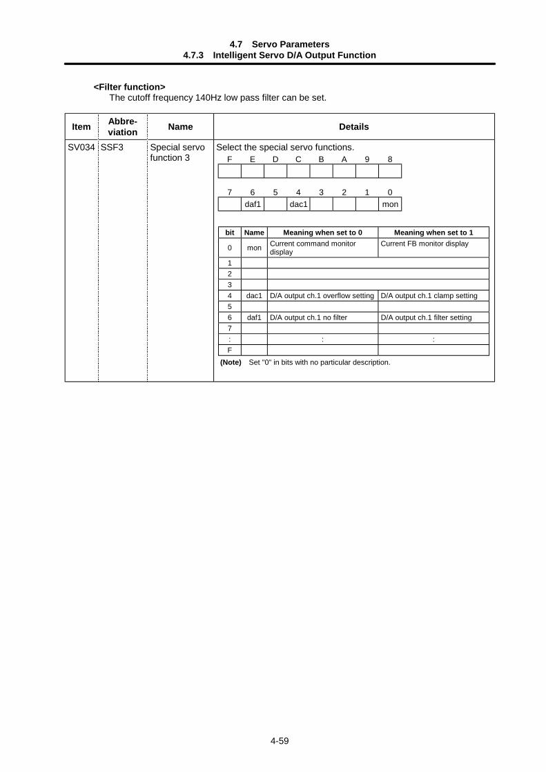
4.7 Servo Parameters4.7.3 Intelligent Servo D/A Output Function
4-59
<Filter function>The cutoff frequency 140Hz low pass filter can be set.
Item Abbre-viation Name Details
SV034 SSF3 Special servofunction 3
Select the special servo functions.F E D C B A 9 8
7 6 5 4 3 2 1 0daf1 dac1 mon
bit Name Meaning when set to 0 Meaning when set to 1
0 mon Current command monitordisplay
Current FB monitor display
1234 dac1 D/A output ch.1 overflow setting D/A output ch.1 clamp setting56 daf1 D/A output ch.1 no filter D/A output ch.1 filter setting7: : :F
(Note) Set "0" in bits with no particular description.
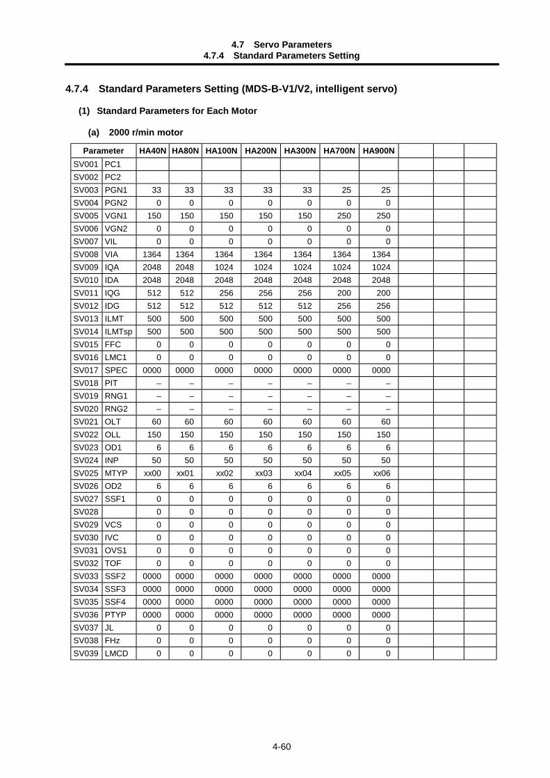
4.7 Servo Parameters4.7.4 Standard Parameters Setting
4-60
4.7.4 Standard Parameters Setting (MDS-B-V1/V2, intelligent servo)
(1) Standard Parameters for Each Motor
(a) 2000 r/min motor
Parameter HA40N HA80N HA100N HA200N HA300N HA700N HA900NSV001 PC1SV002 PC2SV003 PGN1 33 33 33 33 33 25 25SV004 PGN2 0 0 0 0 0 0 0SV005 VGN1 150 150 150 150 150 250 250SV006 VGN2 0 0 0 0 0 0 0SV007 VIL 0 0 0 0 0 0 0SV008 VIA 1364 1364 1364 1364 1364 1364 1364SV009 IQA 2048 2048 1024 1024 1024 1024 1024SV010 IDA 2048 2048 2048 2048 2048 2048 2048SV011 IQG 512 512 256 256 256 200 200SV012 IDG 512 512 512 512 512 256 256SV013 ILMT 500 500 500 500 500 500 500SV014 ILMTsp 500 500 500 500 500 500 500SV015 FFC 0 0 0 0 0 0 0SV016 LMC1 0 0 0 0 0 0 0SV017 SPEC 0000 0000 0000 0000 0000 0000 0000SV018 PIT – – – – – – –SV019 RNG1 – – – – – – –SV020 RNG2 – – – – – – –SV021 OLT 60 60 60 60 60 60 60SV022 OLL 150 150 150 150 150 150 150SV023 OD1 6 6 6 6 6 6 6SV024 INP 50 50 50 50 50 50 50SV025 MTYP xx00 xx01 xx02 xx03 xx04 xx05 xx06SV026 OD2 6 6 6 6 6 6 6SV027 SSF1 0 0 0 0 0 0 0SV028 0 0 0 0 0 0 0SV029 VCS 0 0 0 0 0 0 0SV030 IVC 0 0 0 0 0 0 0SV031 OVS1 0 0 0 0 0 0 0SV032 TOF 0 0 0 0 0 0 0SV033 SSF2 0000 0000 0000 0000 0000 0000 0000SV034 SSF3 0000 0000 0000 0000 0000 0000 0000SV035 SSF4 0000 0000 0000 0000 0000 0000 0000SV036 PTYP 0000 0000 0000 0000 0000 0000 0000SV037 JL 0 0 0 0 0 0 0SV038 FHz 0 0 0 0 0 0 0SV039 LMCD 0 0 0 0 0 0 0
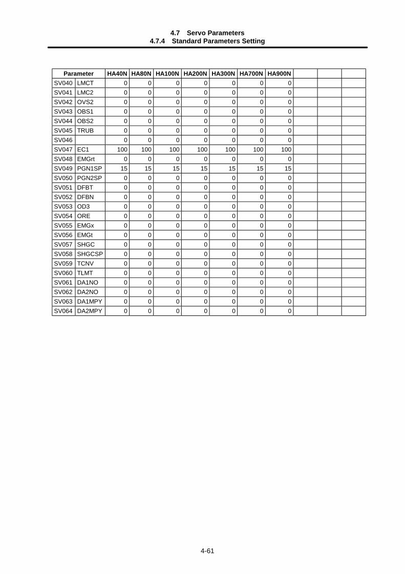
4.7 Servo Parameters4.7.4 Standard Parameters Setting
4-61
Parameter HA40N HA80N HA100N HA200N HA300N HA700N HA900NSV040 LMCT 0 0 0 0 0 0 0SV041 LMC2 0 0 0 0 0 0 0SV042 OVS2 0 0 0 0 0 0 0SV043 OBS1 0 0 0 0 0 0 0SV044 OBS2 0 0 0 0 0 0 0SV045 TRUB 0 0 0 0 0 0 0SV046 0 0 0 0 0 0 0SV047 EC1 100 100 100 100 100 100 100SV048 EMGrt 0 0 0 0 0 0 0SV049 PGN1SP 15 15 15 15 15 15 15SV050 PGN2SP 0 0 0 0 0 0 0SV051 DFBT 0 0 0 0 0 0 0SV052 DFBN 0 0 0 0 0 0 0SV053 OD3 0 0 0 0 0 0 0SV054 ORE 0 0 0 0 0 0 0SV055 EMGx 0 0 0 0 0 0 0SV056 EMGt 0 0 0 0 0 0 0SV057 SHGC 0 0 0 0 0 0 0SV058 SHGCSP 0 0 0 0 0 0 0SV059 TCNV 0 0 0 0 0 0 0SV060 TLMT 0 0 0 0 0 0 0SV061 DA1NO 0 0 0 0 0 0 0SV062 DA2NO 0 0 0 0 0 0 0SV063 DA1MPY 0 0 0 0 0 0 0SV064 DA2MPY 0 0 0 0 0 0 0
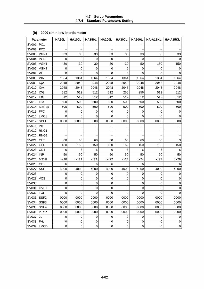
4.7 Servo Parameters4.7.4 Standard Parameters Setting
4-62
(b) 2000 r/min low-inertia motor
Parameter HA50L HA100L HA150L HA200L HA300L HA500L HA-A11KL HA-A15KLSV001 PC1 – – – – – – – –SV002 PC2 – – – – – – – –SV003 PGN1 33 33 33 33 33 33 33 33SV004 PGN2 0 0 0 0 0 0 0 0SV005 VGN1 30 30 30 30 30 50 150 150SV006 VGN2 0 0 0 0 0 0 0 0SV007 VIL 0 0 0 0 0 0 0 0SV008 VIA 1364 1364 1364 1364 1364 1364 1364 1364SV009 IQA 2048 2048 2048 2048 2048 2048 2048 2048SV010 IDA 2048 2048 2048 2048 2048 2048 2048 2048SV011 IQG 512 512 512 512 256 256 512 512SV012 IDG 512 512 512 512 512 512 512 512SV013 ILMT 500 500 500 500 500 500 500 500SV014 ILMTsp 500 500 500 500 500 500 500 500SV015 FFC 0 0 0 0 0 0 0 0SV016 LMC1 0 0 0 0 0 0 0 0SV017 SPEC 0000 0000 0000 0000 0000 0000 0000 0000SV018 PIT – – – – – – – –SV019 RNG1 – – – – – – – –SV020 RNG2 – – – – – – – –SV021 OLT 60 60 60 60 60 60 60 3SV022 OLL 150 150 150 150 150 150 150 150SV023 OD1 6 6 6 6 6 6 6 6SV024 INP 50 50 50 50 50 50 50 50SV025 MTYP xx20 xx21 xx2A xx22 xx23 xx24 xx27 xx28SV026 OD2 6 6 6 6 6 6 6 6SV027 SSF1 4000 4000 4000 4000 4000 4000 4000 4000SV028 0 0 0 0 0 0 0 0SV029 VCS 0 0 0 0 0 0 0 0SV030 0 0 0 0 0 0 0 0SV031 OVS1 0 0 0 0 0 0 0 0SV032 TOF 0 0 0 0 0 0 0 0SV033 SSF2 0000 0000 0000 0000 0000 0000 0000 0000SV034 SSF3 0000 0000 0000 0000 0000 0000 0000 0000SV035 SSF4 0000 0000 0000 0000 0000 0000 0000 0000SV036 PTYP 0000 0000 0000 0000 0000 0000 0000 0000SV037 JL 0 0 0 0 0 0 0 0SV038 FHz 0 0 0 0 0 0 0 0SV039 LMCD 0 0 0 0 0 0 0 0

4.7 Servo Parameters4.7.4 Standard Parameters Setting
4-63
Parameter HA50L HA100L HA150L HA200L HA300L HA500L HA-A11KL HA-A15KLSV040 LMCT 0 0 0 0 0 0 0 0SV041 LMC2 0 0 0 0 0 0 0 0SV042 OVS2 0 0 0 0 0 0 0 0SV043 OBS1 0 0 0 0 0 0 0 0SV044 OBS2 0 0 0 0 0 0 0 0SV045 TRUB 0 0 0 0 0 0 0 0SV046 0 0 0 0 0 0 0 0SV047 EC1 100 100 100 100 100 100 100 100SV048 EMGrt 0 0 0 0 0 0 0 0SV049 PGN1sp 15 15 15 15 15 15 15 15SV050 PGN2sp 0 0 0 0 0 0 0 0SV051 DFBT 0 0 0 0 0 0 0 0SV052 DFBN 0 0 0 0 0 0 0 0SV053 OD3 0 0 0 0 0 0 0 0SV054 ORE 0 0 0 0 0 0 0 0SV055 EMGx 0 0 0 0 0 0 0 0SV056 EMGt 0 0 0 0 0 0 0 0SV057 SHGC 0 0 0 0 0 0 0 0SV058 SHGCsp 0 0 0 0 0 0 0 0SV059 TCNV 0 0 0 0 0 0 0 0SV060 TLMT 0 0 0 0 0 0 0 0SV061 DA1NO 0 0 0 0 0 0 0 0SV062 DA2NO 0 0 0 0 0 0 0 0SV063 DA1MPY 0 0 0 0 0 0 0 0SV064 DA2MPY 0 0 0 0 0 0 0 0
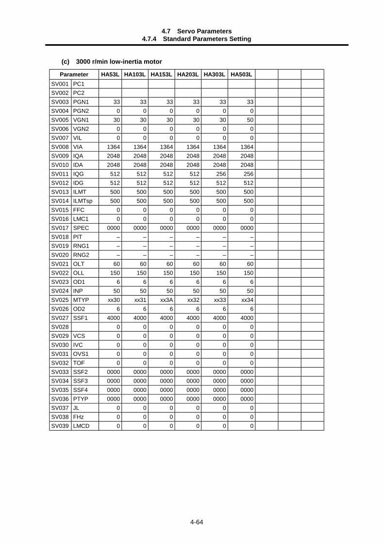
4.7 Servo Parameters4.7.4 Standard Parameters Setting
4-64
(c) 3000 r/min low-inertia motor
Parameter HA53L HA103L HA153L HA203L HA303L HA503LSV001 PC1SV002 PC2SV003 PGN1 33 33 33 33 33 33SV004 PGN2 0 0 0 0 0 0SV005 VGN1 30 30 30 30 30 50SV006 VGN2 0 0 0 0 0 0SV007 VIL 0 0 0 0 0 0SV008 VIA 1364 1364 1364 1364 1364 1364SV009 IQA 2048 2048 2048 2048 2048 2048SV010 IDA 2048 2048 2048 2048 2048 2048SV011 IQG 512 512 512 512 256 256SV012 IDG 512 512 512 512 512 512SV013 ILMT 500 500 500 500 500 500SV014 ILMTsp 500 500 500 500 500 500SV015 FFC 0 0 0 0 0 0SV016 LMC1 0 0 0 0 0 0SV017 SPEC 0000 0000 0000 0000 0000 0000SV018 PIT – – – – – –SV019 RNG1 – – – – – –SV020 RNG2 – – – – – –SV021 OLT 60 60 60 60 60 60SV022 OLL 150 150 150 150 150 150SV023 OD1 6 6 6 6 6 6SV024 INP 50 50 50 50 50 50SV025 MTYP xx30 xx31 xx3A xx32 xx33 xx34SV026 OD2 6 6 6 6 6 6SV027 SSF1 4000 4000 4000 4000 4000 4000SV028 0 0 0 0 0 0SV029 VCS 0 0 0 0 0 0SV030 IVC 0 0 0 0 0 0SV031 OVS1 0 0 0 0 0 0SV032 TOF 0 0 0 0 0 0SV033 SSF2 0000 0000 0000 0000 0000 0000SV034 SSF3 0000 0000 0000 0000 0000 0000SV035 SSF4 0000 0000 0000 0000 0000 0000SV036 PTYP 0000 0000 0000 0000 0000 0000SV037 JL 0 0 0 0 0 0SV038 FHz 0 0 0 0 0 0SV039 LMCD 0 0 0 0 0 0
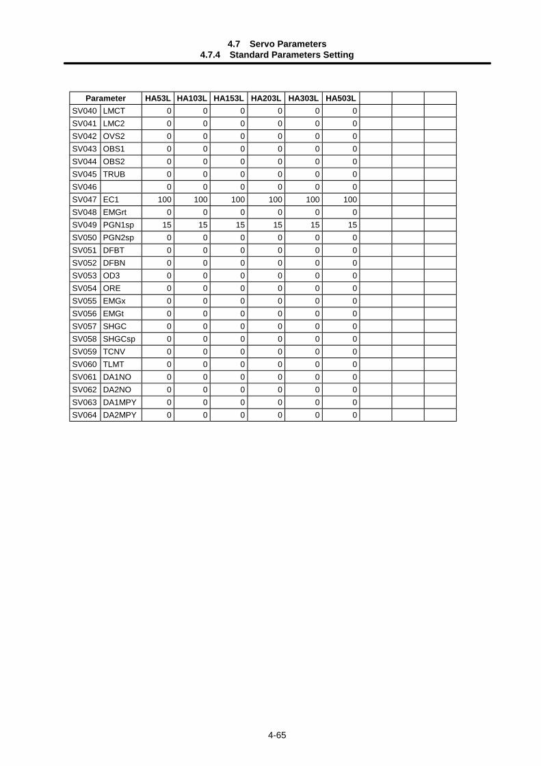
4.7 Servo Parameters4.7.4 Standard Parameters Setting
4-65
Parameter HA53L HA103L HA153L HA203L HA303L HA503LSV040 LMCT 0 0 0 0 0 0SV041 LMC2 0 0 0 0 0 0SV042 OVS2 0 0 0 0 0 0SV043 OBS1 0 0 0 0 0 0SV044 OBS2 0 0 0 0 0 0SV045 TRUB 0 0 0 0 0 0SV046 0 0 0 0 0 0SV047 EC1 100 100 100 100 100 100SV048 EMGrt 0 0 0 0 0 0SV049 PGN1sp 15 15 15 15 15 15SV050 PGN2sp 0 0 0 0 0 0SV051 DFBT 0 0 0 0 0 0SV052 DFBN 0 0 0 0 0 0SV053 OD3 0 0 0 0 0 0SV054 ORE 0 0 0 0 0 0SV055 EMGx 0 0 0 0 0 0SV056 EMGt 0 0 0 0 0 0SV057 SHGC 0 0 0 0 0 0SV058 SHGCsp 0 0 0 0 0 0SV059 TCNV 0 0 0 0 0 0SV060 TLMT 0 0 0 0 0 0SV061 DA1NO 0 0 0 0 0 0SV062 DA2NO 0 0 0 0 0 0SV063 DA1MPY 0 0 0 0 0 0SV064 DA2MPY 0 0 0 0 0 0
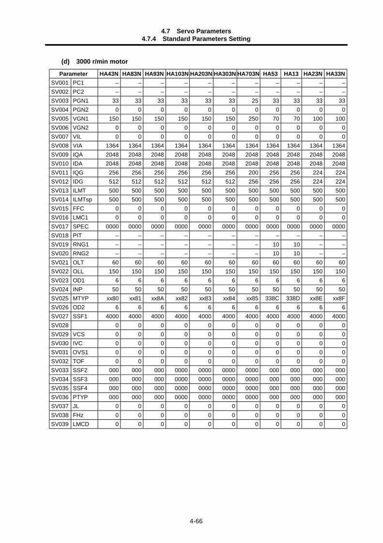
4.7 Servo Parameters4.7.4 Standard Parameters Setting
4-66
(d) 3000 r/min motor
Parameter HA43N HA83N HA93N HA103N HA203N HA303N HA703N HA53 HA13 HA23N HA33NSV001 PC1 – – – – – – – – – – –SV002 PC2 – – – – – – – – – – –SV003 PGN1 33 33 33 33 33 33 25 33 33 33 33SV004 PGN2 0 0 0 0 0 0 0 0 0 0 0SV005 VGN1 150 150 150 150 150 150 250 70 70 100 100SV006 VGN2 0 0 0 0 0 0 0 0 0 0 0SV007 VIL 0 0 0 0 0 0 0 0 0 0 0SV008 VIA 1364 1364 1364 1364 1364 1364 1364 1364 1364 1364 1364SV009 IQA 2048 2048 2048 2048 2048 2048 2048 2048 2048 2048 2048SV010 IDA 2048 2048 2048 2048 2048 2048 2048 2048 2048 2048 2048SV011 IQG 256 256 256 256 256 256 200 256 256 224 224SV012 IDG 512 512 512 512 512 512 256 256 256 224 224SV013 ILMT 500 500 500 500 500 500 500 500 500 500 500SV014 ILMTsp 500 500 500 500 500 500 500 500 500 500 500SV015 FFC 0 0 0 0 0 0 0 0 0 0 0SV016 LMC1 0 0 0 0 0 0 0 0 0 0 0SV017 SPEC 0000 0000 0000 0000 0000 0000 0000 0000 0000 0000 0000SV018 PIT – – – – – – – – – – –SV019 RNG1 – – – – – – – 10 10 – –SV020 RNG2 – – – – – – – 10 10 – –SV021 OLT 60 60 60 60 60 60 60 60 60 60 60SV022 OLL 150 150 150 150 150 150 150 150 150 150 150SV023 OD1 6 6 6 6 6 6 6 6 6 6 6SV024 INP 50 50 50 50 50 50 50 50 50 50 50SV025 MTYP xx80 xx81 xx8A xx82 xx83 xx84 xx85 338C 338D xx8E xx8FSV026 OD2 6 6 6 6 6 6 6 6 6 6 6SV027 SSF1 4000 4000 4000 4000 4000 4000 4000 4000 4000 4000 4000SV028 0 0 0 0 0 0 0 0 0 0 0SV029 VCS 0 0 0 0 0 0 0 0 0 0 0SV030 IVC 0 0 0 0 0 0 0 0 0 0 0SV031 OVS1 0 0 0 0 0 0 0 0 0 0 0SV032 TOF 0 0 0 0 0 0 0 0 0 0 0SV033 SSF2 000 000 000 0000 0000 0000 0000 000 000 000 000SV034 SSF3 000 000 000 0000 0000 0000 0000 000 000 000 000SV035 SSF4 000 000 000 0000 0000 0000 0000 000 000 000 000SV036 PTYP 000 000 000 0000 0000 0000 0000 000 000 000 000SV037 JL 0 0 0 0 0 0 0 0 0 0 0SV038 FHz 0 0 0 0 0 0 0 0 0 0 0SV039 LMCD 0 0 0 0 0 0 0 0 0 0 0
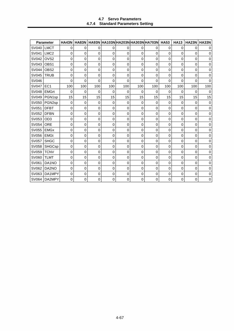
4.7 Servo Parameters4.7.4 Standard Parameters Setting
4-67
Parameter HA43N HA83N HA93N HA103N HA203N HA303N HA703N HA53 HA13 HA23N HA33NSV040 LMCT 0 0 0 0 0 0 0 0 0 0 0SV041 LMC2 0 0 0 0 0 0 0 0 0 0 0SV042 OVS2 0 0 0 0 0 0 0 0 0 0 0SV043 OBS1 0 0 0 0 0 0 0 0 0 0 0SV044 OBS2 0 0 0 0 0 0 0 0 0 0 0SV045 TRUB 0 0 0 0 0 0 0 0 0 0 0SV046 0 0 0 0 0 0 0 0 0 0 0SV047 EC1 100 100 100 100 100 100 100 100 100 100 100SV048 EMGrt 0 0 0 0 0 0 0 0 0 0 0SV049 PGN1sp 15 15 15 15 15 15 15 15 15 15 15SV050 PGN2sp 0 0 0 0 0 0 0 0 0 0 0SV051 DFBT 0 0 0 0 0 0 0 0 0 0 0SV052 DFBN 0 0 0 0 0 0 0 0 0 0 0SV053 OD3 0 0 0 0 0 0 0 0 0 0 0SV054 ORE 0 0 0 0 0 0 0 0 0 0 0SV055 EMGx 0 0 0 0 0 0 0 0 0 0 0SV056 EMGt 0 0 0 0 0 0 0 0 0 0 0SV057 SHGC 0 0 0 0 0 0 0 0 0 0 0SV058 SHGCsp 0 0 0 0 0 0 0 0 0 0 0SV059 TCNV 0 0 0 0 0 0 0 0 0 0 0SV060 TLMT 0 0 0 0 0 0 0 0 0 0 0SV061 DA1NO 0 0 0 0 0 0 0 0 0 0 0SV062 DA2NO 0 0 0 0 0 0 0 0 0 0 0SV063 DA1MPY 0 0 0 0 0 0 0 0 0 0 0SV064 DA2MPY 0 0 0 0 0 0 0 0 0 0 0
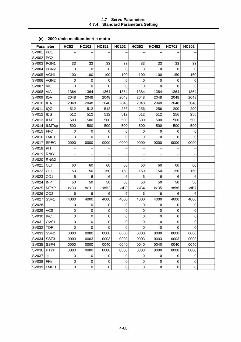
4.7 Servo Parameters4.7.4 Standard Parameters Setting
4-68
(e) 2000 r/min medium-inertia motor
Parameter HC52 HC102 HC152 HC202 HC352 HC452 HC702 HC902SV001 PC1 – – – – – – – –SV002 PC2 – – – – – – – –SV003 PGN1 33 33 33 33 33 33 33 33SV004 PGN2 0 0 0 0 0 0 0 0SV005 VGN1 100 100 100 100 100 100 150 150SV006 VGN2 0 0 0 0 0 0 0 0SV007 VIL 0 0 0 0 0 0 0 0SV008 VIA 1364 1364 1364 1364 1364 1364 1364 1364SV009 IQA 2048 2048 2048 2048 2048 2048 2048 2048SV010 IDA 2048 2048 2048 2048 2048 2048 2048 2048SV011 IQG 512 512 512 256 256 256 200 200SV012 IDG 512 512 512 512 512 512 256 256SV013 ILMT 500 500 500 500 500 500 500 500SV014 ILMTsp 500 500 500 500 500 500 500 500SV015 FFC 0 0 0 0 0 0 0 0SV016 LMC1 0 0 0 0 0 0 0 0SV017 SPEC 0000 0000 0000 0000 0000 0000 0000 0000SV018 PIT – – – – – – – –SV019 RNG1 – – – – – – – –SV020 RNG2 – – – – – – – –SV021 OLT 60 60 60 60 60 60 60 60SV022 OLL 150 150 150 150 150 150 150 150SV023 OD1 6 6 6 6 6 6 6 6SV024 INP 50 50 50 50 50 50 50 50SV025 MTYP xxB0 xxB1 xxB2 xxB3 xxB4 xxB5 xxB6 xxB7SV026 OD2 6 6 6 6 6 6 6 6SV027 SSF1 4000 4000 4000 4000 4000 4000 4000 4000SV028 0 0 0 0 0 0 0 0SV029 VCS 0 0 0 0 0 0 0 0SV030 IVC 0 0 0 0 0 0 0 0SV031 OVS1 0 0 0 0 0 0 0 0SV032 TOF 0 0 0 0 0 0 0 0SV033 SSF2 0000 0000 0000 0000 0000 0000 0000 0000SV034 SSF3 0003 0003 0003 0003 0003 0003 0003 0003SV035 SSF4 0000 0000 0040 0040 0040 0040 0040 0040SV036 PTYP 0000 0000 0000 0000 0000 0000 0000 0000SV037 JL 0 0 0 0 0 0 0 0SV038 FHz 0 0 0 0 0 0 0 0SV039 LMCD 0 0 0 0 0 0 0 0
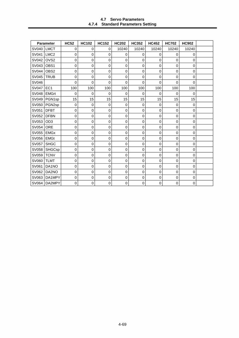
4.7 Servo Parameters4.7.4 Standard Parameters Setting
4-69
Parameter HC52 HC102 HC152 HC202 HC352 HC452 HC702 HC902SV040 LMCT 0 0 0 10240 10240 10240 10240 10240SV041 LMC2 0 0 0 0 0 0 0 0SV042 OVS2 0 0 0 0 0 0 0 0SV043 OBS1 0 0 0 0 0 0 0 0SV044 OBS2 0 0 0 0 0 0 0 0SV045 TRUB 0 0 0 0 0 0 0 0SV046 0 0 0 0 0 0 0 0SV047 EC1 100 100 100 100 100 100 100 100SV048 EMGrt 0 0 0 0 0 0 0 0SV049 PGN1sp 15 15 15 15 15 15 15 15SV050 PGN2sp 0 0 0 0 0 0 0 0SV051 DFBT 0 0 0 0 0 0 0 0SV052 DFBN 0 0 0 0 0 0 0 0SV053 OD3 0 0 0 0 0 0 0 0SV054 ORE 0 0 0 0 0 0 0 0SV055 EMGx 0 0 0 0 0 0 0 0SV056 EMGt 0 0 0 0 0 0 0 0SV057 SHGC 0 0 0 0 0 0 0 0SV058 SHGCsp 0 0 0 0 0 0 0 0SV059 TCNV 0 0 0 0 0 0 0 0SV060 TLMT 0 0 0 0 0 0 0 0SV061 DA1NO 0 0 0 0 0 0 0 0SV062 DA2NO 0 0 0 0 0 0 0 0SV063 DA1MPY 0 0 0 0 0 0 0 0SV064 DA2MPY 0 0 0 0 0 0 0 0
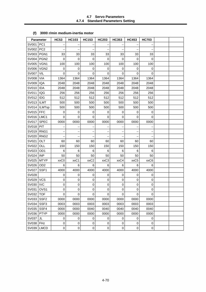
4.7 Servo Parameters4.7.4 Standard Parameters Setting
4-70
(f) 3000 r/min medium-inertia motor
Parameter HC53 HC103 HC153 HC203 HC353 HC453 HC703SV001 PC1 – – – – – – –SV002 PC2 – – – – – – –SV003 PGN1 33 33 33 33 33 33 33SV004 PGN2 0 0 0 0 0 0 0SV005 VGN1 100 100 100 100 100 100 100SV006 VGN2 0 0 0 0 0 0 0SV007 VIL 0 0 0 0 0 0 0SV008 VIA 1364 1364 1364 1364 1364 1364 1364SV009 IQA 2048 2048 2048 2048 2048 2048 2048SV010 IDA 2048 2048 2048 2048 2048 2048 2048SV011 IQG 256 256 256 256 256 256 256SV012 IDG 512 512 512 512 512 512 512SV013 ILMT 500 500 500 500 500 500 500SV014 ILMTsp 500 500 500 500 500 500 500SV015 FFC 0 0 0 0 0 0 0SV016 LMC1 0 0 0 0 0 0 0SV017 SPEC 0000 0000 0000 0000 0000 0000 0000SV018 PIT – – – – – – –SV019 RNG1 – – – – – – –SV020 RNG2 – – – – – – –SV021 OLT 60 60 60 60 60 60 60SV022 OLL 150 150 150 150 150 150 150SV023 OD1 6 6 6 6 6 6 6SV024 INP 50 50 50 50 50 50 50SV025 MTYP xxC0 xxC1 xxC2 xxC3 xxC4 xxC5 xxC6SV026 OD2 6 6 6 6 6 6 6SV027 SSF1 4000 4000 4000 4000 4000 4000 4000SV028 0 0 0 0 0 0 0SV029 VCS 0 0 0 0 0 0 0SV030 IVC 0 0 0 0 0 0 0SV031 OVS1 0 0 0 0 0 0 0SV032 TOF 0 0 0 0 0 0 0SV033 SSF2 0000 0000 0000 0000 0000 0000 0000SV034 SSF3 0003 0003 0003 0003 0003 0003 0003SV035 SSF4 0000 0000 0040 0040 0040 0040 0040SV036 PTYP 0000 0000 0000 0000 0000 0000 0000SV037 JL 0 0 0 0 0 0 0SV038 FHz 0 0 0 0 0 0 0SV039 LMCD 0 0 0 0 0 0 0
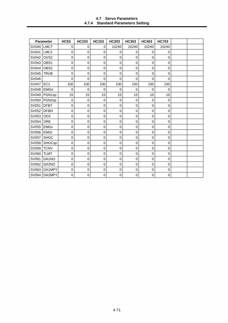
4.7 Servo Parameters4.7.4 Standard Parameters Setting
4-71
Parameter HC53 HC103 HC153 HC203 HC353 HC453 HC703SV040 LMCT 0 0 0 10240 10240 10240 10240SV041 LMC2 0 0 0 0 0 0 0SV042 OVS2 0 0 0 0 0 0 0SV043 OBS1 0 0 0 0 0 0 0SV044 OBS2 0 0 0 0 0 0 0SV045 TRUB 0 0 0 0 0 0 0SV046 0 0 0 0 0 0 0SV047 EC1 100 100 100 100 100 100 100SV048 EMGrt 0 0 0 0 0 0 0SV049 PGN1sp 15 15 15 15 15 15 15SV050 PGN2sp 0 0 0 0 0 0 0SV051 DFBT 0 0 0 0 0 0 0SV052 DFBN 0 0 0 0 0 0 0SV053 OD3 0 0 0 0 0 0 0SV054 ORE 0 0 0 0 0 0 0SV055 EMGx 0 0 0 0 0 0 0SV056 EMGt 0 0 0 0 0 0 0SV057 SHGC 0 0 0 0 0 0 0SV058 SHGCsp 0 0 0 0 0 0 0SV059 TCNV 0 0 0 0 0 0 0SV060 TLMT 0 0 0 0 0 0 0SV061 DA1NO 0 0 0 0 0 0 0SV062 DA2NO 0 0 0 0 0 0 0SV063 DA1MPY 0 0 0 0 0 0 0SV064 DA2MPY 0 0 0 0 0 0 0
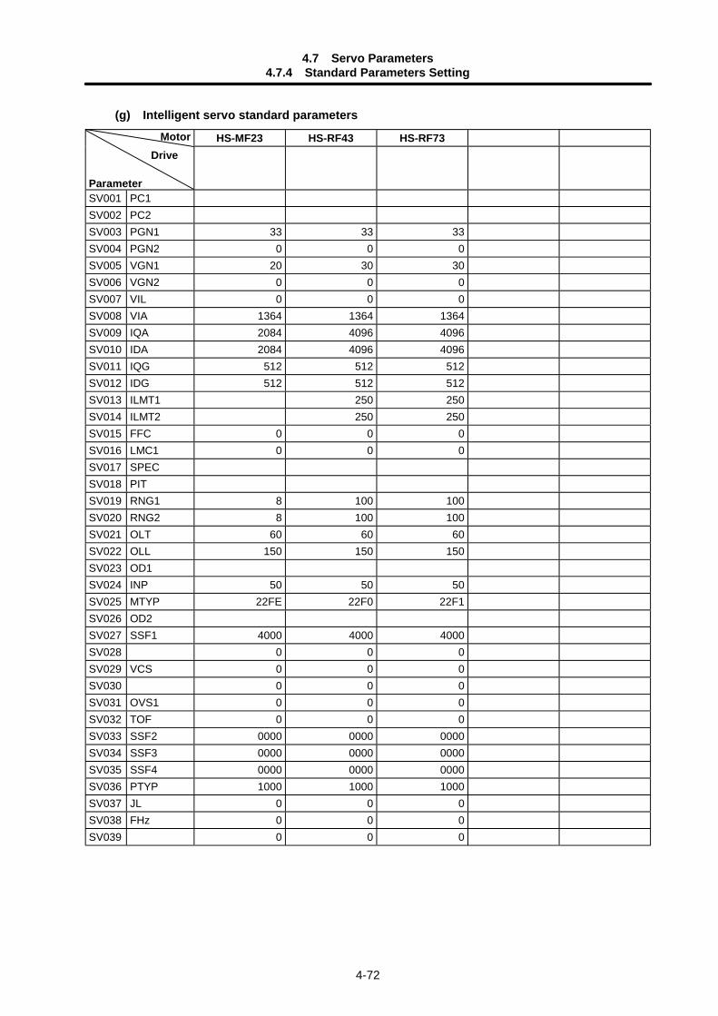
4.7 Servo Parameters4.7.4 Standard Parameters Setting
4-72
(g) Intelligent servo standard parameters
HS-MF23 HS-RF43 HS-RF73Motor Drive
ParameterSV001 PC1SV002 PC2SV003 PGN1 33 33 33SV004 PGN2 0 0 0SV005 VGN1 20 30 30SV006 VGN2 0 0 0SV007 VIL 0 0 0SV008 VIA 1364 1364 1364SV009 IQA 2084 4096 4096SV010 IDA 2084 4096 4096SV011 IQG 512 512 512SV012 IDG 512 512 512SV013 ILMT1 250 250SV014 ILMT2 250 250SV015 FFC 0 0 0SV016 LMC1 0 0 0SV017 SPECSV018 PITSV019 RNG1 8 100 100SV020 RNG2 8 100 100SV021 OLT 60 60 60SV022 OLL 150 150 150SV023 OD1SV024 INP 50 50 50SV025 MTYP 22FE 22F0 22F1SV026 OD2SV027 SSF1 4000 4000 4000SV028 0 0 0SV029 VCS 0 0 0SV030 0 0 0SV031 OVS1 0 0 0SV032 TOF 0 0 0SV033 SSF2 0000 0000 0000SV034 SSF3 0000 0000 0000SV035 SSF4 0000 0000 0000SV036 PTYP 1000 1000 1000SV037 JL 0 0 0SV038 FHz 0 0 0SV039 0 0 0
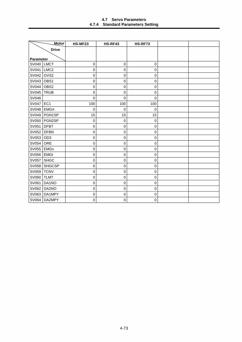
4.7 Servo Parameters4.7.4 Standard Parameters Setting
4-73
HS-MF23 HS-RF43 HS-RF73Motor Drive
ParameterSV040 LMCT 0 0 0SV041 LMC2 0 0 0SV042 OVS2 0 0 0SV043 OBS1 0 0 0SV044 OBS2 0 0 0SV045 TRUB 0 0 0SV046 0 0 0SV047 EC1 100 100 100SV048 EMGrt 0 0 0SV049 PGN1SP 15 15 15SV050 PGN2SP 0 0 0SV051 DFBT 0 0 0SV052 DFBN 0 0 0SV053 OD3 0 0 0SV054 ORE 0 0 0SV055 EMGx 0 0 0SV056 EMGt 0 0 0SV057 SHGC 0 0 0SV058 SHGCSP 0 0 0SV059 TCNV 0 0 0SV060 TLMT 0 0 0SV061 DA1NO 0 0 0SV062 DA2NO 0 0 0SV063 DA1MPY 0 0 0SV064 DA2MPY 0 0 0
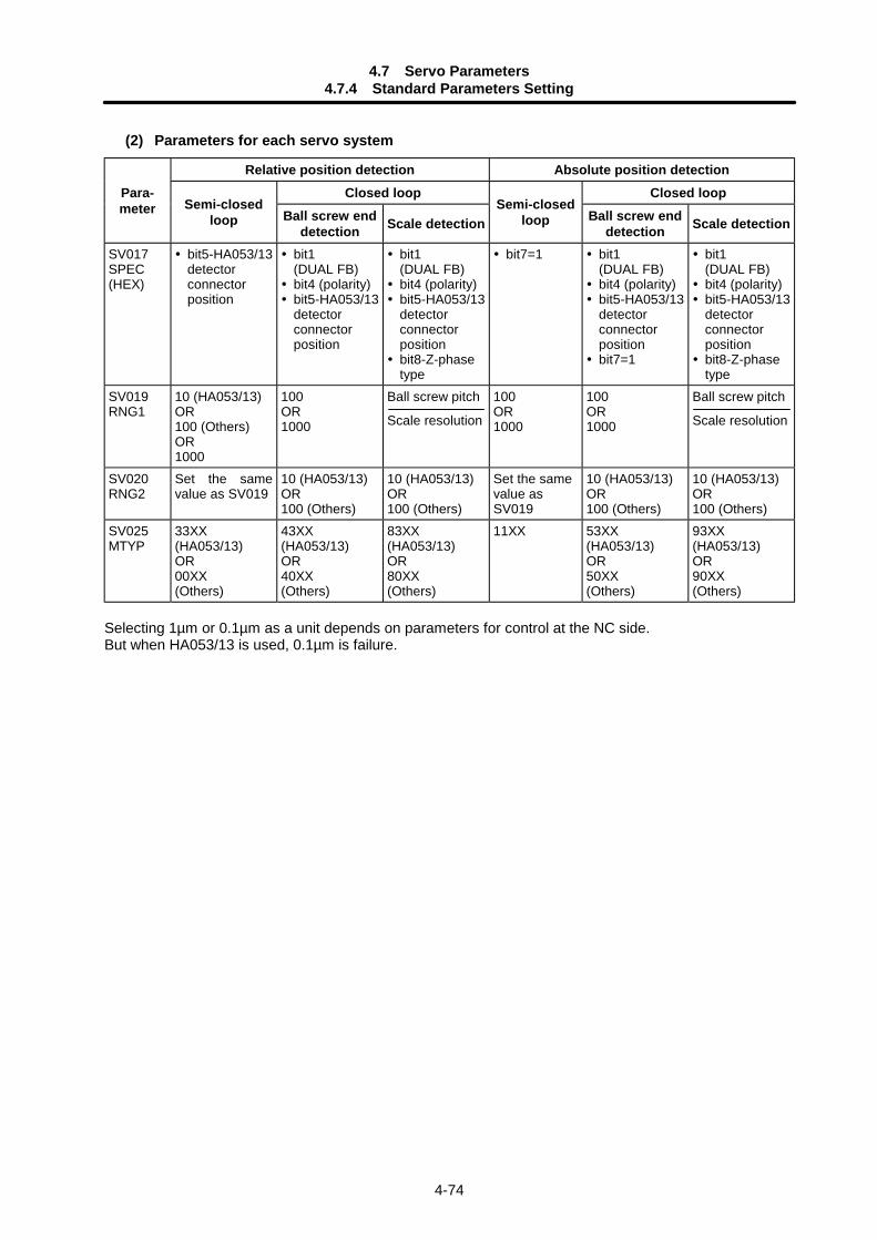
4.7 Servo Parameters4.7.4 Standard Parameters Setting
4-74
(2) Parameters for each servo system
Relative position detection Absolute position detectionClosed loop Closed loopPara-
meter Semi-closedloop Ball screw end
detection Scale detectionSemi-closed
loop Ball screw enddetection Scale detection
SV017SPEC(HEX)
bit5-HA053/13detectorconnectorposition
bit1(DUAL FB) bit4 (polarity) bit5-HA053/13detectorconnectorposition
bit1(DUAL FB) bit4 (polarity) bit5-HA053/13detectorconnectorposition bit8-Z-phasetype
bit7=1 bit1(DUAL FB) bit4 (polarity) bit5-HA053/13detectorconnectorposition bit7=1
bit1(DUAL FB) bit4 (polarity) bit5-HA053/13detectorconnectorposition bit8-Z-phasetype
SV019RNG1
10 (HA053/13)OR100 (Others)OR1000
100OR1000
Ball screw pitch
Scale resolution
100OR1000
100OR1000
Ball screw pitch
Scale resolution
SV020RNG2
Set the samevalue as SV019
10 (HA053/13)OR100 (Others)
10 (HA053/13)OR100 (Others)
Set the samevalue asSV019
10 (HA053/13)OR100 (Others)
10 (HA053/13)OR100 (Others)
SV025MTYP
33XX(HA053/13)OR00XX(Others)
43XX(HA053/13)OR40XX(Others)
83XX(HA053/13)OR80XX(Others)
11XX 53XX(HA053/13)OR50XX(Others)
93XX(HA053/13)OR90XX(Others)
Selecting 1µm or 0.1µm as a unit depends on parameters for control at the NC side.But when HA053/13 is used, 0.1µm is failure.
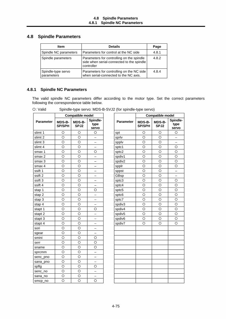
4.8 Spindle Parameters4.8.1 Spindle NC Parameters
4-75
4.8 Spindle Parameters
Item Details PageSpindle NC parameters Parameters for control at the NC side 4.8.1Spindle parameters Parameters for controlling on the spindle
side when serial-connected to the spindlecontroller
4.8.2
Spindle-type servoparameters
Parameters for controlling on the NC sidewhen serial-connected to the NC axis.
4.8.4
4.8.1 Spindle NC Parameters
The valid spindle NC parameters differ according to the motor type. Set the correct parametersfollowing the correspondence table below.
: Valid Spindle-type servo: MDS-B-SVJ2 (for spindle-type servo)Compatible model Compatible model
Parameter MDS-B-SP/SPH
MDS-B-SPJ2
Spindle-type
servo
Parameter MDS-B-SP/SPH
MDS-B-SPJ2
Spindle-type
servoslimt 1 sptslimt 2 – sprlv –slimt 3 – spplv –slimt 4 – sptc1smax 1 sptc2smax 2 – spdiv1smax 3 – spdiv2smax 4 – spplrssift 1 – sppst –ssift 2 – GBsp –ssift 3 – sptc3ssift 4 – sptc4stap 1 sptc5stap 2 – sptc6stap 3 – sptc7stap 4 – spdiv3stapt 1 spdiv4stapt 2 – spdiv5stapt 3 – spdiv6stapt 4 – spdiv7sori –sgear –sminiserrsnamesprcmm –senc_pno –sana_pno –spflgsenc_no –sana_no –smcp_no
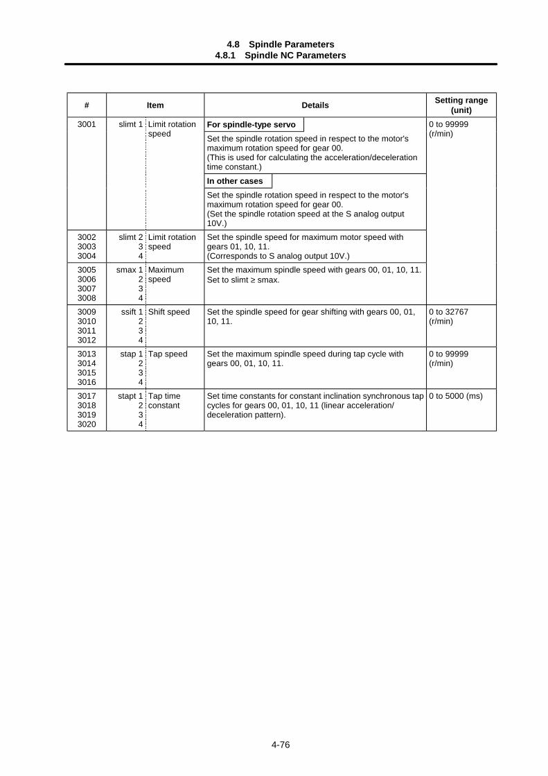
4.8 Spindle Parameters4.8.1 Spindle NC Parameters
4-76
# Item Details Setting range(unit)
For spindle-type servoSet the spindle rotation speed in respect to the motor'smaximum rotation speed for gear 00.(This is used for calculating the acceleration/decelerationtime constant.)
In other cases
3001 slimt 1 Limit rotationspeed
Set the spindle rotation speed in respect to the motor'smaximum rotation speed for gear 00.(Set the spindle rotation speed at the S analog output10V.)
300230033004
slimt 234
Limit rotationspeed
Set the spindle speed for maximum motor speed withgears 01, 10, 11.(Corresponds to S analog output 10V.)
3005300630073008
smax 1234
Maximumspeed
Set the maximum spindle speed with gears 00, 01, 10, 11.Set to slimt ≥ smax.
0 to 99999(r/min)
3009301030113012
ssift 1234
Shift speed Set the spindle speed for gear shifting with gears 00, 01,10, 11.
0 to 32767(r/min)
3013301430153016
stap 1234
Tap speed Set the maximum spindle speed during tap cycle withgears 00, 01, 10, 11.
0 to 99999(r/min)
3017301830193020
stapt 1234
Tap timeconstant
Set time constants for constant inclination synchronous tapcycles for gears 00, 01, 10, 11 (linear acceleration/deceleration pattern).
0 to 5000 (ms)

4.8 Spindle Parameters4.8.1 Spindle NC Parameters
4-77
Relationship between spindle limit speed and spindle maximum speed
smax1 slimt1 smax2 slimt2 smax(n) slimt(n)0
Output voltage(W)10V
Maximum speed of gearing 1 (Parameter setting)Set 0 for any unused gear.
Limit speed of gearing 1 (Parameter setting)
Spindle speed (r/min)
stapt(n)stapt(n)stapt2
stapt1
slimt(n)
slimt2
slimt1
0
Relation between the spindle limit speed and the spindle tap time constant(for the constant inclination synchronous tap cycle)
Execution timeconstant
slimt(n)
S command
Time (ms)Time (ms)
Spindle speed (r/min)Spindle speed (r/min)
# Item Details Setting range(unit)
3021 sori Orientationspeed
Set the spindle orientation speed.Set the speed for when the spindle rotates at the constantspeed.
0 to 32767(r/min)
3022 sgear Encoder gearratio
Set the gear ratio of the spindle to the encoder. 0: 1/11: 1/22: 1/43: 1/8
3023 smini Minimumspeed
Set the minimum speed of the spindle.If an S command instructs the rotation speed below thissetting, the spindle rotates at the minimum speed set bythis parameter.
0 to 32767(r/min)
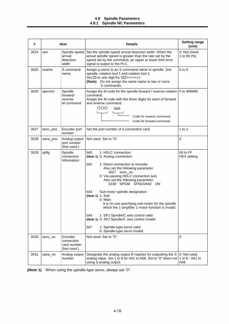
4.8 Spindle Parameters4.8.1 Spindle NC Parameters
4-78
# Item Details Setting range(unit)
3024 serr Spindle speedarrivaldetectionwidth
Set the spindle speed arrival detection width. When theactual spindle speed is greater than the rate set by thespeed set by the command, an upper or lower limit errorsignal is output to the PLC.
0: Not check1 to 99 (%)
3025 sname S commandname
Assign a name to an S command name to spindle, 2ndspindle, rotation tool 1 and rotation tool 2.Set =in one digit for S =××××××.(Note) Do not assign the same name to two or more S commands.
0 to 9
3026 sprcmm Spindleforward/reverseM command
Assign the M code for the spindle forward / reverse rotationcommand.Assign the M code with the three digits for each of forwardand reverse command.
Code for reverse commandCode for forward command
∆∆∆
0 to 999999
3027 senc_pno Encoder portnumber
Set the port number of a connection card. 1 to 2
3028 sana_pno Analog outputport number(Not used.)
Not used. Set to "0". 0
3029 spflg Spindleconnectioninformation
bit0 1: HDLC connection(Note 1) 0: Analog connection
bit2 1: Direct connection to encoderAlso set the following parameter.
3027 senc_no0: Via passing HDLC connection axis
Also set the following parameter. 3238 SP038 SFNC6/bit2 ON
bit3 Sub-motor spindle designation(Note 1) 1: Sub
0: Main It is no use specifying sub-motor for the spindle which the 1 amplifier 2 motor function is invalid.
bit4 1: SPJ Spindle/C axis control valid(Note 1) 0: SPJ Spindle/C axis control invalid
bit7 1: Spindle-type servo valid0: Spindle-type servo invalid
00 to FFHEX setting
3030 senc_no Encoderconnectioncard number(Not used.)
Not used. Set to "0". 0
3031 sana_no Analog outputnumber
Designate the analog output R register for outputting the Sanalog value. Set 1 to 8 for A01 to A08. Set to "0" when notusing S analog output.
0: Not used.1 to 8 : A01 toA08
(Note 1) When using the spindle-type servo, always set "0".
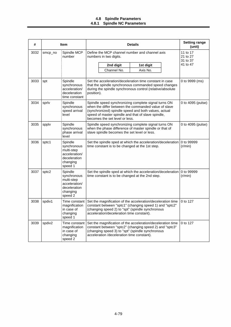
4.8 Spindle Parameters4.8.1 Spindle NC Parameters
4-79
# Item Details Setting range(unit)
3032 smcp_no Spindle MCPnumber
Define the MCP channel number and channel axisnumbers in two digits.
11 to 1721 to 2731 to 3741 to 47
3033 spt Spindlesynchronousacceleration/decelerationtime constant
Set the acceleration/deceleration time constant in casethat the spindle synchronous commanded speed changesduring the spindle synchronous control (relative/absoluteposition).
0 to 9999 (ms)
3034 sprlv Spindlesynchronousspeed arrivallevel
Spindle speed synchronizing complete signal turns ONwhen the differ between the commanded value of slave(synchronized) spindle speed and both values, actualspeed of master spindle and that of slave spindle,becomes the set level or less.
0 to 4095 (pulse)
3035 spplv Spindlesynchronousphase arrivallevel
Spindle speed synchronizing complete signal turns ONwhen the phase difference of master spindle or that ofslave spindle becomes the set level or less.
0 to 4095 (pulse)
3036 sptc1 Spindlesynchronousmulti-stepacceleration/decelerationchangingspeed 1
Set the spindle sped at which the acceleration/decelerationtime constant is to be changed at the 1st step.
0 to 99999(r/min)
3037 sptc2 Spindlesynchronousmulti-stepacceleration/decelerationchangingspeed 2
Set the spindle sped at which the acceleration/decelerationtime constant is to be changed at the 2nd step.
0 to 99999(r/min)
3038 spdiv1 Time constantmagnificationin case ofchangingspeed 1
Set the magnification of the acceleration/deceleration timeconstant between "sptc1" (changing speed 1) and "sptc2"(changing speed 2) to "spt" (spindle synchronousacceleration/deceleration time constant).
0 to 127
3039 spdiv2 Time constantmagnificationin case ofchangingspeed 2
Set the magnification of the acceleration/deceleration timeconstant between "sptc2" (changing speed 2) and "sptc3"(changing speed 3) to "spt" (spindle synchronousacceleration /deceleration time constant).
0 to 127
2nd digit 1st digitChannel No. Axis No.
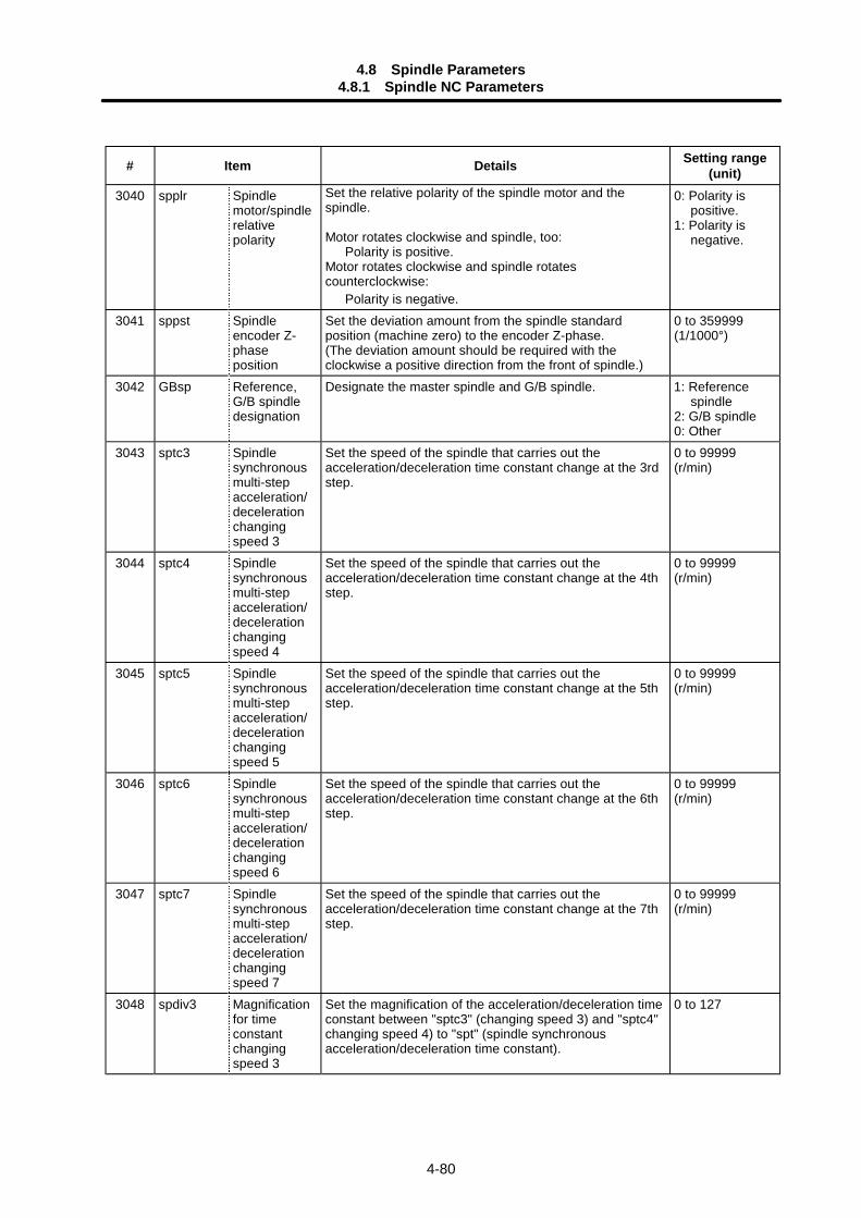
4.8 Spindle Parameters4.8.1 Spindle NC Parameters
4-80
# Item Details Setting range(unit)
3040 spplr Spindlemotor/spindlerelativepolarity
Set the relative polarity of the spindle motor and thespindle.
Motor rotates clockwise and spindle, too: Polarity is positive.Motor rotates clockwise and spindle rotatescounterclockwise: Polarity is negative.
0: Polarity ispositive.
1: Polarity isnegative.
3041 sppst Spindleencoder Z-phaseposition
Set the deviation amount from the spindle standardposition (machine zero) to the encoder Z-phase.(The deviation amount should be required with theclockwise a positive direction from the front of spindle.)
0 to 359999(1/1000°)
3042 GBsp Reference,G/B spindledesignation
Designate the master spindle and G/B spindle. 1: Referencespindle
2: G/B spindle0: Other
3043 sptc3 Spindlesynchronousmulti-stepacceleration/decelerationchangingspeed 3
Set the speed of the spindle that carries out theacceleration/deceleration time constant change at the 3rdstep.
0 to 99999(r/min)
3044 sptc4 Spindlesynchronousmulti-stepacceleration/decelerationchangingspeed 4
Set the speed of the spindle that carries out theacceleration/deceleration time constant change at the 4thstep.
0 to 99999(r/min)
3045 sptc5 Spindlesynchronousmulti-stepacceleration/decelerationchangingspeed 5
Set the speed of the spindle that carries out theacceleration/deceleration time constant change at the 5thstep.
0 to 99999(r/min)
3046 sptc6 Spindlesynchronousmulti-stepacceleration/decelerationchangingspeed 6
Set the speed of the spindle that carries out theacceleration/deceleration time constant change at the 6thstep.
0 to 99999(r/min)
3047 sptc7 Spindlesynchronousmulti-stepacceleration/decelerationchangingspeed 7
Set the speed of the spindle that carries out theacceleration/deceleration time constant change at the 7thstep.
0 to 99999(r/min)
3048 spdiv3 Magnificationfor timeconstantchangingspeed 3
Set the magnification of the acceleration/deceleration timeconstant between "sptc3" (changing speed 3) and "sptc4"changing speed 4) to "spt" (spindle synchronousacceleration/deceleration time constant).
0 to 127
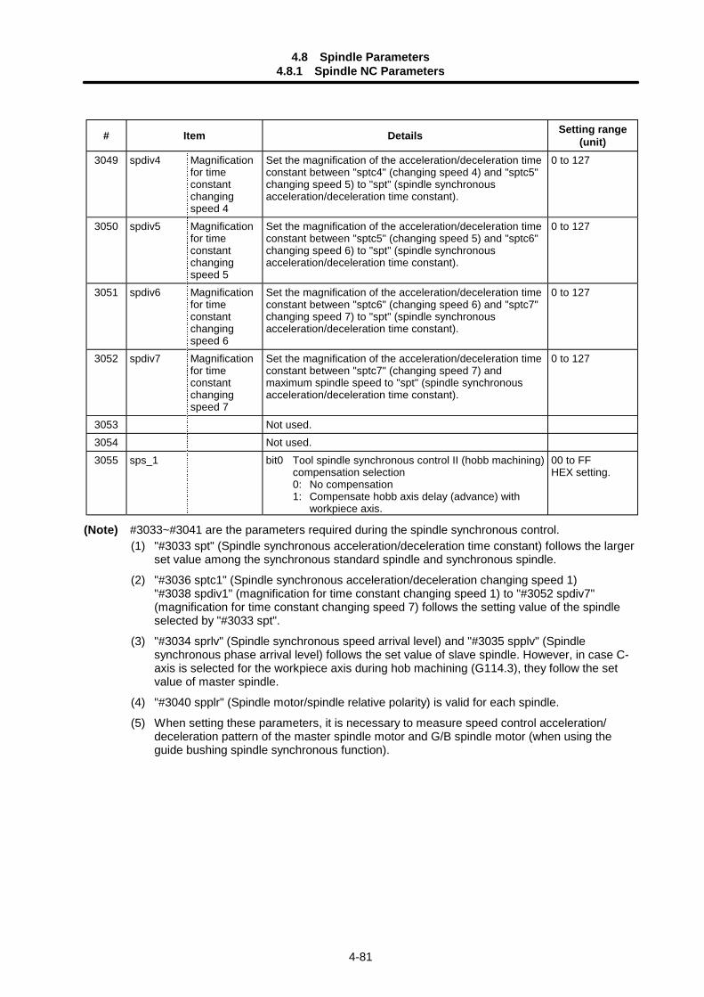
4.8 Spindle Parameters4.8.1 Spindle NC Parameters
4-81
# Item Details Setting range(unit)
3049 spdiv4 Magnificationfor timeconstantchangingspeed 4
Set the magnification of the acceleration/deceleration timeconstant between "sptc4" (changing speed 4) and "sptc5"changing speed 5) to "spt" (spindle synchronousacceleration/deceleration time constant).
0 to 127
3050 spdiv5 Magnificationfor timeconstantchangingspeed 5
Set the magnification of the acceleration/deceleration timeconstant between "sptc5" (changing speed 5) and "sptc6"changing speed 6) to "spt" (spindle synchronousacceleration/deceleration time constant).
0 to 127
3051 spdiv6 Magnificationfor timeconstantchangingspeed 6
Set the magnification of the acceleration/deceleration timeconstant between "sptc6" (changing speed 6) and "sptc7"changing speed 7) to "spt" (spindle synchronousacceleration/deceleration time constant).
0 to 127
3052 spdiv7 Magnificationfor timeconstantchangingspeed 7
Set the magnification of the acceleration/deceleration timeconstant between "sptc7" (changing speed 7) andmaximum spindle speed to "spt" (spindle synchronousacceleration/deceleration time constant).
0 to 127
3053 Not used.3054 Not used.3055 sps_1 bit0 Tool spindle synchronous control II (hobb machining)
compensation selection0: No compensation1: Compensate hobb axis delay (advance) with
workpiece axis.
00 to FFHEX setting.
(Note) #3033~#3041 are the parameters required during the spindle synchronous control.(1) "#3033 spt" (Spindle synchronous acceleration/deceleration time constant) follows the larger
set value among the synchronous standard spindle and synchronous spindle.
(2) "#3036 sptc1" (Spindle synchronous acceleration/deceleration changing speed 1)"#3038 spdiv1" (magnification for time constant changing speed 1) to "#3052 spdiv7"(magnification for time constant changing speed 7) follows the setting value of the spindleselected by "#3033 spt".
(3) "#3034 sprlv" (Spindle synchronous speed arrival level) and "#3035 spplv" (Spindlesynchronous phase arrival level) follows the set value of slave spindle. However, in case C-axis is selected for the workpiece axis during hob machining (G114.3), they follow the setvalue of master spindle.
(4) "#3040 spplr" (Spindle motor/spindle relative polarity) is valid for each spindle.
(5) When setting these parameters, it is necessary to measure speed control acceleration/deceleration pattern of the master spindle motor and G/B spindle motor (when using theguide bushing spindle synchronous function).
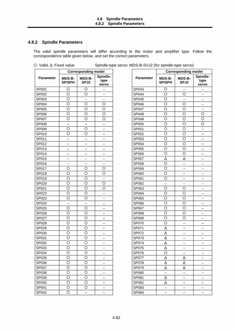
4.8 Spindle Parameters4.8.2 Spindle Parameters
4-82
4.8.2 Spindle Parameters
The valid spindle parameters will differ according to the motor and amplifier type. Follow thecorrespondence table given below, and set the correct parameters.
: Valid, ∆: Fixed value Spindle-type servo: MDS-B-SVJ2 (for spindle-type servo)Corresponding model Corresponding model
Parameter MDS-B-SP/SPH
MDS-B-SPJ2
Spindle-type
servo
Parameter MDS-B-SP/SPH
MDS-B-SPJ2
Spindle-type
servoSP001 – SP043 – –SP002 – SP044 –SP003 – – SP045 – –SP004 SP046 –SP005 SP047 –SP006 SP048SP007 SP049SP008 – – – SP050SP009 – SP051 –SP010 – SP052 –SP011 – – – SP053 –SP012 – – – SP054 –SP013 – – – SP055 –SP014 – – – SP056 –SP015 – – – SP057 ∆ ∆ –SP016 – – – SP058 – –SP017 SP059 – –SP018 SP060 – –SP019 – SP061 – –SP020 SP062 – – –SP021 SP063 –SP022 – SP064 –SP023 – SP065 –SP024 – – – SP066 –SP025 – SP067 –SP026 – SP068 –SP027 – SP069 –SP028 – SP070 – –SP029 – SP071 ∆ – –SP030 – SP072 ∆ – –SP031 – SP073 ∆ – –SP032 – SP074 ∆ – –SP033 – SP075 ∆ – –SP034 – SP076 – –SP035 – SP077 ∆ ∆ –SP036 – SP078 ∆ ∆ –SP037 – SP079 ∆ ∆ –SP038 – SP080 – – –SP039 – SP081 ∆ – –SP040 – SP082 ∆ – –SP041 – SP083 – – –SP042 – – SP084 – – –
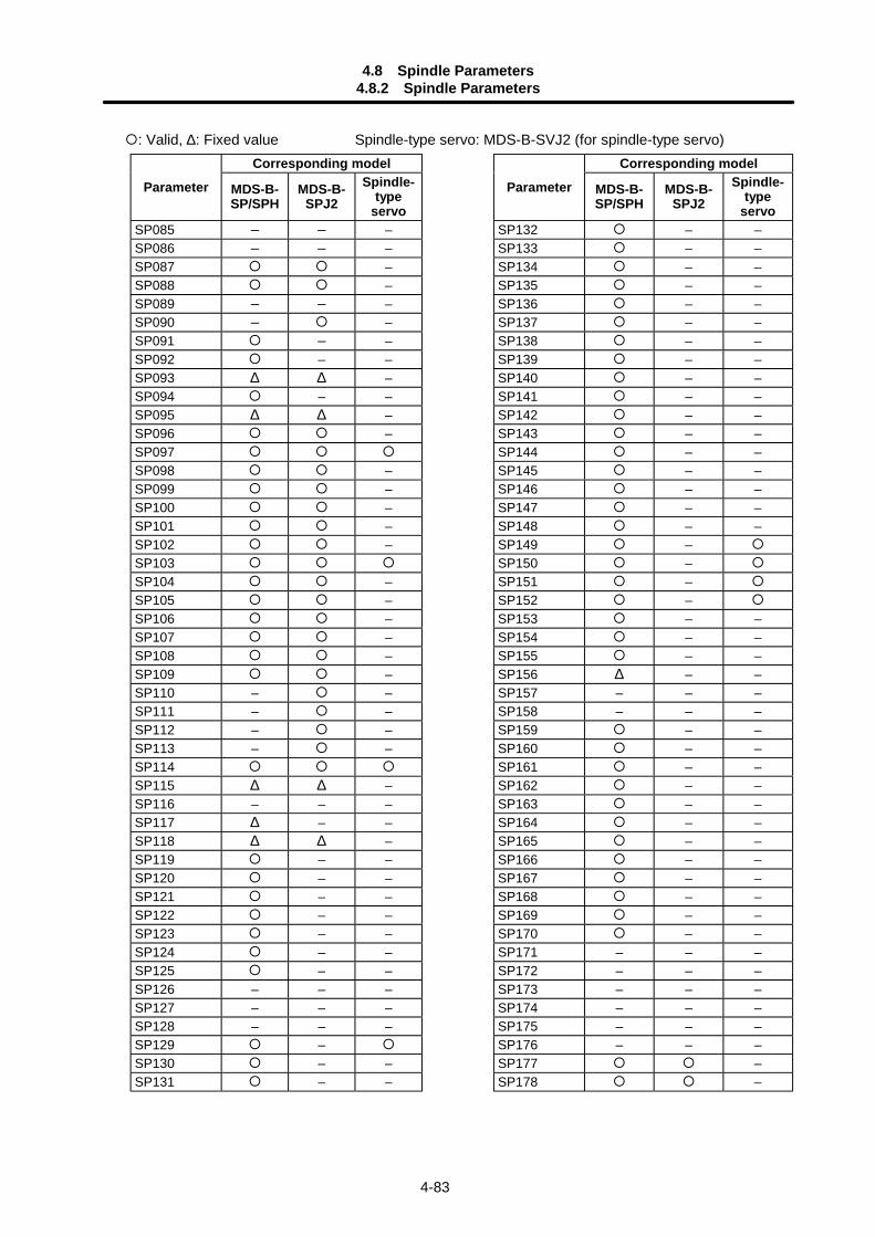
4.8 Spindle Parameters4.8.2 Spindle Parameters
4-83
: Valid, ∆: Fixed value Spindle-type servo: MDS-B-SVJ2 (for spindle-type servo)Corresponding model Corresponding model
Parameter MDS-B-SP/SPH
MDS-B-SPJ2
Spindle-type
servo
Parameter MDS-B-SP/SPH
MDS-B-SPJ2
Spindle-type
servoSP085 – – – SP132 – –SP086 – – – SP133 – –SP087 – SP134 – –SP088 – SP135 – –SP089 – – – SP136 – –SP090 – – SP137 – –SP091 – – SP138 – –SP092 – – SP139 – –SP093 ∆ ∆ – SP140 – –SP094 – – SP141 – –SP095 ∆ ∆ – SP142 – –SP096 – SP143 – –SP097 SP144 – –SP098 – SP145 – –SP099 – SP146 – –SP100 – SP147 – –SP101 – SP148 – –SP102 – SP149 –SP103 SP150 –SP104 – SP151 –SP105 – SP152 –SP106 – SP153 – –SP107 – SP154 – –SP108 – SP155 – –SP109 – SP156 ∆ – –SP110 – – SP157 – – –SP111 – – SP158 – – –SP112 – – SP159 – –SP113 – – SP160 – –SP114 SP161 – –SP115 ∆ ∆ – SP162 – –SP116 – – – SP163 – –SP117 ∆ – – SP164 – –SP118 ∆ ∆ – SP165 – –SP119 – – SP166 – –SP120 – – SP167 – –SP121 – – SP168 – –SP122 – – SP169 – –SP123 – – SP170 – –SP124 – – SP171 – – –SP125 – – SP172 – – –SP126 – – – SP173 – – –SP127 – – – SP174 – – –SP128 – – – SP175 – – –SP129 – SP176 – – –SP130 – – SP177 –SP131 – – SP178 –
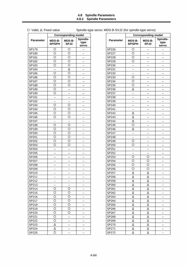
4.8 Spindle Parameters4.8.2 Spindle Parameters
4-84
: Valid, ∆: Fixed value Spindle-type servo: MDS-B-SVJ2 (for spindle-type servo)Corresponding model Corresponding model
Parameter MDS-B-SP/SPH
MDS-B-SPJ2
Spindle-type
servo
Parameter MDS-B-SP/SPH
MDS-B-SPJ2
Spindle-type
servoSP179 – SP226 – –SP180 – SP227 – –SP181 – SP228 – –SP182 – SP229 – –SP183 – SP230 – – –SP184 – ∆ – SP231 – – –SP185 – SP232 – – –SP186 – SP233 – –SP187 – SP234 – –SP188 – SP235 – –SP189 – – SP236 ∆ – –SP190 – – SP237 – – –SP191 – – – SP238 – – –SP192 – – – SP239 – – –SP193 – SP240 – – –SP194 – SP241 – – –SP195 – SP242 ∆ – –SP196 – SP243 ∆ – –SP197 – – – SP244 ∆ – –SP198 – SP245 – –SP199 – SP246 ∆ – –SP200 – SP247 – – –SP201 – SP248 – – –SP202 – SP249 – –SP203 – SP250 – –SP204 – – – SP251 – – –SP205 – – – SP252 – – –SP206 – – – SP253 –SP207 – – – SP254 –SP208 – – – SP255 –SP209 – – – SP256 –SP210 – – – SP257 ∆ ∆ –SP211 – – – SP258 ∆ ∆ –SP212 – – – SP259 ∆ ∆ –SP213 – – – SP260 ∆ ∆ –SP214 – SP261 ∆ ∆ –SP215 – SP262 ∆ ∆ –SP216 – SP263 ∆ ∆ –SP217 – SP264 ∆ ∆ –SP218 – SP265 ∆ ∆ –SP219 – SP266 ∆ ∆ –SP220 – SP267 ∆ ∆ –SP221 – – SP268 ∆ ∆ –SP222 – – SP269 ∆ ∆ –SP223 ∆ – – SP270 ∆ ∆ –SP224 ∆ – – SP271 ∆ ∆ –SP225 – – SP272 ∆ ∆ –
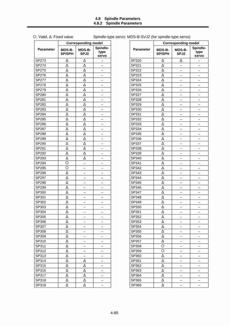
4.8 Spindle Parameters4.8.2 Spindle Parameters
4-85
: Valid, ∆: Fixed value Spindle-type servo: MDS-B-SVJ2 (for spindle-type servo)Corresponding model Corresponding model
Parameter MDS-B-SP/SPH
MDS-B-SPJ2
Spindle-type
servo
Parameter MDS-B-SP/SPH
MDS-B-SPJ2
Spindle-type
servoSP273 ∆ ∆ – SP320 ∆ ∆ –SP274 ∆ ∆ – SP321 ∆ – –SP275 ∆ ∆ – SP322 ∆ – –SP276 ∆ ∆ – SP323 ∆ – –SP277 ∆ ∆ – SP324 ∆ – –SP278 ∆ ∆ – SP325 ∆ – –SP279 ∆ ∆ – SP326 ∆ – –SP280 ∆ ∆ – SP327 ∆ – –SP281 ∆ ∆ – SP328 ∆ – –SP282 ∆ ∆ – SP329 ∆ – –SP283 ∆ ∆ – SP330 ∆ – –SP284 ∆ ∆ – SP331 ∆ – –SP285 ∆ ∆ – SP332 ∆ – –SP286 ∆ ∆ – SP333 ∆ – –SP287 ∆ ∆ – SP334 ∆ – –SP288 ∆ ∆ – SP335 ∆ – –SP289 ∆ ∆ – SP336 ∆ – –SP290 ∆ ∆ – SP337 ∆ – –SP291 ∆ ∆ – SP338 ∆ – –SP292 ∆ ∆ – SP339 ∆ – –SP293 ∆ ∆ – SP340 ∆ – –SP294 – – SP341 ∆ – –SP295 – – SP342 ∆ – –SP296 ∆ – – SP343 ∆ – –SP297 ∆ – – SP344 ∆ – –SP298 ∆ – – SP345 ∆ – –SP299 ∆ – – SP346 ∆ – –SP300 ∆ – – SP347 ∆ – –SP301 ∆ – – SP348 ∆ – –SP302 ∆ – – SP349 ∆ – –SP303 ∆ – – SP350 ∆ – –SP304 ∆ – – SP351 ∆ – –SP305 ∆ – – SP352 ∆ – –SP306 ∆ – – SP353 ∆ – –SP307 ∆ – – SP354 ∆ – –SP308 ∆ – – SP355 ∆ – –SP309 ∆ – – SP356 ∆ – –SP310 ∆ – – SP357 ∆ – –SP311 ∆ – – SP358 – –SP312 ∆ – – SP359 – –SP313 ∆ – – SP360 ∆ – –SP314 ∆ ∆ – SP361 ∆ – –SP315 ∆ ∆ – SP362 ∆ – –SP316 ∆ ∆ – SP363 ∆ – –SP317 ∆ ∆ – SP364 ∆ – –SP318 ∆ ∆ – SP365 ∆ – –SP319 ∆ ∆ – SP366 ∆ – –
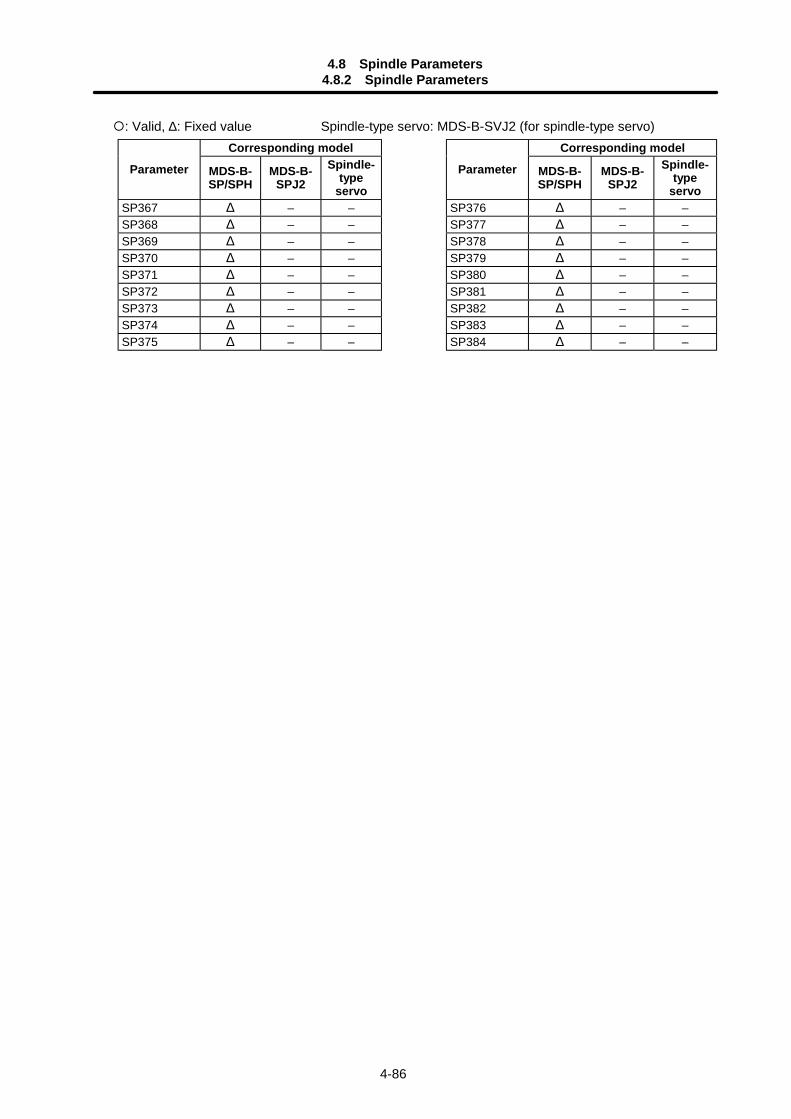
4.8 Spindle Parameters4.8.2 Spindle Parameters
4-86
: Valid, ∆: Fixed value Spindle-type servo: MDS-B-SVJ2 (for spindle-type servo)Corresponding model Corresponding model
Parameter MDS-B-SP/SPH
MDS-B-SPJ2
Spindle-type
servo
Parameter MDS-B-SP/SPH
MDS-B-SPJ2
Spindle-type
servoSP367 ∆ – – SP376 ∆ – –SP368 ∆ – – SP377 ∆ – –SP369 ∆ – – SP378 ∆ – –SP370 ∆ – – SP379 ∆ – –SP371 ∆ – – SP380 ∆ – –SP372 ∆ – – SP381 ∆ – –SP373 ∆ – – SP382 ∆ – –SP374 ∆ – – SP383 ∆ – –SP375 ∆ – – SP384 ∆ – –
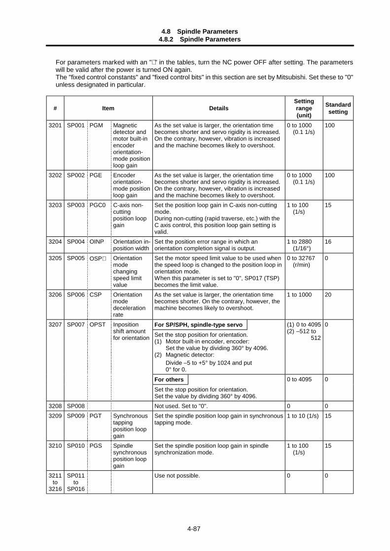
4.8 Spindle Parameters4.8.2 Spindle Parameters
4-87
For parameters marked with an "∗ " in the tables, turn the NC power OFF after setting. The parameterswill be valid after the power is turned ON again.The "fixed control constants" and "fixed control bits" in this section are set by Mitsubishi. Set these to "0"unless designated in particular.
# Item DetailsSettingrange(unit)
Standardsetting
3201 SP001 PGM Magneticdetector andmotor built-inencoderorientation-mode positionloop gain
As the set value is larger, the orientation timebecomes shorter and servo rigidity is increased.On the contrary, however, vibration is increasedand the machine becomes likely to overshoot.
0 to 1000 (0.1 1/s)
100
3202 SP002 PGE Encoderorientation-mode positionloop gain
As the set value is larger, the orientation timebecomes shorter and servo rigidity is increased.On the contrary, however, vibration is increasedand the machine becomes likely to overshoot.
0 to 1000 (0.1 1/s)
100
3203 SP003 PGC0 C-axis non-cuttingposition loopgain
Set the position loop gain in C-axis non-cuttingmode.During non-cutting (rapid traverse, etc.) with theC axis control, this position loop gain setting isvalid.
1 to 100 (1/s)
15
3204 SP004 OINP Orientation in-position width
Set the position error range in which anorientation completion signal is output.
1 to 2880 (1/16°)
16
3205 SP005 OSP∗ Orientationmodechangingspeed limitvalue
Set the motor speed limit value to be used whenthe speed loop is changed to the position loop inorientation mode.When this parameter is set to "0", SP017 (TSP)becomes the limit value.
0 to 32767 (r/min)
0
3206 SP006 CSP Orientationmodedecelerationrate
As the set value is larger, the orientation timebecomes shorter. On the contrary, however, themachine becomes likely to overshoot.
1 to 1000 20
For SP/SPH, spindle-type servoSet the stop position for orientation.(1) Motor built-in encoder, encoder:
Set the value by dividing 360° by 4096.(2) Magnetic detector:
Divide –5 to +5° by 1024 and put0° for 0.
(1) 0 to 4095(2) –512 to 512
0
For others
3207 SP007 OPST Inpositionshift amountfor orientation
Set the stop position for orientation.Set the value by dividing 360° by 4096.
0 to 4095 0
3208 SP008 Not used. Set to "0". 0 03209 SP009 PGT Synchronous
tappingposition loopgain
Set the spindle position loop gain in synchronoustapping mode.
1 to 10 (1/s) 15
3210 SP010 PGS Spindlesynchronousposition loopgain
Set the spindle position loop gain in spindlesynchronization mode.
1 to 100 (1/s)
15
3211to
3216
SP011to
SP016
Use not possible. 0 0
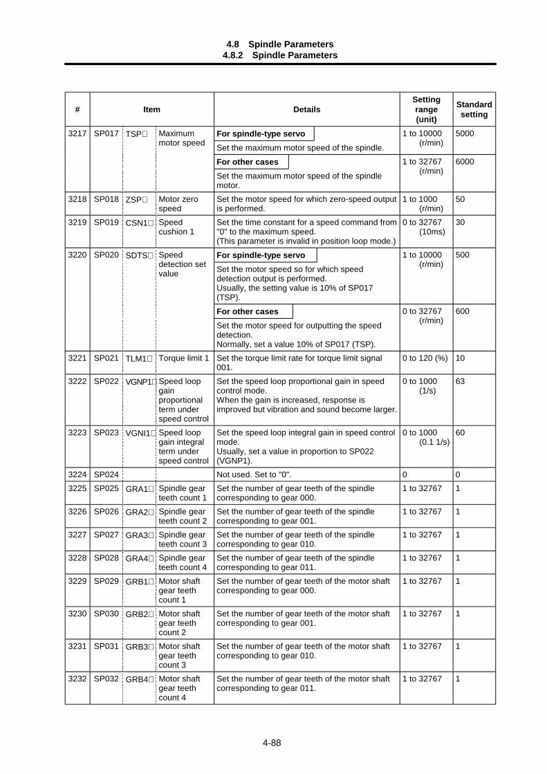
4.8 Spindle Parameters4.8.2 Spindle Parameters
4-88
# Item DetailsSettingrange(unit)
Standardsetting
For spindle-type servoSet the maximum motor speed of the spindle.
1 to 10000 (r/min)
5000
For other cases
3217 SP017 TSP∗ Maximummotor speed
Set the maximum motor speed of the spindlemotor.
1 to 32767 (r/min)
6000
3218 SP018 ZSP∗ Motor zerospeed
Set the motor speed for which zero-speed outputis performed.
1 to 1000 (r/min)
50
3219 SP019 CSN1∗ Speedcushion 1
Set the time constant for a speed command from"0" to the maximum speed.(This parameter is invalid in position loop mode.)
0 to 32767 (10ms)
30
For spindle-type servoSet the motor speed so for which speeddetection output is performed.Usually, the setting value is 10% of SP017(TSP).
1 to 10000 (r/min)
500
For other cases
3220 SP020 SDTS∗ Speeddetection setvalue
Set the motor speed for outputting the speeddetection.Normally, set a value 10% of SP017 (TSP).
0 to 32767 (r/min)
600
3221 SP021 TLM1∗ Torque limit 1 Set the torque limit rate for torque limit signal001.
0 to 120 (%) 10
3222 SP022 VGNP1∗ Speed loopgainproportionalterm underspeed control
Set the speed loop proportional gain in speedcontrol mode.When the gain is increased, response isimproved but vibration and sound become larger.
0 to 1000 (1/s)
63
3223 SP023 VGNI1∗ Speed loopgain integralterm underspeed control
Set the speed loop integral gain in speed controlmode.Usually, set a value in proportion to SP022(VGNP1).
0 to 1000 (0.1 1/s)
60
3224 SP024 Not used. Set to "0". 0 03225 SP025 GRA1∗ Spindle gear
teeth count 1Set the number of gear teeth of the spindlecorresponding to gear 000.
1 to 32767 1
3226 SP026 GRA2∗ Spindle gearteeth count 2
Set the number of gear teeth of the spindlecorresponding to gear 001.
1 to 32767 1
3227 SP027 GRA3∗ Spindle gearteeth count 3
Set the number of gear teeth of the spindlecorresponding to gear 010.
1 to 32767 1
3228 SP028 GRA4∗ Spindle gearteeth count 4
Set the number of gear teeth of the spindlecorresponding to gear 011.
1 to 32767 1
3229 SP029 GRB1∗ Motor shaftgear teethcount 1
Set the number of gear teeth of the motor shaftcorresponding to gear 000.
1 to 32767 1
3230 SP030 GRB2∗ Motor shaftgear teethcount 2
Set the number of gear teeth of the motor shaftcorresponding to gear 001.
1 to 32767 1
3231 SP031 GRB3∗ Motor shaftgear teethcount 3
Set the number of gear teeth of the motor shaftcorresponding to gear 010.
1 to 32767 1
3232 SP032 GRB4∗ Motor shaftgear teethcount 4
Set the number of gear teeth of the motor shaftcorresponding to gear 011.
1 to 32767 1
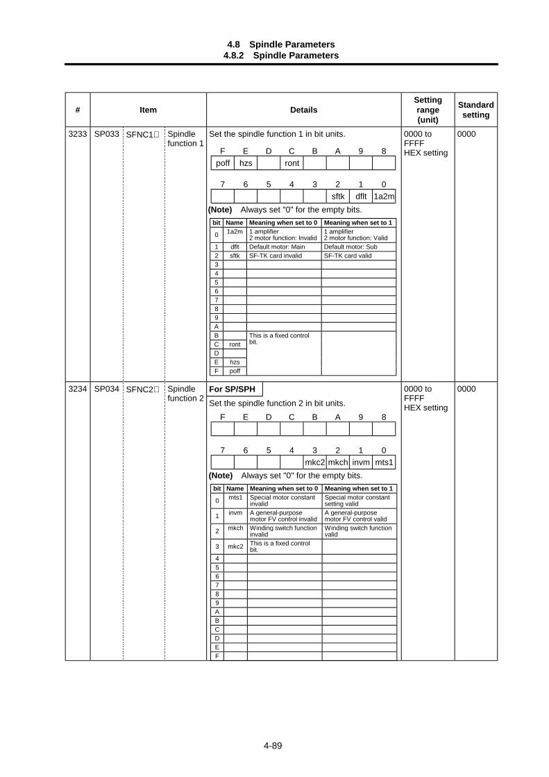
4.8 Spindle Parameters4.8.2 Spindle Parameters
4-89
# Item DetailsSettingrange(unit)
Standardsetting
3233 SP033 SFNC1∗ Spindlefunction 1
Set the spindle function 1 in bit units. 0000 toFFFFHEX setting
0000
For SP/SPH3234 SP034 SFNC2∗ Spindlefunction 2 Set the spindle function 2 in bit units.
0000 toFFFFHEX setting
0000
F E D C B A 9 8poff hzs ront
7 6 5 4 3 2 1 0sftk dflt 1a2m
(Note) Always set "0" for the empty bits.bit Name Meaning when set to 0 Meaning when set to 1
0 1a2m 1 amplifier2 motor function: Invalid
1 amplifier2 motor function: Valid
1 dflt Default motor: Main Default motor: Sub2 sftk SF-TK card invalid SF-TK card valid3456789ABC rontDE hzsF poff
This is a fixed controlbit.
F E D C B A 9 8
7 6 5 4 3 2 1 0mkc2 mkch invm mts1
(Note) Always set "0" for the empty bits.bit Name Meaning when set to 0 Meaning when set to 1
0 mts1 Special motor constantinvalid
Special motor constantsetting valid
1 invm A general-purposemotor FV control invalid
A general-purposemotor FV control valid
2 mkch Winding switch functioninvalid
Winding switch functionvalid
3 mkc2 This is a fixed controlbit.
456789ABCDEF
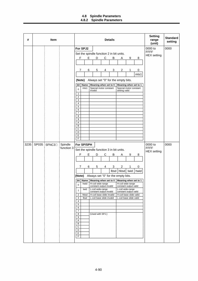
4.8 Spindle Parameters4.8.2 Spindle Parameters
4-90
# Item DetailsSettingrange(unit)
Standardsetting
For SPJ2Set the spindle function 2 in bit units.
0000 toFFFFHEX setting
0000
For SP/SPH3235 SP035 SFNC3∗ Spindlefunction 3 Set the spindle function 3 in bit units.
0000 toFFFFHEX setting
0000
bit Name Meaning when set to 0 Meaning when set to 1
0 mts1 Special motor constantinvalid
Special motor constantsetting valid
123456789ABCDEF
F E D C B A 9 8
7 6 5 4 3 2 1 0mts1
(Note) Always set "0" for the empty bits.
F E D C B A 9 8
7 6 5 4 3 2 1 0lbsd hbsd lwid hwid
(Note) Always set "0" for the empty bits.bit Name Meaning when set to 0 Meaning when set to 1
0 hwid H-coil wide-rangeconstant output invalid
H-coil wide-rangeconstant output valid
1 lwid L-coil wide-rangeconstant output invalid
L-coil wide-rangeconstant output valid
2 hbsd H-coil base slide invalid H-coil base slide valid3 lbsd L-coil base slide invalid L-coil base slide valid456789ABCDEF
(Used with SPJ.)
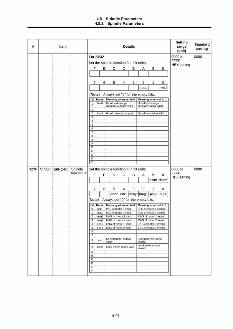
4.8 Spindle Parameters4.8.2 Spindle Parameters
4-91
# Item DetailsSettingrange(unit)
Standardsetting
For SPJ2Set the spindle function 3 in bit units.
0000 toFFFFHEX setting
0000
3236 SP036 SFNC4∗ Spindlefunction 4
Set the spindle function 4 in bit units. 0000 toFFFFHEX setting
0000
bit Name Meaning when set to 0 Meaning when set to 1
0 hwid H-coil wide-rangeconstant output invalid
H-coil wide-rangeconstant output valid
12 hbsd H-coil base slide invalid H-coil base slide valid3456789ABCDEF
F E D C B A 9 8dslm dssm
7 6 5 4 3 2 1 0enc2 enc1 mag2 mag1 plg2 plg1
F E D C B A 9 8
7 6 5 4 3 2 1 0hbsd hwid
(Note) Always set "0" for the empty bits.
(Note) Always set "0" for the empty bits.bit Name Meaning when set to 0 Meaning when set to 10 plg1 PLG of motor 1 valid PLG of motor 1 invalid1 plg2 PLG of motor 2 valid PLG of motor 2 invalid2 mag1 MAG of motor 1 valid MAG of motor 1 invalid3 mag2 MAG of motor 2 valid MAG of motor 2 invalid4 enc1 ENC of motor 1 valid ENC of motor 1 invalid5 enc2 ENC of motor 2 valid ENC of motor 2 invalid67
8 dssm Speedometer outputvalid
Speedometer outputinvalid
9 dslm Load meter output valid Load meter outputinvalid
ABCDEF
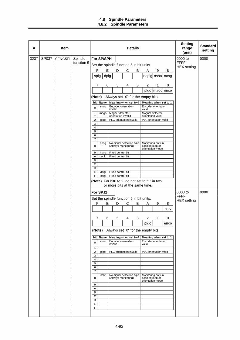
4.8 Spindle Parameters4.8.2 Spindle Parameters
4-92
# Item DetailsSettingrange(unit)
Standardsetting
For SP/SPH3237 SP037 SFNC5∗ Spindlefunction 5 Set the spindle function 5 in bit units.
0000 toFFFFHEX setting
0000
For SPJ2Set the spindle function 5 in bit units.
0000 toFFFFHEX setting
0000
F E D C B A 9 8splg dplg noplg nsno nosg
7 6 5 4 3 2 1 0plgo mago enco
F E D C B A 9 8nstv
7 6 5 4 3 2 1 0plgo enco
(Note) Always set "0" for the empty bits.
(Note) Always set "0" for the empty bits.bit Name Meaning when set to 0 Meaning when set to 1
0 enco Encoder orientationinvalid
Encoder orientationvalid
1 mago Magnet detectororientation invalid
Magnet detectororientation valid
2 plgo PLG orientation invalid PLG orientation valid34567
8nosg No-signal detection type
(Always monitoring)Monitoring only inposition loop ororientation-mode
9 nsno Fixed control bitA noplg Fixed control bitBCDE dplg Fixed control bitF splg Fixed control bit
(Note) For bit0 to 2, do not set to "1" in twoor more bits at the same time.
bit Name Meaning when set to 0 Meaning when set to 1
0 enco Encoder orientationinvalid
Encoder orientationvalid
12 plgo PLG orientation invalid PLG orientation valid34567
8nstv No-signal detection type
(Always monitoring)Monitoring only inposition loop ororientation mode
9ABCDEF
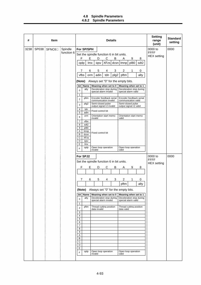
4.8 Spindle Parameters4.8.2 Spindle Parameters
4-93
# Item DetailsSettingrange(unit)
Standardsetting
For SP/SPH3238 SP038 SFNC6∗ Spindlefunction 6 Set the spindle function 6 in bit units.
0000 toFFFFHEX setting
0000
For SPJ2Set the spindle function 6 in bit units.
0000 toFFFFHEX setting
0000
F E D C B A 9 8
7 6 5 4 3 2 1 0pftm alty
(Note) Always set "0" for the empty bits.
F E D C B A 9 8oplp lmx iqsv XFzs dcsn lmnp pl80 sdt2
7 6 5 4 3 2 1 0vfbs orm adin tdn plg2 pftm alty
(Note) Always set "0" for the empty bits.bit Name Meaning when set to 0 Meaning when set to 1
0 alty Deceleration stop duringspecial alarm invalid
Deceleration stop duringspecial alarm valid
1
2 pftm Encoder feedback serialcommunication invalid
Encoder feedback serialcommunication valid
3 plg2 Semi-closed pulseoutput signal ×2 invalid
Semi-closed pulseoutput signal ×2 valid
4 tdn5 adin
Fixed control bit
6 orm Orientation start memoinvalid
Orientation start memovalid
7 vfbs8 sdt29 pl80A lmnpB dcsnC XFzsD iqsvE lmx
Fixed control bit
F oplp Open loop operationinvalid
Open loop operationvalid
bit Name Meaning when set to 0 Meaning when set to 1
0 alty Deceleration stop duringspecial alarm invalid
Deceleration stop duringspecial alarm valid
1
2 pftm Thread cutting positiondata invalid
Thread cutting positiondata valid
3456789ABCDE
F oplp Open loop operationinvalid
Open loop operationvalid
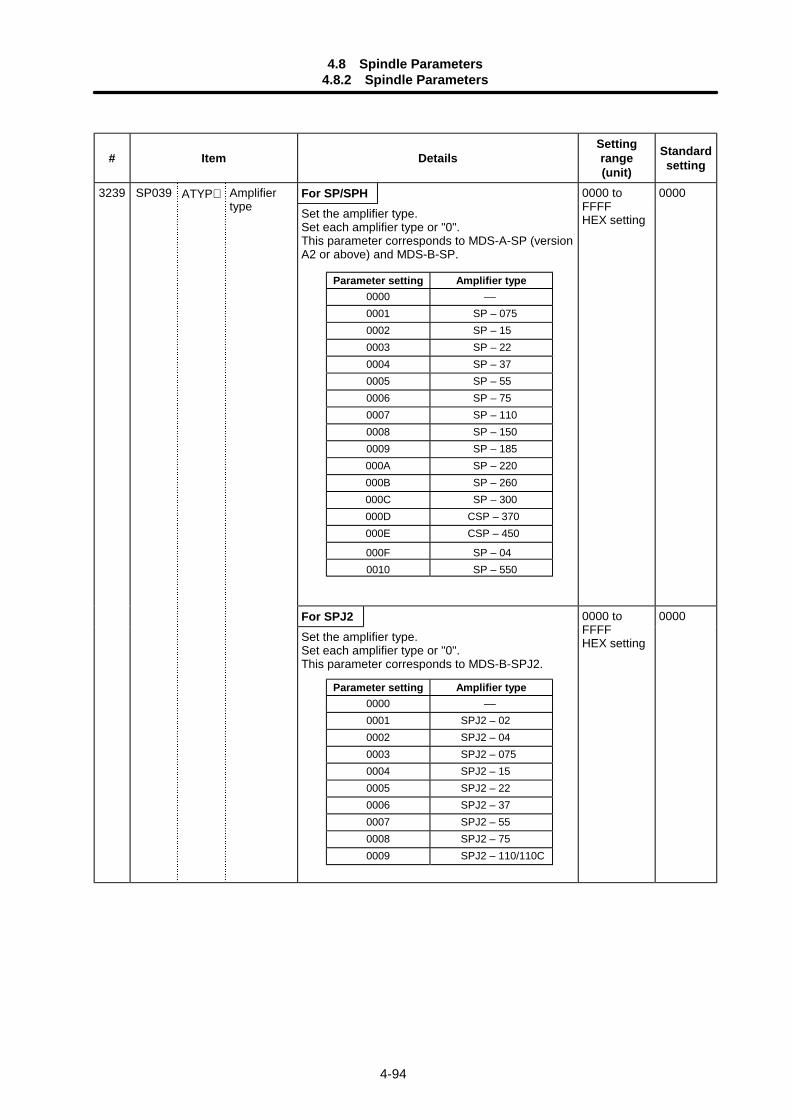
4.8 Spindle Parameters4.8.2 Spindle Parameters
4-94
# Item DetailsSettingrange(unit)
Standardsetting
For SP/SPHSet the amplifier type.Set each amplifier type or "0".This parameter corresponds to MDS-A-SP (versionA2 or above) and MDS-B-SP.
0000 toFFFFHEX setting
0000
For SPJ2
3239 SP039 ATYP∗ Amplifiertype
Set the amplifier type.Set each amplifier type or "0".This parameter corresponds to MDS-B-SPJ2.
0000 toFFFFHEX setting
0000
Parameter setting Amplifier type0000 ––0001 SPJ2 – 020002 SPJ2 – 040003 SPJ2 – 0750004 SPJ2 – 150005 SPJ2 – 220006 SPJ2 – 370007 SPJ2 – 550008 SPJ2 – 750009 SPJ2 – 110/110C
Parameter setting Amplifier type0000 ––0001 SP – 0750002 SP – 150003 SP – 220004 SP – 370005 SP – 550006 SP – 750007 SP – 1100008 SP – 1500009 SP – 185000A SP – 220000B SP – 260000C SP – 300000D CSP – 370000E CSP – 450
000F SP – 040010 SP – 550
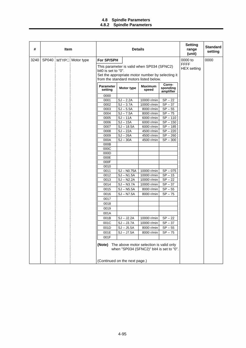
4.8 Spindle Parameters4.8.2 Spindle Parameters
4-95
# Item DetailsSettingrange(unit)
Standardsetting
MTYP∗ For SP/SPH3240 SP040 Motor type
This parameter is valid when SP034 (SFNC2)bit0 is set to "0".Set the appropriate motor number by selecting itfrom the standard motors listed below.
(Note) The above motor selection is valid onlywhen "SP034 (SFNC2)" bit4 is set to "0".
(Continued on the next page.)
0000 toFFFFHEX setting
0000
Parametersetting Motor type Maximum
speedCorre-
spondingamplifier
00000001 SJ – 2.2A 10000 r/min SP – 220002 SJ – 3.7A 10000 r/min SP – 370003 SJ – 5.5A 8000 r/min SP – 550004 SJ – 7.5A 8000 r/min SP – 750005 SJ – 11A 6000 r/min SP – 1100006 SJ – 15A 6000 r/min SP – 1500007 SJ – 18.5A 6000 r/min SP – 1850008 SJ – 22A 4500 r/min SP – 2200009 SJ – 26A 4500 r/min SP – 260000A SJ – 30A 4500 r/min SP – 300000B000C000D000E000F00100011 SJ – N0.75A 10000 r/min SP – 0750012 SJ – N1.5A 10000 r/min SP – 150013 SJ – N2.2A 10000 r/min SP – 220014 SJ – N3.7A 10000 r/min SP – 370015 SJ – N5.5A 8000 r/min SP – 550016 SJ – N7.5A 8000 r/min SP – 75001700180019001A001B SJ – J2.2A 10000 r/min SP – 22001C SJ – J3.7A 10000 r/min SP – 37001D SJ – J5.5A 8000 r/min SP – 55001E SJ – J7.5A 8000 r/min SP – 75001F
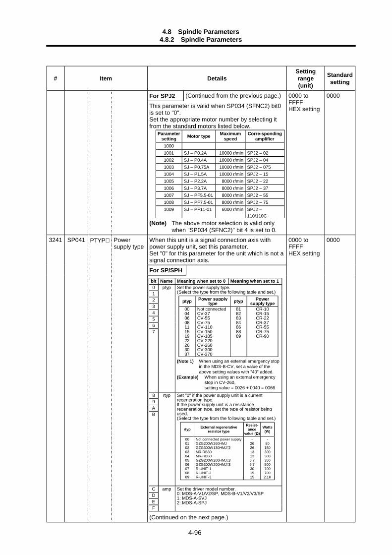
4.8 Spindle Parameters4.8.2 Spindle Parameters
4-96
# Item DetailsSettingrange(unit)
Standardsetting
For SPJ2 (Continued from the previous page.)
This parameter is valid when SP034 (SFNC2) bit0is set to "0".Set the appropriate motor number by selecting itfrom the standard motors listed below.
(Note) The above motor selection is valid onlywhen "SP034 (SFNC2)" bit 4 is set to 0.
0000 toFFFFHEX setting
0000
When this unit is a signal connection axis withpower supply unit, set this parameter.Set "0" for this parameter for the unit which is not asignal connection axis.
For SP/SPH
3241 SP041 PTYP∗ Powersupply type
(Continued on the next page.)
0000 toFFFFHEX setting
0000
Parametersetting Motor type Maximum
speedCorre-sponding
amplifier10001001 SJ – P0.2A 10000 r/min SPJ2 – 021002 SJ – P0.4A 10000 r/min SPJ2 – 041003 SJ – P0.75A 10000 r/min SPJ2 – 0751004 SJ – P1.5A 10000 r/min SPJ2 – 151005 SJ – P2.2A 8000 r/min SPJ2 – 221006 SJ – P3.7A 8000 r/min SPJ2 – 371007 SJ – PF5.5-01 8000 r/min SPJ2 – 551008 SJ – PF7.5-01 8000 r/min SPJ2 – 751009 SJ – PF11-01 6000 r/min SPJ2 –
110/110C
bit Name Meaning when set to 0 Meaning when set to 10 ptyp1234567
Set the power supply type.(Select the type from the following table and set.)
ptyp Power supplytype ptyp Power
supply type0004060811151922263037
Not connectedCV-37CV-55CV-75CV-110CV-150CV-185CV-220CV-260CV-300CV-370
81828384868889
CR-10CR-15CR-22CR-37CR-55CR-75CR-90
(Note 1) When using an external emergency stopin the MDS-B-CV, set a value of theabove setting values with "40" added.
(Example) When using an external emergencystop in CV-260,setting value = 0026 + 0040 = 0066
89AB
rtyp Set "0" if the power supply unit is a currentregeneration type.If the power supply unit is a resistanceregeneration type, set the type of resistor beingused.(Select the type from the following table and set.)
rtyp External regenerativeresistor type
Resist-ance
value (ΩΩΩΩ)Watts(W)
00010203040506070809
Not connected power supplyGZG200W260HMJGZG300W130HMJ∗ 2MR-RB30MR-RB50GZG200W200HMJ∗ 3GZG300W200HMJ∗ 3R-UNIT-1R-UNIT-2R-UNIT-3
-262613136.76.7301515
-801503005003505007007002.1K
CDEF
amp Set the driver model number.0: MDS-A-V1/V2/SP, MDS-B-V1/V2/V3/SP1: MDS-A-SVJ2: MDS-A-SPJ

4.8 Spindle Parameters4.8.2 Spindle Parameters
4-97
# Item DetailsSettingrange(unit)
Standardsetting
For SPJ2 (Continued from the previous page.)
Select a value from the following table accordingto the regenerative resistor being used.
(Note 1) This setting is also used when twoFCUA-RB75/2s are used in parallel aswell as one.
3242 SP042 CRNG∗ C-axisdetectorrange
This parameter is used to set the C-axis detectorrange.Set "0" for this parameter.
0 to 7 0
3243 SP043 TRNG∗ Synchronoustapping,spindlesynchronousdetectorrange
This parameter is used to set the synchronoustapping or spindle synchronous detector range.Set "0" for this parameter.
0 to 7 0
3244 SP044 TRANS∗ NC communi-cationfrequency
Set a frequency of data communication with NC. 0 to 32767 Standard: 0Special: 1028
3245 SP045 CSNT Dual cushiontimer
Set the cycle to add the increment values in thedual cushion process.Increasing the setting value elongates the dualcushion process, and the changes in the speedduring acceleration/deceleration becomesgradual.
0 to 1000 (ms)
0
3246 SP046 CSN2∗ Speedcommanddual cushion
For an acceleration/deceleration time constantdefined in SP019 (CSN1) , this parameter is usedto provide smooth movement only at the start ofacceleration/deceleration.As the value of this parameter is smaller, itmoves smoother but theacceleration/deceleration time becomes longer.To make this parameter invalid, set "0".
0 to 1000 0
3247 SP047 SDTR∗ Speeddetectionreset value
Set the reset hysteresis width for a speeddetection set value defined in SP020 (SDTS).
0 to 1000 (r/min)
30
3248 SP048 SUT∗ Speed reachrange
Set the speed deviation rate with respect to thecommanded speed for output of the speed reachsignal.
0 to 100 (%) 15
3249 SP049 TLM2 Torque limit 2 Set the torque limit rate for the torque limit signal010.
1 to 120 (%) 20
Settingvalue
Regenerative resistortype
Resist-ancevalue (ΩΩΩΩ)
Capacity(W)
000020002100220023002400250026002700280029002A002B002C00
–Not connectedFCUA-RB04FCUA-RB075FCUA-RB15FCUA-RB22FCUA-RB37FCUA-RB55FCUA-RB75/2R–UNIT–1R–UNIT–2R–UNIT–3R–UNIT–4R–UNIT–5
––
20010060402520
30/153015151010
––6080120155185340
340/680700700210021003100
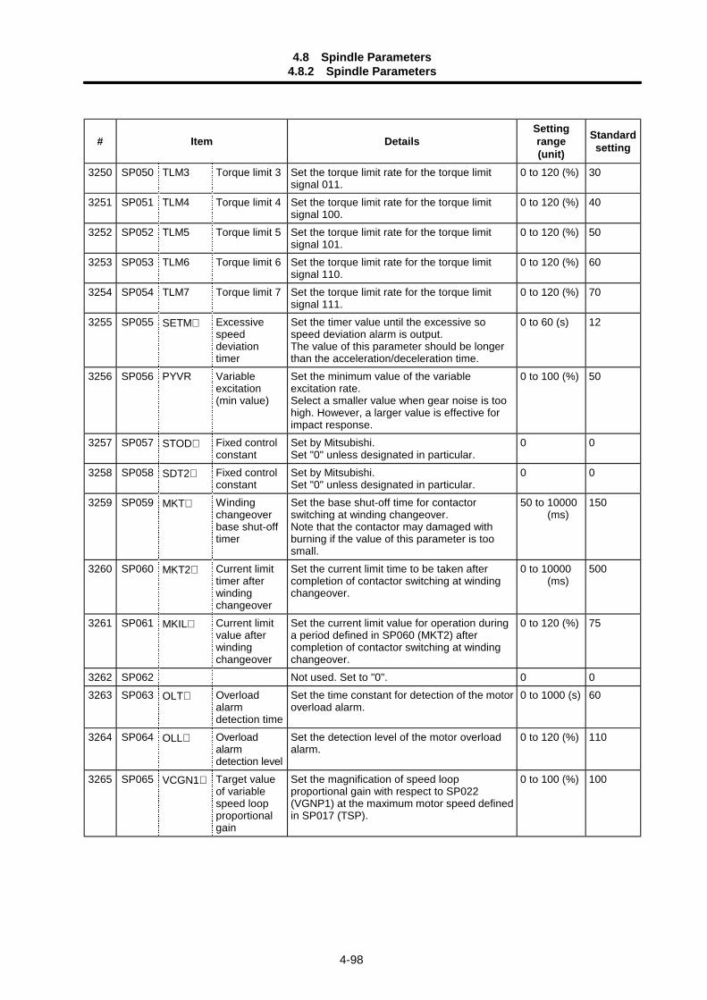
4.8 Spindle Parameters4.8.2 Spindle Parameters
4-98
# Item DetailsSettingrange(unit)
Standardsetting
3250 SP050 TLM3 Torque limit 3 Set the torque limit rate for the torque limitsignal 011.
0 to 120 (%) 30
3251 SP051 TLM4 Torque limit 4 Set the torque limit rate for the torque limitsignal 100.
0 to 120 (%) 40
3252 SP052 TLM5 Torque limit 5 Set the torque limit rate for the torque limitsignal 101.
0 to 120 (%) 50
3253 SP053 TLM6 Torque limit 6 Set the torque limit rate for the torque limitsignal 110.
0 to 120 (%) 60
3254 SP054 TLM7 Torque limit 7 Set the torque limit rate for the torque limitsignal 111.
0 to 120 (%) 70
3255 SP055 SETM∗ Excessivespeeddeviationtimer
Set the timer value until the excessive sospeed deviation alarm is output.The value of this parameter should be longerthan the acceleration/deceleration time.
0 to 60 (s) 12
3256 SP056 PYVR Variableexcitation(min value)
Set the minimum value of the variableexcitation rate.Select a smaller value when gear noise is toohigh. However, a larger value is effective forimpact response.
0 to 100 (%) 50
3257 SP057 STOD∗ Fixed controlconstant
Set by Mitsubishi.Set "0" unless designated in particular.
0 0
3258 SP058 SDT2∗ Fixed controlconstant
Set by Mitsubishi.Set "0" unless designated in particular.
0 0
3259 SP059 MKT∗ Windingchangeoverbase shut-offtimer
Set the base shut-off time for contactorswitching at winding changeover.Note that the contactor may damaged withburning if the value of this parameter is toosmall.
50 to 10000 (ms)
150
3260 SP060 MKT2∗ Current limittimer afterwindingchangeover
Set the current limit time to be taken aftercompletion of contactor switching at windingchangeover.
0 to 10000 (ms)
500
3261 SP061 MKIL∗ Current limitvalue afterwindingchangeover
Set the current limit value for operation duringa period defined in SP060 (MKT2) aftercompletion of contactor switching at windingchangeover.
0 to 120 (%) 75
3262 SP062 Not used. Set to "0". 0 03263 SP063 OLT∗ Overload
alarmdetection time
Set the time constant for detection of the motoroverload alarm.
0 to 1000 (s) 60
3264 SP064 OLL∗ Overloadalarmdetection level
Set the detection level of the motor overloadalarm.
0 to 120 (%) 110
3265 SP065 VCGN1∗ Target valueof variablespeed loopproportionalgain
Set the magnification of speed loopproportional gain with respect to SP022(VGNP1) at the maximum motor speed definedin SP017 (TSP).
0 to 100 (%) 100
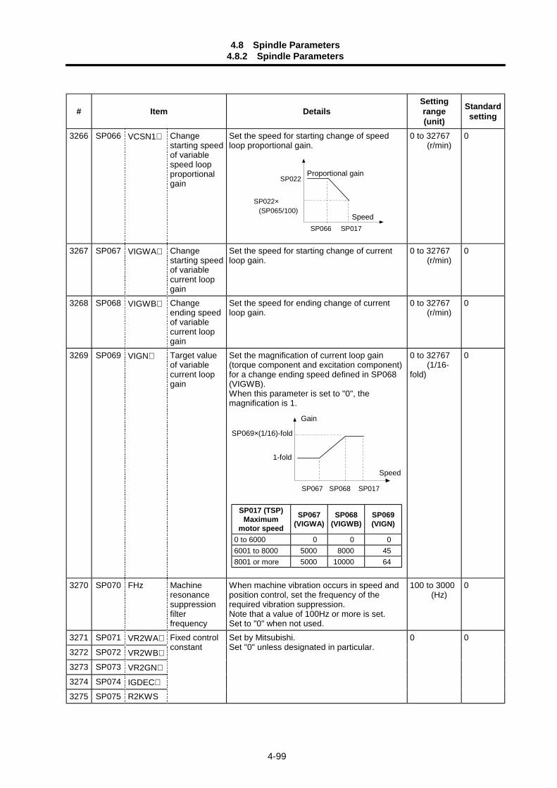
4.8 Spindle Parameters4.8.2 Spindle Parameters
4-99
# Item DetailsSettingrange(unit)
Standardsetting
3266 SP066 VCSN1∗ Changestarting speedof variablespeed loopproportionalgain
Set the speed for starting change of speedloop proportional gain.
SP066 SP017
SP022
SP022× (SP065/100)
0 to 32767 (r/min)
0
3267 SP067 VIGWA∗ Changestarting speedof variablecurrent loopgain
Set the speed for starting change of currentloop gain.
0 to 32767 (r/min)
0
3268 SP068 VIGWB∗ Changeending speedof variablecurrent loopgain
Set the speed for ending change of currentloop gain.
0 to 32767 (r/min)
0
3269 SP069 VIGN∗ Target valueof variablecurrent loopgain
Set the magnification of current loop gain(torque component and excitation component)for a change ending speed defined in SP068(VIGWB).When this parameter is set to "0", themagnification is 1.
SP067 SP017SP068
0 to 32767 (1/16-fold)
0
3270 SP070 FHz Machineresonancesuppressionfilterfrequency
When machine vibration occurs in speed andposition control, set the frequency of therequired vibration suppression.Note that a value of 100Hz or more is set.Set to "0" when not used.
100 to 3000 (Hz)
0
3271 SP071 VR2WA∗
3272 SP072 VR2WB∗
3273 SP073 VR2GN∗
3274 SP074 IGDEC∗
3275 SP075 R2KWS
Fixed controlconstant
Set by Mitsubishi.Set "0" unless designated in particular.
0 0
Speed
Proportional gain
Speed
Gain
SP017 (TSP)Maximum
motor speed
SP067(VIGWA)
SP068(VIGWB)
SP069(VIGN)
0 to 6000 0 0 06001 to 8000 5000 8000 458001 or more 5000 10000 64
1-fold
SP069×(1/16)-fold
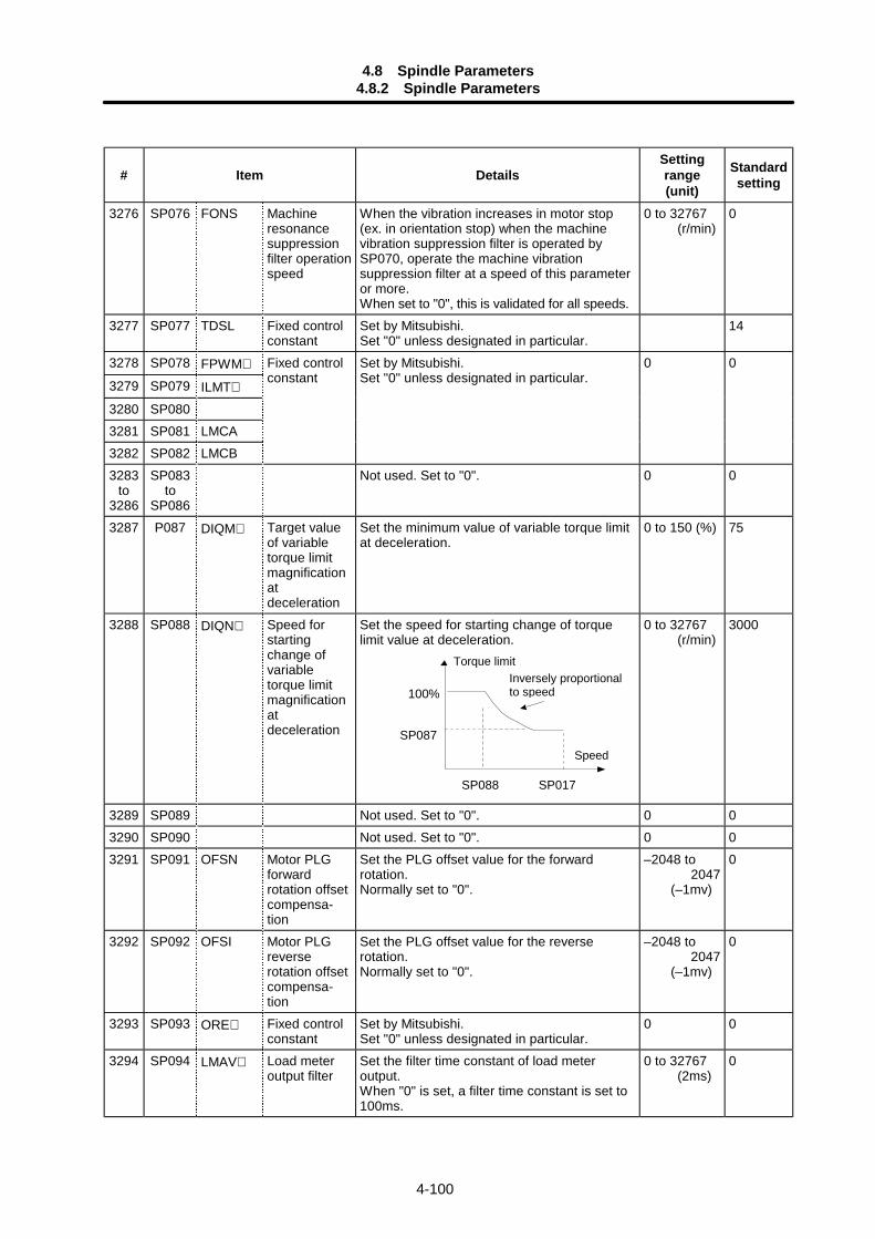
4.8 Spindle Parameters4.8.2 Spindle Parameters
4-100
# Item DetailsSettingrange(unit)
Standardsetting
3276 SP076 FONS Machineresonancesuppressionfilter operationspeed
When the vibration increases in motor stop(ex. in orientation stop) when the machinevibration suppression filter is operated bySP070, operate the machine vibrationsuppression filter at a speed of this parameteror more.When set to "0", this is validated for all speeds.
0 to 32767 (r/min)
0
3277 SP077 TDSL Fixed controlconstant
Set by Mitsubishi.Set "0" unless designated in particular.
14
3278 SP078 FPWM∗
3279 SP079 ILMT∗
3280 SP0803281 SP081 LMCA3282 SP082 LMCB
Fixed controlconstant
Set by Mitsubishi.Set "0" unless designated in particular.
0 0
3283to
3286
SP083to
SP086
Not used. Set to "0". 0 0
3287 P087 DIQM∗ Target valueof variabletorque limitmagnificationatdeceleration
Set the minimum value of variable torque limitat deceleration.
0 to 150 (%) 75
3288 SP088 DIQN∗ Speed forstartingchange ofvariabletorque limitmagnificationatdeceleration
Set the speed for starting change of torquelimit value at deceleration.
SP088 SP017
100%
SP087
0 to 32767 (r/min)
3000
3289 SP089 Not used. Set to "0". 0 03290 SP090 Not used. Set to "0". 0 03291 SP091 OFSN Motor PLG
forwardrotation offsetcompensa-tion
Set the PLG offset value for the forwardrotation.Normally set to "0".
–2048 to 2047 (–1mv)
0
3292 SP092 OFSI Motor PLGreverserotation offsetcompensa-tion
Set the PLG offset value for the reverserotation.Normally set to "0".
–2048 to 2047 (–1mv)
0
3293 SP093 ORE∗ Fixed controlconstant
Set by Mitsubishi.Set "0" unless designated in particular.
0 0
3294 SP094 LMAV∗ Load meteroutput filter
Set the filter time constant of load meteroutput.When "0" is set, a filter time constant is set to100ms.
0 to 32767 (2ms)
0
Speed
Inversely proportionalto speed
Torque limit
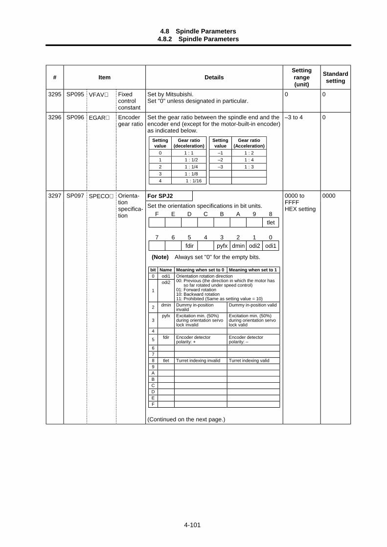
4.8 Spindle Parameters4.8.2 Spindle Parameters
4-101
# Item DetailsSettingrange(unit)
Standardsetting
3295 SP095 VFAV∗ Fixedcontrolconstant
Set by Mitsubishi.Set "0" unless designated in particular.
0 0
3296 SP096 EGAR∗ Encodergear ratio
Set the gear ratio between the spindle end and theencoder end (except for the motor-built-in encoder)as indicated below.
Settingvalue
Gear ratio(Acceleration)
–1 1 : 2–2 1 : 4–3 1 : 3
Settingvalue
Gear ratio(deceleration)
0 1 : 11 1 : 1/22 1 : 1/43 1 : 1/84 1 : 1/16
–3 to 4 0
For SPJ23297 SP097 SPECO∗ Orienta-tionspecifica-tion
Set the orientation specifications in bit units.
(Continued on the next page.)
0000 toFFFFHEX setting
0000
F E D C B A 9 8tlet
7 6 5 4 3 2 1 0fdir pyfx dmin odi2 odi1
(Note) Always set "0" for the empty bits.
bit Name Meaning when set to 0 Meaning when set to 10 odi1
1
odi2Orientation rotation direction00: Previous (the direction in which the motor has
so far rotated under speed control)01: Forward rotation10: Backward rotation11: Prohibited (Same as setting value = 10)
2 dmin Dummy in-positioninvalid
Dummy in-position valid
3pyfx Excitation min. (50%)
during orientation servolock invalid
Excitation min. (50%)during orientation servolock valid
4
5 fdir Encoder detectorpolarity: +
Encoder detectorpolarity: –
678 tlet Turret indexing invalid Turret indexing valid9ABCDEF
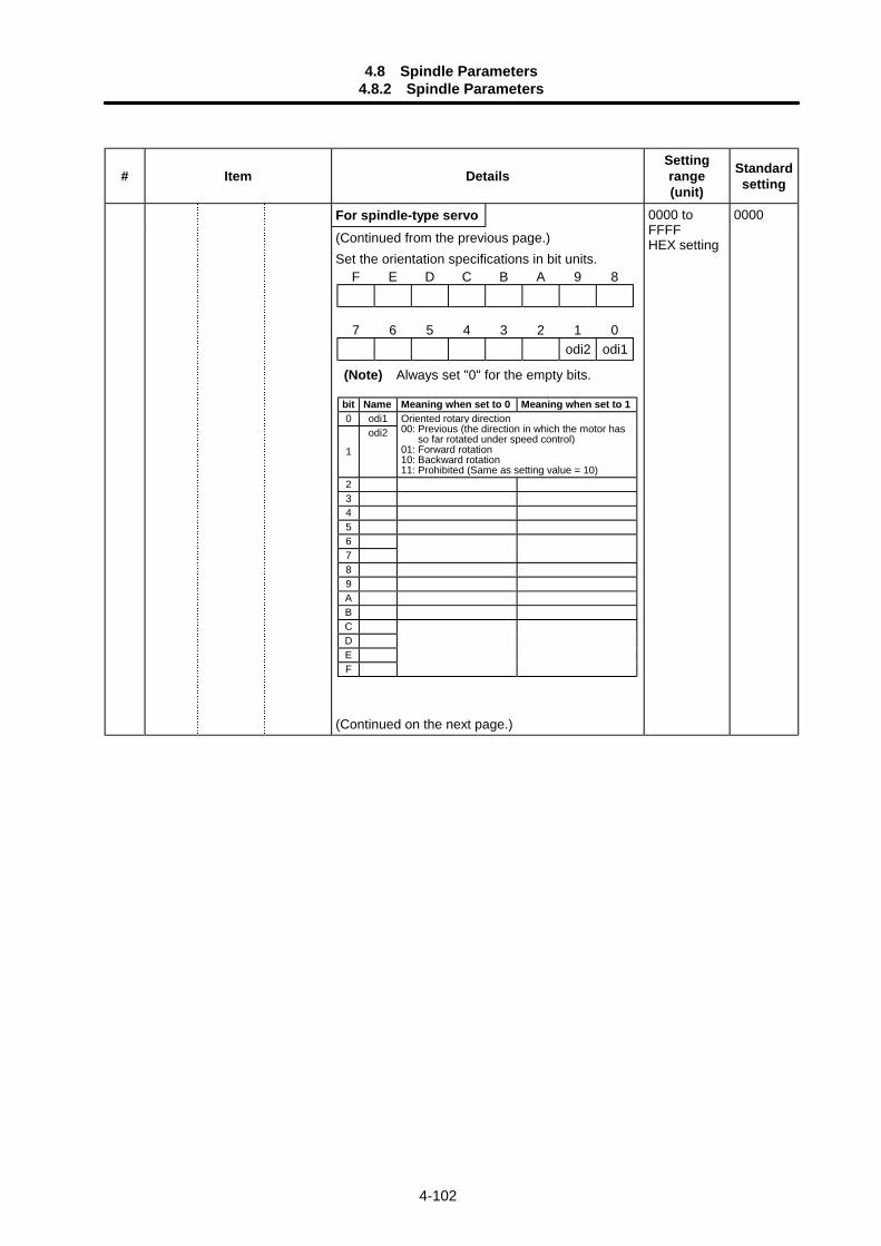
4.8 Spindle Parameters4.8.2 Spindle Parameters
4-102
# Item DetailsSettingrange(unit)
Standardsetting
For spindle-type servo(Continued from the previous page.)Set the orientation specifications in bit units.
(Continued on the next page.)
0000 toFFFFHEX setting
0000
F E D C B A 9 8
7 6 5 4 3 2 1 0odi2 odi1
(Note) Always set "0" for the empty bits.
bit Name Meaning when set to 0 Meaning when set to 10 odi1
1
odi2Oriented rotary direction00: Previous (the direction in which the motor has
so far rotated under speed control)01: Forward rotation10: Backward rotation11: Prohibited (Same as setting value = 10)
23456789ABCDEF
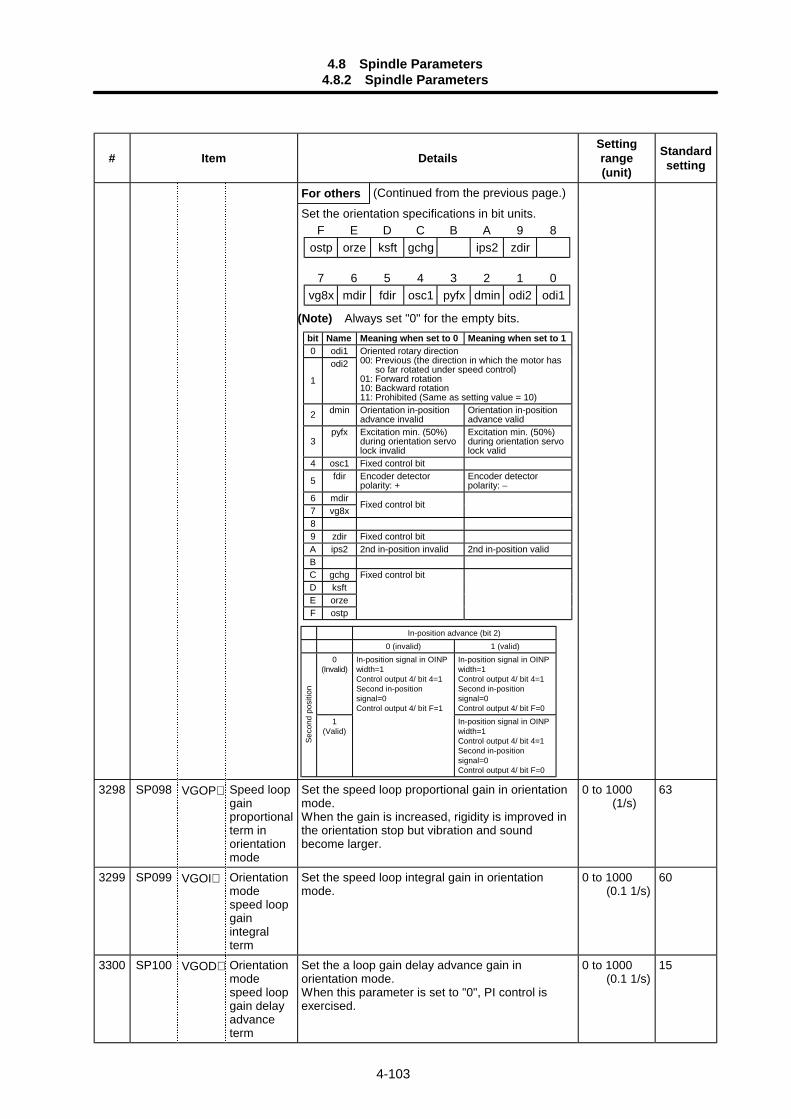
4.8 Spindle Parameters4.8.2 Spindle Parameters
4-103
# Item DetailsSettingrange(unit)
Standardsetting
For others (Continued from the previous page.)
Set the orientation specifications in bit units.
3298 SP098 VGOP∗ Speed loopgainproportionalterm inorientationmode
Set the speed loop proportional gain in orientationmode.When the gain is increased, rigidity is improved inthe orientation stop but vibration and soundbecome larger.
0 to 1000 (1/s)
63
3299 SP099 VGOI∗ Orientationmodespeed loopgainintegralterm
Set the speed loop integral gain in orientationmode.
0 to 1000 (0.1 1/s)
60
3300 SP100 VGOD∗ Orientationmodespeed loopgain delayadvanceterm
Set the a loop gain delay advance gain inorientation mode.When this parameter is set to "0", PI control isexercised.
0 to 1000 (0.1 1/s)
15
F E D C B A 9 8ostp orze ksft gchg ips2 zdir
7 6 5 4 3 2 1 0vg8x mdir fdir osc1 pyfx dmin odi2 odi1
(Note) Always set "0" for the empty bits.bit Name Meaning when set to 0 Meaning when set to 10 odi1
1
odi2Oriented rotary direction00: Previous (the direction in which the motor has
so far rotated under speed control)01: Forward rotation10: Backward rotation11: Prohibited (Same as setting value = 10)
2 dmin Orientation in-positionadvance invalid
Orientation in-positionadvance valid
3pyfx Excitation min. (50%)
during orientation servolock invalid
Excitation min. (50%)during orientation servolock valid
4 osc1 Fixed control bit
5 fdir Encoder detectorpolarity: +
Encoder detectorpolarity: –
6 mdir7 vg8x
Fixed control bit
89 zdir Fixed control bitA ips2 2nd in-position invalid 2nd in-position validBC gchgD ksftE orzeF ostp
Fixed control bit
In-position advance (bit 2)0 (invalid) 1 (valid)
0(Invalid)
In-position signal in OINPwidth=1Control output 4/ bit 4=1Second in-positionsignal=0Control output 4/ bit F=0
Seco
nd p
ositi
on
1(Valid)
In-position signal in OINPwidth=1Control output 4/ bit 4=1Second in-positionsignal=0Control output 4/ bit F=1
In-position signal in OINPwidth=1Control output 4/ bit 4=1Second in-positionsignal=0Control output 4/ bit F=0
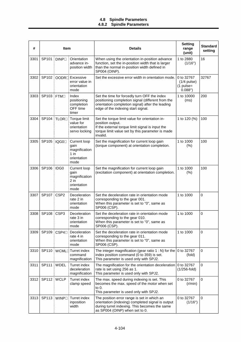
4.8 Spindle Parameters4.8.2 Spindle Parameters
4-104
# Item DetailsSettingrange(unit)
Standardsetting
3301 SP101 DINP∗ Orientationadvance in-position width
When using the orientation in-position advancefunction, set the in-position width that is largerthan the normal in-position width defined inSP004 (OINP).
1 to 2880 (1/16°)
16
3302 SP102 OODR∗ Excessiveerror value inorientationmode
Set the excessive error width in orientation mode. 0 to 32767 (1/4 pulse)(1 pulse= 0.088°)
32767
3303 SP103 FTM∗ IndexpositioningcompletionOFF timetimer
Set the time for forcedly turn OFF the indexpositioning completion signal (different from theorientation completion signal) after the leadingedge of the indexing start signal.
1 to 10000 (ms)
200
3304 SP104 TLOR∗ Torque limitvalue fororientationservo locking
Set the torque limit value for orientation in-position output.If the external torque limit signal is input thetorque limit value set by this parameter is madeinvalid.
1 to 120 (%) 100
3305 SP105 IQG0∗ Current loopgainmagnification1 inorientationmode
Set the magnification for current loop gain(torque component) at orientation completion.
1 to 1000 (%)
100
3306 SP106 IDG0 Current loopgainmagnification2 inorientationmode
Set the magnification for current loop gain(excitation component) at orientation completion.
1 to 1000 (%)
100
3307 SP107 CSP2 Decelerationrate 2 inorientationmode
Set the deceleration rate in orientation modecorresponding to the gear 001.When this parameter is set to "0", same asSP006 (CSP).
1 to 1000 0
3308 SP108 CSP3 Decelerationrate 3 inorientationmode
Set the deceleration rate in orientation modecorresponding to the gear 010.When this parameter is set to "0", same asSP006 (CSP).
1 to 1000 0
3309 SP109 CSP4∗ Decelerationrate 4 inorientationmode
Set the deceleration rate in orientation modecorresponding to the gear 011.When this parameter is set to "0", same asSP006 (CSP).
1 to 1000 0
3310 SP110 WCML∗ Turret indexcommandmagnification
The integer magnification (gear ratio 1 : N) for theindex position command (0 to 359) is set.This parameter is used only with SPJ2.
0 to 32767 (fold)
0
3311 SP111 WDEL Turret indexdecelerationmagnification
The magnification for the orientation decelerationrate is set using 256 as 1.This parameter is used only with SPJ2.
0 to 32767(1/256-fold)
0
3312 SP112 WCLP Turret indexclamp speed
The max. speed during indexing is set. Thisbecomes the max. speed of the motor when setto 0.This parameter is used only with SPJ2.
0 to 32767 (r/min)
0
3313 SP113 WINP∗ Turret indexinpositionwidth
The position error range is set in which anorientation (indexing) completed signal is outputduring turret indexing. This becomes the sameas SP004 (OINP) when set to 0.
0 to 32767 (1/16°)
0
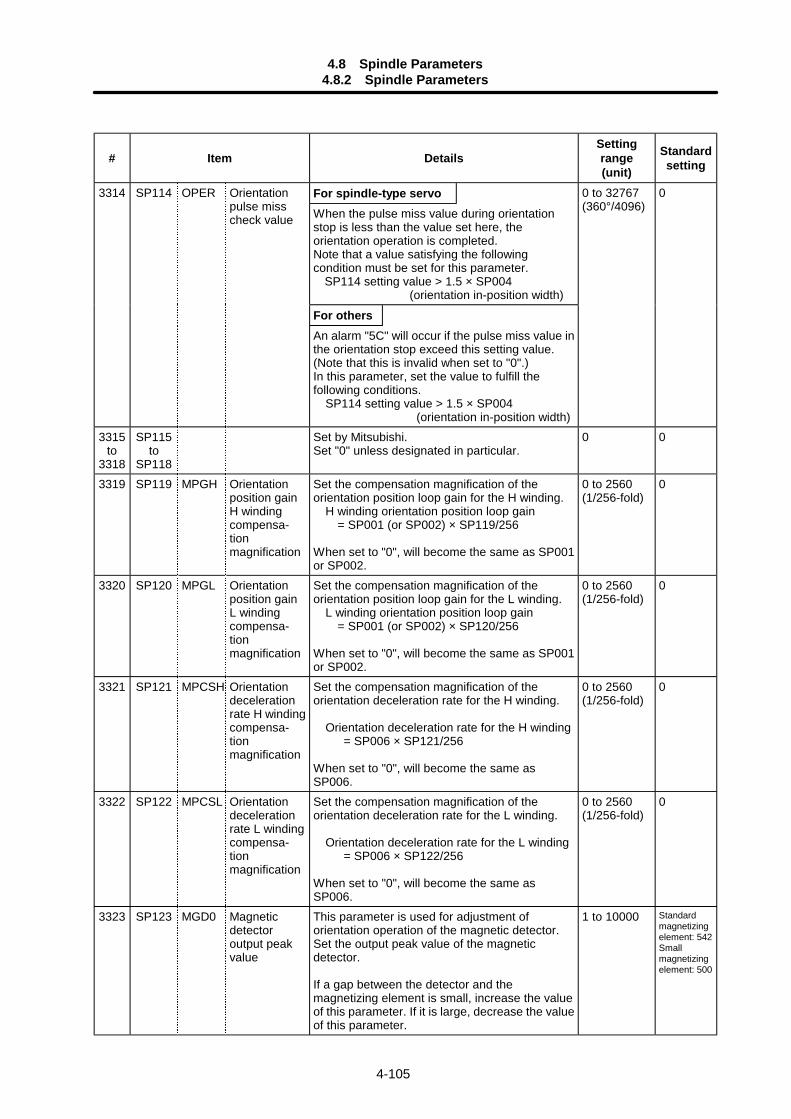
4.8 Spindle Parameters4.8.2 Spindle Parameters
4-105
# Item DetailsSettingrange(unit)
Standardsetting
For spindle-type servoWhen the pulse miss value during orientationstop is less than the value set here, theorientation operation is completed.Note that a value satisfying the followingcondition must be set for this parameter.
SP114 setting value > 1.5 × SP004 (orientation in-position width)
For others
3314 SP114 OPER Orientationpulse misscheck value
An alarm "5C" will occur if the pulse miss value inthe orientation stop exceed this setting value.(Note that this is invalid when set to "0".)In this parameter, set the value to fulfill thefollowing conditions. SP114 setting value > 1.5 × SP004 (orientation in-position width)
0 to 32767(360°/4096)
0
3315to
3318
SP115to
SP118
Set by Mitsubishi.Set "0" unless designated in particular.
0 0
3319 SP119 MPGH Orientationposition gainH windingcompensa-tionmagnification
Set the compensation magnification of theorientation position loop gain for the H winding. H winding orientation position loop gain = SP001 (or SP002) × SP119/256
When set to "0", will become the same as SP001or SP002.
0 to 2560(1/256-fold)
0
3320 SP120 MPGL Orientationposition gainL windingcompensa-tionmagnification
Set the compensation magnification of theorientation position loop gain for the L winding. L winding orientation position loop gain = SP001 (or SP002) × SP120/256
When set to "0", will become the same as SP001or SP002.
0 to 2560(1/256-fold)
0
3321 SP121 MPCSH Orientationdecelerationrate H windingcompensa-tionmagnification
Set the compensation magnification of theorientation deceleration rate for the H winding.
Orientation deceleration rate for the H winding = SP006 × SP121/256
When set to "0", will become the same asSP006.
0 to 2560(1/256-fold)
0
3322 SP122 MPCSL Orientationdecelerationrate L windingcompensa-tionmagnification
Set the compensation magnification of theorientation deceleration rate for the L winding.
Orientation deceleration rate for the L winding = SP006 × SP122/256
When set to "0", will become the same asSP006.
0 to 2560(1/256-fold)
0
3323 SP123 MGD0 Magneticdetectoroutput peakvalue
This parameter is used for adjustment oforientation operation of the magnetic detector.Set the output peak value of the magneticdetector.
If a gap between the detector and themagnetizing element is small, increase the valueof this parameter. If it is large, decrease the valueof this parameter.
1 to 10000 Standardmagnetizingelement: 542Smallmagnetizingelement: 500
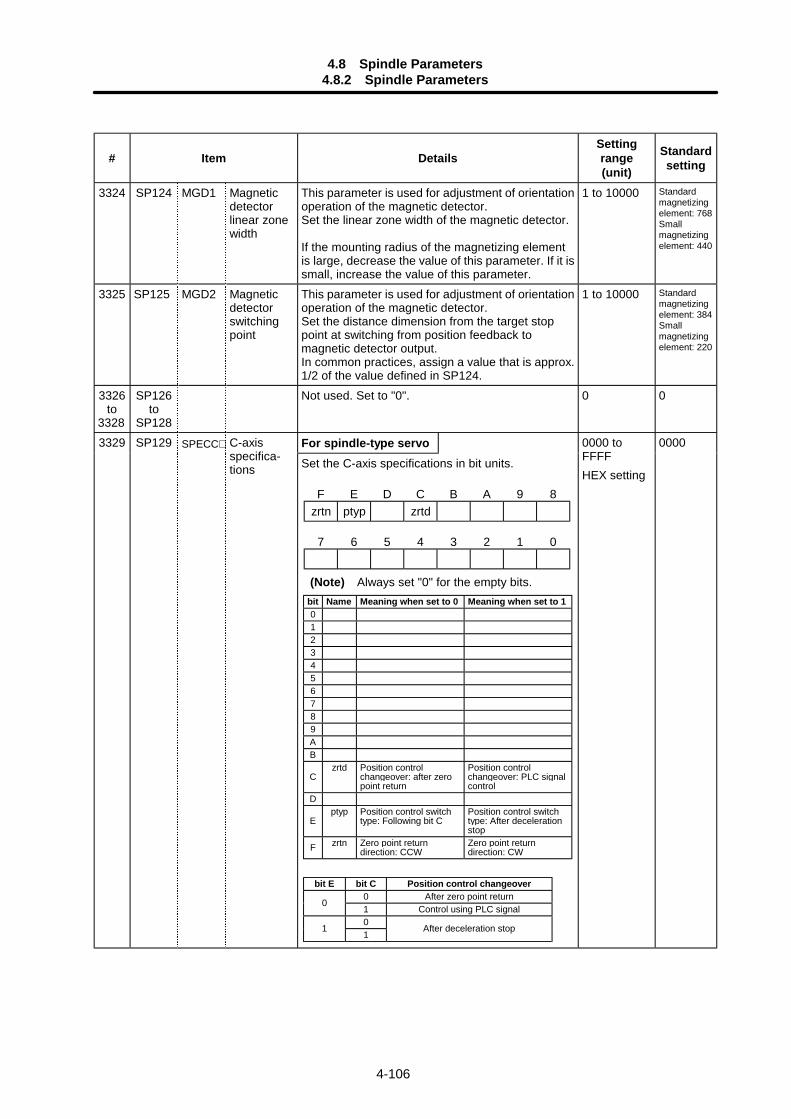
4.8 Spindle Parameters4.8.2 Spindle Parameters
4-106
# Item DetailsSettingrange(unit)
Standardsetting
3324 SP124 MGD1 Magneticdetectorlinear zonewidth
This parameter is used for adjustment of orientationoperation of the magnetic detector.Set the linear zone width of the magnetic detector.
If the mounting radius of the magnetizing elementis large, decrease the value of this parameter. If it issmall, increase the value of this parameter.
1 to 10000 Standardmagnetizingelement: 768Smallmagnetizingelement: 440
3325 SP125 MGD2 Magneticdetectorswitchingpoint
This parameter is used for adjustment of orientationoperation of the magnetic detector.Set the distance dimension from the target stoppoint at switching from position feedback tomagnetic detector output.In common practices, assign a value that is approx.1/2 of the value defined in SP124.
1 to 10000 Standardmagnetizingelement: 384Smallmagnetizingelement: 220
3326to
3328
SP126to
SP128
Not used. Set to "0". 0 0
For spindle-type servo3329 SP129 SPECC∗ C-axisspecifica-tions Set the C-axis specifications in bit units.
0000 toFFFFHEX setting
0000
F E D C B A 9 8zrtn ptyp zrtd
7 6 5 4 3 2 1 0
(Note) Always set "0" for the empty bits.bit Name Meaning when set to 0 Meaning when set to 10123456789AB
Czrtd Position control
changeover: after zeropoint return
Position controlchangeover: PLC signalcontrol
D
Eptyp Position control switch
type: Following bit CPosition control switchtype: After decelerationstop
F zrtn Zero point returndirection: CCW
Zero point returndirection: CW
bit E bit C Position control changeover0 After zero point return
01 Control using PLC signal0
11
After deceleration stop
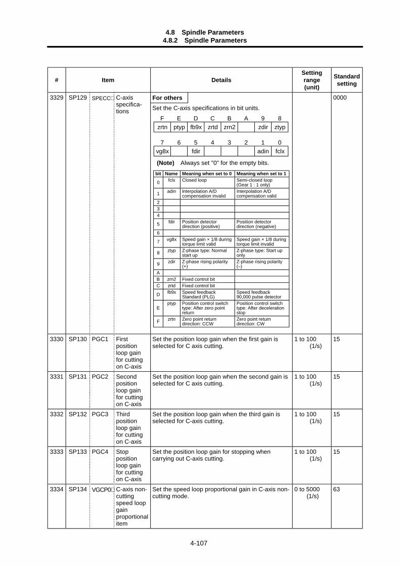
4.8 Spindle Parameters4.8.2 Spindle Parameters
4-107
# Item DetailsSettingrange(unit)
Standardsetting
For others3329 SP129 SPECC∗ C-axisspecifica-tions Set the C-axis specifications in bit units.
0000
3330 SP130 PGC1 Firstpositionloop gainfor cuttingon C-axis
Set the position loop gain when the first gain isselected for C axis cutting.
1 to 100 (1/s)
15
3331 SP131 PGC2 Secondpositionloop gainfor cuttingon C-axis
Set the position loop gain when the second gain isselected for C axis cutting.
1 to 100 (1/s)
15
3332 SP132 PGC3 Thirdpositionloop gainfor cuttingon C-axis
Set the position loop gain when the third gain isselected for C-axis cutting.
1 to 100 (1/s)
15
3333 SP133 PGC4 Stoppositionloop gainfor cuttingon C-axis
Set the position loop gain for stopping whencarrying out C-axis cutting.
1 to 100 (1/s)
15
3334 SP134 VGCP0∗ C-axis non-cuttingspeed loopgainproportionalitem
Set the speed loop proportional gain in C-axis non-cutting mode.
0 to 5000 (1/s)
63
F E D C B A 9 8zrtn ptyp fb9x zrtd zrn2 zdir ztyp
7 6 5 4 3 2 1 0vg8x fdir adin fclx
(Note) Always set "0" for the empty bits.
bit Name Meaning when set to 0 Meaning when set to 1
0 fclx Closed loop Semi-closed loop(Gear 1 : 1 only)
1 adin Interpolation A/Dcompensation invalid
Interpolation A/Dcompensation valid
234
5 fdir Position detectordirection (positive)
Position detectordirection (negative)
6
7 vg8x Speed gain × 1/8 duringtorque limit valid
Speed gain × 1/8 duringtorque limit invalid
8 ztyp Z-phase type: Normalstart up
Z-phase type: Start uponly
9 zdir Z-phase rising polarity(+)
Z-phase rising polarity(–)
AB zrn2 Fixed control bitC zrtd Fixed control bit
D fb9x Speed feedbackStandard (PLG)
Speed feedback90,000 pulse detector
Eptyp Position control switch
type: After zero pointreturn
Position control switchtype: After decelerationstop
F zrtn Zero point returndirection: CCW
Zero point returndirection: CW
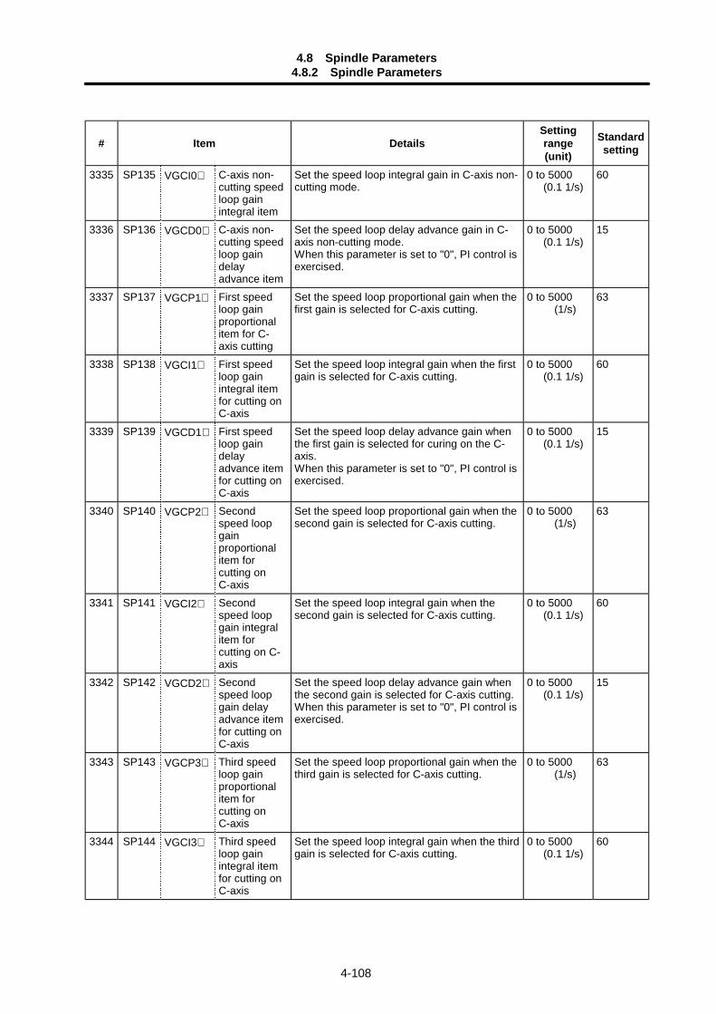
4.8 Spindle Parameters4.8.2 Spindle Parameters
4-108
# Item DetailsSettingrange(unit)
Standardsetting
3335 SP135 VGCI0∗ C-axis non-cutting speedloop gainintegral item
Set the speed loop integral gain in C-axis non-cutting mode.
0 to 5000 (0.1 1/s)
60
3336 SP136 VGCD0∗ C-axis non-cutting speedloop gaindelayadvance item
Set the speed loop delay advance gain in C-axis non-cutting mode.When this parameter is set to "0", PI control isexercised.
0 to 5000 (0.1 1/s)
15
3337 SP137 VGCP1∗ First speedloop gainproportionalitem for C-axis cutting
Set the speed loop proportional gain when thefirst gain is selected for C-axis cutting.
0 to 5000 (1/s)
63
3338 SP138 VGCI1∗ First speedloop gainintegral itemfor cutting onC-axis
Set the speed loop integral gain when the firstgain is selected for C-axis cutting.
0 to 5000 (0.1 1/s)
60
3339 SP139 VGCD1∗ First speedloop gaindelayadvance itemfor cutting onC-axis
Set the speed loop delay advance gain whenthe first gain is selected for curing on the C-axis.When this parameter is set to "0", PI control isexercised.
0 to 5000 (0.1 1/s)
15
3340 SP140 VGCP2∗ Secondspeed loopgainproportionalitem forcutting onC-axis
Set the speed loop proportional gain when thesecond gain is selected for C-axis cutting.
0 to 5000 (1/s)
63
3341 SP141 VGCI2∗ Secondspeed loopgain integralitem forcutting on C-axis
Set the speed loop integral gain when thesecond gain is selected for C-axis cutting.
0 to 5000 (0.1 1/s)
60
3342 SP142 VGCD2∗ Secondspeed loopgain delayadvance itemfor cutting onC-axis
Set the speed loop delay advance gain whenthe second gain is selected for C-axis cutting.When this parameter is set to "0", PI control isexercised.
0 to 5000 (0.1 1/s)
15
3343 SP143 VGCP3∗ Third speedloop gainproportionalitem forcutting onC-axis
Set the speed loop proportional gain when thethird gain is selected for C-axis cutting.
0 to 5000 (1/s)
63
3344 SP144 VGCI3∗ Third speedloop gainintegral itemfor cutting onC-axis
Set the speed loop integral gain when the thirdgain is selected for C-axis cutting.
0 to 5000 (0.1 1/s)
60
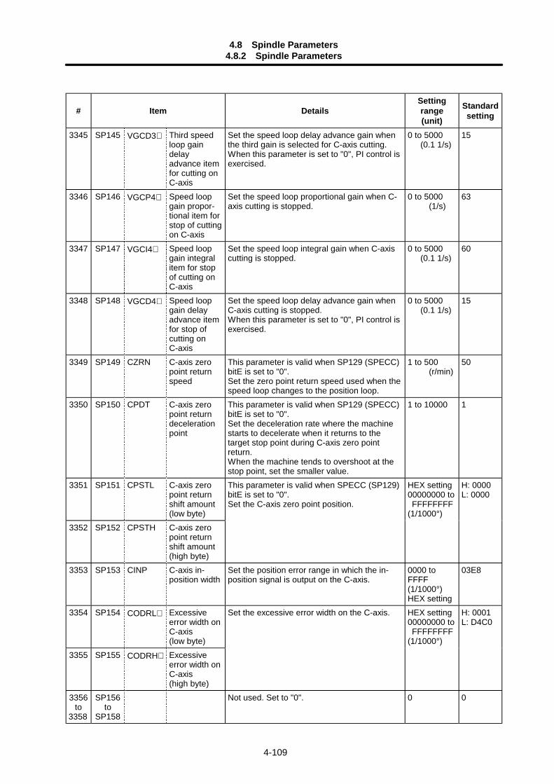
4.8 Spindle Parameters4.8.2 Spindle Parameters
4-109
# Item DetailsSettingrange(unit)
Standardsetting
3345 SP145 VGCD3∗ Third speedloop gaindelayadvance itemfor cutting onC-axis
Set the speed loop delay advance gain whenthe third gain is selected for C-axis cutting.When this parameter is set to "0", PI control isexercised.
0 to 5000 (0.1 1/s)
15
3346 SP146 VGCP4∗ Speed loopgain propor-tional item forstop of cuttingon C-axis
Set the speed loop proportional gain when C-axis cutting is stopped.
0 to 5000 (1/s)
63
3347 SP147 VGCI4∗ Speed loopgain integralitem for stopof cutting onC-axis
Set the speed loop integral gain when C-axiscutting is stopped.
0 to 5000 (0.1 1/s)
60
3348 SP148 VGCD4∗ Speed loopgain delayadvance itemfor stop ofcutting onC-axis
Set the speed loop delay advance gain whenC-axis cutting is stopped.When this parameter is set to "0", PI control isexercised.
0 to 5000 (0.1 1/s)
15
3349 SP149 CZRN C-axis zeropoint returnspeed
This parameter is valid when SP129 (SPECC)bitE is set to "0".Set the zero point return speed used when thespeed loop changes to the position loop.
1 to 500 (r/min)
50
3350 SP150 CPDT C-axis zeropoint returndecelerationpoint
This parameter is valid when SP129 (SPECC)bitE is set to "0".Set the deceleration rate where the machinestarts to decelerate when it returns to thetarget stop point during C-axis zero pointreturn.When the machine tends to overshoot at thestop point, set the smaller value.
1 to 10000 1
3351 SP151 CPSTL C-axis zeropoint returnshift amount(low byte)
3352 SP152 CPSTH C-axis zeropoint returnshift amount(high byte)
This parameter is valid when SPECC (SP129)bitE is set to "0".Set the C-axis zero point position.
HEX setting00000000 to FFFFFFFF(1/1000°)
H: 0000L: 0000
3353 SP153 CINP C-axis in-position width
Set the position error range in which the in-position signal is output on the C-axis.
0000 toFFFF(1/1000°)HEX setting
03E8
3354 SP154 CODRL∗ Excessiveerror width onC-axis(low byte)
3355 SP155 CODRH∗ Excessiveerror width onC-axis(high byte)
Set the excessive error width on the C-axis. HEX setting00000000 to FFFFFFFF(1/1000°)
H: 0001L: D4C0
3356to
3358
SP156to
SP158
Not used. Set to "0". 0 0
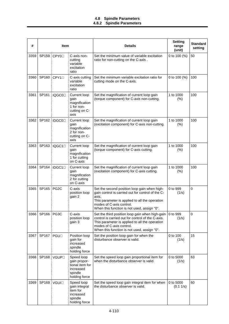
4.8 Spindle Parameters4.8.2 Spindle Parameters
4-110
# Item DetailsSettingrange(unit)
Standardsetting
3359 SP159 CPY0∗ C-axis non-cuttingvariableexcitationratio
Set the minimum value of variable excitationratio for non-cutting on the C-axis .
0 to 100 (%) 50
3360 SP160 CPY1∗ C-axis cuttingvariableexcitationratio
Set the minimum variable excitation ratio forcutting mode on the C-axis.
0 to 100 (%) 100
3361 SP161 IQGC0∗ Current loopgainmagnification1 for non-cutting on C-axis
Set the magnification of current loop gain(torque component) for C-axis non-cutting.
1 to 1000 (%)
100
3362 SP162 IDGC0∗ Current loopgainmagnification2 for non-cutting on C-axis
Set the magnification of current loop gain(excitation component) for C-axis non-cutting.
1 to 1000 (%)
100
3363 SP163 IQGC1∗ Current loopgainmagnification1 for cuttingon C-axis
Set the magnification of current loop gain(torque component) for C-axis cutting.
1 to 1000 (%)
100
3364 SP164 IDGC1∗ Current loopgainmagnification2 for cuttingon C-axis
Set the magnification of current loop gain(excitation component) for C-axis cutting.
1 to 1000 (%)
100
3365 SP165 PG2C C-axisposition loopgain 2
Set the second position loop gain when high-gain control is carried out for control of the C-axis.This parameter is applied to all the operationmodes of C-axis control.When this function is not used, assign "0".
0 to 999 (1/s)
0
3366 SP166 PG3C C-axisposition loopgain 3
Set the third position loop gain when high-gaincontrol is carried out for control of the C-axis.This parameter is applied to all the operationmodes of C-axis control.When this function is not used, assign "0".
0 to 999 (1/s)
0
3367 SP167 PGU∗ Position loopgain forincreasedspindleholding force
Set the position loop gain for when thedisturbance observer is valid.
0 to 100 (1/s)
15
3368 SP168 VGUP∗ Speed loopgain propor-tional item forincreasedspindleholding force
Set the speed loop gain proportional item forwhen the disturbance observer is valid.
0 to 5000 (1/s)
63
3369 SP169 VGUI∗ Speed loopgain integralitem forincreasedspindleholding force
Set the speed loop gain integral item for whenthe disturbance observer is valid.
0 to 5000 (0.1 1/s)
60
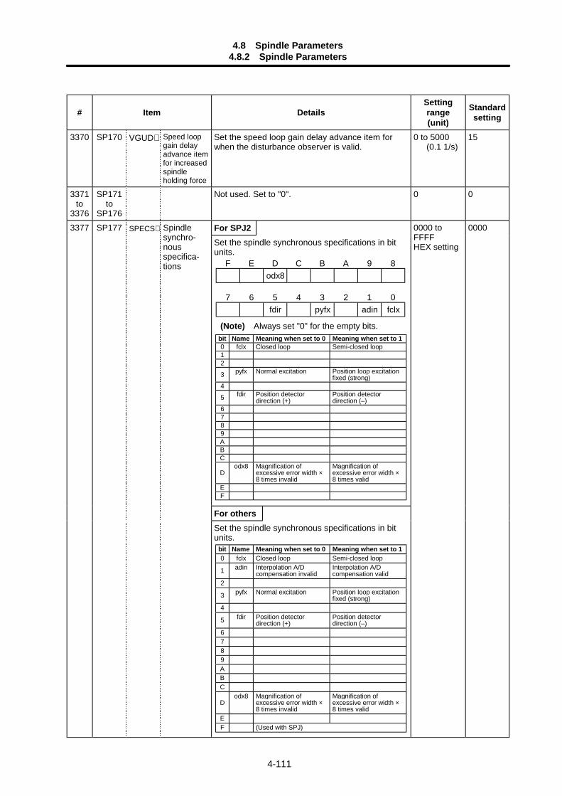
4.8 Spindle Parameters4.8.2 Spindle Parameters
4-111
# Item DetailsSettingrange(unit)
Standardsetting
3370 SP170 VGUD∗ Speed loopgain delayadvance itemfor increasedspindleholding force
Set the speed loop gain delay advance item forwhen the disturbance observer is valid.
0 to 5000 (0.1 1/s)
15
3371to
3376
SP171to
SP176
Not used. Set to "0". 0 0
For SPJ23377 SP177 SPECS∗ Spindlesynchro-nousspecifica-tions
Set the spindle synchronous specifications in bitunits.
0000 toFFFFHEX setting
0000
For othersSet the spindle synchronous specifications in bitunits.
F E D C B A 9 8odx8
7 6 5 4 3 2 1 0fdir pyfx adin fclx
(Note) Always set "0" for the empty bits.bit Name Meaning when set to 0 Meaning when set to 10 fclx Closed loop Semi-closed loop12
3 pyfx Normal excitation Position loop excitationfixed (strong)
4
5 fdir Position detectordirection (+)
Position detectordirection (–)
6789ABC
Dodx8 Magnification of
excessive error width ×8 times invalid
Magnification ofexcessive error width ×8 times valid
EF
bit Name Meaning when set to 0 Meaning when set to 10 fclx Closed loop Semi-closed loop
1 adin Interpolation A/Dcompensation invalid
Interpolation A/Dcompensation valid
2
3 pyfx Normal excitation Position loop excitationfixed (strong)
4
5 fdir Position detectordirection (+)
Position detectordirection (–)
6789ABC
Dodx8 Magnification of
excessive error width ×8 times invalid
Magnification ofexcessive error width ×8 times valid
EF (Used with SPJ)
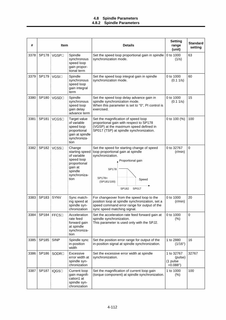
4.8 Spindle Parameters4.8.2 Spindle Parameters
4-112
# Item DetailsSettingrange(unit)
Standardsetting
3378 SP178 VGSP∗ Spindlesynchronousspeed loopgain propor-tional term
Set the speed loop proportional gain in spindlesynchronization mode.
0 to 1000 (1/s)
63
3379 SP179 VGSI∗ Spindlesynchronousspeed loopgain integralterm
Set the speed loop integral gain in spindlesynchronization mode.
0 to 1000 (0.1 1/s)
60
3380 SP180 VGSD∗ Spindlesynchronousspeed loopgain delayadvance term
Set the speed loop delay advance gain inspindle synchronization mode.When this parameter is set to "0", PI control isexercised.
0 to 1000 (0.1 1/s)
15
3381 SP181 VCGS∗ Target valueof variablespeed loopproportionalgain at spindlesynchroniza-tion
Set the magnification of speed loopproportional gain with respect to SP178(VGSP) at the maximum speed defined inSP017 (TSP) at spindle synchronization.
0 to 100 (%) 100
3382 SP182 VCSS∗ Changestarting speedof variablespeed loopproportionalgain atspindlesynchroniza-tion
Set the speed for starting change of speedloop proportional gain at spindlesynchronization.
SP182 SP017
SP178
SP178× (SP181/100)
0 to 32767 (r/min)
0
3383 SP183 SYNV Sync match-ing speed atspindle syn-chronization
For changeover from the speed loop to theposition loop at spindle synchronization, set aspeed command error range for output of thesync speed matching signal.
0 to 1000 (r/min)
20
3384 SP184 FFCS∗ Accelerationrate feedforward gainat spindlesynchroniza-tion
Set the acceleration rate feed forward gain atspindle synchronization.This parameter is used only with the SPJ2.
0 to 1000 (%)
0
3385 SP185 SINP Spindle syncin-positionwidth
Set the position error range for output of thein-position signal at spindle synchronization.
1 to 2880 (1/16°)
16
3386 SP186 SODR∗ Excessiveerror width atspindle syn-chronization
Set the excessive error width at spindlesynchronization.
1 to 32767 (pulse)(1 pulse =0.088°)
32767
3387 SP187 IQGS∗ Current loopgain magnifi-cation1 atspindle syn-chronization
Set the magnification of current loop gain(torque component) at spindle synchronization.
1 to 1000 (%)
100
Proportional gain
Speed
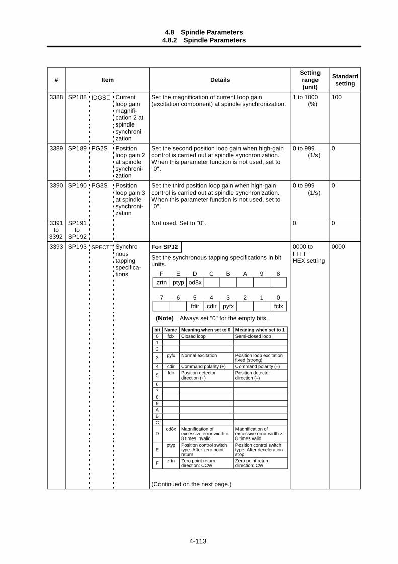
4.8 Spindle Parameters4.8.2 Spindle Parameters
4-113
# Item DetailsSettingrange(unit)
Standardsetting
3388 SP188 IDGS∗ Currentloop gainmagnifi-cation 2 atspindlesynchroni-zation
Set the magnification of current loop gain(excitation component) at spindle synchronization.
1 to 1000 (%)
100
3389 SP189 PG2S Positionloop gain 2at spindlesynchroni-zation
Set the second position loop gain when high-gaincontrol is carried out at spindle synchronization.When this parameter function is not used, set to"0".
0 to 999 (1/s)
0
3390 SP190 PG3S Positionloop gain 3at spindlesynchroni-zation
Set the third position loop gain when high-gaincontrol is carried out at spindle synchronization.When this parameter function is not used, set to"0".
0 to 999 (1/s)
0
3391to
3392
SP191to
SP192
Not used. Set to "0". 0 0
For SPJ23393 SP193 SPECT∗ Synchro-noustappingspecifica-tions
Set the synchronous tapping specifications in bitunits.
(Continued on the next page.)
0000 toFFFFHEX setting
0000
F E D C B A 9 8zrtn ptyp od8x
7 6 5 4 3 2 1 0fdir cdir pyfx fclx
(Note) Always set "0" for the empty bits.
bit Name Meaning when set to 0 Meaning when set to 10 fclx Closed loop Semi-closed loop12
3 pyfx Normal excitation Position loop excitationfixed (strong)
4 cdir Command polarity (+) Command polarity (–)
5 fdir Position detectordirection (+)
Position detectordirection (–)
6789ABC
Dod8x Magnification of
excessive error width ×8 times invalid
Magnification ofexcessive error width ×8 times valid
Eptyp Position control switch
type: After zero pointreturn
Position control switchtype: After decelerationstop
F zrtn Zero point returndirection: CCW
Zero point returndirection: CW
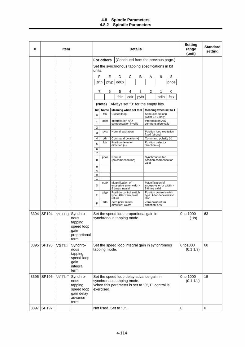
4.8 Spindle Parameters4.8.2 Spindle Parameters
4-114
# Item DetailsSettingrange(unit)
Standardsetting
For others (Continued from the previous page.)
Set the synchronous tapping specifications in bitunits.
3394 SP194 VGTP∗ Synchro-noustappingspeed loopgainproportionalterm
Set the speed loop proportional gain insynchronous tapping mode.
0 to 1000 (1/s)
63
3395 SP195 VGTI∗ Synchro-noustappingspeed loopgainintegralterm
Set the speed loop integral gain in synchronoustapping mode.
0 to1000 (0.1 1/s)
60
3396 SP196 VGTD∗ Synchro-noustappingspeed loopgain delayadvanceterm
Set the speed loop delay advance gain insynchronous tapping mode.When this parameter is set to "0", PI control isexercised.
0 to 1000 (0.1 1/s)
15
3397 SP197 Not used. Set to "0". 0 0
F E D C B A 9 8zrtn ptyp od8x phos
7 6 5 4 3 2 1 0fdir cdir pyfx adin fclx
(Note) Always set "0" for the empty bits.bit Name Meaning when set to 0 Meaning when set to 1
0 fclx Closed loop Semi-closed loop(Gear 1 : 1 only)
1 adin Interpolation A/Dcompensation invalid
Interpolation A/Dcompensation valid
2
3 pyfx Normal excitation Position loop excitationfixed (strong)
4 cdir Command polarity (+) Command polarity (–)
5 fdir Position detectordirection (+)
Position detectordirection (–)
67
8phos Normal
(no compensation)Synchronous tapposition compensationvalid
9ABC
Dod8x Magnification of
excessive error width ×8 times invalid
Magnification ofexcessive error width ×8 times valid
Eptyp Position control switch
type: After zero pointreturn
Position control switchtype: After decelerationstop
F zrtn Zero point returndirection: CCW
Zero point returndirection: CW
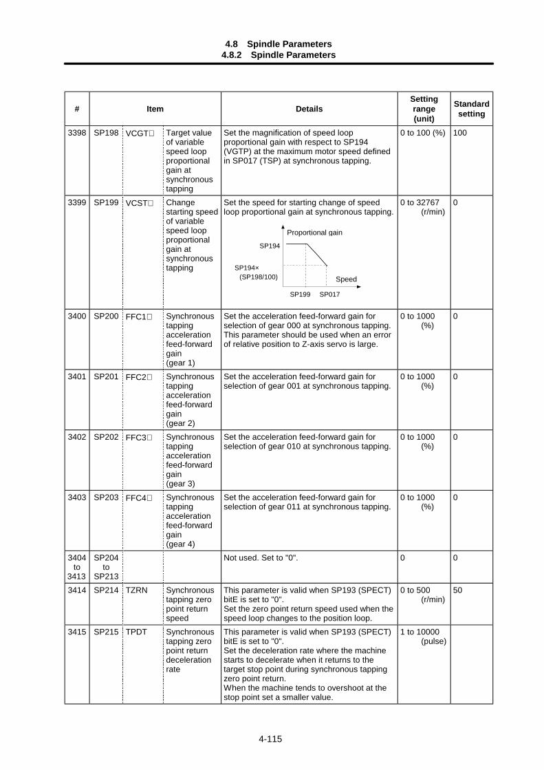
4.8 Spindle Parameters4.8.2 Spindle Parameters
4-115
# Item DetailsSettingrange(unit)
Standardsetting
3398 SP198 VCGT∗ Target valueof variablespeed loopproportionalgain atsynchronoustapping
Set the magnification of speed loopproportional gain with respect to SP194(VGTP) at the maximum motor speed definedin SP017 (TSP) at synchronous tapping.
0 to 100 (%) 100
3399 SP199 VCST∗ Changestarting speedof variablespeed loopproportionalgain atsynchronoustapping
Set the speed for starting change of speedloop proportional gain at synchronous tapping.
SP199 SP017
SP194
SP194× (SP198/100)
0 to 32767 (r/min)
0
3400 SP200 FFC1∗ Synchronoustappingaccelerationfeed-forwardgain(gear 1)
Set the acceleration feed-forward gain forselection of gear 000 at synchronous tapping.This parameter should be used when an errorof relative position to Z-axis servo is large.
0 to 1000 (%)
0
3401 SP201 FFC2∗ Synchronoustappingaccelerationfeed-forwardgain(gear 2)
Set the acceleration feed-forward gain forselection of gear 001 at synchronous tapping.
0 to 1000 (%)
0
3402 SP202 FFC3∗ Synchronoustappingaccelerationfeed-forwardgain(gear 3)
Set the acceleration feed-forward gain forselection of gear 010 at synchronous tapping.
0 to 1000 (%)
0
3403 SP203 FFC4∗ Synchronoustappingaccelerationfeed-forwardgain(gear 4)
Set the acceleration feed-forward gain forselection of gear 011 at synchronous tapping.
0 to 1000 (%)
0
3404to
3413
SP204to
SP213
Not used. Set to "0". 0 0
3414 SP214 TZRN Synchronoustapping zeropoint returnspeed
This parameter is valid when SP193 (SPECT)bitE is set to "0".Set the zero point return speed used when thespeed loop changes to the position loop.
0 to 500 (r/min)
50
3415 SP215 TPDT Synchronoustapping zeropoint returndecelerationrate
This parameter is valid when SP193 (SPECT)bitE is set to "0".Set the deceleration rate where the machinestarts to decelerate when it returns to thetarget stop point during synchronous tappingzero point return.When the machine tends to overshoot at thestop point set a smaller value.
1 to 10000 (pulse)
Proportional gain
Speed
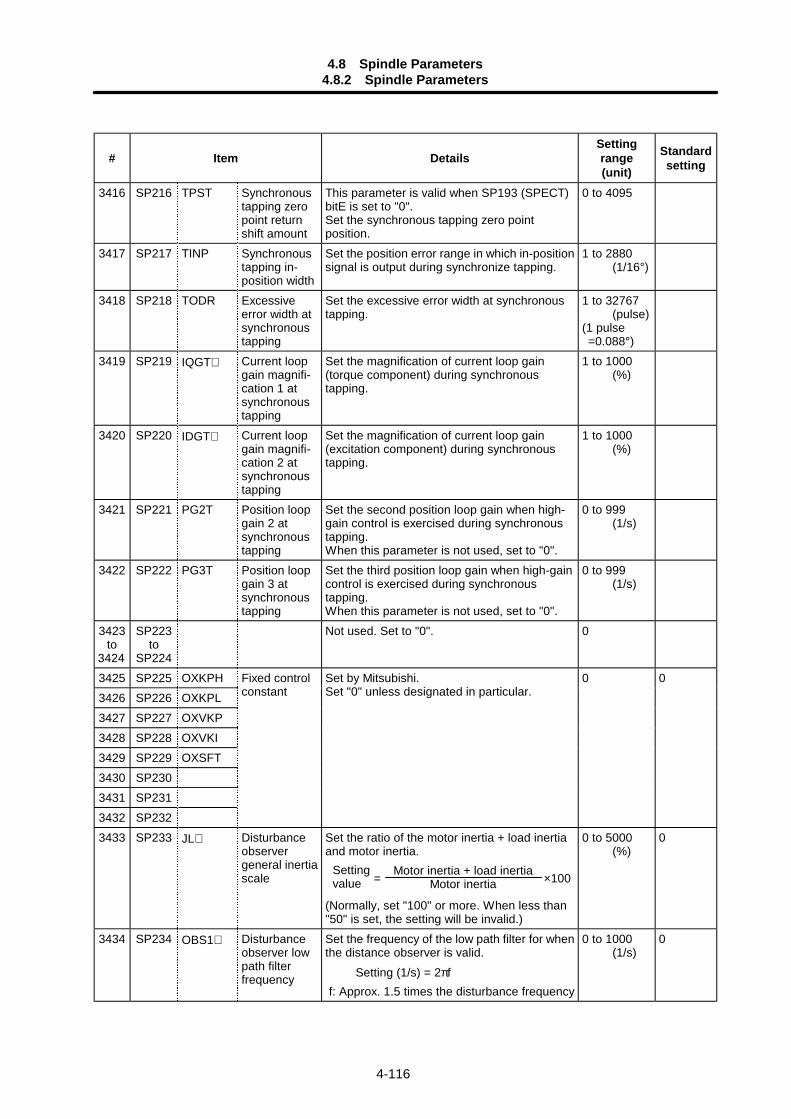
4.8 Spindle Parameters4.8.2 Spindle Parameters
4-116
# Item DetailsSettingrange(unit)
Standardsetting
3416 SP216 TPST Synchronoustapping zeropoint returnshift amount
This parameter is valid when SP193 (SPECT)bitE is set to "0".Set the synchronous tapping zero pointposition.
0 to 4095
3417 SP217 TINP Synchronoustapping in-position width
Set the position error range in which in-positionsignal is output during synchronize tapping.
1 to 2880 (1/16°)
3418 SP218 TODR Excessiveerror width atsynchronoustapping
Set the excessive error width at synchronoustapping.
1 to 32767 (pulse)(1 pulse =0.088°)
3419 SP219 IQGT∗ Current loopgain magnifi-cation 1 atsynchronoustapping
Set the magnification of current loop gain(torque component) during synchronoustapping.
1 to 1000 (%)
3420 SP220 IDGT∗ Current loopgain magnifi-cation 2 atsynchronoustapping
Set the magnification of current loop gain(excitation component) during synchronoustapping.
1 to 1000 (%)
3421 SP221 PG2T Position loopgain 2 atsynchronoustapping
Set the second position loop gain when high-gain control is exercised during synchronoustapping.When this parameter is not used, set to "0".
0 to 999 (1/s)
3422 SP222 PG3T Position loopgain 3 atsynchronoustapping
Set the third position loop gain when high-gaincontrol is exercised during synchronoustapping.When this parameter is not used, set to "0".
0 to 999 (1/s)
3423to
3424
SP223to
SP224
Not used. Set to "0". 0
3425 SP225 OXKPH3426 SP226 OXKPL3427 SP227 OXVKP3428 SP228 OXVKI3429 SP229 OXSFT3430 SP2303431 SP2313432 SP232
Fixed controlconstant
Set by Mitsubishi.Set "0" unless designated in particular.
0 0
3433 SP233 JL∗ Disturbanceobservergeneral inertiascale
Set the ratio of the motor inertia + load inertiaand motor inertia.
= ×100
(Normally, set "100" or more. When less than"50" is set, the setting will be invalid.)
0 to 5000 (%)
0
3434 SP234 OBS1∗ Disturbanceobserver lowpath filterfrequency
Set the frequency of the low path filter for whenthe distance observer is valid. Setting (1/s) = 2πff: Approx. 1.5 times the disturbance frequency
0 to 1000 (1/s)
0
Motor inertia + load inertiaMotor inertia
Settingvalue
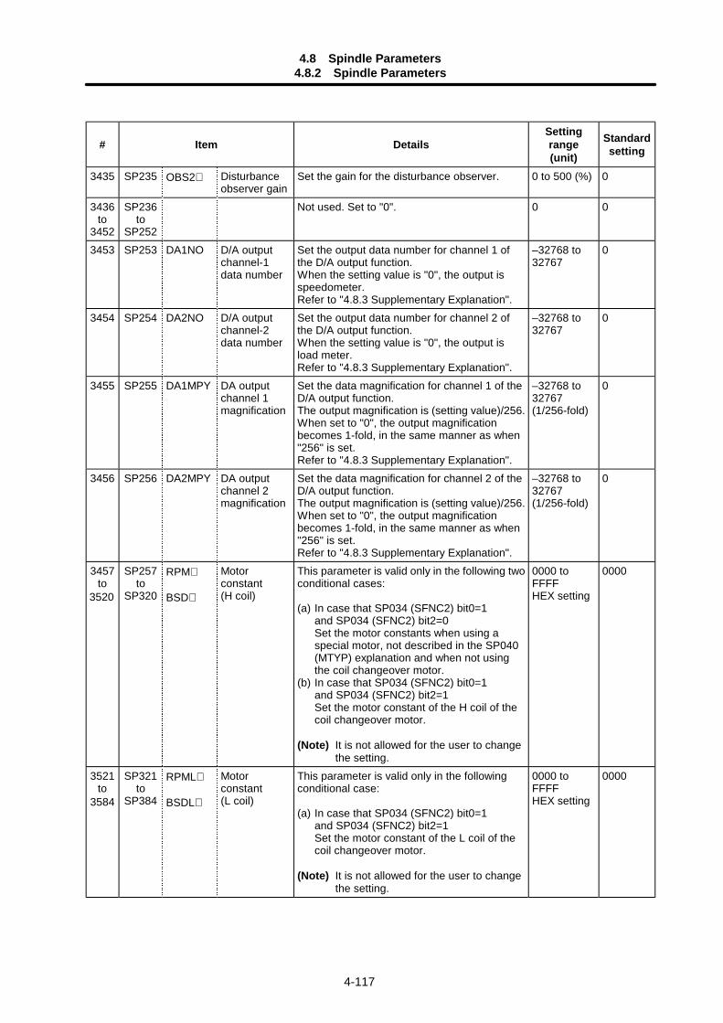
4.8 Spindle Parameters4.8.2 Spindle Parameters
4-117
# Item DetailsSettingrange(unit)
Standardsetting
3435 SP235 OBS2∗ Disturbanceobserver gain
Set the gain for the disturbance observer. 0 to 500 (%) 0
3436to
3452
SP236to
SP252
Not used. Set to "0". 0 0
3453 SP253 DA1NO D/A outputchannel-1data number
Set the output data number for channel 1 ofthe D/A output function.When the setting value is "0", the output isspeedometer.Refer to "4.8.3 Supplementary Explanation".
–32768 to32767
0
3454 SP254 DA2NO D/A outputchannel-2data number
Set the output data number for channel 2 ofthe D/A output function.When the setting value is "0", the output isload meter.Refer to "4.8.3 Supplementary Explanation".
–32768 to32767
0
3455 SP255 DA1MPY DA outputchannel 1magnification
Set the data magnification for channel 1 of theD/A output function.The output magnification is (setting value)/256.When set to "0", the output magnificationbecomes 1-fold, in the same manner as when"256" is set.Refer to "4.8.3 Supplementary Explanation".
–32768 to32767(1/256-fold)
0
3456 SP256 DA2MPY DA outputchannel 2magnification
Set the data magnification for channel 2 of theD/A output function.The output magnification is (setting value)/256.When set to "0", the output magnificationbecomes 1-fold, in the same manner as when"256" is set.Refer to "4.8.3 Supplementary Explanation".
–32768 to32767(1/256-fold)
0
3457to
3520
SP257to
SP320
RPM∗
BSD∗
Motorconstant(H coil)
This parameter is valid only in the following twoconditional cases:
(a) In case that SP034 (SFNC2) bit0=1and SP034 (SFNC2) bit2=0Set the motor constants when using aspecial motor, not described in the SP040(MTYP) explanation and when not usingthe coil changeover motor.
(b) In case that SP034 (SFNC2) bit0=1and SP034 (SFNC2) bit2=1Set the motor constant of the H coil of thecoil changeover motor.
(Note) It is not allowed for the user to changethe setting.
0000 toFFFFHEX setting
0000
3521to
3584
SP321to
SP384
RPML∗
BSDL∗
Motorconstant(L coil)
This parameter is valid only in the followingconditional case:
(a) In case that SP034 (SFNC2) bit0=1and SP034 (SFNC2) bit2=1Set the motor constant of the L coil of thecoil changeover motor.
(Note) It is not allowed for the user to changethe setting.
0000 toFFFFHEX setting
0000
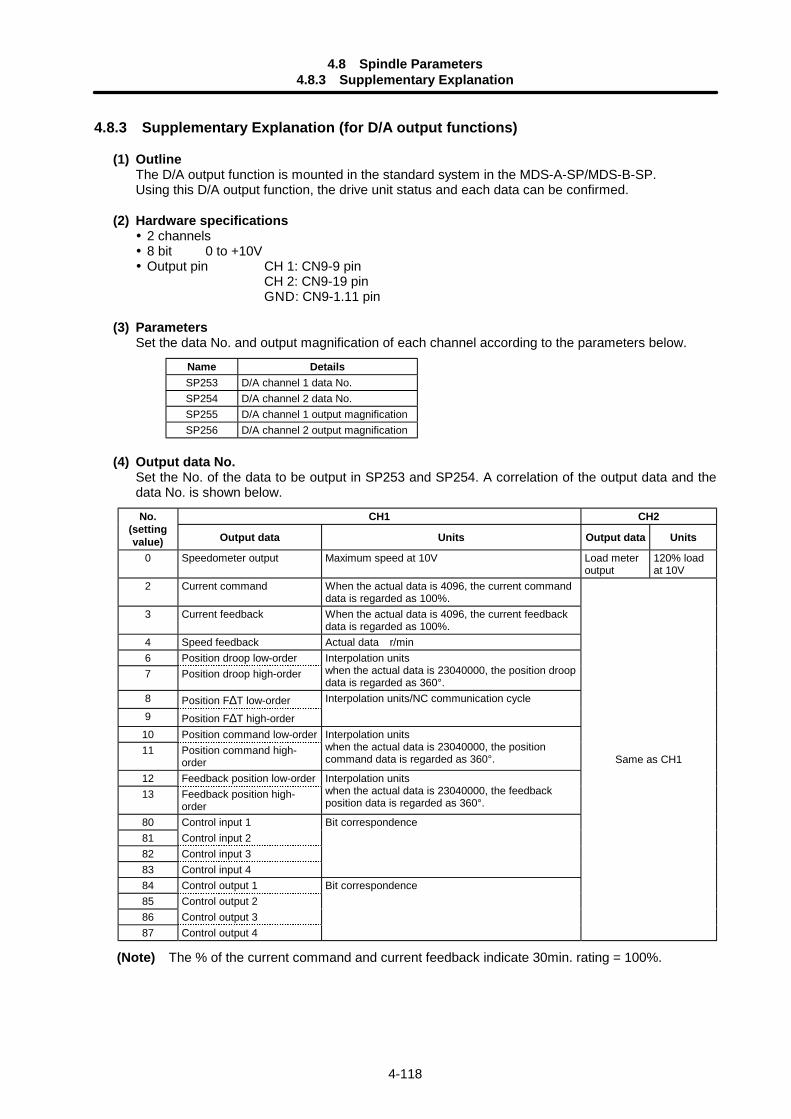
4.8 Spindle Parameters4.8.3 Supplementary Explanation
4-118
4.8.3 Supplementary Explanation (for D/A output functions)
(1) OutlineThe D/A output function is mounted in the standard system in the MDS-A-SP/MDS-B-SP.Using this D/A output function, the drive unit status and each data can be confirmed.
(2) Hardware specifications 2 channels 8 bit 0 to +10V Output pin CH 1: CN9-9 pin
CH 2: CN9-19 pinGND: CN9-1.11 pin
(3) ParametersSet the data No. and output magnification of each channel according to the parameters below.
Name DetailsSP253 D/A channel 1 data No.SP254 D/A channel 2 data No.SP255 D/A channel 1 output magnificationSP256 D/A channel 2 output magnification
(4) Output data No.Set the No. of the data to be output in SP253 and SP254. A correlation of the output data and thedata No. is shown below.
CH1 CH2No.(settingvalue) Output data Units Output data Units
0 Speedometer output Maximum speed at 10V Load meteroutput
120% loadat 10V
2 Current command When the actual data is 4096, the current commanddata is regarded as 100%.
3 Current feedback When the actual data is 4096, the current feedbackdata is regarded as 100%.
4 Speed feedback Actual data r/min6 Position droop low-order7 Position droop high-order
Interpolation unitswhen the actual data is 23040000, the position droopdata is regarded as 360°.
8 Position F∆T low-order9 Position F∆T high-order
Interpolation units/NC communication cycle
10 Position command low-order11 Position command high-
order
Interpolation unitswhen the actual data is 23040000, the positioncommand data is regarded as 360°.
12 Feedback position low-order13 Feedback position high-
order
Interpolation unitswhen the actual data is 23040000, the feedbackposition data is regarded as 360°.
80 Control input 181 Control input 282 Control input 383 Control input 4
Bit correspondence
84 Control output 185 Control output 286 Control output 387 Control output 4
Bit correspondence
Same as CH1
(Note) The % of the current command and current feedback indicate 30min. rating = 100%.

4.8 Spindle Parameters4.8.3 Supplementary Explanation
4-119
(5) Setting the output magnificationSet the output magnification in SP255 and SP256.
Data = actual data ×
Using the expression above,1) Output data other than speedometer output and load meter output carries out the D/A output in
Fig. 1 below.2) Speedometer data and load meter data carries out the D/A output in Fig. 2 below.
DATA
0 +127
+10V
+5V
0V-128
DATA0 +127
+10V
+5V
0V+255
(Example 1) Current command, current feedbackData units are 100% converted when the actual data = 4096.Therefore, for example, the actual data is output as shown below during +120% currentfeedback.
Actual data = 4096 × 1.2 = 4915If "256" is set (magnification 1) in parameter SP255 (SP256), the D/A output voltagefrom Fig. 1 will be as shown below, exceeding the D/A output voltage maximum value.
5V + 4915 × 1 × (5V/128) = 197V > 10VTherefore, if (for example) "6" is set in parameter SP255 (SP256), the D/A output voltagewill become as shown below, and data confirmation will be possible.
5V + 4915 × 6/256 × (5V/128) = 9.5V < 10V
SP255 or SP256256
D/A output voltage
Fig. 2Fig. 1
D/A output voltage
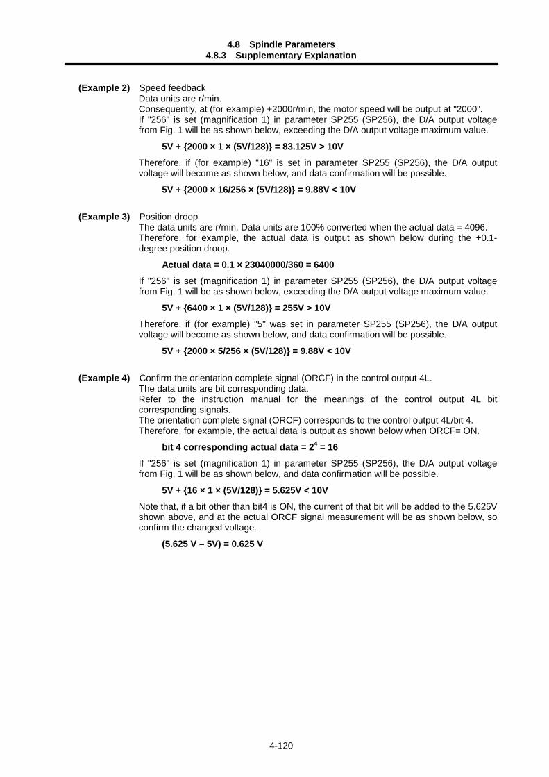
4.8 Spindle Parameters4.8.3 Supplementary Explanation
4-120
(Example 2) Speed feedbackData units are r/min.Consequently, at (for example) +2000r/min, the motor speed will be output at "2000".If "256" is set (magnification 1) in parameter SP255 (SP256), the D/A output voltagefrom Fig. 1 will be as shown below, exceeding the D/A output voltage maximum value.
5V + 2000 × 1 × (5V/128) = 83.125V > 10VTherefore, if (for example) "16" is set in parameter SP255 (SP256), the D/A outputvoltage will become as shown below, and data confirmation will be possible.
5V + 2000 × 16/256 × (5V/128) = 9.88V < 10V
(Example 3) Position droopThe data units are r/min. Data units are 100% converted when the actual data = 4096.Therefore, for example, the actual data is output as shown below during the +0.1-degree position droop.
Actual data = 0.1 × 23040000/360 = 6400If "256" is set (magnification 1) in parameter SP255 (SP256), the D/A output voltagefrom Fig. 1 will be as shown below, exceeding the D/A output voltage maximum value.
5V + 6400 × 1 × (5V/128) = 255V > 10VTherefore, if (for example) "5" was set in parameter SP255 (SP256), the D/A outputvoltage will become as shown below, and data confirmation will be possible.
5V + 2000 × 5/256 × (5V/128) = 9.88V < 10V
(Example 4) Confirm the orientation complete signal (ORCF) in the control output 4L.The data units are bit corresponding data.Refer to the instruction manual for the meanings of the control output 4L bitcorresponding signals.The orientation complete signal (ORCF) corresponds to the control output 4L/bit 4.Therefore, for example, the actual data is output as shown below when ORCF= ON.
bit 4 corresponding actual data = 24 = 16If "256" is set (magnification 1) in parameter SP255 (SP256), the D/A output voltagefrom Fig. 1 will be as shown below, and data confirmation will be possible.
5V + 16 × 1 × (5V/128) = 5.625V < 10VNote that, if a bit other than bit4 is ON, the current of that bit will be added to the 5.625Vshown above, and at the actual ORCF signal measurement will be as shown below, soconfirm the changed voltage.
(5.625 V – 5V) = 0.625 V
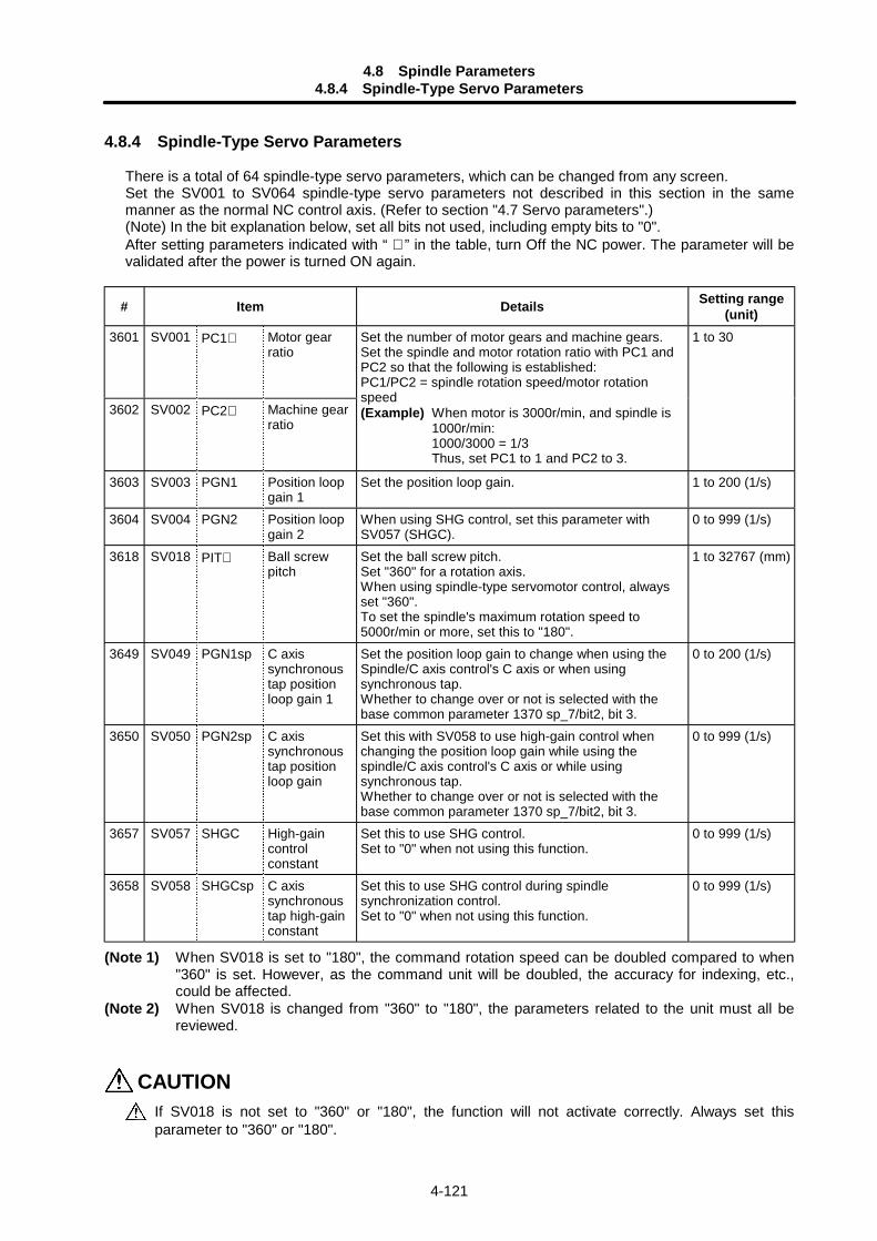
4.8 Spindle Parameters4.8.4 Spindle-Type Servo Parameters
4-121
4.8.4 Spindle-Type Servo Parameters
There is a total of 64 spindle-type servo parameters, which can be changed from any screen.Set the SV001 to SV064 spindle-type servo parameters not described in this section in the samemanner as the normal NC control axis. (Refer to section "4.7 Servo parameters".)(Note) In the bit explanation below, set all bits not used, including empty bits to "0".After setting parameters indicated with “ ∗ ” in the table, turn Off the NC power. The parameter will bevalidated after the power is turned ON again.
# Item Details Setting range(unit)
3601 SV001 PC1∗ Motor gearratio
3602 SV002 PC2∗ Machine gearratio
Set the number of motor gears and machine gears.Set the spindle and motor rotation ratio with PC1 andPC2 so that the following is established:PC1/PC2 = spindle rotation speed/motor rotationspeed(Example) When motor is 3000r/min, and spindle is
1000r/min:1000/3000 = 1/3Thus, set PC1 to 1 and PC2 to 3.
1 to 30
3603 SV003 PGN1 Position loopgain 1
Set the position loop gain. 1 to 200 (1/s)
3604 SV004 PGN2 Position loopgain 2
When using SHG control, set this parameter withSV057 (SHGC).
0 to 999 (1/s)
3618 SV018 PIT∗ Ball screwpitch
Set the ball screw pitch.Set "360" for a rotation axis.When using spindle-type servomotor control, alwaysset "360".To set the spindle's maximum rotation speed to5000r/min or more, set this to "180".
1 to 32767 (mm)
3649 SV049 PGN1sp C axissynchronoustap positionloop gain 1
Set the position loop gain to change when using theSpindle/C axis control's C axis or when usingsynchronous tap.Whether to change over or not is selected with thebase common parameter 1370 sp_7/bit2, bit 3.
0 to 200 (1/s)
3650 SV050 PGN2sp C axissynchronoustap positionloop gain
Set this with SV058 to use high-gain control whenchanging the position loop gain while using thespindle/C axis control's C axis or while usingsynchronous tap.Whether to change over or not is selected with thebase common parameter 1370 sp_7/bit2, bit 3.
0 to 999 (1/s)
3657 SV057 SHGC High-gaincontrolconstant
Set this to use SHG control.Set to "0" when not using this function.
0 to 999 (1/s)
3658 SV058 SHGCsp C axissynchronoustap high-gainconstant
Set this to use SHG control during spindlesynchronization control.Set to "0" when not using this function.
0 to 999 (1/s)
(Note 1) When SV018 is set to "180", the command rotation speed can be doubled compared to when"360" is set. However, as the command unit will be doubled, the accuracy for indexing, etc.,could be affected.
(Note 2) When SV018 is changed from "360" to "180", the parameters related to the unit must all bereviewed.
CAUTIONIf SV018 is not set to "360" or "180", the function will not activate correctly. Always set thisparameter to "360" or "180".
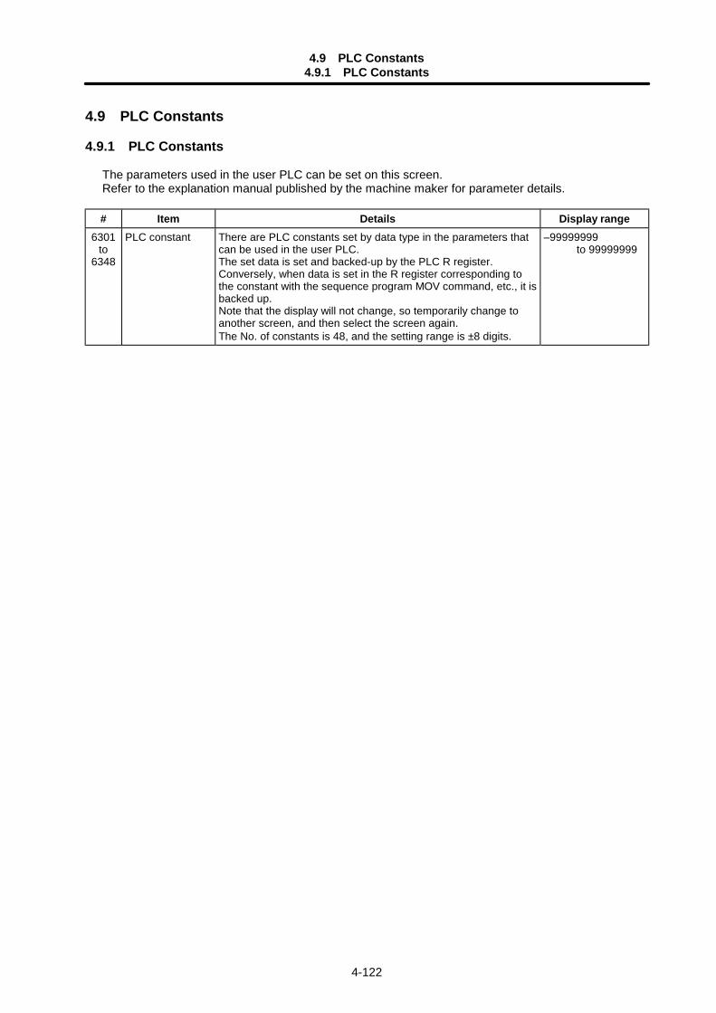
4.9 PLC Constants4.9.1 PLC Constants
4-122
4.9 PLC Constants
4.9.1 PLC Constants
The parameters used in the user PLC can be set on this screen.Refer to the explanation manual published by the machine maker for parameter details.
# Item Details Display range6301
to6348
PLC constant There are PLC constants set by data type in the parameters thatcan be used in the user PLC.The set data is set and backed-up by the PLC R register.Conversely, when data is set in the R register corresponding tothe constant with the sequence program MOV command, etc., it isbacked up.Note that the display will not change, so temporarily change toanother screen, and then select the screen again.The No. of constants is 48, and the setting range is ±8 digits.
–99999999 to 99999999
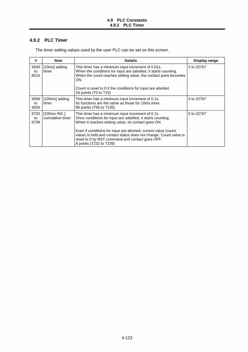
4.9 PLC Constants4.9.2 PLC Timer
4-123
4.9.2 PLC Timer
The timer setting values used by the user PLC can be set on this screen.
# Item Details Display range6500
to6515
[10ms] addingtimer
This timer has a minimum input increment of 0.01s.When the conditions for input are satisfied, it starts counting.When the count reaches setting value, the contact point becomesON.
Count is reset to 0 if the conditions for input are aborted.16 points (T0 to T15)
0 to 32767
6556to
6635
[100ms] addingtimer
This timer has a minimum input increment of 0.1s.Its functions are the same as those for 10ms timer.80 points (T56 to T135)
0 to 32767
6732to
6739
[100ms INC.]cumulative timer
This timer has a minimum input increment of 0.1s.Once conditions for input are satisfied, it starts counting.When it reaches setting value, its contact goes ON.
Even if conditions for input are aborted, current value (countvalue) is held and contact status does not change. Count value isreset to 0 by RST command and contact goes OFF.8 points (T232 to T239)
0 to 32767

4.10 Custom Variables
4-124
4.9.3 PLC Counter
The counter setting value used by the user PLC can be set on this screen.
# Item Details Display range6200
to6223
Counter It detects rising of conditions for input and counts with incrementalsystem.Count value is not cleared even if input conditions are aborted.Count value is reset to 0 by RST command.24 points (C0 to C23)
0 to 32767
4.9.4 Selecting the PLC Bit
The bit parameter used in the user PLC can be set on this screen.
# Item Details Display range6401
to6496
Bit selection There are bit selection parameters set by bit type in theparameters that can be used in the user PLC.The set data is set and backed-up by the PLC R register.When bit operation is used in the sequence program, it is usedafter temporarily transferring the R register details to the memory(M) with a MOV command. Conversely, when data is set in the Rregister corresponding to the bit selection with the MOVcommand, etc., it is backed up.
0: OFF1: ON
(Note) Bit selection parameters #6449 to #6496 are used by the machine maker and Mitsubishi, so the details arefixed.
4.10 Custom Variables
The custom variable data can be set on this screen.
# Item Details801to
999
Custom variables These indicate the variable numbers and their contents. When the variable data is"empty", the data display area will be blank.Data with a large number of digits will be exponentially displayed.
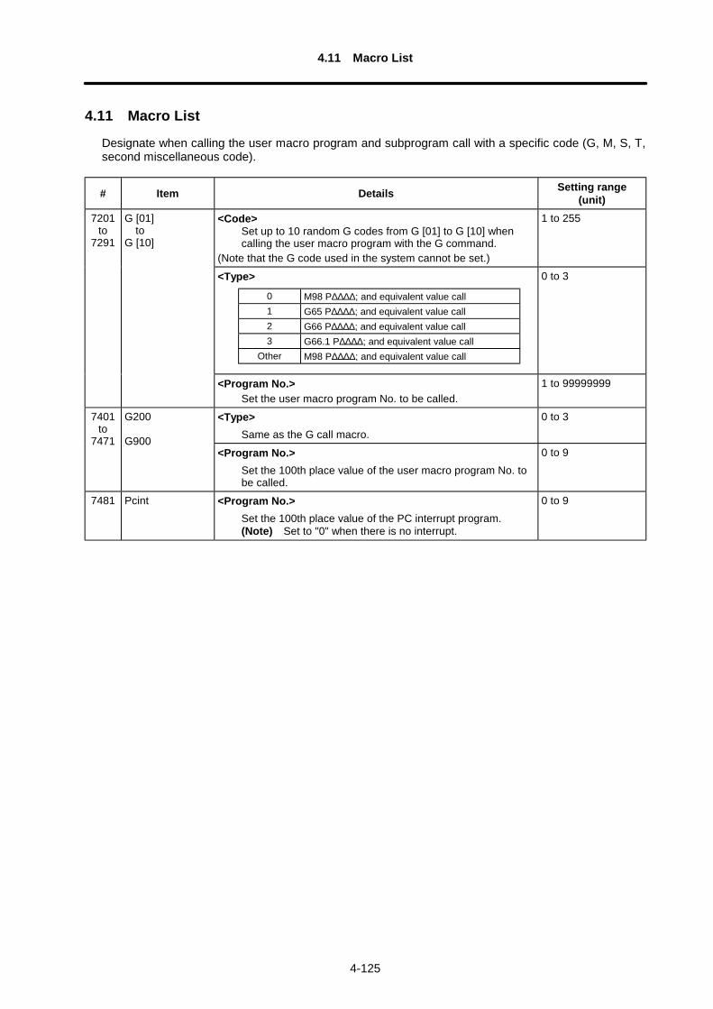
4.11 Macro List
4-125
4.11 Macro List
Designate when calling the user macro program and subprogram call with a specific code (G, M, S, T,second miscellaneous code).
# Item Details Setting range(unit)
<Code>Set up to 10 random G codes from G [01] to G [10] whencalling the user macro program with the G command.
(Note that the G code used in the system cannot be set.)
1 to 255
<Type> 0 to 3
7201to
7291
G [01] toG [10]
<Program No.>Set the user macro program No. to be called.
1 to 99999999
<Type>Same as the G call macro.
0 to 37401to
7471
G200
G900<Program No.>
Set the 100th place value of the user macro program No. tobe called.
0 to 9
7481 Pcint <Program No.>Set the 100th place value of the PC interrupt program.(Note) Set to "0" when there is no interrupt.
0 to 9
0 M98 P∆∆∆∆; and equivalent value call1 G65 P∆∆∆∆; and equivalent value call2 G66 P∆∆∆∆; and equivalent value call3 G66.1 P∆∆∆∆; and equivalent value call
Other M98 P∆∆∆∆; and equivalent value call
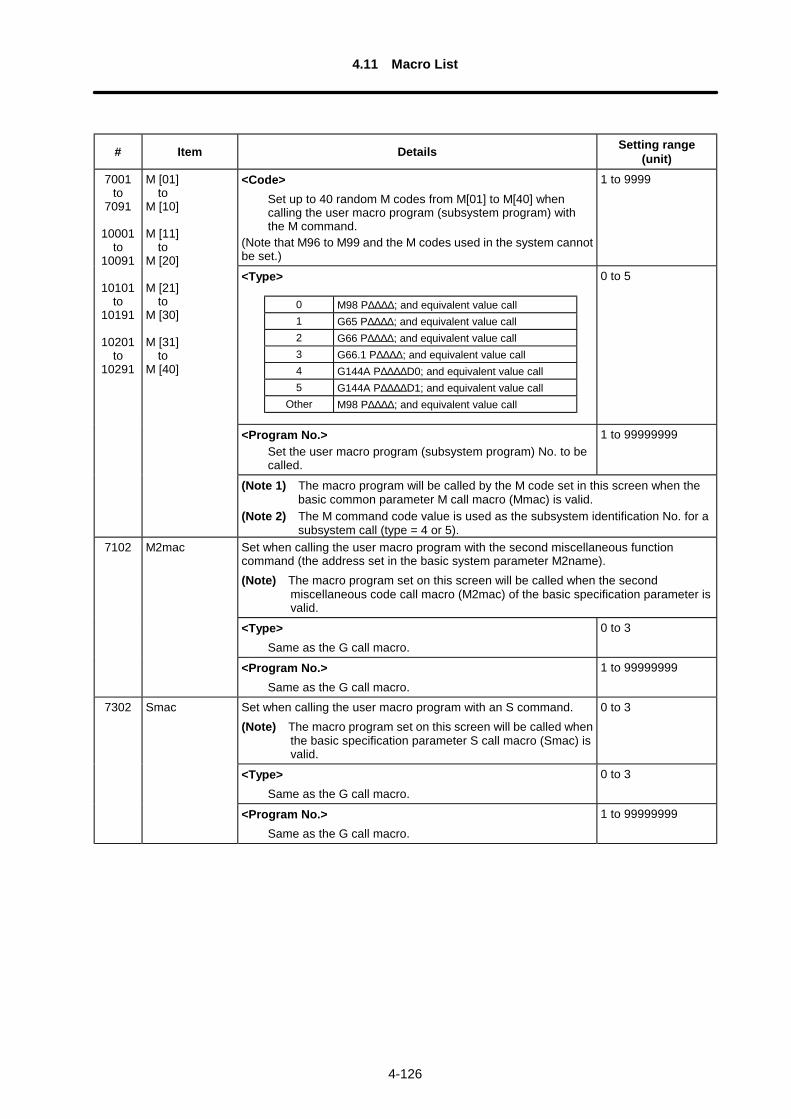
4.11 Macro List
4-126
# Item Details Setting range(unit)
<Code>Set up to 40 random M codes from M[01] to M[40] whencalling the user macro program (subsystem program) withthe M command.
(Note that M96 to M99 and the M codes used in the system cannotbe set.)
1 to 9999
<Type> 0 to 5
<Program No.>Set the user macro program (subsystem program) No. to becalled.
1 to 99999999
7001to
7091
10001to
10091
10101to
10191
10201to
10291
M [01] toM [10]
M [11] toM [20]
M [21] toM [30]
M [31] toM [40]
(Note 1) The macro program will be called by the M code set in this screen when thebasic common parameter M call macro (Mmac) is valid.
(Note 2) The M command code value is used as the subsystem identification No. for asubsystem call (type = 4 or 5).
Set when calling the user macro program with the second miscellaneous functioncommand (the address set in the basic system parameter M2name).(Note) The macro program set on this screen will be called when the second
miscellaneous code call macro (M2mac) of the basic specification parameter isvalid.
<Type>Same as the G call macro.
0 to 3
7102 M2mac
<Program No.>Same as the G call macro.
1 to 99999999
Set when calling the user macro program with an S command.(Note) The macro program set on this screen will be called when
the basic specification parameter S call macro (Smac) isvalid.
0 to 3
<Type>Same as the G call macro.
0 to 3
7302 Smac
<Program No.>Same as the G call macro.
1 to 99999999
0 M98 P∆∆∆∆; and equivalent value call1 G65 P∆∆∆∆; and equivalent value call2 G66 P∆∆∆∆; and equivalent value call3 G66.1 P∆∆∆∆; and equivalent value call4 G144A P∆∆∆∆D0; and equivalent value call5 G144A P∆∆∆∆D1; and equivalent value call
Other M98 P∆∆∆∆; and equivalent value call
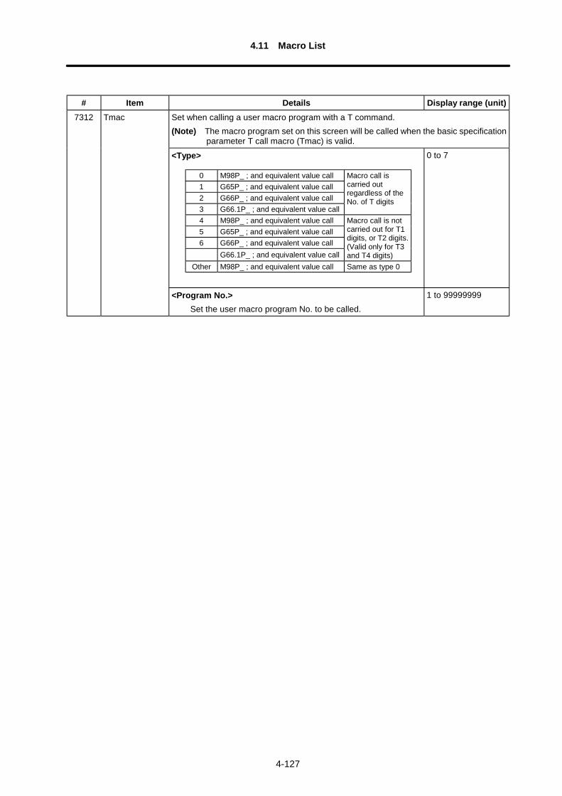
4.11 Macro List
4-127
# Item Details Display range (unit)Set when calling a user macro program with a T command.(Note) The macro program set on this screen will be called when the basic specification
parameter T call macro (Tmac) is valid.
<Type> 0 to 7
7312 Tmac
<Program No.>Set the user macro program No. to be called.
1 to 99999999
0 M98P_ ; and equivalent value call1 G65P_ ; and equivalent value call2 G66P_ ; and equivalent value call3 G66.1P_ ; and equivalent value call
Macro call iscarried outregardless of theNo. of T digits
4 M98P_ ; and equivalent value call5 G65P_ ; and equivalent value call6 G66P_ ; and equivalent value call
G66.1P_ ; and equivalent value call
Macro call is notcarried out for T1digits, or T2 digits.(Valid only for T3and T4 digits)
Other M98P_ ; and equivalent value call Same as type 0
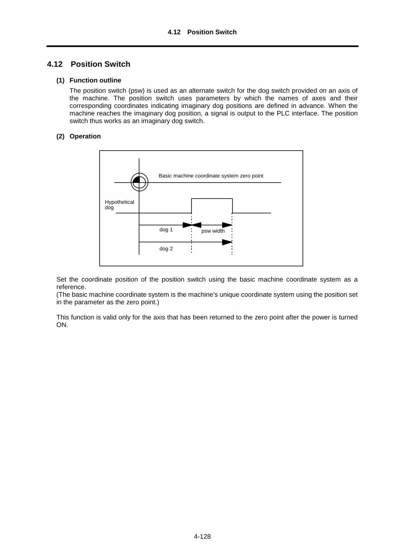
4.12 Position Switch
4-128
4.12 Position Switch
(1) Function outlineThe position switch (psw) is used as an alternate switch for the dog switch provided on an axis ofthe machine. The position switch uses parameters by which the names of axes and theircorresponding coordinates indicating imaginary dog positions are defined in advance. When themachine reaches the imaginary dog position, a signal is output to the PLC interface. The positionswitch thus works as an imaginary dog switch.
(2) Operation
Basic machine coordinate system zero point
Hypotheticaldog
dog 1
dog 2
psw width
Set the coordinate position of the position switch using the basic machine coordinate system as areference.(The basic machine coordinate system is the machine's unique coordinate system using the position setin the parameter as the zero point.)
This function is valid only for the axis that has been returned to the zero point after the power is turnedON.
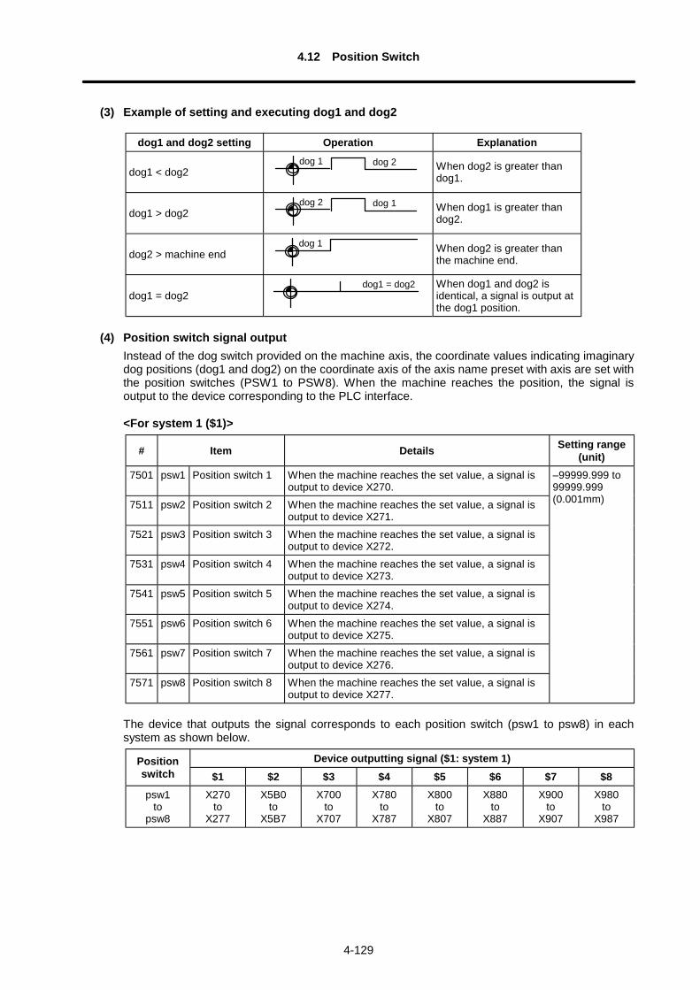
4.12 Position Switch
4-129
(3) Example of setting and executing dog1 and dog2
dog1 and dog2 setting Operation Explanation
dog1 < dog2dog 1 dog 2 When dog2 is greater than
dog1.
dog1 > dog2dog 2 dog 1 When dog1 is greater than
dog2.
dog2 > machine enddog 1 When dog2 is greater than
the machine end.
dog1 = dog2dog1 = dog2 When dog1 and dog2 is
identical, a signal is output atthe dog1 position.
(4) Position switch signal outputInstead of the dog switch provided on the machine axis, the coordinate values indicating imaginarydog positions (dog1 and dog2) on the coordinate axis of the axis name preset with axis are set withthe position switches (PSW1 to PSW8). When the machine reaches the position, the signal isoutput to the device corresponding to the PLC interface.
<For system 1 ($1)>
# Item Details Setting range(unit)
7501 psw1 Position switch 1 When the machine reaches the set value, a signal isoutput to device X270.
7511 psw2 Position switch 2 When the machine reaches the set value, a signal isoutput to device X271.
7521 psw3 Position switch 3 When the machine reaches the set value, a signal isoutput to device X272.
7531 psw4 Position switch 4 When the machine reaches the set value, a signal isoutput to device X273.
7541 psw5 Position switch 5 When the machine reaches the set value, a signal isoutput to device X274.
7551 psw6 Position switch 6 When the machine reaches the set value, a signal isoutput to device X275.
7561 psw7 Position switch 7 When the machine reaches the set value, a signal isoutput to device X276.
7571 psw8 Position switch 8 When the machine reaches the set value, a signal isoutput to device X277.
–99999.999 to99999.999(0.001mm)
The device that outputs the signal corresponds to each position switch (psw1 to psw8) in eachsystem as shown below.
Device outputting signal ($1: system 1)Positionswitch $1 $2 $3 $4 $5 $6 $7 $8psw1
topsw8
X270to
X277
X5B0to
X5B7
X700to
X707
X780to
X787
X800to
X807
X880to
X887
X900to
X907
X980to
X987
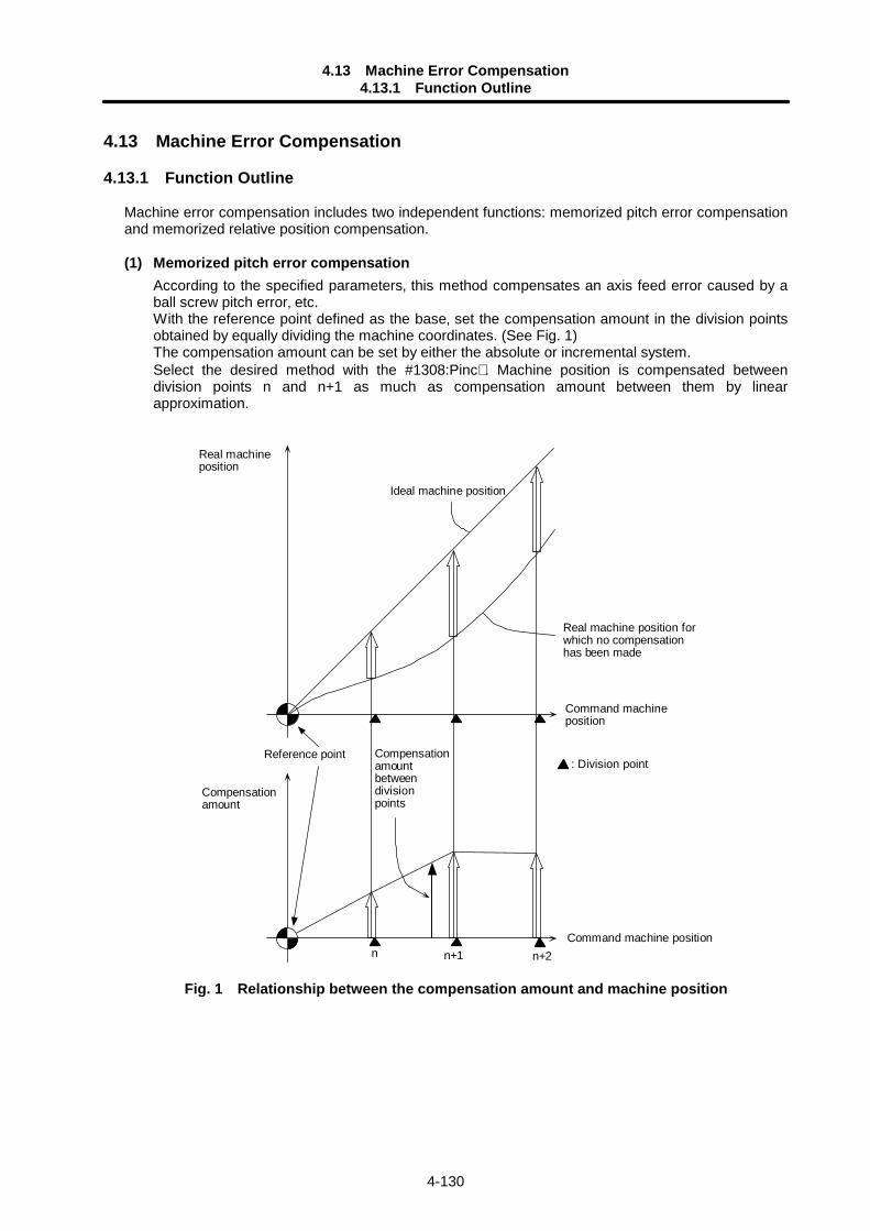
4.13 Machine Error Compensation4.13.1 Function Outline
4-130
4.13 Machine Error Compensation
4.13.1 Function Outline
Machine error compensation includes two independent functions: memorized pitch error compensationand memorized relative position compensation.
(1) Memorized pitch error compensationAccording to the specified parameters‚ this method compensates an axis feed error caused by aball screw pitch error‚ etc.With the reference point defined as the base‚ set the compensation amount in the division pointsobtained by equally dividing the machine coordinates. (See Fig. 1)The compensation amount can be set by either the absolute or incremental system.Select the desired method with the #1308:Pinc∗ . Machine position is compensated betweendivision points n and n+1 as much as compensation amount between them by linearapproximation.
Command machineposition
Ideal machine position
Reference point
Real machine position forwhich no compensationhas been made
n n+1 n+2Command machine position
Compensationamountbetweendivisionpoints
: Division point
Real machineposition
Compensationamount
Fig. 1 Relationship between the compensation amount and machine position
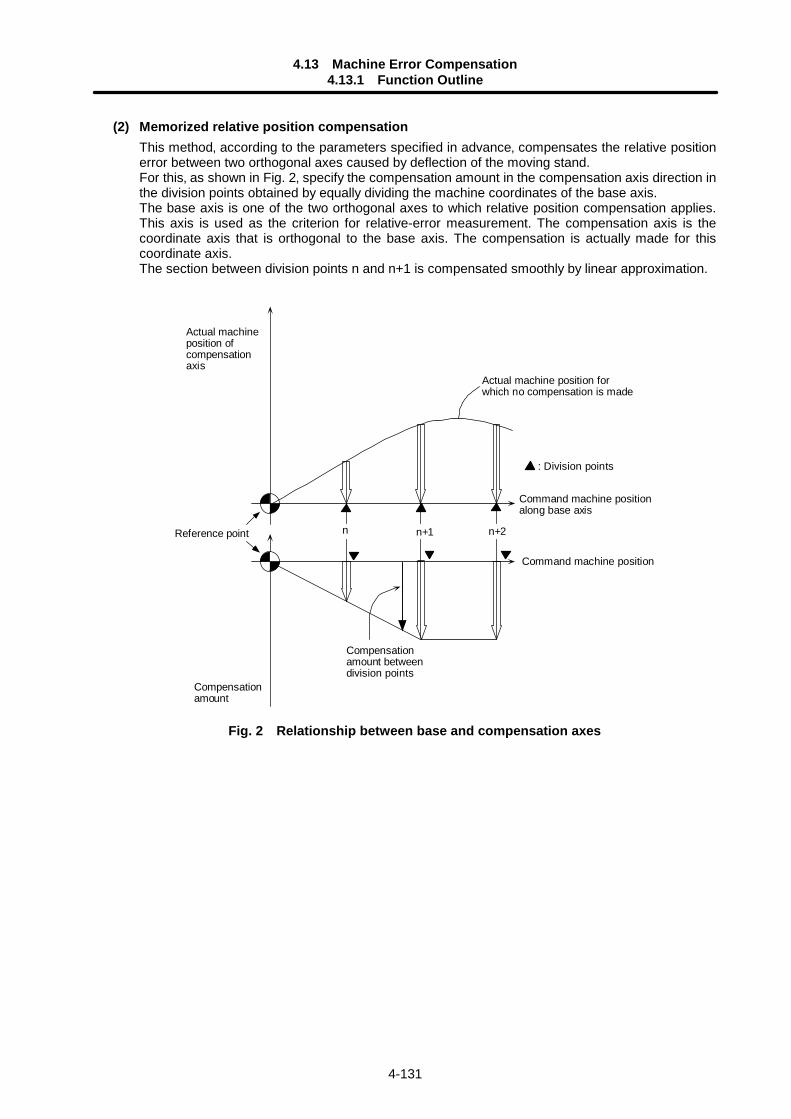
4.13 Machine Error Compensation4.13.1 Function Outline
4-131
(2) Memorized relative position compensationThis method‚ according to the parameters specified in advance‚ compensates the relative positionerror between two orthogonal axes caused by deflection of the moving stand.For this‚ as shown in Fig. 2‚ specify the compensation amount in the compensation axis direction inthe division points obtained by equally dividing the machine coordinates of the base axis.The base axis is one of the two orthogonal axes to which relative position compensation applies.This axis is used as the criterion for relative-error measurement. The compensation axis is thecoordinate axis that is orthogonal to the base axis. The compensation is actually made for thiscoordinate axis.The section between division points n and n+1 is compensated smoothly by linear approximation.
Command machine positionalong base axis
Reference point
Actual machine position forwhich no compensation is made
n n+1 n+2
Command machine position
Compensationamount betweendivision points
: Division points
Actual machineposition ofcompensationaxis
Compensationamount
Fig. 2 Relationship between base and compensation axes
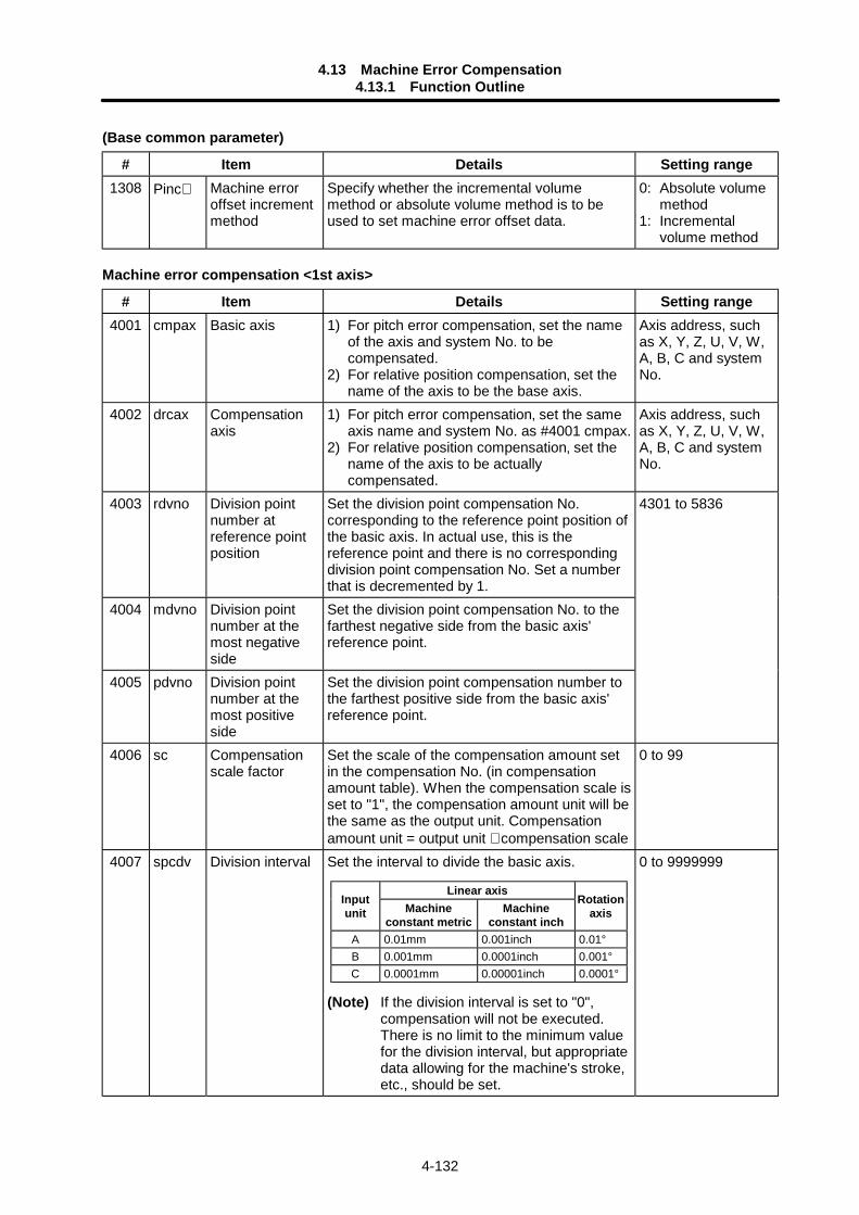
4.13 Machine Error Compensation4.13.1 Function Outline
4-132
(Base common parameter)
# Item Details Setting range1308 Pinc∗ Machine error
offset incrementmethod
Specify whether the incremental volumemethod or absolute volume method is to beused to set machine error offset data.
0: Absolute volumemethod
1: Incrementalvolume method
Machine error compensation <1st axis>
# Item Details Setting range4001 cmpax Basic axis 1) For pitch error compensation‚ set the name
of the axis and system No. to becompensated.
2) For relative position compensation‚ set thename of the axis to be the base axis.
Axis address, suchas X, Y, Z, U, V, W,A, B, C and systemNo.
4002 drcax Compensationaxis
1) For pitch error compensation‚ set the sameaxis name and system No. as #4001 cmpax.
2) For relative position compensation‚ set thename of the axis to be actuallycompensated.
Axis address, suchas X, Y, Z, U, V, W,A, B, C and systemNo.
4003 rdvno Division pointnumber atreference pointposition
Set the division point compensation No.corresponding to the reference point position ofthe basic axis. In actual use, this is thereference point and there is no correspondingdivision point compensation No. Set a numberthat is decremented by 1.
4301 to 5836
4004 mdvno Division pointnumber at themost negativeside
Set the division point compensation No. to thefarthest negative side from the basic axis'reference point.
4005 pdvno Division pointnumber at themost positiveside
Set the division point compensation number tothe farthest positive side from the basic axis'reference point.
4006 sc Compensationscale factor
Set the scale of the compensation amount setin the compensation No. (in compensationamount table). When the compensation scale isset to "1", the compensation amount unit will bethe same as the output unit. Compensationamount unit = output unit ∗ compensation scale
0 to 99
4007 spcdv Division interval Set the interval to divide the basic axis.
(Note) If the division interval is set to "0",compensation will not be executed.There is no limit to the minimum valuefor the division interval, but appropriatedata allowing for the machine's stroke,etc., should be set.
0 to 9999999
Linear axisInputunit Machine
constant metricMachine
constant inch
Rotationaxis
A 0.01mm 0.001inch 0.01°B 0.001mm 0.0001inch 0.001°C 0.0001mm 0.00001inch 0.0001°
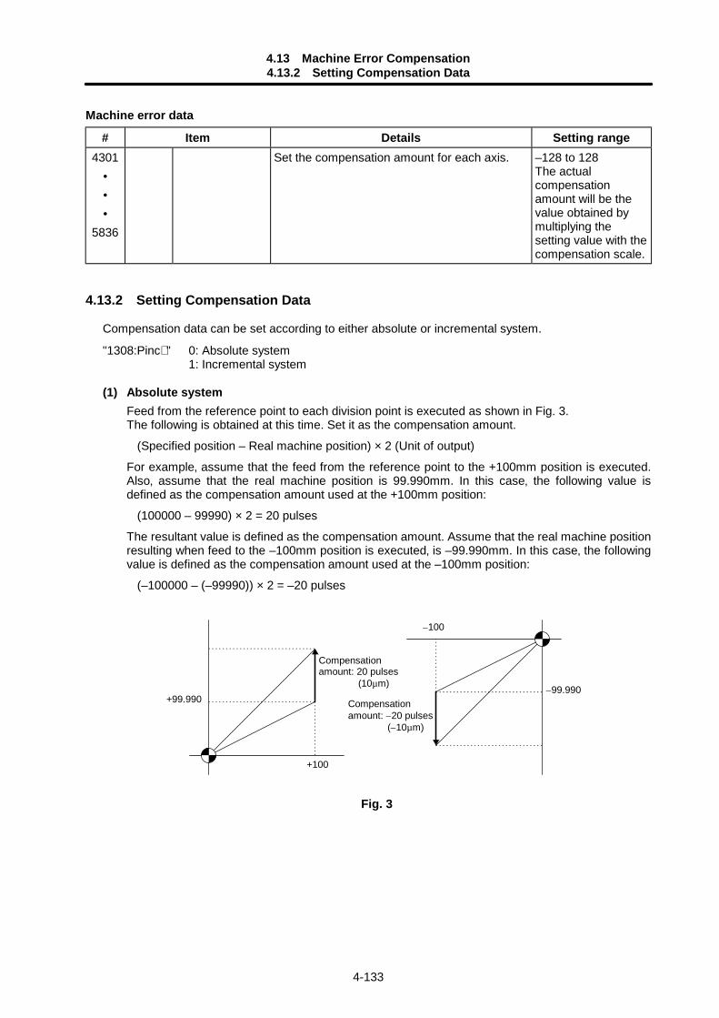
4.13 Machine Error Compensation4.13.2 Setting Compensation Data
4-133
Machine error data
# Item Details Setting range4301
•••
5836
Set the compensation amount for each axis. –128 to 128The actualcompensationamount will be thevalue obtained bymultiplying thesetting value with thecompensation scale.
4.13.2 Setting Compensation Data
Compensation data can be set according to either absolute or incremental system.
"1308:Pinc∗ " 0: Absolute system1: Incremental system
(1) Absolute systemFeed from the reference point to each division point is executed as shown in Fig. 3.The following is obtained at this time. Set it as the compensation amount.
(Specified position – Real machine position) × 2 (Unit of output)
For example‚ assume that the feed from the reference point to the +100mm position is executed.Also‚ assume that the real machine position is 99.990mm. In this case‚ the following value isdefined as the compensation amount used at the +100mm position:
(100000 – 99990) × 2 = 20 pulses
The resultant value is defined as the compensation amount. Assume that the real machine positionresulting when feed to the –100mm position is executed‚ is –99.990mm. In this case‚ the followingvalue is defined as the compensation amount used at the –100mm position:
(–100000 – (–99990)) × 2 = –20 pulses
+99.990
+100
Compensationamount: –20 pulses (–10µm)
Compensationamount: 20 pulses (10µm)
–99.990
–100
Fig. 3
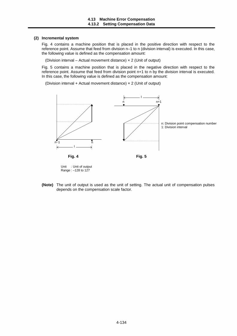
4.13 Machine Error Compensation4.13.2 Setting Compensation Data
4-134
(2) Incremental systemFig. 4 contains a machine position that is placed in the positive direction with respect to thereference point. Assume that feed from division n–1 to n (division interval) is executed. In this case‚the following value is defined as the compensation amount:
(Division interval – Actual movement distance) × 2 (Unit of output)
Fig. 5 contains a machine position that is placed in the negative direction with respect to thereference point. Assume that feed from division point n+1 to n by the division interval is executed.In this case‚ the following value is defined as the compensation amount:
(Division interval + Actual movement distance) × 2 (Unit of output)
nn–1l
n+1nl
(Note) The unit of output is used as the unit of setting. The actual unit of compensation pulsesdepends on the compensation scale factor.
Fig. 5Fig. 4
n: Division point compensation number1: Division interval
Unit : Unit of outputRange : –128 to 127
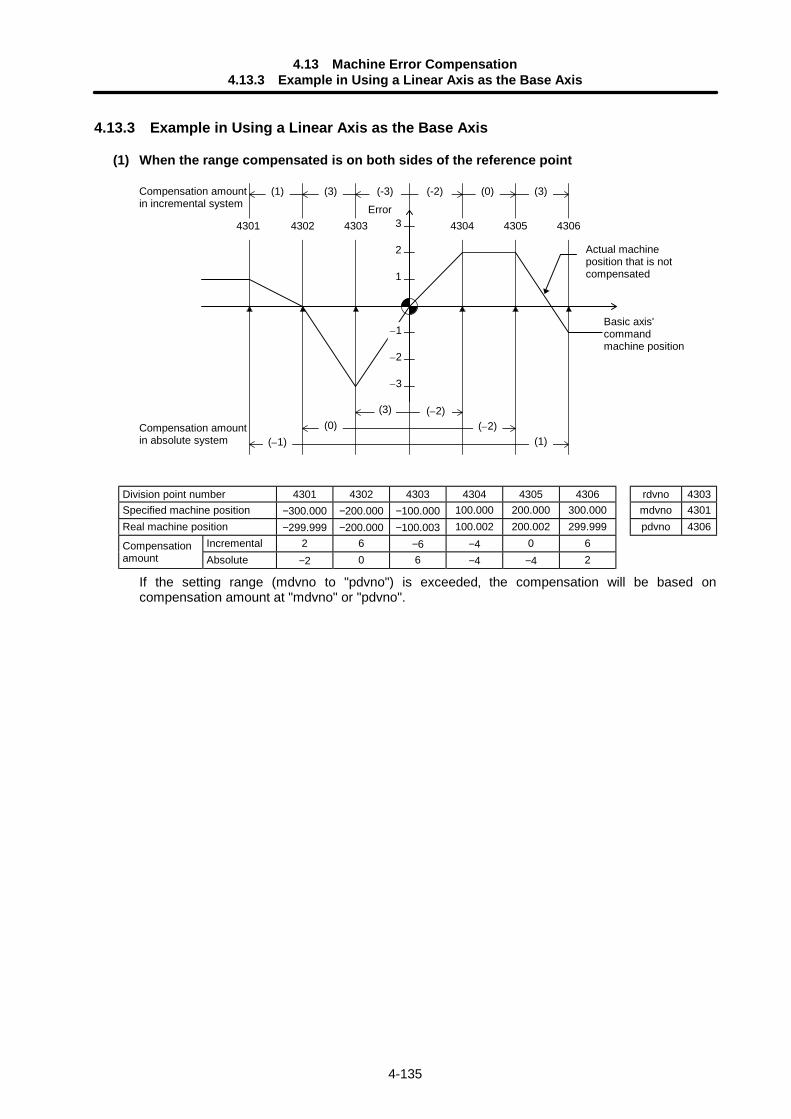
4.13 Machine Error Compensation4.13.3 Example in Using a Linear Axis as the Base Axis
4-135
4.13.3 Example in Using a Linear Axis as the Base Axis
(1) When the range compensated is on both sides of the reference point
4301
Compensation amountin incremental system
43034302 4304 4305 4306
2
1
–1
Error
–2
–3
(1) (3) (-3) (-2) (0) (3)
(3) (–2)(0) (–2)
(–1) (1)Compensation amountin absolute system
Basic axis'commandmachine position
3
Actual machineposition that is notcompensated
Division point number 4301 4302 4303 4304 4305 4306 rdvno 4303Specified machine position −300.000 −200.000 −100.000 100.000 200.000 300.000 mdvno 4301Real machine position −299.999 −200.000 −100.003 100.002 200.002 299.999 pdvno 4306
Incremental 2 6 −6 −4 0 6Compensationamount Absolute −2 0 6 −4 −4 2
If the setting range (mdvno to "pdvno") is exceeded‚ the compensation will be based oncompensation amount at "mdvno" or "pdvno".
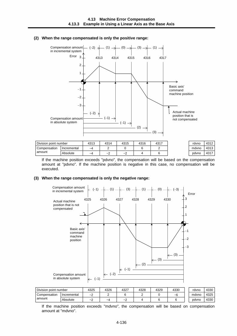
4.13 Machine Error Compensation4.13.3 Example in Using a Linear Axis as the Base Axis
4-136
(2) When the range compensated is only the positive range:
43144313 4316 4317
2
1
–1
–2
–3
(–2) (1) (0) (3) (1)
(–2)(–1)
(2)
3 4315
(–1)
(3)
Actual machineposition that isnot compensated
Error
Compensation amountin incremental system
Compensation amountin absolute system
Basic axis'commandmachine position
Division point number 4313 4314 4315 4316 4317 rdvno 4312Incremental −4 2 0 6 2 mdvno 4313Compensation
amount Absolute −4 −2 −2 4 6 pdvno 4317
If the machine position exceeds "pdvno"‚ the compensation will be based on the compensationamount at "pdvno". If the machine position is negative in this case‚ no compensation will beexecuted.
(3) When the range compensated is only the negative range:
43284327 43304326
2
1
–1
–2
–3
(3) (1) (0) (–3)
(3)(3)
(–1)
34329
(2)
(–2)
(–1) (1)
4325
(–1)
Actual machineposition that is notcompensated
Error
Compensation amountin incremental system
Compensation amountin absolute system
Basic axis'commandmachineposition
Division point number 4325 4326 4327 4328 4329 4330 rdvno 4330Incremental −2 2 6 2 0 −6 mdvno 4325Compensation
amount Absolute −2 −4 −2 4 6 6 pdvno 4330
If the machine position exceeds "mdvno"‚ the compensation will be based on compensationamount at "mdvno".
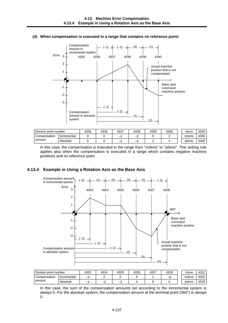
4.13 Machine Error Compensation4.13.4 Example in Using a Rotation Axis as the Base Axis
4-137
(4) When compensation is executed in a range that contains no reference point:
43364335 4338 4339
2
1
–1
–2
–3
(1)(–1) (–1) (3)
(–1)(–2)
(2)
3 4337
(1)
4340
Actual machineposition that is notcompensated
Error
Compensationamount inincremental system
Compensationamount in absolutesystem
Basic axis'commandmachine position
Division point number 4335 4336 4337 4338 4339 4340 rdvno 4334Incremental 0 0 −2 −2 6 2 mdvno 4336Compensation
amount Absolute 0 0 −2 −4 2 4 pdvno 4340
In this case‚ the compensation is executed in the range from "mdvno" to "pdvno". This setting ruleapplies also when the compensation is executed in a range which contains negative machinepositions and no reference point.
4.13.4 Example in Using a Rotation Axis as the Base Axis
43244323 4326 4327
2
1
–1
–2
–3
(–2) (1) (0) (3) (1)
(–2)(–1)
(2)
3 4325
(–1)
(3)
(–3)
4328
(0)
360°
Actual machineposition that is notcompensated
Error
Compensation amountin incremental system
Compensation amountin absolute system
Basic axis'commandmachine position
Division point number 4323 4324 4325 4326 4327 4328 rdvno 4322Incremental −4 2 0 6 2 −6 mdvno 4323Compensation
amount Absolute −4 −2 −2 4 6 0 pdvno 4328
In this case‚ the sum of the compensation amounts set according to the incremental system isalways 0. For the absolute system‚ the compensation amount at the terminal point (360°) is always0.
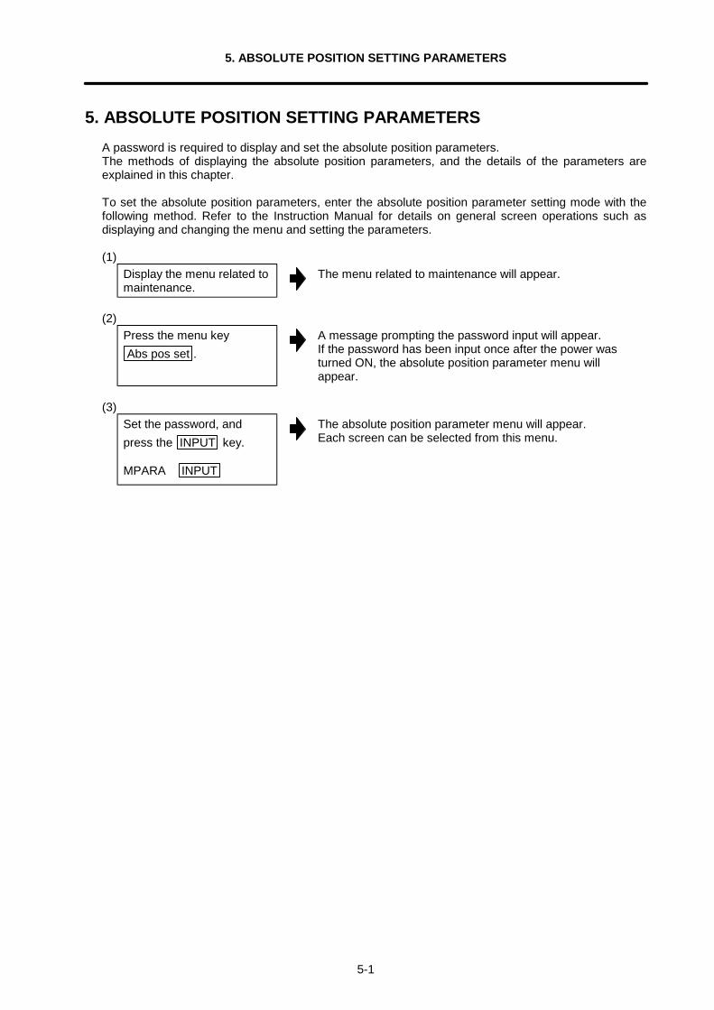
5. ABSOLUTE POSITION SETTING PARAMETERS
5-1
5. ABSOLUTE POSITION SETTING PARAMETERSA password is required to display and set the absolute position parameters.The methods of displaying the absolute position parameters, and the details of the parameters areexplained in this chapter.
To set the absolute position parameters, enter the absolute position parameter setting mode with thefollowing method. Refer to the Instruction Manual for details on general screen operations such asdisplaying and changing the menu and setting the parameters.
(1)Display the menu related tomaintenance.
The menu related to maintenance will appear.
(2)Press the menu keyAbs pos set .
A message prompting the password input will appear.If the password has been input once after the power wasturned ON, the absolute position parameter menu willappear.
(3)Set the password, andpress the INPUT key.
MPARA INPUT
The absolute position parameter menu will appear.Each screen can be selected from this menu.
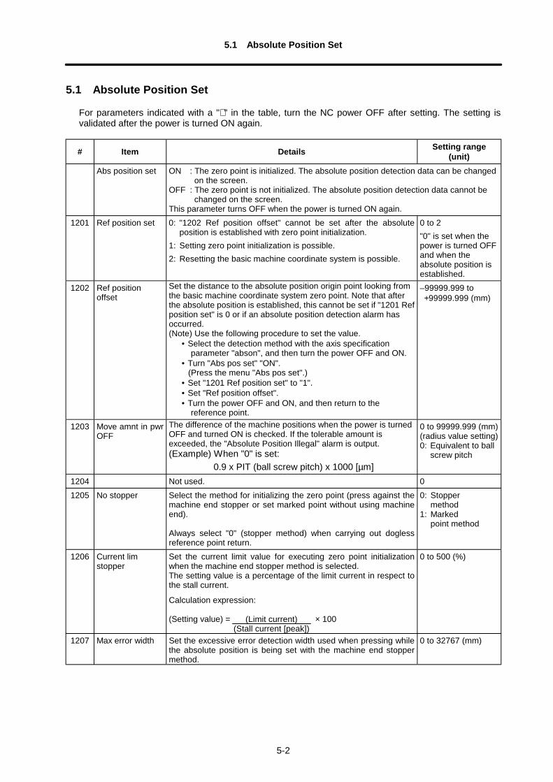
5.1 Absolute Position Set
5-2
5.1 Absolute Position Set
For parameters indicated with a "∗ " in the table, turn the NC power OFF after setting. The setting isvalidated after the power is turned ON again.
# Item Details Setting range(unit)
Abs position set ON : The zero point is initialized. The absolute position detection data can be changed on the screen.OFF : The zero point is not initialized. The absolute position detection data cannot be changed on the screen.This parameter turns OFF when the power is turned ON again.
1201 Ref position set 0: "1202 Ref position offset" cannot be set after the absoluteposition is established with zero point initialization.
1: Setting zero point initialization is possible.2: Resetting the basic machine coordinate system is possible.
0 to 2"0" is set when thepower is turned OFFand when theabsolute position isestablished.
1202 Ref positionoffset
Set the distance to the absolute position origin point looking fromthe basic machine coordinate system zero point. Note that afterthe absolute position is established, this cannot be set if "1201 Refposition set" is 0 or if an absolute position detection alarm hasoccurred.(Note) Use the following procedure to set the value.
• Select the detection method with the axis specificationparameter "abson", and then turn the power OFF and ON.
• Turn "Abs pos set" "ON".(Press the menu "Abs pos set".)
• Set "1201 Ref position set" to "1".• Set "Ref position offset".• Turn the power OFF and ON, and then return to the
reference point.
–99999.999 to +99999.999 (mm)
1203 Move amnt in pwrOFF
The difference of the machine positions when the power is turnedOFF and turned ON is checked. If the tolerable amount isexceeded, the "Absolute Position Illegal" alarm is output.(Example) When "0" is set:
0.9 x PIT (ball screw pitch) x 1000 [µm]
0 to 99999.999 (mm)(radius value setting)0: Equivalent to ball
screw pitch
1204 Not used. 01205 No stopper Select the method for initializing the zero point (press against the
machine end stopper or set marked point without using machineend).
Always select "0" (stopper method) when carrying out doglessreference point return.
0: Stoppermethod
1: Markedpoint method
1206 Current limstopper
Set the current limit value for executing zero point initializationwhen the machine end stopper method is selected.The setting value is a percentage of the limit current in respect tothe stall current.
Calculation expression:
(Setting value) = × 100
0 to 500 (%)
1207 Max error width Set the excessive error detection width used when pressing whilethe absolute position is being set with the machine end stoppermethod.
0 to 32767 (mm)
(Limit current)(Stall current [peak])
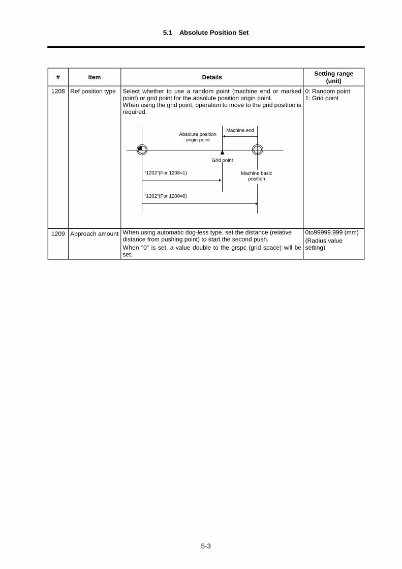
5.1 Absolute Position Set
5-3
# Item Details Setting range(unit)
1208 Ref position type Select whether to use a random point (machine end or markedpoint) or grid point for the absolute position origin point.When using the grid point, operation to move to the grid position isrequired.
“1202”(For 1208=1)
“1202”(For 1208=0)
Grid point
Machine basicposition
Machine endAbsolute position
origin point
0: Random point1: Grid point
1209 Approach amount When using automatic dog-less type, set the distance (relativedistance from pushing point) to start the second push.When "0" is set, a value double to the grspc (grid space) will beset.
0to99999.999 (mm)(Radius valuesetting)
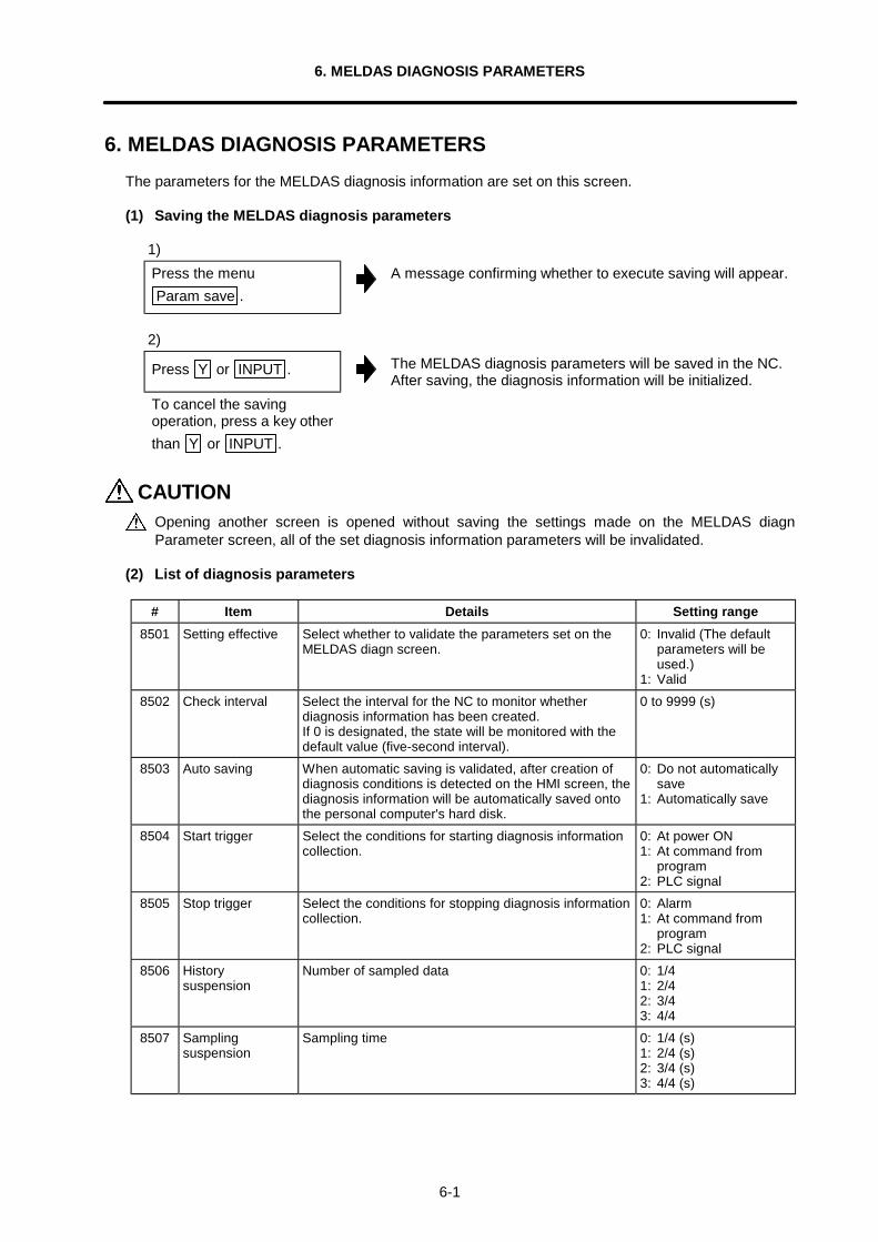
6. MELDAS DIAGNOSIS PARAMETERS
6-1
6. MELDAS DIAGNOSIS PARAMETERSThe parameters for the MELDAS diagnosis information are set on this screen.
(1) Saving the MELDAS diagnosis parameters
1)Press the menuParam save .
A message confirming whether to execute saving will appear.
2)
Press Y or INPUT . The MELDAS diagnosis parameters will be saved in the NC.After saving, the diagnosis information will be initialized.
To cancel the savingoperation, press a key otherthan Y or INPUT .
CAUTIONOpening another screen is opened without saving the settings made on the MELDAS diagnParameter screen, all of the set diagnosis information parameters will be invalidated.
(2) List of diagnosis parameters
# Item Details Setting range8501 Setting effective Select whether to validate the parameters set on the
MELDAS diagn screen.0: Invalid (The default
parameters will beused.)
1: Valid8502 Check interval Select the interval for the NC to monitor whether
diagnosis information has been created.If 0 is designated, the state will be monitored with thedefault value (five-second interval).
0 to 9999 (s)
8503 Auto saving When automatic saving is validated, after creation ofdiagnosis conditions is detected on the HMI screen, thediagnosis information will be automatically saved ontothe personal computer's hard disk.
0: Do not automaticallysave
1: Automatically save
8504 Start trigger Select the conditions for starting diagnosis informationcollection.
0: At power ON1: At command from
program2: PLC signal
8505 Stop trigger Select the conditions for stopping diagnosis informationcollection.
0: Alarm1: At command from
program2: PLC signal
8506 Historysuspension
Number of sampled data 0: 1/41: 2/42: 3/43: 4/4
8507 Samplingsuspension
Sampling time 0: 1/4 (s)1: 2/4 (s)2: 3/4 (s)3: 4/4 (s)
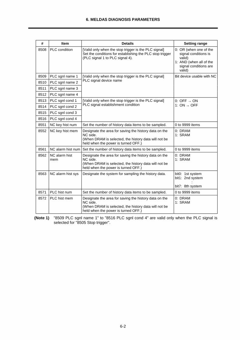
6. MELDAS DIAGNOSIS PARAMETERS
6-2
# Item Details Setting range8508 PLC condition [Valid only when the stop trigger is the PLC signal]
Set the conditions for establishing the PLC stop trigger(PLC signal 1 to PLC signal 4).
0: OR (when one of thesignal conditions isvalid)
1: AND (when all of thesignal conditions arevalid)
8509 PLC sgnl name 18510 PLC sgnl name 28511 PLC sgnl name 38512 PLC sgnl name 4
[Valid only when the stop trigger is the PLC signal]PLC signal device name
Bit device usable with NC
8513 PLC sgnl cond 18514 PLC sgnl cond 28515 PLC sgnl cond 38516 PLC sgnl cond 4
[Valid only when the stop trigger is the PLC signal]PLC signal establishment condition
0: OFF → ON1: ON → OFF
8551 NC key hist num Set the number of history data items to be sampled. 0 to 9999 items8552 NC key hist mem Designate the area for saving the history data on the
NC side.(When DRAM is selected, the history data will not beheld when the power is turned OFF.)
0: DRAM1: SRAM
8561 NC alarm hist num Set the number of history data items to be sampled. 0 to 9999 items8562 NC alarm hist
memDesignate the area for saving the history data on theNC side.(When DRAM is selected, the history data will not beheld when the power is turned OFF.)
0: DRAM1: SRAM
8563 NC alarm hist sys Designate the system for sampling the history data. bit0: 1st systembit1: 2nd system
:bit7: 8th system
8571 PLC hist num Set the number of history data items to be sampled. 0 to 9999 items8572 PLC hist mem Designate the area for saving the history data on the
NC side.(When DRAM is selected, the history data will not beheld when the power is turned OFF.)
0: DRAM1: SRAM
(Note 1) "8509 PLC sgnl name 1" to "8516 PLC sgnl cond 4" are valid only when the PLC signal isselected for "8505 Stop trigger".
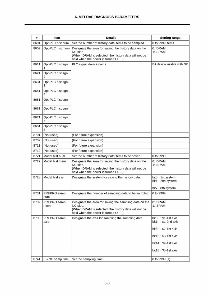
6. MELDAS DIAGNOSIS PARAMETERS
6-3
# Item Details Setting range8601 Opt-PLC hist num Set the number of history data items to be sampled. 0 to 9999 items8602 Opt-PLC hist mem Designate the area for saving the history data on the
NC side.(When DRAM is selected, the history data will not beheld when the power is turned OFF.)
0: DRAM1: SRAM
8611 Opt-PLC hist sgnl1
8621 Opt-PLC hist sgnl2
8631 Opt-PLC hist sgnl3
8641 Opt-PLC hist sgnl4
8651 Opt-PLC hist sgnl5
8661 Opt-PLC hist sgnl6
8671 Opt-PLC hist sgnl7
8681 Opt-PLC hist sgnl8
PLC signal device name Bit device usable with NC
8701 (Not used) (For future expansion)8702 (Not used) (For future expansion)8711 (Not used) (For future expansion)8712 (Not used) (For future expansion)8721 Modal hist num Set the number of history data items to be saved. 0 to 99998722 Modal hist mem Designate the area for saving the history data on the
NC side.(When DRAM is selected, the history data will not beheld when the power is turned OFF.)
0: DRAM1: SRAM
8723 Modal hist sys Designate the system for saving the history data. bit0: 1st systembit1: 2nd system
:bit7: 8th system
8731 PREPRO sampnum
Designate the number of sampling data to be sampled. 0 to 9999
8732 PREPRO sampmem
Designate the area for saving the sampling data on theNC side.(When DRAM is selected, the history data will not beheld when the power is turned OFF.)
0: DRAM1: SRAM
8733 PREPRO sampaxis
Designate the axis for sampling the sampling data. bit0 : $1-1st axisbit1 : $1-2nd axis
:bit5 : $2-1st axis
:bit10 : $3-1st axis
:bit14 : $4-1st axis
:bit18 : $5-1st axis
:8741 ISYNC samp time Set the sampling time. 0 to 9999 (s)
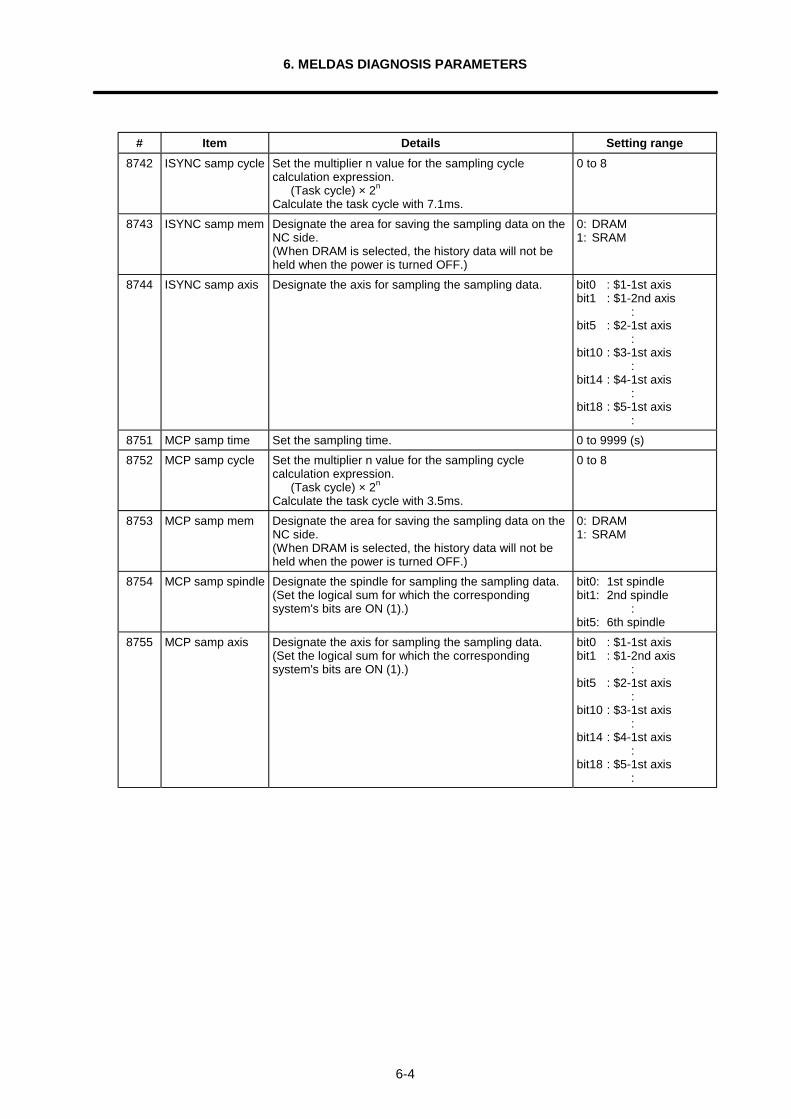
6. MELDAS DIAGNOSIS PARAMETERS
6-4
# Item Details Setting range8742 ISYNC samp cycle Set the multiplier n value for the sampling cycle
calculation expression. (Task cycle) × 2n
Calculate the task cycle with 7.1ms.
0 to 8
8743 ISYNC samp mem Designate the area for saving the sampling data on theNC side.(When DRAM is selected, the history data will not beheld when the power is turned OFF.)
0: DRAM1: SRAM
8744 ISYNC samp axis Designate the axis for sampling the sampling data. bit0 : $1-1st axisbit1 : $1-2nd axis
:bit5 : $2-1st axis
:bit10 : $3-1st axis
:bit14 : $4-1st axis
:bit18 : $5-1st axis
:8751 MCP samp time Set the sampling time. 0 to 9999 (s)8752 MCP samp cycle Set the multiplier n value for the sampling cycle
calculation expression. (Task cycle) × 2n
Calculate the task cycle with 3.5ms.
0 to 8
8753 MCP samp mem Designate the area for saving the sampling data on theNC side.(When DRAM is selected, the history data will not beheld when the power is turned OFF.)
0: DRAM1: SRAM
8754 MCP samp spindle Designate the spindle for sampling the sampling data.(Set the logical sum for which the correspondingsystem's bits are ON (1).)
bit0: 1st spindlebit1: 2nd spindle
:bit5: 6th spindle
8755 MCP samp axis Designate the axis for sampling the sampling data.(Set the logical sum for which the correspondingsystem's bits are ON (1).)
bit0 : $1-1st axisbit1 : $1-2nd axis
:bit5 : $2-1st axis
:bit10 : $3-1st axis
:bit14 : $4-1st axis
:bit18 : $5-1st axis
:

Revision History
Sub-No. Date of revision Revision details
∗ October, 2000 First edition created.

Notice
Every effort has been made to keep up with software and hardware revisions in
the contents described in this manual. However, please understand that in
some unavoidable cases simultaneous revision is not possible.Please contact your Mitsubishi Electric dealer with any questions or commentsregarding the use of this product.
Duplication ProhibitedThis instruction manual may not be reproduced in any form, in part or in whole,without written permission from Mitsubishi Electric Corporation.
2000 MITSUBISHI ELECTRIC CORPORATION ALL RIGHTS RESERVED.

MITSUBISHI ELECTRIC CORPORATIONHEAD OFFICE: MITSUBISHI DENKI BLD. MARUNOUCHI. TOKYO 100-0005 TEL:03-218-3426
Printed in Japan Specifications subject to change without notice.
Related Documents


![OWNER’S MANUAL - Soundstream the [SEL] button to enter the Sound Parameter Setup, Picture Parameter Setup & Tuner Parameter Setup. ... Manual Store Radio Station -1 2 ...](https://static.cupdf.com/doc/110x72/5b06b6407f8b9ae9628d6de8/owners-manual-the-sel-button-to-enter-the-sound-parameter-setup-picture.jpg)
