MEIC IR Design Yuhong Zhang EIC Generic R&D Advisory Committee Meeting December 13, 2012

MEIC IR Design Yuhong Zhang EIC Generic R&D Advisory Committee Meeting December 13, 2012.
Dec 17, 2015
Welcome message from author
This document is posted to help you gain knowledge. Please leave a comment to let me know what you think about it! Share it to your friends and learn new things together.
Transcript
MEIC IR Design
Yuhong Zhang
EIC Generic R&D Advisory Committee Meeting
December 13, 2012
Y. Zhang ---2---
Outline
• Introduction
• MEIC Accelerator Design overview
• Interaction Region Design• Optimization for detector capability• Optimization for chromaticity Compensation
• Machine Background
• Summary

Acknowledgement
The work reported in this presentation are done primarily by
• Vasiliy Morozov and Fanglei Lin, CASA, Jefferson Lab
• Pawel Nadel-Turonski, Physics Division, Jefferson Lab
• Charles Hyde, Jefferson Lab/Old Dominion University
• Michael Sullivan, SLAC
I would also like to thank members of the JLab EIC design study group and our external collaborators
Y. Zhang --3--
Introduction
• JLab’s fixed target program after the 12 GeV CEBAF upgrade will be world-leading for at least a decade.
• A Medium energy Electron-Ion Collider (MEIC) at JLab will open new frontiers in nuclear science.
• The timing of MEIC construction can be tailored to match available DOE-ONP funding while the 12 GeV physics program continues.
• MEIC parameters are chosen to optimize science, technology development, and project cost.
• We maintain a well defined path for future upgrade to higher energies and luminosities.
• A conceptual machine design has been completed recently, providing a base for performance evaluation, cost estimation, and technical risk assessment.
Y. Zhang --4--
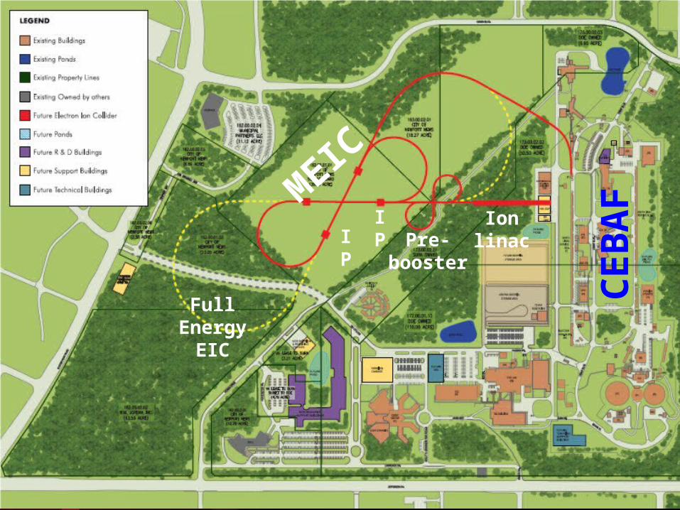
Pre-booster
Ion linacIP
IP
MEI
C
Full Energy
EIC
CEB
AF

Y. Zhang ---6---
MEIC is The Stage 1 at JLab
• Energy (bridging the gap of 12 GeV CEBAF & HERA/LHeC)
– Full coverage of s from a few 100 to a few 1000 GeV2
– Electrons 3-12 GeV, protons 20-100 GeV, ions 12-40 GeV/u
• Ion species– Polarized light ions: p, d, 3He, and possibly Li, and polarized heavier ions– Un-polarized light to heavy ions up to A above 200 (Au, Pb)
• Up to 2 detectors
• Luminosity– Greater than 1034 cm-2s-1 per interaction point– Maximum luminosity should optimally be around √s=45 GeV
• Polarization– At IP: longitudinal for both beams, transverse for ions only– All polarizations >70% desirable
• Upgradeable to higher energies and luminosity– 20 GeV electron, 250 GeV proton, and 100 GeV/u ion

MEIC Design Report Released!
Y. Zhang --7--
arXiv:1209.0757
Table of ContentsExecutive Summary
1. Introduction
2. Nuclear Physics with MEIC
3. Baseline Design and Luminosity Concept
4. Electron Complex
5. Ion Complex
6. Electron Cooling
7. Interaction Regions7.1 MEIC Primary Detector
7.2 Interaction Region Design Considerations
7.3 Interaction Region Layout and Detector Acceptance
7.4 Linear Optics Design
7.5 Chromaticity Compensation
7.6 Momentum Acceptance and Dynamic Aperture
7.7 Crab Crossing
7.8 Synchrotron Radiation and Detector Background
7.9 Beam-Beam Interactions.
8. Outlook
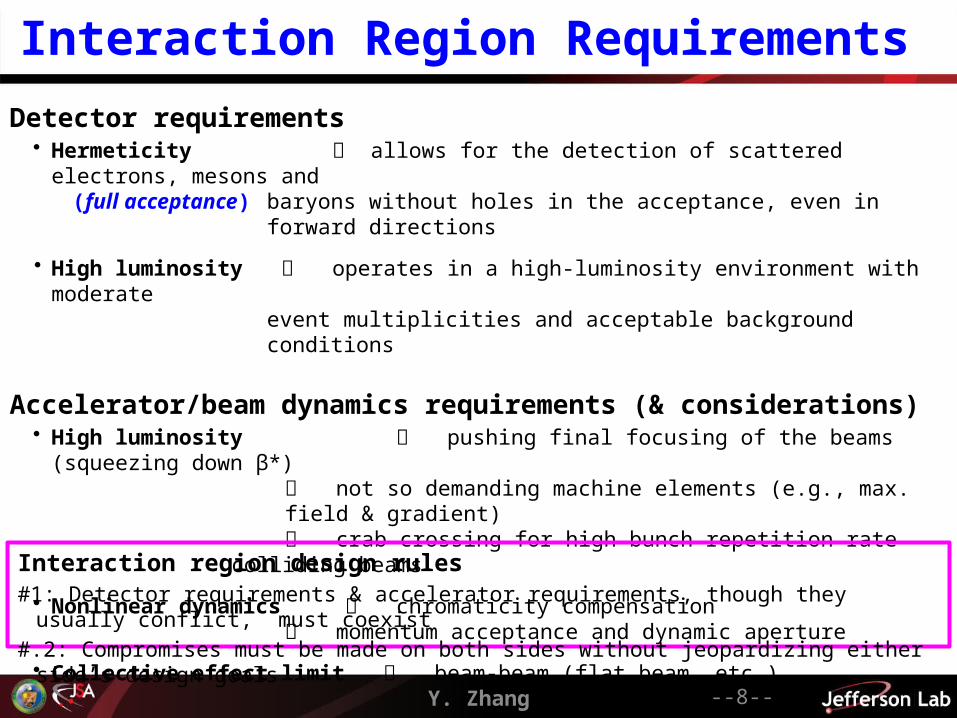
Interaction Region Requirements
Detector requirements• Hermeticity allows for the detection of scattered electrons, mesons and (full acceptance) baryons without holes in the acceptance, even in forward directions
• High luminosity operates in a high-luminosity environment with moderateevent multiplicities and acceptable background conditions
Accelerator/beam dynamics requirements (& considerations)• High luminosity pushing final focusing of the beams (squeezing down β*)
not so demanding machine elements (e.g., max. field & gradient) crab crossing for high bunch repetition rate colliding beams
• Nonlinear dynamics chromaticity compensation momentum acceptance and dynamic aperture
• Collective effect limit beam-beam (flat beam, etc.)
Y. Zhang --8--
Interaction region design rules#1: Detector requirements & accelerator requirements, though they usually conflict, must coexist
#.2: Compromises must be made on both sides without jeopardizing either side’s design goals
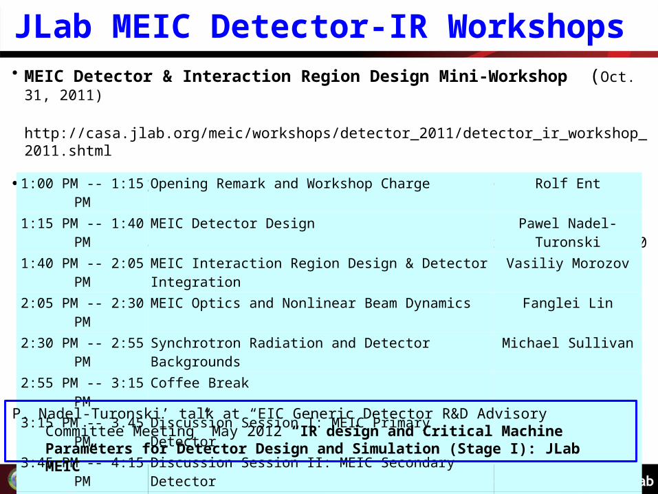
JLab MEIC Detector-IR Workshops • MEIC Detector & Interaction Region Design Mini-Workshop (Oct. 31, 2011)
http://casa.jlab.org/meic/workshops/detector_2011/detector_ir_workshop_2011.shtml
• The 2nd MEIC Detector & Interaction Region Design Mini-Workshop (Nov. 2, 2012)
http://casa.jlab.org/meic/workshops/detector2012/detector_ir_workshop2012.shtml
Y. Zhang --9--
1:00 PM -- 1:15 PM Opening Remark and Workshop Charge Rolf Ent1:15 PM -- 1:40 PM MEIC Detector Design Pawel Nadel-Turonski1:40 PM -- 2:05 PM MEIC Interaction Region Design & Detector Integration Vasiliy Morozov2:05 PM -- 2:30 PM MEIC Optics and Nonlinear Beam Dynamics Fanglei Lin2:30 PM -- 2:55 PM Synchrotron Radiation and Detector Backgrounds Michael Sullivan2:55 PM -- 3:15 PM Coffee Break3:15 PM -- 3.45 PM Discussion Session I: MEIC Primary Detector3:45 PM -- 4:15 PM Discussion Session II: MEIC Secondary Detector4:15 PM -- 4:25 PM LEIC Luminosity Yuhong Zhang4:25 PM -- 4:55 PM Discussion Session III: LEIC4:55 PM -- 5:00 PM Workshop Summary Andrew Hutton
P. Nadel-Turonski’ talk at “EIC Generic Detector R&D Advisory Committee Meeting” May 2012 “IR design and Critical Machine Parameters for Detector Design and Simulation (Stage I): JLab MEIC”
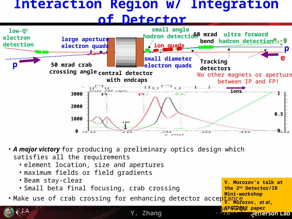
Interaction Region w/ Integration of Detector
Y. Zhang --10--
ultra forwardhadron detection
low-Q2
electron detection
large apertureelectron quads
small diameterelectron quads
central detector with endcaps
ion quads
50 mrad crab crossing angle
n, g
ep
p
small anglehadron detection 60 mrad
bend
Tracking detectors
No other magnets or apertures between IP and FP!
ions3000
2000
1000
0
1
0.5
0
V. Morozov’s talk at the 2nd Detector/IR Mini-workshop
V. Morozov, et al, IPAC2012 paper
• A major victory for producing a preliminary optics design which satisfies all the requirements• element location, size and apertures• maximum fields or field gradients• Beam stay-clear• Small beta final focusing, crab crossing
• Make use of crab crossing for enhancing detector acceptance
• Adopted permanent magnets for smaller sizes of electron FFQs
npe
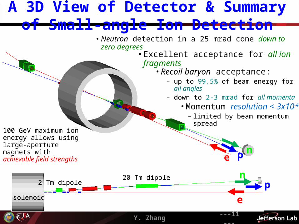
100 GeV maximum ion energy allows using large-aperture magnets with achievable field strengths
• Momentum resolution < 3x10⁻⁴
– limited by beam momentum spread
• Excellent acceptance for all ion fragments
• Neutron detection in a 25 mrad cone down to zero degrees
• Recoil baryon acceptance:– up to 99.5% of beam energy for all angles– down to 2-3 mrad for all momenta
A 3D View of Detector & Summary of Small-angle Ion Detection
Y. Zhang ---11---
e
pn20 Tm dipole
2 Tm dipole
solenoid
Y. Zhang ---12---
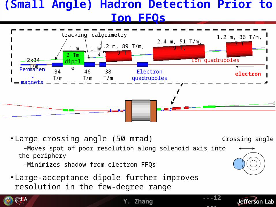
(Small Angle) Hadron Detection Prior to Ion FFQs
• Large crossing angle (50 mrad)–Moves spot of poor resolution along solenoid axis into the periphery–Minimizes shadow from electron FFQs
• Large-acceptance dipole further improves resolution in the few-degree range
Crossing angle
2 Tm dipole Ion quadrupoles
Electron quadrupoles
tracking calorimetry
1 m1 m
electron
1.2 m, 89 T/m, 9 T2.4 m, 51 T/m, 9 T,
1.2 m, 36 T/m, 7 T
46 T/m 38 T/m34 T/mPermanent magnets
2x34 T/m
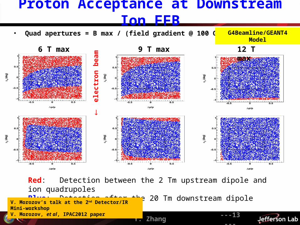
Proton Acceptance at Downstream Ion FFB
Y. Zhang ---13---
• Quad apertures = B max / (field gradient @ 100 GeV/c)
6 T max 9 T max 12 T max
e
lect
ron
bea
m
Red: Detection between the 2 Tm upstream dipole and ion quadrupolesBlue: Detection after the 20 Tm downstream dipole
G4Beamline/GEANT4 Model
V. Morozov’s talk at the 2nd Detector/IR Mini-workshopV. Morozov, et al, IPAC2012 paper

Forward Ion Momentum & Angle Resolution at Focal Point
Y. Zhang --14--
electron beam
e
lect
ron
bea
m
|x| > 3 mrad @ p/p = 0
• Protons with different p/p launched with x spread around nominal trajectory

Y. Zhang ---15---
Nonlinear Beam Dynamics
MEIC chromaticity compensation scheme• Local compensation scheme: dedicated chromaticity
compensation blocks (CCB) near an IP• Using families of sextupoles and octupoles• simultaneous compensation of chromatic tune-shift
and beam smear at IP • Symmetric CCB (with respect to its center)
– ux is anti-symmetric, uy is symmetric– D is symmetric– n and ns are symmetric
Chromaticity is an issue in MEIC design, particularly due to the low-β insertions• Chromatic turn spread• Chromatic beta-smear at IP
Ion ring (ξx/ξy) Electron ring (ξx/ξy)
Contribution from whole arc 17.4 / 16.1 68.8 / 70. 1
Contribution per IR 130 / 126 47.3 / 54.0
Whole ring (2IP+arc) 278 / 268 188 / 202
MEIC design report Section 7.4
Y. Zhang --16--
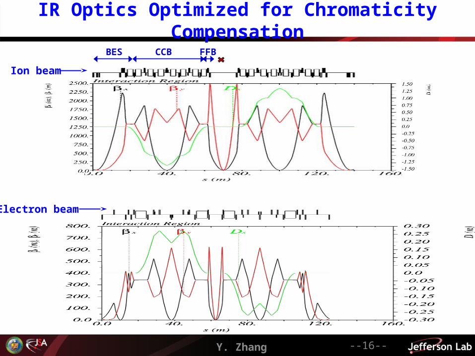
IR Optics Optimized for Chromaticity Compensation
Ion beam
Electron beam
FFBCCBBES

Y. Zhang ---17---
Momentum Acceptance & Dynamic Aperture• Compensation of chromaticity with 2 sextupole families only using symmetry• Nonlinear dynamic studies (aperture optimization and error impact) under way
p/p = 0.310-3 at 60 GeV/c
5 p/p
Ions
p/p = 0.710-3 at 5 GeV/c
5 p/p
Electrons
/ xx
/
/ yy
/ xx
w/o Octupole
with OctupoleIons Ions
F. Lin’s talk at the 2nd Detector/IR Mini-workshopF, Lin, et al, IPAC2012 paper
Y. Zhang ---18---
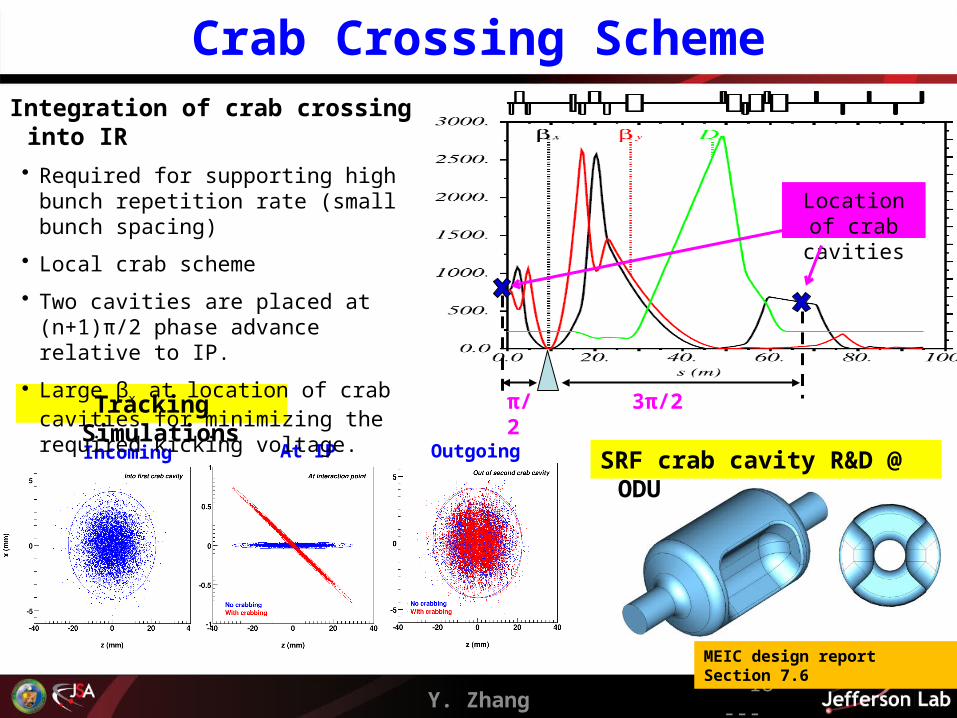
Crab Crossing Scheme
Incoming At IP Outgoing
Tracking Simulations
Integration of crab crossing into IR
• Required for supporting high bunch repetition rate (small bunch spacing)
• Local crab scheme
• Two cavities are placed at (n+1)π/2 phase advance relative to IP.
• Large βx at location of crab cavities for minimizing the required kicking voltage.
π/2 3π/2
Location of crab cavities
SRF crab cavity R&D @ ODU
MEIC design report Section 7.6

Beam Synchronization at IP & Collision Pattern
Path length difference in collider rings• Electrons travel at the speed of light, protons/ions are slower • Slower proton/ ion bunches will not meet the electron bunch again at the IP after one revolution • Synchronization must be achieved at every IP in the collider ring simultaneously
Y. Zhang --19--
Present conceptual solution• Varying number of bunches (harmonic number) in the
ion collider ring would synchronize beams at IPs for a set of ion energies (harmonic energies)
• To cover the energies between the harmonic values– varying electron orbit up to half bunch spacing– varying RF frequency (less than 0.01%)
Bunches in ion ring
Energy (GeV/u)
Proton Lead
3370 100
3371 35.9 35.9
3372 26.3 26.3
3373 21.7 21.7
3374 18.9
3375 17.0Collision pattern at IP
• Each time it returns to the IP, an Ion bunch will collide with a different electron bunch
(Specifically, If n is the difference of ion and electron harmonic numbers, then an ion bunch will always collide the n-th bunch in the electron bunch train)
• An ion bunch will collider all or a subset (eg. all even numbers) electron bunches
• Number of bunch in the electron ring is always 3370
• Assuming electron and ion have a same circumference (1350 m) at 100 GeV proton energy
MEIC design report section 5.9
Suppressing Synchrotron Radiation at IR
Y. Zhang --20--
MEIC Design optimized for suppressing synchrotron radiation at IR
• Flat electron ring ions travels to the plane of the electron ring for horizontal crab crossing at collision points
• Detector solenoid is along the electron beamline
• Gentle bending of electrons at end of each arcs
• Minimizing bending of electrons in long straights of figure-8
• Keep bending angles of dipoles in chromaticity compensation blocks small
• (Place IP close to the end of arc where ion beam comes from)
More synchrotron radiation issues• A high forward detector design requires carefully tracing synchrotron radiation
fans from bend magnets to see • where the power goes • how this interacts with the beam pipe design in front of the detector
• Local forward and back scattering rates from nearby beam pipe surface
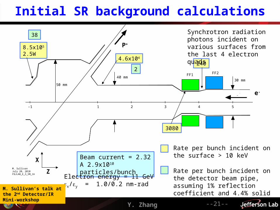
Initial SR background calculations
FF1 FF2
e-
P+
1 2 3 4 5-1
40 mm30 mm
50 mm
240
3080
4.6x10⁴
8.5x10⁵
2.5W
38
2
Synchrotron radiation photons incident on various surfaces from the last 4 electron quads
Rate per bunch incident on the surface > 10 keV
Rate per bunch incident on the detector beam pipe, assuming 1% reflection coefficient and 4.4% solid angle acceptance
M. SullivanJuly 20, 2010F$JLAB_E_3_5M_1A
Beam current = 2.32 A 2.9x10¹⁰ particles/bunch
X
P+
e-
ZElectron energy = 11 GeVx/y = 1.0/0.2 nm-rad
Y. Zhang --21--
M. Sullivan’s talk at the 2nd Detector/IR Mini-workshop
Summary
• The 1st design of MEIC is completed and a comprehensive design report has been released
• The MEIC interaction region has been designed to support a full-acceptance detector and also optimized for achieving good chromaticity compensation
• The MEIC design is optimized for suppressing synchrotron radiation in the interaction regions and at the detectors.
• Lots of interaction region design studies are still in progress– integration of detector-interaction-region– optimization of dynamic aperture and studies of impact of magnet errors– Synchrotron radiation and background
• We plan to study interaction region design for the 2nd MEIC detector and also a low energy (up to 25 GeV proton) EIC detector
Y. Zhang --22--
Backup slides
Y. Zhang --23--
Y. Zhang ---24---
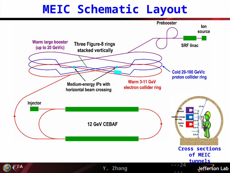
MEIC Schematic Layout
Cross sections of MEIC tunnels
Y. Zhang ---25---
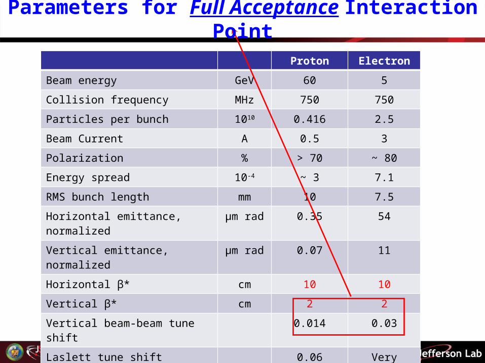
Proton Electron
Beam energy GeV 60 5
Collision frequency MHz 750 750
Particles per bunch 1010 0.416 2.5
Beam Current A 0.5 3
Polarization % > 70 ~ 80
Energy spread 10-4 ~ 3 7.1
RMS bunch length mm 10 7.5
Horizontal emittance, normalized µm rad 0.35 54
Vertical emittance, normalized µm rad 0.07 11
Horizontal β* cm 10 10
Vertical β* cm 2 2
Vertical beam-beam tune shift 0.014 0.03
Laslett tune shift 0.06 Very small
Distance from IP to 1st FF quad m 7 3
Luminosity per IP, 1033 cm-2s-1 5.6
Parameters for Full Acceptance Interaction Point
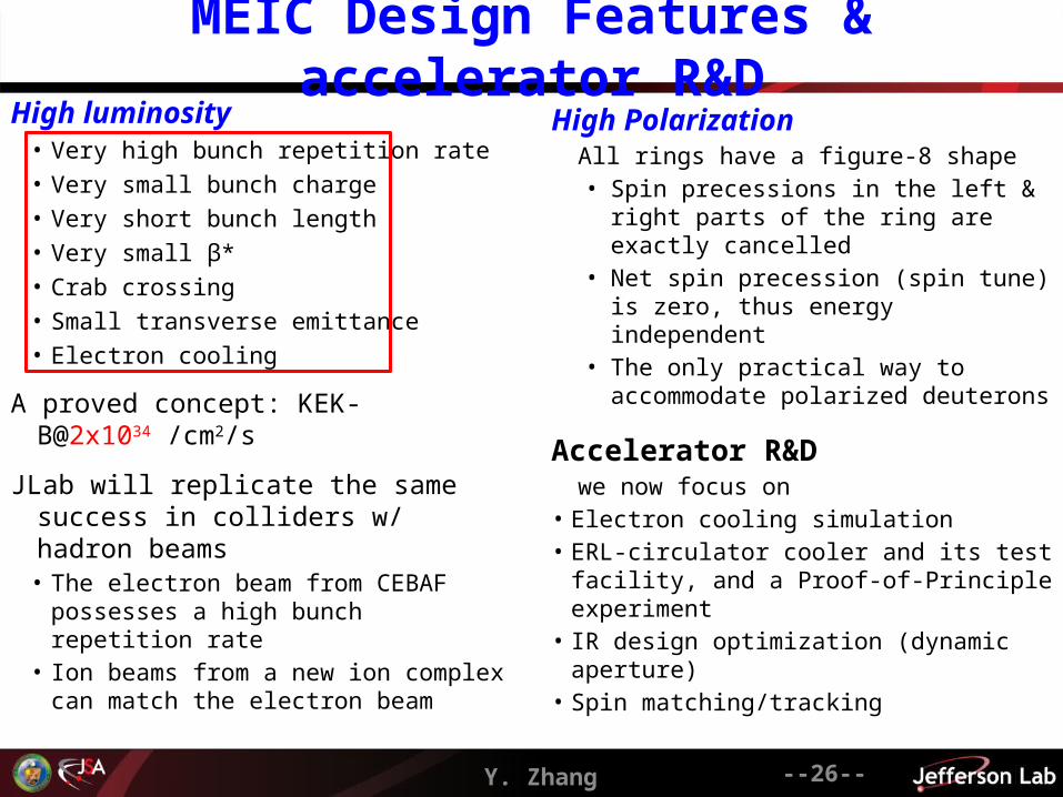
MEIC Design Features & accelerator R&D
Y. Zhang --26--
High luminosity• Very high bunch repetition rate• Very small bunch charge• Very short bunch length• Very small β*• Crab crossing• Small transverse emittance• Electron cooling
A proved concept: KEK-B@2x1034 /cm2/s
JLab will replicate the same success in colliders w/ hadron beams
• The electron beam from CEBAF possesses a high bunch repetition rate
• Ion beams from a new ion complex can match the electron beam
High PolarizationAll rings have a figure-8 shape • Spin precessions in the left & right parts of
the ring are exactly cancelled• Net spin precession (spin tune) is zero,
thus energy independent• The only practical way to accommodate
polarized deuterons
Accelerator R&Dwe now focus on
• Electron cooling simulation• ERL-circulator cooler and its test facility, and
a Proof-of-Principle experiment• IR design optimization (dynamic aperture)• Spin matching/tracking
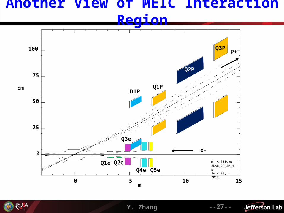
Another View of MEIC Interaction Region
--27--
0
25
50
75
100
cm
0 5 10 15m
M. SullivanJLAB_EP_3M_4RJuly 30, 2012
Q1PD1P
Q1e Q2e
Q3e
Q4e Q5e
e-
P+
Q2P
Q3P
Y. Zhang
Y. Zhang ---28---
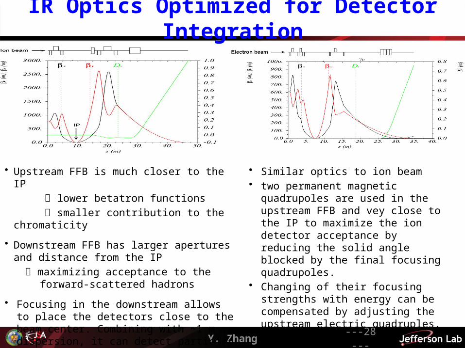
IR Optics Optimized for Detector Integration
• Upstream FFB is much closer to the IP
lower betatron functions
smaller contribution to the chromaticity
• Downstream FFB has larger apertures and distance from the IP
maximizing acceptance to the forward-scattered hadrons
• Focusing in the downstream allows to place the detectors close to the beam center. Combining with ~1 m dispersion, it can detect particles with small momentum offset Δp/p
• Similar optics to ion beam• two permanent magnetic quadrupoles are
used in the upstream FFB and vey close to the IP to maximize the ion detector acceptance by reducing the solid angle blocked by the final focusing quadrupoles.
• Changing of their focusing strengths with energy can be compensated by adjusting the upstream electric quadruples.
Y. Zhang ---29---
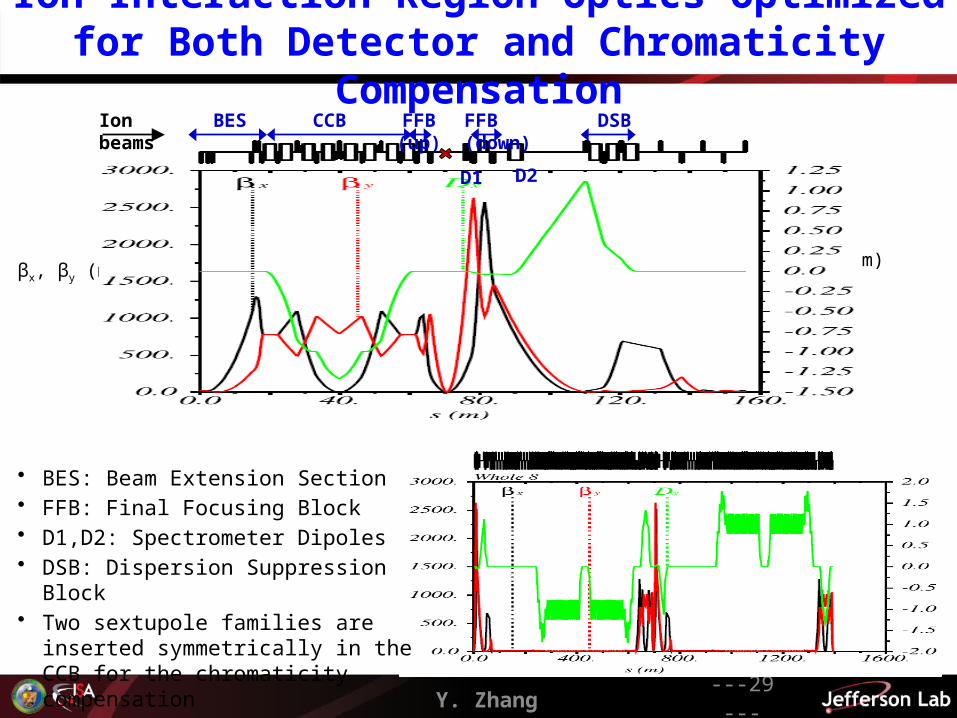
Ion Interaction Region Optics Optimized for Both Detector and Chromaticity Compensation
βx,
βy
(m)
Dx
(m)
FFB (up)CCBBES FFB (down)
D1 D2
Ion beams
DSB
• BES: Beam Extension Section• FFB: Final Focusing Block• D1,D2: Spectrometer Dipoles• DSB: Dispersion Suppression Block• Two sextupole families are inserted
symmetrically in the CCB for the chromaticity compensation
Y. Zhang --30--
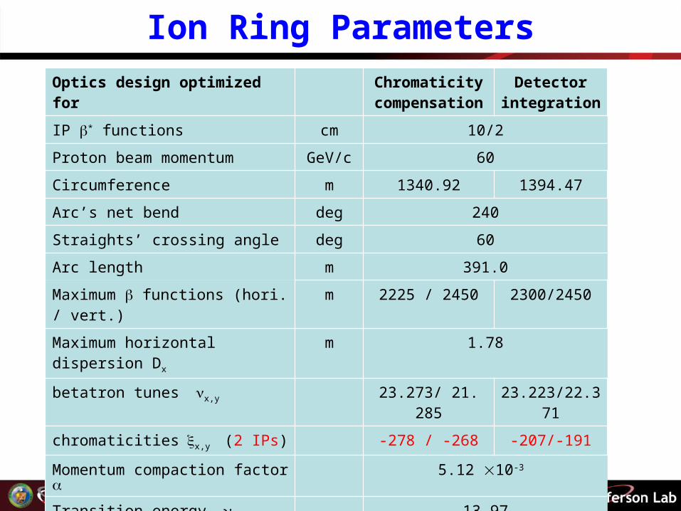
Ion Ring ParametersOptics design optimized for Chromaticity
compensationDetector
integration
IP * functions cm 10/2
Proton beam momentum GeV/c 60
Circumference m 1340.92 1394.47
Arc’s net bend deg 240
Straights’ crossing angle deg 60
Arc length m 391.0
Maximum functions (hori. / vert.) m 2225 / 2450 2300/2450
Maximum horizontal dispersion Dx m 1.78
betatron tunes x,y 23.273/ 21. 285 23.223/22.371
chromaticitiesx,y (2 IPs) -278 / -268 -207/-191
Momentum compaction factor 5.12 10-3
Transition energy tr 13.97
Normalized emittance x,y µm rad 0.35 / 0.07
Maximum RMS beam size x,y mm 3.5 / 1.6 3.6/1.6
Related Documents