MEETING TC 4-15 “Road Lighting Calculations, Test Data and Measurement” 16 May 2005 / Leon

MEETING TC 4-15 “Road Lighting Calculations, Test Data and Measurement” 16 May 2005 / Leon.
Dec 14, 2015
Welcome message from author
This document is posted to help you gain knowledge. Please leave a comment to let me know what you think about it! Share it to your friends and learn new things together.
Transcript
MEETING
TC 4-15
“Road Lighting Calculations,
Test Data and Measurement”
16 May 2005 / Leon

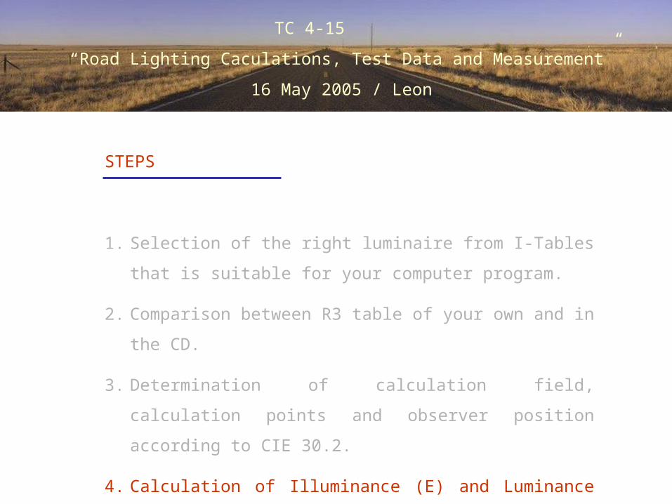
STEPS
1. Selection of the right luminaire from I-Tables that is suitable
for your computer program.
2. Comparison between R3 table of your own and in the CD.
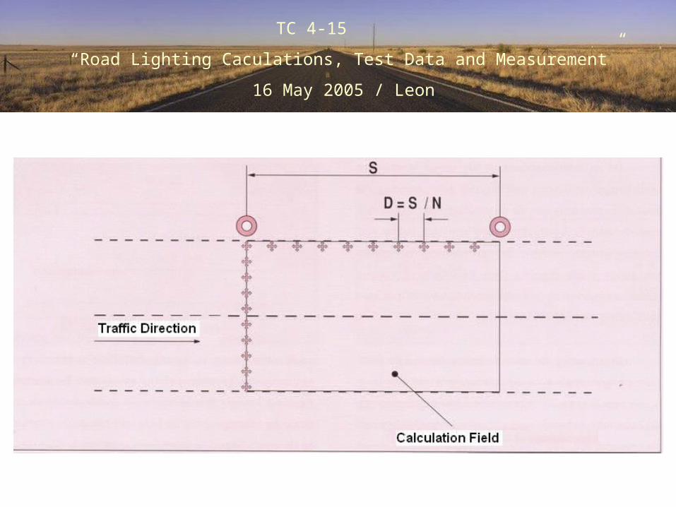
3. Determination of calculation field, calculation points and
observer position according to CIE 30.2.
4. Calculation of Illuminance (E) and Luminance (L) for 7
situations of lighting arragements. (Maintanance factor = 1)
TC 4-15
“Road Lighting Caculations, Test Data and Measurement”
16 May 2005 / Leon
TC 4-15
“Road Lighting Caculations, Test Data and Measurement”
16 May 2005 / Leon
STEPS
1. Selection of the right luminaire from I-Tables that is suitable
for your computer program.
2. Comparison between R3 table of your own and in the CD.
3. Determination of calculation field, calculation points and
observer position according to CIE 30.2.
4. Calculation of Illuminance (E) and Luminance (L) for 7
situations of lighting arragements. (Maintanance factor = 1)

I - Tables

TC 4-15
“Road Lighting Caculations, Test Data and Measurement”
16 May 2005 / Leon
STEPS
1. Selection of the right luminaire from I-Tables that is suitable
for your computer program.
2. Comparison between R3 table of your own and in the CD.
3. Determination of calculation field, calculation points and
observer position according to CIE 30.2.
4. Calculation of Illuminance (E) and Luminance (L) for 7
situations of lighting arragements. (Maintanance factor = 1)

Road Surface
Classification
Table
TC 4-15
“Road Lighting Caculations, Test Data and Measurement”
16 May 2005 / Leon
STEPS
1. Selection of the right luminaire from I-Tables that is suitable
for your computer program.
2. Comparison between R3 table of your own and in the CD.
3. Determination of calculation field, calculation points and
observer position according to CIE 30.2.
4. Calculation of Illuminance (E) and Luminance (L) for 7
situations of lighting arragements. (Maintanance factor = 1)
TC 4-15
“Road Lighting Caculations, Test Data and Measurement”
16 May 2005 / Leon
TC 4-15
“Road Lighting Caculations, Test Data and Measurement”
16 May 2005 / Leon
STEPS
1. Selection of the right luminaire from I-Tables that is suitable
for your computer program.
2. Comparison between R3 table of your own and in the CD.
3. Determination of calculation field, calculation points and
observer position according to CIE 30.2.
4. Calculation of Illuminance (E) and Luminance (L) for 7
situations of lighting arragements. (Maintanance factor = 1)
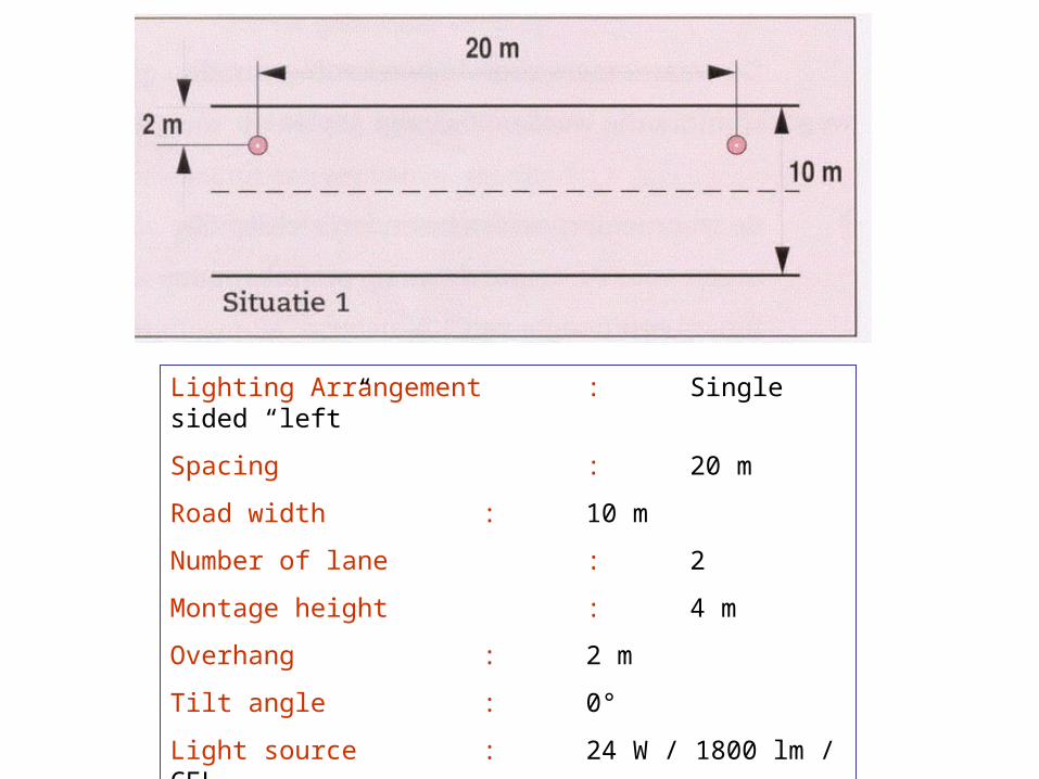
Lighting Arrangement : Single sided “left”
Spacing : 20 m
Road width : 10 m
Number of lane : 2
Montage height : 4 m
Overhang : 2 m
Tilt angle : 0°
Light source : 24 W / 1800 lm / CFL

Lighting Arragement : Straggered
Spacing : 20 m
Road width : 10 m
Number of lane : 2
Montage height : 4 m
Overhang : 2 m
Tilt angle : 0°
Light source : 24 W / 1800 lm / CFL
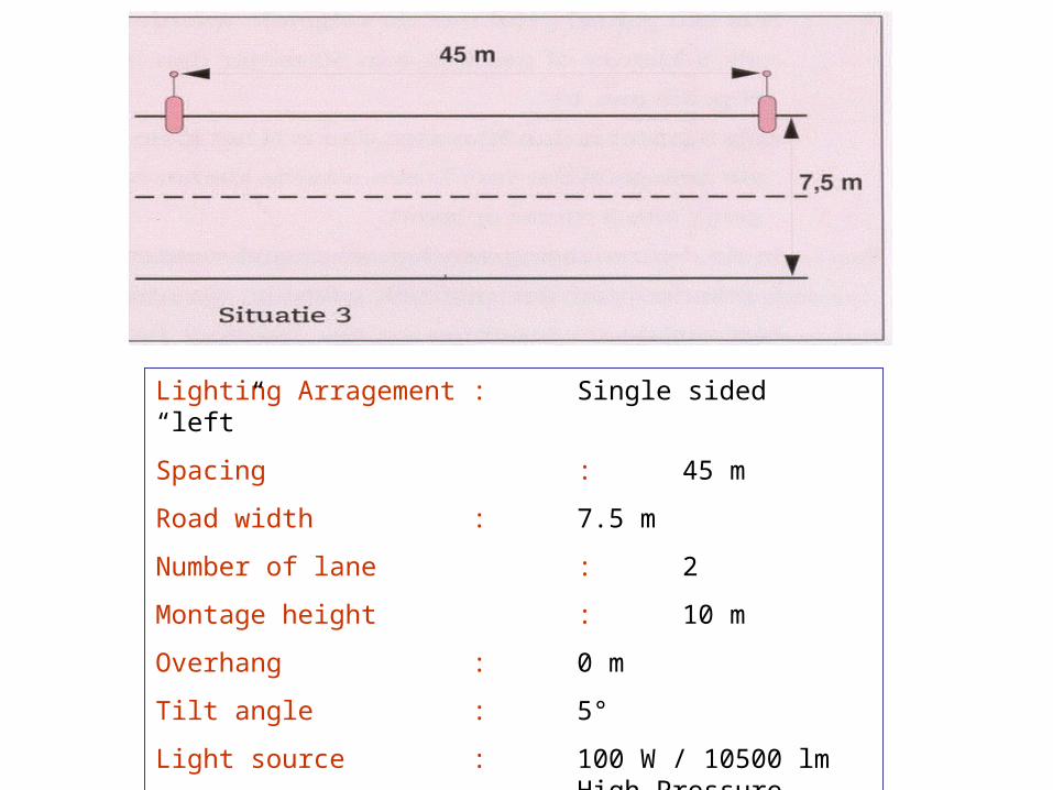
Lighting Arragement : Single sided “left”
Spacing : 45 m
Road width : 7.5 m
Number of lane : 2
Montage height : 10 m
Overhang : 0 m
Tilt angle : 5°
Light source : 100 W / 10500 lm High Pressure Sodium L.

Lighting Arragement : Staggered
Spacing : 35 m
Road width : 7 m
Number of lane : 2
Montage height : 8 m
Overhang : 0 m
Tilt angle : 5°
Light source : 100 W / 10500 lm High Pressure Sodium L.
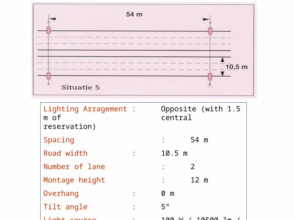
Lighting Arragement : Opposite (with 1.5 m of central reservation)
Spacing : 54 m
Road width : 10.5 m
Number of lane : 2
Montage height : 12 m
Overhang : 0 m
Tilt angle : 5°
Light source : 100 W / 10500 lm / HPS
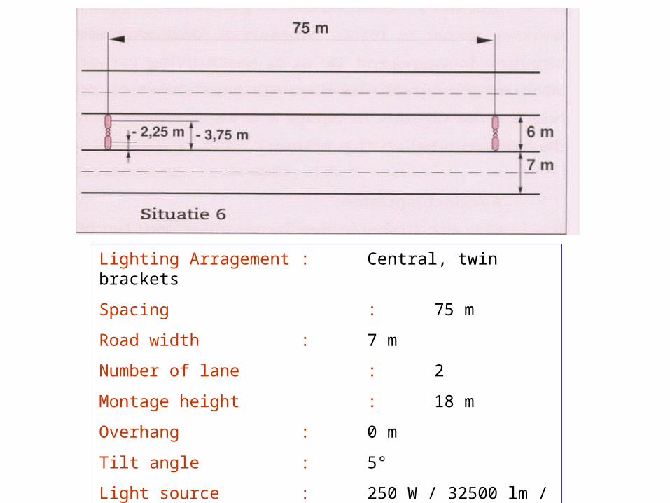
Lighting Arragement : Central, twin brackets
Spacing : 75 m
Road width : 7 m
Number of lane : 2
Montage height : 18 m
Overhang : 0 m
Tilt angle : 5°
Light source : 250 W / 32500 lm / HPS
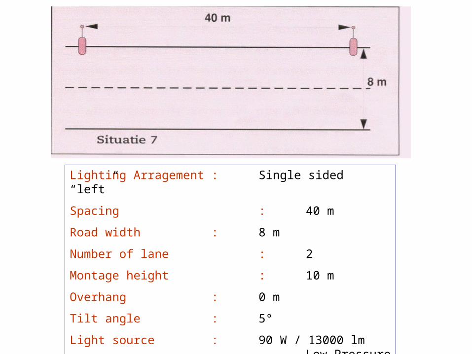
Lighting Arragement : Single sided “left”
Spacing : 40 m
Road width : 8 m
Number of lane : 2
Montage height : 10 m
Overhang : 0 m
Tilt angle : 5°
Light source : 90 W / 13000 lm Low Pressure Sodium L.
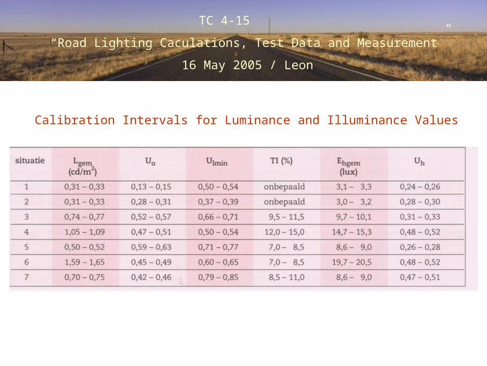
Calibration Intervals for Luminance and Illuminance Values
TC 4-15
“Road Lighting Caculations, Test Data and Measurement”
16 May 2005 / Leon

TC 4-15
“Road Lighting Caculations, Test Data and Measurement”
16 May 2005 / Leon
The results of Calculations According to CIE 30.2
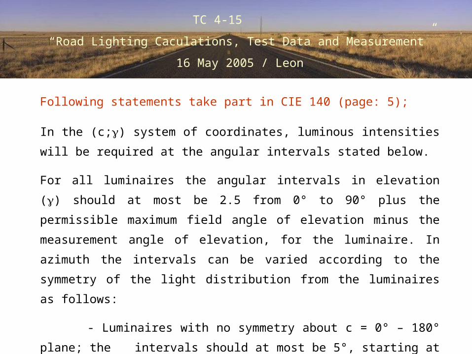
In the (c;) system of coordinates, luminous intensities will be required at the
angular intervals stated below.
For all luminaires the angular intervals in elevation () should at most be 2.5
from 0° to 90° plus the permissible maximum field angle of elevation minus
the measurement angle of elevation, for the luminaire. In azimuth the
intervals can be varied according to the symmetry of the light distribution
from the luminaires as follows:
- Luminaires with no symmetry about c = 0° – 180° plane; the
intervals should at most be 5°, starting at 0°, when the luminaire is in
its measurement angle of elevation and ending at 355°.
TC 4-15
“Road Lighting Caculations, Test Data and Measurement”
16 May 2005 / Leon
Following statements take part in CIE 140 (page: 5);
I-table of road lighting luminaire with no symmetry light distribution
should be given according to those definitions.
TC 4-15
“Road Lighting Caculations, Test Data and Measurement”
16 May 2005 / Leon

TC 4-15
“Road Lighting Caculations, Test Data and Measurement”
16 May 2005 / Leon
Road Surface Reflection Data
TC 4-15
“Road Lighting Caculations, Test Data and Measurement”
16 May 2005 / Leon
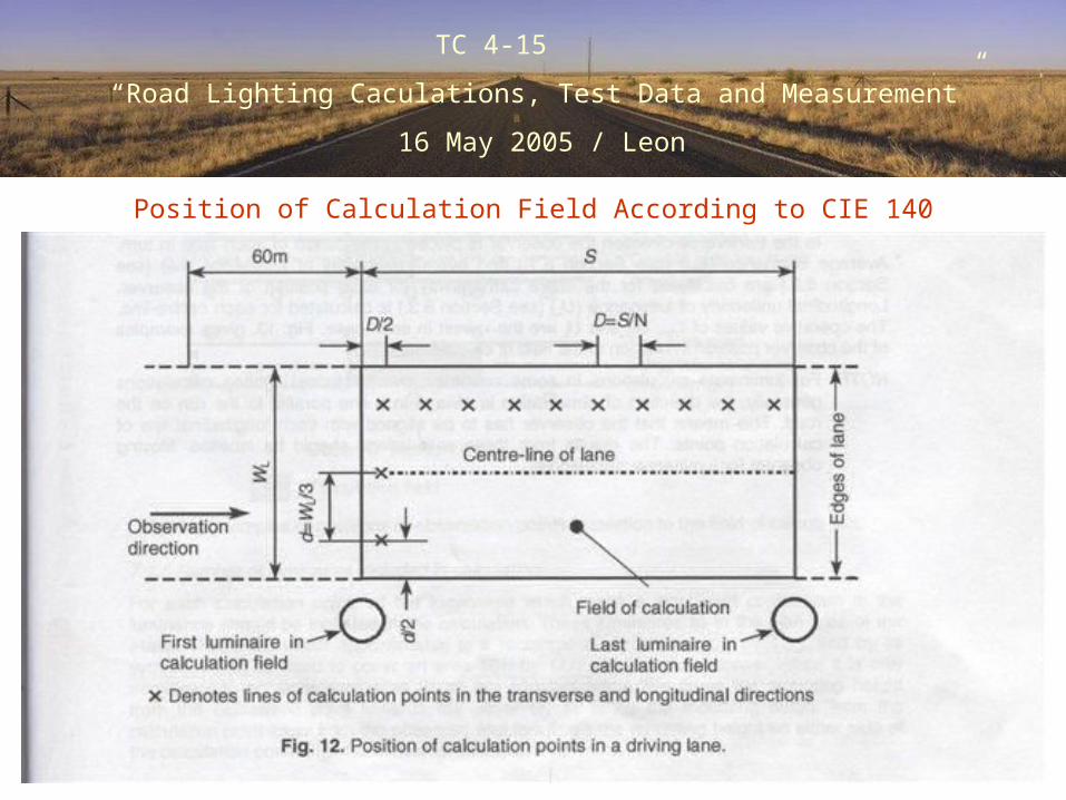
Position of Calculation Field According to CIE 140

TC 4-15
“Road Lighting Caculations, Test Data and Measurement”
16 May 2005 / Leon
The results of Calculations According to CIE 140
According to CIE 140, the observer’s eye height 1.5 m above road level, is
positioned transversely a quarter of road width from the carriageway edge,
and longitudinally at a distances in meters of 2.75 (mounting height: 1.5) in
front of the field of calculation.
In EN13201 Part: 3, it is stated that “the observer’s eye, is positioned in
the centre line of each lane in turn” by keeping all other parts same.
TC 4-15
“Road Lighting Caculations, Test Data and Measurement”
16 May 2005 / Leon

TC 4-15
“Road Lighting Caculations, Test Data and Measurement”
16 May 2005 / Leon
The results of Calculations According to EN 13201
Related Documents