Welcome message from author
This document is posted to help you gain knowledge. Please leave a comment to let me know what you think about it! Share it to your friends and learn new things together.
Transcript
Minutes of the 54
th Meeting of PCSC held on 26
th May, 2016 Page 1
SOUTHERN REGIONAL POWER COMMITTEE BENGALURU
Minutes of the 54th Meeting of Protection Coordination Sub-Committee
(PCSC – 54) of SRPC held on 26th May, 2016
1. Introduction
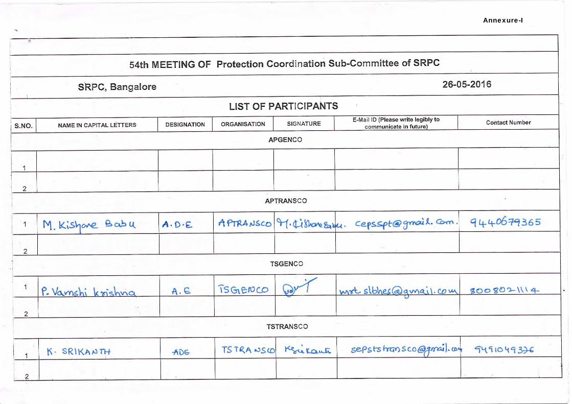
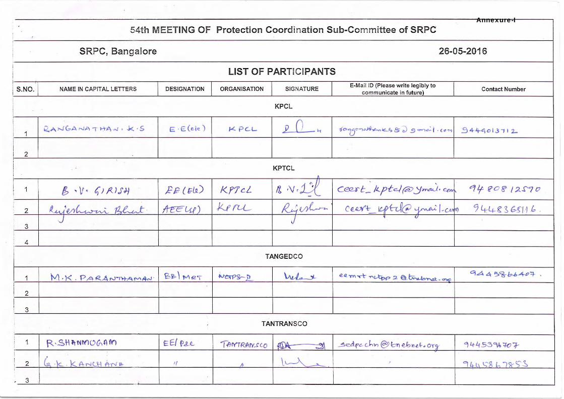
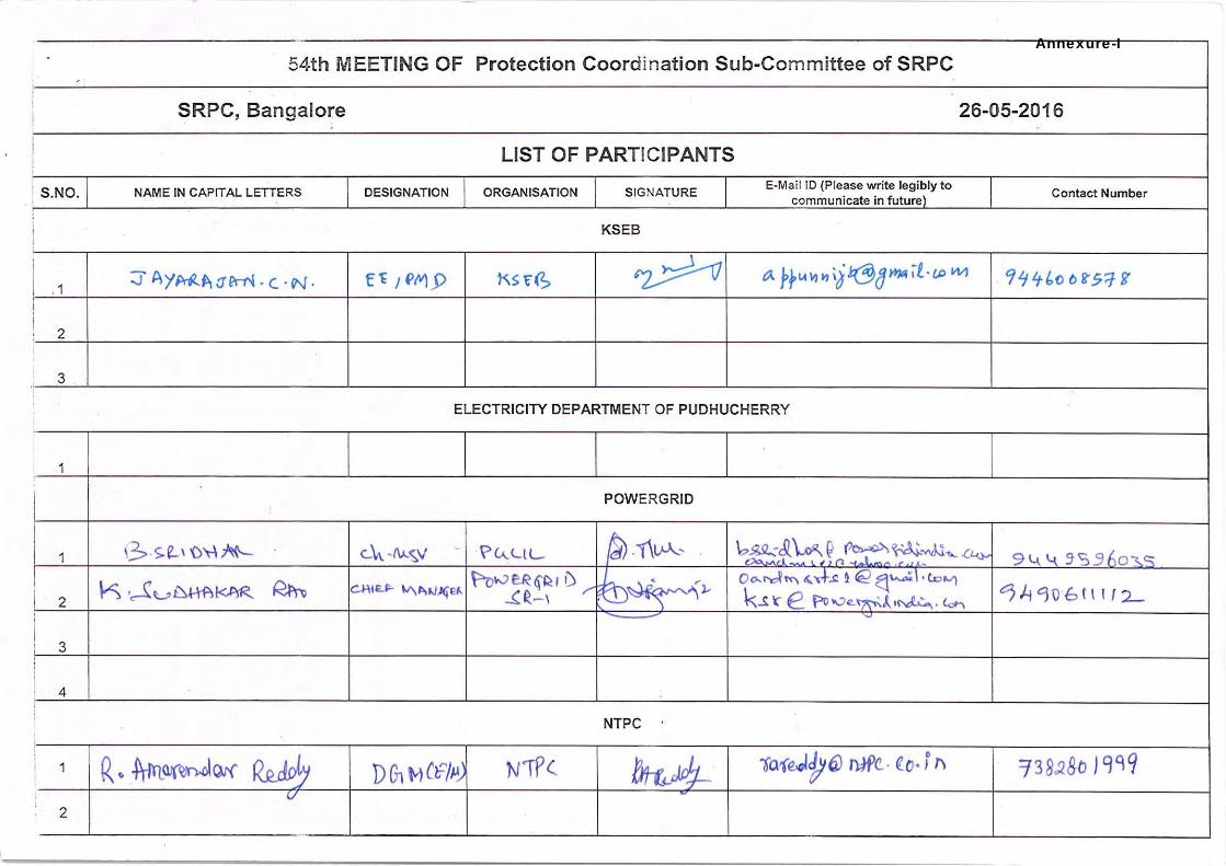
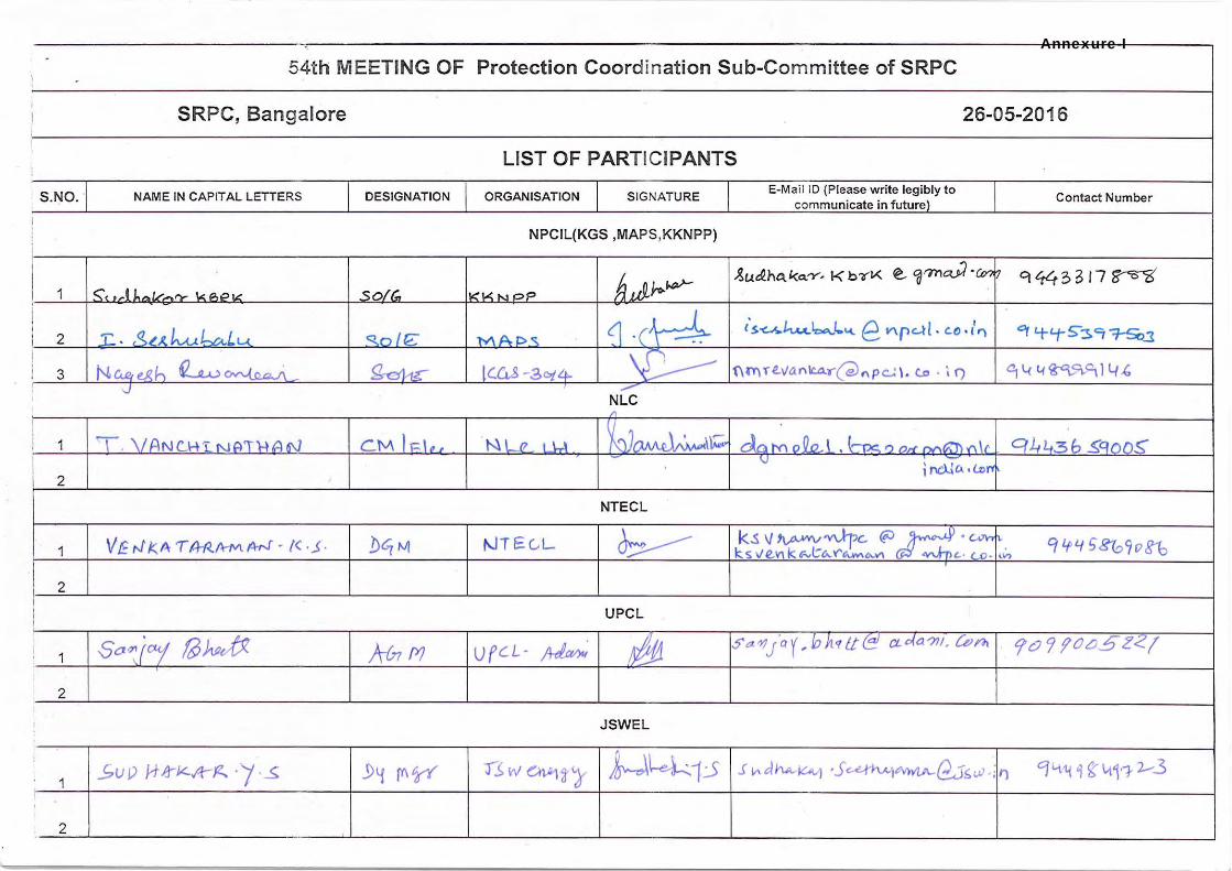
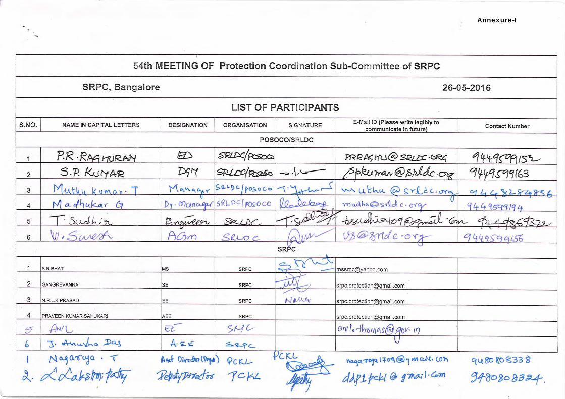
The 54th meeting of Protection Coordination Sub-Committee (PCSC-54) was held on 26th May, 2016 in the Conference Hall of Southern Regional Power Committee (SRPC), Bangalore. The list of participants is enclosed at Annexure-I.
Sh. S.R. Bhat, Member Secretary (MS), SRPC welcomed Members and Participants to the meeting and briefed them on the following:
Informed members that a special meeting was held on 19.05.2016 to deliberate on the pending issues in respect of NPCIL/ BHAVINI. In the meeting concrete assurances were obtained from NPCIL/ BHAVINI on a host of issues like planned outages of NPCIL Units, Reactors’ installation at KGS, KKNPP, enabling of A/R feature on evacuation lines of NPCIL/ BHAVINI, Tap-changing & MVAR-Interchange at KGS and KKNPP, pending SCADA Inputs from NPCIL/ BHAVINI, compliance of PSAG-14 recommendations, etc, and hoped that NPCIL/ BHAVINI would initiate steps to meet the agreed timelines.
Apprised members that Protection Audit Review of Stations (15 in number) under Task-2 by the Consultant was under progress. Audit of 13 Stations had already been completed. The remaining two Stations, viz., 400/220 kV Raichur TPS (8-10 June, 2016) and 220 kV Nagjheri HPS (14-16 July, 2016) would also be audited shortly. He requested Constituents’ active cooperation in completing Task-2 activities to the satisfaction of all parties involved.
Briefed members that the data required for the review of Islanding Schemes of the Southern Region had been furnished by the concerned Constituents (TSTRANSCO, TANTRANSCO & KSEB), and the details of the Islanding Schemes along with study results would be shortly furnished for implementation by the concerned Constituents.
Wished Shri P. Raghuram, Executive Director, SRLDC on his getting superannuation by May, 2016, and placed on record the invaluable contribution made by him to various SRPC forums in general and PCSC forum in particular. Describing his towering personality, MS, SRPC stated his absence would be a colossal loss not only to his parent organization, but to power sector as well. So thorough was his command over the subject that he had been able to take firm stance and get his way through on many a complex issue, and was the guiding/ central force behind the disciplined operation of SR-grid as it was today. Then MS, SRPC requested ED, SRLDC to say a few words on the gracious but painful occasion for the benefit of SR-Constituents.
ED, SRLDC stated that when he started his career as PLCC Engineer with NTPC, he, being an E.C.E. graduate, knew nothing about protection. However, when later asked to look after protection related works, he started focussing on the fundamentals, and with the help/ guidance of his seniors, he was able to learn them quite effectively, and apply in practical situations. In this regard, he placed on record the guidance he received from Mr. Babu, Div.
Minutes of the 54
th Meeting of PCSC held on 26
th May, 2016 Page 2
Engineer, APTRANSCO and Mr. Venkateshwarulu, Div. Engineer, APTRANSCO in mastering protection concepts and disturbance analysis. He stated that when PGCIL took over RLDC, SR-grid was rather undeveloped, and there used to be frequent black-outs in the region. However, with the concerted efforts of all SR-Constituents, the situation improved significantly so much so that there was not even a single black-out in the region in the past 10 years. In this regard, the introduction of Special Protection Schemes as a defence mechanism was specially mentioned. The success of Talcher – Kolar SPS, the first of its kind, led other players in the Indian power sector to emulate & reap the benefits of properly designed SPS’s. ED, SRLDC stated that he had been attending PCSC meetings since 1994, and was witness to the marked difference in the way the things are analyzed in terms of thoroughness and quality, and wished to follow them even after retirement. He expressed his gratefulness to PCSC forum for giving him an opportunity to develop himself, and wished good luck to all. On this, PGCIL (SR-II) representative stated that Raghuram Sir would be remembered for the camaraderie he enjoyed with all including the junior staff posted in sites, and for the down-to-earth approach he adopted in resolving various issues. He was so systematic & meticulous in analyzing the things, esp. tripping events, that root-cause analysis often turned out to be a plaything for him, and he learnt a lot from him in this regard. Describing Raghuram Sir, KPTCL representative mentioned that the relation he shared with him was one that existed between a Principal and a Student, and every rendezvous with him was more than just a learning experience for him. With his pragmatic approach, he was able to enforce the much needed discipline in the operation of SR-grid, and rein in the unwarranted trippings that used to fester SR-grid in the past. Requesting for his continued guidance in future, he wished him a happy retired life. KSEB representative recounted that Raghuram Sir would be remembered not just for the knowledge he commanded or for the contribution he made to SR-grid, but also for the philosopher-guide role he played with his subordinates. With regard to any issue, he always asked only the relevant questions, and once he got right answers, he was also quick to appreciate others - a rare/ quintessential quality needed to motivate subordinates. In this regard, he briefly shared his own experience as to how he got encouragement from him when a black-out of Kozhikode took place in the past. MS, SRPC thanked all Constituents & Members for all the nice words, and stated that the admiration all Constituents had for ED, SRLDC shows how popular & committed he was, and it would be really painful to miss him in future meetings. On behalf of all PCSC members, he wished him success in all future endeavours.
22. Confirmation of the Minutes of the 53rd PCSC meeting held on 28th April, 2016
SE (Protection), SRPC stated that the Minutes of the 53rd meeting of the PCSC had been circulated vide SRPC letter No. SRPC/SE-III/ PCSC-53/ 2016/ 3031 – 64 dated 16.05.2016.
Minutes of the 54
th Meeting of PCSC held on 26
th May, 2016 Page 3
Subsequently, KSEB vide their e-mail dated 25.05.2016 informed that KSEB remarks under III.2 and III.3 tripping events included in Annexure-II of the minutes should be modified as follows:
“KSEB:
Prior to the tripping event, single-phase auto-reclose feature in Main-II relay (CG make ZLV type) was in enabled condition. This feature requires breaker open status of each pole for successful reclosing operation. This had not been wired. Therefore, for each single-phase tripping in Zone-1, in the absence of breaker open status of that particular pole, the relay would initiate three-phase lock-out tripping.
Remedial action:
Now as a remedial measure, they had disabled A/R feature of this relay, and provided it through a separate external A/R relay (EE make, VARM type), and is working in good condition”.
With above modification, the Minutes of the 53rd Meeting of PCSC were confirmed.
3. Details of Grid Disturbances (GD’s), Grid Incidents (GI’s), Line Trippings due to Auto-Reclose
non-operation and PLCC mal- operation. The trippings due to GD’s, GI’s, Auto-Reclosure failure/ non-operation, and PLCC mal-operation
that had occurred during the period April - May, 2016 were discussed in the Meeting. The details of the tripping events including relevant PMU plots presented by SRLDC in the meeting are given at Annexure–II for kind reference. The deliberations and recommendations of the PCSC-forum are given at Annexure–III for further needful action.
4. Status of pending PCSC recommendations The status of implementation of pending PCSC recommendations was discussed in the meeting.
The Constituents had been requested to kindly submit the status of their compliance latest by 24.06.2016. The updated status of the same as on 10.06.2016 is enclosed at Annexure–IV.
5. Remedial measures/ Action taken for the tripping incidents of the transmission elements
under forced outage The tripping incidents of the transmission elements under forced outage for which the remedial
measures/ actions taken still awaited were discussed in the meeting. The Constituents had been requested to kindly furnish the remedial measures/ action taken in time so as to forward the same to Central Electricity Authority. The updated list of the same as on 10.06.2016 is enclosed at Annexure-V.
6. Certificate for Healthiness of Batteries
As per the MoP/ CEA direction given in pursuant to recommendations of the Enquiry Committee (NEW grid disturbance on 30th & 31st July, 2012), RPC’s are required to obtain from their respective Constituents the monthly certificate for healthiness of batteries, installed at 220 KV
Minutes of the 54
th Meeting of PCSC held on 26
th May, 2016 Page 4
and above voltage level Substations (for power supply to Relays, RTUs and PLCC equipment) and furnish the same to CEA/ MoP. With reference to above, the Constituents have been requested to submit the certificate on healthiness of batteries on monthly basis (i.e. status for a month shall be sent by the 7th day of the following month) to SRPC. The sought status for the month of April, 2016 has not been received from the following SR-Constituents:
TSTRANSCO, KPTCL, PED, PGCIL (SR-I & SR-II), NTPC-Ramagundam,
NTPL, CEPL & SEL
7. TSTRANSCO’s request to disable Special Protection Scheme at their 400 kV Mamidipally SS
An SPS had been implemented at 400kV Mamidipally substation in the year 2012 to avoid tripping of all 3x315MVA ICTs on overload in case of tripping of any one of the ICT’s. As per the scheme, whenever any ICT trips at 400kV Mamidipally substation, a Direct Trip signal would be generated at 400kV Mamidipally substation and trips the HV circuit breakers of 160/100 MVA, 220/132 kV Transformers at 220kV Shamshabad and 220kV Shadnagar substations to avoid tripping of remaining two ICTs at 400kV Mamidipally substation due to over loading. Now TSTRANSCO vide their mail dated 11.05.2016 informed that the daily average load on each 3x315MVA ICTs was not exceeding 230 MW for the past one year. Moreover, fourth 315 MVA ICT was taken into service on 07.01.2016. With this, even if any one of the 4x315 MVA ICTs was tripped, the remaining 3 ICTs would be able to share the available load. In view of the above, TSTRANSCO had requested for disabling/ deactivating the existing SPS scheme at 400kV Mamidipally substation to avoid tripping of PTRs at 220kV Shamshabad and 220kV Shadnagar substations as balance 3 nos. ICTs could cater to the loads in the eventuality of tripping any one of the fours ICT’s at 400kV Mamidipally substation. The above proposal of TSTRANSCO was discussed, and the forum acceded to TSTRANSCO’s request to disable/ deactivate the existing SPS t their 400 kV Mamidipally SS.
8. Special Meeting on Pending Protection Issues of M/s KPCL A special meeting was held on 3rd June, 2016 to deliberate on the pending protection issues of
M/s KPCL. The minutes of the meeting are given at Annexure-VI for kind reference. 9. Network configuration changes
As per the information furnished by SR-Constituents to the OCC forum in their 119th meeting (held on 10.05.2015; Minutes circulated on 27.05.2016), it is formed that the following configuration changes (additions/ deletions/ modifications of transmission elements) took place in the southern grid during March, 2016.
2nd Unit of M/s IL & FS Tamil Nadu Power Company Limited (ITPCL) (2x600 MW) in Tamil Nadu had declared COD from 00:00 Hours of 30.04.2016.
SR I, Power grid vide letter dated 30.04.2016 informed that consequent to successful completion of Trial Operation, the following assets under “Transmission System for Ultra
Minutes of the 54
th Meeting of PCSC held on 26
th May, 2016 Page 5
Mega Solar Park in Anantapur Dist, Andhra Pradesh – Part – A (Phase –I)” have been put under Commercial Operation w.e.f 00:00 hrs of 28th April 2016 in terms of Clause 4 of CERC (terms and Conditions of Tariff) Regulations, 2014. 1 No. 500 MVA, 400/220kV Transformer at NP Kunta Pooling Station along with
associated bays and equipment. LILO of 400 kV Kadapa (Cuddapah) – Kolar S/C line at NP Kunta Pooling Station. 2 Nos of 220 kV line bays at NP Kunta Pooling Station
220 kV D/C line from Jurala SS to Lower Jurala Hydro power of 22 ckm was commissioned on 29.04.2016 by TSTRANSCO.
220 kV SS at Dichpally in Nizamabad Dist of 1 x 160 + 2 x 100 existing MVA capacity was augmented to a capacity of 2 x 160 + 2 x 100 MVA and was commissioned on 06.04.2016 by TSTRANSCO.
220 kV SS at Bongiri in Nalgonda Dist of 2 x 100 existing MVA capacity was augmented to a capacity of 3 x100 MVA and commissioned on 16.04.2016 by TSTRANSCO.
220 kV SS at Waddekothapally in Warangal Dist of 2 x 160 + 1 x 100 MVA existing Capacity was augmented to a capacity of 3 x 160 MVA and was commissioned on 25.04.2016 by TSTRANSCO.
220 kV SS at Miryalguda in Nalgonda Dist Dist of 2 x160 + 1 x 100 existing MVA was augmented to a capacity is of 2 x 160 + 2 x 100 MVA and was commissioned on 26.04.2016 by TSTRANSCO.
220 kV SS at Renigunta in Chitoor Dist of 3 x 100 MVA was augmented to a capacity of 2 x100 + 1 x 160 MVA and was commissioned on 01.04.2016 by APTRANSCO.
220 kV SS at Chinakampally in YSR Dist of 1 x 100 MVA was augmented to a capacity of 1 x100 + 1 x 161 MVA and was commissioned on 02.04.2016 by APTRANSCO.
220 kV SS at Kondapally in Krishna Dist of 3 x100 MVA Capacity was augmented to a capacity of 2 x 100 + 1 x160 MVA and was commissioned on 25.04.2016 by APTRANSCO.
10. Instances of SPS Operation
Based on the information furnished by SRLDC, it is informed that the following instances of SPS operation took place in SR during the period 28.04.2016 – 25.05.2016.
Sl No
Date Time (hrs)
Reason Load relief obtained (MW)
AP KAR KEL TN Total
1 30-May-16 9:49 Talcher-Kolar SPS operated as pole-1
tripped 250 300 0 319 869
11. Compliance of Hon’ble CERC Orders
11.1 Petition No. 146/MP/2013 with I.A. 36/2013: Order dated 20.02.2014
Compliance of Regulations 5.2 I of the Grid Code: Issue regarding non-furnishing of FIR / Trip Analysis Report, EL, DR, etc. was also highlighted. It is pointed out that the above reports are to be submitted / uploaded on SRLDC web application within 24
Minutes of the 54
th Meeting of PCSC held on 26
th May, 2016 Page 6
hours as mandated under IEGC / CEA Regulations.
Implementation of Phase-I and Phase-II of Protection Audit Recommendations: All the constituents are requested to submit the updated status of the compliance (those who have not completed recommendations mentioned in the Phase I and Phase II) to SRPC Secretariat at the earliest.
Compliance of Regulations 5.2 (e) & 5.2 (l) of the Grid Code and Regulation 3(1)(e) of CEA Grid Standards: The constituents are requested to strictly comply with these provisions by ensuring standard protections systems having the reliability, selectivity, speed and sensitivity to isolate the faulty equipment and protect all components from any type of faults, within the specified fault clearance time and providing protection coordination
Ensuring proper maintenance of transmission lines and adopting best O&M practices: The constituents are requested to conduct line patrolling regularly as per the SRPC transmission line patrolling guidelines (available under the menu item “All Uploads Operation Miscellaneous Transmission Line Patrolling Protocol / Guidelines for Southern Region” on SRPC website). (http://www.srpc.kar.nic.in/website/2014/operation/patrolling.pdf).
11.2 Petition No. 167/Suo- Motu/2012: Order dated 22.02.2014
The Constituents are requested to follow approved protection philosophy
ISTS licensees are requested to submit details of updated distance protection relay setting of all inter-regional lines to POSOCO & RPCs.
All SLDCs are requested to install/activate sound recording system in their control rooms within three months from the date of issue of this order.
The Constituents are requested to submit the progress of implementation to SRPC and SRLDC as specified in the Hon’ble CERC Order.
11.3 Petition No. 263/MP/2012: Order dated 19.12.2013
Constituents are requested to implement the quantum of relief by AUFR and df/dt relays by identifying additional feeders and keep them functional within one month of issuing this order.
SLDCs are also requested to map these relays on their respective SCADA system within three months of issuance of this order.
The Constituents are requested to submit the progress of implementation to SRPC and SRLDC as specified in the Hon’ble CERC Order.
11.4 APTRANSCO’s Petition No.95/MP/2015: Date of hearing 09-04-2015
It was noted in the Analysis and Decision part of the Order that:
“8. Noting the submissions of the petitioner, SRPC and SRLDC and activities initiated by the petitioner for procurement of materials required for implementation of the remarks of protecting audit, we allow time to the petitioner till 31.12.2015 for completion of our directions in Order dated 19.12.2013 in Petition No. 146/MP/2013.”
Minutes of the 54
th Meeting of PCSC held on 26
th May, 2016 Page 7
“9. SRPC is directed to monitor the status of completion of works relating to protection audit remarks in respect of 7 nos 400 kV sub-stations and 11 nos 220 kV sub-stations of APTRANSCO, protection audit remarks in Protection Coordination Sub-Committee (PCSC) meetings and coordinate the periodic protection audit to be carried out in Southern Region after deliberation in SRPC and submit bi-monthly report to the Commission.”
11.5 TSTRANSCO’s Petition No.83/MP/2015: Order dated 14-05-2015
It was noted in the Order that:
“12. Noting the submission of the petitioner, SRLDC and SRPC and considering the actions already initiated by the petitioner for implementation of works relating to protection audit, we allow time till 31.10.2015 and 31.8.2016 for implementation of Phase-I and Phase -II works respectively. The petitioner is directed to submit affidavit confirming the completion of Phase I of protection audit remarks by 31.10.2015 and Phase-II of protection audit remarks by 31.8.2016.
13. SRPC is directed to monitor the status of completion of remarks in these substations vis-à-vis protection audit remarks in Protection Coordination Sub Committee (PCSC) meetings. SRPC is further directed to coordinate the periodic protection audit to be carried out in Southern Region after deliberation in SRPC.”
11.6 Order in Petition No. 86/MP/2014 and 374/MP/2014: Order dated 18-08-2015
The time-lines given to the various SR-Constituents for completion of Phase-I and Phase-II activities of Protection Audit Recommendations vide above Order are given below:
(A) KSEBL:
18. Noting the submission of KSEBL, SRLDC and SRPC and considering the actions already initiated by KSEBL for implementation of remarks of protection audit, we allow time till 31.12.2015 and 31.3.2016 for implementation of Phase-II works and R&M works at Idduki HEP respectively.
(B) TANTRANSCO:
21. After considering the submissions of TANTRANSCO, SRLDC and SRPC, it is noted that TANTRANSCO`s request for time till 31.5.2015 for implementation of Phase–I activities of providing numerical relays for feeder protection and Auto transformer protection is already over. We allow time till 30.6.2016 for other Phase-I activities such as provision of line VT, 5 core CT, Time synchronizing with GPS, Disturbance recorder & event logger and Phase-II activities. According to SRLDC, total implementation period is 15 to 16 months for items which involve major procurement, design changes with major site modification/civil activities. Accordingly, we allow 16 months time i.e up to 30.11.2016, for Renovation and Modernization of Singarpet, Singaperumalkoil, Salem and Tondiarpet 230 kV sub-stations from the issue of the order.
(C) NLC:
22. NLC has sought time upto 31.12.2014 and 31.3.2015 for completion of Phase-I work of Numerical Relay Retrofitting and for Phase-II works of providing second battery bank of PLCC respectively. It is noted that the completion dates for Phase-I and Phase-II of protection audit remarks as requested by NLC are already over. Therefore, no direction is required in this regard. However, we direct NLC to file a confirmation report regarding
Minutes of the 54
th Meeting of PCSC held on 26
th May, 2016 Page 8
completion of protection audit works for Phase-I and Phase-II.
(D) KPTCL:
23. …
…
Considering the submission of KPTCL and SRLDC, we allow time to KPTCL time till 15.01.2016 for completion of Phase-I and Phase-II of protection audit remarks. No further extension shall be granted in this regard.
(E) KPCL:
24. …
…
Considering the submission of KPCL and SRLDC, we allow time to KPCL till 31.10.2015 and 31.12.2015 for completion of Phase-I for Phase-II of protection audit remarks respectively. No further extension shall be granted in this regard.
26. We direct SRPC to (a) submit status of protection audit remarks in respect of APGENCO, NTPC (SR), Talcher, Puducherry, PGCIL (SRTS I & II), MAPS and TANGEDCO, (b) monitor the status of completion of remarks of protection audit in respect of all constituents of Southern Region in Protection Coordination Sub-Committee (PCSC) meetings, and (c) to coordinate periodic protection audit to be carried out in Southern Region after deliberation in SRPC. All the constituents of Southern Region are directed to file their status with SRPC on regular basis to facilitate proper monitoring in PCSC meetings. SRPC is directed to submit bi-annually status report to the Commission confirming the completion of Phase-I, Phase-II and R&M works of protection audit remarks of the constituents of Southern Region.
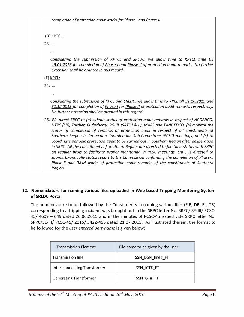
12. Nomenclature for naming various files uploaded in Web based Tripping Monitoring System of SRLDC Portal
The nomenclature to be followed by the Constituents in naming various files (FIR, DR, EL, TR) corresponding to a tripping incident was brought out in the SRPC letter No. SRPC/ SE-III/ PCSC-45/ 4609 – 649 dated 26.06.2015 and in the minutes of PCSC-45 issued vide SRPC letter No. SRPC/SE-III/ PCSC-45/ 2015/ 5422-455 dated 21.07.2015. As illustrated therein, the format to be followed for the user entered part-name is given below:
Transmission Element File name to be given by the user
Transmission line SSN_DSN_line#_FT
Inter-connecting Transformer SSN_ICT#_FT
Generating Transformer SSN_GT#_FT
Minutes of the 54
th Meeting of PCSC held on 26
th May, 2016 Page 9
Generating Unit SSN_Unit#_FT
Where, SSN = Source Station Name/ From end Station Name/ Sending end Station Name
DSN = Destination Station Name/ To end Station Name/ Receiving end Station Name
FT = File Type (FIR/ DR/ EL/ TR)
All SR-Constituents are requested to kindly intimate the above file naming nomenclature to all the concerned and ensure that it is strictly followed at all stations in their control area so that tripping analysis can be done systematically.
13. Date & Venue of the next Meeting
It is informed that the 55th PCSC meeting will be held on 29.06.2015 (Wednesday) at 10:30 hrs in the Conference Hall of SRPC, Bengaluru.
*****
Annexure-I
Annexure-I
Annexure-I
Annexure-I
Annexure-I
Annexure-I
54th PCSC meeting of SRPC
Annexure-II
Page 1 of 42
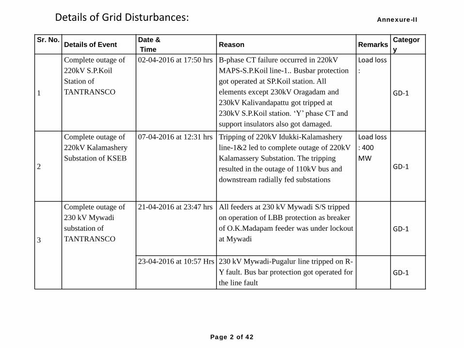
Sr. No.
Details of Event
Date &
Time Reason Remarks
Categor
y
1
Complete outage of
220kV S.P.Koil
Station of
TANTRANSCO
02-04-2016 at 17:50 hrs B-phase CT failure occurred in 220kV
MAPS-S.P.Koil line-1.. Busbar protection
got operated at SP.Koil station. All
elements except 230kV Oragadam and
230kV Kalivandapattu got tripped at
230kV S.P.Koil station. ‘Y’ phase CT and
support insulators also got damaged.
Load loss
:
GD-1
2
Complete outage of
220kV Kalamashery
Substation of KSEB
07-04-2016 at 12:31 hrs Tripping of 220kV Idukki-Kalamashery
line-1&2 led to complete outage of 220kV
Kalamassery Substation. The tripping
resulted in the outage of 110kV bus and
downstream radially fed substations
Load loss
: 400
MW GD-1
3
Complete outage of
230 kV Mywadi
substation of
TANTRANSCO
21-04-2016 at 23:47 hrs All feeders at 230 kV Mywadi S/S tripped
on operation of LBB protection as breaker
of O.K.Madapam feeder was under lockout
at Mywadi
GD-1
23-04-2016 at 10:57 Hrs 230 kV Mywadi-Pugalur line tripped on R-
Y fault. Bus bar protection got operated for
the line fault
GD-1
Details of Grid Disturbances: Annexure-II
Page 2 of 42
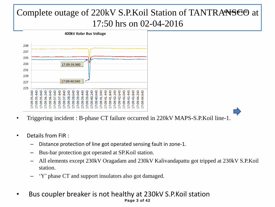
Complete outage of 220kV S.P.Koil Station of TANTRANSCO at
17:50 hrs on 02-04-2016
• Triggering incident : B-phase CT failure occurred in 220kV MAPS-S.P.Koil line-1.
• Details from FIR :
– Distance protection of line got operated sensing fault in zone-1.
– Bus-bar protection got operated at SP.Koil station.
– All elements except 230kV Oragadam and 230kV Kalivandapattu got tripped at 230kV S.P.Koil
station.
– ‘Y’ phase CT and support insulators also got damaged.
• Bus coupler breaker is not healthy at 230kV S.P.Koil station
Annexure-II
Page 3 of 42
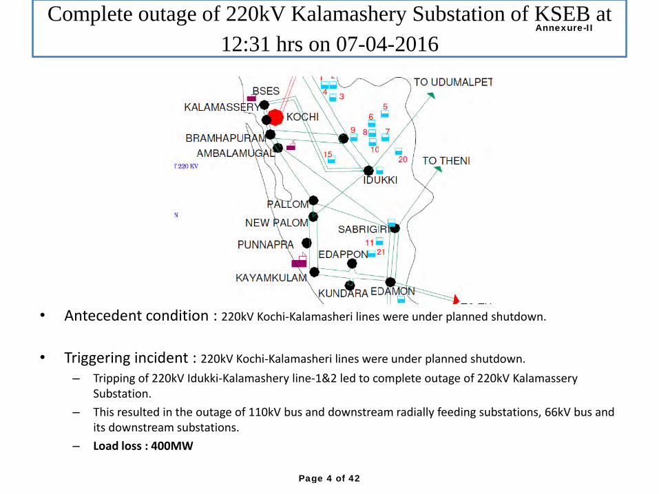
Complete outage of 220kV Kalamashery Substation of KSEB at
12:31 hrs on 07-04-2016
• Antecedent condition : 220kV Kochi-Kalamasheri lines were under planned shutdown.
• Triggering incident : 220kV Kochi-Kalamasheri lines were under planned shutdown.
– Tripping of 220kV Idukki-Kalamashery line-1&2 led to complete outage of 220kV Kalamassery Substation.
– This resulted in the outage of 110kV bus and downstream radially feeding substations, 66kV bus and its downstream substations.
– Load loss : 400MW
Annexure-II
Page 4 of 42
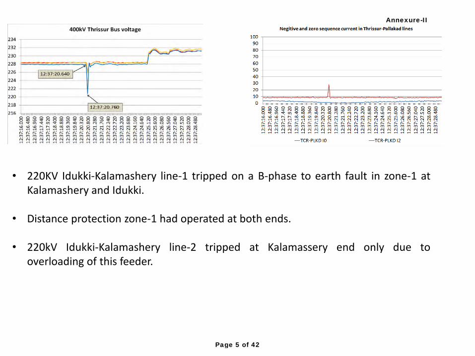
• 220KV Idukki-Kalamashery line-1 tripped on a B-phase to earth fault in zone-1 at Kalamashery and Idukki.
• Distance protection zone-1 had operated at both ends.
• 220kV Idukki-Kalamashery line-2 tripped at Kalamassery end only due to
overloading of this feeder.
Annexure-II
Page 5 of 42
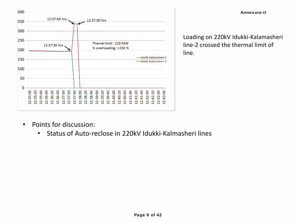
Loading on 220kV Idukki-Kalamasheri line-2 crossed the thermal limit of line.
• Points for discussion: • Status of Auto-reclose in 220kV Idukki-Kalmasheri lines
Annexure-II
Page 6 of 42
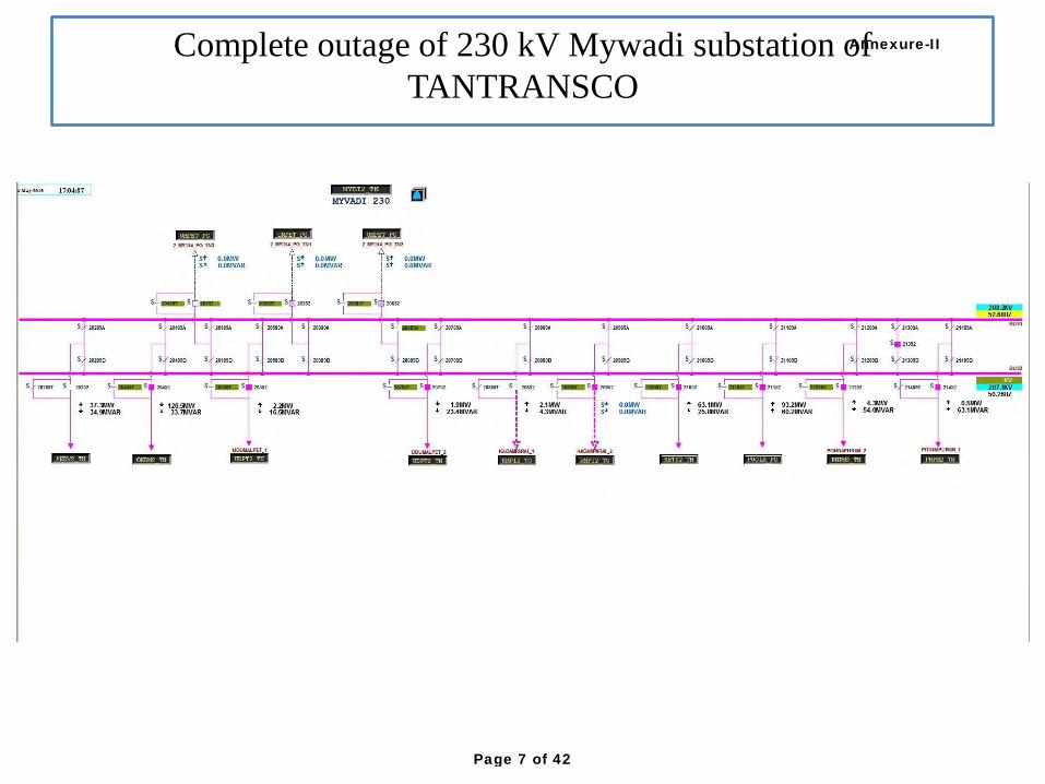
Complete outage of 230 kV Mywadi substation of
TANTRANSCO
Annexure-II
Page 7 of 42
Complete outage of 230 kV Mywadi substation of
TANTRANSCO
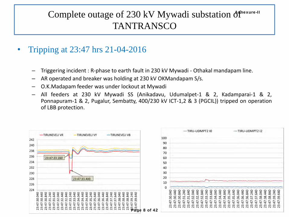
• Tripping at 23:47 hrs 21-04-2016
– Triggering incident : R-phase to earth fault in 230 kV Mywadi - Othakal mandapam line.
– AR operated and breaker was holding at 230 kV OKMandapam S/s.
– O.K.Madapam feeder was under lockout at Mywadi
– All feeders at 230 kV Mywadi SS (Anikadavu, Udumalpet-1 & 2, Kadamparai-1 & 2, Ponnapuram-1 & 2, Pugalur, Sembatty, 400/230 kV ICT-1,2 & 3 (PGCIL)) tripped on operation of LBB protection.
Annexure-II
Page 8 of 42
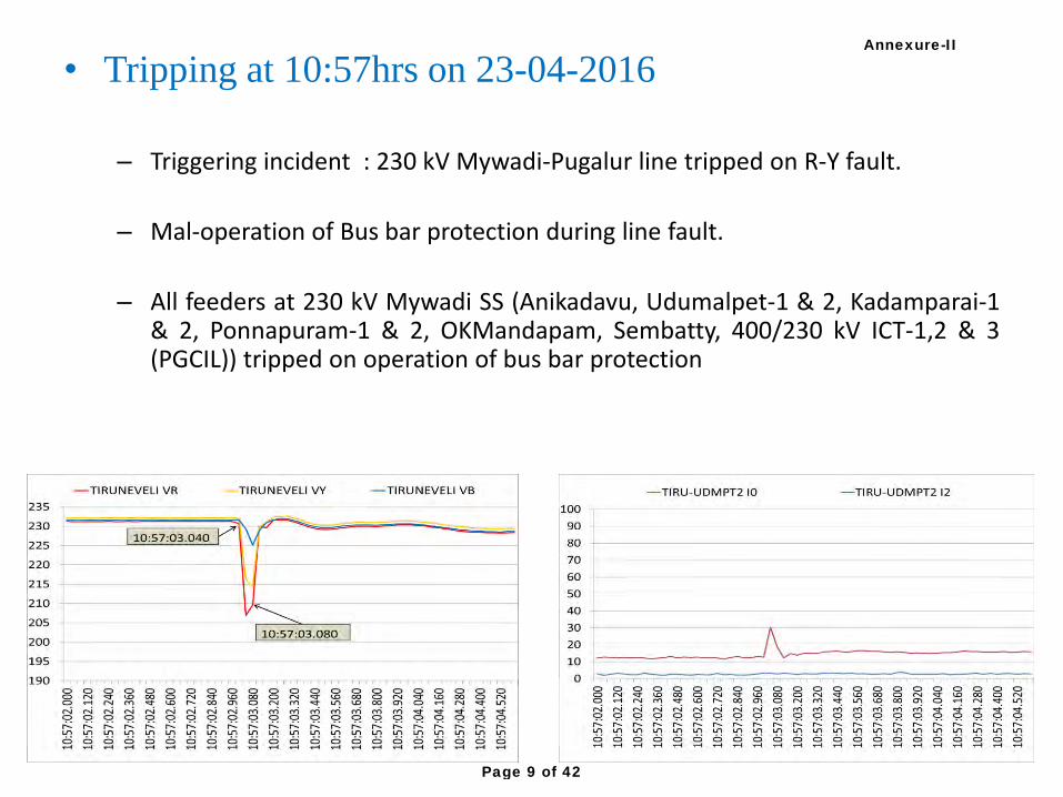
• Tripping at 10:57hrs on 23-04-2016
– Triggering incident : 230 kV Mywadi-Pugalur line tripped on R-Y fault.
– Mal-operation of Bus bar protection during line fault.
– All feeders at 230 kV Mywadi SS (Anikadavu, Udumalpet-1 & 2, Kadamparai-1 & 2, Ponnapuram-1 & 2, OKMandapam, Sembatty, 400/230 kV ICT-1,2 & 3 (PGCIL)) tripped on operation of bus bar protection
Annexure-II
Page 9 of 42

• Line tripped on R-phase to earth.
• LBB of tie breaker got operated at Nellore (AP) which resulted in tripping of 400kV Vijayawada-Nellore line and 400/220kV ICT-2 at Nellore (AP).
• Reason for LBB operation and remedial actions taken may be furnished
Tripping of 400kV Vijayawada-Nellore(AP) line-1 and ICT-2
at 13:52 Hrs on 03-04-2016
Vijayawada-1
Nellore (AP)
ICT-2
Annexure-II
Page 10 of 42
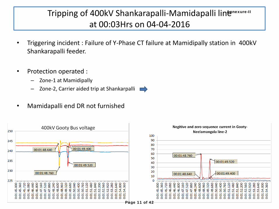
• Triggering incident : Failure of Y-Phase CT failure at Mamidipally station in 400kV Shankarapalli feeder.
• Protection operated : – Zone-1 at Mamidipally
– Zone-2, Carrier aided trip at Shankarpalli
• Mamidapalli end DR not furnished
Tripping of 400kV Shankarapalli-Mamidapalli line
at 00:03Hrs on 04-04-2016
Annexure-II
Page 11 of 42
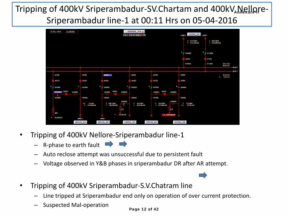
• Tripping of 400kV Nellore-Sriperambadur line-1 – R-phase to earth fault
– Auto reclose attempt was unsuccessful due to persistent fault
– Voltage observed in Y&B phases in sriperambadur DR after AR attempt.
• Tripping of 400kV Sriperambadur-S.V.Chatram line – Line tripped at Sriperambadur end only on operation of over current protection.
– Suspected Mal-operation
Tripping of 400kV Sriperambadur-SV.Chartam and 400kV Nellore-
Sriperambadur line-1 at 00:11 Hrs on 05-04-2016
Annexure-II
Page 12 of 42
• Line tripped on operation of Backup impedance protection of line reactor.
• Direct trip was received at Mahboobnagar end. DR not furnished
• Reason for operation of Backup impedance may be furnished
Tripping of Raichur TPS-Mahboobnagar line at 10:23Hrs on
05-04-2016
Annexure-II
Page 13 of 42
• During both tripping, B-phase to earth fault had occurred in line.
• At Hassan end breakers tripped after Zone-2 time i.e. 350 ms and protection did trip instantaneously on Carrier aided tripping.
Tripping of 400kV Hassan-UPCL line-2 at 12:55Hrs and 13:32 Hrs
on 07-04-2016
Annexure-II
Page 14 of 42
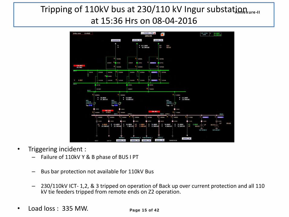
• Triggering incident : – Failure of 110kV Y & B phase of BUS I PT
– Bus bar protection not available for 110kV Bus
– 230/110kV ICT- 1,2, & 3 tripped on operation of Back up over current protection and all 110
kV tie feeders tripped from remote ends on Z2 operation.
• Load loss : 335 MW.
Tripping of 110kV bus at 230/110 kV Ingur substation
at 15:36 Hrs on 08-04-2016
Annexure-II
Page 15 of 42
Annexure-II
Page 16 of 42
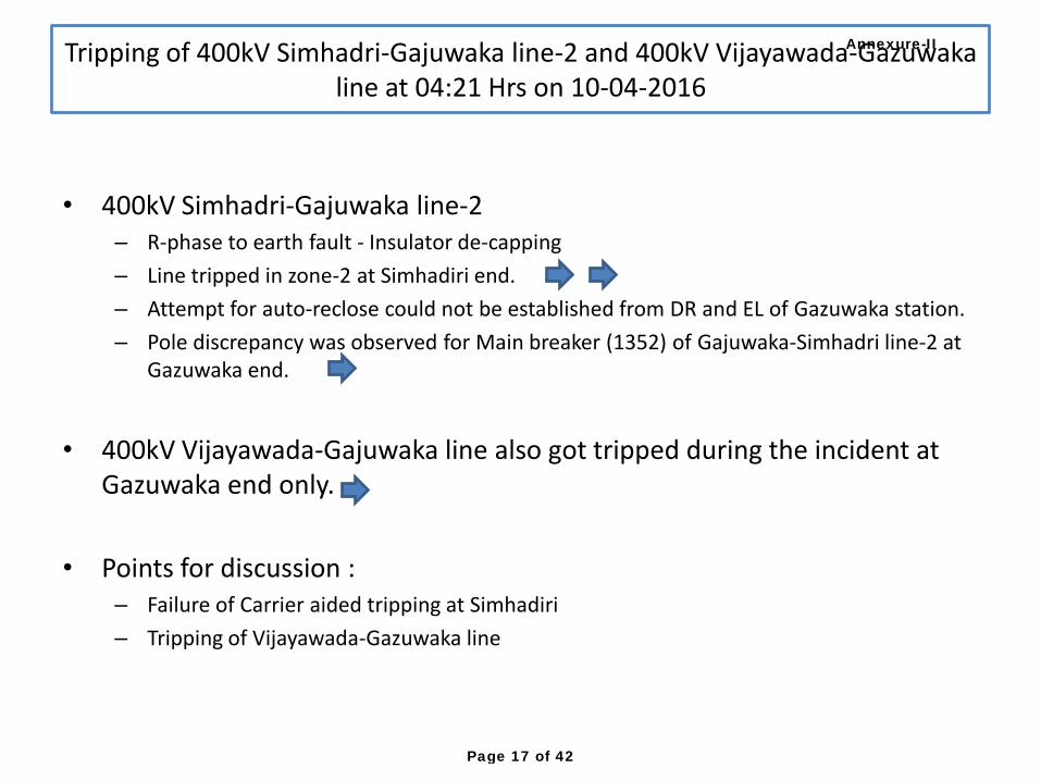
• 400kV Simhadri-Gajuwaka line-2 – R-phase to earth fault - Insulator de-capping
– Line tripped in zone-2 at Simhadiri end.
– Attempt for auto-reclose could not be established from DR and EL of Gazuwaka station.
– Pole discrepancy was observed for Main breaker (1352) of Gajuwaka-Simhadri line-2 at Gazuwaka end.
• 400kV Vijayawada-Gajuwaka line also got tripped during the incident at Gazuwaka end only.
• Points for discussion : – Failure of Carrier aided tripping at Simhadiri
– Tripping of Vijayawada-Gazuwaka line
Tripping of 400kV Simhadri-Gajuwaka line-2 and 400kV Vijayawada-Gazuwaka
line at 04:21 Hrs on 10-04-2016
Annexure-II
Page 17 of 42
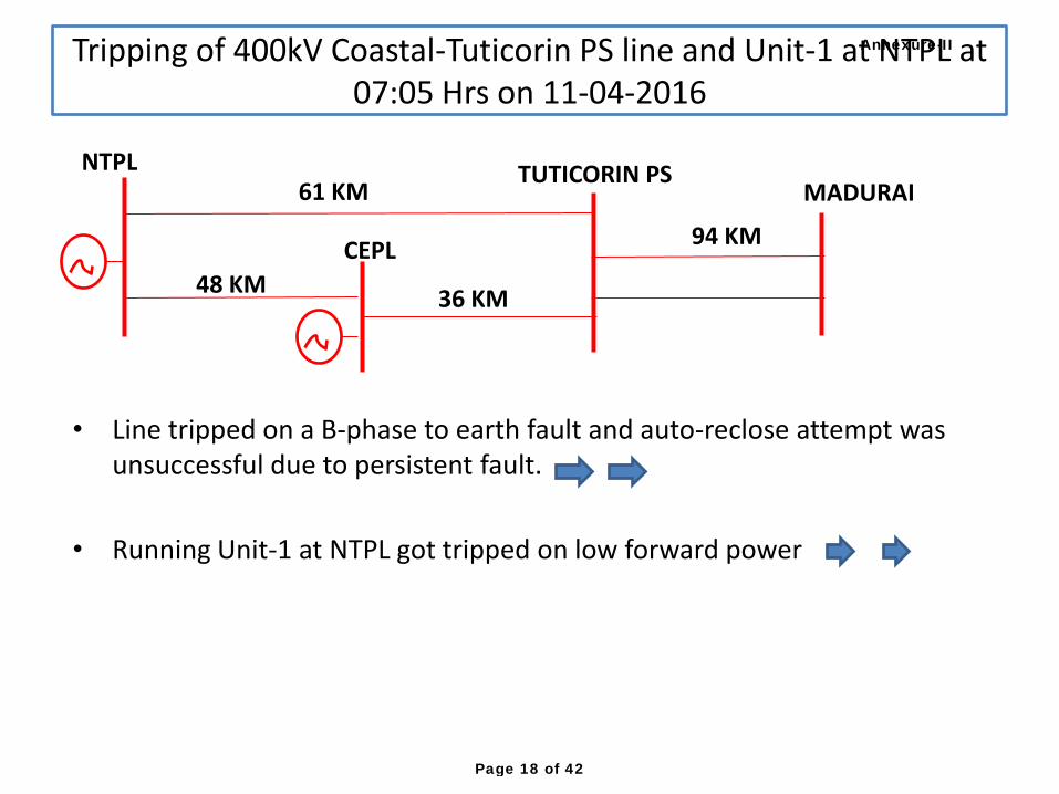
• Line tripped on a B-phase to earth fault and auto-reclose attempt was unsuccessful due to persistent fault.
• Running Unit-1 at NTPL got tripped on low forward power
Tripping of 400kV Coastal-Tuticorin PS line and Unit-1 at NTPL at
07:05 Hrs on 11-04-2016
94 KM
61 KM
36 KM 48 KM
NTPL TUTICORIN PS
CEPL
MADURAI
Annexure-II
Page 18 of 42
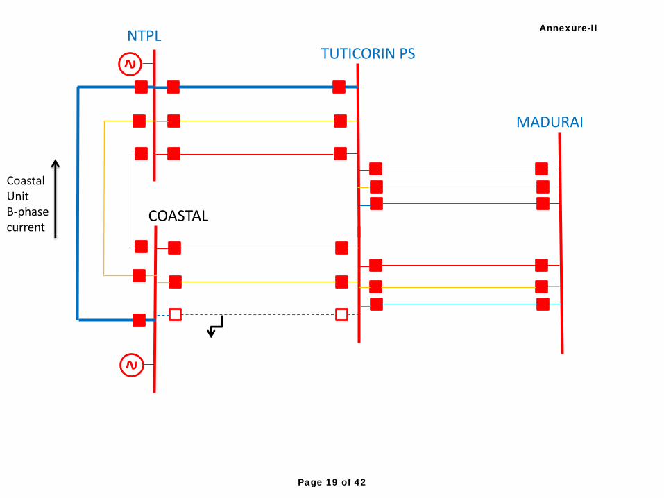
NTPL
COASTAL
TUTICORIN PS
MADURAI
CoastalUnit B-phase current
Annexure-II
Page 19 of 42
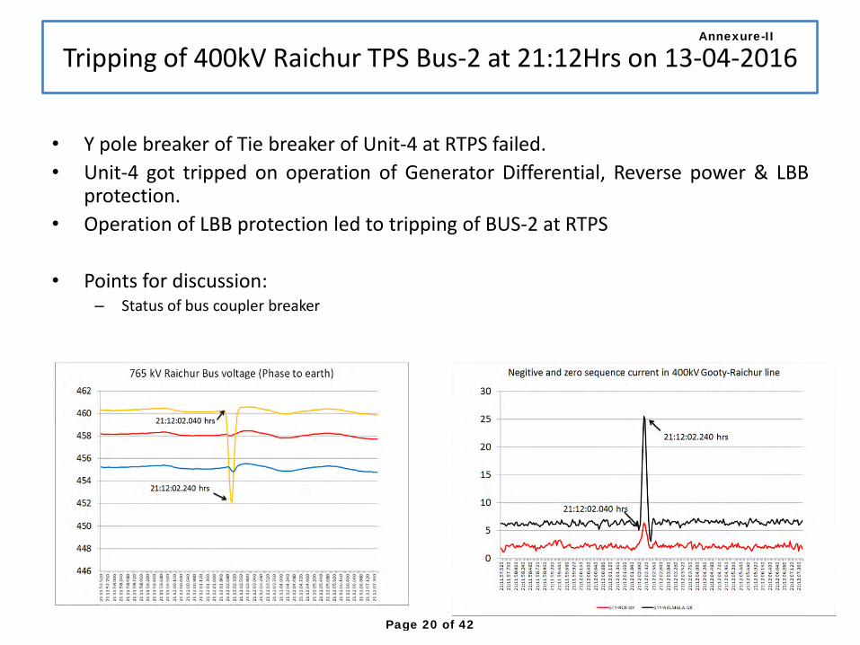
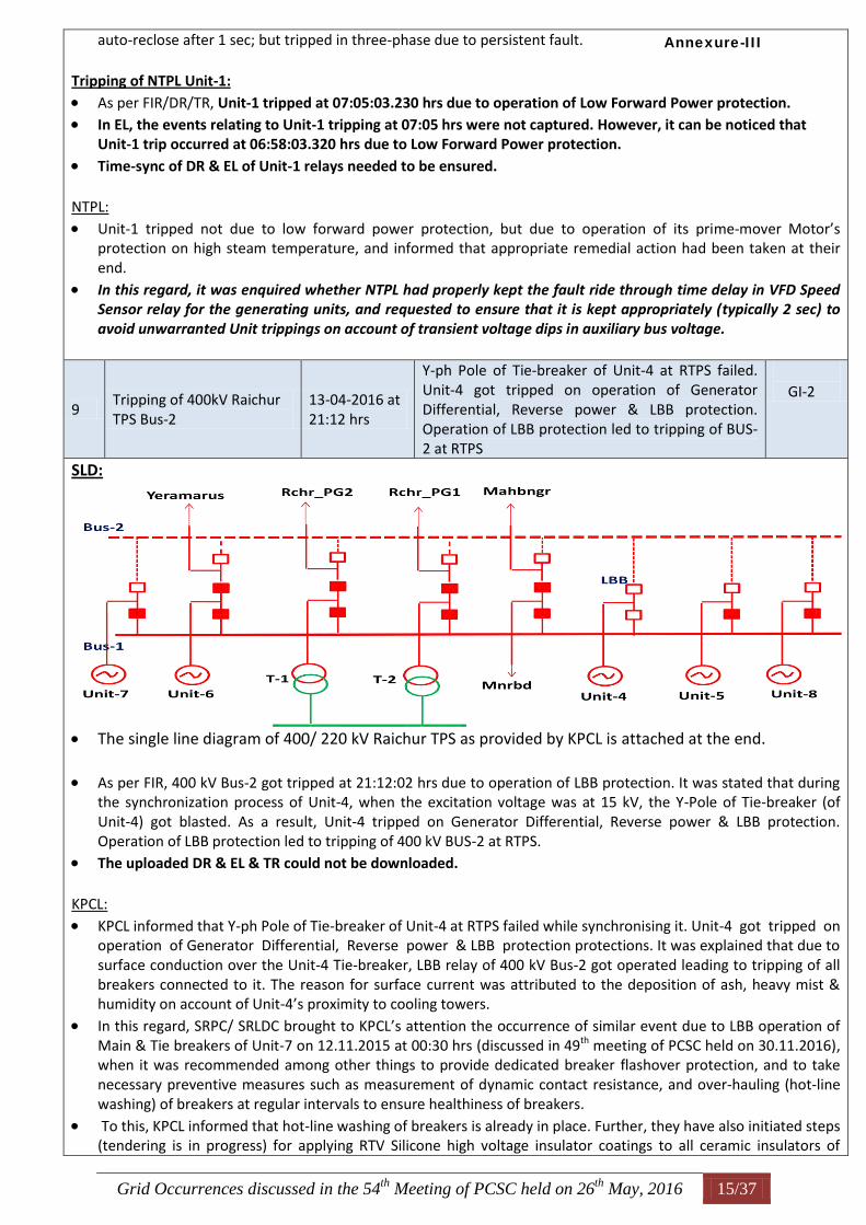
• Y pole breaker of Tie breaker of Unit-4 at RTPS failed.
• Unit-4 got tripped on operation of Generator Differential, Reverse power & LBB protection.
• Operation of LBB protection led to tripping of BUS-2 at RTPS
• Points for discussion: – Status of bus coupler breaker
Tripping of 400kV Raichur TPS Bus-2 at 21:12Hrs on 13-04-2016
Annexure-II
Page 20 of 42
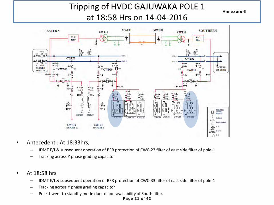
• Antecedent : At 18:33hrs, – IDMT E/f & subsequent operation of BFR protection of CWC-23 filter of east side filter of pole-1
– Tracking across Y phase grading capacitor
• At 18:58 hrs – IDMT E/f & subsequent operation of BFR protection of CWC-33 filter of east side filter of pole-1
– Tracking across Y phase grading capacitor
– Pole-1 went to standby mode due to non-availability of South filter.
Tripping of HVDC GAJUWAKA POLE 1
at 18:58 Hrs on 14-04-2016
Annexure-II
Page 21 of 42
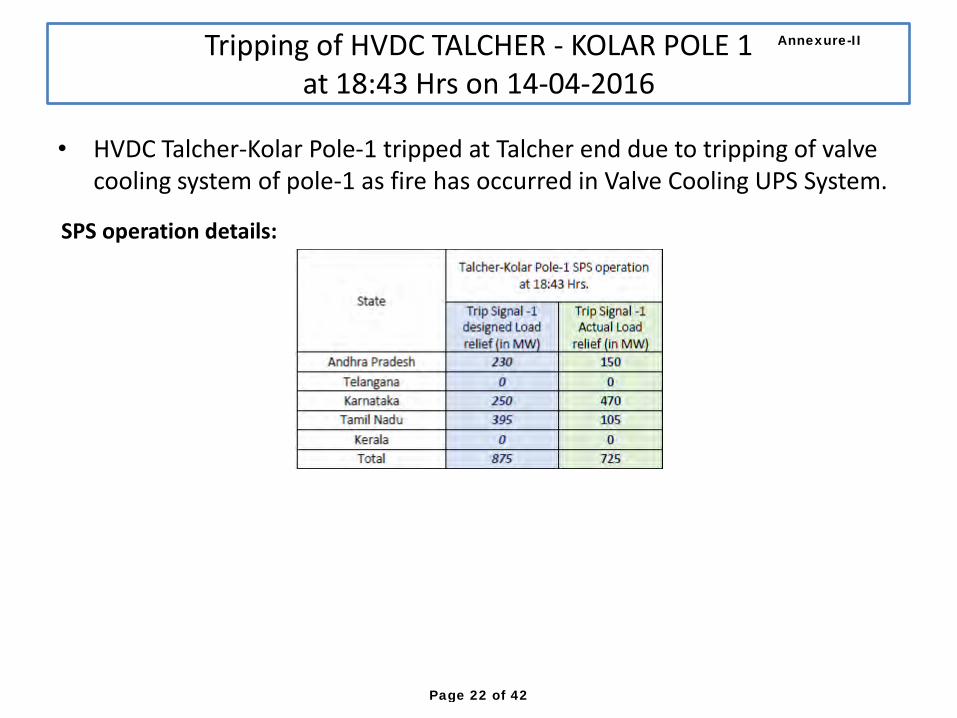
• HVDC Talcher-Kolar Pole-1 tripped at Talcher end due to tripping of valve cooling system of pole-1 as fire has occurred in Valve Cooling UPS System.
Tripping of HVDC TALCHER - KOLAR POLE 1
at 18:43 Hrs on 14-04-2016
SPS operation details:
Annexure-II
Page 22 of 42
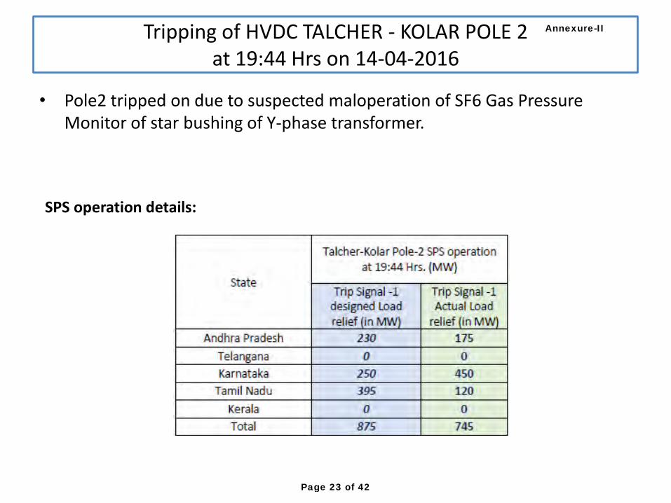
• Pole2 tripped on due to suspected maloperation of SF6 Gas Pressure Monitor of star bushing of Y-phase transformer.
Tripping of HVDC TALCHER - KOLAR POLE 2
at 19:44 Hrs on 14-04-2016
SPS operation details:
Annexure-II
Page 23 of 42
• Poles tripped due to loss of East bus voltage due to disturbance in Eastern region.
Tripping of HVDC GAJUWAKA POLE-1&2 at 12:23 Hrs on
15-04-2016
Annexure-II
Page 24 of 42
• During testing of retrofitted distance protection in 400kV Raichur-2 feeder, LBB protection trip DC got extended to Bus trip.
• This resulted in tripping of 220kV bus at RTPS and subsequently tripping of all connected 220kV elements.
• Unit-4 which is connected to 400kV Bus got tripped due to tripping of Station Utility Transformer
• Generation loss was around 760 MW.
Tripping of 220kV elements and Units1,2,3&4 at Raichur TPS at
15:36 Hrs on 15-04-2016
Annexure-II
Page 25 of 42
• East Converter Transformer Y-phase OLTC Tap gone out of step as compared to R and Y-Phase
• “Y” Phase transformer remained stuck at position 15, “R” and “Y” tap position are at 13.
• AC MCB of OLTC Motor of Y-phase got tripped in OLTC cubicle
• Remedial actions taken to avoid repetition of event may be furnished
Tripping of HVDC GAJUWAKA POLE 1 at 10:18 Hrs on 16-04-2016
Annexure-II
Page 26 of 42

• ICT tripped on operation on operation of Bus Reactor TEED protection.
• Dip observed in B-phase voltage in DR
• Findings and remedial actions may be shared with PSC
Tripping of ICT-2 at Cudappah station at 21:14 Hrs on 20-04-2016
Annexure-II
Page 27 of 42
• Tripping at 1:40 hrs on 21-04-2016 – Line tripped on direct trip receive at Satenapalli end.
– over-volatage start was observed in DR of Srisailam
• Tripping at 13:40 hrs on 21-04-2016 – R-Ph to earth fault had occurred in line. Line did not auto-reclose
– Direct trip receive was observed in DR of Sattenapalli and Srisailam.
Tripping of 400kV Sattenapalli-Srisailam line-2 at 01:40 Hrs on
21-04-2016
Annexure-II
Page 28 of 42
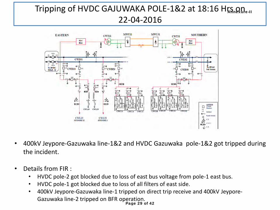
Tripping of HVDC GAJUWAKA POLE-1&2 at 18:16 Hrs on
22-04-2016
• 400kV Jeypore-Gazuwaka line-1&2 and HVDC Gazuwaka pole-1&2 got tripped during the incident.
• Details from FIR :
• HVDC pole-2 got blocked due to loss of east bus voltage from pole-1 east bus. • HVDC pole-1 got blocked due to loss of all filters of east side. • 400kV Jeypore-Gazuwaka line-1 tripped on direct trip receive and 400kV Jeypore-
Gazuwaka line-2 tripped on BFR operation.
Annexure-II
Page 29 of 42
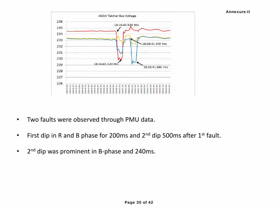
• Two faults were observed through PMU data.
• First dip in R and B phase for 200ms and 2nd dip 500ms after 1st fault.
• 2nd dip was prominent in B-phase and 240ms.
Annexure-II
Page 30 of 42
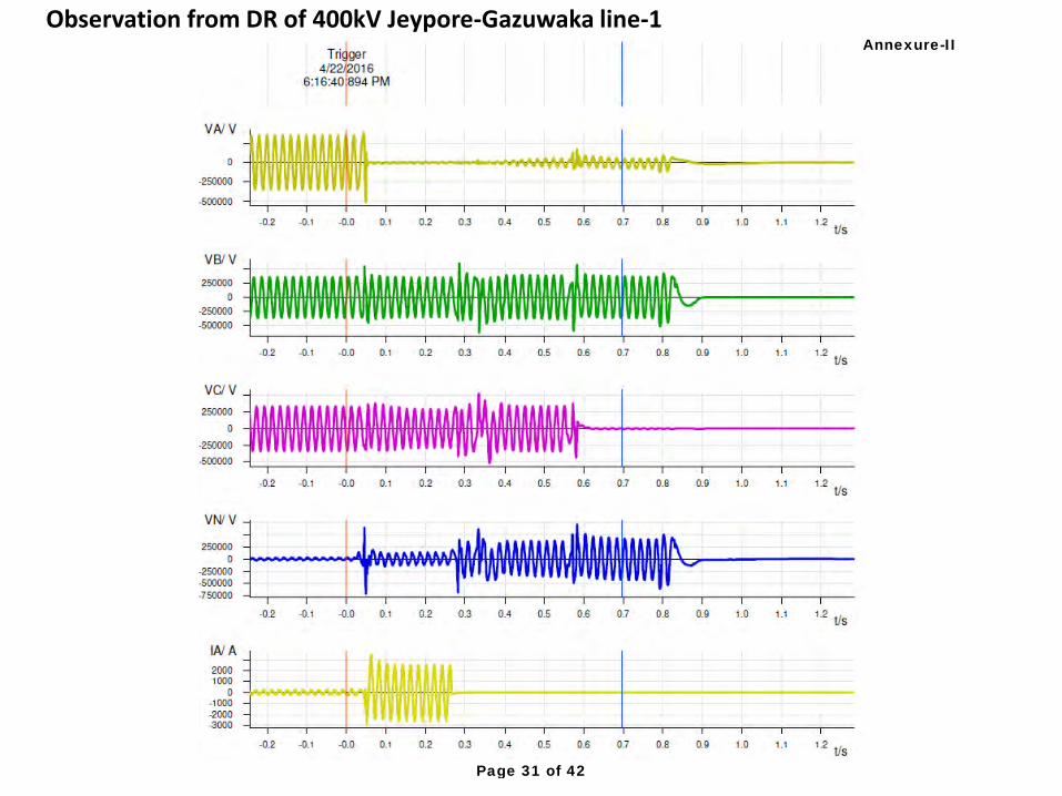
Observation from DR of 400kV Jeypore-Gazuwaka line-1 Annexure-II
Page 31 of 42
Annexure-II
Page 32 of 42
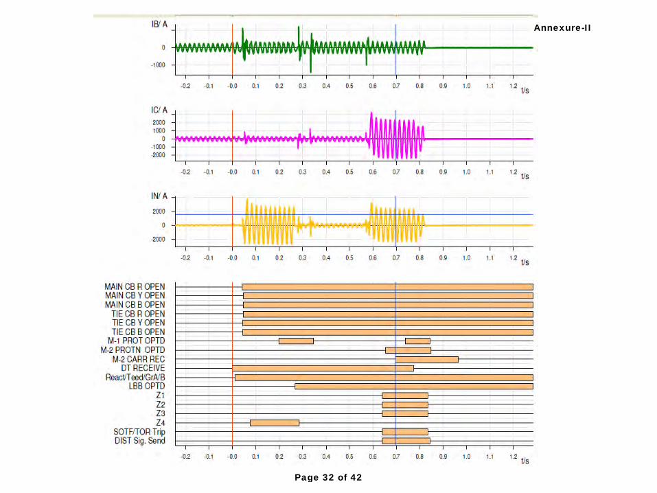
• It can be observed that R-phase to earth fault had occurred in 400kV Jeypore-Gazuwaka line-1. Breakers at Gazuwaka got tripped on direct trip receive.
• Distance protection zone-4 operation observed at Gazuwaka.
• Current is observed in R-phase even after opening of breakers at Gazuwaka.
LBB protection got operated at Gazuwaka after 250ms. Direct trip sent was not observed in digital channel.
• Distance protection operation observed after 600ms. Fault current observed in B-phase for 200 ms.
• Voltage in B-phase is observed for 800ms and in B-phase for 600ms.
Annexure-II
Page 33 of 42
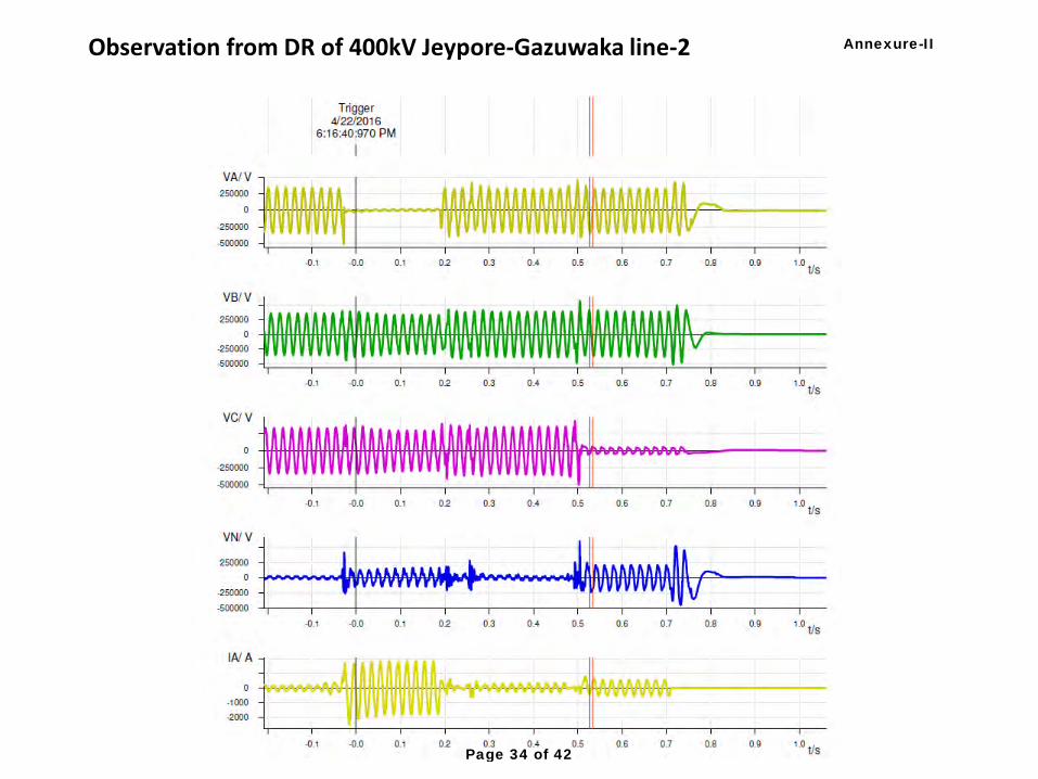
Observation from DR of 400kV Jeypore-Gazuwaka line-2 Annexure-II
Page 34 of 42
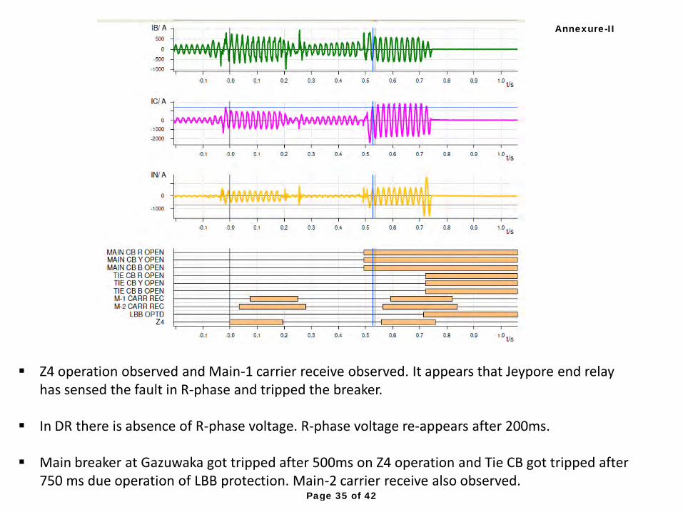
Z4 operation observed and Main-1 carrier receive observed. It appears that Jeypore end relay has sensed the fault in R-phase and tripped the breaker.
In DR there is absence of R-phase voltage. R-phase voltage re-appears after 200ms. Main breaker at Gazuwaka got tripped after 500ms on Z4 operation and Tie CB got tripped after
750 ms due operation of LBB protection. Main-2 carrier receive also observed.
Annexure-II
Page 35 of 42
Points for further investigation: Reason for LBB operation for Main- CB (CWD20-Q51) of 400kV Jeypore-Gazuwaka line-1, Tie breaker CW20 Q50, and Main breaker (CWD20-Q52) of filters CWC-23,24&25. Over-reach of relay at Jeypore end for fault in line-1.
Annexure-II
Page 36 of 42
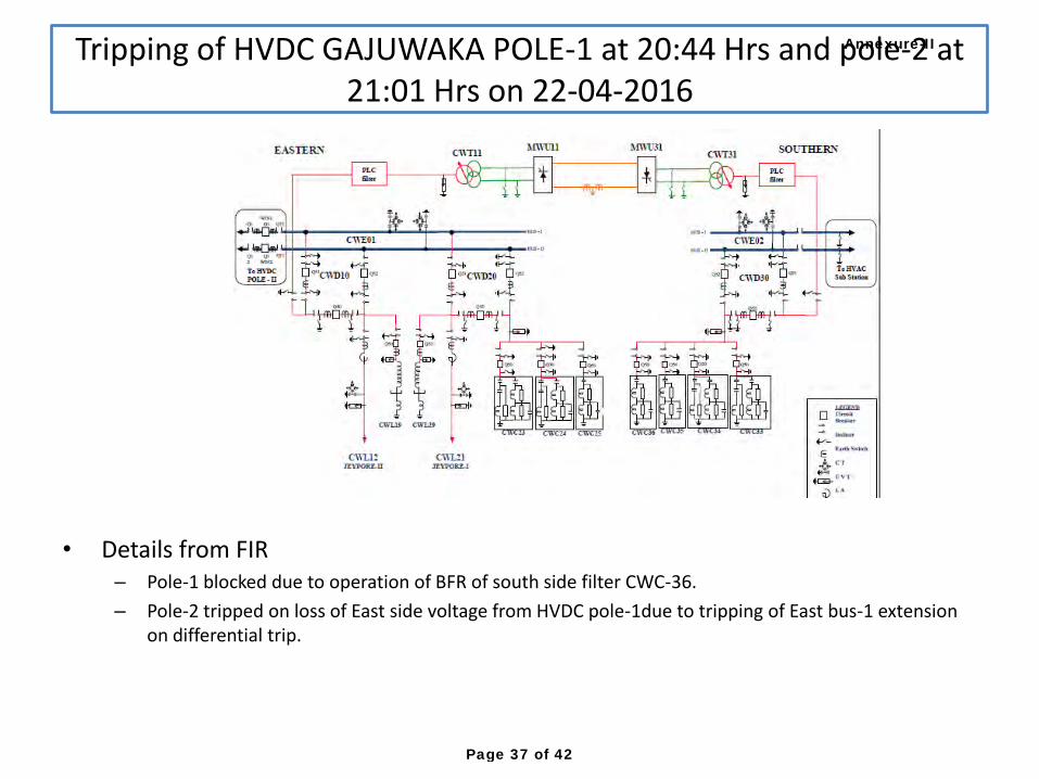
• Details from FIR – Pole-1 blocked due to operation of BFR of south side filter CWC-36.
– Pole-2 tripped on loss of East side voltage from HVDC pole-1due to tripping of East bus-1 extension on differential trip.
Tripping of HVDC GAJUWAKA POLE-1 at 20:44 Hrs and pole-2 at
21:01 Hrs on 22-04-2016
Annexure-II
Page 37 of 42
• Line tripped during disturbance at 230kV Myavdi TNEB SS as Main-I relay picked up in zone- 3
• Findings and remedial actions may be shared with PCSC
Tripping of 400kV Madurai-Udumalpet line at 10:57 Hrs on
23-04-2016
Annexure-II
Page 38 of 42
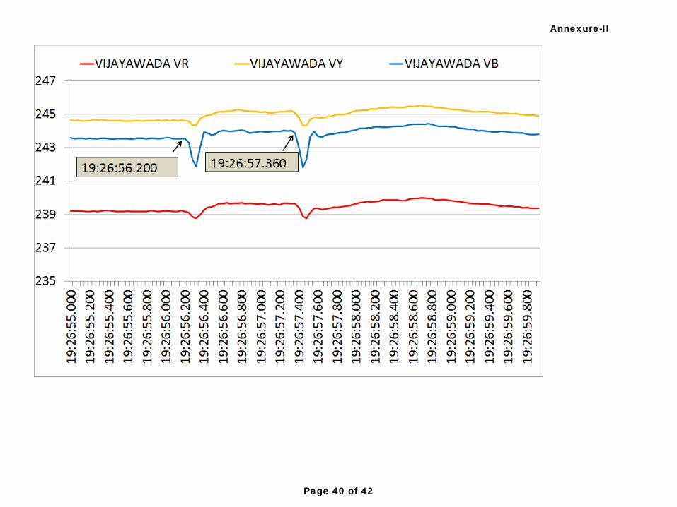
Tripping of 400kV Ramagundam-Chandrapur line-1&2 at 19:26hrs on 04-05-2016
• Tripping of Ramagundam-Chandrapur line-1 – B-phase to earth fault in line at 19:16 hrs
– Line auto-reclosed at Chandrapur and did not auto-reclose at Ramagundam
– Pole discrepancy was observed in E.L
• Tripping of Ramagundam-Chandrapur line-2 – B-phase to earth fault in line at 19:26:hrs
– Ramagundam end tried to auto-reclose
– 3 phase trip at chandrapur both ends as line-1 had already tripped.
– Bhadrawati pole-1&2 tripped due to loss of south bus voltage
Annexure-II
Page 39 of 42
Annexure-II
Page 40 of 42
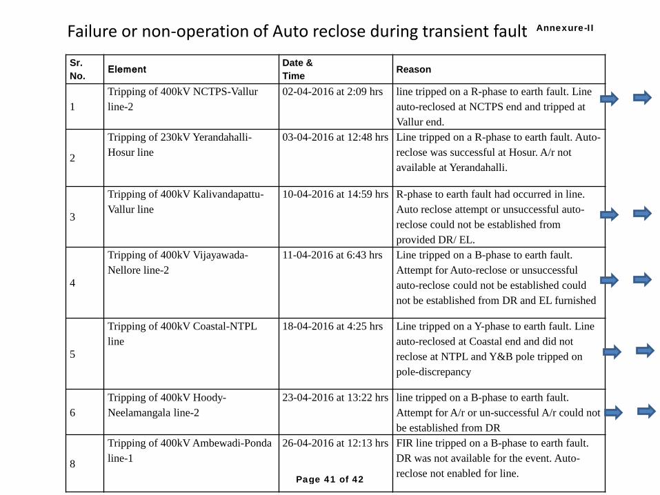
Sr.
No. Element
Date &
Time Reason
1
Tripping of 400kV NCTPS-Vallur
line-2
02-04-2016 at 2:09 hrs line tripped on a R-phase to earth fault. Line
auto-reclosed at NCTPS end and tripped at
Vallur end.
2
Tripping of 230kV Yerandahalli-
Hosur line
03-04-2016 at 12:48 hrs Line tripped on a R-phase to earth fault. Auto-
reclose was successful at Hosur. A/r not
available at Yerandahalli.
3
Tripping of 400kV Kalivandapattu-
Vallur line
10-04-2016 at 14:59 hrs R-phase to earth fault had occurred in line.
Auto reclose attempt or unsuccessful auto-
reclose could not be established from
provided DR/ EL.
4
Tripping of 400kV Vijayawada-
Nellore line-2
11-04-2016 at 6:43 hrs Line tripped on a B-phase to earth fault.
Attempt for Auto-reclose or unsuccessful
auto-reclose could not be established could
not be established from DR and EL furnished
5
Tripping of 400kV Coastal-NTPL
line
18-04-2016 at 4:25 hrs Line tripped on a Y-phase to earth fault. Line
auto-reclosed at Coastal end and did not
reclose at NTPL and Y&B pole tripped on
pole-discrepancy
6
Tripping of 400kV Hoody-
Neelamangala line-2
23-04-2016 at 13:22 hrs line tripped on a B-phase to earth fault.
Attempt for A/r or un-successful A/r could not
be established from DR
8
Tripping of 400kV Ambewadi-Ponda
line-1
26-04-2016 at 12:13 hrs FIR line tripped on a B-phase to earth fault.
DR was not available for the event. Auto-
reclose not enabled for line.
Failure or non-operation of Auto reclose during transient fault Annexure-II
Page 41 of 42
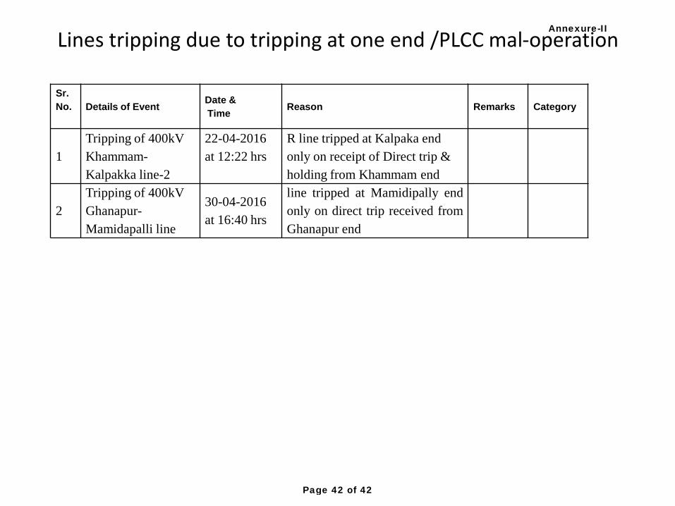
Sr.
No.
Details of Event Date &
Time Reason Remarks Category
1
Tripping of 400kV
Khammam-
Kalpakka line-2
22-04-2016
at 12:22 hrs
R line tripped at Kalpaka end
only on receipt of Direct trip &
holding from Khammam end
2
Tripping of 400kV
Ghanapur-
Mamidapalli line
30-04-2016
at 16:40 hrs
line tripped at Mamidipally end
only on direct trip received from
Ghanapur end
Lines tripping due to tripping at one end /PLCC mal-operation Annexure-II
Page 42 of 42
Grid Occurrences discussed in the 54th
Meeting of PCSC held on 26th
May, 2016 1/37
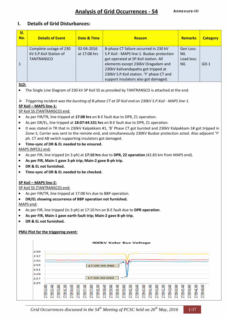
Analysis of Grid Occurrences - 54
I. Details of Grid Disturbances:
Sl. No.
Details of Event Date & Time Reason Remarks Category
1
Complete outage of 230 kV S.P.Koil Station of TANTRANSCO
02-04-2016 at 17:08 hrs
B-phase CT failure occurred in 230 kV S.P.Koil - MAPS line-1. Busbar protection got operated at SP.Koil station. All elements except 230kV Oragadam and 230kV Kalivandapattu got tripped at 230kV S.P.Koil station. ‘Y’ phase CT and support insulators also got damaged.
Gen Loss: NIL Load loss: NIL
GD-1
SLD: The Single Line Diagram of 230 kV SP Koil SS as provided by TANTRANSCO is attached at the end. Triggering incident was the bursting of B-phase CT at SP Koil end on 230kV S.P.Koil - MAPS line-1. SP Koil – MAPS line-1: SP Koil SS (TANTRANSCO) end:
As per FIR/TR, line tripped at 17:08 hrs on B-E fault due to DPR, Z1 operation. As per DR/EL, line tripped at 18:07:44.531 hrs on B-E fault due to DPR, Z1 operation. It was stated in TR that in 230kV Kalpakkam #1, ‘B’ Phase CT got bursted and 230kV Kalpakkam-1# got tripped in
Zone-1; Carrier was sent to the remote end, and simultaneously 230KV Busbar protection acted. Also adjacent ‘Y’ ph. CT and AB switch supporting insulators got damaged.
Time-sync of DR & EL needed to be ensured. MAPS (NPCIL) end:
As per FIR, line tripped (in 3-ph) at 17:10 hrs due to DPR, Z2 operation (42.83 km from MAPS end). As per FIR, Main-1 gave 3-ph trip; Main-2 gave B-ph trip.
DR & EL not furnished. Time-sync of DR & EL needed to be checked. SP Koil – MAPS line-2: SP Koil SS (TANTRANSCO) end:
As per FIR/TR, line tripped at 17:08 hrs due to BBP operation. DR/EL showing occurrence of BBP operation not furnished. MAPS end:
As per FIR, line tripped (in 3-ph) at 17:10 hrs on B-E fault due to DPR operation. As per FIR, Main-1 gave earth fault trip; Main-2 gave B-ph trip. DR & EL not furnished. PMU Plot for the triggering event:
Annexure-III
Grid Occurrences discussed in the 54th
Meeting of PCSC held on 26th
May, 2016 2/37
SRPC/ SRLDC:
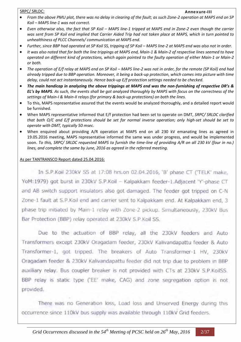
From the above PMU plot, there was no delay in clearing of the fault; as such Zone-2 operation at MAPS end on SP Koil – MAPS line-1 was not correct.
Even otherwise also, the fact that SP Koil – MAPS line-1 tripped at MAPS end in Zone-2 even though the carrier was sent from SP Koil end implied that Carrier Aided Trip had not taken place at MAPS, which in turn pointed to unhealthiness of PLCC Channels/ communication at MAPS end.
Further, since BBP had operated at SP Koil SS, tripping of SP Koil – MAPS line-2 at MAPS end was also not in order. It was also noted that for both the line trippings at MAPS end, Main-1 & Main-2 of respective lines seemed to have
operated on different kind of protections, which again pointed to the faulty operation of either Main-1 or Main-2 or both.
The operation of E/f relay at MAPS end on SP Koil – MAPS line-2 was not in order, for the remote (SP Koil) end had already tripped due to BBP operation. Moreover, it being a back-up protection, which comes into picture with time delay, could not act instantaneously. Hence back-up E/f protection settings needed to be checked.
The main handicap in analyzing the above trippings at MAPS end was the non-furnishing of respective DR’s & EL’s by MAPS. As such, the events shall be got analyzed thoroughly by MAPS with focus on the correctness of the settings of Main-I & Main-II relays (for primary & back-up protections) on both the lines.
To this, MAPS representative assured that the events would be analyzed thoroughly, and a detailed report would be furnished.
When MAPS representative informed that E/f protection had been set to operate on DMT, SRPC/ SRLDC clarified that both O/C and E/f protections should be set for normal inverse operation; only high-set should be set to operate with DMT, typically 50 msec.
When enquired about providing A/R operation at MAPS end on all 230 kV emanating lines as agreed in 19.05.2016 meeting, MAPS representative informed the same was under progress, and would be implemented soon. To this, SRPC/ SRLDC requested MAPS to furnish the time-line of providing A/R on all 230 kV (four in no.) lines, and complete the same by June, 2016 as agreed in the referred meeting.
As per TANTRANSCO Report dated 25.04.2016:
Annexure-III
Grid Occurrences discussed in the 54th
Meeting of PCSC held on 26th
May, 2016 3/37
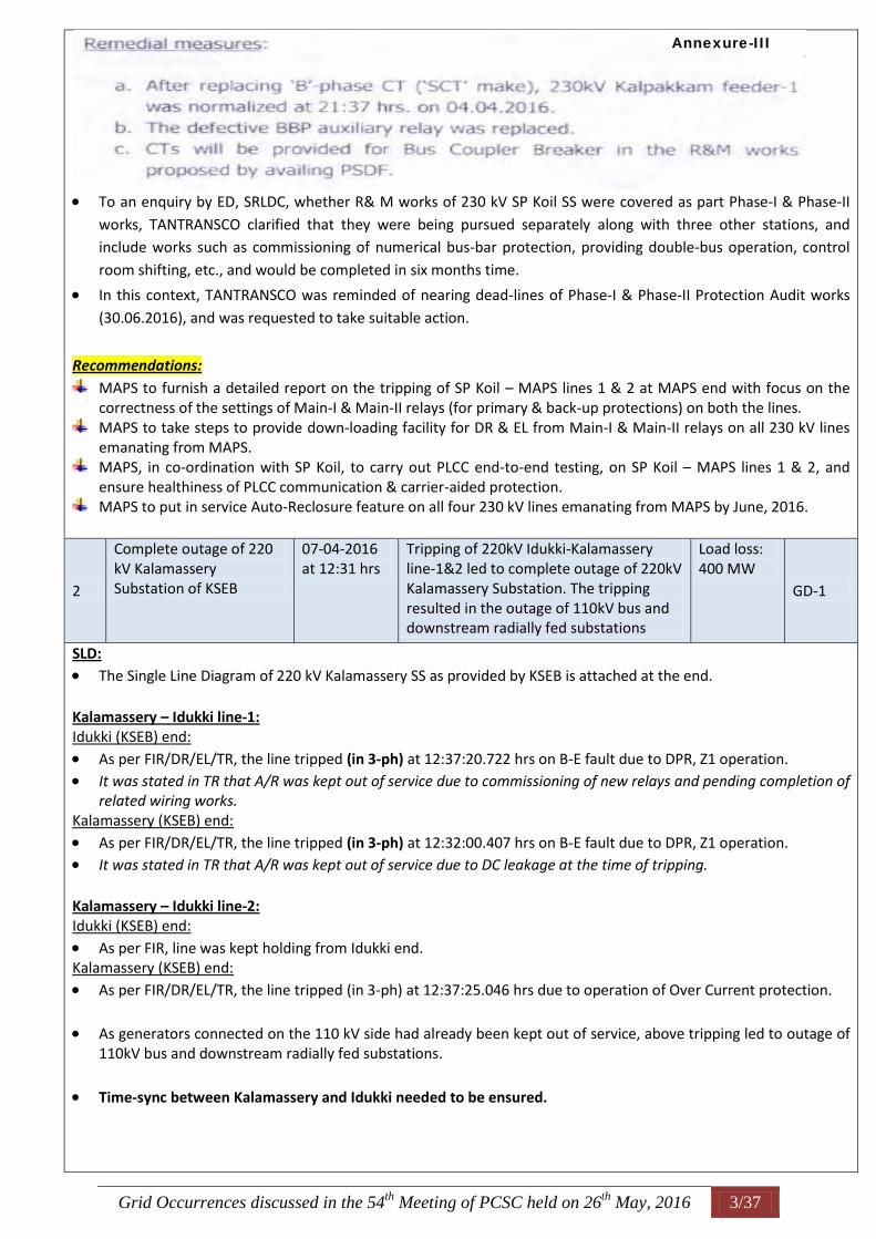
To an enquiry by ED, SRLDC, whether R& M works of 230 kV SP Koil SS were covered as part Phase-I & Phase-II
works, TANTRANSCO clarified that they were being pursued separately along with three other stations, and
include works such as commissioning of numerical bus-bar protection, providing double-bus operation, control
room shifting, etc., and would be completed in six months time.
In this context, TANTRANSCO was reminded of nearing dead-lines of Phase-I & Phase-II Protection Audit works
(30.06.2016), and was requested to take suitable action.
Recommendations:
MAPS to furnish a detailed report on the tripping of SP Koil – MAPS lines 1 & 2 at MAPS end with focus on the correctness of the settings of Main-I & Main-II relays (for primary & back-up protections) on both the lines.
MAPS to take steps to provide down-loading facility for DR & EL from Main-I & Main-II relays on all 230 kV lines emanating from MAPS.
MAPS, in co-ordination with SP Koil, to carry out PLCC end-to-end testing, on SP Koil – MAPS lines 1 & 2, and ensure healthiness of PLCC communication & carrier-aided protection.
MAPS to put in service Auto-Reclosure feature on all four 230 kV lines emanating from MAPS by June, 2016.
2
Complete outage of 220 kV Kalamassery Substation of KSEB
07-04-2016 at 12:31 hrs
Tripping of 220kV Idukki-Kalamassery line-1&2 led to complete outage of 220kV Kalamassery Substation. The tripping resulted in the outage of 110kV bus and downstream radially fed substations
Load loss: 400 MW
GD-1
SLD:
The Single Line Diagram of 220 kV Kalamassery SS as provided by KSEB is attached at the end. Kalamassery – Idukki line-1: Idukki (KSEB) end:
As per FIR/DR/EL/TR, the line tripped (in 3-ph) at 12:37:20.722 hrs on B-E fault due to DPR, Z1 operation. It was stated in TR that A/R was kept out of service due to commissioning of new relays and pending completion of
related wiring works. Kalamassery (KSEB) end:
As per FIR/DR/EL/TR, the line tripped (in 3-ph) at 12:32:00.407 hrs on B-E fault due to DPR, Z1 operation. It was stated in TR that A/R was kept out of service due to DC leakage at the time of tripping.
Kalamassery – Idukki line-2: Idukki (KSEB) end:
As per FIR, line was kept holding from Idukki end. Kalamassery (KSEB) end:
As per FIR/DR/EL/TR, the line tripped (in 3-ph) at 12:37:25.046 hrs due to operation of Over Current protection.
As generators connected on the 110 kV side had already been kept out of service, above tripping led to outage of 110kV bus and downstream radially fed substations.
Time-sync between Kalamassery and Idukki needed to be ensured.
Annexure-III
Grid Occurrences discussed in the 54th
Meeting of PCSC held on 26th
May, 2016 4/37
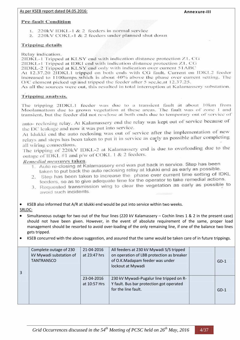
As per KSEB report dated 04.05.2016:
KSEB also informed that A/R at Idukki end would be put into service within two weeks. SRLDC:
Simultaneous outage for two out of the four lines (220 kV Kalamassery – Cochin lines 1 & 2 in the present case) should not have been given. However, in the event of absolute requirement of the same, proper load management should be resorted to avoid over-loading of the only remaining line, if one of the balance two lines gets tripped.
KSEB concurred with the above suggestion, and assured that the same would be taken care of in future trippings.
3
Complete outage of 230 kV Mywadi substation of TANTRANSCO
21-04-2016 at 23:47 hrs
All feeders at 230 kV Mywadi S/S tripped on operation of LBB protection as breaker of O.K.Madapam feeder was under lockout at Mywadi
GD-1
23-04-2016 at 10:57 Hrs
230 kV Mywadi-Pugalur line tripped on R-Y fault. Bus bar protection got operated for the line fault.
GD-1
Annexure-III
Grid Occurrences discussed in the 54th
Meeting of PCSC held on 26th
May, 2016 5/37
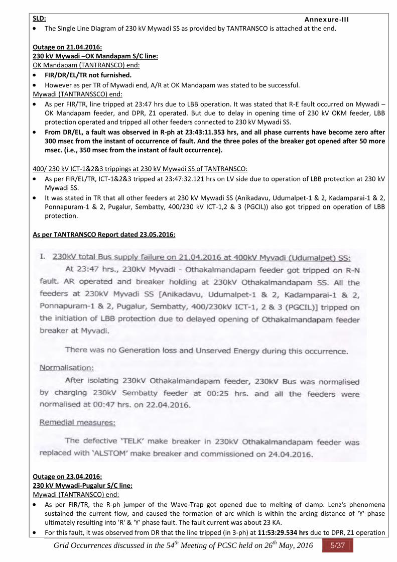
SLD:
The Single Line Diagram of 230 kV Mywadi SS as provided by TANTRANSCO is attached at the end. Outage on 21.04.2016: 230 kV Mywadi –OK Mandapam S/C line: OK Mandapam (TANTRANSCO) end: FIR/DR/EL/TR not furnished.
However as per TR of Mywadi end, A/R at OK Mandapam was stated to be successful. Mywadi (TANTRANSSCO) end:
As per FIR/TR, line tripped at 23:47 hrs due to LBB operation. It was stated that R-E fault occurred on Mywadi – OK Mandapam feeder, and DPR, Z1 operated. But due to delay in opening time of 230 kV OKM feeder, LBB protection operated and tripped all other feeders connected to 230 kV Mywadi SS.
From DR/EL, a fault was observed in R-ph at 23:43:11.353 hrs, and all phase currents have become zero after 300 msec from the instant of occurrence of fault. And the three poles of the breaker got opened after 50 more msec. (i.e., 350 msec from the instant of fault occurrence).
400/ 230 kV ICT-1&2&3 trippings at 230 kV Mywadi SS of TANTRANSCO:
As per FIR/EL/TR, ICT-1&2&3 tripped at 23:47:32.121 hrs on LV side due to operation of LBB protection at 230 kV Mywadi SS.
It was stated in TR that all other feeders at 230 kV Mywadi SS (Anikadavu, Udumalpet-1 & 2, Kadamparai-1 & 2, Ponnapuram-1 & 2, Pugalur, Sembatty, 400/230 kV ICT-1,2 & 3 (PGCIL)) also got tripped on operation of LBB protection.
As per TANTRANSCO Report dated 23.05.2016:
Outage on 23.04.2016: 230 kV Mywadi-Pugalur S/C line: Mywadi (TANTRANSCO) end:
As per FIR/TR, the R-ph jumper of the Wave-Trap got opened due to melting of clamp. Lenz's phenomena sustained the current flow, and caused the formation of arc which is within the arcing distance of 'Y' phase ultimately resulting into 'R' & 'Y' phase fault. The fault current was about 23 KA.
For this fault, it was observed from DR that the line tripped (in 3-ph) at 11:53:29.534 hrs due to DPR, Z1 operation
Annexure-III
Grid Occurrences discussed in the 54th
Meeting of PCSC held on 26th
May, 2016 6/37
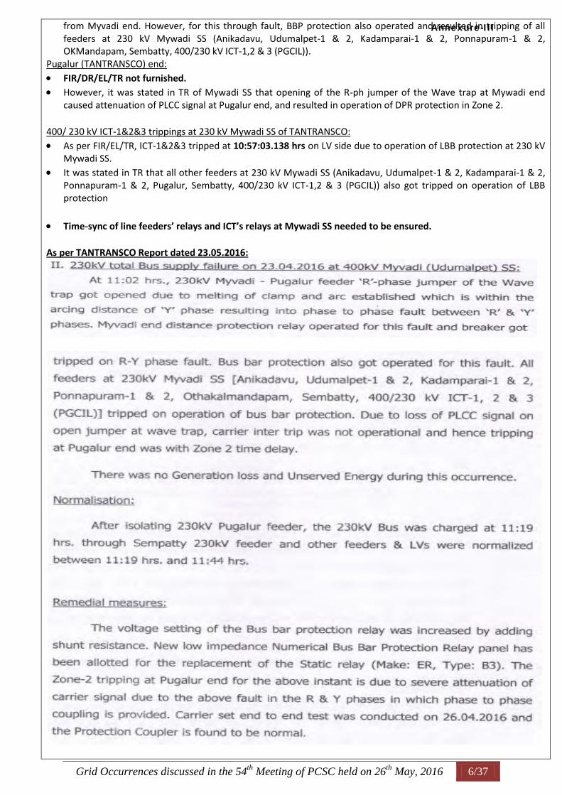
from Myvadi end. However, for this through fault, BBP protection also operated and resulted in tripping of all feeders at 230 kV Mywadi SS (Anikadavu, Udumalpet-1 & 2, Kadamparai-1 & 2, Ponnapuram-1 & 2, OKMandapam, Sembatty, 400/230 kV ICT-1,2 & 3 (PGCIL)).
Pugalur (TANTRANSCO) end:
FIR/DR/EL/TR not furnished.
However, it was stated in TR of Mywadi SS that opening of the R-ph jumper of the Wave trap at Mywadi end caused attenuation of PLCC signal at Pugalur end, and resulted in operation of DPR protection in Zone 2.
400/ 230 kV ICT-1&2&3 trippings at 230 kV Mywadi SS of TANTRANSCO: As per FIR/EL/TR, ICT-1&2&3 tripped at 10:57:03.138 hrs on LV side due to operation of LBB protection at 230 kV
Mywadi SS. It was stated in TR that all other feeders at 230 kV Mywadi SS (Anikadavu, Udumalpet-1 & 2, Kadamparai-1 & 2,
Ponnapuram-1 & 2, Pugalur, Sembatty, 400/230 kV ICT-1,2 & 3 (PGCIL)) also got tripped on operation of LBB protection
Time-sync of line feeders’ relays and ICT’s relays at Mywadi SS needed to be ensured. As per TANTRANSCO Report dated 23.05.2016:
Annexure-III
Grid Occurrences discussed in the 54th
Meeting of PCSC held on 26th
May, 2016 7/37
In view of the imminent onset of the wind season, ED, SRLDC enquired about the status of commissioning of 230 kV Numerical Busbar protection at 230 kV Mywadi SS, to which TANTRANSCO replied/ assured that the works, which were under progress, were directly being monitored by their Chief Engineer (P&C), and would be completed in 15 days time.
400 kV Madurai – Udumalpet S/C line: Udumalpet (PGCIL-SR2) end:
As per FIR, the line was kept holding Madurai (PGCIL-SR2) end: As per FIR/EL/TR, the line tripped (in 3-ph) at 10:57:03.045 hrs on R-Y fault due to DPR, Z3 operation.
From DR, this event (Z3-trip) seemed to have occurred at 11:57:03.044 hrs. Also Z3-trip happened almost instantaneously with the occurrence of R-Y fault. However, CB’s (152 & 252) were observed to be in CLOSED condition.
Time sync of DR & EL at 400 kV Madurai SS of PCIL (SR-II) needed to be ensured. PGCIL (SR-II):
The instantaneous Z3 trip was given by the newly commissioned Main-II (Micom P44) relay. Upon investigation with the help of OEM, they found that due to some additional/ wrong PSL logics, the relay was configured to give instantaneous trip in case of L-L faults.
Remedial action: The wrong/ additional PSL logics responsible for instantaneous trip in case of L-L faults had been removed.
On this, KSEB remarked that commissioning engineers should be properly instructed to disable all old settings while configuring relays with new settings.
KPTCL mentioned that not only during commissioning, even while undertaking testing activities also due care should be taken to disable/ enable requisite/ appropriate protections.
4
Tripping of Nagjheri Generators
14-04-2016 at 12:29 hrs
220 kV Nagjheri - Bidnal line tripped on B-E fault at 12:28 Hrs. At the same time, five running generating units (1, 2, 3, 4 & 6) at Nagjheri tripped on operation of Generator Transformer’s back-up Over Current & Earth Fault protection.
Gen. Loss: 640 MW
GD-1
SLD:
The Single Line Diagram of 220 kV Nagjheri PH as provided by KPCL is attached at the end. 220 kV Nagjheri – Bidnal S/C line: Nagjheri (KPCL) end:
FIR/DR/EL/TR not furnished. However, as per FIR of Bidnal, Nagjheri end tripped at 12:29 hrs on B-E fault due to DPR, Z2 operation (3.2 kA, 91
km from Nagjheri end) Bidnal (KPTCL) end:
As per FIR, the line tripped at 12:29 hrs due to DEFR operation. It was stated in FIR that as the line tripped on B/U protection (which is an electro-mechanical relay), DR & EL’s
were not available. KPTCL: At Bidnal, line tripped on DEFR due to suspected high resistive fault.
Remedial action: In the SEL relay, Mho characteristics had been previously selected for E/F protection. Now as remedial action,
Quadrilateral characteristics were selected for DEFR protection. Further, the resistive reach in Nagzari line distance relay at Bidnal end had been reviewed and revised. Action would be taken to trigger DR in numerical distance relay for b/u protection operation also.
Annexure-III
Grid Occurrences discussed in the 54th
Meeting of PCSC held on 26th
May, 2016 8/37
Outage of 220 kV Nagjheri PH of KPCL: SRPC/ SRLDC: It was noted that the various tripping files (FIR/DR/EL/TR) uploaded under Sender and Receiver sections in
SRLDC web portal were not related to the outage of 220 kV Nagjheri PH of KPCL on 14.04.2016 at 12:29 hrs. For example, the following can be noted from the various tripping files uploaded: As per SENDER-FIR, Nagjheri – Hubli line-2 tripped at 18:18 hrs on B-E fault due to DPR, Z1 operation. (It was
also stated that only Unit-1 was in service at the time of occurrence of this fault). As per SENDER-EL/SENDER-TR, Nagjheri – Ambewadi line-2 tripped at 15:02 hrs on B-E fault due to DPR, Z1
operation. (It was also stated that all Units except Unit-2 were in service at the time of occurrence of this fault).
The SENDER-DR pertains to Nagjheri – Ambewadi line-2 for an event on 13.04.2020 at 15:02:53.416 hrs. Type of fault was not shown. (DR not in order).
In place of RECEIVER-FIR, a DR was uploaded as per which Nagjheri – Hubli line-2 tripped at 18:18 hrs on B-E fault.
As per RECEIVER-TR/ RECEIVER-DR/ RECEIVER-EL, Nagjheri – Bidnal line tripped at 12:29:49.356hrs on B-E fault due to DPR, Z2 operation (91 km). (It was also stated in TR that all Units except Unit-5 were in service at the time of occurrence of this fault. Further, all in-service Units were stated to be tripped on operation of Generator Transformer’s back-up Over Current & Earth Fault protection.)
Thus KPCL, in gross violation of IEGC Regulation 5.2 (r), had not furnished any of the relevant tripping files pertaining to the event.
Further, operation of Generator Transformer’s back-up Over Current & Earth Fault (high-set) protection was not in order, for the fault current was stated to be 3.2 kA. Accordingly, there was a need to revise the settings of GT’s back-up O/C and E/F protections considering their individual contribution to solid bus fault at 220 kV bus of Nagjheri PH.
KPCL:
To this, KPCL informed that they had revised GT’s back-up protection settings in the recent past only from 5A to 7.5 A. However, they would re-check the adopted settings, and revise accordingly.
On this, KSEB suggested to keep appropriate time delay for high-set operation of GT’s transformer back-up protections.
Upon an enquiry by SRLDC as to whether SPS in place at Nagjheri operated during the event, KPCL replied that as it was a case of instantaneous high-set operation, GT’s were tripped even before the SPS could act.
Recommendations:
KPCL to revise the settings of GT’s back-up O/C and E/F protections considering their individual contribution to solid bus fault at 220 kV bus of Nagjheri PH.
KPCL to upload/ make available various tripping files (FIR/DR/EL/TR) for all tripping involving their stations in compliance of IEGC Regulation 5.2 (r).
Annexure-III
Grid Occurrences discussed in the 54th
Meeting of PCSC held on 26th
May, 2016 9/37
II. Details of Grid incidents:
Sl. No.
Details of Event Date & Time Reason Category
1
Tripping of 400 kV Vijayawada - Nellore (AP) line-1 and ICT-2 at Nellore(AP)
03-04-2016 at 13:52 hrs
Line tripped on R-phase to earth. LBB of tie breaker got operated at Nellore (AP) which resulted in tripping of 400kV Vijayawada-Nellore line-1 and 400/220kV ICT-2 at Nellore (AP)
GI-2
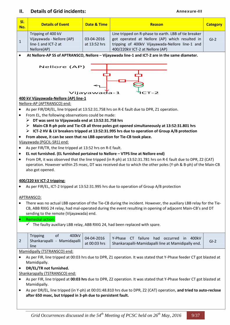
At Nellore-AP SS of APTRANSCO, Nellore – Vijayawada line-1 and ICT-2 are in the same diameter.
400 kV Vijayawada-Nellore (AP) line-1 Nellore-AP (APTRANSCO) end:
As per FIR/DR/EL, line tripped at 13:52:31.758 hrs on R-E fault due to DPR, Z1 operation. From EL, the following observations could be made: DT was sent to Vijayawada end at 13:52:31.758 hrs Main-CB R-ph pole and Tie-CB all three poles got opened simultaneously at 13:52:31.801 hrs ICT-2 HV & LV breakers tripped at 13:52:31.995 hrs due to operation of Group A/B protection
From above, it can be seen that no LBB operation for Tie-CB took place. Vijayawada (PGCIL-SR1) end: As per FIR/TR, the line tripped at 13:52 hrs on R-E fault.
EL not furnished. (EL furnished pertained to Nellore – VTPS line at Nellore end) From DR, it was observed that the line tripped (in R-ph) at 13:52:31.781 hrs on R-E fault due to DPR, Z2 (CAT)
operation. However within 25 msec, DT was received due to which the other poles (Y-ph & B-ph) of the Main-CB also got opened.
400/220 kV ICT-2 tripping:
As per FIR/EL, ICT-2 tripped at 13:52:31.995 hrs due to operation of Group A/B protection APTRANSCO:
There was no actual LBB operation of the Tie-CB during the incident. However, the auxiliary LBB relay for the Tie-CB, ABB RXIG 24 relay, had mal-operated during the event resulting in opening of adjacent Main-CB’s and DT sending to the remote (Vijayawada) end.
Remedial action: The faulty auxiliary LBB relay, ABB RXIG 24, had been replaced with spare.
2 Tripping of 400kV Shankarapalli - Mamidapalli line
04-04-2016 at 00:03 hrs
Y-Phase CT failure had occurred in 400kV Shankarapalli-Mamidapalli line at Mamidipally end.
GI-2
Mamidipally (TSTRANSCO) end:
As per FIR, line tripped at 00:03 hrs due to DPR, Z1 operation. It was stated that Y-Phase feeder CT got blasted at Mamidipally.
DR/EL/TR not furnished. Shankarapally (TSTRANSCO) end: As per FIR, line tripped at 00:03 hrs due to DPR, Z2 operation. It was stated that Y-Phase feeder CT got blasted at
Mamidipally.
As per DR/EL, line tripped (in Y-ph) at 00:01:48.810 hrs due to DPR, Z2 (CAT) operation, and tried to auto-reclose after 650 msec, but tripped in 3-ph due to persistent fault.
Annexure-III
Grid Occurrences discussed in the 54th
Meeting of PCSC held on 26th
May, 2016 10/37
TSTRANSCO:
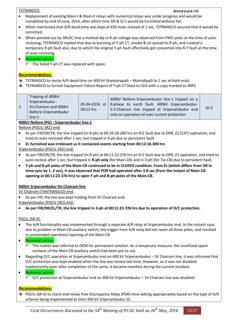
Replacement of existing Main-I & Main-II relays with numerical relays was under progress and would be completed by end of June, 2016, after which time DR & EL’s would be furnished without fail.
When mentioned that A/R dead-time was kept at 650 msec instead of 1 sec, TSTRANSCO assured that it would be corrected.
When pointed out by SRLDC that a marked dip in R-ph voltage was observed from PMU plots at the time of auto-reclosing, TSTRANSCO replied that due to bursting of Y-ph CT, smoke & oil spread to R-ph, and created a temporary R-ph fault also, due to which the original Y-ph fault effectively got converted into R-Y fault at the time of auto-reclosing.
Remedial action: The failed Y-ph CT was replaced with spare.
Recommendations:
TSTRANSCO to revise A/R dead-time on 400 kV Shankarapalli – Mamidipalli to 1 sec at both ends. TSTRANSCO to furnish Equipment Failure Report of Y-ph CT blast to CEA with a copy marked to SRPC.
3
Tripping of 400kV Sriperambudur - SV.Chartam and 400kV Nellore-Sriperambudur line-1
05-04-2016 at 00:11 hrs
400kV Nellore-Sriperambudur line-1 tripped on a R-phase to earth fault. 400kV Sriperambudur-S.V.Chatram line tripped at Sriperambudur end only on operation of over current protection
GI-2
400kV Nellore (PG) - Sriperambudur line-1 Nellore (PGCIL-SR2) end: As per FIR/DR/TR, the line tripped (in R-ph) at 00:10:18.280 hrs on R-E fault due to DPR, Z2 (CAT) operation, and
tried to auto-reclosed after 1 sec; but tripped in 3-ph due to persistent fault. EL furnished was irrelevant as it contained events starting from 00:12:18.300 hrs Sriperambudur (PGCIL-SR2) end:
As per FIR/DR/TR, the line tripped (in R-ph) at 00:11:22.376 hrs on R-E fault due to DPR, Z1 operation, and tried to auto-reclose after 1 sec; but tripped in R-ph only (for Main-CB) and in 3-ph (for Tie-CB) due to persistent fault.
Y-ph and B-ph poles of the Main-CB continued to be in CLOSED condition. From EL (which differs from DR in time-sync by 1 .2 sec), it was observed that PDR had operated after 3.8 sec (from the instant of Main-CB opening at 00:11:22.376 hrs) to open Y-ph and B-ph poles of the Main-CB.
400kV Sriperambadur-SV.Chatram line SV Chatram (TANTRANSCO) end:
As per FIR, the line was kept holding from SV Chatram end. Sriperambudur (PGCIL-SR2) end: As per FIR/DR/EL/TR, the line tripped in 3-ph at 00:11:23.726 hrs due to operation of O/C protection. PGCIL (SR-II):
The A/R functionality was implemented through a separate A/R relay at Sriperambudur end. In the instant case, due to problem in Main-CB auxiliary switch, the trigger from A/R relay did not reach all three poles, and resulted in unintended operation/ opening of the Main-CB.
Remedial action: The matter was referred to OEM for permanent solution. As a temporary measure, the unutilized spare
contacts of the Main-CB auxiliary switch had been put to use.
Regarding O/C operation at Sriperambudur end on 400 kV Sriperambudur – SV Chatram line, it was informed that O/C protection was kept enabled when the line was tested last time, However, as it was not disabled inadvertently even after completion of the same, it became manifest during the current incident.
Remedial action: O/C protection at Sriperambudur end on 400 kV Sriperambudur – SV Chatram line was disabled.
Recommendations:
PGCIL (SR-II) to check and revise Pole Discrepancy Relay (PDR) time setting appropriately based on the type of A/R scheme being implemented at their 400 kV Sriperambudur SS.
Annexure-III
Grid Occurrences discussed in the 54th
Meeting of PCSC held on 26th
May, 2016 11/37
4 Tripping of 400 kV Raichur TPS-Mahboobnagar line
05-04-2016 at 10:23 hrs
Line tripped on operation of Backup impedance protection of line reactor. Direct trip was received at Mahboobnagar end.
GI-2
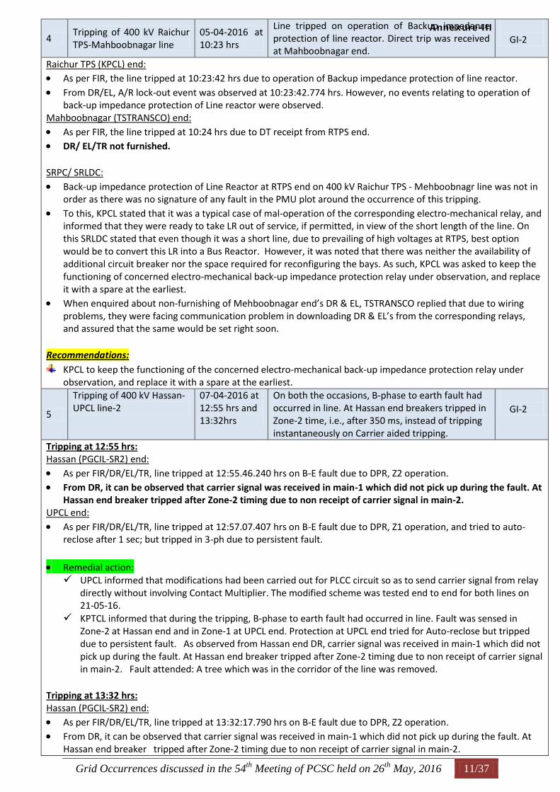
Raichur TPS (KPCL) end: As per FIR, the line tripped at 10:23:42 hrs due to operation of Backup impedance protection of line reactor.
From DR/EL, A/R lock-out event was observed at 10:23:42.774 hrs. However, no events relating to operation of back-up impedance protection of Line reactor were observed.
Mahboobnagar (TSTRANSCO) end:
As per FIR, the line tripped at 10:24 hrs due to DT receipt from RTPS end. DR/ EL/TR not furnished. SRPC/ SRLDC:
Back-up impedance protection of Line Reactor at RTPS end on 400 kV Raichur TPS - Mehboobnagr line was not in order as there was no signature of any fault in the PMU plot around the occurrence of this tripping.
To this, KPCL stated that it was a typical case of mal-operation of the corresponding electro-mechanical relay, and informed that they were ready to take LR out of service, if permitted, in view of the short length of the line. On this SRLDC stated that even though it was a short line, due to prevailing of high voltages at RTPS, best option would be to convert this LR into a Bus Reactor. However, it was noted that there was neither the availability of additional circuit breaker nor the space required for reconfiguring the bays. As such, KPCL was asked to keep the functioning of concerned electro-mechanical back-up impedance protection relay under observation, and replace it with a spare at the earliest.
When enquired about non-furnishing of Mehboobnagar end’s DR & EL, TSTRANSCO replied that due to wiring problems, they were facing communication problem in downloading DR & EL’s from the corresponding relays, and assured that the same would be set right soon.
Recommendations:
KPCL to keep the functioning of the concerned electro-mechanical back-up impedance protection relay under observation, and replace it with a spare at the earliest.
5
Tripping of 400 kV Hassan-UPCL line-2
07-04-2016 at 12:55 hrs and 13:32hrs
On both the occasions, B-phase to earth fault had occurred in line. At Hassan end breakers tripped in Zone-2 time, i.e., after 350 ms, instead of tripping instantaneously on Carrier aided tripping.
GI-2
Tripping at 12:55 hrs: Hassan (PGCIL-SR2) end:
As per FIR/DR/EL/TR, line tripped at 12:55.46.240 hrs on B-E fault due to DPR, Z2 operation. From DR, it can be observed that carrier signal was received in main-1 which did not pick up during the fault. At
Hassan end breaker tripped after Zone-2 timing due to non receipt of carrier signal in main-2. UPCL end:
As per FIR/DR/EL/TR, line tripped at 12:57.07.407 hrs on B-E fault due to DPR, Z1 operation, and tried to auto-reclose after 1 sec; but tripped in 3-ph due to persistent fault.
Remedial action: UPCL informed that modifications had been carried out for PLCC circuit so as to send carrier signal from relay
directly without involving Contact Multiplier. The modified scheme was tested end to end for both lines on 21-05-16.
KPTCL informed that during the tripping, B-phase to earth fault had occurred in line. Fault was sensed in Zone-2 at Hassan end and in Zone-1 at UPCL end. Protection at UPCL end tried for Auto-reclose but tripped due to persistent fault. As observed from Hassan end DR, carrier signal was received in main-1 which did not pick up during the fault. At Hassan end breaker tripped after Zone-2 timing due to non receipt of carrier signal in main-2. Fault attended: A tree which was in the corridor of the line was removed.
Tripping at 13:32 hrs: Hassan (PGCIL-SR2) end:
As per FIR/DR/EL/TR, line tripped at 13:32:17.790 hrs on B-E fault due to DPR, Z2 operation. From DR, it can be observed that carrier signal was received in main-1 which did not pick up during the fault. At
Hassan end breaker tripped after Zone-2 timing due to non receipt of carrier signal in main-2.
Annexure-III
Grid Occurrences discussed in the 54th
Meeting of PCSC held on 26th
May, 2016 12/37
UPCL end:
As per FIR/DR/EL/TR, line tripped at 13:33:39.848 hrs on B-E fault due to A/R (Z1) operation, and tried to auto-reclose after 1 sec; but tripped in 3-ph due to persistent fault.
Remedial action: UPCL informed that modifications had been carried out for PLCC circuit so as to send carrier signal from relay
directly without involving contact Multiplier. The modified scheme was tested for both lines on 21-05-16 end to end.
KPTCL informed that during the tripping, B-phase to earth fault had occurred in line. Fault was sensed in zone-2 at Hassan end and in zone-1 at UPCL end. Protection at UPCL end tried for Auto-reclose but tripped due to persistent fault. As observed from Hassan end DR, carrier signal was received in main-1 which did not pick up during the fault. At Hassan end breaker tripped after Zone-2 timing due to non receipt of carrier signal in main-2. Fault attended: A tree which was in the corridor of the line was removed.
Time-sync of DR & EL’s at UPCL needed to be ensured. SRPC/SRLDC:
Even though the tripping at Hassan end in Zone-2 was in order, and was as per the implemented PLCC carrier scheme, it shall be tried on experimental basis for this line exclusively that a Contact Multiplier be used at each end, which upon receiving the carrier signal from the other end on any of the PLCC channels, would replicate it and send to both Main-I and Main-II relays.
PGCIL (SR-II) and UPCL are requested to try the above scheme for 400 kV UPCL – Hassan line, and inform its efficacy to PCSC forum in their next (55th) meeting.
Further, as the width of the carrier signal received at Hassan end has been observed to be very narrow, UPCL is requested use appropriate pulse-stretcher circuit/device at their end so as to generate carrier pulses of adequate width, say 50 - 100 msec.
6
Tripping at 230 kV Ingur substation
08-04-2016 at 15:36 hrs
110 kV “Y“ and “B” phase of BUS-1 PT got failed at Ingur substation. Due to absence of Bus bar protection in 110kV Bus, 230/110kV ICT- 1,2, & 3 tripped on operation of Back up over current protection and all 110 kV tie feeders tripped from remote ends on Z2 operation
GI-1
SLD:
The Single Line Diagram of 230 kV Ingur SS as provided by TANTRANSCO is attached at the end.
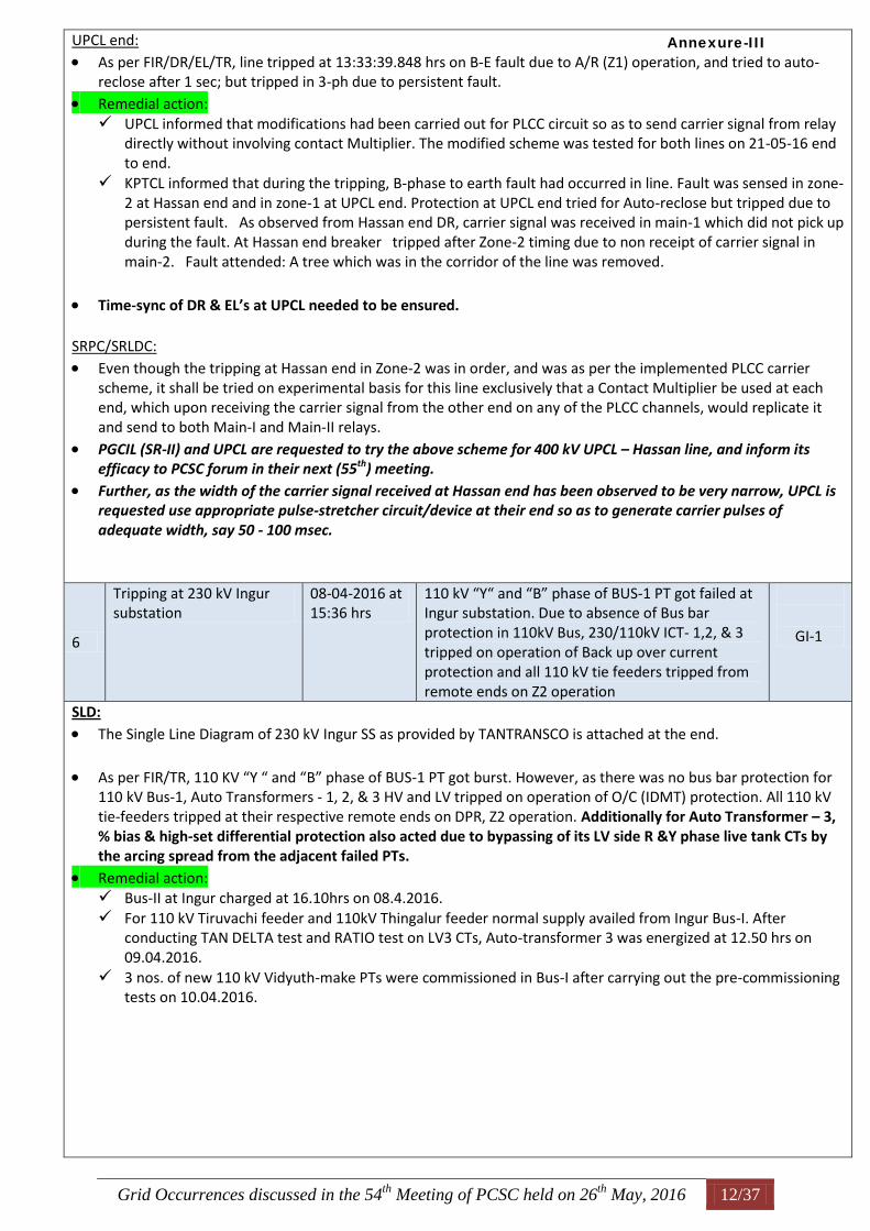
As per FIR/TR, 110 KV “Y “ and “B” phase of BUS-1 PT got burst. However, as there was no bus bar protection for 110 kV Bus-1, Auto Transformers - 1, 2, & 3 HV and LV tripped on operation of O/C (IDMT) protection. All 110 kV tie-feeders tripped at their respective remote ends on DPR, Z2 operation. Additionally for Auto Transformer – 3, % bias & high-set differential protection also acted due to bypassing of its LV side R &Y phase live tank CTs by the arcing spread from the adjacent failed PTs.
Remedial action: Bus-II at Ingur charged at 16.10hrs on 08.4.2016. For 110 kV Tiruvachi feeder and 110kV Thingalur feeder normal supply availed from Ingur Bus-I. After
conducting TAN DELTA test and RATIO test on LV3 CTs, Auto-transformer 3 was energized at 12.50 hrs on 09.04.2016.
3 nos. of new 110 kV Vidyuth-make PTs were commissioned in Bus-I after carrying out the pre-commissioning tests on 10.04.2016.
Annexure-III
Grid Occurrences discussed in the 54th
Meeting of PCSC held on 26th
May, 2016 13/37
As per TANTRANSCO’s Report dated 25.04.2016:
7
Tripping of 400kV Gajuwaka-Simhadri line-2 and 400kV Gazuwaka-Vijayawada line
10-04-2016 at 4:21 hrs
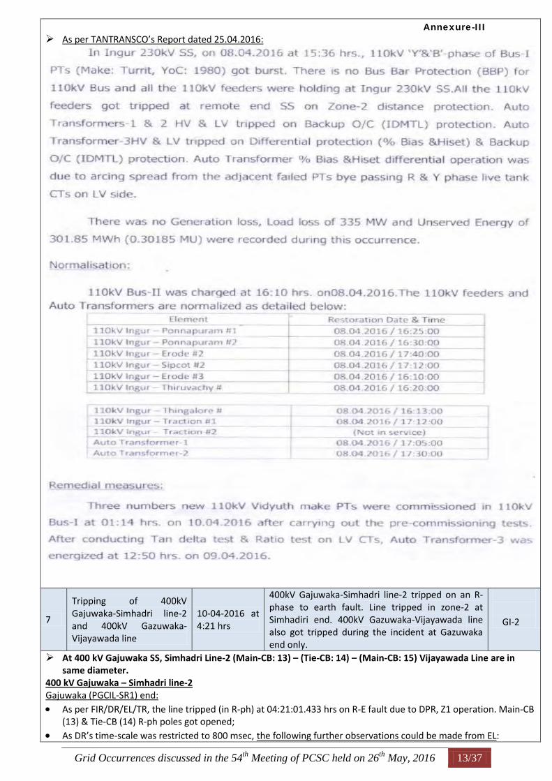
400kV Gajuwaka-Simhadri line-2 tripped on an R-phase to earth fault. Line tripped in zone-2 at Simhadiri end. 400kV Gazuwaka-Vijayawada line also got tripped during the incident at Gazuwaka end only.
GI-2
At 400 kV Gajuwaka SS, Simhadri Line-2 (Main-CB: 13) – (Tie-CB: 14) – (Main-CB: 15) Vijayawada Line are in same diameter.
400 kV Gajuwaka – Simhadri line-2 Gajuwaka (PGCIL-SR1) end:
As per FIR/DR/EL/TR, the line tripped (in R-ph) at 04:21:01.433 hrs on R-E fault due to DPR, Z1 operation. Main-CB (13) & Tie-CB (14) R-ph poles got opened;
As DR’s time-scale was restricted to 800 msec, the following further observations could be made from EL:
Annexure-III
Grid Occurrences discussed in the 54th
Meeting of PCSC held on 26th
May, 2016 14/37
During A/R’s dead-time at around 04:21:01.530 hrs Gajuwaka – Vijayawada line got tripped from Gajuwaka end opening its respective Main and Tie CB’s (M-CB: 15; T-CB: 14).
It was further observed that Tie-CB (14) and Main-CB (15)’s Trip Circuits were found to be faulty around 04:21: 01.950 hrs.
It was also observed that at 04:21:03.867 hrs, the other poles (Y & B) of Main-CB (13) got opened due to PDR operation. ----------------- Reasons for this?
From above observations of EL, it can be deduced that line failed to auto-reclose at Gajuwaka end. Simhadri (NTPC) end:
As per FIR/DR/EL/TR, the line tripped at 04:21:01.773 hrs on R-E fault due to DPR, Z2 operation. 400 kV Gajuwaka – Vijayawada S/C line Gajuwaka (PGCIL-SR1) end:
As per FIR/TR, the line tripped at 04:21 hrs on R-N and Y-N faults due to DPR operation. It was stated that 01 No. tension insulator was decapped at Loc No. 845.
From EL, it was observed that the line had tripped at around 04:21:01.530 hrs opening its respective Main and Tie CB’s (M-CB: 15; T-CB: 14).
Vijayawada (PGCIL-SR1) end:
As per FIR, the line was kept holding from Vijayawada end.
As per EL, the line tripped at 05:12:17.720 hrs on R-N and Y-N faults due to DPR operation. It was also observed that respective Main-CB (24) and Tie-CB (23) went into LOCK-OUT.
DR furnished (triggering time = 04:21:01.397 hrs) did not show the above events. Time-sync between DR and EL needs to be ensured.
PGCIL (SR-II) representative informed that the line was hand-tripped from Vijayawada end. PGCIL (SR-I):
The observed anomalies at Gajuwaka SS were because of the Insulator tracking phenomenon that severely affected their SS in April, 2016. Due to dense fog in and around Vizag Substation mixed with saline pollutants caused visible/audible tracking in the insulators and resulted in insulation breakdown and decapping of insulators.
Remedial action: Cold line washing of entire HVAC, HVDC Pole-1 & 2 including Filter Banks had been carried out. In Gajuwaka SS, all Strung Bus Porcelain insulators had been replaced with CLR Polymer type insulators. RTV Silicon High Voltage Insulation Coating on BPI insulator stacks and Isolator support structures connected
to 400kV Bus had been completed. In 400kV Simhadri – Gajuwaka – 1 & 2 Lines, all the porcelain insulators had been replaced with CLR Polymer
insulators. In 400kV Vijayawada – Gajuwaka S/C line, transmission lines porcelain insulators up to 30 km radius had been
replaced with CLR Polymer insulators. In 400kV Jeypore – Gajuwaka – 1 & 2, it was proposed to replace porcelain insulators with CLR Polymer
insulators up to 30 km radius. The work is under progress. In 400kV Simhadri – Vemagiri – 1 & 2, it was proposed to replace porcelain insulators with CLR Polymer
insulators up to 30 km radius. PLCC end-to-end testing on Gajuwaka – Simhadri line-2 was carried out on 28.04.2016, and ensured that PLCC
carrier communication is in healthy condition.
8
Tripping of 400kV Coastal-Tuticorin PS line and Unit-1 at NTPL
11-04-2016 at 7:05 hrs
Line tripped on a B-phase to earth fault and auto-reclose attempt was unsuccessful due to persistent fault. Running Unit-1 at NTPL got tripped during the incident.
GI-2
Tripping of 400 kV CEPL-TTNPS line: CEPL end:
As per FIR/DR/EL/TR, line tripped at 07:04:43.517 hrs on B-E fault due to DPR, Z1 operation, and tried to auto-reclose after 1.2 sec; but tripped in three-phase due to persistent fault.
From EL, it can also be observed that GCB (of CEPL Unit-1) had tripped at 07:04:45.100 hrs (which is as per the SPS in place at CEPL)
TTNPS (PGCIL-SR2) end:
As per FIR/DR/EL/TR, line tripped at 07:04:43.510 hrs on B-E fault due to DPR, Z2 (CAT) operation, and tried to
Annexure-III
Grid Occurrences discussed in the 54th
Meeting of PCSC held on 26th
May, 2016 15/37
auto-reclose after 1 sec; but tripped in three-phase due to persistent fault. Tripping of NTPL Unit-1:
As per FIR/DR/TR, Unit-1 tripped at 07:05:03.230 hrs due to operation of Low Forward Power protection. In EL, the events relating to Unit-1 tripping at 07:05 hrs were not captured. However, it can be noticed that
Unit-1 trip occurred at 06:58:03.320 hrs due to Low Forward Power protection.
Time-sync of DR & EL of Unit-1 relays needed to be ensured. NTPL:
Unit-1 tripped not due to low forward power protection, but due to operation of its prime-mover Motor’s protection on high steam temperature, and informed that appropriate remedial action had been taken at their end.
In this regard, it was enquired whether NTPL had properly kept the fault ride through time delay in VFD Speed Sensor relay for the generating units, and requested to ensure that it is kept appropriately (typically 2 sec) to avoid unwarranted Unit trippings on account of transient voltage dips in auxiliary bus voltage.
9 Tripping of 400kV Raichur TPS Bus-2
13-04-2016 at 21:12 hrs
Y-ph Pole of Tie-breaker of Unit-4 at RTPS failed. Unit-4 got tripped on operation of Generator Differential, Reverse power & LBB protection. Operation of LBB protection led to tripping of BUS-2 at RTPS
GI-2
SLD:
The single line diagram of 400/ 220 kV Raichur TPS as provided by KPCL is attached at the end.
As per FIR, 400 kV Bus-2 got tripped at 21:12:02 hrs due to operation of LBB protection. It was stated that during the synchronization process of Unit-4, when the excitation voltage was at 15 kV, the Y-Pole of Tie-breaker (of Unit-4) got blasted. As a result, Unit-4 tripped on Generator Differential, Reverse power & LBB protection. Operation of LBB protection led to tripping of 400 kV BUS-2 at RTPS.
The uploaded DR & EL & TR could not be downloaded. KPCL:
KPCL informed that Y-ph Pole of Tie-breaker of Unit-4 at RTPS failed while synchronising it. Unit-4 got tripped on operation of Generator Differential, Reverse power & LBB protection protections. It was explained that due to surface conduction over the Unit-4 Tie-breaker, LBB relay of 400 kV Bus-2 got operated leading to tripping of all breakers connected to it. The reason for surface current was attributed to the deposition of ash, heavy mist & humidity on account of Unit-4’s proximity to cooling towers.
In this regard, SRPC/ SRLDC brought to KPCL’s attention the occurrence of similar event due to LBB operation of Main & Tie breakers of Unit-7 on 12.11.2015 at 00:30 hrs (discussed in 49th meeting of PCSC held on 30.11.2016), when it was recommended among other things to provide dedicated breaker flashover protection, and to take necessary preventive measures such as measurement of dynamic contact resistance, and over-hauling (hot-line washing) of breakers at regular intervals to ensure healthiness of breakers.
To this, KPCL informed that hot-line washing of breakers is already in place. Further, they have also initiated steps (tendering is in progress) for applying RTV Silicone high voltage insulator coatings to all ceramic insulators of
Annexure-III
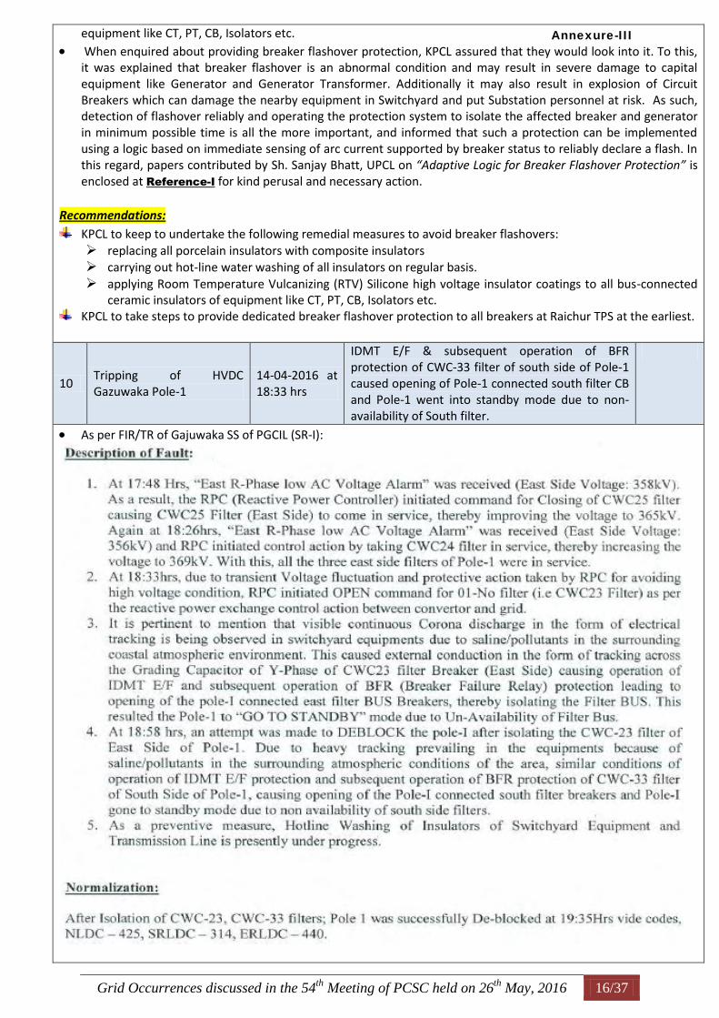
Grid Occurrences discussed in the 54th
Meeting of PCSC held on 26th
May, 2016 16/37
equipment like CT, PT, CB, Isolators etc.
When enquired about providing breaker flashover protection, KPCL assured that they would look into it. To this, it was explained that breaker flashover is an abnormal condition and may result in severe damage to capital equipment like Generator and Generator Transformer. Additionally it may also result in explosion of Circuit Breakers which can damage the nearby equipment in Switchyard and put Substation personnel at risk. As such, detection of flashover reliably and operating the protection system to isolate the affected breaker and generator in minimum possible time is all the more important, and informed that such a protection can be implemented using a logic based on immediate sensing of arc current supported by breaker status to reliably declare a flash. In this regard, papers contributed by Sh. Sanjay Bhatt, UPCL on “Adaptive Logic for Breaker Flashover Protection” is enclosed at Reference-I for kind perusal and necessary action.
Recommendations:
KPCL to keep to undertake the following remedial measures to avoid breaker flashovers: replacing all porcelain insulators with composite insulators carrying out hot-line water washing of all insulators on regular basis. applying Room Temperature Vulcanizing (RTV) Silicone high voltage insulator coatings to all bus-connected
ceramic insulators of equipment like CT, PT, CB, Isolators etc. KPCL to take steps to provide dedicated breaker flashover protection to all breakers at Raichur TPS at the earliest.
10 Tripping of HVDC Gazuwaka Pole-1
14-04-2016 at 18:33 hrs
IDMT E/F & subsequent operation of BFR protection of CWC-33 filter of south side of Pole-1 caused opening of Pole-1 connected south filter CB and Pole-1 went into standby mode due to non-availability of South filter.
As per FIR/TR of Gajuwaka SS of PGCIL (SR-I):
Annexure-III
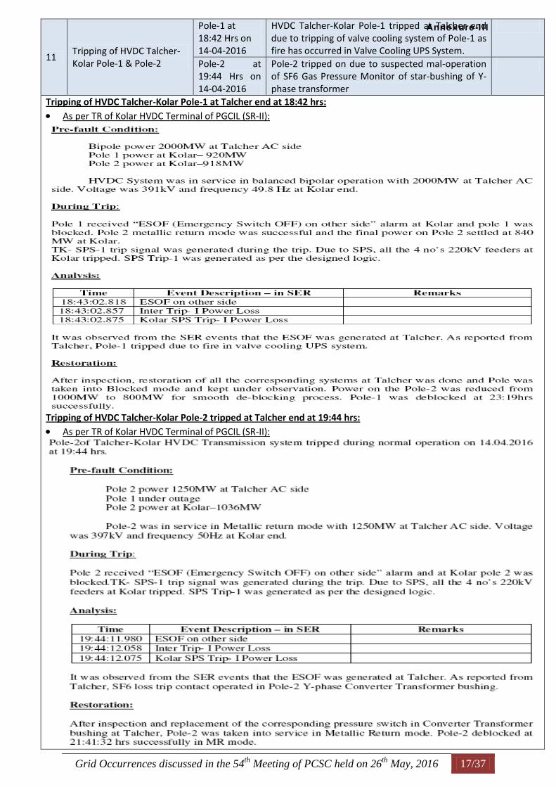
Grid Occurrences discussed in the 54th
Meeting of PCSC held on 26th
May, 2016 17/37
11 Tripping of HVDC Talcher-Kolar Pole-1 & Pole-2
Pole-1 at 18:42 Hrs on 14-04-2016
HVDC Talcher-Kolar Pole-1 tripped at Talcher end due to tripping of valve cooling system of Pole-1 as fire has occurred in Valve Cooling UPS System.
Pole-2 at 19:44 Hrs on 14-04-2016
Pole-2 tripped on due to suspected mal-operation of SF6 Gas Pressure Monitor of star-bushing of Y-phase transformer
Tripping of HVDC Talcher-Kolar Pole-1 at Talcher end at 18:42 hrs:
As per TR of Kolar HVDC Terminal of PGCIL (SR-II):
Tripping of HVDC Talcher-Kolar Pole-2 tripped at Talcher end at 19:44 hrs:
As per TR of Kolar HVDC Terminal of PGCIL (SR-II):
Annexure-III
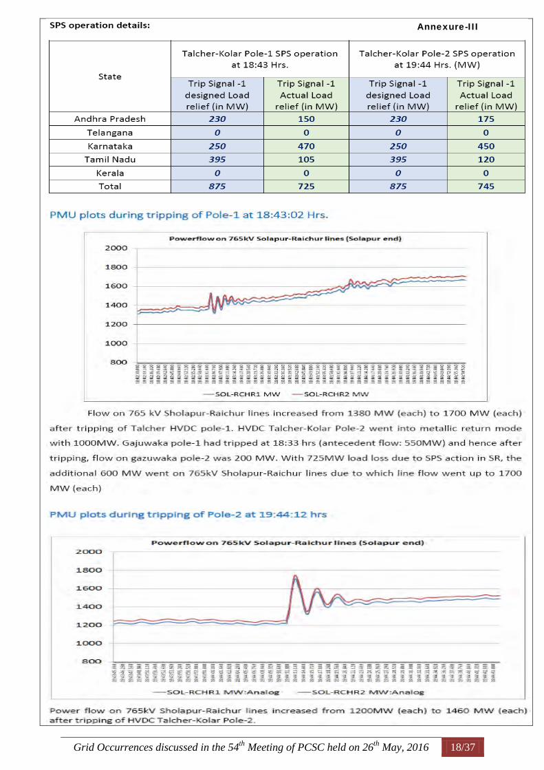
Grid Occurrences discussed in the 54th
Meeting of PCSC held on 26th
May, 2016 18/37
Annexure-III
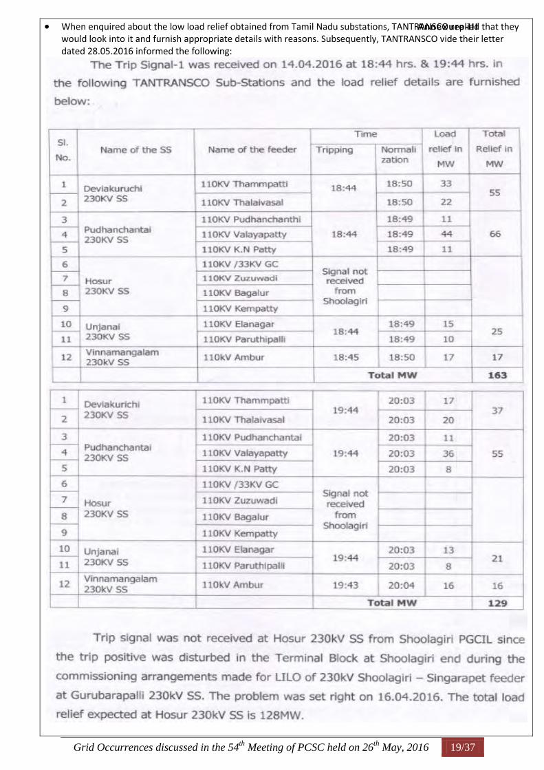
Grid Occurrences discussed in the 54th
Meeting of PCSC held on 26th
May, 2016 19/37
When enquired about the low load relief obtained from Tamil Nadu substations, TANTRANSCO replied that they would look into it and furnish appropriate details with reasons. Subsequently, TANTRANSCO vide their letter dated 28.05.2016 informed the following:
Annexure-III
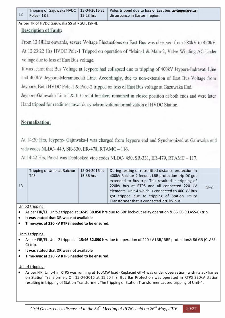
Grid Occurrences discussed in the 54th
Meeting of PCSC held on 26th
May, 2016 20/37
12 Tripping of Gajuwaka HVDC Poles - 1&2
15-04-2016 at 12:23 hrs
Poles tripped due to loss of East bus voltage due to disturbance in Eastern region.
As per TR of HVDC Gajuwaka SS of PGCIL (SR-I):
13
Tripping of Units at Raichur TPS
15-04-2016 at 15:36 hrs
During testing of retrofitted distance protection in 400kV Raichur-2 feeder, LBB protection trip DC got extended to Bus trip. This resulted in tripping of 220kV bus at RTPS and all connected 220 kV elements. Unit-4 which is connected to 400 kV Bus got tripped due to tripping of Station Utility Transformer that is connected 220 kV bus
GI-2
Unit-2 tripping:
As per FIR/EL, Unit-2 tripped at 16:49:38.850 hrs due to BBP lock-out relay operation & 86 GB (CLASS-C) trip. It was stated that DR was not available Time-sync at 220 kV RTPS needed to be ensured. Unit-3 tripping:
As per FIR/EL, Unit-2 tripped at 15:46:32.890 hrs due to operation of 220 kV LBB/ BBP protection& 86 GB (CLASS-C) trip.
It was stated that DR was not available Time-sync at 220 kV RTPS needed to be ensured. Unit-4 tripping:
As per FIR, Unit-4 in RTPS was running at 100MW load (Replaced GT-4 was under observation) with its auxiliaries on Station Transformer. On 15-04-2016 at 15.50 hrs. Bus Bar Protection was operated in RTPS 220kV station resulting in tripping of Station Transformer. The tripping of Station Transformer caused tripping of Unit-4.
Annexure-III
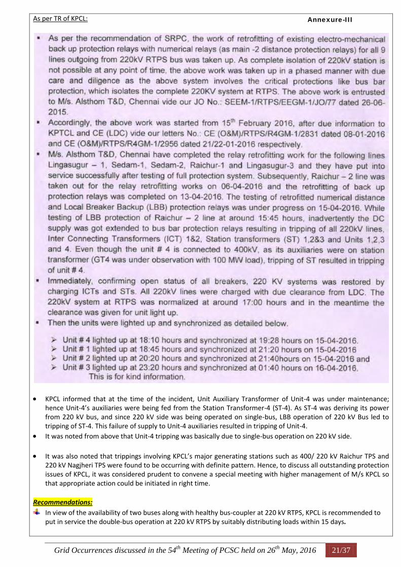
Grid Occurrences discussed in the 54th
Meeting of PCSC held on 26th
May, 2016 21/37
As per TR of KPCL:
KPCL informed that at the time of the incident, Unit Auxiliary Transformer of Unit-4 was under maintenance; hence Unit-4’s auxiliaries were being fed from the Station Transformer-4 (ST-4). As ST-4 was deriving its power from 220 kV bus, and since 220 kV side was being operated on single-bus, LBB operation of 220 kV Bus led to tripping of ST-4. This failure of supply to Unit-4 auxiliaries resulted in tripping of Unit-4.
It was noted from above that Unit-4 tripping was basically due to single-bus operation on 220 kV side.
It was also noted that trippings involving KPCL’s major generating stations such as 400/ 220 kV Raichur TPS and 220 kV Nagjheri TPS were found to be occurring with definite pattern. Hence, to discuss all outstanding protection issues of KPCL, it was considered prudent to convene a special meeting with higher management of M/s KPCL so that appropriate action could be initiated in right time.
Recommendations:
In view of the availability of two buses along with healthy bus-coupler at 220 kV RTPS, KPCL is recommended to put in service the double-bus operation at 220 kV RTPS by suitably distributing loads within 15 days.
Annexure-III
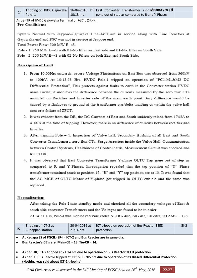
Grid Occurrences discussed in the 54th
Meeting of PCSC held on 26th
May, 2016 22/37
14 Tripping of HVDC Gajuwaka Pole- 1
16-04-2016 at 10:18 hrs
East Converter Transformer Y-phase OLTC Tap gone out of step as compared to R and Y-Phases
As per TR of HVDC Gajuwaka Terminal of PGCIL (SR-I):
15 Tripping of ICT-2 at Cudappah station
20-04-2016 at 21:14 hrs
ICT tripped on operation of Bus Reactor TEED protection
GI-2
At Kadapa SS of PGCIL (SR-I), ICT-2 and Bus Reactor are in same dia. Bus Reactor’s CB’s are: Main-CB = 13; Tie-CB = 14.
As per FIR, ICT-2 tripped at 21:14 hrs due to operation of Bus Reactor TEED protection. As per EL, Bus Reactor tripped at 21:15.00.205 hrs due to operation of its Biased Differential Protection.
(Nothing was said about ICT-2 tripping)
Annexure-III
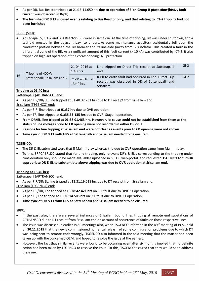
Grid Occurrences discussed in the 54th
Meeting of PCSC held on 26th
May, 2016 23/37
As per DR, Bus Reactor tripped at 21:15.11.650 hrs due to operation of 3-ph Group-B protection (heavy fault current was observed in B-ph).
The furnished DR & EL showed events relating to Bus Reactor only, and that relating to ICT-2 tripping had not been furnished.
PGCIL (SR-I):
At Kadapa SS, ICT-2 and Bus Reactor (BR) were in same dia. At the time of tripping, BR was under shutdown, and a scaffold erected in the adjacent bay (to undertake some maintenance activites) accidentally fell upon the conductor portion between the BR breaker and its line-side (away from BR) isolator. This created a fault in the differential zone of the BR. As a significant amount of this fault current (> 10 kA) was contributed by ICT-2, it also tripped on high-set operation of the corresponding O/C protection.
16 Tripping of 400kV Sattenapalli-Srisailam line-2
21-04-2016 at 1:40 hrs
Line tripped on Direct Trip receipt at Sattenapalli end
GI-2
21-04-2016 at 13:40 hrs
R-Ph to earth fault had occurred in line. Direct Trip receipt was observed in DR of Sattenapalli and Srisailam.
GI-2
Tripping at 01:40 hrs: Sattenapalli (APTRANSCO) end:
As per FIR/DR/EL, line tripped at 01:40:37.731 hrs due to DT receipt from Srisailam end. Srisailam (TSGENCO) end:
As per FIR, line tripped at 01:37 hrs due to OVR operation. As per TR, line tripped at 01:35.33.135 hrs due to OVR, Stage-I operation. From DR/EL, line tripped at 01:38:01.463 hrs. However, its cause could not be established from them as the
status of line voltages prior to CB opening were not recorded in either DR or EL.
Reasons for line tripping at Srisailam end were not clear as events prior to CB opening were not shown. Time sync of DR & EL with GPS at Sattenapalli and Srisailam needed to be ensured. TSGENCO: The DR & EL submitted were that if Main-I relay whereas trip due to OVR operation came from Main-II relay.
To this, SRPC/ SRLDC stated that for any tripping, only relevant DR’s & EL’s corresponding to the tripping under consideration only should be made available/ uploaded in SRLDC web-portal, and requested TSGENCO to furnish appropriate DR & EL to substantiate above tripping was due to OVR operation at Srisailam end.
Tripping at 13:40 hrs: Sattenapalli (APTRANSCO) end: As per FIR/DR/EL, line tripped at 13:31:19.018 hrs due to DT receipt from Srisailam end. Srisailam (TSGENCO) end:
As per FIR/DR, line tripped at 13:28:42.421 hrs on R-E fault due to DPR, Z1 operation. As per EL, line tripped at 13:26:14.505 hrs on R-E fault due to DPR, Z1 operation. Time sync of DR & EL with GPS at Sattenapalli and Srisailam needed to be ensured. SRPC:
In the past also, there were several instances of Srisailam bound lines tripping at remote end substations of APTRANSCO due to DT receipt from Srisailam end on account of occurrence of faults on those respective lines.
The issue was discussed in earlier PCSC meetings also, when TSGENCO informed in the 49th meeting of PCSC held on 30.11.2015 that the newly commissioned numerical relays had some configuration problems due to which DT was being sent to remote ends wrongly. TSGENCO also informed in the said meeting that the matter had been taken up with the concerned OEM, and hoped to resolve the issue at the earliest.
However, the fact that similar events were found to be occurring even after six months implied that no definite action had been taken by TSGENCO to resolve the issue. To this, TSGENCO assured that they would soon address the issue.
Annexure-III
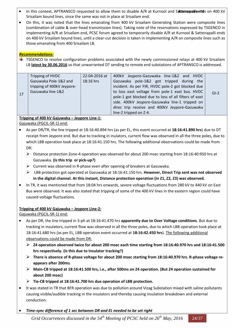
Grid Occurrences discussed in the 54th
Meeting of PCSC held on 26th
May, 2016 24/37
In this context, APTRANSCO requested to allow them to disable A/R at Kurnool and Sattenapalli ends on 400 kV Srisailam bound lines, since the same was not in place at Srisailam end.
On this, it was noted that the lines emanating from 400 kV Srisailam Generating Station were composite lines (combination of cable & over-head transmission lines). Taking note of the reservations expressed by TSGENCO in implementing A/R at Srisailam end, PCSC forum agreed to temporarily disable A/R at Kurnool & Sattenapalli ends on 400 kV Srisailam bound lines, until a clear-cut decision is taken in implementing A/R on composite lines such as those emanating from 400 Srisailam LB.
Recommendations:
TSGENCO to resolve configuration problems associated with the newly commissioned relays at 400 kV Srisailam LB latest by 30.06.2016 so that unwarranted DT sending to remote end substations of APTRANSCO is addressed.
17
Tripping of HVDC Gazuwaka Pole-1&2 and tripping of 400kV Jeypore-Gazuwaka line-1&2
22-04-2016 at 18:16 hrs
400kV Jeypore-Gazuwaka line-1&2 and HVDC Gazuwaka pole-1&2 got tripped during the incident. As per FIR, HVDC pole-2 got blocked due to loss east voltage from pole-1 east bus. HVDC pole-1 got blocked due to loss of all filters of east side. 400kV Jeypore-Gazuwaka line-1 tripped on direc trip receive and 400kV Jeypore-Gazuwaka line-2 tripped on Z-4.
GI-2
Tripping of 400 kV Gajuwaka – Jeypore Line-1: Gajuwaka (PGCIL-SR-1) end:
As per DR/TR, the line tripped at 18:16:40.894 hrs (as per EL, this event occurred at 18:16:41.890 hrs) due to DT
receipt from Jeypore end. But due to tracking in inulators, current flow was observed in all the three poles, due to
which LBB operation took place at 18:16:41.150 hrs. The following additional observations could be made from
DR:
Distance protection Zone-4 operation was observed for about 200 msec starting from 18:16:40:950 hrs at
Gazuwaka. (Is this trip or pick-up?)
Current was observed in R-phase even after opening of breakers at Gazuwaka.
LBB protection got operated at Gazuwaka at 18:16:41.150 hrs. However, Direct Trip sent was not observed
in the digital channel. At this instant, Distance protection operation (in Z1, Z2, Z3) was observed.
In TR, it was mentioned that from 18:04 hrs onwards, severe voltage fluctuations from 280 kV to 440 kV on East
Bus were observed. It was also stated that tripping of some of the 400 kV lines in the eastern region could have
caused voltage fluctuations.
Tripping of 400 kV Gajuwaka – Jeypore Line-2: Gajuwaka (PGCIL-SR-1) end:
As per DR, the line tripped in 3-ph at 18:16:41.470 hrs apparently due to Over Voltage conditions. But due to
tracking in insulators, current flow was observed in all the three poles, due to which LBB operation took place at
18:16:41.680 hrs (as per EL, LBB operation event occurred at 18:16:42.450 hrs). The following additional
observations could be made from DR:
Z4 operation observed twice for about 200 msec each time starting from 18:16:40.970 hrs and 18:16:41.500
hrs respectively. (Is this due to Insulator tracking?)
There is absence of R-phase voltage for about 200 msec starting from 18:16:40.970 hrs. R-phase voltage re-
appears after 200ms.
Main-CB tripped at 18:16:41.500 hrs, i.e., after 500ms on Z4 operation. (But Z4 operation sustained for
about 200 msec)
Tie-CB tripped at 18:16:41.700 hrs due operation of LBB protection.
It was stated in TR that BFR operation was due to pollution around Vizag Substation mixed with saline pollutants
causing visible/audible tracking in the insulators and thereby causing insulation breakdown and external
conduction.
Time-sync difference of 1 sec between DR and EL needed to be set right
Annexure-III
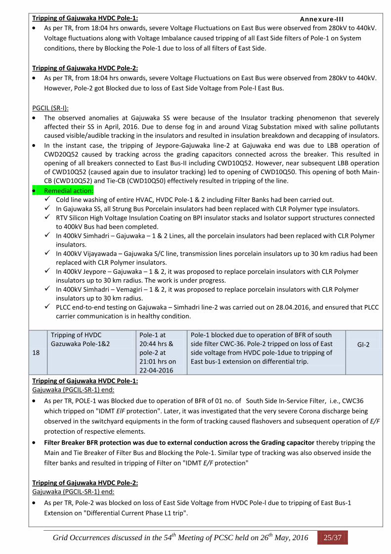
Grid Occurrences discussed in the 54th
Meeting of PCSC held on 26th
May, 2016 25/37
Tripping of Gajuwaka HVDC Pole-1: As per TR, from 18:04 hrs onwards, severe Voltage Fluctuations on East Bus were observed from 280kV to 440kV.
Voltage fluctuations along with Voltage Imbalance caused tripping of all East Side filters of Pole-1 on System
conditions, there by Blocking the Pole-1 due to loss of all filters of East Side.
Tripping of Gajuwaka HVDC Pole-2: As per TR, from 18:04 hrs onwards, severe Voltage Fluctuations on East Bus were observed from 280kV to 440kV.
However, Pole-2 got Blocked due to loss of East Side Voltage from Pole-l East Bus.
PGCIL (SR-I): The observed anomalies at Gajuwaka SS were because of the Insulator tracking phenomenon that severely
affected their SS in April, 2016. Due to dense fog in and around Vizag Substation mixed with saline pollutants caused visible/audible tracking in the insulators and resulted in insulation breakdown and decapping of insulators.
In the instant case, the tripping of Jeypore-Gajuwaka line-2 at Gajuwaka end was due to LBB operation of CWD20Q52 caused by tracking across the grading capacitors connected across the breaker. This resulted in opening of all breakers connected to East Bus-II including CWD10Q52. However, near subsequent LBB operation of CWD10Q52 (caused again due to insulator tracking) led to opening of CWD10Q50. This opening of both Main-CB (CWD10Q52) and Tie-CB (CWD10Q50) effectively resulted in tripping of the line.
Remedial action: Cold line washing of entire HVAC, HVDC Pole-1 & 2 including Filter Banks had been carried out. In Gajuwaka SS, all Strung Bus Porcelain insulators had been replaced with CLR Polymer type insulators. RTV Silicon High Voltage Insulation Coating on BPI insulator stacks and Isolator support structures connected
to 400kV Bus had been completed. In 400kV Simhadri – Gajuwaka – 1 & 2 Lines, all the porcelain insulators had been replaced with CLR Polymer
insulators. In 400kV Vijayawada – Gajuwaka S/C line, transmission lines porcelain insulators up to 30 km radius had been
replaced with CLR Polymer insulators. In 400kV Jeypore – Gajuwaka – 1 & 2, it was proposed to replace porcelain insulators with CLR Polymer
insulators up to 30 km radius. The work is under progress. In 400kV Simhadri – Vemagiri – 1 & 2, it was proposed to replace porcelain insulators with CLR Polymer
insulators up to 30 km radius. PLCC end-to-end testing on Gajuwaka – Simhadri line-2 was carried out on 28.04.2016, and ensured that PLCC
carrier communication is in healthy condition.
18
Tripping of HVDC Gazuwaka Pole-1&2
Pole-1 at 20:44 hrs & pole-2 at 21:01 hrs on 22-04-2016
Pole-1 blocked due to operation of BFR of south side filter CWC-36. Pole-2 tripped on loss of East side voltage from HVDC pole-1due to tripping of East bus-1 extension on differential trip.
GI-2
Tripping of Gajuwaka HVDC Pole-1: Gajuwaka (PGCIL-SR-1) end:
As per TR, POLE-1 was Blocked due to operation of BFR of 01 no. of South Side In-Service Filter, i.e., CWC36
which tripped on "IDMT ElF protection". Later, it was investigated that the very severe Corona discharge being
observed in the switchyard equipments in the form of tracking caused flashovers and subsequent operation of E/F
protection of respective elements.
Filter Breaker BFR protection was due to external conduction across the Grading capacitor thereby tripping the
Main and Tie Breaker of Filter Bus and Blocking the Pole-1. Similar type of tracking was also observed inside the
filter banks and resulted in tripping of Filter on "IDMT E/F protection"
Tripping of Gajuwaka HVDC Pole-2: Gajuwaka (PGCIL-SR-1) end:
As per TR, Pole-2 was blocked on loss of East Side Voltage from HVDC Pole-l due to tripping of East Bus-1
Extension on "Differential Current Phase L1 trip".
Annexure-III
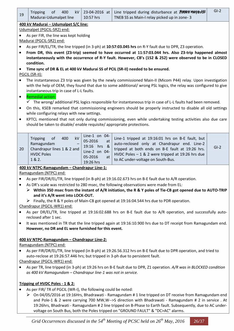
Grid Occurrences discussed in the 54th
Meeting of PCSC held on 26th
May, 2016 26/37
19 Tripping of 400 kV Madurai-Udumalpet line
23-04-2016 at 10:57 hrs
Line tripped during disturbance at 230kV Myavdi TNEB SS as Main-I relay picked up in zone- 3
GI-2
400 kV Madurai – Udumalpet S/C line: Udumalpet (PGCIL-SR2) end:
As per FIR, the line was kept holding Madurai (PGCIL-SR2) end:
As per FIR/EL/TR, the line tripped (in 3-ph) at 10:57:03.045 hrs on R-Y fault due to DPR, Z3 operation. From DR, this event (Z3-trip) seemed to have occurred at 11:57:03.044 hrs. Also Z3-trip happened almost
instantaneously with the occurrence of R-Y fault. However, CB’s (152 & 252) were observed to be in CLOSED condition.
Time sync of DR & EL at 400 kV Madurai SS of PCIL (SR-II) needed to be ensured. PGCIL (SR-II):
The instantaneous Z3 trip was given by the newly commissioned Main-II (Micom P44) relay. Upon investigation with the help of OEM, they found that due to some additional/ wrong PSL logics, the relay was configured to give instantaneous trip in case of L-L faults.
Remedial action: The wrong/ additional PSL logics responsible for instantaneous trip in case of L-L faults had been removed.
On this, KSEB remarked that commissioning engineers should be properly instructed to disable all old settings while configuring relays with new settings.
KPTCL mentioned that not only during commissioning, even while undertaking testing activities also due care should be taken to disable/ enable requisite/ appropriate protections.
20
Tripping of 400 kV Ramagundam – Chandrapur lines 1 & 2 and HVDC Poles 1 & 2.
Line-1 on 04-05-2016 at 19:16 hrs & Line-2 on 04-05-2016 at 19:26 hrs
Line-1 tripped at 19:16:01 hrs on B-E fault, but auto-reclosed only at Chandrapur end. Line-2 tripped at both ends on B-E fault at 19:26 hrs. HVDC Poles – 1 & 2 were tripped at 19:26 hrs due to AC under-voltage on South-Bus.
GI-2
400 kV NTPC-Ramagundam – Chandrapur Line-1: Ramagundam (NTPC) end:
As per FIR/DR/EL/TR, line tripped (in B-ph) at 19:16.02.673 hrs on B-E fault due to A/R operation.
As DR’s scale was restricted to 280 msec, the following observations were made from EL: Within 350 msec from the instant of A/R initiation, the R & Y poles of Tie-CB got opened due to AUTO-TRIP
and it’s A/R went into LOCK-OUT. Finally, the R & Y poles of Main-CB got opened at 19:16:04.544 hrs due to PDR operation.
Chandrapur (PGCIL-WR1) end:
As per DR/EL/TR, line tripped at 19:16:02.688 hrs on B-E fault due to A/R operation, and successfully auto-reclosed after 1 sec.
It was mentioned in TR that the line tripped again at 19:16:10.900 hrs due to DT receipt from Ramagundam end. However, no DR and EL were furnished for this event.
400 kV NTPC-Ramagundam – Chandrapur Line-2: Ramagundam (NTPC) end: As per FIR/DR/EL/TR, line tripped (in B-ph) at 19:26.56.312 hrs on B-E fault due to DPR operation, and tried to
auto-reclose at 19:26:57.446 hrs; but tripped in 3-ph due to persistent fault. Chandrapur (PGCIL-WR1) end: As per TR, line tripped (in 3-ph) at 19:26 hrs on B-E fault due to DPR, Z1 operation. A/R was in BLOCKED condition
as 400 kV Ramagundam – Chandrapur line-1 was not in service. Tripping of HVDC Poles - 1 & 2: As per FIR/ TR of PGCIL (WR-I), the following could be noted: On 04/05/2016 at 19:16Hrs, Bhadrawati - Ramagundam # 1 line tripped on DT receive from Ramagundam end
and Pole-1 & 2 were carrying 700 MW,W-->S direction with Bhadrawati - Ramagundam # 2 in service . At 19:26hrs, Bhadrwati - Ramagundam # 2 line tripped on B-Phase to Earth fault. Subsequently, due to AC under-voltage on South Bus, both the Poles tripped on "GROUND FAULT" & "DC>AC" alarms.
Annexure-III
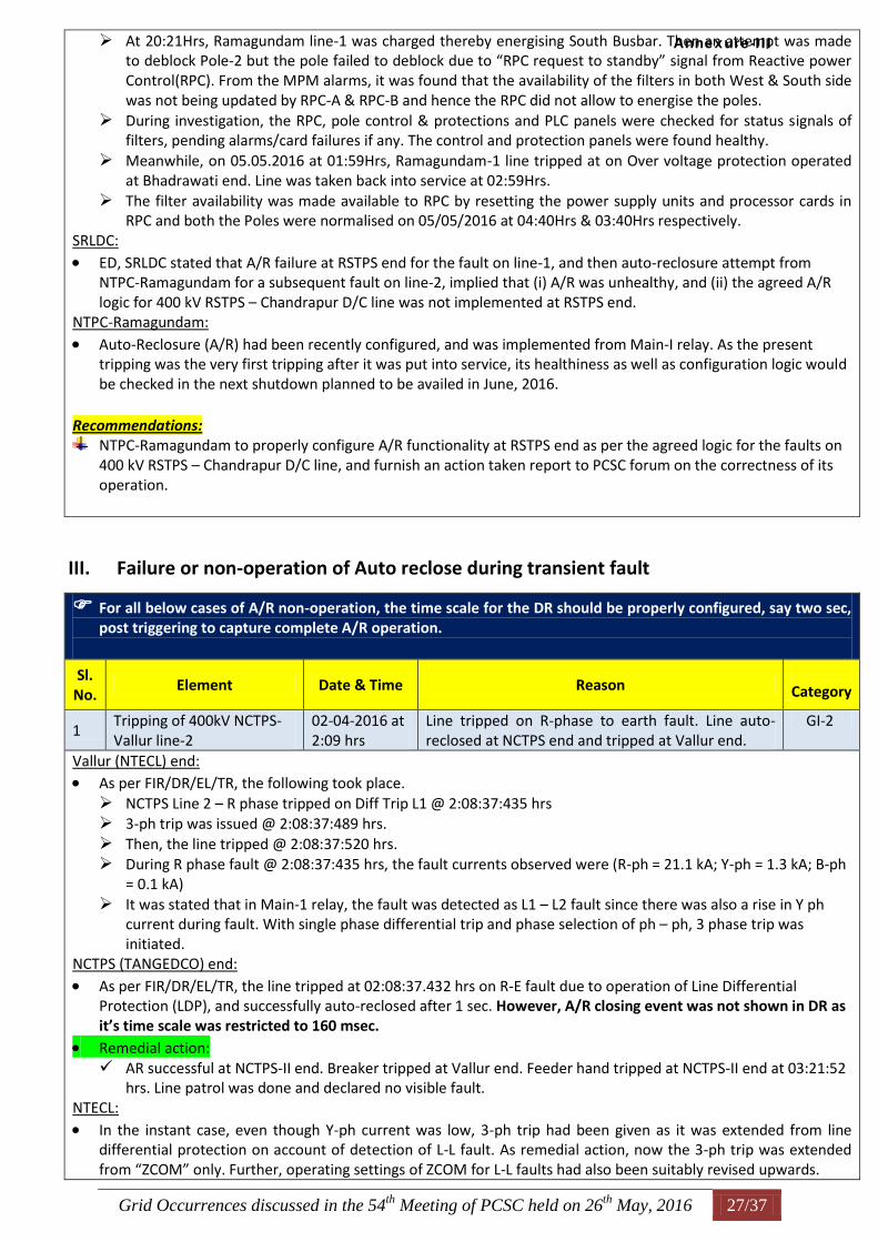
Grid Occurrences discussed in the 54th
Meeting of PCSC held on 26th
May, 2016 27/37
At 20:21Hrs, Ramagundam line-1 was charged thereby energising South Busbar. Then an attempt was made to deblock Pole-2 but the pole failed to deblock due to “RPC request to standby” signal from Reactive power Control(RPC). From the MPM alarms, it was found that the availability of the filters in both West & South side was not being updated by RPC-A & RPC-B and hence the RPC did not allow to energise the poles.
During investigation, the RPC, pole control & protections and PLC panels were checked for status signals of filters, pending alarms/card failures if any. The control and protection panels were found healthy.
Meanwhile, on 05.05.2016 at 01:59Hrs, Ramagundam-1 line tripped at on Over voltage protection operated at Bhadrawati end. Line was taken back into service at 02:59Hrs.
The filter availability was made available to RPC by resetting the power supply units and processor cards in RPC and both the Poles were normalised on 05/05/2016 at 04:40Hrs & 03:40Hrs respectively.
SRLDC:
ED, SRLDC stated that A/R failure at RSTPS end for the fault on line-1, and then auto-reclosure attempt from NTPC-Ramagundam for a subsequent fault on line-2, implied that (i) A/R was unhealthy, and (ii) the agreed A/R logic for 400 kV RSTPS – Chandrapur D/C line was not implemented at RSTPS end.
NTPC-Ramagundam:
Auto-Reclosure (A/R) had been recently configured, and was implemented from Main-I relay. As the present tripping was the very first tripping after it was put into service, its healthiness as well as configuration logic would be checked in the next shutdown planned to be availed in June, 2016.
Recommendations:
NTPC-Ramagundam to properly configure A/R functionality at RSTPS end as per the agreed logic for the faults on 400 kV RSTPS – Chandrapur D/C line, and furnish an action taken report to PCSC forum on the correctness of its operation.
III. Failure or non-operation of Auto reclose during transient fault
For all below cases of A/R non-operation, the time scale for the DR should be properly configured, say two sec, post triggering to capture complete A/R operation.
Sl. No.
Element Date & Time Reason
Category
1 Tripping of 400kV NCTPS-Vallur line-2
02-04-2016 at 2:09 hrs
Line tripped on R-phase to earth fault. Line auto-reclosed at NCTPS end and tripped at Vallur end.
GI-2
Vallur (NTECL) end: As per FIR/DR/EL/TR, the following took place. NCTPS Line 2 – R phase tripped on Diff Trip L1 @ 2:08:37:435 hrs 3-ph trip was issued @ 2:08:37:489 hrs. Then, the line tripped @ 2:08:37:520 hrs. During R phase fault @ 2:08:37:435 hrs, the fault currents observed were (R-ph = 21.1 kA; Y-ph = 1.3 kA; B-ph
= 0.1 kA) It was stated that in Main-1 relay, the fault was detected as L1 – L2 fault since there was also a rise in Y ph
current during fault. With single phase differential trip and phase selection of ph – ph, 3 phase trip was initiated.
NCTPS (TANGEDCO) end:
As per FIR/DR/EL/TR, the line tripped at 02:08:37.432 hrs on R-E fault due to operation of Line Differential Protection (LDP), and successfully auto-reclosed after 1 sec. However, A/R closing event was not shown in DR as it’s time scale was restricted to 160 msec.
Remedial action: AR successful at NCTPS-II end. Breaker tripped at Vallur end. Feeder hand tripped at NCTPS-II end at 03:21:52
hrs. Line patrol was done and declared no visible fault. NTECL:
In the instant case, even though Y-ph current was low, 3-ph trip had been given as it was extended from line differential protection on account of detection of L-L fault. As remedial action, now the 3-ph trip was extended from “ZCOM” only. Further, operating settings of ZCOM for L-L faults had also been suitably revised upwards.
Annexure-III
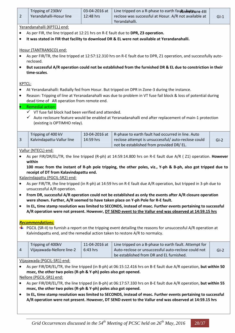
Grid Occurrences discussed in the 54th
Meeting of PCSC held on 26th
May, 2016 28/37
2 Tripping of 230kV Yerandahalli-Hosur line
03-04-2016 at 12:48 hrs
Line tripped on a R-phase to earth fault. Auto-reclose was successful at Hosur. A/R not available at Yerandahalli.
GI-1
Yerandanahalli (KPTCL) end: As per FIR, the line tripped at 12:21 hrs on R-E fault due to DPR, Z3 operation.
It was stated in FIR that facility to download DR & EL were not available at Yerandanahalli. Hosur (TANTRANSCO) end:
As per FIR/TR, the line tripped at 12:57:12.310 hrs on R-E fault due to DPR, Z1 operation, and successfully auto-reclosed.
But successful A/R operation could not be established from the furnished DR & EL due to constriction in their time-scales.
KPTCL:
At Yerandanahalli: Radially fed from Hosur. But tripped on DPR in Zone-3 during the instance. Reason: Tripping of line at Yeranadanahalli was due to problem in VT fuse fail block & loss of potential during
dead time of AR operation from remote end.
Remedial action: VT fuse fail block had been verified and attended. Auto reclosure feature would be enabled at Yeranadanahalli end after replacement of main-1 protection
(existing is OPTIMHO relay).
3 Tripping of 400 kV Kalvindapattu-Vallur line
10-04-2016 at 14:59 hrs
R-phase to earth fault had occurred in line. Auto reclose attempt is unsuccessful/ auto-reclose could not be established from provided DR/ EL.
GI-2
Vallur (NTECL) end:
As per FIR/DR/EL/TR, the line tripped (R-ph) at 14:59:14.800 hrs on R-E fault due A/R ( Z1) operation. However within 100 msec from the instant of R-ph pole tripping, the other poles, viz., Y-ph & B-ph, also got tripped due to receipt of DT from Kalavindapattu end.
Kalavindapattu (PGCIL-SR2) end:
As per FIR/TR, the line tripped (in R-ph) at 14:59 hrs on R-E fault due A/R operation, but tripped in 3-ph due to unsuccessful A/R operation.
From DR, successful A/R operation could not be established as only the events after A/R closure operation were shown. Further, A/R seemed to have taken place on Y-ph Pole for R-E fault.
In EL, time stamp resolution was limited to SECONDS, instead of msec. Further events pertaining to successful A/R operation were not present. However, DT SEND event to the Vallur end was observed at 14:59.15 hrs
Recommendations:
PGCIL (SR-II) to furnish a report on the tripping event detailing the reasons for unsuccessful A/R operation at Kalvindapattu end, and the remedial action taken to restore A/R to normalcy.
4 Tripping of 400kV Vijayawada-Nellore line-2
11-04-2016 at 6:43 hrs
Line tripped on a B-phase to earth fault. Attempt for Auto-reclose or unsuccessful auto-reclose could not be established from DR and EL furnished.
GI-2
Vijayawada (PGCIL-SR1) end:
As per FIR/DR/EL/TR, the line tripped (in B-ph) at 06:15:12.416 hrs on B-E fault due A/R operation, but within 50 msec, the other two poles (R-ph & Y-ph) poles also got opened.
Nellore (PGCIL-SR1) end:
As per FIR/DR/EL/TR, the line tripped (in B-ph) at 06:17:57.330 hrs on B-E fault due A/R operation, but within 55 msec, the other two poles (R-ph & Y-ph) poles also got opened.
In EL, time stamp resolution was limited to SECONDS, instead of msec. Further events pertaining to successful A/R operation were not present. However, DT SEND event to the Vallur end was observed at 14:59.15 hrs
Annexure-III
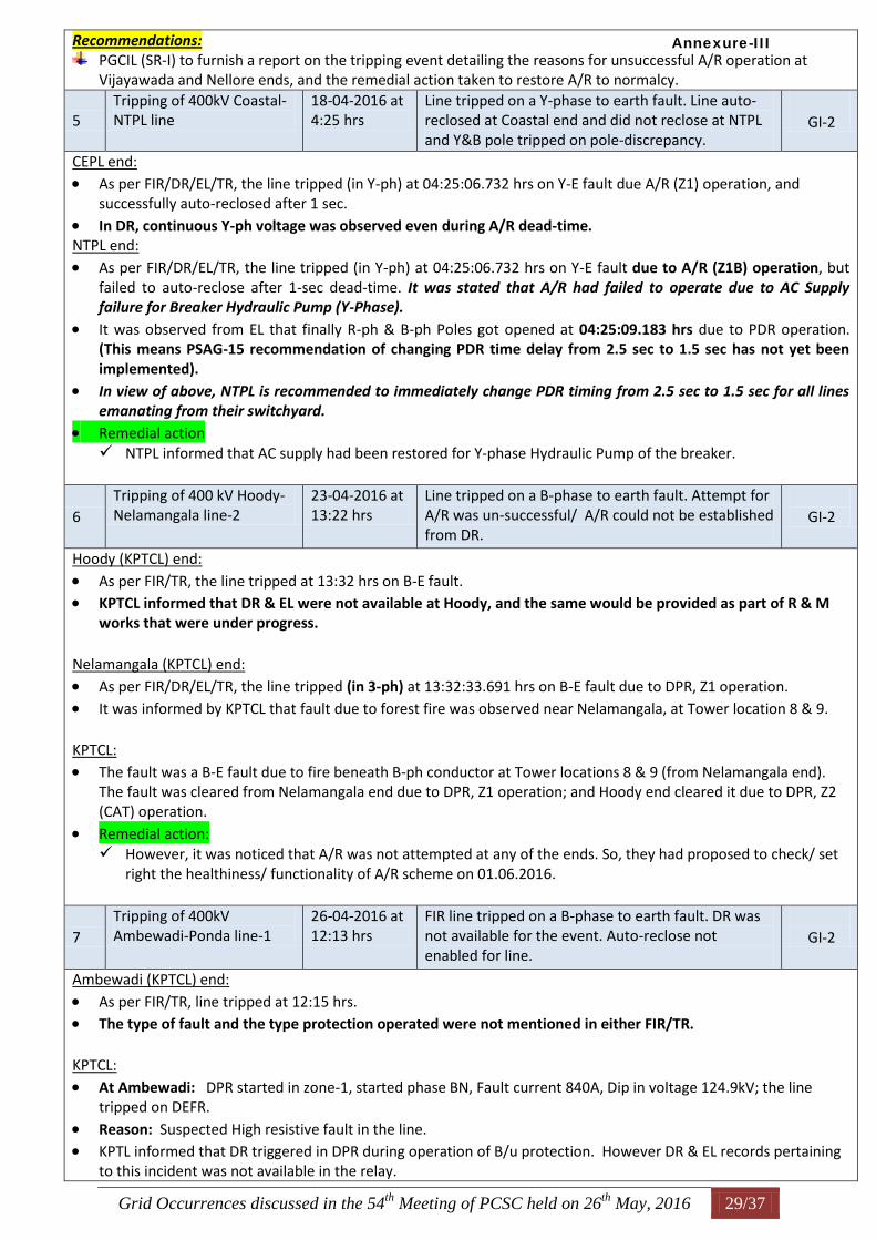
Grid Occurrences discussed in the 54th
Meeting of PCSC held on 26th
May, 2016 29/37
Recommendations: PGCIL (SR-I) to furnish a report on the tripping event detailing the reasons for unsuccessful A/R operation at
Vijayawada and Nellore ends, and the remedial action taken to restore A/R to normalcy.
5 Tripping of 400kV Coastal-NTPL line
18-04-2016 at 4:25 hrs
Line tripped on a Y-phase to earth fault. Line auto-reclosed at Coastal end and did not reclose at NTPL and Y&B pole tripped on pole-discrepancy.
GI-2
CEPL end:
As per FIR/DR/EL/TR, the line tripped (in Y-ph) at 04:25:06.732 hrs on Y-E fault due A/R (Z1) operation, and successfully auto-reclosed after 1 sec.
In DR, continuous Y-ph voltage was observed even during A/R dead-time. NTPL end:
As per FIR/DR/EL/TR, the line tripped (in Y-ph) at 04:25:06.732 hrs on Y-E fault due to A/R (Z1B) operation, but failed to auto-reclose after 1-sec dead-time. It was stated that A/R had failed to operate due to AC Supply failure for Breaker Hydraulic Pump (Y-Phase).
It was observed from EL that finally R-ph & B-ph Poles got opened at 04:25:09.183 hrs due to PDR operation. (This means PSAG-15 recommendation of changing PDR time delay from 2.5 sec to 1.5 sec has not yet been implemented).
In view of above, NTPL is recommended to immediately change PDR timing from 2.5 sec to 1.5 sec for all lines emanating from their switchyard.
Remedial action NTPL informed that AC supply had been restored for Y-phase Hydraulic Pump of the breaker.
6 Tripping of 400 kV Hoody-Nelamangala line-2
23-04-2016 at 13:22 hrs
Line tripped on a B-phase to earth fault. Attempt for A/R was un-successful/ A/R could not be established from DR.
GI-2
Hoody (KPTCL) end:
As per FIR/TR, the line tripped at 13:32 hrs on B-E fault. KPTCL informed that DR & EL were not available at Hoody, and the same would be provided as part of R & M
works that were under progress. Nelamangala (KPTCL) end:
As per FIR/DR/EL/TR, the line tripped (in 3-ph) at 13:32:33.691 hrs on B-E fault due to DPR, Z1 operation.
It was informed by KPTCL that fault due to forest fire was observed near Nelamangala, at Tower location 8 & 9. KPTCL:
The fault was a B-E fault due to fire beneath B-ph conductor at Tower locations 8 & 9 (from Nelamangala end). The fault was cleared from Nelamangala end due to DPR, Z1 operation; and Hoody end cleared it due to DPR, Z2 (CAT) operation.
Remedial action: However, it was noticed that A/R was not attempted at any of the ends. So, they had proposed to check/ set
right the healthiness/ functionality of A/R scheme on 01.06.2016.
7 Tripping of 400kV Ambewadi-Ponda line-1
26-04-2016 at 12:13 hrs
FIR line tripped on a B-phase to earth fault. DR was not available for the event. Auto-reclose not enabled for line.
GI-2
Ambewadi (KPTCL) end:
As per FIR/TR, line tripped at 12:15 hrs. The type of fault and the type protection operated were not mentioned in either FIR/TR. KPTCL:
At Ambewadi: DPR started in zone-1, started phase BN, Fault current 840A, Dip in voltage 124.9kV; the line tripped on DEFR.
Reason: Suspected High resistive fault in the line. KPTL informed that DR triggered in DPR during operation of B/u protection. However DR & EL records pertaining
to this incident was not available in the relay.
Annexure-III
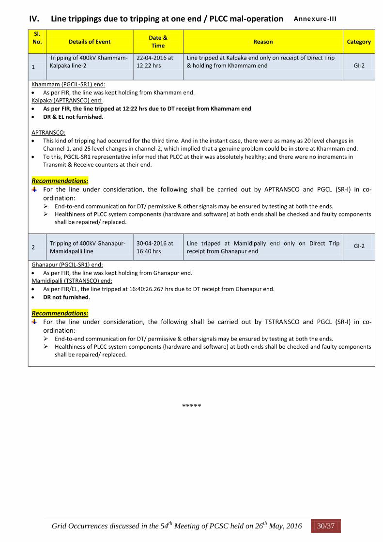
Grid Occurrences discussed in the 54th
Meeting of PCSC held on 26th
May, 2016 30/37
IV. Line trippings due to tripping at one end / PLCC mal-operation
Sl. No.
Details of Event
Date & Time
Reason Category
1
Tripping of 400kV Khammam-Kalpaka line-2
22-04-2016 at 12:22 hrs
Line tripped at Kalpaka end only on receipt of Direct Trip & holding from Khammam end
GI-2
Khammam (PGCIL-SR1) end:
As per FIR, the line was kept holding from Khammam end. Kalpaka (APTRANSCO) end:
As per FIR, the line tripped at 12:22 hrs due to DT receipt from Khammam end
DR & EL not furnished. APTRANSCO:
This kind of tripping had occurred for the third time. And in the instant case, there were as many as 20 level changes in Channel-1, and 25 level changes in channel-2, which implied that a genuine problem could be in store at Khammam end.
To this, PGCIL-SR1 representative informed that PLCC at their was absolutely healthy; and there were no increments in Transmit & Receive counters at their end.
Recommendations: For the line under consideration, the following shall be carried out by APTRANSCO and PGCL (SR-I) in co-
ordination: End-to-end communication for DT/ permissive & other signals may be ensured by testing at both the ends. Healthiness of PLCC system components (hardware and software) at both ends shall be checked and faulty components
shall be repaired/ replaced.
2 Tripping of 400kV Ghanapur-Mamidapalli line
30-04-2016 at 16:40 hrs
Line tripped at Mamidipally end only on Direct Trip receipt from Ghanapur end
GI-2
Ghanapur (PGCIL-SR1) end:
As per FIR, the line was kept holding from Ghanapur end. Mamidipalli (TSTRANSCO) end:
As per FIR/EL, the line tripped at 16:40:26.267 hrs due to DT receipt from Ghanapur end.
DR not furnished.
Recommendations: For the line under consideration, the following shall be carried out by TSTRANSCO and PGCL (SR-I) in co-
ordination: End-to-end communication for DT/ permissive & other signals may be ensured by testing at both the ends. Healthiness of PLCC system components (hardware and software) at both ends shall be checked and faulty components
shall be repaired/ replaced.
*****
Annexure-III
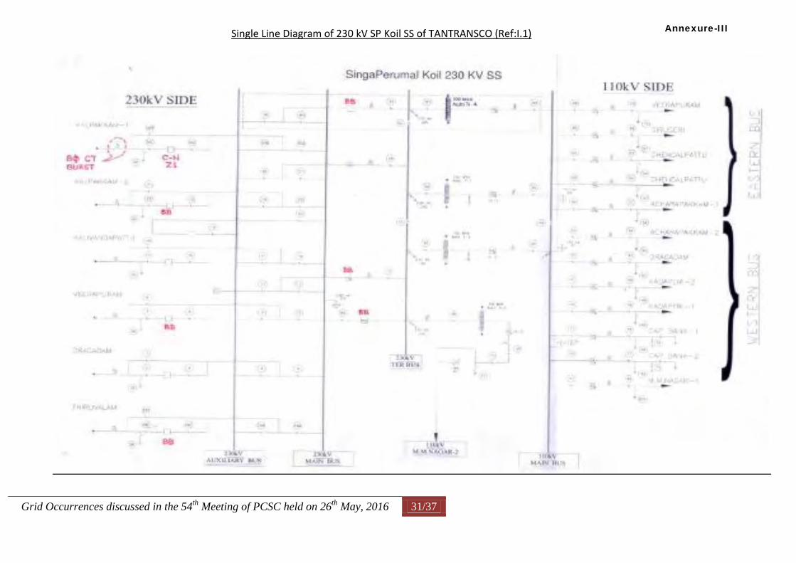
Grid Occurrences discussed in the 54th
Meeting of PCSC held on 26th
May, 2016 31/37
Single Line Diagram of 230 kV SP Koil SS of TANTRANSCO (Ref:I.1)
Annexure-III
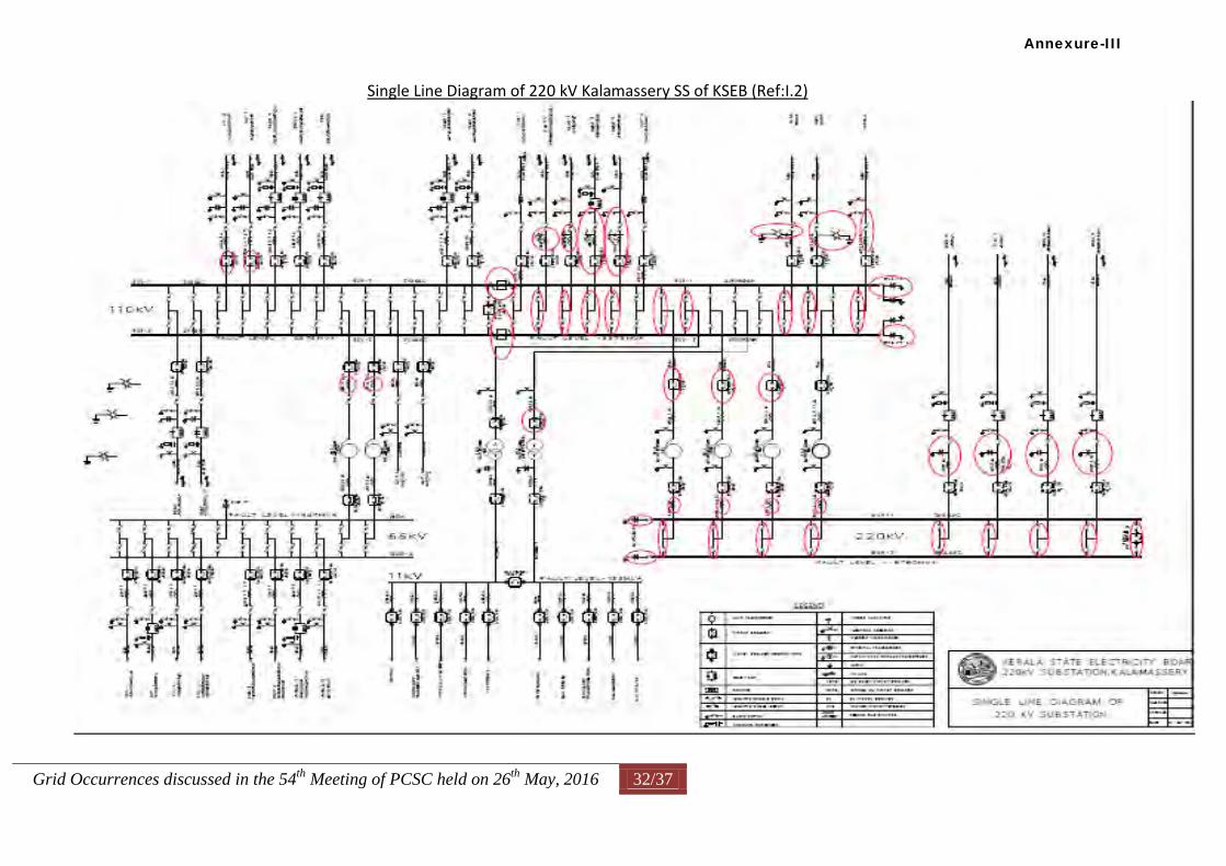
Grid Occurrences discussed in the 54th
Meeting of PCSC held on 26th
May, 2016 32/37
Single Line Diagram of 220 kV Kalamassery SS of KSEB (Ref:I.2)
Annexure-III
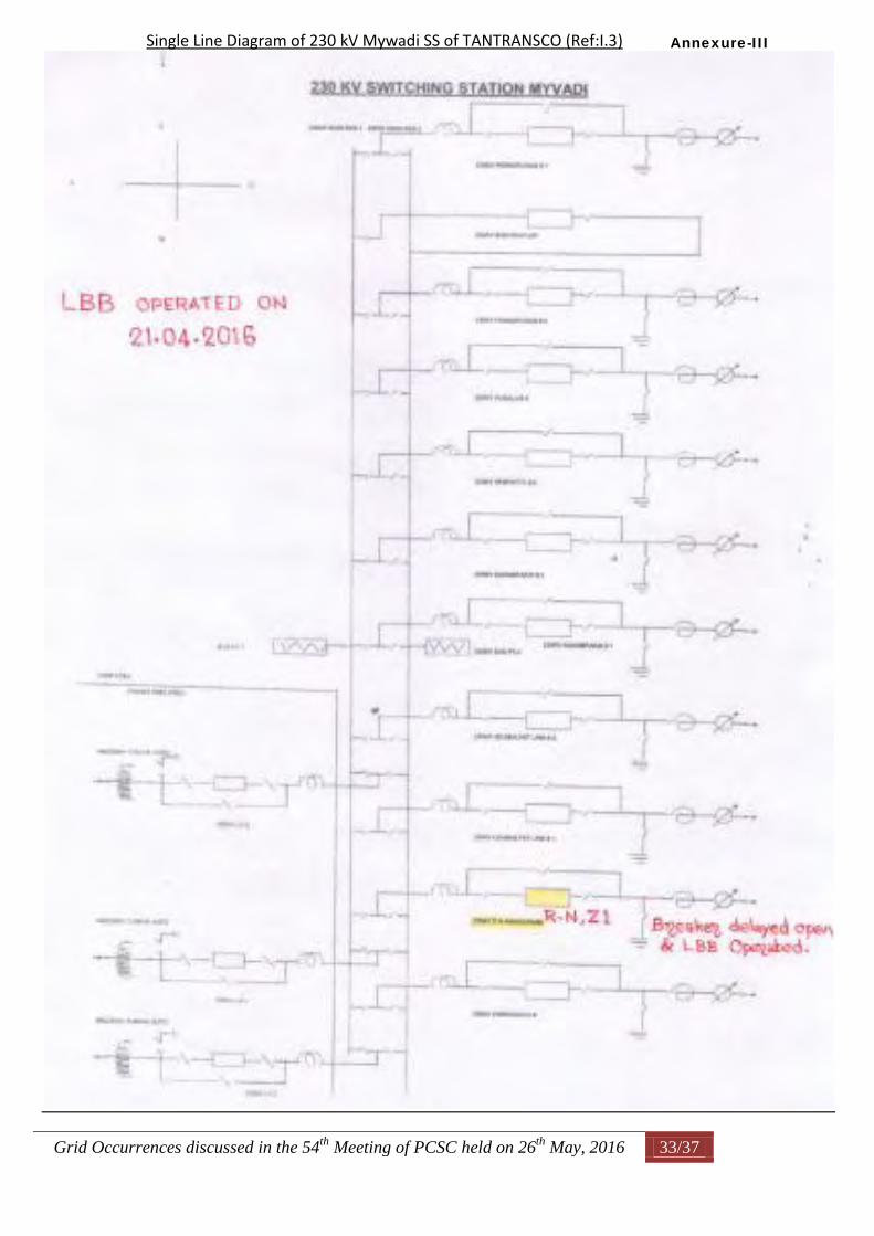
Grid Occurrences discussed in the 54th
Meeting of PCSC held on 26th
May, 2016 33/37
Single Line Diagram of 230 kV Mywadi SS of TANTRANSCO (Ref:I.3)
Annexure-III
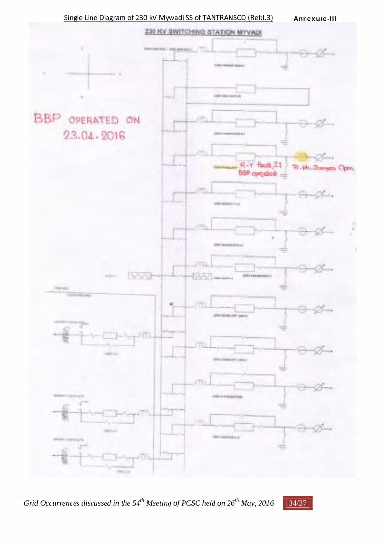
Grid Occurrences discussed in the 54th
Meeting of PCSC held on 26th
May, 2016 34/37
Single Line Diagram of 230 kV Mywadi SS of TANTRANSCO (Ref:I.3)
Annexure-III
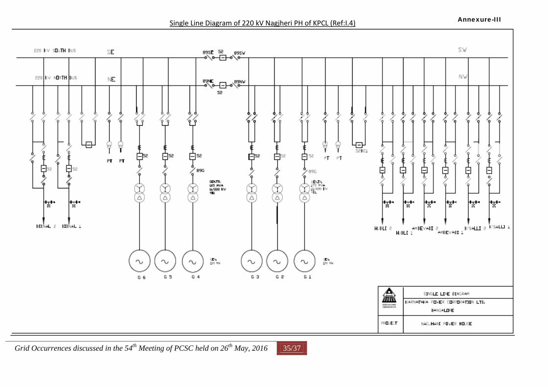
Grid Occurrences discussed in the 54th
Meeting of PCSC held on 26th
May, 2016 35/37
Single Line Diagram of 220 kV Nagjheri PH of KPCL (Ref:I.4)
Annexure-III
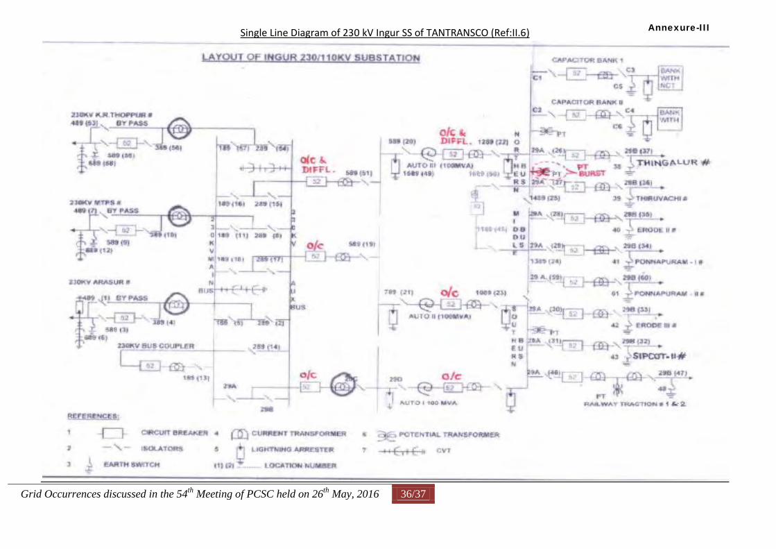
Grid Occurrences discussed in the 54th
Meeting of PCSC held on 26th
May, 2016 36/37
Single Line Diagram of 230 kV Ingur SS of TANTRANSCO (Ref:II.6)
Annexure-III
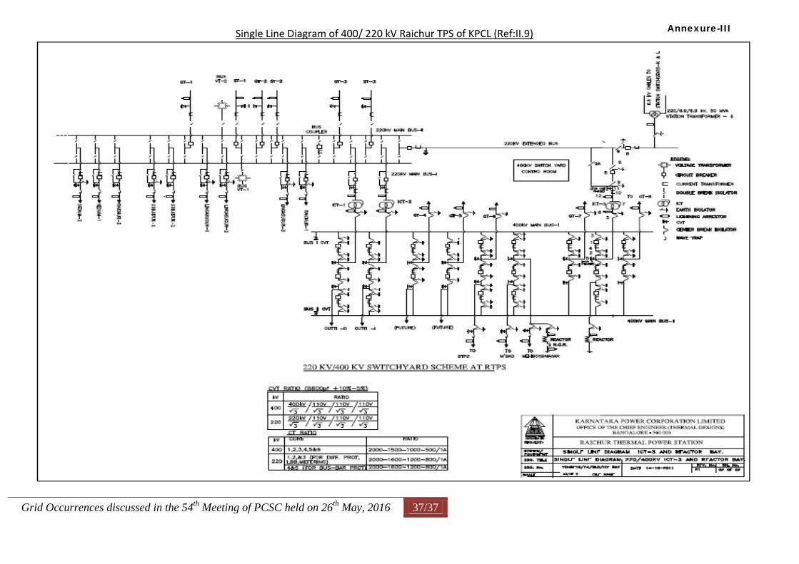
Grid Occurrences discussed in the 54th
Meeting of PCSC held on 26th
May, 2016 37/37
Single Line Diagram of 400/ 220 kV Raichur TPS of KPCL (Ref:II.9)
Annexure-III
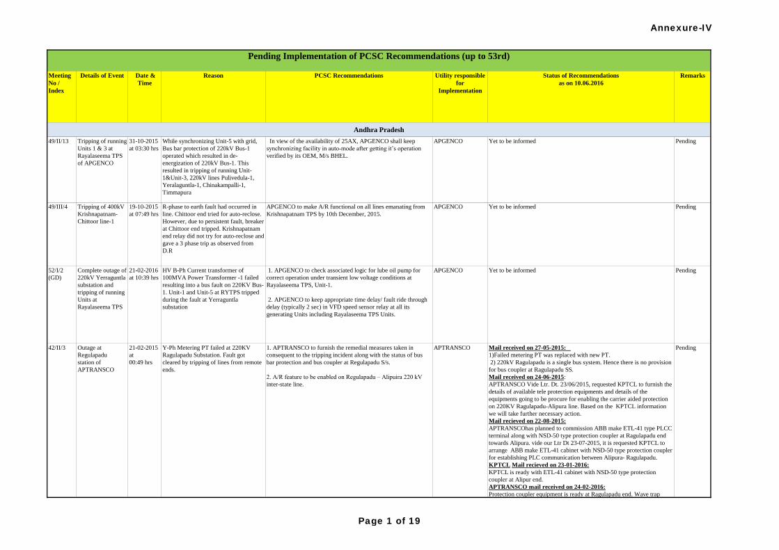
Meeting
No /
Index
Details of Event Date &
Time
Reason PCSC Recommendations Utility responsible
for
Implementation
Status of Recommendations
as on 10.06.2016
Remarks
Pending Implementation of PCSC Recommendations (up to 53rd)
42/II/3 Outage at
Regulapadu
station of
APTRANSCO
21-02-2015
at
00:49 hrs
Y-Ph Metering PT failed at 220KV
Ragulapadu Substation. Fault got
cleared by tripping of lines from remote
ends.
1. APTRANSCO to furnish the remedial measures taken in
consequent to the tripping incident along with the status of bus
bar protection and bus coupler at Regulapadu S/s.
2. A/R feature to be enabled on Regulapadu – Alipuira 220 kV
inter-state line.
APTRANSCO Mail received on 27-05-2015:
1)Failed metering PT was replaced with new PT.
2) 220kV Ragulapadu is a single bus system. Hence there is no provision
for bus coupler at Ragulapadu SS.
Mail received on 24-06-2015:
APTRANSCO Vide Ltr. Dt. 23/06/2015, requested KPTCL to furnish the
details of available tele protection equipments and details of the
equipments going to be procure for enabling the carrier aided protection
on 220KV Ragulapadu-Alipura line. Based on the KPTCL information
we will take further necessary action.
Mail recieved on 22-08-2015:
APTRANSCOhas planned to commission ABB make ETL-41 type PLCC
terminal along with NSD-50 type protection coupler at Ragulapadu end
towards Alipura. vide our Ltr Dt 23-07-2015, it is requested KPTCL to
arrange ABB make ETL-41 cabinet with NSD-50 type protection coupler
for establishing PLC communication between Alipura- Ragulapadu.
KPTCL Mail recieved on 23-01-2016:
KPTCL is ready with ETL-41 cabinet with NSD-50 type protection
coupler at Alipur end.
APTRANSCO mail received on 24-02-2016:
Protection coupler equipment is ready at Ragulapadu end. Wave trap
errection is pending at Ragulapadu end. To maintain the ground
clearenace structural modification works are going on for errection of
wave trap.
Pending
Complete outage of
220kV Yerraguntla
substation and
tripping of running
Units at
Rayalaseema TPS
52/I/2
(GD)
PendingYet to be informedAPGENCO 1. APGENCO to check associated logic for lube oil pump for
correct operation under transient low voltage conditions at
Rayalaseema TPS, Unit-1.
2. APGENCO to keep appropriate time delay/ fault ride through
delay (typically 2 sec) in VFD speed sensor relay at all its
generating Units including Rayalaseema TPS Units.
HV B-Ph Current transformer of
100MVA Power Transformer -1 failed
resulting into a bus fault on 220KV Bus-
1. Unit-1 and Unit-5 at RYTPS tripped
during the fault at Yerraguntla
substation
21-02-2016
at 10:39 hrs
Yet to be informed Pending
Andhra Pradesh
49/II/13
APGENCO Yet to be informed Pending
31-10-2015
at 03:30 hrs
Tripping of running
Units 1 & 3 at
Rayalaseema TPS
of APGENCO
While synchronizing Unit-5 with grid,
Bus bar protection of 220kV Bus-1
operated which resulted in de-
energization of 220kV Bus-1. This
resulted in tripping of running Unit-
1&Unit-3, 220kV lines Pulivedula-1,
Yeralaguntla-1, Chinakampalli-1,
Timmapura
In view of the availability of 25AX, APGENCO shall keep
synchronizing facility in auto-mode after getting it’s operation
verified by its OEM, M/s BHEL.
APGENCO
49/III/4 Tripping of 400kV
Krishnapatnam-
Chittoor line-1
19-10-2015
at 07:49 hrs
R-phase to earth fault had occurred in
line. Chittoor end tried for auto-reclose.
However, due to persistent fault, breaker
at Chittoor end tripped. Krishnapatnam
end relay did not try for auto-reclose and
gave a 3 phase trip as observed from
D.R
APGENCO to make A/R functional on all lines emanating from
Krishnapatnam TPS by 10th December, 2015.
Annexure-IV
Page 1 of 19
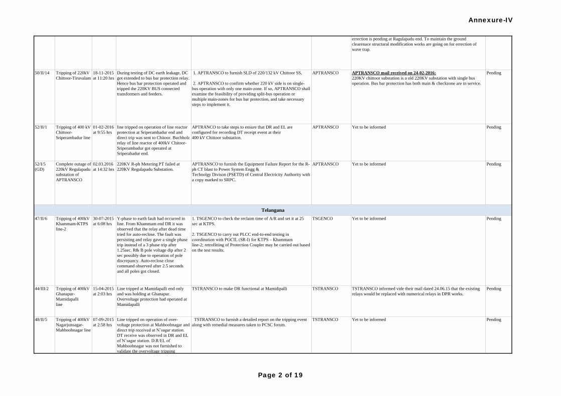
52/II/1 Tripping of 400 kV
Chittoor-
Sriperambadur line
01-02-2016
at 9:55 hrs
line tripped on operation of line reactor
protection at Sriperambadur end and
direct trip was sent to Chitoor. Buchholz
relay of line reactor of 400kV Chitoor-
Sriperambadur got operated at
Sriperabadur end.
APTRANCO to take steps to ensure that DR and EL are
configured for recording DT receipt event at their
400 kV Chittoor substation.
APTRANSCO Yet to be informed Pending
44/III/2 Tripping of 400kV
Ghanapur-
Mamidapalli
line
15-04-2015
at 2:03 hrs
Line tripped at Mamidapalli end only
and was holding at Ghanapur.
Overvoltage protection had operated at
Mamidapalli
TSTRANSCO to make DR functional at Mamidipalli TSTRANSCO TSTRANSCO informed vide their mail dated 24.06.15 that the existing
relays would be replaced with numerical relays in DPR works.
Pending
APTRANSCO mail received on 24-02-2016:
220KV chittoor substation is a old 220KV substation with single bus
operation. Bus bar protection has both main & checkzone are in service.
PendingDuring testing of DC earth leakage, DC
got extended to bus bar protection relay.
Hence bus bar protection operated and
tripped the 220KV BUS connected
transformers and feeders.
18-11-2015
at 11:20 hrs
Tripping of 220kV
Chittoor-Tiruvalam
50/II/14
Pending
47/II/6 Tripping of 400kV
Khammam-KTPS
line-2
30-07-2015
at 6:08 hrs
1. TSGENCO to check the reclaim time of A/R and set it at 25
sec at KTPS.
2. TSGENCO to carry out PLCC end-to-end testing in
coordination with PGCIL (SR-I) for KTPS – Khammam
line-2; retrofitting of Protection Coupler may be carried out based
on the test results.
TSGENCO
07-09-2015
at 2:58 hrs
Line tripped on operation of over-
voltage protection at Mahboobnagar and
direct trip received at N’sagar station.
DT receive was observed in DR and EL
of N’sagar station. D.R/EL of
Mahboobnagar was not furnished to
validate the overvoltage tripping
42/II/3 Outage at
Regulapadu
station of
APTRANSCO
21-02-2015
at
00:49 hrs
Y-Ph Metering PT failed at 220KV
Ragulapadu Substation. Fault got
cleared by tripping of lines from remote
ends.
1. APTRANSCO to furnish the remedial measures taken in
consequent to the tripping incident along with the status of bus
bar protection and bus coupler at Regulapadu S/s.
2. A/R feature to be enabled on Regulapadu – Alipuira 220 kV
inter-state line.
APTRANSCO Mail received on 27-05-2015:
1)Failed metering PT was replaced with new PT.
2) 220kV Ragulapadu is a single bus system. Hence there is no provision
for bus coupler at Ragulapadu SS.
Mail received on 24-06-2015:
APTRANSCO Vide Ltr. Dt. 23/06/2015, requested KPTCL to furnish the
details of available tele protection equipments and details of the
equipments going to be procure for enabling the carrier aided protection
on 220KV Ragulapadu-Alipura line. Based on the KPTCL information
we will take further necessary action.
Mail recieved on 22-08-2015:
APTRANSCOhas planned to commission ABB make ETL-41 type PLCC
terminal along with NSD-50 type protection coupler at Ragulapadu end
towards Alipura. vide our Ltr Dt 23-07-2015, it is requested KPTCL to
arrange ABB make ETL-41 cabinet with NSD-50 type protection coupler
for establishing PLC communication between Alipura- Ragulapadu.
KPTCL Mail recieved on 23-01-2016:
KPTCL is ready with ETL-41 cabinet with NSD-50 type protection
coupler at Alipur end.
APTRANSCO mail received on 24-02-2016:
Protection coupler equipment is ready at Ragulapadu end. Wave trap
errection is pending at Ragulapadu end. To maintain the ground
clearenace structural modification works are going on for errection of
wave trap.
Pending
52/I/5
(GD)
Complete outage of
220kV Regulapadu
substation of
APTRANSCO
02.03.2016
at 14:32 hrs
220KV R-ph Metering PT failed at
220KV Regulapadu Substation.
APTRANSCO to furnish the Equipment Failure Report for the R-
ph CT blast to Power System Engg &
Technolgy Divison (PSETD) of Central Electricity Authority with
a copy marked to SRPC.
TSTRANSCO Yet to be informed TSTRANSCO to furnish a detailed report on the tripping event
along with remedial measures taken to PCSC forum.
Telangana
APTRANSCO Yet to be informed
Pending
Y-phase to earth fault had occurred in
line. From Khammam end DR it was
observed that the relay after dead time
tried for auto-reclose. The fault was
persisting and relay gave a single phase
trip instead of a 3 phase trip after
1.25sec. R& B pole voltage dip after 2
sec possibly due to operation of pole
discrepancy. Auto-reclose close
command observed after 2.5 seconds
and all poles got closed.
1. APTRANSCO to furnish SLD of 220/132 kV Chittoor SS,
2. APTRANSCO to confirm whether 220 kV side is on single-
bus operation with only one main-zone. If so, APTRANSCO shall
examine the feasibility of providing split-bus operation or
multiple main-zones for bus bar protection, and take necessary
steps to implement it.
APTRANSCO
Yet to be informed Pending
48/II/5 Tripping of 400kV
Nagarjunsagar-
Mahboobnagar line
Annexure-IV
Page 2 of 19
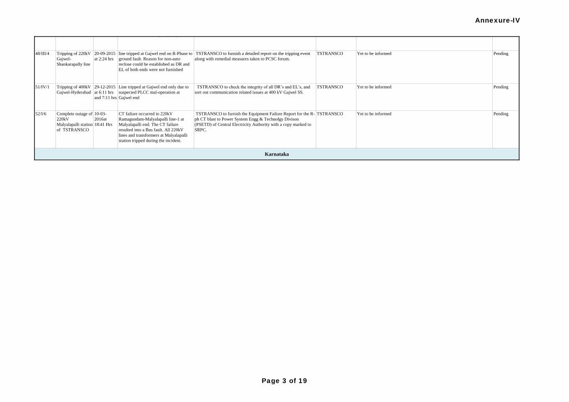
48/III/4 Tripping of 220kV
Gajwel-
Shankarapally line
20-09-2015
at 2:24 hrs
line tripped at Gajwel end on R-Phase to
ground fault. Reason for non-auto
reclose could be established as DR and
EL of both ends were not furnished
TSTRANSCO to furnish a detailed report on the tripping event
along with remedial measures taken to PCSC forum.
TSTRANSCO Yet to be informed Pending
51/IV/1 Tripping of 400kV
Gajwel-Hyderabad
29-12-2015
at 6:11 hrs
and 7:11 hrs
Line tripped at Gajwel end only due to
suspected PLCC mal-operation at
Gajwel end
TSTRANSCO to check the integrity of all DR’s and EL’s, and
sort out communication related issues at 400 kV Gajwel SS.
TSTRANSCO Yet to be informed Pending
52/I/6 Complete outage of
220kV
Malyalapalli station
of TSTRANSCO
10-03-
2016at
18:41 Hrs
CT failure occurred in 220kV
Ramagundam-Malyalapalli line-1 at
Malyalapalli end. The CT failure
resulted into a Bus fault. All 220kV
lines and transformers at Malyalapalli
station tripped during the incident.
TSTRANSCO to furnish the Equipment Failure Report for the R-
ph CT blast to Power System Engg & Technolgy Divison
(PSETD) of Central Electricity Authority with a copy marked to
SRPC.
TSTRANSCO Yet to be informed Pending
Karnataka
07-09-2015
at 2:58 hrs
Line tripped on operation of over-
voltage protection at Mahboobnagar and
direct trip received at N’sagar station.
DT receive was observed in DR and EL
of N’sagar station. D.R/EL of
Mahboobnagar was not furnished to
validate the overvoltage tripping
TSTRANSCO Yet to be informed TSTRANSCO to furnish a detailed report on the tripping event
along with remedial measures taken to PCSC forum.
Pending48/II/5 Tripping of 400kV
Nagarjunsagar-
Mahboobnagar line
Annexure-IV
Page 3 of 19
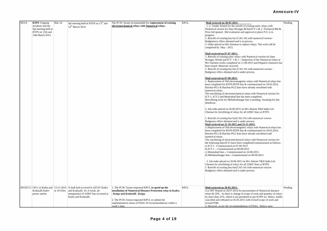
Mail recieved on 28-05-2015:
1) e-NIT floated on 28.07.2014 for procurement of Numerical distance
relays & GPS. As there is change in scope of work and quantity of relays
by more than 25%, which is not permitted as per KTPP act. Hence, tender
cancelled and refloated on 05.05.2015 with revised scope of work and
revised PQR.
2. However, as per the recommendations of PSAG, Relays were
temporarily rearranged, replaced and wired up. testing & commissioning
shall be completed with the assistance of KPTCL.
Mail recieved on 07-07-2015:
1. Cover -1 of the bid is scheduled for open eing on 25.06.2015.
2. As per the recommendations of PSAG, Relays were temporarily
rearranged. testing & commissioning completed with the assistance of
KPTCL.
Mail recieved on 07-09-2015:
NIT floated on 5.5.15 through e-portal. Bid evaluation completed.
Obtaining of Administration approval to place P.O is in progress.
However, as per therecommendationsof PSAG-10, Relays
weretemporarilyrearranged.Testing & commissioning completed with the
assistanceofKPTCL.
Mail recieved on 21-10-2015:
NIT floated on 5.5.15 through e-portal. Bid evaluation completed. LOA's
issued to M/s Schneider Electric Infrastructure Ltd. on 08.10.2015.
Mail recieved on 23-11-2015:
LOA's issued to M/s Schneider Electric Infrastructure Ltd. on 08.10.2015.
Engineering work is in progress.
Status informed during Special Meeting held on 03.06.2016:
LOA’s issued to M/s Schneider on 08.10.2015. Inspection of relays
completed and received at site. DI issued for all balance materials except
furnitures.
PendingKPCL1. The PCSC forum requested KPCL to speed up the
installation of Numerical Distance Protection relay in Kadra
–Kaiga and Kodasalli –Kaiga.
2. The PCSC forum requested KPCL to submit the
implementation status of PSAG-10 recommendations within a
week’s time.
A fault had occurred in 220 kV Kadra
and Kodasalli. As A result, de-
energization of 220kV bus occurred at
Kadra and Kodasalli.
13-11-2014
at 19:31hrs
GD-1 at Kadra and
Kodasalli hydro
power station
38/GD/3.5
Mail recieved on 28-05-2015:
1. e- Tender folated for the retrofit of existing static relays with
Numerical version for lines M.nagar,M.bad,ICT-1 & 2 -Technical Bid &
Price bid opened . Bid evaluation and approval to place P.O. is in
progress.
2. Retrofit of existing bus bar (CAG-34) with numerical version -
Budgetetory offers obtained and is in process.
3. Order placed on M/s Siemens to replace relays. The work will be
completed by May - 2015.
Mail recieved on 07-07-2015:
1. Retrofit of existing static relays with Numerical version for lines
M.nagar, M.bad and ICT- 1 & 2 -- Inspection of the Numerical relays at
M/s Siemens works completed on 11-06-2015 and Dispatch clearance has
been issued. Materials received.
2. Retrofit of existing bus bar (CAG-34) with numerical version –
Budgetary offers obtained and is under process.
Mail recieved on 07-09-2015:
1. Replacement of Old electromagnetic relays with Numerical relays has
been completed for RTPS-BTPS line & commissioned on 18.03.2014.
Raichur-PG1 & Raichur-PG2 lines have already retrofitted with
numerical relays.
The retrofitting of electromechanical relays with Numerical version for
ICT-1, ICT-2 and Munirabad line has been completed.
Retrofitting work for Mehaboobnagar line is pending. Awaiting for line
shutdown.
2. Job order placed on 26.06.2015 on M/s Alstom T&D India Ltd.
Chennai for retrofitting of relays for all 220kV lines at RTPS.
3. Retrofit of existing bus bar(CAG-34) with numerical version–
Budgetary offers obtained and is under process.
Mail recieved on 21-10-2015 and 23-11-2015:
1) Replacement of Old electromagnetic relays with Numerical relays has
been completed for RTPS-BTPS line & commissioned on 18.03.2014.
Raichur-PG1 & Raichur-PG2 lines have already retrofitted with
numerical relays.
The retrofitting of electromechanical relays with Numerical version for
the following lines/ICTs have been completed/commissioned as follows:
a) ICT-2 –Commissioned on 01-08-2015
b) ICT-1 ---Commissioned on 08-08-2015
c) Munirabad line--- Commissioned on 16-08-2015.
d) Mehaboobnagar line-- Commissioned on 09-09-2015.
2. Job order placed on 26.06.2015 on M/s Alstom T&D India Ltd.
Chennai for retrofitting of relays for all 220kV lines at RTPS.
3. Retrofit of existing bus bar(CAG-34) with numerical version–
Budgetary offers obtained and is under process.
PendingRTPS Tripping
incidents and the
Spl meeting held at
RTPS on 13th and
14th March 2014
30/I/A KPCLThe PCSC forum recommended for replacement of existing
electromechanical relays with Numerical relays. Spl meeting held at RTPS on 13
th and
14th
March 2014
Mar-14
Annexure-IV
Page 4 of 19
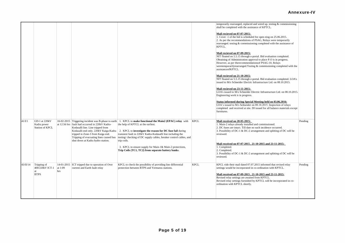
Mail recieved on 28-05-2015:
1) e-NIT floated on 28.07.2014 for procurement of Numerical distance
relays & GPS. As there is change in scope of work and quantity of relays
by more than 25%, which is not permitted as per KTPP act. Hence, tender
cancelled and refloated on 05.05.2015 with revised scope of work and
revised PQR.
2. However, as per the recommendations of PSAG, Relays were
temporarily rearranged, replaced and wired up. testing & commissioning
shall be completed with the assistance of KPTCL.
Mail recieved on 07-07-2015:
1. Cover -1 of the bid is scheduled for open eing on 25.06.2015.
2. As per the recommendations of PSAG, Relays were temporarily
rearranged. testing & commissioning completed with the assistance of
KPTCL.
Mail recieved on 07-09-2015:
NIT floated on 5.5.15 through e-portal. Bid evaluation completed.
Obtaining of Administration approval to place P.O is in progress.
However, as per therecommendationsof PSAG-10, Relays
weretemporarilyrearranged.Testing & commissioning completed with the
assistanceofKPTCL.
Mail recieved on 21-10-2015:
NIT floated on 5.5.15 through e-portal. Bid evaluation completed. LOA's
issued to M/s Schneider Electric Infrastructure Ltd. on 08.10.2015.
Mail recieved on 23-11-2015:
LOA's issued to M/s Schneider Electric Infrastructure Ltd. on 08.10.2015.
Engineering work is in progress.
Status informed during Special Meeting held on 03.06.2016:
LOA’s issued to M/s Schneider on 08.10.2015. Inspection of relays
completed and received at site. DI issued for all balance materials except
furnitures.
PendingKPCL1. The PCSC forum requested KPCL to speed up the
installation of Numerical Distance Protection relay in Kadra
–Kaiga and Kodasalli –Kaiga.
2. The PCSC forum requested KPCL to submit the
implementation status of PSAG-10 recommendations within a
week’s time.
A fault had occurred in 220 kV Kadra
and Kodasalli. As A result, de-
energization of 220kV bus occurred at
Kadra and Kodasalli.
13-11-2014
at 19:31hrs
GD-1 at Kadra and
Kodasalli hydro
power station
38/GD/3.5
ICT tripped due to operation of Over
current and Earth fault relay
14-01-2015
at 1:09
hrs
KPCL to check the possibility of providing line differential
protection between RTPS and Yermarus stations.
KPCL
GD-1 at 220kV
Kadra power
Station of KPCL
16-02-2015
at 12:56 hrs
41/I/1
Tripping of
400/220kV ICT-1
at
BTPS
43/II/14
Pending
KPCL vide their mail dated 07.07.2015 informed that revised relay
settings would be incorporated in co-ordination with KPTCL.
Mail received on 07-09-2015 , 21-10-2015 and 23-11-2015:
Revised relay settings are awaited from KPTCL.
Revised relay settings furnished by KPTCL will be incorporated in co-
ordination with KPTCL shortly.
Pending
KPCL Mail received on 28-05-2015:
1. Main-2 relays already installed and commissioned.
2. DC fuses are intact. Till date no such incidence occurred.
3. Possibility of DC-1 & DC-2 arrangement and splitting of DC will be
reviewed.
Mail received on 07-07-2015 , 21-10-2015 and 23-11-2015:
1. Completed.
2. Completed.
3. Possibility of DC-1 & DC-2 arrangement and splitting of DC will be
reviewed.
Triggering incident was B-phase to earth
fault had occurred in 220kV Kadra-
Kodasalli line. Line tripped from
Kodasalli end only. 220kV Kaiga-Kadra
tripped in Zone-3 from Kaiga end.
Tripping of evacuating lines caused bus
shut down at Kadra hydro station.
1. KPCL to make functional the Main2 (EPAC) relay with
the help of KPTCL at the earliest.
2. KPCL to investigate the reason for DC fuse fail during
transient fault in 220kV Kadra-Kodasalli line including the
testing/ checking of DC supply cables, breaker control cables, and
trip coils.
3. KPCL to ensure supply for Main-1& Main-2 protections,
Trip Coils (TC1, TC2) from separate battery banks.
Annexure-IV
Page 5 of 19
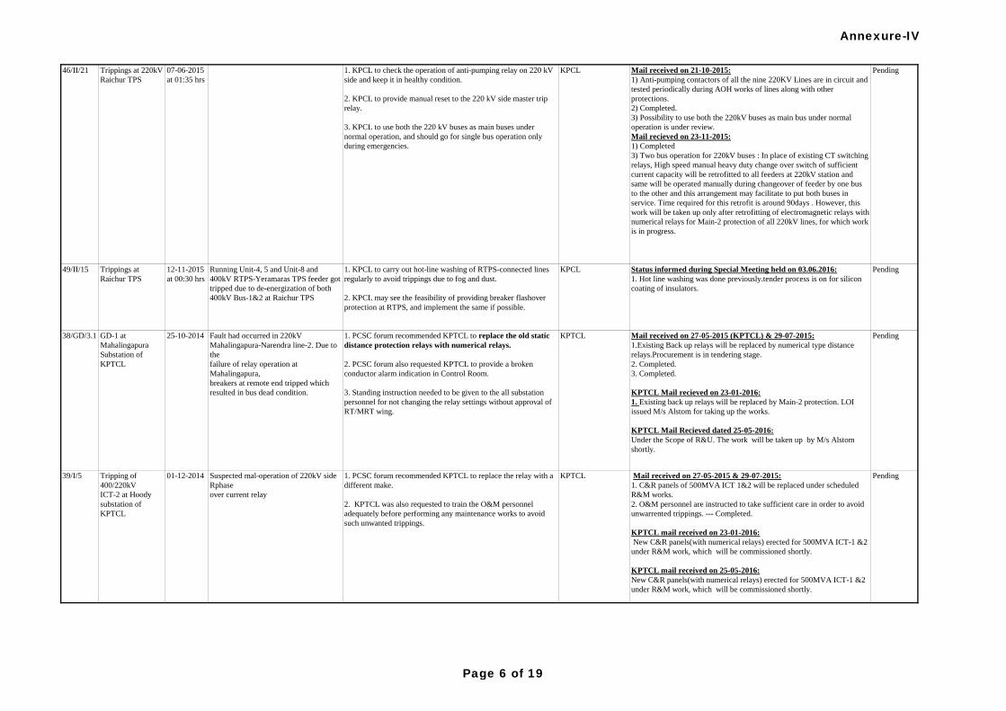
49/II/15 Trippings at
Raichur TPS
12-11-2015
at 00:30 hrs
Running Unit-4, 5 and Unit-8 and
400kV RTPS-Yeramaras TPS feeder got
tripped due to de-energization of both
400kV Bus-1&2 at Raichur TPS
1. KPCL to carry out hot-line washing of RTPS-connected lines
regularly to avoid trippings due to fog and dust.
2. KPCL may see the feasibility of providing breaker flashover
protection at RTPS, and implement the same if possible.
KPCL Status informed during Special Meeting held on 03.06.2016:
1. Hot line washing was done previously.tender process is on for silicon
coating of insulators.
Pending
PendingMail received on 21-10-2015:
1) Anti-pumping contactors of all the nine 220KV Lines are in circuit and
tested periodically during AOH works of lines along with other
protections.
2) Completed.
3) Possibility to use both the 220kV buses as main bus under normal
operation is under review.
Mail recieved on 23-11-2015:
1) Completed
3) Two bus operation for 220kV buses : In place of existing CT switching
relays, High speed manual heavy duty change over switch of sufficient
current capacity will be retrofitted to all feeders at 220kV station and
same will be operated manually during changeover of feeder by one bus
to the other and this arrangement may facilitate to put both buses in
service. Time required for this retrofit is around 90days . However, this
work will be taken up only after retrofitting of electromagnetic relays with
numerical relays for Main-2 protection of all 220kV lines, for which work
is in progress.
KPCL1. KPCL to check the operation of anti-pumping relay on 220 kV
side and keep it in healthy condition.
2. KPCL to provide manual reset to the 220 kV side master trip
relay.
3. KPCL to use both the 220 kV buses as main buses under
normal operation, and should go for single bus operation only
during emergencies.
07-06-2015
at 01:35 hrs
Trippings at 220kV
Raichur TPS
Mail received on 27-05-2015 (KPTCL) & 29-07-2015:
1.Existing Back up relays will be replaced by numerical type distance
relays.Procurement is in tendering stage.
2. Completed.
3. Completed.
KPTCL Mail recieved on 23-01-2016:
1. Existing back up relays will be replaced by Main-2 protection. LOI
issued M/s Alstom for taking up the works.
KPTCL Mail Recieved dated 25-05-2016:
Under the Scope of R&U. The work will be taken up by M/s Alstom
shortly.
KPTCL1. PCSC forum recommended KPTCL to replace the old static
distance protection relays with numerical relays.
2. PCSC forum also requested KPTCL to provide a broken
conductor alarm indication in Control Room.
3. Standing instruction needed to be given to the all substation
personnel for not changing the relay settings without approval of
RT/MRT wing.
Mail received on 27-05-2015 & 29-07-2015:
1. C&R panels of 500MVA ICT 1&2 will be replaced under scheduled
R&M works.
2. O&M personnel are instructed to take sufficient care in order to avoid
unwarrented trippings. --- Completed.
KPTCL mail received on 23-01-2016:
New C&R panels(with numerical relays) erected for 500MVA ICT-1 &2
under R&M work, which will be commissioned shortly.
KPTCL mail received on 25-05-2016:
New C&R panels(with numerical relays) erected for 500MVA ICT-1 &2
under R&M work, which will be commissioned shortly.
KPTCL1. PCSC forum recommended KPTCL to replace the relay with a
different make.
2. KPTCL was also requested to train the O&M personnel
adequately before performing any maintenance works to avoid
such unwanted trippings.
Pending
Fault had occurred in 220kV
Mahalingapura-Narendra line-2. Due to
the
failure of relay operation at
Mahalingapura,
breakers at remote end tripped which
resulted in bus dead condition.
25-10-2014GD-1 at
Mahalingapura
Substation of
KPTCL
38/GD/3.1
Suspected mal-operation of 220kV side
Rphase
over current relay
01-12-2014Tripping of
400/220kV
ICT-2 at Hoody
substation of
KPTCL
46/II/21
Pending
39/I/5
Annexure-IV
Page 6 of 19
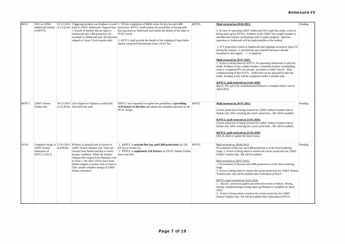
PendingMail recieved on 29-07-2015:
Carrier protection is being restored for 220kV Sedam-Tandoor line at
Sedam end. After restoring the carrier protection , AR will be enabled.
KPTCL mail recieved on 23-01-2016:
Carrier protection is being restored for 220kV Sedam-Tandoor line at
Sedam end. After restoring the carrier protection , AR will be enabled.
KPTCL mail recieved on 25-05-2016:
SEE,SCADA to update the latest status
Mail received on 28-04-2015:
Procurement of Bus bar and LBB protection is in the final tendering
stage. 2. Action is being taken to restore the carrier protection for 220kV
Sedam-Tandoor line. AR will be enabled.
Mail received on 29-07-2015:
1. Procurement of Bus bar and LBB protection is in the final tendering
stage.
2. Action is being taken to restore the carrier protection for 220kV Sedam-
Tandoor line. AR will be enabled after restoration of PLCC.
KPTCL mail received on 23-01-2016:
1. Bus bar protection panels pocured and erected at Sedam. Wiring ,
testing ,commissioning is being taken up.Planned to complete by April
2016.
2. Action is being taken to restore the carrier protection for 220kV
Sedam-Tandoor line. AR will be enabled after restoration of PLCC.
PendingKPTCL 1. KPTCL to provide Bus bar and LBB protections for 220
kV bus at Sedam S/s.
2. KPTCL to implement A/R feature on 220 kV Sedam-Tandur
inter-state line.
R-Phase to ground fault occurred on
220kV Sedam-Shahpur line. Fault not
cleared from Sedam end due to stuck-
breaker condition. While the Sedam-
Sahapur line tripped from Shahapur end
in Zone-1, the other 220 kv lines from
Sedam tripped at remote ends in Zone-2.
This caused complete outage of 220kV
Sedam substation.
Triggering incident was B-phase to earth
fault in 220kV Ambewadi- Nagzari line-
1. B-pole of breaker did not open at
Ambewadi end. LBB protection not
available at Ambewadi end. All elements
tripped on Zone-2 from remote ends.
22-12-2014
at 21:22 hrs
GD-1 at 220kV
Ambewadi Station
of KPTCL
27-01-2015
at 8.00 hrs
Complete outage at
220kV Sedam
Substation of
KPTCL (GD-1)
Mail received on 28-04-2015:
1. In view of operating 220kV Ambewadi SS in split bus mode, action is
being taken up by KPTCL. Problem in the 220kV bus coupler breaker is
attended and isolator overhauling work is under progress. Spilt bus
operation at Ambewadi will be made possible at the earliest.
2. ICT protection system at Ambewadi and trippings occured at Supa GS
during the instance is checked up and remedial measures already
furnished in this regard. ---- Completed
Mail recieved on 29-07-2015:
1. Action is being taken by KPTCL for operating Ambewadi in split bus
mode. Problem in bus coupler breaker is attended.Isolator overhaulling
work is completed.PTs are already provided to 220kV Bus-II. After
commissioning of Bus-II PTs, Ambewadi can be operated in split bus
mode. Pending works will be completed within a months time.
KPTCL mail recieved on 23-01-2016:
Bus-II PTs yet to be commissioned.Planned to complete before end of
April-2016.
Pending1. Till the completion of R&M works for bus bar and LBB
protection, KPTCL shall explore the possibility of having split
bus operation at Ambewadi and submit the details of the same to
PCSC forum.
2. KPTCL shall provide the details of the tripping of Supa hydro
station connected downstream from 110 kV bus.
KPTCL40/I/1
41/I/4
KPTCL was requested to explore the possibility of providing
A/R feature to this line and submit the remedial measures to the
PCSC forum.
Line tripped on Yphase to earth fault
from both the ends
20-12-2014
at 22:20 hrs
220kV Sedam-
Tandur line
40/IV/1 KPTCL
Annexure-IV
Page 7 of 19
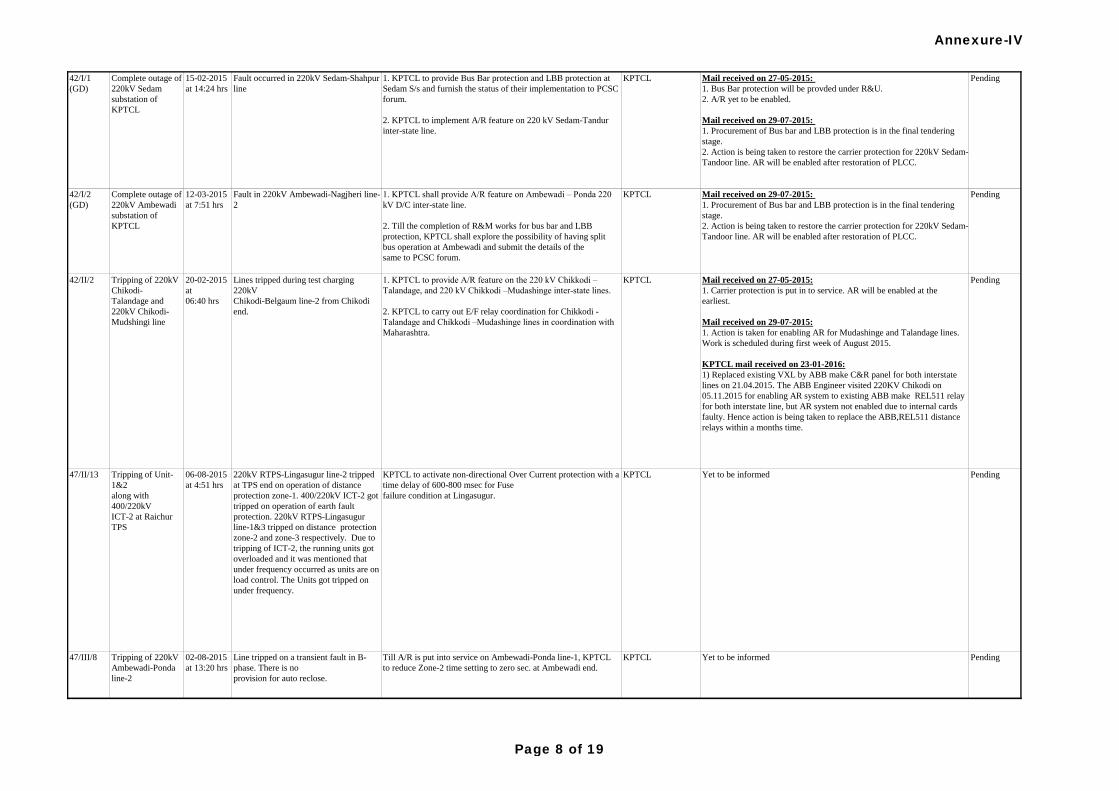
47/III/8 Tripping of 220kV
Ambewadi-Ponda
line-2
02-08-2015
at 13:20 hrs
Line tripped on a transient fault in B-
phase. There is no
provision for auto reclose.
PendingYet to be informed
Yet to be informed Pending
Mail received on 27-05-2015:
1. Carrier protection is put in to service. AR will be enabled at the
earliest.
Mail received on 29-07-2015:
1. Action is taken for enabling AR for Mudashinge and Talandage lines.
Work is scheduled during first week of August 2015.
KPTCL mail received on 23-01-2016:
1) Replaced existing VXL by ABB make C&R panel for both interstate
lines on 21.04.2015. The ABB Engineer visited 220KV Chikodi on
05.11.2015 for enabling AR system to existing ABB make REL511 relay
for both interstate line, but AR system not enabled due to internal cards
faulty. Hence action is being taken to replace the ABB,REL511 distance
relays within a months time.
Pending
42/I/2
(GD)
42/II/2
KPTCL to activate non-directional Over Current protection with a
time delay of 600-800 msec for Fuse
failure condition at Lingasugur.
Tripping of Unit-
1&2
along with
400/220kV
ICT-2 at Raichur
TPS
06-08-2015
at 4:51 hrs
KPTCL
KPTCL1. KPTCL to provide A/R feature on the 220 kV Chikkodi –
Talandage, and 220 kV Chikkodi –Mudashinge inter-state lines.
2. KPTCL to carry out E/F relay coordination for Chikkodi -
Talandage and Chikkodi –Mudashinge lines in coordination with
Maharashtra.
Lines tripped during test charging
220kV
Chikodi-Belgaum line-2 from Chikodi
end.
20-02-2015
at
06:40 hrs
Tripping of 220kV
Chikodi-
Talandage and
220kV Chikodi-
Mudshingi line
47/II/13
Till A/R is put into service on Ambewadi-Ponda line-1, KPTCL
to reduce Zone-2 time setting to zero sec. at Ambewadi end.
1. KPTCL to provide Bus Bar protection and LBB protection at
Sedam S/s and furnish the status of their implementation to PCSC
forum.
2. KPTCL to implement A/R feature on 220 kV Sedam-Tandur
inter-state line.
Pending1. KPTCL shall provide A/R feature on Ambewadi – Ponda 220
kV D/C inter-state line.
2. Till the completion of R&M works for bus bar and LBB
protection, KPTCL shall explore the possibility of having split
bus operation at Ambewadi and submit the details of the
same to PCSC forum.
KPTCL
KPTCL
Fault in 220kV Ambewadi-Nagjheri line-
2
12-03-2015
at 7:51 hrs
Complete outage of
220kV Ambewadi
substation of
KPTCL
220kV RTPS-Lingasugur line-2 tripped
at TPS end on operation of distance
protection zone-1. 400/220kV ICT-2 got
tripped on operation of earth fault
protection. 220kV RTPS-Lingasugur
line-1&3 tripped on distance protection
zone-2 and zone-3 respectively. Due to
tripping of ICT-2, the running units got
overloaded and it was mentioned that
under frequency occurred as units are on
load control. The Units got tripped on
under frequency.
Fault occurred in 220kV Sedam-Shahpur
line
Pending
Mail received on 29-07-2015:
1. Procurement of Bus bar and LBB protection is in the final tendering
stage.
2. Action is being taken to restore the carrier protection for 220kV Sedam-
Tandoor line. AR will be enabled after restoration of PLCC.
Mail received on 27-05-2015:
1. Bus Bar protection will be provded under R&U.
2. A/R yet to be enabled.
Mail received on 29-07-2015:
1. Procurement of Bus bar and LBB protection is in the final tendering
stage.
2. Action is being taken to restore the carrier protection for 220kV Sedam-
Tandoor line. AR will be enabled after restoration of PLCC.
KPTCL15-02-2015
at 14:24 hrs
Complete outage of
220kV Sedam
substation of
KPTCL
42/I/1
(GD)
Annexure-IV
Page 8 of 19
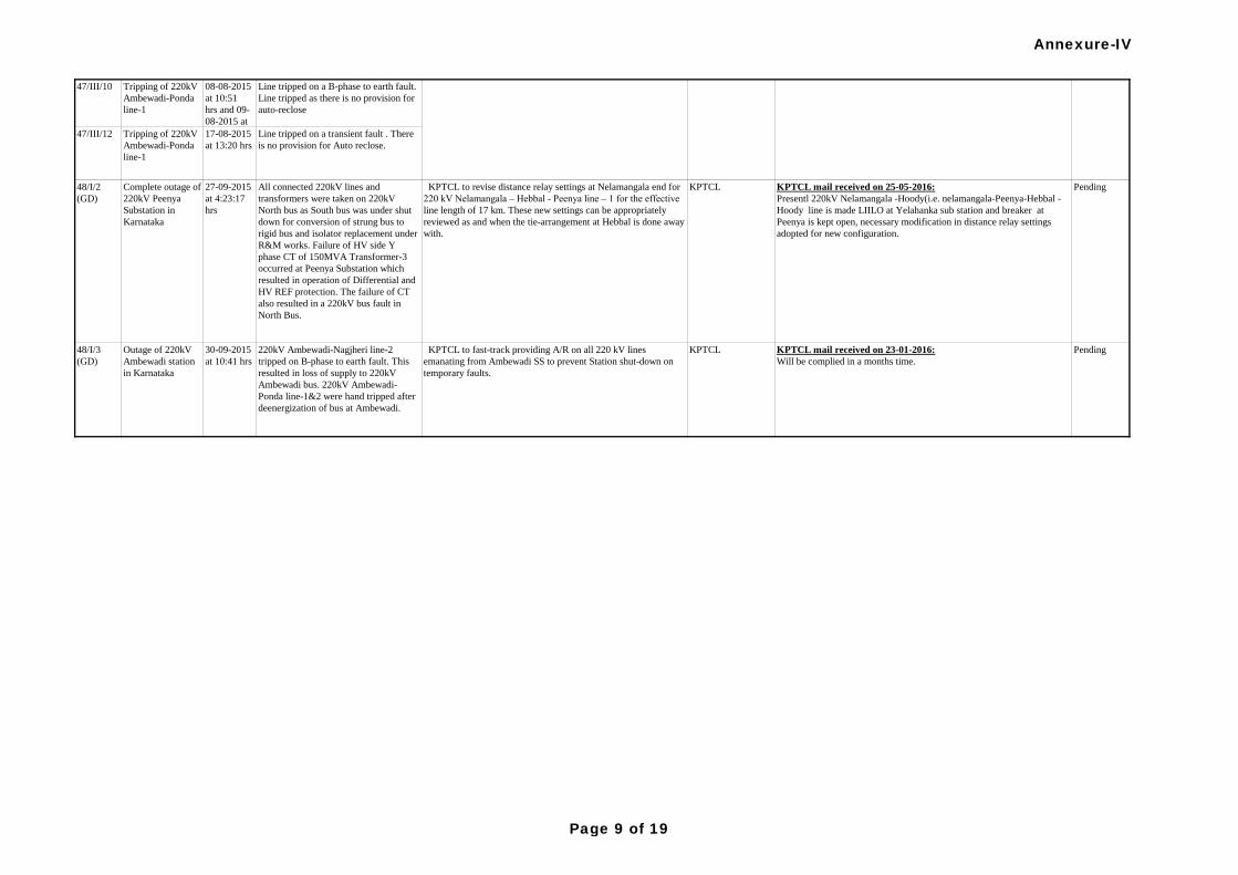
47/III/10 Tripping of 220kV
Ambewadi-Ponda
line-1
08-08-2015
at 10:51
hrs and 09-
08-2015 at
11:15 hrs
Line tripped on a B-phase to earth fault.
Line tripped as there is no provision for
auto-reclose
47/III/12 Tripping of 220kV
Ambewadi-Ponda
line-1
17-08-2015
at 13:20 hrs
Line tripped on a transient fault . There
is no provision for Auto reclose.
KPTCL mail received on 25-05-2016:
Presentl 220kV Nelamangala -Hoody(i.e. nelamangala-Peenya-Hebbal -
Hoody line is made LIILO at Yelahanka sub station and breaker at
Peenya is kept open, necessary modification in distance relay settings
adopted for new configuration.
Pending
PendingYet to be informed
220kV Ambewadi-Nagjheri line-2
tripped on B-phase to earth fault. This
resulted in loss of supply to 220kV
Ambewadi bus. 220kV Ambewadi-
Ponda line-1&2 were hand tripped after
deenergization of bus at Ambewadi.
KPTCL to fast-track providing A/R on all 220 kV lines
emanating from Ambewadi SS to prevent Station shut-down on
temporary faults.
KPTCL
48/I/2
(GD)
Complete outage of
220kV Peenya
Substation in
Karnataka
27-09-2015
at 4:23:17
hrs
All connected 220kV lines and
transformers were taken on 220kV
North bus as South bus was under shut
down for conversion of strung bus to
rigid bus and isolator replacement under
R&M works. Failure of HV side Y
phase CT of 150MVA Transformer-3
occurred at Peenya Substation which
resulted in operation of Differential and
HV REF protection. The failure of CT
also resulted in a 220kV bus fault in
North Bus.
KPTCL to revise distance relay settings at Nelamangala end for
220 kV Nelamangala – Hebbal - Peenya line – 1 for the effective
line length of 17 km. These new settings can be appropriately
reviewed as and when the tie-arrangement at Hebbal is done away
with.
KPTCL
Outage of 220kV
Ambewadi station
in Karnataka
48/I/3
(GD)
Till A/R is put into service on Ambewadi-Ponda line-1, KPTCL
to reduce Zone-2 time setting to zero sec. at Ambewadi end.
KPTCL
KPTCL mail received on 23-01-2016:
Will be complied in a months time.
Pending30-09-2015
at 10:41 hrs
Annexure-IV
Page 9 of 19
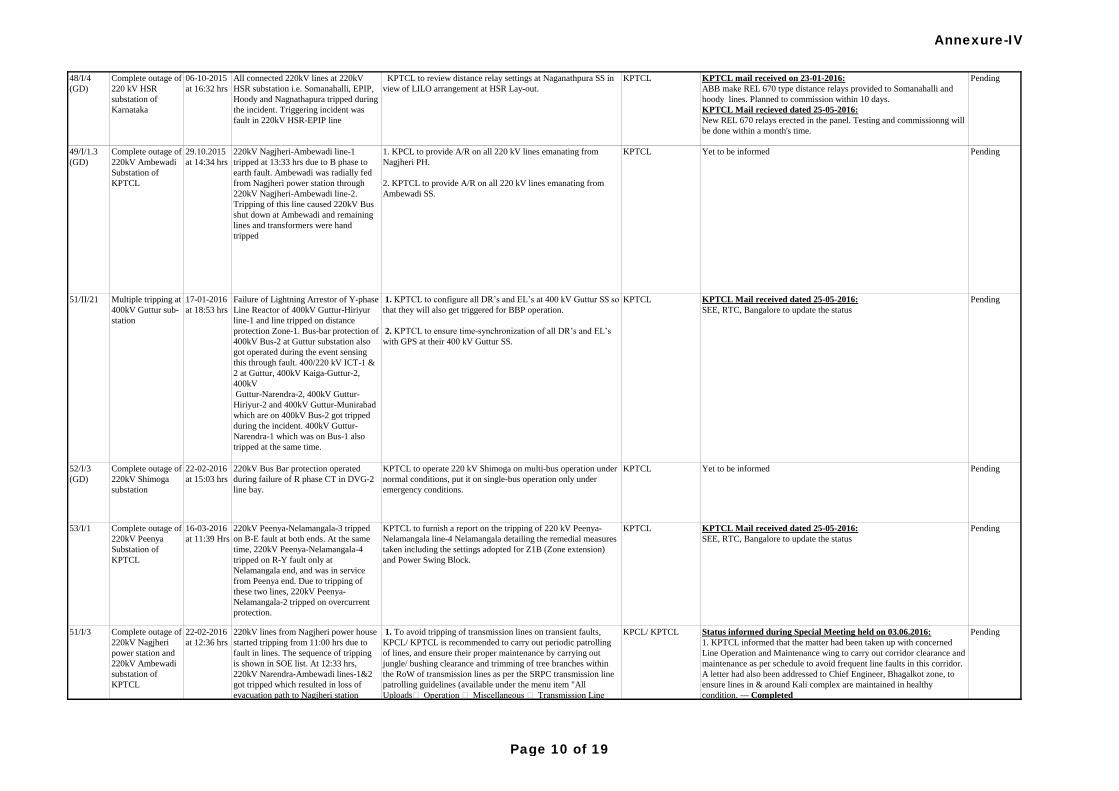
48/I/4
(GD)
Complete outage of
220 kV HSR
substation of
Karnataka
06-10-2015
at 16:32 hrs
All connected 220kV lines at 220kV
HSR substation i.e. Somanahalli, EPIP,
Hoody and Nagnathapura tripped during
the incident. Triggering incident was
fault in 220kV HSR-EPIP line
KPTCL to review distance relay settings at Naganathpura SS in
view of LILO arrangement at HSR Lay-out.
KPTCL KPTCL mail received on 23-01-2016:
ABB make REL 670 type distance relays provided to Somanahalli and
hoody lines. Planned to commission within 10 days.
KPTCL Mail recieved dated 25-05-2016:
New REL 670 relays erected in the panel. Testing and commissionng will
be done within a month's time.
Pending
52/I/3
(GD)
Complete outage of
220kV Shimoga
substation
22-02-2016
at 15:03 hrs
220kV Bus Bar protection operated
during failure of R phase CT in DVG-2
line bay.
KPTCL to operate 220 kV Shimoga on multi-bus operation under
normal conditions, put it on single-bus operation only under
emergency conditions.
KPTCL Yet to be informed Pending
Yet to be informed Pending
220kV lines from Nagjheri power house
started tripping from 11:00 hrs due to
fault in lines. The sequence of tripping
is shown in SOE list. At 12:33 hrs,
220kV Narendra-Ambewadi lines-1&2
got tripped which resulted in loss of
evacuation path to Nagjheri station
resulting in tripping of running Units
and complete outage at Nagjhheri power
station. 220kV Ambewadi station also
got de-energized due to tripping of
source feeders i.e. 220kV Narendra-
Ambewadi-1&2 and 220kV Nagjheri-
Ambewadi-1&2.
1. To avoid tripping of transmission lines on transient faults,
KPCL/ KPTCL is recommended to carry out periodic patrolling
of lines, and ensure their proper maintenance by carrying out
jungle/ bushing clearance and trimming of tree branches within
the RoW of transmission lines as per the SRPC transmission line
patrolling guidelines (available under the menu item "All
Uploads Operation Miscellaneous Transmission Line
Patrolling Protocol / Guidelines for Southern Region" on SRPC
website).
2. KPCL/ KPTCL to review operation of SPS at NPH for
functionality (reduction of generation with tripping of evacuating
lines) and healthiness.
3. KPCL to put 220 kV Kodasalli - Nagjheri D/C lines into
service if more than 200 MW generation from Kali Complex
(with Nagheri Contribution not less than 50 MW) is ensured on
sustained basis.
KPCL/ KPTCL Status informed during Special Meeting held on 03.06.2016:
1. KPTCL informed that the matter had been taken up with concerned
Line Operation and Maintenance wing to carry out corridor clearance and
maintenance as per schedule to avoid frequent line faults in this corridor.
A letter had also been addressed to Chief Engineer, Bhagalkot zone, to
ensure lines in & around Kali complex are maintained in healthy
condition. --- Completed
2. KPTCL assurd that the final modified SPS would be implemented at
Nagjheri PH at the earliest. ------ Pending
3. KPCL informed that Nagjhari- Kodasalli Lines 1 & 2 had been kept in
service since 23.05.2016 @ 08.06hrs. ---- Completed
KPTCL Mail received dated 25-05-2016:
SEE, RTC, Bangalore to update the status
Complete outage of
220kV Ambewadi
Substation of
KPTCL
29.10.2015
at 14:34 hrs
1. KPCL to provide A/R on all 220 kV lines emanating from
Nagjheri PH.
2. KPTCL to provide A/R on all 220 kV lines emanating from
Ambewadi SS.
KPTCL
Failure of Lightning Arrestor of Y-phase
Line Reactor of 400kV Guttur-Hiriyur
line-1 and line tripped on distance
protection Zone-1. Bus-bar protection of
400kV Bus-2 at Guttur substation also
got operated during the event sensing
this through fault. 400/220 kV ICT-1 &
2 at Guttur, 400kV Kaiga-Guttur-2,
400kV
Guttur-Narendra-2, 400kV Guttur-
Hiriyur-2 and 400kV Guttur-Munirabad
which are on 400kV Bus-2 got tripped
during the incident. 400kV Guttur-
Narendra-1 which was on Bus-1 also
tripped at the same time.
51/II/21 Multiple tripping at
400kV Guttur sub-
station
17-01-2016
at 18:53 hrs
KPTCL 1. KPTCL to configure all DR’s and EL’s at 400 kV Guttur SS so
that they will also get triggered for BBP operation.
2. KPTCL to ensure time-synchronization of all DR’s and EL’s
with GPS at their 400 kV Guttur SS.
220kV Nagjheri-Ambewadi line-1
tripped at 13:33 hrs due to B phase to
earth fault. Ambewadi was radially fed
from Nagjheri power station through
220kV Nagjheri-Ambewadi line-2.
Tripping of this line caused 220kV Bus
shut down at Ambewadi and remaining
lines and transformers were hand
tripped
49/I/1.3
(GD)
Complete outage of
220kV Peenya
Substation of
KPTCL
53/I/1 Pending16-03-2016
at 11:39 Hrs
22-02-2016
at 12:36 hrs
51/I/3
Pending
Pending
220kV Peenya-Nelamangala-3 tripped
on B-E fault at both ends. At the same
time, 220kV Peenya-Nelamangala-4
tripped on R-Y fault only at
Nelamangala end, and was in service
from Peenya end. Due to tripping of
these two lines, 220kV Peenya-
Nelamangala-2 tripped on overcurrent
protection.
KPTCL to furnish a report on the tripping of 220 kV Peenya-
Nelamangala line-4 Nelamangala detailing the remedial measures
taken including the settings adopted for Z1B (Zone extension)
and Power Swing Block.
KPTCL KPTCL Mail received dated 25-05-2016:
SEE, RTC, Bangalore to update the status
Complete outage of
220kV Nagjheri
power station and
220kV Ambewadi
substation of
KPTCL
Annexure-IV
Page 10 of 19
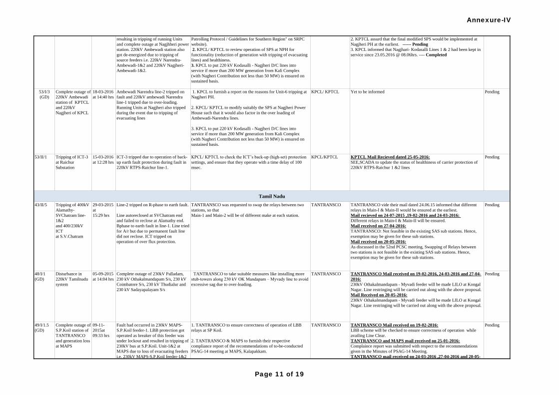
53/II/1 Tripping of ICT-3
at Raichur
Substation
15-03-2016
at 12:28 hrs
ICT-3 tripped due to operation of back-
up earth fault protection during fault in
220kV RTPS-Raichur line-1.
KPCL/ KPTCL to check the ICT’s back-up (high-set) protection
settings, and ensure that they operate with a time delay of 100
msec.
KPCL/KPTCL KPTCL Mail Recieved dated 25-05-2016:
SEE,SCADA to update the status of healthiness of carrier protection of
220kV RTPS-Raichur 1 &2 lines
Pending
220kV lines from Nagjheri power house
started tripping from 11:00 hrs due to
fault in lines. The sequence of tripping
is shown in SOE list. At 12:33 hrs,
220kV Narendra-Ambewadi lines-1&2
got tripped which resulted in loss of
evacuation path to Nagjheri station
resulting in tripping of running Units
and complete outage at Nagjhheri power
station. 220kV Ambewadi station also
got de-energized due to tripping of
source feeders i.e. 220kV Narendra-
Ambewadi-1&2 and 220kV Nagjheri-
Ambewadi-1&2.
1. To avoid tripping of transmission lines on transient faults,
KPCL/ KPTCL is recommended to carry out periodic patrolling
of lines, and ensure their proper maintenance by carrying out
jungle/ bushing clearance and trimming of tree branches within
the RoW of transmission lines as per the SRPC transmission line
patrolling guidelines (available under the menu item "All
Uploads Operation Miscellaneous Transmission Line
Patrolling Protocol / Guidelines for Southern Region" on SRPC
website).
2. KPCL/ KPTCL to review operation of SPS at NPH for
functionality (reduction of generation with tripping of evacuating
lines) and healthiness.
3. KPCL to put 220 kV Kodasalli - Nagjheri D/C lines into
service if more than 200 MW generation from Kali Complex
(with Nagheri Contribution not less than 50 MW) is ensured on
sustained basis.
KPCL/ KPTCL Status informed during Special Meeting held on 03.06.2016:
1. KPTCL informed that the matter had been taken up with concerned
Line Operation and Maintenance wing to carry out corridor clearance and
maintenance as per schedule to avoid frequent line faults in this corridor.
A letter had also been addressed to Chief Engineer, Bhagalkot zone, to
ensure lines in & around Kali complex are maintained in healthy
condition. --- Completed
2. KPTCL assurd that the final modified SPS would be implemented at
Nagjheri PH at the earliest. ------ Pending
3. KPCL informed that Nagjhari- Kodasalli Lines 1 & 2 had been kept in
service since 23.05.2016 @ 08.06hrs. ---- Completed
Tamil Nadu
PendingYet to be informed 1. KPCL to furnish a report on the reasons for Unit-6 tripping at
Nagjheri PH.
2. KPCL/ KPTCL to modify suitably the SPS at Nagjheri Power
House such that it would also factor in the over loading of
Ambewadi-Narendra lines.
3. KPCL to put 220 kV Kodasalli - Nagjheri D/C lines into
service if more than 200 MW generation from Kali Complex
(with Nagheri Contribution not less than 50 MW) is ensured on
sustained basis.
KPCL/ KPTCL
Pending TANTRANSCO to take suitable measures like installing more
stub-towers along 230 kV OK Mandapam – Myvady line to avoid
excessive sag due to over-loading.
TANTRANSCO
1. TANTRANSCO to ensure correctness of operation of LBB
relays at SP Koil.
2. TANTRANSCO & MAPS to furnish their respective
compliance report of the recommendations of to-be-conducted
PSAG-14 meeting at MAPS, Kalapakkam.
TANTRANSCO
TANTRANSCO vide their mail dated 24.06.15 informed that different
relays in Main-I & Main-II would be ensured at the earliest.
Mail recieved on 24-07-2015 ,19-02-2016 and 24-03-2016:
Different relays in Main-I & Main-II will be ensured.
Mail received on 27-04-2016:
TANTRANSCO: Not feasible in the existing SAS sub stations. Hence,
exemption may be given for these sub stations.
Mail received on 20-05-2016:
As discussed in the 52nd PCSC meeting, Swapping of Relays between
two stations is not feasible in the existing SAS sub stations. Hence,
exemption may be given for these sub stations.
Pending
Complete outage of
S.P.Koil station of
TANTRANSCO
and generation loss
at MAPS
TANTRANSCO Mail received on 19-02-2016:
LBB scheme will be checked to ensure correctness of operation while
availing Line Clear.
TANTRANSCO and MAPS mail received on 25-01-2016:
Complaince report was submitted with respect to the recommendations
given in the Minutes of PSAG-14 Meeting.
TANTRANSCO mail received on 24-03-2016 ,27-04-2016 and 20-05-
2016:
Complaince report was submitted on 25.01.2016 with respect to the
recommendations given in the Minutes of PSAG-14 Meeting.
TANTRANSCO Mail received on 19-02-2016, 24-03-2016 and 27-04-
2016:
230kV Othakalmandapam - Myvadi feeder will be made LILO at Kongal
Nagar. Line restringing will be carried out along with the above proposal.
Mail Received on 20-05-2016:
230kV Othakalmandapam - Myvadi feeder will be made LILO at Kongal
Nagar. Line restringing will be carried out along with the above proposal.
43/II/5 Tripping of 400kV
Alamathy-
SVChatram line-
1&2
and 400/230kV
ICT
at S.V.Chatram
29-03-2015
at
15:29 hrs
TANTRANSCO was requested to swap the relays between two
stations, so that
Main-1 and Main-2 will be of different make at each station.
TANTRANSCOLine-2 tripped on R-phase to earth fault.
Line autoreclosed at SVChatram end
and failed to reclose at Alamathy end.
Bphase to earth fault in line-1. Line tried
for A/r but due to permanent fault line
did not reclose. ICT tripped on
operation of over flux protection.
53/I/3
(GD)
Complete outage of
220kV Ambewadi
station of KPTCL
and 220kV
Nagjheri of KPCL
18-03-2016
at 14:40 hrs
Ambewadi Narendra line-2 tripped on
fault and 220kV ambewadi Narendra
line-1 tripped due to over-loading.
Running Units at Nagjheri also tripped
during the event due to tripping of
evacuating lines
09-11-
2015at
09:33 hrs
Fault had occurred in 230kV MAPS-
S.P.Koil feeder-1. LBB protection got
operated as breaker of this feeder was
under lockout and resulted in tripping of
230kV bus at S.P.Koil. Unit-1&2 at
MAPS due to loss of evacuating feeders
i.e. 230kV MAPS-S.P.Koil feeder-1&2
Complete outage of 230kV Palladam,
230 kV Othakalmandapam S/s, 230 kV
Coimbatore S/s, 230 kV Thudialur and
230 kV Sadayapalayam S/s
05-09-2015
at 14:04 hrs
Disturbance in
220kV Tamilnadu
system
48/I/1
(GD)
49/I/1.5
(GD)
22-02-2016
at 12:36 hrs
51/I/3
Pending
PendingComplete outage of
220kV Nagjheri
power station and
220kV Ambewadi
substation of
KPTCL
Annexure-IV
Page 11 of 19
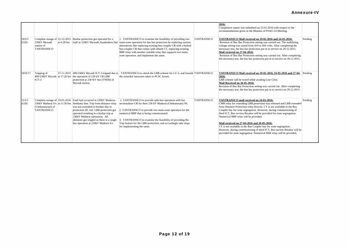
50/II/17
21-12-2015
at 6:28 hrs
Pending
TANTRANSCO to check the LBB scheme for LV-3, and furnish
the remedial measures taken to PCSC forum.
TANTRANSCO TANTRANSCO mail received on 24-03-2016:
CMR relay for extending LBB protection was released and LBB extended
from Distance Protection relay directly. CT is not available in the Bus
Coupler bay for zone segregation. However, during commissioning of
third ICT, Bus section Breaker will be provided for zone segregation.
Numerical BBP relay will be provided.
Mail recieved on 27-04-2016 and 20-05-2016:
CT is not available in the Bus Coupler bay for zone segregation.
However, during commissioning of third ICT, Bus section Breaker will be
provided for zone segregation. Numerical BBP relay will be provided.
Fault had occurred in 230kV Madurai-
Sembatty line. Trip from distance relay
was not extended to breaker due to
protection DC fail. LBB protection got
operated resulting in a busbar trip at
230kV Madurai substation. All
elements got tripped as there is a single
bus operation at 230kV Madurai S/s
1. TANTRANSCO to provide split-bus operation with bus
sectionalizer CB for their 230 kV Madurai (Chekanurani) SS.
2. TANTRANSCO to provide two main-zone operation for the
numerical BBP that is being commissioned.
3. TANTRANSCO to examine the feasibility of providing Re-
Trip feature for the LBB protection, and accordingly take steps
for implementing the same.
400/230kV Myvadi ICT-3 tripped due to
the operation of 230 kV CB LBB
protection at 230 KV bus (TNEB) of
Myvadi station.
27-11-2015
at 17:26 hrs
Tripping of
400/230kV Myvadi
ICT-3
Complete outage of
230kV Madurai S/s
(Chekanaurani) of
TANTRANSCO
19-01-2016
at 11:56 hrs
1. TANTRANSCO to examine the feasibility of providing two
main-zone operation for bus bar protection by exploring various
alternatives like replacing existing bus-coupler CB with a hybrid
bus-coupler CB that comes with inbuilt CT, replacing existing
BBP relay with another suitable relay that supports two main-
zone operation, and implement the same.
1. TANTRANSCO to ensure correctness of operation of LBB
relays at SP Koil.
2. TANTRANSCO & MAPS to furnish their respective
compliance report of the recommendations of to-be-conducted
PSAG-14 meeting at MAPS, Kalapakkam.
TANTRANSCOComplete outage of
S.P.Koil station of
TANTRANSCO
and generation loss
at MAPS
TANTRANSCO Mail received on 19-02-2016:
LBB scheme will be checked to ensure correctness of operation while
availing Line Clear.
TANTRANSCO and MAPS mail received on 25-01-2016:
Complaince report was submitted with respect to the recommendations
given in the Minutes of PSAG-14 Meeting.
TANTRANSCO mail received on 24-03-2016 ,27-04-2016 and 20-05-
2016:
Complaince report was submitted on 25.01.2016 with respect to the
recommendations given in the Minutes of PSAG-14 Meeting.
Busbar protection got operated for a
fault in 230kV Mywadi-Anaikadavu line
09-11-
2015at
09:33 hrs
Fault had occurred in 230kV MAPS-
S.P.Koil feeder-1. LBB protection got
operated as breaker of this feeder was
under lockout and resulted in tripping of
230kV bus at S.P.Koil. Unit-1&2 at
MAPS due to loss of evacuating feeders
i.e. 230kV MAPS-S.P.Koil feeder-1&2
49/I/1.5
(GD)
TANTRANSCO Mail received on 19-02-2016 and 24-03-2016:
Revision of Bus Bar Protection setting was carried out. The stabilizing
voltage setting was raised from 410 to 450 volts. After completing the
necessary test, the bus bar protection put in to service on 29.12.2015.
Mail recieved on 27-04-2016:
Revision of Bus Bar Protection setting was carried out. After completing
the necessary test, the bus bar protection put in to service on 29.12.2015.
TANTRANSCO
Pending
Complete outage of
230kV Mywadi
station of
TANTRANSCO
50/I/3
(GD)
51/I/1
(GD)
Pending
TANTRANSCO Mail received on 19-02-2016, 24-03-2016 and 27-04-
2016:
LBB scheme will be tested while availing Line Clear.
Mail Received on 20-05-2016:
Revision of Bus Bar Protection setting was carried out. After completing
the necessary test, the bus bar protection put in to service on 29.12.2015.
TANTRANSCO Pending
Annexure-IV
Page 12 of 19
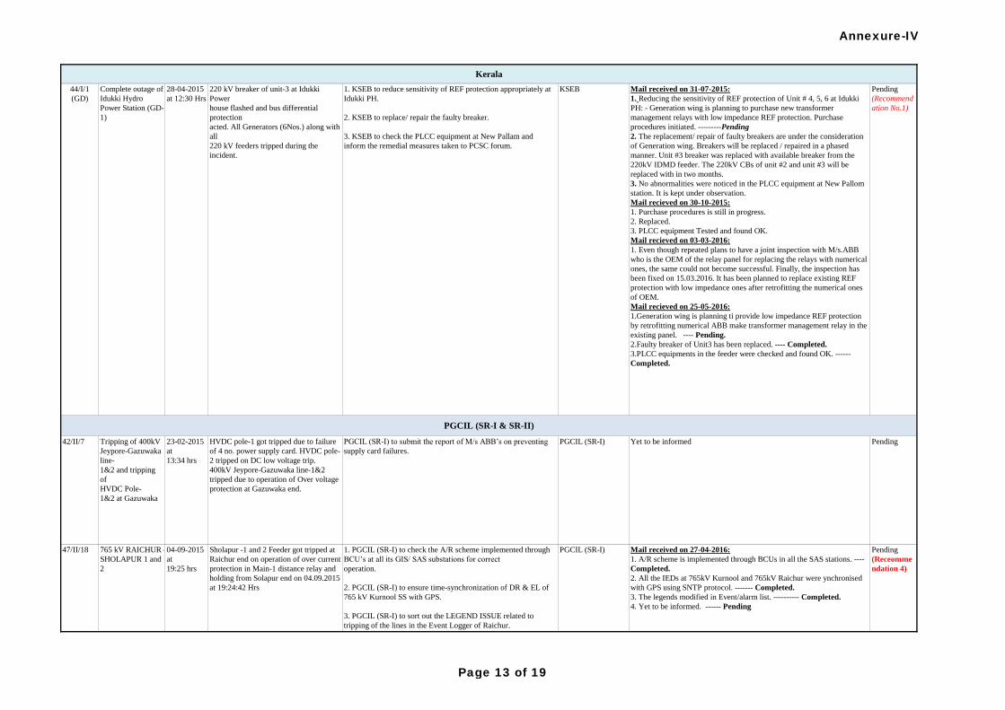
765 kV RAICHUR -
SHOLAPUR 1 and
2
Kerala
Pending
(Recommend
ation No.1)
PGCIL (SR-I & SR-II)
Pending
(Receomme
ndation 4)
Sholapur -1 and 2 Feeder got tripped at
Raichur end on operation of over current
protection in Main-1 distance relay and
holding from Solapur end on 04.09.2015
at 19:24:42 Hrs
04-09-2015
at
19:25 hrs
Mail received on 31-07-2015:
1. Reducing the sensitivity of REF protection of Unit # 4, 5, 6 at Idukki
PH: - Generation wing is planning to purchase new transformer
management relays with low impedance REF protection. Purchase
procedures initiated. ---------Pending
2. The replacement/ repair of faulty breakers are under the consideration
of Generation wing. Breakers will be replaced / repaired in a phased
manner. Unit #3 breaker was replaced with available breaker from the
220kV IDMD feeder. The 220kV CBs of unit #2 and unit #3 will be
replaced with in two months.
3. No abnormalities were noticed in the PLCC equipment at New Pallom
station. It is kept under observation.
Mail recieved on 30-10-2015:
1. Purchase procedures is still in progress.
2. Replaced.
3. PLCC equipment Tested and found OK.
Mail recieved on 03-03-2016:
1. Even though repeated plans to have a joint inspection with M/s.ABB
who is the OEM of the relay panel for replacing the relays with numerical
ones, the same could not become successful. Finally, the inspection has
been fixed on 15.03.2016. It has been planned to replace existing REF
protection with low impedance ones after retrofitting the numerical ones
of OEM.
Mail recieved on 25-05-2016:
1.Generation wing is planning ti provide low impedance REF protection
by retrofitting numerical ABB make transformer management relay in the
existing panel. ---- Pending.
2.Faulty breaker of Unit3 has been replaced. ---- Completed.
3.PLCC equipments in the feeder were checked and found OK. ------
Completed.
KSEB1. KSEB to reduce sensitivity of REF protection appropriately at
Idukki PH.
2. KSEB to replace/ repair the faulty breaker.
3. KSEB to check the PLCC equipment at New Pallam and
inform the remedial measures taken to PCSC forum.
220 kV breaker of unit-3 at Idukki
Power
house flashed and bus differential
protection
acted. All Generators (6Nos.) along with
all
220 kV feeders tripped during the
incident.
28-04-2015
at 12:30 Hrs
1. PGCIL (SR-I) to check the A/R scheme implemented through
BCU’s at all its GIS/ SAS substations for correct
operation.
2. PGCIL (SR-I) to ensure time-synchronization of DR & EL of
765 kV Kurnool SS with GPS.
3. PGCIL (SR-I) to sort out the LEGEND ISSUE related to
tripping of the lines in the Event Logger of Raichur.
4. PGCIL (SR-I) to check & ensure the functionality &
healthiness of synchronization facility at Raichur end at
the earliest opportune time.
Pending42/II/7 Tripping of 400kV
Jeypore-Gazuwaka
line-
1&2 and tripping
of
HVDC Pole-
1&2 at Gazuwaka
23-02-2015
at
13:34 hrs
HVDC pole-1 got tripped due to failure
of 4 no. power supply card. HVDC pole-
2 tripped on DC low voltage trip.
400kV Jeypore-Gazuwaka line-1&2
tripped due to operation of Over voltage
protection at Gazuwaka end.
PGCIL (SR-I) to submit the report of M/s ABB’s on preventing
supply card failures.
PGCIL (SR-I)
PGCIL (SR-I) Mail received on 27-04-2016:
1. A/R scheme is implemented through BCUs in all the SAS stations. ----
Completed.
2. All the IEDs at 765kV Kurnool and 765kV Raichur were ynchronised
with GPS using SNTP protocol. ------- Completed.
3. The legends modified in Event/alarm list. ---------- Completed.
4. Yet to be informed. ------ Pending
Yet to be informed
Complete outage of
Idukki Hydro
Power Station (GD-
1)
44/I/1
(GD)
47/II/18
Annexure-IV
Page 13 of 19
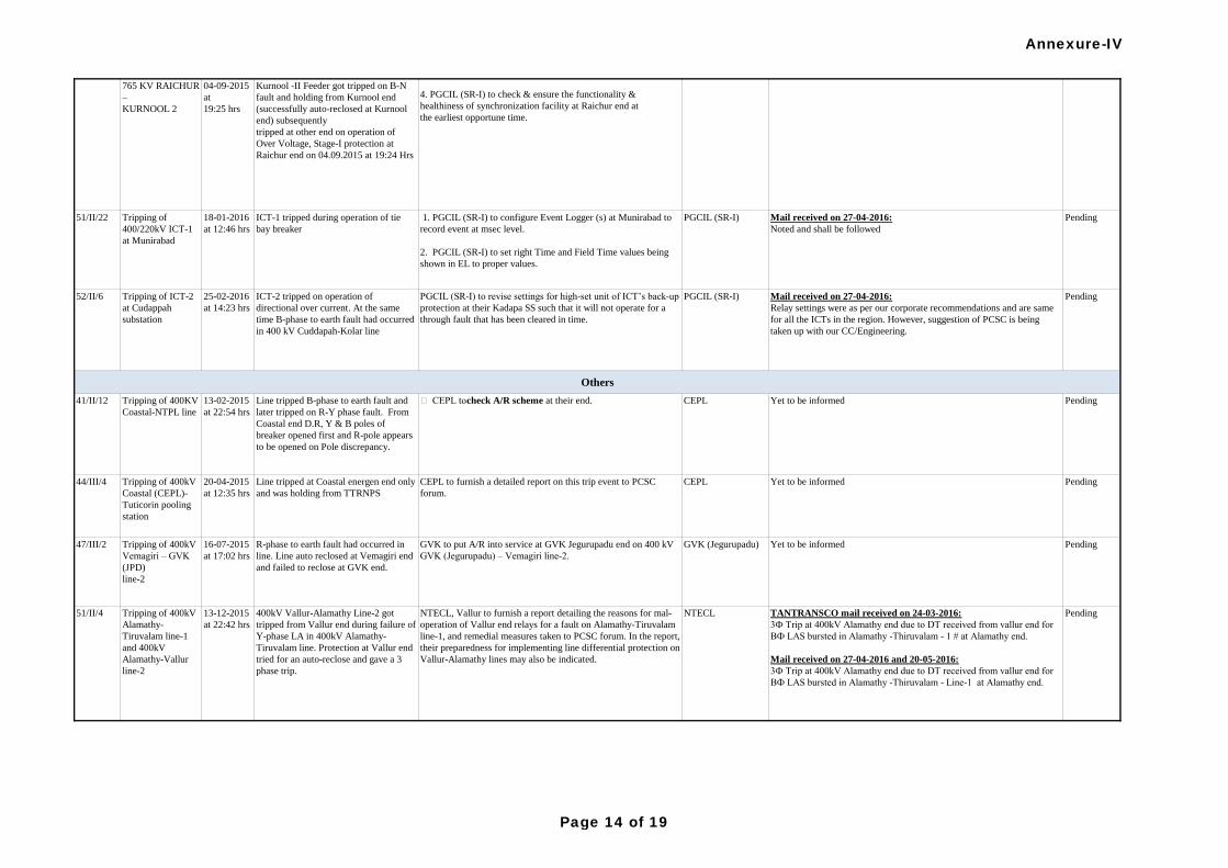
51/II/22 Tripping of
400/220kV ICT-1
at Munirabad
18-01-2016
at 12:46 hrs
ICT-1 tripped during operation of tie
bay breaker
1. PGCIL (SR-I) to configure Event Logger (s) at Munirabad to
record event at msec level.
2. PGCIL (SR-I) to set right Time and Field Time values being
shown in EL to proper values.
PGCIL (SR-I) Mail received on 27-04-2016:
Noted and shall be followed
Pending
52/II/6 Tripping of ICT-2
at Cudappah
substation
25-02-2016
at 14:23 hrs
ICT-2 tripped on operation of
directional over current. At the same
time B-phase to earth fault had occurred
in 400 kV Cuddapah-Kolar line
PGCIL (SR-I) to revise settings for high-set unit of ICT’s back-up
protection at their Kadapa SS such that it will not operate for a
through fault that has been cleared in time.
PGCIL (SR-I) Mail received on 27-04-2016:
Relay settings were as per our corporate recommendations and are same
for all the ICTs in the region. However, suggestion of PCSC is being
taken up with our CC/Engineering.
Pending
41/II/12 Tripping of 400KV
Coastal-NTPL line
13-02-2015
at 22:54 hrs
Line tripped B-phase to earth fault and
later tripped on R-Y phase fault. From
Coastal end D.R, Y & B poles of
breaker opened first and R-pole appears
to be opened on Pole discrepancy.
CEPL to check A/R scheme at their end. CEPL Yet to be informed Pending
44/III/4 Tripping of 400kV
Coastal (CEPL)-
Tuticorin pooling
station
20-04-2015
at 12:35 hrs
Line tripped at Coastal energen end only
and was holding from TTRNPS
CEPL to furnish a detailed report on this trip event to PCSC
forum.
CEPL Yet to be informed Pending
47/III/2 Tripping of 400kV
Vemagiri – GVK
(JPD)
line-2
16-07-2015
at 17:02 hrs
R-phase to earth fault had occurred in
line. Line auto reclosed at Vemagiri end
and failed to reclose at GVK end.
GVK to put A/R into service at GVK Jegurupadu end on 400 kV
GVK (Jegurupadu) – Vemagiri line-2.
GVK (Jegurupadu) Yet to be informed Pending
Kurnool -II Feeder got tripped on B-N
fault and holding from Kurnool end
(successfully auto-reclosed at Kurnool
end) subsequently
tripped at other end on operation of
Over Voltage, Stage-I protection at
Raichur end on 04.09.2015 at 19:24 Hrs
04-09-2015
at
19:25 hrs
765 KV RAICHUR
–
KURNOOL 2
Others
Pending
(Receomme
ndation 4)
1. PGCIL (SR-I) to check the A/R scheme implemented through
BCU’s at all its GIS/ SAS substations for correct
operation.
2. PGCIL (SR-I) to ensure time-synchronization of DR & EL of
765 kV Kurnool SS with GPS.
3. PGCIL (SR-I) to sort out the LEGEND ISSUE related to
tripping of the lines in the Event Logger of Raichur.
4. PGCIL (SR-I) to check & ensure the functionality &
healthiness of synchronization facility at Raichur end at
the earliest opportune time.
PGCIL (SR-I) Mail received on 27-04-2016:
1. A/R scheme is implemented through BCUs in all the SAS stations. ----
Completed.
2. All the IEDs at 765kV Kurnool and 765kV Raichur were ynchronised
with GPS using SNTP protocol. ------- Completed.
3. The legends modified in Event/alarm list. ---------- Completed.
4. Yet to be informed. ------ Pending
TANTRANSCO mail received on 24-03-2016:
3Ф Trip at 400kV Alamathy end due to DT received from vallur end for
BФ LAS bursted in Alamathy -Thiruvalam - 1 # at Alamathy end.
Mail received on 27-04-2016 and 20-05-2016:
3Ф Trip at 400kV Alamathy end due to DT received from vallur end for
BФ LAS bursted in Alamathy -Thiruvalam - Line-1 at Alamathy end.
PendingNTECLNTECL, Vallur to furnish a report detailing the reasons for mal-
operation of Vallur end relays for a fault on Alamathy-Tiruvalam
line-1, and remedial measures taken to PCSC forum. In the report,
their preparedness for implementing line differential protection on
Vallur-Alamathy lines may also be indicated.
47/II/18
400kV Vallur-Alamathy Line-2 got
tripped from Vallur end during failure of
Y-phase LA in 400kV Alamathy-
Tiruvalam line. Protection at Vallur end
tried for an auto-reclose and gave a 3
phase trip.
13-12-2015
at 22:42 hrs
Tripping of 400kV
Alamathy-
Tiruvalam line-1
and 400kV
Alamathy-Vallur
line-2
51/II/4
Annexure-IV
Page 14 of 19
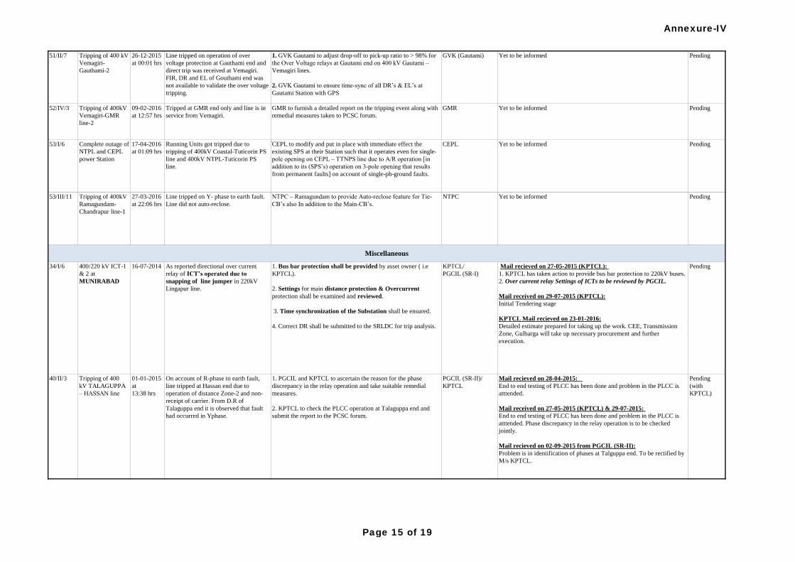
51/II/7 Tripping of 400 kV
Vemagiri-
Gauthami-2
26-12-2015
at 00:01 hrs
Line tripped on operation of over
voltage protection at Gauthami end and
direct trip was received at Vemagiri.
FIR, DR and EL of Gouthami end was
not available to validate the over voltage
tripping.
1. GVK Gautami to adjust drop-off to pick-up ratio to > 98% for
the Over Voltage relays at Gautami end on 400 kV Gautami –
Vemagiri lines.
2. GVK Gautami to ensure time-sync of all DR’s & EL’s at
Gautami Station with GPS
GVK (Gautami) Yet to be informed Pending
52/IV/3 Tripping of 400kV
Vemagiri-GMR
line-2
09-02-2016
at 12:57 hrs
Tripped at GMR end only and line is in
service from Vemagiri.
GMR to furnish a detailed report on the tripping event along with
remedial measures taken to PCSC forum.
GMR Yet to be informed Pending
53/I/6 Complete outage of
NTPL and CEPL
power Station
17-04-2016
at 01:09 hrs
Running Units got tripped due to
tripping of 400kV Coastal-Tuticorin PS
line and 400kV NTPL-Tuticorin PS
line.
CEPL to modify and put in place with immediate effect the
existing SPS at their Station such that it operates even for single-
pole opening on CEPL – TTNPS line due to A/R operation [in
addition to its (SPS’s) operation on 3-pole opening that results
from permanent faults] on account of single-ph-ground faults.
CEPL Yet to be informed Pending
53/III/11 Tripping of 400kV
Ramagundam-
Chandrapur line-1
27-03-2016
at 22:06 hrs
Line tripped on Y- phase to earth fault.
Line did not auto-reclose.
NTPC – Ramagundam to provide Auto-reclose feature for Tie-
CB’s also In addition to the Main-CB’s.
NTPC Yet to be informed Pending
Miscellaneous
On account of R-phase to earth fault,
line tripped at Hassan end due to
operation of distance Zone-2 and non-
receipt of carrier. From D.R of
Talaguppa end it is observed that fault
had occurred in Yphase.
01-01-2015
at
13:38 hrs
Tripping of 400
kV TALAGUPPA
– HASSAN line
40/II/3
PendingKPTCL/
PGCIL (SR-I)
1. PGCIL and KPTCL to ascertain the reason for the phase
discrepancy in the relay operation and take suitable remedial
measures.
2. KPTCL to check the PLCC operation at Talaguppa end and
submit the report to the PCSC forum.
PGCIL (SR-II)/
KPTCL
As reported directional over current
relay of ICT’s operated due to
snapping of line jumper in 220kV
Lingapur line.
16-07-2014400/220 kV ICT-1
& 2 at
MUNIRABAD
34/I/6 Mail recieved on 27-05-2015 (KPTCL):
1. KPTCL has taken action to provide bus bar protection to 220kV buses.
2. Over current relay Settings of ICTs to be reviewed by PGCIL.
Mail received on 29-07-2015 (KPTCL):
Initial Tendering stage
KPTCL Mail recieved on 23-01-2016:
Detailed estimate prepared for taking up the work. CEE, Transmission
Zone, Gulbarga will take up necessary procurement and further
execution.
1. Bus bar protection shall be provided by asset owner ( i.e
KPTCL).
2. Settings for main distance protection & Overcurrent
protection shall be examined and reviewed.
3. Time synchronization of the Substation shall be ensured.
4. Correct DR shall be submitted to the SRLDC for trip analysis.
Mail recieved on 28-04-2015:
End to end testing of PLCC has been done and problem in the PLCC is
atttended.
Mail received on 27-05-2015 (KPTCL) & 29-07-2015:
End to end testing of PLCC has been done and problem in the PLCC is
atttended. Phase discrepancy in the relay operation is to be checked
jointly.
Mail recieved on 02-09-2015 from PGCIL (SR-II):
Problem is in identification of phases at Talguppa end. To be rectified by
M/s KPTCL.
Pending
(with
KPTCL)
Annexure-IV
Page 15 of 19
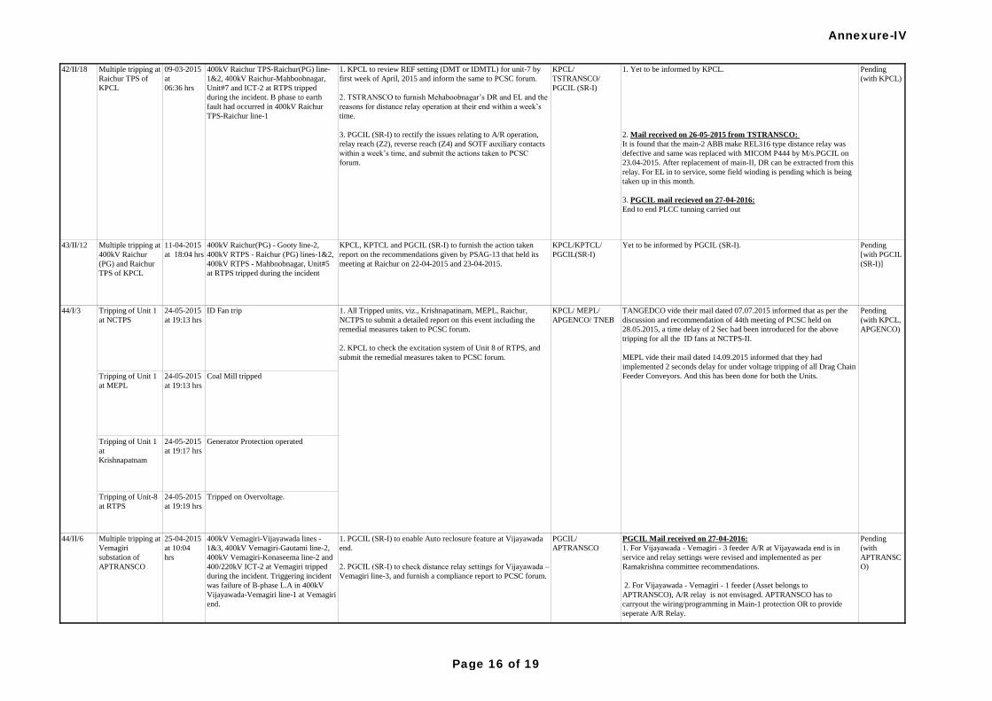
43/II/12 Multiple tripping at
400kV Raichur
(PG) and Raichur
TPS of KPCL
11-04-2015
at 18:04 hrs
400kV Raichur(PG) - Gooty line-2,
400kV RTPS - Raichur (PG) lines-1&2,
400kV RTPS - Mahboobnagar, Unit#5
at RTPS tripped during the incident
KPCL, KPTCL and PGCIL (SR-I) to furnish the action taken
report on the recommendations given by PSAG-13 that held its
meeting at Raichur on 22-04-2015 and 23-04-2015.
KPCL/KPTCL/
PGCIL(SR-I)
Yet to be informed by PGCIL (SR-I). Pending
[with PGCIL
(SR-I)]
Tripping of Unit 1
at NCTPS
24-05-2015
at 19:13 hrs
ID Fan trip
Tripping of Unit 1
at MEPL
24-05-2015
at 19:13 hrs
Coal Mill tripped
Tripping of Unit 1
at
Krishnapatnam
24-05-2015
at 19:17 hrs
Generator Protection operated
Tripping of Unit-8
at RTPS
24-05-2015
at 19:19 hrs
Tripped on Overvoltage.
Pending
(with
APTRANSC
O)
400kV Raichur TPS-Raichur(PG) line-
1&2, 400kV Raichur-Mahboobnagar,
Unit#7 and ICT-2 at RTPS tripped
during the incident. B phase to earth
fault had occurred in 400kV Raichur
TPS-Raichur line-1
09-03-2015
at
06:36 hrs
Multiple tripping at
Raichur TPS of
KPCL
42/II/18
1. PGCIL (SR-I) to enable Auto reclosure feature at Vijayawada
end.
2. PGCIL (SR-I) to check distance relay settings for Vijayawada –
Vemagiri line-3, and furnish a compliance report to PCSC forum.
400kV Vemagiri-Vijayawada lines -
1&3, 400kV Vemagiri-Gautami line-2,
400kV Vemagiri-Konaseema line-2 and
400/220kV ICT-2 at Vemagiri tripped
during the incident. Triggering incident
was failure of B-phase L.A in 400kV
Vijayawada-Vemagiri line-1 at Vemagiri
end.
25-04-2015
at 10:04
hrs
Multiple tripping at
Vemagiri
substation of
APTRANSCO
44/II/6
1. Yet to be informed by KPCL.
2. Mail received on 26-05-2015 from TSTRANSCO:
It is found that the main-2 ABB make REL316 type distance relay was
defective and same was replaced with MICOM P444 by M/s.PGCIL on
23.04-2015. After replacement of main-II, DR can be extracted from this
relay. For EL in to service, some field winding is pending which is being
taken up in this month.
3. PGCIL mail recieved on 27-04-2016:
End to end PLCC tunning carried out
1. KPCL to review REF setting (DMT or IDMTL) for unit-7 by
first week of April, 2015 and inform the same to PCSC forum.
2. TSTRANSCO to furnish Mehaboobnagar’s DR and EL and the
reasons for distance relay operation at their end within a week’s
time.
3. PGCIL (SR-I) to rectify the issues relating to A/R operation,
relay reach (Z2), reverse reach (Z4) and SOTF auxiliary contacts
within a week’s time, and submit the actions taken to PCSC
forum.
KPCL/
TSTRANSCO/
PGCIL (SR-I)
Pending
(with KPCL)
PGCIL/
APTRANSCO
PGCIL Mail received on 27-04-2016:
1. For Vijayawada - Vemagiri - 3 feeder A/R at Vijayawada end is in
service and relay settings were revised and implemented as per
Ramakrishna committee recommendations.
2. For Vijayawada - Vemagiri - 1 feeder (Asset belongs to
APTRANSCO), A/R relay is not envisaged. APTRANSCO has to
carryout the wiring/programming in Main-1 protection OR to provide
seperate A/R Relay.
44/I/3 1. All Tripped units, viz., Krishnapatinam, MEPL, Raichur,
NCTPS to submit a detailed report on this event including the
remedial measures taken to PCSC forum.
2. KPCL to check the excitation system of Unit 8 of RTPS, and
submit the remedial measures taken to PCSC forum.
KPCL/ MEPL/
APGENCO/ TNEB
TANGEDCO vide their mail dated 07.07.2015 informed that as per the
discussion and recommendation of 44th meeting of PCSC held on
28.05.2015, a time delay of 2 Sec had been introduced for the above
tripping for all the ID fans at NCTPS-II.
MEPL vide their mail dated 14.09.2015 informed that they had
implemented 2 seconds delay for under voltage tripping of all Drag Chain
Feeder Conveyors. And this has been done for both the Units.
Pending
(with KPCL,
APGENCO)
Annexure-IV
Page 16 of 19
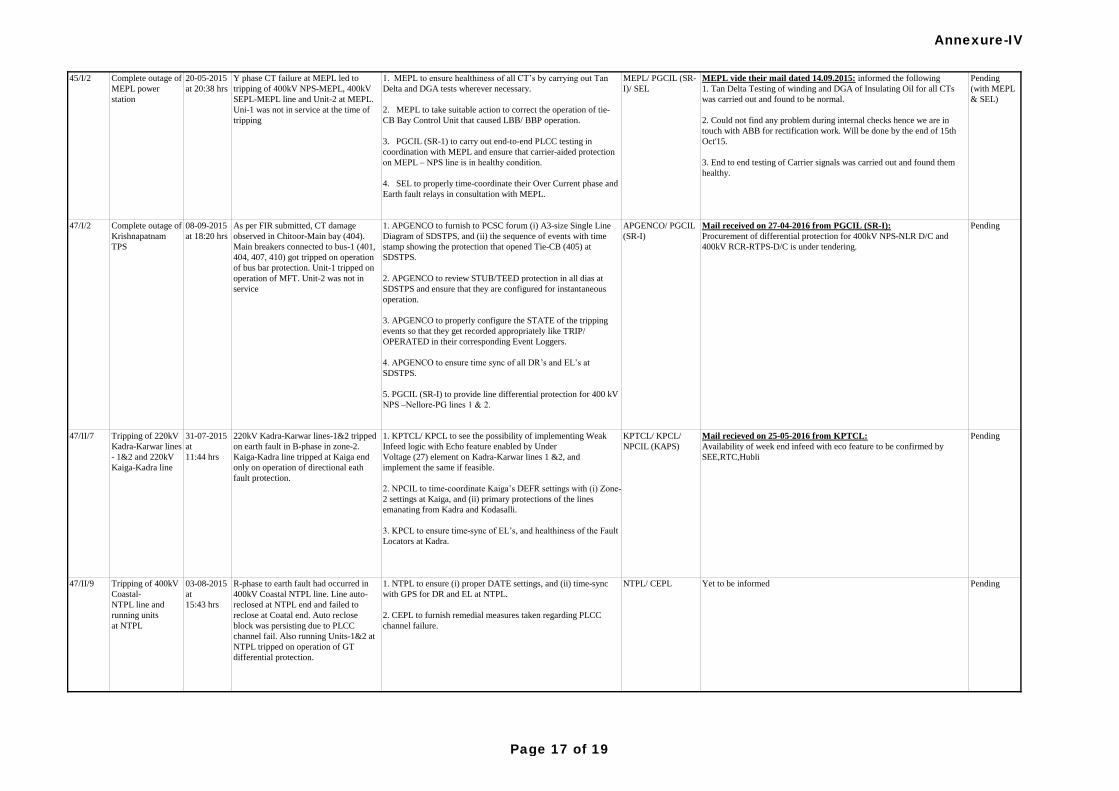
1. APGENCO to furnish to PCSC forum (i) A3-size Single Line
Diagram of SDSTPS, and (ii) the sequence of events with time
stamp showing the protection that opened Tie-CB (405) at
SDSTPS.
2. APGENCO to review STUB/TEED protection in all dias at
SDSTPS and ensure that they are configured for instantaneous
operation.
3. APGENCO to properly configure the STATE of the tripping
events so that they get recorded appropriately like TRIP/
OPERATED in their corresponding Event Loggers.
4. APGENCO to ensure time sync of all DR’s and EL’s at
SDSTPS.
5. PGCIL (SR-I) to provide line differential protection for 400 kV
NPS –Nellore-PG lines 1 & 2.
As per FIR submitted, CT damage
observed in Chitoor-Main bay (404).
Main breakers connected to bus-1 (401,
404, 407, 410) got tripped on operation
of bus bar protection. Unit-1 tripped on
operation of MFT. Unit-2 was not in
service
08-09-2015
at 18:20 hrs
Complete outage of
Krishnapatnam
TPS
47/I/2 APGENCO/ PGCIL
(SR-I)
Mail received on 27-04-2016 from PGCIL (SR-I):
Procurement of differential protection for 400kV NPS-NLR D/C and
400kV RCR-RTPS-D/C is under tendering.
Pending
1. MEPL to ensure healthiness of all CT’s by carrying out Tan
Delta and DGA tests wherever necessary.
2. MEPL to take suitable action to correct the operation of tie-
CB Bay Control Unit that caused LBB/ BBP operation.
3. PGCIL (SR-1) to carry out end-to-end PLCC testing in
coordination with MEPL and ensure that carrier-aided protection
on MEPL – NPS line is in healthy condition.
4. SEL to properly time-coordinate their Over Current phase and
Earth fault relays in consultation with MEPL.
MEPL/ PGCIL (SR-
I)/ SEL
MEPL vide their mail dated 14.09.2015: informed the following
1. Tan Delta Testing of winding and DGA of Insulating Oil for all CTs
was carried out and found to be normal.
2. Could not find any problem during internal checks hence we are in
touch with ABB for rectification work. Will be done by the end of 15th
Oct'15.
3. End to end testing of Carrier signals was carried out and found them
healthy.
Pending
(with MEPL
& SEL)
Y phase CT failure at MEPL led to
tripping of 400kV NPS-MEPL, 400kV
SEPL-MEPL line and Unit-2 at MEPL.
Uni-1 was not in service at the time of
tripping
20-05-2015
at 20:38 hrs
Complete outage of
MEPL power
station
45/I/2
R-phase to earth fault had occurred in
400kV Coastal NTPL line. Line auto-
reclosed at NTPL end and failed to
reclose at Coatal end. Auto reclose
block was persisting due to PLCC
channel fail. Also running Units-1&2 at
NTPL tripped on operation of GT
differential protection.
03-08-2015
at
15:43 hrs
Tripping of 400kV
Coastal-
NTPL line and
running units
at NTPL
47/II/9 1. NTPL to ensure (i) proper DATE settings, and (ii) time-sync
with GPS for DR and EL at NTPL.
2. CEPL to furnish remedial measures taken regarding PLCC
channel failure.
NTPL/ CEPL Yet to be informed Pending
Mail recieved on 25-05-2016 from KPTCL:
Availability of week end infeed with eco feature to be confirmed by
SEE,RTC,Hubli
PendingKPTCL/ KPCL/
NPCIL (KAPS)
1. KPTCL/ KPCL to see the possibility of implementing Weak
Infeed logic with Echo feature enabled by Under
Voltage (27) element on Kadra-Karwar lines 1 &2, and
implement the same if feasible.
2. NPCIL to time-coordinate Kaiga’s DEFR settings with (i) Zone-
2 settings at Kaiga, and (ii) primary protections of the lines
emanating from Kadra and Kodasalli.
3. KPCL to ensure time-sync of EL’s, and healthiness of the Fault
Locators at Kadra.
220kV Kadra-Karwar lines-1&2 tripped
on earth fault in B-phase in zone-2.
Kaiga-Kadra line tripped at Kaiga end
only on operation of directional eath
fault protection.
31-07-2015
at
11:44 hrs
Tripping of 220kV
Kadra-Karwar lines
- 1&2 and 220kV
Kaiga-Kadra line
47/II/7
Annexure-IV
Page 17 of 19
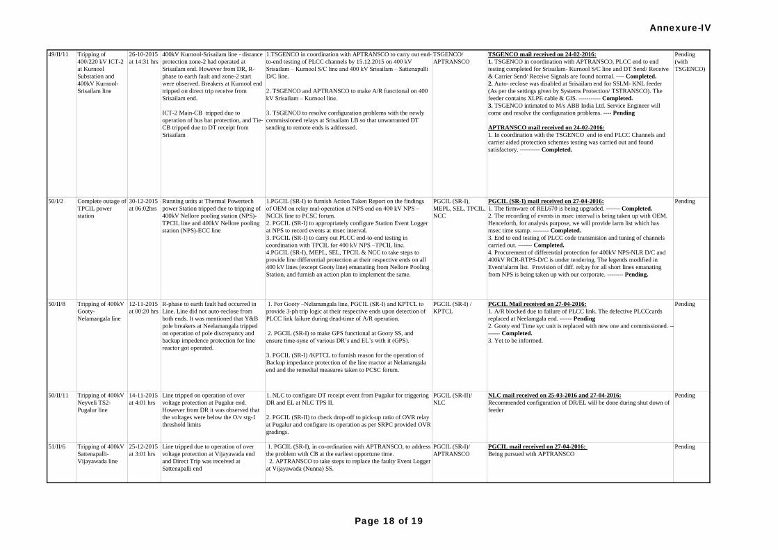
50/II/11 Tripping of 400kV
Neyveli TS2-
Pugalur line
14-11-2015
at 4:01 hrs
Line tripped on operation of over
voltage protection at Pugalur end.
However from DR it was observed that
the voltages were below the O/v stg-1
threshold limits
1. NLC to configure DT receipt event from Pugalur for triggering
DR and EL at NLC TPS II.
2. PGCIL (SR-II) to check drop-off to pick-up ratio of OVR relay
at Pugalur and configure its operation as per SRPC provided OVR
gradings.
PGCIL (SR-II)/
NLC
NLC mail received on 25-03-2016 and 27-04-2016:
Recommended configuration of DR/EL will be done during shut down of
feeder
Pending
51/II/6 Tripping of 400kV
Sattenapalli-
Vijayawada line
25-12-2015
at 3:01 hrs
Line tripped due to operation of over
voltage protection at Vijayawada end
and Direct Trip was received at
Sattenapalli end
1. PGCIL (SR-I), in co-ordination with APTRANSCO, to address
the problem with CB at the earliest opportune time.
2. APTRANSCO to take steps to replace the faulty Event Logger
at Vijayawada (Nunna) SS.
PGCIL (SR-I)/
APTRANSCO
PGCIL mail received on 27-04-2016:
Being pursued with APTRANSCO
Pending
TSGENCO mail received on 24-02-2016:
1. TSGENCO in coordination with APTRANSCO, PLCC end to end
testing completed for Srisailam- Kurnool S/C line and DT Send/ Receive
& Carrier Send/ Receive Signals are found normal. ---- Completed.
2. Auto- reclose was disabled at Srisailam end for SSLM- KNL feeder
(As per the settings given by Systems Protection/ TSTRANSCO). The
feeder contains XLPE cable & GIS. ----------- Completed.
3. TSGENCO intimated to M/s ABB India Ltd. Service Engineer will
come and resolve the configuration problems. ---- Pending
APTRANSCO mail received on 24-02-2016:
1. In coordination with the TSGENCO end to end PLCC Channels and
carrier aided protection schemes testing was carried out and found
satisfactory. ---------- Completed.
1.TSGENCO in coordination with APTRANSCO to carry out end-
to-end testing of PLCC channels by 15.12.2015 on 400 kV
Srisailam – Kurnool S/C line and 400 kV Srisailam – Sattenapalli
D/C line.
2. TSGENCO and APTRANSCO to make A/R functional on 400
kV Srisailam – Kurnool line.
3. TSGENCO to resolve configuration problems with the newly
commissioned relays at Srisailam LB so that unwarranted DT
sending to remote ends is addressed.
TSGENCO/
APTRANSCO
400kV Kurnool-Srisailam line - distance
protection zone-2 had operated at
Srisailam end. However from DR, R-
phase to earth fault and zone-2 start
were observed. Breakers at Kurnool end
tripped on direct trip receive from
Srisailam end.
ICT-2 Main-CB tripped due to
operation of bus bar protection, and Tie-
CB tripped due to DT receipt from
Srisailam
26-10-2015
at 14:31 hrs
Tripping of
400/220 kV ICT-2
at Kurnool
Substation and
400kV Kurnool-
Srisailam line
49/II/11 Pending
(with
TSGENCO)
Pending
1. For Gooty –Nelamangala line, PGCIL (SR-I) and KPTCL to
provide 3-ph trip logic at their respective ends upon detection of
PLCC link failure during dead-time of A/R operation.
2. PGCIL (SR-I) to make GPS functional at Gooty SS, and
ensure time-sync of various DR’s and EL’s with it (GPS).
3. PGCIL (SR-I) /KPTCL to furnish reason for the operation of
Backup impedance protection of the line reactor at Nelamangala
end and the remedial measures taken to PCSC forum.
PGCIL (SR-I) /
KPTCL
PGCIL Mail received on 27-04-2016:
1. A/R blocked due to failure of PLCC link. The defective PLCCcards
replaced at Neelamgala end. ------ Pending
2. Gooty end Time syc unit is replaced with new one and commissioned. --
------ Completed.
3. Yet to be informed.
PendingR-phase to earth fault had occurred in
Line. Line did not auto-reclose from
both ends. It was mentioned that Y&B
pole breakers at Neelamangala tripped
on operation of pole discrepancy and
backup impedence protection for line
reactor got operated.
12-11-2015
at 00:20 hrs
Tripping of 400kV
Gooty-
Nelamangala line
50/II/8
Running units at Thermal Powertech
power Station tripped due to tripping of
400kV Nellore pooling station (NPS)-
TPCIL line and 400kV Nellore pooling
station (NPS)-ECC line
30-12-2015
at 06:02hrs
Complete outage of
TPCIL power
station
50/I/2 1.PGCIL (SR-I) to furnish Action Taken Report on the findings
of OEM on relay mal-operation at NPS end on 400 kV NPS –
NCCK line to PCSC forum.
2. PGCIL (SR-I) to appropriately configure Station Event Logger
at NPS to record events at msec interval.
3. PGCIL (SR-I) to carry out PLCC end-to-end testing in
coordination with TPCIL for 400 kV NPS –TPCIL line.
4.PGCIL (SR-I), MEPL, SEL, TPCIL & NCC to take steps to
provide line differential protection at their respective ends on all
400 kV lines (except Gooty line) emanating from Nellore Pooling
Station, and furnish an action plan to implement the same.
PGCIL (SR-I),
MEPL, SEL, TPCIL,
NCC
PGCIL (SR-I) mail received on 27-04-2016:
1. The firmware of REL670 is being upgraded. ------- Completed.
2. The recording of events in msec interval is being taken up with OEM.
Henceforth, for analysis purpose, we will provide larm list which has
msec time stamp. -------- Completed.
3. End to end testing of PLCC code transmision and tuning of channels
carried out. ------- Completed.
4. Procurement of differential protection for 400kV NPS-NLR D/C and
400kV RCR-RTPS-D/C is under tendering. The legends modified in
Event/alarm list. Provision of diff. rel;ay for all short lines emanating
from NPS is being taken up with our corporate. -------- Pending.
Annexure-IV
Page 18 of 19
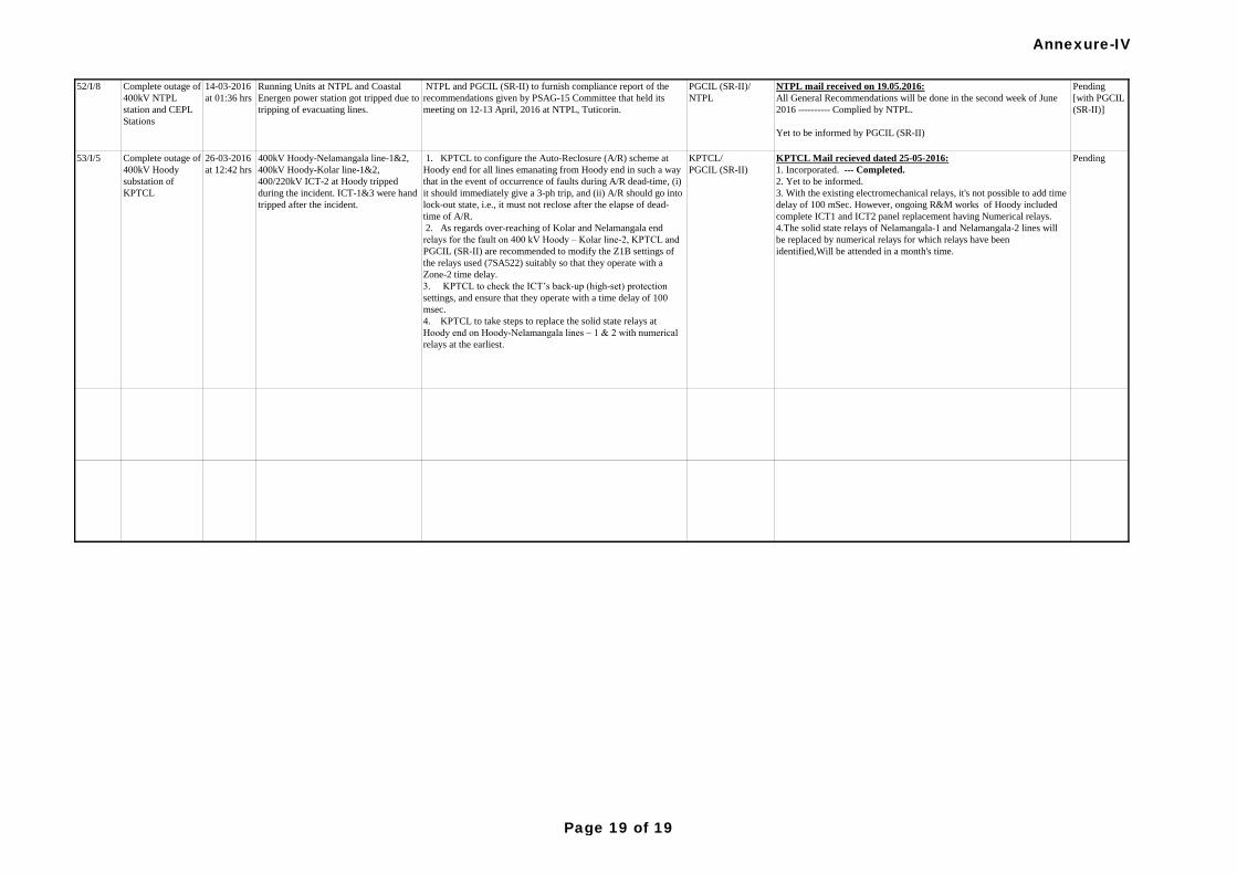
52/I/8 Complete outage of
400kV NTPL
station and CEPL
Stations
14-03-2016
at 01:36 hrs
Running Units at NTPL and Coastal
Energen power station got tripped due to
tripping of evacuating lines.
NTPL and PGCIL (SR-II) to furnish compliance report of the
recommendations given by PSAG-15 Committee that held its
meeting on 12-13 April, 2016 at NTPL, Tuticorin.
PGCIL (SR-II)/
NTPL
NTPL mail received on 19.05.2016:
All General Recommendations will be done in the second week of June
2016 ---------- Complied by NTPL.
Yet to be informed by PGCIL (SR-II)
Pending
[with PGCIL
(SR-II)]
1. KPTCL to configure the Auto-Reclosure (A/R) scheme at
Hoody end for all lines emanating from Hoody end in such a way
that in the event of occurrence of faults during A/R dead-time, (i)
it should immediately give a 3-ph trip, and (ii) A/R should go into
lock-out state, i.e., it must not reclose after the elapse of dead-
time of A/R.
2. As regards over-reaching of Kolar and Nelamangala end
relays for the fault on 400 kV Hoody – Kolar line-2, KPTCL and
PGCIL (SR-II) are recommended to modify the Z1B settings of
the relays used (7SA522) suitably so that they operate with a
Zone-2 time delay.
3. KPTCL to check the ICT’s back-up (high-set) protection
settings, and ensure that they operate with a time delay of 100
msec.
4. KPTCL to take steps to replace the solid state relays at
Hoody end on Hoody-Nelamangala lines – 1 & 2 with numerical
relays at the earliest.
KPTCL/
PGCIL (SR-II)
KPTCL Mail recieved dated 25-05-2016:
1. Incorporated. --- Completed.
2. Yet to be informed.
3. With the existing electromechanical relays, it's not possible to add time
delay of 100 mSec. However, ongoing R&M works of Hoody included
complete ICT1 and ICT2 panel replacement having Numerical relays.
4.The solid state relays of Nelamangala-1 and Nelamangala-2 lines will
be replaced by numerical relays for which relays have been
identified,Will be attended in a month's time.
Pending400kV Hoody-Nelamangala line-1&2,
400kV Hoody-Kolar line-1&2,
400/220kV ICT-2 at Hoody tripped
during the incident. ICT-1&3 were hand
tripped after the incident.
26-03-2016
at 12:42 hrs
Complete outage of
400kV Hoody
substation of
KPTCL
53/I/5
Annexure-IV
Page 19 of 19
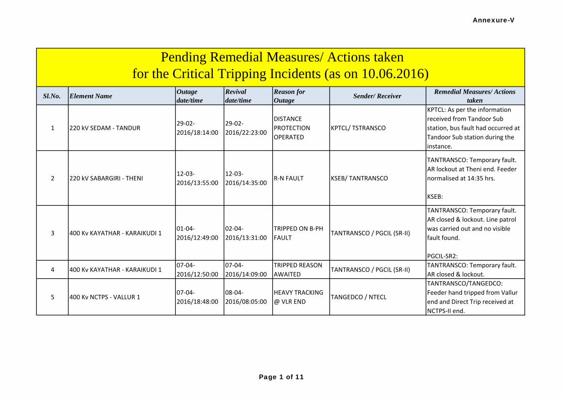
Sl.No. Element NameOutage
date/time
Revival
date/time
Reason for
OutageSender/ Receiver
Remedial Measures/ Actions
taken
1 220 kV SEDAM - TANDUR29-02-
2016/18:14:00
29-02-
2016/22:23:00
DISTANCE
PROTECTION
OPERATED
KPTCL/ TSTRANSCO
KPTCL: As per the information
received from Tandoor Sub
station, bus fault had occurred at
Tandoor Sub station during the
instance.
2 220 kV SABARGIRI - THENI12-03-
2016/13:55:00
12-03-
2016/14:35:00R-N FAULT KSEB/ TANTRANSCO
TANTRANSCO: Temporary fault.
AR lockout at Theni end. Feeder
normalised at 14:35 hrs.
KSEB:
3 400 Kv KAYATHAR - KARAIKUDI 101-04-
2016/12:49:00
02-04-
2016/13:31:00
TRIPPED ON B-PH
FAULTTANTRANSCO / PGCIL (SR-II)
TANTRANSCO: Temporary fault.
AR closed & lockout. Line patrol
was carried out and no visible
fault found.
PGCIL-SR2:
4 400 Kv KAYATHAR - KARAIKUDI 107-04-
2016/12:50:00
07-04-
2016/14:09:00
TRIPPED REASON
AWAITEDTANTRANSCO / PGCIL (SR-II)
TANTRANSCO: Temporary fault.
AR closed & lockout.
5 400 Kv NCTPS - VALLUR 107-04-
2016/18:48:00
08-04-
2016/08:05:00
HEAVY TRACKING
@ VLR ENDTANGEDCO / NTECL
TANTRANSCO/TANGEDCO:
Feeder hand tripped from Vallur
end and Direct Trip received at
NCTPS-II end.
Pending Remedial Measures/ Actions taken
for the Critical Tripping Incidents (as on 10.06.2016)
Annexure-V
Page 1 of 11
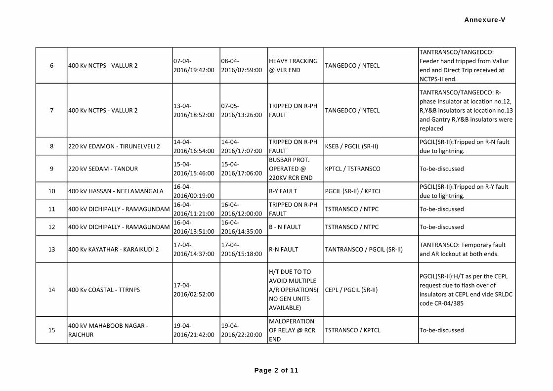
6 400 Kv NCTPS - VALLUR 207-04-
2016/19:42:00
08-04-
2016/07:59:00
HEAVY TRACKING
@ VLR ENDTANGEDCO / NTECL
TANTRANSCO/TANGEDCO:
Feeder hand tripped from Vallur
end and Direct Trip received at
NCTPS-II end.
7 400 Kv NCTPS - VALLUR 213-04-
2016/18:52:00
07-05-
2016/13:26:00
TRIPPED ON R-PH
FAULTTANGEDCO / NTECL
TANTRANSCO/TANGEDCO: R-
phase Insulator at location no.12,
R,Y&B insulators at location no.13
and Gantry R,Y&B insulators were
replaced
8 220 kV EDAMON - TIRUNELVELI 214-04-
2016/16:54:00
14-04-
2016/17:07:00
TRIPPED ON R-PH
FAULTKSEB / PGCIL (SR-II)
PGCIL(SR-II):Tripped on R-N fault
due to lightning.
9 220 kV SEDAM - TANDUR15-04-
2016/15:46:00
15-04-
2016/17:06:00
BUSBAR PROT.
OPERATED @
220KV RCR END
KPTCL / TSTRANSCO To-be-discussed
10 400 kV HASSAN - NEELAMANGALA16-04-
2016/00:19:00R-Y FAULT PGCIL (SR-II) / KPTCL
PGCIL(SR-II):Tripped on R-Y fault
due to lightning.
11 400 kV DICHIPALLY - RAMAGUNDAM16-04-
2016/11:21:00
16-04-
2016/12:00:00
TRIPPED ON R-PH
FAULTTSTRANSCO / NTPC To-be-discussed
12 400 kV DICHIPALLY - RAMAGUNDAM16-04-
2016/13:51:00
16-04-
2016/14:35:00B - N FAULT TSTRANSCO / NTPC To-be-discussed
13 400 Kv KAYATHAR - KARAIKUDI 217-04-
2016/14:37:00
17-04-
2016/15:18:00R-N FAULT TANTRANSCO / PGCIL (SR-II)
TANTRANSCO: Temporary fault
and AR lockout at both ends.
14 400 Kv COASTAL - TTRNPS17-04-
2016/02:52:00
H/T DUE TO TO
AVOID MULTIPLE
A/R OPERATIONS(
NO GEN UNITS
AVAILABLE)
CEPL / PGCIL (SR-II)
PGCIL(SR-II):H/T as per the CEPL
request due to flash over of
insulators at CEPL end vide SRLDC
code CR-04/385
15400 kV MAHABOOB NAGAR -
RAICHUR
19-04-
2016/21:42:00
19-04-
2016/22:20:00
MALOPERATION
OF RELAY @ RCR
END
TSTRANSCO / KPTCL To-be-discussed
Annexure-V
Page 2 of 11
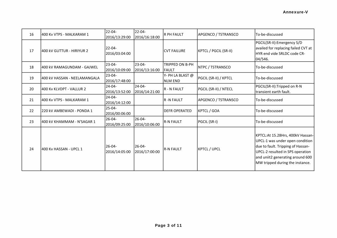
16 400 Kv VTPS - MALKARAM 122-04-
2016/13:29:00
22-04-
2016/16:18:00R PH FAULT APGENCO / TSTRANSCO To-be-discussed
17 400 kV GUTTUR - HIRIYUR 222-04-
2016/03:04:00CVT FAILURE KPTCL / PGCIL (SR-II)
PGCIL(SR-II):Emergency S/D
availed for replacing failed CVT at
HYR end vide SRLDC code CR-
04/546.
18 400 kV RAMAGUNDAM - GAJWEL23-04-
2016/10:09:00
23-04-
2016/13:16:00
TRIPPED ON B-PH
FAULTNTPC / TSTRANSCO To-be-discussed
19 400 kV HASSAN - NEELAMANGALA23-04-
2016/17:48:00
Y- PH LA BLAST @
NLM ENDPGCIL (SR-II) / KPTCL To-be-discussed
20 400 Kv KLVDPT - VALLUR 224-04-
2016/13:52:00
24-04-
2016/14:21:00R - N FAULT PGCIL (SR-II) / NTECL
PGCIL(SR-II):Tripped on R-N
transient earth fault.
21 400 Kv VTPS - MALKARAM 124-04-
2016/14:12:00R -N FAULT APGENCO / TSTRANSCO To-be-discussed
22 220 kV AMBEWADI - PONDA 125-04-
2016/00:06:00DEFR OPERATED KPTCL / GOA To-be-discussed
23 400 kV KHAMMAM - N'SAGAR 126-04-
2016/09:25:00
26-04-
2016/10:06:00R-N FAULT PGCIL (SR-I) To-be-discussed
24 400 Kv HASSAN - UPCL 126-04-
2016/14:05:00
26-04-
2016/17:00:00R-N FAULT KPTCL / UPCL
KPTCL:At 15.28Hrs, 400kV Hassan-
UPCL-1 was under open condition
due to fault. Tripping of Hassan-
UPCL-2 resulted in SPS operation
and uniit2 generating around 600
MW tripped during the instance.
Annexure-V
Page 3 of 11
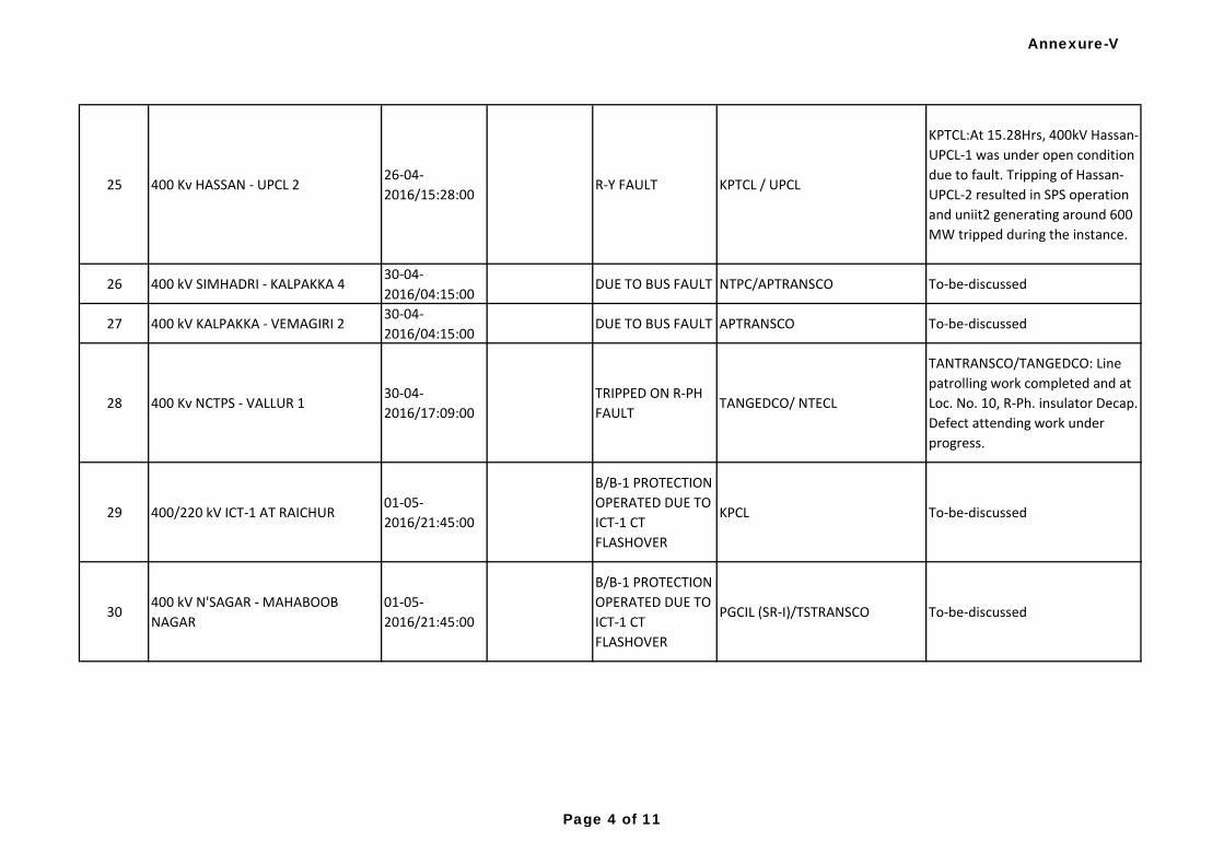
25 400 Kv HASSAN - UPCL 226-04-
2016/15:28:00R-Y FAULT KPTCL / UPCL
KPTCL:At 15.28Hrs, 400kV Hassan-
UPCL-1 was under open condition
due to fault. Tripping of Hassan-
UPCL-2 resulted in SPS operation
and uniit2 generating around 600
MW tripped during the instance.
26 400 kV SIMHADRI - KALPAKKA 430-04-
2016/04:15:00DUE TO BUS FAULT NTPC/APTRANSCO To-be-discussed
27 400 kV KALPAKKA - VEMAGIRI 230-04-
2016/04:15:00DUE TO BUS FAULT APTRANSCO To-be-discussed
28 400 Kv NCTPS - VALLUR 130-04-
2016/17:09:00
TRIPPED ON R-PH
FAULTTANGEDCO/ NTECL
TANTRANSCO/TANGEDCO: Line
patrolling work completed and at
Loc. No. 10, R-Ph. insulator Decap.
Defect attending work under
progress.
29 400/220 kV ICT-1 AT RAICHUR01-05-
2016/21:45:00
B/B-1 PROTECTION
OPERATED DUE TO
ICT-1 CT
FLASHOVER
KPCL To-be-discussed
30400 kV N'SAGAR - MAHABOOB
NAGAR
01-05-
2016/21:45:00
B/B-1 PROTECTION
OPERATED DUE TO
ICT-1 CT
FLASHOVER
PGCIL (SR-I)/TSTRANSCO To-be-discussed
Annexure-V
Page 4 of 11
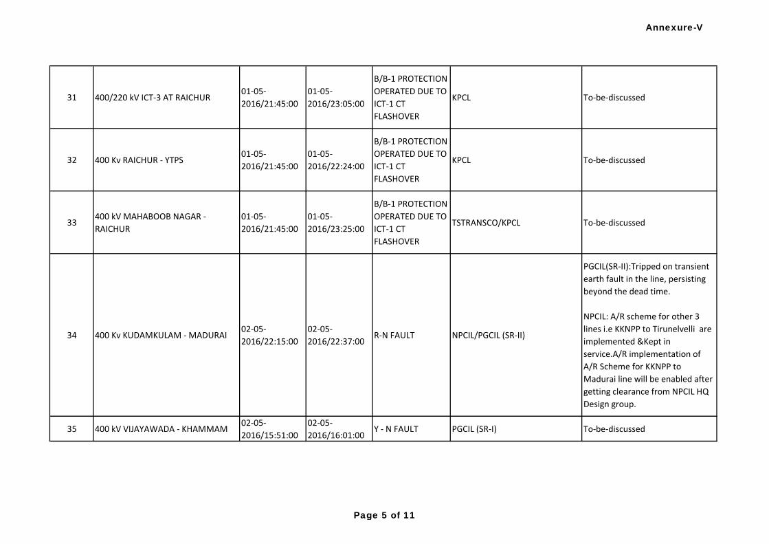
31 400/220 kV ICT-3 AT RAICHUR01-05-
2016/21:45:00
01-05-
2016/23:05:00
B/B-1 PROTECTION
OPERATED DUE TO
ICT-1 CT
FLASHOVER
KPCL To-be-discussed
32 400 Kv RAICHUR - YTPS01-05-
2016/21:45:00
01-05-
2016/22:24:00
B/B-1 PROTECTION
OPERATED DUE TO
ICT-1 CT
FLASHOVER
KPCL To-be-discussed
33400 kV MAHABOOB NAGAR -
RAICHUR
01-05-
2016/21:45:00
01-05-
2016/23:25:00
B/B-1 PROTECTION
OPERATED DUE TO
ICT-1 CT
FLASHOVER
TSTRANSCO/KPCL To-be-discussed
34 400 Kv KUDAMKULAM - MADURAI02-05-
2016/22:15:00
02-05-
2016/22:37:00R-N FAULT NPCIL/PGCIL (SR-II)
PGCIL(SR-II):Tripped on transient
earth fault in the line, persisting
beyond the dead time.
NPCIL: A/R scheme for other 3
lines i.e KKNPP to Tirunelvelli are
implemented &Kept in
service.A/R implementation of
A/R Scheme for KKNPP to
Madurai line will be enabled after
getting clearance from NPCIL HQ
Design group.
35 400 kV VIJAYAWADA - KHAMMAM02-05-
2016/15:51:00
02-05-
2016/16:01:00Y - N FAULT PGCIL (SR-I) To-be-discussed
Annexure-V
Page 5 of 11
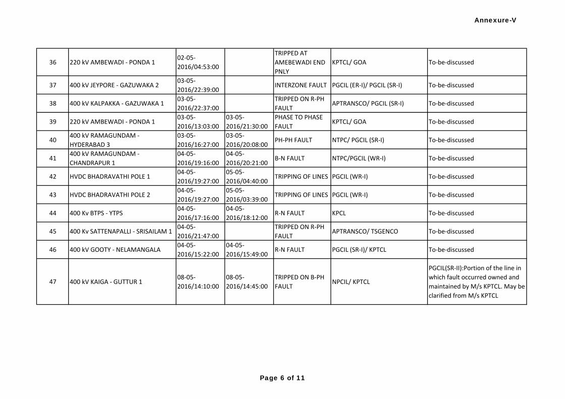
36 220 kV AMBEWADI - PONDA 102-05-
2016/04:53:00
TRIPPED AT
AMEBEWADI END
PNLY
KPTCL/ GOA To-be-discussed
37 400 kV JEYPORE - GAZUWAKA 203-05-
2016/22:39:00INTERZONE FAULT PGCIL (ER-I)/ PGCIL (SR-I) To-be-discussed
38 400 kV KALPAKKA - GAZUWAKA 103-05-
2016/22:37:00
TRIPPED ON R-PH
FAULTAPTRANSCO/ PGCIL (SR-I) To-be-discussed
39 220 kV AMBEWADI - PONDA 103-05-
2016/13:03:00
03-05-
2016/21:30:00
PHASE TO PHASE
FAULTKPTCL/ GOA To-be-discussed
40400 kV RAMAGUNDAM -
HYDERABAD 3
03-05-
2016/16:27:00
03-05-
2016/20:08:00PH-PH FAULT NTPC/ PGCIL (SR-I) To-be-discussed
41400 kV RAMAGUNDAM -
CHANDRAPUR 1
04-05-
2016/19:16:00
04-05-
2016/20:21:00B-N FAULT NTPC/PGCIL (WR-I) To-be-discussed
42 HVDC BHADRAVATHI POLE 104-05-
2016/19:27:00
05-05-
2016/04:40:00TRIPPING OF LINES PGCIL (WR-I) To-be-discussed
43 HVDC BHADRAVATHI POLE 204-05-
2016/19:27:00
05-05-
2016/03:39:00TRIPPING OF LINES PGCIL (WR-I) To-be-discussed
44 400 Kv BTPS - YTPS04-05-
2016/17:16:00
04-05-
2016/18:12:00R-N FAULT KPCL To-be-discussed
45 400 Kv SATTENAPALLI - SRISAILAM 104-05-
2016/21:47:00
TRIPPED ON R-PH
FAULTAPTRANSCO/ TSGENCO To-be-discussed
46 400 kV GOOTY - NELAMANGALA04-05-
2016/15:22:00
04-05-
2016/15:49:00R-N FAULT PGCIL (SR-I)/ KPTCL To-be-discussed
47 400 kV KAIGA - GUTTUR 108-05-
2016/14:10:00
08-05-
2016/14:45:00
TRIPPED ON B-PH
FAULTNPCIL/ KPTCL
PGCIL(SR-II):Portion of the line in
which fault occurred owned and
maintained by M/s KPTCL. May be
clarified from M/s KPTCL
Annexure-V
Page 6 of 11
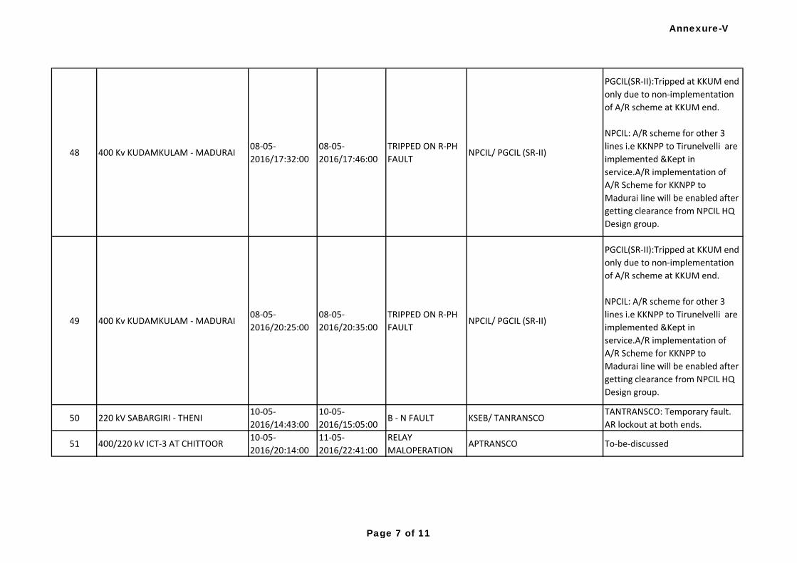
48 400 Kv KUDAMKULAM - MADURAI08-05-
2016/17:32:00
08-05-
2016/17:46:00
TRIPPED ON R-PH
FAULTNPCIL/ PGCIL (SR-II)
PGCIL(SR-II):Tripped at KKUM end
only due to non-implementation
of A/R scheme at KKUM end.
NPCIL: A/R scheme for other 3
lines i.e KKNPP to Tirunelvelli are
implemented &Kept in
service.A/R implementation of
A/R Scheme for KKNPP to
Madurai line will be enabled after
getting clearance from NPCIL HQ
Design group.
49 400 Kv KUDAMKULAM - MADURAI08-05-
2016/20:25:00
08-05-
2016/20:35:00
TRIPPED ON R-PH
FAULTNPCIL/ PGCIL (SR-II)
PGCIL(SR-II):Tripped at KKUM end
only due to non-implementation
of A/R scheme at KKUM end.
NPCIL: A/R scheme for other 3
lines i.e KKNPP to Tirunelvelli are
implemented &Kept in
service.A/R implementation of
A/R Scheme for KKNPP to
Madurai line will be enabled after
getting clearance from NPCIL HQ
Design group.
50 220 kV SABARGIRI - THENI10-05-
2016/14:43:00
10-05-
2016/15:05:00B - N FAULT KSEB/ TANRANSCO
TANTRANSCO: Temporary fault.
AR lockout at both ends.
51 400/220 kV ICT-3 AT CHITTOOR10-05-
2016/20:14:00
11-05-
2016/22:41:00
RELAY
MALOPERATIONAPTRANSCO To-be-discussed
Annexure-V
Page 7 of 11
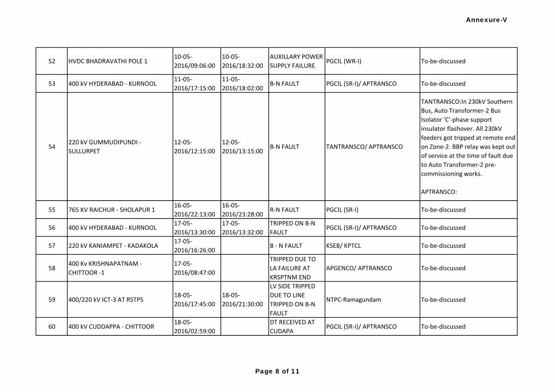
52 HVDC BHADRAVATHI POLE 110-05-
2016/09:06:00
10-05-
2016/18:32:00
AUXILLARY POWER
SUPPLY FAILUREPGCIL (WR-I) To-be-discussed
53 400 kV HYDERABAD - KURNOOL11-05-
2016/17:15:00
11-05-
2016/18:02:00B-N FAULT PGCIL (SR-I)/ APTRANSCO To-be-discussed
54220 kV GUMMUDIPUNDI -
SULLURPET
12-05-
2016/12:15:00
12-05-
2016/13:15:00B-N FAULT TANTRANSCO/ APTRANSCO
TANTRANSCO:In 230kV Southern
Bus, Auto Transformer-2 Bus
Isolator 'C'-phase support
insulator flashover. All 230kV
feeders got tripped at remote end
on Zone-2. BBP relay was kept out
of service at the time of fault due
to Auto Transformer-2 pre-
commissioning works.
APTRANSCO:
55 765 KV RAICHUR - SHOLAPUR 116-05-
2016/22:13:00
16-05-
2016/23:28:00R-N FAULT PGCIL (SR-I) To-be-discussed
56 400 kV HYDERABAD - KURNOOL17-05-
2016/13:30:00
17-05-
2016/13:32:00
TRIPPED ON B-N
FAULTPGCIL (SR-I)/ APTRANSCO To-be-discussed
57 220 kV KANIAMPET - KADAKOLA17-05-
2016/16:26:00B - N FAULT KSEB/ KPTCL To-be-discussed
58400 Kv KRISHNAPATNAM -
CHITTOOR -1
17-05-
2016/08:47:00
TRIPPED DUE TO
LA FAILURE AT
KRSPTNM END
APGENCO/ APTRANSCO To-be-discussed
59 400/220 kV ICT-3 AT RSTPS18-05-
2016/17:45:00
18-05-
2016/21:30:00
LV SIDE TRIPPED
DUE TO LINE
TRIPPED ON B-N
FAULT
NTPC-Ramagundam To-be-discussed
60 400 kV CUDDAPPA - CHITTOOR18-05-
2016/02:59:00
DT RECEIVED AT
CUDAPAPGCIL (SR-I)/ APTRANSCO To-be-discussed
Annexure-V
Page 8 of 11
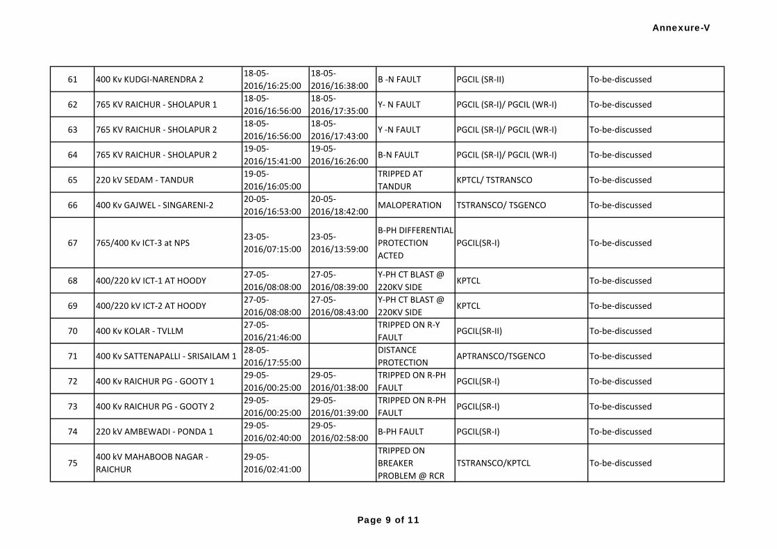
61 400 Kv KUDGI-NARENDRA 218-05-
2016/16:25:00
18-05-
2016/16:38:00B -N FAULT PGCIL (SR-II) To-be-discussed
62 765 KV RAICHUR - SHOLAPUR 118-05-
2016/16:56:00
18-05-
2016/17:35:00Y- N FAULT PGCIL (SR-I)/ PGCIL (WR-I) To-be-discussed
63 765 KV RAICHUR - SHOLAPUR 218-05-
2016/16:56:00
18-05-
2016/17:43:00Y -N FAULT PGCIL (SR-I)/ PGCIL (WR-I) To-be-discussed
64 765 KV RAICHUR - SHOLAPUR 219-05-
2016/15:41:00
19-05-
2016/16:26:00B-N FAULT PGCIL (SR-I)/ PGCIL (WR-I) To-be-discussed
65 220 kV SEDAM - TANDUR19-05-
2016/16:05:00
TRIPPED AT
TANDURKPTCL/ TSTRANSCO To-be-discussed
66 400 Kv GAJWEL - SINGARENI-220-05-
2016/16:53:00
20-05-
2016/18:42:00MALOPERATION TSTRANSCO/ TSGENCO To-be-discussed
67 765/400 Kv ICT-3 at NPS23-05-
2016/07:15:00
23-05-
2016/13:59:00
B-PH DIFFERENTIAL
PROTECTION
ACTED
PGCIL(SR-I) To-be-discussed
68 400/220 kV ICT-1 AT HOODY27-05-
2016/08:08:00
27-05-
2016/08:39:00
Y-PH CT BLAST @
220KV SIDEKPTCL To-be-discussed
69 400/220 kV ICT-2 AT HOODY27-05-
2016/08:08:00
27-05-
2016/08:43:00
Y-PH CT BLAST @
220KV SIDEKPTCL To-be-discussed
70 400 Kv KOLAR - TVLLM27-05-
2016/21:46:00
TRIPPED ON R-Y
FAULTPGCIL(SR-II) To-be-discussed
71 400 Kv SATTENAPALLI - SRISAILAM 128-05-
2016/17:55:00
DISTANCE
PROTECTIONAPTRANSCO/TSGENCO To-be-discussed
72 400 Kv RAICHUR PG - GOOTY 129-05-
2016/00:25:00
29-05-
2016/01:38:00
TRIPPED ON R-PH
FAULTPGCIL(SR-I) To-be-discussed
73 400 Kv RAICHUR PG - GOOTY 229-05-
2016/00:25:00
29-05-
2016/01:39:00
TRIPPED ON R-PH
FAULTPGCIL(SR-I) To-be-discussed
74 220 kV AMBEWADI - PONDA 129-05-
2016/02:40:00
29-05-
2016/02:58:00B-PH FAULT PGCIL(SR-I) To-be-discussed
75400 kV MAHABOOB NAGAR -
RAICHUR
29-05-
2016/02:41:00
TRIPPED ON
BREAKER
PROBLEM @ RCR
TSTRANSCO/KPTCL To-be-discussed
Annexure-V
Page 9 of 11
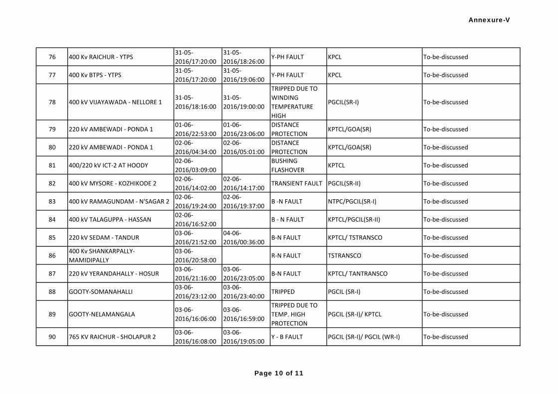
76 400 Kv RAICHUR - YTPS31-05-
2016/17:20:00
31-05-
2016/18:26:00Y-PH FAULT KPCL To-be-discussed
77 400 Kv BTPS - YTPS31-05-
2016/17:20:00
31-05-
2016/19:06:00Y-PH FAULT KPCL To-be-discussed
78 400 kV VIJAYAWADA - NELLORE 131-05-
2016/18:16:00
31-05-
2016/19:00:00
TRIPPED DUE TO
WINDING
TEMPERATURE
HIGH
PGCIL(SR-I) To-be-discussed
79 220 kV AMBEWADI - PONDA 101-06-
2016/22:53:00
01-06-
2016/23:06:00
DISTANCE
PROTECTIONKPTCL/GOA(SR) To-be-discussed
80 220 kV AMBEWADI - PONDA 102-06-
2016/04:34:00
02-06-
2016/05:01:00
DISTANCE
PROTECTIONKPTCL/GOA(SR) To-be-discussed
81 400/220 kV ICT-2 AT HOODY02-06-
2016/03:09:00
BUSHING
FLASHOVERKPTCL To-be-discussed
82 400 kV MYSORE - KOZHIKODE 202-06-
2016/14:02:00
02-06-
2016/14:17:00TRANSIENT FAULT PGCIL(SR-II) To-be-discussed
83 400 kV RAMAGUNDAM - N'SAGAR 202-06-
2016/19:24:00
02-06-
2016/19:37:00B -N FAULT NTPC/PGCIL(SR-I) To-be-discussed
84 400 kV TALAGUPPA - HASSAN02-06-
2016/16:52:00B - N FAULT KPTCL/PGCIL(SR-II) To-be-discussed
85 220 kV SEDAM - TANDUR03-06-
2016/21:52:00
04-06-
2016/00:36:00B-N FAULT KPTCL/ TSTRANSCO To-be-discussed
86400 Kv SHANKARPALLY-
MAMIDIPALLY
03-06-
2016/20:58:00R-N FAULT TSTRANSCO To-be-discussed
87 220 kV YERANDAHALLY - HOSUR03-06-
2016/21:16:00
03-06-
2016/23:05:00B-N FAULT KPTCL/ TANTRANSCO To-be-discussed
88 GOOTY-SOMANAHALLI03-06-
2016/23:12:00
03-06-
2016/23:40:00TRIPPED PGCIL (SR-I) To-be-discussed
89 GOOTY-NELAMANGALA03-06-
2016/16:06:00
03-06-
2016/16:59:00
TRIPPED DUE TO
TEMP. HIGH
PROTECTION
PGCIL (SR-I)/ KPTCL To-be-discussed
90 765 KV RAICHUR - SHOLAPUR 203-06-
2016/16:08:00
03-06-
2016/19:05:00Y - B FAULT PGCIL (SR-I)/ PGCIL (WR-I) To-be-discussed
Annexure-V
Page 10 of 11
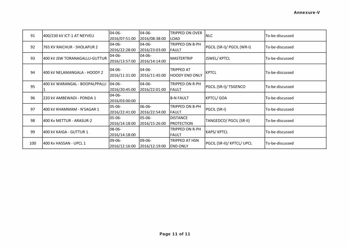
91 400/230 kV ICT-1 AT NEYVELI04-06-
2016/07:51:00
04-06-
2016/08:38:00
TRIPPED ON OVER
LOADNLC To-be-discussed
92 765 KV RAICHUR - SHOLAPUR 204-06-
2016/22:28:00
04-06-
2016/23:03:00
TRIPPED ON B-PH
FAULTPGCIL (SR-I)/ PGCIL (WR-I) To-be-discussed
93 400 kV JSW TORANAGALLU-GUTTUR04-06-
2016/13:57:00
04-06-
2016/14:14:00MASTERTRIP JSWEL/ KPTCL To-be-discussed
94 400 kV NELAMANGALA - HOODY 204-06-
2016/11:31:00
04-06-
2016/11:45:00
TRIPPED AT
HOODY END ONLYKPTCL To-be-discussed
95400 kV WARANGAL - BOOPALPPALLI
1
04-06-
2016/20:45:00
04-06-
2016/22:01:00
TRIPPED ON R-PH
FAULTPGCIL (SR-I)/ TSGENCO To-be-discussed
96 220 kV AMBEWADI - PONDA 104-06-
2016/03:00:00B-N FAULT KPTCL/ GOA To-be-discussed
97 400 kV KHAMMAM - N'SAGAR 105-06-
2016/22:41:00
06-06-
2016/22:54:00
TRIPPED ON B-PH
FAULTPGCIL (SR-I) To-be-discussed
98 400 Kv METTUR - ARASUR-205-06-
2016/14:18:00
05-06-
2016/15:26:00
DISTANCE
PROTECTIONTANGEDCO/ PGCIL (SR-II) To-be-discussed
99 400 kV KAIGA - GUTTUR 108-06-
2016/14:18:00
TRIPPED ON R-PH
FAULTKAPS/ KPTCL To-be-discussed
100 400 Kv HASSAN - UPCL 109-06-
2016/12:16:00
09-06-
2016/12:19:00
TRIPPED AT HSN
END ONLYPGCIL (SR-II)/ KPTCL/ UPCL To-be-discussed
Annexure-V
Page 11 of 11
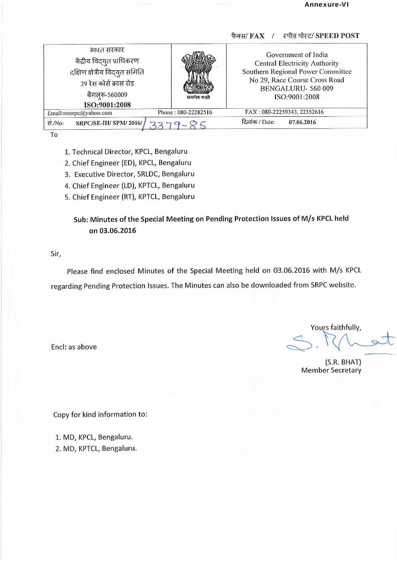
Annexure-VI
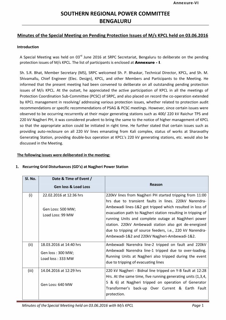
Minutes of the Special Meeting held on 03.06.2016 with M/s KPCL Page 1
SOUTHERN REGIONAL POWER COMMITTEE BENGALURU
Minutes of the Special Meeting on Pending Protection Issues of M/s KPCL held on 03.06.2016
Introduction
A Special Meeting was held on 03rd June 2016 at SRPC Secretariat, Bengaluru to deliberate on the pending
protection issues of M/s KPCL. The list of participants is enclosed at Annexure - I. Sh. S.R. Bhat, Member Secretary (MS), SRPC welcomed Sh. P. Bhaskar, Technical Director, KPCL, and Sh. M.
Shivamallu, Chief Engineer (Elec. Design), KPCL, and other Members and Participants to the Meeting. He
informed that the present meeting had been convened to deliberate on all outstanding pending protection
issues of M/s KPCL. At the outset, he appreciated the active participation of KPCL in all the meetings of
Protection Coordination Sub-Committee (PCSC) of SRPC, and also placed on record the co-operation extended
by KPCL management in resolving/ addressing various protection issues, whether related to protection audit
recommendations or specific recommendations of PSAG & PCSC meetings. However, since certain issues were
observed to be occurring recurrently at their major generating stations such as 400/ 220 kV Raichur TPS and
220 kV Nagjheri PH, it was considered prudent to bring the same to the notice of higher management of KPCL
so that the appropriate action could be initiated in right time. He further stated that certain issues such as
providing auto-reclosure on all 220 kV lines emanating from Kali complex, status of works at Sharavathy
Generating Station, providing double-bus operation at KPCL’s 220 kV generating stations, etc. would also be
discussed in the Meeting.
The following issues were deliberated in the meeting:
1. Recurring Grid Disturbances (GD’s) at Nagjheri Power Station
Sl. No. Date & Time of Event /
Gen loss & Load Loss
Reason
(i) 22.02.2016 at 12:36 hrs
Gen Loss: 500 MW;
Load Loss: 99 MW
220kV lines from Nagjheri PH started tripping from 11:00
hrs due to transient faults in lines. 220kV Narendra-
Ambewadi lines-1&2 got tripped which resulted in loss of
evacuation path to Nagjheri station resulting in tripping of
running Units and complete outage at Nagjhheri power
station. 220kV Ambewadi station also got de-energized
due to tripping of source feeders, i.e., 220 kV Narendra-
Ambewadi-1&2 and 220kV Nagjheri-Ambewadi-1&2.
(ii) 18.03.2016 at 14:40 hrs
Gen loss : 300 MW;
Load loss : 333 MW
Ambewadi Narendra line-2 tripped on fault and 220kV
Ambewadi Narendra line-1 tripped due to over-loading.
Running Units at Nagjheri also tripped during the event
due to tripping of evacuating lines
(iii) 14.04.2016 at 12:29 hrs
Gen Loss: 640 MW
220 kV Nagjheri - Bidnal line tripped on Y-B fault at 12:28
Hrs. At the same time, five running generating units (1,3,4,
5 & 6) at Nagjheri tripped on operation of Generator
Transformer’s back-up Over Current & Earth Fault
protection.
Annexure-VI
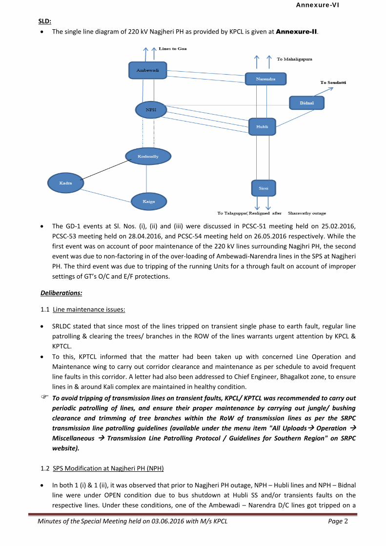
Minutes of the Special Meeting held on 03.06.2016 with M/s KPCL Page 2
SLD:
The single line diagram of 220 kV Nagjheri PH as provided by KPCL is given at Annexure-II.
The GD-1 events at Sl. Nos. (i), (ii) and (iii) were discussed in PCSC-51 meeting held on 25.02.2016,
PCSC-53 meeting held on 28.04.2016, and PCSC-54 meeting held on 26.05.2016 respectively. While the
first event was on account of poor maintenance of the 220 kV lines surrounding Nagjhri PH, the second
event was due to non-factoring in of the over-loading of Ambewadi-Narendra lines in the SPS at Nagjheri
PH. The third event was due to tripping of the running Units for a through fault on account of improper
settings of GT’s O/C and E/F protections.
Deliberations:
1.1 Line maintenance issues:
SRLDC stated that since most of the lines tripped on transient single phase to earth fault, regular line
patrolling & clearing the trees/ branches in the ROW of the lines warrants urgent attention by KPCL &
KPTCL.
To this, KPTCL informed that the matter had been taken up with concerned Line Operation and
Maintenance wing to carry out corridor clearance and maintenance as per schedule to avoid frequent
line faults in this corridor. A letter had also been addressed to Chief Engineer, Bhagalkot zone, to ensure
lines in & around Kali complex are maintained in healthy condition.
To avoid tripping of transmission lines on transient faults, KPCL/ KPTCL was recommended to carry out
periodic patrolling of lines, and ensure their proper maintenance by carrying out jungle/ bushing
clearance and trimming of tree branches within the RoW of transmission lines as per the SRPC
transmission line patrolling guidelines (available under the menu item "All Uploads Operation
Miscellaneous Transmission Line Patrolling Protocol / Guidelines for Southern Region" on SRPC
website).
1.2 SPS Modification at Nagjheri PH (NPH)
In both 1 (i) & 1 (ii), it was observed that prior to Nagjheri PH outage, NPH – Hubli lines and NPH – Bidnal
line were under OPEN condition due to bus shutdown at Hubli SS and/or transients faults on the
respective lines. Under these conditions, one of the Ambewadi – Narendra D/C lines got tripped on a
Annexure-VI
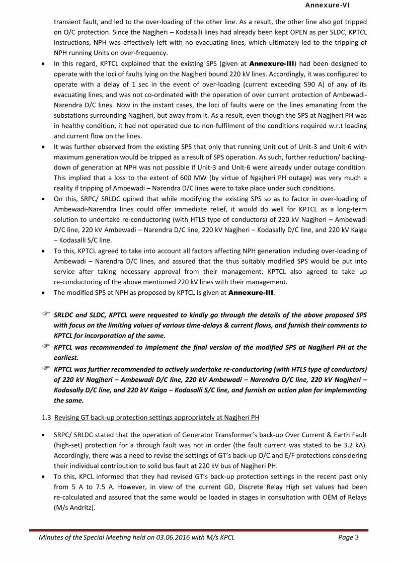
Minutes of the Special Meeting held on 03.06.2016 with M/s KPCL Page 3
transient fault, and led to the over-loading of the other line. As a result, the other line also got tripped
on O/C protection. Since the Nagjheri – Kodasalli lines had already been kept OPEN as per SLDC, KPTCL
instructions, NPH was effectively left with no evacuating lines, which ultimately led to the tripping of
NPH running Units on over-frequency.
In this regard, KPTCL explained that the existing SPS (given at Annexure-III) had been designed to
operate with the loci of faults lying on the Nagjheri bound 220 kV lines. Accordingly, it was configured to
operate with a delay of 1 sec in the event of over-loading (current exceeding 590 A) of any of its
evacuating lines, and was not co-ordinated with the operation of over current protection of Ambewadi-
Narendra D/C lines. Now in the instant cases, the loci of faults were on the lines emanating from the
substations surrounding Nagjheri, but away from it. As a result, even though the SPS at Nagjheri PH was
in healthy condition, it had not operated due to non-fulfilment of the conditions required w.r.t loading
and current flow on the lines.
It was further observed from the existing SPS that only that running Unit out of Unit-3 and Unit-6 with
maximum generation would be tripped as a result of SPS operation. As such, further reduction/ backing-
down of generation at NPH was not possible if Unit-3 and Unit-6 were already under outage condition.
This implied that a loss to the extent of 600 MW (by virtue of Ngajheri PH outage) was very much a
reality if tripping of Ambewadi – Narendra D/C lines were to take place under such conditions.
On this, SRPC/ SRLDC opined that while modifying the existing SPS so as to factor in over-loading of
Ambewadi-Narendra lines could offer immediate relief, it would do well for KPTCL as a long-term
solution to undertake re-conductoring (with HTLS type of conductors) of 220 kV Nagjheri – Ambewadi
D/C line, 220 kV Ambewadi – Narendra D/C line, 220 kV Nagjheri – Kodasally D/C line, and 220 kV Kaiga
– Kodasalli S/C line.
To this, KPTCL agreed to take into account all factors affecting NPH generation including over-loading of
Ambewadi – Narendra D/C lines, and assured that the thus suitably modified SPS would be put into
service after taking necessary approval from their management. KPTCL also agreed to take up
re-conductoring of the above mentioned 220 kV lines with their management.
The modified SPS at NPH as proposed by KPTCL is given at Annexure-III.
SRLDC and SLDC, KPTCL were requested to kindly go through the details of the above proposed SPS
with focus on the limiting values of various time-delays & current flows, and furnish their comments to
KPTCL for incorporation of the same.
KPTCL was recommended to implement the final version of the modified SPS at Nagjheri PH at the
earliest.
KPTCL was further recommended to actively undertake re-conductoring (with HTLS type of conductors)
of 220 kV Nagjheri – Ambewadi D/C line, 220 kV Ambewadi – Narendra D/C line, 220 kV Nagjheri –
Kodasally D/C line, and 220 kV Kaiga – Kodasalli S/C line, and furnish an action plan for implementing
the same.
1.3 Revising GT back-up protection settings appropriately at Nagjheri PH
SRPC/ SRLDC stated that the operation of Generator Transformer’s back-up Over Current & Earth Fault
(high-set) protection for a through fault was not in order (the fault current was stated to be 3.2 kA).
Accordingly, there was a need to revise the settings of GT’s back-up O/C and E/F protections considering
their individual contribution to solid bus fault at 220 kV bus of Nagjheri PH.
To this, KPCL informed that they had revised GT’s back-up protection settings in the recent past only
from 5 A to 7.5 A. However, in view of the current GD, Discrete Relay High set values had been
re-calculated and assured that the same would be loaded in stages in consultation with OEM of Relays
(M/s Andritz).
Annexure-VI
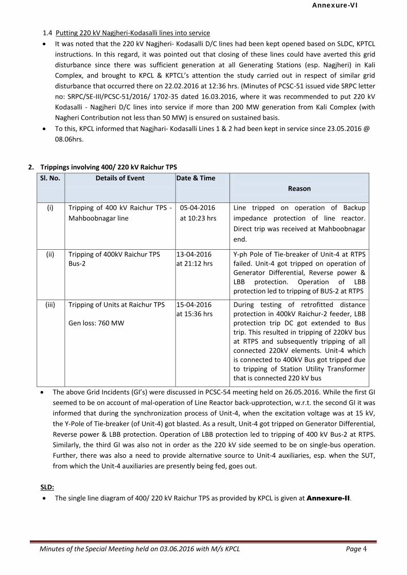
Minutes of the Special Meeting held on 03.06.2016 with M/s KPCL Page 4
1.4 Putting 220 kV Nagjheri-Kodasalli lines into service
It was noted that the 220 kV Nagjheri- Kodasalli D/C lines had been kept opened based on SLDC, KPTCL
instructions. In this regard, it was pointed out that closing of these lines could have averted this grid
disturbance since there was sufficient generation at all Generating Stations (esp. Nagjheri) in Kali
Complex, and brought to KPCL & KPTCL’s attention the study carried out in respect of similar grid
disturbance that occurred there on 22.02.2016 at 12:36 hrs. (Minutes of PCSC-51 issued vide SRPC letter
no: SRPC/SE-III/PCSC-51/2016/ 1702-35 dated 16.03.2016, where it was recommended to put 220 kV
Kodasalli - Nagjheri D/C lines into service if more than 200 MW generation from Kali Complex (with
Nagheri Contribution not less than 50 MW) is ensured on sustained basis.
To this, KPCL informed that Nagjhari- Kodasalli Lines 1 & 2 had been kept in service since 23.05.2016 @
08.06hrs.
2. Trippings involving 400/ 220 kV Raichur TPS
Sl. No. Details of Event Date & Time
Reason
(i) Tripping of 400 kV Raichur TPS -
Mahboobnagar line
05-04-2016
at 10:23 hrs
Line tripped on operation of Backup
impedance protection of line reactor.
Direct trip was received at Mahboobnagar
end.
(ii) Tripping of 400kV Raichur TPS Bus-2
13-04-2016 at 21:12 hrs
Y-ph Pole of Tie-breaker of Unit-4 at RTPS failed. Unit-4 got tripped on operation of Generator Differential, Reverse power & LBB protection. Operation of LBB protection led to tripping of BUS-2 at RTPS
(iii) Tripping of Units at Raichur TPS Gen loss: 760 MW
15-04-2016 at 15:36 hrs
During testing of retrofitted distance protection in 400kV Raichur-2 feeder, LBB protection trip DC got extended to Bus trip. This resulted in tripping of 220kV bus at RTPS and subsequently tripping of all connected 220kV elements. Unit-4 which is connected to 400kV Bus got tripped due to tripping of Station Utility Transformer that is connected 220 kV bus
The above Grid Incidents (GI’s) were discussed in PCSC-54 meeting held on 26.05.2016. While the first GI
seemed to be on account of mal-operation of Line Reactor back-upprotection, w.r.t. the second GI it was
informed that during the synchronization process of Unit-4, when the excitation voltage was at 15 kV,
the Y-Pole of Tie-breaker (of Unit-4) got blasted. As a result, Unit-4 got tripped on Generator Differential,
Reverse power & LBB protection. Operation of LBB protection led to tripping of 400 kV Bus-2 at RTPS.
Similarly, the third GI was also not in order as the 220 kV side seemed to be on single-bus operation.
Further, there was also a need to provide alternative source to Unit-4 auxiliaries, esp. when the SUT,
from which the Unit-4 auxiliaries are presently being fed, goes out.
SLD:
The single line diagram of 400/ 220 kV Raichur TPS as provided by KPCL is given at Annexure-II.
Annexure-VI
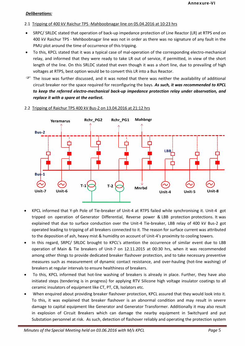
Minutes of the Special Meeting held on 03.06.2016 with M/s KPCL Page 5
Deliberations:
2.1 Tripping of 400 kV Raichur TPS -Mahboobnagar line on 05.04.2016 at 10:23 hrs
SRPC/ SRLDC stated that operation of back-up impedance protection of Line Reactor (LR) at RTPS end on
400 kV Raichur TPS - Mehboobnagar line was not in order as there was no signature of any fault in the
PMU plot around the time of occurrence of this tripping.
To this, KPCL stated that it was a typical case of mal-operation of the corresponding electro-mechanical
relay, and informed that they were ready to take LR out of service, if permitted, in view of the short
length of the line. On this SRLDC stated that even though it was a short line, due to prevailing of high
voltages at RTPS, best option would be to convert this LR into a Bus Reactor.
The issue was further discussed, and it was noted that there was neither the availability of additional
circuit breaker nor the space required for reconfiguring the bays. As such, it was recommended to KPCL
to keep the referred electro-mechanical back-up impedance protection relay under observation, and
replace it with a spare at the earliest.
2.2 Tripping of Raichur TPS 400 kV Bus-2 on 13.04.2016 at 21:12 hrs
KPCL informed that Y-ph Pole of Tie-breaker of Unit-4 at RTPS failed while synchronising it. Unit-4 got
tripped on operation of Generator Differential, Reverse power & LBB protection protections. It was
explained that due to surface conduction over the Unit-4 Tie-breaker, LBB relay of 400 kV Bus-2 got
operated leading to tripping of all breakers connected to it. The reason for surface current was attributed
to the deposition of ash, heavy mist & humidity on account of Unit-4’s proximity to cooling towers.
In this regard, SRPC/ SRLDC brought to KPCL’s attention the occurrence of similar event due to LBB
operation of Main & Tie breakers of Unit-7 on 12.11.2015 at 00:30 hrs, when it was recommended
among other things to provide dedicated breaker flashover protection, and to take necessary preventive
measures such as measurement of dynamic contact resistance, and over-hauling (hot-line washing) of
breakers at regular intervals to ensure healthiness of breakers.
To this, KPCL informed that hot-line washing of breakers is already in place. Further, they have also
initiated steps (tendering is in progress) for applying RTV Silicone high voltage insulator coatings to all
ceramic insulators of equipment like CT, PT, CB, Isolators etc.
When enquired about providing breaker flashover protection, KPCL assured that they would look into it.
To this, it was explained that breaker flashover is an abnormal condition and may result in severe
damage to capital equipment like Generator and Generator Transformer. Additionally it may also result
in explosion of Circuit Breakers which can damage the nearby equipment in Switchyard and put
Substation personnel at risk. As such, detection of flashover reliably and operating the protection system
Annexure-VI
Minutes of the Special Meeting held on 03.06.2016 with M/s KPCL Page 6
to isolate the affected breaker and generator in minimum possible time is all the more important, and
informed that such a protection can be implemented using a logic based on immediate sensing of arc
current supported by breaker status to reliably declare a flash. In this regard, papers contributed by
Adani personnel on (i) “Adaptive Logic for Breaker Flashover Protection”, (ii) “External Flashover of
Generator Circuit Breaker in Coastal Power Plants having Air Insulated Switchyard”, and (iii) “Practical
Interlock Logics to prevent undesired Circuit breaker closing, Isolator opening & charging of Bay in
Substations using IEDs” are enclosed at Annexure-IV for kind perusal and necessary action.
Thus, KPCL was recommended to undertake the following remedial measures to avoid breaker
flashovers:
replacing all porcelain insulators with composite insulators
carrying out hot-line water washing of all insulators on regular basis.
applying Room Temperature Vulcanizing (RTV) Silicone high voltage insulator coatings to all bus-
connected ceramic insulators of equipment like CT, PT, CB, Isolators etc.
KPCL was also recommended to take steps to provide dedicated breaker flashover protection to all
breakers at Raichur TPS at the earliest.
2.3 Tripping of Units at Raichur TPS on 15-04-2016 at 15:36 hrs
KPCL informed the following:
KPCL informed that at the time of the incident, Unit Auxiliary Transformer of Unit-4 was under
maintenance; hence Unit-4’s auxiliaries were being fed from the Station Transformer-4 (ST-4). As ST-4
Annexure-VI
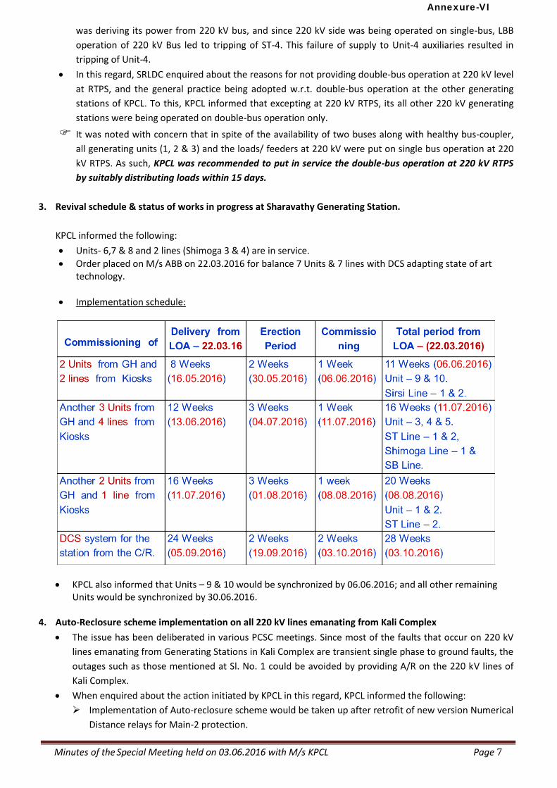
Minutes of the Special Meeting held on 03.06.2016 with M/s KPCL Page 7
was deriving its power from 220 kV bus, and since 220 kV side was being operated on single-bus, LBB
operation of 220 kV Bus led to tripping of ST-4. This failure of supply to Unit-4 auxiliaries resulted in
tripping of Unit-4.
In this regard, SRLDC enquired about the reasons for not providing double-bus operation at 220 kV level
at RTPS, and the general practice being adopted w.r.t. double-bus operation at the other generating
stations of KPCL. To this, KPCL informed that excepting at 220 kV RTPS, its all other 220 kV generating
stations were being operated on double-bus operation only.
It was noted with concern that in spite of the availability of two buses along with healthy bus-coupler,
all generating units (1, 2 & 3) and the loads/ feeders at 220 kV were put on single bus operation at 220
kV RTPS. As such, KPCL was recommended to put in service the double-bus operation at 220 kV RTPS
by suitably distributing loads within 15 days.
3. Revival schedule & status of works in progress at Sharavathy Generating Station.
KPCL informed the following:
Units- 6,7 & 8 and 2 lines (Shimoga 3 & 4) are in service.
Order placed on M/s ABB on 22.03.2016 for balance 7 Units & 7 lines with DCS adapting state of art technology.
Implementation schedule:
KPCL also informed that Units – 9 & 10 would be synchronized by 06.06.2016; and all other remaining Units would be synchronized by 30.06.2016.
4. Auto-Reclosure scheme implementation on all 220 kV lines emanating from Kali Complex
The issue has been deliberated in various PCSC meetings. Since most of the faults that occur on 220 kV
lines emanating from Generating Stations in Kali Complex are transient single phase to ground faults, the
outages such as those mentioned at Sl. No. 1 could be avoided by providing A/R on the 220 kV lines of
Kali Complex.
When enquired about the action initiated by KPCL in this regard, KPCL informed the following:
Implementation of Auto-reclosure scheme would be taken up after retrofit of new version Numerical
Distance relays for Main-2 protection.
Annexure-VI
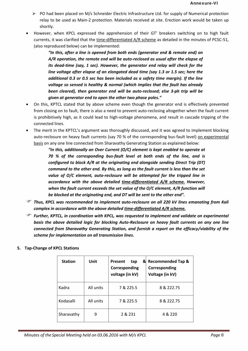
Minutes of the Special Meeting held on 03.06.2016 with M/s KPCL Page 8
PO had been placed on M/s Schneider Electric Infrastructure Ltd. for supply of Numerical protection
relay to be used as Main-2 protection. Materials received at site. Erection work would be taken up
shortly.
However, when KPCL expressed the apprehension of their GT’ breakers switching on to high fault
currents, it was clarified that the time-differentiated A/R scheme as detailed in the minutes of PCSC-51,
(also reproduced below) can be implemented:
“In this, after a line is opened from both ends (generator end & remote end) on
A/R operation, the remote end will be auto-reclosed as usual after the elapse of
its dead-time (say, 1 sec). However, the generator end relay will check for the
line voltage after elapse of an elongated dead time (say 1.3 or 1.5 sec; here the
additional 0.3 or 0.5 sec has been included as a safety time margin). If the line
voltage so sensed is healthy & normal (which implies that the fault has already
been cleared), then generator end will be auto-reclosed; else 3-ph trip will be
given at generator end to open the other two phase poles.”
On this, KPTCL stated that by above scheme even though the generator end is effectively prevented
from closing on to fault, there is also a need to prevent auto-reclosing altogether when the fault current
is prohibitively high, as it could lead to high-voltage phenomena, and result in cascade tripping of the
connected lines.
The merit in the KPTCL’s argument was thoroughly discussed, and it was agreed to implement blocking
auto-reclosure on heavy fault currents (say 70 % of the corresponding bus-fault level) on experimental
basis on any one line connected from Sharavathy Generating Station as explained below:
“In this, additionally an Over Current (O/C) element is kept enabled to operate at
70 % of the corresponding bus-fault level at both ends of the line, and is
configured to block A/R at the originating end alongside sending Direct Trip (DT)
command to the other end. By this, as long as the fault current is less than the set
value of O/C element, auto-reclosure will be attempted for the tripped line in
accordance with the above detailed time-differentiated A/R scheme. However,
when the fault current exceeds the set value of the O/C element, A/R function will
be blocked at the originating end, and DT will be sent to the other end”.
Thus, KPCL was recommended to implement auto-reclosure on all 220 kV lines emanating from Kali
complex in accordance with the above detailed time-differentiated A/R scheme.
Further, KPTCL, in coordination with KPCL, was requested to implement and validate on experimental
basis the above detailed logic for blocking Auto-Reclosure on heavy fault currents on any one line
connected from Sharavathy Generating Station, and furnish a report on the efficacy/viability of the
scheme for implementation on all transmission lines.
5. Tap-Change of KPCL Stations
Station Unit Present tap &
Corresponding
voltage (in kV)
Recommended Tap &
Corresponding
Voltage (in kV)
Kadra All units 7 & 225.5 8 & 222.75
Kodasalli All units 7 & 225.5 8 & 222.75
Sharavathy 9 2 & 231 4 & 220
Annexure-VI
Minutes of the Special Meeting held on 03.06.2016 with M/s KPCL Page 9
KPCL informed that the Taps at Kadra and Kodasalli Power Houses had been kept at 7/225.5 to suit
system condition against the recommended value of 8/225.75 for matching generator voltage with
system voltage. Similarly, at Sharavathy Generating Stations (SGS), the 9th Unit GT-tap could not be
changed due to technical problems. KPCL informed that tendering is in progress for procurement of
115 MVA Generator transformers, after which the required tap would be provided at SGS.
On this, SRLDC explained that since the system voltage for synchronization is 220 kV at Kadra & Kodasalli,
and the recommended value is nearer to this, KPCL’s reservations on changing to recommended tap are
mi splaced.To this, KPCL agreed to look into the issue, and adjust tap positions accordingly.
KPCL was recommended to adopt the SRLDC recommended tap-positions at their Kadra (all Units),
Kodasalli (all Units) and SGS (Unit-9) stations at the earliest.
6. Compliance of pending Recommendations of the following Power System Analysis Group (PSAG) Meetings
The status of recommendations of PSAG-3 held on 04.09.2013 to analyze the multiple trippings that at
Sharavathy HPS on 18-08-2013 is given at Annexure-V.
The status of recommendations of PSAG- 6 held on 05.02.2014 to analyze the multiple trippings at
Raichur TPS on 26-01-2014 and 30-01-2014 is given at Annexure-VI.
The status of recommendations of PSAG-10 held on 12.11.2014 to analyze the Grid Disturbances at
Kadra, Kodasalli and Kaiga Power Stations that occurred on 26-09-2014 and 05-10-2014 is given at
Annexure-VII.
The status of recommendations of PSAG-13 held on 22-23 April, 2015 to analyze the cause of multiple
trippings that took place at RTPS and Raichur-PG on 09.03.2015 & 11.04.2015 is given at
Annexure-VIII.
It was noted that generally recommendations involving procurement activities are pending. As can be
seen from the furnished status, the erection & commissioning activities for the recommended works are
under progress.
7. Pending Implementation of PCSC Recommendations
The latest status of compliance of recommendations of various PCSC meetings relating to KPCL Stations is
given at Annexure-IX.
It was noted that steps had been taken to implement various PCSC recommendations relating to revision
of specific relay settings, enabling of A/R scheme, replacement of old electromechanical relays with
numerical relays at KPCL Stations, etc.
8. Protection Audit Recommendations (Phase- I & II)
The latest status of compliance of Protection Audit recommendations (Phase-I and Phase-II works) pertaining
to KPCL Stations is given at Annexure-X.
It can be seen from the furnished status that all works of Phase-I & Phase-II have been targeted to be
completed before 30.12.2016, the dead-line for which KPCL has committed before Hon’ble CERC in their
application seeking time-extension for implementing protection audit recommendations relating to their
stations.
Annexure-VI
Minutes of the Special Meeting held on 03.06.2016 with M/s KPCL Page 10
9. High resistance faults are frequently observed in 220kV lines in Kali complex due to the dense vegetation. Faults are often observed to be cleared by back up protections. The resistive reach of distance protection relays to be reviewed along with proper vegetation management. KPCL informed that they were seized of the matter, and assured that the Resistive reach of lines would be
revised in co-ordination with KPTCL.
10. Fault level at Raichur TPS
During failure of R-phase CT of 400/220kV ICT-1at Raichur TPSat 21:44 Hrs on 01-05-2016 the fault current
recorded in DR was 36 kA. Suitable actions need to be planned as fault level may exceed 40kA in near future.
To take care of the situation arising out of 400 kV RTPS bus fault level exceeding 40 kA, KPCL informed
that in RTPS area switchgear which can withstand such fault level only are being put into service in recent
days. Further, materials with design specifications considering 50 kA only are being procured. The same
will be CONSIDERED and adopted in all future replacements.
11. Differential protection for 400kV lines
400kV Raichur-Raichur TPS line-1&2 and 400kV Raichur-YTPS and in future lines from Bellary pooling station
to nearby generating TPS are to be provided with differential protection as frequent over-reach is observed
with distance protection relays.
KPCL informed that DIFFERENTIAL PROTECTION for 400 kV lines would be provided in consultation with
KPTCL and considering site feasibility.
12. Faulty distance relay in 400kV RaichurTPS-YeramarusTPS line
400 kV RTPS-YTPS line is tripping from Raichur TPS end for any through fault due to problem in distance relay
at RTPS end.
KPCL informed that the SOTF logic implemented in Micom P444 distance relay at RTPS end on 400 kV RTPS –YTPS line had been wrongly configured with continuous enabling, due to which whenever any fault takes place on down-stream network, it is invariably acting to trip the line.
Now the ALSTOM make P444 relay settings were revised on 01.05.2016 in consultation with M/s
ALSTOM, and the line is found to be stable.
13. D.R and station event logger to be triggered with operation of Main and Back-up protections of transmission
line/ generator /bus-bar protection with proper time synchronization for proper analysis.
KPCL informed that protection relays with built-in Disturbance Recorder (DR) and Event Logger (EL) with
facility to synchronize with GPS were being procured and commissioned.
To this SRPC/ SRLDC while appreciating KPCL’s initiative in procuring new protection (numerical) relays
with DR and EL and time-synchronization facilities, informed that the new relays must be suitably
configuring for recording even those events that occur on operation of back-up protections of
transmission line/ generator /bus-bar. To this, KPCL agreed to take necessary action for capturing events
on back-up protection operation.
Annexure-VI
Minutes of the Special Meeting held on 03.06.2016 with M/s KPCL Page 11
14. Integrity test for Station earth mats in KPCL stations
As per CPRI report, improper earthing was one of the reasons attributed for fire incident at Sharavathy
power house. Station Earth mat integrity test need to be carried out at all KPCL power station as a
precautionary measure.
KPCL informed that New Earthing System as per design of M/S CPRI would be put into service, which
would be in addition to the existed earth mat. KPCL also assured that Station Earth-mat integrity test
would be carried-out at all KPCL power stations as a precautionary measure.
Vote of Thanks
MS, SRPC thanked Technical Director, KPCL and other Officials from KPCL & KPTCL for participating in the
Meeting. He hoped that with active cooperation, visible improvement would be witnessed in the near future
on these pending protection issues.
*****
Annexure-VI
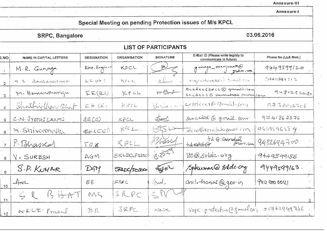
Annexure-I
Annexure-VI
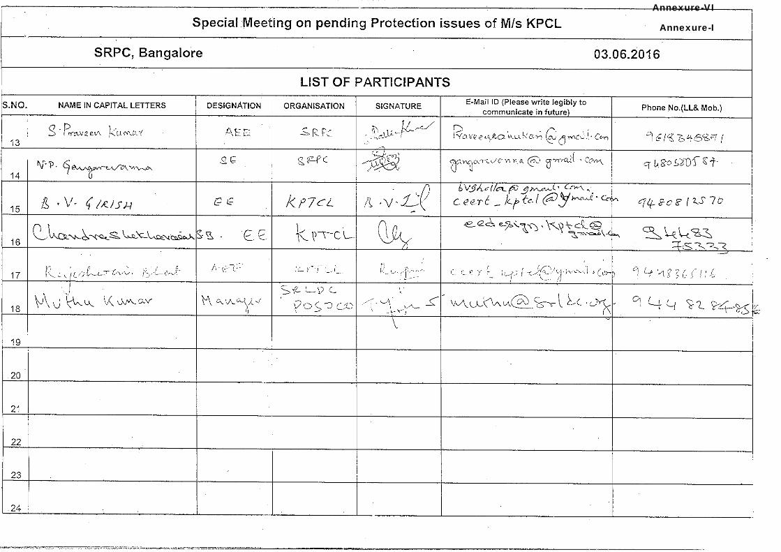
Annexure-I
Annexure-VI
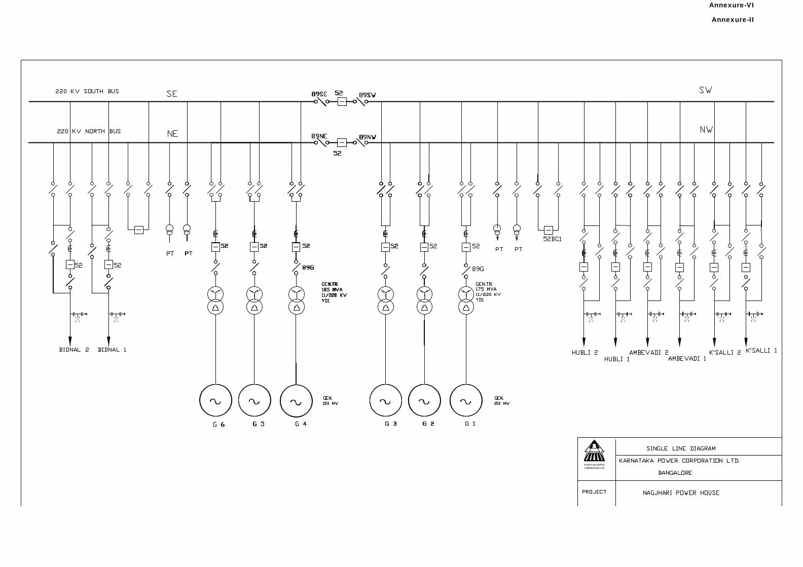
Annexure-II
Annexure-VI
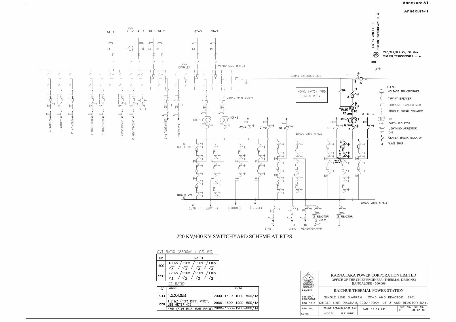
SHAHPUR-1
SHAHPUR-2
Annexure-II
Annexure-VI
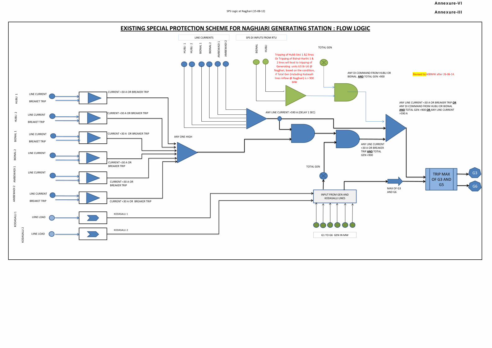
SPS Logic at Nagjhari (15-08-12)
Revised to 600MW after 26-06-14.
EXISTING SPECIAL PROTECTION SCHEME FOR NAGHJARI GENERATING STATION : FLOW LOGIC
Tripping of Hubli-Sirsi 1 &2 lines
Or Tripping of Bidnal-Harthi 1 &
2 lines will lead to tripping of
Generating units U3 0r U6 @
Nagjhari, based on the condition,
if Total Gen (including Kodasalli
lines inflow @ Nagjhari) is > 900
MW
KODASALLI 2
KODASALLI 1
INPUT FROM GEN AND KODASALLI LINES
TRIP MAX OF G3 AND
G5
G3
G6H
UB
LI 1
CURRENT <30 A OR BREAKER TRIP
LINE CURRENT
BREAKET TRIP
G1 TO G6 GEN IN MW
ANY ONE HIGH
CURRENT <30 A OR BREAKER TRIP
CURRENT <30 A OR BREAKER TRIP
CURRENT <30 A OR BREAKER TRIP
CURRENT <30 A OR BREAKER TRIP
CURRENT <30 A OR BREAKER TRIP
LINE CURRENT
BREAKET TRIP
LINE CURRENT
BREAKET TRIP
LINE CURRENT
LINE CURRENT
LINE CURRENT
BREAKET TRIP
HU
BLI
2
BID
NA
L 1
BID
NA
L 2
AM
BEW
AD
I 1
AM
BEW
AD
I 2
HU
BLI
1H
UB
LI 2
BID
NA
L 1
BID
NA
L 2
AM
BEW
AD
I 1A
MB
EWA
DI 2
KO
DA
SALL
I1
KO
DA
SALL
I 2
LINE CURRENTS
ANY LINE CURRENT >590 A (DELAY 1 SEC)
ANY LINE CURRENT <30 A OR BREAKER TRIP ORANY DI COMMAND FROM HUBLI OR BIDNAL AND TOTAL GEN >900 OR ANY LINE CURRENT >590 A
TOTAL GEN
ANY LINE CURRENT<30 A OR BREAKER TRIP AND TOTALGEN >900
LIINE LOAD
LIINE LOAD
MAX OF G3 AND G6
TOTAL GEN
HU
BLI
BID
NA
L
SPS DI INPUTS FROM RTU
ANY DI COMMAND FROM HUBLI OR BIDNAL AND TOTAL GEN >900
Annexure-III
Annexure-VI
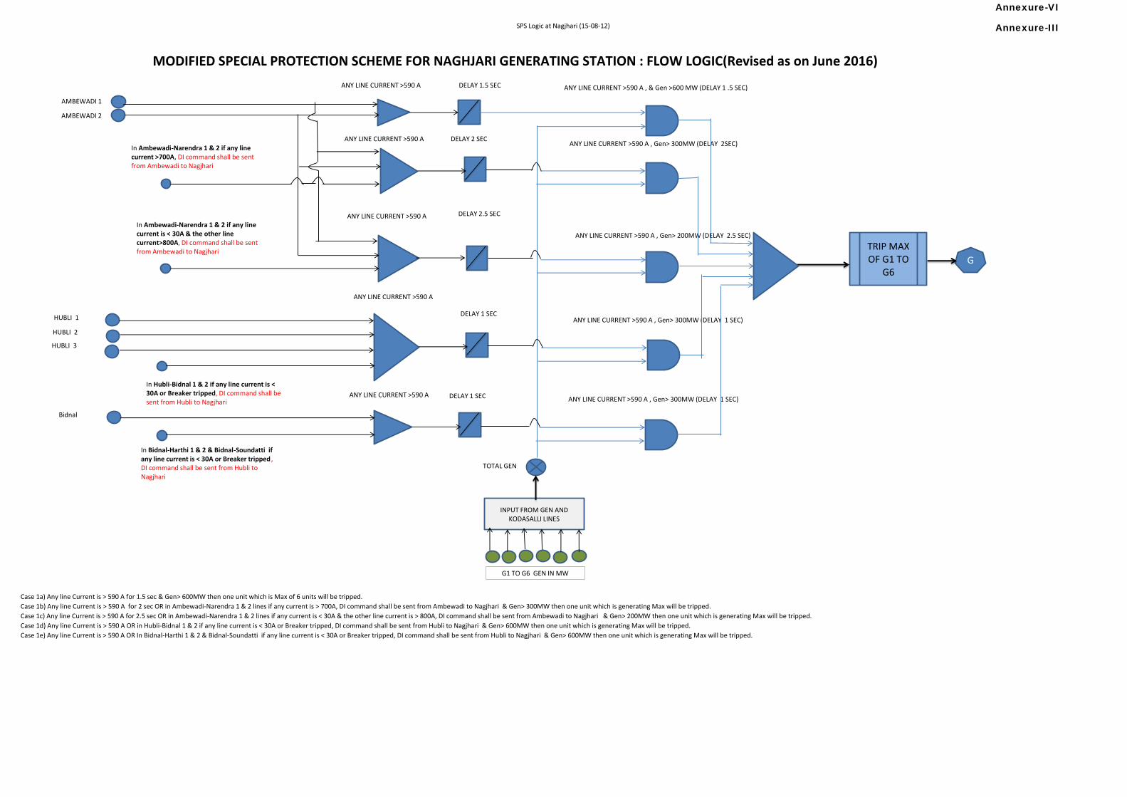
SPS Logic at Nagjhari (15-08-12)
Case 1e) Any line Current is > 590 A OR In Bidnal-Harthi 1 & 2 & Bidnal-Soundatti if any line current is < 30A or Breaker tripped, DI command shall be sent from Hubli to Nagjhari & Gen> 600MW then one unit which is generating Max will be tripped.
MODIFIED SPECIAL PROTECTION SCHEME FOR NAGHJARI GENERATING STATION : FLOW LOGIC(Revised as on June 2016)
Case 1a) Any line Current is > 590 A for 1.5 sec & Gen> 600MW then one unit which is Max of 6 units will be tripped.
Case 1b) Any line Current is > 590 A for 2 sec OR in Ambewadi-Narendra 1 & 2 lines if any current is > 700A, DI command shall be sent from Ambewadi to Nagjhari & Gen> 300MW then one unit which is generating Max will be tripped.
Case 1c) Any line Current is > 590 A for 2.5 sec OR in Ambewadi-Narendra 1 & 2 lines if any current is < 30A & the other line current is > 800A, DI command shall be sent from Ambewadi to Nagjhari & Gen> 200MW then one unit which is generating Max will be tripped.
Case 1d) Any line Current is > 590 A OR in Hubli-Bidnal 1 & 2 if any line current is < 30A or Breaker tripped, DI command shall be sent from Hubli to Nagjhari & Gen> 600MW then one unit which is generating Max will be tripped.
INPUT FROM GEN AND KODASALLI LINES
TRIP MAX OF G1 TO
G6G
G1 TO G6 GEN IN MW
AMBEWADI 1
HUBLI 1
ANY LINE CURRENT >590 A
TOTAL GEN
ANY LINE CURRENT >590 A , Gen> 300MW (DELAY 2SEC)
AMBEWADI 2
In Ambewadi-Narendra 1 & 2 if any line current >700A, DI command shall be sent from Ambewadi to Nagjhari
In Ambewadi-Narendra 1 & 2 if any line current is < 30A & the other line current>800A, DI command shall be sent from Ambewadi to Nagjhari
HUBLI 2
HUBLI 3
In Hubli-Bidnal 1 & 2 if any line current is < 30A or Breaker tripped, DI command shall be sent from Hubli to Nagjhari
Bidnal
In Bidnal-Harthi 1 & 2 & Bidnal-Soundatti if any line current is < 30A or Breaker tripped , DI command shall be sent from Hubli to Nagjhari
ANY LINE CURRENT >590 A , & Gen >600 MW (DELAY 1 .5 SEC)DELAY 1.5 SEC
ANY LINE CURRENT >590 A DELAY 2 SEC
ANY LINE CURRENT >590 A DELAY 2.5 SEC
ANY LINE CURRENT >590 A , Gen> 200MW (DELAY 2.5 SEC)
ANY LINE CURRENT >590 A
DELAY 1 SECANY LINE CURRENT >590 A , Gen> 300MW (DELAY 1 SEC)
ANY LINE CURRENT >590 A DELAY 1 SEC ANY LINE CURRENT >590 A , Gen> 300MW (DELAY 1 SEC)
Annexure-III
Annexure-VI
Adaptive Logic for Breaker Flashover Protection of Generator. Sanjay Bhatt
Protection Automation and Metering Group Adani Power Training and Research Institute
Adani Power Limited, Ahmedabad [email protected]
1. ABSTRACT:
Flashover can occur on any breaker in the network where an overvoltage condition is present, but the probability is higher for breakers being used to synchronize two isolated power systems; e.g. on generator breakers, line breaker connecting two separate sources or grids. For Generator/line breaker, the Period is considered as critical in view of withstanding rise in voltage vector appearing across poles of Circuit Breaker and the arc quenching process before generator/line synchronization, or just following generator/line tripping respectively. The circuit breaker for above said applications for must be designed capable of maintaining the sufficient insulation level to withstand the same. The detection of flashover reliably and operating protection to isolate the affected breaker and generator in possible minimum time calls for a logic based on immediate sensing of arc current supported by breaker status to reliably declare a flash. This paper describes the logic adapting the numerical relaying logic blocks with current status different from conventionally used and also described in IEEE guideline for Generator Protection C37.102.
2. KEYWORDS: Breaker Flashover, Generator Protection for GT Breaker flashover, unintended arc across Generator breaker
3. INTRODUCTION:
(I) It is because the vectors of the protected generator and grid vector across circuit breaker poles are slipping with respect to a power system. This will lead to a condition to establish at least twice rated phase-neutral voltage across the generator circuit breaker. Due to the system and machine operation condition it is quite often possible that even higher voltage may be established. This will lead to establishment of arc between two poles of circuit breaker, which may be internal or external, leading to failure of breaker damaging self and also nearby equipments and persons. Further the establishment of arc will also lead to the asynchronous energisation of Generator with grid and create oscillation damaging Generator Transformer / Generator. Detecting the flashover The abnormal rise in voltage just after generator tripping is most likely due to following reasons,
Prime mover failure: which is associated by the excitation level not matching instantly with the lowering of active power, where the pre-failure level of excitation might be maintained until AVR action takes place.
AVR malfunction: this is associated with failure of AVR to discharge energy through discharging resistor at the time of tripping boosted by residual flux.
Annexure-IV
Page 1 of 23
Annexure-VI
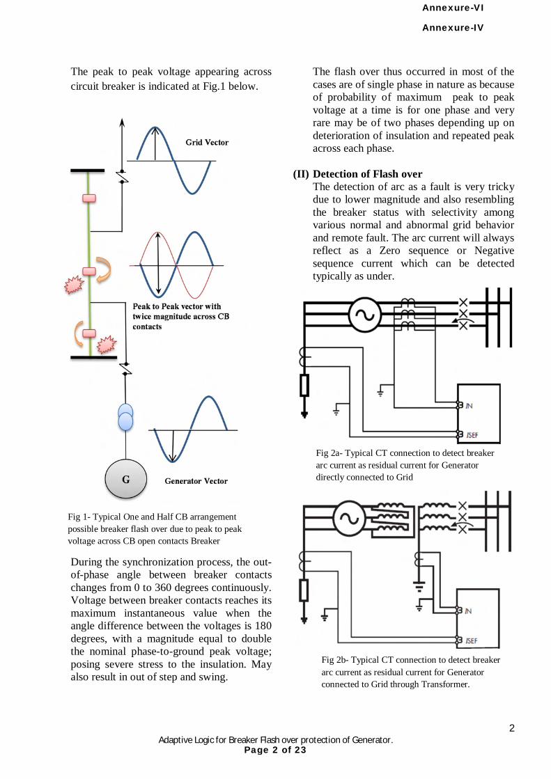
2 Adaptive Logic for Breaker Flash over protection of Generator.
The peak to peak voltage appearing across circuit breaker is indicated at Fig.1 below.
During the synchronization process, the out-of-phase angle between breaker contacts changes from 0 to 360 degrees continuously. Voltage between breaker contacts reaches its maximum instantaneous value when the angle difference between the voltages is 180 degrees, with a magnitude equal to double the nominal phase-to-ground peak voltage; posing severe stress to the insulation. May also result in out of step and swing.
The flash over thus occurred in most of the cases are of single phase in nature as because of probability of maximum peak to peak voltage at a time is for one phase and very rare may be of two phases depending up on deterioration of insulation and repeated peak across each phase.
(II) Detection of Flash over The detection of arc as a fault is very tricky due to lower magnitude and also resembling the breaker status with selectivity among various normal and abnormal grid behavior and remote fault. The arc current will always reflect as a Zero sequence or Negative sequence current which can be detected typically as under.
Fig 1- Typical One and Half CB arrangement possible breaker flash over due to peak to peak voltage across CB open contacts Breaker
Fig 2a- Typical CT connection to detect breaker arc current as residual current for Generator directly connected to Grid
Fig 2b- Typical CT connection to detect breaker arc current as residual current for Generator connected to Grid through Transformer.
Annexure-IV
Page 2 of 23
Annexure-VI
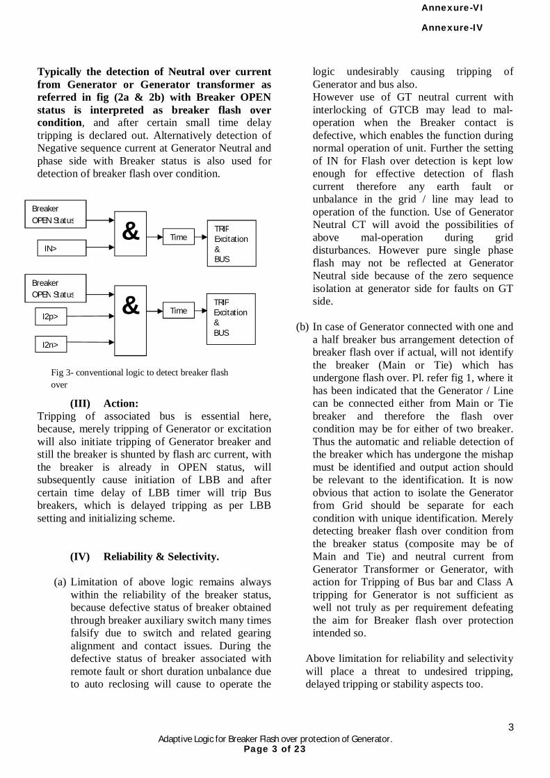
3 Adaptive Logic for Breaker Flash over protection of Generator.
Typically the detection of Neutral over current from Generator or Generator transformer as referred in fig (2a & 2b) with Breaker OPEN status is interpreted as breaker flash over condition, and after certain small time delay tripping is declared out. Alternatively detection of Negative sequence current at Generator Neutral and phase side with Breaker status is also used for detection of breaker flash over condition.
(III) Action: Tripping of associated bus is essential here, because, merely tripping of Generator or excitation will also initiate tripping of Generator breaker and still the breaker is shunted by flash arc current, with the breaker is already in OPEN status, will subsequently cause initiation of LBB and after certain time delay of LBB timer will trip Bus breakers, which is delayed tripping as per LBB setting and initializing scheme.
(IV) Reliability & Selectivity.
(a) Limitation of above logic remains always within the reliability of the breaker status, because defective status of breaker obtained through breaker auxiliary switch many times falsify due to switch and related gearing alignment and contact issues. During the defective status of breaker associated with remote fault or short duration unbalance due to auto reclosing will cause to operate the
logic undesirably causing tripping of Generator and bus also. However use of GT neutral current with interlocking of GTCB may lead to mal-operation when the Breaker contact is defective, which enables the function during normal operation of unit. Further the setting of IN for Flash over detection is kept low enough for effective detection of flash current therefore any earth fault or unbalance in the grid / line may lead to operation of the function. Use of Generator Neutral CT will avoid the possibilities of above mal-operation during grid disturbances. However pure single phase flash may not be reflected at Generator Neutral side because of the zero sequence isolation at generator side for faults on GT side.
(b) In case of Generator connected with one and a half breaker bus arrangement detection of breaker flash over if actual, will not identify the breaker (Main or Tie) which has undergone flash over. Pl. refer fig 1, where it has been indicated that the Generator / Line can be connected either from Main or Tie breaker and therefore the flash over condition may be for either of two breaker. Thus the automatic and reliable detection of the breaker which has undergone the mishap must be identified and output action should be relevant to the identification. It is now obvious that action to isolate the Generator from Grid should be separate for each condition with unique identification. Merely detecting breaker flash over condition from the breaker status (composite may be of Main and Tie) and neutral current from Generator Transformer or Generator, with action for Tripping of Bus bar and Class A tripping for Generator is not sufficient as well not truly as per requirement defeating the aim for Breaker flash over protection intended so.
Above limitation for reliability and selectivity will place a threat to undesired tripping, delayed tripping or stability aspects too.
& Breaker OPEN Status
IN>
I2p>
I2n>
TRIP Excitation& BUS
& Breaker OPEN Status
TRIP Excitation& BUS
Fig 3- conventional logic to detect breaker flash over
Time
Time
Annexure-IV
Page 3 of 23
Annexure-VI
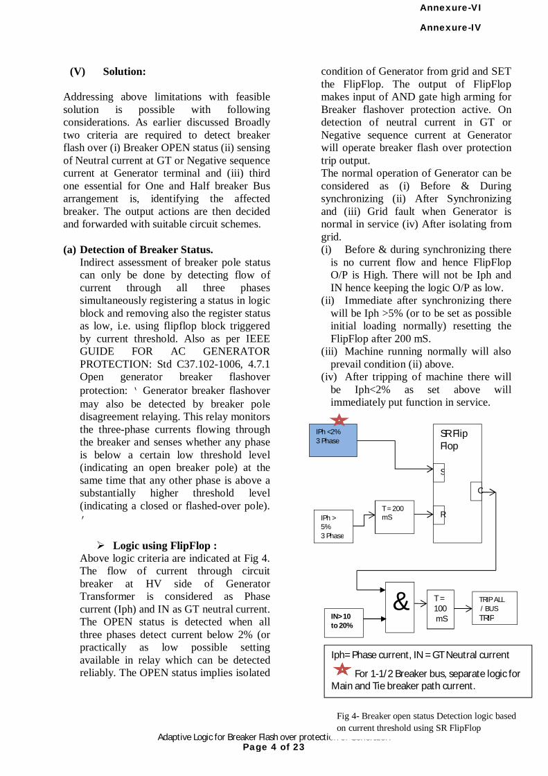
4 Adaptive Logic for Breaker Flash over protection of Generator.
(V) Solution: Addressing above limitations with feasible solution is possible with following considerations. As earlier discussed Broadly two criteria are required to detect breaker flash over (i) Breaker OPEN status (ii) sensing of Neutral current at GT or Negative sequence current at Generator terminal and (iii) third one essential for One and Half breaker Bus arrangement is, identifying the affected breaker. The output actions are then decided and forwarded with suitable circuit schemes. (a) Detection of Breaker Status.
Indirect assessment of breaker pole status can only be done by detecting flow of current through all three phases simultaneously registering a status in logic block and removing also the register status as low, i.e. using flipflop block triggered by current threshold. Also as per IEEE GUIDE FOR AC GENERATOR PROTECTION: Std C37.102-1006, 4.7.1 Open generator breaker flashover protection: ‘Generator breaker flashover may also be detected by breaker pole disagreement relaying. This relay monitors the three-phase currents flowing through the breaker and senses whether any phase is below a certain low threshold level (indicating an open breaker pole) at the same time that any other phase is above a substantially higher threshold level (indicating a closed or flashed-over pole).’ Logic using FlipFlop :
Above logic criteria are indicated at Fig 4. The flow of current through circuit breaker at HV side of Generator Transformer is considered as Phase current (Iph) and IN as GT neutral current. The OPEN status is detected when all three phases detect current below 2% (or practically as low possible setting available in relay which can be detected reliably. The OPEN status implies isolated
condition of Generator from grid and SET the FlipFlop. The output of FlipFlop makes input of AND gate high arming for Breaker flashover protection active. On detection of neutral current in GT or Negative sequence current at Generator will operate breaker flash over protection trip output. The normal operation of Generator can be considered as (i) Before & During synchronizing (ii) After Synchronizing and (iii) Grid fault when Generator is normal in service (iv) After isolating from grid. (i) Before & during synchronizing there
is no current flow and hence FlipFlop O/P is High. There will not be Iph and IN hence keeping the logic O/P as low.
(ii) Immediate after synchronizing there will be Iph >5% (or to be set as possible initial loading normally) resetting the FlipFlop after 200 mS.
(iii) Machine running normally will also prevail condition (ii) above.
(iv) After tripping of machine there will be Iph<2% as set above will immediately put function in service.
Fig 4- Breaker open status Detection logic based on current threshold using SR FlipFlop
SR Flip Flop
S
R
O
IPh <2% 3 Phase
IPh > 5% 3 Phase
T = 200 mS
& IN> 10 to 20%
T = 100 mS
TRIP ALL / BUS TRIP
Iph= Phase current, IN = GT Neutral current
For 1-1/2 Breaker bus, separate logic for Main and Tie breaker path current.
Annexure-IV
Page 4 of 23
Annexure-VI
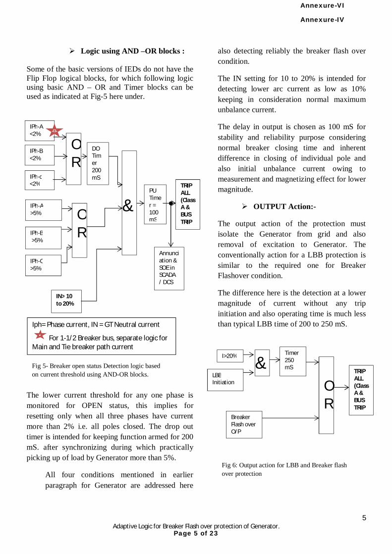
5 Adaptive Logic for Breaker Flash over protection of Generator.
Logic using AND –OR blocks : Some of the basic versions of IEDs do not have the Flip Flop logical blocks, for which following logic using basic AND – OR and Timer blocks can be used as indicated at Fig-5 here under.
The lower current threshold for any one phase is monitored for OPEN status, this implies for resetting only when all three phases have current more than 2% i.e. all poles closed. The drop out timer is intended for keeping function armed for 200 mS. after synchronizing during which practically picking up of load by Generator more than 5%.
All four conditions mentioned in earlier paragraph for Generator are addressed here
also detecting reliably the breaker flash over condition.
The IN setting for 10 to 20% is intended for detecting lower arc current as low as 10% keeping in consideration normal maximum unbalance current.
The delay in output is chosen as 100 mS for stability and reliability purpose considering normal breaker closing time and inherent difference in closing of individual pole and also initial unbalance current owing to measurement and magnetizing effect for lower magnitude.
OUTPUT Action:-
The output action of the protection must isolate the Generator from grid and also removal of excitation to Generator. The conventionally action for a LBB protection is similar to the required one for Breaker Flashover condition.
The difference here is the detection at a lower magnitude of current without any trip initiation and also operating time is much less than typical LBB time of 200 to 250 mS.
Fig 5- Breaker open status Detection logic based on current threshold using AND-OR blocks.
Iph= Phase current, IN = GT Neutral current
For 1-1/2 Breaker bus, separate logic for Main and Tie breaker path current
&
IN> 10 to 20%
PU Timer = 100 mS
TRIP ALL (Class A & BUS TRIP
IPh-B <2%
IPh-c <2%
OR
IPh-A >5%
IPh-B >5%
IPh-C >5%
OR
DO Timer 200 mS
Annunciation & SOE in SCADA / DCS
IPh-A <2%
LBB Initiation
OR
TRIP ALL (Class A & BUS TRIP
Breaker Flash over O/P
I>20% Timer 250 mS
&
Fig 6: Output action for LBB and Breaker flash over protection
Annexure-IV
Page 5 of 23
Annexure-VI

6 Adaptive Logic for Breaker Flash over protection of Generator.
(V) Solution
(b) Selectivity of Breaker Flash over for One and Half Breaker system arrangement of Bus.
The One and half breaker arrangement is mainly having advantage of redundant connectivity for feeders. As shown in fig-7, the Phase current used for Breaker flash over can be referred from Main or Tie breaker CTs. The breaker flash over may occur for Main or Tie breaker during synchronizing or after isolation from Grid. So both the paths must be
separately detected for flash arc current i.e. Main and Tie breaker. The action required after detection of flashover are different as detailed below.
(1) MAIN Breaker flash over Tripping of Generator in Class-A
to trip excitation immediately and stop prime mover for any rise in voltage due to residual magnetism.
Open all bus breaker to isolate the affected breaker from grid.
(2) TIE Breaker flash over. Tripping of Generator in Class-A
to trip excitation immediately and stop prime mover for any rise in voltage due to residual magnetism.
Trip Main breaker of Line side. Send Direct Trip Transfer signal to
isolate source from remote end.
The logic described for Current detection as Iph-A-B-C in earlier paragraphs equally used separately for Main and Tie breaker. The CT input for Main and Tie paths are indicated in fig-7.
Two separate logics should be built as conveniently in bay IEDs like, BCU or back up relay with separate set of actions as described above.
Please note that the neutral current here and elsewhere in document is indicated from GT neutral, whereas can also be used as Negative sequence current of Generator Phase connection also.
The setting values shown here are from experienced values for a 660 MW Generator, however can be considered on typical machine behavior and normal operation.
TIE
Fig 7: Current detection for selectivity for One and Half Breaker arrangement for breaker flash over protection.
Line Feeder
Y
D
Main-Line
Main-Gen
G
Iph-TIE
Iph-MAIN G
IN
Annexure-IV
Page 6 of 23
Annexure-VI
7 Adaptive Logic for Breaker Flash over protection of Generator.
(VI) CONCLUSION;
The breaker flash over phenomena is a very typical one to detect reliably and opt for action like isolation of bus and feeder at minimum possible time. Typical logic are offered by various manufacturer as indicated earlier, however use of reliable detection and output action is a part of scheme designing and adaption of philosophy.
Reliable detection and comprehensive logic is now very easy to be built in IEDs having numerous logical blocks, I/O configuration and even use of GOOSE signals for interlocking.
Breaker flash over protection must be used as a critical protection function particularly the locations like sea shore based or saline atmosphere surrounded installations, where chances of external flash over is higher. The lower flash arc current may also cause severe oscillation and asynchronous energisation may lead to damage to TG set or transformer.
Careful design should be carried out to handle flash over detection and isolation for one and Half breaker arrangement.
(VII) REFERENCES a. IEEE Guide for AC Generator
Protection: Std C37.102-1006, 4.7.1
b. Guide for Ac Generator Protection, ANSI/IEEEC 37.102-1995.
c. Application manual AREVA Micom P34x relay.
(VIII) Acknowledgement:
Author takes opportunity to express gratitude and special thanks to HOD of P&M Group of Adani Power Ltd., his guideline & knowledge, Adani Power Training & Research Institute, APL management for granting permission and inspiration to think and present this paper.
(IX) Author:
Sanjay U. Bhatt, working as DGM (Protection) at Adani Power Ltd, Ahmedabad, (Protection Automation & Metering Department), from January 2012.
B.E. (Electrical) -1993 from L.E. College Morvi , Gujarat (India).
Worked: o In G.S.F.C.-Jamnagar, as Ele.
Maintenance Engr. o In Govt. Polytechnic, as a lecturer on
clearing GPSC. o In GSECL, Gujarat as Junior Engineer
at Sikka Power station as Electrical Testing & Maintenance engineer and at SLDC during commissioning of SCADA and related system.
o As Deputy Engineer at GSECL corporate office as Testing engineer.
Annexure-IV
Page 7 of 23
Annexure-VI
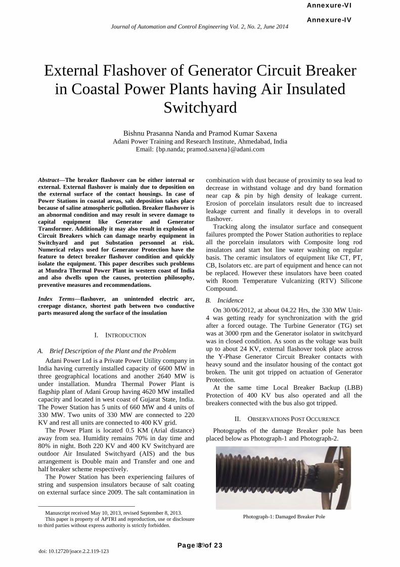
External Flashover of Generator Circuit Breaker
in Coastal Power Plants having Air Insulated
Switchyard
Bishnu Prasanna Nanda and Pramod Kumar Saxena Adani Power Training and Research Institute, Ahmedabad, India
Email: {bp.nanda; pramod.saxena}@adani.com
Abstract—The breaker flashover can be either internal or
external. External flashover is mainly due to deposition on
the external surface of the contact housings. In case of
Power Stations in coastal areas, salt deposition takes place
because of saline atmospheric pollution. Breaker flashover is
an abnormal condition and may result in severe damage to
capital equipment like Generator and Generator
Transformer. Additionally it may also result in explosion of
Circuit Breakers which can damage nearby equipment in
Switchyard and put Substation personnel at risk.
Numerical relays used for Generator Protection have the
feature to detect breaker flashover condition and quickly
isolate the equipment. This paper describes such problems
at Mundra Thermal Power Plant in western coast of India
and also dwells upon the causes, protection philosophy,
preventive measures and recommendations.
Index Terms—flashover, an unintended electric arc,
creepage distance, shortest path between two conductive
parts measured along the surface of the insulation
I. INTRODUCTION
A. Brief Description of the Plant and the Problem
Adani Power Ltd is a Private Power Utility company in
India having currently installed capacity of 6600 MW in
three geographical locations and another 2640 MW is
under installation. Mundra Thermal Power Plant is
flagship plant of Adani Group having 4620 MW installed
capacity and located in west coast of Gujarat State, India.
The Power Station has 5 units of 660 MW and 4 units of
330 MW. Two units of 330 MW are connected to 220
KV and rest all units are connected to 400 KV grid.
The Power Plant is located 0.5 KM (Arial distance)
away from sea. Humidity remains 70% in day time and
80% in night. Both 220 KV and 400 KV Switchyard are
outdoor Air Insulated Switchyard (AIS) and the bus
arrangement is Double main and Transfer and one and
half breaker scheme respectively.
The Power Station has been experiencing failures of
string and suspension insulators because of salt coating
on external surface since 2009. The salt contamination in
Manuscript received May 10, 2013, revised September 8, 2013. This paper is property of APTRI and reproduction, use or disclosure
to third parties without express authority is strictly forbidden.
combination with dust because of proximity to sea lead to
decrease in withstand voltage and dry band formation
near cap & pin by high density of leakage current.
Erosion of porcelain insulators result due to increased
leakage current and finally it develops in to overall
flashover.
Tracking along the insulator surface and consequent
failures prompted the Power Station authorities to replace
all the porcelain insulators with Composite long rod
insulators and start hot line water washing on regular
basis. The ceramic insulators of equipment like CT, PT,
CB, Isolators etc. are part of equipment and hence can not
be replaced. However these insulators have been coated
with Room Temperature Vulcanizing (RTV) Silicone
Compound.
B. Incidence
On 30/06/2012, at about 04.22 Hrs, the 330 MW Unit-
4 was getting ready for synchronization with the grid
after a forced outage. The Turbine Generator (TG) set
was at 3000 rpm and the Generator isolator in switchyard
was in closed condition. As soon as the voltage was built
up to about 24 KV, external flashover took place across
the Y-Phase Generator Circuit Breaker contacts with
heavy sound and the insulator housing of the contact got
broken. The unit got tripped on actuation of Generator
Protection.
At the same time Local Breaker Backup (LBB)
Protection of 400 KV bus also operated and all the
breakers connected with the bus also got tripped.
II. OBSERVATIONS POST OCCURENCE
Photographs of the damage Breaker pole has been
placed below as Photograph-1 and Photograph-2.
Photograph-1: Damaged Breaker Pole
119
Journal of Automation and Control Engineering Vol. 2, No. 2, June 2014
doi: 10.12720/joace.2.2.119-123
Annexure-IV
Page 8 of 23
Annexure-VI
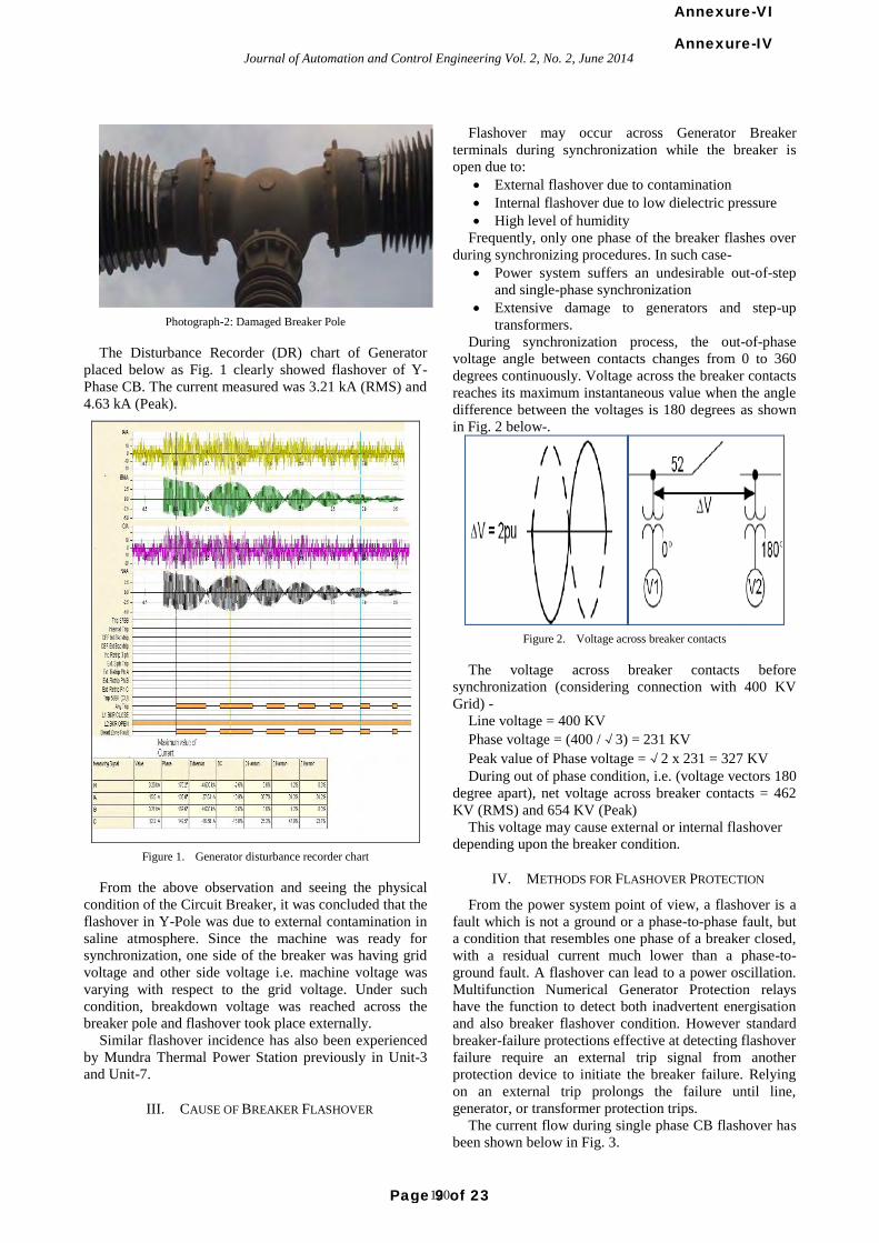
Photograph-2: Damaged Breaker Pole
The Disturbance Recorder (DR) chart of Generator
placed below as Fig. 1 clearly showed flashover of Y-
Phase CB. The current measured was 3.21 kA (RMS) and
4.63 kA (Peak).
Figure 1. Generator disturbance recorder chart
From the above observation and seeing the physical
condition of the Circuit Breaker, it was concluded that the
flashover in Y-Pole was due to external contamination in
saline atmosphere. Since the machine was ready for
synchronization, one side of the breaker was having grid
voltage and other side voltage i.e. machine voltage was
varying with respect to the grid voltage. Under such
condition, breakdown voltage was reached across the
breaker pole and flashover took place externally.
Similar flashover incidence has also been experienced
by Mundra Thermal Power Station previously in Unit-3
and Unit-7.
III. CAUSE OF BREAKER FLASHOVER
Flashover may occur across Generator Breaker
terminals during synchronization while the breaker is
open due to:
External flashover due to contamination
Internal flashover due to low dielectric pressure
High level of humidity
Frequently, only one phase of the breaker flashes over
during synchronizing procedures. In such case-
Power system suffers an undesirable out-of-step
and single-phase synchronization
Extensive damage to generators and step-up
transformers.
During synchronization process, the out-of-phase
voltage angle between contacts changes from 0 to 360
degrees continuously. Voltage across the breaker contacts
reaches its maximum instantaneous value when the angle
difference between the voltages is 180 degrees as shown
in Fig. 2 below-.
Figure 2. Voltage across breaker contacts
The voltage across breaker contacts before
synchronization (considering connection with 400 KV
Grid) -
Line voltage = 400 KV
Phase voltage = (400 /√3) = 231 KV
Peak value of Phase voltage =√2 x 231 = 327 KV
During out of phase condition, i.e. (voltage vectors 180
degree apart), net voltage across breaker contacts = 462
KV (RMS) and 654 KV (Peak)
This voltage may cause external or internal flashover
depending upon the breaker condition.
IV. METHODS FOR FLASHOVER PROTECTION
From the power system point of view, a flashover is a
fault which is not a ground or a phase-to-phase fault, but
a condition that resembles one phase of a breaker closed,
with a residual current much lower than a phase-to-
ground fault. A flashover can lead to a power oscillation.
Multifunction Numerical Generator Protection relays
have the function to detect both inadvertent energisation
and also breaker flashover condition. However standard
breaker-failure protections effective at detecting flashover
failure require an external trip signal from another
protection device to initiate the breaker failure. Relying
on an external trip prolongs the failure until line,
generator, or transformer protection trips.
The current flow during single phase CB flashover has
been shown below in Fig. 3.
120
Journal of Automation and Control Engineering Vol. 2, No. 2, June 2014Annexure-IV
Page 9 of 23
Annexure-VI
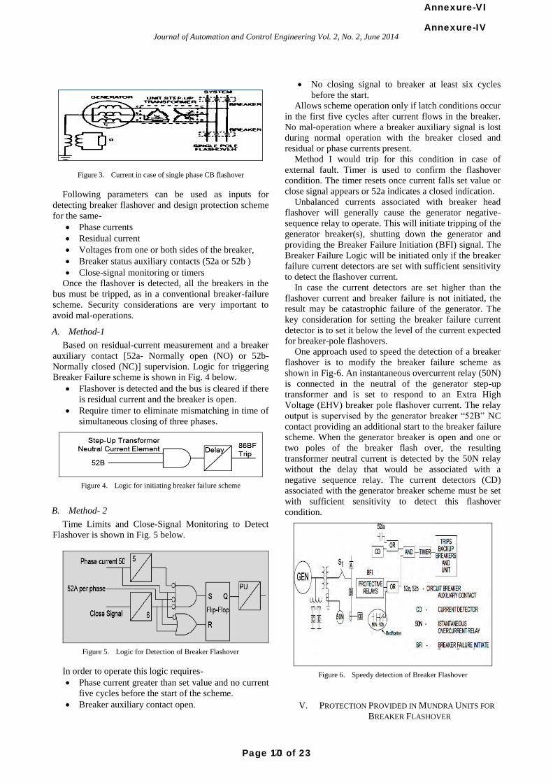
Figure 3. Current in case of single phase CB flashover
Following parameters can be used as inputs for
detecting breaker flashover and design protection scheme
for the same-
Phase currents
Residual current
Voltages from one or both sides of the breaker,
Breaker status auxiliary contacts (52a or 52b )
Close-signal monitoring or timers
Once the flashover is detected, all the breakers in the
bus must be tripped, as in a conventional breaker-failure
scheme. Security considerations are very important to
avoid mal-operations.
A. Method-1
Based on residual-current measurement and a breaker
auxiliary contact [52a- Normally open (NO) or 52b-
Normally closed (NC)] supervision. Logic for triggering
Breaker Failure scheme is shown in Fig. 4 below.
Flashover is detected and the bus is cleared if there
is residual current and the breaker is open.
Require timer to eliminate mismatching in time of
simultaneous closing of three phases.
Figure 4. Logic for initiating breaker failure scheme
B. Method- 2
Time Limits and Close-Signal Monitoring to Detect
Flashover is shown in Fig. 5 below.
Figure 5. Logic for Detection of Breaker Flashover
In order to operate this logic requires-
Phase current greater than set value and no current
five cycles before the start of the scheme.
Breaker auxiliary contact open.
No closing signal to breaker at least six cycles
before the start.
Allows scheme operation only if latch conditions occur
in the first five cycles after current flows in the breaker.
No mal-operation where a breaker auxiliary signal is lost
during normal operation with the breaker closed and
residual or phase currents present.
Method I would trip for this condition in case of
external fault. Timer is used to confirm the flashover
condition. The timer resets once current falls set value or
close signal appears or 52a indicates a closed indication.
Unbalanced currents associated with breaker head
flashover will generally cause the generator negative-
sequence relay to operate. This will initiate tripping of the
generator breaker(s), shutting down the generator and
providing the Breaker Failure Initiation (BFI) signal. The
Breaker Failure Logic will be initiated only if the breaker
failure current detectors are set with sufficient sensitivity
to detect the flashover current.
In case the current detectors are set higher than the
flashover current and breaker failure is not initiated, the
result may be catastrophic failure of the generator. The
key consideration for setting the breaker failure current
detector is to set it below the level of the current expected
for breaker-pole flashovers.
One approach used to speed the detection of a breaker
flashover is to modify the breaker failure scheme as
shown in Fig-6. An instantaneous overcurrent relay (50N)
is connected in the neutral of the generator step-up
transformer and is set to respond to an Extra High
Voltage (EHV) breaker pole flashover current. The relay
output is supervised by the generator breaker “52B” NC
contact providing an additional start to the breaker failure
scheme. When the generator breaker is open and one or
two poles of the breaker flash over, the resulting
transformer neutral current is detected by the 50N relay
without the delay that would be associated with a
negative sequence relay. The current detectors (CD)
associated with the generator breaker scheme must be set
with sufficient sensitivity to detect this flashover
condition.
Figure 6. Speedy detection of Breaker Flashover
V. PROTECTION PROVIDED IN MUNDRA UNITS FOR
BREAKER FLASHOVER
121
Journal of Automation and Control Engineering Vol. 2, No. 2, June 2014Annexure-IV
Page 10 of 23
Annexure-VI
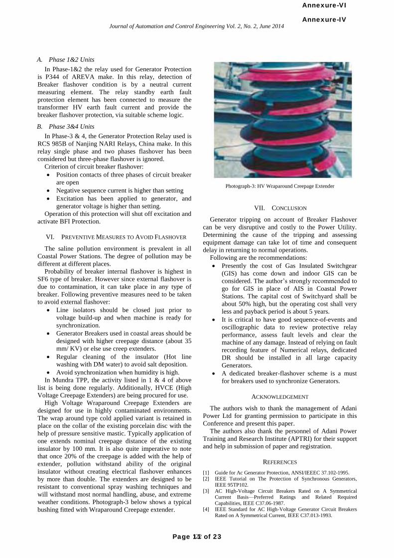
A. Phase 1&2 Units
In Phase-1&2 the relay used for Generator Protection
is P344 of AREVA make. In this relay, detection of
Breaker flashover condition is by a neutral current
measuring element. The relay standby earth fault
protection element has been connected to measure the
transformer HV earth fault current and provide the
breaker flashover protection, via suitable scheme logic.
B. Phase 3&4 Units
In Phase-3 & 4, the Generator Protection Relay used is
RCS 985B of Nanjing NARI Relays, China make. In this
relay single phase and two phases flashover has been
considered but three-phase flashover is ignored.
Criterion of circuit breaker flashover:
Position contacts of three phases of circuit breaker
are open
Negative sequence current is higher than setting
Excitation has been applied to generator, and
generator voltage is higher than setting.
Operation of this protection will shut off excitation and
activate BFI Protection.
VI. PREVENTIVE MEASURES TO AVOID FLASHOVER
The saline pollution environment is prevalent in all
Coastal Power Stations. The degree of pollution may be
different at different places.
Probability of breaker internal flashover is highest in
SF6 type of breaker. However since external flashover is
due to contamination, it can take place in any type of
breaker. Following preventive measures need to be taken
to avoid external flashover:
Line isolators should be closed just prior to
voltage build-up and when machine is ready for
synchronization.
Generator Breakers used in coastal areas should be
designed with higher creepage distance (about 35
mm/ KV) or else use creep extenders.
Regular cleaning of the insulator (Hot line
washing with DM water) to avoid salt deposition.
Avoid synchronization when humidity is high.
In Mundra TPP, the activity listed in 1 & 4 of above
list is being done regularly. Additionally, HVCE (High
Voltage Creepage Extenders) are being procured for use.
High Voltage Wraparound Creepage Extenders are
designed for use in highly contaminated environments.
The wrap around type cold applied variant is retained in
place on the collar of the existing porcelain disc with the
help of pressure sensitive mastic. Typically application of
one extends nominal creepage distance of the existing
insulator by 100 mm. It is also quite imperative to note
that once 20% of the creepage is added with the help of
extender, pollution withstand ability of the original
insulator without creating electrical flashover enhances
by more than double. The extenders are designed to be
resistant to conventional spray washing techniques and
will withstand most normal handling, abuse, and extreme
weather conditions. Photograph-3 below shows a typical
bushing fitted with Wraparound Creepage extender.
Photograph-3: HV Wraparound Creepage Extender
VII. CONCLUSION
Generator tripping on account of Breaker Flashover
can be very disruptive and costly to the Power Utility.
Determining the cause of the tripping and assessing
equipment damage can take lot of time and consequent
delay in returning to normal operations.
Following are the recommendations:
Presently the cost of Gas Insulated Switchgear
(GIS) has come down and indoor GIS can be
considered. The author’s strongly recommended to
go for GIS in place of AIS in Coastal Power
Stations. The capital cost of Switchyard shall be
about 50% high, but the operating cost shall very
less and payback period is about 5 years.
It is critical to have good sequence-of-events and
oscillographic data to review protective relay
performance, assess fault levels and clear the
machine of any damage. Instead of relying on fault
recording feature of Numerical relays, dedicated
DR should be installed in all large capacity
Generators.
A dedicated breaker-flashover scheme is a must
for breakers used to synchronize Generators.
ACKNOWLEDGEMENT
The authors wish to thank the management of Adani
Power Ltd for granting permission to participate in this
Conference and present this paper.
The authors also thank the personnel of Adani Power
Training and Research Institute (APTRI) for their support
and help in submission of paper and registration.
REFERENCES
[1] Guide for Ac Generator Protection, ANSI/IEEEC 37.102-1995. [2] IEEE Tutorial on The Protection of Synchronous Generators,
IEEE 95TP102.
[3] AC High-Voltage Circuit Breakers Rated on A Symmetrical Current Basis—Preferred Ratings and Related Required
Capabilities, IEEE C37.06-1987. [4] IEEE Standard for AC High-Voltage Generator Circuit Breakers
Rated on A Symmetrical Current, IEEE C37.013-1993.
122
Journal of Automation and Control Engineering Vol. 2, No. 2, June 2014Annexure-IV
Page 11 of 23
Annexure-VI
[5] IEEE Standard Test Procedure for AC High-Voltage Circuit Breakers Rated on a Symmetrical Current Basis, IEEE C37.09-
1979.
[6] IEEE Guide for AC Generator Protection, IEEE C37.102-1987. [7] Evaluation of Methods for Breaker Flashover Protection, Ramón
Sandoval Comisión Federal de Electricidad Sinaloa, México.
Bishnu Prasanna Nanda has about 32 years’ experience in Indian Power sector and has worked
in both Public and Private Power utilities. He has
done B.Tech in Electrical Engg from National Institute of Technology, Raurkela, Odisha, India
in 1981. He has also done Advanced Diploma in Management from IGNOU, New Delhi. He has
been certified as Energy Auditor by Bureau of
Energy Efficiency, New Delhi, India. During his career spanning 32 years, he worked with NTPC Ltd for 27 years in various Project sites in
Operation & Maintenance wing. Since 2008, he is with Adani Group
and presently working as Vice President (Engineering).
Pramod Kumar Saxena has more than 28 years’
experience in Indian Power sector and has
worked in both Public and Private Power utilities. He has done B.E in Electrical Engg from
Government Engineering College Rewa Madhya Pradesh, India in 1984. During his career
spanning 28 years, he worked with NTPC Ltd for
20 years in various Project sites in Operation & Maintenance wing. Since 2008, he is with Adani
Group. Up to 2012 he worked in projects and commissioned 5 units of 660 MW at Mundra. Presently he is working as General Manager
(O&M) at Mundra TPP.
123
Journal of Automation and Control Engineering Vol. 2, No. 2, June 2014Annexure-IV
Page 12 of 23
Annexure-VI
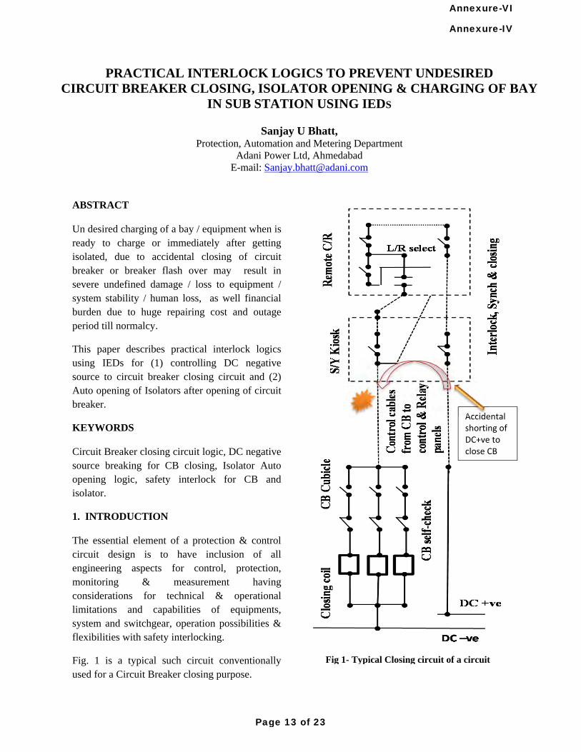
PRACTICAL INTERLOCK LOGICS TO PREVENT UNDESIRED CIRCUIT BREAKER CLOSING, ISOLATOR OPENING & CHARGING OF BAY
IN SUB STATION USING IEDS
Sanjay U Bhatt, Protection, Automation and Metering Department
Adani Power Ltd, Ahmedabad E-mail: [email protected]
ABSTRACT Un desired charging of a bay / equipment when is ready to charge or immediately after getting isolated, due to accidental closing of circuit breaker or breaker flash over may result in severe undefined damage / loss to equipment / system stability / human loss, as well financial burden due to huge repairing cost and outage period till normalcy.
This paper describes practical interlock logics using IEDs for (1) controlling DC negative source to circuit breaker closing circuit and (2) Auto opening of Isolators after opening of circuit breaker.
KEYWORDS Circuit Breaker closing circuit logic, DC negative source breaking for CB closing, Isolator Auto opening logic, safety interlock for CB and isolator.
1. INTRODUCTION The essential element of a protection & control circuit design is to have inclusion of all engineering aspects for control, protection, monitoring & measurement having considerations for technical & operational limitations and capabilities of equipments, system and switchgear, operation possibilities & flexibilities with safety interlocking.
Fig. 1 is a typical such circuit conventionally used for a Circuit Breaker closing purpose.
Fig 1- Typical Closing circuit of a circuit
Accidental shorting of DC+ve to close CB
Annexure-IV
Page 13 of 23
Annexure-VI
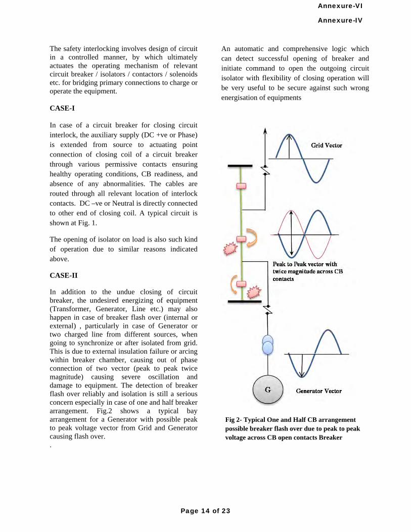
The safety interlocking involves design of circuit in a controlled manner, by which ultimately actuates the operating mechanism of relevant circuit breaker / isolators / contactors / solenoids etc. for bridging primary connections to charge or operate the equipment. CASE-I In case of a circuit breaker for closing circuit interlock, the auxiliary supply (DC +ve or Phase) is extended from source to actuating point connection of closing coil of a circuit breaker through various permissive contacts ensuring healthy operating conditions, CB readiness, and absence of any abnormalities. The cables are routed through all relevant location of interlock contacts. DC –ve or Neutral is directly connected to other end of closing coil. A typical circuit is shown at Fig. 1.
The opening of isolator on load is also such kind of operation due to similar reasons indicated above.
CASE-II
In addition to the undue closing of circuit breaker, the undesired energizing of equipment (Transformer, Generator, Line etc.) may also happen in case of breaker flash over (internal or external) , particularly in case of Generator or two charged line from different sources, when going to synchronize or after isolated from grid. This is due to external insulation failure or arcing within breaker chamber, causing out of phase connection of two vector (peak to peak twice magnitude) causing severe oscillation and damage to equipment. The detection of breaker flash over reliably and isolation is still a serious concern especially in case of one and half breaker arrangement. Fig.2 shows a typical bay arrangement for a Generator with possible peak to peak voltage vector from Grid and Generator causing flash over. .
An automatic and comprehensive logic which can detect successful opening of breaker and initiate command to open the outgoing circuit isolator with flexibility of closing operation will be very useful to be secure against such wrong energisation of equipments
Fig 2- Typical One and Half CB arrangement possible breaker flash over due to peak to peak voltage across CB open contacts Breaker
Annexure-IV
Page 14 of 23
Annexure-VI
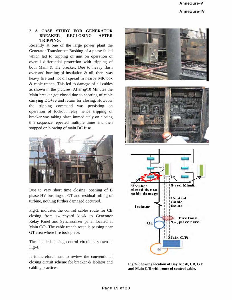
2 A CASE STUDY FOR GENERATOR BREAKER RECLOSING AFTER TRIPPING.
Recently at one of the large power plant the Generator Transformer Bushing of a phase failed which led to tripping of unit on operation of overall differential protection with tripping of both Main & Tie breaker. Due to heavy flash over and burning of insulation & oil, there was heavy fire and hot oil spread in nearby MK box & cable trench. This led to damage of all cables as shown in the pictures. After @10 Minutes the Main breaker got closed due to shorting of cable carrying DC+ve and return for closing. However the tripping command was persisting on operation of lockout relay hence tripping of breaker was taking place immediately on closing this sequence repeated multiple times and then stopped on blowing of main DC fuse.
Due to very short time closing, opening of B phase HV bushing of GT and residual rolling of turbine, nothing further damaged occurred.
Fig-3, indicates the control cables route for CB closing from switchyard kiosk to Generator Relay Panel and Synchronizer panel located at Main C/R. The cable trench route is passing near GT area where fire took place.
The detailed closing control circuit is shown at Fig-4.
It is therefore must to review the conventional closing circuit scheme for breaker & Isolator and cabling practices.
Fig 3- Showing location of Bay Kiosk, CB, GT and Main C/R with route of control cable.
Annexure-IV
Page 15 of 23
Annexure-VI
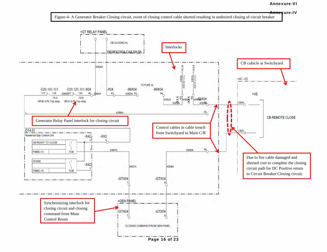
Due to fire cable damaged and shorted core to complete the closing circuit path for DC Positive return to Circuit Breaker Closing circuit.
Generator Relay Panel interlock for closing circuit
Synchronizing interlock for closing circuit and closing command from Main Control Room
CB cubicle at Switchyard
Control cables in cable trench from Switchyard to Main C/R
Interlocks
Figure-4- A Generator Breaker Closing circuit, event of closing control cable shorted resulting in undesired closing of circuit breaker Annexure-IV
Page 16 of 23
Annexure-VI
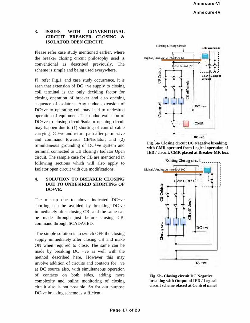
3. ISSUES WITH CONVENTIONAL CIRCUIT BREAKER CLOSING & ISOLATOR OPEN CIRCUIT.
Please refer case study mentioned earlier, where the breaker closing circuit philosophy used is conventional as described previously. The scheme is simple and being used everywhere.
Pl. refer Fig.1, and case study occurrence, it is seen that extension of DC +ve supply to closing coil terminal is the only deciding factor for closing operation of breaker and also opening sequence of isolator . Any undue extension of DC+ve to operating coil may lead to undesired operation of equipment. The undue extension of DC+ve to closing circuit/isolator opening circuit may happen due to (1) shorting of control cable carrying DC+ve and return path after permissive and command towards CB/Isolator, and (2) Simultaneous grounding of DC+ve system and terminal connected to CB closing / Isolator Open circuit. The sample case for CB are mentioned in following sections which will also apply to Isolator open circuit with due modifications.
4. SOLUTION TO BREAKER CLOSING DUE TO UNDESIRED SHORTING OF DC+VE.
The mishap due to above indicated DC+ve shorting can be avoided by breaking DC-ve immediately after closing CB and the same can be made through just before closing CB, command through SCADA/IED.
The simple solution is to switch OFF the closing supply immediately after closing CB and make ON when required to close. The same can be made by breaking DC +ve as well with the method described here. However this may involve addition of circuits and contacts for +ve at DC source also, with simultaneous operation of contacts on both sides, adding more complexity and online monitoring of closing circuit also is not possible. So for our purpose DC-ve breaking scheme is sufficient.
.
Existing Closing Circuit
Close Guard I/P
Fig. 5a- Closing circuit DC Negative breaking with CMR operated from Logical operation of IED / circuit. CMR placed at Breaker MK box.
Fig. 5b- Closing circuit DC Negative breaking with Output of IED / Logical circuit scheme placed at Control panel
Digital / Analogue Interlock I/O
Digital / Analogue Interlock I/O
Annexure-IV
Page 17 of 23
Annexure-VI
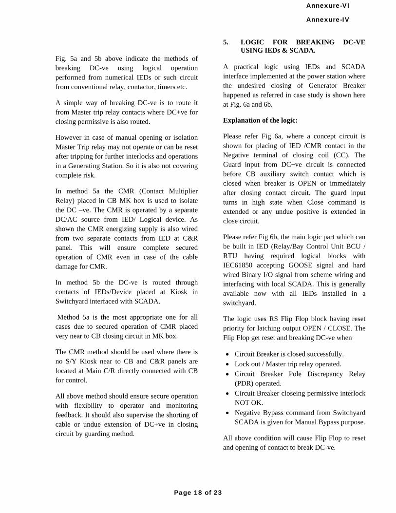
Fig. 5a and 5b above indicate the methods of breaking DC-ve using logical operation performed from numerical IEDs or such circuit from conventional relay, contactor, timers etc.
A simple way of breaking DC-ve is to route it from Master trip relay contacts where DC+ve for closing permissive is also routed.
However in case of manual opening or isolation Master Trip relay may not operate or can be reset after tripping for further interlocks and operations in a Generating Station. So it is also not covering complete risk.
In method 5a the CMR (Contact Multiplier Relay) placed in CB MK box is used to isolate the DC –ve. The CMR is operated by a separate DC/AC source from IED/ Logical device. As shown the CMR energizing supply is also wired from two separate contacts from IED at C&R panel. This will ensure complete secured operation of CMR even in case of the cable damage for CMR.
In method 5b the DC-ve is routed through contacts of IEDs/Device placed at Kiosk in Switchyard interfaced with SCADA.
Method 5a is the most appropriate one for all cases due to secured operation of CMR placed very near to CB closing circuit in MK box.
The CMR method should be used where there is no S/Y Kiosk near to CB and C&R panels are located at Main C/R directly connected with CB for control.
All above method should ensure secure operation with flexibility to operator and monitoring feedback. It should also supervise the shorting of cable or undue extension of DC+ve in closing circuit by guarding method.
5. LOGIC FOR BREAKING DC-VE USING IEDs & SCADA.
A practical logic using IEDs and SCADA interface implemented at the power station where the undesired closing of Generator Breaker happened as referred in case study is shown here at Fig. 6a and 6b.
Explanation of the logic:
Please refer Fig 6a, where a concept circuit is shown for placing of IED /CMR contact in the Negative terminal of closing coil (CC). The Guard input from DC+ve circuit is connected before CB auxiliary switch contact which is closed when breaker is OPEN or immediately after closing contact circuit. The guard input turns in high state when Close command is extended or any undue positive is extended in close circuit.
Please refer Fig 6b, the main logic part which can be built in IED (Relay/Bay Control Unit BCU / RTU having required logical blocks with IEC61850 accepting GOOSE signal and hard wired Binary I/O signal from scheme wiring and interfacing with local SCADA. This is generally available now with all IEDs installed in a switchyard.
The logic uses RS Flip Flop block having reset priority for latching output OPEN / CLOSE. The Flip Flop get reset and breaking DC-ve when
Circuit Breaker is closed successfully. Lock out / Master trip relay operated. Circuit Breaker Pole Discrepancy Relay
(PDR) operated. Circuit Breaker closeing permissive interlock
NOT OK. Negative Bypass command from Switchyard
SCADA is given for Manual Bypass purpose.
All above condition will cause Flip Flop to reset and opening of contact to break DC-ve.
Annexure-IV
Page 18 of 23
Annexure-VI
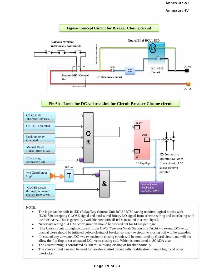
52b
CC
Various external interlocks / commands
Breaker MK / Control Box
IED/ CMR Contact
DC ‐ve
DC +ve
CB CLOSE (Except Line Bay)
CB-PDR Operated
Lock out relay Operated
RESET
SET
OUT
+ve Guard input High
‘CLOSE circuit through command’ (Pulse) from OWS
RS Flip-flop
IED Contacts to
operate CMR or to
DC‐ve circuit of CB
as per scheme
adopted.
Guard BI of BCU / IED
200 ms
NOTE: The logic can be built in IED (Relay/Bay Control Unit BCU / RTU having required logical blocks with
IEC61850 accepting GOOSE signal and hard wired Binary I/O signal from scheme wiring and interfacing with local SCADA. This is generally available now with all IEDs installed in a switchyard.
Necessary wiring / GOOSE configuration should be worked out for I/O as per logic. ‘The Close circuit through command’ from OWS (Operator Work Station of SCADA) to extend DC-ve for
manual close should be initiated before closing of breaker so that –ve circuit to closing coil will be extended. In case of any unwanted DC +ve extension in closing circuit will be monitored by Guard circuit and will not
allow the flip flop to set to extend DC –ve to closing coil. Which is monitored in SCADA also. The Guard timing is considered as 200 mS allowing closing of breaker normally. The above circuit can also be used for isolator control circuit with modification in input logic and other
interlocks.
Manual Reset (Pulse) from OWS
CB closing permissive OK
Interlock status feedback to SCADA / OWS
Fig 6b - Logic for DC-ve breaking for Circuit Breaker Closing circuit
Fig-6a- Concept Circuit for Breaker Closing circuit
Breaker Aux. contact
Annexure-IV
Page 19 of 23
Annexure-VI
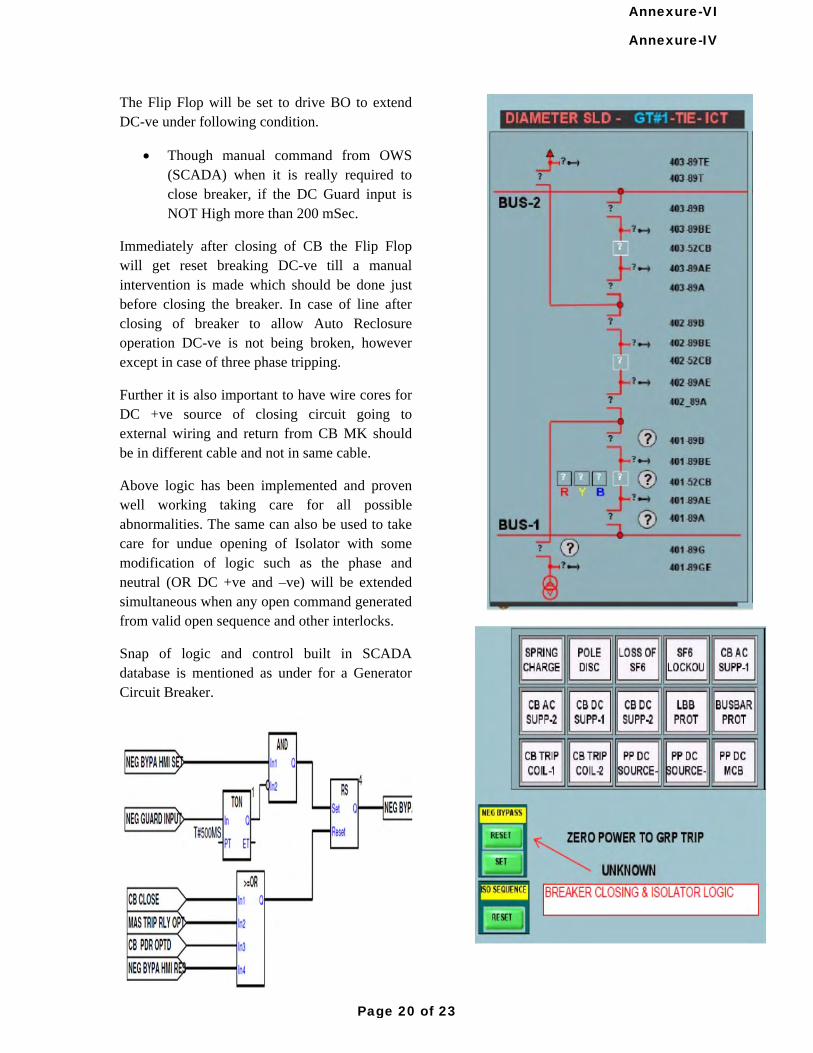
The Flip Flop will be set to drive BO to extend DC-ve under following condition.
Though manual command from OWS (SCADA) when it is really required to close breaker, if the DC Guard input is NOT High more than 200 mSec.
Immediately after closing of CB the Flip Flop will get reset breaking DC-ve till a manual intervention is made which should be done just before closing the breaker. In case of line after closing of breaker to allow Auto Reclosure operation DC-ve is not being broken, however except in case of three phase tripping.
Further it is also important to have wire cores for DC +ve source of closing circuit going to external wiring and return from CB MK should be in different cable and not in same cable.
Above logic has been implemented and proven well working taking care for all possible abnormalities. The same can also be used to take care for undue opening of Isolator with some modification of logic such as the phase and neutral (OR DC +ve and –ve) will be extended simultaneous when any open command generated from valid open sequence and other interlocks.
Snap of logic and control built in SCADA database is mentioned as under for a Generator Circuit Breaker.
Annexure-IV
Page 20 of 23
Annexure-VI
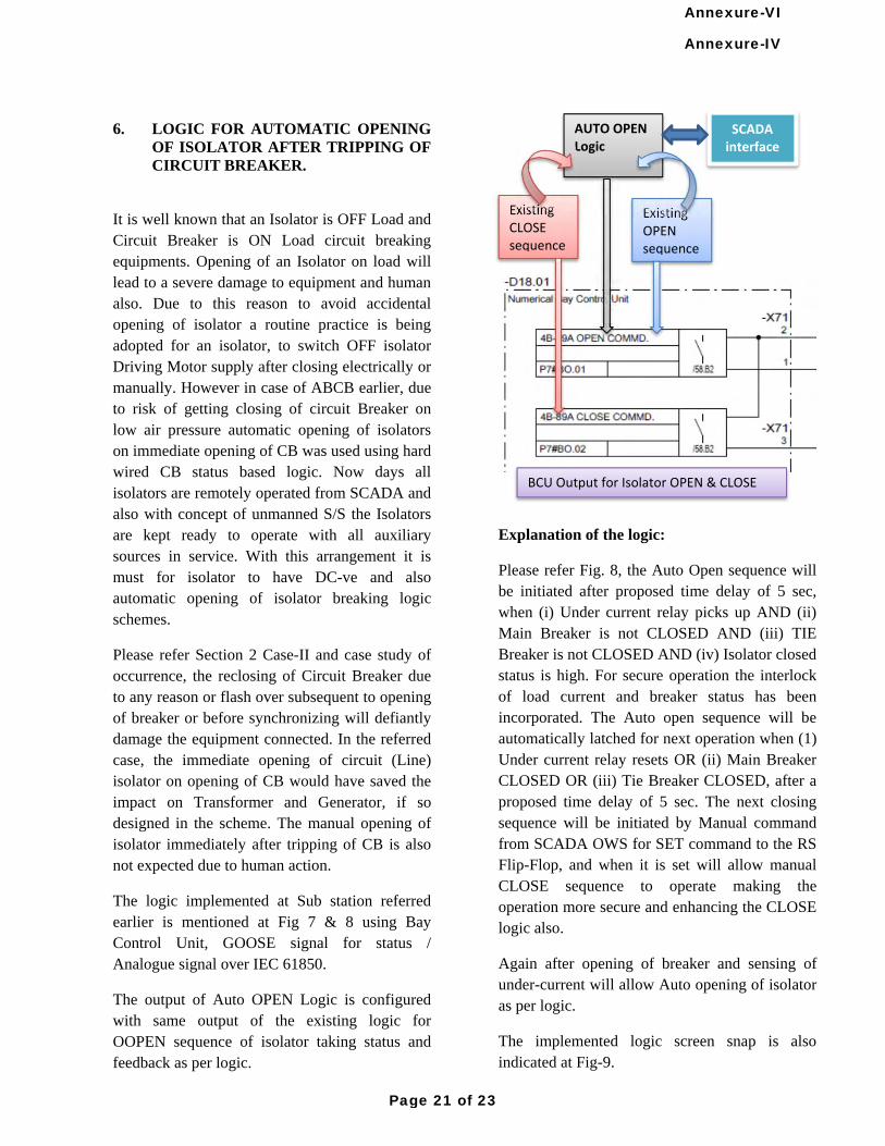
6. LOGIC FOR AUTOMATIC OPENING
OF ISOLATOR AFTER TRIPPING OF CIRCUIT BREAKER.
It is well known that an Isolator is OFF Load and Circuit Breaker is ON Load circuit breaking equipments. Opening of an Isolator on load will lead to a severe damage to equipment and human also. Due to this reason to avoid accidental opening of isolator a routine practice is being adopted for an isolator, to switch OFF isolator Driving Motor supply after closing electrically or manually. However in case of ABCB earlier, due to risk of getting closing of circuit Breaker on low air pressure automatic opening of isolators on immediate opening of CB was used using hard wired CB status based logic. Now days all isolators are remotely operated from SCADA and also with concept of unmanned S/S the Isolators are kept ready to operate with all auxiliary sources in service. With this arrangement it is must for isolator to have DC-ve and also automatic opening of isolator breaking logic schemes.
Please refer Section 2 Case-II and case study of occurrence, the reclosing of Circuit Breaker due to any reason or flash over subsequent to opening of breaker or before synchronizing will defiantly damage the equipment connected. In the referred case, the immediate opening of circuit (Line) isolator on opening of CB would have saved the impact on Transformer and Generator, if so designed in the scheme. The manual opening of isolator immediately after tripping of CB is also not expected due to human action.
The logic implemented at Sub station referred earlier is mentioned at Fig 7 & 8 using Bay Control Unit, GOOSE signal for status / Analogue signal over IEC 61850.
The output of Auto OPEN Logic is configured with same output of the existing logic for OOPEN sequence of isolator taking status and feedback as per logic.
Explanation of the logic:
Please refer Fig. 8, the Auto Open sequence will be initiated after proposed time delay of 5 sec, when (i) Under current relay picks up AND (ii) Main Breaker is not CLOSED AND (iii) TIE Breaker is not CLOSED AND (iv) Isolator closed status is high. For secure operation the interlock of load current and breaker status has been incorporated. The Auto open sequence will be automatically latched for next operation when (1) Under current relay resets OR (ii) Main Breaker CLOSED OR (iii) Tie Breaker CLOSED, after a proposed time delay of 5 sec. The next closing sequence will be initiated by Manual command from SCADA OWS for SET command to the RS Flip-Flop, and when it is set will allow manual CLOSE sequence to operate making the operation more secure and enhancing the CLOSE logic also.
Again after opening of breaker and sensing of under-current will allow Auto opening of isolator as per logic.
The implemented logic screen snap is also indicated at Fig-9.
Existing CLOSE sequence
Existing OPEN sequence
AUTO OPEN Logic
BCU Output for Isolator OPEN & CLOSE
SCADA interface
Annexure-IV
Page 21 of 23
Annexure-VI
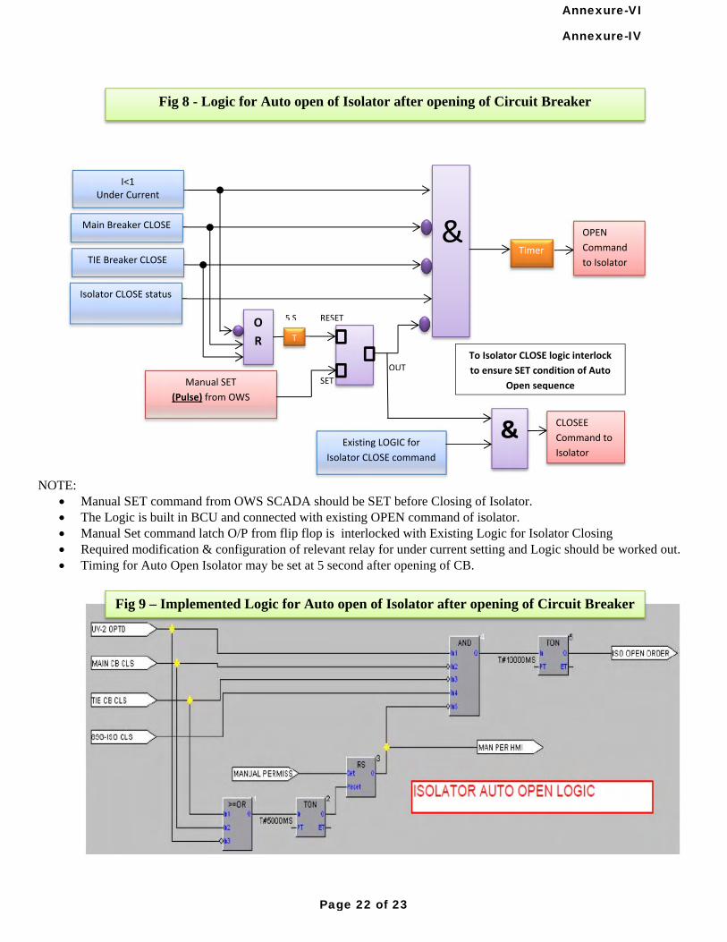
Fig 8 - Logic for Auto open of Isolator after opening of Circuit Breaker
&
I<1 Under Current
Main Breaker CLOSE
TIE Breaker CLOSE
Isolator CLOSE status
Manual SET
(Pulse) from OWS
Timer OPEN
Command
to Isolator
RESET
OUT
O
R
SET
To Isolator CLOSE logic interlock
to ensure SET condition of Auto
Open sequence
& Existing LOGIC for
Isolator CLOSE command
CLOSEE
Command to
Isolator
T
5 S
NOTE: Manual SET command from OWS SCADA should be SET before Closing of Isolator. The Logic is built in BCU and connected with existing OPEN command of isolator. Manual Set command latch O/P from flip flop is interlocked with Existing Logic for Isolator Closing Required modification & configuration of relevant relay for under current setting and Logic should be worked out. Timing for Auto Open Isolator may be set at 5 second after opening of CB.
Fig 9 – Implemented Logic for Auto open of Isolator after opening of Circuit Breaker
Annexure-IV
Page 22 of 23
Annexure-VI
7. CONCLUSION
The described engineering practice should be implemented as a standard scheme for operation of Circuit Breaker and Isolators looking to secure operation of primary switching.
Because numbers of incidences are being occurred on account of damaged cables or DC- grounding or mal-operation even during fault finding or testing of control wiring. The use of latest technology or equipment without reliable operating mechanism is waiting for a disaster always.
Availability of Numerical technological IEDs and GOOSE signals over IEC61850 protocol with SCADA has made the task very easy and secure.
(1) Circuit Breaker Closing circuit should be equipped with DC-ve breaking as near as possible to Closing Coil with Contact Multiplying relay / IED (Relay) contact with secured logic, control and monitoring facility in SCADA.
(2) Isolator OPEN circuit should also be equipped with similar above scheme logic indicated at (1).
(3) Circuit (Line) Isolator should be automatically opened immediately after tripping /Opening of CB/s. The logic should be secured enough to ensure complete OFF Loading of circuit and also with no confliction with CLOSE sequence operation.
(4) The control cables carrying DC-ve from CB / Isolator and to IED/Relay at C&R panel should be in different cable, preferably separate route to avoid any possibility of malfunction of the above discussed circuit itself.
(5) All the input / output and logical status should be configured in event of IED and SCADA for future analysis on event of occurrence.
(6) The new specification for C&R panel and scheme should be included with above said requirements.
REFERENCES:
(1) Various schemes drawing for different substations.
(2) AREVA make application manuals on BCU MICOM C264 /EN/AP/ C30, PACIS Operation Interface for Automation and other IEDs
(3) ABB make application manuals on 670 series IEDs.
AUTHOR:
.
.
.
Sanjay U. Bhatt, working as DGM (Protection) at Adani Power Ltd, Ahmedabad, (Protection Automation & Metering Department), from January 2012.
B.E. (Electrical) -1993 from L.E. College Morvi , Gujarat (India). Worked: In G.S.F.C.-Jamnagar, as Ele. Maintenance Engr. In Govt. Polytechnic, as a lecturer on clearing GPSC. In GSECL as Junior Engineer at Sikka Power station as Electrical Testing & Maintenance engineer and at SLDC during commissioning of SCADA and related system. As Deputy Engineer at GSECL corporate office as Testing engineer.
Annexure-IV
Page 23 of 23
Annexure-VI
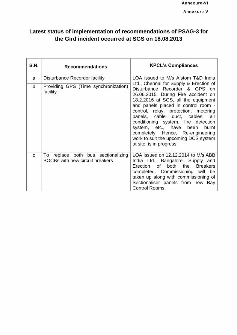
Latest status of implementation of recommendations of PSAG-3 for
the Gird incident occurred at SGS on 18.08.2013
S.N.
Recommendations
KPCL’s Compliances
a Disturbance Recorder facility LOA issued to M/s Alstom T&D India Ltd., Chennai for Supply & Erection of Disturbance Recorder & GPS on 26.06.2015. During Fire accident on 18.2.2016 at SGS, all the equipment and panels placed in control room - control, relay, protection, metering panels, cable duct, cables, air conditioning system, fire detection system, etc., have been burnt completely. Hence, Re-engineering work to suit the upcoming DCS system at site, is in progress.
b Providing GPS (Time synchronization) facility
c To replace both bus sectionalizing BOCBs with new circuit breakers
LOA issued on 12.12.2014 to M/s ABB India Ltd., Bangalore. Supply and Erection of both the Breakers completed. Commissioning will be taken up along with commissioning of Sectionaliser panels from new Bay Control Rooms.
Annexure-V
Annexure-VI
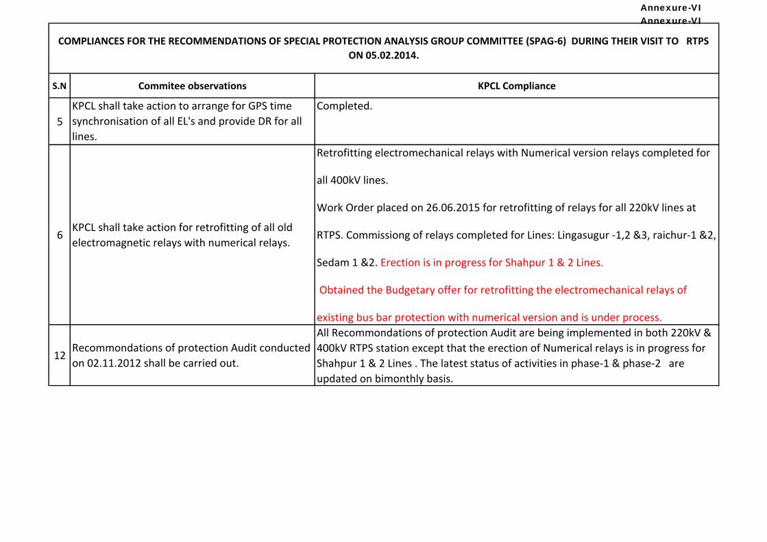
S.N Commitee observations KPCL Compliance
5
KPCL shall take action to arrange for GPS time
synchronisation of all EL's and provide DR for all
lines.
Completed.
6KPCL shall take action for retrofitting of all old
electromagnetic relays with numerical relays.
Retrofitting electromechanical relays with Numerical version relays completed for
all 400kV lines.
Work Order placed on 26.06.2015 for retrofitting of relays for all 220kV lines at
RTPS. Commissiong of relays completed for Lines: Lingasugur -1,2 &3, raichur-1 &2,
Sedam 1 &2. Erection is in progress for Shahpur 1 & 2 Lines.
Obtained the Budgetary offer for retrofitting the electromechanical relays of
existing bus bar protection with numerical version and is under process.
12Recommondations of protection Audit conducted
on 02.11.2012 shall be carried out.
All Recommondations of protection Audit are being implemented in both 220kV &
400kV RTPS station except that the erection of Numerical relays is in progress for
Shahpur 1 & 2 Lines . The latest status of activities in phase-1 & phase-2 are
updated on bimonthly basis.
COMPLIANCES FOR THE RECOMMENDATIONS OF SPECIAL PROTECTION ANALYSIS GROUP COMMITTEE (SPAG-6) DURING THEIR VISIT TO RTPS
ON 05.02.2014.
Annexure-VIAnnexure-VI
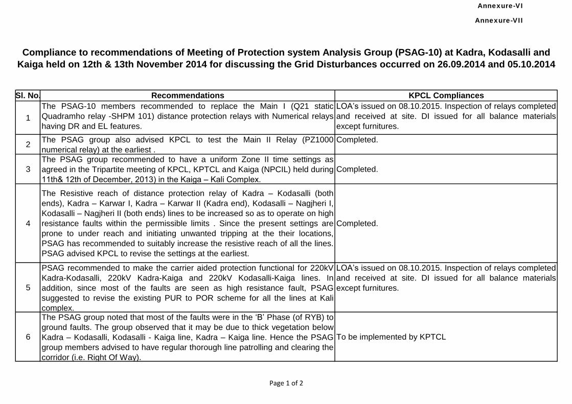
1
The PSAG-10 members recommended to replace the Main I (Q21 static
Quadramho relay -SHPM 101) distance protection relays with Numerical relays
having DR and EL features.
LOA’s issued on 08.10.2015. Inspection of relays completed
and received at site. DI issued for all balance materials
except furnitures.
2The PSAG group also advised KPCL to test the Main II Relay (PZ1000
numerical relay) at the earliest .
Completed.
3
The PSAG group recommended to have a uniform Zone II time settings as
agreed in the Tripartite meeting of KPCL, KPTCL and Kaiga (NPCIL) held during
11th& 12th of December, 2013) in the Kaiga – Kali Complex.
Completed.
4
The Resistive reach of distance protection relay of Kadra – Kodasalli (both
ends), Kadra – Karwar I, Kadra – Karwar II (Kadra end), Kodasalli – Nagjheri I,
Kodasalli – Nagjheri II (both ends) lines to be increased so as to operate on high
resistance faults within the permissible limits . Since the present settings are
prone to under reach and initiating unwanted tripping at the their locations,
PSAG has recommended to suitably increase the resistive reach of all the lines.
PSAG advised KPCL to revise the settings at the earliest.
Completed.
5
PSAG recommended to make the carrier aided protection functional for 220kV
Kadra-Kodasalli, 220kV Kadra-Kaiga and 220kV Kodasalli-Kaiga lines. In
addition, since most of the faults are seen as high resistance fault, PSAG
suggested to revise the existing PUR to POR scheme for all the lines at Kali
complex.
LOA’s issued on 08.10.2015. Inspection of relays completed
and received at site. DI issued for all balance materials
except furnitures.
6
The PSAG group noted that most of the faults were in the ‘B’ Phase (of RYB) to
ground faults. The group observed that it may be due to thick vegetation below
Kadra – Kodasalli, Kodasalli - Kaiga line, Kadra – Kaiga line. Hence the PSAG
group members advised to have regular thorough line patrolling and clearing the
corridor (i.e. Right Of Way).
To be implemented by KPTCL
Compliance to recommendations of Meeting of Protection system Analysis Group (PSAG-10) at Kadra, Kodasalli and
Kaiga held on 12th & 13th November 2014 for discussing the Grid Disturbances occurred on 26.09.2014 and 05.10.2014
Sl. No. Recommendations KPCL Compliances
Page 1 of 2
Annexure-VII
Annexure-VI
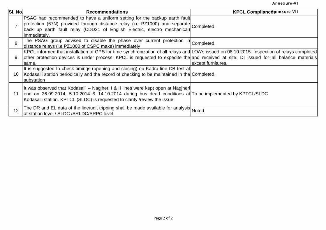
Sl. No. Recommendations KPCL Compliances
7
PSAG had recommended to have a uniform setting for the backup earth fault
protection (67N) provided through distance relay (i.e PZ1000) and separate
back up earth fault relay (CDD21 of English Electric, electro mechanical)
immediately.
Completed.
8The PSAG group advised to disable the phase over current protection in
distance relays (i.e PZ1000 of CSPC make) immediatelyCompleted.
9
KPCL informed that installation of GPS for time synchronization of all relays and
other protection devices is under process. KPCL is requested to expedite the
same.
LOA’s issued on 08.10.2015. Inspection of relays completed
and received at site. DI issued for all balance materials
except furnitures.
10
It is suggested to check timings (opening and closing) on Kadra line CB test at
Kodasalli station periodically and the record of checking to be maintained in the
substation
Completed.
11
It was observed that Kodasalli – Nagjheri I & II lines were kept open at Nagjheri
end on 26.09.2014, 5.10.2014 & 14.10.2014 during bus dead conditions at
Kodasalli station. KPTCL (SLDC) is requested to clarify /review the issue
To be implemented by KPTCL/SLDC
12The DR and EL data of the line/unit tripping shall be made available for analysis
at station level / SLDC /SRLDC/SRPC level.Noted
Page 2 of 2
Annexure-VII
Annexure-VI
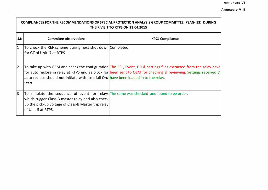
S.N Commitee observations KPCL Compliance
1 To check the REF scheme during next shut down
for GT of Unit -7 at RTPS
Completed.
2 To take up with OEM and check the configuration
for auto reclose in relay at RTPS end as block for
auto reclose should not initiate with fuse fail On/
Start
The PSL, Event, DR & settings files extracted from the relay have
been sent to OEM for checking & reviewing. Settings received &
have been loaded in to the relay.
3 To simulate the sequence of event for relays
which trigger Class-B master relay and also check
up the pick-up voltage of Class-B Master trip relay
of Unit-5 at RTPS.
The same was checked and found to be order.
COMPLIANCES FOR THE RECOMMENDATIONS OF SPECIAL PROTECTION ANALYSIS GROUP COMMITTEE (PSAG- 13) DURING
THEIR VISIT TO RTPS ON 23.04.2015
Annexure-VIII
Annexure-VI
Mee
ting
No /
Inde
x
Details of
Event
Date Reason PCSC Recommendations Utility
Responsible
for
implementatio
n
Status of Recommendations
as on
Remark
s
Pending Implementation of PCSC Recommendations (30th to 53rd)
Karnataka
Annexure-IX
Page 1 of 12
Annexure-VI
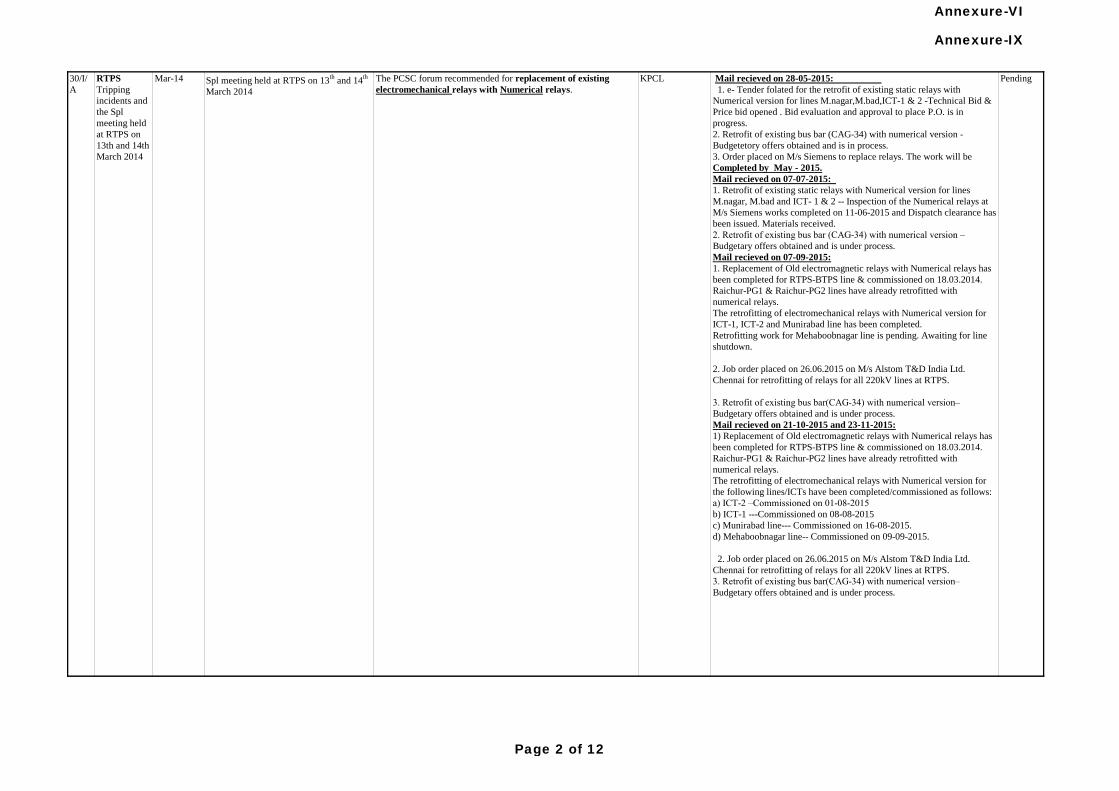
Pending Mail recieved on 28-05-2015:
1. e- Tender folated for the retrofit of existing static relays with
Numerical version for lines M.nagar,M.bad,ICT-1 & 2 -Technical Bid &
Price bid opened . Bid evaluation and approval to place P.O. is in
progress.
2. Retrofit of existing bus bar (CAG-34) with numerical version -
Budgetetory offers obtained and is in process.
3. Order placed on M/s Siemens to replace relays. The work will be
Completed by May - 2015.
Mail recieved on 07-07-2015:
1. Retrofit of existing static relays with Numerical version for lines
M.nagar, M.bad and ICT- 1 & 2 -- Inspection of the Numerical relays at
M/s Siemens works completed on 11-06-2015 and Dispatch clearance has
been issued. Materials received.
2. Retrofit of existing bus bar (CAG-34) with numerical version –
Budgetary offers obtained and is under process.
Mail recieved on 07-09-2015:
1. Replacement of Old electromagnetic relays with Numerical relays has
been completed for RTPS-BTPS line & commissioned on 18.03.2014.
Raichur-PG1 & Raichur-PG2 lines have already retrofitted with
numerical relays.
The retrofitting of electromechanical relays with Numerical version for
ICT-1, ICT-2 and Munirabad line has been completed.
Retrofitting work for Mehaboobnagar line is pending. Awaiting for line
shutdown.
2. Job order placed on 26.06.2015 on M/s Alstom T&D India Ltd.
Chennai for retrofitting of relays for all 220kV lines at RTPS.
3. Retrofit of existing bus bar(CAG-34) with numerical version–
Budgetary offers obtained and is under process.
Mail recieved on 21-10-2015 and 23-11-2015:
1) Replacement of Old electromagnetic relays with Numerical relays has
been completed for RTPS-BTPS line & commissioned on 18.03.2014.
Raichur-PG1 & Raichur-PG2 lines have already retrofitted with
numerical relays.
The retrofitting of electromechanical relays with Numerical version for
the following lines/ICTs have been completed/commissioned as follows:
a) ICT-2 –Commissioned on 01-08-2015
b) ICT-1 ---Commissioned on 08-08-2015
c) Munirabad line--- Commissioned on 16-08-2015.
d) Mehaboobnagar line-- Commissioned on 09-09-2015.
2. Job order placed on 26.06.2015 on M/s Alstom T&D India Ltd.
Chennai for retrofitting of relays for all 220kV lines at RTPS.
3. Retrofit of existing bus bar(CAG-34) with numerical version–
Budgetary offers obtained and is under process.
RTPS
Tripping
incidents and
the Spl
meeting held
at RTPS on
13th and 14th
March 2014
30/I/
A
KPCLThe PCSC forum recommended for replacement of existing
electromechanical relays with Numerical relays. Spl meeting held at RTPS on 13
th and 14
th
March 2014
Mar-14
Annexure-IX
Page 2 of 12
Annexure-VI
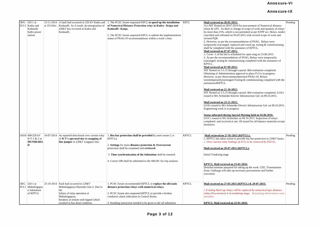
Mail recieved on 28-05-2015:
1) e-NIT floated on 28.07.2014 for procurement of Numerical distance
relays & GPS. As there is change in scope of work and quantity of relays
by more than 25%, which is not permitted as per KTPP act. Hence, tender
cancelled and refloated on 05.05.2015 with revised scope of work and
revised PQR.
2. However, as per the recommendations of PSAG, Relays were
temporarily rearranged, replaced and wired up. testing & commissioning
shall be completed with the assistance of KPTCL.
Mail recieved on 07-07-2015:
1. Cover -1 of the bid is scheduled for open eing on 25.06.2015.
2. As per the recommendations of PSAG, Relays were temporarily
rearranged. testing & commissioning completed with the assistance of
KPTCL.
Mail recieved on 07-09-2015:
NIT floated on 5.5.15 through e-portal. Bid evaluation completed.
Obtaining of Administration approval to place P.O is in progress.
However, as per therecommendationsof PSAG-10, Relays
weretemporarilyrearranged.Testing & commissioning completed with the
assistanceofKPTCL.
Mail recieved on 21-10-2015:
NIT floated on 5.5.15 through e-portal. Bid evaluation completed. LOA's
issued to M/s Schneider Electric Infrastructure Ltd. on 08.10.2015.
Mail recieved on 23-11-2015:
LOA's issued to M/s Schneider Electric Infrastructure Ltd. on 08.10.2015.
Engineering work is in progress.
Status informed during Special Meeting held on 03.06.2016:
LOA’s issued to M/s Schneider on 08.10.2015. Inspection of relays
completed and received at site. DI issued for all balance materials except
furnitures.
KPCL1. The PCSC forum requested KPCL to speed up the installation
of Numerical Distance Protection relay in Kadra –Kaiga and
Kodasalli –Kaiga.
2. The PCSC forum requested KPCL to submit the implementation
status of PSAG-10 recommendations within a week’s time.
A fault had occurred in 220 kV Kadra and
Kodasalli. As A result, de-energization of
220kV bus occurred at Kadra and
Kodasalli.
13-11-2014
at 19:31hrs
Mail received on 27-05-2015 (KPTCL) & 29-07-2015:
1.Existing Back up relays will be replaced by numerical type distance
relays.Procurement is in tendering stage. Remaining observations were
attended.
KPTCL Mail recieved on 23-01-2016:
Existing back up relays will be replaced by Main-2 protection. LOI issued
M/s Alstom for taking up the works.Remaining observations were
attended.
KPTCL Mail Recieved dated 25-05-2016:
Under the Scope of R&U. The work will be taken up by M/s Alstom
shortly.
KPTCL1. PCSC forum recommended KPTCL to replace the old static
distance protection relays with numerical relays.
2. PCSC forum also requested KPTCL to provide a broken
conductor alarm indication in Control Room.
3. Standing instruction needed to be given to the all substation
personnel for not changing the relay settings without approval of
RT/MRT wing.
Fault had occurred in 220kV
Mahalingapura-Narendra line-2. Due to
the
failure of relay operation at
Mahalingapura,
breakers at remote end tripped which
resulted in bus dead condition.
25-10-2014GD-1 at
Mahalingapur
a Substation
of KPTCL
38/G
D/3.1
Pending
Mail recieved on 27-05-2015 (KPTCL):
1. KPTCL has taken action to provide bus bar protection to 220kV buses.
2. Over current relay Settings of ICTs to be reviewed by PGCIL.
Mail received on 29-07-2015 (KPTCL):
Initial Tendering stage
KPTCL Mail recieved on 23-01-2016:
Detailed estimate prepared for taking up the work. CEE, Transmission
Zone, Gulbarga will take up necessary procurement and further
execution.
1. Bus bar protection shall be provided by asset owner ( i.e
KPTCL).
2. Settings for main distance protection & Overcurrent
protection shall be examined and reviewed.
3. Time synchronization of the Substation shall be ensured.
4. Correct DR shall be submitted to the SRLDC for trip analysis.
Pending
400/220 kV
ICT-1 & 2 at
MUNIRABA
D
34/I/6 As reported directional over current relay
of ICT’s operated due to snapping of
line jumper in 220kV Lingapur line.
16-07-2014 PendingKPTCL
GD-1 at
Kadra and
Kodasalli
hydro power
station
38/G
D/3.5
Annexure-IX
Page 3 of 12
Annexure-VI
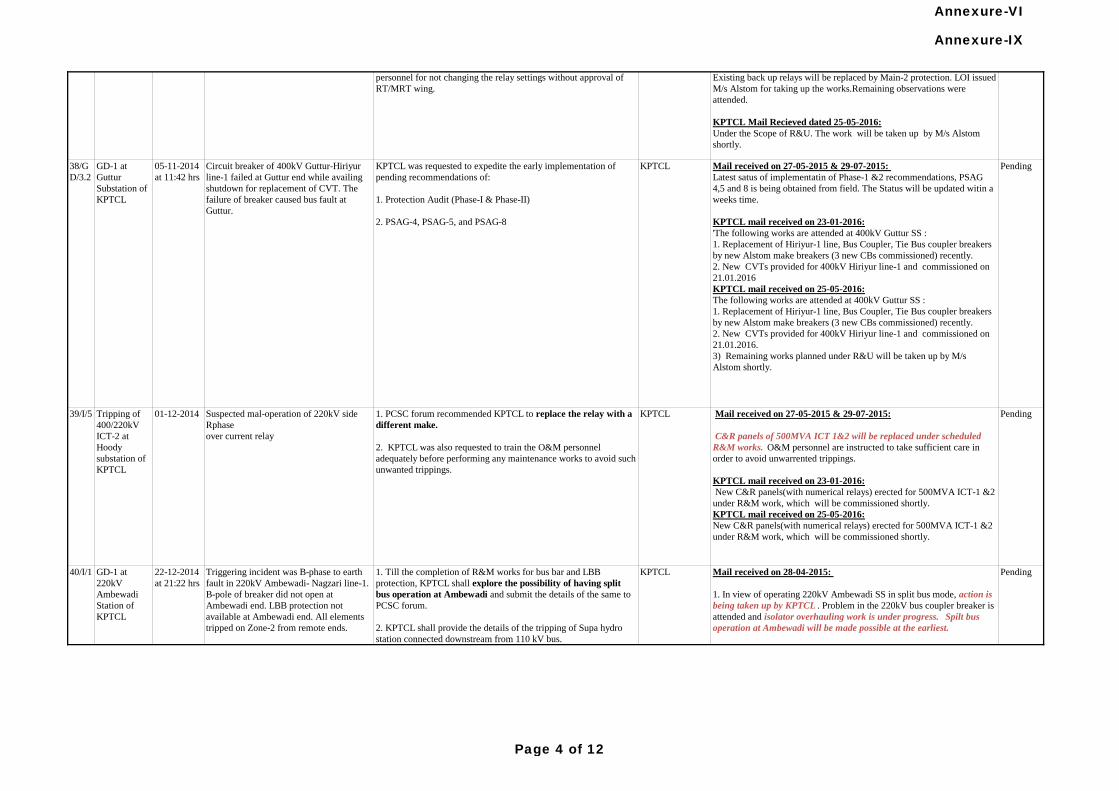
Circuit breaker of 400kV Guttur-Hiriyur
line-1 failed at Guttur end while availing
shutdown for replacement of CVT. The
failure of breaker caused bus fault at
Guttur.
05-11-2014
at 11:42 hrs
GD-1 at
Guttur
Substation of
KPTCL
38/G
D/3.2
Mail received on 27-05-2015 (KPTCL) & 29-07-2015:
1.Existing Back up relays will be replaced by numerical type distance
relays.Procurement is in tendering stage. Remaining observations were
attended.
KPTCL Mail recieved on 23-01-2016:
Existing back up relays will be replaced by Main-2 protection. LOI issued
M/s Alstom for taking up the works.Remaining observations were
attended.
KPTCL Mail Recieved dated 25-05-2016:
Under the Scope of R&U. The work will be taken up by M/s Alstom
shortly.
KPTCL1. PCSC forum recommended KPTCL to replace the old static
distance protection relays with numerical relays.
2. PCSC forum also requested KPTCL to provide a broken
conductor alarm indication in Control Room.
3. Standing instruction needed to be given to the all substation
personnel for not changing the relay settings without approval of
RT/MRT wing.
Fault had occurred in 220kV
Mahalingapura-Narendra line-2. Due to
the
failure of relay operation at
Mahalingapura,
breakers at remote end tripped which
resulted in bus dead condition.
25-10-2014GD-1 at
Mahalingapur
a Substation
of KPTCL
38/G
D/3.1
PendingKPTCLKPTCL was requested to expedite the early implementation of
pending recommendations of:
1. Protection Audit (Phase-I & Phase-II)
2. PSAG-4, PSAG-5, and PSAG-8
Pending
Mail received on 27-05-2015 & 29-07-2015:
Latest satus of implementatin of Phase-1 &2 recommendations, PSAG
4,5 and 8 is being obtained from field. The Status will be updated witin a
weeks time.
KPTCL mail received on 23-01-2016:
'The following works are attended at 400kV Guttur SS :
1. Replacement of Hiriyur-1 line, Bus Coupler, Tie Bus coupler breakers
by new Alstom make breakers (3 new CBs commissioned) recently.
2. New CVTs provided for 400kV Hiriyur line-1 and commissioned on
21.01.2016
KPTCL mail received on 25-05-2016:
The following works are attended at 400kV Guttur SS :
1. Replacement of Hiriyur-1 line, Bus Coupler, Tie Bus coupler breakers
by new Alstom make breakers (3 new CBs commissioned) recently.
2. New CVTs provided for 400kV Hiriyur line-1 and commissioned on
21.01.2016.
3) Remaining works planned under R&U will be taken up by M/s
Alstom shortly.
39/I/5 Pending
Mail received on 28-04-2015:
1. In view of operating 220kV Ambewadi SS in split bus mode, action is
being taken up by KPTCL . Problem in the 220kV bus coupler breaker is
attended and isolator overhauling work is under progress. Spilt bus
operation at Ambewadi will be made possible at the earliest.
2. ICT protection system at Ambewadi and trippings occured at Supa GS
during the instance is checked up and remedial measures already
furnished in this regard.
Mail recieved on 29-07-2015:
Action is being taken by KPTCL for operating Ambewadi in split bus
mode. Problem in bus coupler breaker is attended.Isolator overhaulling
work is completed.PTs are already provided to 220kV Bus-II. After
commissioning of Bus-II PTs, Ambewadi can be operated in split bus
mode. Pending works will be completed within a months time.
KPTCL mail recieved on 23-01-2016:
Bus-II PTs yet to be commissioned.Planned to complete before end of
April-2016.
Pending1. Till the completion of R&M works for bus bar and LBB
protection, KPTCL shall explore the possibility of having split
bus operation at Ambewadi and submit the details of the same to
PCSC forum.
2. KPTCL shall provide the details of the tripping of Supa hydro
station connected downstream from 110 kV bus.
KPTCLTriggering incident was B-phase to earth
fault in 220kV Ambewadi- Nagzari line-1.
B-pole of breaker did not open at
Ambewadi end. LBB protection not
available at Ambewadi end. All elements
tripped on Zone-2 from remote ends.
22-12-2014
at 21:22 hrs
GD-1 at
220kV
Ambewadi
Station of
KPTCL
40/I/1
Mail received on 27-05-2015 & 29-07-2015:
C&R panels of 500MVA ICT 1&2 will be replaced under scheduled
R&M works. O&M personnel are instructed to take sufficient care in
order to avoid unwarrented trippings.
KPTCL mail received on 23-01-2016:
New C&R panels(with numerical relays) erected for 500MVA ICT-1 &2
under R&M work, which will be commissioned shortly.
KPTCL mail received on 25-05-2016:
New C&R panels(with numerical relays) erected for 500MVA ICT-1 &2
under R&M work, which will be commissioned shortly.
KPTCL1. PCSC forum recommended KPTCL to replace the relay with a
different make.
2. KPTCL was also requested to train the O&M personnel
adequately before performing any maintenance works to avoid such
unwanted trippings.
Suspected mal-operation of 220kV side
Rphase
over current relay
01-12-2014Tripping of
400/220kV
ICT-2 at
Hoody
substation of
KPTCL
Annexure-IX
Page 4 of 12
Annexure-VI
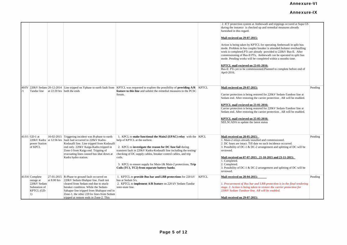
Line tripped on Yphase to earth fault from
both the ends
20-12-2014
at 22:20 hrs
220kV Sedam-
Tandur line
40/IV
/1
Mail received on 28-04-2015:
1. Procurement of Bus bar and LBB protection is in the final tendering
stage. 2. Action is being taken to restore the carrier protection for
220kV Sedam-Tandoor line. AR will be enabled.
Mail received on 29-07-2015:
1. Procurement of Bus bar and LBB protection is in the final tendering
stage.
2. Action is being taken to restore the carrier protection for 220kV
Sedam-Tandoor line. AR will be enabled after restoration of PLCC.
KPTCL mail received on 23-01-2016:
1. Bus bar protection panels pocured and erected at Sedam. Wiring ,
testing ,commissioning is being taken up.Planned to complete by April
2016.
2. Action is being taken to restore the carrier protection for 220kV
Sedam-Tandoor line. AR will be enabled after restoration of PLCC.
PendingKPTCL 1. KPTCL to provide Bus bar and LBB protections for 220 kV
bus at Sedam S/s.
2. KPTCL to implement A/R feature on 220 kV Sedam-Tandur
inter-state line.
R-Phase to ground fault occurred on
220kV Sedam-Shahpur line. Fault not
cleared from Sedam end due to stuck-
breaker condition. While the Sedam-
Sahapur line tripped from Shahapur end in
Zone-1, the other 220 kv lines from Sedam
tripped at remote ends in Zone-2. This
caused complete outage of 220kV Sedam
substation.
27-01-2015
at 8.00 hrs
Complete
outage at
220kV Sedam
Substation of
KPTCL (GD-
1)
41/I/4
Mail recieved on 29-07-2015:
Carrier protection is being restored for 220kV Sedam-Tandoor line at
Sedam end. After restoring the carrier protection , AR will be enabled.
KPTCL mail recieved on 23-01-2016:
Carrier protection is being restored for 220kV Sedam-Tandoor line at
Sedam end. After restoring the carrier protection , AR will be enabled.
KPTCL mail recieved on 25-05-2016:
SEE,SCADA to update the latest status
KPTCLKPTCL was requested to explore the possibility of providing A/R
feature to this line and submit the remedial measures to the PCSC
forum.
Pending
Mail received on 28-04-2015:
1. In view of operating 220kV Ambewadi SS in split bus mode, action is
being taken up by KPTCL . Problem in the 220kV bus coupler breaker is
attended and isolator overhauling work is under progress. Spilt bus
operation at Ambewadi will be made possible at the earliest.
2. ICT protection system at Ambewadi and trippings occured at Supa GS
during the instance is checked up and remedial measures already
furnished in this regard.
Mail recieved on 29-07-2015:
Action is being taken by KPTCL for operating Ambewadi in split bus
mode. Problem in bus coupler breaker is attended.Isolator overhaulling
work is completed.PTs are already provided to 220kV Bus-II. After
commissioning of Bus-II PTs, Ambewadi can be operated in split bus
mode. Pending works will be completed within a months time.
KPTCL mail recieved on 23-01-2016:
Bus-II PTs yet to be commissioned.Planned to complete before end of
April-2016.
Pending1. Till the completion of R&M works for bus bar and LBB
protection, KPTCL shall explore the possibility of having split
bus operation at Ambewadi and submit the details of the same to
PCSC forum.
2. KPTCL shall provide the details of the tripping of Supa hydro
station connected downstream from 110 kV bus.
KPTCLTriggering incident was B-phase to earth
fault in 220kV Ambewadi- Nagzari line-1.
B-pole of breaker did not open at
Ambewadi end. LBB protection not
available at Ambewadi end. All elements
tripped on Zone-2 from remote ends.
22-12-2014
at 21:22 hrs
GD-1 at
220kV
Ambewadi
Station of
KPTCL
40/I/1
GD-1 at
220kV Kadra
power Station
of KPCL
16-02-2015
at 12:56 hrs
KPCL Mail received on 28-05-2015:
1. Main-2 relays already installed and commissioned.
2. DC fuses are intact. Till date no such incidence occurred.
3. Possibility of DC-1 & DC-2 arrangement and splitting of DC will be
reviewed.
Mail received on 07-07-2015 , 21-10-2015 and 23-11-2015:
1. Completed.
2. Completed.
3. Possibility of DC-1 & DC-2 arrangement and splitting of DC will be
reviewed.
Triggering incident was B-phase to earth
fault had occurred in 220kV Kadra-
Kodasalli line. Line tripped from Kodasalli
end only. 220kV Kaiga-Kadra tripped in
Zone-3 from Kaiga end. Tripping of
evacuating lines caused bus shut down at
Kadra hydro station.
Pending41/I/1 1. KPCL to make functional the Main2 (EPAC) relay with the
help of KPTCL at the earliest.
2. KPCL to investigate the reason for DC fuse fail during
transient fault in 220kV Kadra-Kodasalli line including the testing/
checking of DC supply cables, breaker control cables, and trip
coils.
3. KPCL to ensure supply for Main-1& Main-2 protections, Trip
Coils (TC1, TC2) from separate battery banks.
Annexure-IX
Page 5 of 12
Annexure-VI
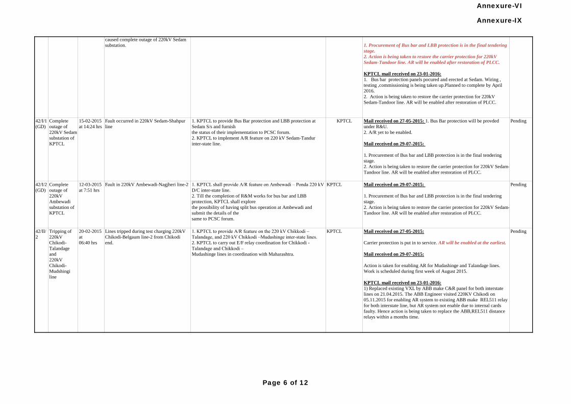
Fault in 220kV Ambewadi-Nagjheri line-212-03-2015
at 7:51 hrs
Complete
outage of
220kV
Ambewadi
substation of
KPTCL
42/I/2
(GD)
Mail received on 27-05-2015:
Carrier protection is put in to service. AR will be enabled at the earliest.
Mail received on 29-07-2015:
Action is taken for enabling AR for Mudashinge and Talandage lines.
Work is scheduled during first week of August 2015.
KPTCL mail received on 23-01-2016:
1) Replaced existing VXL by ABB make C&R panel for both interstate
lines on 21.04.2015. The ABB Engineer visited 220KV Chikodi on
05.11.2015 for enabling AR system to existing ABB make REL511 relay
for both interstate line, but AR system not enable due to internal cards
faulty. Hence action is being taken to replace the ABB,REL511 distance
relays within a months time.
KPTCL1. KPTCL to provide A/R feature on the 220 kV Chikkodi –
Talandage, and 220 kV Chikkodi –Mudashinge inter-state lines.
2. KPTCL to carry out E/F relay coordination for Chikkodi -
Talandage and Chikkodi –
Mudashinge lines in coordination with Maharashtra.
Lines tripped during test charging 220kV
Chikodi-Belgaum line-2 from Chikodi
end.
20-02-2015
at
06:40 hrs
Tripping of
220kV
Chikodi-
Talandage
and
220kV
Chikodi-
Mudshingi
line
42/II/
2
Mail received on 28-04-2015:
1. Procurement of Bus bar and LBB protection is in the final tendering
stage. 2. Action is being taken to restore the carrier protection for
220kV Sedam-Tandoor line. AR will be enabled.
Mail received on 29-07-2015:
1. Procurement of Bus bar and LBB protection is in the final tendering
stage.
2. Action is being taken to restore the carrier protection for 220kV
Sedam-Tandoor line. AR will be enabled after restoration of PLCC.
KPTCL mail received on 23-01-2016:
1. Bus bar protection panels pocured and erected at Sedam. Wiring ,
testing ,commissioning is being taken up.Planned to complete by April
2016.
2. Action is being taken to restore the carrier protection for 220kV
Sedam-Tandoor line. AR will be enabled after restoration of PLCC.
PendingKPTCL 1. KPTCL to provide Bus bar and LBB protections for 220 kV
bus at Sedam S/s.
2. KPTCL to implement A/R feature on 220 kV Sedam-Tandur
inter-state line.
R-Phase to ground fault occurred on
220kV Sedam-Shahpur line. Fault not
cleared from Sedam end due to stuck-
breaker condition. While the Sedam-
Sahapur line tripped from Shahapur end in
Zone-1, the other 220 kv lines from Sedam
tripped at remote ends in Zone-2. This
caused complete outage of 220kV Sedam
substation.
27-01-2015
at 8.00 hrs
Complete
outage at
220kV Sedam
Substation of
KPTCL (GD-
1)
41/I/4
Pending
1. KPTCL to provide Bus Bar protection and LBB protection at
Sedam S/s and furnish
the status of their implementation to PCSC forum.
2. KPTCL to implement A/R feature on 220 kV Sedam-Tandur
inter-state line.
Pending1. KPTCL shall provide A/R feature on Ambewadi – Ponda 220 kV
D/C inter-state line.
2. Till the completion of R&M works for bus bar and LBB
protection, KPTCL shall explore
the possibility of having split bus operation at Ambewadi and
submit the details of the
same to PCSC forum.
KPTCL
15-02-2015
at 14:24 hrs
Complete
outage of
220kV Sedam
substation of
KPTCL
42/I/1
(GD)
Mail received on 27-05-2015: 1. Bus Bar protection will be provded
under R&U.
2. A/R yet to be enabled.
Mail received on 29-07-2015:
1. Procurement of Bus bar and LBB protection is in the final tendering
stage.
2. Action is being taken to restore the carrier protection for 220kV Sedam-
Tandoor line. AR will be enabled after restoration of PLCC.
KPTCLFault occurred in 220kV Sedam-Shahpur
line
Pending
Mail received on 29-07-2015:
1. Procurement of Bus bar and LBB protection is in the final tendering
stage.
2. Action is being taken to restore the carrier protection for 220kV Sedam-
Tandoor line. AR will be enabled after restoration of PLCC.
Annexure-IX
Page 6 of 12
Annexure-VI
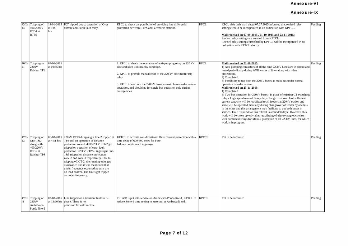
47/III
/8
Tripping of
220kV
Ambewadi-
Ponda line-2
02-08-2015
at 13:20 hrs
Line tripped on a transient fault in B-
phase. There is no
provision for auto reclose.
KPTCL to activate non-directional Over Current protection with a
time delay of 600-800 msec for Fuse
failure condition at Lingasugur.
Pending
ICT tripped due to operation of Over
current and Earth fault relay
14-01-2015
at 1:09
hrs
Tripping of
400/220kV
ICT-1 at
BTPS
43/II/
14
Pending
Tripping of
Unit-1&2
along with
400/220kV
ICT-2 at
Raichur TPS
06-08-2015
at 4:51 hrs
KPTCL Yet to be informed Pending
Mail received on 21-10-2015:
1) Anti-pumping contactors of all the nine 220KV Lines are in circuit and
tested periodically during AOH works of lines along with other
protections.
2) Completed.
3) Possibility to use both the 220kV buses as main bus under normal
operation is under review.
Mail recieved on 23-11-2015:
1) Completed
3) Two bus operation for 220kV buses : In place of existing CT switching
relays, High speed manual heavy duty change over switch of sufficient
current capacity will be retrofitted to all feeders at 220kV station and
same will be operated manually during changeover of feeder by one bus
to the other and this arrangement may facilitate to put both buses in
service. Time required for this retrofit is around 90days . However, this
work will be taken up only after retrofitting of electromagnetic relays
with numerical relays for Main-2 protection of all 220kV lines, for which
work is in progress.
KPCL1. KPCL to check the operation of anti-pumping relay on 220 kV
side and keep it in healthy condition.
2. KPCL to provide manual reset to the 220 kV side master trip
relay.
3. KPCL to use both the 220 kV buses as main buses under normal
operation, and should go for single bus operation only during
emergencies.
07-06-2015
at 01:35 hrs
Trippings at
220kV
Raichur TPS
46/II/
21
KPCL vide their mail dated 07.07.2015 informed that revised relay
settings would be incorporated in co-ordination with KPTCL.
Mail received on 07-09-2015 , 21-10-2015 and 23-11-2015:
Revised relay settings are awaited from KPTCL.
Revised relay settings furnished by KPTCL will be incorporated in co-
ordination with KPTCL shortly.
PendingKPCL to check the possibility of providing line differential
protection between RTPS and Yermarus stations.
KPCL
Yet to be informedKPTCL
220kV RTPS-Lingasugur line-2 tripped at
TPS end on operation of distance
protection zone-1. 400/220kV ICT-2 got
tripped on operation of earth fault
protection. 220kV RTPS-Lingasugur line-
1&3 tripped on distance protection
zone-2 and zone-3 respectively. Due to
tripping of ICT-2, the running units got
overloaded and it was mentioned that
under frequency occurred as units are
on load control. The Units got tripped
on under frequency.
47/II/
13
Till A/R is put into service on Ambewadi-Ponda line-1, KPTCL to
reduce Zone-2 time setting to zero sec. at Ambewadi end.
Annexure-IX
Page 7 of 12
Annexure-VI
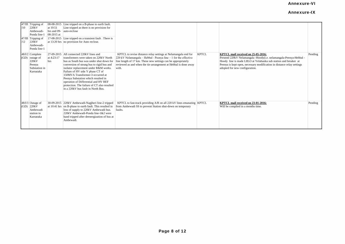
47/III
/10
Tripping of
220kV
Ambewadi-
Ponda line-1
08-08-2015
at 10:51
hrs and 09-
08-2015 at
11:15 hrs
Line tripped on a B-phase to earth fault.
Line tripped as there is no provision for
auto-reclose
47/III
/12
Tripping of
220kV
Ambewadi-
Ponda line-1
17-08-2015
at 13:20 hrs
Line tripped on a transient fault . There is
no provision for Auto reclose.
220kV Ambewadi-Nagjheri line-2 tripped
on B-phase to earth fault. This resulted in
loss of supply to 220kV Ambewadi bus.
220kV Ambewadi-Ponda line-1&2 were
hand tripped after deenergization of bus at
Ambewadi.
KPTCL to fast-track providing A/R on all 220 kV lines emanating
from Ambewadi SS to prevent Station shut-down on temporary
faults.
KPTCL KPTCL mail received on 23-01-2016:
Will be complied in a months time.
Pending30-09-2015
at 10:41 hrs
Outage of
220kV
Ambewadi
station in
Karnataka
48/I/3
(GD)
48/I/2
(GD)
Complete
outage of
220kV
Peenya
Substation in
Karnataka
27-09-2015
at 4:23:17
hrs
All connected 220kV lines and
transformers were taken on 220kV North
bus as South bus was under shut down for
conversion of strung bus to rigid bus and
isolator replacement under R&M works.
Failure of HV side Y phase CT of
150MVA Transformer-3 occurred at
Peenya Substation which resulted in
operation of Differential and HV REF
protection. The failure of CT also resulted
in a 220kV bus fault in North Bus.
KPTCL to revise distance relay settings at Nelamangala end for
220 kV Nelamangala – Hebbal - Peenya line – 1 for the effective
line length of 17 km. These new settings can be appropriately
reviewed as and when the tie-arrangement at Hebbal is done away
with.
KPTCL KPTCL mail received on 25-05-2016:
Presentl 220kV Nelamangala -Hoody(i.e. nelamangala-Peenya-Hebbal -
Hoody line is made LIILO at Yelahanka sub station and breaker at
Peenya is kept open, necessary modification in distance relay settings
adopted for new configuration.
Pending
PendingYet to be informedKPTCLTill A/R is put into service on Ambewadi-Ponda line-1, KPTCL to
reduce Zone-2 time setting to zero sec. at Ambewadi end. Annexure-IX
Page 8 of 12
Annexure-VI
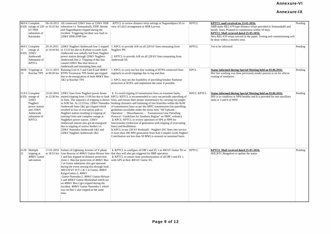
48/I/4
(GD)
Complete
outage of 220
kV HSR
substation of
Karnataka
06-10-2015
at 16:32 hrs
All connected 220kV lines at 220kV HSR
substation i.e. Somanahalli, EPIP, Hoody
and Nagnathapura tripped during the
incident. Triggering incident was fault in
220kV HSR-EPIP line
KPTCL to review distance relay settings at Naganathpura SS in
view of LILO arrangement at HSR Lay-out.
KPTCL KPTCL mail received on 23-01-2016:
ABB make REL 670 type distance relays provided to Somanahalli and
hoody lines. Planned to commission within 10 days.
KPTCL Mail recieved dated 25-05-2016:
New REL 670 relays erected in the panel. Testing and commissionng will
be done within a month's time.
Pending
49/I/1
.3
(GD)
Complete
outage of
220kV
Ambewadi
Substation of
KPTCL
29.10.2015
at 14:34 hrs
220kV Nagjheri-Ambewadi line-1 tripped
at 13:33 hrs due to B phase to earth fault.
Ambewadi was radially fed from Nagjheri
power station through 220kV Nagjheri-
Ambewadi line-2. Tripping of this line
caused 220kV Bus shut down at
Ambewadi and remaining lines and
transformers were hand tripped
1. KPCL to provide A/R on all 220 kV lines emanating from
Nagjheri PH.
2. KPTCL to provide A/R on all 220 kV lines emanating from
Ambewadi SS.
KPTCL Yet to be informed Pending
49/II/
15
Trippings at
Raichur TPS
12-11-2015
at 00:30 hrs
Running Unit-4, 5 and Unit-8 and 400kV
RTPS-Yeramaras TPS feeder got tripped
due to de-energization of both 400kV Bus-
1&2 at Raichur TPS
1. KPCL to carry out hot-line washing of RTPS-connected lines
regularly to avoid trippings due to fog and dust.
2. KPCL may see the feasibility of providing breaker flashover
protection at RTPS, and implement the same if possible.
KPCL Status informed during Special Meeting held on 03.06.2016:
Hot line washing was done previously.tender process is on for silicon
coating of insulators.
Pending
Failure of Lightning Arrestor of Y-phase
Line Reactor of 400kV Guttur-Hiriyur line-
1 and line tripped on distance protection
Zone-1. Bus-bar protection of 400kV Bus-
2 at Guttur substation also got operated
during the event sensing this through fault.
400/220 kV ICT-1 & 2 at Guttur, 400kV
Kaiga-Guttur-2, 400kV
Guttur-Narendra-2, 400kV Guttur-Hiriyur-
2 and 400kV Guttur-Munirabad which are
on 400kV Bus-2 got tripped during the
incident. 400kV Guttur-Narendra-1 which
was on Bus-1 also tripped at the same
time.
51/II/
21
Multiple
tripping at
400kV Guttur
sub-station
17-01-2016
at 18:53 hrs
KPTCL 1. KPTCL to configure all DR’s and EL’s at 400 kV Guttur SS so
that they will also get triggered for BBP operation.
2. KPTCL to ensure time-synchronization of all DR’s and EL’s
with GPS at their 400 kV Guttur SS.
KPTCL Mail received dated 25-05-2016:
SEE,RTC,Bangalore to update the status
Pending
220kV lines from Nagjheri power house
started tripping from 11:00 hrs due to fault
in lines. The sequence of tripping is shown
in SOE list. At 12:33 hrs, 220kV Narendra-
Ambewadi lines-1&2 got tripped which
resulted in loss of evacuation path to
Nagjheri station resulting in tripping of
running Units and complete outage at
Nagjhheri power station. 220kV
Ambewadi station also got de-energized
due to tripping of source feeders i.e.
220kV Narendra-Ambewadi-1&2 and
220kV Nagjheri-Ambewadi-1&2.
1. To avoid tripping of transmission lines on transient faults,
KPCL/ KPTCL is recommended to carry out periodic patrolling of
lines, and ensure their proper maintenance by carrying out jungle/
bushing clearance and trimming of tree branches within the RoW
of transmission lines as per the SRPC transmission line patrolling
guidelines (available under the menu item "All Uploads
Operation Miscellaneous Transmission Line Patrolling
Protocol / Guidelines for Southern Region" on SRPC website).
2. KPCL/ KPTCL to review operation of SPS at NPH for
functionality (reduction of generation with tripping of evacuating
lines) and healthiness.
3. KPCL to put 220 kV Kodasalli - Nagjheri D/C lines into service
if more than 200 MW generation from Kali Complex (with Nagheri
Contribution not less than 50 MW) is ensured on sustained basis.
KPCL/ KPTCL Status informed during Special Meeting held on 03.06.2016:
SPS is in condition at NPH healthy and It is provded for non auxilliary
units ie 3 and 6 of NPH
PendingComplete
outage of
220kV
Nagjheri
power station
and 220kV
Ambewadi
substation of
KPTCL
22-02-2016
at 12:36 hrs
51/I/3
(GD)
Annexure-IX
Page 9 of 12
Annexure-VI

52/I/3
(GD)
Complete
outage of
220kV
Shimoga
substation
22-02-2016
at 15:03 hrs
220kV Bus Bar protection operated during
failure of R phase CT in DVG-2 line bay.
KPTCL to operate 220 kV Shimoga on multi-bus operation under
normal conditions, put it on single-bus operation only under
emergency conditions.
KPTCL Yet to be informed Pending
53/II/
1 (GI)
Tripping of
ICT-3 at
Raichur
Substation
15-03-2016
at 12:28 hrs
ICT-3 tripped due to operation of back-up
earth fault protection during fault in
220kV RTPS-Raichur line-1.
KPCL/ KPTCL to check the ICT’s back-up (high-set) protection
settings, and ensure that they operate with a time delay of 100
msec.
KPCL/KPTCL KPTCL Mail Recieved dated 25-05-2016:
SEE,SCADA to update the status of healthiness of carrier protection of
220kV RTPS-Raichur 1 &2 lines
Status informed during Special Meeting held on 03.06.2016:
Revised settings will be uploaded in co-ordination with KPTCL
Pending
220kV Peenya-Nelamangala-3 tripped on
B-E fault at both ends. At the same time,
220kV Peenya-Nelamangala-4 tripped on
R-Y fault only at Nelamangala end, and
was in service from Peenya end. Due to
tripping of these two lines, 220kV Peenya-
Nelamangala-2 tripped on overcurrent
protection.
KPTCL to furnish a report on the tripping of 220 kV Peenya-
Nelamangala line-4 Nelamangala detailing the remedial measures
taken including the settings adopted for Z1B (Zone extension) and
Power Swing Block.
KPTCL KPTCL Mail received dated 25-05-2016:
SEE,RTC,Bangalore to update the status
Pending16-03-2016
at 11:39 Hrs
Complete
outage of
220kV
Peenya
Substation of
KPTCL
53/I/1
(GD)
1. KPTCL to configure the Auto-Reclosure (A/R) scheme at
Hoody end for all lines emanating from Hoody end in such a way
that in the event of occurrence of faults during A/R dead-time, (i) it
should immediately give a 3-ph trip, and (ii) A/R should go into
lock-out state, i.e., it must not reclose after the elapse of dead-time
of A/R.
2. As regards over-reaching of Kolar and Nelamangala end relays
for the fault on 400 kV Hoody – Kolar line-2, KPTCL and PGCIL
(SR-II) are recommended to modify the Z1B settings of the relays
used (7SA522) suitably so that they operate with a Zone-2 time
delay.
3. KPTCL to check the ICT’s back-up (high-set) protection
settings, and ensure that they operate with a time delay of 100
msec.
4. KPTCL to take steps to replace the solid state relays at Hoody
end on Hoody-Nelamangala lines – 1 & 2 with numerical relays at
the earliest.
KPTCL KPTCL Mail recieved dated 25-05-2016:
1. Incorporated.
3. With the existing electromechanical relays, it's not possible to add time
delay of 100 mSec. However, ongoing R&M works of Hoody included
complete ICT1 and ICT2 panel replacement having Numerical relays.
4.The solid state relays of Nelamangala-1 and Nelamangala-2 lines will
be replaced by numerical relays for which relays have been
identified,Will be attended in a month's time.
400kV Hoody-Nelamangala line-1&2,
400kV Hoody-Kolar line-1&2, 400/220kV
ICT-2 at Hoody tripped during the
incident. ICT-1&3 were hand tripped after
the incident.
26-03-2016
at 12:42 hrs
Complete
outage of
400kV Hoody
substation of
KPTCL
53/I/1
(GD)
Pending
PendingYet to be informed53/I/3
(GD)
Complete
outage of
220kV
Ambewadi
station of
KPTCL and
220kV
Nagjheri of
KPCL
18-03-2016
at 14:40 hrs
Ambewadi Narendra line-2 tripped on
fault and 220kV ambewadi Narendra line-
1 tripped due to over-loading. Running
Units at Nagjheri also tripped during the
event due to tripping of evacuating lines
1. KPCL to furnish a report on the reasons for Unit-6 tripping at
Nagjheri PH.KPCL/ KPTCL to modify suitably the SPS at Nagjheri
Power House such that it would also factor in the over loading of
Ambewadi-Narendra lines.
2. KPCL/ KPTCL to put 220 kV Kodasalli - Nagjheri D/C lines
into service if more than 200 MW generation from Kali Complex
(with Nagheri Contribution not less than 50 MW) is ensured on
sustained basis.
KPCL/ KPTCL
Miscellaneous
Annexure-IX
Page 10 of 12
Annexure-VI
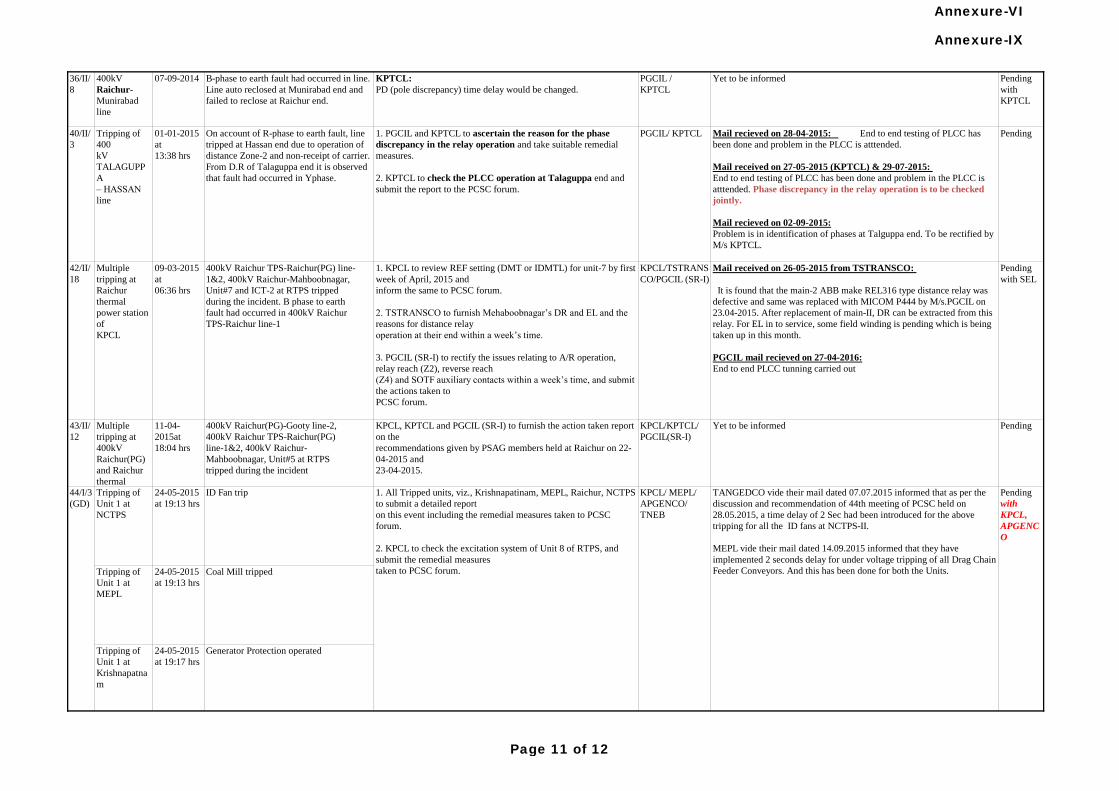
36/II/
8
400kV
Raichur-
Munirabad
line
07-09-2014 B-phase to earth fault had occurred in line.
Line auto reclosed at Munirabad end and
failed to reclose at Raichur end.
KPTCL:
PD (pole discrepancy) time delay would be changed.
PGCIL /
KPTCL
Yet to be informed Pending
with
KPTCL
43/II/
12
Multiple
tripping at
400kV
Raichur(PG)
and Raichur
thermal
11-04-
2015at
18:04 hrs
400kV Raichur(PG)-Gooty line-2,
400kV Raichur TPS-Raichur(PG)
line-1&2, 400kV Raichur-
Mahboobnagar, Unit#5 at RTPS
tripped during the incident
KPCL, KPTCL and PGCIL (SR-I) to furnish the action taken report
on the
recommendations given by PSAG members held at Raichur on 22-
04-2015 and
23-04-2015.
KPCL/KPTCL/
PGCIL(SR-I)
Yet to be informed Pending
Tripping of
Unit 1 at
NCTPS
24-05-2015
at 19:13 hrs
ID Fan trip
Tripping of
Unit 1 at
MEPL
24-05-2015
at 19:13 hrs
Coal Mill tripped
Tripping of
Unit 1 at
Krishnapatna
m
24-05-2015
at 19:17 hrs
Generator Protection operated
Mail received on 26-05-2015 from TSTRANSCO:
It is found that the main-2 ABB make REL316 type distance relay was
defective and same was replaced with MICOM P444 by M/s.PGCIL on
23.04-2015. After replacement of main-II, DR can be extracted from this
relay. For EL in to service, some field winding is pending which is being
taken up in this month.
PGCIL mail recieved on 27-04-2016:
End to end PLCC tunning carried out
1. KPCL to review REF setting (DMT or IDMTL) for unit-7 by first
week of April, 2015 and
inform the same to PCSC forum.
2. TSTRANSCO to furnish Mehaboobnagar’s DR and EL and the
reasons for distance relay
operation at their end within a week’s time.
3. PGCIL (SR-I) to rectify the issues relating to A/R operation,
relay reach (Z2), reverse reach
(Z4) and SOTF auxiliary contacts within a week’s time, and submit
the actions taken to
PCSC forum.
KPCL/TSTRANS
CO/PGCIL (SR-I)
Pending
with SEL
400kV Raichur TPS-Raichur(PG) line-
1&2, 400kV Raichur-Mahboobnagar,
Unit#7 and ICT-2 at RTPS tripped
during the incident. B phase to earth
fault had occurred in 400kV Raichur
TPS-Raichur line-1
09-03-2015
at
06:36 hrs
Multiple
tripping at
Raichur
thermal
power station
of
KPCL
42/II/
18
Mail recieved on 28-04-2015: End to end testing of PLCC has
been done and problem in the PLCC is atttended.
Mail received on 27-05-2015 (KPTCL) & 29-07-2015:
End to end testing of PLCC has been done and problem in the PLCC is
atttended. Phase discrepancy in the relay operation is to be checked
jointly.
Mail recieved on 02-09-2015:
Problem is in identification of phases at Talguppa end. To be rectified by
M/s KPTCL.
Pending1. PGCIL and KPTCL to ascertain the reason for the phase
discrepancy in the relay operation and take suitable remedial
measures.
2. KPTCL to check the PLCC operation at Talaguppa end and
submit the report to the PCSC forum.
PGCIL/ KPTCLOn account of R-phase to earth fault, line
tripped at Hassan end due to operation of
distance Zone-2 and non-receipt of carrier.
From D.R of Talaguppa end it is observed
that fault had occurred in Yphase.
01-01-2015
at
13:38 hrs
Tripping of
400
kV
TALAGUPP
A
– HASSAN
line
40/II/
3
44/I/3
(GD)
1. All Tripped units, viz., Krishnapatinam, MEPL, Raichur, NCTPS
to submit a detailed report
on this event including the remedial measures taken to PCSC
forum.
2. KPCL to check the excitation system of Unit 8 of RTPS, and
submit the remedial measures
taken to PCSC forum.
KPCL/ MEPL/
APGENCO/
TNEB
TANGEDCO vide their mail dated 07.07.2015 informed that as per the
discussion and recommendation of 44th meeting of PCSC held on
28.05.2015, a time delay of 2 Sec had been introduced for the above
tripping for all the ID fans at NCTPS-II.
MEPL vide their mail dated 14.09.2015 informed that they have
implemented 2 seconds delay for under voltage tripping of all Drag Chain
Feeder Conveyors. And this has been done for both the Units.
Pending
with
KPCL,
APGENC
O
Annexure-IX
Page 11 of 12
Annexure-VI
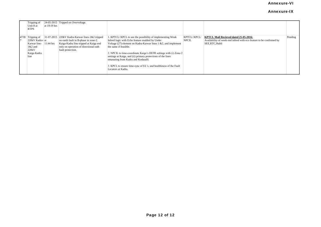
Tripping of
Unit-8 at
RTPS
24-05-2015
at 19:19 hrs
Tripped on Overvoltage.
KPTCL Mail Recieved dated 25-05-2016:
Availability of week end infeed with eco feature to be confirmed by
SEE,RTC,Hubli
PendingKPTCL/ KPCL/
NPCIL
44/I/3
(GD)
1. All Tripped units, viz., Krishnapatinam, MEPL, Raichur, NCTPS
to submit a detailed report
on this event including the remedial measures taken to PCSC
forum.
2. KPCL to check the excitation system of Unit 8 of RTPS, and
submit the remedial measures
taken to PCSC forum.
KPCL/ MEPL/
APGENCO/
TNEB
TANGEDCO vide their mail dated 07.07.2015 informed that as per the
discussion and recommendation of 44th meeting of PCSC held on
28.05.2015, a time delay of 2 Sec had been introduced for the above
tripping for all the ID fans at NCTPS-II.
MEPL vide their mail dated 14.09.2015 informed that they have
implemented 2 seconds delay for under voltage tripping of all Drag Chain
Feeder Conveyors. And this has been done for both the Units.
Pending
with
KPCL,
APGENC
O
1. KPTCL/ KPCL to see the possibility of implementing Weak
Infeed logic with Echo feature enabled by Under
Voltage (27) element on Kadra-Karwar lines 1 &2, and implement
the same if feasible.
2. NPCIL to time-coordinate Kaiga’s DEFR settings with (i) Zone-2
settings at Kaiga, and (ii) primary protections of the lines
emanating from Kadra and Kodasalli.
3. KPCL to ensure time-sync of EL’s, and healthiness of the Fault
Locators at Kadra.
220kV Kadra-Karwar lines-1&2 tripped
on earth fault in B-phase in zone-2.
Kaiga-Kadra line tripped at Kaiga end
only on operation of directional eath
fault protection.
31-07-2015
at
11:44 hrs
Tripping of
220kV Kadra-
Karwar line-
1&2 and
220kV
Kaiga-Kadra
line
47/II/
7
Annexure-IX
Page 12 of 12
Annexure-VI
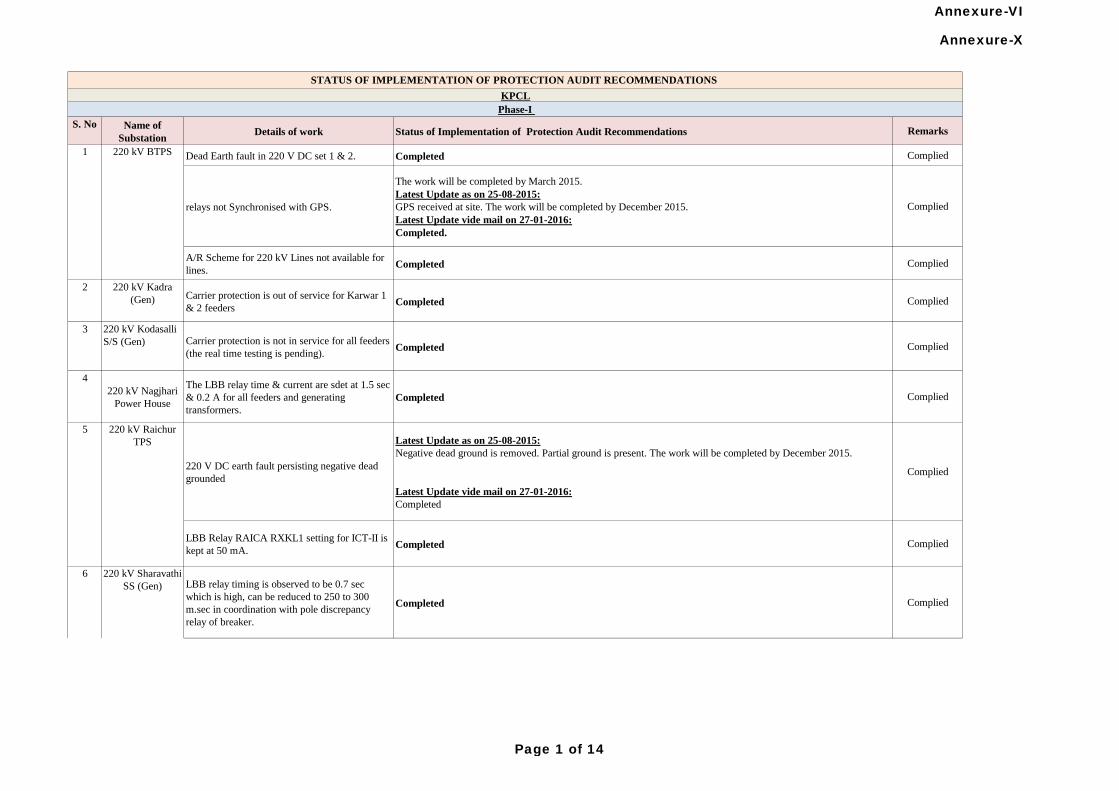
S. No Name of
SubstationDetails of work Status of Implementation of Protection Audit Recommendations Remarks
Dead Earth fault in 220 V DC set 1 & 2. Completed Complied
relays not Synchronised with GPS.
The work will be completed by March 2015.
Latest Update as on 25-08-2015:
GPS received at site. The work will be completed by December 2015.
Latest Update vide mail on 27-01-2016:
Completed.
Complied
A/R Scheme for 220 kV Lines not available for
lines.Completed Complied
2 220 kV Kadra
(Gen) Carrier protection is out of service for Karwar 1
& 2 feedersCompleted Complied
3 220 kV Kodasalli
S/S (Gen) Carrier protection is not in service for all feeders
(the real time testing is pending).Completed Complied
4
220 kV Nagjhari
Power House
The LBB relay time & current are sdet at 1.5 sec
& 0.2 A for all feeders and generating
transformers.
Completed Complied
220 V DC earth fault persisting negative dead
grounded
Latest Update as on 25-08-2015:
Negative dead ground is removed. Partial ground is present. The work will be completed by December 2015.
Latest Update vide mail on 27-01-2016:
Completed
Complied
LBB Relay RAICA RXKL1 setting for ICT-II is
kept at 50 mA.Completed Complied
LBB relay timing is observed to be 0.7 sec
which is high, can be reduced to 250 to 300
m.sec in coordination with pole discrepancy
relay of breaker.
Completed Complied
KPCL
Phase-I
1 220 kV BTPS
5 220 kV Raichur
TPS
6 220 kV Sharavathi
SS (Gen)
STATUS OF IMPLEMENTATION OF PROTECTION AUDIT RECOMMENDATIONS
Annexure-X
Page 1 of 14
Annexure-VI
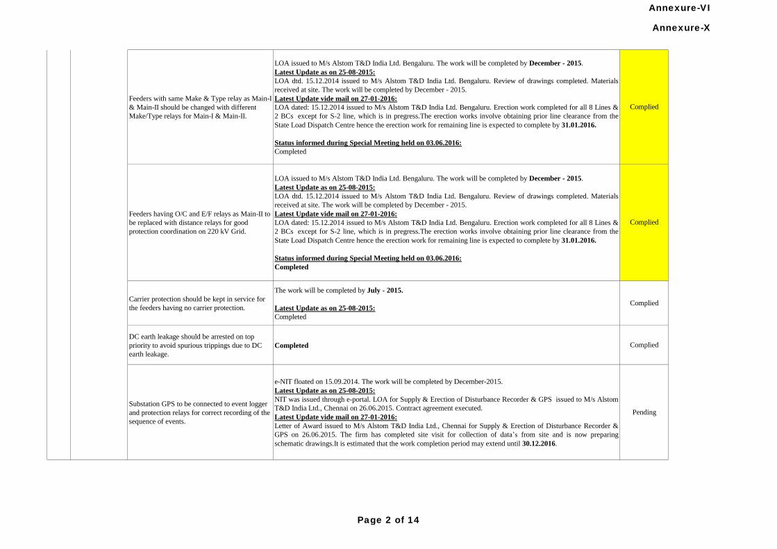
Carrier protection should be kept in service for
the feeders having no carrier protection.
The work will be completed by July - 2015.
Latest Update as on 25-08-2015:
Completed
Complied
DC earth leakage should be arrested on top
priority to avoid spurious trippings due to DC
earth leakage.
Completed Complied
Substation GPS to be connected to event logger
and protection relays for correct recording of the
sequence of events.
e-NIT floated on 15.09.2014. The work will be completed by December-2015.
Latest Update as on 25-08-2015:
NIT was issued through e-portal. LOA for Supply & Erection of Disturbance Recorder & GPS issued to M/s Alstom
T&D India Ltd., Chennai on 26.06.2015. Contract agreement executed.
Latest Update vide mail on 27-01-2016:
Letter of Award issued to M/s Alstom T&D India Ltd., Chennai for Supply & Erection of Disturbance Recorder &
GPS on 26.06.2015. The firm has completed site visit for collection of data’s from site and is now preparing
schematic drawings.It is estimated that the work completion period may extend until 30.12.2016.
Pending
Complied
Feeders with same Make & Type relay as Main-I
& Main-II should be changed with different
Make/Type relays for Main-I & Main-II.
LOA issued to M/s Alstom T&D India Ltd. Bengaluru. The work will be completed by December - 2015.
Latest Update as on 25-08-2015:
LOA dtd. 15.12.2014 issued to M/s Alstom T&D India Ltd. Bengaluru. Review of drawings completed. Materials
received at site. The work will be completed by December - 2015.
Latest Update vide mail on 27-01-2016:
LOA dated: 15.12.2014 issued to M/s Alstom T&D India Ltd. Bengaluru. Erection work completed for all 8 Lines &
2 BCs except for S-2 line, which is in pregress.The erection works involve obtaining prior line clearance from the
State Load Dispatch Centre hence the erection work for remaining line is expected to complete by 31.01.2016.
Status informed during Special Meeting held on 03.06.2016:
Completed
Complied
6 220 kV Sharavathi
SS (Gen)
Feeders having O/C and E/F relays as Main-II to
be replaced with distance relays for good
protection coordination on 220 kV Grid.
LOA issued to M/s Alstom T&D India Ltd. Bengaluru. The work will be completed by December - 2015.
Latest Update as on 25-08-2015:
LOA dtd. 15.12.2014 issued to M/s Alstom T&D India Ltd. Bengaluru. Review of drawings completed. Materials
received at site. The work will be completed by December - 2015.
Latest Update vide mail on 27-01-2016:
LOA dated: 15.12.2014 issued to M/s Alstom T&D India Ltd. Bengaluru. Erection work completed for all 8 Lines &
2 BCs except for S-2 line, which is in pregress.The erection works involve obtaining prior line clearance from the
State Load Dispatch Centre hence the erection work for remaining line is expected to complete by 31.01.2016.
Status informed during Special Meeting held on 03.06.2016:
Completed
Annexure-X
Page 2 of 14
Annexure-VI
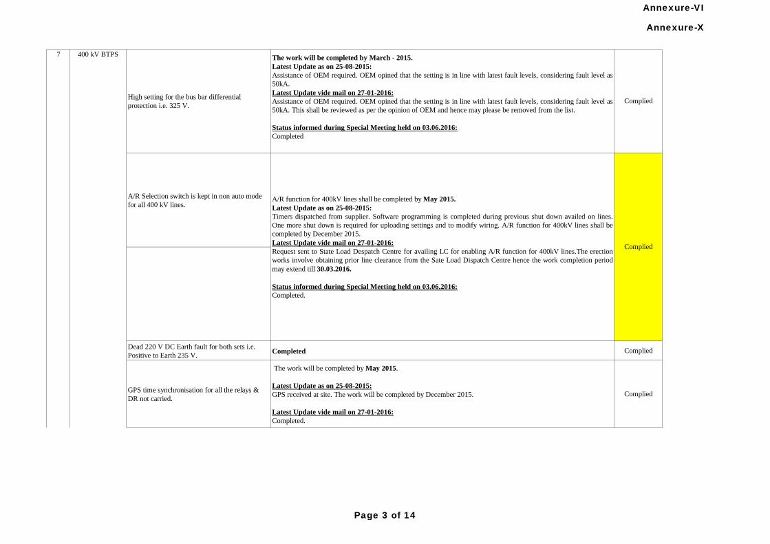
A/R Selection switch is kept in non auto mode
for all 400 kV lines.
Dead 220 V DC Earth fault for both sets i.e.
Positive to Earth 235 V.Completed Complied
GPS time synchronisation for all the relays &
DR not carried.
The work will be completed by May 2015.
Latest Update as on 25-08-2015:
GPS received at site. The work will be completed by December 2015.
Latest Update vide mail on 27-01-2016:
Completed.
Complied
High setting for the bus bar differential
protection i.e. 325 V.
The work will be completed by March - 2015.
Latest Update as on 25-08-2015:
Assistance of OEM required. OEM opined that the setting is in line with latest fault levels, considering fault level as
50kA.
Latest Update vide mail on 27-01-2016:
Assistance of OEM required. OEM opined that the setting is in line with latest fault levels, considering fault level as
50kA. This shall be reviewed as per the opinion of OEM and hence may please be removed from the list.
Status informed during Special Meeting held on 03.06.2016:
Completed
Complied
7
A/R function for 400kV lines shall be completed by May 2015.
Latest Update as on 25-08-2015:
Timers dispatched from supplier. Software programming is completed during previous shut down availed on lines.
One more shut down is required for uploading settings and to modify wiring. A/R function for 400kV lines shall be
completed by December 2015.
Latest Update vide mail on 27-01-2016:
Request sent to State Load Despatch Centre for availing LC for enabling A/R function for 400kV lines.The erection
works involve obtaining prior line clearance from the Sate Load Dispatch Centre hence the work completion period
may extend till 30.03.2016.
Status informed during Special Meeting held on 03.06.2016:
Completed.
Complied
400 kV BTPS
Annexure-X
Page 3 of 14
Annexure-VI
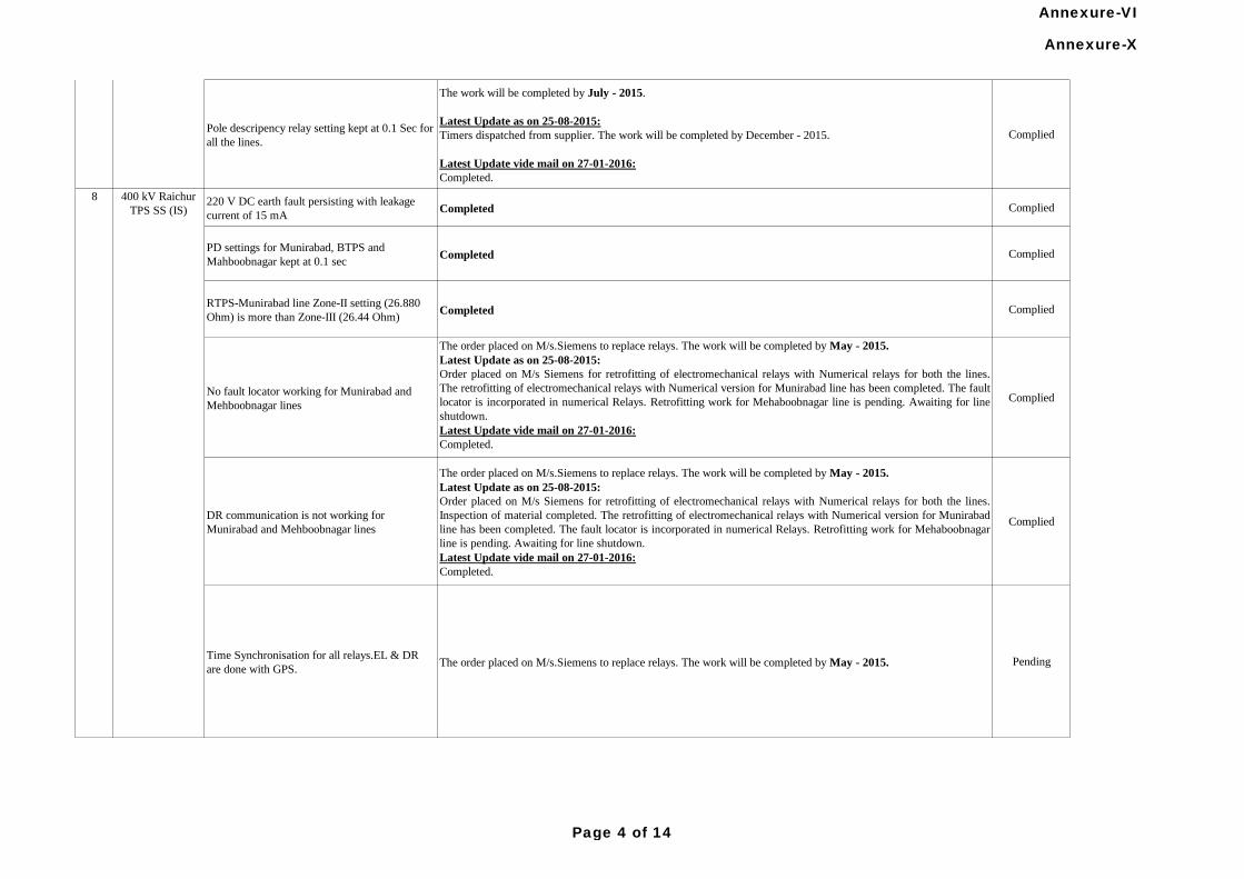
Pole descripency relay setting kept at 0.1 Sec for
all the lines.
The work will be completed by July - 2015.
Latest Update as on 25-08-2015:
Timers dispatched from supplier. The work will be completed by December - 2015.
Latest Update vide mail on 27-01-2016:
Completed.
Complied
220 V DC earth fault persisting with leakage
current of 15 mACompleted Complied
PD settings for Munirabad, BTPS and
Mahboobnagar kept at 0.1 secCompleted Complied
RTPS-Munirabad line Zone-II setting (26.880
Ohm) is more than Zone-III (26.44 Ohm)Completed Complied
No fault locator working for Munirabad and
Mehboobnagar lines
The order placed on M/s.Siemens to replace relays. The work will be completed by May - 2015.
Latest Update as on 25-08-2015:
Order placed on M/s Siemens for retrofitting of electromechanical relays with Numerical relays for both the lines.
The retrofitting of electromechanical relays with Numerical version for Munirabad line has been completed. The fault
locator is incorporated in numerical Relays. Retrofitting work for Mehaboobnagar line is pending. Awaiting for line
shutdown.
Latest Update vide mail on 27-01-2016:
Completed.
Complied
DR communication is not working for
Munirabad and Mehboobnagar lines
The order placed on M/s.Siemens to replace relays. The work will be completed by May - 2015.
Latest Update as on 25-08-2015:
Order placed on M/s Siemens for retrofitting of electromechanical relays with Numerical relays for both the lines.
Inspection of material completed. The retrofitting of electromechanical relays with Numerical version for Munirabad
line has been completed. The fault locator is incorporated in numerical Relays. Retrofitting work for Mehaboobnagar
line is pending. Awaiting for line shutdown.
Latest Update vide mail on 27-01-2016:
Completed.
Complied
Time Synchronisation for all relays.EL & DR
are done with GPS.The order placed on M/s.Siemens to replace relays. The work will be completed by May - 2015. Pending
7 400 kV BTPS
8 400 kV Raichur
TPS SS (IS)
Annexure-X
Page 4 of 14
Annexure-VI
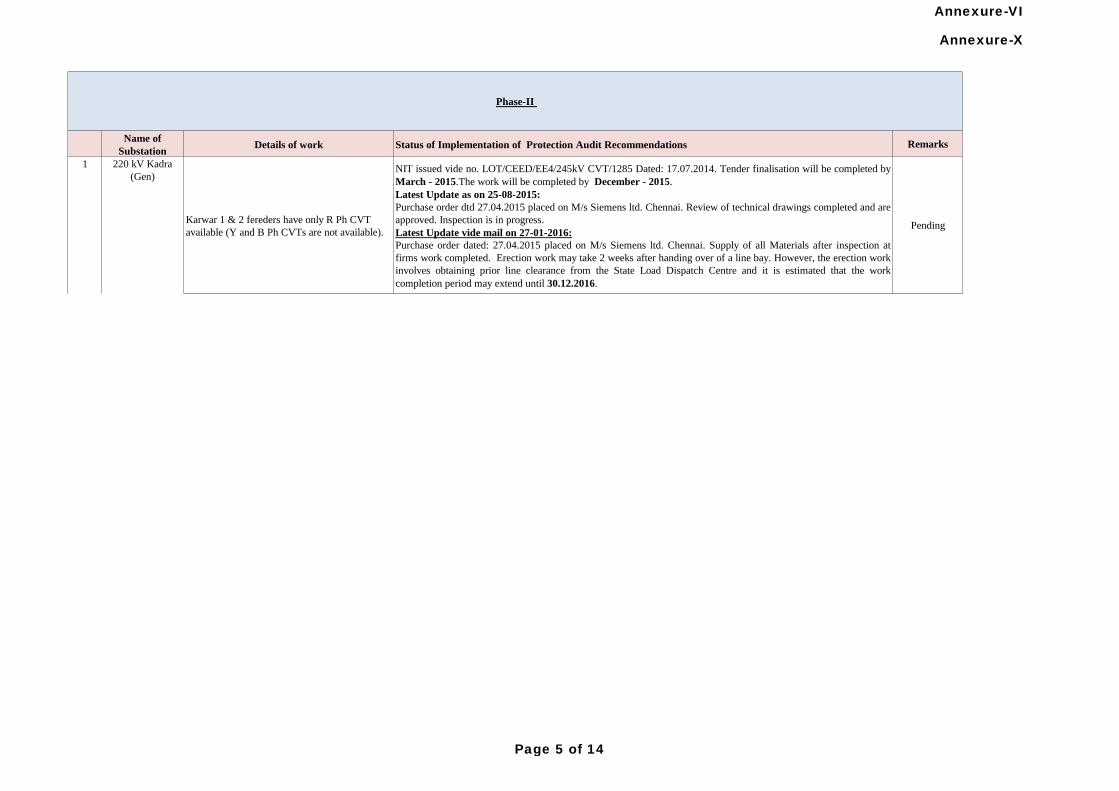
Name of
SubstationDetails of work Status of Implementation of Protection Audit Recommendations Remarks
Karwar 1 & 2 fereders have only R Ph CVT
available (Y and B Ph CVTs are not available).
NIT issued vide no. LOT/CEED/EE4/245kV CVT/1285 Dated: 17.07.2014. Tender finalisation will be completed by
March - 2015.The work will be completed by December - 2015.
Latest Update as on 25-08-2015:
Purchase order dtd 27.04.2015 placed on M/s Siemens ltd. Chennai. Review of technical drawings completed and are
approved. Inspection is in progress.
Latest Update vide mail on 27-01-2016:
Purchase order dated: 27.04.2015 placed on M/s Siemens ltd. Chennai. Supply of all Materials after inspection at
firms work completed. Erection work may take 2 weeks after handing over of a line bay. However, the erection work
involves obtaining prior line clearance from the State Load Dispatch Centre and it is estimated that the work
completion period may extend until 30.12.2016.
Pending
220 kV Kadra
(Gen)
1
Phase-II
Annexure-X
Page 5 of 14
Annexure-VI
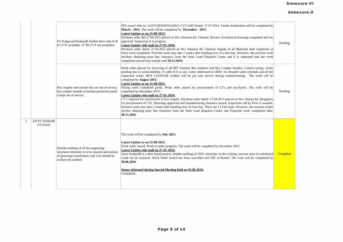
For Kaiga and Kodasalli feeders have only R &
B CVTs available. (Y Ph CVT not available)
NIT issued vide no. LOT/CEED/EE4/245kV CVT/1285 Dated: 17.07.2014. Tender finalisation will be completed by
March - 2015. The work will be completed by December - 2015.
Latest Update as on 25-08-2015:
Purchase order dtd 27.04.2015 placed on M/s Siemens ltd. Chennai. Review of technical drawings completed and are
approved. Inspection is in progress.
Latest Update vide mail on 27-01-2016:
Purchase order dated: 27.04.2015 placed on M/s Siemens ltd. Chennai. Supply of all Materials after inspection at
firms work completed. Erection work may take 2 weeks after handing over of a line bay. However, the erection work
involves obtaining prior line clearance from the State Load Dispatch Centre and it is estimated that the work
completion period may extend until 30.12.2016.
Pending
Work order placed for Servicing of all 89T Transfer Bus isolators and Bus Coupler breaker. Control wiring works
pending due to nonavailability of cable ICS at site. Letter addressed to OEM for detailed cable schedule and all the
connected works. BUS COUPLER module will be put into service during commissioning. The work will be
completed by August 2015.
Latest Update as on 25-08-2015:
Wiring work completed partly. Work order placed for procurement of CT's and auxiliaries. The work will be
completed by December 2015.
Latest Update vide mail on 27-01-2016:
CT’s required for commission of bus coupler. Purchase order dated: 27.04.2015 placed on M/s Alstom ltd. Bengaluru
for procurement of CTs. Drawings approved and manufacturing clearance issued. Inspection call by Firm is awaited.
Erection work may take 2 weeks after handing over of Line bay. There are 13 Line bays. However, the erection works
involve obtaining prior line clearance from the State Load Dispatch Centre and Expected work completion date:
30.12.2016
Pending
Bus coupler and transfer bus are out of service,
bus coupler module on busbar protection panel
is kept out of service.
220 kV Kadra
(Gen)
1
2 220 kV Kodasalli
S/S (Gen)
Double earthing of all the supporting
structures/elements is to be ensured and neutral
of generting transformers and LAs should be
exclusively earthed.
The work will be completed by July 2015.
Latest Update as on 25-08-2015:
Work order issued. Work is under progress. The work will be completed by December 2015.
Latest Update vide mail on 27-01-2016:
Since Kodasalli is a dam based project, double earthing of ODY structures in the existing concrete area of switchyard
could not be assessed. Work Order issued has been cancelled and NIT re-floated. The work will be completed by
30.06.2016.
Status informed during Special Meeting held on 03.06.2016:
Completed.
Complied
Annexure-X
Page 6 of 14
Annexure-VI
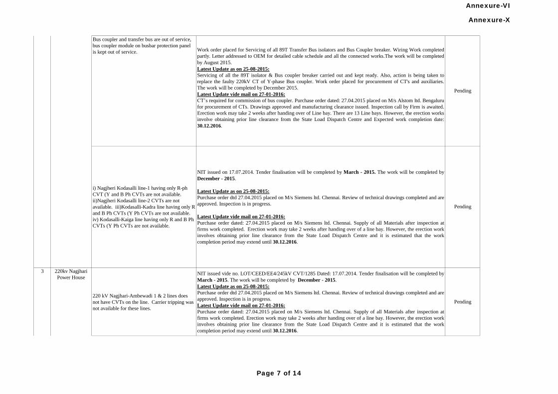
220 kV Nagjhari-Ambewadi 1 & 2 lines does
not have CVTs on the line. Carrier tripping was
not available for these lines.
NIT issued vide no. LOT/CEED/EE4/245kV CVT/1285 Dated: 17.07.2014. Tender finalisation will be completed by
March - 2015. The work will be completed by December - 2015.
Latest Update as on 25-08-2015:
Purchase order dtd 27.04.2015 placed on M/s Siemens ltd. Chennai. Review of technical drawings completed and are
approved. Inspection is in progress.
Latest Update vide mail on 27-01-2016:
Purchase order dated: 27.04.2015 placed on M/s Siemens ltd. Chennai. Supply of all Materials after inspection at
firms work completed. Erection work may take 2 weeks after handing over of a line bay. However, the erection work
involves obtaining prior line clearance from the State Load Dispatch Centre and it is estimated that the work
completion period may extend until 30.12.2016.
Pending
Pending
NIT issued on 17.07.2014. Tender finalisation will be completed by March - 2015. The work will be completed by
December - 2015.
Latest Update as on 25-08-2015:
Purchase order dtd 27.04.2015 placed on M/s Siemens ltd. Chennai. Review of technical drawings completed and are
approved. Inspection is in progress.
Latest Update vide mail on 27-01-2016:
Purchase order dated: 27.04.2015 placed on M/s Siemens ltd. Chennai. Supply of all Materials after inspection at
firms work completed. Erection work may take 2 weeks after handing over of a line bay. However, the erection work
involves obtaining prior line clearance from the State Load Dispatch Centre and it is estimated that the work
completion period may extend until 30.12.2016.
i) Nagjheri Kodasalli line-1 having only R-ph
CVT (Y and B Ph CVTs are not available.
ii)Nagjheri Kodasalli line-2 CVTs are not
available. iii)Kodasalli-Kadra line having only R
and B Ph CVTs (Y Ph CVTs are not available.
iv) Kodasalli-Kaiga line having only R and B Ph
CVTs (Y Ph CVTs are not available.
2 220 kV Kodasalli
S/S (Gen)
3 220kv Nagjhari
Power House
Work order placed for Servicing of all 89T Transfer Bus isolators and Bus Coupler breaker. Wiring Work completed
partly. Letter addressed to OEM for detailed cable schedule and all the connected works.The work will be completed
by August 2015.
Latest Update as on 25-08-2015:
Servicing of all the 89T isolator & Bus coupler breaker carried out and kept ready. Also, action is being taken to
replace the faulty 220kV CT of Y-phase Bus coupler. Work order placed for procurement of CT's and auxiliaries.
The work will be completed by December 2015.
Latest Update vide mail on 27-01-2016:
CT’s required for commission of bus coupler. Purchase order dated: 27.04.2015 placed on M/s Alstom ltd. Bengaluru
for procurement of CTs. Drawings approved and manufacturing clearance issued. Inspection call by Firm is awaited.
Erection work may take 2 weeks after handing over of Line bay. There are 13 Line bays. However, the erection works
involve obtaining prior line clearance from the State Load Dispatch Centre and Expected work completion date:
30.12.2016.
Pending
Bus coupler and transfer bus are out of service,
bus coupler module on busbar protection panel
is kept out of service.
Annexure-X
Page 7 of 14
Annexure-VI
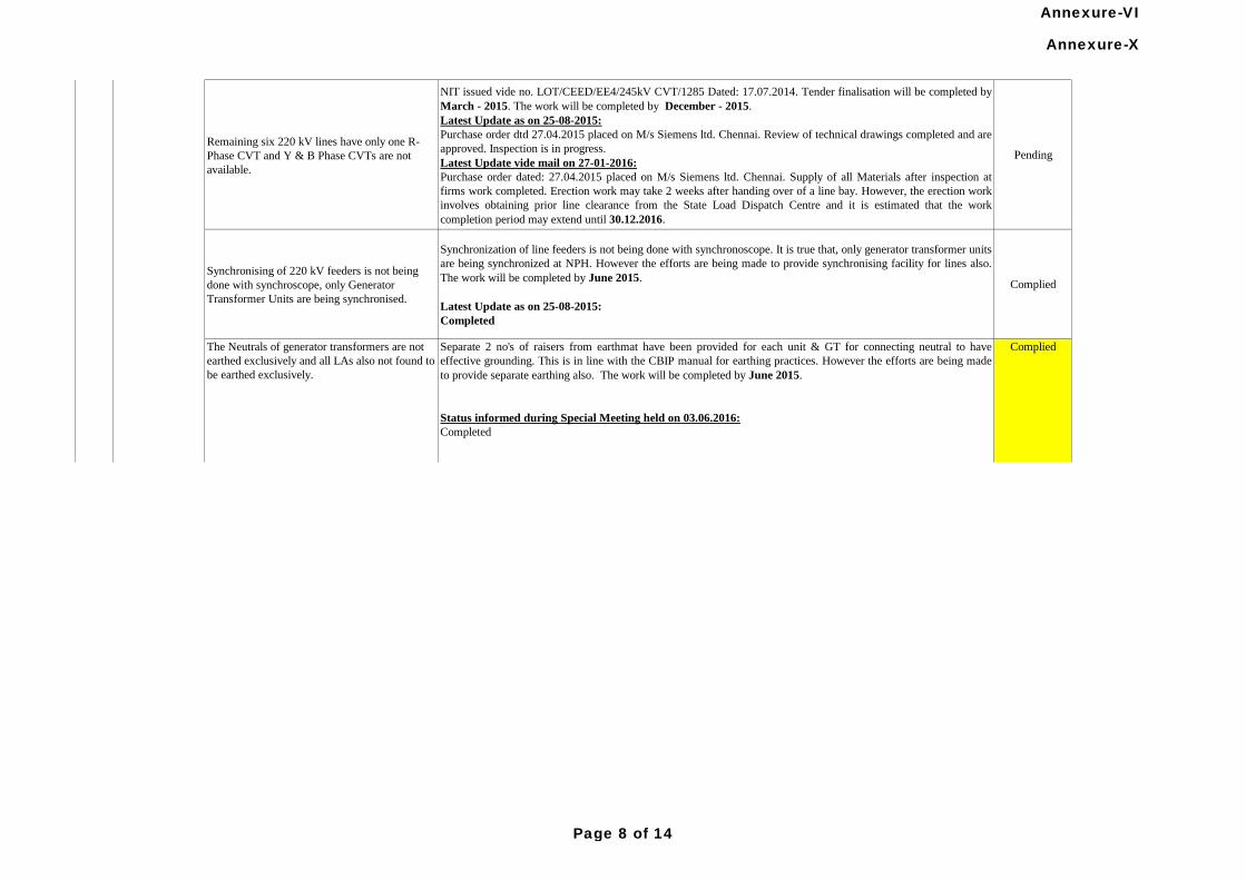
Remaining six 220 kV lines have only one R-
Phase CVT and Y & B Phase CVTs are not
available.
NIT issued vide no. LOT/CEED/EE4/245kV CVT/1285 Dated: 17.07.2014. Tender finalisation will be completed by
March - 2015. The work will be completed by December - 2015.
Latest Update as on 25-08-2015:
Purchase order dtd 27.04.2015 placed on M/s Siemens ltd. Chennai. Review of technical drawings completed and are
approved. Inspection is in progress.
Latest Update vide mail on 27-01-2016:
Purchase order dated: 27.04.2015 placed on M/s Siemens ltd. Chennai. Supply of all Materials after inspection at
firms work completed. Erection work may take 2 weeks after handing over of a line bay. However, the erection work
involves obtaining prior line clearance from the State Load Dispatch Centre and it is estimated that the work
completion period may extend until 30.12.2016.
Pending
Synchronising of 220 kV feeders is not being
done with synchroscope, only Generator
Transformer Units are being synchronised.
Synchronization of line feeders is not being done with synchronoscope. It is true that, only generator transformer units
are being synchronized at NPH. However the efforts are being made to provide synchronising facility for lines also.
The work will be completed by June 2015.
Latest Update as on 25-08-2015:
Completed
Complied
3 220kv Nagjhari
Power House
Separate 2 no's of raisers from earthmat have been provided for each unit & GT for connecting neutral to have
effective grounding. This is in line with the CBIP manual for earthing practices. However the efforts are being made
to provide separate earthing also. The work will be completed by June 2015.
Status informed during Special Meeting held on 03.06.2016:
Completed
Latest Update as on 25-08-2015 and mail on 27-01-2016:
CompliedThe Neutrals of generator transformers are not
earthed exclusively and all LAs also not found to
be earthed exclusively.
Annexure-X
Page 8 of 14
Annexure-VI
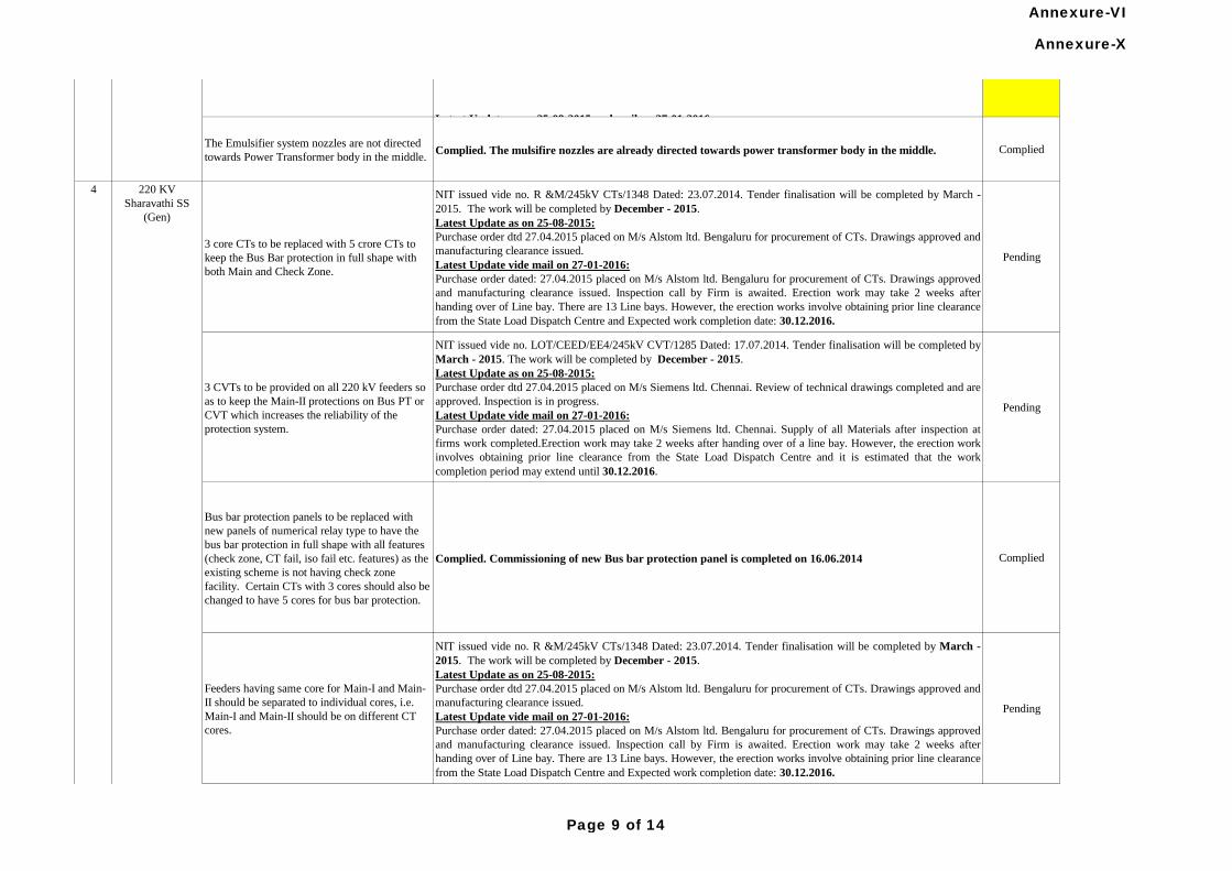
The Emulsifier system nozzles are not directed
towards Power Transformer body in the middle.Complied. The mulsifire nozzles are already directed towards power transformer body in the middle. Complied
3 core CTs to be replaced with 5 crore CTs to
keep the Bus Bar protection in full shape with
both Main and Check Zone.
NIT issued vide no. R &M/245kV CTs/1348 Dated: 23.07.2014. Tender finalisation will be completed by March -
2015. The work will be completed by December - 2015.
Latest Update as on 25-08-2015:
Purchase order dtd 27.04.2015 placed on M/s Alstom ltd. Bengaluru for procurement of CTs. Drawings approved and
manufacturing clearance issued.
Latest Update vide mail on 27-01-2016:
Purchase order dated: 27.04.2015 placed on M/s Alstom ltd. Bengaluru for procurement of CTs. Drawings approved
and manufacturing clearance issued. Inspection call by Firm is awaited. Erection work may take 2 weeks after
handing over of Line bay. There are 13 Line bays. However, the erection works involve obtaining prior line clearance
from the State Load Dispatch Centre and Expected work completion date: 30.12.2016.
Pending
3 CVTs to be provided on all 220 kV feeders so
as to keep the Main-II protections on Bus PT or
CVT which increases the reliability of the
protection system.
NIT issued vide no. LOT/CEED/EE4/245kV CVT/1285 Dated: 17.07.2014. Tender finalisation will be completed by
March - 2015. The work will be completed by December - 2015.
Latest Update as on 25-08-2015:
Purchase order dtd 27.04.2015 placed on M/s Siemens ltd. Chennai. Review of technical drawings completed and are
approved. Inspection is in progress.
Latest Update vide mail on 27-01-2016:
Purchase order dated: 27.04.2015 placed on M/s Siemens ltd. Chennai. Supply of all Materials after inspection at
firms work completed.Erection work may take 2 weeks after handing over of a line bay. However, the erection work
involves obtaining prior line clearance from the State Load Dispatch Centre and it is estimated that the work
completion period may extend until 30.12.2016.
Pending
Bus bar protection panels to be replaced with
new panels of numerical relay type to have the
bus bar protection in full shape with all features
(check zone, CT fail, iso fail etc. features) as the
existing scheme is not having check zone
facility. Certain CTs with 3 cores should also be
changed to have 5 cores for bus bar protection.
Complied. Commissioning of new Bus bar protection panel is completed on 16.06.2014 Complied
Feeders having same core for Main-I and Main-
II should be separated to individual cores, i.e.
Main-I and Main-II should be on different CT
cores.
NIT issued vide no. R &M/245kV CTs/1348 Dated: 23.07.2014. Tender finalisation will be completed by March -
2015. The work will be completed by December - 2015.
Latest Update as on 25-08-2015:
Purchase order dtd 27.04.2015 placed on M/s Alstom ltd. Bengaluru for procurement of CTs. Drawings approved and
manufacturing clearance issued.
Latest Update vide mail on 27-01-2016:
Purchase order dated: 27.04.2015 placed on M/s Alstom ltd. Bengaluru for procurement of CTs. Drawings approved
and manufacturing clearance issued. Inspection call by Firm is awaited. Erection work may take 2 weeks after
handing over of Line bay. There are 13 Line bays. However, the erection works involve obtaining prior line clearance
from the State Load Dispatch Centre and Expected work completion date: 30.12.2016.
Pending
3 220kv Nagjhari
Power House
4 220 KV
Sharavathi SS
(Gen)
Separate 2 no's of raisers from earthmat have been provided for each unit & GT for connecting neutral to have
effective grounding. This is in line with the CBIP manual for earthing practices. However the efforts are being made
to provide separate earthing also. The work will be completed by June 2015.
Status informed during Special Meeting held on 03.06.2016:
Completed
Latest Update as on 25-08-2015 and mail on 27-01-2016:
CompliedThe Neutrals of generator transformers are not
earthed exclusively and all LAs also not found to
be earthed exclusively.
Annexure-X
Page 9 of 14
Annexure-VI
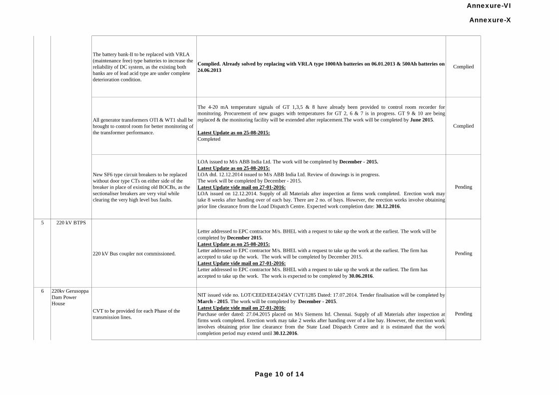
The battery bank-II to be replaced with VRLA
(maintenance free) type batteries to increase the
reliability of DC system, as the existing both
banks are of lead acid type are under complete
deterioration condition.
Complied. Already solved by replacing with VRLA type 1000Ah batteries on 06.01.2013 & 500Ah batteries on
24.06.2013Complied
All generator transformers OTI & WT1 shall be
brought to control room for better monitoring of
the transformer performance.
The 4-20 mA temperature signals of GT 1,3,5 & 8 have already been provided to control room recorder for
monitoring. Procurement of new guages with temperatures for GT 2, 6 & 7 is in progress. GT 9 & 10 are being
replaced & the monitoring facility will be extended after replacement.The work will be completed by June 2015.
Latest Update as on 25-08-2015:
Completed
Complied
New SF6 type circuit breakers to be replaced
without door type CTs on either side of the
breaker in place of existing old BOCBs, as the
sectionaliser breakers are very vital while
clearing the very high level bus faults.
LOA issued to M/s ABB India Ltd. The work will be completed by December - 2015.
Latest Update as on 25-08-2015:
LOA dtd. 12.12.2014 issued to M/s ABB India Ltd. Review of drawings is in progress.
The work will be completed by December - 2015.
Latest Update vide mail on 27-01-2016:
LOA issued on 12.12.2014. Supply of all Materials after inspection at firms work completed. Erection work may
take 8 weeks after handing over of each bay. There are 2 no. of bays. However, the erection works involve obtaining
prior line clearance from the Load Dispatch Centre. Expected work completion date: 30.12.2016.
Pending
5 220 kV BTPS
220 kV Bus coupler not commissioned.
Letter addressed to EPC contractor M/s. BHEL with a request to take up the work at the earliest. The work will be
completed by December 2015.
Latest Update as on 25-08-2015:
Letter addressed to EPC contractor M/s. BHEL with a request to take up the work at the earliest. The firm has
accepted to take up the work. The work will be completed by December 2015.
Latest Update vide mail on 27-01-2016:
Letter addressed to EPC contractor M/s. BHEL with a request to take up the work at the earliest. The firm has
accepted to take up the work. The work is expected to be completed by 30.06.2016.
Pending
CVT to be provided for each Phase of the
transmission lines.
NIT issued vide no. LOT/CEED/EE4/245kV CVT/1285 Dated: 17.07.2014. Tender finalisation will be completed by
March - 2015. The work will be completed by December - 2015.
Latest Update vide mail on 27-01-2016:
Purchase order dated: 27.04.2015 placed on M/s Siemens ltd. Chennai. Supply of all Materials after inspection at
firms work completed. Erection work may take 2 weeks after handing over of a line bay. However, the erection work
involves obtaining prior line clearance from the State Load Dispatch Centre and it is estimated that the work
completion period may extend until 30.12.2016.
Pending
4 220 KV
Sharavathi SS
(Gen)
220kv Gerusoppa
Dam Power
House
6
Annexure-X
Page 10 of 14
Annexure-VI
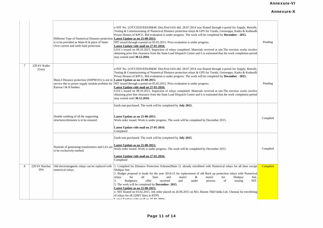
Main-I Distance protection (SHPM101) is not in
service due to power supply module problem for
Karwar I & II feeders.
e-NIT No. LOT/CEED/EE6/R&M/ Dist.Prot/1416 dtd: 28.07.2014 was floated through e-portal for Supply, Retrofit,
Testing & Commissioning of Numerical Distance protection relays & GPS for Varahi, Gerusoppa, Kadra & Kodasalli
Power Houses of KPCL. Bid evaluation is under progress. The work will be completed by December - 2015.
Latest Update as on 25-08-2015:
NIT issued through e-portal on 05.05.2015. Price evaluation is under progress.
Latest Update vide mail on 27-01-2016:
LOA’s issued on 08.10.2015. Inspection of relays completed. Materials received at site.The erection works involve
obtaining prior line clearance from the State Load Dispatch Centre and it is estimated that the work completion period
may extend until 30.12.2016.
Pending
Double earthing of all the supporting
structures/elements is to be ensured.
Earth mat purchased. The work will be completed by July 2015.
Latest Update as on 25-08-2015:
Work order issued. Work is under progress. The work will be completed by December 2015.
Latest Update vide mail on 27-01-2016:
Completed
Complied
Neutrals of generating transformers and LA's are
to be exclusively earthed.
Earth mat purchased. The work will be completed by July 2015.
Latest Update as on 25-08-2015:
Work order issued. Work is under progress. The work will be completed by December 2015.
Latest Update vide mail on 27-01-2016:
Completed
Complied
7 220 kV Kadra
(Gen)
1. Complied for Distance Protection Scheme(Main 1) already retrofitted with Numerical relays for all lines except
Shahpur line.
2. Budget proposal is made for the year 2014-15 for replacement of old Back up protection relays with Numerical
relays for all lines and main1 & main2 for Shahpur line.
3. Budgetary offer received and under process of issuing NIT.
5. The work will be completed by December- 2015.
Latest Update as on 25-08-2015:
e- NIT floated on 03.02.2015. Job order placed on 26.06.2015 on M/s Alstom T&D India Ltd. Chennai for retrofitting
of relays for all 220kV lines at RTPS.
Latest Update vide mail on 27-01-2016:
Work Order placed on 26.06.2015 for retrofitting of relays for all 220kV lines at RTPS. Materials received at site.
The erection works involve obtaining prior line clearance from the State Load Dispatch Centre and it is estimated that
the work completion period may extend until 30.06.2016.
Status informed during Special Meeting held on 03.06.2016:
Completed
Old electromagnetic relays can be replaced with
numerical relays.
220 kV Raichur
TPS
8 Complied
Pending
e-NIT No. LOT/CEED/EE6/R&M/ Dist.Prot/1416 dtd: 28.07.2014 was floated through e-portal for Supply, Retrofit,
Testing & Commissioning of Numerical Distance protection relays & GPS for Varahi, Gerusoppa, Kadra & Kodasalli
Power Houses of KPCL. Bid evaluation is under progress. The work will be completed by December - 2015.
Latest Update as on 25-08-2015:
NIT issued through e-portal on 05.05.2015. Price evaluation is under progress.
Latest Update vide mail on 27-01-2016:
LOA’s issued on 08.10.2015. Inspection of relays completed. Materials received at site.The erection works involve
obtaining prior line clearance from the State Load Dispatch Centre and it is estimated that the work completion period
may extend until 30.12.2016.
Different Type of Numerical Distance protection
is to be provided as Main-II in place of Static
Over current and earth fault protection.
220kv Gerusoppa
Dam Power
House
6
Annexure-X
Page 11 of 14
Annexure-VI
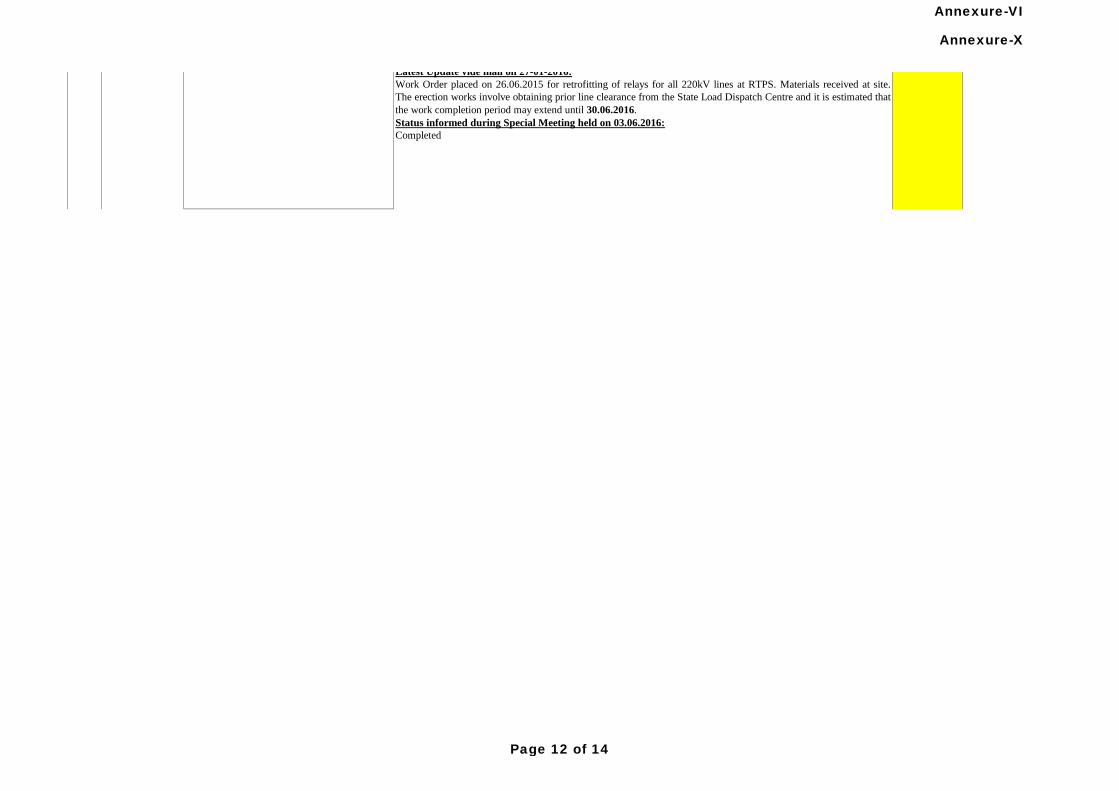
1. Complied for Distance Protection Scheme(Main 1) already retrofitted with Numerical relays for all lines except
Shahpur line.
2. Budget proposal is made for the year 2014-15 for replacement of old Back up protection relays with Numerical
relays for all lines and main1 & main2 for Shahpur line.
3. Budgetary offer received and under process of issuing NIT.
5. The work will be completed by December- 2015.
Latest Update as on 25-08-2015:
e- NIT floated on 03.02.2015. Job order placed on 26.06.2015 on M/s Alstom T&D India Ltd. Chennai for retrofitting
of relays for all 220kV lines at RTPS.
Latest Update vide mail on 27-01-2016:
Work Order placed on 26.06.2015 for retrofitting of relays for all 220kV lines at RTPS. Materials received at site.
The erection works involve obtaining prior line clearance from the State Load Dispatch Centre and it is estimated that
the work completion period may extend until 30.06.2016.
Status informed during Special Meeting held on 03.06.2016:
Completed
Complied
Annexure-X
Page 12 of 14
Annexure-VI
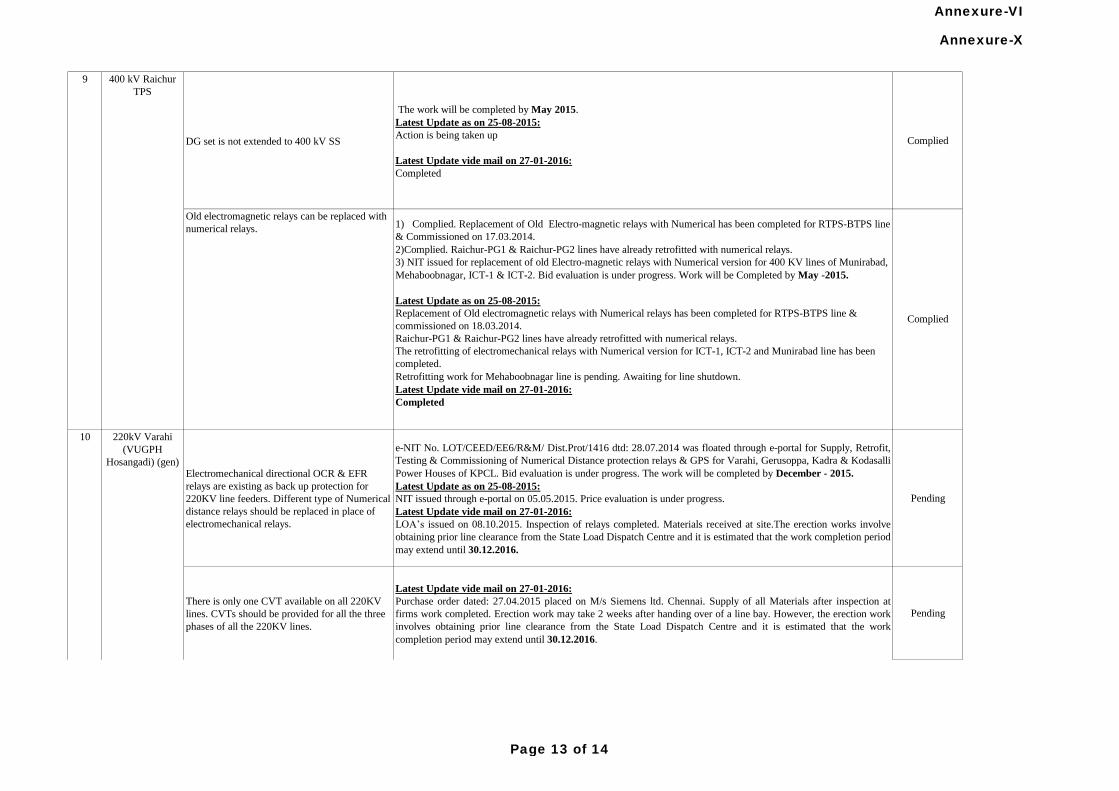
DG set is not extended to 400 kV SS
The work will be completed by May 2015.
Latest Update as on 25-08-2015:
Action is being taken up
Latest Update vide mail on 27-01-2016:
Completed
Complied
Electromechanical directional OCR & EFR
relays are existing as back up protection for
220KV line feeders. Different type of Numerical
distance relays should be replaced in place of
electromechanical relays.
e-NIT No. LOT/CEED/EE6/R&M/ Dist.Prot/1416 dtd: 28.07.2014 was floated through e-portal for Supply, Retrofit,
Testing & Commissioning of Numerical Distance protection relays & GPS for Varahi, Gerusoppa, Kadra & Kodasalli
Power Houses of KPCL. Bid evaluation is under progress. The work will be completed by December - 2015.
Latest Update as on 25-08-2015:
NIT issued through e-portal on 05.05.2015. Price evaluation is under progress.
Latest Update vide mail on 27-01-2016:
LOA’s issued on 08.10.2015. Inspection of relays completed. Materials received at site.The erection works involve
obtaining prior line clearance from the State Load Dispatch Centre and it is estimated that the work completion period
may extend until 30.12.2016.
Pending
There is only one CVT available on all 220KV
lines. CVTs should be provided for all the three
phases of all the 220KV lines.
Latest Update vide mail on 27-01-2016:
Purchase order dated: 27.04.2015 placed on M/s Siemens ltd. Chennai. Supply of all Materials after inspection at
firms work completed. Erection work may take 2 weeks after handing over of a line bay. However, the erection work
involves obtaining prior line clearance from the State Load Dispatch Centre and it is estimated that the work
completion period may extend until 30.12.2016.
Pending
10 220kV Varahi
(VUGPH
Hosangadi) (gen)
1) Complied. Replacement of Old Electro-magnetic relays with Numerical has been completed for RTPS-BTPS line
& Commissioned on 17.03.2014.
2)Complied. Raichur-PG1 & Raichur-PG2 lines have already retrofitted with numerical relays.
3) NIT issued for replacement of old Electro-magnetic relays with Numerical version for 400 KV lines of Munirabad,
Mehaboobnagar, ICT-1 & ICT-2. Bid evaluation is under progress. Work will be Completed by May -2015.
Latest Update as on 25-08-2015:
Replacement of Old electromagnetic relays with Numerical relays has been completed for RTPS-BTPS line &
commissioned on 18.03.2014.
Raichur-PG1 & Raichur-PG2 lines have already retrofitted with numerical relays.
The retrofitting of electromechanical relays with Numerical version for ICT-1, ICT-2 and Munirabad line has been
completed.
Retrofitting work for Mehaboobnagar line is pending. Awaiting for line shutdown.
Latest Update vide mail on 27-01-2016:
Completed
Complied
Old electromagnetic relays can be replaced with
numerical relays.
400 kV Raichur
TPS
9
Annexure-X
Page 13 of 14
Annexure-VI
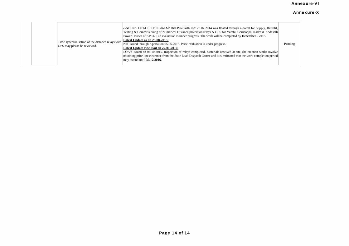
Time synchronisation of the distance relays with
GPS may please be reviewed.
e-NIT No. LOT/CEED/EE6/R&M/ Dist.Prot/1416 dtd: 28.07.2014 was floated through e-portal for Supply, Retrofit,
Testing & Commissioning of Numerical Distance protection relays & GPS for Varahi, Gerusoppa, Kadra & Kodasalli
Power Houses of KPCL. Bid evaluation is under progress. The work will be completed by December - 2015.
Latest Update as on 25-08-2015:
NIT issued through e-portal on 05.05.2015. Price evaluation is under progress.
Latest Update vide mail on 27-01-2016:
LOA’s issued on 08.10.2015. Inspection of relays completed. Materials received at site.The erection works involve
obtaining prior line clearance from the State Load Dispatch Centre and it is estimated that the work completion period
may extend until 30.12.2016.
Pending
10 220kV Varahi
(VUGPH
Hosangadi) (gen)
Annexure-X
Page 14 of 14
Annexure-VI
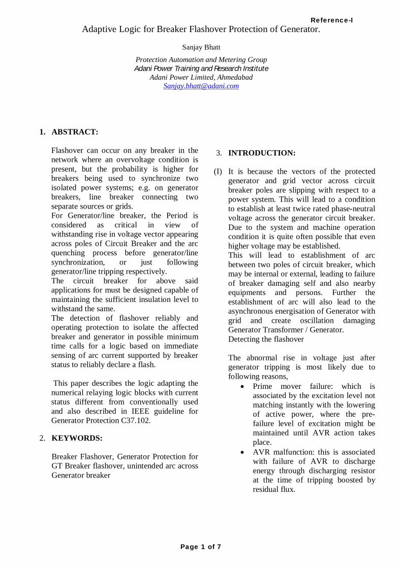
Adaptive Logic for Breaker Flashover Protection of Generator. Sanjay Bhatt
Protection Automation and Metering Group Adani Power Training and Research Institute
Adani Power Limited, Ahmedabad [email protected]
1. ABSTRACT:
Flashover can occur on any breaker in the network where an overvoltage condition is present, but the probability is higher for breakers being used to synchronize two isolated power systems; e.g. on generator breakers, line breaker connecting two separate sources or grids. For Generator/line breaker, the Period is considered as critical in view of withstanding rise in voltage vector appearing across poles of Circuit Breaker and the arc quenching process before generator/line synchronization, or just following generator/line tripping respectively. The circuit breaker for above said applications for must be designed capable of maintaining the sufficient insulation level to withstand the same. The detection of flashover reliably and operating protection to isolate the affected breaker and generator in possible minimum time calls for a logic based on immediate sensing of arc current supported by breaker status to reliably declare a flash. This paper describes the logic adapting the numerical relaying logic blocks with current status different from conventionally used and also described in IEEE guideline for Generator Protection C37.102.
2. KEYWORDS: Breaker Flashover, Generator Protection for GT Breaker flashover, unintended arc across Generator breaker
3. INTRODUCTION:
(I) It is because the vectors of the protected generator and grid vector across circuit breaker poles are slipping with respect to a power system. This will lead to a condition to establish at least twice rated phase-neutral voltage across the generator circuit breaker. Due to the system and machine operation condition it is quite often possible that even higher voltage may be established. This will lead to establishment of arc between two poles of circuit breaker, which may be internal or external, leading to failure of breaker damaging self and also nearby equipments and persons. Further the establishment of arc will also lead to the asynchronous energisation of Generator with grid and create oscillation damaging Generator Transformer / Generator. Detecting the flashover The abnormal rise in voltage just after generator tripping is most likely due to following reasons,
Prime mover failure: which is associated by the excitation level not matching instantly with the lowering of active power, where the pre-failure level of excitation might be maintained until AVR action takes place.
AVR malfunction: this is associated with failure of AVR to discharge energy through discharging resistor at the time of tripping boosted by residual flux.
Reference-I
Page 1 of 7
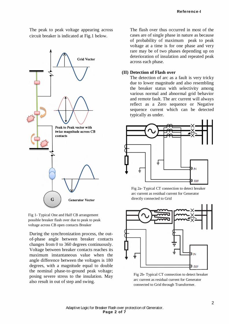
2 Adaptive Logic for Breaker Flash over protection of Generator.
The peak to peak voltage appearing across circuit breaker is indicated at Fig.1 below.
During the synchronization process, the out-of-phase angle between breaker contacts changes from 0 to 360 degrees continuously. Voltage between breaker contacts reaches its maximum instantaneous value when the angle difference between the voltages is 180 degrees, with a magnitude equal to double the nominal phase-to-ground peak voltage; posing severe stress to the insulation. May also result in out of step and swing.
The flash over thus occurred in most of the cases are of single phase in nature as because of probability of maximum peak to peak voltage at a time is for one phase and very rare may be of two phases depending up on deterioration of insulation and repeated peak across each phase.
(II) Detection of Flash over The detection of arc as a fault is very tricky due to lower magnitude and also resembling the breaker status with selectivity among various normal and abnormal grid behavior and remote fault. The arc current will always reflect as a Zero sequence or Negative sequence current which can be detected typically as under.
Fig 1- Typical One and Half CB arrangement possible breaker flash over due to peak to peak voltage across CB open contacts Breaker
Fig 2a- Typical CT connection to detect breaker arc current as residual current for Generator directly connected to Grid
Fig 2b- Typical CT connection to detect breaker arc current as residual current for Generator connected to Grid through Transformer.
Reference-I
Page 2 of 7
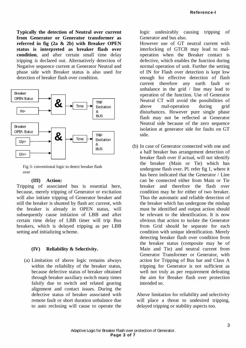
3 Adaptive Logic for Breaker Flash over protection of Generator.
Typically the detection of Neutral over current from Generator or Generator transformer as referred in fig (2a & 2b) with Breaker OPEN status is interpreted as breaker flash over condition, and after certain small time delay tripping is declared out. Alternatively detection of Negative sequence current at Generator Neutral and phase side with Breaker status is also used for detection of breaker flash over condition.
(III) Action: Tripping of associated bus is essential here, because, merely tripping of Generator or excitation will also initiate tripping of Generator breaker and still the breaker is shunted by flash arc current, with the breaker is already in OPEN status, will subsequently cause initiation of LBB and after certain time delay of LBB timer will trip Bus breakers, which is delayed tripping as per LBB setting and initializing scheme.
(IV) Reliability & Selectivity.
(a) Limitation of above logic remains always within the reliability of the breaker status, because defective status of breaker obtained through breaker auxiliary switch many times falsify due to switch and related gearing alignment and contact issues. During the defective status of breaker associated with remote fault or short duration unbalance due to auto reclosing will cause to operate the
logic undesirably causing tripping of Generator and bus also. However use of GT neutral current with interlocking of GTCB may lead to mal-operation when the Breaker contact is defective, which enables the function during normal operation of unit. Further the setting of IN for Flash over detection is kept low enough for effective detection of flash current therefore any earth fault or unbalance in the grid / line may lead to operation of the function. Use of Generator Neutral CT will avoid the possibilities of above mal-operation during grid disturbances. However pure single phase flash may not be reflected at Generator Neutral side because of the zero sequence isolation at generator side for faults on GT side.
(b) In case of Generator connected with one and a half breaker bus arrangement detection of breaker flash over if actual, will not identify the breaker (Main or Tie) which has undergone flash over. Pl. refer fig 1, where it has been indicated that the Generator / Line can be connected either from Main or Tie breaker and therefore the flash over condition may be for either of two breaker. Thus the automatic and reliable detection of the breaker which has undergone the mishap must be identified and output action should be relevant to the identification. It is now obvious that action to isolate the Generator from Grid should be separate for each condition with unique identification. Merely detecting breaker flash over condition from the breaker status (composite may be of Main and Tie) and neutral current from Generator Transformer or Generator, with action for Tripping of Bus bar and Class A tripping for Generator is not sufficient as well not truly as per requirement defeating the aim for Breaker flash over protection intended so.
Above limitation for reliability and selectivity will place a threat to undesired tripping, delayed tripping or stability aspects too.
& Breaker OPEN Status
IN>
I2p>
I2n>
TRIP Excitation& BUS
& Breaker OPEN Status
TRIP Excitation& BUS
Fig 3- conventional logic to detect breaker flash over
Time
Time
Reference-I
Page 3 of 7
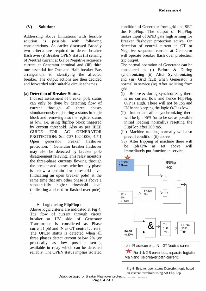
4 Adaptive Logic for Breaker Flash over protection of Generator.
(V) Solution: Addressing above limitations with feasible solution is possible with following considerations. As earlier discussed Broadly two criteria are required to detect breaker flash over (i) Breaker OPEN status (ii) sensing of Neutral current at GT or Negative sequence current at Generator terminal and (iii) third one essential for One and Half breaker Bus arrangement is, identifying the affected breaker. The output actions are then decided and forwarded with suitable circuit schemes. (a) Detection of Breaker Status.
Indirect assessment of breaker pole status can only be done by detecting flow of current through all three phases simultaneously registering a status in logic block and removing also the register status as low, i.e. using flipflop block triggered by current threshold. Also as per IEEE GUIDE FOR AC GENERATOR PROTECTION: Std C37.102-1006, 4.7.1 Open generator breaker flashover protection: ‘Generator breaker flashover may also be detected by breaker pole disagreement relaying. This relay monitors the three-phase currents flowing through the breaker and senses whether any phase is below a certain low threshold level (indicating an open breaker pole) at the same time that any other phase is above a substantially higher threshold level (indicating a closed or flashed-over pole).’ Logic using FlipFlop :
Above logic criteria are indicated at Fig 4. The flow of current through circuit breaker at HV side of Generator Transformer is considered as Phase current (Iph) and IN as GT neutral current. The OPEN status is detected when all three phases detect current below 2% (or practically as low possible setting available in relay which can be detected reliably. The OPEN status implies isolated
condition of Generator from grid and SET the FlipFlop. The output of FlipFlop makes input of AND gate high arming for Breaker flashover protection active. On detection of neutral current in GT or Negative sequence current at Generator will operate breaker flash over protection trip output. The normal operation of Generator can be considered as (i) Before & During synchronizing (ii) After Synchronizing and (iii) Grid fault when Generator is normal in service (iv) After isolating from grid. (i) Before & during synchronizing there
is no current flow and hence FlipFlop O/P is High. There will not be Iph and IN hence keeping the logic O/P as low.
(ii) Immediate after synchronizing there will be Iph >5% (or to be set as possible initial loading normally) resetting the FlipFlop after 200 mS.
(iii) Machine running normally will also prevail condition (ii) above.
(iv) After tripping of machine there will be Iph<2% as set above will immediately put function in service.
Fig 4- Breaker open status Detection logic based on current threshold using SR FlipFlop
SR Flip Flop
S
R
O
IPh <2% 3 Phase
IPh > 5% 3 Phase
T = 200 mS
& IN> 10 to 20%
T = 100 mS
TRIP ALL / BUS TRIP
Iph= Phase current, IN = GT Neutral current
For 1-1/2 Breaker bus, separate logic for Main and Tie breaker path current.
Reference-I
Page 4 of 7
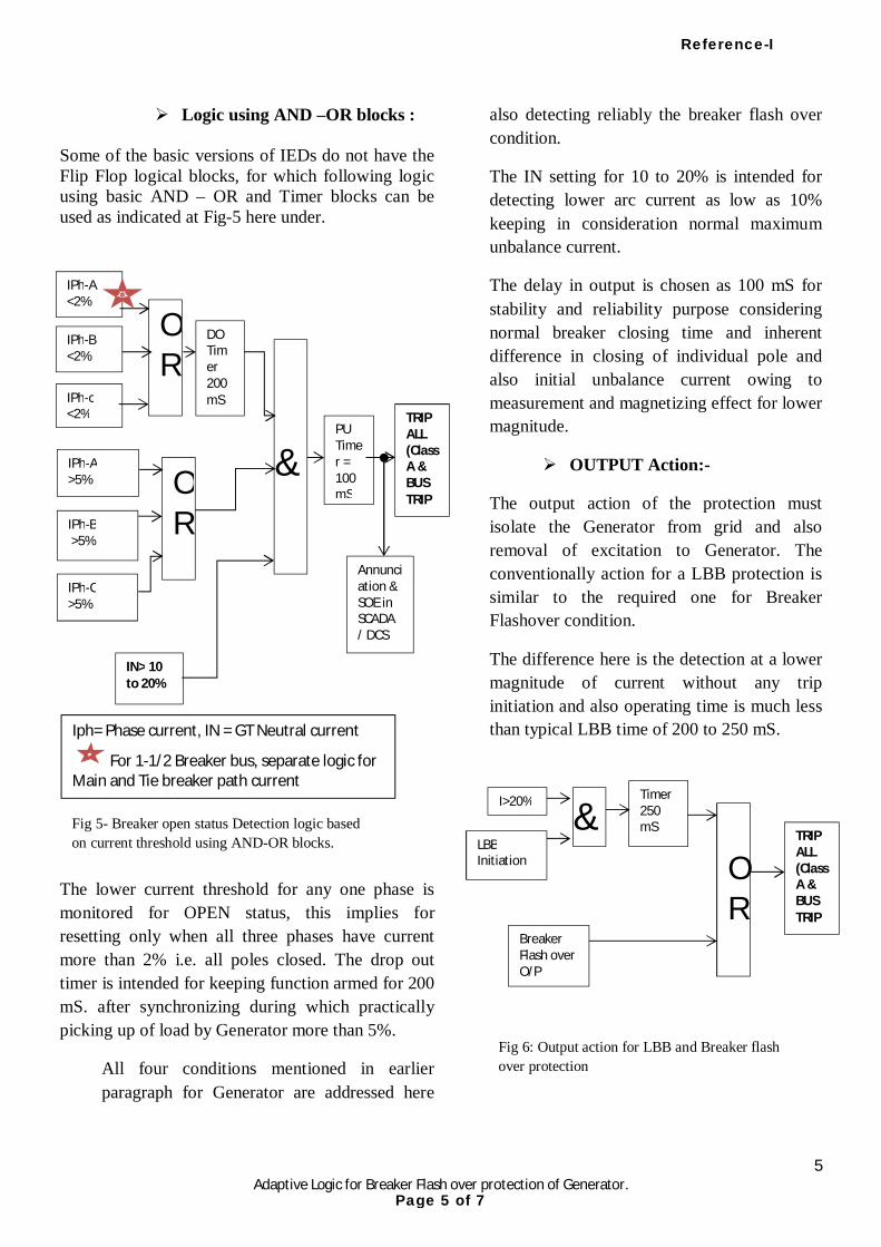
5 Adaptive Logic for Breaker Flash over protection of Generator.
Logic using AND –OR blocks : Some of the basic versions of IEDs do not have the Flip Flop logical blocks, for which following logic using basic AND – OR and Timer blocks can be used as indicated at Fig-5 here under.
The lower current threshold for any one phase is monitored for OPEN status, this implies for resetting only when all three phases have current more than 2% i.e. all poles closed. The drop out timer is intended for keeping function armed for 200 mS. after synchronizing during which practically picking up of load by Generator more than 5%.
All four conditions mentioned in earlier paragraph for Generator are addressed here
also detecting reliably the breaker flash over condition.
The IN setting for 10 to 20% is intended for detecting lower arc current as low as 10% keeping in consideration normal maximum unbalance current.
The delay in output is chosen as 100 mS for stability and reliability purpose considering normal breaker closing time and inherent difference in closing of individual pole and also initial unbalance current owing to measurement and magnetizing effect for lower magnitude.
OUTPUT Action:-
The output action of the protection must isolate the Generator from grid and also removal of excitation to Generator. The conventionally action for a LBB protection is similar to the required one for Breaker Flashover condition.
The difference here is the detection at a lower magnitude of current without any trip initiation and also operating time is much less than typical LBB time of 200 to 250 mS.
Fig 5- Breaker open status Detection logic based on current threshold using AND-OR blocks.
Iph= Phase current, IN = GT Neutral current
For 1-1/2 Breaker bus, separate logic for Main and Tie breaker path current
&
IN> 10 to 20%
PU Timer = 100 mS
TRIP ALL (Class A & BUS TRIP
IPh-B <2%
IPh-c <2%
OR
IPh-A >5%
IPh-B >5%
IPh-C >5%
OR
DO Timer 200 mS
Annunciation & SOE in SCADA / DCS
IPh-A <2%
LBB Initiation
OR
TRIP ALL (Class A & BUS TRIP
Breaker Flash over O/P
I>20% Timer 250 mS
&
Fig 6: Output action for LBB and Breaker flash over protection
Reference-I
Page 5 of 7
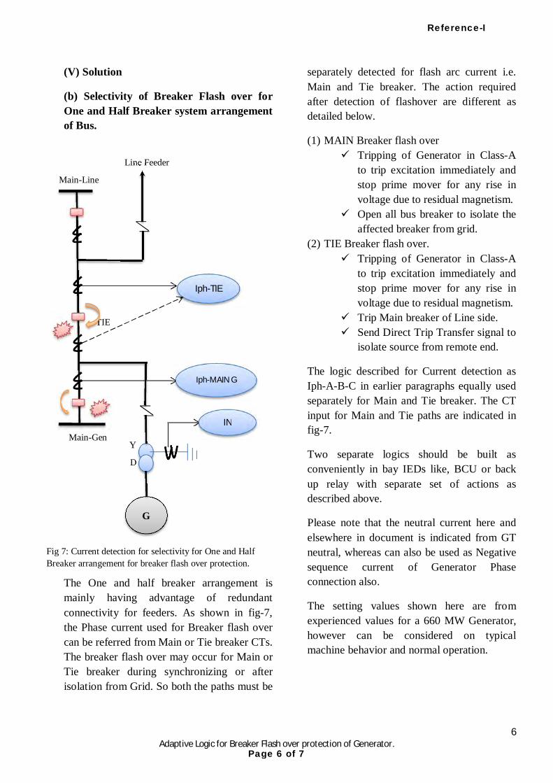
6 Adaptive Logic for Breaker Flash over protection of Generator.
(V) Solution
(b) Selectivity of Breaker Flash over for One and Half Breaker system arrangement of Bus.
The One and half breaker arrangement is mainly having advantage of redundant connectivity for feeders. As shown in fig-7, the Phase current used for Breaker flash over can be referred from Main or Tie breaker CTs. The breaker flash over may occur for Main or Tie breaker during synchronizing or after isolation from Grid. So both the paths must be
separately detected for flash arc current i.e. Main and Tie breaker. The action required after detection of flashover are different as detailed below.
(1) MAIN Breaker flash over Tripping of Generator in Class-A
to trip excitation immediately and stop prime mover for any rise in voltage due to residual magnetism.
Open all bus breaker to isolate the affected breaker from grid.
(2) TIE Breaker flash over. Tripping of Generator in Class-A
to trip excitation immediately and stop prime mover for any rise in voltage due to residual magnetism.
Trip Main breaker of Line side. Send Direct Trip Transfer signal to
isolate source from remote end.
The logic described for Current detection as Iph-A-B-C in earlier paragraphs equally used separately for Main and Tie breaker. The CT input for Main and Tie paths are indicated in fig-7.
Two separate logics should be built as conveniently in bay IEDs like, BCU or back up relay with separate set of actions as described above.
Please note that the neutral current here and elsewhere in document is indicated from GT neutral, whereas can also be used as Negative sequence current of Generator Phase connection also.
The setting values shown here are from experienced values for a 660 MW Generator, however can be considered on typical machine behavior and normal operation.
TIE
Fig 7: Current detection for selectivity for One and Half Breaker arrangement for breaker flash over protection.
Line Feeder
Y
D
Main-Line
Main-Gen
G
Iph-TIE
Iph-MAIN G
IN
Reference-I
Page 6 of 7
7 Adaptive Logic for Breaker Flash over protection of Generator.
(VI) CONCLUSION;
The breaker flash over phenomena is a very typical one to detect reliably and opt for action like isolation of bus and feeder at minimum possible time. Typical logic are offered by various manufacturer as indicated earlier, however use of reliable detection and output action is a part of scheme designing and adaption of philosophy.
Reliable detection and comprehensive logic is now very easy to be built in IEDs having numerous logical blocks, I/O configuration and even use of GOOSE signals for interlocking.
Breaker flash over protection must be used as a critical protection function particularly the locations like sea shore based or saline atmosphere surrounded installations, where chances of external flash over is higher. The lower flash arc current may also cause severe oscillation and asynchronous energisation may lead to damage to TG set or transformer.
Careful design should be carried out to handle flash over detection and isolation for one and Half breaker arrangement.
(VII) REFERENCES a. IEEE Guide for AC Generator
Protection: Std C37.102-1006, 4.7.1
b. Guide for Ac Generator Protection, ANSI/IEEEC 37.102-1995.
c. Application manual AREVA Micom P34x relay.
(VIII) Acknowledgement:
Author takes opportunity to express gratitude and special thanks to HOD of P&M Group of Adani Power Ltd., his guideline & knowledge, Adani Power Training & Research Institute, APL management for granting permission and inspiration to think and present this paper.
(IX) Author:
Sanjay U. Bhatt, working as DGM (Protection) at Adani Power Ltd, Ahmedabad, (Protection Automation & Metering Department), from January 2012.
B.E. (Electrical) -1993 from L.E. College Morvi , Gujarat (India).
Worked: o In G.S.F.C.-Jamnagar, as Ele.
Maintenance Engr. o In Govt. Polytechnic, as a lecturer on
clearing GPSC. o In GSECL, Gujarat as Junior Engineer
at Sikka Power station as Electrical Testing & Maintenance engineer and at SLDC during commissioning of SCADA and related system.
o As Deputy Engineer at GSECL corporate office as Testing engineer.
Reference-I
Page 7 of 7
Related Documents