Meet the Engineer 2015 Presentations from 10 th June 2015 Event

Meet the Engineer 2015 Presentations
Aug 11, 2015
Welcome message from author
This document is posted to help you gain knowledge. Please leave a comment to let me know what you think about it! Share it to your friends and learn new things together.
Transcript
Meet the Engineer 2015
Presentations from 10th June 2015 Event

© Productiv Ltd 2015
Meet the Engineer 2015
Welcome & ContextRichard Bruges
© Productiv Ltd 2015
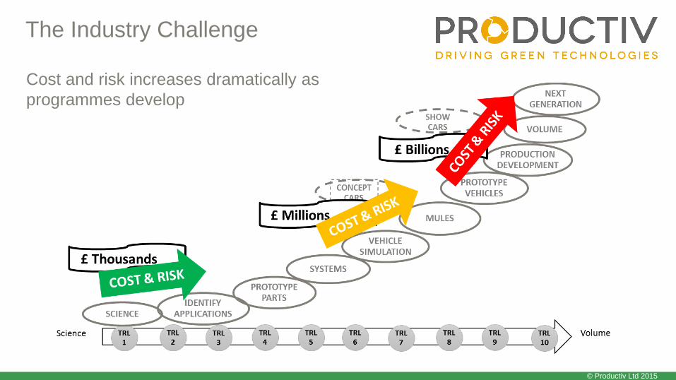
The Industry Challenge
Cost and risk increases dramatically as
programmes develop

© Productiv Ltd 2015
The Investment Opportunity
Prototype
Technology & Manufacturing Development
Proving Volume
High Volume
TRL4
TRL6
TRL9
Value is generated as technologies are
developed

© Productiv Ltd 2015
The Market Failure
Tier 1 suppliers don’t invest in low volume
technology

© Productiv Ltd 2015
The Productiv Offer

The Proving Factory Model


© Productiv Ltd 2015
Meet the Engineer 2015
Technology PitchesSession 1
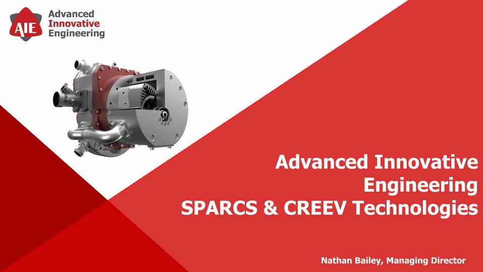
Nathan Bailey, Managing Director
Advanced Innovative Engineering
SPARCS & CREEV Technologies
• UK based engineering company specialising in the development of innovative rotary
engine technologies.
• Combined team experience of over 80 years in rotary engine design.
• AIE is located on the outskirts of Birmingham in the United Kingdom, an area recognised
as the heart of British Engineering and Manufacturing.
www.aieuk.com

Background

Background - Observations
Aerospace• The air-cooled-rotor (ACR) type of Wankel engine is now well established for powering military unmanned aerial
vehicles (UAVs). These engines have achieved over 2 million hours of in-service operation.
• This generally high-rpm high-load UAV application exploits all the best characteristics of the rotary. The engines
have extremely high power-to-weight ratio, low vibration, high reliability, and reasonably good specific fuel
consumption (sfc).
Automotive• One of the most promising types of future electric vehicle is the Series Hybrid which has a modest weight of
batteries on board, offering a battery-only limited range. This meets the needs of 80% of typical daily car usage
without use of any gasoline. The batteries are recharged overnight from the mains supply.
• During longer journeys, as the batteries become partially depleted, an on-board engine-generator (genset)
provides electrical power such that the vehicle has a normal range limited only by the capacity of the fuel tank.
• In this duty the engine operates at high rpm and high load; or is switched off. All parameters which affect sfc are
optimised without compromise for this single running condition.
• Hence the sfc is much lower than the average sfc of conventional mechanical drive vehicles using engines which
have to operate over the full load-speed spectrum.
• For most journeys the genset is unused. (It is a dead weight) It is important therefore that its weight is very low.
Also, because the change from “off” to high power may occur when the vehicle is moving quite slowly in almost
total silence under battery power alone, it is essential that when the engine starts it is extremely quiet and free of
vibration.

Background - Opportunity
• AIE believe the hybrid vehicle application is ideal for a single-rotor Wankel engine. Even more than in UAVs, it
fully exploits the strengths of the rotary engine and avoids the engine ever having to operate in the difficult low
load / low speed areas where rotary’s sfc is inferior to that of reciprocating engines. A high-speed rotary engine
“genset” would weigh less than 40% of a unit using a reciprocating engine, which for NVH reasons must run at
lower speed.
• To utilise a Wankel rotary engine in an automotive application, though some of the less desirable characteristics of
the engine need to be mitigated or eliminated:
• Low Engine Life
• High Oil Consumption
• High Exhaust Energy and Emissions
• Poor Thermal Stability
• AIE has developed 2 key technologies that address these characteristics without removing the engines core
advantages
• SPARCS - Pressurised Gas Rotor Cooling System
• CREEV - Exhaust Expander Unit

Technology
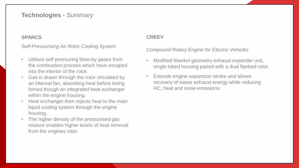
SPARCS
Self-Pressurising Air Rotor Cooling System
Utilises self pressuring blow by gases from
the combustion process which have escaped
into the interior of the rotor.
Gas is drawn through the rotor circulated by
an internal fan, absorbing heat before being
forced though an integrated heat exchanger
within the engine housing.
Heat exchanger then rejects heat to the main
liquid cooling system through the engine
housing.
The higher density of the pressurised gas
mixture enables higher levels of heat removal
from the engines rotor.
CREEV
Compound Rotary Engine for Electric Vehicles
• Modified Wankel geometry exhaust expander unit,
single lobed housing paired with a dual flanked rotor.
• Extends engine expansion stroke and allows
recovery of waste exhaust energy while reducing
HC, heat and noise emissions.
SPARCS
Self-Pressurising Air Rotor Cooling System
• Utilises self pressuring blow-by gases from
the combustion process which have escaped
into the interior of the rotor.
• Gas is drawn through the rotor circulated by
an internal fan, absorbing heat before being
forced though an integrated heat exchanger
within the engine housing.
• Heat exchanger then rejects heat to the main
liquid cooling system through the engine
housing.
• The higher density of the pressurised gas
mixture enables higher levels of heat removal
from the engines rotor.
Technologies - Summary

SPARCS Technologies

Background – Rotor Cooling OCR vs ACR
• The key difference in the design of rotary engines for UAV’s and all Wankel rotaries designed for automotive use, such as the NSU Ro 80 and the Mazda RX 7 / 8, relates to the method used for cooling the rotor.
• The UAV type use air (designated ACR = air cooled rotor), the latter use oil (OCR).
• The ACR system was originally conceived by NSU in the early 1960s. For many years it was considered to be only suitable for low-cost low-specific-power engines as satisfactory for some industrial applications. Many engineers working on the OCR Wankel considered the ACR type to be little more than a toy.
• Nevertheless, NSU did demonstrate a lower SFC with their 215 cc ACR engine than with any of their OCR types (resulting from lower friction and heated induction air)
• At the time, though, it was not known how to achieve a high bmep with the ACR type engine. (Indeed, it was considered that any significant increase would be impossible because of overheating of the rolling-element rotor bearing).
• In the late 1960s, the power output of a typical 300cc ACR engine as manufactured by Fichtel & Sachs was about 20 bhp. (Note that a 300cc Wankel is equivalent to a 600cc 4-stroke engine)
• During the period 1970 to 2000, this same size engine was progressively developed in the UK to give 60 bhp, with the sfc reduced by 30% relative to the F&S versions.
• The application was initially as a power unit for motorcycles and then from 1985, for UAVs.
• Specific power output and specific fuel consumption (sfc) of ACR engines are now superior to the OCR type.

Background – Rotor Cooling OCR vs ACR
• OCR type engines generally require twin axially-spring-loaded oil scraper rings to be fitted in each side of the rotor in order to prevent oil leakage into the working chambers. The springs typically have a high axial load of around 50kg. Hence there is considerable mechanical friction loss as these sealing rings orbit and rotate relative to the engine side plates.
• There is also some further energy loss due to the “cocktail shaker” effect of oil in the partially filled rotor.
• The sealing rings also require radial space between the OD of the rotor ring gear and the inside edge of the rotor side gas seals. Hence, for a given size of rotor, the PCD of the rotor gear has to be smaller; and as a result the shaft eccentricity, “e”, (= “throw” of the shaft) which, from the basic geometry, has the precise value of 1/6 the PCD of the rotor ring gear, is also limited to a smaller value.
• The swept volume (V) of the engine is directly proportional to e, via the formula:
• V = 3√3 e R B where R = rotor radius, and B = rotor axial width.
• The overall result is that the OCR type engine, for a given swept volume, is physically bigger and heavier than the ACR type.
• The important R/e value (designated “K ratio” ) of an OCR rotary engine is limited to a minimum value of about 6.7 / 7.0.
• The ACR engine, which has no oil scraper rings, can use a K ratio of 6.0 .
Background – General ACR Advantages (summary)
The ACR type has the following advantages relative to the “conventional” Wankel engine with OCR :
• Much lower friction losses :
• More compact combustion chamber (lower S/V ratio , lower heat loss):
• Increased forced air movement around TDC / faster combustion
• lower weight ( via smaller diameter rotor and main housings)
• Fewer components and hence lower cost
• Larger diameter and more rigid eccentric shaft as allowed by the larger diameter stationary gear (an important advantage for mounting a bearing-less cantilevered generator rotor)
• Lower stressed stationary gear
• Lower cranking torque when starting, particularly at low temps (ACR has all rolling element bearings)
• More precise balancing (it is difficult for the OCR to have a consistent volume of oil inside the rotor under all conditions); allowing the ACR to generally use hard mounting which can save space and weight
Historically, of course, the rotor cooling quality of the ACR was not as good as the OCR which has always been the main reason for the latter to receive so much more attention.

SPARCS – Concept
The SPARCS system introduces a new and improved approach to the cooling of an air-cooled rotor engine.
• As in all internal combustion engines there is a degree of blow-by past the combustion seals. In a piston engine it is
combustion gas that enters the crankcase before being discharged through a crankcase ventilation system. It is
desirable to keep pressure in the crankcase low since it acts on the bottom of the piston, and reduces engine BMEP.
• In the rotary engine, crankcase pressure acts on all of the internal faces of the rotor and therefore does not affect
engine BMEP. SPARCS takes advantage of this by sealing the crankcase and allowing pressure to build.
• The high pressure results in densification of the rotor air and this, in turn, improves the heat transfer properties of the
air, Cp.
• The heat transfer coefficient is increased in proportion to the density of the medium, so that if pressure is increased by
a factor of three, then Cp goes up by a factor of 3^0.8, or 2.4 .
• SPARCS uses a closed circuit rotor cooling system which includes an integrated cooling heat exchanger and an air
circulating fan.
• The air within the circuit is heated by the rotor, and then circulated through the internal heat exchanger by the
circulating fan. The rotor air is then cooled within the heat exchanger before being returned to the rotor where it is
heated again, continuing the circuit.
The application of the SPARCS is unique to the Wankel engine. In a reciprocating engine the pressurized crankcase
would impart a force on the back side of the piston and any pressure would directly subtract from the engine BMEP, with
the attendant loss in performance. In the Wankel engine this force is balanced about the center of the rotor, and does not
affect engine BMEP
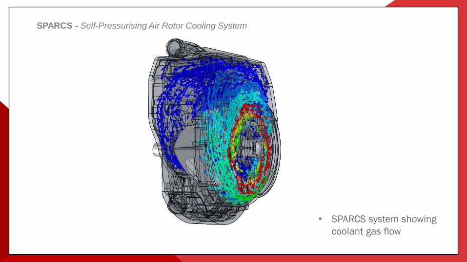
SPARCS - Self-Pressurising Air Rotor Cooling System
• SPARCS system showing
coolant gas flow
SPARCS - Major Advantages
1. Lower Temperature / Longer Life• The pressurisation of the cooling gas will enable the rotor temperature to be very considerably
lowered; and then be similar to that in the OCR type rotary engine. Larger-capacity engines will now be able to use the advantageous ACR system. And turbocharged or supercharged engines will be practical for high altitude UAVs and light aircraft without rotor overheating. Reducing the temperature also increases engine bearing life and therefore the overall life of the engine.
2. Better Lubrication / Lower Oil Consumption• The metered oil will be recirculated many times inside the rotor. Lubrication of all the rotor internal
components will be excellent and oil usage low (comparable to a 4-stroke, but without any oil changes / servicing being required) The oil can eventually only escape past the side gas seals of the engine (in opposite direction to the pressurising gas) where it will migrate over the side plate surfaces to the trochoid surface and then lubricate the apex seals before being consumed in the exhaust. The supply of oil into the working chamber via the side seal and corner bolt leakage paths makes a positive contribution to the gas sealing quality and is ideal for the Wankel engine; and superior to any previous arrangement.
3. Automatic Rotor Temperature Regulation / Better Thermal Stability• There will be automatic regulation of the rotor temperature. At lower bmep, when heat rejection is
lower, the cooling fluid pressurisation is lowered and reduced cooling will then occur. (Note that high rotor flank temperatures are advantageous for SFC particularly at light load).

CREEV Technologies

Background – Challenge
• The reciprocating engine industry has been searching for 125 years for a compact and mechanically-efficient way to extend the expansion stroke of the Otto cycle to a value much higher than the compression stroke in order to recover energy that otherwise goes to waste.
• The diagram below illustrates the amount of energy that potentially can be recovered.
P-V diagram without and with additional expansion
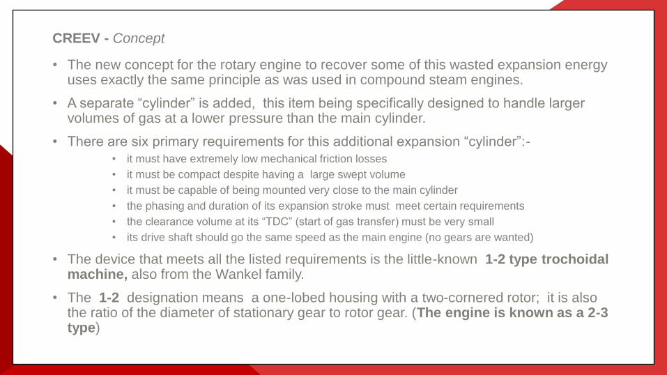
CREEV - Concept
• The new concept for the rotary engine to recover some of this wasted expansion energy uses exactly the same principle as was used in compound steam engines.
• A separate “cylinder” is added, this item being specifically designed to handle larger volumes of gas at a lower pressure than the main cylinder.
• There are six primary requirements for this additional expansion “cylinder”:-
• it must have extremely low mechanical friction losses
• it must be compact despite having a large swept volume
• it must be capable of being mounted very close to the main cylinder
• the phasing and duration of its expansion stroke must meet certain requirements
• the clearance volume at its “TDC” (start of gas transfer) must be very small
• its drive shaft should go the same speed as the main engine (no gears are wanted)
• The device that meets all the listed requirements is the little-known 1-2 type trochoidalmachine, also from the Wankel family.
• The 1-2 designation means a one-lobed housing with a two-cornered rotor; it is also the ratio of the diameter of stationary gear to rotor gear. (The engine is known as a 2-3 type)
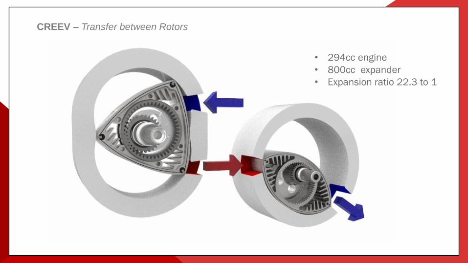
CREEV – Transfer between Rotors
• 294cc engine
• 800cc expander
• Expansion ratio 22.3 to 1

CREEV - Major Advantages
1. Increase in power output and in thermal efficiency
• If the expander unit had an adiabatic expansion efficiency of 100%, then the power output of the compound assembly would be increased by about 30% - - and the sfc reduced accordingly. In practice, the expander does have some mechanical friction and heat losses ; and there is some small energy loss (due to unrestricted expansion and flow pressure loss) in the gas transfer between the two chambers. Therefore, net power gain will be about 20%.
2. Reduction of Noise and heat
• The exhaust noise of a single-rotor, peripherally-ported Wankel engine at high rpm is extremely high, due to the sudden opening of the exhaust port and the abrupt release of high pressure gas. With the additional expander unit, the exhaust gasses will be expanded down to atmospheric pressure (or very near) before the port opens. Gas temperature will have been reduced from 950 C to 600 C or thereabouts.
3. Reduction of Emissions
• At low RPM and part-throttle, the basic rotary engine has higher emissions of HC than a reciprocating engine; whereas CO emissions are similar, and NOx are lower. However, when operated at high load and high rpm and with excess air, the HC emissions are not particularly high. The addition of the separate expander unit can be expected to give a further significant reduction in HC emissions. The hot exhaust gasses (around 950◦C) from the engine will transfer to the expander unit in a turbulent manner with unconsumed oxygen present. The expander chamber will then act as an exhaust reactor.

Test Data

SPARCS & CREEV – Testing
SPARCS
• 100s of hours of testing completed in AIE’s development test rigs
• Thermal stability achieved at high engine powers
• Engine rotor temperature 50% of that normally seen in a ACR engine
• 80% reduction in oil consumption
CREEV
• Initial prototype Expander Unit test completed in AIE’s test cells
• 20% increase in power
• 20% reduction in sfc
• Greatly reduced engine noise and exhaust gas temperature

Technology Readiness Level

SPARCS & CREEV – TRL Levels
TRL Achievements SPA
RC
S
CR
EEV
1
Basic Principles have been observed and reported.
Scientific research undertaken.
Scientific research is beginning to be translated into applied research and
development.
Paper studies and scientific experiments have taken place.
Performance has been predicted.
2
Speculative applications have been identified.
Exploration into key principles is ongoing.
Application specific simulations or experiments have been undertaken.
Performance predictions have been refined.
3
Analytical and experimental assessments have identified critical functionality
and/or characteristics.
Analytical and laboratory studies have physically validated predictions of separate
elements of the technology or components that are not yet integrated or
representative.
Performance investigation using analytical experimentation and/or simulations is
underway.
TRL Achievements SPA
RC
S
CR
EEV
4
The technology component and/or basic subsystem have been validated in the
laboratory or test house environment.
The basic concept has been observed in other industry sectors (e.g. Space,
Aerospace).
Requirements and interactions with relevant vehicle systems have been
determined.
5
The technology component and/or basic subsystem have been validated in
relevant environment, potentially through a mule or adapted current production
vehicle.
Basic technological components are integrated with reasonably realistic
supporting elements so that the technology can be tested with equipment that
can simulate and validate all system specifications within a laboratory, test
house or test track setting with integrated components
Design rules have been established.
Performance results demonstrate the viability of the technology and confidence
to select it for new vehicle programme consideration.
6
A model or prototype of the technology system or subsystem has been
demonstrated as part of a vehicle that can simulate and validate all system
specifications within a test house, test track or similar operational environment.
Performance results validate the technology’s viability for a specific vehicle
class.
Production
SPARCS & CREEV – Productionisation
• SPARCS
• Initial engine (225CS) now in 2nd generation of productionisation process
• Major components sand cast and engine is designed with volume manufacturing in mind
• Cost reduction exercise currently being undertaken
• CREEV
• Still in development prototype
• As outlined the expander unit is in effect a simplified version of the engine so can follow the same
manufacturing development process
• Both SPARCS and CREEV are currently working through stage 2 of the APC TDAP
programme.
• AIE are currently in discussions with several niche OEM’s to develop concept vehicles utilising
the SPARCS enabled engine with a CREEV expander unit installed.

Commercial
Commercialisation – Overview
Intellectual Property
• 3 Patents secured (SPARCS, Compact SPARCS and CREEV)
Commercial Model
• AIE are looking to produce engines in low volume for niche markets (UAV’s) but then also license
the technology for use in larger markets (Automotive).
Business Funding
• AIE is currently funded through shareholder equity investment and loans (over £2m invested to
date). Commercial engine sales have now been achieved within the UAV market and AIE’s
business model predicts break-even in 2016.
Technology / Business Risks
• Risks mitigated at all stages through parallel technology and market development activities, and
the existence of a solid core market for rotary engine power units.


PATENTED SPARK
IGNITION TECHNOLOGY

Overview
• About Ambixtra
• Part 1 : Emmission Legislation
• Part 2 : Engine Design Direction
• Part 3 : Current Ignition Problems
• Part 3 : Ambixtra Solution
• Part 4 : Technology Status
• Part 5 : Business Model
• Contact Details

About Ambixtra
• Technology development company
• Automotive focused
• Development center in South Africa
• Business development office in Paris
• Patented electronic & spark ignition technologies
– "Variable Spark Ignition”
– "Advanced Plasma Ignition”
• Solves ignition challenges with new gasoline engine designs
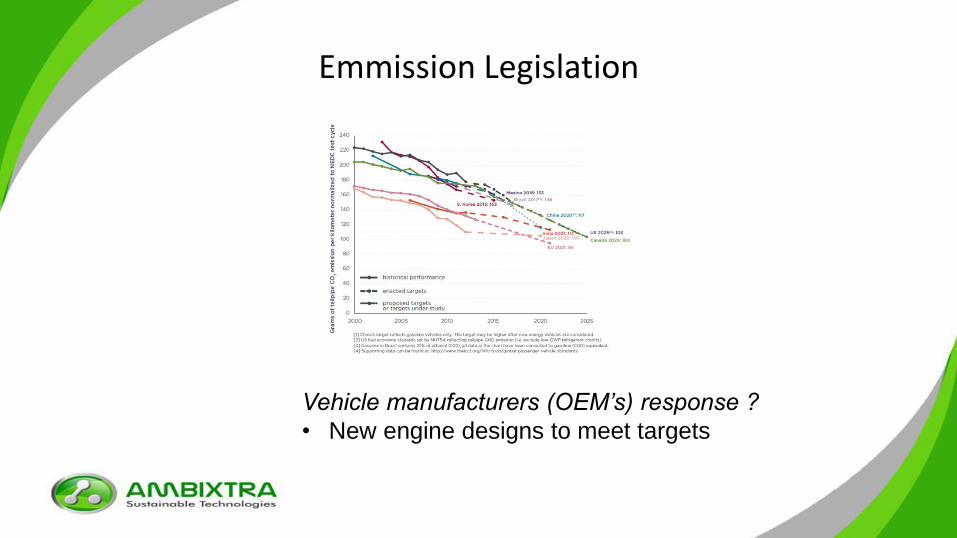
Emmission Legislation
Vehicle manufacturers (OEM’s) response ?
• New engine designs to meet targets
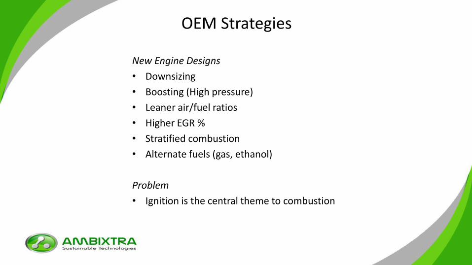
OEM Strategies
New Engine Designs
• Downsizing
• Boosting (High pressure)
• Leaner air/fuel ratios
• Higher EGR %
• Stratified combustion
• Alternate fuels (gas, ethanol)
Problem
• Ignition is the central theme to combustion

Ignition Challenges
Current ignition becoming a handicap
• Operation problems under high pressure
• Operation problems with higher EGR %
• Operation problems with leaner A/F ratios
• Operation problems in stratified conditions
Adverse effects include
• Cyclic Variation
Ignition challenge significant
• IAV GmbH “Global Ignition Congress”
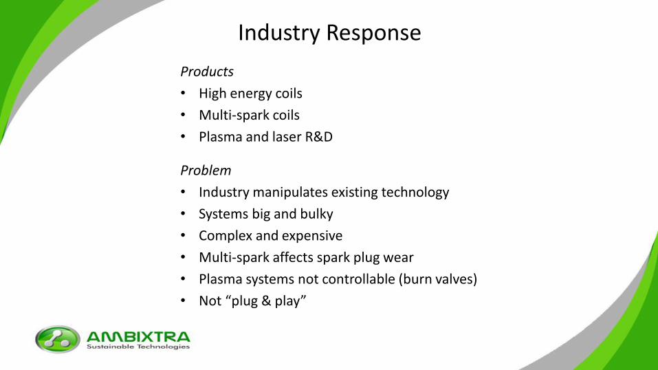
Industry Response
Products
• High energy coils
• Multi-spark coils
• Plasma and laser R&D
Problem
• Industry manipulates existing technology
• Systems big and bulky
• Complex and expensive
• Multi-spark affects spark plug wear
• Plasma systems not controllable (burn valves)
• Not “plug & play”

Solution
Invented at NW University at the “Unit for Space Physics”Fast-switching MOSFET technique (Factor 10 faster)
Advantage• Switches high voltages and high
currents at a high frequency with low loss
• Technique is basis for ignition solution

Ambixtra Ignition Solution
Variable Spark Ignition (VSI)
• Spark duration precisely controlled
• Energy levels precisely controlled
• Continuous spark with variable spark duration and energy.
• Control according to combustion conditions.– Higher energy & longer spark duration in lean
and high pressure conditions.
– Lower energy & shorter spark duration in rich and low pressure conditions.
• Combustion sensing and spark intelligence

VSI Benifits
• Reduced CO2 emissions
• Leaner A/F ratios
• Higher EGR %
• Reduced cyclic variations
• Extended knock limits
• Cold start improved
• Plug & play on existing engines

Patents
‘x5 patents underpin the ignition
solution’
Technology Status (VSI)
• Testing at IAV GmbH – 4 cylinder engine testing in Chemnitz
– Pressure chamber and turbulence testing in Giffhorn
– Single cylinder and 4 cylinder engine testing in Berlin
• On engine testing AVL GmbH in Austria– AVL demonstrator car (Test track in Graz)
• Apogee in France– Motorcycle engine testing
• On engine testing at Fiat CRF in Turin.– 4 cylinder MultiAir Engine
• Following TRL process with Peugeot-Citroen in Paris for a EURO 7 engine.
• IDIADA Spain gas engine

Testing Chamber at IAV

Technology Outlook
Variable Spark Ignition
(VSI)
Spark plug Corona plugCorona plug
Advanced Plasma Ignition
(API)
Phase 1 Phase 2
VSI• Various engine tests
• TRL 5/6
API• Demonstrators
• Pressure chamber tests
performed
• See SIA Versailles Conference
May 2015

Business Model
• OEM’s are reducing supplier base
• Ambixtra will not manufacture VSI
• Licensing model
• Discussions with Tier 1’s in progress

Deon Smit (CEO)
148 Rue de l'Université,
75007 Paris, France.
Telephone : +33 6 67 02 18 78
Mr. James Mackenzie (Chief Technical Officer)
Wedgefield Office Park, 17 Muswell Road South,
Bryanston , Johannesburg, 2021.
Telephone : +27 83 461 6868
Air-Bearing Technology
Bladon Jets (UK) Ltd.
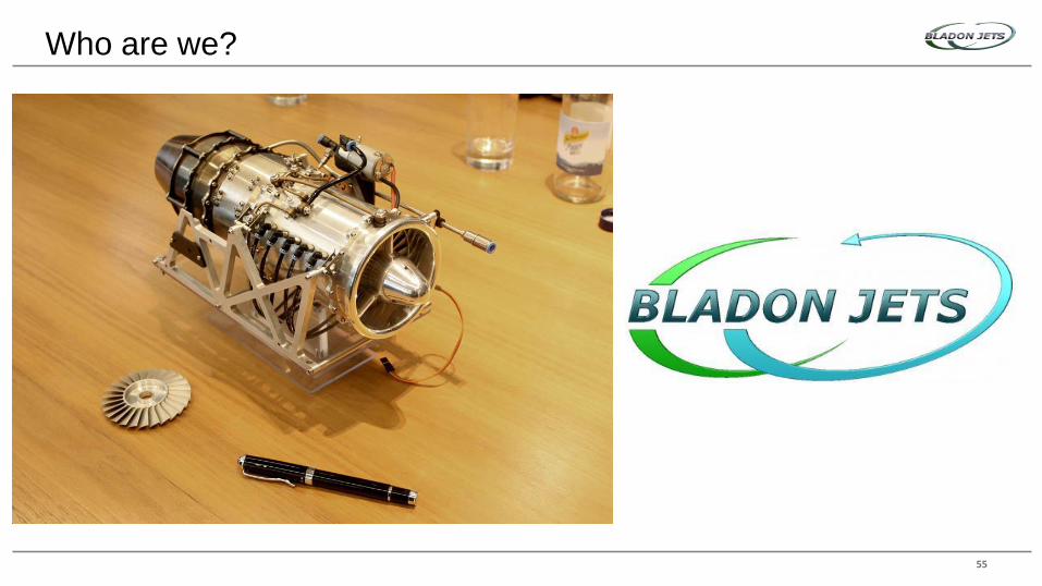
Who are we?
55
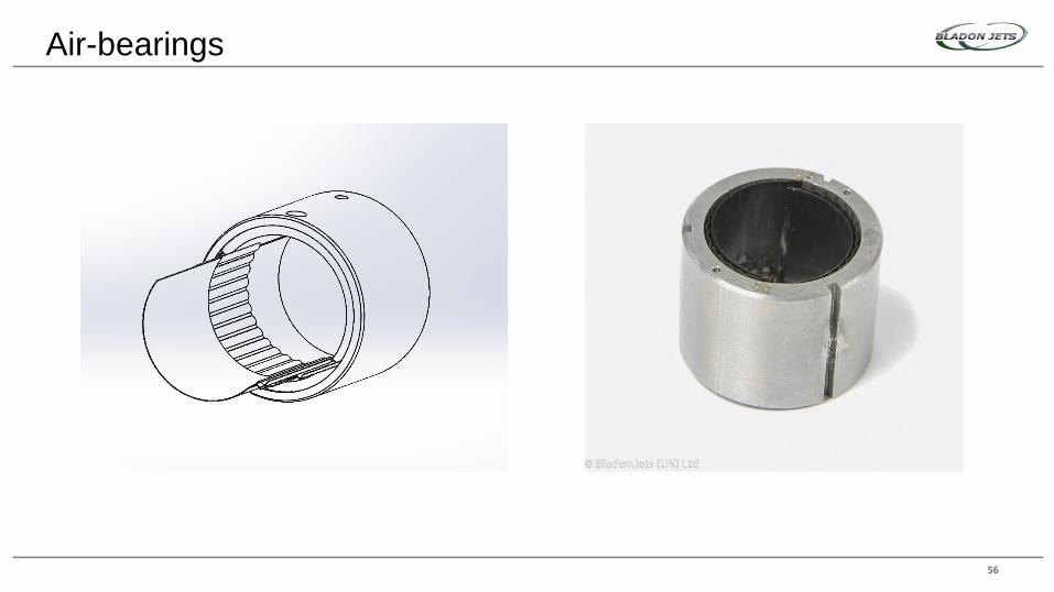
Air-bearings
56

Benefits
57
0
5
10
15
Air Bearing oilVis
cosity in m
m2/s
Viscosity at 40 C

Our application
58
Clearance
profile
Temperature
Profile

Turbochargers
59

The knowledge gap
60

The ‘why’
61
2019
£0.5
billion
£1210%
47%

IP
Operation
Installation and running
Manufacturing
62

Business model
63
BladonJets
Development partner
Production release
Partnerships
64
?

THANK YOU
65

Powertrain Technologies

CAD

CAE

CNC
CMM

Test Cell Configured as Motoring Dyno
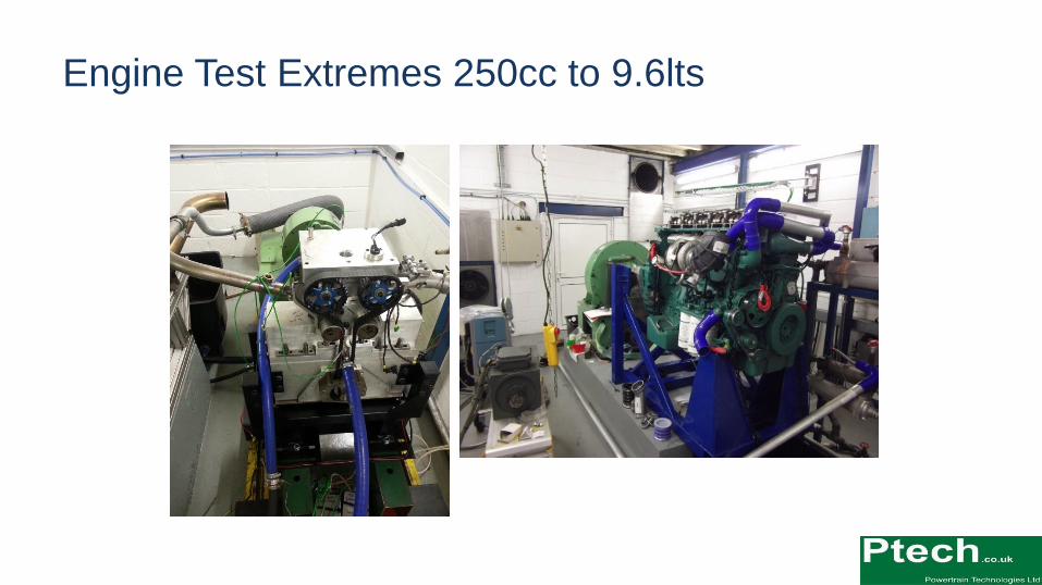
Engine Test Extremes 250cc to 9.6lts

Oil Sampling in Progress during
Dyno Test. Ptech unique system to
extract oil from the piston ring region
Engine Test Technology

Instrumented vehicle with
intelligent lubrication system
Prototype Vehicles

3 Cyl Gasoline
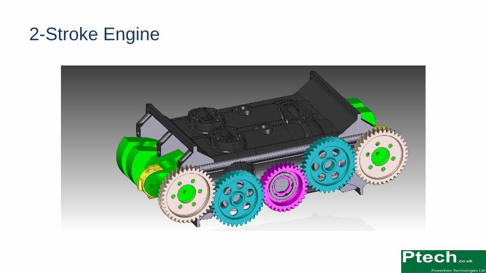
2-Stroke Engine
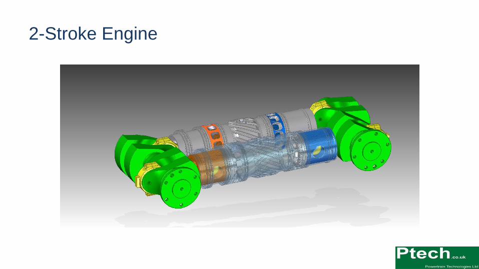
2-Stroke Engine

2-Stroke Engine
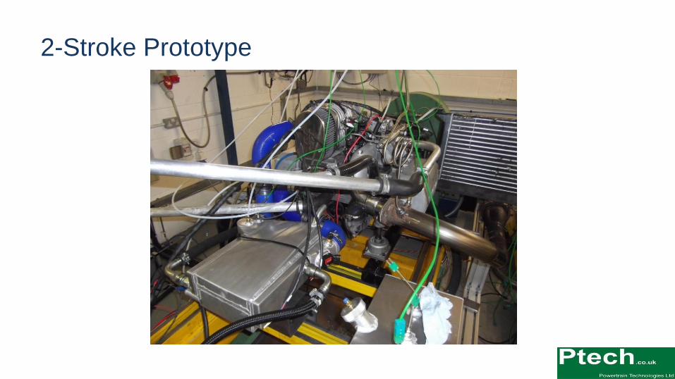
2-Stroke Prototype
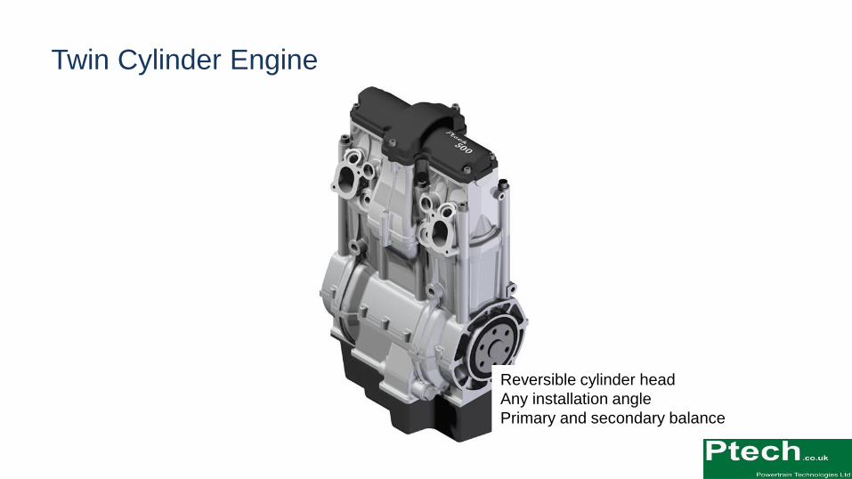
Twin Cylinder Engine
Reversible cylinder head
Any installation angle
Primary and secondary balance
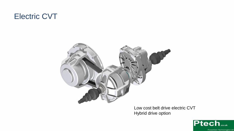
Electric CVT
Low cost belt drive electric CVT
Hybrid drive option

New Technology Development

Ptech Research Engine with Variable
Compression and Capacity System
Variable Compression & Capacity

Hybrid Generator Unit
Bus Hybrid Generator Unit
with Ancillary Drive System
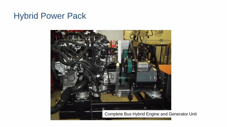
Hybrid Power Pack
Complete Bus Hybrid Engine and Generator Unit

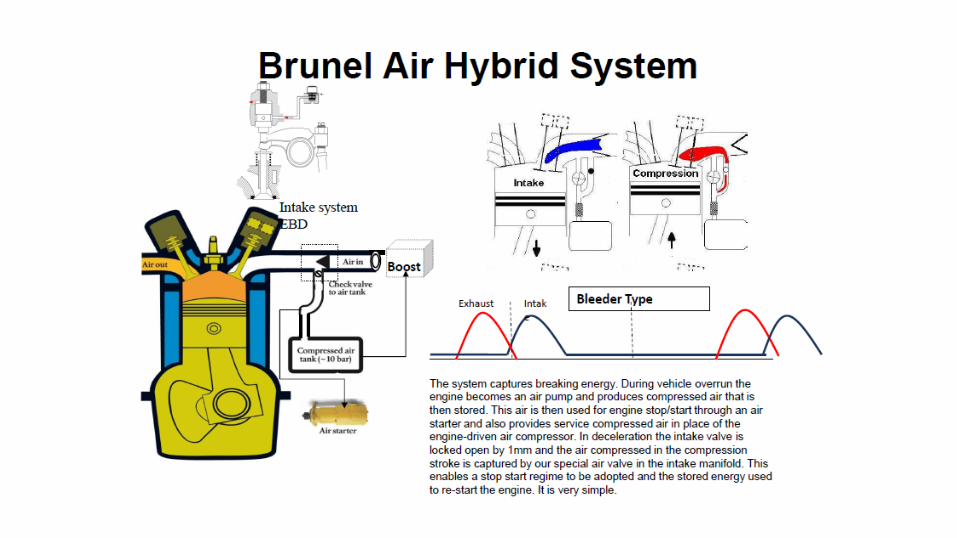
Air Hybrid – Energy Recovery
• Collaborative Research Project
• Commercial Vehicle Energy Recovery
• Technology Created by Brunel University
• Who are coming up next………


Ultra-fast engine emissions measurement
Mark Peckham

Introduction – Company summary
• Engineering services
division
• Emissions calibration
• Engine and after-treatment systems
evaluation
• Using dyno simulation of vehicle drive
cycles, and vehicle chassis rolls
• Products division
• Develop, manufacture and support
specialised fast response analyzers and
other emissions-related equipment
• Gaseous pollutants (HC, NOx, COx)
• Particulates
• DPF testing system
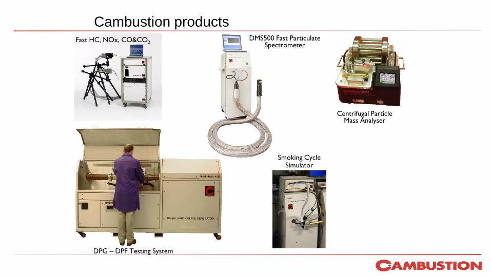
Cambustion productsFast HC, NOx, CO&CO2
DPG – DPF Testing System
Smoking Cycle Simulator
Centrifugal Particle Mass Analyser
DMS500 Fast Particulate Spectrometer

HFR500 fast FID

PFI gasoline cold start
Transient HC measurement0 - 105 seconds of FTP 75 drive-cycle
0
2000
4000
6000
8000
10000
12000
14000
16000
18000
20000
0 20 40 60 80 100
Time since start (seconds)
[HC
] a
s p
pm
pro
pa
ne
-10
0
10
20
30
40
50
60
Ve
hic
le s
pe
ed
(m
ph
)
Fast FID Engine Out
Fast FID Tailpipe
Slow FID Engine Out
Desired Speed (mph)
Maximum HC occurs during Cold-Start.
Fast FID accurately resolves magnitude
of initial transients in real time
Individual cylinder
exhaust events visible in
engine out HC
Conventional bench
analyzer

Exhaust port [HC] PFI cold start

Cold start lambda using fast NDIR
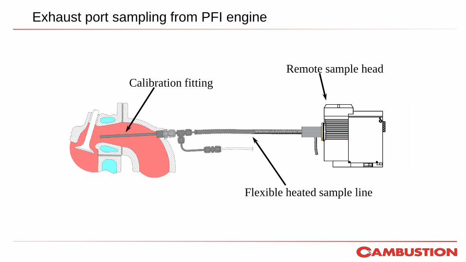
Exhaust port sampling from PFI engine
Calibration fitting
Flexible heated sample line
Remote sample head

Cycle-by-cycle HC, CO&CO2 from a cold start gasoline engine
0
20
40
60
HC
(p
pm
C3/1
00
0)
0
5
10
15
CO
, C
O2 (
%v
olu
me
)
Cylin
de
r P
ressu
re (
ba
r)
•Fast gas analysers able to distinguish each exhaust event
•Late Burn stroke 1, High CO2+very low CO suggest lean burn
•Misfires Strokes 3,6 shown by high HC, reducing CO+CO2 and cyl pressure
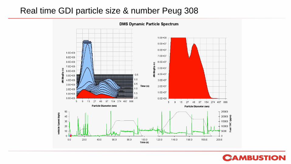
Real time GDI particle size & number Peug 308

Direct tailpipe on-board sampling
109
Important user note:
avoid sampling water
from muffler!

Instrumentation photos
110
Sample head
with long
probe
Small
cabinet
Inverte
r
70Ah 12V
battery
1m3/hr
carbon vane
pump with
silencer
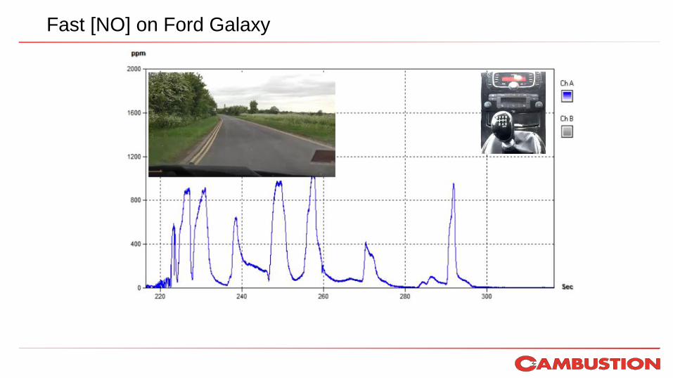
Fast [NO] on Ford Galaxy

Fast CO2 from Diesel Ford Galaxy

For more information:
Dr. Mark PeckhamCambustion Ltd.,J6 The Paddocks347 Cherry Hinton RoadCambridgeCB1 8DH
Tel: (01223) 210250Fax: (01223) 210190E-mail: [email protected]:// www.cambustion.com

Cella EnergySafe, low cost hydrogen energy
Meet the Engineer 10th June 2015
Stephen Bennington
Aerospace, Defense, Transportation, Portable Energy
114
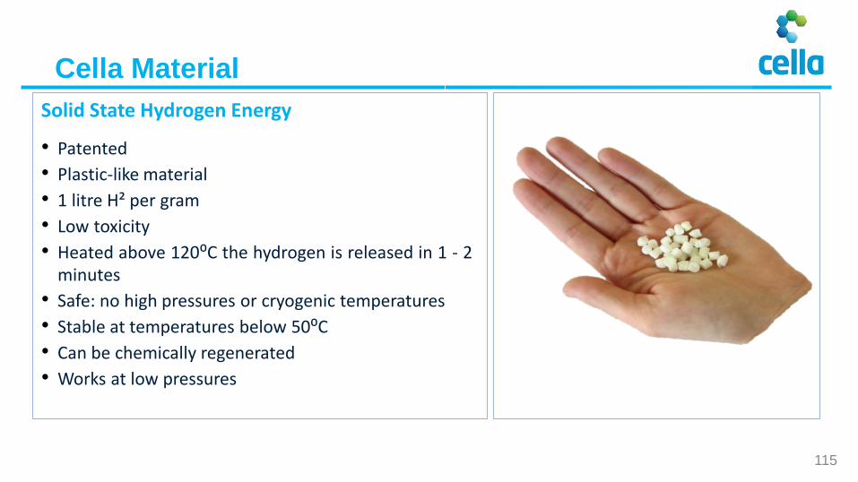
Solid State Hydrogen Energy
• Patented
• Plastic-like material
• 1 litre H² per gram
• Low toxicity
• Heated above 120⁰C the hydrogen is released in 1 - 2minutes
• Safe: no high pressures or cryogenic temperatures
• Stable at temperatures below 50⁰C
• Can be chemically regenerated
• Works at low pressures
Cella Material
115
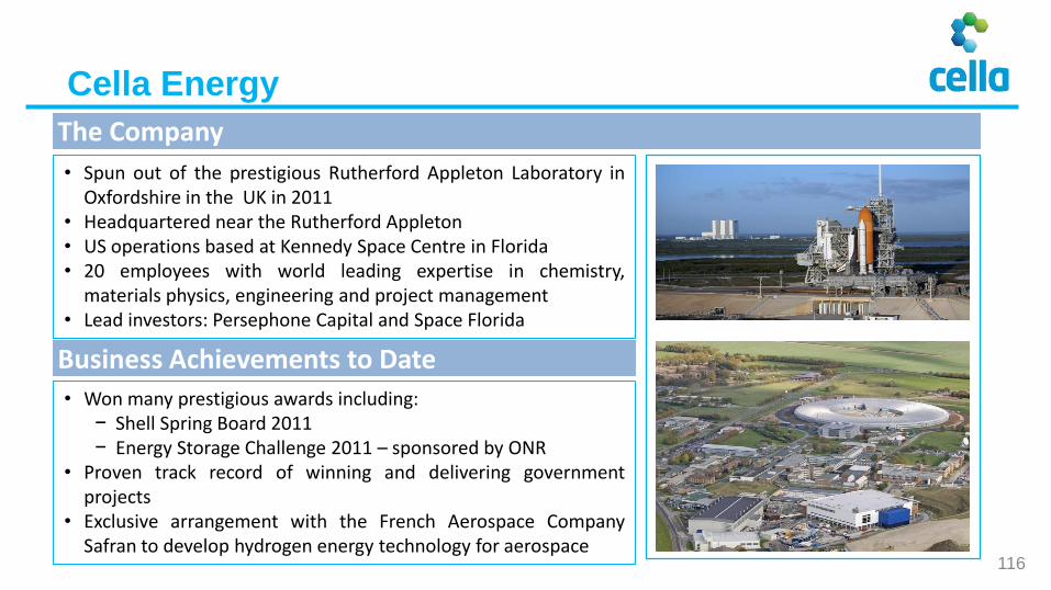
• Spun out of the prestigious Rutherford Appleton Laboratory inOxfordshire in the UK in 2011
• Headquartered near the Rutherford Appleton• US operations based at Kennedy Space Centre in Florida• 20 employees with world leading expertise in chemistry,
materials physics, engineering and project management• Lead investors: Persephone Capital and Space Florida
The Company
Cella Energy
• Won many prestigious awards including:− Shell Spring Board 2011− Energy Storage Challenge 2011 – sponsored by ONR
• Proven track record of winning and delivering governmentprojects
• Exclusive arrangement with the French Aerospace CompanySafran to develop hydrogen energy technology for aerospace
Business Achievements to Date
116
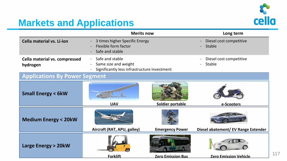
Merits now Long term
Cella material vs. Li-ion - 3 times higher Specific Energy- Flexible form factor- Safe and stable
- Diesel cost competitive- Stable
Cella material vs. compressed hydrogen
- Safe and stable- Same size and weight- Significantly less infrastructure investment
- Diesel cost competitive- Stable
Applications By Power Segment
Small Energy < 6kW
UAV Soldier portable e-Scooters
Medium Energy < 20kW
Aircraft (RAT, APU, galley)
Large Energy > 20kW
Diesel abatement/ EV Range Extender
Zero Emission Vehicle
Emergency Power
Forklift Zero Emission Bus
Markets and Applications
117
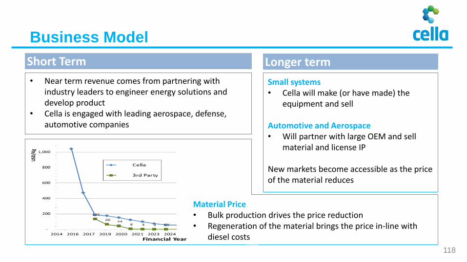
Business Model
• Near term revenue comes from partnering with industry leaders to engineer energy solutions and develop product
• Cella is engaged with leading aerospace, defense, automotive companies
Short Term Longer term
Small systems• Cella will make (or have made) the
equipment and sell
Automotive and Aerospace• Will partner with large OEM and sell
material and license IP
New markets become accessible as the price of the material reduces
Material Price• Bulk production drives the price reduction• Regeneration of the material brings the price in-line with
diesel costs
118

Military
Security
Agriculture
Fisheries
Coast guard
Infrastructural surveys (oil rigs, pipelines, transmission lines)
First responder
Deliveries (medical, emergency, military, etc. )
Environmental audits
• The Federal Aviation Authority expected deregulate in 2015 / 16
• The economic impact is predicted to be $82 billion between 2015
to 2025 in the US alone
A Deutsche Post (DHL) delivery of Pharmaceuticals in Bonn
Unmanned Systems
UAV applications
119

Competitive Advantages
Unmanned Systems
• Three times lighter than li-polymer batteries
• Three times the range or flight time• No moving parts and no liquids• Unlike batteries does not catch fire if
containment is breached• Stable indefinitely at temperatures
below 50⁰C• Provides stealth for large UAV’s
• Flying third prototype in July / August• Signed up a major UAV manufacturer
Cella’s 450 Whpower supply
120
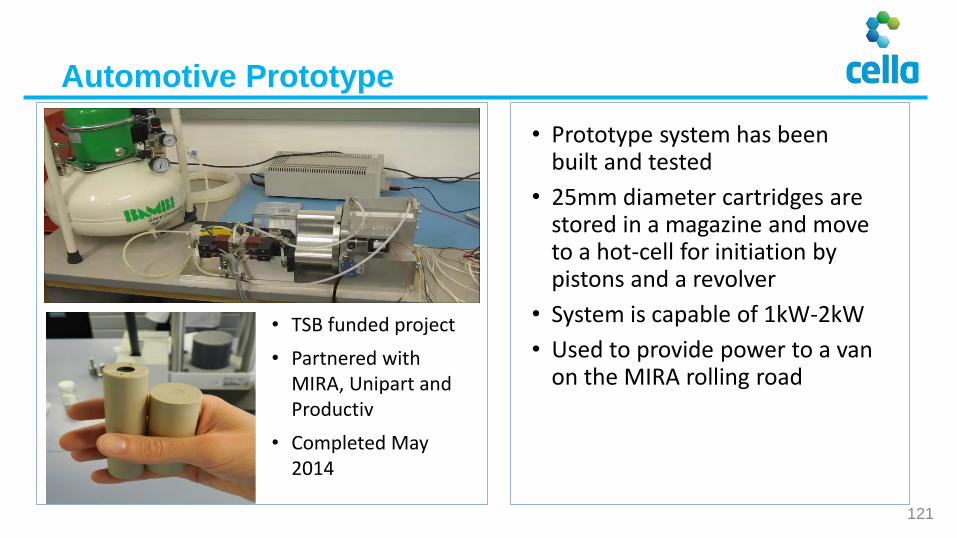
• Prototype system has been built and tested
• 25mm diameter cartridges are stored in a magazine and move to a hot-cell for initiation by pistons and a revolver
• System is capable of 1kW-2kW
• Used to provide power to a van on the MIRA rolling road
Automotive Prototype
• TSB funded project
• Partnered with MIRA, Unipart and Productiv
• Completed May 2014
121

Other Markets
Emergency or back-up applications:• Electric vehicle range extenders• System resilience• Remote power for sensors
Using the hydrogen:• Cleaning up particulates from diesel engines
• Remote weather balloons
Cella’s Range extender design
Aerospace Other Applications
Filter Box
H2
Foam unit for
insulation
and
containment
• Exclusive arrangement with Safran (one of the world’s 10 largest aerospace companies)
• Safety compliance for high pressures and liquid hydrogen difficult for aerospace
• Multiple potential applications
• Willing to invest in new technology
Cella’s Aerospace test system
122

Pumping pellets1) Batch of beads are
pumped into the hot-cell
2) The beads are heated and
the hydrogen driven out
3) The beads are pumped
back into the top of the
store
4) The hydrogen is stored is
an buffer before being
used in the fuel cell
Larger systems: Automotive and Aerospace
• Cella is developing a fluid version of the material• This uses small beads of Cella material that can be pumped like a fluid• A liquid like fuel is simple to transport and refuel• Uses cheap pumps similar to vacuum cleaner technology
123
Fuel store
Pellet pump
Ho
t-C
ell
Hyd
roge
n
bu
ffer
Fuel cell
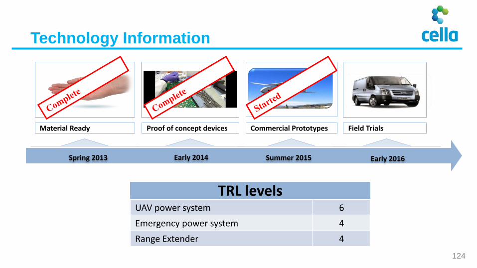
Material Ready Commercial Prototypes Field Trials
Early 2014 Early 2016Spring 2013
Proof of concept devices
Summer 2015
TRL levelsUAV power system 6
Emergency power system 4
Range Extender 4
Technology Information
124
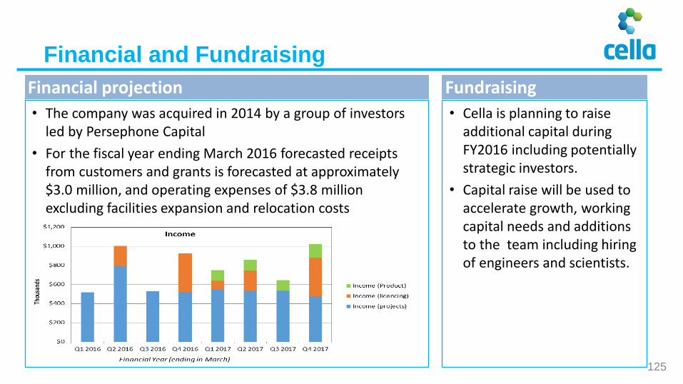
Financial and Fundraising
• Cella is planning to raise additional capital during FY2016 including potentially strategic investors.
• Capital raise will be used to accelerate growth, working capital needs and additions to the team including hiring of engineers and scientists.
• The company was acquired in 2014 by a group of investors led by Persephone Capital
• For the fiscal year ending March 2016 forecasted receipts from customers and grants is forecasted at approximately $3.0 million, and operating expenses of $3.8 million excluding facilities expansion and relocation costs
FundraisingFinancial projection
125

Alex Sorokin (CEO)
T: +1 203 216 9756E: [email protected]: www.cellaenergy.com
Paul Prince(Automotive Project Lead)
T: 01235 447752E: [email protected]: www.cellaenergy.com
Contacts
Stephen Bennington (Managing Director)
T: 01235 447505E: [email protected]: www.cellaenergy.com
Kevin Brundish(Chief Operating Officer)
T: 01235 447750E: [email protected]: www.cellaenergy.com
126

contents
CMCL Innovations Software products Innovation partner Commercial
Software | Consulting | Training
Contents

Computational Modelling Cambridge Ltd.
Software | Consulting | Training
- Powertrains & fuels
- Energy & chemicals
www.cmclinnovations.com
Simulation and design software supplier to industry and academia
>10 years in innovative R&D and advanced engineering
Organically growing with an experienced team
Recent innovation awards
CMCL Innovations: an overview

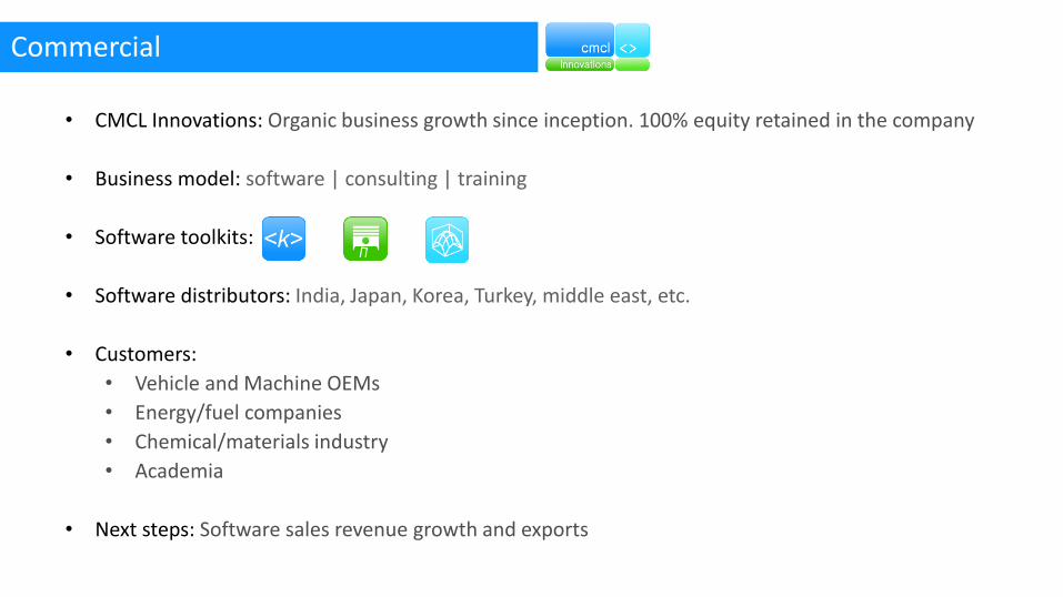
Commercial
• CMCL Innovations: Organic business growth since inception. 100% equity retained in the company
• Business model: software | consulting | training
• Software toolkits:
• Software distributors: India, Japan, Korea, Turkey, middle east, etc.
• Customers:
• Vehicle and Machine OEMs
• Energy/fuel companies
• Chemical/materials industry
• Academia
• Next steps: Software sales revenue growth and exports

Thank you
www.cmclinnovations.com
CMCL Innovations
@cmclinnovations
Dr Amit Bhave<e>: [email protected]
Meet the Engineer10th June 2015
Private and Confidential
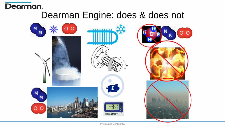
Dearman Engine: does & does not
135
Private and Confidential
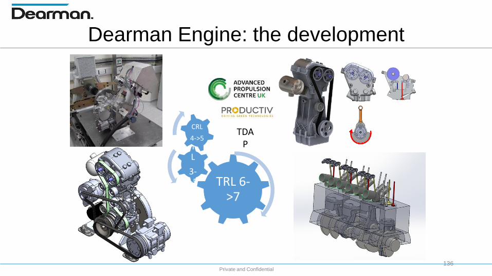
Dearman Engine: the development
136
TRL 6->7
MRL
3->5
CRL
4->5TDA
P
Private and Confidential
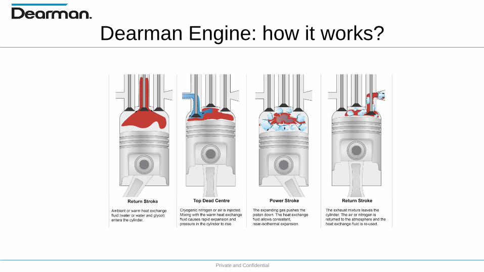
Dearman Engine: how it works?
Private and Confidential
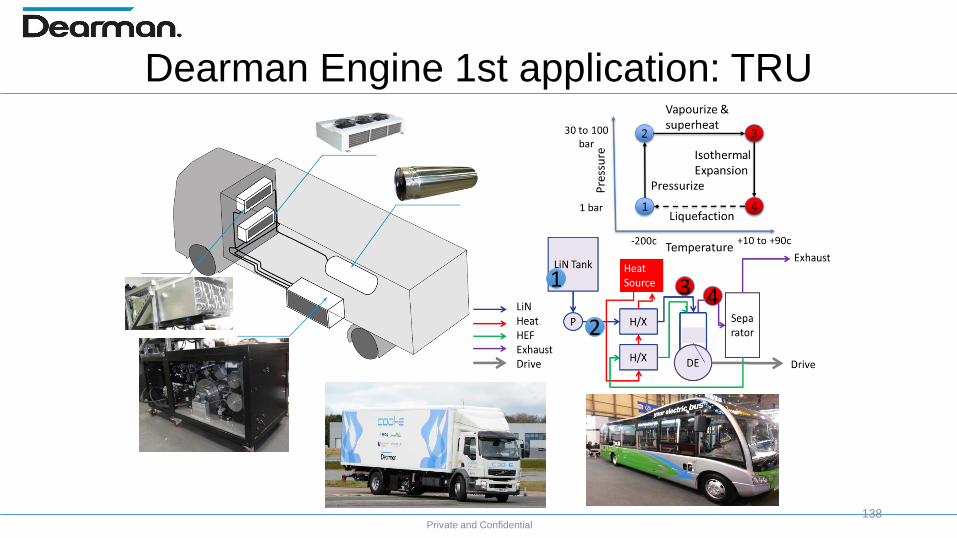
Dearman Engine 1st application: TRU
138
1
2
3 4


Private and Confidential
TRU Business case: clean & sustainable cold chain
140

Private and Confidential
TRU Business case:bigger & more cost effective cold chain
141
DEARMAN TRUVs
DieselVs
Evaporative
£
CO2 nowCO2 2030
0
1
2
3
4
5
20
…
20
…
20
…
20
…
20
…
20
…
20
…
20
…
20
…
20
…
20
…
Mill
ion
sTRU ANNUAL MARKET
SIZEUNEP Global
9b.
Private and Confidential
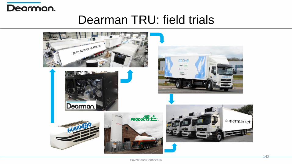
Dearman TRU: field trials
142
Private and Confidential
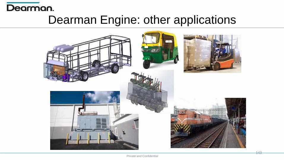
Dearman Engine: other applications
143

Private and Confidential
Dearman: the company behind
144
50
£1M
40
3020

Private and Confidential
Organisations working with Dearman
145
Private and Confidential
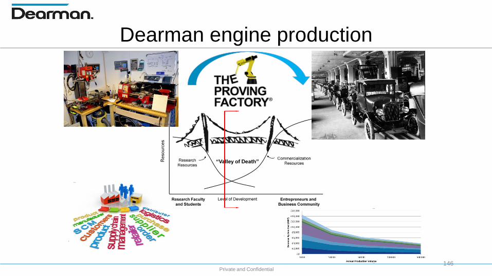
Dearman engine production
146
Private and Confidential
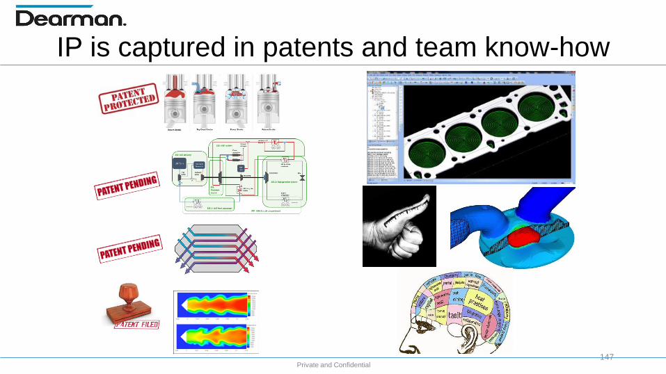
IP is captured in patents and team know-how
147
Private and Confidential
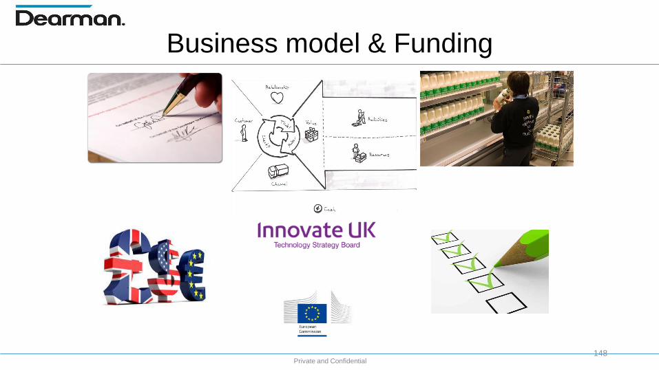
Business model & Funding
148
Private and Confidential
Dearman: networking opportunities
149

CARBON EFFICIENT SOLUTIONS
Low CostEfficient Permanent Magnet Generators
Targeted Markets:
Automotive, Aerospace, Marine
Wind power generation, Decentralized Power Systems
Dr Nabeel Shirazee 10th June 2015

CARBON EFFICIENT SOLUTIONS
Driving Cost & CO2 Down
Developing low-cost high-performance advanced
motors and generators
Cost and performance are key enablers to meeting the
US Department of Energy 2020 technical targets for the electric
drive systems

CARBON EFFICIENT SOLUTIONS
Technical Targets for Traction Systems 2010 2015 2020 ?
Cost, USD $/kW < 19 < 12 < 8
Specific power, kW/kg > 1.06 > 1.2 > 1.4
Power density, kW/l > 2.6 > 3.5 > 4.0
Efficiency (10%-100% speed at 20% rated torque) > 90% > 93% > 94%
Financial Targets: Achieving Low Cost High Performance
Department Of Energy Targets (USA)

CARBON EFFICIENT SOLUTIONS
Identify innovative motor/generator topologies, advanced
materials and novel cooling.
Apply concepts for further development to design non-
rare earth motors and generators.
The Solution: Low Cost High Performance
CARBON EFFICIENT SOLUTIONS
High-Performance Motors & Generators with Non-Rare
Earth Materials
High efficiency over a wide speed and load ranges
High power density and high coolant inlet temperature
Low cost targets based on 100k to 500k units/year
Cost USD $/kW < 4.7 …eventually … true cost? may be…
We Want…
The Solution: Low Cost High Performance

CARBON EFFICIENT SOLUTIONS
• Very good thermal management is needed to reduce size and improve
performance of electric motors and generators.
• Improve power capability within cost and efficiency constraints.
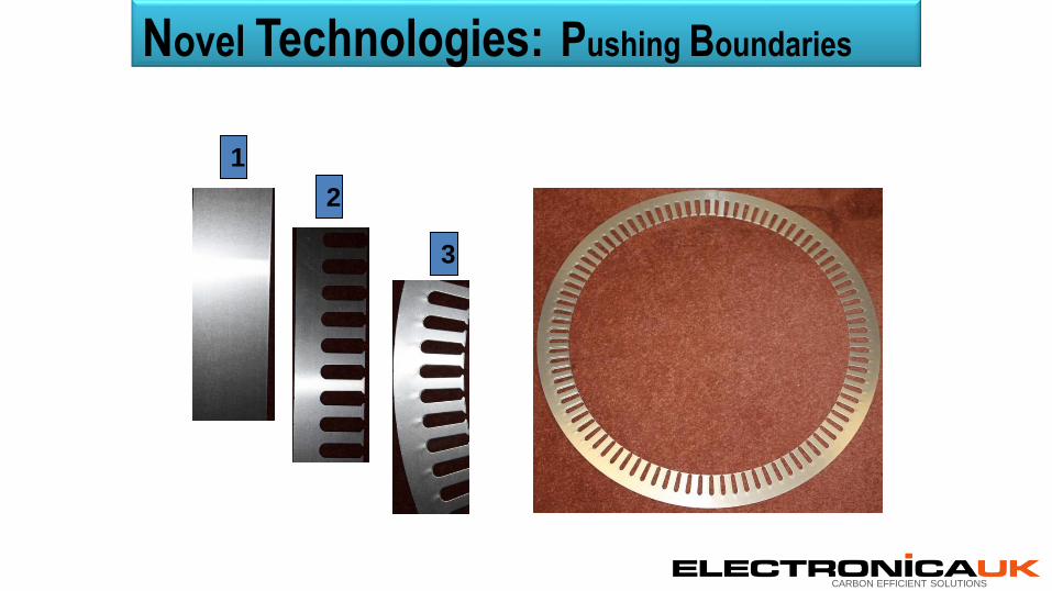
Novel Technologies: Pushing Boundaries
CARBON EFFICIENT SOLUTIONS
Novel Technologies: Pushing Boundaries
2
3
1

CARBON EFFICIENT SOLUTIONS
Optimization of
Stator Laminations
Current weight = 16.8kg
Improved design = 13.3kg
Weight Reduction = 21%
Novel Technologies: Pushing Boundaries
CARBON EFFICIENT SOLUTIONS
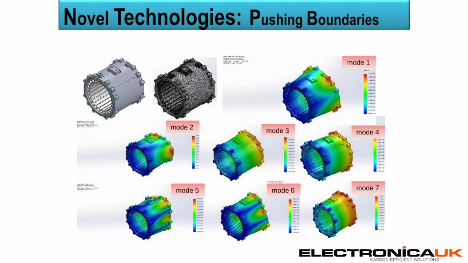
mode 2mode 3
mode 7mode 6
mode 1
mode 5
mode 4
Novel Technologies: Pushing Boundaries

CARBON EFFICIENT SOLUTIONS
Understanding & Improving Heat Losses
Technical Targets: Achieving Low Cost High Performance
CARBON EFFICIENT SOLUTIONS
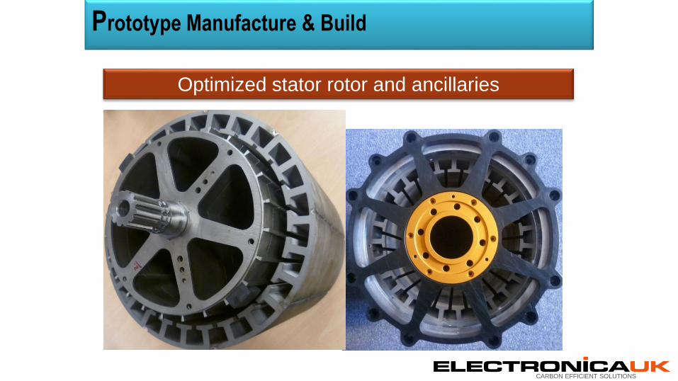
Prototype Manufacture & Build
Optimized stator rotor and ancillaries

CARBON EFFICIENT SOLUTIONS
Prototype Manufacture & Build
Special Slot Liners

CARBON EFFICIENT SOLUTIONS
Prototype Manufacture & Build
Non Rare-Earth Rotor
CARBON EFFICIENT SOLUTIONS
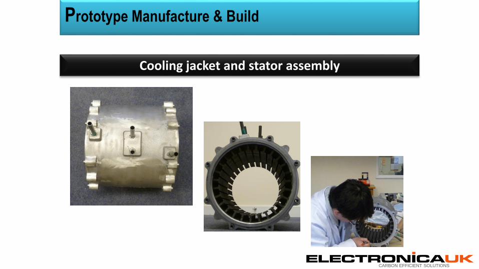
Cooling jacket and stator assembly
Prototype Manufacture & Build
CARBON EFFICIENT SOLUTIONS
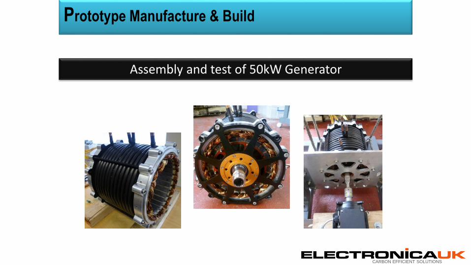
Assembly and test of 50kW Generator
Prototype Manufacture & Build

CARBON EFFICIENT SOLUTIONS
Simulated Results
Actual Results
Results: 50kW Generator

CARBON EFFICIENT SOLUTIONS
0
10000
20000
30000
40000
50000
60000
92.5 93 93.5 94 94.5 95 95.5
Input Power Output Power
Input and Output Power Efficiency Plots.
Po
wer
in k
W
Efficiency %
Results: 50kW Generator
CARBON EFFICIENT SOLUTIONS
Generator type: 3-Phase bridge rectified output
Power Output: 50kW
Weight : 45kg
Output Voltage: 380Vdc to 415Vdc
Efficiency: 96% peak
Current: 125A
Basic Specifications: Low Cost High Performance Generators

CARBON EFFICIENT SOLUTIONS
Where are We Today ?
1. Technology Readiness Level 3 moving on to TRL 4
2. Patents pending
3. Production via The Proving Factory in low volumes
4. Licencing of technology an option

CARBON EFFICIENT SOLUTIONS
Future Technologies: Pushing Boundaries
Next Generation Designs !

CARBON EFFICIENT SOLUTIONS
THANK YOU
The Future Starts Here

© Far-UK 2015 All rights reserved
Chris Taylor
MD Axon Automotive
June 2015
Meet the Engineer

© Far-UK 2015 All rights reserved 172
Vehicle Structures and Components
• Lightweight – up to 70% savings compared to steel
• Can be applied to complete structures and components
• Can be applied cost effectively
• Combination of carbon fibre with a range of materials e.g. aluminium, steel, glass fibre
© Far-UK 2015 All rights reserved 173
Technology Background – Why Axontex™
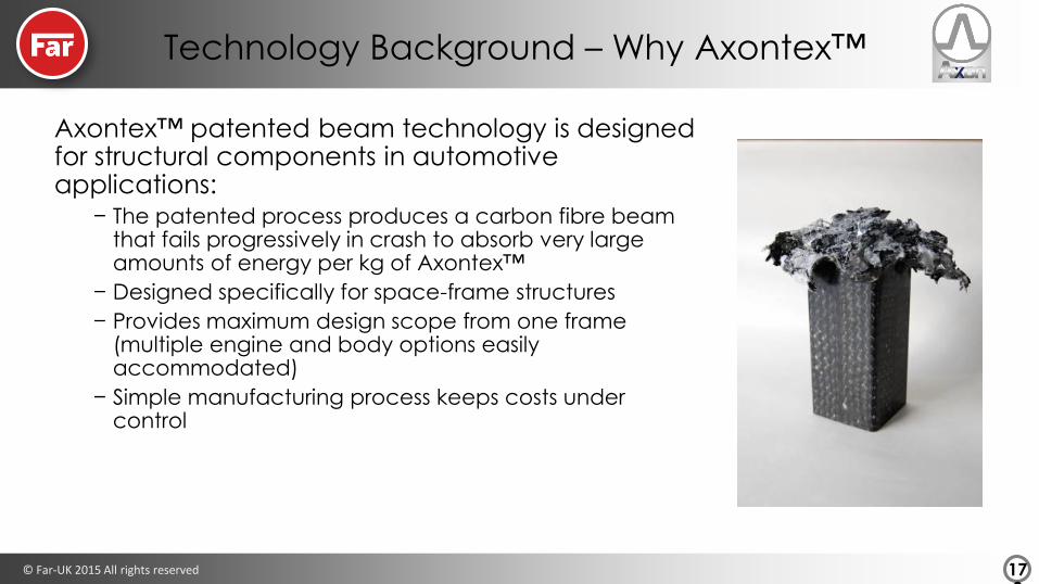
Axontex™ patented beam technology is designed for structural components in automotive applications:
− The patented process produces a carbon fibre beam that fails progressively in crash to absorb very large amounts of energy per kg of Axontex™
− Designed specifically for space-frame structures
− Provides maximum design scope from one frame (multiple engine and body options easily accommodated)
− Simple manufacturing process keeps costs under control

© Far-UK 2015 All rights reserved 174
Building Up Data
Coupon Testing
•Establish Material Properties
Beam testing
•Establish properties of Axontex™ beams
Initial model building
•Model basic structures and assemblies
Testing of crash structures
•Validate the model
Model full vehicles
•Demonstrate crash performance in a model

© Far-UK 2015 All rights reserved 175
Static Stability
• Coupons behave in a brittle manner
• Design in structural stability
© Far-UK 2015 All rights reserved 176
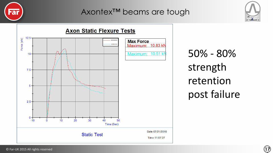
Axontex™ beams are tough
50% - 80% strength retention post failure

© Far-UK 2015 All rights reserved 177
Axontex™ absorbs energy
we can tailor the mechanical properties for each application
© Far-UK 2015 All rights reserved 178
Production
• In house facilities for prototyping and low volume production
• Initial programmes with OEM for design and manufacture of test structures
• Route to production
− Low volume – in house manufacture
− Medium volume – investment or work with existing Tier 1
− High volume – work with existing Tier 1
© Far-UK 2015 All rights reserved 179
Commercial
• Patented technology
• Similar costs to aluminium structures
• Company funded through commercial contracts & R&D funding
• Initial sales income for low volume components

© Far-UK 2015 All rights reserved 180
Next Steps
• Work with additional Tier 1 for production
• Develop routes to production with OEM’s
• Additional funding / investment into Axon for growth
• Implement weight saving technology

© Productiv Ltd 2015
Meet the Engineer 2015
Government & Industry SupportRichard Adlington

Advanced Propulsion Centre UK Limited
“Turning low carbon
propulsion technologies into
products developed in the UK”
Government & Industry support.
Presentation to Meet the Engineer
10th June 2015
Advanced Propulsion Centre UK Limited
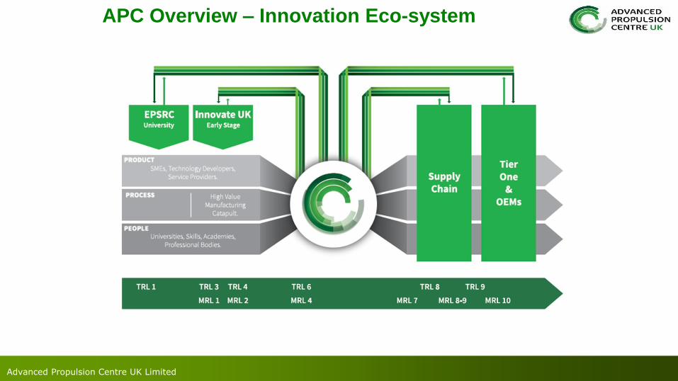
APC Overview – Innovation Eco-system
Advanced Propulsion Centre UK Limited
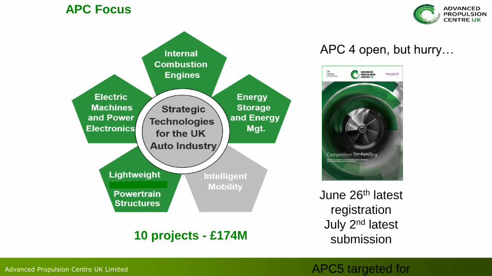
APC Focus
10 projects - £174M
APC 4 open, but hurry…
June 26th latest
registration
July 2nd latest
submission
APC5 targeted for
November

Advanced Propulsion Centre UK Limited
A few other sources of funding…
interact.innovateuk.orgsmmt.co.uk/industry-
topics/funding-support/
Innovate UK Open
Competitions for Funding
SMMT Funding Guide

© Productiv Ltd 2015
Meet the Engineer 2015
Technology PitchesSession 2

MAGSPLIT - a magnetic CVT
Dave Latimer - Magnomatics
© 2015 Magnomatics
®
188Confidential
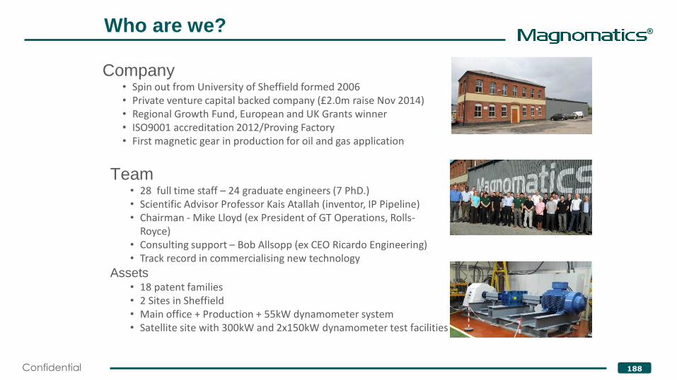
Who are we?
Company• Spin out from University of Sheffield formed 2006• Private venture capital backed company (£2.0m raise Nov 2014)• Regional Growth Fund, European and UK Grants winner• ISO9001 accreditation 2012/Proving Factory• First magnetic gear in production for oil and gas application
Team• 28 full time staff – 24 graduate engineers (7 PhD.) • Scientific Advisor Professor Kais Atallah (inventor, IP Pipeline)• Chairman - Mike Lloyd (ex President of GT Operations, Rolls-
Royce)• Consulting support – Bob Allsopp (ex CEO Ricardo Engineering)• Track record in commercialising new technology
Assets• 18 patent families• 2 Sites in Sheffield• Main office + Production + 55kW dynamometer system• Satellite site with 300kW and 2x150kW dynamometer test facilities
®
189Confidential

®
190Confidential
Direct Kinetic
ElectricDirect
ElectricIn -Direct

®
191Confidential
Fuel
Consumption Payback
• Base Vehicle (Urban delivery) = 100 n/a
• Parallel Hybrid(1) = 83 6 years(3)
• MAGSPLIT Hybrid(2) = 63 3 years(3)
1. Measured data
2. Measured efficiency map modelled drive cycle
3. OEM figures
MAGSPLIT® Fuel Benefits
®
192Confidential
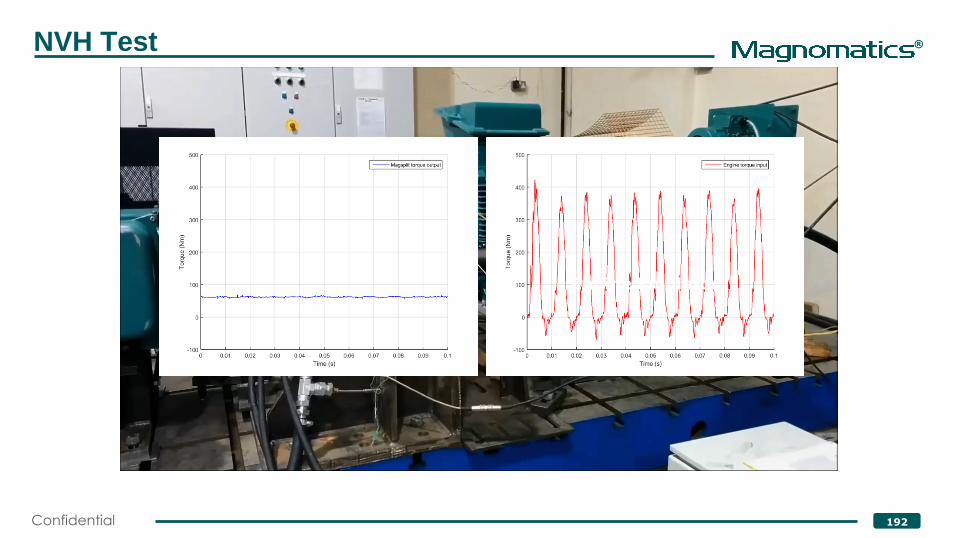
NVH Test
Engine Emulator

®
193Confidential
Progress to date
• Completed three Innovate UK funded projects (to TRL5/MRL4)
• MAGSPLIT has been broadly and successfully rig tested up to 800Nm
• We have live OEM funded development contracts (non-grant)
• We have strong interest from other OEMs to develop vehicle demos
®
194Confidential
What do we want?
• We are looking for further engagements to TRL8/MRL6 an
beyond
• OEMs
• Tier ones
• Other demonstration vehicle opportunities

Magnomatics LimitedPark House
Bernard RoadSheffieldS2 5BQ
UK
Tel: (+44) 114 241 2570Email: [email protected]
www.magnomatics.com
Questions?
Contact me
Dave Latimer

High efficiency- low cost-engine
Oaktec...who are we?
Paul Andrews
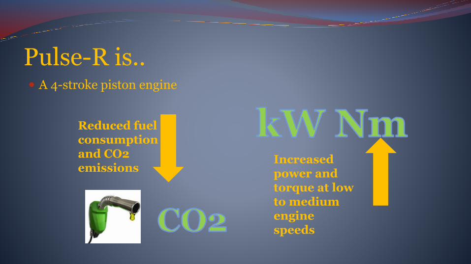
Pulse-R is.. A 4-stroke piston engine
Reduced fuel consumption and CO2 emissions
Increased power and torque at low to medium engine speeds

Minimum technological risk
Off-the-shelf components
Existing component technology
Innovative architecture

What is Pulse-R ?
• A 4 stroke piston engine with a novel cylinder head design
• Uses valve design and gas dynamics for excellent volumetric efficiency
• Design enables very high Compression Ratio• Has lower pumping and mechanical losses • Has an ideal combustion chamber• Is very simple, reliable, durable and low cost
It is a proven practical working engine
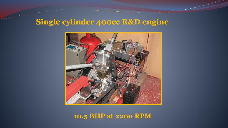
Single cylinder 400cc R&D engine
10.5 BHP at 2200 RPM
What are its advantages ?
• Proven to be more efficient than market leading small engines
• BSFC 215 g/kW hr on propane... target is sub 200g/kW hr
• Has better power and torque ....over 35% gain on benchmarked diesel and 15 – 20% compared to other gas engines
• So far developed for 1200-3600 rpm range
What we’ve learned from testing
Pulse-R is very tolerant of:
Fuel quality
Fuelling and ignition settings
Valve timing
Best power with low ignition advance
Low exhaust gas temperature at full load

Fuels Works well with any fuel
Advantages with gas fuels over conventional engines
Gas engines like high CR, good volumetric efficiency, and a good combustion chamber
Tested with petrol, propane, butane, methane, and simulated bio-gas with high CO2 content

• Gas and bio-gas is on every Global future fuel roadmap
• New legislation restricting emissions from small engines
• Gas engines can be very clean
• Energy security
• Bio-gas Generators....45 million small AD plants in China
There is no current small engine optimised for gas fuels....current engines are converted petrol or diesels
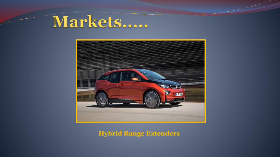
Hybrid Range Extenders

A bio-gas range extended hybrid bus????
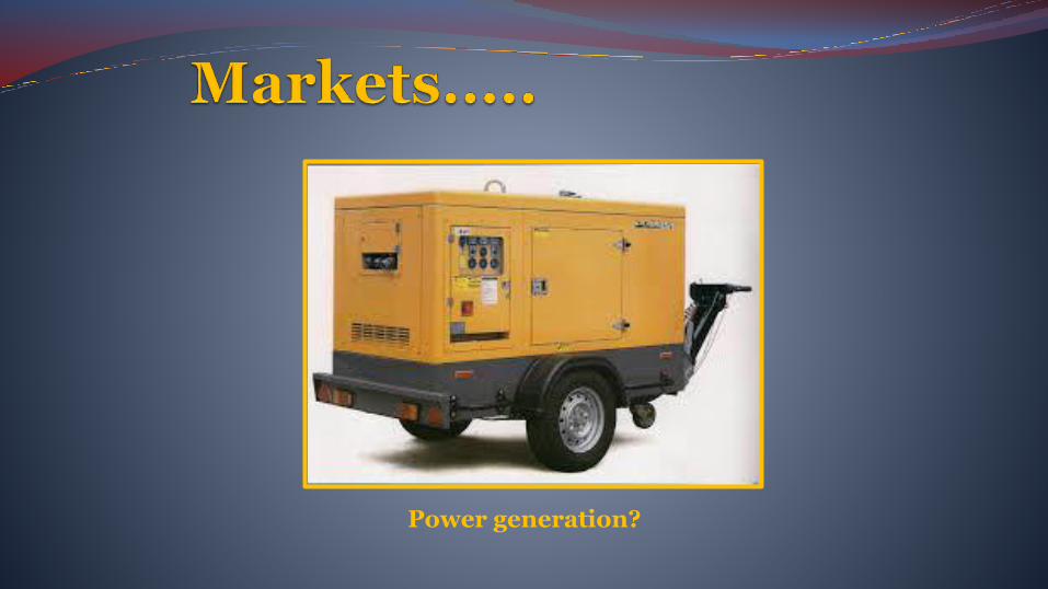
Power generation?
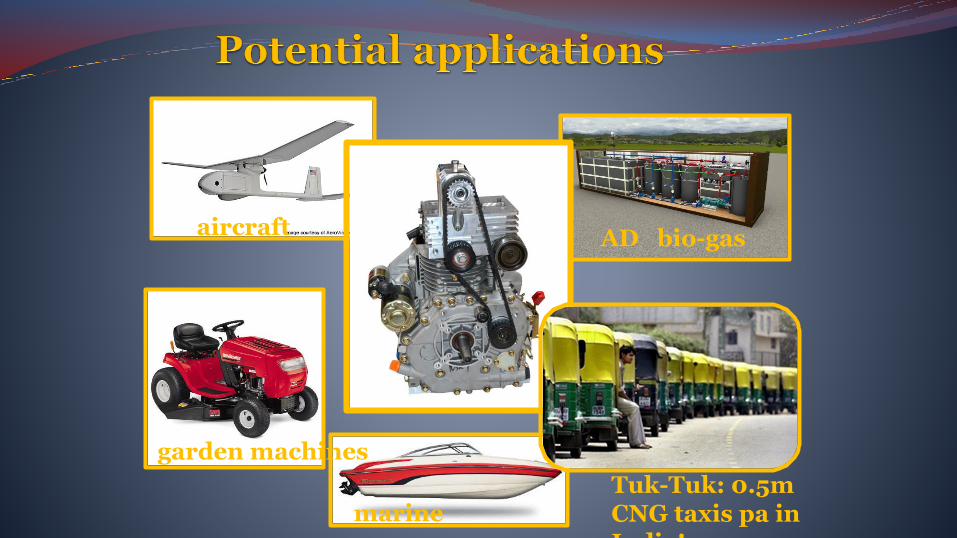
aircraft
garden machines
marineTuk-Tuk: 0.5m CNG taxis pa in India!
AD bio-gas
Pulse-R .... where we are now.....
Current support from
• Industry experienced R&D team• Batch of test engines under development• TRL 5/6• MRL 4/5
I. P.
Oaktec has just filed an international patent under the PCT to cover the core invention
‘Pulse-R’ has been filed as an international trademark
Oaktec will consider licence agreements on the Pulse-R design IP with suitable partners

• Manufacture engines in the UK for early adopters
• Partner with large organisations to commercialise globally
• Licence IP to global engine manufacturers
• Develop the Pulse-R for a wide range of applications and markets
• Development has been on small engines but Pulse-R is scalable
Paul Andrews www.oaktec.net
The Ogunmuyiwa Engine Cycle
Dapo Ogunmuyiwa M.Sc VDI
Chairman / CEO
Tel: (+49) 162 / 961 04 50
E-mail: [email protected]
Ogunmuyiwa Motorentechnik GmbHTechnologie- und Gruenderzentrum (TGZ)
Am Römerturm 2
D-56759 Kaisersesch
Germany

Planetary Reciprocating Piston Engine Description
10.06.2015 The Ogunmuyiwa Engine Cycle 213
1. Housing
2. Rotor
3. Cylinder
4. Piston
5. Connecting Rod
6. Crankshaft
7. Planet Gear
8. Sun Gear
9. Intake Port
10. Exhaust Port

Planetary Reciprocating Piston Engine Description
10.06.2015 The Ogunmuyiwa Engine Cycle 214
1. Housing
2. Rotor
3. Cylinder
4. Piston
5. Connecting Rod
6. Crankshaft
7. Planet Gear
8. Sun Gear
9. Intake Port
10. Exhaust Port
11. Combustion Chamber
12. Link to Central Crankshaft
13. Central Crankshaft
14. Fuel Injector
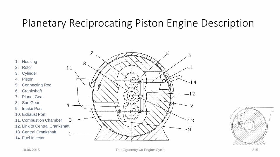
Planetary Reciprocating Piston Engine Description
10.06.2015 The Ogunmuyiwa Engine Cycle 215
1. Housing
2. Rotor
3. Cylinder
4. Piston
5. Connecting Rod
6. Crankshaft
7. Planet Gear
8. Sun Gear
9. Intake Port
10. Exhaust Port
11. Combustion Chamber
12. Link to Central Crankshaft
13. Central Crankshaft
14. Fuel Injector

Conventional Reciprocating Piston Engine Analysis
10.06.2015 The Ogunmuyiwa Engine Cycle 216
𝑇𝑜𝑟𝑞𝑢𝑒 = 𝐹𝑡. 𝑅𝑐𝑟
𝑅𝑐𝑟
𝐹𝑡
𝐹𝑟
𝐹𝑛
𝐹𝑞
𝐹𝑝𝑖𝑠𝑡𝑜𝑛

Planetary Reciprocating Piston Engine Analysis
10.06.2015 The Ogunmuyiwa Engine Cycle 217
𝑅𝑐𝑟
𝐹𝑡
𝐹𝑟
𝐹𝑛
𝑇𝑜𝑟𝑞𝑢𝑒= 𝐹𝑡. 𝑅𝑡 + 𝐹𝑛. 𝑅𝑛 + 𝐹𝑞. 𝐻𝑝𝑖𝑠𝑡𝑜𝑛
𝑅
𝑅𝑡 𝑅𝑛
𝐹𝑞
𝐻𝑝𝑖𝑠𝑡𝑜𝑛
𝐹𝑝𝑖𝑠𝑡𝑜𝑛
= 𝐹𝑡. 𝑅𝑐𝑟 + 𝑅. 𝑆𝑖𝑛𝜃 + 𝐹𝑛. 𝑅𝑛 + 𝐹𝑞. 𝐻𝑝𝑖𝑠𝑡𝑜𝑛
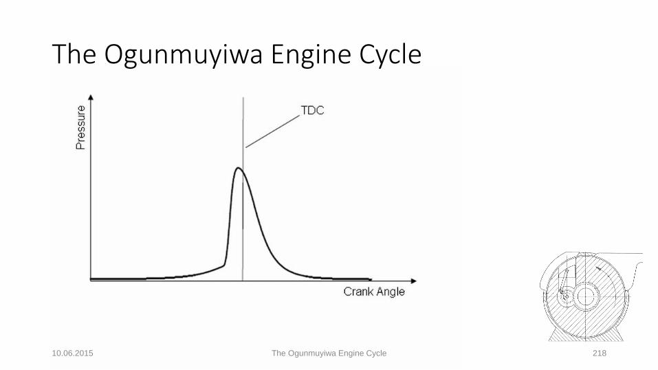
The Ogunmuyiwa Engine Cycle
10.06.2015 The Ogunmuyiwa Engine Cycle 218
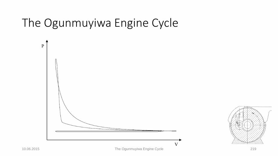
The Ogunmuyiwa Engine Cycle
10.06.2015 The Ogunmuyiwa Engine Cycle 219
P
V

10.06.2015 The Ogunmuyiwa Engine Cycle 220
• 4-Stroke Normal Aspirated Engine:
• Bore:................................................... 7.512500 cm
• Stroke:.................................................7.493264 cm
• Number of Cylinders:......................... 6
• Engine Capacity:........................... 1993 cc
• Engine Output Shaft Speed:..…….. 7500 rpm
• SFC:................................................... 96.400852 g/kWh
• Indicated Thermal Efficiency:…………. 83.787454 %
Engine Simulation Example

Joint Development Plan with a Vehicle OEM
10.06.2015 The Ogunmuyiwa Engine Cycle 221

Requirements of Customer Vehicle OEMs
• Development contract up till <SC> Gateway including such technical requirements as:
• Application vehicle package data;
• Power, torque, NVH, durability, safety requirements, …. etc.;
• Testing signoff requirements;
• Milestones & timing.
• Production sourcing contract from <SC> gateway including:• Start of Production Date;
• Annual Volumes;
• Lifetime Volumes;
• Commercial agreements such as piece price, tooling, capex, ….etc.10.06.2015 The Ogunmuyiwa Engine Cycle 222

Industrialisation Plan
• Current development status: TRL 3• Privately developed since 1984;
• Patented with simulation proof of concept;
• Production costs will be similar to those for current engine manufacture.
• TRL 4, 5 & 6: To be jointly developed with an OEM up till <SC> Gateway;
• TRL 7 & 8: To be jointly developed with an OEM up till <DV Signoff> Gateway;
• TRL 9: To be jointly developed with an OEM up till <PV Signoff> Gateway;• Production Approval to be achieved at <PV Signoff> Gateway.
10.06.2015 The Ogunmuyiwa Engine Cycle 223

Commercial Strategy
• IP Status:• 1 Patent Granted
• PCT Patent Application progressing
• Know-How to be kept in-house
• Manufacturing to be in-house
• User Licenses to be granted
• Engines to be produced as a Tier-1 Supplier
10.06.2015 The Ogunmuyiwa Engine Cycle 224

Commercial Strategy
• Vehicle OEM development contract to fund demonstration prototypes;
• Vehicle OEM sourcing contract lifetime volumes to determine:• Production requirements;
• Facilities requirements;
• Staffing requirements;
• Development budget;
• Investment plan;
• NPV & EV calculations.
10.06.2015 The Ogunmuyiwa Engine Cycle 225

Next Steps• Continue to develop contacts with vehicle OEMs;
• Collaborations sought for 2020 SOP timeframe;
• Continue marketing the innovation;• Engine Expo 2015;
• 2015 Cenex LCV;
• Progress the Patent applications.
10.06.2015 The Ogunmuyiwa Engine Cycle 226
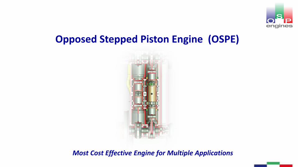
Opposed Stepped Piston Engine (OSPE)
Most Cost Effective Engine for Multiple Applications

OSPE 228
OSPE Features & USPs
• 1, 2 & 4 cylinder 2-stroke stepped pistons, SI & CI versions
• Double diameter piston or under piston does pumping
• ~ 20-30% cost saving vs same power, fuel economy & emission
4-stroke.
• ~ 10-15% weight saving vs same power, fuel economy &emission 4-stroke.
• Improved NVH: ~90% Reduced shaking forces vs L4 4-stroke

OSPE 229
Background: Opposed Piston Engine Renaissance
• 2-stroke Opposed Piston Engines (OPE) are re-emerging dueto their cost/benefit, simplicity vs the 4-stroke and loweremission capability using 4-stroke aftertreatment systems.
• Recent development examples have shown leading edgeemission, fuel economy, package, power density & oilconsumption capability.
• NA SI OPs also have potential for >36% brake efficiency at thetightest emission levels due to inherent features of reducedheat loss, high rate of expansion, and lower friction versus 4-stroke.
• Current OP investigations cover 2 wheelers, automotive,outboard marine, medium speed, military and aviation
OSPE 230
Rationale for 2-stroke “Re-think”
• 4-stroke in-cylinder and after-treatment emissiontechnologies applicable to 2-stroke e.g. Port injection FIE, 3 –way catalyst.
• Solutions available for either cylinder bore oil control or zerooil to bore , e.g. stepped piston, and/or labyrinth sealing forconstant speed/load operation.
• OP has ability for 1:1 scavenging/swept volume with goodperformance, bsfc and λ =1 exhaust.
• Rectilinear Drive System enables non-contacting piston &labyrinth sealing.
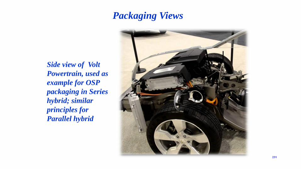
231
Side view of Volt
Powertrain, used as
example for OSP
packaging in Series
hybrid; similar
principles for
Parallel hybrid
Packaging Views
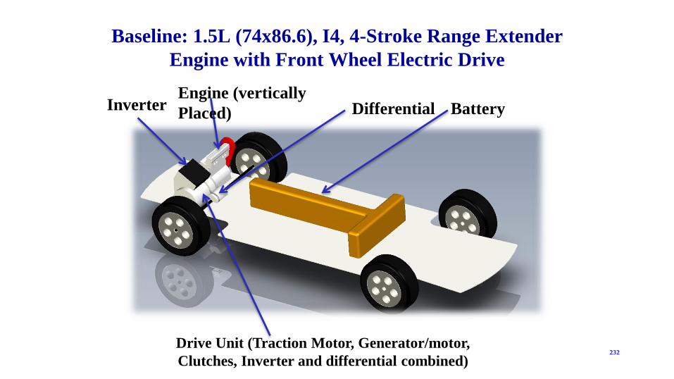
Baseline: 1.5L (74x86.6), I4, 4-Stroke Range Extender
Engine with Front Wheel Electric Drive
232
Engine (vertically
Placed)Inverter Differential
Drive Unit (Traction Motor, Generator/motor,
Clutches, Inverter and differential combined)
Battery

233
1.1L (70x70), I2, OSP FWD Range Extender
Same Drive
Unit OSP Engine ; 264mm lower than baseline

OSPE 234
OSP Engine USPs
• Performance & cost– Leading power/weight in naturally aspirated (NA) segment
– Leading power/bulk volume in NA multicylinder segment
– Lowest £/kW unit cost multicylinder power unit on same material basis
– Lowest investment cost for NA multicylinder power rating
– Lowest vibration levels of any reciprocating configuration
– Same architecture for CI and SI
• Applications– Industrial, marine, CHP and automotive, single base architecture
– Pressure & turbo charging suitability without independent scavenge pump
– best suited of any reciprocating engine for multi-fuel applications, eggasoline, kersosene, diesel, low cetanes, bio fuels, NG

Visionary Design. Practical Solution.
proteanelectric.com
Visionary Design. Practical Solution.
Protean ElectricIn-wheel Electric Motors
Dr Chris Hilton, CTO
June 2015
236
The Proving Factory – 10/06/2015
proteanelectric.com
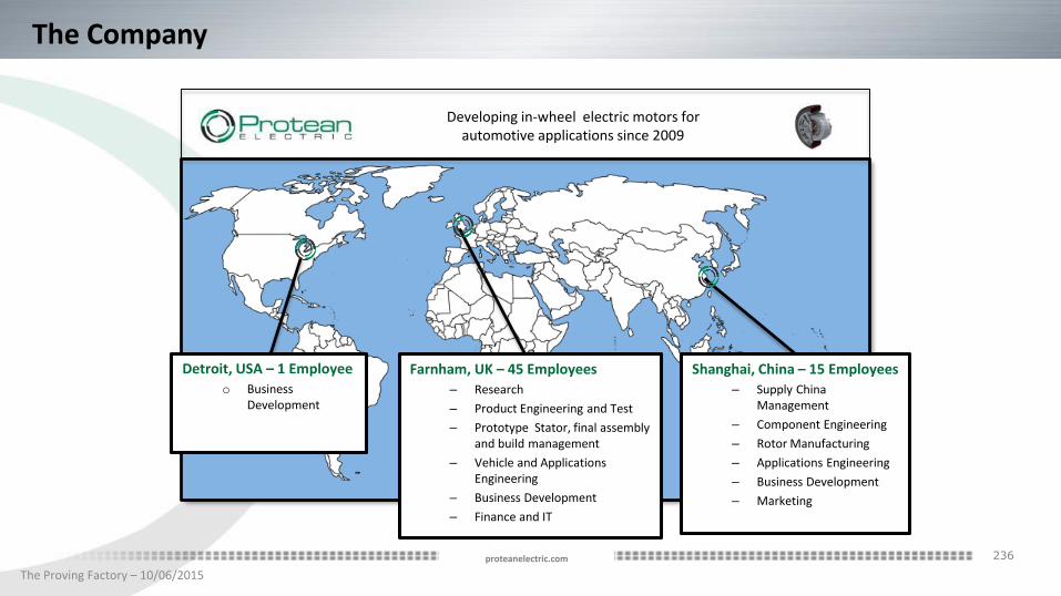
Detroit, USA – 1 Employee
o Business Development
The Company
Shanghai, China – 15 Employees
– Supply China Management
– Component Engineering
– Rotor Manufacturing
– Applications Engineering
– Business Development
– Marketing
Farnham, UK – 45 Employees
– Research
– Product Engineering and Test
– Prototype Stator, final assembly and build management
– Vehicle and Applications Engineering
– Business Development
– Finance and IT
Developing in-wheel electric motors for automotive applications since 2009
237
The Proving Factory – 10/06/2015
proteanelectric.com
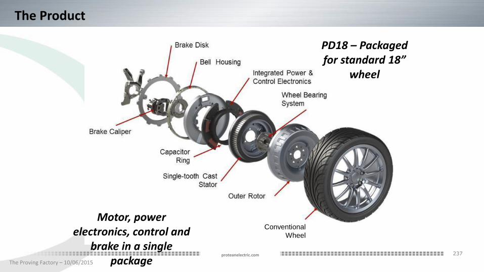
Motor, power electronics, control and
brake in a single package
Conventional
Wheel
PD18 – Packaged for standard 18”
wheel
The Product
238
The Proving Factory – 10/06/2015
proteanelectric.com
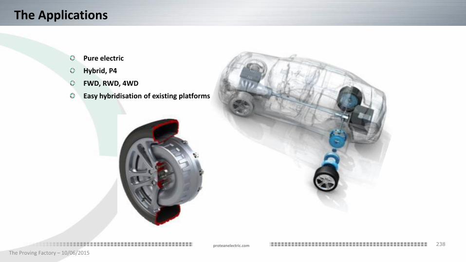
The Applications
Pure electric
Hybrid, P4
FWD, RWD, 4WD
Easy hybridisation of existing platforms
239
The Proving Factory – 10/06/2015
proteanelectric.com
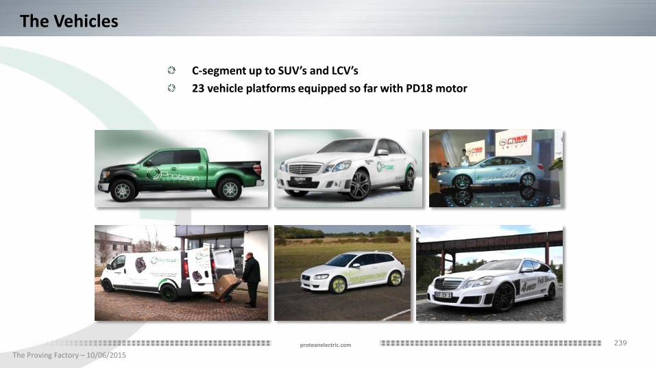
The Vehicles
C-segment up to SUV’s and LCV’s
23 vehicle platforms equipped so far with PD18 motor

240
The Proving Factory – 10/06/2015
proteanelectric.com
The Advantages
Packaging
Efficiency
System Cost
Low-disruption hybridisation
Vehicle dynamics

241
The Proving Factory – 10/06/2015
proteanelectric.com
The Performance
Performance as measured on existing PD18 motor shown
o Efficiency includes inverter losses
o Upgrade to 1250 Nm torque available in 2016 PD18 motor

242
The Proving Factory – 10/06/2015
proteanelectric.com
Functional Safety
Product developed in accordance with ISO26262
Key hazards identified and rated
Comprehensive functional safety concept

243
The Proving Factory – 10/06/2015
proteanelectric.com
Test
Comprehensive DVP based on European and US OEMstandards for electrical components and suspension
Vehicle and laboratory testing
Durability cycles developed by Millbrook for Protean
Life-time component

244
The Proving Factory – 10/06/2015
proteanelectric.com
Manufacturing
Designed for manufacture
Tooling for small series line developed
Rotor production in China
Full motor production in China by end 2015

245
The Proving Factory – 10/06/2015
proteanelectric.com
Production Plans
Protean has capability up to 50k per year
License design and manufacturing processes to OEM/Tier 1

246
The Proving Factory – 10/06/2015
proteanelectric.com
The Future
Protean is currently engaged with OEM’s and Tier 1’s on SOP intent programmes related tothe PD18 motor
Protean is carrying out concept-level designs for customers wanting motors of otherspecifications
We are ready to engage with other OEM’s and tier 1’s with serious production intent toimplement in-wheel motor solutions in their hybrid and electric vehicles
Visionary Design. Practical Solution.

Visionary Design. Practical Solution.
proteanelectric.com
Visionary Design. Practical Solution.
247
Visionary Design . Practical Solution

Bob Austin
Productiv

What is a Heat Battery?
Heat batteries store heat that is normally wasted and return it for use when needed

Heat Battery Construction
Heat In(charge)
Heat Out(discharge)
Phase Change or Thermo-Chemical
material
Heat battery casing

Sunamp Automotive Heat Battery
Long-Term Storage Heat Battery
• IDP 8 funded project with Edinburgh University
• Stores large amounts of waste heat indefinitely
• Heat is reactivated on demand
• e.g. ICE cold start
• Potential to store heat at temperature of up to 400°C using thermochemical materials (TCM) orsub-cooled PCM
Absorbs heat from engine/exhaust (ICE); when plugged-in (EV)
Returns heat to vehicle when required
Fast-Response Heat Battery
• Stores waste heat for short periods
• Store & release heat at high rate
• e.g. bridging HVAC in stop/start
• Potential to store heat and cool energy at selected temperatures between 5°C and 120°C using phase change materials (PCM)
• Safe, non-toxic, non-flammable materials chosen• Self heal when punctured• Integrate with liquid, refrigerant or air circuits• Physical shape can be adapted to suit the installation

How it Integrates
Integrate into ICE cooling circuit
Integrate into battery cooling circuit
Use high temperature heat
exchanger with catalyst / after-
treatment
Heat electrically during battery
charge
Charging circuit Discharge circuit
Cabin heater/screen demister
Transmission oil circuit
Traction battery
After-treatment

Automotive applications
Rapid engine warm-up after cold start: cylinder head, block, oil
Maintain temperature during light load and stop-start
EV traction battery thermal
conditioning
Transmission oil heating
Instant cabin heat / windscreen
demisting
Heat DEF to prevent freezing
Rapid catalyst light-off after cold-start
Application
USP
Competitor
Market
Lighter Smaller
High Energy Density
Activate Heat on Demand
Lossless Storage
High Thermal Power Fuel Cell cold-start
Comfort Enhancing
Range Extending
Non-FlammableNon-Toxic
Size & Shape Flexible
FlasksPrius*Bosch
Heat BatteriesSchatz*BMW*
* Withdrawn from market: cost, low performance, toxicity, corrosion
Intake air heating
Much lower cost than Li-ion batteries
Highly efficient
Re-uses waste heat
EV range consistency
Thermal Engine CoversMercedes
Block Heaters

Opportunities Matrix
Attractiveness – Payback or TCO, Market size, profitability
Ease
of
entr
y –
Ris
k, C
om
pet
itio
n, I
nve
stm
ent
Adequate High
Dif
ficu
ltEa
sy
Engine warm-up (bus)
Auto. Trans. fluid heating (car)
Cabin heating (bus)
EV Range consistency (bus)Engine warm-
up (car)
EV range consistency (car)
After-treatment thermal management
Stop start heater temperature smoothing
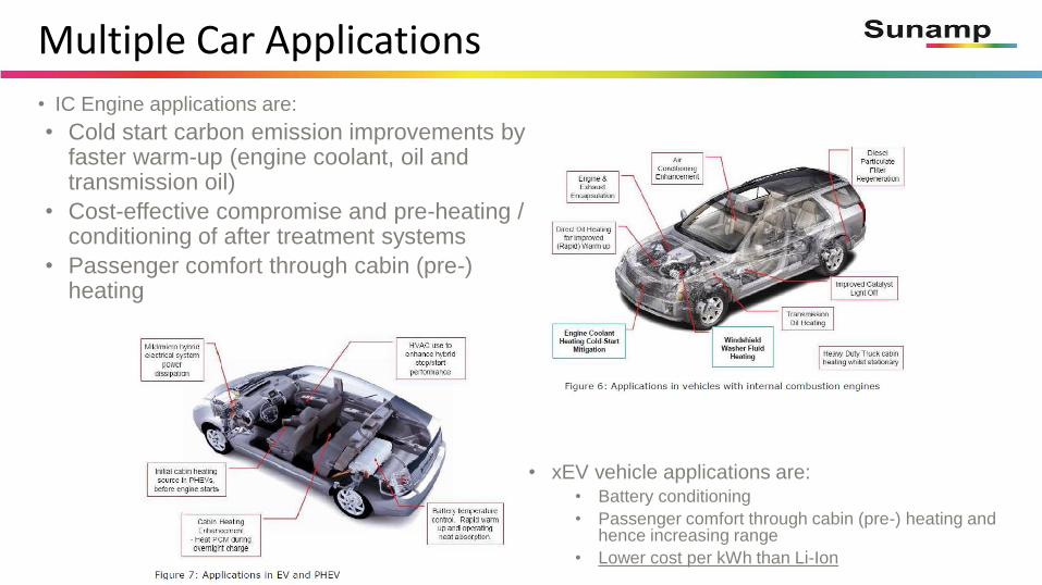
Multiple Car Applications
• xEV vehicle applications are:• Battery conditioning
• Passenger comfort through cabin (pre-) heating and hence increasing range
• Lower cost per kWh than Li-Ion
• IC Engine applications are:
• Cold start carbon emission improvements by faster warm-up (engine coolant, oil and transmission oil)
• Cost-effective compromise and pre-heating / conditioning of after treatment systems
• Passenger comfort through cabin (pre-) heating

Multiple Bus Applications
• Potential bus applications are:
• Immediate cabin heating from cold
• Rapid engine heating (or pre-heating)
• Immediate windscreen demist
• After-treatment pre-heating
• After-treatment temperature management for stop-start
• Heater temperature smoothing
• Cabin cooling
• Electric and hybrid bus:
• Range consistency
• Battery temperature management
• Fuel cell cold start and thermal management
• Cabin heating and windscreen demisting
• Lower cost per kWh than Li-Ion

Enables Off-Highway Innovation
• Off-Highway opportunities:
• Immediate cabin heating from cold (or cabin pre-heating)
• Rapid engine heating (or pre-heating)
• Immediate windscreen demist
• Heater temperature smoothing for stop start
• Hydraulic oil pre-heating for improved efficiency from cold
• Engine inlet air heating
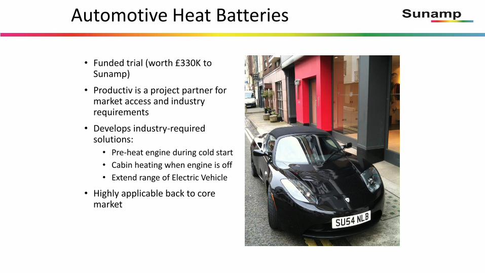
Automotive Heat Batteries
• Funded trial (worth £330K to Sunamp)
• Productiv is a project partner for market access and industry requirements
• Develops industry-required solutions:
• Pre-heat engine during cold start
• Cabin heating when engine is off
• Extend range of Electric Vehicle
• Highly applicable back to core market

Electrical battery
Heat battery
Bosch BPT-S 5 Hybrid
SunampPV
4.4kWh
€12,000
600 x 700 x 1.650mm
693 dm3 occupied volume
3.6 kWh (to 45°C) / 5.0 kWh (to 20°C)
€1,500
280 x 510 x 680mm
97 dm3 occupied volume
PV panel
Self-consumption solutions demanded
vs Electric Battery
Current cost of Heat Battery is £45 - £85 per kWh at volumeAutomotive Li-Ion batteries are £150 - £210 at very high volumes

Summary of Technologies
Long-Term Storage Heat Battery (TCM or sub-cooled PCM)
• TRL: 1
• MRL: 0
Progress:
• Lab based development of TCM materials (multiple candidates evaluated, some de-selected)
• Sub-cooled PCM can be electronically activated in the lab
Design & Technology Challenges:
• Reliable full melting of PCM to allow sub-cooling
• Choice of TCMs
• TCM heat battery detail design
• Design for integration in Peugeot iOn EV
Fast-Response Heat Battery (PCM)
• TRL: 4
• MRL: 1
Progress:
• PCM heat batteries proven in built environment
• PCMs for EV cabin heating tested on-vehicle for 2+ years
• High temp automotive PCMs selected for ICE
• Prototype heat batteries designed, undergoing lab validation tests, planned proof-of-concept in engine coolant loop of Ford Focus
Design & Technology Challenges:
• Fit into spaces available; mass limits; integration to existing coolant loop & cabin HVAC
• EV: Energy required leads to too high mass & volume => must use TCM
TC48 Town and Country Hybrid
Jez CoatesChief Engineer – Vehicle Projects
RDM Group Limited
What is TC48?
• State of the art, low cost, 48v Plug-in hybrid electric(PHEV) drivetrain• Suitable for electrically powered urban driving below 35 mph with 15 miles electric (Town) range• Internal Combustion Engine powered driving above 35mph (Country) • Low-cost novel switched reluctance electric motor (SRM) • 5kWh Li-Ion battery pack • State of the Art TriCore AURIX™ microcontroller and Oikos controller design platform

Who is involved in TC48?
• TC48 is an IDP9 project funded by Innovate UK – Technology Strategy Board
• Participates: RDM Group – Lead
Productiv
Tata Steel
Newcastle University
Loughborough University
Libralato
Infineon Technologies

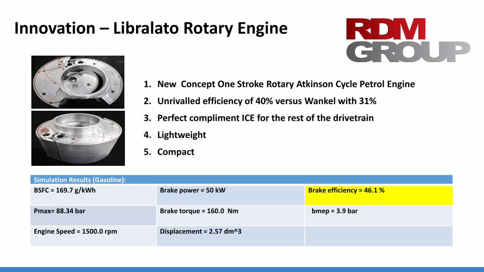
Innovation – Libralato Rotary Engine
1. New Concept One Stroke Rotary Atkinson Cycle Petrol Engine
2. Unrivalled efficiency of 40% versus Wankel with 31%
3. Perfect compliment ICE for the rest of the drivetrain
4. Lightweight
5. Compact
Simulation Results (Gasoline):
BSFC = 169.7 g/kWh Brake power = 50 kW Brake efficiency = 46.1 %
Pmax= 88.34 bar Brake torque = 160.0 Nm bmep = 3.9 bar
Engine Speed = 1500.0 rpm Displacement = 2.57 dm^3

Project Aims & Objectives
1. Significant improvement in performance and cost effectiveness of the electric propulsion system
• Electric Vehicle with 15 miles All Electric Range
• Fuel Consumption & Economy Targets based on using Vauxhall Adam vehicle: 112 mpg, 52g/km CO2 with low marginal cost

Project Aims & Objectives
2. New topologies and reduction in rare materials usage
• Switched Reluctance Motor (SRM) with no rare earth components reducing cost
• New 6 phase topology for advanced motor control developed by Newcastle University
Project Aims & Objectives
3. Highly integrated electric drive train, power electronics, & Control Systems
• Modelled & tested within controlled Loughborough University environment and then fitted to the donor vehicle to prove & optimise for ‘real world’ conditions
• AURIXTM TriCoreTM powertrain & vehicle ECUs designed by world leaders Infineon now make this control system possible due to very high speed processing with built in safety case strategy control

Project Aims & Objectives
4. Design for Manufacture
• Trial manufacture of integrated SRM
• Prove design for manufacture & assembly to develop a capability in the UK of 20,000 units pa by 2017 using Productiv in conjunction with Tata Steel
• Demonstrate whole vehicle concept to major vehicle manufacturers and fleet users as a fully working and viable proposal
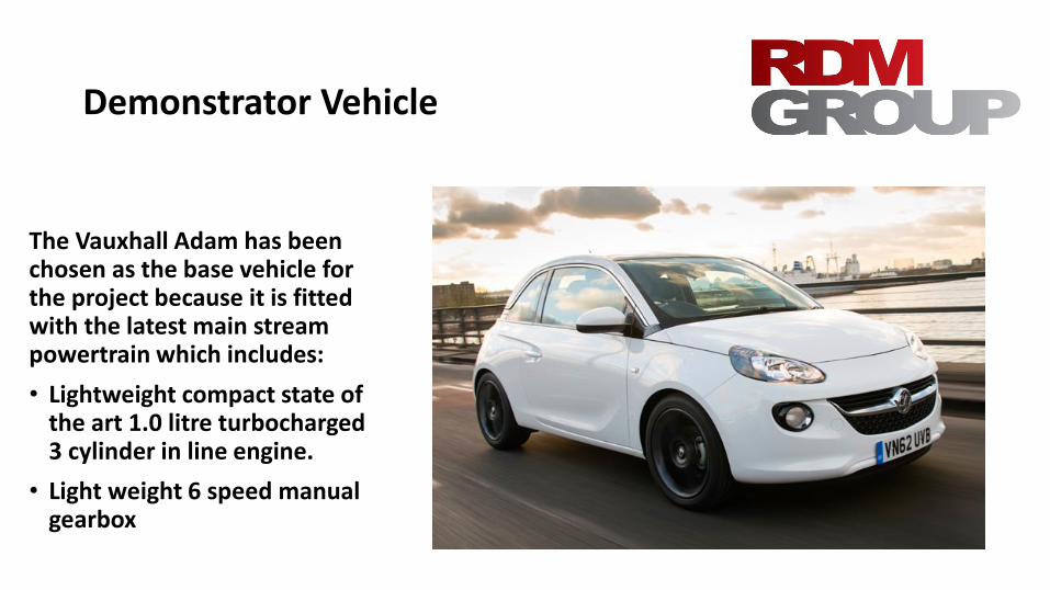
Demonstrator Vehicle
The Vauxhall Adam has been chosen as the base vehicle for the project because it is fitted with the latest main stream powertrain which includes:
• Lightweight compact state of the art 1.0 litre turbocharged 3 cylinder in line engine.
• Light weight 6 speed manual gearbox

Switched Reluctance Motor
The SRM will be mounted above the gearbox and will drive the input shaft of the gearbox via a toothed belt.
This layout has several advantages:
• The SRM is relatively easy to package.
• The belt drive will help to reduce any torque ripple present in the SRM.
• The belt drive allows the introduction of a gearing ratio between the SRM and the gearbox.
• The SRM will be mounted high in the engine bay making installation quick and easy with minimal modification.
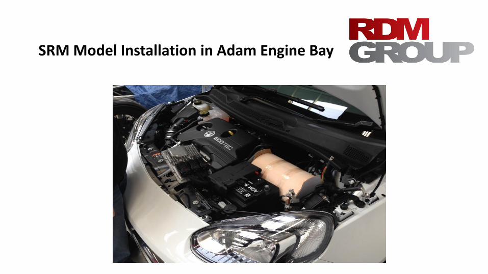
SRM Model Installation in Adam Engine Bay

Vehicle Architecture continued
4. Batteries• Originally it was planned to fit a combination of 6 individual power & energy batteries
in the engine bay
• Examination of the Vauxhall Adam engine bay has confirmed that there was insufficient room for the fitment of 6 large batteries
• In addition there is a safety concern in a frontal impact with a very densely packed battery rich engine bay.
• Further examination of the Adam revealed a large under utilised space behind the rear axle and below the boot floor. This space lends itself to the fitment of a single bespoke tablet shaped battery pack.
• As a result a bespoke battery pack will be fitted under the boot floor.
Project Evolution
• Significant change to Topology
• Very Promising Electric Motor
• Innovative ICE – The Libralato
• A Manual Hybrid!
• Minimal Disruption to OE Vehicle Architecture
• Viable Conversion from ICE to Hybrid for Fleet Operators

Infinitely Variable Transmission
IVT
we all know what it is but
what’s different about this new system?

Virtually unlimited torque capability
IRWD – Individual Rear Wheel Drive
IAWD – Individual All Wheel Drive
Simplicity of operation and manufacture
Step change in vehicle dynamics and performance

Virtually unlimited torque capability
Innovative modular disc construction can be expanded
depending on the torque requirement, and is compound
geared on both the input and output drives to unify the
torque across the system


IRWD – Individual Rear Wheel Drive
IAWD – Individual All Wheel Drive
The IVT has the unique capability of multiple variable speed
outputs from the speed variator discs. Note: the output to
each wheel is in absolute speed control, not thrust vectoring,
this overcomes the traction limitations of traditional
differentials and offers a step change in vehicle dynamics
and performance in off road and low traction conditions

Simplicity of operation and manufactureMechanically straight forward, and modular with less component parts
Common hydraulic control system actuation with existing CVT gearboxes
Compact lightweight design, reduced mass production cost

Vehicle dynamics and performanceAdvantages of IVT and CVT are well documented, however current systems
are limited in power capability, typically 240 HP, The new IVT’s modular
design and high torque capacity enables its application to the entire vehicle
transmission market
Individual wheel speed control reduces and in some cases eliminates reliance
on ABS braking systems
Multiple input and output drives to the system Variator, enabling easy
application of Hybrid and Kinetic energy recovery systems
Applications
Traditional Vehicle Transmission
Transaxle IRWD – Individual Rear Wheel drive
IFWD – Individual Front Wheel Drive
IAWD – Individual All Wheel Drive
Rear Differential – Individual Rear Wheel speed control
Tracked Vehicles – Individual speed and direction
control
Virtually limitless Torque capacity!

David McManamon
CEO and Founder Transfiniti Ltd.
Looking for development partnerships to exploit the full
commercial potential of this exciting new technology.

The WITT - Capturing Energy from Motion (using all six degrees of freedom) for Transport
& other Energy Harvesting Applications
Meet the Engineer Presentation
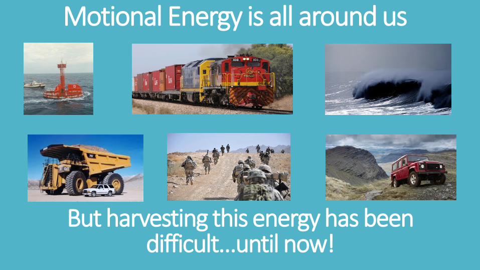
Motional Energy is all around us
But harvesting this energy has been difficult…until now!
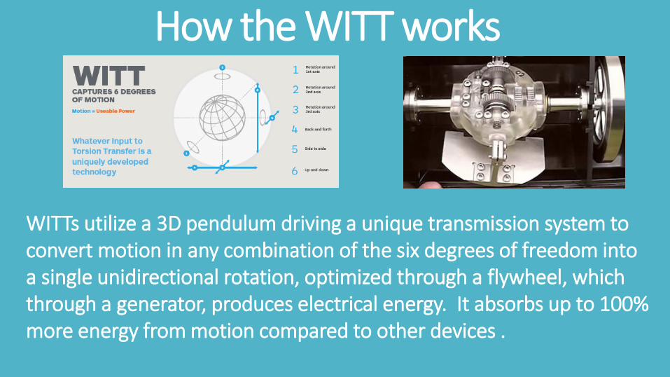
How the WITT works
WITTs utilize a 3D pendulum driving a unique transmission system to convert motion in any combination of the six degrees of freedom into a single unidirectional rotation, optimized through a flywheel, which through a generator, produces electrical energy. It absorbs up to 100% more energy from motion compared to other devices .
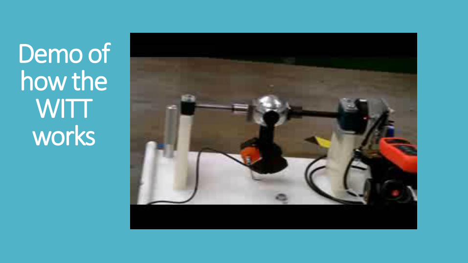
Demo of how the
WITT works

WITT USPs
• Completely scalable patented platform technology
• The 1st global market personal energy harvester
• Low cost, clean tech, energy generation solution.
• Collects power 24/7 where there is motion
• Sealed structure, protects from external environment
• Can be designed to be maintenance free
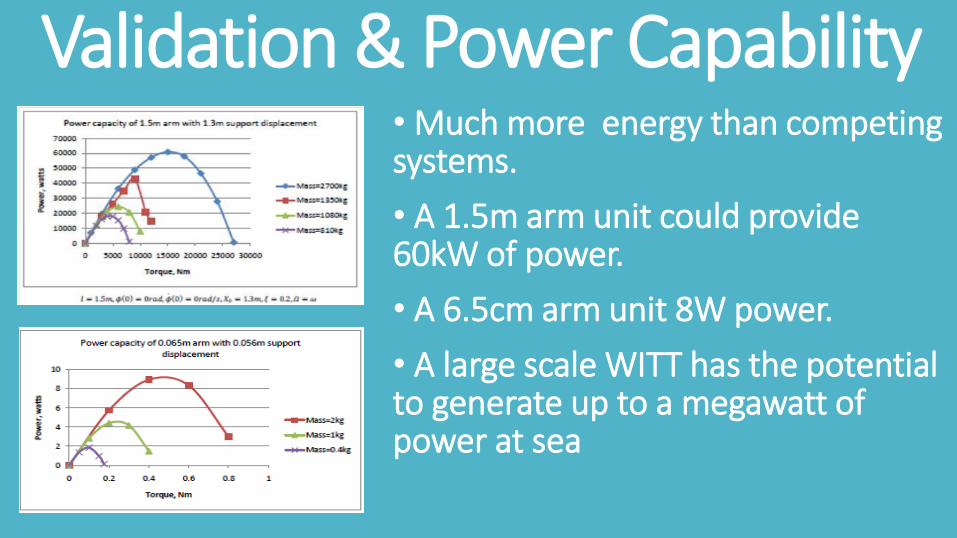
Validation & Power Capability• Much more energy than competing systems.
• A 1.5m arm unit could provide 60kW of power.
• A 6.5cm arm unit 8W power.
• A large scale WITT has the potential to generate up to a megawatt of power at sea

1st Application – Light vesselsWhy WITT?
• Provides power 24/7• Sealed unit• No maintenance
Up to 15 Watts
TRANSMISSION DESIGN CONSULTANT SOUGHT
Up to 150 Watts
Market Opportunity• 20m+ light vessels• 20m+ buoys, etc
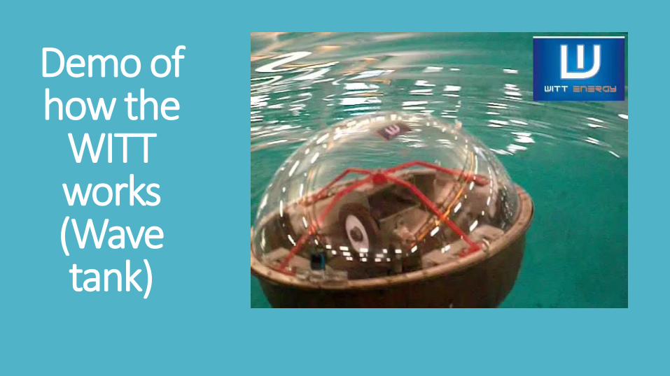
Demo of how the
WITT works(Wave tank)

Potential Customers

2nd Application – Dismounted SoldierWhy WITT?
• Provides up to 10Watts power insoldier backpack
• Manufacturer, Reliance
• Customer driven with specific defence agencies interested
Market Opportunity• 14,692,675 soldiers• Wide consumer market

Demo of how the
WITT works
(Backpack)

Contract Manufacturer – Reliance Precision
Expertise in gearing and electrical systems
Systems are deployed in Aerospace and Defence applications.
Work with global Primes inc Lockheed Martin, Northrop Gruman & Saab

3rd Application – Off Highway?
• Potential interest in licensing technology
• CAT seeking to develop their own energy harvester that can capture energy from 6 degrees of freedom!

Potential Customers & Research Partners

Witt Limited Contact Details
Witt Limited operates out of Plymouth, Devon, England
www.witt-energy.com
CEO Mairi Wickett
[email protected] tel +44 7456 169669

ZAP&GO
Graphene
supercapacitors
Stephen Voller
CEO
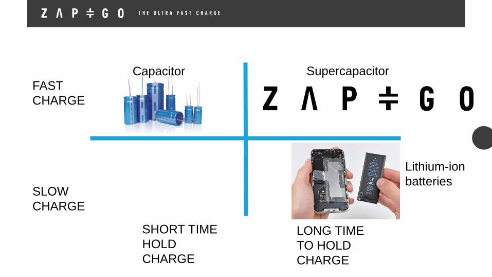
FAST
CHARGE
SLOW
CHARGE
SHORT TIME
HOLD
CHARGE
LONG TIME
TO HOLD
CHARGE
Lithium-ion
batteries
Capacitor Supercapacitor

Flat and flexible supercapacitors

Human hair ~100µm
Zap&Go graphene supercapacitor
electrode is thinner than a human hair
Porous barriermembrane20-25µm
- NEGATIVEElectrode layer –
graphene composite 1-2µm
Current
collector
20µm
foil
Ionic electrolyte
Electrode ~70µm
CONFIDENTIAL
Current
collector
20µm
foil
+ POSITIVEElectrode layer –
graphene composite 1-2µm

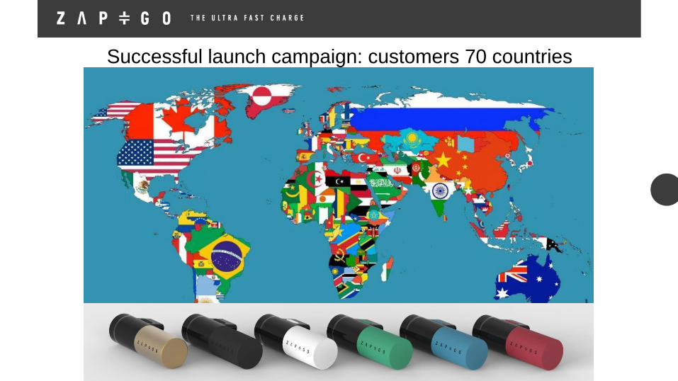
Successful launch campaign: customers 70 countries

Goal is phones that charge in minutes, not hours…
Cordless power tools that perform liked corded tools
Cordless power tools that perform like corded tools…

… and in electric vehicle charging, charge in the same
time as filling a fuel tank – game changing
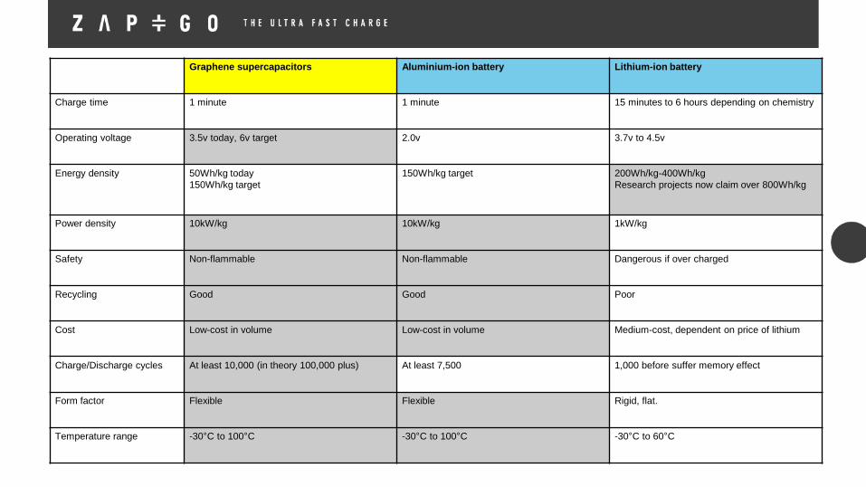
Graphene supercapacitors Aluminium-ion battery Lithium-ion battery
Charge time 1 minute 1 minute 15 minutes to 6 hours depending on chemistry
Operating voltage 3.5v today, 6v target 2.0v 3.7v to 4.5v
Energy density 50Wh/kg today
150Wh/kg target
150Wh/kg target 200Wh/kg-400Wh/kg
Research projects now claim over 800Wh/kg
Power density 10kW/kg 10kW/kg 1kW/kg
Safety Non-flammable Non-flammable Dangerous if over charged
Recycling Good Good Poor
Cost Low-cost in volume Low-cost in volume Medium-cost, dependent on price of lithium
Charge/Discharge cycles At least 10,000 (in theory 100,000 plus) At least 7,500 1,000 before suffer memory effect
Form factor Flexible Flexible Rigid, flat.
Temperature range -30°C to 100°C -30°C to 100°C -30°C to 60°C


© Productiv Ltd 2015
Meet the Engineer 2015
Enquiries & Connection [email protected] | 02476 309 291
Related Documents