Issue Date: July 31, 2013 RENEWAL PARTS MEDIUM VOLTAGE VARIABLE SPEED DRIVE Supersedes: 160.00-RP6 (512) Form 160.00-RP6 (713) LD12287 MEDIUM VOLTAGE 500-2500 HP, 2300V, 3300V, 4160V, 6600, 12.4KV & 13.8KV, 60HZ 3300V, 6600V, 10KV & 11KV 50HZ VARIABLE SPEED DRIVES FOR YK CHILLER APPLICATIONS FOR PARTS RELATED QUESTIONS, CONTACT: BALTIMORE PARTS CENTER 800-932-1701 Email : [email protected] www.johnsoncontrols.com

Welcome message from author
This document is posted to help you gain knowledge. Please leave a comment to let me know what you think about it! Share it to your friends and learn new things together.
Transcript
Issue Date: July 31, 2013
RENEWAL PARTS
MEDIUM VOLTAGE VARIABLE SPEED DRIVE
Supersedes: 160.00-RP6 (512) Form 160.00-RP6 (713)
LD12287
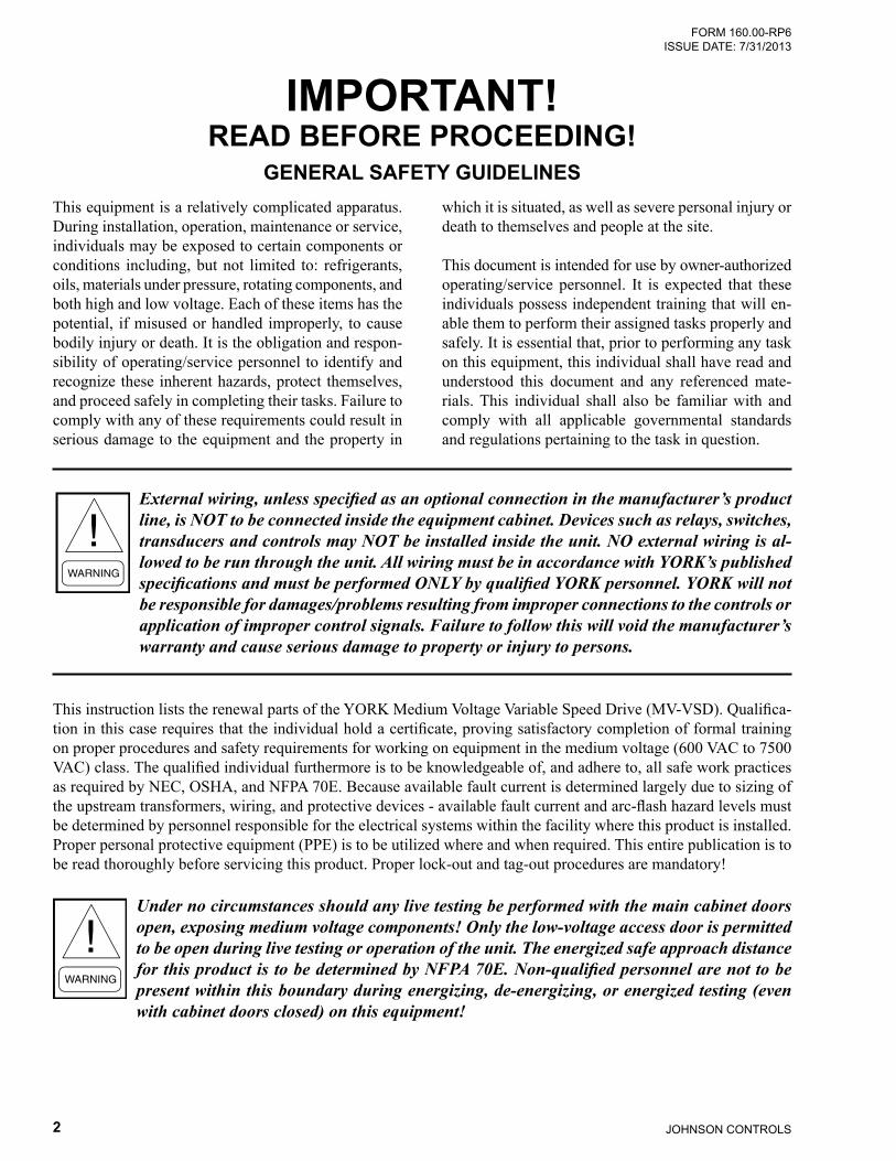
MEDIUM VOLTAGE 500-2500 HP,2300V, 3300V, 4160V, 6600, 12.4KV & 13.8KV, 60HZ
3300V, 6600V, 10KV & 11KV 50HZVARIABLE SPEED DRIVES FOR
YK CHILLER APPLICATIONS
FOR PARTS RELATED QUESTIONS, CONTACT:BALTIMORE PARTS CENTER
800-932-1701Email : [email protected]
www.johnsoncontrols.com
JOHNSON CONTROLS2
FORM 160.00-RP6 ISSUE DATE: 7/31/2013
This equipment is a relatively complicated apparatus. During installation, operation, maintenance or service, individuals may be exposed to certain components or conditions including, but not limited to: refrigerants, oils, materials under pressure, rotating components, and both high and low voltage. Each of these items has the potential, if misused or handled improperly, to cause bodily injury or death. It is the obligation and respon-sibility of operating/service personnel to identify and recognize these inherent hazards, protect themselves, and proceed safely in completing their tasks. Failure to comply with any of these requirements could result in serious damage to the equipment and the property in
IMPORTANT!READ BEFORE PROCEEDING!
GENERAL SAFETY GUIDELINESwhich it is situated, as well as severe personal injury or death to themselves and people at the site.
This document is intended for use by owner-authorized operating/service personnel. It is expected that these individuals possess independent training that will en-able them to perform their assigned tasks properly and safely. It is essential that, prior to performing any task on this equipment, this individual shall have read and understood this document and any referenced mate-rials. This individual shall also be familiar with and comply with all applicable governmental standards and regulations pertaining to the task in question.
External wiring, unless specified as an optional connection in the manufacturer’s product line, is NOT to be connected inside the equipment cabinet. Devices such as relays, switches, transducers and controls may NOT be installed inside the unit. NO external wiring is al-lowed to be run through the unit. All wiring must be in accordance with YORK’s published specifications and must be performed ONLY by qualified YORK personnel. YORK will not be responsible for damages/problems resulting from improper connections to the controls or application of improper control signals. Failure to follow this will void the manufacturer’s warranty and cause serious damage to property or injury to persons.
This instruction lists the renewal parts of the YORK Medium Voltage Variable Speed Drive (MV-VSD). Qualifica-tion in this case requires that the individual hold a certificate, proving satisfactory completion of formal training on proper procedures and safety requirements for working on equipment in the medium voltage (600 VAC to 7500 VAC) class. The qualified individual furthermore is to be knowledgeable of, and adhere to, all safe work practices as required by NEC, OSHA, and NFPA 70E. Because available fault current is determined largely due to sizing of the upstream transformers, wiring, and protective devices - available fault current and arc-flash hazard levels must be determined by personnel responsible for the electrical systems within the facility where this product is installed. Proper personal protective equipment (PPE) is to be utilized where and when required. This entire publication is to be read thoroughly before servicing this product. Proper lock-out and tag-out procedures are mandatory!
Under no circumstances should any live testing be performed with the main cabinet doors open, exposing medium voltage components! Only the low-voltage access door is permitted to be open during live testing or operation of the unit. The energized safe approach distance for this product is to be determined by NFPA 70E. Non-qualified personnel are not to be present within this boundary during energizing, de-energizing, or energized testing (even with cabinet doors closed) on this equipment!
3JOHNSON CONTROLS
FORM 160.00-RP6 ISSUE DATE: 7/31/2013
LIST OF TABLES
LIST OF FIGURES
TABLE 1 - Recommended Spares Kit .......................................................................................................................6TABLE 2 - 74" x 44" x 104" (188 x 112 x 264) Models ..............................................................................................7TABLE 3 - 74" x 44" x 104" (188 x 112 x 264) Components .....................................................................................8TABLE 4 - 122" x 44" x 104" (310 x 112 x 264) Models .......................................................................................... 11TABLE 5 - 236" x 44" x 104" (600 x 112 x 264) Models ..........................................................................................13TABLE 6 - 122" and 236" x 44" x 104" (310 and 600 x 112 x 264) Components ....................................................15TABLE 7 - 164" x 50" x 104" (417 x 127 x 264) Models ..........................................................................................19TABLE 8 - 278 x 50" x 104" (706 x 127 x 264) Models ...........................................................................................21TABLE 9 - 164" and 278" x 44" x 104" (417 and 706 x 127 x 264) Components ...................................................22TABLE 10 - 174" x 50" x 104" (442 x 127 x 264) Models ........................................................................................25TABLE 11 - 174" x 50" x 104" (442 x 127 x 264) Components ...............................................................................26TABLE 12 - 222" x 50" x 104" (564 x 127 x 264) Models ........................................................................................29TABLE 13 - 174" x 50" x 104" (442 x 127 x 264) Components ...............................................................................30
FIGURE 1 - Power Module ......................................................................................................................................28FIGURE 2 - Low Voltage Compartment ..................................................................................................................28FIGURE 3 - Motor Lead Compartment ....................................................................................................................29FIGURE 4 - Controller Compartment ......................................................................................................................29FIGURE 5 - Rectifier and Fuses ..............................................................................................................................30FIGURE 6 - Pre-Charge Assembly ..........................................................................................................................30FIGURE 7 - Fans .....................................................................................................................................................31FIGURE 8 - Filters ...................................................................................................................................................31

JOHNSON CONTROLS4
FORM 160.00-RP6 ISSUE DATE: 7/31/2013
UNIT MODEL NUMBER NOMENCLATUREMVVSD __ __ __ __ __ __ - __ __{
{ {
{
MAXIMUM DRIVE HORSEPOWER RATING
0500=500 HP0600=600 HP0700=700 HP0800=800 HP0900=900 HP1000=1000 HP1250=1250 HP1500=1500 HP1750=1750 HP2000=2000 HP2250=2250 HP2500=2500 HP
YEAR MANUFACTURED
MONTH MANUFACTURED
R = REMOTE MOUNT
K = YK OIL PUMP SUPPLY
INPUT VOLTAGE CODE80 = 2300V/60HZ84 = 4160V/60HZ85 = 6600V/60HZ92 = 3300V/50HZ94 = 3300V/60HZ95 = 6600V/50HZ98 = 10,000V/50HZ96 = 11,000V/50HZ86 = 12,470V/60HZ88 = 13,800V/60HZ
2 5 0 0 R K 8 4
SERIAL NUMBER BREAKDOWN0 7 1 2 0 3 0 8 8

5JOHNSON CONTROLS
FORM 160.00-RP6 ISSUE DATE: 7/31/2013
LOW VOLTAGE COMPARTMENT
DATA PLATE
YORK MODEL #
CAPACITY:
INPUT:
OUTPUT:
2kW ControlSupply:
Oil PumpSupply:
SERIAL #:
IMPULSE TEST VOLTAGE (BIL):
kVA
kV
kV
V
V
kW
A
A
A
A
MFD.DATE
S u i t a b l e F o r U s e O n a C i r c u i t C a p a b l e o f D e l i v e r i n g N o t M o r e
T h a n RMS. Sym. Amperes kV Maximum
HP
Hz
Hz
Hz
Hz
O
O
O
O
MVVSD1250RK-80
071203088
When contacting Baltimore Parts Center,
have the YORK Model Number
and Unit Serial Number
in hand to verify that the correct parts are being
ordered.
FOR PARTS RELATED QUESTIONS, CONTACT:BALTIMORE PARTS CENTER
800-932-1701Email : [email protected]
www.johnsoncontrols.com

JOHNSON CONTROLS6
FORM 160.00-RP6 ISSUE DATE: 7/31/2013
TABLE 1 - RECOMMENDED SPARES KITITEM DESCRIPTION QUANTITY FIGURE
1 POWER MODULE (OPTIONAL) 1 18 POWER SUPPLY ASSEMBLY 1 29 PWB, CTR, Wi SERIES, TYPE: M 1 2
10 PWB, XIO Wi SERIES DIFFERENTAL 1 211 PWB, DISP. T300MVi-EOI 1 212 PWB, T300MVi I/F 1 213 PWB, GDI, Wi SERIES, INTERNAL HCT 1 214 PWB, PDM 1 215 PWB, GSD3+, TYPE B3 1 210 FUSE, TYPE E 4 411 FUSE, TYPE E 3 411 FUSE, TYPE E 3 41 FUSE, AC/DC, W/IND 12 52 DIODE/DIODE, PK, 12 51 FAN, 3700 CFM, 460V, 3PH 1 7
YORK part numbers for these kits vary, please refer to the model tables for the kit part numbers, and refer to the components tables for the component part numbers.
7JOHNSON CONTROLS
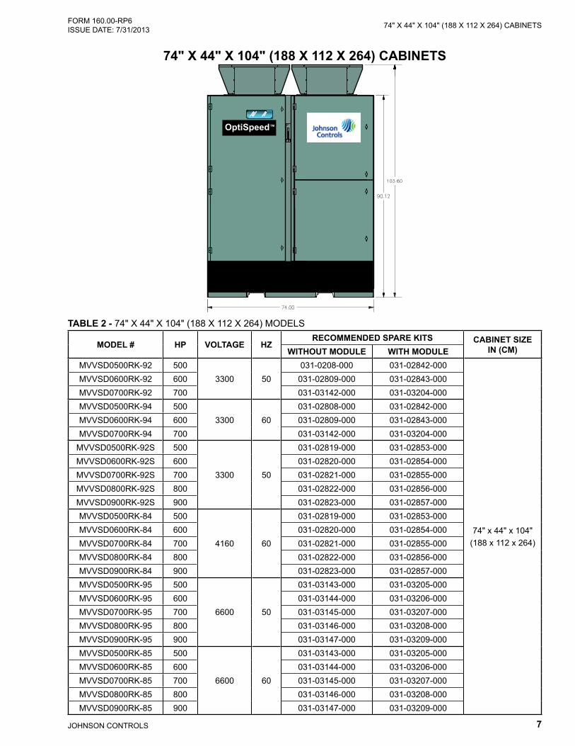
74" X 44" X 104" (188 X 112 X 264) CABINETSFORM 160.00-RP6 ISSUE DATE: 7/31/2013
74" X 44" X 104" (188 X 112 X 264) CABINETS
OptiSpeed™
TABLE 2 - 74" X 44" X 104" (188 X 112 X 264) MODELS
MODEL # HP VOLTAGE HZRECOMMENDED SPARE KITS CABINET SIZE
IN (CM)WITHOUT MODULE WITH MODULEMVVSD0500RK-92 500
3300 50031-0208-000 031-02842-000
74" x 44" x 104" (188 x 112 x 264)
MVVSD0600RK-92 600 031-02809-000 031-02843-000MVVSD0700RK-92 700 031-03142-000 031-03204-000MVVSD0500RK-94 500
3300 60031-02808-000 031-02842-000
MVVSD0600RK-94 600 031-02809-000 031-02843-000MVVSD0700RK-94 700 031-03142-000 031-03204-000
MVVSD0500RK-92S 500
3300 50
031-02819-000 031-02853-000MVVSD0600RK-92S 600 031-02820-000 031-02854-000MVVSD0700RK-92S 700 031-02821-000 031-02855-000MVVSD0800RK-92S 800 031-02822-000 031-02856-000MVVSD0900RK-92S 900 031-02823-000 031-02857-000MVVSD0500RK-84 500
4160 60
031-02819-000 031-02853-000MVVSD0600RK-84 600 031-02820-000 031-02854-000MVVSD0700RK-84 700 031-02821-000 031-02855-000MVVSD0800RK-84 800 031-02822-000 031-02856-000MVVSD0900RK-84 900 031-02823-000 031-02857-000MVVSD0500RK-95 500
6600 50
031-03143-000 031-03205-000MVVSD0600RK-95 600 031-03144-000 031-03206-000MVVSD0700RK-95 700 031-03145-000 031-03207-000MVVSD0800RK-95 800 031-03146-000 031-03208-000MVVSD0900RK-95 900 031-03147-000 031-03209-000MVVSD0500RK-85 500
6600 60
031-03143-000 031-03205-000MVVSD0600RK-85 600 031-03144-000 031-03206-000MVVSD0700RK-85 700 031-03145-000 031-03207-000MVVSD0800RK-85 800 031-03146-000 031-03208-000MVVSD0900RK-85 900 031-03147-000 031-03209-000
JOHNSON CONTROLS8
FORM 160.00-RP6 ISSUE DATE: 7/31/201374" X 44" X 104" (188 X 112 X 264) CABINETS
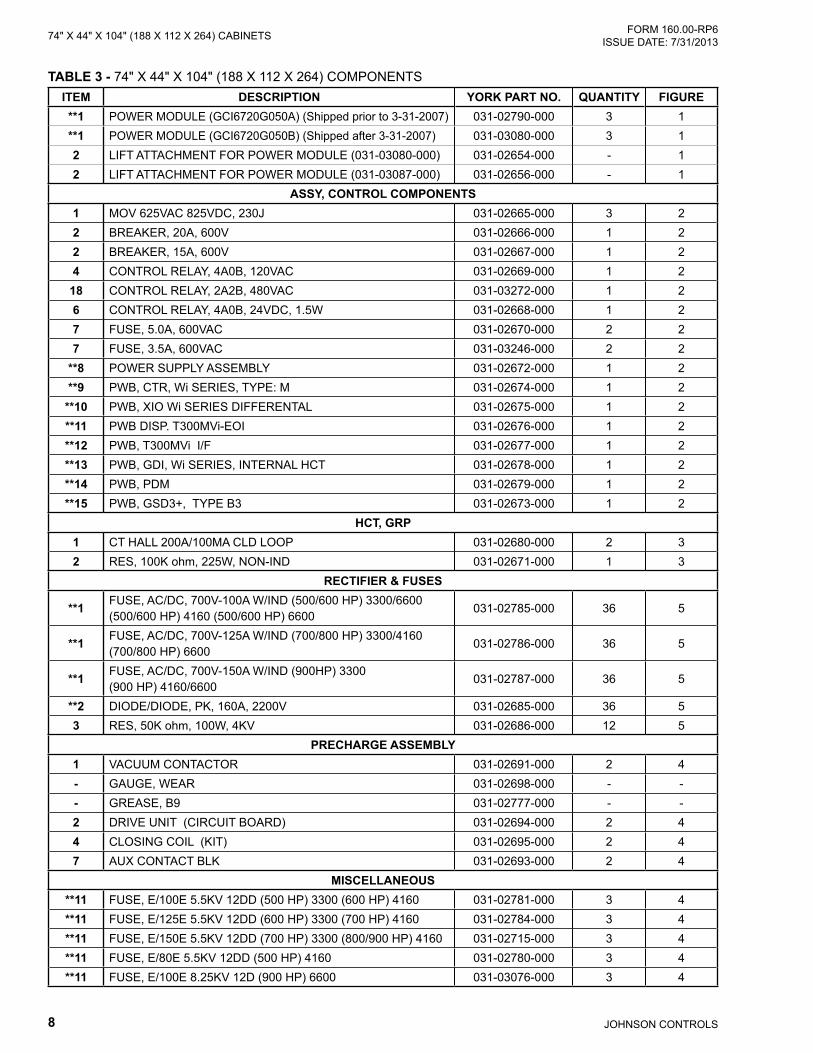
TABLE 3 - 74" X 44" X 104" (188 X 112 X 264) COMPONENTSITEM DESCRIPTION YORK PART NO. QUANTITY FIGURE**1 POWER MODULE (GCI6720G050A) (Shipped prior to 3-31-2007) 031-02790-000 3 1**1 POWER MODULE (GCI6720G050B) (Shipped after 3-31-2007) 031-03080-000 3 12 LIFT ATTACHMENT FOR POWER MODULE (031-03080-000) 031-02654-000 - 12 LIFT ATTACHMENT FOR POWER MODULE (031-03087-000) 031-02656-000 - 1
ASSY, CONTROL COMPONENTS1 MOV 625VAC 825VDC, 230J 031-02665-000 3 22 BREAKER, 20A, 600V 031-02666-000 1 22 BREAKER, 15A, 600V 031-02667-000 1 24 CONTROL RELAY, 4A0B, 120VAC 031-02669-000 1 2
18 CONTROL RELAY, 2A2B, 480VAC 031-03272-000 1 26 CONTROL RELAY, 4A0B, 24VDC, 1.5W 031-02668-000 1 27 FUSE, 5.0A, 600VAC 031-02670-000 2 27 FUSE, 3.5A, 600VAC 031-03246-000 2 2
**8 POWER SUPPLY ASSEMBLY 031-02672-000 1 2**9 PWB, CTR, Wi SERIES, TYPE: M 031-02674-000 1 2
**10 PWB, XIO Wi SERIES DIFFERENTAL 031-02675-000 1 2**11 PWB DISP. T300MVi-EOI 031-02676-000 1 2**12 PWB, T300MVi I/F 031-02677-000 1 2**13 PWB, GDI, Wi SERIES, INTERNAL HCT 031-02678-000 1 2**14 PWB, PDM 031-02679-000 1 2**15 PWB, GSD3+, TYPE B3 031-02673-000 1 2
HCT, GRP1 CT HALL 200A/100MA CLD LOOP 031-02680-000 2 32 RES, 100K ohm, 225W, NON-IND 031-02671-000 1 3
RECTIFIER & FUSES
**1 FUSE, AC/DC, 700V-100A W/IND (500/600 HP) 3300/6600 (500/600 HP) 4160 (500/600 HP) 6600
031-02785-000 36 5
**1 FUSE, AC/DC, 700V-125A W/IND (700/800 HP) 3300/4160 (700/800 HP) 6600
031-02786-000 36 5
**1 FUSE, AC/DC, 700V-150A W/IND (900HP) 3300 (900 HP) 4160/6600
031-02787-000 36 5
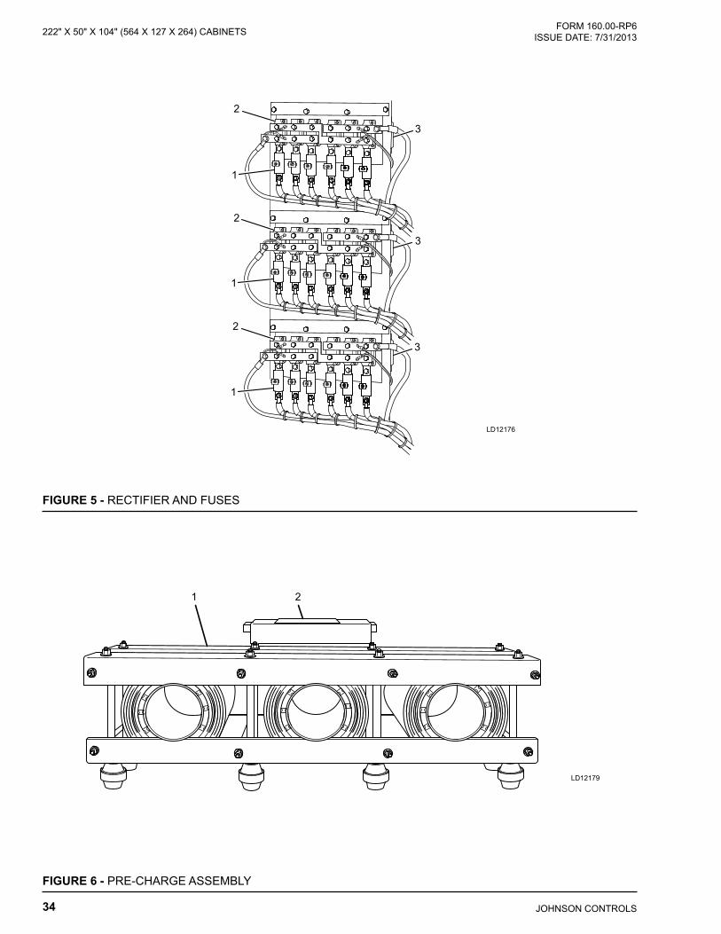
**2 DIODE/DIODE, PK, 160A, 2200V 031-02685-000 36 53 RES, 50K ohm, 100W, 4KV 031-02686-000 12 5
PRECHARGE ASSEMBLY1 VACUUM CONTACTOR 031-02691-000 2 4- GAUGE, WEAR 031-02698-000 - -- GREASE, B9 031-02777-000 - -2 DRIVE UNIT (CIRCUIT BOARD) 031-02694-000 2 44 CLOSING COIL (KIT) 031-02695-000 2 47 AUX CONTACT BLK 031-02693-000 2 4
MISCELLANEOUS**11 FUSE, E/100E 5.5KV 12DD (500 HP) 3300 (600 HP) 4160 031-02781-000 3 4**11 FUSE, E/125E 5.5KV 12DD (600 HP) 3300 (700 HP) 4160 031-02784-000 3 4**11 FUSE, E/150E 5.5KV 12DD (700 HP) 3300 (800/900 HP) 4160 031-02715-000 3 4**11 FUSE, E/80E 5.5KV 12DD (500 HP) 4160 031-02780-000 3 4**11 FUSE, E/100E 8.25KV 12D (900 HP) 6600 031-03076-000 3 4
9JOHNSON CONTROLS
74" X 44" X 104" (188 X 112 X 264) CABINETSFORM 160.00-RP6 ISSUE DATE: 7/31/2013
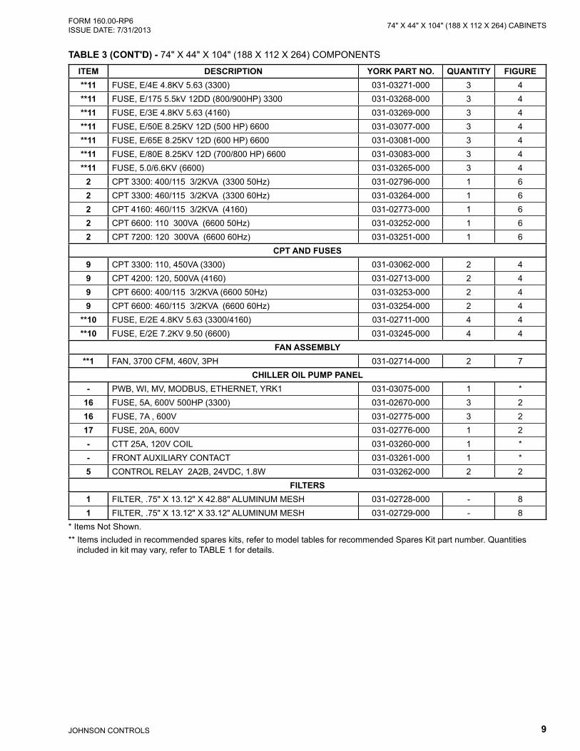
ITEM DESCRIPTION YORK PART NO. QUANTITY FIGURE**11 FUSE, E/4E 4.8KV 5.63 (3300) 031-03271-000 3 4**11 FUSE, E/175 5.5kV 12DD (800/900HP) 3300 031-03268-000 3 4**11 FUSE, E/3E 4.8KV 5.63 (4160) 031-03269-000 3 4**11 FUSE, E/50E 8.25KV 12D (500 HP) 6600 031-03077-000 3 4**11 FUSE, E/65E 8.25KV 12D (600 HP) 6600 031-03081-000 3 4**11 FUSE, E/80E 8.25KV 12D (700/800 HP) 6600 031-03083-000 3 4**11 FUSE, 5.0/6.6KV (6600) 031-03265-000 3 4
2 CPT 3300: 400/115 3/2KVA (3300 50Hz) 031-02796-000 1 62 CPT 3300: 460/115 3/2KVA (3300 60Hz) 031-03264-000 1 62 CPT 4160: 460/115 3/2KVA (4160) 031-02773-000 1 62 CPT 6600: 110 300VA (6600 50Hz) 031-03252-000 1 62 CPT 7200: 120 300VA (6600 60Hz) 031-03251-000 1 6
CPT AND FUSES9 CPT 3300: 110, 450VA (3300) 031-03062-000 2 49 CPT 4200: 120, 500VA (4160) 031-02713-000 2 49 CPT 6600: 400/115 3/2KVA (6600 50Hz) 031-03253-000 2 49 CPT 6600: 460/115 3/2KVA (6600 60Hz) 031-03254-000 2 4
**10 FUSE, E/2E 4.8KV 5.63 (3300/4160) 031-02711-000 4 4**10 FUSE, E/2E 7.2KV 9.50 (6600) 031-03245-000 4 4
FAN ASSEMBLY**1 FAN, 3700 CFM, 460V, 3PH 031-02714-000 2 7
CHILLER OIL PUMP PANEL- PWB, WI, MV, MODBUS, ETHERNET, YRK1 031-03075-000 1 *
16 FUSE, 5A, 600V 500HP (3300) 031-02670-000 3 216 FUSE, 7A , 600V 031-02775-000 3 217 FUSE, 20A, 600V 031-02776-000 1 2- CTT 25A, 120V COIL 031-03260-000 1 *- FRONT AUXILIARY CONTACT 031-03261-000 1 *5 CONTROL RELAY 2A2B, 24VDC, 1.8W 031-03262-000 2 2
FILTERS1 FILTER, .75" X 13.12" X 42.88" ALUMINUM MESH 031-02728-000 - 81 FILTER, .75" X 13.12" X 33.12" ALUMINUM MESH 031-02729-000 - 8
* Items Not Shown.** Items included in recommended spares kits, refer to model tables for recommended Spares Kit part number. Quantities
included in kit may vary, refer to TABLE 1 for details.
TABLE 3 (CONT'D) - 74" X 44" X 104" (188 X 112 X 264) COMPONENTS

JOHNSON CONTROLS10
FORM 160.00-RP6 ISSUE DATE: 7/31/201374" X 44" X 104" (188 X 112 X 264) CABINETS
THIS PAGE INTENTIONALLY LEFT BLANK

11JOHNSON CONTROLS
122" X 44" X 104" (310 X 112 X 264) CABINETSFORM 160.00-RP6 ISSUE DATE: 7/31/2013
122" X 44" X 104" (310 X 112 X 264) CABINETS
OptiSpeed™
TABLE 4 - 122" X 44" X 104" (310 X 112 X 264) MODELS
MODEL # HP VOLTAGE HZRECOMMENDED SPARE KITS CABINET SIZE
IN (CM)WITHOUT MODULE WITH MODULEMVVSD0500RK-80 500
2300 60
031-02797-000 031-02831-000
122" x 44" x 104"(310 x 112 x 264)
MVVSD0600RK-80 600 031-02798-000 031-02832-000MVVSD0700RK-80 700 031-03141-000 031-03203-000MVVSD0800RK-80 800 031-02799-000 031-02833-000MVVSD0900RK-80 900 031-02800-000 031-02834-000MVVSD1000RK-80 1000 031-02801-000 031-02835-000MVVSD0800RK-92 800
3300 50
031-02810-000 031-02844-000MVVSD0900RK-92 900 031-02811-000 031-02845-000MVVSD1000RK-92 1000 031-02812-000 031-02846-000MVVSD1250RK-92 1250 031-02813-000 031-02847-000MVVSD1500RK-92 1500 031-02814-000 031-02848-000
MVVSD1000RK-92S 1000
3300 50
031-02824-000 031-02858-000MVVSD1250RK-92S 1250 031-02825-000 031-02859-000MVVSD1500RK-92S 1500 031-02826-000 031-02860-000MVVSD1750RK-92S 1750 031-02827-000 031-02861-000MVVSD2000RK-92S 2000 031-02828-000 031-02862-000MVVSD0800RK-94 800
3300 60
031-02810-000 031-02844-000MVVSD0900RK-94 900 031-02811-000 031-02845-000MVVSD1000RK-94 1000 031-02812-000 031-02846-000MVVSD1250RK-94 1250 031-02813-000 031-02847-000MVVSD1500RK-94 1500 031-02814-000 031-02848-000
JOHNSON CONTROLS12
FORM 160.00-RP6 ISSUE DATE: 7/31/2013122" X 44" X 104" (310 X 112 X 264) CABINETS
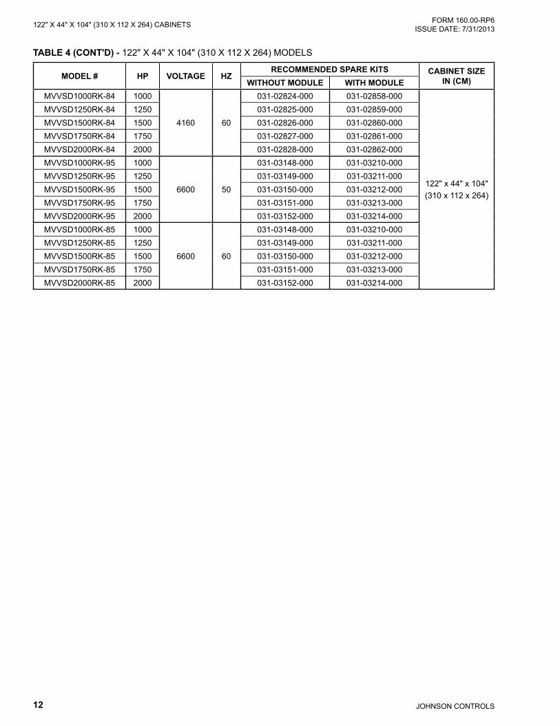
MODEL # HP VOLTAGE HZRECOMMENDED SPARE KITS CABINET SIZE
IN (CM)WITHOUT MODULE WITH MODULEMVVSD1000RK-84 1000
4160 60
031-02824-000 031-02858-000
122" x 44" x 104"(310 x 112 x 264)
MVVSD1250RK-84 1250 031-02825-000 031-02859-000MVVSD1500RK-84 1500 031-02826-000 031-02860-000MVVSD1750RK-84 1750 031-02827-000 031-02861-000MVVSD2000RK-84 2000 031-02828-000 031-02862-000MVVSD1000RK-95 1000
6600 50
031-03148-000 031-03210-000MVVSD1250RK-95 1250 031-03149-000 031-03211-000MVVSD1500RK-95 1500 031-03150-000 031-03212-000MVVSD1750RK-95 1750 031-03151-000 031-03213-000MVVSD2000RK-95 2000 031-03152-000 031-03214-000MVVSD1000RK-85 1000
6600 60
031-03148-000 031-03210-000MVVSD1250RK-85 1250 031-03149-000 031-03211-000MVVSD1500RK-85 1500 031-03150-000 031-03212-000MVVSD1750RK-85 1750 031-03151-000 031-03213-000MVVSD2000RK-85 2000 031-03152-000 031-03214-000
TABLE 4 (CONT'D) - 122" X 44" X 104" (310 X 112 X 264) MODELS
13JOHNSON CONTROLS
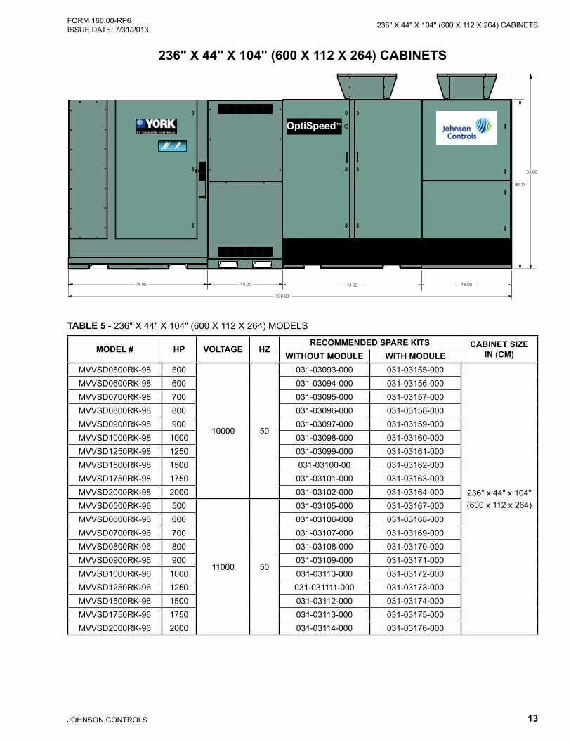
236" X 44" X 104" (600 X 112 X 264) CABINETSFORM 160.00-RP6 ISSUE DATE: 7/31/2013
TABLE 5 - 236" X 44" X 104" (600 X 112 X 264) MODELS
MODEL # HP VOLTAGE HZRECOMMENDED SPARE KITS CABINET SIZE
IN (CM)WITHOUT MODULE WITH MODULEMVVSD0500RK-98 500
10000 50
031-03093-000 031-03155-000
236" x 44" x 104" (600 x 112 x 264)
MVVSD0600RK-98 600 031-03094-000 031-03156-000MVVSD0700RK-98 700 031-03095-000 031-03157-000MVVSD0800RK-98 800 031-03096-000 031-03158-000MVVSD0900RK-98 900 031-03097-000 031-03159-000MVVSD1000RK-98 1000 031-03098-000 031-03160-000MVVSD1250RK-98 1250 031-03099-000 031-03161-000MVVSD1500RK-98 1500 031-03100-00 031-03162-000MVVSD1750RK-98 1750 031-03101-000 031-03163-000MVVSD2000RK-98 2000 031-03102-000 031-03164-000MVVSD0500RK-96 500
11000 50
031-03105-000 031-03167-000MVVSD0600RK-96 600 031-03106-000 031-03168-000MVVSD0700RK-96 700 031-03107-000 031-03169-000MVVSD0800RK-96 800 031-03108-000 031-03170-000MVVSD0900RK-96 900 031-03109-000 031-03171-000MVVSD1000RK-96 1000 031-03110-000 031-03172-000MVVSD1250RK-96 1250 031-031111-000 031-03173-000MVVSD1500RK-96 1500 031-03112-000 031-03174-000MVVSD1750RK-96 1750 031-03113-000 031-03175-000MVVSD2000RK-96 2000 031-03114-000 031-03176-000
OptiSpeed™
236" X 44" X 104" (600 X 112 X 264) CABINETS
JOHNSON CONTROLS14
FORM 160.00-RP6 ISSUE DATE: 7/31/2013122" X 44" X 104" (310 X 112 X 264) CABINETS
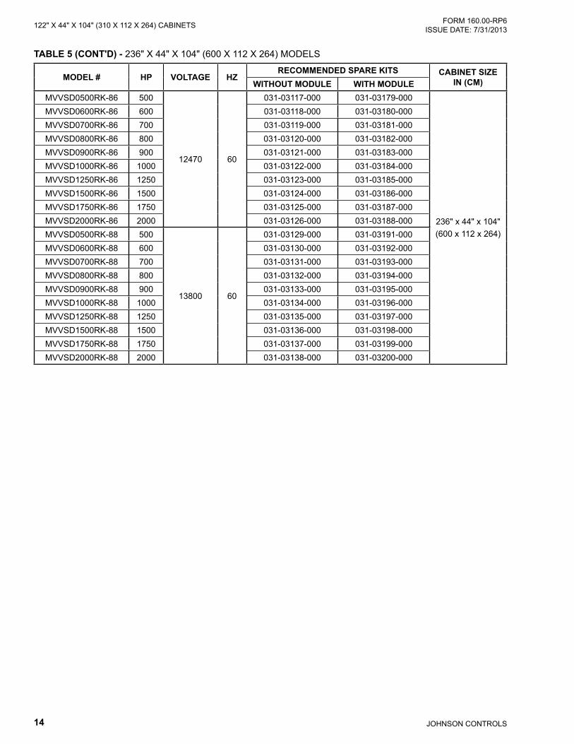
MODEL # HP VOLTAGE HZRECOMMENDED SPARE KITS CABINET SIZE
IN (CM)WITHOUT MODULE WITH MODULEMVVSD0500RK-86 500
12470 60
031-03117-000 031-03179-000
236" x 44" x 104" (600 x 112 x 264)
MVVSD0600RK-86 600 031-03118-000 031-03180-000MVVSD0700RK-86 700 031-03119-000 031-03181-000MVVSD0800RK-86 800 031-03120-000 031-03182-000MVVSD0900RK-86 900 031-03121-000 031-03183-000MVVSD1000RK-86 1000 031-03122-000 031-03184-000MVVSD1250RK-86 1250 031-03123-000 031-03185-000MVVSD1500RK-86 1500 031-03124-000 031-03186-000MVVSD1750RK-86 1750 031-03125-000 031-03187-000MVVSD2000RK-86 2000 031-03126-000 031-03188-000MVVSD0500RK-88 500
13800 60
031-03129-000 031-03191-000MVVSD0600RK-88 600 031-03130-000 031-03192-000MVVSD0700RK-88 700 031-03131-000 031-03193-000MVVSD0800RK-88 800 031-03132-000 031-03194-000MVVSD0900RK-88 900 031-03133-000 031-03195-000MVVSD1000RK-88 1000 031-03134-000 031-03196-000MVVSD1250RK-88 1250 031-03135-000 031-03197-000MVVSD1500RK-88 1500 031-03136-000 031-03198-000MVVSD1750RK-88 1750 031-03137-000 031-03199-000MVVSD2000RK-88 2000 031-03138-000 031-03200-000
TABLE 5 (CONT'D) - 236" X 44" X 104" (600 X 112 X 264) MODELS
15JOHNSON CONTROLS
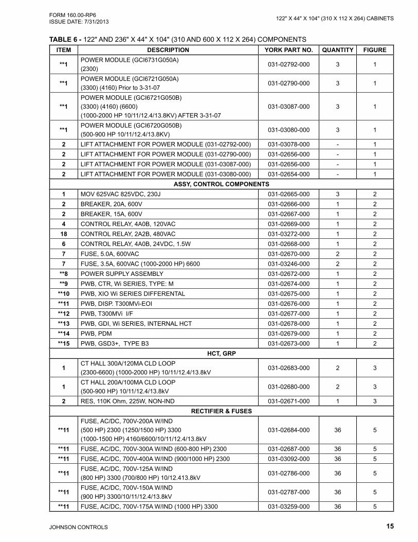
122" X 44" X 104" (310 X 112 X 264) CABINETSFORM 160.00-RP6 ISSUE DATE: 7/31/2013
TABLE 6 - 122" AND 236" X 44" X 104" (310 AND 600 X 112 X 264) COMPONENTSITEM DESCRIPTION YORK PART NO. QUANTITY FIGURE
**1POWER MODULE (GCI6731G050A) (2300)
031-02792-000 3 1
**1POWER MODULE (GCI6721G050A)(3300) (4160) Prior to 3-31-07
031-02790-000 3 1
**1POWER MODULE (GCI6721G050B)(3300) (4160) (6600) (1000-2000 HP 10/11/12.4/13.8KV) AFTER 3-31-07
031-03087-000 3 1
**1POWER MODULE (GCI6720G050B)(500-900 HP 10/11/12.4/13.8KV)
031-03080-000 3 1
2 LIFT ATTACHMENT FOR POWER MODULE (031-02792-000) 031-03078-000 - 12 LIFT ATTACHMENT FOR POWER MODULE (031-02790-000) 031-02656-000 - 12 LIFT ATTACHMENT FOR POWER MODULE (031-03087-000) 031-02656-000 - 12 LIFT ATTACHMENT FOR POWER MODULE (031-03080-000) 031-02654-000 - 1
ASSY, CONTROL COMPONENTS1 MOV 625VAC 825VDC, 230J 031-02665-000 3 22 BREAKER, 20A, 600V 031-02666-000 1 22 BREAKER, 15A, 600V 031-02667-000 1 24 CONTROL RELAY, 4A0B, 120VAC 031-02669-000 1 2
18 CONTROL RELAY, 2A2B, 480VAC 031-03272-000 1 26 CONTROL RELAY, 4A0B, 24VDC, 1.5W 031-02668-000 1 27 FUSE, 5.0A, 600VAC 031-02670-000 2 27 FUSE, 3.5A, 600VAC (1000-2000 HP) 6600 031-03246-000 2 2
**8 POWER SUPPLY ASSEMBLY 031-02672-000 1 2**9 PWB, CTR, Wi SERIES, TYPE: M 031-02674-000 1 2
**10 PWB, XIO Wi SERIES DIFFERENTAL 031-02675-000 1 2**11 PWB, DISP. T300MVi-EOI 031-02676-000 1 2**12 PWB, T300MVi I/F 031-02677-000 1 2**13 PWB, GDI, Wi SERIES, INTERNAL HCT 031-02678-000 1 2**14 PWB, PDM 031-02679-000 1 2**15 PWB, GSD3+, TYPE B3 031-02673-000 1 2
HCT, GRP
1CT HALL 300A/120MA CLD LOOP (2300-6600) (1000-2000 HP) 10/11/12.4/13.8kV
031-02683-000 2 3
1CT HALL 200A/100MA CLD LOOP (500-900 HP) 10/11/12.4/13.8kV
031-02680-000 2 3
2 RES, 110K Ohm, 225W, NON-IND 031-02671-000 1 3RECTIFIER & FUSES
**11FUSE, AC/DC, 700V-200A W/IND (500 HP) 2300 (1250/1500 HP) 3300 (1000-1500 HP) 4160/6600/10/11/12.4/13.8kV
031-02684-000 36 5
**11 FUSE, AC/DC, 700V-300A W/IND (600-800 HP) 2300 031-02687-000 36 5**11 FUSE, AC/DC, 700V-400A W/IND (900/1000 HP) 2300 031-03092-000 36 5
**11FUSE, AC/DC, 700V-125A W/IND (800 HP) 3300 (700/800 HP) 10/12.413.8kV
031-02786-000 36 5
**11FUSE, AC/DC, 700V-150A W/IND (900 HP) 3300/10/11/12.4/13.8kV
031-02787-000 36 5
**11 FUSE, AC/DC, 700V-175A W/IND (1000 HP) 3300 031-03259-000 36 5
JOHNSON CONTROLS16
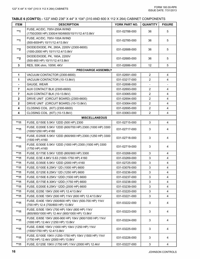
FORM 160.00-RP6 ISSUE DATE: 7/31/2013122" X 44" X 104" (310 X 112 X 264) CABINETS
ITEM DESCRIPTION YORK PART NO. QUANTITY FIGURE
**1FUSE, AC/DC, 700V-250A W/IND (1750/2000 HP) 3300/4160/6600/10/11/12.4/13.8kV
031-02788-000 36 5
**1FUSE, AC/DC, 700V-100A W/IND (500-600HP) 10/11/12.4/13.8kV
031-02785-000 36 5
**2DIODE/DIODE, PK, 260A, 2200V (2300-6600) (1000-2000 HP) 10/11/12.4/13.8kV
031-02688-000 36 5
**2DIODE/DIODE, PK, 160A, 2200V (500-900 HP) 10/11/12.4/13.8kV
031-02685-000 36 5
3 RES, 50K ohm, 100W, 4KV 031-02686-000 12 5PRECHARGE ASSEMBLY
1 VACUUM CONTACTOR (2300-6600) 031-02691-000 2 41 VACUUM CONTACTOR (10-13.8kV) 031-03217-000 2 4- GAUGE, WEAR 031-02698-000 - -7 AUX CONTACT BLK (2300-6600) 031-02693-000 2 47 AUX CONTACT BLK (10-13.8kV) 031-03065-000 2 42 DRIVE UNIT (CIRCUIT BOARD) (2300-6600) 031-02694-000 2 42 DRIVE UNIT (CIRCUIT BOARD) (10-13.8kV) 031-03064-000 2 44 CLOSING COIL (KIT) (2300-6600) 031-02695-000 2 44 CLOSING COIL (KIT) (10-13.8kV) 031-03063-000 2 4
MISCELLANEOUS**11 FUSE, E/150E 5.5KV 12DD (500 HP) 2300 031-02715-000 3 4
**11 FUSE, E/200E 5.5KV 12DD (600/700 HP) 2300 (1000 HP) 3300 (1000/1250 HP) 4160
031-02717-000 3 4
**11 FUSE, E/250E 5.5KV 12DD (800/900 HP) 2300 (1250 HP) 3300 (1500 HP) 4160
031-02718-000 3 4
**11 FUSE, E/300E 5.5KV 12DD (1000 HP) 2300 (1500 HP) 3300 (1750 HP) 4160
031-02719-000 3 4
**11 FUSE, E/175E 5.5KV 12DD (800/900 HP) 3300 031-03268-000 3 4**11 FUSE, E/3E 4.8KV 5.63 (1000-1750 HP) 4160 031-03269-000 3 4**11 FUSE, E/350E 5.5KV 12DD (2000 HP) 4160 031-02725-000 3 4**11 FUSE, E/100E 8.25KV 12D (1000 HP) 6600 031-03076-000 3 4**11 FUSE, E/125E 8.25KV 12D (1250 HP) 6600 031-03236-000 3 4**11 FUSE, E/150E 8.25KV 12DD (1500 HP) 6600 031-03237-000 3 4**11 FUSE, E/175E 8.30KV 12DD (1750 HP) 6600 031-03238-000 3 4**11 FUSE, E/200E 8.25KV 12DD (2000 HP) 6600 031-03239-000 3 4**11 FUSE, E/25E 15KV (500 HP) 12.4/13.8kV 031-03220-000 3 4**11 FUSE, E/30E 15KV (500 HP) 11kV (600 HP) 12.4/13.8kV 031-03221-000 3 4
**11 FUSE, E/40E 15KV (500/600 HP) 10kV (500-700 HP) 11kV (700 HP) 12.4 (700/800 HP) 13.8kV
031-03222-000 3 4
**11 FUSE, E/50E 15KV (700 HP) 10kV (800 HP) 11kV (800/900/1000 HP) 12.4kV (900/1000 HP) 13.8kV
031-03223-000 3 4
**11 FUSE, E/65E 15KV (800-900 HP) 10kV (900/1000 HP) 11kV (1000 HP) 12.4kV (1250 HP) 13.8kV
031-03224-000 3 4
**11 FUSE, E/80E 15KV (1000 HP) 10kV (1250 HP) 11kV (1500/1750 HP) 12.4/13.8kV
031-03225-000 3 4
**11 FUSE, E/100E 15KV (1250-1750 HP) 10kV (1500 HP) 11kV (1750 HP) 12.4kV (2000 HP) 13.8kV
031-03226-000 3 4
**11 FUSE, E/125E 15KV (1750 HP) 11kV (2000 HP) 12.4kV 031-03227-000 3 4
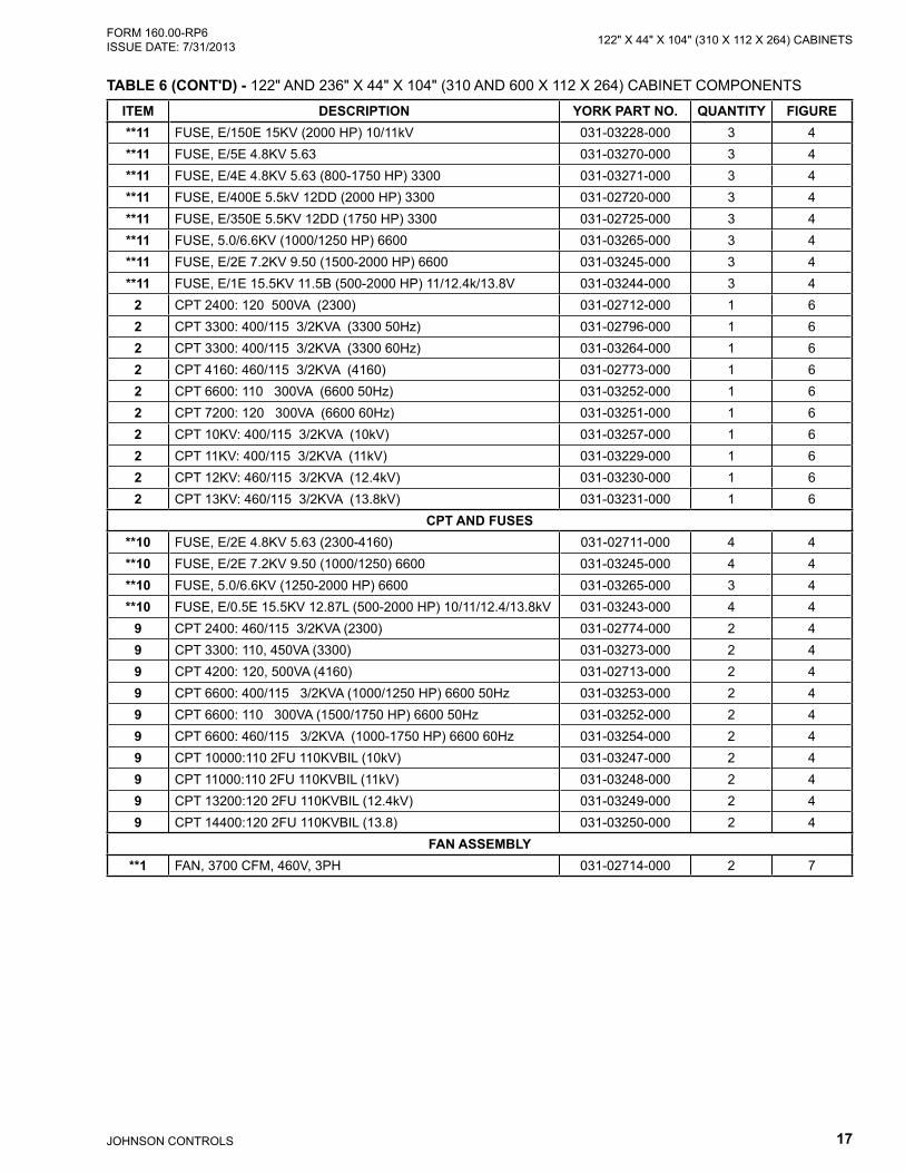
TABLE 6 (CONT'D) - 122" AND 236" X 44" X 104" (310 AND 600 X 112 X 264) CABINET COMPONENTS
17JOHNSON CONTROLS
122" X 44" X 104" (310 X 112 X 264) CABINETSFORM 160.00-RP6 ISSUE DATE: 7/31/2013
ITEM DESCRIPTION YORK PART NO. QUANTITY FIGURE**11 FUSE, E/150E 15KV (2000 HP) 10/11kV 031-03228-000 3 4**11 FUSE, E/5E 4.8KV 5.63 031-03270-000 3 4**11 FUSE, E/4E 4.8KV 5.63 (800-1750 HP) 3300 031-03271-000 3 4**11 FUSE, E/400E 5.5kV 12DD (2000 HP) 3300 031-02720-000 3 4**11 FUSE, E/350E 5.5KV 12DD (1750 HP) 3300 031-02725-000 3 4**11 FUSE, 5.0/6.6KV (1000/1250 HP) 6600 031-03265-000 3 4**11 FUSE, E/2E 7.2KV 9.50 (1500-2000 HP) 6600 031-03245-000 3 4**11 FUSE, E/1E 15.5KV 11.5B (500-2000 HP) 11/12.4k/13.8V 031-03244-000 3 4
2 CPT 2400: 120 500VA (2300) 031-02712-000 1 62 CPT 3300: 400/115 3/2KVA (3300 50Hz) 031-02796-000 1 62 CPT 3300: 400/115 3/2KVA (3300 60Hz) 031-03264-000 1 62 CPT 4160: 460/115 3/2KVA (4160) 031-02773-000 1 62 CPT 6600: 110 300VA (6600 50Hz) 031-03252-000 1 62 CPT 7200: 120 300VA (6600 60Hz) 031-03251-000 1 62 CPT 10KV: 400/115 3/2KVA (10kV) 031-03257-000 1 62 CPT 11KV: 400/115 3/2KVA (11kV) 031-03229-000 1 62 CPT 12KV: 460/115 3/2KVA (12.4kV) 031-03230-000 1 62 CPT 13KV: 460/115 3/2KVA (13.8kV) 031-03231-000 1 6
CPT AND FUSES**10 FUSE, E/2E 4.8KV 5.63 (2300-4160) 031-02711-000 4 4**10 FUSE, E/2E 7.2KV 9.50 (1000/1250) 6600 031-03245-000 4 4**10 FUSE, 5.0/6.6KV (1250-2000 HP) 6600 031-03265-000 3 4**10 FUSE, E/0.5E 15.5KV 12.87L (500-2000 HP) 10/11/12.4/13.8kV 031-03243-000 4 4
9 CPT 2400: 460/115 3/2KVA (2300) 031-02774-000 2 49 CPT 3300: 110, 450VA (3300) 031-03273-000 2 49 CPT 4200: 120, 500VA (4160) 031-02713-000 2 49 CPT 6600: 400/115 3/2KVA (1000/1250 HP) 6600 50Hz 031-03253-000 2 49 CPT 6600: 110 300VA (1500/1750 HP) 6600 50Hz 031-03252-000 2 49 CPT 6600: 460/115 3/2KVA (1000-1750 HP) 6600 60Hz 031-03254-000 2 49 CPT 10000:110 2FU 110KVBIL (10kV) 031-03247-000 2 49 CPT 11000:110 2FU 110KVBIL (11kV) 031-03248-000 2 49 CPT 13200:120 2FU 110KVBIL (12.4kV) 031-03249-000 2 49 CPT 14400:120 2FU 110KVBIL (13.8) 031-03250-000 2 4
FAN ASSEMBLY**1 FAN, 3700 CFM, 460V, 3PH 031-02714-000 2 7
TABLE 6 (CONT'D) - 122" AND 236" X 44" X 104" (310 AND 600 X 112 X 264) CABINET COMPONENTS

JOHNSON CONTROLS18
FORM 160.00-RP6 ISSUE DATE: 7/31/2013122" X 44" X 104" (310 X 112 X 264) CABINETS
ITEM DESCRIPTION YORK PART NO. QUANTITY FIGURECHILLER OIL PUMP PANEL
- PWB, Wi, MV, MODBUS, ETHERNET, YRK1 031-03075-000 1 *16 FUSE, 5A , 600V 031-02670-000 3 216 FUSE, 7A , 600V 031-02775-000 3 217 FUSE, 20A, 600V 031-02776-000 1 2- CTT 25A, 120V COIL 031-03260-000 1 *- FRONT AUX. CONTACT 031-03261-000 1 *5 CONTROL RELAY 2A2B, 24VDC, 1.8W 031-03262-000 2 2
FILTERS1 FILTER, .75" X 13.12" X 42.88" ALUMINUM MESH 031-02728-000 - 81 FILTER, .75" X 29.5" X 24" ALUMINUM MESH 031-03413-000 - 81 FILTER, .75" X 13.12" X 33.12" ALUMINUM MESH 031-02729-000 - 8
* Items Not Shown.** Items included in recommended spares kits, refer to model tables for recommended Spares Kit part number. Quantities
included in kit may vary, refer to TABLE 1 for details.
TABLE 6 (CONT'D) - 122" AND 236" X 44" X 104" (310 AND 600 X 112 X 264) CABINET COMPONENTS
19JOHNSON CONTROLS
164" X 50" X 104" (417 X 127 X 264) CABINETSFORM 160.00-RP6 ISSUE DATE: 7/31/2013
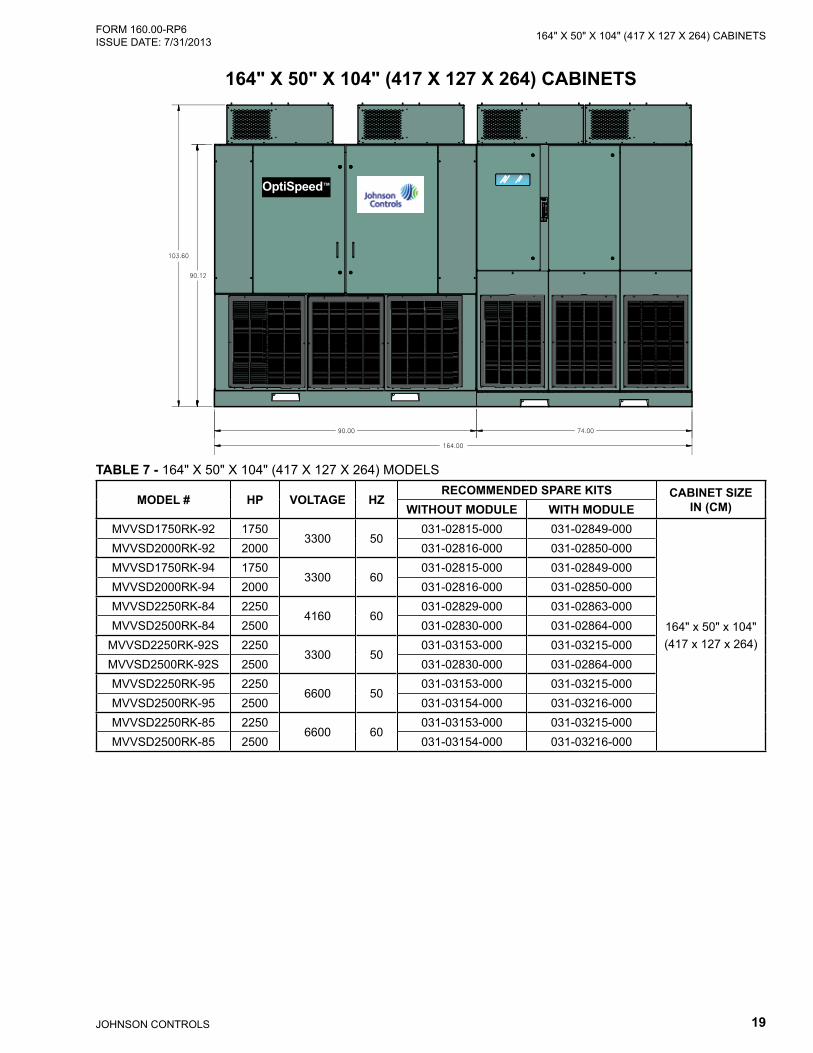
164" X 50" X 104" (417 X 127 X 264) CABINETS
OptiSpeed™
TABLE 7 - 164" X 50" X 104" (417 X 127 X 264) MODELS
MODEL # HP VOLTAGE HZRECOMMENDED SPARE KITS CABINET SIZE
IN (CM)WITHOUT MODULE WITH MODULEMVVSD1750RK-92 1750
3300 50031-02815-000 031-02849-000
164" x 50" x 104" (417 x 127 x 264)
MVVSD2000RK-92 2000 031-02816-000 031-02850-000MVVSD1750RK-94 1750
3300 60031-02815-000 031-02849-000
MVVSD2000RK-94 2000 031-02816-000 031-02850-000MVVSD2250RK-84 2250
4160 60031-02829-000 031-02863-000
MVVSD2500RK-84 2500 031-02830-000 031-02864-000MVVSD2250RK-92S 2250
3300 50031-03153-000 031-03215-000
MVVSD2500RK-92S 2500 031-02830-000 031-02864-000MVVSD2250RK-95 2250
6600 50031-03153-000 031-03215-000
MVVSD2500RK-95 2500 031-03154-000 031-03216-000MVVSD2250RK-85 2250
6600 60031-03153-000 031-03215-000
MVVSD2500RK-85 2500 031-03154-000 031-03216-000

JOHNSON CONTROLS20
FORM 160.00-RP6 ISSUE DATE: 7/31/2013164" X 50" X 104" (417 X 127 X 264) CABINETS
THIS PAGE INTENTIONALLY LEFT BLANK

21JOHNSON CONTROLS
278" X 50" X 104" (706 X 127 X 264) CABINETSFORM 160.00-RP6 ISSUE DATE: 7/31/2013
TABLE 8 - 278 X 50" X 104" (706 X 127 X 264) MODELS
MODEL # HP VOLTAGE HZRECOMMENDED SPARE KITS CABINET SIZE
IN (CM)WITHOUT MODULE WITH MODULEMVVSD2250RK-98 2250 10000
50031-03103-000 031-03165-000
278" x 50" x 104" (706 x 127 x 264)
MVVSD2500RK-98 2500 10000 031-03104-000 031-03166-000MVVSD2250RK-96 2250 11000
50031-03115-000 031-03177-000
MVVSD2500RK-96 2500 11000 031-03116-000 031-03178-000MVVSD2250RK-86 2250 12470
60031-03127-000 031-03189-000
MVVSD2500RK-86 2500 12470 031-03128-000 031-03190-000MVVSD2250RK-88 2250 13800
60031-03139-000 031-03201-000
MVVSD2500RK-88 2500 13800 031-03140-000 031-03202-000
OptiSpeed™
278" X 50" X 104" (706 X 127 X 264) CABINETS
JOHNSON CONTROLS22
FORM 160.00-RP6 ISSUE DATE: 7/31/2013278" X 50" X 104" (706 X 127 X 264) CABINETS
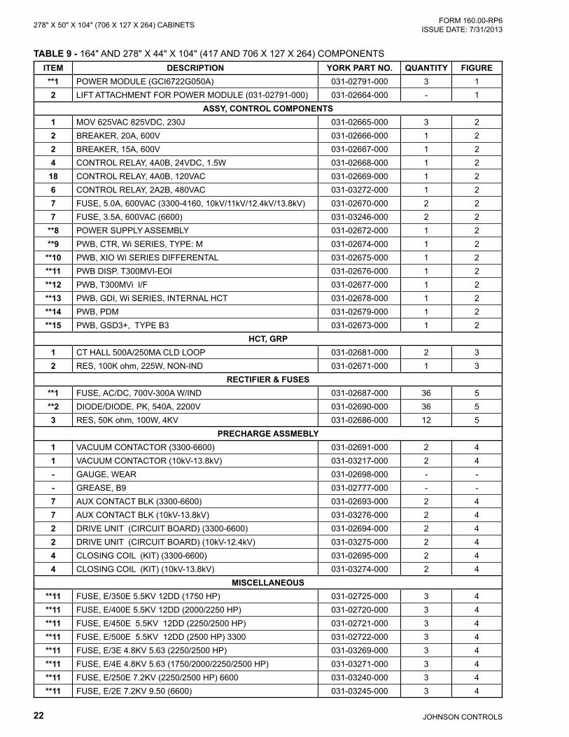
TABLE 9 - 164" AND 278" X 44" X 104" (417 AND 706 X 127 X 264) COMPONENTSITEM DESCRIPTION YORK PART NO. QUANTITY FIGURE**1 POWER MODULE (GCI6722G050A) 031-02791-000 3 12 LIFT ATTACHMENT FOR POWER MODULE (031-02791-000) 031-02664-000 - 1
ASSY, CONTROL COMPONENTS1 MOV 625VAC 825VDC, 230J 031-02665-000 3 22 BREAKER, 20A, 600V 031-02666-000 1 22 BREAKER, 15A, 600V 031-02667-000 1 24 CONTROL RELAY, 4A0B, 24VDC, 1.5W 031-02668-000 1 2
18 CONTROL RELAY, 4A0B, 120VAC 031-02669-000 1 26 CONTROL RELAY, 2A2B, 480VAC 031-03272-000 1 27 FUSE, 5.0A, 600VAC (3300-4160, 10kV/11kV/12.4kV/13.8kV) 031-02670-000 2 27 FUSE, 3.5A, 600VAC (6600) 031-03246-000 2 2
**8 POWER SUPPLY ASSEMBLY 031-02672-000 1 2**9 PWB, CTR, Wi SERIES, TYPE: M 031-02674-000 1 2
**10 PWB, XIO Wi SERIES DIFFERENTAL 031-02675-000 1 2**11 PWB DISP. T300MVI-EOI 031-02676-000 1 2**12 PWB, T300MVi I/F 031-02677-000 1 2**13 PWB, GDI, Wi SERIES, INTERNAL HCT 031-02678-000 1 2**14 PWB, PDM 031-02679-000 1 2**15 PWB, GSD3+, TYPE B3 031-02673-000 1 2
HCT, GRP1 CT HALL 500A/250MA CLD LOOP 031-02681-000 2 32 RES, 100K ohm, 225W, NON-IND 031-02671-000 1 3
RECTIFIER & FUSES**1 FUSE, AC/DC, 700V-300A W/IND 031-02687-000 36 5**2 DIODE/DIODE, PK, 540A, 2200V 031-02690-000 36 53 RES, 50K ohm, 100W, 4KV 031-02686-000 12 5
PRECHARGE ASSMEBLY1 VACUUM CONTACTOR (3300-6600) 031-02691-000 2 41 VACUUM CONTACTOR (10kV-13.8kV) 031-03217-000 2 4- GAUGE, WEAR 031-02698-000 - -- GREASE, B9 031-02777-000 - -7 AUX CONTACT BLK (3300-6600) 031-02693-000 2 47 AUX CONTACT BLK (10kV-13.8kV) 031-03276-000 2 42 DRIVE UNIT (CIRCUIT BOARD) (3300-6600) 031-02694-000 2 42 DRIVE UNIT (CIRCUIT BOARD) (10kV-12.4kV) 031-03275-000 2 44 CLOSING COIL (KIT) (3300-6600) 031-02695-000 2 44 CLOSING COIL (KIT) (10kV-13.8kV) 031-03274-000 2 4
MISCELLANEOUS**11 FUSE, E/350E 5.5KV 12DD (1750 HP) 031-02725-000 3 4**11 FUSE, E/400E 5.5KV 12DD (2000/2250 HP) 031-02720-000 3 4**11 FUSE, E/450E 5.5KV 12DD (2250/2500 HP) 031-02721-000 3 4**11 FUSE, E/500E 5.5KV 12DD (2500 HP) 3300 031-02722-000 3 4**11 FUSE, E/3E 4.8KV 5.63 (2250/2500 HP) 031-03269-000 3 4**11 FUSE, E/4E 4.8KV 5.63 (1750/2000/2250/2500 HP) 031-03271-000 3 4**11 FUSE, E/250E 7.2KV (2250/2500 HP) 6600 031-03240-000 3 4**11 FUSE, E/2E 7.2KV 9.50 (6600) 031-03245-000 3 4
23JOHNSON CONTROLS
278" X 50" X 104" (706 X 127 X 264) CABINETSFORM 160.00-RP6 ISSUE DATE: 7/31/2013
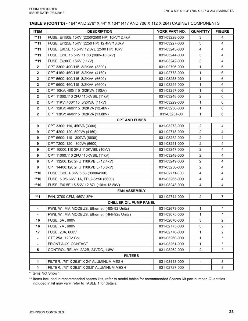
ITEM DESCRIPTION YORK PART NO. QUANTITY FIGURE**11 FUSE, E/150E 15KV (2250/2500 HP) 10kV/12.4kV 031-03228-000 3 4**11 FUSE, E/125E 15KV (2250 HP) 12.4kV/13.8kV 031-03227-000 3 4**11 FUSE, E/0.5E 15.5KV 12.87L (2500 HP) 10kV 031-03243-000 4 4**11 FUSE, E/1E 15.5KV 11.5B (10kV-13.8kV) 031-03244-000 3 4**11 FUSE, E/200E 15KV (11kV) 031-03242-000 3 4
2 CPT 3300: 400/115 3/2KVA (3300) 031-02796-000 1 62 CPT 4160: 460/115 3/2KVA (4160) 031-02773-000 1 62 CPT 6600: 400/115 3/2KVA (6600) 031-03253-000 1 62 CPT 6600: 460/115 3/2KVA (6600) 031-03254-000 1 62 CPT 10KV: 400/115 3/2KVA (10kV) 031-03257-000 1 62 CPT 11000:110 2FU 110KVBIL (11kV) 031-03248-000 2 62 CPT 11KV: 400/115 3/2KVA (11kV) 031-03229-000 1 62 CPT 12KV: 460/115 3/2KVA (12.4kV) 031-03230-000 1 62 CPT 13KV: 460/115 3/2KVA (13.8kV) 031-03231-00 1 6
CPT AND FUSES9 CPT 3300: 110, 450VA (3300) 031-03273-000 2 49 CPT 4200: 120, 500VA (4160) 031-02713-000 2 49 CPT 6600: 110 300VA (6600) 031-03252-000 2 49 CPT 7200: 120 300VA (6600) 031-03251-000 2 49 CPT 10000:110 2FU 110KVBIL (10kV) 031-03247-000 2 49 CPT 11000:110 2FU 110KVBIL (11kV) 031-03248-000 2 49 CPT 13200:120 2FU 110KVBIL (12.4kV) 031-03249-000 2 49 CPT 14400:120 2FU 110KVBIL (13.8kV) 031-03250-000 2 4
**10 FUSE, E/2E 4.8KV 5.63 (3300/4160) 031-02711-000 4 4**10 FUSE, 5.0/6.6KV, 1A, FPJ2-6Y50 (6600) 031-03265-000 4 4**10 FUSE, E/0.5E 15.5KV 12.87L (10kV-13.8kV) 031-03243-000 4 4
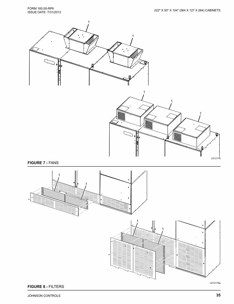
FAN ASSEMBLY**1 FAN, 3700 CFM, 460V, 3PH 031-02714-000 2 7
CHILLER OIL PUMP PANEL- PWB, Wi, MV, MODBUS, Ethernet, (-80/-92 Units) 031-02673-000 1 *- PWB, Wi, MV, MODBUS, Ethernet, (-94/-92s Units) 031-03075-000 1 *
16 FUSE, 5A , 600V 031-02670-000 3 216 FUSE, 7A , 600V 031-02775-000 3 217 FUSE, 20A, 600V 031-02776-000 1 2- CTT 25A, 120V Coil 031-03260-000 1 *- FRONT AUX. CONTACT 031-03261-000 1 *5 CONTROL RELAY 2A2B, 24VDC, 1.8W 031-03262-000 2 *
FILTERS1 FILTER, .75" X 29.5" X 24" ALUMINUM MESH 031-03413-000 - 81 FILTER, .75" X 29.5" X 20.0" ALUMINUM MESH 031-02727-000 - 8
* Items Not Shown.** Items included in recommended spares kits, refer to model tables for recommended Spares Kit part number. Quantities
included in kit may vary, refer to TABLE 1 for details.
TABLE 9 (CONT'D) - 164" AND 278" X 44" X 104" (417 AND 706 X 112 X 264) CABINET COMPONENTS

JOHNSON CONTROLS24
FORM 160.00-RP6 ISSUE DATE: 7/31/2013278" X 50" X 104" (706 X 127 X 264) CABINETS
THIS PAGE INTENTIONALLY LEFT BLANK

25JOHNSON CONTROLS
174" X 50" X 104" (442 X 127 X 264)FORM 160.00-RP6 ISSUE DATE: 7/31/2013
174" X 50" X 104" (442 X 127 X 264)
OptiSpeed™
TABLE 10 - 174" X 50" X 104" (442 X 127 X 264) MODELS
MODEL # HP VOLTAGE HZRECOMMENDED SPARE KITS CABINET SIZE
IN (CM)WITHOUT MODULE WITH MODULEMVVSD1250RK-80 1250
2300 60031-02802-000 031-02836-000
174 x 50 x 104 (442 x 127 x 264)
MVVSD1500RK-80 1500 031-02803-000 031-02837-000MVVSD1750RK-80 1750 031-02804-000 031-02805-000
MVVSD2250RK-92 22502300 50
031-02817-000 031-02851-000 174 x 50 x 104 (442 x 127 x 264)MVVSD2500RK-92 2500 031-02818-000 031-02852-000
MVVSD2250RK-94 22503300 60
031-02817-000 031-02851-000 174 x 50 x 104 (442 x 127 x 264)MVVSD2500RK-94 2500 031-02818-000 031-02852-000

JOHNSON CONTROLS26
FORM 160.00-RP6 ISSUE DATE: 7/31/2013174" X 50" X 104" (442 X 127 X 264)
TABLE 11 - 174" X 50" X 104" (442 X 127 X 264) COMPONENTSITEM DESCRIPTION YORK PART NO. QUANTITY FIGURE**1 POWER MODULE (GC16733G050A) 1250/1500/1750 HP 031-02793-000 3 1**1 POWER MODULE (GCI6723G050A) 2250/2500 HP 031-03088-000 3 12 LIFT ATTACHMENT FOR POWER MODULE (031-02793-000) 031-03082-000 - 12 LIFT ATTACHMENT FOR POWER MODULE (031-03088-000) 031-02659-000 - 1
ASSY, CONTROL COMPONENTS1 MOV 625VAC 825VDC, 230J 031-02665-000 3 22 BREAKER, 20A, 600V 031-02666-000 1 22 BREAKER, 15A, 600V 031-02667-000 1 24 CONTROL RELAY, 4A0B, 24VDC, 1.5W 031-02668-000 1 2
18 CONTROL RELAY, 4A0B, 120VAC 031-02669-000 1 26 CONTROL RELAY, 2A2B, 480VAC 031-03272-000 1 27 FUSE, 5.0A, 600VAC 031-02670-000 2 2
**8 POWER SUPPLY ASSEMBLY 031-02672-000 1 2**9 PWB, CTR, Wi SERIES, TYPE: M 031-02674-000 1 2
**10 PWB, XIO Wi SERIES DIFFERENTAL 031-02675-000 1 2**11 PWB, DISP. T300MVi-EOI 031-02676-000 1 2**12 PWB, T300MVi I/F 031-02677-000 1 2**13 PWB, GDI, Wi SERIES, INTERNAL HCT 031-02678-000 1 2**14 PWB, PDM 031-02679-000 1 2**15 PWB, GSD3+, TYPE B3 031-02673-000 1 2
HCT, GRP1 CT HALL 300A/120MA CLD LOOP 031-02681-000 2 32 RES, 100K ohm, 225W, NON-IND 031-02671-000 1 3
RECTIFIER & FUSES**1 FUSE, AC/DC, 700V-500A W/IND (1250/1500 HP) 031-02689-000 36 5**1 FUSE, AC/DC, 700V-600A W/IND (1750 HP) 031-03218-000 36 5**1 FUSE, AC/DC, 700V-300A W/IND (2250/2500 HP) 031-02687-000 36 5**2 DIODE/DIODE, PK, 540A, 2200V 031-02690-000 36 53 RES, 50K ohm, 100W, 4KV 031-02686-000 12 5
PRECHARGE ASSMEBLY1 VACUUM CONTACTOR 031-02702-000 2 4- GAUGE, WEAR 031-02706-000 - -- GREASE, B9 031-02777-000 - -7 AUX CONTACT BLK 031-02693-000 2 42 DRIVE UNIT (CIRCUIT BOARD) 031-02704-000 2 44 CLOSING COIL (KIT) 031-02703-000 2 4
MISCELLANEOUS**11 FUSE, E/400E 5.5KV 12DD (1250 HP) 031-02720-000 3 4**11 FUSE, E/450E 5.5KV 12DD (1500/2250 HP) 031-02721-000 3 4**11 FUSE, E/500E 5.5KV 12DD (1750/2500 HP) 031-02722-000 3 4**11 FUSE, E/5E 4.8KV 5.63 (1250/1500/1750 HP) 031-03270-000 3 4**11 FUSE, E/4E 4.8KV 5.63 (2250/2500 HP) 031-03271-000 3 4
2 CPT 2400: 120 500VA (1250/1500/1750 HP) 031-02712-000 1 62 CPT 3300: 400/115 3/2KVA (2250/2500 HP 50Hz) 031-02796-000 1 62 CPT 3300: 460/115 3/2KVA (2250/2500 HP 60Hz) 031-03264-000 1 6

27JOHNSON CONTROLS
174" X 50" X 104" (442 X 127 X 264)FORM 160.00-RP6 ISSUE DATE: 7/31/2013
ITEM DESCRIPTION YORK PART NO. QUANTITY FIGURECPT AND FUSES
9 CPT 2400: 460/115 3/2KVA (1250/1500/1750 HP) 031-02774-000 2 69 CPT 3300: 110, 450VA (2250/2500 HP) 031-03273-000 2 6
**10 FUSE, E/2E 4.8KV 5.63 031-02711-000 4 4FAN ASSEMBLY
**1 FAN, 3700 CFM, 460V, 3PH 031-02714-000 2 7CHILLER OIL PUMP PANEL
- PWB, Wi, MV, MODBUS, Ethernet, (-80/-92 Units) 031-02673-000 1 *- PWB, Wi, MV, MODBUS, Ethernet, (-94 Units) 031-03075-000 1 *
16 FUSE, 7A , 600V 031-02775-000 3 217 FUSE, 20A, 600V 031-02776-000 1 2- CTT 25A, 120V Coil 031-03260-000 1 *- FRONT AUX. CONTACT 031-03261-000 1 *5 CONTROL RELAY 2A2B, 24VDC, 1.8W 031-03262-000 2 2
FILTERS1 FILTER, .75 X 29.5 X 20.0 ALUMINUM MESH 031-02727-000 - 8
* Items Not Shown.** Items included in recommended spares kits, refer to model tables for recommended Spares Kit part number. Quantities
included in kit may vary, refer to TABLE 1 for details.
TABLE 11 (CONT'D) - 174" X 50" X 104" (442 X 127 X 264) COMPONENTS

JOHNSON CONTROLS28
FORM 160.00-RP6 ISSUE DATE: 7/31/2013174" X 50" X 104" (442 X 127 X 264)
THIS PAGE INTENTIONALLY LEFT BLANK
29JOHNSON CONTROLS
222" X 50" X 104" (564 X 127 X 264) CABINETSFORM 160.00-RP6 ISSUE DATE: 7/31/2013
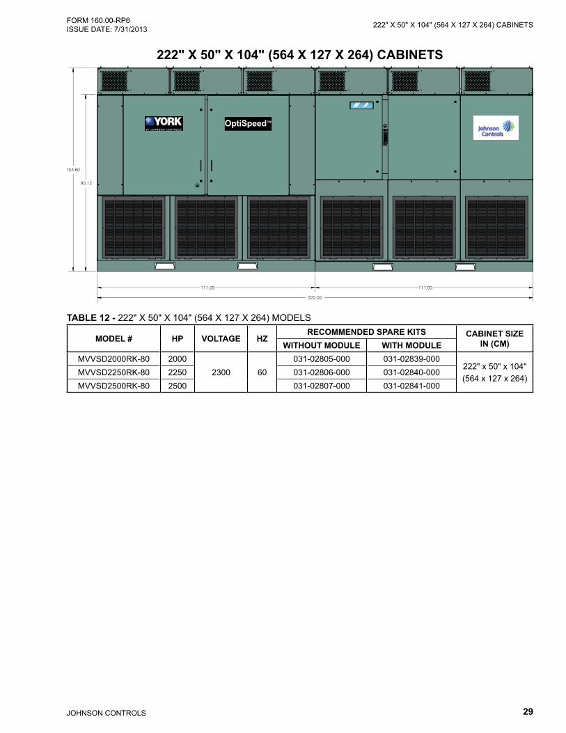
222" X 50" X 104" (564 X 127 X 264) CABINETS
OptiSpeed™
TABLE 12 - 222" X 50" X 104" (564 X 127 X 264) MODELS
MODEL # HP VOLTAGE HZRECOMMENDED SPARE KITS CABINET SIZE
IN (CM)WITHOUT MODULE WITH MODULEMVVSD2000RK-80 2000
2300 60031-02805-000 031-02839-000
222" x 50" x 104" (564 x 127 x 264)
MVVSD2250RK-80 2250 031-02806-000 031-02840-000MVVSD2500RK-80 2500 031-02807-000 031-02841-000
JOHNSON CONTROLS30
FORM 160.00-RP6 ISSUE DATE: 7/31/2013222" X 50" X 104" (564 X 127 X 264) CABINETS
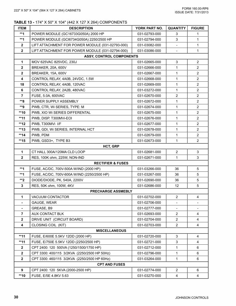
TABLE 13 - 174" X 50" X 104" (442 X 127 X 264) COMPONENTSITEM DESCRIPTION YORK PART NO. QUANTITY FIGURE**1 POWER MODULE (GC16733G050A) 2000 HP 031-02793-000 3 1**1 POWER MODULE (GCI6734G050A) 2250/2500 HP 031-02794-000 3 12 LIFT ATTACHMENT FOR POWER MODULE (031-02793-000) 031-03082-000 - 12 LIFT ATTACHMENT FOR POWER MODULE (031-02794-000) 031-03086-000 - 1
ASSY, CONTROL COMPONENTS1 MOV 625VAC 825VDC, 230J 031-02665-000 3 22 BREAKER, 20A, 600V 031-02666-000 1 22 BREAKER, 15A, 600V 031-02667-000 1 24 CONTROL RELAY, 4A0B, 24VDC, 1.5W 031-02668-000 1 2
18 CONTROL RELAY, 4A0B, 120VAC 031-02669-000 1 26 CONTROL RELAY, 2A2B, 480VAC 031-03272-000 1 27 FUSE, 5.0A, 600VAC 031-02670-000 2 2
**8 POWER SUPPLY ASSEMBLY 031-02672-000 1 2**9 PWB, CTR, Wi SERIES, TYPE: M 031-02674-000 1 2
**10 PWB, XIO Wi SERIES DIFFERENTAL 031-02675-000 1 2**11 PWB, DISP. T300MVi-EOI 031-02676-000 1 2**12 PWB, T300MVi I/F 031-02677-000 1 2**13 PWB, GDI, Wi SERIES, INTERNAL HCT 031-02678-000 1 2**14 PWB, PDM 031-02679-000 1 2**15 PWB, GSD3+, TYPE B3 031-02673-000 1 2
HCT, GRP1 CT HALL 300A/120MA CLD LOOP 031-02681-000 2 32 RES, 100K ohm, 225W, NON-IND 031-02671-000 1 3
RECTIFIER & FUSES**1 FUSE, AC/DC, 700V-500A W/IND (2000 HP) 031-03266-000 36 5**1 FUSE, AC/DC, 700V-600A W/IND (2250/2500 HP) 031-03267-000 36 5**2 DIODE/DIODE, PK, 540A, 2200V 031-02690-000 36 53 RES, 50K ohm, 100W, 4KV 031-02686-000 12 5
PRECHARGE ASSMEBLY1 VACUUM CONTACTOR 031-02702-000 2 4- GAUGE, WEAR 031-02706-000 - -- GREASE, B9 031-02777-000 - -7 AUX CONTACT BLK 031-02693-000 2 42 DRIVE UNIT (CIRCUIT BOARD) 031-02704-000 2 44 CLOSING COIL (KIT) 031-02703-000 2 4
MISCELLANEOUS**11 FUSE, E/600E 5.5KV 12DD (2000 HP) 031-02720-000 3 4**11 FUSE, E/750E 5.5KV 12DD (2250/2500 HP) 031-02721-000 3 4
2 CPT 2400: 120 500VA (1250/1500/1750 HP) 031-02712-000 1 62 CPT 3300: 400/115 3/2KVA (2250/2500 HP 50Hz) 031-02796-000 1 62 CPT 3300: 460/115 3/2KVA (2250/2500 HP 60Hz) 031-03264-000 1 6
CPT AND FUSES9 CPT 2400: 120 5KVA (2000-2500 HP) 031-02774-000 2 6
**10 FUSE, E/5E 4.8KV 5.63 031-03270-000 4 4
31JOHNSON CONTROLS
222" X 50" X 104" (564 X 127 X 264) CABINETSFORM 160.00-RP6 ISSUE DATE: 7/31/2013
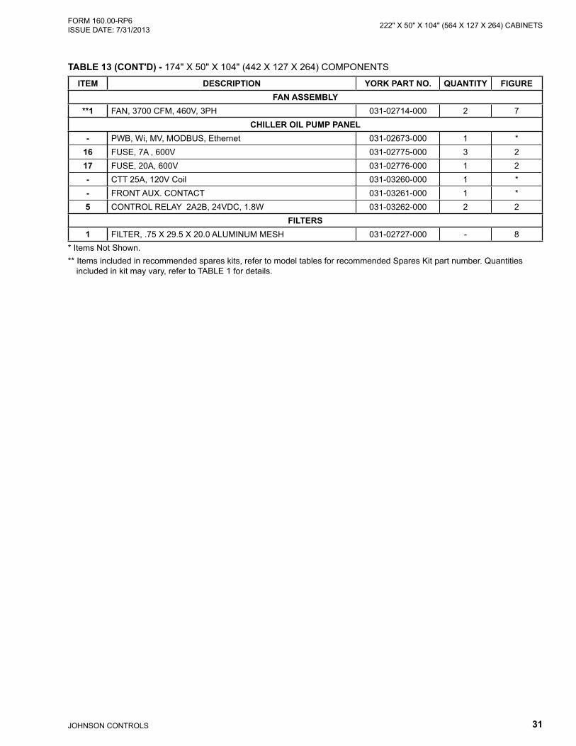
ITEM DESCRIPTION YORK PART NO. QUANTITY FIGUREFAN ASSEMBLY
**1 FAN, 3700 CFM, 460V, 3PH 031-02714-000 2 7CHILLER OIL PUMP PANEL
- PWB, Wi, MV, MODBUS, Ethernet 031-02673-000 1 *16 FUSE, 7A , 600V 031-02775-000 3 217 FUSE, 20A, 600V 031-02776-000 1 2- CTT 25A, 120V Coil 031-03260-000 1 *- FRONT AUX. CONTACT 031-03261-000 1 *5 CONTROL RELAY 2A2B, 24VDC, 1.8W 031-03262-000 2 2
FILTERS1 FILTER, .75 X 29.5 X 20.0 ALUMINUM MESH 031-02727-000 - 8
* Items Not Shown.** Items included in recommended spares kits, refer to model tables for recommended Spares Kit part number. Quantities
included in kit may vary, refer to TABLE 1 for details.
TABLE 13 (CONT'D) - 174" X 50" X 104" (442 X 127 X 264) COMPONENTS

JOHNSON CONTROLS32
FORM 160.00-RP6 ISSUE DATE: 7/31/2013222" X 50" X 104" (564 X 127 X 264) CABINETS
LD12166
15
14
8
6 5 410
ACCESS DOOR TO
MOTOR LEADS
11(Inside
Cabinet Door)
12
17
13(Inside
Access Door)
1716
9
18 13 2
AC NEUTRALBUS
LIFTINGEYE
LD15422a
FIGURE 1 - POWER MODULE
1
2
FIGURE 2 - LOW VOLTAGE COMPARTMENT
33JOHNSON CONTROLS
222" X 50" X 104" (564 X 127 X 264) CABINETSFORM 160.00-RP6 ISSUE DATE: 7/31/2013
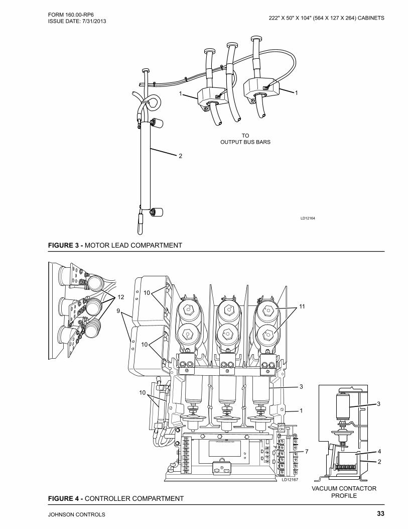
FIGURE 3 - MOTOR LEAD COMPARTMENT
11
2
TOOUTPUT BUS BARS
LD12164
FIGURE 4 - CONTROLLER COMPARTMENT
2
3
4
VACUUM CONTACTORPROFILE
9
3
LD12167
1
10
10
10
11
7
12
JOHNSON CONTROLS34
FORM 160.00-RP6 ISSUE DATE: 7/31/2013222" X 50" X 104" (564 X 127 X 264) CABINETS
1 2
LD12179
LD12176
1
2
2
2
1
1
3
3
3
FIGURE 5 - RECTIFIER AND FUSES
FIGURE 6 - PRE-CHARGE ASSEMBLY
35JOHNSON CONTROLS
222" X 50" X 104" (564 X 127 X 264) CABINETSFORM 160.00-RP6 ISSUE DATE: 7/31/2013
LD12178a
FIGURE 7 - FANS
1
1
FIGURE 8 - FILTERS
1
1
1
1
1
LD12178
1
1

Tele. 800-861-1001www.johnsoncontrols.com
P.O. Box 1592, York, Pennsylvania USA 17405-1592 Subject to change without notice. Printed in USACopyright © by Johnson Controls 2013 ALL RIGHTS RESERVEDForm 160.00-RP6 (713)Issue Date: July 31, 2013 Supersedes: 160.00-RP6 (512)
Related Documents