1 Medium voltage superconducting cable systems for inner city power supply F. Schmidt , M. Stemmle, A. Hobl, F. Merschel, M. Noe

Welcome message from author
This document is posted to help you gain knowledge. Please leave a comment to let me know what you think about it! Share it to your friends and learn new things together.
Transcript

1Cabos ´11, Maceio
Medium voltage superconducting cable systems for inner city power
supply
F. Schmidt, M. Stemmle, A. Hobl, F. Merschel, M. Noe

2Cabos ´11, Maceio
Content
• Basics of Superconductivity
• Superconducting Cable System Components
• Motivation for Inner City HTS Cables
• HTS Cable Design for MV
• Application Concept
• Case Study
• Ampacity Project
• Conclusions

3Cabos ´11, Maceio
Content
• Basics of Superconductivity
• Superconducting Cable System Components
• Motivation for Inner City HTS Cables
• HTS Cable Design for MV
• Application Concept
• Case Study
• Ampacity Project
• Conclusions

4Cabos ´11, Maceio
Temperature
Spec
ific
resi
stan
ce
Metallic conductor
Tc
Superconductor
Superconducting State
Superconducting state is reached below critical temperature Tc

5Cabos ´11, Maceio
E
J
1 μV/cm
Jc
Metallic conductor
Superconductor
Current-Voltage-Characteristics
Practical definition of critical current density with 1 µV/cm criterion

6Cabos ´11, Maceio
HTS Wire for Cable Applications
Bi2Sr2Ca2Cu3O10 (Bi-2223)
1st generation material (1G)
Available in long length (> 1 km)
Critical current up to 200 A
Wire geometry: 4.3 mm × 0.4 mm
YBa2Cu3O7 (Y-123)
2nd generation material (2G)
Different manufacturing process
Expected to be cheaper
Critical current up to 100 A
Wire geometry: 4.4 mm × 0.4 mm
7Cabos ´11, Maceio
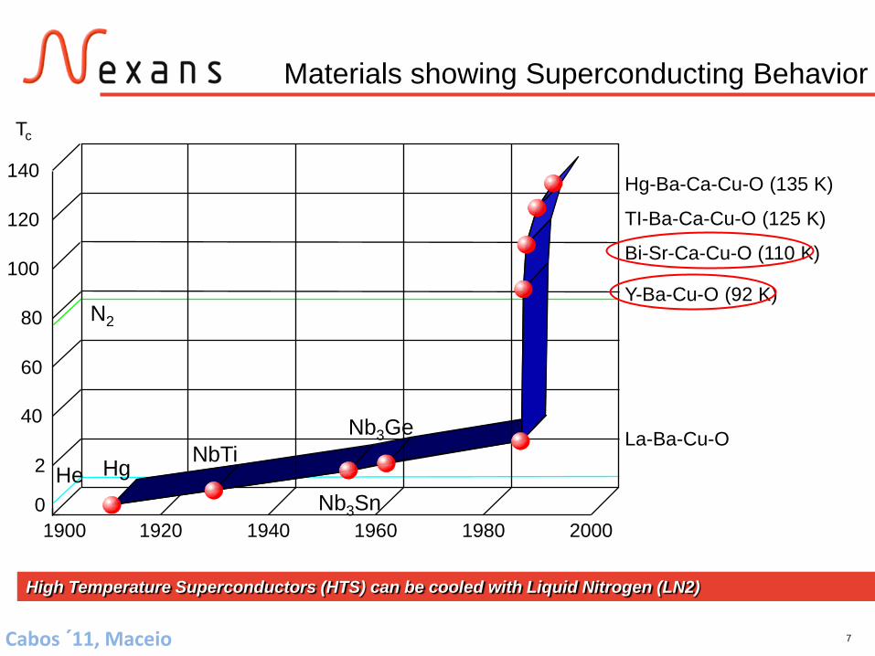
Materials showing Superconducting Behavior
Hg-Ba-Ca-Cu-O (135 K)
TI-Ba-Ca-Cu-O (125 K)
Bi-Sr-Ca-Cu-O (110 K)
Y-Ba-Cu-O (92 K)
La-Ba-Cu-O
1900 1920 1940 1960 1980 20000
2
40
60
80
100
120
140
Hg NbTi
Nb3Sn
Nb3Ge
N2
He
Tc
High Temperature Superconductors (HTS) can be cooled with Liquid Nitrogen (LN2)

8Cabos ´11, Maceio
Content
• Basics of Superconductivity
• Superconducting Cable System Components
• Motivation for Inner City HTS Cables
• HTS Cable Design for MV
• Application Concept
• Case Study
• Ampacity Project
• Conclusions

9Cabos ´11, Maceio
Components of an HTS-Cablesystem Core
Transport the current Withstand the voltage
Cryostat Insulate thermally – keep the cable cold Transport the liquid nitrogen
Termination Connect the system to the grid Manage the transition between cold temperature and
room temperature Provide connection to the cooling system
Joints Connection of two cables Intermediate access to cooling medium

10Cabos ´11, Maceio
High Voltage Dielectric for HTS Cables
Lapped dielectric system using PPLP (Polypropylene laminated paper) is established as the insulation for high voltage superconducting power cables
Low dielectric losses
High dielectric strength
Can be used on conventional paper lapping machines
Very good mechanical properties (dry bending)
Insulation is impregnated with LN2 under pressure to avoid the formation of nitrogen bubbles
Low dielectric loss factor tan δ is important for cables at higher voltage levels as all losses have to be removed by the cooling system

11Cabos ´11, Maceio
Thermal Insulation - Cryostat Design of cryogenic envelope Two concentric longitudinal welded and
corrugated stainless steel tubes Multilayer Superinsulation in between the
tubes Low loss spacer to avoid contact between
inner and outer tube Vacuum to avoid convection heat losses (10-5
mbar) PE-outer sheath (optional)
Manufactured in a continuous process on UNIWEMA machines (Nexans own built machine)
Quality control Helium leak test of all welds and pieces to
ensure long term vacuum tightness
Nexans has delivered more than 100 km of flexible transferlines

12Cabos ´11, Maceio
Cooling Flow
RedundantCooling & Control
Bul
k LN
2S
tora
ge
Heat
Pow
er
SC
AD
A
Supply
Return
No separate return line required in case of individual cryostats

13Cabos ´11, Maceio
Content
• Basics of Superconductivity
• Superconducting Cable System Components
• Motivation for Inner City HTS Cables
• HTS Cable Design for MV
• Application Concept
• Case Study
• Ampacity Project
• Conclusions

14Cabos ´11, Maceio
Motivation for Inner City HTS Cables
Power supply within European cities predominantly with cables
Many quite old cables and substations
Refurbishment / replacement in upcoming years
Adaption of substations to new load requirements
Study was done investigating employment of high temperature superconductor systems (HTS cables in combination with HTS fault current limiters)
Option for replacing conventional cables
Enabling of new grid concepts

15Cabos ´11, Maceio
Content
• Basics of Superconductivity
• Superconducting Cable System Components
• Motivation for Inner City HTS Cables
• HTS Cable Design for MV
• Application Concept
• Case Study
• Ampacity Project
• Conclusions

16Cabos ´11, Maceio
Cable and Termination Design
DielectricFormer
Phase 3
Screen
LN2Inlet
Cryostat
Phase 2Phase 1
Cooling System Inlet / Return
LN2Return
Phase 3
Phase 1

17Cabos ´11, Maceio
Content
• Basics of Superconductivity
• Superconducting Cable System Components
• Motivation for Inner City HTS Cables
• HTS Cable Design for MV
• Application Concept
• Case Study
• Ampacity Project
• Conclusions
18Cabos ´11, Maceio
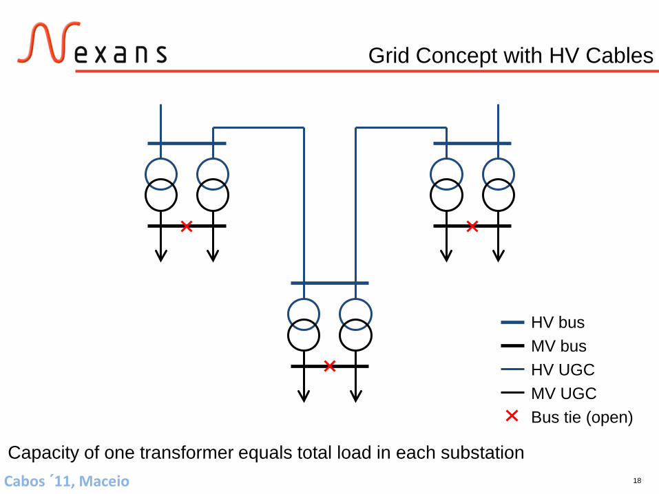
HV busMV busHV UGCMV UGCBus tie (open)
Capacity of one transformer equals total load in each substation
Grid Concept with HV Cables
19Cabos ´11, Maceio
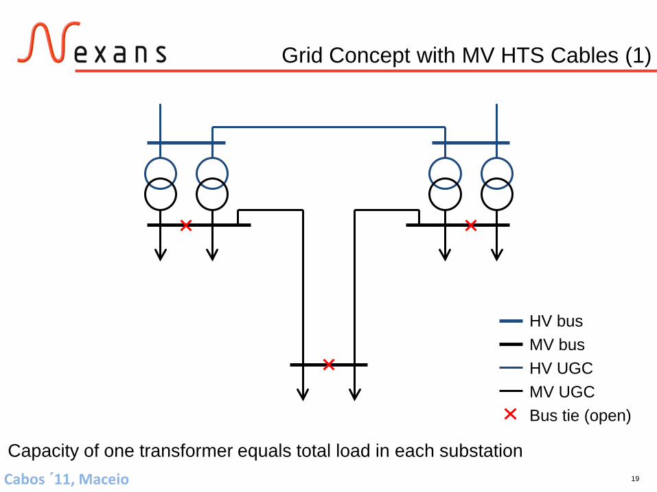
HV busMV busHV UGCMV UGCBus tie (open)
Capacity of one transformer equals total load in each substation
Grid Concept with MV HTS Cables (1)

20Cabos ´11, Maceio
HV busMV busHV UGCMV UGCBus tie (open)
Capacity of one transformer equals total load in each substation
Grid Concept with MV HTS Cables (2)

21Cabos ´11, Maceio
Content
• Basics of Superconductivity
• Superconducting Cable System Components
• Motivation for Inner City HTS Cables
• HTS Cable Design for MV
• Application Concept
• Case Study
• Ampacity Project
• Conclusions

22Cabos ´11, Maceio
Contents• Applications and specification• Cable design• Operation parameters• HTS cables in the grid• Economic feasibility• State-of-the-art of HTS cable R&D• Tests
Superconducting MV Cables for Power Supply
in Urban Areas
Case Study

23Cabos ´11, Maceio
A
D E
40 MVA
J
B
C
F
IHG
40 MVA
40 MVA 40 MVA 40 MVA 40 MVA
40 MVA
40 MVA
40 MVA40 MVA
110 kV OHL
110 kV UGC
10 kV UGC
110 kV busbar
10 kV busbar
Bus tie (open)
5,0 km
6,2 km
4,6
km2,
6 km
2,7
km
3,0
km
3,1
km
2,2 km
3,6 km
2,6
km
4,3 km
3,2 km4,7 km
A
D E
40 MVA
J
B
C
F
IHG
40 MVA
40 MVA 40 MVA 40 MVA 40 MVA
40 MVA
40 MVA
40 MVA40 MVA
110 kV OHL
110 kV UGC
10 kV UGC
110 kV busbar
10 kV busbar
Bus tie (open)
A
D E
40 MVA
J
B
C
F
IHG
40 MVA
40 MVA 40 MVA 40 MVA 40 MVA
40 MVA
40 MVA
40 MVA40 MVA
110 kV OHL
110 kV UGC
10 kV UGC
110 kV busbar
10 kV busbar
Bus tie (open)
110 kV OHL
110 kV UGC
10 kV UGC
110 kV busbar
10 kV busbar
Bus tie (open)
5,0 km
6,2 km
4,6
km2,
6 km
2,7
km
3,0
km
3,1
km
2,2 km
3,6 km
2,6
km
4,3 km
3,2 km4,7 km
Urban Grid with HV Cables

24Cabos ´11, Maceio
5,0 km
6,2 km
4,6
km
2,6
km
2,7
km
3,0
km
3,6 km
6,8 km
3,2 km
4,7 km
A
D
E
J
B
C
F
I
H
G
110 kV OHL
110 kV UGC
10 kV UGC
110 kV busbar
10 kV busbar
Bus tie (open)
40 MVA
40 MVA 40 MVA
40 MVA
40 MVA
40 MVA40 MVA40 MVA
40 MVA
40 MVA
3,0
km
8,4
km
2,7
km 2,6
km
5,0 km
6,2 km
4,6
km
2,6
km
2,7
km
3,0
km
3,6 km
6,8 km
3,2 km
4,7 km
A
D
E
J
B
C
F
I
H
G
110 kV OHL
110 kV UGC
10 kV UGC
110 kV busbar
10 kV busbar
Bus tie (open)
40 MVA
40 MVA 40 MVA
40 MVA
40 MVA
40 MVA40 MVA40 MVA
40 MVA
40 MVA
A
D
E
J
B
C
F
I
H
G
110 kV OHL
110 kV UGC
10 kV UGC
110 kV busbar
10 kV busbar
Bus tie (open)
110 kV OHL
110 kV UGC
10 kV UGC
110 kV busbar
10 kV busbar
Bus tie (open)
40 MVA
40 MVA 40 MVA
40 MVA
40 MVA
40 MVA40 MVA40 MVA
40 MVA
40 MVA
3,0
km
8,4
km
2,7
km 2,6
km
Urban Grid with MV HTS Cables

25Cabos ´11, Maceio
Overall Changes in the Grid
Dispensable devices for new grid concept
12.1 km of 110 kV cable systems
12 x 110 kV cable switchgear
5 x 40 MVA, 110/10 kV transformers
5 x 110 kV transformer switchgear
5 x 10 kV transformer switchgear
Additionally required devices for new grid concept
23.4 km of 10 kV HTS cable system
16 x 10 kV cable switchgear
3 x 10 kV bus ties
26Cabos ´11, Maceio
Nexans HTS 10/40NA2XS2Y 1 x 630 RM/35N2XS(FL)2Y 1 x 300 RM/35
1200
600
175 175125 125
1050
650
850
125125 100 100100 100
145
200
400
700
100 100
ROW and Installation Space
27Cabos ´11, Maceio
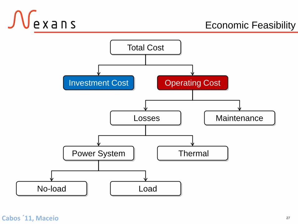
Total Cost
Investment Cost Operating Cost
Losses Maintenance
Power System Thermal
No-load Load
Economic Feasibility

28Cabos ´11, Maceio
Economic Feasibility
Comparison of 3 different options based on NPV method
Investment costs and operating costs (maintenance and losses)
40 years
2 % yearly increase
6.5 % interest rate
65 €/MWh Tota
l NP
V in
M€
103.287.7
93.7

29Cabos ´11, Maceio
Content
• Basics of Superconductivity
• Superconducting Cable System Components
• Motivation for Inner City HTS Cables
• HTS Cable Design for MV
• Application Concept
• Case Study
• Ampacity Project
• Conclusions

30Cabos ´11, Maceio
Ampacity Project
Project objectives• Development and field test of a 1 km long 10 kV, 40 MVA (2.3 kA)
HTS cable in combination with a resistive type SFCL• Project start: 09/2011
Project partners• RWE – Specification and field test• Nexans – HTS cable and FCL• KIT – HTS tests and characterization

31Cabos ´11, Maceio
Installation in Downtown Essen
• 10 kV bus connection of two substations with HTS system (cable + SFCL)
• Approximately 1 km cable system length with one joint
• Installation in Q4/2013, afterwards at least two year field test in grid

32Cabos ´11, Maceio
Content
• Basics of Superconductivity
• Superconducting Cable System Components
• Motivation for Inner City HTS Cables
• HTS Cable Design for MV
• Application Concept
• Case Study
• Ampacity Project
• Conclusions

33Cabos ´11, Maceio
Conclusions
HTS systems attractive alternatives to conventional systems
Replacing HV cable systems with MV HTS cable systems
Reduction of inner city transformer substations
Concentric HTS cable systems for MV applications
Very good electromagnetic behavior
Thermally independent from environment
Small right of way and reduced installation costs
Enabling new grid concepts for urban area power supply
Ampacity project in Germany started (HTS cable and SFCL)
Related Documents


![Design and construction of a high- eld superconducting ... › media › 7e › 5c › 22de2c8164a488... · superconducting shield. In [4] two bulk superconducting materials were](https://static.cupdf.com/doc/110x72/5f2429ce6552cd39e01177ff/design-and-construction-of-a-high-eld-superconducting-a-media-a-7e-a.jpg)


