VM1-T Vacuum circuit-breaker Contents 1 Summary 6 2 Structure 7 3 Function 8 4 Despatch and storage 11 5 Installation and mounting of the breaker 12 6 Commissioning / Operation 12 7 Maintenance 14 8 Application of the X-ray regulations 21 9 Figures 21 10 Technical data 30 11 Comparison of designations to IEC 61346-1 / 61346-2, IEC 81346-1 / 81346-2 and VDE-DIN 40719 Part 2 43 Medium voltage products

Welcome message from author
This document is posted to help you gain knowledge. Please leave a comment to let me know what you think about it! Share it to your friends and learn new things together.
Transcript

VM1-TVacuum circuit-breaker
Instruction manual BA 543/02
Contents 1 Summary 6 2 Structure 7
3 Function 8
4 Despatch and storage 11
5 Installation and mounting of the breaker 12
6 Commissioning / Operation 12
7 Maintenance 14 8 Application of the X-ray regulations 21
9 Figures 21
10 Technical data 30 11 Comparison of designations to IEC 61346-1 / 61346-2, IEC 81346-1 / 81346-2 and VDE-DIN 40719 Part 2 43
Medium voltage products Medium voltage products

2 VM1-T | Instruction manual 543/02

Instruction manual 543/02 | VM1-T 3
Your safety first – always!
That’s why our instruction manual begins with these recommendations:
• Only install switchgear and/or switchboards in enclosed rooms suitable for electrical equipment.
• Ensure that installation, operation and maintenance are carried out by specialist electricians only.
• Comply in full with the legally recognized standards (DIN VDE/IEC), the connection conditions of the local electrical utility and the applicable safety at work regulations.
• Observe the relevant information in the instruction manual for all actions involving switchgear and switchboards.
• Danger!
Pay special attention to the hazard notes in the instruction manual marked with this warning symbol.
• Make sure that under operation condition of the switchgear or switchboard the specified data are not exceeded.
• Keep the instruction manual accessible to all persons concerned with installation, operation and maintenance.
• The user’s personnel are to act responsibly in all matters affecting safety at work and the correct handling of the switchgear.
• Always observe the five safety rules set out in EN 50110 on establishing and securing the off-circuit condition at the place of work for the duration of work on the switchgear.
- Isolate
- Secure to prevent reconnection
- Check the off-circuit condition
- Earth and short-circuit
- Cover the guard off adjacent live parts
If you have any further questions on this instruction manual, the members of our field organization will be pleased to provide the required information.

4 VM1-T | Instruction manual 543/02
We reserve all rights to this publication. Misuse, particularly including duplication and making available of this man-ual – or extracts – to third parties is prohibited. The information supplied is without liability. Subject to alteration.
© ABB AG 2012
Contents Page
1 Summary 61.1 General 61.2 Standards and specifications 6
1.2.1 Switchgear manufacture 61.2.2 Installation and operation 6
1.3 Operating conditions 61.3.1 Normal operating conditions 61.3.2 Special operating conditions 6
2 Structure 72.1 Structure of the operating mechanism 7
2.1.1 Structure of the control module 72.1.2 Storage capacitor 72.1.3 Sensor system 7
2.2 Structure of the breaker poles 72.3 Basic structure of the circuit-breaker on withdrawable part 8
3 Function 83.1 Function of the circuit-breaker operating mechanism 8
3.1.1 Magnetic actuator 83.1.2 Opening and closing procedure 83.1.3 Auto-reclosing sequence 83.1.4 Circuit-breaker controller 83.1.5 “READY” lamp 93.1.6 Blocking magnet -RL2 9
3.2 Wiring diagrams for C.B. on withdrawable part 93.3 Quenching principle of the vacuum interrupter 103.4 Interlocks 10
3.4.1 Interlocks/protection against maloperation (for C.B. on withdrawable part) 103.4.2 Interlocks for VM1-T withdrawable part 10
3.4.2.1 Interlocks when ABB withdrawable assemblies are used 103.4.3 Interlocks when non-original withdrawable assemblies are used 10
4 Despatch and storage 114.1 Condition on delivery 114.2 Packaging 114.3 Transport 114.4 Delivery 114.5 Intermediate storage 11
5 Installation and mounting of the breaker 12
6 Commissioning / Operation 126.1 Note on safety at work 126.2 Preparatory activities 126.3 Earthing 13

Instruction manual 543/02 | VM1-T 5
Contents Page
6.4 Movement of the withdrawable breaker part 136.4.1 Manual insertion from the test/disconnected position into the service position 136.4.2 Manual withdrawal from the service position into the test/disconnected position 136.4.3 Motor-driven movement of the withdrawable part 136.4.4 Withdrawal from the test/disconnected position onto the service truck 136.4.5 Insertion from the service truck into the test/disconnected position 14
6.5 Operation of the circuit-breaker 14
7 Maintenance 147.1 General 147.2 Inspection and functional testing 15
7.2.1 Circuit-breaker in general 157.2.2 Magnetic actuator operating mechanism 157.2.3 Lock and release device withdrawable assembly 16
7.3 Servicing 167.3.1 Circuit-breaker in general 167.3.2 Magnetic actuator operating mechanism 167.3.3 Breaker pole 16
7.4 Repair 177.4.1 Repair of surface damage 177.4.2 Replacement of components 17
7.5 Tests on withdrawable parts with VM1-T-type circuit-breaker 187.5.1 Motor-driven withdrawable parts 187.5.2 Checking the auxiliary switch settings on withdrawable parts 187.5.3 Checking the direction of rotation of the travel motors on motor-driven withdrawable parts 187.5.4 Checking of interlock conditions 18
7.6 Spare parts, auxiliary materials, lubricants 197.6.1 Spare parts 197.6.2 Auxiliary materials and lubricants 20
8 Application of the X-ray regulations 21
9 Figures 21
10 Technical data 3010.1 Technical data, general 30
10.1.1 Technical data for Control electronics 3010.1.2 Technical data for AC/DC converter 3010.1.3 Permissible number of vacuum interrupter operating cycles 31
10.2 Technical data circuit-breakers for fixed installation 3310.2.1 Performance data and weights 3310.2.2 Dimensions 34
10.3 Technical data circuit-breakers on withdrawable part 3710.3.1 Performance data and weights 3710.3.2 Dimensional drawings 3810.3.3 Wiring diagrams for C.B. on withdrawable part 41
11 Comparison of designations to IEC 61346-1 / 61346-2, IEC 81346-1 / 81346-2 and VDE-DIN 40719 Part 2 43

6 VM1-T | Instruction manual 543/02
1 Summary
1.1 General
The vacuum circuit-breakers of type VM1-T are inten ded for indoor installation in air-insulated switch gear. They have a switching capacity capable of handling the loads occuring at start-up and shutdown of equipment and plant units both in normal and in fault state.
Vacuum circuit-breakers have particular advan t ages for use in systems where the switching frequency in the operating current range is high, and/or where a certain number of short-circuit breaking operations have to be reckoned with. Vacuum circuit-breakers of type VM1-T are prepared for auto-reclosing opera tions and are notable for their especially high operational reliability and extremely long service life with complete free-dom from maintenance.
The vacuum circuit-breakers of type VM1-T in column design can be supplied both as individual units for stationary mount-ing and mounted on trucks. Their basic structure is shown in section “Technical data”.
1.2 Standards and specifications
1.2.1 Switchgear manufacture
The switchgear complies with the following speci fications in accordance with DIN VDE and the relevant IEC publications:
- VDE 0670, part 1000 and IEC 60694 - VDE 0671, part 100 and IEC 62271-100
1.2.2 Installation and operation
The relevant specifications are to be taken into account during installation and operation, particularly:
- DIN VDE 0101, Power installations exceeding AC 1 kV - DIN VDE 0100-410, Erection of power installations up to
1000 V, protective measures - VDE 0105, Operation of electrical installations - DIN VDE 0141, Earthing systems for special power installa-
tions with rated voltages above 1 kV - Accident prevention regulations issued by the appropriate
professional bodies or comparable organisations. In Germany, these comprise the following safety regula-tions: - Health and Safety at Work Standards BGV A1 and BGV A3
- Safety guidelines for auxiliary and operating materials - Order related details provided by ABB.
1.3 Operating conditions
1.3.1 Normal operating conditions
Design to VDE 0670, part 1000, “Common specifications for high-voltage switchgear and controlgear standards” and IEC publication 60694, with the following limit values:
- Ambient temperature: - Maximum + 40 °C - Maximum 24 hour average + 35 °C - Minimum (according to “minus 25 indoor class”) – 25 °C
- Humidity: - the average value of the relative humidity measured over a period of 24 h, does not exceed 95 %
- the average value of the water vapour pressure, over a period of 24 h, does not exceed 2,2 kPa
- the average value of the relative humidity, over a period of one month, does not exceed 90 %
- the average value of water vapour pressure, over a period of one month, does not exceed 1,8 kPa
- Maximum site altitude: - ≤ 1000 m above sea level.
1.3.2 Special operating conditions
Special operating conditions are to be agreed on by the manufacturer and user. The manufacturer must be consulted in advance about each special operating condition:
- Site altitude over 1000 m: - Allow for the reduction in the dielectric strength of the air.
- Increased ambient temperature: - Current carrying capacity is reduced. - Provide additional ventilation for heat dissipation.
- Climate: - Avoid the risk of corrosion or other damage, e.g. to the operating mechanisms, in areas: - with high humidity and/or - with major rapid temperature fluctuations.
- Implement preventive measures (e.g. electric heaters) to preclude condensation pheno mena.

Instruction manual 543/02 | VM1-T 7
2 Structure
2.1 Structure of the operating mechanism (Figures 9/10 to 9/13 and 9/25)
The operating mechanism is of the magnetic type. It funda-mentally consists of the magnetic actuator 10, the control module 27 with sensor systems, the storage capacitors 26 and the linkages which transmit the force to the breaker poles.
In addition, there are supplementary components for emer-gency manual opening and the controls located on the front of the enclosure.
The actuator 10 acts on the three breaker poles via lever shaft 18. The storage capacitors 26 provides the necessary actuat-ing energy on demand.
The mechanical switch positions of the circuit-breaker are detected by two sensors 15 and 16 directly at lever shaft 18.
There are rating plates 7 with the main data of the switching device on front plate 1.1, and at the left side in the mecha-nism enclosure.
The basic version of the magnetic actuator mechanism is fitted with the following controls and instruments:
- ON push-button 3 - OFF push-button 4 - Emergency manual OFF 8 - Mechanical position indicator 6 - Mechanical operating cycle counter 5 - Signal lamp for switching readiness 2 (“READY” lamp).
The following may also be installed:
- Five-pole auxiliary switches for switch position signal: -BB1 and -BB3.
2.1.1 Structure of the control module (Figures 9/13 and 9/15a)
The control module consists of 2 circuit boards:
1. Control board Control module ED 2.0 produces a voltage of 80 V from
any supply voltage within the input voltage range, with which the storage capacitors are charged. This is also used to generate a voltage of 18 V to supply the breaker controller.
2. Power output (upper board) - Power electronics for activation of the actuator coils.
2.1.2 Storage capacitor (Figures 9/13, 9/15b and 9/25)
The electrical energy for operation of the circuit-breaker is stored in three capacitors. The capacitors are designed in such a way that the energy for an OFF-ON-OFF operating cycle is provided without recharging.
The energy stored in the capacitors is constantly monitored. This is accomplished by measuring the capacitor voltage.
When the supply voltage is applied, the “READY” lamp indi-cates the readiness of the circuit-breaker to perform the next switching operation (see sections 3.1.5 and 6.2).
The energy stored in the capacitors is a criterion for illumina-tion of the “READY” lamp:
- Case 1: Breaker in the OFF position. - The available energy is sufficient for an ON and OFF operation.
- Case 2: Breaker in the ON position. - The available energy is sufficient for an OFF operation. - On failure of the supply voltage, the available energy is sufficient during the initial 180 seconds for an OFF operation (see also section 6.5).
When the energy is not sufficient, a NOT READY signal indi-cates that the circuit-breaker is not ready to switch.
2.1.3 Sensor system (Figures 9/12 and 9/13)
The systematic use of sensors permits control of the circuit-breaker without auxiliary switches.
Two inductive proximity switches 15 and 16 are used to detect the mechanical limit positions, which also provide for self-monitoring of the system.
2.2 Structure of the breaker poles (Figures 9/6, 9/7 and 9/11)
The poles in column design are mounted on the bracket-shaped rear part of mechanism enclosure 1. The live parts of the breaker poles are enclosed in cast resin and protected from impacts and other external influences.
With the breaker closed, the current path leads from the upper breaker terminal 25 to the fixed contact 24.2 in the vacuum interrupter 24, then via the moving contact 24.1 and the flexible connector 21 to the lower breaker terminal 22.
The switching motions are effected by means of the insulated link rod 19 with internal contact force springs 20.

8 VM1-T | Instruction manual 543/02
2.3 Basic structure of the circuit-breaker on withdrawable part (Figures 9/5 to 9/9 and 9/21)
The withdrawable part, which can be moved manually or by a motor if fitted, consists of a steel sheet structure on which the circuit-breaker with its ancillary components is mounted.
Insulated contact arms 34 with the spring-loaded contact sys-tems 34.1 are fitted to the circuit-breaker poles. These create the electrical connection to the panel when the withdrawable part is inserted into the service position.
A multi-pole control wiring plug connector 36.1 connects the signalling, protection and control wiring between the panel and the withdrawable part.
The withdrawable assembly and the circuit-breaker are connected via a multi-pole control wiring plug connector 37.
As soon as the withdrawable part 31 has been slid into the panel and its base frame has engaged in the test/discon-nected position, it is positively connected to the panel. At the same time, it is earthed by its travel rollers in their rails. The magnetic actuator mechanism of the circuit-breaker, includ-ing its controls and indicators, is accessible at the front of the withdrawable part.
Withdrawable parts of the same version are interchangable. With the same dimensions but different circuit-breaker equip-ment, coding of the control wiring plug prevents impermissible combinations of withdrawable parts and panels (see figure 9/14).
3 Function
3.1 Function of the circuit-breaker operating mechanism
3.1.1 Magnetic actuator (Figure 9/11)
The actuator is the heart of the circuit-breaker operating mechanism. It combines the following integrated functions:
- latching in the limit positions, - release, - switching.
The actuator is a bistable permanent magnet system in which the armature motion is effected by activating the ON or OFF coil. In the limit positions, the armature is held in place mag-netically by the field of two permanent magnets. Release of a switching operation is effected by exciting one of the two coils until the latching force of the permanent magnets is exceeded temporarily.
3.1.2 Opening and closing procedure (Figures 9/10 to 9/11)
The opening and closing processes can be remote controlled by applying a voltage to input -MC (ON) and -MO1 (OFF) (see also sections 10.1.1a and 6.2). The breaker can be operated locally by pressing push-buttons 3 and 4.
In the closing process, the armature motion acts direct via lever shaft 18 on the moving contact 24.1 until the contacts meet.
In the further motion sequence, the pretensioned spring arrangement 20 is tensioned to 100 % and the necessary contact force thus applied. The available overtravel is greater than the maximum contact burn-off throughout the life of the vacuum interrupter
3.1.3 Reclosing sequence
The operating mechanism is fundamentally prepared for reclosing, and with the short recharging time of the storage capacitor (max. 3 s) it is also suitable for multi-shot reclosing.
3.1.4 Circuit-breaker controller
All the conditions for control of the opening and closing commands to the magnetic actuator are defined in a fixed-programmed logic module:
- Supply voltage must be applied to the AC/DC converter. - The storage capacitors must be sufficiently charged for the
next switching operation:
Switch position: Storage capacitor energy for:
OFF ON and OFF
ON OFF
- The moving contacts in the circuit-breaker poles must be in a defined ON or OFF limit position.
- The closing coil can only be activated when the breaker is OFF.
- The opening coil can only be activated when the breaker is ON.
- Closing is disabled when an opening command is simulta-neously active.
- Activation of the closing coil can be disabled by an external blocking signal.
- The anti-pumping system ensures that only one ON-OFF operation is performed when a closing command is active and followed by an opening command. The active closing command must be cancelled and reset for the next closing operation.
- Deactivation of the opening or closing coil takes place when the relevant limit position has been reached.

Instruction manual 543/02 | VM1-T 9
- Input -MU “opening command” (undervoltage release) and input -RL1 “closing lock-out” (undervoltage release) must be energized for the circuit-breaker to be closed.
- In the as-delivered condition of devices for stationary-mounted installation (without wiring), these inputs are therefore provided with a voltage of 80 V by an internal circuit as soon as the storage capacitor is charged.
- If these undervoltage releases are used to monitor a volt-age, the voltage to be monitored is to be applied to these inputs.
- If the voltage at undervoltage release -RL1 fails, closing is blocked.
- If the voltage at undervoltage release -MU fails, the breaker opens.
- Undervoltage release -MU (Figures 10/7 and 10/8).
This input switches the VM1-T off if the voltage applied falls below the tolerance range stipulated in IEC 62271.
The nominal value of the voltage to be monitored is set at the works in accordance with the specification in the order.
In order to prevent switch-off when the voltage briefly falls below the specified level (e.g. on motor start-up), a tolerance time can additionally be set.
If no voltage is applied to -MU, the VM1-T cannot be closed normally. However a closing support function is provided, that can enable the closing operation even if no voltage is applied to -MU. If after this closing operation no voltage is applied to -MU, the VM1-T will switch off.
The function of -MU can on the control module be deactivated if it is not required. If the function of -MU is deactivated, the VM1-T can be opened and closed without any voltage being applied.
For the coding of the DIP switches, see figure 9/15a.
- Monitoring of the closing and opening coil of the actuator
This function monitors the closing and opening coil of the ac-tuator for cable breakage. If such a breakage is detected, the “READY” lamp on the front of he switching device goes out and corresponding signals (-DR, -DN) are issued.
- Additional contacts for position signalling
An additional pair of NO contacts to signal the ON and OFF positions are made available by the controller (-DO2, -DC2).
- Direct opening without microprocessor is supported
The second opening input -MO2 is designed in such a way that an opening command is executed directly without being passed through the microprocessor.
3.1.5 The “READY” lamp monitors the following conditions:
- supply of auxiliary power to the VM1-T circuit-breaker (see also section 6.2),
- detection of a defined ON or OFF position by the position sensors,
- monitoring of the controlled function of the microprocessor – Watchdog,
- sufficient voltage at the capacitors for the next switching operation (see also section 2.1.2) and
- continuity of the actuator coils.
The “READY” lamp does not monitor the status of inputs -RL1 and -MU. Therefore, it may happen that the VM1 will not perform a closing operation even though “READY” is shin-ing. In that case, the status of inputs -RL1 and -MU has to be checked.
A flashing “READY” lamp signals recharging of the capacitor. Switching readiness is enabled during that time.
3.1.6 Blocking magnet -RL2 (Figure 9/27)
The optional blocking magnet prevents the with-drawable part from being moved when no supply voltage is applied or when the CB is not in OFF position. This interlock is cancelled by applying supply voltage to blocking magnet -RL2.
3.2 Circuit diagrams for circuit-breaker withdrawable assemblies (Figures 9/14, 10/7 and 10/8)
- The circuit diagrams, shown in figures 10/7 and 10/8, comprise the basic equipment and all possible additional equipment for the various VM1-T types. The scope of equipment possible for each type is shown in the relevant switching device list. The equipment fitted in individual cases is detailed in the order documents.
Panel type Plug type Figure no.
UniGear type ZS1 58-pole 10/7 and
control wiring plug 10/8
The possible coding of a 58-pole plug is shown in figure 9/14.

10 VM1-T | Instruction manual 543/02
3.3 Quenching principle of the vacuum interrupter
Due to the extremely low static interrupter chamber pres-sure of 10-4 to 10-8 hPa, only a relatively small contact gap is required to achieve a high dielectric strength. The vacuum arc is extinguished on one of the first natural current zeros.
Due to the small contact gap and the high conductivity of the metal vapour plasma, the arc drop voltage, and additionally, due to the short arcing time, the associated arc energy, are extremely low, which has advantageous effects on the life of the contacts and thus on that of the vacuum interrupters.
3.4 Interlocks
3.4.1 Interlocks/protection against maloperation (for C.B. on withdrawable parts) (Figure 9/8)
A series of interlocks are provided to prevent dangerous situations and any maloperation. The interlocks of the panel system ZS and/or the Powerbloc/mounting frame, which are normally effective, are as follows (concerning the circuit-breaker):
- The withdrawable part can only be moved from the test/disconnected position into the service position (and back) with the circuit-breaker open and the blocking magnet sup-plied.
- The circuit-breaker can only be closed if the withdrawable part is precisely in the defined test position or service posi-tion (electrical interlock).
- The circuit-breaker can only be opened manually in the service or test position when no control voltage is applied, and it can not be closed.
- The panel is equipped with devices which allow the con-nection and disconnection of the control wiring plug 36.1 only in the test/disconnected position.
- Details of any additional interlocks, e.g. in connection with a blocking magnet on the earthing switch operating mechanism, can be found in the order documents for each individual case.
3.4.2 Interlocks for VM1-T withdrawable parts
3.4.2.1 Interlocks when ABB withdrawable assemblies are used (Figures 9/9 and 9/26)
1. The VM1-T can only be closed via input -MC when a voltage of 24 V to 240 V AC/DC is applied to input -RL1 (electrical closing lock-out).
2. The VM1-T can only be closed when the withdrawable assembly is in service or test position. In the intermediate positions, the voltage for the closing lock-out is interrupted by auxiliary switches -BT2 / -BT1.
3. A mechanical interlock 35.5 and 41.2 prevents a closed breaker that is not in the OFF position being moved.
3.4.3 Interlocks when non-original withdrawable assemblies are used (Figure 9/26)
VM1-T circuit-breakers which are not mounted on ABB with-drawable part must be electrically interlocked with one or two additional auxiliary switches. These must interrupt the input voltage to the electrical closing lock-out (input -RL1).
In a similar manner to auxiliary switches -BT2 and -BT1 on the ABB withdrawable part, no further electrical pulse may be re-ceived by -RL1 after the first half revolution of spindle system 35.1, and it may only be re-applied after the last half revolu-tion. This ensures that the circuit-breaker cannot be closed when the withdrawable part is in an intermediate position.
A mechanical interlock as described in 3.4.2.1 part 3.) is to be implemented to prevent a circuit-breaker which is not in the OFF position being moved. The slide blocker 41.2 on the VM1-T (optional accessory for stationary mounted breakers) can be used for this purpose: the slide blocker is outside base plate 41.4. Figure 9/9 shows pawl 35.5 on the ABB withdraw-able part. With the circuit-breaker not in the OFF position, pawl 35.5 cannot be moved upwards. This prevents move-ment of the withdrawable assembly and therefore movement of the circuit-breaker.
Note:Additionally fitted interlocks must not exert any force on the operating mechanism of the circuit-breaker.
If the interlock mechanism projects beyond the base of the circuit-breaker casing, measures must be taken to prevent the the circuit-breaker from weighing down on the interlock, for instance during transport.

Instruction manual 543/02 | VM1-T 11
4 Despatch and storage
4.1 Condition on delivery
- The factory-assembled switching devices are checked at the works for completeness of the equipment installed and simultaneously sub jected to a routine test in accordance with VDE 0670, part 1000 or IEC publication 60694, thus verifying their correct structure and function.
The storage capacitors 26 are discharged by the connected control electronics, and have a terminal voltage < 10 V on delivery.
4.2 Packaging
The switching devices are mounted individually on a wooden pallet and sealed in film and/or packed in cardboard for deliv-ery.
Packaging for overseas shipment:
- Drying agent bags inserted in the film sealed packaging. - Drying agent bags according to DIN 55 473.
4.3 Transport
Loading of the package units must only be carried out with a
- crane, - fork-lift truck and/or - trolley jack.
Notes: - Avoid impact during handling. - Do not subject to other damaging mechanical stresses. - Lifting gear must not be attached to the breaker poles or
parts of the operating mechanism. Use lifting bores 1.2 and lifting lugs, e.g. in figure 9/10 and in the dimensional drawings.
4.4 Delivery
The duties of the consignee on receipt of the switching de-vices at site include the following:
- Checking the delivery for completeness and freedom from damage (e.g. moisture and its adverse effects).
- Any short quantities, defects or damage in transit: - Must be precisely documented on the consignment note. - The shipper/carrier is to be notified immediately in accor-dance with the liability provisions of the German general conditions for forwarders (ADSp/KVO).
Note:Always document any major damage with photographs.
4.5 Intermediate storage
Conditions for optimum intermediate storage:
1. Devices with basic packaging or unpacked: - A dry and well ventilated storeroom with climate in
accordance with VDE 0670, Part 1000 / IEC 60694. - Room temperature which does not fall below –25°C. - Do not remove or damage the packaging. - Unpackaged devices:
- Are to be loosely covered with protective sheeting. - Sufficient air circulation must be maintained.
- Check regularly for any condensation.
2. Devices with seaworthy or similar packaging with internal protective sheeting:
- Store the transport units: - protected from the weather, - dry, - safe from damage.
- Check the packaging for damage. - If the maximum storage period starting from the date of
packaging has been exceeded: - The protective function of the packaging is no longer guaranteed.
- Suitable action must be taken if intermediate storage is to continue.
3. Storage capacitor 26: - There is no limit on storage when the above conditions are
fulfilled.

12 VM1-T | Instruction manual 543/02
5 Installation and mounting of the breaker
Careful and professional installation of the switchgear is one of the fundamental conditions of trouble-free circuit-breaker operation.
- Install the mechanism enclosure in the panel without distor-tion, placing a dished washer under the nut and bolt head at each of the four mounting points (depending on the order).
- Connect the main terminals without any residual tension or pressure forces, exerted for example by the conductor bars.
- When connecting the conductor bars, the bolts must be inserted to the depth shown on the dimensional drawing.
- Observe the tested terminal zone where appropriate. - Use DIN bolts of tensile class 8.8 together with dished
washers to fasten the conductor bars. - Only use the tightening torques shown in the following
table. - Remove any contamination (see also section 7.3.1.).
Recommended tightening torque 1) Nm
Lubricant 2)
Thread without Oil or (dry) grease
M 06 10.5 4.5
M 08 26 10
M 10 50 20
M 12 86 40
M 16 200 80
1) The rated tightening torques for fasteners without lubrication are based on a coefficient of friction for the thread of 0.14 (the actual values are subject to an unavoidable, partly not inconsiderable, spread).
Rated tightening torques for fasteners with lubrication in accordance with DIN 43 673.
2) Thread and head contact surface lubricated.
Any tightening torques which deviate from those in the general table (e.g. for contact systems or device terminals) are to be taken into account as stated in the detailed technical documentation. It is recommended that the threads and head contact surfaces of screws should be lightly oiled or greased, so as to achieve a precise rated tightening torque.
6 Commissioning / Operation
6.1 Notes on safety at work
- Operation is only permissible by specially trained personnel who are familiar with the characteristics of the particular switching device.
- Observe the relevant specifications as set out in section 1.2.
- Before a VM1-T on the withdrawable part is moved it must be verified that the circuit-breaker is switched off. This is the case when the mechanical position indicator 6 shows the position “O” and when “READY” is shining on the READY lamp 2 while the breaker is supplied with auxiliary voltage.
- Due to safety reasons, the circuit-breaker has to be treated as “switched on” if the switching position can not be clearly determined. In this case all high voltage connections to the breaker have to be de-energized and zero potential on the primary side of the breaker has to be confirmed prior to commis-sioning, operation, maintenance or repair work.
- The discharge energy of the storage capacitor is greater than 350 mJ. The procedure for discharge of the storage capacitor as set out in section 7.1 is to be observed. 6.2 Preparatory activities (before connecting the primary voltage)
- Check the circuit-breaker, withdrawable part, contact arms, insulating parts etc. for damage, and restore to their proper condition if necessary.
- Remove any dirt collected during transport, storage or installation (particularly on the insulating materials) as described in section 7.3.1.
- Remove lifting lugs T (Figures 10/2, and 10/5). - Check the primary and secondary connections and the
protective earth conductor connection. - Check the connection of the main earthing bar with the
station earthing conductor (DIN VDE 0141). - Remove all material residues, foreign bodies and tools from
the switchgear. - Properly refit all covers, etc., removed during assembly and
testing processes. - Connect the supply voltage (Figures 9/15b, 10/7 and 10/8)
- “READY” will shine. Inputs -RL1: “Closing lock-out” and -MU: “Undervoltage release” (if applicable) must be sup-plied with power before the circuit-breaker can be closed.
- For this reason, an internal circuit applies a voltage of 80 V to the input -RL1 (Figure 9/15b), as soon as the storage capacitor is charged in as-delivered condition of devices with no connector wiring.
- “READY” will shine even if the closing operation is blocked by inputs -RL1 or -MU.
- If no voltage is applied to input -RL1, closing is impossible. - If no voltage is applied to input -MU, closing is impossible
in case of activated -MU and not activated closing support.
- Storage capacitors 26: Following a (de-energised) storage period of more than 2 years, reforming on initial start-up leads to a temporary increase in current consumption at the AC/DC converter, which is however below 2 A. - Check mechanical and electrical interlocks for effective-
ness, without using force. - Perform test closing and opening of the circuit-breaker by
pressing push-buttons 3 and 4 (see Figure 9/16). - On motor-driven withdrawable parts, check the direction of
rotation of the travel motors as described in section 7.5.3. - For any further questions on the functions of the withdraw-
able circuit-breaker part and its testing, see section 7.5. - Instruct the local operators in the fundamental details of
regular handling of the switchgear.

Instruction manual 543/02 | VM1-T 13
6.4 Movement of the withdrawable breaker part (Figures 9/9, 9/16 and 9/20 to 9/22)
Perform switching operations with the front doors shut.
6.4.1 Manual insertion from the test/disconnection position to the service position
- Connect control wiring plug 36.1. - Close the front door. - Ensure that the circuit-breaker is in the OFF position. - Fit hand crank 38 on square spigot 35.2 of the spindle
mechanism 35.1.
Note:In order to avoid damage to the operating mechanism, use the original hand crank only:
- Standard version without slip clutch, - optional version with slip clutch. - Turn the crank clockwise according the table until the stop
is reached and the withdrawable part 31 is in the service position.
Note:Do not use force to move the withdrawable breaker part (Maximum torque 25 Nm!)
Comply with the conditions for movement of the withdrawable part as set out in section 7.5.4!
Panel type Number of crank turns 12/17.5 kV 24 kV
UniGear type ZS1 20 30
- Observe the position indicator in the front door. - Remove hand crank 38 by first pressing slightly
against the hand crank and then remove. Note:When removing the crank, it is essential to ensure that the spring-loaded guide 35.6 slides into the untensioned front position. Spindle 35.1 is thus locked in place, preventing inadvertent turning of the spindle. Turning of the spindle opens auxiliary switches -BT2 / -BT1 and thus prevents the circuit-breaker from being operated.
Note:The withdrawable part must not be stopped at any position in the travel range between the service position and test/discon-nected position!
6.4.2 Manual withdrawal from the service position into the test/disconnected position
- Ensure that the circuit-breaker is in the OFF position. - Reverse the procedure described above for insertion into
the service position. Note:Withdrawable parts with blocking magnet -RL2 may not be forcibly moved during power failures. In such a case they are blocked in the service and test positions. For deblocking, see section 7.5.4.
6.4.3 Motor-driven movement of the withdrawable part
- Briefly operate the electrical control for insertion or with-drawal (the withdrawable part then automatically moves into the opposite position).
- Observe the position indicator in the front door. Note:When the motor fails, the withdrawable part can be moved in emergency manual operation. If the drive motor fails during movement of the withdrawable part, the withdrawable part must be moved into a limit position in emergency manual operation.
Emergency manual operation: Emergency manual operation is carried out with the hand crank 38 on the spindle mechanism 35.1, in a similar man-ner to operation of a withdrawable breaker part with manual systems:
- Turn off the supply voltage (m.c.b.), since the motor would otherwise be braked electrically.
- Turn hand crank 38 in the required direction. - When the withdrawable part moves, the motor turns. The
motor functions in such a case like a generator, i.e. it can lead to reverse voltages in the terminals.
- The motor protection device must not be changed from the specified type and rated value, or the behaviour of the permanent magnet motor could be irreversibly impaired.
6.4.4 Withdrawal from the test/disconnected position onto the service truck (Figures 9/21 and 9/22)
- Open the door of the circuit-breaker compartment. - Pull out control wiring plug 36.1 and place it in the recep-
tacle provided. - Position service truck 40 with the guide pins 40.2 of the
adjustable bench top at the correct height facing the panel front, and allow catch 40.3 to engage.
- Move sliding handles 35.3 inwards against the springs to release withdrawable part 31, withdraw onto the service truck and secure it in the catches on the truck.
- Press the release lever (at the front underneath the bench top) and release the service truck from the panel.
6.3 Earthing
For the fixed version circuit-breaker, carry out earthing by means of the special screw marked with the relative symbol. Clean and degrease the area around the screw to a diameter of about 30 mm and, on completion of assembly, cover the joint again with Vaseline grease.
Use a conductor (busbar or braid) with a cross-section conforming to the Standards in force.

14 VM1-T | Instruction manual 543/02
6.4.5 Insertion from the service truck into the test/disconnected position
- Carry out the procedure as described above for withdraw-al, changing the order accordingly.
6.5 Operation of the circuit-breaker (Figures 9/16 to 9/19)
Voltage is applied when switching readiness is indicated (“READY” lamp 2 lights up).
Please also observe the notes in section 3.1.5.
1. Closing: By remote control, by applying a voltage to input -MC
(see also sections 10.1.1a and 6.2) or locally by pressing ON pushbutton 3.
2. Opening: By remote control, by applying a voltage to input -MO1
(see also sections 10.1.1a and 6.2) or locally by pressing OFF pushbutton 4.
3. Opening on failure of the supply voltage: a) Initially, for a period of 180 seconds, opening by remote
control or by pressing pushbutton 4 is still possible. b) During the subsequent period, emergency manual open-
ing of the breaker is possible.
Insert emergency OFF lever 28 into the receptacle 8 on the front plate and turn it anti-clockwise to open the circuit-breaker. First, spring 29 on lever 28 has to be tensioned. At the end of the tensioning motion (approx. 65° to 70°) a tangible resistance caused by the disengagement of the actuator armature has to be over- come. The circuit-breaker is then switched off, and any further turns would have no effect.
4. Closing on failure of the supply voltage: Closing is not appropriate and not possible.
5. Operating cycle and switching condition indicators on the switching device:
After every operating cycle (ON-OFF), operating cycle counter 5 is incremented by one full digit. On completion of a switching operation, switch position indicator 6 shows the current switch position.
6. Anti-pumping system: - The circuit-breaker controller ensures that closing of the circuit-breaker is blocked when an opening command is active.
- On closing with a following opening command, renewed closing while the closing command is still applied is blocked. A further closing command has to be issued for the next closing operation.
7 Maintenance
Maintenance serves to preserve trouble-free operation and achieve the longest possible working life of the switchgear. In accordance with DIN 31 051 and IEC 61208, it comprises the following closely related activities:
Inspection:Determination of the actual condition
Servicing:Preservation of a functional condition
Repair:Measures to restore the functional condition 7.1 General
All vacuum circuit-breakers are simple and robust in design. They can be expected to have a long service life. The vacuum is not even impaired by frequent switching of operating and short-circuit currents.
The typical life expectancy of a VM1-T vacuum circuit-breaker is a function of:
- Maintenance-free, embedded vacuum interrupters for up to 2,000 mechanical operating cycles.
- Maintenance-free control module with sensor system and no auxiliary switches.
- Auxiliary switch for ON/OFF position signalling (optional) for up to 2,000 operating cycles.
- Withdrawable assembly: With careful operation and ap-propriately performed inspection work, up to 1,000 move-ments can be performed.
See also IEC 60298.
Concerning detailed information about the maintenance of the VM1-T circuit-breaker please contact the ABB service.
The service life data fundamentally refer to all components which are not directly influenced by the operator.
Deviations can occur for parts operated manually (movement of the withdrawable part, etc.), depending on how they are handled.
The servicing intervals and scope are determined by the envi-ronmental influences, the switching frequency and the number of short-circuit breaking operations.
Note:The following must be observed for all maintenance work: - The relevant specifications in section 1.2.2 - Notes on safety at work in section 6.1 - Standards and specifications in the country of installation.

Instruction manual 543/02 | VM1-T 15
Maintenance work may only be performed by fully trained personnel, observing all the relevant safety regulations. It is recommended that ABB after-sales service personnel should be called in, at least during the performance of servicing and repair work.
While the work is in progress, and if the work permits, all sup-ply voltage sources must also be disconnected and secured to prevent re-connection.
Note:
In order to prevent accidents (particularly injury to hands!) extreme care should be taken during all repair work on the operating mechanism, especially with front plate 1.1 removed.
The energy of the storage capacitor can be released uncon-trollably during incorrect handling!
Procedure for capacitor discharge:
1. Close the circuit-breaker.
2. Turn off the supply voltage (m.c.b.).
3. Switch the circuit-breaker in the following cycle by pressing pushbuttons 3 and 4: OFF/ON/OFF. On completion of this switching cycle the “READY” lamp goes out, i.e. the circuit-breaker is no longer ready for operation.
4. After approx. 12 minutes, the storage capacitors have discharged to less than 15 V:
In addition to this instruction manual, it may be necessary in individual cases to observe further details in the technical documentation for the switchgear (e.g. on special operat-ing conditions if stipulated).
7.2 Inspection and functional testing
7.2.1 Circuit-breaker in general
- Under normal operating conditions, inspection within the stated number of operating cycles is not necessary.
- Inspection may be necessary under exceptional operating conditions (including adverse climatic conditions) and/or particular environmental stresses (e.g. serious contamina-tion and aggressive air).
- The inspection primarily comprises visual exa mina tion for contamination, corrosion, moisture and discharge phe-nomena on the high voltage side.
- If an irregular condition is found, appropriate maintenance work is to be initiated.
- No external discharge may occur on the surfaces of equip-ment at operating voltage. This can, for example, be de-tected by characteristic noises, a clearly perceptible smell of ozone, or visible glowing in the dark.
- If irregular conditions are detected, then corresponding repair measures should be initiated.
7.2.2 Magnetic actuator operating mechanism (Figures 9/11 and 9/19)
A first functional test of the operating mechanism is to be performed: - after the stated number of operating cycles, or - during maintenance work as described in section 7.2.1.
Before the functional test, open the circuit-breaker and - move it into the test position (withdrawable breaker) or - isolate and secure the working area in accordance with
the Safety Regulations to DIN VDE / IEC (with stationary mounted breakers).
- Observe the procedure for capacitor discharge as set down in section 7.1.
- Perform visual examination of the condition (removing front plate 1.1), e.g.: - the lubrication at the rotary bearings, - the operating cycle counter, - the sensor mounting, - the position indicator.
Scope of functional testing: - Connect the supply voltage. - Perform several switching operations under no load. This
is predominantly applicable to circuit- breakers which are rarely operated under normal circumstances.
- Perform one rapid OFF/ON/OFF operation with the circuit-breaker to check the storage capacitors by pressing but-tons 3 and 4 rapidly in sequence.
- The LEDs on the inductive proximity switches 15 and 16 are activated when the circuit-breaker has reached its OFF and ON limit positions respectively.

16 VM1-T | Instruction manual 543/02
7.2.3 Withdrawable part
- The inspection should always include a visual examination of the withdrawable part assembly. Special attention is to be paid to those parts which may possibly be damaged by improper handling.
- Perform a visual check on the condition of the isolating contact system. It is recommended that the contact system be turned alternately so that its inner contact points can be cleaned. If there are signs of impermissible overheating (discoloured surface), the contact points are to be cleaned (see the sec-tion on repairs).
- The interlock conditions and the ease of movement of the withdrawable assembly are to be checked as described under “Repair”.
- When checking the interlock conditions, it is essential to ensure that no force is used.
Maximum torque 25 Nm!
7.3 Servicing
7.3.1 Circuit-breaker in general
If the necessity of cleaning is established during inspections as described in 7.2.1, the following procedure is to be adopted:
- Prior to cleaning, isolate and secure the working area if necessary in accordance with the safety regulations of DIN VDE and IEC.
- Observe the procedure for capacitor discharge as set down in section 7.1.
- Cleaning of surfaces in general: - Remove weakly adhering dry dust deposits with a soft dry cloth.
- Remove more strongly adhering dirt with a slightly alka-line household cleanser, or with Rivolta BWR 210.
- Cleaning of insulating material surfaces and conductive parts: - Minor contamination: with Rivolta BWR 210. - Strongly adhering contamination: with cold cleanser 716. After cleaning, wipe down with clean water and dry care-fully.
- Observe the manufacturer’s instructions and the special ABB instruction manuals BA 1002/E or BA 1006/E on safety at work.
Note:Use only halogen-free cleaning agents. Never use 1.1.1-tri-chloroethane, trichloroethylene or carbon tetrachloride!
7.3.2 Magnetic actuator operating mechanism
The magnetic actuator mechanism is maintenance-free up to the number of operating cycles stated in section 7.1.
7.3.3 Breaker pole
The breaker pole with the vacuum interrupter is maintenance-free up to the permissible number of operating cycles as sent down in section 10.1.3.
The working life of the vacuum interrupter is defined by the sum current limit corresponding to the equipment data in individual cases in accordance with section 10.1.3:
- When the sum current limit is reached, the complete breaker poles are to be replaced.
Note:Dismantling and replacement of the breaker poles should only be performed by the ABB after-sales service or adequately trained specialist staff, in particular with regard to the neces-sity for precise setting.
The following equipment, for example, can be used to check the vacuum (without dismantling the circuit-breaker:
- VIDAR vacuum tester, from Programma Electric GmbH Bad Homburg v.d.H., Germany The following test values have to be set for checking of the internal interrupter chamber pressure with the VIDAR vacuum tester:
Rated voltage of DC test voltage the circuit-breaker
12 kV 40 kV
17.5 kV 40 kV
24 kV 60 kV
Testing is to be performed at the rated contact distance in the OFF condition.
Procedure for vacuum interrupter testing for stationary mounted switching devices: - Isolate and secure the working area in accordance with the
Safety Regulations to DIN VDE / IEC. - Open the VM1-T circuit-breaker. - Earth all poles of the VM1-T circuit-breaker on one side. - Connect the earthed test lead of the VIDAR vacuum tester
conductively to the station earth. - Connect the high voltage test lead of the VIDAR vacuum
tester with phase L1 of the unearthed pole side and test the vacuum interrupter chamber with the circuit-breaker contact gap open. Repeat for phases L2 and L3.
Note:Connected cables may lead to a “defective” indication on the vacuum tester as a result of their cable capacitance. In such cases, the cables are to be removed.

Instruction manual 543/02 | VM1-T 17
7.4 Repair
7.4.1 Repair of surface damage
Circuit-breaker part in general - Sheet steel parts, painted:
- Remove rust, e.g. with a wire brush. - Grind off paint coat and degrease. - Apply anti-rust primer and top coat. - Use a top coat in the standard colour RAL 7035 or the relevant special colour.
- Sheet steel parts with aluminium-zinc surfaces and chro-mated functional parts: - Remove white rust, with a wire brush or cleaning pad (e.g. Scotch-Brite, white).
- Remove loosely adhering particles with a dry cloth. - Apply zinc spray or zinc dust primer.
- Functional parts, phosphated: - Remove rust, with a wire brush or cleaning pad (e.g. Scotch-Brite, white).
- Clean with a dry cloth. - Grease with Isoflex Topas NB 52 lubricant.
Withdrawable circuit-breaker part in general: - Where required, regrease or thoroughly clean slide plates
and bearings in the panel and regrease them with Isoflex NB 52 lubricant. Remove the contact system for thoroughly cleaning as described below (Figures 9/23 and 9/24: - Slide the two inner annular tension springs 34.2 facing the
breaker pole to a position beside the other two outer an-nual tension springs, thus releasing contact system 34.1, and remove the contact system from contact arm 34.
- The contact pin of the contact system and the slot on the contact arm are to be cleaned and greased.
- Fit the contact system back to front on the thin end of arbor 39, and slide it forwards onto the thicker part of the shank.
- Fit arbor 39 onto the relevant contact arm 34, slide the contact system 34.1 over onto the contact arm, and withdraw the arbor.
- Check all contact fingers and annular tension springs for perfect fit.
Note: The set installation position of contact arms 34 must not be changed by the improper use of force.
7.4.2 Replacement of components
- Only remove and reassemble circuit-breaker parts and accessories when the breaker has been switched off and the working area is to be isolated and secured against reclosing.
- All supply voltage sources must be dis connected and secured to prevent reconnection during the removal and installation work.
- The storage capacitor is to be discharged in accordance with the instructions in section 7.1.
1. Circuit-breaker control module: Replacement of the circuit-breaker control module may
only be performed by ABB after-sales service personnel or by specially trained specialists. This is because the internal sequence times are set by jumpers on each individual con-trol unit.
2. Withdrawable assembly: (Figures 9/8, 9/9, 9/26 and 9/27)
- Disconnect plug connector 37. - For motorized withdrawable assemblies, remove the two
socket head bolts which are accessible from below the assembly.
- Unbolt the circuit-breaker from the withdrawable assembly (4 x M12 bolts).
- Mount the circuit-breaker on a new with drawable assembly in the reverse order.
- Check the settings of the slide blocker 41.2: - The circuit-breaker is in the ON position. - The distance between pawl 35.5 on the withdrawable assembly and slide blocker 41.2 must be 0.1 + 0.4 mm. If a correction is necessary, the screws 41.3 are to be released and the slide blocker 41.2 is to be adjusted by a feeler gauge. Thereafter the screws must be fixed again.
18 VM1-T | Instruction manual 543/02
7.5 Test on withdrawable parts with VM1-T type circuit-breakers
The following conditions are to be checked to test the func-tion of the withdrawable part.
7.5.1 Motor-driven withdrawable parts (non-standard)
Inspection of motor-driven withdrawable parts should be performed as for manually operated withdrawable parts in accordance with Section 7.5.2:
- Turn off the supply voltage (m.c.b.), since the motor could otherwise be braked electrically.
- Turn hand crank 38 in the required direction (see Figure 9/25).
Note:When the withdrawable part moves, the motor turns. The mo-tor functions in such a case like a generator, i.e. it can lead to reverse voltages in the terminals.
7.5.2 Checking the auxiliary switch settings on withdrawable parts (Figures 9/14 and 9/25)
Compliance with the interlock conditions in the test/discon-nected and service position areas is ensured by position signalling switches -BT2 and located in the withdrawable assembly and factory-set.
In test operations, the withdrawable part must be moved by hand with the crank fitted with the motor power switched off.
1. Settings in the area of the test/disconnected position: - Move the withdrawable part out of the test/disconnected position towards the service position with a few turns of the crank.
- Slowly move the withdrawable part back to the stop. Auxiliary switch -BT2 must then switch over just before
the stop is reached. - Slowly insert the withdrawable part from the test/ disconnected position towards the service position until auxiliary switch -BT2 just operates (approx. 30° rotation of the crank).
It is no longer possible to switch the circuit-breaker on in this position.
When the hand crank is turned further, the position of the circuit-breaker is polled by pawl 35.5 after a total angle of turn of approx. 90°. If the circuit-breaker is closed, the withdrawable part cannot be moved any further. - For this test, the function of the blocking magnet -RL2 (if fitted) must be disabled manually.
2. Settings in the area of the service position: - Move the withdrawable part out of the limit position towards the test/disconnected position with a few turns of the crank.
- Slowly move the withdrawable part forwards again to the stop. Auxiliary switch -BT1 must then switch over just before the stop is reached.
- Slowly move the withdrawable part out of the service position towards the test/disconnected position until auxiliary switch -BT1 just responds (approx. 30° rotation of the crank). When the hand crank is turned further, the position of the circuit-breaker is polled by pawl 35.5 after a total angle of turn of approx. 90°. If the circuit-breaker is closed, the withdrawable part cannot be moved any further.
7.5.3 Checking the direction of rotation of the travel motors on motor-driven withdrawable parts
- Move the withdrawable part by hand into a central position between the test/disconnected position and the service position.
- Remove the hand crank. - Switch the supply voltage for the travel motor on. - Use the local electrical controls to check that the withdraw-
able part moves in the correct direction.
Caution:
Do not allow the withdrawable part to run up against a block when the travel direction is incorrect! Switch the motor power off immediately (the travel process functions electrically by a seal-in system with limit position switch-off).
There may be a danger of injury when the door is open!
7.5.4 Checking of interlock conditions (Figures 9/16 and 9/20)
1. The withdrawable part must only be movable from the test/disconnected position into the service position when the circuit-breaker is open. Check this conditions as follows: - With the circuit-breaker closed, insertion of the withdraw-able part towards the service position must be blocked after only half a turn of the crank in the clockwise direc-tion, and the travel motor on motor-operated withdraw-able parts must not be capable of being switched on. Do not use force (maximum torque 25 Nm)!

Instruction manual 543/02 | VM1-T 19
2. The withdrawable part must only be movable from the service position into the test/disconnected position with the circuit-breaker open. Check this condition as follows: - With the circuit-breaker closed, withdrawal movement of the withdrawable part must be blocked after only half a turn of the crank in the anti-clockwise direction, and the travel motor on motor-operated withdrawable parts must not be capable of being switched on.
3. Closing of the circuit-breaker must only be possible when the withdrawable part is in the defined test/disconnected position or service position. The control wiring plug 36.1 must previously have been inserted. Check this condition as follows: - It must not be possible to close the circuit-breaker with the withdrawable part in any position between the test/disconnected position and the service position.
- Readiness for switching is established electrically when the service position is reached by auxiliary switch -BT1 in the withdrawable assembly switching over.
- For motion into the test/disconnected position, the same enabling conditions apply analogously, in this case by means of auxiliary switch -BT2 in the withdrawable assembly.
4. It must only be possible to open the circuit-breaker manu-ally in the service position and in the test/disconnected position on failure of the supply voltage:
a) Initially by pressing OFF pushbutton 4, until 180 seconds have expired.
b) In subsequent periods, emergency manual opening with operating lever 28 is possible.
5. Withdrawable parts with order-related blocking magnet -RL2 may not be moved in case of control power failure, or when there is no control power. Do not forcibly move blocked withdrawable parts! The blocking magnet -RL2 is only present on manually operated withdrawable parts (Figure 9/25). Releasing the blocking magnet -RL2: - Remove front plate 1.1, - disengage blocking magnet -RL2 by pulling the magnet armature,
- while doing so, turn crank 38 about one half turn (either direction of rotation is permissible).
The blocking magnet is only active in the test position and service position. In intermediate positions it has no effect.
7.6 Spare parts, auxiliary materials, lubricants
7.6.1 Spare parts
When parts are required, the serial number of the relevant withdrawable breaker part or circuit-breaker should always be quoted. Setting instructions are to be requested separately.
Withdrawable assembly ofVM1-T: - Manually movable withdrawable assembly:
- See drawing GCE 7003570, sheets 1 and 2, for notes for setting of auxiliary switches -BT2 / -BT1 and slide blocker.
- Motor-driven withdrawable parts: - For notes on settings see drawing GCE 7003571.
- Blocking magnet -RL2: - For notes on settings see drawing GCE 7003820, sheet 1 (table 2).
20 VM1-T | Instruction manual 543/02
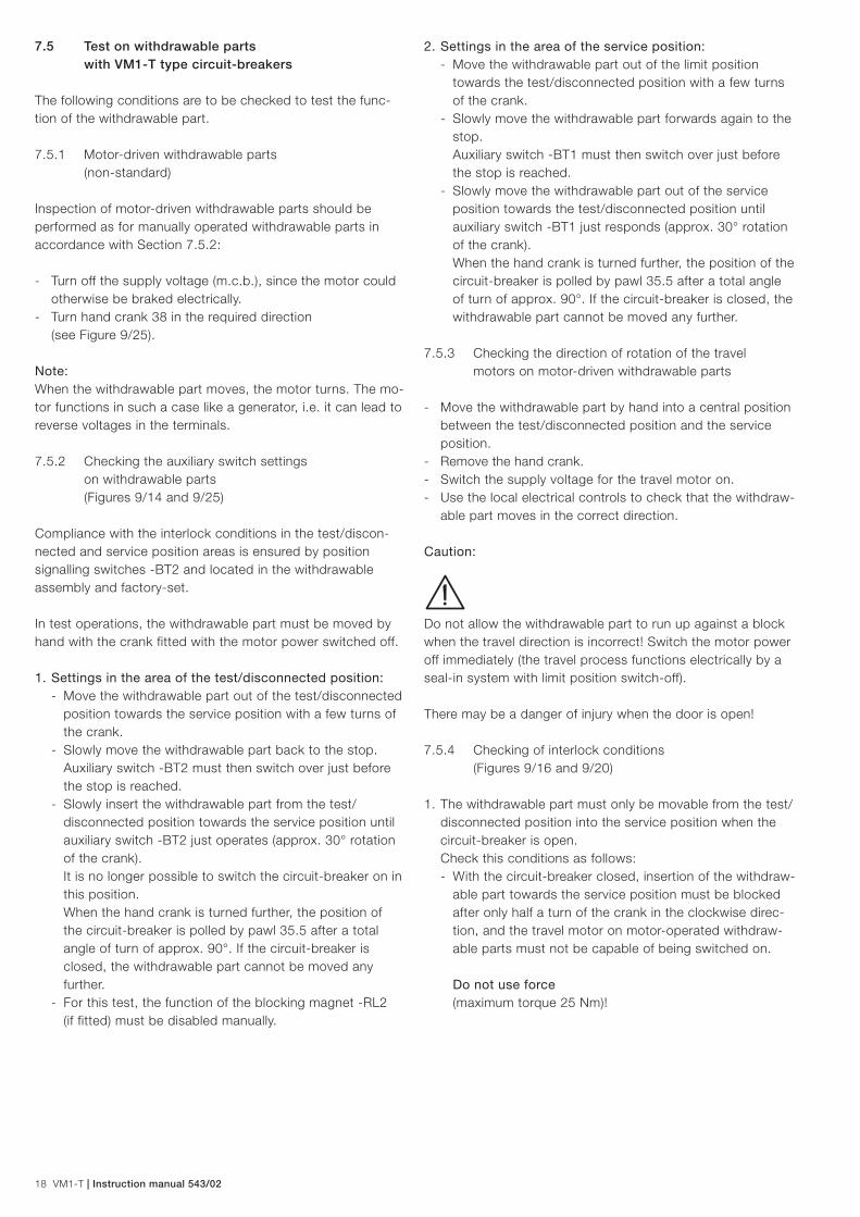
7.6.2 Auxiliary materials and lubricants
Designation Part no. (order code)
Lubricant:
Isoflex Topas NB 52 GCE0007249P0100
Halogen-free cleansers:
Rivolta BWR 210 (for general cleaning) GCE0007707P0100
ABB Instruction manual BA 1002/E GCEA901002P0101
Cold cleanser 716 (for use with conductive components,
components of insulating materials and in case of serious grime!) GCE0007706P0100
ABB Instruction manual BA 1006/E GCEA901006P0101
Paint:
Touch-up paint: Standard colour RAL 7035
- 1-kg-box GCE9014060R0103
- Spray tin GCE0007895P0100
Table: VM1-T withdrawable part
Designation Item Rated supply Part no. no. voltage (order code)
Auxiliary switch for manually operated mechanism -BT2 / -BT1
- Silver-plated contacts GCE7004024R0101
- Gold-plated contacts GCE7004024R0103
Auxiliary switches for motor-operated driving mechanism -BT2 / -BT1
- Silver-plated contacts GCE7004024R0102
- Gold-plated contacts GCE7004024R0104
Blocking magnet -RL2 24 V GCE7003820R0101
30 V R0102
48 V R0103
60 V R0104
110 V R0105
125 V R0107
220 V R0106
Motor with gearbox -MT 24 V GCE0940150P0111
30 V P0112
48 V P0113
60 V P0114
110 V .. .125 V P0115
220 V P0116
Tabel: VM-T type circuit-breaker
Designation Item Part no. no. (order code)
Auxiliary switch for ON/OFF position signalization -BB1 / -BB3
- Silver-plated contacts GCE7002397R0119
- Gold-plated contacts GCE7002397R0125
Designation Rated supply Part no. voltage (order code)
Breaker controller VM1-T 24 V … 48 V AC GCE7004902R0136
with power pack A 24 V … 60 V DC
Breaker controller VM1-T 100 V … 240 V AC GCE7004902R0137
with power pack B 110 V … 240 V DC

Instruction manual 543/02 | VM1-T 21
8 Application of the X-ray regulations
One of the physical properties of vacuum insulation is the possibility of X-ray emissions when the contact gap is open. The specified test performed by the Physikalisch-Technische Bundesanstalt (PTB) in Braunschweig demonstrates that the local dosage output of 1 µSv/h at a distance of 10 cm from the touchable surface is not exceeded when the rated voltage is applied.
The results are as follows: - Testing of the switching device or the vacuum interrupter
to VDE 0671 part 100 or IEC 62271-100 at the relevant rated power frequency withstand voltage may only be performed by trained personnel observing the stipulations
9 Figures
Figure 9/3: Vacuum circuit-breaker, Typ VM1-T, for fixed installation, 12 kV, 1600 … 2000 A, 25 kA, mechanism side.
Figure 9/4: Vacuum circuit-breaker, Typ VM1-T, for fixed installation, 12 kV, 1600 … 2000 A, 25 kA, pol side..
Figure 9/2: Vacuum circuit-breaker, type VM1-T, for fixed installation, 12 kV, ≤ 1250 A, ≤ 25 kA, pole side.
Figure 9/1: Vacuum circuit-breaker, type VM1-T, for fixed installation, 12 kV, ≤ 1250 A, ≤ 25 kA, mechanism side.
of the EU basic standard (Stipulation 96/29/Euratom of the senate from 13 May 1996 (ABI.L 159 from 29 June 1996)).
- Application of the rated voltage specified for the switching device by VDE 0671 part 100 or IEC 62271-100 is com-pletely safe.
- Higher voltages than the rated voltage or DC test voltage specified in VDE or IEC standards must not be applied!
- The containment of the above mentioned local dosage output with the vacuum interrupter in the open position is dependent on maintenance of the specified distance between the contacts (which is automatically ensured with correct mechanism function and force transmission).
- Safety clearances must be maintained.

22 VM1-T | Instruction manual 543/02
Figure 9/5: Vacuum circuit-breaker, type VM1-T, on withdrawable part, 24 kV, 1250 A, ≤ 25 kA, mechanism side.
Figure 9/6: Vacuum circuit-breaker, type VM1-T, on withdrawable part, 12 kV, 630 A, ≤ 25 kA, pole side. 33 Breaker pole 34 Contact arm with insulating tube (versions for rated currents to 1250 A and above have shrink sleeves) 34.1 Contact system
33
34
34.1
Figure 9/7: Vacuum circuit-breaker, type VM1-T, on withdrawable part, 24 kV, 1250 A, ≤ 25 kA, pole side. 33 Breaker pole 34 Contact arm with insulating tube (versions for rated currents to 630 A and above have insulating tubes) 34.1 Contact system
33
34
34.1
Figure 9/8: Vacuum circuit-breaker, type VM1-T, on withdrawable part, 24 kV, 1250 A, ≤ 25 kA, mechanism side. 35 Withdrawable assembly 36.1 Control wiring plug
35
36.1
Instruction manual 543/02 | VM1-T 23
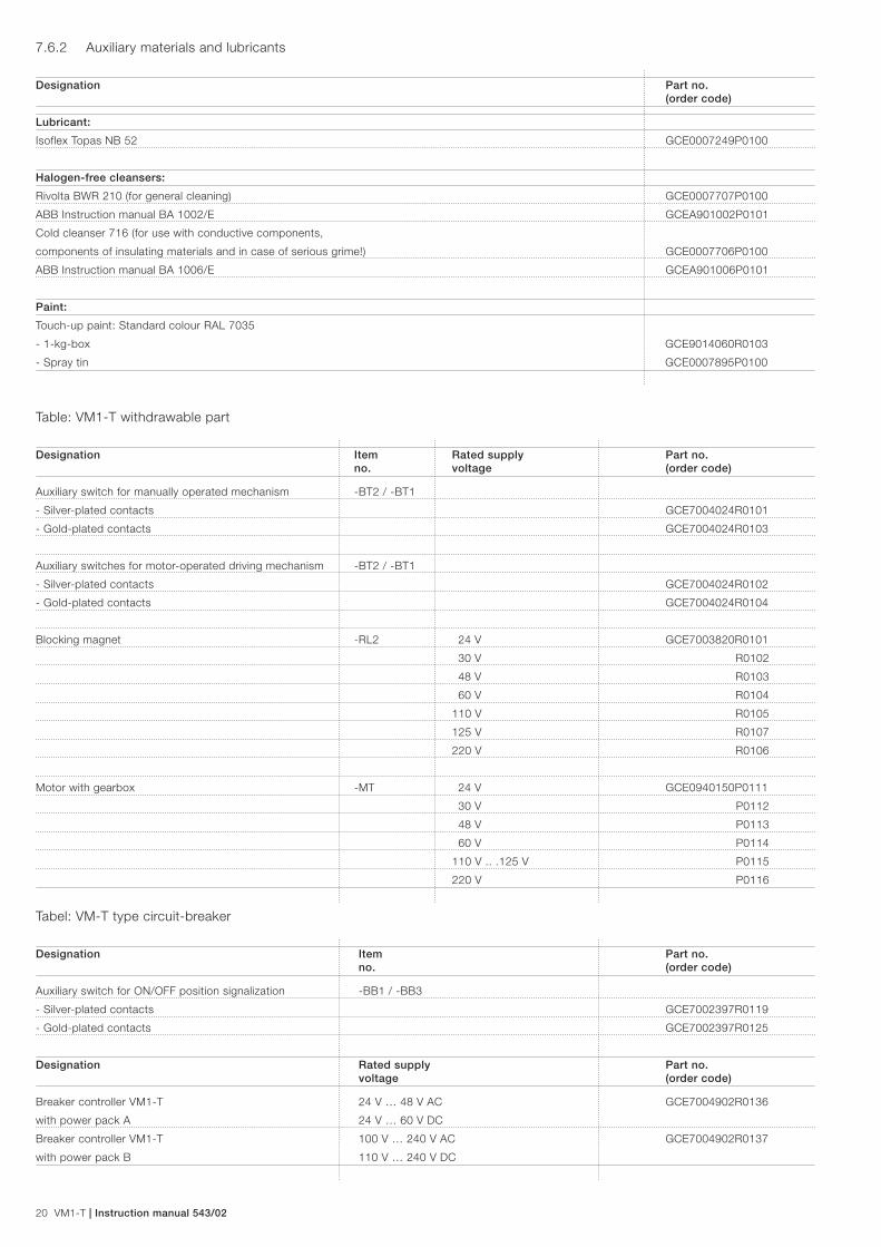
Figure 9/9: Withdrawable part with built-in auxiliary switch -BT2 Test position indicator -BT1 Service position indicator 35.1 Spindle mechanism 35.2 Square spigot 35.5 Pawl 35.6 Scene head on spindle 37 Control wiring plug connector for withdrawable assembly
Figure 9/10: Circuit-breaker front with controls and annunciations. 1 Mechanism enclosure 1.1 Front plate 1.2 Bore for handling, both sides 2 ”READY” lamp 3 ON push-button 4 OFF push-button 5 Mechanical operating cycle counter 6 Mechanical position indicator 7 Rating plate 8 Socket for emergency manual operation lever
35.5 35.2 35.6 35.1 -BT1 -BT2 37
7 5 6 4 3 2
8 1.1 1 1.2
22
21
2019
17
16
14
12
11
9
125
24
23
13
1.1
10
15
18
24.124.2
Figure 9/11: Sectional view of a vacuum circuit-breaker type VM1-T, schematic diagram. 1 Mechanism enclosure 1.1 Front plate, removable 9 Emergency manual opening mechanism 10 Magnetic actuator 11 OFF coil 12 Magnet armature 13 Permanent magnets 14 ON coil 15 Sensor -B0A for ”circuit-breaker OFF” signal 16 Sensor -B0E for ”circuit-breaker ON” signal 17 Travel adjuster 18 Lever shaft 19 Insulated link rod 20 Contact force spring 21 Flexible connector 22 Lower breaker terminal 23 Cast insulation 24 Vacuum interrupter 24.1 Moving contact 24.2 Fixed contact 25 Upper breaker terminal
Figure 9/12: Position indicator. 6 Mechanical position indicator 15 Sensor -B0A for “circuit-breaker OFF” signal 16 Sensor -B0E for “circuit-breaker ON” signal
6 15 16

24 VM1-T | Instruction manual 543/02
/ A: 24 V...48 V AC/DC; 60 V DC
LOGIC
3
4
27
2
-Q0 15 10
16
26
30
-RL1
-MO2
-MO1
-MC
-DN
-DR
-DC1-DC2-DO1-DO2
-BB4
-MU
B: 100 V AC; 110 V...240 V AC/DC=
= ⊕-MS
Figure 9/13: Block diagram of the magnetic actuator mechanism. 2 ”READY” lamp (LED) 3 ON push-button 4 OFF push-button 10 Actuator 15 Sensor for ”circuit-breaker OFF” signal 16 Sensor for ”circuit-breaker ON” signal 26 Storage capacitor 27 Circuit-breaker control unit 30 Converter for operation with AC or DC voltage -Q0 Circuit-breaker
Figure 9/14: Possible encoding of the control wiring plug connector, 58-way control wiring socket. 36.2 Control wiring socket 36.3 Centres for coding pins and bores 36.4 Bore for the actuating pin on the control wiring plug for controling the auxiliary switch.
External circuit-breaker connection:
Inputs:-MU Switching command OFF (closed circuit)-RL1 Closing lock-out (closed circuit)-MO2 Switching command OFF 2 (open circuit)-MO1 Switching command OFF 1 (open circuit)-MC Switching command ON (open circuit)-MS Supply voltage
Outputs:-BB4 Fleeting contact (100 ms)-DN NOT READY (NCC)-DR READY (NOC)-DC2 ON signal 2 (NOC)-DO2 OFF signal 2 (NOC)-DC1 ON signal 1 (NOC)-DO1 OFF signal 1 (NOC)
See page 43 for comparison of IEC/VDE designations.
Sample for coding
Control Code B1 B2 B3 B4 B5 B6
wiring Pin X X
socket Hole
Control Hole X X
wiring Pin
plug Code B1 B2 B3 B4 B5* B6
* B5 is used in special cases only

Instruction manual 543/02 | VM1-T 25
Undervoltage release deactivated
No delay
delay: 0,5 s
delay: 1 s
delay: 2 s
delay: 3 s
delay: 4 s
delay: 5 s
24-30 V DC 11 V … 16 V DC
48-60 V DC 21 V … 33 V DC
100-127 V AC DC 45 V … 70 V AC DC
220-240 V AC DC 84 V … 154 V AC DC
Input -MSfor voltage
supply
Input for ON/OFFposition signal
(sensor)
I 1001
I 1004
I 1002
Connection for:• ON button (3)• OFF button (4)• “Ready” lamp (2)
Inputs:-MU-RL1-MO2-MO1-MC
Outputs:-BB4-DN-DR-DC2-DO2-DC1-DO1
Treshold for undervoltage release -MUI 1001 Rated voltage Treshold
range 35 % ... 70 %321
On Off
321
On Off
321
On Off
321
On Off
Delay time undervoltage release -MUI 1004
432
On Off
432
On Off
432
On Off
432
On Off
432
On Off
432
On Off
432
On Off
432
On Off
Deactivated (normal delivery status)
AUTO-OFF at declining capacitor voltageI 1004
1On Off
Activated (on customer demand)1On Off
5 For VM1-T: ON
I 1004
Connection foractuator coils
Connection forstorage capacitors
Closing support for -MUIf the DIP-switch is in ON position, theVM1-T with activated undervoltage release-MU can be closed even if no voltage is appliedto -MU.
On Off
I 1002
3
For VM1-T: OFFOn Off
2
Always ON (enables -MO2) in spite offailure of the microprocessor)On Off
1
Figure 9/15 a: Circuit-breaker control unit
Note: Some changes to the settings of the DIP-switches require a discharge of the storage capacitor (section 7.1) to become effective.
See page 43 for comparison of IEC/VDE designations.
26 VM1-T | Instruction manual 543/02
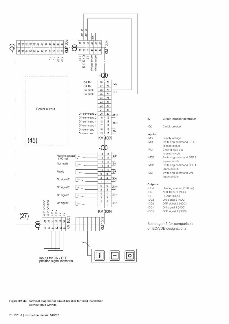
27 Circuit-breaker controller
-Q0 Circuit-breaker
Inputs:-MS Supply voltage-MU Switching command (OFF) (closed circuit)-RL1 Closing lock-out (closed circuit)-MO2 Switching command OFF 2 (open circuit)-MO1 Switching command OFF 1 (open circuit)-MC Switching command ON (open circuit)
Outputs:-BB4 Fleeting contact (100 ms)-DN NOT READY (NCC)-DR READY (NOC)-DC2 ON signal 2 (NOC)-DO2 OFF signal 2 (NOC)-DC1 ON signal 1 (NOC)-DO1 OFF signal 1 (NOC)
See page 43 for comparison of IEC/VDE designations
Figure 9/15b: Terminal diagram for circuit-breaker for fixed installation (without plug wiring).
Instruction manual 543/02 | VM1-T 27
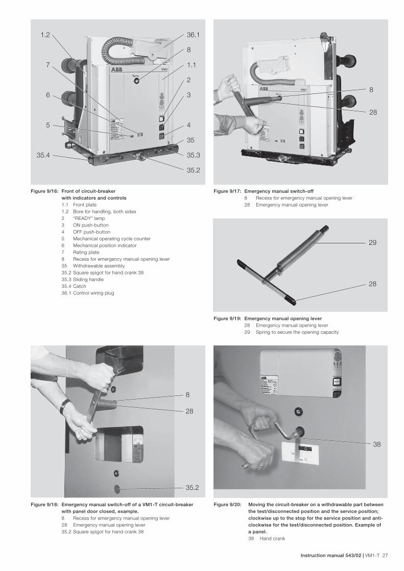
Figure 9/16: Front of circuit-breaker with indicators and controls 1.1 Front plate 1.2 Bore for handling, both sides 2 “READY” lamp 3 ON push-button 4 OFF push-button 5 Mechanical operating cycle counter 6 Mechanical position indicator 7 Rating plate 8 Recess for emergency manual opening lever 35 Withdrawable assembly 35.2 Square spigot for hand crank 38 35.3 Sliding handle 35.4 Catch 36.1 Control wiring plug
Figure 9/17: Emergency manual switch-off 8 Recess for emergency manual opening lever 28 Emergency manual opening lever
Figure 9/18: Emergency manual switch-off of a VM1-T circuit-breaker with panel door closed, example. 8 Recess for emergency manual opening lever 28 Emergency manual opening lever 35.2 Square spigot for hand crank 38
Figure 9/19: Emergency manual opening lever 28 Emergency manual opening lever 29 Spring to secure the opening capacity
8
28
35.2
29
28
36.1
8
1.1
2
3
5 4
35
35.3
35.2
1.2
7
6
35.4
8
28
Figure 9/20: Moving the circuit-breaker on a withdrawable part between the test/disconnected position and the service position; clockwise up to the stop for the service position and anti- clockwise for the test/disconnected position. Example of a panel. 38 Hand crank
38

28 VM1-T | Instruction manual 543/02
Figure 9/21: Withdrawal of the withdrawable part with circuit-breaker onto the service truck. - Service truck engaged with the panel - Move the sliding handles inwards to disengage 31 Withdrawable part with VM1-T circuit-breaker 35.3 Sliding handle 40 Service truck
Figure 9/22: Sevice truck approaching the panel. Align the guide pins on the load surface with the height adjusters, position the truck at the panel and allow the catch to engage. 40.1 Height adjuster for the load surface 40.2 Guide pin 40.3 Catch
Figure 9/23: Fit the contact system back-to-front on the thin end of the arbor and slide it onto the thicker shank area. 34.1 Contact system 39 Arbor 39.1 Journal
Figure 9/24: Slide the contact system over from the arbor onto the contact arm and allow it to engage there. 34 Contact arm 34.1 Contact system 34.2 Internal tension springs 34.3 Insulating sleeve 39 Arbor
35.3 31 40
40.3
40.2
40.1
39.1 39 34.1 34.3 34 34.1 34.2 39

Instruction manual 543/02 | VM1-T 29
5 6 15/16 27.1 27
26 10 8 27.2 45 60
Figure 9/25: View of the operating mechanism of the VM1-T circuit- breaker with auxiliary devices, front plate removed. 5 Mechanical operating cycle counter 6 Mechanical position indicator 8 Receptacle for emergency manual opening lever 10 Magnetic actuator 15 Sensor for “circuit-breaker OFF“ signal (top) 16 Sensor for “circuit-breaker ON“ signal (bottom)
Figure 9/27: Manually movable withdrawable part, front plate removed. -RL2 blocking magnet for the withdrawable part (only on manually movable parts) 41 Mechanical interlock between the withdrawable assembly and the circuit-breaker
-RL2 41
27.3
26 Storage capacitors 27 Circuit-breaker control unit 27.1 Plug connector for outputs -BB4, -DR, -DN, -DO1, -DC1 27.2 Plug connector for supply voltage 27.3 Plug connector for inputs (filter card not shown) 45 Power output 60 Filter card
Figure 9/26: Mechanical interlock between the withdrawable assembly and the circuit-breaker, setting of the slide blocker. View from front 35.5 Pawl in the withdrawable assembly 41.1 Fixing sheet 41.2 Slide blocker 41.3 Revolute joint 41.4 Base plate of the circuit-breaker 41.5 Screw
Unlocked
Locked
30 VM1-T | Instruction manual 543/02
10 Technical data
10.1 Technical data, general
10.1.1 Technical data Control electronics
a) Binary inputs The following applies to all 5 input channels:
- Electrical isolation between all inputs and from the elec-tronics: 2.0 kV AC
- AC/DC operation (any polarity for DC) - Response range at inputs -MO1, -MC und -MO2, according to the type of filter card 1): - 24 V –15% … 60 V +15% AC 24 V –30% … 60 V +15% DC
- 100 V –15% … 125 V +15% AC 100 V –30% … 125 V +15% DC
- 220 V –15% … 240 V +15% AC 220 V –30% … 240 V +15% DC
- Response range -MU 2) adjustable, see page 26 - Response range -RL1:
- 24 V –15% … 240 V +15% AC - 24 V –30% … 240 V +15% DC
- Base load at input: - 300 kΩ (-MU 2), -RL1, -MO2) 3)
- 14 kΩ (-MO1, -MC) - Inputs protected from voltage surges.
b) Binary outputs The following applies to all 5 output channels:
- Electrical isolation between all outputs and from the elec-tronics: 2.0 kV AC
- Switching voltage: max. 400 V AC or 300 V DC - Switching current: max. 6 A / 250 V AC (resistive) - ON resistance: 100 mΩ - Switch putputs: NOC, NCC and fleeting contact - Duration of fleeting contact pulse: 100 ms - Output connections: varistors
10.1.2 Technical data AC/DC converter
- Input voltage ranges, optional: - Power pack A:
- 24 V –15% … 48 V +15% AC - 24 V –15% … 60 V +15% DC
- Power pack B: - 100 V –15% … 240 V +10% AC - 110 V –15% … 240 V +10% DC
- Protection of power feed (must be ordered): - Power pack A: ABB-Stotz m.c.b.: S 282 UC-K; 1.6 A
- Power pack B: ABB-Stotz m.c.b.: S 282 UC-K; 1.0 A
- Power consumption on the input side during a charging process: ca. 100 W
- Power consumption in normal position: P < 10 W - Charging times of the capacitor (example for DC voltage):
a) Initial charging on commissioning: - Breakers up to 25 kA: max. 20s depending on the supply voltage. In this time, the capacitor(s) is/are charged to 80 V, and an ON-OFF operating cycle is already possible at 69 V. (The ”READY” lamp indicates readiness for switch-ing. A flashing “READY” lamp signals recharging of the capacitor. Switching readiness is enabled during that time).
b) Recharging after a switch operation to a charge of 80 V: max. 10s
1) Different response ranges for individual inputs on request.
2) Full version on the control module
3) In general, with AC signals which are connected via long lines, it should be checked whether the installed base load of 300 kΩ is sufficient (mutual capacitive coupling!) to ensure a reliably low interference level. Otherwise, an appropriately dimensioned resistor or capacitor is to be connected in parallel at the input terminals.

Instruction manual 543/02 | VM1-T 31
Diagram A)
810 2
2
3
45678
103
2
3
45678
4
2
3
45678
105
10
678
10
2
3
4567
50,05 0,1 0,2 0,3 0,4 0,5 0,6 0,8 2 3 4 5 6 7 8 109 20 3010,01 0,02 0,03 0,08
Breaking current la (kA)
Num
ber
of o
per
atin
g cy
cles
n
10.1.3 Permissible number of vacuum interrupter operating cycles
Diagram B)
810 2
2
3
45678
103
2
3
45678
4
2
3
45678
105
10
678
10
2
3
4567
50,05 0,1 0,2 0,3 0,4 0,5 0,6 0,8 2 3 4 5 6 7 8 109 20 3010,01 0,02 0,03 0,08
Breaking current la (kA)
Num
ber
of o
per
atin
g cy
cles
n
Diagram C)
810 2
2
3
45678
103
2
3
45678
4
2
3
45678
105
10
678
10
2
3
4567
50,05 0,1 0,2 0,3 0,4 0,5 0,6 0,8 2 3 4 5 6 7 8 109 20 3010,01 0,02 0,03 0,08
Breaking current la (kA)
Num
ber
of o
per
atin
g cy
cles
n

32 VM1-T | Instruction manual 543/02
Diagram D)
Figure 9/28: Permissible number of vacuum interrupter operating cycles n as a function of the breaking current Ia. (Reference see section 10.2 and 10.3 – Technical data page 33 and 36)
810 2
2
3
45678
103
2
3
45678
4
2
3
45678
105
10
678
10
2
3
4567
50,05 0,1 0,2 0,3 0,4 0,5 0,6 0,8 2 3 4 5 6 7 8 109 20 3010,01 0,02 0,03 0,08
Breaking current la (kA)
Num
ber
of o
per
atin
g cy
cles
n
Breaking current la (kA)
Num
ber
of o
per
atin
g cy
cles
n
Diagram E)
810 2
2
3
45678
103
2
3
45678
4
2
3
45678
105
10
678
10
2
3
4567
50,05 0,1 0,2 0,3 0,4 0,5 0,6 0,8 2 3 4 5 6 7 8 109 20 3010,01 0,02 0,03 0,08
Breaking current la (kA)
Num
ber
of o
per
atin
g cy
cles
n
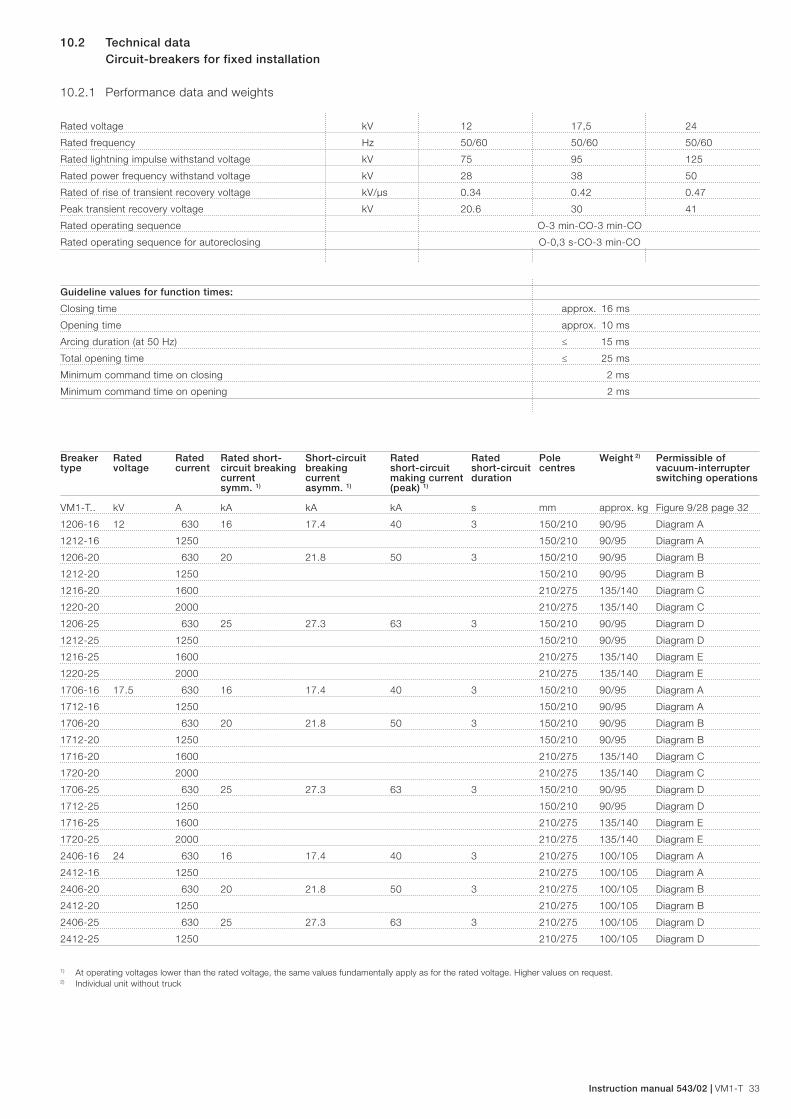
Instruction manual 543/02 | VM1-T 33
10.2 Technical data Circuit-breakers for fixed installation
10.2.1 Performance data and weights
Rated voltage kV 12 17,5 24
Rated frequency Hz 50/60 50/60 50/60
Rated lightning impulse withstand voltage kV 75 95 125
Rated power frequency withstand voltage kV 28 38 50
Rated of rise of transient recovery voltage kV/µs 0.34 0.42 0.47
Peak transient recovery voltage kV 20.6 30 41
Rated operating sequence O-3 min-CO-3 min-CO
Rated operating sequence for autoreclosing O-0,3 s-CO-3 min-CO
Guideline values for function times:
Closing time approx. 16 ms
Opening time approx. 10 ms
Arcing duration (at 50 Hz) ≤ 15 ms
Total opening time ≤ 25 ms
Minimum command time on closing 2 ms
Minimum command time on opening 2 ms
Breaker Rated Rated Rated short- Short-circuit Rated Rated Pole Weight 2) Permissible of type voltage current circuit breaking breaking short-circuit short-circuit centres vacuum-interrupter current current making current duration switching operations symm. 1) asymm. 1) (peak) 1)
VM1-T.. kV A kA kA kA s mm approx. kg Figure 9/28 page 32
1206-16 12 630 16 17.4 40 3 150/210 90/95 Diagram A
1212-16 1250 150/210 90/95 Diagram A
1206-20 630 20 21.8 50 3 150/210 90/95 Diagram B
1212-20 1250 150/210 90/95 Diagram B
1216-20 1600 210/275 135/140 Diagram C
1220-20 2000 210/275 135/140 Diagram C
1206-25 630 25 27.3 63 3 150/210 90/95 Diagram D
1212-25 1250 150/210 90/95 Diagram D
1216-25 1600 210/275 135/140 Diagram E
1220-25 2000 210/275 135/140 Diagram E
1706-16 17.5 630 16 17.4 40 3 150/210 90/95 Diagram A
1712-16 1250 150/210 90/95 Diagram A
1706-20 630 20 21.8 50 3 150/210 90/95 Diagram B
1712-20 1250 150/210 90/95 Diagram B
1716-20 1600 210/275 135/140 Diagram C
1720-20 2000 210/275 135/140 Diagram C
1706-25 630 25 27.3 63 3 150/210 90/95 Diagram D
1712-25 1250 150/210 90/95 Diagram D
1716-25 1600 210/275 135/140 Diagram E
1720-25 2000 210/275 135/140 Diagram E
2406-16 24 630 16 17.4 40 3 210/275 100/105 Diagram A
2412-16 1250 210/275 100/105 Diagram A
2406-20 630 20 21.8 50 3 210/275 100/105 Diagram B
2412-20 1250 210/275 100/105 Diagram B
2406-25 630 25 27.3 63 3 210/275 100/105 Diagram D
2412-25 1250 210/275 100/105 Diagram D
1) At operating voltages lower than the rated voltage, the same values fundamentally apply as for the rated voltage. Higher values on request. 2) Individual unit without truck
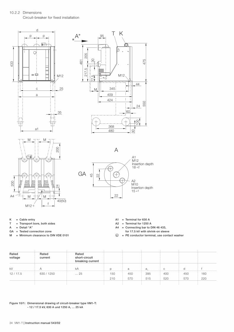
34 VM1-T | Instruction manual 543/02
10.2.2 Dimensions Circuit-breaker for fixed installation
K = Cable entryT = Transport bore, both sidesA = Detail “A”GA = Tested connection zoneM = Minimum clearance to DIN VDE 0101
A1 = Terminal for 630 AA2 = Terminal for 1250 AA4 = Connecting bar to DIN 46 433, for 17.5 kV with shrink-on sleeve = PE conductor terminal, use contact washer
Rated Rated Rated voltage current short-circuit breaking current
kV A kA p a a1 c d f
12 / 17.5 630 / 1250 ... 25 150 450 395 400 450 160
210 570 515 520 570 220
Figure 10/1: Dimensional drawing of circuit-breaker type VM1-T: - 12 / 17.5 kV, 630 A und 1250 A, … 25 kA
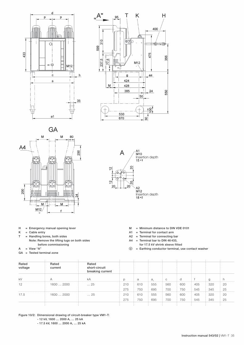
Instruction manual 543/02 | VM1-T 35
H = Emergency manual opening leverK = Cable entryT = Handling bores, both sides Note: Remove the lifting lugs on both sides before commissioningA = View “A”GA = Tested terminal zone
M = Minimum distance to DIN VDE 0101A1 = Terminal for contact armA2 = Terminal for connecting barA4 = Terminal bar to DIN 46 433, for 17.5 kV shrink sleeve fitted = Earthing conductor terminal, use contact washer
Rated Rated Rated voltage current short-circuit breaking current
kV A kA p a a1 c d f g h
12 1600 … 2000 ... 25 210 610 555 560 600 405 320 20
275 750 695 700 750 545 345 25
17.5 1600 … 2000 … 25 210 610 555 560 600 405 320 20
275 750 695 700 750 545 345 25
Figure 10/2: Dimensional drawing of circuit-breaker type VM1-T: - 12 kV, 1600 … 2000 A, … 25 kA - 17.5 kV, 1600 … 2000 A, … 25 kA

36 VM1-T | Instruction manual 543/02
K = Cable entryT = Trnasport bore, both sidesA = Detail “A”GA = Tested connection zoneM = Minimum clearance to DIN VDE 0101
A1 = Terminal for 630 AA2 = Terminal for 1250 AA4 = Connection bar to DIN 46 433, for 17.5 kV with shrink-on sleeve = PE conductor terminal, use contact washer
Rated Rated Rated voltage current short-circuit breaking current
kV A kA p a a1 c d f p e i k l
24 630 / 1250 ... 25 210 570 515 520 570 220 210 409 60 368 480
275 750 695 700 750 545 275 428 50 530 670
Figure 10/3: Dimensional drawing of circuit-breaker type VM1-T: - 24 kV, 630 A and 1250 A, … 25 kA

Instruction manual 543/02 | VM1-T 37
10.3 Technical data Circuit-breakers on withdrawable part 1)
10.3.1 Performance data and weights
Rated voltage kV 12 17.5 24
Rated frequency Hz 50/60 50/60 50/60
Rated lightning impulse withstand voltage kV 75 95 125
Rated power frequency withstand voltage kV 28 38 50
Rated of rise of transient recovery voltage kV/µs 0.34 0.42 0.47
Peak transient recovery voltage kV 20.6 30 41
Rated operating sequence O-3 min-CO-3 min-CO
Rated operating sequence for autoreclosing O-0,3 s-CO-3 min-CO
Guideline values for function times:
Closing time approx. 16 ms
Opening time approx. 10 ms
Arcing duration (at 50 Hz) ≤ 15 ms
Break time ≤ 25 ms
Minimum command time on closing 2 ms
Minimum command time on opening 2 ms
Breaker Rated Rated Rated short- Short-circuit Rated Rated Pole Weight 2) Permissible of type voltage current circuit breaking breaking short-circuit short-circuit centres 1) 1) 3) vacuum-interrupter current current making current duration switching operations symm. 2) asymm. 2) (peak) 2)
VM1-T.. kV A kA kA kA s mm approx. kg Figure 9/28 page 31/32
1206-16 12 630 16 17.4 40 3 150 127 Diagram A
1212-16 1250 150 131 Diagram A
1206-20 630 20 21.8 50 3 150 127 Diagram B
1212-20 1250 150 131 Diagram B
1216-20 1600 210/275 135/140 Diagram C
1220-20 2000 210/275 135/140 Diagram C
1206-25 630 25 27.3 63 3 150 127 Diagram D
1212-25 1250 150 131 Diagram D
1216-25 1600 210/275 135/140 Diagram E
1220-25 2000 210/275 135/140 Diagram E
1706-16 17.5 630 16 17.4 40 3 150 127 Diagram A
1712-16 1250 150 131 Diagram A
1706-20 630 20 21.8 50 3 150 127 Diagram B
1712-20 1250 150 131 Diagram B
1716-20 1600 210/275 135/140 Diagram C
1720-20 2000 210/275 135/140 Diagram C
1706-25 630 25 27.3 63 3 150 127 Diagram D
1712-25 1250 150 131 Diagram D
1716-25 1600 210/275 135/140 Diagram E
1720-25 2000 210/275 135/140 Diagram E
2406-16 24 630 16 17.4 40 3 210/275 128/133 Diagram A
2412-16 1250 210/275 142/147 Diagram A
2406-20 630 20 21.8 50 3 210/275 128/133 Diagram B
2412-20 1250 210/275 142/147 Diagram B
2406-25 630 25 27.3 63 3 210/275 128/133 Diagram D
2412-25 1250 210/275 142/147 Diagram D
1) For further details on the cell type assignments see the section on dimensions for circuit-breaker on withdrawable assembly. 2) At operating voltages lower than the rated voltage, the same values fundamentally apply as for the rated voltage. Higher values on request. 3) With a motorized withdrawable part, the weight is increased by approx. 2 kg

38 VM1-T | Instruction manual 543/02
10.3.2 Dimensional drawings Circuit-breakers on withdrawable part
Figure 10/4: Vacuum circuit-breaker on withdrawable part, type VM1-T: - Use in UniGear type ZS1 - 12 kV, … 1250 A, … 25 kA - 17.5 kV, … 1250 A, … 25 kA
*) Travel rail **) Front edge of bolt
1) Only fitted if BT1/BT2 is configured in the panel.2) Versions for up to 630 A (with insulating tube) 3) Versions for 1250 A upwards (with shrink sleeve) 4) For motor-operated withdrawable parts, the weight is increased by approx. 2 kg.
Table 1:
Panel type Parameters Parameters Weight 4) 12 kV 17.5 kV p A C D E J Y 2) Z 3) approx. kg
UniGear type ZS1 630 A, ... 25 kA 630 A, ...25 kA 150 502 466 490 503 492 x - 127
1250 A, ... 25 kA 1250 A, ...25 kA 150 502 466 490 503 492 - x 131
Table 2:
p N O Q R S T F1 G1
UniGear type ZS1 150 624±2 618 628 620±2 128±1 120±1 30±1 203±1

Instruction manual 543/02 | VM1-T 39
*) Rail **) Front edge of bar
1) Only fitted if BT1/BT2 is configured in the panel. 2) Remove the lifting lugs on both sides before commissioning. 3) Weight is increased by approx. 2 kg if the motor-driven withdrawable part is installed.
Figure 10/5: Vacuum circuit-breaker on withdrawable part, type VM1-T: - Use in UniGear type ZS1 - 12 kV, 1600 … 2000 A, … 25 kA - 17.5 kV, 1600 … 2000 A, … 25 kA
Table 1:
Panel type Parameters Parameters Weight 3) 12 kV 17.5 kV p A C D E J M W approx. kg
UniGear type ZS1 1600 A, ... 25 kA 1600 A, ... 25 kA 210 650 618 640 653 636 120 79 215
1600 A, … 25 kA 1600 A, … 25 kA 275 850 812 836 853 844 120 79 220
2000 A, … 25 kA 2000 A, … 25 kA 210 650 618 640 653 636 120 79 215
2000 A, … 25 kA 2000 A, … 25 kA 275 850 812 836 853 844 120 79 220
Table 2:
p N O Q R S T G1
UniGear type ZS1 210 691±2 688 698 688±2 119 111±1 273±2
275 691±2 688 698 688±2 119 111±1 273±2
O Q
DE
Ap p
J
MW
1)
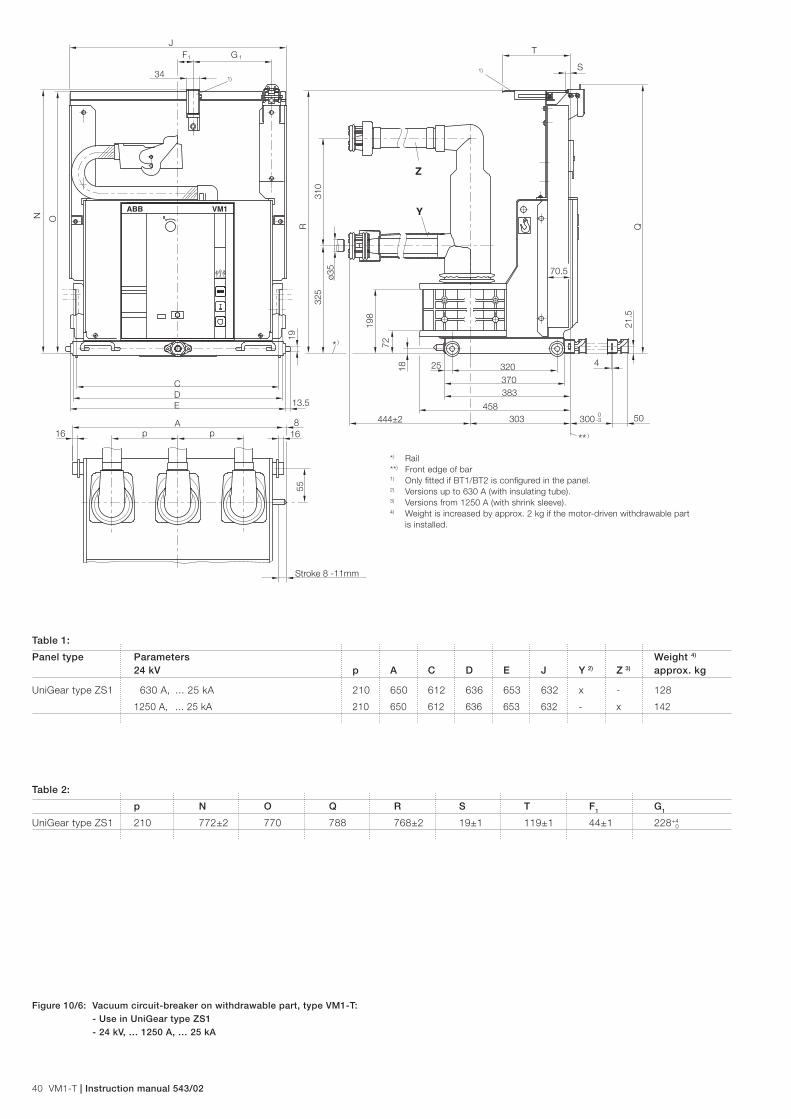
40 VM1-T | Instruction manual 543/02
*) Rail **) Front edge of bar
1) Only fitted if BT1/BT2 is configured in the panel. 2) Versions up to 630 A (with insulating tube). 3) Versions from 1250 A (with shrink sleeve). 4) Weight is increased by approx. 2 kg if the motor-driven withdrawable part is installed.
Figure 10/6: Vacuum circuit-breaker on withdrawable part, type VM1-T: - Use in UniGear type ZS1 - 24 kV, … 1250 A, … 25 kA
Table 1:
Panel type Parameters Weight 4) 24 kV p A C D E J Y 2) Z 3) approx. kg
UniGear type ZS1 630 A, ... 25 kA 210 650 612 636 653 632 x - 128
1250 A, ... 25 kA 210 650 612 636 653 632 - x 142
Table 2:
p N O Q R S T F1 G1
UniGear type ZS1 210 772±2 770 788 768±2 19±1 119±1 44±1 228+4
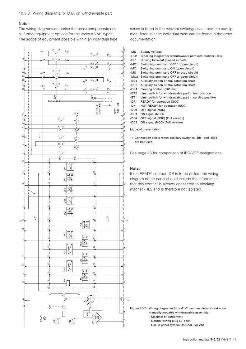
Instruction manual 543/02 | VM1-T 41
Figure 10/7: Wiring diagramm for VM1-T vacuum circuit-breaker on manually movable withdrawable assembly: - Maximal of equipment - Control wiring plug 58-pole - Use in panel system UniGear-Typ ZS1
See page 43 for comparison of IEC/VDE designations.
Note:If the READY contact -DR is to be polled, the wiring diagram of the panel should include the information that this contact is already connected to blocking magnet -RL2 and is therefore not isolated.
-MS Supply voltage-RL2 Blocking magnet for withdrawable part with rectifier -TR5-RL1 Closing lock-out (closed circuit)-MO1 Switching command OFF 1 (open circuit)-MC Switching command ON (open circuit)-MU Switching command OFF (closed circuit)-MO2 Switching command OFF 2 (open circuit)-BB1 Auxiliary switch on the actuating shaft-BB3 Auxiliary switch on the actuating shaft-BB4 Fleeting contact (100 ms)-BT2 Limit switch for withdrawable part in test position-BT1 Limit switch for withdrawable part in service position-DR READY for operation (NOC)-DN NOT READY for operation (NCC)-DO1 OFF signal (NOC)-DC1 ON signal (NOC)-DO2 OFF signal (NOC) (Full version)-DC2 ON signal (NOC) (Full version)
Mode of presentation:
1) Connection exists when auxiliary switches -BB1 and -BB3 are not used.
10.3.3 Wiring diagrams for C.B. on withdrawable part
Note:The wiring diagrams comprise the basic com ponents and all further equipment options for the various VM1 types. The scope of equipment possible within an individual type
series is listed in the relevant switchgear list, and the euquip-ment fitted in each individual case can be found in the order documentation.

42 VM1-T | Instruction manual 543/02
Figure 10/8: Wiring diagram for VM1-T vacuum circuit-breaker on motor-driven withdrawable assembly: - Maximum of equipment - Control wiring plug 58-pole - Use in panel system UniGear type ZS1
See page 43 for comparison of IEC/VDE designations.
-MS Supply voltage-RL1 Closing lock-out (closed circuit)-MO1 Switching command OFF 1 (open circuit)-MC Switching command ON (open circuit)-MU Switching command OFF (closed circuit)-MO2 Switching command OFF 2 (open circuit)-BB1 Auxiliary switch on the actuating shaft-BB3 Auxiliary switch on the actuating shaft-BB4 Fleeting contact (100 ms)-BT2 Limit switch for withdrawable part in test position-BT1 Limit switch for withdrawable part in service position-DR READY for operation (NOC)-DN NOT READY for operation (NCC)-DO1 OFF signal (NOC)-DC1 ON signal (NOC)-DO2 OFF signal (NOC) (Full version)-DC2 ON signal (NOC) (Full version)
Mode of presentation:
1) Connection exists when auxiliary switches -BB1 and -BB3 are not used.

Instruction manual 543/02 | VM1-T 43
11 Comparison of designations to IEC 61346-1 / 61346-2, IEC 81346-1 / 81346-2 and VDE-DIN 40719 Part 2
Description IEC 61346-1 / 61346-2 IEC 81346-1 / 81346-2 VDE DIN 40719 Part 2
Blocking magnet for withdrawable part with rectifier -TR5 -RL2 -RLE2 -Y0
Closing lock-out (closed circuit) -RL1 -RLE1 -Y1
Switching command OFF 1 (open circuit) -MO1 -MBO1 -Y2
Switching command ON (open circuit) -MC -MBC -Y3
Switching command OFF (closed circuit) -MU -MBU -Y4
Switching command OFF 2 (open circuit) -MO2 -MBO2 -Y9
Auxiliary switch on the actuating shaft -BB1 -BGB1 -S3
Auxiliary switch on the actuating shaft -BB3 -BGB3 -S5
Fleeting contact (100 ms) -BB4 -BGB4 -S7
Limit switch for withdrawable part in test position -BT2 -BGT2 -S8
Limit switch for withdrawable part in service position -BT1 -BGT1 -S9
READY for operation (NOC) -DR -BGB31 -S11
NOT READY for operation (NCC) -DN -BGB32 -S12
OFF signal (NOC) -DO1 -BGB41 -S41
ON signal (NOC) -DC1 -BGB42 -S42
OFF-Signal (NOC) (Full version) -DO2 -BGB43 -S43
ON-Signal (NOC) (Full version) -DC2 -BGB44 -S44
Supply voltage -MS -MAS -M0

MA
_VM
1-T(
EN
)-_1
VC
D60
1412
- 16
01 (G
S)ABB S.p.A.
Electrification Products Division Medium Voltage Products Via Friuli, 4 I-24044 Dalmine Tel.: +39 035 6952 111 Fax: +39 035 6952 874 E-mail: [email protected]
ABB AGCalor Emag Medium Voltage ProductsOberhausener Strasse 33 Petzower Strasse 840472 Ratingen 14542 Werder (Havel) OT GlindowGERMANY GERMANYTel.: 02102 12-0Fax: 02102 12-17 77E-Mail: [email protected]
www.abb.com/mediumvoltage
The data and illustrations are not binding. We reserve the right to modify the contents of this document without prior notice following technical and product developments.
© Copyright 2016 ABB. All rights reserved.
Contact us
Related Documents