Reliability Assessment and Improvement of Large Power Induction Motor Winding Insulation Protection System Using Predictive Analysis Mahfoud Chafai, Larbi Refoufi , Hamid Bentarzi Signals and Systems Laboratory (SisyLab) DGEE, FSI, University of Boumerdes, Algeria E-mail:[email protected] Abstract: The paper presents a reliability assessment of a widely used protection system of large power squirrel cage induction motors. In conjunction with published field induction motors Failure data this assessment effort is based on a integrated predictive analysis using three methods: (1) a Fault Tree Analysis (FTA) that allows to identify and then quantify the initiating failure cause weighting factors; (2) an Event Tree Analysis (ETA) that allows to predict the protection system probability outcomes following an external disturbance and (3) a Failure Mode Effect and Criticality Analysis (FMECA) that will help set the stage for developing a preventive maintenance program fit to keep up the induction motor protection system reliability at the required level with particular attention given to aggressive environmental factors such as found in cement plants. Key words: FTA, ETA, FMECA, Induction motors , Protection, Reliability , Failure Modes. 1 Introduction The induced draft fan high power induction motor, that draws hot gas off the rotary kiln, is a central piece of cement industry process. Despite its robustness and arguably high reliability it has its physical limitations which, if exceeded, will result in premature failure. Any operational failure will cause plant shut down and hence considerable economic losses. There is therefore a great need to improve the motor availability through improving its protection system. According to published failure rates, bearings and winding insulation failures are by far the most dominant failures of large induction motors [1-2-3] together, they represent about 80% of the total number of motor failures. Failures of bearings can be detected during operation at an early stage from vibration measurements; insulation failures are comparatively faster developing failures for which adequate monitoring approaches have not yet fully matured [4] and [6], calling for attention to be focused on this latter aspect. In the present work, dominant failure modes and failure mechanisms of motor insulation parts, the initiating causes of -Field Published Data - Motor Insulation Failure mechanism Selection of Critical initiating events or causes - Event tree development: - Reduced protection sequence -Quantification -Fault tree for top event insulation breakdown -Root-cause & Importance factor - Reliability Improvement -Maintenance program -Failure rates -Failure-success probability outcomes -FMECA of protection system Fig1 Reliability assessment approach of large induction motor insulation protection system WSEAS TRANSACTIONS on CIRCUITS AND SYSTEMS Mahfoud Chafai, Larbi Refoufi , Hamid Bentarzi ISSN: 1109-2734 184 Issue 4, Volume 7, April 2008

Welcome message from author
This document is posted to help you gain knowledge. Please leave a comment to let me know what you think about it! Share it to your friends and learn new things together.
Transcript
Reliability Assessment and Improvement of Large Power Induction Motor Winding Insulation Protection System
Using Predictive Analysis
Mahfoud Chafai, Larbi Refoufi , Hamid Bentarzi Signals and Systems Laboratory (SisyLab)
DGEE, FSI, University of Boumerdes, Algeria E-mail:[email protected]
Abstract: The paper presents a reliability assessment of a widely used protection system of large power squirrel cage induction motors. In conjunction with published field induction motors Failure data this assessment effort is based on a integrated predictive analysis using three methods: (1) a Fault Tree Analysis (FTA) that allows to identify and then quantify the initiating failure cause weighting factors; (2) an Event Tree Analysis (ETA) that allows to predict the protection system probability outcomes following an external disturbance and (3) a Failure Mode Effect and Criticality Analysis (FMECA) that will help set the stage for developing a preventive maintenance program fit to keep up the induction motor protection system reliability at the required level with particular attention given to aggressive environmental factors such as found in cement plants. Key words: FTA, ETA, FMECA, Induction motors , Protection, Reliability , Failure Modes. 1 Introduction The induced draft fan high power induction motor, that draws hot gas off the rotary kiln, is a central piece of cement industry process. Despite its robustness and arguably high reliability it has its physical limitations which, if exceeded, will result in premature failure. Any operational failure will cause plant shut down and hence considerable economic losses. There is therefore a great need to improve the motor availability through improving its protection system. According to published failure rates, bearings and winding insulation failures are by far the most
dominant failures of large induction motors [1-2-3] together, they represent about 80% of the total number of motor failures. Failures of bearings can be detected during operation at an early stage from vibration measurements; insulation failures are comparatively faster developing failures for which adequate monitoring approaches have not yet fully matured [4] and [6], calling for attention to be focused on this latter aspect. In the present work, dominant failure modes and failure mechanisms of motor insulation parts, the initiating causes of
-Field Published Data - Motor Insulation Failure mechanism
Selection of Critical initiating events or causes
- Event tree development: - Reduced protection sequence -Quantification
-Fault tree for top event insulation breakdown -Root-cause & Importance factor
- Reliability Improvement -Maintenance program
-Failure rates -Failure-success probability outcomes
-FMECA of protection system
Fig1 Reliability assessment approach of large induction motor insulation protection system
WSEAS TRANSACTIONS on CIRCUITS AND SYSTEMS
Mahfoud Chafai, Larbi Refoufi , Hamid Bentarzi
ISSN: 1109-2734184
Issue 4, Volume 7, April 2008
failure and their weighted contribution factors are first determined making use of published reliability data. FTA, ETA and FMECA analyses are then developed for the assessment of the motor electrical protection system reliability followed by a given number of measures to be taken in the framework of a preventive maintenance program. The followed fundamental approach is depicted in the block diagram shown in Fig.1
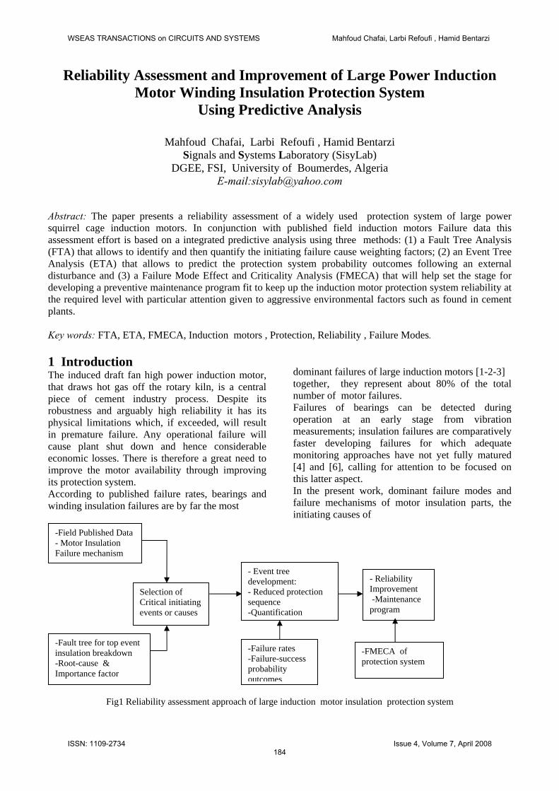
2 Induction motor stator insulation failure mechanisms The electrical insulation material is one of the most critical and vulnerable components for operation of large AC electric machines. There has been a substantial effort in identifying the causes of stator insulation degradation and failure [2].
Insulation Breakdown
Thermal
Cycling
Aging
Overloading
Temperature Rise
Cycling
Obstructed ventilation
High ambiant T°
Electrical
Transientsts
Dielectric
Tracking
Spikes Start-up lightning
Turn-Turn Turn -GND
Mechanical
Coil movement
Rotor strike
Environmental Contamination
foreign objects
Abrasion
Moisture
Chemical
Overload unbalance Voltage Variations
Vibrations
Fig.2 Insulation failure mechanism 2.1 Insulation Failure Mechanisms (IFM) The stator winding insulation is always subjected to the combined thermal, electrical, mechanical and environmental stresses during long-term machine operation [2]. 2.1.1 Thermal stress Over time, the insulation material will deteriorate due to the normal thermal aging process; but the occurrence of premature failures, which are predominant, are a direct result of an overheat due to an over-current caused generally by an overload, a voltage unbalance and/or voltage variations [2] and [3]. High ambient temperature and obstructed ventilation are also other causes of thermal stresses which can lead to the delamination or cracking of the insulation [2]
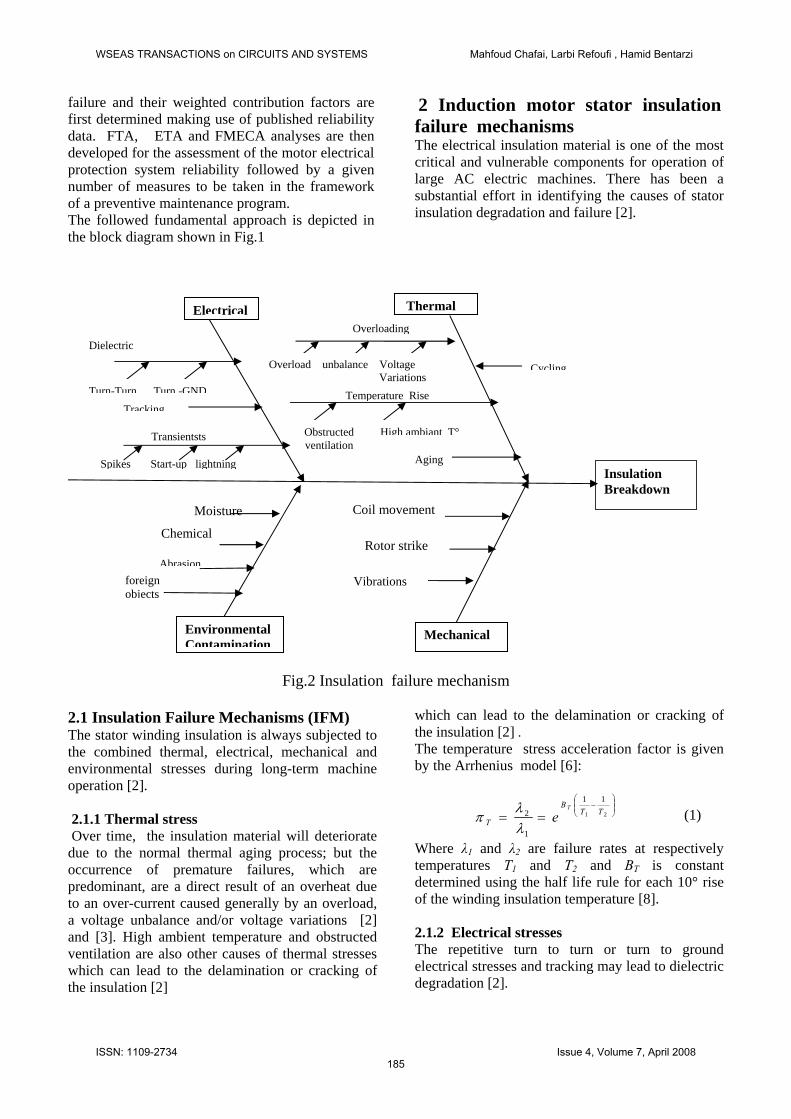
which can lead to the delamination or cracking of the insulation [2] . The temperature stress acceleration factor is given by the Arrhenius model [6]:
⎟⎟⎠
⎞⎜⎜⎝
⎛−
== 21
11
1
2 TTB
T
T
eλλπ (1)
Where λ1 and λ2 are failure rates at respectively temperatures T1 and T2 and BBT is constant determined using the half life rule for each 10° rise of the winding insulation temperature [8]. 2.1.2 Electrical stresses The repetitive turn to turn or turn to ground electrical stresses and tracking may lead to dielectric degradation [2].
WSEAS TRANSACTIONS on CIRCUITS AND SYSTEMS Mahfoud Chafai, Larbi Refoufi , Hamid Bentarzi
ISSN: 1109-2734185
Issue 4, Volume 7, April 2008
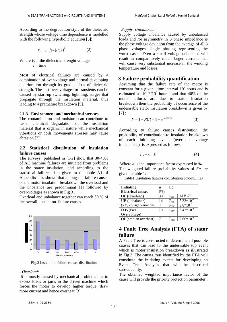
According to the degradation style of the dielectric strength whose voltage time dependence is modelled with the following hyperbolic equation [5]: ( )2
17/18 tVs −⋅= (2) Where Vs = the dielectric strenght voltage t = time Most of electrical failures are caused by a combination of over-voltage and normal developing deterioration through its gradual loss of dielectric strength. The fast over-voltages or transients can be caused by start-up switching, lightning, surges that propagate through the insulation material, thus leading to a premature breakdown [5]. 2.1.3 Environment and mechanical stresses The contamination and moisture can contribute to faster chemical degradation of the insulation material that is organic in nature while mechanical vibrations or coils movements stresses may cause abrasion [2]. 2.2 Statistical distribution of insulation failure causes The surveys published in [1-2] show that 30-40% of AC machine failures are initiated from problems in the stator insulation; and according to the statistical failures data given in the table A1 of Appendix it is shown that among the failure causes of the motor insulation breakdown the overload and the unbalance are predominant [1] followed by over-voltages as shown in Fig 3 . Overload and unbalance together can reach 50 % of the overall insulation failure causes.
0
5
10
15
20
25
30
35
OL UB VV FOV AOH C AEvent causes
FIg.3 Insulation failure causes distribution
- Overload: It is mostly caused by mechanical problems due to excess loads or jams in the driven machine which forces the motor to develop higher torque, draw more current and hence overheat [3].
-Supply Unbalance: Supply voltage unbalance caused by unbalanced loads and /or asymmetry in 3 phase impedance is the phase voltage deviation from the average of all 3 phase voltages, single phasing representing the worst case. Even a small voltage unbalance will result in comparatively much larger currents that will cause very substantial increase in the winding temperature and losses.
3 Failure probability quantification Assuming that the failure rate of the motor is constant for a given time interval 104 hours and is estimated as 10 F/106 hours and that 40% of the motor failures are due to stator insulation breakdown then the probability of occurrence of the undesirable stator insulation breakdown is given by [7] : (3) tetRF .10.4 6
1)(1−−−=−=
According to failure causes distribution, the probability of contribution to insulation breakdown of each initiating event (overload, voltage imbalance..) is expressed as follows: Fc= α . F (4) Where α is the importance factor expressed in % . The weighted failure probability values of Fc are given in table 1:
Table1 Insulation failures contribution probabilities
Initiating Electrical causes
α (%)
Fc
OL (Overload) 30 POL 1.14*10-2
UB (unbalance) 14 PUB 5.32*10-3
(VV)Voltage Variations 9 PVV 3.8*10-3
FOV(Fast Overvoltage)
10 POV 3.42*10-3
OH(ambian.overheat) 7 POH 2.66*10-3
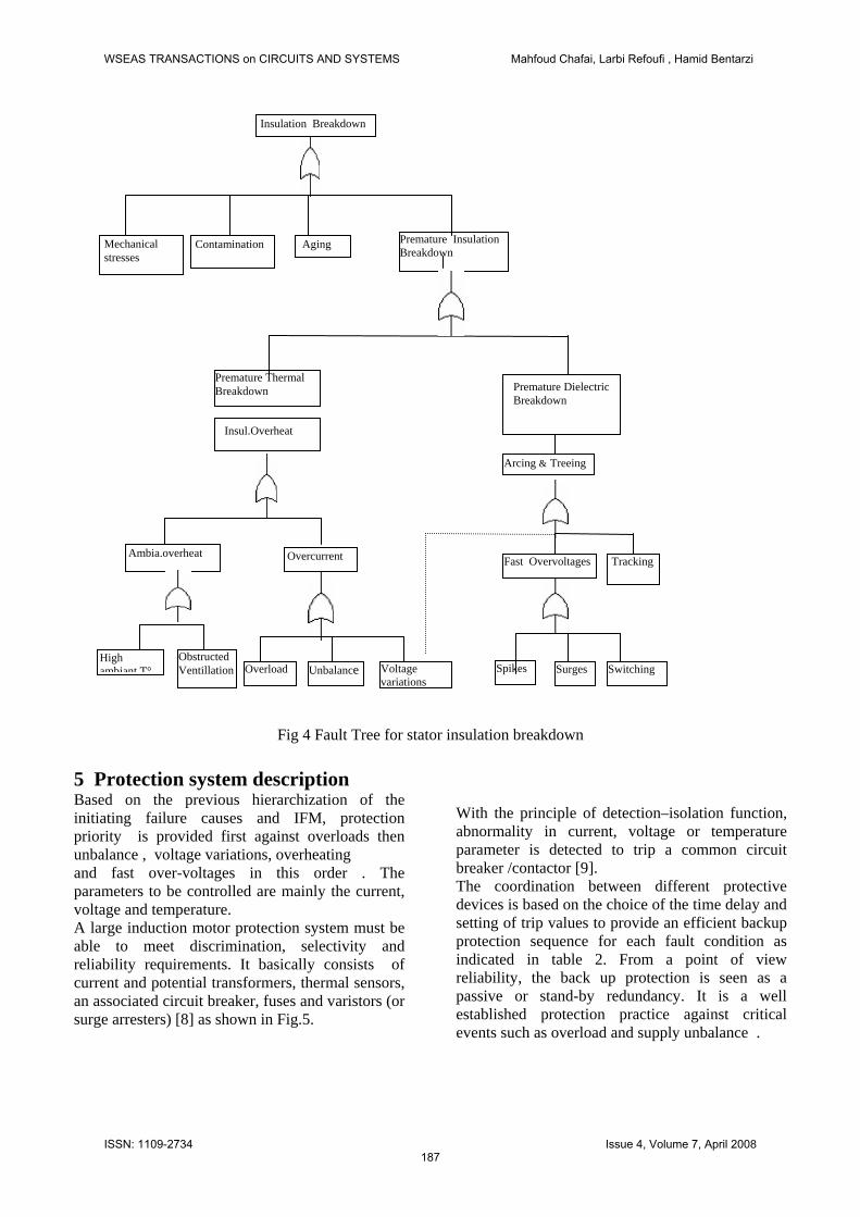
4 Fault Tree Analysis (FTA) of stator failure A Fault Tree is constructed to determine all possible causes that can lead to the undesirable top event which is motor insulation breakdown as illustrated in Fig.3. The causes thus identified by the FTA will constitute the initiating events for developing an Event Tree Analysis that will be described subsequently. The obtained weighted importance factor of the cause will provide the priority protection parameter .
WSEAS TRANSACTIONS on CIRCUITS AND SYSTEMS Mahfoud Chafai, Larbi Refoufi , Hamid Bentarzi
ISSN: 1109-2734186
Issue 4, Volume 7, April 2008
Premature Thermal Breakdown
Voltage variations
Overload Unbalance
Overcurrent Ambia.overheat
High ambiant T°
Obstructed Ventillation
Insul.Overheat
Premature Dielectric Breakdown
Switching Surges
Fast Overvoltages
Spikes
Arcing & Treeing
Premature Insulation Breakdown
Aging Contamination
Tracking
Mechanical stresses
Insulation Breakdown
Fig 4 Fault Tree for stator insulation breakdown
5 Protection system description Based on the previous hierarchization of the initiating failure causes and IFM, protection priority is provided first against overloads then unbalance , voltage variations, overheating and fast over-voltages in this order . The parameters to be controlled are mainly the current, voltage and temperature. A large induction motor protection system must be able to meet discrimination, selectivity and reliability requirements. It basically consists of current and potential transformers, thermal sensors, an associated circuit breaker, fuses and varistors (or surge arresters) [8] as shown in Fig.5.
With the principle of detection–isolation function, abnormality in current, voltage or temperature parameter is detected to trip a common circuit breaker /contactor [9]. The coordination between different protective devices is based on the choice of the time delay and setting of trip values to provide an efficient backup protection sequence for each fault condition as indicated in table 2. From a point of view reliability, the back up protection is seen as a passive or stand-by redundancy. It is a well established protection practice against critical events such as overload and supply unbalance .
WSEAS TRANSACTIONS on CIRCUITS AND SYSTEMS Mahfoud Chafai, Larbi Refoufi , Hamid Bentarzi
ISSN: 1109-2734187
Issue 4, Volume 7, April 2008
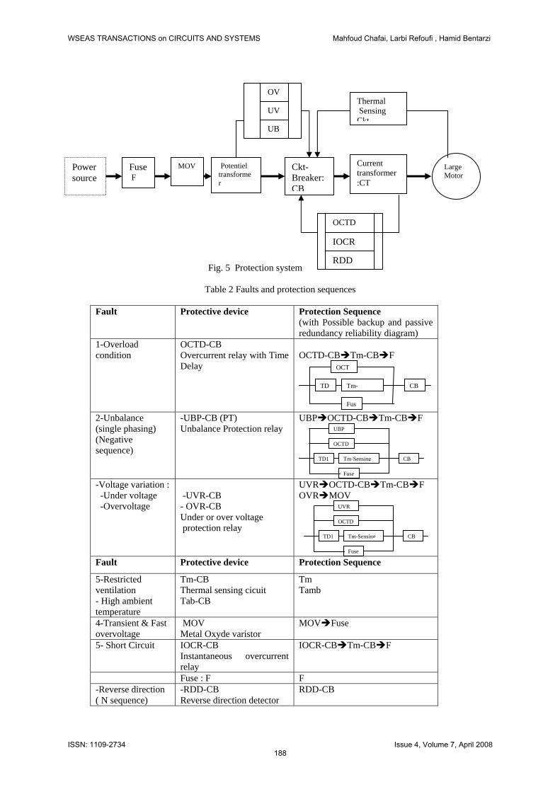
Fig. 5 Protection system
Potentiel transformer
Large Motor
Current transformer :CT
Power source
Thermal Sensing Ckt
Ckt-Breaker:CB
Fuse F
MOV
OCTD
IOCR
RDD
UB
UV
OV
Table 2 Faults and protection sequences
Fault Protective device Protection Sequence
(with Possible backup and passive redundancy reliability diagram)
1-Overload condition
OCTD-CB Overcurrent relay with Time Delay
OCTD-CB Tm-CB F
2-Unbalance (single phasing) (Negative sequence)
-UBP-CB (PT) Unbalance Protection relay
OCT
Fus
Tm-TD CB
UBP OCTD-CB Tm-CB F
-Voltage variation : -Under voltage -Overvoltage
OCTD
Fuse
Tm-SensingTD1 CB
UBP
-UVR-CB - OVR-CB Under or over voltage protection relay
UVR OCTD-CB Tm-CB F OVR MOV
Fault Protective device Protection Sequence
5-Restricted ventilation - High ambient temperature
Tm-CB
OCTD
Fuse
Tm-SensingTD1 CB
UVR
Thermal sensing cicuit Tab-CB
Tm Tamb
4-Transient & Fast overvoltage
MOV Metal Oxyde varistor
MOV Fuse
5- Short Circuit IOCR-CB Instantaneous overcurrent relay
IOCR-CB Tm-CB F
Fuse : F F -Reverse direction ( N sequence)
-RDD-CB Reverse direction detector
RDD-CB
WSEAS TRANSACTIONS on CIRCUITS AND SYSTEMS Mahfoud Chafai, Larbi Refoufi , Hamid Bentarzi
ISSN: 1109-2734188
Issue 4, Volume 7, April 2008
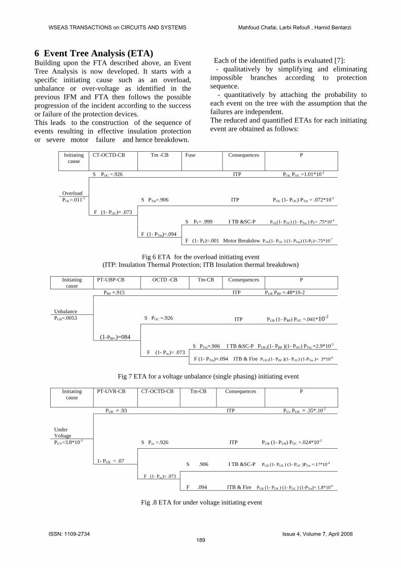
6 Event Tree Analysis (ETA) Building upon the FTA described above, an Event Tree Analysis is now developed. It starts with a specific initiating cause such as an overload, unbalance or over-voltage as identified in the previous IFM and FTA then follows the possible progression of the incident according to the success or failure of the protection devices. This leads to the construction of the sequence of events resulting in effective insulation protection or severe motor failure and hence breakdown.
Each of the identified paths is evaluated [7]: - qualitatively by simplifying and eliminating impossible branches according to protection sequence. - quantitatively by attaching the probability to each event on the tree with the assumption that the failures are independent. The reduced and quantified ETAs for each initiating event are obtained as follows:
Initiating cause
CT-OCTD-CB Tm -CB
Fuse Consequences P
S POC =.926 ITP POL POC =1.01*10-2
Overload
S PTm=.906 ITP POL (1- POC) PTm = .072*10-2 F (1- POC)= .073
S PF= .999 I TB &SC-P POL(1- POC) (1- PTm ) PF= .75*10-4
F (1- PTm)=.094
POL=.011-2
F (1- PF)=.001 Motor Breakdow POL(1- POC ) (1- PTm) (1-PF)=.75*10-7
Fig 6 ETA for the overload initiating event
(ITP: Insulation Thermal Protection; ITB Insulation thermal breakdown)
Initiating cause
PT-UBP-CB
OCTD -CB Tm-CB
Consequences P
PBP =.915 ITP PUB PBP =.48*10-2 Unbalance
S POC =.926 ITP PUB (1- PBP) POC =.041*10-2 (1-PBP.)=084
S PTm=.906 I TB &SC-P PUB ((1- PBP )(1- POC) PTm =2.9*10-5
F (1- Poc)= .073
PUB=.0053
F (1- PTm)=.094 ITB & Fire PUB ((1- PBP )(1- POC) (1-PTm )= 3*10-6
Fig 7 ETA for a voltage unbalance (single phasing) initiating event
Initiating
cause PT-UVR-CB CT-OCTD-CB Tm-CB
Consequences P
PUR = .93 ITP PUv PUR = .35*.10-2
Under Voltage
S Poc =.926 ITP PUB (1- PUR) POC =.024*10-2 1- PUR = .07
S .906 I TB &SC-P PUB (1- PUR ) (1- POC )PTm =.17*10-4
F (1- Poc)= .073
PUV=3.8*10-3
F .094 ITB & Fire PUB (1- PUR ) (1- POC ) (1-PTm)= 1.8*10-6
Fig .8 ETA for under voltage initiating event
WSEAS TRANSACTIONS on CIRCUITS AND SYSTEMS Mahfoud Chafai, Larbi Refoufi , Hamid Bentarzi
ISSN: 1109-2734189
Issue 4, Volume 7, April 2008
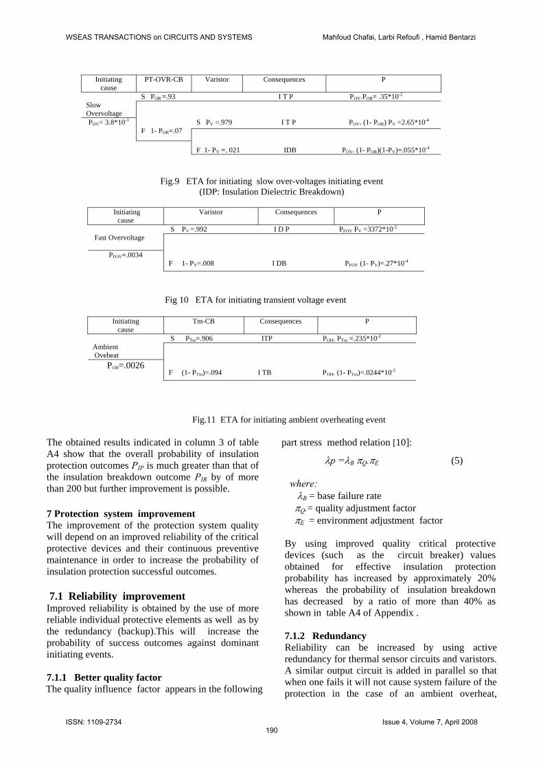
Initiating
cause PT-OVR-CB Varistor Consequences P
S POR =.93 I T P POV.POR= .35*10-2 Slow Overvoltage
S PV =.979 I T P POV. (1- POR) PV =2.65*10-4
F 1- POR=.07
F 1- PV =. 021 IDB POV. (1- POR)(1-PV)=.055*10-4
POV= 3.8*10-3
Fig.9 ETA for initiating slow over-voltages initiating event
(IDP: Insulation Dielectric Breakdown)
Initiating cause
Varistor Consequences P
S PV =.992 I D P PFOV PV =3372*10-2 Fast Overvoltage
F 1- PV=.008
I DB PFOV (1- PV)=.27*10-4
PFOV=.0034
Fig 10 ETA for initiating transient voltage event
Initiating cause
Tm-CB Consequences P
S PTm=.906 ITP POH. PTm =.235*10-2 Ambient Oveheat
F (1- PTm)=.094
I TB POH. (1- PTm)=.0244*10-2
POH=.0026
Fig.11 ETA for initiating ambient overheating event
The obtained results indicated in column 3 of table A4 show that the overall probability of insulation protection outcomes PIP is much greater than that of the insulation breakdown outcome PIB by of more than 200 but further improvement is possible. 7 Protection system improvement The improvement of the protection system quality will depend on an improved reliability of the critical protective devices and their continuous preventive maintenance in order to increase the probability of insulation protection successful outcomes. 7.1 Reliability improvement Improved reliability is obtained by the use of more reliable individual protective elements as well as by the redundancy (backup).This will increase the probability of success outcomes against dominant initiating events. 7.1.1 Better quality factor
The quality influence factor appears in the following
part stress method relation [10]:
λp =λB πB Q.πE (5) where: λB = base failure rate B
πQ.= quality adjustment factor πE = environment adjustment factor By using improved quality critical protective devices (such as the circuit breaker) values obtained for effective insulation protection probability has increased by approximately 20% whereas the probability of insulation breakdown has decreased by a ratio of more than 40% as shown in table A4 of Appendix . 7.1.2 Redundancy Reliability can be increased by using active redundancy for thermal sensor circuits and varistors. A similar output circuit is added in parallel so that when one fails it will not cause system failure of the protection in the case of an ambient overheat,
WSEAS TRANSACTIONS on CIRCUITS AND SYSTEMS Mahfoud Chafai, Larbi Refoufi , Hamid Bentarzi
ISSN: 1109-2734190
Issue 4, Volume 7, April 2008
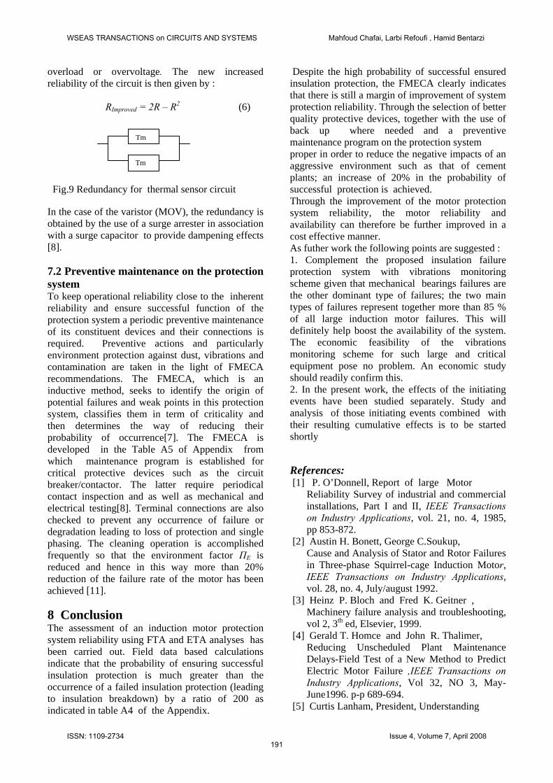
overload or overvoltage. The new increased reliability of the circuit is then given by :
RImproved = 2R – R2 (6)
Fig.9 Redundancy for thermal sensor circuit In the case of the varistor (MOV), the redundancy is obtained by the use of a surge arrester in association with a surge capacitor to provide dampening effects [8].
7.2 Preventive maintenance on the protection system To keep operational reliability close to the inherent reliability and ensure successful function of the protection system a periodic preventive maintenance of its constituent devices and their connections is required. Preventive actions and particularly environment protection against dust, vibrations and contamination are taken in the light of FMECA recommendations. The FMECA, which is an inductive method, seeks to identify the origin of potential failures and weak points in this protection system, classifies them in term of criticality and then determines the way of reducing their probability of occurrence[7]. The FMECA is developed in the Table A5 of Appendix from which maintenance program is established for critical protective devices such as the circuit breaker/contactor. The latter require periodical contact inspection and as well as mechanical and electrical testing[8]. Terminal connections are also checked to prevent any occurrence of failure or degradation leading to loss of protection and single phasing. The cleaning operation is accomplished frequently so that the environment factor ПE is reduced and hence in this way more than 20% reduction of the failure rate of the motor has been achieved [11]. 8 Conclusion The assessment of an induction motor protection system reliability using FTA and ETA analyses has been carried out. Field data based calculations indicate that the probability of ensuring successful insulation protection is much greater than the occurrence of a failed insulation protection (leading to insulation breakdown) by a ratio of 200 as indicated in table A4 of the Appendix.
Despite the high probability of successful ensured insulation protection, the FMECA clearly indicates that there is still a margin of improvement of system protection reliability. Through the selection of better quality protective devices, together with the use of back up where needed and a preventive maintenance program on the protection system Tm
Tm proper in order to reduce the negative impacts of an aggressive environment such as that of cement plants; an increase of 20% in the probability of successful protection is achieved. Through the improvement of the motor protection system reliability, the motor reliability and availability can therefore be further improved in a cost effective manner. As futher work the following points are suggested : 1. Complement the proposed insulation failure protection system with vibrations monitoring scheme given that mechanical bearings failures are the other dominant type of failures; the two main types of failures represent together more than 85 % of all large induction motor failures. This will definitely help boost the availability of the system. The economic feasibility of the vibrations monitoring scheme for such large and critical equipment pose no problem. An economic study should readily confirm this. 2. In the present work, the effects of the initiating events have been studied separately. Study and analysis of those initiating events combined with their resulting cumulative effects is to be started shortly References: [1] P. O’Donnell, Report of large Motor
Reliability Survey of industrial and commercial installations, Part I and II, IEEE Transactions on Industry Applications, vol. 21, no. 4, 1985, pp 853-872.
[2] Austin H. Bonett, George C.Soukup, Cause and Analysis of Stator and Rotor Failures in Three-phase Squirrel-cage Induction Motor, IEEE Transactions on Industry Applications, vol. 28, no. 4, July/august 1992.
[3] Heinz P. Bloch and Fred K. Geitner , Machinery failure analysis and troubleshooting, vol 2, 3th ed, Elsevier, 1999.
[4] Gerald T. Homce and John R. Thalimer, Reducing Unscheduled Plant Maintenance Delays-Field Test of a New Method to Predict Electric Motor Failure ,IEEE Transactions on Industry Applications, Vol 32, NO 3, May-June1996. p-p 689-694.
[5] Curtis Lanham, President, Understanding
WSEAS TRANSACTIONS on CIRCUITS AND SYSTEMS Mahfoud Chafai, Larbi Refoufi , Hamid Bentarzi
ISSN: 1109-2734191
Issue 4, Volume 7, April 2008
the Tests that are Recommended for Electric Motor Predictive Maintenance, Baker Instrument Company, Energy publication, 2002.
[6] Monitoring und Diagnose elektrischer Maschinen und Antriebe, Allianz Schadensstatistik an HS Motoren 1996-1999 in VDE Workshop, 2001.
[7] Charles E. Ebeling, An introduction to Reliability and Maintainability Engineering ,, Mc Graw–Hill, 1997.
[8] K.C. Agrawal, Industrial Power Engineering and Applications Handbook, Butterworth-Heinemann, 2001
[9] S. F Farag, R.G Barcheld, T.G Fabeder , An integrated on-line motor protection system, IEEE Industry Application Magazine Marsh/April, 1996.
[10] Military Handbook MIL-HDBK - 217 F , Dept. of Defense (USA), 2 Dec 1991.
[11] M. Chafai, L. Refoufi, H. Bentarzi (2007) Medium Induction Motor Winding Insulation Protection System Reliability Evaluation and Improvement using Predictive analysis, 6th WSEAS International Conference on CIRCUITS, SYSTEMS, Cairo, Egypt, Dec 29-312007, pp. 156-161.
[12] Rapport interne de suivi de maintenance et protection d’un moteur ventilateur des Cimenteries de Beni-saf et Chlef, Algeria, 2004.
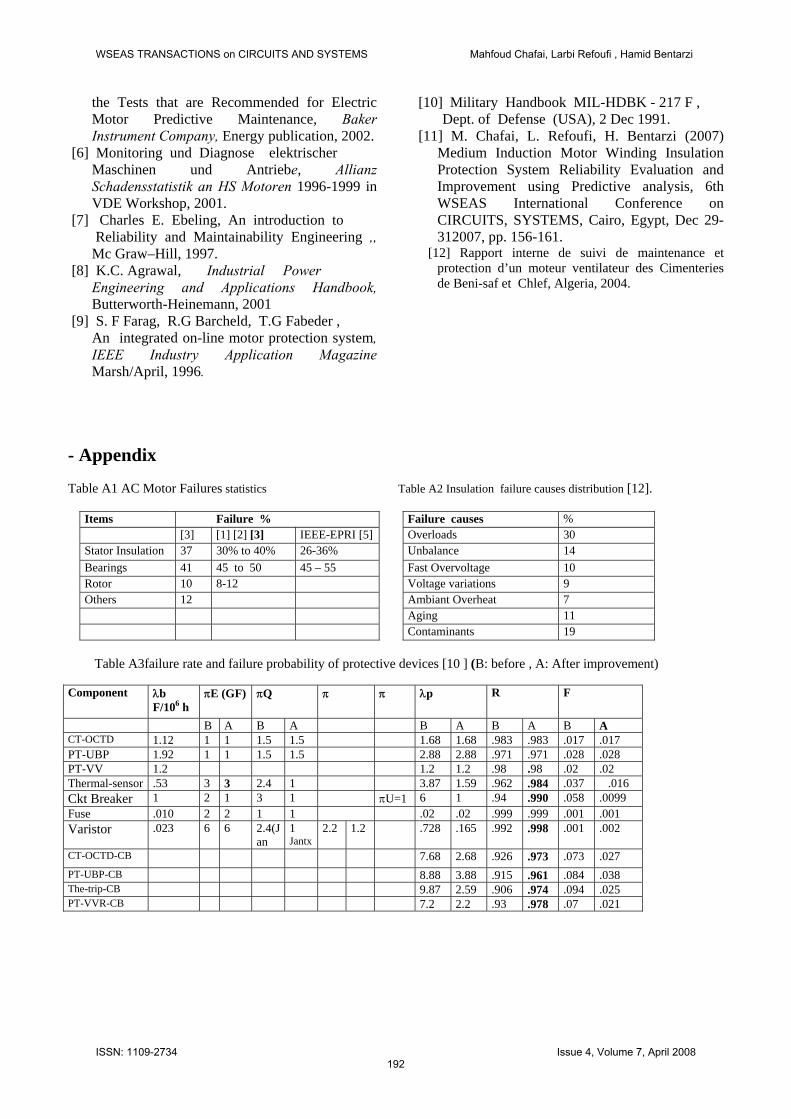
- Appendix Table A1 AC Motor Failures statistics Table A2 Insulation failure causes distribution [12].
Items Failure % Failure causes % [3] [1] [2] [3] IEEE-EPRI [5] Overloads 30 Stator Insulation 37 30% to 40% 26-36% Unbalance 14 Bearings 41 45 to 50 45 – 55 Fast Overvoltage 10 Rotor 10 8-12 Voltage variations 9 Others 12 Ambiant Overheat 7 Aging 11 Contaminants 19
Table A3failure rate and failure probability of protective devices [10 ] (B: before , A: After improvement) Component λb
F/106 h πE (GF) πQ π π λp
R F
B A B A B A B A B A CT-OCTD 1.12 1 1 1.5 1.5 1.68 1.68 .983 .983 .017 .017 PT-UBP 1.92 1 1 1.5 1.5 2.88 2.88 .971 .971 .028 .028 PT-VV 1.2 1.2 1.2 .98 .98 .02 .02 Thermal-sensor .53 3 3 2.4 1 3.87 1.59 .962 .984 .037 .016 Ckt Breaker 1 2 1 3 1 πU=1 6 1 .94 .990 .058 .0099 Fuse .010 2 2 1 1 .02 .02 .999 .999 .001 .001 Varistor .023 6 6 2.4(J
an 1 Jantx
2.2 1.2 .728 .165 .992 .998 .001 .002
CT-OCTD-CB 7.68 2.68 .926 .973 .073 .027 PT-UBP-CB 8.88 3.88 .915 .961 .084 .038 The-trip-CB 9.87 2.59 .906 .974 .094 .025 PT-VVR-CB 7.2 2.2 .93 .978 .07 .021
WSEAS TRANSACTIONS on CIRCUITS AND SYSTEMS Mahfoud Chafai, Larbi Refoufi , Hamid Bentarzi
ISSN: 1109-2734192
Issue 4, Volume 7, April 2008
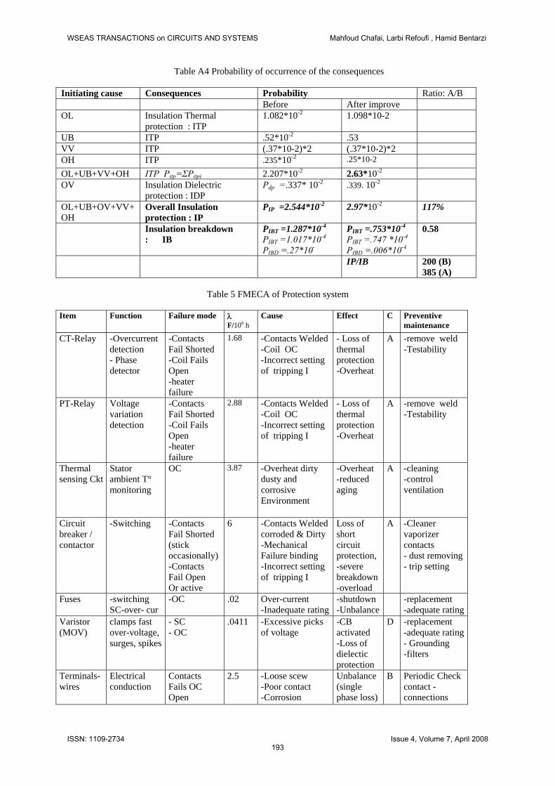
Table A4 Probability of occurrence of the consequences
Initiating cause Consequences Probability Ratio: A/B Before After improve OL Insulation Thermal
protection : ITP 1.082*10-2 1.098*10-2
UB ITP .52*10-2 .53 VV ITP (.37*10-2)*2 (.37*10-2)*2 OH ITP .235*10-2 .25*10-2
OL+UB+VV+OH ITP Pitp=ΣPitpi 2.207*10-2 2.63*10-2 OV Insulation Dielectric
protection : IDP Pdp =.337* 10-2 .339. 10-2
OL+UB+OV+VV+OH
Overall Insulation protection : IP
PIP =2.544*10-2 2.97*10-2 117%
Insulation breakdown : IB
PIBT =1.287*10-4
PIBT =1.017*10-4
PIBD =.27*10-
PIBT =.753*10-4
PIBT =.747 *10-4
PIBD =.006*10-4
0.58
IP/IB 200 (B) 385 (A)
Table 5 FMECA of Protection system
Item Function Failure mode λ
F/106 h Cause Effect C Preventive
maintenance CT-Relay -Overcurrent
detection - Phase detector
-Contacts Fail Shorted -Coil Fails Open -heater failure
1.68 -Contacts Welded -Coil OC -Incorrect setting of tripping I
- Loss of thermal protection -Overheat
A -remove weld -Testability
PT-Relay Voltage variation detection
-Contacts Fail Shorted -Coil Fails Open -heater failure
2.88 -Contacts Welded -Coil OC -Incorrect setting of tripping I
- Loss of thermal protection -Overheat
A -remove weld -Testability
Thermal sensing Ckt
Stator ambient T° monitoring
OC 3.87 -Overheat dirty dusty and corrosive Environment
-Overheat -reduced aging
A -cleaning -control ventilation
Circuit breaker / contactor
-Switching
-Contacts Fail Shorted (stick occasionally) -Contacts Fail Open Or active
6 -Contacts Welded corroded & Dirty -Mechanical Failure binding -Incorrect setting of tripping I
Loss of short circuit protection, -severe breakdown -overload
A -Cleaner vaporizer contacts - dust removing - trip setting
Fuses -switching SC-over- cur
-OC .02
Over-current -Inadequate rating
-shutdown -Unbalance
-replacement -adequate rating
Varistor (MOV)
clamps fast over-voltage, surges, spikes
- SC - OC
.0411 -Excessive picks of voltage
-CB activated -Loss of dielectic protection
D -replacement -adequate rating- Grounding -filters
Terminals- wires
Electrical conduction
Contacts Fails OC Open
2.5 -Loose scew -Poor contact -Corrosion
Unbalance (single phase loss)
B Periodic Check contact -connections
WSEAS TRANSACTIONS on CIRCUITS AND SYSTEMS Mahfoud Chafai, Larbi Refoufi , Hamid Bentarzi
ISSN: 1109-2734193
Issue 4, Volume 7, April 2008
Related Documents