Hardware Installation Manual AudioCodes Mediant™ Series of Media Gateways & Session Border Controllers Mediant 500L Enterprise Session Border Controller (E-SBC) and Media Gateway

Welcome message from author
This document is posted to help you gain knowledge. Please leave a comment to let me know what you think about it! Share it to your friends and learn new things together.
Transcript

Hardware Installation Manual
AudioCodes Mediant™ Series of Media Gateways & Session Border Controllers
Mediant 500L Enterprise Session Border Controller (E-SBC) and Media Gateway


Media Gateway & E-SBC 3 Mediant 500L
Hardware Installation Manual Contents
Table of Contents 1 Introduction ......................................................................................................... 9
2 Unpacking the Device ...................................................................................... 11
3 Physical Description ........................................................................................ 13
3.1 Physical Dimensions and Operating Environment ................................................. 13 3.2 Front Panel Description .......................................................................................... 13
3.2.1 LED Descriptions .................................................................................................... 14 3.2.1.1 Power LED ............................................................................................... 14 3.2.1.2 Status LED ............................................................................................... 14
3.3 Rear Panel Description .......................................................................................... 15 3.3.1 LAN Interface LEDs ................................................................................................ 16
4 Mounting the Device ........................................................................................ 17
4.1 19-Inch Rack Mounting .......................................................................................... 17 4.2 Wall Mounting ......................................................................................................... 20
5 Cabling the Device ........................................................................................... 23
5.1 Connecting LAN Interfaces .................................................................................... 23 5.2 ISDN BRI Interfaces ............................................................................................... 25
5.2.1 Connecting BRI Lines ............................................................................................. 25 5.2.2 Connecting PSTN Fallback for BRI Lines ............................................................... 27
5.3 Analog Interfaces ................................................................................................... 28 5.3.1 Connecting FXS Interfaces ..................................................................................... 28 5.3.2 Connecting FXO Interfaces ..................................................................................... 29 5.3.3 Connecting the FXS Analog Lifeline ....................................................................... 31
5.4 Cabling the Serial Interface to a PC ....................................................................... 32 5.5 Connecting a USB Storage Device ........................................................................ 33 5.6 Connecting to the Power Supply ............................................................................ 34
5.6.1 Powering On or Off the Device ............................................................................... 37

Hardware Installation Manual 4 Document #: LTRT-10490
Mediant 500L
List of Figures Figure 3-1: Front Panel .......................................................................................................................... 13 Figure 3-2: Rear Panel .......................................................................................................................... 15 Figure 4-1: Minimum Vertical Space for 19-inch Rack Mounting .......................................................... 17 Figure 4-2: Positioning Shelf in Rack ..................................................................................................... 18 Figure 4-3: Positioning the Device's Anti-Slide Rubber Legs into Shelf's Openings ............................. 19 Figure 4-4: Device Mounted on Shelf in 19-inch Rack .......................................................................... 19 Figure 4-5: Dimensions for Drilled Holes ............................................................................................... 20 Figure 4-6: Protruded Screw Distance from Wall Surface ..................................................................... 22 Figure 4-7: Hanging Device on Screw Heads ....................................................................................... 22 Figure 5-1: Default Ethernet Port Groups and Port String Names for Software Configuration ............. 23 Figure 5-2: Cabling LAN Ports ............................................................................................................... 24 Figure 5-3: RJ-45 Connector Pinouts for TE or NT BRI Ports ............................................................... 25 Figure 5-4: Cabling BRI Ports ................................................................................................................ 26 Figure 5-5: Cabling BRI PSTN Fallback ................................................................................................ 27 Figure 5-6: RJ-11 Connector Pinouts for FXS Interface ........................................................................ 28 Figure 5-7: Connecting FXS Interfaces ................................................................................................. 29 Figure 5-8: RJ-11 Connector Pinouts for FXO Interface ....................................................................... 30 Figure 5-9: Connecting FXO Interfaces ................................................................................................. 30 Figure 5-10: RJ-11 Connector Pinouts for FXS Lifeline ........................................................................ 31 Figure 5-11: Cabling the FXS Analog Lifeline ....................................................................................... 31 Figure 5-12: RJ-45 to DB-9 Female Cable Adapter .............................................................................. 32 Figure 5-13: Cabling Serial Port ............................................................................................................ 32 Figure 5-14: Connecting USB Storage Device ...................................................................................... 33 Figure 5-15: AC/DC Power Adapter ...................................................................................................... 34 Figure 5-16: Inserting Plug into Power Adapter ..................................................................................... 35 Figure 5-17: Cabling to Power using Power Adapter ............................................................................ 36
List of Tables Table 3-1: Physical Dimensions and Operating Environment ............................................................... 13 Table 3-2: Front Panel Description ........................................................................................................ 13 Table 3-3: Power LED Description ........................................................................................................ 14 Table 3-4: Status LED Description ........................................................................................................ 14 Table 3-5: Front Panel Description ........................................................................................................ 15 Table 3-6: LAN LED Description ............................................................................................................ 16 Table 5-1: RJ-45 Connector Pinouts for GE .......................................................................................... 23 Table 5-2: RJ-45 to DB-9 Serial Cable Connector Pinouts ................................................................... 32 Table 5-3: Power Specifications ............................................................................................................ 34 Table 5-4: Power Adapter with Interchangeable Plugs ......................................................................... 35
Media Gateway & E-SBC 5 Mediant 500L
Hardware Installation Manual Notices
Notice Information contained in this document is believed to be accurate and reliable at the time of printing. However, due to ongoing product improvements and revisions, AudioCodes cannot guarantee accuracy of printed material after the Date Published nor can it accept responsibility for errors or omissions. Updates to this document can be downloaded from https://www.audiocodes.com/library/technical-documents.
This document is subject to change without notice.
Date Published: December-25-2017
WEEE EU Directive Pursuant to the WEEE EU Directive, electronic and electrical waste must not be disposed of with unsorted waste. Please contact your local recycling authority for disposal of this product.
Customer Support Customer technical support and services are provided by AudioCodes or by an authorized AudioCodes Service Partner. For more information on how to buy technical support for AudioCodes products and for contact information, please visit our Web site at https://www.audiocodes.com/services-support/maintenance-and-support.
Abbreviations and Terminology Each abbreviation, unless widely used, is spelled out in full when first used. Throughout this manual, unless otherwise specified, the term device refers to Mediant 500L Gateway & E-SBC.

Hardware Installation Manual 6 Document #: LTRT-10490
Mediant 500L
Related Documentation
Document Name
SIP Release Notes
Mediant 500L Gateway & E-SBC User's Manual
CLI Reference Guide
General Notes and Warnings, and Safety Information
Warning: Adhere to all warning statements in this document.
Note: Open source software may have been added and/or amended for this product. For further information, please visit our website at http://audiocodes.com/support or contact your AudioCodes sales representative.
Warning: The device is an INDOOR unit and therefore, must be installed only indoors.
Caution Electrical Shock Do not open or disassemble this device. The device carries high voltage and contact with internal components may expose you to electrical shock and bodily harm.
Warning: The device must be installed and serviced only by qualified service personnel.
Warning: For deployment in Finland, Sweden and Norway, the device must be installed only in restricted access locations that are compliant with ETS 300253 guidelines where equipotential bonding has been implemented.
Warning: Disconnect the device from the mains and Telephone Network Voltage (TNV) before servicing.

Media Gateway & E-SBC 7 Mediant 500L
Hardware Installation Manual Notices
Document Revision Record
LTRT Description
10480 Initial document release for Version 7.0.
10481 Connector pinouts updated for serial interface.
10482 Max. power consumption updated.
10483 Status LED for software upgrade.
10484 19-inch rack mount; wall mounting.
10485 AC power cable warning (Japanese).
10486 Wall-mounting template.
10487 FXS and FXO interfaces added.
10488 LAN FE changed to GE.
10489 Typo re 19-inch rack mount shelf.
10490 Logo updated; PSTN Fallback/Analog lifeline updated.

Hardware Installation Manual 8 Document #: LTRT-10490
Mediant 500L
Documentation Feedback AudioCodes continually strives to produce high quality documentation. If you have any comments (suggestions or errors) regarding this document, please fill out the Documentation Feedback form on our Web site at https://online.audiocodes.com/documentation-feedback.

Media Gateway & E-SBC 9 Mediant 500L
Hardware Installation Manual 1. Introduction
1 Introduction This document provides a hardware description of the Mediant 500L Gateway & E-SBC (hereafter referred to as device) and step-by-step procedures for mounting and cabling the device. The device supports the following interfaces: Four Gigabit Ethernet (1000Base-T) LAN ports (RJ-45). One USB port for optional USB storage services. Up four ISDN BRI port interfaces, supporting up to eight voice channels as well as
PSTN fallback. Up to four FXS port interfaces. Up to four FXO port interfaces. Serial console port (RJ-45) for device management.
Notes:
• Hardware configurations may change without notice. Currently available hardware configurations are listed in AudioCodes Price Book. For further enquiries, please contact your AudioCodes sales representative.
• For information on configuring the device, refer to the device's User’s Manual.

Hardware Installation Manual 10 Document #: LTRT-10490
Mediant 500L
This page is intentionally left blank.

Media Gateway & E-SBC 11 Mediant 500L
Hardware Installation Manual 2. Unpacking the Device
2 Unpacking the Device Follow the procedure below for unpacking the carton in which the device was shipped.
To unpack the device:
1. Open the carton and carefully remove packing materials. 2. Remove the chassis from the carton. 3. Check that there is no equipment damage. 4. Ensure that in addition to the chassis, the package contains the following items:
• Four anti-slide bumpers for desktop installation • Serial cable adapter • AC/DC power adapter
5. Check, retain and process any documents. If there are any damaged or missing items, notify your AudioCodes sales representative.

Hardware Installation Manual 12 Document #: LTRT-10490
Mediant 500L
This page is intentionally left blank.
Media Gateway & E-SBC 13 Mediant 500L
Hardware Installation Manual 3. Physical Description
3 Physical Description This section provides a physical description of the device.
3.1 Physical Dimensions and Operating Environment The device's physical dimensions and operating environment are listed in the table below:
Table 3-1: Physical Dimensions and Operating Environment
Specification Value
Dimensions (H x W x D) 51 x 296 x 160 mm (2 x 11.65 x 6.3 in.)
Weight 670 g (1.5 lbs.)
Operating Environment Operational: 5 to 40°C (41 to 104°F) Storage: -25 to 85°C (-13 to 185°F) Relative Humidity: 10 to 90% non-condensing
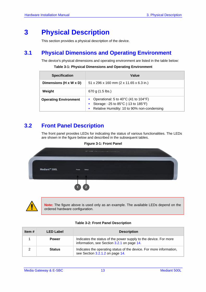
3.2 Front Panel Description The front panel provides LEDs for indicating the status of various functionalities. The LEDs are shown in the figure below and described in the subsequent tables.
Figure 3-1: Front Panel
Note: The figure above is used only as an example. The available LEDs depend on the ordered hardware configuration.
Table 3-2: Front Panel Description
Item # LED Label Description
1 Power Indicates the status of the power supply to the device. For more information, see Section 3.2.1 on page 14.
2 Status Indicates the operating status of the device. For more information, see Section 3.2.1.2 on page 14.

Hardware Installation Manual 14 Document #: LTRT-10490
Mediant 500L
3.2.1 LED Descriptions The LED descriptions are provided in the subsequent subsections.
3.2.1.1 Power LED The Power LED indicates whether or not the device is powered on or off, as described in the table below.
Table 3-3: Power LED Description
Color State Description
Green On Power is received by the device.
- Off No power is received by the device.
3.2.1.2 Status LED The Status LED indicates the operating status, as described in the table below.
Table 3-4: Status LED Description
Color State Description
Green On Device is operational.
Flashing Initial rebooting stage. Software upgrade (.cmp file) in process (currently supported
only by Software Version 6.8).
Red On Boot failure.
- Off Advanced rebooting stage.
Media Gateway & E-SBC 15 Mediant 500L
Hardware Installation Manual 3. Physical Description
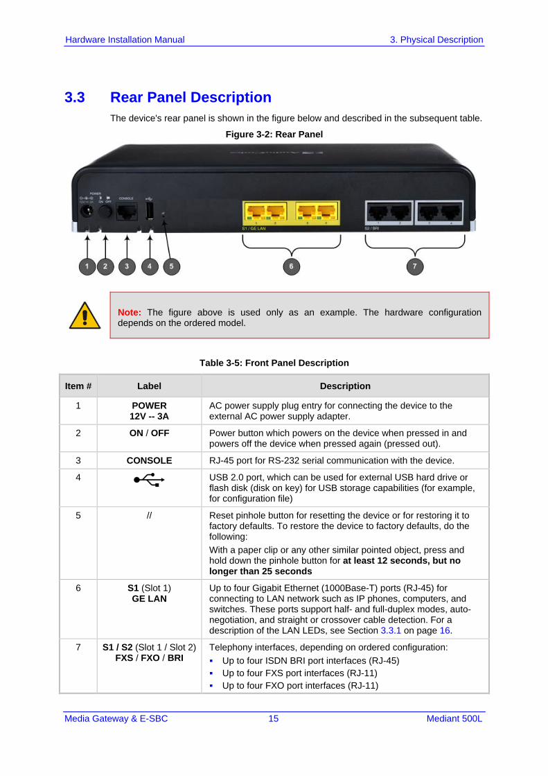
3.3 Rear Panel Description The device's rear panel is shown in the figure below and described in the subsequent table.
Figure 3-2: Rear Panel
Note: The figure above is used only as an example. The hardware configuration depends on the ordered model.
Table 3-5: Front Panel Description
Item # Label Description
1 POWER 12V -- 3A
AC power supply plug entry for connecting the device to the external AC power supply adapter.
2 ON / OFF Power button which powers on the device when pressed in and powers off the device when pressed again (pressed out).
3 CONSOLE RJ-45 port for RS-232 serial communication with the device.
4
USB 2.0 port, which can be used for external USB hard drive or flash disk (disk on key) for USB storage capabilities (for example, for configuration file)
5 // Reset pinhole button for resetting the device or for restoring it to factory defaults. To restore the device to factory defaults, do the following: With a paper clip or any other similar pointed object, press and hold down the pinhole button for at least 12 seconds, but no longer than 25 seconds
6 S1 (Slot 1) GE LAN
Up to four Gigabit Ethernet (1000Base-T) ports (RJ-45) for connecting to LAN network such as IP phones, computers, and switches. These ports support half- and full-duplex modes, auto-negotiation, and straight or crossover cable detection. For a description of the LAN LEDs, see Section 3.3.1 on page 16.
7 S1 / S2 (Slot 1 / Slot 2) FXS / FXO / BRI
Telephony interfaces, depending on ordered configuration: Up to four ISDN BRI port interfaces (RJ-45) Up to four FXS port interfaces (RJ-11) Up to four FXO port interfaces (RJ-11)

Hardware Installation Manual 16 Document #: LTRT-10490
Mediant 500L
3.3.1 LAN Interface LEDs Each Ethernet port provides a LED for indicating LAN operating status, as described in the table below.
Table 3-6: LAN LED Description
Color State Description
Green On Ethernet link established.
Flashing Data is being received or transmitted.
- Off No Ethernet link.

Media Gateway & E-SBC 17 Mediant 500L
Hardware Installation Manual 4. Mounting the Device
4 Mounting the Device You can mount the device using one of the following methods: Desktop mounting 19-inch Rack mounting Wall mounting
4.1 19-Inch Rack Mounting You can mount the device in a standard 19-inch rack, using AudioCodes 1U 19-inch rack mount shelf (not supplied).
Note: The AudioCodes 1U 19-inch rack mount shelf is not supplied with your product and can be ordered separately from an AudioCodes sales distributor.
Warning:
• Elevated Operating Ambient: If installed in a closed or multi-unit rack assembly, consideration should be given to installing the equipment in an environment compatible with the maximum ambient temperature (Tmax) of 40°C (104°F).
• Reduced Air Flow: Installation should be such that the amount of air flow required for safe operation on the equipment is not compromised. Do not stack equipment one on top of the other and keep the ventilation openings free from cables or any objects to allow free air circulation. The device must be mounted correctly on the rack mount shelf to avoid air blockage to the three vents located on the bottom of the device. Mounting the device on a shelf other than AudioCodes' rack mount shelf may cause the device to overheat, resulting in permanent damage to it.
• Only one device can be mounted per rack mount shelf. • The minimum vertical rack space for mounting the device in a 19-inch rack must be
2Us (3.5 in. or 88.9 mm). See figure below.
Figure 4-1: Minimum Vertical Space for 19-inch Rack Mounting

Hardware Installation Manual 18 Document #: LTRT-10490
Mediant 500L
To mount the device in a 19-inch rack:
1. Position the rack mount shelf (not supplied) in the 19-inch rack, aligning the holes of the shelf's side brackets with the holes of the rack's front posts, as shown in the figure below.
Figure 4-2: Positioning Shelf in Rack
Note: Make sure that you attach the shelf's side brackets (left and right) at the same height level in the rack so that the shelf is in a horizontal position.
2. Attach the shelf to the rack posts using four standard 19-inch rack bolts (not supplied).

Media Gateway & E-SBC 19 Mediant 500L
Hardware Installation Manual 4. Mounting the Device
3. Place the device on the shelf so that the device's front panel faces the front of the rack and the device's four anti-slide rubber legs (located on the bottom of the device) fit into the four square openings on the shelf, as shown in the figure below (viewed from underneath):
Figure 4-3: Positioning the Device's Anti-Slide Rubber Legs into Shelf's Openings
4. Make sure the device is firmly mounted on the shelf so it does not horizontally slide in
any direction:
Figure 4-4: Device Mounted on Shelf in 19-inch Rack

Hardware Installation Manual 20 Document #: LTRT-10490
Mediant 500L
4.2 Wall Mounting You can mount the device on a wall using the keyholes on the bottom of the device.
To mount the device on a wall:
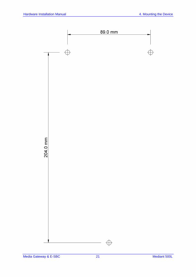
1. Drill three holes in the wall where you want to mount the device, using the distances between the holes as shown in the figure below: • Horizontal distance between the top two parallel holes: 89 mm (5.51 in.) • Vertical distance between the top two parallel holes and bottom hole: 204 mm
(8.03 in.) • Horizontal distance between a top hole and the bottom hole: 44.5 (1.75 in.)
Figure 4-5: Dimensions for Drilled Holes
Note: • When choosing the area on the wall to mount the device, make sure that sufficient
space is available for attaching cables on the rear panel. • Make sure that you drill the holes in the same orientation as shown in the above
figure (i.e., two parallel holes on the top and the single hole on the bottom). • Use the mounting template on the following page (print out) to mark the locations for
the mounting holes on the wall.
Media Gateway & E-SBC 21 Mediant 500L
Hardware Installation Manual 4. Mounting the Device

Hardware Installation Manual 22 Document #: LTRT-10490
Mediant 500L
2. Insert wall anchors of the appropriate size into each hole. 3. Thread screws (not supplied) into each of the wall anchors. The recommended screw
type is DIN 7982 3.5x25 Phillips flat head. Make sure that the heads extend sufficiently (about 4 mm or 0.157 in.) from the wall for the device's keyholes to hang on:
Figure 4-6: Protruded Screw Distance from Wall Surface
4. Hold the device so that it is orientated with the bottom panel with the keyholes facing
the wall and the rear panel with the ports facing your right. 5. Mount the device on the wall by hanging the device's keyholes on the screw heads:
Figure 4-7: Hanging Device on Screw Heads

Media Gateway & E-SBC 23 Mediant 500L
Hardware Installation Manual 5. Cabling the Device
5 Cabling the Device This chapter describes the cabling of the device, which includes the following: Connecting LAN interfaces – see Section 5.1 on page 23 Connecting BRI lines – see Section 5.2.1 on page 25 Connecting the PSTN Fallback for BRI Lines – see Section 5.2.2 on page 27 Connecting analog interfaces – see Section 5.3 on page 28 Connecting the serial interface – see Section 5.4 on page 32 Connecting a USB storage device – see Section 5.5 on page 24 Connecting to power – see Section 5.6 on page 34
5.1 Connecting LAN Interfaces The device's Gigabit Ethernet LAN ports (1000Base-T) can be connected to network equipment and entities such as computers, switches, and IP phones. These ports support half- and full-duplex modes, auto-negotiation, and straight or crossover cable detection. The Ethernet ports can operate in pairs (Ethernet Groups) to provide 1+1 port redundancy, where one port serves as the active port while the other as standby. When the active port fails, the device switches to the standby port. By default, the Ethernet ports are grouped into pairs, as shown in the figure below with the port string names used for software configuration. You can change this port assignment, including assigning only a single port to an Ethernet Group. For more information, refer to the User's Manual.
Figure 5-1: Default Ethernet Port Groups and Port String Names for Software Configuration
The Ethernet cabling specifications include the following: Cable: Straight-through, Category (Cat) 5, 5e or 6 cable Connector: Standard RJ-45 Connector Pinouts:
Table 5-1: RJ-45 Connector Pinouts for GE
Pin Signal Name
1 Ethernet signal pair (1000Base-T)
2
3 Ethernet signal pair (1000Base-T)
6
4 Ethernet signal pair (1000Base-T)

Hardware Installation Manual 24 Document #: LTRT-10490
Mediant 500L
Pin Signal Name
5
7 Ethernet signal pair (1000Base-T)
8
Shield Chassis ground
To connect the device to the LAN: 1. Connect one end of a straight-through RJ-45 Cat 5e or Cat 6 cable to the LAN port,
located on the rear panel and labeled GE LAN.
Figure 5-2: Cabling LAN Ports
2. Connect the other end of the cable to a network device or entity. 3. For 1+1 LAN protection, repeat steps 1 and 2 for the standby port, but connect it to
another network (but in the same subnet).
Warning: Ethernet port interface cabling must be routed only indoors and must not exit the building.

Media Gateway & E-SBC 25 Mediant 500L
Hardware Installation Manual 5. Cabling the Device
5.2 ISDN BRI Interfaces This section describes how to connect the device to ISDN BRI lines.
5.2.1 Connecting BRI Lines The BRI ports can be connected to ISDN terminal equipment such as ISDN telephones or PBXs. Each BRI port can be configured either as termination equipment/user side (TE) or network termination/network side (NT). Up to eight terminal equipment (TE) devices can be connected per BRI S/T port, using an ISDN S-bus providing eight ISDN ports. When configured as NT, the BRI port drives a nominal voltage of 38V with limited current supply of up to 100 mA.
Warning: To protect against electrical shock and fire, use a 26 AWG min wire to connect the BRI ports to the PSTN.
Note: BRI interface is a customer-ordered item which is supported only on specific hardware configurations. For more information, contact your AudioCodes sales representative.
The BRI cabling specifications include the following: Cable: Straight-through, Category (Cat) 5, 5e or 6 cable Connector: Standard RJ-45 Connector Pinouts:
Figure 5-3: RJ-45 Connector Pinouts for TE or NT BRI Ports

Hardware Installation Manual 26 Document #: LTRT-10490
Mediant 500L
To connect a BRI line:
1. Connect the RJ-45 cable to the device's BRI port, located on the rear panel and labeled BRI.
Figure 5-4: Cabling BRI Ports
2. Connect the other end of the cable to your ISDN equipment.

Media Gateway & E-SBC 27 Mediant 500L
Hardware Installation Manual 5. Cabling the Device
5.2.2 Connecting PSTN Fallback for BRI Lines The device supports PSTN Fallback for BRI lines. If the device loses power, for example, due to a power outage or the unplugging of its power cable, it automatically routes calls from the Tel side to the PSTN (instead of the IP network). This guarantees call continuity. The BRI PSTN Fallback uses BRI ports #1 and #2. When the BRI PSTN Fallback is activated, the internal metallic relay switch of BRI port #1 automatically connects BRI ports #1 and #2, and calls can be routed and established between these entities.
To cable the BRI PSTN Fallback:
1. Connect BRI line 1 (Port #1), located on the rear panel, to an ISDN PBX. 2. Connect BRI line 2 (Port #2)), located on the rear panel, to the ISDN network (PSTN).
Figure 5-5: Cabling BRI PSTN Fallback
Notes:
• For the four-BRI port configuration, fallback is not supported on ports #3 and #4. • The BRI PSTN Fallback feature is a customer-ordered item, which is supported only
on specific hardware configurations providing BRI interfaces. For more information, contact your AudioCodes sales representative.
• The BRI PSTN Fallback feature has no relation to the PSTN Fallback Software License Key.

Hardware Installation Manual 28 Document #: LTRT-10490
Mediant 500L
5.3 Analog Interfaces This section describes how to connect the device to analog equipment.
5.3.1 Connecting FXS Interfaces The procedure below describes how to cable the device's FXS interfaces.
Warnings: • The device is an INDOOR unit and therefore, must be installed only indoors. • FXS port interface cabling must be routed only indoors and must not exit the
building. • Make sure that the FXS ports are connected to the appropriate, external devices;
otherwise, damage to the device may occur. • FXS ports are considered TNV-2.
Notes: • FXS interface is a customer-ordered item. • FXS is the interface replacing the Exchange (i.e., the CO or the PBX) and connects to
analog telephones, dial-up modems, and fax machines. The FXS is designed to supply line voltage and ringing current to these telephone devices. An FXS VoIP device interfaces between the analog telephone devices and the Internet.
Cable specifications: Cable: Standard straight-through RJ-11-to-RJ-11 telephone cable Connector Type: RJ-11 Connector Pinouts:
Figure 5-6: RJ-11 Connector Pinouts for FXS Interface

Media Gateway & E-SBC 29 Mediant 500L
Hardware Installation Manual 5. Cabling the Device
To connect the FXS interfaces:
1. Connect one end of an RJ-11 cable to the device's FXS port (labeled FXS), located on the rear panel:
Figure 5-7: Connecting FXS Interfaces
2. Connect the other end of the cable to the required telephone interface (e.g., fax
machine, dial-up modem, or analog POTS telephone).
5.3.2 Connecting FXO Interfaces The procedure below describes how to cable the device's FXO interfaces.
Warnings: • The device does not include primary telecom protection! When the FXO telephone
lines are routed outside the building, additional protection - usually a 350V three-electrode Gas Discharge Tube (GDT) as described in ITU-T K.44 - must be provided at the entry point of the telecom wires into the building (usually on the main distribution frame / MDF), in conjunction with proper grounding. The center pin of the GDT (MDF grounding bar) must be connected to the equipotential grounding bus bar of the Telecommunication room.
• To protect against electrical shock and fire, use a minimum 26-AWG wire to connect FXO ports to the PSTN.
• Ensure that the FXO ports are connected to the appropriate, external devices; otherwise, damage to the device may occur.
• FXO ports are considered TNV-3.

Hardware Installation Manual 30 Document #: LTRT-10490
Mediant 500L
Notes:
• FXO interface is a customer-ordered item. • FXO is the interface replacing the analog telephone and connects to a Public
Switched Telephone Network (PSTN) line from the Central Office (CO) or to a Private Branch Exchange (PBX). The FXO is designed to receive line voltage and ringing current, supplied from the CO or the PBX (similar to an analog telephone). An FXO VoIP device interfaces between the CO/PBX line and the Internet.
Cable specifications: Cable: 26 AWG min Connector Type: RJ-11 Connector Pinouts:
Figure 5-8: RJ-11 Connector Pinouts for FXO Interface
To connect the FXO interfaces:
1. Connect one end of an RJ-11 cable to the device's FXO port (labeled FXO), located on the rear panel:
Figure 5-9: Connecting FXO Interfaces
2. Connect the other end of the cable to the required telephone interface: (e.g., telephone
exchange analog lines or PBX extensions).

Media Gateway & E-SBC 31 Mediant 500L
Hardware Installation Manual 5. Cabling the Device
5.3.3 Connecting the FXS Analog Lifeline The device supports Analog Lifeline. If the device loses power, for example, due to a power outage or the unplugging of its power cable, it automatically routes calls from a POTS telephone ("lifeline" phone), connected to an FXS port, to the PSTN (instead of the IP network). The FXS Lifeline extension or phone connects to FXS Port #1 while the PSTN/PBX connects to FXO Port #1. When the Lifeline is triggered, the FXS line automatically connects to the FXO line and calls between these entities can occur.
Note: The FXS Analog Lifeline feature is a customer-ordered item and is only supported on specific hardware configurations with combined FXS and FXO interfaces. For more information, contact your AudioCodes sales representative.
Cable specifications: Connector Types: RJ-11 Connector Pinouts:
Figure 5-10: RJ-11 Connector Pinouts for FXS Lifeline
To cable the FXS Analog Lifeline:
1. Connect the analog lifeline telephone to FXS Port #1 (labeled FXS), located on the rear panel.
2. Connect an analog PSTN line to FXO Port #1 (labeled FXO), located on the rear panel.
Figure 5-11: Cabling the FXS Analog Lifeline
Hardware Installation Manual 32 Document #: LTRT-10490
Mediant 500L
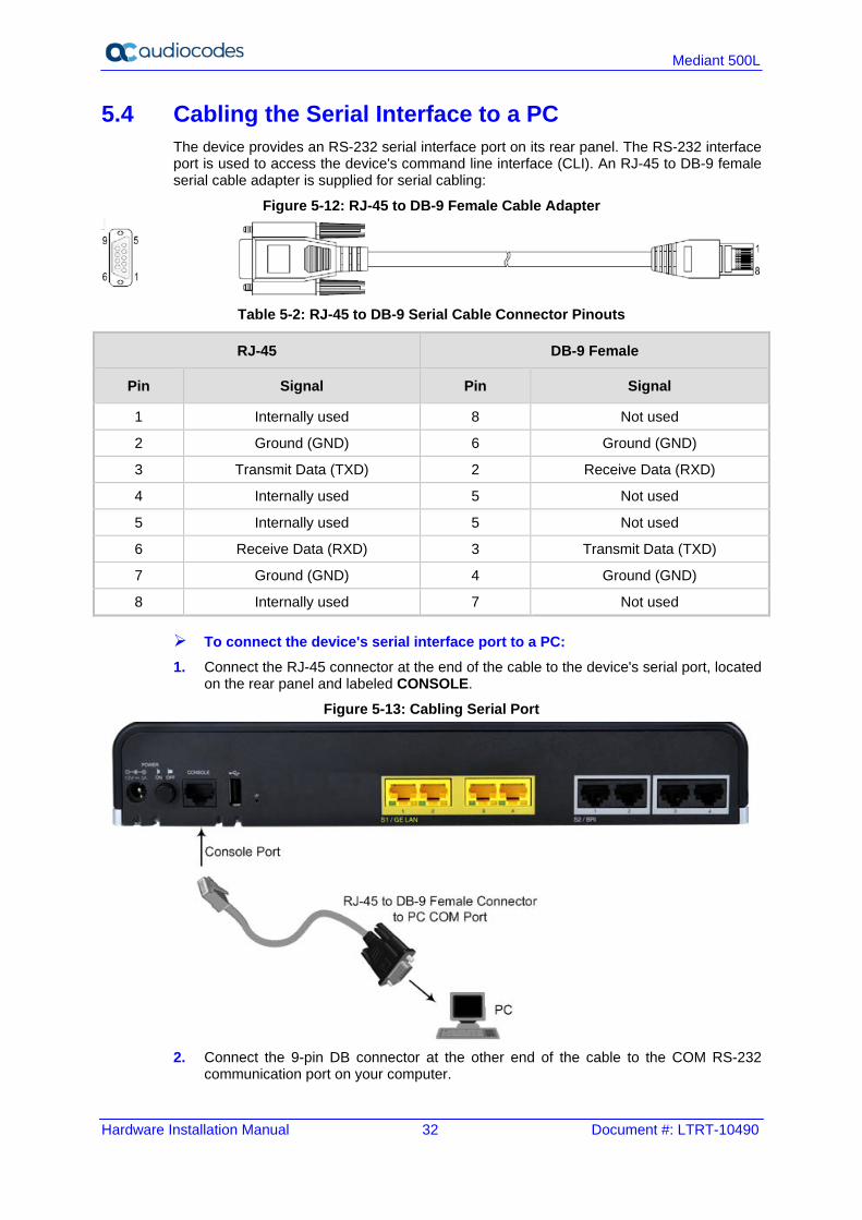
5.4 Cabling the Serial Interface to a PC The device provides an RS-232 serial interface port on its rear panel. The RS-232 interface port is used to access the device's command line interface (CLI). An RJ-45 to DB-9 female serial cable adapter is supplied for serial cabling:
Figure 5-12: RJ-45 to DB-9 Female Cable Adapter
Table 5-2: RJ-45 to DB-9 Serial Cable Connector Pinouts
RJ-45 DB-9 Female
Pin Signal Pin Signal
1 Internally used 8 Not used
2 Ground (GND) 6 Ground (GND)
3 Transmit Data (TXD) 2 Receive Data (RXD)
4 Internally used 5 Not used
5 Internally used 5 Not used
6 Receive Data (RXD) 3 Transmit Data (TXD)
7 Ground (GND) 4 Ground (GND)
8 Internally used 7 Not used
To connect the device's serial interface port to a PC: 1. Connect the RJ-45 connector at the end of the cable to the device's serial port, located
on the rear panel and labeled CONSOLE.
Figure 5-13: Cabling Serial Port
2. Connect the 9-pin DB connector at the other end of the cable to the COM RS-232
communication port on your computer.

Media Gateway & E-SBC 33 Mediant 500L
Hardware Installation Manual 5. Cabling the Device
5.5 Connecting a USB Storage Device The device supports USB storage capabilities, using an external USB hard drive or flash disk (disk on key) connected to the device's USB port. The storage capabilities are configured through CLI and include the following: Saving network captures to USB Upgrading the device's firmware from USB Updating the device's configuration from USB Saving the current configuration to USB
To connect the USB storage device: Connect the USB storage device to the USB port, located on the rear panel.
Figure 5-14: Connecting USB Storage Device
Note: Only a single USB storage (formatted to FAT/FAT32) operation is supported at any given time.

Hardware Installation Manual 34 Document #: LTRT-10490
Mediant 500L
5.6 Connecting to the Power Supply The device is powered by an external 12V AC/DC power adapter (supplied), connected to a standard alternating current (AC) electrical wall outlet.
Table 5-3: Power Specifications
Item Description
Power Supply Single universal external AC power supply
Input Ratings 100-240 VAC, 50-60 Hz
Output Ratings 12V/3A
Max. Power Consumption Only SBC (no BRI): 7W BRI: 2.5W per NT port 0.4W per TE port
Warning: Use only the AC/DC power adapter supplied with the device.
ご注意
本製品に添付の電源ケーブルは、Mediant 500L Gateway & E-SBC に専用設計されているため、汎用性がありません. 本電源ケーブルを他の機器に使用されないよう、ご注意ください.
The device is shipped with the AC/DC power adapter shown in the figure below. The power adapter also supports interchangeable plugs to suite the electrical wall outlet type requirement of the country in which the device is being installed.
Figure 5-15: AC/DC Power Adapter

Media Gateway & E-SBC 35 Mediant 500L
Hardware Installation Manual 5. Cabling the Device
Table 5-4: Power Adapter with Interchangeable Plugs
Item Description
1 Plug slot
2 Plug lock
3 Plug release lever
4 DC power cord
5 DC power plug
To connect the device to the power supply using the power adapter:
1. Insert the relevant AC plug into the housing power adapter: a. Insert the top part of the plug into the upper part of the housing slot (1). b. Press down on the bottom part of the plug until a "click" sound is heard, indicating
that the plug is securely inserted in the housing slot. To remove the plug, push and slide down the OPEN plug release lever (3).
Figure 5-16: Inserting Plug into Power Adapter
2. Insert the DC plug (5) located at the end of the power cord (4) of the power adapter
into the device's power socket located on the rear panel.

Hardware Installation Manual 36 Document #: LTRT-10490
Mediant 500L
Figure 5-17: Cabling to Power using Power Adapter
3. Plug the power adapter directly into a standard electrical wall outlet.

Media Gateway & E-SBC 37 Mediant 500L
Hardware Installation Manual 5. Cabling the Device
5.6.1 Powering On or Off the Device The device is equipped with a power switch, which is located on its rear panel (see Section 3.3 on page 15) for turning it on or off.
To power on the device:
Press in the power button; the device receives power, indicated by the lighting of the Power LED, located on the front panel.
To power off the device: Press out the power button; the device powers off, indicated by the Power LED going
off.

International Headquarters 1 Hayarden Street, Airport City Lod 7019900, Israel Tel: +972-3-976-4000 Fax: +972-3-976-4040 AudioCodes Inc. 27 World’s Fair Drive, Somerset, NJ 08873 Tel: +1-732-469-0880 Fax: +1-732-469-2298 Contact us: https://www.audiocodes.com/corporate/offices-worldwide Website: https://www.audiocodes.com/ ©2017 AudioCodes Ltd. All rights reserved. AudioCodes, AC, HD VoIP, HD VoIP Sounds Better, IPmedia, Mediant, MediaPack, What’s Inside Matters, OSN, SmartTAP, User Management Pack, VMAS, VoIPerfect, VoIPerfectHD, Your Gateway To VoIP, 3GX, VocaNom, AudioCodes One Voice and CloudBond are trademarks or registered trademarks of AudioCodes Limited. All other products or trademarks are property of their respective owners. Product specifications are subject to change without notice.
Document #: LTRT-10490
Related Documents