Operation Manual Media Express 2.0 Windows ™ September 2009 Mac OS X ™

Welcome message from author
This document is posted to help you gain knowledge. Please leave a comment to let me know what you think about it! Share it to your friends and learn new things together.
Transcript
Operation Manual
Media Express 2.0
Windows™
September 2009
Mac OS X™

Capture2 Playback2Contents
Media Express 2.0 Manual
Introduction
Preferences
Media List
Capture
Playback
Master
03
06
08
10
14
17

Introduction
3

Introduction4
Welcome to Media Express 2.0.
Blackmagic Media Express 2.0 is a sophistocated software application which enables DeckLink, Multibridge and Intensity users to capture, play back and preview video and audio via Blackmagic capture hardware. DeckLink and Multibridge users can also master to tape, using insert or assemble edit, with frame accurate RS-422 device control.
This Media Express 2.0 manual supplements the DeckLink, Multibridge and Intensity manuals. Media Express 2.0 replaces all previous versions of Blackmagic Deck Control and Blackmagic Media Express. We hope you love the new interface and features.
Media Express has an intuitive interface and requires a 1920 x 1200 pixel computer display, or larger, to compliment its uncluttered appearance. The capture, playback and master views are color-coded so you will know at a glance which mode is being used.
Media Express uses many of the same keyboard shortcuts which are standard in the video industry so there is little to learn. Use j, k, l to shuttle backwards, pause and shuttle forwards, or use i and o to mark in and out points when batch capturing or mastering to tape. Hold down the control and shift keys to reveal a jog wheel and then use your mouse, with the jog wheel, for precision control of your tape deck.
VITC timecode is supported via RS-422 and RP188 timecode is supported via SDI.
DeckLink and Multibridge users can use the Media List feature to log multiple clips for batch capture or to seamlessly play back multiple clips from a playlist and master them to tape.
Media Express can directly capture to, and play back from, DPX files or movie files.
Use the Grab Frame feature to capture still images during capture, playback or when mastering to tape. Frame grabs are saved in the targa (.tga) graphic file format.
Blackmagic Media Express 2.0 is not NLE software and does not have a timeline. It is a great tool when you don’t need the complexity of NLE software but simply want to capture, play back and output clips to tape, especially when working with video compositing software.

Introduction5
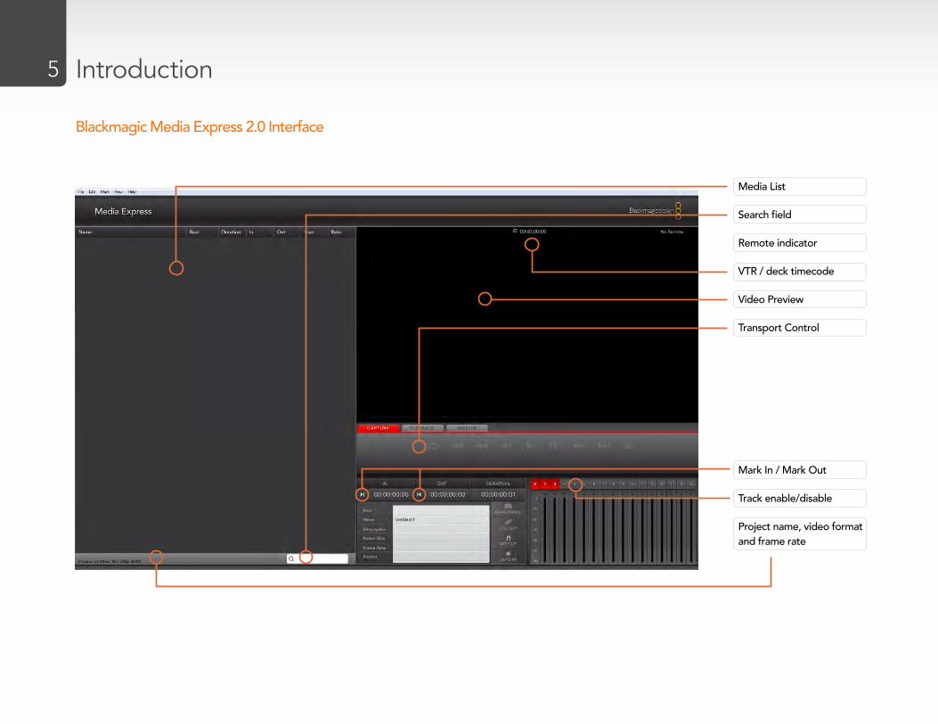
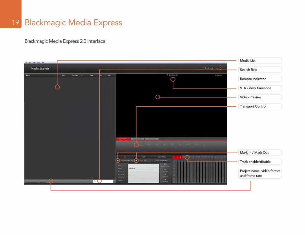
Media List
Search field
Remote indicator
VTR / deck timecode
Video Preview
Transport Control
Mark In / Mark Out
Track enable/disable
Project name, video format and frame rate
Blackmagic Media Express 2.0 Interface

Preferences
6

Preferences7
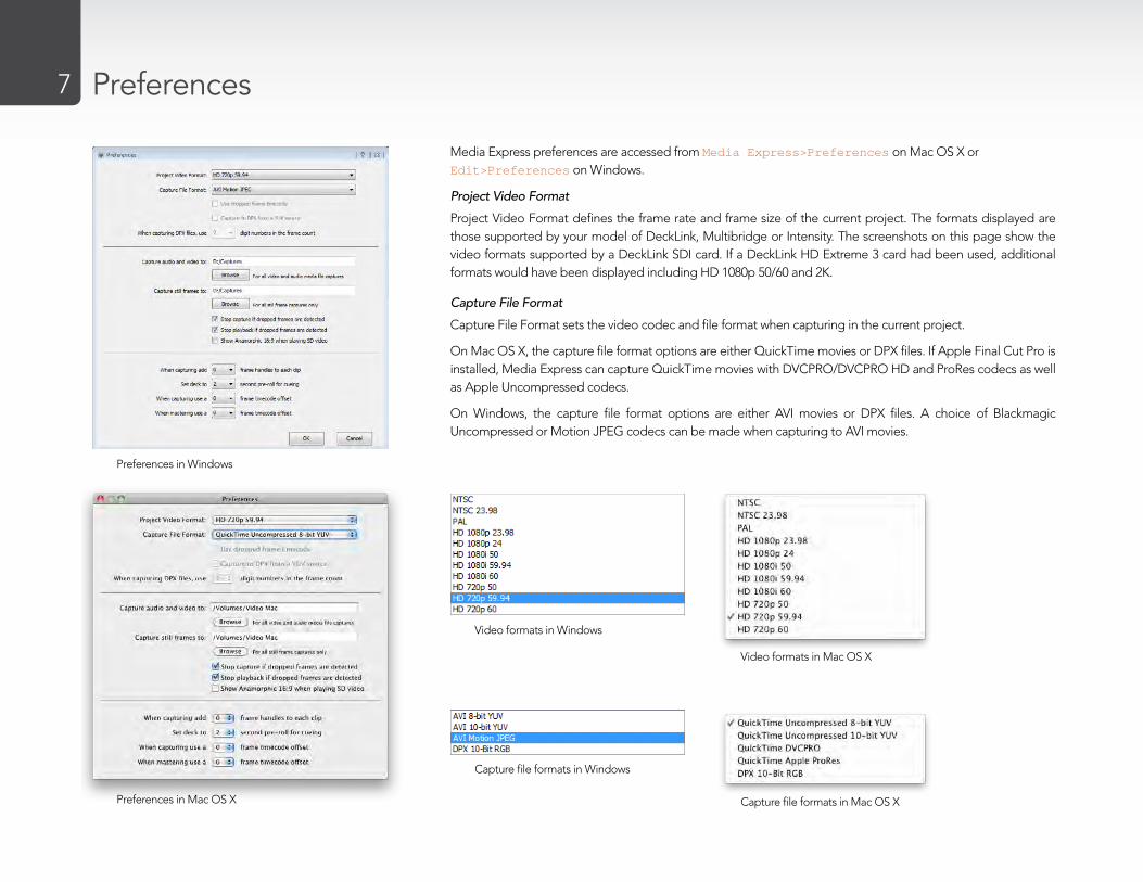
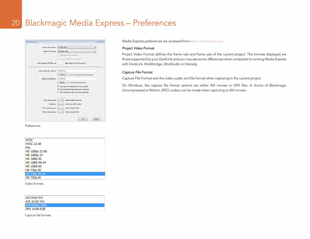
Media Express preferences are accessed from Media Express>Preferences on Mac OS X or Edit>Preferences on Windows.
Project Video Format
Project Video Format defines the frame rate and frame size of the current project. The formats displayed are those supported by your model of DeckLink, Multibridge or Intensity. The screenshots on this page show the video formats supported by a DeckLink SDI card. If a DeckLink HD Extreme 3 card had been used, additional formats would have been displayed including HD 1080p 50/60 and 2K.
Capture File Format
Capture File Format sets the video codec and file format when capturing in the current project.
On Mac OS X, the capture file format options are either QuickTime movies or DPX files. If Apple Final Cut Pro is installed, Media Express can capture QuickTime movies with DVCPRO/DVCPRO HD and ProRes codecs as well as Apple Uncompressed codecs.
On Windows, the capture file format options are either AVI movies or DPX files. A choice of Blackmagic Uncompressed or Motion JPEG codecs can be made when capturing to AVI movies.
Preferences in Windows
Preferences in Mac OS X
Video formats in Mac OS X
Video formats in Windows
Capture file formats in Mac OS X
Capture file formats in Windows

Media List
8

Media List9
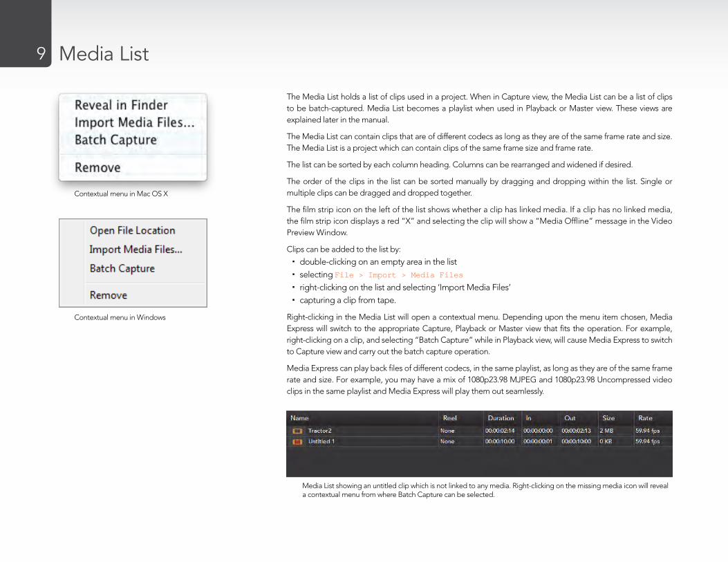
The Media List holds a list of clips used in a project. When in Capture view, the Media List can be a list of clips to be batch-captured. Media List becomes a playlist when used in Playback or Master view. These views are explained later in the manual.
The Media List can contain clips that are of different codecs as long as they are of the same frame rate and size. The Media List is a project which can contain clips of the same frame size and frame rate.
The list can be sorted by each column heading. Columns can be rearranged and widened if desired.
The order of the clips in the list can be sorted manually by dragging and dropping within the list. Single or multiple clips can be dragged and dropped together.
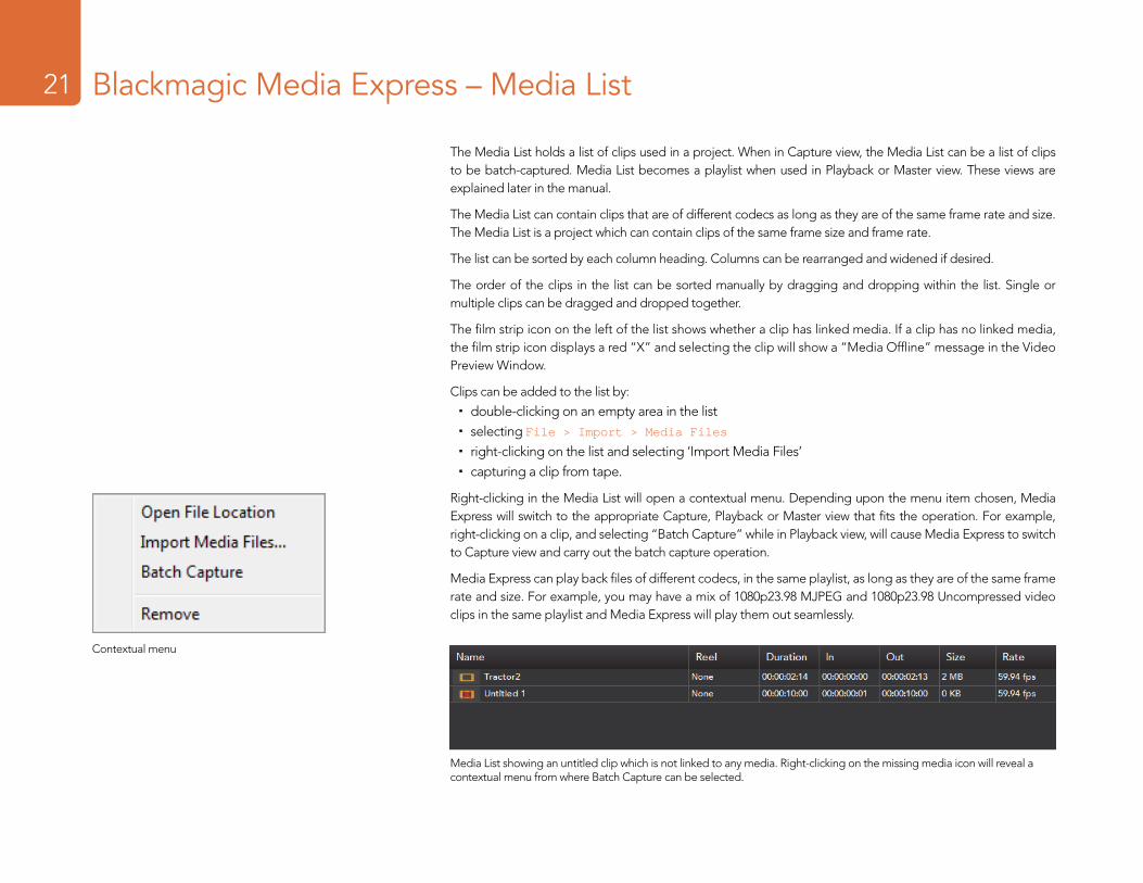
The film strip icon on the left of the list shows whether a clip has linked media. If a clip has no linked media, the film strip icon displays a red “X” and selecting the clip will show a “Media Offline” message in the Video Preview Window.
Clips can be added to the list by:
double-clicking on an empty area in the list �selecting � File > Import > Media Files
right-clicking on the list and selecting ‘Import Media Files’ �capturing a clip from tape. �
Right-clicking in the Media List will open a contextual menu. Depending upon the menu item chosen, Media Express will switch to the appropriate Capture, Playback or Master view that fits the operation. For example, right-clicking on a clip, and selecting “Batch Capture” while in Playback view, will cause Media Express to switch to Capture view and carry out the batch capture operation.
Media Express can play back files of different codecs, in the same playlist, as long as they are of the same frame rate and size. For example, you may have a mix of 1080p23.98 MJPEG and 1080p23.98 Uncompressed video clips in the same playlist and Media Express will play them out seamlessly.
Media List showing an untitled clip which is not linked to any media. Right-clicking on the missing media icon will reveal a contextual menu from where Batch Capture can be selected.
Contextual menu in Windows
Contextual menu in Mac OS X

Capture
10
Capture11
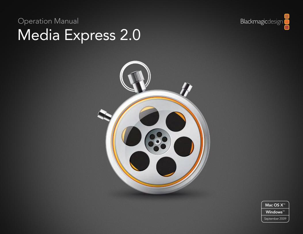
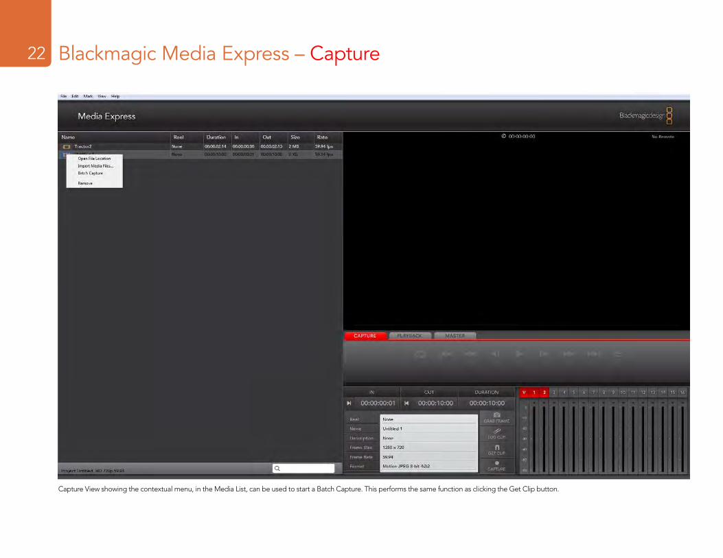
Capture View showing the contextual menu, in the Media List, can be used to start a Batch Capture. This performs the same function as clicking the Get Clip button.
Capture12
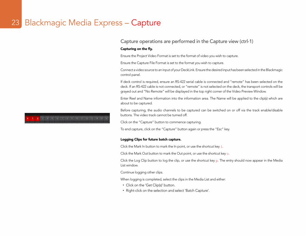
Capture operations are performed in the Capture view (ctrl-1, cmd-1)Capturing on the fly with DeckLink, Multibridge and Intensity.
Ensure the Project Video Format is set to the format of video you wish to capture.
Ensure the Capture File Format is set to the format you wish to capture.
Connect a video source to an input of your DeckLink, Multibridge or Intensity. Ensure the desired input has been selected in the Blackmagic control panel (Windows) or Blackmagic system preferences (Mac OS X).
If deck control is required (with DeckLink or Multibridge), ensure an RS-422 serial cable is connected and “remote” has been selected on the deck. If an RS-422 cable is not connected, or “remote” is not selected on the deck, the transport controls will be grayed out and “No Remote” will be displayed in the top right corner of the Video Preview Window.
Enter Reel and Name information into the information area. The Name will be applied to the clip(s) which are about to be captured.
Before capturing, the audio channels to be captured can be switched on or off via the track enable/disable buttons. The video track cannot be turned off.
Click on the “Capture” button to commence capturing.
To end capture, click on the “Capture” button again or press the “Esc” key.
Logging Clips for future batch capture with DeckLink and Multibridge.
Click the Mark In button to mark the In point, or use the shortcut key i.
Click the Mark Out button to mark the Out point, or use the shortcut key o.
Click the Log Clip button to log the clip, or use the shortcut key p. The entry should now appear in the Media List window.
Continue logging other clips.
When logging is completed, select the clips in the Media List and either:
Click on the ‘Get Clip(s)’ button. �Right-click on the selection and select ‘Batch Capture’. �

Capture13
Capturing a clip with precise In and Out timecode with DeckLink and Multibridge.
Click on the Mark In button to mark the In point or use the shortcut key i.
Click on the Mark Out button to mark the Out point or use the shortcut key o.
Click on the Get Clip button.
Media Express will cue the tape and precisely capture the clip from the In to the Out timecode points, including any handles specified in the application preferences.
While capturing, if the file name (Name) of a clip already exists on the selected capture drive, the user will be prompted if they want to over-write the file or not. If ‘No’ is selected, the file name will be auto-incremented with a number.

Playback
14
Capture15 Playback15
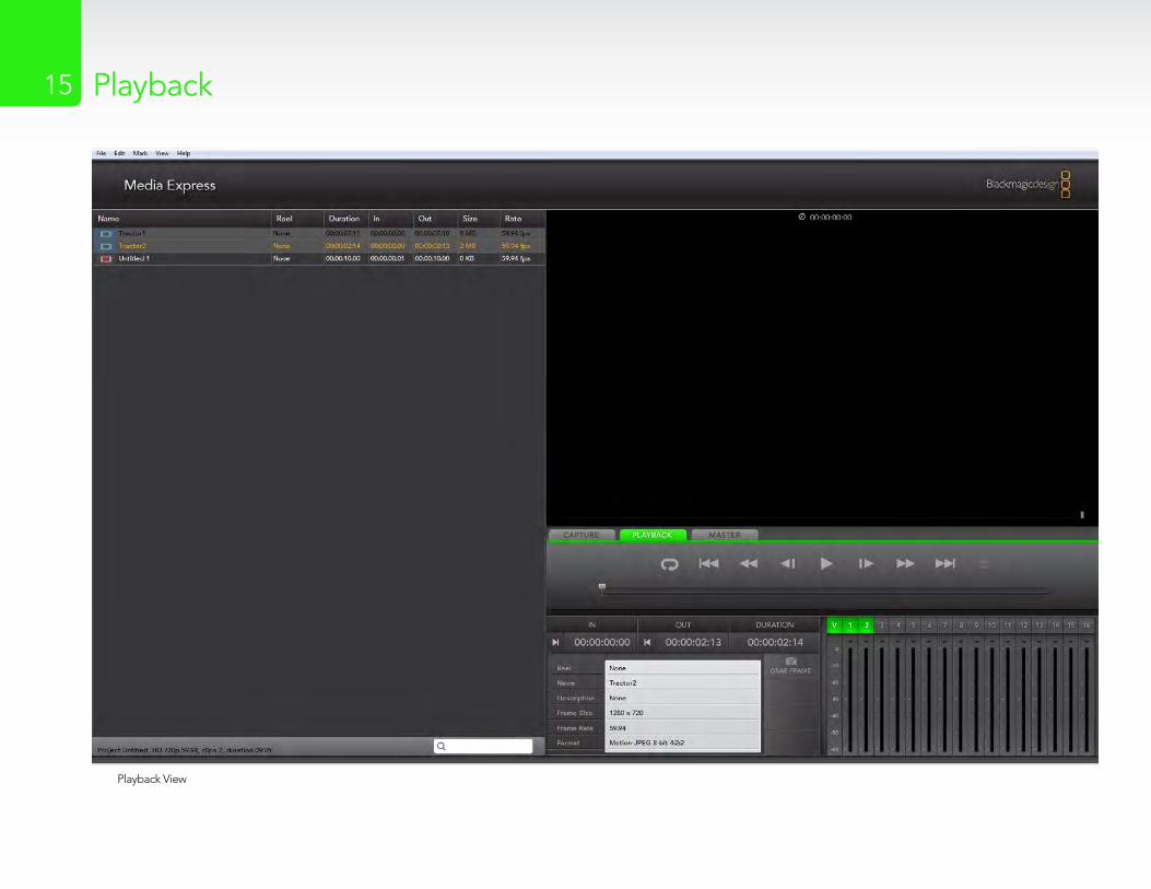
Playback View
Capture16 Playback16
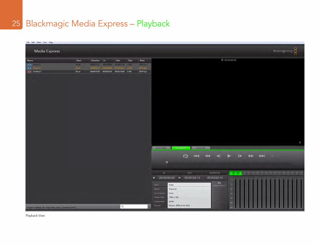
Playback operations are performed in the Playback tab (ctrl-2, cmd-2)Importing clips into the Media List
Import media into the Media List using one of the following methods:
Double-click on an empty area of the list. �Select � File > Import > Media Files.Right-click on the list and select ‘Import Media Files’. �Capture a clip from tape. �
Any of these actions will reveal an Open Video Clip window where more where one or more files can be selected.
If the files being imported match the frame rate and size of those in the Media List, the import will be successful.
If the files being imported do not match the frame rate and size of existing clips in the Media List, the user will be prompted to create a new project and to save the current project.
If the current project has had no changes, and has already been saved, the user will only be prompted to start a new project as there is no need to save the existing project.
Playing back a single clip
Selecting a clip (single click) on the list will load it into the Video Preview Window.
To play back a single clip in the Media List, double click the clip and it will start playing in the Video Preview Window.
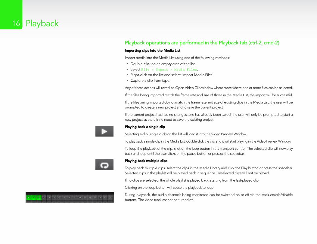
To loop the playback of the clip, click on the loop button in the transport control. The selected clip will now play back and loop until the user clicks on the pause button or presses the spacebar.
Playing back multiple clips
To play back multiple clips, select the clips in the Media Library and click the Play button or press the spacebar. Selected clips in the playlist will be played back in sequence. Unselected clips will not be played.
If no clips are selected, the whole playlist is played back, starting from the last-played clip.
Clicking on the loop button will cause the playback to loop.
During playback, the audio channels being monitored can be switched on or off via the track enable/disable buttons. The video track cannot be turned off.

Master
17

Capture18 Master18
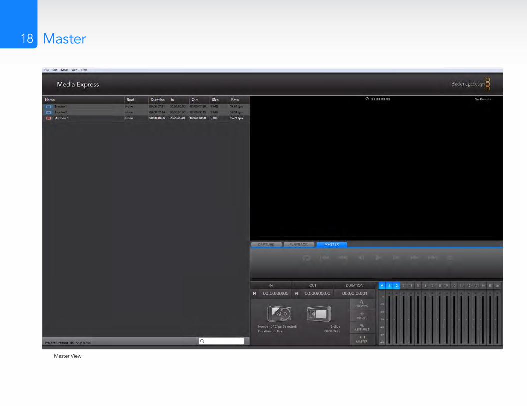
Master View

Operation Manual
Media Express 2.0
Windows™
September 2009
Mac OS X™
Capture2 Playback2Contents
Media Express 2.0 Manual
Introduction
Preferences
Media List
Capture
Playback
Master
03
06
08
10
14
17
Introduction4
Welcome to Media Express 2.0.
Blackmagic Media Express 2.0 is a sophistocated software application which enables DeckLink, Multibridge and Intensity users to capture, play back and preview video and audio via Blackmagic capture hardware. DeckLink and Multibridge users can also master to tape, using insert or assemble edit, with frame accurate RS-422 device control.
This Media Express 2.0 manual supplements the DeckLink, Multibridge and Intensity manuals. Media Express 2.0 replaces all previous versions of Blackmagic Deck Control and Blackmagic Media Express. We hope you love the new interface and features.
Media Express has an intuitive interface and requires a 1920 x 1200 pixel computer display, or larger, to compliment its uncluttered appearance. The capture, playback and master views are color-coded so you will know at a glance which mode is being used.
Media Express uses many of the same keyboard shortcuts which are standard in the video industry so there is little to learn. Use j, k, l to shuttle backwards, pause and shuttle forwards, or use i and o to mark in and out points when batch capturing or mastering to tape. Hold down the control and shift keys to reveal a jog wheel and then use your mouse, with the jog wheel, for precision control of your tape deck.
VITC timecode is supported via RS-422 and RP188 timecode is supported via SDI.
DeckLink and Multibridge users can use the Media List feature to log multiple clips for batch capture or to seamlessly play back multiple clips from a playlist and master them to tape.
Media Express can directly capture to, and play back from, DPX files or movie files.
Use the Grab Frame feature to capture still images during capture, playback or when mastering to tape. Frame grabs are saved in the targa (.tga) graphic file format.
Blackmagic Media Express 2.0 is not NLE software and does not have a timeline. It is a great tool when you don’t need the complexity of NLE software but simply want to capture, play back and output clips to tape, especially when working with video compositing software.
Introduction5
Media List
Search field
Remote indicator
VTR / deck timecode
Video Preview
Transport Control
Mark In / Mark Out
Track enable/disable
Project name, video format and frame rate
Blackmagic Media Express 2.0 Interface
Preferences7
Media Express preferences are accessed from Media Express>Preferences on Mac OS X or Edit>Preferences on Windows.
Project Video Format
Project Video Format defines the frame rate and frame size of the current project. The formats displayed are those supported by your model of DeckLink, Multibridge or Intensity. The screenshots on this page show the video formats supported by a DeckLink SDI card. If a DeckLink HD Extreme 3 card had been used, additional formats would have been displayed including HD 1080p 50/60 and 2K.
Capture File Format
Capture File Format sets the video codec and file format when capturing in the current project.
On Mac OS X, the capture file format options are either QuickTime movies or DPX files. If Apple Final Cut Pro is installed, Media Express can capture QuickTime movies with DVCPRO/DVCPRO HD and ProRes codecs as well as Apple Uncompressed codecs.
On Windows, the capture file format options are either AVI movies or DPX files. A choice of Blackmagic Uncompressed or Motion JPEG codecs can be made when capturing to AVI movies.
Preferences in Windows
Preferences in Mac OS X
Video formats in Mac OS X
Video formats in Windows
Capture file formats in Mac OS X
Capture file formats in Windows
Media List9
The Media List holds a list of clips used in a project. When in Capture view, the Media List can be a list of clips to be batch-captured. Media List becomes a playlist when used in Playback or Master view. These views are explained later in the manual.
The Media List can contain clips that are of different codecs as long as they are of the same frame rate and size. The Media List is a project which can contain clips of the same frame size and frame rate.
The list can be sorted by each column heading. Columns can be rearranged and widened if desired.
The order of the clips in the list can be sorted manually by dragging and dropping within the list. Single or multiple clips can be dragged and dropped together.
The film strip icon on the left of the list shows whether a clip has linked media. If a clip has no linked media, the film strip icon displays a red “X” and selecting the clip will show a “Media Offline” message in the Video Preview Window.
Clips can be added to the list by:
double-clicking on an empty area in the list �selecting � File > Import > Media Files
right-clicking on the list and selecting ‘Import Media Files’ �capturing a clip from tape. �
Right-clicking in the Media List will open a contextual menu. Depending upon the menu item chosen, Media Express will switch to the appropriate Capture, Playback or Master view that fits the operation. For example, right-clicking on a clip, and selecting “Batch Capture” while in Playback view, will cause Media Express to switch to Capture view and carry out the batch capture operation.
Media Express can play back files of different codecs, in the same playlist, as long as they are of the same frame rate and size. For example, you may have a mix of 1080p23.98 MJPEG and 1080p23.98 Uncompressed video clips in the same playlist and Media Express will play them out seamlessly.
Media List showing an untitled clip which is not linked to any media. Right-clicking on the missing media icon will reveal a contextual menu from where Batch Capture can be selected.
Contextual menu in Windows
Contextual menu in Mac OS X

Capture11
Capture View showing the contextual menu, in the Media List, can be used to start a Batch Capture. This performs the same function as clicking the Get Clip button.

Capture12
Capture operations are performed in the Capture view (ctrl-1, cmd-1)Capturing on the fly with DeckLink, Multibridge and Intensity.
Ensure the Project Video Format is set to the format of video you wish to capture.
Ensure the Capture File Format is set to the format you wish to capture.
Connect a video source to an input of your DeckLink, Multibridge or Intensity. Ensure the desired input has been selected in the Blackmagic control panel (Windows) or Blackmagic system preferences (Mac OS X).
If deck control is required (with DeckLink or Multibridge), ensure an RS-422 serial cable is connected and “remote” has been selected on the deck. If an RS-422 cable is not connected, or “remote” is not selected on the deck, the transport controls will be grayed out and “No Remote” will be displayed in the top right corner of the Video Preview Window.
Enter Reel and Name information into the information area. The Name will be applied to the clip(s) which are about to be captured.
Before capturing, the audio channels to be captured can be switched on or off via the track enable/disable buttons. The video track cannot be turned off.
Click on the “Capture” button to commence capturing.
To end capture, click on the “Capture” button again or press the “Esc” key.
Logging Clips for future batch capture with DeckLink and Multibridge.
Click the Mark In button to mark the In point, or use the shortcut key i.
Click the Mark Out button to mark the Out point, or use the shortcut key o.
Click the Log Clip button to log the clip, or use the shortcut key p. The entry should now appear in the Media List window.
Continue logging other clips.
When logging is completed, select the clips in the Media List and either:
Click on the ‘Get Clip(s)’ button. �Right-click on the selection and select ‘Batch Capture’. �
Capture13
Capturing a clip with precise In and Out timecode with DeckLink and Multibridge.
Click on the Mark In button to mark the In point or use the shortcut key i.
Click on the Mark Out button to mark the Out point or use the shortcut key o.
Click on the Get Clip button.
Media Express will cue the tape and precisely capture the clip from the In to the Out timecode points, including any handles specified in the application preferences.
While capturing, if the file name (Name) of a clip already exists on the selected capture drive, the user will be prompted if they want to over-write the file or not. If ‘No’ is selected, the file name will be auto-incremented with a number.

Capture15 Playback15
Playback View

Capture16 Playback16
Playback operations are performed in the Playback tab (ctrl-2, cmd-2)Importing clips into the Media List
Import media into the Media List using one of the following methods:
Double-click on an empty area of the list. �Select � File > Import > Media Files.Right-click on the list and select ‘Import Media Files’. �Capture a clip from tape. �
Any of these actions will reveal an Open Video Clip window where more where one or more files can be selected.
If the files being imported match the frame rate and size of those in the Media List, the import will be successful.
If the files being imported do not match the frame rate and size of existing clips in the Media List, the user will be prompted to create a new project and to save the current project.
If the current project has had no changes, and has already been saved, the user will only be prompted to start a new project as there is no need to save the existing project.
Playing back a single clip
Selecting a clip (single click) on the list will load it into the Video Preview Window.
To play back a single clip in the Media List, double click the clip and it will start playing in the Video Preview Window.
To loop the playback of the clip, click on the loop button in the transport control. The selected clip will now play back and loop until the user clicks on the pause button or presses the spacebar.
Playing back multiple clips
To play back multiple clips, select the clips in the Media Library and click the Play button or press the spacebar. Selected clips in the playlist will be played back in sequence. Unselected clips will not be played.
If no clips are selected, the whole playlist is played back, starting from the last-played clip.
Clicking on the loop button will cause the playback to loop.
During playback, the audio channels being monitored can be switched on or off via the track enable/disable buttons. The video track cannot be turned off.
Capture18 Master18
Master View
Capture19 Master19
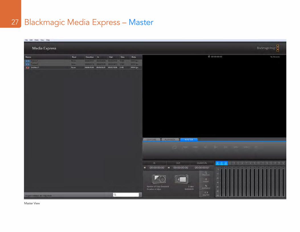
Mastering to tape operations are performed in the Master view (ctrl-3, cmd-3)Media Express can use DeckLink or Multibridge to master to tape via Insert or Assemble editing.
Only clips that are selected in the Media List will be output to tape. If no clips are selected, it is assumed that the entire Media List will be output.
To master to tape, click on the Master view and ensure RS-422 device control is connected.
Enter the In and Out points of the tape by entering timecode into the respective text boxes, or by cueing the tape to the desired point via the transport control and then clicking the Mark In button, or use the shortcut key i.
If no Out point is entered, Media Express will set the duration of the edit to the total length of the clips in the Media List. If an out point is defined, Media Express will leave edit mode once the Out point timecode is reached, even if some clips have not been output.
The Insert and Assemble buttons are mutually exclusive and only one mode can be selected at a time. This determines which mode Media Express will use to master to tape. Select the Insert or Assemble button as required.
The Preview and Master buttons are also mutually exclusive. Clicking on either button will instruct Media Express to proceed with the specified operation. Preview mode mimics the edit process but does not record to tape. This mode allows one to check the edit point is correct.
Preview edit operations should always be checked on monitors connected directly to the output of the deck to view the preceding video already on tape, the new video and the following video already on tape.
If Record Inhibit is enabled either on the deck or on the tape in the deck, Media Express will display a dialog box, when the user clicks on the Master button, informing the user that Record Inhibit is enabled. Check the deck/tape and disable Record Inhibit before trying again.
Before mastering, the audio channels to be put to tape can be selected on or off via the track enable/disable buttons. The Video track cannot be turned off.
Contents
Current DeckLink Cards
How to Install
Installation 6 Installing a DeckLink PCIe card 6 Installing the HDMI bracket 7 Installing DeckLink Optical Fiber 7 Installing the Software 9
Software
Blackmagic Software 11 Setting Blackmagic Preferences 11 Using Blackmagic Media Express 18 Blackmagic Disk Speed Test 29 Disk arrays 29
Third Party Applications 30 Adobe Premiere Pro 30 Adobe After Effects 33 Adobe Photoshop 34
Supported File Formats 35
Troubleshooting Video Capture and Playback 36
05
10
Connection Diagrams
Betacam SP analog deck 38 SDI digital deck 39 Sony HDCAM SR deck in 4:2:2 40 Sony HDCAM SR deck in 4:4:4 41 NTSC/PAL monitor 42 Connecting to S-Video 43 YUV component monitor 44 Connecting to an HDTV 45 2K Monitoring with HDLink 46 HDMI Workflow 47
Product Diagrams
DeckLink Duo 49 DeckLink HD Extreme 3D 50 DeckLink SDI 51 DeckLink Studio 2 52
Developer Information
Blackmagic 2K Format – Overview 54 Blackmagic 2K Format – Vertical Timing Reference 55 Blackmagic 2K Format – Data Stream Format 56
37
53
48
Contents
Previous DeckLink Cards
Installation & Setup
Before installing a DeckLink card 58 Lookup Tables (LUTs) in DeckLink HD Extreme 2 59
Connection Diagrams
Betacam SP analog deck 62 SDI digital deck 63 Sony HDCAM SR deck in 4:2:2 (DeckLink HD Extreme 2) 64 Sony HDCAM SR deck in 4:2:2 (DeckLink HD Pro PCIe) 65 Sony HDCAM SR deck in 4:4:4 66 NTSC/PAL monitor 67 Connecting to S-Video DeckLink HD Extreme 2 68 Connecting to S-Video DeckLink HD Extreme 69 YUV component monitor 70 Connecting to an HDTV 71 HDMI Workflow 72 2K Monitoring with HDLink 73
57
61
Product Diagrams
DeckLink 75 DeckLink Extreme 76 DeckLink Extreme PCIe 77 DeckLink HD 78 DeckLink HD Extreme and Professional Breakout Cable 79 DeckLink HD Extreme and Consumer Breakout Cable 80 DeckLink HD Extreme 2 and Professional Breakout Cable 81 DeckLink HD Extreme 2 and Consumer Breakout Cable 82 DeckLink HD Extreme 3 and Professional Breakout Cable 83 DeckLink HD Plus 84 DeckLink HD Pro 4:2:2 PCI-X 85 DeckLink HD Pro 4:4:4 PCI-X 86 DeckLink HD Pro PCIe 87 DeckLink HD Studio 88 DeckLink Optical Fiber 89 DeckLink Plus 90 DeckLink Pro 91 DeckLink SP 92 DeckLink SP PCIe 93 DeckLink Studio 94
Warranty
Warranty Terms and Conditions 96
74
95
Welcome4
Welcome to DeckLink.We hope you share our dream for the television industry to become a truly creative industry by allowing anyone to have access to the highest quality video.
Previously high end television and post production required investment in millions of dollars of hardware, however with DeckLink cards, even 10 bit uncompressed 3D is now easily affordable. We hope you get years of use from your new DeckLink card and have fun working with some of the world’s hottest television and design software!
This instruction manual should contain all the information you’ll need on installing your DeckLink capture card, although it’s always a good idea to ask a technical assistant for help if you have not installed hardware cards into computers before. As DeckLink uses uncompressed video and the data rates are quite high, you’ll need fast disk storage and a high-end PC.
We think it should take you approximately 10 minutes to complete installation. Before you install DeckLink, please check our website at www.blackmagic-design.com and click the support page to download the latest updates to this manual and DeckLink driver software. Lastly, please register your DeckLink when downloading software updates. We would love to keep you updated on new software updates and new features for your DeckLink. Perhaps you can even send us your latest show reel of work completed on your DeckLink and any suggestions for improvements to the software. We are constantly working on new features and improvements, so we would love to hear from you!
Grant PettyCEO Blackmagic Design
Installation6
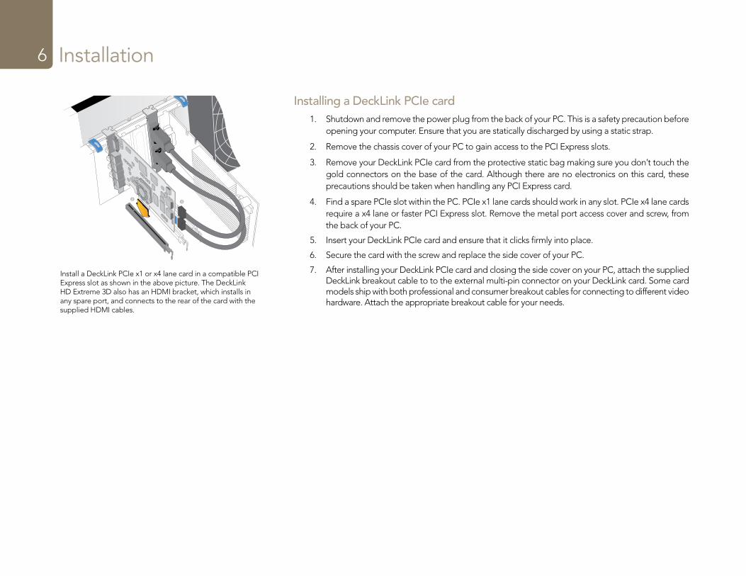
Installing a DeckLink PCIe card1. Shutdown and remove the power plug from the back of your PC. This is a safety precaution before
opening your computer. Ensure that you are statically discharged by using a static strap.
2. Remove the chassis cover of your PC to gain access to the PCI Express slots.
3. Remove your DeckLink PCIe card from the protective static bag making sure you don’t touch the gold connectors on the base of the card. Although there are no electronics on this card, these precautions should be taken when handling any PCI Express card.
4. Find a spare PCIe slot within the PC. PCIe x1 lane cards should work in any slot. PCIe x4 lane cards require a x4 lane or faster PCI Express slot. Remove the metal port access cover and screw, from the back of your PC.
5. Insert your DeckLink PCIe card and ensure that it clicks firmly into place.
6. Secure the card with the screw and replace the side cover of your PC.
7. After installing your DeckLink PCIe card and closing the side cover on your PC, attach the supplied DeckLink breakout cable to to the external multi-pin connector on your DeckLink card. Some card models ship with both professional and consumer breakout cables for connecting to different video hardware. Attach the appropriate breakout cable for your needs.
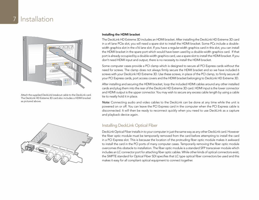
Install a DeckLink PCIe x1 or x4 lane card in a compatible PCI Express slot as shown in the above picture. The DeckLink HD Extreme 3D also has an HDMI bracket, which installs in any spare port, and connects to the rear of the card with the supplied HDMI cables.
Installation7
Installing the HDMI bracket
The DeckLink HD Extreme 3D includes an HDMI bracket. After installing the DeckLink HD Extreme 3D card in a x4 lane PCIe slot, you will need a spare slot to install the HDMI bracket. Some PCs include a double-width graphics slot in the x16 lane slot. If you have a regular-width graphics card in this slot, you can install the HDMI bracket in the spare port which would have been used by a double-width graphics card. If that port is already occupied by a double-width graphics card, use a spare slot to install the HDMI bracket. If you don’t need HDMI input and output, there is no necessity to install the HDMI bracket.
Some computer cases provide a PCI clamp which is designed to secure all PCI Express cards without the need for screws. The clamp does not always firmly secure the HDMI bracket and so we have included 6 screws with your DeckLink HD Extreme 3D. Use these screws, in place of the PCI clamp, to firmly secure all your PCI Express cards, port access covers and the HDMI bracket belonging to DeckLink HD Extreme 3D.
After installing and securing the HDMI bracket, loop the included HDMI cables around any other installed cards and plug them into the rear of the DeckLink HD Extreme 3D card. HDMI input is the lower connector and HDMI output is the upper connector. You may wish to secure any excess cable length by using a cable tie to neatly hold it in place.
Note: Connecting audio and video cables to the DeckLink can be done at any time while the unit is powered on or off. You can leave the PCI Express card in the computer when the PCI Express cable is disconnected. It will then be ready to reconnect quickly when you need to use DeckLink as a capture and playback device again.
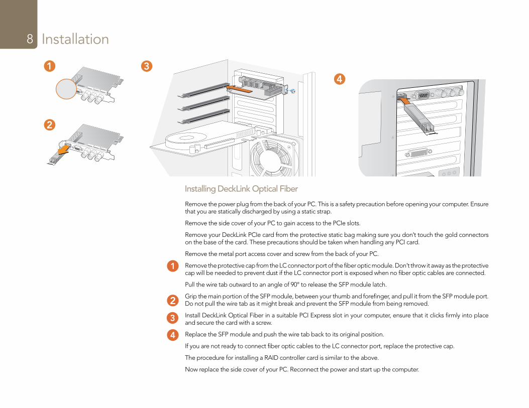
Installing DeckLink Optical FiberDeckLink Optical Fiber installs in to your computer in just the same way as any other DeckLink card. However the fiber optic module must be temporarily removed from the card before attempting to install the card in a PCI Express slot. This is because the location of the protruding fiber optic module makes it awkward to install the card in the PCI ports of many computer cases. Temporarily removing the fiber optic module overcomes this obstacle to installation. The fiber optic module is a standard SFP transceiver module which includes an LC connector port for attaching fiber optic cables. While other kinds of optical connectors exist, the SMPTE standard for Optical Fiber SDI specifies that LC type optical fiber connectors be used and this makes it easy for all compliant optical equipment to connect together.
Attach the supplied DeckLink breakout cable to the DeckLink card. The DeckLink HD Extreme 3D card also includes a HDMI bracket as pictured above.
Installation8
Remove the power plug from the back of your PC. This is a safety precaution before opening your computer. Ensure that you are statically discharged by using a static strap.
Remove the side cover of your PC to gain access to the PCIe slots.
Remove your DeckLink PCIe card from the protective static bag making sure you don’t touch the gold connectors on the base of the card. These precautions should be taken when handling any PCI card.
Remove the metal port access cover and screw from the back of your PC.
Remove the protective cap from the LC connector port of the fiber optic module. Don’t throw it away as the protective cap will be needed to prevent dust if the LC connector port is exposed when no fiber optic cables are connected.
Pull the wire tab outward to an angle of 90° to release the SFP module latch.
Grip the main portion of the SFP module, between your thumb and forefinger, and pull it from the SFP module port. Do not pull the wire tab as it might break and prevent the SFP module from being removed.
Install DeckLink Optical Fiber in a suitable PCI Express slot in your computer, ensure that it clicks firmly into place and secure the card with a screw.
Replace the SFP module and push the wire tab back to its original position.
If you are not ready to connect fiber optic cables to the LC connector port, replace the protective cap.
The procedure for installing a RAID controller card is similar to the above.
Now replace the side cover of your PC. Reconnect the power and start up the computer.
Installing DeckLink Optical Fiber
4
12
11
12
11
43
3
Windows
Mac OS X
Installation9
Installing the software
Contents
The DeckLink software installer will install the following components for you:
� Blackmagic drivers � Blackmagic Control Panel � Blackmagic Media Express application � Blackmagic AVI and QuickTime™ codecs � Blackmagic Disk Speed Test � Blackmagic DirectShow™ SDK � Adobe® presets and plug-ins
DeckLink software
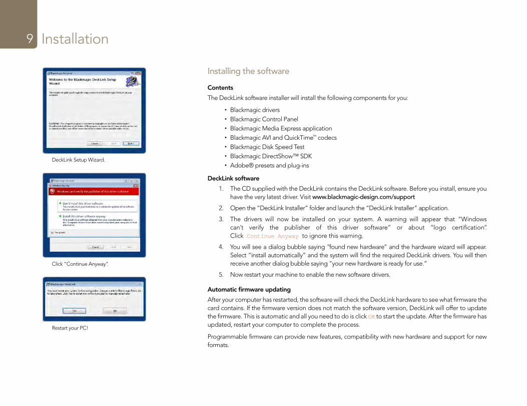
1. The CD supplied with the DeckLink contains the DeckLink software. Before you install, ensure you have the very latest driver. Visit www.blackmagic-design.com/support
2. Open the “DeckLink Installer” folder and launch the “DeckLink Installer” application.
3. The drivers will now be installed on your system. A warning will appear that “Windows can’t verify the publisher of this driver software” or about “logo certification”. Click Continue Anyway to ignore this warning.
4. You will see a dialog bubble saying “found new hardware” and the hardware wizard will appear. Select “install automatically” and the system will find the required DeckLink drivers. You will then receive another dialog bubble saying “your new hardware is ready for use.”
5. Now restart your machine to enable the new software drivers.
Automatic firmware updating
After your computer has restarted, the software will check the DeckLink hardware to see what firmware the card contains. If the firmware version does not match the software version, DeckLink will offer to update the firmware. This is automatic and all you need to do is click OK to start the update. After the firmware has updated, restart your computer to complete the process.
Programmable firmware can provide new features, compatibility with new hardware and support for new formats.
DeckLink Setup Wizard.
Click “Continue Anyway”.
Restart your PC!
Blackmagic Software11
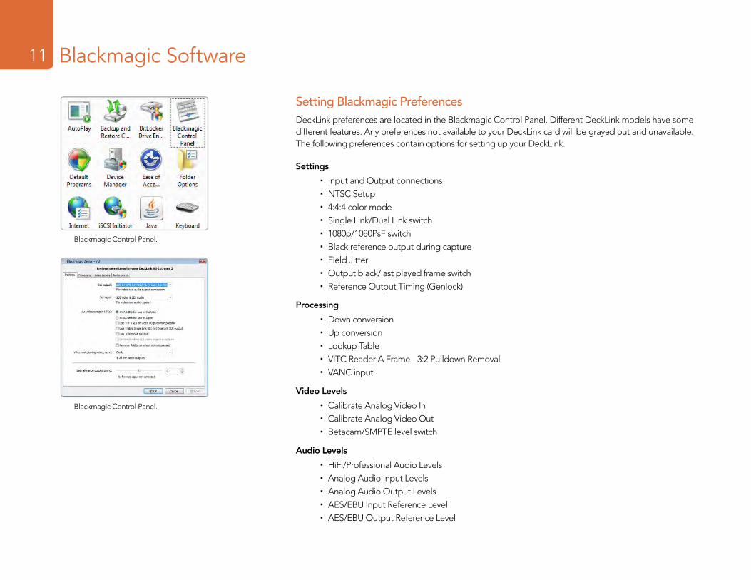
Setting Blackmagic PreferencesDeckLink preferences are located in the Blackmagic Control Panel. Different DeckLink models have some different features. Any preferences not available to your DeckLink card will be grayed out and unavailable. The following preferences contain options for setting up your DeckLink.
Settings
� Input and Output connections � NTSC Setup � 4:4:4 color mode � Single Link/Dual Link switch � 1080p/1080PsF switch � Black reference output during capture � Field Jitter � Output black/last played frame switch � Reference Output Timing (Genlock)
Processing
� Down conversion � Up conversion � Lookup Table � VITC Reader A Frame - 3:2 Pulldown Removal � VANC input
Video Levels
� Calibrate Analog Video In � Calibrate Analog Video Out � Betacam/SMPTE level switch
Audio Levels
� HiFi/Professional Audio Levels � Analog Audio Input Levels � Analog Audio Output Levels � AES/EBU Input Reference Level � AES/EBU Output Reference Level
Blackmagic Control Panel.
Blackmagic Control Panel.
Blackmagic Software12
Setting Blackmagic Preferences
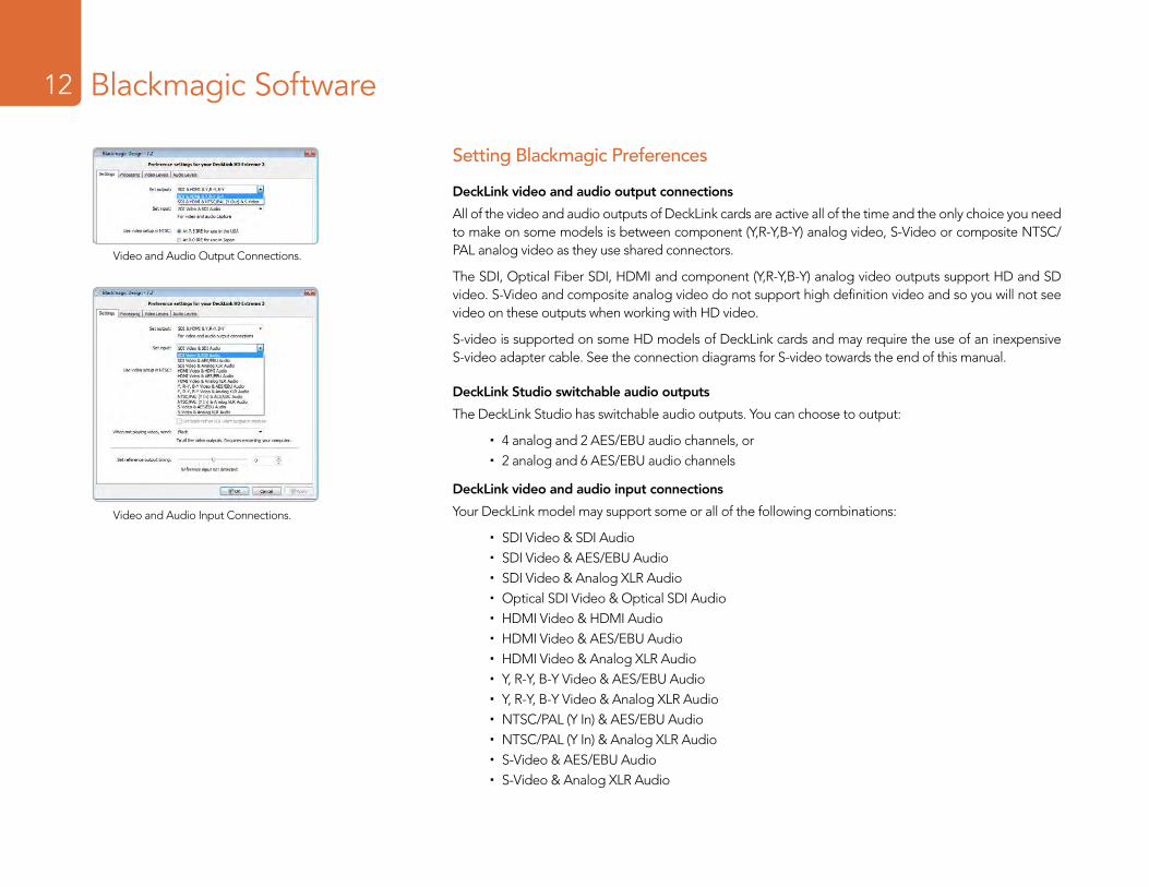
DeckLink video and audio output connections
All of the video and audio outputs of DeckLink cards are active all of the time and the only choice you need to make on some models is between component (Y,R-Y,B-Y) analog video, S-Video or composite NTSC/PAL analog video as they use shared connectors.
The SDI, Optical Fiber SDI, HDMI and component (Y,R-Y,B-Y) analog video outputs support HD and SD video. S-Video and composite analog video do not support high definition video and so you will not see video on these outputs when working with HD video.
S-video is supported on some HD models of DeckLink cards and may require the use of an inexpensive S-video adapter cable. See the connection diagrams for S-video towards the end of this manual.
DeckLink Studio switchable audio outputs
The DeckLink Studio has switchable audio outputs. You can choose to output:
� 4 analog and 2 AES/EBU audio channels, or � 2 analog and 6 AES/EBU audio channels
DeckLink video and audio input connections
Your DeckLink model may support some or all of the following combinations:
� SDI Video & SDI Audio � SDI Video & AES/EBU Audio � SDI Video & Analog XLR Audio � Optical SDI Video & Optical SDI Audio � HDMI Video & HDMI Audio � HDMI Video & AES/EBU Audio � HDMI Video & Analog XLR Audio � Y, R-Y, B-Y Video & AES/EBU Audio � Y, R-Y, B-Y Video & Analog XLR Audio � NTSC/PAL (Y In) & AES/EBU Audio � NTSC/PAL (Y In) & Analog XLR Audio � S-Video & AES/EBU Audio � S-Video & Analog XLR Audio
Video and Audio Output Connections.
Video and Audio Input Connections.
Blackmagic Software13
Setting Blackmagic Preferences
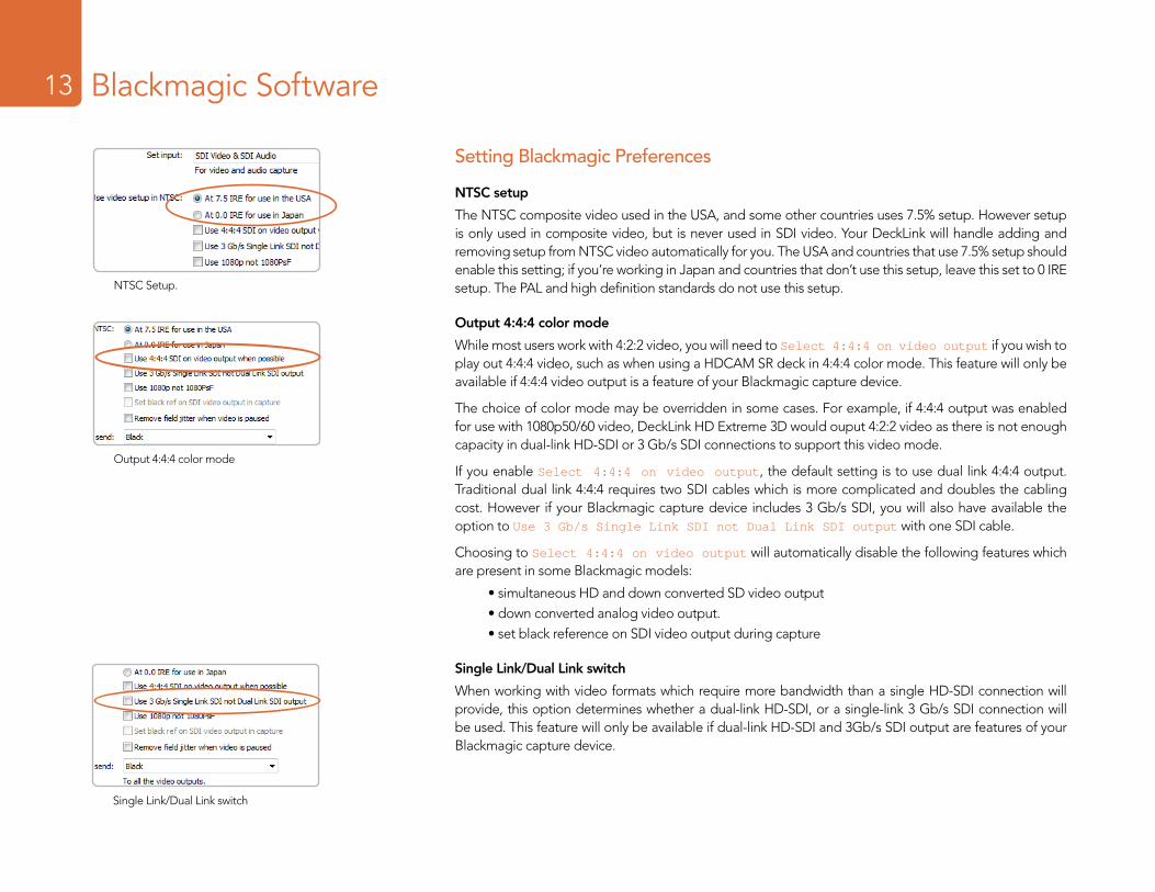
NTSC setup
The NTSC composite video used in the USA, and some other countries uses 7.5% setup. However setup is only used in composite video, but is never used in SDI video. Your DeckLink will handle adding and removing setup from NTSC video automatically for you. The USA and countries that use 7.5% setup should enable this setting; if you’re working in Japan and countries that don’t use this setup, leave this set to 0 IRE setup. The PAL and high definition standards do not use this setup.
Output 4:4:4 color mode
While most users work with 4:2:2 video, you will need to Select 4:4:4 on video output if you wish to play out 4:4:4 video, such as when using a HDCAM SR deck in 4:4:4 color mode. This feature will only be available if 4:4:4 video output is a feature of your Blackmagic capture device.
The choice of color mode may be overridden in some cases. For example, if 4:4:4 output was enabled for use with 1080p50/60 video, DeckLink HD Extreme 3D would ouput 4:2:2 video as there is not enough capacity in dual-link HD-SDI or 3 Gb/s SDI connections to support this video mode.
If you enable Select 4:4:4 on video output, the default setting is to use dual link 4:4:4 output. Traditional dual link 4:4:4 requires two SDI cables which is more complicated and doubles the cabling cost. However if your Blackmagic capture device includes 3 Gb/s SDI, you will also have available the option to Use 3 Gb/s Single Link SDI not Dual Link SDI output with one SDI cable.
Choosing to Select 4:4:4 on video output will automatically disable the following features which are present in some Blackmagic models:
• simultaneous HD and down converted SD video output• down converted analog video output.• set black reference on SDI video output during capture
Single Link/Dual Link switch
When working with video formats which require more bandwidth than a single HD-SDI connection will provide, this option determines whether a dual-link HD-SDI, or a single-link 3 Gb/s SDI connection will be used. This feature will only be available if dual-link HD-SDI and 3Gb/s SDI output are features of your Blackmagic capture device.
NTSC Setup.
Output 4:4:4 color mode
Single Link/Dual Link switch
Blackmagic Software14
Setting Blackmagic Preferences
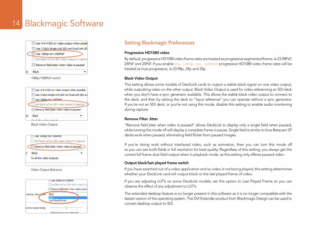
Progressive HD1080 video
By default, progressive HD1080 video frame rates are treated as progressive segmented frame, ie 23.98PsF, 24PsF and 25PsF. If you enable Use 1080p not 1080PsF progressive HD1080 video frame rates will be treated as true progressive, ie 23.98p, 24p and 25p.
Black Video Output
This setting allows some models of DeckLink cards to output a stable black signal on one video output, while outputting video on the other output. Black Video Output is used for video referencing an SDI deck when you don’t have a sync generator available. This allows the stable black video output to connect to the deck, and then by setting the deck to “input reference” you can operate without a sync generator. If you’re not an SDI deck, or you’re not using this mode, disable this setting to enable audio monitoring during capture.
Remove Filter Jitter
“Remove field jitter when video is paused” allows DeckLink to display only a single field when paused, while turning this mode off will display a complete frame in pause. Single field is similar to how Betacam SP decks work when paused, eliminating field flicker from paused images.
If you’re doing work without interlaced video, such as animation, then you can turn this mode off so you can see both fields in full resolution for best quality. Regardless of this setting, you always get the correct full frame dual field output when in playback mode, as this setting only effects paused video.
Output black/last played frame switch
If you have switched out of a video application and so video is not being played, this setting determines whether your DeckLink card will output black or the last played frame of video.
If you are adjusting LUT’s on some DeckLink models, set this option to Last Played Frame so you can observe the effect of any adjustment to LUT’s.
The extended desktop feature is no longer present in this software as it is no longer compatible with the lastest version of the operating system. The DVI Extender product from Blackmagic Design can be used to convert desktop output to SDI.
1080p/1080PsF switch
Black Video Output.
Video Output Behavior.
Blackmagic Software15
Setting Blackmagic Preferences
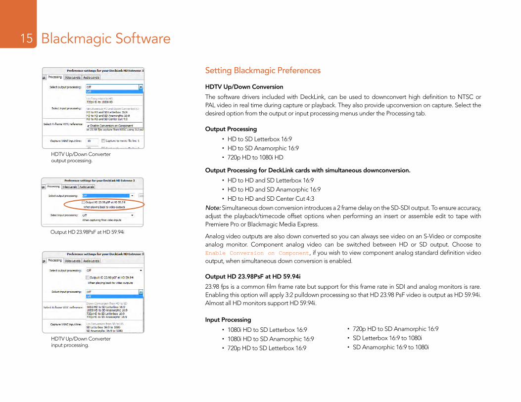
HDTV Up/Down Conversion
The software drivers included with DeckLink, can be used to downconvert high definition to NTSC or PAL video in real time during capture or playback. They also provide upconversion on capture. Select the desired option from the output or input processing menus under the Processing tab.
Output Processing
� HD to SD Letterbox 16:9 � HD to SD Anamorphic 16:9 � 720p HD to 1080i HD
Output Processing for DeckLink cards with simultaneous downconversion.
� HD to HD and SD Letterbox 16:9 � HD to HD and SD Anamorphic 16:9 � HD to HD and SD Center Cut 4:3
Note: Simultaneous down conversion introduces a 2 frame delay on the SD-SDI output. To ensure accuracy, adjust the playback/timecode offset options when performing an insert or assemble edit to tape with Premiere Pro or Blackmagic Media Express.
Analog video outputs are also down converted so you can always see video on an S-Video or composite analog monitor. Component analog video can be switched between HD or SD output. Choose to Enable Conversion on Component, if you wish to view component analog standard definition video output, when simultaneous down conversion is enabled.
Output HD 23.98PsF at HD 59.94i
23.98 fps is a common film frame rate but support for this frame rate in SDI and analog monitors is rare. Enabling this option will apply 3:2 pulldown processing so that HD 23.98 PsF video is output as HD 59.94i. Almost all HD monitors support HD 59.94i.
Input Processing
� 1080i HD to SD Letterbox 16:9 � 1080i HD to SD Anamorphic 16:9 � 720p HD to SD Letterbox 16:9
� � 720p HD to SD Anamorphic 16:9 � SD Letterbox 16:9 to 1080i � SD Anamorphic 16:9 to 1080i
HDTV Up/Down Converter output processing.
HDTV Up/Down Converter input processing.
Output HD 23.98PsF at HD 59.94i
Blackmagic Software16
Setting Blackmagic Preferences
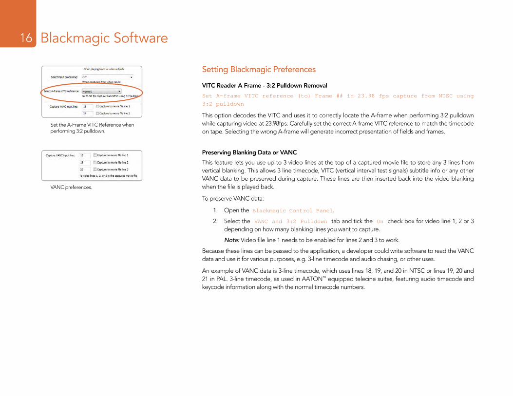
VITC Reader A Frame - 3:2 Pulldown Removal
Set A-frame VITC reference (to) Frame ## in 23.98 fps capture from NTSC using
3:2 pulldown
This option decodes the VITC and uses it to correctly locate the A-frame when performing 3:2 pulldown while capturing video at 23.98fps. Carefully set the correct A-frame VITC reference to match the timecode on tape. Selecting the wrong A-frame will generate incorrect presentation of fields and frames.
Preserving Blanking Data or VANC
This feature lets you use up to 3 video lines at the top of a captured movie file to store any 3 lines from vertical blanking. This allows 3 line timecode, VITC (vertical interval test signals) subtitle info or any other VANC data to be preserved during capture. These lines are then inserted back into the video blanking when the file is played back.
To preserve VANC data:
1. Open the Blackmagic Control Panel.
2. Select the VANC and 3:2 Pulldown tab and tick the On check box for video line 1, 2 or 3 depending on how many blanking lines you want to capture.
Note: Video file line 1 needs to be enabled for lines 2 and 3 to work.
Because these lines can be passed to the application, a developer could write software to read the VANC data and use it for various purposes, e.g. 3-line timecode and audio chasing, or other uses.
An example of VANC data is 3-line timecode, which uses lines 18, 19, and 20 in NTSC or lines 19, 20 and 21 in PAL. 3-line timecode, as used in AATON™ equipped telecine suites, featuring audio timecode and keycode information along with the normal timecode numbers.
Set the A-Frame VITC Reference when performing 3:2 pulldown.
VANC preferences.
Blackmagic Software17
Setting Blackmagic Preferences
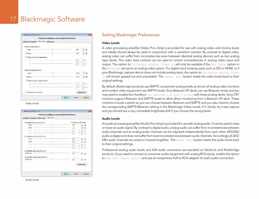
Video Levels
A video processing amplifier (Video Proc Amp) is provided for use with analog video and chroma levels and ideally should always be used in conjunction with a waveform monitor. By contrast to digital video, analog video can suffer from inconsistencies even between identical analog devices such as two analog tape decks. The video level controls can be used to correct inconsistencies in analog video input and output. The option to Calibrate Analog Video In will only be available if the Set Input option in the Settings are set to an analog video option. If a digital input is being used, such as SDI or HDMI, or if your Blackmagic capture device does not include analog input, the option to Calibrate Analog Video In will remain grayed out and unavailable. The Reset Gain button resets the video levels back to their original settings.
By default, Blackmagic products use SMPTE component analog levels as almost all analog video monitors and modern video equipment use SMPTE levels. Sony Betacam SP decks can use Betacam levels and you may need to enable the checkbox Use Betacam Y,B-Y,R-Y Levels with these analog decks. Sony CRT monitors support Betacam and SMPTE levels to allow direct monitoring from a Betacam SP deck. These monitors include a switch so you can choose between Betacam and SMPTE and you also need to choose the corresponding SMPTE/Betacam setting in the Blackmagic Video Levels. If in doubt, try a test capture and you should see a very noticeable brightness shift if you choose the wrong levels.
Audio Levels
An audio processing amplifier (Audio Proc Amp) is provided for use with analog audio. It can be used to raise or lower an audio signal. By contrast to digital audio, analog audio can suffer from inconsistencies between audio channels and so analog audio channels can be adjusted independently from each other. AES/EBU audio is digital and does not suffer from level inconsistencies between audio channels. Accordingly all AES/EBU audio channels are raised or lowered together. The Reset Gain button resets the audio levels back to their original settings.
Professional analog audio levels and XLR audio connectors are standard on DeckLink and Multibridge products. If you need to connect to consumer audio equipment with analog RCA inputs, enable the option to Use HiFi Audio Levels and use an inexpensive XLR to RCA adapter for each audio connection.
Video levels
Audio levels
Welcome18 Blackmagic Media Express18
Welcome to Media Express 2.0.
Blackmagic Media Express 2.0 is a sophistocated software application which enables UltraStudio, DeckLink, Multibridge and Intensity users to capture, play back and preview video and audio via Blackmagic capture hardware. DeckLink, Multibridge and UltraStudio users can also master to tape, using insert or assemble edit, with frame accurate RS-422 device control.
Media Express 2.0 replaces all previous versions of Blackmagic Deck Control and Blackmagic Media Express. We hope you love the new interface and features.
Media Express has an intuitive interface and requires a 1920 x 1200, or 1280 x 800, pixel computer display to compliment its uncluttered appearance. The capture, playback and master views are color-coded so you will know at a glance which mode is being used.
Media Express uses many of the same keyboard shortcuts which are standard in the video industry so there is little to learn. Use j, k, l to shuttle backwards, pause and shuttle forwards, or use i and o to mark in and out points when batch capturing or mastering to tape. Hold down the control and shift keys to reveal a jog wheel and then use your mouse, with the jog wheel, for precision control of your tape deck.
VITC timecode is supported via RS-422 and RP188 timecode is supported via SDI.
DeckLink, Multibridge and UltraStudio users can use the Media List feature to log multiple clips for batch capture or to seamlessly play back multiple clips from a playlist and master them to tape.
Media Express can directly capture to, and play back from, DPX files or movie files.
Use the Grab Frame feature to capture still images during capture, playback or when mastering to tape. Frame grabs are saved in the targa (.tga) graphic file format.
Blackmagic Media Express 2.0 is not NLE software and does not have a timeline. It is a great tool when you don’t need the complexity of NLE software but simply want to capture, play back and output clips to tape, especially when working with video compositing software.
Welcome19 Blackmagic Media Express19
Media List
Search field
Remote indicator
VTR / deck timecode
Video Preview
Transport Control
Mark In / Mark Out
Track enable/disable
Project name, video format and frame rate
Blackmagic Media Express 2.0 Interface
Welcome20 Blackmagic Media Express – Preferences20
Media Express preferences are accessed from Edit>Preferences.
Project Video Format
Project Video Format defines the frame rate and frame size of the current project. The formats displayed are those supported by your DeckLink and you may see some differences when compared to running Media Express with DeckLink, Multibridge, UltraStudio or Intensity.
Capture File Format
Capture File Format sets the video codec and file format when capturing in the current project.
On Windows, the capture file format options are either AVI movies or DPX files. A choice of Blackmagic Uncompressed or Motion JPEG codecs can be made when capturing to AVI movies.
Preferences
Video formats
Capture file formats
Welcome21 Blackmagic Media Express – Media List21
The Media List holds a list of clips used in a project. When in Capture view, the Media List can be a list of clips to be batch-captured. Media List becomes a playlist when used in Playback or Master view. These views are explained later in the manual.
The Media List can contain clips that are of different codecs as long as they are of the same frame rate and size. The Media List is a project which can contain clips of the same frame size and frame rate.
The list can be sorted by each column heading. Columns can be rearranged and widened if desired.
The order of the clips in the list can be sorted manually by dragging and dropping within the list. Single or multiple clips can be dragged and dropped together.
The film strip icon on the left of the list shows whether a clip has linked media. If a clip has no linked media, the film strip icon displays a red “X” and selecting the clip will show a “Media Offline” message in the Video Preview Window.
Clips can be added to the list by:
� double-clicking on an empty area in the list � selecting File > Import > Media Files � right-clicking on the list and selecting ‘Import Media Files’ � capturing a clip from tape.
Right-clicking in the Media List will open a contextual menu. Depending upon the menu item chosen, Media Express will switch to the appropriate Capture, Playback or Master view that fits the operation. For example, right-clicking on a clip, and selecting “Batch Capture” while in Playback view, will cause Media Express to switch to Capture view and carry out the batch capture operation.
Media Express can play back files of different codecs, in the same playlist, as long as they are of the same frame rate and size. For example, you may have a mix of 1080p23.98 MJPEG and 1080p23.98 Uncompressed video clips in the same playlist and Media Express will play them out seamlessly.
Media List showing an untitled clip which is not linked to any media. Right-clicking on the missing media icon will reveal a contextual menu from where Batch Capture can be selected.
Contextual menu
Welcome22 Blackmagic Media Express – Capture22
Capture View showing the contextual menu, in the Media List, can be used to start a Batch Capture. This performs the same function as clicking the Get Clip button.
Welcome23 Blackmagic Media Express – Capture23
Capture operations are performed in the Capture view (ctrl-1)Capturing on the fly.
Ensure the Project Video Format is set to the format of video you wish to capture.
Ensure the Capture File Format is set to the format you wish to capture.
Connect a video source to an input of your DeckLink. Ensure the desired input has been selected in the Blackmagic control panel.
If deck control is required, ensure an RS-422 serial cable is connected and “remote” has been selected on the deck. If an RS-422 cable is not connected, or “remote” is not selected on the deck, the transport controls will be grayed out and “No Remote” will be displayed in the top right corner of the Video Preview Window.
Enter Reel and Name information into the information area. The Name will be applied to the clip(s) which are about to be captured.
Before capturing, the audio channels to be captured can be switched on or off via the track enable/disable buttons. The video track cannot be turned off.
Click on the “Capture” button to commence capturing.
To end capture, click on the “Capture” button again or press the “Esc” key.
Logging Clips for future batch capture.
Click the Mark In button to mark the In point, or use the shortcut key i.
Click the Mark Out button to mark the Out point, or use the shortcut key o.
Click the Log Clip button to log the clip, or use the shortcut key p. The entry should now appear in the Media List window.
Continue logging other clips.
When logging is completed, select the clips in the Media List and either:
� Click on the ‘Get Clip(s)’ button. � Right-click on the selection and select ‘Batch Capture’.
Welcome24 Blackmagic Media Express – Capture24
Capturing a clip with precise In and Out timecode.
Click on the Mark In button to mark the In point or use the shortcut key i.
Click on the Mark Out button to mark the Out point or use the shortcut key o.
Click on the Get Clip button.
Media Express will cue the tape and precisely capture the clip from the In to the Out timecode points, including any handles specified in the application preferences.
While capturing, if the file name (Name) of a clip already exists on the selected capture drive, the user will be prompted if they want to over-write the file or not. If ‘No’ is selected, the file name will be auto-incremented with a number.
Welcome25 Capture25 Blackmagic Media Express – Playback25
Playback View
Welcome26 Capture26 Blackmagic Media Express – Playback26
Playback operations are performed in the Playback tab (ctrl-2)Importing clips into the Media List
Import media into the Media List using one of the following methods:
� Double-click on an empty area of the list. � Select File > Import > Media Files. � Right-click on the list and select ‘Import Media Files’. � Capture a clip from tape.
Any of these actions will reveal an Open Video Clip window where more where one or more files can be selected.
If the files being imported match the frame rate and size of those in the Media List, the import will be successful.
If the files being imported do not match the frame rate and size of existing clips in the Media List, the user will be prompted to create a new project and to save the current project.
If the current project has had no changes, and has already been saved, the user will only be prompted to start a new project as there is no need to save the existing project.
Playing back a single clip
Selecting a clip (single click) on the list will load it into the Video Preview Window.
To play back a single clip in the Media List, double click the clip and it will start playing in the Video Preview Window.
To loop the playback of the clip, click on the loop button in the transport control. The selected clip will now play back and loop until the user clicks on the pause button or presses the spacebar.
Playing back multiple clips
To play back multiple clips, select the clips in the Media Library and click the Play button or press the spacebar. Selected clips in the playlist will be played back in sequence. Unselected clips will not be played.
If no clips are selected, the whole playlist is played back, starting from the last-played clip.
Clicking on the loop button will cause the playback to loop.
During playback, the audio channels being monitored can be switched on or off via the track enable/disable buttons. The video track cannot be turned off.
Welcome27 Capture27 Blackmagic Media Express – Master27
Master View
Welcome28 Capture28 Blackmagic Media Express – Master28
Mastering to tape operations are performed in the Master view (ctrl-3)Media Express can use DeckLink to master to tape via Insert or Assemble editing.
Only clips that are selected in the Media List will be output to tape. If no clips are selected, it is assumed that the entire Media List will be output.
To master to tape, click on the Master view and ensure RS-422 device control is connected.
Enter the In and Out points of the tape by entering timecode into the respective text boxes, or by cueing the tape to the desired point via the transport control and then clicking the Mark In button, or use the shortcut key i.
If no Out point is entered, Media Express will set the duration of the edit to the total length of the clips in the Media List. If an out point is defined, Media Express will leave edit mode once the Out point timecode is reached, even if some clips have not been output.
The Insert and Assemble buttons are mutually exclusive and only one mode can be selected at a time. This determines which mode Media Express will use to master to tape. Select the Insert or Assemble button as required.
The Preview and Master buttons are also mutually exclusive. Clicking on either button will instruct Media Express to proceed with the specified operation. Preview mode mimics the edit process but does not record to tape. This mode allows one to check the edit point is correct.
Preview edit operations should always be checked on monitors connected directly to the output of the deck to view the preceding video already on tape, the new video and the following video already on tape.
If Record Inhibit is enabled either on the deck or on the tape in the deck, Media Express will display a dialog box, when the user clicks on the Master button, informing the user that Record Inhibit is enabled. Check the deck/tape and disable Record Inhibit before trying again.
Before mastering, the audio channels to be put to tape can be selected on or off via the track enable/disable buttons. The Video track cannot be turned off.
Blackmagic Software29
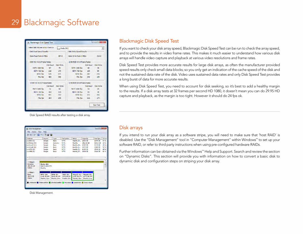
Blackmagic Disk Speed TestIf you want to check your disk array speed, Blackmagic Disk Speed Test can be run to check the array speed, and to provide the results in video frame rates. This makes it much easier to understand how various disk arrays will handle video capture and playback at various video resolutions and frame rates.
Disk Speed Test provides more accurate results for large disk arrays, as often the manufacturer provided speed results only check small data blocks; so you only get an indication of the cache speed of the disk and not the sustained data rate of the disk. Video uses sustained data rates and only Disk Speed Test provides a long burst of data for more accurate results.
When using Disk Speed Test, you need to account for disk seeking, so it’s best to add a healthy margin to the results. If a disk array tests at 32 frames per second HD 1080, it doesn’t mean you can do 29.95 HD capture and playback, as the margin is too tight. However it should do 24 fps ok.
Disk arraysIf you intend to run your disk array as a software stripe, you will need to make sure that ‘host RAID’ is disabled. Use the “Disk Management” tool in “Computer Management” within Windows™ to set up your software RAID, or refer to third party instructions when using pre-configured hardware RAIDs.
Further information can be obtained via the Windows™ Help and Support. Search and review the section on “Dynamic Disks”. This section will provide you with information on how to convert a basic disk to dynamic disk and configuration steps on striping your disk array.
Disk Management.
Disk Speed RAID results after testing a disk array.
Third Party Applications30
Adobe Premiere Pro CS5Adobe Premiere Pro® is a powerful real-time video and audio non-linear editing application. Full presets for Premiere Pro are included with the Blackmagic driver software and will be automatically loaded into your system during the installation process. Premiere Pro must be installed on your system before running the Blackmagic driver installer.
Premiere Pro can capture and playback with sequences of different formats within the one project. For example, DeckLink can capture 1080i59.94, 1080i50 and NTSC video to corresponding sequences within the one Premiere Pro project.
Setting Up
1. Launch Premiere Pro CS5.
2. Create a New Project and set the Capture Format to Blackmagic Capture.
3. Click on the Properties button and then choose from the desired properties for your project. The Video Standard can be set to NTSC, PAL, HD720, HD1080 or 2K. The Video Format can be uncompressed or compressed and you should also specify the number of audio channels to be captured. Now click OK.
4. Select your disk array as the Location for your media.
5. Set the location and type the name of your project. Click OK.
6. The New Sequence window will appear. Select the desired Blackmagic preset, give the sequence a name and then click OK.
Audio
Blackmagic software features support for multiple channels of audio in Premiere Pro CS5 using the Blackmagic audio plugin. Blackmagic audio hardware is automatically chosen when a new project is created and the capture format is set to Blackmagic Capture. The choice of audio hardware can also be configured through Edit > Preferences > Audio Hardware. The ASIO Settings button serves no function as ASIO audio is not used for capture or playback.
You may also wish to visit Edit > Preferences > Audio Output Mapping to select the mix of the multi-channel audio. Set Map Output for to either Blackmagic Audio or Blackmagic Audio (CS5) as both are the same as each other.
Adobe Premiere Pro
New Sequence
Audio Output Mapping
Third Party Applications31
Device Control
DeckLink includes RS-422 device control for connection to decks. Blackmagic Device
Control is automatically chosen when a new project is created and the capture format is set to Blackmagic Capture. The choice of device control can also be configured through Edit > Preferences > Device Control.
The Options button is disabled as the settings are automatically detected and configured when you choose Blackmagic Device Control.
Player Settings
The default player should be switched from Adobe Player to Blackmagic Design Playback. The choice of player settings can be configured through Edit > Preferences > Player Settings.
Playback
As a quick test to make sure everything is connected correctly, use the Premiere Pro test media (Bars and Tone or Universal Counter Leader). Drag your test media from within the Premiere Pro project and drop it on to the timeline. You should now see the image on both your computer desktop and the output of your DeckLink. If you can’t see any video on your Blackmagic output, check the connections again and ensure you have the correct output settings configured in the Blackmagic Control Panel. SDI, HDMI and analog outputs are always active.
Capture
To capture choose: File > Capture [F5]
To immediately capture, click the red record button [G]. If you wish to log the clip, enter the desired In and Out points using either the Set In and Set Out buttons, or manually by typing the timecode and clicking Log Clip. The empty clip will now appear in the Project window. Repeat this until you have logged all of the clips you wish to batch capture.
To change the capture format, click on the Settings tab and then the Edit button. Ensure the Capture Format is set to Blackmagic Capture, click on the Properties button and then change the Blackmagic Capture Settings as desired.
Device Control
Capture
Third Party Applications32
Batch Capture
Select the clips you wish to capture by drag selecting or shift-clicking each clip. Then choose: File > Batch Capture [F6]. To set handles on the clips, enable the option to Capture with handles and type the number of additional frames you require at the start and end of each clip.
Export to Tape
To export to tape, select the sequence you require and then choose File > Export > Tape
Insert editing requires unbroken timecode over the full length of the project which is to be laid to tape. The process of creating unbroken timecode is referred to as “blacking the tape”.
In assemble mode the tape needs only to be “blacked” until a point just beyond the start time of the project. As assemble editing erases the tape ahead of the record heads, it should not be used where other projects already exist on the tape after the out point of your edit.
When editing to tape, the software waits at the first frame of your project for the deck to drop into record at the predetermined timecode. At that exact moment, the software begins to play until the edit is completed. Should you find that either the first frame of your program is repeated or lost, during the edit to tape procedure, you will need to adjust the playback offset to bring the deck and computer in sync. You should only need to do this once with any combination of deck and computer and the correct setting will be retained.
Now, simply enter the desired in point and offsets if required, and click OK.
Export to Tape
Third Party Applications33
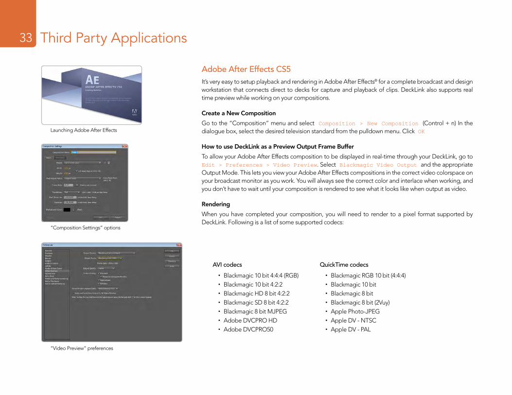
Adobe After Effects CS5It’s very easy to setup playback and rendering in Adobe After Effects® for a complete broadcast and design workstation that connects direct to decks for capture and playback of clips. DeckLink also supports real time preview while working on your compositions.
Create a New Composition
Go to the “Composition” menu and select Composition > New Composition (Control + n) In the dialogue box, select the desired television standard from the pulldown menu. Click OK
How to use DeckLink as a Preview Output Frame Buffer
To allow your Adobe After Effects composition to be displayed in real-time through your DeckLink, go to Edit > Preferences > Video Preview. Select Blackmagic Video Output and the appropriate Output Mode. This lets you view your Adobe After Effects compositions in the correct video colorspace on your broadcast monitor as you work. You will always see the correct color and interlace when working, and you don’t have to wait until your composition is rendered to see what it looks like when output as video.
Rendering
When you have completed your composition, you will need to render to a pixel format supported by DeckLink. Following is a list of some supported codecs:
Launching Adobe After Effects
“Video Preview” preferences
“Composition Settings” options
AVI codecs
� Blackmagic 10 bit 4:4:4 (RGB) � Blackmagic 10 bit 4:2:2 � Blackmagic HD 8 bit 4:2:2 � Blackmagic SD 8 bit 4:2:2 � Blackmagic 8 bit MJPEG � Adobe DVCPRO HD � Adobe DVCPRO50
QuickTime codecs
� Blackmagic RGB 10 bit (4:4:4) � Blackmagic 10 bit � Blackmagic 8 bit � Blackmagic 8 bit (2Vuy) � Apple Photo-JPEG � Apple DV - NTSC � Apple DV - PAL
Third Party Applications34
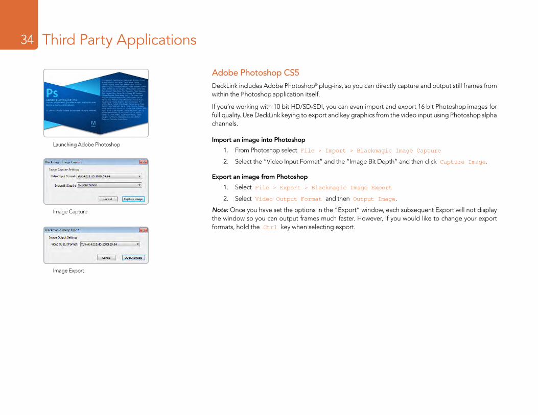
Adobe Photoshop CS5DeckLink includes Adobe Photoshop® plug-ins, so you can directly capture and output still frames from within the Photoshop application itself.
If you’re working with 10 bit HD/SD-SDI, you can even import and export 16 bit Photoshop images for full quality. Use DeckLink keying to export and key graphics from the video input using Photoshop alpha channels.
Import an image into Photoshop
1. From Photoshop select File > Import > Blackmagic Image Capture
2. Select the “Video Input Format” and the “Image Bit Depth” and then click Capture Image.
Export an image from Photoshop
1. Select File > Export > Blackmagic Image Export
2. Select Video Output Format and then Output Image.
Note: Once you have set the options in the “Export” window, each subsequent Export will not display the window so you can output frames much faster. However, if you would like to change your export formats, hold the Ctrl key when selecting export.
Image Capture
Launching Adobe Photoshop
Image Export
Supported File Formats35
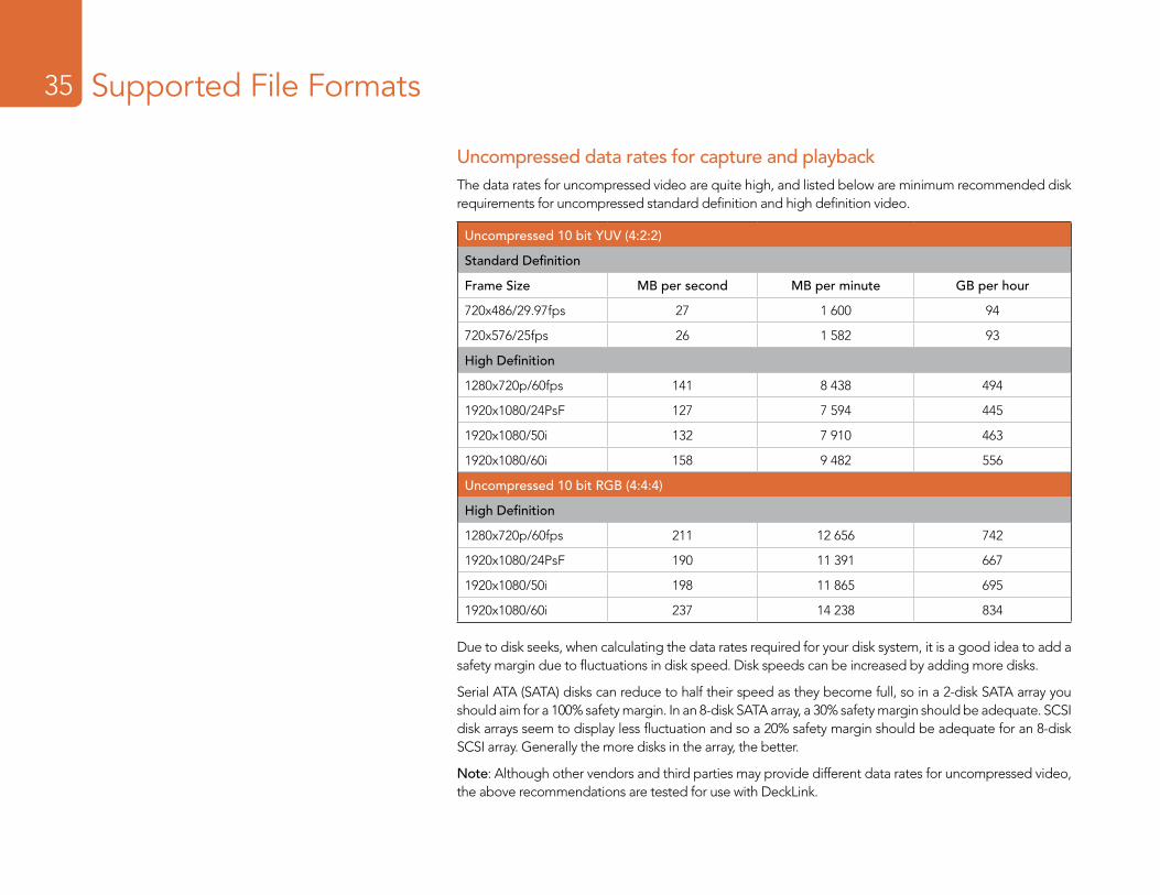
Uncompressed data rates for capture and playbackThe data rates for uncompressed video are quite high, and listed below are minimum recommended disk requirements for uncompressed standard definition and high definition video.
Uncompressed 10 bit YUV (4:2:2)
Standard Definition
Frame Size MB per second MB per minute GB per hour
720x486/29.97fps 27 1 600 94
720x576/25fps 26 1 582 93
High Definition
1280x720p/60fps 141 8 438 494
1920x1080/24PsF 127 7 594 445
1920x1080/50i 132 7 910 463
1920x1080/60i 158 9 482 556
Uncompressed 10 bit RGB (4:4:4)
High Definition
1280x720p/60fps 211 12 656 742
1920x1080/24PsF 190 11 391 667
1920x1080/50i 198 11 865 695
1920x1080/60i 237 14 238 834
Due to disk seeks, when calculating the data rates required for your disk system, it is a good idea to add a safety margin due to fluctuations in disk speed. Disk speeds can be increased by adding more disks.
Serial ATA (SATA) disks can reduce to half their speed as they become full, so in a 2-disk SATA array you should aim for a 100% safety margin. In an 8-disk SATA array, a 30% safety margin should be adequate. SCSI disk arrays seem to display less fluctuation and so a 20% safety margin should be adequate for an 8-disk SCSI array. Generally the more disks in the array, the better.
Note: Although other vendors and third parties may provide different data rates for uncompressed video, the above recommendations are tested for use with DeckLink.
Troubleshooting36
Using your DeckLink as a capture and playback solution when connected to a computer is exciting, but also complex due to the huge range of different software applications. Video data rates are also very high, so the disk array you use for video storage can have a big impact on your system’s performance.
Information about a wide range of disk array solutions and compatible application software would be outside the scope of this manual, however there are three ways to get more information.
There are four steps to getting help.
1. Check out the Blackmagic Design website www.blackmagic-design.com/support for the latest support information. We have a huge number of technical notes covering all the common questions we are asked.
2. Call your reseller. Your reseller will have the latest technical updates from Blackmagic Design and should be able to give you immediate assistance. We also recommend you check out the support options your dealer offers as they can arrange various support plans based on your workflow requirements. Your reseller will also understand your disk array configuration, and as disk array problems account for around 90% of support questions with NLE systems, your reseller or disk array vendor will be able to provide expert help.
3. The next option is to email us with your questions using the web form at www.blackmagic-design.com/support/contact
4. Phone a Blackmagic Design support office. Please check our web site for current support phone numbers in your area. www.blackmagic-design.com/company/.
Note: Please provide us with as much information as possible regarding your technical problem and system specifications so that we may try to reproduce your problem quickly. Also please let us know how to reproduce any problem you’re having, so we can try it on our test systems before replying to your email.
Connection Diagrams38
VIDEO INPUT
REF. VIDEO
VIDEO
VIDEO
COMPONENT 2 COMPONENT 2
COMPONENT 1 COMPONENT 1
IN OUT AUDIO
CH-1 CH-2
CH-1 CH-2
S VIDEO
S VIDEO
TIME CODE MONITOR
REMOTE TBC REMOTE
VIDEO OUTPUT AUDIO INPUT
AUDIO OUTPUT
2 3 4 5 6 7 8 9 10 11 12 13 14 15
DeckLink HD Extreme 3
Breakout Cable
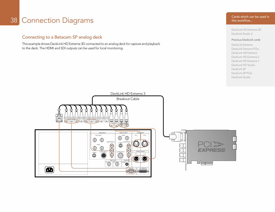
Connecting to a Betacam SP analog deckThis example shows DeckLink HD Extreme 3D connected to an analog deck for capture and playback to the deck. The HDMI and SDI outputs can be used for local monitoring.
Cards which can be used in this workflow...
DeckLink HD Extreme 3DDeckLink Studio 2
Previous DeckLink cards
DeckLink ExtremeDeckLink Extreme PCIeDeckLink HD ExtremeDeckLink HD Extreme 2DeckLink HD Extreme 3DeckLink HD StudioDeckLink SPDeckLink SP PCIeDeckLink Studio
Connection Diagrams39
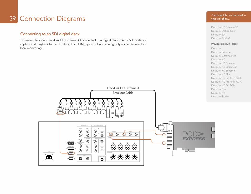
Connecting to an SDI digital deckThis example shows DeckLink HD Extreme 3D connected to a digital deck in 4:2:2 SD mode for capture and playback to the SDI deck. The HDMI, spare SDI and analog outputs can be used for local monitoring.
ANALOG VIDEO I/O DIGITAL AUDIO I/O (AES/EBU)
REF VIDEO
IN
IN
IN
IN1
2
3
OUT
CH-1 CH-2 CH-3 CH-4
CH-1 CH-2 CH-3 CH-4
IN
OUTOUT
OUT
OUT
OUT
VIDEO IN
VIDEO OUT
S VIDEO
MONITOR AUDIO
AUDIO OUT
AUDIO IN
SDI OUTPUT SDI INPUT
TIME CODE
VIDEO CONTROL
CONTROL PANEL
REMOTE - INAC IN
REMOTE - OUT
COMPONENT VIDEO
2 3 4 5 6 7 8 9 10 11 12 13 14 15
DeckLink HD Extreme 3
Breakout Cable
Cards which can be used in this workflow...
DeckLink HD Extreme 3DDeckLink Optical FiberDeckLink SDIDeckLink Studio 2
Previous DeckLink cards
DeckLinkDeckLink ExtremeDeckLink Extreme PCIeDeckLink HDDeckLink HD ExtremeDeckLink HD Extreme 2DeckLink HD Extreme 3DeckLink HD PlusDeckLink HD Pro 4:2:2 PCI-XDeckLink HD Pro 4:4:4 PCI-XDeckLink HD Pro PCIeDeckLink PlusDeckLink ProDeckLink Studio
Connection Diagrams40
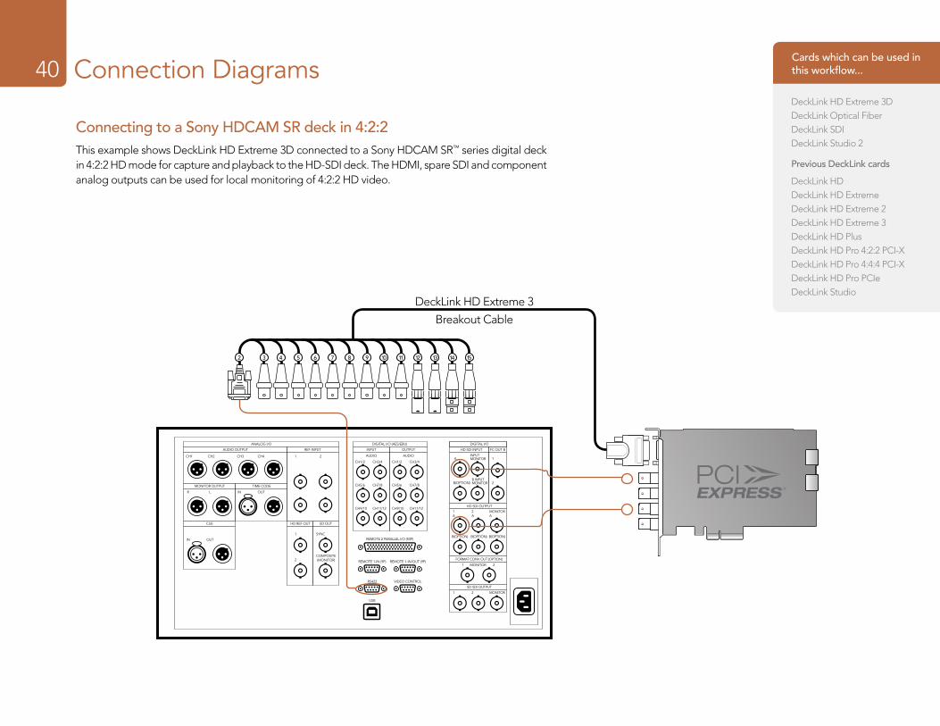
Connecting to a Sony HDCAM SR deck in 4:2:2This example shows DeckLink HD Extreme 3D connected to a Sony HDCAM SR™ series digital deck in 4:2:2 HD mode for capture and playback to the HD-SDI deck. The HDMI, spare SDI and component analog outputs can be used for local monitoring of 4:2:2 HD video.
2 3 4 5 6 7 8 9 10 11 12 13 14 15
ANALOG I/O DIGITAL I/O (AES/EBU) DIGITAL I/O
AUDIO OUTPUT REF INPUT INPUT HD SDI INPUT
HD SDI OUTPUT
FORMAT CONV. OUT (OPTION)
MONITOR1 2
SD SDI OUTPUT
FC OUT BOUTPUT
AUDIOA 1
2B(OPTION)
B(OPTION) B(OPTION) B(OPTION)
1A
2A
MONITORA
1 2 MONITOR
INPUTMONITOR
B INPUTMONITOR
CH1/2 CH3/4
CH5/6 CH7/8
CH9/10 CH11/12
AUDIO
MONITOR OUTPUT
CUE HD REF OUT SD OUT
TIME CODE
IN OUTR L
CH3 CH4 1 2
1 SYNC
2COMPOSITE(MONITOR)
CH1 CH2
IN OUT
CH1/2 CH3/4
CH5/6 CH7/8
CH9/10 CH11/12
REMOTE 2 PARALLEL I/O (50P)
REMOTE 1-IN (9P) REMOTE 1-IN/OUT (9P)
RS422
USB
VIDEO CONTROL
DeckLink HD Extreme 3
Breakout Cable
Cards which can be used in this workflow...
DeckLink HD Extreme 3DDeckLink Optical FiberDeckLink SDIDeckLink Studio 2
Previous DeckLink cards
DeckLink HDDeckLink HD ExtremeDeckLink HD Extreme 2DeckLink HD Extreme 3DeckLink HD PlusDeckLink HD Pro 4:2:2 PCI-XDeckLink HD Pro 4:4:4 PCI-XDeckLink HD Pro PCIeDeckLink Studio
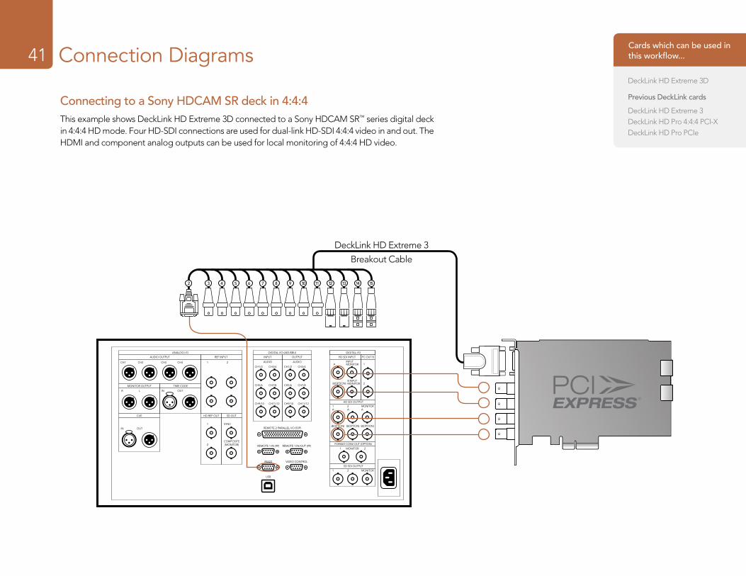
Connection Diagrams41
Connecting to a Sony HDCAM SR deck in 4:4:4This example shows DeckLink HD Extreme 3D connected to a Sony HDCAM SR™ series digital deck in 4:4:4 HD mode. Four HD-SDI connections are used for dual-link HD-SDI 4:4:4 video in and out. The HDMI and component analog outputs can be used for local monitoring of 4:4:4 HD video.
ANALOG I/O DIGITAL I/O (AES/EBU) DIGITAL I/O
AUDIO OUTPUT REF INPUT INPUT HD SDI INPUT
HD SDI OUTPUT
FORMAT CONV. OUT (OPTION)
MONITOR1 2
SD SDI OUTPUT
FC OUT BOUTPUT
AUDIOA 1
2B(OPTION)
B(OPTION) B(OPTION) B(OPTION)
1A
2A
MONITORA
1 2 MONITOR
INPUTMONITOR
B INPUTMONITOR
CH1/2 CH3/4
CH5/6 CH7/8
CH9/10 CH11/12
AUDIO
MONITOR OUTPUT
CUE HD REF OUT SD OUT
TIME CODE
IN OUTR L
CH3 CH4 1 2
1 SYNC
2COMPOSITE(MONITOR)
CH1 CH2
IN OUT
CH1/2 CH3/4
CH5/6 CH7/8
CH9/10 CH11/12
REMOTE 2 PARALLEL I/O (50P)
REMOTE 1-IN (9P) REMOTE 1-IN/OUT (9P)
RS422
USB
VIDEO CONTROL
DeckLink HD Extreme 3
Breakout Cable
2 3 4 5 6 7 8 9 10 11 12 13 14 15
Cards which can be used in this workflow...
DeckLink HD Extreme 3D
Previous DeckLink cards
DeckLink HD Extreme 3DeckLink HD Pro 4:4:4 PCI-XDeckLink HD Pro PCIe
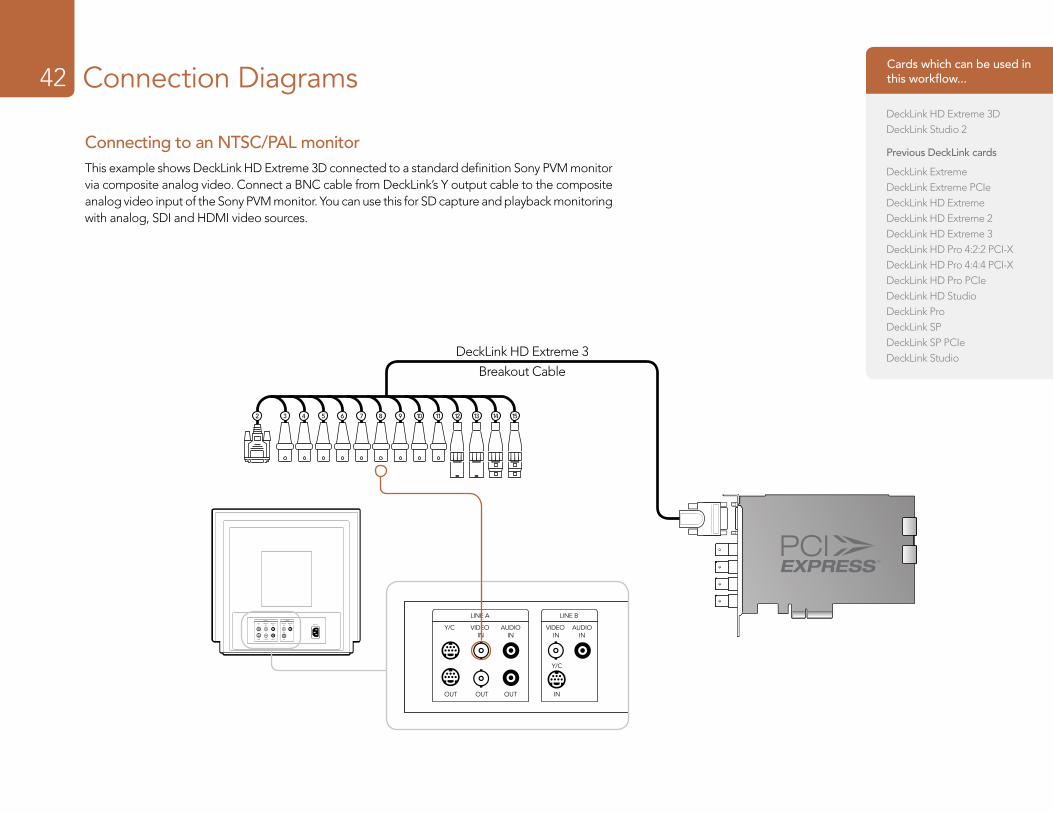
Connection Diagrams42
Connecting to an NTSC/PAL monitorThis example shows DeckLink HD Extreme 3D connected to a standard definition Sony PVM monitor via composite analog video. Connect a BNC cable from DeckLink’s Y output cable to the composite analog video input of the Sony PVM monitor. You can use this for SD capture and playback monitoring with analog, SDI and HDMI video sources.
LINE A LINE B
VIDEO IN
AUDIOIN
VIDEO IN
Y/C
Y/C
INOUTOUTOUT
AUDIOIN AC IN
LINE A LINE B
VIDEO IN
AUDIOIN
VIDEO IN
Y/C
Y/C
INOUTOUTOUT
AUDIOIN AC IN
2 3 4 5 6 7 8 9 10 11 12 13 14 15
DeckLink HD Extreme 3
Breakout Cable
Cards which can be used in this workflow...
DeckLink HD Extreme 3DDeckLink Studio 2
Previous DeckLink cards
DeckLink ExtremeDeckLink Extreme PCIeDeckLink HD ExtremeDeckLink HD Extreme 2DeckLink HD Extreme 3DeckLink HD Pro 4:2:2 PCI-XDeckLink HD Pro 4:4:4 PCI-XDeckLink HD Pro PCIeDeckLink HD StudioDeckLink ProDeckLink SPDeckLink SP PCIeDeckLink Studio
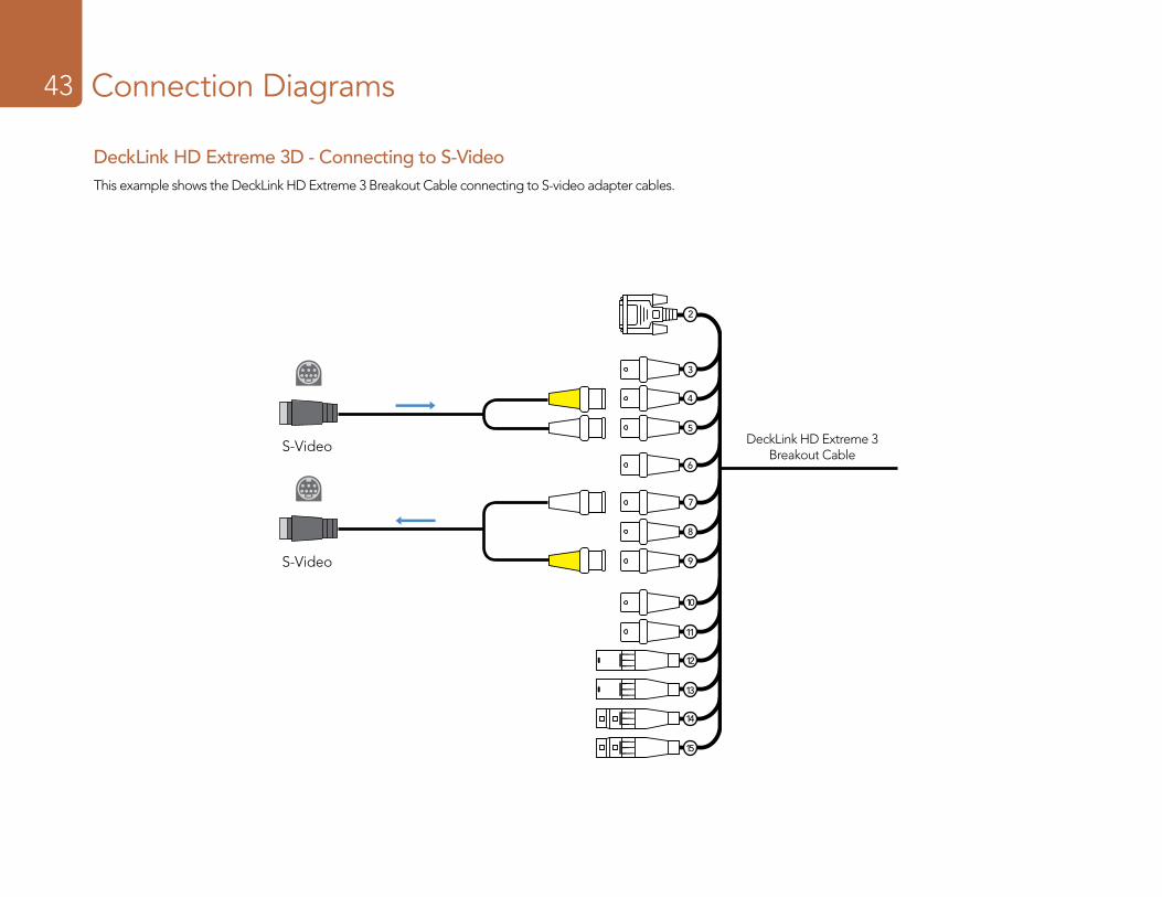
Connection Diagrams43
DeckLink HD Extreme 3 Breakout Cable
2
3
4
5
6
7
8
9
10
11
12
13
14
15
DeckLink HD Extreme 3D - Connecting to S-VideoThis example shows the DeckLink HD Extreme 3 Breakout Cable connecting to S-video adapter cables.
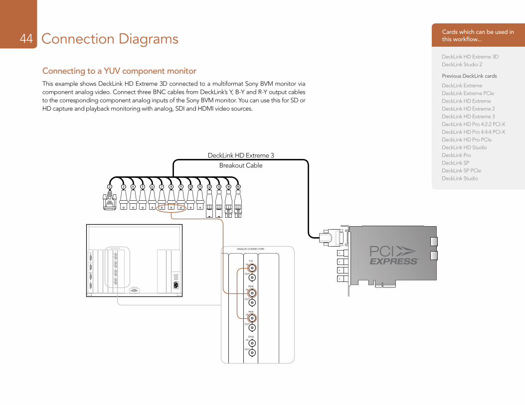
Connection Diagrams44
Connecting to a YUV component monitorThis example shows DeckLink HD Extreme 3D connected to a multiformat Sony BVM monitor via component analog video. Connect three BNC cables from DeckLink’s Y, B-Y and R-Y output cables to the corresponding component analog inputs of the Sony BVM monitor. You can use this for SD or HD capture and playback monitoring with analog, SDI and HDMI video sources.
AC IN
MAIN POWER
I
O
ANALOG CONNECTORS
REMOTE 1IN
REMOTE 1OUT
REMOTE 2
ISR
Y/G
PB/B
PR/R
CONTROL UNIT
SYNC
IN
OUT
IN
OUT
IN
OUT
IN
OUT
AC IN
MAIN POWER
I
O
ANALOG CONNECTORS
REMOTE 1IN
REMOTE 1OUT
REMOTE 2
ISR
Y/G
PB/B
PR/R
CONTROL UNIT
SYNC
IN
OUT
IN
OUT
IN
OUT
IN
OUT
2 3 4 5 6 7 8 9 10 11 12 13 14 15
DeckLink HD Extreme 3
Breakout Cable
Cards which can be used in this workflow...
DeckLink HD Extreme 3DDeckLink Studio 2
Previous DeckLink cards
DeckLink ExtremeDeckLink Extreme PCIeDeckLink HD ExtremeDeckLink HD Extreme 2DeckLink HD Extreme 3DeckLink HD Pro 4:2:2 PCI-XDeckLink HD Pro 4:4:4 PCI-XDeckLink HD Pro PCIeDeckLink HD StudioDeckLink ProDeckLink SPDeckLink SP PCIeDeckLink Studio
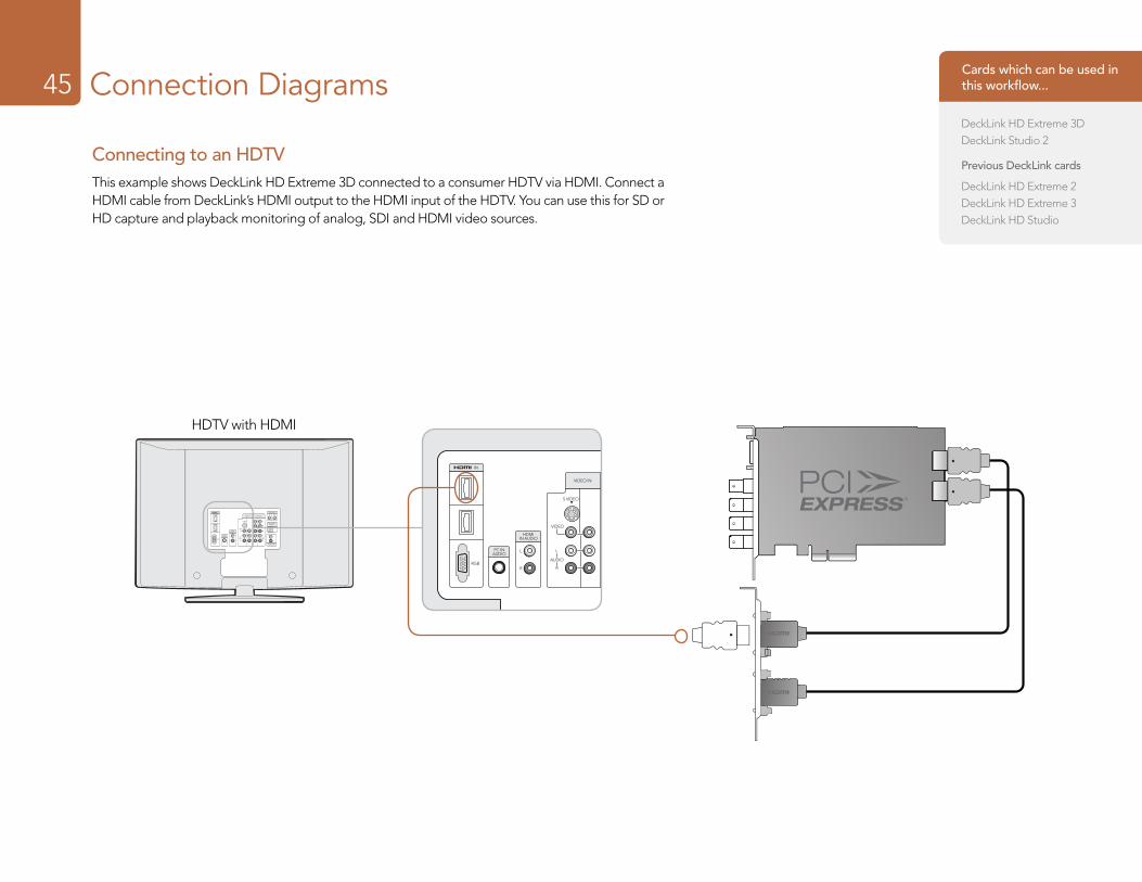
Connection Diagrams45
Connecting to an HDTVThis example shows DeckLink HD Extreme 3D connected to a consumer HDTV via HDMI. Connect a HDMI cable from DeckLink’s HDMI output to the HDMI input of the HDTV. You can use this for SD or HD capture and playback monitoring of analog, SDI and HDMI video sources.
AUDIO OUT
DIGITAL OUT(OPTICAL)
AUDIO
VIDEO
S VIDEO
R
L
R
LAUDIO
R
L
PR
PB
Y
L
R
IN
RGB
PC INAUDIO
HDMIIN AUDIO
CONTROLS
VIDEO IN HD/DVD ININ OUT
AUDIO OUT
DIGITAL OUT(OPTICAL)
AUDIO
VIDEO
S VIDEO
R
L
R
LAUDIO
R
L
PR
PB
Y
L
R
IN
RGB
PC INAUDIO
HDMIIN AUDIO
CONTROLS
VIDEO IN HD/DVD ININ OUT
HDTV with HDMI 2 3 4 5 6 7 8 9 10 11 12 13 14 15
Cards which can be used in this workflow...
DeckLink HD Extreme 3DDeckLink Studio 2
Previous DeckLink cards
DeckLink HD Extreme 2DeckLink HD Extreme 3DeckLink HD Studio
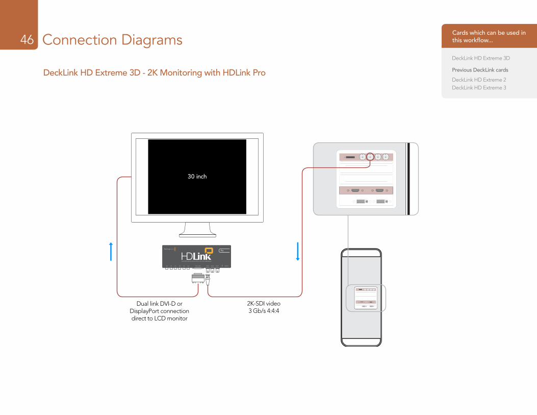
Connection Diagrams46
DeckLink HD Extreme 3D - 2K Monitoring with HDLink Pro
30 inch
2K-SDI video 3 Gb/s 4:4:4
Dual link DVI-D or DisplayPort connection direct to LCD monitor
Cards which can be used in this workflow...
DeckLink HD Extreme 3D
Previous DeckLink cards
DeckLink HD Extreme 2DeckLink HD Extreme 3
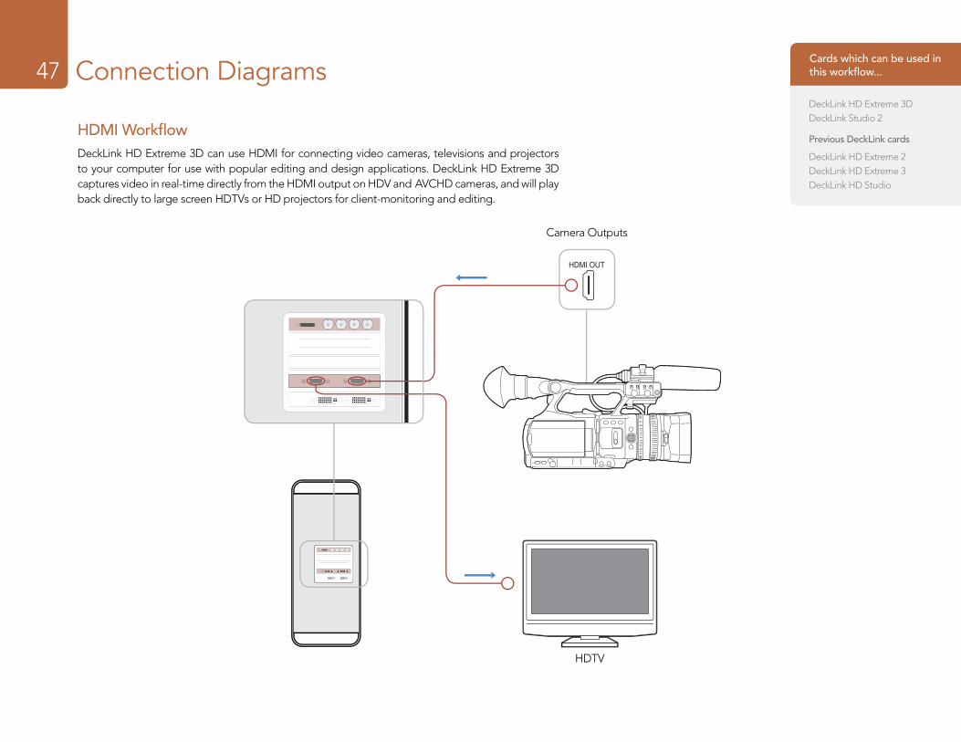
Connection Diagrams47
HDMI WorkflowDeckLink HD Extreme 3D can use HDMI for connecting video cameras, televisions and projectors to your computer for use with popular editing and design applications. DeckLink HD Extreme 3D captures video in real-time directly from the HDMI output on HDV and AVCHD cameras, and will play back directly to large screen HDTVs or HD projectors for client-monitoring and editing.
HDTV
Camera Outputs
Cards which can be used in this workflow...
DeckLink HD Extreme 3DDeckLink Studio 2
Previous DeckLink cards
DeckLink HD Extreme 2DeckLink HD Extreme 3DeckLink HD Studio
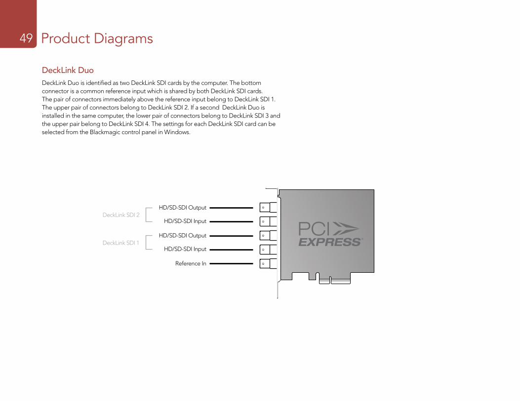
Product Diagrams49
DeckLink DuoDeckLink Duo is identified as two DeckLink SDI cards by the computer. The bottom connector is a common reference input which is shared by both DeckLink SDI cards. The pair of connectors immediately above the reference input belong to DeckLink SDI 1. The upper pair of connectors belong to DeckLink SDI 2. If a second DeckLink Duo is installed in the same computer, the lower pair of connectors belong to DeckLink SDI 3 and the upper pair belong to DeckLink SDI 4. The settings for each DeckLink SDI card can be selected from the Blackmagic control panel in Windows.
HD/SD-SDI Output
HD/SD-SDI Input
Reference In
HD/SD-SDI OutputDeckLink SDI 2
DeckLink SDI 1
HD/SD-SDI Input
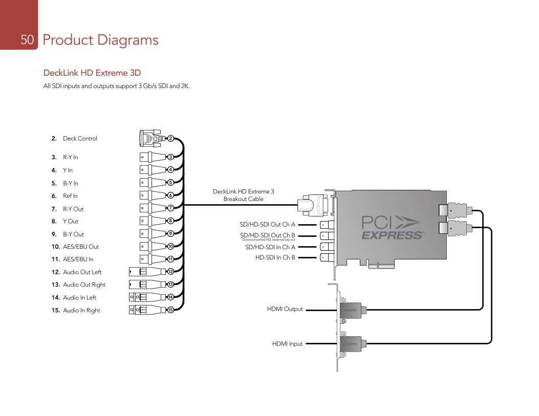
Product Diagrams50
DeckLink HD Extreme 3 Breakout Cable
23
45
67
89
1011
1213
1415
2
3
4
5
6
7
8
9
10
11
12
13
14
15
2. Deck Control
3. R-Y In
SD/HD-SDI Out Ch B Downconverted HD, external key out
SD/HD-SDI Out Ch A
SD/HD-SDI In Ch A
4. Y In
5. B-Y In
6. Ref In
7. R-Y Out
8. Y Out
9. B-Y Out
10. AES/EBU Out
11. AES/EBU In
12. Audio Out Left
13. Audio Out Right
14. Audio In Left
15. Audio In Right HDMI Output
HDMI Input
HD-SDI In Ch B
DeckLink HD Extreme 3DAll SDI inputs and outputs support 3 Gb/s SDI and 2K.
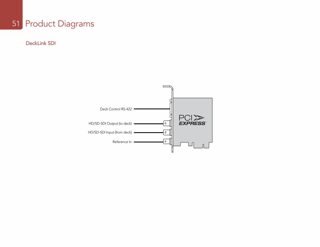
Product Diagrams51
Deck Control RS-422
HD/SD-SDI Output (to deck)
HD/SD-SDI Input (from deck)
Reference In
DeckLink SDI
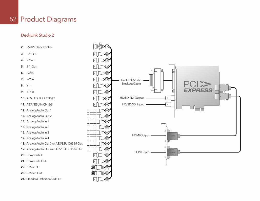
Product Diagrams52
DeckLink Studio Breakout Cable
HD/SD-SDI Output
HD/SD-SDI Input
19
18
17
16
15
14
13
12
11
10
09
08
07
06
05
04
03
02
20
21
22
23
24
2. RS-422 Deck Control
3. R-Y Out
4. Y Out
5. B-Y Out
6. Ref In
7. R-Y In
8. Y In
9. B-Y In
10. AES / EBU Out CH1&2
11. AES / EBU In CH1&2
12. Analog Audio Out 1
16. Analog Audio In 3
14. Analog Audio In 1
18. Analog Audio Out 3 or AES/EBU CH3&4 Out
20. Composite In
22. S-Video In
13. Analog Audio Out 2
17. Analog Audio In 4
15. Analog Audio In 2
19. Analog Audio Out 4 or AES/EBU CH5&6 Out
21. Composite Out
23. S-Video Out
24. Standard Definition SDI Out
DeckLink Studio 2
HDMI Output
HDMI Input
Developer Information54
Frame Structure
� Transmitted at 23.98, 24 or 25 frames per second as a Progressive Segmented Frame. � Active video is 2048 pixels wide by 1556 lines deep. � Total lines per frame : 1650 � Active words per line are 1535. One word consists of a 10-bit sample for each of the four data streams,
i.e. a total of 40 bits. See the diagram named Blackmagic 2K Format - Data Stream Format. � Total active lines : 1556 � Total words per line : 1875 for 23.98/24Hz and 1800 for 25Hz. � Fields per frame : 2, 825 lines each
� Active lines located on lines 16-793 (field 1) and 841-1618 (field 2).
Transport Structure
� Based on SMPTE 372M Dual Link mapping and SMPTE 425M-B support for mapping SMPTE 372M into a single 3 Gb/s link.
� Timing reference signals, line number and line CRC insertion is the same as above. � Optional ancillary data is inserted into both virtual interfaces. � At present, only audio data is included: as per standard HD audio insertion (SMPTE S299M) the audio
data packets are carried on data stream two and audio control packets are carried on data stream one. � During active video, 10-bit Red, Green and Blue data is sent in the following sequence:
Data stream1: Green_1, Green_2, Green_3, Green_5...Green_2047
Data stream 2: Blue_1, Blue_2, Green_4, Blue_5...Green_2048.
Data stream 3: Red_1, Blue_3, Blue_4, Red_5...Blue_2048.
Data stream 4: Red_2, Red_3, Red_4, Red_6...Red_2048.
The diagram, Vertical Timing Reference, shows the vertical timing details with line numbers and Field, Vertical and Horizontal bits for the Timing Reference Signal codes.
The diagram, Data Stream Format, shows the data stream formats around the optional ancillary data section of the horizontal line. Note that each active pixel takes up three samples.
Blackmagic 2K Format – OverviewThe latest Blackmagic Design products use the new 3 Gb/s SDI video, which allows twice the data rate of traditional HD-SDI video. We thought it would be a really nice idea to add 2K film support, via this new 3 Gb/s SDI technology, so we could simplify feature film workflows. With the popularity of Blackmagic Design editing systems worldwide, now thousands of people can benefit from a feature film workflow revolution.
This information includes everything product developers need to know for building native 2K SDI equipment. Of course, all Blackmagic products can be updated, so if the television industry adopts an alternative SDI-based film standard, we can add support for that too!
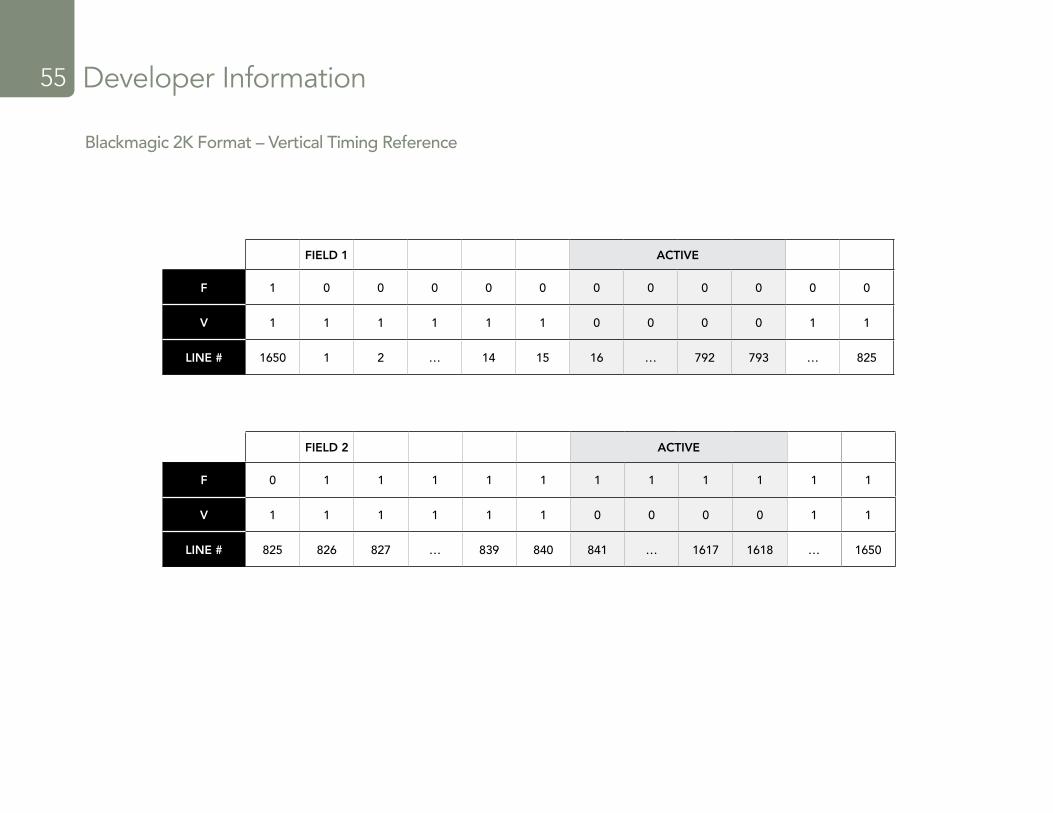
Developer Information55
FIELD 1 ACTIVE
F 1 0 0 0 0 0 0 0 0 0 0 0
V 1 1 1 1 1 1 0 0 0 0 1 1
LINE # 1650 1 2 … 14 15 16 … 792 793 … 825
Blackmagic 2K Format – Vertical Timing Reference
FIELD 2 ACTIVE
F 0 1 1 1 1 1 1 1 1 1 1 1
V 1 1 1 1 1 1 0 0 0 0 1 1
LINE # 825 826 827 … 839 840 841 … 1617 1618 … 1650
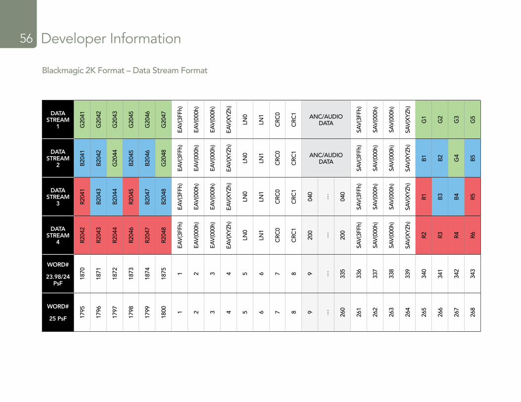
Developer Information56
DATA STREAM
1 G20
41
G20
42
G20
43
G20
45
G20
46
G20
47
EAV
(3FF
h)
EAV
(000
h)
EAV
(000
h)
EAV
(XYZ
h)
LN0
LN1
CRC
0
CRC
1 ANC/AUDIO DATA
SAV
(3FF
h)
SAV
(000
h)
SAV
(000
h)
SAV
(XYZ
h)
G1
G2
G3
G5
DATA STREAM
2 B20
41
B20
42
G20
44
B20
45
B20
46
G20
48
EAV
(3FF
h)
EAV
(000
h)
EAV
(000
h)
EAV
(XYZ
h)
LN0
LN1
CRC
0
CRC
1 ANC/AUDIO DATA
SAV
(3FF
h)
SAV
(000
h)
SAV
(000
h)
SAV
(XYZ
h)
B1
B2
G4
B5
DATA STREAM
3 R204
1
B20
43
B20
44
R204
5
B20
47
B20
48
EAV
(3FF
h)
EAV
(000
h)
EAV
(000
h)
EAV
(XYZ
h)
LN0
LN1
CRC
0
CRC
1
040
… 040
SAV
(3FF
h)
SAV
(000
h)
SAV
(000
h)
SAV
(XYZ
h)
R1 B3
B4 R5
DATA STREAM
4 R204
2
R204
3
R204
4
R204
6
R204
7
R204
8
EAV
(3FF
h)
EAV
(000
h)
EAV
(000
h)
EAV
(XYZ
h)
LN0
LN1
CRC
0
CRC
1
200
… 200
SAV
(3FF
h)
SAV
(000
h)
SAV
(000
h)
SAV
(XYZ
h)
R2 R3 R4 R6
WORD#
23.98/24 PsF
1870
1871
1872
1873
1874
1875 1 2 3 4 5 6 7 8 9 … 335
336
337
338
339
340
341
342
343
WORD#
25 PsF 1795
1796
1797
1798
1799
1800 1 2 3 4 5 6 7 8 9 … 260
261
262
263
264
265
266
267
268
Blackmagic 2K Format – Data Stream Format
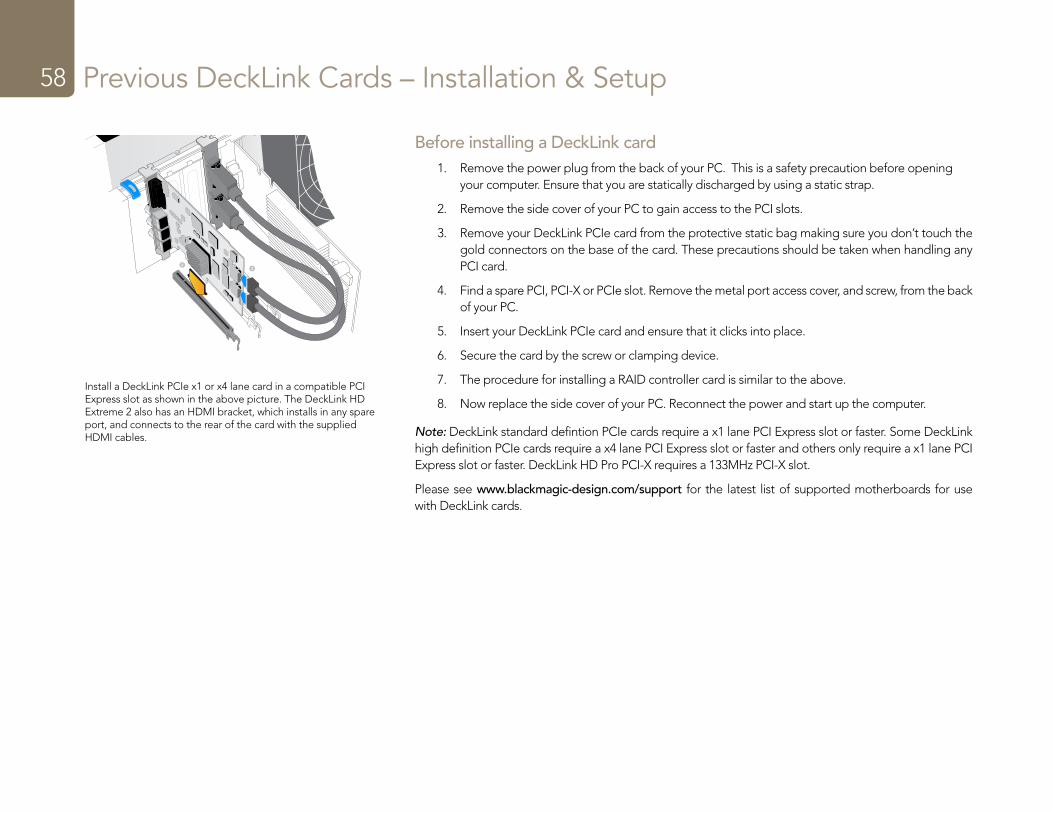
Previous DeckLink Cards – Installation & Setup58
Before installing a DeckLink card1. Remove the power plug from the back of your PC. This is a safety precaution before opening
your computer. Ensure that you are statically discharged by using a static strap.
2. Remove the side cover of your PC to gain access to the PCI slots.
3. Remove your DeckLink PCIe card from the protective static bag making sure you don’t touch the gold connectors on the base of the card. These precautions should be taken when handling any PCI card.
4. Find a spare PCI, PCI-X or PCIe slot. Remove the metal port access cover, and screw, from the back of your PC.
5. Insert your DeckLink PCIe card and ensure that it clicks into place.
6. Secure the card by the screw or clamping device.
7. The procedure for installing a RAID controller card is similar to the above.
8. Now replace the side cover of your PC. Reconnect the power and start up the computer.
Note: DeckLink standard defintion PCIe cards require a x1 lane PCI Express slot or faster. Some DeckLink high definition PCIe cards require a x4 lane PCI Express slot or faster and others only require a x1 lane PCI Express slot or faster. DeckLink HD Pro PCI-X requires a 133MHz PCI-X slot.
Please see www.blackmagic-design.com/support for the latest list of supported motherboards for use with DeckLink cards.
Install a DeckLink PCIe x1 or x4 lane card in a compatible PCI Express slot as shown in the above picture. The DeckLink HD Extreme 2 also has an HDMI bracket, which installs in any spare port, and connects to the rear of the card with the supplied HDMI cables.
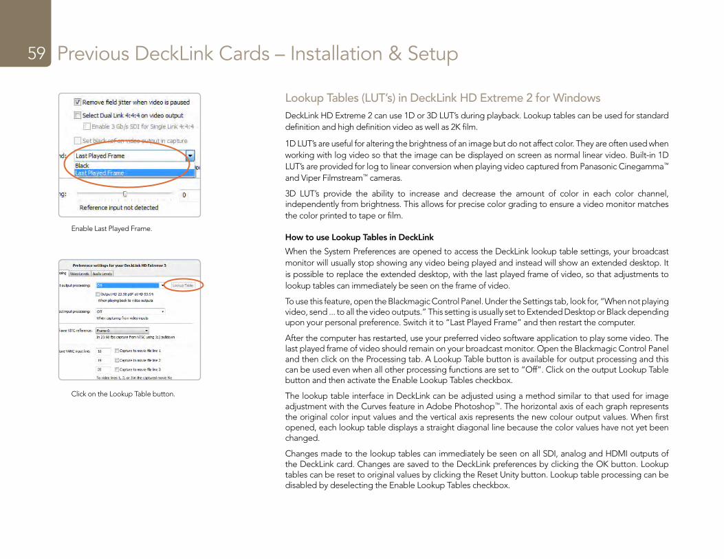
Previous DeckLink Cards – Installation & Setup59
Lookup Tables (LUT’s) in DeckLink HD Extreme 2 for WindowsDeckLink HD Extreme 2 can use 1D or 3D LUT’s during playback. Lookup tables can be used for standard definition and high definition video as well as 2K film.
1D LUT’s are useful for altering the brightness of an image but do not affect color. They are often used when working with log video so that the image can be displayed on screen as normal linear video. Built-in 1D LUT’s are provided for log to linear conversion when playing video captured from Panasonic Cinegamma™ and Viper Filmstream™ cameras.
3D LUT’s provide the ability to increase and decrease the amount of color in each color channel, independently from brightness. This allows for precise color grading to ensure a video monitor matches the color printed to tape or film.
How to use Lookup Tables in DeckLink
When the System Preferences are opened to access the DeckLink lookup table settings, your broadcast monitor will usually stop showing any video being played and instead will show an extended desktop. It is possible to replace the extended desktop, with the last played frame of video, so that adjustments to lookup tables can immediately be seen on the frame of video.
To use this feature, open the Blackmagic Control Panel. Under the Settings tab, look for, “When not playing video, send ... to all the video outputs.” This setting is usually set to Extended Desktop or Black depending upon your personal preference. Switch it to “Last Played Frame” and then restart the computer.
After the computer has restarted, use your preferred video software application to play some video. The last played frame of video should remain on your broadcast monitor. Open the Blackmagic Control Panel and then click on the Processing tab. A Lookup Table button is available for output processing and this can be used even when all other processing functions are set to “Off”. Click on the output Lookup Table button and then activate the Enable Lookup Tables checkbox.
The lookup table interface in DeckLink can be adjusted using a method similar to that used for image adjustment with the Curves feature in Adobe Photoshop™. The horizontal axis of each graph represents the original color input values and the vertical axis represents the new colour output values. When first opened, each lookup table displays a straight diagonal line because the color values have not yet been changed.
Changes made to the lookup tables can immediately be seen on all SDI, analog and HDMI outputs of the DeckLink card. Changes are saved to the DeckLink preferences by clicking the OK button. Lookup tables can be reset to original values by clicking the Reset Unity button. Lookup table processing can be disabled by deselecting the Enable Lookup Tables checkbox.
Enable Last Played Frame.
Click on the Lookup Table button.
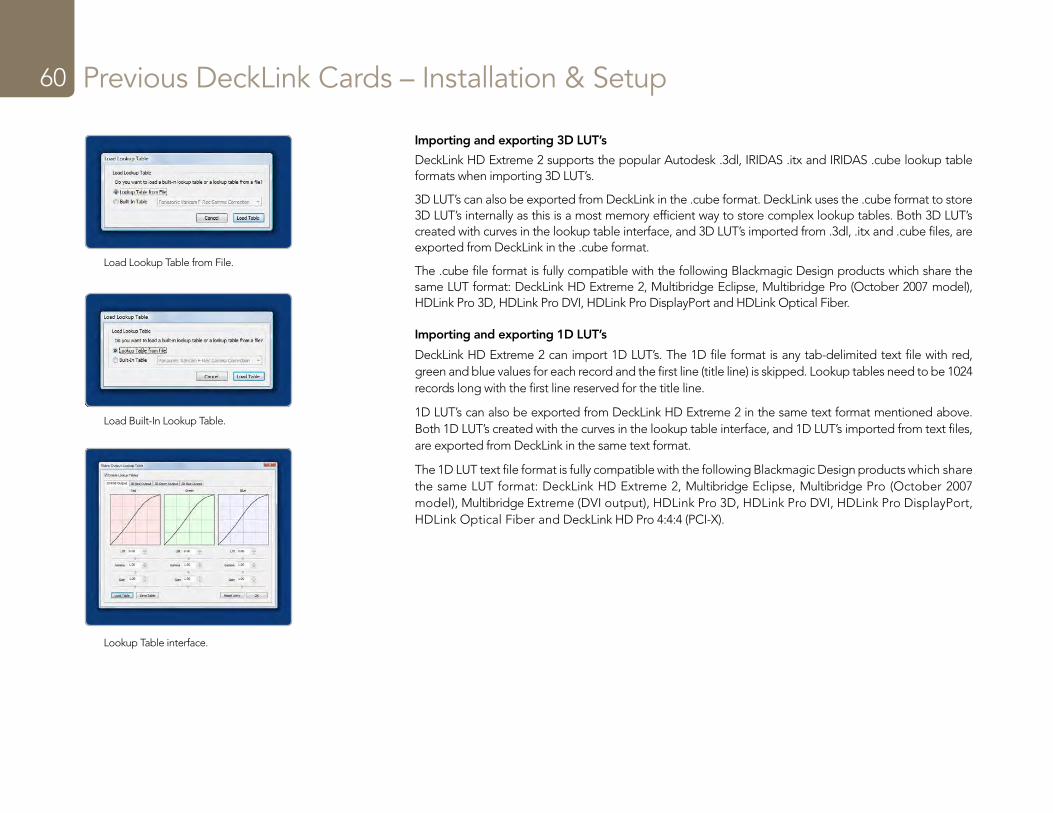
Previous DeckLink Cards – Installation & Setup60
Importing and exporting 3D LUT’s
DeckLink HD Extreme 2 supports the popular Autodesk .3dl, IRIDAS .itx and IRIDAS .cube lookup table formats when importing 3D LUT’s.
3D LUT’s can also be exported from DeckLink in the .cube format. DeckLink uses the .cube format to store 3D LUT’s internally as this is a most memory efficient way to store complex lookup tables. Both 3D LUT’s created with curves in the lookup table interface, and 3D LUT’s imported from .3dl, .itx and .cube files, are exported from DeckLink in the .cube format.
The .cube file format is fully compatible with the following Blackmagic Design products which share the same LUT format: DeckLink HD Extreme 2, Multibridge Eclipse, Multibridge Pro (October 2007 model), HDLink Pro 3D, HDLink Pro DVI, HDLink Pro DisplayPort and HDLink Optical Fiber.
Importing and exporting 1D LUT’s
DeckLink HD Extreme 2 can import 1D LUT’s. The 1D file format is any tab-delimited text file with red, green and blue values for each record and the first line (title line) is skipped. Lookup tables need to be 1024 records long with the first line reserved for the title line.
1D LUT’s can also be exported from DeckLink HD Extreme 2 in the same text format mentioned above. Both 1D LUT’s created with the curves in the lookup table interface, and 1D LUT’s imported from text files, are exported from DeckLink in the same text format.
The 1D LUT text file format is fully compatible with the following Blackmagic Design products which share the same LUT format: DeckLink HD Extreme 2, Multibridge Eclipse, Multibridge Pro (October 2007 model), Multibridge Extreme (DVI output), HDLink Pro 3D, HDLink Pro DVI, HDLink Pro DisplayPort, HDLink Optical Fiber and DeckLink HD Pro 4:4:4 (PCI-X).
Load Lookup Table from File.
Load Built-In Lookup Table.
Lookup Table interface.
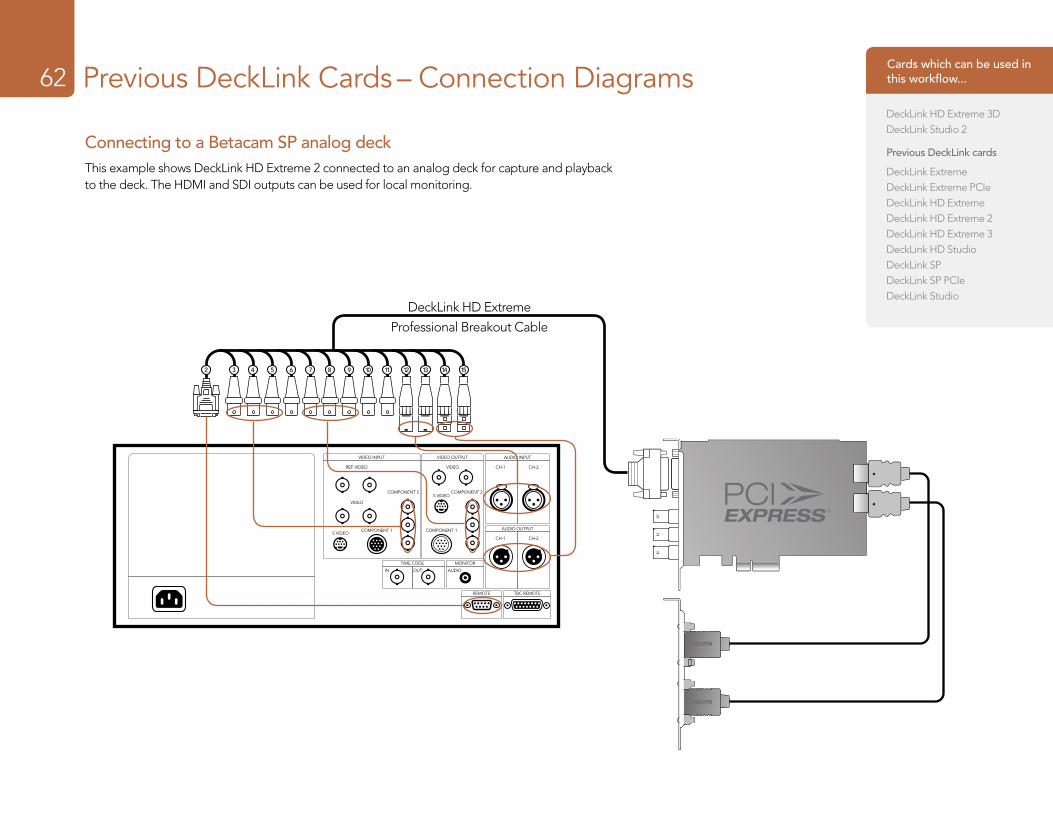
Previous DeckLink Cards – Connection Diagrams62
VIDEO INPUT
REF. VIDEO
VIDEO
VIDEO
COMPONENT 2 COMPONENT 2
COMPONENT 1 COMPONENT 1
IN OUT AUDIO
CH-1 CH-2
CH-1 CH-2
S VIDEO
S VIDEO
TIME CODE MONITOR
REMOTE TBC REMOTE
VIDEO OUTPUT AUDIO INPUT
AUDIO OUTPUT
2 3 4 5 6 7 8 9 10 11 12 13 14 15
2 3 4 5 6 7 8 9 10 11 12 13 14 15
DeckLink HD Extreme
Professional Breakout Cable
Connecting to a Betacam SP analog deckThis example shows DeckLink HD Extreme 2 connected to an analog deck for capture and playback to the deck. The HDMI and SDI outputs can be used for local monitoring.
Cards which can be used in this workflow...
DeckLink HD Extreme 3DDeckLink Studio 2
Previous DeckLink cards
DeckLink ExtremeDeckLink Extreme PCIeDeckLink HD ExtremeDeckLink HD Extreme 2DeckLink HD Extreme 3DeckLink HD StudioDeckLink SPDeckLink SP PCIeDeckLink Studio
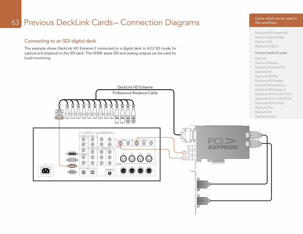
Previous DeckLink Cards – Connection Diagrams63
ANALOG VIDEO I/O DIGITAL AUDIO I/O (AES/EBU)
REF VIDEO
IN
IN
IN
IN1
2
3
OUT
CH-1 CH-2 CH-3 CH-4
CH-1 CH-2 CH-3 CH-4
IN
OUTOUT
OUT
OUT
OUT
VIDEO IN
VIDEO OUT
S VIDEO
MONITOR AUDIO
AUDIO OUT
AUDIO IN
SDI OUTPUT SDI INPUT
TIME CODE
VIDEO CONTROL
CONTROL PANEL
REMOTE - INAC IN
REMOTE - OUT
COMPONENT VIDEO
2 3 4 5 6 7 8 9 10 11 12 13 14 15
2 3 4 5 6 7 8 9 10 11 12 13 14 15
DeckLink HD Extreme
Professional Breakout Cable
Connecting to an SDI digital deckThis example shows DeckLink HD Extreme 2 connected to a digital deck in 4:2:2 SD mode for capture and playback to the SDI deck. The HDMI, spare SDI and analog outputs can be used for local monitoring.
Cards which can be used in this workflow...
DeckLink HD Extreme 3DDeckLink Optical FiberDeckLink SDIDeckLink Studio 2
Previous DeckLink cards
DeckLinkDeckLink ExtremeDeckLink Extreme PCIeDeckLink HDDeckLink HD PlusDeckLink HD ExtremeDeckLink HD Extreme 2DeckLink HD Extreme 3DeckLink HD Pro 4:2:2 PCI-XDeckLink HD Pro 4:4:4 PCI-XDeckLink HD Pro PCIeDeckLink PlusDeckLink ProDeckLink Studio
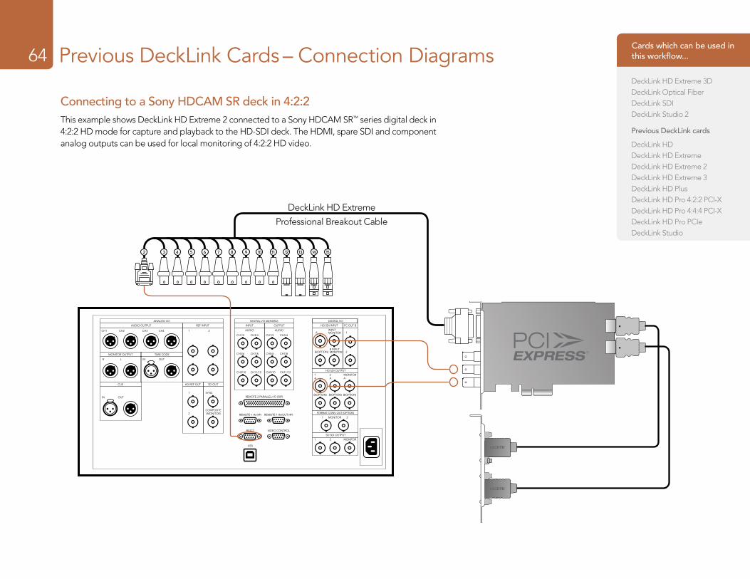
Previous DeckLink Cards – Connection Diagrams64
Connecting to a Sony HDCAM SR deck in 4:2:2This example shows DeckLink HD Extreme 2 connected to a Sony HDCAM SR™ series digital deck in 4:2:2 HD mode for capture and playback to the HD-SDI deck. The HDMI, spare SDI and component analog outputs can be used for local monitoring of 4:2:2 HD video.
2 3 4 5 6 7 8 9 10 11 12 13 14 15
2 3 4 5 6 7 8 9 10 11 12 13 14 15
ANALOG I/O DIGITAL I/O (AES/EBU) DIGITAL I/O
AUDIO OUTPUT REF INPUT INPUT HD SDI INPUT
HD SDI OUTPUT
FORMAT CONV. OUT (OPTION)
MONITOR1 2
SD SDI OUTPUT
FC OUT BOUTPUT
AUDIOA 1
2B(OPTION)
B(OPTION) B(OPTION) B(OPTION)
1A
2A
MONITORA
1 2 MONITOR
INPUTMONITOR
B INPUTMONITOR
CH1/2 CH3/4
CH5/6 CH7/8
CH9/10 CH11/12
AUDIO
MONITOR OUTPUT
CUE HD REF OUT SD OUT
TIME CODE
IN OUTR L
CH3 CH4 1 2
1 SYNC
2COMPOSITE(MONITOR)
CH1 CH2
IN OUT
CH1/2 CH3/4
CH5/6 CH7/8
CH9/10 CH11/12
REMOTE 2 PARALLEL I/O (50P)
REMOTE 1-IN (9P) REMOTE 1-IN/OUT (9P)
RS422
USB
VIDEO CONTROL
DeckLink HD Extreme
Professional Breakout Cable
Cards which can be used in this workflow...
DeckLink HD Extreme 3DDeckLink Optical FiberDeckLink SDIDeckLink Studio 2
Previous DeckLink cards
DeckLink HDDeckLink HD ExtremeDeckLink HD Extreme 2DeckLink HD Extreme 3DeckLink HD PlusDeckLink HD Pro 4:2:2 PCI-XDeckLink HD Pro 4:4:4 PCI-XDeckLink HD Pro PCIeDeckLink Studio
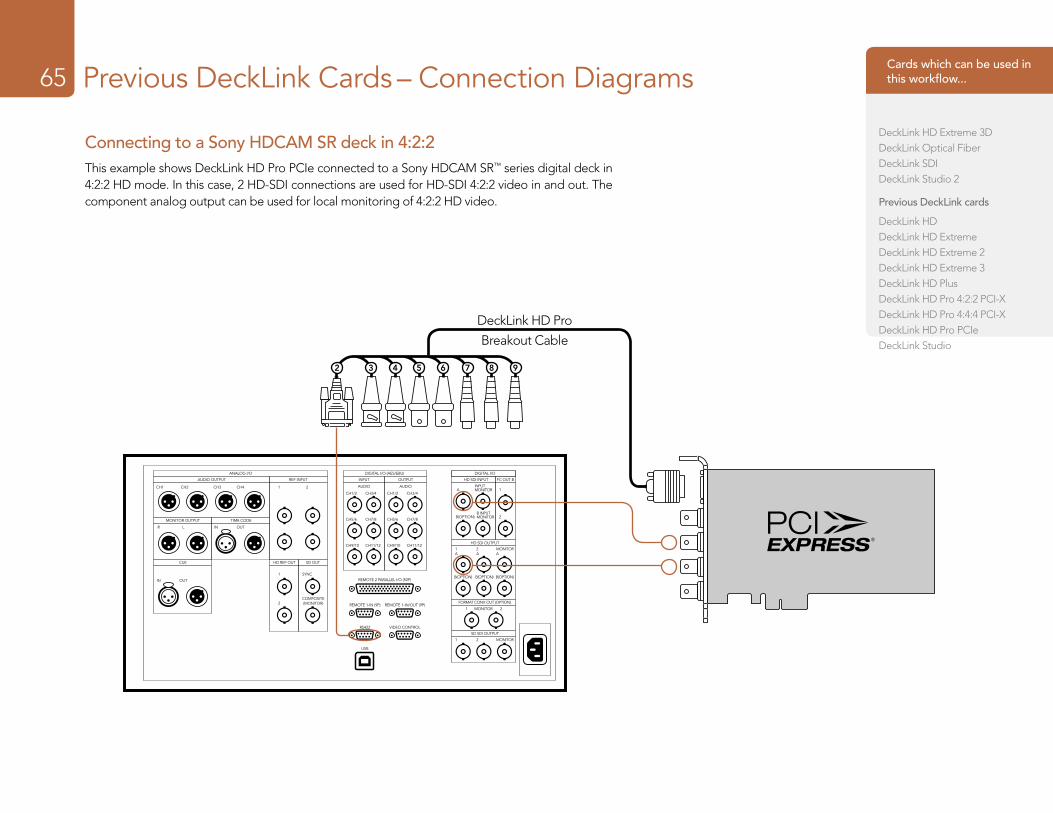
Previous DeckLink Cards – Connection Diagrams65
Connecting to a Sony HDCAM SR deck in 4:2:2This example shows DeckLink HD Pro PCIe connected to a Sony HDCAM SR™ series digital deck in 4:2:2 HD mode. In this case, 2 HD-SDI connections are used for HD-SDI 4:2:2 video in and out. The component analog output can be used for local monitoring of 4:2:2 HD video.
ANALOG I/O DIGITAL I/O (AES/EBU) DIGITAL I/O
AUDIO OUTPUT REF INPUT INPUT HD SDI INPUT
HD SDI OUTPUT
FORMAT CONV. OUT (OPTION)
MONITOR1 2
SD SDI OUTPUT
FC OUT BOUTPUT
AUDIOA 1
2B(OPTION)
B(OPTION) B(OPTION) B(OPTION)
1A
2A
MONITORA
1 2 MONITOR
INPUTMONITOR
B INPUTMONITOR
CH1/2 CH3/4
CH5/6 CH7/8
CH9/10 CH11/12
AUDIO
MONITOR OUTPUT
CUE HD REF OUT SD OUT
TIME CODE
IN OUTR L
CH3 CH4 1 2
1 SYNC
2COMPOSITE(MONITOR)
CH1 CH2
IN OUT
CH1/2 CH3/4
CH5/6 CH7/8
CH9/10 CH11/12
REMOTE 2 PARALLEL I/O (50P)
REMOTE 1-IN (9P) REMOTE 1-IN/OUT (9P)
RS422
USB
VIDEO CONTROL
DeckLink HD Pro
Breakout Cable
2 3 4 5 6 7 8 9
Cards which can be used in this workflow...
DeckLink HD Extreme 3DDeckLink Optical FiberDeckLink SDIDeckLink Studio 2
Previous DeckLink cards
DeckLink HDDeckLink HD ExtremeDeckLink HD Extreme 2DeckLink HD Extreme 3DeckLink HD PlusDeckLink HD Pro 4:2:2 PCI-XDeckLink HD Pro 4:4:4 PCI-XDeckLink HD Pro PCIeDeckLink Studio
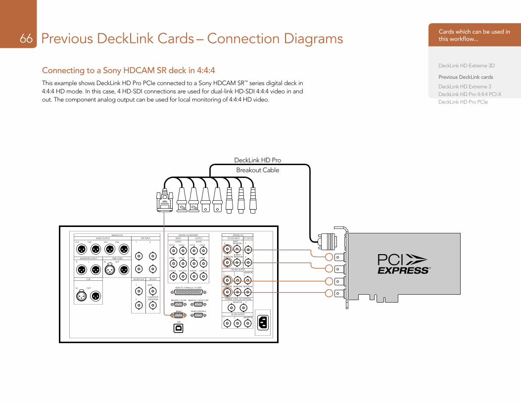
Previous DeckLink Cards – Connection Diagrams66
Connecting to a Sony HDCAM SR deck in 4:4:4This example shows DeckLink HD Pro PCIe connected to a Sony HDCAM SR™ series digital deck in 4:4:4 HD mode. In this case, 4 HD-SDI connections are used for dual-link HD-SDI 4:4:4 video in and out. The component analog output can be used for local monitoring of 4:4:4 HD video.
ANALOG I/O DIGITAL I/O (AES/EBU) DIGITAL I/O
AUDIO OUTPUT REF INPUT INPUT HD SDI INPUT
HD SDI OUTPUT
FORMAT CONV. OUT (OPTION)
MONITOR1 2
SD SDI OUTPUT
FC OUT BOUTPUT
AUDIOA 1
2B(OPTION)
B(OPTION) B(OPTION) B(OPTION)
1A
2A
MONITORA
1 2 MONITOR
INPUTMONITOR
B INPUTMONITOR
CH1/2 CH3/4
CH5/6 CH7/8
CH9/10 CH11/12
AUDIO
MONITOR OUTPUT
CUE HD REF OUT SD OUT
TIME CODE
IN OUTR L
CH3 CH4 1 2
1 SYNC
2COMPOSITE(MONITOR)
CH1 CH2
IN OUT
CH1/2 CH3/4
CH5/6 CH7/8
CH9/10 CH11/12
REMOTE 2 PARALLEL I/O (50P)
REMOTE 1-IN (9P) REMOTE 1-IN/OUT (9P)
RS422
USB
VIDEO CONTROL
DeckLink HD Pro
Breakout Cable
Cards which can be used in this workflow...
DeckLink HD Extreme 3D
Previous DeckLink cards
DeckLink HD Extreme 3DeckLink HD Pro 4:4:4 PCI-XDeckLink HD Pro PCIe
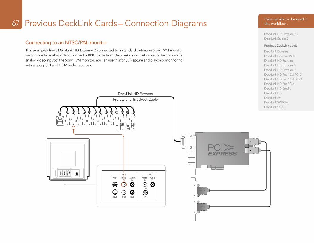
Previous DeckLink Cards – Connection Diagrams67
Connecting to an NTSC/PAL monitorThis example shows DeckLink HD Extreme 2 connected to a standard definition Sony PVM monitor via composite analog video. Connect a BNC cable from DeckLink’s Y output cable to the composite analog video input of the Sony PVM monitor. You can use this for SD capture and playback monitoring with analog, SDI and HDMI video sources.
LINE A LINE B
VIDEO IN
AUDIOIN
VIDEO IN
Y/C
Y/C
INOUTOUTOUT
AUDIOIN AC IN
LINE A LINE B
VIDEO IN
AUDIOIN
VIDEO IN
Y/C
Y/C
INOUTOUTOUT
AUDIOIN AC IN
2 3 4 5 6 7 8 9 10 11 12 13 14 15
2 3 4 5 6 7 8 9 10 11 12 13 14 15
DeckLink HD Extreme
Professional Breakout Cable
Cards which can be used in this workflow...
DeckLink HD Extreme 3DDeckLink Studio 2
Previous DeckLink cards
DeckLink ExtremeDeckLink Extreme PCIeDeckLink HD ExtremeDeckLink HD Extreme 2DeckLink HD Extreme 3DeckLink HD Pro 4:2:2 PCI-XDeckLink HD Pro 4:4:4 PCI-XDeckLink HD Pro PCIeDeckLink HD StudioDeckLink ProDeckLink SPDeckLink SP PCIeDeckLink Studio
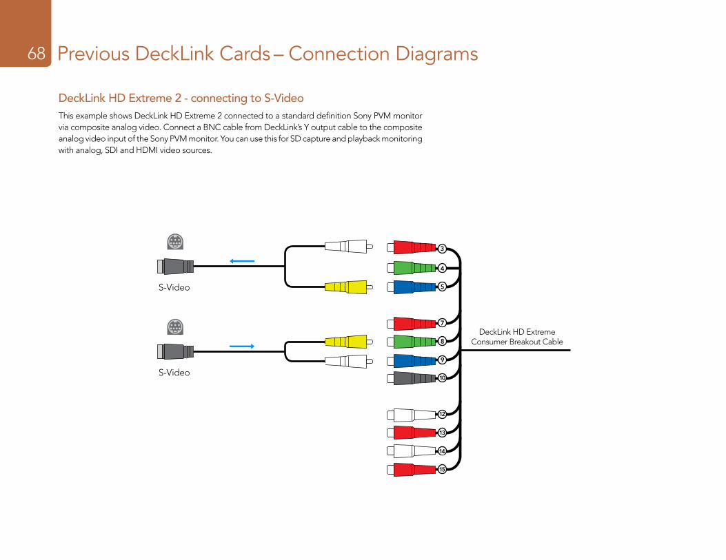
Previous DeckLink Cards – Connection Diagrams68
DeckLink HD Extreme Consumer Breakout Cable
3
4
5
7
8
9
10
12
13
14
15
B-Y Input
Y Input
S-Video
B-Y Input
Y Input
S-Video
B-Y Input
Y Input
S-Video
B-Y Input
Y Input
S-Video B-Y Input
Y Input
S-Video B-Y Input
Y Input
S-Video
DeckLink HD Extreme 2 - connecting to S-VideoThis example shows DeckLink HD Extreme 2 connected to a standard definition Sony PVM monitor via composite analog video. Connect a BNC cable from DeckLink’s Y output cable to the composite analog video input of the Sony PVM monitor. You can use this for SD capture and playback monitoring with analog, SDI and HDMI video sources.
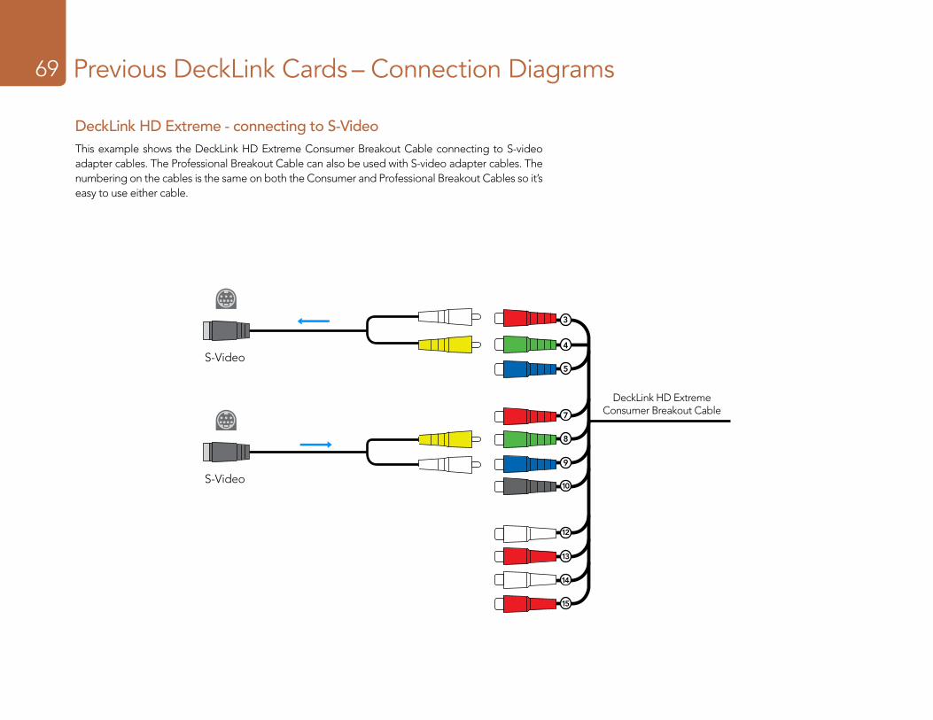
Previous DeckLink Cards – Connection Diagrams69
B-Y Input
Y Input
S-Video
B-Y Input
Y Input
S-Video
B-Y Input
Y Input
S-Video
B-Y Input
Y Input
S-Video B-Y Input
Y Input
S-Video B-Y Input
Y Input
S-Video
DeckLink HD Extreme Consumer Breakout Cable
3
4
5
7
8
9
10
12
13
14
15
DeckLink HD Extreme - connecting to S-VideoThis example shows the DeckLink HD Extreme Consumer Breakout Cable connecting to S-video adapter cables. The Professional Breakout Cable can also be used with S-video adapter cables. The numbering on the cables is the same on both the Consumer and Professional Breakout Cables so it’s easy to use either cable.
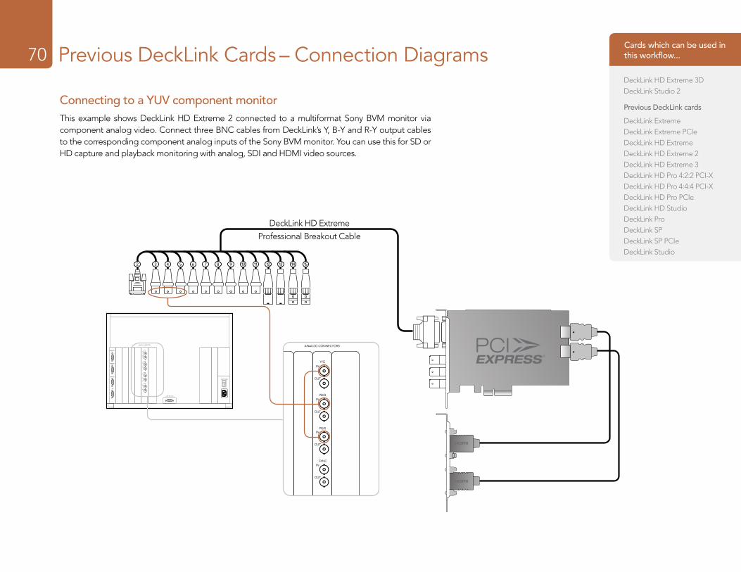
Previous DeckLink Cards – Connection Diagrams70
AC IN
MAIN POWER
I
O
ANALOG CONNECTORS
REMOTE 1IN
REMOTE 1OUT
REMOTE 2
ISR
Y/G
PB/B
PR/R
CONTROL UNIT
SYNC
IN
OUT
IN
OUT
IN
OUT
IN
OUT
AC IN
MAIN POWER
I
O
ANALOG CONNECTORS
REMOTE 1IN
REMOTE 1OUT
REMOTE 2
ISR
Y/G
PB/B
PR/R
CONTROL UNIT
SYNC
IN
OUT
IN
OUT
IN
OUT
IN
OUT
2 3 4 5 6 7 8 9 10 11 12 13 14 15
2 3 4 5 6 7 8 9 10 11 12 13 14 15
DeckLink HD Extreme
Professional Breakout Cable
Connecting to a YUV component monitorThis example shows DeckLink HD Extreme 2 connected to a multiformat Sony BVM monitor via component analog video. Connect three BNC cables from DeckLink’s Y, B-Y and R-Y output cables to the corresponding component analog inputs of the Sony BVM monitor. You can use this for SD or HD capture and playback monitoring with analog, SDI and HDMI video sources.
Cards which can be used in this workflow...
DeckLink HD Extreme 3DDeckLink Studio 2
Previous DeckLink cards
DeckLink ExtremeDeckLink Extreme PCIeDeckLink HD ExtremeDeckLink HD Extreme 2DeckLink HD Extreme 3DeckLink HD Pro 4:2:2 PCI-XDeckLink HD Pro 4:4:4 PCI-XDeckLink HD Pro PCIeDeckLink HD StudioDeckLink ProDeckLink SPDeckLink SP PCIeDeckLink Studio
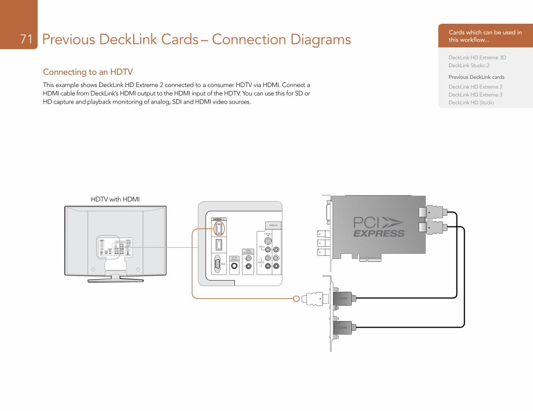
Previous DeckLink Cards – Connection Diagrams71
Connecting to an HDTVThis example shows DeckLink HD Extreme 2 connected to a consumer HDTV via HDMI. Connect a HDMI cable from DeckLink’s HDMI output to the HDMI input of the HDTV. You can use this for SD or HD capture and playback monitoring of analog, SDI and HDMI video sources.
AUDIO OUT
DIGITAL OUT(OPTICAL)
AUDIO
VIDEO
S VIDEO
R
L
R
LAUDIO
R
L
PR
PB
Y
L
R
IN
RGB
PC INAUDIO
HDMIIN AUDIO
CONTROLS
VIDEO IN HD/DVD ININ OUT
AUDIO OUT
DIGITAL OUT(OPTICAL)
AUDIO
VIDEO
S VIDEO
R
L
R
LAUDIO
R
L
PR
PB
Y
L
R
IN
RGB
PC INAUDIO
HDMIIN AUDIO
CONTROLS
VIDEO IN HD/DVD ININ OUT
HDTV with HDMI2 3 4 5 6 7 8 9 10 11 12 13 14 152 3 4 5 6 7 8 9 10 11 12 13 14 15
Cards which can be used in this workflow...
DeckLink HD Extreme 3DDeckLink Studio 2
Previous DeckLink cards
DeckLink HD Extreme 2DeckLink HD Extreme 3DeckLink HD Studio
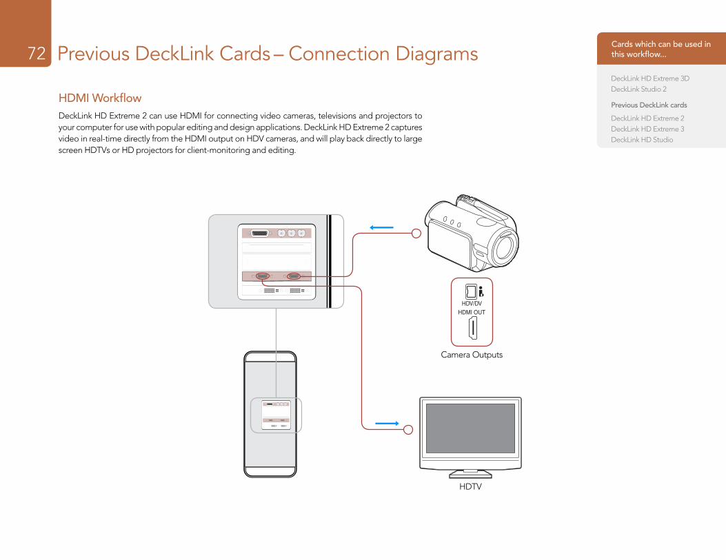
Previous DeckLink Cards – Connection Diagrams72
HDMI WorkflowDeckLink HD Extreme 2 can use HDMI for connecting video cameras, televisions and projectors to your computer for use with popular editing and design applications. DeckLink HD Extreme 2 captures video in real-time directly from the HDMI output on HDV cameras, and will play back directly to large screen HDTVs or HD projectors for client-monitoring and editing.
HDTV
Camera Outputs
Cards which can be used in this workflow...
DeckLink HD Extreme 3DDeckLink Studio 2
Previous DeckLink cards
DeckLink HD Extreme 2DeckLink HD Extreme 3DeckLink HD Studio
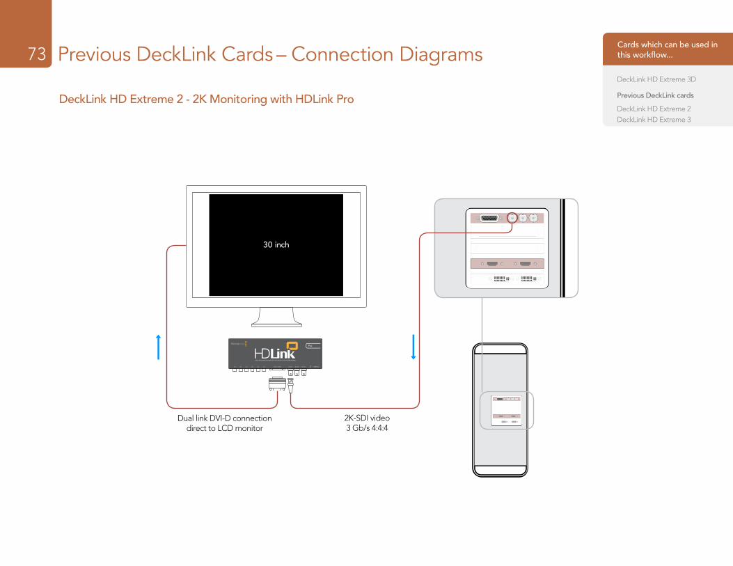
Previous DeckLink Cards – Connection Diagrams73
DeckLink HD Extreme 2 - 2K Monitoring with HDLink Pro
30 inch
2K-SDI video 3 Gb/s 4:4:4
Dual link DVI-D connection direct to LCD monitor
Cards which can be used in this workflow...
DeckLink HD Extreme 3D
Previous DeckLink cards
DeckLink HD Extreme 2DeckLink HD Extreme 3
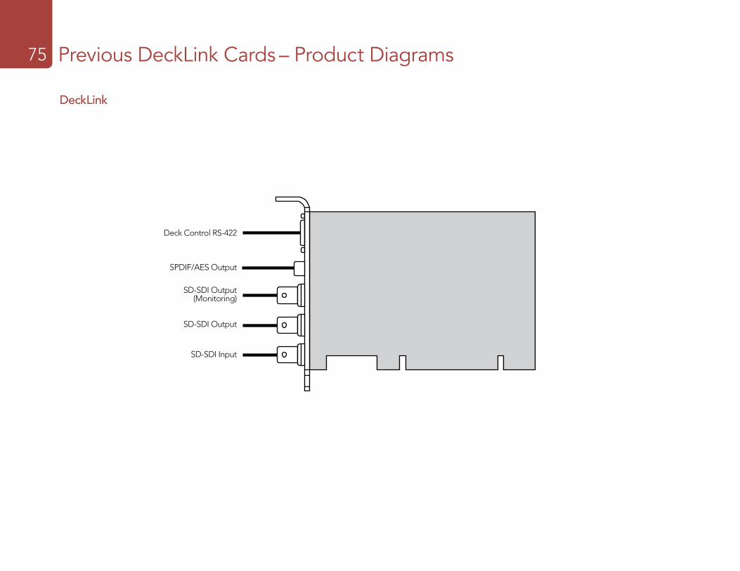
Previous DeckLink Cards – Product Diagrams75
Deck Control RS-422
SPDIF/AES Output
SD-SDI Output (Monitoring)
SD-SDI Output
SD-SDI Input
DeckLink
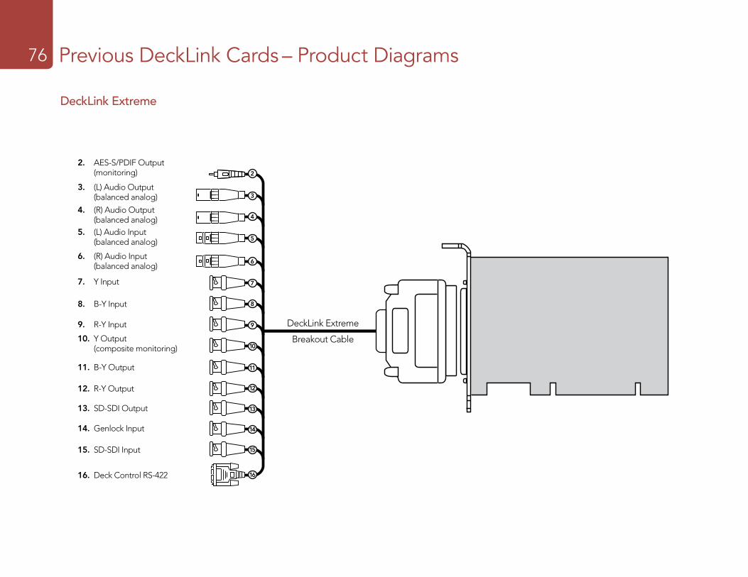
Previous DeckLink Cards – Product Diagrams76
DeckLink Extreme
Y Input
R-Y Output
B-Y Output
Y Output (composite monitoring)
SD-SDI Input
SD-SDI Output
Genlock Input
Deck Control RS-422
DeckLink Extreme 7ft Breakout Cable
B-Y Input
R-Y Input
AES-S/PDIF Output(monitoring)
(L) Audio Input (balanced analog)
(L) Audio Output (balanced analog)
(R) Audio Input (balanced analog)
(R) Audio Output (balanced analog)
2
3
4
5
7
6
8
9
10
11
12
13
14
15
2. AES-S/PDIF Output (monitoring)
3. (L) Audio Output (balanced analog)
6. (R) Audio Input (balanced analog)
9. R-Y Input
4. (R) Audio Output (balanced analog)
7. Y Input
10. Y Output (composite monitoring)
5. (L) Audio Input (balanced analog)
8. B-Y Input
11. B-Y Output
12. R-Y Output
13. SD-SDI Output
14. Genlock Input
15. SD-SDI Input
16. Deck Control RS-422
DeckLink Extreme
Breakout Cable
16
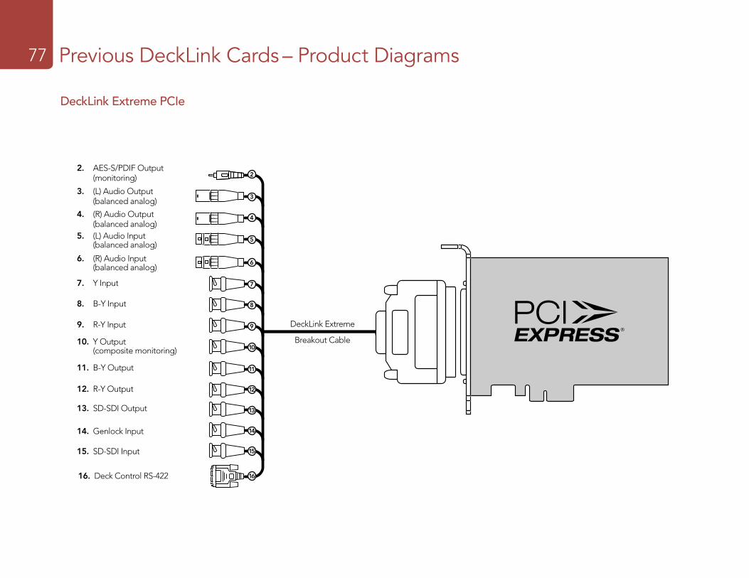
Previous DeckLink Cards – Product Diagrams77
DeckLink Extreme PCIe
16
Y Input
R-Y Output
B-Y Output
Y Output (composite monitoring)
SD-SDI Input
SD-SDI Output
Genlock Input
Deck Control RS-422
7ft break-out cable
B-Y Input
R-Y Input
SPDIF/AES Output(monitoring)
(L) Audio Input (balanced analog)
(L) Audio Output (balanced analog)
(R) Audio Input (balanced analog)
(R) Audio Output (balanced analog)
2
3
4
5
7
6
8
9
10
11
12
13
14
15
2. AES-S/PDIF Output (monitoring)
3. (L) Audio Output (balanced analog)
6. (R) Audio Input (balanced analog)
9. R-Y Input
4. (R) Audio Output (balanced analog)
7. Y Input
10. Y Output (composite monitoring)
5. (L) Audio Input (balanced analog)
8. B-Y Input
11. B-Y Output
12. R-Y Output
13. SD-SDI Output
14. Genlock Input
15. SD-SDI Input
DeckLink Extreme
Breakout Cable
16. Deck Control RS-422
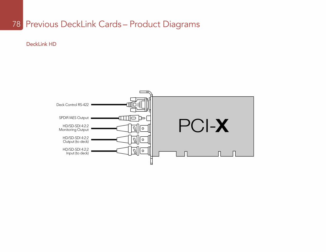
Previous DeckLink Cards – Product Diagrams78
DeckLink HD
Deck Control RS-422
SPDIF/AES Output
HD/SD-SDI 4:2:2 Monitoring Output
HD/SD-SDI 4:2:2 Output (to deck)
HD/SD-SDI 4:2:2 Input (to deck)
SPDIF/AES Output
Deck Control RS-422
HD/SD-SDI 4:2:2Monitoring Output
HD/SD-SDI 4:2:2Output (to deck)
HD/SD-SDI 4:2:2 Input (from deck)
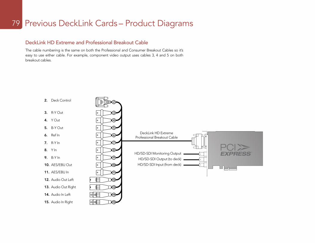
Previous DeckLink Cards – Product Diagrams79
2 3 4 5 6 7 8 9 10 11 12 13 14 15
23
45
67
89
1011
1213
1415
DeckLink HD Extreme Professional Breakout Cable
23
45
67
89
1011
1213
1415
2
3
4
5
6
7
8
9
10
11
12
13
14
15
2. Deck Control
3. R-Y Out
HD/SD-SDI Monitoring Output
HD/SD-SDI Output (to deck)
HD/SD-SDI Input (from deck)
4. Y Out
5. B-Y Out
6. Ref In
7. R-Y In
8. Y In
9. B-Y In
10. AES/EBU Out
11. AES/EBU In
12. Audio Out Left
13. Audio Out Right
14. Audio In Left
15. Audio In Right
DeckLink HD Extreme and Professional Breakout CableThe cable numbering is the same on both the Professional and Consumer Breakout Cables so it’s easy to use either cable. For example, component video output uses cables 3, 4 and 5 on both breakout cables.
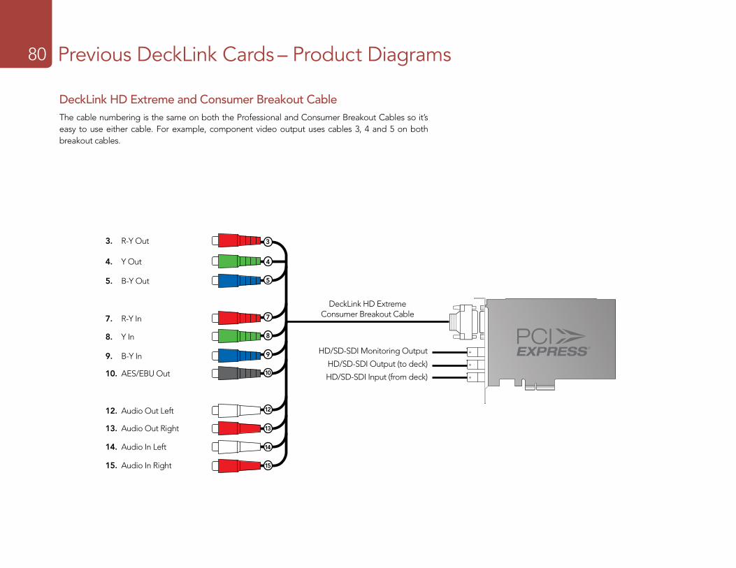
Previous DeckLink Cards – Product Diagrams80
DeckLink HD Extreme Consumer Breakout Cable
3
4
5
7
8
9
10
12
13
14
15
3. R-Y Out
HD/SD-SDI Monitoring Output
HD/SD-SDI Output (to deck)
HD/SD-SDI Input (from deck)
4. Y Out
5. B-Y Out
7. R-Y In
8. Y In
9. B-Y In
10. AES/EBU Out
12. Audio Out Left
13. Audio Out Right
14. Audio In Left
15. Audio In Right
2 3 4 5 6 7 8 9 10 11 12 13 14 15
23
45
67
89
1011
1213
1415
DeckLink HD Extreme and Consumer Breakout CableThe cable numbering is the same on both the Professional and Consumer Breakout Cables so it’s easy to use either cable. For example, component video output uses cables 3, 4 and 5 on both breakout cables.
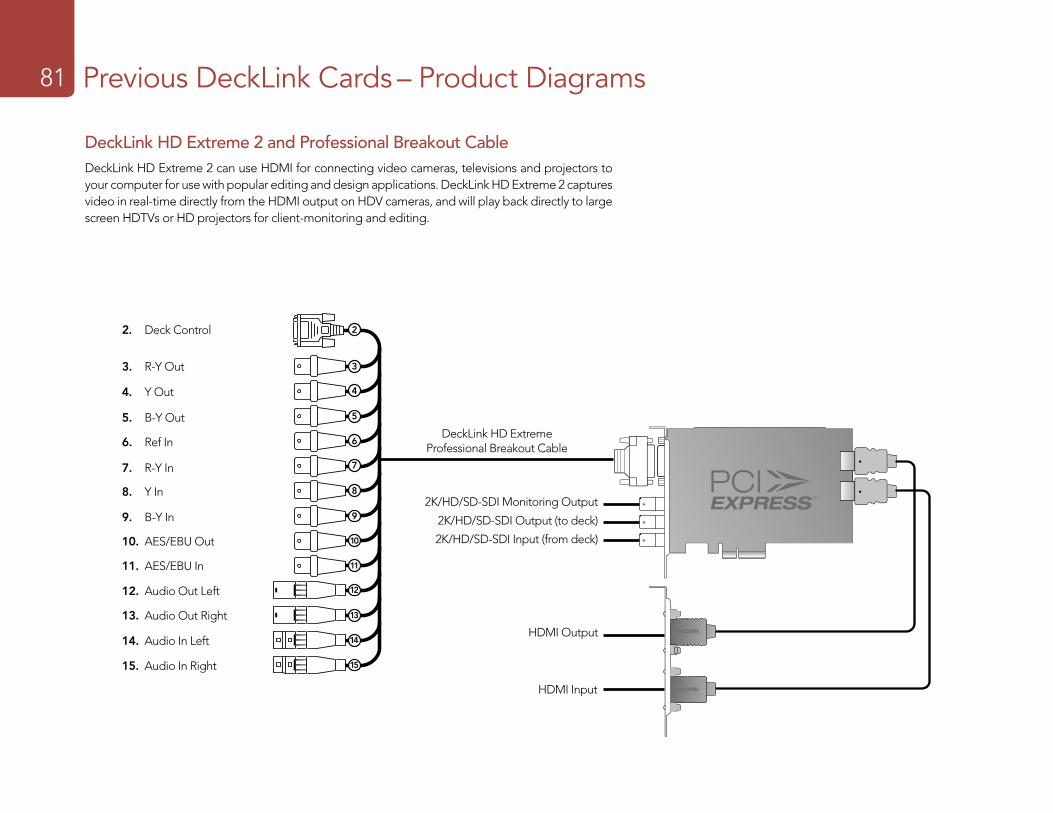
Previous DeckLink Cards – Product Diagrams81
2 3 4 5 6 7 8 9 10 11 12 13 14 15DeckLink HD Extreme
Professional Breakout Cable
23
45
67
89
1011
1213
1415
2
3
4
5
6
7
8
9
10
11
12
13
14
15
2. Deck Control
3. R-Y Out
2K/HD/SD-SDI Monitoring Output
2K/HD/SD-SDI Output (to deck)
2K/HD/SD-SDI Input (from deck)
HDMI Output
HDMI Input
4. Y Out
5. B-Y Out
6. Ref In
7. R-Y In
8. Y In
9. B-Y In
10. AES/EBU Out
11. AES/EBU In
12. Audio Out Left
13. Audio Out Right
14. Audio In Left
15. Audio In Right
DeckLink HD Extreme 2 and Professional Breakout CableDeckLink HD Extreme 2 can use HDMI for connecting video cameras, televisions and projectors to your computer for use with popular editing and design applications. DeckLink HD Extreme 2 captures video in real-time directly from the HDMI output on HDV cameras, and will play back directly to large screen HDTVs or HD projectors for client-monitoring and editing.
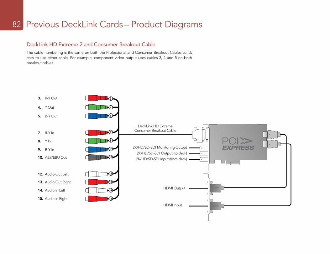
Previous DeckLink Cards – Product Diagrams82
2 3 4 5 6 7 8 9 10 11 12 13 14 15DeckLink HD Extreme
Consumer Breakout Cable
3
4
5
7
8
9
10
12
13
14
15
3. R-Y Out
2K/HD/SD-SDI Monitoring Output
2K/HD/SD-SDI Output (to deck)
2K/HD/SD-SDI Input (from deck)
HDMI Output
HDMI Input
4. Y Out
5. B-Y Out
7. R-Y In
8. Y In
9. B-Y In
10. AES/EBU Out
12. Audio Out Left
13. Audio Out Right
14. Audio In Left
15. Audio In Right
DeckLink HD Extreme 2 and Consumer Breakout CableThe cable numbering is the same on both the Professional and Consumer Breakout Cables so it’s easy to use either cable. For example, component video output uses cables 3, 4 and 5 on both breakout cables.
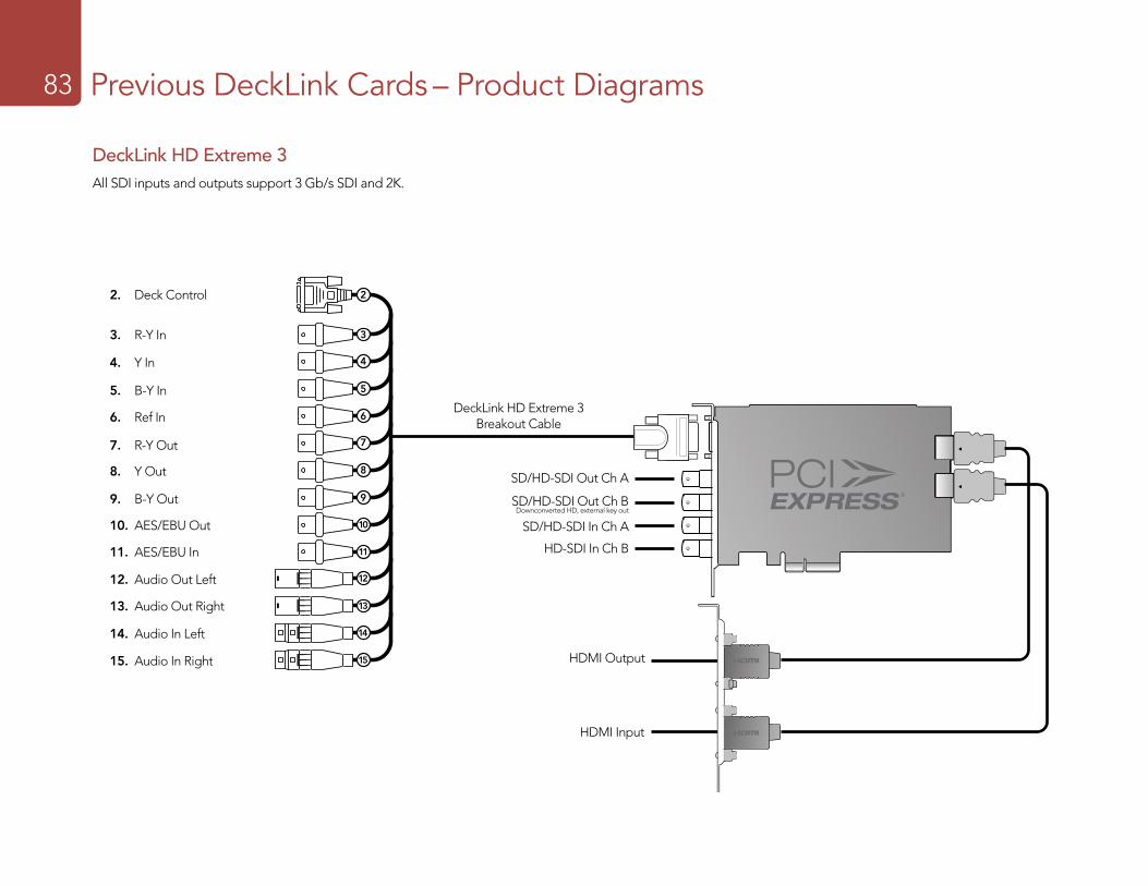
Previous DeckLink Cards – Product Diagrams83
DeckLink HD Extreme 3 Breakout Cable
23
45
67
89
1011
1213
1415
2
3
4
5
6
7
8
9
10
11
12
13
14
15
2. Deck Control
3. R-Y In
SD/HD-SDI Out Ch B Downconverted HD, external key out
SD/HD-SDI Out Ch A
SD/HD-SDI In Ch A
4. Y In
5. B-Y In
6. Ref In
7. R-Y Out
8. Y Out
9. B-Y Out
10. AES/EBU Out
11. AES/EBU In
12. Audio Out Left
13. Audio Out Right
14. Audio In Left
15. Audio In Right HDMI Output
HDMI Input
HD-SDI In Ch B
DeckLink HD Extreme 3All SDI inputs and outputs support 3 Gb/s SDI and 2K.

Previous DeckLink Cards – Product Diagrams84
DeckLink HD Plus
HD/SD-SDI Input (from deck)
HD/SD-SDI Output (to deck)
DeckLink HD Plus Breakout Cable
2
3
4
5
6
2. Deck Control
3. Ref In
4. SPDIF/AES Out
5. SPDIF/AES In
6. Wordclock Out
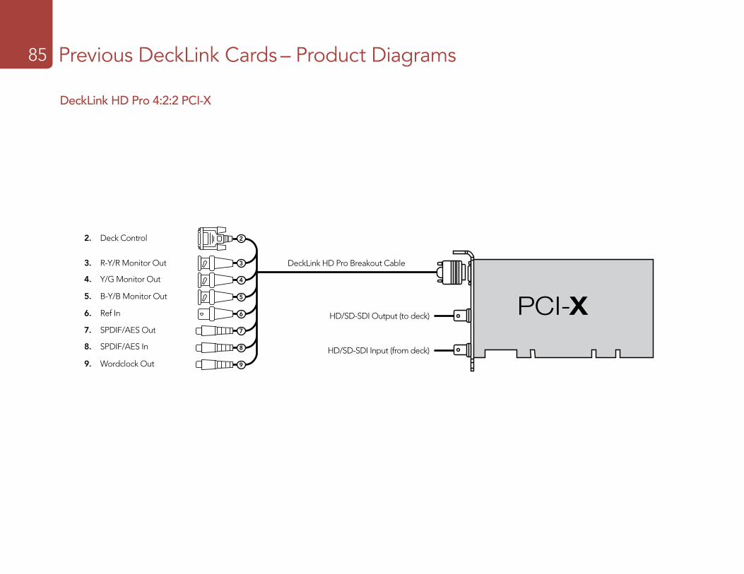
Previous DeckLink Cards – Product Diagrams85
DeckLink HD Pro 4:2:2 PCI-X
2
3
4
5
6
7
8
9
2. Deck Control
3. R-Y/R Monitor Out
4. Y/G Monitor Out
5. B-Y/B Monitor Out
6. Ref In
7. SPDIF/AES Out
8. SPDIF/AES In
9. Wordclock Out
DeckLink HD Pro Breakout Cable
HD/SD-SDI Output (to deck)
HD/SD-SDI Input (from deck)
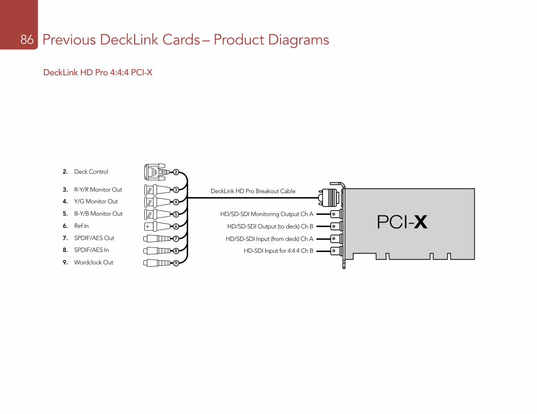
Previous DeckLink Cards – Product Diagrams86
DeckLink HD Pro 4:4:4 PCI-X
2
3
4
5
6
7
8
9
2. Deck Control
HD/SD-SDI Monitoring Output Ch A
HD/SD-SDI Output (to deck) Ch B
HD-SDI Input for 4:4:4 Ch B
HD/SD-SDI Input (from deck) Ch A
3. R-Y/R Monitor Out
4. Y/G Monitor Out
5. B-Y/B Monitor Out
6. Ref In
7. SPDIF/AES Out
8. SPDIF/AES In
9. Wordclock Out
DeckLink HD Pro Breakout Cable
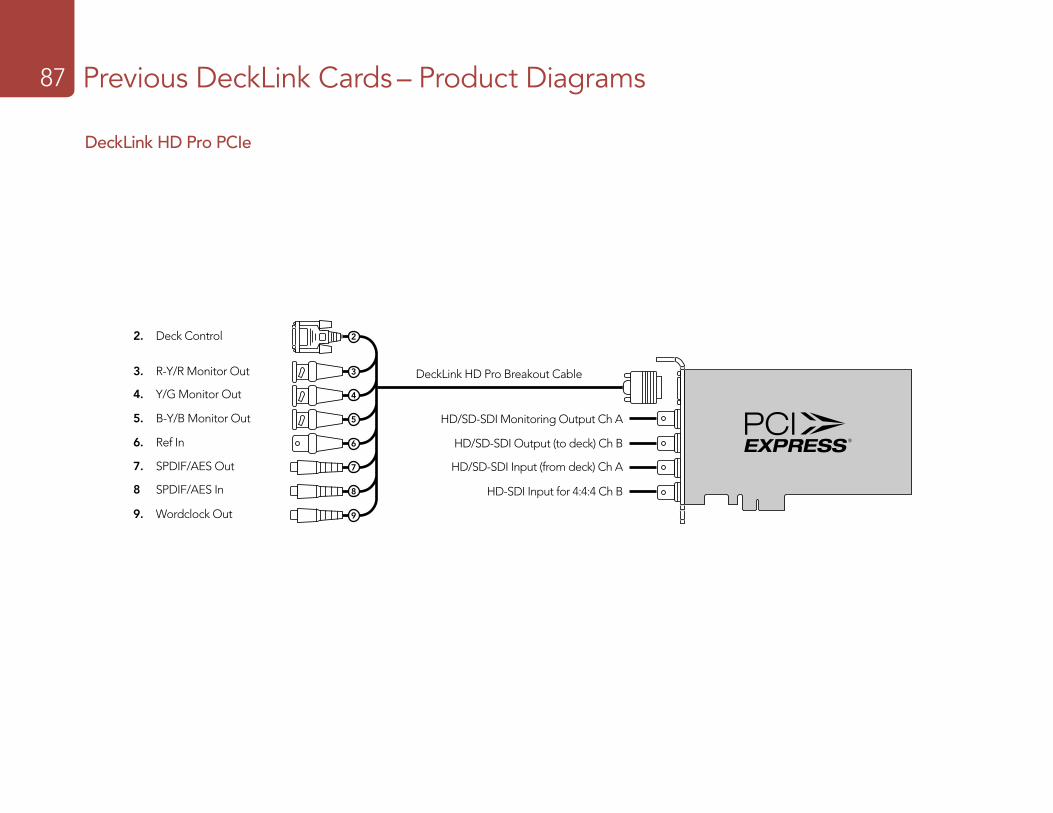
Previous DeckLink Cards – Product Diagrams87
DeckLink HD Pro PCIe
2. Deck Control
HD/SD-SDI Monitoring Output Ch A
HD/SD-SDI Output (to deck) Ch B
HD-SDI Input for 4:4:4 Ch B
HD/SD-SDI Input (from deck) Ch A
3. R-Y/R Monitor Out
4. Y/G Monitor Out
5. B-Y/B Monitor Out
6. Ref In
7. SPDIF/AES Out
8 SPDIF/AES In
9. Wordclock Out
2
3
4
5
6
7
8
9
DeckLink HD Pro Breakout Cable
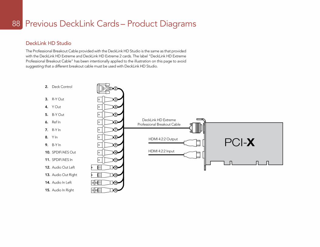
Previous DeckLink Cards – Product Diagrams88
DeckLink HD StudioThe Professional Breakout Cable provided with the DeckLink HD Studio is the same as that provided with the DeckLink HD Extreme and DeckLink HD Extreme 2 cards. The label “DeckLink HD Extreme Professional Breakout Cable” has been intentionally applied to the illustration on this page to avoid suggesting that a different breakout cable must be used with DeckLink HD Studio.
DeckLink HD Extreme Professional Breakout Cable
23
45
67
89
1011
1213
1415
2
3
4
5
6
7
8
9
10
11
12
13
14
15
2. Deck Control
3. R-Y Out
4. Y Out
5. B-Y Out
6. Ref In
7. R-Y In
8. Y In
9. B-Y In
10. SPDIF/AES Out
11. SPDIF/AES In
12. Audio Out Left
13. Audio Out Right
14. Audio In Left
15. Audio In Right
HDMI 4:2:2 Output
HDMI 4:2:2 Input
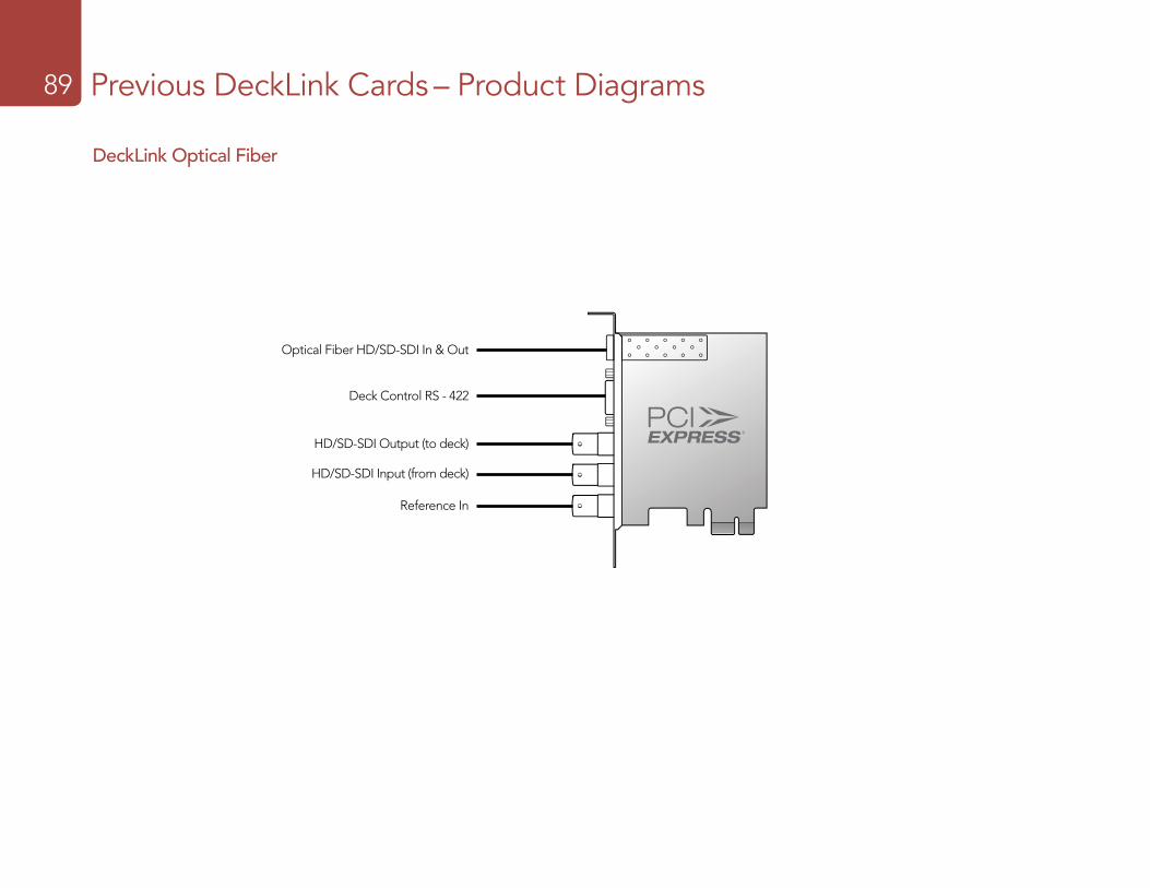
Previous DeckLink Cards – Product Diagrams89
DeckLink Optical Fiber
Optical Fiber HD/SD-SDI In & Out
HD/SD-SDI Output (to deck)
HD/SD-SDI Input (from deck)
Reference In
Deck Control RS - 422
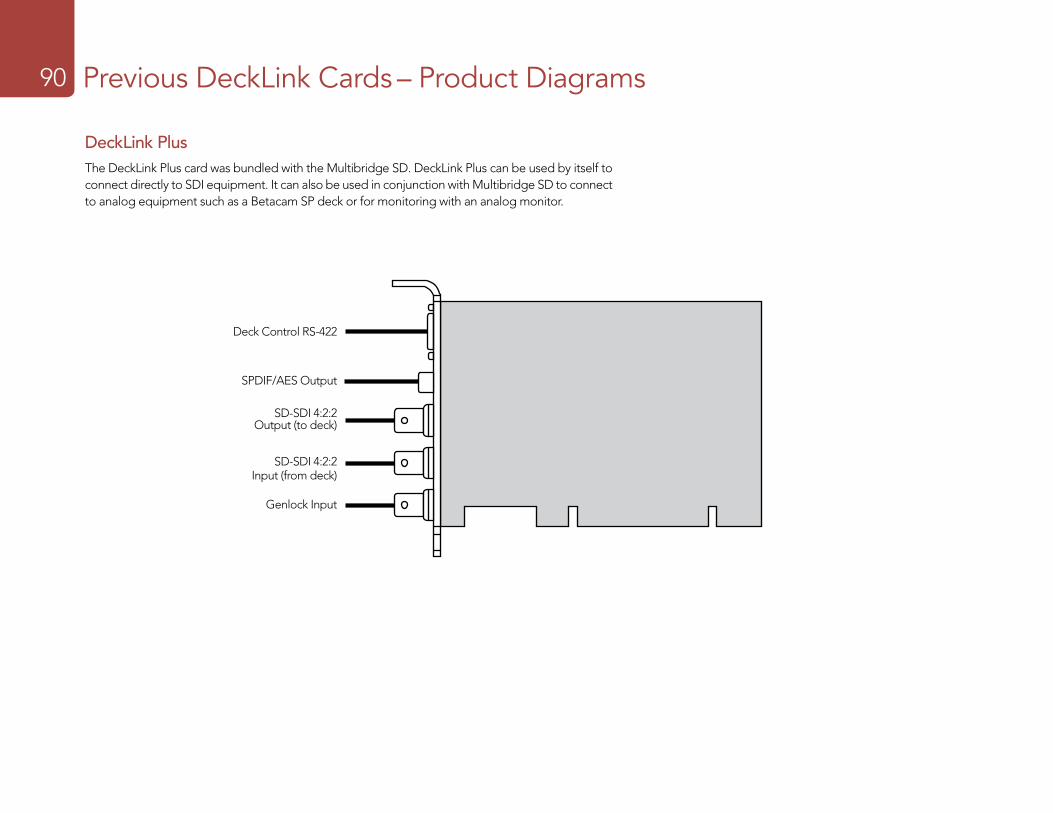
Previous DeckLink Cards – Product Diagrams90
DeckLink PlusThe DeckLink Plus card was bundled with the Multibridge SD. DeckLink Plus can be used by itself to connect directly to SDI equipment. It can also be used in conjunction with Multibridge SD to connect to analog equipment such as a Betacam SP deck or for monitoring with an analog monitor.
Deck Control RS-422
SPDIF/AES Output
SD-SDI 4:2:2Output (to deck)
SD-SDI 4:2:2Input (from deck)
Genlock Input
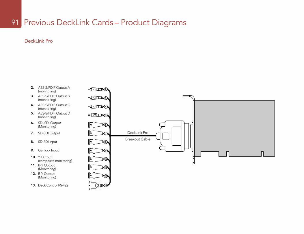
Previous DeckLink Cards – Product Diagrams91
DeckLink Pro
7ft break-out cable
R-Y Output (monitoring)B-Y Output (monitoring)Y Output (composite monitoring)SD-SDI Output (monitoring)
Genlock Input
Deck Control RS-422
SPDIF Output(monitoring D)
SPDIF Output(monitoring C)
SPDIF Output(monitoring B)
SPDIF Output(monitoring A)
SD-SDI Output (to deck)SD-SDI Input (from deck)
8
9
10
11
12
13
DeckLink Pro
Breakout Cable
2
3
4
6
5
7
8. SD-SDI Input
7. SD-SDI Output
10. Y Output (composite monitoring)
2. AES-S/PDIF Output A (monitoring)3. AES-S/PDIF Output B (monitoring)
4. AES-S/PDIF Output C (monitoring)5. AES-S/PDIF Output D (monitoring)
6. SDI-SDI Output (Monitoring)
11. B-Y Output (Monitoring)12. R-Y Output (Monitoring)
9. Genlock Input
13. Deck Control RS-422
Previous DeckLink Cards – Product Diagrams92
DeckLink SP
15. Deck Control RS-422
7ft break-out cable
R-Y Input
B-Y Input
Y Input
R-Y Output
Genlock Input
Deck Control RS-422
SD-SDI Output(monitoring)
SPDIF/AES Output(monitoring)
(L) Audio Input (balanced analog)
(L) Audio Output (balanced analog)
B-Y Output
Y Output(composite monitoring)
(R) Audio Input (balanced analog)
(R) Audio Output (balanced analog) 2
3
4
5
7
6
8
9
10
11
12
13
14
2. AES-S/PDIF Output (monitoring)
3. (L) Audio Output (balanced analog)
6. (R) Audio Input (balanced analog)
9. R-Y Input
4. (R) Audio Output (balanced analog)
7. Y Input
10. Y Output (composite monitoring)
5. (L) Audio Input (balanced analog)
8. B-Y Input
11. B-Y Output
12. R-Y Output
13. SD-SDI Output (Monitoring)
14. Genlock Input
DeckLink SP
Breakout Cable
15
Previous DeckLink Cards – Product Diagrams93
7ft break-out cable
R-Y Input
B-Y Input
Y Input
R-Y Output
Genlock Input
Deck Control RS-422
SD-SDI Output(monitoring)
SPDIF Output(monitoring)
(L) Audio Input (balanced analog)
(L) Audio Output (balanced analog)
B-Y Output
Y Output(composite monitoring)
(R) Audio Input (balanced analog)
(R) Audio Output (balanced analog) 2
3
4
5
7
6
8
9
10
11
12
13
14
2. AES-S/PDIF Output (monitoring)3. (L) Audio Output (balanced analog)
6. (R) Audio Input (balanced analog)
9. R-Y Input
4. (R) Audio Output (balanced analog)
7. Y Input
10. Y Output (composite monitoring)
5. (L) Audio Input (balanced analog)
8. B-Y Input
11. B-Y Output
12. R-Y Output
13. SD-SDI Output (Monitoring)
14. Genlock Input
15. Deck Control RS-422
DeckLink SP
Breakout Cable
15
DeckLink SP PCIe
Previous DeckLink Cards – Product Diagrams94
DeckLink Studio
DeckLink Studio Breakout Cable
HD/SD-SDI Output
HD/SD-SDI Input
19
18
17
16
15
14
13
12
11
10
09
08
07
06
05
04
03
02
20
21
22
23
24
2. RS-422 Deck Control
3. R-Y Out
4. Y Out
5. B-Y Out
6. Ref In
7. R-Y In
8. Y In
9. B-Y In
10. AES / EBU Out CH1&2
11. AES / EBU In CH1&2
12. Analog Audio Out 1
16. Analog Audio In 3
14. Analog Audio In 1
18. Analog Audio Out 3 or AES/EBU CH3&4 Out
20. Composite In
22. S-Video In
13. Analog Audio Out 2
17. Analog Audio In 4
15. Analog Audio In 2
19. Analog Audio Out 4 or AES/EBU CH5&6 Out
21. Composite Out
23. S-Video Out
24. Standard Definition SDI Out

Capture19 Master19
Mastering to tape operations are performed in the Master view (ctrl-3, cmd-3)Media Express can use DeckLink or Multibridge to master to tape via Insert or Assemble editing.
Only clips that are selected in the Media List will be output to tape. If no clips are selected, it is assumed that the entire Media List will be output.
To master to tape, click on the Master view and ensure RS-422 device control is connected.
Enter the In and Out points of the tape by entering timecode into the respective text boxes, or by cueing the tape to the desired point via the transport control and then clicking the Mark In button, or use the shortcut key i.
If no Out point is entered, Media Express will set the duration of the edit to the total length of the clips in the Media List. If an out point is defined, Media Express will leave edit mode once the Out point timecode is reached, even if some clips have not been output.
The Insert and Assemble buttons are mutually exclusive and only one mode can be selected at a time. This determines which mode Media Express will use to master to tape. Select the Insert or Assemble button as required.
The Preview and Master buttons are also mutually exclusive. Clicking on either button will instruct Media Express to proceed with the specified operation. Preview mode mimics the edit process but does not record to tape. This mode allows one to check the edit point is correct.
Preview edit operations should always be checked on monitors connected directly to the output of the deck to view the preceding video already on tape, the new video and the following video already on tape.
If Record Inhibit is enabled either on the deck or on the tape in the deck, Media Express will display a dialog box, when the user clicks on the Master button, informing the user that Record Inhibit is enabled. Check the deck/tape and disable Record Inhibit before trying again.
Before mastering, the audio channels to be put to tape can be selected on or off via the track enable/disable buttons. The Video track cannot be turned off.

Related Documents