Numerical modeling of effect of polyurea on response of steel plates to impulsive loads in direct pressure-pulse experiments M.R. Amini, J. Simon, S. Nemat-Nasser * Center of Excellence for Advanced Materials, Department of Mechanical and Aerospace Engineering, University of California, San Diego, La Jolla, CA 92093-0416, USA article info Article history: Received 25 September 2009 Keywords: Impulsive pressure loads Direct pressure-pulse experiments Physics-based constitutive models Finite-element analysis Fluid-structure interaction Metal-polymer bilayer composites abstract Results of computational modeling and simulation of the response of monolithic DH-36 steel plates and bilayer steel-polyurea plates to impulsive loads in direct pressure-pulse experi- ments (Amini et al., in press-b), are presented and discussed. The corresponding experiments and their results are presented in an accompanying paper (Amini et al., 2010). The entire experimental setup is modeled using the finite-element code, LS-DYNA, in which a phys- ics-based temperature- and strain rate-sensitive constitutive model for DH-36 steel, devel- oped by Nemat-Nasser and Guo (2003b) and an experimentally supported temperature-, rate-, and pressure-sensitive constitutive model for polyurea, developed and incorporated into the computer code, LS-DYNA, by Amirkhizi et al. (2006), have been implemented. The transient response of the plates under impulsive pressure loads is studied, focusing on the effects of the relative position of polyurea with respect to the loading direction, the thick- ness of the polyurea layer, and the polyurea-steel interface bonding strength. The numerical simulations of the entire experiment support the experimentally observed results reported by Amini et al. (2010). Ó 2009 Elsevier Ltd. All rights reserved. 1. Introduction It has been shown by direct pressure-pulse experiments that the failure resistance of steel plates to impulsive pres- sure loads can be enhanced by spray casting a layer of polyurea on the back face of the plates (Amini et al., this is- sue). Here we provide numerical simulations of those experiments, using the finite-element code, LS-DYNA. The aim is to understand the transient response and the under- pinning mechanisms of deformation and failure of the plates under pressure-pulse loading conditions. A comprehensive review of various theoretical and numerical studies of the deformation of thin metal plates subjected to impulsive loads is given by Nurick and Martin (1989) and also Jones (1989). Zhu (1996) performed a numerical investigation to understand the transient behavior of thin plates under explosive loads and com- pared his predictions with the experimental results. Lee and Wierzbicki (2005a,b) employed commercially avail- able codes, PAM-CRASH and ABAQUS, to model various as- pects of transient deformation and fracture of thin plates under localized impulsive loads. Yuen and Nurick (2005) used ABAQUS to predict the response of quadrangular stiff- ened plates subjected to uniform blast loads and compared their predictions with experimental results. Bahei-El-Din et al. (2006) have studied the effect of interlayer elasto- meric polyurea on the dynamic response of sandwich plates under dynamic loads. It has been shown by reverse impact and direct pressure-pulse experiments that the fail- ure resistance of steel plates to impulsive pressure loads can be enhanced by spray casting a layer of polyurea on the back face of the plates (Amini et al. 2010a,b). There are few numerical studies on the effect of poly- urea coating on the performance of steel plates. Amini 0167-6636/$ - see front matter Ó 2009 Elsevier Ltd. All rights reserved. doi:10.1016/j.mechmat.2009.09.009 * Corresponding author. Address: University of California at San Diego, Mechanical and Aerospace Engineering, 4909 Engineering Building 1, 9500 Gilman Drive, La Jolla, CA 92093-0416, USA. Tel.: +1 858 534 4914. E-mail address: [email protected] (S. Nemat-Nasser). Mechanics of Materials 42 (2010) 615–627 Contents lists available at ScienceDirect Mechanics of Materials journal homepage: www.elsevier.com/locate/mechmat

Welcome message from author
This document is posted to help you gain knowledge. Please leave a comment to let me know what you think about it! Share it to your friends and learn new things together.
Transcript

Mechanics of Materials 42 (2010) 615–627
Contents lists available at ScienceDirect
Mechanics of Materials
journal homepage: www.elsevier .com/locate /mechmat
Numerical modeling of effect of polyurea on response of steel platesto impulsive loads in direct pressure-pulse experiments
M.R. Amini, J. Simon, S. Nemat-Nasser *
Center of Excellence for Advanced Materials, Department of Mechanical and Aerospace Engineering, University of California, SanDiego, La Jolla, CA 92093-0416, USA
a r t i c l e i n f o a b s t r a c t
Article history:Received 25 September 2009
Keywords:Impulsive pressure loadsDirect pressure-pulse experimentsPhysics-based constitutive modelsFinite-element analysisFluid-structure interactionMetal-polymer bilayer composites
0167-6636/$ - see front matter � 2009 Elsevier Ltddoi:10.1016/j.mechmat.2009.09.009
* Corresponding author. Address: University of CaMechanical and Aerospace Engineering, 4909 Eng9500 Gilman Drive, La Jolla, CA 92093-0416, USA. T
E-mail address: [email protected] (S. Nemat-Nasser).
Results of computational modeling and simulation of the response of monolithic DH-36 steelplates and bilayer steel-polyurea plates to impulsive loads in direct pressure-pulse experi-ments (Amini et al., in press-b), are presented and discussed. The corresponding experimentsand their results are presented in an accompanying paper (Amini et al., 2010). The entireexperimental setup is modeled using the finite-element code, LS-DYNA, in which a phys-ics-based temperature- and strain rate-sensitive constitutive model for DH-36 steel, devel-oped by Nemat-Nasser and Guo (2003b) and an experimentally supported temperature-,rate-, and pressure-sensitive constitutive model for polyurea, developed and incorporatedinto the computer code, LS-DYNA, by Amirkhizi et al. (2006), have been implemented.
The transient response of the plates under impulsive pressure loads is studied, focusing onthe effects of the relative position of polyurea with respect to the loading direction, the thick-ness of the polyurea layer, and the polyurea-steel interface bonding strength. The numericalsimulations of the entire experiment support the experimentally observed results reportedby Amini et al. (2010).
� 2009 Elsevier Ltd. All rights reserved.
1. Introduction
It has been shown by direct pressure-pulse experimentsthat the failure resistance of steel plates to impulsive pres-sure loads can be enhanced by spray casting a layer ofpolyurea on the back face of the plates (Amini et al., this is-sue). Here we provide numerical simulations of thoseexperiments, using the finite-element code, LS-DYNA. Theaim is to understand the transient response and the under-pinning mechanisms of deformation and failure of theplates under pressure-pulse loading conditions.
A comprehensive review of various theoretical andnumerical studies of the deformation of thin metal platessubjected to impulsive loads is given by Nurick and Martin(1989) and also Jones (1989). Zhu (1996) performed a
. All rights reserved.
lifornia at San Diego,ineering Building 1,
el.: +1 858 534 4914.
numerical investigation to understand the transientbehavior of thin plates under explosive loads and com-pared his predictions with the experimental results. Leeand Wierzbicki (2005a,b) employed commercially avail-able codes, PAM-CRASH and ABAQUS, to model various as-pects of transient deformation and fracture of thin platesunder localized impulsive loads. Yuen and Nurick (2005)used ABAQUS to predict the response of quadrangular stiff-ened plates subjected to uniform blast loads and comparedtheir predictions with experimental results. Bahei-El-Dinet al. (2006) have studied the effect of interlayer elasto-meric polyurea on the dynamic response of sandwichplates under dynamic loads. It has been shown by reverseimpact and direct pressure-pulse experiments that the fail-ure resistance of steel plates to impulsive pressure loadscan be enhanced by spray casting a layer of polyurea onthe back face of the plates (Amini et al. 2010a,b).
There are few numerical studies on the effect of poly-urea coating on the performance of steel plates. Amini

616 M.R. Amini et al. / Mechanics of Materials 42 (2010) 615–627
et al. (2010a) numerically studied the deformation andfailure of monolithic steel and bilayer steel-polyurea platesunder reverse impulsive loads. In these experiments, a hol-low cylindrical projectile carries the plate and impacts on asoft-polyurethane layer resting on a steel plate within aconfining steel cylinder. Because of the nature of the exper-imental setup, the plate failure cannot be photographed.Also, for the same reason, water cannot be used as theloading medium.
Comparing the numerical prediction with the reverseimpact experimental results, they found that the presenceof polyurea coating on the impact face (front face) canaggravate the shock loading and enhance fracturing ofthe steel plates, but it can mitigate failure if the polyureais cast on the face opposite to the impact side (back face).Under pressure, the stiffness of the polyurea layer in-creases substantially, attaining a better impedance matchwith the steel and thereby increasing the energy that istransferred to the plate when it is cast on the front face.On the other hand, when polyurea is cast onto the backface, the initial shock loads the steel plate first and thena part of the shock is captured and dissipated by the poly-urea layer because of its viscoelasticity. Polyurea can alsoincrease the effective tangent modulus of the bilayer andthus delay the onset of the necking instability, if the steelplate does not fail during the initial shock loading andthe polyurea coating remains bonded to the steel. Xueand Hutchinson (2007) studied the neck retardation underbiaxial stretching of bilayer elastomer-metal plates. Theyshow that a substantial increase in the necking limit andthe consequent energy absorption can be achieved in me-tal-elastomer bilayers compared to monolithic steel platesof the same area density.
In the present paper, we perform a full-scale finite-ele-ment modeling of the direct pressure-pulse impact exper-iments reported by Amini et al. (2010). The significance ofthese finite-element models is that they allow: (1) to studythe transient response of the plate; (2) to incorporate com-plex temperature-, pressure-, and rate- dependent consti-tutive models in the finite-element code; and (3) toconduct parametric studies to gain insight into the dy-namic response of the plates. The effect of the relative po-sition of the polyurea layer with respect to the loadingdirection, the effect of the thickness of the polyurea layer,and finally, the effect of the polyurea-steel interface bond-ing strength on the dynamic deformation and fracturing ofthe steel plates are also studied numerically.
2. Finite-element modeling procedure
In this section, the direct pressure-pulse experimentalsetup is briefly mentioned and the corresponding finite-element model is detailed.
2.1. Direct impact-induced pressure-pulse experimental setup
In the direct impact-induced pressure-pulse experi-ments (Amini et al., 2010), performed at UCSD/CEAM’sgas gun facilities, a projectile is propelled by a gas gun ata controlled velocity toward an impedance-matched piston
that loads a confined soft polyurethane or water medium.The loading medium (water or polyurethane) in turn loadsthe plate that rests on a cylindrical step (support) within aconfining cylinder. The load is, directly or through a steelbar/sleeve system, transferred from the support to a 3-in.Hopkinson output bar. For some cases the transmittedforce is measured by the strain gauges that are mountedon the bar. The detailed description of the experimentalsetup and the results are presented in the accompanyingpaper (Amini et al., 2010).
2.2. Finite-element model
The direct impact-induced pressure-pulse experimentsare modeled in full-scale, using the commercially availablefinite-element code, LS-DYNA. Two views of the three-dimensional model used in the finite-element simulationare shown in Fig. 1. The simulation begins at the stage whenthe aluminum projectile of a uniform initial velocity, V0, im-pacts a cylinder that loads a medium (polyurethane orwater) which rests against the sample. The interface be-tween the projectile and the cylinder is modeled as friction-less contact. The projectile mass is 832 g or 1682 gdepending on the experimental conditions. To model theconfinement of the loading medium (nearly incompress-ible) under pressure, the side nodes of the loading mediumthat are in contact with the confining cylinder are restrictedto allow only for sliding in the longitudinal (Z) direction. Theloading medium in turn loads the sample that rests against ahollow cylindrical support. The cylindrical support nodes incontact with the output Hopkinson bar are fixed by requir-ing that the radial, tangential, and longitudinal displace-ment components be zero, i.e., ur = ut = uz = 0. To increasethe stability and the accuracy of the finite-element model,an Arbitrary Lagrangian-Eulerian (ALE) formulation is usedin these calculations. The loading medium (water or poly-urethane) is modeled with one-point ALE multi-materialbrick elements and the remaining components are modeledusing a Lagrangian formulation. The simulation uses thecontact algorithm option of LS-DYNA, entitled CON-STRAINED_LAGRANGE_IN_SOLID to model the interactionsof the Lagrangian and Eulerian domains; see Hallquist(1998) for more details. The CONTACT_AUTOMATIC_SUR-FACE_TO_SURFACE contact algorithm of LS-DYNA is em-ployed to model the interaction between the plate and thecylindrical support. In the modeling, all steel plates have adiameter Dst = 76.00 mm, gauge section thickness t =1.02 mm, rim thickness trim = 4.79 mm, and rim widthwrim = 9.52 mm; see Fig. 2. The plate is modeled usingeight-node brick elements with one integration point,whereas the rim (outer part of the plate) is modeled usingthe fully integrated quadratic eight-node brick elementswith nodal rotation to avoid the undesired hourglass energy.There are 56 elements along the diameter and three ele-ments per millimeter through the thickness of the plate.Fig. 3 presents the spatial discretization of the three sampleconfigurations: the monolithic steel plate (left), the bilayerplate with polyurea on the dish side/back face (middle),and the bilayer plate with polyurea on the flat side/front face(right). The polyurea on the flat side is modeled in two sep-arate parts, the outer portion and the central portion, so the

Fig. 1. Finite-element model of direct impact-induced pressure-pulse experiment, showing: the aluminum projectile of velocity V0, impacting the loadingtarget (polyurethane or water) that rests on the sample (top: oblique view; bottom: side view).
M.R. Amini et al. / Mechanics of Materials 42 (2010) 615–627 617
stretch enhancement in the central region of the plateswould be similar for the two bilayer plate configurations.The 7075 aluminum projectile is modeled by fully inte-grated selectively reduced eight-node brick elements. TheFlanagan-Belytschko integration hourglass-control algo-rithm is used to damp out the overall zero-energy modes.
3. Material constitutive models
The material constitutive models used for DH-36 steel,polyurea, water, and polyurethane are discussed in thissection.
3.1. DH-36 steel
The physics-based (PB) model, proposed by Nemat-Nasserand Guo (2003b) for DH-36 steel, is implemented into
LS-DYNA through a user-defined material subroutine in FOR-TRAN. This PB model expresses the flow stress (effectivestress), s, as a function of temperature, T, effective plasticstrain, c, and effective plastic strain rate, _c, as
s¼70þ750c0:25þ1500 1� �6:6�10�5T ln_c
2�1010
� �� �12
( )32
;
ð1Þ
for T 6 Tc, where the stress is in MPa and T is in degreesKelvin. On the other hand, for T P Tc, we use
s ¼ 70þ 750c0:25; ð2Þ
where Tc ¼ �6:6� 10�5 ln_c
2� 1010
� �� ��1
:

Fig. 2. Oblique view of the discretized monolithic plate of outer diameter Dst = 76.00 mm, rim thickness of trim = 4.79 mm, and rim width of wrim = 9.52 mm.
Fig. 3. Oblique view of discretized plates: (a) monolithic steel plate (left), (b) bilayer plate with polyurea on the dish side (middle), and (c) bilayer plate withpolyurea on the flat side (right).
0.0 0.2 0.4 0.6 0.8 1.00
200
400
600
800
1000
1200
6500/s Exp. Model
4000/s Exp. Model
3000/s Exp. Model
true
str
ess
(MPa
)
true strain
Fig. 4. Comparison of the PB-model predictions with the experimental results at indicated strain rates and initial room temperature.
618 M.R. Amini et al. / Mechanics of Materials 42 (2010) 615–627
Fig. 4 compares three experimentally obtained stress-strain curves with their corresponding PB-modelpredictions at the indicated strain rates. As is seen, excel-lent correlation between the experimental data and themodel predictions is obtained.
3.2. Polyurea
An experimentally based viscoelastic constitutive mod-el, including pressure and temperature sensitivity, intro-duced and implemented into LS-DYNA by Amirkhizi et al.

M.R. Amini et al. / Mechanics of Materials 42 (2010) 615–627 619
(2006), has been employed for modeling the polyurea. Forbulk deformations, this model assumes that the trace ofthe Cauchy stress tensor, r, is given by,
trðrÞ ¼ 3kln J
J; ð3Þ
where J = det F is the Jacobian of the deformation, and k is atemperature-dependent bulk modulus, assumed to be gi-ven by,
kðTÞ ¼ k Tref� �
þm T � Tref� �
; ð4Þ
with Tref being the reference (room) temperature. A hered-itary integral is employed to express the deviatoric part ofthe stress,
r0ðtÞ ¼Z t
0
TðsÞTref
2Gref ðnðtÞ � nðsÞÞD0ðsÞds; ð5Þ
where D0 is the deviatoric part of the deformation rate ten-sor, and n is a pressure sensitive reduced time, related tothe actual time, t, through the following equation:
nðtÞ ¼Z t
0
dsaTðsÞ
; ð6Þ
aT ¼ 10AðT�Ctp P�Tref ÞBþT�CtpP�Tref : ð7Þ
Here, P is the pressure and Ctp is a time-pressurecoefficient.
In this study the four-term (n = 4) Prony series option ofthe Amirkhizi et al. (2006) code is used to define the relax-ation function,
Gref ðtÞ ¼ G1 1þXn
i¼1
pie�t=qi
!: ð8Þ
The local temperature is calculated using
@T@t¼ 1
Cv
@Wd
@t; ð9Þ
where Cv is the heat capacity at constant volume, and Wd isthe dissipated work, both measured per unit original vol-ume. The right-hand side of this equation is expressed as,
@Wd
@t¼ G1
TðtÞTref
Xn
i¼0
pi
qiei
dðtÞ : eidðtÞ; ð10Þ
where,
eidðtÞ ¼
Z t
0e�ðnðtÞ�nðsÞÞ=qi D0ðsÞds: ð11Þ
The numerical values of the parameters used in this modelare listed in Table 1.
Table 1Values of the constitutive parameters used in the polyurea model.
Tref (K) A B (K) Ctp (K/GPa) Cv (J/mm3 K)
273 �10 107.54 7.2 1.977 � 10�3
p1 p2 p3 p4 q1 (ms
0.8458 1.686 3.594 4.342 463.4
3.3. Water and polyurethane
An elastic fluid model, entitled MAT_ELASTIC_FLUID, ofLS-DYNA is used to model water. In this model, the pres-sure rate, _p, is given by,
_p ¼ �K _eii; ð12Þ
where K = 2202 MPa is the bulk modulus and _eij are thestrain rate components. A tensor viscosity is used whichacts only on the deviatoric stress, r0ij, given in terms ofthe damping coefficient as:
r0ij ¼ VC � DL � aq _e0ij; ð13Þ
where VC = 0.1 is the viscosity coefficient, DL is a charac-teristic element length calculated by the software, a isthe fluid bulk sound speed, q = 1.00 g/cm3 is the density,and _e0ij is the deviatoric strain rate component.
The polyurethane is modeled using a Moony-Rivlin rub-ber constitutive model with shear modulus G = 16 MPa andPoisson’s ratio m = 0.495, the density being q = 1.19 g/cm3;for more details, see LS-DYNA theoretical manual (Hall-quist, 1998).
4. Comparison of numerical predictions andexperimental results
4.1. Calculating the principal stretches
To validate the finite-element models, the variation ofthe three principal stretches along the radial line for sev-eral plates is compared with their corresponding finite-ele-ment model predictions. To this end, the deformed platesare sectioned along their diametral plane and scanned.The scanned cross section of the deformed plate is discret-ized into a number of trapezoidal elements. Since the plas-tic deformation of steel can be considered nearly isochoric,the volume of the ring, generated by the rotation of trape-zoidal elements along the center line of the model, is thesame in the deformed and undeformed states. Using thisfact and the known constant thickness of the undeformedsteel plate, one can calculate the length of the central ringin the radial direction in the undeformed state. By repeat-ing this calculation and marching from the center line to-wards the rim of the plate, and given the volume of eachring, its constant thickness, and its distance from the cen-ter, the radial length of each element in the radial directionand the location of the next farther element can be ob-tained. The deformation gradient of each element can thenbe calculated; see Amini et al. (2010a) for details of themeasurements and analysis. After calculating the deforma-tion gradient of each element, a MATLAB program is used
CTE (K) m (GPa/K) n kref (GPa) G1 (GPa)
2 � 10�4 �0.015 4 4.948 0.0224
) q2 (ms) q3 (ms) q4 (ms)
0.06407 1.163 � 10�4 7.321 � 10�7
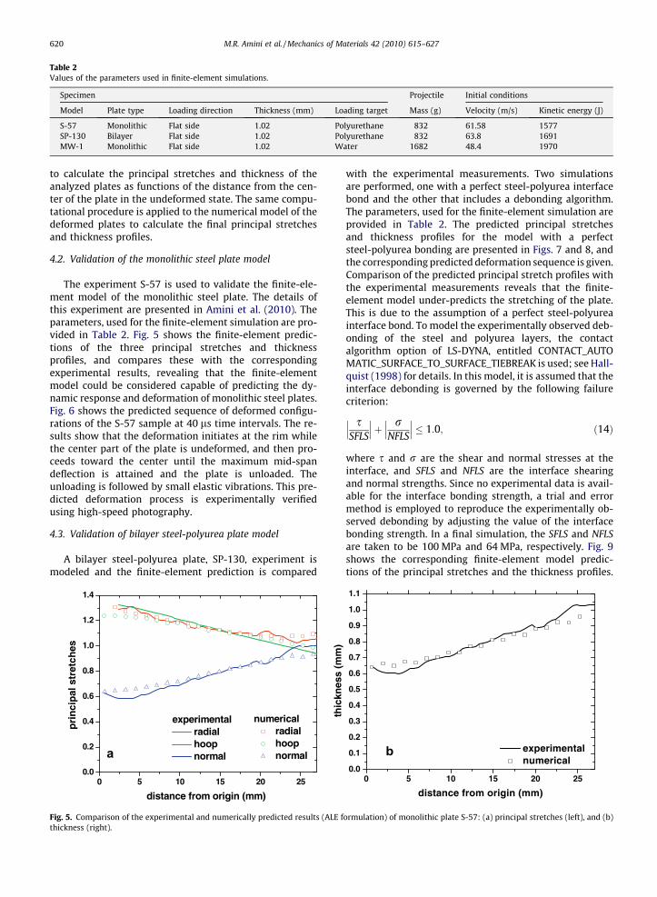
Table 2Values of the parameters used in finite-element simulations.
Specimen Projectile Initial conditions
Model Plate type Loading direction Thickness (mm) Loading target Mass (g) Velocity (m/s) Kinetic energy (J)
S-57 Monolithic Flat side 1.02 Polyurethane 832 61.58 1577SP-130 Bilayer Flat side 1.02 Polyurethane 832 63.8 1691MW-1 Monolithic Flat side 1.02 Water 1682 48.4 1970
620 M.R. Amini et al. / Mechanics of Materials 42 (2010) 615–627
to calculate the principal stretches and thickness of theanalyzed plates as functions of the distance from the cen-ter of the plate in the undeformed state. The same compu-tational procedure is applied to the numerical model of thedeformed plates to calculate the final principal stretchesand thickness profiles.
4.2. Validation of the monolithic steel plate model
The experiment S-57 is used to validate the finite-ele-ment model of the monolithic steel plate. The details ofthis experiment are presented in Amini et al. (2010). Theparameters, used for the finite-element simulation are pro-vided in Table 2. Fig. 5 shows the finite-element predic-tions of the three principal stretches and thicknessprofiles, and compares these with the correspondingexperimental results, revealing that the finite-elementmodel could be considered capable of predicting the dy-namic response and deformation of monolithic steel plates.Fig. 6 shows the predicted sequence of deformed configu-rations of the S-57 sample at 40 ls time intervals. The re-sults show that the deformation initiates at the rim whilethe center part of the plate is undeformed, and then pro-ceeds toward the center until the maximum mid-spandeflection is attained and the plate is unloaded. Theunloading is followed by small elastic vibrations. This pre-dicted deformation process is experimentally verifiedusing high-speed photography.
4.3. Validation of bilayer steel-polyurea plate model
A bilayer steel-polyurea plate, SP-130, experiment ismodeled and the finite-element prediction is compared
0 5 10 15 20 250.0
0.2
0.4
0.6
0.8
1.0
1.2
1.4
numerical radial hoop normal
experimental radial hoop normal
pri
nci
pal
str
etch
es
distance from origin (mm)
thic
knes
s (m
m)
a
Fig. 5. Comparison of the experimental and numerically predicted results (ALE fthickness (right).
with the experimental measurements. Two simulationsare performed, one with a perfect steel-polyurea interfacebond and the other that includes a debonding algorithm.The parameters, used for the finite-element simulation areprovided in Table 2. The predicted principal stretchesand thickness profiles for the model with a perfectsteel-polyurea bonding are presented in Figs. 7 and 8, andthe corresponding predicted deformation sequence is given.Comparison of the predicted principal stretch profiles withthe experimental measurements reveals that the finite-element model under-predicts the stretching of the plate.This is due to the assumption of a perfect steel-polyureainterface bond. To model the experimentally observed deb-onding of the steel and polyurea layers, the contactalgorithm option of LS-DYNA, entitled CONTACT_AUTOMATIC_SURFACE_TO_SURFACE_TIEBREAK is used; see Hall-quist (1998) for details. In this model, it is assumed that theinterface debonding is governed by the following failurecriterion:
sSFLS
��� ���þ rNFLS
��� ��� � 1:0; ð14Þ
where s and r are the shear and normal stresses at theinterface, and SFLS and NFLS are the interface shearingand normal strengths. Since no experimental data is avail-able for the interface bonding strength, a trial and errormethod is employed to reproduce the experimentally ob-served debonding by adjusting the value of the interfacebonding strength. In a final simulation, the SFLS and NFLSare taken to be 100 MPa and 64 MPa, respectively. Fig. 9shows the corresponding finite-element model predic-tions of the principal stretches and the thickness profiles.
0 5 10 15 20 250.0
0.1
0.2
0.3
0.4
0.5
0.6
0.7
0.8
0.9
1.0
1.1
experimental numerical
distance from origin (mm)
b
ormulation) of monolithic plate S-57: (a) principal stretches (left), and (b)

Fig. 6. Sequence of the side view of the numerical estimate of the deflection of S-57 monolithic steel plate at 40 ms time intervals; note that a quarter of themodel is masked to provide a better view of the thickness profile.
M.R. Amini et al. / Mechanics of Materials 42 (2010) 615–627 621
The comparison of the experimental results and thenumerical predictions, presented in Fig. 9, shows thatexcellent correlation between experimental and numeri-cal results can be obtained by introducing the debondingalgorithm with suitable interface strength values. Fig. 10shows a sequence of predicated deformed configurationsof the SP-130 sample at 40 ls time intervals, showing acomplete debonding of the steel and polyurea layers.
0 5 10 15 20 250.0
0.2
0.4
0.6
0.8
1.0
1.2
1.4
numerical radial hoop normal
experimental radial hoop normal
prin
cipa
l str
etch
es
distance from origin (mm)
a
Fig. 7. Comparison of the experimental and numerically predicted results (SP-13initial distance from the center of the plate for SFLS =1.
The debonding initiates from the edge and propagates to-wards the center.
4.4. Transmitted force: finite-element vs. experiment
As explained in Section 2 of this paper, the force trans-mitted through the plate is measured by the strain gaugesthat are mounted on the output bar, for a set of selected
0 5 10 15 20 250.0
0.2
0.4
0.6
0.8
1.0
1.2
experimental numerical
thic
knes
s (m
m)
distance from origin (mm)
b
0): (a) principal stretches (left), and (b) thickness (right) as functions of the

Fig. 8. Sequence of the side view of the numerical estimate of the deflection of SP-130 bilayer plate at 40 ms time intervals with SFLS =1; note that aquarter of the model is masked to obtain a better view of the profile.
622 M.R. Amini et al. / Mechanics of Materials 42 (2010) 615–627
experiments. The detailed description of the experimentalconditions is presented in Amini et al. (2010). To furtherassess the finite-element models, the forces measured forsamples S-117 and S-119 are compared with the corre-sponding finite-element results. The parameters used forthe finite-element simulation (MW-1) are provided inTable 2. The results are shown in Fig. 11, revealing thatthe model does predict the four experimentally observedstages of loading: shock loading (pre-cavitation), cavita-tion, post-cavitation loading, and unloading. The predictedtransmitted force has an excellent correlation with theexperimental measurements of the pulse shape, its dura-tion, and its amplitude.
5. Parametric study results
This section gives the results of a parametric study ofthe bilayer plates under impulsive pressure loads. Themain parameters that are investigated are:
� the relative position of the polyurea layer with respectto the loading direction,
� the strength of the polyurea-steel interface bonding, and� the effect of the thickness of the polyurea layer.
The accumulated effective plastic strains of the ele-ments within a 4 mm (original) distance from the centerof the steel plates are averaged and used to assess the re-sponse of the plates, since it has been observed experimen-tally that failure initiates within the central region of thesteel plates (Amini et al., 2010).
The projectile used in the finite-element models re-ported in this section has a mass of 1682 g and an initialvelocity of 48.4 m/s that provides the same initial kineticenergy for all the modeled samples. All the steel platemodels have a gauge section thickness of 1.02 mm andare loaded through a polyurethane medium. The detailsof the finite-element model parameters are given inTable 3.

0 5 10 15 20 250.0
0.2
0.4
0.6
0.8
1.0
1.2
1.4
numerical radial hoop normal
experimental radial hoop normal
prin
cipa
l str
etch
es
distance from origin (mm)0 5 10 15 20 25
0.0
0.2
0.4
0.6
0.8
1.0
1.2
experimental numerical
thic
knes
s (m
m)
distance from origin (mm)
a b
Fig. 9. Comparison of the experimental and numerically predicted results (SP-130): (a) principal stretches (left), and (b) thickness (right) as functions of theinitial distance from the center of the plate for SFLS = 100 MPa, NSFS = 64 MPa.
M.R. Amini et al. / Mechanics of Materials 42 (2010) 615–627 623
5.1. Effect of relative position of polyurea layer
To study the effect of the relative position of polyurea,three simulations are performed: a monolithic steel plate(M1), a bilayer plate with the polyurea layer on the impactreceiving side, front face (F3), and a bilayer plate with thepolyurea layer on the back face (B3). A perfect bond be-tween the polyurea and steel is assumed for the bilayer
Fig. 10. Sequence of the side view of the numerical estimate of the deflectionNSFS = 64 MPa; note that a quarter of the model is masked to present a better v
plate models. The computed average effective plastic strainhistories of the three simulations are presented in Fig. 12.
The effective plastic strain history curve of the mono-lithic plate, M1, clearly reveals the presence of the fourloading stages. The initial increase of the effective plasticstrain corresponds to the shock loading. The first plateauthat follows the initial rise indicates the cavitation stagewhere the pressure applied by the loading medium on
of SP-130 bilayer plate at 40 ms time intervals with SFLS = 100 MPa andiew of the profile.

0 100 200 300 400 5000
100
200
300
400fo
rce
(KN
)
time (µs)
experiment S-117 S-119
simulation MW-1
Fig. 11. Comparison of the experimentally measured force historiesrecorded by the strain gauges mounted on the 3-in. Hopkinson output barfor selected experiments and the finite-element prediction results.
0 100 200 300 400 5000.0
0.1
0.2
0.3
0.4
0.5
0.6
effe
ctiv
e pl
astic
str
ain
time (µs)
M1B1B2B3 F1 F2 F3
Fig. 12. Average effective plastic strain history of a monolithic plate (M1),three bilayer plates with different thicknesses of polyurea on the front face(F1, F2, F3) and three bilayer plates with different thicknesses of polyureaon the back face (B1, B2, B3). The polyurea layer thickness is 1.26 mm for F1and B1, 2.52 mm for F2 and B2, and 3.78 mm for F3 and B3.
624 M.R. Amini et al. / Mechanics of Materials 42 (2010) 615–627
the plate is released. At the end of the first plateau, thereis a second rise in the effective plastic strain which is dueto the post-cavitation loading. These stages can also bedetected in the effective plastic strain histories of the bi-layer plates. The comparison of the three curves showsthat the presence of the polyurea improves the overallperformance of the plate (if it remains bonded to thesteel layer). However, the presence of polyurea on thefront face aggravates the initial shock loading effect. Thiscan be explained by considering that, when polyurea ison the front face of a bilayer plate, it would transmit agreater amount of the impact energy to the steel platedue to a better impedance matching, in comparison towhen it is on the back face of the plate. High-strain rateimpact experiments performed on polyuera elastomersby Yi and Boyce (2004), Clifton and Jiao (2004), andNemat-Nasser et al. (2003a) revealed a significant stiffen-ing under high pressures and high-strain rates that pro-
Table 3Values of the parameters used in the finite-element simulations of the effect of relpolyurea layer, and the assumed polyurea-steel interface bonding strength.
Model Polyurea Strength on interface b
Normal (NFLS)
M1 N/A N/AB1 Back face 1B2 Back face 1B3 Back face 1F1 Front face 1F2 Front face 1F3 Front face 1B4 Back face 64B5 Back face 64F4 Front face 64F5 Front face 64B6 Back face 1F6 Front face 1B7 Back face 1F7 Front face 1B8 Back face 1
duce a closer match between the impedance of thesteel and that of polyurea. In addition, the viscoelasticdamping of the initial shock load transferred to polyurea,results in the better performance of the bilayer plate withpolyurea on the back face.
As the incident pressure-pulse reaches a material inter-face, a part of the pressure-pulse is transmitted into thesecond material and a part of it is reflected back. The ratioof the transmitted and the incident wave pressures can beapproximated using the following relation from elasticwave propagation theory in layered media:
PT
PI¼ 2qT VT
qT VT þ qIVI; ð15Þ
where, PT and PI are the transmitted and incident pres-sures, respectively; qT and qI are the densities and VT and
ative position of polyurea with respect to the loading direction, thickness of
ond (MPa) Polyurea thickness (mm)
Shear (SFLS)
N/A N/A1 1.261 2.521 3.781 1.261 2.521 3.78140 3.78100 3.78140 3.78100 3.78100 3.78100 3.78140 3.78140 3.78180 3.78

M.R. Amini et al. / Mechanics of Materials 42 (2010) 615–627 625
VI are the longitudinal wave velocities of the correspondinglayer. The density and longitudinal wave velocity of steel,polyurea, and water are presented in Table 4. It has beenshown before (Yi and Boyce, 2004; Clifton and Jiao 2004;Nemat-Nasser et al., 2003a) that the stiffness of polyureais highly pressure-dependent and can increase by ordersof magnitude with compression. Thus, the longitudinalwave velocity of the polyurea layer is calculated based ona plain-strain finite-element simulation. In the case thatpolyurea is on the back face, as the wave traveling in thewater arrives at the water-steel interface, the ratio of thepressure transmitted to steel to the incident pressure inthe water is 1.95. On the other hand, when the polyureais on the front face, as the wave traveling in the waterarrives at the water-polyurea interface, the ratio of thepressure transmitted to the polyurea to the incident pres-sure in the water is 1.66. Then, as this transmitted pres-sure-pulse reaches the polyurea-steel interface, the ratioof the pressure transmitted to the steel to the incidentpressure in the polyurea is 1.80. If the assumption of nodissipation of energy in the polyurea (in compression only)is valid, then the ratio of the pressure transmitted to thesteel to the initial incident pressure in water for the bilayerplate with the polyurea on the front face is 2.99 which isabout 53% greater than the corresponding value for the bi-layer plate with the polyurea on the back face. It should benoted that these calculations are based on one-dimen-sional elastic wave propagation theory and ignore thethree-dimensional effects. Nevertheless, they seem to cor-respond, at least qualitatively, with the experimentally ob-served results.
Xue and Hutchinson (2007) have shown by simulations,that the presence of the polyurea on either face wouldincrease the corresponding overall tangent modulus,thereby retarding the necking of the plate which has beenobserved to precede failure in thin DH-36 steel plates.However this applies only if the bilayer plate does not failduring the initial shock loading and the polyurea remainsbonded to the steel layer.
5.2. Effect of thickness of polyurea layer
A set of simulations is performed to study the effect ofthe polyurea layer thickness on the performance of the bi-layer plates. In these simulations the thicknesses of thepolyurea layer used for the simulations are 3.78 mm,2.52 mm, and 1.26 mm. The simulations are performedfor both bilayer configurations. A perfect steel-polyureainterface bond is assumed. The details of the simulationsare given in Table 3. Fig. 12 compares the averaged effec-tive plastic strain histories obtained in these simulations.The comparison reveals that the increase in the thicknessof the polyurea layer placed on the back face, improves
Table 4Density and longitudinal wave velocity of steel, polyurea, and water.
Material Density (g/cm3) Longitudinal wave velocity (m/s)
Polyurea 1.10 4800Steel 7.83 6042Water 1.00 1098
the overall performance of the bilayer plates. On the otherhand, as the thickness of the polyurea layer placed on thefront face increases, the initial shock becomes more pro-nounced. However the increase in the polyurea layer thick-ness also increases the overall effective tangent modulus ofthe plate and leads to a superior performance of the bilayerplates in this case (perfect interface bond). We note thatthe thickness of the steel plate has kept constant in theseas well as in the Xue and Hutchinson (2007) simulations.Recently, Samiee et al. (in preparation) have performed asystematic three-dimensional simulation of a 1 m diame-ter steel plate with and without polyurea, keeping the arealdensity the same. They observe a similar trend as reportedabove, even when a thicker steel plate is used in order tomaintain equivalent areal densities.
5.3. Effect of steel-polyurea interface bonding strength
It is experimentally observed (Amini et al., 2010) thatthe polyurea layer may detach from the steel plate eitherpartially or completely, depending on the interface bond-ing strength and the initial kinetic energy input. Simula-tions B4 through B8 and F4 through F7 are aimed atevaluating the effect of the polyurea-steel interface bond-ing strength on the performance of the bilayer plates. Thevalues of the parameters used for these simulations are gi-ven in Table 3. The results are compared with those ob-tained for the perfectly bonded steel-polyurea bilayers.Fig. 13 compares the corresponding averaged effectiveplastic strain histories. It can be observed that the perfor-mance of the bilayer plates in the shock loading stage(pre-cavitation) is not significantly affected by the steel-polyurea debonding. However, after the cavitation stage,the effective plastic strain increases due to debonding ofthe layers. The effect of the debonding on the performanceof the bilayer plate is more pronounced for the case whenpolyurea is on the back face. When the debonding algo-rithm is employed, in some cases, it is observed that the bi-layer plate with polyurea on the front face has a superiorperformance compared to the bilayer plate with polyureaon the back face. In the case that polyurea is on the frontface, the delamination initiates from the center and pro-ceeds to the edge. On the other hand, when polyurea ison the back face, the delamination initiates from the edgeand proceeds towards the center, resulting in partial orcomplete debonding. It should be noted that the delamina-tion criterion used in this study needs to be investigatedsystematically for more accurate predictions.
6. Summary and conclusions
The response of monolithic steel and bilayer steel-poly-urea plates in direct impact-iduced pressure-pulse experi-ments is evaluated using finite-element methods. Thefinite-element simulations model the entire experimentalsetup detailed in Amini et al. (2010). An explicit versionof the commercially available finite-element code, LS-DYNA, is used. User-defined material models are imple-mented into the software for steel and polyurea. Thenumerically predicted, spatial variations along the radial

0 100 200 300 400 5000.0
0.1
0.2
0.3
0.4
0.5
0.6ef
fect
ive
plas
tic s
trai
n
time (µs)
M1 B3 F3 B5 B4 F5 F4 B6 F6 B7 B8 F7
Fig. 13. Average effective plastic strain history of a monolithic plate andbilayer plates of different polyurea-steel interface bonding strengths. Thethickness of polyurea layer is 3.78 mm for all bilayer samples. M1:monolithic plate; F3 through F7: bilayer plates with polyurea on the frontface; B3 through B8: bilayer plates with polyurea on the back face. B3 andF3: (NFLS =1, SFLS =1), B4 and F4: (NFLS = 64, SFLS = 140), B5 and F5:(NFLS = 64, SFLS = 100), B6 and F6: (NFLS =1, SFLS = 100), B7 and F7:(NFLS =1, SFLS = 140) and B8: (NFLS =1, SFLS = 180).
626 M.R. Amini et al. / Mechanics of Materials 42 (2010) 615–627
line, of the three principal stretches of the steel plates forselected monolithic and bilayer plates are compared totheir corresponding experimentally obtained results. Theexperimentally observed delamination of the steel andpolyurea layers is modeled by employing a failure algo-rithm based on the normal and shear strength of the poly-urea-steel interface bond. The numerical predictions of theplate deformation are in excellent correlation with theexperimental results for both the monolithic and the bi-layer plates. In addition, the experimentally measuredtransferred force to the output bar is compared to the cor-responding finite-element prediction. It is found that thefinite-element model does predict the four stages of load-ing (i.e., shock loading, cavitation, post-cavitation loading,and unloading) with great accuracy; in pulse shape, dura-tion, and amplitude.
A set of finite-element simulations is performed tounderstand the effects of the relative position of the poly-urea layer with respect to the loading direction, the thick-ness of the polyurea layer, and the polyurea-steel interfacebonding strength on the response of the bilayer plates un-der impulsive loads. The accumulated effective plasticstrains of the elements within a 4 mm (original) distancefrom the center of the steel plates are averaged and usedto assess the response of the plates.
It is found that the presence of the polyurea layer im-proves the overall performance of the plate (if it remainsbonded to the steel layer). However, the presence of poly-urea on the front face aggravates the initial shock loadingeffect. The explanation for this observation is that, whenpolyurea is on the front face of a bilayer plate, it transmitsa greater amount of the impact energy to the steel platedue to a better impedance matching, in comparison towhen it is on the back face of the plate. A simple one-dimensional wave propagation theory is also used to esti-
mate the portion of the initial shock that is transmittedfrom water to a steel-polyurea bilayer plate. The ratio ofthe transmitted pressure to the incident pressure dependson the ratio of the specific acoustic response of the twointerfacing materials. Assuming no compressional dissipa-tion in polyurea, the ratio of the pressure transmitted tothe steel to the initial incident pressure in water for the bi-layer plate with polyurea on the front face, is about 53%greater than the corresponding value for the bilayer platewith the polyurea on the back face. In addition, the visco-elastic damping of the initial shock load transferred topolyurea, results in a further improved performance ofthe bilayer plate with the polyurea on the back face.
Our study also shows that, when polyurea is on the frontface, then the increase of the polyurea layer thickness hastwo effects: first, it aggravates the initial shock effect onthe steel layer, and, second, it increases the effective tan-gent modulus of the plate. These two factors have anopposing influence on the overall performance of the bi-layer plate, and, depending on the conditions, the increaseof the polyurea layer thickness on the front face might im-prove or aggravate the shock response of the plate. On theother hand, when polyurea is on the back face, the increasein its thickness improves the overall performance of the bi-layer plate.
The finite-element simulations of the polyurea-steelbilayers of different assumed interface bonding strengthsreveal that the performance of the bilayer plate is depen-dent on the strength of the interface bond. This depen-dence is more pronounced when polyurea is on the backface. It should be noted that the delamination criterionused in this study needs to be investigated systematicallyfor more accurate predictions.
Acknowledgment
This work has been supported by the ONR (MURI)GrantNo. 00140210666 to the University of California, San Diego,under Dr. Roshdy G. Barsoum’s research program.
References
Amini, M.R., Isaacs, J., Nemat-Nasser, S., 2010. Investigation of effect ofpolyurea on response of steel plates to impulsive loads in directpressure-pulse experiments. Mechanics of Materials 42, 628–639.
Amini, M.R., Amirkhizi, A.V., Nemat-Nasser, S., 2010a. Numericalmodeling of response of monolithic and bilayer plates to impulsiveloads. International Journal of Impact Engineering 37 (1), 90–102.
Amini, M.R., Isaacs, J., Nemat-Nasser, S., 2010b. Experimentalinvestigation of response of monolithic and bilayer plates toimpulsive loads. International Journal of Impact Engineering 37 (1),82–89.
Amirkhizi, A.V., Isaacs, J., McGee, J., Nemat-Nasser, S., 2006. Anexperimentally-based viscoelastic constitutive model for polyurea,including pressure and temperature effects. Philosophical Magazineand Philosophical Magazine Letters 86 (36), 5847–5866.
Bahei-El-Din, Y.A., Dvorak, G.J., Fredricksen, O.J., 2006. A clast-tolerantsandwich plate design with a polyuera interlayer. InternationalJournal of Solids and Structures 43, 7644–7658.
Clifton, R., Jiao, T., 2004. High strain rate response of elastomers. In:Proceedings of ONR, ERC, ACTD Workshop, MIT, Cambridge,Massachusetts, November.
Hallquist, J.O., 1998. LS-DYNA, Theory Manual. LSTC, Livermore, CA.Jones, N., 1989. Structural Impact. Cambridge University Press,
Cambridge.

M.R. Amini et al. / Mechanics of Materials 42 (2010) 615–627 627
Lee, Y., Wierzbicki, T., 2005a. Fracture prediction of thin plates underlocalized impulsive loading. Part I: dishing. International Journal ofImpact Engineering 31, 1253–1276.
Lee, Y., Wierzbicki, T., 2005b. Fracture prediction of thin plates underlocalized impulsive loading. Part II: discing and petaling. InternationalJournal of Impact Engineering 31, 1277–1308.
Nemat-Nasser, S., Amirkhizi, A.V., Isaacs, J., 2003a. Experimentalcharacterization of polyurea, CEAM Technical Report to ONR,December.
Nemat-Nasser, S., Guo, W.G., 2003b. Thermomechanical response of DH-36 structural steel over a wide range of strain rates and temperatures.Mechanics of Materials 35, 1023–1047.
Nurick, G.N., Martin, J.B., 1989. Deformation of thin plates subjected toimpulsive loading-A review, Part I: theoretical considerations.International Journal of Impact Engineering 8, 159–170.
Samiee, H., Amirkhizi, A., Nemat-Nasser, S., in preparation. Effect ofpolyurea on the performance of steel plates under blast.
Xue, Z., Hutchinson, J.W., 2007. Neck retardation and enhanced energyabsorption in metal–elastomer bilayers. Mechanics of Materials 39,473–487.
Yi, J., Boyce, M.C., 2004. Stress-strain behavior of polyurea andpolyurethane: preliminary experiments and modeling results. In:Proceedings of ONR, ERC, ACTD Workshop, MIT, Cambridge,Massachusetts, November.
Yuen, S.C.K., Nurick, G.N., 2005. Experimental and numerical studies on theresponse of quadrangular stiffened plates. Part I: subjected to uniformblast load. International Journal of Impact Engineering 31, 55–83.
Zhu, L., 1996. Transient deformation modes of square plates subjected toexplosive loads. International Journal of Solids and Structures 33,301–314.
Related Documents