An Najah National University Faculty of Engineering Department of Mechanical Engineering Students: Ahmad Mohammed Shraim “10615437” Abdulqader Ghazi Shekh Yasine “10612348” Taher Talal Asma “10508438” Jalal Kamel Abdul Hadi “10611141” Dec. 2010 Graduation Project Submitted In Partial Fulfilment Of The Requirements For The Degree Of B.Sc. In Mechanical Engineering.

Welcome message from author
This document is posted to help you gain knowledge. Please leave a comment to let me know what you think about it! Share it to your friends and learn new things together.
Transcript

An Najah National UniversityFaculty of EngineeringDepartment of Mechanical Engineering
Students:
Ahmad Mohammed Shraim “10615437”
Abdulqader Ghazi Shekh Yasine “10612348”
Taher Talal Asma “10508438”
Jalal Kamel Abdul Hadi “10611141” Dec. 2010
Graduation Project Submitted In Partial Fulfilment Of The Requirements For The Degree Of B.Sc. In Mechanical
Engineering.

ContentsChapter One...................................................................................................3Introduction......................................................................................................3
1.1 Introduction.........................................................................................41.2 Hot Water system :..............................................................................61.3 Types of Hot Water Boiler :..................................................................81.4 Air Conditioning Systems:..................................................................10
Chapter Two................................................................................................24Description of the Building.............................................................................24
2.1 Introduction:......................................................................................252.2 Building Location:..............................................................................252.3 Inside Design Condition:....................................................................252.4 Out Side Design Conditions:..............................................................262.5 Overall Heat Transfer Coefficient {U}:...............................................262.6 Building Details:.................................................................................27
Chapter Three.............................................................................................32HEATING AND COOLING LOAD CALCULATION................................................32
3.1 Heating Load Calculation:..................................................................333.2 Cooling Load:.....................................................................................37
Chapter Four................................................................................................43Plumping & Fire Alarm System.......................................................................43
4.1 principles of plumping:......................................................................444.2 Water Service....................................................................................484.3 Domestic hot water heater:...............................................................494.4 Thermal store system:.......................................................................534.5 Distribution pipe sizing:.....................................................................544.6 Fire Protection:...................................................................................554.7 Fire Fighting System:.........................................................................574.8 Fire Alarm System:.............................................................................57
P a g e 2 |

References ...................................................................................................................................66
" اإلهداء "
إلى خاتم االنبياء والمرسلين..أشرف الخلق... سيد المجاهدين... إلى المعلم األول....
سيدنا محمد )صلى الله عليه وسلم(
إلى الحضن الدافئ المعطر بأريج الوطن.. إلى اليد التي اندّست في خصال شعري.. ينبوع الصبر والتفاؤل واألمل.. رمز الحب وبلسم الشفاء.. إلى القلب
الناصع بالبياض
إليك )أمي(
إلى من أحمل اسمه بكل فخر.. من اقتدي به منذ الصغر.. إلى ذلك الرجل الذي علمني العزة وكحل عيني بالكبرياء.. من علمني كيف الصعود والمثابرة.. إلى
منارة دربي
إليك )أبي(
إلى سندي وقوتي ومالذي بعد الله.. من حفتني وإياهم ذكريات بيت واحد.. مناظهرو لي ما هو أجمل من الحياة
)إليكم أخوتي(
إلى من رافقني في دربي.. في السراء والضراء.. أخوتي بالله .. من اتمنى انتبقى صورهم في عيوني
إليكم )اصدقائي(
إلى السنبلة الذهبية في بالدي وبيارات البرتقال.. كروم العنب وغصن الزيتون..إلى رغيف الطابون وريح الزعتر
إليك )فلسطين(
P a g e 3 |

الذين قدموا ارواحهم ورووا األرض بدمائهم.. إلى االبطال وقادة الثورة إلى
شهداء فلسطين
إليكم جميعا أهدي فاتحة العطاء...على أمل البقاء بإذن الله عز وجل
P a g e 4 |

بسم الله الرحمن الرحيم
" رِب أوزعني أن أشكَر نِعمتََك التي أنعَمَت عَليَّ وعلَى والديّ"
صدق الله العظيم
"شكر و تقدير" بعد الحمد لله رب العالمين الذي مّن علينا بتحقيق أكبر طموحاتنا بالوصول
الى هذه المرحلة وانجاز مشروع التخرج, ال بد لنا ونحن نخطو خطوتنا األخيرة في الحياة الجامعية من وقفة نتقدم فيها بجزيل الشكر والعرفان الى كل من ساعد وساهم في انجاز مشروع التخرج واخراجه الى حيز الوجود,
وقبل أن نمضي فإننا نقدم أجمل باقات الورد المعطرة بكل الشكر والتقدير لمنارة قسم الهندسة الميكانيكية ممثلة برئيسه الدكتور الفاضل أحمد
.الرمحي
كما نتقدم بأسمى آيات الشكر والتقديرواالمتنان والمحبة إلى اساتذتنا في كلية الهندسة الذين حملوا أقدس رسالة في الحياة وقدموا لنا الكثير وكانوا دوماً إلى جانبنا حتى وصلنا مرحلة التخرج، ونخص بالذكر كل من الدكتور
الفاضل إياد عساف والدكتور بشير النوري والدكتور رامز عبد الله والدكتور نضال فرحات و الدكتور محمد أبو هالل حيث كانوا قدوةً وعوناً لنا خالل
الخمس سنوات الماضية فكل الشكر واالمتنان واالحترام لحضرتكم.
واخيراً وليس اخراً, نتقدم باسمى آيات الشكر والعرفان إلى األصدقاء والزمالء في قسم الهندسة الميكانيكية على دعمهم ومساعدتهم لنا بكل
.الوسائل
P a g e 5 |

Chapter One
Introduction
P a g e 6 |

P a g e 7 |

1.1 Introduction The objective of this project is to design the heating ventilation and air condition
system (HVAC) for Building of An Najah University Hospital "Building Section B"
which built in Nablus city, the building consist of sex floors , and contains many
different rooms inside the building such as , clinics, pharmacy, and laboratories…etc.
The primary requirement of the heating, ventilating and air conditioning (HVAC)
systems in a medical facility is the support of medical function and the assurance of
occupant health, comfort, and safety.
The HVAC system functions not only to maintain minimum requirements of comfort
and ventilation, but is an essential tool for the control of infection, removal of noxious
odors, dilution and expelling of contaminants, and establishment of special environmental
conditions conducive to medical procedures and patient healing.
In addition to the HVAC system, water services and plumbing design is required ,the
availably of water service system inside the building the hot or cold water, these service
can be achieved by selecting the right size of piping and tubing for fixtures of drainage
system prevent the hose from the hazard leakage, pollution, the medical gas system
consisting of a central supply system (manifold, bulk ,or compressors), including control
equipment and piping extending to station outlets in the facility where medical gases may
be required, the medical vacuum system consisting of central vacuum–production
equipment with vacuum swathes and operating controls, shutoff valves, alarm warning
system, gauges, and network of piping extending to and terminating with station inlets at
location where patient suction may be required. Includes surgical vacuum system, waste
anesthesia gas disposal (gas scavenging system), and beside suction system.
P a g e 8 |

The following patient care areas for hospitals have been identified by reputable
authority as "Critical Care Areas" where patients may be subjected to invasive procedures
and connected to line-operated electro-medical devices:
a. Operating rooms.
b. Delivery rooms and Labor and delivery rooms.
c. Cyst scope rooms.
d. Oral Surgery Maxillofacial surgery, Perodontics, and Endodontic.
e. Recovery (surgery, and labor recovery beds).
f. Coronary care units (patient bedrooms
g. Intensive care unit (patient bedrooms).
h. Emergency care units (treatment/trauma/urgent care rooms and cubicles).
i. Labor rooms (including stress test and preparation).
j. Intensive care and isolation care nursery.
k. Cardiac catherization.
l. Angiographic exposure room.
m. Hemodialysis (patient station).
n. Surgery suite preparation and hold.
o. Hyperbaric chamber.
p. Hypobaric chamber.
q. Radiation Therapy (including simulator room).
r. Nuclear medicine (camera room)
P a g e 9 |

In non-humid climates, the following areas are generally not provided with air conditioning. Heating and/or ventilation shall be provided as required to meet criteria.
a. Motor Vehicle Storage Area b. Energy (Boiler/Chiller) Plants c. Mechanical Equipment Rooms, unless containing sensitive electronic equipment requiring temperature control.
d. Toilets/Showers and Locker Rooms not located with outside exposure. Note that locker rooms which do not include a shower room or toilet may be recirculat
Temperature controlling is adjust to keep the space temperature in the range or the degree
in which the human feel comfort.
This temperature is different in summer than winter and depends in the location of
the building which we are going to design its Heating , Ventilation, and Air Conditioning
system.
1.2 Hot Water system :Hot water heating systems are of two types, forced or hydronic and gravity.
Gravity systems have no water pump and use larger piping. They tend to heat
unevenly, are slow to respond, and can only heat spaces above the level of their boiler,
and its considered inefficient .
Forced hot water systems are usually heated by gas- or oil-fired boilers and contains a
pump to produce the circulation .
P a g e 10 |

Figure (1.1) : (forced heating system)
1.2.1 Hot Water System Boiler There are gas or oil boilers and a combination of the two with dual fuel burners. A
boiler is simply a pressure vessel where water is heated for the purpose of providing heat
somewhere for something. There are low and high pressure boilers.
1.2.1.1 Boiler Selection The AQUATHERM/YGNIS model AY hot water boiler is our most commonly
supplied boiler to the commercial and institutional market. The AY boiler is suitable for
schools, hospitals or high-rise office buildings.
Available for firing on Oil, LPG or Natural Gas in sizes from 100 kW to 3000 kW of
boiler output.
P a g e 11 |
Figure (1.2) : (The AQUATHERM/YGNIS model AY hot water boiler)
1.3 Types of Hot Water Boiler :
Here are four general types of boiler you're likely to hear mentioned by heating engineers:
1) Condensing boilers:
Condensing boilers are a new(ish) type of boiler that extract more of the heat energy
in the gas (or oil, or any other fuel) than non-condensing boilers and turn it into useable
heat to warm your home with. This means they burn less gas for the same amount of
heating, leading to slightly lower fuel bills and slightly less carbon dioxide emitted by the
boiler into the atmosphere. Carbon dioxide is generally acknowledged to be a 'greenhouse
gas', and is widely believed to contribute to 'global warming'. Condensing boilers have
now been made compulsory by the Building Regulations (with a few limited exceptions)
when you replace a domestic central heating boiler.
2)Combi Boilers:
Combi boilers are often confused with condensing boilers but the expressions are
completely unrelated. You do NOT have to fit a combi boiler under the Building
Regulations, but you DO have to fit a condensing boiler.
Combi boilers heat the hot tap water as it is used. When a hot tap is turned on, the tap
water flows directly through the boiler, the gas flames light and heat the water on it's way
P a g e 12 |

to the hot tap. In contrast, non-combi boilers heat a tank of hot-tap water and store it
ready for use later.
Installers often recommend combi boilers because they are quicker, cheaper and
easier to fit than non-combis, mainly because here are no tanks to supply and fit in the
loft or airing cupboard. It is often not mentioned that they are also more complex and
prone to breakdown than non-combi boilers.
3)Regular Boilers:
The expression 'Regular Boiler' just means a non-condensing boiler. The expression
was not needed until recently as (almost) all boilers were non-condensing.
4)System Boilers:
System boilers are boilers designed to make the installer's life easier. They have an
expansion vessel and the circulating pump built into them, saving the installer fitting
these components separately.
1.3.1 Boiler EfficiencyThe term “boiler efficiency” is often substituted for thermal efficiency or fuel-to-
steam efficiency. When the term “boiler efficiency” is used, it is important to know
which type of efficiency is being represented. Why? Because thermal efficiency, which
does not account for radiation and convection losses, is not an indication of the true boiler
efficiency. Fuel-to steam efficiency, which does account for radiation and convection
losses, is a true indication of overall boiler efficiency. The term “boiler efficiency”
should be defined by the boiler manufacturer before it is used in any economic
evaluation.
P a g e 13 |

Efficiency of boiler can be calculated as:
Ec=100 Qout
Qfuel
Where:
Qout: heat output from the hot water or steam.
Qfuel: The heat fuel consumed.
1.3.2 Fuel Selection :Ther are different types of fuel which are used as the source of the boiler such as,
gas,coal , oil and electricity.
In addition, storage facilities and cost should be considered before a fuel is selected.
Table1: typical annual fuel cost and efficiency [2]
Typical Annual Fuel Costs
Seasonal efficiency Flat Bungalow Terraced Semi-
detached Detached
Old boiler (heavy weight) 55% £267 £341 £354 £397 £550
Old boiler (light weight) 65% £231 £293 £304 £340 £470
New boiler (non-condensing) 78% £197 £249 £258 £289 £396
New boiler (condensing) 88% £178 £224 £232 £259 £355
P a g e 14 |

1.4 Air Conditioning Systems: Air Conditioning and refrigeration are provided through the removal of heat. The
definition of cold is the absence of heat and all air conditioning systems work on this
basic principle. Heat can be removed through the process of radiation, convection, and
Heat conduction using mediums such as water, air, ice, and special refrigerants
sometimes referred to as Freon. In order to remove heat from something, you simply need
to provide a medium that is colder, this is how all air conditioning and refrigeration
systems work.
An air conditioning system, or a standalone air conditioner, provides cooling,
ventilation, and humidity control for all or part of a house or building. The Freon or
refrigerant provides cooling through a process called the refrigeration cycle. The
refrigeration cycle consists of four essential elements to create a cooling effect. A
compressor provides compression for the system, a condenser ejects or removes heat
from the system, and the evaporator absorbs or adds heat to the system, and the metering
device acts as a restriction in the system at the evaporator to ensure that the heat being
absorbed by the system is absorbed at the proper rate.
Central, 'all-air' air conditioning systems are often installed in modern residences,
offices, and public buildings, but are difficult to retrofit (install in a building that was not
designed to receive it) because of the bulky air ducts required. A duct system must be
carefully maintained to prevent the growth of pathogenic bacterium bacteria in the ducts.
An alternative to large ducts to carry the needed air to heat or cool an area is the use of
remote fan coils or split systems. These systems, although most often seen in residential
applications, are gaining popularity in small commercial buildings. The remote coil is
connected to a remote condenser unit using piping instead of ducts.
P a g e 15 |

Dehumidification in an air conditioning system is provided by the evaporator. Since
the evaporator operates at a temperature below dew point, moisture is collected at the
evaporator. This moisture is collected at the bottom of the evaporator in a condensate pan
and removed by piping it to a central drain or onto the ground outside. A dehumidifier is
an air-conditioner-like device that controls the humidity of a room or building. They are
often employed in basements which have a higher relative humidity because of their
lower temperature (and propensity for damp floors and walls). In food retailing
establishments, large open chiller cabinets are highly effective at dehumidifying the
internal air. Conversely, a humidifier increases the humidity of a building.
Air-conditioned buildings often have sealed windows, because open windows would
disrupt the attempts of the HVAC system to maintain constant indoor air conditions.
1.4.1 Types of Air Conditioners:The HVAC designer will recommend different types of air conditioning systems for
different applications.
There are various types of air conditioning systems. The application of a particular type
of system depends upon a number of factors like how large the area is to be cooled, the
total heat generated inside the enclosed area, etc. An HVAC designer would consider all
the related parameters and suggest the system most suitable for your space.
Air conditioning systems can be categorized according to the means by which the
controllable cooling is accomplished in the conditioned space. They are further
segregated to accomplish specific purposes by special equipment arrangement.
1) Window and through-wall units:
Windows air conditioners are one of the most widely used types of air conditioners
because they are the simplest form of the air conditioning systems. Window air
conditioner comprises of the rigid base on which all the parts of the window air
conditioner are assembled. The base is assembled inside the casing which is fitted into
the wall or the window of the room in which the air conditioner is fitted.
P a g e 16 |

The whole assembly of the window air conditioner can be divided into two
compartments: the room side, which is also the cooling side and the outdoor side from
where the heat absorbed by the room air is liberated to the atmosphere. The room side
and outdoor side are separated from each other by an insulated partition enclosed inside
the window air conditioner assembly .
In the front of the window air conditioner on the room side there is beautifully
decorated front panel on which the supply and return air grills are fitted (the whole front
panel itself is commonly called as front grill). The louvers fitted in the supply air grills
are adjustable so as to supply the air in desired direction. There is also one opening in the
grill that allows access to the control panel or operating panel in front of the window air
conditioner.
The various parts of the window air conditioner can be divided into following
categories: the refrigeration system, air circulation system, ventilation system, control
system, and the electrical protection system.
P a g e 17 |

Figure (1.3) : (The Window Air Conditioner)
2) Split Air Conditioner :
A split air conditioning system consists of an indoor unit and an outdoor unit
connected together by refrigerant pipes. The refrigerant circulates between these 2 units
to take heat from indoor to outdoor, by firstly having heat of the room air absorbed into
the refrigerant via an air-refrigerant heat exchanger which is the indoor unit, then
conveying the heat to the outdoor unit for disposal.
There are two main parts of the split air conditioner. These are:
a. The indoor unit
comprises a finned coil and a fan which is driven by an electric motor. Refrigerant is
circulated inside the finned coil to the outside unit and then back to the indoor unit. The
fan pulls or pushes air around the outer surfaces of the coil inside the indoor unit, taking
P a g e 18 |

warm air from the room and injecting cooled air into the room in summer. The refrigerant
has no direct contact with air. So the heat of the room air is transferred into the
refrigerant in the indoor unit. Inside the coil, refrigerant evaporates, and the indoor unit is
therefore commonly called an evaporator by the engineers. The indoor unit is wall-
mount or ceiling mount unit.
b. The outdoor unit
The refrigerant then takes the heat from the indoor unit to the outdoor unit, which is
commonly called a condensing unit. In an air-cooled outdoor unit, heat exchange occurs
in the same way as the indoor unit. However, the outdoor unit contains a refrigerant
compressor, in addition to having a finned coil and motor-driven fan. The refrigerant
does not have direct contact with air. Refrigerant going through this outdoor coil is losing
its energy across the metal surface of the coil to the atmosphere, as outside air is drawn
pass the surface of the finned coil by the fan. By passing through this finned coil, the
outside air is heated up, by normally about 5 deg. rise in temperature. The outside air
passing through the outdoor unit is an open circuit. That is, air path is not recirculated.
P a g e 19 |

Figure (1.4) : (The Split Air Conditioner unit )
3) Packaged Air Conditioner :
sThe window and split air conditioners are usually used for the small air conditioning capacities up to 5 tons. The central air conditioning systems are used for where the cooling loads extend beyond 20 tons. The packaged air conditioners are used for the cooling capacities in between these two extremes. The packaged air conditioners are available in the fixed rated capacities of 3, 5, 7, 10 and 15 tons. These units are used commonly in places like restaurants, telephone exchanges, homes, small halls, etc.
P a g e 20 |

Figure (1.5) : (The Packaged Air Conditioner unit)
4) Central Air Conditioning System :
The central air conditioning system is used for cooling big buildings, houses, offices, entire hotels, gyms, movie theaters, factories etc. If the whole building is to be air conditioned, HVAC engineers find that putting individual units in each of the rooms is very expensive initially as well in the long run. The central air conditioning system is comprised of a huge compressor that has the capacity to produce hundreds of tons of air conditioning. Cooling big halls, malls, huge spaces, galleries etc is usually only feasible with central conditioning units.
There are two types of central air conditioning plants or systems:
a) Direct expansion or DX central air conditioning plant:
In this system the huge compressor, and the condenser are housed in the plant room, while the expansion valve and the evaporator or the cooling coil and the air handling unit are housed in separate room. The cooling coil is fixed in the air handling unit, which also has large blower housed in it. The blower sucks the hot return air from the room via ducts and blows it over the cooling coil. The cooled air is then supplied through various ducts and into the spaces which are to be cooled. This type of system is useful for small buildings.
P a g e 21 |

b) Chilled water central air conditioning plant:
This type of system is more useful for large buildings comprising of a number of floors. It has the plant room where all the important units like the compressor, condenser, throttling valve and the evaporator are housed. The evaporator is a shell and tube. On the tube side the Freon fluid passes at extremely low temperature, while on the shell side the brine solution is passed. After passing through the evaporator, the brine solution gets chilled and is pumped to the various air handling units installed at different floors of the building. The air handling units comprise the cooling coil through which the chilled brine flows, and the blower. The blower sucks hot return air from the room via ducts and blows it over the cooling coil.
The cool air is then supplied to the space to be cooled through the ducts. The brine solution which has absorbed the room heat comes back to the evaporator, gets chilled and is again pumped back to the air handling unit.
To operate and maintain central air conditioning systems you need to have good operators, technicians and engineers. Proper preventative and breakdown maintenance.
1.4.2 Chiller: A chiller is a machine that removes heat from a liquid via a vapor-compression or
absorption refrigeration cycle. This liquid can then be circulated through a heat exchanger to cool air or equipment as required.
The components of the chiller (evaporator, compressor, an air- or water-cooled condenser, and expansion device) are often manufactured, assembled, and tested as a complete package within the factory. These packaged systems can reduce field labor, speed installation and improve reliability.
Alternatively, the components of the refrigeration loop may be selected separately. While water cooled chillers are rarely installed as separate components, some air cooled chillers offer the flexibility of separating the components for installation in different locations. This allows the system design engineer to position the components where they best serve the space, acoustic, and maintenance requirements of the building owner.
Another benefit of a chilled-water applied system is refrigerant containment. Having the refrigeration equipment installed in a central location minimizes the potential for refrigerant leaks, simplifies refrigerant handling practices, and typically makes it easier to contain a leak if one does occur
P a g e 22 |

The flow of the heat in central air conditioning system can be summarized as follows:
1) Heat is transferred from the air in the rooms to chilled water at the air handling units.
2) The chilled water is pumped through the chiller and the heat is transferred to the refrigerant.
3) The refrigerant is cooled by cooling water circulating in the condenser of the chiller.
1.4.2.1 Types of Chillers:
1. Reciprocating chiller:
There are two mainly types:
a. hermetically sealed units(are the most common).b. units of open construction
2. Centrifugal Chiller:
Centrifugal chillers are variable volume displacement units. Typically, an electric drive powers one or more rotating impellers that use centrifugal force to compress the refrigerant vapor. The cooling capacity is controlled through the use of inlet vanes on the impellers that restrict refrigerant flow.
3. Rotary or screw chillers:
Rotary or screw chiller, like reciprocating chiller, are positive-displacement
compressors. An electric motor drives two machined rotors that compress refrigerant gas
between their lobes as they mesh. Units are available in both hermetically sealed and
open construction.
Two major advantages of a rotary chiller are its compact size and light weight. With
a relatively high compression ratio and few moving parts, rotary chiller is smaller and
lighter than reciprocating and centrifugal chiller of the same cooling capacity. Rotary
chiller also offers quieter, vibration-free operation.
P a g e 23 |

4. Absorption chillers: Reciprocating, centrifugal and rotary chillers use mechanical energy in the form of a
motor to drive the cooling cycle. Absorption chillers use heat as the energy source to drive the process. Absorption chillers offer the advantage of using an energy source other than electricity to power the air conditioning system.
1.4.2.2 Energy efficiency: Energy efficiency is using less energy to provide the same level of energy service.
For example, insulating home allows a building to use less heating and cooling energy to achieve and maintain a comfortable temperature.
Efficient energy use is achieved primarily by means of a more efficient technology or process rather than by changes in individual behavior.
1.4.3 Air Handling Unit :
Air Handling Unit is a device used to condition and circulate air as part of a heating, ventilating, and air-conditioning (HVAC) system.
An air handler is usually a large metal box containing a blower, heating or cooling elements filter racks or chambers, sound attenuators, and dampers.
Air handlers usually connect to ductwork that distributes the conditioned air through the building and returns it to the AHU. Sometimes AHUs discharge (supply) and admit (return) air directly to and from the space served without ductwork.
Small air handlers, for local use, are called terminal units, and may only include an air filter, coil, and blower; these simple terminal units are called blower coils or fan coil units.
A larger air handler that conditions 100% outside air, and no recalculated air, is known as a makeup air unit (MAU). An air handler designed for outdoor use, typically on roofs, is known as a packaged unit (PU) or rooftop unit (RTU).
P a g e 24 |

Figure (1.6) :AHU with its components [1]
An air handling unit; air flow is from the right to left in this case. Some AHU components shown are:1 - Supply duct2 - Fan compartment3 - Vibration isolator ('flex joint')4 - Heating and/or cooling coil5 - Filter compartment6 - Mixed (recalculated + outside) air duct
P a g e 25 |
1.4.4 Fan :The fan is very important component of any air conditioning and warm air heating system. It is used to circulate air through duct and branches.
Fans may be classified into centrifugal fans, axial flow fans, mixed flow fans.
Centrifugal fans are widely used and they can circulate a small amount of air or large amount over wide range of pressure.
Axial flow fans can produce axial floe rate and this type is mounted on the center of the line of duct, this type circulate large amount of air at low pressure.
The noise produced should be considered when we select the fan, and noise in units of, should be specified for a given application in order to specify the suitable fan for that application.
To select a fan for specified application the flow rate of air and total pressure should be calculated and mass, size, efficiency, speed, noise level.
When the above performance parameters are known the fan are selected for specific application we need.
1.4.4.1 Fan-Coil Unit :Fan-coil units provide heating, cooling, or both to individual spaces. They may be
mounted in freestanding cabinets, inside walls, in ceiling plenums, or in other locations. Fan-coil units usually discharge air directly from their enclosures, although some may be installed with short ducts.
The main components of fan-coil units are a fan and one or two coils. Units may have separate heating and cooling coils, or a single water coil may be used for both functions. The coils may operate with hot water, chilled water, electric resistance, or rarely, steam.
The output of a fan-coil unit can be controlled by cycling the fan, by controlling the speed of the fan, by throttling the flow of water in the coil, or by turning electric coils on and off. Units typically have control panels to allow occupants to select heating or cooling, to select the fan speed, and to control outside air ventilation, if any is available. Automatic controls may shut off flow through hydronic coils when the fan stops, and they may perform other functions. The fan-coil unit may have thermostatic controls that are entirely self-contained, or the fan-coil unit may have actuators that are powered by external thermostats.
Fan-coil units that are designed to provide a large amount of outside air ventilation are called “unit ventilators.” Unit ventilators are combined with relief air fans to provide positive control of outside air intake, maximize ventilation capacity, and direct the air flow. The unit ventilator and its relief fan should function as an integral system.
P a g e 26 |

1.4.4.2 types of fan-coil unit :
Fan coil units are divided into two types: Two pipe fan coil units or four pipe fan coil units:
. Two pipe fan coil units have one (1) supply and one (1) return pipe. The supply pipe supplies either cold or hot water to the unit depending on the time of year
. Four pipe fan coil units have two (2) supply pipes and two (2) return pipes. This allows either hot or cold water to enter the unit at any given time.
Or we can divide into vertical and horizontal FCU:
1) Vertical type:
Figure (1.7): Vertical Fan Coil [8]
2) Horizontal type:
Figure (1.8): Horizontal Fan Coil. [8]
P a g e 27 |
Figure (1.9) Individual Room Control - Fan Coil [8]
P a g e 28 |

Chapter Two
Description of the Building
P a g e 29 |

2.1 Introduction: The aim of this project is to design an air conditioning and water system for a hospital
and this chapter describes the building's details that must be taken into consideration in
air conditioning load and water system.
2.2 Building Location:Country: Palestine/ Nablus
Latitude: 32 N
Longitude: 35 E
Elevation: 940 m above sea level.
Wind's speed in Nablus is about 5 m/s [3] above.
Building face sits at the north orientation.
2.3 Inside Design Condition: The name inside design conditions refer to temperature, humidity, air speed and
cleanliness of inside air that will induce comfort to occupants of the space at minimum
energy consumption. There are several factors that control of selection of the inside
design conditions and expenditure of energy to maintain those conditions:
1. The outside design condition.
2. The period of occupancy of the conditional space.
3. The level of activity of the occupants in conditional space.
4. The type of building and its use.
Usually the range of temperature difference between inside and outside is 11 C. the
relative humidity range in the conditioned space varies from 30% - 60% . if it falls below
30% , it will lead to a drought in the surrounding air, or it will lead to feel sickness if it
increases more than 60%.
The Indoor air speed is not designed as a parameter for comfortable as long as the
treated air is moved to the desired corners and edges of the spaces. However, it is
P a g e 30 |

desirable to keep it within the range of 0.1 to 0.35 m/s for comfortable. In Palestine the
inside design condition is:
For winter:
Dry bulb temperature Td = 20-23.5 C
Relative humidity RH = 50 %
For summer:
The dry bulb temperature Td = 22.5 – 26 C
Relative humidity RH = 50% [3]
2.4 Out Side Design Conditions: Outside design conditions are very important parameters, they must be evaluated
correctly since they will determine whether the air conditioning system will provide the desired comfortable or not, and detemine whether the system will be undersized or oversized. An undersized system will not provide the desired indoor conditions for comfortable. An oversized system will cost more than it should for a proper economical engineering system.
Outside design condition vary considerably with the location that are determined by averaging conditions that occur over a number of years, and they generally exclude usually high or low values that are reached in a period of time less than 10 days in summer and winter seasons. in Palestine, the outside design conditions are :
For winter:
Dry bulb temperature Td = 6 C Relative humidity RH = 73 %
For summer:
The dry bulb temperature Td = 31 C Relative humidity RH = 49% [3]
2.5 Overall Heat Transfer Coefficient {U}:To find the overall heat transfer coefficient, U overall, the construction was taking in
consideration because U overall control with the quantity of losses by wall, ceiling, grounds, windows and doors.
P a g e 31 |

The U overall is given by:
U overall = 1
[ 1Ro
+x1
k1+
x2
k2+. ..+ 1
Ri ] (2.1)
In our project the method was used as following:-
U = 1/R (2.2)
Where:
Rtot= R i+ R +Ro
(2.3)
Where:
R = D/K for every element in construction.
Where:
The unit of Uoverall is W/m.˚C.
Where: D is the thickness of construction.
U: The overall heat transfer coefficient [W/m.˚C]
Ri: Inside film temperature [m².˚C/W]
Ro : Outside film temperature [m².˚C/W]
K : Thermal conductivity of the material [W/m.˚C]
X1,2,…,n : Thickness of each element of the wall construction [m]
2.6 Building Details:The building contains six floors, one of them is the ground and the other five are
basement 1 ,basement 2 , basement 3 , basement 4 and basement 5, the hospital building also contains many sections like an emergency room, operations rooms, patient rooms,
P a g e 32 |

medical laboratories, x-ray rooms, clinics, secretarial rooms and waiting rooms for the auditors. As for the details of internal and external walls and celings will be as follows:
2.6.1 External WallThe external wall consists of six parts; the parts are stone (0.07 m) , clay (0.03 m),
insulation material (0.05 m), cementbrcik (0.10 m) , reinforced concrete (0.10m) and plaster (0.03m). This is shown in figure (2.1).
Figure 2.1 : External wall construction
The specification for each content tabulated in table 1:
Table (1): Dimension and specification for each material in the external walls [1]
Construction # Thickness(D)(m)
Thermal conductivity(k)(W/m.c)
Thermal resistance (R)(m².c/W)
Plaster 1 0.03 1.2 0.025Cement Brick 2 0.10 0.90 0.111Insulater 3 0.05 0.04 1.25Reinforced Concrete 4 0.10 0.88 0.113Clay 5 0.03 1.72 0.017Stone 6 0.07 1.70 0.041
P a g e 33 |

2.6.2 Internal Walls:The internal walls consists of two parts which are plaster (0.03m) and block (0.10m ), which shown in figure (2.2).
Now we will represent the dimension and specification for the materials in the internal walls
Table (2): the dimensions for the materials in the internal wall [1]
Construction # Thickness(D)(m)
Thermal conductivity (K)(w/m.c)
Thermal resistance (R)(m2.c/w)
Plaster 1 0.03 1.20 0.025Block 2 0.10 0.90 0.111
P a g e 34 |
Figure 2.2 :
Internal
wall construction

2.6.3 For Ceiling: The ceiling include four parts, they are asphalt (0.02 m ) cementBrick (0.32 m), reinforced concrete (0.40 m), and plaster (0.03 m).
.
Figure 2.3 : Ceiling construction
Table (3): specification of material in the ceiling [1]
Construction # Thickness (D)(m)
Thermal conductivity (K)(w/m.c)
Thermal resistance(R)(m².c/W)
Asphalt 1 0.02 0.70 0.03Reinforced concrete 4 0.40 0.88 0.45Cement Brick 2 0.32 0.90 0.36Plaster 3 0.03 1.20 0.025
Uoverall for windows and doors taken directly from Energy Efficient building Code as follow:
- Windows double glass with aluminum material type, wind velocity > 5 m/s → Uwidows = 3.5 W/m².c
- Doors with wood material type, wind velocity > 5 m/s
P a g e 35 |

→ Udoor = 5 W/m².c
Figure 2.4 : Floor Details
P a g e 36 |

Chapter Three
HEATING AND COOLING LOAD CALCULATION
P a g e 37 |

3.1 Heating Load Calculation:
The heat loss is divided into two groups:
(1) The heat transmission losses through the confining walls, floor, ceiling, glass, or other surfaces, and
(2) The infiltration losses through cracks and openings, or heat required to warm outdoor air used for ventilation.
As a basis for design, the most unfavorable but economical combination of temperature and wind speed is chosen. The wind speed has great effect on high infiltration loss and on outside surface resistance in conduction heat transfer.
Normally, the heating load is estimated for winter design temperature usually occurring at night; therefore, internal heat gain is neglected except for theaters, assembly halls, industrial plant and commercial buildings. Internal heat gain is the sensible and latent heat emitted within an internal space by the occupants, lighting, electric motors, electronic equipment, etc.
3.1.1 Heat Transmission Loss:
Heat loss by conduction and convection heat transfer through any surface is given by
Q= U A Δ T (3 .1 )
Where:
Q = heat transfer through walls, roof, glass, etc.
A = surface areas
U = overall heat transfer coefficient
ΔT: Difference in out side temperature and in side temperature
P a g e 38 |

Heat transfer through basement walls and floors to the ground depends on:
(1) Difference between room air temperature and ground temperature/outdoor air
temperature,
(2) Materials of walls and floor of the basement, and
(3) Conductivity of the surrounding earth
3.1.2 Infiltration and Ventilation Loss:
The heat loss due to infiltration and controlled natural ventilation is
divided into sensible and latent losses.
Sensible Heat Loss, Qsb
The energy associated with having to raise the temperature of infiltrating
or ventilating air up to indoor air temperature is the sensible heat loss which
is estimated by:
Q=1. 2∗V∗(T i -To) (3 . 2)
Where:
V = Volume of changed air
Ti = Indoor air temperature
To = Outdoor air temperature
P a g e 39 |

- Latent Heat Loss, Qla
The energy quantity associated with net loss of moisture from the space
is latent heat loss which is given by:
Q=3∗V∗(wi -wo) (3 .3)
Where:
V = Volume of changed air
wi = Humidity ratio of indoor air
wo = Humidity ratio of outdoor air
The amount of heat generated is known as the heat gain or heat load.
Heat is measured in either British Thermal Units (BTU) or Kilowatts (KW).
1KW is equivalent to 3412BTUs; in our work and calculation Kilowatts are
used.
The amount of heating for underground floors is considered as
ventilation because air can not pass inside these floors, but amount of
heating which considers in the above floors is infiltration thus the air passes
through these floors.
P a g e 40 |

3.1.3 Adjacent Unheated Spaces:Heat loss from the heated space to the adjacent unheated space Qun,
Btu /h (W), is usually assumed to be balanced by the heat transfer from the
unheated space to the outdoor air, and this can be calculated approximately
by the following formula:
(a) Heating with adjacent unheated rooms (In summer cooling):
Tun – Ti = 2 / 3 (To – Ti) (3.4)
(b) Cooling with unconditioned adjacent space (In winter heating):
Ti – Tun = 0.5 (Ti – To)
3.1.4 Infiltration:Infiltration can be considered to be 0.15 to 0.4 air changes per hour (ach)
at winter design conditions only when (1) the exterior window is not well sealed and (2) there is a high wind velocity. The more sides that have windows in a room, the greater will be the infiltration. For hotels, motels, and high-rise domicile buildings, an infiltration rate of 0.038 cfm / ft2 (0.193 L/ s.m2) of gross area of exterior windows is often used for computations for the perimeter zone. As soon as the volume flow rate of infiltrated air, cfm (m3 /min), is determined.
3.2 Cooling Load: A cooling load calculation determines total sensible cooling load due to heat gain
1)Through structural components (walls, floors, and ceilings).
2)Through windows.
3)Caused by infiltration and ventilation.
4)Due to occupancy.
P a g e 41 |

The latent portion of the cooling load is evaluated separately. While the entire
structure may be considered a single zone, equipment selection and system design should
be based on a room-by-room calculation. For proper design of the distribution system, the
amount of conditioned air required by each room must be known.
3.2.1: Cooling Load Due to Heat Gain through Structure:The sensible cooling load due to heat gains through the exterior walls, floor, and
ceiling of each room is calculated using appropriate cooling load temperature differences
(CLTDs). But to calculate the cooling load through the interior walls, ceiling, and floor
we use the same procedure that be discuss in the heat load calculation.
Cooling load due to heat gain through the interior structure:
Q=UA ΔT=UA (T un−T in ) (3 .5)
Where:
Q: Heat flow through the structure from the inside room to unheated room (W)
U: over all heat transfer coefficient of the structure (W/ m2.C0)
A: area of the structure (m2)
Tin: the inside design temperature
Tun: the temperature of unheated (unconditioned) room
*The basic equations used for calculation:
Q=U ext⋅[ Awall−( Awindow+ Adoor )]∗y+SHG⋅SC⋅CLF⋅Awindow+ [U glass⋅Awindow⋅Z ] +[Udoor⋅Adoor⋅T o−T i ] (3. 6)
P a g e 42 |

Where:
U ext : Overall coefficient for external walls [W/m2.K]
A wall : Area of wall [m2]
A door : Area of wall [m2]
SHG : solar heat gain factor [W/m2]
SC : Shading coefficient
CLF : Cooling load factor
To : outside temperature (C)
Ti : inside temperature (C)
y : it is Cooling Load Temperature Difference correction factor and it's equal
y= ( (CLTD+LM )⋅K )+(25 .5−T i )+(To−29 .4 ) (3.7)
Where:
CLTD: Cooling Load Temperature Difference for wall
LM: latitude correction factor
K: color adjustment factor such that;
K=1 for dark colored roof and K= 0.5 for permanently light color.
To : outside temperature (C)
Ti : inside temperature (C)
Z: Cooling Load Temperature Difference for window and it's equal
Z=CLTDWINDOW +(25 .5−T i )+(T o−29. 4 ) (3.8)
P a g e 43 |

3.2.2 Heat gain from internal wall and sections:
Q=U int⋅[ Awall−( Awindow+ Adoor )⋅(Tun−T i )]+[U door⋅Adoor⋅( I−T i ) ] + [U glass⋅Aglass⋅( I−T i ) ] (3.9)
Where:
I: Unconditioned temperature in cooling load and it is equal:
Tun=T in+2
3 (T o−T i ) (3.10)
3.2.3 Heat Gain from Infiltration load:
Q=0. 35×N×V ×(T i−T o ) dfg (3.11)
N: change of air per hour
V: Volume of the space (m2)
Ti: inside temperature (C)
To: outside temperature (C)
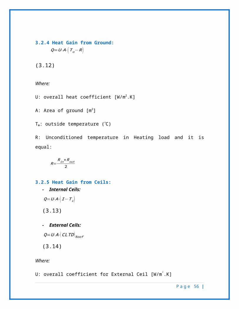
3.2.4 Heat Gain from Ground:Q=U⋅A⋅(To−R ) (3.12)
Where:
U: overall heat coefficient [W/m2.K]
A: Area of ground [m2]
To: outside temperature (C)
P a g e 44 |

R: Unconditioned temperature in Heating load and it is equal:
R=Rin+Rout
2
3.2.5 Heat Gain from Ceils:- Internal Ceils:
Q=U⋅A⋅( I −T i ) (3.13)
- External Ceils:
Q=U⋅A⋅(CLTD )Roof (3.14)
Where:
U: overall coefficient for External Ceil [W/m².K]
A: Area of Ceil [m²]
CLTD: Cooling Load Temperature Difference for Roof and it is equal:
Q= (CLTD+ LM )⋅K + (25 .5−T i )+(T o−29 . 4 )
Where:
CLTD: Cooling Load Temperature Difference for roof
LM: latitude correction factor
K: color adjustment factor and it is equal;
K=1 for dark colored walls
K= 0.83 for permanently medium color wall.
K= .65 for permanently light color wall.
P a g e 45 |

Heat Gain from Occupants "People":
Q= # of people ⋅Latent Heat + # of people ⋅S ensible Heat ⋅CLF (3.15)
*Heat Gain from Lights:
Q=W attage ⋅CLF (3.16)
Wattage is determined by:
Every 25 m2 consume 120 Watt; we depend on this rough estimation.
*Heat Gain from Equipments
Q=W attage ⋅CLF (3.17)
3.3 Sample of Calculation :
For Ground Floor room number two (three beds patient room ):
3.3.1 conduction Heating Load:From equation 3.1 :
Q = U A ∆T
Area of wall one : 11.16 m2
U factor for wall one : 0.59 w/m2.K
∆T = 17.3
For window in wall number one :
Q = U A ∆T
Area of wall one : 1.8 m2
U factor for wall one : 3.5 w/m2.K
Q = Q wall + Q window
Q = 206.15 W
P a g e 46 |

3.3.1.1 ventilation and infiltration Heating Load:
The equation used to calculate the sensible heat loads due to infiltration and ventilation
is as shown:
QS , Vent /inf = =1.2*105*17.3 =2016 [Watt]
=3*105*4 = 1260[Watt]
Where:
QS , Vent /inf : Heating load due to ventilation or infiltration.
QS , Vent /inf :heating load due to latent ventilation.
V vent /inf : The maximum amount from ventilation or infiltration.
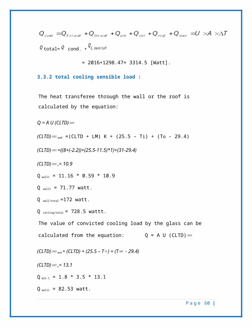
3.3.1.2 total heat sensible load :
Q total=Q cond. +QS ,Vent /inf
= 2016+1298.47= 3314.5 [Watt].
3.3.2 total cooling sensible load :
The heat transferee through the wall or the roof is calculated by the equation:
Q = A U (CLTD)corr
(CLTD)corr wall =(CLTD + LM) K + (25.5 – Ti) + (To - 29.4)
(CLTD)corr =((8+(-2.2))+(25.5-11.5)*1)+(31-29.4)
P a g e 47 |

(CLTD)corr ,= 10.9
Q wall1 = 11.16 * 0.59 * 10.9
Q wall1 = 71.77 watt.
Q wall/total =172 watt.
Q ceiling/total = 728.5 wattt.
The value of convicted cooling load by the glass can be calculated from the equation:
Q = A U (CLTD)corr
(CLTD)corr win.= (CLTD) + (25.5 – Tin ) + (Tout - 29.4)
(CLTD)corr ,= 13.1
Q win.1 = 1.8 * 3.5 * 13.1
Q wall1 = 82.53 watt.
The transmitted cooling load of the solar radiation can be calculated from the relation:
Q = A (SHG) (SC) (CLF)
Q = 1.8 * (189) *(0.25)*(0.35)
Q = 29.8 watt.
3.3.2.1 ventilation and infiltration Cooling Load:
The equation used to calculate the sensible heat loads due to infiltration and ventilation
is as shown:
QS , Vent /inf = =1.2*105*9 =1134 [Watt]
=3*105*4 = 1260[Watt]
People:
P a g e 48 |
The equation used to calculate the sensible heat loads due to people occupancy is as
shown:
QP .S=qS×n×CLF = 75 x 7 x 0.8 = 420 w (3.18)
QP . L=qL×n = 35 x 7 = 245 w (3.19)
Where:
QP .S &QP .L : Sensible and latent heat gain respectively for people
qS &qL : Sensible and latent heat gain respectively per person
n: number of people
CLF: Cooling load factor for people.
Lighting :
QL=W ×CLF = 1000 x 0.8 = 800 w (3.20)
Where:
QL : Net heat gain for lighting
W: lighting capacity (watt).
CLF: cooling load factor for lighting.
QE . S=qS×CLF = 200 x 0.8 = 160 w (3.21)
QE .L=qL = 0 w (3.22)
Where:
QE . S &QE . L : Sensible and latent heat gain respectively for equipment.
qS & qL : Equipments capacity (Sensible and latent respectively)
P a g e 49 |

CLF: cooling load factor for equipment from ASHREA tables for both hooded and unheeded
applications.
Qs total Heating = 3314.47 W
QL total Heating = 1260 W
Qs total Cooling = 3526.56 W
QL total Cooling =1505 W
Name of floor Heating load)kw(
Cooling load)kw(
GF 65 66B1 53.3 56.5B2 54 60B3 72.8 76.6B4 50 60.9B5 57.4 52.1Total load )kw( 353.8 372.9
Table 4.1 : Floors Heating and Cooling loads
room Qs Heating Ql Heating QS Cooling Ql cooling1 3414.694 1417.5 4083.414 21352 3314.47 1417.5 3526.566 21353 3314.47 1417.5 3526.566 21354 3577.846 1417.5 3639.979 21355 1480.784 567 1784.497 8966 1186.171 160.68 1788.577 214.247 581.0112 110.565 921.3983 147.428 1743.901 526.5 1841.835 7029 1727.763 607.5 1997.282 915
10 2289.824 877.5 2823.26 134511 2289.824 877.5 2823.26 134512 2990.24 945 3342.025 143513 3301.122 1906.125 4385.343 3041.514 948.08 357.435 1676.802 556.5815 505.5115 75.12375 1338.764 170.16516 1349.722 687.96 2292.416 997.2817 853.8752 137.1825 942.2726 182.9118 30222.83 9165 23253.16 12220
P a g e 50 |

Table 4.2 : Ground Floors Heating and Cooling loads
Chapter Four
Plumping & Fire Alarm System
P a g e 51 |

4.1 principles of plumping:
The plumber uses some easy but basic principles of physics in order to fulfill most if not
all the basic requirements of its task. Plumbing is simply knowing how to control the
flow of clean water into a building or an area of interest and knowing how well it should
exit the building. In essence the plumber’ work is summarized into these two areas. The
two principles that he often uses are:
1: The law of gravity
It is clear that water will flow down a given solid system of drainage if allowed to. The
law of gravity defines that the water, just like any other substance is subject to some
certain downward pressure due to the earth’s gravitational pull towards it. Therefore, the
exit of water from the premises is simply subject to a slight or heavy tilt of the pipe that is
leading the water out.
2: The law of pressure
It is also evident that any material subjected to any amount of pressure will do its best to
evade the subsequent direction of this pressure. Water too is subject to this principle. The
work of the plumber is therefore rooting out a map for any water coming into the
premises. The pressure is already provided by the council. His job is to measure and fix
the type of pipe that the water will need to flow through. You are aware that the smaller
the diameter of the pipe, the faster the water travels through it and the higher the amount
of pressure it flows with. Using this small but valuable principle, the plumber gets his
water to very high points in the house he works on.
Nevertheless, plumbing is also an art. The plumber needs to be more than informed about
how and what to do. He also needs to design ways in which to combat some of the
challenges that come with the profession. He will need to know of ways in which he can
adjust and readjust working system in order to suit a certain architectural need. More
P a g e | 52

often than not, plumbers need to be creative enough to go around existing plumbing
challenges.
4.1.1 Plumbing Code
the Uniform Plumbing Code (UPC) is a model code developed by the International
Association of Plumbing and Mechanical Officials (IAPMO) to govern the installation
and inspection of plumbing systems as a means of promoting the public's health, safety
and welfare.
The UPC is developed using the American National Standards Institute's consensus
development procedures. This process brings together volunteers representing a variety
of viewpoints and interests to achieve consensus on plumbing practices.
The UPC is designed to provide consumers with safe and sanitary plumbing systems
while, at the same time, allowing latitude for innovation and new technologies.
Once hired, the plumber should be made to understand that all installations must meet
local requirements and must be able to pass tests of local plumbing inspectors. Remember
to have a corporation cock installed at the street main, if required, and a curb cock
installed outside the house to enable you to cut off your water supply if necessary.
4.1.2 Good plumbing practice:
A general set of principles which can be used to guide you is found in the Recommended
Minimum Requirements for Plumbing developed by the Bureau of Standards, U.S.
Department of Commerce. These basic plumbing principles were written to meet the
minimum sanitary requirements for all parts of the country, after due consideration of
differences in climate, building codes, and methods of sewage disposal.
1. All premises intended for human habitation or occupancy shall be provided with a
supply of neither pure and wholesome water, neither connected with unsafe water
supplies nor cross connected through plumbing fixtures to the drainage system. If
P a g e | 53

such premises abut on a street in which there is a public sewer, they shall have a
connection, if possible, a separate connection, with the sewer.
2. Buildings in which water closets and other plumbing fixtures exist shall be
provided with a supply of water adequate in volume and pressure for flushing
purposes by pipes of sufficient size to supply such water without reducing
pressure at other fixtures.
3. Plumbing systems shall be maintained in a sanitary condition and will be designed
and constructed to guard against fouling and clogging, but with adequate and
accessible cleanouts in case, such stoppages should occur.
4. Plumbing fixtures shall be made of smooth, non-absorbent materials, shall be free
from concealed fouling surfaces, and shall be set free of enclosures, with each
fixture or combination fixture provided with a separate, accessible, self-scouring,
reliable, water-seal trap placed as near the fixture as possible.
5. Drainage system piping shall be so designed and constructed as to be proof for a
reasonable life of the building against leakage of water or drain air due to
defective materials, imperfect connections, corrosion, settlements or vibration of
the ground or building, temperature changes, freezing, or other causes.
6. The plumbing system shall be subject to a water- or air-pressure test and to a final
air-pressure test in such a manner as to disclose all leaks and imperfections in the
work.
7. House drainage systems shall be so designed that there will be an adequate
circulation of air in all pipes and no danger of siphoning, aspiration, or forcing of
trap seals under conditions of ordinary use. The soil stack shall extend full size
upward through the roof and have a free opening with no danger of clogging from
frost or roof water draining into it or of any air from it passing to any window.
P a g e | 54

8. If water closets or other fixtures exist in buildings where no sewer is within a
reasonable distance, suitable provision shall be made for disposing of house
sewage by some method of sewage treatment and disposal satisfactory to the
health authority having jurisdiction. Where backflow of sewage is possible,
provision should be made to prevent its overflow in the building.
With these basic principles in mind, a proper plumbing system can be installed which
will safeguard the health of your family. But there are several physical safeguards in the
actual installing of a system. For example, though it is accepted that the main should be
of a size adequate to supply sufficient water at all times, that main should be run as
straight as possible to avoid frictional losses, and should be laid on a level bed of soft,
rock-free dirt so that jagged or sharp cornered stones will not eventually cut into it.
All outside water mains should be provided with a "gooseneck." This is nothing more
than an additional kink or bend placed in the pipe in such a manner as to allow for
expansion and contraction so that connections will not break and leak. The gooseneck is
usually placed near the main and close to the corporation cock, so that all vibration,
settlement, expansion and contraction will act to tighten the cock joint rather than loosen
it.
Where the main runs through the foundation wall, it should be protected with a sleeve,
usually of iron pipe, which does not touch the main itself. Made large enough to allow for
expansion, this sleeve protects the main from contact with corrosive elements in concrete
and also keeps minor physical changes from either straining the wall or the main.
Once the water main has been installed and local regulations met, it is entirely
possible that the remaining interior piping can be installed by the owner himself. But
before actually beginning installing and connecting pipe and fixtures, survey the area,
whether kitchen or bathroom, carefully and plan out where each fixture is to be placed,
what clearance you must allow, how the existing piping can be utilized, and what new
piping will be necessary. The general principles and details of sketching a layout will be
described in the pages that follow.
P a g e | 55
The basics of a plumbing system are easy to understand. Water enters you house
through a pressurized water line. After being split into hot and cold water lines, the water
supply runs to each fixture in your home. Once used, fresh water becomes waste water,
and it enters the drain-waste-vent (DWV) system. Gravity now takes over, pulling the
waste water down a series of sloped, ever larger pipes toward the house sewer.
Water arrives under pressure; water leaves by gravity, taking with it dish soap, human
waste and anything else put down the drain. It's a simple and elegant system. Until
something goes wrong. Ironically, the same principles that allow your system to operate
smoothly are what cause many of the problems. Under the stress of constant pressure,
supply pipes corrode and eventually leak or burst. And the slow movement of waste
through the DWV pipes can lead to clogs.
Throughout this Plumbing 101, you'll learn more about plumbing fundamentals which
will make it possible for you to follow the flow of water through your house. You'll also
learn to identify parts of the system that could give you trouble in the future. While every
house relies on the same plumbing principles-pressure in, gravity out-plumbing materials
vary widely from house to house. Many systems are amalgams of different materials-
especially in older homes, where repairs and updates may have been done in several
phases. Identifying these materials and knowing their characteristics will help you when
troubles eventually arise.
4.2 Water ServiceThe water system serves path room, a levorotary and boundary. Water closet tank and
garden hose bibs are supplied with cold water all other fixtures are supplied with both hot
and cold water.
The entire system under pressure from the street main when faucets at the fixture
opened , the street pressure cause flow , when a hot water faucet is opened , the pressure
acts through the hot water tank to deliver hot water at the faucets all that services deliver
through Pipes, tubing and fittings.
ABS : Acrylonitrile-Butadiene-Styrene.
P a g e | 56

PB : Polybutylene.
PE : polyethylene.
PP : polyprolene.
PVC : polyvinyl chloride.
CPVC: chlorinated polyvinyl chloride.
4.3 Domestic hot water heater:
Water heating is a thermodynamic process using an energy source to heat water above
its initial temperature. Typical domestic uses of hot water are for cooking, cleaning,
bathing, and space heating. In industry, both hot water and water heated to steam have
many uses.
Domestically, water is traditionally heated in vessels known as water heaters, kettles,
cauldrons, pots, or coppers. These metal vessels heat a batch of water but do not produce
a continual supply of heated water at a preset temperature. The temperature will vary
based on the consumption rate of hot water, use more and the water becomes cooler.
Appliances for providing a more-or-less constant supply of hot water are variously
known as water heaters, boilers, heat exchangers, clarifiers, or geysers depending on
whether they are heating potable or non-potable water, in domestic or industrial use, their
energy source, and in which part of the world they are found. In domestic installations,
potable water heated for uses other than space heating is sometimes known as domestic
hot water (DHW).
In many countries the most common energy sources for heating water are fossil fuels:
natural gas, liquefied petroleum gas, oil, or sometimes solid fuels. These fuels may be
consumed directly or by the use of electricity (which may derive from any of the above
fuels or from nuclear or renewable sources). Alternative energy such as solar energy, heat
pumps, hot water heat recycling, and sometimes geothermal heating, may also be used as
available, usually in combination with backup systems supplied by gas, oil or electricity.
P a g e | 57

In some countries district heating is a major source of water heating. This is especially
the case in Scandinavia. District heating systems make it possible to supply all of the
energy for water heating as well as space heating from waste heat from industries, power
plants, incinerators, geothermal heating, and central solar heating. The actual heating of
the tap water is performed in heat exchangers at the consumer's premises. Generally the
consumer needs no backup system due to the very high availability of district heating
systems.
In the majority of houses in this country, there are two different types of hot water
system. The circulation from a boiler around the radiators is the central heating system.
The water to your taps is the domestic hot water. The water to your radiators is the central
heating system.
Although both share some of the main components in the heating system, the water
and pipe work is not mixed. Different ways of heating the domestic hot water need to be
understood in order for the home owner to identify theirs and affect any maintenance
needed. It will also be necessary to asses any type of shower you may wish to install.
The types of domestic water heating can be broken down into two categories. 1. Hot
water is stored in a cylinder. 2. Cold water is heated on demand.
4.3.1 Stored hot water:
This category, although the hot water is always stored in a cylinder or tank, can be
further divided into three categories.
Immersion: An immersion heater is an electric element which screws into the hot
water tank. This element is wired to the mains electrical supply via an isolating switch, a
thermostat to control the temperature, and sometimes a timer which enables you set the
times you wish to have the water heated. Using a timer, together with a well insulated
tank, it is possible to heat the water when electricity rates are at their cheapest (Economy,
7 between 12 midnight and 7 am), and use it during the day. It is worth remembering that
the hot water from an immersion heater is always drawn from the top of the cylinder,
P a g e | 58

where it has risen over the cold water underneath (convection current). The cold water,
fed to the tank from underneath, gives the hot water the pressure it needs to leave the
cylinder, from the top, when required by the taps. Some tanks can contain two elements,
giving you a choice as to how much water you want to heat up at any one time. It is quite
rare nowadays for the immersion heater to be the only method of domestic water heating
in a home and the immersion is generally used as a back up to one, or both, of the
following two methods.
4.3.2 Direct boiler system:
In older houses, with a direct system, the hot water may be stored in a square
galvanized tank. The principle is the same. Using the diagram above as a reference,
another cold water pipe runs from the base of the cylinder to the boiler. The boiler heats
the water and returns it to the tank higher up. When hot water is drawn from the tank, it is
replaced by cold from the cold tank, which in turn is fed to the boiler. This is direct
heating of the water by either a) the immersion or b) the boiler. The hot water is simply
stored in the tank.
To identify a direct water system you will find the end of the vent pipe fixed above
your cold water tank. This allows for any stem expansion in the cylinder to flow directly
into the cold tank and not damage the cylinder or cause air locks in the system.
4.3.3 Indirect boiler system:
With an indirect water system, the copper hot water cylinder contains a coil of pipe.
This coil forms part of a run of pipe work attached to the boiler. It is heated directly by
the boiler. Indirectly, it heats the water in the cylinder. The coil, or "heat exchanger"
forms part of the central heating circuit, and its water heating abilities are purely a by-
product of its main function, which is to heat the radiators. This heating is called the
"primary" circuit; the pipes running to and from the boiler are called the primary flow and
return. The hot water tank operates in exactly the same way as the direct system.
To identify an indirect system, you will see two water tanks in your loft. The second,
smaller one is the feed for the primary circuit. It will top up the system when necessary
P a g e | 59
and will also have a vent pipe over the top. The level of water in this tank will be
considerably lower to allow the water to rise as it expands when it gets hot without
overflowing.
Both of the boiler systems above are called "vented" systems. Because of this vent pie,
they are open to atmospheric pressure and operate as "low pressure" systems. They both
call for cold water from a cold tank stored, generally, in the roof space. Because they are
low pressure, sometimes the flow from the taps etc is not as great as one might like and
pumps can be introduced, both for the domestic hot water and the heating, to give greater
flow.
1. Pressure vessel
2. Expansion relief valve
3. Cold water inlet
4. Temperature relief valve
5. Hot water outlet
6. Immersion heater
7. Tundish or visual overflow
8. Non-return valve
9. Cold to taps
10. Pressure limiter
11. Strainer
12. Stopcock
13. Mains
P a g e | 60

14. Discharge pipe
Figure (4.1): boiler system [7]
The unvented system operates purely from mains water. The principles of heating are
the same, but because everything is under the pressure of the mains water, flow rates are
much better...Many safety devices are built into this system to accommodate for the
greater pressure and expansion of the water. Although a small tank may be found in the
loft for venting and feeding your central heating, No cold water storage tank is necessary.
Hot water cylinder capacity varies between 25 gallons to 50 gallons for normal
domestic supply, with the larger being enough to supply an average family for a day.
Most cylinders are made from thin copper and you should make sure your cylinder is
well lagged to prevent heat loss. Pre-lagged cylinders are available, which are coated
with foamed polyurethane.
4.4 Thermal store system:
A revolutionary new concept (British development) which reverses the indirect
principle detailed above. The boiler heats the water and sends it to a cylinder, and then on
to the central heating. On its way it heats, in the cylinder, via a very efficient heat
exchanger, the mains fed water for the taps. An integral feed and expansion tank can be
incorporated on top of the main tank. This system is so efficient; a thermostatic (cold/hot)
mixer valve is built into the pipe work before the hot reaches the taps or shower. For the
two part tank to be viable, the system must be installed at the highest possible level in the
house, however it can be installed with the feed tank separately installed in the loft. This
system is now available with its own dedicated boiler allowing the central heating to be
switched off in summer. The ultimate in combination systems.
P a g e | 61

4.4.1 Single point water heater:
Single point water heaters come in both gas and electricity "flavor" and are sited,
generally, next to the point they serve. In the case of an electric heater (an electric shower
is an example) they must be wired to the mains via an isolating switch. A heater up to
3kw can be plugged into an ordinary 13 amp socket, but that socket must not be in reach
of the water outlet. Above 3kw, the heater must be wired directly to the fuse box with a
double pole isolating switch in the circuit. In the kitchen, this switch may be wall
mounted, again, out of reach from the sink, but in the bathroom it must either be a cord
operated switch on the ceiling, or an isolating switch outside the room. Differing cable
sizes are needed for differently rated heater and checks should be made for the particular
heater you wish to install.
Single point gas heaters of the old "Ascot" type are based on a thermostat sensing the
arrival of cold water into its reservoir when water is asked for from a tap. As soon as the
tap is open, fresh cold water comes in to replace that being drawn from the tap. This
triggers the ignition of the burners which heat the water. The hot water rises to the top
and is available immediately.
4.4.2 Multi point water heater:
The most common of these is a combination boiler. These heaters operate on the same
principle as above, but can serve many points (taps, washing machine, etc) as well as, in
the case of a combination boiler, supplying the hot water for a central heating system. An
ordinary multi point heater will only supply water to the domestic water system but can
be installed in conjunction with an ordinary central heating boiler.
A combination boiler combines the functions of a central heating boiler and an
instantaneous multi point water heater, giving priority to the supply of domestic hot
water. Combination boilers can be direct or indirect in much the same way as the
cylinders above, using clarifiers (heat producers) to heat water passing through them.
P a g e | 62

4.5 Distribution pipe sizing: The sizing of a water distribution pipe system is achieved by establishing the anticipated
flow rates in liters per second (Vs) taking account of the diversity of use of all the various
types and numbers of appliances, and equipment requiring a water supply connection. In
practical terms all the water draw-off points are not in use at the same time.
The actual number in use, in relation to the total number capable of being used varies
dependant on the occupational use in the various types of building.
System and tanks; It is intended that, when necessary, modifications to pipe and
storage systems should take place so that only one unit for continuous disinfection need
be installed. Wherever possible the cold water storage system and storage tanks
should store water at below 20°C. The Responsible Person should eliminate the
possibility of any conditions which produce abnormally high temperature rises.
Advice should be sought on the method to be used to control any temperature rise.
4.6 Fire Protection:
Fire protection is the study and practice of mitigating the unwanted effects of fires [1].
It involves the study of the behavior, compartmentalization, suppression and investigation
of fire and its related emergencies, as well as the research and development, production,
testing and application of mitigating systems. In structures, be they land-based, offshore
or even ships, the owners and operators are responsible to maintain their facilities in
accordance with a design-basis that is rooted in laws, including the local building code
and fire code, which are enforced by the Authority Having Jurisdiction. Buildings must
be constructed in accordance with the version of the building code that is in effect when
an application for a building permit is made. Building inspectors check on compliance of
a building under construction with the building code. Once construction is complete, a
building must be maintained in accordance with the current fire code, which is enforced
by the fire prevention officers of a local fire department. In the event of fire emergencies,
Firefighters, fire investigators, and other fire prevention personnel called to mitigate,
investigate and learn from the damage of a fire. Lessons learned from fires are applied to
the authoring of both building codes and fire codes.
P a g e | 63

In the United States, this term is used by engineers and code officials when referring
only to active and passive fire protection systems, and does usually not encompass fire
detection systems such as fire alarms or smoke detection.
4.6.1 Smoke and Fire Dampers: HVAC service zones should be designed to coincide with smoke compartments
whenever practicable. Ductwork penetrations of fire/smoke rated walls should be
minimized, to minimize the required number of smoke/fire dampers and complexity of
controls. Coordinate with the architectural design to assure that necessary access for
inspection or service of these dampers is provided.
4.6.2 Ductwork: Air supply and exhaust systems shall be of the mechanical ventilation type and shall
meet the requirements of NFPA 90A and 96. Grease-laden vapor exhaust ductwork shall
be in accordance with NFPA 96.
4.6.3 Smoke Mode Operation: Comply with applicable standards and practices.
4.6.4 Commissioning of Fire/HVAC Systems: Guide specifications typically do not contain provisions for the simultaneous testing of
HVAC and fire protection systems, which can have complex, interwoven operational
requirements in some facilities. For each project where applicable, designers shall
develop or modify specifications as needed to provide for testing of HVAC systems
under fire alarm conditions, to permit verification not only of correct function, but of
acceptable speed of response. In more complex systems involving smoke evacuation or
compartmentalization/pressurization, detailed testing protocols and/or system diagrams
must be developed to clearly convey the required scope of the commissioning effort.
4.6.1 Goals:
Fire protection has three major goals:
P a g e | 64

Continuity of operations - on a public scale, this is intended to prevent the
interruption of critical services necessary for the public welfare (e.g., a 911
emergency call center).
Property protection - on a public scale, this is intended to prevent area wide
conflagrations. At an individual building level, this is typically an insurance
consideration (e.g., a requirement for financing), or a regulatory requirement.
Life safety - the minimum standard used in fire and building codes
4.6.2 Classifying fires:
When deciding on what fire protection is appropriate for any given situation, it is
important to assess the types of fire hazard that may be faced.
Some jurisdictions operate systems of classifying fires using code letters. Whilst these
may agree on some classifications, they also vary.
4.7 Fire Fighting System: The fire fighting system will be used when a big fire has already started. There is a
need to extinguish it. Sprinkler systems, and hose reel systems are some of the systems
used for fire fighting. Wet risers are pipes which distribute large volumes of water to
canvas hoses.
The fire fighting systems contain pumps, tanks, and their own distribution piping.
Motors or diesel engines drive the pumps. Hose reels and canvas hoses are terminated
with nozzles for spray or jet. Sprinkler systems have special glass bulbs and sprinkler
rose. Flow switches are installed to cause bells to ring when the sprinkler systems are
activated. The systems can also contain gongs activated by water flow.
Automatic CO2 flooding system will discharge CO2 gas into electrical rooms to stop any
fire.
P a g e | 65

Portable fire extinguishers are installed at strategic locations so that they can be used
to put out small fires. Fire intercom systems are used by fire fighters to communicate
with fire control room personnel.
Fire escape doors are indicated with Exit signs, and emergency lights are installed to
give a bit of light if the main electrical supply has been cut off. Firemen who have to
fight fires will face the danger of electrocution if they use hoses and water. The fireman
switch can be switched off to avoid this problem
4.8 Fire Alarm System:
An automatic fire alarm system is designed to detect the unwanted presence of fire by
monitoring environmental changes associated with combustion. In general, a fire alarm
system is either classified as automatically actuated, manually actuated, or both.
Automatic fire alarm systems can be used to notify people to evacuate in the event of a
fire or other emergency, to summon emergency services, and to prepare the structure and
associated systems to control the spread of fire and smoke.
After the fire protection goals are established - usually by referencing the minimum
levels of protection mandated by the appropriate model building code, insurance
agencies, and other authorities - the fire alarm designer undertakes to detail specific
components, arrangements, and interfaces necessary to accomplish these goals.
Equipment specifically manufactured for these purposes are selected and standardized
installation methods are anticipated during the design. In the United States, NFPA 72,
The National Fire Alarm Code is an established and widely used installation standard.
P a g e | 66

Figure (4.2): Fundamental configuration
A Honeywell fire alarm control panel:
Fire alarm control panel: This component, the hub of the system, monitors inputs
and system integrity, controls outputs and relays information.
Primary Power supply: Commonly the non-switched 120 or 240 Volt Alternating
Current source supplied from a commercial power utility. In non-residential
applications, a branch circuit is dedicated to the fire alarm system and its
constituents. "Dedicated branch circuits" should not be confused with "Individual
branch circuits" which supply energy to a single appliance.
Secondary (backup) Power supplies: This component, commonly consisting of
sealed lead-acid storage batteries or other emergency sources including
generators, is used to supply energy in the event of a primary power failure.
Initiating Devices: This component acts as an input to the fire alarm control unit
and are either manually or automatically actuated.
Notification appliances: This component uses energy supplied from the fire alarm
system or other stored energy source, to inform the proximate persons of the need
to take action, usually to evacuate.
Building Safety Interfaces: This interface allows the fire alarm system to control
aspects of the built environment and to prepare the building for fire and to control
the spread of smoke fumes and fire by influencing air movement, lighting, process
control, human transport and exit.
4.8.1 Active fire protection: Is an integral part of fire protection? AFP is characterized by items and/or systems, which require a certain amount of motion and response in order to work, contrary to passive fire protection
P a g e | 67
4.8.1.1 Fire suppression
Fire can be controlled or extinguished, either manually (firefighting) or automatically.
Manual includes the use of a fire extinguisher or a Standpipe system. Automatic means
can include a fire sprinkler system, a gaseous clean agent, or fire fighting foam system.
Automatic suppression systems would usually be found in large commercial kitchens or
other high-risk areas.
4.8.1.2 Sprinkler systems
Fire sprinkler systems are installed in all types of buildings, commercial and
residential. They are usually located at ceiling level and are connected to a reliable water
source, most commonly city water. A typical sprinkler system operates when heat at the
site of a fire causes a glass component in the sprinkler head to fail, thereby releasing the
water from the sprinkler head. This means that only the sprinkler head at the fire location
operate - not all the sprinklers on a floor or in a building. (This is a common
misconception which stems from action movie scenes). Sprinkler systems help to reduce
the growth of a fire, thereby increasing life safety and limiting structural damage.
4.8.1.3 Fire detection
The fire is detected either by locating the smoke, flame or heat, and an alarm is
sounded to enable emergency evacuation as well as to dispatch the local fire department.
An introduction to fire detection and suppression can be found here. Where a detection
system is activated, it can be programmed to carry out other actions. These include de-
energizing magnetic hold open devices on Fire doors and opening servo-actuated vents in
stairways
4.8.2 Fire suppression:
A fire extinguisher is an active fire protection device used to extinguish or control
small fires, often in emergency situations. It is not intended for use on an out-of-control
fire, such as one which has reached the ceiling, endangers the user (i.e. no escape route,
smoke, explosion hazard, etc.), or otherwise requires the expertise of a fire department.
P a g e | 68

Typically, a fire extinguisher consists of a hand-held cylindrical pressure vessel
containing an agent which can be discharged to extinguish a fire.
There are two main types of fire extinguishers: stored pressure and cartridge-operated.
In stored pressure units, the expellant is stored in the same chamber as the firefighting
agent itself. Depending on the agent used, different propellants are used. With dry
chemical extinguishers, nitrogen is typically used; water and foam extinguishers typically
use air. Stored pressure fire extinguishers are the most common type. Cartridge-operated
extinguishers contain the expellant gas in a separate cartridge that is punctured prior to
discharge, exposing the propellant to the extinguishing agent. This type is not as
common, used primarily in areas such as industrial facilities, where they receive higher-
than-average use. They have the advantage of simple and prompt recharge, allowing an
operator to discharge the extinguisher, recharge it, and return to the fire in a reasonable
amount of time. Unlike stored pressure types, these extinguishers utilize compressed
carbon dioxide instead of nitrogen, although nitrogen cartridges are used on low
temperature (-60 rated) models. Cartridge operated extinguishers are available in dry
chemical and dry powder types in the US and in water, wetting agent, foam, dry chemical
(classes ABC and BC),and dry powder (class D) types in the rest of the world.
P a g e | 69

Figure (4.3): fire extinguisher [7]
4.8.3 Fire detection:
A smoke detector is a device that detects smoke. Commercial, industrial, and mass
residential devices issue a signal to a fire alarm system, while household detectors,
known as smoke alarms, generally issue a local audible and/or visual alarm from the
detector itself.
Smoke detectors are typically housed in a disk-shaped plastic enclosure about
150 millimeters (6 in) in diameter and 25 millimeters (1 in) thick, but the shape can vary
by manufacturer or product line. Most smoke detectors work either by optical detection
(photoelectric) or by physical process (ionization), while others use both detection
methods to increase sensitivity to smoke. Smoke detectors in large commercial,
industrial, and residential buildings are usually powered by a central fire alarm system,
which is powered by the building power with a battery backup. However, in many single
P a g e | 70

family detached and smaller multiple family housings, a smoke alarm is often powered
only by a single disposable battery.
Figure (4.4) smoke detector [7]
4.8.3.1 Optical detector: An optical detector is a transducer that converts an optical signal into an electrical
signal. It does this by generating an electrical current proportional to the intensity of
incident optical radiation. The relationship between the input optical radiation and the
output electrical current is given by the detector responsively. Responsively is discussed
later in this chapter.
P a g e | 71

Figure (4.5): (optical detector) [7]
Optical Smoke Detector
1: optical chamber
2: cover
3: case molding
4: photodiode (detector)
5: infrared LED
4.8.3.2 Ionization detector: Ionization smoke detectors use an ionization chamber and a source of ionizing
radiation to detect smoke. This type of smoke detector is more common because it is
inexpensive and better at detecting the smaller amounts of smoke produced by flaming
fires.
Inside ionization detector is a small amount (perhaps 1/5000th of a gram) of
americium-241. The radioactive element americium has a half-life of 432 years, and is a
good source of alpha particles.
A flame ionization detector (FID) is a type of gas detector used in gas chromatography.
The first flame ionization detector was developed in 1957 by scientists working for the
CSIRO in Melbourne, Australia.[1][2][3]
P a g e | 72

Figure (4.6): ionization detector [7]
4.8.3.3 Heat detector:
A heat detector is a device that responds to changes in ambient temperature. Typically,
if the ambient temperature rises above a predetermined threshold an alarm signal is
triggered. In the case of sprinkler systems, water will be released to extinguish the fire.
Heat detectors can also be further broken down
into two main classifications of activation, "rate-of-
rise" and "fixed." The most sophisticated units are
activated by both conditions.
P a g e | 73
Figure (4.7): heat detector [7]

Chapter Five
Design & Selection
P a g e | 74

5.7 Fan coil units Selection :Using Trane catalogues :* Calculating Heating load and Cooling load for each room i.e ( Q =3526.56 W 415 CFM )
* select a suitable fan coil , 600 CFM .* Make the duct work and piping at 600 CFM 0.19 L/sFrom Trane catalogues , selected fan coil unit :
H F C 06 G N A 1 B O N B
H F C 06 G N A 1 B O N B
HorizontalFan Coil
Concealed Casing
600 CFM
FAN
3 raw Cooling
1 raw H
eating
No electrical
heater
Low M
otor
220 V/50 Hz
2 pipe system
Long galvanized
No-Filter
Second
Table (5...) : Fan coil selectionFor further information return to appendix page ()
5.1 Duct Work Design :Duct network are used to transport heated or cooled air from the fan coil unit or air handler unit to air conditioned space and return back air from spaces to the unit or to outside.
V`Circulation = Q
1.2 ∆T (5.1)
A= Vcirvelocity
P a g e | 75

D=( 4×A
π)0 .5
Where :
V` = Volume flow rate [m3/s]
Q : Sensible heat gain [KW]
∆T = temperature drop in fan coil [oC] .
V`Circulation = Q [KW ]
1.2 ∆ T
V`=3.526 (cooling load )/ 1.2 X (15)
V`= 0.53 m3/S
Table (5.1) : Fan coil and diffusersCFM = 0.53 X 2119 = 1123 CFM
Diffuser Capacity = 400 cfm
Number of diffusers = 1123 / 400 = 2.8 ,
So we need 3 diffusers .
DUCT V ` V A D ∆P/L H WAB 0.53 5 0.106 0.36 0.825 250 450BC 0.177 2.2 0.088 0.196 0.825 100 100BD 0.177 2.2 0.088 0.196 0.825 100 100BE 0.177 2.2 0.088 0.196 0.825 100 100
P a g e | 76
Figure (5.1) : Fan coil and diffusers

5.9 Air Fans :5.9.1 Fresh Air Fan :Fresh air fan will supply fresh air through the longest duct reaching to further fan coil .Total flow rate = 11.27 m3/sFan head = 77 Pa 5.9.2 Exhaust Fan :Exhaust fan is added to Toilet and W.C. , Average W.C Fan 100 CFM .
5.9 Pump Selection :
5.9.1 Circulating pump )A/C( :Water mass flow rate of chilled water = Q x ( 1
4.18 xTdrop¿
(5.9)
P a g e | 77

M` = 412 x 14.18 x5.6 = 17.6 L/s
Figure (5.6) : Salmson pumps
at 17.6 L/s ,head = 4.5 mH2O4.5 mH2O = 4.5 x 9.81 x 1000 = 44145 PaLongest pipe = 110 m ΔP/L = 44145 / 110 = 401 pa/m , accepted .Selected Pump from Salmson Catalogues Model : 80-160
P a g e | 78

5.9.2 Circulating Domestic pump )Hot water ( :Hot water system flow rate : 218 L/min @ (354KPA=36m)Pump : salmson : 40-250
5.9.3 Circulating Domestic pump )Cold water ( :Hot water system flow rate : 458 L/min @ (36KPA=3m)Pump : salmson : 50-125
5.9.4 Circulating pump )Heat exchanger – Hot tank ( :Hot water system flow rate : 1.5m3/hr Pump : salmson : 40-125
4.9.5 Circulating pump )Boiler - Heat exchanger ( :Hot water system flow rate : 19m3/hr Pump : salmson : 40-125
5.2 Pipe Design :To determine the diameter for the water supply for each roof and each fan coil units can be done by using equation :
m’cir. = Qs(ventilation,infiltration)+Qs conduction/ (cp (Ti-To)) (5.2)
for the room #2 (3-bed patient room) the cooling load is equal to (Qs= 3526.5 watt) and the heating load is equal to ( Qs= 3314.5 watt) , so we choose the cooling load because it is bigger.
now by using the equation for m’cir. For cooling load :
m’cir.= (3526.5)/(4180*(5.6))
m’cir.=0.150 kg/s
P a g e | 79

5.4 Boiler Selection :5.4.1 Domestic Hot water :
Q domestic = Mw xCp x ΔTΔt
(5.6)
Where : Mw : Daily consumption of domestic hot water Cp: Specific heat for water ΔT : Th – Tc : Th : hot water supply temperature Tc: temperature of the cold water Mw = 5L/hr for each person Average in hospital 300 person5 x 300 = 1500 L / hr1500 x 24 = 36000 LMw =36m3/ day
Q domestic = 36000 x 4.18 x5024 x3600 = 87 KW
Qtotal = (Heating Load + Domestic hot water ) * 1.1Qtotal = (353.8 + 87 ) x 1.1 = 484.8 KWFrom Byworth catalogues we select Model : FM500 , 500 KW
P a g e | 80

5.5 Chiller Selection :Total cooling load : 372.9 KW x 1.1 = 410.19 KW From Hatatchi Catalogues we select Model : 160AG2 , 412 KW
Figure (5.3) : Hatatchi Chillers5.3 Boiler Chimney Design :
Δ pg = Pb g hR ( 1
Ta− 1
Tg¿ (5.3)
Where:
Δpg : pressure generated of burned gases by boiler .
Pb: atmospheric pressure
g : Gravity acceleration
h : head of chimney
R: Gases constant
Ta: Ambient temperature
Tg : Boiler burned gases temperature
Δ pg = 101.3 x 103 x 9.81 x 25287
( 1280
− 1523
¿ = 143.2 Pa
P a g e | 81
Figure (5.2) : ByWorth Boilers
m`f = Qbμ C .V .
(5.4)
Where :
m`f : mass flow rate of fuel
Qb: Boiler capacity
μ:efficincy
C.V.= power generated in KJ by burning 1Kg of fuel
m`f= 5000.8 X 39000 = 0.016 Kg/s
m`g = m`f x 25.2 (5.5)
where :
m`g: mass flow rate of burned gases
m`g = 0.016 x 25.2 = 0.4 Kg/s
Ac = m gρv
Where:
ρ: density of air
v: velocity of burned gases
Ac = 0.41.1 x5 = 0.0727 m2
D= 0.30 m ; diameter of chimney at minimum speed
Δp/L = 1.06 pa/m
ΔPfriction = ΔP/L x L
Where :
P a g e | 82

ΔP/Lfriction : pressure drop in chimney due to friction
ΔP/L : pressure drop per unit length
L : length of chimney
ΔPfriction = 1.06 x 30 = 31.8 pa
we can reduce diameter of chimney by increasing Δp/L :
ΔPg = ΔP/L x L
143.2 = ΔP/L x 30
ΔP/L = 4.7 pa/m
V`= mρ (5.5)
Where :
V`: volume flow rate of burned gases
V`= 0.41.2 = 0.33 L/s
From ΔP/L and V`= 0.333 L/s
D= 21.9 cm D= 22 cm ; need No Fan
5.8 Tanks :
5.8.1 Diesel Tank :DD= (18.3-Ta) * days of month (5.7)
Where :DD: Degree – days for winter months , calculated from excel sheet .DD= 1194.1
P a g e | 83

Mf = Q x DD x24(Tout−Tin )C .V
¿) (5.8)
Where : Mf : mass of fuelCd: Empirical correction factor for heating 500 KW = 1798561.15 KJ/hr
Mf = 1798561.15 x 1194.1x 24(22−6.7 )39000
¿) = 86645.8 Kg
V= mρ
V = 86645.8 / 0.8 = 108.3 m3 Diesel for winter months .
5.8.2 Cold Water Tank :This tank supplies :- Cold water demand : 36 m3/day- Fire fighting system : 90 min. , 210 m3
Tank capacity = 250 m3 . ( 5 x 5 x 10 ) m - Cold pipe will be taken from 80 cm from the top of the tank , a 210 m3 will be remained for the fire fighting system.
P a g e | 84

P a g e | 85
Figure (5.5) : Heat Exchanger
selection

5.8.3 Hot Water Tank :This tank supplies :- Cold water demand : 36 m3/day 1.5 m3/hr- Tank 1.5 m3
5.10 Expansion tank :Boiler Capacity 500KWFor 233 KW needs 1000L expansion tankFor 500 KW need a two expansion tank of 1000 L.
5.6 Heat Exchanger Selection:* Each person consumes 5 L/hr of domestic water.* An average of 300 person in the hospital .* 300 x 5 = 1500 L/hr 1.5 m3/hr
* The hospital must be ready to supply hot water for their patients any time (24 hr)* 24hr x 1.5m3 = 36 m3/day .* Selected heat exchanger from Thermofin catalogues ,Model : Itex 2
P a g e | 86
Figure (5.4) : Heat Exchanger
selection

5.11Boiler Room :Boiler room contains :- Boiler- Expansion tank-Heat Exchanger- Hot water tank-Pumps- Valves (winter/summer)
P a g e | 87
Figure (5.7): Boiler room

5.12 Potable water system :
* Determining fixture unit for each fixture .* Calculate the summation of fixture units .* Convert the fixture units into flow rate .* Size pipes depending on flow rate.* From flow rate and pipe size we get ΔP/L for each pipe .* For longest pipe calculate the pressure drop .* Add the Back pressure (pressure generated due to water head )* Select the pump according to the pressure and flow rate.* Air puncher is added to each collector and riser branch .
GFFixture unit Size ( “ )
Branch HOT COLD Returned HOT COLD ReturnedAB 9 19 5.4 1 1 ¾ BC 12 22 5.4 1 1 ¾CD 22.5 58.5 13.5 1 1 ¼ 1DE 28.5 90.5 17.1 1 ¼ 1 ½ 1EF 36 83 21.6 1 ¼ 1 ½ 1FG 27 64 16.2 1 ¼ 1 ¼ 1GH 9 26 5.4 1 1 ¼ ¾HI 6 16 3.6 ¾ 1 ¾BX 3 3 --- ½ ½ ---DX 6 32 3.6 ¾ 1 ¼ ½CX 10.5 36.5 6.3 1 1 ¼ ¾FX 9 19 5.4 1 1 ¾GX 9 19 5.4 1 1 ¾GY 9 19 5.4 1 1 ¾HX 3 10 1.8 ½ 1 ½ZE 64.5 173.5 38.1 1 ¼ 2 1 ¼
Table (5.1 ): Fixtures Pipes diameter
P a g e | 88

Pressure drop in COLD water system :Branch FU Gpm Size )“( Length
)m(∆p/L
)pa/m(∆p
O – Z 605 143 3 3 110 330Z – E 173.5 59.7 2 2.15 185 297E – F 83 38.7 1 ½ 3.6 210 756F – G 64 33.3 1 ¼ 7.5 210 1575G – H 26 21.6 1 ¼ 5.8 210 1218H – 5 10 14.6 1 4.5 240 10805 – X 1.5 4 ½ 3.5 250 875
Table (5.2) : pressure drop in cold water system ∆P Friction = 6131 * 1.85 = 11.34 KPa∆P Head = 3m * 9.795 = 29.3 KPa∆P residual = 8 psi * 6.8 = 54 KPa∆P PUMP = ∆P Friction + ∆P residual - ∆P Head ∆P PUMP= 36 Kpa = 5.3 PSI
Pump flow rate = 143 gpm
P a g e | 89

Pressure drop in Hot water system :Branch FU Gpm Size )“( Length
)m(∆p/L
)pa/m(∆p
N –W 216 68.2 2 17 150 2550W – U 201 65 2 4 200 800U – Q 175.5 60 2 4 180 720Q – S 127.5 49.6 1 ½ 4 250 1000S – T 82.5 38.1 1 ½ 4 210 840T – Z 64.5 33.4 1 ¼ 4 210 840Z – E 64.5 33.4 1 ¼ 2.15 210 451.5E – F 36 25 1 ¼ 3.6 160 576F – G 27 25.1 1 ¼ 7.5 170 1275G – H 9 13.7 1 5.8 170 986H – 5 3 6.5 ½ 4.5 600 2700H – 5 1.8 5 ½ 4.5 600 2700G – H 5.4 10 ¾ 5.8 400 2320F – G 16.2 18 1 7.5 500 3750E – F 21.6 19.7 1 3.6 500 1800Z – E 38.1 26 1 ¼ 2.15 200 430T – Z 28.1 26 1 ¼ 4 200 800S – T 47.1 29 1 ¼ 4 300 1200Q – S 72.3 35.75 1 ¼ 4 600 2400U – Q 92.5 41.1 1 ½ 4 250 1000W – U 106 43.8 1 ½ 4 260 1040N –W 115 47.8 1 ½ 17 300 5100
Table (5.3) : pressure drop in Hot water system∆P Friction = 35278.5 * 1.85 = 65.265 KPa
∆P Head = 24 m * 9.795 = 235 KPa∆P residual = 8 psi * 6.8 = 54 KPa∆P PUMP = ∆P Friction + ∆P residual + ∆P Head
∆P PUMP = 355 KPa = 52 PSI
Pump flow rate = 68 gpm
*Note: A pressure regulator is added for each store, high pressure (52PSI) could cause damage to fixtures.
P a g e | 90

5.13 Sanitary system :
* Determining fixture unit for each fixture .* Calculate the summation of fixture units* Size pipes depending on number of fixture units .* Arrange manholes reaching to city main manhole .* The elevation between two adjacent manhole is 1.5% of the distance between them.* The manhole outlet is 5cm below the inlet . Table of manhole )Basement-5(
# ofmanh
oleDimens
ionTop level
Invert
level
Depth)cm(
COVER
TYPE
1 60ǿ 125.77
125.12
65 MEDIUM
REGUIAR
2 60ǿ 125.77
125.05
72 MEDIUM
REGUIAR
3 60ǿ 125.77
124.90
87 MEDIUM
REGUIAR
4 80ǿ 125.77
124.86
91 MEDIUM
REGUIAR
5 80ǿ 125.77
124.76
101 MEDIUM
REGUIAR
6 80ǿ 125.77
124.65
112 MEDIUM
REGUIAR
7 80ǿ 125.77
124.39
138 MEDIUM
REGUIAR
8 100ǿ 125.77
124.22
155 MEDIUM
REGUIAR
9 100ǿ 125.7 124.1 162 MEDIU REGUIA
P a g e | 91

7 5 M R10 100ǿ 125.7
7124.0
6171 MEDIU
MREGUIA
R11 120ǿ 125.7
7123.9
3184 MEDIU
MREGUIA
R12 120ǿ 125.7
7123.8
4193 MEDIU
MREGUIA
R
Table (5.4) : Basement Four Manhole
Table of manohle )Basement-4(
# ofmanh
oleDimens
ionTop level
Invert
level
Depth)cm(
COVER
TYPE
1 60ǿ 127.27
126.62
65 MEDIUM
REGUIAR
2 60ǿ 127.27
126.54
73 MEDIUM
REGUIAR
3 60ǿ 127.27
126.47
80 MEDIUM
REGUIAR
4 80ǿ 127.27
126.34
93 MEDIUM
REGUIAR
5 80ǿ 127.27
126.20
107 MEDIUM
REGUIAR
6 80ǿ 127.27
126.10
117 MEDIUM
REGUIAR
7 60ǿ 127.27
126.62
65 MEDIUM
REGUIAR
8 80ǿ 127.27
126.52
75 MEDIUM
REGUIAR
9 100ǿ 127.2 125.9 133 MEDIU REGUIA
P a g e | 92

7 4 M R
Table (5.4) : Basement Five Manhole Sample of calculation:-
Invert level= Invert level-5cmInvert level=126.62-(1.5%*1.56)=126.59Invert level=126.59-0.05=126.54
Depth(cm)= Top level- Invert levelDepth(cm)= 127.27-126.54=0.73m=73cm
5.14 Fire Fighting System :
In fire fighting system design , we will find that the diameter of the risers is usually (4’’) , and for the line which goes to the landing valve is (2.5’’) and for the cabine is (1.5’’).In any building of two risers the flow rate of the pump must be 750 (gpm) , so when we choose the pump we must know its flow rate (gpm) and its pressure (psi). so now after we find the flow rate of the pupm ,we have to check its pressure by the following steps .
P a g e | 93

1) First we have to find the most weakens point which in our project lise in the floor which is under the roof. (its name is GF).
2) We have to find the tallest path between the two risers to the landing valve ,because it has a pressure equal to 100 (psi) , which is bigger than the cabin’s pressure.
3) After choosing the path , we have to find its length from the bottom of the tank to the risers connections (its flow rate is 750 gpm), then the length from the riser to the landing valve connection (assuming that the flow rate in it is equal to 500 gpm) , finally the length from the landing valve connection to the landing valve hose (assuming the flow rate is 250 gpm).
After that by using the equivalent length in finding the pressure and pressure drop in lines and connections and then to subtract the back pressure.
By using the table which contains the friction loss per 100 feet, and from the hose size and flow rate.
P a g e | 94

The pressure drop = 100+(10.9*8.45*3.28/100)+(27.1*4.95*3.28/100)+(2.5*15*3.28/100)-(3*9.81/6.89)
=100+3.021+4.4+1.23-4.271=104.4 psiThe pressure drop in pipes and fittings = 1.5 *104.4 = 156.6 psi
So the main pump pressure must be equal or more than 156.6 , let say 157 psi , and its flow rate is 750 gpm .
While the jockey pump pressure is 167 psi , and its flow rate is 75 gpm .
5.15 Medical gases :* Determining number of terminals for each room .* Determining the flow rate for each gas.* Calculate the flow rate in each pipe by take the summation of each terminal and then multiply by the diversity factor .* Sizing the pipes , so that the total pressure drop not exceeds 5 psi.*Select a suitable compressor (flow rate & pressure)
branch
Length
Flow rate
size Pressure drop
A-B 17 14.8 3/4 0.4B-C 4 8.2 3/4 0.15C-D 4 12.2 3/4 0.32D-E 4 7.92 3/4 0.13E-F 4 9.5 3/4 0.18
P a g e | 95
Table (5.5) : pressure drop
in O2 Pipes

F-G 11.5 10.9 3/4 0.192G-H 2 7.5 1/2 0.8H-I 2.3 7.5 1/2 0.56I-J 3 7 3/4 0.105J-K 2.5 6 1/2 0.47K-L 3.75 3.75 1/2 0.13L-M 5.1 3 1/2 0.13M-N 3 3 1/2 0.13N-O 3.3 1 1/2 0.13
∆P friction < 5 psi , accepted diameters ∆P = 55 psiFlow rate = 14.8 cfm
P a g e | 96

APPENDIX
P a g e | 97

P a g e | 98

P a g e | 99

P a g e | 100

P a g e | 101

Heat Exchanger :
P a g e | 102

Pumps:
P a g e | 103

Chiller :
P a g e | 104

Boiler :
P a g e | 105

Fan Coil Units :
P a g e | 106

References:
* Books:
[1] Mohammed A. Saad, Heating and Air Conditioning, Third Edition, Department of
Mechanical Engineering, University of Jordan.
[2] ASHRAE Book of Fundamentals, 1985.
[3] Palestine Code for Energy Efficient Building Code, Guidelines for Energy Efficient
Building Design, 2004.
* Internet websites:
[4] http://www.esmagazine.com/Articles/Feature_Article.
[5] http://en.wikipedia.org/wiki/Air_conditioner#Air_conditioning_applications.
[6] http://www.brighthub.com/engineering/mechanical/articles/905.aspx.
[7] http://www.plumbing-basics.com/layout/index.htm.
[8] http://www.epa.gov/iaq/largebldgs/i-beam_html/qref_01_03.htm.
* Duct Design program
www.mcquay.com .
Retrieved Oct.2008
P a g e | 107
Related Documents