ACTA UNIVERSITATIS UPSALIENSIS UPPSALA 2017 Digital Comprehensive Summaries of Uppsala Dissertations from the Faculty of Science and Technology 1553 Mechanical Properties and Deformation Behaviour of Polymer Materials during Nanosectioning Characterisation and Modelling FENGZHEN SUN ISSN 1651-6214 ISBN 978-91-513-0062-7 urn:nbn:se:uu:diva-328906

Welcome message from author
This document is posted to help you gain knowledge. Please leave a comment to let me know what you think about it! Share it to your friends and learn new things together.
Transcript
ACTAUNIVERSITATIS
UPSALIENSISUPPSALA
2017
Digital Comprehensive Summaries of Uppsala Dissertationsfrom the Faculty of Science and Technology 1553
Mechanical Properties andDeformation Behaviour of PolymerMaterials during Nanosectioning
Characterisation and Modelling
FENGZHEN SUN
ISSN 1651-6214ISBN 978-91-513-0062-7urn:nbn:se:uu:diva-328906
Dissertation presented at Uppsala University to be publicly examined in HäggsalenÅngströmlaboratoriet, Lägerhyddsvägen 1, 752 37, Uppsala, Friday, 20 October 2017 at13:00 for the degree of Doctor of Philosophy. The examination will be conducted in English.Faculty examiner: Professor Kai Cheng (Department of Advanced Manufacturing andEnterprise Engineering, Brunel University London, UK).
AbstractSun, F. 2017. Mechanical Properties and Deformation Behaviour of Polymer Materials duringNanosectioning. Characterisation and Modelling. Digital Comprehensive Summaries ofUppsala Dissertations from the Faculty of Science and Technology 1553. 49 pp. Uppsala:Acta Universitatis Upsaliensis. ISBN 978-91-513-0062-7.
Research in local fracture processes and micro-machining of polymers and polymer-basedcomposites has attracted increasing attention, in development of composite materials andminiaturisation of polymer components. In this thesis, sectioning (machining) of a glassypolymer and a carbon nanotube based composite at the nanoscale was performed by aninstrumented ultramicrotome. The yield stresses and fracture toughness of these materialswere determined by analysing the sectioning forces. Fractographic analysis by atomic forcemicroscopy was conducted to characterise the topographies and elastic properties of thesectioned surfaces to explore the deformation and fracture behaviour of the polymer duringnanosectioning. The study reveals that a transition from homogenous to shear localiseddeformation occurred as the uncut chip thickness (depth of cut) or sectioning speedincreased to a critical value. Analytical and finite element methods were used to model thenanosectioning process. The shear localised deformation was caused by thermal softeningdue to plastic dissipation. Although not considering sectioning, the tensile properties of apolymer nanocomposite were additionally investigated, where the degree of nanofibrillation andpolyethylene glycol (PEG) content had significant effects.
Keywords: Nanosectioning; Fracture toughness; Adiabatic shearing; Shear band;Nanosectioning; Glassy polymer; Nanocomposite
Fengzhen Sun, Department of Engineering Sciences, Applied Mechanics, 516, UppsalaUniversity, SE-751 20 Uppsala, Sweden.
© Fengzhen Sun 2017
ISSN 1651-6214ISBN 978-91-513-0062-7urn:nbn:se:uu:diva-328906 (http://urn.kb.se/resolve?urn=urn:nbn:se:uu:diva-328906)

Dedicated to my family

List of Papers
This thesis is based on the following papers, which are referred to in the text
by their Roman numerals.
I Sun, F., Li, H., Lindberg, H., Leifer, K., Gamstedt, E.K. (2017)
Polymer fracture and deformation during nanosectioning in an
ultramicrotome. Engineering Fracture Mechanics, 182:595-606
II Sun, F., Li, H., Leifer, K., Gamstedt, E.K. Rate effects on local-
ized shear deformation during nanosectioning of an amorphous
thermoplastic polymer. International Journal of Solids and
Structures, accepted.
III Sun, F., Li, H., Leifer, K., Gamstedt, E.K. Effect of nanosec-
tioning on surface features and stiffness of an amorphous glassy
polymer. (Submitted)
IV Sun, F., Gamstedt, E.K. Finite element modeling of nanosec-
tioning of a glassy polymer based on an elastic-viscoplastic
model. (Manuscript)
V Sun, F., Wiklund, U., Avilés, F., Gamstedt, E.K. Assessing lo-
cal yield stress and fracture toughness of carbon nanotube
poly(methyl methacrylate) composite by nanosectioning. (Sub-
mitted)
VI Sun, F., Nordli, H.R., Pukstad, B., Gamstedt, E.K., Chinga-
Carrasco, G. (2017) Mechanical characteristics of nanocellu-
lose-PEG bionanocomposite wound dressing in wet conditions.
Journal of the Mechanical Behavior of Biomedical Materials,
69:377-384
Reprints were made with permission from the respective publishers.

Contents
1. Introduction ............................................................................................... 11 1.1 Plastic behaviour of amorphous thermoplastics ................................. 12 1.2 Sectioning ........................................................................................... 14
1.2.1 Chip types ................................................................................... 14 1.2.2 Overview of analysis methods .................................................... 15
1.3 Objective ............................................................................................ 16 1.3.1 Assess the fracture toughness ..................................................... 16 1.3.2 Rate dependence of sectioning ................................................... 17 1.3.3 Influence of nanosectioning on surface properties ..................... 17 1.3.4 Finite element modelling of polymer sectioning ........................ 17 1.3.5 Evaluating the role of carbon nanotubes in composites by
nanosectioning ..................................................................................... 17 1.3.6 Optimising cellulose nanofibre biocomposites ........................... 18
2 Materials and methods ............................................................................... 19 2.1 Nanosectioning setup ......................................................................... 19 2.2 Materials ............................................................................................. 20
2.2.1 PMMA ........................................................................................ 20 2.2.2 MWCNT/PMMA ........................................................................ 21 2.2.3 Cellulose nanofibre composites .................................................. 21
2.3 Analysis methods ............................................................................... 21 2.3.1 Atkins’ model ............................................................................. 22 2.3.2 Adiabatic shearing model ........................................................... 23 2.3.3 Modified Mulliken-Boyce model ............................................... 25
3 Results and discussions .............................................................................. 28 3.1 Mechanical properties of PMMA (Paper I) ........................................ 28 3.2 Rate effect on shear banding (Paper II) .............................................. 29 3.3 Surface properties after sectioning (Paper III) ................................... 30 3.4 FE modelling of shear banding (Paper IV) ........................................ 31 3.5 Nanosectioning of MWCNT/PMMA (Paper V) ................................ 32 3.6 Mechanical characteristics of CNF films (Paper VI) ......................... 34 3.7 Summary ............................................................................................ 35
4 Conclusions ................................................................................................ 37

5 Outlook ...................................................................................................... 40
Sammanfattning på svenska .......................................................................... 41
References ..................................................................................................... 44
Acknowledgement ........................................................................................ 49
Abbreviations
Abbreviations
Symbols
pα
~D , p
β
~D Plastic stretch tensor
F, Fc, Ft Sectioning forces
Fα, Fβ Deformation gradient
I Intercept of the plot Fc vs tu at tu = 0
ls Length of the PSZ
m Softening parameter
n Molecular chain parameter pαN , p
βN Deviatoric directions
Q Friction parameter
q0 Heat flux
R Fracture energy
ri Distance between a heat segment and point M
S Slope of the plot Fc vs tu
αs , βs Athermal shear strength components
Tg Glass transition temperature
tu Uncut chip thickness
Tα, Tβ Cauchy stress tensors
v Sectioning speed
vs Shear velocity on PSZ
wu Width of cut
Z Dimensionless parameter for sectioning
α Rake angle of the knife
AFM Atomic Force Microscopy CNF Cellulose nanofiber
LEFM Linear elastic fracture mechanics
MWCNT Multiwall carbon nanotube
PEG Polyethylene glycol
PMMA Poly(methyl methacrylate)
PSZ Primary shear zone
αp,α, αp,β Hydrostatic pressure coefficients
αt Thermal diffusivity
β Coulomb friction angle
γ Plastic strain pα0, , p
β0, Pre-exponential constants for plastic strain rate
ΔGα, ΔGβ, ΔHβ Activation energy of deformation
ε Strain
Strain rate
0 Pre-exponential constant for strain rate
θM Temperature rise at point M
λ Thermal conductivity
σ Stress
σ1, σ2 Principle stress components
σi(0) Athermal yield stress
σm von Mises stress
σy Yield stress
τBulk Shear stress in the bulk material
τPSZ Shear stress in the primary shear zone
τy Shear yield stress
ϕ Shear plane angle
ϕ' Second shear plane angle
11
1 Introduction
Amorphous glassy polymers such as polycarbonate (PC) and poly(methyl
methacrylate) (PMMA) possess low densities, high transparency and excel-
lent mechanical properties [1], and are extensively used in commercial and
military applications, ranging from vehicle windshields, eyeglasses to intra-
ocular lenses and body armour. Although the mechanical properties of
amorphous polymers have been investigated intensively, the issue of the
measurement of the fracture toughness at a microscopic level is still not well
solved yet. Conventional linear elastic fracture mechanics (LEFM) for mac-
roscopic testing the fracture toughness was initially established for metals in
load carrying structures, and then introduced to polymers and other materi-
als. The fracture toughness of ductile materials measured by LEFM-based
methods is two to three orders of magnitude greater than the theoretical sur-
face free energies (a few J/m2) [2]. Orowan and Irwin argued that the dis-
crepancy between the experimental and theoretical values of surface energy
is due to the large plastic deformation near the crack surface [3]. LEFM test-
ing of polymers is always accompanied with the problem of crack blunting
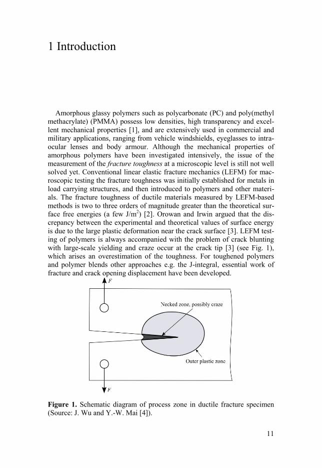
with large-scale yielding and craze occur at the crack tip [3] (see Fig. 1),
which arises an overestimation of the toughness. For toughened polymers
and polymer blends other approaches e.g. the J-integral, essential work of
fracture and crack opening displacement have been developed.
Figure 1. Schematic diagram of process zone in ductile fracture specimen
(Source: J. Wu and Y.-W. Mai [4]).
12
More recently, the sectioning (cutting) method is becoming an alternative
approach for the measurement of fracture toughness for polymers. Section-
ing is a controlled material-removal process, separating a layer of material
from the bulk in forms of chips, which can be viewed as a crack propagation
process. This method can avoid the problem of large-scale yielding in front
of the crack tip since the knife edge can touch the crack tip during the whole
process [5]. Previously, Ericsson and Lindberg [6] used a nanosectioning
method to investigate the energy dissipation mechanisms in polymers. At-
kins [2,7] reformulated the energy balance equation by taking fracture dissi-
pation into account in the sectioning analysis, and concluded that the fracture
toughness of material can be determined from the sectioning force. More
recently, Williams and his co-workers [4,8,9] improved this methodology.
To date, the sectioning method has been applied to determine fracture
toughness of metals [2,10], polymers [5,11], nanocomposites [12,13], wood
[14], body tissues and bones [15,16], etc.
The fast development in device miniaturisation demands increased abili-
ties to manipulate matter at the nanoscale and even the atomic level. Section-
ing of polymers at the nanoscale (sub-microscale) is of great significance in
manufacturing components and devices for electrical and optical applica-
tions [17]. As the sectioning scale goes down to the nanoscale, the terms
related to the volume (e.g. the plastic work) are strongly restricted while the
terms related to surface area (e.g. fracture) becomes relatively more pro-
nounced, and special deformation behaviour is anticipated to occur.
1.1 Plastic behaviour of amorphous thermoplastics
In this section, the plastic behaviour of amorphous thermoplastic poly-
mers is recapitulated. Polymers can deform plastically, with chain molecules
sliding past each other over large distances. As glassy polymers undergo
large deformation, two kinds of physical resistance must be overcome before
large inelastic flow occurs. Below the glass transition temperature Tg, prior
to initial yield, the material needs to be stressed to exceed its intermolecular
resistance to segment rotation. Once the material is free to flow, molecular
alignment occurs, resulting in an anisotropic internal resistance to further
inelastic deformation [18].
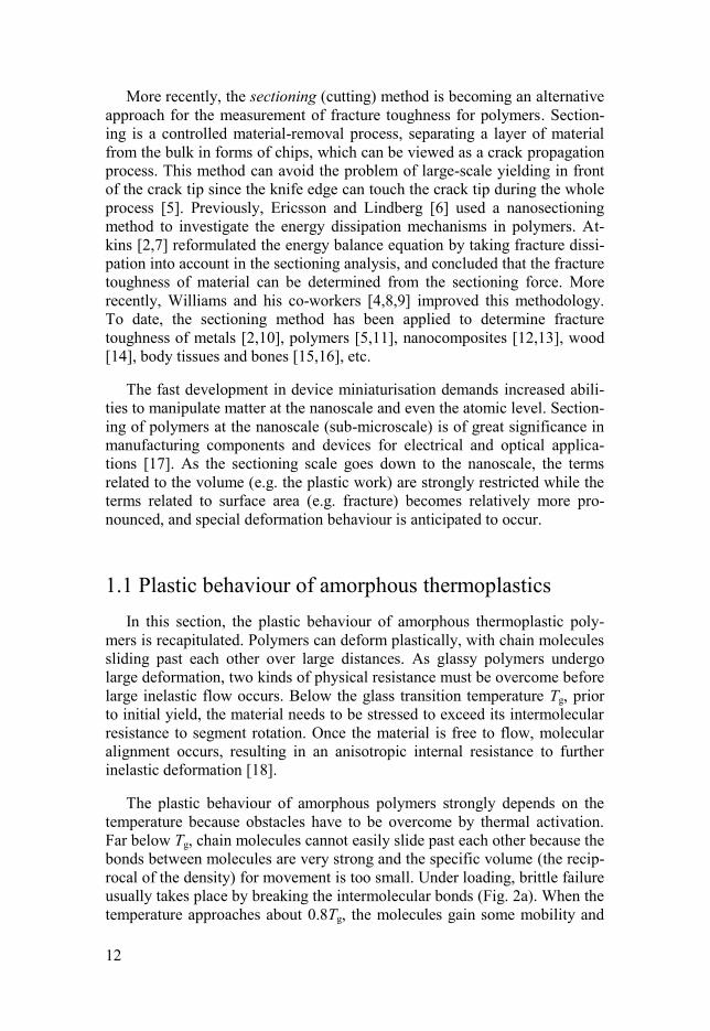
The plastic behaviour of amorphous polymers strongly depends on the
temperature because obstacles have to be overcome by thermal activation.
Far below Tg, chain molecules cannot easily slide past each other because the
bonds between molecules are very strong and the specific volume (the recip-
rocal of the density) for movement is too small. Under loading, brittle failure
usually takes place by breaking the intermolecular bonds (Fig. 2a). When the
temperature approaches about 0.8Tg, the molecules gain some mobility and
13
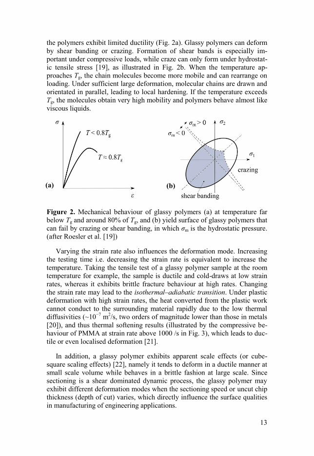
the polymers exhibit limited ductility (Fig. 2a). Glassy polymers can deform
by shear banding or crazing. Formation of shear bands is especially im-
portant under compressive loads, while craze can only form under hydrostat-
ic tensile stress [19], as illustrated in Fig. 2b. When the temperature ap-
proaches Tg, the chain molecules become more mobile and can rearrange on
loading. Under sufficient large deformation, molecular chains are drawn and
orientated in parallel, leading to local hardening. If the temperature exceeds
Tg, the molecules obtain very high mobility and polymers behave almost like
viscous liquids.
Figure 2. Mechanical behaviour of glassy polymers (a) at temperature far
below Tg and around 80% of Tg, and (b) yield surface of glassy polymers that
can fail by crazing or shear banding, in which σm is the hydrostatic pressure.
(after Roesler et al. [19])
Varying the strain rate also influences the deformation mode. Increasing
the testing time i.e. decreasing the strain rate is equivalent to increase the
temperature. Taking the tensile test of a glassy polymer sample at the room
temperature for example, the sample is ductile and cold-draws at low strain
rates, whereas it exhibits brittle fracture behaviour at high rates. Changing
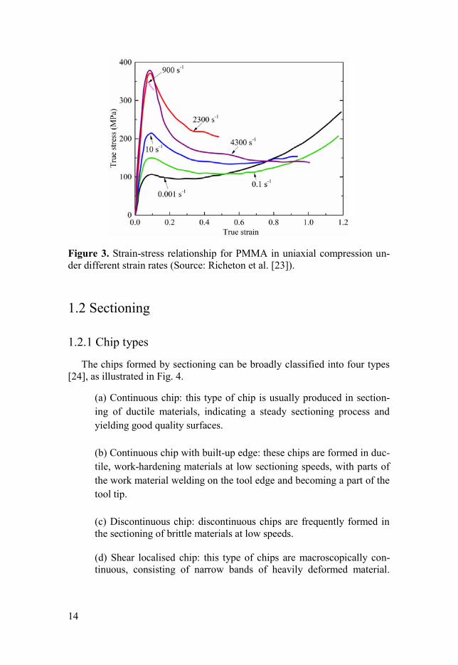
the strain rate may lead to the isothermal–adiabatic transition. Under plastic
deformation with high strain rates, the heat converted from the plastic work
cannot conduct to the surrounding material rapidly due to the low thermal
diffusivities (~10−7
m2/s, two orders of magnitude lower than those in metals
[20]), and thus thermal softening results (illustrated by the compressive be-
haviour of PMMA at strain rate above 1000 /s in Fig. 3), which leads to duc-
tile or even localised deformation [21].
In addition, a glassy polymer exhibits apparent scale effects (or cube-
square scaling effects) [22], namely it tends to deform in a ductile manner at
small scale volume while behaves in a brittle fashion at large scale. Since
sectioning is a shear dominated dynamic process, the glassy polymer may
exhibit different deformation modes when the sectioning speed or uncut chip
thickness (depth of cut) varies, which directly influence the surface qualities
in manufacturing of engineering applications.
(a) (b)
14
Figure 3. Strain-stress relationship for PMMA in uniaxial compression un-
der different strain rates (Source: Richeton et al. [23]).
1.2 Sectioning
1.2.1 Chip types
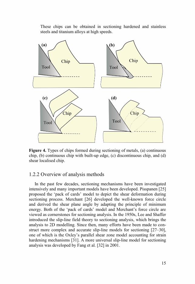
The chips formed by sectioning can be broadly classified into four types
[24], as illustrated in Fig. 4.
(a) Continuous chip: this type of chip is usually produced in section-
ing of ductile materials, indicating a steady sectioning process and
yielding good quality surfaces.
(b) Continuous chip with built-up edge: these chips are formed in duc-
tile, work-hardening materials at low sectioning speeds, with parts of
the work material welding on the tool edge and becoming a part of the
tool tip.
(c) Discontinuous chip: discontinuous chips are frequently formed in
the sectioning of brittle materials at low speeds.
(d) Shear localised chip: this type of chips are macroscopically con-
tinuous, consisting of narrow bands of heavily deformed material.
15
These chips can be obtained in sectioning hardened and stainless
steels and titanium alloys at high speeds.
Figure 4. Types of chips formed during sectioning of metals, (a) continuous
chip, (b) continuous chip with built-up edge, (c) discontinuous chip, and (d)
shear localised chip.
1.2.2 Overview of analysis methods
In the past few decades, sectioning mechanisms have been investigated
intensively and many important models have been developed. Pisspanen [25]
proposed the ‘pack of cards’ model to depict the shear deformation during
sectioning process. Merchant [26] developed the well-known force circle
and derived the shear plane angle by adapting the principle of minimum
energy. Both of the ‘pack of cards’ model and Merchant’s force circle are
viewed as cornerstones for sectioning analysis. In the 1950s, Lee and Shaffer
introduced the slip-line field theory to sectioning analysis, which brings the
analysis to 2D modelling. Since then, many efforts have been made to con-
struct more complex and accurate slip-line models for sectioning [27–30],
one of which is the Oxley’s parallel shear zone model accounting for strain
hardening mechanisms [31]. A more universal slip-line model for sectioning
analysis was developed by Fang et al. [32] in 2001.
(c)
(a) (b)
(d)
16
With regard to the formation of shear localised metal chips, Recht [21]
proposed an adiabatic heating induced shear instability model. Based on
Recht’s hypothesis, Komanduri and Hou [33,34] developed a classical adia-
batic shearing model to predict the onset of shear localised chips. Another
model, shear cracking model, was proposed by Nakayama [35], based on
experimental work on highly cold worked (brittle) brass machined at very
low speeds. This model was later improved by Shaw [36]. The essential dis-
tinction between the two theories lies in the root cause of the shear band.
While the shear band initiates from the knife-tip in the adiabatic shearing
theory, it originates from the free surface of the chip in the shear cracking
theory. Apart from these two models, Sullivan et al. [37] developed the slip-
stick friction model, Davies and Burns [38,39] proposed the loading-
unloading (reactions between the tool surface and material) model to de-
scribe the formation of shear localisations, etc.
With the fast development of the computer technology, finite element
methods have been widely used in analysing the sectioning process since
1980s [24,40–42]. Finite element simulation is now viewed as a reliable
approach to analyse the sectioning process. With finite element analysis, the
complex large elastic-plastic deformation, contact/friction, thermo-
mechanical coupling and chip separation mechanisms, which occur in the
vicinity of the cutting edge and are not directly observable, can be better
described and understood [24]. To date, the Eulerian method, Lagrangian
method and coupled Eulerian-Lagrangian method, smoothed particle hydro-
dynamics, etc. have been used in the analyse of the sectioning process
[43,44]. Recently, researchers have attempted to use molecular dynamics
methods to investigate the sectioning conducted at the nanoscale [45,46].
1.3 Objective
Investigating the mechanical response of glassy polymers during section-
ing process is important for both scientific studies and engineering applica-
tions. The main objective of this thesis is to reveal the mechanisms that gov-
ern the deformation and fracture behaviour of polymeric material during
nanosectioning by experiment and modelling. Such knowledge can be useful
in controlling and limiting damage formation in manufacturing of small-
scale polymer components, and in models predicting the mechanical behav-
iour on the sub-micrometre level in polymer-matrix composites.
1.3.1 Assessing fracture properties of a glassy polymer
In this subtopic, the fracture toughness and energy dissipation mecha-
nisms during sectioning at the nanoscale are investigated. The main work
17
includes: (1) the design and development of robust apparatus for performing
nanosectioning and measurements of sectioning forces, chip thicknesses,
etc.; (2) assessing the fracture toughness of the glassy polymer, and (3) char-
acterising the deformation and fracture behaviour of the glassy polymer dur-
ing nanosectioning.
1.3.2 Rate dependence of sectioning
As be described in Section 1.1, the mechanical behaviour of glassy poly-
mers is very sensitive to the strain rate. In this subtopic, the influence of
strain rate on the material deformation behaviour during sectioning process
is investigated by conducting nanosectioning with varying speed. Modelling
work is also carried out to explore the possible mechanisms that control the
material response.
1.3.3 Influence of nanosectioning on surface properties
Acquiring high-quality surfaces (good integrity, high mechanical and op-
tical properties) by sectioning is a main concern for engineering applications.
In this subtopic, the influence of the sectioning condition (uncut chip thick-
ness, sectioning speed) on the surface elasticity and damage of a glassy pol-
ymer is investigated by experiment and modelling.
1.3.4 Finite element modelling of polymer sectioning
Using finite element methods to investigate polymer sectioning process is
important because sectioning is a complex and nonlinear process which is
difficult to observe by experiment. One aim of this study is to implement
finite element analysis of sectioning of glassy polymer using appropriate
models including the effects of strain rates, temperature, hydrostatic pres-
sure, etc. Numerical modelling is challenging since the mechanisms in sec-
tioning are complex and interacting. As a first step, it is useful to see if the
numerical simulations can recreate the experimentally observed phenomena.
Once the model has been validated, it may be used to predict formation of
damage based on material properties and sectioning conditions.
1.3.5 Testing nanocomposites by sectioning
To investigate the strengthening and toughening mechanisms of nano-
fillers in composites, nanosectioning is performed on multiwall carbon nano-
tube (MWCNT) based composites. The focus of the study is to characterise
the mechanical properties of the nanocomposites and to explore the role of
MWCNT in enhancing the material. The idea is to illustrate how the nano-
18
sectioning method can be used to evaluate more complex materials than neat
amorphous thermoplastics, e.g. composite materials.
1.3.6 Optimising cellulose nanofibre biocomposites
Wood nanocellulose has been proposed for wound dressing applications
because of its capability to form translucent films and aerogels with good
liquid absorption capabilities. Understanding the mechanical properties of
nanocellulose films are most important for tailoring optimizing wound dress-
ing structures with adequate strength, conformability, porosity and exudate
management. Mechanical properties are usually assessed in standard condi-
tions (50% relative humidity), which is not relevant in a wound management
situation. In this study, the effect of nanofibrillation and of polyethylene
glycol (PEG) addition on the mechanical properties of nanocellulose films
are assessed in wet conditions.
Although nanosectioning was not used in this study, this piece of work is
included in the thesis to show an example of an application of a polymer-
based material, whose functionality is controlled by damage and deformation
processes on the sub-micrometre scale. A nanocomposite is a heterogeneous
material, where the reinforcement brings about high local stresses and even-
tually fracture and damage processes at a very local level.
19
2 Materials and methods
2.1 Nanosectioning setup
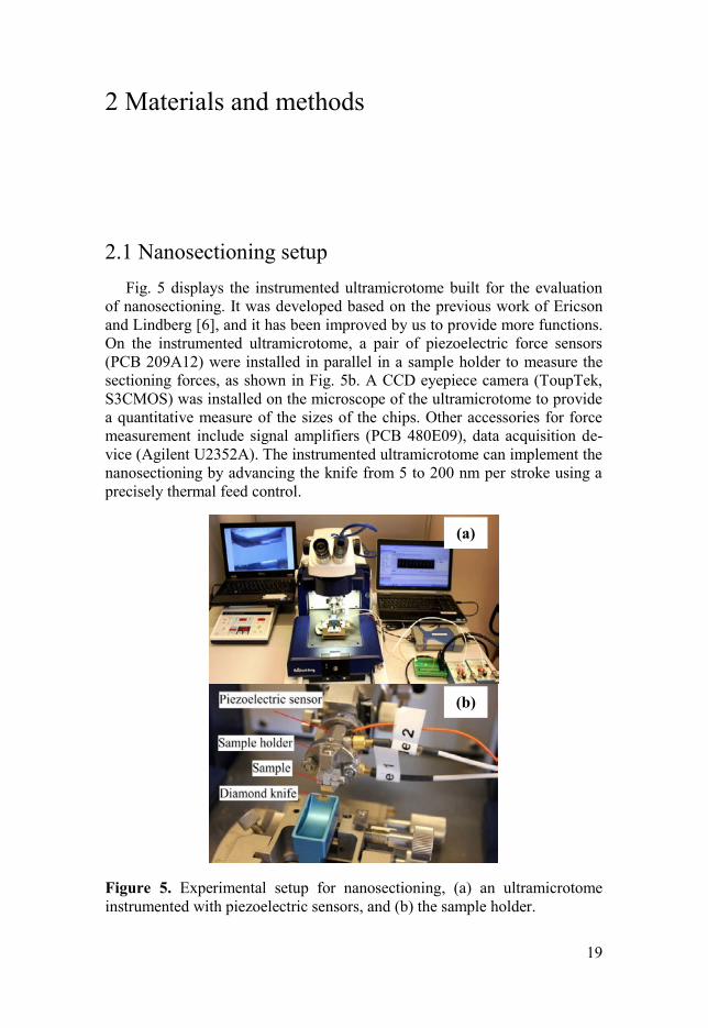
Fig. 5 displays the instrumented ultramicrotome built for the evaluation
of nanosectioning. It was developed based on the previous work of Ericson
and Lindberg [6], and it has been improved by us to provide more functions.
On the instrumented ultramicrotome, a pair of piezoelectric force sensors
(PCB 209A12) were installed in parallel in a sample holder to measure the
sectioning forces, as shown in Fig. 5b. A CCD eyepiece camera (ToupTek,
S3CMOS) was installed on the microscope of the ultramicrotome to provide
a quantitative measure of the sizes of the chips. Other accessories for force
measurement include signal amplifiers (PCB 480E09), data acquisition de-
vice (Agilent U2352A). The instrumented ultramicrotome can implement the
nanosectioning by advancing the knife from 5 to 200 nm per stroke using a
precisely thermal feed control.
Figure 5. Experimental setup for nanosectioning, (a) an ultramicrotome
instrumented with piezoelectric sensors, and (b) the sample holder.
(a)
(b)
20
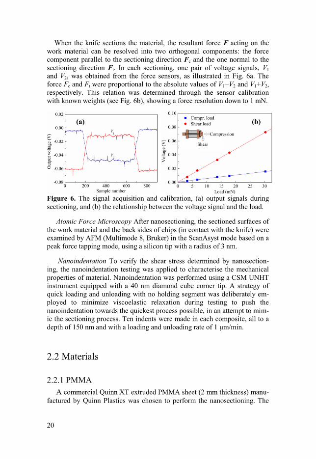
When the knife sections the material, the resultant force F acting on the
work material can be resolved into two orthogonal components: the force
component parallel to the sectioning direction Fc and the one normal to the
sectioning direction Ft. In each sectioning, one pair of voltage signals, V1
and V2, was obtained from the force sensors, as illustrated in Fig. 6a. The
force Fc and Ft were proportional to the absolute values of V1−V2 and V1+V2,
respectively. This relation was determined through the sensor calibration
with known weights (see Fig. 6b), showing a force resolution down to 1 mN.
Figure 6. The signal acquisition and calibration, (a) output signals during
sectioning, and (b) the relationship between the voltage signal and the load.
Atomic Force Microscopy After nanosectioning, the sectioned surfaces of
the work material and the back sides of chips (in contact with the knife) were
examined by AFM (Multimode 8, Bruker) in the ScanAsyst mode based on a
peak force tapping mode, using a silicon tip with a radius of 3 nm.
Nanoindentation To verify the shear stress determined by nanosection-
ing, the nanoindentation testing was applied to characterise the mechanical
properties of material. Nanoindentation was performed using a CSM UNHT
instrument equipped with a 40 nm diamond cube corner tip. A strategy of
quick loading and unloading with no holding segment was deliberately em-
ployed to minimize viscoelastic relaxation during testing to push the
nanoindentation towards the quickest process possible, in an attempt to mim-
ic the sectioning process. Ten indents were made in each composite, all to a
depth of 150 nm and with a loading and unloading rate of 1 μm/min.
2.2 Materials
2.2.1 PMMA
A commercial Quinn XT extruded PMMA sheet (2 mm thickness) manu-
factured by Quinn Plastics was chosen to perform the nanosectioning. The
(a) (b)
21
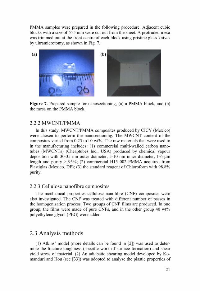
PMMA samples were prepared in the following procedure. Adjacent cubic
blocks with a size of 5×5 mm were cut out from the sheet. A protruded mesa
was trimmed out at the front centre of each block using pristine glass knives
by ultramicrotomy, as shown in Fig. 7.
Figure 7. Prepared sample for nanosectioning, (a) a PMMA block, and (b)
the mesa on the PMMA block.
2.2.2 MWCNT/PMMA
In this study, MWCNT/PMMA composites produced by CICY (Mexico)
were chosen to perform the nanosectioning. The MWCNT content of the
composites varied from 0.25 to1.0 wt%. The raw materials that were used to
in the manufacturing includes: (1) commercial multi-walled carbon nano-
tubes (MWCNTs) (Cheaptubes Inc., USA) produced by chemical vapour
deposition with 30-35 nm outer diameter, 5-10 nm inner diameter, 1-6 μm
length and purity > 95%; (2) commercial H15 002 PMMA acquired from
Plastiglas (Mexico, DF); (3) the standard reagent of Chloroform with 98.8%
purity.
2.2.3 Cellulose nanofibre composites
The mechanical properties cellulose nanofibre (CNF) composites were
also investigated. The CNF was treated with different number of passes in
the homogenisation process. Two groups of CNF films are produced. In one
group, the films were made of pure CNFs, and in the other group 40 wt%
polyethylene glycol (PEG) were added.
2.3 Analysis methods
(1) Atkins’ model (more details can be found in [2]) was used to deter-
mine the fracture toughness (specific work of surface formation) and shear
yield stress of material. (2) An adiabatic shearing model developed by Ko-
manduri and Hou (see [33]) was adopted to analyse the plastic properties of
(a) (b)
22
PMMA under adiabatic heating with a constitutive model proposed by
Richeton et al. [47]. (3) A damage model was used in analysing the effects
of sectioning speed on the surface elasticity of PMMA.
Finite element analysis was conducted to explore the deformation behav-
iour of PMMA during sectioning, in which the experimental stress-strain
plots obtained by Richeton et al. [23] and a modified Mulliken-Boyce model
(see [48]) were used to describe the yield and post-yield response of PMMA
under high strain rates.
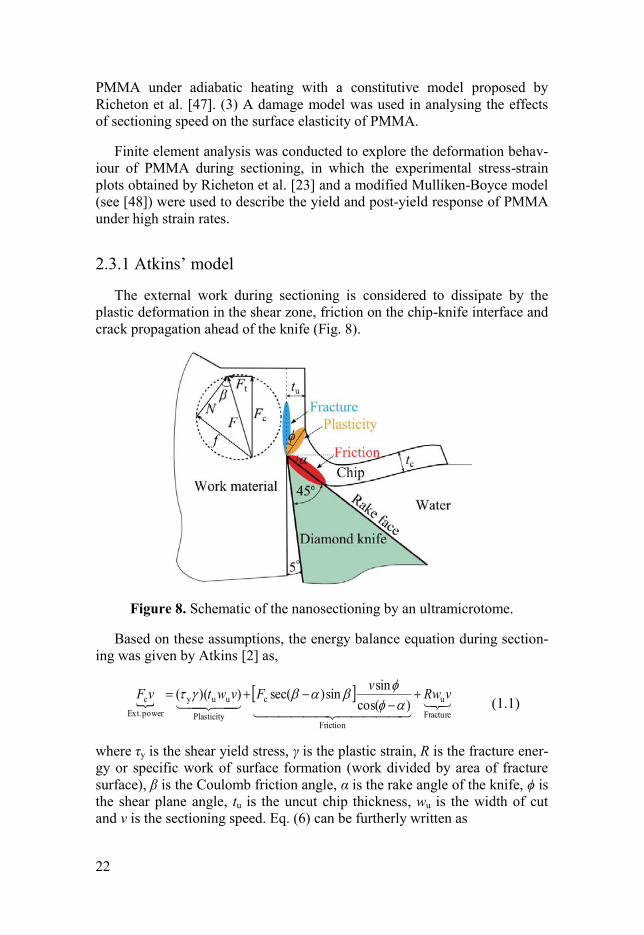
2.3.1 Atkins’ model
The external work during sectioning is considered to dissipate by the
plastic deformation in the shear zone, friction on the chip-knife interface and
crack propagation ahead of the knife (Fig. 8).
Figure 8. Schematic of the nanosectioning by an ultramicrotome.
Based on these assumptions, the energy balance equation during section-
ing was given by Atkins [2] as,
Fracture
u
Friction
c
Plasticity
uuy
power Ext.
c)cos(
sinsin)sec())(( vRw
vFvwtvF
(1.1)
where τy is the shear yield stress, γ is the plastic strain, R is the fracture ener-
gy or specific work of surface formation (work divided by area of fracture
surface), β is the Coulomb friction angle, α is the rake angle of the knife, ϕ is
the shear plane angle, tu is the uncut chip thickness, wu is the width of cut
and v is the sectioning speed. Eq. (6) can be furtherly written as
23
Q
Rt
Qw
F
u
y
u
c
(1.2)
where Q = [1−sinβsinϕ/cos(β−α)cos(ϕ−α)] is a friction parameter. Williams
et al. [49] derived the closed-form solution for ϕ as follows
tan)tan()(tan1)tan(cot 2 Z (1.3)
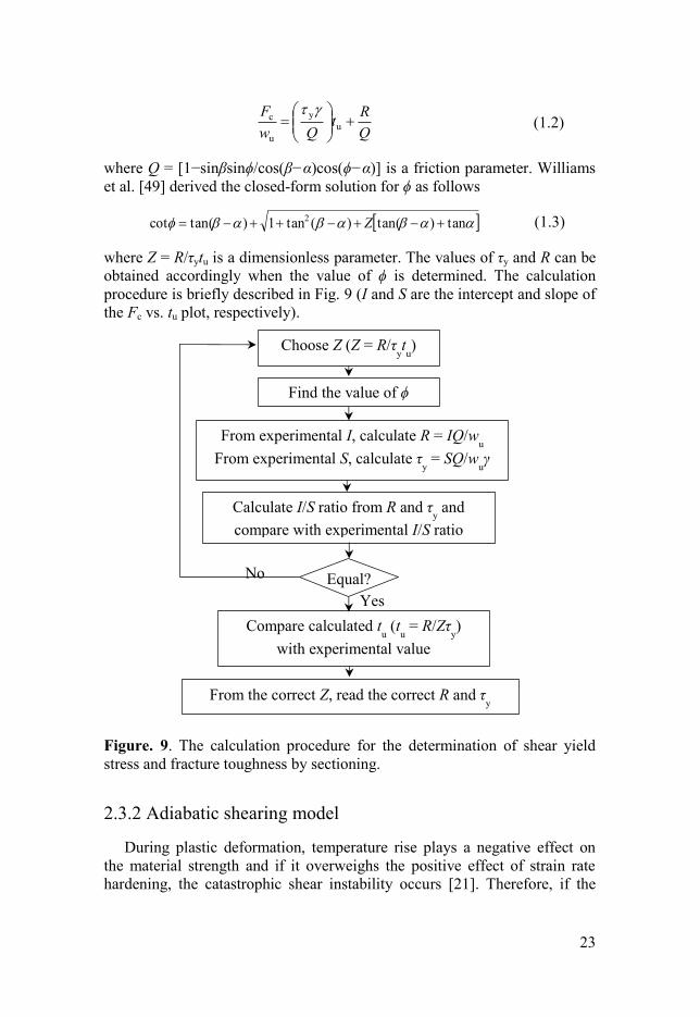
where Z = R/τytu is a dimensionless parameter. The values of τy and R can be
obtained accordingly when the value of ϕ is determined. The calculation
procedure is briefly described in Fig. 9 (I and S are the intercept and slope of
the Fc vs. tu plot, respectively).
Figure. 9. The calculation procedure for the determination of shear yield
stress and fracture toughness by sectioning.
2.3.2 Adiabatic shearing model
During plastic deformation, temperature rise plays a negative effect on
the material strength and if it overweighs the positive effect of strain rate
hardening, the catastrophic shear instability occurs [21]. Therefore, if the
Calculate I/S ratio from R and τy and
compare with experimental I/S ratio
From experimental I, calculate R = IQ/wu
From experimental S, calculate τy = SQ/w
uγ
Find the value of ϕ
Choose Z (Z = R/τytu)
Compare calculated tu (t
u = R/Zτy)
with experimental value
From the correct Z, read the correct R and τy
Equal?
Yes
No
24
stress in the primary shear zone (PSZ), τPSZ, is surpassed by the stress in the
bulk material, τBulk, a shear localisation event takes place.
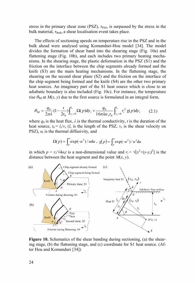
The effects of sectioning speeds on temperature rise in the PSZ and in the
bulk ahead were analysed using Komanduri-Hou model [34]. The model
divides the formation of shear band into the shearing stage (Fig. 10a) and
flattening stage (Fig. 10b), and each includes two primary heating mecha-
nisms. In the shearing stage, the plastic deformation in the PSZ (S1) and the
friction on the interface between the chip segments already formed and the
knife (S3) are the main heating mechanisms. In the flattening stage, the
shearing on the second shear plane (S2) and the friction on the interface of
the chip segment being formed and the knife (S4) are the other two primary
heat sources. An imaginary part of the S1 heat source which is close to an
adiabatic boundary is also included (Fig. 10c). For instance, the temperature
rise θM at M(x, y) due to the first source is formulated in an integral form,
ss
0
2
0t
0
00
0M d)χ(
16d)Ω()
21(
2
l
yii
l
yi
ii
yprt
qyp
t
tq
(2.1)
where q0 is the heat flux, λ is the thermal conductivity, t is the duration of the
heat source, t0 = ls/vs (ls is the length of the PSZ, vs is the shear velocity on
PSZ), αt is the thermal diffusivity, and
p
uuup d/)exp()Ω( 2 ,
p
uuup d/)exp(χ 32
in which p = ri/√4αtt is a non-dimensional value and ri = √[x2+(y-yi)
2] is the
distance between the heat segment and the point M(x, y).
Figure 10. Schematics of the shear banding during sectioning, (a) the shear-
ing stage, (b) the flattening stage, and (c) coordinate for S1 heat source. (Af-
ter Hou and Komanduri [34])
25
The yield stress of PMMA, σy, below the glass transition temperature is
expressed as [47]
n
TkHV
TkmT
1
Bβ0
1
a
Biy
)exp(sinh
2)0(
(2.2)
where σi(0) is the athermal yield stress, m is a softening parameter, kB is the
Boltzmann constant, Va is the activation volume, is the strain rate, 0 is a
pre-exponential constant, ΔHβ is the activation energy and n is a molecular
chain parameter.
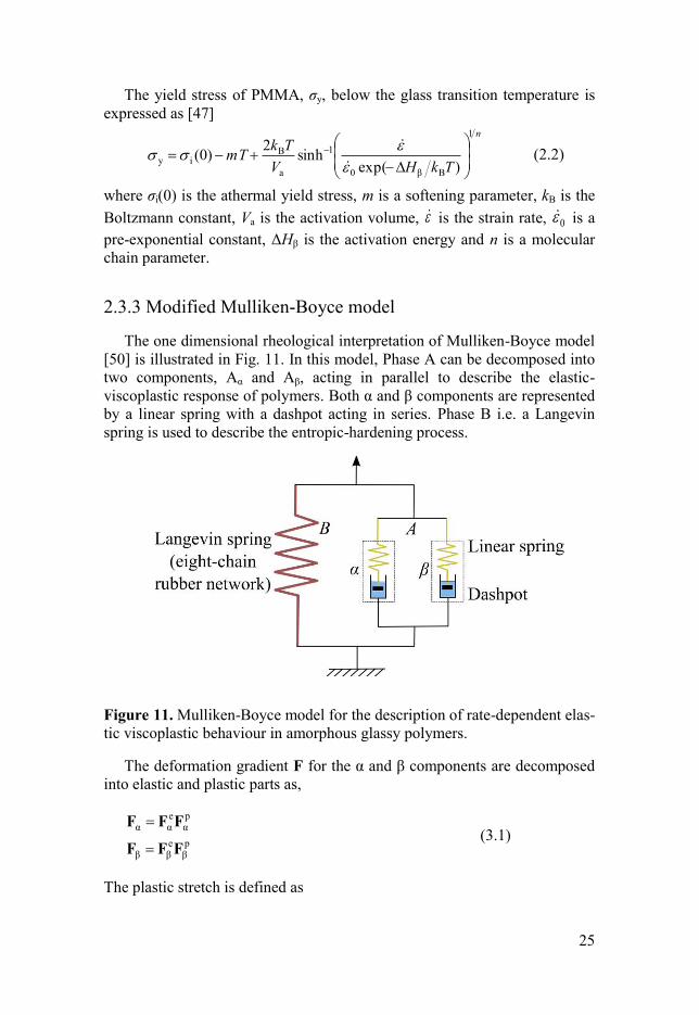
2.3.3 Modified Mulliken-Boyce model
The one dimensional rheological interpretation of Mulliken-Boyce model
[50] is illustrated in Fig. 11. In this model, Phase A can be decomposed into
two components, Aα and Aβ, acting in parallel to describe the elastic-
viscoplastic response of polymers. Both α and β components are represented
by a linear spring with a dashpot acting in series. Phase B i.e. a Langevin
spring is used to describe the entropic-hardening process.
Figure 11. Mulliken-Boyce model for the description of rate-dependent elas-
tic viscoplastic behaviour in amorphous glassy polymers.
The deformation gradient F for the α and β components are decomposed
into elastic and plastic parts as,
pβ
eββ
pα
eαα
FFF
FFF
(3.1)
The plastic stretch is defined as
26
pβ
pβ
pβ
pα
pα
pα
~
~
ND
ND
(3.2)
where pαN and p
βN are taken to be coaxial with the deviatoric stresses acting
on the α and β components, respectively
Aβ
AβpAβ
Aα
AαpAα
T
TN
T
TN
(3.3)
Varghese and Batra [48] modified the flow rule by including new internal
variables to characterise the viscoplastic behaviour,
pstk
G
pstk
G
βp,ββ
αβpβ0,
pβ
αp,αα
ααpα0,
pα
ˆ1exp
ˆ1exp
(3.4)
where pα0, and p
β0, are the pre-exponential factors, αG and βG are the
activation energies, p is the pressure, and αp, and βp, are the hydrostatic
pressure coefficients. The symbols αs and βs denote athermal shear
strengths, and evolve as
pα
αss,
α
0α
αα
α
αα
1ˆ
1
077.0ˆ
t
t
s
ht
s
(3.5a)
pβ
βss,
β
0β
β
β
β
β
β
1ˆ
1
077.0ˆ
t
t
s
ht
s
(3.5b)
Taking the dissipated plasticity into account and assuming the dissipation
as an adiabatic process, the temperature evolution is governed by
)~(tr)
~(tr
1 pAββ
pAαα DTDT
c (3.6)

27
where c is the specific heat, ρ = ρ0/det(F) is the material density in the cur-
rent configuration, Tα and Tβ are the Cauchy stresses in each component.
28
3 Results and discussions
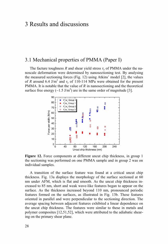
3.1 Mechanical properties of PMMA (Paper I)
The facture toughness R and shear yield stress τy of PMMA under the na-
noscale deformation were determined by nanosectioning test. By analysing
the measured sectioning forces (Fig. 12) using Atkins’ model [2], the values
of R around 6.4 J/m2 and τy of 110-114 MPa were obtained for the present
PMMA. It is notable that the value of 𝑅 in nanosectioning and the theoretical
surface free energy (~1.5 J/m2) are in the same order of magnitude [3].
Figure 12. Force components at different uncut chip thickness, in group 1
the sectioning was performed on one PMMA sample and in group 2 was on
individual samples.
A transition of the surface feature was found at a critical uncut chip
thickness. Fig. 13a displays the morphology of the surface sectioned at 60
nm under AFM, which is flat and smooth. As the uncut chip thickness in-
creased to 85 nm, short and weak wave-like features began to appear on the
surface. As the thickness increased beyond 110 nm, pronounced periodic
features formed on the surfaces, as illustrated in Fig. 13b. These features
oriented in parallel and were perpendicular to the sectioning direction. The
average spacing between adjacent features exhibited a linear dependence on
the uncut chip thickness. The features were similar to these in metals and
polymer composites [12,51,52], which were attributed to the adiabatic shear-
ing on the primary shear plane.
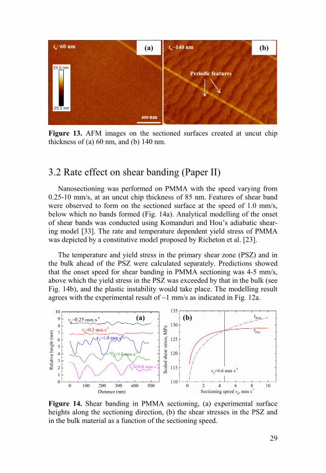
29
Figure 13. AFM images on the sectioned surfaces created at uncut chip
thickness of (a) 60 nm, and (b) 140 nm.
3.2 Rate effect on shear banding (Paper II)
Nanosectioning was performed on PMMA with the speed varying from
0.25-10 mm/s, at an uncut chip thickness of 85 nm. Features of shear band
were observed to form on the sectioned surface at the speed of 1.0 mm/s,
below which no bands formed (Fig. 14a). Analytical modelling of the onset
of shear bands was conducted using Komanduri and Hou’s adiabatic shear-
ing model [33]. The rate and temperature dependent yield stress of PMMA
was depicted by a constitutive model proposed by Richeton et al. [23].
The temperature and yield stress in the primary shear zone (PSZ) and in
the bulk ahead of the PSZ were calculated separately. Predictions showed
that the onset speed for shear banding in PMMA sectioning was 4-5 mm/s,
above which the yield stress in the PSZ was exceeded by that in the bulk (see
Fig. 14b), and the plastic instability would take place. The modelling result
agrees with the experimental result of ~1 mm/s as indicated in Fig. 12a.
Figure 14. Shear banding in PMMA sectioning, (a) experimental surface
heights along the sectioning direction, (b) the shear stresses in the PSZ and
in the bulk material as a function of the sectioning speed.
(a) (b)
(a) (b)
30
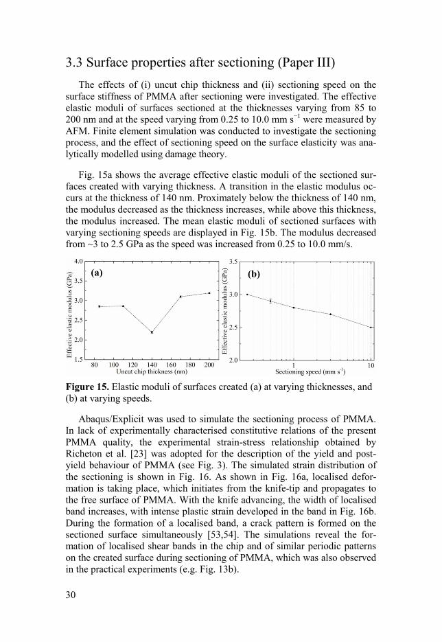
3.3 Surface properties after sectioning (Paper III)
The effects of (i) uncut chip thickness and (ii) sectioning speed on the
surface stiffness of PMMA after sectioning were investigated. The effective
elastic moduli of surfaces sectioned at the thicknesses varying from 85 to
200 nm and at the speed varying from 0.25 to 10.0 mm s−1
were measured by
AFM. Finite element simulation was conducted to investigate the sectioning
process, and the effect of sectioning speed on the surface elasticity was ana-
lytically modelled using damage theory.
Fig. 15a shows the average effective elastic moduli of the sectioned sur-
faces created with varying thickness. A transition in the elastic modulus oc-
curs at the thickness of 140 nm. Proximately below the thickness of 140 nm,
the modulus decreased as the thickness increases, while above this thickness,
the modulus increased. The mean elastic moduli of sectioned surfaces with
varying sectioning speeds are displayed in Fig. 15b. The modulus decreased
from ~3 to 2.5 GPa as the speed was increased from 0.25 to 10.0 mm/s.
Figure 15. Elastic moduli of surfaces created (a) at varying thicknesses, and
(b) at varying speeds.
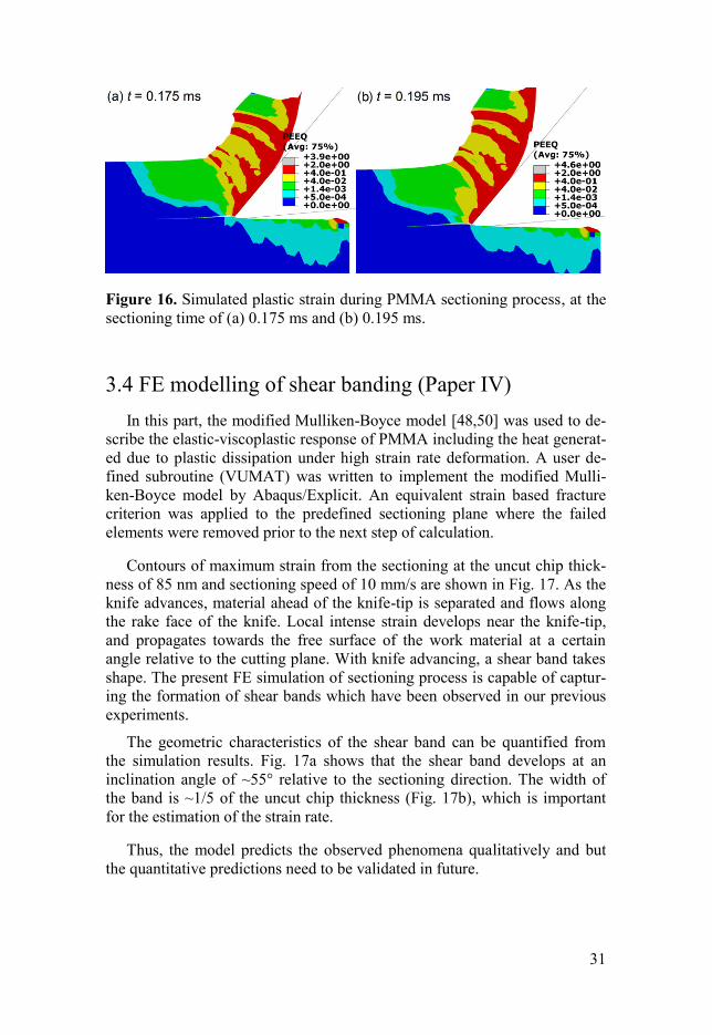
Abaqus/Explicit was used to simulate the sectioning process of PMMA.
In lack of experimentally characterised constitutive relations of the present
PMMA quality, the experimental strain-stress relationship obtained by
Richeton et al. [23] was adopted for the description of the yield and post-
yield behaviour of PMMA (see Fig. 3). The simulated strain distribution of
the sectioning is shown in Fig. 16. As shown in Fig. 16a, localised defor-
mation is taking place, which initiates from the knife-tip and propagates to
the free surface of PMMA. With the knife advancing, the width of localised
band increases, with intense plastic strain developed in the band in Fig. 16b.
During the formation of a localised band, a crack pattern is formed on the
sectioned surface simultaneously [53,54]. The simulations reveal the for-
mation of localised shear bands in the chip and of similar periodic patterns
on the created surface during sectioning of PMMA, which was also observed
in the practical experiments (e.g. Fig. 13b).
(a) (b)
31
Figure 16. Simulated plastic strain during PMMA sectioning process, at the
sectioning time of (a) 0.175 ms and (b) 0.195 ms.
3.4 FE modelling of shear banding (Paper IV)
In this part, the modified Mulliken-Boyce model [48,50] was used to de-
scribe the elastic-viscoplastic response of PMMA including the heat generat-
ed due to plastic dissipation under high strain rate deformation. A user de-
fined subroutine (VUMAT) was written to implement the modified Mulli-
ken-Boyce model by Abaqus/Explicit. An equivalent strain based fracture
criterion was applied to the predefined sectioning plane where the failed
elements were removed prior to the next step of calculation.
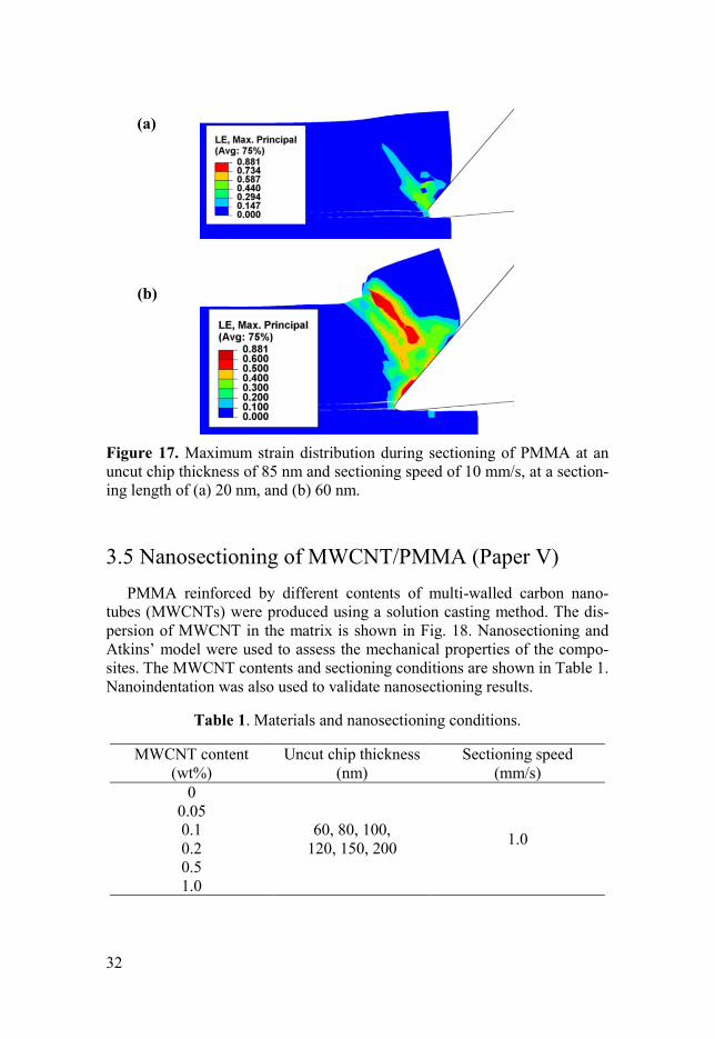
Contours of maximum strain from the sectioning at the uncut chip thick-
ness of 85 nm and sectioning speed of 10 mm/s are shown in Fig. 17. As the
knife advances, material ahead of the knife-tip is separated and flows along
the rake face of the knife. Local intense strain develops near the knife-tip,
and propagates towards the free surface of the work material at a certain
angle relative to the cutting plane. With knife advancing, a shear band takes
shape. The present FE simulation of sectioning process is capable of captur-
ing the formation of shear bands which have been observed in our previous
experiments.
The geometric characteristics of the shear band can be quantified from
the simulation results. Fig. 17a shows that the shear band develops at an
inclination angle of ~55° relative to the sectioning direction. The width of
the band is ~1/5 of the uncut chip thickness (Fig. 17b), which is important
for the estimation of the strain rate.
Thus, the model predicts the observed phenomena qualitatively and but
the quantitative predictions need to be validated in future.
32
Figure 17. Maximum strain distribution during sectioning of PMMA at an
uncut chip thickness of 85 nm and sectioning speed of 10 mm/s, at a section-
ing length of (a) 20 nm, and (b) 60 nm.
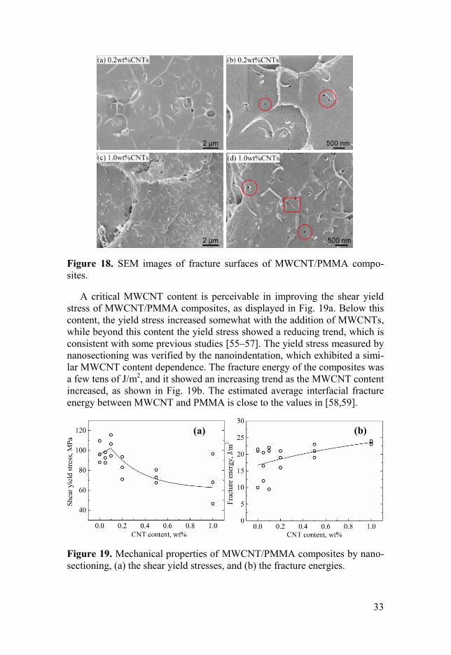
3.5 Nanosectioning of MWCNT/PMMA (Paper V)
PMMA reinforced by different contents of multi-walled carbon nano-
tubes (MWCNTs) were produced using a solution casting method. The dis-
persion of MWCNT in the matrix is shown in Fig. 18. Nanosectioning and
Atkins’ model were used to assess the mechanical properties of the compo-
sites. The MWCNT contents and sectioning conditions are shown in Table 1.
Nanoindentation was also used to validate nanosectioning results.
Table 1. Materials and nanosectioning conditions.
MWCNT content
(wt%)
Uncut chip thickness
(nm)
Sectioning speed
(mm/s)
0
60, 80, 100,
120, 150, 200 1.0
0.05
0.1
0.2
0.5
1.0
(a)
(b)
33
Figure 18. SEM images of fracture surfaces of MWCNT/PMMA compo-
sites.
A critical MWCNT content is perceivable in improving the shear yield
stress of MWCNT/PMMA composites, as displayed in Fig. 19a. Below this
content, the yield stress increased somewhat with the addition of MWCNTs,
while beyond this content the yield stress showed a reducing trend, which is
consistent with some previous studies [55–57]. The yield stress measured by
nanosectioning was verified by the nanoindentation, which exhibited a simi-
lar MWCNT content dependence. The fracture energy of the composites was
a few tens of J/m2, and it showed an increasing trend as the MWCNT content
increased, as shown in Fig. 19b. The estimated average interfacial fracture
energy between MWCNT and PMMA is close to the values in [58,59].
Figure 19. Mechanical properties of MWCNT/PMMA composites by nano-
sectioning, (a) the shear yield stresses, and (b) the fracture energies.
(a) (b)
34
3.6 Mechanical characteristics of CNF films (Paper VI)
Although the nanosectioning method was not employed in this part of the
work, there is a common denominator in the underlying mechanisms in the
polymer components of the composite, such as local yield, deformation and
cracking at the sub-micrometre level.
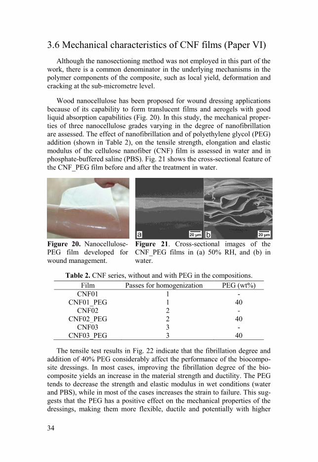
Wood nanocellulose has been proposed for wound dressing applications
because of its capability to form translucent films and aerogels with good
liquid absorption capabilities (Fig. 20). In this study, the mechanical proper-
ties of three nanocellulose grades varying in the degree of nanofibrillation
are assessed. The effect of nanofibrillation and of polyethylene glycol (PEG)
addition (shown in Table 2), on the tensile strength, elongation and elastic
modulus of the cellulose nanofiber (CNF) film is assessed in water and in
phosphate-buffered saline (PBS). Fig. 21 shows the cross-sectional feature of
the CNF_PEG film before and after the treatment in water.
Figure 20. Nanocellulose-
PEG film developed for
wound management.
Figure 21. Cross-sectional images of the
CNF_PEG films in (a) 50% RH, and (b) in
water.
Table 2. CNF series, without and with PEG in the compositions.
Film Passes for homogenization PEG (wt%)
CNF01 1 -
CNF01_PEG 1 40
CNF02 2 -
CNF02_PEG 2 40
CNF03 3 -
CNF03_PEG 3 40
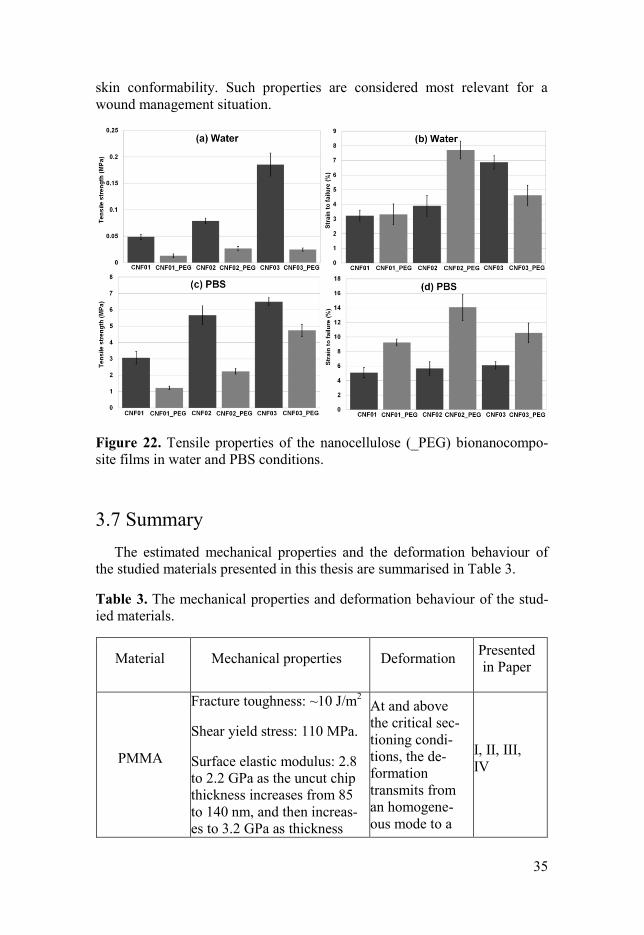
The tensile test results in Fig. 22 indicate that the fibrillation degree and
addition of 40% PEG considerably affect the performance of the biocompo-
site dressings. In most cases, improving the fibrillation degree of the bio-
composite yields an increase in the material strength and ductility. The PEG
tends to decrease the strength and elastic modulus in wet conditions (water
and PBS), while in most of the cases increases the strain to failure. This sug-
gests that the PEG has a positive effect on the mechanical properties of the
dressings, making them more flexible, ductile and potentially with higher
35
skin conformability. Such properties are considered most relevant for a
wound management situation.
Figure 22. Tensile properties of the nanocellulose (_PEG) bionanocompo-
site films in water and PBS conditions.
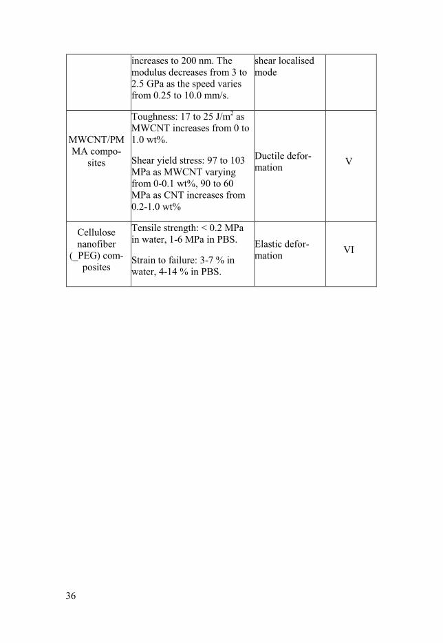
3.7 Summary
The estimated mechanical properties and the deformation behaviour of
the studied materials presented in this thesis are summarised in Table 3.
Table 3. The mechanical properties and deformation behaviour of the stud-
ied materials.
Material Mechanical properties Deformation Presented
in Paper
PMMA
Fracture toughness: ~10 J/m2
Shear yield stress: 110 MPa.
Surface elastic modulus: 2.8
to 2.2 GPa as the uncut chip
thickness increases from 85
to 140 nm, and then increas-
es to 3.2 GPa as thickness
At and above
the critical sec-
tioning condi-
tions, the de-
formation
transmits from
an homogene-
ous mode to a
I, II, III,
IV
36
increases to 200 nm. The
modulus decreases from 3 to
2.5 GPa as the speed varies
from 0.25 to 10.0 mm/s.
shear localised
mode
MWCNT/PM
MA compo-
sites
Toughness: 17 to 25 J/m2 as
MWCNT increases from 0 to
1.0 wt%.
Shear yield stress: 97 to 103
MPa as MWCNT varying
from 0-0.1 wt%, 90 to 60
MPa as CNT increases from
0.2-1.0 wt%
Ductile defor-
mation V
Cellulose
nanofiber
(_PEG) com-
posites
Tensile strength: < 0.2 MPa
in water, 1-6 MPa in PBS.
Strain to failure: 3-7 % in
water, 4-14 % in PBS.
Elastic defor-
mation VI
37
4 Conclusions
In this thesis, the deformation and fracture behaviour of a glassy polymer
and nanocomposite during nanosectioning process are investigated by exper-
iment and modelling. It starts with the measurement of the fracture tough-
ness of glassy polymer under small scale deformation, then focuses on the
effects of the sectioning condition (uncut chip thickness and sectioning
speed) on the polymer deformation behaviour and on the surface mechanical
properties of the glassy polymer, followed by the finite element modelling of
the shear banding issue during sectioning, and ends with the exploration of
the strengthening and toughening mechanisms in nanocomposites using sec-
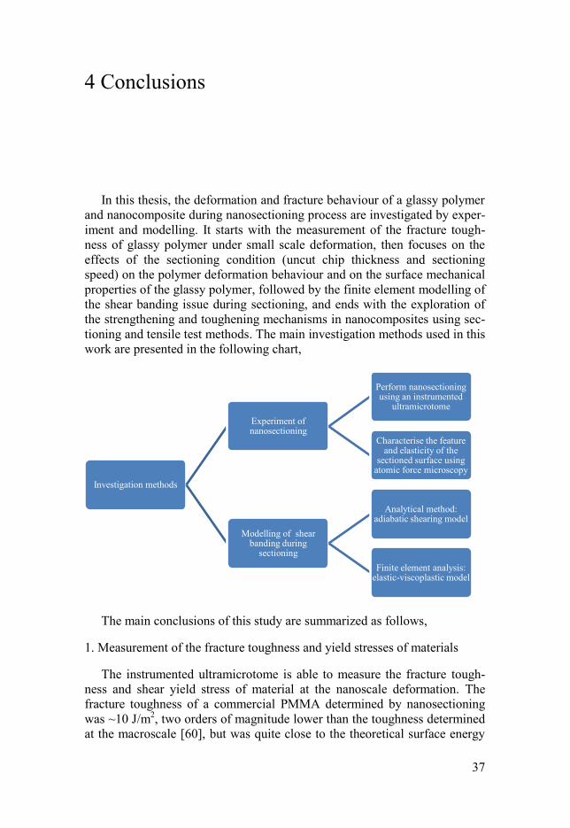
tioning and tensile test methods. The main investigation methods used in this
work are presented in the following chart,
The main conclusions of this study are summarized as follows,
1. Measurement of the fracture toughness and yield stresses of materials
The instrumented ultramicrotome is able to measure the fracture tough-
ness and shear yield stress of material at the nanoscale deformation. The
fracture toughness of a commercial PMMA determined by nanosectioning
was ~10 J/m2, two orders of magnitude lower than the toughness determined
at the macroscale [60], but was quite close to the theoretical surface energy
Investigation methods
Experiment of nanosectioning
Perform nanosectioning using an instrumented
ultramicrotome
Characterise the feature and elasticity of the
sectioned surface using atomic force microscopy
Modelling of shear banding during
sectioning
Analytical method: adiabatic shearing model
Finite element analysis: elastic-viscoplastic model
38
required to create new surfaces by breaking C-C bonds (1.5 J/m2) [3]. The
shear yield stress of the PMMA was approximately 110 MPa.
The fracture toughness of MWCNT/PMMA composites was measured by
nanosectioning. It shows that the MWCNT can enhance the material tough-
ness effectively, which increased from 17 to 25 J/m2 as the MWCNT content
increased from 0 to 1.0 wt%. The nanosectioning test reveals a critical
MWCNT content in enhancing the strength of the composites. Below this
content the composite strength showed an increase as the MWCNT content
increased, while above this content the strength decreased.
2. Shear localisations
Periodic, wavy structures were formed during nanosectioning of PMMA,
which significantly influenced the surface qualities and mechanical proper-
ties. Critical sectioning conditions (uncut chip thickness, sectioning speed)
were revealed in the sectioning of PMMA, below which the created surfaces
were flat and smooth, while above which periodic wavy structures formed
on the surfaces. The average spacing between adjacent wavy structures was
proportional to the uncut chip thickness. These wavy structures were identi-
fied as shear localisations originated from the shear deformation on the pri-
mary shear plane.
The shear localisations were associated with lower elastic moduli com-
pared to the regions outside. The sectioning conditions had importance influ-
ence on the surface elasticity of PMMA. Increasing the sectioning speed led
to a decrease in the surface elasticity. Increasing the uncut chip thickness
decreased the surface elasticity but then improve the elasticity.
3. Formation mechanism of shear localisations
The analytical modelling of the stress variation in the primary shear zone
and in the bulk material in front of the shear zone yields a critical speed for
the onset of shear localisations in sectioning. This predicted speed is quite
close to the experimental result of nanosectioning. The finite element analy-
sis also confirms that localisations are formed during sectioning of PMMA.
The material softening due to the adiabatic heating is the main reason for the
formation of shear localizations. In fabrication of e.g. optical components, it
would be useful to predict processing conditions to avoid formation of shear
localisation defects.
4. Strengthening mechanism in nanocomposites
Incorporating MWCNT in PMMA with an appropriate content improved
the material strength, while excessive addition decreased the material
strength probably due to the MWCNT agglomeration.

39
Improving the fibrillation degree of the cellulose nanofibres led to an in-
crease in the strength and ductility of the CNF biocomposite. The addition of
PEG decreased the strength and elastic modulus in wet conditions, while in
most of the cases increased the strain to failure.
40
5 Outlook
The work presented in this thesis reveals some interesting phenomena
which take place during nanosectioning process, and these phenomena are
analysed using the classic continuum mechanics. To fully understand the
material deformation behaviour during nanosectioning process, more thor-
ough studies need to be undertaken. There are several issues are worthy of
investigations in future. From a scientific viewpoint, the following three
challenges would deserve more efforts.
Finite element analyse of sectioning of polymer matrix composites.
The main challenge is the description of the filler-matrix interfaces
during loading and debonding process. Improving the constitutive
model of glassy polymers under dynamic load, especially at high rates,
is also important. But this topic is highly related to the development of
the experimental set-up since the tested strain rate is limited to the
value of a few thousand now.
Molecular dynamic simulation needs to carry out to understand the
surface response during the sectioning at the nanoscale. The finite el-
ement simulation of the nanosectioning process using classic mechan-
ics needs to be further validated and discussed.
The measurement of the generated heat during sectioning process. To
conduct temperature measurement at such a small scale is important to
reveal the underlying mechanisms controlling the material behaviour,
although this topic is highly dependent on the development of the
miniature sensors.
From an application viewpoint, the methods and conclusions presented in
this thesis also benefit the polymer manufacturing in industry. In future, the
manufacturing of polymer components for optics and electronics using mi-
crosectioning and nanosectioning needs to consider the influences on the
surface qualities caused by sectioning operation. The models presented in
this thesis may be used to predict nanosectioning conditions to avoid damage
formation for high quality products. In addition, more efforts need to be un-
dertaken to improve the sectioning qualities, such as sectioning with lubrica-
tion fluid, cooling the work material, etc.
41
Sammanfattning på svenska
Denna avhandling behandlar deformations- och brottsbeteendet hos en
amorf polymer och nanokompositer, ända ned till nanoskala. Undersökning-
ar har gjort både med praktiska experiment och numerisk modellering. Först
mättes brottsegheten hos den amorfa polymeren för deformationer i mycket
skala, följt av mätningar hur tjocklek och hastighet påverkar deformationsbe-
teendet och de mekaniska ytegenskaperna hos polymeren vid snittning. Fi-
nit-element-modellering har använts för att simulera de skjuvband som upp-
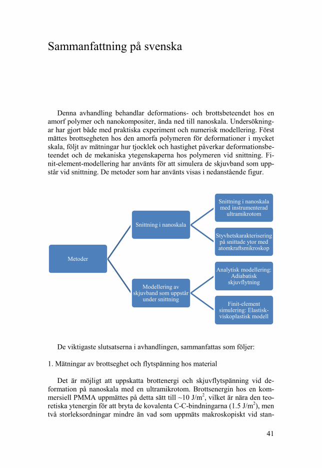
står vid snittning. De metoder som har använts visas i nedanstående figur.
De viktigaste slutsatserna i avhandlingen, sammanfattas som följer:
1. Mätningar av brottseghet och flytspänning hos material
Det är möjligt att uppskatta brottenergi och skjuvflytspänning vid de-
formation på nanoskala med en ultramikrotom. Brottsenergin hos en kom-
mersiell PMMA uppmättes på detta sätt till ~10 J/m2, vilket är nära den teo-
retiska ytenergin för att bryta de kovalenta C-C-bindningarna (1.5 J/m2), men
två storleksordningar mindre än vad som uppmäts makroskopiskt vid stan-
Metoder
Snittning i nanoskala
Snittning i nanoskala med instrumenterad
ultramikrotom
Styvhetskarakterisering på snittade ytor med atomkraftsmikroskop
Modellering av skjuvband som uppstår
under snittning
Analytisk modellering: Adiabatisk
skjuvflytning
Finit-element simulering: Elastisk-viskoplastisk modell
42
dardiserad brottmekanisk provning. Skjuvflytspänningen hos PMMA upp-
skattades till c:a 110 MPa.
Även brottsenergin hos kompositer bestående av flerväggiga kolnanorör i
PMMA-matris uppmättes. Resultatet var att kolnanorören ökade brottenergin
på materialet från 17 till 25 J/m2, då andelen förstärkning ökades från 0 till
1.0 viktsprocent. Vidare upptäcktes ett tröskelvärde för koncentration för-
stärkning för att höja styrkan hos kompositmaterialet. Under denna kritiska
mängd ökade styrkan med ökad mängd kolnanorör, men minskade istället
vid högre koncentrationer.
2. Lokaliserad skjuvning
En periodisk och vågliknande yttextur skapades vid snittning av PMMA,
vilket visat sig påverka dess mekaniska ytegenskaper. Kritiska förhållanden
(snitttjocklek och snitthastighet) kunde kostateras, vilket avgör om ytan får
periodiska mönster eller blir jämn och slät. Den genomsnittliga perioden av
den vågiga formen visade sig vara proportionell med snitttjockleken. Dessa
periodiska former identifierades som lokaliserad skjuvflytning.
Områden som uppvisar lokaliserad skjuvdeformation uppvisade en lägre
elasticitetsmodul jämfört med övriga intakta områden. Förhållandena vid
snittning (hastighet, tjocklek, temperatur osv.) har en stor inverkan på snitty-
tan i PMMA. En ökad snitthastighet ledde till en minskad elasticitetsmodul
på ytan. En ökning av snitttjockleken visade sig först leda till en minskning
av ytans styvhet, och därefter till en ökning.
3. Mekanismer bakom lokaliserad skjuvflytning
En analytisk modell har använts för att bestämma spänningstillståndet i
det primära skjuvområdet och i materialet framför skjuvområdet. En kritisk
snitthastighet för aktivering av skjuvflytning kunde påvisas. Den beräknade
kritiska hastigheten är nära den hastighet som bestämdes experimentellt.
Numeriska simuleringar med finita element bekräftar att lokalisering av
skjuvning sker vid snittning av PMMA. Den största anledningen till lokali-
serad skjuvning är att lokala temperaturhöjningar vid plastisk deformation,
då materialet mjuknar påtagligt.
4. Förstärkningsmekanismer i nanokompositer
Förstärkning av PMMA med kolnanorör i lämplig mängd visade sig leda
till en skönjbara högre hållfasthet i nanoskala, medan en för stor mängd
ledde till en minskad styrka, vilket sannolikt beror på aggregering av kol-
nanorören.
43
En ökad fibrilleringsgrad av cellulosananofibriller visade sig leda till en
högre dragstyrka och duktilitet i en biokomposit tänkbar som sårskydd. Po-
lyetenglykol verkar sänka styrkan och styvheten i vått tillstånd, medan töj-
barheten ökades.
44
References
[1] M. Garg, A.D. Mulliken, M.C. Boyce, Temperature rise in polymeric
materials during high rate defomation, J. Appl. Mech. 75 (2008)
11009.
[2] A.G. Atkins, Modelling metal cutting using modern ductile fracture
mechanics: quantitative explanations for some longstanding
problems, Int. J. Mech. Sci. 45 (2003) 373–396.
[3] I.M. Ward, J. Sweeney, Mechanical Properties of Solid Polymers, 3rd
ed., Wiley, Chichester, UK, 2013.
[4] J. Wu, Y.-W. Mai, The essential fracture work concept for toughness
measurement of ductile polymers, Polym. Eng. Sci. 36 (1996) 2275–
2288.
[5] Y. Patel, B.R.K. Blackman, J.G. Williams, Determining fracture
toughness from cutting tests on polymers, Eng. Fract. Mech. 76
(2009) 2711–2730.
[6] M.L. Ericson, H. Lindberg, A method of measuring energy
dissipation during crack propagation in polymers with an
instrumented ultramicrotome, J. Mater. Sci. 31 (1996) 655–662.
[7] A.G. Atkins, Toughness and cutting: A new way of simultaneously
determining ductile fracture toughness and strength, Eng. Fract.
Mech. 72 (2005) 849–860.
[8] J.G. Williams, Friction and plasticity effects in wedge splitting and
cutting fracture tests, J. Mater. Sci. 33 (1998) 5351–5357.
[9] J.G. Williams, The fracture mechanics of surface layer removal, Int.
J. Fract. 170 (2011) 37–48.
[10] S. Subbiah, S.N. Melkote, Evaluation of Atkins’ model of ductile
machining including the material separation component, J. Mater.
Process. Technol. 182 (2007) 398–404.
[11] F. Sun, H. Li, H. Lindberg, K. Leifer, E.K. Gamstedt, Polymer
fracture and deformation during nanosectioning in an ultramicrotome,
45
Eng. Fract. Mech. 182 (2017) 595-606.
[12] H. Wang, L. Chang, J.G. Williams, L. Ye, Y.-W. Mai, On the
machinability and surface finish of cutting nanoparticle and elastomer
modi fi ed epoxy, Mater. Des. 109 (2016) 580–589.
[13] H. Wang, L. Chang, L. Ye, G.J. Williams, Micro-cutting tests : a new
way to measure the fracture toughness and yield stress of polymeric
nanocomposites, in: 13th Interntational Conf. Fract., Beijing, China,
2013.
[14] K.A. Orlowski, T. Ochrymiuk, J. Sandak, A. Sandak, Estimation of
fracture toughness and shear yield stress of orthotropic materials in
cutting with rotating tools, Eng. Fract. Mech. 178 (2017) 433–444.
[15] Z. Liao, D.A. Axinte, On chip formation mechanism in orthogonal
cutting of bone, Int. J. Mach. Tools Manuf. 102 (2016) 41–55.
[16] A. Feldmann, P. Ganser, L. Nolte, P. Zysset, Orthogonal cutting of
cortical bone: Temperature elevation and fracture toughness, Int. J.
Mach. Tools Manuf. 118–119 (2017) 1–11.
[17] R.L. Rhorer, C.J. Evans, Fabrication of Optics by Diamond Turning,
in: M. Bass (Ed.), Handbook of Optics, 3rd ed., McGraw Hill, 2010.
[18] M.C. Boyce, D.M. Parks, A.S. Argon, Large inelastic deformation of
glassy polymers. part I: rate dependent constitutive model, Mech.
Mater. 7 (1988) 15–33.
[19] J. Roesler, H. Harders, M. Baeker, Mechanical Behaviour of
Engineering Materials, Springer-Verlag Berlin Heidelberg, 2007.
[20] N.A. Fleck, Adiabatic Shear Instability: Theory, in: G.M. Swallowe,
Mechanical Properties and Testing of Polymers, Chapman & Hall,
1998.
[21] R.F. Recht, Catastrophic thermoplastic shear, J Appl Mech. (1964)
189–193.
[22] A.G. Atkins, Slice – push , formation of grooves and the scale effect
in cutting, Interface Focus. 6 (2016) 20160019.
[23] J. Richeton, S. Ahzi, K.S. Vecchio, F.C. Jiang, R.R. Adharapurapu,
Influence of temperature and strain rate on the mechanical behavior
of three amorphous polymers: Characterization and modeling of the
compressive yield stress, Int. J. Solids Struct. 43 (2006) 2318–2335.
46
[24] M. Vaz, D.R.J. Owen, V. Kalhori, M. Lundblad, L.E. Lindgren,
Modelling and simulation of machining processes, Arch. Comput.
Methods Eng. 14 (2007) 173–204.
[25] V. Piispanen, Theory of formation of metal chips, J. Appl. Phys. 19
(1948) 876–881.
[26] M.E. Merchant, Mechanics of metal cutting II, plasticity conditions
in orthogonal cutting, J. Appl. Phys. 16 (1945) 318–324.
[27] Y. Karpat, T. Özel, Mechanics of high speed cutting with curvilinear
edge tools, Int. J. Mach. Tools Manuf. 48 (2008) 195–208.
[28] T.H.C. Childs, Elastic effects in metal cutting chip formation, Int. J.
Mech. Sci. 22 (1980) 457–466.
[29] P. Dewhurst, I.F. Collins, A matrix technique for constructing slip-
line field solutions to a calss of plane strain plasticity problems, Int. J.
Numer. Methods Eng. 7 (1973) 357–378.
[30] A. Toropov, S.L. Ko, Prediction of tool-chip contact length using a
new slip-line solution for orthogonal cutting, Int. J. Mach. Tools
Manuf. 43 (2003) 1209–1215.
[31] P.L.B. Oxley, The mechanics of machining: an analytical approach to
assessing machinability, E. Horwood, 1989.
[32] N. Fang, I.S. Jawahir, P.L.B. Oxley, Universal slip-line model with
non-unique solutions for machining with curled chip formation and a
restricted contact tool, Int. J. Mech. Sci. 43 (2001) 557–580.
[33] R. Komanduri, Z.-B. Hou, On thermoplastic shear instability in the
machining of a titanium alloy (Ti-6Al-4V), Metall. Mater. Trans. A.
33 (2002) 2995–3010.
[34] Z.B. Hou, R. Komanduri, Modeling of thermomechanical shear
instability in machining, Int. J. Mech. Sci. 39 (1997) 1273–1314.
[35] K. Nakayama, M. Arai, T. Kanda, Machining characteristics of hard
materials, CIRP Ann. - Manuf. Technol. 37 (1988) 89–92.
[36] A. Vyas, M.C. Shaw, Mechanics of saw-tooth chip formation in
metal cutting, J. Manuf. Sci. Eng. 121 (1999) 163–172.
[37] K.F. Sullivan, P.K. Wright, P.D. Smith, Metallurgical appraisal of
instabilities arising in machining, Met. Technol. 5 (1978) 181–189.
[38] T. Burns, M. Davies, On repeated adiabatic shear band formation
47
during high-speed machining, Int. J. Plast. 18 (2002) 487–506.
[39] M. a. Davies, T.J. Burns, Thermomechanical oscillations in material
flow during high-speed machining, Philos. Trans. R. Soc. A Math.
Phys. Eng. Sci. 359 (2001) 821–846.
[40] M. Sima, T. Özel, Modified material constitutive models for serrated
chip formation simulations and experimental validation in machining
of titanium alloy Ti-6Al-4V, Int. J. Mach. Tools Manuf. 50 (2010)
943–960.
[41] M. Calamaz, D. Coupard, F. Girot, A new material model for 2D
numerical simulation of serrated chip formation when machining
titanium alloy Ti-6Al-4V, Int. J. Mach. Tools Manuf. 48 (2009) 275–
288.
[42] J. Hua, R. Shivpuri, Prediction of chip morphology and segmentation
during the machining of titanium alloys, J. Mater. Process. Technol.
150 (2004) 124–133.
[43] M.R. Vaziri, M. Salimi, M. Mashayekhi, Evaluation of chip
formation simulation models for material separation in the presence
of damage models, Simul. Model. Pract. Theory. 19 (2011) 718–733.
[44] F. Ducobu, E. Rivière-Lorphèvre, E. Filippi, Application of the
Coupled Eulerian-Lagrangian (CEL) method to the modeling of
orthogonal cutting, Eur. J. Mech. A/Solids. 59 (2016) 58–66.
[45] M.B. Cai, X.P. Li, M. Rahman, Study of the mechanism of nanoscale
ductile mode cutting of silicon using molecular dynamics simulation,
Int. J. Mach. Tools Manuf. 47 (2007) 75–80.
[46] R. Komanduri, N. Chandrasekaran, L.M. Raff, M.D. simulation of
nanometric cutting of single crystal aluminum-effect of crystal
orientation and direction of cutting, Wear. 242 (2000) 60–88.
[47] J. Richeton, S. Ahzi, L. Daridon, Y. Rémond, A formulation of the
cooperative model for the yield stress of amorphous polymers for a
wide range of strain rates and temperatures, Polymer 46 (2005)
6035–6043.
[48] A.G. Varghese, R.C. Batra, Constitutive equations for
thermomechanical deformations of glassy polymers, Int. J. Solids
Struct. 46 (2009) 4079–4094.
[49] J.G. Williams, Y. Patel, B.R.K. Blackman, A fracture mechanics
analysis of cutting and machining, Eng. Fract. Mech. 77 (2010) 293–
48
308.
[50] A.D. Mulliken, M.C. Boyce, Mechanics of the rate-dependent elastic-
plastic deformation of glassy polymers from low to high strain rates,
Int. J. Solids Struct. 43 (2006) 1331–1356.
[51] Y. Gong, Y.-J. Baik, C.P. Li, C. Byon, J.M. Park, T.J. Ko,
Experimental and modeling investigation on machined surfaces of
HDPE-MWCNT polymer nanocomposite, Int. J. Adv. Manuf.
Technol. 88 (2017) 879–885.
[52] H. Wang, S. To, C.Y. Chan, C.F. Cheung, W.B. Lee, Dynamic
modelling of shear band formation and tool-tip vibration in ultra-
precision diamond turning, Int. J. Mach. Tools Manuf. 51 (2011)
512–519.
[53] D.M. Turley, E.D. Doyle, S. Ramalingam, Calculation of shear
strains in chip formation in titanium, Mater. Sci. Eng. 55 (1982) 45–
48.
[54] M.A. Davies, Y. Chou, C.J. Evans, On chip morphology, tool wear
and cutting mechanics in finish hard turning, CIRP Ann. Manuf.
Techn. 45 (1996) 77–82.
[55] J.-H. Du, J. Bai, H.-M. Cheng, The present status and key problems
of carbon nanotube based polymer composites, Express Polym. Lett.
1 (2007) 253–273.
[56] Z. Jia, Z. Wang, C. Xu, J. Liang, B. Wei, D. Wu, S. Zhu, Study on
poly ( methyl methacrylate ) / carbon nanotube composites, Mater.
Sci. Eng. A. 271 (1999) 395–400.
[57] S.A. Meguid, Y. Sun, On the tensile and shear strength of nano-
reinforced composite interfaces, Mater. Des. 25 (2004) 289–296.
[58] A.H. Barber, S.R. Cohen, S. Kenig, H.D. Wagner, Interfacial fracture
energy measurements for multi-walled carbon nanotubes pulled from
a polymer matrix, Compos. Sci. Technol. 64 (2004) 2283–2289.
[59] T.H. Hsieh, A.J. Kinloch, A.C. Taylor, I.A. Kinloch, The effect of
carbon nanotubes on the fracture toughness and fatigue performance
of a thermosetting epoxy polymer, J. Mater. Sci. 46 (2011) 7525–
7535.
[60] E. Sharon, S.P. Gross, J. Fineberg, Energy dissipation in dynamic
fracture, Phys. Rev. Letts. 76 (1996) 2117–2120.
49
Acknowledgement
The work presented in this thesis was supported by China Scholarship
Council, carried out in the Division of Applied Mechanics, Department of
Engineering Sciences at Uppsala University. Several groups from different
institutes contributed to this work. I am very grateful for people who helped
and encouraged me during the study.
First of all, I would like to express my sincere gratitude to my main su-
pervisor Professor Kristofer Gamstedt for giving me this opportunity to start
research. I appreciate your patient supervision and your efforts to provide
full supports for this project. Then, I would like to thank my co-supervisor
Dr. Nico van Dijk for the valuable discussions on finite element analysis and
so many encouragements.
I wish to thank co-authors Dr. Hu Li (Applied Materials Science, UU),
Professor Klaus Leifer (Applied Materials Science, UU), Dr. Gary Chinga
Carrasco (Paper and Fibre Research Institute, Norway), Professor Urban
Wiklund (Applied Materials Science, UU), Professor Francis Avilés (CICY,
Mexico) for your contribution to this work. Dr Björn Lund at Department of
Earth Sciences, UU, is greatly acknowledged for providing the academic
license to the commercial software Abaqus.
I thank Dr. Henrik Lindberg from Linköping. You came to Uppsala many
times to teach me to use the ultramicrotome and helped me analyse the re-
sults. Thanks for mailing your new book to me and I enjoyed the time with
you at Uppsala and Linköping. I would like to thank Professor Bengt
Lundberg. You help me with the scientific writing and concern my study
very much, and I thank you and Pranee kindly inviting me for trips and din-
ners. I want to thank Professor Per Isaksson for lot useful discussions on the
sectioning modelling and providing many good ideas.
Many thanks to all the colleagues from the Division of Applied Mechan-
ics: Gabriella Josefsson, it is a wonderful experience to know you in Uppsala
and share lots of opinions. Alexey Vorobyev, I enjoyed the after-work time
with you and thank you for the help in study and life. Ivon Hassel, I thank
you for caring about me so much during the time in Sweden, and you pro-
vide so many helps to me. Shaohui Chen, Dan Wu, Jinxing Huo, thank you
for helping me so many times in Uppsala, and you bring lots of fun and in-
50
teresting discussions on life, work and future. I wish to thank Juan Jose for
sharing a lot of useful materials on research and courses as well as many
practical helps. Many thanks to Marcus Costa for sharing information about
the equipment in Ångström and helping me prepare samples for SEM. I
thank Otte Marthin for helping me with the Swedish summary of this thesis
and other stuff. Reza Afshar, thank you for giving many important advices
on finite element modelling; I thank Jenny Carlsson for many useful tips on
Abaqus simulation. Elias Garcia Urquia and David Grenot, thank you for the
fun moments after work and so many encouragements and helps. Thomas
Joffre, thank you for sharing knowledge and resources on research. Peter
Bergkvist, thanks for all the help and assistance with the lab tests, and so
many impressive activities and caring. I also wish to thank Senad Rezanica
for the help on sectioning modelling and the fun in Prague. Thank Marcus
Berg for the help in signal processing. Thank Florian Bommier, Sara Gal-
linetti, Navid Alavyoon, Florian Garnier, Grim Skarsgård, Åsa Jonsson,
Urmas Valdek. Many special thanks to my Chinese friends, Meiyuan Guo,
Jiajie Yan, Yingying Zhu, Yuanyuan Han, Changqing Ruan, Liguo Wang,
Feiyan Liang, Lichuan Wu, Shunguo Wang, Weijia Yang, Tianyi Song,
Wenxing Yang, Yi Ren, Song Chen, Shihuai Wang, Mingzhi Jiao, Huimin
Zhu, Liyang Shi and so many others, for sharing lots of fun in Uppsala and
helping me with many practical things.
Finally, my sincere and deep gratitude is reserved to my parents, sister
and Yuwan Xie for your continuous love and supports. With your trust and
love, I can go forward bravely. Thanks!

Acta Universitatis UpsaliensisDigital Comprehensive Summaries of Uppsala Dissertationsfrom the Faculty of Science and Technology 1553
Editor: The Dean of the Faculty of Science and Technology
A doctoral dissertation from the Faculty of Science andTechnology, Uppsala University, is usually a summary of anumber of papers. A few copies of the complete dissertationare kept at major Swedish research libraries, while thesummary alone is distributed internationally throughthe series Digital Comprehensive Summaries of UppsalaDissertations from the Faculty of Science and Technology.(Prior to January, 2005, the series was published under thetitle “Comprehensive Summaries of Uppsala Dissertationsfrom the Faculty of Science and Technology”.)
Distribution: publications.uu.seurn:nbn:se:uu:diva-328906
ACTAUNIVERSITATIS
UPSALIENSISUPPSALA
2017
Related Documents