Thin Solid Films 460 (2004) 156–166 0040-6090/04/$ - see front matter 2004 Elsevier B.V. All rights reserved. doi:10.1016/j.tsf.2004.01.052 Mechanical integrity of transparent conductive oxide films for flexible polymer-based displays Y. Leterrier *, L. Medico , F. Demarco , J.-A.E. Manson , U. Betz , M.F. Escola , a, a a a b b ´ ` ˚ M. Kharrazi Olsson , F. Atamny b b Laboratoire de Technologie des Composites et Polymeres (LTC), Ecole Polytechnique Federale de Lausanne (EPFL), CH-1015 Lausanne, a ` ´´ Switzerland UNAXIS Balzers Ltd., Displays Division, P.O. Box 1000, FL-9496 Balzers, Principality of Liechtenstein b Received 6 June 2003; received in revised form 27 November 2003; accepted 8 January 2004 Available Online 25 March 2004 Abstract The mechanical integrity of tin-doped indium oxide (ITO) thin films sputtered onto a high temperature aromatic polyester developed for flexible display applications was investigated by means of tensile experiments equipped with electrical measurement, and carried out in-situ in an optical microscope. Attention was paid to the influence of ITO thickness, composition and crystalline microstructure, internal stress, annealing, and polymer substrate. It was observed that process-induced internal stresses were systematically compressive, and that tensile cracks in the ITO always initiated at pin-hole defect sites. A transition from stable to unstable crack growth was detected when crack length was several 100 times coating thickness. The occurrence of such a transition, which corresponded to an increase in electrical resistance equal to approximately 10%, indicated that crack propagation controlled the loss of functional performance of the device. It was moreover found that an improved surface quality of the polymer substrate, such as that obtained with planarization hard coats, was a major factor to increase the cohesive properties of ITO thin films. It was also observed that the intrinsic crack onset strain followed classic fracture mechanics scaling, in inverse proportion to the square root of ITO thickness. 2004 Elsevier B.V. All rights reserved. Keywords: Tin-doped indium oxide; Polymer substrate; Failure; Fragmentation test 1. Introduction Color displays based on organic light emitting devices (OLED) deposited onto flexible substrates are being developed as alternatives to liquid crystal displays (LCD) w1x. Substrates for flexible OLED are multilayer composite structures comprising a polymer-based sub- strate on which are deposited a number of functional coatings. These coatings are transparent conducting oxides used to address the images in the display, mois- ture barrier, and solvent barrier layers. The maximum achievable bending and reliability of the display is dictated by the fracture properties of these extremely thin and brittle films, controlled by a complex interplay between process induced defects and residual film stress- *Corresponding author. Tel.: q41-21-693-4848; fax: q41-21-693- 5880. E-mail address: [email protected] (Y. Leterrier). es, cohesive properties and adhesive properties of the individual layers w2x. More specifically, the tensile strain at failure of the coating or crack onset strain (COS) is a key property that determines the functional reliability of the coated assembly. Important to point out is the fact that the COS usually decreases as the coating thickness is increased, contrary to functional properties such as gas permeation and electrical conductivity. It is therefore likely that there exists an optimal thickness, which combines optimal functional and mechanical properties. The present work investigates the mechanical integrity of tin-doped indium oxide (ITO) of thickness in the range between 50 and 200 nm, sputtered onto a high temperature aromatic polyester. A rigorous analysis of the damage evolution of these coatings under mechanical load requires accurate and simultaneous measurement of strain and detection of cracks in the coating. In addition,

Welcome message from author
This document is posted to help you gain knowledge. Please leave a comment to let me know what you think about it! Share it to your friends and learn new things together.
Transcript
Thin Solid Films 460(2004) 156–166
0040-6090/04/$ - see front matter� 2004 Elsevier B.V. All rights reserved.doi:10.1016/j.tsf.2004.01.052
Mechanical integrity of transparent conductive oxide films for flexiblepolymer-based displays
Y. Leterrier *, L. Medico , F. Demarco , J.-A.E. Manson , U. Betz , M.F. Escola ,a, a a a b b´ `˚M. Kharrazi Olsson , F. Atamnyb b
Laboratoire de Technologie des Composites et Polymeres (LTC), Ecole Polytechnique Federale de Lausanne (EPFL), CH-1015 Lausanne,a ` ´ ´Switzerland
UNAXIS Balzers Ltd., Displays Division, P.O. Box 1000, FL-9496 Balzers, Principality of Liechtensteinb
Received 6 June 2003; received in revised form 27 November 2003; accepted 8 January 2004Available Online 25 March 2004
Abstract
The mechanical integrity of tin-doped indium oxide(ITO) thin films sputtered onto a high temperature aromatic polyesterdeveloped for flexible display applications was investigated by means of tensile experiments equipped with electrical measurement,and carried out in-situ in an optical microscope. Attention was paid to the influence of ITO thickness, composition and crystallinemicrostructure, internal stress, annealing, and polymer substrate. It was observed that process-induced internal stresses weresystematically compressive, and that tensile cracks in the ITO always initiated at pin-hole defect sites. A transition from stable tounstable crack growth was detected when crack length was several 100 times coating thickness. The occurrence of such atransition, which corresponded to an increase in electrical resistance equal to approximately 10%, indicated that crack propagationcontrolled the loss of functional performance of the device. It was moreover found that an improved surface quality of thepolymer substrate, such as that obtained with planarization hard coats, was a major factor to increase the cohesive properties ofITO thin films. It was also observed that the intrinsic crack onset strain followed classic fracture mechanics scaling, in inverseproportion to the square root of ITO thickness.� 2004 Elsevier B.V. All rights reserved.
Keywords: Tin-doped indium oxide; Polymer substrate; Failure; Fragmentation test
1. Introduction
Color displays based on organic light emitting devices(OLED) deposited onto flexible substrates are beingdeveloped as alternatives to liquid crystal displays(LCD) w1x. Substrates for flexible OLED are multilayercomposite structures comprising a polymer-based sub-strate on which are deposited a number of functionalcoatings. These coatings are transparent conductingoxides used to address the images in the display, mois-ture barrier, and solvent barrier layers. The maximumachievable bending and reliability of the display isdictated by the fracture properties of these extremelythin and brittle films, controlled by a complex interplaybetween process induced defects and residual film stress-
*Corresponding author. Tel.:q41-21-693-4848; fax:q41-21-693-5880.
E-mail address: [email protected](Y. Leterrier).
es, cohesive properties and adhesive properties of theindividual layersw2x. More specifically, the tensile strainat failure of the coating or crack onset strain(COS) isa key property that determines the functional reliabilityof the coated assembly. Important to point out is thefact that the COS usually decreases as the coatingthickness is increased, contrary to functional propertiessuch as gas permeation and electrical conductivity. It istherefore likely that there exists an optimal thickness,which combines optimal functional and mechanicalproperties.The present work investigates the mechanical integrity
of tin-doped indium oxide(ITO) of thickness in therange between 50 and 200 nm, sputtered onto a hightemperature aromatic polyester. A rigorous analysis ofthe damage evolution of these coatings under mechanicalload requires accurate and simultaneous measurement ofstrain and detection of cracks in the coating. In addition,
157Y. Leterrier et al. / Thin Solid Films 460 (2004) 156–166
Table 1As-grown ITOs. Influence of polymer material(a), ITO film thickness(b) and ITO H -content(c) on specific resistivity, internal stress and2
cohesive properties of as-grown ITO on polymer films
Factor Substrate ITO coating ITO thickness Specific Compressive Crack onset Intrinsic crack(HCshard coat) type* (nm) resistivity stress strain onset strain
(mVØcm) (MPa) (%) (%)
(a) Polymer type Polyester series I 150 476 742"28 1.18"0.22 0.58"0.11HCyPolyesteryHC series I 150 464 510"48 1.38"0.19 0.97"0.16
(b) ITO thickness HCyPolyesteryHC series I 100 672 538"59 1.55"0.04 1.12"0.13series I 150 464 510"48 1.38"0.19 0.97"0.16series II 50 1260 269"78 1.83"0.15 1.61"0.48series II 100 656 342"112 1.42"0.07 1.15"0.38series II 200 298 770"80 1.45"0.16 0.83"0.13
(c) H content2 Polyester Var. I(H : 0.0%)2 100 522 846"112 1.61"0.10 0.93"0.14Var. II (H : 1.6%)2 100 632 417"86 1.06"0.12 0.73"0.17Var. III (H : 3.0%)2 100 684 715"154 1.30"0.18 0.73"0.19Var. IV (H : 3.9%)2 100 734 651"62 1.50"0.15 0.98"0.14
Series 1 and 2 refer to samples prepared under Ar–O and Ar–O –H feed gas.*2 2 2
measurements of stress and of the electrical propertiescan be useful. Electrical resistivity measurements wereused by Cairns et al. and Chen et al. in case of ITO onpoly(ethylene terephthalate) (PET) w3,4x, and by For-tunato et al., in case of ZnO:Al on PETw5x. Theseworks revealed the existence of a thickness dependentcritical strain, when the resistance started to increaseseriously when the conductive layer failed mechanically.However, the experimental techniques and the analysisof the test results suffered several limitations. In casethe compliance of the testing machine, and additionalslippage effects of the sample in the clamps were notcorrected for, the reported strains values were systemat-ically too high. This can be overcome using appropriatecontactless extensometry for accurate strain determina-tion. Another key issue is the identification of the failureprocesses responsible for the sudden increase of resistiv-ity and related loss of functional performance. Thecorrelation between crack initiation, crack propagationand resistivity requires simultaneous electrical measure-ments and observation of cracks, with sufficient resolu-tion in case of nanosized coatings. This is best-achievedin-situ in a microscope, essentially to overcome strainrecovery effects when the sample is unloaded, whichleads to partial or full closure of cracks previouslyformed in the brittle coating. In addition, a properanalysis of the cohesive and adhesive properties of thematerials requires the determination of process-inducedinternal stresses, which were reported to change to aconsiderable extent the hardness, coefficient of friction,and practical adhesion of ITO coatings on glassw6x.The objective was first to establish a reliable mechan-
ical test method, to investigate the failure mechanismsof ITO coatings on polymer substrates. A second objec-tive was to determine the influence of internal stresses,polymer substrate, coating thickness and microstructureof a series of ITO coatings on these failure mechanisms.
This information should be useful for accurate mechan-ical simulations, for example of crack initiation andgrowth under complex thermomechanical cycles, toeventually enable optimal design of OLED structures.
2. Experimental methods
2.1. Materials
The polymer substrate was high temperature aromaticpolyester(Arylite�, Ferrania Imaging Technologies) inthe form of 100mm thick foils, with or without 4mmthick hard coats on both sides. The arylite substrate wassystematically annealed(‘preshrinkage treatment’) at275 8C for 40 min, prior to any subsequent processing,such as hard coat or ITO deposition. Hard coats(HC)were based on acrylate-silica hybrid materials, used asscratch resistant and solvent barriers. The roughness ofthe polyester and of the hard coat was equal to approx-imately 2–3 nm, and 0.7 nm, respectively. The polymersubstrate with and without HC was coated from MitsuiITO targets(10 wt.% SnOq90 wt.% In O) by means2 2 3
of DC magnetron sputtering with an UNAXIS largearea-coating system, UNI 800 ECO. This type of singlebatch coating system, usually used for liquid crystaldisplays (LCD), enables to coat very uniformly areasof 680=880 mm w7x. Several polymer substrates were2
fixed on a carrier glass sheet and transported throughthe system. Deposition at room temperature was per-formed in a pressure range of 0.3–0.4 Pa by introducingAr-sputtering gas and OyH reactive gas into the2 2
process area. The power density was set to 3.2 Wycm .2
The deposition rate of the ITO coatings was determinedto be equal to approximately 3 nmys from opticalreflectometry measurements of coating thickness usinga J.Y. Horiba analyzer.
158 Y. Leterrier et al. / Thin Solid Films 460 (2004) 156–166
A variety of ITO thin films were produced underdifferent process conditions on the two types of polyestersubstrates(uncoated and coated with HC layers), aslisted in Table 1. This set of samples enabled toinvestigate the influence of ITO thickness, internalstress, composition, and hard coat on the failure of theITO coating. Two types of process conditions werechosen. Firstly, an Ar–O process gas composition with2
an O gas flow content of 0.8% was used for the2
synthesis of ITO series I. Secondly, ITO series II wasachieved by introducing a gas mixture of Ar–O –H2 2
with an O and H gas flow content of 3.2% and 2.3%,2 2
respectively. The addition of H to the sputtering process2
gas during ITO cold deposition enabled obtaining entire-ly amorphous thin films. The main benefit of usingamorphous ITO(a-ITO) in case of display manufactur-ing is the excellent patterning behavior during the wetetching process and, more specifically, the high anduniform etching rate and absence of etching residuew8x.Apart from these two coatings series, a third series ofITO layers with variations in the H -content was proc-2
essed. The so-called ITO Variations I, II, III, IV wereprepared by using an Ar–O –H gas composition with2 2
an O -flow content of 3.2% for all cases and an H -2 2
flow content of 0%, 1.6%, 3.0% and 3.9%, respectively.A post-deposition annealing treatment, usually done
to enhance the electrical conductivity and the opticaltransmittance of sputtered ITO films was carried out at200"3 8C for 1 h under 1.1 bar of N , and residual2
O concentration of-0.5 ppm. The quality of ITO thin2
films in terms of electrical specific resistivity waschecked by using a Jandel 4-point-probe. The micros-tructural features of the ITO layers were investigated byhigh resolution scanning electron microscopy(HRSEM)using a GEMINI-LEO1530.
2.2. Internal stress measurement
In-plane deposition-induced internal stresses,s , werei
calculated from the radii of curvature of the film before,R , and after, R , coating deposition, following the1 2
analysis of Rollw9x:¨
2 B B EE B EE h h E 1 1s s c cC C FF C Fs sy 1q 4 y1 Ø y (1)iD D GG D G6 1yn h h E R RŽ .s c s s 2 1
whereE andE are the Young’s moduli of the substrates c
and coating, respectively,n is the substrate Poisson’ss
ratio, andh andh are the corresponding thickness. Thes c
usual convention, where compressive stresses are nega-tive was adopted. The radiiR and R of samples1 2
supported freely on two vertical aluminum plates weremeasured with a binocular lens(Olympus SZH). Theaverage and standard deviation of the stress in each typeof film were calculated from the measured radius of
curvature of four samples cut from the same foil. TheYoung’s modulus of ITO was assumed to be equal to100 GPa. This value is an estimate based on Brillouinlight scattering experiments(88.4"11.3 GPa w10x),Vikers microindentation tests(92 GPaw10x) and nanoin-dentation tests carried out on comparable ITO coatingsdeposited on glass substrates(112 GPa). The Young’smodulus and Poisson’s ratio of the polyester substrate,with and without HC layers were measured by meansof tensile testing and found to be, respectively, equal to2.9 GPa and 0.3 for both types of substrates.
2.3. Fragmentation test
In the fragmentation testw2x, the evolution of crackpatterns in the brittle coating is monitored as a functionof the uniaxial tensile load applied to the substrate, in-situ in a microscope. The application of a tensile loadto rectangular film specimens(typical gauge dimensions10=40 mm) was achieved with a computer controlledMinimat unit (Rheometric Systems), by means of astepper motor. The basic unit provides measurement ofdisplacement within 1mm accuracy, and of load(3 loadcells are available: 20, 200 and 1000 N). It was modifiedto improve the axial parallelism of the clamp displace-ment, and to enable local measurement of specimenstrain with accuracy better than 10 in strain values.y4
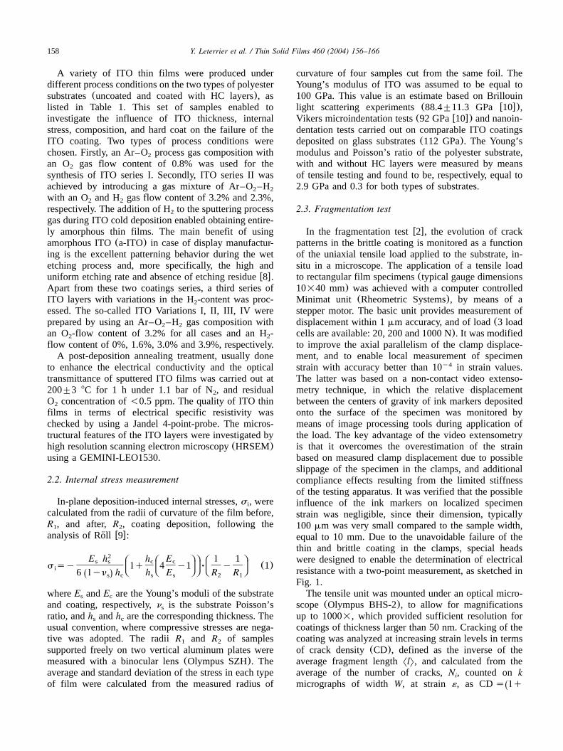
The latter was based on a non-contact video extenso-metry technique, in which the relative displacementbetween the centers of gravity of ink markers depositedonto the surface of the specimen was monitored bymeans of image processing tools during application ofthe load. The key advantage of the video extensometryis that it overcomes the overestimation of the strainbased on measured clamp displacement due to possibleslippage of the specimen in the clamps, and additionalcompliance effects resulting from the limited stiffnessof the testing apparatus. It was verified that the possibleinfluence of the ink markers on localized specimenstrain was negligible, since their dimension, typically100mm was very small compared to the sample width,equal to 10 mm. Due to the unavoidable failure of thethin and brittle coating in the clamps, special headswere designed to enable the determination of electricalresistance with a two-point measurement, as sketched inFig. 1.The tensile unit was mounted under an optical micro-
scope(Olympus BHS-2), to allow for magnificationsup to 1000=, which provided sufficient resolution forcoatings of thickness larger than 50 nm. Cracking of thecoating was analyzed at increasing strain levels in termsof crack density(CD), defined as the inverse of theaverage fragment lengthNlM, and calculated from theaverage of the number of cracks,N , counted onki
micrographs of widthW, at strain ´, as CDs 1qŽ
159Y. Leterrier et al. / Thin Solid Films 460 (2004) 156–166
Fig. 1. Sketch of the clamp with electrical connection for testing conductive coatings under uniaxial loading.
. The factor (1q´) corrects for crackk´ N ykW. i8is1
opening to the first approximation. The resistanceincrease was normalized with respect to the resistanceof unloaded sample, and a 10% increase in resistancewas arbitrarily chosen as criteria for coating failure. Theaverage and standard deviation of the crack onset strain(COS) of each type of film were calculated from themeasured resistance increase, using four samples cutfrom the same foil.
3. Results and discussion
3.1. Microstructural and electrical characterization ofITO coatings
3.1.1. ITO seriesThe average thickness and specific resistivity values
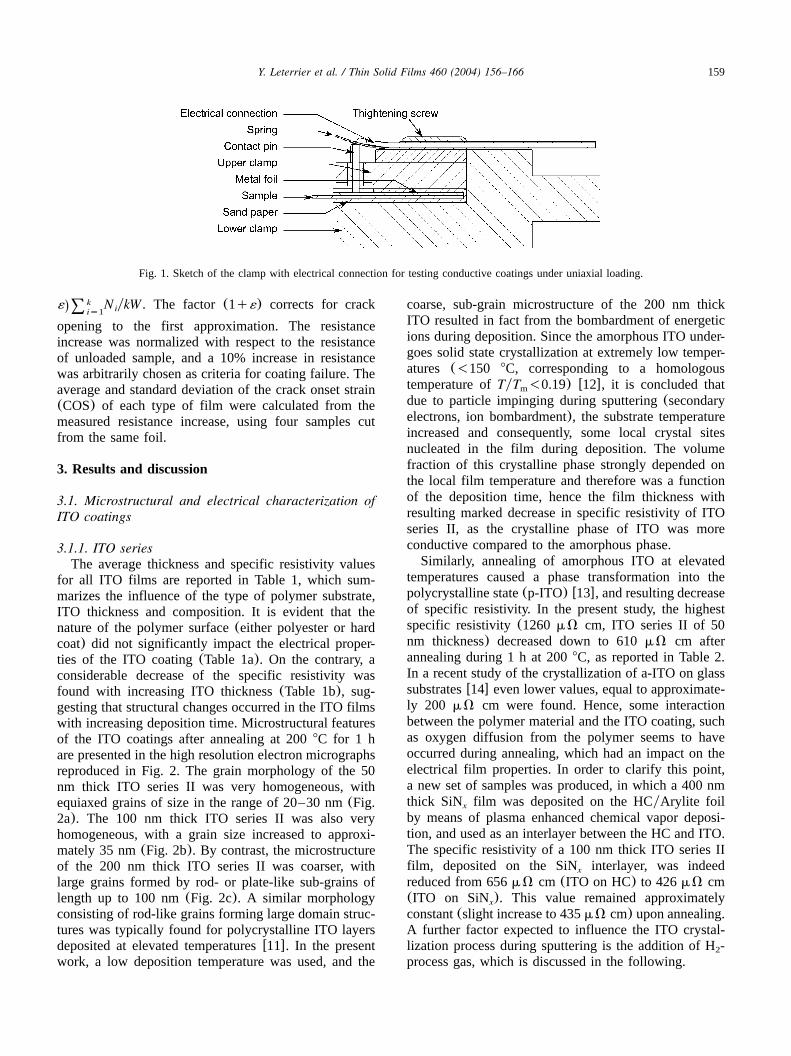
for all ITO films are reported in Table 1, which sum-marizes the influence of the type of polymer substrate,ITO thickness and composition. It is evident that thenature of the polymer surface(either polyester or hardcoat) did not significantly impact the electrical proper-ties of the ITO coating(Table 1a). On the contrary, aconsiderable decrease of the specific resistivity wasfound with increasing ITO thickness(Table 1b), sug-gesting that structural changes occurred in the ITO filmswith increasing deposition time. Microstructural featuresof the ITO coatings after annealing at 2008C for 1 hare presented in the high resolution electron micrographsreproduced in Fig. 2. The grain morphology of the 50nm thick ITO series II was very homogeneous, withequiaxed grains of size in the range of 20–30 nm(Fig.2a). The 100 nm thick ITO series II was also veryhomogeneous, with a grain size increased to approxi-mately 35 nm(Fig. 2b). By contrast, the microstructureof the 200 nm thick ITO series II was coarser, withlarge grains formed by rod- or plate-like sub-grains oflength up to 100 nm(Fig. 2c). A similar morphologyconsisting of rod-like grains forming large domain struc-tures was typically found for polycrystalline ITO layersdeposited at elevated temperaturesw11x. In the presentwork, a low deposition temperature was used, and the
coarse, sub-grain microstructure of the 200 nm thickITO resulted in fact from the bombardment of energeticions during deposition. Since the amorphous ITO under-goes solid state crystallization at extremely low temper-atures (-150 8C, corresponding to a homologoustemperature ofTyT -0.19) w12x, it is concluded thatm
due to particle impinging during sputtering(secondaryelectrons, ion bombardment), the substrate temperatureincreased and consequently, some local crystal sitesnucleated in the film during deposition. The volumefraction of this crystalline phase strongly depended onthe local film temperature and therefore was a functionof the deposition time, hence the film thickness withresulting marked decrease in specific resistivity of ITOseries II, as the crystalline phase of ITO was moreconductive compared to the amorphous phase.Similarly, annealing of amorphous ITO at elevated
temperatures caused a phase transformation into thepolycrystalline state(p-ITO) w13x, and resulting decreaseof specific resistivity. In the present study, the highestspecific resistivity(1260 mV cm, ITO series II of 50nm thickness) decreased down to 610mV cm afterannealing during 1 h at 2008C, as reported in Table 2.In a recent study of the crystallization of a-ITO on glasssubstratesw14x even lower values, equal to approximate-ly 200 mV cm were found. Hence, some interactionbetween the polymer material and the ITO coating, suchas oxygen diffusion from the polymer seems to haveoccurred during annealing, which had an impact on theelectrical film properties. In order to clarify this point,a new set of samples was produced, in which a 400 nmthick SiN film was deposited on the HCyArylite foilx
by means of plasma enhanced chemical vapor deposi-tion, and used as an interlayer between the HC and ITO.The specific resistivity of a 100 nm thick ITO series IIfilm, deposited on the SiN interlayer, was indeedx
reduced from 656mV cm (ITO on HC) to 426mV cm(ITO on SiN ). This value remained approximatelyx
constant(slight increase to 435mV cm) upon annealing.A further factor expected to influence the ITO crystal-lization process during sputtering is the addition of H -2
process gas, which is discussed in the following.
160 Y. Leterrier et al. / Thin Solid Films 460 (2004) 156–166
Fig. 2. High resolution SEM micrographs of ITO series II coatings annealed at 2008C for 1 h (50 nm thick(a); 100 nm thick(b); 200 nm thick(c)).
Table 2Annealed ITOs. Influence of polymer material(a), ITO film thickness(b) and ITO H -content(c) on specific resistivity, internal stress and2
cohesive properties of annealed ITO on polymer films
Factor Substrate ITO coating ITO thickness Specific Compressive Crack onset Intrinsic crack(HCshard coat) type* (nm) resistivity stress strain onset strain
(mVØcm) (MPa) (%) (%)
(a) Polymer type Polyester series I 150 – 1398"96 1.20"0.11 0.29"0.03HCyPolyesteryHC series I 150 – 670"70 1.60 1.07
(b) ITO thickness HCyPolyesteryHC series I 100 – 650"250 1.64"0.05 1.12"0.43series I 150 – 670"70 1.60 1.07series II 50 610 615"51 2.19 1.69series II 100 634 578"76 1.52"0.15 1.06"0.17series II 200 Failure Failure Failure Failure
(c) H content2 Polyester Var. I(H : 0.0%)2 100 – 1085"227 1.58"0.14 0.72"0.16Var. II (H : 1.6%)2 100 – 866"21 1.35"0.13 0.66"0.07Var. III (H : 3.0%)2 100 – 615"103 1.29"0.23 0.80"0.20Var. IV (H : 3.9%)2 100 – 979"258 1.48"0.21 0.70"0.21
Series 1 and 2 refer to samples prepared under Ar–O and Ar–O –H feed gas.*2 2 2
3.1.2. ITO variationsTable 1c illustrates the impact of H -gas flow content2
on the electrical conductivity of the 100 nm thick ITOcoatings. A gradual increase in specific resistivity wasobserved with increasing amount of H during sputter-2
ing, from 522mV cm without H to 734mV cm at a2
maximum H -gas flow(3.9%). This phenomenon would2
result from two factors: firstly, the microstructuralgrowth of the layers during the deposition, and secondly,the passivation of vacancies within the amorphous net-
161Y. Leterrier et al. / Thin Solid Films 460 (2004) 156–166
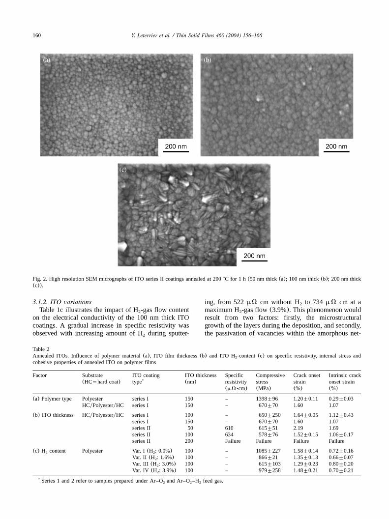
Fig. 3. Biaxial tensile failure of the 200 nm thick ITO series II coatingduring annealing.
work of the layers by –H species. Ando et al.w15xstudied the influence of H and OH contents on theproperties of ITO films. The authors reported that thegrowth of crystal sites was diminished by increasingH O gas flow content, since the absolute value of the2
transition temperature for a transformation from theamorphous phase to the polycrystalline phase was raised.Additionally, small inhomogeneities, such as voids werecreated in the amorphous network of the films, with asize and number increasing with the H-content. Further-more, it was concluded that oxygen vacancies wereeffectively terminated by –OH species, which reducedthe free carrier concentration.In the present work, it was considered that –H species,
besides their crucial role in the microstructural growthof the layers towards a more amorphous structure thanfor a H-free process, were responsible for passivation ofthe trapydefect dangling sites inside the highly amor-phous structure of the films, thus decreasing the electri-cal leakage due to a decrease in the trap density. In fact,the degree of amorphism, hence the trap density can betuned by the H-content.Conversely, a higher amount of O -gas flow enhanced2
the electrical conductivity of cold deposited ITO layers,a result confirmed by recent investigations in which ITOis compared with Zn-doped In O(IZO) w14x. The2 3
specific resistivity values for ITO Var. IV(100 nm, O :23.2%) and ITO series I(100 nm, O : 0.8%) were found2
to be equal to 522mV cm and 672mV cm, respectively.
3.2. Internal stresses
The as-grown ITO coatings were systematically undercompression, with relatively high stress levels thatincreased with ITO thickness(Table 1b). AmorphousITO coatings deposited at room temperature on glasswere also reported to be under compressive stress, withmaximum values in the range of 200–300 MPaw14,16x.In the present study, the higher stress levels of the ITOlayers, formed under comparable conditions, resultedfrom the higher coefficient of thermal expansion of thepolymer substrate, typically an order of magnitude largerthan that of either ITO or glass. During deposition, thesubstrate temperature increased as a result of particlebombardment, and then decreased back to room temper-ature at the end of the deposition cycle. In this finalstage, the thermal contraction of the polymer substrateinduced significant amounts of compressive stresses inthe ITO layer. Interestingly, the comparison of the 150nm thick ITO series II coatings on polyester with andwithout hard coat clearly revealed a lower stress for thecoating on the substrate with the hard coat interlayer(Table 1a). This effect is most likely due to reducedthermal contraction, hence improved dimensional stabil-ity of the substrate with hard coat during the depositionprocess. Annealing further increases the stress(Table
2), in contrast to previous workw17x. This result wasunexpected as the crystallinity, hence the density of ITOincreased during annealing. The constraint exerted bythe adhesion to the substrate would in turn have led tothe progressive build-up of a tensile strain in the thinITO coating that would relax the initial compressivestress. The opposite effect measured suggests that thepolymer substrate undergoes structural shrinkage, forinstance physical aging, which compressed the ITO toan extent that overcame the crystallization tensile stress.Additional work, based on real time monitoring of theITO stress is required to clarify the measured increaseof the ITO compression during annealing. In case of the200 nm thick ITO, the thermal stress resulting from thedifferential expansion between the polymer substrateand the oxide led to tensile failure of the coating(Fig.3).As for the ITO layers with different amount of H -2
content, a minimum of the compressive stress wasdetected at an intermediate H -gas flow(Table 1b,c).2
This phenomenon can be explained by assuming thattwo different mechanisms were responsible for thecreation of film stress in cold deposited ITO. In the lowH -content regime, the partial crystallization of a-ITO2
during cold deposition contributed significantly to ahigher internal film stress. With increasing H -flow-2
content, this effect disappeared and the layer consistedof an entirely amorphous phase. However, at a higherfraction of H , the level of disorder in the amorphous2
network structure increased and, consequently, the vol-ume further expanded and the film stress was intensified.The overall film stress was then the superposition of theabove two mechanisms. Therefore, a minimum com-pressive ITO film stress was obtained at intermediateH -gas-flow-content, where no partial crystallization2
occurred and the volume expansion was relatively low.
162 Y. Leterrier et al. / Thin Solid Films 460 (2004) 156–166
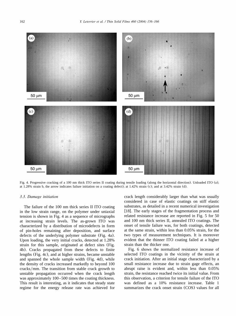
Fig. 4. Progressive cracking of a 100 nm thick ITO series II coating during tensile loading(along the horizontal direction). Unloaded ITO(a);at 1.28% strain b, the arrow indicates failure initiation on a coating defect); at 1.42% strain(c); and at 3.42% strain(d).
3.3. Damage initiation
The failure of the 100 nm thick series II ITO coatingin the low strain range, on the polymer under uniaxialtension is shown in Fig. 4 as a sequence of micrographsat increasing strain levels. The as-grown ITO wascharacterized by a distribution of microdefects in formof pin-holes remaining after deposition, and surfacedefects of the underlying polymer substrate(Fig. 4a).Upon loading, the very initial cracks, detected at 1.28%strain for this sample, originated at defect sites(Fig.4b). Cracks propagated from these defects to finitelengths(Fig. 4c), and at higher strains, became unstableand spanned the whole sample width(Fig. 4d), whilethe density of cracks increased markedly to beyond 100cracksymm. The transition from stable crack growth tounstable propagation occurred when the crack lengthwas approximately 100–500 times the coating thickness.This result is interesting, as it indicates that steady stateregime for the energy release rate was achieved for
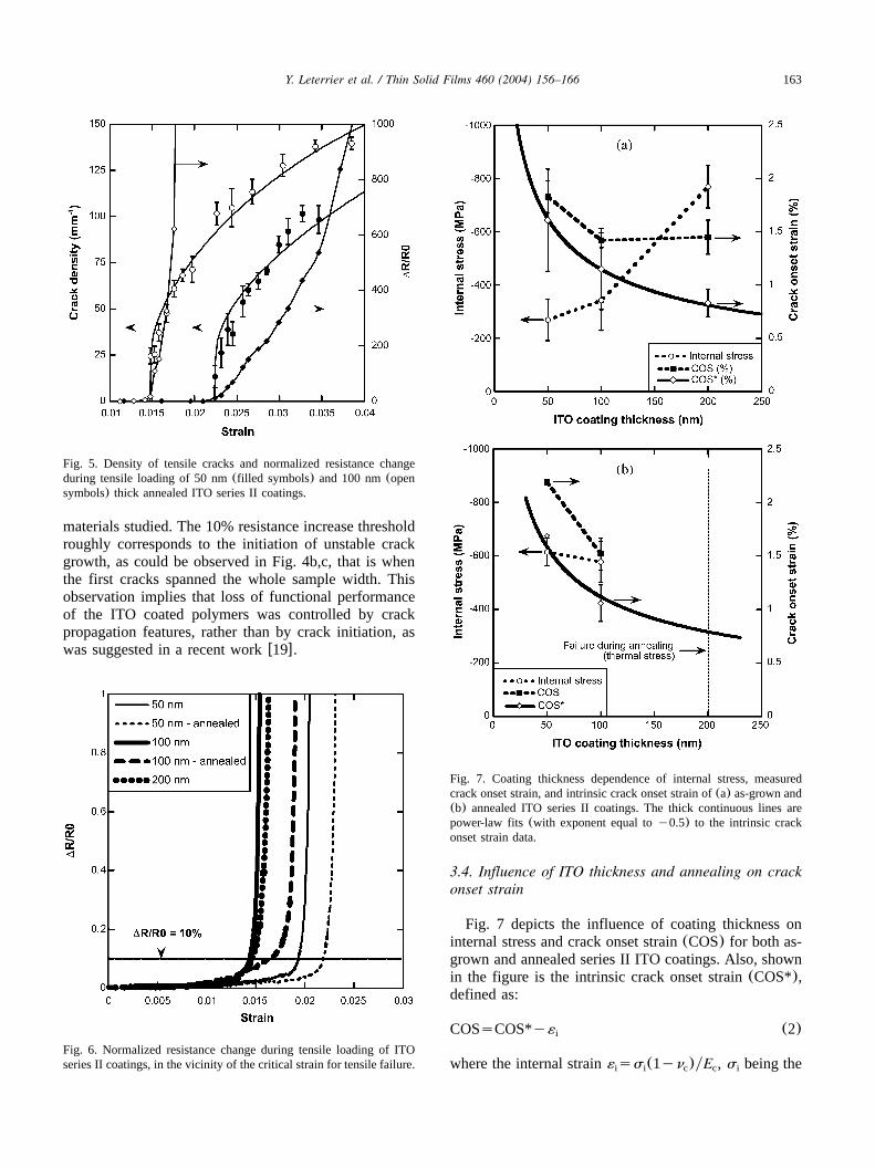
crack length considerably larger than what was usuallyconsidered in case of elastic coatings on stiff elasticsubstrates, as detailed in a recent numerical investigationw18x. The early stages of the fragmentation process andrelated resistance increase are reported in Fig. 5 for 50and 100 nm thick series II, annealed ITO coatings. Theonset of tensile failure was, for both coatings, detectedat the same strain, within less than 0.05% strain, for thetwo types of measurement techniques. It is moreoverevident that the thinner ITO coating failed at a higherstrain than the thicker one.Fig. 6 shows the normalized resistance increase of
selected ITO coatings in the vicinity of the strain atcrack initiation. After an initial stage characterized by asmall resistance increase due to strain gage effects, anabrupt raise is evident and, within less than 0.05%strain, the resistance reached twice its initial value. Fromthis observation, a criterion for tensile failure of the ITOwas defined as a 10% resistance increase. Table 1summarizes the crack onset strain(COS) values for all
163Y. Leterrier et al. / Thin Solid Films 460 (2004) 156–166
Fig. 5. Density of tensile cracks and normalized resistance changeduring tensile loading of 50 nm(filled symbols) and 100 nm(opensymbols) thick annealed ITO series II coatings.
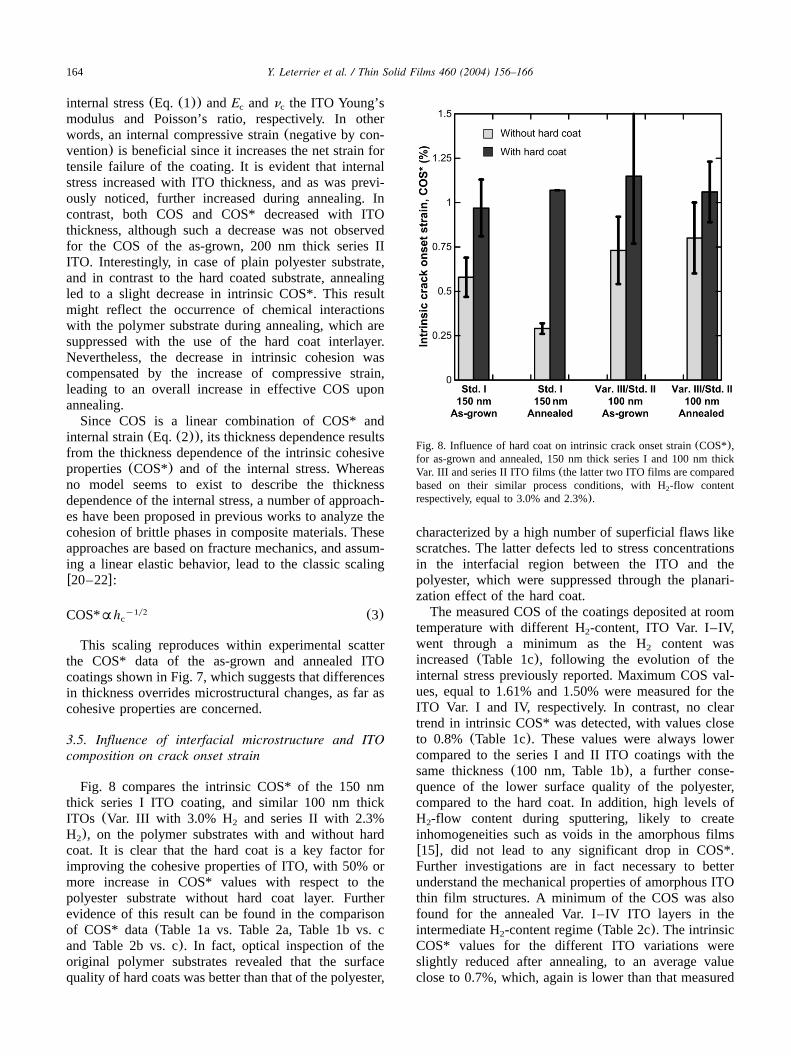
Fig. 7. Coating thickness dependence of internal stress, measuredcrack onset strain, and intrinsic crack onset strain of(a) as-grown and(b) annealed ITO series II coatings. The thick continuous lines arepower-law fits(with exponent equal toy0.5) to the intrinsic crackonset strain data.
Fig. 6. Normalized resistance change during tensile loading of ITOseries II coatings, in the vicinity of the critical strain for tensile failure.
materials studied. The 10% resistance increase thresholdroughly corresponds to the initiation of unstable crackgrowth, as could be observed in Fig. 4b,c, that is whenthe first cracks spanned the whole sample width. Thisobservation implies that loss of functional performanceof the ITO coated polymers was controlled by crackpropagation features, rather than by crack initiation, aswas suggested in a recent workw19x.
3.4. Influence of ITO thickness and annealing on crackonset strain
Fig. 7 depicts the influence of coating thickness oninternal stress and crack onset strain(COS) for both as-grown and annealed series II ITO coatings. Also, shownin the figure is the intrinsic crack onset strain(COS*),defined as:
COSsCOS*y´ (2)i
where the internal strainss (1yn )yE , s being thei i c c i
164 Y. Leterrier et al. / Thin Solid Films 460 (2004) 156–166
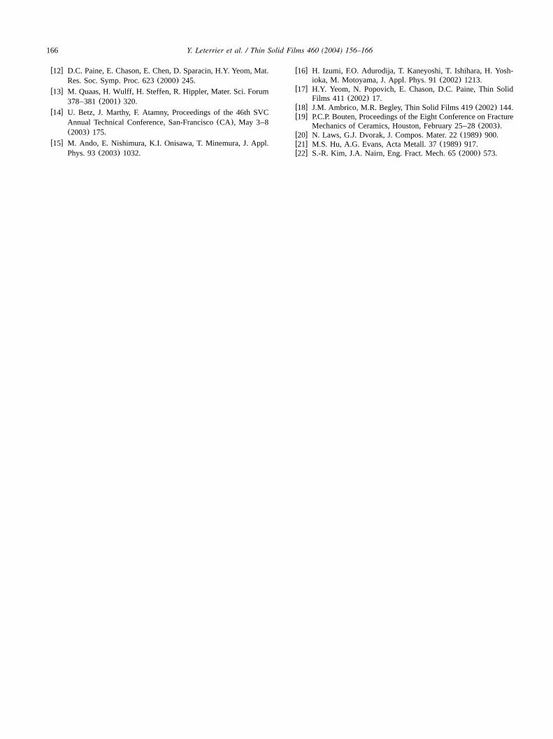
Fig. 8. Influence of hard coat on intrinsic crack onset strain(COS*),for as-grown and annealed, 150 nm thick series I and 100 nm thickVar. III and series II ITO films(the latter two ITO films are comparedbased on their similar process conditions, with H -flow content2
respectively, equal to 3.0% and 2.3%).
internal stress(Eq. (1)) andE andn the ITO Young’sc c
modulus and Poisson’s ratio, respectively. In otherwords, an internal compressive strain(negative by con-vention) is beneficial since it increases the net strain fortensile failure of the coating. It is evident that internalstress increased with ITO thickness, and as was previ-ously noticed, further increased during annealing. Incontrast, both COS and COS* decreased with ITOthickness, although such a decrease was not observedfor the COS of the as-grown, 200 nm thick series IIITO. Interestingly, in case of plain polyester substrate,and in contrast to the hard coated substrate, annealingled to a slight decrease in intrinsic COS*. This resultmight reflect the occurrence of chemical interactionswith the polymer substrate during annealing, which aresuppressed with the use of the hard coat interlayer.Nevertheless, the decrease in intrinsic cohesion wascompensated by the increase of compressive strain,leading to an overall increase in effective COS uponannealing.Since COS is a linear combination of COS* and
internal strain(Eq. (2)), its thickness dependence resultsfrom the thickness dependence of the intrinsic cohesiveproperties(COS*) and of the internal stress. Whereasno model seems to exist to describe the thicknessdependence of the internal stress, a number of approach-es have been proposed in previous works to analyze thecohesion of brittle phases in composite materials. Theseapproaches are based on fracture mechanics, and assum-ing a linear elastic behavior, lead to the classic scalingw20–22x:
y1y2COS*Ah (3)c
This scaling reproduces within experimental scatterthe COS* data of the as-grown and annealed ITOcoatings shown in Fig. 7, which suggests that differencesin thickness overrides microstructural changes, as far ascohesive properties are concerned.
3.5. Influence of interfacial microstructure and ITOcomposition on crack onset strain
Fig. 8 compares the intrinsic COS* of the 150 nmthick series I ITO coating, and similar 100 nm thickITOs (Var. III with 3.0% H and series II with 2.3%2
H ), on the polymer substrates with and without hard2
coat. It is clear that the hard coat is a key factor forimproving the cohesive properties of ITO, with 50% ormore increase in COS* values with respect to thepolyester substrate without hard coat layer. Furtherevidence of this result can be found in the comparisonof COS* data(Table 1a vs. Table 2a, Table 1b vs. cand Table 2b vs. c). In fact, optical inspection of theoriginal polymer substrates revealed that the surfacequality of hard coats was better than that of the polyester,
characterized by a high number of superficial flaws likescratches. The latter defects led to stress concentrationsin the interfacial region between the ITO and thepolyester, which were suppressed through the planari-zation effect of the hard coat.The measured COS of the coatings deposited at room
temperature with different H -content, ITO Var. I–IV,2
went through a minimum as the H content was2
increased(Table 1c), following the evolution of theinternal stress previously reported. Maximum COS val-ues, equal to 1.61% and 1.50% were measured for theITO Var. I and IV, respectively. In contrast, no cleartrend in intrinsic COS* was detected, with values closeto 0.8% (Table 1c). These values were always lowercompared to the series I and II ITO coatings with thesame thickness(100 nm, Table 1b), a further conse-quence of the lower surface quality of the polyester,compared to the hard coat. In addition, high levels ofH -flow content during sputtering, likely to create2
inhomogeneities such as voids in the amorphous filmsw15x, did not lead to any significant drop in COS*.Further investigations are in fact necessary to betterunderstand the mechanical properties of amorphous ITOthin film structures. A minimum of the COS was alsofound for the annealed Var. I–IV ITO layers in theintermediate H -content regime(Table 2c). The intrinsic2
COS* values for the different ITO variations wereslightly reduced after annealing, to an average valueclose to 0.7%, which, again is lower than that measured

165Y. Leterrier et al. / Thin Solid Films 460 (2004) 156–166
in case of the hard coated substrate with improvedsurface quality(Table 2b).To summarize, four different ITO microstructures
were investigated. Namely, these were(i) entirely amor-phous films;(ii) amorphous films with partial crystalli-zation of large surface grains;(iii ) homogeneouspolycrystalline layers with equiaxed grains; and(iv)inhomogeneous polycrystalline films with large surfacegrains. Failure analysis of these ITO films under uniaxialtension revealed that the highest COS were obtained forvery homogeneous, 50 nm thick series II films, inamorphous as well as in very fine-grained polycrystal-line states. Interestingly, similar values of the intrinsicCOS* close to 1.6% were calculated for both structures.In case of thicker films, the formation of the large plate-like surface grains during sputtering and correspondingstress concentrations reduced the mechanical resistanceagainst crack initiation although, in the present case, thedecrease of COS* with increasing thickness was essen-tially controlled by fracture mechanics scaling, followingEq. (3). Besides thickness influence, the key factors,which control the cohesive properties of ITO films onpolymer substrates include the level of process-inducedcompressive stress, and the surface quality of the poly-mer substrate. Suppression of defects in the interfacialregion with a planarization layer enables considerableimprovement of the cohesive properties of the ITO.
4. Conclusions
The mechanical properties of transparent conductiveITO thin films sputtered onto high temperature aromaticpolyesters, developed for flexible displays were investi-gated by means of tensile tests in-situ in an opticalmicroscope, equipped with resistance measurements.The analysis of the relations between ITO cohesiveproperties, polymer substrate, process induced internalstress, ITO thickness and process variables such as gascomposition and annealing lead to the following con-clusions.Damage in ITO coatings under tensile load initiated
at defects sites such as pin-holes, and cracks proceededin a stable manner until their length was of the order of100–500 times the coating thickness. At this stage, theincrease in electrical resistance was equal to approxi-mately 10%, after which crack propagation becameunstable and electrical resistance increased by manyorders of magnitude. The loss of functional performanceof the ITO coated polymers was therefore controlled bycrack propagation features, rather than by crack initia-tion.An homogeneous ITO structure in the amorphous
state as well as a fine grained polycrystalline state werebeneficial for the cohesive properties of ITO, contraryto large surface grains formed during cold deposition,which acted as stress concentrators and decreased the
crack onset strain. Nonetheless, these effects were foundto be less significant for the cohesive properties of theITO films than the surface quality of the polymersubstrate. The use of a planarization layer, such as ahard coat, which reduced roughness and local stressconcentrations at interfacial defect sites, enabled largeincrease in strain at failure of the ITO.The strain at failure of the ITO was analyzed as a
combination of internal stresses and intrinsic cohesiveproperties. On the one hand, the internal stress in as-grown ITO films on the polymer substrates was syste-matically compressive, and higher than that in case ofglass substrates, a result of the higher thermal expansionof the polymer. The stress moreover increased(i) withITO thickness, due to rising substrate temperature withsputtering duration; and(ii) during annealing at 2008C,a probable consequence of the lack of dimensionalstability of the polymer substrate. On the other hand, itwas verified that the intrinsic crack onset strain scaledas the inverse of square root of ITO thickness. It wasslightly reduced during annealing at 2008C, althoughthis decrease was compensated by the increase in inter-nal strain, resulting in a net increase in strain at failure.
Acknowledgments
The authors are indebted to the IST program of theEuropean Union(IST-2001-34215 FLEXled) for fund-ing this work, and to the company Ferrania ImagingTechnologies for the supply of the polymer substrates.The Fraunhofer Institute for Thin Films and SurfaceTechnology, FhG-IST Braunschweig is also gratefullyacknowledged for carrying out high resolution SEManalysis and nanoindentation tests.
References
w1x S. Forrest, P. Burrows, M. Thompson, IEEE Spectrum 37(2000) 29.
w2x Y. Leterrier, Prog. Mater. Sci. 48(2003) 1.w3x D.R. Cairns, R.P. Witte II, D.K. Sparacin, S.M. Sachsman,
D.C. Paine, G.P. Crawford, R.R. Newton, Appl. Phys. Lett. 76(2000) 1425.
w4x Z. Chen, B. Cotterell, W. Wang, Eng. Fract. Mech. 69(2002)597.
w5x E. Fortunato, P. Nunes, A. Marques, D. Costa, H. Aguas, I.Ferreira, M.E.V. da Costa, M.H. Godinho, P.L. Almeida, J.P.Borges, R. Martins, Adv. Eng. Mater. 4(2002) 610.
w6x S. Suzuki, N. Hashimoto, T. Oyama, K. Suzuki, J. Adhes. Sci.Technol. 8(1994) 261.
w7x J. Driessen, V. Cassagne, A. Deschamps, R. Kopfli, P. Grunen-¨ ¨felder, W. Haag, Proceedings of the 18th International DisplayResearch Conference, Seoul, 1998, p. 547.
w8x J.-H. Lan, J. Kanicki, A. Catalano, J. Keane, W.D. Boer, T.Gu, J. Electron. Mater. 25(1996) 1806.
w9x K. Roll, J. Appl. Phys. 47(1976) 3224.¨w10x T. Wittkowski, J. Jorzick, H. Seitz, B. Schroder, K. Jung, B.
Hillebrands, Thin Solid Films 398(2001) 465.w11x Y. Shigesato, D.C. Paine, Thin Solid Films 238(1994) 44.
166 Y. Leterrier et al. / Thin Solid Films 460 (2004) 156–166
w12x D.C. Paine, E. Chason, E. Chen, D. Sparacin, H.Y. Yeom, Mat.Res. Soc. Symp. Proc. 623(2000) 245.
w13x M. Quaas, H. Wulff, H. Steffen, R. Hippler, Mater. Sci. Forum378–381(2001) 320.
w14x U. Betz, J. Marthy, F. Atamny, Proceedings of the 46th SVCAnnual Technical Conference, San-Francisco(CA), May 3–8(2003) 175.
w15x M. Ando, E. Nishimura, K.I. Onisawa, T. Minemura, J. Appl.Phys. 93(2003) 1032.
w16x H. Izumi, F.O. Adurodija, T. Kaneyoshi, T. Ishihara, H. Yosh-ioka, M. Motoyama, J. Appl. Phys. 91(2002) 1213.
w17x H.Y. Yeom, N. Popovich, E. Chason, D.C. Paine, Thin SolidFilms 411(2002) 17.
w18x J.M. Ambrico, M.R. Begley, Thin Solid Films 419(2002) 144.w19x P.C.P. Bouten, Proceedings of the Eight Conference on Fracture
Mechanics of Ceramics, Houston, February 25–28(2003).w20x N. Laws, G.J. Dvorak, J. Compos. Mater. 22(1989) 900.w21x M.S. Hu, A.G. Evans, Acta Metall. 37(1989) 917.w22x S.-R. Kim, J.A. Nairn, Eng. Fract. Mech. 65(2000) 573.
Related Documents