MECHANICAL IC ENGINE & POWER PLANT 1 | Page THE GATE COACH All Rights Reserved 28, Jia Sarai N.Delhi-1626528213,-99981

Welcome message from author
This document is posted to help you gain knowledge. Please leave a comment to let me know what you think about it! Share it to your friends and learn new things together.
Transcript

MECHANICAL IC ENGINE & POWER PLANT
1 | P a g e THE GATE COACH All Rights Reserved 28, Jia Sarai N.Delhi-1626528213,-99981

MECHANICAL IC ENGINE & POWER PLANT
2 | P a g e THE GATE COACH All Rights Reserved 28, Jia Sarai N.Delhi-1626528213,-99982
IC ENGINE
&
POWER PLANT
CONTENTS
1 INTRODUCTION
TO IC ENGINE
Heat engine 7
Wankel engine 7
Stirling engine 8
Engine components 8
I C Engine classification 10
Working of I C Engine 11
Thermodynamic analysis of IC engine 13
2 AIR STANDARD
CYCLE
Introduction 16
Air standard cycle 16
Air standard cycle assumption 16
Air standard cycle parameter 16
Otto Cycle 17
Diesel Cycle 19
Dual Cycle 20
3 FUELS IN IC
ENGINE
Introduction 24
Desirable properties of good IC engine fuels 24
Sources of IC Engine fuels 24
Petroleum-structure and refining 24
Fuels for SI Engines 27
Knock rating of SI engine fuels 30
Diesel fuels 32
MECHANICAL IC ENGINE & POWER PLANT
3 | P a g e THE GATE COACH All Rights Reserved 28, Jia Sarai N.Delhi-1626528213,-99983
4 FUEL SUPPLY
IN SI ENGINE
Introduction 35
Properties of air-petrol mixture 36
Mixture requirement for steady state operation 37
Transient mixture requirement 39
Simple or elementary carburettor 40
Complete carburettor 41
Carburettor types 45
Theory of simple carburettor 49
Petrol injection 51
5 FUEL SUPPLY
IN CI ENGINE
Introduction 55
Requirements of fuel injection system 55
Elements of fuel injection system 55
Types of injection system 56
Fuel pump 58
Types of fuel injector 60
Injection nozzle 60
Spray formation 63
6 IGNITION
SYSTEM
Introduction 65
Principle 65
Requirements 65
Battery ignition system 66
Magneto ignition system 69
Spark plugs 72
7 COMBUSTION
IN SI ENGINE
Introduction 76
Ignition limits 76
Stages of combustion in SI engine 76
Effects on engine variable on flame propagation 77
Detonation and knocking 80
Theories of detonation 82
Effect of engine variables on knock 83
Control of detonation 86
Pre-ignition 88
SI engine combustion chamber design 89

MECHANICAL IC ENGINE & POWER PLANT
4 | P a g e THE GATE COACH All Rights Reserved 28, Jia Sarai N.Delhi-1626528213,-99984
8 COMBUSTION
IN CI ENGINE
Introduction 94
Stages of combustion 94
Air fuel ratio in CI engine 95
Delay period or ignition lag 96
Diesel knock 98
CI combustion chamber design 100
9 ENGINE
COOLING
Introduction 107
Necessity of engine cooling 107
Cooling system 108
Air cooling 108
Water cooling 109
Radiator 113
10 ENGINE
FRICTION
AND
LUBRICATION
Introduction 115
Total engine friction 115
Effect of engine variables on Engine friction 117
Determination of engine friction 118
Lubrication principles 119
Functions of lubrication system 120
Properties of lubricating oil 121
11 SUPERCHARGING
Introduction 127
Objectives 127
Thermodynamic cycle 127
Supercharging power 128
Supercharging of SI engine 128
Supercharging of CI engine 129
Supercharging limits 130

MECHANICAL IC ENGINE & POWER PLANT
5 | P a g e THE GATE COACH All Rights Reserved 28, Jia Sarai N.Delhi-1626528213,-99985
12 COMPARISION
OF SI AND CI
ENGINES
Thermodynamic and operating variables 134
Performance characteristics 136
Other costs 137
Applications 137
13 AIR
POLLUTION
Introduction 139
Pollutants from gasoline engine 139
Gasoline emission control 143
Total emission control package 147
Diesel emission 149
Diesel and smoke control 150
Diesel odour and control 153
14 GAS TURBINE
Introduction 155
Classification 155
Constant pressure combustion type gas turbine 157
Constant volume combustion type gas turbine 160
Methods of improving cycle efficiency 161
15 AIR
COMPRESSOR
Classification 165
Reciprocating compressor 165
Rotary compressor 172
Axial flow compressor 177

MECHANICAL IC ENGINE & POWER PLANT
6 | P a g e THE GATE COACH All Rights Reserved 28, Jia Sarai N.Delhi-1626528213,-99986
16 JET AND
ROCKET
PROPULSION
Introduction 180
The Ram-jet engine 180
Pulse-jet engine 181
Turbo-jet engine 182
Turbo-prop engine 183
Thrust Augmentation 184
Rocket propulsion 186
17 VAPOUR
POWER
CYCLE
Simple vapour power cycle 192
Piping losses 194
Mean temperature of heat addition 196
Reheat Cycle 197
Regeneration 198
Feed water heaters 200
Efficiencies of steam power plant 201
18 STEAM
GENERATOR
Introduction 203
Basic types of steam generators 203
Fire tube boiler 204
Water tube boiler 205
Economiser 210
Superheater 210
19
Sonic velocity 213
Concept of subsonic and supersonic nozzles 214
Steam nozzle 215
Steam nozzle analysis 217
Supersaturated flow 220
Normal shock 224

MECHANICAL IC ENGINE & POWER PLANT
7 | P a g e THE GATE COACH All Rights Reserved 28, Jia Sarai N.Delhi-1626528213,-99987
STEAM
NOZZLE WITH
COMPRESIBLE
FLOW
20 STEAM
TURBINE
Introduction 229
Impulse turbine 229
Compounding of steam turbine 232
Reaction turbine 233
Losses in steam turbine 235
Reheat factor 236
Governing of turbines 236
21 NUCLEAR
POWER
PLANT
Introduction & development 237
Nuclear fission 237
Nuclear reactor components 239
Boiling water reactor 241
Pressurized water reactor 242
CANDU reactor 243
Fast breeder reactor

MECHANICAL IC ENGINE & POWER PLANT
8 | P a g e THE GATE COACH All Rights Reserved 28, Jia Sarai N.Delhi-1626528213,-99988
CHAPTER 10ENGINE FRICTION AND LUBRICATION
INTRODUCTION
Engine friction is defined as the difference between the indicated horse-power (power at
piston top as produced by the combustion gases) and the brake horse-power (useful
power) available at the output shaft, Itof the engine.
Engine friction is also greatly affected by engine speed. The mechanical efficiency,
which is defined as the ratio of bhp and ihp can be as high as 85 per cent for a carefully
designed low speed engine having a piston speed of up to about 600 m/min. But it is
very difficult to get a mechanical efficiency figure better than 75 per cent for a high
speed engine having a piston speed of about 800 m/min. Thus a definite limit is
imposed on the30 maximum output which can be obtained from an engine by increasing
engine speed and it becomes very important to give careful attention to engine friction
at all steps in engine design.
Usually an appreciable difference in the specific fuel consumption between two engines
of almost identical size operating under very similar conditions results due to effect of
engine friction.
TOTAL ENGINE FRICTION
Total engine friction, defined as the difference between ihp and bhp, includes the power
required to drive the compressor or a scavenging pump and the power required to drive
engine auxiliaries such as oil pump, coolant pump and fan, etc.
If the power to drive the compressor and auxiliaries is neglected, the total engine friction
can be divided into five main components. These are:
Crankcase mechanical friction.

MECHANICAL IC ENGINE & POWER PLANT
9 | P a g e THE GATE COACH All Rights Reserved 28, Jia Sarai N.Delhi-1626528213,-99989
Blowby losses (compression-expansion pumping loss).
Exhaust and inlet system throttling losses.
Combustion chamber pumping loop losses.
Piston mechanical friction.
Crankcase Mechanical Friction
Crankcase mechanical friction can further be sub-divided into:
Bearing friction,
Valve gear friction, and
Pump and miscellaneous friction.
The bearing friction includes the friction due to main bearing, connecting rod bearing
and other bearings. Bearing friction is viscous in nature and depends upon the oil
viscosity, the speed, size and geometry of the journal.
The mep lost in journal bearing can be approximated by equation
Where B/S is the bore-stroke ratio of the engine. N the rpm, and A is a constant whose
value is generally about 0.85 for petrol engines and 1.76 tor diesel engine.
The valve gear friction losses vary with the engine design variables and general
equation is available for predicting them.
All crankcase friction losses other than bearing and valve gear losses vary roughly in
proportion to engine displacement and speed.
The bearing losses are affected vary little by the loading of the bearing but they rise
rapidly with increase in speed because these losses are primarily the result of
continuous shear of the oil film in the bearing clearance.
MECHANICAL IC ENGINE & POWER PLANT
10 | P a g e THE GATE COACH All Rights Reserved 28, Jia Sarai N.Delhi-1626528213,-999810
Crankcase mechanical friction is about 15 to 20 per cent of total engine friction.
Blow by Losses
Blowby is the phenomenon of leakage of combustion products past the piston and
piston rings from the cylinder to the crankcase.
These losses depend upon the inlet pressure and compression ratio. These losses vary
as the square root of inlet pressure, and increase as the compression ratio is increased.
Blowby losses are reduced as the engine speed is increased.
Exhaust and Inlet Throttling Loss
The standard practice for sizing the exhaust valve is to make them a certain percentage
smaller than the inlet valves. This usually results in an insufficiently sized exhaust valve
and hence, results in exhaust pumping loss.
As the speed increases, the curve rises steeply and may result in substantial loss if the
valve size, valve timing and valve flow coefficients are not given due attention.
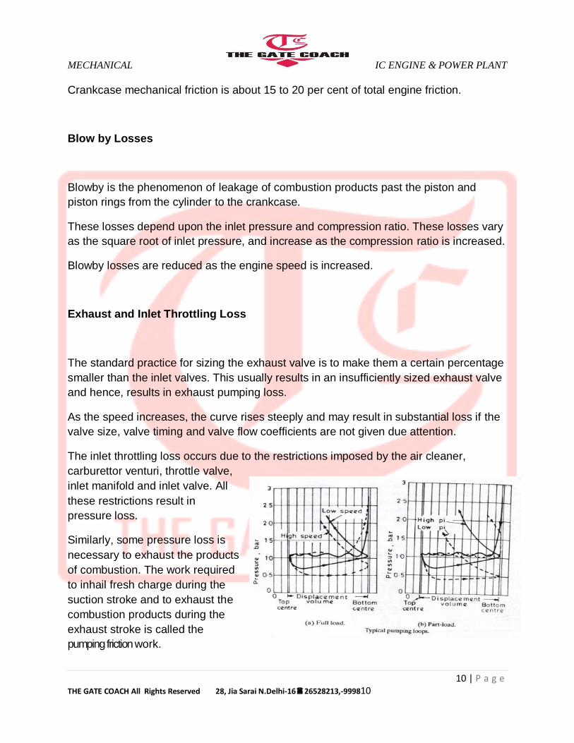
The inlet throttling loss occurs due to the restrictions imposed by the air cleaner,
carburettor venturi, throttle valve,
inlet manifold and inlet valve. All
these restrictions result in
pressure loss.
Similarly, some pressure loss is
necessary to exhaust the products
of combustion. The work required
to inhail fresh charge during the
suction stroke and to exhaust the
combustion products during the
exhaust stroke is called the
pumping friction work.

MECHANICAL IC ENGINE & POWER PLANT
11 | P a g e THE GATE COACH All Rights Reserved 28, Jia Sarai N.Delhi-1626528213,-999811
Combustion Chamber Pumping Loop Losses
In the case of pre-combustion chamber engines an additional loss occurs. This is the
loss occurring due to the pumping work required to pump gases into and out of the pre-
combustion chamber.
The exact value of this would depend upon the orifice size connecting the pre-
combustion chamber and the main chamber, and the speed. Higher the speed greater
is the loss and smaller the orifice size greater is the loss.
Piston Mechanical Friction
Piston mechanical friction can be sub-divided into:
Viscous friction
Non-viscous friction
friction due to ring tension
friction due to gas pressure forces behind the ring.
Figure shows break-up of total
piston mechanical friction into its
component for a C.F.R. engine.
Lower part of the piston works more
or less under viscous friction
conditions. The viscous friction
depends upon the viscosity of the
oil and the temperature of the
various parts of the piston. The
degree to which the upper part of
the piston can be lubricated also
affects the viscous friction. The oil film thickness between piston and the cylinder is also
affected by the piston side-thrust and the resulting vibrations.

MECHANICAL IC ENGINE & POWER PLANT
12 | P a g e THE GATE COACH All Rights Reserved 28, Jia Sarai N.Delhi-1626528213,-999812
EFFECT OF ENGINE VARIABLES ON ENGINE FRICTION
Effect of stroke/bore ratio
The effect of stroke/bore ratio on engine friction and economy is very small. High
stroke/bore ratio engines have equally good friction mep values as that for low
stroke/bore ratio engine. Indications are that at high speeds the higher stroke/bore ratio
engine may be at some disadvantage.
Effect of cylinder size and number of cylinders
The friction and economy improves as a smaller number of larger cylinders are used.
Thisis because the proportion between the working piston area and its friction producing
area, i.e. circumference is reduced.
Effect of number of piston rings
The effect of number of piston ring is not very critical and this number is usually chosen
on the basis of cost, size and other requirements rather than on the basis of their effect
on friction.
Effect of compression ratio
As already discussed the friction mean effective pressure increases as the compression
ratio is increased. But the mechanical efficiency either remains constantor improves as
the compression ratio is increased. If the displacement iS VARIED to keep the maximum
engine torque constant, this results in BETTER PART load friction characteristics. For
example at 1600 RPM, an INCREASE in compression ratio from 9 to 12 results in a 5 per cent
increase in fuel economy becomes 10 per cent.
Effect of engine speed
As already discussed engine friction increases rapidly as the speed increases. The best way to
improve mechanical efficiency at high speed is to increase the number of cylinders.
Effect of oil viscosity
Higher the oil viscosity greater is the friction loss. The temperature of the oil in the crankcase
significantly affects the friction losses, wear and service life of an engine. As the oil
temperatureincreases, the viscosity decreases and friction losses arc reduced owingcertain
temperature range. If the temperature goes higher than at a certain value the local oil film is destroyed
resulting in metal to metal contact.

MECHANICAL IC ENGINE & POWER PLANT
13 | P a g e THE GATE COACH All Rights Reserved 28, Jia Sarai N.Delhi-1626528213,-999813
Effect of cooling water temperature
A risein temperature reduces engine friction through its effect on oil viscosity.During starting
operation the temperature of both the oil and the wateris low, hence, the viscosity is
high. This results in high starting friction losses and rapid engine wear.
Effect of engine load
As the load increases the maximum pressure in the cylinder has a tendency to increase
slightly. This results in slightly higher friction values. However, this increase in friction
loss is more than compensated by the decrease in oil viscosity due to higher
temperatures resulting from increased load. Further in case of petrol engines the
throttling losses reduce as the throttle is opened more and moreto supply more fuel for
allowing an increase in engine load. Both these effects combine to reduce frictional
losses of a petrol engine as engine load is increased.
However, for diesel engines the frictional losses are more or less independent of engine
load.
DETERMINATION OF ENGINE FRICTION
There are five methods of determining the engine friction. These are:
From the ip and bp measurements.
Morse test.
Willan's line method.
Motoring method.
Deceleration method.
From ip and bp measurements
If the ihp is obtained from the indicator diagram and bhp from dynamometer, the fhp can
be obtained by simply subtracting the latter from the former. The main disadvantage of
this method is that it is very difficult to obtain accurate indicator diagram for calculation
of ip. A slight error in location of the tdc position on the indicator diagram may lead to
significant changes in ip obtained.

MECHANICAL IC ENGINE & POWER PLANT
14 | P a g e THE GATE COACH All Rights Reserved 28, Jia Sarai N.Delhi-1626528213,-999814
for calculation of ip. A slight error in location of the tdc position on the indicator diagram
may lead to significant changes in ip obtained.
Morse test
In the Morse test, which is applicable for both petrol and diesel engines, the individual
cylinders are successively cut-off and the brake horse-power is determined. This gives
the ip developed by each cylinder, and hence by the full engine from which if bp is
subtracted, fp can be obtained. Morse test is applicable to multicylinder engines only.
Willan's line method
In the Willan's line method which is applicable for diesel engines only, the gross fuel
consumption is plotted against bp and the line so obtained is extended backwards to
zero fuel consumption. The negative intercept on the bp axis gives the value of fp. The
main disadvantage of this method is that the fuel consumption-bp line is not straight but
it turns up slightly at weak end and considerably at rich end so that unless sufficient
data are taken to accurately plot the straight line portion of the curve the result would be
significantly different. However, method is quite accurate if sufficient care is taken to plot
the graph.
Motoring method
In the motoring method, engine is driven with the help of an external motor. The
powerconsumed by this motor, ifcorrected for mechanical and other losses of the motor,
gives the fp of the engine. The main criticism of this method is that since no actual firing
takes place the peak pressure, exhaust back pressure, engine temperature etc., are
quite different from the firing condition and consequently, the fp value obtained is
different. The main advantage of this method lies in the fact that by successive 'stripping
off of the engine the contribution of each part ot the engine to the overall engine friction
can be accurately obtained.
MECHANICAL IC ENGINE & POWER PLANT
15 | P a g e THE GATE COACH All Rights Reserved 28, Jia Sarai N.Delhi-1626528213,-999815
Deceleration method
In the deceleration method use is made of the fact that if a running engine is left free
after cutting-off the fuel supply it will decelerate due to the effect of the engine friction. If
this deceleration is measured and the polar moment of inertia of the engine is known, fp
can be calculated because engine friction is the product of polar moment of inertia and
initial deceleration.
LUBRICATION PRINCIPLES
Consider a block resting on a flat surface covered with a layer of lubricating oil. If the weight of the block is
very high or the oil is thin, the oil will squeeze out. In other words, a thick oil can support a higher load than
that supported by a thin oil.
Hydrodynamic lubrication
When this block is moved oversurface, a wedge-shaped oil film is built up between
moving block and the surface. This wedge-shaped film is thicker at leading edge than at the rear. In other
words the moving block acts as pump to force oil into clearance that narrows down progressively as the
block moves. This generates appreciable oil film pressure which carries the load. This type of lubrication
where a wedge-shaped oil film is formed between two moving surfaces is called hydrodynamic
lubrication. The important feature of this type of lubrication is that the load carrying capacity of the bearing
increases with increase in relative speed of the moving surfaces. This occurs because at higher speed the
time available to
the oil to squeeze out is less.
The force required to move the block over the surface depends upon the weight of the block, the speed of
movement, and the thickness or viscosity of the oil. This force divided by the pressure caused by the
weight of the block is called the coefficient of friction. A higher coefficient o friction signifies a greater
force to move the block.
The flat surface lubrication of the kind referred above exists at places such as thrust bearings, valve tips and
cam lifters. Many other surfaces which use hydrodynamic lubrication are cylinder wall, valve guide, man
bearings, connecting rod bearings, and camshaft bearings.
MECHANICAL IC ENGINE & POWER PLANT
16 | P a g e THE GATE COACH All Rights Reserved 28, Jia Sarai N.Delhi-1626528213,-999816
Elasto hydrodynamic lubrication
When the load acting on the bearings is very high, the material itself deforms elastically
against the pressure built up of the oil film. This type of lubrication, calledelastohydrodynamic
lubrication, occurs between earns and followers, gear teeth, and rolling bearings where
the contact pressures are extremely high.
Boundary lubrication
If the film thickness between the two surfaces in relative motion becomes so thin that
formation of hydrodynamic oil film is not possible and the surface high spots or
asperities penetrate this thin film to make metal-to-metal contact then such a lubrication
is called boundary lubrication. Such a situation may arise due to too high a load, too thin an
oil or insufficient supply of oil due to low speed of movement. Most of the wear
associated with friction occurs during boundary lubrication due to metal-to-metal
contact. A condition of boundary lubrication always exists when the engine is first
started. The shaft is in contact with the bottom of the bearing with only a thin surface
film ofoil formed on them. The bearing surfaces are not perfectly smooth-they have 'hills'
and Valleys' which tear this thin film which is constantly formed while the crankshaft is
turning slowly. As the speed increases it switches on to hydrodynamic lubrication.
Boundary lubrication may also occur when the engine is under very high loads or when
the oil supply to the bearing is insufficient.
Hydrostatic lubrication
In hydrostatic lubrication a thin oil film resists its instantaneous squeezing-out under
reversal of loads with relatively slow motions. The oil film acts as a cushion. If oil supply
is sufficient the oil film thickness is restored before next reversal of load.

MECHANICAL IC ENGINE & POWER PLANT
17 | P a g e THE GATE COACH All Rights Reserved 28, Jia Sarai N.Delhi-1626528213,-999817
FUNCTIONS OF THE LUBRICATING SYSTEM
The following are the important functions of a lubricating system:
Lubrication
The main function of the lubricating system is tokeep the moving parts sliding freely past
each other and, thus, reduce theengine friction and wear.
Cooling
To keep the surfaces cool by taking away a part of theirheat through the oil passing
over them. This cooling action usually takesplace simultaneous to the lubricating
function. However, under certainconditions lubrication system is used to keep certain
engine parts coolwhich due to their typical location do not come in direct contact with
thecooling water. One typical example is the oil cooling of pistons of highspecific output
engines.
While performing its cooling function the lubricant is exposed to heating and agitation
which promote oxidation. This requires oil to possess good oxidation stability. The heat
input to the oil increases if the cooling function is extended to piston cooling. For a
naturally aspirated diesel engine the heat input to the oil can be equal to some 6-8% of
engine power output. This value is further increased by 50% for an indirect injection
engine and doubled for turbocharged engines
Cleaning.
To keep the bearings and piston rings clean of the products of wear and the products of
combustion, especially the carbon, by washing them away and then, not allowing them
to agglomerate to form sludge.
Sealing.
The lubricating oil must form a good seal between piston rings and cylinder walls. The
oil should be physically capable offilling the minute leakage paths and surface
irregularities of the mechanical sealing elements, i.e., cylinders, pistons and piston rings.
The oil as a sealantis subjected to high temperatures and hence must possess
adequateviscosity stability.
Reduction of noise.
Lubrication reduces the noise of the engine
MECHANICAL IC ENGINE & POWER PLANT
18 | P a g e THE GATE COACH All Rights Reserved 28, Jia Sarai N.Delhi-1626528213,-999818
These functions are conflicting functions. The oil cools best when it is thin but seals best
when it is thick. The oil must collect dirt to scavenge an clean but to lubricate it must be
clean. The engine produces not onlypower but a number of oil contaminants also. The
oil should be able to absorb these-contaminants without affecting its main functions.
Increased speed, compression ratio and, hence, increased power output all result in
higher pressures and temperatures. The shock loading of bearing is also severe.
Larger valves require stiffer valve springs which, m turn, result in increased stresses
and elevated temperatures for many related parts.
All these conflicting and difficult to meet requirements require skilful juggling at the
hands of the engine designer.
PROPERTIES OF THE LUBRICATING OIL
Viscosity
Viscosity of an oil is measure of its resistance to flow and is usually measured in terms
of Saybolt Universal Seconds (SUS) which is the time required, in seconds, for a given
quantity of the oil to flow through a capillary tube under specified test conditions.
Viscosity is usually expressed at two temperatures - 18°C (0°F) and 99°C (210°F).
Viscosity is also expressed in centistokes, centipoise and Redwood seconds. The basic
difference between all these systems of expressing viscosity lies in the type of
apparatus, called viscometer, used for its determination.
Viscosity Index.
The viscosity of an oil is substantially affected by its temperature, higher the
temperature lower is the viscosity. This variation of viscosity of an oil with changes in
temperature is measured by its Viscosity Index (V.I.) The oil is compared with two
reference oils having same viscosity at 99°C (210°F). One, a paraffinic base oil
(considerable change in viscosity with temperature), is arbitrarily assigned an index of
zero and the other, a naphthenic base oil (little change in viscosity with temperature), is
assigned an index of 100.
A high viscosity index number indicates relatively smaller changes in viscosity of the oil
with temperature. Viscosity index of an oil is very important where extreme
temperatures are encountered. The lubricating oil must maintain a sufficient viscosity at
high temperatures and still should not be too viscous for starting the engine at low

MECHANICAL IC ENGINE & POWER PLANT
19 | P a g e THE GATE COACH All Rights Reserved 28, Jia Sarai N.Delhi-1626528213,-999819
temperatures. Typical examples of extreme temperature conditions are the hydraulic
system in an aircraft and automobile engine in cold weather.
To improve the viscosity index of an oil certain compounds, called V.I. improvers, are
added to it. These are viscous, long chain paraffinic, compounds which enable to obtain
an oil having easy starting characteristic of thin oils combined with good protection
against high temperature.
For automobile applications oils having a viscosity index above 90 are considered to be
of high VX, oils between 55 and 90 medium V.I., and below 55, low V.L
Cloud Point and Pour Point
If an oil is cooled, it will start solidifying at some temperature. This temperature is called
cloud point. This clouding or haziness of the oil interferes with its flow. The pour point is that
temperature just above which the oil sample will not flow under certain prescribed
conditions. This temperature is largely determined by the wax content of the oil since as
the temperature is reduced was crystallizes out in long needle-shaped crystals, forming
honeycomb with oil held in the voids between the crystals. Generally oil derived from
paraffinic crudes tend to have higher pour points than those derived from naphthenic
crudes. The pour point can, however, be lowered by the addition of a pour point
depressant usually a polymerised phenol or ester. These substances function by
depositing insulating films on the wax crystals as they begin to separate out from the oil
and by reducing the size of crystals.
This characteristic of the oil is very important at low temperature operation since it will
affect the flow in the pressure line of the lubricating system. Pour point must be at least
15°F lower than the operating temperature to ensure maximum circulation. Even at this
temperature the oil may be viscous so that high power may be necessary for starting.
Flash Point.
The temperature at which the vapours of an oil flash when subject to a naked flame is
known as the flash point of the oil. If the container is closed at the time of the test it is
called closed flash point, and if open it is called Open flash point. Fire point is the temperature at
which the oil, if once lit with flame, will burn steadily at least for 5 seconds. This is
usually 11°C higher than open flash point and varies from 190°C to 290°C for the
lubricants used for the internal combustion engines.

MECHANICAL IC ENGINE & POWER PLANT
20 | P a g e THE GATE COACH All Rights Reserved 28, Jia Sarai N.Delhi-1626528213,-999820
Fire and flash points are good indication of relative flammability of the oil and except for
the safety from fire hazards, they do not have any significance for engine operation.
However, fire and flash points of used lube oil are very good indication of the crankcase
dilution. The light ends of the fuel, which leak into the crankcase, readily evaporate and
burn at considerably lower temperature than the temperature at which the oil would
have burned, clearly indicating the degree of dilution.
Specific Gravity
The specific gravity of the engine lube oils varies from 0.85 to 0.96. Naphthenic base
oils have higher specificgravity than the paraffin base oils. This property is of little
importance except as an indicator of weight and volume.
Carbon Residue
Carbon residue is that quantity of the known mass sample of the oil, which on
evaporation under specific conditions remains as carboneous residue. This is a very
rough pointer to the deposit characteristics of the oil. However, it cannot be relied upon
to predict deposits because the formation of deposits is strongly affected by the design
of the engine, the fuel used, and the operating conditions.Paraffinic-base oils have
higher carbon residue than the asphaltic base oils.
Oiliness
The property of an oil to cling to the metal surfaces by molecular action and then to
provide a very thin layer of lubricant under boundary lubrication conditions is called the
oiliness or lubricity or film strength. This is measured by the coefficient of friction under
extreme conditions of operations. This is very significant at high pressures and small
clearance as it controls the Squeezing out' of the oil, takes care of temporary loss of oil
pressure and also affects starting.
Oxidation Stability
Oxidation stability of an oil is its resistance to oxidation. Due to oxidation the oil will form
deposits on the piston rings and will lose its lubricating property. Low-temperature
operation avoiding the hot-area contact and crankcase ventilation can help in
preservingthe stability of an oil over longer periods. The products of oxidation vary
widely according to the type of oil and the temperature reached and include carbon,
lacquer, sludge and organic acids which can be corrosive to certain metals. Oxidation
inhibitors to improve oxidation stability are used in crankcase oils to counter these ten-
dencies. These are complex compounds of sulphur and phosphorous or amine and
phenol derivatives

MECHANICAL IC ENGINE & POWER PLANT
21 | P a g e THE GATE COACH All Rights Reserved 28, Jia Sarai N.Delhi-1626528213,-999821
Cleanliness
The absence of water and sediments are essential requirements for an oil. Water is not
a lubricating fluid and it pro- Fig. 14.18. Engine sludge motes corrosion while dirt and
small foreign formation location, particles of insoluble matter cause great wear of
engine parts.
Colour
This has no practical significance except that it is an indication of the degree of refining
of the oil.
Acidity and Neutralisation Number
The oil must have low acidity. The neutralisation number is a measure of acidic or
alkaline contents of oil. NEW oil has low neutralisation number, which is the quantity of
alkaline solution or acid solution required to make the oil neutral. Used oil has high
neutralization number.
ADDITIVES
Simple mineral oil has most of the characteristics needed for a good lubricant. However,
varying operating conditions require some specific properties it cannot meet. The
examples are the ability of an oil togive good viscosity over a range of temperatures, i.e.
high viscosity index, resistance to oxidation, the property to dissolve and cleanse the
deposits, the detergency properties, corrosive resistiveness, etc. Water, resins, and
soot from burnt or unburnt fuel which depend upon the mechanical conditions of
operation and load, greatly affect the lube oil.
So, in order to confer upon the oil all or some of the above required attributes different
types of compounds, called additives, are added. The compounds may give one or more
of characteristics, or different compounds can be used to give distinct properties and
accordingly they are called VJ. improvers, anti-oxidants, detergent-dispersants etc.
Table 142 illustrates the major classes of engine oil additives and their primary
functions.
Oxidation inhibitors retard oil oxidation within the engine but they cannot prevent the
formation of carboneous deposits within the combustion zones, some of which are carried
into the crankcase by blowby gases. Neither can they prevent the sludge so formed
from settling out within the engine. Detergents dispersants do not permit such sludge
formation by keeping them suspended in the oil. They prevent agglomeration of the

MECHANICAL IC ENGINE & POWER PLANT
22 | P a g e THE GATE COACH All Rights Reserved 28, Jia Sarai N.Delhi-1626528213,-999822
small carbon or dust particles which if allowed to do so would block filters and oil
passages.
Pour depressants do not allow wax crystals to grow and thick together and give the oil
good flow characteristics as lower temperatures. Extreme pressure and anti-wear
additives avoid boundary lubrication by forming a chemical film.
Other additives used for motor oils are corrosion preventive to reduce acid formation,
rust preventives, metal deactivators, water repellents, colour stabilizer, foam inhibitors,
emulsifiers, dyes and odour control agents.
Oil contamination and sludge formation
After a period of operation the lubricating oil is so much contaminated that it becomes
unsuitable for further use. Contamination occurs because of oxidation, dilution, water,
formation of carbon, lead compounds, metals, dust and dirt. These contaminants, when
mixed with the oil, contribute to the formation of sludge in an engine.
Sludge may be described as a black, brown or gray deposit having the consistency of
soft mud. It is formed in engines as a result of operation at low engine temperatures
during starting warming up, and idling periods.
LUBRICATION SYSTEMS
Various lubricating systems used for internal combustion engines may be
classified as: |
Mist lubrication system
Wet sump lubrication system
Dry sump lubrication system.
MIST LUBRICATION SYSTEM
This system is used for 2-stroke cycle engines. Most of these engines are
crankcharged, i.e. they employ crankcase compression and, thus, are not suitable for
crankcase lubrication.

MECHANICAL IC ENGINE & POWER PLANT
23 | P a g e THE GATE COACH All Rights Reserved 28, Jia Sarai N.Delhi-1626528213,-999823
Such engines are lubricated by adding 2 to 3 per cent lubricating oil in the fuel tank. The
oil and the fuel mixture is inducted through the carburettor. The gasoline is vaporised;
and the oil, in its form of mist, goes via crankcase into the cylinder. The oil which impinges
on the crankcase walls lubricates the main and connecting rod bearings, and the rest of
the oil which passes on to the cylinder during charging and scavenging period lubricates
the piston, piston rings and the cylinder.
The 2-stroke engine is very sensitive to particular oil and fuel combination. The
composition of fuels and lubricants used influence the exhaust smoke, internal
corrosion, bearing life, ring and cylinder bore wear, ring sticking, exhaust and
combustion chamber deposits, and one of the most irritating and difficult problem of
spark plug fouling and whiskering. Therefore, specially formulated ashless oils are used
for 2-stroke engines.
The fuel/oil ratio used is also important for good performance. Afuel/oil ratio of 40 to 50
:1 is optimum. Higher ratios increase the rate ofwear and lower ratios result in spark
plug fouling.
The main advantage of this system is simplicity and low cost because no oil pump, filter,
etc., are required. However, this simplicity is at the cost of many troubles some of which
are enumerated below:
Some of the lubricating oil invariably burns in combustion chamber. This heavy oil when
burned, and still worse, when partially burned in combustion chamber leads to heavy
exhaust emissions and formation of heavy deposits on piston crown, ring grooves and
exhaust port which interferes with the efficient engine operation.
One of the main functions of the lubricating oil is protection of anti-friction bearings, etc.,
against corrosion. Since the oil comes in close contact with acidic vapours produced
during the combustion process, it rapidly loses its anti-corrosion properties resulting in
corrosion damage of bearings.
For effective lubrication, oil and the fuel must be thoroughly mixed. This requires either
separate mixing prior to use or use of some additive to give the oil good mixing
characteristics.
One important limitation of this system is oil starvation of the working parts especially
when the throttle is closed on a descent on a long hill. A closed throttle means no fuel,
and, hence, no oil. The prolonged absence of oil so produced may result in overheating
and piston seizure. This oil starvation can be controlled if the driver while descending on
a hill periodically releases the throttle to replenish for the complete absence of oil.
MECHANICAL IC ENGINE & POWER PLANT
24 | P a g e THE GATE COACH All Rights Reserved 28, Jia Sarai N.Delhi-1626528213,-999824
Due to high exhaust temperature and less efficient scavenging the crankcase oil is
diluted In addition, some lubricating oil also burns in combustion chamber. This results
in about 5 to 15 per cent high lubrication consumption for two-stroke engines as
compared to four-stroke engines of similar size.
Since there is no control over the lubricating oil, once introduced with fuel, most of the
two-stroke engines are over-oiled most of the time.
WET SUMP LUBRICATION SYSTEM
In wet sump lubrication system^ the bottom part of the crankcase, called sump, contains
the lubricating oil from which the oil is supplied to various parts. Fig. 14.19 shows three
versions of wet sump lubrication system. These are:
Splash system
Modified splash system
Full pressure system
The splash system is used for small engines. In this system the oil level in the sump is so maintained that when
the connecting rod big end is at its lowest position the drippers on the connecting rod end strike the oil in the troughs
which are supplied with oil from the sump by an oil pump. Due to this striking of the drippers, oil splashes over
various engine parts like crankpin bearings, piston skirt and rings, piston pins, etc. Excess oil supplied drips back to the
sump.
The splash system is not sufficient if the bearing loads are high. Forsuch cases, the modified splash system is used. The
main and camshaft bearings are lubricated by oil underpressure pumped by an oil pump. The other engine parts are
lubricated by
In the full pressure system, an oil pump is used to lubricate all parts of the engine. Drilled passages are used to lubricate
connecting rod bearings. The cylinder walls, piston and piston rings arc [lubricated by the sprays thrown from the
crankshaft and connecting rod. Full pressure system is used for engines which are exposed in high engine loads.
Since the bearings are machined to a very close tolerance and are likely to be damaged if any foreign materials are
allowed to enter the lubricationline, a strainer is always used in oil circuit. A gear type pump or rotor type pump submerged
in the oil and driven by the camshaft draws oil from the sump through a strainer to prevent foreign material from entering
the I system. A pressure relief valve is also used to avoid very high pressure built up in case of filter clogging or if the oil is
very cold or sluggish

MECHANICAL IC ENGINE & POWER PLANT
25 | P a g e THE GATE COACH All Rights Reserved 28, Jia Sarai N.Delhi-1626528213,-999825
OIL FILTERS
From the pump all the oil used for lubrication usually passes through an oil filter before it
reaches the engine bearings. The bearings are machined to a very close tolerance and
are likely to be damaged if any foreign materials are allowed to enter the lubrication line.
The filter does not keep the engine clean. This function is performed by the lubricating oil.
The extremely small particles from cleaning of carbon and gum remain suspended in
the oil and are able to pass freely through the minimum oil film thickness of about 6-7
micron at the bearings and are removed from the engine only when the oil is drained.
The job of the filter is to remove from oil the abrasive particles that cause wear of the
working surfaces. The size of abrasive particles to be removed is about 10 to 15
microns. Filters also prevent sludge deposit to pass to the bearings.
The filter arrangement may be of
By-pass type, or
Open system, and
Closed crankcase ventilation
In the open system a fresh air supply is induced into the crankcase with the help of
breather. The air picks up the water vapour before i t condenses md also the blowby
gases and flows back to the atmosphere. The main disadvantage of the open
system is that the ventilation is quite inadequate when it is most desired such as during
idle running or running at low speed* The second disadvantage is increased air
pollution.
ENGINE PERFORMANCE AND LUBRICATION
If the viscosity of the lubricating oil is too high, more work will be dissipated in shearing
and pumping the oil which will result in:
Reduction in the torque and power of the engine.
Increase in fuel consumption up to 15 per cent.
MECHANICAL IC ENGINE & POWER PLANT
26 | P a g e THE GATE COACH All Rights Reserved 28, Jia Sarai N.Delhi-1626528213,-999826
On the other hand if the viscosity of the lubricating oil is too low, sealing of the piston
rings and cylinder will be poor which will result in:
Increase in blowby with consequent increase in oxidation of the crankcase oil.
Increase in oil consumption
In automobiles the lowest viscosity oil (in the SAE 10-40) range whichgives satisfactory
oil consumption should be used. Multi-grade oils are preferable.
The consumption of lubricating oil increases with increase in either speed or load since
engine temperatures and pressures increase. The viscosity of the hotter oil is reduced
and hence a greater quantity of oil passes the piston rings. This characteristic of the
lube oil can be improved by increasing the viscosity index {i.e., using a multigrade oil).
However, at high speed, high temperature operation the volatility of the lubricating oil,
as shown by its flash point, may control oil consumption.
The other reasons of increased oil consumption are increased clearance of the
connecting rod bearing with forced-feed oil system, oval cylinders, uneven wear from
top to bottom of the cylinder, out-of-square grooves for the piston rings or plugged oil
control rings. The oil should invariably be changed according to the recommendation of
the manufacturer. The filter should also be changed with each oilchange.
Related Documents