Welcome message from author
This document is posted to help you gain knowledge. Please leave a comment to let me know what you think about it! Share it to your friends and learn new things together.
Transcript


Mechanical Engineers’ Handbook

Mechanical Engineers’HandbookFourth Edition
Design, Instrumentation,and Controls
Edited byMyer Kutz

Cover image: © denisovd / ThinkstockCover design: Wiley
This book is printed on acid-free paper.Copyright © 2014 by John Wiley & Sons, Inc. All rights reserved
Published by John Wiley & Sons, Inc., Hoboken, New JerseyPublished simultaneously in Canada
No part of this publication may be reproduced, stored in a retrieval system, or transmitted in any form orby any means, electronic, mechanical, photocopying, recording, scanning, or otherwise, except aspermitted under Section 107 or 108 of the 1976 United States Copyright Act, without either the priorwritten permission of the Publisher, or authorization through payment of the appropriate per-copy fee tothe Copyright Clearance Center, 222 Rosewood Drive, Danvers, MA 01923, (978) 750–8400, fax (978)646–8600, or on the web at www.copyright.com. Requests to the Publisher for permission should beaddressed to the Permissions Department, John Wiley & Sons, Inc., 111 River Street, Hoboken, NJ 07030,(201) 748–6011, fax (201) 748–6008, or online at www.wiley.com/go/permissions.
Limit of Liability/Disclaimer of Warranty: While the publisher and author have used their best efforts inpreparing this book, they make no representations or warranties with the respect to the accuracy orcompleteness of the contents of this book and specifically disclaim any implied warranties ofmerchantability or fitness for a particular purpose. No warranty may be created or extended by salesrepresentatives or written sales materials. The advice and strategies contained herein may not be suitablefor your situation. You should consult with a professional where appropriate. Neither the publisher nor theauthor shall be liable for damages arising herefrom.
For general information about our other products and services, please contact our Customer CareDepartment within the United States at (800) 762–2974, outside the United States at (317) 572–3993 orfax (317) 572–4002.
Wiley publishes in a variety of print and electronic formats and by print-on-demand. Some materialincluded with standard print versions of this book may not be included in e-books or in print-on-demand.If this book refers to media such as a CD or DVD that is not included in the version you purchased, youmay download this material at http://booksupport.wiley.com. For more information about Wiley products,visit www.wiley.com.
Library of Congress Cataloging-in-Publication Data:
Mechanical engineers handbook : design, instrumentation, and controls / edited by Myer Kutz. –Fourth edition.
1 online resource.Includes index.Description based on print version record and CIP data provided by publisher; resource not viewed.ISBN 978-1-118-93080-9 (ePub) – ISBN 978-1-118-93083-0 (Adobe PDF) – ISBN 978-1-118-11899-3(4-volume set) – ISBN 978-1-118-11283-0 (cloth : volume 2 : acid-free paper) 1. Mechanicalengineering–Handbooks, manuals, etc. I. Kutz, Myer, editor of compilation.TJ151621–dc23 2014005952
Printed in the United States of America
10 9 8 7 6 5 4 3 2 1

To Arlene, Bill, Merrilyn, and Jayden


Contents
Preface ixVision for the Fourth Edition xiContributors xiii
PART 1 DESIGN 1
1. Computer-Aided Design 3Emory W. Zimmers Jr., Charalambos A. Marangos, Sekar Sundararajan,and Technical Staff
2. Product Design for Manufacturing and Assembly 55Gordon Lewis
3. Design-for-Environment Processes and Tools 75Daniel P. Fitzgerald, Thornton H. Gogoll, Linda C. Schmidt, Jeffrey W. Herrmann,and Peter A. Sandborn
4. Design Optimization: An Overview 97A. Ravi Ravindran and G. V. Reklaitis
5. Total Quality Management in Mechanical System Design 125B. S. Dhillon
6. Reliability in the Mechanical Design Process 149B.S. Dhillon
7. Product Design and Manufacturing Processes for Sustainability 177I. S. Jawahir, P. C. Wanigarathne, and X. Wang
8. Life-Cycle Design 207Abigail Clarke and John K. Gershenson
9. Design for Maintainability 249O. Geoffrey Okogbaa and Wilkistar Otieno
10. Design for Remanufacturing Processes 301Bert Bras
11. Design for Manufacture and Assembly with Plastics 329James A. Harvey
12. Design for Six Sigma: A Mandate for Competitiveness 341James E. McMunigal and H. Barry Bebb
13. Engineering Applications of Virtual Reality 371Wenjuan Zhu, Xiaobo Peng, and Ming C. Leu
14. Physical Ergonomics 417Maury A. Nussbaum and Jaap H. van Dieën
vii
viii Contents
PART 2 INSTRUMENTATION, SYSTEMS, CONTROLS,AND MEMS 437
15. Electric Circuits 439Albert J. Rosa
16. Measurements 565E. L. Hixson and E. A. Ripperger
17. Signal Processing 579John Turnbull
18. Data Acquisition and Display Systems 597Philip C. Milliman
19. Systems Engineering: Analysis, Design, and Information Processing for Analysisand Design 625Andrew P. Sage
20. Mathematical Models of Dynamic Physical Systems 667K. Preston White Jr.
21. Basic Control Systems Design 747William J. Palm III
22. General-Purpose Control Devices 805James H. Christensen, Robert J. Kretschmann, Sujeet Chand, and Kazuhiko Yokoyama
23. Neural Networks in Feedback Control Systems 843K. G. Vamvoudakis, F.L. Lewis, and Shuzhi Sam Ge
24. Mechatronics 895Shane Farritor and Jeff Hawks
25. Introduction to Microelectromechanical Systems (MEMS):Design and Application 943M. E. Zaghloul
Index 955

Preface
The second volume of the fourth edition of theMechanical Engineers’ Handbook is comprisedof two parts: Part 1, Mechanical Design, with 14 chapters, and Part 2, Instrumentation, Sys-tems, Controls and MEMS, with 11 chapters. The mechanical design chapters were in VolumeI in the third edition. Given the introduction of 6 new chapters, mostly on measurements, inVolume I in this edition, it made sense to move the mechanical design chapters to Volume IIand to cull chapters on instrumentation to make way for the measurements chapters, whichare of greater use to readers of this handbook. Moreover, the mechanical design chapters havebeen augmented with 4 chapters (updated as needed) from my book, Environmentally Con-scious Mechanical Design, thereby putting greater emphasis on sustainability. The 4 chaptersare Design for Environment, Life-Cycle Design, Design for Maintainability, and Design forRemanufacturing Processes. They flesh out sustainability issues that were covered in the thirdedition by only one chapter, Product Design and Manufacturing Processes for Sustainability.The other 9 mechanical design chapters all appeared in the third edition. Six of them havebeen updated.
In the second part of Volume 2, Instrumentation, Systems, Controls and MEMS, 5 ofthe 11 chapters were new to the third edition of the handbook, including the 3 chapters Ilabeled as “new departures”: Neural Networks in Control Systems,Mechatronics, and Introduc-tion to Microelectromechanical Systems (MEMS): Design and Application. These topics havebecome increasingly important to mechanical engineers in recent years and they are includedagain. Overall, 3 chapters have been updated for this edition. In addition, I brought over theElectric Circuits chapter from the fifth edition of Eshbach’s Handbook of Engineering Fun-damentals. Readers of this part of Volume 2 will also find a general discussion of systemsengineering; fundamentals of control system design, analysis, and performance modification;and detailed information about the design of servo actuators, controllers, and general-purposecontrol devices.
All Volume 2 contributors are from North America. I would like to thank all of them forthe considerable time and effort they put into preparing their chapters.
ix


Vision for the Fourth Edition
Basic engineering disciplines are not static, no matter how old and well established they are.The field of mechanical engineering is no exception. Movement within this broadly based disci-pline is multidimensional. Even the classic subjects, on which the discipline was founded, suchas mechanics of materials and heat transfer, keep evolving. Mechanical engineers continue tobe heavily involved with disciplines allied to mechanical engineering, such as industrial andmanufacturing engineering, which are also constantly evolving. Advances in other major dis-ciplines, such as electrical and electronics engineering, have significant impact on the workof mechanical engineers. New subject areas, such as neural networks, suddenly become allthe rage.
In response to this exciting, dynamic atmosphere, the Mechanical Engineers’ Handbookexpanded dramatically, from one to four volumes for the third edition, published in November2005. It not only incorporated updates and revisions to chapters in the second edition, pub-lished seven years earlier, but also added 24 chapters on entirely new subjects, with updatesand revisions to chapters in the Handbook of Materials Selection, published in 2002, as well asto chapters in Instrumentation and Control, edited by Chester Nachtigal and published in 1990,but never updated by him.
The fourth edition retains the four-volume format, but there are several additional majorchanges. The second part of Volume I is now devoted entirely to topics in engineering mechan-ics, with the addition of five practical chapters on measurements from the Handbook of Mea-surement in Science and Engineering, published in 2013, and a chapter from the fifth edition ofEshbach’s Handbook of Engineering Fundamentals, published in 2009. Chapters on mechani-cal design have been moved from Volume I to Volumes II and III. They have been augmentedwith four chapters (updated as needed) from Environmentally Conscious Mechanical Design,published in 2007. These chapters, together with five chapters (updated as needed, three fromEnvironmentally Conscious Manufacturing, published in 2007, and two from EnvironmentallyConscious Materials Handling, published in 2009 ) in the beefed-up manufacturing section ofVolume III, give the handbook greater and practical emphasis on the vital issue of sustainability.
Prefaces to the handbook’s individual volumes provide further details on chapter additions,updates and replacements. The four volumes of the fourth edition are arranged as follows:
Volume 1: Materials and Engineering Mechanics—27 chapters
Part 1. Materials—15 chapters
Part 2. Engineering Mechanics—12 chapters
Volume 2: Design, Instrumentation and Controls—25 chapters
Part 1. Mechanical Design—14 chapters
Part 2. Instrumentation, Systems, Controls and MEMS —11 chapters
Volume 3: Manufacturing and Management—28 chapters
Part 1. Manufacturing—16 chapters
Part 2. Management, Finance, Quality, Law, and Research—12 chapters
xi

xii Vision for the Fourth Edition
Volume 4: Energy and Power—35 chapters
Part 1: Energy—16 chapters
Part 2: Power—19 chapters
The mechanical engineering literature is extensive and has been so for a considerableperiod of time. Many textbooks, reference works, and manuals as well as a substantial num-ber of journals exist. Numerous commercial publishers and professional societies, particularlyin the United States and Europe, distribute these materials. The literature grows continuously,as applied mechanical engineering research finds new ways of designing, controlling, mea-suring, making, and maintaining things, as well as monitoring and evaluating technologies,infrastructures, and systems.
Most professional-level mechanical engineering publications tend to be specialized,directed to the specific needs of particular groups of practitioners. Overall, however, themechanical engineering audience is broad and multidisciplinary. Practitioners work in avariety of organizations, including institutions of higher learning, design, manufacturing, andconsulting firms, as well as federal, state, and local government agencies. A rationale for ageneral mechanical engineering handbook is that every practitioner, researcher, and bureaucratcannot be an expert on every topic, especially in so broad and multidisciplinary a field, andmay need an authoritative professional summary of a subject with which he or she is notintimately familiar.
Starting with the first edition, published in 1986, my intention has always been that theMechanical Engineers’ Handbook stand at the intersection of textbooks, research papers, anddesign manuals. For example, I want the handbook to help young engineers move from thecollege classroom to the professional office and laboratory where they may have to deal withissues and problems in areas they have not studied extensively in school.
With this fourth edition, I have continued to produce a practical reference for the mechan-ical engineer who is seeking to answer a question, solve a problem, reduce a cost, or improvea system or facility. The handbook is not a research monograph. Its chapters offer design tech-niques, illustrate successful applications, or provide guidelines to improving performance, lifeexpectancy, effectiveness, or usefulness of parts, assemblies, and systems. The purpose is toshow readers what options are available in a particular situation and which option they mightchoose to solve problems at hand.
The aim of this handbook is to serve as a source of practical advice to readers. I hope thatthe handbook will be the first information resource a practicing engineer consults when facedwith a new problem or opportunity—even before turning to other print sources, even officiallysanctioned ones, or to sites on the Internet. In each chapter, the reader should feel that he or sheis in the hands of an experienced consultant who is providing sensible advice that can lead tobeneficial action and results.
Can a single handbook, even spread out over four volumes, cover this broad, interdisci-plinary field? I have designed the Mechanical Engineers’ Handbook as if it were serving as acore for an Internet-based information source. Many chapters in the handbook point readersto information sources on the Web dealing with the subjects addressed. Furthermore, whereappropriate, enough analytical techniques and data are provided to allow the reader to employa preliminary approach to solving problems.
The contributors have written, to the extent their backgrounds and capabilities make pos-sible, in a style that reflects practical discussion informed by real-world experience. I wouldlike readers to feel that they are in the presence of experienced teachers and consultants whoknow about the multiplicity of technical issues that impinge on any topic within mechanicalengineering. At the same time, the level is such that students and recent graduates can find thehandbook as accessible as experienced engineers.

Contributors
H. Barry BebbASISan Diego, California
Bert BrasGeorgia Institute of TechnologyAtlanta, Georgia
Sujeet ChandRockwell AutomationMilwaukee, Wisconsin
James H. ChristensenHolobloc, Inc.Cleveland Heights, Ohio
Abigail ClarkeMichigan Technological UniversityHoughton, Michigan
B. S. DhillonUniversity of OttawaOttawa, Ontario, Canada
Shane FarritorUniversity of Nebraska–LincolnLincoln, Nebraska
Daniel P. FitzgeraldStanley Black & DeckerTowson, Maryland
Shuzhi Sam GeUniversity of Electronic Science andTechnology of ChinaChendu, ChinaandNational University of SingaporeSingapore
John K. GershensonMichigan Technological UniversityHoughton, Michigan
Thornton H. GogollStanley Black and DeckerTowson, Maryland
James A. HarveyUnder the Bridge Consulting, Inc.Corvallis, Oregon
Jeff HawksUniversity of Nebraska–LincolnLincoln, Nebraska
Jeffrey W. HerrmannUniversity of MarylandCollege Park, Maryland
E. L. HixsonUniversity of TexasAustin, Texas
I. S. JawahirUniversity of KentuckyLexington, Kentucky
Robert J. KretschmannRockwell AutomationMayfield Heights, Ohio
Ming C. LeuMissouri University of Science andTechnologyRolla, Missouri
Gordon LewisDigital Equipment CorporationMaynard, Massachusetts
F.L. LewisThe University of Texas at ArlingtonFort Worth, Texas
Charalambos A. MarangosLehigh UniversityBethlehem, Pennsylvania
xiii

xiv Contributors
James E. McMunigalMCM AssociatesLong Beach, California
Philip C. MillimanWeyerhaeuser CompanyFederal Way, Washington
Maury A. NussbaumVirginia Tech,Blacksburg, Virginia
O. Geoffrey OkogbaaUniversity of South Florida,Tampa, Florida
Wilkistar OtienoUniversity of South Florida,Tampa, Florida
William J. Palm IIIUniversity of Rhode IslandKingston, Rhode Island
Xiaobo PengMissouri University of Science andTechnologyRolla, Missouri
A. Ravi RavindranThe Pennsylvania State UniversityUniversity Park, Pennsylvania
G. V. ReklaitisPurdue UniversityWest Lafayette, Indiana
E. A. RippergerUniversity of TexasAustin, Texas
Albert J. RosaUniversity of DenverDenver, Colorado
Andrew P. SageGeorge Mason UniversityFairfax, Virginia
Peter A. SandbornUniversity of MarylandCollege Park, Maryland
Linda C. SchmidtUniversity of MarylandCollege Park, Maryland
Sekar SundararajanLehigh UniversityBethlehem, Pennsylvania
John TurnbullCase Western Reserve UniversityCleveland, Ohio
K. G. VamvoudakisUniversity of CaliforniaSanta Barbara, California
Jaap H. van DieënFree University,Amsterdam, The Netherlands
X. WangUniversity of KentuckyLexington, Kentucky
P. C. WanigarathneUniversity of KentuckyLexington, Kentucky
K. Preston White, Jr.University of VirginiaCharlottesville, Virginia
Kazuhiko YokoyamaYaskawa Electric CorporationTokyo, Japan
M. E. ZaghloulGeorge Washington UniversityWashington, D.C.
Wenjuan ZhuMissouri University of Science andTechnologyRolla, Missouri
Emory W. Zimmers, Jr., and Technical StaffLehigh UniversityBethlehem, Pennsylvania

PART 1DESIGN


CHAPTER 1COMPUTER-AIDED DESIGN
Emory W. Zimmers Jr., Charalambos A. Marangos,Sekar Sundararajan, and Technical StaffLehigh UniversityBethlehem, Pennsylvania
1 INTRODUCTION TO CAD 31.1 Historical Perspective
on CAD 41.2 Design Process 51.3 Applying Computers
to Design 8
2 HARDWARE 132.1 Central Processing Unit 142.2 Operating System 142.3 Bus 142.4 Memory 152.5 Video Cards/Graphics 152.6 Hard-Drive/Flash Drive/Cloud
Storage 162.7 Classes of Computers 162.8 Engineering PCs 172.9 Engineering Workstations 182.10 Parallel Processing 18
3 INPUT AND OUTPUTDEVICES 183.1 Keyboard 193.2 Mouse 203.3 Trackball 223.4 Pointing Stick 223.5 Touch Pad 22
3.6 Touch Screen 233.7 Digitizer 233.8 Scanners 253.9 Electronic Displays 273.10 Printers and Plotters 283.11 Mobile Devices 29
4 CAD SOFTWARE 294.1 2D Graphics Software 294.2 3D Graphics Software 314.3 Analysis Software 39
5 CAD STANDARDS ANDTRANSLATORS 43
6 APPLICATIONS OF CAD 446.1 Optimization Applications 446.2 Virtual Prototyping 456.3 Rapid Prototyping and 3D
Printing 456.4 Additive Manufacturing 466.5 Collaborative Product
Design 486.6 Product Life-Cycle
Management 496.7 Product Data Management 50
BIBLIOGRAPHY 51
1 INTRODUCTION TO CAD
Computers have a prominent, often controlling role throughout the life cycle of engineeringproducts and manufacturing processes. Their role is vital as global competitive pressures callfor improvements in product performance and quality coupled with significant reductions inproduct design, development, and manufacturing timetables. Design engineers vastly improvetheir work productivity using computers. For example, performance of a product or process canbe evaluated prior to fabricating a prototype using appropriate simulation software.
Computer-aided design (CAD) uses the mathematical and graphic processing power of thecomputer to assist the engineer in the creation, modification, analysis, and display of designs.Many factors have contributed to CAD technology being a necessary tool in the engineering
3
4 Computer-Aided Design
world for applications including shipbuilding, automotive, aerospace, medical, industrial, andarchitectural design, such as the computer’s speed in processing complex equations and man-aging technical databases. CAD at one time was thought of simply as computer-aided drafting,and its use as an electronic drawing board is still a powerful tool in itself. Geometric modeling,engineering analysis, simulation, and the communication of the design information can alsobe performed using a CAD system. However, the functions of a CAD system are evolving farbeyond its ability to represent and manipulate graphics. The CAD system is being integratedinto the overall product life cycle as part of collaborative product design, sustainability impactanalysis, product life-cycle management, and product data management.
1.1 Historical Perspective on CAD
Graphical representation of data, in many ways, forms the basis of CAD. An early applica-tion of computer graphics was used in the SAGE (Semi-Automatic Ground Environment) AirDefense Command and Control System in the 1950s. SAGE converted radar information intocomputer-generated images on a cathode ray tube (CRT) display. It also used an input device,the light pen, to select information directly from the CRT screen.
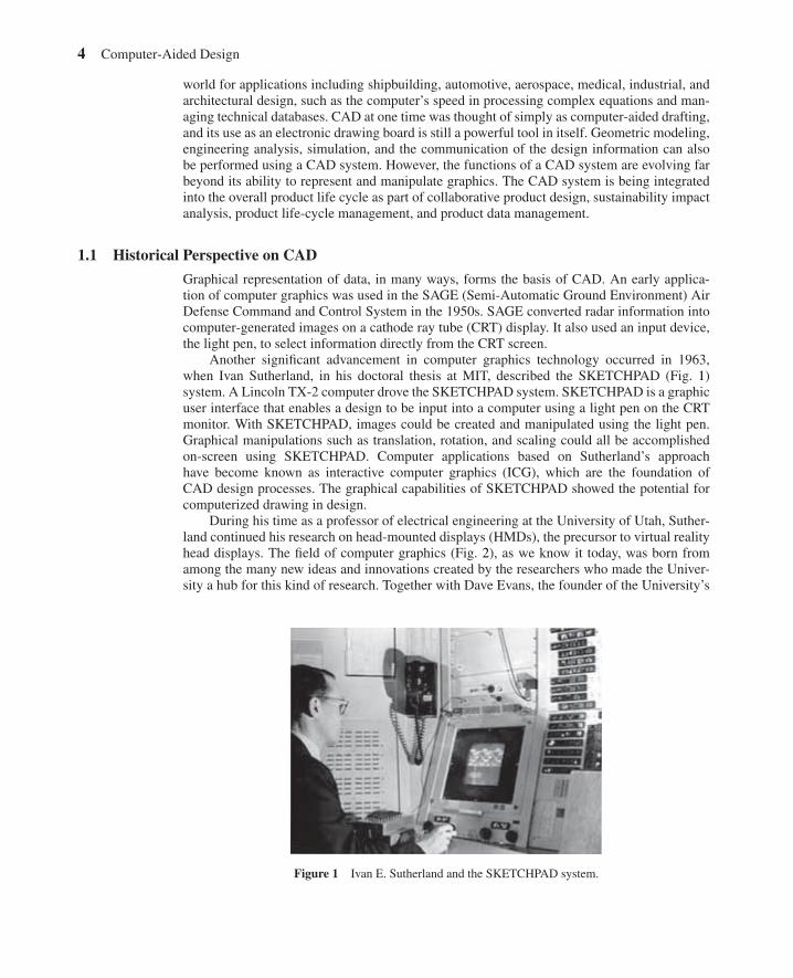
Another significant advancement in computer graphics technology occurred in 1963,when Ivan Sutherland, in his doctoral thesis at MIT, described the SKETCHPAD (Fig. 1)system. A Lincoln TX-2 computer drove the SKETCHPAD system. SKETCHPAD is a graphicuser interface that enables a design to be input into a computer using a light pen on the CRTmonitor. With SKETCHPAD, images could be created and manipulated using the light pen.Graphical manipulations such as translation, rotation, and scaling could all be accomplishedon-screen using SKETCHPAD. Computer applications based on Sutherland’s approachhave become known as interactive computer graphics (ICG), which are the foundation ofCAD design processes. The graphical capabilities of SKETCHPAD showed the potential forcomputerized drawing in design.
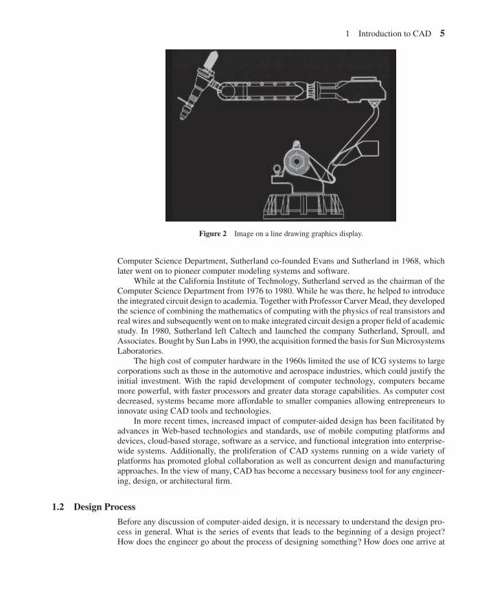
During his time as a professor of electrical engineering at the University of Utah, Suther-land continued his research on head-mounted displays (HMDs), the precursor to virtual realityhead displays. The field of computer graphics (Fig. 2), as we know it today, was born fromamong the many new ideas and innovations created by the researchers who made the Univer-sity a hub for this kind of research. Together with Dave Evans, the founder of the University’s
Figure 1 Ivan E. Sutherland and the SKETCHPAD system.
1 Introduction to CAD 5
Figure 2 Image on a line drawing graphics display.
Computer Science Department, Sutherland co-founded Evans and Sutherland in 1968, whichlater went on to pioneer computer modeling systems and software.
While at the California Institute of Technology, Sutherland served as the chairman of theComputer Science Department from 1976 to 1980. While he was there, he helped to introducethe integrated circuit design to academia. Together with Professor CarverMead, they developedthe science of combining the mathematics of computing with the physics of real transistors andreal wires and subsequently went on tomake integrated circuit design a proper field of academicstudy. In 1980, Sutherland left Caltech and launched the company Sutherland, Sproull, andAssociates. Bought by Sun Labs in 1990, the acquisition formed the basis for SunMicrosystemsLaboratories.
The high cost of computer hardware in the 1960s limited the use of ICG systems to largecorporations such as those in the automotive and aerospace industries, which could justify theinitial investment. With the rapid development of computer technology, computers becamemore powerful, with faster processors and greater data storage capabilities. As computer costdecreased, systems became more affordable to smaller companies allowing entrepreneurs toinnovate using CAD tools and technologies.
In more recent times, increased impact of computer-aided design has been facilitated byadvances in Web-based technologies and standards, use of mobile computing platforms anddevices, cloud-based storage, software as a service, and functional integration into enterprise-wide systems. Additionally, the proliferation of CAD systems running on a wide variety ofplatforms has promoted global collaboration as well as concurrent design and manufacturingapproaches. In the view of many, CAD has become a necessary business tool for any engineer-ing, design, or architectural firm.
1.2 Design Process
Before any discussion of computer-aided design, it is necessary to understand the design pro-cess in general. What is the series of events that leads to the beginning of a design project?How does the engineer go about the process of designing something? How does one arrive at

6 Computer-Aided Design
Analysis andoptimization
Problemdefinition
Final designand
specification
Evaluation
Synthesis
Customer inputand perception
of need
Figure 3 General design process.
the conclusion that the design has been completed? We address these questions by defining theprocess in terms of six distinct stages (Fig. 3):
1. Customer or sales field input and perception of need
2. Problem definition
3. Preliminary design
4. Analysis and optimization
5. Testing/evaluation
6. Final design and specification
A need is usually perceived in one of two ways. Someone from sales field reports orcustomer feedback must recognize either a problem in an existing design or a customer-drivenopportunity in the marketplace for a new product. In either case, a need exists which can beaddressed by modifying an existing design or developing an entirely new design. Because theneed for change may only be indicated by subtle circumstances—such as noise, increasedsustainability concerns, marginal performance characteristics, or deviations from qualitystandards—the design engineer who identifies the need has taken a first step in correcting the

1 Introduction to CAD 7
problem. That step sets in motion processes that may allow others to see the need more readilyand possibly enroll them in the solution process.
Once the decision has been made to take corrective action to the need at hand, the problemmust be defined as a particular problem to be solved such that all significant parameters inthe problem are defined. These parameters often include cost limits, quality standards, sizeand weight characteristics, and functional characteristics. Often, specifications may be definedby the capabilities of the manufacturing process. Anything that will influence the engineer inchoosing design features must be included in the definition of the problem. Careful planningin this stage can lead to fewer iterations in subsequent stages of design.
Once the problem has been fully defined in this way, the designer moves on to the prelim-inary design stage where knowledge and creativity can be applied to conceptualize an initialdesign. Teamwork can make the design more successful and effective at this stage. That designis then subjected to various forms of analysis, which may reveal specific problems in the initialdesign. The designer then takes the analytical results and applies them in an iteration of thepreliminary design stage. These iterations may continue through several cycles of preliminarydesign and analysis until the design is optimized.
The design is then tested/evaluated according to the parameters set forth in the problemdefinition. A scale prototype is often fabricated to perform further analysis and testing to assessoperating performance, quality, reliability, and other criteria. If a design flaw is revealed duringthis stage, the design moves back to the preliminary design/analysis stages for redesign, andthe process moves in this circular manner until the design clears the testing stage and is readyfor presentation.
Final design and specification represent the last stage of the design process. Communicat-ing the design to others in such a way that its manufacture and marketing are seen as vital to theorganization is essential. When the design has been fully approved, detailed engineering draw-ings are produced, complete with specifications for components, subassemblies, and the toolsand fixtures required to manufacture the product and the associated costs of production. Thesecan then be transferred manually or digitally using the CAD data to the various departmentsresponsible for manufacture.
In every branch of engineering, prior to the implementation of CAD, design had tradi-tionally been accomplished manually on the drawing board. The resulting drawing, completewith significant details, was then subjected to analysis using complex mathematical formulasand then sent back to the drawing board with suggestions for improving the design. The sameiterative procedure was followed, and because of the manual nature of the drawing and thesubsequent analysis, the whole procedure was time consuming and labor intensive. CAD hasallowed the designer to bypass much of the manual drafting and analysis previously required,making the design process flow smoothly and efficiently.
It is helpful to understand the general product development process as a stepwise pro-cess. However, in today’s engineering environment, the steps outlined above have becomeconsolidated into a more streamlined approach called “concurrent engineering” or “simulta-neous engineering.” This approach enables teams to work concurrently by providing commonground for interrelated product development tasks. Product information can be easily commu-nicated among all development processes: design, manufacturing, marketing, management, andsupplier networks. Concurrent engineering recognizes that fewer iterations result in less timeand money spent in moving from concept to manufacture and from manufacturing to market.The related processes of design for manufacturing (DFM) and design for assembly (DFA) havebecome integral parts of the concurrent engineering approach.
Design for manufacturing and DFA use cross-disciplinary input from a variety of sources(e.g., design engineers, manufacturing engineers, suppliers, and shop-floor representatives) tofacilitate the efficient design of a product that can be manufactured, assembled, and marketed inthe shortest possible period of time. Often, products designed using DFM and DFA are simpler,

8 Computer-Aided Design
cost less, and reach the marketplace in far less time than traditionally designed products. DFMfocuses on determining what materials and manufacturing techniques will result in the mostefficient use of available resources in order to integrate this information early in the designprocess. The DFAmethodology strives to consolidate the number of parts, uses gravity-assistedassembly techniques wherever possible, and calls for careful review and consensus approval ofdesigns early in the process. By facilitating the free exchange of information, DFM and DFAmethods allow engineering companies to avoid the costly rework often associated with repeatediterations of the design process.
1.3 Applying Computers to Design
Many of the individual tasks within the overall design process can be performed using a com-puter. As each of these tasks is made more efficient, the efficiency of the overall processincreases as well. The computer is especially well suited to design in four areas, which cor-respond to the latter four stages of the general design process (Fig. 4). Computers function in
Analysis andoptimization
Problemdefinition
Final design andspecification
EvaluationDesign reviewand evaluation
Automateddrafting
SynthesisGeometricmodeling
Engineeringanalysis
Customer inputand perception
of need
Figure 4 Application of computers to the design process.

1 Introduction to CAD 9
the design process through geometric modeling capabilities, engineering analysis calculations,automated evaluative procedures, and automated drafting.
Geometric ModelingGeometric modeling is one of the keystones of CAD systems. It uses mathematical descriptionsof geometric elements to facilitate the representation and manipulation of graphical images ona computer display screen. While the computer central processing unit (CPU) and the graph-ics processing unit (GPU) provide the ability to quickly make the calculations specific to theelement, the software provides the instructions necessary for efficient transfer of informationbetween the user and the CPU and the GPU.
Three types of commands are used by the designer in computerized geometric modeling:
1. Input commands allow the user to input the variables needed by the computer to repre-sent basic geometric elements such as points, lines, arcs, circles, splines, and ellipses.
2. Transformation commands are used to transform these elements. Commonly performedtransformations in CAD include scaling, rotation, and translation.
3. Solid commands allow the various elements previously created by the first two com-mands to be joined into a desired shape.
During the entire geometric modeling process, mathematical operations are at work which canbe easily stored as computerized data and retrieved as needed for review, analysis, andmodifica-tion. There are different ways of displaying the same data on the computer monitor, dependingon the needs or preferences of the designer.
One method is to display the design as a two-dimensional (2D) representation of a flatobject formed by interconnecting lines.
Another method displays the design as a three-dimensional (3D) representation of objects.In 3D representations, there are four types of modeling approaches:
• Wire frame modeling• Surface modeling• Solid modeling• Hybrid solid modeling
Wire Frame ModelA wire frame model is a skeletal description of a 3D object. It consists only of points, lines,and curves that describe the boundaries of the object. There are no surfaces in a wire framemodel. 3D wire frame representations can cause the viewer some confusion because all of thelines defining the object appear on the 2D display screen. This makes it hard for the viewer totell whether the model is being viewed from above or below, from inside the object or lookingfrom outside.
Surface modeling defines not only the edge of the 3D object but also its surface. Twodifferent types of surfaces can be generated: faceted surfaces using a polygon mesh and truecurve surfaces.
A polygonal mesh is a surface approximated by polygons such as squares, rectangles,and hexagons. The surface is created as if a mosaic of fine polygons. Depending on the detailrequired by the designer, very fine surfaces cannot be created this way. Instead, polygonalmeshes allow for faster rendering of shapes, as opposed to using curves.
The nonuniform rational basis spline (NURBS) is a B-spline curve or surface defined by aseries of weighted control points and one or more knot vectors. It can exactly represent a widerange of curves such as arcs and conics. The greater flexibility for controlling continuity is one
10 Computer-Aided Design
advantage of NURBS. NURBS can precisely model nearly all kinds of surfaces more robustlythan the polynomial-based curves that were used in earlier surface models. Surface modelingis more sophisticated than wire frame modeling. Here, the computer still defines the object interms of a wire frame but generates a surface “skin” to cover the frame, thus giving the illusionof a “real” object. However, because the computer has the image stored in its data as a wireframe representation having no mass, physical properties cannot be calculated directly from theimage data. Surface models are very advantageous due to point-to-point data collections usu-ally required for numerical control (NC) programs in computer-aided manufacturing (CAM)applications. Most surface modeling systems also produce the stereolithographic data requiredfor rapid prototyping systems.
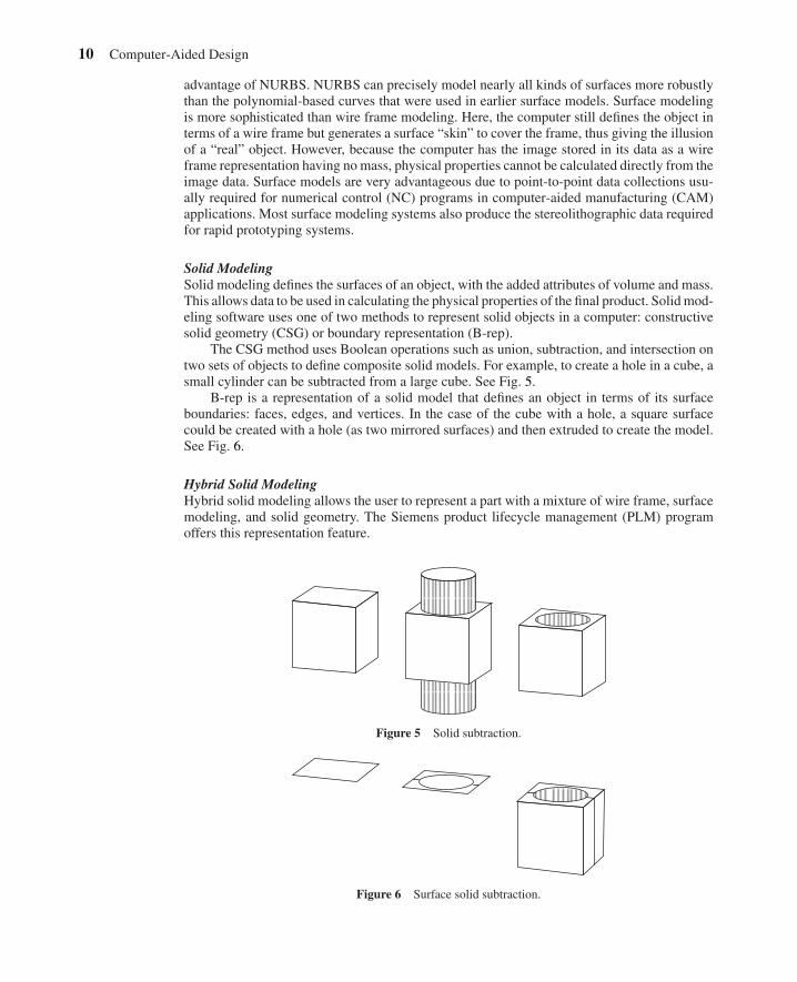
Solid ModelingSolid modeling defines the surfaces of an object, with the added attributes of volume and mass.This allows data to be used in calculating the physical properties of the final product. Solidmod-eling software uses one of two methods to represent solid objects in a computer: constructivesolid geometry (CSG) or boundary representation (B-rep).
The CSG method uses Boolean operations such as union, subtraction, and intersection ontwo sets of objects to define composite solid models. For example, to create a hole in a cube, asmall cylinder can be subtracted from a large cube. See Fig. 5.
B-rep is a representation of a solid model that defines an object in terms of its surfaceboundaries: faces, edges, and vertices. In the case of the cube with a hole, a square surfacecould be created with a hole (as two mirrored surfaces) and then extruded to create the model.See Fig. 6.
Hybrid Solid ModelingHybrid solid modeling allows the user to represent a part with a mixture of wire frame, surfacemodeling, and solid geometry. The Siemens product lifecycle management (PLM) programoffers this representation feature.
Figure 5 Solid subtraction.
Figure 6 Surface solid subtraction.
1 Introduction to CAD 11
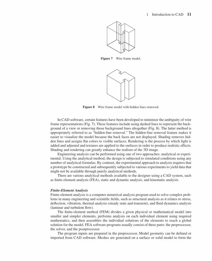
Figure 7 Wire frame model.
Figure 8 Wire frame model with hidden lines removed.
In CAD software, certain features have been developed to minimize the ambiguity of wireframe representations (Fig. 7). These features include using dashed lines to represent the back-ground of a view or removing those background lines altogether (Fig. 8). The latter method isappropriately referred to as “hidden-line removal.” The hidden-line removal feature makes iteasier to visualize the model because the back faces are not displayed. Shading removes hid-den lines and assigns flat colors to visible surfaces. Rendering is the process by which light isadded and adjusted and textures are applied to the surfaces in order to produce realistic effects.Shading and rendering can greatly enhance the realism of the 3D image.
Engineering analysis can be performed using one of two approaches: analytical or experi-mental. Using the analytical method, the design is subjected to simulated conditions using anynumber of analytical formulas. By contrast, the experimental approach to analysis requires thata prototype be constructed and subsequently subjected to various experiments to yield data thatmight not be available through purely analytical methods.
There are various analytical methods available to the designer using a CAD system, suchas finite-element analysis (FEA), static and dynamic analysis, and kinematic analysis.
Finite-Element AnalysisFinite-element analysis is a computer numerical analysis program used to solve complex prob-lems in many engineering and scientific fields, such as structural analysis as it relates to stress,deflection, vibration, thermal analysis (steady state and transient), and fluid dynamics analysis(laminar and turbulent flow).
The finite-element method (FEM) divides a given physical or mathematical model intosmaller and simpler elements, performs analysis on each individual element using requiredmathematics, and then assembles the individual solutions of the elements to reach a globalsolution for the model. FEA software programs usually consist of three parts: the preprocessor,the solver, and the postprocessor.
The program inputs are prepared in the preprocessor. Model geometry can be defined orimported from CAD software. Meshes are generated on a surface or solid model to form the
12 Computer-Aided Design
elements. Element properties and material descriptions can be assigned to the model. Finally,the boundary conditions and loads are applied to the elements and their nodes. Certain checksmust be completed before analysis solving is executed. These include checking for duplicationof nodes and elements and verifying the element connectivity of the surface elements so thatthe surface normals are all in the same direction. In order to optimize disk space and runningtime, the nodes and elements should usually be renumbered and sequenced.
Many analysis options are available in the analysis solver to execute the model. The ele-ment stiffness matrices can be formulated and solved to form a global stiffness value for themodel solution. The results of the analysis data are then interpreted by the postprocessor. Thepostprocessor in most FEA applications offers graphical output and animation displays. Ven-dors of CAD software are developing pre- and postprocessors that allow the user to graphicallyvisualize their input and output. FEA is a powerful tool in effectively developing a design toachieve a superior product.
Kinematic Analysis and SynthesisKinematic analysis and synthesis allow for the study of the motion or position of a set of rigidbodies in a system without reference to the forces causing that motion or the mass of the bod-ies. It allows engineers to see how the mechanisms they design will function and interact inmotion. This kinematic modeler enables the designer to avoid a faulty design and to apply avariety of scenarios to the model without constructing a physical prototype. A superior designmay be developed after analyzing the data extracted from kinematic analysis after numerousmotion iterations. The behavior of the resulting model mechanism may be understood prior toproduction.
Static AnalysisStatic analysis determines reaction forces at the joint positions of resting mechanisms when aconstant load is applied. As long as zero or constant velocity of the entire system under study isassumed, static analysis can also be performed on mechanisms at different points of their rangeof motion. Static analysis allows the designer to determine the reaction forces on mechani-cal systems as well as interconnection forces transmitted to individual joints. Data extractedfrom static analysis can be useful in determining compatibility with the various criteria setout in the problem definition. These criteria may include reliability, fatigue, and performanceconsiderations to be analyzed through stress analysis methods.
Dynamic AnalysisDynamic analysis combines motion with forces in a mechanical system to calculate positions,velocities, accelerations, and reaction forces on parts in the system. The analysis is performedstepwise within a given interval of time. Each degree of freedom is associated with a specificcoordinate for which initial position and velocity must be supplied. Defining the system invarious ways creates the computer model from which the design is analyzed. The user mustsupply joints, forces, and overall system coordination either directly or through a manipulationof data within the software.
Experimental AnalysisExperimental analysis involves fabricating a prototype and subjecting it to various experimentalmethods. Although this usually takes place in the later stages of design, CAD systems enable thedesigner to make more effective use of experimental data, especially where analytical methodsare thought to be unreliable for the given model. CAD also provides the platform for incorpo-rating experimental results into the design process.
2 Hardware 13
Design review can be easily accomplished using CAD. The accuracy of the design canbe checked using automated routines for tolerancing and dimensioning to reduce the possibil-ity of error. Layering is a technique that allows the designer to superimpose images on oneanother. This can be quite useful during the evaluative stage of the design process by allowingthe designer to visually check the dimensions of a final design against the dimensions of stagesof the design’s proposed manufacture, ensuring that sufficient material is present in preliminarystages for correct manufacture. Interference checking can also be performed using CAD. Thisprocedure checks the models and identifies when two parts of a design occupy the same spaceat the same time.
Automated DraftingAutomated drafting capabilities in CAD systems facilitate presentation, which is the final stageof the design process. CAD data, stored in computer memory, can be sent to a plotter or otherhard-copy device to produce a detailed drawing printout. In the early days of CAD, this featurewas the primary rationale for investing in a CAD system. Drafting conventions, including butnot limited to dimensioning, crosshatching, scaling of the design, and enlarged views of partsor other design areas, can be included automatically in nearly all CAD systems. Detail andassembly drawings, bills of materials (BOM), and cross-sectioned views of design parts arealso automated and simplified through CAD parts databases. In addition, most systems arecapable of presenting as many as six views of the design automatically (front, side left, sideright, top, bottom, rear). Drafting standards defined by a company can be programmed into thesystem such that all final drafts will comply with the company standards.
Product Data ManagementProduct data management (PDM) is an important application associated with CAD. PDMallows companies to make CAD data available across the enterprise on computer networks.For example, PDM software may operate in conjunction with CAD software and word process-ing software. This approach holds significant advantages over conventional data management.PDM is not simply a database holding CAD data as a library for interested users. PDM systemsoffer increased data management efficiency, for example, through a client-server environment.Benefits of implementing a PDM system include faster retrieval of CAD files through keywordsearches and other search features such as model parameters like color or serial number, auto-mated distribution of designs to management, manufacturing engineers, and shop-floor workersfor design review, record-keeping functions that provide a history of design changes, and datasecurity functions limiting access levels to design files. PDM facilitates the exchange of infor-mation characteristic of the agile workplace. As companies face increased pressure to provideclients with customized solutions to their individual needs, PDM systems allow an augmentedlevel of teamwork among personnel at all levels of product design and manufacturing, cuttingdown on costs often associated with information lag and rework.
Although CAD has made the design process less tedious andmore efficient than traditionalmethods, the fundamental design process remains unchanged. It still requires the human inputand ingenuity to initiate and proceed through the many iterations of the design process. CADis a powerful, time-saving design tool that competing in the engineering world without it isdifficult if not impossible. The CAD system will now be examined in terms of its components:the hardware and software of a computer.
2 HARDWARE
Just as a draftsman traditionally required pen and ink to bring creativity to bear on the page,there are certain essential components to any working CAD system. The use of computers for
14 Computer-Aided Design
interactive graphics applications can be traced back to the early 1960s, when Ivan Sutherlanddeveloped the SKETCHPAD system. The prohibitively high cost of hardware made general useof interactive computer graphics uneconomical until the 1970s. With the development and sub-sequent popularity of personal computers, interactive graphics applications became an integralpart of the design process.
CAD systems are available for many hardware configurations. CAD systems have beendeveloped for computer systems ranging from mainframes to workstations, desktops, and lap-top computers. A difference between a desktop and a workstation is the power and cost ofthe components and peripherals, a workstation being more expensive. Turnkey CAD systemscomewith all of the hardware and software required to run a particular CAD application and aresupplied by specialized vendors. The use of CAD on smaller computer devices such as smartphones and other mobile or wireless devices is currently limited to viewing and annotating.
Hardware is the tangible element of the computer system. Any physical component of acomputer systemwhether internal to the computer or an external such as printers, machinery, orother equipment is considered to be hardware. In a personal computer (PC) or in a workstation,common external hardware is the display monitor, a keyboard, network cables, and a mouse,while the CPU, memory chips, graphic cards, and hard drives are internal. The term hardwarealso extends beyond PCs to include any information technology (IT) devices such as routersand hubs.
2.1 Central Processing Unit
The CPU is a computer microprocessor component with specialized circuitry that interpretsand processes programming instructions. The processing speed is called the clock rate and itis measured in hertz, that is, number of cycles per second. Recent CPU speeds are 3.6GHz,or 3.6 × 10⁹ cycles per second. In contrast, the early 1980s 8086 Intel chips would runat 12MHz, or 12 × 106 cycles per second.
A CAD system requires a computer with a fast CPU. CAD software typically consists ofmillions of lines of computer code that require a high degree of computer processing power.This processing power is provided by the CPU. Because of the demands that CAD softwarehas on the CPUs, it is written by the CAD vendors to utilize specific CPU capabilities, suchas the rendering of geometry to the screen, or multiprocessing on CPU processors, such as theIntel Core i7 CPU or the AMD 990FX.
2.2 Operating System
Windows is the predominant operating system (OS), with support for UNIX and other systemswaning with respect to high-end CAD support. Windows XP, 7, 8, the 32- and 64-bit versionsare the ones supported by CAD software manufacturers such as AutoCAD and Creo. However,the faster computations on 64-bit OSs may see a decline in support of the slower 32-bit OSs infavor of 64-bit ones, e.g., Windows 7 and 8, as well as the Mac® OS X® v10.8 or later.
2.3 Bus
Communication between the CPU and the CAD program passes through a hardware systemcalled the bus. Other peripherals communicate with each other via the bus. For the hardwarewithin a computer, the bus is called the local bus. External to computer devices such as USBcameras use the universal serial bus (USB). PC bus sizes range from 64 bits to 32 bits, 16 bits,and 8 bits. As the bus gets wider (increase in the bit count), more data can pass through, whichmeans more of the programming code can get from the hard drive to the CPU and back, andCAD software executes commands even faster. Note: 8 bits = 1 byte. One byte is used todescribe 256 different values.
Related Documents