JASON D. MOYER | ME488 MECHANICAL ENGINEERING DESIGN II| OCT. 11 2019 VERSION 3 Mechanical Engineering Technical Project Handbook Information for a successful Senior Design II Project

Welcome message from author
This document is posted to help you gain knowledge. Please leave a comment to let me know what you think about it! Share it to your friends and learn new things together.
Transcript
JASON D. MOYER | ME488 MECHANICAL ENGINEERING DESIGN II| OCT. 11 2019 VERSION 3
Mechanical Engineering Technical Project Handbook
Information for a successful Senior Design II Project
PAGE 1
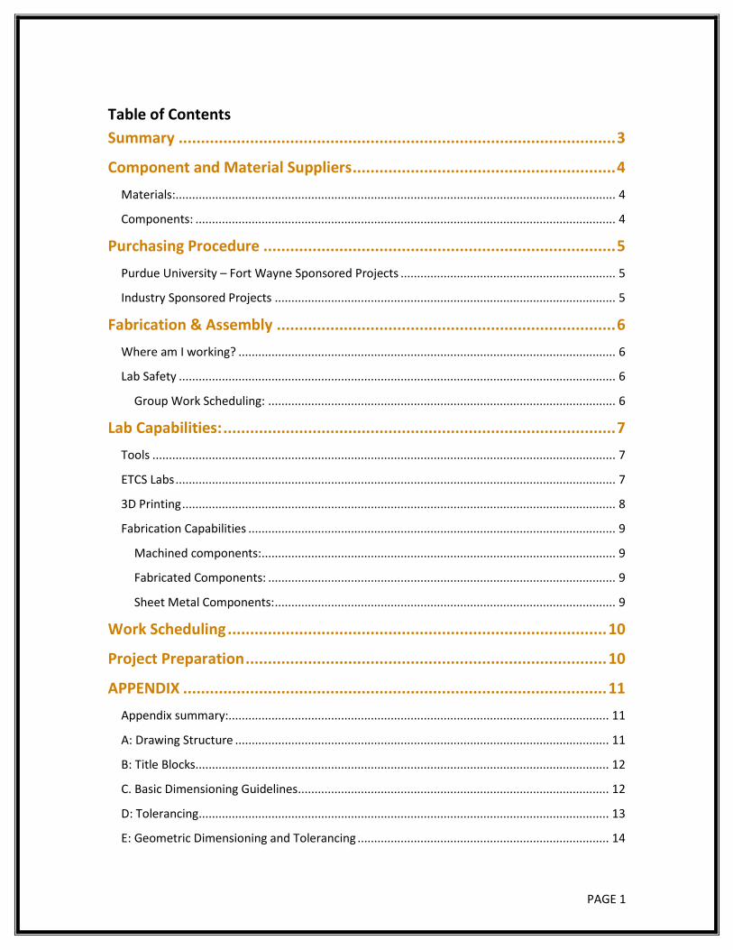
Table of Contents Summary .................................................................................................. 3
Component and Material Suppliers ........................................................... 4
Materials:..................................................................................................................................... 4
Components: ............................................................................................................................... 4
Purchasing Procedure ............................................................................... 5
Purdue University – Fort Wayne Sponsored Projects ................................................................. 5
Industry Sponsored Projects ....................................................................................................... 5
Fabrication & Assembly ............................................................................ 6
Where am I working? .................................................................................................................. 6
Lab Safety .................................................................................................................................... 6
Group Work Scheduling: ......................................................................................................... 6
Lab Capabilities: ........................................................................................ 7
Tools ............................................................................................................................................ 7
ETCS Labs ..................................................................................................................................... 7
3D Printing ................................................................................................................................... 8
Fabrication Capabilities ............................................................................................................... 9
Machined components: ........................................................................................................... 9
Fabricated Components: ......................................................................................................... 9
Sheet Metal Components: ....................................................................................................... 9
Work Scheduling ..................................................................................... 10
Project Preparation ................................................................................. 10
APPENDIX ............................................................................................... 11
Appendix summary:................................................................................................................... 11
A: Drawing Structure ................................................................................................................. 11
B: Title Blocks ............................................................................................................................. 12
C. Basic Dimensioning Guidelines .............................................................................................. 12
D: Tolerancing ............................................................................................................................ 13
E: Geometric Dimensioning and Tolerancing ............................................................................ 14
PAGE 2
Recommended Books ................................................................................................................ 15
Recommended Websites .......................................................................................................... 15
Drill and Tap Chart ..................................................................................................................... 16
PAGE 3
Summary
Over the course of your college career you are working towards a capstone senior design project. The goal is to apply the knowledge you have gained to complete a project that solves a real-world problem.
The purpose of this document is to help you complete your project by providing some upfront information that will hopefully answer your questions, eliminate confusion, and help you complete your project on time.
Included you will find references to component suppliers, drawing examples, geometric dimensioning and tolerancing, as well as other helpful documents and guidelines. This information will help make your senior design project successful.
Thank You,
Department of Civil and Mechanical Engineering Faculty & Staff
PAGE 4
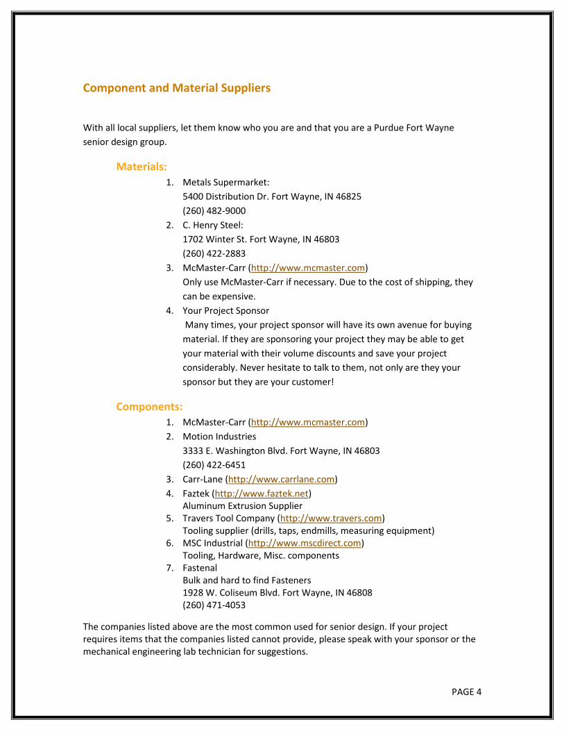
Component and Material Suppliers
With all local suppliers, let them know who you are and that you are a Purdue Fort Wayne senior design group.
Materials: 1. Metals Supermarket:
5400 Distribution Dr. Fort Wayne, IN 46825 (260) 482-9000
2. C. Henry Steel: 1702 Winter St. Fort Wayne, IN 46803 (260) 422-2883
3. McMaster-Carr (http://www.mcmaster.com) Only use McMaster-Carr if necessary. Due to the cost of shipping, they can be expensive.
4. Your Project Sponsor Many times, your project sponsor will have its own avenue for buying material. If they are sponsoring your project they may be able to get your material with their volume discounts and save your project considerably. Never hesitate to talk to them, not only are they your sponsor but they are your customer!
Components: 1. McMaster-Carr (http://www.mcmaster.com) 2. Motion Industries
3333 E. Washington Blvd. Fort Wayne, IN 46803 (260) 422-6451
3. Carr-Lane (http://www.carrlane.com) 4. Faztek (http://www.faztek.net)
Aluminum Extrusion Supplier 5. Travers Tool Company (http://www.travers.com)
Tooling supplier (drills, taps, endmills, measuring equipment) 6. MSC Industrial (http://www.mscdirect.com)
Tooling, Hardware, Misc. components 7. Fastenal
Bulk and hard to find Fasteners 1928 W. Coliseum Blvd. Fort Wayne, IN 46808 (260) 471-4053
The companies listed above are the most common used for senior design. If your project requires items that the companies listed cannot provide, please speak with your sponsor or the mechanical engineering lab technician for suggestions.
PAGE 5
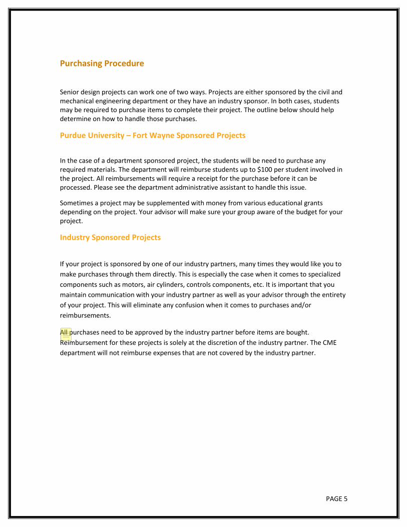
Purchasing Procedure
Senior design projects can work one of two ways. Projects are either sponsored by the civil and mechanical engineering department or they have an industry sponsor. In both cases, students may be required to purchase items to complete their project. The outline below should help determine on how to handle those purchases.
Purdue University – Fort Wayne Sponsored Projects
In the case of a department sponsored project, the students will be need to purchase any required materials. The department will reimburse students up to $100 per student involved in the project. All reimbursements will require a receipt for the purchase before it can be processed. Please see the department administrative assistant to handle this issue.
Sometimes a project may be supplemented with money from various educational grants depending on the project. Your advisor will make sure your group aware of the budget for your project.
Industry Sponsored Projects
If your project is sponsored by one of our industry partners, many times they would like you to make purchases through them directly. This is especially the case when it comes to specialized components such as motors, air cylinders, controls components, etc. It is important that you maintain communication with your industry partner as well as your advisor through the entirety of your project. This will eliminate any confusion when it comes to purchases and/or reimbursements.
All purchases need to be approved by the industry partner before items are bought. Reimbursement for these projects is solely at the discretion of the industry partner. The CME department will not reimburse expenses that are not covered by the industry partner.
Jason Moyer
Update per N. Younis 12/13/18
PAGE 6
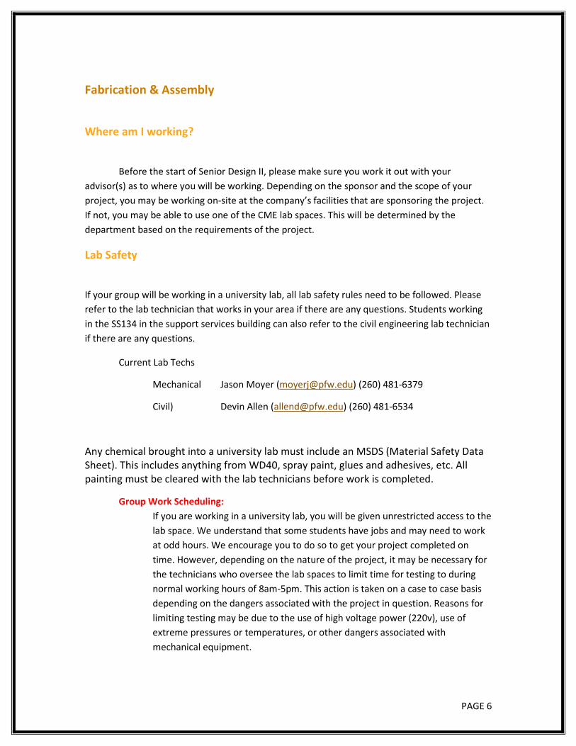
Fabrication & Assembly
Where am I working?
Before the start of Senior Design II, please make sure you work it out with your advisor(s) as to where you will be working. Depending on the sponsor and the scope of your project, you may be working on-site at the company’s facilities that are sponsoring the project. If not, you may be able to use one of the CME lab spaces. This will be determined by the department based on the requirements of the project.
Lab Safety
If your group will be working in a university lab, all lab safety rules need to be followed. Please refer to the lab technician that works in your area if there are any questions. Students working in the SS134 in the support services building can also refer to the civil engineering lab technician if there are any questions.
Current Lab Techs
Mechanical Jason Moyer ([email protected]) (260) 481-6379
Civil) Devin Allen ([email protected]) (260) 481-6534
Any chemical brought into a university lab must include an MSDS (Material Safety Data Sheet). This includes anything from WD40, spray paint, glues and adhesives, etc. All painting must be cleared with the lab technicians before work is completed.
Group Work Scheduling: If you are working in a university lab, you will be given unrestricted access to the lab space. We understand that some students have jobs and may need to work at odd hours. We encourage you to do so to get your project completed on time. However, depending on the nature of the project, it may be necessary for the technicians who oversee the lab spaces to limit time for testing to during normal working hours of 8am-5pm. This action is taken on a case to case basis depending on the dangers associated with the project in question. Reasons for limiting testing may be due to the use of high voltage power (220v), use of extreme pressures or temperatures, or other dangers associated with mechanical equipment.
PAGE 7
Lab Capabilities:
Tools Tools are not supplied to senior design groups. It is your responsibility to provide what ever tools you may need to assemble your project.
*Exception* Specialty tools may be borrowed from the lab technician on a sign out basis. This includes the following:
• Data logging thermometers and thermocouple readers • Thermocouples • Digital calipers/micrometers • Anemometer • Digital tachometer
ETCS Labs Working Air Pressure: 100-130psi
Voltages available: 110v, 220v 1ph
Access to Water: All useable lab spaces have access to at least a sink.
Labview: In SS134 and ET343 only currently
PAGE 8
3D Printing It is perfectly acceptable to 3D print parts for your senior design project. We currently have access to (5) FDM style machines.
• (2) Dremel Idea Builder 3D45 • (1) Dremel Idea Builder 3D40 • (1) Seemecnc Rostock Max V2 • (1) Flashforge Dreamer • (1) Stratasys F170 (limited usage available. See technician for details) • (1) Folgertech FT6
Specifications such as build area are available on the manufacturer websites. We are capable of using the following materials:
• PLA • ABS • PETG • HIPS • TPU • Nylon
Work with the lab technician to determine which machine and which materials are suitable for your project.
These machines are in ET342. Access and usage must be worked out with lab technician. If you have not used a 3D printer before. Please see the 3D printing rules that are posted outside of the lab.
Make sure all printing is scheduled with the lab technician at least a few days ahead of when you need your components as these facilities are used by the ME160 class, senior design, as well as other academic projects. Print times can vary depending on the size and complexity of the components as well as the machine settings. There currently is no charge to the student or the project to use the 3D printers. There is also a 3D print center located in the Walb student union building. You are welcome to use their services as well, but it is not free and you do not get access to the equipment. You provide them with a file, they print the part, and you pay them for the material used.
PAGE 9
Fabrication Capabilities
Machined components: Students who have completed MET335 are welcome to use the manual machine shop located in ET124. Access and usage must be scheduled with either the mechanical lab technician or the machine shop manager.
Machine Shop manager: John Mitchell ([email protected]) (260) 481-6393
The lab technician can help with machined components as well. We do have the ability to CNC components using the HAAS machine tools located in ET124 and ET137. These are open for student use, however the technician can and will machine components based on his availability and on a first come first serve basis. Due to the nature of the projects, his/her availability may be limited. Make sure you have a backup plan to get parts manufactured if the technician is unable to complete your parts in a timely manner.
Students are not charged for machining time. However, it is expected that the group replace any tooling that worn out or broken during manufacturing their parts. This should be figured into your project budget. Any specialized tooling needed will also need to be provided by the project team. Please meet with the lab technician or the machine shop manager prior to purchasing any tooling.
Fabricated Components: The department does have limited welding capabilities. Any welding will need to be scheduled with the lab technician. Students are not permitted to use the department welder due to safety regulations. All welding and hot work (grinding, torch cutting, etc) must be completed in the hot work area located in SS134.
Sheet Metal Components: The PFW machine shop has very limited capability for manufacturing sheet metal components. We do have a basic 24” pan and box break, 24” sheer, and a 24” slip roll. These tools are limited to 16ga steel and 22ga for stainless steel material for capacity. Refer to the lab tech with any questions.
PAGE 10
Work Scheduling
All fabrication, machining, 3D printing work needs to be scheduled with the lab technician as soon as possible. If you are at a point in Senior Design I where you can begin construction, do not hesitate to get started on your build. The technician is a full time Purdue employee. This means that during the summer months when most people are not in class the technician is available to help with component fabrication, machining, or even general advising on the purchase and acquisition of parts for your project.
The technician’s time can be limited so the sooner you contact him/her the better.
Project Preparation This is an overview of what you will need before scheduling any work with the technician.
• Complete detailed drawings of components, assemblies, and weldments that you want to have made.
• A clear timeline when components need to be completed by. • Specification sheets or detailed drawings for purchased components will be required if
they interface with any machined/welded components. • Students will be required to provide all materials used in the fabrication of their parts
except for 3D printer materials. This will come out of our project budget. You should speak with your project sponsor prior to ordering any materials.
• Special tooling required for the fabrication/machining of your project will need to be supplied by the group.
o Examples include custom or uncommon drills, endmills, taps, dies, profile cutters, etc.
o Always check with the machine shop or lab technician before making tooling purchases
PAGE 11
APPENDIX Appendix summary:
Included in this appendix are examples for drawings, specifications, and other documentation needed to complete your project.
Please note that the information given in the appendix is a basic guideline. It is possible that the company that is sponsoring your project may have their own standards on how this type of information is presented. Make sure you follow what your sponsor is expecting. If not, the guidelines presented in this appendix are a good reference.
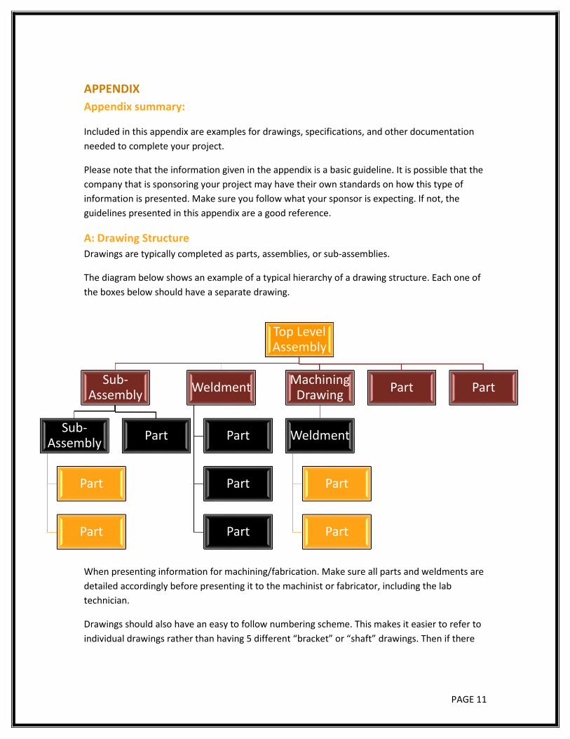
A: Drawing Structure Drawings are typically completed as parts, assemblies, or sub-assemblies.
The diagram below shows an example of a typical hierarchy of a drawing structure. Each one of the boxes below should have a separate drawing.
When presenting information for machining/fabrication. Make sure all parts and weldments are detailed accordingly before presenting it to the machinist or fabricator, including the lab technician.
Drawings should also have an easy to follow numbering scheme. This makes it easier to refer to individual drawings rather than having 5 different “bracket” or “shaft” drawings. Then if there
Top Level Assembly
Sub-Assembly
Sub-Assembly
Part
Part
Part
Weldment
Part
Part
Part
Machining Drawing
Weldment
Part
Part
Part Part
PAGE 12
are slight differences the drawing number will make it explicitly clear as to which part you are referring to.
B: Title Blocks Common title block sizes in the mechanical world are A, B, C, D, E.
Common Drawing sizes (l x h)
• A – 8 ½” x 11” • B – 11” x 17” • C – 17” x 22” • D – 22” x 34” • E – 34” x 44”
Typically, drawings are done either on A/C size or on B/D size depending on the printing capabilities of an office because A/C size drawings will scale and view properly on an 8 ½” x 11” sheet of paper. B/D sizes will scale to an 11”x17” paper easily.
The standard Solidworks ANSI drawing templates work just fine for senior design projects.
All part drawings sent for fabrication need to have a title block on their drawing.
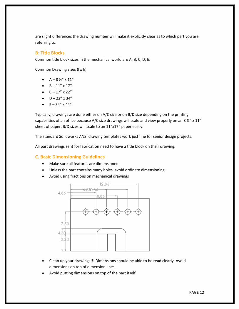
C. Basic Dimensioning Guidelines • Make sure all features are dimensioned • Unless the part contains many holes, avoid ordinate dimensioning. • Avoid using fractions on mechanical drawings
• Clean up your drawings!!! Dimensions should be able to be read clearly. Avoid dimensions on top of dimension lines.
• Avoid putting dimensions on top of the part itself.
PAGE 13
D: Tolerancing Tolerance = $$$
The key to tolerancing a drawing is to only put tolerances where they are critical to the fit or function of a part. All dimensions on a part have a tolerance. If it not shown on the dimension itself, then refer to the generic title block tolerances.
Typical title block tolerances are as follows:
.xx = +/- .015”
.xxx = +/- .005”
Angle Mach. +/- .5° Bend +/- 1°
PAGE 14
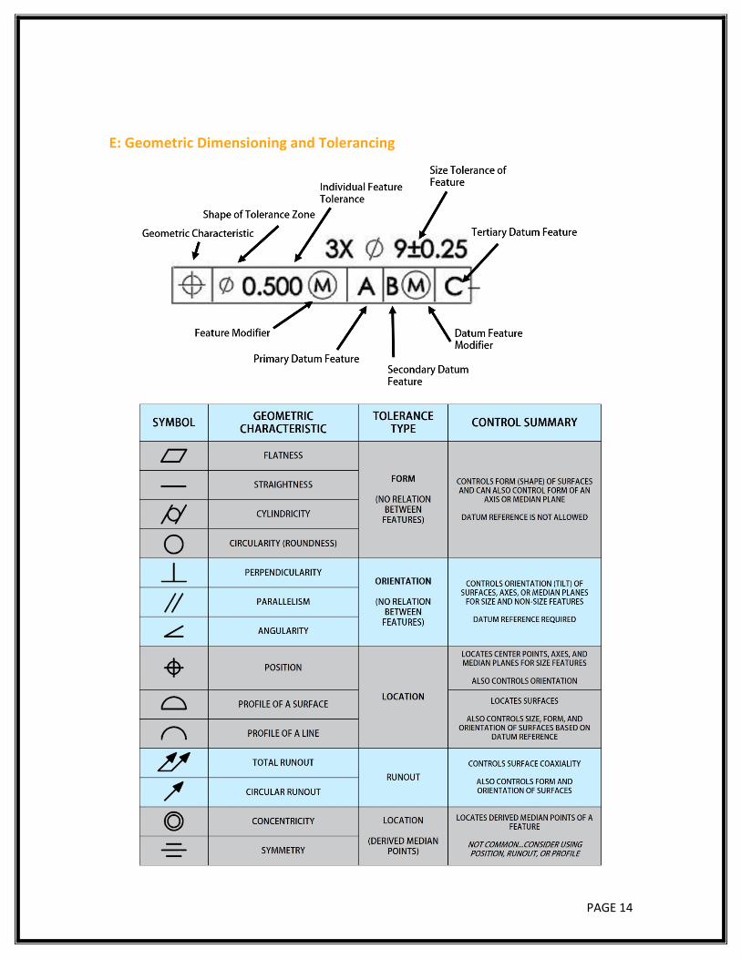
E: Geometric Dimensioning and Tolerancing
PAGE 15
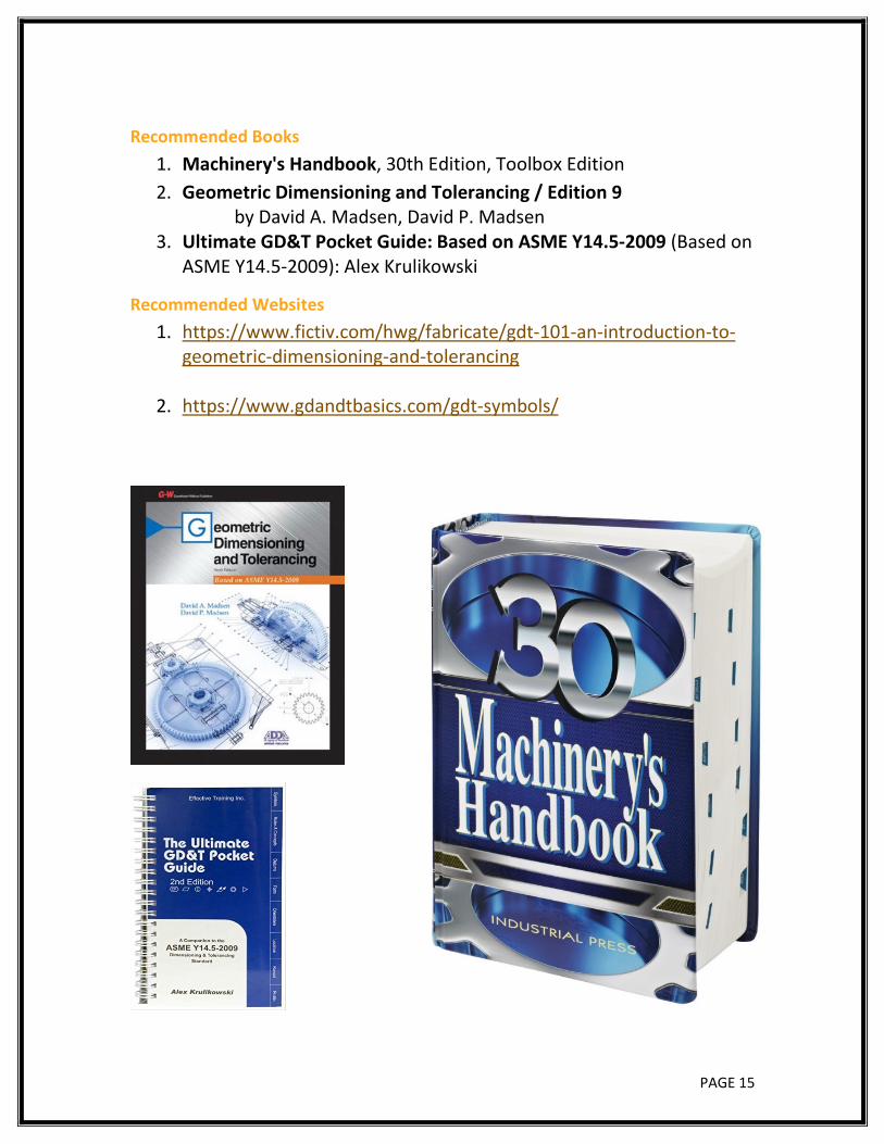
Recommended Books 1. Machinery's Handbook, 30th Edition, Toolbox Edition 2. Geometric Dimensioning and Tolerancing / Edition 9
by David A. Madsen, David P. Madsen 3. Ultimate GD&T Pocket Guide: Based on ASME Y14.5-2009 (Based on
ASME Y14.5-2009): Alex Krulikowski
Recommended Websites 1. https://www.fictiv.com/hwg/fabricate/gdt-101-an-introduction-to-
geometric-dimensioning-and-tolerancing
2. https://www.gdandtbasics.com/gdt-symbols/
PAGE 16
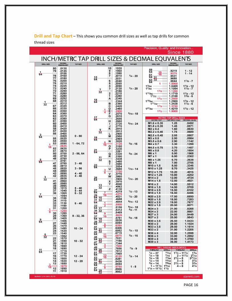
Drill and Tap Chart – This shows you common drill sizes as well as tap drills for common thread sizes
Related Documents