Mechanical design and analysis of a deployment mechanism for low frequency dipole antenna Mara Rosado [email protected] Instituto Superior T´ ecnico, Lisboa, Portugal October 2015 Abstract This work regards the preliminary mechanical design and analysis of a deployment mechanism for a low frequency dipole antenna, performed in collaboration with a space related enterprise, Active Space Technologies. A dipole antenna is used in space applications to perform electric field measurements, which include measurements of ultra-low frequencies associated with important ionospheric and tropospheric phenomena, such as Schumann resonance and Alfv´ en wave signatures. The antenna boom is designed in order to fulfil the desired structural requirements, aiming to achieve a mass that is as low as possible. To perform the preliminary antenna boom design, a trade-off of concepts of deployment mechanism devices available in literature was conducted and a concept to be developed was chosen, through a simplified analytical hierarchy process. An innovative approach to the chosen concept was conceived and a 3D-printer prototype was made and tested to validate it. Regarding the requirements, the material selection was based in criteria that allowed for achievement of a low density and highly stiff material. A finite element model was developed in order to execute static, harmonic and modal analyses to assess the requirements and choose boom dimensions. These analyses were performed taking into account the launch environment and the need for decoupling between boom eigenfrequencies and frequencies associated with the phenomena to be studied. Two designs were created: the most innovative did not fulfil the requirements established, but the more conservative approach was able to comply with most of them. Keywords: dipole antenna, deployable structure, telescopic boom, low frequency antenna, finite elements analysis. 1. Introduction A dipole antenna is an instrument used in several space missions that allows for studying of aero- dynamics and electrodynamics phenomena in the higher layers of the atmosphere. It is composed by a set of two monopole antennas that are usually incor- porated in the satellite opposite walls. In order to provide the possibility of measurements in the lower frequency ranges (extremely low frequency (ELF) - 3 to 30 Hz -, super low frequency (SLF) - 30 to 300 Hz - and ultra low frequency (ULF) - 300 to 3000 Hz - ranges), a long antenna boom is required. A greater antenna boom means a greater mass and the use of this type of instrument has been neglected due to missions strict mass requirements. There- fore, a structural challenge nowadays is to reduce the boom mass of these antennas and improve their deployment mechanisms, taking into account the ef- fects (e.g. interference) of vibration modes of the structure in instrument sensitivity. This work is focused on the preliminary design of the antenna boom, in which static and harmonic analyses were performed for a simplified finite el- ement model of the boom, in order to ascertain if the chosen materials and design criteria are suitable for the launch environment. Modal analyses were also performed for stowed and deployed configura- tions with the main purpose of optimizing the boom mass without placing frequencies in the undesired range. The antenna boom must be a deployable structure, due to the project structural requirements, dis- played in Table 1 and its mass optimization should be performed with the aim of decoupling boom eigenfrequencies from the frequencies to be mea- sured, which are shown in Figure 1. To fulfil the mass requirement, while assessing the respect of the length variability requirement, the boom must have a great stiffness, which led to materials selection: materials should be highly stiff to withstand loading conditions without compromising the length varia- tion requirements and should have low density as well. Less critical but also important are the natural vi- 1

Mechanical design and analysis of a deployment mechanism ... · Mechanical design and analysis of a deployment mechanism for low frequency dipole antenna Mara Rosado [email protected]
Apr 07, 2020
Welcome message from author
This document is posted to help you gain knowledge. Please leave a comment to let me know what you think about it! Share it to your friends and learn new things together.
Transcript

Mechanical design and analysis of a deployment mechanism for
low frequency dipole antenna
Mara [email protected]
Instituto Superior Tecnico, Lisboa, Portugal
October 2015
Abstract
This work regards the preliminary mechanical design and analysis of a deployment mechanism for alow frequency dipole antenna, performed in collaboration with a space related enterprise, Active SpaceTechnologies. A dipole antenna is used in space applications to perform electric field measurements,which include measurements of ultra-low frequencies associated with important ionospheric andtropospheric phenomena, such as Schumann resonance and Alfven wave signatures. The antennaboom is designed in order to fulfil the desired structural requirements, aiming to achieve a mass thatis as low as possible. To perform the preliminary antenna boom design, a trade-off of concepts ofdeployment mechanism devices available in literature was conducted and a concept to be developedwas chosen, through a simplified analytical hierarchy process. An innovative approach to the chosenconcept was conceived and a 3D-printer prototype was made and tested to validate it. Regarding therequirements, the material selection was based in criteria that allowed for achievement of a low densityand highly stiff material. A finite element model was developed in order to execute static, harmonicand modal analyses to assess the requirements and choose boom dimensions. These analyses wereperformed taking into account the launch environment and the need for decoupling between boomeigenfrequencies and frequencies associated with the phenomena to be studied. Two designs werecreated: the most innovative did not fulfil the requirements established, but the more conservativeapproach was able to comply with most of them.Keywords: dipole antenna, deployable structure, telescopic boom, low frequency antenna, finiteelements analysis.
1. Introduction
A dipole antenna is an instrument used in severalspace missions that allows for studying of aero-dynamics and electrodynamics phenomena in thehigher layers of the atmosphere. It is composed by aset of two monopole antennas that are usually incor-porated in the satellite opposite walls. In order toprovide the possibility of measurements in the lowerfrequency ranges (extremely low frequency (ELF) -3 to 30 Hz -, super low frequency (SLF) - 30 to 300Hz - and ultra low frequency (ULF) - 300 to 3000Hz - ranges), a long antenna boom is required.A greater antenna boom means a greater mass andthe use of this type of instrument has been neglecteddue to missions strict mass requirements. There-fore, a structural challenge nowadays is to reducethe boom mass of these antennas and improve theirdeployment mechanisms, taking into account the ef-fects (e.g. interference) of vibration modes of thestructure in instrument sensitivity.This work is focused on the preliminary design ofthe antenna boom, in which static and harmonic
analyses were performed for a simplified finite el-ement model of the boom, in order to ascertain ifthe chosen materials and design criteria are suitablefor the launch environment. Modal analyses werealso performed for stowed and deployed configura-tions with the main purpose of optimizing the boommass without placing frequencies in the undesiredrange.The antenna boom must be a deployable structure,due to the project structural requirements, dis-played in Table 1 and its mass optimization shouldbe performed with the aim of decoupling boomeigenfrequencies from the frequencies to be mea-sured, which are shown in Figure 1. To fulfil themass requirement, while assessing the respect of thelength variability requirement, the boom must havea great stiffness, which led to materials selection:materials should be highly stiff to withstand loadingconditions without compromising the length varia-tion requirements and should have low density aswell.Less critical but also important are the natural vi-
1

Description Value Criticality
Deployment mecha-nism length (folded)
≤ 2 m High
Boom mass (incl.auxiliary mecha-nisms)
≤ 2 kg High
Boom length (de-ployed)
≥ 10 m Medium
Critical range of vi-bration modes
0.1 - 100 Hz Medium
Boom length vari-ability
≤ 1 mm (10mreference)
Medium
Boom composition(material)
Preferentiallydielectric
Low
Table 1: Project structural requirements [1].
bration modes of the boom, because they can di-rectly interfere with the frequencies associated withtropospheric-ionospheric environment - Alfven res-onator (from 0.1 Hz to 4 Hz), Schumann resonance(five peaks shown in Figure 1 from 7.9 Hz to 32.9Hz), sferics and tweeks and whistlers [2].Adding to the requirements list, the spacecraftwhere the antenna under design will be installedis a non-spinning spacecraft.
Figure 1: Wave frequencies associated withtropospheric-ionospheric coupling on Earth.
The antenna may operate in a Low Earth Or-bit (LEO), at an altitude that allows for measure-ment of tropospheric-ionospheric environment fre-quency signatures [3]. The environment for LEOis mainly subjected to ultraviolet radiation (UV),vacuum and thermal gradients and the expectablelifetime for a structure in a LEO is about 10 years[4].When discussing space qualified systems, tempera-ture range is one of the most important parametersto be assessed. The thermal gradients and thermalshocks are the most relevant loads that affect struc-tural changes while operating, disregarding impactfrom space debris.
Besides supporting environment loads while op-erating, the antenna boom also must support thelaunch environment without suffering any struc-tural alteration. The typical longitudinal acceler-ation does not exceed a load factor of 7 g for theVega launcher [5] and 4.55 g for the Ariane 5 [6].The sine-equivalent dynamics that affect the launch
vehicle during powered flight for both launchers arepresented in Table 2.
LauncherFrequency Sine Amplitude (g)Band (Hz) Longitudinal Lateral
Vega
1 - 5 0.4 0.45 - 45 0.8 0.5
45 - 110 1.0 0.5110 - 125 0.2 0.2
Ariane 52 - 50 1.0 0.8
50 - 100 0.8 0.6
Table 2: Sine-equivalent dynamics for Vega and Ar-iane 5 launchers [5, 6].
1.1. Missions ReviewWith the main purpose of detecting water ice de-posits in the subsurface of Mars, Mars Express hadan instrument comprising a low-frequency dipoleand monopole antennas incorporated in the space-craft [7]. The dipole is 40 m tip-to-tip long andthe monopole is 7 m long. The total mass is 7.5kg [8]. Antenna’s booms are composed of foldablecomposite tubes, a combination of flattenable tubesfoldable by hinges made in the tubes by removal ofmaterial, resembling tape springs.
In Cassini mission, the instrument Radio PlasmaWave Science (RPWS), to investigate radio waveemission of the Kronian system, could be adaptedpresenting three monopole antennas or one dipoleand one monopole antennas [9], with a total lengthof 10 m for monopole or 18.5 m tip-to-tip for dipoleconfiguration. Their structure was composed ofconducting cylinders of 28.6 mm diameter.
Each one of the five identical synchronized probesof Themis [10], which scientific objectives were re-lated to the study of the nature of magnetic sub-storm instabilities, was equipped with three dipoleantennas: one stiff antenna coaxial with the space-craft Z-axis, that was a Stacer boom 6.4 m long, andtwo spin-plane wire-booms about Z-axis, achievinga length of 40 and 50 m tip-to-tip.
Identically to Themis, Van Allen probes (formerRBSP) had incorporated an instrument (ElectricField and Waves (EFW)) comprising two orthogo-nal pairs of centrifugally deployed spin-plane boomswith a length of 100 m tip-to-tip and a pair ofspin-axis Stacer booms, 12 to 14 m long, lengthadjustable by adding a wire [11].
2. Technologies Review and SelectionThere are mainly four groups of deployment devices[12, 13]: hinged deployment devices, linear deploy-ment devices, surface deployment devices and vol-ume deployment devices.
Hinged deployment devices allow operations of
2
systems simply rotating or translating by using ahinge or linkage and therefore they are appropriatedfor positioning mechanisms.
Surface deployment devices are appropriated todeploy systems of which the surface area is the pri-mary parameter of interest, like high-gain antennasand solar arrays.
Volume deployment devices are suitable for in-flatable structures.
Linear deployment devices are the only ones ap-propriated for a deployment boom design. Withinthese, there are five main categories:
• Wire deployers: deploy due to the centrifugalforce caused by the satellite spinning, which in-duces tension in the wire, responsible for its stiff-ness. As stated previously, the antenna will beinstalled in a non-spinning spacecraft. Therefore,wire deployers are not considered for this design.
• Telescopic boom (concept 1 - Figure 2(a)): awidely implemented concept that provides a highreliable deployment mechanism. It is composedof nested tubes and is usually activated by a de-ployment actuator that provides the necessarypushing force for deployment of the last boom(from the root) that in turn deploys the consec-utive ones. A fair amount of stiffness during de-ployment, a high stiffness and strength when de-ployed and a small stowage diameter when fullystowed are its main advantages. A high-mass,the need of a powered deployment actuator andthe need of locking mechanisms between boomsare within its disadvantages list. As reference ofalready implemented telescopic boom masses are0.79 kgm−1 [14] and 1.47 kgm−1 [15].
• Coilable mast (concept 2 - Figure 2(b)): de-ployable structure composed by longerons (con-tinuous components), battens and diagonals.Longerons run the full length of the mast, bat-tens are structural elements lying in a plane per-pendicular to the longerons and diagonals, as thename suggests, criss-cross every square face ofeach side of the mast. In a stowed configura-tion, the longerons are bent and twisted into ahelix pattern. During the stowage, strain energyis stored to be employed in a self-deployment. Asfor positive aspects: it can be stowed in 2% of itsdeployed height, it uses the strain energy storedduring stowage to self-deploy and has a low mass.Low stiffness and uncontrolled deployment, thathas to be constrained to prevent damage in thesatellite attitude, are between its negative charac-teristics. Regarding mass aspects, although mastmass is usually around 0.25 kgm−1, the completedeployment mechanism achieve about 1.3 kgm−1
[16].
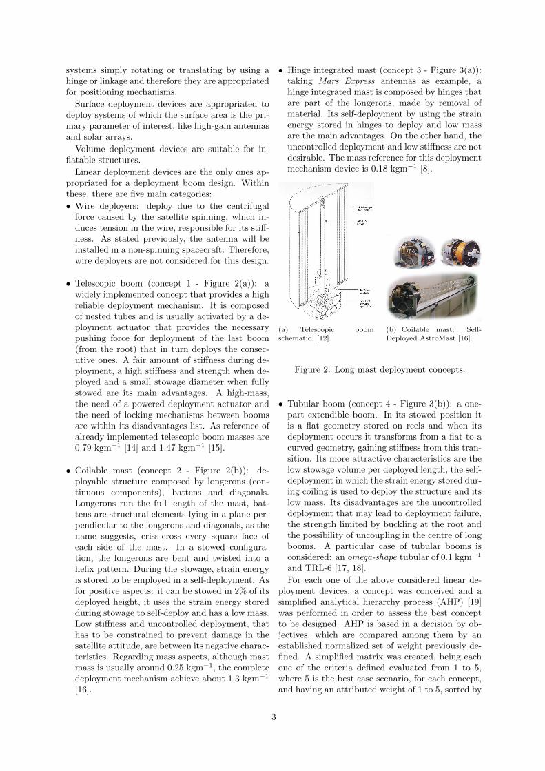
• Hinge integrated mast (concept 3 - Figure 3(a)):taking Mars Express antennas as example, ahinge integrated mast is composed by hinges thatare part of the longerons, made by removal ofmaterial. Its self-deployment by using the strainenergy stored in hinges to deploy and low massare the main advantages. On the other hand, theuncontrolled deployment and low stiffness are notdesirable. The mass reference for this deploymentmechanism device is 0.18 kgm−1 [8].
(a) Telescopic boomschematic. [12].
(b) Coilable mast: Self-Deployed AstroMast [16].
Figure 2: Long mast deployment concepts.
• Tubular boom (concept 4 - Figure 3(b)): a one-part extendible boom. In its stowed position itis a flat geometry stored on reels and when itsdeployment occurs it transforms from a flat to acurved geometry, gaining stiffness from this tran-sition. Its more attractive characteristics are thelow stowage volume per deployed length, the self-deployment in which the strain energy stored dur-ing coiling is used to deploy the structure and itslow mass. Its disadvantages are the uncontrolleddeployment that may lead to deployment failure,the strength limited by buckling at the root andthe possibility of uncoupling in the centre of longbooms. A particular case of tubular booms isconsidered: an omega-shape tubular of 0.1 kgm−1
and TRL-6 [17, 18].
For each one of the above considered linear de-ployment devices, a concept was conceived and asimplified analytical hierarchy process (AHP) [19]was performed in order to assess the best conceptto be designed. AHP is based in a decision by ob-jectives, which are compared among them by anestablished normalized set of weight previously de-fined. A simplified matrix was created, being eachone of the criteria defined evaluated from 1 to 5,where 5 is the best case scenario, for each concept,and having an attributed weight of 1 to 5, sorted by
3
design requirements criticality, being 5 the highestone (Table 3).
(a) Hinge integrated mast:Flattenable Foldable Tube(FFT) [8].
(b) Tubular membrane mast[17].
Figure 3: Long mast deployment concepts.
Criterion WeightConcept
1 2 3 4
Mass 5 2 2 3 5Length 5 4 2 5 4Integration 3 3 4 3 3StowageVolume
2 4 5 4 5
AuxiliaryMechanisms
2 4 4 4 4
ControlledDeployment
5 5 4 3 4
Strength 4 4 2 3 3Fail-Safe 4 4 4 3 4TRL 3 5 5 5 3Reliability 3 4 5 5 1
Ageing Reli-ability
3 5 3 5 3
Risk 5 4 3 1 1Total 4.0 3.4 3.5 3.5 2
Table 3: Analytical Hierarchy Process.
The chosen concept to be designed was the tele-scopic boom, with an innovative solution: an en-gineless actuator to assist boom deployment. Withthis in mind, two approaches were conceived:• Concept 1-A: Clock and counter-clockwise spin-
ning booms 3 - it needs linking between two bytwo booms; it has significant surface friction and
1This value was not attributed due to lack of information.2This value was calculated with all criteria weights except
the Reliability one.3The original idea of this concept is from Active Space
Technologies Engineer Frederico Teixeira.
it only needs deployment aid until second boom(from the root).
• Concept 1-B: Straight or spin concordant opening- it presents lower surface friction than the previ-ous one and needs deployment aid until last boom(from the root).In order to perform the boom design, a matrix of
space approved materials was created and the ma-terial selection was based in criteria that allowedthe achievement of a low density and highly stiffmaterial.Assuming that all the low mass and small di-mensions elements in relation with boom lengthand radius are neglected in the preliminary designof a telescopic boom, this can be approximatelymodelled by stepped beams of hollow circular sec-tions. The eigenfrequencies of a free vibration beam(Euler-Bernoulli beam theory) are given by [20]:
ω = β2
√EI
ρA(1)
where β is a particular solution of the motion equa-tion applying boundary conditions that leads to thisexpression, E is the material Young’s modulus, Irepresents the area moment of inertia of the beam,ρ the density and A the beam cross section area.For a beam eigenfrequencies calculus, the only ma-terial properties dependence is given by Young’smodulus and density, E and ρ respectively. There-fore, after evaluating the collected materials data,three carbon-fibre composite materials were se-lected for further assessment.Not being the aim of this work the material op-timization, with Active Space Technologies and asupplier of composite materials assistance a com-mon plies orientation for maximizing bending andtorsional stiffness was chosen: [0◦ , 0◦ , 0◦ ,±45
◦]s,
which means that the composite material will haveeight plies: three at 0◦ , one at 45◦ , one at −45◦ andother three at 0◦ . The laminate setup is supportedby [18], that states that the choice of a stacking se-quence made up of a combination of 0◦ and ±45◦
is essentially based on the requirement to minimizethe bending.
3. Background3.1. Beam VibrationThe natural frequencies obtained from Euler-Bernoulli beam theory equation of motion for forcedlateral vibration of a uniform beam are computedas:
ω = β2
√EI
ρA= (βl)2
√EI
ρAl4(2)
where l represents the beam length.The solution of transverse vibration for a fixed-
free beam boundary conditions is given in Figure 4,
4

where the established values of βl for the first fourfrequencies are presented.
Figure 4: Fixed-free boundary conditions for thetransverse vibration of a beam [21].
The natural angular frequency ω is given in ra-dians per second. For the frequency to be given inHertz it is necessary to divide it per 2π radians:
f =ω
2π(3)
Finally, for an annulus cross section, the second mo-ment of area is given by:
I =π
4
(r4e − r4i
)(4)
where re and ri and the external and internal ra-dius, respectively.
3.2. Von Mises CriterionThe Von Mises criterion defines that as long as themaximum equivalent stresses obtained, due to theapplied forces, for the structure in study does notexceed the material tensile strength, plastic defor-mation, characterized by the irreversible process ofdeformation, does not occur [22].
3.3. Finite Elements MethodFinite Elements Method (FEM) is a numericalmethod which allows the discretization of a com-plex continuous domain into a group of simplestsub-domains [23]. The solution is given in discretevalues at chosen nodes, denominated degrees of free-dom (DoF).
Euler-Bernoulli beam theory
Euler-Bernoulli beam theory states that plane crosssections perpendicular to the axis of the beam re-main plane and perpendicular to the axis after de-formation [23].
Timoshenko beam theory
Timoshenko beam theory takes into account thetransverse shear deformation: plane sections re-main plane but not necessarily normal to the lon-gitudinal axis after deformation [23].
It is worth noting that when a beam is consideredto be slender, the results obtained with Timoshenkobeam theory are similar to the ones obtained withEuler-Bernoulli beam theory.
ANSYS Elements Type
Two elements types were used during this work,a two-node beam element, BEAM188, in 3-D in-dicated for slender to moderately thick structuresand based in the Timoshenko beam theory and a3-D solid-shell element, SOLSH190 used for simu-lating shell structures from thin to moderately thickand based in the Mindlin-Reissner shell theory, theequivalent of Timoshenko beam theory for plates.These elements geometry are displayed in Figures 5and 6.
Figure 5: Element typeBEAM188 configura-tion [24].
Figure 6: Element typeSOLSH190 configura-tion [24].
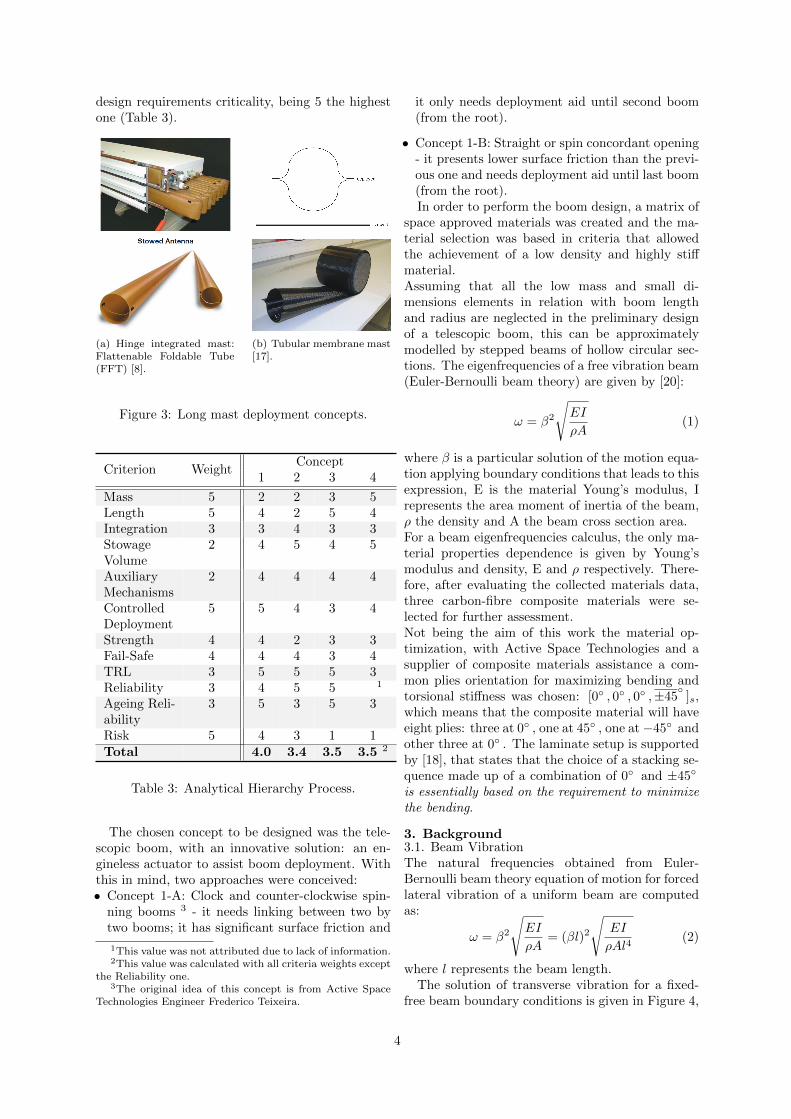
4. Methodologies and Procedures4.1. Computer Aided DesignIn order to perform the boom design, a ComputerAided Design (CAD) model was created using CA-TIA V5R20 software. The modelling was executedusing CATIA parameters options, that only requiredesign modifications when geometric changes aredesired or parameters alterations lead to modellingerrors.To develop the concept 1-A model, it was decidedthat each boom should have three striates of high-relief and their correspondent slot in the previousboom to allow the spinning between each-others.Each boom spin about 90◦ . The space in-betweenthis features is to be fulfilled with straight striateswhere the linkers between boom elements are go-ing to slide (see Figure 7). There is also the needof four straight striates for linkers to prevent theiroverlap during the booms rotation movement. 10booms were designed, completing a total length of9.9 meters.
The booms design was performed through the useof CATIA Wireframe and Surface Design and PartDesign features.
For linkers design, a telescopic structure was alsonecessary, because each linker must have at least aboom length plus the linkers parts that slide (slid-ers) in the boom striates lengths. There are twosliders and two circular connections between thethree linkers connecting two booms for preventinglinkers torsion. The remaining 13 parts constitutethe linker telescopic main structure, being each onecomposed by a hollow squared cross section and
5
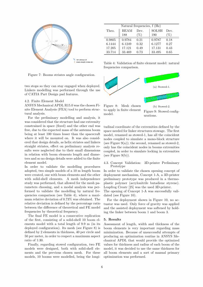
Figure 7: Booms striates angle configuration.
two stops so they can stay engaged when deployed.Linkers modelling was performed through the useof CATIA Part Design pad features.
4.2. Finite Element ModelANSYS Mechanical APDL R15.0 was the chosen Fi-nite Element Analysis (FEA) tool to perform struc-tural analysis.
For the preliminary modelling and analysis, itwas considered that the structure had one extremityconstrained in space (fixed) and the other end wasfree, due to the expected mass of the antenna boombeing at least 100 times lesser than the spacecraftwhere it will be mounted on. It was also consid-ered that design details, as helix striates and linkersstraight striates, effect on preliminary analysis re-sults were neglected due to their small dimensionsin relation with boom elements length and diame-ters and so no design details were added to the finiteelement model.In order to validate the modelling proceduresadopted, two simple models of a 10 m length boomwere created, one with beam elements and the otherwith solid-shell elements. A mesh independencestudy was performed, that allowed for the mesh pa-rameters choosing, and a modal analysis was per-formed to validate the modelling by natural fre-quencies comparison (see Table 4), where a maxi-mum relative deviation of 0.73% was obtained. Therelative deviation is defined by the percentage ratiobetween the difference of theoretical and FE modelfrequencies by theoretical frequency.
The final FE model is a consecutive replicationof the first, consisting of a solid-shell 10 boom el-ements model with a total length of 9.9 m (in itsdeployed configuration). Its mesh (see Figure 8) isdefined by 2 elements in thickness, 40 per circle and50 per meter, in order to respect a maximum aspectratio of 1:30.
Finally, regarding stowed configuration, two FEmodels were designed, both with solid-shell ele-ments and the previous chosen mesh. For thesemodels, 10 booms were modelled, being the longi-
Natural frequencies, f (Hz)
Theo. BEAM188
Dev.(%)
SOLSH190
Dev.(%)
0.9805 0.9784 0.21 0.9787 0.186.1444 6.1249 0.32 6.1277 0.2717.205 17.121 0.49 17.131 0.4333.714 33.469 0.73 33.495 0.65
Table 4: Validation of finite element model: naturalfrequencies comparison.
Figure 8: Mesh chosento apply in finite elementmodel.
(a) Stowed-1.
(b) Stowed-2.
Figure 9: Stowed config-urations.
tudinal coordinate of the extremities defined by thespace needed for linker structures stowage. The firstmodel, renamed as stowed-1, has all the coincidentnodes coupled to simulate a mono-block structure(see Figure 9(a)); the second, renamed as stowed-2,only has the coincident nodes in booms extremitiescoupled, in order to simulate locking in extremities(see Figure 9(b)).
4.3. Concept Validation: 3D-printer PreliminaryPrototype
In order to validate the chosen opening concept ofdeployment mechanism, Concept 1-A, a 3D-printerpreliminary prototype was produced in a thermo-plastic polymer (acrylonitrile butadiene styrene).Leapfrog Creatr [25] was the used 3D-printer.The opening of Concept 1-A was successfully vali-dated (see Figure 10).
For the deployment shown in Figure 10, no ac-tuator was used. Only force of gravity was appliedand the assisted deployment was softened by hold-ing the linker between boom 1 and boom 3.
5. Results
Assessment of length, width and thickness of theboom elements is very important regarding massminimization. Because of unsuccessful attempts ofproducing an optimization routine in ANSYS Me-chanical APDL that would provide the optimizedvalues for thickness and radius of each boom of themodel, it was decided to use the same thickness forall boom elements and a sort of manual primaryoptimization was performed.
6
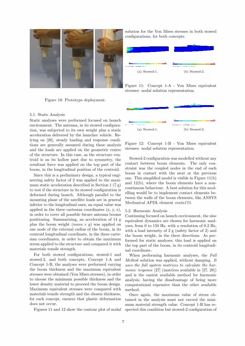
Figure 10: Prototype deployment.
5.1. Static Analysis
Static analyses were performed focused on launchenvironment. The antenna, in its stowed configura-tion, was subjected to its own weight plus a staticacceleration delivered by the launcher vehicle. Re-lying on [26], steady loading and response condi-tions are generally assumed during these analysisand the loads are applied on the geometric centreof the structure. In this case, as the structure cen-troid is on its hollow part due to symmetry, theresultant force was applied on the top part of theboom, in the longitudinal position of the centroid.
Since this is a preliminary design, a typical engi-neering safety factor of 2 was applied to the maxi-mum static acceleration described in Section 1 (7 g)to test if the structure in its stowed configuration isdeformed during launch. Although parallel to themounting plane of the satellite loads are in generalinferior to the longitudinal ones, an equal value wasapplied in the three cartesian coordinates (x, y, z),in order to cover all possible future antenna boomspositioning. Summarizing, an acceleration of 14 gplus the boom weight (mass × g) was applied onone node of the external radius of the boom, in itscentroid longitudinal coordinate, in the three carte-sian coordinates, in order to obtain the maximumstress applied to the structure and compared it withmaterials tensile strength.
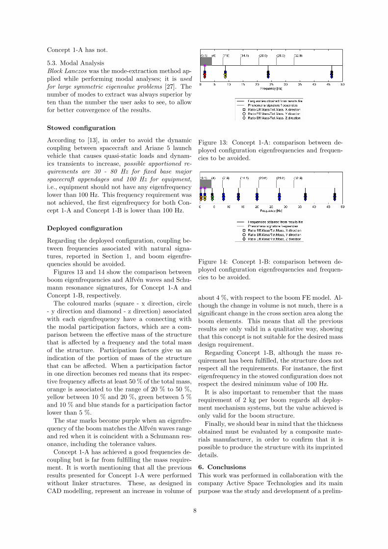
For both stowed configurations, stowed-1 andstowed-2, and both concepts, Concept 1-A andConcept 1-B, the analyses were performed varyingthe boom thickness and the maximum equivalentstresses were obtained (Von Mises stresses), in orderto choose the minimum possible thickness and thelower density material to proceed the boom design.Maximum equivalent stresses were compared withmaterials tensile strength and the chosen thickness,for each concept, ensures that plastic deformationdoes not occur.
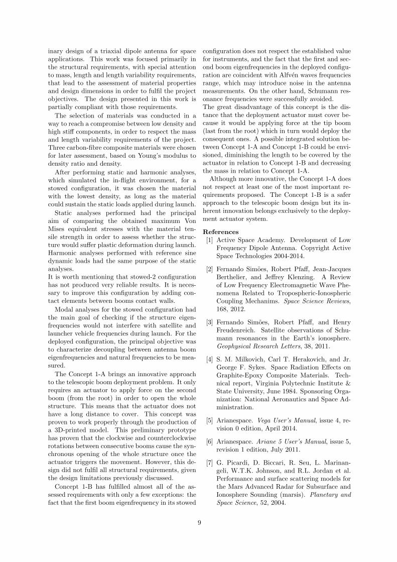
Figures 11 and 12 show the contour plot of nodal
solution for the Von Mises stresses in both stowedconfigurations, for both concepts.
(a) Stowed-1. (b) Stowed-2.
Figure 11: Concept 1-A - Von Mises equivalentstresses: nodal solution representation.
(a) Stowed-1. (b) Stowed-2.
Figure 12: Concept 1-B - Von Mises equivalentstresses: nodal solution representation.
Stowed-2 configuration was modelled without anycontact between boom elements. The only con-straint was the coupled nodes in the end of eachboom in contact with the next or the previousone. This simplified model is visible in Figure 11(b)and 12(b), where the boom elements have a non-continuous behaviour. A best solution for this mod-elling would be to implement contact elements be-tween the walls of the boom elements, like ANSYSMechanical APDL element conta173.
5.2. Harmonic AnalysisContinuing focused on launch environment, the sineequivalent dynamics are chosen for harmonic anal-yses, from 0 to 150 Hz, with a resolution of 0.2 Hz,with a load intensity of 2 g (safety factor of 2) andthe boom weight, in the three directions. As per-formed for static analyses, this load is applied onthe top part of the boom, in its centroid longitudi-nal coordinate.
When performing harmonic analyses, the FullMethod solution was applied, without damping. Ituses the full system matrices to calculate the har-monic response [27] (matrices available in [27, 28])and is the easiest available method for harmonicanalysis, having the disadvantage of being morecomputational expensive than the other availablemethod.
Once again, the maximum value of stress ob-tained in the analysis must not exceed the mini-mum material strength value. Concept 1-B has re-spected this condition but stowed-2 configuration of
7
Concept 1-A has not.
5.3. Modal AnalysisBlock Lanczos was the mode-extraction method ap-plied while performing modal analyses; it is usedfor large symmetric eigenvalue problems [27]. Thenumber of modes to extract was always superior byten than the number the user asks to see, to allowfor better convergence of the results.
Stowed configuration
According to [13], in order to avoid the dynamiccoupling between spacecraft and Ariane 5 launchvehicle that causes quasi-static loads and dynam-ics transients to increase, possible apportioned re-quirements are 30 - 80 Hz for fixed base majorspacecraft appendages and 100 Hz for equipment,i.e., equipment should not have any eigenfrequencylower than 100 Hz. This frequency requirement wasnot achieved, the first eigenfrequecy for both Con-cept 1-A and Concept 1-B is lower than 100 Hz.
Deployed configuration
Regarding the deployed configuration, coupling be-tween frequencies associated with natural signa-tures, reported in Section 1, and boom eigenfre-quencies should be avoided.
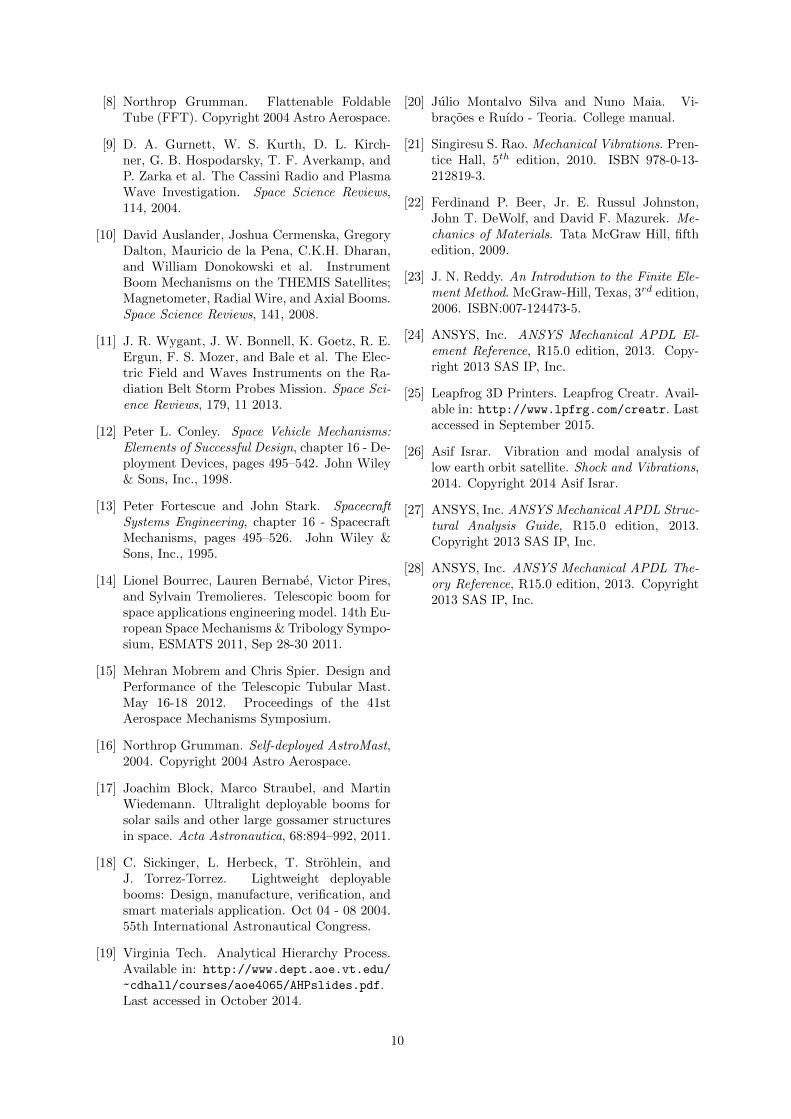
Figures 13 and 14 show the comparison betweenboom eigenfrequencies and Alfven waves and Schu-mann resonance signatures, for Concept 1-A andConcept 1-B, respectively.
The coloured marks (square - x direction, circle- y direction and diamond - z direction) associatedwith each eigenfrequency have a connecting withthe modal participation factors, which are a com-parison between the effective mass of the structurethat is affected by a frequency and the total massof the structure. Participation factors give us anindication of the portion of mass of the structurethat can be affected. When a participation factorin one direction becomes red means that its respec-tive frequency affects at least 50 % of the total mass,orange is associated to the range of 20 % to 50 %,yellow between 10 % and 20 %, green between 5 %and 10 % and blue stands for a participation factorlower than 5 %.
The star marks become purple when an eigenfre-quency of the boom matches the Alfven waves rangeand red when it is coincident with a Schumann res-onance, including the tolerance values.
Concept 1-A has achieved a good frequencies de-coupling but is far from fulfilling the mass require-ment. It is worth mentioning that all the previousresults presented for Concept 1-A were performedwithout linker structures. These, as designed inCAD modelling, represent an increase in volume of
Figure 13: Concept 1-A: comparison between de-ployed configuration eigenfrequencies and frequen-cies to be avoided.
Figure 14: Concept 1-B: comparison between de-ployed configuration eigenfrequencies and frequen-cies to be avoided.
about 4 %, with respect to the boom FE model. Al-though the change in volume is not much, there is asignificant change in the cross section area along theboom elements. This means that all the previousresults are only valid in a qualitative way, showingthat this concept is not suitable for the desired massdesign requirement.
Regarding Concept 1-B, although the mass re-quirement has been fulfilled, the structure does notrespect all the requirements. For instance, the firsteigenfrequency in the stowed configuration does notrespect the desired minimum value of 100 Hz.
It is also important to remember that the massrequirement of 2 kg per boom regards all deploy-ment mechanism systems, but the value achieved isonly valid for the boom structure.
Finally, we should bear in mind that the thicknessobtained must be evaluated by a composite mate-rials manufacturer, in order to confirm that it ispossible to produce the structure with its imprinteddetails.
6. Conclusions
This work was performed in collaboration with thecompany Active Space Technologies and its mainpurpose was the study and development of a prelim-
8
inary design of a triaxial dipole antenna for spaceapplications. This work was focused primarily inthe structural requirements, with special attentionto mass, length and length variability requirements,that lead to the assessment of material propertiesand design dimensions in order to fulfil the projectobjectives. The design presented in this work ispartially compliant with those requirements.
The selection of materials was conducted in away to reach a compromise between low density andhigh stiff components, in order to respect the massand length variability requirements of the project.Three carbon-fibre composite materials were chosenfor later assessment, based on Young’s modulus todensity ratio and density.
After performing static and harmonic analyses,which simulated the in-flight environment, for astowed configuration, it was chosen the materialwith the lowest density, as long as the materialcould sustain the static loads applied during launch.
Static analyses performed had the principalaim of comparing the obtained maximum VonMises equivalent stresses with the material ten-sile strength in order to assess whether the struc-ture would suffer plastic deformation during launch.Harmonic analyses performed with reference sinedynamic loads had the same purpose of the staticanalyses.It is worth mentioning that stowed-2 configurationhas not produced very reliable results. It is neces-sary to improve this configuration by adding con-tact elements between booms contact walls.
Modal analyses for the stowed configuration hadthe main goal of checking if the structure eigen-frequencies would not interfere with satellite andlauncher vehicle frequencies during launch. For thedeployed configuration, the principal objective wasto characterize decoupling between antenna boomeigenfrequencies and natural frequencies to be mea-sured.
The Concept 1-A brings an innovative approachto the telescopic boom deployment problem. It onlyrequires an actuator to apply force on the secondboom (from the root) in order to open the wholestructure. This means that the actuator does nothave a long distance to cover. This concept wasproven to work properly through the production ofa 3D-printed model. This preliminary prototypehas proven that the clockwise and counterclockwiserotations between consecutive booms cause the syn-chronous opening of the whole structure once theactuator triggers the movement. However, this de-sign did not fulfil all structural requirements, giventhe design limitations previously discussed.
Concept 1-B has fulfilled almost all of the as-sessed requirements with only a few exceptions: thefact that the first boom eigenfrequency in its stowed
configuration does not respect the established valuefor instruments, and the fact that the first and sec-ond boom eigenfrequencies in the deployed configu-ration are coincident with Alfven waves frequenciesrange, which may introduce noise in the antennameasurements. On the other hand, Schumann res-onance frequencies were successfully avoided.The great disadvantage of this concept is the dis-tance that the deployment actuator must cover be-cause it would be applying force at the tip boom(last from the root) which in turn would deploy theconsequent ones. A possible integrated solution be-tween Concept 1-A and Concept 1-B could be envi-sioned, diminishing the length to be covered by theactuator in relation to Concept 1-B and decreasingthe mass in relation to Concept 1-A.
Although more innovative, the Concept 1-A doesnot respect at least one of the most important re-quirements proposed. The Concept 1-B is a saferapproach to the telescopic boom design but its in-herent innovation belongs exclusively to the deploy-ment actuator system.
References[1] Active Space Academy. Development of Low
Frequency Dipole Antenna. Copyright ActiveSpace Technologies 2004-2014.
[2] Fernando Simoes, Robert Pfaff, Jean-JacquesBerthelier, and Jeffrey Klenzing. A Reviewof Low Frequency Electromagnetic Wave Phe-nomena Related to Tropospheric-IonosphericCoupling Mechanims. Space Science Reviews,168, 2012.
[3] Fernando Simoes, Robert Pfaff, and HenryFreudenreich. Satellite observations of Schu-mann resonances in the Earth’s ionosphere.Geophysical Research Letters, 38, 2011.
[4] S. M. Milkovich, Carl T. Herakovich, and Jr.George F. Sykes. Space Radiation Effects onGraphite-Epoxy Composite Materials. Tech-nical report, Virginia Polytechnic Institute &State University, June 1984. Sponsoring Orga-nization: National Aeronautics and Space Ad-ministration.
[5] Arianespace. Vega User’s Manual, issue 4, re-vision 0 edition, April 2014.
[6] Arianespace. Ariane 5 User’s Manual, issue 5,revision 1 edition, July 2011.
[7] G. Picardi, D. Biccari, R. Seu, L. Marinan-geli, W.T.K. Johnson, and R.L. Jordan et al.Performance and surface scattering models forthe Mars Advanced Radar for Subsurface andIonosphere Sounding (marsis). Planetary andSpace Science, 52, 2004.
9
[8] Northrop Grumman. Flattenable FoldableTube (FFT). Copyright 2004 Astro Aerospace.
[9] D. A. Gurnett, W. S. Kurth, D. L. Kirch-ner, G. B. Hospodarsky, T. F. Averkamp, andP. Zarka et al. The Cassini Radio and PlasmaWave Investigation. Space Science Reviews,114, 2004.
[10] David Auslander, Joshua Cermenska, GregoryDalton, Mauricio de la Pena, C.K.H. Dharan,and William Donokowski et al. InstrumentBoom Mechanisms on the THEMIS Satellites;Magnetometer, Radial Wire, and Axial Booms.Space Science Reviews, 141, 2008.
[11] J. R. Wygant, J. W. Bonnell, K. Goetz, R. E.Ergun, F. S. Mozer, and Bale et al. The Elec-tric Field and Waves Instruments on the Ra-diation Belt Storm Probes Mission. Space Sci-ence Reviews, 179, 11 2013.
[12] Peter L. Conley. Space Vehicle Mechanisms:Elements of Successful Design, chapter 16 - De-ployment Devices, pages 495–542. John Wiley& Sons, Inc., 1998.
[13] Peter Fortescue and John Stark. SpacecraftSystems Engineering, chapter 16 - SpacecraftMechanisms, pages 495–526. John Wiley &Sons, Inc., 1995.
[14] Lionel Bourrec, Lauren Bernabe, Victor Pires,and Sylvain Tremolieres. Telescopic boom forspace applications engineering model. 14th Eu-ropean Space Mechanisms & Tribology Sympo-sium, ESMATS 2011, Sep 28-30 2011.
[15] Mehran Mobrem and Chris Spier. Design andPerformance of the Telescopic Tubular Mast.May 16-18 2012. Proceedings of the 41stAerospace Mechanisms Symposium.
[16] Northrop Grumman. Self-deployed AstroMast,2004. Copyright 2004 Astro Aerospace.
[17] Joachim Block, Marco Straubel, and MartinWiedemann. Ultralight deployable booms forsolar sails and other large gossamer structuresin space. Acta Astronautica, 68:894–992, 2011.
[18] C. Sickinger, L. Herbeck, T. Strohlein, andJ. Torrez-Torrez. Lightweight deployablebooms: Design, manufacture, verification, andsmart materials application. Oct 04 - 08 2004.55th International Astronautical Congress.
[19] Virginia Tech. Analytical Hierarchy Process.Available in: http://www.dept.aoe.vt.edu/
~cdhall/courses/aoe4065/AHPslides.pdf.Last accessed in October 2014.
[20] Julio Montalvo Silva and Nuno Maia. Vi-bracoes e Ruıdo - Teoria. College manual.
[21] Singiresu S. Rao. Mechanical Vibrations. Pren-tice Hall, 5th edition, 2010. ISBN 978-0-13-212819-3.
[22] Ferdinand P. Beer, Jr. E. Russul Johnston,John T. DeWolf, and David F. Mazurek. Me-chanics of Materials. Tata McGraw Hill, fifthedition, 2009.
[23] J. N. Reddy. An Introdution to the Finite Ele-ment Method. McGraw-Hill, Texas, 3rd edition,2006. ISBN:007-124473-5.
[24] ANSYS, Inc. ANSYS Mechanical APDL El-ement Reference, R15.0 edition, 2013. Copy-right 2013 SAS IP, Inc.
[25] Leapfrog 3D Printers. Leapfrog Creatr. Avail-able in: http://www.lpfrg.com/creatr. Lastaccessed in September 2015.
[26] Asif Israr. Vibration and modal analysis oflow earth orbit satellite. Shock and Vibrations,2014. Copyright 2014 Asif Israr.
[27] ANSYS, Inc. ANSYS Mechanical APDL Struc-tural Analysis Guide, R15.0 edition, 2013.Copyright 2013 SAS IP, Inc.
[28] ANSYS, Inc. ANSYS Mechanical APDL The-ory Reference, R15.0 edition, 2013. Copyright2013 SAS IP, Inc.
10
Related Documents