MECHANICAL ENGINEERING DEPARTMENT SEM – III (MATERIAL SCIENCE AND METALLURGY) 1 GOVERNMENT ENGINEERING COLLEGE, GODHRA INDEX SR. NO TITLE PAGE DATE OF START COMPLE TION DATE SIGN. OF FACULTY GR. Fro m To 1. TO STUDY ABOUT BASICS OF MATERIAL SCIENCE AND METALLURGY 2. TO STUDY ABOUT METALLIC MATERIALS. 3. TO STUDY ABOUT THE EFFECTS OF ALLOYING METALS. 4. TO STUDY MACRO EXAMINATION & MICRO EXAMINATION. 5. TO PERFORM MICRO EXAMINATION OF STANDARD PIECES. 6. TO STUDY ABOUT I RON CARBON DIAGRAM & ALLOTROPY OF IRON. 7. TO STUDY ABOUT CAST IRON. 8. TO STUDY ABOUT HEAT TREATMENT AND CHECK EFFECT OF QUENCHING MEDIA ON HARDNESS OF STEEL.

Welcome message from author
This document is posted to help you gain knowledge. Please leave a comment to let me know what you think about it! Share it to your friends and learn new things together.
Transcript

MECHANICAL ENGINEERING DEPARTMENT SEM – III (MATERIAL SCIENCE AND METALLURGY)
1 GOVERNMENT ENGINEERING COLLEGE, GODHRA
INDEX
SR.
NO
TITLE PAGE DATE OF
START
COMPLE
TION
DATE
SIGN. OF
FACULTY
GR.
Fro
m
To
1.
TO STUDY ABOUT BASICS OF
MATERIAL SCIENCE AND
METALLURGY
2. TO STUDY ABOUT METALLIC
MATERIALS.
3. TO STUDY ABOUT THE
EFFECTS OF ALLOYING METALS.
4.
TO STUDY MACRO
EXAMINATION & MICRO
EXAMINATION.
5.
TO PERFORM MICRO
EXAMINATION OF STANDARD
PIECES.
6.
TO STUDY ABOUT IRON
CARBON DIAGRAM &
ALLOTROPY OF IRON.
7. TO STUDY ABOUT CAST IRON.
8.
TO STUDY ABOUT HEAT
TREATMENT AND CHECK
EFFECT OF QUENCHING MEDIA
ON HARDNESS OF STEEL.
MECHANICAL ENGINEERING DEPARTMENT SEM – III (MATERIAL SCIENCE AND METALLURGY)
2 GOVERNMENT ENGINEERING COLLEGE, GODHRA
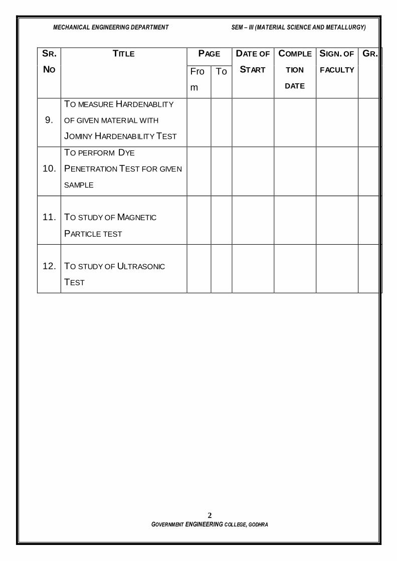
SR.
NO
TITLE PAGE DATE OF
START
COMPLE
TION
DATE
SIGN. OF
FACULTY
GR.
Fro
m
To
9.
TO MEASURE HARDENABLITY
OF GIVEN MATERIAL WITH
JOMINY HARDENABILITY TEST
10.
TO PERFORM DYE
PENETRATION TEST FOR GIVEN
SAMPLE
11.
TO STUDY OF MAGNETIC
PARTICLE TEST
12.
TO STUDY OF ULTRASONIC
TEST

MECHANICAL ENGINEERING DEPARTMENT SEM – III (MATERIAL SCIENCE AND METALLURGY)
3 GOVERNMENT ENGINEERING COLLEGE, GODHRA
INSTRUCTIONS *
THIS LABORATORY MANUAL IS ISSUED ONCE ONLY. THIS IS YOUR RESPONSIBILITY TO
PRESERVE IT IN GOOD CONDITION UP TO TERM WORK SUBMISSION & ORAL EXAMINATION.
YOUR WRITING SHOULD BE NEAT AND CLEAN.
GET CHECKED YOUR MANUAL AT THE END OF THE PERFORMANCE OF EACH PRACTICAL.
PRACTICAL & TUTORIALS THAT CANNOT BE READ OR ARE NOT PRESENTED IN A
PROFESSIONAL ENGINEERING STYLE WILL NOT RECEIVE CREDIT (HIGHER GRADES).
MECHANICAL ENGINEERING DEPARTMENT SEM – III (MATERIAL SCIENCE AND METALLURGY)
4 GOVERNMENT ENGINEERING COLLEGE, GODHRA
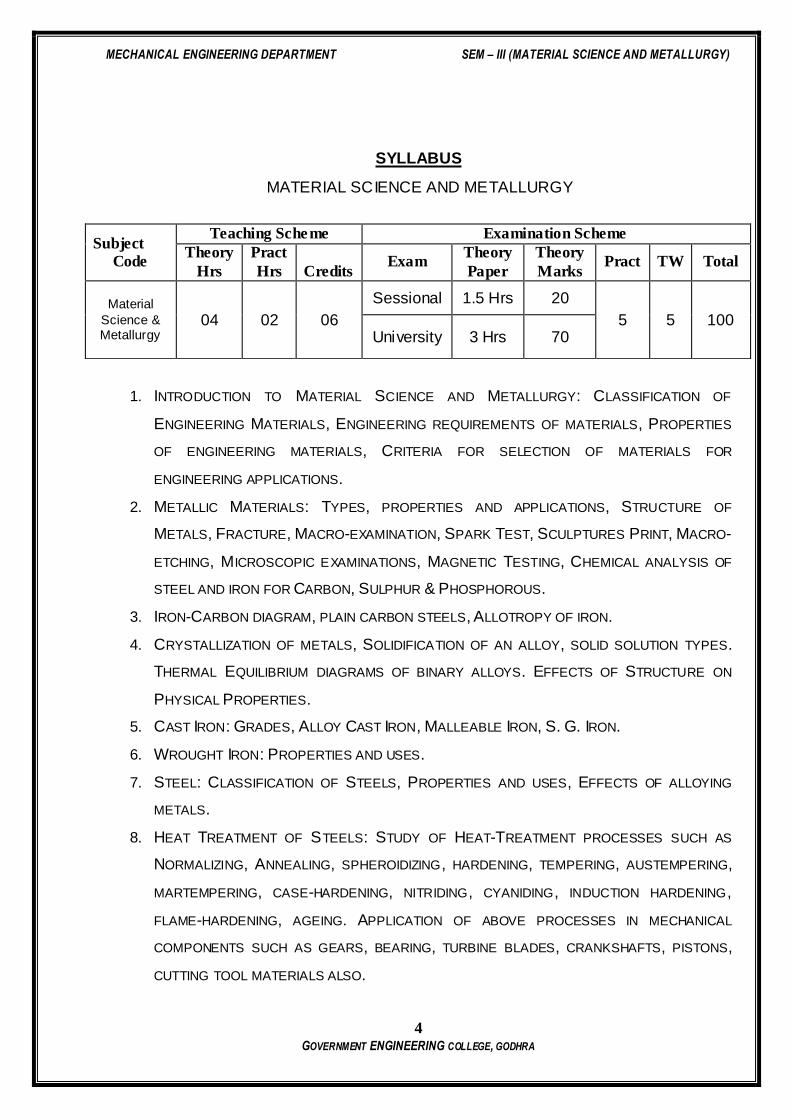
SYLLABUS
MATERIAL SCIENCE AND METALLURGY
1. INTRODUCTION TO MATERIAL SCIENCE AND METALLURGY: CLASSIFICATION OF
ENGINEERING MATERIALS, ENGINEERING REQUIREMENTS OF MATERIALS, PROPERTIES
OF ENGINEERING MATERIALS, CRITERIA FOR SELECTION OF MATERIALS FOR
ENGINEERING APPLICATIONS.
2. METALLIC MATERIALS: TYPES, PROPERTIES AND APPLICATIONS, STRUCTURE OF
METALS, FRACTURE, MACRO-EXAMINATION, SPARK TEST, SCULPTURES PRINT, MACRO-
ETCHING, MICROSCOPIC EXAMINATIONS, MAGNETIC TESTING, CHEMICAL ANALYSIS OF
STEEL AND IRON FOR CARBON, SULPHUR & PHOSPHOROUS.
3. IRON-CARBON DIAGRAM, PLAIN CARBON STEELS, ALLOTROPY OF IRON.
4. CRYSTALLIZATION OF METALS, SOLIDIFICATION OF AN ALLOY, SOLID SOLUTION TYPES.
THERMAL EQUILIBRIUM DIAGRAMS OF BINARY ALLOYS. EFFECTS OF STRUCTURE ON
PHYSICAL PROPERTIES.
5. CAST IRON: GRADES, ALLOY CAST IRON, MALLEABLE IRON, S. G. IRON.
6. WROUGHT IRON: PROPERTIES AND USES.
7. STEEL: CLASSIFICATION OF STEELS, PROPERTIES AND USES, EFFECTS OF ALLOYING
METALS.
8. HEAT TREATMENT OF STEELS: STUDY OF HEAT-TREATMENT PROCESSES SUCH AS
NORMALIZING, ANNEALING, SPHEROIDIZING, HARDENING, TEMPERING, AUSTEMPERING,
MARTEMPERING, CASE-HARDENING, NITRIDING, CYANIDING, INDUCTION HARDENING,
FLAME-HARDENING, AGEING. APPLICATION OF ABOVE PROCESSES IN MECHANICAL
COMPONENTS SUCH AS GEARS, BEARING, TURBINE BLADES, CRANKSHAFTS, PISTONS,
CUTTING TOOL MATERIALS ALSO.
Subject
Code
Teaching Scheme Examination Scheme
Theory
Hrs
Pract
Hrs
Credits Exam
Theory
Paper
Theory
Marks Pract TW Total
Material
Science & Metallurgy
04 02 06
Sessional 1.5 Hrs 20
5 5 100 University 3 Hrs 70

MECHANICAL ENGINEERING DEPARTMENT SEM – III (MATERIAL SCIENCE AND METALLURGY)
5 GOVERNMENT ENGINEERING COLLEGE, GODHRA
9. NON-FERROUS ALLOYS: ALLOYS OF COPPER, ALUMINIUM, MAGNESIUM TITANIUM. OTHER
ALLOYS OF LEAD, TIN, ZINC, NICKEL, MANGANESE, WHITE METALS AND BEARING ALLOYS.
10. POWDER METALLURGY: APPLICATION AND ADVANTAGES, PRODUCTION OF POWDER,
COMPACTING, SINTERING, EQUIPMENT AND PROCESS CAPABILITY.
11. CORROSION OF METALS: MEANING, CAUSES AND NATURE. MEASURES OF
COUNTERACTING CORROSION, METAL COATINGS, ORGANIC COATINGS, LINING AND
CLADDING, USE OF CORROSION INHIBITORS, CATHODIC PROTECTION AGAINST
CORROSION.
12. NON-DESTRUCTIVE TESTING SUCH AS RADIOGRAPHY TESTING, DYE PENETRATION
TESTING, MAGNETIC PARTICLE TESTING, ULTRASONIC TESTING, AND JOMINY
ENDQUENCH TEST.
REFERENCE BOOKS:
1. ENGINEERING METALLURGY AND MATERIAL SCIENCE BY S. P. NAYAK.
2. MATERIALS AND METALLURGY BY G. B. S. NARANG AND K. MANCHANEDY
3. ELEMENTS OF METALLURGY BY DR. SWAROOP AND DR. SAXENA.
4. MATERIAL SCIENCE AND MANUFACTURING PROCESSS BY DHARMENDRAKUMAR AND S. K.
JAIN.
5. PHYSICAL METALLURGY BY ROBERT READ
6. METALLURGY FOR ENGINEERS BY V. RAGHVAN
7. METALLURGY FOR ENGINEERS BY BAVA.
8. PHYSICAL METALLURGY BY ROLLASON.
9. PHYSICAL METALLURGY BY HYEGINS.
10. TOOL STEEL BY RABERT.
11. MATERIAL SCIENCE BY ANNVER.
12. MATERIAL SCIENCE BY O.P. KHANNA.

MECHANICAL ENGINEERING DEPARTMENT SEM – III (MATERIAL SCIENCE AND METALLURGY)
6 GOVERNMENT ENGINEERING COLLEGE, GODHRA
PRACTICAL: 1
INTRODUCTION OF MATERIAL SCIENCE
DATE:
AIM: TO STUDY ABOUT BASICS OF MATERIAL SCIENCE AND METALLURGY.
Objective:
1. To know the importance of the materials.
2. To know about the Engineering requirements of material
3. To know the Various Properties of Engineering Material.
4. To Know the Criteria for the selection of the material.
Introduction:
Beginning of the Material Science - People began to make tools from stone Start
of the Stone Age about two million years ago. Natural materials ( stone, wood,
clay, skins, etc.) were used for different application.
The Stone Age ended about 5000 years ago with introduction of Bronze in the
Far East. Bronze is an alloy (a metal made up of more than one element) of ,
copper + < 25% of tin + other elements. Bronze: can be hammered or cast into a
variety of shapes, can be made harder by alloying, corrode only slowly after a
surface oxide film forms.
The Iron Age began about 3000 years ago and continues today. Use of iron and
steel, a stronger and cheaper material changed drastically daily life of a common
person.
Age of Advanced materials: throughout the Iron Age many new types of materials
have been introduced (ceramic, semiconductors, polymers, composites…).
Due to this much application it is necessary to understanding of the relationship
among structure, properties, processing, and performance of materials. And
based on that to develop intelligent design of new materials.
MECHANICAL ENGINEERING DEPARTMENT SEM – III (MATERIAL SCIENCE AND METALLURGY)
7 GOVERNMENT ENGINEERING COLLEGE, GODHRA
What is material Science?
Material science is the investigation of the relationship among processing, structure,
properties, and performance of materials.
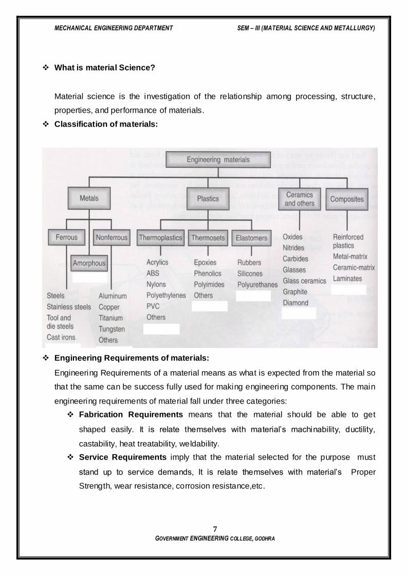
Classification of materials:
Engineering Requirements of materials:
Engineering Requirements of a material means as what is expected from the material so
that the same can be success fully used for making engineering components. The main
engineering requirements of material fall under three categories:
Fabrication Requirements means that the material should be able to get
shaped easily. It is relate themselves with material’s machinability, ductility,
castability, heat treatability, weldability.
Service Requirements imply that the material selected for the purpose must
stand up to service demands, It is relate themselves with material’s Proper
Strength, wear resistance, corrosion resistance,etc.

MECHANICAL ENGINEERING DEPARTMENT SEM – III (MATERIAL SCIENCE AND METALLURGY)
8 GOVERNMENT ENGINEERING COLLEGE, GODHRA
Economic Requirements demand that the engineering part should be made
with minimum overall cost. Minimum overall cost may be achieved by Proper
selection of both technical and marketing variables.
Properties of Engineering Materials:
Properties are the way of the material responds to the environment and external forces.
Physical properties
Dimensions: Dimensions of a material implies its size(i.e. breadth, length,
diameter) and shap (i.e. Square,circular,channel,angle)
Appearance : Appearance includes lustre,colour and finish (e.g., line marks on
the surface) of a material.
Density : is the mass of unit volume of a material.
Melting point : is that temperature at which the solid metals changes into the
molten state.
Porosity: A material is said to be porous if it has pores within it. Pores can
absorb lubricant as in a sintered self – lubricating bearing.
Structure : Means geometric relationships of material components. it also implies
the arrangement of the internal components of matter.
Mechanical properties – response to mechanical forces, strength, etc.
Elasticity: The tendency of deformed solid to seek its original dimensions up on
unloading is called elasticity.
Young’s Modulus of Elas ticity E = Stress/Strain
Plasticity: is that property of a material by virtue of which it may be permanently
deformed when it has been subjected to an externally applied force great enough
to exceed the elastic limit.
Toughness: is the ability of the material to absorb energy during plastic
deformation up to fracture.
Resilience: is the capacity of a material to absorb energy when it is elastically
deformed and then upon unloading, to have this energy recovered.
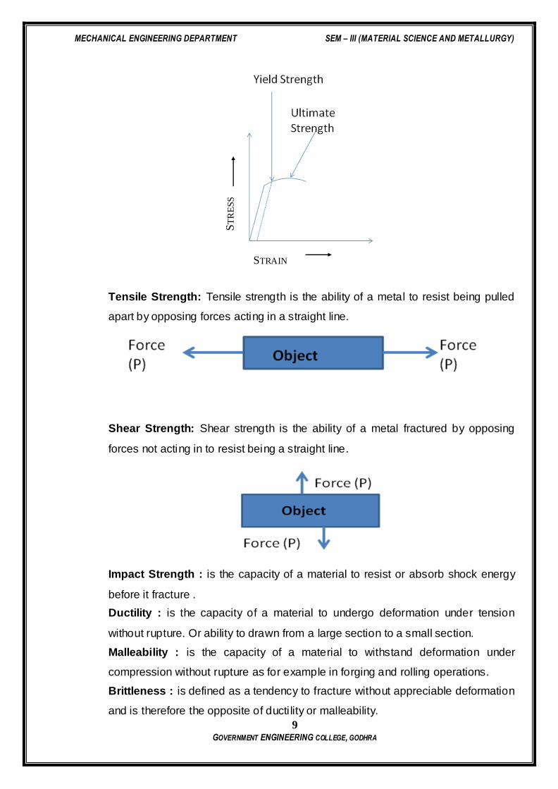
Yield Strength: when metals are subjected to a tensile force, they stretch or
elongate as the stress increases. the point where the stretch suddenly increases,
is known as the yield strength of the material.
MECHANICAL ENGINEERING DEPARTMENT SEM – III (MATERIAL SCIENCE AND METALLURGY)
9 GOVERNMENT ENGINEERING COLLEGE, GODHRA
Tensile Strength: Tensile strength is the ability of a metal to resist being pulled
apart by opposing forces acting in a straight line.
Shear Strength: Shear strength is the ability of a metal fractured by opposing
forces not acting in to resist being a straight line.
Impact Strength : is the capacity of a material to resist or absorb shock energy
before it fracture .
Ductility : is the capacity of a material to undergo deformation under tension
without rupture. Or ability to drawn from a large section to a small section.
Malleability : is the capacity of a material to withstand deformation under
compression without rupture as for example in forging and rolling operations.
Brittleness : is defined as a tendency to fracture without appreciable deformation
and is therefore the opposite of ducti lity or malleability.
ST
RE
SS
STRAIN
MECHANICAL ENGINEERING DEPARTMENT SEM – III (MATERIAL SCIENCE AND METALLURGY)
10 GOVERNMENT ENGINEERING COLLEGE, GODHRA
Hardness : is the resistance of a material to plastic deformation usually by
indentation.
Fatigue : fatigue is the phenomenon that leads to fracture under fluctuating or
repeated loads.
Creep: is the time dependent permanent deformation that occurs under stress;
for most materials, it is important only at elevated temperatures.
Wear resistance: is the ability to resist wear and abrasion.
Compressive strength: Compressive strength is the ability of a metal to
withstand pressures acting on a given plane
Electrical and magnetic properties - response electrical and magnetic fields,
conductivity, etc.
Resistivity : it is a characteristic property of the material , due to which resists
the flow of electricity through it.
Conductivity : The reciprocal of electrical resistivity is called electrical
conductivity. Due to Which the electrical current flows easily through the material.
Dielectric strength : means the insulating capacity of a material against high
voltages.
Thermoelectricity : If two dissimilar metals are joined and this junction is then
heated, a small voltage in the millivolt range is produced and this is known as
thermoelectric effect.
Permeability : magnetic permeability measures the relative ease with which
magnetism may be developed in a material. And is the ratio of magnetic induction
to the intensity of magnetizing field.
Coercive force : This is the opposing magnetizing force which is necessary to
remove previous magnetization or residual magnetization.
Super conductivity : below certain temperature material becomes a perfect
diamagnetic material that is called super conductivity.
Thermal properties are related to transmission of heat and heat capacity.
Heat capacity : is the material’s ability to absorb heat from the external
surroundings.
Specific Heat : is the quantity of heat that must be added to a unit mass of the
solid to raise its temperature by one degree.
MECHANICAL ENGINEERING DEPARTMENT SEM – III (MATERIAL SCIENCE AND METALLURGY)
11 GOVERNMENT ENGINEERING COLLEGE, GODHRA
Thermal Expansion : When thermal energy is added to a material, a change in
its dimensions occurs, this phenomenon is called thermal expansion and property
of a material responsible for this is known as coefficient of thermal expansion.
Melting Point: Is the temperature at which a pure metal,compound,or eutectic
changes from solid to liquid; the temperature at which the liquid and the solid are
in equilibrium.
Thermal Conductivity: The rate at which heat can flow through a material under
the influence of a given temperature gradient is determined by the thermal
conductivity
Thermal Shock Resistance : defines the conditions of a body when it is
subjected to sudden and severe changes in temperature caused either by a
change in external environment or by internal heat generation. The ability of a
body to withstand such temperature changes without failure is called thermal
shock resistance.
Heat Resistance : is a general term referring to the ability of a material and its
properties to remain stable with changes in temperature.
Optical properties include to absorption, transmission and scattering of light.
Refractive Index: is the ration of the velocity of light in vacuum, to the velocity of
light within a material. And if angle of incidence i and the angle of refraction r then
it is equal to sin i / sin r
Absorptivity : Ability of a material to absorb the energy incidence.
Chemical stability in contact with the environment - corrosion resistance.
Corrosion Resistance :
Chemical Composition :
Acidity or Alkalinity :
Material Selection:
Material Selection Process:
1. Analysis of the materials application problem.(Performance requirements,
functional performance, physical attributes and application conditions.
2. Translation of the material application requirements to material properties values.
3. Selection of Candidate materials.
4. Evaluation of the candidate materials. This is parallel to Previous step.

MECHANICAL ENGINEERING DEPARTMENT SEM – III (MATERIAL SCIENCE AND METALLURGY)
12 GOVERNMENT ENGINEERING COLLEGE, GODHRA
Factors affecting a material selection:
• Properties of material
• Performance requirements
• Materials Reliability
• Safety
• Physical attributes
• Environment Conditions
• Availability
• Disposability and recyclability
• Economic Factors
Questions
1) Explain Material Selection Process for Crank Shaft.
2) Explain the Material Science’s Importance .
3) How the below Factors affecting a material Selection? Explain in Brief.
Properties of material
Performance requirements
Materials Reliability
Safety
Physical attributes
Environment Conditions
Availability
Disposability and recyclability
Economic Factors
MECHANICAL ENGINEERING DEPARTMENT SEM – III (MATERIAL SCIENCE AND METALLURGY)
13 GOVERNMENT ENGINEERING COLLEGE, GODHRA
PRACTICAL: 2
METALLIC MATERIALS
DATE:
AIM: TO STUDY ABOUT METALLIC MATERIALS.
Objective: To Know about the metallic material.
Introduction:
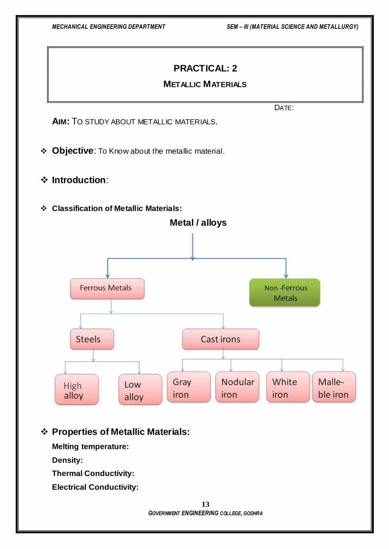
Classification of Metallic Materials:
Metal / alloys
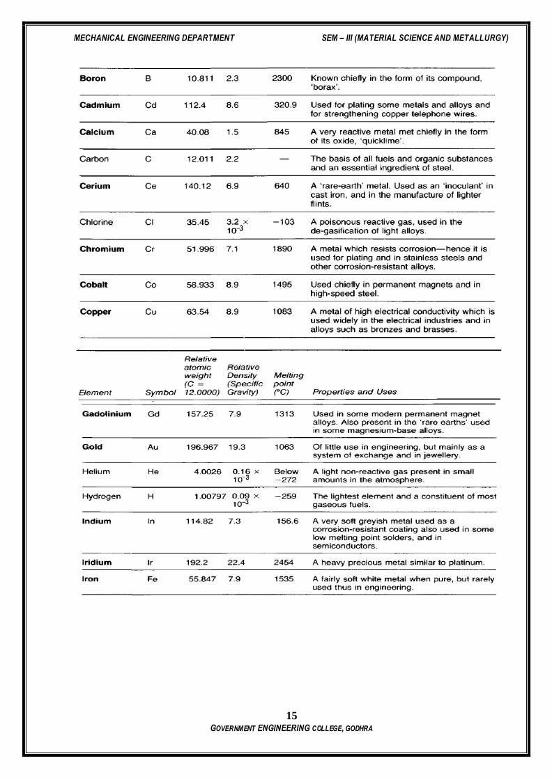
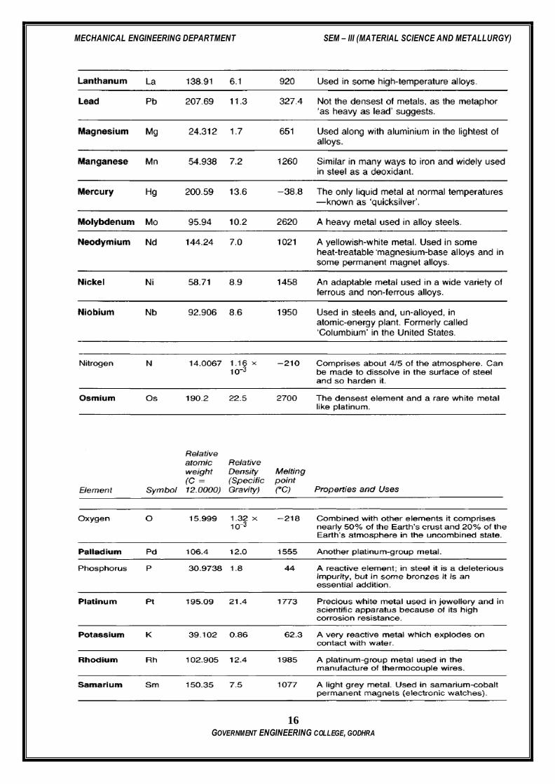
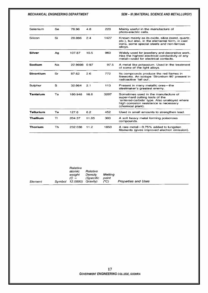
Properties of Metallic Materials:
Melting temperature:
Density:
Thermal Conductivity:
Electrical Conductivity:
MECHANICAL ENGINEERING DEPARTMENT SEM – III (MATERIAL SCIENCE AND METALLURGY)
14 GOVERNMENT ENGINEERING COLLEGE, GODHRA
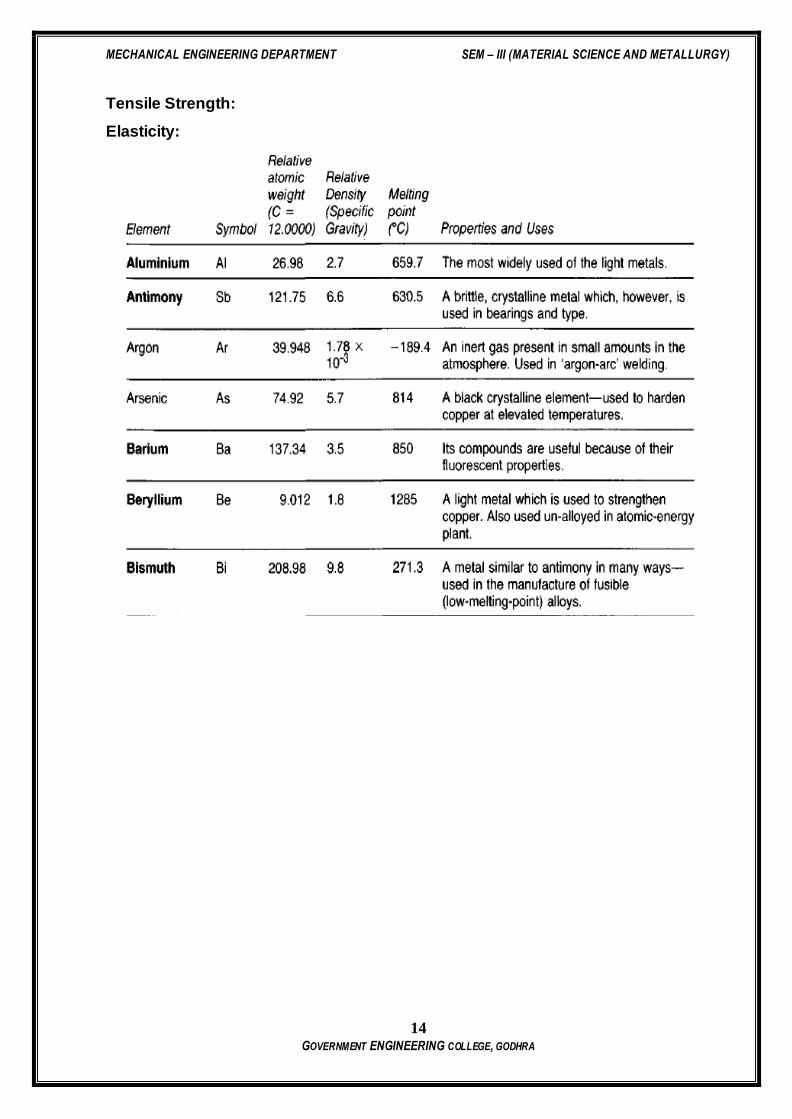
Tensile Strength:
Elasticity:
MECHANICAL ENGINEERING DEPARTMENT SEM – III (MATERIAL SCIENCE AND METALLURGY)
15 GOVERNMENT ENGINEERING COLLEGE, GODHRA
MECHANICAL ENGINEERING DEPARTMENT SEM – III (MATERIAL SCIENCE AND METALLURGY)
16 GOVERNMENT ENGINEERING COLLEGE, GODHRA
MECHANICAL ENGINEERING DEPARTMENT SEM – III (MATERIAL SCIENCE AND METALLURGY)
17 GOVERNMENT ENGINEERING COLLEGE, GODHRA

MECHANICAL ENGINEERING DEPARTMENT SEM – III (MATERIAL SCIENCE AND METALLURGY)
18 GOVERNMENT ENGINEERING COLLEGE, GODHRA
Relative electrical and thermal conductivities of some metals:
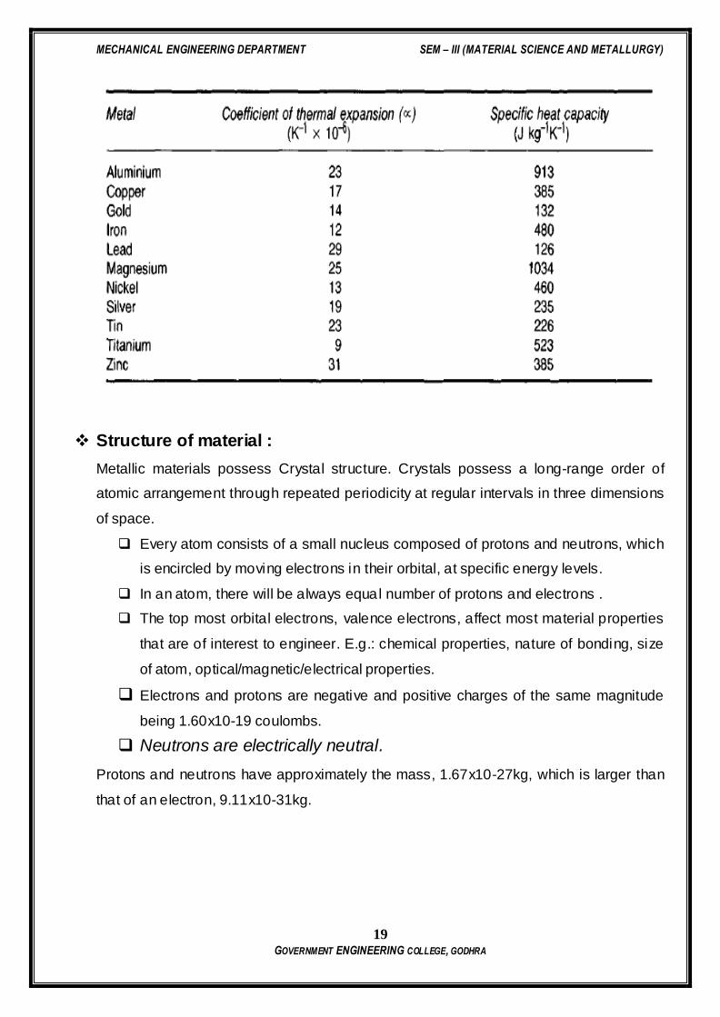
Thermal Properties of some important metals are:
MECHANICAL ENGINEERING DEPARTMENT SEM – III (MATERIAL SCIENCE AND METALLURGY)
19 GOVERNMENT ENGINEERING COLLEGE, GODHRA
Structure of material :
Metallic materials possess Crystal structure. Crystals possess a long-range order of
atomic arrangement through repeated periodicity at regular intervals in three dimensions
of space.
Every atom consists of a small nucleus composed of protons and neutrons, which
is encircled by moving electrons in their orbital, at specific energy levels.
In an atom, there will be always equal number of protons and electrons .
The top most orbital electrons, valence electrons, affect most material properties
that are of interest to engineer. E.g.: chemical properties, nature of bonding, size
of atom, optical/magnetic/electrical properties.
Electrons and protons are negative and positive charges of the same magnitude
being 1.60x10⁻¹⁹ coulombs.
Neutrons are electrically neutral.
Protons and neutrons have approximately the mass, 1.67x10⁻²⁷kg, which is larger than
that of an electron, 9.11x10⁻³¹kg.
MECHANICAL ENGINEERING DEPARTMENT SEM – III (MATERIAL SCIENCE AND METALLURGY)
20 GOVERNMENT ENGINEERING COLLEGE, GODHRA
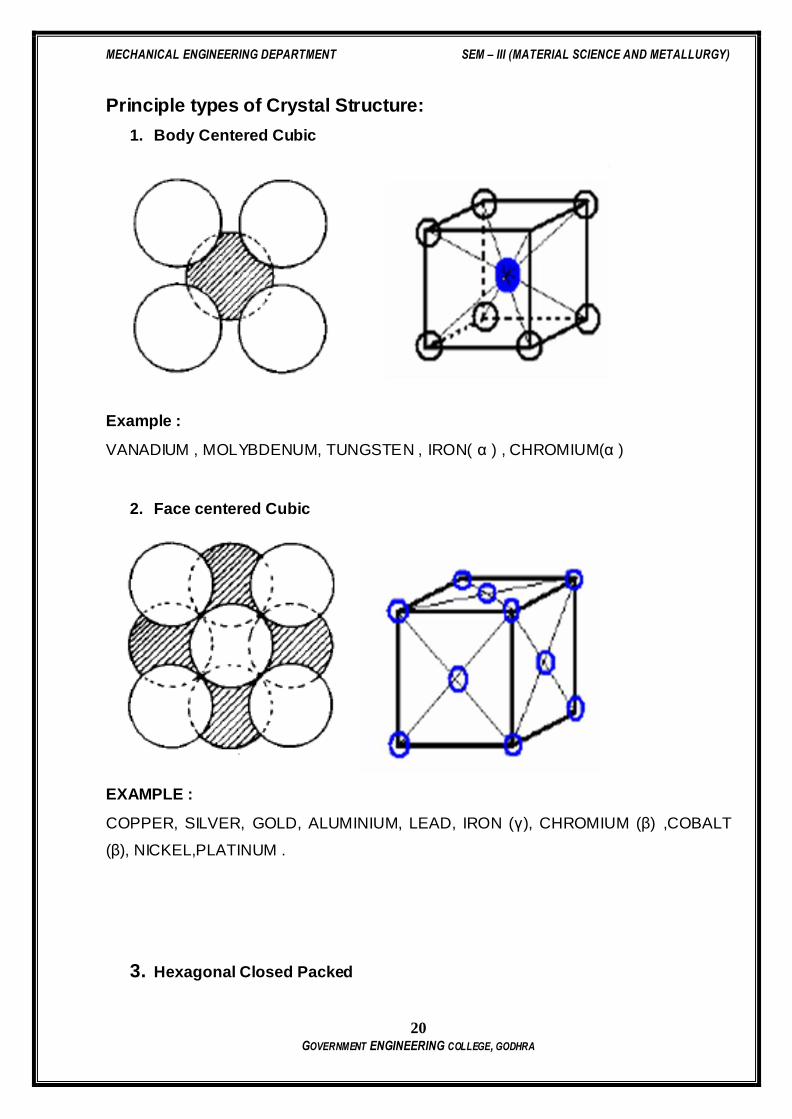
Principle types of Crystal Structure:
1. Body Centered Cubic
Example :
VANADIUM , MOLYBDENUM, TUNGSTEN , IRON( α ) , CHROMIUM(α )
2. Face centered Cubic
EXAMPLE :
COPPER, SILVER, GOLD, ALUMINIUM, LEAD, IRON (γ), CHROMIUM (β) ,COBALT
(β), NICKEL,PLATINUM .
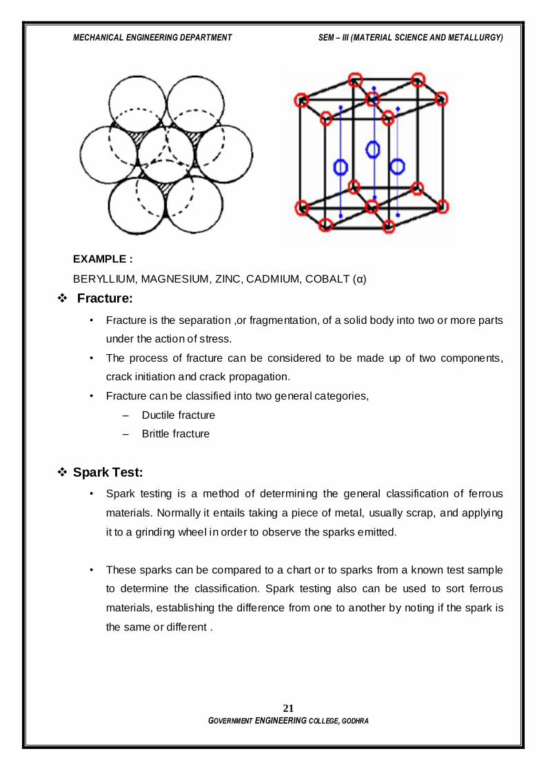
3. Hexagonal Closed Packed
MECHANICAL ENGINEERING DEPARTMENT SEM – III (MATERIAL SCIENCE AND METALLURGY)
21 GOVERNMENT ENGINEERING COLLEGE, GODHRA
EXAMPLE :
BERYLLIUM, MAGNESIUM, ZINC, CADMIUM, COBALT (α)
Fracture:
• Fracture is the separation ,or fragmentation, of a solid body into two or more parts
under the action of stress.
• The process of fracture can be considered to be made up of two components,
crack initiation and crack propagation.
• Fracture can be classified into two general categories,
– Ductile fracture
– Brittle fracture
Spark Test:
• Spark testing is a method of determining the general classification of ferrous
materials. Normally it entails taking a piece of metal, usually scrap, and applying
it to a grinding wheel in order to observe the sparks emitted.
• These sparks can be compared to a chart or to sparks from a known test sample
to determine the classification. Spark testing also can be used to sort ferrous
materials, establishing the difference from one to another by noting if the spark is
the same or different .
MECHANICAL ENGINEERING DEPARTMENT SEM – III (MATERIAL SCIENCE AND METALLURGY)
22 GOVERNMENT ENGINEERING COLLEGE, GODHRA
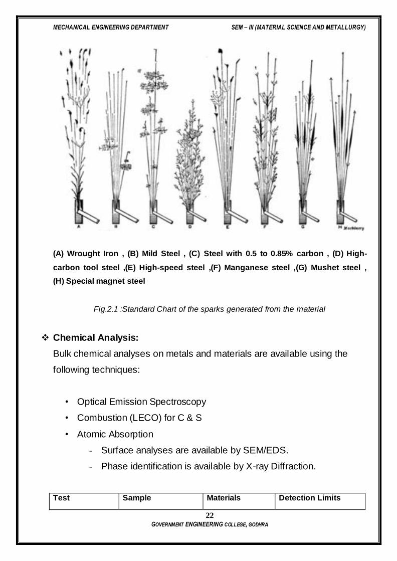
(A) Wrought Iron , (B) Mild Steel , (C) Steel with 0.5 to 0.85% carbon , (D) High-
carbon tool steel ,(E) High-speed steel ,(F) Manganese steel ,(G) Mushet steel ,
(H) Special magnet steel
Fig.2.1 :Standard Chart of the sparks generated from the material
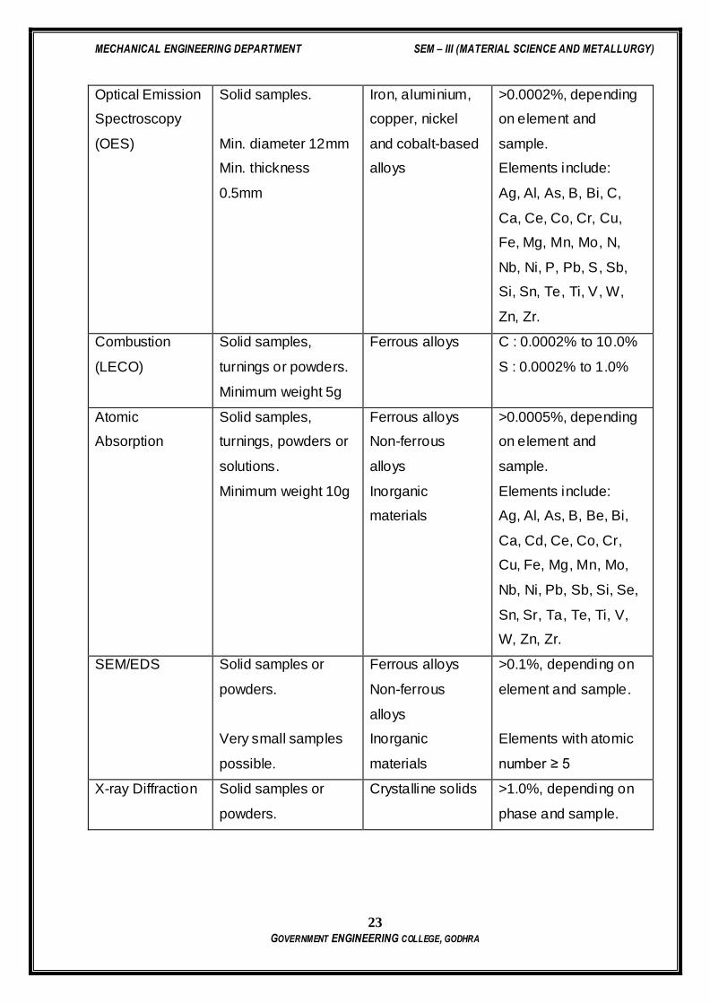
Chemical Analysis:
Bulk chemical analyses on metals and materials are available using the
following techniques:
• Optical Emission Spectroscopy
• Combustion (LECO) for C & S
• Atomic Absorption
- Surface analyses are available by SEM/EDS.
- Phase identification is available by X-ray Diffraction.
Test Sample Materials Detection Limits
MECHANICAL ENGINEERING DEPARTMENT SEM – III (MATERIAL SCIENCE AND METALLURGY)
23 GOVERNMENT ENGINEERING COLLEGE, GODHRA
Optical Emission
Spectroscopy
(OES)
Solid samples.
Min. diameter 12mm
Min. thickness
0.5mm
Iron, aluminium,
copper, nickel
and cobalt-based
alloys
>0.0002%, depending
on element and
sample.
Elements include:
Ag, Al, As, B, Bi, C,
Ca, Ce, Co, Cr, Cu,
Fe, Mg, Mn, Mo, N,
Nb, Ni, P, Pb, S, Sb,
Si, Sn, Te, Ti, V, W,
Zn, Zr.
Combustion
(LECO)
Solid samples,
turnings or powders.
Minimum weight 5g
Ferrous alloys C : 0.0002% to 10.0%
S : 0.0002% to 1.0%
Atomic
Absorption
Solid samples,
turnings, powders or
solutions.
Minimum weight 10g
Ferrous alloys
Non-ferrous
alloys
Inorganic
materials
>0.0005%, depending
on element and
sample.
Elements include:
Ag, Al, As, B, Be, Bi,
Ca, Cd, Ce, Co, Cr,
Cu, Fe, Mg, Mn, Mo,
Nb, Ni, Pb, Sb, Si, Se,
Sn, Sr, Ta, Te, Ti, V,
W, Zn, Zr.
SEM/EDS Solid samples or
powders.
Very small samples
possible.
Ferrous alloys
Non-ferrous
alloys
Inorganic
materials
>0.1%, depending on
element and sample.
Elements with atomic
number ≥ 5
X-ray Diffraction Solid samples or
powders.
Crystalline solids >1.0%, depending on
phase and sample.

MECHANICAL ENGINEERING DEPARTMENT SEM – III (MATERIAL SCIENCE AND METALLURGY)
24 GOVERNMENT ENGINEERING COLLEGE, GODHRA
Questions
MECHANICAL ENGINEERING DEPARTMENT SEM – III (MATERIAL SCIENCE AND METALLURGY)
25 GOVERNMENT ENGINEERING COLLEGE, GODHRA
PRACTICAL: 3
EFFECTS OF ALLOYING
DATE:
Aim: TO STUDY ABOUT THE EFFECTS OF ALLOYING METALS.
Objective:
To know the effects of alloying elements on the steel properties.
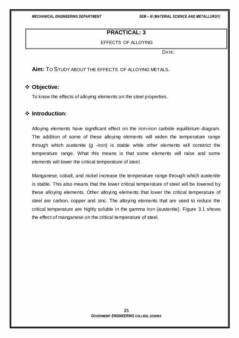
Introduction:
Alloying elements have significant effect on the iron-iron carbide equilibrium diagram.
The addition of some of these alloying elements will widen the temperature range
through which austenite (g -iron) is stable while other elements will constrict the
temperature range. What this means is that some elements will raise and some
elements will lower the critical temperature of steel.
Manganese, cobalt, and nickel increase the temperature range through which austenite
is stable. This also means that the lower critical temperature of steel will be lowered by
these alloying elements. Other alloying elements that lower the critical temperature of
steel are carbon, copper and zinc. The alloying elements that are used to reduce the
critical temperature are highly soluble in the gamma iron (austenite). Figure 3.1 shows
the effect of manganese on the critical temperature of steel.

MECHANICAL ENGINEERING DEPARTMENT SEM – III (MATERIAL SCIENCE AND METALLURGY)
26 GOVERNMENT ENGINEERING COLLEGE, GODHRA
Figure 3.1 The effect of alloying with manganese on the critical temperature of steel and
austenite (g -iron) phase transformation zone on the iron-iron carbide diagram..
Alloys such as aluminum, chromiuim, molybdenum, phosphorus, silicon, tungsten tend
to form solid solutions with alpha iron (ferrite). This constricts the temperature region
through which gamma iron (austenite) is stable. As shown in Figure 3.2, chromium at
different percentages constricts the critical temperature range which results in a marked
reduction of the region where austenite is stable.
Figure 3.2 Effect of alloying with chromium on the critical temperature of steel and
austenite (g -iron) phase transformation zone on the iron-iron carbide diagram.
MECHANICAL ENGINEERING DEPARTMENT SEM – III (MATERIAL SCIENCE AND METALLURGY)
27 GOVERNMENT ENGINEERING COLLEGE, GODHRA
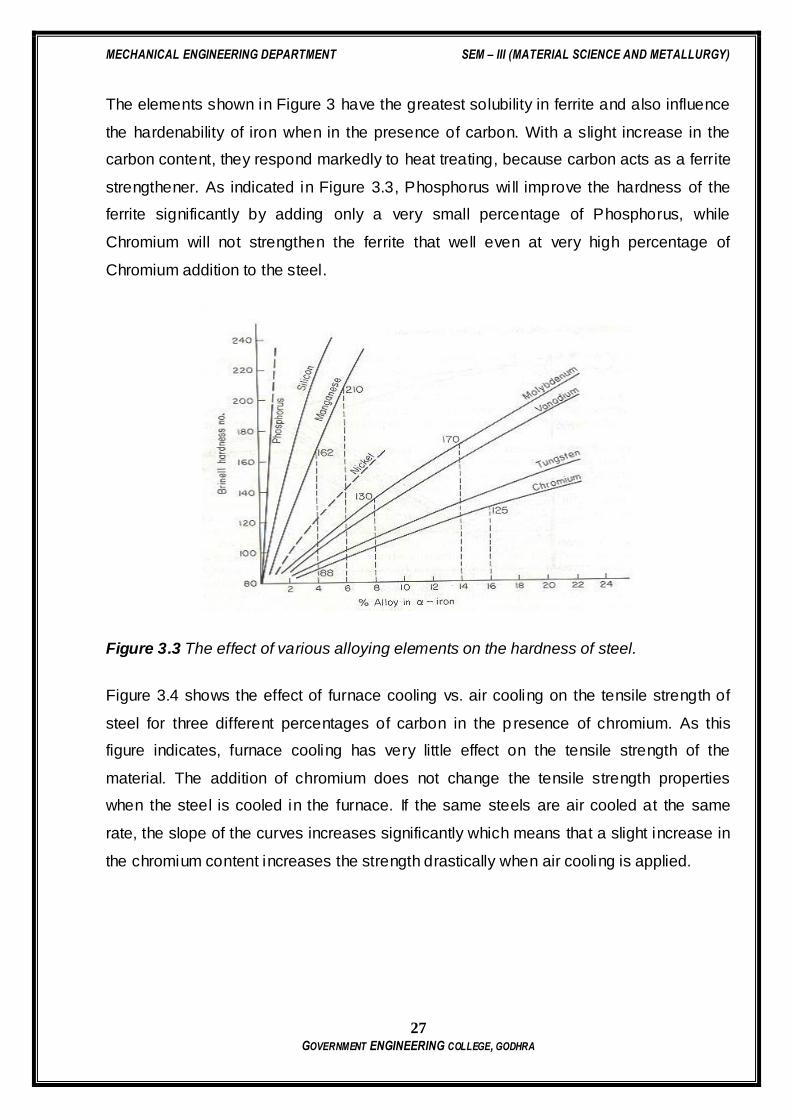
The elements shown in Figure 3 have the greatest solubility in ferrite and also influence
the hardenability of iron when in the presence of carbon. With a slight increase in the
carbon content, they respond markedly to heat treating, because carbon acts as a ferrite
strengthener. As indicated in Figure 3.3, Phosphorus will improve the hardness of the
ferrite significantly by adding only a very small percentage of Phosphorus, while
Chromium will not strengthen the ferrite that well even at very high percentage of
Chromium addition to the steel.
Figure 3.3 The effect of various alloying elements on the hardness of steel.
Figure 3.4 shows the effect of furnace cooling vs. air cooling on the tensile strength of
steel for three different percentages of carbon in the p resence of chromium. As this
figure indicates, furnace cooling has very little effect on the tensile strength of the
material. The addition of chromium does not change the tensile strength properties
when the steel is cooled in the furnace. If the same steels are air cooled at the same
rate, the slope of the curves increases significantly which means that a slight increase in
the chromium content increases the strength drastically when air cooling is applied.

MECHANICAL ENGINEERING DEPARTMENT SEM – III (MATERIAL SCIENCE AND METALLURGY)
28 GOVERNMENT ENGINEERING COLLEGE, GODHRA
Figure 3.4 Effect of different percentages of carbon on the tensile strength of steel in the
presence of chromium.
Effect of Carbon on Physical Properties:
In general, as the carbon content increases the hardness of the steel also increases.
The tensile strength and the yield strength also increase to about 0.83 % carbon.
Thereafter, they level out. This is shown in Figure 3.5.
Figure 3.5 Effect of carbon on hardness, tensile strength and yield
strength of steels.
MECHANICAL ENGINEERING DEPARTMENT SEM – III (MATERIAL SCIENCE AND METALLURGY)
29 GOVERNMENT ENGINEERING COLLEGE, GODHRA
The tensile strength and hardness are affected as the ratio of ferrite to cementite in the
structure of steel changes. As the percentage of pearlite increases in the hypoeutectoid
steels, the tensile strength increases. The hardness does not increase dramatically. The
hypereutectoid steels show only a slight increase in strength as the cementite-to-ferrite
ratio increases.
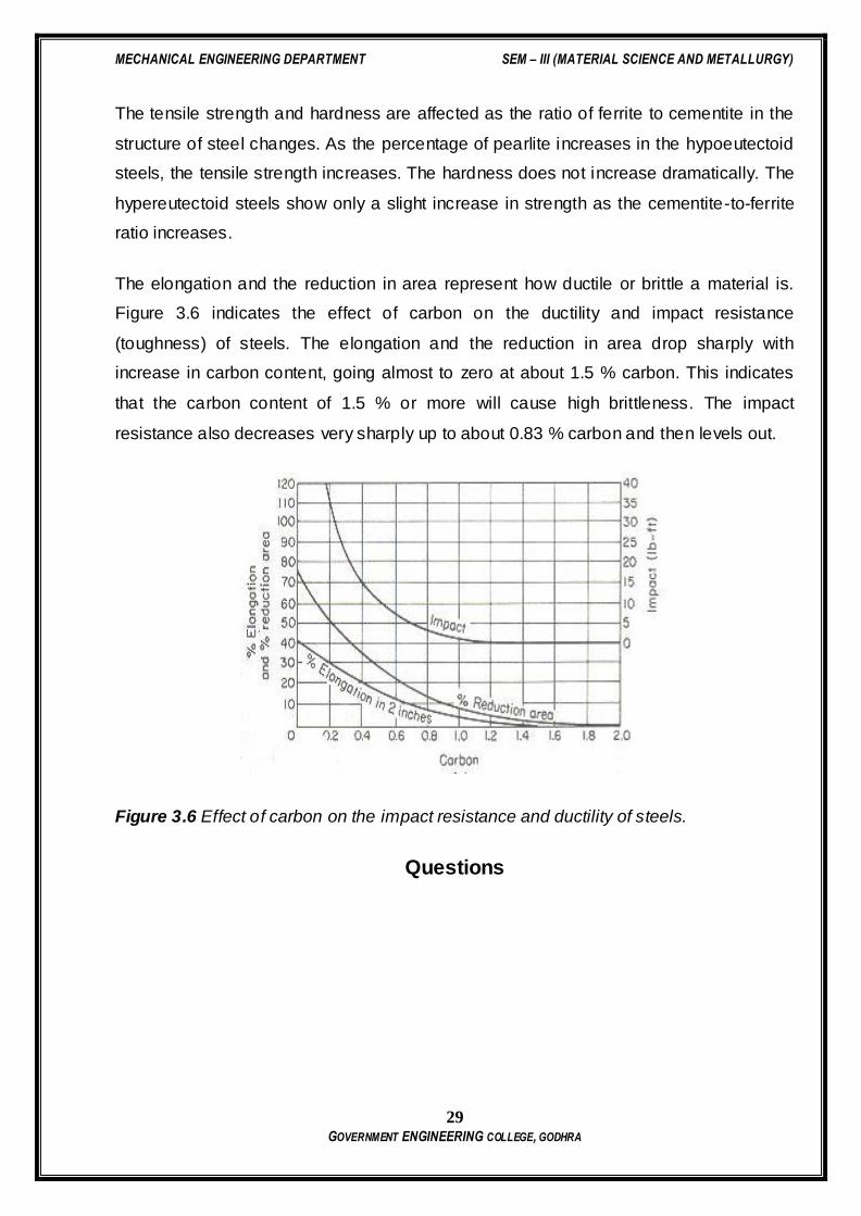
The elongation and the reduction in area represent how ductile or brittle a material is.
Figure 3.6 indicates the effect of carbon on the ductility and impact resistance
(toughness) of steels. The elongation and the reduction in area drop sharply with
increase in carbon content, going almost to zero at about 1.5 % carbon. This indicates
that the carbon content of 1.5 % or more will cause high brittleness. The impact
resistance also decreases very sharply up to about 0.83 % carbon and then levels out.
Figure 3.6 Effect of carbon on the impact resistance and ductility of steels.
Questions
MECHANICAL ENGINEERING DEPARTMENT SEM – III (MATERIAL SCIENCE AND METALLURGY)
30 GOVERNMENT ENGINEERING COLLEGE, GODHRA
PRACTICAL: 4
MACRO EXAMINATION AND MICRO EXAMINATION
DATE:
Aim: TO PREPARE SPECIMEN FOR MACRO EXAMINATION AND MICRO EXAMINATION
Objective:
To study procedure of specimen preparation for macroscopic & microscopic
examination.
Introduction:
A little can be learned regarding the structural characteristics of a metal by microscopic
examination unless the surface that is to be examined is first prepared according to
more or less rigid and precise procedures. With the use of modern metallurgical
microscope and precision optical parts where the obtainable resolution may be as great
as a fraction of the wavelength of the light used to illuminate the specimen, it is evident
that perfect specimen preparation is of the greatest importance.
Improper preparation is likely to remove all important inclusions, erode grain boundaries
of temper hardened steel specimens, ultimately producing a structure, superficially at
least, which upon micro-examination will appear entirely different from that which is truly
representative and characteristic of metal. Obviously an examination of such a prepared
specimen will lead only to erroneous interpretations and unreliable conclusions.
Practical Contents:
1. Determine the appropriate location and orientation of the specimen to be cut.
2. Mounting the specimen if required.
3. If the specimen to be observed is too uneven, or with burrs etc. achieve plane
surface by either filling or grinding on coarse grade emery paper.
MECHANICAL ENGINEERING DEPARTMENT SEM – III (MATERIAL SCIENCE AND METALLURGY)
31 GOVERNMENT ENGINEERING COLLEGE, GODHRA
4. Take emery papers from coarse to finer abrasive grid (i.e 1/0, 2/0, 3/0 & 4/0). The
emery is placed on any clean, hard, level surface. The specimen is rubbed back
and forth across the entire length of paper under moderately applied pressure.
While being ground, the specimen is held so that the new, finer scratches being
introduced on the surface are approximately at right angles to the old scratches
resulting from previous flattening operation. Switch over to next finer grade and
repeat the same procedure.
5. Now for better surface finish go to the polishing wheel. The polishing wheel
mounted cloth is rotated at appropriate speed and the specimen is moved
continuously from the center to the periphery of the polishing wheel with
moderate pressure.
6. Select suitable etchant for the specimen and carry out the etching.
7. Immediately after etching, wash the specimen under running water and dry it with
alcohol.
8. Set the microscope with suitable selection of eye piece and objective for the
desired magnification.
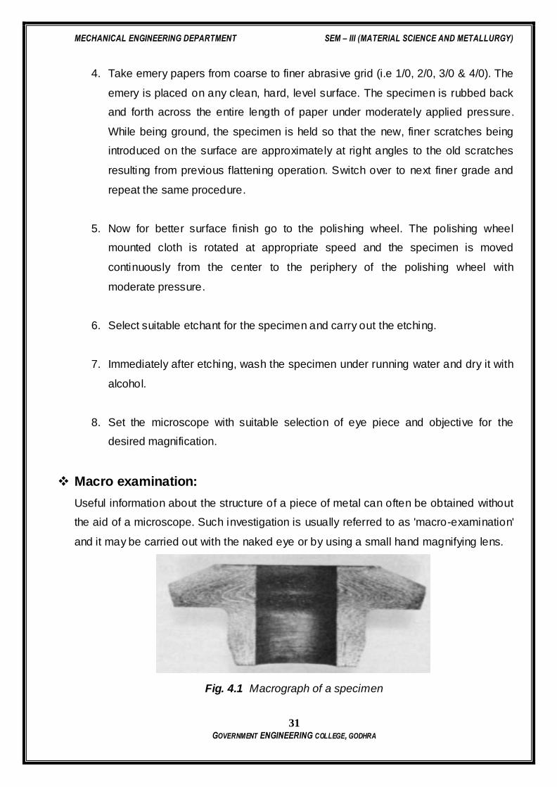
Macro examination:
Useful information about the structure of a piece of metal can often be obtained without
the aid of a microscope. Such investigation is usually referred to as 'macro-examination'
and it may be carried out with the naked eye or by using a small hand magnifying lens.
Fig. 4.1 Macrograph of a specimen

MECHANICAL ENGINEERING DEPARTMENT SEM – III (MATERIAL SCIENCE AND METALLURGY)
32 GOVERNMENT ENGINEERING COLLEGE, GODHRA
Micro examination:
In micro examination the material is examined at the atomic level by using the electron
microscope at high magnification to get the structure details of the same material.
Fig. 4.2 Micro graph of a specimen
Macro etching reagents:

MECHANICAL ENGINEERING DEPARTMENT SEM – III (MATERIAL SCIENCE AND METALLURGY)
33 GOVERNMENT ENGINEERING COLLEGE, GODHRA
Questions
1) What is metallography? Briefly explain its importance in Metallurgy.
2) What is the basic difference between low grade no. emery paper and high grade
no. emery paper in the intermediate polishing process?
3) What is an etchant? Why etching is required? List at least three name of etchant
used for different material.
4) List the instruments and accessories you have used for preparing the sample
along with their specification details.

MECHANICAL ENGINEERING DEPARTMENT SEM – III (MATERIAL SCIENCE AND METALLURGY)
34 GOVERNMENT ENGINEERING COLLEGE, GODHRA
PRACTICAL: 5
MICRO EXAMINATION OF STANDARD SPECIMEN
DATE:
Aim: TO PERFORM MICRO EXAMINATION OF STANDARD SPECIMEN
Objective:
To understand procedure and relevance of Micro-Examination.
Introduction:
Micro examination is study of internal structure of a material i.e. microstructure, which
can be carried out by light microscopy or electron microscopy. An observation of
microstructure in a microscope will show size and shape of grains and the size, shape
and distribution of various phases and inclusions and segregations. These structural
characteristics have great effect on mechanical properties of a material. The
microstructure will reveal the mechanical and thermal treatment of the material and it
may be possible to predict the expected behavior under a given set of conditions.
Practical Contents:
1) Select the etchant required as per the specimen.
2) Carry out etching
3) Immediately after etching, wash the specimen under running water and dry it with
alcohol.
4) Set the microscope with suitable selection of eye piece and objective for the
desired magnification.
5) Sketch the microstructure observed.
Questions:
1) Record the microstructure observed in microscope with the aid of schematic
diagram.
2) Explain the impact of microstructure on various properties of materials

MECHANICAL ENGINEERING DEPARTMENT SEM – III (MATERIAL SCIENCE AND METALLURGY)
35 GOVERNMENT ENGINEERING COLLEGE, GODHRA
PRACTICAL: 6
IRON CARBON DIAGRAM & ALLOTROPY OF IRON
DATE:
AIM: TO STUDY ABOUT IRON CARBON DIAGRAM & ALLOTROPY OF IRON.
Objective:
(1) To understand Iron Carbon Diagram & its application.
(2) To know the allotropy of iron.
Iron Carbon Diagram
A study of iron-carbon system is useful and important in many respects. This is
because (1) steels constitute greatest amount of metallic materials used by man (2)
solid state transformations that occur in steels are varied and interesting. These are
similar to those occur in many other systems and helps explain the properties.
Iron-carbon phase diagram shown in figure-6.1 is not a complete diagram. Part of
the diagram after 6.67 wt% C is ignored as it has little commercial significance. The
6.67%C represents the composition where an inter-metallic compound, cementite
(Fe3C), with solubility limits forms. In addition, phase diagram is not true equilibrium
diagram because cementite is not an equilibrium phase. However, in ordinary steels
decomposition of cementite into graphite never observed because nucleation of
cementite is much easier than that of graphite. Thus cementite can be treated as an
equilibrium phase for practical purposes.
The Fe-Fe3C is characterized by five individual phases and four invariant
reactions. Five phases that exist in the diagram are: α–ferrite (BCC) Fe-C solid solution,
γ-austenite (FCC) Fe-C solid solution, δ-ferrite (BCC) Fe-C solid solution, Fe3C (iron
carbide) or cementite - an inter-metallic compound and liquid Fe-C solution. Four
invariant reactions that cause transformations in the system are namely eutectoid,
eutectic, monotectic and peritectic.

MECHANICAL ENGINEERING DEPARTMENT SEM – III (MATERIAL SCIENCE AND METALLURGY)
36 GOVERNMENT ENGINEERING COLLEGE, GODHRA
Figure 6.1: Iron – Iron carbide phase diagram.
As depicted by left axes, pure iron upon heating exhibits two allotropic changes.
One involves α–ferrite of BCC crystal structure transforming to FCC austenite, γ-iron, at
. t C, austenite changes to BCC phase known as δ-ferrite, which finally
melts at 5 C.
Carbon present in solid iron as interstitial impurity, and forms solid solution with
ferrites / austenite as depicted by three single fields represented by α, γ and δ. Carbon
dissolves least in α–ferrite in which maximum amount of carbon soluble is . at
C. This limited solubility is attributed to shape and size of interstitial position in BCC α–
ferrite. However, carbon present greatly influences the mechanical properties of α–
ferrite. α–ferrite can be used as magnetic material below C. Solubility of carbon in
γ-iron reaches its maximum, 2.11%, at a temperature of 1147 C. Higher solubility of
carbon in austenite is attributed to FCC structure and corresponding interstitial sites.
Phase transformations involving austenite plays very significant role in heat treatment of

MECHANICAL ENGINEERING DEPARTMENT SEM – III (MATERIAL SCIENCE AND METALLURGY)
37 GOVERNMENT ENGINEERING COLLEGE, GODHRA
different steels. Austenite itself is non-magnetic. Carbon solubility in δ-ferrite is
maximum ( . ) at 5 C. As this ferrite exists only at elevated temperatures, it is of
no commercial importance. Cementite, Fe3C an inter-metallic compound forms when
amount of carbon present exceeds its solubility limit at respective temperatures. Out of
these four solid phases, cementite is hardest and brittle that is used in different forms to
increase the strength of steels. α–ferrite, on the other hand, is softest and act as matrix
of a composite material. By combining these two phases in a solution, a material’s
properties can be varied over a large range.
For technological convenience, based on %C dissolved in it, a Fe-C solution is
classified as: commercial pure irons with less than 0.008%C; steels having %C between
0.008-2.11; while cast irons have carbon in the range of 2.11%-6.67%. Thus commercial
pure iron is composed of exclusively α–ferrite at room temperature. Most of the steels
and cast irons contain both α–ferrite and cementite. However, commercial cast irons are
not simple alloys of iron and carbon as they contain large quantities of other elements
such as silicon, thus better consider them as ternary alloys. The presence of Si
promotes the formation of graphite instead of cementite. Thus cast irons may contain
carbon in form of both graphite and cementite, while steels will have carbon only in
combined from as cementite.
As shown in figure-6.1, and mentioned earlier, Fe-C system constitutes Five phases and
four invariant reactions:
CEMENTITE (Fe3C):
Cementite is also known as iron carbide which has a chemical formula, Fe3C. It contains
6.67 % Carbon by weight. It is a typical hard and brittle interstitial compound of low
tensile strength (approximately 5,000 psi) but high compressive strength. Its crystal
structure is orthorhombic.
AUSTENITE (g iron):
It is also known as (g ) gamma-iron, which is an interstitial solid solution of carbon
dissolved in iron with a face centered cubic crystal (F.C.C) structure. Austenite is
normally unstable at room temperature. Under certain conditions it is possible to obtain
austenite at room temperature. Average properties of austenite are:

MECHANICAL ENGINEERING DEPARTMENT SEM – III (MATERIAL SCIENCE AND METALLURGY)
38 GOVERNMENT ENGINEERING COLLEGE, GODHRA
Tensile strength 150,000 psi.
Elongation 10 % in 2 in gage length.
Hardness Rockwell C 40
Toughness High
Table 6.1 Properties of Austenite
Figure 6.2 Austenite (gamma iron) crystal structure
FERRITE (a iron):
Figure 6.3 Ferrite (alpha iron) crystal structure
It is also known as (a ) alpha -iron, which is an interstitial solid solution of a small
amount of carbon dissolved in iron with a Body Centered Cubic (B.C.C.) crystal
structure. It is the softest structure on the iron-iron carbide diagram. Average properties
are:
MECHANICAL ENGINEERING DEPARTMENT SEM – III (MATERIAL SCIENCE AND METALLURGY)
39 GOVERNMENT ENGINEERING COLLEGE, GODHRA
Tensile Strength 40,000 psi
Elongation 40 % in 2 in gage length
Hardness Less than Rockwell C 0 or less than Rockwell B 90.
Toughness Low
Table 6.2 Properties of Ferrite.
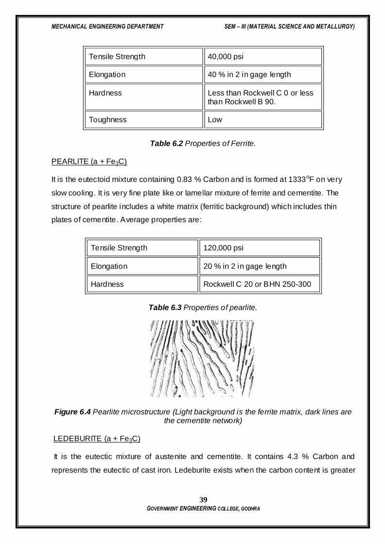
PEARLITE (a + Fe3C)
It is the eutectoid mixture containing 0.83 % Carbon and is formed at 1333oF on very
slow cooling. It is very fine plate like or lamellar mixture of ferrite and cementite. The
structure of pearlite includes a white matrix (ferritic background) which includes thin
plates of cementite. Average properties are:
Tensile Strength 120,000 psi
Elongation 20 % in 2 in gage length
Hardness Rockwell C 20 or BHN 250-300
Table 6.3 Properties of pearlite.
Figure 6.4 Pearlite microstructure (Light background is the ferrite matrix, dark lines are the cementite network)
LEDEBURITE (a + Fe3C)
It is the eutectic mixture of austenite and cementite. It contains 4.3 % Carbon and
represents the eutectic of cast iron. Ledeburite exists when the carbon content is greater

MECHANICAL ENGINEERING DEPARTMENT SEM – III (MATERIAL SCIENCE AND METALLURGY)
40 GOVERNMENT ENGINEERING COLLEGE, GODHRA
than 2 %, which represents the dividing line on the equilibrium diagram between steel
and cast iron.
(d ) DELTA IRON:
Delta iron exists between 2552 and 2802 oF. It may exist in combination with the melt to
about 0.50 % Carbon, in combination with austenite to about 0.18 % Carbon and in a
single phase state out to about 0.10 % carbon. Delta iron has the Body Centered Cubic
(B.C.C) crystal structure and is magnetic.
- peritectic reaction at 5 C and 0.16%C,
δ-ferrite + L ↔ γ-iron (austenite)
- monotectic reaction 5 C and 0.51%C,
L ↔ L + γ-iron (austenite)
- eutectic reaction at C and 4.3 %C,
L ↔ γ-iron + Fe3C (cementite) [ledeburite]
- eutectoid reaction at C and 0.8%C,
γ-iron ↔ α–ferrite + Fe3C (cementite) [pearlite]
Product phase of eutectic reaction is called ledeburite, while product from
eutectoid reaction is called pearlite. During cooling to room temperature, ledeburite
transforms into pearlite and cementite. At room temperature, thus after equilibrium
cooling, Fe-C diagram consists of either α–ferrite, pearlite and/or cementite. Pearlite is
actually not a single phase, but a micro-constituent having alternate thin layers of α–
ferrite (~88%) and Fe3C, cementite (~12%). Steels with less than 0.8%C (mild steels up
to 0.3%C, medium carbon steels with C between 0.3%-0.8% i.e. hypo-eutectoid Fe-C
alloys) i.e. consists pro-eutectoid α–ferrite in addition to pearlite, while steels with carbon
higher than 0.8% (high-carbon steels i.e. hyper-eutectoid Fe-C alloys) consists of
pearlite and pro-eutectoid cementite. Phase transformations involving austenite i.e.
processes those involve eutectoid reaction are of great importance in heat treatment of
steels.
In practice, steels are almost always cooled from the austenitic region to room
temperature. During the cooling upon crossing the boundary of the single phase γ-iron,

MECHANICAL ENGINEERING DEPARTMENT SEM – III (MATERIAL SCIENCE AND METALLURGY)
41 GOVERNMENT ENGINEERING COLLEGE, GODHRA
first pro-eutectoid phase (either α–ferrite or cementite) forms up to eutectoid
temperature. With further cooling below the eutectoid temperature, remaining austenite
decomposes to eutectoid product called pearlite, mixture of thin layers of α–ferrite and
cementite. Though pearlite is not a phase, nevertheless, a constituent because it has a
definiteappearance under the microscope and can be clearly identified in a structure
composed of several constituents. The decomposition of austenite to form pearlite
occurs by nucleation and growth. Nucleation, usually, occurs heterogeneously and
rarely homogeneously at grain boundaries. When it is not homogeneous, nucleation of
pearlite occurs both at grain boundaries and in the grains of austenite. When austenite
forms pearlite at a constant temperature, the spacing between adjacent lamellae of
cementite is very nearly constant. For a given colony of pearlite, all cementite plates
have a common orientation in space, and it is also true for the ferrite plates. Growth of
pearlite colonies occurs not only by the nucleation of additional lamellae but also
through an advance at the ends of the lamellae. Pearlite growth also involves the
nucleation of new colonies at the interfaces between established colonies and the
parent austenite. The thickness ratio of the ferrite and cementite layers in pearlite is
approximately 8 to 1. However, the absolute layer thickness depends on the
temperature at which the isothermal transformation is allowed to occur.
The temperature at which austenite is transformed has a strong effect on the
inter-lamellar spacing of pearlite. The lower the reaction temperature, the smaller will be
inter-lamellar spacing. For example, pearlite spacing is in order of 10-3 mm when it
formed at , while spacing is in order of - mm when formed at C. The
spacing of the pearlite lamellae has a practical significance because the hardness of the
resulting structure depends upon it; the smaller the spacing, the harder the metal. The
growth rate of pearlite is also a strong function of temperature. t temperatures ust
below the eutectoid, the growth rate increases rapidly with decreasing temperature ,
reaching a maximum at C, and then decreases again at lower temperatures.
Additions of alloying elements to Fe-C system bring changes (alternations to
positions of phase boundaries and shapes of fields) depends on that particular element
and its concentration. Almost all alloying elements causes the eutectoid concentration to
decrease, and most of the alloying elements (e.g.: Ti, Mo, Si, W, Cr) causes the
eutectoid temperature to increase while some other (e.g.: Ni, Mn) reduces the eutectoid
MECHANICAL ENGINEERING DEPARTMENT SEM – III (MATERIAL SCIENCE AND METALLURGY)
42 GOVERNMENT ENGINEERING COLLEGE, GODHRA
temperature. Thus alloying additions alters the relative amount of pearlite and pro-
eutectoid phase that form.
Fe-C alloys with more than 2.11% C are called cast irons. Phase transformations in cast
irons involve formation of pro-eutectic phase on crossing the liquidus. During the further
cooling, liquid of eutectic composition decomposes in to mixture of austenite and
cementite, known as ledeburite. On further cooling through eutectoid temperature,
austenite decomposes to pearlite. The room temperature microstructure of cast irons
thus consists of pearlite and cementite. Because of presence of cementite, which is
hard, brittle and white in color, product is called white cast iron. However, depending on
cooling rate and other alloying elements, carbon in cast iron may be present as graphite
or cementite. Gray cast iron contains graphite in form of flakes. These flakes are sharp
and act as stress risers. Brittleness arising because of flake shape can be avoided by
producing graphite in spherical nodules, as in malleable cast iron and SG (spheroidal
graphite) cast iron. Malleable cast iron is produced by heat treat ing white cast iron (Si
) for prolonged periods at about C and then cooling it very slowly. The
cementite decomposes and temper carbon appears approximately as spherical
particles. SG iron is produced by adding inoculants to molten iron. In these Si content
must be about 2.5%, and no subsequent heat treatment is required.
Allotropy of Iron
Polymorphism is a physical phenomenon where a material may have more than one
crystal structure. A material that shows polymorphism exists in more than one type of
space lattice in the solid state. If the change in structure is reversible, then the
polymorphic change is known as allotropy. The prevailing crystal structure depends on
both the temperature and the external pressure.
One familiar example is found in carbon: graphite is the stable polymorph at ambient
conditions, whereas diamond is formed at extremely high pressures.
The best known example for allotropy is iron. There are three allotropic forms of iron,
known as alpha, gamma, and delta.
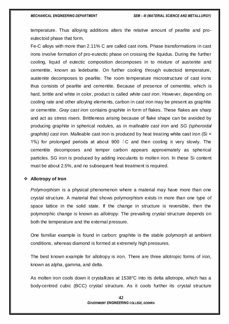
As molten iron cools down it crystallizes at 1538°C into its delta allotrope, which has a
body-centred cubic (BCC) crystal structure. As it cools further its crystal structure
MECHANICAL ENGINEERING DEPARTMENT SEM – III (MATERIAL SCIENCE AND METALLURGY)
43 GOVERNMENT ENGINEERING COLLEGE, GODHRA
changes to face centred cubic (FCC) at 1394°C, when it is known as gamma-iron, or
austenite. At 912°C the crystal structure again becomes BCC as alpha -iron also known
as ferrite, is formed, and at 770°C (the Curie point, Tc ) the iron becomes magnetic as
alpha-iron, which is also BCC, is formed. As the iron passes through the Curie
temperature there is no change in crystalline structure, but there is a change in the
magnetic properties
Figure 6.5. Cooling curve for pure iron. (Allotropic behavior of pure iron)
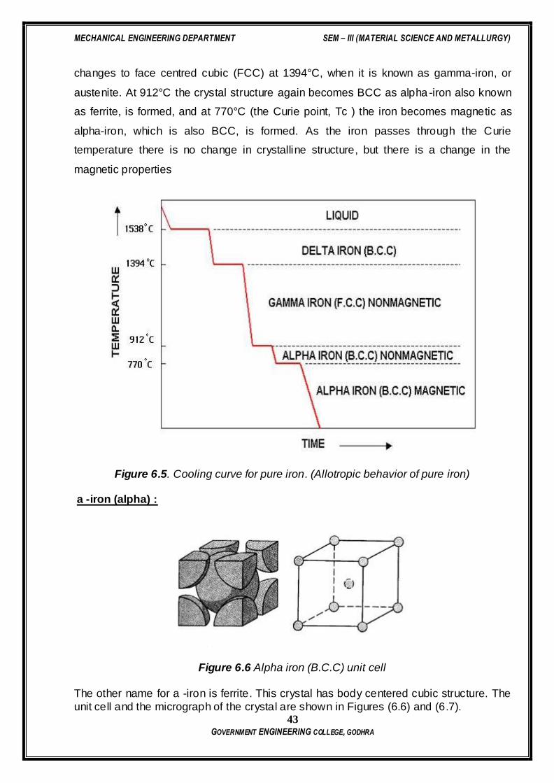
a -iron (alpha) :
Figure 6.6 Alpha iron (B.C.C) unit cell
The other name for a -iron is ferrite. This crystal has body centered cubic structure. The
unit cell and the micrograph of the crystal are shown in Figures (6.6) and (6.7).

MECHANICAL ENGINEERING DEPARTMENT SEM – III (MATERIAL SCIENCE AND METALLURGY)
44 GOVERNMENT ENGINEERING COLLEGE, GODHRA
Figure 6.7 Ferrite crystals.
g -iron (Gamma):
Figure 6.8 Face centered cubic crystal unit cell.
The other name for g -iron is austenite. This crystal has face centered cubic (F.C.C)
structure. The unit cell and the micrograph of the crystal are shown in Figures (6.8) and (6.9).
Figure 6.9 Austenite crystals.

MECHANICAL ENGINEERING DEPARTMENT SEM – III (MATERIAL SCIENCE AND METALLURGY)
45 GOVERNMENT ENGINEERING COLLEGE, GODHRA
Questions
MECHANICAL ENGINEERING DEPARTMENT SEM – III (MATERIAL SCIENCE AND METALLURGY)
46 GOVERNMENT ENGINEERING COLLEGE, GODHRA
PRACTICAL: 7
CAST IRON
DATE:
Aim: TO STUDY ABOUT CAST IRON.
Objective:
(1) To know the various types of Cast irons.
(2) To know Properties of Cast Iron.
Introduction:
Cast iron usually refers to grey iron, but also identifies a large group of ferrous alloys,
which solidify with a eutectic. The colour of a fractured surface can be used to identify
an alloy. White cast iron is named after its white surface when fractured, due to its
carbide impurities which allow cracks to pass straight through. Grey cast iron is named
after its grey fractured surface, which occurs because the graphitic flakes deflect a
passing crack and initiate countless new cracks as the material breaks.
Iron (Fe) accounts for more than 95% by weight (wt%) of the alloy material, while the
main alloying elements are carbon (C) and silicon (Si). The amount of carbon in cast
irons is 2.1 to 4 wt%. Cast irons contain an appreciable amount of silicon, normally 1 to
3 wt%, and consequently, these alloys should be considered ternary Fe-C-Si alloys.
Types of Cast Iron
(1) Grey cast iron :
Grey cast iron is characterized by its graphitic microstructure, which causes fractures of
the material to have a grey appearance. It is the most commonly used cast iron and the
most widely use cast material base on weight. Most cast irons have a chemical
composition of 2.5 to 4.0% carbon, 1 to 3% silicon, and the remainder is iron. Grey cast
iron has less tensile strength and shock resistance than steel, however its compressive
strength is comparable to low and medium carbon steel.

MECHANICAL ENGINEERING DEPARTMENT SEM – III (MATERIAL SCIENCE AND METALLURGY)
47 GOVERNMENT ENGINEERING COLLEGE, GODHRA
(2) White cast iron:
With a lower silicon content and faster cooling, the carbon in white cast iron precipitates
out of the melt as the metastable phase cementite, Fe3C, rather than graphite. The
cementite which precipitates from the melt forms as relatively large particles, usually in a
eutectic mixture, where the other phase is austenite (which on cooling might transform
to martensite). These eutectic carbides are much too large to provide precipitation
hardening (as in some steels, where cementite precipitates might inhibit plastic
deformation by impeding the movement of dislocations through the ferrite matrix).
Rather, they increase the bulk hardness of the cast iron simply by virtue of their own
very high hardness and their substantial volume fraction, such that the bulk hardness
can be approximated by a rule of mixtures. In any case, they offer hardness at the
expense of toughness. Since carbide makes up a large fraction of the material, white
cast iron could reasonably be classified as a cermet. White iron is too brittle for use in
many structural components, but with good hardness and abrasion resistance and
relatively low cost, it finds use in such applications as the wear surfaces (impeller and
volute) of slurry pumps, shell liners and lifter bars in ball mills and autogenous grinding
mills, balls and rings in coal pulverisers, and the teeth of a backhoe's digging bucket
(although cast medium-carbon martensitic steel is more common for this application).
White cast iron can also be made by using a high percentage of chromium (Cr) in the
iron; Cr is a strong carbide-forming element, so at high enough percentages of chrome,
the precipitation of graphite out of the iron is suppressed. High-chrome white iron alloys
allow massive castings (for example, a 10-tonne impeller) to be sand cast, i.e., a high
cooling rate is not required, as well as providing impressive abrasion resistance.
(3) Malleable cast iron :
Malleable iron starts as a white iron casting, that is then heat treated at about 900 °C
(1,650 °F). Graphite separates out much more slowly in this case, so that surface
tension has time to form it into spheroidal particles rather than flakes. Due to their lower
aspect ratio, spheroids are relatively short and far from one another, and have a lower
cross section vis-a-vis a propagating crack or phonon. They also have blunt boundaries,
as opposed to flakes, which alleviates the stress concentration problems faced by grey
MECHANICAL ENGINEERING DEPARTMENT SEM – III (MATERIAL SCIENCE AND METALLURGY)
48 GOVERNMENT ENGINEERING COLLEGE, GODHRA
cast iron. In general, the properties of malleable cast iron are more like mild steel. There
is a limit to how large a part can be cast in malleable iron, since it is made from white
cast iron.
(3) Ductile cast iron :
A more recent development is nodular or ductile cast iron . Tiny amounts of magnesium
or cerium added to these alloys slow down the growth of graphite precipitates by
bonding to the edges of the graphite planes. Along with careful control of other elements
and timing, this allows the carbon to separate as spheroidal particles as the material
solidifies. The properties are similar to malleable iron, but parts can be cast with larger
sections.
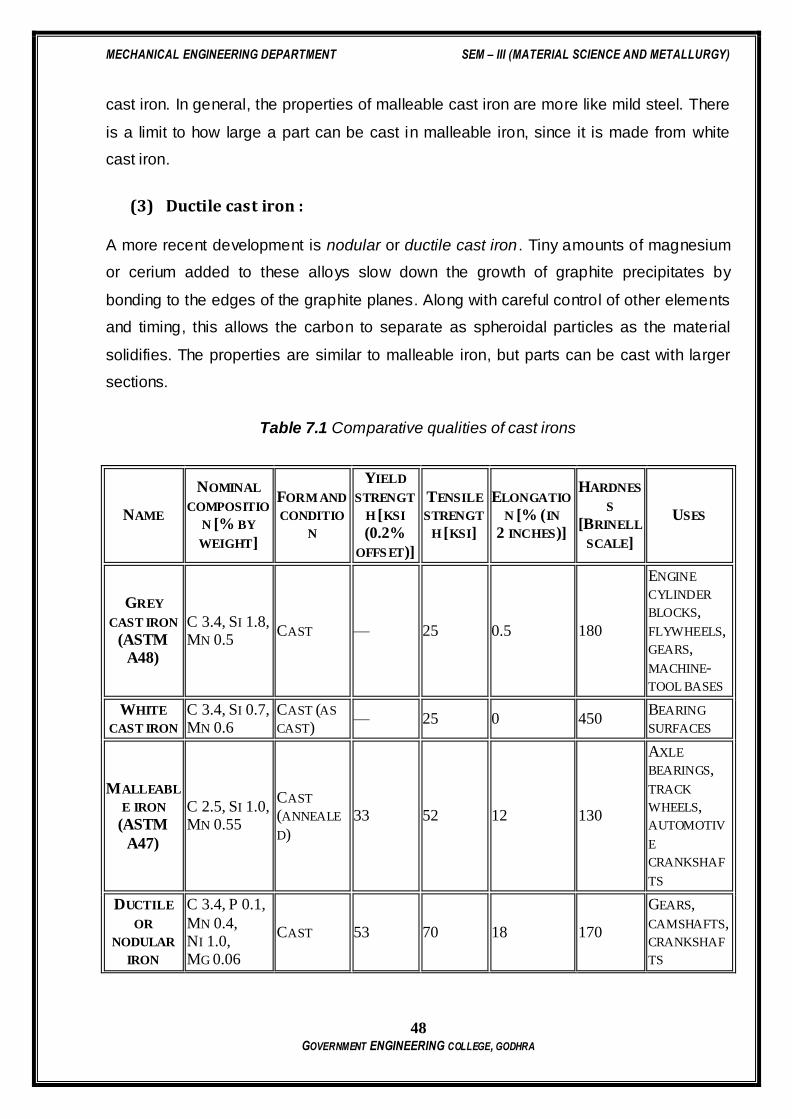
Table 7.1 Comparative qualities of cast irons
NAME
NOMINAL
COMPOSITIO
N [% BY
WEIGHT]
FORM AND
CONDITIO
N
YIELD
STRENGT
H [KSI
(0.2%
OFFS ET)]
TENSILE
STRENGT
H [KSI]
ELONGATIO
N [% (IN
2 INCHES)]
HARDNES
S
[BRINELL
SCALE]
USES
GREY
CAST IRON
(ASTM
A48)
C 3.4, SI 1.8, MN 0.5
CAST — 25 0.5 180
ENGINE
CYLINDER
BLOCKS,
FLYWHEELS, GEARS,
MACHINE-TOOL BASES
WHITE
CAST IRON
C 3.4, SI 0.7, MN 0.6
CAST (AS
CAST) — 25 0 450
BEARING
SURFACES
MALLEABL
E IRON
(ASTM
A47)
C 2.5, SI 1.0, MN 0.55
CAST
(ANNEALE
D)
33 52 12 130
AXLE
BEARINGS,
TRACK
WHEELS, AUTOMOTIV
E
CRANKSHAF
TS
DUCTILE
OR
NODULAR
IRON
C 3.4, P 0.1,
MN 0.4, NI 1.0, MG 0.06
CAST 53 70 18 170
GEARS,
CAMSHAFTS, CRANKSHAF
TS

MECHANICAL ENGINEERING DEPARTMENT SEM – III (MATERIAL SCIENCE AND METALLURGY)
49 GOVERNMENT ENGINEERING COLLEGE, GODHRA
DUCTILE
OR
NODULAR
IRON
(ASTM
A339)
— CAST
(QUENCH
TEMPERED)
108 135 5 310 —
NI-HARD
TYPE 2
C 2.7, SI 0.6, MN 0.5,
NI 4.5, CR 2.0
SAND-
CAST — 55 — 550
HIGH
STRENGTH
APPLICATIO
NS
NI-RESIST
TYPE 2
C 3.0, SI 2.0, MN 1.0,
NI 20.0, CR 2.5
CAST — 27 2 140
RESISTANCE
TO HEAT
AND
CORROSION
Questions
MECHANICAL ENGINEERING DEPARTMENT SEM – III (MATERIAL SCIENCE AND METALLURGY)
50 GOVERNMENT ENGINEERING COLLEGE, GODHRA
PRACTICAL:8
HEAT TREATMENT
DATE:
Aim: TO STUDY ABOUT HEAT TREATMENT
Objectives:
(1) To know the importants of Heat Treatments.
(2) To Know various types of Heat Treatments.
(3) To show the effect of different quenching media (Oil, water and Brine) on the
hardness of specimens of same composition.
Introduction:
As a result of cold working, the hardness, tensile strength, and electrical resistance
increase, while ductility decreases. There is also a large increase in the number of
dislocations, and certain planes in the crystal structure are severely distorted. Most of
the energy used to cold work the metal is dissipated in heat, and a finite amount of
energy is stored in the crystal structure as internal energy associated with the lattice
defects created by the deformation.
Various types of heat treatment processes are used to change the following properties
or conditions of the steel:
Improve the toughness
Increase the hardness
Increase the ductility
Improve the machinability
Refine the grain structure
Remove the residual stresses
Improve the wear resistance

MECHANICAL ENGINEERING DEPARTMENT SEM – III (MATERIAL SCIENCE AND METALLURGY)
51 GOVERNMENT ENGINEERING COLLEGE, GODHRA
The following are the general reasons for heat treatment:
Hardening
Steels can be heat treated to high hardness and strength levels. The reasons for doing
this are obvious. Structural components subjected to high operating stress need the high
strength of a hardened structure. Similarly, tools such as dies, knives, cutting devices,
and forming devices need a hardened structure to resist wear and deformation.
Tempering
As-quenched hardened steels are so brittle that even slight impacts may cause fracture.
Tempering is a heat treatment that reduces the brittleness of a steel without significantly
lowering its hardness and strength. All hardened steels must be tempered before use.
Softening a Hardened Structure
Hardening is reversible. If a hardened tool needs to be remachined, it may be softened
by heat treatment to return it to its machinable condition. Most steels weld better in their
soft state than in their hardened state; softening may be used to aid weldability.
Recrystallization
If a metal is cold worked, grains or crystals deform, become elongated, and in doing so
harden and strengthen a metal. There is a limiting amount of cold work that a particular
metal can be subjected to. In rolling of steel into thin sheets, you can only reduce the
cross-sectional area so much before it gets too hard to roll. At this point it would be
desirable to return the grains to their original shape. Heat treatment can accomplish this.
The transformation of cold-worked grains to an undistorted shape is called
recrystallization. Very large coarse grains can also be refined by recrystallization.This
type of heat treatment is essential if a steel is to be subjected to severe cold working in
rolling, drawing, etc.
Stress Relief
One of the most frequent reasons for heat treatment is to remove internal stress from a
metal that has been subjected to cold working or welding. Stress relieving is a heat
MECHANICAL ENGINEERING DEPARTMENT SEM – III (MATERIAL SCIENCE AND METALLURGY)
52 GOVERNMENT ENGINEERING COLLEGE, GODHRA
treatment used to remove internal strains without significantly lowering the strength. It is
used where close dimensional control is needed on weldments, forgings, castings, etc.
Hot-Working Operations
Most metal shapes produced by steel mills are at least rough shaped at elevated
temperatures. Heat treating is required to bring the rough metal shapes to the proper
temperature for hot-forming operations. Forging, hot rolling, roll welding, and the like are
all performed at temperatures of sufficient magnitude as to prevent the formation of
distorted grains that will harden the metals. Hot-working operations require dynamic
recrystallization which is achieved by working at the proper hot-work temperatures.
Diffusion of Alloying Elements
One of the criteria for hardening a steel is that it have sufficient carbon content. Low
carbon steels can be hardened, at least on the surface, by heat treating at an elevated
temperature in an atmosphere containing an alloying element that will diffuse into the
steel and allow surface hardening on quenching. Carbon is frequently diffused into the
surface of soft steels for surface hardening. Using this same principle, elements such as
chromium, boron, nitrogen, and silicon can be diffused in the surface of steel for special
purposes.
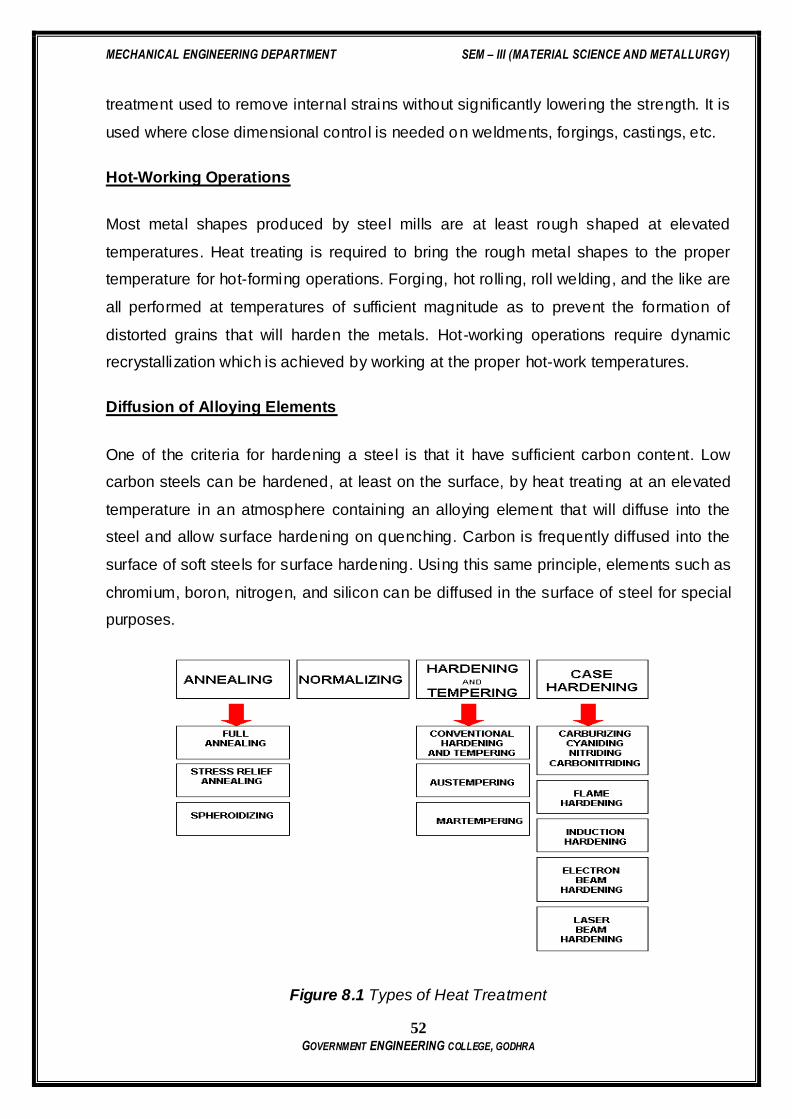
Figure 8.1 Types of Heat Treatment
MECHANICAL ENGINEERING DEPARTMENT SEM – III (MATERIAL SCIENCE AND METALLURGY)
53 GOVERNMENT ENGINEERING COLLEGE, GODHRA
Full Annealing:
Full annealing is the process by which the distorted cold worked lattice structure is
changed back to one which is strain free through the application of heat. This process is
carried out entirely in the solid state and is usually followed by slow cooling in the
furnace from the desired temperature. The annealing process may be divided into three
stages:
Recovery
Recrystallization
Grain growth
Recovery:
This is primarily a low temperature process, and the property changes produced do not
cause appreciable change in microstructure or the properties, such as tensile strength,
yield strength, hardness and ductility. The principal effect of recovery is the relief of
internal stresses due to cold working.
When the load which causes plastic deformation is released, all the elastic deformation
does not disappear. This is due to the different orientation of crystals, which will not
allow some of them to move back when the load is released. As the temperature is
increased, there is some spring back of these elastically displaced atoms which relieve
most of the internal stresses. Electrical conductivity is also increased appreciably during
the recovery stage.
Since the mechanical properties of the metal are essentially unchanged, the main
purpose of heating in the recovery range is stress relieving cold worked alloys to prevent
stress corrosion cracking or to minimize the distortion produced by residual stresses.
Commercially, this low temperature treatment in the recovery range is known as stress
relief annealing or process annealing.
Recrystallization:
As the temperature of the recovery range is reached, minute new crystals appear in the
microstructure. These new crystals have the same composition and lattice structure as
MECHANICAL ENGINEERING DEPARTMENT SEM – III (MATERIAL SCIENCE AND METALLURGY)
54 GOVERNMENT ENGINEERING COLLEGE, GODHRA
the original undeformed grains and are not elongated but are uniform in dimensions.
The new crystals generally appear at the most drastically deformed portions of the grain,
usually the grain boundaries and slip planes. The cluster of atoms from which the new
grains are formed is called a nucleus. Recrystallization takes place by a combination of
nucleation of strain free grains and the growth of these nuclei to absorb the entire cold
worked material.
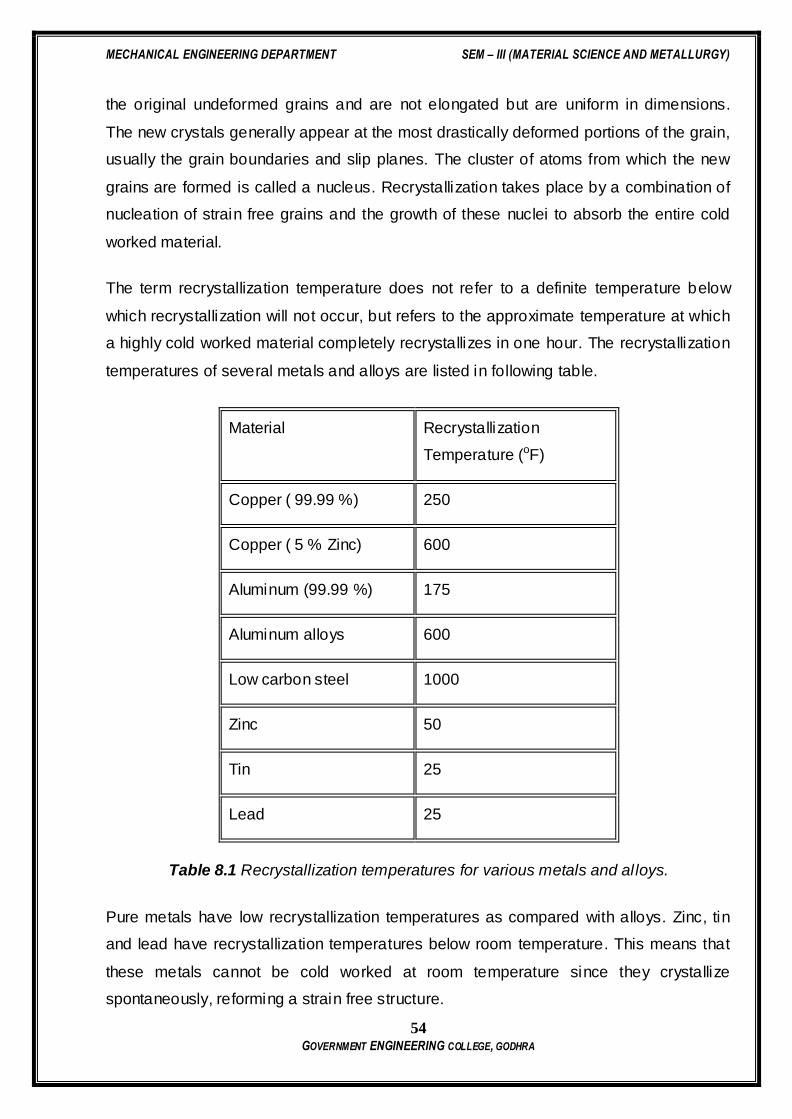
The term recrystallization temperature does not refer to a definite temperature below
which recrystallization will not occur, but refers to the approximate temperature at which
a highly cold worked material completely recrystallizes in one hour. The recrystallization
temperatures of several metals and alloys are listed in following table.
Material Recrystallization
Temperature (oF)
Copper ( 99.99 %) 250
Copper ( 5 % Zinc) 600
Aluminum (99.99 %) 175
Aluminum alloys 600
Low carbon steel 1000
Zinc 50
Tin 25
Lead 25
Table 8.1 Recrystallization temperatures for various metals and alloys.
Pure metals have low recrystallization temperatures as compared with alloys. Zinc, tin
and lead have recrystallization temperatures below room temperature. This means that
these metals cannot be cold worked at room temperature since they crystallize
spontaneously, reforming a strain free structure.
MECHANICAL ENGINEERING DEPARTMENT SEM – III (MATERIAL SCIENCE AND METALLURGY)
55 GOVERNMENT ENGINEERING COLLEGE, GODHRA
The greater the prior deformation, the lower the temperature for the start of
recrystallization.
Increasing the annealing time decreases the recrystallization temperature for the start of
recrystallization.
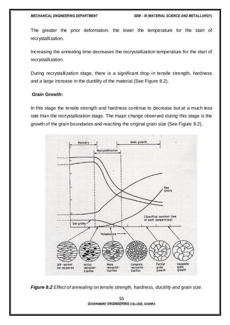
During recrystallization stage, there is a significant drop in tensile strength, hardness
and a large increase in the ductility of the material (See Figure 8.2).
Grain Growth:
In this stage the tensile strength and hardness continue to decrease but at a much less
rate than the recrystallization stage. The major change observed during this stage is the
growth of the grain boundaries and reaching the original grain size (See Figure 8.2).
Figure 8.2 Effect of annealing on tensile strength, hardness, ductility and grain size.
MECHANICAL ENGINEERING DEPARTMENT SEM – III (MATERIAL SCIENCE AND METALLURGY)
56 GOVERNMENT ENGINEERING COLLEGE, GODHRA
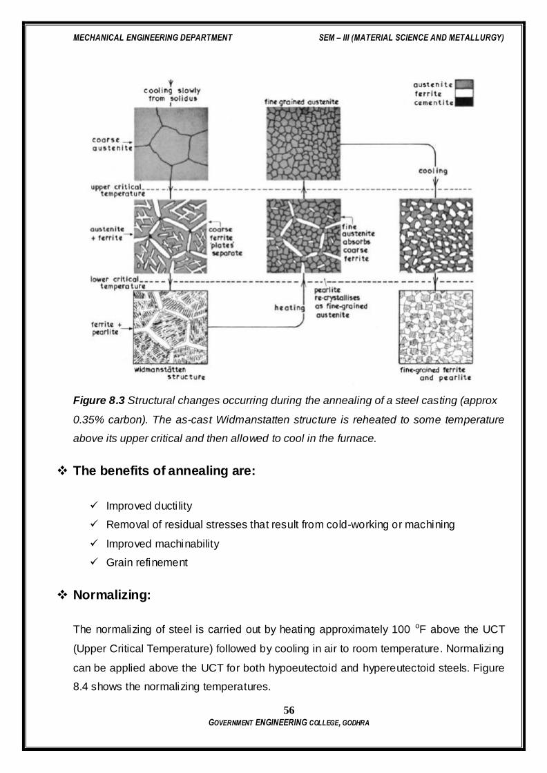
Figure 8.3 Structural changes occurring during the annealing of a steel casting (approx
0.35% carbon). The as-cast Widmanstatten structure is reheated to some temperature
above its upper critical and then allowed to cool in the furnace.
The benefits of annealing are:
Improved ducti lity
Removal of residual stresses that result from cold-working or machining
Improved machinability
Grain refinement
Normalizing:
The normalizing of steel is carried out by heating approximately 100 oF above the UCT
(Upper Critical Temperature) followed by cooling in air to room temperature. Normalizing
can be applied above the UCT for both hypoeutectoid and hypereutectoid steels. Figure
8.4 shows the normalizing temperatures.
MECHANICAL ENGINEERING DEPARTMENT SEM – III (MATERIAL SCIENCE AND METALLURGY)
57 GOVERNMENT ENGINEERING COLLEGE, GODHRA
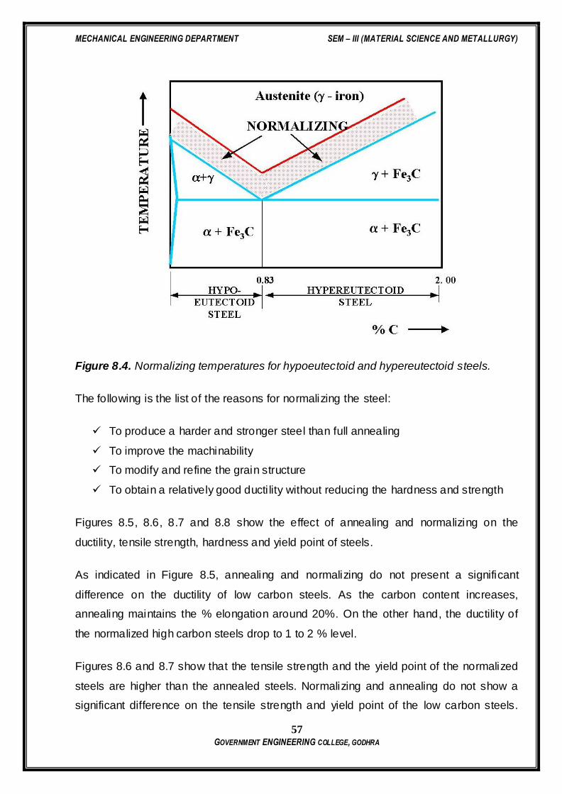
Figure 8.4. Normalizing temperatures for hypoeutectoid and hypereutectoid steels.
The following is the list of the reasons for normalizing the steel:
To produce a harder and stronger steel than full annealing
To improve the machinability
To modify and refine the grain structure
To obtain a relatively good ducti lity without reducing the hardness and strength
Figures 8.5, 8.6, 8.7 and 8.8 show the effect of annealing and normalizing on the
ductility, tensile strength, hardness and yield point of steels.
As indicated in Figure 8.5, annealing and normalizing do not present a significant
difference on the ductility of low carbon steels. As the carbon content increases,
annealing maintains the % elongation around 20%. On the other hand, the ductility of
the normalized high carbon steels drop to 1 to 2 % level.
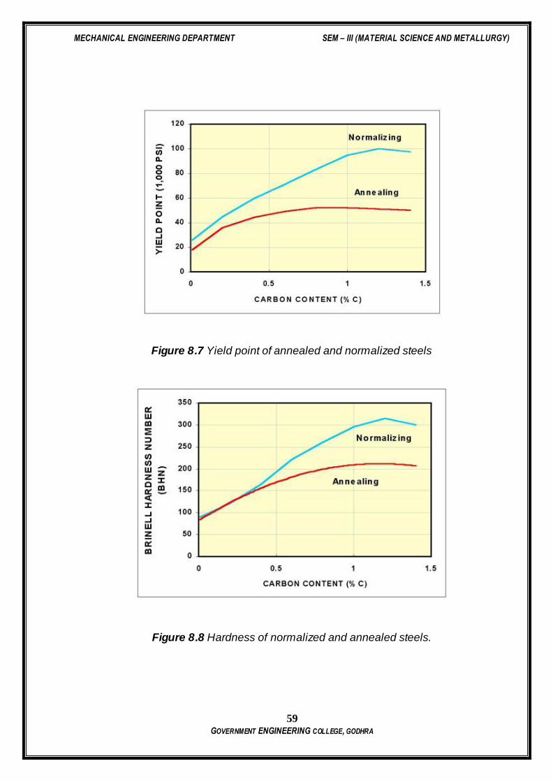
Figures 8.6 and 8.7 show that the tensile strength and the yield point of the normalized
steels are higher than the annealed steels. Normalizing and annealing do not show a
significant difference on the tensile strength and yield point of the low carbon steels.

MECHANICAL ENGINEERING DEPARTMENT SEM – III (MATERIAL SCIENCE AND METALLURGY)
58 GOVERNMENT ENGINEERING COLLEGE, GODHRA
However, normalized high carbon steels present much higher tensile strength and yield
point than those that are annealed.
Figure 8.5 Ductility of annealed and normalized steels.
Figure 8.6 Tensile strength of normalized and annealed steels.
As seen from Figure 8.8, low and medium carbon steels can maintain similar hardness
levels when normalized or annealed. However, when high carbon steels are normalized
they maintain higher levels of hardness than those that are annealed.
MECHANICAL ENGINEERING DEPARTMENT SEM – III (MATERIAL SCIENCE AND METALLURGY)
59 GOVERNMENT ENGINEERING COLLEGE, GODHRA
Figure 8.7 Yield point of annealed and normalized steels
Figure 8.8 Hardness of normalized and annealed steels.

MECHANICAL ENGINEERING DEPARTMENT SEM – III (MATERIAL SCIENCE AND METALLURGY)
60 GOVERNMENT ENGINEERING COLLEGE, GODHRA
Quenching & tempering:
Steels can be heat treated to high hardness and strength levels. The reasons for doing
this are obvious. Structural components subjected to high operating stress need the high
strength of a hardened structure. Similarly, tools such as dies, knives, cutting devices,
and forming devices need a hardened structure to resist wear and deformation.
As-quenched hardened steels are so brittle that even slight impacts may cause fracture.
Tempering is a heat treatment that reduces the brittleness of a steel without significant ly
lowering its hardness and strength. All hardened steels must be tempered before use.
QUENCH AND TEMPERING PROCESSES:
(1) Conventional Heat, Quench and Temper process
(2) Martempering
(3) Austempering
Conventional Heat, Quench and Temper Process:
In this process, Austenite is transformed to Martensite as a result of rapid quench from
furnace to room temperature. Then, martensite is heated to a temperature which gives
the desired hardness. One serious drawback is the possibility of distorting and cracking
the metal as a result of severe quenching required to form Martensite without
transforming any of the austenite to pearlite. During quenching process, the outer area
is cooled quicker than the center. Thinner parts are cooled faster than parts with greater
cross-sectional areas. What this means is that transformations of the Austenite are
proceeding at different rates. As the metal cools, it also contracts and its microstructure
occupies less volume. Extreme variations in size of metal parts complicate the work of
the heat treater and should be avoided in the designing of metal parts. This means there
is a limit to the overall size of parts that can be subjected to such thermal processing.
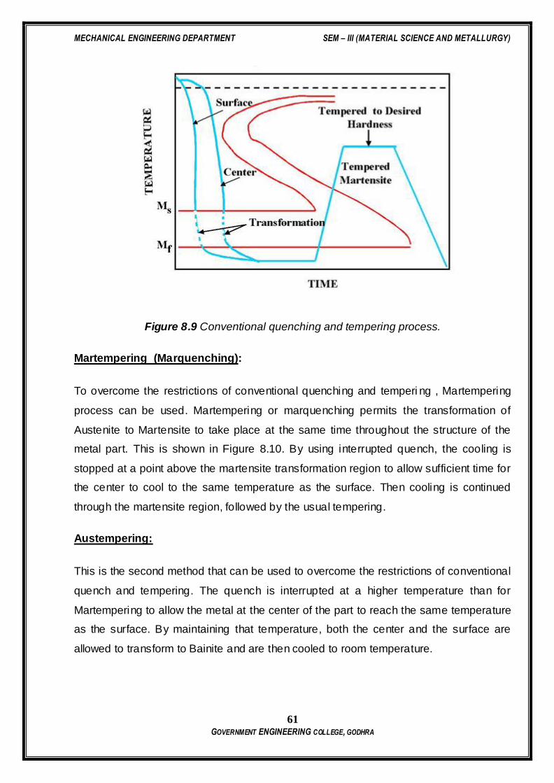
Figure 8.9 shows the conventional hardening, tempering process.
MECHANICAL ENGINEERING DEPARTMENT SEM – III (MATERIAL SCIENCE AND METALLURGY)
61 GOVERNMENT ENGINEERING COLLEGE, GODHRA
Figure 8.9 Conventional quenching and tempering process.
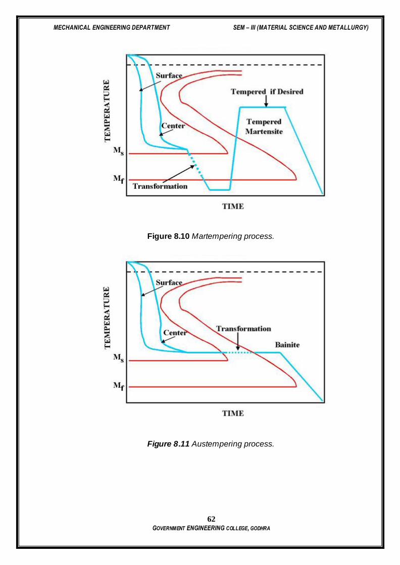
Martempering (Marquenching):
To overcome the restrictions of conventional quenching and temperi ng , Martempering
process can be used. Martempering or marquenching permits the transformation of
Austenite to Martensite to take place at the same time throughout the structure of the
metal part. This is shown in Figure 8.10. By using interrupted quench, the cooling is
stopped at a point above the martensite transformation region to allow sufficient time for
the center to cool to the same temperature as the surface. Then cooling is continued
through the martensite region, followed by the usual tempering.
Austempering:
This is the second method that can be used to overcome the restrictions of conventional
quench and tempering. The quench is interrupted at a higher temperature than for
Martempering to allow the metal at the center of the part to reach the same temperature
as the surface. By maintaining that temperature, both the center and the surface are
allowed to transform to Bainite and are then cooled to room temperature.
MECHANICAL ENGINEERING DEPARTMENT SEM – III (MATERIAL SCIENCE AND METALLURGY)
62 GOVERNMENT ENGINEERING COLLEGE, GODHRA
Figure 8.10 Martempering process.
Figure 8.11 Austempering process.

MECHANICAL ENGINEERING DEPARTMENT SEM – III (MATERIAL SCIENCE AND METALLURGY)
63 GOVERNMENT ENGINEERING COLLEGE, GODHRA
Advantages of Austempering:
(1) Less distortion and cracking than martempering,
(2) No need for final tempering (less time consuming and more energy efficient)
(3) Improvement of toughness (impact resistance is higher than the conventional quench
and tempering)
(4) Improved ducti lity
Limitations of Austempering:
Austempering can be applied to parts where the transformation to pearli te can be
avoided. This means that the section must be cooled fast enough to avoid the formation
of pearlite. Thin sections can be cooled faster than the bulky sections. Most industrial
applications of austempering have been limited to sections less than 1/2 in. thick. The
thickness can be increased by the use of alloy steels, but then the time for completion of
transformation to bainite may become excessive.
In Austempering process, the end product is 100% bainite. It is accomplished by first
heating the part to the proper austenitizing temperature followed by cooling rapidly in a
slat bath which is maintained between 400 and 800 oF. The part is left in the bath until
the transformation to bainite is complete. The steel is caused to go directly from
austenite to bainite.
Effects of Quenching medium on Hardness:
According to the functional requirements of the component, different engineering
components need different hardness for their long service life. Different quenching
media generate different final microstructures (like coarse pearlite, fine pearlite, bainite,
martensite etc.) and thus give different hardness values. So the type of quenching
media and the cooling rate both decide the final microstructure. To derive the suitable
MECHANICAL ENGINEERING DEPARTMENT SEM – III (MATERIAL SCIENCE AND METALLURGY)
64 GOVERNMENT ENGINEERING COLLEGE, GODHRA
hardness, material technologists must know the effect of the quenching medium and
cooling rate, on the hardness of steel. Knowledge of generating different hardness is of
great help in industries for the manufacture of components like gears, cams, shafts,
axles, pins etc. to increase their service life.
THEORY:
Quenching, which means drastic(rapid) cooling, always gives high hardness in ferrous
systems (metal involving iron) because of mechanism of allotropic transformation
suppression.
Mechanism of heat removal during quenching is grouped into three stages:
1) Vapour Blanket Stage: Here the quenching medium (Oil, Water or Brine)
vaporizes at the metal surface due to the high temperature and a thin fi lm of
vapour called vapour blanket, surrounds the hot metal. Presence of vapour
retards the heat transfer process and hence the rate of cooling is relatively low.
2) Vapour Transport Cooling Rate: Here metal has cooled a temperature where
vapour blanket is no longer stable. Because of absence of vapour between metal
and liquid, heat transfer rate increases and cooling rate is maximum.
3) Liquid Cooling Stage: Here the metal reaches the temperature of boiling point of
quenching medium. Heat given by the hot metal is utilized in boiling the liquid. In
this stage, cooling rate is lowest.
To avoid cracks, distortion and warp age, quenching medium should show high initial
cooling rate to avoid transformation in the nose region of the TTT curve, followed by
slow cooling rate through out the low temperature range.
Rise in temperature of quenching medium due to immersion of the component, should
be controlled by selecting the proper volume of quenching medium along with necessary
cooling arrangement so that heat transfer rate gets maintained the level desired.
Practical Contents:
1) Measure the initial hardness of the given specimen on Rockwell Hardness Tester.
2) Load these specimens in the furnace and heat them to the hardening
temperature for 20 to 30 minute.
3) Quench these specimens in oil, water and brine respectively.
4) Measure the hardness of each of them after cooling.

MECHANICAL ENGINEERING DEPARTMENT SEM – III (MATERIAL SCIENCE AND METALLURGY)
65 GOVERNMENT ENGINEERING COLLEGE, GODHRA
Questions
1) What is soaking time? State its importance.
2) What is the necessity of studying the effect of quenching media?
3) What should be the nature of quenching media to avoid cracks, distortion or warp
age of component being hardened?

MECHANICAL ENGINEERING DEPARTMENT SEM – III (MATERIAL SCIENCE AND METALLURGY)
66 GOVERNMENT ENGINEERING COLLEGE, GODHRA
PRACTICAL: 9
HARDENABLITY OF GIVEN MATERIAL WITH JOMINY HARDENBILITY TEST
DATE:
Aim: TO MEASURE HARDENABLITY OF GIVEN MATERIAL WITH JOMINY HARDENBILITY TEST
Objective:
To understand the concept of hardenability and its relevance to heat treatment
procedure to be adopted in practice.
Introduction:
Hardenability is the property that determines the depth and distribution of hardness
induced by quenching in a ferrous alloy. The Jominy test, together with the appropriate
data, is ideally suited for predicting the hardness at a particular location within a section
of any given size regardless of the steel from which the section is made. It establishes a
correlation between the cooling rate and corresponding distance from the quenched end
for each of the test bars. This relationship is the fundamental one and remains
substantially unaltered so long as the Jominy procedure is strictly adhered to. It is
possible through this correlation to predict hardness within any given shaped object
once the cooling rate is known at the location of interest. Such cooling rates within the
objects may be determined experimentally or may be obtained by reference to
appropriate published data if the size shape and heat treatment of the object correspond
to the condition under which data were obtained.
Practical contents:
1) Understand the theory and relevance of hardenability.
2) Heat the specimen to the austenitizing temperature and soak it at this
temperature for 30 minutes.
3) After soaking a test specimen is removed rapidly and placed on a quenching
fixture.
4) The water tap shall be opened as soon as the test piece is fixed in position and
the time of spraying shall be at least 10 minutes. After this time, the cooling of the
test specimen is removed rapidly and placed on a quenching fixture.

MECHANICAL ENGINEERING DEPARTMENT SEM – III (MATERIAL SCIENCE AND METALLURGY)
67 GOVERNMENT ENGINEERING COLLEGE, GODHRA
5) Two flats for measuring the hardness shall be ground on the surface 1800 apart
and parallel to the axis of the test piece, along its entire length. They should be
0.4 to 0.5 mm deep shall be ground with an abundant supply of coolant so as to
prevent any heating likely to modify the microstructure of the quenched test
piece.
6) Rockwell hardness measurements are made at an interval of 1.5 mm along the
longitudinal center line of the flat surface.
7) Record the observations as under
Specimen Material:
Hardness before test:
Temperature & Socking Time:
Sr. No Distance from the quenched end (mm) Hardness (HRC)
8) Plot the graph of Distance v/s Hardness
Questions
1) Draw the neat diagram of standard specimen and practical set up.
2) What is hardenability? What are the factors on which hardenability depends?
3) What kind of transformation is desirable to have a greater hardenability?
4) Differentiate between hardness and hardenability.
5) What is the grain structure of martensite?
6) How is hardenability curve useful?
7) Why it is necessary to cool the test specimen of Jominy hardenability test while
grinding two flat surfaces for measurement purpose?

MECHANICAL ENGINEERING DEPARTMENT SEM – III (MATERIAL SCIENCE AND METALLURGY)
68 GOVERNMENT ENGINEERING COLLEGE, GODHRA
PRACTICAL: 10
LIQUID PENETRATION TEST
DATE:
Aim: TO PERFORM LIQUID PENETRATION TEST FOR GIVEN SAMPLE
Objective:
To understand principle, procedure & capabilities of Liquid / Dye Penetrant Test
Introduction:
Dye penetrant test is essentially useful in detecting minute discontinuities such as
cracks, shrinkages and porosity that are open to the surface. Parts to be tested are
treated with a penetrant. Penetrant is usually light, oil-like liquids which is applied by
dipping, spraying or brushing or in some other convenient manner. The liquid penetrant
is drawn into cracks and other discontinuities by strong capillary action. After the
penetrant ahs had time to seep in, the portion remaining on the surface is removed by
wiping or washing. This leaves the penetrant in all surface -connected discontinuities.
The pest part is now treated with a dry powder or a suspension of powder in a liquid.
This powder or developer acts like a sponge drawing the penetrant from the defect and
enlarging the size of the area of penetrant indication.
Practical contents:
1) Prepare the surface to be investigated and make it free from dirt and grease.
2) Apply cleaner, allow some time so that surface gets dried.
3) Spray dye penetrant on the surface and allow some time (usually 3 to 5 min.
varies from 2 min to few days)
4) Wipe out excess penetrant. (This may be carried out by a light spray of cleaner
and wiping it out)
5) Apply developer and observer indications.
6) If needed the developer once again.
7) Observe the defect

MECHANICAL ENGINEERING DEPARTMENT SEM – III (MATERIAL SCIENCE AND METALLURGY)
69 GOVERNMENT ENGINEERING COLLEGE, GODHRA
Questions
1) What types of properties of the dye are required to perform the LPT accurately?
2) Why the developer is used in LPT?
3) List the limitation & capabilities of LPT.
4) Mention the IS No. for DPT.
5) Draw the neat sketch of sample & indications

MECHANICAL ENGINEERING DEPARTMENT SEM – III (MATERIAL SCIENCE AND METALLURGY)
70 GOVERNMENT ENGINEERING COLLEGE, GODHRA
PRACTICAL: 11
MAGNETIC PARTICLE TEST
Aim: TO STUDY OF MAGNETIC PARTICLE TEST
Objective:
To study principle. procedure & capabilities of Magnetic Particle Test.
Introduction:
The magnetic particle test is one of the most powerful surface and/or subsurface crack
detection method/s for Ferromagnetic Materials. The principle of the operation is that,
when a component under test is magnetized, discontinuities which lie in a direction
generally transverse to the direction of magnetic field will cause a leakage field to be
formed. If leakage field is strong enough, its presence and therefore the discontinuity is
detected by use of finely divided ferromagnetic particles applied over the surface. Some
of the ferromagnetic particles are influence by leakage field and form an outline of the
discontinuity called as an indication. The indication may give about size, shape and
location of the flaw.
Practical contents:
1) Determine the setting up procedure, parameters.
2) Clean the specimen thoroughly. Degreasing may be carried out by spirit or
trichloroethylene bath.
3) Setup the equipment for the nature of the defect to be detected (cracks, surface,
subsurface, porosity etc.). Based on it select the electrical current source.
4) Apply magnetic particles.
5) Perform the test in different orientations of magnetic field application and record
the nature and extent of indication with and without fluorescent powder.
6) Demagnetize the work piece and check for results.

MECHANICAL ENGINEERING DEPARTMENT SEM – III (MATERIAL SCIENCE AND METALLURGY)
71 GOVERNMENT ENGINEERING COLLEGE, GODHRA
Questions:
1) Briefly explain the principle and procedure of MPT with neat sketches.
2) Comment on applications, advantages and limitations of MPT.
MECHANICAL ENGINEERING DEPARTMENT SEM – III (MATERIAL SCIENCE AND METALLURGY)
72 GOVERNMENT ENGINEERING COLLEGE, GODHRA
DATE:
Aim: TO STUDY OF ULTRASONIC TEST
Objective:
To understand principle, procedure and capabilities of ultrasonic test.
Introduction:
The basic principle of the method is detecting the change in attenuation of sound energy
(ultrasonic) – the change being caused by a flaw or the material. In this test ultrasonic
sound waves (above the audible range) capable of penetrating and medium of
appreciable thickness at speeds of several thousand meter/sec, are used. The
frequency may range from 1 to 15 MHz.
There will be changes in probing medium when there is a flaw which will be detected
and indicated by the equipment – the ultrasonic flaw detector.
The pulse-echo technique is widely preferred. This employs a single probe (transducer)
as transmitter and receiver of ultrasonic waves. The ultrasonic waves with high
frequency are generated by piezoelectric effect. When these high frequency waves,
enter the material being tested, part of it is reflected and converted back to an electrical
impulse. This electrical impulse is amplified and rendered visible as an indicator or pip
on the screen of the oscilloscope. When the sound wave reaches the other side of the
other side of the material, it is reflected back and shows as another pip on the screen
further to the right of the first pip (pulse). If there is a flaw between the front and back
surfaces of the material (i.e. the thickness), it will show as a third pip (pulse) on the
screen between the two indications or pulses.
Since the indications on the oscilloscope screen measure the elapsed time between
reflection of the pulse from the front and back surfaces, the distance between indications
is a measure of thickness of the material. The location of a defect can therefore be
accurately determined from the location on the screen.
PRACTICAL: 12
ULTRASONIC TEST

MECHANICAL ENGINEERING DEPARTMENT SEM – III (MATERIAL SCIENCE AND METALLURGY)
73 GOVERNMENT ENGINEERING COLLEGE, GODHRA
Angle probes may be used to detect flaws which are not oriented perpendicular to the
direction of propagation of sound waves.
Practical Contents:
1) With the help of the manual of the equipment, get acquainted with the operating
details of ultrasonic flaw detector.
2) Calibrate the instrument using I.I.W.-V1 Block.
3) Scan the given samples and report the indications in following manner.
4) Sketch the samples you have scanned illustrating the flaws in it.
Sr. No CRT
Reading
Length of defect from probing
surface (mm)
Questions
1) Briefly explain the principle of Ultrasonic Testing. State various methods of
conducting UT and sketch the operating principle of the method you have used in
lab.
2) Evaluate UT with other with respect to other NDT methods you know.
3) Illustrate internal construction of following probes and mention the selection
criteria for each of them.
a) Normal Probe
b) Dual Crystal Probe
c) Angle Probe
4) Explain briefly following terminology in context of UT.
a) Attenuation
b) Dead Zone
c) Near Zone
d) Couplants
e) Acoustic impedance
f) Sensitivity
Related Documents