한국정밀공학회지 제 35 권제 3 호 pp. 253-267 March 2018 / 253 J. Korean Soc. Precis. Eng., Vol. 35, No. 3, pp. 253-267 https://doi.org/10.7736/KSPE.2018.35.3.253 ISSN 1225-9071 (Print) / 2287-8769 (Online) • 특집 • 정밀가공기술의 최근 연구동향 난삭재 절삭 가공공정 기술의 현황 Mechanical Cutting Process Trends for Difficult-to-Cut Materials : A Review 강명구 1 , 김규호 1 , 신강우 2 , 정안목 2 , 김효영 2 , 김철호 2 , 이석우 2 , 김태곤 2,# Myeong Gu Gang 1 , Gyuho Kim 1 , Kangwoo Shin 2 , Anmok Jeong 2 , Hyo-Young Kim 2 , Cheol-Ho Kim 2 , Seok-Woo Lee 2 , and Tae-Gon Kim 2,# 1 연세대학교 기계공학과 (Department of Mechanical Engineering, Yonsei University) 2 한국생산기술연구원 생산시스템그룹 (Manufacturing System Group, Korea Institute of Industrial Technology) # Corresponding Author / E-mail: [email protected], TEL: +82-41-5898-405 ORCID: 0000-0002-2799-1057 KEYWORDS: Titanium alloy ( 티타늄 합금), Inconel alloy ( 니켈 합금), Carbon fiber reinforced plastic ( 탄소섬유복합재), Tool wear ( 공구마모), Surface integrity ( 표면품위), Machinability ( 가공성) Lightweight parts are necessary to improve fuel efficiency and reduce environmental impacts in transportation industry. As a result, there has been a shift away from using conventional metals toward using lighter materials with superior mechanical strength. These new materials typically include titanium alloys, nickel alloys, carbon fiber reinforced plastics (CFRPs), and CFRP-metal stacks, which are classified as advanced materials. However, due to the unique properties of these materials (e.g., high strength, low thermal conductivity, carbon fiber-induced hardness, etc.), the cutting process can be difficult. As a result, various manufacturing issues can occur during the cutting process, such as high tool wear, surface quality deterioration, delamination of the CFRP layer, fiber pull-out, and thermal deformation. In this paper, difficult-to-cut advanced materials were reviewed with regard to the influence of the physical properties of the materials and various defect issues that can occur during the mechanical cutting process. In addition, various approaches to improve the cutting process are introduced, including protecting tools with coatings, altering tool features, using high pressure or cryogenic cooling, extending tool life via ultrasonic vibration machining, and improving product quality and machinability. Manuscript received: February 11, 2017 / Accepted: February 20, 2018 1. 서론 세계적으로 친환경성(Eco-Friendly) 이 강조되면서, 항공 산업 과 같은 운송산업 분야에서는 연비의 향상이 필요 하였고, 그 결 과 기존의 금속보다 우수한 기계적 물성을 가지면서도 훨씬 가벼 운 소재를 적용하기 시작하였다. 이들 소재에는 대표적으로 티타 늄 합금, 니켈 합금, 탄소섬유복합재(Carbon Fiber Reinforced Plastics, CFRP) 가 있으며, 첨단소재로 분류된다. 이 소재들은 공 통적으로 중량 대비 고강도 특성을 가지고 있으며, 구조체를 가볍 게 만들 수 있으므로, 주로 우주/ 항공 분야에서 사용되었다가 점차 그 산업 수요가 증가하고 있다. 1-3 첨단소재를 사용한 부품의 제작 시 제작 단가를 감소시키기 위 해 3D 프린팅과 같은 적층성형을 기반으로 하는 연구와 산업 적 용이 시도되고 있으나, 제품의 형상정밀도 및 소재의 무결성 확보 가 중요한 산업에서는 여전히 밀링, 터닝, 드릴링과 같은 절삭가 공을 통해 기계적 가공을 한다. 2 그런데 소재가 지니는 고강도 특 성과 함께, 기존 금속과는 다른 특유의 물리적 특성( 낮은 열전도 도, 고경도 물질의 함유, 적층구조에 의한 이방성 등) 에 의해 종래 의 절삭가공 방법으로는 가공이 쉽지 않아 난삭재(Difficult-to- Cut Material) 로 분류된다. 본 논문에서는 난삭재로 분류되는 Copyright © The Korean Society for Precision Engineering This is an Open-Access article distributed under the terms of the Creative Commons Attribution Non-Commercial License (http://creativecommons.org/licenses/by-nc/ 3.0) which permits unrestricted non-commercial use, distribution, and reproduction in any medium, provided the original work is properly cited.

Welcome message from author
This document is posted to help you gain knowledge. Please leave a comment to let me know what you think about it! Share it to your friends and learn new things together.
Transcript

한국정밀공학회지 제 35권 제 3호 pp. 253-267 March 2018 / 253
J. Korean Soc. Precis. Eng., Vol. 35, No. 3, pp. 253-267 https://doi.org/10.7736/KSPE.2018.35.3.253
ISSN 1225-9071 (Print) / 2287-8769 (Online)
• 특집 • 정밀가공기술의 최근 연구동향
난삭재 절삭 가공공정 기술의 현황
Mechanical Cutting Process Trends for Difficult-to-Cut Materials : AReview
강명구1, 김규호1, 신강우2, 정안목2, 김효영2, 김철호2, 이석우2, 김태곤2,#
Myeong Gu Gang1, Gyuho Kim1, Kangwoo Shin2, Anmok Jeong2, Hyo-Young Kim2,
Cheol-Ho Kim2, Seok-Woo Lee2, and Tae-Gon Kim2,#
1 연세대학교 기계공학과 (Department of Mechanical Engineering, Yonsei University)
2 한국생산기술연구원 생산시스템그룹 (Manufacturing System Group, Korea Institute of Industrial Technology)
# Corresponding Author / E-mail: [email protected], TEL: +82-41-5898-405
ORCID: 0000-0002-2799-1057
KEYWORDS: Titanium alloy (티타늄 합금), Inconel alloy (니켈 합금), Carbon fiber reinforced plastic (탄소섬유복합재),
Tool wear (공구마모), Surface integrity (표면품위), Machinability (가공성)
Lightweight parts are necessary to improve fuel efficiency and reduce environmental impacts in transportation industry. As a
result, there has been a shift away from using conventional metals toward using lighter materials with superior mechanical
strength. These new materials typically include titanium alloys, nickel alloys, carbon fiber reinforced plastics (CFRPs), and
CFRP-metal stacks, which are classified as advanced materials. However, due to the unique properties of these materials
(e.g., high strength, low thermal conductivity, carbon fiber-induced hardness, etc.), the cutting process can be difficult. As a
result, various manufacturing issues can occur during the cutting process, such as high tool wear, surface quality
deterioration, delamination of the CFRP layer, fiber pull-out, and thermal deformation. In this paper, difficult-to-cut advanced
materials were reviewed with regard to the influence of the physical properties of the materials and various defect issues
that can occur during the mechanical cutting process. In addition, various approaches to improve the cutting process are
introduced, including protecting tools with coatings, altering tool features, using high pressure or cryogenic cooling,
extending tool life via ultrasonic vibration machining, and improving product quality and machinability.
Manuscript received: February 11, 2017 / Accepted: February 20, 2018
1. 서론
세계적으로 친환경성(Eco-Friendly)이 강조되면서, 항공 산업
과 같은 운송산업 분야에서는 연비의 향상이 필요 하였고, 그 결
과 기존의 금속보다 우수한 기계적 물성을 가지면서도 훨씬 가벼
운 소재를 적용하기 시작하였다. 이들 소재에는 대표적으로 티타
늄 합금, 니켈 합금, 탄소섬유복합재(Carbon Fiber Reinforced
Plastics, CFRP)가 있으며, 첨단소재로 분류된다. 이 소재들은 공
통적으로 중량 대비 고강도 특성을 가지고 있으며, 구조체를 가볍
게 만들 수 있으므로, 주로 우주/항공 분야에서 사용되었다가 점차
그 산업 수요가 증가하고 있다.1-3
첨단소재를 사용한 부품의 제작 시 제작 단가를 감소시키기 위
해 3D 프린팅과 같은 적층성형을 기반으로 하는 연구와 산업 적
용이 시도되고 있으나, 제품의 형상정밀도 및 소재의 무결성 확보
가 중요한 산업에서는 여전히 밀링, 터닝, 드릴링과 같은 절삭가
공을 통해 기계적 가공을 한다.2 그런데 소재가 지니는 고강도 특
성과 함께, 기존 금속과는 다른 특유의 물리적 특성(낮은 열전도
도, 고경도 물질의 함유, 적층구조에 의한 이방성 등)에 의해 종래
의 절삭가공 방법으로는 가공이 쉽지 않아 난삭재(Difficult-to-
Cut Material)로 분류된다. 본 논문에서는 난삭재로 분류되는
Copyright © The Korean Society for Precision Engineering
This is an Open-Access article distributed under the terms of the Creative Commons Attribution Non-Commercial License (http://creativecommons.org/licenses/by-nc/
3.0) which permits unrestricted non-commercial use, distribution, and reproduction in any medium, provided the original work is properly cited.
254 / March 2018 한국정밀공학회지 제 35권 제 3호
첨단소재 중, 우주/항공 산업에서 주로 사용되는 티타늄 합금, 니
켈 합금, 탄소섬유 복합재, CFRP-Metal Stack에 대해 소재의 물리
적 특성과 기계적 가공 시 발생 가능한 다양한 결함 이슈, 이러한 결
함의 제거와 가공성(Machinability)의 향상, 생산성 향상을 위해 사
용되는 다양한 가공법을 소개하고자 한다.
2. 티타늄, 니켈 합금 가공
2.1 소재 특성
티타늄은 중량 대비 고강도, 내부식성, 생체 친화성, 용접성이
우수한 금속으로써, 높은 융점, 낮은 열팽창 계수, 열전도도를 갖
는다. 고온에서도 유지되는 고강도 특성 때문에 우주/항공 분야에
서 제트엔진의 부품 재료로 사용되며,2 알루미늄 대비 낮은 열팽
창 특성과 탄소섬유복합재와의 재료 친화성 때문에 에어버스
A350WXB와 보잉 B787과 같은 항공기에서 구조체를 위한 소재
로 활용되고 있다.1 또한 우수한 내부식성 특성은 해양 플랜트, 선
박용 부품에 적합하며, 생체 친화성은 바이오 산업에서 임플란트
제작에 활용된다.
티타늄은 격자 구조에 따라 순수 티타늄, α 합금, α + β 합금,
β 합금의 네 종류로 나눌 수 있다. 순 티타늄의 경우 상온에서는
조밀육방격자(HCP)의 α 상으로 존재하지만, β 변태점(b-Transus)
온도(약 882oC) 이상에서 체심입방격자(BCC) 구조를 가지는 β
상으로 동소변태 한다.2 이때 순수 티타늄에 첨가되는 합금 원소
의 종류 및 첨가량에 따라 β 변태점이 달라지며, 합금원소를 첨가
해서 상온에서 α 상으로만 존재하면 α 합금, β 상으로만 존재하
면 β 합금, α와 β의 2개의 상이 함께 존재하면 α + β 합금이라고
한다. 대표적인 α 합금으로는 Ti-5Al-2.5Sn이 있으며, 저온부터
고온까지 안정한 상태를 유지하며 고온에서도 우수한 크리프
(Creep) 특성을 지닌다. 반면 β 합금의 경우, 연신율 증가에 따른
가공성이 우수하며, 그 중 Ti-10V-2Fe-3Al은 단조성이 뛰어나
Near Net Shape Forming 재료로 사용된다. α + β 합금은 강도
특성, 가공성, 용접성 모두 우수하여 티타늄 합금 사용의 60% 이
상을 차지하고 있으며, 그 중 Ti-6Al-4V는 산업에서 가장 보편적
으로 사용되는 대표적인 α + β 합금이다.4
티타늄 합금 부품의 제조 비용 감소를 위해 주조, 항온단조, 메
탈 3D 프린팅과 같은 Near Net Shape 방법이 도입되어 왔으나,
형상 정밀도, 제품 무결성 등을 요구하는 우주/항공 분야의 대부
분의 부품들은 여전히 밀링, 터닝, 드릴링과 같은 종래의 절삭 가
공을 사용하여 제작된다.2 그러나 티타늄 합금의 낮은 열전도도와
고강도 특성 때문에 절삭 가공 시 1,000oC 이상의 고온의 절삭열
이 발생하고,2,5 고온에서 화학적 활성이 높기 때문에 공구에 응착
이 쉽게 일어남으로써 크레이터 마모를 가속시켜 공구 수명을 단
축시킨다.6
인코넬(Inconel)은 대표적인 니켈-크롬 합금으로써 철, 니오븀,
몰리브덴을 주로 함유하고 있으며, 미량의 알루미늄, 티타늄을 포
함하고 있는 내열 합금강이다. 그 중 Inconel 718은 대표적인 니켈
합금으로 고온강도와 내부식성이 우수하고, 700oC 이상의 고온
환경에서도 피로저항성이 높기 때문에,8,9 우주/항공 분야 에서 제
트엔진 터빈블레이드 소재로 주로 사용된다.1,3 Fig. 1에서 항공기
제트엔진에서의 니켈 합금의 사용 예시를 볼 수 있다.7
티타늄 합금과 마찬가지로 인코넬 역시 고온 강도와 낮은 열전
도도를 가지기 때문에 절삭가공이 쉽지 않다. 특히 인코넬이 난삭
소재로 분류될 수 있는 이유는 바로 석출경화(Precipitation
Hardening)가 가능하기 때문이다.10 절삭 시 가공경화(Work
Hardening) 현상의 발생과 함께, 석출경화에 의해 미세구조 내부
에 발생하는 Metastable γ″ Secondary Phase (Ni3Nb)는 가공물의
인장강도와 항복강도를 증가시켜 더욱 절삭이 어렵게 만든다. 또
한 가공물의 미세구조 내부에 생성 된 고경도 입자(Hard
Abrasive Particle)는 절삭성을 악화시키며 공구수명 역시 단축 시
킨다.9
2.2 기계적 가공 시 발생 결함
티타늄 합금, 니켈 합금과 같은 초합금(Superalloy)의 절삭가공
시, 소재의 난삭성과 증가된 공구마모는 가공물의 표면거칠기를
악화시킬 뿐 아니라,11 다양한 형태의 표면결함(Surface Defects)
과 내부결함(Sublayer Defects), 기계적 결함(Mechanical Defects)
을 야기할 수 있다.
표면 결함은 가공표면에 존재하는 동공(Cavity, Crater,
void),12-14 크랙(Crack),13 응착(Adhesion, Debris)15,16 등을 포함하
며, 주로 절삭가공 시 발생하는 Plucking, Dragging, Smearing,
Tearing 등에 의해 발생한다. 이는 칩의 응착에 의해 공구 끝단에
발생한 구성인선(Built Up Edge, BUE)의 영향이 크며, 가공경화
가 이뤄진 표면에서 발생하기 쉽다. BUE에 의해 가공표면에 높
은 응력이 걸리면서 깨끗한 절삭이 이뤄지지 못하고 표면을 문지
르며 지나가는 경우 문지름(Smearing) 현상이 발생하고, 가공경
화에 의해 취성이 높아진 소재가 공구에 들러붙어 뜯겨 나오면서
찢김(Tearing) 또는 뽑힘(Plucking)이 발생하게 된다. 고경도의 파
티클이 공구의 여유면과 가공물 사이에 끼이면서 긁고 지나가는
경우 끌림(Dragging) 현상이 발생할 수 있다. 한편 주조(Casting)등
을 사용한 소재의 제작 과정에서 발생하는 응고수축공(Shrinkage
Voids), 고밀도개재물(High Density Inclusions)의 존재, 합금 강
Fig. 1 Nickel alloy parts of turbojet engine (Pratt & Whitney JT3turbojet engine)7 (Adapted from Ref. 7 on the basis of openaccess)

한국정밀공학회지 제 35권 제 3호 March 2018 / 255
화용 카바이드의 혼합 등에 의해서도 표면 결함이 발생할 수 있
다.17 고밀도 개재물과 카바이드는 주조시 용융되지 않고 소재 내
부에 파티클 형태로 존재하는데, 변형이 어려우므로 절삭이 이뤄
지지 않고 한번에 떨어져 나감으로써 동공(Cavity, Crater)을 남길
수 있다. 이러한 표면 결함이 존재할 경우 표면거칠기가 증가할
뿐만 아니라, 결함 부분에서 크랙의 발생 및 전파가 쉬워져서 이
로 인해 피로강도가 감소할 수 있다.
내부 결함은 표면 아래의 미세구조에 대한 결함이며, 소성변형
(Microstructural Deformation),13 열변형(Microstructural Alteration),14
백색층(White Layer)18 등이 있다. 공구마모와 함께 소재의 고강
도 특성 때문에 높은 절삭 부하가 걸리며, 이는 미세구조에 전단
응력에 의한 물리적 변형을 발생시킨다.13 또한 낮은 열전도도에
의한 고온의 절삭열은 상변이(Phase Transformation)와 재결정화
(Recrystallization)를 발생시킬 수 있다. 특히 티타늄과 같이 온도
에 따라서 서로 다른 상으로 존재하는 경우, 절삭온도가 변태온도
이상이 되는 경우, 동소변태와 같은 상변태가 발생할 수 있고, 소
재가 고온의 환경에 노출되면서 결정핵생성(Nucleation)과 결정
성장(Growing)에 의해 재결정화가 발생 가능하다.14 한편 고온의
절삭열이 발생한 표면에서 급격한 냉각이 발생하는 경우 담금질
(Quenching) 현상이 발생하면서 높은 취성을 갖는 백색층과 같은
열영향부(Heat Affected Zone)가 발생 가능하다.18
이러한 가공물 표면과 내부에서의 결함은 결과적으로 기계적
결함을 발생시킬 수 있다. 고온의 절삭열과 높은 절삭부하는 가공
표면에 잔류응력(Residual Stress)을19 발생시키며, 크랙에 의한
피로강도(Fatigue Strength)의20 감소, 크리프 강도(Creep Strength)
의 감소 등이 발생 가능하다. 기계적 결함은 가공물의 표면 결함
과 내부 결함에 주로 영향을 받으므로 이들을 제거함으로써 향상
이 가능하다. 그런데 티타늄 합금, 니켈 합금의 절삭가공 시 표면
과 내부의 결함은 주로 낮은 열전도도에 의해 발생하는 고온의
절삭열과 소재의 고강도 특성, 가속화된 공구 마모의 영향을 받으
므로 다양한 윤활, 냉각 방법으로 공구수명을 향상시키고, 절삭성
을 향상시키기 위한 연구가 주로 수행되었다.
2.3 결함저감을 위한 가공 방법
2.3.1 습식 냉각 가공
기존의 금속 소재의 절삭가공 시 공구수명을 향상 시키기 위해
보편적으로 사용하는 윤활, 냉각 방법은 수용성 오일을 냉각재
(Coolant)로 사용하여 절삭부에 분사하는 습식냉각(Flood Cooling)
방법이다.21 그러나 티타늄 합금, 니켈 합금과 같이 기존 금속 대
비 공구와 칩의 접촉길이(Tool-Chip Contact Length)가 짧은 경
우2 외부에서 분사되는 절삭유는 절삭부로의 침투가 쉽지 않아
효과적인 냉각이 어려울 수 있다.22
이러한 기존의 습식 냉각 방법의 냉각한계를 극복하기 위해 제
안된 방법이 고압분사냉각(High Pressure Coolant Cooling)이다.
절삭유를 고압으로 분사함으로써, 칩 처리성을 증가시키고, 미소
한 절삭영역을 냉각시키는 방법이다. da Silva et al.23은 Ti-6Al-4V
의 고속가공 시 절삭유 분사 압력에 따른 PCD (Polycrystalline
Diamond) 공구의 마모를 분석하였으며, 기존의 습식냉각에 비해
서 절삭유를 20.3 MPa의 고압으로 분사하는 경우 공구수명이 현
저히 향상되었다. Nandy et al.24은 Ti-6Al-4V의 선삭 공정에서
칩 형상, 공구수명, 표면품위, 절삭력 등에 대해 고압으로 분사하
는 광유와 수용성 오일의 효과를 비교하였다. 그 결과 수용성 오
일을 10.0 MPa의 고압으로 분사한 경우 공구 마모율을 감소시킴
으로써 생산성을 향상시키고, 기존의 습식 냉각에 비해 공구 수명
을 250% 향상 시켰다. 광유를 고압 분사하는 경우 보다 수용성
오일을 고압 분사하는 경우 칩 절단성이 향상되었고, 이로 인해
공구와 칩 사이의 접촉길이가 감소함에 따라 절삭합력과 추력이
최소화 되는 것을 확인하였다.
그러나 절삭유에는 녹방지제, 윤활제 같은 화학 성분들이 포함
되므로 작업자뿐만 아니라 환경에도 해롭고, 사용이 끝난 절삭유
를 폐기하는 비용 역시 추가적으로 발생한다. 또한 고압분사를 수
행하기 위해서는 추가적인 고압펌프 등이 필요하며, 가공 후에 별
도의 세척 단계를 필요로 한다.
2.3.2 극저온 냉각 가공
종래의 절삭유의 사용 없이 냉각 효과의 향상을 위해 연구된
방법이 냉각기체(Chilled Air), -50oC의 액체 이산화탄소 또는
-196oC의 액체 질소를 냉각재로써 분사하는 극저온 냉각 가공이
다. 절삭유와 달리 냉각 작용 후 바로 대기중으로 기화되므로 잔
류물이 남지 않는 장점이 있으며,25 극저온의 냉매를 사용하므로
냉각 효과가 월등하여 티타늄 합금, 니켈 합금과 같은 고온의 절
삭열이 발생하는 난삭재 가공에 적용하는 연구가 수행되고 있다.
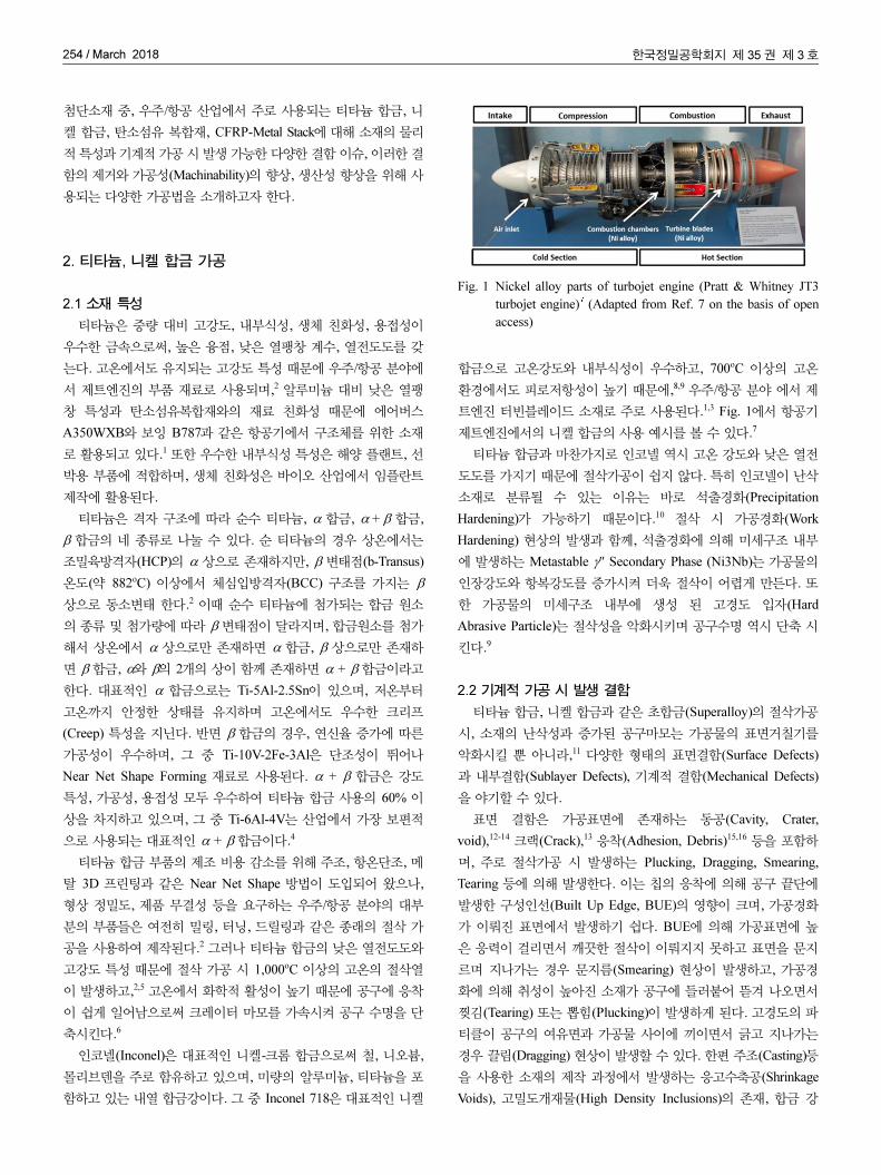
Fig. 2는 Inconel 718의 밀링가공 시 이산화탄소를 사용하여
공구를 극저온 냉각하는 모습을 보여준다. 외부의 노즐을 사용하
여 분사하는 외부분사(External Spraying)와 공구를 관통하는 노
즐을 통해 분사하는 내부분사(Internal Spraying)으로 구분할 수
있다.
Sun et al.은 Ti-6Al-4V의 선삭가공 시 액체질소와 동일한 온
도를 갖도록 냉각된 공기(Chilled Air)를 공구의 여유면과 경사면
에 분사하여 건식가공(Dry Machining) 대비 공구마모와 절삭력
에 대한 냉각기체 효과를 분석하였다. 냉각된 공기 분사에 의해
공구-칩 접촉길이가 감소되고 냉각효과가 증가됨에 따라 절삭열이
Fig. 2 CO2 cryogenic cooling in Inconel milling26 (Adapted fromRef. 26 on the basis of open access)

256 / March 2018 한국정밀공학회지 제 35권 제 3호
감소하였다. 낮은 절삭열로 인해 공구마모율이 감소하여 플랭크
마모 길이 감소 및 크레이터 마모 깊이 감소가 이뤄졌으며, 공구
끝단에 발생하는 BUE를 현저히 감소시키고, 공구 끝단의 강도를
유지함으로써 절삭력을 감소시켰다.27
Machai and Biermann28은 Metastable β-Titanium Alloy의 선
삭가공 시 Carbon Dioxide Snow (CO2)를 쿨런트로 사용하여 기
존의 습식냉각 대비 공구마모 감소 효과를 분석한 결과, CO2
Stream의 냉각 효과가 절삭날에서의 노치마모(Notch Wear)와 여
유면마모(Flank Wear)의 감소에 효과가 있음을 보였다.
그러나 CO2를 사용하는 경우 대기 중으로 방출되면 온실효과
의 문제가 존재하며, CO2 배출을 감소시키려는 국가정책 및 세계
적 흐름에 역행하는 문제가 존재한다.29 따라서 산업적 적용을 위
해서는 공작기계에 추가적인 진공 흡입장치 등 CO2의 대기 중 방
출을 방지할 수 있는 장치가 필요하다.28
반면 액체질소를 사용하는 경우, 공기 중의 78%를 차지하는
질소를 분사하므로 인체 및 환경에 무해하며, -196oC의 극저온이
므로 가장 큰 냉각 효과를 기대할 수 있다. Fig. 3은 티타늄 합금
의 선삭가공 시 외부 노즐을 사용하여 액체질소를 공구에 분사하
는 극저온 냉각 가공하며 절삭력 측정을 통해 절삭성을 분석하는
모습이다.30
Shane Y. Hong29은 Ti-6Al-4V 가공시 기존의 절삭유를 사용할
경우 발생하는 건강 및 환경 문제를 제거하기 위한 경제적, 생태
적 접근법으로써 극저온 제트 냉각 방법을 제안하였다. 마이크로
노즐을 사용하여 절삭 지점에 액체질소를 분사함으로써 그 소비
를 최소화 하고, 전반적인 생산 비용의 감소가 가능하였다. 또한
제안한 극저온 제트 냉각 방법은 공구의 수명, 칩 분쇄성, 표면품
질 및 생산성을 향상 시켰으며, 기존의 절삭유 냉각방법과 냉매
사용 비용을 비교한 결과 국부적 집중 분사 방식을 사용함으로써
종래의 방법 보다 저렴하면서 효과적인 냉각 효과를 얻을 수 있
었다. Bordin et al.25은 전자빔용해로 제작된 Ti-6Al-4V의 선삭
가공 시 외부 노즐을 사용해 액체질소를 분사함으로써 지속가능
제조 전략으로 극저온 냉각 방법을 적용하였다. 공구 마모, 표면
품위, 칩 형상에 대해서 기존의 절삭유 냉각 방식과 비교하였으며,
액체질소를 분사 함으로써 건식가공 또는 습식냉각 방법과 달리
크레이터 발생을 억제하며 Nose Wear를 최소화 함으로써 공구마
모를 감소시킬 수 있었으며, 응착된 파티클이 적은 깨끗한 가공표
면을 얻을 수 있었고, 칩 절단성 역시 향상 가능하였다. Yusuf
Kaynak31은 Inconel 718의 선삭가공 시 외부노즐을 사용하여 공
구의 경사면과 여유면에 액체질소를 분사하는 극저온 가공을 사
용하여 기존의 건식가공, MQL가공 대비 절삭력과 플랭크 마모
길이 및 크레이터 마모 면적, 표면 형상과 발생하는 칩의 온도와
형상을 비교 함으로써 극저온 냉각의 효과를 분석하였다. 120 m/
min의 고속 절삭속도에서 극저온 냉각 방법을 사용함으로써 건식,
MQL 대비 가장 낮은 절삭력을 얻을 수 있었으며, 이는 액체질소
분사를 통해 공구와 칩의 접촉길이가 줄어들었기 때문이며, 250
초 가공 후에 측정한 절삭력과의 비교 결과에서도 그 증가 비율
이 가장 낮았는데, 이는 경사면과 여유면에서의 공구 마모가 감소
하였기 때문이다. 또한 줄어든 공구 마모와 열 변형(Thermal
Distortion)이 감소하기 때문에 극저온 가공 시 표면 품위 역시 향
상되는 연구 결과를 보였다. Lee et al.32은 Ti-6Al-4V의 극저온
밀링 가공 시, 액체질소를 외부 분사하는 경우 가공물이 함께 냉
각되어 발생할 수 있는 냉각경화(Cryogenic Hardening)를 방지하
기 위해 가공물을 예열하여 온도를 증가시키고 극저온 가공을 하
는 연구를 수행하였다. 건식가공, 외부노즐을 사용한 극저온 냉각,
예열과 극저온 가공을 함께 하는 경우에 대해서, 절삭력과 공구마
모, 칩 형상을 비교하였다. 밀링가공 중 액체질소를 외부 분사하
여 절삭력이 약간 증가하는 반면, 예열을 함께 하여 가공물의 냉
각경화를 억제한 경우 절삭력을 65%까지 감소시킬 수 있었다. 공
구수명의 경우 건식가공 대비, 극저온 냉각만 하는 경우에는
50%, 가공물 예열을 함께 하는 경우에는 90%의 향상이 가능하였
다.
극저온 냉각 시 외부 노즐을 사용하는 경우 가공물이 액체질소
에 함께 노출되면서 냉각경화에 의해 저온에서 강도, 경도가 증가
함에 따라 절삭성이 감소할 수 있으며, 수축에 의한 형상 변형이
가능하다. 이러한 문제를 극복하기 위해 제안된 방법이 극저온 공
구 간접 냉각(Indirect Cryogenic Cooling)이다. 공구를 간접적으
로 냉각하기 위해, 공구에 부착된 챔버나 내부에 삽입된 유로에
액체질소 또는 냉각재를 공급하여 전도냉각(Thermal Conduction
Cooling)하는 방법으로써, 가공물이 냉각재에 노출되지 않는 장
점이 있다. 그러나 액체질소를 직접 분사하는 방법에 비해서는 냉
각 효과가 떨어지며, 공구의 열전도도에 영향을 많이 받고, 복잡
한 형상의 공구 및 홀더 설계가 필요한 단점이 있다. Wang and
Rajurkar33는 Ti-6Al-4V와 Inconel 718의 선삭가공 시, 액체질소
분사시 가공물에 발생할 수 있는 부정적 효과 없이 안정적으로
냉각을 할 수 있도록 인서트 상단에 챔버를 부착하여 액체질소
순환 시스템을 만듦으로써 간접냉각을 수행하였다. Cemented
Carbide Tool (H13A)를 사용하여 냉각 여부에 따라 절삭실험을
수행한 결과, 공구간접냉각을 한 경우 공구마모 감소 효과가 크게
발생하였으며, 이는 공구 소재의 강도, 경도가 냉각효과에 의해 절
삭가공 중에도 유지되고, 가공물과 화학적 반응성이 감소되었기
Fig. 3 Cryogenic machining using external LN2 nozzle for titaniumalloy turning30 (Adapted from Ref. 30 on the basis of openaccess)

한국정밀공학회지 제 35권 제 3호 March 2018 / 257
때문이다. 또한 냉각을 함으로써 건식 가공 대비 낮은 표면 거칠
기를 얻을 수 있었다. Dhananchezian and Kumar34는 Ti-6Al-4V
의 선삭가공 시 인서트에 관통홀을 제작함으로써 개선된 형태의
극저온 가공 공구를 개발하였다. 공구의 경사면에 직경 2 mm의
관통홀을 가공하여 공구와 칩의 경계면에 액체질소가 뿌려지도록
하였으며, 여유면에 제작된 직경 1 mm의 구멍을 통한 미소 분사
는 절삭날에 도달 할 수 있도록 설계되었다. 인서트의 구멍을 통
해 분사되는 액체질소는 가공물에 닿지 않게 설계 되었으며 이로
인해 가공물의 과냉각 현상은 발생하지 않는다. 기존의 습식냉각
방법과 비교하여 액체질소를 사용하여 극저온 냉각을 함으로써
절삭온도는 61-66%의 감소가 이뤄졌으며, 절삭력은 35-42% 감
소가 가능하였다. 표면거칠기와 공구마모는 습식냉각 대비 각각
35%와 39%의 감소 효과가 있었다. 이들의 연구에서 사용한 공구
는 외부 노즐을 사용한 제트분사 방법과 챔버를 사용한 간접냉각
방식의 중간 형태로써 액체질소가 공구를 통하여 외부로 분사되
지만, 가공물에 닿지 않고 대기중으로 기화되는 형태여서 공구만
의 냉각이 가능하므로 간접냉각방식과 그 효과가 비슷하다고 볼
수 있다.
2.3.3 하이브리드 가공
극저온 간접냉각방식의 경우 가공물의 냉각이 없으므로, 열 보
조 가공(Heat Assisted Machining)과 함께 하이브리드 가공
(Hybrid Machining)의 형태로 사용되기도 한다. 금속의 경우 고
온에서 Thermal Softening에 의해 인장강도와 경도가 감소하며,
Ti-6Al-4V과 Inconel 718의 경우 700oC 이상에서 인장강도가 감
소한다.6
가공물이 고온의 상태가 되도록 레이저 보조 가공(Laser
Assisted Machining), 플라즈마 보조 가공(Plasma-Enhanced
Machining) 등을 사용하여 가공성을 향상시킨다. 이 때 하이브리
드 가공의 형태로 공구를 극저온 냉각 함으로써 공구의 수명을
더욱 향상 시킨다. Dandekar et al.35은 레이저 보조 가공과 극저
온 공구 간접냉각을 함께 사용하여 Ti-6Al-4V를 선삭으로 하이브
리드 가공을 하였다. 레이저 보조 가공을 사용하여 기존의 건식가
공 시의 낮은 절삭속도(60 m/min)를 중고속 영역(107 m/min)으
로 향상시킬 수 있는 반면, 하이브리드 가공을 사용할 경우 절삭
성을 향상시켜 고속 영역(150-200 m/min)까지 사용함으로써 생
산성 향상이 가능하였다. 경제성 분석 결과 하이브리드 가공을 함
으로써 공구비용은 약 30%, 인건비는 약 40%까지 가능할 것으
로 예상하였다. Feyzi and Safavi36는 Inconel 718의 선삭가공 시
절삭성 향상을 위해 플라즈마 보조 가공과 극저온 가공, 초음파
보조 가공(Ultrasonic Vibration Assisted Machining)을 동시에 사
용하여 하이브리드 가공을 하였다. 플라즈마를 이용해 가공물의
열 연화를 유도하고 극저온 간접냉각을 사용하여 공구를 냉각하
였으며, 절삭 안정성 향상과 절삭력 감소를 위해 초음파 보조 가
공을 적용하였다. 하이브리드 가공을 적용함으로써 기존의 가공
방법 대비 7-14%의 절삭력으로도 가공이 가능하였으며, 공구 마
모 역시 기존 대비 9-14% 밖에 되지 않는다. 또한 표면 거칠기
(Ra) 역시 기존 방법을 사용 하였을 때 Ra 2.5 μm인 반면 하이브
리드 가공을 사용 함으로써 Ra 0.2 μm가 가능하였다.
한편 간접냉각 방식에서는 공구 표면을 따라 유동하는 액체질
소 제트가 없기 때문에 외부에서 노즐을 통해 분사하는 MQL 오
일 미스트가 절삭부까지 침투가 가능하므로, 윤활성 향상을 위해
극저온 냉각과 MQL 오일 분사를 함께 하는 연구도 수행되고 있
다. Park et al.은 Ti-6Al-4V의 극저온 밀링 가공 시 외부 노즐을
사용한 극저온 제트분사에 의한 가공물이 과냉각 되는 현상을 극
복하기 위해, 밀링공구 내부를 관통하여 공구를 냉각하는 내부냉
각방식(Internal Cryogenic Cooling)을 적용하였다. 또한 윤활성
향상을 위해 hBN (Hexagonal Boron Nitride) 나노 파티클이 포
함된 MQL 분사를 동시에 수행하였다. 그 결과 기존의 습식냉각
방법 대비 공구 수명이 32% 증가하였으며, 절삭추력(Thrust Force)
역시 감소가 가능하였다.37
티타늄 합금, 인코넬과 같은 난삭소재의 절삭가공 시 소재의
고강도 특성과 낮은 열전도도에 의한 고온의 절삭열 발생은 공구
수명을 단축하고, 표면품위를 악화 시키므로, 다양한 냉각방법을
적용하여 가공성 증대, 공구마모 감소, 표면거칠기 감소를 달성하
려는 연구가 주로 이뤄졌다.
한편 난삭소재 절삭가공 시 냉각방법의 변경이 아닌, 초음파
진동을 부가시켜 절삭성을 향상시키고 공구수명을 향상시키는 연
구 역시 다양하게 진행되고 있다. 초음파 진동 부가 절삭가공
(Ultrasonic Vibration-Assisted Machining)은 절삭가공 시 고주파
(20-40 kHz) 및 낮은 진폭(2-30 μm)을 갖는 초음파 진동을 절삭
공구 및 공작물에 부가 하면서 가공하는 방법으로, 공구의 회전
과 진동에너지를 이용하여 소재를 제거하므로 하이브리드 절삭가
공 방식으로 분류할 수 있다. Azarhoushang and Akbari38은 Inconel
738-LC의 드릴링 가공 시, 초음파 진동의 부가 여부에 따른 가공
홀의 입구 진원도, 원통도, 홀의 크기 및 가공표면 거칠기를 분석
하였다. 초음파 진동 부가 시 가공 홀의 평균 표면 거칠기와 원통
도를 최대 60% 향상 시킬 수 있었으며, 가공 시 추력이 감소하고,
발생 칩의 크기가 작아지고, 버(Burr)의 발생 억제에도 효과적임
을 확인하였다.
초음파 진동 부가 절삭가공은 난삭소재의 절삭가공 시 공구수
명 향상에도 효과가 있다. Liao et al.39은 Inconel 합금의 드릴링
가공 시, 초음파 진동 부가를 적용하면 절삭추력이 감소하고 토크
(Torque)의 변동 폭이 감소함으로써 드릴의 사용 수명이 연장됨
을 실험적으로 확인하였다. 가진 주파수와 진폭의 영향을 분석한
결과, 진폭의 변화가 공구수명 변화에 주된 영향을 미치는 것을
확인하였다. 진폭이 12 μm 미만으로 제어될 경우 드릴링 성능 향
상이 가능하며, 31.8 kHz의 주파수와 4 μm의 진폭에서 가공 홀의
품질과 공구수명 향상이 가장 좋다는 실험 결과를 보였다.
대부분의 초음파 진동 부가 절삭가공의 연구에서 공구수명 향
상 및 가공품질 향상은 일반적인 절삭속도의 영역에서 가능하였
다. 반면 고속가공을 사용하는 경우 일반적인 초음파 진동 부가는
그 효과가 감소한다.40 그래서 Sui et al.41은 티타늄 합금의 선삭
가공 시 고속 절삭을 위해 고속 초음파 진동 절삭(High-Speed

258 / March 2018 한국정밀공학회지 제 35권 제 3호
Ultrasonic Vibration Cutting, HUVC)을 제안하여, 일반적인 초음
파 진동 부가보다 빠른 절삭속도에서도 그 효과를 유지할 수 있
도록 하였다. 고속 초음파 진동을 사용함으로써 기존의 초음파 부
가 가공의 속도 제한을 극복할 수 있었고, 기존 절삭가공 대비
20-25%의 절삭력 감소와, 1.5-3배의 공구수명 향상, Ra 0.2 μm이
하의 매끄러운 표면의 가공이 가능하였다.
난삭소재의 절삭가공 시 가공성을 향상시키고, 결함을 감소시
키기 위해 극저온 냉각을 포함하는 다양한 냉각방법의 적용이 이
뤄졌고, 초음파 부가와 같은 하이브리드 가공 기술 역시 적용되었
으며, 다양한 연구에서 실험적으로 그 효과가 입증되었다. 하지만
산업적용 및 공정개선을 위해서는 냉각방법, 초음파 부가 방법에
대한 연구뿐만 아니라, 전용 공구의 개발과 함께 부가 기술을 위
한 전용 공작기계 및 장비의 개발 역시 함께 이뤄져야 할 것이다.
3. 탄소섬유복합재 가공
3.1 소재 특성
탄소섬유복합재는 열가소성 또는 열경화성 수지에 탄소섬유가
강화제로 첨가되어 있는 복합재로, 중량 대비 고강도 특성, 높은
내구성, 우수한 내부식성 때문에 항공 산업뿐만 아니라 자동차 산
업에 그 수요가 점차 증가하고 있다.42
CFRP에 들어있는 탄소섬유는 방향성을 가지고 폴리머 매트릭
스와 함께 여러 층(Layer)을 갖도록 적층되어 있는데, 모두 같은
각도로 적층된 경우를 UD CFRP (Uni-Directional CFRP), 층별
로 다른 각도를 이루는 경우 MD CFRP (Multi-Directional CFRP)
라고 하며, 각 층의 탄소섬유가 섬유처럼 직조되어 있는 경우를
Woven CFRP라 한다.43
CFRP는 각 층의 탄소섬유 방향에 따라 그 물성이 다르기 때문
에 층의 개수, 적층 각도는 제품에 요구되는 물성을 충족시킬 수
있도록 설계된다. 또한 사용되는 탄소섬유의 종류, 탄소섬유의 체
적비에 따라서 CFRP의 물성이 달라지기 때문에 용도에 맞게 다
양한 물성을 갖는 CFRP가 제작될 수 있다.44
3.2 기계적 가공 시 발생 결함
CFRP는 Autoclave Molding, Resin Transfer Molding (RTM)
과 같은 방법으로 최종 제품 형상과 가깝게 제작이 되지만 다른
부품과의 체결을 위한 홀 드릴링, 정확한 형상을 위한 라우팅과
같은 기계적 가공이 추가적으로 필요하다. 탄소섬유는 취성이 높
은 재료이기 때문에 일반 금속의 절삭 메커니즘과 다른 원리로
절삭된다. 일반적인 금속 가공의 경우 공구가 재료에 가하는 힘에
의한 소성변형으로 절삭되지만 CFRP의 경우 취성 파괴의 형태
로 재료가 절삭된다. 이러한 절삭원리와 CFRP의 이방성에 의해
금속 가공결함과 다른 형태의 결함이 발생하여 산업에서는 이에
따른 제품의 물성 감소 방지를 위한 가공 품질 관리가 엄격하게
적용되고 있다.
CFRP는 공구에 의한 압축력에 기인한 파괴로 절삭되는데 탄소
섬유와 절삭 공구가 이루는 각도에 따라 그 절삭 형태가 다르다.45
섬유 절삭 각도(Θ)를 공구의 진행방향과 탄소섬유 길이 방향 사
이의 각도를 시계방향으로 측정한 값으로 정의할 때, Fig. 4(a)와
같이 공구 이송방향과 섬유 방향이 일치하는 경우를 Θ = 0°라 할
때 CFRP의 절삭은 Mode I 박리(Delamination) 형태로 발생한다.
공구에 의해 들어올려지는 힘으로 탄소섬유에 굽힘 현상이 발생
하고, 이로 인한 크랙(Crack)이 탄소섬유 길이 방향에 수직으로
발생하며 재료가 제거된다. Figs. 4(b), 4(c)와 같이 0o < Θ ≤ 90o
의 경우, 섬유의 측면으로 힘이 가해 지면서 전단응력에 의해 절
삭이 이뤄진다. 한편 Fig. 4(d)와 같이 Θ > 90o인 경우 섬유에 광
범위한 굽힘이 발생하면서 공구와 접촉한 부분보다 더 아래쪽에
서 전단에 의해 섬유의 뜯김이 발생한다.
탄소섬유의 방향성과 적층 구조로 인하여 발생하는 결함은 제
품의 품질에 악영향을 끼치기 때문에 이를 줄이기 위한 다양한
연구와 분석이 이뤄지고 있다.
박리는 CFRP의 층과 층 사이가 벌어지며 발생하는 결함으로,
외형적으로 Fig. 5와 같이 네 가지 종류로 발생한다.47 Type 1 박
리는 표면의 섬유가 파손되어 가공 면 안쪽까지 제거된 영역을
일컫는다. Type 2 박리는 가공면 밖으로 돌출된 미절삭 섬유를
가리키며, Type 1과 2가 동시에 발생하는 형태의 박리도 발생한
다. Type 3와 같이 가공 후 떨어지지 않은 섬유들이 부분적으로
가공면에 잔존하고, 크랙이 가공면과 평행 하게 발생한 경우를 일
컫는다. 드릴링과 밀링의 경우 박리현상은 모두 CFRP 가공 시
작용하는 힘, 토크에 의해 발생한다. 드릴링의 경우 Fig. 6(a)와
같이 입구에서 공구 진입 시 토크에 의해 층이 들리면서 Mode I,
III 파괴 형태로 발생하는 Peel-Up 박리와 Fig. 6(b)와 같이 출구
에서 공구에 의한 추력으로 Mode I, II 파괴 형태로 층 사이가 분
리되는 Push-Out 박리가 발생한다.48,49 이러한 박리현상 중 출구
에서의 박리 발생 모델에 대한 연구가 활발히 수행됐다. Ho-
Cheng et al.50은 최초로 LEFM Model (Linear Elastic Fracture
Mechanics Model)을 통해 CFRP 드릴링 시 발생하는 출구 박리
발생의 임계 추력을 재료의 물성으로 구성된 수식으로 도출했다.
Fig. 4 Cutting mechanism in the orthogonal machining of CFRP46
(Adapted from Ref. 46 on the basis of open access)

한국정밀공학회지 제 35권 제 3호 March 2018 / 259
이 모델은 빔(Beam)형태의 CFRP 층에 드릴 선단(Chisel Edge)
에서 Point Load가 가해지는 것으로 가정 했다. 박리가 전파되면
서 드릴이 미소 길이만큼 내려갈 때 추력에 의해 발생한 에너지
는 CFRP 층이 변형되는 에너지와 층간 파괴에 필요한 에너지의
합으로 표현된다. 최종적으로 박리를 유발하는 임계 추력은 식(1)
과 같이 도출된다.50
(1)
식(1)에서 h는 공구 아래 남은 CFRP의 두께, GIc는 Mode I 층
간 파괴 인성(Inter Laminar Fracture Toughness)을 뜻한다. E는
CFRP의 Young’s Modulus, ν는 Poisson’S Ratio를 뜻한다. 동일
한 물성의 소재가 사용된 경우, 마지막 층의 두께(h)가 얇아지면
임계추력(F*A)이 작아지므로, 박리가 더 쉽게 발생할 수 있다. 그
러나 이 모델은 CFRP를 등방성의 물질로 가정하였기 때문에 정
확도에 한계가 있어서 이후 재료의 이방성을 고려한 다양한 임계
추력 모델들이 개발되었다.51-53
밀링에서의 박리는 나선형태의 공구 날에서 비롯한 수직 방향
으로의 힘 성분이 한쪽 면으로만 접착되어있는 맨 위 또는 아래
층에 가해져 박리가 발생하게 된다.54 UD CFRP 의 밀링 가공 시
박리발생은 섬유 절삭 각도에 영향을 받는데, 절삭 각도가 90o이
상 180° 이하인 영역에서 Type 1과 Type 2 박리가 동시에 발생
한다.55
적층소재의 가공 시 발생한 박리는 가공제품의 기계적 물성에
영향을 미친다. 따라서 그 영향을 분석하기 위해서는 박리 크기의
정량적 평가가 필요하였고, 다양한 연구에서 평가 지표를 제시하
였다.56 그 중 W.-C. Chen이 제시한 박리지수(Delamination
Factor)가 가장 보편적으로 사용되며, 홀 가공 시 박리가 일어난
영역의 최대 지름과 가공된 홀 지름과의 비(Ratio)를 나타낸다.57
Lambiase et al.58의 실험 결과에서, 유리섬유 강화 플라스틱의 홀
가공 시, 박리지수가 1.08에서 1.17로 증가하면 인장강도(Tensile
Strength)는 약 7% 감소하고, 지압강도(Bearing Strength)는 약
17% 감소한다. Heberger et al59의 연구에서도 역시 CFRP의 리
벳 홀 가공 시 박리지수가 1.1에서 1.3으로 증가 시 지압 강도가
33% 감소하였다. 그 밖에도 박리지수가 증가하면 피로 수명
(Fatigue Life) 역시 감소한다.60
CFRP 가공 시 발생하는 또 다른 형태의 결함으로 Fiber Pull-
Out이 있다. 이는 Fig. 4(d)에서처럼 섬유 절삭 각도가 135o인 부
분에서 공구에 의해 과도한 탄소섬유의 굽힘에 의한 전단현상으
로 인해 공구 접촉면 보다 재료의 안쪽에서 탄소섬유 다발이 절
단되는 현상이다. 드릴링의 경우 가공 홀의 벽면, 밀링 가공 시 측
면 가공면에서 발생한다. Fiber Pull-Out은 CFRP의 매트릭스
(Matrix)의 온도가 고온 일수록 발생 깊이가 깊어 지는데, 절삭열
에 의해 고온이 된 경우 매트릭스의 수지가 연화되어 탄소섬유를
지지하는 힘이 감소하면서, 섬유의 굽힘이 커지고 그만큼 탄소섬
유 다발의 전단이 절단면 보다 더 깊은 지점에서 발생 한다.61
Fig. 7은 UD CFRP 층들이 서로 45도를 이루며 적층된 CFRP
를 드릴링 하였을 때 벽면에서 발생한 결함을 3D 공초점현미경
으로 측정한 결과다. 특정 섬유 각도에서 발생한 Fiber Pull-Out
뿐만아니라 절삭가공 시 발생하는 고온의 절삭열에 의해 매트릭
스가 연화되어 탄소섬유가 가공표면에 노출되는 현상도 관찰된다.
이렇게 노출된 탄소섬유는 가공표면의 조도를 저하시킨다.62
3.3 결함저감을 위한 가공 방법
다양한 CFRP 절삭가공 연구에서, 가공변수(Machining
FA
* 8GIcEh
3
3 1 ν2
–( )--------------------
1 2⁄
=
Fig. 5 Various types of delamination in CFRP machining47
(Adapted from Ref. 47 on the basis of open access)
Fig. 6 Mechanism of drilling-induced delamination in CFRP (a)peel-up and (b) push-out delamination49 (Adapted from Ref.49 on the basis of open access)
Fig. 7 Fiber pull-out on side wall of drilled hole: (a) optical viewand (b) 3D scanned view

260 / March 2018 한국정밀공학회지 제 35권 제 3호
Parameters)와 결함과의 관계를 규명하고, 결함 저감을 위한 공정
연구가 수행되었다. 가공변수인 절삭속도(Cutting Speed), 피드
(Feed), 공구형상이 공구마모 및 박리지수 등에 미치는 영향 분석
이 실험적으로 이뤄졌다. 그 중 가공 품질에 가장 큰 영향을 주는
인자는 피드로 그 크기가 커질수록 절삭속도와 관계없이 절삭력
및 추력이 증가한다.63,64 드릴링, 밀링 공정시 절삭력이 증가하면
Fiber Pull-Out의 깊이는 증가하고, 추력이 증가하면 드릴링 시 가
공 홀의 출구박리지수가 증가한다. 따라서 빠른 가공속도는 유지
하면서 가공품질 을 향상시키기 위해 CFRP 드릴링 가공 시 빠른
피드로 홀 가공을 수행하다 출구 직전에서 피드를 감소시켜 출구
박리를 억제하는 방법이 제안되었다.65 드릴링 가공 시 절삭속도
가 절삭 추력에 미치는 영향은 피드 보다 적지만, 절삭속도가
80 m/min 이상의 고속 드릴링에서는 추력의 감소가 발생하는데
이는 빠른 절삭속도로 인해 매트릭스의 연화로 CFRP의 연성
(Ductility)가 증가하기 때문이다.66
공구의 형상 역시 CFRP 가공 시 결함 발생에 큰 영향을 미친
다. 드릴링의 경우 공구의 선단(Chisel Edge)에서 절삭보다 압입
(Indentation)이 발생하면서 전체 추력의 50% 이상의 추력이 선단
에서 발생하는데, 이는 박리 현상을 발생 시킬 수 있다.67 따라서
선단각이 작은 공구를 사용하면 공구 선단에서 발생하는 추력을
감소시키면서 가공 홀의 박리 현상을 감소시킬 수 있다.68,69 드릴
링 가공 시 선단각 외에도 공구의 종류도 결함에 영향을 미치는
데, 일반적인 트위스트 드릴보다 브래드 포인트 드릴, 스텝 드릴,
스텝 코어 드릴을 사용 시 낮은 추력의 발생이 가능하다.70
추력을 감소시키기 위한 특수 형상의 드릴링 공구는 Fig. 8과
같이 CFRP 드릴링 시 입구와 출구의 박리지수를 감소시키는 효
과가 있다.71 밀링 또는 라우팅의 경우 공구 날의 헬릭스각도
(Helix Angle) 때문에 수직 방향의 힘이 발생하여 박리 현상을 일
으키는데, 이를 억제하기 위해 하나의 공구에 정방향과 역방향 나
선이 동시에 존재하는 형태의 공구가 상용화 되어 있다.
고경도의 탄소섬유에 의해 발생하는 공구의 여유면 마모
(Flank Wear) 역시 절삭가공 시 결함 발생의 원인이 된다.72 마모
된 공구 사용에 의한 절삭력의 증가는 절삭부의 온도를 상승시켜
매트릭스의 변성을 통한 결함을 증가시킨다. 또한 추력 역시 증가
시켜 박리지수를 증가시킨다. 공구 마모를 감소시키기 위해 드릴,
밀링 공구에 고경도의 PCD (Polycrystalline Diamond) 코팅을 하
면 CFRP 가공 시 기존의 초경공구에 비해 마모가 확연히 감소하
여 낮은 절삭력과 추력의 유지가 가능하여 고품질의 가공 결과를
얻을 수 있다.73
그 밖에도 소재 자체의 결함 저항성을 증가시키는 방법이 연구
되었다. CFRP 드릴링 가공 시 가공물 아래에 지지판을 설치하여
소재의 임계추력을 증가시켜 박리를 감소시키는 연구가 수행된 바
있다.74 CFRP의 가공 시 소재에 액체질소를 분사하여 물성을 다르
게 함으로써 절삭성을 향상시킨 연구도 수행된 바 있다. 밀링가공
시 액체질소를 CFRP에 분사하여 매트릭스를 저온경화 시킴으로
써 특정 섬유 각도에서의 탄소섬유의 굽힘을 감소시켜 벽면에서
결함의 발생 깊이를 감소시키고 표면조도의 향상이 가능하다.61
가공 경로를 변화시켜 절삭력과 추력을 감소시키는 방법도 제
안되었다. 일반적인 드릴링과 달리 공구가 나선 형태의 경로를 따
라 가공하는 오비탈드릴링(Orbital Drilling)을 사용하는 경우 절
삭력과 추력이 감소하여 출구면에서의 박리와 벽면의 Fiber Pull-
Out이 감소하고 공구마모 역시 감소되는 효과가 있다.75 하지만
공구 경로가 일반 드릴링에 비해 길어지기 때문에 가공 시간이
증가하는 단점이 있다.
그 밖에도 CFRP 가공 결함을 줄이기 위한 방법으로 냉각 및
윤활 방법이 있다.76,77 Xia et al.78은 CFRP의 드릴링 가공 시 액
체질소를 사용한 극저온 가공을 적용하였다. 극저온 적용 여부에
따라 공구마모, 추력, 토크, 박리지수, 홀 직경오차를 비교하였다.
극저온 드릴링시 건식가공 대비 높은 추력과 토크가 발생하며, 이
로 인해 박리지수가 커지는 결과를 야기한다. 하지만 가공 횟수가
많아 질수록 극저온 드릴링의 공구마모 감소 효과로 인해 건식가
공에 비해 가공 홀의 품질 측면에서 유리한 결과를 보인다. 또한
극저온 드릴링 시 직경 오차의 감소 효과가 발생하는데, 이는 낮
은 공구 온도로 인해 매트릭스의 열팽창을 방지하는 장점이 있기
때문이다.
티타늄, 니켈 합금의 가공과 마찬가지로 CFRP 절삭가공 시에
도 초음파 진동을 사용하여 절삭성을 향상시키고 결함을 감소시
키는 연구가 수행되었다. Gupta et al.79은 CFRP의 드릴링 가공
중 발생하는 결함에 공구의 선단(Chisel Edge)이 미치는 영향을
분석하였으며, 초음파 진동을 부가하는 경우 일반적인 드릴링 가
공과 비교하여 공구 선단에서의 추력이 36% 감소하고, 출구 박리
가 감소함을 실험적으로 보였다. 최근에는 CFRP의 절삭가공 시
회전식 초음파 가공(Rotary Ultrasonic Machining, RUM) 및 회
전식 타원형 초음파 가공(Rotary Ultrasonic Elliptical Machining,
RUEM)이 많이 연구되고 있다. Liu et al.은 CFRP 가공 시 다이
아몬드 코어 드릴로 RUEM을 처음으로 수행하였다. 기존의 방법
과 비교하여 공구마모와 추력이 크게 감소하여 가공 홀의 정밀도
와 출구박리를 감소시킬 수 있었다.80 RUEM이 CFRP의 홀 가공
시 공구수명 향상 및 표면품질 개선면에서 효과적인 방법이나,
Fig. 8 Special drill geometry to reduce delamination factors71
(Adapted from Ref. 71 on the basis of open access)

한국정밀공학회지 제 35권 제 3호 March 2018 / 261
기존의 연구에서는 그 가공이 홀 형태 가공에만 국한되는 한계를
가졌었다. CFRP의 평면 가공시 연삭공구를 적용하는 경우 공구
막힘(Tool Clogging)이 발생하고 이로 인해 표면품위가 저하되는
문제가 있어 그 사용이 제한되었었다. 이러한 한계를 극복하기 위
해 Geng et al.81은 RUEM을 CFRP의 사이드 밀링에 처음으로
적용하여 타원 진동 효과를 유지하는 새로운 접근법을 제안하였
다. 종래의 연삭 방법과 비교하여 절삭력은 2-43% 감소하였고 공
구 수명은 1.98배 향상 시킬 수 있었으며, 간헐적 재료제거 메커
니즘에 의해 칩 배출성이 향상되어 더 우수한 가공표면을 얻을
수 있었다.
앞서 언급한대로 CFRP는 탄소섬유의 방향에 따라서 절삭특성
과 칩 형성, 가공표면의 결함 발생 특성이 달라진다. 이러한 섬유
방향성에 의한 영향을 타원형 진동 보조 가공(Elliptic Vibration-
Assisted Cutting, EVA Cutting)을 사용하여 결함을 감소시키는
연구가 수행되었다. Xu and Zhang은 섬유강화플라스틱(Fiber
Reinforced Polymer Composites)의 절삭가공 시 EVA 기법의 적
용에 앞서 FRP의 섬유방향에 따른 절삭 메커니즘을 모델링하고
신뢰할 수 있는 예측 모델을 개발하였다. 단일 방향의 UD-FRP의
가공 시 기존의 절삭방법과 EVA 기법을 비교한 결과, 제시하는
모델이 섬유의 변형, 섬유-매트릭스 사이의 탈락(Debonding), 가
공면 아래의 결함 및 절삭력을 예측하는데 사용 될 수 있음을 보
였다. 또한 초음파 진동을 부가하여 가공 시 FRP의 파단을 촉진
하고, 표면 손상을 줄일 수 있었으며, 섬유 방향에 의한 결함을 감
소시킬 수 있음을 확인하였다.82
CFRP는 고경도의 탄소섬유가 폴리머 매트릭스 내에서 방향성
을 가지고 정렬된 후 적층이 되어있는 구조이기 때문에, 가벼우면
서도 우수한 물리적 특성을 지닐 수 있었고, 금속 소재를 대체하
기 위한 첨단소재로 사용될 수 있었다. 하지만 소재를 구성하는
성분과 그 구조적 특성 때문에 발생하는, 탄소섬유의 취성파괴,
폴리머 매트릭스의 열변형, 적층구조 사이의 층간 박리 등은 절삭
가공 시 해결 해야만 하는 문제였고, 선행 연구들 에서 결함 감소
를 위해 다양한 방법을 제시하였다. 현재는 산업적용을 위해 공구
제작사를 중심으로 전용 공구의 개발, 코팅 방법의 개발 등이 주
로 수행되었는데, 앞으로는 전용공구의 개발, 절삭공정의 개선뿐
만 아니라, 결함발생 특성을 결정할 수 있는 소재의 구조적 특성
까지 고려한, 소재의 제작 단계까지 아우를 수 있는 공정 개선이
필요하다.
4. CFRP-Metal Stack
4.1 소재 특성
CFRP-Metal Stack은 CFRP와 금속소재의 판재가 함께 겹쳐져
있는 형태(Stack-Up)로 구성된 이종 접합 구조재 이다. CFRP는
금속만 사용할 경우 발생할 수 있는 낮은 피로강도와 내부식성을
보완해 주고, 반대로 금속소재는 CFRP가 갖는 낮은 충격 강도를
보완해 줄 수 있기 때문에, 두 소재를 함께 붙여서 사용한다.83
특히 산업에서 CFRP 부품 또는 구조물을 금속 재료와 결합해야
하는 경우, 주로 리벳팅(Riveting)이 사용되며, 항공기의 경우 수
만개 이상의 리벳 홀이 가공된다. 리벳팅의 경우 두 부품의 홀 사
이 위치 정밀도가 매우 중요하므로, 조립 정밀도를 향상시키기 위
해서는 두 부품을 겹쳐서 CFRP-Metal Stack 상태에서 한번의 드
릴링으로 리벳 홀을 가공하는 것이 효과적이다.84 CFRP 구조체
는 주로 항공산업에서 사용되다 보니 금속 소재는 주로 알루미늄
합금과 티타늄 합금이 사용되고 두 소재 사이는 에폭시로 접합되
어 있다. 앞서 언급하였듯이 티타늄 합금과 CFRP 모두 난삭소재
로 분류되고, 두 소재의 물리적 특성이 완전히 다르기 때문에,
CFRP-Metal Stack의 드릴링 과정에서 기존의 CFRP만을 가공하
는 경우와 다른 결함이 발생할 수 있다.
4.2 기계적 가공 시 발생 결함
CFRP와 금속은 서로 기계적 물성이 다르기 때문에 절삭특성
이 다르고, 따라서 각 소재에 적합한 공구형상 및 코팅조건, 절삭
조건 역시 그 범위가 서로 다를 수 있다. 따라서 CFRP-Metal Stack
드릴링 시 부적절한 공구 형상이나 가공조건이 사용된 경우 가공
홀의 직경오차, 가공 홀 벽면의 품질 저하, 매트릭스의 열화, 경계
면에서의 박리, 버(Burr)의 발생과 같은 다양한 형태의 결함이 발
생할 수 있다.85-88
서로 다른 물성을 갖는 두 개의 소재를 겹쳐서 한번의 드릴링
으로 홀 가공을 수행할 경우, 절삭특성의 차이에 의해 가공 홀의
지름 오차가 발생할 수 있다. Brinksmeier and Janssen89의 연구
에 따르면 CFRP-Al Stack의 드릴링에서 CFRP의 가공 홀 지름이
알루미늄 층의 홀 지름보다 작게 가공된다. 반면 Montoya et al.
과 Yang et al.의 연구 결과에서는 CFRP의 가공 홀 지름이 알루
미늄 층의 홀 지름보다 크게 가공되었다.90,91 CFRP와 알루미늄의
종류와 섬유배열 구성, 사용하는 공구 및 절삭조건에 따라 지름
오차의 발생 특성은 달라질 수 있으나, 드릴링 피드가 증가할 수
록 두 소재 사이의 가공 홀 지름 차이가 증가하는 반면, 절삭속도
가 증가할 수록 그 차이가 감소하는 경향을 보인다.91 이러한 직
경의 차이는 CFRP와 금속 사이의 탄성계수의 차이에 의해 가공
변형량이 다르기 때문에 발생한다.
또한 티타늄 합금과 같은 낮은 열전도도를 갖는 난삭소재의 절
삭 가공 시 발생하는 고온의 절삭열은 CFRP의 폴리머 매트릭스
의 유리전이온도 보다 높게 발생할 수 있다. 따라서 금속 소재의
절삭열에 의해 CFRP 가공 홀의 품질 저하를 야기할 수 있다. 또
한 티타늄 합금과 같은 금속 판재가 CFRP 하단에 존재하는 경우,
드릴링 가공 시 발생하는 고온의 날카로운 칩이 드릴의 나선을
따라 상단으로 배출 되면서 Fig. 9와 같이 CFRP 층의 가공 홀 벽
면에 열적, 기계적 침식을 발생시켜 표면 조도를 악화시킨다. 이
러한 금속 칩 때문에 CFRP의 표면 조도는 항상 금속의 표면 거
칠기 보다 훨씬 크게 되는데, 동일 절삭 조건으로 CFRP-Metal
Stack에 드릴링이 한번에 이뤄질 때 금속부의 표면거칠기(Ra)가
0.3-2 μm인 조건에서 CFRP 부분의 표면거칠기(Ra)는 2-9 μm로
측정된다는 실험 결과가 있다.92,93 또한 Zitoune et al.94의 연구에

262 / March 2018 한국정밀공학회지 제 35권 제 3호
서도, CFRP-Al2024 Stack을 비코팅 초경 공구로 드릴링을 한 경
우, CFRP 부분의 표면거칠기(Ra)가 4-8 μm일 때, 알루미늄 층의
최대 표면거칠기(Ra)는 3 μm로 측정되었는데, 이 역시 금속 부분
이 더 매끄럽게 가공 되는 결과를 보인다. 한편 CFRP-Metal Stack
가공시 발생하는 금속 칩은 CFRP 부분의 표면거칠기를 증가시
킬 뿐만 아니라 홀 외부로 배출되는 과정에서 CFRP의 출구 부분
에서 모서리 손상(Edge Failure)을 발생시키기도 한다.
CFRP-Metal Stack의 드릴링 중 가공온도는 홀의 표면 품질,
특히 CFRP 부분에 가장 큰 영향을 미친다. CFRP 가공 중 고경
도의 탄소섬유에 의해 가속되는 공구마모는 금속부분의 가공 시
절삭성을 감소시켜 고온의 절삭열을 발생시키는데, 이 고온의 열
때문에 매트릭스의 탄화(Carbonization), 융합(Fusion), 열화(Heat
Deterioration)가 발생할 수 있다.91 이러한 고온의 절삭열이 매트
릭스에 과도한 열화 현상을 발생시키는 경우, 출구면에서 변색링
(Discoloaration Ring)이 관찰되기도 한다.95
이러한 온도의 영향을 분석하기 위해 드릴링 가공 시 온도를
측정한 실험이 있으며, Davies et al.96과 Brinksmeier et al.97은
Al / CFRP / Ti Stack의 고속으로 가공 시 발생하는 고온의 절삭
열과 고온의 티타늄 칩에 의해 CFRP 재료의 홀 표면에 손상이
발생함을 보였다.
또한 드릴링의 경우 칩 배출성이 향상이 되어야 좋은 표면 품
위를 얻을 수 있는데, 앞서 언급한 고온의 칩 발생뿐만 아니라, 칩
이 드릴의 플루트(Flute)에 막히는 현상이 발생하여 그로 인한 열
의 축적이 발생하여 가공면 품질 저하가 발생할 수 있다.
4.3 결함저감을 위한 가공 방법
CFRP-Metal Stack의 경우 절삭과정 중 공구는 두 가지 이상의
소재와 접촉하고, 이종소재의 물성 차이 때문에 드릴링 가공 중
공구마모 메커니즘이 달라진다. CFRP층에서는 소재의 고경도 특
성 때문에 연마마모(Abrasive Wear)가 커지며, 금속 소재 층의 가
공 시 소재의 응착(Adhesion)에 의한 구성 인선(Built Up Edge)
이 발생하여 깨끗한 절삭이 이뤄지기 힘들다. 가속된 공구마모는
결과적으로 절삭력과 추력을 증가시키고, 이로 인해 CFRP의 가
공 결함이 증가한다. 따라서 공구의 내마모성을 높이고 형상을 개
선함으로써 절삭성을 유지하는 방법이 제안되었고, PCD 코팅과
캔들스틱(Candle Stick)형상의 공구, 다면(Multifaceted)형상의 공
구를 사용하는 경우 절삭력 감소에 효과가 있다는 연구결과가 있
다.52
CFRP-Metal Stack에서도 공정조건을 개선하여 절삭가공을 하
려는 연구가 수행되고 있다. CFRP와 티타늄, 알루미늄을 위한 최
적의 절삭조건은 각기 다르고, 티타늄의 경우 CFRP 가공시 보다
빠른 피드와 느린 절삭속도가 적합한 것으로 알려져 있다.98 따라
서 CFRP-Metal Stack에서 두 소재가 에폭시를 사용해 접합되어
있는 경계면에서 절삭조건을 변경해 주면, 기존의 단일 조건으로
가공하는 경우보다 더 좋은 가공 품질을 얻을 수 있다. 그런데 각
각의 소재의 정확한 두께를 모르는 경우에도 적용하기 위해서는
실험 중 경계면을 도출할 수 있어야 한다. 다양한 연구에서 절삭
가공 중 발생하는 신호를 분석하여 CFRP-Metal 사이의 경계면을
검출하였다. Fang et al.99은 CFRP/Ti Stack의 드릴링 가공 시 두
소재 사이에서 발생하는 서로 다른 크기의 절삭력을 감지해 경계
면을 검출하였다. Neugebauer et al.100은 CFRP/Al Stack의 드릴
링 시 발생하는 서로 다른 음향방출신호(Acoustic Emission Signal,
AE Signal)를 이용하여 두 소재 사이의 경계면을 검출하였다.
티타늄, 인코넬 합금, CFRP의 절삭가공 시와 마찬가지로
CFRP-Metal Stack에서도 초음파 진동을 사용하는 가공법이 제안
되었다. 드릴링 가공 시 초음파 진동을 가진하는 경우 CFRP와
금속 층 모두에서 절삭력이 감소하는 효과가 있다.101
이에 따라 CFRP 출구 면에서의 박리현상이 감소하였으며, 표
면조도 역시 일반적인 드릴링 가공 시 보다 개선되는 효과가 있
는데, 이는 초음파 가진을 통해 금속 칩의 분쇄가 원활해져 칩 배
출성이 증가함에 따라 칩에 의한 결함이 감소되기 때문이다.
또한 초음파 진동 보조 가공 시 공구수명 향상에 효과적이다.
Fig. 10은 CFRP/Ti Stack의 초음파 진동 보조 드릴링 가공 시 기
존 드릴링 대비 공구수명이 향상된 결과를 보여준다.102
CFRP-Metal Stack의 절삭 가공시 주요 이슈는 절삭열 발생,
칩 처리성 이다. 특히 고온의 절삭열이 발생하기 쉬운 티타늄 합
금이 포함된 Stack의 드릴링 시 고온의 칩에 의해 CFRP 영역의
가공 품질이 저하될 수 있다. 따라서 CFRP-Metal Stack의 가공
Fig. 9 Damaged surface by aluminum chip flow during drilling ofCFRP/Al stack Fig. 10 Trend of tool wear in the cases of conventional drilling
(CD) and ultrasonic assisted drilling (UAD) in variouscutting speed102 (Adapted from Ref. 102 on the basis ofopen access)

한국정밀공학회지 제 35권 제 3호 March 2018 / 263
시에도 가공 홀의 품질을 향상시키기 위해서는 적절한 냉각 기술
이 적용되어야 할 것이다. 앞서 언급하였던 극저온 기술을 적용함
으로써 CFRP 가공 시 매트릭스의 냉각경화에 의한 열팽창 방지
및 절삭성 향상이 가능할 것으로 보이며, 티타늄 합금 부분의 절
삭시에는 고온의 칩 발생을 억제함으로써 가공 홀의 표면 품질을
향상시킬 수 있을 것으로 기대한다.
5. 결론
우주/항공 산업에서 주로 사용되는 대표적인 첨단 소재인 티타
늄 합금, 니켈 합금, 탄소섬유복합재, CFRP-Metal Stack에 대하
여 소재의 특성과 절삭가공 시 발생할 수 있는 결함의 종류와 발
생 메커니즘, 결함 감소를 위한 가공 기술을 살펴보았다. 소재들
모두 중량대비 고강도, 우수한 내부식성 등의 장점을 지니지만,
티타늄 합금의 경우 고온에서도 유지되는 고강도 특성과 낮은 열
전도도, 고온에서의 높은 화학적 활성에 의해 공구마모가 가속화
되고 높은 절삭응력이 발생하는 문제가 있다. 니켈 합금의 경우
고온에서의 고강도 특성과 함께 가공경화 현상에 의한 고강도 개
재물이 공구마모와 난삭성을 증가시킨다. 한편 탄소섬유복합재의
경우 방향성을 가지는 고경도 탄소섬유와 적층 구조, 폴리머 매트
릭스에 의해 박리, Fiber Pull-Out, 열변형과 같은 다양한 결함이
발생한다. CFRP-Metal Stack은 CFRP에 티타늄과 같은 난삭소재
가 결합되어 있기 때문에, 고온의 절삭열과 폴리머 매트릭스에 의
해 결함이 주로 발생한다. 위의 다양한 소재들의 절삭가공 시 발
생하는 대부분의 결함은 고온의 절삭열에 기인하는 경우가 많고,
이는 효과적인 냉각 방법을 적용함으로써 해결할 수 있다. 티타늄
합금, 니켈 합금의 경우 액체질소를 사용한 극저온 가공을 통해
공구수명을 향상시킴으로써 가공 표면의 품위를 향상 시킬 수 있
다. 탄소섬유복합재의 경우에도 폴리머 매트릭스의 냉각경화 효
과를 통해 절삭성을 향상시키면서 고온의 절삭열에 의한 열변형
을 억제할 수 있다. 또한 초음파 진동 부가를 함께 사용함으로써
가공물 품위의 향상 역시 가능하였다.
난삭소재를 위한 기존 산업에서의 솔루션은 주로 공구제작사
를 중심으로 공구를 개선 하는 방법이었으며, 공구에 PCD 코팅
을 수행하거나, 전용공구의 개발을 통해 절삭성을 향상시키고 결
함 생성을 억제하는 방법이었다. 하지만 다양한 연구 결과에서 볼
수 있듯이, 효과적인 냉각방법의 적용, 절삭조건의 최적화, 하이
브리드 공정 적용을 통해서도 절삭성을 향상시키고, 생산성 향상
과, 결함의 감소가 가능하였다. 따라서 향후 친환경성이 부각될수
록 확대될 첨단난삭소재의 수요시장을 대비하여 전용공구 개발과
더불어 전용 가공장비의 개발, 공정 분석 및 최적화가 필요하다.
ACKNOWLEDGEMENT
본 연구는 산업통상자원부의 기계산업핵심기술개발 사업의
일환으로 수행하였습니다[과제번호: 10053248, 과제명: 탄소섬유
복합재(CFRP) 가공시스템 개발].
REFERENCES
1. M'Saoubi, R., Axinte, D., Soo, S. L., Nobel, C., Attia, H., et al.,“High Performance Cutting of Advanced Aerospace Alloys andComposite Materials,” CIRP Annals, Vol. 64, No. 2, pp. 557-580, 2015.
2. Ezugwu, E. and Wang, Z., “Titanium Alloys and theirMachinability—A Review,” Journal of Materials ProcessingTechnology, Vol. 68, No. 3, pp. 262-274, 1997.
3. Ezugwu, E., “Key Improvements in the Machining of Difficult-to-Cut Aerospace Superalloys,” International Journal of MachineTools and Manufacture, Vol. 45, Nos. 12-13, pp. 1353-1367,2005.
4. Boyer, R., “An Overview on the Use of Titanium in theAerospace Industry,” Materials Science and Engineering: A, Vol.213, Nos. 1-2, pp. 103-114, 1996.
5. Bermingham, M., Palanisamy, S., Kent, D., and Dargusch, M.,“A Comparison of Cryogenic and High Pressure EmulsionCooling Technologies on Tool Life and Chip Morphology in Ti-6Al-4V Cutting,” Journal of Materials Processing Technology,Vol. 212, No. 4, pp. 752-765, 2012.
6. Ezugwu, E. O., Bonney, J., and Yamane, Y., “An Overview ofthe Machinability of Aeroengine Alloys,” Journal of MaterialsProcessing Technology, Vol. 134, No. 2, pp. 233-253, 2003.
7. Hafiz, M. S. A., Kawaz, M. H. A., Mohamad, W. N. F., Kasim,M. S., Izamshah, R., et al., “A Review on Feasibility Study ofUltrasonic Assisted Machining on Aircraft ComponentManufacturing,” Proc. of IOP Conference Series: MaterialsScience and Engineering, Paper No. 012034, 2017.
8. Devillez, A., Le Coz, G., Dominiak, S., and Dudzinski, D., “DryMachining of Inconel 718, Workpiece Surface Integrity,” Journalof Materials Processing Technology, Vol. 211, No. 10, pp. 1590-1598, 2011.
9. Imran, M., Mativenga, P. T., Gholinia, A., and Withers, P. J.,“Comparison of Tool Wear Mechanisms and Surface Integrityfor Dry and Wet Micro-Drilling of Nickel-Base Superalloys,”International Journal of Machine Tools and Manufacture, Vol. 76,pp. 49-60, 2014.
10. Wang, Z. Y., Rajurkar, K. P., Fan, J., Lei, S., Shin, Y. C., andPetrescu, G., “Hybrid Machining of Inconel 718,” InternationalJournal of Machine Tools and Manufacture, Vol. 43, No. 13, pp.1391-1396, 2003.
11. Che-Haron, C. and Jawaid, A., “The Effect of Machining onSurface Integrity of Titanium Alloy Ti-6% Al-4% V,” Journal ofMaterials Processing Technology, Vol. 166, No. 2, pp. 188-192,2005.

264 / March 2018 한국정밀공학회지 제 35권 제 3호
12. Zou, B., Chen, M., Huang, C., and An, Q., “Study on SurfaceDamages Caused by Turning NiCr20TiAl Nickel-Based Alloy,”Journal of Materials Processing Technology, Vol. 209, No. 17,pp. 5802-5809, 2009.
13. Sharman, A. R. C., Hughes, J. I., and Ridgway, K., “WorkpieceSurface Integrity and Tool Life Issues when Turning Inconel718TM Nickel Based Superalloy,” Machining Science andTechnology, Vol. 8, No. 3, pp. 399-414, 2004.
14. Ginting, A. and Nouari, M., “Surface Integrity of Dry MachinedTitanium Alloys,” International Journal of Machine Tools andManufacture, Vol. 49, Nos. 3-4, pp. 325-332, 2009.
15. Pawade, R., Joshi, S. S., Brahmankar, P., and Rahman, M., “AnInvestigation of Cutting Forces and Surface Damage in High-Speed Turning of Inconel 718,” Journal of Materials ProcessingTechnology, Vols. 192-193, pp. 139-146, 2007.
16. Pawade, R., Joshi, S. S., and Brahmankar, P., “Effect ofMachining Parameters and Cutting Edge Geometry on SurfaceIntegrity of High-Speed Turned Inconel 718,” InternationalJournal of Machine Tools and Manufacture, Vol. 48, No. 1, pp.15-28, 2008.
17. Ranganath, S., Guo, C., and Holt, S., “Experimental Investigationsinto the Carbide Cracking Phenomenon on Inconel 718Superalloy Material,” Proc. of ASME 2009 InternationalManufacturing Science and Engineering Conference, pp. 33-39,2009.
18. Axinte, D. A., Andrews, P., Li, W., Gindy, N., Withers, P. J., andChilds, T. H. C., “Turning of Advanced Ni Based AlloysObtained via Powder Metallurgy Route,” CIRP Annals-Manufacturing Technology, Vol. 55, No. 1, pp. 117-120, 2006.
19. Sharman, A. R. C., Hughes, J. I., and Ridgway, K., “An Analysisof the Residual Stresses Generated in Inconel 718TM whenTurning,” Journal of Materials Processing Technology, Vol. 173,No. 3, pp. 359-367, 2006.
20. Moussaoui, K., Mousseigne, M., Senatore, J., and Chieragatti, R.,“The Effect of Roughness and Residual Stresses on Fatigue LifeTime of an Alloy of Titanium,” The International Journal ofAdvanced Manufacturing Technology, Vol. 78, Nos. 1-4, pp.557-563, 2015.
21. Brinksmeier, E., Meyer, D., Huesmann-Cordes, A., and Herrmann,C., “Metalworking Fluids—Mechanisms and Performance,”CIRP Annals, Vol. 64, No. 2, pp. 605-628, 2015.
22. Yuan, S., Yan, L., Liu, W., and Liu, Q., “Effects of Cooling AirTemperature on Cryogenic Machining of Ti-6Al-4V Alloy,”Journal of Materials Processing Technology, Vol. 211, No. 3, pp.356-362, 2011.
23. da Silva, R. B., Machado, Á. R., Ezugwu, E. O., Bonney, J., andSales, W. F., “Tool Life and Wear Mechanisms in High SpeedMachining of Ti-6Al-4V Alloy with PCD Tools Under VariousCoolant Pressures,” Journal of Materials Processing Technology,Vol. 213, No. 8, pp. 1459-1464, 2013.
24. Nandy, A., Gowrishankar, M., and Paul, S., “Some Studies on
High-Pressure Cooling in Turning of Ti-6Al-4V,” InternationalJournal of Machine Tools and Manufacture, Vol. 49, No. 2, pp.182-198, 2009.
25. Bordin, A., Sartori, S., Bruschi, S., and Ghiotti, A.,“Experimental Investigation on the Feasibility of Dry andCryogenic Machining as Sustainable Strategies when TurningTi6Al4V Produced by Additive Manufacturing,” Journal ofCleaner Production, Vol. 142, pp. 4142-4151, 2017.
26. Pereira, O., Urbikain, G., Rodríguez, A., Fernández-Valdivielso,A., Calleja, A., et al., “Internal Cryolubrication Approach forInconel 718 Milling,” Procedia Manufacturing, Vol. 13, pp. 89-93, 2017.
27. Sun, S., Brandt, M., Palanisamy, S., and Dargusch, M. S., “Effectof Cryogenic Compressed Air on the Evolution of Cutting Forceand Tool Wear during Machining of Ti-6Al-4V Alloy,” Journalof Materials Processing Technology, Vol. 221, pp. 243-254, 2015.
28. Machai, C. and Biermann, D., “Machining of β-Titanium-AlloyTi-10V-2Fe-3Al under Cryogenic Conditions: Cooling withCarbon Dioxide Snow,” Journal of Materials ProcessingTechnology, Vol. 211, No. 6, pp. 1175-1183, 2011.
29. Hong, S. Y., “Economical and Ecological Cryogenic Machining,”Journal of Manufacturing Science and Engineering, Vol. 123, No.2, pp. 331-338, 2001.
30. Sun, Y., Huang, B., Puleo, D., and Jawahir, I., “EnhancedMachinability of Ti-5553 Alloy from Cryogenic Machining:Comparison with MQL and Flood-Cooled Machining andModeling,” Procedia CIRP, Vol. 31, pp. 477-482, 2015.
31. Kaynak, Y., “Evaluation of Machining Performance in CryogenicMachining of Inconel 718 and Comparison with Dry and MQLMachining,” The International Journal of Advanced ManufacturingTechnology, Vol. 72, NoS. 5-8, pp. 919-933, 2014.
32. Lee, I., Bajpai, V., Moon, S., Byun, J., Lee, Y., and Park, H. W.,“Tool Life Improvement in Cryogenic Cooled Milling of thePreheated Ti-6Al-4V,” The International Journal of AdvancedManufacturing Technology, Vol. 79, Nos. 1-4, pp. 665-673, 2015.
33. Wang, Z. and Rajurkar, K., “Cryogenic Machining of Hard-to-Cut Materials,” Wear, Vol. 239, No. 2, pp. 168-175, 2000.
34. Dhananchezian, M. and Kumar, M. P., “Cryogenic Turning ofthe Ti-6Al-4V Alloy with Modified Cutting Tool Inserts,”Cryogenics, Vol. 51, No. 1, pp. 34-40, 2011.
35. Dandekar, C. R., Shin, Y. C., and Barnes, J., “MachinabilityImprovement of Titanium Alloy (Ti-6Al-4V) via LAM andHybrid Machining,” International Journal of Machine Tools andManufacture, Vol. 50, No. 2, pp. 174-182, 2010.
36. Feyzi, T. and Safavi, S. M., “Improving Machinability of Inconel718 with a New Hybrid Machining Technique,” TheInternational Journal of Advanced Manufacturing Technology,Vol. 66, Nos. 5-8, pp. 1025-1030, 2013.
37. Park, K.-H., Yang, G.-D., Suhaimi, M., Lee, D. Y., Kim, T.-G., etal., “The Effect of Cryogenic Cooling and Minimum Quantity

한국정밀공학회지 제 35권 제 3호 March 2018 / 265
Lubrication on End Milling of Titanium Alloy Ti-6Al-4V,”Journal of Mechanical Science and Technology, Vol. 29, No. 12,pp. 5121-5126, 2015.
38. Azarhoushang, B. and Akbari, J., “Ultrasonic-Assisted Drillingof Inconel 738-LC,” International Journal of Machine Tools andManufacture, Vol. 47, Nos. 7-8, pp. 1027-1033, 2007.
39. Liao, Y. S., Chen, Y. C., and Lin, H. M., “Feasibility Study ofthe Ultrasonic Vibration Assisted Drilling of Inconel Superalloy,”International Journal of Machine Tools and Manufacture, Vol. 47,Nos. 12-13, pp. 1988-1996, 2007.
40. Brehl, D. and Dow, T., “Review of Vibration-AssistedMachining,” Precision Engineering, Vol. 32, No. 3, pp. 153-172,2008.
41. Sui, H., Zhang, X., Zhang, D., Jiang, X., and Wu, R.,“Feasibility Study of High-Speed Ultrasonic Vibration CuttingTitanium Alloy,” Journal of Materials Processing Technology,Vol. 247, pp. 111-120, 2017.
42. Soutis, C., “Fibre Reinforced Composites in Aircraft Construction,”Progress in Aerospace Sciences, Vol. 41, No. 2, pp. 143-151,2005.
43. Daniel, I. M. and Ishai, O., “Engineering Mechanics ofComposite Materials,” Oxford University Press, 1994.
44. Chae, H. G., Newcomb, B. A., Gulgunje, P. V., Liu, Y., Gupta,K. K., et al., “High Strength and High Modulus Carbon Fibers,”Carbon, Vol. 93, pp. 81-87, 2015.
45. Wang, D. H., Ramulu, M., and Arola, D., “Orthogonal CuttingMechanisms of Graphite/Epoxy Composite. Part I: UnidirectionalLaminate,” International Journal of Machine Tools andManufacture, Vol. 35, No. 12, pp. 1623-1638, 1995.
46. Alizadeh Ashrafi, S., Miller, P. W., Wandro, K. M., and Kim, D.,“Characterization and Effects of Fiber Pull-Outs in Hole Qualityof Carbon Fiber Reinforced Plastics Composite,” Materials, Vol.9, No. 10, p. 828, 2016.
47. Sheikh-Ahmad, J., Urban, N., and Cheraghi, H., “MachiningDamage in Edge Trimming of CFRP,” Materials andManufacturing Processes, Vol. 27, No. 7, pp. 802-808, 2012.
48. Hocheng, H. and Tsao, C., “The Path Towards Delamination-Free Drilling of Composite Materials,” Journal of MaterialsProcessing Technology, Vol. 167, Nos. 2-3, pp. 251-264, 2005.
49. Morrell, C. M. and Hampson, P. R., “Pneumatically PoweredDrilling of Carbon Fibre Composites Using SyntheticBiodegradable Lubricating Oil: An Experimental Study,”Aerospace, Vol. 5, No. 1, p. 9, 2018.
50. Ho-Cheng, H. and Dharan, C. K. H., “Delamination duringDrilling in Composite Laminates,” Journal of Engineering forIndustry, Vol. 112, No. 3, pp. 236-239, 1990.
51. Jain, S. and Yang, D. C., “Effects of Feedrate and Chisel Edgeon Delamination in Composites Drilling,” Journal of Engineeringfor Industry, Vol. 115, No. 4, pp. 398-405, 1993.
52. Piquet, R., Ferret, B., Lachaud, F., and Swider, P., “ExperimentalAnalysis of Drilling Damage in Thin Carbon/Epoxy Plate UsingSpecial Drills,” Composites Part A: Applied Science andManufacturing, Vol. 31, No. 10, pp. 1107-1115, 2000.
53. Rahmé, P., Landon, Y., Lachaud, F., Piquet, R., and Lagarrigue,P., “Analytical Models of Composite Material Drilling,” TheInternational Journal of Advanced Manufacturing Technology,Vol. 52, Nos. 5-8, pp. 609-617, 2011.
54. Sheikh-Ahmad, J. Y., “Machining of Polymer Composites,”Springer, 2009.
55. Hintze, W., Hartmann, D., and Schütte, C., “Occurrence andPropagation of Delamination during the Machining of CarbonFibre Reinforced Plastics (CFRPs)–An Experimental Study,”Composites Science and Technology, Vol. 71, No. 15, pp. 1719-1726, 2011.
56. Babu, J., Sunny, T., Paul, N. A., Mohan, K. P., Philip, J., andDavim, J. P., “Assessment of Delamination in CompositeMaterials: A Review,” Proceedings of the Institution ofMechanical Engineers, Part B: Journal of EngineeringManufacture, Vol. 230, No. 11, pp. 1990-2003, 2016.
57. Chen, W.-C., “Some Experimental Investigations in the Drillingof Carbon Fiber-Reinforced Plastic (CFRP) CompositeLaminates,” International Journal of Machine Tools andManufacture, Vol. 37, No. 8, pp. 1097-1108, 1997.
58. Lambiase, F. and Durante, M., “Mechanical Behavior ofPunched Holes Produced on Thin Glass Fiber Reinforced PlasticLaminates,” Composite Structures, Vol. 173, pp. 25-34, 2017.
59. Heberger, L., Kirsch, B., Donhauser, T., Nissle, S., Gurka, M., etal., “Influence of the Quality of Rivet Holes in Carbon-Fiber-Reinforced-Polymer (CFRP) on the Connection Stability,”Procedia Manufacturing, Vol. 6, pp. 140-147, 2016.
60. Persson, E., Eriksson, I., and Zackrisson, L., “Effects of HoleMachining Defects on Strength and Fatigue Life of CompositeLaminates,” Composites Part A: Applied Science andManufacturing, Vol. 28, No. 2, pp. 141-151, 1997.
61. Jia, Z., Fu, R., Wang, F., Qian, B., and He, C., “TemperatureEffects in End Milling Carbon Fiber Reinforced PolymerComposites,” Polymer Composites, Vol. 39, No. 2, pp. 437-447,2016.
62. Merino-Pérez, J. L., Royer, R., Merson, E., Lockwood, A.,Ayvar-Soberanis, S., et al., “Influence of Workpiece Constituentsand Cutting Speed on the Cutting Forces Developed in theConventional Drilling of CFRP Composites,” CompositeStructures, Vol. 140, pp. 621-629, 2016.
63. Davim, J. P., Reis, P., and Antonio, C. C., “Experimental Studyof Drilling Glass Fiber Reinforced Plastics (GFRP)Manufactured by Hand Lay-Up,” Composites Science andTechnology, Vol. 64, No. 2, pp. 289-297, 2004.
64. Sardinas, R. Q., Reis, P., and Davim, J. P., “Multi-ObjectiveOptimization of Cutting Parameters for Drilling Laminate

266 / March 2018 한국정밀공학회지 제 35권 제 3호
Composite Materials by Using Genetic Algorithms,” CompositesScience and Technology, Vol. 66, No. 15, pp. 3083-3088, 2006.
65. Sorrentino, L., Turchetta, S., and Bellini, C., “A New Method toReduce Delaminations during Drilling of FRP Laminates byFeed Rate Control,” Composite Structures, Vol. 186, pp. 154-164, 2018.
66. Rawat, S. and Attia, H., “Characterization of the Dry High SpeedDrilling Process of Woven Composites Using MachinabilityMaps Approach,” CIRP Annals, Vol. 58, No. 1, pp. 105-108,2009.
67. Armarego, E. and Zhao, H., “Predictive Force Models for Point-Thinned and Circular Centre Edge Twist Drill Designs,” CIRPAnnals-Manufacturing Technology, Vol. 45, No. 1, pp. 65-70,1996.
68. Singh, I., Bhatnagar, N., and Viswanath, P., “Drilling of Uni-Directional Glass Fiber Reinforced Plastics: Experimental andFinite Element Study,” Materials & Design, Vol. 29, No. 2, pp.546-553, 2008.
69. Durão, L. M. P., Gonçalves, D. J., Tavares, J. M. R., deAlbuquerque, V. H. C., Vieira, A. A., et al., “Drilling ToolGeometry Evaluation for Reinforced Composite Laminates,”Composite Structures, Vol. 92, No. 7, pp. 1545-1550, 2010.
70. Tsao, C. C., “Prediction of Thrust Force of Step Drill in DrillingComposite Material by Taguchi Method and Radial BasisFunction Network,” The International Journal of AdvancedManufacturing Technology, Vol. 36, Nos. 1-2, pp. 11-18, 2008.
71. Feito, N., Álvarez, J. D., Cantero, J., and Miguélez, M.,“Influence of Special Tool Geometry in Drilling Woven CFRPsMaterials,” Procedia Engineering, Vol. 132, pp. 632-638, 2015.
72. Murphy, C., Byrne, G., and Gilchrist, M., “The Performance ofCoated Tungsten Carbide Drills when Machining Carbon Fibre-Reinforced Epoxy Composite Materials,” Proceedings of theInstitution of Mechanical Engineers, Part B: Journal ofEngineering Manufacture, Vol. 216, No. 2, pp. 143-152, 2002.
73. Iliescu, D., Gehin, D., Gutierrez, M., and Girot, F., “Modelingand Tool Wear in Drilling of CFRP,” International Journal ofMachine Tools and Manufacture, Vol. 50, No. 2, pp. 204-213,2010.
74. Tsao, C. C. and Hocheng, H., “Effects of Exit Back-Up onDelamination in Drilling Composite Materials Using a Saw Drilland a Core Drill,” International Journal of Machine Tools andManufacture, Vol. 45, No. 11, pp. 1261-1270, 2005.
75. Voss, R., Henerichs, M., and Kuster, F., “Comparison ofConventional Drilling and Orbital Drilling in Machining CarbonFibre Reinforced Plastics (CFRP),” CIRP Annals-ManufacturingTechnology, Vol. 65, No. 1, pp. 137-140, 2016.
76. Park, K.-H., Beal, A., Kwon, P., and Lantrip, J., “Tool Wear inDrilling of Composite/Titanium Stacks Using Carbide andPolycrystalline Diamond Tools,” Wear, Vol. 271, Nos. 11-12, pp.2826-2835, 2011.
77. Park, K.-H. and Kwon, P., “Wear Characteristic on BAM CoatedCarbide Tool in Drilling of Composite/Titanium Stack,” Int. J.Precis. Eng. Manuf., Vol. 13, No. 7, pp. 1073-1076, 2012.
78. Xia, T., Kaynak, Y., Arvin, C., and Jawahir, I., “CryogenicCooling-Induced Process Performance and Surface Integrity inDrilling CFRP Composite Material,” The International Journal ofAdvanced Manufacturing Technology, Vol. 82, Nos. 1-4, pp.605-616, 2016.
79. Gupta, A., Ascroft, H., and Barnes, S., “Effect of Chisel Edge inUltrasonic Assisted Drilling of Carbon Fibre Reinforced Plastics(CFRP),” Procedia CIRP, Vol. 46, pp. 619-622, 2016.
80. Liu, J., Zhang, D., Qin, L., and Yan, L., “Feasibility Study of theRotary Ultrasonic Elliptical Machining of Carbon FiberReinforced Plastics (CFRP),” International Journal of MachineTools and Manufacture, Vol. 53, No. 1, pp. 141-150, 2012.
81. Geng, D., Zhang, D., Xu, Y., He, F., Liu, D., et al., “RotaryUltrasonic Elliptical Machining for Side Milling of CFRP: ToolPerformance and Surface Integrity,” Ultrasonics, Vol. 59, pp.128-137, 2015.
82. Xu, W. and Zhang, L., “Mechanics of Fibre Deformation andFracture in Vibration-Assisted Cutting of Unidirectional Fibre-Reinforced Polymer Composites,” International Journal ofMachine Tools and Manufacture, Vol. 103, pp. 40-52, 2016.
83. Xu, J. and El Mansori, M., “Experimental Study on DrillingMechanisms and Strategies of Hybrid CFRP/Ti Stacks,”Composite Structures, Vol. 157, pp. 461-482, 2016.
84. Shyha, I. S., Soo, S. L., Aspinwall, D. K., Bradley, S., Perry, R.,et al., “Hole Quality Assessment Following Drilling of Metallic-Composite Stacks,” International Journal of Machine Tools andManufacture, Vol. 51, Nos. 7-8, pp. 569-578, 2011.
85. Isbilir, O. and Ghassemieh, E., “Delamination and Wear inDrilling of Carbon-Fiber Reinforced Plastic Composites UsingMultilayer TiAln/TiN PVD-Coated Tungsten Carbide Tools,”Journal of Reinforced Plastics and Composites, Vol. 31, No. 10,pp. 717-727, 2012.
86. Davim, J. P., Reis, P., and Antonio, C. C., “Experimental Studyof Drilling Glass Fiber Reinforced Plastics (GFRP)Manufactured by Hand Lay-Up,” Composites Science andTechnology, Vol. 64, No. 2, pp. 289-297, 2004.
87. Xu, J., An, Q., Cai, X., and Chen, M., “Drilling MachinabilityEvaluation on New Developed High-Strength T800s/250f CFRPLaminates,” Int. J. Precis. Eng. Manuf., Vol. 14, No. 10, pp.1687-1696, 2013.
88. Liu, D., Tang, Y., and Cong, W., “A Review of MechanicalDrilling for Composite Laminates,” Composite Structures, Vol.94, No. 4, pp. 1265-1279, 2012.
89. Brinksmeier, E. and Janssen, R., “Drilling of Multi-LayerComposite Materials Consisting of Carbon Fiber ReinforcedPlastics (CFRP), Titanium and Aluminum Alloys,” CIRPAnnals-Manufacturing Technology, Vol. 51, No. 1, pp. 87-90,2002.

한국정밀공학회지 제 35권 제 3호 March 2018 / 267
90. Montoya, M., Calamaz, M., Gehin, D., and Girot, F.,“Evaluation of the Performance of Coated and UncoatedCarbide Tools in Drilling Thick CFRP/Aluminium AlloyStacks,” The International Journal of Advanced ManufacturingTechnology, Vol. 68, Nos. 9-12, pp. 2111-2120, 2013.
91. Wang, C.-Y., Chen, Y.-H., An, Q.-L., Cai, X.-J., Ming, W.-W.,et al., “Drilling Temperature and Hole Quality in Drilling ofCFRP/Aluminum Stacks Using Diamond Coated Drill,” Int. J.Precis. Eng. Manuf., Vol. 16, No. 8, pp. 1689-1697, 2015.
92. Shyha, I., Soo, S. L., Aspinwall, D., Bradley, S., Perry, R., etal., “Hole Quality Assessment Following Drilling of Metallic-Composite Stacks,” International Journal of Machine Tools andManufacture, Vol. 51, Nos. 7-8, pp. 569-578, 2011.
93. Zitoune, R., Krishnaraj, V., Almabouacif, B. S., Collombet, F.,Sima, M., et al., “Influence of Machining Parameters and NewNano-Coated Tool on Drilling Performance of CFRP/Aluminium Sandwich,” Composites Part B: Engineering, Vol.43, No. 3, pp. 1480-1488, 2012.
94. Zitoune, R., Krishnaraj, V., and Collombet, F., “Study ofDrilling of Composite Material and Aluminium Stack,”Composite Structures, Vol. 92, No. 5, pp. 1246-1255, 2010.
95. Ramulu, M., Branson, T., and Kim, D., “A Study on theDrilling of Composite and Titanium Stacks,” CompositeStructures, Vol. 54, No. 1, pp. 67-77, 2001.
96. Davies, M. A., Ueda, T., M’saoubi, R., Mullany, B., andCooke, A. L., “On the Measurement of Temperature inMaterial Removal Processes,” CIRP Annals, Vol. 56, No. 2, pp.581-604, 2007.
97. Brinksmeier, E., Fangmann, S., and Rentsch, R., “Drilling ofComposites and Resulting Surface Integrity,” CIRP Annals-Manufacturing Technology, Vol. 60, No. 1, pp. 57-60, 2011.
98. Shyha, I., Aspinwall, D. K., Soo, S. L., and Bradley, S., “DrillGeometry and Operating Effects when Cutting Small DiameterHoles in CFRP,” International Journal of Machine Tools andManufacture, Vol. 49, Nos. 12-13, pp. 1008-1014, 2009.
99. Fang, Q., Pan, Z.-M., Han, B., Fei, S.-H., Xu, G.-H., et al., “AForce Sensorless Method for CFRP/Ti Stack InterfaceDetection during Robotic Orbital Drilling Operations,”Mathematical Problems in Engineering, Vol. 2015, Article ID:952049, 2015.
100. Neugebauer, R., Ben-Hanan, U., Ihlenfeldt, S., Wabner, M., andStoll, A., “Acoustic Emission as a Tool for Identifying DrillPosition in Fiber-Reinforced Plastic and Aluminum Stacks,”International Journal of Machine Tools and Manufacture, Vol.57, pp. 20-26, 2012.
101. Sanda, A., Arriola, I., Navas, V. G., Bengoetxea, I., andGonzalo, O., “Ultrasonically Assisted Drilling of Carbon FibreReinforced Plastics and Ti6Al4V,” Journal of ManufacturingProcesses, Vol. 22, pp. 169-176, 2016.
102. Dahnel, A. N., Ascroft, H., and Barnes, S., “The Effect ofVarying Cutting Speeds on Tool Wear during Conventional andUltrasonic Assisted Drilling (UAD) of Carbon Fibre Composite(CFC) and Titanium Alloy Stacks,” Procedia Cirp, Vol. 46, pp.420-423, 2016.
Related Documents